SEL-421-4, -5 Instruction Manual
1518
SEL-421 Relay Instruction Manual *PM421-04-NB* SEL-421-4, -5 Protection, Automation, and Control System Instruction Manual 20171021
-
Upload
khangminh22 -
Category
Documents
-
view
0 -
download
0
Transcript of SEL-421-4, -5 Instruction Manual

SEL-421 RelayInstruction Manual
*PM421-04-NB*
SEL-421-4, -5Protection, Automation,
and Control System
Instruction Manual
20171021

SEL-421 Relay Instruction Manual Date Code 20171021
© 2016–2017 by Schweitzer Engineering Laboratories, Inc. All rights reserved.
All brand or product names appearing in this document are the trademark or registered trademark of their respective holders. No SEL trademarks may be used without written permission. SEL products appearing in this document may be covered by U.S. and Foreign patents.
Schweitzer Engineering Laboratories, Inc. reserves all rights and benefits afforded under federal and international copyright and patent laws in its products, including without limitation software, firmware, and documentation. Portions © 1982-2013, QNX Software Systems Limited under license to SEL.
The information in this document is provided for informational use only and is subject to change without notice. Schweitzer Engineering Laboratories, Inc. has approved only the English language document.
This product is covered by the standard SEL 10-year warranty. For warranty details, visit selinc.com or contact your customer service representative. PM421-04

Date Code 20171021 Instruction Manual SEL-421 Relay
Instruction Manual Table of Contents
List of Tables................................................................................................................................................................................v
List of Figures ......................................................................................................................................................................... xiii
Preface .........................................................................................................................................................................................xix
Manual Overview .................................................................................................................................................xixSafety Information .............................................................................................................................................. xxiiGeneral Information.............................................................................................................................................xxv
Section 1: Introduction and SpecificationsFeatures .................................................................................................................................................................1.2Models and Options ..............................................................................................................................................1.5Applications ..........................................................................................................................................................1.8Product Characteristics .......................................................................................................................................1.12Specifications......................................................................................................................................................1.14
Section 2: InstallationShared Configuration Attributes ...........................................................................................................................2.1Plug-In Boards ....................................................................................................................................................2.13Jumpers ...............................................................................................................................................................2.15Relay Placement .................................................................................................................................................2.24Connection ..........................................................................................................................................................2.25AC/DC Connection Diagrams ............................................................................................................................2.50
Section 3: TestingLow-Level Test Interface ......................................................................................................................................3.1Relay Test Connections.........................................................................................................................................3.3Checking Relay Operation....................................................................................................................................3.8Technical Support ...............................................................................................................................................3.23
Section 4: Front-Panel OperationsFront-Panel LCD Default Displays.......................................................................................................................4.1Front-Panel Menus and Screens............................................................................................................................4.3Target LEDs ..........................................................................................................................................................4.9Front-Panel Operator Control Pushbuttons.........................................................................................................4.13One-Line Diagrams.............................................................................................................................................4.15
Section 5: Protection FunctionsCurrent and Voltage Source Selection ..................................................................................................................5.2Polarizing Quantity for Distance Element Calculations .....................................................................................5.14Frequency Estimation .........................................................................................................................................5.15Undervoltage Supervision Logic ........................................................................................................................5.17Over- and Underfrequency Elements..................................................................................................................5.19Time-Error Calculation .......................................................................................................................................5.21Fault Location .....................................................................................................................................................5.23Open-Phase Detection Logic ..............................................................................................................................5.24Pole-Open Logic .................................................................................................................................................5.25Loss-of-Potential Logic ......................................................................................................................................5.28Fault Type Identification Selection Logic...........................................................................................................5.33Ground Directional Element ...............................................................................................................................5.33Phase and Negative-Sequence Directional Elements..........................................................................................5.45Directionality ......................................................................................................................................................5.46CVT Transient Detection ....................................................................................................................................5.47Series-Compensation Line Logic........................................................................................................................5.48

ii
SEL-421 Relay Instruction Manual Date Code 20171021
Table of Contents
Load-Encroachment Logic .................................................................................................................................5.49Out-of-Step Logic (Conventional) ......................................................................................................................5.50Out-of-Step Logic (Zero Settings) ......................................................................................................................5.56Mho Ground-Distance Elements ........................................................................................................................5.72Quadrilateral Ground-Distance Elements ...........................................................................................................5.76Mho Phase-Distance Elements ...........................................................................................................................5.80Quadrilateral Phase-Distance Elements..............................................................................................................5.85Zone Time Delay ................................................................................................................................................5.91Instantaneous Line Overcurrent Elements ..........................................................................................................5.93Inverse-Time Overcurrent Elements ...................................................................................................................5.99Over- and Undervoltage Elements ....................................................................................................................5.113Switch-Onto-Fault Logic ..................................................................................................................................5.117Communications-Assisted Tripping Logic .......................................................................................................5.120Directional Comparison Blocking Scheme.......................................................................................................5.121Permissive Overreaching Transfer Tripping Scheme .......................................................................................5.124Directional Comparison Unblocking Scheme Logic ........................................................................................5.133Trip Logic .........................................................................................................................................................5.137Circuit Breaker Failure Protection ....................................................................................................................5.146Synchronism Check ..........................................................................................................................................5.158
Section 6: Protection Applications Examples230 kV Overhead Distribution Line Example ......................................................................................................6.1500 kV Parallel Transmission Lines With Mutual Coupling Example...............................................................6.18345 kV Tapped Overhead Transmission Line Example .....................................................................................6.53EHV Parallel 230 kV Underground Cables Example.........................................................................................6.87Out-of-Step Logic Application Examples ........................................................................................................6.119Autoreclose Example ........................................................................................................................................6.137Autoreclose and Synchronism-Check Example ...............................................................................................6.141Circuit Breaker Failure Application Examples.................................................................................................6.151230 kV Tapped Transmission Line Application Example ................................................................................6.170
Section 7: Metering, Monitoring, and ReportingMetering................................................................................................................................................................7.1Circuit Breaker Monitor........................................................................................................................................7.7Station DC Battery System Monitor .....................................................................................................................7.7Reporting ..............................................................................................................................................................7.7
Section 8: SettingsAlias Settings ........................................................................................................................................................8.1Global Settings......................................................................................................................................................8.2Breaker Monitor Settings......................................................................................................................................8.9Group Settings ....................................................................................................................................................8.12Protection Freeform SELOGIC Control Equations ..............................................................................................8.34Automation Freeform SELOGIC Control Equations ...........................................................................................8.34Notes Settings .....................................................................................................................................................8.34Output Settings ...................................................................................................................................................8.35Front-Panel Settings............................................................................................................................................8.35Report Settings....................................................................................................................................................8.38Port Settings ........................................................................................................................................................8.38DNP3 Settings—Custom Maps ..........................................................................................................................8.39Bay Settings ........................................................................................................................................................8.39
Section 9: ASCII Command ReferenceDescription of Commands ....................................................................................................................................9.2

iii
Date Code 20171021 Instruction Manual SEL-421 Relay
Table of Contents
Section 10: Communications InterfacesCommunications Database .................................................................................................................................10.1DNP3 Communication........................................................................................................................................10.8IEC 61850 Communication ..............................................................................................................................10.22Synchrophasors .................................................................................................................................................10.30
Section 11: Relay Word BitsAlphabetical List.................................................................................................................................................11.1Row Lists ..........................................................................................................................................................11.34
Section 12: Analog Quantities
Appendix A: Firmware, ICD File, and Manual VersionsFirmware ..............................................................................................................................................................A.1SELBOOT.............................................................................................................................................................A.9ICD File ..............................................................................................................................................................A.9Instruction Manual.............................................................................................................................................A.10
Appendix B: Converting Settings From SEL-421-0, -1, -2, -3 to SEL-421-4, -5Relay Word Bit Changes......................................................................................................................................B.1Analog Quantity Changes ....................................................................................................................................B.2Global Settings Changes ......................................................................................................................................B.3Group Settings Changes.......................................................................................................................................B.3Front-Panel Settings Changes ..............................................................................................................................B.4Port Settings Changes ..........................................................................................................................................B.4DNP3 Mapping Changes .....................................................................................................................................B.6IEC 61850 Object Changes................................................................................................................................B.16
SEL-421-4, -5 Relay Command Summary

This page intentionally left blank

Date Code 20171021 Instruction Manual SEL-421 Relay
List of Tables
Table 1.1 Application Highlights ..............................................................................................................1.11Table 1.2 SEL-421 Relay Characteristics..................................................................................................1.13Table 2.1 Recommended Control Input Pickup Settings.............................................................................2.6Table 2.2 Required Settings for Use with AC Control Signals ...................................................................2.7Table 2.3 Control Inputs ............................................................................................................................2.15Table 2.4 Control Outputs .........................................................................................................................2.15Table 2.5 Main Board Jumpers..................................................................................................................2.16Table 2.6 Main Board Jumpers—JMP2, JMP3, and JMP4.......................................................................2.19Table 2.7 I/O Board Jumpers.....................................................................................................................2.23Table 2.8 Jumper Positions for Breaker OPEN/CLOSE Indication ..........................................................2.23Table 2.9 Jumper Positions for Arc Suppression.......................................................................................2.23Table 2.10 Front-Panel LED Option ...........................................................................................................2.24Table 2.11 Fuse Requirements for the Power Supply .................................................................................2.34Table 2.12 TiDL LED Status.......................................................................................................................2.45Table 3.1 UUT Database Entries for SEL-5401 Relay Test System Software—5 A Relay .......................3.2Table 3.2 UUT Database Entries for SEL-5401 Relay Test System Software—1 A Relay .......................3.2Table 3.3 Negative-Sequence Directional Element Settings AUTO Calculations....................................3.17Table 4.1 Metering Screens Enable Settings ...............................................................................................4.2Table 4.2 Front-Panel Target LEDs...........................................................................................................4.10Table 4.3 TIME Target LED Trigger Elements—Factory Defaults..........................................................4.11Table 4.4 Operator Control Pushbuttons and LEDs—Factory Defaults ...................................................4.13Table 5.1 Available Current Source Selection Settings Combinations .......................................................5.4Table 5.2 Available Current Source Selection Settings Combinations When ESS := Y, NUMBK := 1 ....5.4Table 5.3 Available Current Source Selection Settings Combinations When ESS := Y, NUMBK := 2 ....5.5Table 5.4 Available Voltage Source Selection Setting Combinations ........................................................5.6Table 5.5 ESS := N, Current and Voltage Source Selection .......................................................................5.8Table 5.6 ESS := 1, Current and Voltage Source Selection ........................................................................5.8Table 5.7 ESS := 2, Current and Voltage Source Selection ........................................................................5.9Table 5.8 ESS := 3, Current and Voltage Source Selection ......................................................................5.10Table 5.9 ESS := 4, Current and Voltage Source Selection ......................................................................5.11Table 5.10 ESS := Y, Tapped Line..............................................................................................................5.13Table 5.11 ESS := Y, Current Polarizing Source ........................................................................................5.13Table 5.12 VMEMC Relay Setting .............................................................................................................5.15Table 5.13 Frequency Measurement and Frequency Tracking Ranges.......................................................5.16Table 5.14 Frequency Estimation ................................................................................................................5.16Table 5.15 Voltage and Breaker Pole Correlation.......................................................................................5.17Table 5.16 Frequency Estimation Outputs ..................................................................................................5.17Table 5.17 Table Y12. Summary of the Valpha and 81UVSP Calculations ...............................................5.19Table 5.18 Time-Error Calculation Inputs and Outputs ..............................................................................5.21Table 5.19 Fault Location Triggering Elements..........................................................................................5.23Table 5.20 Fault Type..................................................................................................................................5.24Table 5.21 Fault Location Settings ..............................................................................................................5.24Table 5.22 Fault Location Relay Word Bit .................................................................................................5.24Table 5.23 Open-Phase Detection Relay Word Bits ...................................................................................5.25Table 5.24 Pole-Open Logic Settings ..........................................................................................................5.25Table 5.25 EPO Setting Selections ..............................................................................................................5.25Table 5.26 Pole-Open Logic Relay Word Bits ............................................................................................5.25Table 5.27 LOP Logic Setting .....................................................................................................................5.29Table 5.28 LOP Logic Relay Word Bits .....................................................................................................5.29Table 5.29 Fault Type Identification Logic Settings ...................................................................................5.33Table 5.30 FIDS Relay Word Bits...............................................................................................................5.33Table 5.31 Directional Elements Supervising Ground Elements ................................................................5.33Table 5.32 Ground Directional Element Settings........................................................................................5.34

vi
SEL-421 Relay Instruction Manual Date Code 20171021
List of Tables
Table 5.33 Ground Directional Element Settings AUTO Calculations.......................................................5.35Table 5.34 Ground Directional Element Preferred Settings ........................................................................5.35Table 5.35 Ground Directional Element Enables ........................................................................................5.37Table 5.36 Ground Directional Element Relay Word Bits..........................................................................5.39Table 5.37 Reference Table for Figure 5.23, Figure 5.24, and Figure 5.25 ................................................5.42Table 5.38 Vector Definitions for Equation 1.1 Through Equation 1.11 ....................................................5.43Table 5.39 Phase and Negative-Sequence Directional Elements Relay Word Bits ....................................5.45Table 5.40 Zone Directional Settings ..........................................................................................................5.47Table 5.41 CVT Transient Detection Logic Setting ....................................................................................5.47Table 5.42 CVT Transient Detection Logic Relay Word Bit ......................................................................5.48Table 5.43 Series-Compensation Line Logic Relay Settings ......................................................................5.49Table 5.44 Load-Encroachment Logic Relay Settings ................................................................................5.50Table 5.45 Load-Encroachment Logic Relay Word Bits ............................................................................5.50Table 5.46 OOS Logic Relay Settings.........................................................................................................5.52Table 5.47 OOS Logic Relay Word Bits .....................................................................................................5.53Table 5.48 Input/Output Combinations of the Pole-Open OOS Blocking Logic........................................5.67Table 5.49 Mho Ground-Distance Elements Relay Word Bits ...................................................................5.73Table 5.50 Differences Between the Adaptive Right Resistance Blinder and the Existing Resistance
Blinder ......................................................................................................................................5.77Table 5.51 Quadrilateral Ground-Distance Elements Relay Word Bits......................................................5.77Table 5.52 Mho Phase-Distance Elements Relay Word Bits ......................................................................5.81Table 5.53 High-Speed and Conventional Element Directional Setting Summary.....................................5.85Table 5.54 Quadrilateral Phase-Distance Elements Relay Word Bits.........................................................5.89Table 5.55 Phase Overcurrent Element Settings .........................................................................................5.94Table 5.56 Negative-Sequence Overcurrent Element Settings....................................................................5.94Table 5.57 Residual Ground Overcurrent Element Settings .......................................................................5.95Table 5.58 Phase Instantaneous/Definite-Time Line Overcurrent Relay Word Bits...........................................5.95Table 5.59 Negative-Sequence Instantaneous/Definite-Time Line Overcurrent Relay Word Bits.............5.95Table 5.60 Residual Ground Instantaneous/Definite-Time Line Overcurrent Relay Word Bits.................5.96Table 5.61 Selectable Current Quantities ..................................................................................................5.100Table 5.62 Selectable Inverse-Time Overcurrent Settings ........................................................................5.100Table 5.63 Selectable Inverse-Time Overcurrent Relay Word Bits ..........................................................5.101Table 5.64 Equations Associated With U.S. Curves .................................................................................5.101Table 5.65 Equations Associated With IEC Curves ..................................................................................5.102Table 5.66 Available Input Quantities.......................................................................................................5.114Table 5.67 SOTF Settings..........................................................................................................................5.118Table 5.68 SOTF Relay Word Bits............................................................................................................5.118Table 5.69 ECOMM Setting......................................................................................................................5.120Table 5.70 DCB Settings ...........................................................................................................................5.123Table 5.71 DCB Relay Word Bits .............................................................................................................5.123Table 5.72 POTT Settings .........................................................................................................................5.127Table 5.73 POTT Relay Word Bits ...........................................................................................................5.128Table 5.74 DCUB Settings ........................................................................................................................5.134Table 5.75 DCUB Relay Word Bits ..........................................................................................................5.135Table 5.76 Additional Settings for Single Pole Tripping (SPT)................................................................5.137Table 5.77 Setting TULO Unlatch Trip Options .......................................................................................5.139Table 5.78 Trip Logic Settings ..................................................................................................................5.140Table 5.79 Trip Logic Relay Word Bits ....................................................................................................5.144Table 5.80 Circuit Breaker Failure Relay Word Bits ................................................................................5.155Table 5.81 Synchronism-Check Relay Word Bits.....................................................................................5.161Table 6.1 System Data—230 kV Overhead Transmission Line..................................................................6.2Table 6.2 Secondary Impedances ................................................................................................................6.2Table 6.3 LOP Enable Options ....................................................................................................................6.6Table 6.4 Options for Enabling Pole-Open Logic .....................................................................................6.12Table 6.5 Setting TULO Unlatch Trip Options .........................................................................................6.14Table 6.6 Settings for 230 kV Overhead TX Example..............................................................................6.15Table 6.7 System Data—500 kV Parallel Overhead Transmission Lines.................................................6.19Table 6.8 Secondary Impedances ..............................................................................................................6.20

vii
Date Code 20171021 Instruction Manual SEL-421 Relay
List of Tables
Table 6.9 LOP Enable Options ..................................................................................................................6.25Table 6.10 Tilt Resulting From Nonhomogeneity.......................................................................................6.31Table 6.11 Options for Enabling Pole-Open Logic .....................................................................................6.37Table 6.12 Trip Unlatch Options .................................................................................................................6.42Table 6.13 Settings for 500 kV Parallel TX Example .................................................................................6.47Table 6.14 System Data—345 kV Tapped Overhead Transmission Line .........................................................6.54Table 6.15 Secondary Impedances ..............................................................................................................6.55Table 6.16 LOP Enable Options ..................................................................................................................6.60Table 6.17 Local Zone 2 Fault Impedance Measurements..........................................................................6.62Table 6.18 Apparent Impedance Measurement for Remote Faults .............................................................6.63Table 6.19 Options for Enabling Pole-Open Logic .....................................................................................6.77Table 6.20 Setting TULO Unlatch Trip Options .........................................................................................6.81Table 6.21 Settings for 345 kV Tapped TX Example .................................................................................6.83Table 6.22 System Data—230 kV Parallel Underground Cables................................................................6.87Table 6.23 Secondary Impedances ..............................................................................................................6.88Table 6.24 LOP Enable Options ..................................................................................................................6.93Table 6.25 Tilt Resulting From Nonhomogeneity.......................................................................................6.98Table 6.26 XAG Measurement for Remote AG Fault (k01 = 0.374 –39.2°, Sheath and Ground
Return Path)............................................................................................................................6.101Table 6.27 XAG Measurement for Remote AG Fault (k01 = 0.385 –46.7°, Sheath Return Path) ........6.101Table 6.28 XAG Measurement for Remote AG Fault (k0 = 6.105 44.5°, Ground Return Path) ...........6.101Table 6.29 Options for Enabling Pole-Open Logic ...................................................................................6.110Table 6.30 Setting TULO Unlatch Trip Options .......................................................................................6.113Table 6.31 Settings for 230 kV Parallel Cables Example .........................................................................6.115Table 6.32 Positive-Sequence Impedances (Secondary) ...........................................................................6.120Table 6.33 Automatically Calculated/Hidden Settings .............................................................................6.129Table 6.34 Relay Configuration (Group)...................................................................................................6.129Table 6.35 Out-of-Step Tripping/Blocking ...............................................................................................6.130Table 6.36 Automatically Calculated/Hidden Settings .............................................................................6.136Table 6.37 Relay Configuration (Group)...................................................................................................6.136Table 6.38 Out-of-Step Tripping/Blocking ...............................................................................................6.136Table 6.39 Settings for Autoreclose Example ...........................................................................................6.140Table 6.40 Settings for Autoreclose and Synchronism Check Example ...................................................6.149Table 6.41 Secondary Quantities ...............................................................................................................6.156Table 6.42 Settings for Circuit Breaker Failure Example 1 ......................................................................6.160Table 6.43 Secondary Quantities ...............................................................................................................6.162Table 6.44 Settings for Circuit Breaker Failure Example 2 ......................................................................6.168Table 6.45 Global Settings ........................................................................................................................6.174Table 6.46 Breaker Monitor Settings.........................................................................................................6.174Table 6.47 Group Settings .........................................................................................................................6.175Table 6.48 Protection Freeform SELOGIC Control Equations...................................................................6.176Table 6.49 Control Inputs ..........................................................................................................................6.179Table 6.50 Control Outputs (SELOGIC Control Equations).......................................................................6.179Table 7.1 MET Command ...........................................................................................................................7.2Table 7.2 Instantaneous Metering Quantities—Voltages, Currents, Frequency .........................................7.3Table 7.3 Instantaneous Metering Quantities—Power ................................................................................7.4Table 7.4 Maximum/Minimum Metering Quantities—Voltages, Currents, Frequency, and Powers .........7.5Table 7.5 Demand and Peak Demand Metering Quantities—LINE ...........................................................7.6Table 7.6 Energy Metering Quantities—(LINE).........................................................................................7.6Table 7.7 Event Report Nonvolatile Storage Capability When ERDIG = S ...............................................7.8Table 7.8 Event Report Nonvolatile Storage Capability When ERDIG = A ..............................................7.8Table 7.9 Event Report Metered Analog Quantities .................................................................................7.10Table 7.10 Event Types ...............................................................................................................................7.14Table 8.1 Global Settings Changes..............................................................................................................8.1Table 8.2 Global Settings Categories ..........................................................................................................8.2Table 8.3 General Global Settings...............................................................................................................8.2Table 8.4 Global Enables.............................................................................................................................8.2Table 8.5 Station DC1 Monitor (and Station DC2 Monitor).......................................................................8.3

viii
SEL-421 Relay Instruction Manual Date Code 20171021
List of Tables
Table 8.6 Control Inputs ..............................................................................................................................8.3Table 8.7 Main Board Control Inputs..........................................................................................................8.3Table 8.8 Interface Board #1 Control Inputs ...............................................................................................8.4Table 8.9 Interface Board #2 Control Inputs ...............................................................................................8.4Table 8.10 Settings Group Selection .............................................................................................................8.5Table 8.11 Frequency Estimation ..................................................................................................................8.5Table 8.12 Time-Error Calculation................................................................................................................8.5Table 8.13 Current and Voltage Source Selection.........................................................................................8.5Table 8.14 Synchronized Phasor Configuration Settings ..............................................................................8.6Table 8.15 Phasors Included in the Data .......................................................................................................8.6Table 8.16 Synchronized Phasor Configuration Settings Part 2....................................................................8.7Table 8.17 Synchronized Phasor Recorder Settings......................................................................................8.7Table 8.18 Synchronized Phasor Real Time Control Settings ......................................................................8.8Table 8.19 Time and Date Management........................................................................................................8.8Table 8.20 Data Reset Control.......................................................................................................................8.8Table 8.21 DNP .............................................................................................................................................8.9Table 8.22 Breaker Monitor Settings Categories ..........................................................................................8.9Table 8.23 Enables.........................................................................................................................................8.9Table 8.24 Breaker 1 Inputs...........................................................................................................................8.9Table 8.25 Breaker 2 Inputs.........................................................................................................................8.10Table 8.26 Breaker 1 Monitor (and Breaker 2 Monitor) .............................................................................8.10Table 8.27 Breaker 1 Contact Wear (and Breaker 2 Contact Wear) ...........................................................8.10Table 8.28 Breaker 1 Electrical Operating Time (and Breaker 2 Electrical Operating Time) ....................8.11Table 8.29 Breaker 1 Mechanical Operating Time (and Breaker 2 Mechanical Operating Time) .............8.11Table 8.30 Breaker 1 Pole Scatter and Pole Discrepancy (and Breaker 2 Pole Scatter and Pole
Discrepancy).............................................................................................................................8.11Table 8.31 Breaker 1 Inactivity Time Elapsed (and Breaker 2 Inactivity Time Elapsed)...........................8.11Table 8.32 Breaker 1 Motor Running Time (and Breaker 2 Motor Running Time) ...................................8.11Table 8.33 Breaker 1 Current Interrupted (and Breaker 2 Current Interrupted)..........................................8.11Table 8.34 Group Settings Categories .........................................................................................................8.12Table 8.35 Line Configuration ....................................................................................................................8.13Table 8.36 Relay Configuration ..................................................................................................................8.13Table 8.37 Mho Phase-Distance Element Reach.........................................................................................8.15Table 8.38 Quadrilateral Phase-Distance Element Reach ...........................................................................8.15Table 8.39 Phase-Distance Element Time Delay ........................................................................................8.16Table 8.40 Mho Ground-Distance Element Reach......................................................................................8.16Table 8.41 Quad Ground-Distance Element Reach.....................................................................................8.17Table 8.42 Zero-Sequence Compensation Factor........................................................................................8.18Table 8.43 Ground-Distance Element Time Delay .....................................................................................8.18Table 8.44 Series Compensation .................................................................................................................8.18Table 8.45 Distance Element Common Time Delay ...................................................................................8.18Table 8.46 Switch-Onto-Fault Scheme........................................................................................................8.19Table 8.47 Out-of-Step Tripping/Blocking .................................................................................................8.19Table 8.48 Load Encroachment ...................................................................................................................8.20Table 8.49 Phase Instantaneous Overcurrent Pickup...................................................................................8.21Table 8.50 Phase Definite-Time Overcurrent Time Delay..........................................................................8.21Table 8.51 Phase Instantaneous Definite-Time Overcurrent Torque Control .............................................8.21Table 8.52 Residual Ground Instantaneous Overcurrent Pickup.................................................................8.22Table 8.53 Residual Ground Definite-Time Overcurrent Time Delay........................................................8.22Table 8.54 Residual Ground Instantaneous Definite-Time Overcurrent Torque Control ...........................8.22Table 8.55 Negative-Sequence Instantaneous Overcurrent Pickup.............................................................8.23Table 8.56 Negative-Sequence Definite-Time Overcurrent Time Delay ....................................................8.23Table 8.57 Negative-Sequence Instantaneous Definite-Time Overcurrent Torque Control .......................8.23Table 8.58 Selectable Operating Quantity Inverse Time Overcurrent Element 1 .......................................8.23Table 8.59 Selectable Operating Quantity Inverse Time Overcurrent Element 2 .......................................8.24Table 8.60 Selectable Operating Quantity Inverse Time Overcurrent Element 3 .......................................8.24Table 8.61 81 Elements ...............................................................................................................................8.25Table 8.62 Under Voltage (27) Element e ...................................................................................................8.25

ix
Date Code 20171021 Instruction Manual SEL-421 Relay
List of Tables
Table 8.63 Over Voltage (59) Element e .....................................................................................................8.25Table 8.64 Zone/Level Direction.................................................................................................................8.26Table 8.65 Directional Control Element......................................................................................................8.26Table 8.66 Pole-Open Detection..................................................................................................................8.26Table 8.67 POTT Trip Scheme....................................................................................................................8.27Table 8.68 DCUB Trip Scheme...................................................................................................................8.27Table 8.69 DCB Trip Scheme .....................................................................................................................8.28Table 8.70 Breaker 1 Failure Logic (and Breaker 2 Failure Logic) ............................................................8.28Table 8.71 Synchronism-Check Element Reference ...................................................................................8.29Table 8.72 Breaker 1 Synchronism Check ..................................................................................................8.29Table 8.73 Breaker 2 Synchronism Check ..................................................................................................8.29Table 8.74 Recloser and Manual Closing....................................................................................................8.30Table 8.75 Single-Pole Reclose Settings .....................................................................................................8.31Table 8.76 Three-Pole Reclose Settings ......................................................................................................8.31Table 8.77 Voltage Elements.......................................................................................................................8.32Table 8.78 Demand Metering ......................................................................................................................8.32Table 8.79 MIRRORED BITS Communications Settings ...............................................................................8.33Table 8.80 Trip Logic ..................................................................................................................................8.33Table 8.81 Protection Freeform SELOGIC Control Equations.....................................................................8.34Table 8.82 Main Board Default Values .......................................................................................................8.35Table 8.83 Front-Panel Settings Defaults ....................................................................................................8.35Table 8.84 MIRRORED BITS Protocol Default Settings................................................................................8.38Table 8.85 Bay Settings ...............................................................................................................................8.39Table 9.1 SEL-421 List of Commands ........................................................................................................9.2Table 9.2 MET Command ...........................................................................................................................9.4Table 9.3 MET E Command........................................................................................................................9.5Table 9.4 MET RMS Command..................................................................................................................9.5Table 9.5 MET SYN Command ..................................................................................................................9.5Table 9.6 SET Command Overview............................................................................................................9.6Table 9.7 SHO Command Overview...........................................................................................................9.7Table 10.1 SEL-421 Database Regions .......................................................................................................10.1Table 10.2 SEL-421 Database Structure—LOCAL Region........................................................................10.2Table 10.3 SEL-421 Database Structure—METER Region .......................................................................10.2Table 10.4 SEL-421 Database Structure—DEMAND Region ...................................................................10.4Table 10.5 SEL-421 Database Structure—TARGET Region .....................................................................10.5Table 10.6 SEL-421 Database Structure—HISTORY Region....................................................................10.5Table 10.7 SEL-421 Database Structure—BREAKER Region ..................................................................10.6Table 10.8 SEL-421 Database Structure—STATUS Region......................................................................10.6Table 10.9 SEL-421 Database Structure—ANALOGS Region..................................................................10.7Table 10.10 SEL-421 DNP3 Reference Data Map........................................................................................10.9Table 10.11 SEL-421 Object 12 Control Operations ..................................................................................10.14Table 10.12 Object 30, 32, FTYPE Upper Byte-Event Cause ....................................................................10.16Table 10.13 Object 30, 32, FTYPE Lower Byte-Affected Phase(s)............................................................10.16Table 10.14 SEL-421 DNP3 Default Data Map..........................................................................................10.16Table 10.15 Logical Device: PRO (Protection)...........................................................................................10.22Table 10.16 Logical Device: MET (Metering)............................................................................................10.27Table 10.17 Voltage Synchrophasor Names ...............................................................................................10.30Table 10.18 Current Synchrophasor Names ................................................................................................10.30Table 10.19 Synchrophasor Order in Data Stream (Voltages and Currents)...............................................10.31Table 11.1 Alphabetic List of Relay Word Bits ..........................................................................................11.1Table 11.2 Relay Word Bits: Enable and Tripping Bits ............................................................................11.34Table 11.3 Relay Word Bits: Distance Elements ......................................................................................11.34Table 11.4 Relay Word Bits: Series-Compensated Line Logic.................................................................11.37Table 11.5 Relay Word Bits: Out-of-Step Elements .................................................................................11.38Table 11.6 Relay Word Bits: Directional Elements ..................................................................................11.39Table 11.7 Relay Word Bits: Overcurrent Elements .................................................................................11.40Table 11.8 Relay Word Bits: Synchronism-Check Elements....................................................................11.40Table 11.9 Relay Word Bits: Reclosing Elements ....................................................................................11.41

x
SEL-421 Relay Instruction Manual Date Code 20171021
List of Tables
Table 11.10 Relay Word Bits: Miscellaneous Elements .............................................................................11.43Table 11.11 Relay Word Bits: Trip Logic Elements ...................................................................................11.43Table 11.12 Relay Word Bits: Pilot Tripping Elements..............................................................................11.45Table 11.13 Relay Word Bits: Future Breaker Open-Phase Detector .........................................................11.46Table 11.14 Relay Word Bits: Breaker 1 Failure ........................................................................................11.46Table 11.15 Relay Word Bits: Breaker 2 Failure ........................................................................................11.47Table 11.16 Relay Word Bits: 52 Status and Open-Phase Detector............................................................11.48Table 11.17 Relay Word Bits: Breaker Monitoring ....................................................................................11.50Table 11.18 Relay Word Bits: RTD Status Bits ..........................................................................................11.50Table 11.19 Relay Word Bits: Battery Monitor ..........................................................................................11.51Table 11.20 Relay Word Bits: Metering Elements......................................................................................11.51Table 11.21 Relay Word Bits: Open and Close...........................................................................................11.51Table 11.22 Relay Word Bits: Local Bits....................................................................................................11.51Table 11.23 Relay Word Bits: Remote Bits ................................................................................................11.52Table 11.24 Relay Word Bits: Settings Group Bits.....................................................................................11.52Table 11.25 Relay Word Bits: Future Breaker Failure Bits ........................................................................11.52Table 11.26 Relay Word Bits: Input Elements ............................................................................................11.52Table 11.27 Relay Word Bits: Protection SELOGIC Variables....................................................................11.52Table 11.28 Relay Word Bits: Protection SELOGIC Latches ......................................................................11.53Table 11.29 Relay Word Bits: Protection SELOGIC Conditioning Timers .................................................11.53Table 11.30 Relay Word Bits: Protection SELOGIC Sequencing Timers....................................................11.53Table 11.31 Relay Word Bits: Protection SELOGIC Counters ....................................................................11.53Table 11.32 Relay Word Bits: Automation SELOGIC Variables.................................................................11.53Table 11.33 Relay Word Bits: Automation SELOGIC Latches....................................................................11.54Table 11.34 Relay Word Bits: Automation Sequencing Timers .................................................................11.54Table 11.35 Relay Word Bits: Automation SELOGIC Counters..................................................................11.54Table 11.36 Relay Word Bits: SELOGIC Control Equation Error and Status Reporting.............................11.54Table 11.37 Relay Word Bits: Alarms ........................................................................................................11.55Table 11.38 Relay Word Bits: Time and Date Management and Frequency Estimation............................11.55Table 11.39 Relay Word Bits: Pushbuttons and Outputs ............................................................................11.56Table 11.40 Relay Word Bits: Pushbuttons.................................................................................................11.57Table 11.41 Relay Word Bits: Pushbutton LED Bits ..................................................................................11.57Table 11.42 Relay Word Bits: Data Reset Bits ...........................................................................................11.57Table 11.43 Relay Word Bits: Target Logic Bits ........................................................................................11.57Table 11.44 Relay Word Bits: MIRRORED BITS ..........................................................................................11.58Table 11.45 Relay Word Bits: Test Bits ......................................................................................................11.58Table 11.46 Relay Word Bits: Virtual Bits .................................................................................................11.58Table 11.47 Relay Word Bits: Ethernet Switch...........................................................................................11.59Table 11.48 Relay Word Bits: Signal Profiling...........................................................................................11.60Table 11.49 Relay Word Bits: Fast SER Enable Bits..................................................................................11.60Table 11.50 Relay Word Bits: Source Selection Elements .........................................................................11.60Table 11.51 Relay Word Bits: Full-Cycle Mho and Quad Ground-Distance..............................................11.61Table 11.52 Relay Word Bits: Full-Cycle Mho and Phase Quad Phase-Distance ......................................11.61Table 11.53 Relay Word Bits: High-Speed Mho and Quad Ground-Distance............................................11.62Table 11.54 Relay Word Bits: High-Speed Mho and Quad Phase-Distance...............................................11.63Table 11.55 Relay Word Bits: DNP Event Lock.........................................................................................11.64Table 11.56 Relay Word Bits: Synchrophasor SELOGIC Equations/RTC Synchrophasors Status Bits......11.64Table 11.57 Relay Word Bits: IRIG-B Control...........................................................................................11.65Table 11.58 Relay Word Bit: Time-Error Calculation ................................................................................11.65Table 11.59 Relay Word Bits: Synchrophasor Configuration Error ...........................................................11.66Table 11.60 Relay Word Bits: Pushbuttons, Pushbutton LEDs, and Target LEDs for New HMI..............11.66Table 11.61 Relay Word Bits: Local Bit Supervision .................................................................................11.67Table 11.62 Relay Word Bits: Local Bit Status ..........................................................................................11.67Table 11.63 Relay Word Bits: RTC Remote Digital Status ........................................................................11.67Table 11.64 Relay Word Bits: Fast Operate Transmit Bits .........................................................................11.67Table 11.65 Relay Word Bits: Bay Control Disconnect Status...................................................................11.68Table 11.66 Relay Word Bits: Bay Control Disconnect Bus-Zone Compliant ...........................................11.70Table 11.67 Relay Word Bits: Bay Control Disconnect Control ................................................................11.70

xi
Date Code 20171021 Instruction Manual SEL-421 Relay
List of Tables
Table 11.68 Relay Word Bits: Bay Control Disconnect Timers and Breaker Status ..................................11.72Table 11.69 Under/Overvoltage Elements ..................................................................................................11.76Table 11.70 Relay Word Bits: 81 Frequency Elements ..............................................................................11.77Table 11.71 Full-Cycle Mho and Quad Distance ........................................................................................11.78Table 11.72 Time and Date Management....................................................................................................11.79Table 11.73 Remote Axion Status ...............................................................................................................11.79Table 11.74 Additional Inputs and Outputs.................................................................................................11.79Table 12.1 Analog Quantities Sorted Alphabetically ..................................................................................12.1Table 12.2 Analog Quantities Sorted by Function ....................................................................................12.12Table A.1 Firmware Revision History ........................................................................................................A.2Table A.2 SELBOOT Revision History .......................................................................................................A.9Table A.3 ICD File Revision History.........................................................................................................A.9Table A.4 Instruction Manual Revision History .......................................................................................A.10Table B.1 Relay Word Bit Differences ...................................................................................................... .B.1Table B.2 Analog Quantity Differences..................................................................................................... .B.2Table B.3 Global Settings Differences....................................................................................................... .B.3Table B.4 Group Settings Differences ....................................................................................................... .B.3Table B.5 Serial Port Settings Differences................................................................................................. .B.4Table B.6 Ethernet Port Settings Differences ............................................................................................ .B.4Table B.7 Binary Inputs Point Mapping for MAPSEL = B ....................................................................... .B.6Table B.8 Binary Inputs Point Mapping for MAPSEL = E ....................................................................... .B.7Table B.9 Binary Outputs Point Mapping.................................................................................................. .B.7Table B.10 Counters Point Mapping ............................................................................................................ .B.9Table B.11 Analog Inputs Point Mapping.................................................................................................... .B.9Table B.12 Analog Outputs Point Mapping ............................................................................................... .B.13Table B.13 Binary Outputs Mapping for DNP3 LAN/WAN..................................................................... .B.14Table B.14 IEC 61850 Functional Differences .......................................................................................... .B.16Table B.15 Default Dataset Differences..................................................................................................... .B.16Table B.16 Logical Node Mapping Differences ........................................................................................ .B.16

This page intentionally left blank

Date Code 20171021 Instruction Manual SEL-421 Relay
Instruction Manual List of Figures
Figure 1.1 SEL-421 Functional Overview....................................................................................................1.2Figure 1.2 Protecting a Line Segment With MIRRORED BITS Communications on a Fiber Channel...........1.8Figure 1.3 Single Circuit Breaker Configuration (ESS := 1) ........................................................................1.8Figure 1.4 Single Circuit Breaker Configuration With Line Breaker CTs (ESS := 2)...................................1.9Figure 1.5 Double Circuit Breaker Configuration (ESS := 3) ......................................................................1.9Figure 1.6 Double Circuit Breaker Configuration With Bus Protection (ESS := 4)...................................1.10Figure 1.7 Tapped Line (ESS := Y) ............................................................................................................1.10Figure 2.1 Horizontal Front-Panel Template (a); Vertical Front-Panel Template (b) ..................................2.3Figure 2.2 Rear 3U Template, Fixed Terminal Block Analog Inputs...........................................................2.4Figure 2.3 Rear 3U Template, Connectorized Analog Inputs.......................................................................2.5Figure 2.4 Standard Control Output Connection ..........................................................................................2.8Figure 2.5 Hybrid Control Output Connection .............................................................................................2.9Figure 2.6 High-Speed, High-Current Interrupting Control Output Connection, INT5 (INT8).................2.10Figure 2.7 High-Speed, High-Current Interrupting Control Output Connection, INT4 .............................2.10Figure 2.8 High-Speed, High-Current Interrupting Control Output Typical Terminals, INT5 (INT8)......2.11Figure 2.9 Precharging Internal Capacitance of High-Speed, High-Current Interrupting Output
Contacts, INT5 (INT8)...........................................................................................................2.11Figure 2.10 INT1 I/O Interface Board ..........................................................................................................2.13Figure 2.11 INT2 I/O Interface Board ..........................................................................................................2.13Figure 2.12 INT3 I/O Interface Board ..........................................................................................................2.13Figure 2.13 INT4 I/O Interface Board ..........................................................................................................2.14Figure 2.14 INT5 I/O Interface Board ..........................................................................................................2.14Figure 2.15 INT6 I/O Interface Board ..........................................................................................................2.14Figure 2.16 INT7 I/O Interface Board ..........................................................................................................2.14Figure 2.17 INT8 I/O Interface Board ..........................................................................................................2.14Figure 2.18 Jumper Location on the Main Board .........................................................................................2.16Figure 2.19 Major Component Locations on the SEL-421 Main Board ......................................................2.18Figure 2.20 Major Component Locations on the SEL-421 INT1, INT2, INT4, INT5, INT6, INT7, and
INT8 I/O Boards ....................................................................................................................2.21Figure 2.21 Major Component Locations on the SEL-421 INT3 I/O Board ................................................2.22Figure 2.22 SEL-421 Chassis Dimensions ...................................................................................................2.25Figure 2.23 3U Rear Panel, Main Board.......................................................................................................2.26Figure 2.24 3U Rear Panel, Main Board, Connectorized .............................................................................2.26Figure 2.25 EtherCAT Board for TiDL ........................................................................................................2.27Figure 2.26 4U Rear Panel, Main Board, Without Optional I/O ..................................................................2.27Figure 2.27 4U Rear Panel, Main Board, INT5 I/O Interface Board............................................................2.27Figure 2.28 4U Rear Panel, Main Board, INT8 I/O Interface Board............................................................2.28Figure 2.29 5U Rear Panel, Main Board, INT3 and INT1 I/O Interface Board ...........................................2.28Figure 2.30 5U Rear Panel, Main Board, INT4 and INT1 I/O Interface Board ...........................................2.29Figure 2.31 5U Rear Panel, Main Board, INT6 and INT4 I/O Interface Board ...........................................2.29Figure 2.32 5U Rear Panel, Main Board, INT2 and INT7 I/O Interface Board ...........................................2.30Figure 2.33 Rear-Panel Symbols ..................................................................................................................2.30Figure 2.34 Screw-Terminal Connector Keying...........................................................................................2.31Figure 2.35 Rear-Panel Receptacle Keying ..................................................................................................2.32Figure 2.36 Power Connection Area of the Rear Panel ................................................................................2.33Figure 2.37 Control Output OUT108............................................................................................................2.36Figure 2.38 Axion Chassis ............................................................................................................................2.38Figure 2.39 SEL-2243 Power Coupler..........................................................................................................2.39Figure 2.40 SEL-2244-2 Digital Input Module ............................................................................................2.40Figure 2.41 SEL-2244-5 Fast High-Current Digital Output Module............................................................2.41Figure 2.42 SEL-2245-42 AC Analog Input Module ...................................................................................2.42

xiv
SEL-421 Relay Instruction Manual Date Code 20171021
List of Figures
Figure 2.43 Topology 1.................................................................................................................................2.43Figure 2.44 Topology 2.................................................................................................................................2.43Figure 2.45 Topology 3.................................................................................................................................2.44Figure 2.46 Remote Module Interface ..........................................................................................................2.45Figure 2.47 SEL-421 to Computer—D-Subminiature 9-Pin Connector.......................................................2.47Figure 2.48 Example Ethernet Panel With Fiber-Optic Ports.......................................................................2.48Figure 2.49 Two 100BASE-FX Port Configuration on Ports 5A and 5B.....................................................2.49Figure 2.50 Two 10/100BASE-T Port Configuration on Ports 5A and 5B ..................................................2.49Figure 2.51 100BASE-FX and 10/100BASE-T Port Configuration on Ports 5A and 5B ............................2.49Figure 2.52 Two 100BASE-FX Port Configuration on Ports 5C and 5D.....................................................2.49Figure 2.53 Two 10/100BASE-T Port Configuration on Ports 5C and 5D ..................................................2.49Figure 2.54 100BASE-FX and 10/100BASE-T Port Configuration on Ports 5C and 5D ............................2.49Figure 2.55 Typical External AC/DC Connections—Single Circuit Breaker ..............................................2.51Figure 2.56 Typical External AC/DC Connections—Dual Circuit Breaker.................................................2.52Figure 2.57 SEL-421 Example Wiring Diagram Using the Auxiliary TRIP/CLOSE Pushbuttons .............2.53Figure 3.1 Low-Level Test Interface ............................................................................................................3.2Figure 3.2 Test Connections Using Three Voltage and Three Current Sources...........................................3.4Figure 3.3 Test Connections Using Two Current Sources for Phase-to-Phase, Phase-to-Ground, and
Two-Phase-to-Ground Faults ...................................................................................................3.5Figure 3.4 Test Connections Using Two Current Sources for Three-Phase Faults ......................................3.6Figure 3.5 Test Connections Using a Single Current Source for a Phase-to-Ground Fault..........................3.7Figure 3.6 Test Connections Using a Single Current Source for a Phase-to-Phase Fault ............................3.8Figure 3.7 Negative-Sequence Instantaneous Overcurrent Element Settings: QuickSet............................3.10Figure 3.8 Uploading Group 1 Settings to the SEL-421.............................................................................3.11Figure 3.9 ELEMENT SEARCH Screen ....................................................................................................3.11Figure 3.10 RELAY ELEMENTS Screen Containing Element 50Q1 .........................................................3.12Figure 3.11 Group 1 Relay Configuration Settings: QuickSet .....................................................................3.14Figure 3.12 Breaker 1 Breaker Monitor Settings: QuickSet .........................................................................3.15Figure 3.13 Group 1 Line Configuration Settings: QuickSet .......................................................................3.16Figure 3.14 Directional Settings: QuickSet ..................................................................................................3.17Figure 3.15 Uploading Group 1 and Breaker Monitor Settings to the SEL-421 ..........................................3.18Figure 3.16 RELAY ELEMENTS LCD Screen Containing Elements F32Q and R32Q.....................................3.18Figure 3.17 Finding Phase-to-Phase Test Quantities ....................................................................................3.20Figure 3.18 Phase-Distance Elements Settings: QuickSet............................................................................3.21Figure 3.19 RELAY ELEMENTS LCD Screen Containing Element MBC2 ..............................................3.22Figure 4.1 Sample ROTATING DISPLAY..................................................................................................4.3Figure 4.2 METER MENU Screens .............................................................................................................4.4Figure 4.3 METER SUBMENU ...................................................................................................................4.5Figure 4.4 RMS, FUND, and DEMAND Metering Screens ........................................................................4.6Figure 4.5 ENERGY, MAX/MIN, and SYNCH CHECK Metering Screens...............................................4.7Figure 4.6 EVENT SUMMARY Screens .....................................................................................................4.8Figure 4.7 BREAKER MONITOR Report Screens......................................................................................4.8Figure 4.8 VIEW CONFIGURATION Sample Screens...............................................................................4.9Figure 4.9 Factory-Default Front-Panel Target Areas (16 or 24 LEDs).....................................................4.10Figure 4.10 Operator Control Pushbuttons and LEDs (8 or 12 Pushbuttons)...............................................4.13Figure 4.11 Factory-Default Operator Control Pushbuttons.........................................................................4.15Figure 4.12 Bay Control Screen Selected for Rotating Display ...................................................................4.16Figure 4.13 Configuring PB1_HMI for Direct Bay Control Access ............................................................4.17Figure 4.14 Pole Discrepancy .......................................................................................................................4.18Figure 4.15 Bay With Ground Switch (Option 1).........................................................................................4.19Figure 4.16 Bay Without Ground Switch (Option 2)....................................................................................4.19Figure 4.17 Tie Breaker Bay (Option 3) .......................................................................................................4.20Figure 4.18 Bay With Ground Switch (Option 4).........................................................................................4.20Figure 4.19 Bay Without Ground Switch (Option 5)....................................................................................4.21Figure 4.20 Transfer Bay (Option 6) ............................................................................................................4.21Figure 4.21 Tie Breaker Bay (Option 7) .......................................................................................................4.22

xv
Date Code 20171021 Instruction Manual SEL-421 Relay
List of Figures
Figure 4.22 Bay With Ground Switch (Option 8).........................................................................................4.22Figure 4.23 Bay Without Ground Switch (Option 9)....................................................................................4.23Figure 4.24 Bay With Ground Switch (Option 10).......................................................................................4.23Figure 4.25 Bay Without Ground Switch (Option 11)..................................................................................4.24Figure 4.26 Left Breaker Bay With Ground Switch (Option 12) .................................................................4.24Figure 4.27 Right Breaker Bay With Ground Switch (Option 13) ...............................................................4.25Figure 4.28 Middle Breaker Bay (Option 14)...............................................................................................4.25Figure 4.29 Left Breaker Bay Without Ground Switch (Option 15) ............................................................4.26Figure 4.30 Right Breaker Bay Without Ground Switch (Option 16) ..........................................................4.26Figure 4.31 Bay With Ground Switch (Option 17).......................................................................................4.27Figure 4.32 Bay Without Ground Switch (Option 18)..................................................................................4.27Figure 4.33 Left Breaker Bay With Ground Switch (Option 19) .................................................................4.28Figure 4.34 Left Breaker Bay Without Ground Switch (Option 20) ............................................................4.28Figure 4.35 Right Breaker Bay With Ground Switch (Option 21) ...............................................................4.29Figure 4.36 Right Breaker Bay Without Ground Switch (Option 22) ..........................................................4.29Figure 4.37 Source Transfer (Option 23)......................................................................................................4.30Figure 4.38 Throw-Over Bus Type 1 Switch (Option 24) ............................................................................4.30Figure 4.39 Throw-Over Bus Type 2 Switch (Option 25) ............................................................................4.31Figure 4.40 Screen 1 .....................................................................................................................................4.31Figure 4.41 Screen 2 .....................................................................................................................................4.32Figure 5.1 Current and Voltage Source Connections for the SEL-421 Relay ..............................................5.2Figure 5.2 Main and Alternate Line-Current Source Assignments...............................................................5.3Figure 5.3 Combined Currents for Line-Current Source Assignment ..........................................................5.3Figure 5.4 Breaker Current Source Assignments..........................................................................................5.3Figure 5.5 ESS := 1, Single Circuit Breaker Configuration..........................................................................5.8Figure 5.6 ESS := 2, Single Circuit Breaker Configuration..........................................................................5.9Figure 5.7 ESS := 3, Double Circuit Breaker Configuration ......................................................................5.10Figure 5.8 ESS := 4, Double Circuit Breaker Configuration ......................................................................5.11Figure 5.9 Tapped EHV Overhead Transmission Line...............................................................................5.12Figure 5.10 ESS := Y, Tapped Line..............................................................................................................5.12Figure 5.11 ESS := Y, Single Circuit Breaker With Current Polarizing Source Tapped Power
Transformer............................................................................................................................5.13Figure 5.12 SEL-421 Alpha Quantity Calculation........................................................................................5.16Figure 5.13 Undervoltage Supervision Logic ...............................................................................................5.18Figure 5.14 Frequency Element Logic..........................................................................................................5.20Figure 5.15 Sample TEC Command Response.............................................................................................5.22Figure 5.16 Sample TEC n Command Response..........................................................................................5.22Figure 5.17 Pole-Open Logic Diagram.........................................................................................................5.27Figure 5.18 LOP Logic Process Overview ...................................................................................................5.30Figure 5.19 LOP Logic .................................................................................................................................5.32Figure 5.20 32Q and 32QG Enable Logic Diagram .....................................................................................5.38Figure 5.21 32V and 32I Enable Logic Diagram..........................................................................................5.38Figure 5.22 Best Choice Ground Directional Element Logic .......................................................................5.40Figure 5.23 Negative-Sequence Voltage-Polarized Directional Element Logic ..........................................5.41Figure 5.24 Zero-Sequence Voltage-Polarized Directional Element Logic .................................................5.41Figure 5.25 Zero-Sequence Current-Polarized Directional Element Logic..................................................5.42Figure 5.26 Ground Directional Element Output Logic Diagram ................................................................5.42Figure 5.27 32P, Phase Directional Element Logic Diagram .......................................................................5.46Figure 5.28 32Q, Negative-Sequence Directional Element Logic Diagram.................................................5.46Figure 5.29 CVT Transient Detection Logic ................................................................................................5.48Figure 5.30 Load-Encroachment Logic Diagram .........................................................................................5.49Figure 5.31 Load-Encroachment Characteristics..........................................................................................5.50Figure 5.32 OOS Characteristics ..................................................................................................................5.51Figure 5.33 OOS Positive-Sequence Measurements ....................................................................................5.54Figure 5.34 OOS Override Logic..................................................................................................................5.54Figure 5.35 OOS Logic Diagram..................................................................................................................5.55

xvi
SEL-421 Relay Instruction Manual Date Code 20171021
List of Figures
Figure 5.36 Open-Pole OSB Unblock Logic ................................................................................................5.56Figure 5.37 Zero-Setting OOS Blocking Function .......................................................................................5.56Figure 5.38 Swing Center Voltage Slope Detection Logic...........................................................................5.58Figure 5.39 Starter Zone Characteristic ........................................................................................................5.59Figure 5.40 Swing Signature Detector Logic................................................................................................5.60Figure 5.41 Swing Signature Detector Logic................................................................................................5.61Figure 5.42 Reset Conditions Logic .............................................................................................................5.62Figure 5.43 Type of Power Swings Detected by the DOSB Function..........................................................5.63Figure 5.44 Dependable Power-Swing Block Detector Logic (EOOS = Y1) ..............................................5.64Figure 5.45 Dependable Power-Swing Block Detector Logic (EOOS = Y) ................................................5.65Figure 5.46 Relay Word Bit DOSB Is the OR Combination of DOSBY1 and DOSBY......................................5.65Figure 5.47 Logic Diagram of the Three-Phase Fault Detector....................................................................5.66Figure 5.48 Pole-Open OOS Blocking Logic ...............................................................................................5.66Figure 5.49 I0/IA2 Angle Supervision During Pole-Open Situation............................................................5.67Figure 5.50 Blocking of the MAG Signal by the OSBA Fault Detection ....................................................5.67Figure 5.51 Unblocking of the MAB Signal by the 67QUB Element ..........................................................5.68Figure 5.52 Directional Element Signals 67QUBF and 67QUBR................................................................5.68Figure 5.53 OST Scheme Logic Resistive and Reactive Blinders................................................................5.69Figure 5.54 Logic That Determines Positive-Sequence Impedance Trajectory (EOOS = Y1) ....................5.70Figure 5.55 Out-of-Step Trip Logic (EOOS = Y1).......................................................................................5.71Figure 5.56 Out-of-Step Blocking for Zone 1 Through Zone 5....................................................................5.72Figure 5.57 Zone 1 Mho Ground-Distance Element Logic Diagram ...........................................................5.74Figure 5.58 Zone 2 Mho Ground-Distance Element Logic Diagram ...........................................................5.75Figure 5.59 Zones 3, 4, and 5 Mho Ground-Distance Element Logic Diagram...........................................5.76Figure 5.60 Zone 1 Quadrilateral Ground-Distance Element Logic Diagram..............................................5.78Figure 5.61 Zone 2 Quadrilateral Distance Element Logic Diagram ...........................................................5.79Figure 5.62 Zones 3, 4, and 5 Quadrilateral Ground-Distance Element Logic ............................................5.80Figure 5.63 Zone 1 Mho Phase-Distance Element Logic Diagram ..............................................................5.82Figure 5.64 Zone 2 Mho Phase-Distance Element Logic Diagram ..............................................................5.83Figure 5.65 Zones 3, 4, and 5 Mho Phase-Distance Element Logic Diagram..............................................5.84Figure 5.66 Quadrilateral Phase-Distance Element Characteristic (TANGP = 0)........................................5.86Figure 5.67 Quadrilateral Phase-Distance Element Characteristic (TANGP = –10 degrees) ......................5.87Figure 5.68 Network to Determine Homogeneity ........................................................................................5.87Figure 5.69 Tilt in Apparent Fault Impedance Resulting From Nonhomogeneity .......................................5.88Figure 5.70 Zone 1 AB Loop Conventional Quadrilateral Phase-Distance Element Logic .........................5.90Figure 5.71 Zone 2 AB Loop Conventional Quadrilateral Phase-Distance Element Logic .........................5.90Figure 5.72 Zone 3, 4, and 5 AB Loop Conventional Quadrilateral Phase-Distance Element Logic ..........5.91Figure 5.73 Zone Timers...............................................................................................................................5.93Figure 5.74 Phase Instantaneous/Definite-Time Overcurrent Elements.......................................................5.97Figure 5.75 Residual Ground Instantaneous/Directional Overcurrent Elements..........................................5.98Figure 5.76 Negative-Sequence Instantaneous/Directional Overcurrent Elements..............................................5.99Figure 5.77 U.S. Moderately Inverse—U1 .................................................................................................5.103Figure 5.78 U.S. Inverse—U2 ....................................................................................................................5.104Figure 5.79 U.S. Very Inverse—U3 ...........................................................................................................5.105Figure 5.80 U.S. Extremely Inverse—U4...................................................................................................5.106Figure 5.81 U.S. Short-Time Inverse—U5 .................................................................................................5.107Figure 5.82 IEC Standard Inverse—C1 ......................................................................................................5.108Figure 5.83 IEC Very Inverse—C2 ............................................................................................................5.109Figure 5.84 IEC Extremely Inverse—C3....................................................................................................5.110Figure 5.85 IEC Long-Time Inverse—C4 ..................................................................................................5.111Figure 5.86 IEC Short-Time Inverse—C5..................................................................................................5.112Figure 5.87 Selectable Inverse-Time Overcurrent Element Logic Diagram ..............................................5.113Figure 5.88 Undervoltage Elements............................................................................................................5.113Figure 5.89 Overvoltage Elements..............................................................................................................5.114Figure 5.90 SOTF Logic Diagram ..............................................................................................................5.119Figure 5.91 Required Zone Directional Settings ........................................................................................5.120

xvii
Date Code 20171021 Instruction Manual SEL-421 Relay
List of Figures
Figure 5.92 DCB Logic Diagram................................................................................................................5.124Figure 5.93 Permissive Trip Receiver Logic Diagram ...............................................................................5.129Figure 5.94 POTT Logic Diagram..............................................................................................................5.130Figure 5.95 POTT Cross-Country Logic Diagram .....................................................................................5.131Figure 5.96 POTT Scheme Logic (ECOMM := POTT3) With Echo and Weak Infeed.............................5.132Figure 5.97 Permissive Trip Received Logic Diagram...............................................................................5.135Figure 5.98 DCUB Logic Diagram.............................................................................................................5.136Figure 5.99 Trip Logic Diagram .................................................................................................................5.142Figure 5.100 Two Circuit Breakers Trip Logic Diagram .............................................................................5.145Figure 5.101 Trip A Unlatch Logic ..............................................................................................................5.146Figure 5.102 Trip During Open Pole ............................................................................................................5.146Figure 5.103 Scheme 1 Logic Diagram ........................................................................................................5.147Figure 5.104 Scheme Y1 Circuit Breaker Failure Logic ..............................................................................5.148Figure 5.105 Scheme 2 Three-Pole Circuit Breaker Failure Protection Logic .............................................5.149Figure 5.106 Scheme Y2 Three-Pole Circuit Breaker Failure Logic............................................................5.149Figure 5.107 Scheme 2 Single-Pole Circuit Breaker Failure Protection Logic ............................................5.150Figure 5.108 Scheme Y2 Single-Pole Circuit Breaker Failure Protection Logic .........................................5.150Figure 5.109 Scheme 2 Current-Supervised Three-Pole Retrip Logic .........................................................5.151Figure 5.110 Scheme Y2 Current-Supervised Three-Pole Retrip Logic ......................................................5.151Figure 5.111 Scheme 2 Current-Supervised Single-Pole Retrip Logic ........................................................5.151Figure 5.112 Scheme Y2 Current-Supervised Single-Pole Retrip Logic .....................................................5.152Figure 5.113 No Current/Residual Current Circuit Breaker Failure Protection Logic Diagram..................5.152Figure 5.114 Circuit Breaker Failure Seal-In Logic Diagram ......................................................................5.156Figure 5.115 Failure to Interrupt Load Current Logic Diagram ...................................................................5.157Figure 5.116 Flashover Protection Logic Diagram.......................................................................................5.157Figure 5.117 Circuit Breaker Failure Trip Logic Diagram...........................................................................5.157Figure 5.118 Partial Breaker-and-a-Half or Partial Ring-Bus Breaker Arrangement...................................5.158Figure 5.119 Synchronism-Check Voltages for Two Circuit Breakers ........................................................5.159Figure 5.120 Synchronism-Check Settings...................................................................................................5.160Figure 5.121 Synchronism-Check Relay Word Bits.....................................................................................5.161Figure 5.122 Example Synchronism-Check Voltage Connections to the SEL-421 .....................................5.163Figure 5.123 Synchronism-Check Voltage Reference..................................................................................5.164Figure 5.124 Normalized Synchronism-Check Voltage Sources VS1 and VS2 ..........................................5.165Figure 5.125 Healthy Voltage Window and Indication ................................................................................5.166Figure 5.126 Synchronism-Check Voltage Difference Logic.......................................................................5.166Figure 5.127 Synchronism-Check Enable Logic ..........................................................................................5.168Figure 5.128 “No Slip” System Synchronism-Check Element Output Response ........................................5.170Figure 5.129 “Slip—No Compensation” Synchronism-Check Element Output Response..........................5.171Figure 5.130 “Slip—With Compensation” Synchronism-Check Element Output Response.......................5.173Figure 5.131 Alternative Synchronism-Check Source 2 Example and Settings...........................................5.175Figure 6.1 230 kV Overhead Transmission Line ..........................................................................................6.1Figure 6.2 Circuit Breaker Arrangement at Station S ...................................................................................6.3Figure 6.3 500 kV Parallel Overhead Transmission Lines .........................................................................6.19Figure 6.4 Circuit Breaker-and-a-Half Arrangement: Station S, Line 1.....................................................6.22Figure 6.5 Quadrilateral Ground-Distance Element Reactive Reach Setting .............................................6.28Figure 6.6 Definition of Homogeneous Network .......................................................................................6.30Figure 6.7 Tilt in Apparent Fault Impedance Resulting From Nonhomogeneity .......................................6.31Figure 6.8 Nonhomogeneous Angle Setting ...............................................................................................6.32Figure 6.9 Current Distribution During Cross-Country Fault.....................................................................6.44Figure 6.10 Simplified POTT Scheme KEY1/KEY3 Logic.........................................................................6.45Figure 6.11 345 kV Tapped Overhead Transmission Line ...........................................................................6.54Figure 6.12 Circuit Breaker Arrangement at Station S .................................................................................6.57Figure 6.13 Reverse Zone 3 Coordination ....................................................................................................6.62Figure 6.14 Impedance Diagram...................................................................................................................6.63Figure 6.15 Load-Encroachment Function ...................................................................................................6.67Figure 6.16 345 kV Tapped Line Negative-Sequence Network ...................................................................6.73
xviii
SEL-421 Relay Instruction Manual Date Code 20171021
List of Figures
Figure 6.17 345 kV Tapped Line Zero-Sequence Network..........................................................................6.75Figure 6.18 DC Schematic for DCB Trip Scheme........................................................................................6.80Figure 6.19 230 kV Parallel Underground Cables ........................................................................................6.87Figure 6.20 Circuit Breaker Arrangement at Station S, Cable 1...................................................................6.90Figure 6.21 Quadrilateral Ground-Distance Element Reactive Reach Setting .............................................6.95Figure 6.22 Circuit to Determine Network Homogeneity ............................................................................6.97Figure 6.23 Apparent Fault Impedance Resulting From Nonhomogeneity..................................................6.98Figure 6.24 Nonhomogeneous Angle Setting ...............................................................................................6.99Figure 6.25 External Ground Fault .............................................................................................................6.102Figure 6.26 Negative-Sequence Fault Current Distribution-External Ground Fault...........................................6.105Figure 6.27 Reverse Unbalanced Fault on Cable Circuit (Shunt Admittance) ...........................................6.109Figure 6.28 500 kV Power System .............................................................................................................6.119Figure 6.29 OOS Characteristic Settings Parameters .................................................................................6.121Figure 6.30 Calculating Setting R1R7 ........................................................................................................6.123Figure 6.31 Swing Trajectory to Determine the OSBD Setting .................................................................6.125Figure 6.32 Inner Blinders ..........................................................................................................................6.127Figure 6.33 OST Characteristics .................................................................................................................6.131Figure 6.34 230 kV Example Power System ..............................................................................................6.137Figure 6.35 Circuit Breaker Arrangement at Station S ...............................................................................6.138Figure 6.36 Potential Sources .....................................................................................................................6.140Figure 6.37 500 kV Power System .............................................................................................................6.141Figure 6.38 Partial Circuit Breaker-and-a-Half Arrangement at Station S, Line 1.....................................6.143Figure 6.39 Potential Sources .....................................................................................................................6.147Figure 6.40 Scheme 1 All Faults and Scheme 2 Multiphase Fault Timing Diagram .................................6.154Figure 6.41 Scheme 2 Single-Phase Fault Timing Diagram.......................................................................6.155Figure 6.42 230 kV Power System for Circuit Breaker Failure Scheme 1 .................................................6.155Figure 6.43 Timing Diagram for Setting BFPU1—Scheme 1....................................................................6.157Figure 6.44 Circuit Breaker Failure Trip and Circuit Breaker Trip DC Connections ................................6.160Figure 6.45 500 kV Power System for Circuit Breaker Failure Scheme 2 .................................................6.162Figure 6.46 Fault Current Distribution Through Faulted Line at Station S ................................................6.163Figure 6.47 Timing Diagram for Setting BFPU1—Scheme 2....................................................................6.164Figure 6.48 Timing Sequences for Circuit Breaker Failure Protection Scheme 2......................................6.165Figure 6.49 Circuit Breaker BK1 DC Connections (Two Trip Coils) ........................................................6.168Figure 6.50 230 kV Tapped Overhead Transmission Line .........................................................................6.170Figure 6.51 Automatic Restoration Timing Diagram .................................................................................6.171Figure 6.52 SEL-421 Inputs........................................................................................................................6.173Figure 6.53 Protection Free-Form SELOGIC Control Equations.................................................................6.177Figure 6.54 Protection Freeform SELOGIC Control Equations...................................................................6.181Figure 6.55 Ladder Logic Representation, Protection Freeform SELOGIC Control Equations ..................6.183Figure 7.1 Complex Power (P/Q) Plane........................................................................................................7.4Figure 7.2 Fixed Analog Section of the Event Report ..................................................................................7.9Figure 7.3 Digital Section of the Event Report...........................................................................................7.11Figure 7.4 Sample Digital Portion of the Event Report ..............................................................................7.12Figure 7.5 Summary Section of the Event Report ......................................................................................7.13Figure 7.6 Sample Event Summary Report ................................................................................................7.13Figure 7.7 Sample Event History ................................................................................................................7.15Figure 10.1 MAP 1:METER Command Example ........................................................................................10.8

Date Code 20171021 Instruction Manual SEL-421 Relay
Instruction Manual Preface
This manual provides information and instructions for installing and operating the SEL-421 Relay. This manual is for use by power engineers and others experi-enced in protective relaying applications. Included are detailed technical descrip-tions of the relay and application examples. While this manual gives reasonable examples and illustrations of relay uses, you must exercise sound judgment at all times when applying the relay in a power system.
SEL-421 Versions and Supported Features on page 1.7 shows the relay features supported by versions SEL-421-4 and SEL-421-5. Throughout the manual, we provide margin notes next to the text explaining a feature to specify the availabil-ity of that feature in different versions of the relay. Note that, unless otherwise indicated, SEL-421 refers to the SEL-421-5.
Manual OverviewThe SEL-421 Relay Manual set consists of two volumes:
➤ SEL-421 Instruction Manual
➤ SEL-400 Series Relays Instruction Manual
The SEL-421 Relay Manual set is a comprehensive work covering all aspects of relay application and use. Read the sections that pertain to your application to gain valuable information about using the SEL-421. For example, to learn about relay protection functions, read the protection sections of this manual and skim the automation sections, then concentrate on the operation sections or on the automation sections of this manual as your job needs and responsibilities dictate. An overview of each manual section and section topics follows.
SEL-421 Instruction ManualPreface. Describes manual organization and conventions used to present
information, as well as safety information.
Section 1: Introduction and Specifications. Introduces SEL-421 Relay features, summarizes relay functions and applications, and lists relay specifica-tions, type tests, and ratings.
Section 2: Installation. Discusses the ordering configurations and interface features (control inputs, control outputs, and analog inputs, for example). Provides information about how to design a new physical installation and secure the relay in a panel or rack. Details how to set relay board jumpers and make proper rear-panel connections (including wiring to CTs, PTs, and a GPS receiver). Explains basic connections for the relay communi-cations ports and how to install optional communications cards (such as the Ethernet Card).
Section 3: Testing. Describes techniques for testing, troubleshooting, and maintaining the relay.
Section 4: Front-Panel Operations. Describes the LCD display messages and menu screens that are unique to the SEL-421.

xx
SEL-421 Relay Instruction Manual Date Code 20171021
PrefaceManual Overview
Section 5: Protection Functions. Describes the function of various relay pro-tection elements. Describes how the relay processes these elements. Gives detailed specifics on protection scheme logic for POTT, DCB, DCUB, and DTT. Provides trip logic diagrams, and current and voltage source selection details. Also describes basic 87L communications channel options and configuration parameters.
Section 6: Protection Applications Examples. Provides examples of configur-ing the SEL-421 for some common applications.
Section 7: Metering, Monitoring, and Reporting. Describes SEL-421-specific metering, monitoring, and reporting features.
Section 8: Settings. Provides a list of all relay settings and defaults. The set-tings list is organized in the same order as in the relay and in the ACSEL-ERATOR QuickSet software.
Section 9: ASCII Command Reference. Provides an alphabetical listing of all ASCII commands with examples for each ASCII command option.
Section 10: Communications Interfaces. Describes the SEL-421-specific com-munications characteristics.
Section 11: Relay Word Bits. Contains a summary of Relay Word bits.
Section 12: Analog Quantities. Contains a summary of analog quantities.
Appendix A: Firmware, ICD File, and Manual Versions. Lists the current firmware and manual versions and details differences between the current and pre-vious versions.
Appendix B: Converting Settings From SEL-421-0, -1, -2, -3 to SEL-421-4, -5.Describes differences in settings, Relay Word bits, analog quantities, and DNP3 mapping between these versions of the relay.
SEL-400 Series Relays Instruction ManualPreface. Describes manual organization and conventions used to present
information, as well as safety information.
Section 1: Introduction. Introduces SEL-400 series relay common features.
Section 2: PC Software. Explains how to use ACSELERATOR QuickSet SEL-5030 Software.
Section 3: Basic Relay Operations. Describes how to perform fundamental operations such as applying power and communicating with the relay, set-ting and viewing passwords, checking relay status, viewing metering data, reading event reports and SER (Sequential Events Recorder) records, operating relay control outputs and control inputs, and using relay features to make relay commissioning easier.
Section 4: Front-Panel Operations. Describes the LCD display messages and menu screens. Shows you how to use front-panel pushbuttons and read targets. Provides information about local substation control and how to make relay settings via the front panel.
Section 5: Control. Describes various control features of the relay, including circuit breaker operation, disconnect operation, remote bits, and one-line diagrams.

xxi
Date Code 20171021 Instruction Manual SEL-421 Relay
PrefaceManual Overview
Section 6: Autoreclosing. Explains how to operate the SEL-400 series relay two-circuit breaker multishot recloser. Describes how to set the relay for single-pole reclosing, three-pole reclosing, or both. Shows selection of the lead and follow circuit breakers.
Section 7: Metering. Provides information on viewing current, voltage, power, and energy quantities. Describes how to view other common internal operating quantities.
Section 8: Monitoring. Describes how to use the circuit breaker monitors and the substation dc battery monitors.
Section 9: Reporting. Explains how to obtain and interpret high-resolution raw data oscillograms, filtered event reports, event summaries, history reports, and SER reports. Discusses how to enter SER trigger settings.
Section 10: Testing, Troubleshooting, and Maintenance. Describes techniques for testing, troubleshooting, and maintaining the relay. Includes the list of status notification messages and a troubleshooting chart.
Section 11: Time and Date Management. Explains time keeping principles, syn-chronized phasor measurements, and estimation of power system states using the high-accuracy time-stamping capability. Presents real-time load flow/power flow application ideas.
Section 12: Settings. Provides a list of all common SEL-400 series relay set-tings and defaults.
Section 13: SELOGIC Control Equation Programming. Describes multiple setting groups and SELOGIC control equations and how to apply these equations. Discusses expanded SELOGIC control equation features such as PLC-style commands, math functions, counters, and conditioning timers. Pro-vides a tutorial for converting older format SELOGIC control equations to new freeform equations.
Section 14: ASCII Command Reference. Provides an alphabetical listing of all ASCII commands with examples for each ASCII command option.
Section 15: Communications Interfaces. Explains the physical connection of the relay to various communications network topologies. Describes the various software protocols and how to apply these protocols to substation integration and automation. Includes details about Ethernet IP protocols, SEL ASCII, SEL Compressed ASCII, SEL Fast Meter, SEL Fast Operate, SEL Fast SER, and enhanced MIRRORED BITS communications.
Section 16: DNP3 Communication. Describes the DNP3 communications proto-col and how to apply this protocol to substation integration and automa-tion. Provides a Job Done example for implementing DNP3 in a substation.
Section 17: IEC 61850 Communication. Describes the IEC 61850 protocol and how to apply this protocol to substation automation and integration. Includes IEC 61850 protocol compliance statements.
Section 18: Synchrophasors. Describes the Phasor Measurement Unit (PMU) functions of the relay. Provides details on synchrophasor measurement and real-time control. Describes the IEEE C37.118 synchrophasor proto-col settings. Describes the SEL Fast Message synchrophasor protocol set-tings.

xxii
SEL-421 Relay Instruction Manual Date Code 20171021
PrefaceSafety Information
Section 19: Remote Data Acquisition. Describes the basic concepts of remote data acquisition systems. This includes both the Time-Domain Link (TiDL) remote data acquisition system, which uses SEL-2440 Axion modules to provide remote data acquisition and I/O communication, and UCA 61850-9-2LE Sampled Values.
Appendix A: Manual Versions. Lists the current manual version and details dif-ferences between the current and previous versions.
Appendix B: Firmware Upgrade Instructions. Describes the procedure to update the firmware stored in Flash memory.
Appendix C: Cybersecurity Features. Describes the various features of the relay that impact cybersecurity.
Glossary. Definitions of various technical terms used in the SEL-400 series instruction manuals.
Safety InformationDangers, Warnings, and Cautions
This manual uses three kinds of hazard statements, defined as follows:
Safety SymbolsThe following symbols are often marked on SEL products.
DANGERIndicates an imminently hazardous situation that, if not avoided, will result in death or serious injury.
WARNINGIndicates a potentially hazardous situation that, if not avoided, could result in death or serious injury.
CAUTIONIndicates a potentially hazardous situation that, if not avoided, may result in minor or moderate injury or equipment damage.
CAUTIONRefer to accompanying documents.
ATTENTIONSe reporter à la documentation.
Earth (ground) Terre
Protective earth (ground) Terre de protection
Direct current Courant continu
Alternating current Courant alternatif
Both direct and alternating current Courant continu et alternatif
Instruction manual Manuel d’instructions

xxiii
Date Code 20171021 Instruction Manual SEL-421 Relay
PrefaceSafety Information
Safety MarksThe following statements apply to this device.
General Safety Marks
CAUTIONThere is danger of explosion if the battery is incorrectly replaced. Replace only with Ray-O-Vac no. BR2335 or equivalent recommended by manufacturer. See Owner's Manual for safety instructions. The battery used in this device may present a fire or chemical burn hazard if mis-treated. Do not recharge, disassemble, heat above 100°C or incinerate. Dispose of used batteries according to the manufacturer’s instructions. Keep battery out of reach of children.
ATTENTIONUne pile remplacée incorrectement pose des risques d’explosion. Rem-placez seulement avec un Ray-O-Vac no BR2335 ou un produit équivalent recommandé par le fabricant. Voir le guide d’utilisateur pour les instruc-tions de sécurité. La pile utilisée dans cet appareil peut présenter un risque d’incendie ou de brûlure chimique si vous en faites mauvais usage. Ne pas recharger, démonter, chauffer à plus de 100°C ou incinérer. Élimi-nez les vieilles piles suivant les instructions du fabricant. Gardez la pile hors de la portée des enfants.
For use in Pollution Degree 2 environment. Pour l'utilisation dans un environnement de Degré de Pollution 2.
Other Safety Marks (Sheet 1 of 3)
DANGERDisconnect or de-energize all external connections before opening this device. Contact with hazardous voltages and currents inside this device can cause electrical shock resulting in injury or death.
DANGERDébrancher tous les raccordements externes avant d’ouvrir cet appareil. Tout contact avec des tensions ou courants internes à l’appareil peut cau-ser un choc électrique pouvant entraîner des blessures ou la mort.
DANGERContact with instrument terminals can cause electrical shock that can result in injury or death.
DANGERTout contact avec les bornes de l’appareil peut causer un choc électrique pouvant entraîner des blessures ou la mort.
WARNINGUse of this equipment in a manner other than specified in this manual can impair operator safety safeguards provided by this equipment.
AVERTISSEMENTL’utilisation de cet appareil suivant des procédures différentes de celles indiquées dans ce manuel peut désarmer les dispositifs de protection d’opérateur normalement actifs sur cet équipement.
WARNINGHave only qualified personnel service this equipment. If you are not qual-ified to service this equipment, you can injure yourself or others, or cause equipment damage.
AVERTISSEMENTSeules des personnes qualifiées peuvent travailler sur cet appareil. Si vous n’êtes pas qualifiés pour ce travail, vous pourriez vous blesser avec d’autres personnes ou endommager l’équipement.
WARNINGThis device is shipped with default passwords. Default passwords should be changed to private passwords at installation. Failure to change each default password to a private password may allow unauthorized access. SEL shall not be responsible for any damage resulting from unauthorized access.
AVERTISSEMENTCet appareil est expédié avec des mots de passe par défaut. A l’installa-tion, les mots de passe par défaut devront être changés pour des mots de passe confidentiels. Dans le cas contraire, un accés non-autorisé á l’équi-pement peut être possible. SEL décline toute responsabilité pour tout dommage résultant de cet accés non-autorisé.
WARNINGDo not look into the fiber ports/connectors.
AVERTISSEMENTNe pas regarder vers les ports ou connecteurs de fibres optiques.
WARNINGDo not look into the end of an optical cable connected to an optical out-put.
AVERTISSEMENTNe pas regarder vers l’extrémité d’un câble optique raccordé à une sortie optique.
WARNINGDo not perform any procedures or adjustments that this instruction man-ual does not describe.
AVERTISSEMENTNe pas appliquer une procédure ou un ajustement qui n’est pas décrit explicitement dans ce manuel d’instruction.
WARNINGDuring installation, maintenance, or testing of the optical ports, use only test equipment qualified for Class 1 laser products.
AVERTISSEMENTDurant l’installation, la maintenance ou le test des ports optiques, utilisez exclusivement des équipements de test homologués comme produits de type laser de Classe 1.
WARNINGIncorporated components, such as LEDs and transceivers are not user serviceable. Return units to SEL for repair or replacement.
AVERTISSEMENTLes composants internes tels que les leds (diodes électroluminescentes) et émetteurs-récepteurs ne peuvent pas être entretenus par l'usager. Retourner les unités à SEL pour réparation ou remplacement.

xxiv
SEL-421 Relay Instruction Manual Date Code 20171021
PrefaceSafety Information
CAUTIONEquipment components are sensitive to electrostatic discharge (ESD). Undetectable permanent damage can result if you do not use proper ESD procedures. Ground yourself, your work surface, and this equipment before removing any cover from this equipment. If your facility is not equipped to work with these components, contact SEL about returning this device and related SEL equipment for service.
ATTENTIONLes composants de cet équipement sont sensibles aux décharges élec-trostatiques (DES). Des dommages permanents non-décelables peuvent résulter de l’absence de précautions contre les DES. Raccordez-vous cor-rectement à la terre, ainsi que la surface de travail et l’appareil avant d’en retirer un panneau. Si vous n’êtes pas équipés pour travailler avec ce type de composants, contacter SEL afin de retourner l’appareil pour un service en usine.
CAUTIONEquipment damage can result from connecting ac circuits to Hybrid (high-current interrupting) control outputs. Do not connect ac circuits to Hybrid control outputs. Use only dc circuits with Hybrid control outputs.
ATTENTIONDes dommages à l’appareil pourraient survenir si un circuit CA était rac-cordé aux contacts de sortie à haut pouvoir de coupure de type “Hybrid.” Ne pas raccorder de circuit CA aux contacts de sortie de type “Hybrid.” Utiliser uniquement du CC avec les contacts de sortie de type “Hybrid.”
CAUTIONSubstation battery systems that have either a high resistance to ground (greater than 10 kW) or are ungrounded when used in conjunction with many direct-coupled inputs can reflect a dc voltage offset between bat-tery rails. Similar conditions can exist for battery monitoring systems that have high-resistance balancing circuits or floating grounds. For these applications, SEL provides optional ground-isolated (optoisolated) contact inputs. In addition, SEL has published an application advisory on this issue. Contact the factory for more information.
ATTENTIONLes circuits de batterie de postes qui présentent une haute résistance à la terre (plus grande que 10 kW) ou sont isolés peuvent présenter un biais de tension CC entre les deux polarités de la batterie quand utilisés avec plusieurs entrées à couplage direct. Des conditions similaires peuvent exister pour des systèmes de surveillance de batterie qui utilisent des cir-cuits d’équilibrage à haute résistance ou des masses flottantes. Pour ce type d’applications, SEL peut fournir en option des contacts d’entrée iso-lés (par couplage optoélectronique). De surcroît, SEL a publié des recom-mandations relativement à cette application. Contacter l’usine pour plus d’informations.
CAUTIONIf you are planning to install an INT4 I/O interface board in your relay, first check the firmware version of the relay. If the firmware version is R111 or lower, you must first upgrade the relay firmware to the newest ver-sion and verify that the firmware upgrade was successful before install-ing the new board. Failure to install the new firmware first will cause the I/O interface board to fail, and it may require factory service. Complete firmware upgrade instructions are provided when new firmware is ordered.
ATTENTIONSi vous avez l’intention d’installer une Carte d’Interface INT4 I/O dans votre relais, vérifiez en premier la version du logiciel du relais. Si la ver-sion est R111 ou antérieure, vous devez mettre à jour le logiciel du relais avec la version la plus récente et vérifier que la mise à jour a été correc-tement installée sur la nouvelle carte. Les instructions complètes de mise à jour sont fournies quand le nouveau logiciel est commandé.
CAUTIONField replacement of I/O boards INT1, INT2, INT5, INT6, INT7, or INT8 with INT4 can cause I/O contact failure. The INT4 board has a pickup and dropout delay setting range of 0–1 cycle. For all other I/O boards, pickup and dropout delay settings (IN201PU–IN224PU, IN201DO–IN224DO, IN301PU–IN324PU, and IN301DO–IN324DO) have a range of 0–5 cycles. Upon replacing any I/O board with an INT4 board, manually confirm reset of pickup and dropout delays to within the expected range of 0–1 cycle.
ATTENTIONLe remplacement en chantier des cartes d’entrées/sorties INT1, INT2, INT5, INT6, INT7 ou INT8 par une carte INT4 peut causer la défaillance du contact d’entrée/sortie. La carte INT4 présente un intervalle d’ajuste-ment pour les délais de montée et de retombée de 0 à 1 cycle. Pour toutes les autres cartes, l’intervalle de réglage du délai de montée et retombée (IN201PU–IN224PU, IN201DO– IN224DO, IN301PU–IN324PU, et IN301DO–IN324DO) est de 0 à 5 cycles. Quand une carte d’entrées/sorties est remplacée par une carte INT4, vérifier manuellement que les délais de montée et retombée sont dans l’intervalle de 0 à 1 cycle.
CAUTIONDo not install a jumper on positions A or D of the main board J21 header. Relay misoperation can result if you install jumpers on positions J21A and J21D.
ATTENTIONNe pas installer de cavalier sur les positions A ou D sur le connecteur J21 de la carte principale. Une opération intempestive du relais pourrait résulter suite à l’installation d’un cavalier entre les positions J21A et J21D.
CAUTIONInsufficiently rated insulation can deteriorate under abnormal operating conditions and cause equipment damage. For external circuits, use wiring of sufficiently rated insulation that will not break down under abnormal operating conditions.
ATTENTIONUn niveau d’isolation insuffisant peut entraîner une détérioration sous des conditions anormales et causer des dommages à l’équipement. Pour les circuits externes, utiliser des conducteurs avec une isolation suffi-sante de façon à éviter les claquages durant les conditions anormales d’opération.
CAUTIONRelay misoperation can result from applying other than specified second-ary voltages and currents. Before making any secondary circuit connec-tions, check the nominal voltage and nominal current specified on the rear-panel nameplate.
ATTENTIONUne opération intempestive du relais peut résulter par le branchement de tensions et courants secondaires non conformes aux spécifications. Avant de brancher un circuit secondaire, vérifier la tension ou le courant nominal sur la plaque signalétique à l’arrière.
CAUTIONSevere power and ground problems can occur on the communications ports of this equipment as a result of using non-SEL cables. Never use standard null-modem cables with this equipment.
ATTENTIONDes problèmes graves d’alimentation et de terre peuvent survenir sur les ports de communication de cet appareil si des câbles d’origine autre que SEL sont utilisés. Ne jamais utiliser de câble de modem nul avec cet équi-pement.
Other Safety Marks (Sheet 2 of 3)

xxv
Date Code 20171021 Instruction Manual SEL-421 Relay
PrefaceGeneral Information
General InformationThe SEL-421 Instruction Manual uses certain conventions that identify particular terms and help you find information. To benefit fully from reading this manual, take a moment to familiarize yourself with these conventions.
Typographic ConventionsThere are three ways users typically communicate with SEL-400 series relays:
➤ Using a command line interface on a PC terminal emulation window, such as Microsoft HyperTerminal
➤ Using the front-panel menus and pushbuttons
➤ Using ACSELERATOR QuickSet SEL-5030 Software
The instructions in this manual indicate these options with specific font and for-matting attributes. The following table lists these conventions:
CAUTIONDo not connect power to the relay until you have completed these proce-dures and receive instruction to apply power. Equipment damage can result otherwise.
ATTENTIONNe pas mettre le relais sous tension avant d’avoir complété ces procé-dures et d’avoir reçu l’instruction de brancher l’alimentation. Des dom-mages à l’équipement pourraient survenir autrement.
CAUTIONUse of controls or adjustments, or performance of procedures other than those specified herein, may result in hazardous radiation exposure.
ATTENTIONL’utilisation de commandes ou de réglages, ou l’application de tests de fonctionnement différents de ceux décrits ci-après peuvent entraîner l’exposition à des radiations dangereuses.
Other Safety Marks (Sheet 3 of 3)
Example Description
STATUS Commands, command options, and command variables typed at a command line interface on a PC.
nSUM n
Variables determined based on an application (in bold if part of a com-mand).
<Enter> Single keystroke on a PC keyboard.
<Ctrl+D> Multiple/combination keystroke on a PC keyboard.
Start > Settings PC software dialog boxes and menu selections. The > character indi-cates submenus.
ENABLE Relay front- or rear-panel labels and pushbuttons.
MAIN > METER Relay front-panel LCD menus and relay responses visible on the PC screen. The > character indicates submenus.

xxvi
SEL-421 Relay Instruction Manual Date Code 20171021
PrefaceGeneral Information
Logic DiagramsLogic diagrams in this manual follow the conventions and definitions shown below.
TrademarksTrademarks appearing in this manual are shown in the following table.
A
BC
CA
B
S
RQ
A
A B
B
Y
X
X
Y
A
BC
A
BC
NAME SYMBOL FUNCTION
COMPARATOR
OR
AND
NAND
TIME DELAYED PICK UP AND/ORTIME DELAYED DROP OUT
EDGE TRIGGER TIMER
SET RESET FLIP FLOP
Input A is compared to input B. Output Casserts if A is greater than B.
Either input A or input B asserted causeoutput C to assert.
Input A and input B must assert toassert output C.
If A and/or B are deasserted, output C isasserted.
X is a time-delay-pickup value;Y is a time-delay-dropout value.B asserts time X after input A asserts;B will not assert if A does not remainasserted for time X. If X is zero, Bwill assert when A asserts. If Y iszero, B will deassert when A deasserts.
Rising edge of A starts timers. Output Bwill assert time X after the rising edge ofA. B will remain asserted for time Y. IfY is zero, B will assert for a single processinginterval. Input A is ignored while the timersare running.
Input S asserts output Q until input R asserts.Output Q deasserts or resets when R asserts.
EXCLUSIVE OR
B
AIf either A or B is asserted, output C isasserted. If A and B are of the same state,C is deasserted.
C
NOR
B
AIf neither A nor B asserts, output C asserts.C
AND W/ INVERTED INPUT
B
AIf input A is asserted and input Bis deasserted, output C asserts. Inverter "O"inverts any input or output on any gate.
C
INPUT FLAG Input A comes from other logic.A
—
+
B asserts at the falling edge of input A.FALLING EDGE A B
SEL Trademarks
ACSELERATOR Architect® Job Done®
ACSELERATOR QuickSet® MIRRORED BITS®
Best Choice Ground Directional Element® SELBOOT®
Connectorized® SELOGIC®
Other Trademarksa
a All brand or product names appearing in this document are the trademark or registered trademark of their respective holders.
EtherCAT® Microsoft®
HyperTerminal® Ray-O-Vac®
IEEE® ST®

xxvii
Date Code 20171021 Instruction Manual SEL-421 Relay
PrefaceGeneral Information
Technical SupportWe appreciate your interest in SEL products and services. If you have questions or comments, please contact us at:
Schweitzer Engineering Laboratories, Inc.2350 NE Hopkins CourtPullman, WA 99163-5603 U.S.A. Tel: +1.509.338.3838Fax: +1.509.332.7990 Internet: selinc.com/supportEmail: [email protected]

This page intentionally left blank

Date Code 20171021 Instruction Manual SEL-421 Relay
Instruction ManualInstruction ManualS E C T I O N 1
Introduction and Specifications
The SEL-421 Relay is a high-speed transmission line protective relay featuring single-pole and three-pole tripping and reclosing with synchronism check, circuit breaker monitoring, circuit breaker failure protection, and series-compensated line protection logic. The relay features extensive metering and data recording including high-resolution data capture and reporting.
NOTE: Not all features mentioned on this page are available in the SEL-421-4. See SEL-421 Versions and Supported Features on page 1.7 for more details about the different versions of the relay and about differences among the SEL-421-4 and SEL-421-5.
The SEL-421 features expanded SELOGIC control equation programming for easy and flexible implementation of custom protection and control schemes. The relay has separate protection and automation SELOGIC control equation program-ming areas with extensive protection programming capability and 1000 lines of automation programming capability. You can organize automation of SELOGIC control equation programming into 10 blocks of 100 program lines each.
The SEL-421 provides extensive communications interfaces from standard SEL ASCII and enhanced MIRRORED BITS communications protocols to Ethernet con-nectivity with the optional Ethernet card. With the Ethernet card, you can employ the latest industry communications tools, including Telnet, FTP, IEC 61850, and DNP3 (serial and LAN/WAN) protocols.
Purchase of an SEL-421 includes the ACSELERATOR QuickSet SEL-5030 Soft-ware program. QuickSet assists you in setting, controlling, and acquiring data from the relays, both locally and remotely. ACSELERATOR Architect SEL-5032 Software is included with purchase of the optional Ethernet card with IEC 61850 protocol support. Architect enables you to view and configure IEC 61850 settings via a GUI interface.
The SEL-421 supports IEEE C37.118-2005, Standard for Synchrophasors for Power Systems.
The SEL-421 features bay control functionality. The SEL-421 provides a variety of user-selectable predefined mimic displays. The mimic display selected is dis-played on the front-panel screen in one-line diagram format. The number of dis-connects and breakers that can be controlled by the SEL-421 are a function of the selected mimic display screen. A maximum of ten disconnects and two breakers can be supported in a single mimic display. Control of the breakers and discon-nects is available through front-panel pushbuttons, ASCII interface, Fast Mes-sage, or SELOGIC equations. See Section 5: Control in the SEL-400 Series Relays Instruction Manual for bay control logic and disconnect/circuit breaker operations.
A simple and robust hardware design features efficient digital signal processing. Combined with extensive self-testing, these features provide relay reliability and enhance relay availability.
This section introduces the SEL-421 and provides information on the following topics:
➤ Features on page 1.2
➤ Models and Options on page 1.5
➤ Applications on page 1.8
➤ Product Characteristics on page 1.12
➤ Specifications on page 1.14
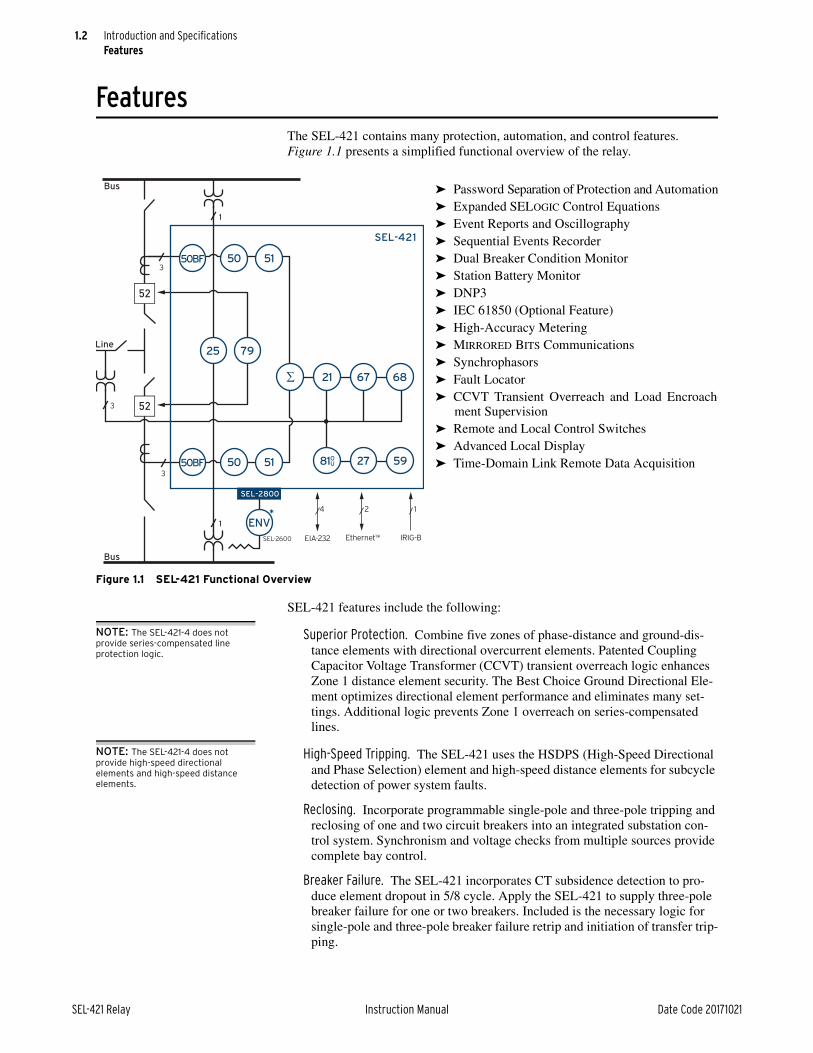
1.2
SEL-421 Relay Instruction Manual Date Code 20171021
Introduction and SpecificationsFeatures
FeaturesThe SEL-421 contains many protection, automation, and control features. Figure 1.1 presents a simplified functional overview of the relay.
SEL-421 features include the following:
NOTE: The SEL-421-4 does not provide series-compensated line protection logic.
Superior Protection. Combine five zones of phase-distance and ground-dis-tance elements with directional overcurrent elements. Patented Coupling Capacitor Voltage Transformer (CCVT) transient overreach logic enhances Zone 1 distance element security. The Best Choice Ground Directional Ele-ment optimizes directional element performance and eliminates many set-tings. Additional logic prevents Zone 1 overreach on series-compensated lines.
NOTE: The SEL-421-4 does not provide high-speed directional elements and high-speed distance elements.
High-Speed Tripping. The SEL-421 uses the HSDPS (High-Speed Directional and Phase Selection) element and high-speed distance elements for subcycle detection of power system faults.
Reclosing. Incorporate programmable single-pole and three-pole tripping and reclosing of one and two circuit breakers into an integrated substation con-trol system. Synchronism and voltage checks from multiple sources provide complete bay control.
Breaker Failure. The SEL-421 incorporates CT subsidence detection to pro-duce element dropout in 5/8 cycle. Apply the SEL-421 to supply three-pole breaker failure for one or two breakers. Included is the necessary logic for single-pole and three-pole breaker failure retrip and initiation of transfer trip-ping.
Figure 1.1 SEL-421 Functional Overview
➤ Password Separation of Protection and Automation➤ Expanded SELOGIC Control Equations➤ Event Reports and Oscillography➤ Sequential Events Recorder➤ Dual Breaker Condition Monitor➤ Station Battery Monitor➤ DNP3➤ IEC 61850 (Optional Feature)➤ High-Accuracy Metering➤ MIRRORED BITS Communications➤ Synchrophasors➤ Fault Locator➤ CCVT Transient Overreach and Load Encroach-
ment Supervision➤ Remote and Local Control Switches➤ Advanced Local Display➤ Time-Domain Link Remote Data Acquisition
SEL-2600
Bus
3
Line
Bus
3
3
1
SEL-2800
1
ENV
21
25
50BF 5150
50BF 5150
67 68
79
81OU
SEL-421
27 59
4
EIA-232
2
Ethernet1*
1
IRIG-B

1.3
Date Code 20171021 Instruction Manual SEL-421 Relay
Introduction and SpecificationsFeatures
Out-of-Step Blocking and Tripping. Select out-of-step blocking of distance ele-ments or out-of-step tripping during power swings. The SEL-421 includes multizone elements and logic for detection of an out-of-step condition.
Switch-Onto-Fault. Relay switch-onto-fault (SOTF) logic permits specific pro-tection elements to quickly trip after the circuit breaker closes, protecting maintenance personnel and substation equipment.
Frequency Elements. Any of the six levels of frequency elements can operate as either an underfrequency element or as an overfrequency element. The frequency elements are suited for applications such as underfrequency load shedding and restoration control systems.
Voltage Elements. The relay offers as many as six undervoltage and six over-voltage elements. Each of these 12 elements has two levels, for a total of 24 over- and undervoltage elements.
Fault Locator. Efficiently dispatch line crews to quickly repair line problems.
Primary Potential Redundancy. Multiple voltage inputs to the SEL-421 pro-vide primary input redundancy. At loss-of-potential (LOP) detection, config-ure the relay to use inputs from an electrically equivalent source. Protection remains in service without compromising security.
Dual CT Input. Apply with ring bus, breaker-and-a-half, or other two-breaker schemes. Combine currents within the relay from two sets of CTs for protec-tion functions, but keep them separately available for monitoring and station integration applications.
NOTE: The SEL-421-4 has only one 100-line automation programming block.
Automation. Take advantage of enhanced automation features that include programmable elements for local control, remote control, protection latch-ing, and automation latching. Local metering on the large format front-panel liquid crystal display (LCD) eliminates the need for separate panel meters. Use serial and Ethernet links to efficiently transmit key information, includ-ing metering data, protection element and control I/O status, Sequential Events Recorder (SER) reports, breaker monitor, relay summary event reports, and time synchronization. Use expanded SELOGIC control equations with math and comparison functions in control applications. Incorporate as many as 1000 lines of automation logic to speed and improve control actions.
Monitoring. Schedule breaker maintenance when accumulated breaker duty (independently monitored for each pole of two circuit breakers) indicates possible excess contact wear. Electrical and mechanical operating times are recorded for both the last operation and the average of operations since func-tion reset. Alarm contacts provide notification of substation battery voltage problems (two independent battery monitors) even if voltage is low only during trip or close operations.
Comprehensive Metering. View metering information for Line, Circuit Breaker 1, and Circuit Breaker 2. SEL-421 metering includes fundamental and rms metering, as well as energy import/export, demand, and peak demand metering data. Synchrophasor data can be used for time-synchro-nized state measurements across the system.
Oscillography and Event Reporting. Record voltages, currents, and internal logic points at as high as 8 kHz sampling rate. Phasor and harmonic analysis features allow investigation of relay and system performance.
Sequential Events Recorder (SER). Record the last 1000 entries, including set-ting changes, power-ups, and selectable logic elements.
1.4
SEL-421 Relay Instruction Manual Date Code 20171021
Introduction and SpecificationsFeatures
High-Accuracy Time Stamping. Time-tag binary COMTRADE event reports with real-time accuracy of better than 10 µs. View system state information to an accuracy of better than 1/4 of an electrical degree.
Digital Relay-to-Relay Communication. Enhanced MIRRORED BITS communi-cations to monitor internal element conditions between relays within a sta-tion, or between stations, using SEL fiber-optic transceivers. Send digital, analog, and virtual terminal data over the same MIRRORED BITS channel.
Parallel Redundancy Protocol (PRP). Provide seamless recovery from any sin-gle Ethernet network failure with this protocol, in accordance with IEC 62439-3. The Ethernet network and all traffic are fully duplicated with both copies operating in parallel.
Ethernet Access. Access all relay functions with the optional Ethernet card. Interconnect with automation systems using IEC 61850 or DNP3 LAN/WAN protocols directly or DNP3 through an SEL-2032 Communications Processor or SEL-3530 RTAC. Use file transfer protocol (FTP) for high-speed data collection.
Increased Security. The SEL-421 divides control and settings into seven relay access levels; the relay has separate breaker, protection, automation, and out-put access levels, among others. Set unique passwords for each access level.
Rules-Based Settings Editor. Communicate with and set the relay using an ASCII terminal, or use the PC-based QuickSet Software to configure the SEL-421 and analyze fault records with relay element response. View real-time phasors.
Settings Reduction. Internal relay programming shows only the settings for the functions and elements you have enabled.
Thermal Overload Modeling. Use the SEL-421 with the SEL-2600 RTD Mod-ule for dynamic overload protection using SELOGIC control equations. For more information, see SEL Application Guide AG2003-06, Implementation of the SEL-49 Relay Line Thermal Protection Using the SEL-421 Relay SELOGIC Equations.
Bay Control. The SEL-421 provides bay control functionality with status indi-cation and control of as many as ten disconnects. The relay features control for as many as two breakers and status indication of as many as three break-ers. Numerous pre-defined user-selectable mimic displays are available; the selected mimic is displayed on the front-panel screen in one-line diagram format. The one-line diagram includes user-configurable labels for discon-nect switches, breakers, bay name, and display for as many as six analog quantities. The SEL-421 features SELOGIC programmable local control supervision of breaker and disconnect switch operations. See Section 5: Control in the SEL-400 Series Relays Instruction Manual for more informa-tion.
Alias Settings. Use as many as 200 aliases to rename any digital or analog quantity in the relay. The aliases are now available for use in customized pro-gramming, making the initial programming and maintenance much easier.
Auxiliary TRIP/CLOSE Pushbuttons. The part number indicates whether the relay has auxiliary TRIP and CLOSE pushbuttons. These pushbuttons are shown in Figure 4.2 on page 4.2 in the SEL-400 Instruction Manual. These features are electrically isolated from the rest of the relay. They function inde-pendently from the relay and do not need relay power.
1.5
Date Code 20171021 Instruction Manual SEL-421 Relay
Introduction and SpecificationsModels and Options
Part numbers 0421xxxxxxxxxx3Axxxxx, 0421xxxxxxxxxx7Axxxxx, 0421xxxxxxxxxx3Bxxxxx, and 0421xxxxxxxxxx7Bxxxxx designate relays with the auxiliary TRIP and CLOSE pushbuttons.
The lowercase xs in the above part numbers represent fields that contain other values that are not important in determining the operator controls of the relay. Refer to the SEL-421 Model Option Table for complete part number details. These tables are available on the SEL website or from the factory.
Models and OptionsConsider the following options when ordering and configuring the SEL-421.
➤ Chassis size
➢ 3U, 4U, and 5U
(U is one rack unit—1.75 inches or 44.45 mm)
➤ Main board I/O
➢ Main Board:
Contact inputs: 5 independent and 2 common inputs (level sensi-tive and optoisolated);
Contact outputs: 2 standard Form A, 3 standard Form C, and 3 high-current interrupting Form A outputs
➤ Additional I/O board (for 4U and 5U chassis)
➢ INT1:
Contact inputs: 8 independent inputs (programmable pickup threshold);
Contact outputs: 13 standard Form A and 2 standard Form C outputs
➢ INT2:
Contact inputs: 8 independent inputs (level sensitive and optoisolated);
Contact outputs: 13 standard Form A and 2 standard Form C outputs
➢ INT3:
Contact inputs: 18 common (2 groups of 9) and 6 independent inputs (level sensitive and optoisolated);
Contact outputs: 4 high-current interrupting
Form A outputs
➢ INT4:
Contact inputs: 18 common (2 groups of 9) and 6 independent inputs (level sensitive and optoisolated);
Contact outputs: 6 high-speed, high-current interrupting Form A and 2 standard Form A outputs
➢ INT5:
Contact inputs: 8 independent inputs (programmable pickup threshold);
Contact outputs: 8 high-speed, high-current interrupting Form A outputs
NOTE: When used in TiDL applications, the relay is only available in the 4U chassis.

1.6
SEL-421 Relay Instruction Manual Date Code 20171021
Introduction and SpecificationsModels and Options
➢ INT6:
Contact inputs: 8 independent inputs (programmable pickup threshold);
Contact outputs: 13 high-current interrupting Form A and 2 stan-dard Form C outputs
➢ INT7:
Contact inputs: 8 independent inputs (level sensitive and optoisolated);
Contact outputs: 13 high-current interrupting Form A and 2 stan-dard Form C outputs
➢ INT8:
Contact inputs: 8 independent inputs (level sensitive and optoisolated);
Contact outputs: 8 high-speed, high-current interrupting Form A outputs
➤ Chassis orientation and type
➢ Horizontal rack mount
➢ Horizontal panel mount
➢ Vertical rack mount
➢ Vertical panel mount
➤ Power supply
➢ 24–48 Vdc
➢ 48–125 Vdc or 110–120 Vac
➢ 125–250 Vdc or 110–240 Vac
➤ Secondary inputs
➢ 1 A nominal or 5 A nominal CT inputs
➢ 300 V phase-to-neutral wye configuration PT inputs
➤ Ethernet card options
➢ Ethernet card with combinations of 10/100BASE-T and 100BASE-FX media connections on each of two ports
➤ Communications protocols
➢ Complete group of SEL protocols
(SEL ASCII, SEL Compressed ASCII, SEL Settings File Trans-fer, SEL Fast Meter, SEL Fast Operate, SEL Fast SER, RTDs, Enhanced MIRRORED BITS Communications), and Synchropha-sors (SEL Fast Message and IEEE C37.118 format), and DNP3
➢ All of the standard protocols, plus IEC 61850
➤ Connector type
➢ Screw-terminal block inputs
➢ Connectorized
Contact the SEL factory or your local Technical Service Center for particular part number and ordering information (see Technical Support on page 3.23). You can also view the latest part number and ordering information on the SEL website at selinc.com.

1.7
Date Code 20171021 Instruction Manual SEL-421 Relay
Introduction and SpecificationsModels and Options
SEL-421 Versions and Supported Features
SEL-421 Features -4 -5
Protection
21MG Mho Ground-Distance and 21MP Mho Phase Distance Standard Standard
21XG Quadrilateral Ground-Distance and 21XP Quadrilateral Phase Distance Standard Standard
High-Speed Distance and High-Speed Directional Standard
50N/G Ground, 50P Phase, and 50Q Negative-Sequence—O/C Standard Standard
51N/G Ground, 51P Phase, and 51Q Negative-Sequence Time—O/C Standard Standard
67N/G Ground, 67P Phase, and 67Q Neg.-Seq. Directional—O/C Standard Standard
Programmable Analog Math Standard Standard
Out-of-Step Trip and Block Standard Standard
Load-Encroachment Supervision Standard Standard
Switch-Onto-Fault Standard Standard
Single-Pole Trip Standard Standard
MIRRORED BITS Communications Standard Standard
Zone/Level Timers Standard Standard
Pilot Protection Logic Standard Standard
Series-Compensated Line Logic Standard
Instrumentation and Control
79 Automatic Reclosing, Voltage Check on Closing, 25 Synchronism Check Standard Standard
Fault Locating Standard Standard
SELOGIC Control Equations Standard Standard
Maximum Automation SELOGIC Control Equations 100 1000
Substation Battery Monitor Standard Standard
Breaker Wear Monitor Standard Standard
Event Report (Multicycle Data) and Sequential Events Recorder Standard Standard
Instantaneous, RMS, and Demand Meter Standard Standard
DNP3 Level 2 Outstation Standard Standard
Synchrophasors (IEEE C37.118 and SEL Fast Message) Standard Standard
Remote Synchrophasor Measurement
Time-Domain Link (TiDL) Remote Data Acquisition Optional Optional
Contact Input Option
Main Board—Optoisolated Level-Sensitive Contact Inputs Standard Standard
INT1 Interface Board—User-Settable Level-Sensitive Contact Inputs Optional Optional
INT2 Interface Board—Optoisolated Level-Sensitive Contact Inputs Standard Standard
INT3 Interface Board—Optoisolated Level-Sensitive Contact Inputs Standard Standard
INT4 Interface Board—Optoisolated Level-Sensitive Contact Inputs
INT5 Interface Board—User-Settable Level-Sensitive Contact Inputs Optional Optional
INT6 Interface Board—User-Settable Level-Sensitive Contact Inputs Optional Optional
INT7 Interface Board—Optoisolated Level-Sensitive Contact Inputs Standard Standard
INT8 Interface Board—Optoisolated Level-Sensitive Contact Inputs Standard Standard
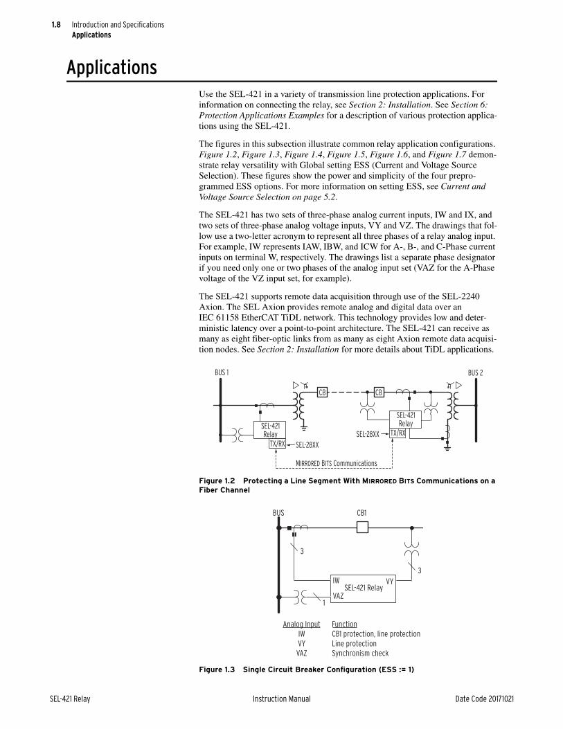
1.8
SEL-421 Relay Instruction Manual Date Code 20171021
Introduction and SpecificationsApplications
ApplicationsUse the SEL-421 in a variety of transmission line protection applications. For information on connecting the relay, see Section 2: Installation. See Section 6: Protection Applications Examples for a description of various protection applica-tions using the SEL-421.
The figures in this subsection illustrate common relay application configurations. Figure 1.2, Figure 1.3, Figure 1.4, Figure 1.5, Figure 1.6, and Figure 1.7 demon-strate relay versatility with Global setting ESS (Current and Voltage Source Selection). These figures show the power and simplicity of the four prepro-grammed ESS options. For more information on setting ESS, see Current and Voltage Source Selection on page 5.2.
The SEL-421 has two sets of three-phase analog current inputs, IW and IX, and two sets of three-phase analog voltage inputs, VY and VZ. The drawings that fol-low use a two-letter acronym to represent all three phases of a relay analog input. For example, IW represents IAW, IBW, and ICW for A-, B-, and C-Phase current inputs on terminal W, respectively. The drawings list a separate phase designator if you need only one or two phases of the analog input set (VAZ for the A-Phase voltage of the VZ input set, for example).
The SEL-421 supports remote data acquisition through use of the SEL-2240 Axion. The SEL Axion provides remote analog and digital data over an IEC 61158 EtherCAT TiDL network. This technology provides low and deter-ministic latency over a point-to-point architecture. The SEL-421 can receive as many as eight fiber-optic links from as many as eight Axion remote data acquisi-tion nodes. See Section 2: Installation for more details about TiDL applications.
Figure 1.2 Protecting a Line Segment With MIRRORED BITS Communications on a Fiber Channel
Figure 1.3 Single Circuit Breaker Configuration (ESS := 1)
SEL-421Relay
CB
TX/RX
SEL-421Relay
TX/RX
MIRRORED BITS Communications
SEL-28XX
SEL-28XX
BUS 1 BUS 2
CB
SEL-421 Relay
BUS CB1
3
3
IW
VAZ
VY
1
Analog Input
IW
VY
VAZ
Function
CB1 protection, line protection
Line protection
Synchronism check

1.9
Date Code 20171021 Instruction Manual SEL-421 Relay
Introduction and SpecificationsApplications
Figure 1.4 Single Circuit Breaker Configuration With Line Breaker CTs (ESS := 2)
Figure 1.5 Double Circuit Breaker Configuration (ESS := 3)
SEL-421 Relay
BUS CB1
3
1
3
IWIX
VAZ
VY
3
Analog Input
IW
IX
VY
VAZ
Function
CB1 protection, line protection
CB1 breaker failure
Line protection
Synchronism check
SEL-421 Relay
BUS 1 BUS 2CB1 CB2
3 3
3
IW IX VAZ
VY
VBZ
1 1
Analog Input
IW+IX
IW
IX
VY
VAZ
VBZ
Function
Line Protection
CB1 protection
CB2 protection
Line protection
Synchronism check Circuit Breaker 1
Synchronism check Circuit Breaker 2

1.10
SEL-421 Relay Instruction Manual Date Code 20171021
Introduction and SpecificationsApplications
Figure 1.6 Double Circuit Breaker Configuration With Bus Protection (ESS := 4)
Figure 1.7 Tapped Line (ESS := Y)
SEL-421 Relay
BUS 1 BUS 2CB1 CB2
33 3
3IW IX VAZ
VY
VBZ
1 1
Analog Input
IW+IX
IW
IX
VY
VAZ
VBZ
Function
CB2 protection
Line protection
CB1 protection
Line protection
Synchronism check Circuit Breaker 1
Synchronism check Circuit Breaker 2
(HV)
TrippingDirection
(LV)
MOD
SEL-421 RelayIW
VY
1
1
3
3
VAZ VBZ
CB2CB1
Analog Input
IW
VY
VAZ
VBZ
Function
Line protection
Line protection
Synchronism check Circuit Breaker 1
Synchronism check Circuit Breaker 2

1.11
Date Code 20171021 Instruction Manual SEL-421 Relay
Introduction and SpecificationsApplications
Application HighlightsApply the SEL-421 in power system protection and control situations. Table 1.1 lists applications and key features of the relay.
NOTE: The SEL-421-4 does not provide high-speed directional elements and high-speed distance elements.
Table 1.1 Application Highlights (Sheet 1 of 2)
Application Key Features
Single-pole and three-pole tripping
High-speed distance elements
Best Choice Ground Directional Element
Secure protection during open-pole interval
Pole-discordance logic trips three-pole for excessive single-pole-open conditions
Remote data acquisition Time-domain link (TiDL)
Multiple-breaker tripping SPT one; 3PT other
SPT both; 3PT both
Breaker failure protection
Reclosing and synchronism check
2 shots SPT; 4 shots 3PT
Leader/follower breaker arrangements
Two-circuit-breaker universal synchronism check
Coupling-Capacitor Voltage Transformer (CCVT) tran-sient detection logic
Detect CCVT transients to provide correct operation of the direct tripping (Zone 1) distance elements
Long lines Load-encroachment elements prevent unwanted trips on load
Voltage elements detect local bus overvoltages
Sensitive negative-sequence and residual overcurrent ele-ments provide sensitive backup protection
Tapped and three-terminal lines
Five zones
Three zero-sequence compensation factors for more accurate ground-distance reach on either side of tap
Independent reach settings for phase, ground mho and phase, ground quadrilateral elements
Multiple settings groups cover any switching configurations
Bus-tie or transfer circuit breakers
Multiple setting groups
Match relay settings group to each line substitution
Eliminate current reversing switches
Local or remote operator switches the setting groups
Subtransmission lines Time-step distance protection
Ground directional overcurrent protection
Torque-controlled time-overcurrent elements
Lines with capacitors Series-compensated line logic
Lines with transformers Negative-sequence overcurrent protection
Short transmission lines Directional overcurrent elements and communications-assisted tripping schemes, quadrilateral phase distance
Permissive Overreaching Transfer Tripping (POTT) schemes
Current reversal guard logic
Open breaker echo keying logic
Weak-infeed and zero-infeed logic
Time-step distance backup protection
Directional Comparison Unblocking Tripping (DCUB) schemes
Includes all POTT logic
All loss-of-channel logic is inside the relay
Time-step distance backup protection
NOTE: If the relay is using a remote data acquisition system, such as TiDL, the operating times will be delayed by 1.5 ms. Use caution when setting the relay coordination times to account for this added delay.
NOTE: The SEL-421-4 does not provide series-compensated line protection logic.

1.12
SEL-421 Relay Instruction Manual Date Code 20171021
Introduction and SpecificationsProduct Characteristics
Product CharacteristicsEach SEL-400 series relay shares common features, but has unique characteris-tics. The following table summarizes the unique characteristics of the SEL-421.
Permissive Underreaching Transfer Tripping (PUTT) schemes
Supported by POTT logic
Time-step distance backup protection
Directional Comparison Blocking Trip (DCB) schemes
Current reversal guard logic
Carrier coordinating timers
Carrier send and receive extend logic
Zone 3 latch eliminates the need for offset three-phase dis-tance elements
Time-step distance backup protection
Direct Transfer Tripping (DTT) schemes
SELOGIC control equations program the elements that key direct tripping
SCADA applications Analog and digital data acquisition for station wide functions
Communications capability SEL ASCII
Enhanced MIRRORED BITS communications
SEL Fast Meter, SEL Fast Operate, SEL Fast SER
SEL Compressed ASCII
Phasor Measurement Unit (PMU) protocols
RTD
Serial DNP3
Optional protocols: Ethernet, IEC 61850, DNP3 (Ethernet), FTP, Telnet
Customized protection and automation schemes
Separate protection and automation SELOGIC control equa-tion programming areas
Use timers and counters in expanded SELOGIC control equa-tions for complete flexibility
Synchrophasors The SEL-421 can function as a phasor measurement unit (PMU) at the same time as it provides best-in-class protective relay functions.
C37.118 message format allows as many as 12 current and 8 voltage synchronized measurements, as many as 60 messages per second (on a 60 Hz nominal power system). Five unique data streams, three choices of filter response, settable angle correction, and a choice of numeric representation makes the data usable for a variety of synchrophasor applications.
SEL Fast Operate commands are available on the synchropha-sor communications ports, allowing control actions initiated by the synchrophasor processor.
Records as much as 120 seconds of C37.118 synchrophasor data based on a trigger. Recorded files follow the C37.232 file naming convention.
SEL Fast Message Synchrophasor format is also available as legacy, with as many as four current and four voltage synchro-nized measurements.
Table 1.1 Application Highlights (Sheet 2 of 2)
Application Key Features

1.13
Date Code 20171021 Instruction Manual SEL-421 Relay
Introduction and SpecificationsProduct Characteristics
Table 1.2 SEL-421 Relay Characteristics
Characteristic Value
Standard processing rate 8 times per cycle
Battery monitor Two
Autorecloser Single-pole
MBG protocol Supported
SELOGIC
Protection freeform 250 lines
Automation freeform 421-4: 1 block of 100 lines
421-5: 10 blocks of 100 lines each
SELOGIC variables 64 protection
256 automation
SELOGIC math variables 64 protection
256 automation
Conditioning timers 32 protection
Sequencing timers 32 protection
32 automation
Counters 32 protection
32 automation
Latch bits 32 automation
32 protection
Control
Remote bits 32
Breakers Two for control and three for status: 1, 2, 3
Three-Pole or Single-Pole
Disconnects 10
Bay control Supported
Metering
Maximum/minimum metering Supported
Energy metering Supported

1.14
SEL-421 Relay Instruction Manual Date Code 20171021
Introduction and SpecificationsSpecifications
SpecificationsSection 1Introduction and SpecificationsInstruction Manual
Note: If the relay uses a remote data acquisition system, such as TiDL, the operating times will be delayed by 1.5 ms. Use caution when setting the relay coordination times to account for this added delay. Element operate times will also have this small added delay.
ComplianceDesigned and manufactured under an ISO 9001 certified quality
management system
47 CFR 15B Class AThis equipment has been tested and found to comply with the limits
for a Class A digital device, pursuant to part 15 of the FCC Rules. These limits are designed to provide reasonable protection against harmful interference when the equipment is operated in a commercial environment. This equipment generates, uses, and can radiate radio frequency energy and, if not installed and used in accordance with the instruction manual, may cause harmful interference in which case the user will be required to correct the interference at his own expense.
UL Listed to U.S. and Canadian safety standards (File E212775; NRGU, NRGU7)
CE Mark
GeneralAC Analog Inputs
Sampling Rate: 8 kHz
AC Current Inputs (Secondary Circuits)
Current Rating (With DC Offset at X/R = 10, 1.5 Cycles)
1 A Nominal: 18.2 A
5 A Nominal: 91 A
Continuous Thermal Rating
1 A Nominal: 3 A4 A (+55°C)
5 A Nominal: 15 A20 A (+55°C)
Saturation Current (Linear) Rating
1 A Nominal: 20 A
5 A Nominal: 100 A
A/D Current Limit
Note: Signal clipping may occur beyond this limit.
5 A Nominal: 247.5 A
1 A Nominal: 49.5 A
One-Second Thermal Rating
1 A Nominal: 100 A
5 A Nominal: 500 A
One-Cycle Thermal Rating
1 A Nominal: 250 A-peak
5 A Nominal: 1250 A-peak
Burden Rating
1 A Nominal: 0.1 VA at 1 A
5 A Nominal: 0.5 VA at 5 A
AC Voltage Inputs
Three-phase, four-wire (wye) connections are supported.
Rated Voltage Range: 0–300 VLN
Ten-Second Thermal Rating: 600 Vac
Burden: 0.1 VA @ 125 V
Frequency and Rotation
Nominal Frequency Rating:
50 ±5 Hz60 ±5 Hz
Phase Rotation: ABC or ACB
Frequency Tracking Range:
40.0–65.0 Hz<40 Hz = 40 Hz>65.0 Hz = 65 Hz
Maximum Slew Rate: 15 Hz/s
Power Supply
24–48 Vdc
Rated Voltage: 24–48 Vdc
Operational Voltage Range: 18–60 Vdc
Vdc Input Ripple: 15% per IEC 60255-26:2013
Interruption: 20 ms at 24 Vdc, 100 ms at 48 Vdc per IEC 60255-26:2013
Burden: <35 W
48–125 Vdc or 110–120 Vac
Rated Voltage: 48–125 Vdc, 110–120 Vac
Operational Voltage Range:
38–140 Vdc85–140 Vac
Rated Frequency: 50/60 Hz
Operational Frequency Range: 30–120 Hz
Vdc Input Ripple: 15% per IEC 60255-26:2013
Interruption: 14 ms at 48 Vdc, 160 ms at 125 Vdc per IEC 60255-26:2013
Burden: <35 W, <90 VA
125–250 Vdc or 110–240 Vac
Rated Voltage: 125–250 Vdc, 110–240 Vac
Operational Voltage Range:
85–300 Vdc85–264 Vac
Rated Frequency: 50/60 Hz
Operational Frequency Range: 30–120 Hz
Vdc Input Ripple: 15% per IEC 60255-26:2013
Interruption: 46 ms at 125 Vdc, 250 ms at 250 Vdc per IEC 60255-26:2013
Burden: <35 W, <90 VA
Control Outputs
Standard
Make: 30 A
Carry: 6 A continuous carry at 70°C4 A continuous carry at 85°C
1 s Rating: 50 A
MOV Protection (Maximum Voltage): 250 Vac, 330 Vdc
Pickup/Dropout Time: 6 ms, resistive load
Update Rate: 1/8 cycle
Break Capacity (10,000 Operations):
48 Vdc 0.50 A L/R = 40 ms125 Vdc 0.30 A L/R = 40 ms250 Vdc 0.20 A L/R = 40 ms

1.15
Date Code 20171021 Instruction Manual SEL-421 Relay
Introduction and SpecificationsSpecifications
Cyclic Capacity (2.5 Cycle/Second):
48 Vdc 0.50 A L/R = 40 ms125 Vdc 0.30 A L/R = 40 ms250 Vdc 0.20 A L/R = 40 ms
Hybrid (High-Current Interrupting)
Make: 30 A
Carry: 6 A continuous carry at 70°C4 A continuous carry at 85°C
1 s Rating: 50 A
MOV Protection (Maximum Voltage): 330Vdc
Pickup/Dropout Time: 6 ms, resistive load
Update Rate: 1/8 cycle
Breaking Capacity (10,000 Operations):
48 Vdc 10.0 A L/R = 40 ms125 Vdc 10.0 A L/R = 40 ms250 Vdc 10.0 A L/R = 20 ms
Cyclic Capacity (4 cycles in 1 second, followed by 2 minutes idle for thermal dissipation):
48 Vdc 10.0 A L/R = 40 ms125 Vdc 10.0 A L/R = 40 ms250 Vdc 10.0 A L/R = 20 ms
Note: Do not use hybrid control outputs to switch ac control signals. These outputs are polarity dependent.
High-Speed, High-Current Interrupting
Make: 30 A
Carry: 6 A continuous carry at 70°C4 A continuous carry at 85°C
1 s Rating: 50 A
MOV Protection (Maximum Voltage): 250 Vac/330 Vdc
Pickup Time: 0 s, resistive load
Dropout Time: 8 ms, resistive load
Update Rate: 1/8 cycle
Breaking Capacity (10,000 Operations):
48 Vdc 10.0 A L/R = 40 ms125 Vdc 10.0 A L/R = 40 ms250 Vdc 10.0 A L/R = 20 ms
Cyclic Capacity (4 cycles in 1 second, followed by 2 minutes idle for thermal dissipation):
48 Vdc 10.0 A L/R = 40 ms125 Vdc 10.0 A L/R = 40 ms250 Vdc 10.0 A L/R = 20 ms
Note: Per IEC 60255-23:1994, using the simplified method of assessment.Note: Make rating per IEEE C37.90-2005.Note: Per IEC 61810-2:2005.
Auxiliary Trip/Close Pushbuttons (Select Models Only)
Resistive DC or AC Outputs With Arc Suppression Disabled
Make: 30 A
Carry: 6 A continuous carry
1 s Rating: 50 A
MOV Protection: 250 Vac/330 Vdc/130 J
Breaking Capacity (1000 Operations):
48 Vdc 0.50 A L/R = 40 ms125 Vdc 0.30 A L/R = 40 ms250 Vdc 0.20 A L/R = 40 ms
High Interrupt DC Outputs With Arc Suppression Enabled
Make: 30 A
Carry: 6 A continuous carry
1 s Rating: 50 A
MOV Protection: 330 Vdc/130 J
Breaking Capacity (10,000 Operations):
48 Vdc 10 A L/R = 40 ms125 Vdc 10 A L/R = 40 ms250 Vdc 10 A L/R = 20 ms
Breaker Open/Closed LEDs:
250 Vdc: on for 150–300 Vdc; 192–288 Vac125 Vdc: on for 80–150 Vdc; 96–144 Vac
48 Vdc: on for 30–60 Vdc;24 Vdc: on for 15–30 Vdc
Note: With nominal control voltage applied, each LED draws 8 mA (max.). Jumpers may be set to 125 Vdc for 110 Vdc input and set to 250 Vdc for 220 Vdc input.
Control Inputs
Direct Coupled (For Use With DC Signals)
INT1, INT5, and INT6Interface Boards: 8 inputs with no shared terminals
Range: 15–265 Vdc, independently adjustable
Accuracy: ±5% ±3 Vdc
Maximum Voltage: 300 Vdc
Sampling Rate: 2 kHz
Typical Burden: 0.24 W @ 125 Vdc
Optoisolated (Use With AC or DC Signals)
Main Board: 5 inputs with no shared terminals2 inputs with shared terminals
INT2, INT7, and INT8 Interface Boards: 8 inputs with no shared terminals
INT3 and INT4 Interface Boards:
6 inputs with no shared terminals18 inputs with shared terminals
(2 groups of 9 inputs with each group sharing one terminal)
Voltage Options: 24 V standard48, 110, 125, 220, 250 V level sensitive
DC Thresholds (Dropout Thresholds Indicate Level-Sensitive Option)
24 Vdc: Pickup 19.2–30.0 Vdc
48 Vdc: Pickup 38.4–60.0 Vdc;Dropout <28.8 Vdc
110 Vdc: Pickup 88.0–132.0 Vdc;Dropout <66.0 Vdc
125 Vdc: Pickup 105–150 Vdc;Dropout <75 Vdc
220 Vdc: Pickup 176–264 Vdc;Dropout <132 Vdc
250 Vdc: Pickup 200–300 Vdc;Dropout <150 Vdc
AC Thresholds (Ratings Met Only When Recommended Control Input Settings Are Used—see Table 2.1 on page 2.6)
24 Vac: Pickup 16.4–30.0 Vac rms
48 Vac: Pickup 32.8–60.0 Vac rms;Dropout <20.3 Vac rms
110 Vac: Pickup 75.1–132.0 Vac rms;Dropout <46.6 Vac rms
125 Vac: Pickup 89.6–150.0 Vac rms;Dropout <53.0 Vac rms
220 Vac: Pickup 150.3–264 Vac rms;Dropout <93.2 Vac rms
250 Vac: Pickup 170.6–300 Vac rms;Dropout <106 Vac rms
Current Drawn: <5 mA at nominal voltage<8 mA for 110 V option
Sampling Rate: 2 kHz

1.16
SEL-421 Relay Instruction Manual Date Code 20171021
Introduction and SpecificationsSpecifications
Communications Ports
EIA-232: 1 Front and 3 Rear
Serial Data Speed: 300–57600 bps
Communications Card Slot for Optional Ethernet Card
Ordering Options: 100BASE-FX fiber-optic Ethernet
Fiber Type: Multimode
Wavelength: 1300 nm
Source: LED
Connector Type: LC fiber
Min. TX Power: –19 dBm
Max. TX Power: –14 dBm
RX Sensitivity: –32 dBm
Sys. Gain: 13 dB
Communications Ports for Optional TiDL Interface
EtherCAT Fiber-Optic Ports: 8
Data Rate: Automatic
Connector Type: LC fiber
Protocols: Dedicated EtherCAT
Class 1 LASER/LED
Wavelength: 1300 nm
Fiber Type: Multimode
Link Budget: 11 dB
Min. TX Power: –20 dBm
Min. RX Sensitivity: –31 dBm
Fiber Size: 50–200 m
Approximate Range: 2 km
Data Rate: 100 Mbps
Typical Fiber Attenuation: –2 dB/km
Time Inputs
IRIG Time Input-Serial Port 1
Input: Demodulated IRIG-B
Rated I/O Voltage: 5 Vdc
Operating Voltage Range: 0–8 Vdc
Logic High Threshold: 2.8 Vdc
Logic Low Threshold: 0.8 Vdc
Input Impedance: 2.5 k
IRIG-B Input—BNC Connector
Input: Demodulated IRIG-B
Rated I/O Voltage: 5 Vdc
Operating Voltage Range: 0–8 Vdc
Logic High Threshold: 2.2 Vdc
Logic Low Threshold: 0.8 Vdc
Input Impedance: 50 or > 1 k
Dielectric Test Voltage: 0.5 kVac
PTP—Ethernet Port 5A, 5B
Input: IEEE 1588 PTPv2
Profiles: Default, C37.238-2011 (Power Profile)
Synchronization Accuracy:
±100 ns @ 1-second synchronization intervals when communicating directly with master clock
Operating Temperature
–40 to +85C (–40 to +185F)
Note: LCD contrast impaired for temperatures below –20° and above +70°C. Stated temperature ranges not applicable to UL applications.
Humidity
5% to 95% without condensation
Weight (Maximum)
3U Rack Unit: 8.0 kg (17.7 lb)
4U Rack Unit: 9.4 kg (20.7 lb)
5U Rack Unit: 11.3 kg (25.0 lb)
Terminal Connections
Rear Screw-Terminal Tightening Torque, #8 Ring Lug
Minimum: 1.0 Nm (9 in-lb)
Maximum: 2.0 Nm (18 in-lb)
User terminals and stranded copper wire should have a minimum temperature rating of 105°C. Ring terminals are recommended.
Wire Sizes and Insulation
Wire sizes for grounding (earthing), current, voltage, and contact connections are dictated by the terminal blocks and expected load currents. You can use the following table as a guide in selecting wire sizes. The grounding conductor should be as short as possible and sized equal to or greater than any other conductor connected to the device unless otherwise required by local or national regulations.
Type TestsThese tests do not apply to contacts rated for 24 Vdc.
Electromagnetic Compatibility (EMC)
Emissions: IEC 60255-25:2000
Electromagnetic Compatibility Immunity
Conducted RF Immunity: IEC 60255-22-6:2001, 10 VrmsIEC 61000-4-6:2008, 10 Vrms
Electrostatic Discharge Immunity:
IEC 60255-22-2:2008IEC 61000-4-2:2008
Levels 2, 4, 6, and 8 kV contact;Levels 2, 4, 8, and 15 kV air
IEEE C37.90.3-2001Levels 2, 4, and 8 kV contact;Levels 4, 8, and 15 kV air
Fast Transient/Burst Immunity:
IEC 60255-22-4:20084 kV at 5 kHz and 2 kV at 5 kHz (Comm Ports)
IEC 61000-4-4:20114 kV at 5 kHz
Magnetic Field Immunity: IEC 61000-4-8:20091000 A/m for 3 s100 A/m for 1 min
IEC 61000-4-9:20011000 A/m
Damped Oscillatory Magnetic Field:
IEC 61000-4-10:2001Severity Level: 100 A/m
Connection Type Min. Wire Size Max. Wire Size
Grounding (Earthing) Connection
14 AWG (2.5 mm2) N/A
Current Connection 16 AWG (1.5 mm2) 10 AWG (5.3 mm2)
Potential (Voltage) Connection
18 AWG (0.8 mm2) 14 AWG (2.5 mm2)
Contact I/O 18 AWG (0.8 mm2) 10 AWG (5.3 mm2)
Other Connection 18 AWG (0.8 mm2) 10 AWG (5.3 mm2)

1.17
Date Code 20171021 Instruction Manual SEL-421 Relay
Introduction and SpecificationsSpecifications
Power Supply Immunity: IEC 60255-11:2008IEC 61000-4-11:2004IEC 61000-4-29:2000
Radiated Digital Radio Telephone RF Immunity:
ENV 50204:199510 V/m at 900 MHz and 1.89 GHz
Radiated Radio Frequency Immunity:
IEC 60255-22-3:2007, 10 V/mIEC 61000-4-3:2010, 10 V/mIEEE C37.90.2-2004, 35 V/m
Surge Immunity: IEC 60255-22-5:2008IEC 61000-4-5:2005
1.0 kV line-to-line2.0 kV line-to-earth
Surge Withstand Capability Immunity:
IEC 60255-22-1:20072.5 kV peak common mode1.0 kV peak differential mode
IEEE C37.90.1-20022.5 kV oscillatory4.0 kV fast transient waveform
Environmental
Cold: IEC 60068-2-1:2007Severity Level: 16 hours at –40C
Damp Heat, Cyclic: IEC 60068-2-30:2005Severity Level: 25°C to 55°C,6 cycles, Relative Humidity: 95%
Dry Heat: IEC 60068-2-2:2007Severity Level: 16 hours at +85°C
Vibration: IEC 60255-21-1:1988 Severity Level: Class 2 (endurance); Class 2 (response)
IEC 60255-21-2:1988Severity Level: Class 1 (shock withstand, bump); Class 2 (shock response)
IEC 60255-21-3:1993Severity Level: Class 2 (quake response)
Safety
Dielectric Strength: IEC 60255-5:2000IEEE C37.90-2005
2500 Vac on contact inputs, contact outputs, and analog inputs for 1 min
3100 Vdc on power supply for 1 min
Impulse: IEC 60255-5:2000, 0.5 J, 5 kVIEEE C37.90-2005, 0.5 J, 5 kV
IP Code: IEC 60529:2001 + CRGD:2003, IP3X
Reporting FunctionsHigh-Resolution Data
Rate: 8000 samples/second4000 samples/second2000 samples/second1000 samples/second
Output Format: Binary COMTRADE
Note: Per IEEE C37.111-1999, IEEE Standard Common Format for Transient Data Exchange (COMTRADE) for Power Systems.
Event Reports
Length: 0.25–24 seconds (based on LER and SRATE settings)
Volatile Memory: 3 s of back-to-back event reports sampled at 8 kHz
Nonvolatile Memory: At least 4 event reports of a 3 s duration sampled at 8 kHz
Resolution: 4 and 8 samples/cycle
Event Summary
Storage: 100 summaries
Breaker History
Storage: 128 histories
Sequential Events Recorder
Storage: 1000 entries
Trigger Elements: 250 relay elements
Resolution: 0.5 ms for contact inputs1/8 cycle for all elements
Processing SpecificationsAC Voltage and Current Inputs
8000 samples per second, 3 dB low-pass analog filter cut-off frequency of 3000 Hz.
Digital Filtering
Full-cycle cosine and half-cycle Fourier filters after low-pass analog and digital filtering.
Protection and Control Processing
8 times per power system cycleReclosing logic runs once per power system cycle
Control Points
32 remote bits32 local control bits32 latch bits in protection logic32 latch bits in automation logic
Relay Element Pickup Ranges and AccuraciesMho Phase-Distance Elements
Zones 1–5 Impedance Reach
Setting Range
5 A Model: OFF, 0.05 to 64 secondary, 0.01 steps
1 A Model: OFF, 0.25 to 320 secondary, 0.01 steps
Sensitivity
5 A Model: 0.5 AP-P secondary
1 A Model: 0.1 AP-P secondary(Minimum sensitivity is controlled by the pickup of the supervising phase-to-phase overcurrent elements for each zone.)
Accuracy (Steady State): ± 3% of setting at line angle for SIR (source-to-line impedance ratio) < 30
± 5% of setting at line angle for 30 SIR 60
Zone 1 Transient Overreach: < 5% of setting plus steady-state accuracy
SEL-421-5 Maximum Operating Time: 0.8 cycle at 70% of reach and SIR = 1
SEL-421-4 Maximum Operating Time: 1.5 cycle at 70% of reach and SIR = 1
Quadrilateral Phase-Distance Elements
Zones 1–5 Impedance Reach
Quadrilateral Reactance Reach
5 A Model: OFF, 0.05 to 64 secondary, 0.01 steps
1 A Model: OFF, 0.25 to 320 secondary, 0.01 steps
Quadrilateral Resistance Reach
Zones 1, 2, and 3
5 A Model: OFF, 0.05 to 50 secondary, 0.01 steps
1 A Model: OFF, 0.25 to 250 secondary, 0.01 steps

1.18
SEL-421 Relay Instruction Manual Date Code 20171021
Introduction and SpecificationsSpecifications
Zones 4 and 5
5 A Model: OFF, 0.05 to 150 secondary, 0.01 steps
1 A Model: OFF, 0.25 to 750 secondary, 0.01 steps
Sensitivity
5 A Model: 0.5 A secondary
1 A Model: 0.1 A secondary
Accuracy (Steady State): ±3% of setting at line angle for SIR < 30±5% of setting at line angle for
30 SIR 60
Transient Overreach: <5% of setting plus steady-state accuracy
Mho Ground-Distance Elements
Zones 1–5 Impedance Reach
Mho Element Reach
5 A Model: OFF, 0.05 to 64 secondary, 0.01 steps
1 A Model: OFF, 0.25 to 320 secondary, 0.01 steps
Sensitivity
5 A Model: 0.5 A secondary
1 A Model: 0.1 A secondary(Minimum sensitivity is controlled by the pickup of the supervising phase and residual overcurrent elements for each zone.)
Accuracy (Steady State): ±3% of setting at line angle for SIR < 30±5% of setting at line angle for
30 SIR 60
Zone 1 Transient Overreach: <5% of setting plus steady-state accuracy
SEL-421-5 Maximum Operating Time: 0.8 cycle at 70% of reach and SIR = 1
SEL-421-4 Maximum Operating Time: 1.5 cycle at 70% of reach and SIR = 1
Quadrilateral Ground-Distance Elements
Zones 1–5 Impedance Reach
Quadrilateral Reactance Reach
5 A Model: OFF, 0.05 to 64 secondary, 0.01 steps
1 A Model: OFF, 0.25 to 320 secondary, 0.01 steps
Quadrilateral Resistance Reach
Zones 1, 2, and 3
5 A Model: OFF, 0.05 to 50 secondary, 0.01 steps
1 A Model: OFF, 0.25 to 250 secondary, 0.01 steps
Zones 4 and 5
5 A Model: OFF, 0.05 to 150 secondary, 0.01 steps
1 A Model: OFF, 0.25 to 750 secondary, 0.01 steps
Sensitivity
5 A Model: 0.5 A secondary
1 A Model: 0.1 A secondary(Minimum sensitivity is controlled by the pickup of the supervising phase and residual overcurrent elements for each zone.)
Accuracy (Steady State): ±3% of setting at line angle for SIR < 30±5% of setting at line angle for
30 SIR 60
Transient Overreach: <5% of setting plus steady-state accuracy
Instantaneous/Definite-Time Overcurrent Elements
Phase, Residual Ground, and Negative-Sequence
Pickup Range
5 A Model: OFF, 0.25–100.00 A secondary, 0.01 A steps
1 A Model: OFF, 0.05–20.00 A secondary, 0.01 A steps
Accuracy (Steady State)
5 A Nominal: ±0.05 A plus ±3% of setting
1 A Nominal: ±0.01 A plus ±3% of setting
Transient Overreach: <5% of pickup
Time-Delay: 0.00–16000.00 cycles, 0.125 cycle steps
Timer Accuracy: ±0.125 cycle plus ±0.1% of setting
Maximum Operating Time: 1.5 cycles
Time-Overcurrent Elements
Pickup Range
5 A Model: 0.25–16.00 A secondary, 0.01 A steps
1 A Model: 0.05–3.20 A secondary, 0.01 A steps
Accuracy (Steady State)
5 A Model: ±0.05 A plus ± 3% of setting
1 A Model: ±0.01 A plus ± 3% of setting
Time Dial Range
US: 0.50–15.00, 0.01 steps
IEC: 0.05–1.00, 0.01 steps
Curve Timing Accuracy: ±1.50 cycles plus ± 4% of curve time (for current between 2 and 30 multiples of pickup)
Reset: 1 power cycle or Electromechanical Reset Emulation time
Ground Directional Elements
Neg.-Seq. Directional Impedance Threshold (Z2F, Z2R)
5 A Model: –64 to 64
1 A Model: –320 to 320
Zero-Seq. Directional Impedance Threshold (Z0F, Z0R)
5 A Model: –64 to 64
1 A Model: –320 to 320
Supervisory Overcurrent Pickup 50FP, 50RP
5 A Model: 0.25 to 5.00 A 3I0 secondary0.25 to 5.00 A 3I2 secondary
1 A Model: 0.05 to 1.00 A 3I0 secondary0.05 to 1.00 A 3I2 secondary
Undervoltage and Overvoltage Elements
Pickup Ranges
Phase Elements: 2–300 V secondary, 0.01 V steps
Phase-to-Phase Elements: 4–520.0 V secondary, 0.01 V steps
Accuracy (Steady State): ±0.5 V plus ± 5% of setting
Transient Overreach: <5% of pickup
Underfrequency and Overfrequency Elements
Pickup Range: 40.01–69.99 Hz, 0.01 Hz steps
Accuracy, Steady State Plus Transient:
±0.005 Hz for frequencies between 40.00 and 70.00 Hz
Maximum Pickup/Dropout Time: 3.0 cycles
Time-Delay Range: 0.04–400.0 s, 0.01 s increments

1.19
Date Code 20171021 Instruction Manual SEL-421 Relay
Introduction and SpecificationsSpecifications
Time-Delay Accuracy: ±0.1% ±0.0042 s
Pickup Range, Undervoltage Blocking: 20–200 VLN (Wye)
Pickup Accuracy, Undervoltage Blocking: ±2% ±0.5 V
Optional RTD Elements(Models Compatible With SEL-2600 RTD Module)
12 RTD Inputs Via SEL-2600 RTD Module and SEL-2800 Fiber-Optic Transceiver
Monitor Ambient or Other Temperatures
PT 100, NI 100, NI 120, and CU 10 RTD-Types Supported, Field Selectable
As long as 500 m Fiber-Optic Cable to SEL-2600 RTD Module
Breaker Failure Instantaneous Overcurrent
Setting Range
5 A Model: 0.50–50.0 A, 0.01 A steps
1 A Model: 0.10–10.0 A, 0.01 A steps
Accuracy
5 A Model: ±0.05 A plus ± 3% of setting
1 A Model: ±0.01 A plus ± 3% of setting
Transient Overreach: <5% of setting
Maximum Pickup Time: 1.5 cycles
Maximum Reset Time: 1 cycle
Timers Setting Range: 0–6000 cycles, 0.125 cycle steps (All but BFIDOn, BFISPn)
0–1000 cycles, 0.125 cycle steps (BFIDOn, BFISPn)
Time Delay Accuracy: 0.125 cycle plus ± 0.1% of setting
Synchronism-Check Elements
Slip Frequency Pickup Range: 0.005–0.500 Hz, 0.001 Hz steps
Slip Frequency Pickup Accuracy: ±0.0025 Hz plus ± 2% of setting
Close Angle Range: 3–80°, 1° steps
Close Angle Accuracy: ±3°
Load-Encroachment Detection
Setting Range
5 A Model: 0.05–64 secondary, 0.01 steps
1 A Model: 0.25–320 secondary, 0.01 steps
Forward Load Angle: –90° to +90°
Reverse Load Angle: +90° to +270°
Accuracy
Impedance Measurement: ±3%
Angle Measurement: ±2°
Out-of-Step Elements
Blinders (R1) Parallel to the Line Angle
5 A Model: 0.05 to 70 secondary–0.05 to –70 secondary
1 A Model: 0.25 to 350 secondary–0.25 to –350 secondary
Blinders (X1) Perpendicular to the Line Angle
5 A Model: 0.05 to 96 secondary–0.05 to –96 secondary
1 A Model: 0.25 to 480 secondary–0.25 to –480 secondary
Accuracy (Steady State)
5 A Model: ±5% of setting plus ±0.01 A for SIR (source to line impedance ratio) < 30 ±10% of setting plus ±0.01 A for 30 SIR 60
1 A Model: ±5% of setting plus ±0.05 A for SIR (source to line impedance ratio) < 30
±10% of setting plus ±0.05 A for 30 SIR 60
Transient Overreach: < 5% of setting plus steady-state accuracy
Positive-Sequence Overcurrent Supervision
Setting Range
5 A Model: 1.0–100.0 A, 0.01 A steps
1 A Model: 0.2–20.0 A, 0.01 A steps
Accuracy (Steady State)
5 A Model: ±3% of setting plus ± 0.05 A
1 A Model: ±3% of setting plus ± 0.01 A
Transient Overreach: <5% of setting
Bay Control
Breakers: 2 (control), 3rd indication
Disconnects (Isolators): 10 (maximum)
Timers Setting Range: 1–99999 cycles, 1-cycle steps
Time-Delay Accuracy: ±0.1% of setting, ±0.125 cycle
Timer SpecificationsBreaker Failure: 0–6000 cycles, 0.125 cycle steps
(All but BFIDOn, BFISPn)0–1000 cycles, 0.125 cycle steps
(BFIDOn, BFISPn)
Communications-Assisted Tripping Schemes: 0.000–16000 cycles, 0.125 cycle steps
Out-of-Step Timers
OSBD, OSTD: 0.500–8000 cycles, 0.125 cycle steps
UBD: 0.500–120 cycles, 0.125 cycle steps
Pole-Open Timer: 0.000–60 cycles, 0.125 cycle steps
Recloser: 1–99999 cycles, 1 cycle steps
Switch-Onto-Fault
CLOEND, 52AEND: OFF, 0.000–16000 cycles,0.125 cycle steps
SOTFD: 0.50–16000 cycles, 0.125 cycle steps
Synchronism-Check Timers
TCLSBK1, TCLSBK2: 1.00–30.00 cycles, 0.25 cycle steps
Zone Time Delay: 0.000–16000 cycles, 0.125 cycle steps
Station DC Battery System Monitor SpecificationsRated Voltage: 15–300 Vdc
Sampling Rate: DC1: 2 kHzDC2: 1 kHz
Processing Rate: 1/8 cycle
Operating Time: Less than 1.5 cycles (all elements except ac ripple)
Less than 1.5 seconds (ac ripple element)
Setting Range
15–300 Vdc, 1 Vdc steps (all elements except ac ripple)
1–300 Vac, 1 Vac steps (ac ripple element)
Accuracy
Pickup Accuracy: ±3% ±2 Vdc (all elements except ac ripple)±10% ±2 Vac (ac ripple element)

1.20
SEL-421 Relay Instruction Manual Date Code 20171021
Introduction and SpecificationsSpecifications
Metering AccuracyAll metering accuracy is at 20°C, and nominal frequency unless
otherwise noted.
Currents
Phase Current Magnitude
5 A Model: ±0.2% plus ±4 mA (2.5–15 A sec)
1 A Model: ±0.2% plus ±0.8 mA (0.5–3.0 A sec)
Phase Current Angle
All Models: ±0.2° in the current range 0.5 • INOM to 3.0 • INOM
Sequence Current Magnitude
5 A Model: ±0.3% plus ± 4 mA (2.5–15 A sec)
1 A Model: ±0.3% plus ± 0.8 mA (0.5–3 A sec)
Sequence Current Angle
All Models: ±0.3° in the current range 0.5 • INOM to 3.0 • INOM
Voltages
Phase and Phase-to-Phase Voltage Magnitude: ±0.1% (33.5–300 VL–N)
Phase and Phase-to-Phase Angle: ±0.5° (33.5–300 VL–N)
Sequence Voltage Magnitude: ±0.1% (33.5–300 VL-N)
Sequence Voltage Angle: ±0.5° (33.5–300 VL-N)
Frequency (Input 40–65 Hz)
Accuracy: ± 0.01 Hz
Power
MW (P), Per Phase (Wye), 3 (Wye or Delta) Per Terminal
±1% (0.1–1.2) • INOM, 33.5–300 Vac, PF = 1, 0.5 lead, lag (1)±0.7% (0.1–1.2) • INOM, 33.5–300 Vac, PF = 1, 0.5 lead, lag (3)
MVAr (Q), Per Phase (Wye), 3 (Wye or Delta) Per Terminal
±1% (0.1–1.2) • INOM, 33.5–300 Vac, PF = 0, 0.5 lead, lag (1)±0.7% (0.1–1.2) • INOM, 33.5–300 Vac, PF = 0, 0.5 lead, lag (3)
MVA (S), Per Phase (Wye), 3 (Wye or Delta) Per Terminal
±1% (0.1–1.2) • INOM, 33.5–300 Vac, PF = 1, 0.5 lead, lag (1)±0.7% (0.1–1.2) • INOM, 33.5–300 Vac, PF = 1, 0.5 lead, lag (3)
PF, Per Phase (Wye), 3 (Wye or Delta) Per Terminal
±1% (0.1–1.2) • INOM, 33.5–300 Vac, PF = 1, 0.5 lead, lag (1)±0.7% (0.1–1.2) • INOM, 33.5–300 Vac, PF = 1, 0.5 lead, lag (3)
Energy
MWh (P), Per Phase (Wye), 3 (Wye or Delta)
±1% (0.1–1.2) • INOM, 33.5–300 Vac, PF = 1, 0.5 lead, lag (1)±0.7% (0.1–1.2) • INOM, 33.5–300 Vac, PF = 1, 0.5 lead, lag (3)
MVARh (Q), Per Phase (Wye), 3 (Wye or Delta)
±1% (0.1–1.2) • INOM, 33.5–300 Vac, PF = 0, 0.5 lead, lag (1)±0.7% (0.1–1.2) • INOM, 33.5–300 Vac, PF = 0, 0.5 lead, lag (3)
Synchrophasor
Number of Synchrophasor Data Streams: 5
Number of Synchrophasors for Each Stream:15 Phase Synchrophasors (6 Voltage and 9 Currents)5 Positive-Sequence Synchrophasors (2 Voltage and 3 Currents)
Number of User Analogs for Each Stream: 16 (any analog quantity)
Number of User Digitals for Each Stream: 64 (any analog quantity)
Synchrophasor Protocol: IEEE C37.118,SEL Fast Message (Legacy)
Synchrophasor Data Rate: as many as 60 messages per second
Synchrophasor Accuracy
Voltage Accuracy: ±1% Total Vector Error (TVE)Range 30–150 V, fNOM ±5 Hz
Current Accuracy: ±1% Total Vector Error (TVE)Range (0.1–2.0) • INOM A, fNOM ±5 Hz
Synchrophasor Data Recording:
Records as much as 120 sIEEE C37.232 File Naming Convention
Date Code 20171021 Instruction Manual SEL-421 Relay
Instruction ManualInstruction ManualS E C T I O N 2
Installation
The first steps in applying the SEL-421 Relay are installing and connecting the relay. This section describes common installation features and particular installa-tion requirements for the many physical configurations of the SEL-421. You can order the relay in horizontal and vertical orientations, and in panel-mount and rack-mount versions. SEL also provides various expansion I/O (input/output) interface boards to tailor the relay to your specific needs.
To install and connect the relay safely and effectively, you must be familiar with relay configuration features and options and relay jumper configuration. You should carefully plan relay placement, cable connection, and relay communica-tion. Consider the following when installing the SEL-421:
➤ Shared Configuration Attributes on page 2.1
➤ Plug-In Boards on page 2.13
➤ Jumpers on page 2.15
➤ Relay Placement on page 2.24
➤ Connection on page 2.25
➤ AC/DC Connection Diagrams on page 2.50
It is also very important to limit access to the SEL-421 settings and control func-tions by using passwords. For information on relay access levels and passwords, see Changing the Default Passwords in the Terminal on page 3.10 in the SEL-400 Series Relays Instruction Manual.
For more introductory information on using the relay, see Section 2: PC Software and Section 3: Basic Relay Operations in the SEL-400 Series Relays Instruction Manual.
Shared Configuration AttributesThere are common or shared attributes among the many possible configurations of SEL-421 Relays. This section discusses the main shared features of the relay.
Relay SizesSEL produces the SEL-421 in horizontal and vertical rack-mount versions and horizontal and vertical panel-mount versions. Relay sizes correspond to height in rack units, U, where U is approximately 1.75 inches or 44.45 mm. The SEL-421 is available in 3U, 4U, and 5U sizes.
NOTE: When used in TiDL applications, the relay is only available in the 4U chassis.
2.2
SEL-421 Relay Instruction Manual Date Code 20171021
InstallationShared Configuration Attributes
Front-Panel TemplatesThe horizontal front-panel template shown in Figure 2.1 is the same for all 3U, 4U, and 5U horizontal versions of the relay. The vertical front-panel template (shown in Figure 2.1) is the same for all 3U, 4U, and 5U vertical versions of the relay.
The SEL-421 front panel has three pockets for slide-in labels: one pocket for the target LED label, and two pockets for the operator control labels. Figure 2.1 shows the front-panel pocket areas and openings for typical horizontal and verti-cal relay orientations; dashed lines denote the pocket areas. Refer to the instruc-tions included in the Configurable Label kit for information on reconfiguring front-panel LED and pushbutton labels.

2.3
Date Code 20171021 Instruction Manual SEL-421 Relay
InstallationShared Configuration Attributes
Rear Panels Rear panels are identical for the horizontal and the vertical configurations of the relay. Figure 2.2 is an example of a rear panel for a 3U relay with fixed terminal block analog inputs. Figure 2.3 shows a rear panel for a 3U relay with Connector-ized analog inputs. See Rear-Panel Layout on page 2.26 for representative 3U, 4U, and 5U relay rear panels (large drawings are in Figure 2.24–Figure 2.32).
Figure 2.1 Horizontal Front-Panel Template (a); Vertical Front-Panel Template (b)
Operator
Control
Labels
Target
LED
LabelOpening
(a) (b)
Opening
Target
LED
Label
Opening
Operator
Control
Labels

2.4
SEL-421 Relay Instruction Manual Date Code 20171021
InstallationShared Configuration Attributes
Connector TypesScrew-Terminal Connectors—I/O and Monitor/Power
Connect to the relay I/O and Monitor/Power terminals on the rear panel through screw-terminal connectors. You can remove the entire screw-terminal connector from the back of the relay to disconnect relay I/O, dc battery monitor, and power without removing each wire connection. The screw-terminal connectors are keyed (see Figure 2.34), so you can replace the screw-terminal connector on the rear panel only at the location from which you removed the screw-terminal con-nector. In addition, the receptacle key prevents you from inverting the screw-ter-minal connector, making removal and replacement easier.
Secondary Circuit ConnectorsFixed Terminal Blocks
Connect PT and CT inputs to the fixed terminal blocks in the bottom row of the relay rear panel.
You cannot remove these terminal blocks from the relay rear panel. These termi-nals offer a secure high-reliability connection for PT and CT secondaries.
Connectorized
The Connectorized SEL-421 features receptacles that accept plug-in/plug-out connectors for terminating PT and CT inputs; this requires ordering a wiring har-ness (SEL-WA0421) with mating plugs and wire leads. Figure 2.3 shows the relay 3U chassis with Connectorized CT and PT analog inputs (see Connector-ized on page 2.35 for more information).
Time-Domain Link (TiDL)
The TiDL SEL-421 features eight fiber-optic EtherCAT connections instead of the standard CT and PT analog inputs (see TiDL Connections on page 2.38 for more information).
(In a vertical-mount relay, the right rear side is at the top.)
Figure 2.2 Rear 3U Template, Fixed Terminal Block Analog Inputs

2.5
Date Code 20171021 Instruction Manual SEL-421 Relay
InstallationShared Configuration Attributes
Secondary CircuitsThe SEL-421 is a very low burden load on the CT secondaries and PT secondar-ies. For both the CT and PT inputs, the frequency range is 40–65 Hz.
The relay accepts two sets of three-phase currents from power system CT inputs:
➤ IAW, IBW, and ICW
➤ IAX, IBX, and ICX
For 5 A relays, the rated nominal input current, INOM, is 5 A. For 1 A relays, the rated nominal input current, INOM, is 1 A.
Input current for both relay types can range to 20 • INOM.
See AC Current Inputs (Secondary Circuits) on page 1.14 for complete CT input specifications.
The relay also accepts two sets of three-phase, four-wire (wye) potentials from power system PT or CCVT (coupling-capacitor voltage transformer) secondaries:
➤ VAY, VBY, and VCY
➤ VAZ, VBZ, and VCZ
The nominal line-to-neutral input voltage for the PT inputs is 67 volts with a range of 0–300 volts. The PT burden is less than 0.5 VA at 67 volts, L-N. See AC Voltage Inputs on page 1.14 for complete PT input specifications.
Some applications do not use all three phases of a source; for example, voltage synchronization sources can be single phase. See Section 6: Protection Applica-tions Examples for examples of connections to the potential inputs.
See Secondary Circuit Connections on page 2.34 for information on connecting power system secondary circuits to these inputs.
Relays that use the TiDL system do not contain secondary circuits on the relay. The secondary circuit uses a remote SEL-2240 Axion to supply the voltages and currents through a direct fiber link; however, the nominal current must be selected to appropriately apply scaling through various protection functions. The relay, by default, assumes 5 A as the nominal current selection. For 1 A scaling, use the CFG CTNOM command (see Table 14.28 on page 14.10 in the SEL-400 Series Relays Instruction Manual for more information). The SEL-2245-42 AC
(In a vertical-mount relay, the right rear side is at the top.)
Figure 2.3 Rear 3U Template, Connectorized Analog Inputs
WARNINGBefore working on a CT circuit, first apply a short to the secondary wind-ing of the CT.
2.6
SEL-421 Relay Instruction Manual Date Code 20171021
InstallationShared Configuration Attributes
Analog Input Module also sets its internal calculations based on this command. The relay internally transmits these data to the Axion modules and adjusts the appropriate scaling in the Axion module when this command is used.
In addition to the CT nominal values, TiDL relays also require you to set the nominal frequency by issuing the CFG NFREQ command. At Access Level 2, issue a CFG NFREQ 60 command to set the relay to 60 Hz nominal or issue a CFG NFREQ 50 command to set the relay to 50 Hz nominal. This command changes the NFREQ setting and restarts the relay, and it is only available in TiDL relays. The relay defaults to 60 Hz, so only use this command if you want to switch to 50 Hz nominal. Issue this command after the CFG CTNOM command but before sending settings to the relay.
Control InputsDirect Coupled
NOTE: The SEL-421 INT1, INT5, and INT6 I/O interface boards have polarity-sensitive inputs, and the terminals are identified with a polarity mark.
The SEL-421 inputs on the optional I/O interface boards (INT1, INT5, or INT6 I/O boards—see Models and Options on page 1.5), are direct-coupled, high-impedance control inputs. Use these inputs for monitoring on/off and logical change-of-state conditions of power system equipment. These high-isolation con-trol inputs are polarity-sensitive circuits. You cannot damage these inputs with a reverse polarity connection, although the relay will not detect input changes with a reverse-polarity input. For more information on control input specifications, see Control Inputs on page 1.15.
Inputs can be independent or common. Independent inputs have two separate ground-isolated connections to a high-isolation analog-to-digital converter (ADC). There are no internal connections among independent inputs. Common inputs share one input leg in common; all input legs of common inputs are ground-isolated. Each pair of common inputs is isolated from all other pairs.
Nominal current draw for these inputs is very low (4 mA or less) with an input voltage range of 15 Vdc to 265 Vdc. You can adjust the level at which these inputs assert (and deassert) and can also debounce the control inputs. See Global Settings on page 8.2 for the default settings and more information.
To ensure secure performance of the control inputs, set the control input pickup level according to the battery voltage level. Table 2.1 lists some of the common DC voltage levels and appropriate settings.
Table 2.1 Recommended Control Input Pickup Settings
Substation DC Voltage Level
Recommended Settings
Pickup: GINPa
a Applies to IN2nnP and IN3nnP when global setting EICIS := N.
Dropout: GINDF
24 18 Vdc 85%
48 36 Vdc 85%
110 88 Vdc 80%
125 100 Vdc 80%
220 176 Vdc 80%
250 200 Vdc 80%

2.7
Date Code 20171021 Instruction Manual SEL-421 Relay
InstallationShared Configuration Attributes
The control input accuracy is ±5 percent of the applied signal plus ±3 Vdc. The maximum voltage input is 300 Vdc, and the relay samples the control inputs at 2 kHz. See Data Processing on page 9.1 in the SEL-400 Series Relays Instruction Manual.
OptoisolatedThe SEL-421 main board inputs, and the inputs on the optional I/O interface boards (INT2, INT3, INT4, INT7, or INT8 I/O boards—see Models and Options on page 1.5), are fixed pickup threshold, optoisolated, control inputs. The pickup voltage level is determined for each board at ordering time.
NOTE: The SEL-421 main board and the INT2, INT3, INT4, INT7, and INT8 I/O interface boards have optoisolated contact inputs that can be used in either polarity.
Use these inputs for monitoring change-of-state conditions of power system equipment. These high-isolation control inputs are ground-isolated circuits and are not polarity sensitive. In other words, the relay will detect input changes with voltage applied at either polarity.
Inputs can be independent or common. Independent inputs have two separate ground-isolated connections, with no internal connections among inputs. Com-mon inputs share one input leg in common; all input legs of common inputs are ground isolated. Each group of common inputs is isolated from all other groups.
Nominal current drawn by these inputs is 8 mA or less with 6 voltage options covering a wide range of voltages, as listed in Control Inputs on page 1.15. You can debounce the control input pickup delay and dropout delay separately for each input, or you can use a single debounce setting that applies to all the contact input pickup and dropout times (see Global Settings on page 8.2).
AC Control Signals
Optoisolated control inputs can be used with ac control signals, within the ratings shown in Control Inputs on page 1.15. Specific pickup and dropout time-delay settings are required to achieve the specified ac thresholds, as shown in Table 2.2.
NOTE: Only the optoisolated control inputs can be used to detect ac control signals. Direct-coupled control inputs can only be used with dc control signals.
It is possible to mix ac and dc control signal detection on the same interface board with optoisolated contact inputs, provided that the two signal types are not present on the same set of combined inputs. Use standard debounce time settings (usually the same value in both the pickup and dropout settings) for the inputs being used with dc control voltages.
Table 2.2 Required Settings for Use with AC Control Signals
Global Settingsa
a First set Global setting EICIS := Y to gain access to the individual input pickup and dropout timer settings.
Prompt Entryb
b These are the only setting values that SEL recommends for detecting ac control signals. Other values may result in inconsistent operation.
Relay Recognition Time for AC Control Signal state change
INnmmPUc
c Where n is 1 for Main Board, 2 for Interface Board 1, and 3 for Interface Board 2; mm is the number of available contact inputs depending on the type of board.
Pickup Delay 0.1250 cycles 0.625 cycles maximum (assertion)
INnmmDOc Dropout Delay 1.0000 cycle 1.1875 cycles maximum
(deassertion)

2.8
SEL-421 Relay Instruction Manual Date Code 20171021
InstallationShared Configuration Attributes
The recognition times listed in Table 2.2 are only valid when:
➤ The ac signal applied is at the same frequency as the power system.
➤ The signal is within the ac threshold pickup ranges defined in Optoisolated (Use With AC or DC Signals) on page 1.15.
➤ The signal contains no dc offset.
The SEL-421 samples the optoisolated inputs at 2 kHz (see Data Processing on page 9.1 in the SEL-400 Series Relays Instruction Manual).
Control OutputsI/O control outputs from the relay include standard outputs, hybrid (high-current interrupting) outputs, and high-speed, high-current interrupting outputs. High-speed, high-current interrupting outputs are available only on the optional INT4, INT5, or INT8 I/O interface boards. A metal oxide varistor (MOV) protects against excess voltage transients for each contact. Each output is individually iso-lated, except Form C outputs, which share a common connection between the NC (normally closed) and NO (normally open) contacts.
The relay updates control outputs eight times per cycle. Updating of relay control outputs does not occur when the relay is disabled. When the relay is reenabled, the control outputs assume the state that reflects the present protection process-ing.
Standard Control OutputsNOTE: You can use ac or dc circuits with standard control outputs.
The standard control outputs are “dry” Form A contacts rated for tripping duty. Ratings for standard outputs are 30 A make, 6 A continuous, and 0.5 A or less break (depending on circuit voltage). Standard contact outputs have a maximum voltage rating of 250 Vac/330 Vdc. Maximum break time is 6 s with a resistive load. The maximum pickup time for the standard control outputs is 6 ms. Figure 2.4 shows a representative connection for a Form A standard control out-put on the main board I/O terminals.
See Control Outputs on page 1.14 for complete standard control output specifications.
Hybrid (High-Current Interrupting) Control OutputsThe hybrid (high-current interrupting) control outputs are polarity-dependent and are capable of interrupting high-current, inductive loads. Hybrid control outputs use an Insulated Gate Bipolar Junction Transistor (IGBT) in parallel with a
Figure 2.4 Standard Control Output Connection
OUT04
O7O8
CAUTIONEquipment damage can result from connecting ac circuits to Hybrid (high-current interrupting) control outputs. Do not connect ac circuits to Hybrid control outputs. Use only dc circuits with Hybrid control outputs.
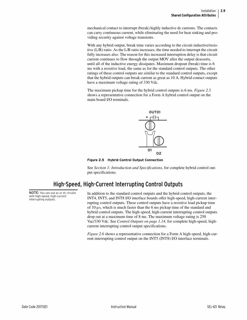
2.9
Date Code 20171021 Instruction Manual SEL-421 Relay
InstallationShared Configuration Attributes
mechanical contact to interrupt (break) highly inductive dc currents. The contacts can carry continuous current, while eliminating the need for heat sinking and pro-viding security against voltage transients.
With any hybrid output, break time varies according to the circuit inductive/resis-tive (L/R) ratio. As the L/R ratio increases, the time needed to interrupt the circuit fully increases also. The reason for this increased interruption delay is that circuit current continues to flow through the output MOV after the output deasserts, until all of the inductive energy dissipates. Maximum dropout (break) time is 6 ms with a resistive load, the same as for the standard control outputs. The other ratings of these control outputs are similar to the standard control outputs, except that the hybrid outputs can break current as great as 10 A. Hybrid contact outputs have a maximum voltage rating of 330 Vdc.
The maximum pickup time for the hybrid control outputs is 6 ms. Figure 2.5 shows a representative connection for a Form A hybrid control output on the main board I/O terminals.
See Section 1: Introduction and Specifications, for complete hybrid control out-put specifications.
High-Speed, High-Current Interrupting Control OutputsNOTE: You can use ac or dc circuits with high-speed, high-current interrupting outputs.
In addition to the standard control outputs and the hybrid control outputs, the INT4, INT5, and INT8 I/O interface boards offer high-speed, high-current inter-rupting control outputs. These control outputs have a resistive load pickup time of 10 s, which is much faster than the 6 ms pickup time of the standard and hybrid control outputs. The high-speed, high-current interrupting control outputs drop out at a maximum time of 8 ms. The maximum voltage rating is 250 Vac/330 Vdc. See Control Outputs on page 1.14, for complete high-speed, high-current interrupting control output specifications.
Figure 2.6 shows a representative connection for a Form A high-speed, high-cur-rent interrupting control output on the INT5 (INT8) I/O interface terminals.
Figure 2.5 Hybrid Control Output Connection
OUT01
+
O1O2

2.10
SEL-421 Relay Instruction Manual Date Code 20171021
InstallationShared Configuration Attributes
Figure 2.7 shows a representative connection for a Form A high-speed, high-cur-rent interrupting control output on the INT4 I/O interface terminals. The HS marks are included to indicate that this is a high-speed control output.
The INT5 (INT8) high-speed, high-current interrupting control output uses three terminal positions, while the INT4 high-speed, high-current interrupting uses two. The third terminal of each INT5 (INT8) high-speed, high-current interrupt-ing control output is connected to precharge resistors that can be used to mitigate transient inrush current conditions, as explained below. A similar technique can be used with INT4 board high-speed, high-current interrupting control outputs using external resistors.
Short transient inrush current can flow at the closing of an external switch in series with open high-speed, high-current interrupting contacts. This transient will not energize the circuits in typical relay-coil control applications (trip coils and close coils), and standard auxiliary relays will not pick up. However, an extremely sensitive digital input or light-duty, high-speed auxiliary relay can pick up for this condition. This false pickup transient occurs when the capacitance of the high-speed, high-current interrupting output circuitry charges (creating a momentary short circuit that a fast, sensitive device sees as a contact closure). A third terminal (03 in Figure 2.8) provides an internal path for precharging the high-speed, high-current interrupting output circuit capacitance when the circuit is open.
Figure 2.6 High-Speed, High-Current Interrupting Control Output Connection, INT5 (INT8)
Figure 2.7 High-Speed, High-Current Interrupting Control Output Connection, INT4
01 0302
OUT01
0102
OUT01HS

2.11
Date Code 20171021 Instruction Manual SEL-421 Relay
InstallationShared Configuration Attributes
Figure 2.9 shows some possible connections for this third terminal that will elim-inate the false pick-up transients when closing an external switch. In general, you must connect the third terminal to the dc rail (positive or negative) that is on the same side as the open external switch condition. If an open switch exists on either side of the output contact, then you can accommodate only one condition because two open switches (one on each side of the contact) defeat the precharge circuit.
For wiring convenience, on the INT5 (INT8) I/O interface board, the precharge resistors shown in Figure 2.8 are built-in to the I/O board, and connected to a third terminal. On the INT4 I/O interface board, there are no built-in precharge resistors, and each high-speed, high-current interrupting control output has only two terminal connections.
Main Board I/OThe SEL-421 base model is a 3U chassis with I/O interface on the main board (the top board). See Figure 2.2 and Figure 2.3 for representative rear-panel views of the 3U chassis rear panel.
Figure 2.8 High-Speed, High-Current Interrupting Control Output Typical Terminals, INT5 (INT8)
Figure 2.9 Precharging Internal Capacitance of High-Speed, High-Current Interrupting Output Contacts, INT5 (INT8)
03
1MΩ 1MΩ
0201
Load
Load
(+) (+)
(–) (—)
Precharge circuitpath internal to high-speed high-current interrupting
control output
01
02
02
01
03
03

2.12
SEL-421 Relay Instruction Manual Date Code 20171021
InstallationShared Configuration Attributes
Every SEL-421 configuration includes the main board I/O and features these connections:
➤ Three hybrid (high-current interrupting) Form A outputs
➤ Two standard Form A outputs
➤ Three standard Form C outputs
➤ Seven high-isolation control inputs (five with no shared terminals and two with shared terminals)
IRIG-B InputsThe SEL-421 has a regular IRIG-B timekeeping mode, and a high-accuracy IRIG-B (HIRIG) timekeeping mode. The IRIG-B serial data format consists of a 1-second frame containing 100 pulses divided into fields, from which the relay decodes the second, minute, hour, and day fields and sets the internal time clock upon detecting valid time data in the IRIG time mode. There is one IRIG-B input on the SEL-421 rear panel, capable of supporting the HIRIG mode.
IRIG-B Pins of Serial Port 1This IRIG-B input is capable of regular IRIG mode timekeeping only. Timing accuracy for the IRIG time mode is 500 µs.
IRIG-B BNC ConnectorThis IRIG-B input is capable of both modes of timekeeping. If the connected timekeeping source is qualified as high-accuracy, the relay enters the HIRIG mode, which has a timing accuracy of 1 µs. If both inputs are connected, the SEL-421 uses the IRIG-B signal from the BNC connection (if a signal is avail-able).
Battery-Backed ClockIf relay input power is lost or removed, a lithium battery powers the relay clock, providing date and time backup. The battery is a 3 V lithium coin cell, Ray-O-Vac No. BR2335 or equivalent. If power is lost or disconnected, the battery dis-charges to power the clock. At room temperature (25°C), the battery will operate for approximately 10 years at rated load.
When the SEL-421 is operating with power from an external source, the self-dis-charge rate of the battery only is very small. Thus, battery life can extend well beyond the nominal 10-year period because the battery rarely discharges after the relay is installed. The battery cannot be recharged. Figure 2.19 shows the clock battery location (at the front of the main board).
If the relay does not maintain the date and time after power loss, replace the bat-tery (see Replacing the Lithium Battery on page 10.22 in the SEL-400 Series Relays Instruction Manual).
Communications InterfacesThe SEL-421 has several communications interfaces you can use to communicate with other intelligent electronic devices (IEDs) via EIA-232 ports: PORT 1, PORT 2, PORT 3, and PORT F. See Section 10: Communications Interfaces for more infor-mation and options for connecting your relay to the communications interfaces.

2.13
Date Code 20171021 Instruction Manual SEL-421 Relay
InstallationPlug-In Boards
An optional Ethernet card provides Ethernet capability for the SEL-421. An Ethernet card gives the relay access to popular Ethernet networking standards including TCP/IP, FTP, Telnet, DNP3, IEEE C37.118 Synchrophasors, and IEC 61850 over local area and wide area networks (the Ethernet card with IEC 61850 support is available at purchase as a factory-installed option). For information on DNP3 applications, see Section 16: DNP3 Communication in the SEL-400 Series Relays Instruction Manual. For more information on IEC 61850 applications, see Section 17: IEC 61850 Communication in the SEL-400 Series Relays Instruction Manual.
Plug-In BoardsThe SEL-421 is available in many input/output configuration options. The relay base model is a 3U chassis with main board I/O and screw-terminal connector connections (see Figure 2.2). Other ordering options include versions of the relay in larger enclosures (4U or 5U) with all, partial, or no extra I/O boards installed.
NOTE: Ordering the 4U and 5U relay with partial or no extra I/O allows for future system expansion and future use of additional relay features.
Plug-in communications cards are also available for the SEL-421. The optional Ethernet card allows you to use TCP/IP, FTP, Telnet, DNP3 LAN/WAN, and IEC 61850 applications on an Ethernet network. This card is available at the time of purchase as a factory-installed option or as a factory-installed conversion to an existing relay.
I/O Interface BoardsYou can choose among eight input/output interface boards for the I/O slots of the 4U and 5U chassis. These I/O interface boards are in addition to the main board I/O described in Main Board I/O on page 2.11. The I/O interface boards are INT1, INT2, INT3, INT4, INT5, INT6, INT7, and INT8. Figure 2.10. Figure 2.11, Figure 2.12, Figure 2.13, Figure 2.14, Figure 2.15, Figure 2.16, and Figure 2.17 show the rear screw-terminal connectors associated with these inter-face boards.
Figure 2.10 INT1 I/O Interface Board
Figure 2.11 INT2 I/O Interface Board
Figure 2.12 INT3 I/O Interface Board

2.14
SEL-421 Relay Instruction Manual Date Code 20171021
InstallationPlug-In Boards
The I/O interface boards carry jumpers that identify the board location (see Jumpers on page 2.15).
I/O Interface Board InputsThe INT1, INT5, and INT6 I/O interface boards have eight independent control inputs. All independent inputs are isolated from other inputs. These high-isola-tion control inputs are direct coupled and hence polarity-sensitive. You cannot damage these inputs with a reverse polarity connection; though, the relay will not detect input changes with a reverse-polarity input.
The INT3 and INT4 I/O interface board has two groups of nine (9) common con-tacts (18 total) and six (6) independent control inputs. The INT2, INT7, and INT8 I/O interface boards have eight independent control inputs. All independent inputs are isolated from other inputs. These control inputs are optoisolated and hence are not polarity sensitive, i.e., the relay will detect input changes with volt-age applied at either polarity, or ac signals (when properly configured, see Optoisolated on page 2.7).
Figure 2.13 INT4 I/O Interface Board
Figure 2.14 INT5 I/O Interface Board
Figure 2.15 INT6 I/O Interface Board
Figure 2.16 INT7 I/O Interface Board
Figure 2.17 INT8 I/O Interface Board
CAUTIONSubstation battery systems that have either a high resistance to ground (greater than 10 k) or are ungrounded when used in conjunction with many direct-coupled inputs can reflect a dc voltage offset between battery rails. Similar conditions can exist for battery monitoring systems that have high-resistance balancing circuits or floating grounds. For these applications, SEL provides optional ground-isolated (optoisolated) con-tact inputs. In addition, SEL has pub-lished an application advisory on this issue. Contact the factory for more information.

2.15
Date Code 20171021 Instruction Manual SEL-421 Relay
InstallationJumpers
Table 2.3 is a comparison of the I/O board input capacities; the table also shows the I/O inputs on the main board. See Control Inputs on page 1.15 for complete control input specifications.
I/O Interface Board OutputsNOTE: Form A control outputs cannot be jumpered to Form B.
The I/O interface boards vary by the type and amount of output capabilities. Table 2.4 lists the outputs of the additional I/O interface boards; the table also shows the I/O outputs on the main board. Information about the standard and hybrid (high-current interrupting) control outputs is in Control Outputs on page 2.8.
Ethernet CardYou can add communications protocols to the SEL-421 by purchasing the Ether-net card option. When installed in the rear relay PORT 5, the Ethernet card pro-vides Ethernet ports for industrial applications that process data traffic between the SEL-421 and a local area network (LAN).
JumpersThe SEL-421 contains jumpers that configure the relay for certain operating modes. The jumpers are located on the main board (the top board) and the I/O interface boards (one or two boards located immediately below the main board).
Table 2.3 Control Inputs
Board Independent Contact Pairs Common Contacts
INT1a, INT5a, INT6a
a INT1, INT5, and INT6 control inputs are direct coupled, and are polarity sensitive.
8
INT2b, INT7b, INT8b
b Main Board, INT2, INT3, INT4, INT7, and INT8 control inputs are optoisolated, and are not polarity sensitive.
8
INT3b, INT4b 6 Two sets of 9
Main Board 5 2
Table 2.4 Control Outputs
BoardStandard
High-Speed, High-Current Interrupting
Hybrida
a High-Current Interrupting.
Form A Form C Form A Form A
INT1, INT2 13 2
INT3 4
INT4 2 6
INT5, INT8 8
INT6, INT7 2 13
Main Board 2 3 3
NOTE: The SEL-421-1 does not support main board B I/O and INT2, INT3, INT7, and INT8 I/O interface boards.

2.16
SEL-421 Relay Instruction Manual Date Code 20171021
InstallationJumpers
Main Board JumpersThe jumpers on the main board of the SEL-421 perform these functions:
➤ Temporary/emergency password disable
➤ Circuit breaker and disconnect control enable
➤ Rear serial port +5 Vdc source enable
Figure 2.19 shows the positions of the main board jumpers. The main board jumpers are in two locations. The password disable jumper and circuit breaker control jumper are at the front of the main board. The serial port jumpers are near the rear-panel serial ports; each serial port jumper is directly in front of the serial port that it controls.
Password and Circuit Breaker JumpersYou can access the password disable jumper and circuit breaker control jumper without removing the main board from the relay cabinet. Remove the SEL-421 front cover to view these jumpers (use appropriate ESD precautions). The pass-word and circuit breaker jumpers (position number J18 or J21) are located on the front of the main board, immediately left of the power connector (see Figure 2.18).
There are four jumpers, denoted D, BREAKER, PASSWORD, and A from left to right (position D is on the left). Position PASSWORD is the password disable jumper; position BREAKER is the circuit breaker control enable jumper. Posi-tions D and A are for SEL use. Figure 2.18 shows the jumper header with the cir-cuit breaker/control jumper in the ON position and the password jumper in the OFF position; these are the normal jumper positions for an in-service relay. Table 2.5 lists the jumper positions and functions.
CAUTIONDo not install a jumper on positions A or D of the main board J18 header. Relay misoperation can result if you install jumpers on positions J18A and J18D.
Figure 2.18 Jumper Location on the Main Board
Jumper Location
5 4 3 2 1
9 8 7 6
Power Connector
J18 or J21
ON
OFF
PASS
WO
RD
BR
EAK
ER
ON
OFF
ABCD
D A
Table 2.5 Main Board Jumpers (Sheet 1 of 2)
Jumper Jumper Location Jumper Positiona Function
A Front OFF For SEL use only
PASSWORD Front OFF Enable password protection (normal and shipped position)
ON Disable password protection (temporary or emergency only)

2.17
Date Code 20171021 Instruction Manual SEL-421 Relay
InstallationJumpers
The password disable jumper, PASSWORD, is for temporary or emergency sus-pension of the relay password protection mechanisms. Under no circumstance should you install PASSWORD on a long-term basis. The SEL-421 ships with password disable jumper PASSWORD OFF (passwords enabled).
The circuit breaker control enable jumper, BREAKER, supervises the CLOSE n command, the OPEN n command, the PULSE OUTnnn command, and front-panel local bit control. To use these functions, you must install Jumper BREAKER. The relay checks the status of the circuit breaker control jumper when you issue CLOSE n, OPEN n, PULSE OUTnnn, and when you use the front panel to close or open circuit breakers, control a local bit, or pulse an out-put. The SEL-421 ships with circuit breaker Jumper BREAKER OFF. For com-missioning and testing of the SEL-421 contact outputs, it may be convenient to set BREAKER ON, so that the PULSE OUTnnn commands can be used to check output wiring. BREAKER must also be set ON if SCADA control of the circuit breaker via Fast Operate is required, or if the LOCAL CONTROL > BREAKER CONTROL screens are going to be used.
BREAKER Front OFF Disable circuit breaker com-mands
(OPEN and CLOSE) and out-put PULSE commandsb (shipped position)
ON Enable circuit breaker com-mands (OPEN and CLOSE) and output PULSE commandsb
D Front OFF For SEL use only
a ON is the jumper shorting both pins of the jumper. Place the jumper over one pin only for OFF.b Also affects the availability of the Fast Operate Breaker Control Messages and the front-panel LOCAL CONTROL > BREAKER CONTROL, and front-panel LOCAL CONTROL > OUTPUT TESTING screens.
Table 2.5 Main Board Jumpers (Sheet 2 of 2)
Jumper Jumper Location Jumper Positiona Function

2.18
SEL-421 Relay Instruction Manual Date Code 20171021
InstallationJumpers
Serial Port JumpersPlace jumpers on the main board to connect +5 Vdc to Pin 1 of each of the three rear-panel EIA-232 serial ports. The maximum current available from this Pin 1 source is 0.5 A. The Pin 1 source is useful for powering an external modem.
Figure 2.19 Major Component Locations on the SEL-421 Main Board
J18 or J21
Rea
r of
Rel
ay

2.19
Date Code 20171021 Instruction Manual SEL-421 Relay
InstallationJumpers
Table 2.6 describes the JMP2, JMP3, and JMP4 positions. Refer to Figure 2.19 for the locations of these jumpers. The SEL-421 ships with JMP2, JMP3, and JMP4 OFF (no +5 Vdc on Pin 1).
Changing Serial Port Jumpers
You must remove the main board to access the serial port jumpers. Perform the following steps to change the JMP2, JMP3, and JMP4 jumpers in an SEL-421:
Step 1. Follow your company standard to remove the relay from service.
Step 2. Disconnect power from the SEL-421.
Step 3. Retain the GND connection, if possible, and ground the equipment to an ESD mat.
Step 4. Remove the communications cable connected to the front-panel serial port, if applicable.
Step 5. Remove the rear-panel EIA-232 PORT mating connectors.
Unscrew the keeper screws and disconnect any serial cables connected to the PORT 1, PORT 2, and PORT 3 rear-panel receptacles.
Step 6. Remove any Ethernet and IRIG-B connections.
Step 7. Loosen the four front-panel screws (they remain attached to the front panel), and remove the relay front panel.
Step 8. Remove the 34-pin ribbon cable from the front panel by pushing the extraction ears away from the connector.
Step 9. Disconnect the power, the interface board, and the analog input board cables from the main board.
Step 10. Carefully pull out the drawout assembly containing the main board.
Step 11. Locate the jumper you want to change.
Jumpers JMP2, JMP3, and JMP4 are located at the rear of the main board, directly in front of PORT 3, PORT 2, and PORT 1, respectively (see Figure 2.19).
Step 12. Install or remove the jumper as needed (see Table 2.5 for jumper position descriptions).
Step 13. Reinstall the SEL-421 main board, and reconnect the power, the interface board, and the analog input board cables.
Step 14. Reconnect the cable removed in Step 7 and reinstall the relay front-panel cover.
Step 15. Reattach the rear-panel connections.
Table 2.6 Main Board Jumpers—JMP2, JMP3, and JMP4
JumperJumperLocation
JumperPositiona
a ON is the jumper shorting both pins of the jumper. Place the jumper over one pin only for OFF.
Function
JMP2 Rear OFF Serial PORT 3, Pin 1 = not connected
ON Serial PORT 3, Pin 1 = +5 Vdc
JMP3 Rear OFF Serial PORT 2, Pin 1 = not connected
ON Serial PORT 2, Pin 1 = +5 Vdc
JMP4 Rear OFF Serial PORT 1, Pin 1 = not connected
ON Serial PORT 1, Pin 1 = +5 Vdc
DANGERContact with instrument terminals can cause electrical shock that can result in injury or death.
WARNINGHave only qualified personnel service this equipment. If you are not quali-fied to service this equipment, you can injure yourself or others, or cause equipment damage.
CAUTIONEquipment components are sensitive to electrostatic discharge (ESD). Undetectable permanent damage can result if you do not use proper ESD procedures. Ground yourself, your work surface, and this equipment before removing any cover from this equipment. If your facility is not equipped to work with these compo-nents, contact SEL about returning this device and related SEL equip-ment for service.

2.20
SEL-421 Relay Instruction Manual Date Code 20171021
InstallationJumpers
Step 16. Reconnect any external cables that you removed from the relay in the disassembly process.
Step 17. Follow your company standard procedure to return the relay to service.
I/O Interface Board JumpersJumpers on the I/O interface boards identify the particular I/O board configura-tion and I/O board control address. Eight I/O interface boards are available: INT1, INT2, INT3, INT4, INT5, INT6, INT7, and INT8 (see I/O Interface Boards on page 2.13 for more information on these boards). The jumpers on these I/O interface boards are at the front of each board, as shown in Figure 2.20 and Figure 2.21.

2.21
Date Code 20171021 Instruction Manual SEL-421 Relay
InstallationJumpers
Figure 2.20 Major Component Locations on the SEL-421 INT1, INT2, INT4, INT5, INT6, INT7, and INT8 I/O Boards

2.22
SEL-421 Relay Instruction Manual Date Code 20171021
InstallationJumpers
To confirm the positions of your I/O board jumpers, remove the front panel and visually inspect the jumper placements. Table 2.7 lists the four jumper positions for I/O interface boards. Refer to Figure 2.20 for the locations of these jumpers.
The I/O board control address has a hundreds-series prefix attached to the control inputs and control outputs for that particular I/O board chassis slot. A 4U chassis has a 200-addresses slot for inputs IN201, IN202, etc., and outputs OUT201, OUT202, etc. A 5U chassis has a 200-addresses slot and a 300-addresses slot.
Figure 2.21 Major Component Locations on the SEL-421 INT3 I/O Board
Rea
r of
Rel
ay

2.23
Date Code 20171021 Instruction Manual SEL-421 Relay
InstallationJumpers
The drawout tray on which each I/O board is mounted is keyed. See Section 10: Testing, Troubleshooting, and Maintenance in the SEL-400 Series Relays Instruc-tion Manual.
Auxiliary TRIP/CLOSE Pushbutton and Breaker Status LED Jumpers (Select Models Only)
The jumpers listed in Table 2.8 are used to select the proper control voltage for breaker open/closed indicating LEDs on the front panel of the relay. Figure 2.21 shows the jumper locations on the magnetics/auxiliary pushbutton board. The jumpers come preset from the factory with the voltage range set the same as the control input voltage, as determined by the part number at order time.
The voltage setting can be different for each LED. To access these jumpers, remove the relay front cover and any ribbon cables that impede accessing the interface board, and draw out the interface board. See the instructions and pre-cautions in the subsection Changing Serial Port Jumpers on page 2.19.
Table 2.9 shows how to enable or disable the arc suppression feature of the TRIP and CLOSE pushbuttons. If ac control power is used to operate the breaker, then the corresponding arc suppression jumper must be removed. If dc control power is used to operate the breaker, then the arc suppression is strongly recommended to break inductive loads. The arc suppression comes enabled from the factory. Figure 2.21 shows the jumper locations on the magnetics/auxiliary pushbutton board.
NOTE: With arc suppression enabled, the corresponding output polarity marks must be followed when wiring the control.
Table 2.7 I/O Board Jumpers
I/O Board Control Address
JMP1A/JMP49Aa
a INT4 I/O interface board jumper numbering.
JMP1B/JMP49Ba
JMP2A/JMP50Aa
JMP2B/JMP50Ba
2XX OFF OFF OFF OFF
3XX ON OFF ON OFF
Table 2.8 Jumper Positions for Breaker OPEN/CLOSE Indication
BREAKER OPEN LED BREAKER CLOSED LED
JMP4 JMP5 JMP5 JMP3 JMP6 JMP8
24 V Installed Installed Installed Installed Installed Installed
48 V Installed Installed Not Installed Installed Installed Not Installed
110/125 V Installed Not Installed Not Installed Installed Not Installed Not Installed
220/250 V Not Installed Not Installed Not Installed Not Installed Not Installed Not Installed
Table 2.9 Jumper Positions for Arc Suppression
OptionTRIP pushbutton CLOSE pushbutton
JMP2 JMP1
Arc Suppression Enabled Installed Installed
Arc Suppression Disabled Not Installed Not Installed

2.24
SEL-421 Relay Instruction Manual Date Code 20171021
InstallationRelay Placement
Relay PlacementProper placement of the SEL-421 helps make certain that you receive years of trouble-free power system protection. Use the following guidelines for proper physical installation of the SEL-421.
Physical LocationYou can mount the SEL-421 in a sheltered indoor environment (a building or an enclosed cabinet) that does not exceed the temperature and humidity ratings for the relay.
The relay is rated at Installation/Overvoltage Category II and Pollution Degree 2. This rating allows mounting the relay indoors or in an outdoor (extended) enclo-sure where the relay is protected against exposure to direct sunlight, precipita-tion, and full wind pressure, but neither temperature nor humidity are controlled.
You can place the relay in extreme temperature and humidity locations. The tem-perature range over which the relay operates is –40° to +185°F (–40° to +85°C, see Operating Temperature on page 1.16). The relay operates in a humidity range from 5 to 95 percent, no condensation, and is rated for installation at a maximum altitude of 2000 m (6560 feet) above mean sea level.
Rack MountingWhen mounting the SEL-421 in a rack, use the reversible front flanges to either semiflush-mount or projection mount the relay.
The semiflush mount gives a small panel protrusion from the relay rack rails of approximately 1.1 in. or 27.9 mm. The projection mount places the front panel approximately 3.5 in. or 88.9 mm in front of the relay rack rails.
See Figure 2.22 for exact mounting dimensions for both the horizontal and verti-cal rack-mount relays. Use four screws of the appropriate size for your rack.
Table 2.10 Front-Panel LED Option
JMP11, JMP12a
a JMP11 Open; JMP12 Closed.
LED Color
BRIDGE
Pins 1 and 3
Pins 2 and 4
Red
BRIDGE
Pins3 and 5
Pins 4 and 6
Green

2.25
Date Code 20171021 Instruction Manual SEL-421 Relay
InstallationConnection
Panel MountingPlace the panel-mount versions of the SEL-421 in a switchboard panel. See the drawings in Figure 2.22 for panel cut and drill dimensions (these dimensions apply to both the horizontal and vertical panel-mount relay versions). Use the supplied mounting hardware to attach the relay.
ConnectionThe SEL-421 is available in many different configurations, depending on the number and type of control inputs, control outputs, and analog input termination you specified at ordering. This subsection presents a representative sample of relay rear-panel configurations and the connections to these rear panels. Only horizontal chassis are shown; rear panels of vertical chassis are identical to hori-zontal chassis rear panels for each of the 3U, 4U, and 5U sizes.
When connecting the SEL-421, refer to your company plan for wire routing and wire management. Be sure to use wire that is appropriate for your installation with an insulation rating of at least 90°C.
Figure 2.22 SEL-421 Chassis Dimensions
CAUTIONInsufficiently rated insulation can deteriorate under abnormal operating conditions and cause equipment dam-age. For external circuits, use wiring of sufficiently rated insulation that will not break down under abnormal operating conditions.

2.26
SEL-421 Relay Instruction Manual Date Code 20171021
InstallationConnection
Rear-Panel LayoutFigure 2.23 through Figure 2.32 show available SEL-421 rear panels.
All relay versions have screw-terminal connectors for I/O, power, and battery monitor. You can order the relay with fixed terminal blocks for the CT and PT connections, or you can order SEL Connectorized rear-panel configurations that feature plug-in/plug-out PT connectors and shorting CT connectors for relay ana-log inputs. Figure 2.24 shows the Connectorized 3U horizontal configuration of the SEL-421.
The screw-terminal connections for the INT1 (or INT2) and the INT6 (or INT7) I/O interface boards are the same. The INT5 (or INT8) I/O interface board has control output terminals grouped in threes, with the fourth terminal as a blank additional separator (terminals 4, 8, 12, 16, 20, 24, 28, and 32). The INT3, INT4, and INT5 (or INT8) I/O interface boards both contain high-speed, high-current interrupting control outputs, but use a different terminal layout—see Control Outputs on page 2.8 for details.
For more information on the main board control inputs and control outputs, see Main Board I/O on page 2.11. For more information on the I/O interface board control inputs and control outputs, see I/O Interface Board Jumpers on page 2.20.
Figure 2.23 3U Rear Panel, Main Board
Figure 2.24 3U Rear Panel, Main Board, Connectorized

2.27
Date Code 20171021 Instruction Manual SEL-421 Relay
InstallationConnection
Figure 2.25 EtherCAT Board for TiDL
Figure 2.26 4U Rear Panel, Main Board, Without Optional I/O
Figure 2.27 4U Rear Panel, Main Board, INT5 I/O Interface Board

2.28
SEL-421 Relay Instruction Manual Date Code 20171021
InstallationConnection
Figure 2.28 4U Rear Panel, Main Board, INT8 I/O Interface Board
(The INT3 board is the 200-addresses slot; the INT1 board is the 300-addresses slot.)
Figure 2.29 5U Rear Panel, Main Board, INT3 and INT1 I/O Interface Board

2.29
Date Code 20171021 Instruction Manual SEL-421 Relay
InstallationConnection
(The INT4 board is the 200-addresses slot; the INT1 board is the 300-addresses slot.)
Figure 2.30 5U Rear Panel, Main Board, INT4 and INT1 I/O Interface Board
Figure 2.31 5U Rear Panel, Main Board, INT6 and INT4 I/O Interface Board

2.30
SEL-421 Relay Instruction Manual Date Code 20171021
InstallationConnection
Rear-Panel SymbolsThere are important safety symbols on the rear of the SEL-421 (see Figure 2.33). Observe proper safety precautions when you connect the relay at terminals marked by these symbols. In particular, the danger symbol located on the rear panel corresponds to the following: Contact with instrument terminals can cause electrical shock that can result in injury or death. Be careful to limit access to these terminals.
Screw-Terminal ConnectorsTerminate connections to the SEL-421 screw-terminal connectors with ring-type crimp lugs. Use a #8 ring lug with a maximum width of 9.1 mm (0.360 in.). The screws in the rear-panel screw-terminal connectors are #8-32 binding head, slot-ted, nickel-plated brass screws. Tightening torque for the terminal connector screws is 1.0 Nm to 2.0 Nm (9 in-lb. to 18 in-lb.).
You can remove the screw-terminal connectors from the rear of the SEL-421 by unscrewing the screws at each end of the connector block. Perform the following steps to remove a screw-terminal connector:
Step 1. Remove the connector by pulling the connector block straight out.
Note that the receptacle on the relay circuit board is keyed; you can insert each screw-terminal connector in only one location on the rear panel.
Figure 2.32 5U Rear Panel, Main Board, INT2 and INT7 I/O Interface Board
Figure 2.33 Rear-Panel Symbols
Danger (Caution,risk of danger)
Symbol
GroundingTerminalSymbol
DC Input SymbolAC/DC Input Symbol

2.31
Date Code 20171021 Instruction Manual SEL-421 Relay
InstallationConnection
Step 2. To replace the screw-terminal connector, confirm that you have the correct connector and push the connector firmly onto the circuit board receptacle.
Step 3. Reattach the two screws at each end of the block.
Changing Screw-Terminal Connector KeyingYou can rotate a screw-terminal connector so that the connector wire dress posi-tion is the reverse of the factory-installed position (for example, wires entering the relay panel from below instead of from above). In addition, you can move similar function screw-terminal connectors to other locations on the rear panel. To move these connectors to other locations, you must change the screw-terminal connector keying.
Inserts in the circuit board receptacles key the receptacles for only one screw-ter-minal connector in one orientation. Each screw-terminal connector has a missing web into which the key fits (see Figure 2.34).
If you want to move a screw-terminal connector to another circuit board recepta-cle or reverse the connector orientation, you must rearrange the receptacle keys to match the screw-terminal connector block. Use long-nosed pliers to move the keys.
Figure 2.35 shows the factory-default key positions.
Figure 2.34 Screw-Terminal Connector Keying
Webs Removed for Keying(Receptacle Keys Fit Here)
Top View
Front View

2.32
SEL-421 Relay Instruction Manual Date Code 20171021
InstallationConnection
Figure 2.35 Rear-Panel Receptacle Keying
AB
C1
23
AB
C1
23
AB
C2
13
CA
BB
21
3A
C1
23
AB
C2
13
CA
BB
12
3A
C1
23
Key
Inse
rts
(One
Pai
r fo
r Ea
ch
Scre
w-T
erm
inal
Con
nect
or)
200
-Add
ress
esR
ecep
tacl
es
100
-Add
ress
esR
ecep
tacl
es
300
-Add
ress
es R
ecep
tacl
es

2.33
Date Code 20171021 Instruction Manual SEL-421 Relay
InstallationConnection
GroundingConnect the grounding terminal (#Z31) labeled GND on the rear panel to a rack frame ground or main station ground for proper safety and performance.
This protective earthing terminal is in the lower right side of the relay panel (see Figure 2.23 through Figure 2.32). The symbol that indicates the grounding termi-nal is shown in Figure 2.33.
Use 2.5 mm2 (14 AWG) or larger wire less than 2 m (6.6 feet) in length for this connection. This terminal connects directly to the internal chassis ground of the SEL-421.
Power ConnectionsThe terminals labeled POWER on the rear panel (#Z29 and #Z30) must connect to a power source that matches the power supply characteristics that your SEL-421 specifies on the rear-panel serial number label. (See Power Supply on page 1.14, for complete power input specifications.) For the relay models that accept dc input, the serial number label specifies dc with the symbol shown in Figure 2.33.
NOTE: The combined voltages applied to the POWER and MONITOR terminals must not exceed 600 V (rms or dc).
The POWER terminals are isolated from chassis ground. Use 0.8 mm2 (18 AWG) or larger size wire to connect to the POWER terminals. Connection to external power must comply with IEC 60947-1 and IEC 60947-3 and must be identified as the disconnect device for the equipment.
Place an external disconnect device, switch/fuse combination, or circuit breaker in the POWER leads for the SEL-421; this device must interrupt both the hot (H/+) and neutral (N/–) power leads. The current rating for the power disconnect circuit breaker or fuse must be 20 A maximum. Be sure to locate this device within 3.0 m (9.8 feet) of the relay.
Operational power is internally fused by power supply fuse F1. Table 2.11 lists the SEL-421 power supply fuse requirements. Be sure to use fuses that comply with IEC 127-2.
You can order the SEL-421 with one of three operational power input ranges listed in Table 2.11. Each of the three supply voltage ranges represents a power supply ordering option. As noted in Table 2.11, model numbers for the relay with these power supplies begin 04214n (or 04215n), where n is 2, 4, or 6, to indicate low, middle, and high voltage input power supplies, respectively. Note that each power supply range covers two widely used nominal input voltages. The SEL-421 power supply operates from 30 Hz to 120 Hz when ac power is used for the POWER input.
Figure 2.36 Power Connection Area of the Rear Panel
Terminal Z29 Terminal Z30 Terminal Z31
SerialNumber
Label

2.34
SEL-421 Relay Instruction Manual Date Code 20171021
InstallationConnection
The SEL-421 accepts dc power input for all three power supply models. The 48–125 Vdc supply also accepts 110–120 Vac; the 125–250 Vdc supply also accepts 110–240 Vac. When connecting a dc power source, you must connect the source with the proper polarity, as indicated by the + (Terminal #Z29) and – (Terminal #Z30) symbols on the power terminals. When connecting to an ac power source, the + Terminal #Z29 is hot (H), and the – Terminal #Z30 is neutral (N).
Each model of the SEL-421 internal power supply exhibits low power consump-tion and a wide input voltage tolerance. For more information on the power sup-plies, see Power Supply on page 1.14.
Monitor Connections (DC Battery)The SEL-421 monitors two dc battery systems. For information on the battery monitoring function, see Station DC Battery System Monitor Specifications on page 1.19.
NOTE: The combined voltages applied to the POWER and MONITOR terminals must not exceed 600 V (rms or dc).
Connect the positive lead of Battery System 1 to Terminal #Z25 and the negative lead of Battery System 1 to Terminal #Z26. (Usually Battery System 1 is also connected to the rear-panel POWER input terminals.) For Battery System 2, con-nect the positive lead to Terminal #Z27, and the negative lead to Terminal #Z28.
Secondary Circuit ConnectionsThe SEL-421 has two sets of three-phase current inputs and two sets of three-phase voltage inputs. Secondary Circuits on page 2.5 describes these inputs in detail. The alert symbol and the word DANGER on the rear panel indicate that you should use all safety precautions when connecting secondary circuits to these ter-minals.
To verify these connections, use SEL-421 metering (see Examining Metering Quantities on page 3.35 in the SEL-400 Series Relays Instruction Manual). You can also review metering data in an event report that results when you issue the TRIGGER command (see Triggering Data Captures and Event Reports on page 9.6 in the SEL-400 Series Relays Instruction Manual).
Fixed Terminal BlocksConnect the secondary circuits to the Z terminal blocks on the relay rear panel. Note the polarity dots above the odd-numbered terminals #Z01, #Z03, #Z05, #Z07, #Z09, and #Z11 for CT inputs. Similar polarity dots are above the odd-numbered terminals #Z13, #Z15, #Z17, #Z19, #Z21, and #Z23 for PT inputs.
Table 2.11 Fuse Requirements for the Power Supply
Rated VoltageOperational Voltage Range
Fuse F1 Fuse DescriptionModel Number
24–48 Vdc 18–60 Vdc T5.0AH250V 5x20 mm, time-lag, 5.0 A, high break capacity, 250 V
042142 or 042152
48–125 Vdc, 110–120 Vac
38–140 Vdc or 85–140 Vac (30–120 Hz)
T3.15AH250V 5x20 mm, time-lag, 3.15 A, high break capacity, 250 V
042144 or 042154 or 042146 or 042156
125–250 Vdc, 110–240 Vac
85–300 Vdc or 85–264 Vac (30–120 Hz)
T3.15AH250V 5x20 mm, time-lag, 3.15 A, high break capacity, 250 V
CAUTIONRelay misoperation can result from applying anything other than speci-fied secondary voltages and currents. Before making any secondary circuit connections, check the nominal volt-age and nominal current specified on the rear-panel nameplate.
DANGERContact with instrument terminals can cause electrical shock that can result in injury or death.
2.35
Date Code 20171021 Instruction Manual SEL-421 Relay
InstallationConnection
ConnectorizedFor the Connectorized SEL-421, order the wiring harness kit, SEL-WA0421. The wiring harness contains four prewired connectors for the relay current and volt-age inputs.
You can order the wiring harness with various wire sizes and lengths. Contact your local Technical Service Center or the SEL factory for ordering information.
Perform the following steps to install the wiring harness:
Step 1. Plug the CT shorting connectors into terminals #Z01 through #Z06 for the IW inputs, and #Z07 through #Z12 for the IX inputs, as appropriate.
Odd-numbered terminals are the polarity terminals.
Step 2. Secure the connector to the relay chassis with the two screws located on each end of the connector.
When you remove the CT shorting connector, pull straight away from the relay rear panel.
As you remove the connector, internal mechanisms within the connector separately short each power system current transformer.
You can install these connectors in only one orientation.
Step 3. Plug the PT voltage connectors into terminals #Z13 to #Z18 for the VY inputs, and #Z19 to #Z24 for the VZ inputs, as appropriate.
Odd numbered terminals are the polarity terminals. You can install these connectors in only one orientation.
Control Circuit ConnectionsYou can configure the SEL-421 with many combinations of control inputs and control outputs. See Main Board I/O on page 2.11 and I/O Interface Boards on page 2.13 for information about I/O configurations. This subsection provides details about connecting these control inputs and outputs. Refer to Figure 2.2, Figure 2.10, and Figure 2.14 for representative rear-panel screw-terminal con-nector locations.
Control InputsNOTE: The combined voltages applied to the INnnn and OUTnnn terminals must not exceed 600 V (rms or dc).
Table 2.3 lists the control inputs available with the SEL-421, and notes that some are Direct-Coupled, and some are Optoisolated.
Direct-Coupled
Direct-coupled control inputs are polarity-sensitive. These inputs use direct-cou-pled circuitry, and have terminal markings to indicate polarity: a + mark appears for each input. Connect the positive sense of the control input to the + terminal. Although you cannot damage these inputs with a reverse polarity connection, a reverse polarity connection will cause the relay internal A/D converter to mea-sure the input voltage incorrectly and the relay will no longer detect input changes (see Control Inputs on page 2.6).
Optoisolated
Optoisolated control inputs are not polarity sensitive. These inputs respond to voltage of either polarity, and can be used with ac control signals when properly configured.

2.36
SEL-421 Relay Instruction Manual Date Code 20171021
InstallationConnection
Note that the main board I/O control inputs have one set of two inputs that share a common input leg and INT3 and INT4 I/O interface boards have two sets of nine inputs that share a common leg (see Figure 2.13).
Assigning
To assign the functions of the control inputs, see Operating the Relay Inputs and Outputs on page 3.61 in the SEL-400 Series Relays Instruction Manual for more details. You can also use ACSELERATOR QuickSet SEL-5030 Software to set and verify operation of the inputs.
Control OutputsThe SEL-421 has three types of outputs:
➤ Standard outputs
➤ Hybrid (high-current interrupting) outputs
➤ High-speed, high-current interrupting outputs
See Control Outputs on page 2.8 for more information.
You can connect the standard outputs and the high-speed, high-current interrupt-ing outputs in either ac or dc circuits. Connect the hybrid (high-current interrupt-ing) outputs to dc circuits only. The screw-terminal connector legends alert you about this requirement by showing polarity marks on the hybrid (high-current interrupting) contacts.
Form A (SPST NO) contacts comprise the majority of the control outputs. Two pairs of Form C (SPDT CO) contacts are on the main board, the INT1 (INT2) I/O interface board, and the INT6 (INT7) I/O interface board.
Alarm Output
The SEL-421 monitors internal processes and hardware in continual self-tests. If the relay senses an out-of-tolerance condition, the relay declares a Status Warn-ing or a Status Failure. The relay signals a Status Warning by pulsing the HALARM Relay Word bit (hardware alarm) to a logical 1 for five seconds. For a Status Failure, the relay latches the HALARM Relay Word bit at logical 1.
To provide remote alarm status indication, connect the b contact of OUT108 to your control system remote alarm input. Figure 2.37 shows the configuration of the a and b contacts of control output OUT108.
Figure 2.37 Control Output OUT108
N/O N/C
COUT108 OUT108
a b
(connect alarm here)

2.37
Date Code 20171021 Instruction Manual SEL-421 Relay
InstallationConnection
Program OUT108 to respond to NOT HALARM by entering the following SELOGIC control equation with a communications terminal in QuickSet:
OUT108 := NOT HALARM
When the relay is operating normally, the NOT HALARM signal is at logical 1 and the b contacts of control output OUT108 are open.
When a status warning condition occurs, the relay pulses the NOT HALARM signal to logical 0 and the b contacts of OUT108 close momentarily to indicate an alarm condition.
For a status failure, the relay disables all control outputs and the OUT108 b con-tacts close to trigger an alarm. Also, when relay power is off, the OUT108 b con-tacts close to generate a power-off alarm. See Relay Self-Tests on page 10.15 in the SEL-400 Series Relays Instruction Manual for information on relay self-tests.
The relay pulses the SALARM Relay Word bit for software programmed condi-tions; these conditions include settings changes, access-level changes, and alarm-ing after three unsuccessful password entry attempts.
The SEL-421 also pulses the BADPASS Relay Word bit after three unsuccessful password entry attempts.
You can add the software alarm SALARM to the alarm output by entering the following SELOGIC control equation:
OUT108 := NOT (HALARM OR SALARM)
Tripping and Closing Outputs
To assign the control outputs for tripping and closing, see Setting Outputs for Tripping and Closing on page 3.67 in the SEL-400 Series Relays Instruction Manual. In addition, you can use the SET O command (see Output Settings on page 8.35 for more details). You can also use the front panel to set and verify operation of the outputs (see Set/Show on page 4.25 in the SEL-400 Series Relays Instruction Manual).
Auxiliary TRIP/CLOSE Pushbuttons and OPEN/CLOSED LEDs (Select Models Only)
Select relay models feature auxiliary TRIP and CLOSE pushbuttons and OPEN and CLOSED LED indicators. These features are electrically isolated from the rest of the relay. They function independently from the relay and do not need relay power.
The pushbuttons and LEDs can be hard-wired into a substation trip and close control circuit and operate the same as a separate installation of external trip/close switches and LED indicators. Figure 2.57 shows example trip and close circuit connections for a control scheme configuration with a dc substation volt-age source. The pushbutton switches come set from the factory for dc operation (arc suppression enabled). To use an ac trip or close potential, the arc suppression must be disabled for one or both pushbuttons (see Table 2.9). The voltage operat-ing ranges of the LEDs are selected by jumpers (see Table 2.8).
Because the TRIP and CLOSE pushbuttons are functionally separate from the relay, a manual trip or close cannot be distinguished from an external protection or automation-initiated operation. Unless provisions are made in the control wiring, the action of the close pushbutton is unsupervised.
WARNINGSEL-421 features such as Hot Line Tag and Synchronism Check do not super-vise the auxiliary close pushbutton.

2.38
SEL-421 Relay Instruction Manual Date Code 20171021
InstallationConnection
TiDL ConnectionsSEL-421 Relays that support TiDL have a 4U chassis. The SEL-421 supports I/O on the main board as well as one additional I/O board. The main board and addi-tional I/O board map to the 100- and 200-level inputs and outputs. The Axion remote modules provide additional I/O for the 300, 400, and 500 levels and ana-log channels.
The protection functions remain unchanged from the standard SEL-421 Relay.
Axion Remote ModulesThe SEL-2240 Axion is a fully integrated analog and digital I/O control solution that is suitable for remote data acquisition. An Axion node consists of a 10-slot, 4-slot, or dual 4-slot chassis that is configurable to contain a power module and combinations of CT/PT, digital input (DI), or digital output (DO) modules.
SEL-2243 Power Coupler
Each chassis requires a SEL-2243 Power Coupler (see Figure 2.39). This module supplies power to the rest of the node and transmits the data to the relay through fiber-optic communication. Although the power coupler has two fiber-optic ports, only PORT 1 is currently used for TiDL.
Figure 2.38 Axion Chassis

2.39
Date Code 20171021 Instruction Manual SEL-421 Relay
InstallationConnection
The SEL-2243 has sufficient power capacity to accommodate an entire Axion node. The terminal strip at the bottom of the unit (shown in Figure 2.39) is the connection point for incoming power. All Axion modules have a 55-position IEC C-style connector that provides a communications and power interface to the backplane. See the SEL-2240 Axion Instruction Manual for more information.
SEL-2244-2 Digital Input Module
The SEL-2244-2 Digital Input Module (see Figure 2.40) consists of 24 optoiso-lated inputs that are not polarity dependent. These inputs can be configured to respond to ac or dc control signals. The TiDL system maps as many as 72 DI points to the relay in the 300, 400, and 500 I/O board levels, based on the mod-ules that occur in the network. Only the first 12 of 24 inputs are used in each module to help distribute the I/O around the network more efficiently. The inputs are mapped to the relay inputs based on the order in which the DI module occurs in the TiDL network.
There can be multiple DI modules in an Axion node, and the order of the DI modules will proceed from left to right in the node to determine the mapping of the inputs.
The first DI module that exists in the system, for example, on PORT 6A, will map to IN301–IN312, and if a second module is available on PORT 6A, it will map to IN313–IN324. If a second module does not exist on PORT 6A, IN313–IN324 will be mapped from the next module appearing in the TiDL system. Mapping order determination starts with PORT 6A and ends with the last port, PORT 6H.
Figure 2.39 SEL-2243 Power Coupler
First SEL-2244-2 DI Module IN301–IN312
Second SEL-2244-2 DI Module IN313–IN324
Third SEL-2244-2 DI Module IN401–IN412
Fourth SEL-2244-2 DI Module IN413–IN424

2.40
SEL-421 Relay Instruction Manual Date Code 20171021
InstallationConnection
SEL-2244-5 Fast High-Current Digital Output Module
The SEL-2244-5 Fast High-Current Digital Output Module consists of 10 fast, high-current output contacts. The outputs use the first 8 of the10 outputs and map as follows:
Fifth SEL-2244-2 DI Module IN501–IN512
Sixth SEL-2244-2 DI Module IN513–IN524
Figure 2.40 SEL-2244-2 Digital Input Module
First SEL-2244-5 DO Module OUT301–OUT308
Second SEL-2244-5 DO Module OUT309–OUT316
Third SEL-2244-5 DO Module OUT401–OUT408
Fourth SEL-2244-5 DO Module OUT409–OUT416
Fifth SEL-2244-5 DO Module OUT501–OUT508
Sixth SEL-2244-5 DO Module OUT509–OUT516

2.41
Date Code 20171021 Instruction Manual SEL-421 Relay
InstallationConnection
For both the DI and DO modules, use 24–12 AWG (0.2–3.31 mm2) wire of suffi-cient current capacity to connect to the digital input and output terminals for your application.
The order of mapping for DO modules is the same as that for DI modules.
SEL-2245-42 AC Analog Input Module
The SEL-2245-42 AC Analog Input Module (see Figure 2.42) provides protec-tion-class ac analog input (CT/PT) and can accept three voltage and three current inputs. The module samples at 24 kHz and is 1 A or 5 A software-selectable. Depending on the supported fixed topology, multiple CT/PT input modules can function in each node. Some topologies only support one CT/PT module per node. See Topologies on page 2.42 for more information on supported relay topologies and their connections.
Figure 2.41 SEL-2244-5 Fast High-Current Digital Output Module

2.42
SEL-421 Relay Instruction Manual Date Code 20171021
InstallationConnection
TopologiesThe SEL-421 Relay has a set of fixed topologies. These topologies map the volt-ages and currents internally in the relay to maintain existing settings and func-tionality. When the TiDL system is commissioned (see Commissioning on page 2.44), the firmware validates the connected Axion nodes and identifies if the installed CT/PT modules in the system match one of the supported topologies for the SEL-421.
Ports listed as optional in the following topology diagrams do not require a CT/PT module to be connected to them. All other ports require a CT/PT module to be connected for the relay to verify the topology.
Figure 2.42 SEL-2245-42 AC Analog Input Module

2.43
Date Code 20171021 Instruction Manual SEL-421 Relay
InstallationConnection
Figure 2.43 Topology 1
IAW, IBW, ICW
Line
VAY, VBY, VCY
IAX, IBX, ICX
1 Phase (VAZ)
1 Phase (VBZ)
Port6A6B6C6D6E6F
AnalogsIAW, IBW, ICWIAX, IBX, ICX (optional)VAY, VBY, VCYVAZ (optional)VBZ (optional)VCZ (optional)
SEL Relay
SEL Axion
SEL Axion SEL Axion
SEL AxionSEL Axion
Substation Yard
Control House
This topology uses two CT/PT modules installed in one Axion node. The first module maps to the W currents and Y voltages, and the second module maps to the X currents and Z voltages.
Figure 2.44 Topology 2
VBZ
IAX, IBX, ICX
VAY, VBY, VCY
VAZ
IAW, IBW, ICW
Port6A
AnalogsIAW, IBW, ICW, VAY, VBY, VCYIAX, IBX, ICX, VAZ, VBZ, VCZ
SEL Axion
SEL Relay
Substation Yard
Control House

2.44
SEL-421 Relay Instruction Manual Date Code 20171021
InstallationConnection
CommissioningIn TiDL applications, the relay receives currents from a remote module. You must set the nominal current input of the relay to either 1 A or 5 A. Many settings and ranges of settings depend on the nominal current. Use the CFG CTNOM command to set the nominal current value. At Access Level 2, issue a CFG CTNOM 1 command to set the relay to 1 A values or use the CFG CTNOM 5 command to set it to 5 A values. This command is only available in relays that support TiDL technology. Note that after issuing this command, the relay settings are forced to their default values and the relay turns off and back on again to reinitialize the settings. The relay defaults to 5 A nominal, so only use this com-mand if you are switching to a 1 A setting (see Section 14: ASCII Command Ref-erence in the SEL-400 Series Relays Instruction Manual for more information). The SEL-2245-42 AC Analog Input Module also sets its internal calculations based on this command. The relay internally transmits this data to the Axion modules and adjusts the scaling in the appropriate Axion module when this com-mand is used.
In addition to the CT nominal values, TiDL relays also require that the nominal frequency be set by issuing the CFG NFREQ command. At Access Level 2, issue a CFG NFREQ 60 command to set the relay to 60 Hz nominal or issue a CFG NFREQ 50 command to set the relay to 50 Hz nominal. This command changes the NFREQ setting and restarts the relay, and it is only available in TiDL relays. The relay defaults to 60 Hz. This command should be issued after the CFG CTNOM command but before settings are sent to the relay.
The TiDL system uses a commissioning feature to identify that the connected remote Axion nodes meet the requirements of the supported topologies for the applied relay. These topologies are a balance between copper reduction and num-ber of nodes. The nodes must be connected in one of the supported topologies so that the relay will map the voltages and currents accordingly.
Figure 2.45 Topology 3
VAY, VBY, VCY
VAY, VBY, VCY
VAZ, VBZ, VCZ
IAW, IBW, ICW IAW, IBW, ICW
Port6A6B
AnalogsIAW, IBW, ICW, VAY, VBY, VCYIAX, IBX, ICX, VAZ, VBZ, VCZ(optional)
Feeder 1 Feeder 2 Feeder 3 Feeder 4
SEL Relay SEL Relay
SEL Axion SEL Axion
SEL Axion
Control House
Substation Yard

2.45
Date Code 20171021 Instruction Manual SEL-421 Relay
InstallationConnection
The SEL-421 has a new interface on its back panel that replaces the original CT and PT input connections. These standard inputs are replaced with a remote mod-ule interface that supports eight fiber ports, labeled PORT 6A–PORT 6H (see Figure 2.46).
Once all the remote Axion nodes are connected to the relay, press the COMMISSION pushbutton on the Remote Module Interface. This process verifies that the con-nected ports and Axion nodes are installed according to one of the supported topologies. Once the process is complete, the topology is stored in memory. At each additional startup of the relay, the firmware validates that the connected modules match those of the stored configuration. It recognizes whether any of the CT/PT modules within the node have changed. If the topology needs to be changed (e.g., modules are added or replaced), the system will need to be recom-missioned by pressing the COMMISSION pushbutton.
When the commissioning and validation of the topology is complete, the voltages and currents map according to the topology assignments (see Topologies on page 2.42). Secondary injection testing takes place at each Axion node. Test sources must inject voltages and currents to the Axion node to verify correct installation and mapping. Monitoring of the voltages and currents remains in the control house with the relay.
LED StatusAs shown in Figure 2.46, the TiDL relay provides LED status indication about the network and configuration. Once the system is connected, and the COMMISSION pushbutton is pressed, the LEDs will provide the status of the commissioning process. Table 2.12 shows the status of the rear-panel LEDs for each commis-sioning state.
Figure 2.46 Remote Module Interface
Commissioning Button
Commission LED for Network Status
Eight Fiber-Optic 100 Mbps EtherCAT Ports
LEDs for Remote Node Status
Table 2.12 TiDL LED Status (Sheet 1 of 2)
State Description LED Status
Initial State Determining if topology exists Green COMMISSION LED OFF
Red COMMISSION LED ON
Green LED: PORT 6A–PORT 6H OFF
Red LED: PORT 6A–PORT 6H ON
Verify Topology Determining if topology is supported Green COMMISSION LED Blinking
Red COMMISSION LED ON
Green LED: PORT 6A–PORT 6H Blinking
Red LED: PORT 6A–PORT 6H ON

2.46
SEL-421 Relay Instruction Manual Date Code 20171021
InstallationConnection
IRIG-B Input ConnectionsThe SEL-421 accepts a demodulated IRIG-B signal through two types of rear-panel connectors. These IRIG-B inputs are the BNC connector labeled IRIG-B and Pin 4 (+) and Pin 6 (–) of the DB-9 rear-panel serial port labeled PORT 1. When you use the PORT 1 input, ensure that you connect Pins 4 and 6 with the proper polarity. See Communications Ports Connections on page 2.47 for other DB-9 connector pinouts and additional details.
These inputs accept the dc shift time code generator output (demodulated) IRIG-B signal with positive edge on the time mark. For more information on IRIG-B and the SEL-421, see IRIG-B Inputs on page 2.12.
The PORT 1 IRIG-B input connects to a 2.5 k grounded resistor and goes through a single logic signal buffer. The PORT 1 IRIG-B is equipped with robust ESD and overvoltage protection but is not optically isolated. When you are using the PORT 1 input, ensure that you connect Pin 4 (+) and Pin 6 (–) with the proper polarity.
The IRIG network should be properly terminated with an external termination resistor (SEL 240-1802, BNC Tee, and SEL 240-1800, BNC terminator, 50 ohm) placed on the unit that is farthest from the source. This termination provides impedance matching of the cable for the best possible signal-to-noise ratio.
Where distance between the SEL-421 and the IRIG-B sending device exceeds the cable length recommended for conventional EIA-232 metallic conductor cables, you can use transceivers to provide isolation and to establish communication to remote locations.
Conventional fiber-optic and telephone modems do not support IRIG-B signal transmission. The SEL-2810 Fiber-Optic Transceiver/Modem includes a channel for the IRIG-B time code. These transceivers enable you to synchronize time pre-cisely from IRIG-B time code generators (such as the SEL-2032 Communica-tions Processor) over a fiber-optic communications link.
Topology Mismatch Connection does not match supported topology Green COMMISSION LED Blinking
Red COMMISSION LED ON
Green LED: PORT 6A–PORT 6H OFF—mismatched/unused
ON—matched
Red LED: PORT 6A–PORT 6H Blinking—mismatched
ON—matched
OFF—ports unused
Topology Matched Connection matches topology Green COMMISSION LED ON
Red COMMISSION LED OFF
Green LED: PORT 6A–PORT 6H ON
Red LED: PORT 6A–PORT 6H OFF
N/A A commissioned port experiences an error Green COMMISSION LED ON
Red COMMISSION LED OFF
Green LED: PORT 6A–PORT 6H ON
Red LED: PORT 6A–PORT 6H Blinking—failed port
Table 2.12 TiDL LED Status (Sheet 2 of 2)
State Description LED Status

2.47
Date Code 20171021 Instruction Manual SEL-421 Relay
InstallationConnection
Communications Ports ConnectionsThe SEL-421 has three rear-panel EIA-232 serial communications ports labeled PORT 1, PORT 2, and PORT 3 and one front-panel port, PORT F. For information on serial communication, see Establishing Communication on page 3.3, Serial Com-munication on page 15.2, and Serial Port Hardware Protocol on page 15.5 in the SEL-400 Series Relays Instruction Manual.
In addition, the rear panel features a PORT 5 for an optional Ethernet card. For additional information about communications topologies and standard protocols that are available in the SEL-421, see Section 15: Communications Interfaces, Section 16: DNP3 Communication, and Section 17: IEC 61850 Communication in the SEL-400 Series Relays Instruction Manual and Section 10: Communica-tions Interfaces in this manual.
Serial PortsThe SEL-421 serial communications ports use EIA-232 standard signal levels in a D-subminiature 9-pin (DB-9) connector. To establish communication between the relay and a DTE device (a computer terminal, for example) with a DB-9 con-nector, use an SEL-C234A cable. Alternatively, you can use a SEL-C662 cable to connect to a USB port.
Figure 2.47 shows the configuration of SEL-C234A cable that you can use for basic ASCII and binary communication with the relay. A properly configured ASCII terminal, terminal emulation program, or QuickSet along with the SEL-C234A cable provide communication with the relay in most cases.
Serial CablesUsing an improper cable can cause numerous problems or failure to operate, so you must be sure to specify the proper cable for application of your SEL-421. Several standard SEL communications cables are available for use with the relay.
Figure 2.47 SEL-421 to Computer—D-Subminiature 9-Pin Connector
SEL-421 Relay
2 3
3
5
8
2
5
8
7
RXD TXD
TXD RXD
GND GND
CTS CTS
RTS
DCD
DTR
DSR
1
4
PinFunc.
PinFunc.
Pin#
Pin#
9-Pin DTE
Device*
*DTE = Data Terminal Equipment (Computer, Terminal, etc.)
6
SHIELDNO CONNECTIONSHELL
CAUTIONSevere power and ground problems can occur on the communications ports of this equipment as a result of using non-SEL cables. Never use stan-dard null-modem cables with this equipment.

2.48
SEL-421 Relay Instruction Manual Date Code 20171021
InstallationConnection
The following list provides additional rules and practices you should follow for successful communication using EIA-232 serial communications devices and cables:
➤ Route communications cables well away from power and control circuits. Switching spikes and surges in power and control circuits can cause noise in the communications circuits if power and control circuits are not adequately separated from communications cables.
➤ Keep the length of the communications cables as short as possible to minimize communications circuit interference and also to minimize the magnitude of hazardous ground potential differences that can develop during abnormal power system conditions.
➤ Ensure that EIA-232 communications cable lengths never exceed 50 feet, and always use shielded cables for communications circuit lengths greater than 10 feet.
➤ Modems provide communication over long distances and give isolation from ground potential differences that are present between device locations (examples are the SEL-28XX-series transceivers).
➤ Lower data speed communication is less susceptible to interference and will transmit greater distances over the same medium than higher data speeds. Use the lowest data speed that provides an adequate data transfer rate.
Ethernet Network ConnectionsThe optional Ethernet card for the SEL-421 comes with two ports, either A and B or C and D. You can use either installed port. These ports can work together to provide a primary and backup interface. Other operating modes (FIXED and SWITCHED) are also available. The following list describes the Ethernet card port options.
➤ 10/100BASE-T. 10 Mbps or 100 Mbps communication using Cat 5 cable (category 5 twisted-pair) and an RJ45 connector
➤ 100BASE-FX. 100 Mbps communication over multimode fiber-optic cable using an LC connector
Ethernet Card Rear-Panel LayoutRear-panel layouts for the three Ethernet card port configurations are shown in Figure 2.49–Figure 2.54.
Figure 2.48 Example Ethernet Panel With Fiber-Optic Ports
Optional fiber-optic ports
CAUTIONUse of controls or adjustments, or performance of procedures other than those specified herein, may result in hazardous radiation expo-sure.
WARNINGDo not look into the fiber ports/con-nectors.

2.49
Date Code 20171021 Instruction Manual SEL-421 Relay
InstallationConnection
Twisted-Pair NetworksNOTE: Use caution with UTP cables as these cables do not provide adequate immunity to interference in electrically noisy environments unless additional shielding measures are employed.
While Unshielded Twisted Pair (UTP) cables dominate office Ethernet networks, Shielded Twisted Pair (STP) cables are often used in industrial applications. The SEL-421 Ethernet card is compatible with standard UTP cables for Ethernet net-works as well as STP cables for Ethernet networks.
Typically UTP cables are installed in relatively low-noise environments including offices, homes, and schools. Where noise levels are high, you must either use STP cable or shield UTP using grounded ferrous raceways such as a steel con-duit.
Figure 2.49 Two 100BASE-FX Port Configuration on Ports 5A and 5B
Figure 2.50 Two 10/100BASE-T Port Configuration on Ports 5A and 5B
Figure 2.51 100BASE-FX and 10/100BASE-T Port Configuration on Ports 5A and 5B
Figure 2.52 Two 100BASE-FX Port Configuration on Ports 5C and 5D
Figure 2.53 Two 10/100BASE-T Port Configuration on Ports 5C and 5D
Figure 2.54 100BASE-FX and 10/100BASE-T Port Configuration on Ports 5C and 5D
WARNINGDo not perform any procedures or adjustments that this instruction manual does not describe.
WARNINGDuring installation, maintenance, or testing of the optical ports, use only test equipment qualified for Class 1 laser products.
WARNINGIncorporated components, such as LEDs and transceivers are not user serviceable. Return units to SEL for repair or replacement.
2.50
SEL-421 Relay Instruction Manual Date Code 20171021
InstallationAC/DC Connection Diagrams
Several types of STP bulk cable and patch cables are available for use in Ethernet networks. If noise in your environment is severe, you should consider using fiber-optic cables. We strongly advise against using twisted-pair cables for segments that leave or enter the control house.
If you use twisted-pair cables, you should use care to isolate these cables from sources of noise to the maximum extent possible. Do not install twisted-pair cables in trenches, raceways, or wireways with unshielded power, instrumenta-tion, or control cables. Do not install twisted-pair cables in parallel with power, instrumentation, or control wiring within panels, rather make them perpendicular to the other wiring.
You must use a cable and connector rated as Category 5 (Cat 5) to operate the twisted-pair interface (10/100BASE-T) at 100 Mbps. Because lower categories are becoming rare and because you may upgrade a 10 Mbps network to 100 Mbps, we recommend using all Cat 5 or better components.
Some industrial Ethernet network devices use 9-pin connectors for STP cables. The Ethernet card RJ45 connectors are grounded so you can ground the shielded cable by using a standard, externally shielded jack with cables terminating at the Ethernet card.
AC/DC Connection DiagramsYou can apply the SEL-421 in many power system protection schemes. Figure 2.55 shows one particular application scheme with connections that repre-sent typical interfaces to the relay for a single circuit breaker connection. Figure 2.56 depicts typical connections for a dual circuit breaker protection scheme.

2.51
Date Code 20171021 Instruction Manual SEL-421 Relay
InstallationAC/DC Connection Diagrams
Figure 2.55 Typical External AC/DC Connections—Single Circuit Breaker
52Circuit
Breaker
Synch Check
I POL
IAX
VAZ
ICW
IBW
IAW
VCY VBY VAY
ABUS
SEL-421 Relay
B
C
LINE
Forw
ard
Dir
ecti
on
Trip Coil
52A1OUT101(+)
(—)Breaker 1Trip Circuit
TC
Close Coil
52B1OUT102(+)
(—)Breaker 1CloseCircuit
CC
Lock Out
86B1OUT103(+)
(—)BreakerFailureTrip Circuit
86
OUT108 (+)
Alarm toAnnunciator, RTU, or SEL-2020/2030
IN101(+)
(—)
(+)
(—)
(+)
(—)
(+)
(—)
(—)IN102
52A1
Breaker Status 1
Breaker Failure Lock Out
PowerPower
Vdc1
Vdc2
Monitor Vdc1(Station Battery)
Monitor Vdc2(Trip Circuits, Comms)
BF LO(+)

2.52
SEL-421 Relay Instruction Manual Date Code 20171021
InstallationAC/DC Connection Diagrams
Figure 2.56 Typical External AC/DC Connections—Dual Circuit Breaker
CircuitBreaker 1
CircuitBreaker 2
ICW
IBW
IAW
IAX
IBX
ICX
BK1 CTs
BK2 CTs
LINE PTs
A
BUS 1
SEL-421 Relay
B
C
A
BUS 2
B
C
A
B
C
LINEForward Direction
Synchronism-Check Circuit Breaker 1
VAZ
PT Send
DTT Send
OUT104
(+)
(—) PermissiveTrip Send (to Comm.Transmitter)
(+)
(—) Direct TransferTrip Send
OUT105
Alarm toAnnunciator, RTU, or SEL-2020/2030
(+)
OUT108
Trip Coil 52A1OUT101
(+)
(—) Breaker 1Trip Circuit
TC
Close Coil 52B1OUT102
(+)
(—) Breaker 1Close Circuit
CC
Lock Out 86B1OUT103
(+)
(—) Bus 1Breaker FailureTrip Circuit
86
Trip Coil 52A2OUT201
(+)
(—) Breaker 2Trip Circuit
TC
Close Coil 52B2OUT202
(+)
(—) Breaker 2Close Circuit
CC
Lock Out 86B2OUT203
(+)
(—) Bus2Breaker FailureTrip Circuit
86
Synchronism-Check Circuit Breaker 2
VBZVCYVBYVAY
(+)
(—)PowerPower
(+)
(—)Vdc1
Monitor Vdc1(Station Battery)
(+)
(—)Vdc2
Monitor Vdc2(Trip Circuits, Comms)
IN101(+)
(—)
52A1
Breaker Status 1
(—)IN102
Bus 1Breaker Failure Lock Out
BF LO(+)
IN103(+)
(—)
PT RX
Permissive TripReceive
(—)IN104 Direct Transfer
Trip Receive
DTT RX(+)
IN201(+)
(—)
52A2
Breaker Status 2
(—)IN202
Bus 2Breaker Failure Lock Out
BF LO(+)
52-1
52-2

2.53
Date Code 20171021 Instruction Manual SEL-421 Relay
InstallationAC/DC Connection Diagrams
Figure 2.57 SEL-421 Example Wiring Diagram Using the Auxiliary TRIP/CLOSE Pushbuttons
Remote Close/Auto-Reclose
To CloseCircuit
Manual ClosePushbutton
207
208
—
52b
BreakerOpen
BreakerClosed
Manual TripPushbutton
Remote Trips/Protection Trips
43Local
52a
52TC
—
203
204
201
202
205
206
+ +

This page intentionally left blank

Date Code 20171021 Instruction Manual SEL-421 Relay
Instruction ManualInstruction ManualS E C T I O N 3
Testing
This section contains guidelines for determining and establishing test routines for the SEL-421 Relay. Follow the standard practices of your company in choosing testing philosophies, methods, and tools. Section 10: Testing, Troubleshooting, and Maintenance in the SEL-400 Series Relays Instruction Manual addresses the concepts related to testing. This section provides supplemental information spe-cific to testing the SEL-421.
Topics presented in this section include the following:
➤ Low-Level Test Interface on page 3.1
➤ Relay Test Connections on page 3.3
➤ Checking Relay Operation on page 3.8
➤ Technical Support on page 3.23
The SEL-421 is factory calibrated; this section contains no calibration informa-tion. If you suspect that the relay is out of calibration, contact your Technical Ser-vice Center or the SEL factory.
Low-Level Test InterfaceYou can test the relay in two ways: by using secondary injection testing, or by applying low-magnitude ac voltage signals to the low-level test interface. This subsection describes the low-level test interface between the calibrated input module and the processing module.
The top circuit board is the relay main board and the bottom circuit board is the input module board. At the right side of the relay main board (the top board) is the processing module. The input to the processing module is multipin connector J24, the analog or low-level test interface connection. Receptacle J24 is on the right side of the main board; for a locating diagram, see Figure 2.19 on page 2.18.
Figure 3.1 shows the low-level interface connections. Note the nominal voltage levels, current levels, and scaling factors listed in Figure 3.1 that you can apply to the relay. Never apply voltage signals greater than 6.6 Vp-p sinusoidal signal (2.33 Vrms) to the low-level test interface.
To use the low-level test interface, perform the following steps:
Step 1. Remove any cables connected to serial ports on the front panel.
Step 2. Loosen the four front-panel screws (they remain attached to the front panel), and remove the relay front panel.
Step 3. Remove the 34-pin ribbon cable from the front panel by pushing the extraction ears away from the connector.
Step 4. Remove the ribbon cable from the main board J24 receptacle.
Step 5. Substitute a test cable with the signals specified in Figure 3.1.
CAUTIONEquipment components are sensitive to electrostatic discharge (ESD). Undetectable permanent damage can result if you do not use proper ESD procedures. Ground yourself, your work surface, and this equipment before removing any cover from this equipment. If your facility is not equipped to work with these compo-nents, contact SEL about returning this device and related SEL equip-ment for service.

3.2
SEL-421 Relay Instruction Manual Date Code 20171021
TestingLow-Level Test Interface
Step 6. Reconnect the cables removed in Step 4 and replace the relay front-panel cover.
Step 7. Reconnect any cables previously connected to serial ports on the front panel.
Use signals from the SEL-4000 Low-Level Relay Test System to test the relay processing module. Apply appropriate signals to the low-level test interface J24 from the SEL-4000 Relay Test System (see Figure 3.1). These signals simulate power system conditions, taking into account PT ratio and CT ratio scaling. Use relay metering to determine whether the applied test voltages and currents pro-duce correct relay operating quantities.
The UUT Database entries for the SEL-421 in the SEL-5401 Relay Test System Software are shown in Table 3.1 and Table 3.2.
Figure 3.1 Low-Level Test Interface
Table 3.1 UUT Database Entries for SEL-5401 Relay Test System Software—5 A Relay
Label Scale Factor Unit
1 IAW 75 A
2 IBW 75 A
3 ICW 75 A
4 IAX 75 A
5 IBX 75 A
6 ICX 75 A
7 VAY 150 V
8 VBY 150 V
9 VCY 150 V
10 VAZ 150 V
11 VBZ 150 V
12 BCZ 150 V
Table 3.2 UUT Database Entries for SEL-5401 Relay Test System Software—1 A Relay (Sheet 1 of 2)
Label Scale Factor Unit
1 IAW 15 A
2 IBW 15 A
3 ICW 15 A
4 IAX 15 A
U.S. Patent 5,479,315
Input Module Output (J3): 66.6 mV At Nominal Current (1 A or 5 A)
446 mV at Nominal Voltage (67 VLN)
Processing Module Input (J24): 6.6 Vp-p Maximum

3.3
Date Code 20171021 Instruction Manual SEL-421 Relay
TestingRelay Test Connections
Relay Test ConnectionsThe SEL-421 is a flexible tool that you can use to implement many protection and control schemes. Although you can connect the relay to the power system in many ways, connecting basic bench test sources helps you model and understand more complex relay field connection schemes.
For each relay element test, you must apply ac voltage and current signals to the relay. The text and figures in this subsection describe the test source connections you need for relay protection element checks. You can use these connections to test protective elements and simulate all fault types.
5 IBX 15 A
6 ICX 15 A
7 VAY 150 V
8 VBY 150 V
9 VCY 150 V
10 VAZ 150 V
11 VBZ 150 V
12 BCZ 150 V
Table 3.2 UUT Database Entries for SEL-5401 Relay Test System Software—1 A Relay (Sheet 2 of 2)
Label Scale Factor Unit
NOTE: The procedures specified in this subsection are for initial relay testing only. Follow your company policy for connecting the relay to the power system.
WARNINGBefore working on a CT circuit, first apply a short to the secondary wind-ing of the CT.

3.4
SEL-421 Relay Instruction Manual Date Code 20171021
TestingRelay Test Connections
Connections for Three Voltage Sources and Three Current SourcesFigure 3.2 shows the connections to use when you have three voltage sources and three current sources available.
Figure 3.2 Test Connections Using Three Voltage and Three Current Sources
Three-Phase
Voltage and Current
Test Sources
IA
VB
IB
VC
IC
VA
IAW
Z01 Z02 Z03 Z04 Z05 Z06
Z13 Z14 Z15 Z16 Z17 Z18
IBW ICW
VAY VBY VCY
Relay Rear-Panel Analog
Voltage and Current Inputs
N
N
N
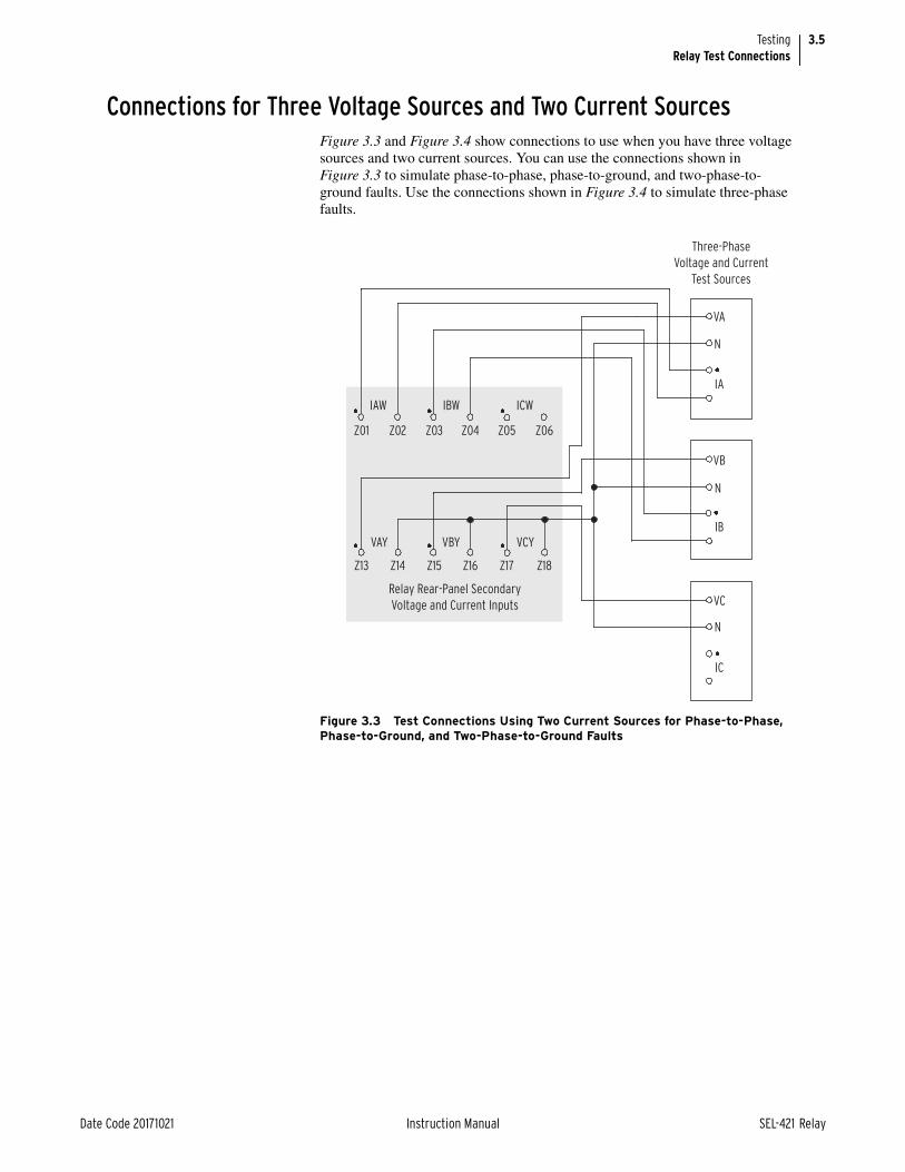
3.5
Date Code 20171021 Instruction Manual SEL-421 Relay
TestingRelay Test Connections
Connections for Three Voltage Sources and Two Current SourcesFigure 3.3 and Figure 3.4 show connections to use when you have three voltage sources and two current sources. You can use the connections shown in Figure 3.3 to simulate phase-to-phase, phase-to-ground, and two-phase-to-ground faults. Use the connections shown in Figure 3.4 to simulate three-phase faults.
Figure 3.3 Test Connections Using Two Current Sources for Phase-to-Phase, Phase-to-Ground, and Two-Phase-to-Ground Faults
Three-Phase
Voltage and Current
Test Sources
IA
VB
IB
VC
IC
VA
IAW
Z01 Z02 Z03 Z04 Z05 Z06
Z13 Z14 Z15 Z16 Z17 Z18
IBW ICW
VAY VBY VCY
Relay Rear-Panel Secondary
Voltage and Current Inputs
N
N
N

3.6
SEL-421 Relay Instruction Manual Date Code 20171021
TestingRelay Test Connections
Figure 3.4 Test Connections Using Two Current Sources for Three-Phase Faults
Three-Phase
Voltage and Current
Test Sources
IA
VB
IB
VC
IC
VA
IAW
Z01 Z02 Z03 Z04 Z05 Z06
Z13 Z14 Z15 Z16 Z17 Z18
IBW ICW
VAY VBY VCY
Relay Rear-Panel Analog
Voltage and Current Inputs
N
N
N

3.7
Date Code 20171021 Instruction Manual SEL-421 Relay
TestingRelay Test Connections
Connections for Three Voltage Sources and One Current SourceFigure 3.5 and Figure 3.6 show connections to use when you have three voltage sources and a single current source. You can use the connections shown in Figure 3.5 to simulate phase-to-ground faults. Use the connections shown in Figure 3.6 to simulate phase-to-phase faults.
Figure 3.5 Test Connections Using a Single Current Source for a Phase-to-Ground Fault
Three-Phase
Voltage and Current
Test Sources
IA
VB
IB
VC
IC
VA
IAW
Z01 Z02 Z03 Z04 Z05 Z06
Z13 Z14 Z15 Z16 Z17 Z18
IBW ICW
VAY VBY VCY
Relay Rear-Panel Secondary
Voltage and Current Inputs
N
N
N

3.8
SEL-421 Relay Instruction Manual Date Code 20171021
TestingChecking Relay Operation
Checking Relay OperationThe SEL-421 comes to you with all functions fully checked and calibrated so that the relay operates correctly and accurately. You can perform tests on the relay to verify proper relay operation, but you do not need to test every relay element, timer, and function in this evaluation. The following checks are valuable for con-firming proper SEL-421 connections and operation:
➤ AC connection check (metering)
➤ Commissioning tests
➤ Functional tests
➤ Element verification
An ac connection check uses relay metering to verify that the relay current and voltage inputs are the proper magnitude and phase rotation (see Examining Metering Quantities on page 3.35 in the SEL-400 Series Relays Instruction Man-ual).
Commissioning tests help you verify that you have properly connected the relay to the power system and all auxiliary equipment. These tests confirm proper con-nection of control inputs and control outputs as well (see Operating the Relay Inputs and Outputs on page 3.61 in the SEL-400 Series Relays Instruction Man-ual).
Figure 3.6 Test Connections Using a Single Current Source for a Phase-to-Phase Fault
Three-Phase
Voltage and Current
Test Sources
IA
VB
IB
VC
IC
VA
IAW
Z01 Z02 Z03 Z04 Z05 Z06
Z13 Z14 Z15 Z16 Z17 Z18
IBW ICW
VAY VBY VCY
Relay Rear-Panel Secondary
Voltage and Current Inputs
N
N
N

3.9
Date Code 20171021 Instruction Manual SEL-421 Relay
TestingChecking Relay Operation
Brief functional tests and element verification confirm correct internal relay pro-cessing.
This subsection discusses tests of the following relay elements:
➤ Overcurrent element: negative-sequence instantaneous, 50Q1
➤ Directional element: negative-sequence portion, F32Q/R32Q, of the phase directional element, F32P/R32P
➤ Distance element: phase-to-phase mho element, MBC2, of Zone 2 mho distance element Z2P
Testing Overcurrent ElementsOvercurrent elements operate by detecting power system sequence quantities and asserting when these quantities exceed a preset threshold.
Apply current to the analog current inputs and compare relay operation to the ele-ment pickup settings to test the instantaneous and definite-time overcurrent ele-ments. Be sure to apply the test current to the proper input set (IW or IX), according to the Global Current and Voltage Source Selection settings (ESS and ALINEI, for example) to accept the input. See Current and Voltage Source Selec-tion on page 5.2 for more information.
Phase Overcurrent ElementsThe SEL-421 phase overcurrent elements compare the phase current applied to the secondary current inputs with the phase overcurrent element pickup setting. The relay asserts the phase overcurrent elements when any of the three phase cur-rents exceeds the corresponding element pickup setting.
Negative-Sequence Overcurrent ElementsThe SEL-421 negative-sequence overcurrent elements compare a negative-sequence calculation of the three-phase secondary inputs with the corresponding negative-sequence overcurrent element pickup setting. The relay makes this neg-ative-sequence calculation (assuming ABC rotation):
3I2 = A-Phase + B-Phase (shifted by –120°) + C-Phase (shifted by 120°)
The relay asserts negative-sequence overcurrent elements when the 3I2 calcula-tion exceeds the corresponding negative-sequence current pickup setting. If bal-anced currents are applied to the relay, the relay reads 3I2 0 (load conditions) and does not pick up the negative-sequence overcurrent elements.
For testing, apply current to a single phase of the relay, causing the negative-sequence overcurrent elements to operate. For example, assume 1 A of current on A-Phase and zero current input on the B-Phase and C-Phase:
3I2 = 1 A + 0 (shifted –120°) + 0 (shifted 120°) = 1 A (a simulated ground fault condition)
Ground Overcurrent ElementsThe SEL-421 ground overcurrent elements compare a residual ground calcula-tion of the three-phase inputs with the residual overcurrent setting. The relay makes this residual current calculation:
3I0 = A-Phase + B-Phase + C-Phase

3.10
SEL-421 Relay Instruction Manual Date Code 20171021
TestingChecking Relay Operation
The relay asserts ground overcurrent elements when the 3I0 calculation exceeds the ground current element pickup setting. If balanced currents are applied to the relay, the relay reads 3I0 = 0 (load conditions) because the currents cancel in the calculation; the relay does not pick up the ground overcurrent elements.
For testing, apply current to a single phase of the relay, causing the residual over-current elements to operate. For example, assume 1 A of current on A-Phase and zero current input on B-Phase and C-Phase:
3I0 = 1 A + 0 + 0 = 1 A (a simulated ground fault condition)
Checking the Negative-Sequence Instantaneous Overcurrent Element, 50Q1The procedure in the following steps tests the 50Q1 negative-sequence overcur-rent element. Use a similar procedure to test other overcurrent elements.
Step 1. Configure the relay.
a. Start ACSELERATOR QuickSet SEL-5030 Software, and read the present configuration in the SEL-421.
b. Click Settings > Read.
The relay sends all settings and configuration data to QuickSet.
c. Expand the Group 1 settings and click the Negative-Seq Inst O/C button of the Settings tree view as shown in Figure 3.7.
You will see the Negative Sequence Instantaneous Overcurrent dialog box similar to Figure 3.7.
d. Click the arrow in the Instantaneous and Definite Time Overcurrent Element Levels E50Q dialog box and select 1.
e. For this test, set the 50Q1P level to 1.00 and 67Q1TC to 1.
NOTE: As you perform this test, other protection elements can assert. This causes the relay to assert other targets and possibly close control outputs. Be sure to isolate the relay from the power system to avoid unexpected system effects.
Figure 3.7 Negative-Sequence Instantaneous Overcurrent Element Settings: QuickSet
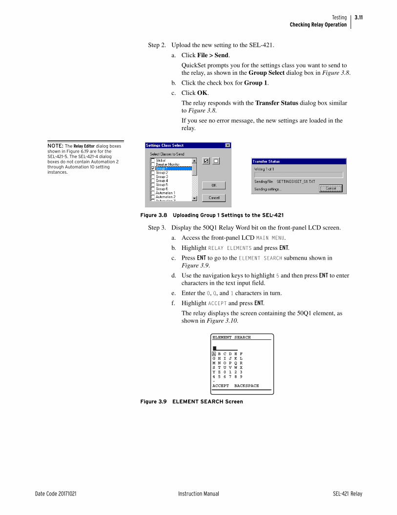
3.11
Date Code 20171021 Instruction Manual SEL-421 Relay
TestingChecking Relay Operation
Step 2. Upload the new setting to the SEL-421.
a. Click File > Send.
QuickSet prompts you for the settings class you want to send to the relay, as shown in the Group Select dialog box in Figure 3.8.
b. Click the check box for Group 1.
c. Click OK.
The relay responds with the Transfer Status dialog box similar to Figure 3.8.
If you see no error message, the new settings are loaded in the relay.
Step 3. Display the 50Q1 Relay Word bit on the front-panel LCD screen.
a. Access the front-panel LCD MAIN MENU.
b. Highlight RELAY ELEMENTS and press ENT.
c. Press ENT to go to the ELEMENT SEARCH submenu shown in Figure 3.9.
d. Use the navigation keys to highlight 5 and then press ENT to enter characters in the text input field.
e. Enter the 0, Q, and 1 characters in turn.
f. Highlight ACCEPT and press ENT.
The relay displays the screen containing the 50Q1 element, as shown in Figure 3.10.
Figure 3.8 Uploading Group 1 Settings to the SEL-421
Figure 3.9 ELEMENT SEARCH Screen
NOTE: The Relay Editor dialog boxes shown in Figure 6.19 are for the SEL-421-5. The SEL-421-4 dialog boxes do not contain Automation 2 through Automation 10 setting instances.
ELEMENT SEARCH
A B C D E F G H I J K LM N O P Q RS T U V W XY Z 0 1 2 34 5 6 7 8 9-ACCEPT BACKSPACE

3.12
SEL-421 Relay Instruction Manual Date Code 20171021
TestingChecking Relay Operation
Step 4. Connect a test source to the relay.
a. Set the current output of a test source to zero output level.
b. Connect a single-phase current output of the test source to the IAW analog input (see Figure 3.5 and Secondary Circuits on page 2.5).
Step 5. Increase the current source to produce a current magnitude greater than 1.00 A secondary in the relay.
You will see that the 50Q1 element state changes on the LCD screen from 50Q1 = 0 to 50Q1 = 1.
Negative-Sequence Directional Element for Phase FaultsThe SEL-421 features a phase directional element (represented by Relay Word bits F32P/R32P) to supervise the phase-distance elements and to control phase directional elements. The negative-sequence directional element, F32Q/R32Q, is a part of the phase directional element, F32P/R32P. Whenever the negative-sequence directional element asserts, the phase directional element asserts.
The relay also contains a ground directional element, F32G/R32G, for directional control of the ground-distance elements and ground overcurrent elements. For more information on directional elements, see Ground Directional Element on page 5.33, and Section 6: Protection Applications Examples.
The SEL-421 calculates the negative-sequence impedance Z2 from the magni-tudes and angles of the negative-sequence voltage and current. Equation 3.1 defines this function (the ‘c’ in Z2c indicates “calculated”).
Equation 3.1
Figure 3.10 RELAY ELEMENTS Screen Containing Element 50Q1
PRESS to search
RELAY ELEMENTS
SEARCH
ROW 26 ROW 2767Q4 =0 * =067Q3 =0 * =067Q2 =0 * =067Q1 =0 * =050Q4 =0 67Q4T =050Q3 =0 67Q3T =050Q2 =0 67Q2T =050Q1 =0 67Q1T =0
where:
V2 = the negative-sequence voltage
I2 = the negative-sequence current
Z1ANG = the positive-sequence line impedance angle
Re = the real part of the term in brackets, for example, (Re[A + jB] = A)
* = the complex conjugate of the expression in parentheses, (A + jB)* = (A – jB)
Z2cRe V2 1 Z1ANG I2
I22------------------------------------------------------------------------=
V2I2
--------- V2 Z1ANG I2–– cos=

3.13
Date Code 20171021 Instruction Manual SEL-421 Relay
TestingChecking Relay Operation
The result of Equation 3.1 is an impedance magnitude that varies with the magni-tude and angle of the applied current. Normally, a forward fault results in a nega-tive Z2c relay calculation.
Test CurrentSolve Equation 3.1 to find the test current values that you need to apply to the relay to test the element. For the negative-sequence current I2, the result is
Equation 3.2
when:
Equation 3.3
Multiply the quantities in Equation 3.2 by three to obtain 3I2, the negative-sequence current that the relay processes. With a fixed applied negative-sequence voltage VA, the relay negative-sequence voltage is 3V2. Set Z2c = Z2F to find the test current magnitude at the point where the impedance calculation equals the forward fault impedance threshold. Equation 3.2 becomes:
Equation 3.4
when:
Equation 3.5
For a reverse fault impedance threshold, where Z2c = Z2R, Equation 3.2 becomes:
Equation 3.6
when the angle calculation is the same as Equation 3.5.
For more information on the directional elements, see Ground Directional Ele-ments on page 1.18 and Quadrilateral Ground-Distance Elements on page 1.18. For settings and application information, see Section 6: Protection Applications Examples.
Checking the Negative-Sequence Directional Element (Phase Faults)This test confirms operation of the F32Q and the R32Q negative-sequence direc-tional elements. This test procedure is for a 5 A relay; scale values appropriately for a 1 A relay.
I2V2
Z2c----------=
I2 V2 Z1ANG–=
ITEST 3I23V2Z2c-------------
3V2Z2F-------------= = =
ITEST 3I2 3V2 Z1ANG–==
ITEST 3I23V2Z2c-------------
3V2Z2R-------------= = =
NOTE: As you perform this test, other protection elements can assert. This causes the relay to assert other targets and possibly close control outputs. Be sure to isolate the relay from the power system to avoid unexpected system effects.

3.14
SEL-421 Relay Instruction Manual Date Code 20171021
TestingChecking Relay Operation
Step 1. Configure the relay.
a. Open QuickSet and read the present configuration in the SEL-421.
b. Click Settings > Read.
The relay sends all settings and configuration data to QuickSet.
c. Expand the Group 1 settings and click the Relay Configuration branch of the Settings tree view as shown in Figure 3.11.
d. Disable supervisory elements.
Confirm that ELOP is set to N.
e. In a similar sequence, click on the + button to expand the Relay Configuration tree view, click on Load Encroachment, and confirm that ELOAD is set to N.
f. Defeat the pole-open logic.
g. Click the + button next to Breaker Monitor to expand the Breaker Monitor branch of the Settings tree view (see Figure 3.12).
h. Click Breaker 1.
You will see the Breaker 1 dialog box similar to Figure 3.12.
Figure 3.11 Group 1 Relay Configuration Settings: QuickSet

3.15
Date Code 20171021 Instruction Manual SEL-421 Relay
TestingChecking Relay Operation
i. Enter 1 in the text boxes for 52AA1 A-Phase N/O Contact Input -BK1, 52AB1 B-Phase N/O Contact Input -BK1, and 52AC1 C-Phase N/O Contact Input -BK1.
The text boxes in Figure 3.12 appear if Breaker Monitor setting BK1TYP := 1.
j. If BK1TYP := 3, enter 1 in the 52AA1 N/O Contact Input -BK1 text box (the other circuit breaker input boxes are dimmed.)
Step 2. Set test values in the relay.
a. Expand the Group 1 settings as shown in Figure 3.13 and select the Line Configuration button.
You will see the Line Configuration dialog box of Figure 3.13.
b. Confirm the default settings of Z1MAG at 7.80 and Z1ANG at 84.00.
c. Click the + mark next to the Relay Configuration branch to expand that Settings branch.
d. Select the Directional button.
You will see the Directional dialog box similar to Figure 3.14.
e. Confirm the following settings: E32 is AUTO, ORDER is Q, 50FP is 0.60, 50RP is 0.40, Z2F is 3.90, Z2R is 4.00, a2 is 0.10, and k2 is 0.2.
The dialog box is dim since there are no settings to change.
The relay calculates these numeric settings automatically because E32 is set to AUTO.
f. If you need to change these settings, set E32 to Y.
Table 3.3 shows the calculations.
See Ground Directional Elements on page 1.18 for details on these relay calculations.
Figure 3.12 Breaker 1 Breaker Monitor Settings: QuickSet

3.16
SEL-421 Relay Instruction Manual Date Code 20171021
TestingChecking Relay Operation
Figure 3.13 Group 1 Line Configuration Settings: QuickSet

3.17
Date Code 20171021 Instruction Manual SEL-421 Relay
TestingChecking Relay Operation
Step 3. Upload the new settings to the SEL-421.
a. Click File > Send.
QuickSet prompts you for the settings class you want to send to the relay, as shown in the Select Groups dialog box in Figure 3.15.
b. Click the check box for Group 1 and for Breaker Monitor.
c. Click OK.
d. QuickSet responds with a Transfer Status dialog box as in Figure 3.15.
If you see no error message, the new settings are loaded in the relay.
Figure 3.14 Directional Settings: QuickSet
Table 3.3 Negative-Sequence Directional Element Settings AUTO Calculations
Setting Calculation
50FP 0.12 • INOM
50RP 0.08 • INOM
Z2F 0.5 • Z1MAG
Z2R Z2F + 1/(2 • INOM)
a2 0.1
k2 0.2

3.18
SEL-421 Relay Instruction Manual Date Code 20171021
TestingChecking Relay Operation
Step 4. Display the F32Q and R32Q Relay Word bits on the front-panel LCD screen.
a. Access the front-panel LCD MAIN MENU.
b. Highlight RELAY ELEMENTS and press ENT.
You will see a RELAY ELEMENTS screen with SEARCH highlighted at the bottom of the screen.
c. Press ENT to go to the ELEMENT SEARCH submenu shown in Figure 3.9.
d. Enter characters in the text input field using the navigation keys.
e. Highlight F and press ENT to enter the F character.
f. Enter the 3, 2, and Q characters in like manner.
g. Highlight ACCEPT and press ENT.
The relay displays the screen containing the F32Q and R32Q elements, as shown in Figure 3.16.
Step 5. Calculate impedance thresholds.
a. For this test, apply an A-Phase voltage of VA = 3V2 = 18.0 180° V secondary.
b. Use Equation 3.6 to find the current that is equal to the reverse impedance threshold Z2R:
Equation 3.7
Step 6. Use Equation 3.4 to find the current that is equal to the forward impedance threshold Z2F:
Equation 3.8
Figure 3.15 Uploading Group 1 and Breaker Monitor Settings to the SEL-421
Figure 3.16 RELAY ELEMENTS LCD Screen Containing Elements F32Q and R32Q
NOTE: The Relay Editor dialog boxes shown in Figure 3.15 are for the SEL-421-5. The SEL-421-4 dialog boxes do not contain Automation 2 through Automation 10 setting
PRESS to search
RELAY ELEMENTS
SEARCH
ROW 20 ROW 2132SPOR =0 32IE =032SPOF =0 32VE =032QR =0 32QGE =032QF =0 32QE =0R32Q =0 50GR =0F32Q =0 50GF =0R32P =0 50QR =0F32P =0 50QF =0
ITEST 3I23V2Z2R-------------
18.0 180V4.00---------------------------------- 4.50 A= = = =
ITEST 3I23V2
Z2RF---------------18.0 180V
3.90---------------------------------- 4.62 A= = = =

3.19
Date Code 20171021 Instruction Manual SEL-421 Relay
TestingChecking Relay Operation
Step 7. Use Equation 3.5 to determine the applied current angle (ITEST):
Step 8. Apply a test current to confirm operation of R32Q and F32Q.
a. Connect a single current test source as shown in Figure 3.5.
b. Apply an A-Phase voltage of VA = 18.0 180° V secondary.
c. Set the current source for IA = 0.0 96° A.
d. Slowly increase the magnitude of IA to apply the source test current.
e. Observe the RELAY ELEMENT LCD screen.
Relay Word bit R32Q asserts when |IA| = 0.4 A, indicating that the relay negative-sequence current is greater than the 50RP pickup threshold.
R32Q deasserts when |IA| = 4.5 A, indicating that the relay negative-sequence calculation Z2c is now less than the Z2 reverse threshold Z2R (see Forward Threshold on page 5.43 and Reverse Threshold on page 5.44).
f. Continue to increase the current source while you observe the RELAY ELEMENT LCD screen.
Relay Word bit F32Q asserts when |IA| = 4.62 A, indicating that the relay negative-sequence calculation Z2c is less than the Z2 forward threshold Z2F.
Distance ElementsApply voltages and currents to the relay analog inputs that simulate fault and load conditions to test distance elements. The relay supervises distance elements so that these elements operate under the appropriate conditions. Be sure to satisfy all the element supervisory conditions before testing a relay element. For supervi-sory conditions for a particular element, see Mho Ground-Distance Elements on page 5.72.
Phase-to-Phase Distance Element MBC2The SEL-421 contains mho phase-distance elements among the many protection elements in the relay. The relay has phase-distance elements to detect phase-to-phase faults, phase-to-phase-to-ground faults, and three-phase faults. The SEL-421 has five independent zones of mho phase-distance protection; each zone consists of phase-to-phase elements that the relay combines to produce a particu-lar zone output.
For example, the OR combination of MAB2, MBC2, and MCA2 produces the Z2P Zone 2 mho phase element. For more information on the mho phase ele-ments and other distance elements, see Section 5: Protection Functions and Section 6: Protection Applications Examples.
Test Current and Voltage for a Phase-to-Phase FaultTo find the test current for a phase-to-phase fault, consider Equation 3.9 for a B-Phase to C-Phase fault:
Equation 3.9
ITEST 3I2 3V2 Z1ANG 180 84 96=–=–==
ITEST IB IC–= =

3.20
SEL-421 Relay Instruction Manual Date Code 20171021
TestingChecking Relay Operation
The B-Phase to C-Phase current vector, IBC, is:
Equation 3.10
Choose a convenient test source current magnitude, |ITEST| = 2.5 A; then |IBC| = 2 • |ITEST| = 5 A.
Find the magnitude of the test source voltage |VTEST|:
Equation 3.11
where relay setting Z2MP (Zone 2 Reach) substitutes for the B-Phase to C-Phase impedance ZBC. For setting Z2MP of 9.36 , the test voltage magnitude |VBC| is:
Equation 3.12
One way to create a VBC phasor is to equate |VB| and |VC| and determine the appropriate angles to make an equilateral triangle, as shown in Figure 3.17.
Subtract 30 degrees (angle 1) from 180 degrees to obtain the angle for test source VC phasor; VC = 46.8 150° V.
Similarly, add 30 degrees (angle 2) to –180 degrees to obtain test source VB phasor; VB = 46.8 –150° V.
Test voltage VA can be the nominal value, VA = 67 0° V.
Thus, the resulting phase-to-phase voltage is VBC = 46.8 –90° V, referenced to the VA phasor at 0 degrees.
Figure 3.17 Finding Phase-to-Phase Test Quantities
IBC IB IC IB IB 2 IB 2 ITEST= =+=–=
VTEST VBC IBC ZBC IBC Z2MP= = =
2 ITEST Z2MP=
VTEST 2 ITEST Z2MP=
2 2.5 9.36 46.8 V==
β2 = 30˚
φ = –150˚
θ = 150˚
–90˚
90˚
VA0˚±180˚
β1 = 30˚
VBCVB
VC

3.21
Date Code 20171021 Instruction Manual SEL-421 Relay
TestingChecking Relay Operation
The relay measures phase-distance element maximum reach when the faulted phase-to-phase current lags the faulted phase-to-phase voltage by the distance element maximum torque angle. In the SEL-421, the phase-distance element maximum torque angle is setting Z1ANG. Current IBC should lag voltage VBC by Z1ANG.
In this example, Z1ANG is 84.0 degrees. From Equation 3.9, the angle of IB is the angle of ITEST, and the angle of IC is 180 degrees from the angle of ITEST. The test source current for IB is the following:
Equation 3.13
And the test source current for IC is the following:
Equation 3.14
Checking the MBC2 Portion of the Z2P Phase-Distance ElementThe following procedure describes how to test the B-Phase to C-Phase distance element MBC2. Although this test refers directly to the Zone 2 phase-distance element, you can apply this procedure to any other forward-reaching phase-to-phase distance element zone.
Step 1. Configure the relay.
Perform the procedure listed under Step 1 in Checking the Negative-Sequence Directional Element (Phase Faults) on page 3.13.
Step 2. Set test values in the relay.
Perform the procedure listed under Step 2 in Checking the Negative-Sequence Directional Element (Phase Faults) on page 3.13.
Step 3. Set the phase-distance element reach.
a. Select the Phase Distance button of the QuickSet Settings tree view.
You will see the Phase Distance Elements dialog box similar to Figure 3.18.
b. Confirm the settings of E2IP at 2, Z1MP at 6.24 and Z2MP at 9.36.
IB 2.5 90– Z1ANG– A=
2.5 90– 84– A=
2.5 174A–=
IC IB 2.5 174A– 2.5 6A=–=–=
Figure 3.18 Phase-Distance Elements Settings: QuickSet
NOTE: As you perform this test, other protection elements can assert. This causes the relay to assert other targets and possibly close control outputs. Be sure to isolate the relay from the power system to avoid unexpected system effects.

3.22
SEL-421 Relay Instruction Manual Date Code 20171021
TestingChecking Relay Operation
Step 4. Upload the new settings to the SEL-421.
a. Click File > Send.
b. QuickSet prompts you for the settings class you want to send to the relay, as shown in the Group Select dialog box of Figure 3.15.
c. Click the check box for Group 1.
d. Click OK.
QuickSet responds with a dialog box similar to the second dialog box of Figure 3.15.
If you see no error message, the new settings are loaded in the relay.
Step 5. Display the MBC2 Relay Word bit on the front-panel LCD screen.
a. Access the front-panel LCD MAIN MENU.
b. Highlight RELAY ELEMENTS and press ENT.
c. You will see a RELAY ELEMENTS screen with SEARCH highlighted at the bottom of the screen.
d. Press ENT to go to the ELEMENT SEARCH submenu shown in Figure 3.9.
e. Use the navigation keys to highlight M and press ENT to enter character in the text input field.
f. Enter the B, C, and 2 characters in like manner.
g. Highlight ACCEPT and press ENT.
The relay displays the LCD screen containing the MBC2 element, as shown in Figure 3.19.
Step 6. Set the magnitudes and angles of the test signals for a B-Phase-to-C-phase fault.
a. Connect the test sources (with power off) to the relay, as in Figure 3.6.
This connection is a B-Phase-to-C-Phase fault where IA 0 and IB = –IC.
b. Adjust the voltage sources to provide the following test voltages: VA = 67 V 0°, VB = 46.8 V –150°, and VC = 46.8 V 150°.
c. Set the current source for IB = 0.0 A –174°.
Figure 3.19 RELAY ELEMENTS LCD Screen Containing Element MBC2
PRESS to search
RELAY ELEMENTS
SEARCH
ROW 8 ROW 9* =0 * =0MCA2 =0 MCA4 =0MBC2 =0 MBC4 =0MAB2 =0 MAB4 =0* =0 * =0MCA1 =0 MCA3 =0MBC1 =0 MBC3 =0MAB1 =0 MAB3 =0
3.23
Date Code 20171021 Instruction Manual SEL-421 Relay
TestingTechnical Support
Step 7. Apply the sources to confirm operation of MBC2.
a. Apply the source test current by slowly increasing the magnitude of IB.
b. Observe the RELAY ELEMENT LCD screen.
Relay Word bit MBC2 asserts when |IB| 2.5 A, indicating that the relay impedance calculation is less than the Z2MP reach setting.
Technical SupportWe appreciate your interest in SEL products and services. If you have questions or comments, please contact us at:
Schweitzer Engineering Laboratories, Inc.2350 NE Hopkins CourtPullman, WA 99163-5603 U.S.A. Tel: +1.509.338.3838Fax: +1.509.332.7990 Internet: selinc.com/supportEmail: [email protected]

This page intentionally left blank

Date Code 20171021 Instruction Manual SEL-421 Relay
Instruction ManualInstruction ManualS E C T I O N 4
Front-Panel Operations
The SEL-421 Relay front panel makes power system data collection and system control quick and efficient. Using the front panel, you can analyze power system operating information, view and change relay settings, and perform relay control functions. The relay features a straightforward menu-driven control structure pre-sented on the front-panel liquid crystal display (LCD). Front-panel targets and other LED indicators give a quick look at SEL-421 operation status. You can per-form often-used control actions rapidly by using the large direct-action pushbut-tons. All of these features help you operate the relay from the front panel and include:
➤ Reading metering
➤ Inspecting targets
➤ Accessing settings
➤ Controlling relay operations
General front-panel operations are described in the Section 4: Front-Panel Oper-ations in the SEL-400 Series Relays Instruction Manual. This section provides additional information that is unique to the SEL-421. This section includes the following:
➤ Front-Panel LCD Default Displays on page 4.1
➤ Front-Panel Menus and Screens on page 4.3
➤ Target LEDs on page 4.9
➤ Front-Panel Operator Control Pushbuttons on page 4.13
➤ One-Line Diagrams on page 4.15
Front-Panel LCD Default DisplaysThe SEL-421 has two screen scrolling modes: autoscrolling mode and manual-scrolling mode. After front-panel time out, the LCD presents each of the display screens in this sequence:
➤ One-line diagram
➤ Any active (filled) alarm points screens
➤ Any active (filled) display points screens
➤ Enabled metering screens
The relay displays enabled metering screens in the order listed in Table 4.1. (see Figure 4.4 for samples of the metering screens.) This sequence comprises the ROTATING DISPLAY.

4.2
SEL-421 Relay Instruction Manual Date Code 20171021
Front-Panel OperationsFront-Panel LCD Default Displays
Use the front-panel settings (the SET F command from a communications port or the Front Panel settings in ACSELERATOR QuickSet SEL-5030 Software) to access the metering screen enables. Entering a Y (Yes) for a metering screen enable setting causes the corresponding metering screen to appear in the ROTAT-ING DISPLAY. Entering an N (No) hides the metering screen from presentation in the ROTATING DISPLAY. Figure 4.1 shows a sample ROTATING DISPLAY consisting of an example alarm points screen, an example display points screen, and the two factory-default metering screens, RMS_I and FUND_VI (the screen values in Figure 4.1 are representative values).
Table 4.1 Metering Screens Enable Settings
Name Prompt Range Default
RMS_V RMS Line Voltage Screen Y, N N
RMS_I RMS Line Current Screena
a The default displays are RMS_I and FUND_VI.
Y, N Y
RMS_VPP RMS Line Voltage Phase-to-Phase Screen Y, N N
RMS_W RMS Active Power Screen Y, N N
FUNDVAR Fundamental Reactive Power Screen Y, N N
RMS_VA RMS Apparent Power Screen Y, N N
RMS_PF RMS Power Factor Screen Y, N N
RMS_BK1 RMS Breaker 1 Currents Screen Y, N N
RMS_BK2 RMS Breaker 2 Currents Screen Y, N N
STA_BAT Station Battery Screen Y, N N
FUND_VI Fundamental Voltage and Current Screena Y, N Y
FUNDSEQ Fundamental Sequence Quantities Screen Y, N N
FUND_BK Fundamental Breaker Currents Screen Y, N N
ONELINE One Line Bay Control Diagram Y, N N
NOTE: The initial display can present only the RMS_I line-current screen. This can occur when you have not enabled any of the metering screens, alarm points, and display points.

4.3
Date Code 20171021 Instruction Manual SEL-421 Relay
Front-Panel OperationsFront-Panel Menus and Screens
The active alarm points are the first screens in the ROTATING DISPLAY (see Alarm Points on page 4.7 in the SEL-400 Series Relays Instruction Manual). Each alarm points screen shows as many as eleven alarm conditions. The SEL-421 can pres-ent a maximum of six alarm points screens.
The active display points are the next screens in the ROTATING DISPLAY (see Dis-play Points on page 4.10 in the SEL-400 Series Relays Instruction Manual). Each display points screen shows as many as 11 enabled display points. (With 96 dis-play points, the SEL-421 can present a maximum of 9 display points screens.) If a display point does not have text to display, the screen space for that display point is maintained.
Front-Panel Menus and ScreensOperate the SEL-421 front panel through a sequence of menus that you view on the front-panel display. The MAIN MENU is the introductory menu for other front-panel menus. These additional menus allow you on-site access to metering, con-
Figure 4.1 Sample ROTATING DISPLAY
*Circuit BK1 SF6 Gas
ROTATING DISPLAY
Press for menu
Circuit Breaker 1 --Closed--
ROTATING DISPLAY
Press for menu
Circuit BK1 SF6 Gas --Alarm--
Circuit Breaker 2 A PH= 119.6 A pri
SF6 ALARM
Line Current (A) RMS
IA = 119.6IB = 119.7IC = 119.5FREQ = 60.00 Hz
ROTATING DISPLAY
Press for menu
Line Quantities FUNDROTATING DISPLAY
Press for menu
Voltage (kV) VA = 130.4 + 6° VB = 130.3 -114° VC = 130.5 -126°Current (A) IA = 119.6 35° IB = 119.7 -95° IC = 119.5 155°FREQ = 60.00 Hz
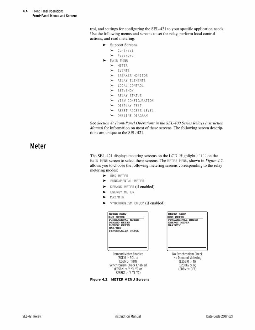
4.4
SEL-421 Relay Instruction Manual Date Code 20171021
Front-Panel OperationsFront-Panel Menus and Screens
trol, and settings for configuring the SEL-421 to your specific application needs. Use the following menus and screens to set the relay, perform local control actions, and read metering:
➤ Support Screens➢ Contrast➢ Password
➤ MAIN MENU➢ METER➢ EVENTS➢ BREAKER MONITOR➢ RELAY ELEMENTS➢ LOCAL CONTROL➢ SET/SHOW➢ RELAY STATUS➢ VIEW CONFIGURATION➢ DISPLAY TEST➢ RESET ACCESS LEVEL➢ ONELINE DIAGRAM
See Section 4: Front-Panel Operations in the SEL-400 Series Relays Instruction Manual for information on most of these screens. The following screen descrip-tions are unique to the SEL-421.
MeterThe SEL-421 displays metering screens on the LCD. Highlight METER on the MAIN MENU screen to select these screens. The METER MENU, shown in Figure 4.2, allows you to choose the following metering screens corresponding to the relay metering modes:
➤ RMS METER➤ FUNDAMENTAL METER
➤ DEMAND METER (if enabled)➤ ENERGY METER➤ MAX/MIN
➤ SYNCHRONISM CHECK (if enabled)
Figure 4.2 METER MENU Screens
METER MENU METER MENU
Demand Meter Enabled(EDEM := ROL orEDEM := THM)
Synchronism Check Enabled(E25BK1 := Y, Y1, Y2 orE25BK2 := Y, Y1, Y2)
No Synchronism CheckNo Demand Metering
(E25BK1 := N)(E25BK2 := N)(EDEM := OFF)
RMS METERFUNDAMENTAL METERENERGY METERMAX/MIN
RMS METERFUNDAMENTAL METERDEMAND METERENERGY METERMAX/MINSYNCHRONISM CHECK

4.5
Date Code 20171021 Instruction Manual SEL-421 Relay
Front-Panel OperationsFront-Panel Menus and Screens
NOTE: Global settings ESS (Enable Source Selection) and NUMBK (Number of Circuit Breakers) affect how the SEL-421 determines the line current and the voltage source for protection functions (directional elements, load encroachment, out-of-step logic, distance element, and loss-of-potential).
Combinations of relay Global settings ESS and NUMBK give you metering data for Line, Circuit Breaker 1, and Circuit Breaker 2 when you view RMS METER, FUNDAMENTAL METER, and MAX/MIN metering screens. The relay shows the METER SUBMENU of Figure 4.3 so you can choose the line or circuit breaker data that you want to display.
For example, if you have two sources feeding a transmission line through two cir-cuit breakers and you set ESS := 3, NUMBK := 2, then the SEL-421 measures BREAKER 1 currents, BREAKER 2 currents, and combined (Circuit Breakers 1 and 2) currents for LINE. The relay displays the METER SUBMENU screen when you make this settings configuration.
Other combinations of settings ESS and NUMBK do not require separate circuit breaker metering screens; for these configurations, the relay does not present the METER SUBMENU screen. See Section 5: Protection Functions and Global Settings on page 6.3 for information on configuring global settings ESS, NUMBK, LINEI, BK1I, and BK2I.
The relay presents the meter screens in the order shown in each column of Figure 4.4 and Figure 4.5. Once you have selected the type of metering data to display (RMS METER, FUNDAMENTAL METER, DEMAND METER, ENERGY METER, MAX/MIN, or SYNCHRONISM CHECK), you can scroll through the particular display col-umn by pressing the Down Arrow pushbutton. Return to a previously viewed screen in each column by pressing the Up Arrow pushbutton. Press ESC to revert the LCD screen to the METER SUBMENU and METER MENU screens.
The metering screens show reset options for the MAX/MIN, ENERGY METER, PEAK DEMAND METER, and DEMAND METER metering quantities at the end of each screen column. Use the Left Arrow and Right Arrow pushbuttons to select a NO or YES response to the reset prompt, and then press ENT to reset the metering quantity.
Figure 4.3 METER SUBMENU
METER SUBMENULINEBREAKER 1BREAKER 2

4.6
SEL-421 Relay Instruction Manual Date Code 20171021
Front-Panel OperationsFront-Panel Menus and Screens
Figure 4.4 RMS, FUND, and DEMAND Metering Screens
VOLTAGE (kV) VA = x xxx.x VB = x xxx.x VC = x xxx.xCURRENT (A) IA = x xxx.x IB = x xxx.x IC = x xxx.xFREQ = 60.00 HzVDC1 = xxx.x VVDC2 = xxx.x V
RMS LINE METER
VOLTAGE (kV) VAB = x xxx.x VBC = x xxx.x VCA = x xxx.x
RMS LINE METER
ACTIVE POWER (MW) A = -xx xxx.x B = -xx xxx.x C = -xx xxx.x 3P = -xx xxx.xREACTIVE (MVAR) A = -xx xxx.x B = -xx xxx.x C = -xx xxx.x 3P = -xx xxx.x
RMS LINE METER
APPARENT POWER (MVA) A = xx xxx.x B = xx xxx.x C = xx xxx.x 3P = xx xxx.xPOWER FACTOR A = x.xx LAG B = x.xx LAG C = x.xx LAG 3P = x.xx LAG
RMS LINE METER
CURRENTS (A) IA = x xxx.x IB = x xxx.x IC = x xxx.x
RMS BREAKER n METER
VOLTAGE (kV) VA = x xxx.x +xxx° VB = x xxx.x +xxx° VC = x xxx.x +xxx°CURRENT (A) IA = x xxx.x +xxx° IB = x xxx.x +xxx° IC = x xxx.x +xxx°FREQ = 60.00 HzVDC1 = xxx.x VVDC2 = xxx.x V
FUND LINE METER
VOLTAGE (kV) VAB = x xxx.x +xxx° VBC = x xxx.x +xxx° VCA = x xxx.x +xxx°
FUND LINE METER
SEQUENCE I (A) I1 = x xxx.x +xxx° 3I2 = x xxx.x +xxx° 3I0 = x xxx.x +xxx°
SEQUENCE V (kV) V1 = x xxx.x +xxx° 3V2 = x xxx.x +xxx° 3V0 = x xxx.x +xxx°
FUND LINE METER
ACTIVE POWER (MW) A = -xx xxx.x B = -xx xxx.x C = -xx xxx.x 3P = -xx xxx.xREACTIVE (MVAR) A = -xx xxx.x B = -xx xxx.x C = -xx xxx.x 3P = -xx xxx.x
FUND LINE METER
APPARENT POWER (MVA) A = xx xxx.xx B = xx xxx.xx C = xx xxx.xx 3P = xx xxx.xxPOWER FACTOR A = x.xx LEAD B = x.xx LEAD C = x.xx LEAD 3P = x.xx LEAD
FUND LINE METER
CURRENTS (A) IA = x xxx.xx +xxx° IB = x xxx.xx +xxx° IC = x xxx.xx +xxx°
FUND BREAKER n METER
BREAKER METERING
LINE METERING
CURRENTS (A) IA PEAK = xxx xxx.x DEM = xxx xxx.x IB PEAK = xxx xxx.x DEM = xxx xxx.x IC PEAK = xxx xxx.x DEM = xxx xxx.x3I2 PEAK = xxx xxx.x DEM = xxx xxx.x3I0 PEAK = xxx xxx.x DEM = xxx xxx.x
DEMAND METER
POWER (MW) A PEAK = xxx xxx.x DEM = xxx xxx.x B PEAK = xxx xxx.x DEM = xxx xxx.x C PEAK = xxx xxx.x DEM = xxx xxx.x3P PEAK = xxx xxx.x DEM = xxx xxx.x
DEMAND METER
POWER(MVA) A PEAK = xxx xxx.x DEM = xxx xxx.x B PEAK = xxx xxx.x DEM = xxx xxx.x C PEAK = xxx xxx.x DEM = xxx xxx.x 3P PEAK = xxx xxx.x DEM = xxx xxx.x
DEMAND METER
DEMAND METER
DEMAND METER
NO YES
RESET PEAK NOW?
LAST PEAK DEMANDRESET:MM/DD/YYYY HH:MM:SS
NO YES
RESET DEMAND NOW?
LAST DEMAND RESET:MM/DD/YYYY HH:MM:SS
n = 1 or 2, representing Circuit Breaker 1 or Circuit Breaker 2,respectively.
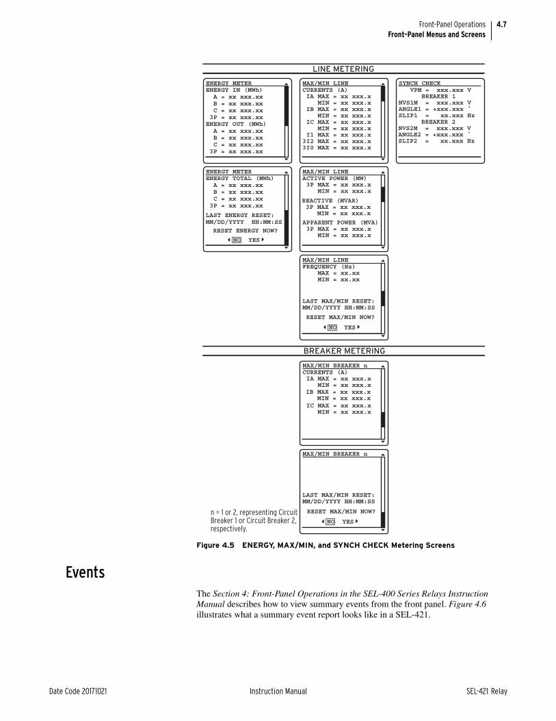
4.7
Date Code 20171021 Instruction Manual SEL-421 Relay
Front-Panel OperationsFront-Panel Menus and Screens
EventsThe Section 4: Front-Panel Operations in the SEL-400 Series Relays Instruction Manual describes how to view summary events from the front panel. Figure 4.6 illustrates what a summary event report looks like in a SEL-421.
Figure 4.5 ENERGY, MAX/MIN, and SYNCH CHECK Metering Screens
LINE METERING
VPM = xxx.xxx V BREAKER 1NVS1M = xxx.xxx VANGLE1 = +xxx.xxx ˚SLIP1 = xx.xxx Hz
SYNCH CHECK
BREAKER 2NVS2M = xxx.xxx VANGLE2 = +xxx.xxx ˚SLIP2 = xx.xxx Hz
ENERGY IN (MWh) A = xx xxx.xx B = xx xxx.xx C = xx xxx.xx 3P = xx xxx.xxENERGY OUT (MWh) A = xx xxx.xx B = xx xxx.xx C = xx xxx.xx 3P = xx xxx.xx
ENERGY METER
ENERGY TOTAL (MWh) A = xx xxx.xx B = xx xxx.xx C = xx xxx.xx 3P = xx xxx.xx
ENERGY METER
RESET ENERGY NOW?
NO YES
LAST ENERGY RESET:MM/DD/YYYY HH:MM:SS
CURRENTS (A) IA MAX = xx xxx.x MIN = xx xxx.x IB MAX = xx xxx.x MIN = xx xxx.x IC MAX = xx xxx.x MIN = xx xxx.x I1 MAX = xx xxx.x3I2 MAX = xx xxx.x3I0 MAX = xx xxx.x
MAX/MIN LINE
BREAKER METERING
ACTIVE POWER (MW) 3P MAX = xx xxx.x MIN = xx xxx.x
MAX/MIN LINE
FREQUENCY (Hz) MAX = xx.xx MIN = xx.xx
MAX/MIN LINE
REACTIVE (MVAR) 3P MAX = xx xxx.x MIN = xx xxx.x
APPARENT POWER (MVA) 3P MAX = xx xxx.x MIN = xx xxx.x
NO YES
RESET MAX/MIN NOW?
CURRENTS (A) IA MAX = xx xxx.x MIN = xx xxx.x
MAX/MIN BREAKER n
LAST MAX/MIN RESET:MM/DD/YYYY HH:MM:SS
MAX/MIN BREAKER n
IB MAX = xx xxx.x MIN = xx xxx.x IC MAX = xx xxx.x MIN = xx xxx.x
NO YES
RESET MAX/MIN NOW?
LAST MAX/MIN RESET:MM/DD/YYYY HH:MM:SS
n = 1 or 2, representing Circuit Breaker 1 or Circuit Breaker 2, respectively.

4.8
SEL-421 Relay Instruction Manual Date Code 20171021
Front-Panel OperationsFront-Panel Menus and Screens
Breaker MonitorThe SEL-421 features an advanced circuit breaker monitor. Select BREAKER MON-ITOR screens from the MAIN MENU to view circuit breaker monitor alarm data on the front-panel display.
Figure 4.7 shows sample breaker monitor display screens. The BKR n ALARM COUNTER screen displays the number of times the circuit breaker exceeded certain alarm thresholds (see Circuit Breaker Monitor on page 7.7).
If you have two circuit breakers and have set NUMBK := 2, the alarm submenu in Figure 4.7 appears first. Use the navigation pushbuttons to choose either Cir-cuit Breaker 1 or Circuit Breaker 2. Press ENT to view the selected circuit breaker monitor information. An example of the Circuit Breaker 1 ALARM COUNTER screen for a single-pole tripping circuit breaker is shown on the right side of Figure 4.7.
View ConfigurationYou can use the front panel to view detailed information about the configuration of the firmware and hardware components in the SEL-421 Relay. In the MAIN MENU, highlight the VIEW CONFIGURATION option by using the navigation pushbut-tons. The relay presents four screens in the order shown in Figure 4.8. Use the navigation pushbuttons to scroll through these screens. When finished viewing these screens, press ESC to return to the MAIN MENU.
Figure 4.6 EVENT SUMMARY Screens
03/15/2001 GROUP 100:00:05.387EVENT: 87A REFFREQUENCY: 60.54
EVENT SUMMARY 10002TARGETS:COMM ZONE 2PHASE BPHASE CGROUND50
EVENT SUMMARY 10002TARGETS:COMM ZONE 2PHASE BPHASE CGROUND50
EVENT SUMMARY 10002FAULT QUANTITIES(kV/A)VA = 131 0.7°VB = 113 -123.4°VC = 113 124.7°
IA = 200 -0.5°IB = 2478 172.3°IC = 2480 6.7°IG = 212 -11.3°
EVENT SUMMARY 10002
Figure 4.7 BREAKER MONITOR Report Screens
BREAKER 1BREAKER 2
BKR ALARM SUBMENU
BKR 1 ALARM COUNTER ALARM COUNTMECH. OP. TIME 0ELEC. OP. TIME 0BKR INACTIVITY 0POLE SCATTER 0POLE DISCREPANCY 0MOTOR RUNTIME 0CURRENTINTERRUPTED 0
LAST RESET:03/15/2001 00:01:00

4.9
Date Code 20171021 Instruction Manual SEL-421 Relay
Front-Panel OperationsTarget LEDs
Target LEDsThe SEL-421 gives you at-a-glance confirmation of relay conditions via opera-tion and target LEDs. These LEDs are located in the middle of the relay front panel. The SEL-421 provides either 16 or 24 LEDs depending on ordering option.
Section 4: Front-Panel Operations in the SEL-400 Series Relays Instruction Manual describes the general operation and configuration of these LEDs. In the SEL-421, targets latch when a trip occurs. For a concise listing of the default pro-gramming on the front-panel LEDs, see Front-Panel Settings on page 8.35.
Use the slide-in labels to mark the LEDs with custom names. Included on the SEL-421 Product Literature CD are Customer Label Templates to print labels for the slide-in label carrier.
Figure 4.8 VIEW CONFIGURATION Sample Screens
FID=SEL-421-5-R101- V0-Z012012- D20100130PART NUMBER: 0451541 5XC0X4H60X0XXXS/N=201001001SELBOOT: BFID=SLBT-4XX- R205-V0-Z001002- D20100130 CHECKSUM: D97F
CONFIGURATION INFO
FIBER PORT: NOT INSTALLED
INTERFACE BOARDS: BOARD 1: 8 INPUTS 15 OUTPUTS BOARD 2:NOT INSTALLED
EXTENDED FEATURES: DNP ACTIVE
CONFIGURATION INFO
MAINBOARD: CODE FLASH: 4 MB DATA FLASH: 8 MB RAM: 3 MB EEPROM: 32 KB
ANALOG INPUTS: W: CURRENTS: 5 A X: CURRENTS: 5 A Y: VOLTAGE: 67 V Z: VOLTAGE: 67 V
CONFIGURATION INFO
IF THE CONFIGURATIONIS NOT WHAT YOU EXPECTED, CONTACTSEL FOR ASSISTANCE.
CONFIGURATION INFO

4.10
SEL-421 Relay Instruction Manual Date Code 20171021
Front-Panel OperationsTarget LEDs
Figure 4.9 shows the arrangement of the operation and target LEDs region into several areas described in Table 4.2.
Trip TypeThe SEL-421 indicates essential information about the most recent relay trip event with the LEDs of the Trip Type area. These trip types are INST, TIME, COMM, and SOTF. For information on setting the corresponding trip logic, see Trip Logic on page 5.137.
The INST target LED illuminates, indicating operation of the SEL-421 instanta-neous elements. This LED lights if elements Z1P (the Zone 1 mho phase-distance element) or Z1G (the Zone 1 mho ground-distance element) pick up and the relay has not illuminated the COMM or SOTF targets.
The TIME target LED indicates that a timed relay element caused a relay trip. Table 4.3 lists the elements that activate the TIME LED in the factory-default set-tings.
Figure 4.9 Factory-Default Front-Panel Target Areas (16 or 24 LEDs)
Table 4.2 Front-Panel Target LEDs
Label Function
ENABLED, TRIP Operational
INST, TIME, COMM, SOTF Trip Type
ZONE 1, ZONE 2, ZONE 3, ZONE 4 Zone Activated
PHASE A, PHASE B, PHASE C, GROUND Phase(s) or Ground
50, 51 Instantaneous and Time-Delayed Overcurrent
79 RESET, 79 LOCKOUT, 79 CYCLEa
a Only available in 24 LED models.
Recloser Status
25 SYNCHa, BKR CLOSEa, BKR FAILa, OSBa, LOPa Miscellaneous Status
PMCU OKa, IRIG LOCKEDa Synchrophasor Status
(1)
(2)
(3)
(4)
(5)
(6)
(7)
(8)
(9)
(10)
(11)
(12)
(13)
(14)
(15)
(16)
(1)
(2)
(3)
(4)
(5)
(6)
(7)
(8)
(9)
(10)
(11)
(12)
(13)
(14)
(15)
(16)
(17)
(18)
(19)
(20)
(21)
(22)
(23)
(24)

4.11
Date Code 20171021 Instruction Manual SEL-421 Relay
Front-Panel OperationsTarget LEDs
The COMM LED illuminates, indicating that tripping resulted from a communica-tions-assisted trip. The relay lights the COMM target when there is a relay tripping condition and the Relay Word bit COMPRM (communications-assisted trip per-mission) asserts.
The SOTF target LED indicates that the switch-onto-fault protection logic oper-ated. The relay illuminates the SOTF target when there is a relay tripping condition and the Relay Word bit SOTFT (switch-onto-fault trip) asserts.
Zone ActivatedThe zone activated area target indicators are the ZONE 1, ZONE 2, ZONE 3, and ZONE 4 LEDs. These targets illuminate when the corresponding zone distance elements pick up and there is a relay tripping condition.
In factory-default programming, the lowest zone LED has priority; only the LED corresponding to the closest protection zone latches for distance element pickups.
The ZONE 1 target illuminates if either the Z1P or Z1G distance elements operated or if the high-speed Zone 1 elements operated.
The ZONE 2 target illuminates if either the Z2P or Z2G distance elements operated or if the high-speed Zone 2 elements operated and the similar ele-ments in Zone 1 did not operate.
The ZONE 3 target illuminates if either the Z3P or Z3G distance elements operated or if the high-speed Zone 3 elements operated and the similar ele-ments in Zone 1 and Zone 2 did not operate.
The ZONE 4 target illuminates if either the Z4P or Z4G distance elements operated and the similar elements in Zone 1, Zone 2, and Zone 3 did not operate.
Phase(s) or GroundThe phase(s) or ground targets illuminate according to the SEL-421 special tar-geting logic. This logic accurately classifies which phase, phases, and/or ground were involved in a trip event.
The PHASE A target LED lights for faults on the power system A-Phase. Single-phase-to-ground faults from A-Phase to ground illuminate both the PHASE A and GROUND targets. A phase-to-phase fault between A-Phase and B-Phase illumi-nates the PHASE A target and the PHASE B target.
The relay displays faults involving other phase combinations similarly. If the phase-to-phase fault includes ground, the relay also lights the GROUND target. The relay lights the PHASE A, PHASE B, and PHASE C target LEDS for a three-phase fault.
Table 4.3 TIME Target LED Trigger Elements—Factory Defaults
Mho Quadrilateral
M2PT Z2GT
M3PT Z3GT
M4PT Z4GT
M5PT Z5GT

4.12
SEL-421 Relay Instruction Manual Date Code 20171021
Front-Panel OperationsTarget LEDs
Instantaneous and Time-Delayed OvercurrentThe 50 target LED indicates that an instantaneous overcurrent element picked up. These elements are the nondirectional 50Pn phase overcurrent elements, 50Qn negative-sequence overcurrent elements, and the 50Gn ground overcurrent ele-ments, where n is the overcurrent level; n = 1, 2, 3, and 4.
The 51 target LED illuminates if a time-overcurrent element has timed out. The relay lights this LED if any of the selectable operating quantity inverse-time overcurrent elements 51S1T, 51S2T, and 51S3T assert.
Recloser StatusThe 79 RESET, 79 LOCKOUT, and 79 CYCLE target LEDs show the operating status of the SEL-421 reclosing function.
The 79 RESET LED indicates that the relay recloser is in the reset or ready-to-reclose state for Circuit Breaker 1 (Relay Word bit BK1RS is asserted).
The 79 LOCKOUT target illuminates when the relay has completed the reclose attempts unsuccessfully (a drive-to-lockout condition), or when other pro-grammed lockout conditions exist.
The 79 CYCLE target illuminates when the relay the relay is in the autoreclose cycle state for Circuit Breaker 1.
Miscellaneous StatusThe 25 SYNCH, BKR CLOSE, BKR FAIL, OSB, and LOP target LEDs illuminate in the SEL-421 for miscellaneous status conditions.
The 25 SYNCH LED illuminates when the relay detects that the Circuit Breaker 1 voltages are within Synchronism Angle 1 (Relay Word bit 25A1BK1 is asserted). See Synchronism Check on page 5.158 for complete details.
The BKR CLOSE LED illuminates when the relay detects a breaker close command for Circuit Breaker 1 (Relay Word bit BK1CL is asserted).
The BKR FAIL LED illuminates when the relay detects a breaker failure trip for Circuit Breaker 1 (Relay Word bit BFTRIP1 is asserted). See Circuit Breaker Failure Trip Logic on page 5.154 for complete details.
The OSB LED illuminates when the relay detects an out-of-step condition (Relay Word bit OSB is asserted). See Out-of-Step Logic (Conventional) on page 5.50 for complete details.
The LOP LED illuminates when the relay detects a loss-of-potential condition (Relay Word bit LOP is asserted). See Loss-of-Potential Logic on page 5.28 for complete details.
Synchrophasor StatusThe PMCU OK target LED illuminates when the relay is enabled for synchrophasor measurement (Relay Word bits TSOK and PMDOK are asserted).

4.13
Date Code 20171021 Instruction Manual SEL-421 Relay
Front-Panel OperationsFront-Panel Operator Control Pushbuttons
The IRIG LOCKED target LED illuminates when the relay detects synchronization to an external clock with less than 500 ns of jitter (Relay Word bit TIRIG is asserted). See Configuring Timekeeping on page 3.75 in the SEL-400 Series Relays Instruction Manual for complete details.
Front-Panel Operator Control PushbuttonsThe SEL-421 front panel features large operator control pushbuttons coupled with amber annunciator LEDs for local control. Figure 4.10 shows this region of the relay front panel with factory-default configurable front-panel label text. The SEL-421 provides either 8 or 12 pushbuttons depending on ordering option.
Factory-default programming associates specific relay functions with the eight pushbuttons and LEDs, as listed in Table 4.4. For a concise listing of the default programming for the front-panel pushbuttons and LEDs, see Front-Panel Settings on page 8.35.
Figure 4.10 Operator Control Pushbuttons and LEDs (8 or 12 Pushbuttons)
Table 4.4 Operator Control Pushbuttons and LEDs—Factory Defaults
Label Function
SPT ENABLED Enable single-pole tripping
COMM SCHEME ENABLED Enable communications scheme
ALT SETTINGS Switch between setting group 1 and setting group 2a. The LED is illuminated when group 1 is not the active setting group.
a With factory settings, the ALT SETTINGS pushbutton must be pressed and held for three seconds before the SEL-421 will change setting groups.
RELAY TEST MODE Enter test mode
MANUAL CLOSE ENABLED Enable manual closing
RECLOSE ENABLED Enable automatic reclosing
AUX nb
b Available on 12-pushbutton models; n is the number of AUX buttons available depending on ordering option.
Auxiliary
BREAKER CLOSEDc
c Not available on models with auxiliary TRIP/CLOSE pushbuttons.
Close Circuit Breaker 1
BREAKER OPENc Open Circuit Breaker 1
OperatorControl
Pushbutton
Annunciator LED

4.14
SEL-421 Relay Instruction Manual Date Code 20171021
Front-Panel OperationsFront-Panel Operator Control Pushbuttons
Press the operator control pushbuttons momentarily to toggle on and off the func-tions listed adjacent to each LED/pushbutton combination. The CLOSE and TRIP pushbuttons momentarily assert the close and trip relay outputs after a short delay.
The operator control pushbuttons and LEDs are programmable. Figure 4.11 describes the factory defaults for the operator controls.
There are two ways to program the operator control pushbuttons. The first is through front-panel settings PBn_HMI. These settings allow any of the operator control pushbuttons to be programmed to display a particular HMI screen cate-gory. The HMI screen categories available are Alarm Points, Display Points, and Event Summaries, and SER. Front-panel setting NUM_ER allows the user to define the number of event summaries that are displayed via the operator control pushbutton; it has no effect on the event summaries automatically displayed or the event summaries available through the main menu. Each HMI screen cate-gory can be assigned to a single pushbutton. Attempting to program more than one pushbutton to a single HMI screen category will result in an error. After assigning a pushbutton to an HMI screen category, pressing the pushbutton will jump to the first available HMI screen in that particular category. If more than one screen is available, a navigation scroll bar will be displayed. Pressing the navigation arrows will scroll through the available screens. Subsequent pressing of the operator control pushbutton will advance through the available screens, behaving the same as the Right Arrow or the Down Arrow pushbutton. Pressing the ESC pushbutton will return the user to the ROTATING DISPLAY. The second way to program the operator control pushbutton is through SELOGIC control equations, using the pushbutton output as a programming element.
Using SELOGIC control equations, you can readily change the default LED func-tions. Use the slide-in labels to mark the pushbuttons and pushbutton LEDs with custom names to reflect any programming changes that you make. The labels are keyed; you can insert each Operator Control Label in only one position on the front of the relay. Included on the SEL-421 Relay Product Literature CD are word processor templates for printing slide-in labels. See the instructions included in the Configurable Label kit for more information on changing the slide-in labels.
The SEL-421 has two types of outputs for each of the front-panel pushbuttons. Relay Word bits represent the pushbutton presses. One set of Relay Word bits fol-lows the pushbutton and another set pulses for one processing interval when the button is pressed. Relay Word bits PB1 through PB12 are the “follow” outputs of operator control pushbuttons. Relay Word bits PB1_PUL through PB12PUL are the pulsed outputs.
Annunciator LEDs for each operator control pushbutton are PB1_LED through PB12LED. The factory defaults programmed for these LEDs are protection latches (PLT01, for example), settings groups, Relay Word bits (NOT SG1), and the status of the circuit breaker auxiliary contacts (52AA1). The asserted and deasserted colors for the LED are determined with settings PBnCOL. Options include red, green, amber, or off.
You can change the LED indications to fit your specific control and operational requirements. This programmability allows great flexibility and provides opera-tor confidence and safety, especially in indicating the status of functions that are controlled both locally and remotely.

4.15
Date Code 20171021 Instruction Manual SEL-421 Relay
Front-Panel OperationsOne-Line Diagrams
One-Line DiagramsSee Section 5: Control in the SEL-400 Series Relays Instruction Manual for a full explanation of one-line diagrams. The SEL-421 supports 25 selectable pre-defined single-screen one-line diagrams.
You can include the bay control screen in the rotating display. Set ONELINE = Y (found under Front Panel settings), selectable screens, as shown in Figure 4.12.
Figure 4.11 Factory-Default Operator Control Pushbuttons
Press this operator control pushbutton to enable/disable user-programmed auxiliary control. Program the corresponding LED to indicate the required state.NOTE: This operator control does not perform any function with the factory settings.
PBn_LED= 0#AUX
AUX
SELOGIC
FactorySetting
OperatorControl
Pushbutton LED Description
Press this operator control pushbutton to trip Circuit Breaker 1. The corresponding BREAKER OPEN LED illuminates, indicating that Circuit Breaker 1 is open.
PBn_LED= NOT 52ACL1 and 52BCL1 and 52CCL1#BREAKER OPEN
BREAKEROPEN
Press this operator control pushbutton to close Circuit Breaker 1. The corresponding BREAKER CLOSED LED illuminates indicating that Circuit Breaker 1 is closed. The MANUAL CLOSE ENABLED function above enables and disables the CLOSE pushbutton.
PBn_LED= 52ACL1 and 52BCL1 and 52CCL1#BREAKERCLOSED
BREAKERCLOSED
Press this operator control pushbutton to enable/disable the automatic recloser. The corresponding LED illuminates to indicate the RECLOSE ENABLED state.
PBn_LED= PLT06#RECLOSEENABLED
RECLOSEENABLED
Press this operator control pushbutton to enable/disable local front-panel circuit breaker closing using the CLOSE pushbutton. The corresponding LED illuminates to indicate the MANUAL CLOSE ENABLED state.
PBn_LED= PLT05#MANUALCLOSE ENABLED
MANUALCLOSEENABLED
Press this operator control pushbutton to enable/disable single-pole tripping. The corresponding LED illuminates to indicate the SPT ENABLED state.
PBn_LED= NOT E3PT#SPT ENABLED
SPTENABLED
Press this operator control pushbutton to enable/disable communications-assisted tripping. The corresponding LED illuminates to indicate the COMM SCHEME ENABLED state.
PBn_LED= PLT02#COMM SCHEMEENABLED
COMMSCHEMEENABLED
Press this operator control pushbutton to enable/disable the relay test mode. The corresponding LED illuminates to indicate the RELAY TEST MODE state.
PBn_LED= PLT04#RELAY TEST MODE
RELAYTESTMODE
Press this operator control pushbutton for three seconds to switch the active setting group between the main setting group (Setting Group 1) and the alternate setting group (Setting Group 2). The corresponding LED illuminates to indicate the ALT SETTINGS state.
PBn_LED= NOT SG1#ALT SETTINGS
ALTSETTINGS

4.16
SEL-421 Relay Instruction Manual Date Code 20171021
Front-Panel OperationsOne-Line Diagrams
You can also configure an HMI pushbutton to give you direct access to the bay control screen. Figure 4.13 shows an example of how to configure HMI Pushbut-ton 1 by selecting the BC option from the drop-down menu.
Figure 4.12 Bay Control Screen Selected for Rotating Display

4.17
Date Code 20171021 Instruction Manual SEL-421 Relay
Front-Panel OperationsOne-Line Diagrams
The Bay Control indicates the status of breakers in the one-line diagrams. The setting EPOLDIS, Enable Single-Pole Discrepancy Logic, controls the behavior. If the breaker is a single-pole type, Global Setting BKnTYP = 1, where n is 1 or 2, the breaker status will be determined based on the EPOLDIS setting. If EPOLDIS = Y, then the breaker status is indicated by the Relay Word bits 52ACLn, 52BCLn, and 52CCLn, which check for current to determine the breaker status. This setting is useful to identify a pole discrepancy, where a pole may not open but the other two do. In this case, the breaker status would display a pole discrep-ancy screen as shown below in Figure 4.14. If EPOLDIS = N, the single-pole dis-crepancy logic is disabled, and the breaker status will follow the 52nCLSM SELOGIC setting.
Figure 4.13 Configuring PB1_HMI for Direct Bay Control Access

4.18
SEL-421 Relay Instruction Manual Date Code 20171021
Front-Panel OperationsOne-Line Diagrams
Predefined Bay Control One-Line DiagramsConfigurations
The following pages illustrate all of the predefined busbar and bay control con-figurations in the SEL-421 defined by the (MIMIC settings). Select the bay screen that exactly matches the bay configuration being controlled from the fol-lowing figures.
➤ Figure 4.15–Figure 4.17: Main Bus and Auxiliary Bus one-line diagram
➤ Figure 4.18–Figure 4.19: Bus 1, Bus 2, and Transfer Bus one-line diagram
➤ Figure 4.20: Transfer Bay one-line diagram
➤ Figure 4.21: Tie Breaker Bay one-line diagram
➤ Figure 4.22–Figure 4.23: Main Bus and Transfer Bus one-line diagram
➤ Figure 4.24–Figure 4.25: Main Bus one-line diagram
➤ Figure 4.26–Figure 4.30: Breaker-and-a-Half one-line diagram
➤ Figure 4.31–Figure 4.32: Ring Bus one-line diagram
➤ Figure 4.33–Figure 4.36: Double Bus Double Breaker one-line diagram
➤ Figure 4.37: Source Transfer Bus one-line diagram
➤ Figure 4.38–Figure 4.39: Throw-Over Bus one-line diagram
Figure 4.14 Pole Discrepancy
A B COPEN CLOSED OPEN
BREAKER 1
BREAKER 1 STATUS
TRIP BREAKER 1CLOSE BREAKER 1
Press TO ACTIVATE

4.19
Date Code 20171021 Instruction Manual SEL-421 Relay
Front-Panel OperationsOne-Line Diagrams
Busbar Configurations Main Bus and Auxiliary Bus
Figure 4.15 Bay With Ground Switch (Option 1)
Figure 4.16 Bay Without Ground Switch (Option 2)
BAYNAMEBUSNAM1
SW4
SW5
BK1
SW2
SW3
SW1
BUSNAM2
ESCNAVIG
AQ_1AQ_2AQ_3AQ_4AQ_5AQ_6
BAYNAMEBUSNAM1
SW4
BK1
SW2
SW3
SW1
BUSNAM2
ESCNAVIG
AQ_1AQ_2AQ_3AQ_4AQ_5AQ_6

4.20
SEL-421 Relay Instruction Manual Date Code 20171021
Front-Panel OperationsOne-Line Diagrams
Bus 1, Bus 2, and Transfer Bus
Figure 4.17 Tie Breaker Bay (Option 3)
BAYNAMEBUSNAM1
BK1
SW2SW1
BUSNAM2
ESCNAVIG
AQ_1AQ_2AQ_3AQ_4AQ_5AQ_6
Figure 4.18 Bay With Ground Switch (Option 4)
BAYNAMEBUSNAM1
BUSNAM3
AQ_1AQ_2AQ_3AQ_4AQ_5AQ_6
ESCNAVIG
BUSNAM2
SW4
SW5
BK1
SW2
SW3
SW1
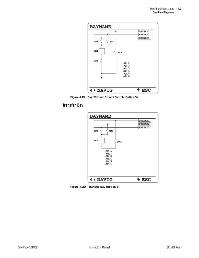
4.21
Date Code 20171021 Instruction Manual SEL-421 Relay
Front-Panel OperationsOne-Line Diagrams
Transfer Bay
Figure 4.19 Bay Without Ground Switch (Option 5)
BAYNAMEBUSNAM1
BUSNAM3
ESCNAVIG
BUSNAM2
AQ_1AQ_2AQ_3AQ_4AQ_5AQ_6
SW4
BK1
SW2
SW3
SW1
Figure 4.20 Transfer Bay (Option 6)
BAYNAMEBUSNAM1
BUSNAM3
AQ_1AQ_2AQ_3AQ_4AQ_5AQ_6
ESCNAVIG
BUSNAM2
BK1
SW2
SW3
SW1

4.22
SEL-421 Relay Instruction Manual Date Code 20171021
Front-Panel OperationsOne-Line Diagrams
Tie Breaker Bay
Main Bus and Transfer Bus
Figure 4.21 Tie Breaker Bay (Option 7)
BAYNAMEBUSNAM1
BUSNAM3
AQ_1AQ_2AQ_3AQ_4AQ_5AQ_6
ESCNAVIG
BUSNAM2
BK1
SW2SW1
Figure 4.22 Bay With Ground Switch (Option 8)
BAYNAMEBUSNAM1
AQ_1AQ_2AQ_3AQ_4AQ_5AQ_6
ESCNAVIG
BUSNAM2
SW3
SW4
BK1
SW2SW1

4.23
Date Code 20171021 Instruction Manual SEL-421 Relay
Front-Panel OperationsOne-Line Diagrams
Main Bus
Figure 4.23 Bay Without Ground Switch (Option 9)
BAYNAMEBUSNAM1
AQ_1AQ_2AQ_3AQ_4AQ_5AQ_6
ESCNAVIG
BUSNAM2
SW3
BK1
SW2SW1
Figure 4.24 Bay With Ground Switch (Option 10)
BAYNAME
AQ_1AQ_2AQ_3AQ_4AQ_5AQ_6
ESCNAVIG
SW3
SW4
BK1
SW2
BUSNAM1
SW1

4.24
SEL-421 Relay Instruction Manual Date Code 20171021
Front-Panel OperationsOne-Line Diagrams
Breaker-and-a-Half
Figure 4.25 Bay Without Ground Switch (Option 11)
BAYNAME
AQ_1AQ_2AQ_3AQ_4AQ_5AQ_6
ESCNAVIG
SW3
BK1
SW2
BUSNAM1
SW1
Figure 4.26 Left Breaker Bay With Ground Switch (Option 12)
BAYNAMEBUSNAM1
AQ_1AQ_2AQ_3AQ_4AQ_5AQ_6
ESCNAVIG
BUSNAM2
SW3
SW2
SW4
BK1 BK3
BK2
SW1

4.25
Date Code 20171021 Instruction Manual SEL-421 Relay
Front-Panel OperationsOne-Line Diagrams
Figure 4.27 Right Breaker Bay With Ground Switch (Option 13)
Figure 4.28 Middle Breaker Bay (Option 14)
BAYNAMEBUSNAM1
ESCNAVIG
BUSNAM2
SW3
SW2
SW4
BK3BK2
BK2
SW1
BAYNAMEBUSNAM1
ESCNAVIG
BUSNAM2
SW3
BAYLAB1 BAYLAB2
BK1
BK2 BK3
SW1 SW2

4.26
SEL-421 Relay Instruction Manual Date Code 20171021
Front-Panel OperationsOne-Line Diagrams
Figure 4.29 Left Breaker Bay Without Ground Switch (Option 15)
Figure 4.30 Right Breaker Bay Without Ground Switch (Option 16)
BAYNAMEBUSNAM1
AQ_1AQ_2AQ_3AQ_4AQ_5AQ_6
ESCNAVIG
BUSNAM2
SW3
SW2
BK1 BK3
BK2
SW1
BAYNAMEBUSNAM1
ESCNAVIG
BUSNAM2
SW3
SW2
BK1BK3
BK2
SW1
AQ_1AQ_2AQ_3AQ_4AQ_5AQ_6

4.27
Date Code 20171021 Instruction Manual SEL-421 Relay
Front-Panel OperationsOne-Line Diagrams
Ring Bus
Figure 4.31 Bay With Ground Switch (Option 17)
Figure 4.32 Bay Without Ground Switch (Option 18)
BAYNAMEBAYLAB1
BAYLAB2
AQ_1AQ_2AQ_3AQ_4AQ_5AQ_6
ESCNAVIG
SW2
BK1
BK2
SW1
SW3
BAYNAMEBAYLAB1
BAYLAB2
AQ_1AQ_2AQ_3AQ_4AQ_5AQ_6
ESCNAVIG
SW2
BK1
BK2
SW1

4.28
SEL-421 Relay Instruction Manual Date Code 20171021
Front-Panel OperationsOne-Line Diagrams
Double-Bus Double Breaker
Figure 4.33 Left Breaker Bay With Ground Switch (Option 19)
Figure 4.34 Left Breaker Bay Without Ground Switch (Option 20)
BAYNAMEBUSNAM1
AQ_1AQ_2AQ_3AQ_4AQ_5AQ_6
ESCNAVIG
BUSNAM2
SW3
SW2
BK1 BK2
SW1
SW4
BAYNAMEBUSNAM1
AQ_1AQ_2AQ_3AQ_4AQ_5AQ_6
ESCNAVIG
BUSNAM2
SW3
SW2
BK1 BK2
SW1

4.29
Date Code 20171021 Instruction Manual SEL-421 Relay
Front-Panel OperationsOne-Line Diagrams
Figure 4.35 Right Breaker Bay With Ground Switch (Option 21)
Figure 4.36 Right Breaker Bay Without Ground Switch (Option 22)
BAYNAMEBUSNAM1
ESCNAVIG
BUSNAM2
SW3
SW2
BK1BK2
SW1
AQ_1AQ_2AQ_3AQ_4AQ_5AQ_6SW4
BAYNAMEBUSNAM1
ESCNAVIG
BUSNAM2
SW3
SW2
BK1BK2
SW1
AQ_1AQ_2AQ_3AQ_4AQ_5AQ_6

4.30
SEL-421 Relay Instruction Manual Date Code 20171021
Front-Panel OperationsOne-Line Diagrams
Source Transfer Bus
Throw-Over Bus
Figure 4.37 Source Transfer (Option 23)
BAYNAME
ESCNAVIG
BUSNAM2
BAYLAB1
BUSNAM1
BK2BK1
AQ_1AQ_2AQ_3
AQ_4AQ_5AQ_6
Figure 4.38 Throw-Over Bus Type 1 Switch (Option 24)
BAYNAMEBUS1
ESCNAVIG
BUS2
SW2
AQ_2AQ_1
SW1
AQ_3AQ_4AQ_5AQ_6
BK1

4.31
Date Code 20171021 Instruction Manual SEL-421 Relay
Front-Panel OperationsOne-Line Diagrams
Panning
When you specify a custom layout that is too large for one screen, you can take advantage of the panning feature to display sections not visible in the present screen view. Figure 4.40 shows an example station with a breaker-and-a-half application.
Figure 4.39 Throw-Over Bus Type 2 Switch (Option 25)
BAYNAMEBUS1
ESCNAVIG
BUS2
SW5
SW3
SW1
SW4
BK2BK1
SW2
AQ_1AQ_2AQ_3AQ_4AQ_5AQ_6
Figure 4.40 Screen 1
BB1SW1
SW2
SW3 SW4
CT1
BKR1
Screen 1
Screen 2
Common
Area
BB2
SW5
SW6
SW7
SW8
CT2
CT3
CT4
BKR2
BKR3
CTT2CT
BKR
T2
R2
CTCT2T
B
T
BKR
2
RR22
BB2
SW6
SW7
SW8
CT3
CT4
BKR3

4.32
SEL-421 Relay Instruction Manual Date Code 20171021
Front-Panel OperationsOne-Line Diagrams
As Figure 4.40 and Figure 4.41 show, panning is discontinuous and necessitates your toggling between two front-panel screens.
➤ Screen 1 plus the common area (Figure 4.40)
➤ Screen 2 plus the common area (Figure 4.41)
When you specify a custom screen, be sure to separately specify these three areas.
Figure 4.41 Screen 2
BB1
BB2
SW1
SW2
SW3 SW4
SW5
SW6
SW7
SW8
CT1
CT2
CT3
CT4
BKR1
BKR2
BKR3
BB1SW1
SW2
SW3 SW4
SW5
CT1
BKR1
CC
BBKBK
CTCT2T2
K
2
KR2R22
CCT
B
T2
BK
2
KKR22
Screen 1
Screen 2
Common
Area

Date Code 20171021 8Instruction Manual SEL-421 Relay
8Instruction ManualInstruction ManualS E C T I O N 5
Protection Functions
NOTE: If the relay is using a remote data acquisition system, such as TiDL, the operating times will be delayed by 1.5 ms. Use caution when setting the relay coordination times to account for this added delay.
This section provides a detailed explanation for each of the many SEL-421 Relay protection functions. Each subsection provides an explanation of the function, along with a list of the corresponding settings and Relay Word bits. Logic dia-grams and other figures are included.
Functions discussed in this section are listed below.
➤ Current and Voltage Source Selection on page 5.2
➤ Polarizing Quantity for Distance Element Calculations on page 5.14
➤ Frequency Estimation on page 5.15
➤ Undervoltage Supervision Logic on page 5.17
➤ Over- and Underfrequency Elements on page 5.19
➤ Time-Error Calculation on page 5.21
➤ Fault Location on page 5.23
➤ Open-Phase Detection Logic on page 5.24
➤ Pole-Open Logic on page 5.25
➤ Loss-of-Potential Logic on page 5.28
➤ Fault Type Identification Selection Logic on page 5.33
➤ Ground Directional Element on page 5.33
➤ Phase and Negative-Sequence Directional Elements on page 5.45
➤ Directionality on page 5.46
➤ CVT Transient Detection on page 5.47
➤ Series-Compensation Line Logic on page 5.48
➤ Load-Encroachment Logic on page 5.49
➤ Out-of-Step Logic (Conventional) on page 5.50
➤ Out-of-Step Logic (Zero Settings) on page 5.56
➤ Mho Ground-Distance Elements on page 5.72
➤ Quadrilateral Ground-Distance Elements on page 5.76
➤ Mho Phase-Distance Elements on page 5.80
➤ Quadrilateral Phase-Distance Elements on page 5.85
➤ Zone Time Delay on page 5.91
➤ Instantaneous Line Overcurrent Elements on page 5.93
➤ Inverse-Time Overcurrent Elements on page 5.99
➤ Over- and Undervoltage Elements on page 5.113
➤ Switch-Onto-Fault Logic on page 5.117
➤ Communications-Assisted Tripping Logic on page 5.120
➤ Directional Comparison Blocking Scheme on page 5.121
➤ Permissive Overreaching Transfer Tripping Scheme on page 5.124
➤ Directional Comparison Unblocking Scheme Logic on page 5.133

5.2
SEL-421 Relay Instruction Manual Date Code 20171021
Protection FunctionsCurrent and Voltage Source Selection
➤ Trip Logic on page 5.137
➤ Circuit Breaker Failure Protection on page 5.146
➤ Synchronism Check on page 5.158
Current and Voltage Source SelectionThe SEL-421 has two sets of three-phase current inputs (IW and IX) and two sets of three-phase voltage inputs (VY and VZ), as shown in Figure 5.1. Currents IW and IX are also combined internally (COMB = IW + IX) on a per-phase basis and made available as the line-current option for protection, metering, etc. You can select the current and voltage sources for a wide variety of applications, using the global settings in Table 8.13 on page 8.5. The SEL-421 provides five default application settings (ESS := N, 1, 2, 3, or 4) that cover common applications (see Table 5.1). When you set ESS := Y, you can set the current and voltage sources for other applications (see Table 5.2 and Table 5.3). ESS settings examples are given later in this subsection.
Current Source SwitchingFigure 5.2 through Figure 5.4 show the basic application of some of these set-tings. Figure 5.2 shows an alternate breaker that can be substituted for the main breaker (bus switching details not shown). Normally, current IW (main breaker) is used as the line-current source. But, if the alternate breaker substitutes for the main breaker, then current IX is used as the line-current source, instead. SELOGIC setting ALTI controls the switching between currents IW and IX as the line-cur-rent source (assert setting ALTI to switch to designated alternate line current ALINEI := IX). Alternate line-current source settings ALINEI and ALTI are not used often and thus are usually set to NA. Setting ALTI is automatically hidden and set to NA if ALINEI := NA (no line-current switching can occur).
NOTE: If a current source is set to "combine" (e.g., LINEI := COMB), then the current transformer ratios for the respective IW and IX secondary circuits have to be the same (i.e. group settings CTRW = CTRX). Starting in firmware R318, the current transformer ratios can be different when the current source is set to "combine" (e.g. LINEI := COMB).
Figure 5.3 shows combined currents IW and IX (see COMB = IW + IX in Figure 5.1) set for line protection, metering, etc. (LINEI := COMB). To combine these currents correctly inside the relay to produce the effective line current, when the CT ratios are different, the relay divides IX by TAPX before adding IX to IW. The relay automatically calculates TAPX from the CTRW and CTRX set-ting values (TAPX = CTRW/CTRX).
Figure 5.1 Current and Voltage Source Connections for the SEL-421 Relay
SEL-421 rear panel
(partial)
COMB = IW + IX
(combined
current
source
for line)
Current
source
(for breaker
and/or
for line)
IAW IBW ICW
IW
IAX IBX ICX
IX
Current
source
(for breaker
and/or as
alternate
for line)
VAZ VBZ VCZ
VZ
Voltage source
(alternate)
VAY VBY VCY
VY
Voltage source

5.3
Date Code 20171021 Instruction Manual SEL-421 Relay
Protection FunctionsCurrent and Voltage Source Selection
Figure 5.4 shows the assignment of breaker currents for as many as two circuit breakers. These assigned breaker currents are used in breaker monitoring and breaker failure functions. These same breaker currents can also be assigned as line currents (e.g., line-current assignment LINE1 := IW in Figure 5.2).
All the available current and voltage source selection settings combinations are covered in Table 5.1, Table 5.2, and Table 5.3. Notice that global setting NUMBK (Number of Breakers in Scheme; see Table 8.3 on page 8.2) influences available settings combinations covered in Table 5.1, Table 5.2, and Table 5.3. In general, if NUMBK := 1, then no settings directly involving a second circuit breaker are made (i.e., Breaker 2 current source setting BK2I is automatically set to NA and hidden, as indicated with the shaded cells in the BK2I columns in Table 5.1 and Table 5.2). Also, for source-selection setting ESS := N, the settings are forced to certain values and hidden, as indicated with the shaded cells in the ESS := N rows in Table 5.1.
Figure 5.2 Main and Alternate Line-Current Source Assignments
Figure 5.3 Combined Currents for Line-Current Source Assignment
Figure 5.4 Breaker Current Source Assignments
IW IX
SEL-421Main
Breaker
Alternate
Breaker
LINEI := IW
ALINEI := IX
IW IX
SEL-421
LINEI := COMB
IW
SEL-421BK1I := IW
IX
SEL-421BK2I := IX

5.4
SEL-421 Relay Instruction Manual Date Code 20171021
Protection FunctionsCurrent and Voltage Source Selection
Table 5.1 Available Current Source Selection Settings Combinationsa
a NA = not applicable.Shaded cells indicate settings forced to given values and hidden.
NUMBK (number of breakers)
ESS (source selection)
LINEI(line-current source)
ALINEI(alternate line-current source)
BK1I(Breaker 1 current source)
BK2I(Breaker 2 current source)
IPOL(polarizing current)
1 Y see Table 5.2
1 N IW NA IW NA NA
1 1 IW IX IW NA NA
1 1 IW NA IW NA IAX, IBX, ICX, or NA
1 2 IW IX IX NA NA
1 2 IW NA IX NA NA
1 3 not allowed
1 4 not allowed
2 Y see Table 5.3
2 N IW NA IW NA NA
2 1 not allowed
2 2 not allowed
2 3 COMB NA IW IX NA
2 4 IW NA IX COMB NA
Table 5.2 Available Current Source Selection Settings Combinations When ESS := Y, NUMBK := 1a
a NA = not applicable.Shaded cells indicate settings forced to given values and hidden.
NUMBK(number of breakers)
ESS(source selection)
LINEI(line-current source)
ALINEI(alternate line-current source)
BK1I(Breaker 1 current source)
BK2I (Breaker 2 current source)
IPOL(polarizing current)
1 Y IW IX IW NA NA
1 Y IW IX IX NA NA
1 Y IW IX NA NA NA
1 Y IW NA IW NA IAX, IBX, ICX, or NA
1 Y IW NA IX NA NA
1 Y IW NA NA NA IAX, IBX, ICX, or NA
1 Y COMB IX IW NA NA
1 Y COMB IX IX NA NA
1 Y COMB IX NA NA NA
1 Y COMB NA IW NA NA
1 Y COMB NA IX NA NA
1 Y COMB NA NA NA NA

5.5
Date Code 20171021 Instruction Manual SEL-421 Relay
Protection FunctionsCurrent and Voltage Source Selection
Current Source UsesRefer to the global settings in Table 8.13 on page 8.5. Line-current source setting LINEI and alternate line-current source settings ALINEI and ALTI, if used, iden-tify the currents used in the following elements/features described later in this section and in other sections:
➤ Fault location
➤ Open-phase detection logic
➤ LOP (loss-of-potential) logic
➤ FIDS (fault-type identification selection) logic
➤ Directional elements
➤ CVT (capacitor voltage transformer) transient detection logic
Table 5.3 Available Current Source Selection Settings Combinations When ESS := Y, NUMBK := 2a
a NA = not applicable.
NUMBK(number of breakers)
ESS(source selection)
LINEI(line-current source)
ALINEI(alternate line-current source)
BK1I(Breaker 1 current source)
BK2I(Breaker 2 current source)
IPOL(polarizing current)
2 Y IW IX IW IX NA
2 Y IW IX IW COMB NA
2 Y IW IX IW NA NA
2 Y IW IX IX COMB NA
2 Y IW IX IX NA NA
2 Y IW IX NA IX NA
2 Y IW IX NA COMB NA
2 Y IW IX NA NA NA
2 Y IW NA IW IX NA
2 Y IW NA IW COMB NA
2 Y IW NA IW NA IAX, IBX, ICX, or NA
2 Y IW NA IX COMB NA
2 Y IW NA IX NA NA
2 Y IW NA NA IX NA
2 Y IW NA NA COMB NA
2 Y IW NA NA NA IAX, IBX, ICX, or NA
2 Y COMB IX IW IX NA
2 Y COMB IX IW NA NA
2 Y COMB IX IX NA NA
2 Y COMB IX NA IX NA
2 Y COMB IX NA NA NA
2 Y COMB NA IW IX NA
2 Y COMB NA IW NA NA
2 Y COMB NA IX NA NA
2 Y COMB NA NA IX NA
2 Y COMB NA NA NA NA

5.6
SEL-421 Relay Instruction Manual Date Code 20171021
Protection FunctionsCurrent and Voltage Source Selection
➤ Series-compensation line logic
➤ Load-encroachment logic
➤ OOS (out-of-step) logic
➤ Distance elements
➤ Instantaneous line overcurrent elements
➤ Inverse-time overcurrent elements
➤ DCUB (directional comparison unblocking) trip scheme logic
➤ Metering on page 7.1, except synchrophasors
Breaker current-source settings (BK1I and BK2I) identify the currents used in the following elements/features described in later in this section and in other sec-tions:
➤ Open-phase detection logic
➤ Inverse-time overcurrent elements
➤ Circuit breaker failure protection
➤ Circuit Breaker Monitor on page 7.7
➤ Metering on page 7.1
Polarizing current-source setting IPOL identifies the single current input con-nected to a zero-sequence current source (e.g., transformer bank neutral). This zero-sequence current is used as a reference in the zero-sequence current-polar-ized directional element. Such a directional element is applied to ground overcur-rent elements (see Table 5.31 and Table 5.27). Setting IPOL is not used often and thus is usually set to NA. Notice that in Table 5.1, Table 5.2 and Table 5.3 there are relatively few scenarios where setting IPOL can be set to a current channel selection (only those cases where three-phase current input IX is not used for any other function). An example of using setting IPOL is found later in this subsec-tion.
Voltage Source Switching and UsesRefer to the global settings in Table 8.13 on page 8.5. Alternate voltage source switching between VY and VZ in Table 5.1 is more straightforward (as shown in Table 5.4) than the preceding discussion on current-source selection/switching (compare to Table 5.1 through Table 5.3).
Table 5.4 Available Voltage Source Selection Setting Combinationsa
(Sheet 1 of 2)
NUMBK (number of breakers)
ESS(source selection)
Line Voltage SourceALINEV (alternate line voltage source)
1 Y VY VZ or NA
1 N VY NA
1 1 VY VZ or NA
1 2 VY VZ or NA
1 3 not allowed
1 4 not allowed
2 Y VY VZ or NA
2 N VY NA
2 1 not allowed
2 2 not allowed

5.7
Date Code 20171021 Instruction Manual SEL-421 Relay
Protection FunctionsCurrent and Voltage Source Selection
SELOGIC setting ALTV controls the switching between voltages VY and VZ for line voltage (assert setting ALTV to switch to designated alternate line voltage ALINEV := VZ). Setting ALTV is automatically hidden and set to NA if ALINEV := NA (no voltage switching can occur). Reasons for switching from one three-phase voltage to another may be for loss-of-potential or bus switching/rearrangement.
Default line voltage source VY and alternate line voltage source settings (ALINEV and ALTV) identify the voltages used in the following elements/fea-tures described later in this section and in other sections:
➤ Fault location
➤ Open-phase detection logic
➤ LOP (loss-of-potential) logic
➤ FIDS (fault-type identification selection) logic
➤ Directional elements
➤ CVT (capacitor voltage transformer) transient detection logic
➤ Series-compensation line logic
➤ Load-encroachment logic
➤ OOS (out-of-step) logic
➤ Distance elements
➤ SOTF (switch-onto-fault) logic
➤ POTT (permissive overreaching transfer tripping) scheme logic
➤ Metering on page 7.1, including synchrophasors
Default ApplicationsUse setting ESS (Current and Voltage Source Selection) to easily configure the relay for your particular application. Five application settings (ESS := N, 1, 2, 3, or 4) cover both single circuit breaker and two circuit breaker configurations. If you select one of these five setting choices, the relay automatically determines the following settings:
NOTE: Setting BK2I is hidden if setting NUMBK, Number of Breakers in the Scheme, is set to 1.
➤ LINEI—Line Current Source (IW, COMB)
➤ BK1I—Breaker 1 Current Source (IW, IX, NA)
➤ BK2I—Breaker 2 Current Source (IX, COMB, NA)
2 3 VY VZ or NA
2 4 VY VZ or NA
a NA = not applicable.Shaded cells indicate settings forced to given values and hidden.
Table 5.4 Available Voltage Source Selection Setting Combinationsa
(Sheet 2 of 2)
NUMBK (number of breakers)
ESS(source selection)
Line Voltage SourceALINEV (alternate line voltage source)
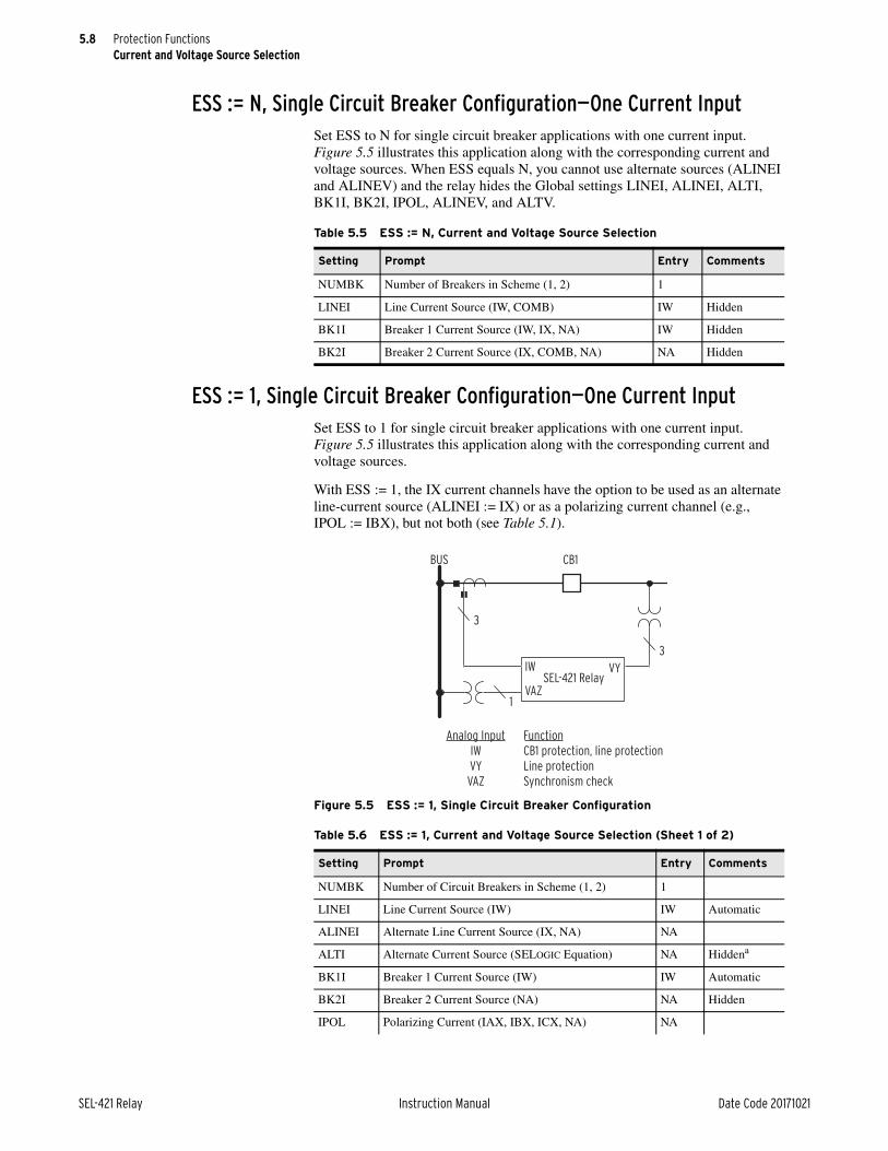
5.8
SEL-421 Relay Instruction Manual Date Code 20171021
Protection FunctionsCurrent and Voltage Source Selection
ESS := N, Single Circuit Breaker Configuration—One Current InputSet ESS to N for single circuit breaker applications with one current input. Figure 5.5 illustrates this application along with the corresponding current and voltage sources. When ESS equals N, you cannot use alternate sources (ALINEI and ALINEV) and the relay hides the Global settings LINEI, ALINEI, ALTI, BK1I, BK2I, IPOL, ALINEV, and ALTV.
ESS := 1, Single Circuit Breaker Configuration—One Current InputSet ESS to 1 for single circuit breaker applications with one current input. Figure 5.5 illustrates this application along with the corresponding current and voltage sources.
With ESS := 1, the IX current channels have the option to be used as an alternate line-current source (ALINEI := IX) or as a polarizing current channel (e.g., IPOL := IBX), but not both (see Table 5.1).
Table 5.5 ESS := N, Current and Voltage Source Selection
Setting Prompt Entry Comments
NUMBK Number of Breakers in Scheme (1, 2) 1
LINEI Line Current Source (IW, COMB) IW Hidden
BK1I Breaker 1 Current Source (IW, IX, NA) IW Hidden
BK2I Breaker 2 Current Source (IX, COMB, NA) NA Hidden
Figure 5.5 ESS := 1, Single Circuit Breaker Configuration
Table 5.6 ESS := 1, Current and Voltage Source Selection (Sheet 1 of 2)
Setting Prompt Entry Comments
NUMBK Number of Circuit Breakers in Scheme (1, 2) 1
LINEI Line Current Source (IW) IW Automatic
ALINEI Alternate Line Current Source (IX, NA) NA
ALTI Alternate Current Source (SELOGIC Equation) NA Hiddena
BK1I Breaker 1 Current Source (IW) IW Automatic
BK2I Breaker 2 Current Source (NA) NA Hidden
IPOL Polarizing Current (IAX, IBX, ICX, NA) NA
SEL-421 Relay
BUS CB1
3
3
IW
VAZ
VY
1
Analog Input
IW
VY
VAZ
Function
CB1 protection, line protection
Line protection
Synchronism check

5.9
Date Code 20171021 Instruction Manual SEL-421 Relay
Protection FunctionsCurrent and Voltage Source Selection
ESS := 2, Single Circuit Breaker Configuration—Two Current InputsSet ESS to 2 for single circuit breaker applications using two current sources. Figure 5.6 illustrates this application along with the corresponding current and voltage sources. The relay uses current source IW for line relaying and current source IX for Circuit Breaker 1 failure protection.
ESS := 3, Double Circuit Breaker Configuration—Independent Current InputsSet ESS to 3 for circuit breaker-and-a-half applications using independent current sources. Figure 5.7 illustrates this application along with the corresponding cur-rent and voltage sources. This selection provides independent circuit breaker fail-ure protection for Circuit Breaker 1 and Circuit Breaker 2.
ALINEV Alternate Line Voltage Source (VZ, NA) NA
ALTV Alternate Voltage Source (SELOGIC Equation) NA Hidden
a Hidden when preceding setting is NA.
Table 5.6 ESS := 1, Current and Voltage Source Selection (Sheet 2 of 2)
Setting Prompt Entry Comments
Figure 5.6 ESS := 2, Single Circuit Breaker Configuration
Table 5.7 ESS := 2, Current and Voltage Source Selection
Setting Prompt Entry Comments
NUMBK Number of Circuit Breakers in Scheme (1, 2) 1
LINEI Line Current Source (IW) IW Automatic
ALINEI Alternate Line Current Source (IX, NA) NA
ALTI Alternate Current Source (SELOGIC Equation) NA Hiddena
a Hidden when preceding setting is NA.
BK1I Breaker 1 Current Source (IX) IX Automatic
BK2I Breaker 2 Current Source (NA) NA Hidden
IPOL Polarizing Current (NA) NA Automatic
ALINEV Alternate Line Voltage Source (VZ, NA) NA
ALTV Alternate Voltage Source (SELOGIC Equation) NA Hidden
SEL-421 Relay
BUS CB1
3
1
3
IWIX
VAZ
VY
3
Analog Input
IW
IX
VY
VAZ
Function
CB1 protection, line protection
CB1 breaker failure
Line protection
Synchronism check

5.10
SEL-421 Relay Instruction Manual Date Code 20171021
Protection FunctionsCurrent and Voltage Source Selection
ESS := 4, Double Circuit Breaker Configuration—Common Current InputsSet ESS to 4 for circuit breaker-and-a-half applications using combined current input IW. Figure 5.8 illustrates this application along with the corresponding cur-rent and voltage sources. Current input IX provides circuit breaker failure protec-tion for Circuit Breaker 1; the corresponding CTs are located on the line-side of Circuit Breaker 1. The relay calculates the current flowing through Circuit Breaker 2 (ICB2 = IW + IX= ICB1 + ICB2 + IX = ICB1 + ICB2 - ICB1) to provide independent circuit breaker failure for Circuit Breaker 2.
Figure 5.7 ESS := 3, Double Circuit Breaker Configuration
Table 5.8 ESS := 3, Current and Voltage Source Selection
Setting Prompt Entry Comments
NUMBK Number of Circuit Breakers in Scheme (1, 2) 2
LINEI Line Current Source (COMB) COMB Automatic
ALINEI Alternate Line Current Source (NA) NA Automatic
ALTI Alternate Current Source (SELOGIC Equation) NA Hidden
BK1I Breaker 1 Current Source (IW) IW Automatic
BK2I Breaker 2 Current Source (IX) IX Automatic
IPOL Polarizing Current (NA) NA Automatic
ALINEV Alternate Line Voltage Source (VZ, NA) NA
ALTV Alternate Voltage Source (SELOGIC Equation) NA Hidden
Analog Input
IW+IX
IW
IX
VY
VAZ
VBZ
Function
Line protection
CB1 protection
CB2 protection
Line protection
Synchronism check Circuit Breaker 1
Synchronism check Circuit Breaker 2
3
3
1 1
Busbar 1 Busbar 2
1
SEL-421
Breaker 1 Breaker 2IW IX
VY
VAZ
VBZ
Line 1 Line 2

5.11
Date Code 20171021 Instruction Manual SEL-421 Relay
Protection FunctionsCurrent and Voltage Source Selection
ESS := Y, Other ApplicationsSet ESS to Y for applications that are not covered under the five default applica-tions.
Tapped LineFigure 5.9 illustrates a tapped EHV transmission overhead line. A power trans-former is located at Substation T along the tapped line. An SEL-421 is located at all three EHV terminals (Substations S, R, and T). The SEL-421 Relays operate in a DCB (directional comparison blocking) trip scheme to provide high-speed clearance for all faults internal to the tapped EHV transmission line. For a com-plete explanation of this example, see 230 kV Tapped Transmission Line Applica-tion Example on page 6.170.
Set NUMBK (Number of Breakers in Scheme) to 2 so you can program the auto-reclosing function and synchronism-check elements to control both of the low-side circuit breakers.
Figure 5.8 ESS := 4, Double Circuit Breaker Configuration
Table 5.9 ESS := 4, Current and Voltage Source Selection
Setting Prompt Entry Comments
NUMBK Number of Circuit Breakers in Scheme (1, 2) 2
LINEI Line Current Source (IW) IW Automatic
ALINEI Alternate Current Source (NA) NA Automatic
ALTI Alternate Current Source (SELOGIC Equation) NA Hidden
BK1I Breaker 1 Current Source (IX) IX Automatic
BK2I Breaker 2 Current Source (COMB) COMB Automatic
IPOL Polarizing Current (NA) NA Automatic
ALINEV Alternate Line Voltage Source (VZ, NA) NA
ALTV Alternate Voltage Source (SELOGIC Equation) NA Hidden
SEL-421 Relay
BUS 1 BUS 2CB1 CB2
33 3
3IW IX VAZ
VY
VBZ
1 1
Analog Input
IW+IX
IW
IX
VY
VAZ
VBZ
Function
CB2 protection
Line protection
CB1 protection
Line protection
Synchronism check Circuit Breaker 1
Synchronism check Circuit Breaker 2
ICB1 ICB2
ILINE

5.12
SEL-421 Relay Instruction Manual Date Code 20171021
Protection FunctionsCurrent and Voltage Source Selection
Figure 5.10 illustrates the tapped overhead transmission line with a motor-operated disconnect (MOD) on the high side of a power transformer and two cir-cuit breakers on the low side.
Figure 5.9 Tapped EHV Overhead Transmission Line
Figure 5.10 ESS := Y, Tapped Line
SEL-421
SEL-421
BK1S BK1R
BK2S
CB1 CB2
BK2R
SEL-421
S R
MOD
(HV)
(LV)
T
(HV)
(LV)
MOD
SEL-421 RelayIW
VY
1
1
3
3
VAZ VBZ
CB2CB1
Analog Input
IW
VY
VAZ
VBZ
Function
Line protection
Line protection
Synchronism check Circuit Breaker 1
Synchronism check Circuit Breaker 2
Tripping
Direction

5.13
Date Code 20171021 Instruction Manual SEL-421 Relay
Protection FunctionsCurrent and Voltage Source Selection
Single Circuit Breaker With Current Polarizing SourceFigure 5.11 shows a single circuit breaker situated by an autotransformer. The SEL-421 uses the delta-connected tertiary as a current polarizing source for the zero-sequence current-polarized directional element 32I. For example, connect to current to input IAX (set IPOL := IAX).
Table 5.10 ESS := Y, Tapped Line
Setting Prompt Entry Comments
NUMBK Number of Circuit Breakers in Scheme (1, 2) 2
LINEI Line Current Source (IW, COMB) IW
ALINEI Alternate Current Source (IX, NA) NA
ALTI Alternate Current Source (SELOGIC Equation) NA Hiddena
a Hidden when preceding setting is NA.
BK1I Breaker 1 Current Source (IW, IX, NA) NA
BK2I Breaker 2 Current Source (IX, COMB, NA) NA
IPOL Polarizing Current (IAX, IBX, ICX, NA) NA
ALINEV Alternate Line Voltage Source (VZ, NA) NA Default
ALTV Alternate Voltage Source (SELOGIC Equation) NA Hidden
Figure 5.11 ESS := Y, Single Circuit Breaker With Current Polarizing Source Tapped Power Transformer
Table 5.11 ESS := Y, Current Polarizing Source (Sheet 1 of 2)
Setting Prompt Entry Comments
NUMBK Number of Circuit Breakers in Scheme (1, 2) 1
LINEI Line Current Source (IW, COMB) IW
ALINEI Alternate Current Source (IX, NA) NA
SEL-421 Relay
BUS CB
IW
VAZ IAX
(Delta-Connected Tertiary)
VY3
1
Analog Input
IW
IAX
VY
VAZ
Function
Line protection
Ground directional element current polarization
Line protection
Synchronism check

5.14
SEL-421 Relay Instruction Manual Date Code 20171021
Protection FunctionsPolarizing Quantity for Distance Element Calculations
Using ALTI and ALTVSELOGIC control equations ALTI and ALTV give great flexibility in choosing alternate CT and PT inputs to the SEL-421. The relay switches to the alternate source when these SELOGIC control equations become true. The relay delays a subsequent ALTI or ALTV switch for eight cycles after the initial switch to give time for the system to settle. The status of ALTI and ALTV will be displayed in the SER report. This confirms if the relay has switched the source it was using.
Test the SELOGIC control equation programming that you use to switch ALTI and ALTV alternate sources. It is possible to create a toggling condition where the relay repeatedly switches between sources. Examine each line of SELOGIC con-trol equation programming to verify that this toggling condition does not occur in your protection/control scheme.
One method for exercising caution when implementing alternate current source and alternate voltage source switching is to use SELOGIC control equation protec-tion latches (PLT01–PLT32) to switch alternate sources. For example, to switch to an alternate voltage, set ALINEV to VZ (enables setting ALTV) and then set ALTV to PLT31. To perform the switch use the protection latch control inputs PLT31S and PLT31R (Set and Reset, respectively).
Polarizing Quantity for Distance Element CalculationsThe relay uses positive-sequence memory voltage as the polarizing quantity for distance element calculations. Memory polarization ensures proper operation during zero-voltage three-phase faults and provides expansion of the mho charac-teristic back to the source impedance, improving fault-resistance coverage. How-ever, longer memory may impair distance element security when a power system disturbance causes a fast frequency excursion.
The polarization memory is adaptive. The relay normally uses positive-sequence voltage with short or medium length memory. This short or medium length mem-ory works satisfactorily for all faults other than zero-voltage three-phase faults. When the relay measures positive-sequence voltage magnitude lower than a threshold, it automatically switches to a long memory polarizing quantity.
The VMEMC setting allows you to choose between short or medium length memory voltage for the normal polarizing quantity. To closely follow the power system frequency, set VMEMC = 0. When VMEMC is deasserted (logical 0), the relay normally uses a short memory time constant that closely follows the posi-tive-sequence voltage, yet automatically switches to the long memory when nec-
ALTI Alternate Current Source (SELOGIC Equation) NA Hidden
BK1I Breaker 1 Current Source (IW, IX, NA) IW
BK2I Breaker 2 Current Source (NA) NA Hidden
IPOL Polarizing Current (IAX, IBX, ICX, NA) IAX
ALINEV Alternate Line Voltage Source (VZ, NA) NA Default
ALTV Alternate Voltage Source (SELOGIC Equation) NA Hidden
Table 5.11 ESS := Y, Current Polarizing Source (Sheet 2 of 2)
Setting Prompt Entry Comments

5.15
Date Code 20171021 Instruction Manual SEL-421 Relay
Protection FunctionsFrequency Estimation
essary. This setting provides less expansion of the distance element characteristics, while still providing security for zero-voltage three-phase faults. SEL recommends that you use this setting.
If your application requires more expansion of the distance element characteris-tics, set VMEMC = 1. When VMEMC is asserted, the relay normally uses medium length memory and automatically switches to the long memory when necessary. This setting provides the same element operation as provided in firm-ware R312 and earlier, including greater expansion of the distance element char-acteristics and the same security for zero-voltage three-phase faults.
The short memory is not available for series-compensated lines (ESERCMP = Y). When ESERCMP = Y, the relay uses the medium length mem-ory and automatically switches to the long memory polarizing quantity when the relay detects voltage inversion or positive-sequence voltage magnitude lower than a threshold.
Frequency EstimationThe relay uses filtered analog values related to the system frequency to calculate internal quantities such as phasor magnitudes and phase angles. When the system frequency changes, the relay measures these frequency changes and adapts the processing rate of the protection functions accordingly. Adapting the processing rate is called frequency tracking.
Note that frequency measurement is not the same as frequency tracking. The relay first measures the frequency and then tracks the frequency by changing the processing rate.
The relay measures the frequency over the 20–80 Hz range (protection frequency, see FREQP in Table 5.16), but only tracks the frequency over the 40–65 Hz range (see FREQ in Table 5.16). If the system frequency is outside the 40–65 Hz range, the relay does not track the frequency. Instead, it clamps the frequency to either limit. For frequencies below 40 Hz, the relay clamps the frequency at 40 Hz. For frequencies above 65 Hz, the relay clamps the frequency at 65 Hz.
To measure the frequency, the relay calculates the alpha component quantity and then estimates the frequency based on the zero-crossings of the alpha component. Relay Word bit FREQOK asserts when the relay measures the frequency over the range 20–80 Hz. If the frequency is below 40 Hz or above 65 Hz, FREQ reports the clamped values of either 40 Hz or 65 Hz. In this case, the relay no longer tracks the frequency. Instead, it uses either 40 Hz or 65 Hz to calculate the inter-nal quantities.
Table 5.12 VMEMC Relay Setting
Setting Prompt Range Default
VMEMCa
a If the Advanced Settings are not enabled (setting EADVS :=N), the relay hides the setting. If the Series Compensation Line Logic Setting is enabled (setting ESERCMP := Y), the relay hides the setting.
Memory Voltage Control (SELOGIC Equation) SV 0b
b Setting VMEMC is forced to 1 if the Series Compensation Line Logic Setting is enabled (setting ESERCMP := Y).

5.16
SEL-421 Relay Instruction Manual Date Code 20171021
Protection FunctionsFrequency Estimation
If the frequency is in the 20–80 Hz range, but outside the 40–65 Hz range (for example, 70 Hz), FREQP shows the frequency the relay measures and FREQ shows the clamped frequency. In this case, FREQP = 70 Hz and FREQ = 65 Hz. Table 5.13 summarizes the frequency measurement and frequency tracking ranges.
If the frequency is below 20 Hz or above 80 Hz, the relay no longer measures the frequency. Relay Word bit FREQFZ asserts and Relay Word bit FREQOK deas-serts to indicate this condition. FREQ and FREQP are no longer valid, but they display the frequency at the time that the relay stopped measuring the frequency.
NOTE: The relay measures/tracks the frequency to a rate of 15 Hz/s.
The relay has six voltage inputs (VAY, VBY, VCY, VAZ, VBZ, and VCZ) that can be used as sources for estimating the frequency. Assign any of the six voltage inputs to VF01, VF02, and VF03. Note that assigning ZERO will set that input to zero. The relay also provides an alternate frequency source selection where you can assign any of the six voltage inputs to VF11, VF12, and VF13. The relay uses VF01, VF02, and VF03 as sources if the SELOGIC evaluation of EAFSRC is 0. The relay uses VF11, VF12, and VF13 as sources if EAFSRC is 1. The relay calculates the alpha quantity, Valpha, as shown in Figure 5.12 using the mapped sources. Note that the alpha quantity is based on the instantaneous secondary voltage samples from the mapped resources and is an instantaneous quantity.
NOTE: These settings are available only if you have enabled Global advanced settings, EGADVS := Y.
Although you have the flexibility to select any of the available voltages for the frequency estimation, the correlation between the selected voltages and the breaker poles is fixed as shown in Table 5.15.
Table 5.13 Frequency Measurement and Frequency Tracking Ranges
Frequency Range (Hz)Measures Frequency
Tracks Frequency
FREQOK FREQFZ
40–65 Y Y 1 0
20–39.99 Y N 1 0
65.01–80 Y N 1 0
Below 20 or above 80 N N 0 1
Figure 5.12 SEL-421 Alpha Quantity Calculation
FREQPVF01
VF02
VF03 1
VF11
VF12
VF13
0
EAFSRC
(SELOGIC)
VFn1 – 0.5 (VFn2 + VFn3)Valpha
Frequency
Estimation
FREQ
DFDTP
FREQOK
FREQFZn = 0 or 1
Table 5.14 Frequency Estimation (Sheet 1 of 2)
Label PromptDefault Value
EAFSRC Alt. Freq. Source (SELOGIC Equation) NA
VF01 Local Freq. Source 1 (ZERO, VAY, VBY, VCY, VAZ, VBZ, VCZ) VAY
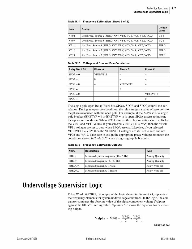
5.17
Date Code 20171021 Instruction Manual SEL-421 Relay
Protection FunctionsUndervoltage Supervision Logic
The single pole-open Relay Word bits SPOA, SPOB and SPOC control the cor-relation. During an open-pole condition, the relay assigns a value of zero volts to the phase associated with the open pole. For example, if the A-Phase of a single pole breaker (BK1TYP = 1 or BK2TYP = 1) is open, SPOA asserts to indicate the open-pole condition. When SPOA asserts, the relay substitutes zero volts for the VF01 and VF11 values. If you selected VF01/VF11 = VAY, then the VF01/VF11 voltages are set to zero when SPOA asserts. Likewise, if you selected VF01/VF11 = VBY, then the VF01/VF11 voltages are still set to zero and not VF02 and VF12. Take care to assign the appropriate phase voltages to match the correlation shown in Table 5.15 when using single-pole breakers.
Undervoltage Supervision LogicRelay Word bit 27B81, the output of the logic shown in Figure 5.13, supervises the frequency elements for system undervoltage conditions. In the logic, the com-parator compares the absolute value of the alpha component voltage (Valpha) against the 81UVSP setting value. Equation 5.1 shows the equation for calculat-ing Valpha.
Equation 5.1
VF02 Local Freq. Source 2 (ZERO, VAY, VBY, VCY, VAZ, VBZ, VCZ) VBY
VF03 Local Freq. Source 3 (ZERO, VAY, VBY, VCY, VAZ, VBZ, VCZ) VCY
VF11 Alt. Freq. Source 1 (ZERO, VAY, VBY, VCY, VAZ, VBZ, VCZ) ZERO
VF12 Alt. Freq. Source 2 (ZERO, VAY, VBY, VCY, VAZ, VBZ, VCZ) ZERO
VF13 Alt. Freq. Source 3 (ZERO, VAY, VBY, VCY, VAZ, VBZ, VCZ) ZERO
Table 5.15 Voltage and Breaker Pole Correlation
Relay Word Bit Phase A Phase B Phase C
SPOA = 0 VF01/VF11 – –
SPOA = 1 0 – –
SPOB = 0 – VF02/VF12 –
SPOB = 1 – 0 –
SPOC = 0 – – VF03/VF13
SPOC = 1 – – 0
Table 5.16 Frequency Estimation Outputs
Name Description Type
FREQ Measured system frequency (40–65 Hz) Analog Quantity
FREQP Measured frequency (20–80 Hz) Analog Quantity
FREQOK Measured frequency is valid Relay Word bit
FREQFZ Measured frequency is frozen Relay Word bit
Table 5.14 Frequency Estimation (Sheet 2 of 2)
Label PromptDefault Value
Valpha VF01 VF022--------------
VF032--------------+–=

5.18
SEL-421 Relay Instruction Manual Date Code 20171021
Protection FunctionsUndervoltage Supervision Logic
Generally, settings VF01, VF02, VF03 correlate to VA, VB, and VC. Equation 5.2 shows the relationship between the peak amplitude of Valpha and the root-mean-square (RMS) value of the system voltage phasors for three-phase voltage inputs.
NOTE: The relay uses the alpha component voltage to track the system frequency. To ensure the relay uses the same voltage for frequency tracking and frequency elements undervoltage supervision, the operating quantity in Figure 5.13 was changed from the positive-sequence voltage to the alpha component voltage. This change affects firmware versions R310 and higher and may require a revision of the 81UVSP setting.
Equation 5.2
where VRMS is the root-mean-square value of the voltage phasor.
Relay Word bit 27B81 asserts if Valpha falls below the 81UVSP setting value for longer than a cycle.
Calculate the 81UVSP Setting ValueBecause the relay accepts voltage input from the potential transformers (PTs) in any combination, Valpha can have different values, depending on the voltage inputs. In general, the following examples use the average (60 percent) of the 50 to 70 percent undervoltage range that IEEE C37.117 Guide recommends. Also, the calculations are based on an RMS phase-to-neutral value of 67 V for the PT inputs, although the 81UVSP setting is a peak value and not an RMS value.
Case 1: Three-Phase PT InputsIn this case, VF01 = VA, VF02 = VB, and VF03 = VC (with default settings). Use Equation 5.2 to calculate the nominal value of Valpha as follows:
Equation 5.3
Equation 5.4
Set 81UVSP to 60 percent of this value:
Equation 5.5
Equation 5.6
Figure 5.13 Undervoltage Supervision Logic
Valpha 2 1.5 VRMS• • =
1.0 cyc
0.0|Valpha|
81UVSP27B81
Valpha 1.5 2 67 V• • =
Valpha 142.13 V=
81UVSP 0.6 142.13 V• =
81UVSP 85.28 V=

5.19
Date Code 20171021 Instruction Manual SEL-421 Relay
Protection FunctionsOver- and Underfrequency Elements
Case 2: Single-Phase PT Input, Connected to the A-Phase InputIn this case, VF01 = VA, VF02 = ZERO, and VF03 = ZERO.
Equation 5.7
Equation 5.8
Set 81UVSP to 60 percent of this value:
Equation 5.9
Equation 5.10
Case 3: Single-Phase PT Input, Connected to the B- or C-Phase InputIn this case, VF01 = ZERO, VF02 = VB, and VF03 = ZERO.
Equation 5.11
Equation 5.12
Set 81UVSP to 60 percent of this value:
Equation 5.13
Equation 5.14
Table 5.17 summarizes the results of the three cases.
Over- and Underfrequency ElementsUse the relay frequency elements for such abnormal frequency protection as underfrequency load shedding.
Figure 5.15 shows the logic for the six levels of over- and underfrequency ele-ments in the relay.
Valpha 2 67 V• =
Valpha 94.75 V=
81UVSP 0.6 94.75• V=
81UVSP 56.85 V=
Table 5.17 Table Y12. Summary of the Valpha and 81UVSP Calculations
Case PT Connections VA VB VC Valpha 0.6 • Valpha
Case 1 Three-phase 67 0° 67 –120° 67 120° 142.13 85.28
Case 2 Single-phase, VA 67 0° 0 0 94.75 56.85
Case 3 Single-phase, VB/VC 0 67 –120° 0 47.38 28.43
Valpha 2 672------V• =
Valpha 47.37 V=
81UVSP 0.6 47.37 V• =
81UVSP 28.43 V=

5.20
SEL-421 Relay Instruction Manual Date Code 20171021
Protection FunctionsOver- and Underfrequency Elements
Each frequency element can operate as an overfrequency or as an underfrequency element, depending on its pickup setting. If the element pickup setting (81DnP, n = 1–6) is less than the nominal system frequency setting, NFREQ, the element operates as an underfrequency element, picking up if measured frequency is less than the set point. If the pickup setting is greater than NFREQ, the element oper-ates as an overfrequency element, picking up if measured frequency is greater than the set point.
Note that Relay Word bit 27B81 controls all six frequency elements. This under-voltage supervision control prevents erroneous frequency element operations during system faults.
Over- and Underfrequency Element Settings E81 (Enable 81 Elements)
Set E81 to enable as many as six over- and underfrequency elements. When E81 = N, the relay disables the frequency elements and hides corresponding set-tings; you do not need to enter these hidden settings.
81UVSP (81 Element Undervoltage Supervision)NOTE: See Undervoltage Supervision Logic on page 5.17 for a discussion on the 81UVSP setting.
This setting applies to all six frequency elements. If the instantaneous alpha volt-age falls below the 81UVSP setting, all frequency elements are disabled.
Figure 5.14 Frequency Element Logic
+FREQP
81DnP
+
81DnP NFREQ
81DnP NFREQ
81Dn
81DnT
81DnOVR
81DnUDR
Frequency Timer n
FREQOK
81DnD
0
0
1 cycFREQFZ
27B81
Setting Prompt Range Default Category
E81 Enable Frequency Elements N, 1–6 N Group
Setting Prompt Range Default Category
81UVSP 81 Element Under Voltage Super 20.00–200 V, sec 85 Group

5.21
Date Code 20171021 Instruction Manual SEL-421 Relay
Protection FunctionsTime-Error Calculation
81DnP (Level n Pickup)Set the value at which you want the frequency element for each of six levels to assert. For a value of 81DnP less than the nominal system frequency NFREQ (50 or 60 Hz), the element operates as an underfrequency element. For a value greater than NFREQ, the element operates as an overfrequency element. Note that n can be one of six levels, 1–6.
81DnD (Level n Time Delay)Select a time in seconds that you want frequency elements to wait before asserting.
Time-Error CalculationDescription and Settings
The time-error calculation function in the SEL-421 measures the amount of time that an ac clock running from the same line frequency measured by the relay would differ from a reference clock. The relay integrates the difference between the measured power system frequency and the nominal frequency (Global setting NFREQ) to create a time-error analog quantity, TE.
NOTE: The LOADTE SELOGIC equation is processed once per cycle. A momentary assertion must be conditioned to be at least one cycle in duration. A rising edge operator (R_TRIG) should not be used in the LOADTE setting.
A correction feature allows the present time-error estimate (TE) to be discarded, and a new value (TECORR) loaded when SELOGIC control equation LOADTE asserts. For example, if the TECORR value is set to zero, and then LOADTE is momentarily asserted, the TE analog quantity will be set to 0.000 seconds.
The TECORR analog quantity can be pre-loaded by the TEC command (see TEC on page 14.54 in the SEL-400 Series Relays Instruction Manual), or via DNP3, object 40, 41 index 01 (see Table 16.8 on page 16.12 in the SEL-400 Series Relays Instruction Manual). In either case, Relay Word bit PLDTE asserts for approximately 1.5 cycles to indicate that the preload was successful.
A separate SELOGIC control equation, STALLTE, when asserted, causes time-error calculation to be suspended.
Table 5.18 lists the inputs and outputs of the time-error function.
Setting Prompt Range Default Category
81DnPa
a n = 1–6.
Level n Pickup 40.01–69.99 Hz 61.00 Group
Setting Prompt Range Default Category
81DnDa
a n = 1–6.
Level n Delay 0.04–400.00 sec 2 Group
Table 5.18 Time-Error Calculation Inputs and Outputs (Sheet 1 of 2)
INPUTS Description
Analog Quantities
FREQ Measured system frequency (see Table 5.16).
TECORR Time-error correction factor. This value can be preloaded via the TEC com-mand, or DNP3.

5.22
SEL-421 Relay Instruction Manual Date Code 20171021
Protection FunctionsTime-Error Calculation
Time-Error Command (TEC)The TEC serial port command provides easy access to the time-error function. See TEC on page 14.54 in the SEL-400 Series Relays Instruction Manual for command access-level information.
Enter the TEC command to view the time-error status. A sample display is given in Figure 5.15.
Enter the TEC command with a single numeric argument n (–30.000 n 30.000) to preload the TECORR value. This operation does not affect the TE analog quantity until the SELOGIC control equation LOADTE next asserts. Figure 5.16 shows an example of the TEC n command in use.
Global Settings
NFREQ Nominal frequency (see Table 8.3 on page 8.2)
LOADTE Load time-error correction factor (SELOGIC control equation). A rising edge will cause the relay to load the TECORR analog quantity into TE. LOADTE has priority over STALLTE.
STALLTE Stall time-error calculation (SELOGIC control equation). A logical 1 will stall (freeze) the time-error function. The TE value will not change when STALLTE is asserted (unless LOADTE asserts).
Relay Word bit
FREQOK Frequency measurement valid. If this Relay Word bit deasserts, the TE quan-tity is frozen (see Table 5.16).
OUTPUTS Description
Analog Quantity
TE Time-error estimate, in seconds. Positive numbers indicate that the ac clock would be fast (ahead of the reference clock). Negative numbers indicate that the ac clock would be slow (behind the reference clock).
Relay Word bit
PLDTE Preload Time-Error value updated. This element asserts for approximately 1.5 cycles after TECORR is changed by the TEC command or by DNP3.
Table 5.18 Time-Error Calculation Inputs and Outputs (Sheet 2 of 2)
INPUTS Description
=>TEC <Enter>
Relay 1 Date: 11/02/2004 Time: 11:25:50.460Station A Serial Number: 0000000000
Time Error Correction Preload ValueTECORR = 0.000 s
Relay Word ElementsLOADTE = 0, STALLTE = 0, FREQOK = 1
Accumulated Time ErrorTE = -7.838 s
=>
Figure 5.15 Sample TEC Command Response
==>TEC 2.25 <Enter>
Relay 1 Date: 11/02/2004 Time: 11:53:12.701Station A Serial Number: 0000000000
Change TECORR to 2.250 s:
Are you sure (Y/N)?Y <Enter>
Figure 5.16 Sample TEC n Command Response

5.23
Date Code 20171021 Instruction Manual SEL-421 Relay
Protection FunctionsFault Location
Fault LocationThe SEL-421 computes distance to fault from data stored in the event reports. The relay calculates distance to fault upon satisfaction of all four of the following conditions:
➤ The fault locator is enabled, setting EFLOC := Y.
➤ A single-pole open condition does not exist (i.e., Relay Word bit SPOA, SPOB, and SPOC equal logical 0).
➤ A phase-distance, ground-distance, residual-ground overcurrent, negative-sequence, or time-overcurrent element picks up no later than 15 cycles after the event report trigger.
➤ The fault duration is greater than one cycle, as determined by the previously listed asserted protection element(s).
The relay calculates distance to fault in per unit of the positive-sequence line impedance, Z1. Use the relay setting LL, Line Length, to determine the units that the relay reports for the distance to a fault. For example, if a fault occurs at the midpoint of the protected line and you set LL to 126 for a line length of 126 kilo-meters, the result of the relay distance-to-fault calculation is 63.
Distance-to-fault calculation results range from –999.99 to 999.99. If the calcula-tion cannot be determined (e.g., insufficient information) or if the result is outside the specified range, the relay reports the fault location as $$$$.$$.
The relay provides an analog fault location value from the most recent event report, labeled FLOC.
The relay specifies fault type along with the distance to fault. The fault type can be one of the types listed in Table 5.20.
Time Error Correction Preload ValueTECORR = 2.250 s
Relay Word ElementsLOADTE = 0, STALLTE = 0, FREQOK = 1
Accumulated Time ErrorTE = -5.862 s
==>
Figure 5.16 Sample TEC n Command Response (Continued)
Table 5.19 Fault Location Triggering Elements
Fault Type Protection Element
Ground Faults Z1G–Z5G67G1–67G467Q1–67Q451S1–51S3a
a Corresponding group setting 51SkO must be set to 3I2L or 3I0L (k = 1–3).
Phase Faults Z1P–Z5P67Q1–67Q451S1–51S3b
b Corresponding group setting 51SkO must be set to IAL, IBL, ICL, I1L, 3I2L, or IMAXL (k = 1–3).

5.24
SEL-421 Relay Instruction Manual Date Code 20171021
Protection FunctionsOpen-Phase Detection Logic
Open-Phase Detection LogicSome line-relaying applications (e.g., circuit breaker failure protection) benefit from fast open-phase detection. The resetting time of the instantaneous overcur-rent elements using filtered quantities can be extended after the corresponding phase(s) is open if subsidence current is present. The SEL-421 open-phase detec-tor senses an open phase in less than one cycle. This information is used for pur-poses such as quickly disabling instantaneous overcurrent elements in the circuit breaker failure schemes and open-pole detection.
The open-phase detection logic uses both the half-cycle and one-cycle cosine digital filter data shown in Figure 9.2 on page 9.5 in the SEL-400 Series Relays Instruction Manual to achieve the high-speed response to an open-phase condi-tion. Table 5.23 lists the output Relay Word bits.
Table 5.20 Fault Type
Label Fault Type
AG A-Phase-to-ground
BG B-Phase-to-ground
CG C-Phase-to-ground
AB A-Phase-to-B-Phase
BC B-Phase-to-C-Phase
CA C-Phase-to-A-Phase
ABG A-Phase-to-B-Phase-to-ground
BCG B-Phase-to-C-Phase-to-ground
CAG C-Phase-to-A-Phase-to-ground
ABC Three-phase
Table 5.21 Fault Location Settings
Setting Prompt RangeDefault (5 A)
Z1MAG Positive-Sequence Line Impedance Magnitude () (0.25–1275)/INOM 7.80
Z1ANG Positive-Sequence Line Impedance Angle (°) 5.00–90 84.00
Z0MAG Zero-Sequence Line Impedance Magnitude () (0.25–1275)/INOM 24.80
Z0ANG Zero-Sequence Line Impedance Angle (°) 5.00–90 81.50
EFLOC Fault Location Y, N Y
LL Line Length 0.10–999 100.00
Table 5.22 Fault Location Relay Word Bit
Name Description
RSTFLOC Fault locator analog quantity reset in progress.a
a Use Global setting RSTFLOC shown in Table 8.20 on page 8.8 to reset the stored fault location analog quantity FLOC. Relay Word bit RSTFLOC will assert momentarily while the clearing action proceeds.When reset, the value contained in FLOC is set to a very large number (greater than 1037). Resetting this value has no effect on the event reports stored in the SEL-421, nor does it have an effect on DNP3 event access.

5.25
Date Code 20171021 Instruction Manual SEL-421 Relay
Protection FunctionsPole-Open Logic
Pole-Open LogicThe SEL-421 pole-open logic detects single-, double-, and three-pole open con-ditions. The relay uses the same processing for single- and double-pole open con-ditions. Pole-open logic supervises various protection elements and functions that use analog inputs from the power system (e.g., distance elements, directional ele-ments, LOP logic).
Setting EPO (Enable Pole Open) offers two options for deciding the conditions that signify an open pole. These options are listed in Table 5.25.
NOTE: The 3PO, SPOA, SPOB, SPOC, and SPO Relay Word bits shown in Figure 5.17 are used in some protective elements of the SEL-421. Separate Relay Word bits SPOBKn, 3POBKn, 2POBKn (n = 1 or 2), and 3POLINE are not affected by the EPO setting and are used in the autoreclose logic only (see Figure 6.5 on page 6.26 and Figure 6.7 on page 6.27 in the SEL-400 Series Relays Instruction Manual).
Set EPO to V only if you use line-side potential transformers for relaying pur-poses. Do not select option V if shunt reactors are applied because the voltage decays slowly after the circuit breaker(s) opens. If you select EPO := V, the relay can incorrectly declare LOP during a pole-open condition if there is charging cur-rent that exceeds the open-pole current threshold.
Table 5.23 Open-Phase Detection Relay Word Bits
Name Description
B1OPHA Breaker 1 A-Phase open
B1OPHB Breaker 1 B-Phase open
B1OPHC Breaker 1 C-Phase open
B2OPHA Breaker 2 A-Phase open
B2OPHB Breaker 2 B-Phase open
B2OPHC Breaker 2 C-Phase open
LOPHA Line A-Phase open
LOPHB Line B-Phase open
LOPHC Line C-Phase open
Table 5.24 Pole-Open Logic Settings
Setting Prompt Range Default
EPO Pole Open Detection 52, V 52
27PO Undervoltage Pole Open Threshold (V)a
a 1 V steps.
1–200 40
SPOD Single-Pole Open Dropout Delay (cycles) 0.000–60 0.500
3POD Three-Pole Open Dropout Delay (cycles) 0.000–60 0.500
Table 5.25 EPO Setting Selections
Selection Description
52 Phase undercurrent and circuit breaker auxiliary contact input status
V Phase undercurrent and phase undervoltage
Table 5.26 Pole-Open Logic Relay Word Bits (Sheet 1 of 2)
Name Description
SPOA A-Phase open
SPOB B-Phase open

5.26
SEL-421 Relay Instruction Manual Date Code 20171021
Protection FunctionsPole-Open Logic
SPOC C-Phase open
SPO One or two poles open
3PO All three poles open
27APO A-Phase undervoltage—pole open
27BPO B-Phase undervoltage—pole open
27CPO C-Phase undervoltage—pole open
Table 5.26 Pole-Open Logic Relay Word Bits (Sheet 2 of 2)
Name Description

5.27
Date Code 20171021 Instruction Manual SEL-421 Relay
Protection FunctionsPole-Open Logic
Figure 5.17 Pole-Open Logic Diagram
LOPH
A(R
elay
Wo
rd B
it)
52A
A1
52A
A2
SPO
A
SPO
B
SPO
C
0
3PO
D
0
SPO
D
SPO
3PO
RESE
T
+
VA
(Set
ting
) 27P
O
27A
PO
(Rel
ay W
ord
Bit
)
(Set
ting
) EPO
:= V
SPO
A
Rela
yW
ord
Bits
SPO
BSP
OC
NU
MBK
= 2
BK2T
YP =
1
BK1T
YP =
1
(Set
ting
) EPO
:= 5
2
Iden
tica
l Log
ic fo
rB-
and
C- P
hase
s
Rela
yW
ord
Bits
(Con
trol
Inpu
ts)
—

5.28
SEL-421 Relay Instruction Manual Date Code 20171021
Protection FunctionsLoss-of-Potential Logic
Loss-of-Potential LogicFuses or molded case circuit breakers often protect the secondary windings of the power system potential transformers. Operation of one or more fuses or molded case circuit breakers results in a loss of polarizing potential inputs to the relay. Loss of one or more phase voltages prevents the relay from discriminating fault distance and direction properly.
An occasional loss-of-potential (LOP) at the secondary inputs of a distance relay is unavoidable but detectable. The relay detects a loss-of-potential condition and asserts Relay Word bits LOP (loss-of-potential detected) and ILOP (Internal loss-of-protection from ELOP setting). This allows you to block distance element operation, block or enable forward-looking directional overcurrent elements, and issue an alarm for any true LOP condition.
If line-side PTs are used, the circuit breaker(s) must be closed for the LOP logic to detect a three-phase LOP condition. Therefore, if three-phase potential to the relay is lost while the circuit breaker(s) is open (e.g., the PT fuses are removed while the line is de-energized), the relay cannot detect an LOP when the circuit breaker(s) closes again.
The SEL-421 also asserts LOP upon circuit breaker closing for one or two miss-ing PTs. If the relay detects a voltage unbalance with balanced currents at circuit breaker close, then the relay declares a loss-of-potential condition.
Inputs into the LOP logic are as follows:
➤ 3PO—three-pole open condition
➤ SPO—single-pole open condition
➤ OOSDET—out-of-step condition detected
➤ OST—out-of-step tripping assertion
➤ V1—positive-sequence voltage (V secondary)
➤ I1—positive-sequence current (A secondary)
➤ V0—zero-sequence voltage (V secondary)
➤ I0—zero-sequence current (A secondary)
All three poles of the circuit breaker(s) must be closed (i.e., Relay Word bit 3PO equals logical 0) and neither Relay Word bit OSB nor OST can be asserted for the LOP logic to operate.
The relay declares an LOP condition (Relay Word bit LOP equals logical 1) if V1 drops in magnitude by at least ten percent and there is no corresponding change in I1 or I0 magnitude or angle. An LOP condition persisting for 15 cycles causes the LOP logic to latch. LOP resets (Relay Word bit LOP equals logical 0) when V1 returns to a level greater than 85 percent nominal voltage and V0 is less than 10 percent of V1.
The LOP logic requires no settings other than enable setting ELOP.
Setting ELOP := NIf you set ELOP to N, the LOP logic operates but does not disable any voltage-polarized elements. This option is for indication only.

5.29
Date Code 20171021 Instruction Manual SEL-421 Relay
Protection FunctionsLoss-of-Potential Logic
Setting ELOP := YIf you set ELOP to Y and an LOP condition occurs, the voltage-polarized direc-tional elements and all distance elements are disabled. The forward-looking directional overcurrent elements effectively become nondirectional and provide overcurrent protection during an LOP condition.
Setting ELOP := Y1If you set ELOP to Y1 and an LOP condition occurs, the voltage-polarized direc-tional elements and all distance elements are disabled. This setting for ELOP also disables the overcurrent elements that these voltage-polarized directional ele-ments control.
Figure 5.18 illustrates how the LOP logic processes an LOP decision. Figure 5.19 provides a logic diagram for the LOP logic.
Table 5.27 LOP Logic Setting
Setting Prompt Range Default
ELOP Loss-of-Potential Y, Y1, N Y1
Table 5.28 LOP Logic Relay Word Bits
Name Description
ILOP Internal loss-of-potential from ELOP setting
LOP Loss-of-potential detected

5.30
SEL-421 Relay Instruction Manual Date Code 20171021
Protection FunctionsLoss-of-Potential Logic
The following text gives additional description of the steps shown in Figure 5.18:
NOTE: When an enabled breaker is set to single-pole open mode, and a single-pole open condition (SPO) occurs, the open-pole voltages are replaced with 0 in the positive-sequence voltage calculation.
(1) Magnitude of positive-sequence voltage is decreasing. Measure positive-sequence voltage magnitude (called |V1(k)|, where k represents the present processing interval result) and compare it to |V1| from one power system cycle earlier (called |V1(k–1 cycle)|). If |V1(k)| is less than or equal to 90 per-cent |V1(k-1 cycle)|, assert LOP if all of the conditions in the next four steps are satisfied. This is the decreasing delta change in V1 (–|V1| > 10%) shown as an input in the logic diagram in Figure 5.19.
(2) Positive-sequence current magnitude not changing. Measure positive-sequence current magnitude (|I1(k)|) and compare it to |I1(k–1 cycle)| from one cycle earlier. If this difference is greater than two percent nominal current, the condition measured is not an LOP, even if all other conditions are met. This input is labeled as |I1| > 2% in Figure 5.19.
(3) Positive-sequence current angle is not changing. Measure positive-sequence current angle (I1k) and compare it to I1(k–1 cycle) from one cycle earlier. If this difference is greater than 5 degrees, the condition measured is not an LOP, even if all other conditions are met. This input is labeled as I1 > 5° in Figure 5.19. If |I1| is less than five percent nominal current (INOM), this angle check does not block LOP.
Figure 5.18 LOP Logic Process Overview
START|V1|
decreasing?
∠ I1changing?
|I1|changing?
|3I0|
changing?
END
DeclareLOP
21
3
4
Y
Y
Y Y
N
NN
N
5
Y
N
∠ 3I0changing?

5.31
Date Code 20171021 Instruction Manual SEL-421 Relay
Protection FunctionsLoss-of-Potential Logic
(4) Zero-sequence current magnitude is not changing. Measure zero-sequence current magnitude (|I0k|) and compare it to |I0(k–1 cycle)| from one cycle ear-lier. If this difference is greater than six percent nominal current, the condi-tion measured is not an LOP, even if all other conditions are met. This input is labeled as |I0| > 6% in Figure 5.19.
(5) Zero-sequence current angle is not changing. Measure zero-sequence cur-rent angle (I0k) and compare it to I0(k–1 cycle). If this difference is greater than 5 degrees, the condition measured is not an LOP even if all other condi-tions are met. This input is labeled as I0 > 5° in Figure 5.19. For security, this declaration requires that |I0| be greater than five percent of nominal cur-rent to override an LOP declaration.
If the criteria identified in all five steps listed above are met, the LOP logic declares an LOP condition.
The relay resets LOP logic when the following conditions are true for 30 cycles:
1. A decreasing delta change in V1 is less than 10 percent (see point (1) above).
2. The magnitude of V1 is larger than 85 percent of VNOM.
3. The magnitude of |V0| is not larger than 10 percent of magnitude |V1|.

5.32
SEL-421 Relay Instruction Manual Date Code 20171021
Protection FunctionsLoss-of-Potential Logic
Figure 5.19 LOP Logic
—Δ| V
1 | >
10
%
| V
0 |
/ | V
1 | >
10
%
3PO
SPO
Res
et h
as
pri
orit
y
LOP
ELO
P :=
Y, Y
1
ILO
P
| V1 |
(la
st c
ycle
) >
8% V
NO
M
| V
1 | >
85%
VN
OM
| I G
| >
5% I N
OM
| I 1
| >
5% I N
OM
| I 1
| >
2% I N
OM
| V
0 |
> 15
% |
V1 |
| I G
| >
15%
| I 1
|
| V
1 | >
15%
VN
OM
Δ| I
G |
> 6%
I NO
M
Δ| I
1 | >
2%
I NO
M
| I G
| (l
ast
cycl
e) >
5%
I NO
M
| I1 |
(la
st c
ycle
) >
5% I N
OM
LOP
(las
t in
terv
al)
15 CYC
0
0
CYC
30
3PO
SPO
A +
SPO
B +
SPO
CO
OSD
ET
0
20 CYC
0
2 CYC
60 CYC
0
ΔI 1
> 5°
ΔI G
> 5
°
3PO
R
−Δ| V
1 | >
10
%
S R
Q
3PO
Res
et
Rel
ayW
ord
Bit
s
Sett
ing
Rel
ay W
ord
Bit
s
Rel
ay W
ord
Bit
s

5.33
Date Code 20171021 Instruction Manual SEL-421 Relay
Protection FunctionsFault Type Identification Selection Logic
Fault Type Identification Selection LogicThe fault type identification selection (FIDS) logic is enabled by the Group Set-ting EFID. This logic identifies the faulted phase(s) for all faults involving ground by comparing the angle between I0 and I2.
For cases where only zero-sequence current flows through the relay terminal (that is, no negative-sequence current and no positive-sequence current), the (FIDS) logic uses single-phase undervoltage elements for faulted phase selection.
The FIDS logic is not active during a single pole-open (SPO) condition (i.e., when SPO equals logical 1).
Setting EFID should be set equal to N only when the relay is applied in high-resistance grounded transmission systems. These systems can challenge the oper-ation of the FIDS logic for phase-to-phase-to-ground faults. Setting EFID equal to N disables the FIDS logic, thereby removing FIDS supervision of phase-distance elements.
For all other applications, EFID must be set equal to Y to ensure proper operation of the phase and ground-distance elements.
Ground Directional ElementThe SEL-421 offers a choice of three independent directional elements to super-vise the ground-distance elements and directional residual ground overcurrent elements (67Gn, where n equals 1 through 4) during ground faults. You can also use the ground directional element for torque control. Internal logic selects the best choice automatically. Table 5.31 lists the directional elements the relay uses to provide ground directional decisions.
Table 5.29 Fault Type Identification Logic Settings
Setting Prompt Range Default
EFID Enable fault identification logic Y, N Y
Table 5.30 FIDS Relay Word Bits
Name Description
FIDEN FIDS logic enabled
FSA A-Phase-to-ground fault or B-Phase to C-Phase-to-ground fault selected
FSB B-Phase-to-ground fault or C-Phase to A-Phase-to-ground fault selected
FSC C-Phase-to-ground fault or A-Phase to B-Phase-to-ground fault selected
Table 5.31 Directional Elements Supervising Ground Elements
Directional Elements
DescriptionForward Output
Reverse Output
32QG Negative-sequence voltage polarized for ground faults
F32QG R32QG
32V Zero-sequence voltage polarized F32V R32V
32I Zero-sequence current polarized F32I R32I

5.34
SEL-421 Relay Instruction Manual Date Code 20171021
Protection FunctionsGround Directional Element
The negative-sequence voltage polarized directional element 32QG listed in Table 5.31 supervises the ground-distance elements and residual ground direc-tional overcurrent elements. The negative-sequence voltage polarized directional element 32Q illustrated in Figure 5.28 only supervises the phase-distance ele-ments.
The relay internal logic selects the best choice for directional supervision accord-ing to prevailing power system conditions during the ground fault. The logic determines the best choice for the ground directional element (32G) from among the negative-sequence voltage-polarized directional element (32QG), zero-sequence voltage-polarized directional element (32V), or the zero-sequence cur-rent-polarized directional element (32I). The ground directional element also supervises the quadrilateral ground-distance elements.
During the single-pole open condition (SPO is a logical 1), the relay supervises the ground directional element with an open-pole directional element. The pur-pose of this directional element is to ensure secure operation of the distance ele-ments during the single-pole open condition. The operation of the single-pole open directional element is indicated by the 32SPOF and the 32SPOR Relay Word bits.
As the single-pole open directional element may operate because of unbalance currents generated during the single-pole open condition, it is recommended that ground and negative-sequence overcurrent elements that are used for single-pole tripping be supervised by the single-pole open condition. To supervise overcur-rent elements during the single-pole open condition, set the element torque con-trol equation (67GnTC or 67QnTC, where n equals 1–4) equal to NOT SPO.
SettingsTable 5.32 lists the relay settings corresponding to the ground directional ele-ment.
If you set E32 to AUTO, the relay automatically calculates the settings shown in Table 5.33.
Table 5.32 Ground Directional Element Settings
Setting Prompt RangeDefault (5 A)
E32 Directional Control Y, AUTO, AUTO2 AUTO2
ORDER Ground Directional Element Priority combine Q, V, I QV
50FP Forward Directional Overcurrent Pickup (A) (0.05–1) • INOM 0.50
50RP Reverse Directional Overcurrent Pickup (A) (0.05–1) • INOM 0.25
Z2F Forward Directional Z2 Threshold () ±320/INOM –0.30
Z2R Reverse Directional Z2 Threshold () ±320/INOM 0.30
a2 Positive-Sequence Restraint Factor, I2/I1 0.02–0.5 0.10
k2 Zero-Sequence Restraint Factor, I2/I0 0.1–1.2 0.20
Z0F Forward Directional Z0 Threshold () ±320/INOM –0.30
Z0R Reverse Directional Z2 Threshold () ±320/INOM 0.30
a0 Positive-Sequence Restraint Factor, I0/I1 0.02–0.5 0.10
E32IV Zero-Sequence Voltage Current Enable SELOGIC Equation 1

5.35
Date Code 20171021 Instruction Manual SEL-421 Relay
Protection FunctionsGround Directional Element
Use caution when you set E32 = AUTO. It is not appropriate for all applications. Systems with a strong negative-sequence source (e.g., equivalent negative-sequence impedance of less than 2.5/INOM in ohms) can use E32 = AUTO. It is best to use E32 = AUTO2 with the settings in Table 5.34 if any of the following apply:
➤ The negative-sequence impedance of the source is greater than 2.5/INOM in ohms
➤ The line impedance is unknown
➤ A non-fault condition occurs, such as a switching transformer energization causing the negative-sequence voltage to be approximately zero
The preferred settings in Table 5.34 will provide equal or better protection than E32 = AUTO for most systems.
Detailed Settings DescriptionIf you set E32 to Y, you can change the settings listed in Table 5.33.
50FP and 50RP
Setting 50FP is the threshold for the current level detector that enables forward decisions for both the negative- and zero-sequence voltage-polarized directional elements. If the magnitude of 3I2 or 3I0 is greater than 50FP, the corresponding directional element can process a forward decision.
Table 5.33 Ground Directional Element Settings AUTO Calculations
Setting Equation
50FP 0.12 • INOM
50RP 0.08 • INOM
Z2F 0.5 • Z1MAG
Z2R Z2F + 1/(2 • INOM)
a2 0.1
k2 0.2
Z0F 0.5 • Z0MAG
Z0R Z0F + 1/(2 • INOM)
a0 0.1
Table 5.34 Ground Directional Element Preferred Settings
Name 5 A nominal 1 A nominal
E32 Y Y
Z2F –0.30 –1.5
Z2R 0.30 1.5
Z0F –0.30 –1.5
Z0R 0.30 1.5
50QFP /50GFP 0. 50 A 0.10 A
50QRP /50GRP 0. 25 A 0.05 A
a2 0.10 0.10
k2 0.20 0.20
a0 0.10 0.10

5.36
SEL-421 Relay Instruction Manual Date Code 20171021
Protection FunctionsGround Directional Element
Setting 50RP is the threshold for the current level detector that enables reverse decisions for both the negative- and zero-sequence voltage-polarized directional elements. If the magnitude of 3I2 or 3I0 is greater than 50RP, the corresponding directional element can process a reverse decision.
Z2F and Z2R
Setting Z2F is the forward threshold for the negative-sequence voltage-polarized directional element. If the relay measures the apparent negative-sequence imped-ance z2 less than Z2F, the relay declares the unbalanced fault to be forward.
Setting Z2R is the reverse threshold for the negative-sequence voltage-polarized directional element. If the relay measures apparent negative-sequence impedance z2 greater than Z2R, the relay declares the unbalanced fault to be reverse.
a2 and k2
Positive-sequence current restraint factor a2 compensates for highly unbalanced systems. Unbalance is typical in systems that have many untransposed lines. This factor also helps prevent misoperation during current transformer saturation. The a2 factor is the ratio of the magnitude of negative-sequence current to the magni-tude of positive-sequence current, |I2|/|I1|. If the measured ratio exceeds a2, the negative-sequence voltage-polarized directional element is enabled. Typically, you can apply the default calculations in Table 5.33.
Zero-sequence current restraint factor k2 also compensates for highly unbalanced systems. This factor is the ratio of the magnitude of negative-sequence current to the magnitude of zero-sequence current, |I2|/|I0|. If the measured ratio exceeds k2, the negative-sequence voltage-polarized directional element is enabled. If the measured ratio is less than k2, the zero-sequence voltage polarized directional element is enabled. Typically, you can apply the default calculations that appear in Table 5.33.
Z0F and Z0R
Setting Z0F is the forward threshold for the zero-sequence voltage-polarized directional element. If the relay measures apparent zero-sequence impedance z0 less than Z0F, the relay declares the unbalanced fault to be forward.
Setting Z0R is the reverse threshold for the zero-sequence voltage-polarized directional element. If the relay measures apparent zero-sequence impedance z0 greater than Z0R, then the relay declares the unbalanced fault to be reverse.
Typically, you can apply the default calculations that appear in Table 5.33 for the settings Z2F, Z2R, Z0F, and Z0R. For series-compensated lines, calculate each of these settings separately. The forward threshold setting must be less than corre-sponding reverse threshold setting to avoid the situation where the measured apparent impedance satisfies both forward and reverse conditions.
a0
Positive-sequence current restraint factor a0 is the ratio of the magnitude of zero-sequence current to the magnitude of positive-sequence current, |I0|/|I1|. If the relay measures a ratio greater than a0, the zero-sequence voltage-polarized direc-tional element is enabled. Typically you can apply the default calculations that appear in Table 5.33.

5.37
Date Code 20171021 Instruction Manual SEL-421 Relay
Protection FunctionsGround Directional Element
ORDER
The SEL-421 uses Best Choice Ground Directional Element logic to determine the order in which the relay selects 32QG, 32V, or 32I to provide directional deci-sions for the ground-distance elements and the residual ground directional over-current elements. Directional element classification is as follows:
➤ Q—Negative-sequence voltage-polarized directional element (32QG)
➤ V—Zero-sequence voltage-polarized directional element (32V)
➤ I—Zero-sequence current-polarized directional element (32I)
You can set ORDER with any combination of Q, V, and I. The listed order of these directional elements determines the priority that these elements operate to provide the ground directional element.
Set E32 := Y to edit the ground directional element settings. If you set E32 := Y the relay hides certain relay settings depending on the setting ORDER.
If ORDER does not contain Q, the relay hides the Z2F, Z2R, a2, and k2 settings. If ORDER does not contain V, the relay hides the Z0F and Z0R settings. If ORDER contains only Q, the relay hides settings a0, E32IV, Z0F, and Z0R.
E32IV
SELOGIC control equation setting E32IV must be asserted to enable the zero-sequence voltage-polarized or zero-sequence current-polarized directional ele-ments. This provides directional control of the ground-distance elements and directional residual ground overcurrent elements.
Directional Element EnablesThe Relay Word bits shown in Table 5.35 indicate when the relay has enabled the ground directional element.
Figure 5.20 and Figure 5.21 correspond to Table 5.35.
Table 5.35 Ground Directional Element Enables
Name Description
32QE Negative-sequence voltage-polarized directional element enable—phase faults
32QGE Negative-sequence voltage-polarized directional element enable—ground faults
32VE Zero-sequence voltage-polarized directional element enable—ground faults
32IE Zero-sequence current-polarized directional element enable—ground faults

5.38
SEL-421 Relay Instruction Manual Date Code 20171021
Protection FunctionsGround Directional Element
Figure 5.20 32Q and 32QG Enable Logic Diagram
Figure 5.21 32V and 32I Enable Logic Diagram
+
—50QF
RelayWordBits
32VE
32IE
SPO
ILOP
Setting Enable"Q" listed in setting
ORDER
RelayWordBits
50FP
Setting
3I2L
+
—50QR
50RP
Setting
+
—32QE
(Internal Enable)
32QGE
(Internal Enable)
a2 • I1L
Setting
Setting
I2L
+
—k2 • I0L
I2L
+
—50GF
RelayWordBits
SPO
Setting Enable
SELOGIC Enable
"I" listed insetting ORDER
Setting Enable"V" listed insetting ORDER
RelayWordBit
50FP
Setting
IGL
+
—50GR
50RP
Setting
E32IV
Setting
+
—
32VE
(Internal Enables)
(Internal Enables)
32IE
a0 • I1L
Setting
I0L

5.39
Date Code 20171021 Instruction Manual SEL-421 Relay
Protection FunctionsGround Directional Element
Table 5.36 Ground Directional Element Relay Word Bits
Name Description
32SPOF Forward open-pole directional declaration
32SPOR Reverse open-pole directional declaration
50QF Forward negative-sequence supervisory current level detector
50QR Reverse negative-sequence supervisory current level detector
32QE 32Q internal enable
32QGE 32QG internal enable
50GF Forward zero-sequence supervisory current level detector
50GR Reverse zero-sequence supervisory current level detector
32VE 32V internal enable
HSDGF Ground fault, high-speed forward directional element
HSDGR Ground fault, high-speed reverse directional element
32IE 32I internal enable
32GF Forward ground directional declaration
32GR Reverse ground directional declaration
F32I Forward current polarized zero-sequence directional element
R32I Reverse current polarized zero-sequence directional element
F32V Forward voltage polarized zero-sequence directional element
R32V Reverse voltage polarized zero-sequence directional element
F32QG Forward negative-sequence ground directional element
R32QG Reverse negative-sequence ground directional element

5.40
SEL-421 Relay Instruction Manual Date Code 20171021
Protection FunctionsGround Directional Element
q From Figure 5.20, w From Figure 5.21, e To Figure 5.23, r To Figure 5.24, t To Figure 5.25
Figure 5.22 Best Choice Ground Directional Element Logic
Directional ElementPriority (setting)
ORDER
32QGE
position 1internal enable
asserted?
N
Y
Y
N
Y
N
N
Y
Y
N
Direction Element Enables (Relay Word Bits)
32VE
32IE
ORDER = 1 2 or 1 2 3?
position 2internal enable
asserted?
no grounddirectionalelementenabled
ORDER =1 2 3 ?
position 3internal enable
asserted?
Best Choice GroundDirectional enable outputEnable ground directionalelement that correspondsto position 1 internal enable
ORDER = 1, 1 2, or 1 2 3
where any combination of Q, V, and I are set in positions 1, 2, or 3 for ground directional element priority.
Q: 32QGE V: 32VE I: 32IE
32QGE32VE32IE
Best Choice GroundDirectional enable outputEnable ground directionalelement that correspondsto position 2 internal enable
32QGE32VE32IE
Best Choice GroundDirectional enable outputEnable ground directionalelement that correspondsto position 3 internal enable
32QGE32VE32IE
ert
ert
ert
q
w

5.41
Date Code 20171021 Instruction Manual SEL-421 Relay
Protection FunctionsGround Directional Element
q From Figure 5.20; w From Figure 5.22
Figure 5.23 Negative-Sequence Voltage-Polarized Directional Element Logic
q From Figure 5.20; w From Figure 5.22
Figure 5.24 Zero-Sequence Voltage-Polarized Directional Element Logic
—
+
SPO
F32QG(Forward)
R32QG(Reverse)
RelayWordBit
32QGE
RelayWordBit
RelayWordBit
RelayWordBits
50QR
Best ChoiceGround
DirectionalLogic
enable output
ILOP
Enable
50QF
V2
I2L
Z2FTH(Calculation)
—
+
Z2RTH(Calculation)
z2 Calculation
RelayWordBit
1
2
SPO
RelayWordBits
F32V(Forward)
R32V(Reverse)
RelayWordBit
RelayWordBit
32VE
RelayWordBit
50GR
RelayWordBit
ILOP
50GF
3V0
IGL
Z0FTH(Calculation)
Z0RTH(Calculation)
Best ChoiceGround
DirectionalLogic
—
+
enable output
Enable
—
+
z0 Calculation
1
2

5.42
SEL-421 Relay Instruction Manual Date Code 20171021
Protection FunctionsGround Directional Element
q From Figure 5.20; w From Figure 5.22
Figure 5.25 Zero-Sequence Current-Polarized Directional Element Logic
SPO
RelayWordBits
F32I(Forward)
R32I(Reverse)
RelayWordBits
32IE
RelayWordBits
50GR
RelayWordBit
ILOP
50GF
IP
IGL
32IFTH(Calculation)
32IRTH(Calculation)
Best ChoiceGround
DirectionalLogic
—
+
enable outputEnable
—
+
32I Calculation
1
2
Figure 5.26 Ground Directional Element Output Logic Diagram
Table 5.37 Reference Table for Figure 5.23, Figure 5.24, and Figure 5.25 (Sheet 1 of 2)
Name Description
z2 Negative-sequence voltage-polarized directional element impedance calculation
Z2FTH Negative-sequence voltage-polarized directional element forward threshold calculation
Z2RTH Negative-sequence voltage-polarized directional element reverse threshold calculation
z0 Zero-sequence voltage-polarized directional element impedance calculation
50QR
50GR
R32IR32V
R32QG
F32I32SPOF
32SPOR
F32V
F32QG
32IELOP
ELOP = Y
50QF
50GF
32GF
reset
32GR
0
.75CYC
0
.75CYC
reset
HSDGF
HSDGR

5.43
Date Code 20171021 Instruction Manual SEL-421 Relay
Protection FunctionsGround Directional Element
Ground Directional Element EquationsFor legibility, these equations use vector quantities, defined in Table 5.38. The analog quantities are listed in Section 12: Analog Quantities.
32QGDirectional Calculation
Equation 5.15
Forward Threshold
If Z2F is less than or equal to 0:
Equation 5.16
If Z2F is greater than 0:
Equation 5.17
Z0FTH Zero-sequence voltage-polarized directional element forward threshold calculation
Z0RTH Zero-sequence voltage-polarized directional element reverse threshold calculation
32I Zero-sequence current-polarized directional element calculation
32IFTH Zero-sequence current-polarized directional element forward threshold calculation
32IRTH Zero-sequence current-polarized directional element reverse threshold calculation
Table 5.37 Reference Table for Figure 5.23, Figure 5.24, and Figure 5.25 (Sheet 2 of 2)
Name Description
Table 5.38 Vector Definitions for Equation 1.1 Through Equation 1.11
Vector Analog Quantities Description
V2 1/3 [3V2FIM] 3V2FIA Negative-sequence voltage
V0 1/3 [3V0FIM] 3V0FIA Zero-sequence voltage
I2 1/3 [L3I2FIM] L3I2FIA Negative-sequence current
IG LIGFIM LIGFIA Zero-sequence current
IP IPFIM IPFIAa
a The polarizing current angle quantity, IPFIA, is an internal quantity only and is not available as an analog quantity.
Polarizing current
z2 Re V2 I2 1 Z1ANG• *•
I22-----------------------------------------------------------------------=
Z2FTH 0.75 Z2F 0.25 V2
I2------•
–• =
Z2FTH 1.25 Z2F 0.25 V2
I2------•
–• =

5.44
SEL-421 Relay Instruction Manual Date Code 20171021
Protection FunctionsGround Directional Element
Reverse Threshold
If Z2R is greater than or equal to 0:
Equation 5.18
If Z2R is less than 0:
Equation 5.19
32VDirectional Calculation
Equation 5.20
Forward Threshold
If Z0F is less than or equal to 0:
Equation 5.21
If Z0F is greater than 0:
Equation 5.22
Reverse Threshold
If Z0R is greater than or equal to 0:
Equation 5.23
If Z0R is less than 0:
Equation 5.24
Z2RTH 0.75 Z2R 0.25 V2
I2------• +• =
Z2RTH 1.25 Z2R 0.25 V2
I2------• +• =
z0 Re 3V0 IG 1 Z0ANG• *•
IG2---------------------------------------------------------------------------=
Z0FTH 0.75 Z0F 0.25 3V0
IG---------•
–• =
Z0FTH 1.25 Z0F 0.25 3V0
IG---------•
–• =
Z0RTH 0.75 Z0R 0.25 3V0
IG---------• +• =
Z0RTH 1.25 Z0R 0.25 3V0
IG---------• +• =

5.45
Date Code 20171021 Instruction Manual SEL-421 Relay
Protection FunctionsPhase and Negative-Sequence Directional Elements
32IDirectional Calculation
Equation 5.25
Forward Threshold
Equation 5.26
Equation 5.27
Phase and Negative-Sequence Directional ElementsPhase (32P) and negative-sequence voltage-polarized (32Q) directional elements supervise the phase-distance elements. 32Q has priority over 32P. Relay Word bit ZLOAD (Load Impedance Detected) disables the 32P element. The 32Q element operates for all unbalanced faults.
When E32 := AUTO or AUTO2, you do not need to enter settings for 32Q or 32P elements. However, if you set E32 (Directional Control) to Y, the settings you enter for 50FP, 50RP, Z2F, Z2R, and a2 affect the 32Q element (see Ground Directional Element on page 5.33 for more details).
where:
IP = Polarizing Current
32I Re IG IP• * =
32IFTH 0.01 InX nominal rating nominal current rating • • =
32IRTH 0.01– InX nominal rating nominal current rating • • =
Table 5.39 Phase and Negative-Sequence Directional Elements Relay Word Bits
Name Description
F32P Forward phase directional declaration
R32P Reverse phase directional declaration
F32Q Forward negative-sequence directional declaration
R32Q Reverse negative-sequence directional declaration
32QF Forward negative-sequence overcurrent directional declaration
32QR Reverse negative-sequence overcurrent directional declaration
HSDQF Phase-to-phase fault, high-speed forward directional element
HSDQR Phase-to-phase fault, high-speed reverse directional element

5.46
SEL-421 Relay Instruction Manual Date Code 20171021
Protection FunctionsDirectionality
DirectionalityZone 1 and Zone 2 distance element directions are fixed in the forward direction. You can select the other distance protection zones (Zone 3, Zone 4, and Zone 5) independently as forward-looking (F), or reverse-looking (R) with settings DIR3, DIR4, and DIR5.
Figure 5.27 32P, Phase Directional Element Logic Diagram
All Phase-to-PhaseDistance Elements Forward
All Phase-to-PhaseDistance Elements Reverse
ZLOAD
VPOLV
ILOP
F32QF32P(Forward)
R32P(Reverse)
R32Q
RelayWordBit
RelayWordBit
RelayWordBits
RelayWordBit
RelayWordBit
Setting
The stability counter can add as much as a 0.5 cycle delay. This prevents the logic from toggling between forward and reverse declarations and gives other protection elements that rely on the directional decision time to operate.
Figure 5.28 32Q, Negative-Sequence Directional Element Logic Diagram
RelayWordBits
Enable
Z2FTH
Z2RTH
Directional Element Characteristic
Clear
Assert
ForwardStabilityCounter
—
+
—
+
—
+
—
+
Clear
Assert
50QF
Z2F(setting)
32QESPOILOP
z2
Z2R(setting)
50QR
ReverseStabilityCounter
F32Q
RelayWordBits
32QF
32QR
HSDQF
HSDQR
R32Q
ELOP = Y(setting)
LOP(Relay Word Bit)
Z2FTH
RelayWord Bit
RelayWord Bits
RelayWord Bit
Z2RTH
Z2 PLANE
R2
X2
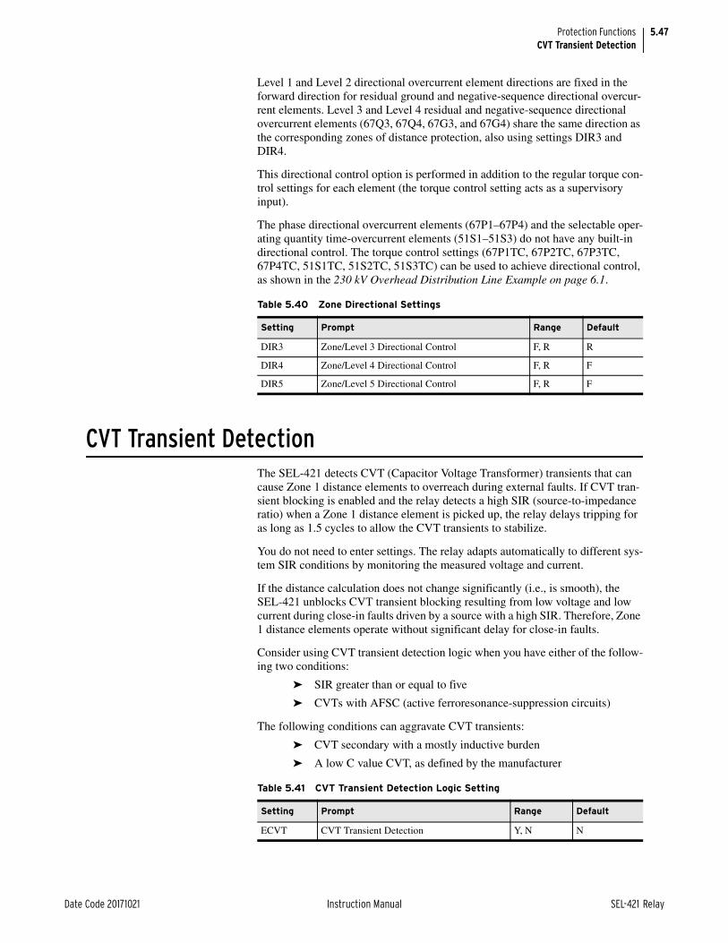
5.47
Date Code 20171021 Instruction Manual SEL-421 Relay
Protection FunctionsCVT Transient Detection
Level 1 and Level 2 directional overcurrent element directions are fixed in the forward direction for residual ground and negative-sequence directional overcur-rent elements. Level 3 and Level 4 residual and negative-sequence directional overcurrent elements (67Q3, 67Q4, 67G3, and 67G4) share the same direction as the corresponding zones of distance protection, also using settings DIR3 and DIR4.
This directional control option is performed in addition to the regular torque con-trol settings for each element (the torque control setting acts as a supervisory input).
The phase directional overcurrent elements (67P1–67P4) and the selectable oper-ating quantity time-overcurrent elements (51S1–51S3) do not have any built-in directional control. The torque control settings (67P1TC, 67P2TC, 67P3TC, 67P4TC, 51S1TC, 51S2TC, 51S3TC) can be used to achieve directional control, as shown in the 230 kV Overhead Distribution Line Example on page 6.1.
CVT Transient DetectionThe SEL-421 detects CVT (Capacitor Voltage Transformer) transients that can cause Zone 1 distance elements to overreach during external faults. If CVT tran-sient blocking is enabled and the relay detects a high SIR (source-to-impedance ratio) when a Zone 1 distance element is picked up, the relay delays tripping for as long as 1.5 cycles to allow the CVT transients to stabilize.
You do not need to enter settings. The relay adapts automatically to different sys-tem SIR conditions by monitoring the measured voltage and current.
If the distance calculation does not change significantly (i.e., is smooth), the SEL-421 unblocks CVT transient blocking resulting from low voltage and low current during close-in faults driven by a source with a high SIR. Therefore, Zone 1 distance elements operate without significant delay for close-in faults.
Consider using CVT transient detection logic when you have either of the follow-ing two conditions:
➤ SIR greater than or equal to five
➤ CVTs with AFSC (active ferroresonance-suppression circuits)
The following conditions can aggravate CVT transients:
➤ CVT secondary with a mostly inductive burden
➤ A low C value CVT, as defined by the manufacturer
Table 5.40 Zone Directional Settings
Setting Prompt Range Default
DIR3 Zone/Level 3 Directional Control F, R R
DIR4 Zone/Level 4 Directional Control F, R F
DIR5 Zone/Level 5 Directional Control F, R F
Table 5.41 CVT Transient Detection Logic Setting
Setting Prompt Range Default
ECVT CVT Transient Detection Y, N N

5.48
SEL-421 Relay Instruction Manual Date Code 20171021
Protection FunctionsSeries-Compensation Line Logic
SIR is defined as follows:
Use the Zone 1 distance element reach (Z1MP, Z1MG, XP1, or XG1) because the CVT transient detection logic only supervises Zone 1 distance protection.
Series-Compensation Line LogicNOTE: The SEL-421-4 does not provide series-compensated line protection logic.
The SEL-421 includes logic to detect when a fault is beyond a series capacitor (a series capacitor can possibly cause Zone 1 overreach). The relay blocks the Zone 1 elements until the series-compensation logic determines that the fault is between the relay and the series capacitor (i.e., the fault is on the protected line section).
The value that you enter for setting XC depends on the position of the series-compensation capacitor(s) relative to the relay potential transformers. Capacitors can be on either end of a line, in the middle of a line, or at both ends of a line. Capacitors that are external to a protected line section can have an effect if infeed conditions are present.
In applications where there is a series capacitor on an adjacent line, for any SEL-421 Relays on non-compensated lines, set ESERCMP := Y and XC := OFF. This allows the Zone 1 element to be set to the desired sensitivity, yet still be secure during the voltage reversal that will occur when a neighboring compen-sated line experiences a fault.
For more information on setting the relay for series-compensated lines see SEL Application Guide AG2000-11, Applying the SEL-321 Relay on Series-Compen-sated Systems.
Table 5.42 CVT Transient Detection Logic Relay Word Bit
Name Description
CVTBL CVT transient blocking active
Figure 5.29 CVT Transient Detection Logic
where:
Z1S = positive-sequence source impedance
ZR = distance element reach
0
1.5CYC
Distance CalculationSmoothnessRelay
WordBits
3POCVTBLSOTFE
ECVT := Y
SIR > 5 DuringZone 1 Fault
Setting
SIR Z1S
ZR-------=

5.49
Date Code 20171021 Instruction Manual SEL-421 Relay
Protection FunctionsLoad-Encroachment Logic
Load-Encroachment LogicThe load-encroachment logic prevents load from causing phase protection to operate. You can set the phase-distance and phase overcurrent elements indepen-dent of load. Two independent positive-sequence impedance characteristics mon-itor the positive-sequence load impedance (Z1) for both export and import load. The positive-sequence voltage-polarized directional element (32P) is blocked when the load-encroachment logic is enabled and load is detected. The phase-distance elements cannot operate during balanced system conditions unless the logic asserts the 32P element.
Figure 5.30 illustrates the load-encroachment logic. The logic operates only if the positive-sequence current (I1) is greater than the positive-sequence threshold (10 percent of the nominal relay current). Relay Word bit ZLOUT indicates that load is flowing out with respect to the relay (an export condition). Relay Word bit ZLIN indicates that load is flowing in with respect to the relay (an import condi-tion). Figure 5.31 illustrates load-encroachment settings and corresponding char-acteristics in the positive-sequence impedance plane. Either Relay Word bit ZLOUT or ZLIN asserts if the relay measures a positive-sequence impedance that lies within the corresponding hatched region. Relay Word bit ZLOAD is the OR combination of ZLOUT and ZLIN.
Table 5.43 Series-Compensation Line Logic Relay Settings
Setting Prompt RangeDefault (5 A)
ESERCMP Series-Compensation Line Logic Y, N N
XC Series Capacitor Reactance () (OFF, 0.25–320 )/INOM OFF
Figure 5.30 Load-Encroachment Logic Diagram
(Setting) (Setting)
(Setting) (Setting)
Pos.-Seq.
I1
V1V1Z1 = ZLOADZ1 (angle)
I1L
Z1 (magnitude)
Threshold
NLAR > Z1 > PLAR
PLAF > Z1 > NLAF
ZLR
ZLFZLOUT
RelayWordBits
ZLIN
Pos.-Seq. Threshold = 0.1 • INOM
Load Out
Load In
(Setting)
(Setting)
+
–
+
–
+
–

5.50
SEL-421 Relay Instruction Manual Date Code 20171021
Protection FunctionsOut-of-Step Logic (Conventional)
Out-of-Step Logic (Conventional)The SEL-421 offers both conventional and settingless (zero-setting) out-of-step (OOS) functions. To use the conventional OOS function, set EOOS = Y. To use the zero-setting OOS function, set EOOS = Y1.
The out-of-step (OOS) logic determines whether a power swing is stable. This relay logic can be set to either block distance protection or allow tripping when the measured positive-sequence impedance (Z1) remains between inner Zone 6 and outer Zone 7 longer than either the OOS blocking delay (setting OSBD) or the OOS tripping delay (setting OSTD), respectively (refer to Figure 5.32).
NOTE: E50Q must be set to 1 or greater for enabling 67Q1T override of OOS blocking for Zone 1 (see Figure 5.57, Figure 5.60, and Figure 5.63).
The OOS logic detects all power swings that enter the OOS characteristics, even if a single-pole open condition exists (Relay Word bit SPO equals logical 1). If either negative-sequence directional element 67QUBF or 67QUBR (67Q1T for Zone 1) picks up during a power swing and a single-pole open condition does not exist (Relay Word bit SPO equals logical 0), the logic overrides OOS blocking
Figure 5.31 Load-Encroachment Characteristics
ZLIN(Load InRegion)
(180˚)
(90˚)
X1
PLARPLAF
NLAR NLAF
ZLFZL
R
(270˚) (—90˚)
ZLOUT(Load Out Region)
(0˚)R1
Table 5.44 Load-Encroachment Logic Relay Settings
Setting Prompt RangeDefault (5 A)
ELOAD Load Encroachment Y, N Y
ZLF Forward Load Impedance () (0.25–320)/INOM 9.22
ZLR Reverse Load Impedance () (0.25–320)/INOM 9.22
PLAF Forward Load Positive angle (°) –90.0 to +90 30.0
NLAF Forward Load Negative angle (°) –90.0 to +90 –30.0
PLAR Reverse Load Positive angle (°) 90.0–270 150.0
NLAR Reverse Load Negative angle (°) 90.0–270 210.0
Table 5.45 Load-Encroachment Logic Relay Word Bits
Name Description
ZLOAD ZLIN OR ZLOUT
ZLIN Import load impedance detected
ZLOUT Export load impedance detected
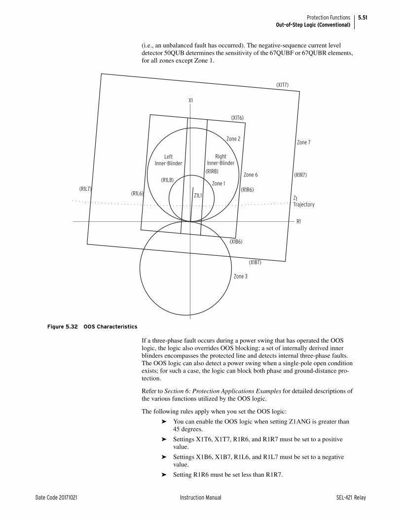
5.51
Date Code 20171021 Instruction Manual SEL-421 Relay
Protection FunctionsOut-of-Step Logic (Conventional)
(i.e., an unbalanced fault has occurred). The negative-sequence current level detector 50QUB determines the sensitivity of the 67QUBF or 67QUBR elements, for all zones except Zone 1.
If a three-phase fault occurs during a power swing that has operated the OOS logic, the logic also overrides OOS blocking; a set of internally derived inner blinders encompasses the protected line and detects internal three-phase faults. The OOS logic can also detect a power swing when a single-pole open condition exists; for such a case, the logic can block both phase and ground-distance pro-tection.
Refer to Section 6: Protection Applications Examples for detailed descriptions of the various functions utilized by the OOS logic.
The following rules apply when you set the OOS logic:
➤ You can enable the OOS logic when setting Z1ANG is greater than 45 degrees.
➤ Settings X1T6, X1T7, R1R6, and R1R7 must be set to a positive value.
➤ Settings X1B6, X1B7, R1L6, and R1L7 must be set to a negative value.
➤ Setting R1R6 must be set less than R1R7.
Figure 5.32 OOS Characteristics
Zone 2
Zone 6
Zone 7
Zone 3
Zone 1
RightInner-Blinder
LeftInner-Blinder
Z1L1(R1L6)(R1L7)
(R1LB)
(R1RB)
(R1R6)
R1
X1
(X1T7)
(R1R7)
Z1 Trajectory
(X1B7)
(X1B6)
(X1T6)

5.52
SEL-421 Relay Instruction Manual Date Code 20171021
Protection FunctionsOut-of-Step Logic (Conventional)
➤ Setting R1L6 must be set greater than R1L7.
➤ Setting X1T6 must be set less than X1T7.
➤ Setting X1B6 must be set greater than X1B7.
➤ The minimum separation between settings R1R6 and R1R7 is 0.25/INOM.
➤ The minimum separation between settings R1L6 and R1L7 is 0.25/INOM.
➤ The minimum separation between settings X1T6 and X1T7 is 0.25/INOM.
➤ The minimum separation between settings X1B6 and X1B7 is 0.25/INOM.
➤ Setting OSBD must be greater than OSTD by a minimum of 0.5 cycle.
Table 5.46 OOS Logic Relay Settings
Setting Prompt RangeDefault (5 A)
EOOS Out-of-Step Y, Y1, N N
OOSB1 Block Zone 1 Y, N Y
OOSB2 Block Zone 2 Y, N Y
OOSB3 Block Zone 3 Y, N Y
OOSB4 Block Zone 4 Y, N N
OOSB5 Block Zone 5 Y, N N
OSBDa
a Hidden when EOOS = Y1.
Out-of-Step Block Time Delay (cycles) 0.500–8000 2.000
OSBLTCHa Latch Out-of-Step Blockingb
b The OSB (Out-of-Step Blocking) logic resets automatically after it asserts for more than 2 seconds. You can latch OSB if the power swing moves outside of Zone 6 before the two-second timer expires.
Y, N N
EOOST Out-of-Step Trip Delayc
c Option I enables tripping on the way into Zone 6; option O enables tripping on the way out of Zone 6; option N disabled OST (Out-of-Step Trip).
N, I, O, C N
OSTDa Out-of-Step Trip Delay (cycles) 0.500–8000 0.500
X1T7a Zone 7 Reactance—Top () (0.25–700)/INOM 23.00
X1T6a Zone 6 Reactance—Top () (0.25–700)/INOM 21.00
R1R7a Zone 7 Resistance—Right () (0.25–700)/INOM 23.00
R1R6a Zone 6 Resistance—Right () (0.25–700)/INOM 21.00
X1B7a,d
d Advanced Setting if EADVS := Y. If the Advanced Settings are not enabled (setting EADVS := N), the relay hides the setting.
Zone 7 Reactance—Bottom () (–0.25–700)/INOM –23.00
X1B6a,d Zone 6 Reactance—Bottom () (–0.25–700)/INOM –21.00
R1L7a,d Zone 7 Resistance—Left () (–0.25–700)/INOM –23.00
R1L6a,d Zone 6 Resistance—Left () (–0.25–700)/INOM –21.00
50ABCPd Pos.-Seq. Current Supervision (A) (0.20–20) • INOM 1.00
50QUBPa,d Neg.-Seq. Current Supervision (A) (OFF, 0.10–20) • INOM OFF
UBDa,d Neg.-Seq. Current Unblock Delay (cycles) 0.500–120 0.500
UBOSBFa,d Out-of-Step Angle Unblock Rate 1–10 4
OOSPSC No. of Pole Slips Before Tripping 1–10 1

5.53
Date Code 20171021 Instruction Manual SEL-421 Relay
Protection FunctionsOut-of-Step Logic (Conventional)
Table 5.47 OOS Logic Relay Word Bits
Name Description
50ABC Positive-sequence current level detector
X6ABC Zone 6
X7ABC Zone 7
UBOSB Unblock out-of-step blocking
OSB Out-of-step blocking
OSTI Incoming out-of-step tripping
OSTO Outgoing out-of-step tripping
OST Out-of-step tripping
67QUBF Negative-sequence forward directional element
67QUBR Negative-sequence reverse directional element
OOSDET OOS condition detected
OSB1 Block Zone 1 during out-of-step condition
OSB2 Block Zone 2 during out-of-step condition
OSB3 Block Zone 3 during out-of-step condition
OSB4 Block Zone 4 during out-of-step condition
OSB5 Block Zone 5 during out-of-step condition
OSBA A-Phase out-of-step blocking
OSBB B-Phase out-of-step blocking
OSBC C-Phase out-of-step blocking

5.54
SEL-421 Relay Instruction Manual Date Code 20171021
Protection FunctionsOut-of-Step Logic (Conventional)
Figure 5.33 OOS Positive-Sequence Measurements
Figure 5.34 OOS Override Logic
UBOSBDD
0
(Internal Function)
UBOSB
3φUnblock
X1
X1
X1
R1
R1
R1
Zone 6
Zone 71
1
RelayWordBits
50ABC
50ABCP
3PO
ILOP
X7ABC
X6ABC
V1
I1L
|I1L| +
—
RelayWordBits
Setting
UBD
0CYC
67QUBF
RelayWordBits
UBD
0CYC
67QUBR
RelayWordBit
RelayWordBit
32QF
Setting
3I2L
50QUBP
32QR
—
+

5.55
Date Code 20171021 Instruction Manual SEL-421 Relay
Protection FunctionsOut-of-Step Logic (Conventional)
Figure 5.35 OOS Logic Diagram
S R
Q
OSB
D
Res
et
0
OST
D
0
0
1/8
CYC
2 SE
C
0
UB
OSB
X7A
BC
EOO
ST :=
NEO
OST
:= I
X6A
BC
Sett
ings
Sett
ings
OSB
LTC
H :=
Y
Sett
ing
Rel
ayW
ord
Bit
s
Rel
ayW
ord
Bit
s
Rel
ayW
ord
Bit
Rel
ayW
ord
Bit
EOO
ST :=
0
OO
SB1
:= Y
OO
SB2
:= Y
OO
SB3
:= Y
OO
SB4
:= Y
OO
SB5
:= Y
Sett
ing
OSB
OST
I
OST
OST
0
OSB
1
OO
SDET
OSB
2
OSB
3
OSB
4
OSB
5
Res
et T
akes
Prio
rity
OO
S D
etec
ted
Aft
er
0
1 SE
C

5.56
SEL-421 Relay Instruction Manual Date Code 20171021
Protection FunctionsOut-of-Step Logic (Zero Settings)
Out-of-Step Logic (Zero Settings)Use the zero-setting out-of-step (OOS) blocking function element when the slip frequency of your system is in the 0.1 to 7 Hz range. (Download the technical paper “Zero-Setting Power-Swing Blocking Protection” by G. Benmouyal, Daqing Hou, and Demetrios Tziouvaras from the SEL website for more informa-tion).
To use the conventional power swing blocking function, set EOOS = Y.
To use the zero-setting power swing blocking function, set EOOS = Y1.
No-Setting OOS Blocking Base Block DiagramThe zero-setting out-of-step blocking function is based on the five functional blocks shown in Figure 5.37. These blocks are the swing-center voltage slope detector, the swing signature detector, the reset conditions, the dependable out-of-step blocking detector, and the three-phase fault detector. Notice that when either SD (swing-center voltage slope detector) or SSD (swing signature detec-tor) asserts, the Latch is set, and OSB_I and OSB are also latched.
Figure 5.36 Open-Pole OSB Unblock Logic
I0LFA–IA2LFA
SPO
50QR
50QF
50GR
OSBB
OSBC
OSBA
SPOA
SPOB
SPOC
50GF
–60 to 60
ENABLE
60 to 180
–60 to –180
Figure 5.37 Zero-Setting OOS Blocking Function
OR 1
AND 1 OSB
OSB_I
SD
SSD
RST
DOSB
DTF
OR 2
Latch
Swing SignatureDetector
Reset Conditions
Dependable OSBDetector
Three-PhaseFault Detector
S
R
Swing Center VoltageSlope Detector

5.57
Date Code 20171021 Instruction Manual SEL-421 Relay
Protection FunctionsOut-of-Step Logic (Zero Settings)
Swing Center Voltage (SCV) Processing and Analog VariablesThe detection of a network power swing condition is based on monitoring the rate-of-change of the positive-sequence swing-center voltage. For the purpose of implementing the function, the following analog variables are used:
➤ SCV1: per-unit positive-sequence swing-center voltage
➤ dSCV1_Unflt: unfiltered derivative of the positive-sequence swing-center voltage
➤ dSCV1_UF: ultra-fast derivative (filtered) of the positive-sequence swing-center voltage
➤ dSCV1_F: fast derivative (moderately filtered) of the positive-sequence swing-center voltage
➤ dSCV1_S: slow derivative (most filtered) of the positive-sequence swing-center voltage
➤ d2SCV1_UF: ultra-fast second derivative (not filtered) of the positive-sequence swing-center voltage
Swing Center Voltage Slope DetectorIn Figure 5.38, the top four comparators determine whether the swing is fast (dSCV1_F remains asserted for 1.75 cycles) or slow (dSCV1_S remains asserted for 5 cycles) for both negative and positive slopes, if the supervision condition are met. The supervision conditions are:
➤ No power swing is in progress (OSB_I is de-asserted), and no Zone 2 through Zone 5 distance elements are asserted or
➤ The absolute value of dSCV1_UF is greater than 0.55) or
➤ The absolute value of dSCV1_UF is lower than 0.55 but greater than 0.2 and the absolute value of d2SCV1_UF is greater than 0.23.
Therefore, if OR Gate OR 1 does not assert, one of the timers (Timer 1 through Timer 4) starts timing. If the conditions prevail, the top input of AND Gate AND 5 asserts after the appropriate timer expires.

5.58
SEL-421 Relay Instruction Manual Date Code 20171021
Protection FunctionsOut-of-Step Logic (Zero Settings)
The bottom input of AND Gate AND 5 asserts when the following is true:
➤ The absolute value of the SCV1 is above 0.05 and
➤ The enable out-of-step setting (EOOST) is either I, O, or C and the positive-sequence impedance is in Zone 7 (Z1ZN7) or
➤ If out-of-step tripping is not selected (EOST = N), then the following conditions must be true: the absolute value of the SCV1 is below 0.85 and the positive-sequence impedance is in the Starter Zone (Z1ZNS)
When AND Gate AND 5 asserts, SD asserts. When SD asserts, the Latch in Figure 5.37 asserts, causing OSB_I and OSB to assert.
Figure 5.38 includes two checks for Z1, the positive-sequence impedance: whether Z1 is in the Starter Zone (see Figure 5.39) and whether Z1 is in Zone 7 (see Figure 5.32).
Figure 5.38 Swing Center Voltage Slope Detection Logic
AND 1
AND 2
AND 3
AND 4
SD
AND 6
AND 5
–0.0172
dSCV1_F
–0.0026
dSCV1_S
dSCV1_F
0.0172
dSCV1_S
0.0026
OSB_I
Z2P
Z5PZ4PZ3P
| dSCV1_UF |
0.55
0.23
| d2SCV1_UF |
0.20
EOOST = I, O, C
Z1ZN7
0.85
| SCV1 |
Z1ZNS
| SCV1 |
0.05
Timer 1
1.75
0CYC
Timer 2
Timer 3
Timer 4
5
0CYC
1.75
0CYC
5
0CYC
Timer 5
0
0.5CYC
OR 1

5.59
Date Code 20171021 Instruction Manual SEL-421 Relay
Protection FunctionsOut-of-Step Logic (Zero Settings)
The purpose of the starter zone is to reduce the sensitivity of the power-swing detector by allowing the PSB elements to assert only for those trajectories of the positive-sequence impedance (Z1) that could possibly move into the characteris-tic of any distance element during a power swing. The area of the starter zone is a rectangle that encompasses all the distance characteristics that must be blocked during a power swing, as shown in Figure 5.39. Furthermore, if the out-of-step tripping (OST) is enabled, the starter zone also encompasses the largest relay characteristic set for the OST logic (Zone 7; see Out-of-Step Tripping (OST)—Zero Settings Element on page 5.68). The algorithm automatically calculates the Starter Zone from the Z2MP–Z5MP, XP2–XP5, and RP2–RP5 Group settings, using the following equations:
R_SZ = max (2 • Z2P, OOSB2, 1.5 • Z3P, OOSB3, 1.5 • Z4P, OOSB4, 1.5 • Z5P, OOSB5)
X_SZ = max (3 • Z2P, OOSB2, 2 • Z3P, OOSB3, 2 • Z4P, OOSB4, 2 • Z5P, OOSB5)
The slope detector typically detects the majority of power-swing conditions. However, there are some system conditions for which the slope detector may not operate. To ensure correct relay power-swing operation, the OSB function also includes two additional detectors: a swing signature detector and a dependable PSB detector.
The Swing Signature DetectorThe swing signature detector (SSD) complements the slope detector and supple-ments the dependable PSB logic. To distinguish a power swing from a system fault, the swing signature detector uses the combination of a step change in the system voltage and the assertion of distance-element-based protection elements (see Figure 5.40).
Figure 5.39 Starter Zone Characteristic
Starter Zone
j X
R

5.60
SEL-421 Relay Instruction Manual Date Code 20171021
Protection FunctionsOut-of-Step Logic (Zero Settings)
In particular, if distance elements pick up without an associated step change in the system voltage, the swing signature detector declares this as a power swing condition and asserts Output SSD. However, if distance elements pick up and there is an associated step change in the system voltage, the swing signature detector does not assert as this is considered a system fault.
Figure 5.41 shows the logic for the swing signature detector. When both inputs into AND 1 asserts, SSD (the swing signature detection) asserts. The top input into AND 1 consists of the phase-distance elements (Z2P–Z5P) and ground-dis-tance elements (Z2G–Z5G) set to be blocked during a power swing.
Enable each distance zone you want included in the power swing blocking func-tion on an individual basis with the OOSB2–OOSB5 settings. Note that you include both phase-distance element (Z2P–Z5P) and ground-distance elements (Z2G–Z5G) with the OOSB2–OOSB5 settings. Phase-distance elements included in the power swing blocking function are further supervised by the OSB unbalance reset conditions (67QUBF, see Figure 5.52) and open-pole conditions. Similarly, ground-distance elements included in the power swing blocking func-tion are further supervised by open-pole conditions.
If any of these distance elements asserts (no supervisory conditions), then the top input into AND 1 asserts.
In a separate calculation, the algorithm calculates and stores three cycles of the absolute values of the first order derivative, dSCV1_unfilt, in a buffer. From these values, the algorithm calculates dSCV1_unfiltMAX, the maximum value of dSCV1_unfilt over the three cycles.
For the summation, the logic uses values from the oldest cycle of the three-cycle buffer (i.e., two cycle old values). This choice of values effectively delays the assertion of the bottom leg of AND 1 for at least two and a half cycles. If three samples in the buffer exceed 5 percent of dSCV1_unfiltMAX, and if dSCV1_un-filtMAX is greater than 0.001, the bottom leg of AND 1 asserts.
Figure 5.40 Swing Signature Detector Logic
AND 1 SSD
Swing Signature Based on Values of | dSCV1 | Stored in a Memory Buffer
Distance-Element-BasedFault Detection

5.61
Date Code 20171021 Instruction Manual SEL-421 Relay
Protection FunctionsOut-of-Step Logic (Zero Settings)
Reset Conditions FunctionThe Reset Conditions logic corresponding to the block with the same name in Figure 5.37 is shown in Figure 5.42.
As shown in Figure 5.37, the OSB function will reset under the following condi-tions:
1. The SCV1 magnitude will be greater than 0.85 or the positive-sequence impedance Z1 will be outside the starter zone for more than 0.5 s or the OST function will be enabled and Z1 will stay outside Zone 7 for more than 30 cycles.
2. The slow derivative dSCV1_S will be smaller than 0.0026 (pu V/cyc) for more than 10 cycles under a no-fault condition.
Figure 5.41 Swing Signature Detector Logic
AND 2
AND 4
OSBA
OSBB
OSBC
Z2G
OOSB2 = Y
Z3G
OOSB3 = Y
Z4G
OOSB4 = Y
Z5G
OOSB5 = Y
Z2P
OOSB2 = Y
Z3P
OOSB3 = Y
Z4P
OOSB4 = Y
Z5P
OOSB5 = Y
67QUBF
SPO
| dSCV1_Unfltk–16
|
| dSCV1_Unfltk–17
|
| dSCV1_Unfltk–23
|
dSCV1_Unfltmax
0.05 • dSCV1_Unfltmax
0.001
2
AND 3
•
•
•
0.125cyc 0.5
CYC
Reset Timer
0
8CYC
SSDAND 1

5.62
SEL-421 Relay Instruction Manual Date Code 20171021
Protection FunctionsOut-of-Step Logic (Zero Settings)
3. The ultra-fast derivative dSCV1_UF will be greater than 0.55 (pu V/cyc) for more than 4 cycles.
4. Either all three poles are open (3PO) or an internal loss-of-potential (ILOP) occurred.
The Dependable Power-Swing Blocking FunctionThe dependable PSB detector function asserts the DOSB signal for power-swing conditions where neither the slope detector nor the swing signature detector can detect a power swing fast enough. An example of this type of situation might occur after a slow-clearing fault right behind or at the remote end of a transmis-sion line on a marginally stable network.
As shown in Figure 5.43, if a close reverse or forward fault clears with a signifi-cant delay, there is a possibility that the network has entered a power swing. In this case, the Z1 trajectory at the relay may cross into the Zone 2 or Zone 1 phase-mho characteristic right after the fault clears, but before the slope detector has detected the power swing. In this case, the phase mho elements of the relay may issue a trip signal as a result of the power swing and not because of a real fault. To overcome this problem, the dependable power-swing detector asserts the DOSB (see Figure 5.37) signal to block the distance elements until the slope detector has had time to detect a power swing.
Figure 5.42 Reset Conditions Logic
AND 2
AND 3
C1
OR 4
OR 4
OR 3
OR 6
AND 4
EOOST = I, O, C
Z1 Outside
Zone 7
| SCV1 |
0.85
Z1 Outside
Starter Zone
C20.0026
| dSCV1_S |
Z2PZ3PZ4PZ5P
C4| dSCV1_UF |
0.55
3PO
ILOP
OR 5
T1
0CYC
30CYC
T2
0CYC
10CYC
T3
0CYC
4CYC
RST

5.63
Date Code 20171021 Instruction Manual SEL-421 Relay
Protection FunctionsOut-of-Step Logic (Zero Settings)
In summary, for an external forward fault, the logic issues a DOSB signal if the signal from a fault detector has lasted several cycles, no power swing has been detected, the relay has issued no trip, and at least one of the Zone 1 phase-mho has picked up or when FZAVG asserts. For a reverse fault, the logic issues a DOSB signal if a power swing has not been detected, the signal from a fault detector has lasted several cycles and been cleared, the relay has issued no trip signal, and a Zone 2 mho-phase has picked up within a time delay.
Depending on the EOOS setting, the relay selects either the logic shown in Figure 5.44 (EOOS = Y1) or the logic shown in Figure 5.45 (EOOS = Y). Figure 5.44 shows the dependable power-swing block detector logic.
Figure 5.43 Type of Power Swings Detected by the DOSB Function
Real (Z1)
Trajectories of Z1
during a power swing
following a reverse fault
Trajectories of Z1
during a power swing
following a forward fault
Imag (Z1)

5.64
SEL-421 Relay Instruction Manual Date Code 20171021
Protection FunctionsOut-of-Step Logic (Zero Settings)
Figure 5.44 Dependable Power-Swing Block Detector Logic (EOOS = Y1)
DIR5 = F
DIR4 = F
Z5P
Z4P
Z3P
Z2POSB
OSB1
TRIP
SERCAB
SERCBC
MAB1I
XAB1I
MBC1I
XBC1I
SERCCAMCA1I
XCA1I
MAB2I
XAB2I
MBC2I
XBC2I
MCA2I
XCA2I
Z1MAG
FZAVG
| Z1Fk — Z1F
k — 1 | • 8 • NFREQ
| d2SCV1_UF |
2 • d2SCV1_UF_avg + 0.06
DIR3 = F
0
0.25CYC
0
0.25CYC
0
0.25CYC
0.25CYC
0
0
0.25CYC
0
2.5CYC
0
0.125CYC
1.5CYC
0
0
2.5CYC
DOSBY1
0
1.5CYC
0
60CYC
1

5.65
Date Code 20171021 Instruction Manual SEL-421 Relay
Protection FunctionsOut-of-Step Logic (Zero Settings)
Figure 5.46 shows DOSB, the OR combination of the output from Figure 5.44 (DOSBY1) and the output from Figure 5.45 (DOSBY). Only Relay Word bit DOSB is available; DOSBY1 and DOSBY are for internal use in the relay.
Three-Phase Fault DetectorFigure 5.47 shows the logic diagram of the three-phase fault detector. If a three-phase fault occurs on a transmission line during a power swing, a step change occurs in the SCV1 waveform. This step change can be identified when the sec-ond derivative of SCV1 has a higher than usual value. Furthermore, the SCV1 has a low value and its rate of change is very small. These properties are taken into account in the three-phase fault detector so as to implement a very fast detector, independent from the swing speed. Three-phase faults will be detected with a minimum and maximum time delay of two and five cycles, respectively.
Figure 5.45 Dependable Power-Swing Block Detector Logic (EOOS = Y)
DIR5 = F
DIR4 = F
Z5P
Z4P
Z3P
Z2POSB
TRIP
SERCAB
SERCBC
MAB1I
XAB1I
MBC1I
XBC1I
SERCCAMCA1I
XCA1I
X7ABC
Z1MAG
| Z1Fk — Z1F
k — 1 | • 8 • NFREQ
DIR3 = F
0
0.25CYC
0
0.25CYC
0
0.25CYC
0
1.5CYC
0
0.125CYC
0
1.5CYC DOSBY
0
1.5CYC
0
60CYC
Figure 5.46 Relay Word Bit DOSB Is the OR Combination of DOSBY1 and DOSBY
DOSBY1
DOSBYDOSB

5.66
SEL-421 Relay Instruction Manual Date Code 20171021
Protection FunctionsOut-of-Step Logic (Zero Settings)
Detection of Ground Faults During a Pole-OpenRegarding the ground-distance elements supervision, if the pole-open OOS logic (OSBA, OSBB, OSBC, see Figure 5.41) is de-asserted, AND 4 turns off. When AND 4 turns off, the ground-distance elements cannot cause the swing signature detector to assert. Figure 5.48 shows the pole-open logic that blocks the ground-distance elements during a power swing condition.
If a power swing occurs during an open-pole condition, the power swing as seen by the relay is no longer balanced. The open-pole OOS blocking logic determines which phase is open so that the relay can correctly identify faults that may occur on the closed phases during the power swing. To identify the open phase, the relay calculates the angle of the ratio of the zero-sequence current and the nega-tive-sequence currents. If the angular relationship indicates a fault, the logic shown in Figure 5.41 turns off AND 4, thus preventing the swing signature detec-tion (SSD) from asserting. When SSD is deasserted, the distance elements can clear the fault.
For example, if the A-Phase is open, the angle of the ratio normally lies between –60 and +60 degrees. If a fault now occurs on B- or C-Phase (or both), this angu-lar relationship is no longer true. In Figure 5.48, OSBA asserts if either B-Phase or C-Phase is open, and no fault is present. If a fault occurs on B-Phase or C-phase (or both), OSBA deasserts because the angular relationship indicates a fault.
Figure 5.47 Logic Diagram of the Three-Phase Fault Detector
| d2SCV1_UF |
0.23
max{0.1, cos(Z1ANG)}
| SCV1 |
| dSCV1_S |
0.01
OSB_I
R1T
| dSCV1_S |
max{0.1, cos(Z1ANG)}
0CYC
6CYC
2CYC
0CYC
20CYC
0CYC
5CYC
0CYC
DTF
Figure 5.48 Pole-Open OOS Blocking Logic
SPO SPOA
AND 3AND 1
AND 2
OR 1
OR 2
AND 4
AND 5
AND 6
AND 7
AND 8
SPOB
SPOC3IOLFA — 3IA2LFA
50QR
50QF
OSBB
OSBC
OSBA
ENABLE
50GR
50GF
OR 3
OR 4
OR 5
—60 to 60
60 to 180
—60 to —180

5.67
Date Code 20171021 Instruction Manual SEL-421 Relay
Protection FunctionsOut-of-Step Logic (Zero Settings)
Figure 5.49 shows the I0/I2 angular relationship during a single pole-open condi-tion, and no system fault present. Figure 5.50 shows the blocking principle of the A-Phase-to-ground mho element by the de-asserted OSBA signal.
The same principle applies to OSBB and OSBC. When all three poles are closed, OSBA, OSBB, and OSBC are de-asserted and the distance elements can trip nor-mal, even during a power swing.
In Figure 5.48, the logic is enabled when the zero-sequence supervisory direc-tional overcurrent element (50GR or 50GF) and negative-sequence supervisory directional overcurrent element (50QR or 50QF) pick up during a single pole-open condition (SPO). Table 5.48 shows the input/output combinations of the logic.
Phase Mho Element Reset LogicIf the OSB function is enabled and a power swing occurs, the OSB signal blocks the phase-fault detectors, but not the ground-fault detectors. Therefore, to remove the OSB signal and clear a fault that occurs during an OOS condition, the relay must detect three-phase and phase-to-phase faults (see Figure 5.51).
Figure 5.49 I0/IA2 Angle Supervision During Pole-Open Situation
Figure 5.50 Blocking of the MAG Signal by the OSBA Fault Detection
Table 5.48 Input/Output Combinations of the Pole-Open OOS Blocking Logic
Gate Turned On Open Phase Phases to Block
AND 6 Phase A Phases B and C
AND 7 Phase B Phases A and C
AND 8 Phase C Phases C and A
A-Phase open
Normal IO/IA2 angle location
B-Phase
Normal IO/IA2 angle location
C-Phase open
Normal IO/IA2 angle location
MAG
Phase A-G
mho signal
OSB
OSBA
Ground A-to-G
distance logic

5.68
SEL-421 Relay Instruction Manual Date Code 20171021
Protection FunctionsOut-of-Step Logic (Zero Settings)
To detect phase-to-phase faults, the relay uses a directional overcurrent element, 67QUBF, based on a negative-sequence directional element, 32QF, as shown in Figure 5.52. 3IA2LFM is the negative-sequence current that the relay measures. If 3IA2LFM exceeds a reference value (a2 • 3 • IA1LFM), Timer 1 starts. If Timer 1 expires and the flow of negative-sequence current is in the forward direc-tion (32QF asserted), then 67QUBF asserts.
Out-of-Step Tripping (OST)—Zero Settings ElementWhile the zero-setting out-of-step blocking function requires no settings, the out-of-step tripping function requires eight blinder settings. These eight blinder set-tings are the Zone 6 and Zone 7 blinder settings, and are common for the conven-tional and the zero-setting OST function (see Figure 5.32).
Figure 5.53 shows the resistive and reactive blinders used in the OST scheme logic. The OST logic uses the traditional OOS calculations for the left (R1R6), right (R1R7), top (X1T6), and bottom (X1T7) blinders of Zone 6 and Zone 7. Specify Settings X1B6 and X1B7 under the advanced settings option. For on-the-way-out (TOWO) out-of-step tripping, these settings do not require any stability studies. However, the out-of-step tripping on-the-way-in (TOWI) still requires stability studies to determine the proper OST settings for right- and left-hand blinders RR6 and RR7.
Figure 5.51 Unblocking of the MAB Signal by the 67QUB Element
Figure 5.52 Directional Element Signals 67QUBF and 67QUBR
MAB
Phases A-B
mho signal
OSB
67QUB
Phase A-to-B
distance logic
3IA2LFM
32QF
32QR
a2 • 3 • IA1LFM
67QUBF
67QUBR
0CYC
1.5
Timer 1
IA2LFM
0.1 • INOM
0.5CYC
0
Time 2

5.69
Date Code 20171021 Instruction Manual SEL-421 Relay
Protection FunctionsOut-of-Step Logic (Zero Settings)
Figure 5.54 shows the logic that determines whether the positive-sequence impedance (Z1) falls within the Zone 6 and/or Zone 7 polygons, provided there is no three-pole open (3PO) or loss-of-potential (ILOP) conditions.
Figure 5.53 OST Scheme Logic Resistive and Reactive Blinders
R
jX
XT 7
XT 6
XB 6
XB 7
RR 7RR 6RL 6RL 7
R 1 R 6
X 1 T 7
X 1 T 6
X 1 B6
X 1 B7
Line
Operate
Restrain
R 1 R 7
R 1 L7
R 1 L6

5.70
SEL-421 Relay Instruction Manual Date Code 20171021
Protection FunctionsOut-of-Step Logic (Zero Settings)
Figure 5.54 Logic That Determines Positive-Sequence Impedance Trajectory (EOOS = Y1)
IA1LFM 50ABC
X1T7_C
X1B7_C
R1R7_C
R1L7_C
X1T6_C
X1B6_C
R1R6_C
R1L6_C
R1RB_C
R1LB_C
Re (Z1)
Im (Z1)
3PO
ILOP
50ABCP
(setting)
X7ABC
X6ABC
UBOSBUBOSBD
0

5.71
Date Code 20171021 Instruction Manual SEL-421 Relay
Protection FunctionsOut-of-Step Logic (Zero Settings)
Figure 5.55 shows the logic for the different EOOST settings (EOOST = N, I, O, C) when EOOS = Y1. Setting EOOST = N turns gate AND 1 off. When AND 1 turns off, all three outputs (OSTI, OST, and OSTO) are also turned off.
Figure 5.55 Out-of-Step Trip Logic (EOOS = Y1)
EOO
ST =
I
EOO
ST =
N
OSB
_I
EOO
ST =
O o
r C
EOO
ST =
0 (
On-
the
-Way
-Out
)
EOO
ST =
C (
On-
the
-Way
-Out
wit
h co
unts
)
EOO
ST =
O
EOO
ST =
C
R7T X7T
X6T
RR
6R
L6R
6TR
R7
RL7
OSTOST
I
OST
O
AN
D 1
OST
FF1
X 7 T
X 6 T
R R 6
R L 6
R 6 T
R R 7
R L 7
R 7 T
FF1
S R
Q
OST
FF3
FF3
S R
Q
Pole
Slip
Coun
ter
Ck
Res
et
OST
FF2
FF2
S R
Q
OST
FF5
FF5
S R
QO
STFF
4
FF4
S R
Q
OST
FF6
FF6
S R
Q

5.72
SEL-421 Relay Instruction Manual Date Code 20171021
Protection FunctionsMho Ground-Distance Elements
Mho Ground-Distance ElementsThe SEL-421 has five independent zones of mho ground-distance protection. The mho ground-distance protection operates only for single phase-to-ground faults. You can set the reach for each zone independently. Zone 1 and Zone 2 distance elements are forward only; you can set Zone 3 through Zone 5 distance elements either forward or reverse. The mho ground-distance elements use positive-sequence voltage polarization for security and generate a dynamic expanding mho characteristic.
NOTE: The SEL-421-4 provides fast and secure tripping but does not have high-speed distance elements. Typical detection time for the SEL-421-4 is 1.5 cycles.
The SEL-421-5 has three independent zones of high-speed mho ground-distance protection. The high-speed mho ground-distance protection operates for single phase-to-ground faults. The first three zones of mho ground-distance protection (Zone 1 through Zone 3) are for high-speed operation; typical detection time is less than one cycle.
NOTE: If the relay is using a remote data acquisition system, such as TiDL, the operating times will be delayed by 1.5 ms. Use caution when setting the relay coordination times to account for this added delay.
The Zone 1 zero-sequence compensation factor (k01) is independent from the forward and reverse compensation factors (k0 and k0R) the relay uses for the other zones.
If you set k0M1 to AUTO, the relay automatically calculates the values k01, k0, and k0R based on the following equation:
Equation 5.28
The SEL-421 has a settable Zone 1 overcurrent supervision setting for phase-distance elements (Z50P1) and for ground-distance elements (Z50G1). These advanced settings (EADVS = Y) apply to both mho and quadrilateral distance
Figure 5.56 Out-of-Step Blocking for Zone 1 Through Zone 5
OSB1
OSB2
OSB3
OSB4
OSB5
OODBI = Y
OOSB5 = Y
OOSB4 = Y
OOSB3 = Y
OOSB2 = Y
EOOS = Y1
OSB
EOOS = Y
OOSDET
where:
Z1L = positive-sequence transmission line impedance
Z0L = zero-sequence transmission line impedance
k0 Z0L Z1L–
3 Z1L• ----------------------=

5.73
Date Code 20171021 Instruction Manual SEL-421 Relay
Protection FunctionsMho Ground-Distance Elements
elements and are useful in applications with series compensation. For more infor-mation on setting relays to protect series-compensated lines, see AG2000-11: Applying the SEL-321 Relay on Series-Compensated Systems.
Table 5.49 Mho Ground-Distance Elements Relay Word Bits
Name Description
MAG1 Zone 1 A-Phase mho ground-distance element
MBG1 Zone 1 B-Phase mho ground-distance element
MCG1 Zone 1 C-Phase mho ground-distance element
MAG2 Zone 2 A-Phase mho ground-distance element
MBG2 Zone 2 B-Phase mho ground-distance element
MCG2 Zone 2 C-Phase mho ground-distance element
MAG3 Zone 3 A-Phase mho ground-distance element
MBG3 Zone 3 B-Phase mho ground-distance element
MCG3 Zone 3 C-Phase mho ground-distance element
MAG4 Zone 4 A-Phase mho ground-distance element
MBG4 Zone 4 B-Phase mho ground-distance element
MCG4 Zone 4 C-Phase mho ground-distance element
MAG5 Zone 5 A-Phase mho ground-distance element
MBG5 Zone 5 B-Phase mho ground-distance element
MCG5 Zone 5 C-Phase mho ground-distance element
Z1G Zone 1 ground-distance element
Z2G Zone 2 ground-distance element
Z3G Zone 3 ground-distance element
Z4G Zone 4 ground-distance element
Z5G Zone 5 ground-distance element

5.74
SEL-421 Relay Instruction Manual Date Code 20171021
Protection FunctionsMho Ground-Distance Elements
Figure 5.57 Zone 1 Mho Ground-Distance Element Logic Diagram
—
+
—
+
yWordBits
RelayWordBits
RelayWordBit
RelayWordBits
32SPOF
CVTBL
MAG1
MBG1
Z1GMCG1
XAG1
XBG1
XCG1
32GF
IAL
IGL
mAGF < Z1MG
FSA
SPO
SPOA
OSB1
OSBA
3PO
67Q1T
ILOP
VPOLV
SERCA
0.1 • INOM
mAGF A-Phase-to-Ground Mho Distance Calculation
A-Phase Mho Ground Distance LogicB- and C-Phase Logic is Similar
Z50G1(setting)

5.75
Date Code 20171021 Instruction Manual SEL-421 Relay
Protection FunctionsMho Ground-Distance Elements
Figure 5.58 Zone 2 Mho Ground-Distance Element Logic Diagram
32SPOF
MAG2
MBG2
Z2GMCG2
XAG2
XBG2
XCG2
32GF
FSA
SPO
SPOA
OSB2
OSBA
3PO
ILOP
VPOLV
A-Phase Mho Ground Distance LogicB- and C-Phase Logic is Similar
mAGF is the Forward A-Phase-to-GroundMho Distance Calculation
RelayWordBit
RelayWordBits
RelayWordBits
RelayWordBits
RelayWordBit
RelayWordBits
—
+
—
+
IAL
IGL
mAGF < Z2MG
0.1 • INOM

5.76
SEL-421 Relay Instruction Manual Date Code 20171021
Protection FunctionsQuadrilateral Ground-Distance Elements
Quadrilateral Ground-Distance ElementsThe SEL-421 has five independent zones of quadrilateral ground-distance protec-tion. The quadrilateral ground-distance protection only operates for single phase-to-ground faults.
Set the reactance (XG) and resistive (RG) reach for each zone independently. Rather than 90 degrees (purely reactive), the reactance measurement lies along the setting Z1ANG (complex).
Zone 1 and Zone 2 distance elements are forward only, while you can set Zone 3 through Zone 5 distance elements either forward or reverse.
You select whether the quadrilateral ground-distance elements use negative- or zero-sequence current to polarize the reactance line when the Advanced Settings are enabled (setting EADVS := Y); otherwise, negative-sequence current is the default setting.
Figure 5.59 Zones 3, 4, and 5 Mho Ground-Distance Element Logic Diagram
32SPOF
DIRn := F
MAGn
MBGn
ZnG MCGn
XAGn
XBGn
XCGn
32GF
OSBn
OSBA
FSA
SPO
SPOA
32GR
32SPOR
3PO
ILOP
VPOLV
mAGF is the Forward A-Phase-to-Ground Mho DistanceCalculation
mAGR is the Reverse A-Phase-to-Ground DistanceCalculation
Zone 3, 4, and 5 Mho Ground Distance Logic forA-Phase. B- and C-Phase Logic is Similar
n = 3, 4, or 5
Setting
RelayWordBit
RelayWordBits
RelayWordBit
RelayWordBit
RelayWordBits
RelayWordBits
RelayWordBits
—
+
—
+
IAL
IGL
mAGF < ZnMG
mAGR > —ZnMG
0.1 • INOM

5.77
Date Code 20171021 Instruction Manual SEL-421 Relay
Protection FunctionsQuadrilateral Ground-Distance Elements
The Zone 1 zero-sequence compensation factor (k01) is independent from the forward and reverse compensation factors (k0 and k0R) that the relay uses for quadrilateral ground-distance protection for the other zones.
When setting E21XG (Quadrilateral Ground-Distance Zones) is 1 or more, there are two selections for setting XGPOL (Quadrilateral Ground Polarizing Quan-tity): I2 or IG. When the setting XGPOL is I2, set the first selection in the setting ORDER (Ground Directional Element Priority) to Q. When the setting XGPOL is IG, the first selection in the setting ORDER must be Q or V.
The quadrilateral element in the relay includes an option by which the right resis-tance blinder can be adapted to load conditions. This adaptive function applies to the ground quadrilateral elements only; the phase quadrilateral elements are not affected. The purpose of the adaptive resistance function is to increase fault resis-tance coverage, particularly for remote faults. To enable the adaptive resistance function, set ARESE = Y.
A supervisory condition is applied to force the resistive blinders to be self-polar-ized under unusual unbalanced loads. The adaptivity of the resistive blinder is enabled by the setting ARESE when the corresponding Relay Word bit CNR2AG, CNR2BG, or CNR2CG, is asserted. When the adaptivity of the right resistive blinder is disabled, it uses self-polarization.
Table 5.50 shows the differences between behavior of the adaptive right resis-tance blinder and the existing resistance blinder.
Each quadrilateral ground-distance element is supervised by the Relay Word bit ENX2nG, where n is the A, B, or C phase. This supervisory condition secures the reactance blinder in the quadrilateral ground-distance element against unusual unbalanced load conditions.
For more information on the element, see the technical paper Adaptive Phase and Ground Quadrilateral Distance Elements, available at selinc.com.
Table 5.50 Differences Between the Adaptive Right Resistance Blinder and the Existing Resistance Blinder
Existing Resistance Blinder Adaptive Resistance Blinder
The left blinder is the negative of the right-blinder setting.
The left blinder is the minimum of the enabled right blinder settings, (min [RG1, RG2, . . . RGn]).
The right resistance blinder is fixed. The right resistance blinder adapts to the changing load conditions.
Table 5.51 Quadrilateral Ground-Distance Elements Relay Word Bits (Sheet 1 of 2)
Name Description
XAG1 Zone 1 A-Phase quadrilateral ground-distance element
XBG1 Zone 1 B-Phase quadrilateral ground-distance element
XCG1 Zone 1 C-Phase quadrilateral ground-distance element
XAG2 Zone 2 A-Phase quadrilateral ground-distance element
XBG2 Zone 2 B-Phase quadrilateral ground-distance element
XCG2 Zone 2 C-Phase quadrilateral ground-distance element
XAG3 Zone 3 A-Phase quadrilateral ground-distance element
XBG3 Zone 3 B-Phase quadrilateral ground-distance element
XCG3 Zone 3 C-Phase quadrilateral ground-distance element

5.78
SEL-421 Relay Instruction Manual Date Code 20171021
Protection FunctionsQuadrilateral Ground-Distance Elements
XAG4 Zone 4 A-Phase quadrilateral ground-distance element
XBG4 Zone 4 B-Phase quadrilateral ground-distance element
XCG4 Zone 4 C-Phase quadrilateral ground-distance element
XAG5 Zone 5 A-Phase quadrilateral ground-distance element
XBG5 Zone 5 B-Phase quadrilateral ground-distance element
XCG5 Zone 5 C-Phase quadrilateral ground-distance element
Table 5.51 Quadrilateral Ground-Distance Elements Relay Word Bits (Sheet 2 of 2)
Name Description
Figure 5.60 Zone 1 Quadrilateral Ground-Distance Element Logic Diagram
CVTBL
XAG1
IAL
IGL
0.1 • INOM
—RG1 < rAG1 < RG1xAG1 < XG1
FSASPO
3PO
0SB1
67Q1T
ILOPVPOLVSERCA
B- and C-Phase Logic is Similar
xAG1 is the A-Phase-to-Ground Zone 1 Reactance Calculation
rAG1 is the A-Phase-to-Ground Zone 1 Resistance Calculation
+
—
+
—
XGPOL := IG(setting)
32VE
32QE32GF
XGPOL := I2(setting)
ARESE = N
ENX2AG
Z50G1(setting)

5.79
Date Code 20171021 Instruction Manual SEL-421 Relay
Protection FunctionsQuadrilateral Ground-Distance Elements
Figure 5.61 Zone 2 Quadrilateral Distance Element Logic Diagram
RelayWordBits
RelayWord Bits
RelayWordBit
(Setting)
(Setting)
XAG2
XGPOL := IG
32VE
32QE32GF
XGPOL := I2
IAL
IGL
xAGF < XG2—RG2 < rAGF < RG2
0.1 • INOM
FSASPO
B- and C-Phase Logic is Similar
xAGF is the A-Phase-to-Ground Forward Reactance Calculation
rAGF is the A-Phase-to-Ground Forward Resistance Calculation
+
—
+
—
| 3IA2LF | +
—
3POILOP
VPOLV
ARESE = N
ENX2AG

5.80
SEL-421 Relay Instruction Manual Date Code 20171021
Protection FunctionsMho Phase-Distance Elements
Mho Phase-Distance ElementsThe SEL-421 has five independent zones of mho phase-distance protection. The mho phase-distance protection operates for phase-to-phase, phase-to-phase-to-ground, and three-phase faults. Set the reach for each zone independently. Zone 1 and Zone 2 distance elements are forward only, while you can set Zone 3 through Zone 5 distance elements either forward or reverse. The mho phase-distance ele-ments use positive-sequence voltage polarization for increased reliability and also generate a dynamic expanding mho characteristic that provides additional fault resistance coverage.
NOTE: The SEL-421-4 provides fast and secure tripping but does not have high-speed distance elements. Typical detection time for the SEL-421-4 is 1.5 cycles.
The SEL-421 has five independent zones of quadrilateral phase-distance protec-tion (see Quadrilateral Phase-Distance Elements on page 5.85). Although the mho and quadrilateral phase elements are independent, you can enable both at the same time. To this end, the outputs from the mho and quadrilateral phase ele-ments are ORed to a single protection output (see Figure 5.61, Figure 5.64, and Figure 5.65).
The SEL-421 has a settable Zone 1 overcurrent supervision setting for phase-distance elements (Z50P1) and for ground-distance elements (Z50G1). These advanced settings (EADVS = Y) apply to both mho and quadrilateral distance
Figure 5.62 Zones 3, 4, and 5 Quadrilateral Ground-Distance Element Logic
—
+
—
+
(Setting)
(Setting)
(Setting)
XGPOL := IG
32VE
XAGn
32QE32GF
XGPOL := I2
DIRn := F
XGPOL := IG
32VE
(Setting)
(Setting)
32QE32GR
XGPOL := I2
xAGR > —XGn
—RGn < rAGR < RGn
3POFSA
ILOPVPOLV
xAGF < XGn—RGn < rAGF < RGn
0.1 • INOM
IGL
IAL
SPO(Relay Word Bit)
Zone 3, 4, and 5 Quadrilateral Ground Distance Logic for A-phase
B- and C-Phase Logic is Similar
n = 3, 4, or 5
RelayWord Bit
RelayWord Bit
RelayWord Bit
RelayWord Bit
ARESE = N
ENX2AG

5.81
Date Code 20171021 Instruction Manual SEL-421 Relay
Protection FunctionsMho Phase-Distance Elements
elements and are useful in applications with series compensation. For more infor-mation on setting relays to protect series-compensated lines, see AG2000-11: Applying the SEL-321 Relay on Series-Compensated Systems.
NOTE: If the relay is using a remote data acquisition system, such as TiDL, the operating times will be delayed by 1.5 ms. Use caution when setting the relay coordination times to account for this added delay.
The SEL-421-5 has three independent zones of high-speed mho phase-distance protection. The high-speed mho phase-distance protection operates for phase-to-phase, phase-to-phase-to-ground, and three-phase faults. The first three zones of mho phase-distance protection (Zone 1, Zone 2, and Zone 3) are for high-speed operation; typical detection time is less than one cycle.
Table 5.52 Mho Phase-Distance Elements Relay Word Bits
Relay Word Bit Description
MAB1 Zone 1 mho A-B phase element
MBC1 Zone 1 mho B-C phase element
MCA1 Zone 1 mho C-A phase element
Z1P Zone 1 phase-distance element
MAB2 Zone 2 mho A-B phase element
MBC2 Zone 2 mho B-C phase element
MCA2 Zone 2 mho C-A phase element
Z2P Zone 2 phase-distance element
MAB3 Zone 3 mho A-B phase element
MBC3 Zone 3 mho B-C phase element
MCA3 Zone 3 mho C-A phase element
Z3P Zone 3 phase-distance element
MAB4 Zone 4 mho A-B phase element
MBC4 Zone 4 mho B-C phase element
MCA4 Zone 4 mho C-A phase element
Z4P Zone 4 phase-distance element
MAB5 Zone 5 mho A-B phase element
MBC5 Zone 5 mho B-C phase element
MCA5 Zone 5 mho C-A phase element
Z5P Zone 5 phase-distance element

5.82
SEL-421 Relay Instruction Manual Date Code 20171021
Protection FunctionsMho Phase-Distance Elements
Figure 5.63 shows the Zone 1 phase-distance element logic. The other fault cal-culations (BC, CA) have similar logic. In Figure 5.63, Output Z1P is the OR combination of the following Zone 1 elements (ØØ = AB, BC, CA):
➤ Conventional mho elements (MØØ1)
➤ Conventional quadrilateral elements (XØØ1)
Figure 5.63 Zone 1 Mho Phase-Distance Element Logic Diagram
—
+
RelayWordBits
RelayWordBits
RelayWordBits
—
+
—
+
IABLFM
MABDF
mABF
Z1MP(setting)
F32P
32SPOF
SPOA
67Q1T
SPOB
SPOC
VPOLV
SERCAB
CVTBL
ILOP
OSBA
OSB1
0.1 • INOM
MAB1
MBC1
XBC1
XCA1
MCA1
XAB1Z1P
FSA
FSB
RelayWordBits
M1P
Z50P1(setting)

5.83
Date Code 20171021 Instruction Manual SEL-421 Relay
Protection FunctionsMho Phase-Distance Elements
Figure 5.64 shows the Zone 2 phase-distance element logic. The other fault cal-culations (BC, CA) have similar logic. In Figure 5.64, Output Z2P is the OR combination of the following Zone 2 elements (ØØ = AB, BC, CA):
➤ Conventional mho elements (MØØ2)
➤ Conventional quadrilateral elements (XØØ2)
Figure 5.64 Zone 2 Mho Phase-Distance Element Logic Diagram
—
+
RelayWordBits
RelayWordBits
RelayWordBits
—
+
—
+
IABLFM
MABDF
mABF
Z2MP(setting)
F32P
32SPOF
SPOA
67QUBF
SPOB
FSA
FSB
SPOC
VPOLV
ILOP
OSBA
OSB2
0.1 • INOM
MAB2
MBC2
XBC2
XCA2
MCA2
XAB2
RelayWordBit
Z2P
RelayWordBits
M2P

5.84
SEL-421 Relay Instruction Manual Date Code 20171021
Protection FunctionsMho Phase-Distance Elements
Figure 5.65 shows the Zone 3, 4 and 5 phase-distance element logic. Other fault calculations (BC, CA) have similar logic. In Figure 5.65, Output ZnP is the OR combination of the following Zone n (n = 3, 4, 5) elements (ØØ = AB, BC, CA):
➤ Conventional mho elements (MØØn)
➤ Conventional quadrilateral elements (XØØn)
Figure 5.65 Zones 3, 4, and 5 Mho Phase-Distance Element Logic Diagram
—
+
RelayWordBits
RelayWordBits
RelayWordBits
RelayWordBits
Setting
32SPOF
IABLFM
DIRn := F
F32P
SPOA
SPOB
R32P
32SPOR
SPOC
VPOLV
ILOP
OSBA
OSBn
67QUBF
67QUBR
—
+—ZnMP
(setting)
—
+ZnMP(setting)
+
—IABL
—0.1 • INOM
+
—0.1 • INOM
mABF
FSA
FSB
MABDFMABn
MBCn
XBCn
XCAn
MCAn
XABn
RelayWordBit
ZnP
RelayWordBits
MnP

5.85
Date Code 20171021 Instruction Manual SEL-421 Relay
Protection FunctionsQuadrilateral Phase-Distance Elements
Quadrilateral Phase-Distance ElementsNOTE: The SEL-421-4 provides fast and secure tripping, but does not have high-speed distance elements. Typical detection time for the SEL-421-4 is 1.5 cycles.
The SEL-421-5 has two groups of quadrilateral phase-distance elements: high-speed elements and conventional elements. There are five zones (Zone 1 through Zone 5) of conventional elements, and three zones of high-speed elements (Zone 1 through Zone 3). Reach settings for the Zone 1 through Zone 3 elements are the same for the two groups. For example, setting XP1 = 4 sets the Zone 1 reactance reach for both high-speed elements and conventional elements to 4 Ohms secondary.
Notice that setting XPx (x = 1–5 or x = 1–3) is an impedance (not reactance) set-ting. You can set the impedance and resistive (RPx) reach for each zone inde-pendently.
NOTE: It is recommended to enable the phase mho elements in conjunction with the phase quadrilateral elements to provide detection for phase-to-phase faults during SPO conditions.
The SEL-421 also has five independent zones of mho phase-distance protection (see Mho Phase-Distance Elements on page 5.80 for more information). Although the mho and quadrilateral phase elements are independent, you can enable both at the same time. To this end, the outputs from the mho and quadrilat-eral phase elements are ORed to a single protection output (see Figure 5.62, Figure 5.64, and Figure 5.65).
For both the high-speed and conventional quadrilateral phase-distance elements, Zone 1 and Zone 2 distance elements operate in the forward direction only. You can set Zone 3 for the high-speed elements and Zone 3 through Zone 5 for the conventional elements to operate in either forward or reverse directions. Table 5.53 summarizes the zone directional settings for the high-speed and con-ventional elements.
The impedance reach for each zone of quadrilateral phase-distance protection lies on the line positive-sequence impedance angle (Z1ANG) rather than on the ordi-nate (reactance) of the impedance plane. When setting the reactance reach of the relay, do not convert the line impedance to a reactance. Enter the impedance value at the line angle in the same way you would enter the impedance value when setting a mho element. For example, if the line impedance is Z = 2 +j15 (15.13 82.4° ) secondary, enter the following settings for an 85 percent Zone 1 reach:
Z1ANG = 82.4°
XP1 = 12.86 (15.13 • 0.85)
Figure 5.66 shows the first three zones of the quadrilateral phase characteristic. Notice that the right blinders are parallel to the line impedance, and not parallel to the reactance axis. There is no setting for –RP, the left blinder; this value is fixed at the negative value of the lowest forward looking resistive RPn setting (n = 1–5). For example, if RP1 is set to RP1 = 3.8 , and if RP1 is the minimum of RP1 through RP5, then the left blinder setting becomes –3.8 . Zones set to OFF (XPn = OFF), reverse looking zones (DIRn = R) and zones not included in the E21XP setting are excluded from the calculations to determine the minimum RP value in the forward direction.
NOTE: If the relay is using a remote data acquisition system, such as TiDL, the operating times will be delayed by 1.5 ms. Use caution when setting the relay coordination times to account for this added delay.
Table 5.53 High-Speed and Conventional Element Directional Setting Summary
Zones High-Speed Elements Conventional Elements
Zone 1 Forward only Forward only
Zone 2 Forward only Forward only
Zone 3 Forward/Reverse Forward/Reverse
Zone 4 NA Forward/Reverse
Zone 5 NA Forward/Reverse
NOTE: The resistive reach of the quadrilateral phase-distance element setting RPn is reduced to RPPn based on the ratio of I2/I1 using the following equation if 32QE is not asserted:
RPPn 0.25 I2I1----- 0.75• +
RPn• =

5.86
SEL-421 Relay Instruction Manual Date Code 20171021
Protection FunctionsQuadrilateral Phase-Distance Elements
Because Zone 1 and Zone 2 operate in the forward direction, the left blinder in the reverse direction is the lowest setting among Zones m (m = 3–5). Zones set to OFF (XPm = OFF), forward looking zones (DIRm = F) and zones not included in the E21XP setting are excluded from the calculations to determine the minimum RP value in the reverse direction.
TANGP, the tilt angle setting, tilts the reactance values, but does not affect the resistance values. Figure 5.66 shows the quadrilateral phase characteristic with TANGP = 0 degrees.
Figure 5.67 shows the quadrilateral phase-distance element characteristic with TANGP = –10 degrees. Notice that the reactance elements are tilted by 10 degrees, but the resistance blinders are unaffected by this setting. Also notice that the pivot point of the tilt is the line impedance and not the reactance axis. Furthermore, there are no individual TANGP settings for each zone; when you enter a value other than zero for TANGP, all enabled zones are tilted by the same value.
Figure 5.66 Quadrilateral Phase-Distance Element Characteristic (TANGP = 0)
Zone 3
Zone 2
Zone 1
Z1ANG
RP1
XP1
XP2
XP3
jX
—RP RP2 RP3R

5.87
Date Code 20171021 Instruction Manual SEL-421 Relay
Protection FunctionsQuadrilateral Phase-Distance Elements
Quadrilateral Phase Nonhomogeneous Setting (TANGP)Nonhomogeneous negative-sequence networks can cause distance elements to underreach or overreach. Use the network in Figure 5.68 to determine whether the negative-sequence network is homogeneous. ZLEFT is the total impedance up to the fault (F) on the left-hand side, while ZRIGHT is the total impedance up to the fault on the right-hand side.
Figure 5.67 Quadrilateral Phase-Distance Element Characteristic (TANGP = –10 degrees)
Zone 3
TANGP = —10 degrees
Zone 2
Zone 1
Z1ANG
RP1
XP1
XP2
XP3
jX
—RP RP2 RP3R
Figure 5.68 Network to Determine Homogeneity
IF
F
IF
ZRIGHTZLEFT
Z1S m • Z1L (1 — m) • Z1L Z1R
S R
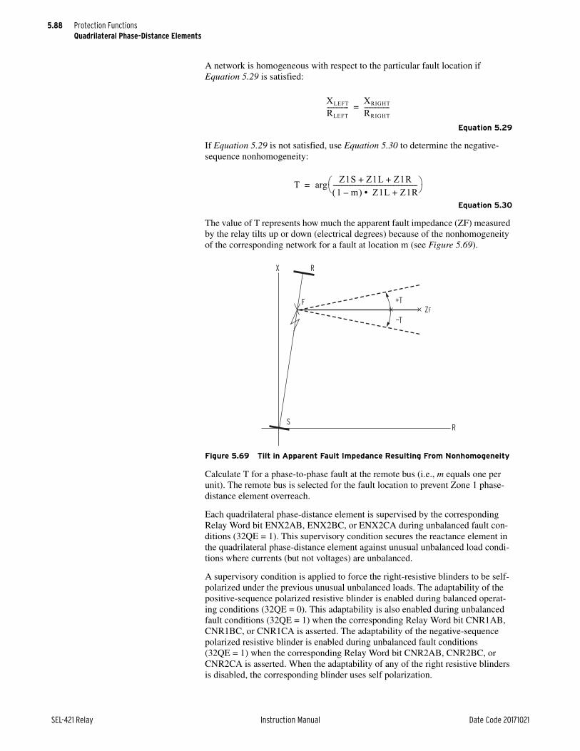
5.88
SEL-421 Relay Instruction Manual Date Code 20171021
Protection FunctionsQuadrilateral Phase-Distance Elements
A network is homogeneous with respect to the particular fault location if Equation 5.29 is satisfied:
Equation 5.29
If Equation 5.29 is not satisfied, use Equation 5.30 to determine the negative-sequence nonhomogeneity:
Equation 5.30
The value of T represents how much the apparent fault impedance (ZF) measured by the relay tilts up or down (electrical degrees) because of the nonhomogeneity of the corresponding network for a fault at location m (see Figure 5.69).
Calculate T for a phase-to-phase fault at the remote bus (i.e., m equals one per unit). The remote bus is selected for the fault location to prevent Zone 1 phase-distance element overreach.
Each quadrilateral phase-distance element is supervised by the corresponding Relay Word bit ENX2AB, ENX2BC, or ENX2CA during unbalanced fault con-ditions (32QE = 1). This supervisory condition secures the reactance element in the quadrilateral phase-distance element against unusual unbalanced load condi-tions where currents (but not voltages) are unbalanced.
A supervisory condition is applied to force the right-resistive blinders to be self-polarized under the previous unusual unbalanced loads. The adaptability of the positive-sequence polarized resistive blinder is enabled during balanced operat-ing conditions (32QE = 0). This adaptability is also enabled during unbalanced fault conditions (32QE = 1) when the corresponding Relay Word bit CNR1AB, CNR1BC, or CNR1CA is asserted. The adaptability of the negative-sequence polarized resistive blinder is enabled during unbalanced fault conditions (32QE = 1) when the corresponding Relay Word bit CNR2AB, CNR2BC, or CNR2CA is asserted. When the adaptability of any of the right resistive blinders is disabled, the corresponding blinder uses self polarization.
Figure 5.69 Tilt in Apparent Fault Impedance Resulting From Nonhomogeneity
XLEFT
RLEFT--------------
XRIGHT
RRIGHT----------------=
T Z1S Z1L Z1R+ +1 m– Z1L Z1R+•
----------------------------------------------------- arg=
X R
RS
F +T
—T
ZF
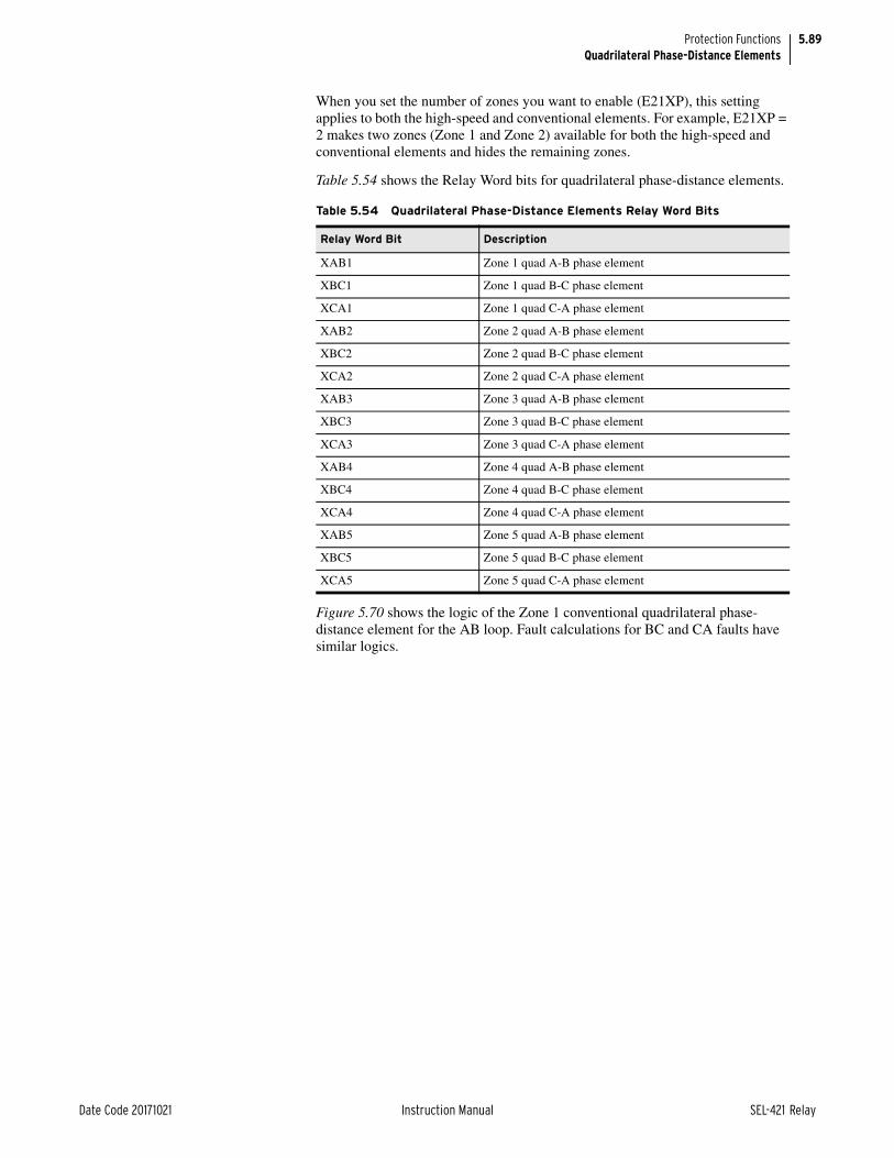
5.89
Date Code 20171021 Instruction Manual SEL-421 Relay
Protection FunctionsQuadrilateral Phase-Distance Elements
When you set the number of zones you want to enable (E21XP), this setting applies to both the high-speed and conventional elements. For example, E21XP = 2 makes two zones (Zone 1 and Zone 2) available for both the high-speed and conventional elements and hides the remaining zones.
Table 5.54 shows the Relay Word bits for quadrilateral phase-distance elements.
Figure 5.70 shows the logic of the Zone 1 conventional quadrilateral phase-distance element for the AB loop. Fault calculations for BC and CA faults have similar logics.
Table 5.54 Quadrilateral Phase-Distance Elements Relay Word Bits
Relay Word Bit Description
XAB1 Zone 1 quad A-B phase element
XBC1 Zone 1 quad B-C phase element
XCA1 Zone 1 quad C-A phase element
XAB2 Zone 2 quad A-B phase element
XBC2 Zone 2 quad B-C phase element
XCA2 Zone 2 quad C-A phase element
XAB3 Zone 3 quad A-B phase element
XBC3 Zone 3 quad B-C phase element
XCA3 Zone 3 quad C-A phase element
XAB4 Zone 4 quad A-B phase element
XBC4 Zone 4 quad B-C phase element
XCA4 Zone 4 quad C-A phase element
XAB5 Zone 5 quad A-B phase element
XBC5 Zone 5 quad B-C phase element
XCA5 Zone 5 quad C-A phase element

5.90
SEL-421 Relay Instruction Manual Date Code 20171021
Protection FunctionsQuadrilateral Phase-Distance Elements
Figure 5.71 shows the logic of the Zone 2 quadrilateral phase-distance element for the AB loop. Fault calculations for BC and CA faults have similar logics.
Figure 5.70 Zone 1 AB Loop Conventional Quadrilateral Phase-Distance Element Logic
Figure 5.71 Zone 2 AB Loop Conventional Quadrilateral Phase-Distance Element Logic
IABLFM
0.1 • INOM
F32P
CVTBLXAB1RABX1
OSB1
67Q1T
FSAFSB
HSDAGFHSDBGF
SERCAB
ILOP
SPO
MABDF
xABF
XP1 (setting)
Phase Selection
VPOLV
ENX2AB
32QE
Z50P1
(setting)
IABLFM
0.1 • INOM
F32P
XAB2
RABX2
OSB267QUBF
FSAFSB
HSDAGFHSDBGF
ILOP
SPO
MABDF
xABFXP2
(setting)
VPOLV
Phase SelectionENX2AB
32QE

5.91
Date Code 20171021 Instruction Manual SEL-421 Relay
Protection FunctionsZone Time Delay
Figure 5.72 shows the logic of the Zone 3, 4, and 5 conventional quadrilateral phase-distance element for the AB loop. Fault calculations for BC and CA faults have similar logics.
Zone Time DelayNOTE: If the relay is using a remote data acquisition system, such as TiDL, the operating times will be delayed by 1.5 ms. Use caution when setting the relay coordination times to account for this added delay.
The SEL-421 supports two philosophies of zone timing:
➤ Independent timing—the phase and ground-distance elements drive separate timers for each zone
➤ Common timing—the phase and ground-distance elements both drive a common timer
Figure 5.72 Zone 3, 4, and 5 AB Loop Conventional Quadrilateral Phase-Distance Element Logic
IABLFM
0.1 • INOM
F32P
R32P
DIRn = F
XABn
RABXn
OSBn
67QUBF
67QUBR
FSAFSB
HSDAGFHSDBGFHSDAGRHSDBGR
ILOP
SPO
MABDF
xABF
XPn
(setting)
—XPn
(setting)
—0.1 • INOM
MABDF
VPOLV
Phase SelectionENX2AB
32QE

5.92
SEL-421 Relay Instruction Manual Date Code 20171021
Protection FunctionsZone Time Delay
Independent Zone TimingUse Relay Word bits ZnPT (Time-Delayed Zone Phase-Distance Protection) and ZnGT (Time-Delayed Zone Ground-Distance Protection) to select independent zone timing in SELOGIC control equation TR (Trip) (n = 1–5).
The example below uses independent timing for Zone 2 phase and ground-dis-tance protection:
TR := Z1P OR Z1G OR Z2PT OR Z2GT
Common Zone TimingUse Relay Word bits ZnT (Zone n Distance Protection) to select common zone timing in SELOGIC control equation TR (Trip) (n = 1–5).
The next example uses common timing for Zone 2 distance protection:
TR := Z1P OR Z1G OR Z2T
If the timer input drops out while timing, the relay suspends the common zone timer for two cycles. This feature prevents resetting the timer when a fault evolves (e.g., the fault changes from a single phase-to-ground to phase-to-phase-to-ground). If the timer expires, the relay blocks the suspend-timing logic. When the zone timer is set to OFF, the output from the timer is blocked.
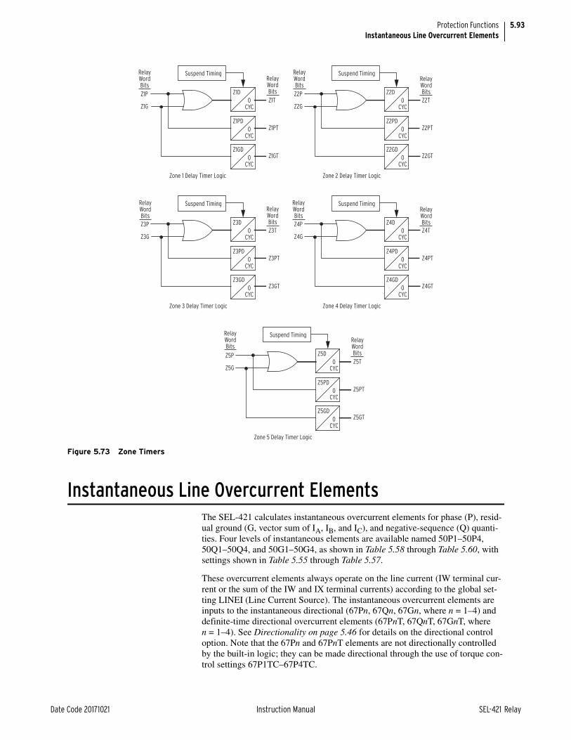
5.93
Date Code 20171021 Instruction Manual SEL-421 Relay
Protection FunctionsInstantaneous Line Overcurrent Elements
Instantaneous Line Overcurrent ElementsThe SEL-421 calculates instantaneous overcurrent elements for phase (P), resid-ual ground (G, vector sum of IA, IB, and IC), and negative-sequence (Q) quanti-ties. Four levels of instantaneous elements are available named 50P1–50P4, 50Q1–50Q4, and 50G1–50G4, as shown in Table 5.58 through Table 5.60, with settings shown in Table 5.55 through Table 5.57.
These overcurrent elements always operate on the line current (IW terminal cur-rent or the sum of the IW and IX terminal currents) according to the global set-ting LINEI (Line Current Source). The instantaneous overcurrent elements are inputs to the instantaneous directional (67Pn, 67Qn, 67Gn, where n = 1–4) and definite-time directional overcurrent elements (67PnT, 67QnT, 67GnT, where n = 1–4). See Directionality on page 5.46 for details on the directional control option. Note that the 67Pn and 67PnT elements are not directionally controlled by the built-in logic; they can be made directional through the use of torque con-trol settings 67P1TC–67P4TC.
Figure 5.73 Zone Timers
RelayWordBits
RelayWordBits
RelayWordBits
RelayWordBits
RelayWordBits
RelayWordBits
RelayWordBits
RelayWordBits
RelayWordBits
RelayWordBits
Z1D
Z1T
Z1PT
Z1GT
Z1P
Z1G
Suspend Timing
Zone 1 Delay Timer Logic
0CYC
Z1PD
0CYC
Z1GD
0CYC
Z2D
Z2T
Z2PT
Z2GT
Z2P
Z2G
Suspend Timing
Zone 2 Delay Timer Logic
0CYC
Z2PD
0CYC
Z2GD
0CYC
Z3D
Z3T
Z3PT
Z3GT
Z3P
Z3G
Suspend Timing
Zone 3 Delay Timer Logic
0CYC
Z3PD
0CYC
Z3GD
0CYC
Z4D
Z4T
Z4PT
Z4GT
Z4P
Z4G
Suspend Timing
Zone 4 Delay Timer Logic
0CYC
Z4PD
0CYC
Z4GD
0CYC
Z5D
Z5T
Z5PT
Z5GT
Z5P
Z5G
Suspend Timing
Zone 5 Delay Timer Logic
0CYC
Z5PD
0CYC
Z5GD
0CYC

5.94
SEL-421 Relay Instruction Manual Date Code 20171021
Protection FunctionsInstantaneous Line Overcurrent Elements
Each of the instantaneous directional elements includes a torque control setting (67PnTC, 67QnTC, 67GnTC, where n = 1–4) to supervise the element operation.
The enable settings (E50P, E50Q, E50G) control how many of each type of instantaneous/definite-time overcurrent elements are available. For example, if E50P := 2, only 50P1, 67P1, 67P1T, 50P2, 67P2, and 67P2T are processed. The remaining phase instantaneous/definite-time overcurrent elements (n = 3–4) are defeated, and the output Relay Word bits are forced to logical 0.
Table 5.55 Phase Overcurrent Element Settings
Setting Prompt Range Default (5 A)
Phase Instantaneous Overcurrent Elements
E50P Phase Inst./Def.-Time O/C Elements N, 1–4 1
50P1P Level 1 Pickup (A) OFF, (0.05–20) • INOM 10.00
50P2P Level 2 Pickup (A) OFF, (0.05–20) • INOM OFF
50P3P Level 3 Pickup (A) OFF, (0.05–20) • INOM OFF
50P4P Level 4 Pickup (A) OFF, (0.05–20) • INOM OFF
Phase Definite-Time Overcurrent Elements
67P1D Level 1 Time Delay (cycles) 0.000–16000 0.000
67P2D Level 2 Time Delay (cycles) 0.000–16000 0.000
67P3D Level 3 Time Delay (cycles) 0.000–16000 0.000
67P4D Level 4 Time Delay (cycles) 0.000–16000 0.000
67P1TC Level 1 Torque Control SELOGIC Equation 1
67P2TC Level 2 Torque Control SELOGIC Equation 1
67P3TC Level 3 Torque Control SELOGIC Equation 1
67P4TC Level 4 Torque Control SELOGIC Equation 1
Table 5.56 Negative-Sequence Overcurrent Element Settings
Setting Prompt RangeDefault (5 A)
Negative-Sequence Instantaneous Overcurrent Elements
E50Q Neg.-Seq. Inst./Def.-Time O/C Elements N, 1–4 N
50Q1P Level 1 Pickup (A) OFF, (0.05–20) • INOM OFF
50Q2P Level 2 Pickup (A) OFF, (0.05–20) • INOM OFF
50Q3P Level 3 Pickup (A) OFF, (0.05–20) • INOM OFF
50Q4P Level 4 Pickup (A) OFF, (0.05–20) • INOM OFF
Negative-Sequence Definite-Time Overcurrent Elements
67Q1D Level 1 Time Delay (cycles) 0.000–16000 0.000
67Q2D Level 2 Time Delay (cycles) 0.000–16000 0.000
67Q3D Level 3 Time Delay (cycles) 0.000–16000 0.000
67Q4D Level 4 Time Delay (cycles) 0.000–16000 0.000
67Q1TC Level 1 Torque Control SELOGIC Equation 1
67Q2TC Level 2 Torque Control SELOGIC Equation 1
67Q3TC Level 3 Torque Control SELOGIC Equation 1
67Q4TC Level 4 Torque Control SELOGIC Equation 1

5.95
Date Code 20171021 Instruction Manual SEL-421 Relay
Protection FunctionsInstantaneous Line Overcurrent Elements
NOTE: If the relay is using a remote data acquisition system, such as TiDL, the operating times will be delayed by 1.5 ms. Use caution when setting the relay coordination times to account for this added delay.
Table 5.57 Residual Ground Overcurrent Element Settings
Setting Prompt RangeDefault (5 A)
Residual Ground Instantaneous Overcurrent Elements
E50G Residual Ground Inst./Def.-TimeO/C Elements
N, 1–4 N
50G1P Level 1 Pickup (A) OFF, (0.05–20) • INOM OFF
50G2P Level 2 Pickup (A) OFF, (0.05–20) • INOM OFF
50G3P Level 3 Pickup (A) OFF, (0.05–20) • INOM OFF
50G4P Level 4 Pickup (A) OFF, (0.05–20) • INOM OFF
Residual Ground Definite-Time Overcurrent Elements
67G1D Level 1 Time Delay (cycles) 0.000–16000 0.000
67G2D Level 2 Time Delay (cycles) 0.000–16000 0.000
67G3D Level 3 Time Delay (cycles) 0.000–16000 0.000
67G4D Level 4 Time Delay (cycles) 0.000–16000 0.000
67G1TC Level 1 Torque Control SELOGIC Equation 1
67G2TC Level 2 Torque Control SELOGIC Equation 1
67G3TC Level 3 Torque Control SELOGIC Equation 1
67G4TC Level 4 Torque Control SELOGIC Equation 1
Table 5.58 Phase Instantaneous/Definite-Time Line Overcurrent Relay Word Bits
Name Description
50P1 Level 1 instantaneous phase overcurrent element
50P2 Level 2 instantaneous phase overcurrent element
50P3 Level 3 instantaneous phase overcurrent element
50P4 Level 4 instantaneous phase overcurrent element
67P1 Level 1 definite-time phase directional overcurrent element
67P2 Level 2 definite-time phase directional overcurrent element
67P3 Level 3 definite-time phase directional overcurrent element
67P4 Level 4 definite-time phase directional overcurrent element
67P1T Level 1 time-delayed definite-time phase directional overcurrent element
67P2T Level 2 time-delayed definite-time phase directional overcurrent element
67P3T Level 3 time-delayed definite-time phase directional overcurrent element
67P4T Level 4 time-delayed definite-time phase directional overcurrent element
Table 5.59 Negative-Sequence Instantaneous/Definite-Time Line Overcurrent Relay Word Bits (Sheet 1 of 2)
Name Description
50Q1 Level 1 instantaneous negative-sequence overcurrent element
50Q2 Level 2 instantaneous negative-sequence overcurrent element
50Q3 Level 3 instantaneous negative-sequence overcurrent element
50Q4 Level 4 instantaneous negative-sequence overcurrent element
67Q1 Level 1 definite-time negative-sequence directional overcurrent element
67Q2 Level 2 definite-time negative-sequence directional overcurrent element
NOTE: If the relay is using a remote data acquisition system, such as TiDL, the operating times will be delayed by 1.5 ms. Use caution when setting the relay coordination times to account for this added delay.

5.96
SEL-421 Relay Instruction Manual Date Code 20171021
Protection FunctionsInstantaneous Line Overcurrent Elements
67Q3 Level 3 definite-time negative-sequence directional overcurrent element
67Q4 Level 4 definite-time negative-sequence directional overcurrent element
67Q1T Level 1 time-delayed definite-time negative-sequence directional overcurrent element
67Q2T Level 2 time-delayed definite-time negative-sequence directional overcurrent element
67Q3T Level 3 time-delayed definite-time negative-sequence directional overcurrent element
67Q4T Level 4 time-delayed definite-time negative-sequence directional overcurrent element
Table 5.60 Residual Ground Instantaneous/Definite-Time Line Overcurrent Relay Word Bits
Name Description
50G1 Level 1 instantaneous residual ground overcurrent element
50G2 Level 2 instantaneous residual ground overcurrent element
50G3 Level 3 instantaneous residual ground overcurrent element
50G4 Level 4 instantaneous residual ground overcurrent element
67G1 Level 1 definite-time residual ground directional overcurrent element
67G2 Level 2 definite-time residual ground directional overcurrent element
67G3 Level 3 definite-time residual ground directional overcurrent element
67G4 Level 4 definite-time residual ground directional overcurrent element
67G1T Level 1 time-delayed definite-time residual ground directional overcurrent element
67G2T Level 2 time-delayed definite-time residual ground directional overcurrent element
67G3T Level 3 time-delayed definite-time residual ground directional overcurrent element
67G4T Level 4 time-delayed definite-time residual ground directional overcurrent element
Table 5.59 Negative-Sequence Instantaneous/Definite-Time Line Overcurrent Relay Word Bits (Sheet 2 of 2)
Name Description

5.97
Date Code 20171021 Instruction Manual SEL-421 Relay
Protection FunctionsInstantaneous Line Overcurrent Elements
Figure 5.74 Phase Instantaneous/Definite-Time Overcurrent Elements
—
+
—
+
—
+
67P1D
67P1
50P1
IAL
IBL
ICL
67P1TC(SELOGIC
Setting)
50P1P(Setting)
67P1T
0
—
+
—
+
—
+
67P2D
67P2
50P2
67P2TC(SELOGIC
Setting)
50P2P(Setting)
67P2T
0—
+
—
+
—
+
67P3D
67P3
50P3
67P3TC(SELOGIC
Setting)
50P3P(Setting)
67P3T
67P4T
0—
+
—
+
—
+
67P4D
67P4
50P4
67P4TC(SELOGIC
Setting)
50P4P(Setting)
0
RelayWordBits

5.98
SEL-421 Relay Instruction Manual Date Code 20171021
Protection FunctionsInstantaneous Line Overcurrent Elements
Figure 5.75 Residual Ground Instantaneous/Directional Overcurrent Elements
67G1D
0
—
+50G1
67G1
67G1T
IGL
50G1P(Setting)
67G1TC(SELOGIC
Setting)
32GF(Relay
Word Bit)
RelayWordBits
67G2D
0
—
+50G2
67G2
67G2T
50G2P(Setting)
67G2TC(SELOGIC
Setting)
32GF(Relay
Word Bit)
67G3D
0
—
+50G3
67G3
67G3T
50G3P (Setting)
DIR3 := F(Setting)
67G3TC(SELOGIC
Setting)
32GF(Relay
Word Bit)
32GR (Relay
Word Bit)
67G4D
0
—
+50G4
67G4
67G4T
50G4P (Setting)
DIR4 := F(Setting)
67G4TC(SELOGIC
Setting)
32GF(Relay
Word Bit)
32GR (Relay
Word Bit)

5.99
Date Code 20171021 Instruction Manual SEL-421 Relay
Protection FunctionsInverse-Time Overcurrent Elements
Inverse-Time Overcurrent ElementsThe SEL-421 provides three selectable operating quantity inverse-time overcur-rent elements. Ten different time-overcurrent characteristics (5 U.S. and 5 IEC curves) are available.
Each time-overcurrent element can be configured to operate on the line current (i.e., IW terminal current or the sum of the IW and IX terminal currents) depend-ing upon setting LINEI; or circuit breaker operating quantities, with the terminal source depending upon settings BK1I and BK2I.
Symmetrical component current quantities are available only for the line-current source. Table 5.61 defines the available setting choices for operating quantities and the corresponding analog quantity name as found in Section 12: Analog Quantities.
Figure 5.76 Negative-Sequence Instantaneous/Directional Overcurrent Elements
67Q1D
0
—
+50Q1
67Q1
67Q1T
3I2L
50Q1P(Setting)
67Q1TC(SELOGIC
Setting)
32QF(Relay
Word Bit)
RelayWordBits
67Q2D
0
—
+50Q2
67Q2
67Q2T
50Q2P(Setting)
67Q2TC(SELOGIC
Setting)
32QF(Relay
Word Bit)
67Q3D
0
—
+50Q3
67Q3
67Q3T
50Q3P (Setting)
DIR3 := F(Setting)
67Q3TC(SELOGIC
Setting)
32QF(Relay
Word Bit)
32QR (Relay
Word Bit)
67Q4D
0
—
+50Q4
67Q4
67Q4T
50Q4P (Setting)
DIR4 := F(Setting)
67Q4TC(SELOGIC
Setting)
32QF(Relay
Word Bit)
32QR (Relay
Word Bit)
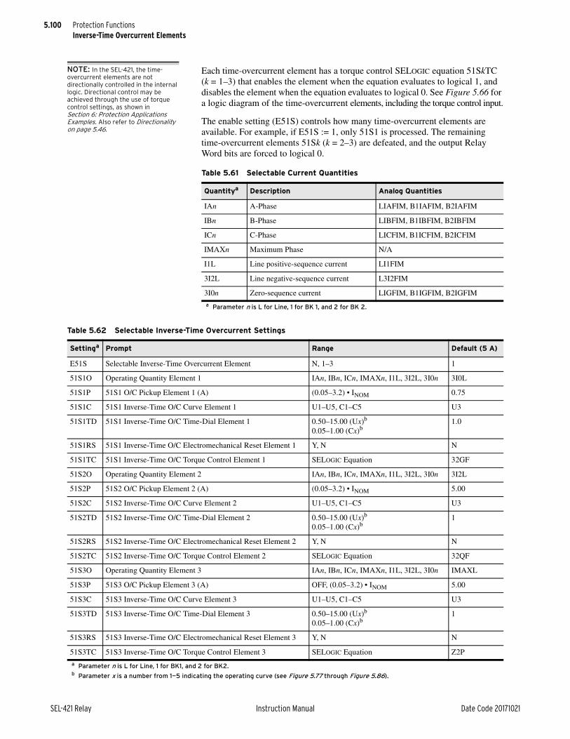
5.100
SEL-421 Relay Instruction Manual Date Code 20171021
Protection FunctionsInverse-Time Overcurrent Elements
NOTE: In the SEL-421, the time-overcurrent elements are not directionally controlled in the internal logic. Directional control may be achieved through the use of torque control settings, as shown in Section 6: Protection Applications Examples. Also refer to Directionality on page 5.46.
Each time-overcurrent element has a torque control SELOGIC equation 51SkTC (k = 1–3) that enables the element when the equation evaluates to logical 1, and disables the element when the equation evaluates to logical 0. See Figure 5.66 for a logic diagram of the time-overcurrent elements, including the torque control input.
The enable setting (E51S) controls how many time-overcurrent elements are available. For example, if E51S := 1, only 51S1 is processed. The remaining time-overcurrent elements 51Sk (k = 2–3) are defeated, and the output Relay Word bits are forced to logical 0.
Table 5.61 Selectable Current Quantities
Quantitya
a Parameter n is L for Line, 1 for BK 1, and 2 for BK 2.
Description Analog Quantities
IAn A-Phase LIAFIM, B1IAFIM, B2IAFIM
IBn B-Phase LIBFIM, B1IBFIM, B2IBFIM
ICn C-Phase LICFIM, B1ICFIM, B2ICFIM
IMAXn Maximum Phase N/A
I1L Line positive-sequence current LI1FIM
3I2L Line negative-sequence current L3I2FIM
3I0n Zero-sequence current LIGFIM, B1IGFIM, B2IGFIM
Table 5.62 Selectable Inverse-Time Overcurrent Settings
Settinga
a Parameter n is L for Line, 1 for BK1, and 2 for BK2.
Prompt Range Default (5 A)
E51S Selectable Inverse-Time Overcurrent Element N, 1–3 1
51S1O Operating Quantity Element 1 IAn, IBn, ICn, IMAXn, I1L, 3I2L, 3I0n 3I0L
51S1P 51S1 O/C Pickup Element 1 (A) (0.05–3.2) • INOM 0.75
51S1C 51S1 Inverse-Time O/C Curve Element 1 U1–U5, C1–C5 U3
51S1TD 51S1 Inverse-Time O/C Time-Dial Element 1 0.50–15.00 (Ux)b
0.05–1.00 (Cx)b
b Parameter x is a number from 1—5 indicating the operating curve (see Figure 5.77 through Figure 5.86).
1.0
51S1RS 51S1 Inverse-Time O/C Electromechanical Reset Element 1 Y, N N
51S1TC 51S1 Inverse-Time O/C Torque Control Element 1 SELOGIC Equation 32GF
51S2O Operating Quantity Element 2 IAn, IBn, ICn, IMAXn, I1L, 3I2L, 3I0n 3I2L
51S2P 51S2 O/C Pickup Element 2 (A) (0.05–3.2) • INOM 5.00
51S2C 51S2 Inverse-Time O/C Curve Element 2 U1–U5, C1–C5 U3
51S2TD 51S2 Inverse-Time O/C Time-Dial Element 2 0.50–15.00 (Ux)b
0.05–1.00 (Cx)b1
51S2RS 51S2 Inverse-Time O/C Electromechanical Reset Element 2 Y, N N
51S2TC 51S2 Inverse-Time O/C Torque Control Element 2 SELOGIC Equation 32QF
51S3O Operating Quantity Element 3 IAn, IBn, ICn, IMAXn, I1L, 3I2L, 3I0n IMAXL
51S3P 51S3 O/C Pickup Element 3 (A) OFF, (0.05–3.2) • INOM 5.00
51S3C 51S3 Inverse-Time O/C Curve Element 3 U1–U5, C1–C5 U3
51S3TD 51S3 Inverse-Time O/C Time-Dial Element 3 0.50–15.00 (Ux)b
0.05–1.00 (Cx)b1
51S3RS 51S3 Inverse-Time O/C Electromechanical Reset Element 3 Y, N N
51S3TC 51S3 Inverse-Time O/C Torque Control Element 3 SELOGIC Equation Z2P

5.101
Date Code 20171021 Instruction Manual SEL-421 Relay
Protection FunctionsInverse-Time Overcurrent Elements
Time-Current Operating CharacteristicsNOTE: If the relay is using a remote data acquisition system, such as TiDL, the operating times will be delayed by 1.5 ms. Use caution when setting the relay coordination times to account for this added delay.
The following information describes curve timing for time-overcurrent element curve and time-dial settings. The time-overcurrent relay curves in Figure 5.77 through Figure 5.86 conform to IEEE C37.112–1996 IEEE Standard Inverse-Time Characteristic Equations for Overcurrent Relays.
Table 5.63 Selectable Inverse-Time Overcurrent Relay Word Bits
Name Description
51S1 Inverse-Time Overcurrent Element 1 pickup
51S1T Inverse-Time Overcurrent Element 1 timed out
51S1R Inverse-Time Overcurrent Element 1 reset
51S2 Inverse-Time Overcurrent Element 2 pickup
51S2T Inverse-Time Overcurrent Element 2 timed out
51S2R Inverse-Time Overcurrent Element 2 reset
51S3 Inverse-Time Overcurrent Element 3 pickup
51S3T Inverse-Time Overcurrent Element 3 timed out
51S3R Inverse-Time Overcurrent Element 3 reset
Tp = operating time in seconds
Tr = electromechanical induction-disk emulation reset time in sec-onds (if you select electromechanical reset setting)
TD = time-dial setting
M = applied multiples of pickup current [for operating time (Tp), M > 1; for reset time (Tr), M 1]
Table 5.64 Equations Associated With U.S. Curves
Curve Type Operating Time Reset Time Figure
U1 (Moderately Inverse) Figure 5.77
U2 (Inverse) Figure 5.78
U3 (Very Inverse) Figure 5.79
U4 (Extremely Inverse) Figure 5.80
U5 (Short-Time Inverse) Figure 5.81
Tp TD 0.0226 0.0104M0.02 1–--------------------+
• = Tr TD 1.081 M2–---------------- • =
Tp TD 0.180 5.95M2 1–----------------+
• = Tr TD 5.951 M2–---------------- • =
Tp TD 0.0963 3.88M2 1–----------------+
• = Tr TD 3.881 M2–---------------- • =
Tp TD 0.02434 5.64M2 1–----------------+
• = Tr TD 5.641 M2–---------------- • =
Tp TD 0.00262 0.00342M0.02 1–--------------------+
• = Tr TD 0.3231 M2–---------------- • =
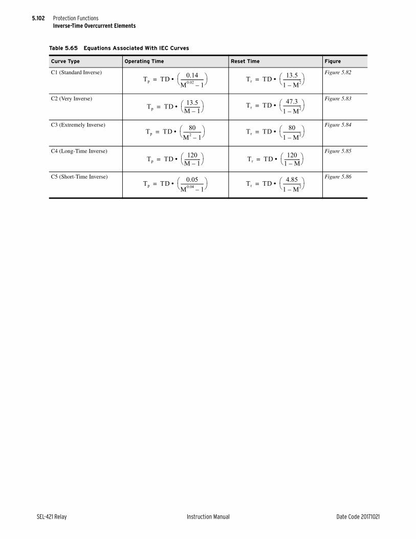
5.102
SEL-421 Relay Instruction Manual Date Code 20171021
Protection FunctionsInverse-Time Overcurrent Elements
Table 5.65 Equations Associated With IEC Curves
Curve Type Operating Time Reset Time Figure
C1 (Standard Inverse) Figure 5.82
C2 (Very Inverse) Figure 5.83
C3 (Extremely Inverse) Figure 5.84
C4 (Long-Time Inverse) Figure 5.85
C5 (Short-Time Inverse) Figure 5.86
Tp TD 0.14M0.02 1–-------------------- • = Tr TD 13.5
1 M2–---------------- • =
Tp TD 13.5M 1–-------------- • = Tr TD 47.3
1 M2–---------------- • =
Tp TD 80M2 1–---------------- • = Tr TD 80
1 M2–---------------- • =
Tp TD 120M 1–-------------- • = Tr TD 120
1 M–-------------- • =
Tp TD 0.05M0.04 1–-------------------- • = Tr TD 4.85
1 M2–---------------- • =

5.103
Date Code 20171021 Instruction Manual SEL-421 Relay
Protection FunctionsInverse-Time Overcurrent Elements
Figure 5.77 U.S. Moderately Inverse—U1
0.50
6.005.00
4.00
3.00
2.00
1.00
15.00
12.0010.00
8.00
.01.5 .6 .7 .8 .9 1
.02
.03
.04
.05
.09
.07
.06
.08
.1
.2
.3
.4
.5
.7
.6
.9
.8
1
42 3 5 6 7 8 9 10 4020 30 7050 60 80 90 100
80
10
2
3
6
4
5
7
98
20
50
30
40
60
70
10090
Tim
e in
Sec
onds
Multiples of Pickup
Tim
e in
Cyc
les
60 H
z (5
0 H
z)
3 (2.5)
6 (5)
15 (12.5)
30 (25)
60 (50)
600 (500)
150 (125)
300 (250)
1500 (1250)
3000 (2500)
6000 (5000)

5.104
SEL-421 Relay Instruction Manual Date Code 20171021
Protection FunctionsInverse-Time Overcurrent Elements
Figure 5.78 U.S. Inverse—U2
0.50
6.005.00
4.00
3.00
2.00
1.00
15.00
12.0010.00
8.00
.01.5 .6 .7 .8 .9 1
.02
.03
.04
.05
.09
.07
.06
.08
.1
.2
.3
.4
.5
.7
.6
.9
.8
1
42 3 5 6 7 8 9 10 4020 30 7050 60 80 90 100
80
10
2
3
6
4
5
7
98
20
50
30
40
60
70
10090
Tim
e in
Sec
onds
Multiples of Pickup
Tim
e in
Cyc
les
60 H
z (5
0 H
z)
3 (2.5)
6 (5)
15 (12.5)
30 (25)
60 (50)
600 (500)
150 (125)
300 (250)
1500 (1250)
3000 (2500)
6000 (5000)

5.105
Date Code 20171021 Instruction Manual SEL-421 Relay
Protection FunctionsInverse-Time Overcurrent Elements
Figure 5.79 U.S. Very Inverse—U3
12.00
1.00
0.50
10.00
8.00
6.005.00
4.00
3.00
2.00
15.00
.01.5 .6 .7 .8 .9 1
.02
.03
.04
.05
.09
.07
.06
.08
.1
.2
.3
.4
.5
.7
.6
.9
.8
1
42 3 5 6 7 8 9 10 4020 30 7050 60 80 90 100
80
10
2
3
6
4
5
7
98
20
50
30
40
60
70
10090
Tim
e in
Sec
onds
Multiples of Pickup
Tim
e in
Cyc
les
60 H
z (5
0 H
z)
3 (2.5)
6 (5)
15 (12.5)
30 (25)
60 (50)
600 (500)
150 (125)
300 (250)
1500 (1250)
3000 (2500)
6000 (5000)

5.106
SEL-421 Relay Instruction Manual Date Code 20171021
Protection FunctionsInverse-Time Overcurrent Elements
Figure 5.80 U.S. Extremely Inverse—U4
.01.5 .6 .7 .8 .9 1
.02
.03
.04
.05
.09
.07
.06
.08
.1
.2
.3
.4
.5
.7
.6
.9
.8
1
42 3 5 6 7 8 9 10 4020 30 7050
60
80
90
100
80
10
2
3
6
4
5
7
98
20
50
30
40
6070
10090
Tim
e in
Sec
on
ds
Multiples of Pickup
3.00
2.00
1.00
0.50
15.00
12.0010.00
8.00
6.005.00
4.00
Tim
e in
Cyc
les
60 H
z (5
0H
z)
3 (2.5)
6 (5)
15 (12.5)
30 (25)
60 (50)
600 (500)
150 (125)
300 (250)
1500 (1250)
3000 (2500)
6000 (5000)

5.107
Date Code 20171021 Instruction Manual SEL-421 Relay
Protection FunctionsInverse-Time Overcurrent Elements
Figure 5.81 U.S. Short-Time Inverse—U5
0.50
1.00
2.00
6.00
3.00
4.00
5.00
10.00
8.00
12.00
15.00
.01.5 .6 .7 .8 1.9
.02
.03
.04
.05
.06
.07
.1
.08
.09
.2
.3
.4
.5
.6
1
.7
.8
.9
2 3 4 5 6 7 8 109 20 30 5040 60 1009070 80
80
9
2
3
4
5
6
78
10
20
30
40
50
60
70
90100
Tim
e in
Sec
onds
Multiples of Pickup
Tim
e in
Cyc
les
60 H
z (5
0 H
z)
3 (2.5)
6 (5)
15 (12.5)
60 (50)
30 (25)
150 (125)
300 (250)
1500 (1250)
600 (500)
3000 (2500)
6000 (5000)
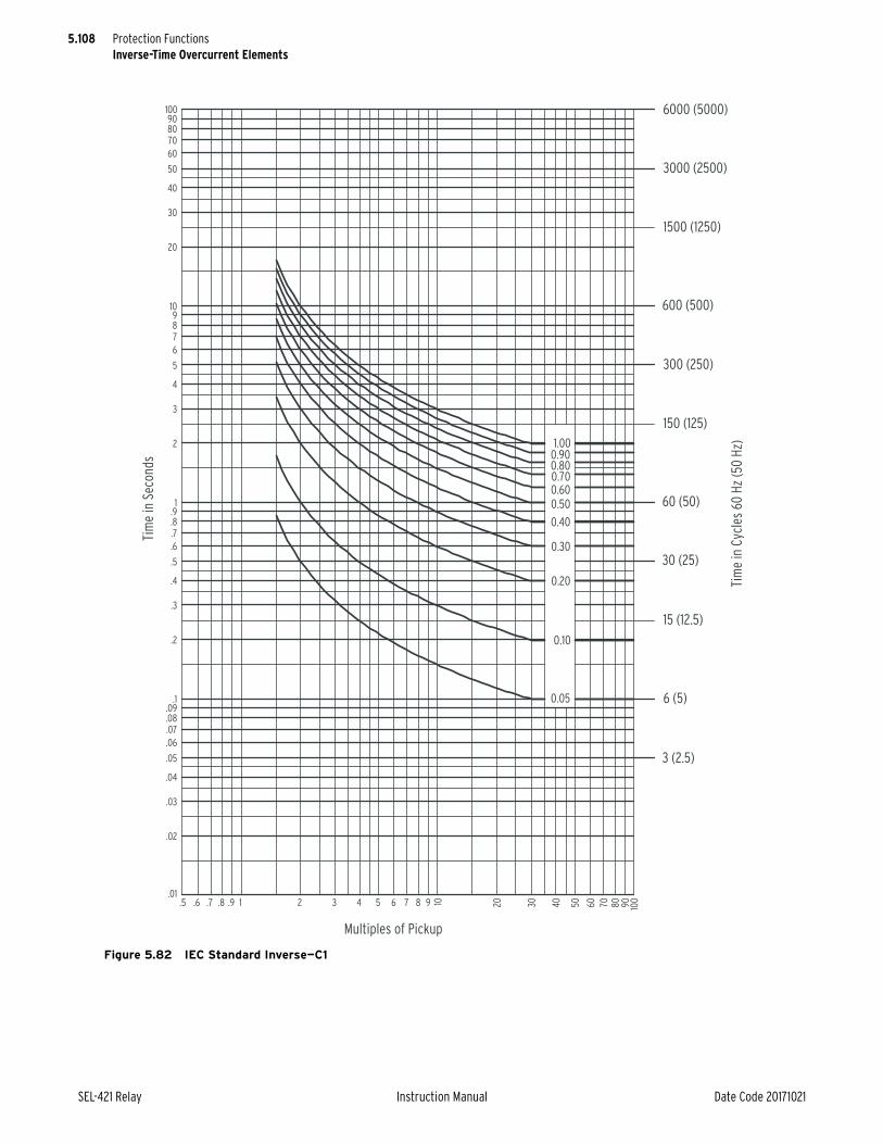
5.108
SEL-421 Relay Instruction Manual Date Code 20171021
Protection FunctionsInverse-Time Overcurrent Elements
Figure 5.82 IEC Standard Inverse—C1
0.60
0.05
0.50
0.40
0.30
0.20
0.10
1.000.900.800.70
.01.5 .6 .7 .8 .9 1
.02
.03
.04
.05
.09
.07
.06
.08
.1
.2
.3
.4
.5
.7
.6
.9
.8
1
42 3 5 6 7 8 9 10 4020 30 7050 60 80 90 100
80
10
2
3
6
4
5
7
98
20
50
30
40
60
70
10090
Tim
e in
Sec
onds
Multiples of Pickup
Tim
e in
Cyc
les
60 H
z (5
0 H
z)
3 (2.5)
6 (5)
15 (12.5)
30 (25)
60 (50)
600 (500)
150 (125)
300 (250)
1500 (1250)
3000 (2500)
6000 (5000)

5.109
Date Code 20171021 Instruction Manual SEL-421 Relay
Protection FunctionsInverse-Time Overcurrent Elements
Figure 5.83 IEC Very Inverse—C2
0.30
0.20
0.10
0.05
1.000.900.800.700.60
0.50
0.40
.01.5 .6 .7 .8 .9 1
.02
.03
.04
.05
.09
.07
.06
.08
.1
.2
.3
.4
.5
.7
.6
.9
.8
1
42 3 5 6 7 8 9 10 4020 30 7050 60 80 90 100
80
10
2
3
6
4
5
7
98
20
50
30
40
60
70
10090
Tim
e in
Sec
onds
Multiples of Pickup
Tim
e in
Cyc
les
60 H
z (5
0 H
z)
3 (2.5)
6 (5)
15 (12.5)
30 (25)
60 (50)
600 (500)
150 (125)
300 (250)
1500 (1250)
3000 (2500)
6000 (5000)

5.110
SEL-421 Relay Instruction Manual Date Code 20171021
Protection FunctionsInverse-Time Overcurrent Elements
Figure 5.84 IEC Extremely Inverse—C3
.01.5 .6 .7 .8 .9 1
.02
.03
.04
.05
.09
.07
.06
.08
.1
.2
.3
.4
.5
.7
.6
.9
.8
1
42 3 5 6 7 8 9 10 4020 30 7050 60 80 90 100
80
10
2
3
6
4
5
7
98
20
50
30
40
60
70
10090
0.200.10
0.05
1.000.900.800.700.60
0.50
0.40
0.30
Tim
e in
Sec
onds
Multiples of Pickup
Tim
e in
Cyc
les
60 H
z (5
0 H
z)
3 (2.5)
6 (5)
15 (12.5)
30 (25)
60 (50)
600 (500)
150 (125)
300 (250)
1500 (1250)
3000 (2500)
6000 (5000)

5.111
Date Code 20171021 Instruction Manual SEL-421 Relay
Protection FunctionsInverse-Time Overcurrent Elements
Figure 5.85 IEC Long-Time Inverse—C4
0.20
0.10
0.05
1.000.900.800.700.60
0.50
0.40
0.30
.7.6.5.1
.9.8 1
.4
.2
.3
.5
.6
.8
.7
.91
2
3
4
5
7
6
42 3 765 1098 4020 30 7050 60 80 90 100
50
98
10
20
30
40
300
200
100
80
60
70
90
1000900800700
600
500
400
Tim
e in
Sec
onds
Multiples of Pickup
Tim
e in
Cyc
les
60 H
z (5
0 H
z)
30 (25)
60 (50)
150 (125)
300 (250)
3000 (2500)
600 (500)
1500 (1250)
6000 (5000)
15000 (12500)
30000 (25000)
60000 (50000)

5.112
SEL-421 Relay Instruction Manual Date Code 20171021
Protection FunctionsInverse-Time Overcurrent Elements
Figure 5.86 IEC Short-Time Inverse—C5
10
20
30
40
50
60708090
100
1
2
3
4
5
6789
.1
.2
.3
.4
.5
.6
.7
.8
.9
.01
.02
.03
.04
.05
.06
.07
.08
.09
1001 2 3 4 5 6 7 8 9.5 .6 .7 .8 .9 908070605040302010
Tim
e in
Sec
on
ds
Tim
e in
Cyc
les
60 H
z (5
0 H
z)
6000 (5000)
3000 (2500)
1500 (1250)
600 (500)
300 (250)
150 (125)
60 (50)
30 (25)
15 (12.5)
6 (5)
3 (2.5)
Multiples of Pickup
0.05
0.10
0.20
0.30
0.40
0.50
0.60
0.700.800.901.00

5.113
Date Code 20171021 Instruction Manual SEL-421 Relay
Protection FunctionsOver- and Undervoltage Elements
NOTE: If the relay is using a remote data acquisition system, such as TiDL, the operating times will be delayed by 1.5 ms. Use caution when setting the relay coordination times to account for this added delay.
Over- and Undervoltage ElementsInstead of having dedicated operating quantities for the undervoltage and over-voltage elements, the relay offers the flexibility of unassigned elements. Unas-signed means that the undervoltage and overvoltage elements are not assigned to a specific input quantity, but they are available for assignment, as the application requires.
The relay offers as many as six undervoltage and six overvoltage elements. Each of these 12 elements has two levels, for a total of 24 over- and undervoltage ele-ments. Figure 5.88 shows the undervoltage element logic, and Figure 5.89 shows the undervoltage element logic.
The relay supports two voltage terminals, Y and Z. Select any one of the voltage quantities from Table 5.66 as an input quantity (27On and 59On settings). You can select the same quantity for an undervoltage element as for an overvoltage element.
Figure 5.87 Selectable Inverse-Time Overcurrent Element Logic Diagram
—
+51SkT
51SkP(Setting)
51SkTC(SELOGIC Setting)
51Sk
RelayWordBits
51SkR
k = 1, 2, or 3
n = 1, 2, or L
IAn
IMAXn
I1L
3I2L
3I0n
51SkO(Setting)
IBn
ICn
IMAXn = MAX (IAn, IBn, ICn)
51 Programmable Time-Overcurrent
Element
Figure 5.88 Undervoltage Elements
27On(Setting)
27TCn(SELOGIC)
27PnP1(Setting)
S1
S1
27nP1
27O1QOperationalQuantity
n = 1 – 6
27PnP2(Setting)
27nP2
27nP1T
Undervoltage Timer
(Infinity)
(Infinity)
1
1
27PnD1
0

5.114
SEL-421 Relay Instruction Manual Date Code 20171021
Protection FunctionsOver- and Undervoltage Elements
Although each under- and overvoltage element offers two levels, only Level 1 has a timer. If your application requires a time delay for the Level 2 elements, use a programmable timer to delay the output.
Select any one of the voltage elements from Table 5.66 as an input quantity. You can select the same quantity for the undervoltage element as for an overvoltage element.
Under- and Overvoltage SettingsE59 (Enable Overvoltage Elements)
Select the number of overvoltage elements (1–6) you require for your application.
Figure 5.89 Overvoltage Elements
Table 5.66 Available Input Quantities
Voltage Quantity Description
VAFIM Filtered instantaneous A-Phase voltage magnitude
VBFIM Filtered instantaneous B-Phase voltage magnitude
VCFIM Filtered instantaneous C-Phase voltage magnitude
V1FIM Filtered instantaneous positive-sequence voltage magnitude
VNMAXF Maximum phase-to-neutral voltage magnitude
VNMINF Minimum phase-to-neutral voltage magnitude
VPMAXF Maximum phase-to-phase voltage magnitude
VPMINF Minimum phase-to-phase voltage magnitude
3V2FIMa
a These quantities are only available for the overvoltage (59) elements.
Filtered instantaneous negative-sequence voltage magnitude
3V0FIMa Filtered instantaneous zero-sequence voltage magnitude
59On(Setting)
59TCn(SELOGIC)
59PnP1(Setting)
S1
S1
59nP1
59O1QOperationalQuantity
n = 1 – 6
59PnP2(Setting)
59nP2
59nP1T
Overvoltage Timer
0
0
1
1
59PnD1
0
Setting Prompt Range Default Category
E59 Enable Overvoltage Elements N, 1–6 N Group

5.115
Date Code 20171021 Instruction Manual SEL-421 Relay
Protection FunctionsOver- and Undervoltage Elements
E27 (Enable Undervoltage Elements)Select the number of undervoltage elements (1–6) you require for your application.
27On (Undervoltage Element Operating Quantity)Select the desired operating quantity for each voltage terminal from Table 5.66.
27PnP1 (Undervoltage Level 1 Pickup)Set pickup values for the voltage values below that you want the Level 1 under-voltage elements to assert.
27PnP2 (Undervoltage Level 2 Pickup)Set pickup values for the voltage values below that you want the Level 2 under-voltage elements to assert.
27TCn (Undervoltage Torque Control)Use the torque-control setting to specify conditions under which the undervoltage elements must be active. There is only one setting for both Level 1 and Level 2 elements. With the default setting equal to 1, both levels are active permanently.
Setting Prompt Range Default Category
E27 Enable Undervoltage Elements N, 1–6 N Group
Setting Prompt Range Default Category
27Ona
a n = 1–6.
U/V Element n Operating Quantity See Table 5.66 V1FIM Group
Setting Prompt Range Default Category
27PnP1a
a n = 1–6.
U/V Element n Level 1 P/U 2.00 to 300 volts, sec. 20 Group
Setting Prompt Range Default Category
27PnP2 U/V Element n Level 2 P/U 2.00 to 300 volts, sec. 15 Group
Setting Prompt Range Default Category
27TCna
a n = 1–6.
U/V Element n Torque Control (SELOGIC Equation)
SELOGIC Equation 1 Group

5.116
SEL-421 Relay Instruction Manual Date Code 20171021
Protection FunctionsOver- and Undervoltage Elements
27PnD1 (Undervoltage Level 1 Time Delay)NOTE: If the relay is using a remote data acquisition system, such as TiDL, the operating times will be delayed by 1.5 ms. Use caution when setting the relay coordination times to account for this added delay.
When the system voltage falls below the undervoltage setting value, the under-voltage timer starts timing. Set the delay (in cycles) for which the timer must run before the output asserts.
59On (Overvoltage Element Operating Quantity)Select from Table 1.70 the desired operating quantity for each voltage terminal.
59PnP1 (Overvoltage Level 1 Pickup)Set pickup values for the voltage values above which you want the Level 1 over-voltage elements to assert.
59PnP2 (Overvoltage Level 2 Pickup)Set pickup values for the voltage value above which you want the Level 2 over-voltage elements to assert.
59TCn (Overvoltage Torque Control)Use the torque-control setting to specify conditions under which the overvoltage elements must be active. There is only one setting for both Level 1 and Level 2 elements. With the default setting equal to 1, both levels are active permanently.
Setting Prompt Range Default Category
27PnD1a
a n = 1–6.
U/V Element n Level 1 Delay 0.00 to 16000 cyc. 10 Group
Setting Prompt Range Default Category
59Ona
a n = 1–6.
O/V Element n Operating Quantity See Table 5.66 V1FIM Group
Setting Prompt Range Default Category
59PnP1a
a n = 1–6.
O/V Element n Level 1 P/U 2.00 to 300 volts, sec. 76 Group
Setting Prompt Range Default Category
59PnP2a
a n = 1–6.
O/V Element n Level 2 P/U 2.00 to 300 volts, sec. 80 Group
Setting Prompt Range Default Category
59TCna
a n = 1–6.
O/V Element n Torque Control (SELOGIC Equation)
SELOGIC Equation 1 Group

5.117
Date Code 20171021 Instruction Manual SEL-421 Relay
Protection FunctionsSwitch-Onto-Fault Logic
59PnD1 (Overvoltage Level 1 Time Delay)When the system voltage exceeds the overvoltage setting value, the overvoltage timer starts timing. Set the delay (in cycles) for which the timer must run before the output asserts.
Switch-Onto-Fault LogicThe switch-onto-fault (SOTF) logic permits specified protection elements to trip for a settable time after the circuit breaker closes. Specify these elements in the SELOGIC control equation TRSOTF (switch-onto-fault trip). The SOTF logic works in two stages: validating a possible SOTF condition and initiating (enabling) the SOTF protection duration.
The relay validates an SOTF condition by sensing the following:
➤ Upon circuit breaker opening: detection of a pole-open condition (3PO or SPO) when setting 52AEND (52A Pole-Open Qualifying Time Delay) is other than OFF
➤ Upon circuit breaker closing: detection of a pole-open condition (3PO or SPO) when setting CLOEND (CLSMON or Single-Pole Open Delay) is other than OFF
Select either or both methods for the validating procedure.
The relay initiates SOTF protection at these corresponding instances:
➤ Circuit breaker opening: 52AEND timer timeout
➤ Circuit breaker closing: CLOEND time timeout and SELOGIC control equation CLSMON assertion
Circuit Breaker Opened SOTF LogicSet ESOTF to Y and set 52AEND to other than OFF to enable the circuit breaker-opened SOTF logic. When the circuit breaker opens, the 52AEND timer operates when one or three poles open (SPO or 3PO assert). The logic includes the SPO condition if setting ESPSTF := Y (see SOTF Options on page 5.118). When the 3PO or SPO condition lasts longer than the 52AEND timer, the relay asserts Relay Word bit SOTFE (SOTF Enable).
When the circuit breaker closes, either Relay Word bit 3PO deasserts after the 3POD dropout time or Relay Word bit SPO deasserts after the SPOD dropout time. When 3PO or SPO deasserts, the relay continues to assert Relay Word bit SOTFE for dropout time SOTFD or until the logic detects a healthy voltage con-dition (if EVRST := Y, see SOTF Options on page 5.118).
Setting Prompt Range Default Category
59PnD1a
a n = 1–6.
O/V Element n Level 1 Delay 0.00 to 16000 cyc. 10 Group

5.118
SEL-421 Relay Instruction Manual Date Code 20171021
Protection FunctionsSwitch-Onto-Fault Logic
Circuit Breaker Closed SOTF LogicYou can detect circuit breaker close bus assertion by monitoring the dc close bus. Connect a control input on the SEL-421 to the dc close bus. The control input energizes whenever a manual close or automatic reclosure occurs. Set SELOGIC control equation CLSMON (Close Signal Monitor) to monitor the control input (e.g., CLSMON := IN102) and consequently detect close bus assertion.
Set ESOTF to Y and set CLOEND to other than OFF to enable the circuit breaker-closed SOTF logic. The CLOEND timer operates when one or three poles open (SPO or 3PO asserts). If the 3PO or SPO condition continues longer than the CLOEND time and the close bus asserts (SELOGIC control equation CLSMON equals logical 1), Relay Word bit SOTFE asserts and remains asserted for dropout time setting SOTFD or until the logic detects a healthy voltage condi-tion (if EVRST := Y, see SOTF Options on page 5.118).
SOTF OptionsSet EVRST = Y to enable the Voltage Reset logic. If the system voltage is bal-anced (ratio of negative-sequence voltage to positive-sequence voltage is below 0.1), Relay Word bit SOTFE resets when the relay measures positive-sequence voltage at greater than VRSTPU times nominal voltage.
If setting ESPSTF (Single-Pole SOTF Enable) is enabled (ESPSTF := Y), the relay provides SOTF protection for an SPO condition.
Table 5.67 SOTF Settings
Setting Prompt RangeDefault (5 A)
ESOTF Switch-Onto-Fault Y, N Y
ESPSTF Single-Pole Switch-Onto-Fault Y, N N
EVRST Switch-Onto-Fault Voltage Reset Y, N N
VRSTPU Switch-Onto-Fault Reset Voltage (0.60–1.00 Pu) 0.60–1.00 pu 0.8
52AEND 52a Pole Open Time Delay (cycles) OFF, 0.000–16000 10.000
CLOEND CLSMON or Single Pole Open Delay (cycles) OFF, 0.000–16000 OFF
SOTFD Switch-Onto-Fault Enable Duration (cycles) 0.500–16000 10.000
CLSMON Close Signal Monitor SELOGIC Equation NA
Table 5.68 SOTF Relay Word Bits
Name Description
SOTFE Switch-Onto-Fault Trip Logic Enabled

5.119
Date Code 20171021 Instruction Manual SEL-421 Relay
Protection FunctionsSwitch-Onto-Fault Logic
Figure 5.90 SOTF Logic Diagram
52A
END
ESPS
TF :=
Y
0
CLO
END
0
5 CYC
0
0
SOTF
DSO
TFE
Res
et
0
SOTF
D
SPO
3PO
Rel
ayW
ord
Bit
52A
END
:= O
FF
Sett
ings
CLO
END
:= O
FF
CLS
MO
N
EVR
ST :=
Y
VA1F
M
VR
STPU
• V
NO
M 0.1
SPO
ASP
OB
SPO
C
Sett
ing
3VA
2FM
3•VA
1FM
Sett
ing
SELO
GIC
Sett
ing
Rel
ayW
ord
Bit
s

5.120
SEL-421 Relay Instruction Manual Date Code 20171021
Protection FunctionsCommunications-Assisted Tripping Logic
Communications-Assisted Tripping LogicCommunications-assisted tripping schemes provide unit protection for transmis-sion lines without any need for external coordination devices. The relay includes the following five schemes.
➤ POTT—Permissive-Overreaching Transfer Trip
➤ POTT2—Two-Channel Permissive Overreaching Transfer Trip
➤ POTT3—Phase-Segregated Permissive Overreaching Transfer Trip
➤ DCUB—Directional Comparison Unblocking
➤ DCB—Directional Comparison Blocking
All of these schemes work in both two-terminal and three-terminal line applica-tions. For the DCUB scheme, you have separate settings choices for these appli-cations (ECOMM equals DCUB1 or DCUB2) because of unique DCUB logic considerations.
You must set Zone 3 reverse-looking (DIR3 equals R) for all three schemes.
Table 5.69 ECOMM Setting
Setting Prompt RangeDefault (5 A)
ECOMM Communications-Assisted Tripping N, DCB, POTT, POTT2, POTT3, DCUB1, DCUB2
POTT
Figure 5.91 Required Zone Directional Settings
SEL-421 Relay
BK1Transmission Line
Bus
S
BK2
SEL-421 Relay
Comm.Equip.
Comm.Equip.
TX
RX
TX
RX
Bus R
Zone 3 (R)
Zone 1 (R)
Zone 2 (R)
Zone 3 (S)
Zone 1 (S)
Zone 2 (S)
5.121
Date Code 20171021 Instruction Manual SEL-421 Relay
Protection FunctionsDirectional Comparison Blocking Scheme
Directional Comparison Blocking SchemeThe Directional Comparison Blocking (DCB) trip scheme performs the follow-ing tasks:
➤ Provides carrier coordination timers that allow time for the block trip signal to arrive from the remote terminal. The 21SD timer is for the Zone 2 distance elements Z2P and Z2G. The 67SD timer is for the Level 2 overcurrent elements 67Q2 and 67G2.
➤ Instantaneously keys the communications equipment to transmit block trip for reverse faults and extends this signal for a settable time (Z3XD) following the dropout of all Zone 3 distance and Level 3 directional overcurrent elements.
➤ Latches block trip send condition by the phase-distance elements following a close-in zero voltage three-phase fault when the polarizing memory expires; return of polarizing memory voltage or interruption of fault current removes the latch.
➤ Extends the received block trip signal by a settable time (BTXD).
The DCB scheme consists of four sections:
➤ Coordination timers
➤ Starting elements
➤ Extension of the blocking signal
➤ Stopping elements
Coordination TimersNOTE: The TRCOMM SELOGIC control equation determines which protection elements cause the relay to trip via the communications-assisted tripping scheme logic. In DCB schemes, set delayed Zone 2 mho phase and ground-distance protection (Z2PGS) plus delayed Level 2 negative-sequence residual ground directional overcurrent element (67QGS2) in the TRCOMM SELOGIC control equation. See 345 kV Tapped Overhead Transmission Line Example on page 6.53.
Momentarily delaying the forward-looking Zone 2 and Level 2 elements that pro-vide high-speed tripping at the local terminal ensures that the local circuit breaker does not trip for external faults behind the remote terminal. This delay provides time for the nondirectional and reverse-looking elements at the remote terminal to send a blocking signal to the local terminal during out-of-section faults. This particular time delay is the coordination time for the DCB scheme. There are sep-arate coordination timers for Zone 2 distance elements (21SD) and Level 2 resid-ual directional overcurrent elements (67SD).
The recommended setting for the 21SD timer is the sum of the following three times:
➤ Control input recognition time (including debounce timer)
➤ Remote Zone 3 distance protection maximum operating time
➤ Maximum communications channel time
The output of Zone 2 delay timer 21SD is Relay Word bit Z2PGS (Zone 2 Phase and Ground Short Delay).
The recommended setting for the 67SD timer is the sum of the following three times:
➤ Control input recognition time (including debounce timer)
➤ Remote Level 3 nondirectional low-set overcurrent element maximum operating time
➤ Maximum communications channel time
The output of Level 2 delay timer 67SD is Relay Word bit 67QG2S (Negative-Sequence and Residual Directional Overcurrent Short Delay).

5.122
SEL-421 Relay Instruction Manual Date Code 20171021
Protection FunctionsDirectional Comparison Blocking Scheme
If the control input time delay on pickup debounce timer is zero, the maximum recognition time for the control input is 0.125 cycles.
Starting ElementsYou can select nondirectional elements, directional elements, or both to detect external faults behind the local terminal. These elements send a blocking signal to the remote station to prevent unwanted high-speed tripping during out-of-sec-tion faults. Nondirectional elements do not process a directional decision, so non-directional elements are always faster than directional elements.
Nondirectional StartRelay Word bit NSTRT (Nondirectional Start) is assigned to a contact output to start transmitting the blocking signal. NSTRT asserts if either 50Q3 or 50G3 pickup.
Directional StartRelay Word bit DSTRT (Directional Start) asserts if any of the following ele-ments pick up:
➤ Zone 3 phase-distance elements
➤ Zone 3 ground-distance elements
➤ Level 3 negative-sequence directional overcurrent element
➤ Level 3 zero-sequence directional overcurrent element
Relay Word bit DSTRT is useful when a bolted close-in three-phase fault occurs behind the relay. Zone 3 phase-distance characteristics do not need a reverse off-set. Should the polarizing voltage for the distance elements collapse to zero, the corresponding Zone 3 supervisory phase-to-phase current level detectors will cause the Zone 3 phase-distance elements to latch.
Use timer Z3XD (Zone 3 Reverse Time Delay on Dropout) to extend the block-ing signal during current reversals. Use timer Z3XPU (Zone 3 Reverse Time Delay on Pickup) to prevent extension of the blocking signal resulting from Z3XD if a reverse-looking element picks up during a transient. This pickup delay ensures high-speed tripping for internal faults.
Extension of the Blocking SignalThe directional comparison blocking scheme typically uses an on/off carrier sig-nal to block high-speed tripping at the remote terminal for out-of-section faults. Connect the carrier receive block signal output contact from the teleprotection equipment to a control input assigned to Relay Word bit BT (Block Trip Received). This input must remain asserted to block the forward-looking ele-ments after the coordination timers expire. If the blocking signal drops out momentarily, the distance relay can trip for out-of-section faults.
Timer BTXD (Block Trip Extension) delays dropout of the control input assigned to Relay Word bit BT so that unwanted tripping does not occur during momen-tary lapses of the blocking signal (carrier holes). This timer maintains the block-ing signal at the receiving relay by delaying the dropout of Relay Word bit BT.

5.123
Date Code 20171021 Instruction Manual SEL-421 Relay
Protection FunctionsDirectional Comparison Blocking Scheme
Three-Terminal LineIf you apply the DCB scheme to a three-terminal line, program SELOGIC control equation BT as follows:
BT := IN105 OR IN106. Block Trip Received (SELOGIC Equation)
Relay inputs IN105 or IN106 assert when the relay receives a blocking signal from either of the two other terminals. The relay cannot high-speed trip if either control input asserts. These two control inputs were chosen for this particular example. Use appropriate control inputs for your application.
Stopping ElementsZone 2 distance and Level 2 directional overcurrent elements detect that the fault is in the tripping direction and stop the starting elements from transmitting the blocking signal to the remote terminal. Program an output contact to stop carrier by energizing an input of the communications equipment transmitter.
The stopping elements must have priority over the nondirectional starting ele-ments; however, directional starting elements must have priority over the stop-ping elements. Figure 5.92 shows that the directional starting elements have internal priority over the stopping elements. Use SELOGIC control equations to make sure that the stopping elements have priority over the nondirectional start-ing elements:
OUT101 := NSTRT AND NOT STOP OR DSTRT. Output (SELOGIC Equation)
Table 5.70 DCB Settings
Setting Prompt RangeDefault (5 A)
Z3XPU Zone 3 Reverse Pickup Delay (cycles) 0.000–16000 1.000
Z3XD Zone 3 Reverse Dropout Time Delay (cycles) 0.000–16000 6.000
BTXD Block Trip Receive Extension Time (cycles) 0.000–16000 1.000
21SD Zone 2 Distance Short Delay (cycles) 0.000–16000 2.000
67SD Level 2 Overcurrent Short Delay (cycles) 0.000–16000 2.000
BT Block Trip Received SELOGIC Equation NA
Table 5.71 DCB Relay Word Bits
Name Description
Z3XT Current reversal guard timer
Z2PGS Zone 2 phase and ground short delay element
67QG2S Negative-sequence and residual directional overcurrent short delay element
DSTRT Directional start element
NSTRT Nondirectional start element
STOP Stop element
BTX Blocking signal extended

5.124
SEL-421 Relay Instruction Manual Date Code 20171021
Protection FunctionsPermissive Overreaching Transfer Tripping Scheme
Permissive Overreaching Transfer Tripping SchemeUse MIRRORED BITS communications to implement a Permissive Overreaching Transfer Tripping (POTT) scheme efficiently and economically. MIRRORED BITS communications technology improves security and improves the overall operat-ing speed. If the communications channel is reliable and noise-free (as with fiber-optic channels), then POTT provides both security and reliability. You can also implement a POTT scheme with other conventional communications channels such as leased telephone lines and microwave. The DCUB trip scheme is a better choice if the communications channel is less than perfect, but communications channel failures are unlikely to occur during external faults.
POTT Scheme SelectionThe SEL-421 offers three POTT schemes: POTT, POTT2, and POTT3. The type of communications channel(s) in your application best determines which scheme to implement.
Figure 5.92 DCB Logic Diagram
2CYC
0
21SD
0
0
1/4CYC
67SD
0
0
BTXD
Z3XPU
Z3XD
—
+
—
+
—
+
RelayWordBits
RelayWordBits
BT
DSTRT
67G2
67Q2
Z2G
Z2P
50G3
50Q3
67G367Q3Z3G Z3P
Z3PRelayWordBits
Z3XT
DSTRT
NSTRT
Z2PGS
67QG2S
STOP
BTX
VPOLV
ICAL
IBCL
IABL
0.1 • INOM
SELOGIC
Setting

5.125
Date Code 20171021 Instruction Manual SEL-421 Relay
Protection FunctionsPermissive Overreaching Transfer Tripping Scheme
POTTUse the conventional POTT scheme for an application with a single communica-tions channel.
For details about implementing a conventional POTT scheme, see POTT Trip Scheme on page 6.38.
POTT2Use the POTT2 scheme for applications with two communications channels, one for single-phase fault identification and one for multiphase fault identification. This scheme is useful in applications where there is a high likelihood of cross-country faults.
For details about implementing a POTT2 scheme, see Cross-Country Fault Iden-tification on page 6.43.
POTT3Use the POTT3 scheme for phase-segregated applications with three communica-tions channels. In this scheme, each channel indicates permissive trip for single-phase. Multiphase fault detection results in all three channels transmitting a per-missive trip.
For details about implementing a POTT3 scheme, see Three-Channel POTT Scheme, POTT3 on page 6.46.
POTT Scheme LogicThe POTT scheme logic performs the following tasks:
➤ Keys the communications equipment to send permissive trip (PT) when any element you include in the TRCOMM/TRCOMMD SELOGIC control equation asserts and the current reversal logic is not asserted
➤ Prevents keying and tripping by the POTT logic following a current reversal
➤ Echoes the received permissive signal to the remote terminal
➤ Prevents channel lockup during echo and test
➤ Provides a secure means of tripping for weak- and/or zero-infeed terminals
➤ Ensures proper tripping at both terminals during cross-country faults (via special logic implemented with SELOGIC control equations)
The POTT scheme logic consists of the following:
➤ Current reversal guard logic
➤ Echo
➤ Weak infeed logic

5.126
SEL-421 Relay Instruction Manual Date Code 20171021
Protection FunctionsPermissive Overreaching Transfer Tripping Scheme
Current Reversal Guard LogicUse current reversal guard for parallel line applications if the Zone 2 reach extends beyond the midpoint of the parallel transmission line. With current rever-sal guard, the relay does not key the transmitter and ignores reception of a per-missive signal from the remote terminal when the reverse-looking protection sees an external fault. The Zone 3 Reverse Block Delay (Z3RBD) timer extends these two actions after a current reversal ceases and the reverse-looking elements drop out.
EchoIf the local circuit breaker is open, or a weak infeed condition exists, the remote relay permissive signal can echo back to itself and issue a high-speed trip for faults beyond the remote relay Zone 1 reach. The SEL-421 includes logic that echoes the received permissive signal back to the remote terminal after specific conditions are satisfied. This echo logic includes timers for qualifying the per-missive signal and timers to block the echo logic during specific conditions.
Use the Echo Block Time Delay (EBLKD) to block the echo logic after dropout of local permissive elements. The recommended time setting for the EBLKD timer is the sum of the following:
➤ Remote terminal circuit breaker opening time
➤ Communications channel round-trip time
➤ Safety margin
An echo delay ensures that the reverse-looking elements at the receiving end have sufficient time to operate and block the received echo signal for external faults behind the remote terminal. This delay also guards the echo and weak infeed logic against noise bursts that can occur on the communications channel during close-in external faults. Typically, these noise bursts coincide with faults external to the line section.
Because of the brief duration of noise bursts and the pickup for the reverse-look-ing elements, a received signal must be present for a short time to allow the POTT scheme to echo the permissive signal back to the remote terminal. The Echo Time Delay Pickup (ETDPU) timer specifies the time a permissive trip sig-nal must be present.
The Echo Duration Time Delay (EDURD) limits the duration of the echoed per-missive signal. Once the echo signal begins, it should remain for a minimum period of time and then stop, even if a terminal receives a continuous permissive signal. This cessation of the echo signal prevents the permissive trip signal from latching between the two terminals.
Weak-Infeed LogicThe SEL-421 provides weak-infeed logic to high-speed trip both line terminals for internal faults near the weak terminal. The weak terminal echoes the permis-sive signal back to the strong terminal and allows the strong terminal to trip. After satisfaction of specific conditions, the weak terminal trips by converting the echoed permissive signal to a trip signal.
In some applications, one terminal might not contribute enough fault current to operate the protective elements, even with all sources in. It is important to trip the weak-infeed terminal to prevent low-level fault current from maintaining the fault

5.127
Date Code 20171021 Instruction Manual SEL-421 Relay
Protection FunctionsPermissive Overreaching Transfer Tripping Scheme
arc (i.e., the fault will restrike following autoreclose at the strong terminal). Because the strong terminal is beyond the Zone 1 reach, it cannot trip for end-zone faults.
The faulted phase voltage(s) is depressed at the weak-infeed terminal, a condition that generates significant residual voltage during ground faults. The SEL-421 uses phase-to-phase undervoltage level detectors and a residual overvoltage level detector to qualify a weak-infeed condition. If setting EWFC equals Y, the relay enables the weak-infeed logic and settings 27PPW and 59NW are active. For sin-gle-pole tripping applications, set EWFC to SP and setting 27PWI is active.
The weak-infeed logic sets the Echo Conversion to Trip (ECTT) element upon satisfaction of the following.
➤ No reverse-looking elements have picked up (the reverse-looking elements override operation of the weak-infeed and echo logic for faults behind the relay location)
➤ LOP is deasserted when the setting ELOP equals Y1
➤ At least one phase-to-phase undervoltage element or the residual overvoltage element operates
➤ The local circuit breaker(s) is closed
➤ A permissive trip signal is received for ETDPU time period
The EWFC setting enables the weak-infeed feature of the relay. When the EWFC setting is Y, the ECTT logic is enabled. When the setting EWFC is SP, the relay can convert echo to a single-pole trip at the local terminal. ECTT logic is disabled when the setting is N.
Three-Terminal LinesIf you apply the POTT scheme to a three-terminal line, program SELOGIC control equation PT1 as follows:
PT1 := IN105 AND IN106. General Permissive Trip Received (SELOGIC Equation)
Relay control inputs IN105 and IN106 assert when the relay receives a permis-sive signal from each of the two other terminals. The relay cannot high-speed trip until both inputs assert. These two control inputs were chosen for this particular example. Use control inputs that are appropriate for your application.
Cross-Country FaultsRefer to 500 kV Parallel Transmission Lines With Mutual Coupling Example on page 6.18 for a complete description of how to apply the SEL-421 using MIR-RORED BITS communications. The SEL-421 POTT scheme logic (ECOMM = POTT2 or POTT3) includes additional logic that ensures proper single-pole trip-ping at both stations during cross-country faults. A cross-country fault consists of simultaneous single phase-to-ground faults on both of the parallel lines. If the simultaneous ground faults are beyond Zone 1 reach with respect to the local sta-tion, unwanted three-pole tripping could occur.
Table 5.72 POTT Settings (Sheet 1 of 2)
Setting Prompt Range Default (5 A)
Z3RBD Zone 3 Reverse Block Time Delay (cycles) 0.000–16000 5.000
EBLKD Echo Block Time Delay (cycles) 0.000–16000 10.000

5.128
SEL-421 Relay Instruction Manual Date Code 20171021
Protection FunctionsPermissive Overreaching Transfer Tripping Scheme
ETDPU Echo Time Delay Pickup (cycles) 0.000–16000 2.000
EDURD Echo Duration Time Delay (cycles) 0.000–16000 4.000
EWFC Weak Infeed Trip Y, N, SP N
27PWIa Weak Infeed Phase Undervoltage Pickup (V) 1.0–200 47.0
27PPWb Weak Infeed Undervoltage Pickup (VFF) 0.1–300 80.0
59NWb Weak Infeed Zero-Sequence Overvoltage Pickup (V) 0.1–200 5.0
PT1 General Permissive Trip Received (when ECOMM = POTT or POTT2) SELOGIC Equation IN102 AND PLT02
PT3 Three-Pole Permissive Trip Received (when ECOMM = POTT2) SELOGIC Equation NA
PTA A-Phase Permissive Trip Received (when ECOMM = POTT3) SELOGIC Equation NA
PTB B-Phase Permissive Trip Received (when ECOMM = POTT3) SELOGIC Equation NA
PTC C-Phase Permissive Trip Received (when ECOMM = POTT3) SELOGIC Equation NA
EPTDIR Enable Directional Element Permissive Trip SELOGIC Equation NA
PTDIR Directional Element Permissive Trip Received SELOGIC Equation NA
COMZDTC Directional Element Communications-assisted Trip Enable SELOGIC Equation NA
a Make setting when EWFC := SP.b Make setting when EWFC := Y or SP.
Table 5.72 POTT Settings (Sheet 2 of 2)
Setting Prompt Range Default (5 A)
Table 5.73 POTT Relay Word Bits (Sheet 1 of 2)
Name Description
PT Permission to trip received (ECOMM = POTT or POTT2)
PTA A-Phase permissive trip received (ECOMM = POTT3)
PTB B-Phase permissive trip received (ECOMM = POTT3)
PTC C-Phase permissive trip received (ECOMM = POTT3)
EPTDIR Directional element permissive trip enabled (ECOMM = POTT)
PTDIR Directional element permissive trip received enabled (PTDIR = Y)
COMZDTC Directional element communications-assisted trip torque equation asserted (PTDIR = Y)
Z3RB Current reversal guard asserted (ECOMM = POTT or POTT2)
Z3RBA A-Phase current reversal guard asserted (ECOMM = POTT3)
Z3RBB B-Phase current reversal guard asserted (ECOMM = POTT3)
Z3RBC C-Phase current reversal guard asserted (ECOMM = POTT3)
KEY Transmit permission to trip (ECOMM = POTT or POTT2)
KEYA Transmit A-Phase permissive trip (ECOMM = POTT3)
KEYB Transmit B-Phase permissive trip (ECOMM = POTT3)
KEYC Transmit C-Phase permissive trip (ECOMM = POTT3)
EKEY Echo received permission to trip (ECOMM = POTT or POTT2)
EKEYA A-Phase echo received permissive trip signal (ECOMM = POTT3)
EKEYB B-Phase echo received permissive trip signal (ECOMM = POTT3)
EKEYC C-Phase echo received permissive trip signal (ECOMM = POTT3)
ECTT Echo conversion to trip (ECOMM = POTT or POTT2)
27AWI A-Phase undervoltage condition
27BWI B-Phase undervoltage condition

5.129
Date Code 20171021 Instruction Manual SEL-421 Relay
Protection FunctionsPermissive Overreaching Transfer Tripping Scheme
27CWI C-Phase undervoltage condition
WFC Weak-infeed detected
KEY1 Transmit permission to single-pole trip
KEY3 Transmit permission to three-pole trip
Figure 5.93 Permissive Trip Receiver Logic Diagram
Table 5.73 POTT Relay Word Bits (Sheet 2 of 2)
Name Description
PT
To POTTLogic
RelayWord Bit
PTDRX
RelayWord Bit
PTDIR
RelayWord Bit
ECOMM := POTT
Setting
ECOMM := DCUB1
ECOMM := DCUB2
PT1PT2
ECOMM := POTT2
Setting
EPTDIR := Y
Setting
Setting
Setting
Control InputAssignments

5.130
SEL-421 Relay Instruction Manual Date Code 20171021
Protection FunctionsPermissive Overreaching Transfer Tripping Scheme
Figure 5.94 POTT Logic Diagram
0
Z3R
BD
0
EBLK
D
ETD
PU
0
0
EDU
RD
Res
et
0
1/8
CYC
1/8
CYC
ETD
PU +
ED
UR
D +
1 C
YCLE
0
0
— + — + — + — +
Z3R
B
KEY
KEY
D
EKEY
ECTT
WFC
Rel
ayW
ord
Bit
s
ILO
P
Z3P
Z3G
67G
367
Q3
3PO
ELO
P :=
Y1
TRCO
MM
D
COM
ZDTC
TRCO
MM
Rel
ayW
ord
Bit
s PT
EPO
:= 5
2
3PT
VAB
VB
C
VCA
27PP
W :=
80
3 •
VO
59N
W :=
5
Rel
ayW
ord
Bit
Rel
ayW
ord
Bit
s
Rel
ayW
ord
Bit
s
SELO
GIC
Sett
ing
Sett
ing
Sett
ing
EBLK
D :=
OFF
ETD
PU :=
OFF
Sett
ings
Sett
ing
Sett
ings
EWFC
:= Y
, SP
— +
VA27
AWI
— +27
BWI
VB
— +27
CWI
VC
27PW
I :=
47
Sett
ing

5.131
Date Code 20171021 Instruction Manual SEL-421 Relay
Protection FunctionsPermissive Overreaching Transfer Tripping Scheme
Figure 5.95 POTT Cross-Country Logic Diagram
0
2CYC
0
EDURD
ETDPU
0
KEY3
KEY1
Reset
3PT
Z2P
Z3RB
Z2GAPSBPSCPS
PT3PT1
SPO
RelayWordBits
RelayWordBits

5.132
SEL-421 Relay Instruction Manual Date Code 20171021
Protection FunctionsPermissive Overreaching Transfer Tripping Scheme
Figure 5.96 POTT Scheme Logic (ECOMM := POTT3) With Echo and Weak Infeed
ILO
P
ELO
P=Y
1
SPO
A
MA
G3
XAG
2
EBLK
D=O
FFET
DPU
=OFF
PTA
TPA
KEY
A
Z3R
BA
EKEY
A
ECTT
AW
FC
|Vab
|
|Vbc
|
|Vca
|
27PP
W
59N
W
|3V
0|
EWFC
=Y,S
P
Not
e:
PTB,
KEY
B f
or B
-Pha
se
PT
C, K
EYC
for
C-p
hase
MA
G2
Z2P
APS
Z2G
Z3G
67G
3
67Q
3
XAG
3Z3
P
67Q
GSP
=Y
Mul
ti-P
hase
Faul
t
3PO
67G
3
67Q
3
ETD
PU
0
0
EBLK
D
0
EDU
RD
0
2 CYC
0.5
CYC Z3
RB
D
0.7
5CY
C
0

5.133
Date Code 20171021 Instruction Manual SEL-421 Relay
Protection FunctionsDirectional Comparison Unblocking Scheme Logic
Directional Comparison Unblocking Scheme LogicThe directional comparison unblocking (DCUB) tripping scheme in the SEL-421 provides a good combination of security and reliability, even when a communica-tions channel is less than perfect. Communications channel failures are unlikely to occur during external faults. You can use the DCUB trip scheme with conven-tional communications channels such as power line carrier (PLC). Use improved methods such as MIRRORED BITS communications to implement the DCUB trip-ping scheme efficiently and economically. MIRRORED BITS communications and the DCUB tripping scheme give secure, high-speed operation.
Through a control input programmed to the loss-of-guard (LOG) function, the relay monitors the LOG output from the communications receiver. If LOG asserts, and no trip permission is received, the relay can high-speed trip during a short window using selected overreaching elements. The relay then asserts per-missive trip blocking signal UBB and locks out permissive trip Relay Word bit PTRX. The typical DCUB application is a POTT scheme with the addition of a frequency shift-keying (FSK) carrier as the communications medium.
Enable the DCUB logic by setting ECOMM to DCUB1 or DCUB2. You must provide the relay all POTT settings plus the settings exclusive to the DCUB scheme. The following is an explanation of the differences between setting choices DCUB1 and DCUB2:
➤ DCUB1—directional comparison unblocking scheme for two-terminal lines (i.e., communication from one remote terminal)
➤ DCUB2—directional comparison unblocking scheme for three-terminal lines (i.e., communication from two remote terminals)
The DCUB logic takes the loss-of-guard and permissive trip outputs from the communications receivers and makes permissive trip (PTRX1 and PTRX2) out-puts and permissive trip (unblock) blocking (UBB1 and UBB2) outputs.
PTRX1 asserts for loss of channel or for an actual received permissive trip in two-terminal line applications (e.g., setting ECOMM to DCUB1).
PTRX1 or PTRX2 assert for loss of channel or for an actual received permissive trip (for the respective Channel 1 or Channel 2) in three-terminal line applica-tions (e.g., setting ECOMM to DCUB2).
Enable setting ECOMM (when set to DCUB1 and DCUB2) determines the rout-ing of Relay Word bits PTRX1 and PTRX2 to control Relay Word bit PTRX. Relay Word bit PTRX is the permissive trip receive input into the trip logic.
Three-Terminal LinesIf you apply the DCUB scheme to a three-terminal line, program SELOGIC con-trol equation PT1 and PT2 as follows:
PT1 := IN105. General Permissive Trip Received (SELOGIC Equation)
PT2 := IN106. Channel 2 Permissive Trip Received (SELOGIC Equation)
Relay control inputs IN105 or IN106 assert when the relay receives a permissive signal from one of the two other terminals. The relay cannot high-speed trip until both inputs assert. These two control inputs were chosen for this example. Use control inputs that are appropriate for your application.

5.134
SEL-421 Relay Instruction Manual Date Code 20171021
Protection FunctionsDirectional Comparison Unblocking Scheme Logic
In addition, for a three-terminal line, program SELOGIC control equations LOG1 and LOG2 as follows:
LOG1 := IN205. Channel 1 Loss-of-Guard
LOG2 := IN206. Channel 2 Loss-of-Guard
Relay control inputs IN205 or IN206 assert when the relay receives a loss-of-guard signal from either of the two other terminals. When SELOGIC control equa-tion LOG1 (Channel 1 Loss-of-Guard) asserts, the relay asserts Relay Word bit UBB1 (Block Permissive Trip on Receiver 1) and removes the possibility that Relay Word bit PTRX1 (Permissive Trip on Receiver 1) will assert. These two control inputs were chosen for this particular example. Use control inputs that are appropriate for your application.
See Table 5.74 for the DCUB settings. The first portion of the settings (from Z3RBD to PT1) are identical to the settings for the ECOMM := POTT scheme; (see POTT Scheme Logic on page 5.125).
Timer Setting RecommendationsGARD1D: Guard-Present Delay
This timer determines the minimum time before the relay reinstates permissive tripping following a loss-of-channel condition. Channel 1 and Channel 2 logic use separate timers but have this same delay setting.
Table 5.74 DCUB Settings
Setting Prompt RangeDefault (5 A)
Z3RBD Zone 3 Reverse Block Time Delay (cycles) 0.000–16000 5.000
EBLKD Echo Block Time Delay (cycles) 0.000–16000 10.000
ETDPU Echo Time Delay Pickup (cycles) 0.000–16000 2.000
EDURD Echo Duration Time Delay (cycles) 0.000–16000 4.000
EWFC Weak Infeed Trip Y, N, SP N
27PWIa
a Make setting when EWFC := SP.
Weak Infeed Phase Undervoltage Pickup (V) 1.0–200 47.0
27PPWb
b Make setting when EWFC := Y or SP.
Weak Infeed Undervoltage Pickup (V) 0.1–300 80.0
59NWb Weak Infeed Zero-Sequence Overvoltage Pickup (V)
0.1–200 5.0
PT1 General Permissive Trip Received SELOGIC Equation IN101 AND PLT02
GARD1D Guard Present Security Delay (cycles) 0.000–16000 120.000
UBDURD Dcub Disabling Time Delay (cycles) 0.000–16000 180.000
UBEND Dcub Duration Time Delay (cycles) 0.000–16000 20.000
PT2c
c Make setting when ECOMM := DCUB2.
Channel 2 Permissive Trip Received SELOGIC Equation NA
LOG1 Channel 1 Loss-of-Guard SELOGIC Equation NA
LOG2c Channel 2 Loss-of-Guard SELOGIC Equation NA

5.135
Date Code 20171021 Instruction Manual SEL-421 Relay
Protection FunctionsDirectional Comparison Unblocking Scheme Logic
UBDURD: DCUB Disable DelayThis timer prevents high-speed tripping via the POTT scheme logic after a setta-ble time following a loss-of-channel condition; a typical setting is nine cycles. Channel 1 and Channel 2 logic use separate timers but have this same delay set-ting.
UBEND: DCUB Duration DelayThis timer determines the minimum time before the relay declares a loss-of-chan-nel condition; a typical setting is 0.5 cycles. Channel 1 and Channel 2 logic use separate timers but have this same delay setting.
Table 5.75 DCUB Relay Word Bits
Name Description
UBB1 Block permissive trip on Receiver 1
PTRX1 Permissive trip received on Channel 1
UBB2 Block permissive trip on Receiver 2
PTXR2 Permissive trip received on Channel 2
UBB Block permissive trip received on Channel 1 or Channel 2
PTRX Permissive trip received on Channel 1 and Channel 2
Figure 5.97 Permissive Trip Received Logic Diagram
PTRX
RelayWordBit
UBBUBB1
UBB2
RelayWordBits
ECOMM := POTT
ECOMM := POTT2
PT1
PT1
PT3
SPT
PTATPA
SPOA
TPBSPOB
TPCSPOC
PTB
PTC
Settings
ECOMM := DCUB2
PTRX1PTRX2
ECOMM := DCUB1ECOMM := POTT3
Settings
RelayWordBits
ECOMM := DCUB1
Setting
ECOMM := DCUB2
Setting
Setting
0.25CYC
0.25CYC
0
0.25CYC

5.136
SEL-421 Relay Instruction Manual Date Code 20171021
Protection FunctionsDirectional Comparison Unblocking Scheme Logic
Figure 5.98 DCUB Logic Diagram
UB
DU
RD
0
GA
RD
1D
UB
END
0
0
Rel
ayW
ord
UB
B2
LOG
2
PT2
Loss
-of-
Gua
rd In
put
Perm
issi
ve T
rip
Inpu
t
Loss
-of-
Gua
rd In
put
Perm
issi
ve T
rip
Inpu
tPT
1
GA
RD
1D
0
0
UB
DU
RD
0
UB
END
Z3R
B
Sett
ings
Logi
c En
able
dif
Set
ting
Logi
c En
able
d
ECO
MM
:= D
CU
B1
if S
etti
ng
orEC
OM
M :=
DC
UB
2
PTRX
2
UB
B1
PTRX
1
Loss
-of-
Cha
nnel
Loss
-of-
Cha
nnel
Rel
ayW
ord
Bit
SELO
GIC
Bit
s
ECO
MM
:= D
CU
B2
LOG
1
Sett
ings
SEL O
GIC

5.137
Date Code 20171021 Instruction Manual SEL-421 Relay
Protection FunctionsTrip Logic
Trip LogicUse the SEL-421 trip logic to configure the relay for tripping one or two circuit breakers. You can apply the SEL-421 in single-pole tripping applications, three-pole tripping applications, or both. Set the SEL-421 to trip unconditionally (as with step distance) or with the aid of a communications channel (as with the POTT, DCUB, DCB, and DTT schemes).
Three-Pole TrippingThe relay uses three-pole tripping logic if Relay Word bit E3PT (three-pole trip enable SELOGIC control equation) equals logical 1. You can set E3PT to 1 or assign a control input so that an external condition changes the state of this Relay Word bit.
There are separate three-pole tripping SELOGIC control equations for two circuit breakers, E3PT1 and E3PT2, respectively. When you set E3PT1 or E3PT2 to 1, the corresponding circuit breaker trips three pole only. For details on setting E3PT, E3PT1, and E3PT2, see Trip Logic and Reclose Sources for Single-Pole Breaker Applications on page 6.9 and Trip Logic and Reclose Sources for Single-Pole Breaker Applications on page 6.25 in the SEL-400 Series Relays Instruction Manual.
Single-Pole TrippingThe relay uses single-pole tripping logic if Relay Word bit E3PT, three-pole trip enable SELOGIC control equation, equals logical 0. You can either set E3PT to 0 or assign a control input so that an external condition changes the state of this Relay Word bit.
The SEL-421 automatically single-pole trips for the following conditions when the single-pole tripping logic is active:
➤ Zone 1 ground-distance protection asserts for a single phase-to-ground fault
➤ Zone 2 ground-distance protection asserts for a single phase-to-ground fault and is permitted to trip via the communications-assisted tripping logic
➤ Any one of three SELOGIC control equations, DTA, DTB, or DTC, is assigned to an input and asserts (per-phase direct transfer trip)
You can also set the SEL-421 to single-pole trip through the following three options:
Table 5.76 Additional Settings for Single Pole Tripping (SPT)
Setting Prompt Selection
Z2GTSP Zone 2 Ground Distance Time Delay Single-Pole Trip Y
67QGSP Zone 2 Directional Negative-Sequence/Residual Ground Overcurrent Single Pole Trip
Y
EWFCa
a In POTT and DCUB settings.
Weak-Infeed Trip SPb
b SP = single pole.

5.138
SEL-421 Relay Instruction Manual Date Code 20171021
Protection FunctionsTrip Logic
Trip SELOGIC Control EquationsYou select the appropriate relay elements for unconditional, direct transfer trip-ping, switch-onto-fault, and communications-assisted tripping. Set these SELOGIC control equations for tripping:
➤ TR—Unconditional tripping
➤ DTA, DTB, DTC—Direct transfer tripping
➤ TRSOTF—SOTF tripping
➤ TRCOMM/TRCOMMD—Communications-assisted tripping
Include the instantaneous and time-delayed tripping elements in the TR SELOGIC control equation. You would typically set instantaneous high-set current level detectors and Zone 2 distance protection in the TRSOTF SELOGIC control equa-tion. You would also set instantaneous Zone 2 distance protection in the TRCOMM SELOGIC control equation.
TRThe TR SELOGIC control equation determines which elements trip uncondition-ally. You would typically set all instantaneous and time-delayed tripping ele-ments (step-distance protection plus instantaneous and time-overcurrent protection) in the TR SELOGIC control equation.
DTA, DTB, and DTCThe DTA, DTB, and DTC SELOGIC control equations determine which elements directly trip the remote terminal. Each equation is phase selective. If you are applying three-pole tripping only, set DTA, DTB, and DTC to the same Relay Word bit expression.
TRSOTFThe TRSOTF control equation defines which elements trip while SOTF protec-tion is active. These elements trip instantaneously if they assert during the SOTFD time.
TRCOMMThe TRCOMM and TRCOMMD SELOGIC control equation determines which elements trip via the communications-based scheme logic. You would typically set the overreaching Zone 2 distance elements or Level 2 directional overcurrent elements in the TRCOMM SELOGIC control equation. Normally, you need only one equation, but if you want to separate distance and directional elements, use both equations. For example, enter the distance elements in the TRCOMM equa-tion and the direction elements in the TRCOMMD equation.
Trip Unlatch OptionsUnlatch the trip contact output after the trip to remove dc voltage from the trip coil. The SEL-421 provides two settings to unlatch trip contact outputs after a protection trip has occurred:
➤ TULO—following a protection trip, phase selective
➤ ULTR—following a protection trip, all three poles

5.139
Date Code 20171021 Instruction Manual SEL-421 Relay
Protection FunctionsTrip Logic
TULOTable 5.77 shows the four trip unlatch options for setting TULO.
ULTRUse ULTR, the unlatch trip SELOGIC control equation, to define the conditions that unlatch the trip contact outputs. This method always unlatches all three poles.
TimersThe SEL-421 provides dedicated timers (minimum trip duration, trip during open pole, etc.) for the trip logic.
Minimum Trip DurationThe minimum trip duration timer settings, TDUR1D and TDUR3D, determine the minimum length of time that Relay Word bits TPA1, TPA2, TPB1, TPB2, TPC1, TPC2, and 3PT assert. Use these timers for the designated trip control out-puts. The trip output occurs for the TDURD time or the duration of the trip condi-tion, whichever is greater.
TDUR1D is the minimum trip duration time following a single-pole trip. TDUR3D is the minimum trip duration time following a three-pole trip. If another trip occurs during the single-pole open dead time following a single-pole trip, TDUR3D replaces TDUR1D.
Trip During Open-Pole Time DelayIf another fault occurs, it is common to trip the two remaining phases for the fol-lowing two periods:
➤ During the single-pole-open interval following the original single-pole trip.
➤ During the reclosing relay reclaim (reset) time state following a single-pole reclose.
To use the reclosing relay in the SEL-421 to reclose the breaker(s), see Internal Recloser on page 6.9 and Internal Recloser on page 6.25 in the SEL-400 Series Relays Instruction Manual. This section describes the E3PT, E3PT1, and E3PT2 settings necessary for autoreclose logic control of the single-pole and three-pole tripping sequence. The TOPD (Trip during Open-Pole Time Delay) setting has no relevance in this situation.
Table 5.77 Setting TULO Unlatch Trip Options
Option Description
1 Unlatch the trip when the relay detects that one or more poles of the line terminal are open and the Relay Word bit 3PT has deasserted.
2 Unlatch the trip when the relay detects that the corresponding 52A contact(s) from both circuit breakers (e.g., 52AA1 and 52AA2) are deasserted.
3 Unlatch the trip when the relay detects that the conditions for Options 1 and 2 are satisfied.
4 Do not run this logic.

5.140
SEL-421 Relay Instruction Manual Date Code 20171021
Protection FunctionsTrip Logic
If an external reclosing relay is being used, control signals from the reclosing relay will typically be used to control the SEL-421 single- and three-pole tripping sequence. Another method is to use the TOP (Trip during Open-Pole) Relay Word bit to select a three-pole trip after a single-pole trip in the SEL-421 by mak-ing an appropriate setting for TOPD (Trip during Open-Pole Time Delay), and then including the TOP Relay Word bit in the E3PT setting—see Figure 5.102. See External Recloser on page 6.10 and External Recloser on page 6.26 in the SEL-400 Series Relays Instruction Manual for additional information. See TOPD on page 6.41 for an application example using the TOP Relay Word bit.
Timer setting TOPD determines the period during which any subsequent single-pole trips are converted to a three-pole trip following the original single-pole trip. To use this feature, include the Relay Word bit TOP in the E3PT setting.
Trip Output SignalsThere are seven Relay Word bits (TPA1, TPA2, TPB1, TPB2, TPC1, TPC2, and 3PT) that you can program to drive contact outputs to trip circuit breakers. Relay Word bits TPAn, TPBn, and TPCn are phase-selective tripping signals for con-trolling the individual poles of the circuit breakers for single-pole tripping schemes. Use Relay Word bit 3PT (Three-Pole Trip) to trip all three poles of both circuit breakers.
Manual Trip LogicThe SEL-421 also has additional logic for manually tripping the circuit breakers. Use SELOGIC control equations BK1MTR and BK2MTR to trip the circuit breakers manually. Use SELOGIC control equations ULMTR1 and ULMTR2 to unlatch manual trips for Circuit Breaker 1 and Circuit Breaker 2, respectively.
Trip Logic Settings and Relay Word BitsThe trip logic settings are shown in Table 5.78, and the Relay Word bits are shown in Table 5.79. Some of the settings are only required in certain situations, as noted.
Table 5.78 Trip Logic Settings (Sheet 1 of 2)
Setting Prompt Range Default (5 A)
TR Trip SELOGIC Equation Z1P OR Z1G OR M2PT OR Z2GT
TRCOMMa Communications-Assisted Trip SELOGIC Equation (Z2P OR Z2G) AND PLT02
TRCOMMD Communications-Assisted Trip SELOGIC Equation NA
TRSOTFb Switch-Onto-Fault Trip SELOGIC Equation 50P1 OR Z2P OR Z2G
DTA Direct Transfer Trip A-Phase SELOGIC Equation NA
DTB Direct Transfer Trip B-Phase SELOGIC Equation NA
DTC Direct Transfer Trip C-Phase SELOGIC Equation NA
BK1MTR Breaker 1 Manual Trip—BK1 SELOGIC Equation OC1 OR PB8_PUL
BK2MTRc Breaker 2 Manual Trip—BK2 SELOGIC Equation NA
ULTR Unlatch Trip SELOGIC Equation TRGTR
ULMTR1 Unlatch Manual Trip—BK1 SELOGIC Equation NOT (52AA1 AND 52AB1 AND 52AC1)
ULMTR2c Unlatch Manual Trip—BK2 SELOGIC Equation 1

5.141
Date Code 20171021 Instruction Manual SEL-421 Relay
Protection FunctionsTrip Logic
TOPD Trip During Open Pole Time Delay (cycles) 2.000-8000 2.000
TULO Trip Unlatch Option 1, 2, 3, 4 3
Z2GTSP Zone 2 Ground Distance Time Delay Y, N N
67QGSP Zone 2 Direct Negative Sequence/Residual Overcurrent SPT Y, N N
TDUR1D Single-Pole Trip Minimum Trip Duration Time Delay (cycles) 2.000–8000 6.000
TDUR3D Three-Pole Trip Minimum Trip Duration Time Delay (cycles) 2.000–8000 12.000
E3PT Three-Pole Trip Enable SELOGIC Equation 1
E3PT1 Breaker 1 Three-Pole Trip SELOGIC Equation 1
E3PT2 Breaker 2 Three-Pole Trip SELOGIC Equation 1
ER Event Report Trigger Equation SELOGIC Equation R_TRIG Z2P OR R_TRIG Z2G OR R_TRIG 51S1 OR R_TRIG Z3P OR R_TRIG Z3G
a Make setting when ECOMM := N.b Make setting when ESOTF := Y.c Make setting when NUMBK := 2.
Table 5.78 Trip Logic Settings (Sheet 2 of 2)
Setting Prompt Range Default (5 A)
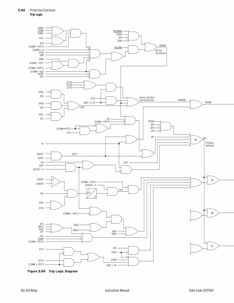
5.142
SEL-421 Relay Instruction Manual Date Code 20171021
Protection FunctionsTrip Logic
Figure 5.99 Trip Logic Diagram
1 CYC
0
PTRXECOMM := N
UBB
E3PT
SPO
Z3RBCZ3RBBZ3RBA
ECOMM = POTT3
Z3RB
ECOMM := POTT2
ECOMM := DCB
ECOMM := POTT
DSTRTBTX
DTA
SPOA
SPOB
SPOC
DTB
DTC
DTR
TR
TRSOTF
SOTFE
FSA
|mAG1F|
|mBCF|
67Q2
67G2
TRCOMM
Z3RB
SPO
PTDRX
TRCOMMD
ECTT
ECTTAECTTBECTTC
EWFC :=Y, SP
Z2PECOMM := POTT3
ECOMM=POTT2
PT3
E3PT
3PT3φ
φa
φb
φc
Z1G
SOTFT
3-PhasesSelected
RX TripPermission
Comm.-AssistedTrip Permission
Z2GT
Z2GTSP := Y
67QGSP := Y
ECOMM := POTT3
XAG2
XAG2Z2P
PTA
ECOMM := POTT3
ECOMM := POTT3
ECTTA
ECTT
Z3RBA
XAG1MAG1
MAG2
MAG2APS
ECOMM := POTT3
APS
COMPRMTRPRM
RXPRM
3PS
DTA
SPOA
27AWI
EWFC := SP
CPS
BPS
APS
PTDRX

5.143
Date Code 20171021 Instruction Manual SEL-421 Relay
Protection FunctionsTrip Logic
Figure 5.99 Trip Logic Diagram (Continued)
0
TDURD
RESET
RESET
RESET
SPT
3PT
TPA
TPB
TPC
ULTRA
ATPA
TRPRM
A3PT
ATPB
ATPC
TRIP
ULTRB
ULTRC
ULTR
RSTTRGT
0
TDURD
0
TDURD

5.144
SEL-421 Relay Instruction Manual Date Code 20171021
Protection FunctionsTrip Logic
Table 5.79 Trip Logic Relay Word Bits
Name Description
RXPRM Receiver trip permission
COMPRM Communications-assisted trip permission
TRPRM Trip permission
DTR Direct transfer trip
SOTFT Switch-onto-fault trip
E3PT Three-pole trip enable
E3PT1 Circuit Breaker 1 three-pole trip enable
E3PT2 Circuit Breaker 2 three-pole trip enable
APS A-Phase selected
BPS B-Phase selected
CPS C-Phase selected
3PS Three-phase selected
27AWI Weak infeed A-Phase undervoltage
27BWI Weak infeed B-Phase undervoltage
27CWI Weak infeed C-Phase undervoltage
ULTRA Unlatch A-Phase trip
ULTRB Unlatch B-Phase trip
ULTRC Unlatch C-Phase trip
ULTR Unlatch all protection trips
ATPA Assert A-Phase trip
ATPB Assert B-Phase trip
ATPC Assert C-Phase trip
A3PT Assert three-pole trip
TPA Trip A-Phase
TPB Trip B-Phase
TPC Trip C-Phase
TRIP Trip A-Phase or B-Phase or C-Phase
3PT Three-pole trip
SPT Single-pole trip
TPA1 Circuit Breaker 1 trip A-Phase
TPB1 Circuit Breaker 1 trip B-Phase
TPC1 Circuit Breaker 1 trip C-Phase
TPA2 Circuit Breaker 2 trip A-Phase
TPB2 Circuit Breaker 2 trip B-Phase
TPC2 Circuit Breaker 2 trip C-Phase
TOP Trip during open-pole timer is asserted
ULMTR1 Circuit Breaker 1 unlatch manual trip
ULMTR2 Circuit Breaker 2 unlatch manual trip

5.145
Date Code 20171021 Instruction Manual SEL-421 Relay
Protection FunctionsTrip Logic
Figure 5.100 Two Circuit Breakers Trip Logic Diagram
0
TDUR3D
0
TDUR3D
BK1MTR
ULMTR1
TPA
TPB
TPC
E3PT1
E3PT2
BK2MTR
ULMTR2
TPA2
TPB2
TPC2
TPA1
TPB1
TPC1
SELOGIC
Setting
SELOGIC
Settings
RelayWordBits
RelayWordBits
RelayWordBits
RelayWordBit

5.146
SEL-421 Relay Instruction Manual Date Code 20171021
Protection FunctionsCircuit Breaker Failure Protection
Circuit Breaker Failure ProtectionUse the SEL-421 to provide circuit breaker failure protection for as many as two circuit breakers. The circuit breaker failure protection logic includes the follow-ing schemes:
➤ Failure to interrupt fault current for phase currents
➤ Failure to interrupt load current
➤ No current/residual current circuit breaker failure protection
➤ Flashover protection while the circuit breaker is open
All schemes can incorporate single-pole and three-pole retrip. Single-pole and three-pole initiations are available for circuit breaker failure, including extended breaker failure initiation. The circuit breaker failure logic also includes breaker failure trip latching logic.
The failure-to-interrupt-fault-current logic includes two schemes; both are suit-able for three-pole or single-pole tripping applications. Scheme 1 is basic circuit breaker failure that is useful for most applications. Scheme 2 allows you to have
Figure 5.101 Trip A Unlatch Logic
Figure 5.102 Trip During Open Pole
0
1CYC
3PT
LOPHA
TULO := 1
TULO := 2
52AA1
52AA2
TULO := 3
LOPHALOPHBLOPHC
ULTRA
TULO := 4 Do not run this logic. ULTRA=0, ULTRB=0, ULTRC=0
RelayWordBit
RelayWordBit
RelayWordBit
RelayWordBits
Setting
Setting
Setting
NUMBK=2
1/8 CYC
TOPD
0
1/8CYC
RelayWordBit
RelayWordBits
TOP
SPT
TPATPBTPC
E3PT
SELOGIC
Setting

5.147
Date Code 20171021 Instruction Manual SEL-421 Relay
Protection FunctionsCircuit Breaker Failure Protection
different breaker failure times to differentiate between single-pole and three-pole tripping conditions. The failure-to-trip-load-current logic uses the circuit breaker failure initiation input for three-pole trips only. The flashover protection logic does not need voltage information.
Subsidence current results from the energy trapped in the CT magnetizing branch after the circuit breaker opens to clear a fault or interrupt load. Subsidence cur-rent exponentially decays and delays resetting of instantaneous overcurrent ele-ments. However, the open-phase detection logic causes the relay 50Fn elements to reset in less than one cycle during subsidence current conditions (see Figure 5.114, Figure 5.115, and Figure 5.116). The open-phase detection logic output is BnOPH (see Table 5.23).
Failure to Interrupt Fault Current: Scheme 1Circuit Breaker Failure Protection Logic
The logic shown in Figure 5.103 applies to single circuit breaker configurations (EBFL = 1). Fault current causes 50FA1 (Breaker 1 A-Phase Instantaneous Over-current Element) to assert immediately following fault inception and just prior to the assertion of Relay Word bit BFI3P1 (Breaker 1 Three-Pole Circuit Breaker Failure Initiation). At circuit breaker failure initiation, timer BFPU1 (Breaker 1 Circuit Breaker Failure Time Delay on Pickup Timer) starts timing. If 50FA1 remains asserted when the BFPU1 timer expires, Relay Word bit FBF1 asserts. Use this Relay Word bit in the circuit breaker failure tripping logic to cause a cir-cuit breaker failure trip (see Circuit Breaker Failure Trip Logic on page 5.154). If the protected circuit breaker opens successfully, 50FA1 drops out before the BFPU1 timer expires and FBF1 does not assert.
Retrip LogicSome three-pole circuit breakers have two separate trip coils. If one trip coil fails, the local protection can attempt to energize the second trip coil to prevent an impending circuit breaker failure operation. Configure your protection system to always attempt a local retrip using the second trip coil before the circuit breaker failure pickup time delay timer expires.
RTPU1 (Retrip Time Delay on Pickup Timer) begins timing when BFI3P1 asserts. Relay Word bit RT1 (Breaker 1 Retrip) asserts immediately after RTPU1 times out. Assign a control output to trip the circuit breaker when Relay Word bit RT1 asserts.
Figure 5.103 Scheme 1 Logic Diagram
BFPU1
0
RTPU1
0
FBF1
RT1
FBFB1
FBFA1
FBFC1
50FA1
BFI3P1
BFIA1
RTB1RTC1
RTA1
RelayWordBits Relay
WordBits
RelayWordBits
RelayWordBits
SELOGIC
Settings

5.148
SEL-421 Relay Instruction Manual Date Code 20171021
Protection FunctionsCircuit Breaker Failure Protection
Failure to Interrupt Fault Current: Scheme Y1Circuit Breaker Failure Protection Logic
The logic shown in Figure 5.104 applies to single breaker configurations. Scheme Y1 is similar to Scheme 1, but the current check (50FA1) is now part of the Breaker Failure initiate timer (BFPU1) and Retrip Time delay (RTPU1) in addition to the Breaker Failure initiate settings (BFI3P1 or BFIA1).
Failure to Interrupt Fault Current: Scheme 2Scheme 2 actually consists of two discrete circuit breaker failure protection schemes. The first scheme is applied for multiphase faults; apply a short time delay on pickup prior to asserting the circuit breaker failure trip because three-phase faults are the greatest threat to transient power system stability. The second scheme is applied for single phase-to-ground faults; an additional timer is pro-vided so you can coordinate retripping and circuit breaker failure tripping for the different fault types.
Circuit Breaker Failure Protection Logic: Multiphase FaultsThe logic diagram shown in Figure 5.105 applies to three-pole tripping for one or two circuit breakers (EBFL = 2). Use this logic when the protected circuit breaker fails following a three-pole trip from the line-relaying scheme.
Fault current causes 50FA1 (Breaker 1 A-Phase Instantaneous Overcurrent Ele-ment) to assert immediately following fault inception and just prior to the asser-tion of Relay Word bit BFIA1 (Breaker 1 A-Phase Circuit Breaker Failure Initiation). At circuit breaker failure initiation, timer BFPU1 (Breaker 1 Circuit Breaker Failure Time Delay on Pickup Timer) starts timing. If 50FA1 remains asserted when timer BFPU1 expires and at least two of the three initiation Relay Word bits BFIA1, BFIB1, or BFIC1 are asserted, Relay Word bit FBF1 (Breaker 1 Circuit Breaker Failure) asserts. (Two of three asserted initiation Relay Word bits indicate a multiphase fault.) Use FBF1 in the circuit breaker fail-ure tripping logic to cause a circuit breaker failure trip (see Circuit Breaker Fail-ure Trip Logic on page 5.154). If the protected circuit breaker opens successfully, 50FA1 drops out before timer BFPU1 expires and Relay Word bit FBF1 does not assert.
Figure 5.104 Scheme Y1 Circuit Breaker Failure Logic
BFPUn
0
RTPUn
0
FBFn
RTn
FBFBn
FBFAn
FBFCn
50FAn
BFI3Pn
BFIAn
RTBn
RTCn
RTAn
RelayWordBits
RelayWordBits
RelayWordBits
RelayWordBits
SELOGIC
Settings

5.149
Date Code 20171021 Instruction Manual SEL-421 Relay
Protection FunctionsCircuit Breaker Failure Protection
Failure to Interrupt Fault Current: Scheme Y2 (Setting EBFL = Y2)Three-Pole Circuit Breaker Failure Protection Logic
The logic shown in Figure 5.106 applies to three-pole breaker configurations. Scheme Y2 is similar to Scheme 2, but the current check (50FA1) is now part of the Breaker Failure initiate timer (BFPU1) in addition to the Breaker Failure ini-tiate settings (BFI3P1 or BFIA1).
Failure to Interrupt Fault Current: Scheme 2 (Setting EBFL = 2)Circuit Breaker Failure Protection Logic: Single-Phase Faults
The logic diagram shown in Figure 5.107 applies to single-pole tripping for one or two circuit breakers (EBFL = 2). A-Phase is discussed; B-Phase and C-Phase logic is similar. Use this logic when one pole of the circuit breaker fails following a single-pole trip from the line-relaying scheme.
Fault current causes 50FA1 (Breaker 1 A-Phase Instantaneous Overcurrent Ele-ment) to assert immediately following ground fault inception and just prior to the assertion of Relay Word bit BFIA1 (Breaker 1 A-Phase Circuit Breaker Failure Initiation). At circuit breaker failure initiation timer BFPU1 (Breaker 1 Circuit Breaker Failure Time Delay on Pickup Timer) starts timing. Timer BFPU1 cas-cades into timer SPBFPU1 (Breaker 1 Single-Pole Trip Breaker Failure Time Delay on Pickup Timer). Therefore, use this second timer, SPBFPU1, to coordi-nate circuit breaker failure operations for single-pole and three-pole trips.
If 50FA1 remains asserted when timer SPBFPU1 expires and neither of the two Relay Word bits BFIB1 and BFIC1 is asserted, Relay Word bit FBFA1 (A-Phase Breaker 1 Circuit Breaker Failure) asserts. Use FBFA1 in the circuit breaker fail-ure tripping logic to cause a circuit breaker failure trip (see Circuit Breaker Fail-ure Trip Logic on page 5.154). If the protected circuit breaker successfully opens, 50FA1 drops out before timer SPBFPU1 expires and Relay Word bit FBFA1 does not assert.
Figure 5.105 Scheme 2 Three-Pole Circuit Breaker Failure Protection Logic
FBF1
BFIA1
50FA1
B-PhaseC-Phase
BFIA1BFIB1BFIC1
FBFC1FBFB1FBFA1
A-Phase
RelayWordBit
RelayWordBit
RelayWordBits
SELOGIC
Settings
SELOGIC
Setting BFPU1
0
2 of 3
Figure 5.106 Scheme Y2 Three-Pole Circuit Breaker Failure Logic
FBF1
BFIA1
50FA1 B-PhaseC-Phase
BFIA1BFIB1BFIC1
FBFC1FBFB1FBFA1
A-Phase
RelayWordBit
RelayWordBits
SELOGIC
Settings
SELOGIC
SettingBFPU1
0
2 of 3

5.150
SEL-421 Relay Instruction Manual Date Code 20171021
Protection FunctionsCircuit Breaker Failure Protection
Failure to Interrupt Fault Current: Scheme Y2 (Setting EBFL = Y2)Single-Pole Circuit Breaker Failure Protection Logic
The logic shown in Figure 5.108 applies to single-pole breaker configurations. Scheme Y2 is similar to Scheme 2, but the current check (50FA1) is now part of the Breaker Failure initiate timer (BFPU1) and Retrip Time delay (RTPU1) in addition to the Breaker Failure initiate settings (BFI3P1 or BFIA1).
Retrip LogicSome single-pole circuit breakers have two separate trip coils per pole. All three primary trip coils are energized if the line-relaying scheme asserts a three-pole trip. If one or more of the primary trip coils fail, the local protection should attempt a three-pole retrip.
Only one of the primary trip coils is energized if the line-relaying scheme asserts a single-pole trip. The corresponding primary trip coil can fail following the sin-gle-pole trip. You can decide whether to single-pole or three-pole retrip following the unsuccessful single-pole trip. Attempt all local retrips before the correspond-ing circuit breaker failure time delay (BFPUn and SPBFPUn) on pickup timer expires.
Retrip Scheme 2 Three Pole (Setting EBFL = 2)Figure 5.109 illustrates the current-supervised three-pole retrip logic (EBFL = 2). Timer RT3PPU1 (Breaker 1 Three-Pole Retrip Time Delay on Pickup Timer) begins timing when at least two of the initiation Relay Word bits BFIA1, BFIB1, or BFIC1 assert. The relay asserts RT3P1 (Three-Pole Retrip) when timer RT3PPU1 times out. You can use just output RT3P1 for three-pole retrip without current supervision. Relay Word bit RTS3P1 (Breaker 1 Current Supervised Three-Pole Retrip) asserts immediately after timer RT3PPU1 expires, if one of the phase current level detectors is picked up.
Figure 5.107 Scheme 2 Single-Pole Circuit Breaker Failure Protection Logic
FBF1
BFIA1BFIB1
50FA1
BFIC1
FBFA1
FBFC1FBFB1
RelayWordBit
RelayWordBit
RelayWordBits
SELOGIC
Settings
BFPU1
0
SPBFPU1
0
2 of 3or
3 of 3
Figure 5.108 Scheme Y2 Single-Pole Circuit Breaker Failure Protection Logic
FBF1
BFIA1BFIB1
50FA1
BFIC1
FBFA1
FBFC1FBFB1
RelayWordBit
RelayWordBits
SELOGIC
Settings
BFPU1
0
SPBFPU1
0
2 of 3or
3 of 3
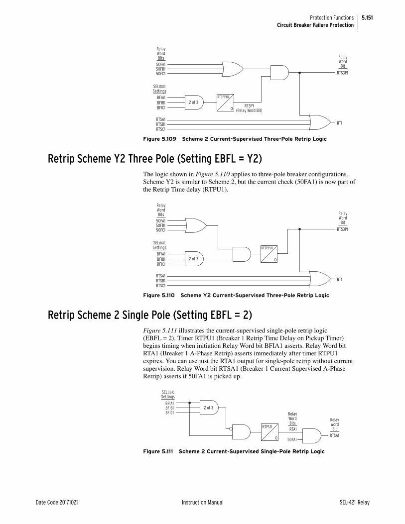
5.151
Date Code 20171021 Instruction Manual SEL-421 Relay
Protection FunctionsCircuit Breaker Failure Protection
Retrip Scheme Y2 Three Pole (Setting EBFL = Y2)The logic shown in Figure 5.110 applies to three-pole breaker configurations. Scheme Y2 is similar to Scheme 2, but the current check (50FA1) is now part of the Retrip Time delay (RTPU1).
Retrip Scheme 2 Single Pole (Setting EBFL = 2)Figure 5.111 illustrates the current-supervised single-pole retrip logic (EBFL = 2). Timer RTPU1 (Breaker 1 Retrip Time Delay on Pickup Timer) begins timing when initiation Relay Word bit BFIA1 asserts. Relay Word bit RTA1 (Breaker 1 A-Phase Retrip) asserts immediately after timer RTPU1 expires. You can use just the RTA1 output for single-pole retrip without current supervision. Relay Word bit RTSA1 (Breaker 1 Current Supervised A-Phase Retrip) asserts if 50FA1 is picked up.
Figure 5.109 Scheme 2 Current-Supervised Three-Pole Retrip Logic
50FA150FB150FC1
BFIA1
RTS3P1
RT1
RT3P1(Relay Word Bit)
BFIB1BFIC1
RTSA1RTSB1RTSC1
RelayWordBits Relay
WordBit
SELOGIC
Settings
RT3PPU1
0
2 of 3
Figure 5.110 Scheme Y2 Current-Supervised Three-Pole Retrip Logic
50FA150FB150FC1
BFIA1
RTS3P1
RT1
BFIB1BFIC1
RTSA1RTSB1RTSC1
RelayWordBits Relay
WordBit
SELOGIC
Settings RT3PPU1
02 of 3
Figure 5.111 Scheme 2 Current-Supervised Single-Pole Retrip Logic
BFIA1BFIB1BFIC1
RTA1
50FA1RTSA1
RelayWordBit
RelayWordBits
SELOGIC
Settings
RTPU1
0
2 of 3

5.152
SEL-421 Relay Instruction Manual Date Code 20171021
Protection FunctionsCircuit Breaker Failure Protection
Retrip Scheme Y2 Single Pole (Setting EBFL = Y2)The logic shown in Figure 5.112 applies to three-pole breaker configurations. Scheme Y2 is similar to Scheme 2, but the current check (50FA1) is now part of the Retrip Time delay (RTPU1).
Circuit Breaker Failure Initiation Dropout and Seal-InThe SEL-421 circuit breaker failure protection features breaker failure initiation extension and a breaker failure seal-in latch. The lower portion of Figure 5.114 shows the dropout and seal-in logic.
Dropout DelaySet timer BFIDO1 (Breaker Failure Initiate Dropout Delay—BK1) to stretch a short pulsed circuit breaker failure initiation. Use this feature for protecting dual circuit breakers when separate 86 BF lockout relays have differing energizing times.
Seal-In DelaySet timer BFISP1 (Breaker Failure Initiate Seal-In Delay—BK1) to qualify extended circuit breaker failure initiation latch seal-in. When you set BFISP1 longer than BFIDO1 and the circuit breaker failure initiate is greater than the dif-ference of the two timers, the relay seals in the circuit breaker failure extended initiation after the initiate signal deasserts until the BFIDO1 time expires and all 50Fn elements deassert.
No Current/Residual Current Circuit Breaker Failure Protection LogicThe SEL-421 has separate circuit breaker failure logic that operates on zero-sequence current rather than phase current. Use this logic to detect a circuit breaker failure and take appropriate action when a weak source drives the fault or if the protected circuit breaker fails to trip during a high-resistance ground fault. The residual current input to this logic is the 50R1 residual overcurrent element (see Figure 5.113). Setting 50RP1 (Residual Current Pickup—BK1) is the pickup threshold setting for the 50R1 element.
Figure 5.112 Scheme Y2 Current-Supervised Single-Pole Retrip Logic
BFIA1BFIB1BFIC1
RTA1RTSA1
RelayWordBit
RelayWordBits
SELOGIC
Settings
RTPU1
0
2 of 3
50FA1
Figure 5.113 No Current/Residual Current Circuit Breaker Failure Protection Logic Diagram
50R1B1OPHAB1OPHBB1OPHC
BFI3P1
BFIN1
ENCBF1 := Y
NBF1
RelayWordBits
RelayWordBit
SELOGIC
Settings
Setting
NPU1
0

5.153
Date Code 20171021 Instruction Manual SEL-421 Relay
Protection FunctionsCircuit Breaker Failure Protection
Relay Word bit NBF1 (Breaker 1 Low Current Breaker Failure) asserts when timer NPU1 (Low Current Breaker Failure Time Delay on Pickup) expires and one of the following conditions exists:
➤ Circuit Breaker 1 residual overcurrent element 50R1 is asserted and the relay does not detect an open pole in any of the three phases for Circuit Breaker 1 (i.e., NOT B1OPHA, NOT B1OPHB, or NOT B1OPHC)
➤ Relay Word bit BFIN1 (No Current Breaker Failure Initiation) is asserted
For no current applications, such as a digital signal indicating a loss-of-field from a generator, use inputs BFI3P1 and BFINn. Circuit breaker failure clearing can occur after timer NPU1 times out. For no current/residual current breaker failure trips, insert NBF1 in the circuit breaker failure trip SELOGIC control equation BFTR1 (see Circuit Breaker Failure Trip Logic on page 5.154).
Failure to Interrupt Load Current Protection LogicThe circuit breaker failure protection used during load conditions is independent from circuit breaker failure protection that you use during fault conditions. Use circuit breaker failure protection for load conditions either alone or in addition to circuit breaker failure protection for fault conditions as a second level of breaker failure protection. Figure 5.115 shows that the output of the load current protec-tion is Relay Word bit LCBF1 (Load Current Breaker Failure). Use this output to activate an external alarm, retrip the circuit breaker, or energize a lockout relay.
Load Current Detection: 50LP1This scheme detects failures of the circuit breaker to open when circuit breaker current is greater than the 50LP1 setting. The 50LP1 element should pick up when the protected circuit breaker is closed.
If the protected circuit breaker is in a ring-bus or circuit breaker-and-a-half arrangement, set 50LP1 to pick up for the line-charging current of the shortest line that circuit breaker services. Use the following equation to calculate the charging current for a given line:
Equation 5.31
Time Delay on Pickup: LCPU1The time delay setting for this protection scheme is typically longer than fault current conditions because of lower current duties associated with this type of circuit breaker failure operation. Extending the time delay allows more time for a slow but operative circuit breaker to clear a low-current fault. A disadvantage with the extended time delay is that a fault continues if the circuit breaker fails. Weigh these considerations when selecting time delays for this scheme. Please note that some circuit breakers take more time than other circuit breakers to break low amounts of current; consult the manufacturer of the protected circuit breaker for details.
where:
Vg = Line-to-ground voltage
Bc = Total line capacitive susceptance
Ic Vg Bc A primary• =

5.154
SEL-421 Relay Instruction Manual Date Code 20171021
Protection FunctionsCircuit Breaker Failure Protection
The recommended setting for LCPU1 is the sum of the following:
➤ Nominal circuit breaker operate time
➤ 50LP1 dropout time
➤ Safety margin
Calculate the safety margin by subtracting all conditions required to isolate the fault during a circuit breaker failure condition from the maximum acceptable fault clearing time. The safety margin will be longer in this case than for the fault current logic because the total acceptable time to clear the fault at these lower fault duties is longer.
Load Current Circuit Breaker Failure Initiation: BFILC1Program SELOGIC control equation BFILC1 (Load Current Breaker Failure Initi-ation) to initiate this scheme. For example, use the auxiliary contacts from the circuit breaker to detect when the circuit breaker is open. Relay Word bit LCBF1 asserts if Relay Word bit BFILC1 remains asserted for time LCPU1 and the relay detects load current.
Circuit Breaker Flashover ProtectionCircuit breaker failure protection during flashover conditions is independent of the other circuit breaker protection functions. Use this protection either alone or in addition to the other protection.
Use current flow to detect when an open circuit breaker pole flashes over. Set BLKFOA1 to TPA or CLS1 to block flashover protection for 6 cycles if an A-phase single-pole trip occurs, or when circuit breaker BK1 closes.
Figure 5.116 shows the flashover circuit breaker failure logic. Flashover timer FOPU1 (Flashover Time Delay—BK1) starts timing if the circuit breaker is open and current exceeds setting 50FO1 (Flashover Current Pickup—BK1). The relay uses pole-open logic BnOPH to determine whether the circuit breaker is open.
The output of the flashover protection is Relay Word bit FOBF1. Use this output to activate an external alarm, retrip the circuit breaker, or energize a lockout relay.
Circuit Breaker Failure Trip LogicThe SEL-421 has dedicated circuit breaker failure trip logic (see Figure 5.117). Set SELOGIC control equation BFTR1 (Breaker Failure Trip—BK1) to assert for circuit breaker failure trips from Relay Word bits FBF1, NBF1, LCBF1, and FOBF1.
When this SELOGIC control equation asserts, the relay sets Relay Word bit BFTRIP1 (Breaker Failure Trip for Circuit Breaker BK1) to logical 1 until BFTR1 deasserts, timer TDUR3D times out, and an unlatch or reset condition is active.
Unlatch Circuit Breaker Failure Trip EquationUse SELOGIC control equation BFULTR1 (Breaker Failure Unlatch Trip—BK1) to define the conditions that unlatch the control outputs that assert during a circuit breaker failure trip. BFULTR1 unlatches the circuit breaker trip condition BFTRIP1.

5.155
Date Code 20171021 Instruction Manual SEL-421 Relay
Protection FunctionsCircuit Breaker Failure Protection
Table 5.80 Circuit Breaker Failure Relay Word Bits (Sheet 1 of 2)
Namea Description
BFI3P1 Three-pole circuit breaker failure initiation
BFIA1 A-Phase circuit breaker failure initiation
BFIB1 B-Phase circuit breaker failure initiation
BFIC1 C-Phase circuit breaker failure initiation
BFIN1 No current circuit breaker failure initiation
BFILC1 Load current breaker failure initiation
BFI3PT1 Three-pole circuit breaker failure extended initiation
BFIAT1 A-Phase circuit breaker failure extended initiation
BFIBT1 B-Phase circuit breaker failure extended initiation
BFICT1 C-Phase circuit breaker failure extended initiation
FBFA1 A-Phase circuit breaker failure
FBFB1 B-Phase circuit breaker failure
FBFC1 C-Phase circuit breaker failure
FBF1 Circuit breaker failure
NBF1 No current/residual current circuit breaker failure
LCBF1 Load current circuit breaker failure
BLKFOA1 Block A-Phase flashover detection
BLKFOB1 Block B-Phase flashover detection
BLKFOC1 Block C-Phase flashover detection
FOA1 A-Phase flashover detected
FOB1 B-Phase flashover detected
FOC1 C-Phase flashover detected
FOBF1 Flashover detected
RT3P1 Three-pole retrip
RTA1 A-Phase retrip
RTB1 B-Phase retrip
RTC1 C-Phase retrip
RT1 Retrip
RTS3P1 Three-pole current supervised retrip
RTSA1 A-Phase current supervised retrip
RTSB1 B-Phase current supervised retrip
RTSC1 C-Phase current supervised retrip
50FA1 A-Phase current threshold
50FB1 B-Phase current threshold
50FC1 C-Phase current threshold
50R1 Residual current threshold
50LCA1 A-Phase load current threshold
50LCB1 B-Phase load current threshold
50LCC1 C-Phase load current threshold
50FOA1 A-Phase flashover current threshold
50FOB1 B-Phase flashover current threshold

5.156
SEL-421 Relay Instruction Manual Date Code 20171021
Protection FunctionsCircuit Breaker Failure Protection
50FOC1 C-Phase flashover current threshold
BFTRIP1 Breaker 1 circuit breaker failure trip
a For Circuit Breaker 2, replace 1 with 2 in the setting label.
Figure 5.114 Circuit Breaker Failure Seal-In Logic Diagram
Table 5.80 Circuit Breaker Failure Relay Word Bits (Sheet 2 of 2)
Namea Description
IABKn
BFI3Pn
BnOPHA
50FAn
50FBn
50FCn
IBBKn
BnOPHB
ICBKn
50FPn
BnOPHC
BFI3PTn
RelayWordBit
RelayWordBit
BFIATn
RelayWordBit
RelayWordBits
RelayWordBits
SELOGIC
Setting 0
BFIDOn
BFISPn
0
—
+
—
+
—
+
BFIAn
50FAn
SELOGIC
Setting 0
BFIDOn
BFISPn
0
BFI3Pn = BFI3PTn OR . . .
When the Scheme requiresBFI Seal-In.
BFIAn = BFIATn OR ...
When the Scheme requires BFI Seal-In.
Common Logic for Schemes 1 and 2.
n = 1 or 2; corresponds to Circuit Breaker 1 or Circuit Breaker 2

5.157
Date Code 20171021 Instruction Manual SEL-421 Relay
Protection FunctionsCircuit Breaker Failure Protection
Figure 5.115 Failure to Interrupt Load Current Logic Diagram
IABKn
ELCBFn := Y
BnOPHA
50LCAn
50LCBn
50LCCn
IBBKn
BnOPHB
ICBKn
50LPn
BnOPHC
BFILCn
LCBFn
RelayWordBits
SELOGICSetting
RelayWordBits
RelayWordBit
LCPUn
0
—
+
—
+
—
+
Setting
n = 1 or 2; corresponds to Circuit Breaker 1 or Circuit Breaker 2
Figure 5.116 Flashover Protection Logic Diagram
EFOBFn := Y
50FOAn
52AAn
BLKFOAn
Relay Word bit BLKFOAn asserts if an A-phasesingle-pole trip occurs, or if the correspondingcircuit breaker closes.
n = 1 or 2; corresponds to Circuit Breaker 1 or Circuit Breaker 2
BnOPHA
50FOn
IABKn
FOBFn
FOAn
FOBnFOCn
RelayWordBit
RelayWordBit
RelayWordBits
RelayWord
Bits 5 CYC
0 FOPUn
0
6 CYC
0
SELOGIC
Settings
S
R
Q
—
+
Setting
Figure 5.117 Circuit Breaker Failure Trip Logic Diagram
BFTRIPn
RelayWordBit
TDURTn
RelayWordBit
TRGTR
RelayWordBit
SELOGIC
SettingsTDUR3D
0
TAR RSerial PortCommand
Target Reset Front Panel
BFULTRn
BFTRn
RSTTRGT

5.158
SEL-421 Relay Instruction Manual Date Code 20171021
Protection FunctionsSynchronism Check
Synchronism CheckNOTE: If the relay is using a remote data acquisition system, such as TiDL, the operating times will be delayed by 1.5 ms. Use caution when setting the relay for synchronism check to account for this added delay.
Synchronism-check elements prevent circuit breakers from closing if the corre-sponding phases across the open circuit breaker are excessively out of phase. The synchronism-check elements selectively close circuit breaker poles under the fol-lowing criteria:
The systems on both sides of the open circuit breaker are in phase (within a settable voltage angle difference), and one of the following is true:
➤ The voltages on both sides of the open circuit breaker are healthy (within a settable voltage magnitude window).
➤ The difference between the voltages on both sides of the open circuit breaker are less than a set limit.
➤ The voltages on both sides are healthy and the difference voltage is less than a set limit.
You can use synchronism-check elements to program the relay to supervise cir-cuit breaker closing; include the synchronism-check element outputs in the close SELOGIC control equations. These element outputs are Relay Word bits 25W1BK1, 25A1BK1, 25W2BK1, 25A2BK1, 25W1BK2, 25A1BK2, 25W2BK2, and 25A2BK2 (see Synchronism-Check Logic Outputs on page 5.160 and Angle Checks and Synchronism-Check Element Outputs on page 5.168).
An example best demonstrates the synchronism-check capability in the relay. This subsection presents a typical synchronism-check system.
Generalized SystemThe generalized system single-line drawing in Figure 5.118 shows a partial cir-cuit breaker-and-a-half or ring-bus substation arrangement. Presuming that both Circuit Breakers BK1 and BK2 are open, the system is split into three sections: Bus 1, Bus 2, and Line.
Paralleled and Asynchronous SystemsFigure 5.118 shows remote sources for each section. Often, a portion of the power system is paralleled beyond the open Circuit Breakers BK1 and BK2; the remote sources are really the same aggregate source. If the aggregate source is much closer to one side of the open circuit breaker than the other, there is a
Figure 5.118 Partial Breaker-and-a-Half or Partial Ring-Bus Breaker Arrangement
Bus 2Bus 1
Line
BK1 BK2

5.159
Date Code 20171021 Instruction Manual SEL-421 Relay
Protection FunctionsSynchronism Check
noticeable voltage angle difference across the system (it is not simply zero degrees). The corresponding angular separation results from load flow and the impedance of the parallel system.
You must consider this angle difference when setting the synchronism-check ele-ment for a paralleled system. For example, if the expected angle because of load flow is 10 degrees, do not set the voltage angle difference setting to less than 15–20 degrees nominal. A paralleled system does not imply a zero degree voltage angle difference at every measuring point.
Single-Phase Voltage InputsFigure 5.119 shows single-phase voltage transformers (1 PT) on Bus 1 and Bus 2. Use these single-phase voltage sources to perform a synchronism check across the two circuit breakers.
Synchronism check occurs on a single-phase voltage basis—see the single-phase potential transformers (1 PT) shown on each bus in Figure 5.119. The assump-tion is that if the monitored single-phase voltage inputs are in phase (within a set-table voltage angle difference), and they meet the criteria of being healthy (within a settable voltage magnitude window) and/or the voltage difference is less than a set limit, the other phase-to-neutral voltages are likewise in phase and share the same voltage magnitude relationship. The line voltage source is three-phase, but you only need a single-phase bus voltage to perform a synchronism check across the corresponding circuit breaker. The relay uses the three-phase voltage from the line for other functions such as distance protection and metering.
Setting E25BKn := YIf E25BKn is set to Y, where n = 1 or 2, the synchronizing logic verifies that both the reference voltage and synchronizing voltage are healthy (within a settable voltage magnitude window) before enabling the synchronism-check logic.
Setting E25BKn := Y1If E25BKn is set to Y1, where n = 1 or 2, the synchronizing logic verifies that the difference voltage between the reference and synchronizing voltages is less than the 25VDIF setting before enabling the synchronism-check logic.
Figure 5.119 Synchronism-Check Voltages for Two Circuit Breakers
Bus 2Bus 1
Line
BK2BK1
1
3
1. . . . . .
. . .
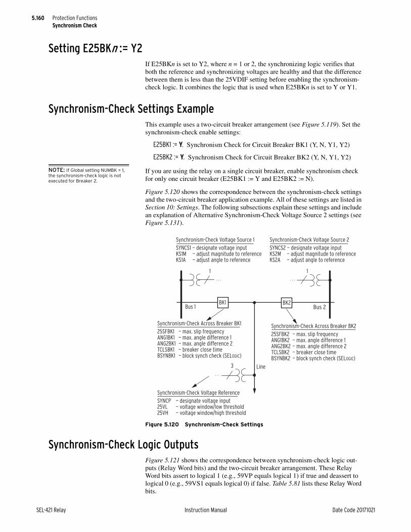
5.160
SEL-421 Relay Instruction Manual Date Code 20171021
Protection FunctionsSynchronism Check
Setting E25BKn := Y2If E25BKn is set to Y2, where n = 1 or 2, the synchronizing logic verifies that both the reference and synchronizing voltages are healthy and that the difference between them is less than the 25VDIF setting before enabling the synchronism-check logic. It combines the logic that is used when E25BKn is set to Y or Y1.
Synchronism-Check Settings ExampleThis example uses a two-circuit breaker arrangement (see Figure 5.119). Set the synchronism-check enable settings:
E25BK1 := Y. Synchronism Check for Circuit Breaker BK1 (Y, N, Y1, Y2)
E25BK2 := Y. Synchronism Check for Circuit Breaker BK2 (Y, N, Y1, Y2)
NOTE: If Global setting NUMBK = 1, the synchronism-check logic is not executed for Breaker 2.
If you are using the relay on a single circuit breaker, enable synchronism check for only one circuit breaker (E25BK1 := Y and E25BK2 := N).
Figure 5.120 shows the correspondence between the synchronism-check settings and the two-circuit breaker application example. All of these settings are listed in Section 10: Settings. The following subsections explain these settings and include an explanation of Alternative Synchronism-Check Voltage Source 2 settings (see Figure 5.131).
Synchronism-Check Logic OutputsFigure 5.121 shows the correspondence between synchronism-check logic out-puts (Relay Word bits) and the two-circuit breaker arrangement. These Relay Word bits assert to logical 1 (e.g., 59VP equals logical 1) if true and deassert to logical 0 (e.g., 59VS1 equals logical 0) if false. Table 5.81 lists these Relay Word bits.
Figure 5.120 Synchronism-Check Settings
Bus 2Bus 1
Line
BK2BK1
Synchronism-Check Voltage Source 1
SYNCS1 — designate voltage inputKS1M — adjust magnitude to referenceKS1A — adjust angle to reference
Synchronism-Check Voltage Reference
SYNCP — designate voltage input25VL — voltage window/low threshold25VH — voltage window/high threshold
Synchronism-Check Across Breaker BK2
25SFBK2 — max. slip frequencyANG1BK2 — max. angle difference 1ANG2BK2 — max. angle difference 2TCLSBK2 — breaker close timeBSYNBK2 — block synch check (SELOGIC)
Synchronism-Check Across Breaker BK1
25SFBK1 — max. slip frequencyANG1BK1 — max. angle difference 1ANG2BK1 — max. angle difference 2TCLSBK1 — breaker close timeBSYNBK1 — block synch check (SELOGIC)
Synchronism-Check Voltage Source 2
SYNCS2 — designate voltage inputKS2M — adjust magnitude to referenceKS2A — adjust angle to reference
1
3
1
. . .
. . .
. . .

5.161
Date Code 20171021 Instruction Manual SEL-421 Relay
Protection FunctionsSynchronism Check
Figure 5.121 Synchronism-Check Relay Word Bits
Table 5.81 Synchronism-Check Relay Word Bits (Sheet 1 of 2)
Relay Word Bit
Description
59VP VP within healthy voltage window
59VS1 VS1 within healthy voltage window
59VDIF1 Circuit Breaker BK1 synchronizing voltage difference less than limit
25ENBK1 Circuit Breaker BK1 synchronism-check element enabled
SFZBK1 Circuit Breaker BK1 slip frequency less than 0.005 Hz (“no slip” condition)
SFBK1 0.005 Hz Circuit Breaker BK1 slip frequency < 25SFBK1
25W1BK1 Voltage angle across Circuit Breaker BK1 < ANG1BK1
25W2BK1 Voltage angle across Circuit Breaker BK1 < ANG2BK1
25A1BK1 Same operation as 25W1BK1, except for the restrictive operation (0° closure attempt) when setting 25SFBK1 OFF and the system is slipping (see Figure 5.130)
25A2BK1 Same operation as 25W2BK1, except for the restrictive operation (0° closure attempt) when setting 25SFBK1 OFF and the system is slipping (see Figure 5.130)
FAST1 Bus 1 frequency greater than line frequency (fS1 > fP)
SLOW1 Bus 1 frequency less than line frequency (fS1 < fP)
59VS2 VS2 within healthy voltage window
59VDIF2 Circuit Breaker BK2 synchronizing voltage difference less than limit
25ENBK2 Circuit Breaker BK2 synchronism-check element enabled
SFZBK2 Circuit Breaker BK2 slip frequency less than 0.005 Hz (“no slip” condition)
SFBK2 0.005 Hz Circuit Breaker BK2 slip frequency < 25SFBK2
25W1BK2 Voltage angle across Circuit Breaker BK2 < ANG1BK2
25W2BK2 Voltage angle across Circuit Breaker BK2 < ANG2BK2
Bus 2Bus 1
Synchronism-Check Voltage Source 1
59VS1 — VS1 healthy
Synchronism-Check Voltage Reference
59VP — VP healthy
Synchronism-Check Voltage Source 2
59VS2 — VS2 healthy
Line
Synchronism-Check Across Breaker BK1
25ENBK1 — synchronism enabledSFZBK1 — no slipSFBK1 — slip < 25SFBK1FAST1 — fS1 > fPSLOW1 — fS1 < fP25W1BK1 — synchronism within ANG1BK125A1BK1 — variation of 25W1BK125W2BK1 — synchronism within ANG2BK125A2BK1 — variation of 25W2BK1
Synchronism-Check Across Breaker BK2
25ENBK2 — synchronism enabledSFZBK2 — no slipSFBK2 — slip < 25SFBK2FAST2 — fS2 > fPSLOW2 — fS2 < fP25W1BK2 — synchronism within ANG1BK225A1BK2 — variation of 25W1BK225W2BK2 — synchronism within ANG2BK225A2BK2 — variation of 25W2BK2
BK2BK1
3
11. . .
. . .
. . .

5.162
SEL-421 Relay Instruction Manual Date Code 20171021
Protection FunctionsSynchronism Check
Supervising Circuit Breaker Closing via Synchronism CheckUse the synchronism-check element outputs to control circuit breaker closing. Some examples follow (the ellipsis indicates other elements that you can add to these SELOGIC control equations).
Supervising Autoreclosing of Circuit Breaker BK13P1CLS := 25A1BK1 OR … Three-Pole BK1 Reclose Supervision
(SELOGIC Equation)
Manual Closing of Circuit Breaker BK1BK1MCL := 25W2BK1 OR … Circuit Breaker BK1 Manual Close
(SELOGIC Equation)
PT ConnectionsFigure 5.122 is an example of connecting PTs to the relay for two circuit break-ers. The Bus 1 and Bus 2 single-phase voltages are connected to relay voltage inputs VAZ and VBZ, respectively. They could just as easily have been connected to any of the other voltage inputs. The voltage connected to voltage input VAZ (setting SYNCS1 := VAZ; see Figure 5.122) is not necessarily from A-Phase on Bus 1. Likewise, the voltage connected to voltage input VBZ (setting SYNCS2 := VBZ; see Figure 5.122) is not necessarily from B-Phase on Bus 2. The connection can be from any phase-to-neutral or phase-to-phase voltage (as long as you do not exceed the relay voltage input ratings). Settings in the relay compensate for any steady-state magnitude or angle difference with respect to a synchronism-check voltage reference, as discussed next in this example.
Three-phase line voltages are connected to relay voltage inputs VAY, VBY, and VCY (these voltage inputs are also used for distance elements fault location, loss-of-potential, load encroachment, and directionality). Only one of these single-phase voltage inputs is designated for use in synchronism check. In this example, this voltage input is also designated the synchronism-check voltage reference (setting SYNCP := VAY; see Figure 5.122). As the synchronism-check voltage reference, the relay makes all steady-state magnitude and angle adjustments for the Bus 1 and Bus 2 synchronism check voltages (connected to voltage inputs FAZ and FBZ, respectively, as discussed in the preceding paragraph) with respect to this designated reference line voltage, VAY, as discussed later in this example.
25A1BK2 Same operation as 25W1BK2, except for the restrictive operation (0° closure attempt) when setting 25SFBK2 OFF and the system is slipping (see Figure 5.130)
25A2BK2 Same operation as 25W2BK2, except for the restrictive operation (0° closure attempt) when setting 25SFBK2 OFF and the system is slipping (see Figure 5.130)
FAST2 Bus 2 frequency greater than line frequency (fS2 > fP)
SLOW2 Bus 2 frequency less than line frequency (fS2 < fP)
Table 5.81 Synchronism-Check Relay Word Bits (Sheet 2 of 2)
Relay Word Bit
Description

5.163
Date Code 20171021 Instruction Manual SEL-421 Relay
Protection FunctionsSynchronism Check
For a single-circuit breaker application, you can use either bus-side potentials or line-side potentials for line relaying; connect the three-phase voltage source to potential inputs VAY, VBY, and VCY. If a single-phase voltage source is avail-able on the other side of the circuit breaker for synchronism check, connect the source to potential input VAZ, VBZ, or VCZ.
Voltage Magnitude and Angle CompensationThe Figure 5.122 example continues in Figure 5.123. The Figure 5.123 example demonstrates possible voltage input connections (presuming ABC phase rota-tion). The synchronism-check voltage reference (VP) is from the A-Phase voltage (VA) of the line. You can connect phase-to-phase voltage VBC originating from Bus 1, and connect phase-to-neutral voltage VC from Bus 2. Thus, Bus 1 voltage VBC lags synchronism-check voltage reference VP by 90 degrees, and Bus 2 volt-age VC lags the synchronism-check voltage reference VP by 240 degrees. To compensate for these steady-state angle differences, set KS1A for Bus 1 and KS2A for Bus 2.
KS1A := 90. Synchronism Source 1 Angle Shift (0, 30, …, 330 degrees)
KS2A := 240. Synchronism Source 2 Angle Shift (0, 30, …, 330 degrees)
Figure 5.122 Example Synchronism-Check Voltage Connections to the SEL-421
Bus 2Bus 1
Relay rear panel
(partial)
Three-phase line
voltage connections
Separate, single-phase
bus/source
voltage connections
Line
BK2BK1
VAY VBY VCY VAZ VBZ VCZ
1
3
1
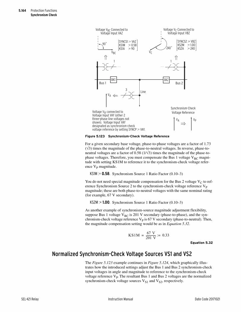
5.164
SEL-421 Relay Instruction Manual Date Code 20171021
Protection FunctionsSynchronism Check
For a given secondary base voltage, phase-to-phase voltages are a factor of 1.73 (3) times the magnitude of the phase-to-neutral voltages. In reverse, phase-to-neutral voltages are a factor of 0.58 (1/3) times the magnitude of the phase-to-phase voltages. Therefore, you must compensate the Bus 1 voltage VBC magni-tude with setting KS1M to reference it to the synchronism-check voltage refer-ence VP magnitude.
KS1M := 0.58. Synchronism Source 1 Ratio Factor (0.10–3)
You do not need special magnitude compensation for the Bus 2 voltage VC to ref-erence Synchronism Source 2 to the synchronism-check voltage reference VP magnitude; these are both phase-to-neutral voltages with the same nominal rating (for example, 67 V secondary).
KS2M := 1.00. Synchronism Source 1 Ratio Factor (0.10–3)
As another example of synchronism-source magnitude adjustment flexibility, suppose Bus 1 voltage VBC is 201 V secondary (phase-to-phase), and the syn-chronism-check voltage reference VP is 67 V secondary (phase-to-neutral). Then, the magnitude compensation setting would be as in Equation 5.32.
Equation 5.32
Normalized Synchronism-Check Voltage Sources VS1 and VS2The Figure 5.123 example continues in Figure 5.124, which graphically illus-trates how the introduced settings adjust the Bus 1 and Bus 2 synchronism-check input voltages in angle and magnitude to reference to the synchronism-check voltage reference VP. The resultant Bus 1 and Bus 2 voltages are the normalized synchronism-check voltage sources VS1 and VS2, respectively.
Figure 5.123 Synchronism-Check Voltage Reference
VBC
Voltage VBC Connected toVoltage Input VAZ
Voltage VC Connected toVoltage Input VBZ
SYNCS1 := VAZKS1M := 0.58KS1A := 90
90˚
VC
240˚
VA
VA VP
SYNCS2 := VBZKS2M := 1.00KS2A := 240
Bus 2Bus 1
Line
BK2BK1
Synchronism-Check
Voltage ReferenceVoltage VA connected to Voltage Input VAY (other 2 three-phase line voltages not shown). Voltage Input VAY designated as synchronism-check voltage reference by setting SYNCP := VAY.
1
3
1
. . . . . .
KS1M 67 V201 V--------------- 0.33:= =

5.165
Date Code 20171021 Instruction Manual SEL-421 Relay
Protection FunctionsSynchronism Check
Voltages VP, VS1, and VS2 are used in the logic in the balance of this section to check for healthy voltage and determine voltage phase angle for synchronism-check element operation.
Voltage Checks and Blocking LogicTwo conditions can cause the synchronism-check function in the SEL-421 to abort. These conditions are out-of-range synchronism-check input voltages and block synchronism check configurations that you specify in SELOGIC control equations.
Voltage Magnitude Checks (Applicable When E25BKn = Y or Y2)For synchronism check to proceed for a given circuit breaker (BK1 or BK2) when E25BKn = Y or Y2, the voltage magnitudes of the synchronism-check volt-age reference VP and the corresponding normalized synchronism-check voltage source on the other side of the circuit breaker (normalized voltage VS1 for Circuit Breaker BK1 and normalized voltage VS2 for Circuit Breaker BK2) must lie within a healthy voltage window, bounded by voltage threshold settings 25VH and 25VL (see Figure 5.125).
The relay asserts Relay Word bits 59VP, 59VS1, and 59VS2 to indicate healthy synchronism-check voltages VP, VS1, and VS2, respectively (see Figure 5.125). If either of the voltage pairs (VP and VS1 or VP and VS2) does not meet this healthy voltage criterion, synchronism check cannot proceed for the circuit breaker asso-ciated with the corresponding voltage pair.
Figure 5.124 Normalized Synchronism-Check Voltage Sources VS1 and VS2
(b)
(a)
VBC
VBC ∠90˚
∠90˚
∠240˚∠240˚
∠240˚
∠90˚
Synchronism-checkVoltage Source 1
Synchronism-checkVoltage Source 2
No effectivemagnitude adjustment
Adjusted for angle
Adjusted for angle
Normalized synchronism-check Voltage Source 1
Adjusted for magnitude
(=1 )
ApplyKS1A := 90
ApplyKS2A := 240
ApplyKS1M := 0.58
ApplyKS2M := 1.00
3
90˚
VS1VBC
3
Normalized synchronism-check Voltage Source 2
VS2
3
VCVC
VC
240˚
VC
VBC

5.166
SEL-421 Relay Instruction Manual Date Code 20171021
Protection FunctionsSynchronism Check
Voltage Difference Checks (Applicable When E25BKn = Y1 or Y2)For synchronism check to proceed for a given circuit breaker (BK1 or BK2) when E25BKn = Y1 or Y2, the absolute value of the difference between the syn-chronism-check reference voltage, VP, and the corresponding normalized syn-chronism-check voltage source on the other side of the circuit breaker (normalized voltage VS1 for Circuit Breaker BK1 and normalized voltage VS2 for Circuit Breaker BK2) must be less than the 25VDIF setting (see Figure 5.126). The logic includes a 5-volt secondary check to ensure the relay does not operate on erroneous signals.
Block Synchronism CheckIf the block synchronism check BSYNBKn SELOGIC control equation (where n = 1 or 2 for Circuit Breaker BK1 or Circuit Breaker BK2, respectively) asserts, synchronism check cannot proceed for the corresponding circuit breaker. Follow-ing is an example for Circuit Breaker BK1:
BSYNBK1 := 52AA1 AND 52AB1 AND 52AC1. Block Synchronism Check—BK1 (SELOGIC Equation)
Figure 5.125 Healthy Voltage Window and Indication
VS1VS2
25VL=60
25VH=73
59VS1 =
logical 1
59VP =
logical 1
59VS2 =
logical 1
Voltagemagnitude
(VP base)
Corresponding Relay
Word Bits:
VP
Figure 5.126 Synchronism-Check Voltage Difference Logic
AnalogQuantities
Setting
VP
VS1
5 Volts
25VDIF
RelayWord Bit
59VDIF1|VP–VS1|
AnalogQuantities
Setting
VP
VS2
5 Volts
25VDIF
RelayWord Bit
59VDIF2|VP–VS2|

5.167
Date Code 20171021 Instruction Manual SEL-421 Relay
Protection FunctionsSynchronism Check
If Circuit Breaker BK1 is closed, the three-pole indication back to the relay shows 52AA1 equals 52AB1 equals 52AC1 equals logical 1. Thus, BSYNBK1 equals logical 1, and synchronism check is blocked for Circuit Breaker BK1. There is no need to qualify or continue with the synchronism check for circuit breaker closing; the circuit breaker is already closed.
Synchronism-Check Enable LogicThe relay combines the voltage check elements and block synchronism check condition to create a synchronism-check enable condition for each circuit breaker, as shown in Figure 5.127. Settings E25BK1 and E25BK2 determine which enable logic is active.

5.168
SEL-421 Relay Instruction Manual Date Code 20171021
Protection FunctionsSynchronism Check
Angle Checks and Synchronism-Check Element OutputsAfter the relay determines that it is appropriate to enable synchronism-check logic as defined in Figure 5.127, the relay must check voltage phase angles across the circuit breakers before a final synchronism-check element output can be available for supervising circuit breaker closing.
The following discussion/examples use Circuit Breaker BK1. Synchronism-check element output operation for Circuit Breaker BK2 is similar (replace BK2 for BK1 in associated settings and Relay Word bits).
Figure 5.127 Synchronism-Check Enable Logic
59VP
59VS1
BSYNBK1
VP healthy
VS1 healthy
Block synchronism check for Circuit Breaker BK1
0
25ENBK1(Enable synchronism check for Circuit Breaker BK1)
SELOGIC
Setting
59VP
59VS2
BSYNBK2Block synchronism check for Circuit Breaker BK2
0
25ENBK2(Enable synchronism check for Circuit Breaker BK2)
SELOGIC
Setting
VP healthy
VS2 healthy
E25BK1 = Y
E25BK2 = Y
SELOGIC
Setting
59VDIF1
Relay
Word Bit
Relay
Word Bit
Relay
Word Bit
Relay
Word Bit
Relay
Word Bit
E25BK1 = Y1
BSYNBK1
6 cyc
6 cyc
6 cyc
0 Relay
Word Bit
25ENBK1
(Enable synchronism check
for Circuit Breaker BK1)
Block synchronism check for Circuit Breaker BK1
SELOGIC
Setting
59VDIF2
Relay
Word Bit
59VP
59VS1
59VDIF1
Relay
Word Bit
E25BK2 = Y1
BSYNBK2
Setting
E25BK1 = Y2
SELOGIC
BSYNBK1
6 cyc
0 Relay
Word Bit
25ENBK2
(Enable synchronism check
for Circuit Breaker BK2)
Block synchronism check for Circuit Breaker BK2
Block synchronism check for Circuit Breaker BK1
6 cyc
0
RelayWord Bit
25ENBK1(Enable synchronism check for Circuit Breaker BK1)
59VP
59VS2
59VDIF2
Relay
Word Bit
Setting
E25BK2 = Y2
SELOGIC
BSYNBK2Block synchronism check for Circuit Breaker BK2
6 cyc
0
RelayWord Bit
25ENBK2(Enable synchronism check for Circuit Breaker BK2)

5.169
Date Code 20171021 Instruction Manual SEL-421 Relay
Protection FunctionsSynchronism Check
Angle Difference Settings ANG1BK1 and ANG2BK1NOTE: If the relay is using a remote data acquisition system, such as TiDL, the operating times will be delayed by 1.5 ms. Use caution when setting the relay for synchronism check to account for this added delay.
Each circuit breaker has two angle difference windows. For Circuit Breaker BK1, the maximum angle difference settings are ANG1BK1 and ANG2BK1.
Often, a greater phase angle across the circuit breaker is tolerated for a manual close. Typically, you set angle setting ANG1BK1 for synchronism check in auto-reclosing Circuit Breaker BK1 (e.g., ANG1BK1 := 20 degrees), and you set angle setting ANG2BK1 for synchronism check when manually closing Circuit Breaker BK1 (e.g., ANG2BK1 := 35 degrees).
Synchronism-Check Element Outputs 25W1BK1 and 25A1BK1Angle difference setting ANG1BK1 affects synchronism-check element outputs 25W1BK1 and 25A1BK1. Figure 5.128, Figure 5.129, and Figure 5.130 illus-trate the operation of synchronism-check element outputs 25W1BK1 and 25A1BK1.
These outputs operate for a voltage phase angle within and without the angle dif-ference setting ANG1BK1 for the following three conditions:
➤ no slip
➤ slip—no compensation
➤ slip—with compensation
The operational differences between synchronism-check element outputs 25W1BK1 and 25A1BK1 are apparent in the “slip—with compensation” exam-ple (Figure 5.130).
The second angle difference setting (ANG2BK1) for Circuit Breaker BK1 oper-ates similarly to affect synchronism-check element outputs 25W2BK1 and 25A2BK1.
“No Slip” Synchronism CheckRefer to the paralleled system beyond the open circuit breaker in Figure 5.119. For such a system, there is essentially no slip across the open circuit breaker (the monitored voltage phasors on each side are not moving with respect to one another). In a “no slip” system, any voltage angle difference across the open cir-cuit breaker remains relatively constant.
The four drawings shown in Figure 5.128 are separate, independent cases for a “no slip” paralleled system. If the phase angle between the synchronism-check voltage reference VP and the normalized synchronism-check voltage source VS1 is less than angle setting ANG1BK1, synchronism-check element outputs 25W1BK1 and 25A1BK1 both assert to logical 1. The relay declares that the per-phase voltages across Circuit Breaker BK1 are in synchronism. Otherwise, if the phase angle is greater than or equal to angle setting ANG1BK1, element outputs 25W1BK1 and 25A1BK1 both deassert to logical 0; the relay declares that the per-phase voltages across Circuit Breaker BK1 are out-of-synchronism.
The out-of-synchronism phase angles in Figure 5.128 appear dramatic for a “no slip” paralleled system. This is for illustrative purposes; these angles are not usu-ally this large in actual systems.

5.170
SEL-421 Relay Instruction Manual Date Code 20171021
Protection FunctionsSynchronism Check
Slip Frequency and SFZBK1Relay Word bit SFZBK1 (BK1 Slip Frequency less than 0.005 Hz) also asserts to logical 1, indicating a “no slip” condition across Circuit Breaker BK1. In other words, the slip frequency is less than 0.005 Hz (|fS1–fP| < 0.005 Hz).
Synchronism-Check Element Output EffectsNote that element outputs 25W1BK1 and 25A1BK1 operate identically in all of the “no slip” cases in Figure 5.128 (both assert to logical 1 or deassert to logical 0).
“Slip—No Compensation” Synchronism CheckThe four cases [(a), (b), (c), and (d)] shown in Figure 5.129 are “slip—no com-pensation” cases for asynchronous systems (not paralleled). The cases progress in time from top to bottom. The normalized synchronism-check voltage source
Figure 5.128 “No Slip” System Synchronism-Check Element Output Response
VP(a)
(b)
(c)
(d)
VS1
VP VS1
VPVS1
VP
VS1
No slip (paralleled system)
Response of synchronism-check
element outputs (Relay Word Bits):
25W1BK1 = logical 1
25A1BK1 = logical 1
25W1BK1 = logical 1
25A1BK1 = logical 1
25W1BK1 = logical 0
25A1BK1 = logical 0
25W1BK1 = logical 0
25A1BK1 = logical 0
ANG1BK1 ANG1BK1
ANG1BK1 ANG1BK1
ANG1BK1 ANG1BK1
ANG1BK1 ANG1BK1

5.171
Date Code 20171021 Instruction Manual SEL-421 Relay
Protection FunctionsSynchronism Check
VS1 slips with respect to synchronism-check voltage reference VP. The indication of the rotation arrow on phasor VS1 (and the time progression down the page) shows that the system corresponding to VS1 has a higher system frequency fS1 than the system corresponding to reference VP with system frequency fP. The slip frequency across Circuit Breaker BK1 is fS1–fP.
Positive Slip FrequencyIf the slip frequency is positive, VS1 is slipping ahead of reference VP (the system corresponding to VS1 has a higher system frequency than the system correspond-ing to VP; fS1 > fP). Positive slip frequency is the counter-clockwise rotation of VS1 with respect to reference VP, as shown in Figure 5.129. Relay Word bit FAST1 asserts to logical 1 (and Relay Word bit SLOW1 deasserts to logical 0) to indicate this condition.
Figure 5.129 “Slip—No Compensation” Synchronism-Check Element Output Response
VP(a)
(b)
(c)
(d)
VS1
VP VS1
VPVS1
VP
VS1
Slip (asynchronous systems—not paralleled).
Max slip frequency setting 25SFBK1 := OFF
Response of synchronism-check
element outputs (Relay Word Bits):
25W1BK1 = logical 1
25A1BK1 = logical 1
25W1BK1 = logical 1
25A1BK1 = logical 1
25W1BK1 = logical 0
25A1BK1 = logical 0
25W1BK1 = logical 0
25A1BK1 = logical 0
ANG1BK1 ANG1BK1
ANG1BK1 ANG1BK1
ANG1BK1 ANG1BK1
ANG1BK1 ANG1BK1

5.172
SEL-421 Relay Instruction Manual Date Code 20171021
Protection FunctionsSynchronism Check
Negative Slip FrequencyIf the slip frequency is negative, VS1 is slipping behind reference VP (the system corresponding to VS1 has a lower system frequency than the system correspond-ing to VP; fS1 < fP). For such a case, VS1 rotates clockwise with respect to refer-ence VP. Relay Word bit SLOW1 asserts to logical 1 (and Relay Word bit FAST1 deasserts to logical 0) to indicate this condition.
“No-Slip” ConditionIf the absolute value of the slip is less than 0.005 Hz (|fS1–fP| < 0.005 Hz; a “no-slip” condition), both Relay Word bits FAST1 and SLOW1 deassert to logical 0 and Relay Word bit SFZBK1 asserts to logical 1. A “no-slip” condition is con-firmed when FAST1 and SLOW1 are deasserted, and SFZBK1 is asserted.
Synchronism-Check Element Output EffectsCompare the corresponding “slip—no compensation” cases in Figure 5.129 to the previous “no-slip” cases in Figure 5.128. Note that synchronism-check ele-ment outputs 25W1BK1 and 25A1BK1 operate identically in all cases of the “slip—no compensation” examples in Figure 5.129 (both assert to logical 1 or deassert to logical 0). The condition of “no slip” or “slip—no compensation” does not affect the operation of element outputs 25W1BK1 and 25A1BK1 in the scenarios depicted in Figure 5.128 and Figure 5.129.
The similarity of element outputs 25W1BK1 and 25A1BK1 for the “no slip” condition (Figure 5.128) and the “slip—no compensation” (Figure 5.129) condi-tion results from the maximum slip frequency setting 25SFBK1 := OFF. Setting 25SFBK1 has no effect in a “no slip” scenario (Figure 5.128), but the setting does affect the operation of synchronism-check element output 25A1BK1 (see the “slip—no compensation” scenario, Figure 5.129).
With setting 25SFBK1 := OFF, the relay does not compensate for the further angular travel of VS1 (with respect to reference VP) during the Circuit Breaker BK1 close time setting TCLSBK1. The relay measures the phase angle directly with no compensation between reference VP and VS1 for synchronism-check ele-ment output 25A1BK1.
The relay always measures the phase angle directly (without compensation) between reference VP and VS1 for element output 25W1BK1. Setting 25SFBK1, time setting TCLSBK1, and whether system conditions are “no slip” (Figure 5.128) (see the “slip—no compensation” in Figure 5.129) have no effect on element output 25W1BK1.
“Slip—With Compensation” Synchronism CheckFigure 5.130 is derived from Figure 5.129, but with the maximum slip frequency setting 25SFBK1 set to some value other than OFF; thus the SEL-421 compen-sates for circuit breaker closing time with setting TCLSBK1. This results in a compensated normalized synchronism-check voltage source V'S1.
Synchronism-check element output 25W1BK1 in Figure 5.130 operates the same as in Figure 5.129. Element output 25W1BK1 is unaffected by relay settings 25SFBK1 and TCLSBK1, and by whether system conditions are slipping. Ele-ment 25W1BK1 follows normalized synchronism-check voltage source VS1.

5.173
Date Code 20171021 Instruction Manual SEL-421 Relay
Protection FunctionsSynchronism Check
NOTE: If the relay is using a remote data acquisition system, such as TiDL, the operating times will be delayed by 1.5 ms. Use caution when setting the relay for synchronism check to account for this added delay.
Element 25A1BK1 follows V'S1. With setting 25SFBK1 (maximum slip fre-quency) set to other than OFF, the relay calculates V'S1 derived from VS1. Phasor V'S1 leads VS1 by an angle described by Equation 5.33:
Equation 5.33
From Equation 5.33 note that the angle between VS1 and V'S1 increases for a greater slip between VS1 and VP (fS1–fP), a greater Circuit Breaker BK1 close time setting TCLSBK1, or both in combination.
Figure 5.130 “Slip—With Compensation” Synchronism-Check Element Output Response
VP(a)
(b)
(c)
(d)
VS1
V'S1
VP VS1
VPVS1
VP
VS1
Response of synchronism-check
element outputs (Relay Word Bits):
25W1BK1 = logical 1
25A1BK1 = logical 1
25W1BK1 = logical 1
25A1BK1 = logical 0
25W1BK1 = logical 0
25A1BK1 = logical 0
25W1BK1 = logical 0 (follows VS1)
25A1BK1 = logical 0 (follows V'S1)
ANG1BK1 ANG1BK1
ANG1BK1 ANG1BK1
ANG1BK1 ANG1BK1
ANG1BK1 ANG1BK1
V'S1
V'S1
V'S1
Slip (asynchronous systems—not paralleled).
Max slip frequency setting 25SFBK1 other than OFF
angle fS1 fP– slip cycle
s 60 cycs-----------------•
-------------------------------------------------360
slip cycle------------------------ TCLSBK1 (cyc)• • =

5.174
SEL-421 Relay Instruction Manual Date Code 20171021
Protection FunctionsSynchronism Check
For any case [(a), (b), (c), or (d)] in Figure 5.130, the location of V'S1 is the loca-tion of VS1 a period later (this period is setting TCLSBK1, Circuit Breaker BK1 Close Time). Consider, for example, issuing a close command to Circuit Breaker BK1. If case (b) in Figure 5.130 represents the time at which the close command occurs, then VS1 is the normalized synchronism-check voltage source position at the instant the close is issued and V'S1 is the position of VS1 when Circuit Breaker BK1 actually closes.
Slip FrequencyIf the slip frequency exceeds setting 25SFBK1, synchronism check cannot pro-ceed via element output 25A1BK1. Synchronism check stops because element output 25A1BK1 deasserts to logical 0 for an out-of-range slip frequency condi-tion, regardless of other synchronism-check conditions such as healthy voltage magnitudes.
Synchronism check remains possible (although not necessarily advantageous) if you use element output 25W1BK1 and the slip frequency exceeds setting 25SFBK1. Synchronism-check element 25W1BK1 does not measure slip. In this instance, synchronism check occurs (25W1BK1 is logical 1) when the phase angle difference between reference VP and VS1 is less than angle setting ANG1BK1.
Synchronism-Check Element Output EffectsA contradiction seems to result from analysis of case (a) in Figure 5.130; it appears that element output 25A1BK1 should assert to logical 1 because V'S1 is within angle setting ANG1BK1. Note in this case, however, that V'S1 is approaching synchronism-check reference VP. This is where element output 25A1BK1 behaves differently than element output 25W1BK1, for setting 25SFBK1 set to some value other than OFF. As V'S1 approaches VP, 25A1BK1 remains deasserted (equals logical 0) until the phase angle difference between reference VP and V'S1 equals zero degrees.
At this zero degrees difference between VP and V'S1 point, element output 25A1BK1 asserts to logical 1. We know the systems will truly be in synchronism (0 degrees between reference VP and VS1) a period later (this period is setting TCLSBK1, Circuit Breaker BK1 Close Time). Thus, if a close command occurs right at the instant that element output 25A1BK1 asserts to logical 1, then there will be a zero degree phase angle difference across Circuit Breaker BK1 when Circuit Breaker BK1 actually closes. Closing Circuit Breaker BK1 at a phase angle difference of 0 degrees between reference VP and V'S1 minimizes system shock when you bring two asynchronous systems together.
Element output 25A1BK1 remains asserted to logical 1 as V'S1 moves away from reference VP. When the phase angle difference between reference VP and V'S1 is again greater than angle setting ANG1BK1, element output 25A1BK1 deasserts to logical 0.
Alternative Synchronism-Check Source 2 Settings You can program alternative input sources for the synchronism-check function in the SEL-421. Alternative inputs give you additional flexibility to synchronize other portions of your power system.
The SELOGIC control equation ALTS2 determines when the relay uses alternate Synchronism-Check Voltage Source 2 in place of regular Synchronism-Check Voltage Source 2. When ALTS2 is logical 1, the relay substitutes alternative Syn-

5.175
Date Code 20171021 Instruction Manual SEL-421 Relay
Protection FunctionsSynchronism Check
chronism-Check Voltage Source 2 (ASYNCS2) and corresponding settings AKS2M and AKS2A for the regular Synchronism-Check Voltage Source 2 val-ues SYNCS2, KS2M, and KS2A. The result is a normalized synchronism-check voltage source VS2 derived from the alternative source.
Example 5.1
Figure 5.131 shows an extra circuit breaker (BK3) and a generator position added to the existing example system of Figure 5.119. You can monitor the voltage at the generator position by connecting a single-phase voltage to remaining voltage input VCZ (see Figure 5.122). Make setting ASYNCS2 := VCZ to designate this relay voltage input as the alternate syn-chronism-check voltage source.
ASYNCS2 := VCZ. Alternative Synchronism Source 2 (VAY, VBY, VCY, VAZ, VBZ, VCZ)
For this new synchronism source voltage connection, adjust the source-to-reference magnitude ratio with setting AKS2M and the source-to-reference angle compensation with setting AKS2A, considering the settings for Volt-age Magnitude and Angle Compensation on page 5.163.
For example, in Figure 5.131, the Bus 2 voltage is the regular Synchronism-Check Voltage Source 2 for synchronism check across Circuit Breaker BK2. However, if Circuit Breaker BK3 is open and the generator switch is closed, the Synchronism-Check Voltage Source 2 transfers to the alternative Syn-chronism-Check Voltage Source 2 the voltage from the generator position.
Figure 5.131 Alternative Synchronism-Check Source 2 Example and Settings
Bus 1
Line
Switch
SYNCS2 — designate voltage inputKS2M — adjust magnitude to referenceKS2A — adjust angle to reference
Bus 2
BK2 BK3BK1
Generator
Synchronism-Check Voltage Source 2
ASYNCS2 — designate voltage inputAKS2M — adjust magnitude to referenceAKS2A — adjust angle to referenceALTS2 — enable alternative source 2
Alternative Synchronism-Check Voltage Source 2
1
3
1
1

5.176
SEL-421 Relay Instruction Manual Date Code 20171021
Protection FunctionsSynchronism Check
For circuit breaker status, make the following 52A auxiliary contact connec-tions from the circuit breaker and switch to control inputs on the SEL-421:
➤ Circuit breaker BK3 to IN103
➤ Generator switch to IN104
These input connections are for this application example only; use relay inputs that are appropriate for your system.
Set the ALTS2 SELOGIC control equation to assert when Circuit Breaker BK3 is open and the generator switch is closed.
ALTS2 := NOT IN103 AND IN104. Alternative Synchronism Source 2 (SELOGIC Equation)
Example 5.1

Date Code 20171021 6Instruction Manual SEL-421 Relay
6Instruction ManualInstruction ManualS E C T I O N 6
Protection Applications Examples
This section provides detailed instructions for setting the SEL-421 Relay protec-tion functions. Use these application examples to help familiarize yourself with the relay, and to assist you with your own protection settings calculations. The settings that are not mentioned in these examples do not apply.
Setting calculation guidelines are provided for the following applications:
➤ 230 kV Overhead Distribution Line Example on page 6.1
➤ 500 kV Parallel Transmission Lines With Mutual Coupling Example on page 6.18
➤ 345 kV Tapped Overhead Transmission Line Example on page 6.53
➤ EHV Parallel 230 kV Underground Cables Example on page 6.87
Separate protection application examples are provided for the following functions:
➤ Out-of-Step Logic Application Examples on page 6.119
➤ Autoreclose Example on page 6.137
➤ Autoreclose and Synchronism Check Example on page 6.141
➤ Circuit Breaker Failure Application Examples on page 6.151
➤ 230 kV Tapped Transmission Line Application Example on page 6.170
230 kV Overhead Distribution Line ExampleFigure 6.1 shows a double-ended 230 kV line with SEL-421 protection at each end. This example explains how to calculate settings for the SEL-421 at Station S that protects the line between Stations S and R.
NOTE: The SEL-421-4 provides fast and secure tripping for the line segment but does not have the high-speed distance elements of the SEL-421-5.
This application example uses step-distance protection to provide high-speed tripping for faults in the first 80 percent of the line and time-delayed tripping for the last 20 percent.
Power System DataTable 6.1 lists the power system data for this application example. Substitute the values and parameters that correspond to your system when you set the relay, using this example as a guide.
Figure 6.1 230 kV Overhead Transmission Line
SEL-421 SEL-421
Z1L, Z0LZ1S, Z0SBK1
S (Harvard) R (Princeton)
BK2Z1R, Z0R

6.2
SEL-421 Relay Instruction Manual Date Code 20171021
Protection Applications Examples230 kV Overhead Distribution Line Example
Convert the power system impedances from primary to secondary, so you can later calculate protection settings. Table 6.2 lists the corresponding secondary impedances. Convert the impedances to secondary ohms as follows:
Equation 6.1
Equation 6.2
The maximum load current is 495 A primary.
Application SummaryThis particular example is for a single circuit breaker, three-pole tripping applica-tion with the following functions:
➤ Two zones of mho distance protection
➢ Zone 1, forward-looking, instantaneous underreaching protection
➢ Zone 2, forward-looking, time-delayed tripping
Table 6.1 System Data—230 kV Overhead Transmission Line
Parameter Value
Nominal system line-to-line voltage 230 kV
Nominal relay current 5 A secondary
Nominal frequency 60 Hz
Line length 50 miles
Line impedances:
Z1L, Z0L 39 84° primary, 124 81.5° primary
Source S impedances:
Z1S = Z0S 50 86° primary
Source R impedances:
Z1R = Z0R 50 86° primary
PTR (potential transformer ratio) 230 kV:115 V = 2000
CTR (current transformer ratio) 500:5 = 100
Phase rotation ABC
Table 6.2 Secondary Impedances
Parameter Value
Line impedances:
Z1L, Z0L 1.95 84° secondary, 6.2 81.5° secondary
Source S impedances:
Z1S = Z0S 2.5 86° secondary
Source R impedances:
Z1R = Z0R 2.5 86° secondary
k CTRPTR------------
1002000------------ 0.05= = =
Z1L ondarysec k Z1L primary • =
0.05 39 84 • =
1.95 84=

6.3
Date Code 20171021 Instruction Manual SEL-421 Relay
Protection Applications Examples230 kV Overhead Distribution Line Example
➤ Inverse-time directional zero-sequence overcurrent backup protection
➤ Switch-onto-fault (SOTF) protection, fast tripping when the circuit breaker closes
Relay settings that are not mentioned in these examples do not apply to this appli-cation example.
Global SettingsGeneral Global Settings
The SEL-421 has settings for identification. These settings allow you to identify the following:
➤ Station (SID)
➤ Relay (RID)
➤ Circuit Breaker 1 (BID1)
You can enter as many as 40 characters per identification setting.
SID := HARVARD — 230 kV. Station Identifier (40 characters)
RID := SEL-421 Relay. Relay Identifier (40 characters)
Configure the SEL-421 for one circuit breaker.
NUMBK := 1. Number of Breakers in Scheme (1, 2)
BID1 := Circuit Breaker 1. Breaker 1 Identifier (40 characters)
You can select both nominal frequency and phase rotation for the relay.
NFREQ := 60. Nominal System Frequency (50, 60 Hz)
PHROT := ABC. System Phase Rotation (ABC, ACB)
Current and Voltage Source SelectionThe voltage and current source selection is for one circuit breaker. The relay derives the line current source from current input IW when you set ESS to N.
ESS := N. Current and Voltage Source Selection (Y, N, 1, 2, 3, 4)
Figure 6.2 illustrates the current and voltage sources for this particular applica-tion. The relay uses potential input VY and current input IW for line relaying; potential input VAZ is for synchronism check. Synchronism Check on page 5.158 describes how to apply the synchronism-check function.
Figure 6.2 Circuit Breaker Arrangement at Station S
SEL-421
VAZ
IW
VY
BK1
3
1 3345
kV B
us

6.4
SEL-421 Relay Instruction Manual Date Code 20171021
Protection Applications Examples230 kV Overhead Distribution Line Example
Breaker MonitorCircuit Breaker Configuration
Set the relay to indicate that Circuit Breaker 1 is a three-pole trip circuit breaker.
BK1TYP := 3. Breaker 1 Trip Type (Single-Pole = 1, Three-Pole = 3)
Circuit Breaker 1 InputsThe SEL-421 uses a normally open auxiliary contact from the circuit breaker to determine whether the circuit breaker is open or closed.
52AA1 := IN101. A-Phase N/O Contact Input -BK1 (SELOGIC Equation)
Group SettingsLine Configuration
The SEL-421 has four transformer turns ratio settings that convert the secondary potentials and currents that the relay measures to the corresponding primary val-ues. These settings are the potential transformer and current transformer ratios PTRY, PTRZ, CTRW, and CTRX.
Use the Y potential input for line relaying and the Z potential input for synchro-nism check. Use the W current input for line relaying. The settings VNOMY and VNOMZ specify the nominal secondary line-to-line voltage of the potential transformers (see Figure 6.2).
CTRW := 100. Current Transformer Ratio—Input W (1–50000)
PTRY := 2000. Potential Transformer Ratio—Input Y (1–10000)
VNOMY := 115. PT Nominal Voltage (L-L)—Input Y (60–300 V secondary)
PTRZ := 2000. Potential Transformer Ratio—Input Z (1–10000)
VNOMZ := 115. PT Nominal Voltage (L-L)—Input Z (60–300 V secondary)
Enter the secondary value of the positive-sequence impedance of the protected line. See Table 6.2 for the secondary line impedances.
Z1MAG := 1.95. Positive-Sequence Line Impedance Magnitude (0.05–255 secondary)
Z1ANG := 84.00. Positive-Sequence Line Impedance Angle (5.00–90 degrees)
Enter the secondary value of the zero-sequence impedance of the protected line.
Z0MAG := 6.20. Zero-Sequence Line Impedance Magnitude (0.05–255 secondary)
Z0ANG := 81.50. Zero-Sequence Line Impedance Angle (5.00–90 degrees)
Enable the fault locator.
EFLOC := Y. Fault Location (Y, N)
The LL setting is the line length. This value has no defined unit; you can set the line length in miles, kilometers, ohms, etc. For this example, set the length in miles.
LL := 50. Line Length (0.10–999)

6.5
Date Code 20171021 Instruction Manual SEL-421 Relay
Protection Applications Examples230 kV Overhead Distribution Line Example
The fault locator uses the values you enter for Z1MAG, Z1ANG, Z0MAG, Z0ANG, and LL.
Relay ConfigurationYou can select from zero to five phase zones of mho phase (E21P), mho ground (E21MG), and quadrilateral ground (E21XG) distance protection. You can inde-pendently select the number of zones per type of distance protection. Select only the number of zones needed. For this application example, use two zones of mho phase and ground-distance protection.
E21P := 2. Mho Phase-Distance Zones (N, 1–5)
E21MG := 2. Mho Ground-Distance Zones (N, 1–5)
E21XG := N. Quadrilateral Ground-Distance Zones (N, 1–5)
Now enable the other logic you will need for this application example.
You do not need CVT transient detection if the SIR (Source Impedance Ratio) is less than five. SIR is equal to the ratio of the local source impedance to the relay reach. Calculate the ratio based on the Zone 1 reach because you do not want Zone 1 distance protection to overreach during an external fault.
Equation 6.3
ECVT := N. CVT Transient Detection (Y, N)
NOTE: The SEL-421-4 does not provide series-compensated line protection logic.
The transmission line is not series compensated.
ESERCMP := N. Series-Compensated Line Logic (Y, N)
You can select a common time delay or an independent time delay per zone for phase and ground-distance protection. If you choose independent timing, evolv-ing faults (such as those changing from single phase to multiphase) cause the timer to reset and result in additional delay. Select common time delay for this application.
ECDTD := Y. Distance Element Common Time Delay (Y, N)
The SOTF logic permits tripping by specified protection elements for a settable time after the circuit breaker closes.
ESOTF := Y. Switch-Onto-Fault (Y, N)
Do not enable the Out-of-Step logic for this application example.
EOOS : = N. Out-of-Step (Y, N)
Do not enable the load-encroachment logic, as the minimum apparent load impedance is outside the mho phase-distance characteristics.
ELOAD := N. Load Encroachment (Y, N)
SIRZ1S
0.8 Z1L• --------------------------=
2.5 0.8 1.95 • -------------------------------=
1.603 SIR 5=

6.6
SEL-421 Relay Instruction Manual Date Code 20171021
Protection Applications Examples230 kV Overhead Distribution Line Example
Use Level 1 high-set instantaneous phase overcurrent element for SOTF protec-tion.
E50P := 1. Phase Instantaneous/Definite-Time Overcurrent Elements (N, 1–4)
This application does not require residual ground overcurrent protection.
E50G := N. Residual Ground Instantaneous/Definite-Time Overcurrent Ele-ments (N, 1–4)
This application does not require negative-sequence overcurrent protection.
E50Q := N. Negative-Sequence Instantaneous/Definite-Time Overcurrent Ele-ments (N, 1–4)
Use inverse-time overcurrent protection to provide backup protection for high-resistance ground faults. The 51S1 element provides backup protection for unbal-anced faults if the step distance protection fails to operate.
E51S := 1. Selectable Inverse-Time Overcurrent Element (N, 1–3)
Set E32 to AUTO or AUTO2 and the relay automatically calculates the settings corresponding to the ground directional element (32G).
E32 := AUTO2. Directional Control (Y, AUTO, AUTO2)
Communications-assisted tripping is not required.
ECOMM := N. Communications-Assisted Tripping (N, DCB, POTT, POTT2, POTT3, DCUB1, DCUB2)
Fuses or molded case circuit breakers often protect potential transformers. Oper-ation of one or more fuses, or molded case circuit breakers, results in a loss of polarizing potential inputs to the relay. Loss of one or more phase voltages pre-vents the relay from properly determining fault distance or direction.
Occasional loss-of-potential (LOP) to the distance relay, while unavoidable, is detectable. When the relay detects the loss-of-potential, the relay can block dis-tance element operation, block or enable forward directional overcurrent ele-ments, and issue an alarm for any true LOP condition.
NOTE: If line-side PTs are used, the circuit breaker(s) must be closed for the LOP logic to detect an LOP condition. Therefore, if three-phase potential to the relay is lost while the circuit breaker(s) is open (e.g., the PT fuses are removed while the line is de-energized), the relay cannot detect an LOP when the circuit breaker(s) closes again.
Set ELOP to Y1 for this application example. This choice reduces the chances of false tripping because of a loss-of-potential condition.
ELOP := Y1. Loss-of-Potential (Y, Y1, N)
You do not need Advanced Settings for this application example.
EADVS := N. Advanced Settings (Y, N)
Table 6.3 LOP Enable Options
Option Description
N The LOP logic operates but does not disable voltage-polarized directional ele-ments, distance elements, and forward directional overcurrent elements. Use LOP in this case for alarm only.
Y The relay disables all voltage-polarized directional elements and distance ele-ments, but enables forward directional overcurrent elements. These forward directional overcurrent elements effectively become nondirectional and provide overcurrent protection during an LOP condition.
Y1 The relay disables all voltage-polarized directional elements and distance ele-ments. The relay also disables the overcurrent elements controlled by the volt-age-polarized directional elements.

6.7
Date Code 20171021 Instruction Manual SEL-421 Relay
Protection Applications Examples230 kV Overhead Distribution Line Example
Phase-Distance Elements (21P)Mho Phase-Distance Element Reach
Employ each zone of mho phase-distance protection as follows:
➤ Zone 1—Instantaneous underreaching tripping
➤ Zone 2—Time-delayed overreaching backup tripping
Zone 1 Phase-Distance Element Reach
Zone 1 phase-distance protection provides instantaneous protection for phase-to-phase, phase-to-phase-to-ground, and three-phase faults in the first 80 percent of the transmission line. Errors in the current transformers and potential transform-ers, modeled transmission line data, and fault study data do not permit setting Zone 1 for 100 percent of the transmission line. If you set Zone 1 for 100 percent of the transmission line, unwanted tripping could occur for faults just beyond the remote end of the line.
Set Zone 1 phase-distance protection equal to 80 percent of the transmission line positive-sequence impedance.
Z1MP = 0.8 • Z1L = 1.56
Z1MP := 1.56. Zone 1 Reach (OFF, 0.05-64 secondary)
Zone 2 Phase-Distance Element Reach
Zone 2 phase-distance protection must have adequate reach to detect all phase-to-phase, phase-to-phase-to-ground, and three-phase faults along the protected line to make certain delayed tripping occurs for faults located in the last 20 percent of the line. Set Zone 2 phase-distance reach equal to 120 percent of the positive-sequence impedance of the transmission line.
Z2MP = 1.2 • Z1L = 2.34
Z2MP := 2.34. Zone 2 Reach (OFF, 0.05–64 secondary)
Ground-Distance Elements (21MG)Mho Ground-Distance Element Reach
Employ each zone of mho ground-distance protection as follows:
➤ Zone 1—Instantaneous underreaching tripping
➤ Zone 2—Time-delayed overreaching backup tripping
Zone 1 Mho Ground-Distance Element Reach
Zone 1 mho ground-distance reach must meet the same requirement as that for Zone 1 mho phase-distance protection; i.e., the reach setting can be no greater than 80 percent of the line.
Z1MG = 0.8 • Z1L = 1.56
Z1MG := 1.56. Zone 1 (OFF, 0.05–64 secondary)

6.8
SEL-421 Relay Instruction Manual Date Code 20171021
Protection Applications Examples230 kV Overhead Distribution Line Example
Zone 2 Mho Ground-Distance Element Reach
Zone 2 mho ground-distance reach must meet the same requirement as that for Zone 2 mho phase-distance protection; i.e., set the reach equal to 120 percent of the line.
Z2MG = 1.2Z1L = 2.34
Z2MG : = 2.34. Zone 2 (OFF, 0.05–64 secondary)
Zero-Sequence Current Compensation Factors
Zero-sequence current compensation helps to keep the phase and ground-dis-tance elements at the same reach if you set the reach equal per zone (for example, Z1MP = Z1MG). Ground-distance elements should measure fault impedance in terms of positive-sequence impedance only. The relay automatically calculates the setting for the Zone 1 zero-sequence current compensation factor when you set k0M1 to AUTO.
k0M1 := AUTO. Zone 1 ZSC Factor Magnitude (AUTO, 0.000–10)
When you enter AUTO as the setting for k0M1, the relay calculates the zero-sequence current compensation as follows:
Equation 6.4
Zone 2 uses the same zero-sequence current compensation factor as that for Zone 1 because the Advanced Settings are disabled.
The relay displays the following values for k0M1 and k0A1:
k0M1 := 0.727. Zone 1 ZSC Factor Magnitude (AUTO, 0.000–10)
k0A1 := –3.65. Zone 1 ZCS Factor Angle
Distance Element Common Time DelaySet the appropriate timers Z1D and Z2D for both phase and ground-distance ele-ments.
NOTE: If the relay is using a remote data acquisition system, such as TiDL, the operating times will be delayed by 1.5 ms. Use caution when setting the relay coordination times to account for this added delay.
You do not need to delay Zone 1 distance protection; it trips instantaneously.
Z1D := 0.000. Zone 1 Time Delay (OFF, 0.000–16000 cycles)
Zone 2 distance protection must coordinate with downstream Zone 1 distance protection, plus downstream circuit breaker operating time and a safety margin. A typical Zone 2 phase and ground-distance time delay setting is 20 cycles.
Z2D := 20.000. Zone 2 Time Delay (OFF, 0.000–16000 cycles)
SOTF SchemeSOTF logic is enabled when the circuit breaker closes. This logic provides pro-tection for a short duration (setting SOTFD) until other protection (such as trip-ping from SELOGIC control equations TR, TRCOMM, and TRCOMMD) is available. The TRSOTF SELOGIC control equation defines which protection ele-ments cause the relay to trip when the SOTF scheme is active. Assertion of the protection elements assigned to TRSOTF during the SOTFD time causes the relay to trip instantaneously.
k01 Z0MAG Z0ANG Z1MAG Z1ANG–3 Z1MAG Z1ANG•
------------------------------------------------------------------------------------------------------=

6.9
Date Code 20171021 Instruction Manual SEL-421 Relay
Protection Applications Examples230 kV Overhead Distribution Line Example
Apply SOTF when using line-side potentials for relaying. Use nondirectional overcurrent protection to clear close-in faults. Also use instantaneous overreach-ing distance protection to clear faults along the line. Assign instantaneous Zone 2 mho phase and ground-distance protection plus Level 1 phase overcurrent ele-ment to TRSOTF.
TRSOTF := Z2P OR Z2G OR 50P1. Switch-Onto-Fault Trip (SELOGIC Equation)
Single-Pole SOTF
This is a three-pole tripping application example; confirm that the SOTF protec-tion is for three-pole tripping.
ESPSTF := N. Single-Pole Switch-Onto-Fault (Y, N)
Voltage Reset
You can configure the logic such that the SOTF enable duration resets within at least 5 cycles after it first asserted, but before the SOTFD timer expires. To quickly reset the SOTF period, the relay must sense that the positive-sequence voltage is greater than the VRSTPU setting multiplied by the nominal voltage.
Use setting EVRST (Switch-Onto-Fault Voltage Reset) to enable fast reset. The advantage of resetting SOTF protection quickly is that unwanted tripping does not occur for subsequent faults external to the remote terminals during the SOTF period; these trips can occur if you set instantaneous Zone 2 distance protection elements in the TRSOTF SELOGIC control equation. Enable the voltage reset option, and leave the VRSTPU setting at default (0.8).
EVRST := Y. Switch-Onto-Fault Voltage Reset (Y, N)
SOTF Initiation
The SOTF logic asserts via one or both of the following methods:
➤ A change in the normally open auxiliary contact 52A status showing that the circuit breaker has just opened
➤ Assertion of the relay control input assigned to the circuit breaker close bus
The 52A method works well for both single and multiple circuit breaker applica-tions and does not require an input from the close bus. However, the close bus method only enables SOTF protection immediately following the close command to the circuit breaker. For more information, see Switch-Onto-Fault Logic on page 5.117.
Turn off 52AEND, 52A Pole-Open Time Delay.
52AEND := OFF. 52A Pole-Open Time Delay (OFF, 0.000–16000 cycles)
Select the close bus option for this application and set the close enable delay (CLOEND) shorter than the shortest reclose open interval.
CLOEND := 10.000. CLSMON or Single-Pole Open Delay (OFF, 0.000–16000 cycles)

6.10
SEL-421 Relay Instruction Manual Date Code 20171021
Protection Applications Examples230 kV Overhead Distribution Line Example
SOTF Duration
Setting SOTFD determines the longest period the SOTF logic can assert after the circuit breaker closes.
SOTFD := 10.000. Switch-Onto-Fault Enable Duration (0.500–16000 cycles)
Close Signal Monitor
Assign the Relay Word bit CLSMON to a control input, so the relay can detect execution of the close command. Connect IN102 in parallel with the circuit breaker close coil.
CLSMON := IN102. Close Signal Monitor (SELOGIC Equation)
Phase Instantaneous/Definite-Time Overcurrent ElementsUse 50P1, Level 1 phase instantaneous overcurrent element, as a nondirectional high-set phase overcurrent element for SOTF protection. If the local circuit breaker closes into a close-in three-phase bolted fault with line-side potential transformers, the polarizing voltage for the phase-distance elements is zero. Therefore, the distance protection does not operate. In this case, the 50P1 ele-ment quickly trips the circuit breaker because this overcurrent element does not rely on the polarizing voltage.
To rapidly clear faults, set 50P1P equal to 50 percent of the fault current mea-sured at the local terminal for a close-in three-phase fault; use weak source condi-tions so that the relay operates for low-level fault current.
50P1P := 13.29. Level 1 Pickup (OFF, 0.25–100 A secondary)
This application uses 50P1 as an instantaneous overcurrent element; you do not need time delay.
67P1D := 0.000. Level 1 Time Delay (0.000–16000 cycles)
This application uses 50P1 as a nondirectional overcurrent element; you do not need torque control.
67P1TC := 1. Level 1 Torque Control (SELOGIC Equation)
Selectable Operating Quantity Time Overcurrent Element 1Use inverse-time overcurrent protection to provide backup protection for high-resistance ground faults. The 51S1 element provides backup protection for unbal-anced faults if the step distance protection fails to operate.
Select zero-sequence line current as the operating quantity.
NOTE: Use your company practices and philosophy when determining these settings.
51S1O := 3I0L. 51S1 Operate Quantity (IAn, IBn, ICn, IMAXn, I1L, 3I2L, 3I0n)
The n in the 51S1O setting is L for line, 1 for BK1, and 2 for BK2.
The relay measures 8.61 A secondary of 3I0 for a bolted single phase-to-ground fault at the remote terminal. Set the pickup to 20 percent of 3I0.
51S1P := 1.72. 51S1 Overcurrent Pickup (0.25–16 A secondary)
NOTE: If the relay is using a remote data acquisition system, such as TiDL, the operating times will be delayed by 1.5 ms. Use caution when setting the relay coordination times to account for this added delay.

6.11
Date Code 20171021 Instruction Manual SEL-421 Relay
Protection Applications Examples230 kV Overhead Distribution Line Example
Use the following formula to determine approximately how much primary fault resistance coverage (RF) is provided by 51S1P on a radial basis:
Equation 6.5
Use the following as a guide to set the curve and time dial; for secure backup pro-tection, perform a coordination study. Set the local overcurrent element to coordi-nate with the downstream overcurrent element such that there is an 18-cycle (60 Hz nominal) safety margin for ground faults in front of the first downstream overcurrent element. Assume the operating time of the downstream overcurrent element is 12 cycles for a close-in ground fault. Therefore, set the local time-overcurrent element to operate approximately 30-cycles for ground faults in front of the first downstream overcurrent element.
51S1C := U3. 51S1 Inverse-Time Overcurrent Curve (U1–U5)
51S1TD := 1.96. 51S1 Inverse-Time Overcurrent Time Dial (0.50–15)
Set the overcurrent element to emulate electromechanical reset, so the overcur-rent element coordinates properly with electromechanical relays.
51S1RS := Y. 51S1 Inverse-Time Overcurrent Electromechanical Reset (Y, N)
Torque control the overcurrent element with the forward decision from the ground directional element.
51S1TC := 32GF. 51S1 Torque Control (SELOGIC Equation)
Directional ControlThe SEL-421 uses an array of directional elements to supervise the ground-dis-tance elements and residual ground directional overcurrent elements during ground fault conditions. Internal logic automatically selects the best choice for the ground directional element (32G) from among the negative-sequence voltage-polarized directional element (32QG), zero-sequence voltage-polarized direc-tional element (32V), and the zero-sequence current-polarized directional ele-ment (32I).
The relay setting ORDER determines the order in which the relay selects direc-tional elements to provide ground directional decisions. You can set ORDER with any combination of Q, V, and I. The listed order of these directional ele-ments determines the priority in which these elements operate to provide the ground directional element. Only one specific directional element operates at any one time. Directional element classification is as follows:
➤ Q—Negative-sequence voltage-polarized directional element
➤ V—Zero-sequence voltage-polarized directional element
➤ I—Zero-sequence current-polarized directional element
Set ORDER equal to QV. The first listed directional element choice, Q, is the first priority directional element to provide directional control for the ground-distance elements and residual ground directional overcurrent elements. If Q is not opera-ble, the second listed directional element choice, V, provides directional control
RFPTRCTR------------
VNOMY 351S1P-----------------------------------• =
2000100------------
115V 31.72A------------------------•
=
722 =

6.12
SEL-421 Relay Instruction Manual Date Code 20171021
Protection Applications Examples230 kV Overhead Distribution Line Example
for the ground-distance elements and residual ground directional overcurrent ele-ments. A polarizing quantity was not available for choice I, so I is not selected for this particular application example.
ORDER := QV. Ground Directional Element Priority (combine Q, V, I)
SELOGIC control equation E32IV must assert to logical 1 to enable V or I for directional control of the ground-distance elements and residual ground direc-tional overcurrent elements. Set E32IV equal to logical 1.
E32IV := 1. Zero-Sequence Voltage and Current Enable (SELOGIC Equation)
Pole-Open DetectionThe setting EPO offers two options for deciding what conditions signify an open pole, as listed in Table 6.4.
Select the second option because a 52A contact is available. The relay uses both open-phase detection and status information from the circuit breaker to make the most secure decision.
EPO := 52. Pole-Open Detection (52, V)
Pole-Open Time Delay on Dropout
The setting 3POD establishes the time delay on dropout after the Relay Word bit 3PO deasserts. This delay is important when you use line-side potential trans-formers for relaying. Use the 3POD setting to stabilize the ground-distance ele-ments in case of pole scatter during closing of the circuit breaker.
3POD := 0.500. Three-Pole Open Time Dropout Delay (0.000–60 cycles)
Trip LogicThis logic configures the relay for tripping. These settings consist of four catego-ries:
➤ Trip equations
➤ Trip unlatch options
➤ Trip timers
➤ Three-pole tripping enable
Table 6.4 Options for Enabling Pole-Open Logic
Option Description
EPO := V The logic declares a single-pole open if the corresponding phase undervoltage element asserts and the open-phase detection logic declares the pole is open. Select this option only if you use line-side potential transformers for relaying purposes. A typical setting for the 27PO, pole-open undervoltage threshold, is 60 percent of the nominal line-to-neutral voltage.
Do not select this option when shunt reactors are applied because the voltage slowly decays after the circuit breaker opens. With this option selected, the relay can incorrectly declare LOP during a pole-open condition if there is charging current that exceeds the pole-open current threshold.
EPO := 52 The logic declares a single-pole open if the corresponding 52A contact (e.g., 52AA1) from the circuit breaker deasserts and the open-phase detection logic declares that the pole is open.

6.13
Date Code 20171021 Instruction Manual SEL-421 Relay
Protection Applications Examples230 kV Overhead Distribution Line Example
Trip Equations
Set these two SELOGIC control equations for tripping:
➤ TR (unconditional)
➤ TRSOTF (SOTF)
TR
The TR SELOGIC control equation determines which protection elements cause the relay to trip unconditionally. You typically set all direct tripping and time-delayed protection elements in the SELOGIC control equation TR. Direct tripping and time-delayed protection elements include step distance protection elements, plus instantaneous and time-overcurrent protection elements.
Set TR equal to Zone 1 instantaneous protection (Z1T), time-delayed Zone 2 dis-tance protection, and the inverse-time overcurrent element (51S1T). For informa-tion on setting 51S1T, see Selectable Operating Quantity Time Overcurrent Element 1 on page 6.10.
TR := Z1T OR Z2T OR 51S1T. Trip (SELOGIC Equation)
TRSOTF
The TRSOTF SELOGIC control equation defines which protection elements cause the relay to trip when the SOTF scheme is active. Assertion of these protection elements during the SOTFD time causes the relay to trip instantaneously (see SOTF Scheme on page 6.8). Set instantaneous Zone 2 distance protection (Z2P and Z2G) and Level 1 phase instantaneous overcurrent element (50P1) in the TRSOTF SELOGIC control equation.
TRSOTF := Z2P OR Z2G OR 50P1. Switch-Onto-Fault Trip (SELOGIC Equa-tion)
Trip Unlatch Options
Unlatch the control output you programmed for tripping (OUT101) after the cir-cuit breaker 52A contacts break the dc current. The SEL-421 provides two meth-ods for unlatching control outputs following a protection trip:
➤ ULTR—all three poles
➤ TULO—phase selective
ULTR
Use ULTR, the Unlatch Trip SELOGIC control equation, to unlatch all three poles. Use the default setting, which asserts ULTR when you push the front-panel TARGET RESET pushbutton.
ULTR := TRGTR. Unlatch Trip (SELOGIC Equation)
TULO
Use TULO (Trip Unlatch Option) to select the conditions that cause the SEL-421 to unlatch the control outputs that you programmed for tripping. Table 6.5 shows the four trip unlatch options for setting TULO.

6.14
SEL-421 Relay Instruction Manual Date Code 20171021
Protection Applications Examples230 kV Overhead Distribution Line Example
Select Option 3 because a 52A contact is available; the relay uses both open-phase detection and status information from the circuit breaker to make the most secure decision. For information on the pole-open logic, see Pole-Open Logic on page 5.25.
TULO := 3. Trip Unlatch Option (1, 2, 3, 4)
Trip Timers
The SEL-421 provides dedicated timers for minimum trip duration.
Minimum Trip Duration
The minimum trip duration timer setting, TDUR3D, determines the minimum time that Relay Word bit 3PT asserts. For this application example, Relay Word bit 3PT is assigned to OUT101. The corresponding control output closes for TDUR3D time or the duration of the trip condition, whichever is longer.
A typical setting for this timer is 9 cycles.
TDUR3D := 9.000. Three-Pole Trip Minimum Trip Duration Time Delay (2.000–8000 cycles)
Three-Pole Tripping Enable
The relay contains both three-pole and single-pole tripping logic. Set E3PT (Three-Pole Trip Enable) equal to logical 1 to enable the SEL-421 for three-pole tripping only.
E3PT := 1. Three-Pole Trip Enable (SELOGIC Equation)
Also set the appropriate three-pole tripping SELOGIC control equation for Circuit Breaker 1.
E3PT1 := 1. Breaker 1 3PT (SELOGIC Equation)
Control OutputsMain Board
OUT101 trips Circuit Breaker 1.
OUT101 := 3PT.
Table 6.5 Setting TULO Unlatch Trip Options
Option Description
1 Unlatch the trip when the relay detects that one or more poles of the line termi-nal are open, and Relay Word bit 3PT has deasserted.
2 Unlatch the trip when the relay detects that the corresponding 52A contact(s) from both circuit breakers (e.g., 52AA1 and 52AA2) are deasserted.
3 Unlatch the trip when the relay detects that the conditions for Options 1 and 2 are satisfied.
4 Do not run this logic.

6.15
Date Code 20171021 Instruction Manual SEL-421 Relay
Protection Applications Examples230 kV Overhead Distribution Line Example
Example CompletedThis completes the application example describing configuration of the SEL-421 for step-distance protection of a 230 kV overhead transmission line. You can use this example as a guide when setting the relay for similar applications. Analyze your particular power system so you can properly determine your corresponding settings.
Relay SettingsTable 6.6 lists the protective relay settings for this example. Settings used in this example appear in boldface type.
Table 6.6 Settings for 230 kV Overhead TX Example (Sheet 1 of 4)
Setting Prompt Entry
General Global (Global)
SID Station Identifier (40 characters) HARVARD - 230 kV
RID Relay Identifier (40 characters) SEL-421 Relay
NUMBK Number of Breakers in Scheme (1, 2) 1
BID1 Breaker 1 Identifier (40 characters) Circuit Breaker 1
NFREQ Nominal System Frequency (Hz) 60
PHROT System Phase Rotation (ABC, ACB) ABC
DATE_F Date Format (MDY, YMD, DMY) MDY
FAULT Fault Condition Equation (SELOGIC Equation) 50P1 OR 51S1 OR Z2P OR Z2G OR Z3P OR Z3G
Current and Voltage Source Selection (Global)
ESS Current and Voltage Source Selection (Y, N, 1, 2, 3, 4) N
Breaker Configuration (Breaker Monitoring)
EB1MON Breaker 1 Monitoring (Y, N) N
BK1TYP Breaker 1 Trip Type (Single Pole = 1, Three Pole = 3) 3
Breaker 1 Inputs (Breaker Monitoring)
52AA1 A-Phase N/O Contact Input—BK1 (SELOGIC Equation) IN101
Line Configuration Settings (Group)
CTRW Current Transformer Ratio—Input W (1–50000) 100
CTRX Current Transformer Ratio—Input X (1–50000) 200
PTRY Potential Transformer Ratio—Input Y (1–10000) 2000.0
VNOMY Pt Nominal Voltage (L-L)—Input Y (60–300 V secondary) 115
PTRZ Potential Transformer Ratio—Input Z (1–10000) 2000.0
VNOMZ PT Nominal Voltage (L-L)—Input Z (60–300 V secondary) 115
Z1MAG Positive-Sequence Line Impedance Magnitude (0.05–255 secondary)
1.95
Z1ANG Positive-Sequence Line Impedance Angle (5.00–90 degrees) 84.00
Z0MAG Zero-Sequence Line Impedance Magnitude (0.05–255 secondary)
6.20
Z0ANG Zero-Sequence Line Impedance Angle (5.00–90 degrees) 81.50

6.16
SEL-421 Relay Instruction Manual Date Code 20171021
Protection Applications Examples230 kV Overhead Distribution Line Example
EFLOC Fault Location (Y, N) Y
LL Line Length (0.10–999) 50
Relay Configuration (Group)
E21P Mho Phase Distance Zones (N, 1–5) 2
E21MG Mho Ground Distance Zones (N, 1–5) 2
E21XG Quadrilateral Ground Distance Zones (N, 1–5) N
ECVT Cvt Transient Detection (Y, N) N
ESERCMP Series-compensated Line Logic (Y, N) N
ECDTD Distance Element Common Time Delay (Y, N) Y
ESOTF Switch-onto-fault (Y, N) Y
EOOS Out-of-Step (Y, Y1, N) N
ELOAD Load Encroachment (Y, N) N
E50P Phase Inst./def.-time O/c Elements (N, 1–4) 1
E50G Residual Ground Inst./def.-time O/c Elements (N, 1–4) N
E50Q Negative-sequence Inst./def.-time O/c Elements (N, 1–4) N
E51S Selectable Inverse-time O/c Elements (N, 1–3) 1
E32 Directional Control (Y, AUTO, AUTO2) AUTO2
ECOMM Communications-Assisted Tripping (N, DCB, POTT, POTT2, POTT3, DCUB1, DCUB2)
N
EBFL1 Breaker 1 Failure Logic (N, 1, 2, Y1, Y2) N
E25BK1 Synchronism Check for Breaker 1 (Y, N, Y1, Y2) N
E79 Reclosing (Y, Y1, N) N
EMANCL Manual Closing (Y, N) N
ELOP Loss-of-Potential (Y, Y1, N) Y1
EDEM Demand Metering (N, THM, ROL) N
EADVS Advanced Settings (Y, N) N
Mho Phase-Distance Element Reach (Group)
Z1MP Zone 1 Reach (OFF, 0.05–64 secondary) 1.56
Z2MP Zone 2 Reach (OFF, 0.05–64 secondary) 2.34
Mho Phase-Distance Element Time Delay (Group)
Z1PD Zone 1 Time Delay (OFF, 0.000–16000 cycles) OFF
Z2PD Zone 2 Time Delay (OFF, 0.000–16000 cycles) OFF
Mho Ground-Distance Element Reach (Group)
Z1MG Zone 1 (OFF, 0.05–64 secondary) 1.56
Z2MG Zone 2 (OFF, 0.05–64 secondary) 2.34
Zero-Sequence Current Compensation Settings (Group)
k0M1 Zone 1 ZSC Factor Magnitude (AUTO, 0.000–10) AUTO
k0A1 Zone 1 ZSC Factor Angle (–180.0 to +180.0 degrees) –3.65
Ground Phase-Distance Element Time Delay (Group)
Z1GD Zone 1 Time Delay (OFF, 0.000–16000 cycles) OFF
Z2GD Zone 2 Time Delay (OFF, 0.000–16000 cycles) OFF
Table 6.6 Settings for 230 kV Overhead TX Example (Sheet 2 of 4)
Setting Prompt Entry

6.17
Date Code 20171021 Instruction Manual SEL-421 Relay
Protection Applications Examples230 kV Overhead Distribution Line Example
Distance Element Common Time Delay (Group)
Z1D Zone 1 Time Delay (OFF, 0.000–16000 cycles) 0.000
Z2D Zone 2 Time Delay (OFF, 0.000–16000 cycles) 20.000
SOTF Scheme Settings (Group)
ESPSTF Single Pole Switch-Onto-Fault (Y, N) N
EVRST Switch-Onto-Fault Voltage Reset (Y, N) Y
VRSTPU Switch-Onto-Fault Reset Voltage (0.60–1.00 pu) 0.8
52AEND 52A Pole Open Delay (OFF, 0.000–16000 cycles) OFF
CLOEND CLSMON or Single Pole Delay (OFF, 0.000–16000 cycles) 10.000
SOTFD Switch-Onto-Fault Enable Duration (0.500–16000 cycles) 10.000
CLSMON Close Signal Monitor (SELOGIC Equation) IN102
Phase Instantaneous Overcurrent Pickup Settings (Group)
50P1P Level 1 Pickup (OFF, 0.25–100 A secondary) 13.29
Phase Overcurrent Definite-Time Delay (Group)
67P1D Level 1 Time Delay (0.000–16000 cycles) 0.000
Phase Overcurrent Torque Control (Group)
67P1TC Level 1 Torque Control (SELOGIC Equation) 1
Selectable Operating Quantity Time Overcurrent Element Settings (Group)
51S1O 51S1 Operating Quantity (IAn, IBn, ICn, IMAXn, I1L, 3I2L, 3I0n)a
3I0L
51S1P 51S1 Overcurrent Pickup (0.25–16 A secondary) 1.72
51S1C 51S1 Inverse-Time Overcurrent Curve (U1–U5) U3
51S1TD 51S1 Inverse-Time Overcurrent Time Dial (0.50–15.00) 1.96
51S1RS 51S1 Inverse-Time Overcurrent Electromechanical Reset (Y, N) Y
51S1TC 51S1 Torque Control (SELOGIC Equation) 32GF
Directional Control (Group)
ORDER Ground Directional Element Priority (combine Q, V, I) QV
E32IV Zero-Sequence Voltage And Current Enable (SELOGIC Equation)
1
Pole-Open Detection Settings (Group)
EPO Pole-Open Detection (52, V) 52
SPOD Single-Pole Open Dropout Delay (0.000–60 cycles) 0.500
3POD Three-Pole Open Dropout Delay (0.000–60 cycles) 0.500
Trip Logic Settings (Group)
TR Trip (SELOGIC Equation) Z1T OR Z2T OR 51S1T
TRSOTF Switch-Onto-Fault Trip (SELOGIC Equation) Z2P OR Z2G OR 50P1
DTA Direct Transfer Trip A-Phase (SELOGIC Equation) NA
DTB Direct Transfer Trip B-Phase (SELOGIC Equation) NA
DTC Direct Transfer Trip C-Phase (SELOGIC Equation) NA
BK1MTR Manual Trip – Breaker 1 (SELOGIC Equation) OC1 OR PB8_PUL
Table 6.6 Settings for 230 kV Overhead TX Example (Sheet 3 of 4)
Setting Prompt Entry

6.18
SEL-421 Relay Instruction Manual Date Code 20171021
Protection Applications Examples500 kV Parallel Transmission Lines With Mutual Coupling Example
500 kV Parallel Transmission Lines With Mutual Coupling Example
Figure 6.3 shows double-ended overhead 500 kV parallel lines with SEL-421 protection at each end of the first circuit. These transmission lines have zero-sequence mutual coupling. This example explains how to calculate settings for the SEL-421 at Station S that protects Line 1 in Figure 6.3 between Stations S and R.
This application example uses communications-assisted tripping with a digital communications channel to provide high-speed protection for faults along the 500 kV circuit. Distance protection is enabled.
ULTR Unlatch Trip (SELOGIC Equation) TRGTR
ULMTR1 Unlatch Manual Trip – Breaker 1 (SELOGIC Equation) NOT (52AA1 AND 52AB1 AND 52AC1)
TOPD Trip During Open Pole Time Delay (2.000–8000 cycles) 2.000
TULO Trip Unlatch Option (1, 2, 3, 4) 3
Z2GTSP Zone 2 Ground Distance Time Delay SPT (Y, N) N
67QGSP Zone 2 Dir. Neg.-Seq./Residual O/C Single Pole Trip (Y, N) N
TDUR1D SPT Minimum Trip Duration Time Delay (2.000–8000 cycles) 6.000
TDUR3D 3PT Minimum Trip Duration Time Delay (2.000–8000 cycles) 9.000
E3PT Three-Pole Trip Enable (SELOGIC Equation) 1
E3PT1 Breaker 1 3PT (SELOGIC Equation) 1
ER Event Report Trigger (SELOGIC Equation) R_TRIG Z2P OR R_TRIG Z2G OR R_TRIG 51S1 OR R_TRIG Z3P OR R_TRIG Z3G
Main Board (Outputs)
OUT101 (SELOGIC Equation) 3PT
a Parameter n is 1 for BK1, 2 for BK2, and L for Line.
Table 6.6 Settings for 230 kV Overhead TX Example (Sheet 4 of 4)
Setting Prompt Entry

6.19
Date Code 20171021 Instruction Manual SEL-421 Relay
Protection Applications Examples500 kV Parallel Transmission Lines With Mutual Coupling Example
Power System DataTable 6.7 lists the power system data for this application example. Substitute the values and parameters that correspond to your system when you set the relay using this example as a guide.
Figure 6.3 500 kV Parallel Overhead Transmission Lines
Z1L1, Z0L1
Z1L2, Z0L2
Z1S, Z0S Z1R, Z0R
Z0M
VY
VAZ
IX
IW
S (Moscow) R (Pullman)
Line 2
Line 1
BK1B
BK1A
BUS 1
BUS 2
SEL-421
500 kV500 kV
Table 6.7 System Data—500 kV Parallel Overhead Transmission Lines
Parameter Value
Nominal system line-to-line voltage 500 kV
Nominal relay current 5 A secondary
Nominal frequency 60 Hz
Line length 75 miles
Line impedances:
Z1L1 = Z1L2
Z0L1 = Z0L2
44.78 87.6° primary162.9 82.1° primary
Zero-sequence mutual coupling:
Z0M 88.35 76.6° primary
Source S impedances:
Z1S = Z0S 50 88° primary
Source R impedances:
Z1R = Z0R 20 88° primary
PTR (Potential transformer ratio) 500 kV:111.11 V = 4500
CTR (Current transformer ratio) 2000:5 = 400
Phase rotation ABC

6.20
SEL-421 Relay Instruction Manual Date Code 20171021
Protection Applications Examples500 kV Parallel Transmission Lines With Mutual Coupling Example
Convert the power system impedances from primary to secondary so you can later calculate protection settings. Table 6.8 lists the corresponding secondary impedances. Convert the impedances to secondary ohms as follows:
Equation 6.6
Equation 6.7
The maximum load current is 1302 A primary and occurs when the parallel line is out of service.
Application SummaryThis application is for two circuit breakers, single-pole tripping application with the following functions:
➤ POTT (permissive overreaching transfer tripping) scheme
➤ Three zones of phase (mho) and ground (mho and quadrilateral) distance protection
➢ Zone 1, forward-looking, instantaneous underreaching protection
➢ Zone 2, forward-looking, communications-assisted and time-delayed tripping
➢ Zone 3, reverse-looking, prevents unwanted tripping during current reversals
➤ Inverse-time directional zero-sequence overcurrent backup protection
➤ SOTF protection, fast tripping when the circuit breaker closes
Relay settings that are not mentioned in this example do not apply to this applica-tion example.
Table 6.8 Secondary Impedances
Parameter Value
Line impedances:
Z1L1 = Z1L2
Z0L1 = Z0L2
3.98 87.6° secondary
14.48 82.1° secondary
Zero-sequence mutual coupling:
Z0M7.86 76.6° secondary
Source S impedances:
Z1S = Z0S4.45 88° secondary
Source R impedances:
Z1R = Z0R1.78 88° secondary
k CTRPTR------------
4004500------------ 0.089===
Z1L1 ondarysec k Z• 1L1 primary =
0.089 • (44.78 87.6 =
3.98 87.6=

6.21
Date Code 20171021 Instruction Manual SEL-421 Relay
Protection Applications Examples500 kV Parallel Transmission Lines With Mutual Coupling Example
Global SettingsGeneral Global Settings
The SEL-421 has settings for identification. These settings allow you to identify the following:
➤ Station (SID)
➤ Relay (RID)
➤ Circuit Breaker 1 (BID1)
➤ Circuit Breaker 2 (BID2)
You can enter as many as 40 characters per identification setting.
SID := MOSCOW — 500 kV. Station Identifier (40 characters)
RID := SEL-421 Relay. Relay Identifier (40 characters)
Configure the SEL-421 for two circuit breakers. This particular application uses two circuit breakers because the terminal is a circuit breaker-and-a-half configu-ration.
NUMBK := 2. Number of Breakers in Scheme (1, 2)
BID1 := Circuit Breaker 1. Breaker 1 Identifier (40 characters)
BID2 := Circuit Breaker 2. Breaker 2 Identifier (40 characters)
You can select both the nominal frequency and phase rotation.
NFREQ := 60. Nominal System Frequency (50, 60 Hz)
PHROT := ABC. System Phase Rotation (ABC, ACB)
Current and Voltage Source SelectionThe voltage and current source selection is for two circuit breakers in a circuit breaker-and-a-half configuration. Set ESS to 3.
ESS := 3. Current and Voltage Source Selection (Y, N, 1, 2, 3, 4)
After you select 3 for setting ESS, the relay automatically sets LINEI, BK1I, and BK2I as follows:
LINEI := COMB. Line Current Source (IW, COMB)
BK1I := IW. Breaker 1 Current Source (IW, IX, NA)
BK2I := IX. Breaker 2 Current Source (IW, IX, NA)
In this application example Circuit Breaker BK1A is Breaker 1 in the relay set-tings and BK1B is Breaker 2 in the relay settings.
Figure 6.4 illustrates the current and voltage sources for this particular applica-tion. The relay uses potential input VY and the combination of current inputs IW and IX for line relaying; potential input VAZ is for synchronism check. Autore-close and Synchronism Check Example on page 6.141 describes how to apply the synchronism-check function.

6.22
SEL-421 Relay Instruction Manual Date Code 20171021
Protection Applications Examples500 kV Parallel Transmission Lines With Mutual Coupling Example
Breaker MonitorCircuit Breaker Configuration
Set the relay to indicate that both circuit breakers are single-pole trip type.
BK1TYP := 1. Breaker 1 Trip Type (Single-Pole = 1, Three-Pole = 3)
BK2TYP := 1. Breaker 2 Trip Type (Single-Pole = 1, Three-Pole = 3)
Circuit Breaker 1 InputsThe SEL-421 uses normally open auxiliary contacts from the circuit breakers to determine whether each pole is opened or closed.
52AA1 := IN101. A-Phase N/O Contact Input—BK1 (SELOGIC Equation)
52AB1 := IN102. B-Phase N/O Contact Input—BK1 (SELOGIC Equation)
52AC1 := IN103. C-Phase N/O Contact Input—BK1 (SELOGIC Equation)
Circuit Breaker 2 Inputs52AA2 := IN104. A-Phase N/O Contact Input—BK2 (SELOGIC Equation)
52AB2 := IN105. B-Phase N/O Contact Input—BK2 (SELOGIC Equation)
52AC2 := IN106. C-Phase N/O Contact Input—BK2 (SELOGIC Equation)
Group SettingsLine Configuration
The SEL-421 has four transformer turns ratio settings that convert the secondary potentials and currents that the relay measures to the corresponding primary val-ues. These settings are the potential transformer and current transformer ratios PTRY, PTRZ, CTRW, and CTRX. Use the Y potential input for line relaying and the Z potential input for synchronism checks. Enable the voltage and current source selection so you can combine W and X current inputs for the line current. VNOMY and VNOMZ specify the nominal secondary line-to-line voltage of the potential transformers (see Figure 6.4).
Figure 6.4 Circuit Breaker-and-a-Half Arrangement: Station S, Line 1
VY
Circuit 1
VAZ
IX
IW
BK1A
BK1B
SEL-4211 3
33

6.23
Date Code 20171021 Instruction Manual SEL-421 Relay
Protection Applications Examples500 kV Parallel Transmission Lines With Mutual Coupling Example
CTRW := 400. Current Transformer Ratio—Input W (1–50000)
CTRX := 400. Current Transformer Ratio—Input X (1–50000)
PTRY := 4500. Potential Transformer Ratio—Input Y (1–10000)
VNOMY := 111. PT Nominal Voltage (L–L)—Input Y (60–300 V secondary)
PTRZ := 4500. Potential Transformer Ratio—Input Z (1–10000)
VNOMZ := 111. PT Nominal Voltage (L–L)—Input Z (60–300 V secondary)
Enter the secondary value of the positive-sequence impedance of the protected line. See Table 6.8 for the secondary line impedances.
Z1MAG := 3.98. Positive-Sequence Line Impedance Magnitude (0.05–255 secondary)
Z1ANG := 87.6. Positive-Sequence Line Impedance Angle (5.00–90 degrees)
Enter the secondary value of the zero-sequence impedance of the protected line.
Z0MAG := 14.48. Zero-Sequence Line Impedance Magnitude (0.05–255 secondary)
Z0ANG := 82.1. Zero-Sequence Line Impedance Angle (5.00–90 degrees)
Enable the fault locator.
EFLOC := Y. Fault Location (Y, N)
The LL setting is the line length. This value has no defined unit; you can set the line length in miles, kilometers, ohms, etc. Set the length in miles.
LL := 75.00. Line Length (0.10–999)
The relay fault locator uses the values you enter for Z1MAG, Z1ANG, Z0MAG, Z0ANG, and LL.
Relay ConfigurationYou can select from zero to five phase mho (E21P), ground mho (E21MG), and ground quadrilateral (E21XG) distance zones. You can independently select the number of zones per type of distance protection. Select only the number of zones needed. For this application example, use three zones of phase and ground-dis-tance protection.
E21P := 3. Mho Phase-Distance Zones (N, 1–5)
E21MG := 3. Mho Ground-Distance Zones (N, 1–5)
E21XG := 3. Quadrilateral Ground-Distance Zones (N, 1–5)
Now enable the other logic you will need for this application example.
You do not need CVT transient detection if the SIR (Source Impedance Ratio) is less than five. SIR is equal to the ratio of the local source impedance to the relay reach. Calculate the ratio based on the Zone 1 reach because you do not want Zone 1 distance protection to overreach during an external fault. Double the source impedance magnitude because the relay measures half the total fault cur-rent when the parallel line is in service and the fault is located at the remote bus.

6.24
SEL-421 Relay Instruction Manual Date Code 20171021
Protection Applications Examples500 kV Parallel Transmission Lines With Mutual Coupling Example
Equation 6.8
ECVT := N. CVT Transient Detection (Y, N)
NOTE: The SEL-421-4 does not provide series-compensated line protection logic.
The transmission line is not series compensated.
ESERCMP := N. Series-Compensated Line Logic (Y, N)
You can select a common time delay or an independent time delay per zone for phase and ground-distance protection. If you choose independent timing, evolv-ing faults (such as those changing from single phase to multiphase) cause the timer to reset and result in additional delay. Select common time delay for this application.
ECDTD := Y. Distance Element Common Time Delay (Y, N)
The SOTF logic permits tripping by specified protection elements for a settable time after the circuit breaker closes.
ESOTF := Y. Switch-Onto-Fault (Y, N)
Do not enable the Out-of-Step logic for this application example.
EOOS : = N. Out-of-Step (Y, N)
Do not enable the load-encroachment logic, as the minimum apparent load impedance is outside the mho phase-distance characteristics.
ELOAD := N. Load Encroachment (Y, N)
Use Level 1 high-set instantaneous phase overcurrent element for SOTF protection.
E50P := 1. Phase Instantaneous/Definite-Time Overcurrent Elements (N, 1–4)
This application does not require residual ground overcurrent protection.
E50G := N. Residual Ground Instantaneous/Definite-Time Overcurrent Ele-ments (N, 1–4)
This application does not require negative-sequence overcurrent protection.
E50Q := N. Negative-Sequence Instantaneous/Definite-Time Overcurrent Ele-ments (N, 1–4)
Use inverse-time overcurrent protection to provide backup protection for high-resistance ground faults. The 51S1 element provides backup protection for unbal-anced faults if both the communications-assisted and step distance protection fail to operate.
E51S := 1. Selectable Inverse-Time Overcurrent Element (N, 1–3)
Set E32 to AUTO or AUTO2 and the relay automatically calculates the settings corresponding to the ground directional element (32G).
E32 := AUTO2. Directional Control (Y, AUTO, AUTO2)
SIR2 Z1S•
0.8 Z1L• --------------------------=
2 • 4.45 0.8 • 3.98 ------------------------------=
2.76, SIR 5=

6.25
Date Code 20171021 Instruction Manual SEL-421 Relay
Protection Applications Examples500 kV Parallel Transmission Lines With Mutual Coupling Example
Use the two-channel POTT trip scheme (POTT2) to quickly clear faults internal to the protected line.
ECOMM := POTT2. Communications-Assisted Tripping (N, DCB, POTT, POTT2, POTT3, DCUB1, DCUB2)
Fuses or molded case circuit breakers often protect potential transformers. Oper-ation of one or more fuses, or molded case circuit breakers, results in a loss of polarizing potential inputs to the relay. Loss of one or more phase voltages pre-vents the relay from properly determining fault distance or direction.
Occasional loss-of-potential to the distance relay, while unavoidable, is detect-able. When the relay detects a loss-of-potential condition, the relay can block dis-tance element operation, block or enable forward-looking directional overcurrent elements, and issue an alarm for any true loss-of-potential condition.
If line-side PTs are used, the circuit breaker(s) must be closed for the LOP logic to detect an LOP condition. Therefore, if three-phase potential to the relay is lost while the circuit breaker(s) is open (e.g., the PT fuses are removed while the line is de-energized), the relay cannot detect a loss-of-potential condition when the circuit breaker(s) closes again. At circuit breaker closing, the relay can detect one or two missing potentials that occurred while the circuit breaker was open. See Loss-of-Potential Logic on page 5.28 for more information.
Table 6.9 lists the three choices for enabling LOP.
Set ELOP to Y1 for this application example. This choice reduces the chances of false tripping because of a loss-of-potential condition.
ELOP := Y1. Loss-of-Potential (Y, Y1, N)
Enable the Advanced Settings so you can properly set the zero-sequence com-pensation factors for the zero-sequence mutual coupling between the parallel transmission lines.
EADVS := Y. Advanced Settings (Y, N)
Table 6.9 LOP Enable Options
Option Description
N The LOP logic operates but does not disable voltage-polarized directional ele-ments, distance elements, and forward-looking directional overcurrent ele-ments. Use LOP in this case for alarm only.
Y The relay disables all voltage-polarized directional elements and distance ele-ments, but enables forward-looking directional overcurrent elements. These forward-looking directional overcurrent elements effectively become nondirec-tional and provide overcurrent protection during an LOP condition.
Y1 The relay disables all voltage-polarized directional elements and distance ele-ments. The relay also disables the overcurrent elements controlled by the volt-age-polarized directional elements.

6.26
SEL-421 Relay Instruction Manual Date Code 20171021
Protection Applications Examples500 kV Parallel Transmission Lines With Mutual Coupling Example
Phase-Distance Elements (21P)Mho Phase-Distance Element Reach
Employ each zone of distance protection as follows:
➤ Zone 1—Instantaneous underreaching direct tripping
➤ Zone 2—Forward-looking tripping elements for the POTT scheme and backup tripping
➤ Zone 3—Current reversal guard for the POTT scheme, echo tripping, and weak infeed logic
Zone 1 Phase-Distance Element Reach
Zone 1 phase-distance protection provides instantaneous protection for phase-to-phase, phase-to-phase-to-ground, and three-phase faults in the first 80 percent of the transmission line. Errors in the current transformers, potential transformers, modeled transmission line data, and fault study data do not permit setting of Zone 1 for 100 percent of the transmission line. Unwanted tripping could occur for faults just beyond the remote end of the line if you set Zone 1 for 100 percent of the transmission line.
Set Zone 1 phase-distance protection equal to 80 percent of the transmission line positive-sequence impedance.
Z1MP = 0.8 • Z1L1 = 3.18
Z1MP := 3.18. Zone 1 Reach (OFF, 0.05–64 secondary)
Zone 2 Phase-Distance Element Reach
Zone 2 phase-distance protection must have adequate reach to detect all phase-to-phase, phase-to-phase-to-ground, and three-phase faults along the protected line. Set Zone 2 phase-distance reach to 120 percent of the positive-sequence imped-ance of the transmission line. This setting provides high-speed tripping via the communications channel for faults located in the last 20 percent of the line.
Z2MP = 1.2 • Z1L1 = 4.78
Z2MP := 4.78. Zone 2 Reach (OFF, 0.05–64 secondary)
Zone 3 Phase-Distance Element Reach
Zone 3 phase-distance protection must have adequate reach to prevent unwanted tripping during current reversals (this application example uses a permissive overreaching transfer tripping (POTT) scheme). Set the Zone 3 reach equal to Zone 2 and rely on the length of the protected transmission line for the safety margin. This setting makes the Zone 3 fault coverage greater than the Zone 2 fault coverage at the remote terminal.
Z3MP = Z2MP = 4.78
Z3MP := 4.78. Zone 3 Reach (OFF, 0.05–64 secondary)

6.27
Date Code 20171021 Instruction Manual SEL-421 Relay
Protection Applications Examples500 kV Parallel Transmission Lines With Mutual Coupling Example
Ground-Distance Elements (21MG and 21XG)Mho Ground-Distance Element Reach
Employ each zone of distance protection as follows:
➤ Zone 1—Instantaneous underreaching direct tripping
➤ Zone 2—Forward-looking tripping elements for the POTT scheme and backup tripping
➤ Zone 3—Current reversal guard for the POTT scheme, echo tripping, and weak infeed logic
Zone 1 Mho Ground-Distance Element Reach
Zone 1 mho ground-distance reach must meet the same requirement as that for Zone 1 mho phase-distance protection; the reach setting should be no greater than 80 percent of the line.
Z1MG = 0.8 • Z1L1 = 3.18
Z1MG := 3.18. Zone 1 (OFF, 0.05–64 secondary)
Zone 2 Mho Ground-Distance Element Reach
Zone 2 mho and ground-distance reach must meet the same requirement as that for Zone 2 mho phase-distance protection; the reach setting is 120 percent of the line.
Z2MG = 1.2 • Z1L1 = 4.78
Z2MG := 4.78. Zone 2 (OFF, 0.05–64 secondary)
Zone 3 Mho Ground-Distance Element Reach
Zone 3 mho ground-distance reach must meet the same requirement as that for Zone 3 mho phase-distance protection; it equals the Zone 2 reach.
Z3MG = Z2MG = 4.78
Z3MG := 4.78. Zone 3 (OFF, 0.05–64 secondary)
Quadrilateral Ground-Distance Element Reach
The reactive reach for each zone of quadrilateral ground-distance protection lies on the relay characteristic angle (Z1ANG), rather than on the ordinate (reactance) of the impedance plane (see Figure 6.5).

6.28
SEL-421 Relay Instruction Manual Date Code 20171021
Protection Applications Examples500 kV Parallel Transmission Lines With Mutual Coupling Example
Zone 1 Reactance
Zone 1 quadrilateral ground-distance reactance reach must meet the same requirement as that for Zone 1 mho phase-distance protection; the reach setting should be no greater than 80 percent of the line.
XG1 = 0.8 • Z1L1 = 3.18
XG1 := 3.18. Zone 1 Reactance (OFF, 0.05–64 secondary)
Zone 1 Resistance
Find RG1 (Zone1 resistance) from the per-unit reach m of the Zone 1 reactance. Use Equation 6.9, which is Equation 3 in Appendix A—Quadrilateral Reactive Reach Versus Resistive Reach Setting Guideline from the paper Digital Commu-nications for Power System Protection: Security, Availability, and Speed. You can find a copy of this paper on the SEL website at selinc.com.
Equation 6.9
XG1 is set at 80 percent of the transmission line (i.e., m = 0.8 per-unit); the posi-tive-sequence reactance of the overhead transmission line X1L1 is 3.977 sec-ondary (from the rectangular form of Z1L1 in Table 6.8).
Equation 6.10
Figure 6.5 Quadrilateral Ground-Distance Element Reactive Reach Setting
X
XG
R
where:
m = per-unit reach of XG1
R = RG1, the Zone 1 resistance
X1L1 = positive-sequence transmission line reactance
m 1 RX1L1 • 20------------------------–=
Z1L1 3.98 87.6=
R1L1 jX1L1+=
0.167 j3.977+=

6.29
Date Code 20171021 Instruction Manual SEL-421 Relay
Protection Applications Examples500 kV Parallel Transmission Lines With Mutual Coupling Example
Rearrange Equation 6.9 as follows to calculate RG1:
Equation 6.11
SEL recommends that you apply a safety margin of 50 percent because single pole tripping is enabled for this particular application.
RG1 = 0.5 • 15.9 = 7.96
RG1 := 7.96. Zone 1 Resistance (0.05–50 secondary)
Zone 2 Reactance
Zone 2 quadrilateral ground-distance reach must meet the same requirement as that for Zone 2 mho phase-distance protection; the reach setting is 120 percent of the line.
XG2 = 1.2 • Z1L1 = 1.2 • 3.98 = 4.78
XG2 := 4.78. Zone 2 Reactance (OFF, 0.05–64 secondary)
Zone 2 Resistance
Set Zone 2 quadrilateral resistive reach as follows:
Equation 6.12
RG2 := 12.00. Zone 2 Resistance (0.05–50 secondary)
Zone 3 Reactance
Zone 3 quadrilateral ground-distance reach must meet the same requirement as that for Zone 3 mho phase-distance protection; it equals Zone 2 reach.
XG3 = XG2 = 4.78
XG3 := 4.78. Zone 3 Reactance (OFF, 0.05–64 secondary)
Zone 3 Resistance
The Zone 3 quadrilateral resistive reach is also scaled by an additional factor of 125 percent to ensure that it has greater coverage than the remote Zone 2 during external resistive ground faults behind the local terminal.
RG3 = 1.25 • RG2 = 1.25 • 12.00 = 15
RG3 := 15.00. Zone 3 Resistance (0.05–50 secondary)
Quadrilateral Ground Polarizing Quantity
You must enter two final settings for quadrilateral ground-distance protection because Advanced Settings are enabled. These settings are XGPOL and TANGG.
RG1 1 m– • 20 • X1L1=
1 0.8– • 20 • 3.977 =
15.9 =
RG2 XG2 • RG1XG1------------=
4.78 • 7.96 3.18 -------------------=
11.97 =

6.30
SEL-421 Relay Instruction Manual Date Code 20171021
Protection Applications Examples500 kV Parallel Transmission Lines With Mutual Coupling Example
XGPOL allows you to choose the polarizing quantity for the quadrilateral ground-distance protection. You can choose either negative- or zero-sequence current. Choose appropriately to reduce overreach and underreach of the reac-tance line. The reactance line can underreach or overreach during high-resistance single phase-to-ground faults. Nonhomogeneous negative- or zero-sequence net-works can cause this underreach or overreach.
Figure 6.6 defines whether the negative- or zero-sequence network is homogeneous.
ZLEFT is the total impedance up to the fault (F) on the left-hand side, while ZRIGHT is the total impedance up to the fault on the right-hand side. A network is homogeneous with respect to the particular fault location if Equation 6.12 is satisfied:
Equation 6.13
Use Equation 6.14 and Equation 6.15 to determine the zero-sequence and nega-tive-sequence homogeneity:
Equation 6.14
Equation 6.15
The values T0 and T2 represent how much the apparent fault impedance (ZF) measured by relay tilts up or down (electrical degrees) because of the nonhomo-geneity of the corresponding network for a fault at location m (see Figure 6.7).
Figure 6.6 Definition of Homogeneous Network
ZLEFT ZRIGHT
S
IF
IF
IFS IFRZS ZRm ZL (1—m) ZLR
F
XLEFTRLEFT-----------------
XRIGHTRRIGHT--------------------=
T0 argZ0S Z0L Z0R+ +
1 m– • Z0L Z0R+--------------------------------------------------
=
T2 argZ1S Z1L Z1R+ +
1 m– • Z1L Z1R+--------------------------------------------------
=

6.31
Date Code 20171021 Instruction Manual SEL-421 Relay
Protection Applications Examples500 kV Parallel Transmission Lines With Mutual Coupling Example
Calculate T0 and T2 for a ground fault at the remote bus (i.e., m equals one per unit). The magnitude of whichever angle is greater indicates that the correspond-ing network is less homogeneous for a ground fault at the remote bus. The remote bus is selected for the fault location to prevent Zone 1 ground-distance overreach.
Table 6.15 provides the results of Equation 6.14 and Equation 6.15 for both the negative-sequence and zero-sequence networks. The negative-sequence network is more homogeneous than the zero-sequence network because the magnitude of T2 is less than the magnitude of T0.
Select negative-sequence current flowing in the line as the polarizing quantity for the ground-distance quadrilateral reactance measurement.
XGPOL := I2. Quadrilateral Ground Polarizing Quantity (I2, IG)
Nonhomogeneous Correction Angle
TANGG is the nonhomogeneous angle setting that also helps prevent overreach or underreach by compensating the angle of the reactance line.
Figure 6.7 Tilt in Apparent Fault Impedance Resulting From Nonhomogeneity
Table 6.10 Tilt Resulting From Nonhomogeneity
Calculation Angle
T2 –0.2°
T0 –4.1°
X
R
+T
—T
ZF
S
R
F

6.32
SEL-421 Relay Instruction Manual Date Code 20171021
Protection Applications Examples500 kV Parallel Transmission Lines With Mutual Coupling Example
Set TANGG to prevent the Zone 1 quadrilateral ground-distance reactance mea-surement from overreaching for ground faults located at the remote bus. Equation 6.15 (T2) from Quadrilateral Ground Polarizing Quantity was approxi-mately zero. Therefore, set TANGG equal to zero.
TANGG := 0. Nonhomogeneous Correction Angle (–40.0 to +40.0 degrees)
Zero-Sequence Current Compensation Factors
Zero-sequence current compensation helps to keep the phase and ground-distance elements at the same reach if you set the reach equal per zone (for exam-ple, Z1MP = Z1MG). Ground-distance elements should measure fault impedance in terms of positive-sequence impedance only.
The relay has three zero-sequence current compensation factors (k01, k0, and k0R). The Zone 1 ground-distance element has a dedicated zero-sequence current compensation factor (k01). Advanced Settings are enabled for this particular example; set two independent zero-sequence current compensation factors, one for forward-looking (k0) zones and one for reverse-looking (k0R) zones.
The SEL-421 ground-distance elements do not employ zero-sequence mutual coupling compensation. Zero-sequence mutual coupling can cause under/over-reaching problems on both the faulted line and the nonfaulted line relaying termi-nals for parallel line applications employing ground-distance elements. Set the residual current compensation factors k0 and k0R appropriately to compensate for the effect of mutual coupling on parallel lines.
Apply the following expression for the Zone 1 zero-sequence current compensa-tion factor.
Equation 6.16
k0M1 := 0.880. Zone 1 ZSC Factor Magnitude (AUTO, 0.000–10)
k0A1 := -7.60. Zone 1 ZSC Factor Angle (–180.0 to +180.0 degrees)
Figure 6.8 Nonhomogeneous Angle Setting
X
R
TANGG > 0
TANGG = 0
TANGG < 0
k01Z0L1 Z1L1–
3 • Z1L1------------------------------=
14.48 82.1 3.98 87.6–3 • 3.98 87.6
-----------------------------------------------------------------------------------=
0.88 –7.6=

6.33
Date Code 20171021 Instruction Manual SEL-421 Relay
Protection Applications Examples500 kV Parallel Transmission Lines With Mutual Coupling Example
Zone 2 ground-distance elements tend to underreach for faults at the remote bus because residual current flows in the same direction for both parallel lines. Apply the following expression for the forward compensation factor so that Zone 2 ground-distance elements see ground faults at the remote bus when zero-sequence mutual coupling is a concern.
Equation 6.17
k0M := 1.540. Forward Zones ZSC Factor Magnitude (0.000–10)
k0A := –9.0. Forward Zones ZSC Factor Angle (–180.0 to +180.0 degrees)
Set the reverse compensation factor equal to the forward compensation factor so that Zone 3 ground-distance protection has the same reach for external faults as the remote Zone 2 ground-distance protection.
K0MR := 1.540. Reverse Zones ZSC Factor Magnitude (0.000–10)
k0AR := –9.0. Reverse Zones ZSC Factor Angle (–180.0 to +180.0 degrees)
Parallel Line Out-of-Service
When the parallel line is out-of-service, Zone 2 and 3 ground-distance elements overreach; these elements still coordinate properly during external faults because the elements overreach by the same amount. Consider using an alternate settings group if Zone 2 ground-distance protection provides time-delayed backup protec-tion; Zone 2 ground-distance protection and downstream Zone 1 ground-distance protection could coordinate poorly.
Distance Element Common Time DelayNOTE: If the relay is using a remote data acquisition system, such as TiDL, the operating times will be delayed by 1.5 ms. Use caution when setting the relay coordination times to account for this added delay.
Set the appropriate timers Z1D, Z2, and Z3D for both phase and ground-distance elements.
There is no need to delay Zone 1 distance protection since it trips instanta-neously.
Z1D = 0.000. Zone 1 Time Delay (OFF, 0.000–16000 cycles)
Zone 2 distance protection must coordinate with downstream Zone 1 distance protection, downstream circuit breaker operating time, and a safety margin. A typical Zone 2 phase and ground-distance time delay setting is 20 cycles.
Z2D := 20.000. Zone 2 Time Delay (OFF, 0.000–16000 cycles)
Set Zone 3 for zero time delay.
Z3D := 0.000. Zone 3 Time Delay (OFF, 0.000–16000 cycles)
SOTF SchemeSOTF logic is enabled when the circuit breaker closes. This logic provides pro-tection for a short duration (setting SOTFD) until other protection (such as trip-ping from SELOGIC control equations TR, TRCOMM, and TRCOMMD) is available. The TRSOTF SELOGIC control equation defines which protection ele-
k0Z0L1 Z1L1 + Z0M–
3 • Z1L1------------------------------------------------=
14.48 82.1 3.98 87.6 + 7.86 76.6–3 • 3.98 87.6
-------------------------------------------------------------------------------------------------------------------------------=
1.54 –9=

6.34
SEL-421 Relay Instruction Manual Date Code 20171021
Protection Applications Examples500 kV Parallel Transmission Lines With Mutual Coupling Example
ments cause the relay to trip when the SOTF scheme is active. Assertion of the protection elements assigned to TRSOTF during the SOTFD time causes the relay to trip instantaneously.
Apply SOTF when using line-side potentials for relaying. Use nondirectional overcurrent protection to clear close-in faults. Also use instantaneous overreach-ing distance protection to clear faults along the line. Assign instantaneous Zone 2 mho phase and ground-distance protection plus Level 1 phase overcurrent ele-ment to TRSOTF.
TRSOTF := Z2P OR Z2G OR 50P1. Switch-Onto-Fault Trip (SELOGIC Equation)
Single-Pole SOTF
Single-pole tripping is applied for this particular example. The ability to single-pole trip when SOTF is enabled helps improve transient power system stability. The setting ESPSTF enables single-pole switch-onto-fault protection; the SOTF is armed following a single-pole reclose attempt. Enable this option.
ESPSTF := Y. Single-Pole Switch-Onto-Fault (Y, N)
Voltage Reset
You can configure the logic so the SOTF enable duration resets within at least 5 cycles after it first asserted, but before the SOTFD timer expires. To quickly reset the SOTF period, the relay must sense that the positive-sequence voltage is greater than the VRSTPU setting multiplied by the nominal voltage.
Use setting EVRST (Switch-Onto-Fault Voltage Reset) to enable fast reset. The advantage of resetting SOTF protection quickly is that unwanted tripping does not occur for subsequent faults external to the remote terminals during the SOTF period; these trips can occur if you set instantaneous Zone 2 distance protection elements in the TRSOTF SELOGIC control equation. Enable the voltage reset option, and leave VRSTPU = 0.8.
EVRST := Y. Switch-Onto-Fault Voltage Reset (Y, N)
SOTF Initiation
The SOTF logic asserts via one or both of the following methods:
➤ A change in the normally open auxiliary contact 52A status showing that the circuit breaker has just opened
➤ Assertion of the relay control input assigned to the circuit breaker close bus
The 52A method works well for both single and multiple circuit breaker applica-tions and does not require an input from the close bus. However, the close bus method only enables SOTF protection immediately following the close command to the circuit breaker. For more information, see Switch-Onto-Fault Logic on page 5.117.
Select the 52A option for this application and set the delay (52AEND) shorter than the shortest reclose open interval.
52AEND := 10.000. 52A Pole-Open Time Delay (OFF, 0.000–16000 cycles)

6.35
Date Code 20171021 Instruction Manual SEL-421 Relay
Protection Applications Examples500 kV Parallel Transmission Lines With Mutual Coupling Example
Turn off CLOEND (CLSMON Delay) because this method is not used.
CLOEND := OFF. CLSMON or Single Pole-Open Delay (OFF, 0.000–16000 cycles)
SOTF Duration
Setting SOTFD determines the longest period the SOTF logic can assert after the circuit breaker closes.
SOTFD := 10.000. Switch-Onto-Fault Enable Duration (0.500–16000 cycles)
Phase Instantaneous/Definite-Time Overcurrent ElementsUse 50P1, Level 1 phase instantaneous overcurrent element, as a nondirectional high-set phase overcurrent element for SOTF protection. If the local circuit breaker closes into a close-in three-phase bolted fault with line-side potential transformers, the polarizing voltage for the phase-distance elements is zero. Therefore, the distance protection does not operate. In this case, the 50P1 ele-ment quickly trips the circuit breaker because this overcurrent element does not rely on the polarizing voltage.
To rapidly clear faults, set 50P1P equal to 50 percent of the fault current mea-sured at the local terminal for a close-in three-phase fault; use weak source condi-tions so that the relay operates for low-level fault current.
50P1P := 7.21. Level 1 Pickup (OFF, 0.25–100 A secondary)
This application uses 50P1 as an instantaneous overcurrent element; you do not need time delay.
67P1D := 0.000. Level 1 Time Delay (0.000–16000 cycles)
This application uses 50P1 as a nondirectional overcurrent element; place no conditions on torque control.
67P1TC := 1. Level 1 Torque Control (SELOGIC Equation)
Selectable Operating Quantity Time Overcurrent Element 1Use inverse-time overcurrent protection to provide backup protection for high-resistance ground faults. The 51S1 element provides backup protection for unbal-anced faults if both the communications-assisted and step distance protection fail to operate.
NOTE: Use your company practices and philosophy when determining these settings.
Select zero-sequence line current as the operating quantity.
51S1O := 3I0L. 51S1 Operate Quantity (Ian, Ibn, Icn, IMAXn, I1L, 3I2L, 3I0n)
The n in the 51S1O setting is L for line, 1 for BK1, and 2 for BK2.
The fault current (3I0) measured by the relay for a bolted single phase-to-ground fault at the remote station with both lines in-service is 2.25 A secondary. (A remote end fault for the downstream relay gives a fault current of 1.22 A second-ary.) Set the pickup to 30 to 50 percent of 3I0.
51S1P = 0.50. 51S1 Overcurrent Pickup (0.25–16 A secondary)

6.36
SEL-421 Relay Instruction Manual Date Code 20171021
Protection Applications Examples500 kV Parallel Transmission Lines With Mutual Coupling Example
Use the following formula to determine approximately how much primary fault resistance coverage (RF) is provided by 51S1P on a radial basis:
Equation 6.18
Use the following as a guide to set the curve and time dial; for secure backup pro-tection, perform a coordination study.
Set the local overcurrent element to coordinate with the downstream overcurrent element such that there is an 18-cycle (60 Hz nominal) safety margin for ground faults in front of the first downstream overcurrent element. Assume the operating time of the downstream overcurrent element is 12 cycles for a close-in ground fault. Therefore, set the local time-overcurrent element to operate approximately 30 cycles for ground faults in front of the first downstream overcurrent element.
51S1C = U3. 51S1 Inverse-Time Overcurrent Curve (U1–U5)
51S1TD = 1.68. 51S1 Inverse-Time Overcurrent Time Dial (0.50–15.0)
Set the overcurrent element to emulate electromechanical reset.
51S1RS = Y. 51S1 Inverse-Time Overcurrent Electromechanical Reset (Y, N)
Torque control the overcurrent element with the forward decision from the ground directional element.
51S1TC = 32GF. 51S1 Torque Control (SELOGIC Equation)
Zone/Level DirectionZone 1 and Zone 2 distance element directions are fixed in the forward direction. You can select the other zones independently as forward-looking (F), or reverse-looking (R). Set Zone 3 distance elements reverse-looking, because these are blocking elements for the POTT trip scheme.
DIR3 := R. Zone/Level 3 Directional Control (F, R)
Directional ControlThe SEL-421 uses an array of directional elements to supervise the ground-distance elements and residual directional overcurrent elements during ground fault conditions. Internal logic automatically selects the best choice for the ground directional element (32G) from among the negative-sequence voltage-polarized directional element (32QG), zero-sequence voltage-polarized direc-tional element (32V), and the zero-sequence current-polarized directional ele-ment (32I).
The relay setting ORDER determines the order in which the relay selects direc-tional elements to provide ground directional decisions. You can set ORDER with any combination of Q, V, and I. The listed order of these directional ele-
RFPTRCTR------------ • VNOMY 3
51S1P-------------------------------------=
4500400------------ • 111.11 V 3
0.50 A-----------------------------------=
1443 primary=

6.37
Date Code 20171021 Instruction Manual SEL-421 Relay
Protection Applications Examples500 kV Parallel Transmission Lines With Mutual Coupling Example
ments determines the priority in which these elements operate to provide the ground directional element. Only one specific directional element operates at any one time. Directional element classification is as follows:
➤ Q—Negative-sequence voltage-polarized directional element
➤ V—Zero-sequence voltage-polarized directional element
➤ I—Zero-sequence current-polarized directional element
Set ORDER to QV. The first listed directional element choice, Q, is the first pri-ority directional element to provide directional control for the ground-distance elements and residual ground directional overcurrent elements. If Q is not opera-ble, the second listed directional element choice, V, provides directional control for the ground-distance elements and residual ground directional overcurrent ele-ments. A polarizing quantity was not available for choice I, so I is not selected for this particular application example.
ORDER := QV. Ground Directional Element Priority (combine Q, V, I)
SELOGIC control equation E32IV must assert to logical 1 to enable V or I for directional control of the ground-distance elements and residual ground direc-tional overcurrent elements. Set E32IV to logical 1.
E32IV := 1. Zero-Sequence Voltage and Current Enable (SELOGIC Equation)
Pole-Open DetectionThe setting EPO offers two options for deciding what conditions signify an open pole, as listed in Table 6.11.
Select the second option because a 52A contact is available. The relay uses both open-phase detection and status information from the circuit breaker to make the most secure decision.
EPO := 52. Pole-Open Detection (52, V)
Pole-Open Time Delay on Dropout
SPOD is the time delay on dropout after the Relay Word bit SPO deasserts. This time delay allows power system transients to settle after the open pole recloses, thereby stabilizing the ground-distance elements corresponding to that phase. If a three-pole open condition (3PO) asserts, SPOD resets immediately.
SPOD := 0.500. Single-Pole Open Dropout Delay (0.000–60 cycles)
Table 6.11 Options for Enabling Pole-Open Logic
Option Description
EPO := V The logic declares a single-pole open if the corresponding phase undervolt-age element asserts and the open-phase detection logic declares the pole is open. Select this option only if you use line-side potential transformers for relaying purposes. A typical setting for the 27PO, pole-open undervoltage threshold, is 60 percent of the nominal line-to-neutral voltage.Do not select this option when shunt reactors are applied, because the volt-age slowly decays after the circuit breaker opens. With this option selected, the relay can incorrectly declare LOP during a pole-open condition if there is charging current that exceeds the pole-open current threshold.
EPO := 52 The logic declares a single-pole open if the corresponding 52A contact (52AA1, for example) from the circuit breaker deasserts and the open-phase detection logic declares that the pole is open.

6.38
SEL-421 Relay Instruction Manual Date Code 20171021
Protection Applications Examples500 kV Parallel Transmission Lines With Mutual Coupling Example
The setting 3POD establishes the time delay on dropout after the Relay Word bit 3PO deasserts. This delay is important when you use line-side potential trans-formers for relaying. Use the 3POD setting to stabilize the ground-distance ele-ments in case of pole scatter during closing of the circuit breaker(s).
3POD := 0.500. Three-Pole Open Dropout Delay (0.000–60 cycles)
POTT Trip SchemeThe permissive overreaching transfer trip (POTT) scheme is selected to provide high-speed tripping for faults along the protected line.
The POTT scheme logic consists of four sections:
➤ Current reversal guard logic
➤ Echo
➤ Weak infeed logic
➤ Permission to Trip Received
Current Reversal Guard Logic
You need current reversal guard for this parallel line application. When a reverse-looking element detects an external fault, the relay does not key the transmitter and ignores reception of a permissive signal from the remote terminal. The Zone 3 Reverse Block Delay (Z3RBD) timer extends these two conditions after a current reversal occurs and the reverse-looking elements drop out.
Set Z3RBD timer to accommodate for the following:
➤ Remote terminal R circuit breaker maximum opening time
➤ Maximum communications channel reset time
➤ Remote terminal R Zone 2 relay maximum reset time
Assume a circuit breaker opening time of 3 cycles, a communications channel reset time of 1 cycle, and remote Zone 2 relay reset time of 1 cycle. The sum of these times gives a conservative setting of 5 cycles for a three-cycle circuit breaker.
Z3RBD := 5.000. Zone 3 Reverse Block Time Delay (0.000–16000 cycles)
Echo
If the local circuit breaker is open, or a weak infeed condition exists at the local terminal, the received permissive signal can echo back to the remote relay and cause it to issue a high-speed trip for faults beyond the remote relay Zone 1 reach. The SEL-421 includes logic that echoes the received permissive signal back to the remote terminal after specific conditions are satisfied. The echo logic includes timers for qualifying the permissive signal as well as timers for blocking the echo logic during specific conditions.
Use setting EBLKD (Echo Block Time Delay) to block the echo logic after drop-out of local permissive elements. The recommended setting for the EBLKD timer is the sum of the following:
➤ Remote terminal R circuit breaker opening time
➤ Communications channel round trip time
➤ Safety margin

6.39
Date Code 20171021 Instruction Manual SEL-421 Relay
Protection Applications Examples500 kV Parallel Transmission Lines With Mutual Coupling Example
Assume a circuit breaker opening time of 3 cycles, a communications channel round trip time of 2 cycles, and a safety margin of 5 cycles. The sum of these three times gives a conservative setting of 10 cycles for a 3-cycle circuit breaker.
EBLKD := 10.000. Echo Block Time Delay (OFF, 0.000–16000 cycles)
The echo time delay, setting ETDPU, makes certain that the reverse-looking ele-ments at the receiving end have sufficient time to operate and block the received echo signal for external faults behind the remote terminal. The delay also guards the echo and weak infeed logic against noise bursts that can occur on the commu-nications channel during close-in external faults.
Because of the brief duration of noise bursts and the pickup time for the reverse-looking elements, a received signal must be present for a short time to allow the POTT scheme to echo the permissive signal back to the remote terminal. The echo time delay pickup (ETDPU) timer specifies the time a permissive trip signal must be present. The ETDPU setting depends upon your communications equip-ment, but a conservative setting for this timer is 2 cycles.
ETDPU := 2.000. Echo Time Delay Pickup (OFF, 0.000–16000 cycles)
The setting EDURD (Echo Duration Time-Delay) limits the duration of the echoed permissive signal. Once an echo signal initiates, it should remain for a minimum period of time and then stop, even if a terminal receives a continuous permissive signal. This termination of the echo signal prevents the permissive trip signal from latching between the two terminals. Assume a 3-cycle circuit breaker at the remote terminal and a 1-cycle channel delay. The sum of these two is a set-ting of 4 cycles.
EDURD := 4.000. Echo Duration Time Delay (0.000–16000 cycles)
Weak Infeed
The SEL-421 provides weak infeed logic to high-speed trip both line terminals for internal faults near the weak terminal. The weak terminal echoes the permis-sive signal back to the strong terminal and causes the strong terminal to trip. The weak terminal trips by converting the echoed permissive signal to a trip signal after satisfaction of specific conditions.
This application does not require use of the weak-infeed feature.
EWFC := N. Weak Infeed Trip (Y, N, SP)
Permission to Trip Received
Two Relay Word bits identify receipt of permission to trip:
➤ PT1—General permission to trip received
➤ PT3—Three-pole permission to trip received
Refer to Cross-Country Fault Identification on page 6.43 for a detailed explana-tion of this particular communications-assisted tripping scheme logic.
If PT1 is asserted, the relay can high-speed single-pole trip via the communica-tions channel. However, if PT3 is asserted, the relay high-speed three-pole trips via the communications channel. This logic prevents the SEL-421 at Station S from three-pole tripping for cross-country faults (for example, A-Phase-to-ground fault on Line 1 and B-Phase-to-ground fault simultaneously on Line 2) beyond the reach of local Zone 1 ground-distance protection.

6.40
SEL-421 Relay Instruction Manual Date Code 20171021
Protection Applications Examples500 kV Parallel Transmission Lines With Mutual Coupling Example
Direct tripping is also implemented for reliability and to decrease the overall trip-ping time of the SEL-421 at Station S for cross-country faults beyond the reach of local Zone 1 ground-distance protection. The logic PT1 and PT3 requires that the circuit breakers at Station R single-pole trip the external fault on line 2 first before the SEL-421 at Station S can single-pole trip for the case of cross-country faults beyond the reach of Zone 1 ground-distance protection at Station S. Direct tripping for cross-country faults is faster since the SEL-421 at Station S do not have to wait for the remote circuit breakers to single-pole trip.
PT1 := RMB1A. General Permissive Trip Received (SELOGIC Equation)
PT3 := RMB2A. Three-Pole Permissive Trip Received (SELOGIC Equation)
Trip LogicTrip logic configures the relay for tripping. These settings consists of the following:
➤ Trip equations
➤ Trip unlatch options
➤ Single-pole trip options
➤ Trip timers
➤ Enable single-pole tripping
Trip Equations
Set these six SELOGIC control equations for tripping:
➤ TR (unconditional)
➤ TRCOMM/TRCOMMD (communications-assisted)
➤ TRSOTF (SOTF)
➤ DTA, DTB, and DTC (direct tripping)
The TR SELOGIC control equation determines which protection elements trip unconditionally. Set TR to Zone 1 instantaneous distance protection, Zone 2 time-delayed distance protection, and inverse time overcurrent protection for backup.
TR := Z1T OR Z2T OR 51S1T. Trip (SELOGIC Equation)
The TRCOMM/TRCOMMD SELOGIC control equation determines which ele-ments trip via the communication-based scheme logic. In this example, only use the TRCOMM setting (i.e., set TRCOMMD = NA). Set instantaneous Zone 2 distance protection in the TRCOMM logic equation.
TRCOMM := Z2P OR Z2G. Communications-Assisted Trip (SELOGIC Equation)
The TRSOTF SELOGIC control equation defines which elements trip when SOTF protection is active. Set instantaneous overcurrent element 50P1 and Zone 2 dis-tance protection in the TRSOTF SELOGIC control equation.
TRSOTF := Z2P OR Z2G OR 50P1. Switch-Onto-Fault Trip (SELOGIC Equation)
The DTA, DTB, and DTC SELOGIC control equations receive single-pole direct transfer trips from the remote terminal whenever the remote SEL-421 single-pole trips. Use this tripping logic for reliability and to decrease SEL-421 operating time during cross-country faults beyond the reach of local Zone 1 ground-dis-tance protection.

6.41
Date Code 20171021 Instruction Manual SEL-421 Relay
Protection Applications Examples500 kV Parallel Transmission Lines With Mutual Coupling Example
DTA := RMB3A. Direct Transfer Trip A-Phase (SELOGIC Equation)
DTB := RMB4A. Direct Transfer Trip B-Phase (SELOGIC Equation)
DTC := RMB5A. Direct Transfer Trip C-Phase (SELOGIC Equation)
Trip Unlatch Options
Unlatch the control output programmed for tripping after the circuit breaker aux-iliary a contacts break the dc current. The SEL-421 provides three methods for unlatching control outputs programmed for tripping after occurrence of a protec-tion trip:
➤ ULTR—following a protection trip, all three poles
➤ TOPD—Unlatch single-pole trip if another protection trip occurs during single-pole dead time
➤ TULO—following a protection trip, phase selective
ULTR
Use ULTR, the unlatch trip SELOGIC control equation, to unlatch all three poles. Use the default setting, to assert ULTR when you push the front-panel TARGET RESET pushbutton.
ULTR := TRGTR. Unlatch Trip (SELOGIC Equation)
TOPD
It is common practice to trip the two remaining phases after the single-pole open dead time, or if the single-pole autoreclose cycle does not reset, following the original single-pole trip. If the SEL-421 internal reclosing relay is being used, the E3PT, E3PT1, and E3PT2 settings in the trip logic should be set as shown in Internal Recloser on page 6.9 and Internal Recloser on page 6.25 in the SEL-400 Series Relays Instruction Manual. See Autoreclose Example on page 6.137 for information on using the SEL-421 reclosing relay.
To illustrate another way of using an external reclosing relay, this example will not use the SEL-421 Relay’s autoreclose logic, rather, it uses the TOP (Trip During Open Pole) Relay Word bit to control the trip logic.
The timer setting TOPD determines the length of time for converting any subse-quent single-pole trips to a three-pole trip following the original single-pole trip. Set this timer to the single-pole open dead time (30 cycles) and the reset time (three seconds) for the recloser plus a 5-cycle safety margin. See Trip During Open-Pole Time Delay on page 5.139 in this manual and External Recloser on page 6.10 and External Recloser on page 6.26 in the SEL-400 Series Relays Instruction Manual for additional information.
TOPD := 215.00. Trip During Open Pole Time Delay (2.000–8000 cycles)
TULO
Use TULO (Trip Unlatch Option) to select the conditions that cause the SEL-421 to unlatch the control outputs that you programmed for tripping. You can select from among the four trip unlatch options in Table 6.12.

6.42
SEL-421 Relay Instruction Manual Date Code 20171021
Protection Applications Examples500 kV Parallel Transmission Lines With Mutual Coupling Example
Select the third option if a 52A contact is available because the relay uses both open-phase detection and status information from the circuit breaker(s). For information on the pole-open logic, see Switch-Onto-Fault Logic on page 5.117.
TULO := 3. Trip Unlatch Option (1, 2, 3, 4)
Single-Pole Trip Options
You can program the SEL-421 to single-pole trip for Zone 2 ground-distance operations. Employ this method if you want single-pole tripping during ground faults within the last 20 percent of the protected line when the communications channel is not available. Do not enable this option.
Z2GTSP := N. Zone 2 Ground-Distance Time Delay SPT (Y, N)
The SEL-421 can assert a single-pole trip during high resistance ground faults such that the fault impedance lies outside of the ground-distance protection char-acteristics; the FIDS logic selects the faulted phase when residual directional overcurrent elements provide communications-assisted tripping. Do not enable this option.
67QGSP := N. Zone 2 Dir. Negative-Sequence/Residual Ground Overcurrent SPT (Y, N)
Trip Timers
The SEL-421 provides dedicated timers for minimum trip durations and open-pole time delays.
Minimum Trip Duration
The minimum trip duration timer settings, TDUR1D and TDUR3D, determine the minimum length of time that Relay Word bits TPA1, TPA2, TPB1, TPB2, TPC1, TPC2, and 3PT assert. Use these timers to control the designated trip con-trol outputs. The control outputs programmed for tripping close for the greater of the TDURnD time, or the duration of the trip condition.
TDUR1D is the minimum trip duration following a single-pole trip. TDUR3D is the minimum trip duration following a three-pole trip. If another trip occurs during the single-pole open dead time following a single-pole trip, TDUR3D replaces TDUR1D.
A typical setting for both of these timers is 9 cycles.
TDUR1D := 9.000. SPT Min Trip Duration Time Delay (2.000–8000 cycles)
TDUR3D := 9.000. 3PT Min Trip Duration Time Delay (2.000–8000 cycles)
Table 6.12 Trip Unlatch Options
Option Description
1 Unlatch the trip when the relay has detected that one or more poles of the line terminal are open, and Relay Word bit 3PT has deasserted.
2 Unlatch the trip when the relay has detected that the corresponding 52A contact(s) from both circuit breakers (e.g., 52AA1 and 52AA2) are deas-serted.
3 Unlatch the trip when the relay has detected that the conditions for the first two options are satisfied.
4 Do not run this logic.

6.43
Date Code 20171021 Instruction Manual SEL-421 Relay
Protection Applications Examples500 kV Parallel Transmission Lines With Mutual Coupling Example
Enable Single-Pole Tripping
The relay contains both three-pole and single-pole tripping logic. The relay uses single-pole tripping logic if the setting for E3PT, Three-Pole Trip Enable SELOGIC control equation, equals logical 0. For this example, an external reclos-ing relay is present. Use the TOP (Trip During Open Pole) Relay Word bit and the IN107 control input, to enable single-pole tripping. If E3PT equals logical 0 (assigned control input is deasserted), single-pole tripping is enabled.
E3PT := IN107 OR TOP. Three-Pole Trip Enable (SELOGIC Equation)
Also set the appropriate three-pole tripping SELOGIC control equation for Circuit Breaker BK1 and Circuit Breaker BK2. In this example, the same three-phase trip selection input is used for both breakers. See Trip Logic and Reclose Sources for Single-Pole Breaker Applications on page 6.9 and Trip Logic and Reclose Sources for Single-Pole Breaker Applications on page 6.25 in the SEL-400 Series Relays Instruction Manual for details on the three-pole trip enable settings.
E3PT1 := IN107. Breaker 1 3PT (SELOGIC Equation)
E3PT2 := IN107. Breaker 2 3PT (SELOGIC Equation)
Control OutputsMain Board
Use SELOGIC control equations to assign the control outputs for tripping.
Use the main board control outputs for tripping. The first three control outputs trip Circuit Breaker BK1A and the next three trip circuit breaker BK1B.
OUT101 := TPA1.
OUT102 := TPB1.
OUT103 := TPC1.
OUT104 := TPA2.
OUT105 := TPB2.
OUT106 := TPC2.
Cross-Country Fault IdentificationFault Identification
The SEL-421 provides two means of implementing simultaneous ground fault tripping logic for single-pole tripping applications in double-circuit tower appli-cations. This particular example is based upon the POTT2 scheme, a 2-channel POTT scheme. The implementation of this logic uses the simplicity and flexibil-ity of SELOGIC control equations and MIRRORED BITS communications.
For this particular example, when a cross-country fault occurs close in to Station R, the local line protection correctly identifies the faults as single phase-to-ground; Line 1 protection identifies a Zone 1 A Phase-to-ground fault, while Line 2 protection identifies a Zone 1 B Phase-to-ground fault. Tripping for both lines at Station R is instantaneous and independent from the communications channel. Figure 6.9 illustrates a cross-country fault close in to Station R (that is, beyond Zone 1 reach with respect to Station S).

6.44
SEL-421 Relay Instruction Manual Date Code 20171021
Protection Applications Examples500 kV Parallel Transmission Lines With Mutual Coupling Example
The difficulty arises with the line protection at Station S prior to a circuit breaker opening at Station R (after the circuit breakers open at Station R, the line protec-tion at Station S identifies each fault as single phase-to-ground). This difficulty diminishes as the fault location moves closer to Station S. At Station S, the relays for Lines 1 and 2 misidentify the fault as ABG. If the permissive trip signal from Station R arrives while an overreaching Zone 2 phase-to-phase distance element at Station S is picked up, an undesirable three-pole trip results for both lines at Station S. (An ABG fault involves more than one phase, so protection for this fault must use three-pole tripping.)
To avoid this, you must make provisions for identifying the mismatch in fault type identification between the line protection at both ends of the line. In doing so, you avoid three-pole tripping both lines at Station S while single-pole tripping both lines at Station R.
Transmit Equations
Overcoming this mismatch requires at least two communications channels, one for transmitting three-pole trip permission (KEY3) and another for transmitting all permissive trips (KEY1). The relay at Station S must receive both permissive signals before three-pole tripping via the communications scheme. Thus, the POTT2 scheme determines if there is agreement at both line ends on fault type declaration. The relay checks fault type agreement by comparing the local fault identification with the type of received permissive trip signal.
The Zone 2 phase-distance (Z2P) element asserts KEY1 and KEY3. The Zone 2 ground-distance (Z2G) element asserts KEY1 only. Use two separate signals, rather than one, to send permission:
➤ KEY1—Transmit General Permissive Trip
➤ KEY3—Transmit Three-Phase Permissive Trip
Figure 6.9 Current Distribution During Cross-Country Fault
LINE 1
LINE 2
IAS1
IBS1
IAR1
3I0(1)
3I0(2)
IBS1
IBR2
IAR2
IBR2
A B C
S R
IAR2
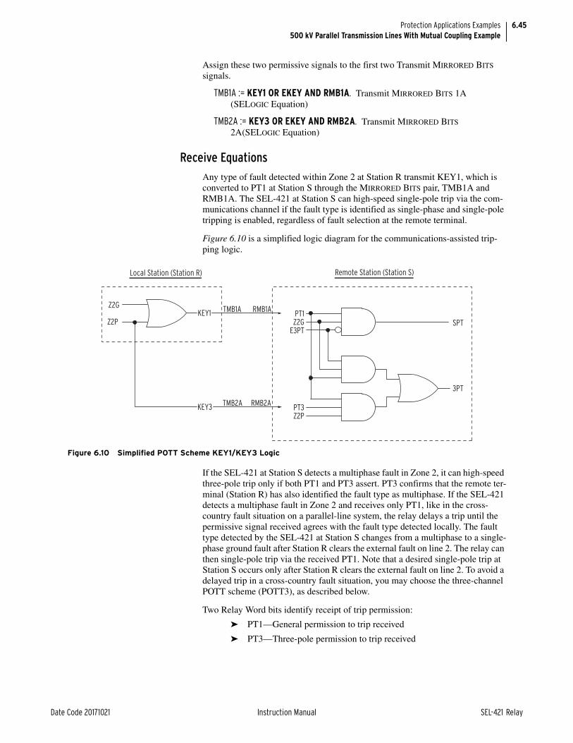
6.45
Date Code 20171021 Instruction Manual SEL-421 Relay
Protection Applications Examples500 kV Parallel Transmission Lines With Mutual Coupling Example
Assign these two permissive signals to the first two Transmit MIRRORED BITS signals.
TMB1A := KEY1 OR EKEY AND RMB1A. Transmit MIRRORED BITS 1A (SELOGIC Equation)
TMB2A := KEY3 OR EKEY AND RMB2A. Transmit MIRRORED BITS 2A(SELOGIC Equation)
Receive Equations
Any type of fault detected within Zone 2 at Station R transmit KEY1, which is converted to PT1 at Station S through the MIRRORED BITS pair, TMB1A and RMB1A. The SEL-421 at Station S can high-speed single-pole trip via the com-munications channel if the fault type is identified as single-phase and single-pole tripping is enabled, regardless of fault selection at the remote terminal.
Figure 6.10 is a simplified logic diagram for the communications-assisted trip-ping logic.
If the SEL-421 at Station S detects a multiphase fault in Zone 2, it can high-speed three-pole trip only if both PT1 and PT3 assert. PT3 confirms that the remote ter-minal (Station R) has also identified the fault type as multiphase. If the SEL-421 detects a multiphase fault in Zone 2 and receives only PT1, like in the cross-country fault situation on a parallel-line system, the relay delays a trip until the permissive signal received agrees with the fault type detected locally. The fault type detected by the SEL-421 at Station S changes from a multiphase to a single-phase ground fault after Station R clears the external fault on line 2. The relay can then single-pole trip via the received PT1. Note that a desired single-pole trip at Station S occurs only after Station R clears the external fault on line 2. To avoid a delayed trip in a cross-country fault situation, you may choose the three-channel POTT scheme (POTT3), as described below.
Two Relay Word bits identify receipt of trip permission:
➤ PT1—General permission to trip received
➤ PT3—Three-pole permission to trip received
Figure 6.10 Simplified POTT Scheme KEY1/KEY3 Logic
KEY1
Local Station (Station R)
KEY3
Z2GPT1
PT3
Z2G
TMB2A RMB2A
RMB1ATMB1A
Z2P
E3PTSPT
3PT
Z2P
Remote Station (Station S)

6.46
SEL-421 Relay Instruction Manual Date Code 20171021
Protection Applications Examples500 kV Parallel Transmission Lines With Mutual Coupling Example
Assign PT1 to the corresponding Received MIRRORED BITS signals.
PT1 := RMB1A. General Permissive Trip Received (SELOGIC Equation)
PT3 := RMB2A. Three-Pole Permissive Trip Received (SELOGIC Equation)
Three-Channel POTT Scheme, POTT3
In a cross-country fault situation of a mutually coupled parallel-line system, a relay using the one-channel POTT scheme will trip all three poles at the remote-to-fault terminal. This is because the relay at the remote terminal sees a multi-phase fault and receives the only permissive trip signal. Both transmission lines will be out of service if even a single-phase ground fault occurs on each circuit.
The two-channel POTT scheme retains the much-desired single-pole tripping in the event of cross-country faults. However, the relay at the remote terminal has to delay a single-pole trip until the external fault is cleared at the close-in terminal. This application example uses direct transfer trips described below to compli-ment the two-channel POTT scheme and reduce the single-pole trip delay to a minimum.
As an alternative to the two-channel POTT scheme with direct transfer trips, you may use the phase-segregate three-channel POTT scheme (POTT3) to correctly single-pole trip without a delay in the event of cross-country faults. In the previ-ous cross-country fault example, the SEL-421 on line 1 at Station R will transmit KEYA to the relay at Station S, which converts it to PTA, a permissive A-Phase trip signal. The relay then combines a locally detected Zone 2 phase-distance ele-ment with the received PTA and trips A-Phase only without a time delay. Because the direct transfer trips are not necessary in the three-channel POTT scheme, the total communications channels used would be three.
For three-channel POTT applications, the following equations apply:
ECOMM := POTT3. Communications-Assisted Tripping (N, DCB, POTT, POTT2, POTT3, DCUB1, DCUB2)
TMB1A := KEYA. Transmit MIRRORED BITS 1A (SELOGIC Equation)
TMB2A := KEYB. Transmit MIRRORED BITS 2A (SELOGIC Equation)
TMB3A := KEYC. Transmit MIRRORED BITS 3A (SELOGIC Equation)
PTA := RMB1A. A-Phase Permissive Trip Received (SELOGIC Equation)
PTB := RMB2A. B-Phase Permissive Trip Received (SELOGIC Equation)
PTC := RMB3A. C-Phase Permissive Trip Received (SELOGIC Equation)
Relay Word bit KEY is general permission to trip.
Single-Line Applications
For single-line applications, the following equations apply:
ECOMM := POTT. Communications-Assisted Tripping (N, DCB, POTT, POTT2, POTT3, DCUB1, DCUB2)
TMB1A := KEY. Transmit MIRRORED BITS 1A (SELOGIC Equation)
PT1 := RMB1A. General Permissive Trip Received (SELOGIC Equation)
Relay Word bit KEY is general permission to trip.

6.47
Date Code 20171021 Instruction Manual SEL-421 Relay
Protection Applications Examples500 kV Parallel Transmission Lines With Mutual Coupling Example
Direct TrippingDirect tripping is faster because the SEL-421 Relays at Station S do not have to wait for the circuit breakers at Station R to single-pole trip first; that is, the SEL-421 Relays at Station R single-pole direct transfer trip the SEL-421 Relays at Station S during crossing country faults beyond the reach of Zone 1 ground-distance protection at Station S.
Transmit EquationsTMB3A := TPA AND NOT 3PT. Transmit MIRRORED BITS 3A (SELOGIC Equa-
tion)
TMB4A := TPB AND NOT 3PT. Transmit MIRRORED BITS 4A (SELOGIC Equa-tion)
TMB5A := TPC AND NOT 3PT. Transmit MIRRORED BITS 5A (SELOGIC Equa-tion)
Receive EquationsDTA := RMB3A. Direct Transfer Trip A-Phase (SELOGIC Equation)
DTB := RMB4A. Direct Transfer Trip B-Phase (SELOGIC Equation)
DTC := RMB5A. Direct Transfer Trip C-Phase (SELOGIC Equation)
Example CompletedThis completes the application example that describes how to set the SEL-421 for communications-assisted protection of 500 kV parallel overhead transmission lines with zero-sequence mutual coupling. Analyze your particular power system to determine the appropriate settings for your application.
Relay SettingsTable 6.13 lists all protective relay settings for this example. Settings used in this example appear in boldface type.
Table 6.13 Settings for 500 kV Parallel TX Example (Sheet 1 of 7)
Setting Prompt Entry
General Global (Global)
SID Station Identifier (40 characters) MOSCOW - 500 kV
RID Relay Identifier (40 characters) SEL-421 Relay
NUMBK Number of Breakers in Scheme (1, 2) 2
BID1 Breaker 1 Identifier (40 characters) Circuit Breaker 1
BID2 Breaker 2 Identifier (40 characters) Circuit Breaker 2
NFREQ Nominal System Frequency (50, 60 Hz) 60
PHROT System Phase Rotation (ABC, ACB) ABC
DATE_F Date Format (MDY, YMD, DMY) MDY
FAULT Fault Condition (SELOGIC Equation) 50P1 OR 51S1 OR Z2P OR Z2G OR Z3P OR Z3G

6.48
SEL-421 Relay Instruction Manual Date Code 20171021
Protection Applications Examples500 kV Parallel Transmission Lines With Mutual Coupling Example
Current and Voltage Source Selection (Global)
ESS Current And Voltage Source Selection (Y, N, 1, 2, 3, 4)
3
LINEI Line Current Source (IW, COMB) COMB
BK1I Breaker 1 Current Source (IW, IX, NA) IW
BK2I Breaker 2 Current Source (IX, COMB, NA) IX
Breaker Configuration (Breaker Monitoring)
EB1MON Breaker 1 Monitoring (Y, N) N
EB2MON Breaker 2 Monitoring (Y, N) N
BK1TYP Breaker 1 Trip Type (Single Pole = 1, Three Pole = 3)
1
BK2TYP Breaker 2 Trip Type (Single Pole = 1, Three Pole = 3)
1
Breaker 1 Inputs (Breaker Monitoring)
52AA1 A-Phase N/O Contact Input—BK1 (SELOGIC Equation)
IN101
52AB1 B-Phase N/O Contact Input—BK1 (SELOGIC Equation)
IN102
52AC1 C-Phase N/O Contact Input—BK1 (SELOGIC Equation)
IN103
Breaker 2 Inputs (Breaker Monitoring)
52AA2 A-Phase N/O Contact Input—BK2 (SELOGIC Equation)
IN104
52AB2 B-Phase N/O Contact Input—BK2 (SELOGIC Equation)
IN105
52AC2 C-Phase N/O Contact Input—BK2 (SELOGIC Equation)
IN106
Line Configuration (Group)
CTRW Current Transformer Ratio—Input W (1–50000) 400
CTRX Current Transformer Ratio—Input X (1–50000) 400
PTRY Potential Transformer Ratio—Input Y (1–10000) 4500.0
VNOMY PT Nominal Voltage (L-L)—Input Y (60–300 V secondary)
111
PTRZ Potential Transformer Ratio—Input Z (1–10000) 4500.0
VNOMZ PT Nominal Voltage (L-L)—Input Z (60–300 V secondary)
111
Z1MAG Positive-Sequence Line Impedance Magnitude (0.05–255 secondary)
3.98
Z1ANG Positive-Sequence Line Impedance Angle (5.00–90 degrees)
87.6
Z0MAG Zero-Sequence Line Impedance Magnitude (0.05–255 secondary)
14.48
Z0ANG Zero-Sequence Line Impedance Angle (5.00–90 degrees)
82.1
EFLOC Fault Location (Y, N) Y
LL Line Length (0.10–999) 75
Table 6.13 Settings for 500 kV Parallel TX Example (Sheet 2 of 7)
Setting Prompt Entry

6.49
Date Code 20171021 Instruction Manual SEL-421 Relay
Protection Applications Examples500 kV Parallel Transmission Lines With Mutual Coupling Example
Relay Configuration (Group)
E21P Mho Phase Distance Zones (N, 1–5) 3
E21MG Mho Ground Distance Zones (N, 1–5) 3
E21XG Quadrilateral Ground Distance Zones (N, 1–5) 3
ECVT Cvt Transient Detection (Y, N) N
ESERCMP Series-Compensated Line Logic (Y, N) N
ECDTD Distance Element Common Time Delay (Y, N) Y
ESOTF Switch-Onto-Fault (Y, N) Y
EOOS Out-Of-Step (Y, Y1, N) N
ELOAD Load Encroachment (Y, N) N
E50P Phase Inst./Def.-Time O/C Elements (N, 1–4) 1
E50G Residual Ground Inst./Def.-Time O/C Elements (N, 1–4)
N
E50Q Negative-Sequence Inst./Def.-Time O/C Elements (N, 1–4)
N
E51S Selectable Inverse-Time O/C Elements (N, 1–3) 1
E32 Directional Control (Y, AUTO, AUTO2) AUTO2
ECOMM Communications-Assisted Tripping (N, DCB, POTT, POTT2, POTT3, DCUB2, DCUB2)
POTT2
EBFL1 Breaker 1 Failure Logic (N, 1, 2, Y1, Y2) N
EBFL2 Breaker 2 Failure Logic (N, 1, 2, Y1, Y2) N
E25BK1 Synchronism Check for Breaker 1 (Y, N, Y1, Y2) N
E25BK2 Synchronism Check for Breaker 2 (Y, N, Y1, Y2) N
E79 Reclosing (Y, Y1, N) N
EMANCL Manual Closing (Y, N) N
ELOP Loss-of-Potential (Y, Y1, N) Y1
EDEM Demand Metering (N, THM, ROL) N
EADVS Advanced Settings (Y, N) Y
VMEMC Memory Voltage Control (SELOGIC equation) 0
EFID Enable FID Logic (Y, N) Y
Z50P1 Zone 1 Phase Fault Detector (0.50–170.00 A, secondary)
0.5
Z50G1 Zone 1 Ground Fault Detector (0.50–100.00 A, secondary)
0.5
Mho Phase-Distance Element Reach (Group)
Z1MP Zone 1 Reach (OFF, 0.05–64 secondary) 3.18
Z2MP Zone 2 Reach (OFF, 0.05–64 secondary) 4.78
Z3MP Zone 3 Reach (OFF, 0.05–64 secondary) 4.78
Mho Phase-Distance Element Time Delay (Group)
Z1PD Zone 1 Time Delay (OFF, 0.000–16000 cycles) OFF
Z2PD Zone 2 Time Delay (OFF, 0.000–16000 cycles) OFF
Z3PD Zone 3 Time Delay (OFF, 0.000–16000 cycles) OFF
Table 6.13 Settings for 500 kV Parallel TX Example (Sheet 3 of 7)
Setting Prompt Entry

6.50
SEL-421 Relay Instruction Manual Date Code 20171021
Protection Applications Examples500 kV Parallel Transmission Lines With Mutual Coupling Example
Mho Ground-Distance Element Reach (Group)
Z1MG Zone 1 (OFF, 0.05–64 secondary) 3.18
Z2MG Zone 2 (OFF, 0.05–64 secondary) 4.78
Z3MG Zone 3 (OFF, 0.05–64 secondary) 4.78
Quadrilateral Ground-Distance Element Reach (Group)
XG1 Zone 1 Reactance (OFF, 0.05–64 secondary) 3.18
RG1 Zone 1 Resistance (0.05–50 secondary) 7.96
XG2 Zone 2 Reactance (OFF, 0.05–64 secondary) 4.78
RG2 Zone 2 Resistance (0.05–50 secondary) 12.00
XG3 Zone 3 Reactance (OFF, 0.05–64 secondary) 4.78
RG3 Zone 3 Resistance (0.05–50 secondary) 15.00
XGPOL Quadrilateral Ground Polarizing Quantity (I2, IG) I2
TANGG Nonhomogeneous Correction Angle (–40.0 to +40.0 degrees)
0.0
Zero-Sequence Current Compensation Factor (Group)
k0M1 Zone 1 ZSC Factor Magnitude (AUTO, 0.000–10) 0.880
k0A1 Zone 1 ZSC Factor Angle (–180.0 to +180.0 degrees)
–7.6
k0M Forward Zones ZSC Factor Magnitude (0.000–10) 1.540
k0A Forward Zones ZSC Factor Angle (–180.0 to +180.0 degrees)
–9.0
k0MR Reverse Zones ZSC Factor Magnitude (0.000–10) 1.540
k0AR Reverse Zones ZSC Factor Angle (–180.0 to +180.0 degrees)
–9.0
Ground-Distance Element Time Delay (Group)
Z1GD Zone 1 Time Delay (OFF, 0.000–16000 cycles) OFF
Z2GD Zone 2 Time Delay (OFF, 0.000–16000 cycles) OFF
Z3GD Zone 3 Time Delay (OFF, 0.000–16000 cycles) OFF
Distance Element Common Time Delay (Group)
Z1D Zone 1 Time Delay (OFF, 0.000–16000 cycles) 0.000
Z2D Zone 2 Time Delay (OFF, 0.000–16000 cycles) 20.000
Z3D Zone 3 Time Delay (OFF, 0.000–16000 cycles) 0.000
SOTF Scheme Settings
ESPSTF Single-Pole Switch-Onto-Fault (Y, N) Y
EVRST Switch-Onto-Fault Voltage Reset (Y, N) Y
VRSTPU Switch-Onto-Fault Reset Voltage (0.60–1.00 pu) 0.60–1.00 pu
52AEND 52A Pole Open Time Delay (OFF, 0.000–16000 cycles)
10.000
CLOEND CLSMON or Single Pole Open Delay (OFF, 0.000–16000 cycles)
OFF
SOTFD Switch-Onto-Fault Enable Duration (0.500–16000 cycles)
10.000
CLSMON Close Signal Monitor (SELOGIC Equation) NA
Table 6.13 Settings for 500 kV Parallel TX Example (Sheet 4 of 7)
Setting Prompt Entry
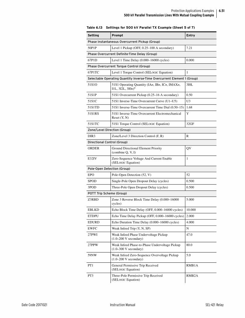
6.51
Date Code 20171021 Instruction Manual SEL-421 Relay
Protection Applications Examples500 kV Parallel Transmission Lines With Mutual Coupling Example
Phase Instantaneous Overcurrent Pickup (Group)
50P1P Level 1 Pickup (OFF, 0.25–100 A secondary) 7.21
Phase Overcurrent Definite-Time Delay (Group)
67P1D Level 1 Time Delay (0.000–16000 cycles) 0.000
Phase Overcurrent Torque Control (Group)
67P1TC Level 1 Torque Control (SELOGIC Equation) 1
Selectable Operating Quantity Inverse-Time Overcurrent Element 1 (Group)
51S1O 51S1 Operating Quantity (IAn, IBn, ICn, IMAXn, I1L, 3I2L, 3I0n)a
3I0L
51S1P 51S1 Overcurrent Pickup (0.25–16 A secondary) 0.50
51S1C 51S1 Inverse-Time Overcurrent Curve (U1–U5) U3
51S1TD 51S1 Inverse-Time Overcurrent Time Dial (0.50–15) 1.68
51S1RS 51S1 Inverse-Time Overcurrent Electromechanical Reset (Y, N)
Y
51S1TC 51S1 Torque Control (SELOGIC Equation) 32GF
Zone/Level Direction (Group)
DIR3 Zone/Level 3 Direction Control (F, R) R
Directional Control (Group)
ORDER Ground Directional Element Priority (combine Q, V, I)
QV
E32IV Zero-Sequence Voltage And Current Enable (SELOGIC Equation)
1
Pole-Open Detection (Group)
EPO Pole-Open Detection (52, V) 52
SPOD Single-Pole Open Dropout Delay (cycles) 0.500
3POD Three-Pole Open Dropout Delay (cycles) 0.500
POTT Trip Scheme (Group)
Z3RBD Zone 3 Reverse Block Time Delay (0.000–16000 cycles)
5.000
EBLKD Echo Block Time Delay (OFF, 0.000–16000 cycles) 10.000
ETDPU Echo Time Delay Pickup (OFF, 0.000–16000 cycles) 2.000
EDURD Echo Duration Time Delay (0.000–16000 cycles) 4.000
EWFC Weak Infeed Trip (Y, N, SP) N
27PWI Weak Infeed Phase Undervoltage Pickup (1.0–200 V secondary)
47.0
27PPW Weak Infeed Phase-to-Phase Undervoltage Pickup (1.0–300 V secondary)
80.0
59NW Weak Infeed Zero-Sequence Overvoltage Pickup (1.0–200 V secondary)
5.0
PT1 General Permissive Trip Received (SELOGIC Equation)
RMB1A
PT3 Three-Pole Permissive Trip Received (SELOGIC Equation)
RMB2A
Table 6.13 Settings for 500 kV Parallel TX Example (Sheet 5 of 7)
Setting Prompt Entry

6.52
SEL-421 Relay Instruction Manual Date Code 20171021
Protection Applications Examples500 kV Parallel Transmission Lines With Mutual Coupling Example
Trip Logic (Group)
TR Trip (SELOGIC Equation) Z1T OR Z2T OR 51S1T
TRCOMM Communications-Assisted Trip (SELOGIC Equation) Z2G OR Z2P
TRCOMMD Dir. Element Comms.-Assisted Trip (SELOGIC Equation)
NA
TRSOTF Switch-Onto-Fault Trip (SELOGIC Equation) Z2P OR Z2G OR 50P1
DTA Direct Transfer Trip A-Phase (SELOGIC Equation) RMB3A
DTB Direct Transfer Trip B-Phase (SELOGIC control equation)
RMB4A
DTC Direct Transfer Trip C-Phase (SELOGIC Equation) RMB5A
BK1MTR Manual Trip—Breaker 1 (SELOGIC Equation) OC1 OR PB7_PUL
BK2MTR Manual Trip—Breaker 2 (SELOGIC Equation) OC2 OR PB8_PUL
ULTR Unlatch Trip (SELOGIC Equation) TRGTR
ULMTR1 Unlatch Manual Trip—Breaker 1 (SELOGIC Equation)
NOT (52AA1AND 52AB1 AND 52AC1)
ULMTR2 Unlatch Manual Trip—Breaker 2 (SELOGIC Equation)
NOT (52AA2 AND 52AB2 AND 52AC2)
TOPD Trip During Open Pole Time Delay (2.000–8000 cycles)
215.000
TULO Trip Unlatch Option (1, 2, 3, 4) 3
Z2GTSP Zone 2 Ground Distance Time Delay SPT (Y, N) N
67QGSP Zone 2 Directional Neg.-Seq./Residual Ground Overcurrent SPT (Y, N)
N
TDUR1D SPT Minimum Trip Duration Time Delay (2.000–8000 cycles)
9.000
TDUR3D 3PT Minimum Trip Duration Time Delay (2.000–8000 cycles)
9.000
E3PT Three-Pole Trip Enable (SELOGIC Equation) IN107 OR TOP
E3PT1 Breaker 1 3PT (SELOGIC Equation) IN107
E3PT2 Breaker 2 3PT (SELOGIC Equation) IN107
ER Event Report Trigger (SELOGIC Equation) R_TRIG Z2P OR R_TRIG Z2G OR R_TRIG 51S1 OR R_TRIG Z3P OR R_TRIG Z3G
Main Board (Outputs)
OUT101 (SELOGIC Equation) TPA1
OUT102 (SELOGIC Equation) TPB1
OUT103 (SELOGIC Equation) TPC1
OUT104 (SELOGIC Equation) TPA2
OUT105 (SELOGIC Equation) TPB2
OUT106 (SELOGIC Equation) TPC2
Table 6.13 Settings for 500 kV Parallel TX Example (Sheet 6 of 7)
Setting Prompt Entry

6.53
Date Code 20171021 Instruction Manual SEL-421 Relay
Protection Applications Examples345 kV Tapped Overhead Transmission Line Example
345 kV Tapped Overhead Transmission Line ExampleFigure 6.11 shows a three-ended 345 kV transmission line with SEL-421 protec-tion at Stations S and R. A tap midway between Stations S and R feeds an auto-transformer. This example explains how to calculate settings for the SEL-421 at Station S that protects the 345 kV circuit between Substation S, Substation R, and the autotransformer. The 345 kV and 138 kV windings of the autotrans-former are wye-connected and solidly grounded. The tertiary voltage windings are delta-connected and lag the other windings by 30 degrees.
This application example uses communications-assisted tripping with PLC (power line carrier) communication to provide high-speed protection for faults along the 345 kV circuit. The relay uses distance elements and residual ground directional overcurrent elements in this protection scheme.
Another SEL-421 located on the 138 kV side of the autotransformer blocks high-speed tripping at Stations S and R for faults on the 138 kV side of the autotrans-former.
MIRRORED BITS Transmit Equations (Outputs)
TMB1A (SELOGIC Equation) KEY1 OR EKEY AND RMB1A
TMB2A (SELOGIC Equation) KEY3 OR EKEY AND RMB2A
TMB3A (SELOGIC Equation) TPA AND NOT 3PT
TMB4A (SELOGIC Equation) TPB AND NOT 3PT
TMB5A (SELOGIC Equation) TPC AND NOT 3PT
TMB6A (SELOGIC Equation) NA
TMB7A (SELOGIC Equation) NA
TMB8A (SELOGIC Equation) NA
TMB1B (SELOGIC Equation) NA
TMB2B (SELOGIC Equation) NA
TMB3B (SELOGIC Equation) NA
TMB4B (SELOGIC Equation) NA
TMB5B (SELOGIC Equation) NA
TMB6B (SELOGIC Equation) NA
TMB7B (SELOGIC Equation) NA
TMB8B (SELOGIC Equation) NA
a Parameter n is 1 for BK1, 2 for BK2, and L for Line.
Table 6.13 Settings for 500 kV Parallel TX Example (Sheet 7 of 7)
Setting Prompt Entry

6.54
SEL-421 Relay Instruction Manual Date Code 20171021
Protection Applications Examples345 kV Tapped Overhead Transmission Line Example
Power System DataTable 6.14 lists the power system data for this application example. Substitute the values and parameters that correspond to your system when you set the relay using this example as a guide.
Figure 6.11 345 kV Tapped Overhead Transmission Line
SEL-421
SEL-421
SEL-421
Z1L1, Z0L1 Z1L2, Z0L2
Z1L3, Z0L3
Z1T, Z0T
(Section 3)
(Section 2)(Section 1)
Z1S, Z0SBK1
S (Kellogg) R (St. Maries)
BK2 Z1R, Z0R
BK3
345 kV
VAZVAZ
IW
VY
IWIW
VY VY
345 kV
13.8 kV
138 kV T (Bonners Ferry)
Table 6.14 System Data—345 kV Tapped Overhead Transmission Line (Sheet 1 of 2)
Parameter Value
EHV nominal system line-to-line voltage (transformer primary)
345 kV
HV line-to-line voltage (transformer secondary) 138 kV
MV line-to-line voltage (transformer tertiary) 13.8 kV
Nominal relay current 5 A secondary
Nominal frequency 60 Hz
Line lengthsa
S–t (Section 1) t–R (Section 2) t–T (Section 3)
50 miles 50 miles 75 miles
Line impedances:
Z1L1 = Z1L2 Z0L1 = Z0L2 Z1L3 Z0L3
29.67 84.7° primary 96.65 73° primary 44.5 84.7° primary 144.98 73° primary
Transformer impedances:
XHM XML XHL
8% on 500 MVA; 1.6% on 100 MVA 10% on 25 MVA; 40% on 100 MVA 15% on 25 MVA; 60% on 100 MVA
Source S impedances: Z1S = Z0S 10 87° primary
Source R impedances: Z1R = Z0R 35 87° primary

6.55
Date Code 20171021 Instruction Manual SEL-421 Relay
Protection Applications Examples345 kV Tapped Overhead Transmission Line Example
Convert the power system impedances from primary to secondary so you can later calculate protection settings. Table 6.15 lists the corresponding secondary impedances. Convert the impedances to secondary ohms as follows:
Equation 6.19
Equation 6.20
The tapped autotransformer is rated at 500 MVA; the corresponding maximum load current is 837 A primary at 354 kV.
Source T impedances: Z1T = Z0T 0.656 87° per unit
PTR (potential transformer ratio) 345 kV:115 V = 3000.0
CTR (current transformer ratio) 1000:5 = 200
Phase rotation ABC
a Parameter t is the tap point on the 345 kV line; S and R are terminals at the ends of the 345 kV line (see Figure 6.11).
Table 6.15 Secondary Impedances
Parameter Value
Line impedances:
Z1L1 = Z1L2 Z0L1 = Z0L2 Z1L3 Z0L3
2 84.7° secondary 6.44 73° secondary 3 84.7° secondary 9.65 73° secondary
Transformer impedances:
XHM XML XHL
8% @ 500 MVA; 1.6% on 100 MVA 10% @ 25 MVA; 40% on 100 MVA 15% @ 25 MVA; 60% on 100 MVA
Source S impedances:
Z1S = Z0S
0.67 87° secondary
Source R impedances:
Z1R = Z0R
2.33 87° secondary
Source T impedances:
Z1T = Z0T
0.656 87° per unit
Table 6.14 System Data—345 kV Tapped Overhead Transmission Line (Sheet 2 of 2)
Parameter Value
k CTRPTR------------
2003000------------ 0.067= = =
Z1L1 secondary k Z1L1 primary • =
0.067 29.67 84.7 • =
2 84.7=

6.56
SEL-421 Relay Instruction Manual Date Code 20171021
Protection Applications Examples345 kV Tapped Overhead Transmission Line Example
Application SummaryThis particular example is for a single circuit breaker, three-pole tripping applica-tion with the following functions:
➤ DCB (directional comparison blocking) trip scheme
➤ Three zones of mho phase and ground-distance protection
➢ Zone 1, forward-looking, instantaneous underreaching protection
➢ Zone 2, forward-looking, communications-assisted high-speed tripping and time-delayed tripping
➢ Zone 3, reverse-looking, starting element
➤ Two levels of zero-sequence directional overcurrent protection
➢ Level 2, forward-looking, communications-assisted high-speed tripping
➢ Level 3, reverse-looking, starting element
➤ Inverse-time directional zero-sequence overcurrent backup protection
➤ Load-encroachment logic: prevents unwanted tripping during heavy load conditions
➤ SOTF protection: fast tripping when the circuit breaker closes
Relay settings that are not mentioned in this example do not apply to this applica-tion example.
Global SettingsGeneral Global Settings
The SEL-421 has settings for identification. These settings allow you to identify the following:
➤ Station (SID)
➤ Relay (RID)
➤ Circuit Breaker 1 (BID1)
You can enter as many as 40 characters per identification setting.
SID := KELLOG - 345 kV. Station Identifier (40 characters)
RID := SEL-421 Relay. Relay Identifier (40 characters)
Configure the SEL-421 for one circuit breaker.
NUMBK := 1. Number of Breakers in Scheme (1, 2)
BID1 := Circuit Breaker 1. Breaker 1 Identifier (40 characters)
You can select both nominal frequency and phase rotation for the relay.
NFREQ := 60. Nominal System Frequency (50, 60 Hz)
PHROT := ABC. System Phase Rotation (ABC, ACB)

6.57
Date Code 20171021 Instruction Manual SEL-421 Relay
Protection Applications Examples345 kV Tapped Overhead Transmission Line Example
Current and Voltage Source SelectionThe voltage and current source selection is for one circuit breaker. The relay derives the line current source from current input IW when you set ESS to N.
ESS := N. Current and Voltage Source Selection (Y, N, 1, 2, 3, 4)
Figure 6.12 illustrates the current and voltage sources for this particular applica-tion. The relay uses potential input VY and current input IW for line relaying; potential input VAZ is for synchronism check. Synchronism Check on page 5.158 describes how to apply the synchronism check function.
Breaker MonitorCircuit Breaker Configuration
Set the relay to indicate that Circuit Breaker 1 is a three-pole trip circuit breaker.
BK1TYP := 3. Breaker 1 Trip Type (Single-Pole = 1, Three-Pole = 3)
Circuit Breaker 1 InputsThe SEL-421 uses a normally open auxiliary contact from the circuit breaker to determine whether the circuit breaker is open or closed.
52AA1 := IN101. A-Phase N/O Contact Input -BK1 (SELOGIC Equation)
Group SettingsLine Configuration
The SEL-421 has four transformer turns ratio settings that convert the secondary potentials and currents that the relay measures to the corresponding primary val-ues. These settings are the potential transformer and current transformer ratios PTRY, PTRZ, CTRW, and CTRX. Use the Y potential input for line relaying and the Z potential input for synchronism checks. Use the W current input for line relaying. The settings VNOMY and VNOMZ specify the nominal secondary line-to-line voltage of the potential transformers (see Figure 6.12).
CTRW := 200. Current Transformer Ratio—Input W (1–50000)
PTRY := 3000. Potential Transformer Ratio—Input Y (1–10000)
VNOMY := 115. PT Nominal Voltage (L–L)—Input Y (60–300 V secondary)
PTRZ := 3000. Potential Transformer Ratio—Input Z (1–10000)
VNOMZ := 115. PT Nominal Voltage (L–L)—Input Z (60–300 V secondary)
Figure 6.12 Circuit Breaker Arrangement at Station S
SEL-421
VAZ
IW
VY
BK1
3
1 3345
kV B
us

6.58
SEL-421 Relay Instruction Manual Date Code 20171021
Protection Applications Examples345 kV Tapped Overhead Transmission Line Example
Set Z1MAG equal to Z1L1 plus Z1L2 so the fault locator provides correct results for internal faults not located on the tap (i.e., source T is extremely weak and pro-vides practically no infeed). See Table 6.15 for the secondary line impedances.
Z1MAG := 4.00. Positive-Sequence Line Impedance Magnitude (0.05–255 secondary)
Z1ANG := 84.7. Positive-Sequence Line Impedance Angle (5.00–90 degrees)
Enter the secondary value of the zero-sequence impedance of the protected line from Station S to Station R, ignoring the tap.
Z0MAG := 12.88. Zero-Sequence Line Impedance Magnitude (0.05–255 secondary)
Z0ANG := 73.0. Zero-Sequence Line Impedance Angle (5.00–90 degrees)
Enable the fault locator.
EFLOC := Y. Fault Location (Y, N)
The LL setting is the line length. This value has no defined unit; you can set the line length in miles, kilometers, ohms, etc. Set the length in miles.
LL := 100.00. Line Length (0.10–999)
The relay fault locator uses the values you enter for Z1MAG, Z1ANG, Z0MAG, Z0ANG, and LL.
Relay ConfigurationYou can select from zero to five phase zones of phase mho (E21P), ground mho (E21MG), and ground quadrilateral (E21XG) distance protection. You can inde-pendently select the number of zones per type of distance protection. Select only the number of zones needed. For this application example, use three zones of mho phase and ground-distance protection.
E21P := 3. Mho Phase-Distance Zones (N, 1–5)
E21MG := 3. Mho Ground-Distance Zones (N, 1–5)
E21XG := N. Quadrilateral Ground-Distance Zones (N, 1–5)
Now enable the other logic you will need for this application example.
You do not need CVT transient detection if the SIR (Source Impedance Ratio) is less than five. SIR is equal to the ratio of the local source impedance to the relay reach. Calculate the ratio based on the Zone 1 reach because you do not want Zone 1 distance protection to overreach during an external fault.
Equation 6.21
ECVT := N. CVT Transient Detection (Y, N)
NOTE: The SEL-421-4 does not provide series-compensated line protection logic.
The transmission line is not series compensated.
ESERCMP := N. Series-Compensated Line Logic (Y, N)
SIRZ1S
0.8 Z1L1 Z1L2+• ------------------------------------------------=
0.67 0.8 2 2 + • ---------------------------------------------=
0.209, SIR<5=

6.59
Date Code 20171021 Instruction Manual SEL-421 Relay
Protection Applications Examples345 kV Tapped Overhead Transmission Line Example
You can select a common time delay or an independent time delay per zone for phase and ground-distance protection. If you choose independent timing, evolv-ing faults (such as those changing from single phase to multiphase) cause the timer to reset and result in additional delay. Select common time delay for this application.
ECDTD := Y. Distance Element Common Time Delay (Y, N)
The SOTF logic permits tripping by specified protection elements for a settable time after the circuit breaker closes.
ESOTF := Y. Switch-Onto-Fault (Y, N)
Do not enable the Out-of-Step logic for this application example.
EOOS : = N. Out-of-Step (Y, N)
The relay has a load-encroachment feature that prevents operation of the phase-distance elements during heavy load. This unique feature permits the load to enter a predefined area of the phase-distance characteristics without causing unwanted tripping.
ELOAD := Y. Load Encroachment (Y, N)
Use Level 1 high-set instantaneous phase overcurrent element for SOTF protection.
E50P := 1. Phase Instantaneous/Definite-Time Overcurrent Elements (N, 1–4)
Use residual ground overcurrent elements for the DCB trip scheme. The Level 2 residual ground overcurrent element (67G2) is forward-looking and provides communications-assisted tripping. The Level 3 residual overcurrent element (67G3) is reverse-looking and blocks the tripping at Station R during out-of-sec-tion faults behind Station S. Enable three levels of residual ground overcurrent protection.
E50G := 3. Residual Ground Instantaneous/Definite-Time Overcurrent Elements (N, 1–4)
This application does not require negative-sequence overcurrent protection.
E50Q := N. Negative-Sequence Instantaneous/Definite-Time Overcurrent Elements (N, 1–4)
Use inverse-time overcurrent protection to provide backup protection for high-resistance ground faults. The 51S1 element provides backup protection for unbal-anced faults if both the communications-assisted and step distance protection fail to operate.
E51S := 1. Selectable Inverse-Time Overcurrent Element (N, 1–3)
Set E32 to AUTO or AUTO2 and the relay automatically calculates the settings corresponding to the ground directional element (32G).
E32 := AUTO2. Directional Control (Y, AUTO, AUTO2)
Use the DCB tripping scheme.
ECOMM := DCB. Communications-Assisted Tripping (N, DCB, POTT, POTT2, POTT3, DCUB1, DCUB2)
Fuses or molded case circuit breakers often protect potential transformers. Oper-ation of one or more fuses, or molded case circuit breakers, results in a loss of polarizing potential inputs to the relay. Loss of one or more phase voltages pre-vents the relay from properly determining fault distance or direction.

6.60
SEL-421 Relay Instruction Manual Date Code 20171021
Protection Applications Examples345 kV Tapped Overhead Transmission Line Example
Occasional loss-of-potential to the distance relay, while unavoidable, is detect-able. When the relay detects a loss-of-potential condition, the relay can block dis-tance element operation, block or enable forward-looking directional overcurrent elements, and issue an alarm for any true loss-of-potential condition.
If line-side PTs are used, the circuit breaker(s) must be closed for the LOP logic to detect an LOP condition. Therefore, if three-phase potential to the relay is lost while the circuit breaker(s) is open (e.g., the PT fuses are removed while the line is de-energized), the relay cannot detect a loss-of-potential condition when the circuit breaker(s) closes again. At circuit breaker closing, the relay can detect one or two missing potentials that occurred while the circuit breaker was open. See Loss-of-Potential Logic on page 5.28 for more information.
Table 6.16 lists the three choices for enabling LOP.
Set ELOP to Y1 for this application example. This choice reduces the chances of false tripping because of a loss-of-potential condition.
ELOP := Y1. Loss-of-Potential (Y, Y1, N)
You do not need Advanced Settings for this application example.
EADVS := N. Advanced Settings (Y, N)
Phase-Distance Elements (21P)Mho Phase-Distance Element Reach
Employ each zone of mho phase-distance protection as follows:
➤ Zone 1—Instantaneous underreaching tripping
➤ Zone 2—DCB scheme tripping
➤ Zone 3—DCB scheme blocking
Zone 1 Phase-Distance Element Reach
Zone 1 phase-distance protection provides instantaneous protection for phase-to-phase, phase-to-phase-to-ground, and three-phase faults for 80 percent of the dis-tance from Station S to Station R because this is the shortest line segment from one terminal to another. Errors in the current transformers, potential transform-ers, modeled transmission line data, and fault study data do not permit Zone 1 to be set equal to 100 percent of the distance to Station R. Otherwise, unwanted trip-ping could occur for faults just beyond the remote terminal.
Set Zone 1 phase-distance protection equal to 80 percent of the positive-sequence impedance from Station S to Station R.
Table 6.16 LOP Enable Options
Option Description
N The LOP logic operates but does not disable voltage-polarized directional ele-ments, distance elements, and forward-looking directional overcurrent ele-ments. Use LOP in this case for alarm only.
Y The relay disables all voltage-polarized directional elements and distance ele-ments, but enables forward-looking directional overcurrent elements. These forward-looking directional overcurrent elements effectively become nondirec-tional and provide overcurrent protection during an LOP condition.
Y1 The relay disables all voltage-polarized directional elements and distance ele-ments. The relay also disables the overcurrent elements controlled by the volt-age-polarized directional elements.

6.61
Date Code 20171021 Instruction Manual SEL-421 Relay
Protection Applications Examples345 kV Tapped Overhead Transmission Line Example
Equation 6.22
Z1MP := 3.2. Zone 1 Reach (OFF, 0.05–64 secondary)
Zone 2 Phase-Distance Element Reach
Set Zone 2 phase-distance reach to include the tapped autotransformer.
Perform the following fault study to determine the apparent fault impedance the SEL-421 distance elements measure for faults at the 138 kV terminals of the autotransformer. Use these measurements to set the distance reach settings. Sta-tion R should be in service to account for infeed. Place an AG and ABC fault at the 138 kV terminals of the autotransformer and record the secondary voltage and current the relay measures at Station S. Apply these quantities in Equation 6.23 and Equation 6.26, to determine the fault impedance the relay measures for the two fault types shown in Table 6.17. Use Equation 6.23 for an A-Phase-to-ground fault and Equation 6.26 for the three-phase fault.
Equation 6.23
The relay uses the zero-sequence compensation factor to measure zero-sequence quantities in terms of positive-sequence quantities.
Equation 6.24
The zero-sequence current is the sum of the phase currents.
Equation 6.25
The magnitude of the impedance for B-Phase-to-C-Phase, B-Phase-to-C-Phase-to-ground, and three-phase faults is |ZBC|.
Equation 6.26
Z1MP 0.8 Z1L1 Z+ 1L2 • =
0.8 2 2+ • =
3.2 =
where:
VA = A-Phase-to-neutral voltage
IA = A-Phase current
k0 = zero-sequence compensation factor
3I0 = zero-sequence current
where:
VBC = B-Phase-to-C-Phase voltage
IBC = B-Phase-to-C-Phase current
ZAGVA
IA k0 3I0• +--------------------------------=
k0Z0L1 Z1L1–
3 Z1L1• ------------------------------=
3I0 IA IB IC+ +=
ZBCVBCIBC-----------=

6.62
SEL-421 Relay Instruction Manual Date Code 20171021
Protection Applications Examples345 kV Tapped Overhead Transmission Line Example
Table 6.17 lists the results of the ZAG and ZBC calculations.
Select the phase-to-phase measurement from Table 6.17. Multiply this value by a safety factor of 125 percent to obtain Zone 2 phase-distance element reach.
Equation 6.27
Z2MP := 11.00. Zone 2 Reach (OFF, 0.05–64 secondary)
Zone 3 Phase-Distance Element Reach
Zone 3 phase-distance protection is reverse-looking. Zone 3 at Station S must have adequate reach to prevent unwanted tripping by the SEL-421 Relays at Sta-tions R or T during external faults behind the local terminal. The Zone 3 reach at Station S must cover overreach from the furthest reaching remote Zone 2 for reverse faults when there is no infeed from the other remote terminal.
Figure 6.13 illustrates this coordination issue. You must set the Zone 2 reach at Station T to account for infeed during faults beyond the tap on the 345 kV sys-tem. However, when one 345 kV station is out of service, the Zone 2 at Station T overreaches for faults on the other side of the tap on the 345 kV system.
Place AG and ABC faults at Station T and use Equation 6.23 and Equation 6.26 with respect to Station R to record the results in primary. Next place AG and ABC faults at Station R and use Equation 6.23 and Equation 6.26 with respect to Station T to record the results in primary. Table 6.18 lists the results in primary and per unit.
Table 6.17 Local Zone 2 Fault Impedance Measurements
Fault Type |ZAG| |ZBC|
AG 7.77 NA
ABC NA 8.8
Z2MP 1.25 8.8 • =
11.00 =
Figure 6.13 Reverse Zone 3 Coordination
Z1L3, Z0L3
S R
T
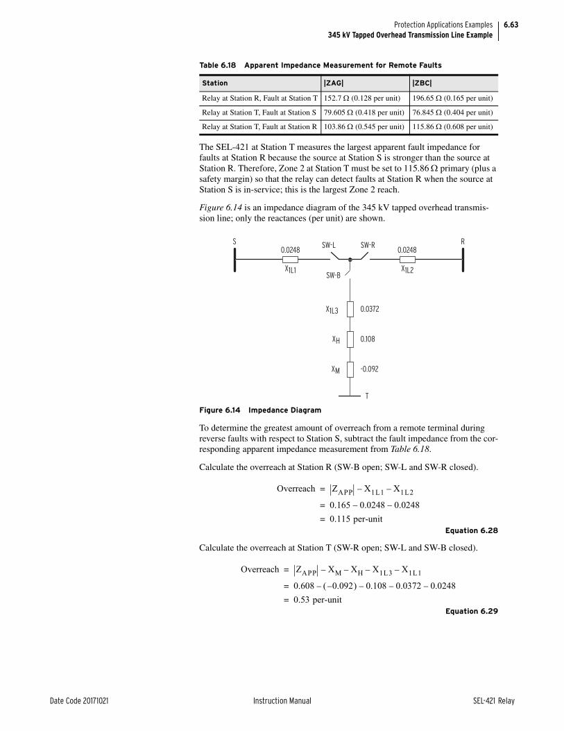
6.63
Date Code 20171021 Instruction Manual SEL-421 Relay
Protection Applications Examples345 kV Tapped Overhead Transmission Line Example
The SEL-421 at Station T measures the largest apparent fault impedance for faults at Station R because the source at Station S is stronger than the source at Station R. Therefore, Zone 2 at Station T must be set to 115.86 primary (plus a safety margin) so that the relay can detect faults at Station R when the source at Station S is in-service; this is the largest Zone 2 reach.
Figure 6.14 is an impedance diagram of the 345 kV tapped overhead transmis-sion line; only the reactances (per unit) are shown.
To determine the greatest amount of overreach from a remote terminal during reverse faults with respect to Station S, subtract the fault impedance from the cor-responding apparent impedance measurement from Table 6.18.
Calculate the overreach at Station R (SW-B open; SW-L and SW-R closed).
Equation 6.28
Calculate the overreach at Station T (SW-R open; SW-L and SW-B closed).
Equation 6.29
Table 6.18 Apparent Impedance Measurement for Remote Faults
Station |ZAG| |ZBC|
Relay at Station R, Fault at Station T 152.7 (0.128 per unit) 196.65 (0.165 per unit)
Relay at Station T, Fault at Station S 79.605 (0.418 per unit) 76.845 (0.404 per unit)
Relay at Station T, Fault at Station R 103.86 (0.545 per unit) 115.86 (0.608 per unit)
Figure 6.14 Impedance Diagram
0.0248
X1L1 X1L2
SW-L SW-R
SW-B
X1L3
XH
XM
0.0372
0.108
-0.092
T
0.0248S R
Overreach ZAPP X1L1– X1L2–=
0.165 0.0248– 0.0248–=
0.115 per-unit=
Overreach ZAPP XM– XH X1L3 X1L1–––=
0.608 0.092– – 0.108 0.0372– 0.0248––=
0.53 per-unit=

6.64
SEL-421 Relay Instruction Manual Date Code 20171021
Protection Applications Examples345 kV Tapped Overhead Transmission Line Example
Station T has the greatest overreach. Use Equation 6.30 to set Zone 3 phase-distance element reach.
Equation 6.30
where:
Equation 6.31
Z3MP := 50.50. Zone 3 Reach (OFF, 0.05–64 secondary)
Ground-Distance Elements (21MG and 21XG)Mho Ground-Distance Element Reach
Employ each zone of mho ground-distance protection as follows:
➤ Zone 1—Instantaneous underreaching tripping
➤ Zone 2—DCB scheme tripping
➤ Zone 3—DCB scheme blocking
Zone 1 Mho Ground-Distance Element Reach
Zone 1 mho ground-distance element reach must meet the same requirement as that for Zone 1 mho phase-distance protection; the reach setting can be no greater than 80 percent of the protected line.
Z1MG = Z1MP = 3.2
Z1MG := 3.20. Zone 1 (OFF, 0.05–64 secondary)
Zone 2 Mho Ground-Distance Element Reach
Set Zone 2 ground-distance element reach equal to Zone 2 phase-distance ele-ment reach; this ensures that Zone 2 ground-distance elements can see faults internal to the tapped autotransformer. Zone 2 phase-distance element reach was set to see the largest apparent fault impedance for faults at the 138 kV terminal of the tapped autotransformer.
Z2MG = Z2MP = 11
Z2MG := 11.00. Zone 2 (OFF, 0.05–64 secondary)
Zone 3 Mho Ground-Distance Element Reach
Set Zone 3 ground-distance element reach equal to Zone 3 phase-distance ele-ment reach; this ensures that Zone 3 ground-distance elements coordinate with the remote Zone 2 ground-distance elements at Station R and Station T for out-
Z3MP CTRPTR------------= % Z per-unit Zbase 120%• •
2003000------------ 0.53 1190.25 1.2• • • =
50.5 =
Zbase345kV 2
100 MVA-------------------------=
1190.25 =

6.65
Date Code 20171021 Instruction Manual SEL-421 Relay
Protection Applications Examples345 kV Tapped Overhead Transmission Line Example
of-section faults behind the local terminal. Zone 3 phase-distance element reach was set to coordinate with the largest remote Zone 2 phase-distance element reach.
Z3MG = Z3MP = 50.50
Z3MG := 50.50. Zone 3 (OFF, 0.05–64 secondary)
Zero-Sequence Current Compensation Factors
Zero-sequence current compensation helps to keep the phase and ground-dis-tance elements at the same reach if you set the reach equal per zone (for example, Z1MP = Z1MG). Ground-distance elements should measure fault impedance in terms of positive-sequence impedance only. The relay automatically calculates the setting for the Zone 1 zero-sequence current compensation factor when you set k0M1 to AUTO.
k0M1 := AUTO. Zone 1 ZSC Factor Magnitude (AUTO, 0.000–10)
When you enter AUTO as the setting for k0M1, the relay calculates the zero-sequence current compensation as follows:
Equation 6.32
Zone 2 and Zone 3 use the same zero-sequence current compensation factor as that for Zone 1 because Advanced Settings are disabled.
The relay displays the following values for k0M1 and k0MA:
k0M1 := 0.750. Zone 1 ZSC Factor Magnitude (AUTO, 0.000–10)
k0MA := -16.87. Zone 1 ZCS Factor Angle (–180.0 to +180.0 degrees)
Distance Element Common Time DelayNOTE: If the relay is using a remote data acquisition system, such as TiDL, the operating times will be delayed by 1.5 ms. Use caution when setting the relay coordination times to account for this added delay.
Set the appropriate timers Z1D, Z2D, and Z3D for both phase and ground-dis-tance elements.
You do not need to delay Zone 1 distance protection; it trips instantaneously.
Z1D := 0.000. Zone 1 Time Delay (OFF, 0.000–16000 cycles)
Zone 2 distance protection provides time-delayed tripping as a backup function. Set this delay to 20 cycles.
Z2D := 20.000. Zone 2 Time Delay (OFF, 0.000–16000 cycles)
Zone 3 distance protection is reverse-looking and you do not need to apply it for tripping in this application. Set Zone 3 for zero time delay.
Z3D := 0.000. Zone 3 Time Delay (OFF, 0.000–16000 cycles)
SOTF SchemeSOTF logic is enabled when the circuit breaker closes. This logic provides pro-tection for a short duration (setting SOTFD) until other protection (such as trip-ping from SELOGIC control equations TR, TRCOMM, and TRCOMMD) is available. The TRSOTF SELOGIC control equation defines which protection ele-
k01 Z0MAG Z0ANG Z1MAG Z1ANG–3 Z1MAG Z1ANG•
------------------------------------------------------------------------------------------------------=

6.66
SEL-421 Relay Instruction Manual Date Code 20171021
Protection Applications Examples345 kV Tapped Overhead Transmission Line Example
ments cause the relay to trip when the SOTF scheme is active. Assertion of the protection elements assigned to TRSOTF during the SOTFD time causes the relay to trip instantaneously.
Apply SOTF when using line-side potentials for relaying. Use nondirectional overcurrent protection to clear close-in faults. Also use instantaneous overreach-ing distance protection to clear faults along the line. Assign instantaneous Zone 2 mho phase and ground-distance protection plus Level 1 phase overcurrent ele-ment to TRSOTF.
TRSOTF := Z2P OR Z2G OR 50P1. Switch-Onto-Fault Trip (SELOGIC Equa-tion)
Single-Pole SOTF
This is a three-pole tripping application example; confirm that the SOTF protec-tion is for three-pole tripping.
ESPSTF := N. Single-Pole Switch-Onto-Fault (Y, N)
Voltage Reset
You can configure the logic so the SOTF enable duration resets within at least 5 cycles after it first asserted, but before the SOTFD timer expires. To quickly reset the SOTF period, the relay must sense that the positive-sequence voltage is greater than the VRSTPU setting times the nominal voltage.
Use setting EVRST (Switch-Onto-Fault Voltage Reset) to enable fast reset. The advantage of resetting SOTF protection quickly is that unwanted tripping does not occur for subsequent faults external to the remote terminals during the SOTF period; these trips can occur if you set instantaneous Zone 2 distance protection elements in the TRSOTF SELOGIC control equation. Enable the voltage reset option, and leave VRSTPU = 0.8.
EVRST := Y. Switch-Onto-Fault Voltage Reset (Y, N)
SOTF Initiation
The SOTF logic asserts via one or both of the following methods:
➤ A change in the normally open auxiliary contact 52A status showing that the circuit breaker has just opened
➤ Assertion of the relay control input assigned to the circuit breaker close bus
The 52A method works well for both single and multiple circuit breaker applica-tions and does not require an input from the close bus. However, the close bus method only enables SOTF protection immediately following the close command to the circuit breaker. For more information, see Switch-Onto-Fault Logic on page 5.117.
Turn off 52AEND, 52A Pole-Open Time Delay, because the 52A method is not used.
52AEND := OFF. 52A Pole-Open Time Delay (OFF, 0.000–16000 cycles)
Select the close bus option for this application and set the close enable delay (CLOEND) shorter than the shortest reclose open interval.
CLOEND := 10.000. CLSMON or Single-Pole Open Delay (OFF, 0.000–16000 cycles)

6.67
Date Code 20171021 Instruction Manual SEL-421 Relay
Protection Applications Examples345 kV Tapped Overhead Transmission Line Example
SOTF Duration
Setting SOTFD determines the longest period the SOTF logic can assert after the circuit breaker closes.
SOTFD := 10.000. Switch-Onto-Fault Enable Duration (0.500–16000 cycles)
Close Signal Monitor
Assign the Relay Word bit CLSMON to a control input, so the relay can detect execution of the close command.
CLSMON := IN102. Close Signal Monitor (SELOGIC Equation)
Load EncroachmentThe relay uses a load-encroachment feature that prevents operation of the phase-distance elements during heavy load. This unique feature permits the load to enter a predefined area of the phase-distance characteristics without causing unwanted tripping. Figure 6.15 illustrates the load-encroachment function super-imposed on the mho phase-distance protection characteristics.
Define the load-encroachment characteristic with load impedance settings in the forward (ZLF) and reverse (ZLR) directions. Define the two load sectors, export and import, with angle settings PLAF, NLAF, PLAR, and NLAR in the forward and reverse directions.
Figure 6.15 Load-Encroachment Function
IMPORT EXPORT
Z2P
Z3P
R1
X1
Z1P
PLAF
NLAF
PLAR
NLAR
ZLR ZLF

6.68
SEL-421 Relay Instruction Manual Date Code 20171021
Protection Applications Examples345 kV Tapped Overhead Transmission Line Example
The transformer MVA rating is the maximum load. Assume that Station S can supply the total load the autotransformer draws. Set load encroachment accord-ing to maximum load for the protected line (4.2 A secondary). The bus voltage at Station S is 65.7 V line-to-neutral during maximum load.
VLN = 65.7 V
I = 4.2 A
Therefore, the minimum load impedance the relay measures is as follows:
Equation 6.33
Note that this load impedance is well inside the Zone 3 mho ground-distance ele-ment reach, Z3MG, or 50.5 .
Multiply Zload by a safety factor of 80 percent to account for overload conditions.
Equation 6.34
Set the forward and reverse load impedance thresholds (ZLF and ZLR, respec-tively) according to the minimum load impedance.
ZLF := 12.5. Forward Load Impedance (0.05–64 secondary)
ZLR := 12.5. Reverse Load Impedance (0.05–64 secondary)
To be conservative, assume a load angle range of ±45°. Assume both forward (export) and reverse (import) load ranges to be the same.
PLAF := 45.0. Forward Load Positive Angle (–90.0 to +90.0 degrees)
NLAF := –45.0. Forward Load Negative Angle (–90.0 to +90.0 degrees)
PLAR := 135.0. Reverse Load Positive Angle (+90.0 to +270.0 degrees)
NLAR := 225.0. Reverse Load Negative Angle (+90.0 to +270.0 degrees)
Phase Instantaneous/Definite-Time Overcurrent ElementsUse 50P1, Level 1 phase instantaneous overcurrent element, as a nondirectional high-set phase overcurrent element for SOTF protection. If the local circuit breaker closes into a close-in three-phase bolted fault with line-side potential transformers, the polarizing voltage for the phase-distance elements is zero. Therefore, the distance protection does not operate. In this case, the 50P1 ele-ment quickly trips the circuit breaker because this overcurrent element does not rely on the polarizing voltage.
To rapidly clear faults, set 50P1P equal to 50 percent of the fault current mea-sured at the local terminal for a close-in three-phase fault; use weak source condi-tions to ensure the relay operates for low-level fault current.
50P1P := 49.80. Level 1 Pickup (OFF, 0.25–100 A secondary)
ZloadVLN
I-----------=
65.7 V4.2 A-----------------=
15.6 =
Zload 0.8 15.6 • =
12.5 =

6.69
Date Code 20171021 Instruction Manual SEL-421 Relay
Protection Applications Examples345 kV Tapped Overhead Transmission Line Example
This application uses 50P1 as an instantaneous overcurrent element; you do not need time delay.
67P1D := 0.000. Level 1 Time Delay (0.000–16000 cycles)
This application uses 50P1 as a nondirectional overcurrent element; you do not need torque control.
67P1TC := 1. Level 1 Torque Control (SELOGIC Equation)
Residual Ground Instantaneous/Definite-Time Overcurrent ElementsThis application example has three levels of residual ground overcurrent ele-ments. You will use these overcurrent elements later in the DCB scheme. The Level 2 residual ground overcurrent element is set forward-looking to serve as a tripping element. The Level 3 residual ground overcurrent element is set as both a nondirectional (50G3) and reverse-looking (67G3) starting element. Be sure to set residual ground elements above any loading unbalance.
Disable Level 1 residual ground overcurrent element; this particular application does not use this element.
50G1P := OFF. Level 1 Pickup (OFF, 0.25–100 A secondary)
Enable Level 2 residual ground overcurrent element for DCB tripping. Ground-distance elements measure fault resistance consisting of arcing resistance and ground return resistance. Ground return resistance can consist of tower footing resistance and tree resistance. The total ground fault resistance can lie outside of the ground-distance characteristics. Residual overcurrent protection is the best method available for detecting high-resistance ground faults because this method of protection provides the greatest sensitivity. Set the pickup to 20 percent of the nominal current (5 A).
50G2P := 1.00. Level 2 Pickup (OFF, 0.25–100 A secondary)
Enable Level 3 residual ground overcurrent element to send the blocking signal for out-of-section faults. Set the pickup of Level 3 residual ground overcurrent element (50G3) at Station S to half the remote forward-looking residual ground overcurrent element (50G2) at Station R.
Equation 6.35
This measure provides security during out-of-section faults, because the blocking elements are twice as sensitive as the tripping elements.
50G3P := 0.50. Level 3 Pickup (OFF, 0.25–100 A secondary)
You do not need to add intentional time delays for Level 2 and Level 3 pickups.
67G2D := 0.000. Level 2 Time Delay (0.000–16000 cycles)
67G3D := 0.000. Level 3 Time Delay (0.000–16000 cycles)
Set Level 2 torque control equation to the forward decision from the ground directional element, 32GF.
67G2TC := 32GF. Level 2 Torque Control (SELOGIC Equation)
50G3PS50G2PR
2---------------------=

6.70
SEL-421 Relay Instruction Manual Date Code 20171021
Protection Applications Examples345 kV Tapped Overhead Transmission Line Example
Set Level 3 torque control equation to the reverse decision from the ground direc-tional element, 32GR.
67G3TC := 32GR. Level 3 Torque Control (SELOGIC Equation)
Selectable Operating Quantity Time Overcurrent Element 1Use inverse-time overcurrent protection to provide backup protection for high-resistance ground faults. The 51S1 element provides backup protection for unbal-anced faults if both the communications-assisted and step distance protection fail to operate.
NOTE: Use your company practices and philosophy when determining these settings.
Select zero-sequence line current as the operating quantity.
51S1O := 3I0L. 51S1 Operating Quantity (IAn, IBn, ICn, IMAXn, I1L, 3I2L, 3I0n)
The n in the 51S1O setting is L for line, 1 for BK1, and 2 for BK2.
The relay measures 4.8 A secondary of 3I0 for a bolted single-phase-to-ground fault at the 345 kV terminals of the autotransformer. Set the pickup to 20 percent of 3I0.
51S1P := 0.96. 51S1 Overcurrent Pickup (0.25–16 A secondary)
Use the following formula to determine approximately how much primary fault resistance coverage (RF) is provided by 51S1P on a radial basis:
Equation 6.36
Use the following as a guide to set the curve and time dial; for secure backup pro-tection, perform a coordination study.
Set the local overcurrent element to coordinate with the downstream overcurrent element such that there is an 18-cycle (60 Hz nominal) safety margin for ground faults in front of the first downstream overcurrent element. Assume the operating time of the downstream overcurrent element is 12 cycles for a close-in ground fault. Therefore, set the local time-overcurrent element to operate approximately 30 cycles for ground faults in front of the first downstream overcurrent element.
51S1C := U3. 51S1 Inverse-Time Overcurrent Curve (U1–U5)
51S1TD := 2.0. 51S1 Inverse-Time Overcurrent Time Dial (0.50–15.0)
Set the overcurrent element to emulate electromechanical reset, so the overcur-rent element coordinates properly with electromechanical overcurrent relays.
51S1RS := Y. 51S1 Inverse-Time Overcurrent Electromechanical Reset (Y, N)
Torque control the overcurrent element with the forward decision from the ground directional element.
51S1TC := 32GF. 51S1 Torque Control (SELOGIC Equation)
RFPTRCTR------------
VNOMY 351S1P-----------------------------------• =
3000200------------
115V 30.96A------------------------•
=
1037 primary=

6.71
Date Code 20171021 Instruction Manual SEL-421 Relay
Protection Applications Examples345 kV Tapped Overhead Transmission Line Example
Zone/Level DirectionZone 1 and Zone 2 distance element directions are fixed in the forward direction. You can select the other zones independently as forward-looking (F) or reverse-looking (R). Set Zone 3 distance elements reverse-looking because these are blocking elements for the DCB trip scheme.
DIR3 := R. Zone/Level 3 Directional Control (F, R)
Directional ControlThe SEL-421 uses an array of directional elements to supervise the ground-distance elements and residual directional overcurrent elements during ground fault conditions. Internal logic automatically selects the best choice for the ground directional element (32G) from among the negative-sequence voltage-polarized directional element (32QG), zero-sequence voltage-polarized direc-tional element (32V), and the zero-sequence current-polarized directional ele-ment (32I).
The relay setting ORDER determines the order in which the relay selects direc-tional elements to provide ground directional decisions. You can set ORDER with any combination of Q, V, and I. The listed order of these directional ele-ments determines the priority in which these elements operate to provide the ground directional element. Only one specific directional element operates at any one time. Directional element classification is as follows:
➤ Q—Negative-sequence voltage-polarized directional element
➤ V—Zero-sequence voltage-polarized directional element
➤ I—Zero-sequence current-polarized directional element
Set ORDER to QV. The first listed directional element choice, Q, is the first pri-ority directional element to provide directional control for the ground-distance elements and residual directional overcurrent elements. If Q is not operable, the second listed directional element choice, V, provides directional control for the ground-distance elements and residual directional overcurrent elements. A polar-izing quantity was not available for choice I, so I is not selected for this particular application example.
ORDER := QV. Ground Directional Element Priority (combine Q, V, I)
SELOGIC control equation E32IV must assert to logical 1 to enable V or I for directional control of the ground-distance elements and residual directional over-current elements. Set E32IV to logical 1.
E32IV := 1. Zero-Sequence Voltage and Current Enable (SELOGIC Equation)
Reverse Ground Directional Checks
32QG and 32V makes forward and reverse directional decisions during unbal-anced faults based upon the following four settings:
➤ Z2F—Forward Directional Z2 Threshold
➤ Z2R—Reverse Directional Z2 Threshold
➤ Z0F—Forward Directional Z0 Threshold
➤ Z0R—Reverse Directional Z0 Threshold
For 32QG, if the apparent negative-sequence impedance measured by the relay (z2) is less than Z2F, the unbalanced fault is declared forward. If z2 is greater than Z2R, the unbalanced fault is declared reverse.

6.72
SEL-421 Relay Instruction Manual Date Code 20171021
Protection Applications Examples345 kV Tapped Overhead Transmission Line Example
For 32V, if the apparent zero-sequence impedance measured by the relay (z0) is less than Z0F, the unbalanced fault is declared forward. If z0 is greater than Z0R, the unbalanced fault is declared reverse.
The SEL-421 automatically calculates these four settings as follows when Advanced Settings are disabled and setting E32 is AUTO:
Equation 6.37
Equation 6.38
Equation 6.39
Equation 6.40
Perform the following two checks to make sure the ground directional element does not incorrectly make a forward decision during a reverse unbalanced fault.
32QG Reverse Directional Check
You set Z1MAG equal to Z1L1 plus Z1L2 so the fault locator provides correct results for internal faults not located on the tap (i.e., source T is extremely weak and provides practically no infeed).
Figure 6.16 is the negative-sequence network for the 345 kV tapped overhead transmission line. Assume that the negative-sequence impedances are equal to the positive-sequence impedances.
Z2F 0.5 Z1MAG• =
0.5 4.00 • =
2.00 =
Z2R Z2F 0.5INOM--------------+=
2.00 0.10 +=
2.10 =
Z0F 0.5 Z0MAG• =
0.5 12.88 • =
6.44 =
Z0R Z0F 0.5INOM--------------+=
6.44 0.10 +=
6.54 =

6.73
Date Code 20171021 Instruction Manual SEL-421 Relay
Protection Applications Examples345 kV Tapped Overhead Transmission Line Example
Zn is an approximation of the impedance calculation for the n-sequence voltage-polarized directional statement for a reverse fault.
If z2 is less than Z2F during a reverse unbalanced fault, 32QG incorrectly declares that the fault is forward with respect to the relay location (CT shown in Figure 6.16). The relay automatically sets Z2F equal to one-half Z1MAG. Equation 6.41 is the apparent negative-sequence impedance z2 measured by the 32QG element during a reverse unbalanced fault.
Equation 6.41
The downstream parallel impedance, Z2P, is the Line 3 impedance, the trans-former reactances, and the Bus R impedance.
Equation 6.42
Use the following two assumptions to simplify the calculations:
1. Assume the power system is purely reactive
2. Ignore source impedances Z1R and Z1T (a conservative assumption)
Figure 6.16 345 kV Tapped Line Negative-Sequence Network
where:
Z2P = parallel combination of the Line 3 impedance, transformer reactances (neglect resistance), and the Bus T impedance with Line 2 and the Bus R impedance
XH = transformer high-side winding reactance
XM = transformer low-side winding reactance
XL = transformer tertiary winding reactance
Z1T
ZM
ZH
SZ1L3
Z1L2Z1L1
I2
I2
Z1RZ1S
R
T
SEL-421
z0 Z0L1 Z0P+=
Z2P Z1L3 jXH jXM jX1T+ + + =
Z1L2 Z1R+

6.74
SEL-421 Relay Instruction Manual Date Code 20171021
Protection Applications Examples345 kV Tapped Overhead Transmission Line Example
Calculate the transformer reactances.
Equation 6.43
Use these assumptions from Equation 6.42 to create a simplified form of the downstream parallel impedance.
Equation 6.44
The secondary base impedance is calculated as follows:
Equation 6.45
Calculate the parallel impedance in secondary ohms.
Equation 6.46
To determine whether the 32QG element always operates correctly during reverse unbalanced faults, check the following condition:
Z2F < |Z1L1| + |Z2P|
2 < 2 + 1.35
2 < 3.35
The condition is satisfied; the reverse negative-sequence voltage-polarized direc-tional element decision is correct during reverse unbalanced faults.
XH 0.5 XHM XHL XML–+ • =
0.5 0.016 0.6 0.4–+ • =
0.108 per-unit=
XM 0.5 XHM XML XHL–+ • =
0.5 0.016 0.4 0.6–+ • =
0.092– per-unit=
XL 0.5 XHL XML XHM–+ • =
0.5 0.6 0.4 0.016–+ • =
0.492 per-unit=
Z2P j X1L3 XH XM+ + X1L2 =
jX1L3 XH XM+ + X1L2•
X1L3 XH XM+ + XIL2+-------------------------------------------------------------------
=
j 0.038 0.108 0.092–+ 0.025• 0.038 0.108 0.092–+ 0.025+
----------------------------------------------------------------------------- =
j0.017 per-unit primary=
ZbaseCTR 345 kV 2• PTR 100 MVA• ---------------------------------------------=
200 345 kV 2• 3000 100 MVA• --------------------------------------------=
79.35 =
Z2P ondarysec Z2P primary Zbase• =
J0.017 79.35 • =
1.35 secondary=

6.75
Date Code 20171021 Instruction Manual SEL-421 Relay
Protection Applications Examples345 kV Tapped Overhead Transmission Line Example
32V Reverse Directional Check
You set Z0MAG equal to Z0L1 plus Z0L2 so the fault locator provides correct results for internal faults not located on the tap (that is, source T is extremely weak and provides practically no infeed).
Figure 6.17 is the zero-sequence network for the 345 kV tapped overhead transmission line.
If z0 is less than Z0F during a reverse unbalanced fault, 32V incorrectly declares that the fault is forward with respect to the relay location (CT shown in Figure 6.17). The relay automatically sets Z0F equal to one-half Z0MAG. Equation 6.47 is the apparent zero-sequence impedance measured by 32V during reverse unbalanced faults:
Equation 6.47
Equation 6.48
Use the following two assumptions to simplify the calculations:
1. Assume the power system is purely reactive
2. Ignore source impedances Z0R and Z0T (a conservative assumption)
Figure 6.17 345 kV Tapped Line Zero-Sequence Network
where:
Z0P = parallel combination of the Line 3 impedance, transformer high-side reactance (neglect resistance), and the parallel com-bination of the transformer low-side and Bus T impedance in parallel with the transformer tertiary impedance, in parallel with Line 2 and the Bus R impedance (see Figure 6.17).
where:
Z0PP = the parallel combination of the transformer low-side and Bus T impedance in parallel with the transformer tertiary impedance
Z0T
ZM
ZL
ZH
SZ0L3
Z0L2Z0L1
IO
IO
Z0RZ0S
R
T
SEL-421
z0 Z0L1 Z0P+=
Z0P Z0L3 jXH Z0PP+ + Z0L2 Z0R+ =

6.76
SEL-421 Relay Instruction Manual Date Code 20171021
Protection Applications Examples345 kV Tapped Overhead Transmission Line Example
Calculate the effect of transformer low side and transformer tertiary impedances.
Equation 6.49
Use these assumptions to create a simplified form of the downstream parallel impedance (from Equation 6.48).
Equation 6.50
Calculate the parallel impedance using Zbase from Equation 6.45.
Equation 6.51
To determine whether the zero-sequence voltage-polarized 32V element always operates correctly during reverse unbalanced faults, check the following condition:
Z0F < |Z0L1| + |Z0P|
6.44 < 6.44 + 3.8
6.44 < 10.24
The condition is satisfied; the reverse zero-sequence voltage-polarized direc-tional element decision is correct during reverse unbalanced faults.
Pole-Open DetectionThe setting EPO offers two options for deciding what conditions signify an open pole, as listed in Table 6.19.
Z0PP ZM Z0T+ ZL=
j2XM XL•
j XM XL+ • -----------------------------------=
j– 1– 0.092– 0.492• • • 0.092– 0.492+
-------------------------------------------------------------=
X0PP j0.113 per-unit, X0PP–=
Z0P X0L3 XH X0PP+ + X0L2 =
jX0L3 XH X0PP+ + X0L2•
X0L3 XH X0PP+ + X0L2+-----------------------------------------------------------------------
=
j 0.122 0.108 0.113–+ 0.081• 0.122 0.108 0.113–+ 0.081+
----------------------------------------------------------------------------- =
j0.048 per unit=
Z0P Z0P Zbase• =
j 0.048 79.35 • =
3.8 secondary=

6.77
Date Code 20171021 Instruction Manual SEL-421 Relay
Protection Applications Examples345 kV Tapped Overhead Transmission Line Example
Select the second option because a 52A contact is available. The relay uses both open-phase detection and status information from the circuit breaker to make the most secure decision.
EPO := 52. Pole-Open Detection (52, V)
Pole-Open Time Delay on Dropout
The setting 3POD establishes the time delay on dropout after the Relay Word bit 3PO deasserts. This delay is important when you use line-side potential trans-formers for relaying. Use the 3POD setting to stabilize the ground-distance ele-ments in case of pole scatter during closing of the circuit breaker(s).
3POD := 0.500. Three-Pole Open Time Dropout Delay (0.000–60 cycles)
DCB Trip SchemeThis application example uses DCB trip scheme. In this scheme high-speed trip-ping occurs during internal autotransformer faults when the communications channel is not available.
The DCB trip scheme consists of the following three sections:
➤ Starting elements
➤ Coordination timers
➤ Extension of the blocking signal
Starting Elements
You can select nondirectional elements (NSTRT), directional elements (DSTRT), or both to detect out-of-section faults behind the local terminal. These elements send a blocking signal to Station R to prevent unwanted tripping during out-of-section faults. Nondirectional elements are always faster than directional ele-ments, because directional elements need additional time to process the direc-tional decision. Select both types of elements for this application.
Assign Relay Word bit NSTRT (Nondirectional Start) to OUT102 to start trans-mission of the blocking signal. NSTRT asserts if Level 3 residual ground over-current element (50G3) picks up. However, Relay Word bit STOP has priority over Relay Word bit NSTRT. If a Z2P, Z2G, or 67G2 assert, the relay halts trans-mission of the blocking signal that nondirectional overcurrent elements started.
Table 6.19 Options for Enabling Pole-Open Logic
Option Description
EPO := V The logic declares a single-pole open if the corresponding phase undervolt-age element asserts and the open-phase detection logic declares the pole is open. Select this option only if you use line-side potential transformers for relaying purposes. A typical setting for the 27PO, pole-open undervoltage threshold, is 60 percent of the nominal line-to-neutral voltage.
Do not select this option when shunt reactors are applied because the volt-age slowly decays after the circuit breaker opens. With this option selected, the relay can incorrectly declare LOP during a pole-open condition if there is charging current that exceeds the pole-open current threshold.
EPO := 52 The logic declares a single-pole open if the corresponding 52A contact (e.g., 52AA1) from the circuit breaker deasserts and the open-phase detec-tion logic declares that the pole is open.

6.78
SEL-421 Relay Instruction Manual Date Code 20171021
Protection Applications Examples345 kV Tapped Overhead Transmission Line Example
You have enabled three levels of residual ground overcurrent elements. The Level 2 residual ground directional overcurrent element provides communica-tions-assisted tripping for internal unbalanced faults. The Level 3 residual ground overcurrent element provides nondirectional start (50G3) and directional start (67G3).
The Relay Word bit DSTRT asserts if any of the following elements pick up:
➤ Zone 3 phase-distance elements (Z3P)
➤ Zone 3 ground-distance elements (Z3MG)
➤ Level 3 residual ground directional overcurrent element (67G3)
Relay Word bit DSTRT is useful when a bolted close-in three-phase fault occurs behind the relay. If the polarizing voltage for the distance elements collapses to zero, the corresponding Zone 3 supervisory phase-to-phase current level detec-tors latch the Zone 3 phase-distance elements. Therefore, the Zone 3 phase-distance characteristics do not need a reverse offset for this particular situation.
Assign Relay Word bit DSTRT (Directional Start) to OUT102 to start transmis-sion of the blocking signal.
OUT102 := NSTRT AND NOT STOP OR DSTRT.
OUT103 stops the local transmitter from sending the blocking signal to the remote terminal.
OUT103 := STOP OR 3PT.
Time delay on pickup prevents transmission of the blocking signal if a transient causes a reverse-looking element to pick up momentarily. Set the corresponding timer to 1 cycle.
Z3XPU := 1.000. Zone 3 Reverse Pickup Time Delay (0.000–16000 cycles)
You can also extend the blocking signal during current reversals. Set the corre-sponding dropout timer to 5 cycles.
Z3XD := 5.000. Zone 3 Reverse Dropout Delay (0.000–16000 cycles)
Coordination Timers
The forward-looking elements that provide high-speed tripping at Station S must be delayed momentarily so the local circuit breaker does not trip for external faults behind Station R. This time delay provides time for the nondirectional and reverse-looking blocking elements at Station R to send a signal to Station S during out-of-section faults. This particular time delay is the coordination time for the DCB trip scheme. There are separate coordination timers for Zone 2 dis-tance elements (21SD) and Level 2 residual directional overcurrent elements (67SD).
The recommended setting for the 21SD timer is the sum of the following three times:
➤ Control input recognition time (including debounce timer)
➤ Remote Zone 3 distance protection maximum operating time
➤ Maximum communications channel time
If the control input time delay on pickup debounce timer is zero, the maximum recognition time for the control input is 0.125 cycles. Assume a remote Zone 3 distance protection pickup time of one cycle; the remote Zone 3 distance protec-tion should operate faster than the local Zone 2 distance protection because the
6.79
Date Code 20171021 Instruction Manual SEL-421 Relay
Protection Applications Examples345 kV Tapped Overhead Transmission Line Example
apparent fault impedance is deeper inside the remote Zone 3 distance protection characteristic. Finally, assume a communications channel time of 0.5 cycle. The sum of these times provides a conservative setting of 1.63 cycles.
21SD := 1.625. Zone 2 Distance Short Delay (0.000–16000 cycles)
The recommended setting for the 67SD timer is the sum of the following three times:
➤ Control input recognition time (including debounce timer)
➤ Remote Level 3 nondirectional low-set overcurrent element maximum operating time
➤ Maximum communications channel time
If the control input time delay on pickup debounce timer is zero, the maximum recognition time for the control input is 0.125 cycles. Assume a 1-cycle pickup for remote Level 3 nondirectional blocking elements; the remote Level 3 current level detectors operate faster than the local Level 2 current level detectors because the remote Level 3 current level detectors pickup is lower. Finally, assume a communications channel time of 0.5 cycle. The sum of these times pro-vides a conservative setting of 1.63 cycles.
67SD := 1.625. Level 2 Overcurrent Short Delay (0.000–16000 cycles)
Blocking Signal Extension
Assign a control input to recognize when the local terminal receives a blocking signal from the remote terminal during external faults.
BT := IN103. Block Trip Received (SELOGIC Equation)
The DCB trip scheme uses an on/off carrier signal to block high-speed tripping at Stations S and R for out-of-section faults. Connect the carrier receive block sig-nal output from the teleprotection equipment to a control input assigned to the SELOGIC control equation BT. This control input must remain asserted to block the forward-looking tripping elements after the coordination timers expire. If the blocking signal drops out momentarily, the distance relay can trip for out-of-section faults.
A built-in timer, BTXD, delays dropout of the control input assigned to BT. This timer maintains the blocking signal at the receiving relay by delaying the dropout of BT. However, delayed tripping can occur for internal faults because this DCB protection scheme employs nondirectional elements; the relay always sends a blocking signal regardless of fault location. Therefore, set this timer to zero so that high-speed tripping occurs when the nondirectional starting elements assert for an internal autotransformer fault.
BTXD := 0.000. Block Trip Received Extension Time (0.000–16000 cycles)
Figure 6.18 illustrates the dc schematic for the DCB trip scheme.

6.80
SEL-421 Relay Instruction Manual Date Code 20171021
Protection Applications Examples345 kV Tapped Overhead Transmission Line Example
Trip LogicTrip logic configures the relay for tripping. There are four trip logic settings:
➤ Trip equations
➤ Trip unlatch options
➤ Trip timers
➤ Three-pole tripping enable
Trip Equations
Set these three SELOGIC control equations for tripping:
➤ TR (unconditional)
➤ TRCOMM/TRCOMMD (communications-assisted; in this example, use only TRCOMM)
➤ TRSOTF (Switch-Onto-Fault)
TR
The TR SELOGIC control equation determines which protection elements cause the relay to trip unconditionally. Set TR to the Zone 1 instantaneous distance pro-tection (Z1T), Zone 2 time-delayed distance protection, and the inverse-time overcurrent element (51S1) for backup protection. For information on setting 51S1, see Selectable Operating Quantity Time Overcurrent Element 1 on page 6.10.
TR := Z1T OR Z2T OR 51S1T. Trip (SELOGIC Equation)
TRCOMM
The TRCOMM SELOGIC control equation determines which protection elements cause the relay to trip via the communications-assisted tripping scheme logic. Set delayed Zone 2 mho phase and ground-distance protection (Z2PGS) plus delayed
Figure 6.18 DC Schematic for DCB Trip Scheme
52TC
OUT101(3PT)
52A
START
IN101(52AA1)
CB1 (Partial)
SEL-421 Relay(Partial)
Carrier(Partial)
IN103(BT)
STOP
OUT102(START)
OUT103(STOP OR 3PT)
52A
+
—
RX

6.81
Date Code 20171021 Instruction Manual SEL-421 Relay
Protection Applications Examples345 kV Tapped Overhead Transmission Line Example
Level 2 negative-sequence residual ground directional overcurrent element (67QGS2) in the TRCOMM SELOGIC control equation. See Directional Com-parison Blocking Scheme on page 5.121 for more information.
TRCOMM := Z2PGS OR 67QG2S. Communications-Assisted Trip (SELOGIC Equation)
TRSOFT
The TRSOTF SELOGIC control equation defines which protection elements cause the relay to trip when the SOTF scheme is active. Assertion of these protection elements during the SOTFD time causes the relay to trip instantaneously (see SOTF Scheme on page 6.8). Set instantaneous Zone 2 distance protection (Z2P and Z2G) and Level 1 phase instantaneous overcurrent element (50P1) in the TRSOTF SELOGIC control equation.
TRSOTF := Z2P OR Z2G OR 50P1. Switch-Onto-Fault Trip (SELOGIC Equation)
Trip Unlatch Options
Unlatch the control output you programmed for tripping (OUT101) after the cir-cuit breaker auxiliary “a” contacts break the dc current. The SEL-421 provides two methods for unlatching control outputs following a protection trip:
➤ ULTR—all three poles
➤ TULO—phase selective
ULTR
Use ULTR, the Unlatch Trip SELOGIC control equation, to unlatch all three poles. Use the default setting, which asserts ULTR when you push the front-panel target reset button.
ULTR := TRGTR. Unlatch Trip (SELOGIC Equation)
TULO
Use TULO (Trip Unlatch Option) to select the conditions that cause the SEL-421 to unlatch the control outputs that you programmed for tripping. Table 6.20 shows the four trip unlatch options for setting TULO.
Select Option 3 because a 52A contact is available; the relay uses both open-phase detection and status information from the circuit breaker to make the most secure decision. For information on the pole-open logic, see Pole-Open Logic on page 5.25.
TULO := 3. Trip Unlatch Option (1, 2, 3, 4)
Table 6.20 Setting TULO Unlatch Trip Options
Option Description
1 Unlatch the trip when the relay detects that one or more poles of the line termi-nal are open and Relay Word bit 3PT has deasserted.
2 Unlatch the trip when the relay detects that the corresponding 52A contact(s) from both circuit breakers (e.g., 52AA1 and 52AA2) are deasserted.
3 Unlatch the trip when the relay detects that the conditions for Options 1 and 2 are satisfied.
4 Do not run this logic.

6.82
SEL-421 Relay Instruction Manual Date Code 20171021
Protection Applications Examples345 kV Tapped Overhead Transmission Line Example
Trip Timers
The SEL-421 provides dedicated timers for minimum trip duration.
Minimum Trip Duration
The minimum trip duration timer setting, TDUR3D, determines the minimum time that Relay Word bit 3PT asserts. For this application example, Relay Word bit 3PT is assigned to OUT101. The corresponding control output closes for TDUR3D time or the duration of the trip condition, whichever is longer.
A typical setting for this timer is 9 cycles.
TDUR3D := 9.000. Three-Pole Trip Minimum Trip Duration Time Delay (2.000–8000 cycles)
Three-Pole Tripping Enable
The relay contains both three-pole and single-pole tripping logic. Set E3PT (Three-Pole Trip Enable) to logical 1 to enable three-pole tripping only.
E3PT := 1. Three-Pole Trip Enable (SELOGIC Equation)
Also set the appropriate three-pole tripping SELOGIC control equation for Circuit Breaker BK1.
E3PT1 := 1. Breaker 1 3PT (SELOGIC Equation)
Control OutputsMain Board
OUT101 trips Circuit Breaker 1.
OUT101 := 3PT.
OUT102 keys the local transmitter to send the blocking signal to the remote ter-minal during out-of-section faults behind Station S.
OUT102 := NSTRT AND NOT STOP OR DSTRT.
OUT103 stops the local transmitter from sending the blocking signal to the remote terminal.
OUT103 := STOP OR 3PT.
Example CompletedThis completes the application example that describes setting of the SEL-421 for communications-assisted protection of a 345 kV tapped overhead transmission line. Analyze your particular power system to determine the appropriate settings.
Relay SettingsTable 6.21 lists all protective relay settings for this example.

6.83
Date Code 20171021 Instruction Manual SEL-421 Relay
Protection Applications Examples345 kV Tapped Overhead Transmission Line Example
Table 6.21 Settings for 345 kV Tapped TX Example (Sheet 1 of 4)
Setting Prompt Entry
General Global (Global)
SID Station Identifier (40 characters) KELLOG --345 kV
RID Relay Identifier (40 characters) SEL-421 Relay
NUMBK Number of Breakers in Scheme (1, 2) 1
BID1 Breaker 1 Identifier (40 characters) Circuit Breaker 1
NFREQ Nominal System Frequency (50, 60 Hz) 60
PHROT System Phase Rotation (ABC, ACB) ABC
DATE_F Date Format (MDY, YMD, DMY) MDY
FAULT Fault Condition Equation (SELOGIC Equation) 50P1 OR 51S1 OR Z2P OR Z2G OR Z3P OR Z3G
Current and Voltage Source Selection Settings (Global)
ESS Current and Voltage Source Selection (Y, N, 1, 2, 3, 4) N
Breaker Configuration (Breaker Monitoring)
EB1MON Breaker 1 Monitoring (Y, N) N
BK1TYP Breaker 1 Trip Type (Single Pole = 1, Three Pole = 3) 3
Breaker 1 Inputs (Breaker Monitoring)
52AA1 A-Phase N/O Contact Input—BK1 (SELOGIC Equation) IN101
Line Configuration (Group)
CTRW Current Transformer Ratio—Input W (1–50000) 200
CTRX Current Transformer Ratio—Input X (1–50000) 200
PTRY Potential Transformer Ratio—Input Y (1–10000) 3000.0
VNOMY PT Nominal Voltage (L-L)—Input Y (60–300 V secondary) 115
PTRZ Potential Transformer Ratio—Input Z (1–10000) 3000.0
VNOMZ PT Nominal Voltage (L-L)—Input Z (60–300 V secondary) 115
Z1MAG Positive-Sequence Line Impedance Magnitude (0.05–255 secondary) 4.00
Z1ANG Positive-Sequence Line Impedance Angle (5.00–90 degrees) 84.7
Z0MAG Zero-Sequence Line Impedance Magnitude (0.05–255 secondary) 12.88
Z0ANG Zero-Sequence Line Impedance Angle (5.00–90 degrees) 73.0
EFLOC Fault Location (Y, N) Y
LL Line Length (0.10–999) 100.00
Relay Configuration (Group)
E21P Mho Phase Distance Zones (N, 1–5) 3
E21MG Mho Ground Distance Zones (N, 1–5) 3
E21XG Quadrilateral Ground Distance Zones (N, 1–5) N
ECVT CVT Transient Detection N
ESERCMP Series-Compensated Line Logic (Y, N) N
ECDTD Distance Element Common Time Delay (Y, N) Y
ESOTF Switch-Onto-Fault (Y, N) Y
EOOS Out-of-Step (Y, Y1, N) N
ELOAD Load Encroachment (Y, N) Y
E50P Phase Inst./Def.-Time O/C Elements (N, 1–4) 1

6.84
SEL-421 Relay Instruction Manual Date Code 20171021
Protection Applications Examples345 kV Tapped Overhead Transmission Line Example
E50G Residual Ground Inst./Def.-Time O/C Elements (N, 1–4) 3
E50Q Negative-Sequence Inst./Def.-Time O/C Elements (N, 1–4) N
E51S Selectable Inverse-Time O/C Elements (N, 1–3) 1
E32 Directional Control (Y, AUTO, AUTO2) AUTO2
ECOMM Communications-Assisted Tripping (N, DCB, POTT, POTT2, POTT3, DCUB1, DCUB2)
DCB
EBFL1 Breaker 1 Failure Logic (N, 1, 2, Y1, Y2) N
E25BK1 Synchronism Check for Breaker 1 (Y, N, Y1, Y2) N
E79 Reclosing (Y, Y1, N) N
EMANCL Manual Closing (Y, N) N
ELOP Loss-of-Potential (Y, Y1, N) Y1
EDEM Demand Metering (N, THM, ROL) N
EADVS Advanced Settings (Y, N) N
Mho Phase-Distance Element Reach (Group)
Z1MP Zone 1 Reach (OFF, 0.05–64 secondary) 3.20
Z2MP Zone 2 Reach (OFF, 0.05–64 secondary) 11.00
Z3MP Zone 3 Reach (OFF, 0.05–64 secondary) 50.5
Mho Phase-Distance Element Time Delay (Group)
Z1PD Zone 1 Time Delay (OFF, 0.000–16000 cycles) OFF
Z2PD Zone 2 Time Delay (OFF, 0.000–16000 cycles) OFF
Z3PD Zone 3 Time Delay (OFF, 0.000–16000 cycles) OFF
Mho Ground-Distance Element Reach (Group)
Z1MG Zone 1 (OFF, 0.05–64 secondary) 3.20
Z2MG Zone 2 (OFF, 0.05–64 secondary) 11.00
Z3MG Zone 3 (OFF, 0.05–64 secondary) 50.5
Zero-Sequence Current Compensation Factor (Group)
k0M1 Zone 1 ZSC Factor Magnitude (AUTO, 0.000–10) 0.750
k0A1 Zone 1 ZSC Factor Angle (–180.00 to +180 degrees) –16.87
Ground-Distance Element Time Delay (Group)
Z1GD Zone 1 Time Delay (OFF, 0.000–16000 cycles) OFF
Z2GD Zone 2 Time Delay (OFF, 0.000–16000 cycles) OFF
Z3GD Zone 3 Time Delay (OFF, 0.000–16000 cycles) OFF
Distance Element Common Time Delay (Group)
Z1D Zone 1 Time Delay (OFF, 0.000–16000 cycles) 0.000
Z2D Zone 2 Time Delay (OFF, 0.000–16000 cycles) 20.000
Z3D Zone 3 Time Delay (OFF, 0.000–16000 cycles) 0.000
SOTF Scheme (Group)
ESPSTF Single-Pole Switch-Onto-Fault (Y, N) N
EVRST Switch-Onto-Fault Voltage Reset (Y, N) Y
VRSTPU Switch-Onto-Fault Reset Voltage (0.60–1.00 pu) 0.60–1.00 pu
52AEND 52A Pole Open Time Delay (OFF, 0.000–16000 cycles) OFF
Table 6.21 Settings for 345 kV Tapped TX Example (Sheet 2 of 4)
Setting Prompt Entry

6.85
Date Code 20171021 Instruction Manual SEL-421 Relay
Protection Applications Examples345 kV Tapped Overhead Transmission Line Example
CLOEND CLSMON or Single Pole Open Delay (OFF, 0.000–16000 cycles) 10.000
SOTFD Switch-Onto-Fault Enable Duration (0.500–16000 cycles) 10.000
CLSMON Close Signal Monitor (SELOGIC Equation) IN102
Load Encroachment (Group)
ZLF Forward Load Impedance (0.05–64 secondary) 12.50
ZLR Reverse Load Impedance (0.05–64 secondary) 12.50
PLAF Forward Load Positive Angle (–90.0 to +90 degrees) 45.0
NLAF Forward Load Negative Angle (–90.0 to +90 degrees) –45.0
PLAR Reverse Load Positive Angle (+90.0 to +270 degrees) 135.0
NLAR Reverse Load Negative Angle (+90.0 to +270 degrees) 225.0
Phase Instantaneous Overcurrent Pickup (Group)
50P1P Level 1 Pickup (OFF, 0.25–100 A secondary) 49.80
Phase Overcurrent Definite-Time Delay (Group)
67P1D Level 1 Time Delay (0.000–16000 cycles) 0.000
Phase Overcurrent Torque Control (Group)
67P1TC Level 1 Torque Control (SELOGIC Equation) 1
Residual Ground Instantaneous Overcurrent Pickup (Group)
50G1P Level 1 Pickup (OFF, 0.25–100 A secondary) OFF
50G2P Level 2 Pickup (OFF, 0.25–100 A secondary) 1.00
50G3P Level 3 Pickup (OFF, 0.25–100 A secondary) 0.50
Residual Ground Overcurrent Definite-Time Delay (Group)
67G2D Level 2 Time Delay (0.000–16000 cycles) 0.000
67G3D Level 3 Time Delay (0.000–16000 cycles) 0.000
Residual Ground Overcurrent Torque Control (Group)
67G2TC Level 2 Torque Control (SELOGIC Equation) 32GF
67G3TC Level 3 Torque Control (SELOGIC Equation) 32GR
Selectable Operating Quantity Inverse-Time Overcurrent Element 1 (Group)
51S1O 51S1 Operating Quantity (IAn, IBn, ICn, IMAXn, I1L, 3I2L, 3I0n)a 3I0L
51S1P 51S1 Overcurrent Pickup (0.25–16 A secondary) 0.96
51S1C 51S1 Inverse Time Overcurrent Curve (U1–U5) U3
51S1TD 51S1 Inverse Time Overcurrent Time Dial (0.50–15.00) 2.0
51S1RS 51S1 Inverse Time Overcurrent Electromagnetic Reset (Y, N) Y
51S1TC 51S1 Torque Control (SELOGIC Equation) 32GF
Zone/Level Direction (Group)
DIR3 Zone/Level 3 Directional Control (F, R) R
Directional Control (Group)
ORDER Ground Directional Element Priority (combine Q, V, I) QV
E32IV Zero-Sequence Voltage And Current Enable (SELOGIC Equation) 1
Table 6.21 Settings for 345 kV Tapped TX Example (Sheet 3 of 4)
Setting Prompt Entry

6.86
SEL-421 Relay Instruction Manual Date Code 20171021
Protection Applications Examples345 kV Tapped Overhead Transmission Line Example
Pole-Open Detection (Group)
EPO Pole Open Detection (52, V) 52
SPOD Single Pole Open Dropout Delay (0.000–60 cycles) 0.500
3POD Three Pole Open Dropout Delay (0.000–60 cycles) 0.500
DCB Trip Scheme (Group)
Z3XPU Zone 3 Reverse Pickup Time Delay (0.000–16000 cycles) 1.000
Z3XD Zone 3 Reverse Dropout Delay (0.000–16000 cycles) 5.000
21SD Zone 2 Distance Short Delay (0.000–16000 cycles) 1.625
67SD Level 2 Overcurrent Short Delay (0.000–16000 cycles) 1.625
BT Block Trip Received (SELOGIC Equation) IN103
BTXD Block Trip Receive Extension Time (0.000–16000 cycles) 0.000
Trip Logic (Group)
TR Trip (SELOGIC Equation) Z1T OR Z2T OR 51S1T
TRCOMM Communications-Assisted Trip (SELOGIC Equation) Z2PGS OR 67QG2S
TRCOMMD Dir. Element Comms.-Assisted Trip (SELOGIC Equation) NA
TRSOTF Switch-Onto-Fault Trip (SELOGIC Equation) Z2P OR Z2G OR 50P1
DTA Direct Transfer Trip A-Phase (SELOGIC Equation) NA
DTB Direct Transfer Trip B-Phase (SELOGIC Equation) NA
DTC Direct Transfer Trip C-Phase (SELOGIC Equation) NA
BK1MTR Manual Trip–Breaker 1 (SELOGIC Equation) OC1 OR PB8_PUL
ULTR Unlatch Trip (SELOGIC Equation) TRGTR
ULMTR1 Unlatch Manual Trip–Breaker 1 (SELOGIC Equation) NOT (52AA1 AND 52AB1 AND 52AC1)
TOPD Trip During Open Pole Time Delay (2.000–8000 cycles) 2.000
TULO Trip Unlatch Option (1, 2, 3, 4) 3
Z2GTSP Zone 2 Ground Distance Time Delay For Single-Pole Tripping (Y, N) N
67QGSP Zone 2 Directional Negative-Sequence/Residual Overcurrent Single-Pole Trip (Y, N)
N
TDUR1D Single-Pole Trip Minimum Trip Duration Time Delay (2.000–8000 cycles) 6.000
TDUR3D Three-Pole Trip Minimum Trip Duration Time Delay (2.000–8000 cycles) 9.000
E3PT Three-Pole Trip Enable (SELOGIC Equation) 1
E3PT1 Breaker 1 Three-Pole Trip (SELOGIC Equation) 1
ER Event Report Trigger (SELOGIC Equation) R_TRIG Z2P OR R_TRIG Z2G OR R_TRIG 51S1 OR R_TRIG Z3P OR R_TRIG Z3G
Main Board (Outputs)
OUT101 (SELOGIC Equation) 3PT
OUT102 (SELOGIC Equation) NSTRT AND NOT STOP OR DSTRT
OUT103 (SELOGIC Equation) STOP OR 3PT
a Parameter n is 1 for BK1, 2 for BK2, and L for Line.
Table 6.21 Settings for 345 kV Tapped TX Example (Sheet 4 of 4)
Setting Prompt Entry

6.87
Date Code 20171021 Instruction Manual SEL-421 Relay
Protection Applications ExamplesEHV Parallel 230 kV Underground Cables Example
EHV Parallel 230 kV Underground Cables ExampleThis application example presents an underground cable system with double-ended 230 kV parallel cables (see Figure 6.19). SEL-421 Relays protect each end of the first circuit. This example explains settings calculations for the SEL-421 at Station S that protects Cable 1 between Station S and Station R.
The SEL-421 uses communications-assisted high-speed tripping to provide pro-tection for faults along the 230 kV underground cable.
The two 230 kV underground cables run from Station S to Station R. Each circuit consists of three single-phase cables, each having an oil-filled copper conductor (hollow core). The cables are insulated with impregnated paper and have a lead sheath to prevent intrusion of moisture and to withstand fluid pressure. The cables are also grounded at both ends. Depending on the nature of a ground fault, ground fault current can return via the sheath, the ground, or both the sheath and ground.
Power System DataTable 6.22 lists the power system data for this application example. Substitute the values and parameters that correspond to your system when you set the relay, using this example as a guide.
Figure 6.19 230 kV Parallel Underground Cables
R (Grangeville)
SEL-421Z1S, Z0S Z1R, Z0R
BK1IW IW
VYVY
Z1L1, Z0L1BK2
BK3 Z1L2, Z0L2BK4
S (Lewiston)
Cable 1
Cable 2
230 kV
SEL-421
230 kV
Table 6.22 System Data—230 kV Parallel Underground Cables (Sheet 1 of 2)
Parameter Value
Nominal System Line-to-Line Voltage 230 kV
Nominal Relay Current 5 A secondary
Nominal Frequency 60 Hz
Cable Length 25 miles
Cable Impedances:
Z1L1 = Z1L2 Z0L1 (sheath return) = Z0L2 (sheath return)Z0L1 (ground return) = Z0L2 (ground return) Z0L1 (sheath and ground return) = Z0L2 (sheath and ground return)
4.78 42.5° primary 9.45 17.4° primary 91.4 84.9° primary 9.58 21.7° primary

6.88
SEL-421 Relay Instruction Manual Date Code 20171021
Protection Applications ExamplesEHV Parallel 230 kV Underground Cables Example
Convert the power system impedances from primary to secondary so you can later calculate protection settings. Table 6.23 lists the corresponding secondary quantities. Convert the impedances to secondary ohms as follows:
Equation 6.52
Equation 6.53
The maximum load current of 777 A primary occurs when the parallel cable is out of service.
Cable Admittances:
Y1L1 = Y1L2 Y0L1 = Y0L2
j6.71 • 10–6 S primary (susceptance)j6.71 • 10–6 S primary (susceptance)
Source S Impedances:
Z1S = Z0S 50 87° primary
Source R Impedances:
Z1R = Z0R 35 87° primary
PTR (potential transformer ratio) 230 kV:115 V = 2000
CTR (current transformer ratio) 1000:5 = 200
Phase Rotation ABC
Table 6.23 Secondary Impedances
Parameter Value
Cable Impedances:
Z1L1 = Z1L2 Z0L1 (sheath return only) = Z0L2 (sheath return only) Z0L1 (ground return only) = Z0L2 (ground return only) Z0L1 (sheath and ground return) = Z0L2 (sheath and ground return)
0.48 42.5° secondary 0.95 17.4° secondary 9.14 84.9° secondary 0.96 21.7° secondary
Cable Admittance:
Y1L1 = Y1L2 Y0L1 = Y0L2
6.71 • 10–5 S 90° secondary 6.71 • 10–5 S 90° secondary
Source S Impedances:
Z1S = Z0S 5.0 87° secondary
Source R Impedances:
Z1R = Z0R 3.5 87° secondary
Table 6.22 System Data—230 kV Parallel Underground Cables (Sheet 2 of 2)
Parameter Value
k CTRPTR------------
2002000------------ 0.1= = =
Z1L1 secondary k Z1L1 primary • =
0.10 4.78 42.5• =
0.48 42.5=

6.89
Date Code 20171021 Instruction Manual SEL-421 Relay
Protection Applications ExamplesEHV Parallel 230 kV Underground Cables Example
Application SummaryThis particular example is for a single circuit breaker, three-pole tripping applica-tion with the following functions:
➤ POTT (permissive overreaching transfer trip) scheme
➤ Three zones of phase (mho) and ground (quadrilateral) distance protection
➢ Zone 1—forward-looking, provides instantaneous underreaching protection
➢ Zone 2—forward-looking, provides communications-assisted and time-delayed tripping
➢ Zone 3—reverse-looking, prevents unwanted tripping during current reversals
➤ Two levels of negative-sequence directional overcurrent protection
➢ Level 2—forward-looking, provides communications-assisted high-speed tripping
➢ Level 3—reverse-looking, prevents unwanted tripping during current reversals
➤ Inverse-time directional negative-sequence overcurrent backup protection
➤ SOTF protection (fast tripping when the circuit breaker closes)
Relay settings that are not mentioned in this example do not apply to this applica-tion example.
Global SettingsGeneral Global Settings
The SEL-421 has settings for identification. These settings allow you to identify the following:
➤ Station (SID)
➤ Relay (RID)
➤ Circuit Breaker 1 (BID1)
You can enter as many as 40 characters per identification setting.
SID := LEWISTON -- 230 kV. Station Identifier (40 characters)
RID := SEL-421 Relay. Relay Identifier (40 characters)
Configure the SEL-421 for the one circuit breaker that this particular application uses:
NUMBK := 1. Number of Breakers in Scheme (1, 2)
BID1 := Circuit Breaker 1. Breaker 1 Identifier (40 characters)
Set the relay for nominal frequency and phase rotation.
NFREQ := 60. Nominal System Frequency (50, 60 Hz)
PHROT := ABC. System Phase Rotation (ABC, ACB)

6.90
SEL-421 Relay Instruction Manual Date Code 20171021
Protection Applications ExamplesEHV Parallel 230 kV Underground Cables Example
Current and Voltage Source SelectionThe voltage and current source selection is for one circuit breaker. The relay derives the line current source from current input IW when you set ESS to N.
ESS := N. Current and Voltage Source Selection (Y, N, 1, 2, 3, 4)
Figure 6.20 illustrates the current and voltage sources for this particular applica-tion. The relay uses potential input VY and current input IW for line relaying.
Breaker MonitorCircuit Breaker Configuration
Set the Circuit Breaker BK1 type for a three-pole trip circuit breaker.
BK1TYP := 3. Breaker 1 Trip Type (Single-Pole = 1, Three-Pole = 3)
Circuit Breaker 1 InputsThe SEL-421 uses a normally open auxiliary contact (52A) from the circuit breaker to determine whether the circuit breaker is open or closed.
52AA1 := IN101. N/O Contact Input—BK1 (SELOGIC Equation)
Group SettingsLine Configuration
The SEL-421 has four transformer turns ratio settings that convert the secondary potentials and current s the relay measures to the corresponding primary values. These settings are the potential transformer and current transformer ratios (PTRY, PTRZ, CTRW, and CTRX). Use the VY potential input for line relaying; these come from the bus potentials (see Figure 6.20). Use the IW current input for line current. Relay setting VNOMY is the nominal secondary line-to-line voltage of the potential transformers.
PTRY := 2000. Potential Transformer Ratio—Input Y (1–10000)
VNOMY := 115. PT Nominal Voltage (L–L)—Input Y (60–300 V secondary)
CTRW := 200. Current Transformer Ratio—Input W (1–50000)
Figure 6.20 Circuit Breaker Arrangement at Station S, Cable 1
SEL-4213
3
(Bus Potential)
230
kV
VY
IW BK1

6.91
Date Code 20171021 Instruction Manual SEL-421 Relay
Protection Applications ExamplesEHV Parallel 230 kV Underground Cables Example
Enter the secondary values of the positive-sequence impedance of the protected cable. See Table 6.23 for the secondary cable impedances.
Z1MAG := 0.48. Positive-Sequence Line Impedance Magnitude (0.05–255 secondary)
Z1ANG := 42.5. Positive-Sequence Line Impedance Angle (5.00–90 degrees)
Enter the secondary values of the zero-sequence impedance of the protected cable. The zero-sequence impedance should correspond to the parallel sheath and ground fault return path (see Z0L1(sheath and ground) in Table 6.23).
Equation 6.54
Z0MAG = 0.1 • |Z0L1(sheath and ground)| = 0.1 • |9.58 21.7°| = 0.96
Z0MAG := 0.96. Zero-Sequence Line Impedance Magnitude (0.05–255 sec-ondary)
Z0ANG := 21.7. Zero-Sequence Line Impedance Angle (5.00–90 degrees)
Enable the fault locator.
EFLOC := Y. Fault Location (Y, N)
The LL setting is the line length. This value has no defined unit; you can set the line length in miles, kilometers, ohms, etc. Set the length in miles.
LL := 25.00. Line Length (0.10–999)
The relay fault locator uses the values you enter for Z1MAG, Z1ANG, Z0MAG, Z0ANG, and LL.
Relay ConfigurationYou can select from zero to five phase mho (E21P), ground mho (E21MG), and ground quadrilateral (E21XG) distance zones. The number of zones per type of distance protection is independently selectable. Select only the number of zones you need. For this application example, use three zones of mho phase-distance protection and three zones of quadrilateral ground-distance protection.
E21P := 3. Mho Phase-Distance Zones (N, 1–5)
E21MG := N. Mho Ground-Distance Zones (N, 1–5)
E21XG := 3. Quadrilateral Ground-Distance Zones (N, 1–5)
You do not need CVT (capacitive voltage transformer) transient detection because PTs with wound windings are used for this particular application example.
ECVT := N. CVT Transient Detection (Y, N)
NOTE: The SEL-421-4 does not provide series-compensated line protection logic.
The underground cable is not series-compensated.
ESERCMP := N. Series-Compensated Line Logic (Y, N)
where:
k = the result of Equation 6.52
Z0MAG k Z0L1 sheath and ground • =

6.92
SEL-421 Relay Instruction Manual Date Code 20171021
Protection Applications ExamplesEHV Parallel 230 kV Underground Cables Example
You can select a common time delay or an independent time delay per zone for phase and ground-distance protection. If you choose independent timing, evolv-ing faults (such as those changing from single phase to multiphase) cause the timer to reset and result in additional delay. Select common time delay for this application.
ECDTD := Y. Distance Element Common Time Delay (Y, N)
The SOTF (switch-onto-fault) protection logic permits tripping by specified pro-tection elements for a settable time after the circuit breaker closes.
ESOTF := Y. Switch-Onto-Fault (Y, N)
Do not enable the out-of-step logic for this application example.
EOOS := N. Out-of-Step (Y, N)
Do not enable the load-encroachment logic; the minimum apparent load imped-ance is outside the mho phase-distance characteristics.
ELOAD := N. Load Encroachment (Y, N)
Use Level 1 high-set instantaneous phase overcurrent element for SOTF protec-tion.
E50P := 1. Phase Instantaneous/Definite-Time Overcurrent Elements (N, 1–4)
This application does not require residual ground overcurrent protection.
E50G := N. Residual Ground Instantaneous/Definite-Time Overcurrent Ele-ments (N, 1–4)
Enable three levels of negative-sequence overcurrent protection. Use these nega-tive-sequence current level detectors in conjunction with the communications-assisted tripping scheme.
E50Q := 3. Negative-Sequence Instantaneous/Definite-Time Overcurrent Ele-ments (N, 1–4)
Use inverse-time overcurrent protection to provide backup protection for high-resistance ground faults. The 51S1 element provides backup protection for unbal-anced faults if both the communications-assisted and step distance protection fail to operate.
E51S := 1. Selectable Operating Quantity Inverse-Time Overcurrent Element (N, 1–3)
The relay automatically calculates all of the ground directional elements settings when you select AUTO or AUTO2.
E32 := AUTO2. Directional Control (Y, AUTO, AUTO2)
Use the POTT trip scheme to quickly clear faults internal to the protected line.
ECOMM := POTT. Communications-Assisted Tripping (N, DCB, POTT, POTT2, POTT3, DCUB1, DCUB2)
Fuses or molded case circuit breakers often protect potential transformers. Oper-ation of one or more fuses, or molded case circuit breakers, results in a loss of polarizing potential inputs to the relay. Loss of one or more phase voltages pre-vents the relay from properly determining fault distance or direction.
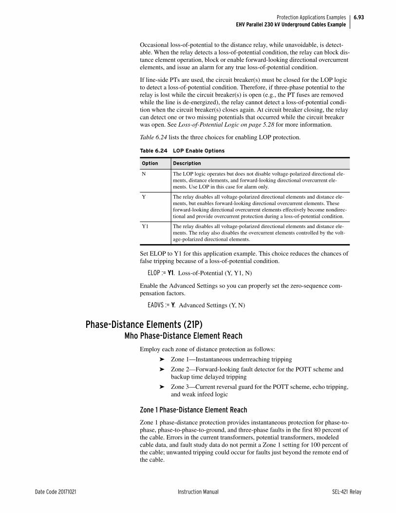
6.93
Date Code 20171021 Instruction Manual SEL-421 Relay
Protection Applications ExamplesEHV Parallel 230 kV Underground Cables Example
Occasional loss-of-potential to the distance relay, while unavoidable, is detect-able. When the relay detects a loss-of-potential condition, the relay can block dis-tance element operation, block or enable forward-looking directional overcurrent elements, and issue an alarm for any true loss-of-potential condition.
If line-side PTs are used, the circuit breaker(s) must be closed for the LOP logic to detect a loss-of-potential condition. Therefore, if three-phase potential to the relay is lost while the circuit breaker(s) is open (e.g., the PT fuses are removed while the line is de-energized), the relay cannot detect a loss-of-potential condi-tion when the circuit breaker(s) closes again. At circuit breaker closing, the relay can detect one or two missing potentials that occurred while the circuit breaker was open. See Loss-of-Potential Logic on page 5.28 for more information.
Table 6.24 lists the three choices for enabling LOP protection.
Set ELOP to Y1 for this application example. This choice reduces the chances of false tripping because of a loss-of-potential condition.
ELOP := Y1. Loss-of-Potential (Y, Y1, N)
Enable the Advanced Settings so you can properly set the zero-sequence com-pensation factors.
EADVS := Y. Advanced Settings (Y, N)
Phase-Distance Elements (21P)Mho Phase-Distance Element Reach
Employ each zone of distance protection as follows:
➤ Zone 1—Instantaneous underreaching tripping
➤ Zone 2—Forward-looking fault detector for the POTT scheme and backup time delayed tripping
➤ Zone 3—Current reversal guard for the POTT scheme, echo tripping, and weak infeed logic
Zone 1 Phase-Distance Element Reach
Zone 1 phase-distance protection provides instantaneous protection for phase-to-phase, phase-to-phase-to-ground, and three-phase faults in the first 80 percent of the cable. Errors in the current transformers, potential transformers, modeled cable data, and fault study data do not permit a Zone 1 setting for 100 percent of the cable; unwanted tripping could occur for faults just beyond the remote end of the cable.
Table 6.24 LOP Enable Options
Option Description
N The LOP logic operates but does not disable voltage-polarized directional ele-ments, distance elements, and forward-looking directional overcurrent ele-ments. Use LOP in this case for alarm only.
Y The relay disables all voltage-polarized directional elements and distance ele-ments, but enables forward-looking directional overcurrent elements. These forward-looking directional overcurrent elements effectively become nondirec-tional and provide overcurrent protection during a loss-of-potential condition.
Y1 The relay disables all voltage-polarized directional elements and distance ele-ments. The relay also disables the overcurrent elements controlled by the volt-age-polarized directional elements.

6.94
SEL-421 Relay Instruction Manual Date Code 20171021
Protection Applications ExamplesEHV Parallel 230 kV Underground Cables Example
Set Zone 1 phase-distance protection to 80 percent of the cable positive-sequence impedance.
Z1MP = 0.8 • Z1L1 = 0.8 • 0.48 = 0.38
Z1MP := 0.38. Zone 1 Reach (OFF, 0.05–64 secondary)
Zone 2 Phase-Distance Element Reach
Zone 2 phase-distance protection must have adequate reach to detect all phase-to-phase, phase-to-phase-to-ground, and three-phase faults along the protected cable. Set Zone 2 phase-distance protection to 120 percent of the cable positive-sequence impedance. With this reach, high-speed tripping occurs via the commu-nications channel for faults located in the last 20 percent of the cable.
Z2MP = 1.2 • Z1L1 = 1.2 • 0.48 = 0.58
Z2MP := 0.58. Zone 2 Reach (OFF, 0.05–64 secondary)
Zone 3 Phase-Distance Element Reach
Zone 3 phase-distance protection must have adequate reach to prevent unwanted tripping during current reversals when the parallel line is in service because this example uses a POTT scheme. So that Zone 3 has greater fault coverage than Zone 2 at the remote terminal, set the reach to remote Zone 2 and rely upon the length of the protected cable as the safety margin.
Z3MP = Z2P = 0.58
Z3MP := 0.58. Zone 3 Reach (OFF, 0.05–64 secondary)
Ground-Distance Elements (21XG)Quadrilateral Ground-Distance Element Reach
The main advantage of ground-distance protection is that Zone 1 provides instan-taneous protection independent of the communications channel. Typically cable faults have little fault resistance; it is advantageous to conservatively set the resis-tance reach for quadrilateral ground-distance protection. Supplement quadrilat-eral ground-distance protection with directional negative-sequence overcurrent elements. The directional negative-sequence overcurrent elements employed in the communications-assisted tripping scheme provide excellent resistive cover-age for high-resistance ground faults (e.g., a contaminated pothead flashes over).
The reactive reach for each zone of quadrilateral ground-distance protection lies on the relay characteristic angle (Z1ANG), rather than on the ordinate (reactance) of the impedance plane (see Figure 6.21).

6.95
Date Code 20171021 Instruction Manual SEL-421 Relay
Protection Applications ExamplesEHV Parallel 230 kV Underground Cables Example
Employ each zone of distance protection as follows:
➤ Zone 1—Instantaneous underreaching direct tripping
➤ Zone 2—Forward-looking tripping elements for the POTT scheme and backup tripping
➤ Zone 3—Current reversal guard for the POTT scheme, echo tripping, and weak infeed logic
Zone 1 Reactance
The reach of the Zone 1 reactance measurement of the quadrilateral ground-dis-tance elements must meet the same requirement as that for Zone 1 mho phase-distance protection; the reach setting can be no greater than 80 percent of the cable.
XG1 = 0.8 • |Z1L1| = 0.8 • 0.48 = 0.38
XG1 := 0.38. Zone 1 Reactance (OFF, 0.05–64 secondary)
Zone 1 Resistance
Find RG1 (Zone 1 Resistance) from the per-unit reach m of the Zone 1 reactance. Use Equation 6.55, which is Equation 3 in Appendix A—Quadrilateral Reactive Reach Versus Resistive Reach Setting Guideline from the paper Digital Commu-nications for Power System Protection: Security, Availability, and Speed (go to selinc.com for a copy of this paper):
Equation 6.55
XG1 is set at 80 percent of the underground cable (i.e., m = 0.8 per-unit); the pos-itive-sequence reactance of the cable, X1L1, is 0.323 secondary (from the rect-angular form of Z1L1 in Table 6.23).
Figure 6.21 Quadrilateral Ground-Distance Element Reactive Reach Setting
X
XG
R
where:
m = per-unit reach of XG1
R = RG1 (the Zone 1 resistance)
X1L1 = positive-sequence transmission line reactance
m 1 RX1L1 20• -------------------------–=

6.96
SEL-421 Relay Instruction Manual Date Code 20171021
Protection Applications ExamplesEHV Parallel 230 kV Underground Cables Example
Rearrange Equation 6.55 to calculate RG1:
Equation 6.56
RG1 := 1.29. Zone 1 Resistance (0.05–50 secondary)
Zone 2 Reactance
Zone 2 quadrilateral ground-distance reach must meet the same requirement as that for Zone 2 mho phase-distance protection; the reach setting is 120 percent of the cable.
XG2 = 1.2 • |Z1L1| = 1.2 • 0.48 = 0.58
XG2 := 0.58. Zone 2 Reactance (OFF, 0.05–64 secondary)
Zone 2 Resistance
Use the following formula to set RG2:
Equation 6.57
RG2 := 1.97. Zone 2 Resistance (0.05–50 secondary)
Zone 3 Reactance
Zone 3 quadrilateral ground-distance reach must meet the same requirement as that for Zone 3 mho phase-distance protection; it equals Zone 2 reach.
XG3 = XG2 = 0.58
XG3 := 0.58. Zone 3 Reactance (OFF, 0.05–64 secondary)
Zone 3 Resistance
Set the Zone 3 resistance reach equal to Zone 2 resistance reach and multiply the reach by 125 percent for a safety margin to account for external resistive ground faults.
RG3 = 1.25 • RG2 = 1.25 • 1.97 = 2.46
RG3 := 2.46. Zone 3 Resistance (0.05–50 secondary)
Z1L1 = R1L1 + jX1L1
= 0.48 42.5°
= 0.354 + j0.323
RG1 1 m– 20 X1L1• • =
1 0.8– 20 0.323 • • =
1.29 =
RG2 XG2 RG1XG1------------• =
0.58 1.29 0.38 -----------------•
=
0.58 3.4• =
1.97 =

6.97
Date Code 20171021 Instruction Manual SEL-421 Relay
Protection Applications ExamplesEHV Parallel 230 kV Underground Cables Example
Quadrilateral Ground Polarizing Quantity
Advanced Settings are enabled, so you must enter two final settings for the quad-rilateral ground-distance protection. With setting XGPOL, you can choose the polarizing quantity for the quadrilateral ground-distance protection. You can choose either negative-sequence current (I2) or zero-sequence current (IG). Choose the appropriate quantity to reduce overreach and underreach of the reac-tance line. The reactance line can underreach or overreach during high-resistance single phase-to-ground faults because of nonhomogeneous negative-sequence or zero-sequence networks, and prefault load flow.
Figure 6.22 shows the network to determine negative-sequence or zero-sequence homogeneity.
Zleft is the total impedance up to the fault (F) on the left side of the fault location, while Zright is the total impedance up to the fault on the right side of the network. A network is homogeneous with respect to the particular fault location if Equation 6.58 is satisfied:
Equation 6.58
Use Equation 6.59 and Equation 6.60 to determine the zero-sequence and nega-tive-sequence homogeneity:
Equation 6.59
Equation 6.60
The values T0 and T2 represent how much the apparent fault impedance mea-sured by XAG tilts up or down (electrical degrees) because of the nonhomogene-ity of the corresponding network. Figure 6.23 illustrates the possible tilt situations caused by a nonhomogeneous network.
Figure 6.22 Circuit to Determine Network Homogeneity
Zleft Zright
S
IF
IF
IFS IFRZS ZRm ZL (1—m) ZLR
F
XleftRleft------------
XrightRright---------------=
T0 ARGZ0S Z0L Z0R+ +
1 m– Z0L Z0R+• ---------------------------------------------------
=
T2 ARGZ1S Z1L Z1R+ +
1 m– Z1L Z1R+• ---------------------------------------------------
=

6.98
SEL-421 Relay Instruction Manual Date Code 20171021
Protection Applications ExamplesEHV Parallel 230 kV Underground Cables Example
Table 6.25 provides the results of Equation 6.59 and Equation 6.60 for both the negative-sequence and zero-sequence networks. Remember that T0 depends on the return path of the ground fault; i.e., sheath, ground, or a parallel combination of both. The distance to fault is assumed to be 100 percent (m equals 1).
The negative-sequence network is more homogeneous than the zero-sequence network when compared with two of the three corresponding cable zero-sequence impedances. Choose negative-sequence current for polarizing the quad-rilateral ground-distance protection.
XGPOL := I2. Quadrilateral Ground Polarizing Quantity (I2, IG)
Selection I2 indicates that the negative-sequence current flowing in the cable is the polarizing quantity for the reactance line.
Figure 6.23 Apparent Fault Impedance Resulting From Nonhomogeneity
Table 6.25 Tilt Resulting From Nonhomogeneity
Angle T2T0(sheath)
T0(ground)
T0 (ground and sheath)
Negative-Sequence Network –2.2°
Zero-Sequence Network –5.8° –1.1° –5.6°
X
RS
R
XAG
+T
—T

6.99
Date Code 20171021 Instruction Manual SEL-421 Relay
Protection Applications ExamplesEHV Parallel 230 kV Underground Cables Example
Nonhomogeneous Correction Angle
TANGG, the nonhomogeneous angle setting, also helps prevent overreach or underreach for ground faults at a specific fault location by compensating the angle of the reactance line.
Set TANGG to prevent the Zone 1 quadrilateral ground-distance reactance mea-surement from overreaching for ground faults located at the remote bus. Use the result from Equation 6.60 (T2 in Quadrilateral Ground Polarizing Quantity on page 6.29).
TANGG := —2.2. Nonhomogeneous Correction Angle (–40.0 to +40.0 degrees)
Zero-Sequence Current Compensation Factors
Zero-sequence current compensation helps keep the phase and ground-distance elements at the same reach if you set the phase reach and the ground reach equal per zone (e.g., Z1MP = XG1). Ground-distance elements should measure fault impedance in terms of positive-sequence impedance only.
The relay has three zero-sequence current compensation factors (k01, k0, and k0R). The Zone 1 ground-distance element has a dedicated zero-sequence current compensation factor (k01). Advanced Settings are enabled for this particular example (EADVS := Y), so you must set two additional independent zero-sequence current compensation factors, one for forward-looking zones (k0) and one for reverse-looking zones (k0R).
The zero-sequence cable impedance depends on the return path of the ground fault current during ground faults. The zero-sequence current compensation fac-tors must be set so the Zone 1 ground-distance elements do not see ground faults external to the protected cable, while Zone 2 and Zone 3 ground-distance ele-ments must see all internal ground faults.
The SEL-421 uses Equation 6.61 to calculate the A-Phase-to-ground distance reactance measurement.
Equation 6.61
Figure 6.24 Nonhomogeneous Angle Setting
X
R
TANGG > 0
TANGG = 0
TANGG < 0
XAGIm VA IPOL ej TANGG•
• *
•
Im z1 IA k01 3I0• + IPOL ej TANGG• •
*• •
------------------------------------------------------------------------------------------------------------------------------=

6.100
SEL-421 Relay Instruction Manual Date Code 20171021
Protection Applications ExamplesEHV Parallel 230 kV Underground Cables Example
Equation 6.62
Equation 6.63
k01
You can set k01 based on three values for the zero-sequence cable impedance: Z0L1(sheath), Z0L1(ground), or Z0L1(sheath and ground). Select the zero-sequence cable impedance that prevents Zone 1 ground-distance element overreach.
To determine the best setting for k01, place an A-Phase-to-ground fault at Station R with the parallel cable out of service. Find the ground-distance reac-tance measurement XAG that does not overreach for this fault. Perform this eval-uation using Z0L1(sheath and ground) and Z0L1(sheath) for the zero-sequence cable impedance. There is no need to determine the XAG measurement for ground faults at the remote terminal when k01 is set based on Z0L1(ground) because severe overreach occurs in all cases for the ground-only path.
Sheath and Ground Return Path
First apply Equation 6.61 with k01 based on Z0L1(sheath and ground) (k01 equal to 0.374 –39.2°). This is the most common ground fault return path. Set TANGG equal to zero and assume that IPOL is equal to negative-sequence current (i.e., XGPOL is equal to I2).
Table 6.26 lists the corresponding XAG (reactance of the phase-to-ground fault) calculations for the remote single phase-to-ground fault for each of the three pos-sible zero-sequence cable impedances when the k01 calculation is based on the parallel return path. Use Equation 6.64 to determine the amount of overreach/underreach:
Equation 6.64
where:
VA = A-Phase-to-ground voltage measured at Station S
IA = A-Phase current measured through Cable 1 at Station S
3I0 = zero-sequence current measured through Cable 1 at Station S
IPOL = negative-sequence or zero-sequence current measured through Cable 1 at Station S (based on the XGPOL setting, see Quadri-lateral Ground Polarizing Quantity on page 6.29)
TANGG = nonhomogeneous correction angle
Im[ ] = imaginary part
* = complex conjugate
where:
Z1 = Cable 1 positive-sequence impedance
z1Z1Z1---------=
k01Z0L1 Z1L1–
3 Z1L1• ------------------------------=
Overreach/Underreach XAGZ1L1
--------------- 100% • =

6.101
Date Code 20171021 Instruction Manual SEL-421 Relay
Protection Applications ExamplesEHV Parallel 230 kV Underground Cables Example
The results in Table 6.26 show that the XAG calculation overreaches by 6.2 per-cent (i.e., 100% – 93.8% = 6.2%) if the sheath is the return path for the ground fault; therefore, you should not set k01 based on the sheath and ground (parallel) return path.
Sheath Return Path
Table 6.27 lists the corresponding XAG (reactance of the phase-to-ground fault) calculations for the remote single phase-to-ground fault for each of the three pos-sible zero-sequence cable impedances when the k01 calculation is based on the sheath return path.
The results in Table 6.27 show that there is no Zone 1 ground-distance overreach. Therefore, set k01 based on Z0L1(sheath).
k0M1 := 0.385. Zone 1 ZSC Factor Magnitude (AUTO, 0.000–10)
k0A1 := –46.7. Zone 1 ZSC Factor Angle (–180.0 to +180.0 degrees)
k0 and k0R
Set the forward (k0) and reverse (k0R) zero-sequence current compensation fac-tors so that the overreaching zones of ground-distance protection do not under-reach for any internal ground fault. Put both parallel cables in service. Table 6.28 lists the corresponding XAG calculations for a remote (Station R) ground fault for each of the three possible zero-sequence cable impedances when the k0 calcu-lation is based on Z0L1(ground). (Replace k01 with k0 or replace k01 with k0R in Equation 6.61 and Equation 6.63.)
The results of Table 6.28 show that the XAG calculation does not underreach when you set k0 based on the ground return path. Set k0 and k0R based on Z0L1(ground).
Table 6.26 XAG Measurement for Remote AG Fault (k01 = 0.374 –39.2°, Sheath and Ground Return Path)
Calculation Z0L1(sheath) Z0L1(ground) Z0L1(sheath and ground)
XAG (secondary ohms) 0.45 3.04 0.48
Overreach/Underreacha
a O indicates overreach, U indicates underreach.
93.8% (O) 633% (U) 100%
Table 6.27 XAG Measurement for Remote AG Fault (k01 = 0.385 –46.7°, Sheath Return Path)
Calculation Z0L1(sheath) Z0L1(ground) Z0L1(sheath and ground)
XAG (secondary ohms) 0.48 3.17 0.51
Overreach/Underreacha
a O indicates overreach, U indicates underreach.
100% 660% (U) 106% (U)
Table 6.28 XAG Measurement for Remote AG Fault (k0 = 6.105 44.5°, Ground Return Path)
Calculation Z0L1(sheath) Z0L1(ground) Z0L1(sheath and ground)
XAG (secondary ohms) 0.04 0.48 0.05
Overreach/Underreacha
a O indicates overreach, U indicates underreach
8.33% (O) 100% 10.4% (O)

6.102
SEL-421 Relay Instruction Manual Date Code 20171021
Protection Applications ExamplesEHV Parallel 230 kV Underground Cables Example
k0M := 6.105. Forward Zones ZSC Factor Magnitude (0.000–10)
k0A := 44.5. Forward Zones ZSC Factor Angle (–180.0 to +180.0 degrees)
k0MR := 6.105. Reverse Zones ZSC Factor Magnitude (0.000–10)
k0AR := 44.5. Reverse Zones ZSC Factor Angle (–180.0 to +180.0 degrees)
Distance Element Common Time DelaySet the operation time delay of both the phase and ground-distance elements.
Zone 1
There is no need to delay Zone 1 distance protection; the relay trips instanta-neously for faults in Zone 1.
Z1D = 0.000. Zone 1 Time Delay (OFF, 0.000–16000 cycles)
Zone 2
Zone 2 distance protection must coordinate with downstream Zone 1 distance protection plus the downstream circuit breaker operating time and a safety mar-gin. A typical Zone 2 phase and ground-distance time delay setting is 20 cycles.
Z2D := 20.000. Zone 2 Time Delay (OFF, 0.000–16000 cycles)
Short Adjacent Lines
You do not need to consider the following fault current return path scenario for this application example; this information is provided here for applications with short adjacent lines. Figure 6.25 illustrates an important consideration if you apply time-delayed Zone 2 ground-distance protection to backup downstream Zone 1 ground-distance protection.
Fault current flows through the sheath and ground with respect to the cable because the sheath is grounded at each end during external ground faults. How-ever, because you must make sure that Zone 2 ground-distance elements see all ground faults at remote Station R, the k0 setting was for the ground path only. Therefore, Zone 2 ground-distance protection may overreach for external ground faults, especially for the case of a short adjacent line. The solution is to increase Zone 2 time delay.
Figure 6.25 External Ground Fault
SEL-421
Conductor
IF
IC
IS
IG
Sheath
Ground
RS
Zone 2 Ground Distance
Zone 1 Ground Distance

6.103
Date Code 20171021 Instruction Manual SEL-421 Relay
Protection Applications ExamplesEHV Parallel 230 kV Underground Cables Example
Zone 3
Zone 3 has reverse-looking distance protection that you do not need to apply for tripping in this application. Set Zone 3 for zero time delay.
Z3D := 0.000. Zone 3 Time Delay (OFF, 0.000–16000 cycles)
SOTF ProtectionSOTF logic is enabled when the circuit breaker closes. This logic provides pro-tection for a short duration (setting SOTFD) until other protection (such as trip-ping from SELOGIC control equations TR, TRCOMM, and TRCOMMD) is available. The TRSOTF SELOGIC control equation defines which protection ele-ments cause the relay to trip when the SOTF scheme is active. Assertion of the protection elements assigned to TRSOTF during the SOTFD time causes the relay to trip instantaneously.
Use nondirectional overcurrent protection to clear close-in faults. Also use instantaneous overreaching distance protection to clear faults along the line. Assign instantaneous Zone 2 mho phase and ground-distance protection plus Level 1 phase overcurrent element to TRSOTF.
TRSOTF := Z2P OR Z2G OR 50P1. Switch-Onto-Fault Trip (SELOGIC Equa-tion)
Voltage Reset
You can configure the logic so the SOTF enable duration resets within at least 5 cycles after it first asserted but before the SOTFD timer expires. To quickly reset the SOTF period before this time, the relay must sense that the positive-sequence voltage V1 is greater than setting VRSTPU times the nominal voltage.
Use setting EVRST (Switch-Onto-Fault Voltage Reset) to enable fast reset. The advantage of resetting SOTF protection quickly is that unwanted tripping does not occur for subsequent faults external to the remote terminals during the SOTF period; these trips can occur if you set instantaneous Zone 2 distance protection elements in the TRSOTF SELOGIC control equation. Enable the voltage reset option.
EVRST := Y. Switch-Onto-Fault Voltage Reset (Y, N)
SOTF Initiation
The SOTF logic asserts via one or both of the following methods:
➤ A change in the normally open auxiliary contact 52A status showing that the circuit breaker has just opened
➤ Assertion of the relay control input assigned to the circuit breaker close bus
The 52A method initiation works well for both single and multiple circuit breaker applications and does not require an input from the close bus. However, close bus only initiation enables SOTF protection immediately following the close com-mand to the circuit breaker. For more information see Switch-Onto-Fault Logic on page 5.117.
Turn off 52AEND (52A Pole-Open Time Delay).
52AEND := OFF. 52A Pole-Open Time Delay (OFF, 0.000–16000 cycles)

6.104
SEL-421 Relay Instruction Manual Date Code 20171021
Protection Applications ExamplesEHV Parallel 230 kV Underground Cables Example
Select the close bus option for this application and set the close enable delay (CLOEND) shorter than the shortest reclose open interval.
CLOEND := 10.000. CLSMON or Single-Pole Open Delay (OFF, 0.000–16000 cycles)
SOTF Duration
Setting SOTFD determines the longest period the SOTF logic can assert after the circuit breaker closes.
SOTFD := 10.000. Switch-Onto-Fault Enable Duration (0.500–16000 cycles)
Close Signal Monitor
Assign the Relay Word bit CLSMON to a control input, so the relay can detect execution of the close command.
CLSMON := IN102. Close Signal Monitor (SELOGIC Equation)
Phase Instantaneous/Definite-Time Overcurrent ElementsUse Level 1 instantaneous phase overcurrent element (50P1) as a nondirectional high-set phase overcurrent element for SOTF protection. To rapidly clear faults, set pickup threshold 50P1P equal to 50 percent of the fault current measured at the local terminal for a close-in three-phase fault; use weak source conditions so that the relay operates for low-level fault current.
50P1P := 9.57. Level 1 Pickup (OFF, 0.25–100 A secondary)
This application uses 50P1 as an instantaneous overcurrent element; you do not need time delay.
67P1D := 0.000. Level 1 Time Delay (0.000–16000 cycles)
This application uses 50P1 as a nondirectional overcurrent element; you do not need torque control.
67P1TC := 1. Level 1 Torque Control (SELOGIC Equation)
Negative-Sequence Instantaneous/Definite-Time Overcurrent Elements
Negative-sequence directional overcurrent protection is an excellent choice for underground cable. The cable zero-sequence impedance depends on the current return paths, but the cable negative-sequence impedance does not. Negative-sequence directional overcurrent protection provides reliable and sensitive pro-tection for cables against all unbalanced faults. Be sure to set negative-sequence overcurrent elements above system unbalances.
Negative-Sequence Overcurrent Elements
Enable three levels of negative-sequence overcurrent elements.
E50Q := 3. Negative-Sequence Instantaneous/Definite-Time Overcurrent Ele-ments (N, 1–4)

6.105
Date Code 20171021 Instruction Manual SEL-421 Relay
Protection Applications ExamplesEHV Parallel 230 kV Underground Cables Example
Disable Level 1 negative-sequence overcurrent element. This application does not use 50Q1.
50Q1P := OFF. Level 1 Pickup (OFF, 0.25–100 A secondary)
The Level 2 negative-sequence directional overcurrent element (67Q2) provides communications-assisted tripping for internal unbalanced faults. This element detects unbalanced faults in the forward direction and trips via the communica-tions channel. The 50Q2P setting is the pickup for the directional overcurrent ele-ment 67Q2. Apply a setting equal to the default for the pickup of 32QG (Negative-Sequence Voltage Polarized Directional Element), which is 50FP (For-ward Supervisory Overcurrent Pickup)
50Q2P = 50FP = 0.12 • INOM = 0.12 • 5 A = 0.6 A
50Q2P := 0.60. Level 2 Pickup (OFF, 0.25–100 A secondary)
The Level 3 negative-sequence directional overcurrent element (67Q3) provides current reversal guard during unbalanced faults on the parallel cable to prevent unwanted tripping. The 50Q3P setting is the pickup for directional overcurrent element 67Q3. Set the pickup of Level 3 negative-sequence overcurrent element equal to the default for the pickup of 32QG (Negative-Sequence Voltage Polar-ized Directional Element), which is 50RP (Reverse Supervisory Overcurrent Pickup). The reverse-looking element is 150 percent more sensitive than the for-ward-looking element.
50Q3P = 50RP = 0.08 • INOM = 0.08 • 5 A = 0.4 A
50Q3P := 0.40. Level 3 Pickup (OFF, 0.25–100 A secondary)
Negative-Sequence Overcurrent Pickup Coordination Check
Figure 6.26 illustrates why you need to check the sensitivity of the forward (50Q2P) and reverse (50Q3P) negative-sequence overcurrent pickup settings.
The shunt capacitance of the 230 kV cable causes the SEL-421 at Station S to measure less negative-sequence fault current for a reverse out-of-section ground fault than at Station R.
Equation 6.65
Figure 6.26 Negative-Sequence Fault Current Distribution-External Ground Fault
where:
I2R = negative-sequence fault current supplied from Source R
I2S = negative-sequence fault current flowing through the line termi-nal at Station S
I2CR = negative-sequence shunt current at Station R
I2CS = negative-sequence shunt current at Station S
67Q3
I2S S R
67Q2
I2R
I2CS I2CR
I2S I2R I2CR– I2CS–=

6.106
SEL-421 Relay Instruction Manual Date Code 20171021
Protection Applications ExamplesEHV Parallel 230 kV Underground Cables Example
Therefore, if the reverse-looking directional element at the local station is not more sensitive than the forward-looking directional element at the remote station, unwanted tripping can occur during external ground faults; the local 67Q3 ele-ment can fail to detect a reverse unbalanced fault that the remote 67Q2 element sees.
Use a short-circuit study to determine I2S for a close-in reverse single phase-to-ground fault with respect to Station S; make sure to perform the fault calculations for the parallel cable both in service and out of service. The results of the study for this particular application show that the maximum difference between I2S and I2R for any close-in reverse unbalanced fault at Station S is 8.5 mA secondary. Therefore, the existing settings provided for 50Q2P and 50Q3P maintain coordi-nation for external unbalanced faults.
There is no need to add any intentional time delay on pickup for Level 2 or 3 neg-ative-sequence overcurrent elements.
67Q2D := 0.000. Level 2 Time Delay (0.000–16000 cycles)
67Q3D := 0.000. Level 3 Time Delay (0.000–16000 cycles)
Set the Level 2 torque control equation to the forward decision from the ground directional element.
67Q2TC := 32GF. Level 2 Torque Control (SELOGIC Equation)
Set the Level 3 torque control equation to the reverse decision from the ground directional element.
67Q3TC := 32GR. Level 3 Torque Control (SELOGIC Equation)
Selectable Operating Quantity Time Overcurrent Element 1Use inverse-time overcurrent protection to provide backup protection for unbal-anced faults including high-resistance ground faults. Selectable Operating Quan-tity Time Overcurrent Element 1 51S1 provides backup protection for unbalanced faults if both the communications-assisted and step distance protec-tion fail to operate.
NOTE: Use your company practices and philosophy when determining these settings.
Select negative-sequence line current 3I2L as the operating quantity rather than 3I0L because ground current return paths vary.
51S1O := 3I2L. 51S1 Operating Quantity (IAn, IBn, ICn, IMAXn, I1L, 3I2L, 3I0n)
The fault current (3I2) that the relay measures for a bolted single phase-to-ground fault at the end of the longest line from the remote station with the parallel cable in service at minimum generation is 3.0 A secondary (this is the minimum of minimums). Set the pickup between 30 to 50 percent of this current.
51S1P = 1/3 • 3I2FAULT = 1/3 • 3.00 A = 1.00 A
51S1P = 1.00. 51S1 Overcurrent Pickup (0.25–16 A secondary)

6.107
Date Code 20171021 Instruction Manual SEL-421 Relay
Protection Applications ExamplesEHV Parallel 230 kV Underground Cables Example
Use the following formula to determine approximately how much primary fault resistance coverage (RF) that 51S1P provides on a radial basis:
Equation 6.66
Use the following as a guide to set the curve and time dial; for secure backup pro-tection, perform a coordination study. Set the local overcurrent element to coordi-nate with the downstream overcurrent element so there is a 12-cycle (60 Hz nominal) safety margin for phase-to-phase (high current) faults in front of the first downstream overcurrent element. Assume the operating time of the down-stream overcurrent element is 12 cycles for close-in phase-to-phase faults. There-fore, set the local time-overcurrent element to operate at approximately 24 cycles for phase-to-phase faults in front of the first downstream overcurrent element.
The fault current (3I2) that the relay measures for a bolted close-in phase-to-phase fault at the remote station with the parallel cable out of service is 18.67 A secondary. The pickup multiple is shown in Equation 6.67.
Equation 6.67
Use the parameters of 24 cycles operating time and M = 18.67 to choose the curve and time dial settings for the 51S1 element. For curve and timing informa-tion, see Inverse-Time Overcurrent Elements on page 5.99.
51S1C = U3. 51S1 Inverse-Time Overcurrent Curve (U1–U5)
51S1TD = 3.72. 51S1 Inverse-Time Overcurrent Time Dial (0.50–15.0)
Set the overcurrent element to emulate electromechanical reset.
51S1RS = Y. 51S1 Inverse-Time Overcurrent EM Reset (Y, N)
Torque control the overcurrent element with the forward decision from the ground directional element.
51S1TC = 32GF. 51S1 Torque Control (SELOGIC Equation)
Zone/Level DirectionZone 1 and Zone 2 distance element directions are fixed in the forward direction. You can select the other zones independently as forward-looking (F), or reverse-looking (R). Set Zone 3 distance elements reverse-looking; these are blocking elements for the POTT scheme.
DIR3 := R. Zone/Level 3 Directional Control (F, R)
RFPTRCTR------------
VNOMY3
------------------------
51S1P---------------------------• =
2000200------------
115 V3
---------------
1.00 A----------------•
=
664 primary=
MI2FAULT51S1P---------------------=
18.67 A1.00 A-------------------=
18.67=

6.108
SEL-421 Relay Instruction Manual Date Code 20171021
Protection Applications ExamplesEHV Parallel 230 kV Underground Cables Example
Directional ControlThe SEL-421 uses an array of directional elements to supervise the ground-distance elements and residual directional overcurrent elements during ground fault conditions. Internal logic automatically selects the best choice for the ground directional element (32G) from among the negative-sequence voltage-polarized directional element (32QG), zero-sequence voltage-polarized direc-tional element (32V), and the zero-sequence current-polarized directional ele-ment (32I).
The relay setting ORDER determines the order in which the relay selects direc-tional elements to provide the ground directional decisions. You can set ORDER with any combination of Q, V, and I. The listed order of these directional ele-ments determines the priority in which these elements operate to provide ground directional decisions. Only one specific directional element operates at any one time. Directional element classification is as follows:
➤ Q—Negative-sequence voltage-polarized directional element
➤ V—Zero-sequence voltage-polarized directional element
➤ I—Zero-sequence current-polarized directional element
Set ORDER to Q. This setting selects only the negative-sequence voltage-polar-ized directional element. You rely on 32QG to provide high-speed reliable and sensitive protection during unbalanced faults via the communications channel. Cable zero-sequence impedance depends on the fault current return path; the neg-ative-sequence impedance of the cable does not.
ORDER := Q. Ground Directional Element Priority (combine Q, V, I)
The relay hides the Z0F, Z0R, a0, and E32IV settings because ORDER does not contain V or I.
Negative-Sequence Voltage-Polarized Directional Element Reverse Decision (R32QG) Check
The setting Z2R is the reverse threshold for the negative-sequence voltage-polar-ized directional element. If the apparent negative-sequence impedance (z2) that the relay measures is greater than Z2R, the relay declares that an unbalanced fault is reverse. For overhead transmission lines, ignore the shunt admittance that rep-resents the charging capacitance. The shunt negative-sequence admittance of the underground cable is significant and modifies the z2 measurement during reverse faults. You must include this admittance in the cable model to verify proper oper-ation of the default setting.
Figure 6.27 illustrates the effect of the shunt admittance at both ends of the cir-cuit for a reverse unbalanced fault.

6.109
Date Code 20171021 Instruction Manual SEL-421 Relay
Protection Applications ExamplesEHV Parallel 230 kV Underground Cables Example
The technical paper Underground/Submarine Cable Protection Using a Sequence Directional Comparison Scheme (see selinc.com for a copy of this paper) pro-vides an equation that allows you to express the apparent negative-sequence impedance at the relay terminal for a reverse unbalanced fault when accounting for charging capacitance:
Equation 6.68
The SEL-421 uses Equation 6.69 to calculate the apparent negative-sequence impedance during unbalanced faults:
Equation 6.69
Equation 6.69 yields a more conservative result for the negative-sequence imped-ance when the parallel cable is out of service:
|Z2S| = 2.97
The result of Equation 6.69 is greater than the default setting for Z2R; Z2R = (Z2F + 1/(2 • INOM). (See Ground Directional Elements on page 1.18 for more information.)
Figure 6.27 Reverse Unbalanced Fault on Cable Circuit (Shunt Admittance)
Z1L1 Z1RZ1S S R
Z1L1 R Z1RZ1S
I2
I2
I2S I2RI2V2
S
Y1L1
2
Y1L1
2
Impedance Diagram
Negative-Sequence Network
SEL-421
Z2SV2S–
I2S-------------=
4 Z1L1 2+ Y1L1 Z1L1 Z1R 4+ Z1R• • • • •
4 4 Y1L1 Z1R 2+ Y1L1 Z1L1 Y21L1+ Z1L1 Z1R• • • • • • +
----------------------------------------------------------------------------------------------------------------------------------------------------------=
3.86 =
z2Re V2 I2 Z1ANG• •
*
I22----------------------------------------------------------------------=

6.110
SEL-421 Relay Instruction Manual Date Code 20171021
Protection Applications ExamplesEHV Parallel 230 kV Underground Cables Example
Pole-Open DetectionThe setting EPO offers two options for deciding what conditions signify an open pole, as listed in Table 6.29.
Select the second option because a 52A contact is available. The relay uses both open-phase detection and status information from the circuit breaker to make the most secure decision.
EPO := 52. Pole-Open Detection (52, V)
Pole-Open Time Delay on Dropout
The setting 3POD is the time delay on dropout after the Relay Word bit 3PO deasserts. The setting 3POD stabilizes the ground-distance elements during pole scatter when the circuit breaker closes.
3POD := 0.500. Three-Pole Open Dropout Delay (0.000–60 cycles)
POTT Trip SchemeThis application example presents the permissive overreaching transfer trip (POTT) scheme to high-speed trip for faults along the protected cable.
The POTT scheme logic consists of the following sections:
➤ Current reversal guard logic
➤ Echo
➤ Weak infeed logic
➤ Permission to trip received
Current Reversal Guard Logic
This is a parallel cable application, so you must use current reversal guard. When the reverse-looking elements detect an external fault, the relay does not key the transmitter and ignores reception of a permissive signal from the remote terminal. The Zone 3 Reverse Block Delay (Z3RBD) timer extends these two operations after a current reversal occurs and the reverse-looking elements drop out.
Table 6.29 Options for Enabling Pole-Open Logic
Option Description
EPO := V The logic declares a single-pole open if the corresponding phase undervoltage element asserts and the open-phase detection logic declares the pole is open. Select this option only if you use line-side potential transformers for relaying purposes. A typical setting for the 27PO, pole-open undervoltage threshold, is 60 percent of the nominal line-to-neutral voltage.
Do not select this option when shunt reactors are applied because the voltage slowly decays after the circuit breaker opens. With this option selected, the relay can incorrectly declare LOP during a pole-open condition if there is charging current that exceeds the pole-open current threshold.
EPO := 52 The logic declares a single-pole open if the corresponding 52A contact (52AA1) from the circuit breaker deasserts and the open-phase detection logic declares that the pole is open.

6.111
Date Code 20171021 Instruction Manual SEL-421 Relay
Protection Applications ExamplesEHV Parallel 230 kV Underground Cables Example
Set the Z3RBD timer to accommodate the following:
➤ Remote Station R circuit breaker maximum opening time
➤ Maximum communications channel reset time
➤ Remote Station R Zone 2 relay maximum reset time
Assume a circuit breaker opening time of 3 cycles, a communications channel reset time of 1 cycle, and remote Zone 2 relay reset time of 1 cycle. The sum of these times gives a conservative setting of 5 cycles for a three-cycle circuit breaker.
Z3RBD := 5.000. Zone 3 Reverse Block Time Delay (0.000–16000 cycles)
Echo
If the circuit breaker is open, or a weak infeed condition exists at the local termi-nal, the received permissive signal can echo back to the remote relay and cause it to issue a high-speed trip for faults beyond the remote relay Zone 1 reach. The SEL-421 includes logic that echoes the received permissive trip signal back to the remote terminal after specific conditions are satisfied. The echo logic includes timers for blocking the echo logic as well as timers for qualifying the permissive signal.
Use Echo Block Time Delay (EBLKD) to block the echo logic after dropout of local permissive elements. The recommended setting for the EBLKD timer is the sum of the following:
➤ Remote Station R circuit breaker opening time
➤ Communications channel round trip time
➤ Safety margin
Assume a circuit breaker opening time of 3 cycles, a communications channel round trip time of 2 cycles, and a safety margin of 5 cycles. The sum of these times gives a conservative setting of 10 cycles for a three-cycle circuit breaker.
EBLKD := 10.000. Echo Block Time Delay (OFF, 0.000–16000 cycles)
The echo time delay, setting ETDPU, makes certain that the reverse-looking ele-ments at the receiving end have sufficient time to operate and block the received echo signal for external faults behind the remote terminal. The delay also guards the echo and weak infeed logic against noise bursts that can occur on the commu-nications channel during close-in external faults.
Because of the brief duration of noise bursts and the pickup time for the reverse-looking elements, a received signal must be present for a short time to allow the POTT scheme to echo the permissive signal back to the remote terminal. The ETDPU timer specifies the time a permissive trip signal must be present. The ETDPU setting depends upon your communications equipment, but a conserva-tive setting for this timer is 2 cycles.
ETDPU := 2.000. Echo Time Delay Pickup (OFF, 0.000–16000 cycles)
The setting EDURD (Echo Duration Time Delay) limits the duration of the echoed permissive signal. Once an echo signal initiates, it should remain for a minimum period of time and then stop, even if a terminal receives a continuous permissive signal. This cessation of the echo signal prevents the permissive trip signal from latching between the two terminals. Assume a 3-cycle circuit breaker at the remote terminal and a 1-cycle channel delay. The sum of these two is a set-ting of 4 cycles.
EDURD := 4.000. Echo Duration Time Delay (0.000–16000 cycles)

6.112
SEL-421 Relay Instruction Manual Date Code 20171021
Protection Applications ExamplesEHV Parallel 230 kV Underground Cables Example
Weak Infeed
The SEL-421 provides weak-infeed logic to high-speed trip both line terminals for internal faults near the weak terminal. The weak terminal echoes the permis-sive signal back to the strong terminal and causes the strong terminal to trip. The weak terminal trips by converting the echoed permissive signal to a trip signal if specific conditions are satisfied.
This application example does not use the weak-infeed feature.
EWFC := N. Weak Infeed Trip (Y, N, SP)
Permission to Trip Received
Assign a control input to receive trip permission from the remote terminal.
PT1 := IN103. General Permissive Trip Received (SELOGIC Equation)
Trip LogicTrip logic configures the relay for tripping. There are four trip logic settings com-ponents:
➤ Trip equations
➤ Trip unlatch options
➤ Trip timers
➤ Three-pole tripping enable
Trip Equations
Set these three SELOGIC control equations for tripping:
➤ TR (unconditional)
➤ TRCOMM/TRCOMMD (communications-assisted; in this example we use only TRCOMM)
➤ TRSOTF (SOTF)
TR
The TR SELOGIC control equation determines which protection elements cause the relay to trip unconditionally. Set TR to the Zone 1 instantaneous distance pro-tection (Z1T), Zone 2 time-delayed distance protection, and the inverse-time overcurrent element (51S1) for backup protection. For information on setting 51S1, see Selectable Operating Quantity Time Overcurrent Element 1 on page 6.10.
TR := Z1T OR Z2T OR 51S1T. Trip (SELOGIC Equation)
TRCOMM
The TRCOMM SELOGIC control equation determines which elements trip via the communication-assisted tripping logic. In the TRCOMM SELOGIC control equation, set Zone 2 mho phase-distance protection for phase faults, and Level 2 negative-sequence directional overcurrent element (67Q2) for ground faults.
TRCOMM := Z2P OR 67Q2. Communications-Assisted Trip (SELOGIC Equation)

6.113
Date Code 20171021 Instruction Manual SEL-421 Relay
Protection Applications ExamplesEHV Parallel 230 kV Underground Cables Example
TRSOTF
The TRSOTF SELOGIC control equation defines which protection elements cause the relay to trip when the SOTF scheme is active. Assertion of these protection elements during the SOTFD time causes the relay to trip instantaneously (see SOTF Protection on page 6.103). Set instantaneous Zone 2 distance protection (Z2G) and Level 1 phase instantaneous overcurrent element (50P1) in the TRSOTF SELOGIC control equation.
TRSOTF := Z2P OR Z2G OR 50P1. Switch-Onto-Fault Trip (SELOGIC Equation)
Trip Unlatch Options
Unlatch the control output you programmed for tripping (OUT101) after the cir-cuit breaker auxiliary a contacts break the dc current. The SEL-421 provides two methods for unlatching control outputs following a protection trip:
➤ ULTR—all three poles
➤ TULO—phase selective
ULTR
Use ULTR, the Unlatch Trip SELOGIC control equation, to unlatch all three poles. Use the default setting to assert ULTR when you push the front-panel tar-get reset button.
ULTR := TRGTR. Unlatch Trip (SELOGIC Equation)
TULO
Use TULO (Trip Unlatch Option) to select the conditions that cause the SEL-421 to unlatch the control outputs that you programmed for tripping. Table 6.30 shows the four trip unlatch options for setting TULO.
Select Option 3 because a 52A contact is available; the relay uses both open-phase detection and status information from the circuit breaker to make the most secure decision. For information on the pole-open logic, see Pole-Open Logic on page 5.25.
TULO := 3. Trip Unlatch Option (1, 2, 3, 4)
Table 6.30 Setting TULO Unlatch Trip Options
Option Description
1 Unlatch the trip when the relay detects that one or more poles of the line termi-nal are open, and Relay Word bit 3PT has deasserted.
2 Unlatch the trip when the relay detects that the corresponding 52A contact(s) from both circuit breakers (52AA1 and 52AA2) are deasserted.
3 Unlatch the trip when the relay detects that the conditions for Options 1 and 2 are satisfied.
4 Do not run this logic.

6.114
SEL-421 Relay Instruction Manual Date Code 20171021
Protection Applications ExamplesEHV Parallel 230 kV Underground Cables Example
Trip Timers
The SEL-421 provides dedicated timers for minimum trip duration.
Minimum Trip Duration
The minimum trip duration timer setting, TDUR3D, determines the minimum time that Relay Word bit 3PT asserts. For this application example, Relay Word bit 3PT is assigned to OUT101. The corresponding control output closes for TDUR3D time or the duration of the trip condition, whichever is longer.
A typical setting for this timer is 9 cycles.
TDUR3D := 9.000. Three-Pole Trip Minimum Trip Duration Time Delay (2.000–8000 cycles)
Three-Pole Tripping Enable
The relay contains both three-pole and single-pole tripping logic. Set E3PT (Three-Pole Trip Enable) to logical 1 to enable the SEL-421 for three-pole trip-ping only.
E3PT := 1. Three-Pole Trip Enable (SELOGIC Equation)
Also set the appropriate three-pole tripping SELOGIC control equation for Circuit Breaker BK1.
E3PT1 := 1. Breaker 1 3PT (SELOGIC Equation)
Control OutputsMain Board
Use SELOGIC control equations to assign the control output for tripping.
Use the main board control outputs for tripping and keying the transmitter of the external teleprotection equipment.
OUT101 := 3PT. (SELOGIC Equation)
OUT102 := KEY. (SELOGIC Equation)
Example CompletedThis completes the application example that describes setting of the SEL-421 for communications-assisted protection of 230 kV underground cables. You can use this example as a guide when setting the relay for similar applications. Analyze your particular power system to determine the proper settings for your application.
Relay SettingsTable 6.31 lists the protective relay settings available for this example.
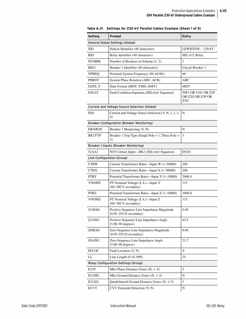
6.115
Date Code 20171021 Instruction Manual SEL-421 Relay
Protection Applications ExamplesEHV Parallel 230 kV Underground Cables Example
Table 6.31 Settings for 230 kV Parallel Cables Example (Sheet 1 of 5)
Setting Prompt Entry
General Global Settings (Global)
SID Station Identifier (40 characters) LEWISTON -- 230 kV
RID Relay Identifier (40 characters) SEL-421 Relay
NUMBK Number of Breakers in Scheme (1, 2) 1
BID1 Breaker 1 Identifier (40 characters) Circuit Breaker 1
NFREQ Nominal System Frequency (50, 60 Hz) 60
PHROT System Phase Rotation (ABC, ACB) ABC
DATE_F Date Format (MDY, YMD, DMY) MDY
FAULT Fault Condition Equation (SELOGIC Equation) 50P1 OR 51S1 OR Z2P OR Z2G OR Z3P OR Z3G
Current and Voltage Source Selection (Global)
ESS Current and Voltage Source Selection (Y, N, 1, 2, 3, 4)
N
Breaker Configuration (Breaker Monitoring)
EB1MON Breaker 1 Monitoring (Y, N) N
BK1TYP Breaker 1 Trip Type (Single Pole = 1, Three Pole = 3)
3
Breaker 1 Inputs (Breaker Monitoring)
52AA1 N/O Contact Input—BK1 (SELOGIC Equation) IN101
Line Configuration (Group)
CTRW Current Transformer Ratio—Input W (1–50000) 200
CTRX Current Transformer Ratio—Input X (1–50000) 200
PTRY Potential Transformer Ratio—Input Y (1–10000) 2000.0
VNOMY PT Nominal Voltage (L-L)—Input Y (60–300 V secondary)
115
PTRZ Potential Transformer Ratio—Input Z (1–10000) 2000.0
VNOMZ PT Nominal Voltage (L-L)—Input Z (60–300 V secondary)
115
Z1MAG Positive-Sequence Line Impedance Magnitude (0.05–255 secondary)
0.48
Z1ANG Positive-Sequence Line Impedance Angle (5.00–90 degrees)
42.5
Z0MAG Zero-Sequence Line Impedance Magnitude (0.05–255 secondary)
0.96
Z0ANG Zero-Sequence Line Impedance Angle (5.00–90 degrees)
21.7
EFLOC Fault Location (Y, N) Y
LL Line Length (0.10–999) 25
Relay Configuration Settings (Group)
E21P Mho Phase Distance Zones (N, 1–5) 3
E21MG Mho Ground Distance Zones (N, 1–5) N
E21XG Quadrilateral Ground Distance Zones (N, 1–5) 3
ECVT CVT Transient Detection (Y, N) N

6.116
SEL-421 Relay Instruction Manual Date Code 20171021
Protection Applications ExamplesEHV Parallel 230 kV Underground Cables Example
ESERCMP Series-Compensated Line Logic (Y, N) N
ECDTD Distance Element Common Time Delay (Y, N) Y
ESOTF Switch-Onto-Fault (Y, N) Y
EOOS Out-of-Step (Y, Y1, N) N
ELOAD Load Encroachment (Y, N) N
E50P Phase Inst./Def.-Time O/C Elements (N, 1–4) 1
E50G Res. Ground Inst./Def. Time O/C Elements (N, 1–4)
N
E50Q Negative-Sequence Inst./Def. Time O/C Elements (N, 1–4)
3
E51S Selectable Inverse Time O/C Element (N, 1–3) 1
E32 Directional Control (Y, AUTO, AUTO2) AUTO2
ECOMM Comm.-Assisted Tripping (N, DCB, POTT, POTT2, POTT3, DCUB1, DCUB2)
POTT
EBFL1 Breaker 1 Failure Logic (N, 1, 2, Y1, Y2) N
E25BK1 Synchronism Check for Breaker 1 (Y, N, Y1, Y2) N
E79 Reclosing (Y, Y1, N) N
EMANCL Manual Closing (Y, N) N
ELOP Loss-of-Potential (Y, Y1, N) Y1
EDEM Demand Metering (N, THM, ROL) N
EADVS Advanced Settings (Y, N) Y
Mho Phase-Distance Element Reach (Group)
Z1MP Zone 1 Reach (OFF, 0.05–64 secondary) 0.38
Z2MP Zone 2 Reach (OFF, 0.05–64 secondary) 0.58
Z3MP Zone 3 Reach (OFF, 0.05–64 secondary) 0.58
Mho Phase-Distance Element Time Delay (Group)
Z1PD Zone 1 Time Delay (OFF, 0.000–16000 cycles) OFF
Z2PD Zone 2 Time Delay (OFF, 0.000–16000 cycles) OFF
Z3PD Zone 3 Time Delay (OFF, 0.000–16000 cycles) OFF
Quadrilateral Ground-Distance Element Reach (Group)
XG1 Zone 1 Reactance (OFF, 0.05–64 secondary) 0.38
RG1 Zone 1 Resistance (0.05–50 secondary) 1.29
XG2 Zone 2 Reactance (OFF, 0.05–64 secondary) 0.58
RG2 Zone 2 Resistance (0.05–50 secondary) 1.97
XG3 Zone 3 Reactance (OFF, 0.05–64 secondary) 0.58
RG3 Zone 3 Resistance (0.05–50 secondary) 2.46
XGPOL Quad Ground Polarizing Quantity (I2, IG) I2
TANGG Nonhomogeneous Correction Angle (–40.0 to +40 degrees)
–2.2
Zero-Sequence Current Compensation Factor (Group)
k0M1 Zone 1 ZSC Factor Magnitude (AUTO, 0.000–10) 0.385
k0A1 Zone 1 ZSC Factor Angle (–180.0 to +180 degrees) –46.7
Table 6.31 Settings for 230 kV Parallel Cables Example (Sheet 2 of 5)
Setting Prompt Entry

6.117
Date Code 20171021 Instruction Manual SEL-421 Relay
Protection Applications ExamplesEHV Parallel 230 kV Underground Cables Example
k0M Forward Zones ZSC Factor Magnitude (0.000–10) 6.105
k0A Forward Zones ZSC Factor Angle (–180.0 to +180 degrees)
44.5
k0MR Reverse Zones ZSC Factor Magnitude (0.000–10) 6.105
k0AR Reverse Zones ZSC Factor Angle (–180.0 to +180 degrees)
44.5
Ground-Distance Element Time Delay (Group)
Z1GD Zone 1 Time Delay (OFF, 0.000–16000 cycles) OFF
Z2GD Zone 2 Time Delay (OFF, 0.000–16000 cycles) OFF
Z3GD Zone 3 Time Delay (OFF, 0.000–16000 cycles) OFF
Distance Element Common Time Delay (Group)
Z1D Zone 1 Time Delay (OFF, 0.000–16000 cycles) 0.000
Z2D Zone 2 Time Delay (OFF, 0.000–16000 cycles) 20.000
Z3D Zone 3 Time Delay (OFF, 0.000–16000 cycles) 0.000
SOTF Scheme (Group)
ESPSTF Single-Pole Switch-Onto-Fault (Y, N) N
EVRST Switch-Onto-Fault Voltage Reset (Y, N) Y
VRSTPU Switch-Onto-Fault Reset Voltage (0.60–1.00 pu) 0.60–1.00 pu
52AEND 52A Pole Open Time Delay (OFF, 0.000–16000 cycles)
OFF
CLOEND CLSMON or Single Pole Open Delay (OFF, 0.000–16000 cycles)
10.000
SOTFD Switch-Onto-Fault Enable Duration (0.500–16000 cycles)
10.000
CLSMON Close Signal Monitor (SELOGIC Equation) IN102
Phase Instantaneous Overcurrent Pickup (Group)
50P1P Level 1 Pickup (OFF, 0.25–100 A secondary) 9.57
Phase Overcurrent Definite-Time Delay (Group)
67P1D Level 1 Time Delay (0.000–16000 cycles) 0.000
Phase Overcurrent Torque Control (Group)
67P1TC Level 1 Torque Control (SELOGIC Equation) 1
Negative-Sequence Instantaneous Overcurrent Pickup (Group)
50Q1P Level 1 Pickup (OFF, 0.25–100 A secondary) OFF
50Q2P Level 2 Pickup (OFF, 0.25–100 A secondary) 0.60
50Q3P Level 3 Pickup (OFF, 0.25–100 A secondary) 0.40
Negative-Sequence Overcurrent Definite-Time Delay (Group)
67Q2D Level 2 Time Delay (0.000–16000 cycles) 0.000
67Q3D Level 3 Time Delay (0.000–16000 cycles) 0.000
Negative-Sequence Overcurrent Torque Control (Group)
67Q2TC Level 2 Torque Control (SELOGIC Equation) 32GF
67Q3TC Level 3 Torque Control (SELOGIC Equation) 32GR
Table 6.31 Settings for 230 kV Parallel Cables Example (Sheet 3 of 5)
Setting Prompt Entry

6.118
SEL-421 Relay Instruction Manual Date Code 20171021
Protection Applications ExamplesEHV Parallel 230 kV Underground Cables Example
Selectable Operating Quantity Inverse-Time Overcurrent Element 1 (Group)
51S1O 51S1 Op. Qty (IAn, IBn, ICn, IMAXn, I1L, 3I2L, 3I0n)a
3I2L
51S1P 51S1 O/C Pickup (0.25–16 A secondary) 1.00
51S1C 51S1 Inverse Time O/C Curve (U1–U5) U3
51S1TD 51S1 Inverse Time O/C Time Dial (0.50–15) 3.72
51S1RS 51S1 Inverse Time O/C EM Reset (Y, N) Y
51S1TC 51S1 Torque Control (SELOGIC Equation) 32GF
Zone/Level Direction (Group)
DIR3 Zone/Level 3 Directional Control (F, R) R
Directional Control (Group)
ORDER Ground Dir. Element Priority (combine Q, V, I) Q
Pole-Open Detection (Group)
EPO Pole Open Detection (52, V) 52
SPOD Single Pole Open Dropout Delay (0.000–60 cycles) 0.500
3POD Three Pole Open Dropout Delay (0.000–60 cycles) 0.500
POTT Trip Scheme (Group)
Z3RBD Zone 3 Reverse Block Time Delay (0.000–16000 cycles)
5.000
EBLKD Echo Block Time Delay (OFF, 0.000–16000 cycles)
10.000
ETDPU Echo Time Delay Pickup (OFF, 0.000–16000 cycles)
2.000
EDURD Echo Duration Time Delay (0.000–16000 cycles) 4.000
EWFC Weak Infeed Trip (Y, N, SP) N
PT1 General Permissive Trip Received (SELOGIC Equation)
IN103
Trip Logic (Group)
TR Trip (SELOGIC Equation) Z1T OR Z2T OR 51S1T
TRCOMM Communications-Assisted Trip (SELOGIC Equation)
Z2P OR 67Q2
TRCOMMD Dir. Element Comms.-Assisted Trip (SELOGIC Equation)
NA
TRSOTF Switch-Onto-Fault Trip (SELOGIC Equation) Z2P OR Z2G OR 50P1
DTA Direct Transfer Trip A-Phase (SELOGIC Equation) NA
DTB Direct Transfer Trip B-Phase (SELOGIC Equation) NA
DTC Direct Transfer Trip C-Phase (SELOGIC Equation) NA
BK1MTR Manual Trip–Breaker 1 (SELOGIC Equation) OC1 OR PB8_PUL
ULTR Unlatch Trip (SELOGIC Equation) TRGTR
ULMTR1 Unlatch Manual Trip–Breaker 1 (SELOGIC Equation)
NOT (52AA1 AND 52AB1 AND 52AC1)
TOPD Trip During Open Pole Time Delay (2.000–8000 cycles)
2.000
TULO Trip Unlatch Option (1, 2, 3, 4) 3
Table 6.31 Settings for 230 kV Parallel Cables Example (Sheet 4 of 5)
Setting Prompt Entry

6.119
Date Code 20171021 Instruction Manual SEL-421 Relay
Protection Applications ExamplesOut-of-Step Logic Application Examples
Out-of-Step Logic Application ExamplesThe SEL-421 features OOS (out-of-step) logic for the following two functions:
➤ OSB (out-of-step blocking) logic blocks phase-distance elements and Zone 1 ground-distance elements during power swings.
➤ OST (out-of-step tripping) logic trips the circuit breaker(s) during unstable swings.
There are two application examples that explain how to apply OOS logic: an out-of-step blocking scheme and an out-of-step tripping and blocking scheme. The examples provide detailed setting procedures for a 5 A relay.
These examples are for three-pole tripping in a 500 kV power system. Applica-tions for single-pole tripping are similar. Refer to Figure 6.28 for a one-line dia-gram of the 500 kV system.
Z2GTSP Zone 2 Ground Distance Time Delay SPT (Y, N) N
67QGSP Zone 2 Dir. Negative-Sequence/Residual Overcur-rent Single Pole Trip (Y, N)
N
TDUR1D SPT Min Trip Duration Time Delay (2.000–8000 cycles)
6.000
TDUR3D 3PT Min Trip Duration Time Delay (2.000–8000 cycles)
9.000
E3PT Three-Pole Trip Enable (SELOGIC Equation) 1
E3PT1 Breaker 1 3PT (SELOGIC Equation) 1
ER Event Report Trigger (SELOGIC Equation) R_TRIG Z2P OR R_TRIG Z2G OR R_TRIG 51S1 OR R_TRIG Z3P OR R_TRIG Z3G
Main Board (Outputs)
OUT101 (SELOGIC Equation) 3PT
OUT102 (SELOGIC Equation) KEY
a Parameter n is 1 for BK1, 2 for BK2, and L for Line.
Table 6.31 Settings for 230 kV Parallel Cables Example (Sheet 5 of 5)
Setting Prompt Entry
Figure 6.28 500 kV Power System
SEL-421
Z1L1 Z1RZ1S
S R

6.120
SEL-421 Relay Instruction Manual Date Code 20171021
Protection Applications ExamplesOut-of-Step Logic Application Examples
Power System ParametersTable 6.32 lists the power system parameters.
Out-of-Step BlockingThis example demonstrates setting OSB function. Use this logic to discriminate between power swings and faults to prevent unwanted distance element trips. This application example assumes that you have set the phase-to-phase mho dis-tance element Zone 2 reach. First, enable the OOS logic. Next, calculate the impedance reach settings for Zone 6 and Zone 7 (R1R6, R1R7, X1T6, and X1T7), and then calculate OSBD (out-of-step block time delay). All of the OOS settings appear in Table 6.33 and Table 6.34 at the end of this example.
Enable OOS LogicNOTE: The relay automatically calculates and hides settings when you set EADVS to N and EOOST to N. Table 6.33 lists these settings.
Access Group settings to enable the out-of-step logic.
EOOS := Y. Out-of-Step (Y, N)
You do not need to enable the Advanced Settings for this application example.
EADVS := N. Advanced Settings (Y, N)
Out-of-Step Tripping
Disable the OST logic for this particular application example.
EOOST := N. Out-of-Step Tripping (N, I, O)
Phase-Distance Element Blocking
OSB logic blocks phase-distance protection during a swing when the measured positive-sequence impedance enters the operating characteristics of the phase-distance elements (see Zone 1 and Zone 2 in Figure 6.29). In practice, it is not necessary to block all zones. In this application example, the OSB logic blocks zones that generate instantaneous tripping. The OSB logic blocks instantaneous Zone 1 and Zone 2 (Zone 2 is part of the communications-assisted tripping scheme).
Table 6.32 Positive-Sequence Impedances (Secondary)
Parameter Value
Line impedances:
Z1L1 8.00 87.6° secondary (Z1MAG W ÐZ1ANG°)
Zone 2 Phase-Distance Reach:
Z2MP 9.60 secondary
Source S impedances:
Z1S 8.8 88° secondary
Source R impedances:
Z1R 3.52 88° secondary
Nominal frequency (fNOM) 60 Hz
Nominal current (INOM) 5 A secondary
Line Length 100 miles

6.121
Date Code 20171021 Instruction Manual SEL-421 Relay
Protection Applications ExamplesOut-of-Step Logic Application Examples
The OSB logic typically supervises forward-looking Zone 1 and Zone 2 because the operation time of these two zones is ordinarily shorter than the time period during which the impedance of a power swing resides in these protection zones. For example, if the period of a swing is 1.5 seconds, OSB logic should supervise instantaneous Zone 1 and communications-assisted Zone 2.
During a power swing, the relay typically does not block overreaching zones of protection that provide time-delayed tripping. Do not block reverse-looking Zone 3 when this zone serves as a starting element for the DCB (directional com-parison blocking) scheme or when this zone provides current reversal guard for the POTT (permissive overreaching transfer tripping) scheme. For example, if the OSB logic inhibits the DCB blocking signal during swings that pass behind the local relay, over-tripping can occur at the remote terminal. If a power swing enters both the local reverse-looking Zone 3 and the remote overreaching Zone 2, high-speed tripping occurs at the remote terminal because OSB logic removes the local Zone 3 element DCB scheme block.
Set the relay to block Zone 1 and Zone 2.
OOSB1 := Y. Block Zone 1 (Y, N)
OOSB2 := Y. Block Zone 2 (Y, N)
OOSB3 := N. Block Zone 3 (Y, N)
Zone 6 and Zone 7 Impedance SettingsThe OOS logic uses two zones of concentric polygons, outer Zone 7 and inner Zone 6 (see Figure 6.29). The relay uses Zone 6 and Zone 7 for OOS logic timing to differentiate between power swings and faults. The relay measures a traveling
Figure 6.29 OOS Characteristic Settings Parameters
S
R
Zone 2
Zone 1
MinimumLoad Impedance(Export)R1
X1X1T7
X1B7
X1T6
X1B6
R1R6R1L6 R1R7
Z1 Trajectory
R1L7

6.122
SEL-421 Relay Instruction Manual Date Code 20171021
Protection Applications ExamplesOut-of-Step Logic Application Examples
positive-sequence impedance locus (Z1) in Zone 6 and Zone 7 when a power swing or fault occurs. Two factors affect the Zone 6 and Zone 7 impedance set-tings:
➤ The outermost overreaching zone of phase-distance protection that you want to block.
➤ The load impedance that the relay measures during maximum load (minimum load impedance locus).
NOTE: This settings philosophy provides the most time for the relay to decide whether a fault or a power swing has occurred.
Set inner Zone 6 (X1T6, R1R6, X1B6, and R1L6) to encompass the outermost zone of phase-distance protection that you have selected for out-of-step blocking. Set Zone 7 so that the closest minimum load impedance locus is outside the Zone 7 characteristic for all loading conditions.
Resistance Blinders
Zone 2 is the outermost characteristic for this particular example. Include a safety margin (20 percent for this example).
When you set Zone 6, SEL recommends that you assume that Z1ANG is at 90 degrees. This allows the user to set the resistive reach of the zone along the x-axis. Internally, the relay will adjust the setting by the line angle Z1ANG when the zone setting is applied. Adjusting the setting by Z1ANG allows the resistive reach to be parallel with the line angle, as shown in Figure 6.29. Use Equation 6.70 to set the reach of Zone 6 along the x-axis.
Equation 6.70
R1R6 := 5.77. Zone 6 Resistance—Right (0.05–140 secondary)
Set Zone 7 outer resistance blinders according to maximum load. In other words, set the Zone 7 outer right-hand resistance blinder just inside the corresponding minimum export load impedance locus (maximum load locus). The maximum load current is 2.41 A secondary, determined from load studies. The correspond-ing line-to-neutral voltage during maximum load at Station S is 61.44 V second-ary.
Determine the minimum load impedance that the relay measures:
Equation 6.71
where:
Z2MP = Zone 2 mho phase-distance element reach (see Table 6.32).
IL(max) =2.41 A VLN =61.44 V
R1R6 1.2 Z2MP2----------------• =
1.2 9.60 2-----------------•
=
5.77 =
ZLmin
VLNIL MAX ---------------------=
61.44 V2.41 A-------------------=
25.49 =

6.123
Date Code 20171021 Instruction Manual SEL-421 Relay
Protection Applications ExamplesOut-of-Step Logic Application Examples
Assume that the maximum load angle is ±45°. Use trigonometry to calculate R1R7, which is the distance from the origin to the right-hand resistance blinder along line OP, the c side of the right triangle (see Table 6.30). The resistance blinders are parallel to the line characteristic impedance Z1L1, for which the angle is setting Z1ANG.
Equation 6.72
Rearrange Equation 6.72 and multiply by a safety factor of 90 percent to calcu-late R1R7.
Equation 6.73
R1R7 := 15.53. Zone 7 Resistance—Right (0.05–140 secondary)
where:
A = 45° + (90°–Z1ANG)
b = ZL(min)
c = setting R1R7
Figure 6.30 Calculating Setting R1R7
A cos cb---=
45˚
R
X
b
a
cOP
A
ZIL1
B
CExportLoad
Minimum Load Impedance
Safety Margin
R1R7 0.9% ZL min A cos• • =
0.9 ZL min 45 90 Z1ANG– + cos• • =
0.9 25.49 45 90 87.6– + cos• • =
0.9 25.49 47.4 cos• • =
15.53 =

6.124
SEL-421 Relay Instruction Manual Date Code 20171021
Protection Applications ExamplesOut-of-Step Logic Application Examples
Reactance Lines
Zone 6 inner reactance lines X1T6 and X1B6 should completely encompass the outermost zone of phase-distance protection that you want to block from tripping during a power swing. Include a safety margin (20 percent).
Equation 6.74
X1T6 := 11.52. Zone 6 Reactance—Top (0.05–140 secondary)
The distance between Zones 6 and 7 top reactance lines should equal the distance between Zones 6 and 7 right-hand resistance blinders.
NOTE: The value for X1T7 must be at least 0.1 greater than that for X1T6.
Equation 6.75
X1T7 := 21.29. Zone 7 Reactance—Top (0.05–140 secondary)
Out-of-Step Block Time DelayWhen the Z1 impedance locus initially moves inside Zone 7, the relay starts the OSBD (out-of-step block time delay) timer. The Z1 impedance trajectory is shown in Figure 6.31 for the case of |EA| = |EB| (EA is the voltage at Node A and EB is the voltage at Node B). The OSBD timer detects slow swings. If the OSBD timer expires before the Z1 trajectory enters Zone 6, the relay detects a power swing blocking condition.
where:
Z2MP = Zone 2 mho phase-distance element reach
X1T6 1.2 Z2MP• =
1.2 9.60 • =
11.52 =
X1T7 X1T6 R1R7 R1R6– +=
11.52 15.53 5.76 – +=
21.29 =

6.125
Date Code 20171021 Instruction Manual SEL-421 Relay
Protection Applications ExamplesOut-of-Step Logic Application Examples
Use Equation 6.76 through Equation 6.79 to calculate the OSBD setting. These equations are derived from the impedance trajectory shown in Figure 6.31. Line section AB is the transfer impedance, ZT. The horizontal dashed line represents the trajectory of the power swing perpendicular to line section AB. The trajectory passes through the midpoint of line section AB.
Equation 6.76
Equation 6.77
Figure 6.31 Swing Trajectory to Determine the OSBD Setting
where:
ZT = transfer impedance
Z1S = positive-sequence source impedance
Z1L1 = positive-sequence impedance for Line 1
Z1R = positive-sequence remote impedance
B
A
Minimum Load Impedance
Z1 Trajectory
R1
X1
OAng_R6
Zone 6Zone 7
Ang_R7
ZT Z1S Z1L1 Z1R+ +=
Ang_R6 2ZT2---------
R1R6 -------------------
atan• =
28.8 88 8.00 87.6 3.52 88+ +
2--------------------------------------------------------------------------------------------------------------
5.77 --------------------------------------------------------------------------------------------------------------atan•
=
120.9=

6.126
SEL-421 Relay Instruction Manual Date Code 20171021
Protection Applications ExamplesOut-of-Step Logic Application Examples
Equation 6.78
A typical stable swing frequency is slip = 5 Hz. Use this value in Equation 6.79 to find setting OSBD.
Equation 6.79
The OSBD timer settings are in increments of 0.125 cycle; round up to the near-est valid relay setting.
OSBD := 1.875. Out-of-Step Block Time Delay (0.500–8000 cycles)
Latch Out-of-Step BlockingThe SEL-421 automatically resets the OSB logic if this logic asserts for more than two seconds while the positive-sequence impedance locus is inside Zone 7. During an unstable power swing, the relay also resets the OSB logic each time the swing impedance exits Zone 7. You can latch on the OSB function during an unstable power swing to continue blocking the distance elements if the power swing impedance locus moves outside of Zone 7 and before it comes back inside Zone 7 on its next swing cycle. If latched, the OSB logic resets one second after the power system stops the out-of-step. Latching the OSB gives you an advantage in that the relay can successfully block uncontrolled distance element operations if a fault occurs when the unstable swing impedance is outside of Zone 7. Relay elements detect internal faults that occur during a power swing and take the appropriate action (unblock).
OSBLTCH := Y. Latch Out-of-Step Blocking (Y, N)
Out-of-Step Unblocking
The relay disables out-of-step blocking automatically when a fault occurs during a power swing. Therefore, the distance protection successfully detects all fault types and trips the circuit breaker(s) during internal faults.
where:
NOM = nominal power system frequency (Hz)
slip = maximum slip frequency (Hz)
Ang_R7 2ZT2---------
R1R7---------------atan• =
28.8 88 8.00 87.6 3.52 88+ +
2--------------------------------------------------------------------------------------------------------------
15.53 --------------------------------------------------------------------------------------------------------------atan•
=
66.4=
OSBDAng_R6 Ang_R7– fNOM•
360cycle-------------- fslip•
--------------------------------------------------------------------------- cycles=
120.9 66.4– 60 Hz• 360cycle-------------- 5 Hz•
------------------------------------------------------------- cycles=
1.82 cycles=

6.127
Date Code 20171021 Instruction Manual SEL-421 Relay
Protection Applications ExamplesOut-of-Step Logic Application Examples
Out-of-Step Unblocking During Three-Phase Faults
The trajectories of a three-phase fault and a power swing appear the same to phase-distance elements because both a three-phase fault and a power swing con-sist of positive-sequence quantities only (V1 and I1). Therefore, if a power swing evolves into an internal three-phase fault, typical OSB logic cannot detect the occurrence of the balanced fault. The SEL-421 includes an additional set of inner blinders to provide proper detection of the internal three-phase fault (see Figure 6.32). If the positive-sequence impedance resides between these blinders for a specific duration, OSB logic unblocks. The relay calculates this duration (UBOSBD) each time the power swing enters Zone 7. A short timer setting is adequate for fast swings, but the relay needs a longer timer setting for slow power swings. For example, if the positive-sequence impedance passes gradually between the two inner blinders during a slow swing, a short timer setting would cause unwanted tripping.
The UBOSBD timer length is the expected duration of the power swing within the inner blinders. The relay bases the calculation on the actual time required for the swing to traverse from Zone 7 to Zone 6, before entering the inner blinders. If the swing remains inside the inner blinders for a period greater than UBOSBD, an unblock signal asserts.
Figure 6.32 Inner Blinders
S
R
B
A
Zone 2
R1
X1
Zone 6
Zone 7
RightBlinder
LeftBlinder

6.128
SEL-421 Relay Instruction Manual Date Code 20171021
Protection Applications ExamplesOut-of-Step Logic Application Examples
You can increase the adaptive UBOSBD timer calculation in multiples of setting UBOSBF. If UBOSBF is a multiplier of one, the relay calculates the expected time to traverse across the inner blinders based on the rate at which the swing moved from Zone 7 to Zone 6. Similarly, if UBOSBF is a multiplier of four, the relay multiplies UBOSBD by four.
Out-of-Step Unblocking During Unbalanced Faults
The SEL-421 treats Zone 1 phase and ground-distance elements differently than phase-distance elements of other zones.
Operation of either of two negative-sequence directional elements, 67QUBF (for-ward-looking), or 67QUBR (reverse-looking), defeats the OSB logic and unblocks the phase-distance elements (except the Zone 1 elements) when an unbalanced fault occurs following a power swing. Therefore, the phase-distance protection operates in the POTT scheme and high-speed clears the unbalanced fault if it is an internal one. The time-delayed elements of associated zones also start timing to initiate backup protection functions. The 67QUBF element unblocks forward-looking zones and 67QUBR unblocks reverse-looking zones.
The relay supervises the 67QUBF and 67QUBR elements with negative-sequence pickup setting 50QUBP. When you set the 50QUBP pickup level to other than OFF, the level of negative-sequence current exceeds the 50QUBP set-ting threshold, and the relay has made a valid directional decision (32 elements), the relay asserts either the 67QUBF or the 67QUBR directional element after time delay setting UBD. In this manner the relay removes out-of-step blocking for phase-distance elements other than Zone 1 elements during unbalanced faults.
The 50QUBP setting is an advanced setting and must be coordinated with the dis-tance protection for the protected line. Setting UBD is also an advanced setting; set the UBD timer to coordinate clearing times with protection external to the protected line.
For out-of-step unblocking on unbalanced faults you must do the following:
Step 1. Set EADVS := Y to enable advanced settings.
Step 2. Set the negative sequence unblocking element pickup with setting 50QUBP (Negative-Sequence Current Supervision).
Coordinate with line distance protection.
Step 3. Set the unblock delay timer UBD (Negative-Sequence Current Unblock Delay).
Coordinate clearing times with other protection.
If a power swing center is on the line under protection, the Zone 1 distance ele-ments at one or both terminals may operate if the OSB is removed. For example, during an unstable swing, if an external A-Phase ground fault occurs beyond the remote terminal R in Figure 6.28, the A-Phase ground-distance elements at both terminals operate correctly; that is, A-Phase distance element picks up in Zone 2 at the S terminal, and in reverse Zone 3 at the R terminal. However, all Zone 1 phase and ground-distance elements at both terminals may also operate if the swing center is within the Zone 1 reach and a negative-sequence overcurrent ele-ment removes the OSB. The undesirable operations of Zone 1 elements may trip all three phases at both terminals for an external A-Phase fault.
The SEL-421 uses a directional negative-sequence element (67Q1T) to supervise the out-of-step blocking of Zone 1 distance elements. 67Q1T is independent from 67QUBF and 67QUBR, which are used to defeat the OSB for distance elements other than Zone 1 elements. This separation gives you a choice to control the Zone 1 element operations during an unstable swing situation.

6.129
Date Code 20171021 Instruction Manual SEL-421 Relay
Protection Applications ExamplesOut-of-Step Logic Application Examples
For those applications that allow the relay to operate for any internal and external faults on a system during a power swing, set the 67Q1T element similar to the 67QUBF element:
50Q1P := same value as of 50QUBP. Level 1 Pickup (OFF, 0.25–100 Amps sec.)
67Q1D := same value as of UBD. Level 1 Time Delay (0.000–16000 cycles)
67Q1TC := 1. Level 1 Torque Control (SELOGIC Equation)
For those applications that require the relay only trip for internal faults during a power swing, disable the 67Q1T element by setting 50Q1P to OFF or E50Q = N. This way, the Zone 1 distance elements are always blocked by the OSB logic. The relay relies on Zone 2 overreaching elements together with the POTT scheme to make high-speed trips for internal faults.
Example CompletedThis completes the application example that describes setting the SEL-421 for out-of-step blocking. Analyze your particular power system to determine the appropriate settings for your application.
Relay SettingsTable 6.33 lists the settings that the relay automatically calculates and hides when you set EADVS to N and EOOST to N.
Table 6.34 and Table 6.35 list the protective relay settings available in this example.
Table 6.33 Automatically Calculated/Hidden Settings
Setting Prompt Default Setting
X1B7 Zone 7 Reactance—Bottom (–0.05 to –140 secondary) X1B7 = –X1T7
X1B6 Zone 6 Reactance—Bottom (–0.05 to –140 secondary) X1B6 = –X1T6
R1L7 Zone 7 Resistance—Left (–0.05 to –140 secondary) R1L7 = –R1R7
R1L6 Zone 6 Resistance—Left (–0.05 to –140 secondary) R1L6 = –R1R6
OSTD Out-of-Step Trip Delay (0.500–8000 cycles) 0.500
50ABCP Positive-Sequence Current Supervision (1.00–100 A secondary) 50ABCP = 0.2 • INOM
50QUBP Negative-Sequence Current Supervision (OFF, 0.50–100 A secondary)
OFF
UBD Negative-Sequence Current Unblock Delay (0.500–120 cycles)
0.500
UBOSBF Out-of-Step Angle Unblock Rate (1–10) 4
Table 6.34 Relay Configuration (Group)
Setting Prompt Entry
EOOS Out-of-Step (Y, Y1, N) Y
EADVS Advanced Settings (Y, N) N

6.130
SEL-421 Relay Instruction Manual Date Code 20171021
Protection Applications ExamplesOut-of-Step Logic Application Examples
Out-of-Step TrippingThis example demonstrates how to set the OST (out-of-step tripping) function. Use OST logic to detect an unstable power swing and trip the local terminal. With OST logic, you can split the power system at predetermined locations after an OST condition occurs.
The Zone 6 and Zone 7 settings for the OST logic depend on the positive sequence impedance (Z1) trajectory of the power swing (see Figure 6.33). Set inner Zone 6 at the point along the trajectory where the power system cannot regain stability. Set Zone 7 so that the impedance because of maximum load con-ditions is outside the Zone 7 characteristic for all loading conditions.
Table 6.35 Out-of-Step Tripping/Blocking
Setting Prompt Entry
OOSB1 Block Zone 1 (Y, N) Y
OOSB2 Block Zone 2 (Y, N) Y
OOSB3 Block Zone 3 (Y, N) N
OSBD Out-of-Step Block Time Delay (0.500–8000 cycles) 1.875
OSBLTCH Latch Out-of-Step Blocking (Y, N) Y
EOOST Out-of-Step Tripping (N, I, O) N
X1T7 Zone 7 Reactance—Top (0.05 to 140 secondary) 21.29
X1T6 Zone 6 Reactance—Top (0.05 to 140 secondary) 11.52
R1R7 Zone 7 Resistance—Right (0.05 to 140 secondary) 15.53
R1R6 Zone 6 Resistance—Right (0.05 to 140 secondary) 5.77
X1B7 Zone 7 Reactance—Bottom (–0.05 to –140 secondary) –21.29
X1B6 Zone 6 Reactance—Bottom (–0.05 to –140 secondary) –11.52
R1L7 Zone 7 Resistance—Left (–0.05 to –140 secondary) –15.53
R1L6 Zone 6 Resistance—Left (–0.05 to –140 secondary) –5.77
50ABCP Positive-Sequence Current Supervision (1.00–100 A secondary) 1.00
50QUBP Negative-Sequence Current Supervision (OFF, 0.50–100 A secondary) OFF
UBD Negative-Sequence Current Unblock Delay (0.500–120 cycles) 0.500
UBOSBF Out-of-Step Angle Unblock Rate (1–10) 4
50Q1P Level Pickup (OFF, 0.25–100 Amps sec.) OFF
67Q1D Level 1 Time Delay (0.000–16000 cycles) 0.000
67Q1TC Level 1 Torque Control (SELOGIC Equation) 1

6.131
Date Code 20171021 Instruction Manual SEL-421 Relay
Protection Applications ExamplesOut-of-Step Logic Application Examples
NOTE: This setting philosophy provides the most time for the relay to decide whether the power swing is unstable.
To configure the OOS logic for out-of-step tripping, enable the OOS logic. Next, calculate the impedance reach settings for Zone 6 and Zone 7 (R1R6, R1R7, X1T6, and X1T7), and then calculate OSTD (out-of-step trip delay) and OSBD (out-of-step block time delay). All of the OOS settings appear in Table 6.37 and Table 6.38.
Enable OOS LogicAccess Group settings to enable the out-of-step logic.
EOOS := Y. Out-of-Step (Y, N)
NOTE: Table 6.36 lists the settings that the relay automatically calculates and hides when you set EADVS to N.
You do not need to enable the Advanced Settings for this application example.
EADVS := N. Advanced Settings (Y, N)
Out-of-Step Tripping
When the positive-sequence impedance locus enters Zone 7, both OOS logic tim-ers (OSBD and OSTD) start (see Figure 6.33). If OSTD expires before OSBD and Zone 6 asserts, the relay declares an out-of-step tripping condition. Enable the relay to trip when Zone 6 drops out (Trip-On-the-Way-Out). See Out-of-Step Tripping and Blocking on page 6.133 for OSTD and OSBD calculations.
EOOST := O. Out-of-Step Tripping (N, I, O)
Figure 6.33 OST Characteristics
B
A
Minimum Load Impedance
Z1
R1
X1
O
Ang_R66
Zone 6
Zone 2
Zone 7
Ang_R7
TOWITOWO
where:
I = Enable out-of-step tripping (Trip-On-the-Way-In)
O = Enable out-of-step tripping (Trip-On-the-Way-Out)
N = Disable out-of-step tripping

6.132
SEL-421 Relay Instruction Manual Date Code 20171021
Protection Applications ExamplesOut-of-Step Logic Application Examples
Phase-Distance Element Blocking
Enable the OSB function to prevent tripping when the positive-sequence imped-ance locus enters the Zone 1 and Zone 2 distance protection characteristics during an unstable power swing. Therefore, in this application example, the relay trips after the Z1 impedance locus exits Zone 6 (Zone 6 drops out).
Block Zone 1 and Zone 2 distance protection elements during power swings.
OOSB1 := Y. Block Zone 1 (Y, N)
OOSB2 := Y. Block Zone 2 (Y, N)
OOSB3 := N. Block Zone 3 (Y, N)
Zone 6 and Zone 7 Impedance SettingsThe purpose of this OOS application example is to configure the relay to trip when the power system reaches a critical angle limit to prevent system collapse. Thus, the Zone 6 impedance setting differs from Out-of-Step Blocking on page 6.120.
Resistance Blinders
If the angle of the power swing Z1 trajectory passes 120 degrees with respect to the transfer impedance, the power system cannot recover. The transfer impedance is the total impedance of the power system (line AB in Figure 6.33). Set the Zone 6 right-hand inner resistance blinder R1R6 so Ang_R6 equals 120 degrees. Rearrange Equation 6.77 as shown in Equation 6.80:
Equation 6.80
R1R6 := 5.87. Zone 6 Resistance—Right (0.05 to 140 secondary)
Use the minimum load impedance ZL(min) (Equation 6.71) and the 90 percent safety margin criterion (see Equation 6.73) applied earlier in Resistance Blinders on page 6.122 to set the Zone 7 right-hand resistance blinder.
Equation 6.81
R1R7 := 15.53. Zone 7 Resistance—Right (0.05–140 secondary)
R1R6
ZT2---------
Ang_R62----------------------
tan------------------------------------=
8.80 88 8.00 87.6 3.52 88+ +2-----------------------------------------------------------------------------------------------------------------
1202-----------
tan-----------------------------------------------------------------------------------------------------------------=
10.16120
2----------- tan
-------------------------=
5.87 =
R1R7 0.9 ZL min 45 90 Z1ANG– + cos• • =
0.9 25.49 45 90 87.6– + cos• • =
0.9 25.49 47.4 cos• • =
15.53 =

6.133
Date Code 20171021 Instruction Manual SEL-421 Relay
Protection Applications ExamplesOut-of-Step Logic Application Examples
Reactance Lines
Set the reactance lines equal to the maximum values to help the relay detect power swings far from the relay location.
Set the Zone 7 top reactance line equal to the maximum setting.
X1T7 := 96. Zone 7 Reactance—Top (0.05–140 secondary)
Set the Zone 6 top reactance line to the maximum setting minus one ohm.
Equation 6.82
X1T6 := 95. Zone 6 Reactance—Top (0.05–140 secondary)
Out-of-Step Tripping and BlockingThe OOS logic uses two zones of concentric polygons, outer Zone 7 and inner Zone 6 (see Figure 6.33). The relay uses Zone 6 and Zone 7 for OOS logic timing to differentiate OOS blocking conditions, OOS tripping conditions, and faults. The relay measures a traveling positive-sequence impedance locus (Z1) in Zone 6 and Zone 7 when a power swing or fault occurs. When the impedance locus ini-tially moves inside Zone 7, the relay starts two OOS logic timers. One OOS timer detects OOS blocking conditions (OSBD), while the other timer detects OOS tripping conditions (OSTD).
NOTE: You must set OSTD shorter than OSBD by at least a half cycle.
The OOS logic declares a blocking condition if OSBD expires before the posi-tive-sequence impedance locus enters Zone 6. The logic declares a tripping con-dition if OSTD expires and the positive-sequence impedance locus enters Zone 6 prior to OSBD timing out.
Trip-On-Way-In/Trip-On-Way-Out
You can select one of two methods to trip during an unstable swing. You can enable the relay to trip if OSTD expires and the positive-sequence impedance enters Zone 6; this method is Trip-On-the-Way-In (TOWI in Figure 6.33). The relay asserts Relay Word bits OSTI and OST for a Trip-On-the-Way-In condition.
You can also enable the relay to trip if OSTD expires and the positive-sequence impedance enters and exits Zone 6; this second method is Trip-On-the-Way-Out (TOWO in Figure 6.33). The relay asserts Relay Word bits OSTO and OST for a Trip-On-the-Way-Out condition. Relay Word bit OST is the OR combination of OSTI and OSTO (see Out-of-Step Logic (Conventional) on page 5.50).
Trip-On-the-Way-Out (TOWO) is selected for this application example (see Enable OOS Logic on page 6.131).
Out-of-Step Tripping Time Delay
Use Equation 6.83, Equation 6.84, and Equation 6.85 to calculate the OSTD set-ting. These equations are derived from the impedance trajectory shown in Figure 6.33. Line section AB is the transfer impedance, ZT. The horizontal dashed line represents the trajectory of the power swing perpendicular to line sec-tion AB. The trajectory passes through the midpoint of line section AB.
X1T6 X1T7 1 –=
96 1 –=
95 =
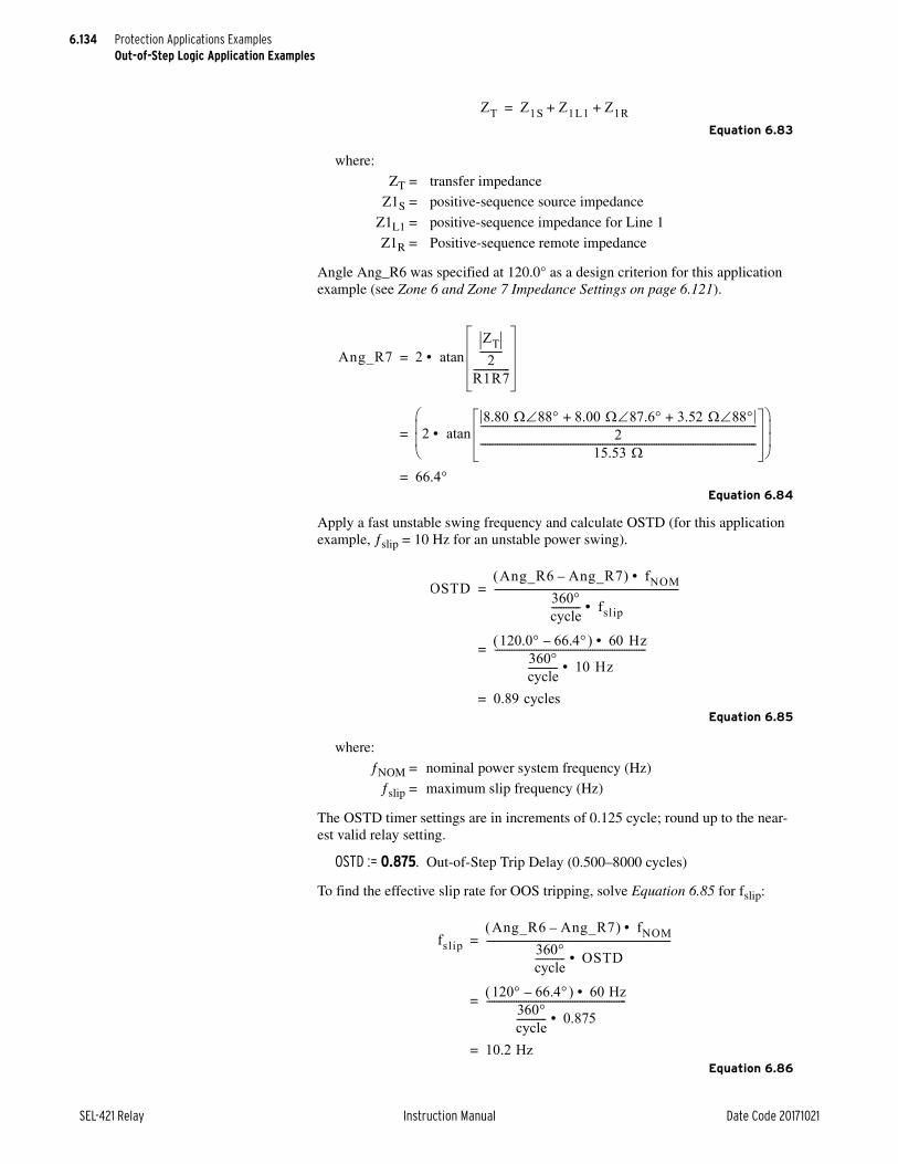
6.134
SEL-421 Relay Instruction Manual Date Code 20171021
Protection Applications ExamplesOut-of-Step Logic Application Examples
Equation 6.83
Angle Ang_R6 was specified at 120.0° as a design criterion for this application example (see Zone 6 and Zone 7 Impedance Settings on page 6.121).
Equation 6.84
Apply a fast unstable swing frequency and calculate OSTD (for this application example, slip = 10 Hz for an unstable power swing).
Equation 6.85
The OSTD timer settings are in increments of 0.125 cycle; round up to the near-est valid relay setting.
OSTD := 0.875. Out-of-Step Trip Delay (0.500–8000 cycles)
To find the effective slip rate for OOS tripping, solve Equation 6.85 for fslip:
Equation 6.86
where:
ZT = transfer impedance
Z1S = positive-sequence source impedance
Z1L1 = positive-sequence impedance for Line 1
Z1R = Positive-sequence remote impedance
where:
NOM = nominal power system frequency (Hz)
slip = maximum slip frequency (Hz)
ZT Z1S Z1L1 Z1R+ +=
Ang_R7 2ZT2---------
R1R7---------------atan• =
28.80 88 8.00 87.6 3.52 88+ +
2-----------------------------------------------------------------------------------------------------------------
15.53 -----------------------------------------------------------------------------------------------------------------atan•
=
66.4=
OSTDAng_R6 Ang_R7– fNOM•
360cycle------------ fslip•
---------------------------------------------------------------------------=
120.0 66.4– 60 Hz• 360cycle------------ 10 Hz•
--------------------------------------------------------------=
0.89 cycles=
fslipAng_R6 Ang_R7– fNOM•
360cycle------------ OSTD•
---------------------------------------------------------------------------=
120 66.4– 60 Hz• 360cycle------------ 0.875•
---------------------------------------------------------=
10.2 Hz=

6.135
Date Code 20171021 Instruction Manual SEL-421 Relay
Protection Applications ExamplesOut-of-Step Logic Application Examples
Out-of-Step Block Time Delay
Set OSBD longer than OSTD by the next timer setting step (0.125-cycle step size) greater than 0.500 cycle. Thus, the OSBD setting is calculated in Equation 6.87.
Equation 6.87
OSBD := 1.500. Out-of-Step Block Time Delay (0.500–8000 cycles)
To find the effective slip rate for OOS blocking, solve Equation 6.88 for fslip.
Equation 6.88
The relay detects OOS blocking conditions for power swing slip frequencies up to 5.95 Hz and OOS tripping conditions for power swing slip frequencies from 5.95 Hz to 10.2 Hz (see Equation 6.86). Zone 1 and Zone 2 elements remain blocked during these OSB and OST conditions. The event is not a swing condi-tion if the Z1 impedance locus crosses Zone 7 and Zone 6 before the OSTD and OSBD timers time out. The relay identifies this event as a fault condition.
Latch Out-of-Step BlockingLatch out-of-step blocking to maintain the blocking condition throughout the entire swing cycle.
OSBLTCH := Y. Latch Out-of-Step Blocking (Y, N)
Control OutputsFor local OOS tripping, configure the relay control outputs for tripping and remote notification of an out-of-step condition. Include Relay Word bit OST in the direct tripping SELOGIC control equation TR. (Add OR OST to the existing TR equation; the default is shown here.)
TR := Z1P OR Z1G OR M2PT OR Z2GT OR OST. Trip (SELOGIC Equation)
Set a control output for remote notification of the out-of-step tripping condition. This example uses OUT205. Select a relay control output that is appropriate for your particular application.
OUT205 := OST. Output OUT205 (SELOGIC Equation)
OSBD OSTD 0.500 cycle timer step+ +=
0.875 0.500 0.125+ +=
1.500 cycles=
fslipAng_R6 Ang_R7– fNOM•
360cycle------------ OSBD•
---------------------------------------------------------------------------=
120.0 66.4– 60 Hz• 360cycle------------ 1.500 cycle•
--------------------------------------------------------------=
5.5 Hz=

6.136
SEL-421 Relay Instruction Manual Date Code 20171021
Protection Applications ExamplesOut-of-Step Logic Application Examples
Example CompletedThis completes the application example that describes setting the SEL-421 for out-of-step tripping. Analyze your particular power system to determine the appropriate settings for your application.
Relay SettingsTable 6.36 lists the settings that the relay automatically calculates and hides when you set EADVS to N.
Table 6.37 and Table 6.38 list the protective relay settings available in this example.
Table 6.36 Automatically Calculated/Hidden Settings
Setting Prompt Default Setting
X1B7 Zone 7 Reactance—Bottom (–0.05 to –140 secondary) X1B7 = –X1T7
X1B6 Zone 6 Reactance—Bottom (–0.05 to –140 secondary) X1B6 = –X1T6
R1L7 Zone 7 Resistance—Left (–0.05 to –140 secondary) R1L7 = –R1R7
R1L6 Zone 6 Resistance—Left (–0.05 to –140 secondary) R1L6 = –R1R6
50ABCP Positive-Sequence Current Supervision (1.00–100 A secondary)
50ABCP = 0.2 • INOM
50QUBP Negative-Sequence Current Supervision (OFF, 0.50–100 A secondary)
OFF
UBD Negative-Sequence Current Unblock Delay (0.500–120 cycles)
0.500
UBOSBF Out-of-Step Angle Unblock Rate (1–10) 4
Table 6.37 Relay Configuration (Group)
Setting Prompt Entry
EOOS Out-of-Step Y
EADVS Advanced Settings (Y, N) N
Table 6.38 Out-of-Step Tripping/Blocking (Sheet 1 of 2)
Setting Prompt Entry
OOSB1 Block Zone 1 (Y, N) Y
OOSB2 Block Zone 2 (Y, N) Y
OOSB3 Block Zone 3 (Y, N) N
OSBD Out-of-Step Block Time Delay (0.500–8000 cycles) 1.500
OSBLTCH Latch Out-of-Step Blocking (Y, N) Y
EOOST Out-of-Step Tripping (N, I, O) O
OSTD Out-of-Step Trip Delay (0.500–8000 cycles) 0.875
X1T7 Zone 7 Reactance—Top (0.05 to 140 secondary) 96.00
X1T6 Zone 6 Reactance—Top (0.05 to 140 secondary) 95.00
R1R7 Zone 7 Resistance—Right (0.05 to 140 secondary) 15.53
R1R6 Zone 6 Resistance—Right (0.05 to 140 secondary) 5.87
X1B7 Zone 7 Reactance—Bottom (–0.05 to –140 secondary) –96.00
X1B6 Zone 6 Reactance—Bottom (–0.05 to –140 secondary) –95.00
R1L7 Zone 7 Resistance—Left (–0.05 to –140 secondary) –15.53

6.137
Date Code 20171021 Instruction Manual SEL-421 Relay
Protection Applications ExamplesAutoreclose Example
Autoreclose ExampleThis application example is for a double-ended 230 kV overhead transmission line with SEL-421 protection at each end. The one-line drawing for this circuit is shown in Figure 6.34. This example shows settings for the SEL-421 at Station S (Harvard) in Figure 6.35.
ApplicationAutoreclose Mode of Operation
Apply the SEL-421 for one shot of three-pole autoreclose.
R1L6 Zone 6 Resistance—Left (–0.05 to –140 secondary) –5.87
50ABCP Positive-Sequence Current Supervision (1.00–100 A secondary)
1.00
50QUBP Negative-Sequence Current Supervision (OFF, 0.50–100 A secondary)
OFF
UBD Negative-Sequence Current Unblock Delay (0.500–120 cycles)
0.500
UBOSBF Out-of-Step Angle Unblock Rate (1–10) 4
50Q1P Level Pickup (OFF, 0.25–100 Amps sec.) OFF
67Q1D Level 1 Time Delay (0.000–16000 cycles) 0.000
67Q1TC Level 1 Torque Control (SELOGIC Equation) 1
TR Trip (SELOGIC Equation) Z1P OR Z1G OR M2PT OR Z2GT OR OST
OUT205 Output OUT205 (SELOGIC Equation) OST
Table 6.38 Out-of-Step Tripping/Blocking (Sheet 2 of 2)
Setting Prompt Entry
Figure 6.34 230 kV Example Power System
SEL-421 SEL-421
Z1L, Z0LZ1S, Z0SBK1
S (Harvard) R (Princeton)
BK2Z1R, Z0R

6.138
SEL-421 Relay Instruction Manual Date Code 20171021
Protection Applications ExamplesAutoreclose Example
SolutionAutoreclose Conditions
The relay initiates three-pole autoreclosing if a Zone 1 trip occurs because of a multiphase fault.
Circuit Breaker1 attempts the three-pole reclose if Bus 1 is hot and the line is dead. For this application example, block autoreclose if any of the following events occur:
➤ Manual trip
➤ Time-delayed trip
➤ Bus trip
➤ Circuit breaker failure trip
If the SEL-421 detects an LOP condition, the autoreclose logic drives the autore-close function to lockout.
Relay SettingsSelect the relay settings for this application example.
Relay ConfigurationNOTE: Setting E79 := Y1 is intended for certain double circuit breaker applications. Use E79 := Y for a single circuit breaker.
Enable reclosing:
E79 := Y. Reclosing (Y, Y1, N)
Recloser ClosingSelect one shot of three-pole autoreclose.
N3PSHOT := 1. Number of Three-Pole Reclosures (N, 1–4)
Use an external switch to select when Circuit Breaker 1 is enabled for three-pole autoreclose.
E3PR1 := IN106. Three-Pole Reclose Enable -BK1 (SELOGIC Equation)
If Circuit Breaker 1 fails to close within 10 seconds after the reclose command is received, the autoreclose logic goes to lockout.
BKCFD := 600. Breaker Close Failure Delay (1–99999 cycles)
Figure 6.35 Circuit Breaker Arrangement at Station S
SEL-421
VAZ
IW
VY
BK1
3
1 3345
kV B
us

6.139
Date Code 20171021 Instruction Manual SEL-421 Relay
Protection Applications ExamplesAutoreclose Example
Unlatch the reclose command to Circuit Breaker 1 when all three poles are closed.
ULCL1 := 52AA1 AND 52AB1 AND 52AC1. Unlatch Closing for Circuit Breaker 1 (SELOGIC Equation)
Drive the autoreclose logic to lockout if the SEL-421 detects an LOP condition.
79DTL := LOP. Recloser Drive to Lockout (SELOGIC Equation)
You can block the reclaim timing. However, it is not necessary for this single shot application example.
79BRCT := NA. Block Reclaim Timer (SELOGIC Equation)
When leaving the lockout condition, the recloser goes to the Ready or Reset state after the 3PMRCD (Manual Close Reclaim Time Delay) timer has expired.
3PMRCD := 900. Manual Close Reclaim Time Delay (1–99999 cycles)
If Circuit Breaker 1 reclose supervision conditions fail to occur within 300 cycles after the three-pole open interval time delay expires, BK1CLST will assert, and the autoreclose logic goes to lockout.
BK1CLSD := 300. BK1 Reclose Supervision Delay (OFF, 1–99999 cycles)
Three-Pole RecloseSet the three-pole open interval time equal to 30 cycles.
3POID1 := 30. Three-Pole Open Interval 1 Delay (1–99999 cycles)
There is no need to enable fast three-pole autoreclose because we have already used the first and only three-pole shot for this purpose.
3PFARC := NA. Three-Pole Fast ARC Enable (SELOGIC Equation)
Set the reset time following a three-pole autoreclose cycle equal to 900 cycles.
3PRCD := 900. Three-Pole Reclaim Time Delay (1–99999 cycles)
Initiate a three-pole autoreclose cycle when the SEL-421 three-pole trips because of Zone 1 phase-distance protection. Communications-assisted tripping is not enabled.
3PRI := 3PT AND Z1P. Three-Pole Reclose Initiation (SELOGIC Equation)
You can force the autoreclose logic to skip a three-pole shot. However, it is not necessary for this application example.
79SKP := NA. Skip Reclosing Shot (SELOGIC Equation)
Only attempt to reclose Circuit Breaker 1 if the bus is hot and the line is dead (setting cannot be set to NA or logical 0).
3P1CLS := DLLB1. Three Pole BK 1 Reclose Supervision (SELOGIC Equation)
Voltage ElementsThe SEL-421 checks the Bus and Line conditions when you enable the voltage check elements. Figure 6.36 shows a typical checking scheme. Potentials VAY and VAX are the default synchronism inputs for VP (setting SYNCP) and VS1 (setting SYNCS1), respectively (see PT Connections on page 5.162).

6.140
SEL-421 Relay Instruction Manual Date Code 20171021
Protection Applications ExamplesAutoreclose Example
Enable the voltage check elements.
EVCK := Y. Reclosing Voltage Check (Y, N)
Set the dead line voltage threshold equal to 15 V secondary.
27LP := 15.0. Dead Line Voltage (1.0–200 V secondary)
Set the live line voltage threshold equal to 50 V secondary.
59LP := 50.0. Live Line Voltage (1.0–200 V secondary)
Set the dead bus voltage threshold for Circuit Breaker 1 equal to 15 V secondary.
27BK1P := 15.0. Breaker 1 Dead Busbar Voltage (1.0–200 V secondary)
Set the live bus voltage threshold for Circuit Breaker 1 equal to 50 V secondary.
59BK1P := 50.0. Breaker 1 Live Busbar Voltage (1.0–200 V secondary)
Example CompleteThis completes the application example that describes setting the SEL-421 for one shot of three-pole reclosing for a single circuit breaker. Analyze your partic-ular power system to determine the appropriate settings for your application.
Relay SettingsTable 6.39 provides a list of all the SEL-421 autoreclose settings. Those settings that were applied for this particular application appear in boldface.
Figure 6.36 Potential Sources
SEL-4211 3
LineDisconnect
(Line Potential)
(Bus Potential)
VAZ
VYBK1
Table 6.39 Settings for Autoreclose Example (Sheet 1 of 2)
Setting Prompt Entry
Relay Configuration
E79 Reclosing (Y, Y1, N) Y
Recloser Closing (Group)
NSPSHOT Number of Single-Pole Reclosures (N, 1, 2) N
N3PSHOT Number of Three-Pole Reclosures (N, 1–4) 1
E3PR1 Three-Pole Reclose Enable—BK1 (SELOGIC Equation) IN106
BKCFD Breaker Close Failure Delay (OFF, 1–99999 cycles) 600
ULCL1 Unlatch Closing for Breaker 1(SELOGIC Equation) 52AA1
79DTL Recloser Drive to Lockout (SELOGIC Equation) LOP
79BRCT Block Reclaim Timer (SELOGIC Equation) NA

6.141
Date Code 20171021 Instruction Manual SEL-421 Relay
Protection Applications ExamplesAutoreclose and Synchronism-Check Example
Autoreclose and Synchronism-Check ExampleUse the SEL-421 to provide automatic reclosing and synchronism check for overhead transmission lines. This application example is for double-ended 500 kV parallel lines with SEL-421 protection at each end of the first circuit as shown in Figure 6.37. This example shows the settings for the SEL-421 at Station S protecting Line 1 in Figure 6.38 between Buses S (Moscow) and R (Pullman).
First set the autoreclose logic, and then set the synchronism-check function.
3PMRCD Manual Close Reclaim Time Delay (1–99999 cycles) 900
BK1CLSD BK1 Reclose Supervision Delay (OFF, 1–99999 cycles) 300
Three-Pole Reclose (Group)
3POID1 Three-Pole Open Interval 1 delay (1–99999 cycles) 30
3PFARC Three-Pole Fast Automatic Reclose Enable (SELOGIC Equation) NA
3PRCD Three-Pole Reclaim Time Delay (1–99999 cycles) 900
3PRI Three-Pole Reclose Initiation (SELOGIC Equation) 3PT AND Z1P
79SKP Skip Reclosing Shot (SELOGIC Equation) NA
3P1CLSa Three-Pole BK 1 Reclose Supervision (SELOGIC Equation) DLLB1
Voltage Elements (Group)
EVCK Reclosing Voltage Check (Y, N) Y
27LP Dead Line Voltage (1.0–200 V secondary) 15.0
59LP Live Line Voltage (1.0–200 V secondary) 50.0
27BK1P Breaker 1 Dead Busbar Voltage (1.0–200 V secondary) 15.0
59BK1P Breaker 1 Live Busbar Voltage (1.0–200 V secondary) 50.0
a This setting cannot be set to NA or logical 0.
Table 6.39 Settings for Autoreclose Example (Sheet 2 of 2)
Setting Prompt Entry
Figure 6.37 500 kV Power System
Z1L1, Z0L1
Z1L2, Z0L2
Z1S, Z0S Z1R, Z0R
Z0M
VY
VBZ
VAZ
S (Moscow) R (Pullman)
SEL-421
CB2
CB1
BUS 1
BUS 2

6.142
SEL-421 Relay Instruction Manual Date Code 20171021
Protection Applications ExamplesAutoreclose and Synchronism-Check Example
Autoreclose ApplicationApply the SEL-421 for one shot of single-pole reclosing and one shot of three-pole reclosing.
Select the recloser mode with the enable setting E79 := Y or Y1, and set E3PR1 and E3PR2 to logical 1.
Modes of OperationThe SEL-421 autoreclose logic operates in one of two modes at all times:
➤ Single-pole mode (SPAR)
➤ Three-pole mode (3PAR)
Single-pole trips initiate single-pole reclosing. For this application example, if the single-pole reclose is unsuccessful, the second trip is a three-pole trip. Three-pole trips initiate three-pole reclosing. If a single-pole autoreclose cycle is in progress and the relay receives an initiation for three-pole reclosing, the relay immediately starts a three-pole autoreclose cycle.
Select the recloser mode with the three-pole enable settings and the single-pole enable settings E3PR1, E3PR2, ESPR1, and ESPR2.
Autoreclose SequenceThe relay performs one shot of reclosing for both single-pole and three-pole auto-matic reclosing.
When E79 := Y, the leader circuit breaker (CB1) recloses if the line is dead and Bus 1 is hot. If the leader successfully recloses, the follower circuit breaker (CB2) also attempts a reclose if the synchronism check is successful. CB2 can also close if the line is dead and Bus 2 is hot if CB1 is out of service. A similar SEL-421 installation would protect Line 2, and provide autoreclose capabilities.
When E79 := Y1, if CB2 trips from the Line 2 protection (not shown), the SEL-421 on Line 1 would attempt to reclose CB2. This configuration would typ-ically employ a hot bus check.
Open interval timing does not begin until the faulted phase(s) is opened.
If another trip occurs while the single-pole autoreclose cycle is in progress the relay trips the other two poles.
The autoreclose logic resets after the reclaim timer (SPRCD or 3PRCD) expires.
Dynamic Determination of the Leader Circuit BreakerIf Circuit Breaker 1 (the leader breaker) is out of service, the leader settings are automatically routed to Circuit Breaker 2. Circuit Breaker 2 operates as the leader circuit breaker when Circuit Breaker 1 is out of service. When Circuit Breaker 2 is the leader, this circuit breaker can single-pole reclose.

6.143
Date Code 20171021 Instruction Manual SEL-421 Relay
Protection Applications ExamplesAutoreclose and Synchronism-Check Example
Autoreclose SolutionAutoreclose Conditions
The relay initiates single-pole autoreclose if a Zone 1 trip or a communications-assisted trip occurs for a single phase-to-ground fault. The relay initiates three-pole autoreclose if a Zone 1 trip or a communications-assisted trip occurs for a multiphase fault.
Circuit Breaker 1 can attempt a reclose if Bus 1 is hot and the line is dead. Circuit Breaker 2 can attempt a reclose if the synchronism check is successful or if Cir-cuit Breaker 1 is out of service and the line is dead and Bus 2 is hot.
Block autoreclose if any of the following events occur:
➤ Manual trip
➤ Time-delayed trip
➤ Bus trip
➤ Circuit breaker failure trip
If the SEL-421 detects a loss-of-potential condition, the autoreclose logic drives the autoreclose function to lockout.
Autoreclose Relay SettingsSelect the autoreclose relay settings for this application example.
Relay ConfigurationEnable reclosing.
E79 := Y. Reclosing (Y, Y1, N)
Selection Y1 can be used in circumstances where CB2 can be tripped externally, yet the SEL-421 is to be able to autoreclose.
Figure 6.38 Partial Circuit Breaker-and-a-Half Arrangement at Station S, Line 1
BUS 1
VY
Follower
Line Disconnect
Leader
VBZVAZ
SEL-421 Relay
from BUS 2
CB1 CB2
3
1
1

6.144
SEL-421 Relay Instruction Manual Date Code 20171021
Protection Applications ExamplesAutoreclose and Synchronism-Check Example
Recloser ClosingSelect one shot of single-pole autoreclose.
NSPSHOT := 1. Number of Single-Pole Reclosures (N, 1, 2)
Use an external switch to select when the leader or follower circuit breaker is enabled for single-pole autoreclose.
ESPR1 := IN205. Single-Pole Reclose Enable—BK1 (SELOGIC Equation)
ESPR2 := IN206. Single-Pole Reclose Enable—BK2 (SELOGIC Equation)
Select one shot of three-pole autoreclose.
N3PSHOT := 1. Number of Three-Pole Reclosures (N, 1–4)
Use an external switch to select when the leader or follower circuit breaker is enabled for three-pole autoreclose.
E3PR1 := IN207. Three-Pole Reclose Enable—BK1 (SELOGIC Equation)
E3PR2 := IN208. Three-Pole Reclose Enable—BK2 (SELOGIC Equation)
The time delay before Circuit Breaker 2 attempts a reclose after Circuit Breaker 1 has successfully reclosed is 15 cycles. The short delay prevents both circuit breakers closing back into a permanent fault.
TBBKD := 15. Time Between Breakers for ARC (1–99999 cycles)
If either circuit breaker fails to close within 10 seconds after the reclose com-mand is received, the autoreclose logic goes to lockout for the failed circuit breaker.
BKCFD := 600. Breaker Close Failure Delay (OFF, 1–99999 cycles)
You can use a normally-closed (a) auxiliary contact from the Circuit Breaker 1 disconnect switch to denote that this circuit breaker is the leader when in service. Use the contact to energize a control input; if the disconnect switch is closed, the input is energized.
SLBK1 := IN107. Lead Breaker = Breaker 1 (SELOGIC Equation)
We have selected Circuit Breaker 1 as the leader. The autoreclose logic automati-cally recognizes Circuit Breaker 2 as the leader when Circuit Breaker 1 is out of service.
SLBK2 := 0. Lead Breaker = Breaker 2 (SELOGIC Equation)
Circuit Breaker 2 is the follower circuit breaker. The follower can attempt to reclose if all three poles of Circuit Breaker 2 are actually open or if Circuit Breaker 1 is out of service.
FBKCEN := 3POBK2 OR (NOT LEADBK1). Follower Breaker Closing Enable (SELOGIC Equation)
Unlatch the reclose command to Circuit Breaker 1 when all three poles are closed.
ULCL1 := 52AA1 AND 52AB1 AND 52AC1. Unlatch Closing for Breaker 1 (SELOGIC Equation)
Unlatch the reclose command to Circuit Breaker 2 when all three poles are closed.
ULCL2 := 52AA2 AND 52AB2 AND 52AC2. Unlatch Closing for Breaker 2 (SELOGIC Equation)

6.145
Date Code 20171021 Instruction Manual SEL-421 Relay
Protection Applications ExamplesAutoreclose and Synchronism-Check Example
Drive the autoreclose logic to lockout if the SEL-421 detects a loss-of-potential condition.
79DTL := LOP. Recloser Drive to Lockout (SELOGIC Equation)
You can block reclaim timing. However, it is not necessary for this application example.
79BRCT := NA. Block Reclaim Timer (SELOGIC Equation)
When leaving the lockout condition, the recloser goes to the Ready or Reset state after the 3PMRCD (Manual Close Reclaim Time Delay) timer has expired.
3PMRCD := 900. Manual Close Reclaim Time Delay (1–99999 cycles)
If Circuit Breaker 1 reclose supervision conditions (settings SP1CLS and 3P1-CLS) fail to occur within 300 cycles after the three-pole open interval time delay expires, the autoreclose logic goes to lockout.
BK1CLSD := 300. BK1 Reclose Supervision Delay (OFF, 1–99999 cycles)
If Circuit Breaker 2 reclose supervision conditions (settings SP2CLS and 3P2-CLS) fail to occur within 300 cycles after the three-pole open interval time delay expires, the autoreclose logic goes to lockout.
BK2CLSD := 300. BK2 Reclose Supervision Delay (OFF, 1–99999 cycles)
Single-Pole Autoreclose LogicInitiate a single-pole autoreclose cycle whenever the SEL-421 single-pole trips. Autoreclose is blocked if a manual, time-delayed, bus, or circuit breaker failure trip occurs. None of these events generate a single-pole trip (see Autoreclose Conditions on page 6.143).
Set the single-pole open interval time equal to one second.
SPOID := 60. Single-Pole Open Interval Delay (1–99999 cycles)
Set the reclaim time following a single-pole autoreclose cycle equal to 900 cycles.
SPRCD := 900. Single-Pole Reclaim Time Delay (1–99999 cycles)
Initiate a single-pole autoreclose cycle whenever the SEL-421 single-pole trips.
SPRI := SPT AND (Z1G OR COMPRM). Single-Pole Reclose Initiation (SELOGIC Equation)
No supervision is required before Circuit Breaker 1 attempts a single-pole reclose. The SEL-421 autoreclose logic only applies synchronism supervision during a single-pole autoreclose cycle in this application example (setting cannot be set to NA or logical 0).
SP1CLS := 1. Single-Pole BK1 Reclose Supervision (SELOGIC Equation)
No supervision is required before Circuit Breaker 2 attempts a single-pole reclose when this circuit breaker is the leader. The SEL-421 autoreclose logic only applies synchronism supervision during a single-pole autoreclose cycle in this application example (setting cannot be set to NA or logical 0).
SP2CLS := NOT LEADBK1. Single-Pole BK2 Reclose Supervision (SELOGIC Equation)
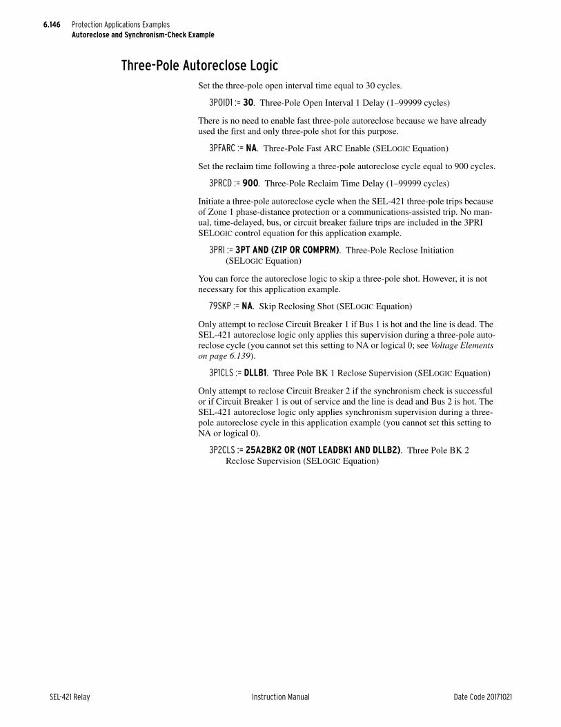
6.146
SEL-421 Relay Instruction Manual Date Code 20171021
Protection Applications ExamplesAutoreclose and Synchronism-Check Example
Three-Pole Autoreclose LogicSet the three-pole open interval time equal to 30 cycles.
3POID1 := 30. Three-Pole Open Interval 1 Delay (1–99999 cycles)
There is no need to enable fast three-pole autoreclose because we have already used the first and only three-pole shot for this purpose.
3PFARC := NA. Three-Pole Fast ARC Enable (SELOGIC Equation)
Set the reclaim time following a three-pole autoreclose cycle equal to 900 cycles.
3PRCD := 900. Three-Pole Reclaim Time Delay (1–99999 cycles)
Initiate a three-pole autoreclose cycle when the SEL-421 three-pole trips because of Zone 1 phase-distance protection or a communications-assisted trip. No man-ual, time-delayed, bus, or circuit breaker failure trips are included in the 3PRI SELOGIC control equation for this application example.
3PRI := 3PT AND (Z1P OR COMPRM). Three-Pole Reclose Initiation (SELOGIC Equation)
You can force the autoreclose logic to skip a three-pole shot. However, it is not necessary for this application example.
79SKP := NA. Skip Reclosing Shot (SELOGIC Equation)
Only attempt to reclose Circuit Breaker 1 if Bus 1 is hot and the line is dead. The SEL-421 autoreclose logic only applies this supervision during a three-pole auto-reclose cycle (you cannot set this setting to NA or logical 0; see Voltage Elements on page 6.139).
3P1CLS := DLLB1. Three Pole BK 1 Reclose Supervision (SELOGIC Equation)
Only attempt to reclose Circuit Breaker 2 if the synchronism check is successful or if Circuit Breaker 1 is out of service and the line is dead and Bus 2 is hot. The SEL-421 autoreclose logic only applies synchronism supervision during a three-pole autoreclose cycle in this application example (you cannot set this setting to NA or logical 0).
3P2CLS := 25A2BK2 OR (NOT LEADBK1 AND DLLB2). Three Pole BK 2 Reclose Supervision (SELOGIC Equation)

6.147
Date Code 20171021 Instruction Manual SEL-421 Relay
Protection Applications ExamplesAutoreclose and Synchronism-Check Example
Voltage Elements
Enable the voltage check elements.
EVCK := Y. Reclosing Voltage Check (Y, N)
Set the dead line voltage threshold equal to 15 V secondary.
27LP := 15.0. Dead Line Voltage (1.0–200 V secondary)
Set the live line voltage threshold equal to 50 V secondary.
59LP := 50.0. Live Line Voltage (1.0–200 V secondary)
Set the dead bus voltage threshold for Circuit Breakers 1 and 2 equal to 15 volts secondary.
27BK1P := 15.0. Breaker 1 Dead Busbar Voltage (1.0–200 V secondary)
27BK2P := 15.0. Breaker 2 Dead Busbar Voltage (1.0–200 V secondary)
Set the live bus voltage threshold for Circuit Breakers 1 and 2 equal to 50 V sec-ondary.
59BK1P := 50.0. Breaker 1 Live Busbar Voltage (1.0–200 V secondary)
59BK2P := 50.0. Breaker 2 Live Busbar Voltage (1.0–200 V secondary)
Trip LogicIf you want Circuit Breaker 2 to always three-pole trip, except when Circuit Breaker 2 is the leader, program SELOGIC control equation E3PT2 as follows:
E3PT2 := NOT LEADBK2. Breaker 2 3PT (SELOGIC Equation)
Synchronism-Check ApplicationReclose Circuit Breaker 1 following a three-pole trip if the line is dead and Bus 1 is hot. Reclose Circuit Breaker 2 following a three-pole trip if a synchronism check across the hot line to Bus 2 is successful or Circuit Breaker 1 is out of ser-vice and the line is dead and Bus 2 is hot.
Figure 6.39 Potential Sources
BUS 1
VAZ
VY
(Bus Potential) (Bus Potential)
(Line Potential)
Follower
Line DisconnectSEL-421 Relay
Leader
VBZ
from BUS 2CB1 CB2
3
11

6.148
SEL-421 Relay Instruction Manual Date Code 20171021
Protection Applications ExamplesAutoreclose and Synchronism-Check Example
In this application example, the relay does not perform a synchronism check on single-pole reclosing.
Synchronism-Check SolutionApply the synchronism-check function as follows for Circuit Breaker 2:
➤ Use the A-Phase voltages from the line and Bus 2 for the synchronism check across Circuit Breaker 2.
➤ Select the high voltage magnitude and low voltage magnitude thresholds for the synchronism check.
➤ Select the maximum voltage angle difference allowed for both reclosing and manual closing.
➤ Select conditions that block the synchronism check.
Synchronism-Check Relay SettingsSelect the relay settings for this application example.
Relay ConfigurationEnable synchronism check for Circuit Breaker 2 only.
E25BK1 := N. Synchronism Check for Breaker 1 (Y, N, Y1, Y2)
E25BK2 := Y. Synchronism Check for Breaker 2 (Y, N, Y1, Y2)
Synchronism-Check Element ReferenceSelect A-Phase voltage from the line source for the synchronism check reference. VAY is the reference for the synchronism check because this analog input is con-nected to the line potential.
SYNCP := VAY. Synch Reference (VAY, VBY, VCY, VAZ, VBZ, VCZ)
Set the low-voltage threshold that supervises synchronism check equal to 60 V secondary.
25VL := 60.0. Voltage Window Low Threshold (20.0–200 V secondary)
Set the high-voltage threshold that supervises synchronism check equal to 70 V secondary.
25VH := 70.0. Voltage Window High Threshold (20.0–200 V secondary)
Circuit Breaker 2 Synchronism CheckSelect A-Phase voltage from Bus 2 for the synchronism check source. VBZ is the source for the synchronism check because this is the bus potential.
SYNCS2 := VBZ. Synch Source 2 (VAY, VBY, VCY, VAZ, VBZ, VCZ)
Both the line reference and bus source voltages are measured line-to-neutral. Set the ratio factor equal to unity.
KS2M : = 1.00. Synch Source 2 Ratio Factor (0.000–30)

6.149
Date Code 20171021 Instruction Manual SEL-421 Relay
Protection Applications ExamplesAutoreclose and Synchronism-Check Example
You do not need to shift the angle of the synchronism check because both the source and reference voltage are measured A-Phase-to-neutral.
KS2A := 0. Synch Source 2 Angle Shift (0, 30, 60, 90, 120, 150, 180, 210, 240, 270, 300, 330 degrees)
There is no alternate synchronism source for Circuit Breaker 2 in this application example.
ALTS2 := NA. Alternative Synch Source 2 (SELOGIC Equation)
Assume that there is no slip between the source and reference voltages.
25SFBK2 := OFF. Maximum Slip Frequency—BK2 (OFF, 0.005–0.5 Hz)
Set the maximum allowable voltage angular difference between the source and reference voltages equal to 20 degrees when attempting to reclose Circuit Breaker 2.
ANG1BK2 := 20.0. Maximum Angle Difference 1—BK2 (3.0–80 degrees)
Set the maximum allowable voltage angular difference between the source and reference voltages equal to 20 degrees when attempting to manually close Circuit Breaker 2.
ANG2BK2 := 20.0. Maximum Angle Difference 2—BK2 (3.0–80 degrees)
The relay does not compensate the synchronism check to account for circuit breaker closing time because setting 25SFBK2 is OFF. Leave the close time com-pensation setting at the default.
TCLSBK2 := 1.00. Breaker 2 Close Time (1.00–30 cycles)
Block the synchronism check if Circuit Breaker 2 is closed.
BSYNBK2 := 52AA2 AND 52AB2 AND 52AC2. Block Synchronism Check—BK2 (SELOGIC Equation)
Example CompleteThis completes the application example that describes setting the SEL-421 for one shot of high-speed single-pole reclosing and one shot of three-pole reclosing for two circuit breakers. This example showed a configuration for synchronism check, as well. Analyze your particular power system to determine the appropri-ate settings for your application.
Relay SettingsTable 6.40 provides a list of all the SEL-421 autoreclose settings.
Table 6.40 Settings for Autoreclose and Synchronism Check Example (Sheet 1 of 3)
Setting Prompt Entry
Recloser Closing (Group)
E79 Reclosing (Y, Y1, N) Y
NSPSHOT Number of Single-Pole Reclosures (N, 1, 2) 1
ESPR1 Single-Pole Reclose Enable—BK1 (SELOGIC Equation) IN205
ESPR2 Single-Pole Reclose Enable—BK2 (SELOGIC Equation) IN206

6.150
SEL-421 Relay Instruction Manual Date Code 20171021
Protection Applications ExamplesAutoreclose and Synchronism-Check Example
N3PSHOT Number of Three-Pole Reclosures (N, 1–4) 1
E3PR1 Three-Pole Reclose Enable—BK1 (SELOGIC Equation) IN207
E3PR2 Three-Pole Reclose Enable—BK2 (SELOGIC Equation) IN208
TBBKD Time Between Breakers for Automatic Reclose (1–99999 cycles)
15
BKCFD Breaker Close Failure Delay (OFF, 1–99999 cycles) 600
SLBK1 Lead Breaker = Breaker 1(SELOGIC Equation) IN107
SLBK2 Lead Breaker = Breaker 2 (SELOGIC Equation) 0
FBKCEN Follower Breaker Closing Enable (SELOGIC Equation) 3POBK2 OR NOT LEADBK1
ULCL1 Unlatch Closing for Breaker 1 (SELOGIC Equation) 52AA1 AND 52AB1 AND 52AC1
ULCL2 Unlatch Closing for Breaker 2 (SELOGIC Equation) 52AA2 AND 52AB2 AND 52AC2
79DTL Recloser Drive to Lockout (SELOGIC Equation) LOP
79BRCT Block Reclaim Timer (SELOGIC Equation) NA
3PMRCD Manual Close Reclaim Time Delay (1–99999 cycles) 900
BK1CLSD BK1 Reclose Supervision Delay (OFF, 1–99999 cycles) 300
BK2CLSD BK2 Reclose Supervision Delay (OFF, 1–99999 cycles) 300
Single-Pole Reclose (Group)
SPOID Single-Pole Open Interval Delay (1–99999 cycles) 60
SPRCD Single-Pole Reclaim Time Delay (1–99999 cycles) 900
SPRI Single-Pole Reclose Initiation (SELOGIC Equation) SPT AND (Z1G AND COMPRM)
SP1CLSa Single-Pole BK1 Reclose Supervision (SELOGIC control equation)
1
SP2CLSa Single-Pole BK2 Reclose Supervision (SELOGIC Equation)
NOT LEADBK1
Three-Pole Reclose (Group)
3POID1 Three-Pole Open Interval 1 Delay (1–99999 cycles) 30
3PFARC Three-Pole Fast autoreclose Enable (SELOGIC Equation) NA
3PRCD Three-Pole Reclaim Time Delay (1–99999 cycles) 900
3PRI Three-Pole autoreclose Initiate (SELOGIC Equation) 3PT AND (Z1P OR COMPRM)
79SKP Skip Reclosing Shot (SELOGIC Equation) NA
3P1CLSa Three-Pole BK 1 Reclose Supervision (SELOGIC Equation)
DLLB1
3P2CLSa Three-Pole BK 2 Reclose Supervision (SELOGIC Equation)
25A2BK2 OR (NOT LEADBK1 AND DLLB2)
Voltage Elements (Group)
EVCK Reclosing Voltage Check (Y, N) Y
27LP Dead Line Voltage (1.0–200 V secondary) 15.0
59LP Live Line Voltage (1.0–200 V secondary) 50.0
Table 6.40 Settings for Autoreclose and Synchronism Check Example (Sheet 2 of 3)
Setting Prompt Entry
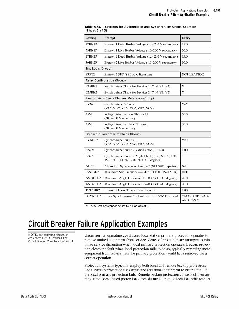
6.151
Date Code 20171021 Instruction Manual SEL-421 Relay
Protection Applications ExamplesCircuit Breaker Failure Application Examples
Circuit Breaker Failure Application ExamplesNOTE: The following discussion designates Circuit Breaker 1. For Circuit Breaker 2, replace the 1 with 2.
Under normal operating conditions, local station primary protection operates to remove faulted equipment from service. Zones of protection are arranged to min-imize service disruption when local primary protection operates. Backup protec-tion clears the fault when local protection fails to do so, typically removing more equipment from service than the primary protection would have removed for a correct operation.
Protection systems typically employ both local and remote backup protection. Local backup protection uses dedicated additional equipment to clear a fault if the local primary protection fails. Remote backup protection consists of overlap-ping, time-coordinated protection zones situated at remote locations with respect
27BK1P Breaker 1 Dead Busbar Voltage (1.0–200 V secondary) 15.0
59BK1P Breaker 1 Live Busbar Voltage (1.0–200 V secondary) 50.0
27BK2P Breaker 2 Dead Busbar Voltage (1.0–200 V secondary) 15.0
59BK2P Breaker 2 Live Busbar Voltage (1.0–200 V secondary) 50.0
Trip Logic (Group)
E3PT2 Breaker 2 3PT (SELOGIC Equation) NOT LEADBK2
Relay Configuration (Group)
E25BK1 Synchronism Check for Breaker 1 (Y, N, Y1, Y2) N
E25BK2 Synchronism Check for Breaker 2 (Y, N, Y1, Y2) Y
Synchronism-Check Element Reference (Group)
SYNCP Synchronism Reference (VAY, VBY, VCY, VAZ, VBZ, VCZ)
VAY
25VL Voltage Window Low Threshold (20.0–200 V secondary)
60.0
25VH Voltage Window High Threshold (20.0–200 V secondary)
70.0
Breaker 2 Synchronism Check (Group)
SYNCS2 Synchronism Source 2 (VAY, VBY, VCY, VAZ, VBZ, VCZ)
VBZ
KS2M Synchronism Source 2 Ratio Factor (0.10–3) 1.00
KS2A Synchronism Source 2 Angle Shift (0, 30, 60, 90, 120, 150, 180, 210, 240, 270, 300, 330 degrees)
0
ALTS2 Alternative Synchronism Source 2 (SELOGIC Equation) NA
25SFBK2 Maximum Slip Frequency—BK2 (OFF, 0.005–0.5 Hz) OFF
ANG1BK2 Maximum Angle Difference 1—BK2 (3.0–80 degrees) 20.0
ANG2BK2 Maximum Angle Difference 2—BK2 (3.0–80 degrees) 20.0
TCLSBK2 Breaker 2 Close Time (1.00–30 cycles) 1.00
BSYNBK2 Block Synchronism Check—BK2 (SELOGIC Equation) 52AA2 AND 52AB2 AND 52AC2
a These settings cannot be set to NA or logical 0.
Table 6.40 Settings for Autoreclose and Synchronism Check Example (Sheet 3 of 3)
Setting Prompt Entry

6.152
SEL-421 Relay Instruction Manual Date Code 20171021
Protection Applications ExamplesCircuit Breaker Failure Application Examples
to the local terminal. Remote backup protection operates if a fault outside the local protection zone persists. Circuit breaker failure relaying is local backup protection.
The SEL-421 features four types of circuit breaker failure and retrip protection capability:
1. Failure to interrupt fault current for phase currents
2. No current/residual current circuit breaker failure protection
3. Failure to interrupt load current
4. Flashover circuit breaker failure protection
Protection against failure to interrupt fault current for phase currents is the most common implementation. This subsection describes failure to interrupt fault cur-rent circuit breaker failure protection.
Failure to Interrupt Fault Current for Phase CurrentsThe SEL-421 provides two schemes for failure to interrupt fault current for phase currents. Scheme 1 is protection for basic cases involving both multiphase faults and single-phase faults with a common breaker failure time delay. Scheme 2 is for more elaborate protection that discriminates between multiphase and single-phase faults and features separate circuit breaker failure time delays. Use Scheme 2 for separate circuit breaker failure timing for three-pole and single-pole faults.
Basic Operation—Scheme 1 and Scheme 2NOTE: The following discussion specifies three elements. There is one element for each phase: =A, B, and C).
A trip output from the local primary or backup line protection typically initiates the failure to interrupt fault current circuit breaker failure scheme (BFI3P1 and BFI1 for Scheme 1 or BFI1 for Scheme 2). When initiated, the relay starts cir-cuit breaker failure timing; the time delay is BFPU1 (Breaker Failure Time Delay—BK1). The SEL-421 does not require an external BFI contact when applied for local circuit breaker failure protection because the relay detects line faults. In addition, you can add external BFI from an input in parallel with the cir-cuit breaker trip coil to capture additional trip initiations to increase scheme dependability.
Set the instantaneous overcurrent element pickup threshold 50FP1 to pick up for all line faults. The relay asserts Relay Word bit 50F1 when the phase current exceeds the 50FP1 threshold. The 50F1 element must reset quickly even during the presence of subsidence current at the circuit breaker opening.
If 50F1 is asserted when timer BFPU1 expires, the relay asserts circuit breaker failure protection Relay Word bit FBF1 (Breaker 1 Breaker Failure). Assign FBF1 to SELOGIC control equation BFTR1 (Breaker Failure Trip—BK1) as one of the circuit breaker failure elements that can cause a circuit breaker failure trip. When SELOGIC control equation BFTRI asserts, the relay asserts corresponding Relay Word bit BFTRIP1 (Breaker 1 Failure Trip Output). Assign BFTRIP1 to a high-current interrupting control output to perform circuit breaker failure tripping or to a standard control output to operate an 86 lockout relay.

6.153
Date Code 20171021 Instruction Manual SEL-421 Relay
Protection Applications ExamplesCircuit Breaker Failure Application Examples
Scheme ComponentsThe following are components of the circuit breaker failure schemes in the SEL-421:
➤ Circuit Breaker Failure Initiation (BFI3P1 or BFI1)
➤ Phase Fault Current Pickup (50FP1)
➤ Breaker Failure Pickup Time Delay (BFPU1)
For a detailed description see Circuit Breaker Failure Trip Logic on page 5.154.
Circuit Breaker Failure Initiation (BFI3P1 or BFI1)
All circuit breaker trips typically initiate the circuit breaker failure scheme. The SEL-421 detects power system faults; the relay does not need an external BFI contact for local circuit breaker failure protection applications.
Scheme 1
Scheme 1 uses initiation SELOGIC control equation BFI3P1 for three-pole trip-ping applications and BFI1 for single-pole tripping applications.
Scheme 2
Scheme 2 uses initiation SELOGIC control equations BFI1 for both three-pole (multiphase) and single-phase faults.
Phase Fault Current Pickup (50FP1)
Circuit breaker failure protection must pick up for all faults on the protected line. Two settings philosophies are prevalent. One philosophy is to set the instanta-neous overcurrent element (50F1) to pick up above load current and below the minimum fault current (under minimum generation), if possible (Iload max < 50FP1 < Iminimum fault). Another settings philosophy is to set the threshold to match the line protection sensitivity; this increases circuit breaker failure protec-tion dependability.
In the following application examples, we use the first settings philosophy because this approach gives greater security. In either case, when input phase cur-rents exceed the overcurrent element threshold, the relay asserts Relay Word bit 50F1.
Subsidence current results from the energy trapped in the CT magnetizing branch after the circuit breaker opens to clear a fault or interrupt load. Subsidence cur-rent exponentially decays and delays resetting of instantaneous overcurrent ele-ments. However, the open-phase detection logic causes the SEL-421 50F1 element to reset in less than one cycle during subsidence current conditions. The open-phase detection logic determines that a pol e is open during the presence of subsidence current and immediately resets the corresponding current level detectors.
Breaker Failure Pickup Time Delay (BFPU1)Scheme 1
Relay Word bit FBF1 (Breaker 1 Breaker Failure) asserts when the time delay on pickup timer BFPU1 expires and the corresponding 50F1 element is asserted.

6.154
SEL-421 Relay Instruction Manual Date Code 20171021
Protection Applications ExamplesCircuit Breaker Failure Application Examples
Scheme 2
Relay Word bit FBF1 (Breaker 1 Breaker Failure) asserts for these conditions:
➤ A single phase-to-ground fault occurs: FBF1 asserts when time delay on pickup timers BFPU1 (Breaker Failure Time Delay—BK1) followed by SPBFPU1 (SPT Breaker Failure Time Delay—BK1) expire. The corresponding 50FP1 element and only one single-phase breaker failure initiation (for example, BFIA1) are asserted.
➤ A multiphase fault occurs: FBF1 asserts when time delay on pickup timer BFPU1 (Breaker Failure Time Delay—BK1) expires. The corresponding 50F1 elements and at least two single-phase breaker failure initiations (for example, BFIA1 and BFIB1) are asserted.
Timing SequenceFigure 6.40 and Figure 6.41 illustrate the timing sequence for circuit breaker fail-ure schemes.
Scheme 1
Scheme 1 follows Figure 6.40.
Scheme 2
Scheme 2 uses both timing sequences in Figure 6.40 and Figure 6.41, depending on the fault type (multiphase fault and single-phase fault, respectively).
Figure 6.40 Scheme 1 All Faults and Scheme 2 Multiphase Fault Timing Diagram
50Fφn ElementAsserts
TransferTrip
Asserts
BF TripOutputs Assert
BF Timer Delay (BFPU)
Communications Channel Time
Absolute Maximum Fault Clearing Time
tLocal Backup Breakers Trip
Time
Remote BreakersTrip Time
Protective RelayOperate Time
Maximum BreakerOperating Time
50FφnDropout Time
Safety Margin Time
Fault Occurs
Trip AssertsNormal
Operation
BreakerFailure
Operation
Auxiliary Breaker FailureRelay Operate Time

6.155
Date Code 20171021 Instruction Manual SEL-421 Relay
Protection Applications ExamplesCircuit Breaker Failure Application Examples
The absolute maximum fault clearing time depends on power system transient stability and the thermal withstand capability of the equipment. If a circuit breaker fails, the total time required to trip all electrically adjacent circuit break-ers must be less than this absolute maximum clearing time. Set the time delay on pickup timer to allow time for the protected circuit breaker to operate and the instantaneous overcurrent element (50F1) to reset. Always include a safety mar-gin, remembering that the operating time of the line relays and the electrically adjacent circuit breakers limit this margin.
Circuit Breaker Failure Protection—Example 1Use the SEL-421 to provide circuit breaker failure protection for one circuit breaker. This is a circuit breaker failure protection Scheme 1 application example for three-pole tripping circuit breakers (you can also use this scheme for single-pole tripping applications). For a single-pole tripping circuit breaker application example (Scheme 2), see Circuit Breaker Failure Protection—Example 2 on page 6.161. This example uses a 230 kV power system similar to the system in 230 kV Overhead Distribution Line Example. Figure 6.42 shows the SEL-421 at the S terminal of the two-terminal line between Harvard and Princeton. Table 6.41 provides the related power system parameters.
Figure 6.41 Scheme 2 Single-Phase Fault Timing Diagram
50Fφn ElementAsserts
TransferTrip
Asserts
BF TripOutputsAssert
BF Timer Delay (BFPU)
Communications Channel Time
Absolute Maximum Fault Clearing Time
tLocal Backup
Breakers OperateTime
Remote BreakersTrip Time
Protective RelayOperate Time
Maximum BreakerOperating Time
50FφnDropout Time
Safety Margin Time
SPBF Timer Delay (SPBFPU)
Fault Occurs
Trip Asserts
NormalOperation
BreakerFailure
Operation
Auxiliary Breaker FailureRelay Operate Time
Figure 6.42 230 kV Power System for Circuit Breaker Failure Scheme 1
SEL-421
BK1IW
S (Harvard) R (Princeton)
BK2

6.156
SEL-421 Relay Instruction Manual Date Code 20171021
Protection Applications ExamplesCircuit Breaker Failure Application Examples
Relay ConfigurationEnable Scheme 1 circuit breaker failure protection for Circuit Breaker BK1.
EBFL1 := 1. Breaker 1 Failure Logic (N, 1, 2, Y1, Y2)
Circuit Breaker 1 Failure LogicPhase Current Level Detector
NOTE: This is one method for calculating setting 50FP1. Use your company practices and policies for determining the pickup setting for your particular application.
Set the phase current level detector equal to 120 percent of the maximum load current Iload. Check that this setting is less than the minimum fault current ( fault) with minimum generation. Circuit breaker failure protection for faults involving ground (SLG and G faults) is covered in this application example by no current/residual current circuit breaker failure protection (see Residual Cur-rent Circuit Breaker Failure Protection on page 6.158). This settings philosophy provides security for the circuit breaker failure protection. For this power system, the maximum load current is 4.95 A secondary and the minimum fault current is 13.0 A secondary.
50FP1 = 120% • Iload = 120% • 4.95 A = 5.94 A
50FP1 := 5.94. Phase Fault Current Pickup—BK1 (0.50–50 A secondary)
Circuit Breaker Failure Protection Time Delay
The recommended setting for BFPU1 (Breaker Failure Time Delay—BK1) is the sum of the following (see Figure 6.43):
➤ Maximum circuit breaker operating time
➤ 50FA1 maximum dropout time
➤ Safety margin
Table 6.41 Secondary Quantities
Parameter Value
Line impedances
Z1L
Z0L
1.95 84° secondary 6.2 81.5° secondary
Source S impedances
Z1S = Z0S
2.5 86° secondary
Source R impedances
Z1R = Z0R
2.5 86° secondary
Nominal frequency (fNOM) 60 Hz
Maximum operating current load (Iload) 4.95 A secondary

6.157
Date Code 20171021 Instruction Manual SEL-421 Relay
Protection Applications ExamplesCircuit Breaker Failure Application Examples
To maintain system stability, the relay must clear the fault within the total clear-ing time. Use the maximum operating time of the local and remote circuit break-ers. The maximum operating time of the circuit breaker, tl-bk, is 3 cycles for this example. Also, use the maximum dropout time for Relay Word bit 50FA1; the maximum dropout time of the phase current level detector, t50r, is 1 cycle. You must also include the communications channel time, tch, for remote circuit breaker tripping.
To determine setting BFPU1, you must find the safety margin, ts. Determine the safety margin from Figure 6.40:
Equation 6.89
Use the safety margin result from Equation 6.89 to calculate BFPU1:
Equation 6.90
BFPU1 := 10.000. Breaker Failure Time Delay—BK1 (0.000–6000 cycles)
Figure 6.43 Timing Diagram for Setting BFPU1—Scheme 1
BreakerOperate Time tl-bk
BFPU1
Line ProtectionMaximum Operate Time
Fault Occurs
50FA1
BFI3P1
FBF1
50FA1Dropout Time, t50r
SafetyMargin Time, ts
where:
ts = safety margin
tt = total clearing time (17 cycles)
tlr = line protection maximum operating time (2 cycles)
tl-bk = local circuit breaker maximum operating time (3 cycles)
t50r = circuit breaker failure overcurrent element 50FA1 maximum reset time (1 cycle)
t86 = auxiliary breaker failure relay operating time (1 cycle)
tch = communications channel maximum operating time (1 cycle)
tr-bk = remote circuit breaker maximum operating time (3 cycles)
ts tt t1r t1 bk– t50r t86 tch tr bk–+ + + + + –=
17 2 3 1 1 1 3+ + + + + –=
6 cycles=
BFPU1 t1 bk– t50r ts+ +=
3 1 6+ +=
10 cycles=
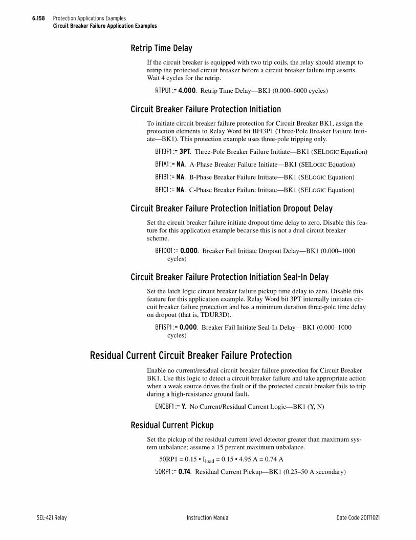
6.158
SEL-421 Relay Instruction Manual Date Code 20171021
Protection Applications ExamplesCircuit Breaker Failure Application Examples
Retrip Time Delay
If the circuit breaker is equipped with two trip coils, the relay should attempt to retrip the protected circuit breaker before a circuit breaker failure trip asserts. Wait 4 cycles for the retrip.
RTPU1 := 4.000. Retrip Time Delay—BK1 (0.000–6000 cycles)
Circuit Breaker Failure Protection Initiation
To initiate circuit breaker failure protection for Circuit Breaker BK1, assign the protection elements to Relay Word bit BFI3P1 (Three-Pole Breaker Failure Initi-ate—BK1). This protection example uses three-pole tripping only.
BFI3P1 := 3PT. Three-Pole Breaker Failure Initiate—BK1 (SELOGIC Equation)
BFIA1 := NA. A-Phase Breaker Failure Initiate—BK1 (SELOGIC Equation)
BFIB1 := NA. B-Phase Breaker Failure Initiate—BK1 (SELOGIC Equation)
BFIC1 := NA. C-Phase Breaker Failure Initiate—BK1 (SELOGIC Equation)
Circuit Breaker Failure Protection Initiation Dropout Delay
Set the circuit breaker failure initiate dropout time delay to zero. Disable this fea-ture for this application example because this is not a dual circuit breaker scheme.
BFIDO1 := 0.000. Breaker Fail Initiate Dropout Delay—BK1 (0.000–1000 cycles)
Circuit Breaker Failure Protection Initiation Seal-In Delay
Set the latch logic circuit breaker failure pickup time delay to zero. Disable this feature for this application example. Relay Word bit 3PT internally initiates cir-cuit breaker failure protection and has a minimum duration three-pole time delay on dropout (that is, TDUR3D).
BFISP1 := 0.000. Breaker Fail Initiate Seal-In Delay—BK1 (0.000–1000 cycles)
Residual Current Circuit Breaker Failure ProtectionEnable no current/residual circuit breaker failure protection for Circuit Breaker BK1. Use this logic to detect a circuit breaker failure and take appropriate action when a weak source drives the fault or if the protected circuit breaker fails to trip during a high-resistance ground fault.
ENCBF1 := Y. No Current/Residual Current Logic—BK1 (Y, N)
Residual Current Pickup
Set the pickup of the residual current level detector greater than maximum sys-tem unbalance; assume a 15 percent maximum unbalance.
50RP1 = 0.15 • Iload = 0.15 • 4.95 A = 0.74 A
50RP1 := 0.74. Residual Current Pickup—BK1 (0.25–50 A secondary)

6.159
Date Code 20171021 Instruction Manual SEL-421 Relay
Protection Applications ExamplesCircuit Breaker Failure Application Examples
Residual Current Circuit Breaker Failure Time Delay
Setting NPU1 is the time delay on pickup before the relay asserts a low current circuit breaker failure trip for Circuit Breaker BK1. You can set this delay greater than BFPU1; a high-resistance ground fault is not as much a threat to power sys-tem transient stability as is a phase fault, because synchronizing power still flows through the two unfaulted phases.
NPU1 := 12.000. No Current Breaker Failure Delay—BK1 (0.000–6000 cycles)
Residual Current Circuit Breaker Failure Initiation
This particular application uses the residual current circuit breaker failure scheme only to detect when the circuit breaker fails to trip during high-resistance ground faults. Set SELOGIC control equation BFIN1 (No Current Breaker Failure Initi-ate) to NA.
If you want to apply this scheme for no current conditions (e.g., weak source), assign the 52A contact from Circuit Breaker BK1 (52AA1) to the SELOGIC con-trol equation BFIN1 (No Current Breaker Failure Initiate).
BFIN1 := NA. No Current Breaker Failure Initiate—BK1 (SELOGIC Equation)
Load Current Circuit Breaker Failure ProtectionDisable load current circuit breaker failure protection for Circuit Breaker BK1.
ELCBF1 := N. Load Current Breaker Failure Logic—BK1 (Y, N)
Flashover Circuit Breaker Failure ProtectionDisable flashover current circuit breaker failure protection for Circuit Breaker BK1.
EFOBF1 := N. Flashover Breaker Failure Logic—BK1 (Y, N)
Circuit Breaker Failure Protection Trip LogicCircuit Breaker 1 Failure Trip Equation
The SEL-421 has dedicated circuit breaker failure trip logic. Set SELOGIC con-trol equation BFTR1 (Breaker Failure Trip—BK1) to assert for either Circuit Breaker BK1 circuit breaker failure trip or Circuit Breaker BK1 residual current circuit breaker failure trip. When this SELOGIC control equation asserts, the relay sets Relay Word bit BFTRIP1 to logical 1 until BFTR1 deasserts, the TDUR3D timer times out, and an unlatch or reset condition is active.
BFTR1 := FBF1 OR NBF1. Breaker Failure Trip—BK1 (SELOGIC Equation)
Unlatch Circuit Breaker 1 Failure Trip Equation
Use SELOGIC control equation BFULTR1 (Breaker Failure Unlatch Trip—BK1) to define the conditions that unlatch the control outputs that assert during a circuit breaker failure trip. BFULTR1 unlatches the circuit breaker trip condition

6.160
SEL-421 Relay Instruction Manual Date Code 20171021
Protection Applications ExamplesCircuit Breaker Failure Application Examples
BFTRIP1 (Breaker Failure Trip for Circuit Breaker BK1). Assign a control input that is energized externally to signal the relay when the circuit breaker failure trip clears the fault successfully.
BFULTR1 := IN104. Breaker Failure Unlatch Trip—BK1 (SELOGIC Equation)
Control OutputsUse SELOGIC control equations to assign control outputs for tripping Circuit Breaker BK1, retripping Circuit Breaker BK1, and circuit breaker failure trip-ping. Figure 6.44 shows dc connections for the circuit breaker failure trip and cir-cuit breaker trip/retrip.
Use the main board high current interrupting control output for the retrip signal (RT1) because this output can interrupt large circuit breaker coil currents. There is no TDUR3D (3PT Minimum Trip Duration Time Delay) for RT1; the RT1 sig-nal can drop out while there is current flowing through the trip coil, if the auxil-iary circuit breaker contacts have not yet opened.
OUT101 := 3PT.
OUT103 := RT1.
OUT107 := BFTRIP1.
Example CompletedThis completes the application example that describes setting of the SEL-421 for circuit breaker failure protection. Analyze your particular power system to deter-mine the appropriate settings for your application.
Relay SettingsTable 6.42 lists all protective relay settings applied for this example.
Figure 6.44 Circuit Breaker Failure Trip and Circuit Breaker Trip DC Connections
86-1
86-1
86-1BFTRIP1(OUT107)
DC1 (—) DC2 (—)
DC2 (+)DC1 (+)
TC-1
3PT(OUT101)
TRIP COIL #2TRIP COIL #1CBF LOCKOUT
TC-2
52AA1
RT1(OUT103)
DC3 (—)
DC3 (+)
52AA1
Table 6.42 Settings for Circuit Breaker Failure Example 1 (Sheet 1 of 2)
Setting Prompt Entry
Relay Configuration (Group)
EBFL1 Breaker 1 Failure Logic (N, 1, 2, Y1, Y2) 1

6.161
Date Code 20171021 Instruction Manual SEL-421 Relay
Protection Applications ExamplesCircuit Breaker Failure Application Examples
Circuit Breaker Failure Protection—Example 2Use the SEL-421 to provide circuit breaker failure protection for both circuit breakers in breaker-and-a-half schemes. This application example explains set-ting the relay for Circuit Breaker BK1 (see Figure 6.45). You can apply these same settings for Circuit Breaker BK2. You can apply circuit breaker failure Scheme 2 protection for single-pole trip circuit breakers. Scheme 2 provides sep-arate timers for multiphase faults (BFPU1) and single-phase faults (SPBFPU1). For more information on Scheme 2 circuit breaker failure protection, see Failure to Interrupt Fault Current: Scheme 2 on page 5.148.
NOTE: This application example is for two circuit breakers. Apply the same settings for Circuit Breaker BK2 as for Circuit Breaker BK1. For Circuit Breaker BK2, substitute 2 for 1 in the following settings.
This example uses a 500 kV power system with single-pole tripping enabled (see Figure 6.45). Table 6.43 provides the power system parameters.
Breaker 1 Failure Logic (Group)
50FP1 Phase Fault Current Pickup—BK1 (0.50–50 A secondary) 5.94
BFPU1 Breaker Failure Time Delay—BK1 (0.000–6000 cycles) 10.000
RTPU1 Retrip Time Delay—BK1 (0.000–6000 cycles) 4.000
BFI3PI Three-Pole Breaker Failure Initiate—BK1 (SELOGIC Equation) 3PT
BFIA1 A-Phase Breaker Failure Initiate—BK1 (SELOGIC Equation) NA
BFIB1 B-Phase Breaker Failure Initiate—BK1 (SELOGIC Equation) NA
BFIC1 C-Phase Breaker Failure Initiate—BK1 (SELOGIC Equation) NA
BFIDO1 Breaker Fail Initiate Dropout Delay—BK1 (0.000–1000 cycles) 0.000
BFISP1 Breaker Fail Initiate Seal-In Delay—BK1 (0.000–1000 cycles) 0.000
ENCBF1 No Current/Residual Current Logic—BK1 (Y, N) Y
50RP1 Residual Current Pickup—BK1 (0.25–50 A secondary) 0.74
NPU1 No Current Breaker Failure Delay—BK1 (0.000–6000 cycles) 12.000
BFIN1 No Current Breaker Failure Initiate—BK1 (SELOGIC Equation) NA
ELCBF1 Load Current Breaker Failure Logic—BK1 (Y, N) N
EFOBF1 Flashover Breaker Failure Logic—BK1 (Y, N) N
BFTR1 Breaker Failure Trip—BK1 (SELOGIC Equation) FBF1 OR NBF1
BFULTR1 Breaker Failure Unlatch Trip—BK1 (SELOGIC Equation) IN104
Main Board (Outputs)
OUT101 3PT
OUT103 RT1
OUT107 BFTRIP1
Table 6.42 Settings for Circuit Breaker Failure Example 1 (Sheet 2 of 2)
Setting Prompt Entry

6.162
SEL-421 Relay Instruction Manual Date Code 20171021
Protection Applications ExamplesCircuit Breaker Failure Application Examples
Relay ConfigurationEnable Scheme 2 circuit breaker failure protection for two circuit breakers.
EBFL1 := 2. Breaker 1 Failure Logic (N, 1, 2, Y1, Y2)
EBFL2 := 2. Breaker 2 Failure Logic (N, 1, 2, Y1, Y2)
Circuit Breaker 1 Failure LogicPhase Current Level Detector
Set the phase fault current pickup greater than maximum load and less than the fault current that flows through Circuit Breaker BK1 (IS(BK1)). Maximum load current, IS, is 3.25 A secondary.
Figure 6.45 500 kV Power System for Circuit Breaker Failure Scheme 2
Table 6.43 Secondary Quantities
Parameter Value
Line impedances
Z1L1
Z0L1
3.98 87.6° secondary
14.48 82.1° secondary
Source S impedances
Z1S = Z0S 4.4 88° secondary
Source R impedances
Z1R = Z0R 1.78 88° secondary
Nominal frequency (fNOM) 60 Hz
Maximum operating current (Iload) 3.25 A secondary
Line 1
Line 2
S (MOSCOW) R (PULLMAN)
BK1
BK2
BUS 1
IWIX
SEL-421
BUS 2

6.163
Date Code 20171021 Instruction Manual SEL-421 Relay
Protection Applications ExamplesCircuit Breaker Failure Application Examples
Assume that the total load current (IS) supplied from Substation S flows through BK1 only; IS(BK1) = IS (see Figure 6.46). Calculate setting 50FP1 with all the load current IS through Circuit Breaker BK1.
Equation 6.91
A fault study shows that the minimum ground fault current, Ifault minimum, is 4.2 A secondary when the parallel line is in service at minimum generation. Cal-culate the 50FP1 setting for dependability at 1/2 of the minimum fault current.
Equation 6.92
Although the result of this setting calculation is below maximum load (see Equation 6.91), use this calculation to set the 50FP1 element for dependability.
50FP1 := 2.10. Phase Fault Current Pickup—BK1 (0.50–50 A secondary)
Circuit Breaker Failure Time DelayNOTE: This is one method for calculating setting 50FP1. Use your company practices and policies for determining the pickup setting for your particular application.
BFPU1 (Breaker Failure Time Delay—BK1) is the time delay on pickup for a circuit breaker trip following a multiphase fault. You can also add an additional delay, SPBFPU1 (SPT Breaker Failure Time Delay—BK1).
The recommended setting for BFPU1 is the sum of the following (see Figure 6.47):
➤ Maximum circuit breaker operating time
➤ 50FA1 maximum dropout time
➤ Safety margin
Figure 6.46 Fault Current Distribution Through Faulted Line at Station S
IS
IS(BK1)
BK1
BK2
IWSEL-421
IS(BK2)
50FP1 120% Percent Current IS• • =
120% 100% 3.25 A• • =
3.91 A secondary=
50FP1 0.5 Percent Current Ifault-minimum• • =
0.5 100% 4.20 A• • =
2.10 A secondary=

6.164
SEL-421 Relay Instruction Manual Date Code 20171021
Protection Applications ExamplesCircuit Breaker Failure Application Examples
To maintain system stability, you must clear the fault within the total clearing time. Use the maximum operating time of the local and remote circuit breakers. The maximum operating time of the circuit breaker, tl-bk, is 2 cycles for this example. Also use the maximum reset time of 50FA1; the maximum reset (drop-out) time of the phase current level detector, t50r, is 1 cycle. You must also include the communications channel time, tch, for remote circuit breaker tripping.
To determine setting BFPU1, you must find the safety margin, ts. Determine the safety margin from Figure 6.40.
Equation 6.93
Use the safety margin result from Equation 6.94 to calculate BFPU1:
Equation 6.94
BFPU1 := 10.000. Breaker Failure Time Delay—BK1 (0.000–6000 cycles)
Figure 6.47 Timing Diagram for Setting BFPU1—Scheme 2
BreakerOperate Time tl-bk
BFPU1 SPBFPU1
Line ProtectionMaximum Operate Time
Fault Occurs
50FA1
BFIA1
FBF1
50FA1Dropout Time, t50r
SafetyMargin Time, ts
where:
ts = safety margin
tt = total clearing time (15 cycles)
tlr = line protection maximum operating time (2 cycles)
tl-bk = local circuit breaker maximum operating time (2 cycles)
t50r = circuit breaker failure overcurrent element 50FA1 maximum reset time (1 cycle)
t86 = auxiliary breaker failure relay operating time (1 cycle)
tch = communications channel maximum operating time (1 cycle)
tr-bk = remote circuit breaker maximum operating time (2 cycles)
ts tt t1r t1 bk– t50r t86 tch tr bk–+ + + + + –=
15 2 2 1 1 1 2+ + + + + –=
6 cycles=
BFPU1 t1 bk– t50r ts+ +=
3 1 6+ +=
10 cycles=

6.165
Date Code 20171021 Instruction Manual SEL-421 Relay
Protection Applications ExamplesCircuit Breaker Failure Application Examples
SPBFPU1 is an additional delay you can cascade to BFPU1 for single-phase faults (see Figure 6.48). Set SPBFPU1 to extend breaker failure pickup time delay as long as the total clearing time tt = 15 cycles.
SPBFPU1 := 5.000. SPT Breaker Failure Time Delay—BK1 (0.000–6000 cycles)
Retrip Time Delay
Scheme 2 provides retrip timers RT3PPU1 for multiphase faults and RTPU1 for single-phase faults. Set the retrip following a single-pole trip to occur 3 cycles after circuit breaker failure initiation.
RTPU1 := 3.000. Retrip Time Delay—BK1 (0.000–6000 cycles)
A three-pole retrip follows a three-pole trip. The relay should attempt to retrip the protected circuit breaker before a circuit breaker failure trip asserts. Apply the default setting for the three-pole retrip time delay on pickup.
RT3PPU1 := 3.000. Three-Pole Retrip Time Delay—BK1 (0.000–6000 cycles)
Figure 6.48 compares the complete timing sequence for single-pole versus three-pole circuit breaker failure operations.
Circuit Breaker Failure Initiation
Scheme 2 does not use Relay Word bit BFI3P1 to initiate failure to interrupt fault current circuit breaker failure protection.
BFI3P1 := NA. Three-Pole Breaker Failure Initiate—BK1 (SELOGIC Equation)
Figure 6.48 Timing Sequences for Circuit Breaker Failure Protection Scheme 2
3-Pole Event(AB Fault)
BFIA1
50FA1 RT3PPU1
BFPU1
BFIB1
RT3P1
FBF1
1-Pole Event(AG Fault)
50FA1
RTPU1
BFPU1
BFIA1
RTA1
FBF1
SPBFPU1

6.166
SEL-421 Relay Instruction Manual Date Code 20171021
Protection Applications ExamplesCircuit Breaker Failure Application Examples
Assign the protection elements to Relay Word bits BFIA1, BFIB1, and BFIC1 to initiate single-pole trip circuit breaker failure protection for Circuit Breaker BK1. For a complete description of circuit breaker failure initiation, see Circuit Breaker Failure Protection on page 5.146. This application example uses the POTT tripping scheme, step-distance backup protection, and SOTF protection.
BFIA1 := BFIAT1 OR TPA1. A-Phase Breaker Failure Initiate—BK1 (SELOGIC Equation)
BFIB1 := BFIBT1 OR TPB1. B-Phase Breaker Failure Initiate—BK1 (SELOGIC Equation)
BFIC1 := BFICT1 OR TPC1. C-Phase Breaker Failure Initiate—BK1 (SELOGIC Equation)
Relay Word bits BFIAT1, BFIBT1, and BFICT1 (Circuit Breaker 1 Latched Sin-gle-Pole Circuit Breaker Failure Initiation) latch the BFIA1, BFIB1, and BFIC1 inputs to the circuit breaker failure protection.
Circuit Breaker Failure Protection Initiation Dropout Delay
Set the circuit breaker failure initiate time delay on dropout to stretch a short pulsed circuit breaker failure initiation. Enable this feature for this application example because you are protecting dual circuit breakers.
BFIDO1 := 3.000. Breaker Failure Initiate Dropout Delay—BK1 (0.000–1000 cycles)
Circuit Breaker Failure Protection Initiation Seal-In Delay
Set the circuit breaker failure initiate time delay on pickup for the latch logic to qualify extended circuit breaker failure initiation latch seal-in.
BFISP1 := 4.000. Breaker Failure Initiate Seal-In Delay—BK1 (0.000–1000 cycles)
For these BFIDO1 and BFISP1 settings, if the circuit breaker failure initiate is 1 cycle or more, the relay seals in the circuit breaker failure extended initiation after the initiate signal deasserts until the BFIDO1 time (3 cycles) expires and all 50F1 elements deassert.
Residual Current Circuit Breaker Failure ProtectionDisable residual current circuit breaker failure protection for Circuit Breaker BK1 because a strong source drives this terminal.
ENCBF1 := N. No Current/Residual Current Logic—BK1 (Y, N)
Load Current Circuit Breaker Failure ProtectionDisable load current circuit breaker failure protection for Circuit Breaker BK1.
ELCBF1 := N. Load Current Breaker Failure Logic—BK1 (Y, N)
Flashover Circuit Breaker Failure ProtectionDisable flashover current circuit breaker failure protection for Circuit Breaker BK1.
EFOBF1 := N. Flashover Breaker Failure Logic—BK1 (Y, N)

6.167
Date Code 20171021 Instruction Manual SEL-421 Relay
Protection Applications ExamplesCircuit Breaker Failure Application Examples
Circuit Breaker Failure Protection Trip LogicCircuit Breaker 1 Failure Trip Equation
The SEL-421 has dedicated circuit breaker failure trip logic. Set SELOGIC con-trol equation BFTR1 (Breaker Failure Trip—BK1) to assert for a Circuit Breaker BK1 circuit breaker failure trip. When this SELOGIC control equation asserts, the relay sets Relay Word bit BFTRIP1 to logical 1 until BFTR1 deasserts, the TDUR1D timer times out, and an unlatch or reset condition is active.
BFTR1 := FBF1. Breaker Failure Trip—BK1 (SELOGIC Equation)
Unlatch Circuit Breaker Failure Trip Equation
Use SELOGIC control equation BFULTR1 (Breaker Failure Unlatch Trip—BK1) to define the conditions that unlatch the control outputs that assert during a circuit breaker failure trip. BFULTR1 unlatches the circuit breaker trip condition BFTRIP1 (Breaker Failure Trip for Circuit Breaker 1). Assign a control input that is energized externally to signal the relay when the circuit breaker failure trip clears the fault successfully.
BFULTR1 := IN104. Breaker Failure Unlatch Trip—BK1 (SELOGIC Equation)
Use the same input signal to unlatch the circuit breaker failure trip on Circuit Breaker BK2.
Control OutputsUse SELOGIC control equations to assign the control outputs for tripping and retripping Circuit Breaker BK1 and Circuit Breaker BK2 and circuit breaker fail-ure tripping. These output assignments are for the SEL-421 with an additional INT6 I/O interface board (see I/O Interface Boards on page 2.13).
NOTE: The symbol indicates A, B, and C for A-Phase, B-Phase, or C-phase of the power system.
Assign the trip outputs to the hybrid (high current interrupting) control outputs. Use the high current interrupting control outputs for the retrip signal (RT1) because these outputs can interrupt large circuit breaker coil currents. There is no TDUR3D (3PT Minimum Trip Duration Time Delay) for RT1; the RT1 signal can drop out while there is current flowing through the trip coil, if the auxiliary circuit breaker contacts have not yet opened.
OUT101 := TPA1.
OUT102 := TPB1.
OUT103 := TPC1.
OUT107 := BFTRIP1.
OUT201 := TPA2.
OUT202 := TPB2.
OUT203 := TPC2.
OUT204 := RTA1.
OUT205 := RTB1.
OUT206 := RTC1.
OUT207 := RTA2.

6.168
SEL-421 Relay Instruction Manual Date Code 20171021
Protection Applications ExamplesCircuit Breaker Failure Application Examples
OUT208 := RTB2.
OUT209 := RTC2.
Figure 6.49 illustrates the corresponding dc connections for Circuit Breaker BK1. Circuit Breaker BK2 connections are similar.
Example CompletedThis completes the application example that describes setting the SEL-421 for Scheme 2 circuit breaker failure protection. Analyze your particular power sys-tem to determine the appropriate settings for your application.
Relay SettingsFigure 6.44 lists all protective relay settings applied for this example. These set-tings are for Circuit Breaker BK1; settings for Circuit Breaker BK2 are similar unless otherwise noted.
Figure 6.49 Circuit Breaker BK1 DC Connections (Two Trip Coils)
86-1
86-1
86-1
BFTRIP1(OUT107)
DC1 (—)
DC2 (—)
DC2 (+)
DC1 (+)
TCA-1
TPA1(OUT101)
BK1 TRIP COILS #1
BK1 TRIP COILS #2
TCA-2
52AA1
RTA1(OUT204)
TCB-2
52AB1
RTB1(OUT205)
TCC-2
52AC1
RTC1(OUT206)
DC3 (-)
DC3 (+)
52AA1
86-1
TCB-1
TPB1(OUT102)
52AB1
86-1
TCC-1
TPC1(OUT103)
52AC1
Table 6.44 Settings for Circuit Breaker Failure Example 2 (Sheet 1 of 2)
Setting Prompt Entry
Relay Configuration (Group)
EBFL1 Breaker 1 Failure Logic (N, 1, 2, Y1, Y2) 2
EBFL2 Breaker 2 Failure Logic (N, 1, 2, Y1, Y2) 2

6.169
Date Code 20171021 Instruction Manual SEL-421 Relay
Protection Applications ExamplesCircuit Breaker Failure Application Examples
Breaker 1 Failure Logic (Group)
50FP1 Phase Fault Current Pickup—BK1 (0.50–50 A secondary) 2.10
BFPU1 Breaker Failure Time Delay—BK1 (0.000–6000 cycles) 10.000
SPBFU1 SPT Breaker Failure Time Delay—BK1 (0.000–6000 cycles) 5.000
RTPU1 Retrip Time Delay—BK1 (0.000–6000 cycles) 3.000
RT3PPU1 Three-Pole Retrip Time Delay—BK1 (0.000–6000 cycles) 3.000
BFI3P1 Three-Pole Breaker Failure Initiate—BK1 NA
BFIAI A-Phase Breaker Failure Initiate—BK1(SELOGIC Equation) BFIAT1 OR TPA1
BFIB1 B-Phase Breaker Failure Initiate—BK1(SELOGIC Equation) BFIBT1 OR TPB1
BFIC1 C-Phase Breaker Failure Initiate—BK1(SELOGIC Equation) BFICT1 OR TPC1
BFIDO1 Breaker Fail Initiate Dropout Delay—BK1 (0.000–1000 cycles) 3.000
BFISP1 Breaker Fail Initiate Seal-In Delay—BK1 (0.000–1000 cycles) 4.000
ENCBF1 No Current/Residual Current Logic—BK1 (Y, N) N
ELCBF1 Load Current Breaker Failure Logic—BK1 (Y, N) N
EFOBF1 Flashover Breaker Failure Logic—BK1 (Y, N) N
BFTR1 Breaker Failure Trip—BK1 (SELOGIC Equation) FBF1
BFULTR1 Breaker Failure Unlatch Trip—BK1 (SELOGIC Equation) IN104
Control Outputs
OUT101 TPA1
OUT102 TPB1
OUT103 TPC1
OUT107 BFTRIP1
OUT201 TPA2
OUT202 TPB2
OUT203 TPC2
OUT204 RTA1
OUT205 RTB1
OUT206 RTC1
OUT207 RTA2
OUT208 RTB2
OUT209 RTC2
Table 6.44 Settings for Circuit Breaker Failure Example 2 (Sheet 2 of 2)
Setting Prompt Entry

6.170
SEL-421 Relay Instruction Manual Date Code 20171021
Protection Applications Examples230 kV Tapped Transmission Line Application Example
230 kV Tapped Transmission Line Application ExampleThis example shows you how to automate the complete restoration sequence, including autoreclose and synchronism check, for the tapped 230/115 kV auto-transformer located at Substation T. Figure 6.50 shows a one-line diagram of the tapped 230 kV overhead transmission line.
The tapped autotransformer at Substation T has a high-side MOD (motor-oper-ated disconnect) and two low-side circuit breakers. Whenever an internal fault occurs on the 230 kV overhead transmission line, the SEL-421 Relays at each of the three terminals open all of the circuit breakers, followed by the high-side MOD at Substation T. The SEL-421 Relays replace separate line relays, discrete reclosing and synchronism check relays, timers, latching relays, and extensive wiring for this particular example.
Use the SEL-421 protection freeform SELOGIC control equations in Table 6.48 to automate the following actions at Substation T:
➤ Restore tapped Substation T to service after a successful 230 kV overhead transmission line autoreclose operation.
➤ Restore the 230 kV overhead transmission line to service after an autotransformer failure or a low-side circuit breaker failure operation.
➤ Restore Substation T station service and 115 kV bus continuity after an unsuccessful automatic line reclose operation or a remote 230 kV circuit breaker failure trip.
Figure 6.50 230 kV Tapped Overhead Transmission Line
SEL-421
SEL-421
MIRRORED BITS MIRRORED BITS
BK1S BK1R
BK2S BK2R
SEL-421
115 kV
230 kV
S R
(EHV)
MOD
BK2T BK1T
T
(HV)

6.171
Date Code 20171021 Instruction Manual SEL-421 Relay
Protection Applications Examples230 kV Tapped Transmission Line Application Example
PhilosophySystem Protection Philosophy
SEL-421 Relays located at each of the three 230 kV terminals protect the tapped 230 kV transmission line; the relays operate in the DCB (directional comparison blocking) trip scheme. Zone 1 distance protection also operates in the DUTT (direct underreaching transfer trip) scheme. When the high-side MOD is closed, the SEL-421 at Substation T direct transfer trips the other two terminals if a 115 kV circuit breaker fails to operate or an autotransformer failure occurs; the SEL-421 at Substation T also receives direct transfer trip commands from Sub-station S and Substation R.
Autoreclose PhilosophyRefer to Table 6.46 for a timing diagram of the complete autoreclose cycle.
Use the SEL-421 to provide autoreclose at Substation T as follows.
Circuit Breaker BK1T➤ If the high-side MOD is closed and the synchronism check across
Circuit Breaker BK1T with respect to the 230 kV potential is successful for at least four seconds, the SEL-421 recloses Circuit Breaker BK1T in five seconds total.
➤ If the high-side MOD is open and the 115 kV system has been energized for at least four seconds, the relay recloses Circuit Breaker BK1T in five seconds total.
Circuit Breaker BK2T➤ If Circuit Breaker BK1T recloses and the synchronism check is
successful across Circuit Breaker BK2T with respect to the 230 kV potential for at least four seconds, the SEL-421 recloses Circuit Breaker BK2T in five seconds total.
➤ If the high-side MOD is open, Circuit Breaker BK1T recloses, and the 115 kV system has been energized for at least four seconds, the relay recloses Circuit Breaker BK2T in five seconds total.
Figure 6.51 Automatic Restoration Timing Diagram
Initial operation230 kV line dead
MODopens
MOD open
MOD closed
0 2s 5s 10s 15s 20s 25s
230 kV line reclosed
MOD closesif 230 kV line
is hot
MOD locked open if:230 kV line is dead
BK1T closes if:(1) Synch-check successful(2) MOD closed
BK1T closes if:(1) 115 kV source is hot(2) MOD is locked open
BK2T closes if:(1) BK1T closed,(2) Synch-check successful(3) MOD closed
BK2T closes if:(1) 115 kV source is hot(2) MOD is locked open(3) BK1T is closed

6.172
SEL-421 Relay Instruction Manual Date Code 20171021
Protection Applications Examples230 kV Tapped Transmission Line Application Example
Automatic Restoration PhilosophyRefer to Figure 6.51 for a timing diagram of the complete automatic restoration cycle. The SEL-421 at Substation T automatically restores service in response to the following system conditions:
➤ Low-side circuit breaker or autotransformer failure at Substation T
➤ Successful 230 kV line reclose
➤ Permanent 230 kV line fault or circuit breaker failure at Substation S or Substation R
Transmission Line Faults or Circuit Breaker/Autotransformer Failure
The SEL-421 at Substation T responds to a 230 kV transmission line fault, low-side circuit breaker failure or autotransformer failure at the local substation, and any circuit breaker failure at Substations S and R. For these situations, the relay does the following:
➤ Sends a pulsed open command to the high-side MOD. The 230 kV transmission line must be dead for two seconds, and the relay must have successfully opened the 115 kV circuit breakers.
➤ Disables DTT (direct transfer trip) via MIRRORED BITS communications (issued at Substation T) when the high-side MOD is open
➤ Inhibits reception of any DTT via MIRRORED BITS communications from any of the two remote 230 kV terminals when the high-side MOD is open
Low-Side Circuit Breaker or Autotransformer Failure
The following actions occur if a low-side circuit breaker or autotransformer fail-ure occurs at Substation T:
➤ Substation S and R reclose five seconds later.
➤ Lockout relays at Substation T locks out the high-side MOD and low-side circuit breakers. The relay uses an external lockout relay (86 a and 86 b contacts in the breaker trip and close circuits, and an 86 b contact in the MOD close circuit); Substation T remains locked out pending further action from operations or field personnel.
Successful 230 kV Line Reclose
The SEL-421 at Substation T issues the following actions if the 230 kV transmis-sion line autoreclose is successful at Substation S and Substation R:
➤ Sends a pulsed close command to the high-side MOD at Substation T to energize the autotransformer if the relay measures balanced nominal voltage from the high-side PTs for five seconds and the low-side circuit breakers are open; the tertiary windings of the autotransformer restore station service.
➤ Recloses Circuit Breaker BK1T five seconds after the high-side MOD closes, if the voltage is nominal and synchronized.
➤ Recloses Circuit Breaker BK2T five seconds later if the voltage is still nominal and synchronized.
Thus, the local SEL-421 restores the 115 kV system at Substation T.

6.173
Date Code 20171021 Instruction Manual SEL-421 Relay
Protection Applications Examples230 kV Tapped Transmission Line Application Example
Permanent 230 kV Line Fault Or Circuit Breaker Failure
If a permanent 230 kV line fault or circuit breaker failure operation occurs at Substation S or Substation R, the SEL-421 at Substation T executes the following actions:
➤ Locks open the high-side MOD if there is no voltage on the 230 kV side for 13 seconds. (You can implement this logically via a timer and latch bit combination.) The latch resets if the 230 kV system is hot for 60 seconds and both low-side circuit breakers (BK1T and BK2T) are open.
➤ Recloses Circuit Breaker BK1T after five seconds if there is nominal voltage on the 115 kV side and the high-side MOD is locked open.
➤ Recloses Circuit Breaker BK2T five seconds later if there is nominal voltage on the 115 kV side, the high-side MOD is locked open, and Circuit Breaker BK1T reclosed successfully.
These actions restore station service and low-side continuity at Substation T. Substation T operates in this configuration until operations or field personnel take further action.
SEL-421 ConfigurationIn this example, the SEL-421 at Substation T measures a single set of three-phase potentials (input VY) and a single set of three-phase currents (input IW) on the 230 kV side of the autotransformer. The relay uses single-phase potential inputs VAZ and VBZ to provide synchronism check across the low-side circuit break-ers. Figure 6.52 shows the connection diagram.
Figure 6.52 SEL-421 Inputs
230 kV
2000/13
MOD
VY
IW
VAZ
VBZ
SEL-
421 R
elay
1200/5
1
1000/1
1
1000/1
115 kV
BK2T BK1T

6.174
SEL-421 Relay Instruction Manual Date Code 20171021
Protection Applications Examples230 kV Tapped Transmission Line Application Example
SEL-421 Settings at Substation TThe settings in Table 6.45 through Table 6.50 provide 230 kV transmission line protection, autoreclose, and substation restoration at Substation T as described in this application example.
Protection freeform SELOGIC control equations appear in tabular form (see Figure 6.48). These equations, which are the freeform settings extracted from a SEL-421, are also shown in Figure 6.53.
Global Settings
Breaker Monitor
Table 6.45 Global Settingsa
a This table shows only the global settings relevant to this particular application example.
Setting Prompt Entry
General Global Settings
SID Station Identifier Station T
RID Relay Identifier SEL-421
NUMBK Number of Breakers in Scheme 2
BID1 Breaker 1 Identifier Circuit Breaker 1–115 kV
BID2 Breaker 2 Identifier Circuit Breaker 2–115 kV
NFREQ Nominal System Frequency (Hz) 60
PHROT System Phase Rotation ABC
Current and Voltage Source Selection
ESS Current and Voltage Source Selection Y
LINEI Line Current Source IW
BK1I Breaker 1 Current Source NA
BK2I Breaker 2 Current Source NA
Table 6.46 Breaker Monitor Settingsa
a This table shows only the breaker monitor settings relevant to this particular application example.
Setting Prompt Entry
Breaker Configuration
BK1TYP Breaker 1 Trip Type (Single-Pole = 1, Three-Pole = 3) 3
BK2TYP Breaker 2 Trip Type (Single-Pole = 1, Three-Pole = 3) 3
Breaker 1 Inputs
52AA1 N/O Contact Input—BK1 (SELOGIC) NOT IN101
Breaker 2 Inputs
52AA2 N/O Contact Input—BK2 (SELOGIC) NOT IN102

6.175
Date Code 20171021 Instruction Manual SEL-421 Relay
Protection Applications Examples230 kV Tapped Transmission Line Application Example
Group Settings
Table 6.47 Group Settings (Sheet 1 of 2)
Setting Prompt Entry
Line Configuration
CTRW CT Ratio—Input W 240
CTRX CT Ratio—Input X 240
PTRY PT Ratio—Input Y 2000.0
VNOMY PT Nominal Voltage (L-L)—Input Y 115
PTRZ PT Ratio—Input Z 1000.0
VNOMZ PT Nominal Voltage (L-L)—Input Z 115
DCB Trip Schemea
BT Block Trip RMB1A OR RMB1B
Synchronism-Check Element Reference (Group)
SYNCP Synch Reference VAY
25VL Voltage Window Low Threshold (volts) 60.0
25VH Voltage Window High Threshold (volts) 70.0
Breaker 1 Synchronism Check (Group)
SYNCS1 Synch Source 1 VAZ
KS1M Synch Source 1 Ratio Factor 1.00
KS1A Synch Source 1 Angle Shift (degrees) 0.00
25SFBK1 Maximum Slip Frequency—BK1 OFF
ANG1BK1 Maximum Angle Difference 1—BK1(degrees) 20.00
ANG2BK1 Maximum Angle Difference 2—BK1 (degrees) 20.00
BSYNBK1 Block Synchronism Check—BK1 (SELOGIC) NA
Breaker 2 Synchronism Check (Group)
SYNCS2 Synch Source 2 VBZ
KS2M Synch Source 2 Ratio Factor 1.00
KS2A Synch Source 2 Angle Shift (degrees) 0.00
ALTS2 Alternative Synch Source 2 (SELOGIC) NA
25SFBK2 Maximum Slip Frequency—BK2 OFF
ANG1BK2 Maximum Angle Difference 1—BK2 (degrees) 20.00
ANG2BK2 Maximum Angle Difference 2—BK2 (degrees) 20.00
BSYNBK2 Block Synchronism Check—BK2 (SELOGIC) NA
Recloser and Manual Closing
NSPSHOT Number of Single-Pole Reclosures N
N3PSHOT Number of Three-Pole Reclosures 1
E3PRI1 Three-Pole Reclose Enable—BK1 (SELOGIC) 1
E3PRI2 Three-Pole Reclose Enable—BK2 (SELOGIC) NOT LEADBK2
TBBKD Time Between Breakers for ARC (cycles) 300
BKCFD Breaker Close Failure Delay (cycles) 300
SLBK1 Leader = Circuit Breaker 1 (SELOGIC) 1
SLBK2 Leader = Circuit Breaker 2 (SELOGIC) 0

6.176
SEL-421 Relay Instruction Manual Date Code 20171021
Protection Applications Examples230 kV Tapped Transmission Line Application Example
Protection Freeform SELOGIC Control Equations
FBKCEN Follower Breaker Closing Enable (SELOGIC) 52AA1
ULCL1 Unlatch Closing for Breaker 1 (SELOGIC) 52AA1
ULCL2 Unlatch Closing for Breaker 2 (SELOGIC) 52AA2
79DTL Recloser Drive to Lockout (SELOGIC) NA
79BRCT Block Reclaim Timer (SELOGIC) NA
BK1CLSD BK1 Reclose Supervision Delay (cycles) 1200
BK2CLSD BK2 Reclose Supervision Delay (cycles) 1200
Three-Pole Reclose Settings (Group)
3POID1 Three-Pole Open Interval 1 Delay (cycles) 300
3PFARC Three-Pole Fast ARC Enable (SELOGIC) NA
3PRCD Three-Pole Reclaim Time Delay (cycles) 1200
3PRI Three-Pole Reclose Initiation (SELOGIC) Z1P OR Z1G OR RXPRM
79SKP Skip Reclosing Shot (SELOGIC) NA
3P1CLS Three-Pole BK1 Reclose Supervision (SELOGIC) PCT01Q
3P2CLS Three-Pole BK2 Reclose Supervision (SELOGIC) PCT02Q
Trip Logica
TR Zone 1 direct transfer trip RMB2A OR RMB2B OR
Step-distance or time-overcurrent protection Z1T OR Z2T OR 51S1T OR
Direct transfer trip if MOD closed (RMB3A OR RMB3B) AND NOT IN103…
a This portion of the table shows all of the receive MIRRORED BITS (RMBn) communications assignments.
Table 6.47 Group Settings (Sheet 2 of 2)
Setting Prompt Entry
Table 6.48 Protection Freeform SELOGIC Control Equations (Sheet 1 of 2)
Setting Description Entry Comments
PSV01 Protection Comparison 1 PSV01 := V1M >= 119.500 Logical 1 if V1 greater than or equal to 90% nominal voltage
PSV02 Protection Comparison 2 PSV02 := V1M < 26.500 Logical 1 if V1 is less than 20% nominal voltage
PLT01S Protection Latch 1 set PLT01S := R_TRIG PST02Q AND NOT PLT01
MOD latch set
PLT01R Protection Latch 1 reset PLT01R := R_TRIG PST03Q AND PLT01
MOD latch reset
PST01PT Protection Sequence Timer 1 preset PST01PT := 150.00 Pulse open the MOD if:
PST01R Protection Sequence Timer 1 reset PST01R := NOT PSV02 OR NOT IN101 OR NOT IN102 OR PST01Q OR IN103
230 kV bus is not dead OR BK1T OR BK2T is closed OR PST01 output equals logical 1 OR MOD is open
PST01IN Protection Sequence Timer 1 enable PSTO1IN := PSV02 AND IN101 AND IN102 AND NOT IN103
230 kV bus is dead AND BK1T AND BK2T are open AND MOD is closed
OUT103a Output 103 PST01ET > 120.00 AND NOT PCN01Q MOD open command
PST02PT Protection Sequence Timer 2 preset PST02PT := 780.00 MOD latch is set if:

6.177
Date Code 20171021 Instruction Manual SEL-421 Relay
Protection Applications Examples230 kV Tapped Transmission Line Application Example
PST02R Protection Sequence Timer 2 reset PST02R := PLT01
PST02IN Protection Sequence Timer 2 enable PST02IN := PSV02 AND IN103 230 kV bus is dead AND MOD is open
PST03PT Protection Sequence Timer 3 preset PST03PT := 3600.00 MOD latch reset if:
PST03R Protection Sequence Timer 3 reset PST03R := NOT PLT01
PST03IN Protection Sequence Timer 3 enable PST03IN := PSV01 AND IN101 AND IN102
230 kV bus is hot AND BK1T AND BK2T are open for 60 s
PST04PT Protection Sequence Timer 4 preset PST04PT := 330.00 Pulse close the MOD if:
PST04R Protection Sequence Timer 4 reset PST04R := NOT PSV01 OR NOT IN101 OR NOT IN102 OR NOT IN103 OR PLT01 OR PST04Q
230 kV bus is not hot OR BK1T OR BK2T is closed OR MOD is closed OR PST04 output equals logical 1
PST04IN Protection Sequence Timer 4 enable PST04IN := PSV01 AND IN101 AND IN102 AND IN103 AND NOT PLT01
230 kV bus is hot AND BK1T AND BK2T are open AND MOD is open AND MOD latch reset
OUT106* Output 106 AND NOT PCN02Q PST04ET > 300.00 AND NOT PCN02Q MOD close command
PCN01PV Protection Counter 1 preset PCN01PV := 2 MOD block trip if:
PCN01R Protection Counter 1 reset PCN01R := IN103
PCN01IN Protection Counter 1 enable PCN01IN := OUT103 Two trips without MOD open
PCN02PV Protection Counter 2 preset PCN02PV := 2 MOD block close if:
PCN02R Protection Counter 2 reset PCN02R := NOT IN103
PCN02IN Protection Counter 2 enable PCN02IN := OUT106 Two closes without MOD closed
PCT01PU Protection Conditioning Timer 1 Pickup
240.00
PCT01DO Protection Conditioning Timer 1 Dropout
0.00
PCT01IN Protection Conditioning Timer 1 Enable
NOT IN103 AND 25A1BK1 OR PLT01 AND IN103 AND 59VS1
MOD is closed AND synchronized OR MOD latch set AND MOD is open AND BK1T bus is hot for 4 s
PCT02PU Protection Conditioning Timer 2 Pickup
240.00
PCT02DO Protection Conditioning Timer 2 Dropout
0.00
PCT02IN Protection Conditioning Timer 2 Enable
NOT IN103 AND 25A1BK2 AND NOT IN101 OR PLT01 AND IN103 AND 59VS2 AND NOT IN101
MOD is closed AND synchronized AND BK1T is closed OR MOD latch set AND MOD is open AND BK2T bus is hot AND BK11T is closed for 4 s
a This control output assignment is not a protection freeform SELOGIC control equation, but appears in this table for continuity of the overall logic.
Table 6.48 Protection Freeform SELOGIC Control Equations (Sheet 2 of 2)
Setting Description Entry Comments
=>> SHO L <Enter>
Protection 1
Free-Form Protection SELogic
1: ### PROTECTION FREE-FORM AUTOMATION EXAMPLE
2: ###
3: ### SET CONTROL VARIABLE 1
4: ### ASSERTS WHEN PRIMARY POSITIVE SEQUENCE VOLTAGE IS
5: ### GREATER THAN 90% OF NOMINAL
Figure 6.53 Protection Free-Form SELOGIC Control Equations
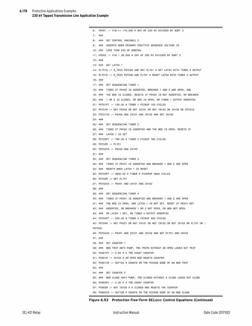
6.178
SEL-421 Relay Instruction Manual Date Code 20171021
Protection Applications Examples230 kV Tapped Transmission Line Application Example
6: PSV01 := V1M >= 119.500 # 90% OF 230 KV DIVIDED BY SQRT 3
7: ###
8: ### SET CONTROL VARIABLE 2
9: ### ASSERTS WHEN PRIMARY POSITIVE SEQUENCE VOLTAGE IS
10: ### LESS THAN 20% OF NOMINAL
11: PSV02 := V1M < 26.500 # 20% OF 230 KV DIVIDED BY SQRT 3
12: ###
13: ### SET LATCH 1
14: PLT01S := R_TRIG PST02Q AND NOT PLT01 # SET LATCH WITH TIMER 2 OUTPUT
15: PLT01R := R_TRIG PST03Q AND PLT01 # RESET LATCH WITH TIMER 3 OUTPUT
16: ###
17: ### SET SEQUENCING TIMER 1
18: ### TIMES IF PSV02 IS ASSERTED, BREAKER 1 AND 2 ARE OPEN, AND
19: ### THE MOD IS CLOSED. RESETS IF PSV02 IS NOT ASSERTED, OR BREAKER
20: ### 1 OR 2 IS CLOSED, OR MOD IS OPEN, OR TIMER 1 OUTPUT ASSERTED
21: PST01PT := 150.00 # TIMER 1 PICKUP 150 CYCLES
22: PST01R := NOT PSV02 OR NOT IN101 OR NOT IN102 OR IN103 OR PST01Q
23: PST01IN := PSV02 AND IN101 AND IN102 AND NOT IN103
24: ###
25: ### SET SEQUENCING TIMER 2
26: ### TIMES IF PSV02 IS ASSERTED AND THE MOD IS OPEN. RESETS IF
27: ### LATCH 1 IS SET
28: PST02PT := 780.00 # TIMER 2 PICKUP 780 CYCLES
29: PST02R := PLT01
30: PST02IN := PSV02 AND IN103
31: ###
32: ### SET SEQUENCING TIMER 3
33: ### TIMES IF PSV01 IS ASSERTED AND BREAKER 1 AND 2 ARE OPEN
34: ### RESETS WHEN LATCH 1 IS RESET
35: PST03PT := 3600.00 # TIMER 3 PICKPUP 3600 CYCLES
36: PST03R := NOT PLT01
37: PST03IN := PSV01 AND IN101 AND IN102
38: ###
39: ### SET SEQUENCING TIMER 4
40: ### TIMES IF PSV01 IS ASSERTED AND BREAKER 1 AND 2 ARE OPEN
41: ### THE MOD IS OPEN, AND LATCH 1 IS NOT SET. RESET IF PSV01 NOT
42: ### ASSERTED, OR BREAKER 1 OR 2 NOT OPEN, OR MOD NOT OPEN
43: ### OR LATCH 1 SET, OR TIMER 4 OUTPUT ASSERTED
44: PST04PT := 330.00 # TIMER 4 PICKUP 330 CYCLES
45: PST04R := NOT PSV01 OR NOT IN101 OR NOT IN102 OR NOT IN103 OR PLT01 OR \
PST04Q
46: PST04IN := PSV01 AND IN101 AND IN102 AND NOT PLT01 AND IN103
47: ###
48: ### SET COUNTER 1
49: ### MOD TRIP ANTI-PUMP, TWO TRIPS WITHOUT AN OPEN LOCKS OUT TRIP
50: PCN01PV := 2.00 # A TWO COUNT COUNTER
51: PCN01R := IN103 # AN OPEN MOD RESETS COUNTER
52: PCN01IN := OUT103 # COUNTS ON THE RISING EDGE OF AN MOD TRIP
53: ###
54: ### SET COUNTER 2
55: ### MOD CLOSE ANTI-PUMP, TWO CLOSES WITHOUT A CLOSE LOCKS OUT CLOSE
56: PCN02PV := 2.00 # A TWO COUNT COUNTER
57: PCN02R := NOT IN103 # A CLOSED MOD RESETS THE COUNTER
58: PCN02IN := OUT106 # COUNTS ON THE RISING EDGE OF AN MOD CLOSE
Figure 6.53 Protection Free-Form SELOGIC Control Equations (Continued)

6.179
Date Code 20171021 Instruction Manual SEL-421 Relay
Protection Applications Examples230 kV Tapped Transmission Line Application Example
Control InputsConnect the relay control inputs as specified in Table 6.49. This table shows the substation equipment that each control input monitors.
Control Outputs
59: ###
60: ### SET CONDITIONING TIMER 1
61: ### SUPERVISES BK1 RECLOSING, ASSERTS IF MOD IS CLOSED AND IN SYNC. OR
62: ### MOD LATCH SET AND MOD OPEN AND BK1 BUS HOT FOR FOUR SECONDS
63: PCT01PU := 240.00 # FOUR SECOND PICKUP TIME
64: PCT01DO := 0.0 # NO DELAY ON DROPOUT
65: PCT01IN := NOT IN103 AND 25A1BK1 OR PLT01 AND IN103 AND 59VS1
66: ###
67: ### SET CONDITIONING TIMER 2
68: ### SUPERVISES BK2 RECLOSING, ASSERTS IF MOD IS CLOSED AND IN SYNC. AND BK1
69: ### CLOSED OR MOD LATCH SET AND MOD OPEN AND BK2 BUS HOT AND BK1 CLOSED
70: ### FOR FOUR SECONDS
71: PCT02PU := 240.00 # FOUR SECOND PICKUP TIME
72: PCT02DO := 0.0 # NO DELAY ON DROPOUT
73: PCT02IN := NOT IN103 AND 25A1BK2 AND NOT IN101 OR PLT01 AND IN103 AND \
59VS2 AND NOT IN101
Figure 6.53 Protection Free-Form SELOGIC Control Equations (Continued)
Table 6.49 Control Inputs
Input Monitor Condition
IN101 115 kV BK1T 52 b contact
IN102 115 kV BK2T 52 b contact
IN103 230 kV MOD b contact
IN104 Circuit breaker and autotransformer failure lockouts (86)
Table 6.50 Control Outputs (SELOGIC Control Equations) (Sheet 1 of 2)
Setting Function Entry
Main Board
OUT101 Trip BK1T TRIP
OUT102 Trip BK2T TRIP
OUT103 Trip MOD PST01ET > 120.00 AND NOT PCN01Q
OUT104 Close BK1T BK1CL
OUT105 Close BK2T BK2CL
OUT106 Close MOD PST04ET > 300.00 AND NOT PCN02Q
OUT107 General alarm NOT HALARM OR NOT SALARM OR NOT ILOP
MIRRORED BITS Transmit Equations (SELOGIC Control Equations)
TMB1A Blocking signal Z3P OR Z3G OR DSTRT
TMB2A Zone 1 direct underreaching transfer trip Z1P OR Z1G
TMB3A Direct transfer trip: 86BF or 86T and MOD closed NOT IN103 AND IN104

6.180
SEL-421 Relay Instruction Manual Date Code 20171021
Protection Applications Examples230 kV Tapped Transmission Line Application Example
Figure 6.54 is a logical representation of the freeform protection SELOGIC con-trol equations.
TMB1B Blocking signal Z3P OR Z3G OR DSTRT
TMB2B Zone 1 direct underreaching transfer trip Z1P OR Z1G
TMB3B Direct transfer trip: 86BF or 86T and MOD closed NOT IN103 AND IN104
Table 6.50 Control Outputs (SELOGIC Control Equations) (Sheet 2 of 2)
Setting Function Entry

6.181
Date Code 20171021 Instruction Manual SEL-421 Relay
Protection Applications Examples230 kV Tapped Transmission Line Application Example
Figure 6.54 Protection Freeform SELOGIC Control Equations
>=V1M
119,500.00
PSV01
<V1M
26,500.00
PSV02
IN
R
PT
Q
ET
PST01
AND
OR
IN101
PSV02
IN103
IN102
IN101
PSV02150
IN103
PST01Q
IN102
IN
R
PT
Q
ET
PST02
ANDPSV02
IN103
PLT01
780
IN
R
PV
Q
CV
PCN01
OUT103
IN103
2
IN
R
PV
Q
CV
PCN02
OUT106
IN103
2
IN
R
PT
Q
ET
PST03
AND
IN101
IN102
PSV01
PLT01
3600
OUT103
>
AND120
PCN01Q
PST01ET

6.182
SEL-421 Relay Instruction Manual Date Code 20171021
Protection Applications Examples230 kV Tapped Transmission Line Application Example
Figure 6.54 Protection Freeform SELOGIC Control Equations (Continued)
S
R
PLT01
AND
AND
PST02Q
IN
R
PT
Q
ET
PST04
AND
OR
IN101
PSV01
IN103
IN102
IN101
PSV01
330
IN103
PLT01
IN102
PLT01
PST04Q
IN
PU
DO
Q
PCT01
AND
AND
OR25AIBK1
IN103
IN103
PLT01
59VS1
240.0
0.0
>
AND300
PST04ET
PCN02Q
OUT106
IN
PU
DO
Q
PCT02
AND
OR
59VS2
IN101
PLT01
240.0
0.0
IN103
AND
25AIBK2
IN103
IN101
R_TRIG
PST03Q R_TRIG

6.183
Date Code 20171021 Instruction Manual SEL-421 Relay
Protection Applications Examples230 kV Tapped Transmission Line Application Example
Figure 6.55 Ladder Logic Representation, Protection Freeform SELOGIC Control Equations
>=
V1M
119.500
PSV01
PSV02
<
V1M
26.500
OUT103
>
PST01ET
120.0
R_TRIG
IN101
IN102
IN103
IN
R
PT=150.0
Q
ET
PST01PSV02 IN101 IN102 IN103
PSV02
IN
R
PT=780
PST02PSV02 IN103
PLT01
IN
R
PV=2
PCN01OUT103
IN103
IN
R
PV=2
PCN02OUT106
IN103
IN
R
PT=3600
PST03PSV01 IN101 IN102
PLT01
S
R
PLT01PST02Q PLT01
PLT01PST03Q
PST01Q
PCN01Q
R_TRIG
Q
ET
Q
CV
Q
CV
Q
ET

6.184
SEL-421 Relay Instruction Manual Date Code 20171021
Protection Applications Examples230 kV Tapped Transmission Line Application Example
Figure 6.55 Ladder Logic Representation, Protection Freeform SELOGIC Control Equations (Continued)
OUT106
>
PST04ET
300.0
IN101
IN102
IN103
IN
R
PT=330
Q
ET
PST04PSV01 IN101 IN102 IN103 PLT01
PSV01
IN
PU=240.0
DO=0.0
Q
PCT01IN103 25AIBK1
PLT01 IN103 59VS1
IN
PU=240.0
DO=0.0
Q
PCT02IN103 25AIBK2 IN101
PLT01 IN103 59VS2 IN101
PLT01
PCN02Q
PST04Q

Date Code 20171021 Instruction Manual SEL-421 Relay
Instruction ManualInstruction ManualS E C T I O N 7
Metering, Monitoring, and Reporting
The SEL-421 Relay provides extensive capabilities for monitoring substation components, metering important power system parameters, and reporting on power system performance. The relay provides the following useful features:
➤ Metering on page 7.1
➤ Circuit Breaker Monitor on page 7.7
➤ Station DC Battery System Monitor on page 7.7
➤ Reporting on page 7.7
See Section 7: Metering, Section 8: Monitoring, and Section 9: Reporting in the SEL-400 Series Relays Instruction Manual for general information. This section contains details specific to the SEL-421.
MeteringThe SEL-421 provides five metering modes for measuring power system operations:
➤ Instantaneous Metering on page 7.2
➤ Maximum/Minimum Metering on page 7.5
➤ Demand Metering on page 7.6
➤ Energy Metering on page 7.6
➤ Synchrophasor Metering on page 7.7
Monitor present power system operating conditions with instantaneous metering. Maximum/Minimum metering displays the largest and smallest system devia-tions since the last reset. Demand metering includes either thermal or rolling analyses of the power system and peak demand metering. Energy metering dis-plays the megawatt-hours imported, megawatt-hours exported, and total mega-watt-hours. Time-synchronized metering displays the line voltage and current synchrophasors.
The SEL-421 processes three sets of current quantities: LINE, BK1, and BK2 (when configured for two circuit breakers). In one configuration using two circuit breakers, Terminal W is usually connected as BK1, and Terminal X is generally connected as BK2. The line voltage from Terminal Y (VY) provides the voltage quantities for LINE. See Current and Voltage Source Selection on page 5.2 for more information on configuring the SEL-421 inputs.
Use the MET command to access the metering functions. Issuing the MET com-mand with no options returns the fundamental frequency measurement quantities listed in Table 7.2. The MET command followed by a number, MET k, specifies the number of times the command will repeat (k can range from 1 to 32767). This is useful for troubleshooting or investigating uncharacteristic power system con-ditions. With other command options, you can view currents from either circuit breaker. For example, you can monitor the fundamental currents on Circuit

7.2
SEL-421 Relay Instruction Manual Date Code 20171021
Metering, Monitoring, and ReportingMetering
Breaker 1 or Circuit Breaker 2 by entering MET BK1 or MET BK2, respec-tively. Additionally, the MET PM command provides time-synchronized phasor measurements at a specific time, e.g., MET PM 12:00:00.
Table 7.1 lists MET command variants for instantaneous, maximum/minimum, demand, and energy metering. See METER on page 14.37 in the SEL-400 Series Relays Instruction Manual and METER on page 9.4 in this manual for more information on these and other MET command options. Other MET command options are for viewing protection and automation variables, analog values from MIRRORED BITS communications, and synchronism check.
Instantaneous MeteringUse instantaneous metering to monitor power system parameters in real time. The SEL-421 provides these fundamental frequency readings:
➤ Fundamental frequency phase voltages and currents
➤ Phase-to-phase voltages
➤ Sequence voltages and currents
➤ Fundamental real, reactive, and apparent power
➤ Displacement power factor
You can also monitor these real-time rms quantities (with harmonics included):
➤ RMS phase voltages and currents
➤ Real and apparent rms power
➤ True power factor
Both the fundamental and the rms-metered quantities are available for the LINE input. The relay also provides both the fundamental and rms circuit breaker cur-rents for circuit breakers BK1 and BK2.
Table 7.1 MET Command
Namea
a n is 1 or 2, representing Circuit Breaker 1 and Circuit Breaker 2, respectively.
Description
MET Display Fundamental Line metering information
MET BKn Display Fundamental Circuit Breaker n metering information
MET RMS Display rms Line metering information
MET BKn RMS Display rms Circuit Breaker n metering information
MET M Display Line Maximum/Minimum metering information
MET BKn M Display Circuit Breaker n Maximum/Minimum metering information
MET RM Reset Line Maximum/Minimum metering information
MET BKn RM Reset Circuit Breaker n Maximum/Minimum metering information
MET D Display Demand Line metering information
MET RD Reset Demand Line metering information
MET RP Reset Peak Demand Line metering information
MET E Display Energy Line metering information
MET RE Reset Energy Line metering information
MET SYN Display Synchronism Check voltage and slip angle/frequency information
MET BAT Display DC Battery Monitor information
MET PM Display Phasor Measurement (Synchrophasor) metering information

7.3
Date Code 20171021 Instruction Manual SEL-421 Relay
Metering, Monitoring, and ReportingMetering
Voltages, Currents, FrequencyNOTE: After power up, automatic restart, or a warm start, including settings change and group switch, in the beginning period of 20 cycles, the 10-cycle average values are initialized with the latest calculated 1-cycle average values.
Table 7.2 summarizes the metered voltage, current, and frequency quantities available in the SEL-421. The relay reports all instantaneous voltage magnitudes, current magnitudes, and frequency as absolute value 10-cycle averages (for example, the LINE A-Phase filtered magnitude LIAFM_10c; see Section 12: Analog Quantities). Instantaneous metering also reports sequence quantities ref-erenced to A-Phase. The SEL-421 references angle measurements to positive-sequence quantities. The relay reports angle measurements in the range of ±180.00 degrees.
PowerTable 7.3 shows the power quantities that the relay measures. The instantaneous power measurements are derived from 10-cycle averages that the SEL-421 reports by using the generator condition of the positive power flow convention; for example, real and reactive power flowing out (export) is positive, and real and reactive power flowing in (import) is negative (see Figure 7.1).
For power factor, LAG and LEAD refer to whether the current lags or leads the applied voltage. The reactive power Q is positive when the voltage angle is greater than the current angle (V > I), which is the case for inductive loads
Table 7.2 Instantaneous Metering Quantities—Voltages, Currents, Frequency
Metered Quantity Symbol Fundamental RMS
Phase voltage magnitude |V X X
Phase voltage angle (V) X
Phase current magnitude |I| X X
Phase current angle (I) X
Phase-to-phase voltage magnitude |V| X X
Phase-to-phase voltage angle (V) X
Positive-sequence voltage magnitude |V1| X
Positive-sequence voltage angle (V1) X
Negative-sequence voltage magnitude |3V2| X
Negative-sequence voltage angle (3V2) X
Zero-sequence voltage magnitude |3V0| X
Zero-sequence voltage angle (3V0) X
Positive-sequence current magnitude |I1| X
Positive-sequence current angle (I1) X
Negative-sequence current magnitude |3I2| X
Negative-sequence current angle (3I2) X
Zero-sequence current magnitude |3I0| X
Zero-sequence current angle (3I0) X
Battery voltages Vdc X
Frequency f X X
Circuit breaker current magnitudes |I| X X
Circuit breaker current angles (I) X

7.4
SEL-421 Relay Instruction Manual Date Code 20171021
Metering, Monitoring, and ReportingMetering
where the current lags the applied voltage. Conversely, Q is negative when the voltage angle is less than the current angle (V < I); this is when the current leads the voltage, as in the case of capacitive loads.
The SEL-421 includes Relay Word bits to indicate the leading or lagging power factor (see Section 11: Relay Word Bits). In the case of a unity power factor or loss of phase or potential condition, the resulting power factor angle will be on the axis of the complex power (P/Q) plane shown in Figure 7.1. This causes the power factor Relay Word bits to rapidly change state (chatter). Be aware of expected system conditions when monitoring the power factor Relay Word bits. SEL does not recommend the use of chattering Relay Word bits in the SER or anything that will trigger an event.
Figure 7.1 Complex Power (P/Q) Plane
Table 7.3 Instantaneous Metering Quantities—Power (Sheet 1 of 2)
Metered Quantity SymbolFundamental
(50 Hz/60 Hz Only)
RMS (Harmonics Included)
Per-phase fundamental real power P1 X
Per-phase true real power Prms X
Per-phase reactive power Q1 X X
Per-phase fundamental apparent power S1 X
Per-phase true apparent power Urms X
Three-phase fundamental real power 3P1 X
Three-phase true real power 3Prms X
Three-phase reactive power 3Q1 X X
Three-phase fundamental apparent power 3S1 X
Q
P
+P+Q
Complex Power S 1
Complex Power S2
pf = Lead
pf = Lag
—P+Q
+P—Q
—P—Q
Export power andexport reactive power(inductive load)
Export power andimport reactive power(capacitive load)

7.5
Date Code 20171021 Instruction Manual SEL-421 Relay
Metering, Monitoring, and ReportingMetering
Relay Word bits PF_OK and DPF_OK are provided to indicate that the infor-mation coming into the relay is sufficient to provide a valid power factor mea-surement. The per-phase power factor bit, PF_OK, is equal to 1 if the measured per-phase rms voltage, Vrms, is greater than 10 percent of the nominal voltage setting and the relay does not detect an open-phase condition. Otherwise, PF_OK = 0. Similarly, for the per-phase displacement power factor check, DPF_OK, is equal to 1 if the magnitude of the per-phase fundamental voltage, VFM, is greater than 10 percent of the nominal voltage setting and the relay does not detect an open-phase condition. Otherwise, DPF_OK = 0.
High-Accuracy Instantaneous MeteringThe SEL-421 is a high-accuracy metering instrument. See Section 7: Metering in the SEL-400 Series Relays Instruction Manual for details of the accuracy and how to calculate error coefficients.
Maximum/Minimum MeteringSee Maximum/Minimum Metering on page 7.5 in the SEL-400 Series Relays Instruction Manual for a complete description of using and controlling maxi-mum/minimum metering.
The SEL-421 provides maximum/minimum metering for LINE input rms volt-ages, rms currents, rms powers, and frequency; it also conveys the maximum/minimum rms currents for circuit breakers BK1 and BK2, as well as both dc bat-tery voltage maximums and minimums. The SEL-421 also records the maximum values of the sequence voltages and sequence currents. Table 7.4 lists these quan-tities.
Three-phase true apparent power 3Urms X
Per-phase displacement power factor PF1 X
Per-phase true power factor PF X
Three-phase displacement power factor 3PF1 X
Three-phase true power factor 3PF X
Table 7.3 Instantaneous Metering Quantities—Power (Sheet 2 of 2)
Metered Quantity SymbolFundamental
(50 Hz/60 Hz Only)
RMS (Harmonics Included)
Table 7.4 Maximum/Minimum Metering Quantities—Voltages, Currents, Frequency, and Powers (Sheet 1 of 2)
Metered Quantity Symbol
RMS phase voltage Vrms
RMS phase current Irms
Positive-sequence voltage magnitudea |V1|
Negative-sequence voltage magnitudea |3V2|
Zero-sequence voltage magnitudea |3V0|
DC battery voltage VDC1, VDC2
Positive-sequence current magnitudea |I1|
Negative-sequence current magnitudea |3I2|
Zero-sequence current magnitudea |3I0|

7.6
SEL-421 Relay Instruction Manual Date Code 20171021
Metering, Monitoring, and ReportingMetering
Demand MeteringSee Demand Metering on page 7.6 in the SEL-400 Series Relays Instruction Manual for a complete description of how demand metering works. The SEL-421 provides demand metering and peak demand metering for the LINE quantities. Table 7.5 lists the quantities used for demand and peak demand metering.
Energy MeteringEnergy is the power consumed or developed in the electric power system mea-sured over time. See Energy Metering on page 7.6 in the SEL-400 Series Relays Instruction Manual for complete details of energy metering computation, view-ing, and control. Energy metering is available only for the LINE data. Table 7.6 lists the energy metering quantities that the relay displays.
Frequency f
Circuit breaker rms current Irms
Three-phase true real power 3Prms
Three-phase reactive power 3Q1
Three-phase true apparent power 3Urms
a Sequence components are maximum values only.
Table 7.4 Maximum/Minimum Metering Quantities—Voltages, Currents, Frequency, and Powers (Sheet 2 of 2)
Metered Quantity Symbol
Table 7.5 Demand and Peak Demand Metering Quantities—LINE
Symbol Units Description
Irms A, primary Input rms current
IGrmsa
a (IG = 3I0 = IA + IB + IC).
A, primary Residual ground rms current
3I2 A, primary Negative-sequence current
P MW, primary Single-phase real powers (with harmonics)
Q MVAR, primary Single-phase reactive powers
U MVA, primary Single-phase total powers (with harmonics)
3P MW, primary Three-phase real power (with harmonics)
3Q MVAR, primary Three-phase reactive power
3U MVA, primary Three-phase total power (with harmonics)
Table 7.6 Energy Metering Quantities—(LINE)
Analog Quantity Units Description
MWHOUT MWh, primary Single-phase energy export
MWHIN MWh, primary Single-phase energy import
MWHT MWh, primary Single-phase energy total
3MWHOUT MWh, primary Three-phase energy export
3MWHIN MWh, primary Three-phase energy import
3MWH3T MWh, primary Three-phase energy total

7.7
Date Code 20171021 Instruction Manual SEL-421 Relay
Metering, Monitoring, and ReportingCircuit Breaker Monitor
Synchrophasor MeteringThe SEL-421 provides synchrophasor measurement with an angle reference according to IEEE C37.118. See Section 7: Metering in the SEL-400 Series Relays Instruction Manual for details of synchrophasor metering.
Circuit Breaker MonitorThe SEL-421 features advanced circuit breaker monitoring. The general features of the circuit breaker monitor are described in Circuit Breaker Monitor on page 8.1 in the SEL-400 Series Relays Instruction Manual. The SEL-421 sup-ports monitoring of two breakers, designated 1 and 2.
Station DC Battery System MonitorThe SEL-421 automatically monitors station battery system health by measuring the dc voltage, ac ripple, and voltage between each battery terminal and ground. The relay provides two dc monitor channels, Vdc1 and Vdc2. See Station DC Battery System Monitor on page 7.7 in the SEL-400 Series Relays Instruction Manual for a complete description of the battery monitor.
ReportingThe SEL-421 features comprehensive power system data analysis capabilities, which are described in Section 9: Reporting in the SEL-400 Series Relays Instruction Manual. This section describes reporting characteristics that are unique to the SEL-421.
Duration of Data Captures and Event ReportsThe SEL-421 stores high-resolution raw data and filtered data. The number of stored high-resolution raw data captures and event reports is a function of the quantity of data contained in each capture.
Table 7.7 lists the maximum number of data captures/event reports the relay stores in nonvolatile memory when ERDIG = S for various report lengths and sample rates. The relay automatically overwrites the oldest events with the new-est events when the nonvolatile storage capacity is exceeded.
NOTE: Consider the total capture time when choosing a value for setting LER at the SRATE := 8 kHz. At LER := 3.0 the relay records at least 13 data captures when ERDIG = S. These and smaller LER settings are sufficient for most power system disturbances.
The relay stores high-resolution raw and filtered event data in nonvolatile mem-ory. Table 7.7 lists the storage capability of the SEL-421 for common event reports.
The lower rows of Table 7.7 show the number of event reports the relay stores at the maximum data capture times for each SRATE sampling rate setting. Table entries are the maximum number of stored events; these can vary by 10 percent according to relay memory usage.

7.8
SEL-421 Relay Instruction Manual Date Code 20171021
Metering, Monitoring, and ReportingReporting
When the event report digital setting is set to include all Relay Word bits in the event report (ERDIG = A), the maximum number of stored reports is reduced, as shown in Table 7.8.
Event Reports, Event Summaries, and Event HistoriesSee Event Reports, Event Summaries, and Event Histories on page 9.13 in the SEL-400 Series Relays Instruction Manual for an overview of event reports, event summaries, and event histories. This section describes the characteristics of those that are unique to the SEL-421.
Base Set of Relay Word BitsThe following Relay Word bits are always including in 8 kHz oscillography and compressed event reports: TLED_1, TLED_2, TLED_3, TLED_4, TLED_5, TLED_6, TLED_7, TLED_8, TLED_9, TLED_10, TLED_11, TLED_12, TLED_13, TLED_14, TLED_15, TLED_16, TLED_17, TLED_18, TLED_19, TLED_20, TLED_21, TLED_22, TLED_23, TLED_24, SPOA, SPOB, SPOC, FSA, FSB, FSC, Z1P, Z2P, Z3P, Z4P, Z5P, Z123PFL, 67Q1, 67Q2, 67Q3,67Q4, 51S1, 51S2, 51S3, Z1G, Z2G, Z3G, Z4G, Z5G, Z123GFL, 67G1, 67G2, 67G3, 67G4, RMBnA, TMBnA, RMBnB, TMBnB, ROKA, RBADA, CBADA, LBOKA, ROKB, RBADB, CBADB, LBOKB, TRIP, TPx1, TPx2, 52xCL1, 52xCL2, BK1CL, BK2CL (n = 1–8, x = A, B, C).
Table 7.7 Event Report Nonvolatile Storage Capability When ERDIG = S
Event Report LengthMaximum Number of Stored Reports
8 kHz 4 kHz 2 kHz 1 kHz
0.25 seconds 161 193 212 248
0.50 seconds 98 123 139 173
1.0 seconds 54 70 82 107
3.0 seconds 19 25 30 41
6.0 seconds N/A 12 15 21
12.0 seconds N/A N/A 7 10
24.0 seconds N/A N/A N/A 4
Table 7.8 Event Report Nonvolatile Storage Capability When ERDIG = A
Event Report LengthMaximum Number of Stored Reports
8 kHz 4 kHz 2 kHz 1 kHz
0.25 seconds 125 148 159 180
0.50 seconds 74 89 98 112
1.0 seconds N/A 49 54 64
3.0 seconds N/A N/A 19 23
6.0 seconds N/A N/A N/A 11
12.0 seconds N/A N/A N/A N/A
24.0 seconds N/A N/A N/A N/A

7.9
Date Code 20171021 Instruction Manual SEL-421 Relay
Metering, Monitoring, and ReportingReporting
Event ReportReport Header and Analog Section of the Event Report
The first portion of an event report is the report header and the analog section. See Figure 7.2 for the location of items included in a sample analog section of an event report. If you want to view only the analog portion of an event report, use the EVE A command.
The report header is the standard SEL-421 header listing the relay identifiers, date, and time. Report headers help you organize report data. Each event report begins with information about the relay and the event. The report lists the RID setting (Relay ID) and the SID setting (Station ID). The FID string identifies the relay model, flash firmware version, and the date code of the firmware. See Firm-ware Version Number on page 10.18 in the SEL-400 Series Relays Instruction Manual for a description of the FID string. The relay reports a date and time stamp to indicate the internal clock time when the relay triggered the event. The relay reports the firmware checksum as CID.
The event report column labels follow the header. The data underneath the analog column labels contain samples of power system voltages and currents in primary kilovolts and primary amperes, respectively. These quantities are instantaneous values scaled by 2/2 (0.707) and are described in Table 7.9. To obtain phasor rms values, use the methods illustrated in Obtaining RMS Phasors From 4-Sam-ples/Cycle Event Reports on page 9.17, Figure 9.7 on page 9.18, and Figure 9.8 on page 9.20 in the SEL-400 Series Relays Instruction Manual.
Relay 1 Date: 03/15/2001 Time: 23:30:49.026Station A Serial Number: 2001001234FID=SEL-421-R101-V0-Z001001-D20010315 Event Number = 10007 CID=0x3425
Header
Firmware ID in bold
Currents (Amps Pri) Voltages (kV Pri) IA IB IC IG VA VB VC VS1 VS2 V1mem
[1] -267 167 44 -56 -288.0 337.7 -47.8 215.3 144.9 -287.9 -76 -203 241 -37 -223.7 -138.4 361.3 -290.5 331.3 -223.7 266 -166 -45 55 288.2 -337.5 47.5 -215.2 -145.0 288.1 76 202 -242 36 223.4 138.7 -361.4 290.5 -331.2 223.5
One Cycle of Data
See Figure 3.7 and Figure 3.8 to calculate phasors for the data in bold
•
•
•
[6] -269 167 46 -56 -289.3 336.9 -45.8 215.5 144.7 -289.4 -74 -202 240 -35 -222.2 -140.2 361.5 -290.2 331.4 -221.8 268 -165 -45 57 289.4 -336.7 45.6 -215.4 -144.6 289.5 93 151 -888 -643 221.1 133.5 -335.0 290.2 -331.4 220.8
[7] -208 2701 -3760 -1267 -288.7 293.7 -24.1 215.5 144.5 -286.3
-146 2941 173 2968 -219.6 -87.6 261.6 -290.1 331.4 -214.0> Trigger
134 -5748 8310 2696 286.9 -232.4 3.5 -215.6 -144.4 273.3 179 -6677 1811 -4688 219.8 47.4 -214.2 290.0 -331.5 202.8
[8] -125 5661 -8506 -2971 -286.1 213.6 -3.8 215.8 144.2 -256.5
-177 6857 -1950 4730 -220.8 -46.9 214.2 -289.9 331.6 -193.2* Largest Current (to Event Summary)
129 -5508 8382 3003 286.9 -213.8 3.6 -216.0 -144.0 243.9 174 -6726 1839 -4712 220.4 47.2 -214.2 289.8 -331.6 185.9
[9] -128 5623 -8479 -2984 -287.1 213.9 -3.5 216.1 143.8 -234.5 -173 6821 -1924 4724 -219.8 -47.3 214.0 -289.7 331.7 -180.4 126 -5540 8404 2990 286.6 -213.7 3.5 -216.3 -143.7 227.3 177 -6749 1860 -4713 220.0 47.4 -212.9 289.6 -331.8 176.2
Figure 7.2 Fixed Analog Section of the Event Report

7.10
SEL-421 Relay Instruction Manual Date Code 20171021
Metering, Monitoring, and ReportingReporting
Figure 7.2 contains selected data from the analog section of a 4-samples/cycle event report for a BCG fault on a 400 kV line with CT ratio := 400/1 and PT ratio := 3636/1. The bracketed numbers at the left of the report (for example, [11]) indicate the cycle number; Figure 7.2 presents seven cycles of 4-samples/cycle data.
The trigger row includes a > character following immediately after the V1Mem column to indicate the trigger point. This is the dividing point between the pre-fault or PRE time and the fault or remainder of the data capture.
The row that the relay uses for the currents in the event summary is the row with the largest current magnitudes; the relay marks this row on the event report with an asterisk (*) character immediately after the V1Mem column. The (*) takes precedence over the > if both occur on the same row in the analog section of the event report.
Digital Section of the Event Report
The second portion of an event report is the digital section. Inspect the digital data to evaluate relay element response during an event. See Figure 7.3 for the locations of items in a sample event report digital section. If you want to view only the digital portion of an event report, use the EVE D command (see EVE D on page 14.24 in the SEL-400 Series Relays Instruction Manual for details). In the digital portion of the event report, the relay indicates deasserted elements with a period (.) and asserted elements with an asterisk (*) character.
The element and digital information labels are single character columns. Read these columns from top to bottom. The trigger row includes a > character follow-ing immediately after the last digital element column to indicate the trigger point. The relay marks the row used to report the maximum fault current with an aster-
[10] -126 4616 -6204 -1714 -282.9 178.6 41.9 216.4 143.5 -222.1 -106 4288 -1047 3135 -231.6 -64.5 95.3 -289.4 331.9 -162.6 65 -1722 1878 221 140.2 -72.1 -43.6 -216.6 -143.3 194.6
16 -807 4 -786 105.1 41.3 10.5 289.2 -332.0 130.7 Circuit Breaker Open
[11] -1 -1 -2 -5 13.8 1.1 0.3 216.8 143.1 -147.1 2 3 4 9 54.8 -0.7 -0.3 -289.1 332.1 -93.5 1 1 2 5 -8.1 -1.6 -1.1 -217.0 -142.8 109.8 -2 -2 -3 -8 -58.2 0.2 0.2 289.0 -332.2 65.3
Figure 7.2 Fixed Analog Section of the Event Report (Continued)
Table 7.9 Event Report Metered Analog Quantities
Quantity Description
IA Instantaneous filtered line current, A-Phase
IB Instantaneous filtered line current, B-Phase
IC Instantaneous filtered line current, C-Phase
IG Instantaneous filtered line current, residual (or ground)
VA Instantaneous filtered A-Phase voltage
VB Instantaneous filtered B-Phase voltage
VC Instantaneous filtered C-Phase voltage
VS1 Instantaneous filtered synchronization Source 1 voltage
VS2 Instantaneous filtered synchronization Source 2 voltage
V1Mem Instantaneous memorized positive-sequence polarization voltage

7.11
Date Code 20171021 Instruction Manual SEL-421 Relay
Metering, Monitoring, and ReportingReporting
isk (*) character at the right of the last digital element column. Event reports that are 4-samples/cycle reports show the OR combination of digital elements in the two 8-samples/cycle rows to make the quarter-cycle entry.
The digital report arranges the event report digital settings into 79 column pages. For every 79 columns, the relay generates a new report that follows the previous report.
The report displays the digital label header for each column in a vertical fashion, aligned on the last character. For example, if the first digital section elements are IN101, #, RMBA5, Z2P, LOKA, #, OUT203, OUT204, and HALARM, the header appears as in Figure 7.4. If the Relay Word bits included in the header were assigned aliases, the alias names appear in the report.
22 B B C 55 F F VZ S 66 66 55 O BBBBBB AA T T MMM ZZZ PL 3333 O5 666 77 666 77 511 Z M KKKKKK 11 RFRFTTT MMMM 234 ZZZZ 234 OOL OO 3S 2222 T0 777 GG 777 QQ 1SS 3KP 121212 BB IBIBPPP 1234 PPP 1234 GGG LAO SS PP QQGG FP GGG 23 QQQ 23 S11 PRER RRLLCC KK PFPFABC PPPP TTT GGGG TTT VDP BT OO FRFR T1 123 TT 123 TT 1TR TBYM SSOOLL 12 1122
Digital Column Labels
[1]... .... ... .... ... *.. .. .. .... .. ... .. ... .. ... .... ...... .. ....... .... ... .... ... *.. .. .. .... .. ... .. ... .. ... .... ...... .. ....... .... ... .... ... *.. .. .. .... .. ... .. ... .. ... .... ...... .. ....... .... ... .... ... *.. .. .. .... .. ... .. ... .. ... .... ...... .. ....
One Cycle of Data
•
•
•
[6]... .... ... .... ... *.. .. .. .... .. ... .. ... .. ... .... ...... .. ....... .... ... .... ... *.. .. .. .... .. ... .. ... .. ... .... ...... .. ....... .... ... .... ... *.. .. .. .... .. ... .. ... .. ... .... ...... .. ....... .... ... .... ... *.. .. .. .... .. ... .. ... .. ... .... ...... .. ....
[7]*** **.. ... .... ... *.. .. .. .... .. ... .. ... .. ... .... ...... .. ....
*** **.. ... .... ... *.. .. .. *.*. .. ... .. ... .. ... .... ...... .. ....> Trigger
*** **.. ... .... ... *.. .. .. *.*. .. ... .. ... .. ... .... ...... .. ....*** **.. ... .... ... *.. .. .. *.*. .. ... .. ... .. ... .... ...... .. ....
[8]*** **.. ... .... ... *.. .. .. *.*. .. ... .. ... .. ... .... ...... .. ....
*** **.. ... .... ... *.. .. .. *.*. .. ... .. ... .. ... .... ...... .. ....* Largest Current (to Event Summary)
*** **.. ... .... ... *.. .. .. *.*. .. ... .. ... .. ... .... ...... .. ....*** **.. ... .... ... *.. .. .. *.*. .. ... .. ... .. ... .... ...... .. ....
[9]*** **.. ... .... ... *.. .. .. *.*. .. ... .. ... .. ... .... ...... .. ....*** **.. ... .... ... *.. .. .. *.*. .. ... .. ... .. ... .... ...... .. ....*** **.. ... .... ... *.. .. .. *.*. .. ... .. ... .. ... .... ...... .. ....*** **.. ... .... ... *.. .. .. *.*. .. ... .. ... .. ... .... ...... .. ....
[10]*** **.. ... .... ... *.. .. .. *.*. .. ... .. ... .. ... .... ...... .. ....*** **.. ... .... ... *.. .. .. *.*. .. ... .. ... .. ... .... ...... .. ....
*** .... ... .... ... *.. .. .* .... .. ... .. ... .. ... .... ...... .. .... Circuit Breaker Open
*** .... ... .... ... *.. .. *. .... .. ... .. ... .. ... .... ...... .. ....
[11]*** .... ... .... ... *.. .. *. *.*. .. ... .. ... .. ... .... ...... .. ....*** .... ... .... ... *.. .. *. .... .. ... .. ... .. ... .... ...... .. ....*** .... ... .... ... *.. .. *. .... .. ... .. ... .. ... .... ...... .. ....*** .... ... .... ... *.. .. *. .... .. ... .. ... .. ... .... ...... .. ....
Figure 7.3 Digital Section of the Event Report

7.12
SEL-421 Relay Instruction Manual Date Code 20171021
Metering, Monitoring, and ReportingReporting
Event Summary Section of the Event Report
The third portion of an event report is the summary section. See Figure 7.5 for the locations of items included in a sample summary section of an event report. If you want to exclude the summary portion from an event report, use the EVE NSUM command (see EVENT on page 14.23 in the SEL-400 Series Relays Instruction Manual).
The information in the summary portion of the event report is the same informa-tion in the event summary, except that the report header does not appear immedi-ately before the event information when you view a summary in the event report. See Event Summary on page 7.13 for a description of the items in the summary portion of the event report.
Figure 7.4 Sample Digital Portion of the Event Report
Example 7.1 Reading the Digital Portion of the Event Report
This example shows how to read the digital event report shown in Figure 7.3. The sample digital event report shows seven cycles of 4-samples/cycle data for a BCG fault that trips a single-pole-capable circuit breaker.
In this particular report, the mho phase-distance elements Z1P and Z2P pick up in the first sample of Cycle [7]. The relay asserts the tripping Relay Word bits TPA, TPB, and TPC when the distance elements operate because of pro-gramming in the TR (Unconditional Tripping) SELOGIC control equation.
In the next reported sample (the second sample of Cycle [7]), the digital event report shows that the relay has asserted the negative-sequence direc-tional element, 32QF, and the ground directional element, 32GF.
Approximately three cycles later, the digital event report shows that the cir-cuit breaker has tripped. In Cycle [10], Relay Word bit SPO indicates that the relay has detected a single-pole open; one of the poles of the circuit breaker has opened. The remaining poles open and the relay asserts Relay Word bit 3PO (Three-Pole Open). Note that the relay polarizing voltage for element security, VPOLV, is always available.
00HI R UUAN M L TTL1 BM0 22A0 A2K 00R1 5PA 34M
. ... ... .. ...
* ..* ...* ..* ...
IN101#RMBA5Z2PLOKA#OUT203OUT204HALARM

7.13
Date Code 20171021 Instruction Manual SEL-421 Relay
Metering, Monitoring, and ReportingReporting
Event SummaryYou can retrieve a summary version of stored event reports as event summaries. These short-form reports present vital information about a triggered event. The relay generates an event in response to power system faults and other trigger events. See Figure 7.6 for a sample event summary.
The event summary contains the following information:
➤ Standard report header
➢ Relay and terminal identification
➢ Event date and time
➤ Event type
➤ Location of fault (if applicable)
➤ Time source (HIRIG or OTHER)
➤ Event number
➤ Recloser shot counter at the trigger time
➤ System frequency
Event: BCG T Location: 48.17 Time Source: OTHEREvent Number#: 10007 Shot 1P: 0 Shot 3P: 0 Freq: 60.01 Group: 1Targets: INST TIME ZONE_1 A_PHASE B_PHASE bk1rsBreaker 1: OPEN Trip Time: 23:30:49.026Breaker 2: OPEN Trip Time: 23:30:49.026
Event Information
PreFault: IA IB IC IG 3I2 VA VB VC V1mem
MAG(A/kV) 276 262 246 65 17 364.704 364.903 364.452 364.614 Prefault Data
ANG(DEG) 22.1 -91.7 138.2 5.1 178.5 0.0 -119.9 120.3 0.2Fault:
MAG(A/kV) 217 8892 8727 5586 11403 361.421 218.687 214.239 321.083 Fault Data
ANG(DEG) -17.0 167.3 24.8 95.6 94.4 0.1 -129.9 126.7 0.7
L C R L C R B B B R B B B R O A A O O A A O K D D K K D D KMB:8->1 RMBA TMBA RMBB TMBB A A A A B B B B TRIG 00000000 00000000 00000000 00000000 0 0 0 0 0 0 0 0
MIRRORED BITS Channel Status
Figure 7.5 Summary Section of the Event Report
Relay 1 Date: 03/15/2001 Time: 23:30:49.026Station A Serial Number: 2001001234 Report Header
Event: BCG T Location: 48.17 Time Source: OTHEREvent Number#: 10007 Shot 1P: 0 Shot 3P: 0 Freq: 60.01 Group: 1 Event Information
Targets: INST TIME ZONE_1 A_PHASE B_PHASE bk1rsBreaker 1: OPEN Trip Time: 23:30:49.026Breaker 2: OPEN Trip Time: 23:30:49.026
Circuit Breaker Status
PreFault: IA IB IC IG 3I2 VA VB VC V1mem
MAG(A/kV) 276 262 246 65 17 364.704 364.903 364.452 364.614 Prefault Data
ANG(DEG) 22.1 -91.7 138.2 5.1 178.5 0.0 -119.9 120.3 0.2
Fault:MAG(A/kV) 217 8892 8727 5586 11403 361.421 218.687 214.239 321.083ANG(DEG) -17.0 167.3 24.8 95.6 94.4 0.1 -129.9 126.7 0.7
Fault Data
L C R L C R B B B R B B B R O A A O O A A O K D D K K D D KMB:8->1 RMBA TMBA RMBB TMBB A A A A B B B B TRIG 00000000 00000000 00000000 00000000 0 0 0 0 0 0 0 0 TRIP 00000000 00000000 00000000 00000000 0 0 0 0 0 0 0 0
MIRRORED BITS Channels Status
Figure 7.6 Sample Event Summary Report

7.14
SEL-421 Relay Instruction Manual Date Code 20171021
Metering, Monitoring, and ReportingReporting
➤ Active group at trigger time
➤ Targets
➤ Circuit breaker trip and close times; and auxiliary contact(s) status
➤ Prefault and fault voltages, currents, and sequence current (from the event report row with the largest current)
➤ MIRRORED BITS communications channel status (if enabled)
The relay derives the summary target information and circuit breaker trip and close times from the rising edge of relevant Relay Word bits during the event. If no trip or circuit breaker element asserted during the event, the relay uses the last row of the event.
Fault location data can be indeterminate (for example, when there is no fault on the power system). If this is the case, the relay displays “$$$$.$$” for the Loca-tion entry in the event summary. You will also see the “$$$$.$$” display if the fault location enable setting EFLOC is N.
The SEL-421 reports the event type according to the output of the fault location algorithm. Table 7.10 lists event types in fault reporting priority. Fault event types (AG, BG, and BCG, for example) have reporting priority over indeterminate fault events. For example, you can trigger an event when there is no fault condition on the power system by using the TRI command. In this case, when there is no fault, the relay reports the event type as TRIG.
Event HistoryThe event history gives you a quick look at recent relay activity. The relay labels each new event with a unique number from 10000 to 42767. (At 42767, the top of the numbering range, the relay returns to 10000 for the next event number and then continues to increment.) See Figure 7.7 for a sample event history.
The event history contains the following:
➤ Standard report header
➢ Relay and terminal identification
➢ Date and time of report
➤ Event number
➤ Event date and time
➤ Event type
➤ Location of fault (if applicable)
➤ Maximum phase current from summary fault data
Table 7.10 Event Types
Event Event Trigger
AG, BG, CG, ABC, AB, BC, CA, ABG, BCG, CAG
The relay reports phase involvement. If Relay Word bit TRIP asserts at any time during the event, the relay appends a T to the phase (AG T, for example).
TRIP The event report includes the rising edge of Relay Word bit TRIP, but phase involvement is indeterminate.
ER The relay generates the event with elements in the SELOGIC control equation ER, but phase involvement is indeterminate.
TRIG The relay generates the event in response to the TRI command.

7.15
Date Code 20171021 Instruction Manual SEL-421 Relay
Metering, Monitoring, and ReportingReporting
➤ Active group at the trigger instant
➤ Targets
Figure 7.7 is a sample event history from a terminal.
Fault location data can be indeterminate (for example, when you trigger an event and there is no fault on the power system). If this is the case, the relay displays $$$$.$$ for the Location entry in the event history. You will also see the $$$$.$$ display if the fault location enable setting EFLOC is N.
The event types in the event history are the same as the event types in the event summary (see Table 7.10 for event types).
Figure 7.7 Sample Event History
Relay 1 Date: 03/16/2001 Time: 11:57:27.803Station A Serial Number: 2001001234
# DATE TIME EVENT LOCAT CURR GRP TARGETS10007 03/15/2001 23:30:49.026 BCG T 48.17 8892 1 INST TIME ZONE_1 B_PHASE 10006 03/15/2001 07:15:00.635 ABC T 22.82 8203 1 INST ZONE_1 A_PHASE bk1rs 10005 03/15/2001 06:43:53.428 TRIG $$$$.$$ 0 1
EventNumber
EventType
FaultLocation
ActiveGroup

This page intentionally left blank

Date Code 20171021 Instruction Manual SEL-421 Relay
Instruction ManualInstruction ManualS E C T I O N 8
Settings
Section 12: Settings in the SEL-400 Series Relays Instruction Manual describes common platform settings. This section contains tables of relay settings for the SEL-421 Relay.
The relay hides some settings based upon other settings. If you set an enable set-ting to OFF, for example, the relay hides all settings associated with that enable setting. This section does not explain rules for hiding settings; these rules are dis-cussed in the applications sections of the instruction manual where appropriate.
The settings prompts in this section are similar to the ASCII terminal and ACSELERATOR QuickSet SEL-5030 software prompts. The prompts in this sec-tion are unabbreviated and show all possible setting options.
For information on using settings in protection and automation, see the examples in Section 6: Protection Applications Examples. The section contains informa-tion on the following settings classes.
➤ Alias Settings on page 8.1
➤ Automation Freeform SELOGIC Control Equations on page 8.34
➤ Bay Settings on page 8.39
➤ Breaker Monitor Settings on page 8.9
➤ DNP3 Settings—Custom Maps on page 8.39
➤ Front-Panel Settings on page 8.35
➤ Global Settings on page 8.2
➤ Group Settings on page 8.12
➤ Notes Settings on page 8.34
➤ Output Settings on page 8.35
➤ Port Settings on page 8.38
➤ Protection Freeform SELOGIC Control Equations on page 8.34
➤ Report Settings on page 8.38
Alias SettingsSee Alias Settings on page 12.20 in the SEL-400 Series Relays Instruction Man-ual for a complete description of alias settings. Table 8.1 lists the default alias settings for the SEL-421.
WARNINGIsolate the relay trip circuits while changing settings. When changing settings for multiple classes, it is pos-sible to be in an intermediate state that will cause an unexpected trip.
Table 8.1 Global Settings Changes
Setting Default Value
EN RLY_EN

8.2
SEL-421 Relay Instruction Manual Date Code 20171021
SettingsGlobal Settings
Global Settings
Make Table 8.5 settings when Global enable setting EDCMON := 1 or 2. These settings are hidden when EDCMON := N.
Table 8.2 Global Settings Categories
Settings Reference
General Global Settings Table 8.3
Global Enables Table 8.4
Station DC1 Monitor (and Station DC2 Monitor) Table 8.5
Control Inputs (Global) Table 8.6
Main Board Control Inputs Table 8.7
Interface Board #1 Control Inputs Table 8.8
Interface Board #2 Control Inputs Table 8.9
Settings Group Selection Table 8.10
Frequency Estimation Table 8.11
Time-Error Calculation Table 8.12
Current and Voltage Source Selection Table 8.13
Synchronized Phasor Measurement Table 8.14
Time and Date Measurement Table 8.19
Data Reset Controls Table 8.20
DNP Table 8.21
Table 8.3 General Global Settings
Setting Prompt Default Value
SID Station Identifier (40 characters) Station A
RID Relay Identifier (40 characters) Relay 1
NUMBK Number of Breakers in Scheme (1, 2) 1
BID1 Breaker 1 Identifier (40 characters) Breaker 1
BID2 Breaker 2 Identifier (40 characters) Breaker 2
NFREQ Nominal System Frequency (50, 60 Hz) 60
PHROT System Phase Rotation (ABC, ACB) ABC
FAULT Fault Condition Equation SELOGIC Equation) 50P1 OR 51S1 OR Z2P OR Z2G OR Z3P OR Z3G
Table 8.4 Global Enables
Setting Prompt Default Value
EDCMON Station DC Battery Monitor (N, 1, 2) N
EICIS Independent Control Input Settings (Y, N) N
EDRSTC Data Reset Control (Y, N) N
EGADVS Advanced Global Settings (Y, N) N
EPMU Synchronized Phasor Measurement (Y, N) N

8.3
Date Code 20171021 Instruction Manual SEL-421 Relay
SettingsGlobal Settings
Make Table 8.6 settings when Global enable setting EICIS := N.
Make Table 8.7 settings when Global enable setting EICIS := Y.
Table 8.5 Station DC1 Monitor (and Station DC2 Monitor)
Settinga
a Replace 1 with 2 in the setting for DC2 Monitor settings.
Prompt Default Value
DC1LFP Low Level Fail Pickup (OFF, 15–300 Vdc) 100
DC1LWP Low Level Warn Pickup (OFF, 15–300 Vdc) 127
DC1HWP High Level Warn Pickup (OFF, 15–300 Vdc) 137
DC1HFP High Level Fail Pickup (OFF, 15–300 Vdc) 142
DC1RP Peak to Peak AC Ripple Pickup (1–300 Vac) 9
DC1GF Ground Detection Factor (1.00–2.00) 1.05
Table 8.6 Control Inputs
Setting Prompt Default Value Increment
GINPa
a Setting applies to all direct coupled contact inputs if available, otherwise, the setting is not available.
Input Pickup Level (15–265 Vdc) 85b
b Factory set at 18 for 24–48 Vdc rated power supply, 36 for 48–125 Vdc rated power supply, and 85 for 125–240 Vdc rated power supply. See Control Inputs on page 2.6 for setting guidelines.
1
GINDFa,c
c Setting applies to all direct coupled contact inputs independent of EICIS set to Y or N.
Input Dropout Level (10–100% of pickup level) 80 1
IN1XXDd
d Setting applies to all the main board input contacts.
Main Board Debounce Time (0.0000–5 cyc) 0.1250 0.0001
IN2XXDe
e Setting applies to all the Interface Board #1 input contacts.
Int Board #1 Debounce Time (0.0000–5 cycf)
f If the interface board has more than eight input contacts, the upper range is 1 cycle.
0.1250 0.0001
IN3XXDg
g Setting applies to all the Interface Board #2 input contacts.
Int Board #2 Debounce Time (0.0000–5 cycf) 0.1250 0.0001
Table 8.7 Main Board Control Inputs
Setting Prompt Default Value Increment
IN101PU Input IN101 Pickup Delay (0.0000–5 cyc) 0.1250a
a Set to Global setting IN1XXD when EICIS := N.
0.0001
IN101DO Input IN101 Dropout Delay (0.0000–5 cyc) 0.1250a 0.0001
•
•
•
•
•
•
•
•
•
IN107PU Input IN107 Pickup Delay (0.0000–5 cyc) 0.1250a 0.0001
IN107DO Input IN107 Dropout Delay (0.0000–5 cyc) 0.1250a 0.0001

8.4
SEL-421 Relay Instruction Manual Date Code 20171021
SettingsGlobal Settings
Make Table 8.8 settings for Interface Board #1 when Global enable setting EICIS := Y.
Make Table 8.9 settings for Interface Board #2 when Global enable setting EICIS := Y.
Table 8.8 Interface Board #1 Control Inputs
Setting Prompt Default Value Increment
IN201Pa
a Setting is not available for interface boards INT2, INT4, INT7, and INT8. Set to Global setting GINP when EICIS := N.
Input IN201 Pickup Level (15–265 Vdc) 85b
b Factory set at 18 for 24–48 Vdc rated power supply, 36 for 48–125 Vdc rated power supply, and 85 for 125–240 Vdc rated power supply. See Control Inputs on page 2.6 for setting guidelines.
1
•
•
•
•
•
•
•
•
•
•
•
•
IN2mmPa Input IN2mm Pickup Level (15–265 Vdc) 85b 1
IN201PU Input IN201 Pickup Delay (0.0000–5 cycc)
c If the interface board has more than eight input contacts, the upper range is 1 cycle.
0.1250d
d Set to Global setting IN2XXD when EICIS :-= N
0.0001
IN201DO Input IN201 Dropout Delay (0.0000–5 cycc) 0.1250d 0.0001
•
•
•
•
•
•
•
•
•
•
•
•
IN2mmPUe
e mm is the number of available input contacts on the interface board.
Input IN2mme Pickup Delay (0.0000–5 cycc) 0.1250d 0.0001
IN2mmDOe Input IN2mme Dropout Delay (0.0000–5 cycc) 0.1250d 0.0001
Table 8.9 Interface Board #2 Control Inputs
Setting Prompt Default Value Increment
IN301Pa
a Setting is not available for interface boards INT2, INT4, INT7, and INT8. Set to Global setting GINP when EICIS := N.
Input IN301 Pickup Level (15–265 Vdc) 85b
b Factory set at 18 for 24–48 Vdc rated power supply, 36 for 48–125 Vdc rated power supply, and 85 for 125–240 Vdc rated power supply. See Control Inputs on page 2.6 for setting guidelines.
1
•
•
•
•
•
•
•
•
•
IN3mmPa Input IN3mm Pickup Level (15–265 Vdc) 85b 1
IN301PU Input IN301 Pickup Delay (0.0000–5 cycc)
c If the interface board has more than eight input contacts, the upper range is 1 cycle.
0.1250d
d Set to Global setting IN3XXD when EICIS := N.
0.0001
IN301DO Input IN301 Dropout Delay (0.0000–5 cycc) 0.1250d 0.0001
•
•
•
•
•
•
•
•
•
IN3mmPUe
e mm is the number of available input contacts on the interface board.
Input IN3mme Pickup Delay (0.0000–5 cycc) 0.1250d 0.0001
IN3mmDOe Input IN3mme Dropout Delay (0.0000–5 cycc) 0.1250d 0.0001

8.5
Date Code 20171021 Instruction Manual SEL-421 Relay
SettingsGlobal Settings
Make Table 8.11 settings when Global enable setting EGADVS := Y.
See Current and Voltage Source Selection on page 5.2 for more information on Table 8.13 settings.
Table 8.10 Settings Group Selection
Setting Prompt Default Value
SS1 Select Setting Group 1 (SELOGIC Equation) PB3 AND NOT SG1
SS2 Select Setting Group 2 (SELOGIC Equation) PB3 AND SG1
SS3 Select Setting Group 3 (SELOGIC Equation) 0
SS4 Select Setting Group 4 (SELOGIC Equation) 0
SS5 Select Setting Group 5 (SELOGIC Equation) 0
SS6 Select Setting Group 6 (SELOGIC Equation) 0
TGR Group Change Delay (0–54000 cycles) 180
Table 8.11 Frequency Estimation
Setting PromptDefault Value
EAFSRC Alternate Frequency Source (SELOGIC Equation) NA
VF01 Local Frequency Source 1 (ZERO, VAY, VBY, VCY, VAZ, VBZ, VCZ) VAY
VF02 Local Frequency Source 2 (ZERO, VAY, VBY, VCY, VAZ, VBZ, VCZ) VBY
VF03 Local Frequency Source 3 (ZERO, VAY, VBY, VCY, VAZ, VBZ, VCZ) VCY
VF11 Alternate Frequency Source 1 (ZERO, VAY, VBY, VCY, VAZ, VBZ, VCZ) ZERO
VF12 Alternate Frequency Source 2 (ZERO, VAY, VBY, VCY, VAZ, VBZ, VCZ) ZERO
VF13 Alternate Frequency Source 3 (ZERO, VAY, VBY, VCY, VAZ, VBZ, VCZ) ZERO
Table 8.12 Time-Error Calculation
Setting Prompt Default Value
STALLTE Stall Time-Error Calculation (SELOGIC Equation) NA
LOADTE Load TECORR Factor (SELOGIC Equation) NA
Table 8.13 Current and Voltage Source Selection
Setting Prompt Default Value
ESS Current and Voltage Source Selection (Y, N, 1, 2, 3, 4) N
LINEI Line Current Source (IW, COMB) IW
ALINEI Alternate Line Current Source (IX, NA) NA
ALTI Alternate Current Source (SELOGIC Equation) NA
BK1I Breaker 1 Current Source (IW, IX, NA) IW
BK2I Breaker 2 Current Source (IX, COMB, NA) NA
IPOL Polarizing Current (IAX, IBX, ICX, NA) NA
ALINEV Alternate Line Voltage Source (VZ, NA) NA
ALTV Alternate Voltage Source (SELOGIC Equation) NA

8.6
SEL-421 Relay Instruction Manual Date Code 20171021
SettingsGlobal Settings
Phasors Included in the Data qTerminal Name, Relay Word Bit, Alternate Terminal Name
Specify the terminal for Synchrophasor measurement and transmission in the synchrophasor data stream q.
This is a freeform setting category for enabling the terminals for synchrophasor measurement and transmission. This freeform setting has three arguments. Spec-ify the terminal name (any one of W, X, S, Y, or Z) for the first argument. Specify any Relay Word bit for the second argument. Specify the alternate terminal name (any one of W, X, S, Y, or Z) for the third argument.
The second and third arguments are optional unless switching between terminals is required. Whenever the Relay Word bit in the second argument is asserted the terminal synchrophasor data are replaced by the alternate terminal data.
Table 8.14 Synchronized Phasor Configuration Settings
Setting Prompt Default
MFRMT Message Format (C37.118, FM) C37.118
MRATEa
a Only available in MFRMT = C37.118.
Messages per Second (1, 2, 4, 5, 10, 12, 15, 20, 30, 60)b
b If NFREQ = 50 then the range is 1, 2, 5, 10, 25, 50.
2
PMAPP PMU Application (F, N, 1)c
c Option 1 is available only if MRATE = 60.
N
PMLEGCYa Synchrophasor Legacy Settings (Y, N) N
NUMPHDCa,d
d Only available if PMLEGCY = N.
Number of Data Configurations (1–5) 1
PMSTNqa,e
e q = 1–NUMPHDC. If PMLEGACY = Y, then these two settings become PMSTN and PMID.
Station Name (16 characters) STATION A
PMIDqa,e PMU Hardware ID (1–65534) 1
PHVOLTf
f Only available if PMLEGCY = Y.
Include Voltage Terminal (combo of Y,Z) Y
PHDATAVf Phasor Data Set, Voltages (V1, PH, ALL, NA) V1
PHCURRf Include Current Terminal (combo of W, X, S) W
PHDATAIf Phasor Data Set, Currents (I1, PH, ALL, NA) NA
Table 8.15 Phasors Included in the Data
Setting Prompt Default
PHDVqa
a q = 1–NUMPHDC.
Phasor Data Set, Voltages (V1, PH, ALL) V1
PHDIqa Phasor Data Set, Currents (I1, PH, ALL) ALL
PHNRqa Phasor Num. Representation (I = Integer, F = Float) I
PHFMTqa Phasor Format (R = Rectangular, P = Polar) R
FNRqa Freq. Num. Representation (I = Integer, F = Float) I

8.7
Date Code 20171021 Instruction Manual SEL-421 Relay
SettingsGlobal Settings
Phasor Aliases in Data Configuration qPhasor Name, Alias
This is a freeform setting category with two arguments. Specify the phasor name and an optional 16-character alias to be included in the synchrophasor data stream q. See Table 10.17 on page 10.30 and Table 10.18 on page 10.30 for a list of phasor names that the PMU supports. The PMU can be configured for as many as 20 unique phasors for each PMU configuration.
Synchrophasor Analog Quantities in Data Configuration q (Maximum 16 Analog Quantities)Analog Quantity Name or Alias
This is a freeform setting category with one argument. Specify the analog quan-tity name or its alias to be included in the synchrophasor data stream q. See Section 12: Analog Quantities for a list of analog quantities that the PMU sup-ports. The PMU can be configured for as many as 16 unique analog quantities for each data configuration q. The analog quantities are floating point values, so each analog quantity the PMU includes will take four bytes.
Synchrophasor Digitals in Data Configuration q (Maximum 64 Digitals)Relay Word Bit Name or Alias.
This is a freeform setting category with one argument. Specify the Relay Word bit name or its alias that you need to include in the synchrophasor data stream q. See Section 11: Relay Word Bits for a list of Relay Word bits that the PMU sup-ports. You can configure the PMU for as many as 64 unique digitals for each data configuration q.
Setting Prompt Default
NUMANq Number of Analog Quantities (0–16) 0
Setting Prompt Default
NUMDWq Number of 16-bit Digital Status Words (0, 1, 2, 3, 4) 1
Table 8.16 Synchronized Phasor Configuration Settings Part 2
Setting Prompt Default Increment
TREA[4] Trigger Reason Bit [4] (SELOGIC Equation) NA
PMTRIG Trigger (SELOGIC Equation) NA
PMTEST PMU in Test Mode (SELOGIC Equation) NA
VkaCOMP
a k = Y and Z.
Comp. Angle Terminal k (–179.99° to 180°) 0.00 0.01
InbCOMP
b n = W, X, S.
Comp. Angle Terminal n (–179.99° to 180°) 0.00 0.01
PMFRQST PMU Primary Frequency Source Terminal (Y, Z) Y
PMFRQA PMU Frequency Application (F, S) S
PHCOMP Freq. Based Phasor Compensation (Y, N) Y
Table 8.17 Synchronized Phasor Recorder Settings (Sheet 1 of 2)
Setting Prompt Default
EPMDR Enable PMU Data Recording (Y, N) N
SPMDR Select Data Configuration for PMU Recording (1–NUMPHDC) 1
CONAM Company Name (3 characters) abc

8.8
SEL-421 Relay Instruction Manual Date Code 20171021
SettingsGlobal Settings
Make Table 8.20 settings when Global enable setting EDRSTC := Y.
PMLER Length of PMU Triggered Data (2–120 s) 30
PMPRE Length of PMU Pre-Triggered Data (1–20 s) 5
Table 8.18 Synchronized Phasor Real Time Control Settings
Setting Prompt Default
RTCRATE Remote Messages per Second(1, 2, 5, 10, or 50 when NFREQ := 50)(1, 2, 4, 5, 10, 12, 15, 20, 30, or 60 when NFREQ := 60)
2
MRTCDLY Maximum RTC Synchrophasor Packet Delay (20–1000 ms) 500
Table 8.19 Time and Date Management
Setting Prompt Default Value
DATE_F Date Format (MDY, YMD, DMY) MDY
IRIGCa
a When EPMU = Y and MFRMT = C37.118, IRIGC is forced to C37.118.
IRIG-B Control Bits Definition (None, C37.118) None
UTCOFFb
b All data, reports, and commands from the relay are stored and displayed in local time, referenced to an internal UTC master clock. Use the UTCOFF setting to specify the time offset from UTC time reference with respect to the relay location. (The only data still displayed in UTC time is streaming synchrophasor and IEC 61850 data.)
Offset From UTC to Local Time (–15.5 to 15.5) –8
BEG_DSTc
c The BEG_DST (and END_DST) daylight-saving time setting consists of four fields or OFF:hh = local time hour (0–23); defines when daylight-saving time begins.n = the week of the month when daylight-saving time begins (1–3, L); occurs in either the 1st, 2nd, 3rd, or last week of the month.d = day of week (1–7); Sunday is the first day of the week.mm = month (1–12).OFF = hides the daylight-saving time settings.
Begin DST (hh, n, d, mm, or OFF) “2, 2, 1, 3”
END_DST End DST (hh, n, d, mm) “2, 1, 1, 11”
Table 8.20 Data Reset Control (Sheet 1 of 2)
Setting Prompt Default Value
RST_DEM Reset Demand Metering (SELOGIC Equation) NA
RST_PDM Reset Peak Demand Metering (SELOGIC Equation) NA
RST_ENE Reset Energy Metering (SELOGIC Equation) NA
RSTMML Reset Maximum/Minimum Line (SELOGIC Equation) NA
RSTMMB1 Reset Maximum/Minimum Breaker 1 (SELOGIC Equation) NA
RSTMMB2 Reset Maximum/Minimum Breaker 2 (SELOGIC Equation) NA
RST_BK1 Reset Monitoring Breaker 1 (SELOGIC Equation) NA
RST_BK2 Reset Monitoring Breaker 2 (SELOGIC Equation) NA
RST_BAT Reset Battery Monitoring (SELOGIC Equation) NA
RST_79C Reset Recloser Shot Count Accumulators (SELOGIC Equation) NA
RSTTRGT Target Reset (SELOGIC Equation) NA
RSTFLOC Reset Fault Locator (SELOGIC Equation) NA
Table 8.17 Synchronized Phasor Recorder Settings (Sheet 2 of 2)
Setting Prompt Default
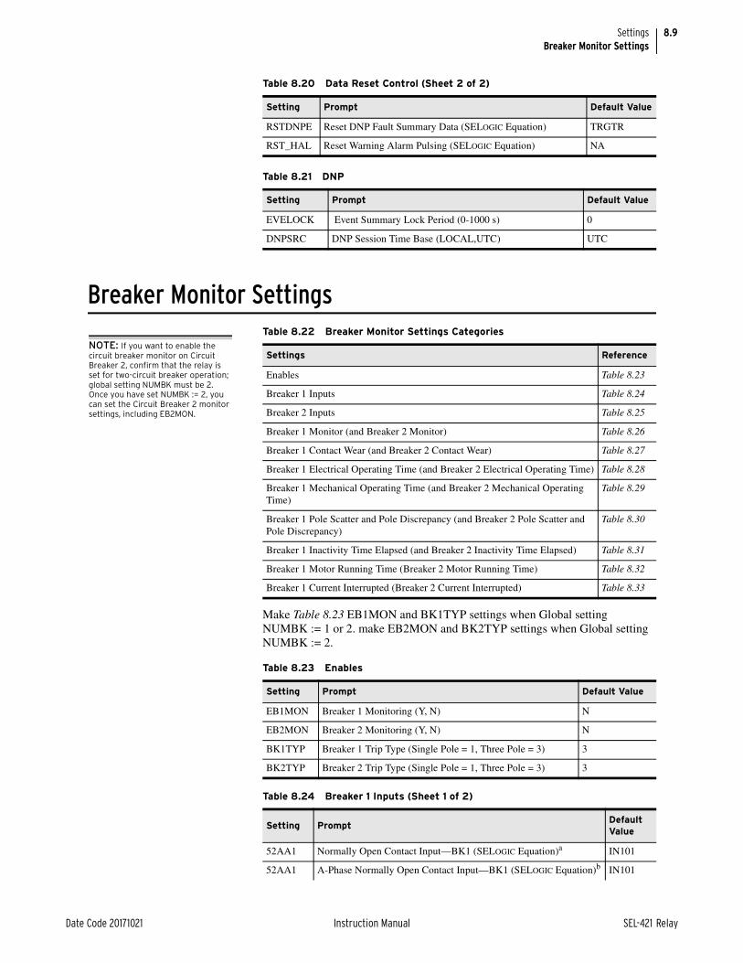
8.9
Date Code 20171021 Instruction Manual SEL-421 Relay
SettingsBreaker Monitor Settings
Breaker Monitor Settings
Make Table 8.23 EB1MON and BK1TYP settings when Global setting NUMBK := 1 or 2. make EB2MON and BK2TYP settings when Global setting NUMBK := 2.
RSTDNPE Reset DNP Fault Summary Data (SELOGIC Equation) TRGTR
RST_HAL Reset Warning Alarm Pulsing (SELOGIC Equation) NA
Table 8.21 DNP
Setting Prompt Default Value
EVELOCK Event Summary Lock Period (0-1000 s) 0
DNPSRC DNP Session Time Base (LOCAL,UTC) UTC
Table 8.20 Data Reset Control (Sheet 2 of 2)
Setting Prompt Default Value
Table 8.22 Breaker Monitor Settings Categories
Settings Reference
Enables Table 8.23
Breaker 1 Inputs Table 8.24
Breaker 2 Inputs Table 8.25
Breaker 1 Monitor (and Breaker 2 Monitor) Table 8.26
Breaker 1 Contact Wear (and Breaker 2 Contact Wear) Table 8.27
Breaker 1 Electrical Operating Time (and Breaker 2 Electrical Operating Time) Table 8.28
Breaker 1 Mechanical Operating Time (and Breaker 2 Mechanical Operating Time)
Table 8.29
Breaker 1 Pole Scatter and Pole Discrepancy (and Breaker 2 Pole Scatter and Pole Discrepancy)
Table 8.30
Breaker 1 Inactivity Time Elapsed (and Breaker 2 Inactivity Time Elapsed) Table 8.31
Breaker 1 Motor Running Time (Breaker 2 Motor Running Time) Table 8.32
Breaker 1 Current Interrupted (Breaker 2 Current Interrupted) Table 8.33
Table 8.23 Enables
Setting Prompt Default Value
EB1MON Breaker 1 Monitoring (Y, N) N
EB2MON Breaker 2 Monitoring (Y, N) N
BK1TYP Breaker 1 Trip Type (Single Pole = 1, Three Pole = 3) 3
BK2TYP Breaker 2 Trip Type (Single Pole = 1, Three Pole = 3) 3
Table 8.24 Breaker 1 Inputs (Sheet 1 of 2)
Setting PromptDefault Value
52AA1 Normally Open Contact Input—BK1 (SELOGIC Equation)a IN101
52AA1 A-Phase Normally Open Contact Input—BK1 (SELOGIC Equation)b IN101
NOTE: If you want to enable the circuit breaker monitor on Circuit Breaker 2, confirm that the relay is set for two-circuit breaker operation; global setting NUMBK must be 2. Once you have set NUMBK := 2, you can set the Circuit Breaker 2 monitor settings, including EB2MON.

8.10
SEL-421 Relay Instruction Manual Date Code 20171021
SettingsBreaker Monitor Settings
Make Table 8.25 settings if Global setting NUMBK := 2.
Make Table 8.26 through Table 8.33 settings when Breaker Monitor setting EB1MON := Y or EB2MON := Y.
52AB1 B-Phase Normally Open Contact Input—BK1 (SELOGIC Equation)b 52AA1
52AC1 C-Phase Normally Open Contact Input—BK1 (SELOGIC Equation)b 52AA1
a This setting for three-pole trip applications when setting BK1TYP := 3.b This setting for single-pole trip applications when setting BK1TYP := 1.
Table 8.25 Breaker 2 Inputs
Setting PromptDefault Value
52AA2 Normally Open Contact Input—BK2 (SELOGIC Equation)a
a This setting for three-pole trip applications when setting BK2TYP := 3.
NA
52AA2 A-Phase Normally Open Contact Input—BK2 (SELOGIC Equation)b
b This setting for single-pole trip applications when setting BK2TYP := 1.
NA
52AB2 B-Phase Normally Open Contact Input—BK2 (SELOGIC Equation)b 52AA2
52AC2 C-Phase Normally Open Contact Input—BK2 (SELOGIC Equation)b 52AA2
Table 8.26 Breaker 1 Monitor (and Breaker 2 Monitor)
Settinga
a Replace 1 with 2 in the setting, prompt, and default value for Breaker 2 settings.
Prompt Default Value
BM1TRPA Breaker Monitor Trip—BK1 (SELOGIC Equation)b
b This setting for three-pole trip applications when setting BK1TYP := 3.
TPA1
BM1TRPA Breaker Monitor A-Phase Trip—BK1 (SELOGIC Equation)c
c This setting for single-pole trip applications when setting BK1TYP := 1.
TPA1
BM1TRPB Breaker Monitor B-Phase Trip—BK1 (SELOGIC Equation)c BM1TRPA
BM1TRPC Breaker Monitor C-Phase Trip—BK1 (SELOGIC Equation)c BM1TRPA
BM1CLSA Breaker Monitor Close—BK1 (SELOGIC Equation)b BK1CL
BM1CLSA Breaker Monitor A-Phase Close—BK1 (SELOGIC Equation)c BK1CL
BM1CLSB Breaker Monitor B-Phase Close—BK1 (SELOGIC Equation)c BM1CLSA
BM1CLSC Breaker Monitor C-Phase Close—BK1 (SELOGIC Equation)c BM1CLSA
Table 8.27 Breaker 1 Contact Wear (and Breaker 2 Contact Wear)
Settinga
a Replace 1 with 2 in the setting and prompt for Breaker 2 settings.
Prompt Default Value
B1COSP1 Close/Open Set Point 1—BK1 (0–65000 operations) 1000
B1COSP2 Close/Open Set Point 2—BK1 (0–65000 operations) 100
B1COSP3 Close/Open Set Point 3—BK1 (0–65000 operations) 10
B1KASP1 kA Interrupted Set Point 1—BK1 (1.0–999 kA) 20.0
B1KASP2 kA Interrupted Set Point 2—BK1 (1.0–999 kA) 60.0
B1KASP3 kA Interrupted Set Point 3—BK1 (1.0–999 kA) 100.0
B1BCWAT Contact Wear Alarm Threshold—BK1 (0–100%) 90
Table 8.24 Breaker 1 Inputs (Sheet 2 of 2)
Setting PromptDefault Value

8.11
Date Code 20171021 Instruction Manual SEL-421 Relay
SettingsBreaker Monitor Settings
Table 8.28 Breaker 1 Electrical Operating Time (and Breaker 2 Electrical Operating Time)
Settinga
a Replace 1 with 2 in the setting and prompt for Breaker 2 settings.
Prompt Default Value
B1ESTRT Electrical Slow Trip Alarm Threshold—BK1 (1–999 ms) 50
B1ESCLT Electrical Slow Close Alarm Threshold—BK1 (1–999 ms) 120
Table 8.29 Breaker 1 Mechanical Operating Time (and Breaker 2 Mechanical Operating Time)
Settinga
a Replace 1 with 2 in the setting and prompt for Breaker 2 settings.
Prompt Default Value
B1MSTRT Mechanical Slow Trip Alarm Threshold—BK1 (1–999 ms) 50
B1MSCLT Mechanical Slow Close Alarm Threshold—BK1 (1–999 ms) 120
Table 8.30 Breaker 1 Pole Scatter and Pole Discrepancy (and Breaker 2 Pole Scatter and Pole Discrepancy)
Settinga
a Replace 1 with 2 in the setting and prompt for Breaker 2 settings.
Prompt Default Value
B1PSTRT Pole Scatter Trip Alarm Threshold—BK1 (1–999 ms) 20
B1PSCLT Pole Scatter Close Alarm Threshold—BK1 (1–999 ms) 20
B1PDD Pole Discrepancy Time Delay—BK1 (1–9999 ms) 1400
E1PDCS Pole Discrepancy Current Supervision—BK1 (Y, N) N
Table 8.31 Breaker 1 Inactivity Time Elapsed (and Breaker 2 Inactivity Time Elapsed)
Settinga
a Replace 1 with 2 in the setting and prompt for Breaker 2 settings.
Prompt Default Value
B1ITAT Inactivity Time Alarm Threshold—BK1 (N, 1–9999 days) 365
Table 8.32 Breaker 1 Motor Running Time (and Breaker 2 Motor Running Time)
Settinga
a Replace 1 with 2 in the setting and prompt for Breaker 2 settings.
Prompt Default Value
B1MRTIN Motor Run Time Contact Input—BK1 (SELOGIC Equation) NA
B1MRTAT Motor Run Time Alarm Threshold—BK1 (1–9999 seconds) 25
Table 8.33 Breaker 1 Current Interrupted (and Breaker 2 Current Interrupted)
Settinga
a Replace 1 with 2 in the setting and prompt for Breaker 2 settings.
Prompt Default Value
B1KAIAT kA Interrupt Capacity Alarm Threshold—BK1 (N, 1–100%) 90
B1MKAI Maximum kA Interrupt Rating—BK1 (1–999 kA) 50

8.12
SEL-421 Relay Instruction Manual Date Code 20171021
SettingsGroup Settings
Group Settings
Table 8.34 Group Settings Categories (Sheet 1 of 2)
Settings Reference
Line Configuration Table 8.35
Relay Configuration Table 8.36
Mho Phase Distance Element Reach Table 8.37
Quadrilateral Phase Distance Element Reach Table 8.38
Phase Distance Element Time Delay Table 8.39
Mho Ground Distance Element Reach Table 8.40
Quad Ground Distance Element Reach Table 8.41
Zero-Sequence Compensation Factor Table 8.42
Ground Distance Element Time Delay Table 8.43
Series Compensation Table 8.44
Distance Element Common Time Delay Table 8.45
Switch-Onto-Fault Scheme Table 8.46
Out-of-Step Tripping/Blocking Table 8.47
Load Encroachment Table 8.48
Phase Instantaneous Overcurrent Pickup Table 8.49
Phase Definite-Time Overcurrent Time Delay Table 8.50
Phase Instantaneous Definite-Time Overcurrent Torque Control Table 8.51
Residual Ground Instantaneous Overcurrent Pickup Table 8.52
Residual Ground Definite-Time Overcurrent Time Delay Table 8.53
Residual Ground Instantaneous Definite-Time Overcurrent Torque Control Table 8.54
Negative-Sequence Instantaneous Overcurrent Pickup Table 8.55
Negative-Sequence Definite-Time Overcurrent Time Delay Table 8.56
Negative-Sequence Instantaneous Definite-Time Overcurrent Torque Control Table 8.53
Selectable Operating Quantity Inverse Time Overcurrent Element 1 Table 8.58
Selectable Operating Quantity Inverse Time Overcurrent Element 2 Table 8.59
Selectable Operating Quantity Inverse Time Overcurrent Element 3 Table 8.60
81 Elements Table 8.61
Under Voltage (27) Elements Table 8.62
Over Voltage (59) Elements Table 8.63
Zone/Level Direction Table 8.64
Directional Control Element Table 8.65
Pole-Open Detection Table 8.66
POTT Trip Scheme Table 8.67
DCUB Trip Scheme Table 8.68
DCB Trip Scheme Table 8.69
Breaker 1 Failure Logic (and Breaker 2 Failure Logic) Table 8.70
Synchronism Check Element Reference Table 8.71
Breaker 1 Synchronism Check Table 8.72
Breaker 2 Synchronism Check Table 8.73

8.13
Date Code 20171021 Instruction Manual SEL-421 Relay
SettingsGroup Settings
Recloser and Manual Closing Table 8.74
Single-Pole Reclose Settings Table 8.75
Three-Pole Reclose Settings Table 8.76
Voltage Elements Table 8.77
Demand Metering Table 8.78
MIRRORED BITS Communications Settings Table 8.79
Trip Logic Table 8.80
Table 8.35 Line Configuration
Setting PromptDefault Value
Increment5 A 1 A
CTRW Current Transformer Ratio—Input W (1–50000) 200 200 1
CTRX Current Transformer Ratio—Input X (1–50000) 200 200 1
PTRY Potential Transformer Ratio—Input Y (1–10000) 2000 2000.0 0.1
VNOMY PT Nominal Voltage (L-L)—Input Y (60–300 V secondary)
115 115 1
PTRZ Potential Transformer Ratio—Input Z (1–10000) 2000 2000.0 0.1
VNOMZ PT Nominal Voltage (L-L)—Input Z (60–300 V secondary)
115 115 1
Z1MAG Positive-Sequence Line Impedance Magnitude
(0.05–255 W secondary) 5 A
(0.25–1275 W secondary) 1 A
7.80 39.00 0.01
Z1ANG Positive-Sequence Line Impedance Angle (5.00–90 degrees)
84.00 84.00 0.01
Z0MAG Zero-Sequence Line Impedance Magnitude
(0.05–255 W secondary) 5 A
(0.25–1275 W secondary) 1 A
24.80 124.00 0.01
Z0ANG Zero-Sequence Line Impedance Angle (5.00–90 degrees)
81.50 81.50 0.01
EFLOC Fault Location (Y, N) Y Y
LL Line Length (0.10–999) 100.00 100.00 0.01
Table 8.36 Relay Configuration (Sheet 1 of 2)
Setting PromptDefault Value
Increment
EMBA Channel A MIRRORED BITS Enable (Y, N) N
EMBB Channel B MIRRORED BITS Enable (Y, N) N
E21MP Mho Phase Distance Zones (N, 1–5) 3
E21XP Quadrilateral Phase Distance Zones (N, 1–5) 3
E21MG Mho Ground Distance Zones (N, 1–5) 3
E21XG Quadrilateral Ground Distance Zones (N, 1–5) N
ECVT Capacitive Voltage Transformer Transient Detection (Y, N)
N
ESERCMP Series-Compensated Line Logic (Y, N) N
Table 8.34 Group Settings Categories (Sheet 2 of 2)
Settings Reference
NOTE: The SEL-421-4 does not provide series-compensated line protection logic. This setting is unavailable in the SEL-421-4.

8.14
SEL-421 Relay Instruction Manual Date Code 20171021
SettingsGroup Settings
The number of pickup settings in Table 8.37 is dependent on Group setting E21P := 1–5. When E21P := N, no settings are made for Table 8.37.
ECDTD Distance Element Common Time Delay (Y, N) N
ESOTF Switch-Onto-Fault (Y, N) Y
EOOS Out-of-Step (Y, Y1, N) N
ELOAD Load Encroachment (Y, N) Y
E50P Phase Instantaneous Definite-Time Overcurrent Ele-ments (N, 1–4)
1
E50G Residual Ground Instantaneous Definite-Time Overcur-rent Element (N, 1–4)
N
E50Q Negative-Sequence Instantaneous Definite-Time Over-current Elements (N, 1–4)
N
E51S Selectable Operating Quantity Inverse Time Overcurrent Element (N, 1–3)
1
E81 Enable Frequency Elements (N, 4–6) N
E27 Enable Under Voltage Elements (N, 1–6) N
E59 Enable Over Voltage Elements (N, 1–6) N
E32 Directional Control (Y, AUTO, AUTO2) AUTO2
ECOMM Communications-Assisted Tripping (N, DCB, POTT, POTT2, POTT3, DCUB1, DCUB2)
POTT
EBFL1 Breaker 1 Failure Logic (N, 1, 2, Y1, Y2) N
EBFL2 Breaker 2 Failure Logic (N, 1, 2, Y1, Y2) N
E25BK1 Synchronism Check for Breaker 1 (Y, N, Y1, Y2) N
E25BK2 Synchronism Check for Breaker 2 (Y, N, Y1, Y2) N
E79 Reclosing (Y, Y1, N) Y
EMANCL Manual Closing (Y, N) Y
ELOP Loss-of-Potential (Y, Y1, N) Y1
EDEM Demand Metering (N, THM, ROL) N
VMEMCa Memory Voltage Control (SELOGIC Equation) 0
EFIDb Enable FID Logic (Y, N) Y
EADVS Advanced Settings (Y, N) N
Z50G1b Zone 1 Ground Distance Fault Detector (0.50–100.00 A, secondary)c
0.5 0.01
Z50P1b Zone 1 Phase Distance Fault Detector (0.50–170.00 A, secondary)c
0.5 0.01
a Only available if EADVS = Y and ESERCMP = N.b Only available if EADVS = Y.c Range and default are for a 5 A relay. For a 1 A relay, divide the range and default by 5.
Table 8.36 Relay Configuration (Sheet 2 of 2)
Setting PromptDefault Value
Increment
NOTE: The SEL-421-4 does not provide series-compensated line protection logic. This setting is unavailable in the SEL-421-4.

8.15
Date Code 20171021 Instruction Manual SEL-421 Relay
SettingsGroup Settings
The number of pickup settings in Table 8.38 is dependent on Group setting E21XP := 1–5. When E21XP := N, no settings are made for Table 8.38.
Table 8.37 Mho Phase-Distance Element Reach
Setting PromptDefault Value
Increment5 A 1 A
ZIMP Zone 1 Reach
(OFF, 0.05–64 secondary) 5 A
(OFF, 0.25–320 secondary) 1 A
6.24 31.2 0.01
Z2MP Zone 2 Reach
(OFF, 0.05–64 secondary) 5 A
(OFF, 0.25–320 secondary) 1 A
9.36 46.8 0.01
Z3MP Zone 3 Reach
(OFF, 0.05–64 secondary) 5 A
(OFF, 0.25–320 secondary) 1 A
1.87 9.35 0.01
Z4MP Zone 4 Reach
(OFF, 0.05–64 secondary) 5 A
(OFF, 0.25–320 secondary) 1 A
OFF OFF 0.01
Z5MP Zone 5 Reach
(OFF, 0.05–64 secondary) 5 A
(OFF, 0.25–320 secondary) 1 A
OFF OFF 0.01
Table 8.38 Quadrilateral Phase-Distance Element Reach (Sheet 1 of 2)
Setting PromptDefault Value
Increment5 A 1 A
XP1 Zone 1 Reactance (ohms, secondary)
(OFF, 0.05–64 secondary) 5 A
(OFF, 0.25–320 secondary) 1 A
OFF OFF 0.01
RP1 Zone 1 Resistance (ohms, secondary)
(OFF, 0.05–50 secondary) 5 A
(OFF, 0.25–250 secondary) 1 A
12.48 62.40 0.01
XP2 Zone 2 Reactance (ohms, secondary)
(OFF, 0.05–64 secondary) 5 A
(OFF, 0.25–320 secondary) 1 A
OFF OFF 0.01
RP2 Zone 2 Resistance (ohms, secondary)
(OFF, 0.05–50 secondary) 5 A
(OFF, 0.25–250 secondary) 1 A
18.72 93.60 0.01
XP3 Zone 3 Reactance (ohms, secondary)
(OFF, 0.05–64 secondary) 5 A
(OFF, 0.25–320 secondary) 1 A
OFF OFF 0.01
RP3 Zone 3 Resistance (ohms, secondary)
(OFF, 0.05–50 secondary) 5 A
(OFF, 0.25–250 secondary) 1 A
3.64 18.20 0.01
XP4 Zone 4 Reactance (ohms, secondary)
(OFF, 0.05–64 secondary) 5 A
(OFF, 0.25–320 secondary) 1 A
OFF OFF 0.01
RP4 Zone 4 Resistance (ohms, secondary)
(OFF, 0.05–150 secondary) 5 A
(OFF, 0.25–750 secondary) 1 A
31.20 156.00 0.01

8.16
SEL-421 Relay Instruction Manual Date Code 20171021
SettingsGroup Settings
Make corresponding zone n = 1–5 settings in Table 8.39 for any ZnP settings that are made in Table 8.37 or Table 8.38.
The number of pickup settings in Table 8.40 is dependent on Group setting E21MG := 1–5. When E21MG := N, no settings are made for Table 8.40.
XP5 Zone 5 Reactance (ohms, secondary)
(OFF, 0.05–64 secondary) 5 A
(OFF, 0.25–320 secondary) 1 A
OFF OFF 0.01
RP5 Zone 5 Resistance (ohms, secondary)
(OFF, 0.05–150 secondary) 5 A
(OFF, 0.25–750 secondary) 1 A
50.00 250.00 0.01
TANGPa Phase Nonhomogenous Corr. Ang (–40 to 40 deg) –7.0 –7.0 0.1
a Hidden and forced to default if EAVDS = N or E21XP = N.
Table 8.39 Phase-Distance Element Time Delay
Setting Prompt Default Value Increment
Z1PD Zone 1 Time Delay (OFF, 0.000–16000 cycles) 0.000 0.125
Z2PD Zone 2 Time Delay (OFF, 0.000–16000 cycles) 20.000 0.125
Z3PD Zone 3 Time Delay (OFF, 0.000–16000 cycles) 60.000 0.125
Z4PD Zone 4 Time Delay (OFF, 0.000–16000 cycles) OFF 0.125
Z5PD Zone 5 Time Delay (OFF, 0.000–16000 cycles) OFF 0.125
Table 8.40 Mho Ground-Distance Element Reach
Setting PromptDefault Value
Increment5 A 1 A
Z1MG Zone 1
(OFF, 0.05–64 secondary) 5 A
(OFF, 0.25–320 secondary) 1 A
6.24 31.2 0.01
Z2MG Zone 2
(OFF, 0.05–64 secondary) 5 A
(OFF, 0.25–320 secondary) 1 A
9.36 46.8 0.01
Z3MG Zone 3
(OFF, 0.05–64 secondary) 5 A
(OFF, 0.25–320 secondary) 1 A
1.87 9.35 0.01
Z4MG Zone 4
(OFF, 0.05–64 secondary) 5 A
(OFF, 0.25–320 secondary) 1 A
OFF OFF 0.01
Z5MG Zone 5
(0.05–64 secondary) 5 A
(0.25–320 secondary) 1 A
OFF OFF 0.01
Table 8.38 Quadrilateral Phase-Distance Element Reach (Sheet 2 of 2)
Setting PromptDefault Value
Increment5 A 1 A

8.17
Date Code 20171021 Instruction Manual SEL-421 Relay
SettingsGroup Settings
The number of pickup settings in Table 8.41 is dependent on Group setting E21XG := 1–5. When E21XG := N, no settings are made for Table 8.41.
Table 8.41 Quad Ground-Distance Element Reach
Setting PromptDefault Value
Increment5 A 1 A
ARESE Enable Adaptive Resistive Element (Y, N) N N
XG1 Zone 1 Reactance
(OFF, 0.05–64 secondary) 5 A
(OFF, 0.25–320 secondary) 1 A
OFF OFF 0.01
RG1 Zone 1 Resistance
(0.05–50 secondary) 5 A
(0.25–250 secondary) 1 A
12.48 62.4 0.01
XG2 Zone 2 Reactance
(OFF, 0.05–64 secondary) 5 A
(OFF, 0.25–320 secondary) 1 A
OFF OFF 0.01
RG2 Zone 2 Resistance
(0.05–50 secondary) 5 A
(0.25–250 secondary) 1 A
18.72 93.6 0.01
XG3 Zone 3 Reactance
(OFF, 0.05–64 secondary) 5 A
(OFF, 0.25–320 secondary) 1 A
OFF OFF 0.01
RG3 Zone 3 Resistance
(0.05–50 secondary) 5 A
(0.25–250 secondary) 1 A
3.64 18.2 0.01
XG4 Zone 4 Reactance
(OFF, 0.05–64 secondary) 5 A
(OFF, 0.25–320 secondary) 1 A
OFF OFF 0.01
RG4 Zone 4 Resistance
(0.05–150 secondary) 5 A
(0.25–750 secondary) 1 A
31.2 156 0.01
XG5 Zone 5 Reactance
(OFF, 0.05–64 secondary) 5 A
(OFF, 0.25–320 secondary) 1 A
OFF OFF 0.01
RG5 Zone 5 Resistance
(0.05–150 secondary) 5 A
(0.25–750 secondary) 1 A
50 250 0.01
XGPOLa
a Setting only available when Group setting EADVS := Y.
Quad Ground Polarizing Quantity (I2, IG) I2 I2
TANGGa, b
b Hide and force to TANGP if XGPOL = I2.
Nonhomogeneous Correction Angle (–40.0 to +40.0 degrees)
–7.0 –7.0 0.1

8.18
SEL-421 Relay Instruction Manual Date Code 20171021
SettingsGroup Settings
Make Table 8.42 settings when Group setting E21MG := 1–5 or E21XG := 1–5.
The number of pickup settings in Table 8.43 is dependent on Group settings E21G := 1–5 and E21XG := 1–5, and the settings made from Table 8.40 and Table 8.41.
NOTE: If the relay is using a remote data acquisition system, such as TiDL, the operating times will be delayed by 1.5 ms. Use caution when setting the relay coordination times to account for this added delay.
Make Table 8.44 settings when Group setting ESERCMP := Y.
NOTE: The SEL-421-4 does not provide series-compensated line protection logic. This setting is available in the SEL-421-5.
Make Table 8.45 settings only when Group setting ECDTD := Y; the number of settings is dependent on Group settings E21P := 1–5, E21G := 1–5, and E21XG := 1–5, and the settings made from Table 8.37, Table 8.40 and Table 8.41.
Table 8.42 Zero-Sequence Compensation Factor
Setting PromptDefault Value
Increment
k0M1 Zone 1 Zero-Sequence Compensation Factor Magnitude (AUTO, 0.000–10)
0.726 0.001
k0A1 Zone 1 Zero-Sequence Compensation Factor Angle (–180.0 to +180.0 degrees)
–3.69 0.01
k0Ma
a Setting only available when Group setting EADVS := Y.
Forward Zones Zero-Sequence Compensation Factor Magnitude (0.000–10)
0.726 0.001
k0Aa Forward Zones Zero-Sequence Compensation Factor Angle (–180.0 to +180.0 degrees)
–3.69 0.01
k0MRa Reverse Zones Zero-Sequence Compensation Factor Magnitude (0.000–10)
0.726 0.001
k0ARa Reverse Zones Zero-Sequence Compensation Factor Angle (–180.0 to +180.0 degrees)
–3.69 0.01
Table 8.43 Ground-Distance Element Time Delay
Setting PromptDefault Value
Increment
Z1GD Zone 1 Time Delay (OFF, 0.000–16000 cycles) 0.000 0.125
Z2GD Zone 2 Time Delay (OFF, 0.000–16000 cycles) 20.000 0.125
Z3GD Zone 3 Time Delay (OFF, 0.000–16000 cycles) 60.000 0.125
Z4GD Zone 4 Time Delay (OFF, 0.000–16000 cycles) OFF 0.125
Z5GD Zone 5 Time Delay (OFF, 0.000–16000 cycles) OFF 0.125
Table 8.44 Series Compensation
Setting PromptDefault Value
Increment5 A 1 A
XC Series Capacitor Reactance
(OFF, 0.05–64 secondary) 5 A
(OFF, 0.25–320 secondary) 1 A
OFF OFF 0.01
Table 8.45 Distance Element Common Time Delay (Sheet 1 of 2)
Setting PromptDefault Value
Increment
Z1D Zone 1 Time Delay (OFF, 0.000–16000 cycles) 0.000 0.125
Z2D Zone 2 Time Delay (OFF, 0.000–16000 cycles) 20.000 0.125

8.19
Date Code 20171021 Instruction Manual SEL-421 Relay
SettingsGroup Settings
Make Table 8.46 settings when Group setting ESOTF := Y.
Make Table 8.47 settings only when Group setting EOOS := Y; the number of settings is dependent on Group settings E21P := 1–5 and E21G := 1–5.
Z3D Zone 3 Time Delay (OFF, 0.000–16000 cycles) 60.000 0.125
Z4D Zone 4 Time Delay (OFF, 0.000–16000 cycles) OFF 0.125
Z5D Zone 5 Time Delay (OFF, 0.000–16000 cycles) OFF 0.125
Table 8.46 Switch-Onto-Fault Scheme
Setting PromptDefault Value
Increment
ESPSTF Single-Pole Switch-Onto-Fault (Y, N) N
EVRST Switch-Onto-Fault Voltage Reset (Y, N) N
VRSTPU Switch-Onto-Fault Reset Voltage (0.60–1.00 pu) 0.60–1.00 pu
0.01
52AEND 52A Pole Open Time Delay (OFF, 0.000–16000 cycles) 10.000 0.125
CLOEND CLSMON or Single Pole Open Delay (OFF, 0.000–16000 cycles)
OFF 0.125
SOTFD Switch-Onto-Fault Enable Duration (0.500–16000 cycles)
10.000 0.125
CLSMON Close Signal Monitor (SELOGIC Equation) NA
Table 8.47 Out-of-Step Tripping/Blocking (Sheet 1 of 2)
Setting PromptDefault Value
Increment5 A 1 A
OOSB1 Block Zone 1 (Y, N) Y Y
OOSB2 Block Zone 2 (Y, N) Y Y
OOSB3 Block Zone 3 (Y, N) Y Y
OOSB4 Block Zone 4 (Y, N) N N
OOSB5 Block Zone 5 (Y, N) N N
OSBD Out-of-Step Block Time Delay (0.500–8000 cycles)
2.000 2.000 0.125
OSBLTCH Latch Out-of-Step Blocking (Y, N) N N
EOOST Out-of-Step Tripping (N, I, O) N N
OSTD Out-of-Step Trip Delay (0.500–8000 cycles) 0.500 0.500 0.125
X1T7 Zone 7 Reactance—Top
(0.05 to 140 secondary) 5 A
(0.25 to 700 secondary) 1 A
23.0 115 0.01
X1T6 Zone 6 Reactance—Top
(0.05 to 140 secondary) 5 A
(0.25 to 700 secondary) 1 A
21.0 105 0.01
R1R7 Zone 7 Resistance—Right
(0.05 to 140 secondary) 5 A
(0.25 to 700 secondary) 1 A
23.0 115 0.01
Table 8.45 Distance Element Common Time Delay (Sheet 2 of 2)
Setting PromptDefault Value
Increment

8.20
SEL-421 Relay Instruction Manual Date Code 20171021
SettingsGroup Settings
Make Table 8.48 settings when Group setting ELOAD := Y.
R1R6 Zone 6 Resistance—Right
(0.05 to 140 secondary) 5 A
(0.25 to 700 secondary) 1 A
21.0 105 0.01
X1B7a Zone 7 Reactance—Bottom
(–0.05 to –140 secondary) 5 A
(–0.25 to –700 secondary) 1 A
–23.0 –115 0.01
X1B6a Zone 6 Reactance—Bottom
(–0.05 to –140 secondary) 5 A
(–0.25 to –700 secondary) 1 A
–21.0 –105 0.01
R1L7a Zone 7 Resistance—Left
(–0.05 to –140 secondary) 5 A
(–0.25 to –700 secondary) 1 A
–23.0 –115 0.01
R1L6a Zone 6 Resistance—Left
(–0.05 to –140 secondary) 5 A
(–0.25 to –700 secondary) 1 A
–21.0 –105 0.01
50ABCPa Positive-Sequence Current Supervision
(1.00–100 A secondary) 5 A
(0.20–20 A secondary) 1 A
1 0.2 0.01
50QUBPa Negative-Sequence Current Supervision
(OFF, 0.50–100 A secondary) 5 A
(OFF, 0.10–20 A secondary) 1 A
OFF OFF 0.01
UBDa Negative-Sequence Current Unblock Delay (0.500–120 cycles)
0.500 0.500 0.125
UBOSBFa Out-of-Step Angle Unblock Rate (1–10) 4 4 1
OOSPSC Number of Pole Slips Before Tripping (1-10) 1 1 1
a Setting only available when Group setting EADVS := Y.
Table 8.48 Load Encroachment
Setting PromptDefault Value
Increment5 A 1 A
ZLF Forward Load Impedance
(0.05–64 secondary) 5 A
(0.25–320 secondary) 1 A
9.22 46.1 0.01
ZLR Reverse Load Impedance
(0.05–64 secondary) 5 A
(0.25–320 secondary) 1 A
9.22 46.1 0.01
PLAF Forward Load Positive Angle (–90 to +90 degrees) 30.0 30.0 0.1
NLAF Forward Load Negative Angle (–90 to +90 degrees)
–30.0 –30.0 0.1
PLAR Reverse Load Positive Angle (+90 to +270 degrees)
150.0 150.0 0.1
NLAR Reverse Load Negative Angle (+90 to +270 degrees)
210.0 210.0 0.1
Table 8.47 Out-of-Step Tripping/Blocking (Sheet 2 of 2)
Setting PromptDefault Value
Increment5 A 1 A

8.21
Date Code 20171021 Instruction Manual SEL-421 Relay
SettingsGroup Settings
The number of pickup settings in Table 8.49 is dependent on Group setting E50P := 1–4. When E50P := N, no settings are made for Table 8.49 through Table 8.51.
Make corresponding zone n = 1–4 settings in Table 8.50 and Table 8.51 for any 50PnP settings that are made in Table 8.49.
NOTE: If the relay is using a remote data acquisition system, such as TiDL, the operating times will be delayed by 1.5 ms. Use caution when setting the relay coordination times to account for this added delay.
Table 8.49 Phase Instantaneous Overcurrent Pickup
Setting PromptDefault Value
Increment5 A 1 A
50P1P Level 1 Pickup
(OFF, 0.25–100 A secondary) 5 A
(OFF, 0.05–20 A secondary) 1 A
10.0 2 0.01
50P2P Level 2 Pickup
(OFF, 0.25–100 A secondary) 5 A
(OFF, 0.05–20 A secondary) 1 A
OFF OFF 0.01
50P3P Level 3 Pickup
(OFF, 0.25–100 A secondary) 5 A
(OFF, 0.05–20 A secondary) 1 A
OFF OFF 0.01
50P4P Level 4 Pickup
(OFF, 0.25–100 A secondary) 5 A
(OFF, 0.05–20 A secondary) 1 A
OFF OFF 0.01
Table 8.50 Phase Definite-Time Overcurrent Time Delay
Setting Prompt Default Value Increment
67P1D Level 1 Time Delay (0.000–16000 cycles) 0.000 0.125
67P2D Level 2 Time Delay (0.000–16000 cycles) 0.000 0.125
67P3D Level 3 Time Delay (0.000–16000 cycles) 0.000 0.125
67P4D Level 4 Time Delay (0.000–16000 cycles) 0.000 0.125
Table 8.51 Phase Instantaneous Definite-Time Overcurrent Torque Controla
a These settings cannot be set to NA or to logical 0.
Setting Prompt Default Value
67P1TC Level 1 Torque Control (SELOGIC Equation) 1
67P2TC Level 2 Torque Control (SELOGIC Equation) 1
67P3TC Level 3 Torque Control (SELOGIC Equation) 1
67P4TC Level 4 Torque Control (SELOGIC Equation) 1

8.22
SEL-421 Relay Instruction Manual Date Code 20171021
SettingsGroup Settings
The number of pickup settings in Table 8.52 is dependent on Group setting E50G := 1–4. When E50G := N, no settings are made for Table 8.52 through Table 8.54.
Make corresponding zone n = 1–4 settings in Table 8.53 and Table 8.54 for any 50GnP settings that are made in Table 8.52.
NOTE: If the relay is using a remote data acquisition system, such as TiDL, the operating times will be delayed by 1.5 ms. Use caution when setting the relay coordination times to account for this added delay.
The number of pickup settings in Table 8.55 is dependent on Group setting E50Q := 1–4. When E50Q := N, no settings are made for Table 8.55 through Table 8.57.
Table 8.52 Residual Ground Instantaneous Overcurrent Pickup
Setting PromptDefault Value
Increment5 A 1 A
50G1P Level 1 Pickup
(OFF, 0.25–100 A secondary) 5 A
(OFF, 0.05–20 A secondary) 1 A
OFF OFF 0.01
50G2P Level 2 Pickup
(OFF, 0.25–100 A secondary) 5 A
(OFF, 0.05–20 A secondary) 1 A
OFF OFF 0.01
50G3P Level 3 Pickup
(OFF, 0.25–100 A secondary) 5 A
(OFF, 0.05–20 A secondary) 1 A
OFF OFF 0.01
50G4P Level 4 Pickup
(OFF, 0.25–100 A secondary) 5 A
(OFF, 0.05–20 A secondary) 1 A
OFF OFF 0.01
Table 8.53 Residual Ground Definite-Time Overcurrent Time Delay
Setting Prompt Default Value Increment
67G1D Level 1 Time Delay (0.000–16000 cycles) 0.000 0.125
67G2D Level 2 Time Delay (0.000–16000 cycles) 0.000 0.125
67G3D Level 3 Time Delay (0.000–16000 cycles) 0.000 0.125
67G4D Level 4 Time Delay (0.000–16000 cycles) 0.000 0.125
Table 8.54 Residual Ground Instantaneous Definite-Time Overcurrent Torque
Controla
a These settings cannot be set to NA or to logical 0.
Setting Prompt Default Value
67G1TC Level 1 Torque Control (SELOGIC Equation) 1
67G2TC Level 2 Torque Control (SELOGIC Equation) 1
67G3TC Level 3 Torque Control (SELOGIC Equation) 1
67G4TC Level 4 Torque Control (SELOGIC Equation) 1

8.23
Date Code 20171021 Instruction Manual SEL-421 Relay
SettingsGroup Settings
Make corresponding zone n = 1–4 settings in Table 8.56 and Table 8.57 for any 50QnP settings that are made in Table 8.55.
Make Table 8.58 settings if Group setting E51S := 1–3.
NOTE: If the relay is using a remote data acquisition system, such as TiDL, the operating times will be delayed by 1.5 ms. Use caution when setting the relay coordination times to account for this added delay.
Table 8.55 Negative-Sequence Instantaneous Overcurrent Pickup
Setting PromptDefault Value
Increment5 A 1 A
50Q1P Level 1 Pickup
(OFF, 0.25–100 A secondary) 5 A
(OFF, 0.05–20 A secondary) 1 A
OFF OFF 0.01
50Q2P Level 2 Pickup
(OFF, 0.25–100 A secondary) 5 A
(OFF, 0.05–20 A secondary) 1 A
OFF OFF 0.01
50Q3P Level 3 Pickup
(OFF, 0.25–100 A secondary) 5 A
(OFF, 0.05–20 A secondary) 1 A
OFF OFF 0.01
50Q4P Level 4 Pickup
(OFF, 0.25–100 A secondary) 5 A
(OFF, 0.05–20 A secondary) 1 A
OFF OFF 0.01
Table 8.56 Negative-Sequence Definite-Time Overcurrent Time Delay
Setting Prompt Default Value Increment
67Q1D Level 1 Time Delay (0.000–16000 cycles) 0.000 0.125
67Q2D Level 2 Time Delay (0.000–16000 cycles) 0.000 0.125
67Q3D Level 3 Time Delay (0.000–16000 cycles) 0.000 0.125
67Q4D Level 4 Time Delay (0.000–16000 cycles) 0.000 0.125
Table 8.57 Negative-Sequence Instantaneous Definite-Time Overcurrent
Torque Controla
a These settings cannot be set to NA or to logical 0.
Setting Prompt Default Value
67Q1TC Level 1 Torque Control (SELOGIC Equation) 1
67Q2TC Level 2 Torque Control (SELOGIC Equation) 1
67Q3TC Level 3 Torque Control (SELOGIC Equation) 1
67Q4TC Level 4 Torque Control (SELOGIC Equation) 1
Table 8.58 Selectable Operating Quantity Inverse Time Overcurrent Element 1 (Sheet 1 of 2)
Setting PromptDefault Value
5 A 1 A
51S1O 51S1 Operating Quantity (IAn, IBn, ICn, IMAXn, I1L, 3I2L, 3I0n)a
3I0L 3I0L
51S1P 51S1 Overcurrent Pickup
(0.25–16 A secondary) 5 A
(0.05–3.2 A secondary) 1 A
0.75 0.15

8.24
SEL-421 Relay Instruction Manual Date Code 20171021
SettingsGroup Settings
Make Table 8.59 settings if Group setting E51S := 2 or 3.
Make Table 8.60 settings if Group setting E51S := 3.
51S1C 51S1 Inverse Time Overcurrent Curve
(U1–U5) US
(C1–C5) IEC
U3 U3
51S1TD 51S1 Inverse Time Overcurrent Time Dial
(0.50–15.00) US
(0.05–1.00) IEC
1.0 1.0
51S1RS 51S1 Inverse Time Overcurrent Electromagnetic Reset (Y, N)
N N
51S1TCb 51S1 Torque Control (SELOGIC Equation) 32GF 32GF
a Parameter n = L for line, 1 for BK1, and 2 for BK2.b This setting cannot be set to NA or to logical 0.
Table 8.59 Selectable Operating Quantity Inverse Time Overcurrent Element 2
Setting PromptDefault Value
5 A 1 A
51S2O 51S2 Operating Quantity (IAn, IBn, ICn, IMAXn, I1L, 3I2L, 3I0n)a
a Parameter n = L for line, 1 for BK1, 2 for BK2.
3I2L 3I2L
51S2P 51S2 Overcurrent Pickup
(0.25–16 A secondary) 5 A
(0.05–3.2 A secondary) 1 A
5.00 1.00
51S2C 51S2 Inverse Time Overcurrent Curve
(U1–U5) US
(C1–C5) IEC
U3 U3
51S2TD 51S2 Inverse Time Overcurrent Time Dial
(0.50–15.00)
(0.05–1.00) IEC
1.0 1.0
51S2RS 51S2 Inverse Time Overcurrent Electromagnetic Reset (Y, N)
N N
51S2TCb
b This setting cannot be set to NA or to logical 0.
51S2 Torque Control (SELOGIC Equation) 32QF 32QF
Table 8.60 Selectable Operating Quantity Inverse Time Overcurrent Element 3 (Sheet 1 of 2)
Setting PromptDefault Value
5 A 1 A
51S3O 51S3 Operating Quantity (IAn, IBn, ICn, IMAXn, I1L, 3I2L, 3I0n)a
IMAXL IMAXL
51S3P 51S3 Overcurrent Pickup
(0.25–16 A secondary) 5 A
(0.05–3.2 A secondary) 1 A
5.00 1.00
Table 8.58 Selectable Operating Quantity Inverse Time Overcurrent Element 1 (Sheet 2 of 2)
Setting PromptDefault Value
5 A 1 A

8.25
Date Code 20171021 Instruction Manual SEL-421 Relay
SettingsGroup Settings
Make Table 8.61 settings if E81 is not N.
Make Table 8.62 settings if E27 is not set to N.
Make Table 8.63 settings if E27 is not set to N.
51S3C 51S3 Inverse Time Overcurrent Curve
(U1–U5) US
(C1–C5) IEC
U3 U3
51S3TD 51S3 Inverse Time Overcurrent Time Dial
(0.50–15.00) US
(0.05–1.00) IEC
1.0 1.0
51S3RS 51S3 Inverse Time Overcurrent Electromagnetic Reset (Y, N)
N N
51S3TCb 51S3 Torque Control (SELOGIC Equation) Z2P Z2P
a Parameter n = L for line, 1 for BK1, 2 for BK2.b This setting cannot be set to NA or to logical 0.
Table 8.61 81 Elements
Setting Prompt Default Value
81UVSP 81 Element Under Voltage Supervision (20.00–200 V, sec) 85
81DnPa
a Where n is 1-E81.
Level n Pickup (40.01–69.99 Hz) 61
81DnDa Level n Time Delay (0.04–400 s) 2
Table 8.62 Under Voltage (27) Element ea
a Where e is 1-E27.
Setting Prompt Default Value
27Oe Under Voltage e Operating Quantity V1F1M
27PeP1 Under Voltage e Level 1 Pickup (2.00–300 V, sec) 20
27TCe Under Voltage e Torque Control (SELOGIC Equation) 1
27PeD1 Under Voltage e Level 1 Delay (0.00–16000 cycles) 10
27PeP2 Under Voltage e Level 2 Pickup (2.00–300 V, sec) 15
Table 8.63 Over Voltage (59) Element ea
a Where e is 1-E59.
Setting Prompt Default Value
59Oe Over Voltage e Operating Quantity V1F1M
59PeP1 Over Voltage e Level 1 Pickup (2.00–300 V, sec) 76
59TCe Over Voltage e Torque Control (SELOGIC Equation) 1
59PeD1 Over Voltage e Level 1 Delay (0.00–16000 cycles) 10
59PeP2 Over Voltage e Level 2 Pickup (2.00–300 V, sec) 80
Table 8.60 Selectable Operating Quantity Inverse Time Overcurrent Element 3 (Sheet 2 of 2)
Setting PromptDefault Value
5 A 1 A

8.26
SEL-421 Relay Instruction Manual Date Code 20171021
SettingsGroup Settings
Make Table 8.64 settings if any of the Group settings E21P, E21G, E21XG, E50P, E50G or E50Q := 3, 4, or 5.
Table 8.64 Zone/Level Direction
Setting Prompt Default Value
DIR3 Zone/Level 3 Directional Control (F, R) R
DIR4 Zone/Level 4 Directional Control (F, R) F
DIR5 Zone/Level 5 Directional Control (F, R) F
Table 8.65 Directional Control Element
Setting PromptDefault Value
Increment5 A 1 A
ORDER Ground Directional Element Priority (combine Q, V, I)
QV QV
50FPa
a Setting only available when Group setting E32 := Y. Setting automatically calculated when E32 := AUTO or AUTO2.
Forward Directional Overcurrent Pickup
(0.25–5 A secondary) 5 A
(0.05–1 A secondary) 1 A
0.50 0.10 0.01
50RPa Reverse Directional Overcurrent Pickup
(0.25–5 A secondary) 5 A
(0.05–1 A secondary) 1 A
0.25 0.05 0.01
Z2Fa Forward Directional Z2 Threshold
(–64.00 to +64.00 secondary) 5 A
(–320.00 to +320.00 secondary) 1 A
–0.30 –1.50 0.01
Z2Ra Reverse Directional Z2 Threshold
(–64.00 to +64.00 secondary) 5 A
(–320.00 to +320.00 secondary) 1 A
0.30 1.50 0.01
a2a Positive-Sequence Restraint Factor, I2/I1 (0.02–0.50)
0.10 0.10 0.01
k2a Zero-Sequence Restraint Factor, I2/I0 (0.10–1.20) 0.20 0.20 0.01
Z0Fa Forward Directional Z0 Threshold
(–64.00 to +64.00 secondary) 5 A
(–320.00 to +320.00 secondary) 1 A
–0.30 –1.50 0.01
Z0Ra Reverse Directional Z0 Threshold
(–64.00 to +64.00 secondary) 5 A
(–320.00 to +320.00 secondary) 1 A
0.30 1.50 0.01
a0a Positive-Sequence Restraint Factor, I0/I1 (0.02–0.5) 0.10 0.10 0.01
E32IV Zero-Sequence Voltage and Current Enable (SELOGIC Equation)
1 1
Table 8.66 Pole-Open Detection
Setting Prompt Default Value Increment
EPO Pole Open Detection (52, V) 52
27PO Undervoltage Pole Open Threshold (1–200 V) 40 1
SPOD Single Pole Open Dropout Delay (0.000–60 cycles) 0.500 0.125
3POD Three Pole Open Dropout Delay (0.000–60 cycles) 0.500 0.125

8.27
Date Code 20171021 Instruction Manual SEL-421 Relay
SettingsGroup Settings
Make Table 8.67 settings if Group setting ECOMM := POTT, POTT2, POTT3, DCUB1, or DCUB2. Some settings are not required for every mode (see Table 5.70 on page 5.123, Table 5.72 on page 5.127, and Table 5.74 on page 5.134 for details).
NOTE: If the relay is using a remote data acquisition system, such as TiDL, the operating times will be delayed by 1.5 ms. Use caution when setting the relay coordination times to account for this added delay.
Make Table 8.68 settings if Group setting ECOMM := DCUB1 or DCUB2.
NOTE: If the relay is using a remote data acquisition system, such as TiDL, the operating times will be delayed by 1.5 ms. Use caution when setting the relay coordination times to account for this added delay.
Table 8.67 POTT Trip Scheme
Setting PromptDefault Value
Increment
Z3RBD Zone 3 Reverse Block Time Delay (0.000–16000 cycles)
5.000 0.125
EBLKD Echo Block Time Delay (OFF, 0.000–16000 cycles) 10.000 0.125
ETDPU Echo Time Delay Pickup (OFF, 0.000–16000 cycles) 2.000 0.125
EDURD Echo Duration Time Delay (0.000–16000 cycles) 4.000 0.125
EWFC Weak Infeed Trip (Y, N, SP) N
27PWI Weak Infeed Phase Undervoltage Pickup (1.0–200 V secondary)
47 0.1
27PPW Weak Infeed Phase-to-Phase Undervoltage Pickup (1.0–300 V secondary)
80 0.1
59NW Weak Infeed Zero-Sequence Overvoltage Pickup (1.0–200 V secondary)
5 0.1
PT1 General Permissive Trip Received (SELOGIC Equation)
IN102 AND PLT02
PT3 Three-Pole Permissive Trip Received (SELOGIC Equation)
NA
PTA A-Phase Permissive Trip Received (SELOGIC Equation)
NA
PTB B-Phase Permissive Trip Received (SELOGIC Equation)
NA
PTC C-Phase Permissive Trip Received (SELOGIC Equation)
NA
EPTDIR Enable Directional Element Permissive Trip (Y, N) N
PTDIR Dir. Ele. Permissive Trip Recvd (SELOGIC Equation) NA
COMZDTC Dir. Ele. Comm.-Assisted Trip Enable (SELOGIC Equation)
NA
Table 8.68 DCUB Trip Scheme
Setting PromptDefault Value
Increment
GARD1D Guard Present Security Delay (0.000–16000 cycles) 120.000 0.125
UBDURD DCUB Disabling Time Delay (0.000–16000 cycles) 180.000 0.125
UBEND DCUB Duration Time Delay (0.000–16000 cycles) 20.000 0.125
PT2 Channel 2 Permissive Trip Received (SELOGIC Equation) NA
LOG1 Channel 1 Loss-of-Guard (SELOGIC Equation) NA
LOG2 Channel 2 Loss-of-Guard (SELOGIC Equation) NA

8.28
SEL-421 Relay Instruction Manual Date Code 20171021
SettingsGroup Settings
Make Table 8.69 settings if Group setting ECOMM := DCB.
Make Table 8.70 settings if Group settings EBFL1 := 1, 2, Y1, or Y2; or EBFL2 := 1, 2, Y1, or Y2.
Table 8.69 DCB Trip Scheme
Setting PromptDefault Value
Increment
Z3XPU Zone 3 Reverse Pickup Time Delay (0.000–16000 cycles) 1.000 0.125
Z3XD Zone 3 Reverse Dropout Delay (0.000–16000 cycles) 6.000 0.125
BTXD Block Trip Receive Extension Time (0.000–16000 cycles) 1.000 0.125
21SD Zone 2 Distance Short Delay (0.000–16000 cycles) 2.000 0.125
67SD Level 2 Overcurrent Short Delay (0.000–16000 cycles) 2.000 0.125
BT Block Trip Received (SELOGIC Equation) NA
Table 8.70 Breaker 1 Failure Logic (and Breaker 2 Failure Logica) (Sheet 1 of 2)
Setting PromptDefault Value
Increment5 A 1 A
50FP1 Phase Fault Current Pickup—BK1
(0.50–50 A secondary) 5 A
(0.10–10 A secondary) 1 A
6.00 1.20 0.01
BFPU1 Breaker Failure Time Delay—BK1 (0.000–6000 cycles) 9.000 9.000 0.125
SPBFPU1b SPT Breaker Fail. Time Delay—BK1 (0.000–6000 cycles) 6.000 6.000 0.125
RTPU1 Retrip Time Delay—BK1 (0.000–6000 cycles) 3.000 3.000 0.125
RT3PPU1b Three-Pole Retrip Time Delay—BK1 (0.000–6000 cycles) 3.000 3.000 0.125
BFI3P1 Three-Pole Breaker Failure Initiate—BK1 (SELOGIC Equation) NA NA
BFIA1 A-Phase Breaker Failure Initiate—BK1 (SELOGIC Equation) NA NA
BFIB1 B-Phase Breaker Failure Initiate—BK1 (SELOGIC Equation) NA NA
BFIC1 C-Phase Breaker Failure Initiate—BK1 (SELOGIC Equation) NA NA
BFIDO1 Breaker Fail Initiate Dropout Delay—BK1 (0.000–1000 cycles) 1.500 1.500 0.125
BFISP1 Brkr Fail Init Seal-in Delay—BK1 (0.000–1000 cycles) 2.000 2.000 0.125
ENCBF1 No Current/Residual Current Logic—BK1 (Y, N) N N
50RP1 Residual Current Pickup—BK1
(0.25–50 A secondary) 5 A
(0.05–10 A secondary) 1 A
1.00 0.20 0.01
NPU1 No Current Brkr Fail. Delay—BK1 (0.000–6000 cycles) 12.000 12.000 0.125
BFIN1 No Current Breaker Failure Initiate—BK1 (SELOGIC Equation) NA NA
ELCBF1 Load Current Breaker Failure Logic—BK1 (Y, N) N N
50LP1 Phase Load Current Pickup—BK
(0.25–50 A secondary) 5 A
(0.05–10 A secondary) 1 A
0.50 0.10 0.01
LCPU1 Load Pickup Time Delay—BK1 (0.000–6000 cycles) 9.000 9.000 0.125
BFILC1 Breaker Failure Load Current Initiate—BK1 (SELOGIC Equation) NA NA
EFOBF1 Flashover Breaker Failure Logic—BK1 (Y, N) N N
50FO1 Flashover Current Pickup—BK1
(0.25–50 A secondary) 5 A
(0.05–10 A secondary) 1 A
0.50 0.10 0.01

8.29
Date Code 20171021 Instruction Manual SEL-421 Relay
SettingsGroup Settings
Make Table 8.71 settings if Group settings E25BK1 := Y or E25BK2 := Y.
Make Table 8.72 settings if Group setting E25BK1 := Y.
NOTE: If the relay is using a remote data acquisition system, such as TiDL, the operating times will be delayed by 1.5 ms. Use caution when setting the relay for synchronism check to account for this added delay
Make Table 8.73 settings if Group setting E25BK2 := Y.
FOPU1 Flashover Time Delay—BK1 (0.000–6000 cycles) 9.000 9.000 0.125
BLKFOA1 Block A-Phase Flashover—BK1 (SELOGIC Equation) NA NA
BLKFOB1 Block B-Phase Flashover—BK1 (SELOGIC Equation) NA NA
BLKFOC1 Block C-Phase Flashover—BK1 (SELOGIC Equation) NA NA
BFTR1 Breaker Failure Trip—BK1 (SELOGIC Equation) NA NA
BFULTR1 Breaker Failure Unlatch Trip—BK1 (SELOGIC Equation) NA NA
a Replace 1 with 2 in the setting for Breaker 2.b Setting only available when EBFL1 := 2, Y2 or EBFL2 := 2, Y2.
Table 8.70 Breaker 1 Failure Logic (and Breaker 2 Failure Logica) (Sheet 2 of 2)
Setting PromptDefault Value
Increment5 A 1 A
Table 8.71 Synchronism-Check Element Reference
Setting PromptDefault Value
Increment
SYNCP Synchronism Reference (VAY, VBY, VCY, VAZ, VBZ, VCZ)
VAY
25VL Voltage Window Low Threshold (20.0–200 V secondary) 55.0 0.1
25VH Voltage Window High Threshold (20.0–200 V secondary) 70.0 0.1
Table 8.72 Breaker 1 Synchronism Check
Setting PromptDefault Value
Increment
SYNCS1 Synchronism Source 1 (VAY, VBY, VCY, VAZ, VBZ, VCZ)
VAZ
KS1M Synchronism Source 1 Ratio Factor (0.10–3) 1.00 0.01
KS1A Synchronism Source 1 Angle Shift (0, 30, 60, 90, 120, 150, 180, 210, 240, 270, 300, 330 degrees)
0 30
25SFBK1 Maximum Slip Frequency—BK1 (OFF, 0.005–0.5 Hz) 0.050 0.001
ANG1BK1 Maximum Angle Difference 1—BK1 (3.0–80 degrees) 10.0 0.1
ANG2BK1 Maximum Angle Difference 2—BK1 (3.0–80 degrees) 10.0 0.1
TCLSBK1 Breaker 1 Close Time (1.00–30 cycles)a
a Adjust setting TCLSBK1 in 0.25-cycle steps.
8.00 0.25
BSYNBK1 Block Synchronism Check—BK1(SELOGIC Equation) NA
Table 8.73 Breaker 2 Synchronism Check (Sheet 1 of 2)
Setting PromptDefault Value
Increment
SYNCS2 Synchronism Source 2 (VAY, VBY, VCY, VAZ, VBZ, VCZ)
VBZ
KS2M Synchronism Source 2 Ratio Factor (0.10–3) 1.00 0.01
KS2A Synchronism Source 2 Angle Shift (0, 30, 60, 90, 120, 150, 180, 210, 240, 270, 300, 330 degrees)
0 30

8.30
SEL-421 Relay Instruction Manual Date Code 20171021
SettingsGroup Settings
Make Table 8.74 through Table 8.76 settings if Group settings E79 := Y or Y1 or EMANCL := Y. The number of settings also depends on the Global settings NUMBK := 1 or 2, BK1TYP := 1 or 3, and BK2TYP := 1 or 3.
ALTS2 Alternative Synchronism Source 2 (SELOGIC Equation) NA
ASYNCS2 Alternative Synchronism Source 2 (VAY, VBY, VCY, VAZ, VBZ, VCZ)
VCZ
AKS2M Alternative Synchronism Source 2 Ratio Factor (0.10–3) 1.00 0.01
AKS2A Alternative Synchronism Source 2 Angle Shift (0, 30, 60, 90, 120, 150, 180, 210, 240, 270, 300, 330 degrees)
0 30
25SFBK2 Maximum Slip Frequency—BK2 (OFF, 0.005–0.5 Hz) 0.050 0.001
ANG1BK2 Maximum Angle Difference 1—BK2 (3.0–80 degrees) 10.0 0.1
ANG2BK2 Maximum Angle Difference 2—BK2 (3.0–80 degrees) 10.0 0.1
TCLSBK2 Breaker 2 Close Time (1.00–30 cycles)a 8.00 0.25
BSYNBK2 Block Synchronism Check—BK2 (SELOGIC Equation) NA
a Adjust setting TCLSBK2 in 0.25-cycle steps.
Table 8.74 Recloser and Manual Closinga (Sheet 1 of 2)
Setting PromptDefault Value
Increment
NSPSHOT Number of Single-Pole Reclosures (N, 1, 2) N
ESPR1 Single-Pole Reclose Enable—BK1 (SELOGIC Equation)
NA
ESPR2 Single-Pole Reclose Enable—BK2 (SELOGIC Equation)
NA
N3PSHOT Number of Three-Pole Reclosures (N, 1–4) 2
E3PR1 Three-Pole Reclose Enable—BK1 (SELOGIC Equation)
PLT06
E3PR2 Three-Pole Reclose Enable—BK2 (SELOGIC Equation)
PLT06
TBBKD Time Between Breakers for Automatic Reclose(1–99999 cycles)
300 1
BKCFD Breaker Close Failure Delay (OFF, 1–99999 cycles)
300 1
SLBK1 Lead Breaker = Breaker 1 (SELOGIC Equation) 1
SLBK2 Lead Breaker = Breaker 2 (SELOGIC Equation) NA
FBKCEN Follower Breaker Closing Enable (SELOGIC Equation)
1
ULCL1 Unlatch Closing for Breaker 1 (SELOGIC Equation) 52AA1 AND 52AB1 AND 52AC1
ULCL2 Unlatch Closing for Breaker 2 (SELOGIC Equation) 52AA2 AND 52AB2 AND 52AC2
79DTL Recloser Drive to Lockout (SELOGIC Equation) NA
79BRCT Block Reclaim Timer (SELOGIC Equation) NA
Table 8.73 Breaker 2 Synchronism Check (Sheet 2 of 2)
Setting PromptDefault Value
Increment

8.31
Date Code 20171021 Instruction Manual SEL-421 Relay
SettingsGroup Settings
BK1MCL Breaker 1 Manual Close (SELOGIC Equation)
8 pushbuttons (CC1 OR PB7_PUL) AND PLT04
12 pushbuttons (CC1 OR PB11PUL) AND PLT04
12 pushbuttons and auxiliary TRIP/CLOSE push-buttons
CC1 AND PLT04
BK2MCL Breaker 2 Manual Close (SELOGIC Equation) NA
3PMRCD Manual Close Reclaim Time Delay (1–99999 cycles)
900 1
BK1CLSD BK1 Reclose Supervision Delay (OFF, 1–99999 cycles)
7200 1
BK2CLSD BK2 Reclose Supervision Delay (OFF, 1–99999 cycles)
7200 1
a Adjust all timers in 1-cycle steps.
Table 8.75 Single-Pole Reclose Settings
Settinga
a Adjust all timers in 1-cycle steps.
Prompt Default Value Increment
SPOISC Single-Pole Open Interval Supervision (SELOGIC Equation)b
b These settings cannot be set to NA or to logical 0.
1
SPOISD Single-Pole Open Interval Supervision Delay (OFF, 1–99999 cycles)
1 1
SPOID Single-Pole Open Interval Delay (1–99999 cycles) 60 1
SPRCD Single-Pole Reclaim Time Delay (1–99999 cycles) 900 1
SPRI Single-Pole Reclose Initiation (SELOGIC Equation) SPT
SP1CLS Single-Pole BK1 Reclose Supervision (SELOGIC Equation)b
1
SP2CLS Single-Pole BK2 Reclose Supervision (SELOGIC Equation)b
1
Table 8.76 Three-Pole Reclose Settingsa (Sheet 1 of 2)
Setting Prompt Default Value Increment
3PRIH Three-Pole Reclose Open Failure Delay(OFF, 1–99999)
15 1
3POISC Three-Pole Open Interval Supervision (SELOGIC Equation)b
1
3POISD Three-Pole Open Interval Supervision Delay (OFF, 1–99999 cycles)
1 1
3POID1 Three-Pole Open Interval 1 Delay (1–99999 cycles) 180 1
3POID2 Three-Pole Open Interval 2 Delay (1–99999 cycles) 180 1
3POID3 Three-Pole Open Interval 3 Delay (1–99999 cycles) 180 1
3POID4 Three-Pole Open Interval 4 Delay (1–99999 cycles) 180 1
Table 8.74 Recloser and Manual Closinga (Sheet 2 of 2)
Setting PromptDefault Value
Increment

8.32
SEL-421 Relay Instruction Manual Date Code 20171021
SettingsGroup Settings
Make Table 8.77 settings if Group settings E79 := Y or Y1 or EMANCL := Y.
Make Table 8.78 settings if Group setting EDEM := THM or ROL.
3PFARC Three-Pole Fast Automatic Reclose Enable (SELOGIC Equation)
NA
3PFOID Three-Pole Fast Open Interval Delay (1–99999 cycles)
60 1
3PRCD Three-Pole Reclaim Time Delay (1–99999 cycles) 900 1
3PRI Three-Pole Reclose Initiation (SELOGIC Equation) 3PT AND NOT (M2PT OR Z2GT OR M3PT OR Z3GT OR SOTFT)
79SKP Skip Reclosing Shot (SELOGIC Equation) NA
3P1CLS Three-Pole BK 1 Reclose Supervision (SELOGIC Equation)b
1
3P2CLS Three-Pole BK 2 Reclose Supervision (SELOGIC Equation)b
1
a Adjust all timers in 1-cycle steps.b These settings cannot be set to NA or to logical 0.
Table 8.77 Voltage Elements
Setting PromptDefault Value
Increment
EVCK Reclosing Voltage Check (Y, N) N
27LP Dead Line Voltage (1.0–200 V secondary) 14.0 0.1
59LP Live Line Voltage (1.0–200 V secondary) 53.0 0.1
27BK1P Breaker 1 Dead Busbar Voltage (1.0–200 V secondary) 14.0 0.1
59BK1P Breaker 1 Live Busbar Voltage (1.0–200 V secondary) 53.0 0.1
27BK2P Breaker 2 Dead Busbar Voltage (1.0–200 V secondary) 14.0 0.1
59BK2P Breaker 2 Live Busbar Voltage (1.0–200 V secondary) 53.0 0.1
Table 8.78 Demand Metering
Setting PromptDefault Value
Increment5 A 1 A
DMTC Demand Metering Time Constant (5, 10, . . . , 300 minutes)
15 15 5
PDEMP Phase Current Pickup
(OFF, 0.50–16 A secondary) 5 A
(OFF, 0.10–3.2 A secondary) 1 A
OFF OFF 0.01
GDEMP Residual Ground Current Pickup
(OFF, 0.50–16 A secondary) 5 A
(OFF, 0.10–3.2 A secondary) 1 A
OFF OFF 0.01
QDEMP Negative-Sequence Current Pickup
(OFF, 0.50–16 A secondary) 5 A
(OFF, 0.10–3.2 A secondary) 1 A
OFF OFF 0.01
Table 8.76 Three-Pole Reclose Settingsa (Sheet 2 of 2)
Setting Prompt Default Value Increment

8.33
Date Code 20171021 Instruction Manual SEL-421 Relay
SettingsGroup Settings
If a port is configured for MBGA or MBGB communications and the correspond-ing group setting EMBA or EMBB is enabled, then use the settings shown in Table 8.79.
Table 8.79 MIRRORED BITS Communications Settings
Setting Prompt Default
TX_IDA MIRRORED BITS ID of This Device (1-4) 2
RX_IDA MIRRORED BITS ID of Device Receiving From (1-4) 1
TX_IDB MIRRORED BITS ID of This Device (1-4) 2
RX_IDB MIRRORED BITS ID of Device Receiving From (1-4) 1
TMBmAa
a Where m is 1-8.
Transmit MIRRORED BITS (SELOGIC Equation) NA
RMBmAa Transmit MIRRORED BITS (SELOGIC Equation) NA
Table 8.80 Trip Logic (Sheet 1 of 2)
Setting Prompt Default Value Increment
TR Trip (SELOGIC Equation) Z1P OR Z1G OR M2PT OR Z2GT
TRCOMM Communications-Assisted Trip (SELOGIC Equation) (Z2P OR Z2G) AND PLT02
TRCOMMD Directional Element Communications-Assisted Trip (SELOGIC Equation) NA
TRSOTF Switch-Onto-Fault Trip (SELOGIC Equation) 50P1 OR Z2P OR Z2G
DTA Direct Transfer Trip A-Phase (SELOGIC Equation) NA
DTB Direct Transfer Trip B-Phase (SELOGIC Equation) NA
DTC Direct Transfer Trip C-Phase (SELOGIC Equation) NA
BK1MTR Breaker 1 Manual Trip—BK1 (SELOGIC Equation)
8 pushbuttons OC1 OR PB8_PUL
12 pushbuttons OC1 OR PB12PUL
12 pushbuttons and auxiliary TRIP/CLOSE pushbuttons OC1
BK2MTR Breaker 2 Manual Trip—BK2 (SELOGIC Equation) NA
ULTR Unlatch Trip (SELOGIC Equation) TRGTR
ULMTR1 Unlatch Manual Trip—BK1 (SELOGIC Equation) NOT (52AA1 AND 52AB1 AND 52AC1)
ULMTR2 Unlatch Manual Trip—BK2 (SELOGIC Equation) 1
TOPD Trip During Open Pole Time Delay (2.000–8000 cycles) 2.000 0.125
TULO Trip Unlatch Option (1, 2, 3, 4) 3
Z2GTSP Zone 2 Ground Distance Time Delay for Single-Pole Tripping (Y, N) N
67QGSP Zone 2 Directional Negative-Sequence/Residual Overcurrent Single-Pole Trip (Y, N)
N
TDUR1D Single-Pole Trip Minimum Trip Duration Time Delay (2.000–8000 cycles) 6.000 0.125
TDUR3D Three-Pole Trip Minimum Trip Duration Time Delay (2.000–8000 cycles) 12.000 0.125
E3PT Three-Pole Trip Enable (SELOGIC Equation) 1
E3PT1 Breaker 1 Three-Pole Trip (SELOGIC Equation) 1

8.34
SEL-421 Relay Instruction Manual Date Code 20171021
SettingsProtection Freeform SELOGIC Control Equations
Protection Freeform SELOGIC Control EquationsProtection freeform SELOGIC control equations are in classes 1 through 6 corre-sponding to settings Groups 1 through Group 6 (see Multiple Setting Groups on page 12.4 in the SEL-400 Series Relays Instruction Manual).
Table 8.81 only shows the factory-default protection freeform SELOGIC control equations. Up to 250 lines of freeform equations may be entered in each of six settings groups, although the actual maximum capacity may be less. See SELOGIC Control Equation Capacity on page 13.5 in the SEL-400 Series Relays Instruction Manual for more information.
Automation Freeform SELOGIC Control EquationsSee Automation Freeform SELOGIC Control Equations on page 12.21 in the SEL-400 Series Relays Instruction Manual for a description of automation SELOGIC control equations. The SEL-421-4 supports a single block of 100 lines; the SEL-421-5 supports 10 blocks of 100 lines.
Notes SettingsUse the Notes settings like a text pad to leave notes about the relay in Notes area of the relay. See Notes Settings on page 12.24 in the SEL-400 Series Relays Instruction Manual for additional information on Notes settings.
E3PT2 Breaker 2 Three-Pole Trip (SELOGIC Equation) 1
ER Event Report Trigger Equation (SELOGIC Equation) R_TRIG Z2P OR R_TRIG Z2G OR R_TRIG 51S1 OR R_TRIG Z3P OR R_TRIG Z3G
Table 8.80 Trip Logic (Sheet 2 of 2)
Setting Prompt Default Value Increment
Table 8.81 Protection Freeform SELOGIC Control Equations
Setting Default Value
PLT02S PB2_PUL AND NOT PLT02 # COMM SCHEME ENABLED
PLT02R PB2_PUL AND PLT02
PLT04S PB4_PUL AND NOT PLT04 # RELAY TEST MODE
PLT04R PB4_PUL AND PLT04
PLT05S PB5_PUL AND NOT PLT05 # MANUAL CLOSE ENABLED
PLT05R PB5_PUL AND PLT05
PLT06S PB6_PUL AND NOT PLT06 # RECLOSE ENABLED
PLT06R PB6_PUL AND PLT06
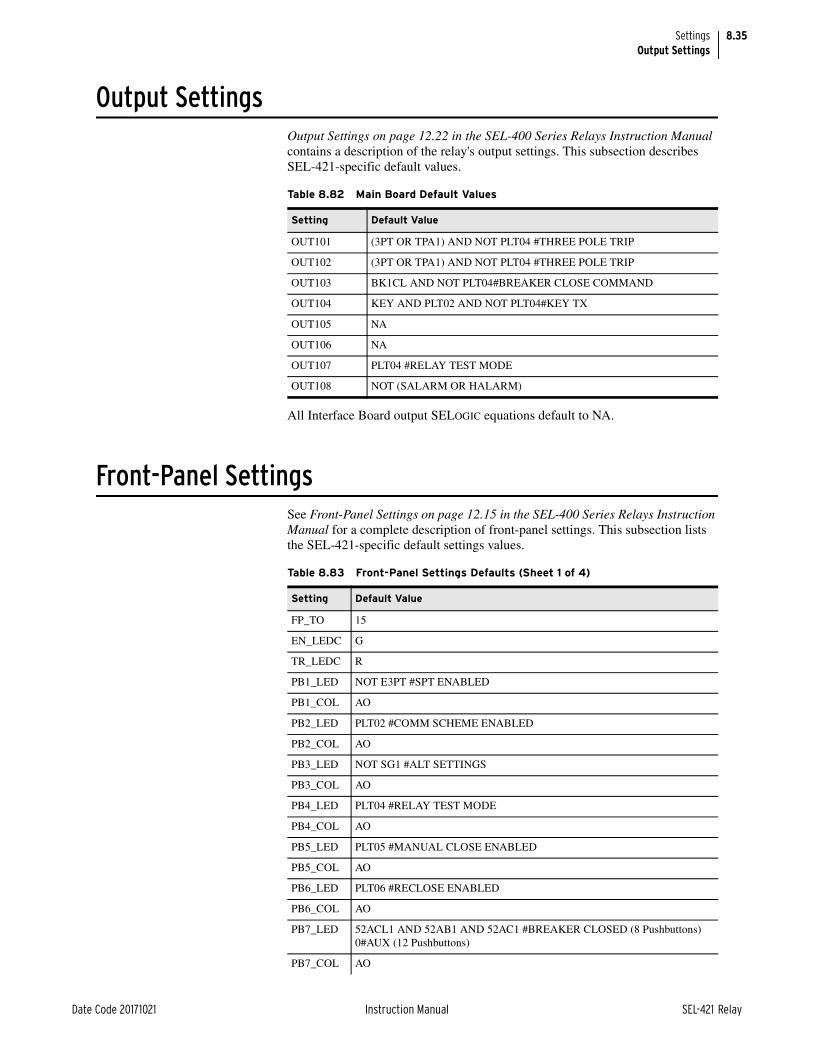
8.35
Date Code 20171021 Instruction Manual SEL-421 Relay
SettingsOutput Settings
Output SettingsOutput Settings on page 12.22 in the SEL-400 Series Relays Instruction Manual contains a description of the relay's output settings. This subsection describes SEL-421-specific default values.
All Interface Board output SELOGIC equations default to NA.
Front-Panel SettingsSee Front-Panel Settings on page 12.15 in the SEL-400 Series Relays Instruction Manual for a complete description of front-panel settings. This subsection lists the SEL-421-specific default settings values.
Table 8.82 Main Board Default Values
Setting Default Value
OUT101 (3PT OR TPA1) AND NOT PLT04 #THREE POLE TRIP
OUT102 (3PT OR TPA1) AND NOT PLT04 #THREE POLE TRIP
OUT103 BK1CL AND NOT PLT04#BREAKER CLOSE COMMAND
OUT104 KEY AND PLT02 AND NOT PLT04#KEY TX
OUT105 NA
OUT106 NA
OUT107 PLT04 #RELAY TEST MODE
OUT108 NOT (SALARM OR HALARM)
Table 8.83 Front-Panel Settings Defaults (Sheet 1 of 4)
Setting Default Value
FP_TO 15
EN_LEDC G
TR_LEDC R
PB1_LED NOT E3PT #SPT ENABLED
PB1_COL AO
PB2_LED PLT02 #COMM SCHEME ENABLED
PB2_COL AO
PB3_LED NOT SG1 #ALT SETTINGS
PB3_COL AO
PB4_LED PLT04 #RELAY TEST MODE
PB4_COL AO
PB5_LED PLT05 #MANUAL CLOSE ENABLED
PB5_COL AO
PB6_LED PLT06 #RECLOSE ENABLED
PB6_COL AO
PB7_LED 52ACL1 AND 52AB1 AND 52AC1 #BREAKER CLOSED (8 Pushbuttons) 0#AUX (12 Pushbuttons)
PB7_COL AO

8.36
SEL-421 Relay Instruction Manual Date Code 20171021
SettingsFront-Panel Settings
PB8_LED NOT (52ACL1 AND 52AB1 AND 52AC1) #BREAKER OPEN (8 Pushbut-tons) 0#AUX (12 Pushbuttons)
PB8_COL AO
PB9_LEDa 0 #AUX
PB9_COLa AO
PB10LEDa 0 #AUX
PB10COLa AO
PB11LEDa 52ACL1 AND 52AB1 AND 52AC1 #BREAKER CLOSED 0 #AUX (Auxil-iary TRIP/CLOSE Pushbuttons)
PB11COLa AO
PB12LEDa NOT (52ACL1 AND 52AB1 AND 52AC1) #BREAKER OPEN 0 #AUX (Aux-iliary TRIP/CLOSE Pushbuttons)
PB12COLa AO
T1_LED (Z1P OR Z1G) AND NOT (SOTFT OR TLED_3)
T1LEDL Y
T1LEDC RO
T2_LED (Z2PT OR Z2GT OR Z3PT OR Z3GT OR Z4PT OR Z4GT) AND NOT (TLED_1 OR TLED_3 OR TLED_4)
T2LEDL Y
T2LEDC RO
T3_LED COMPRM AND NOT (Z1P OR Z1G OR TLED_1 OR SOTFT)
T3LEDL Y
T3LEDC RO
T4_LED SOTFT
T4LEDL Y
T4LEDC RO
T5_LED (Z1P OR Z1G) AND NOT (TLED_6 OR TLED_7 OR TLED_8)
T5LEDL Y
T5LEDC RO
T6_LED (Z2P OR Z2G) AND NOT (Z1P OR Z1G OR TLED_5)
T6LEDL Y
T6LEDC RO
T7_LED (Z3P OR Z3G) AND NOT (Z1P OR Z2P OR Z1G OR Z2G OR TLED_5 OR TLED_6)
T7LEDL Y
T7LEDC RO
T8_LED (Z4P OR Z4G) AND NOT (Z1P OR Z2P OR Z3P OR Z1G OR Z2G OR Z3G OR TLED_5 OR TLED_6 OR TLED_7)
T8LEDL Y
T8LEDC RO
T9_LED PHASE_A
T9LEDL Y
T9LEDC RO
Table 8.83 Front-Panel Settings Defaults (Sheet 2 of 4)
Setting Default Value

8.37
Date Code 20171021 Instruction Manual SEL-421 Relay
SettingsFront-Panel Settings
T10_LED PHASE_B
T10LEDL Y
T10LEDC RO
T11_LED PHASE_C
T11LEDL Y
T11LEDC RO
T12_LED GROUND
T12LEDL Y
T12LEDC RO
T13_LED 50P1 OR 50P2 OR 50P3 OR 50P4 OR 50Q1 OR 50Q2 OR 50Q3 OR 50Q4 OR 50G1 OR 50G2 OR 50G3 OR 50G4
T13LEDL Y
T13LEDC RO
T14_LED 51S1T OR 51S2T OR 51S3T
T14LEDL Y
T14LEDC RO
T15_LED BK1RS
T15LEDL N
T15LEDC RO
T16_LED BK1LO
T16LEDL N
T16LEDC RO
T17_LEDb 79CY1 OR 79CY3
T17LEDLb N
T17LEDCb RO
T18_LEDb 25A1BK1
T18LEDLb N
T18LEDCb RO
T19_LEDb BK1CL
T19LEDLb N
T19LEDCb RO
T20_LEDb BFTRIP1
T20LEDLb N
T20LEDCb RO
T21_LEDb OSB
T21LEDLb N
T21LEDCb RO
T22_LEDb LOP
T22LEDLb N
T22LEDCb RO
T23_LEDb PMDOK AND TSOK
Table 8.83 Front-Panel Settings Defaults (Sheet 3 of 4)
Setting Default Value
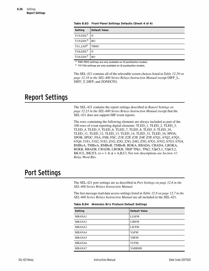
8.38
SEL-421 Relay Instruction Manual Date Code 20171021
SettingsReport Settings
The SEL-421 contains all of the selectable screen choices listed in Table 12.29 on page 12.18 in the SEL-400 Series Relays Instruction Manual except DIFF_L, DIFF_T, DIFF, and ZONECFG.
Report SettingsThe SEL-421 contains the report settings described in Report Settings on page 12.23 in the SEL-400 Series Relays Instruction Manual except that the SEL-421 does not support HIF event reports.
The rows containing the following elements are always included as part of the 100 rows of event reporting digital elements: TLED_1, TLED_2, TLED_3, TLED_4, TLED_5, TLED_6, TLED_7, TLED_8, TLED_9, TLED_10, TLED_11, TLED_12, TLED_13, TLED_14, TLED_15, TLED_16, SPOA, SPOB, SPOC, FSA, FSB, FSC, Z1P, Z2P, Z3P, Z4P, Z5P, 67Q1, 67Q2, 67Q3, 67Q4, 51S1, 51S2, 51S3, Z1G, Z2G, Z3G, Z4G, Z5G, 67G1, 67G2, 67G3, 67G4, RMBnA, TMBnA, RMBnB, TMBnB, ROKA, RBADA, CBADA, LBOKA, ROKB, RBADB, CBADB, LBOKB, TRIP TP1, TP2, 52CL1, 52CL2, BK1CL, BK2CL (n = 1–8, = A,B,C). For row descriptions see Section 11: Relay Word Bits.
Port SettingsThe SEL-421 port settings are as described in Port Settings on page 12.6 in the SEL-400 Series Relays Instruction Manual.
The fast message read data access settings listed in Table 12.8 on page 12.7 in the SEL-400 Series Relays Instruction Manual are all included in the SEL-421.
T23LEDLb N
T23LEDCb RO
T24_LEDb TIRIG
T24LEDLb N
T24LEDCb RO
a PB9–PB12 settings are only available on 12-pushbutton models.b T17–T24 settings are only available on 12-pushbutton models.
Table 8.83 Front-Panel Settings Defaults (Sheet 4 of 4)
Setting Default Value
Table 8.84 MIRRORED BITS Protocol Default Settings
Setting Default Value
MBANA1 LIAFM
MBANA2 LIBFM
MBANA3 LICFM
MBANA4 VAFM
MBANA5 VBFM
MBANA6 VCFM
MBANA7 VABRMS

8.39
Date Code 20171021 Instruction Manual SEL-421 Relay
SettingsDNP3 Settings—Custom Maps
DNP3 Settings—Custom MapsThe SEL-421 DNP3 custom map settings operate as described in the DNP3 Set-tings—Custom Maps on page 12.15 in the SEL-400 Series Relays Instruction Manual. See Table 10.14 on page 10.16 to see the default map configuration.
Bay Settings
Table 8.85 Bay Settings (Sheet 1 of 2)
Setting Prompt Default Value
MIMIC Busbar One-Line Screen Number (1–999) 9
BAYNAME Bay Name (20 characters) BAY 1
BAYLABya Bay Label ya (max 35 pixels, 5–9 characters) LABEL ya
EPOLDIS Enable Single-Pole Discrepancy Logic (Y, N) Y
BUSNAMya Busbar ya Name (max 40 pixels, 6–10 characters) BUSNAM ya
ByHMINM Breaker ya HMI Name (max 17 pixels, 3–4 characters) BKya
BzCTLNMb Breaker zb Cntl. Scr. Name (max 15 characters) Breaker zb
52yCLSMa Breaker ya Close Status (SELOGIC Equation) 52ACLya
523CLSM = NA
52y_ALMa Breaker ya Alarm Status (SELOGIC Equation) 52AALya
523_ALM = NA
DrHMINc Disconnect m HMI Name (max 17 pixels, 3–4 characters)d SW[m]
DrCTLNc Disconnect m Control Scr. Name (max 15 char.)d BB [m]
89AMrc Disconnect m N/O Contact (SELOGIC Equation)d 1
89BMrc Disconnect m N/C Contact (SELOGIC Equation)d 0
89ALPrc Disconnect m Alarm Pickup Delay (1–99999 cyc)d 300
89CCNrc Dis. m Remote Close Control (SELOGIC Equation)d 89CCr
89OCNrc Dis. m Remote Open Control (SELOGIC Equation)d 89OCr
89CSTrc Dis. m Close Seal-in Time (OFF, 1–99999 cyc)d 280
89CITrc Dis. m Close Immobility Time (OFF, 1–99999 cyc)d 20
89CRSrc Disconnect m Close Reset (SELOGIC Equation)d 89CLr OR 89CSIr
89CBLrc Disconnect m Close Block (SELOGIC Equation)d NA
89OSTrc Dis. m Open Seal-in Time (OFF, 1–99999 cyc)d 280
89OITrc Dis. m Open Immobility Time (OFF, 1–99999 cyc)d 20
89ORSrc Disconnect m Open Reset (SELOGIC Equation)d 89OPNr OR 89OSIr
89OBLrc Disconnect m Open Block (SELOGIC Equation)d NA
89CIRrc Dis. m Close Immob. Time Reset (SELOGIC Equation)d NOT 89OPNr
89OIRrc Dis. m Open Immob. Time Reset (SELOGIC Equation)d NOT 89CLr
MDELEne Analog Quantity <Blank>
MDNAMne Pretext <Blank>
MDSETne Text Formatting {w.d} <Blank>
MDCLRne Post-Text

8.40
SEL-421 Relay Instruction Manual Date Code 20171021
SettingsBay Settings
MDSCAne Scale Format {s} 1
LOCAL Local Control (SELOGIC Equation) PLT06
a y = 1—3.b z = 1—2.c r = 01–10.d m = 1–10.e n = 1–24.
Table 8.85 Bay Settings (Sheet 2 of 2)
Setting Prompt Default Value

Date Code 20171021 Instruction Manual SEL-421 Relay
Instruction ManualInstruction ManualS E C T I O N 9
ASCII Command Reference
You can use a communications terminal or terminal emulation program to set and operate the SEL-421 Relay. This section explains the commands that you send to the SEL-421 using SEL ASCII communications protocol. The relay responds to commands such as settings, metering, and control operations.
This section lists all the commands supported by the relay but most are described in Section 14: ASCII Command Reference in the SEL-400 Series Relays Instruc-tion Manual. This section provides information on commands and command options that are unique to the SEL-421.
This section lists ASCII commands alphabetically. Commands, command options, and command variables that you enter are shown in bold. Lower case italic letters and words in a command represent command variables that you determine based on the application (for example, circuit breaker number n = 1 or 2, remote bit number nn = 01–32, and level).
Command options appear with brief explanations about the command function. Refer to the references listed with the commands for more information on the relay function corresponding to the command or examples of the relay response to the command.
You can simplify the task of entering commands by shortening any ASCII com-mand to the first three characters; for example, ACCESS becomes ACC. Always send a carriage return <CR> character, or a carriage return character followed by a line feed character <CR><LF> to command the relay to process the ASCII command. Usually, most terminals and terminal programs interpret the <Enter> key as a <CR>. For example, to send the ACCESS command, type ACC <Enter>.
Tables in this section show the access level(s) where the command or command option is active. Access levels in the SEL-421 are Access Level 0, Access Level 1, Access Level B (breaker), Access Level P (protection), Access Level A (automation), Access Level O (output), and Access Level 2.

9.2
SEL-421 Relay Instruction Manual Date Code 20171021
ASCII Command ReferenceDescription of Commands
Description of CommandsTable 9.1 lists all the commands supported by the relay and the corresponding links to the descriptions in Section 14: ASCII Command Reference in the SEL-400 Series Relays Instruction Manual.
Command List
Table 9.1 SEL-421 List of Commands (Sheet 1 of 3)
CommandLocation of Command in Section 14: ASCII Command Reference in the SEL-400 Series Relays Instruction Manual
2ACCESS 2ACCESS on page 14.1
89CLOSE n 89CLOSE n on page 14.2 (The SEL-421 supports 10 disconnects.)
89OPEN n 89OPEN n on page 14.2 (The SEL-421 supports 10 disconnects.)
AACCESS AACCESS on page 14.3
ACCESS ACCESS on page 14.3
BACCESS BACCESS on page 14.3
BNAME BNAME on page 14.4
BREAKER BREAKER on page 14.4 (The SEL-421 supports two circuit breakers, designated 1 and 2.)
CAL CAL on page 14.5
CASCII CASCII on page 14.5
CBREAKER CBREAKER on page 14.6 (The SEL-421 supports two circuit breakers, designated 1 and 2.)
CEVENT CEVENT on page 14.6 (In the SEL-421, CEV L provides an 8 samples/cycle large resolution event report.)
CFG CTNOM i CFG CTNOM on page 14.10 (In the SEL-421, the nominal current choices are 1 and 5 for 1 A nom-inal and 5 A nominal CT inputs.)
CFG NFREQ f CFG NFREQ on page 14.11
CHISTORY CHISTORY on page 14.11
CLOSE n CLOSE n on page 14.11 (The SEL-421 supports two circuit breakers, designated 1 and 2.)
COMMUNICATIONS COMMUNICATIONS on page 14.12
CONTROL nn CONTROL nn on page 14.16
COPY COPY on page 14.17
CPR CPR on page 14.17
CSER CSER on page 14.18
CSTATUS CSTATUS on page 14.19
CSUMMARY CSUMMARY on page 14.19
DATE DATE on page 14.21
DNAME X DNAME X on page 14.21
DNP DNP on page 14.22
ETHERNET ETHERNET on page 14.22
EVENT EVENT on page 14.23 (The SEL-421 supports large resolution event reports of 8 samples/cycle.)
EXIT EXIT on page 14.27
FILE FILE on page 14.27
GOOSE GOOSE on page 14.28
GROUP GROUP on page 14.31

9.3
Date Code 20171021 Instruction Manual SEL-421 Relay
ASCII Command ReferenceDescription of Commands
HELP HELP on page 14.32
HISTORY HISTORY on page 14.32
ID ID on page 14.33
IRIG IRIG on page 14.34
LOOPBACK LOOPBACK on page 14.35
MAC MAC on page 14.36
MAP MAP on page 14.37
METER See METER on page 9.4 in this section.
MET See MET on page 9.4 in this section.
MET AMV MET AMV on page 14.38
MET ANA MET ANA on page 14.38
MET BAT MET BAT on page 14.38 (The SEL-421 provides battery metering for two battery monitor channels.)
MET D MET D on page 14.39
MET E See MET E on page 9.5 in this section.
MET M MET M on page 14.39
MET PM MET PM on page 14.39
MET PMV MET PMV on page 14.40
MET RMS See MET RMS on page 9.5 in this section.
MET RTC MET RTC on page 14.41
MET SYN See MET SYN on page 9.5 in this section.
MET T MET T on page 14.41
OACCESS OACCESS on page 14.41
OPEN n OPEN n on page 14.42 (The SEL-421 supports two circuit breakers, designated 1 and 2.)
PACCESS PACCESS on page 14.42
PASSWORD PASSWORD on page 14.42
PING PING on page 14.43
PORT PORT on page 14.44
PROFILE PROFILE on page 14.45
PULSE PULSE on page 14.45
QUIT QUIT on page 14.46
RTC RTC on page 14.46
SER SER on page 14.46
SET SET on page 14.48 (Table 9.6 lists the class and instance options available in the SEL-421.)
SHOW SHOW on page 14.50 (Table 9.7 lists the class and instance options available in the SEL-421.)
SNS SNS on page 14.50
STATUS STATUS on page 14.50
SUMMARY SUMMARY on page 14.52
TARGET TARGET on page 14.53
TEC TEC on page 14.54
TEST DB TEST DB on page 14.55
Table 9.1 SEL-421 List of Commands (Sheet 2 of 3)
CommandLocation of Command in Section 14: ASCII Command Reference in the SEL-400 Series Relays Instruction Manual
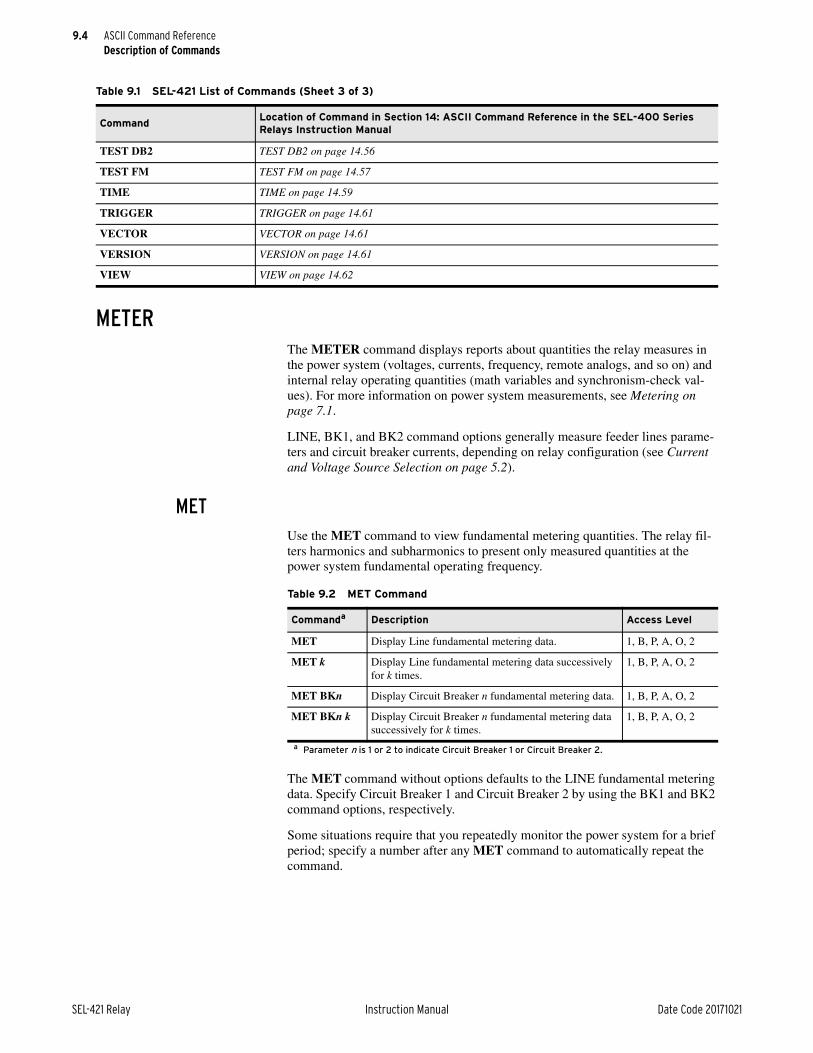
9.4
SEL-421 Relay Instruction Manual Date Code 20171021
ASCII Command ReferenceDescription of Commands
METERThe METER command displays reports about quantities the relay measures in the power system (voltages, currents, frequency, remote analogs, and so on) and internal relay operating quantities (math variables and synchronism-check val-ues). For more information on power system measurements, see Metering on page 7.1.
LINE, BK1, and BK2 command options generally measure feeder lines parame-ters and circuit breaker currents, depending on relay configuration (see Current and Voltage Source Selection on page 5.2).
METUse the MET command to view fundamental metering quantities. The relay fil-ters harmonics and subharmonics to present only measured quantities at the power system fundamental operating frequency.
The MET command without options defaults to the LINE fundamental metering data. Specify Circuit Breaker 1 and Circuit Breaker 2 by using the BK1 and BK2 command options, respectively.
Some situations require that you repeatedly monitor the power system for a brief period; specify a number after any MET command to automatically repeat the command.
TEST DB2 TEST DB2 on page 14.56
TEST FM TEST FM on page 14.57
TIME TIME on page 14.59
TRIGGER TRIGGER on page 14.61
VECTOR VECTOR on page 14.61
VERSION VERSION on page 14.61
VIEW VIEW on page 14.62
Table 9.1 SEL-421 List of Commands (Sheet 3 of 3)
CommandLocation of Command in Section 14: ASCII Command Reference in the SEL-400 Series Relays Instruction Manual
Table 9.2 MET Command
Commanda
a Parameter n is 1 or 2 to indicate Circuit Breaker 1 or Circuit Breaker 2.
Description Access Level
MET Display Line fundamental metering data. 1, B, P, A, O, 2
MET k Display Line fundamental metering data successively for k times.
1, B, P, A, O, 2
MET BKn Display Circuit Breaker n fundamental metering data. 1, B, P, A, O, 2
MET BKn k Display Circuit Breaker n fundamental metering data successively for k times.
1, B, P, A, O, 2

9.5
Date Code 20171021 Instruction Manual SEL-421 Relay
ASCII Command ReferenceDescription of Commands
MET EUse the MET E command to view the energy import and export quantities.
The reset command, MET RE, resets the Line, BK1, and BK2 energy metering quantities. When you issue the MET RE command, the relay responds with Reset Energy Metering (Y/N)? If you answer Y <Enter>, the relay responds with Energy Metering Reset.
MET RMSUse the MET RMS command to view root-mean-square (rms) metering quanti-ties. The relay includes power system harmonics and subharmonics in rms quan-tities.
NOTE: In firmware R310 and newer, the rms value is zero when the current is below 0.02 • INOM.
MET SYNUse the MET SYN command to view the synchronism-check reference voltage, normalized source voltages, angles, and slip calculations.
If you have not enabled the synchronism-check function, the relay responds with Synchronism Check Element Is Not Available. (Enable synchronism check with the Global settings E25BK1, E25BK2, and NUMBK; see Synchronism Check on page 5.158).
Table 9.3 MET E Command
Command Description Access Level
MET E Display Line energy metering data. 1, B, P, A, O, 2
MET E k Display Line energy metering data successively for k times. 1, B, P, A, O, 2
MET RE Reset Line energy metering data. P, A, O, 2
Table 9.4 MET RMS Command
Commanda
a Parameter n is 1 or 2 to indicate Circuit Breaker 1 or Circuit Breaker 2.
Description Access Level
MET RMS Display Line rms metering data. 1, B, P, A, O, 2
MET RMS k Display Line rms metering data successively for k times.
1, B, P, A, O, 2
MET BKn RMS Display Circuit Breaker n rms metering data. 1, B, P, A, O, 2
MET BKn RMS k Display Circuit Breaker n rms metering data succes-sively for k times.
1, B, P, A, O, 2
Table 9.5 MET SYN Command
Command Description Access Level
MET SYN Display the synchronism-check values. 1, B, P, A, O, 2
MET SYN k Display the synchronism-check values successively for k times.
1, B, P, A, O, 2

9.6
SEL-421 Relay Instruction Manual Date Code 20171021
ASCII Command ReferenceDescription of Commands
SETSee SET on page 14.48 in the SEL-400 Series Relays Instruction Manual. The following table lists the options specifically available in the SEL-421.
NOTE: The SEL-421-4 has only one 100-line block of automation freeform SELOGIC control equation programming.
Table 9.6 SET Command Overview
Command Description Access Level
SETa
a Parameter n = 1–6, representing Group 1 through Group 6.
Set the Group relay settings, beginning at the first setting in the active group.
P, 2
SET na Set the Group n relay settings, beginning at the first set-ting n each.
P, 2
SET Ab
b Parameter m = 1–10 for Block 1 through Block 10.
Set the Automation SELOGIC control equation relay set-tings in Block 1.
A, 2
SET A mb Set the Automation SELOGIC control equation relay set-tings in Block m.
A, 2
SET B Bay control settings, beginning at the first setting in this class.
P, A, O, 2
SET D Set the DNP3 remapping settings, beginning at the first setting in this class for instance 1.
P, A, O, 2
SET D instance
Set the DNP3 remapping settings beginning at the first setting of instance.
P, A, O, 2
SET F Set the front-panel relay settings, beginning at the first set-ting in this class.
P, A, O, 2
SET G Set the Global relay settings, beginning at the first setting in this class.
P, A, O, 2
SET La Set the Protection SELOGIC control equation relay settings for the active settings group.
P, 2
SET L na Set the Protection SELOGIC relay settings for Instance n, which is Group n.
P, 2
SET M Set the Breaker Monitor relay settings, beginning at the first setting in this class.
P, 2
SET N Enter text using the text-edit format. P, A, O, 2
SET O Set the Output SELOGIC control equation relay settings, beginning at OUT101.
O, 2
SET Pc
c Parameter p = 1–3, F, or 5, corresponding to PORT 1–PORT 3, PORT F, or PORT 5.
Set the port presently in use, beginning at the first setting for this port.
P, A, O, 2
SET P pc Set the communications Port relay settings for Port p, beginning at the first setting for this port.
P, A, O, 2
SET R Set the Report relay settings, beginning at the first setting for this class.
P, A, O, 2
SET T Set the alias settings. P, A, O, 2

9.7
Date Code 20171021 Instruction Manual SEL-421 Relay
ASCII Command ReferenceDescription of Commands
SHOWSee SHOW on page 14.50 in the SEL-400 Series Relays Instruction Manual. The following table lists the class and instance options available in the SEL-421.
Table 9.7 SHO Command Overview
Command Description Access Level
SHOa
a Parameter n = 1–6, representing Group 1 through Group 6.
Show the Group relay settings, beginning at the first setting in the active group.
1, B, P, A, O, 2
SHO na Show the Group n relay settings, beginning at the first setting in each instance.
1, B, P, A, O, 2
SHO Ab
b Parameter m = 1–10 for Block 1 through Block 10.
Show the Automation SELOGIC control equation relay settings in Block 1.
1, B, P, A, O, 2
SHO A mb Show the Automation SELOGIC control equation relay settings in Block m.
1, B, P, A, O, 2
SHO B Show the Bay Control relay settings, beginning at the first setting in this class.
1, B, P, A, O, 2
SHO D Show the DNP3 remapping settings for instance 1. P, A, O, 2
SHO D instance Show the DNP3 remapping settings for instance. P, A, O, 2
SHO F Show the front-panel relay settings, beginning at the first setting in this class.
1, B, P, A, O, 2
SHO G Show the Global relay settings, beginning at the first setting in this class.
1, B, P, A, O, 2
SHO La Show the Protection SELOGIC control equation relay settings for the active group.
1, B, P, A, O, 2
SHO L na Show the Protection SELOGIC control equation relay settings for Instance n, which is Group n.
1, B, P, A, O, 2
SHO M Show the Breaker Monitor relay settings, beginning at the first setting in this class.
1, B, P, A, O, 2
SHO N Show notes in the relay. 1, B, P, A, O, 2
SHO O Show the Output SELOGIC control equation relay set-tings, beginning at OUT101.
1, B, P, A, O, 2
SHO Pc
c Parameter p = 1–3, F, and 5, which corresponds to PORT 1–PORT 3, PORT F, and PORT 5.
Show the relay settings for the port presently in use, beginning at the first setting.
1, B, P, A, O,
SHO P pc Show the communications Port relay settings for Port p, beginning at the first setting for this port.
1, B, P, A, O, 2
SHO R Show the Report relay settings, beginning at the first setting for this class.
1, B, P, A, O, 2
SHO T Show the alias settings. 1, B, P, A, O, 2

This page intentionally left blank

Date Code 20171021 Instruction Manual SEL-421 Relay
SEL-421 RelayInstruction ManualS E C T I O N 1 0
Communications Interfaces
Section 15: Communications Interfaces through Section 18: Synchrophasors in the SEL-400 Series Relays Instruction Manual describes the various communica-tions interfaces and protocols used in SEL-400 series relays. This section describes aspects of the communications protocols that are unique to the SEL-421. The following topics are discussed:
➤ Communications Database on page 10.1
➤ DNP3 Communication on page 10.8
➤ IEC 61850 Communication on page 10.22
➤ Synchrophasors on page 10.30
Communications DatabaseThe SEL-421 maintains a database to describe itself to external devices via the Fast Message Data Access protocol. This database includes a variety of data within the relay that are available to devices connected in a serial or Ethernet net-work. The database includes the regions and data described in Table 10.1. Use the MAP and VIEW commands to display maps and contents of the database regions. See Section 9: ASCII Command Reference for more information on the MAP and VIEW commands.
Data within the regions are available for access by external devices via the SEL Fast Message protocol.
The LOCAL region contains the device FID, SID, and RID. It will also provide appropriate status points. This region is updated on settings changes and when-ever monitored status points change (see Table 10.2).
Table 10.1 SEL-421 Database Regions
Region Name Contents Update Rate
LOCAL Relay identification data including FID, Relay ID, Station ID, and active protec-tion settings group
Updated on settings change and whenever monitored values change
METER Metering and measurement data 0.5 s
DEMAND Demand and peak demand measurement data
15 s
TARGET Selected rows of Relay Word bit data 0.5 s
HISTORY Relay event history records for the 10 most recent events
Within 15 s of any new event
BREAKER Circuit breaker monitor summary data 15 s
STATUS Self-test diagnostic status data 5 s
ANALOGS Protection and automation math variables 0.5 s

10.2
SEL-421 Relay Instruction Manual Date Code 20171021
Communications InterfacesCommunications Database
The METER region contains all the basic meter and energy information. This region is updated every 0.5 seconds. See Table 10.3 for the Map.
Table 10.2 SEL-421 Database Structure—LOCAL Region
Address (Hex)
Name Type Description
0000 FID char[48] FID string
0030 BFID char[48] SELBOOT FID string
0060 SER_NUM char[16] Device Serial number, from factory settings
0070 PART_NUM char[24] Device part number, from factory settings
0088 CONFIG char[8] Device configuration string(as reported in ID command)
0090 SPECIAL char[8] Special device configuration string(as reported in ID command)
0098 DEVICE_ID char[40] Relay ID setting, from global settings
00C0 NODE_ID char[40] Station ID from global settings
00E8 GROUP int Active group
00E9 STATUS int Bit map of status flags: 0 for okay, 1 for failure
Table 10.3 SEL-421 Database Structure—METER Region (Sheet 1 of 3)
Address (Hex)
Name Type Description
1000 _YEAR int 4-digit year when data were sampled
1001 DAY_OF_YEAR int 1–366 day when data were sampled
1002 TIME(ms) long int Time of day in ms when data were sampled(0–86,400,00)
1004 FREQ float System frequency
1006 VDC1 float Battery 1 voltage
1008 VDC2 float Battery 2 voltage
100A, 100C
IA1 float[2] Line A-Phase current magnitude and phase
100E, 1010
IB1 float[2] Line B-Phase current magnitude and phase
1012, 1014
IC1 float[2] Line C-Phase current magnitude and phase
1016, 1018
I0_1 float[2] Line 0-sequence current magnitude and phase
101A, 101C
I1_1 float[2] Line 1-sequence current magnitude and phase
101E, 1020
I2_1 float[2] Line 2-sequence current magnitude and phase
1022, 1024
IA2 float[2] Breaker 1 A-Phase current magnitude and phase
1026, 1028
IB2 float[2] Breaker 1 B-Phase current magnitude and phase
102A, 102C
IC2 float[2] Breaker 1 C-Phase current magnitude and phase
102E, 1030
IA3 float[2] Breaker 2 A-Phase current magnitude and phase

10.3
Date Code 20171021 Instruction Manual SEL-421 Relay
Communications InterfacesCommunications Database
1032, 1034
IB3 float[2] Breaker 2 B-Phase current magnitude and phase
1036, 1038
IC3 float[2] Breaker 2 C-Phase current magnitude and phase
103A, 103C
VA float[2] A-Phase voltage magnitude and phase
103E, 1040
VB float[2] B-Phase voltage magnitude and phase
1042, 1044
VC float[2] C-Phase voltage magnitude and phase
1046, 1048
V0 float[2] 0-sequence voltage magnitude and phase
104A, 104C
V1 float[2] 1-sequence voltage magnitude and phase
104E, 1050
V2 float[2] 2-sequence voltage magnitude and phase
1052 VP float Polarizing voltage magnitude
1054 VS1 float Synchronizing Voltage 1 magnitude
1056 VS2 float Synchronizing Voltage 2 magnitude
1058 ANG1_DIF float VS1 and VP angle difference, in degrees
105A VS1_SLIP float VS1 frequency slip with respect to VP, in HZ
105C ANG2_DIF float VS2 and VP angle difference, in degrees
105E VS2_SLIP float VS2 frequency slip with respect to VP, in HZ
1060 PA float A-Phase real power
1062 PB float B-Phase real power
1064 PC float C-Phase real power
1066 P float Total real power
1068 QA float A-Phase reactive power
106A QB float B-Phase reactive power
106C QC float C-Phase reactive power
106E Q float Total reactive power
1070 SA float A-Phase apparent power, if available
1072 SB float B-Phase apparent power, if available
1074 SC float C-Phase apparent power, if available
1076 S float Total apparent power
1078 PFA float A-Phase power factor
107A PFB float Phase power factor
107C PFC float Phase power factor
107E PF float Three-phase power factor
1080 PEA float Positive A-Phase energy in KWh
1082 PEB float Positive B-Phase energy in KWh
1084 PEC float Positive C-Phase energy in KWh
1086 PE float Total positive energy in KWh
Table 10.3 SEL-421 Database Structure—METER Region (Sheet 2 of 3)
Address (Hex)
Name Type Description

10.4
SEL-421 Relay Instruction Manual Date Code 20171021
Communications InterfacesCommunications Database
The DEMAND region contains demand and peak demand information. This region is updated every 15 seconds. See Table 10.4 for the Map.
1088 NEA float Negative A-Phase energy in KWh
108A NEB float Negative B-Phase energy in KWh
108C NEC float Negative C-Phase energy in KWh
108E NE float Total negative energy in KWh
Table 10.4 SEL-421 Database Structure—DEMAND Region
Address (Hex)
Name Type Description
2000 _YEAR int Four-digit year when data were sampled
2001 DAY_OF_YEAR int 1–366 day when data were sampled
2002 TIME(ms) long int Time of day in ms when data were sampled(0–86,400,00)
2004 IA float A-Phase demand current
2006 IB float B-Phase demand current
2008 IC float C-Phase demand current
200A I0 float 0-sequence demand current
200C I2 float 2-sequence demand current
200E PA float A-Phase demand real power
2010 PB float B-Phase demand real power
2012 PC float C-Phase demand real power
2014 P float Total demand real power
2016 SA float A-Phase demand apparent power
2018 SB float B-Phase demand apparent power
201A SC float C-Phase demand apparent power
201C S float Total demand apparent power
201E PK_IA float A-Phase demand current
2020 PK_IB float B-Phase demand current
2022 PK_IC float C-Phase demand current
2024 PK_I0 float Zero-sequence demand current
2026 PK_I2 float Two-sequence demand current
2028 PK_PA float A-Phase demand real power
202A PK_PB float B-Phase demand real power
202C PK_PC float C-Phase demand real power
202E PK_P float Total demand real power
2030 PK_SA float A-Phase demand apparent power
2032 PK_SB float B-Phase demand apparent power
2034 PK_SC float C-Phase demand apparent power
2036 PK_S float Total demand apparent power
Table 10.3 SEL-421 Database Structure—METER Region (Sheet 3 of 3)
Address (Hex)
Name Type Description

10.5
Date Code 20171021 Instruction Manual SEL-421 Relay
Communications InterfacesCommunications Database
The TARGET region contains the entire visible Relay Word plus the rows desig-nated specifically for the TARGET region. This region is updated every 0.5 sec-onds. See Table 10.5 for the Map. See Section 11: Relay Word Bits for detailed information on the Relay Word bits.
The HISTORY region contains all information available in a History report for the most recent 10 events. This region is updated within 15 seconds of any new events. See Table 10.6 for the Map.
The BREAKER region contains some of the information available in a summary Breaker report. This region is updated every 15 seconds. See Table 10.7 for the Map.
Table 10.5 SEL-421 Database Structure—TARGET Region
Address (Hex)
Name Type Description
3000 _YEAR int Four-digit year when data were sampled
3001 DAY_OF_YEAR int 1–366 day when data were sampled
3002 TIME(ms) long int Time of day in ms when data were sampled(0–86,400,000)
3004 TARGET char[~240] Entire Relay Word with bit labels
Table 10.6 SEL-421 Database Structure—HISTORY Region
Address (Hex)
Name Type Description
4000 _YEAR int Four-digit year when data were sampled
4001 DAY_OF_YEAR int 1–366 day when data were sampled
4002 TIME(ms) long int Time of day in ms when data were sample(0–86,400,000)
4004 REF_NUM int[10] Event serial number
400E MONTH int[10] Month of event
4018 DAY int[10] Day of event
4022 YEAR int[10] Year of event
402C HOUR int[10] Hour of event
4036 MIN int[10] Minute of event
4040 SEC int[10] Second of event
404A MSEC int[10] Milliseconds of event
4054 EVENT char[60] Event type string
4090 GROUP int[10] Active group during fault
409A FREQ float[10] System frequency at time of fault
40AE TARGETS char[160] System targets from event
414E FAULT_LOC float[10] Fault location
4162 SHOT int[10] Recloser shot counter (sum of 1-pole and 3-pole)
416C SHOT_1P int[10] Single-pole recloser counter
4176 SHOT_3P int[10] Three-pole recloser counter
4180 CURR int[10] Fault current in primary amperes

10.6
SEL-421 Relay Instruction Manual Date Code 20171021
Communications InterfacesCommunications Database
The STATUS region contains complete relay status information. This region is updated every 5 seconds. See Table 10.8 for the Map.
Table 10.7 SEL-421 Database Structure—BREAKER Region
Address (Hex)
Name Type Description
5000 _YEAR int Four-digit year when data were sampled
5001 DAY_OF_YEAR int 1–366 day when data were sampled
5002 TIME(ms) long int Time of day in ms when data were sampled(0–86,400,000)
5004 BCWA1 float Breaker 1 A-Phase breaker wear (%)
5006 BCWB1 float Breaker 1 B-Phase breaker wear (%)
5008 BCWC1 float Breaker 1 C-Phase breaker wear (%)
500A BCWA2 float Breaker 2 A-Phase breaker wear (%)
500C BCWB2 float Breaker 2 B-Phase breaker wear (%)
500E BCWC2 float Breaker 2 C-Phase breaker wear (%)
5010 CURA1 float Breaker 1 A-Phase accumulated current (kA)
5012 CURB1 float Breaker 1 B-Phase accumulated current (kA)
5014 CURC1 float Breaker 1 C-Phase accumulated current (kA)
5016 CURA2 float Breaker 2 A-Phase accumulated current (kA)
5018 CURB2 float Breaker 2 B-Phase accumulated current (kA)
501A CURC2 float Breaker 2 C-Phase accumulated current (kA)
501C NOPA1 long int Breaker 1 A-Phase number of operations
501E NOPB1 long int Breaker 1 B-Phase number of operations
5020 NOPC1 long int Breaker 1 C-Phase number of operations
5022 NOPA2 long int Breaker 2 A-Phase number of operations
5024 NOPB2 long int Breaker 2 B-Phase number of operations
5026 NOPC2 long int Breaker 2 C-Phase number of operations
Table 10.8 SEL-421 Database Structure—STATUS Region (Sheet 1 of 2)
Address (Hex)
Name Type Description
6000 _YEAR int Four-digit year when data were sampled
6001 DAY_OF_YEAR int 1–366 day when data were sampled
6002 TIME(ms) long int Time of day in ms when data were sampled(0–86,400,000)
6004 CH1(mV) int Channel 1 offset
6005 CH2(mV) int Channel 2 offset
6006 CH3(mV) int Channel 3 offset
6007 CH4(mV) int Channel 4 offset
6008 CH5(mV) int Channel 5 offset
6009 CH6(mV) int Channel 6 offset
600A CH7(mV) int Channel 7 offset
600B CH8(mV) int Channel 8 offset
600C CH9(mV) int Channel 9 offset

10.7
Date Code 20171021 Instruction Manual SEL-421 Relay
Communications InterfacesCommunications Database
The ANALOGS region contains protection and automation variables. This region is updated every 0.5 seconds. See Table 10.9 for the Map.
The database is virtual device 1 in the relay. You can display the contents of a region using the MAP 1:region command (where region is one of the database region names listed in Table 10.1). An example of the MAP command is shown in Figure 10.1.
600D CH10(mV) int Channel 10 offset
600E CH11(mV) int Channel 11 offset
600F CH12(mV) int Channel 12 offset
6010 MOF(mV) int Master offset
6011 OFF_WARN char[8] Offset warning string
6019 OFF_FAIL char[8] Offset failure string
6021 PS3(V) float 3.3 Volt power supply voltage
6023 PS5(V) float 5 Volt power supply voltage
6025 PS_N5(V) float –5 Volt regulated voltage
6027 PS15(V) float 15 Volt power supply voltage
6029 PS_N15(V) float –15 Volt power supply voltage
602B PS_WARN char[8] Power supply warning string
6033 PS_FAIL char[8] Power supply failure string
603B HW_FAIL char[40] Hardware failure strings
6063 CC_STA char[40] Comm. card status strings
608B PORT_STA char[160] Serial port status strings
612B TIME_SRC char[10] Time source
6135 LOG_ERR char[40] SELOGIC error strings
615D TEST_MD char[160] Test mode string
Table 10.9 SEL-421 Database Structure—ANALOGS Region
Address (Hex)
Name Type Description
7000 _YEAR int Four-digit year when data were sampled
7001 DAY_OF_YEAR int 1–366 day when data were sampled
7002 TIME(ms) long int Time of day in ms when data were sampled(0–86400000)
7004 PMV01_64 float[64] PMV01–PMV64
7084 AMV001_256 float[256] AMV001–AMV256
Table 10.8 SEL-421 Database Structure—STATUS Region (Sheet 2 of 2)
Address (Hex)
Name Type Description
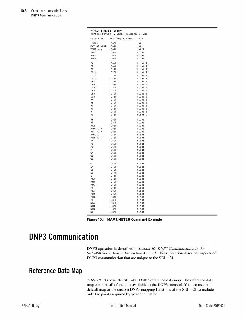
10.8
SEL-421 Relay Instruction Manual Date Code 20171021
Communications InterfacesDNP3 Communication
DNP3 CommunicationDNP3 operation is described in Section 16: DNP3 Communication in the SEL-400 Series Relays Instruction Manual. This subsection describes aspects of DNP3 communication that are unique to the SEL-421.
Reference Data MapTable 10.10 shows the SEL-421 DNP3 reference data map. The reference data map contains all of the data available to the DNP3 protocol. You can use the default map or the custom DNP3 mapping functions of the SEL-421 to include only the points required by your application.
=>>MAP 1 METER <Enter>Virtual Device 1, Data Region METER Map
Data Item Starting Address Type
_YEAR 1000h intDAY_OF_YEAR 1001h intTIME(ms) 1002h int[2]FREQ 1004h floatVDC1 1006h floatVDC2 1008h float
IA1 100ah float[2]IB1 100eh float[2]IC1 1012h float[2]I0_1 1016h float[2]I1_1 101ah float[2]I2_1 101eh float[2]IA2 1022h float[2]IB2 1026h float[2]IC2 102ah float[2]IA3 102eh float[2]IB3 1032h float[2]IC3 1036h float[2]VA 103ah float[2]VB 103eh float[2]VC 1042h float[2]V0 1046h float[2]V1 104ah float[2]V2 104eh float[2]
VP 1052h floatVS1 1054h floatVS2 1056h floatANG1_DIF 1058h floatVS1_SLIP 105ah floatANG2_DIF 105ch floatVS2_SLIP 105eh floatPA 1060h floatPB 1062h floatPC 1064h floatP 1066h floatQA 1068h floatQB 106ah floatQC 106ch float
Q 106eh floatSA 1070h floatSB 1072h floatSC 1074h floatS 1076h floatPFA 1078h floatPFB 107ah floatPFC 107ch floatPF 107eh floatPEA 1080h floatPEB 1082h floatPEC 1084h floatPE 1086h floatNEA 1088h floatNEB 108ah floatNEC 108ch floatNE 108eh float
Figure 10.1 MAP 1:METER Command Example

10.9
Date Code 20171021 Instruction Manual SEL-421 Relay
Communications InterfacesDNP3 Communication
The entire Relay Word (See Section 11: Relay Word Bits) is part of the DNP3 ref-erence map. You may include any label in the Relay Word as part of a DNP3 cus-tom map.
The SEL-421 scales analog values by the indicated settings or fixed scaling. Ana-log inputs for event (fault) summary reporting use a default scale factor of 1 and dead band of ANADBM. Per-point scaling and dead band settings specified in a custom DNP3 map will override defaults.
Table 10.10 SEL-421 DNP3 Reference Data Map (Sheet 1 of 6)
Object Label Description
Binary Inputs
01, 02 RLYDIS Relay disabled
01, 02 STFAIL Relay diagnostic failure
01, 02 STWARN Relay diagnostic warning
01, 02 STSET Settings change or relay restart
01, 02 UNRDEV New relay event available
01, 02 NUNREV An unread event exists, newer than the event in the Event summary AIs
01, 02 LDATPFW Leading true power factor A-Phase, Terminal W (1 if leading, 0 if lagging or zero)
01, 02 LDBTPFW Leading true power factor B-Phase, Terminal W (1 if leading, 0 if lagging or zero)
01, 02 LDCTPFW Leading true power factor C-Phase, Terminal W (1 if leading, 0 if lagging or zero)
01, 02 LD3TPFW Leading true power factor three-phase, Terminal W (1 if leading, 0 if lagging or zero)
01, 02 Relay Word Relay Word bit label (See Section 11: Relay Word Bits)
Binary Outputs
10, 12 RB01–RB32 Remote bits RB01–RB32
10, 12 RB01:RB02
RB03:RB04
RB05:RB06
•
•
•
RB29:RB30
RB31:RB32
Remote bit pairs RB01–RB32
10, 12 OC1 Pulse Open Circuit Breaker 1 command
10, 12 CC1 Pulse Close Circuit Breaker 1 command
10, 12 OC1:CC1 Open/Close pair for Circuit Breaker 1
10, 12 OC2 Pulse Open Circuit Breaker 2 command
10, 12 CC2 Pulse Close Circuit Breaker 2 command
10, 12 OC2:CC2 Open/Close pair for Circuit Breaker 2
10, 12 89OC01–89OC10 Open Disconnect Switch Control 1–10
10, 12 89CC01–89CC10 Close Disconnect Switch Control 1–10
10, 12 89OC01:89CC01
89OC02:89CC02
89OC03:89CC03
•
•
•
89OC09:89CC09
89OC10:89CC10
Open/Close Disconnect Switch Control Pair 1–10

10.10
SEL-421 Relay Instruction Manual Date Code 20171021
Communications InterfacesDNP3 Communication
10, 12 RST_DEM Reset demands
10, 12 RST_PDM Reset demand peaks
10, 12 RST_ENE Reset energies
10, 12 RSTMML Reset min/max metering data for the line
10, 12 RSTMMB1 Reset min/max metering data for Circuit Breaker 1
10, 12 RSTMMB2 Reset min/max metering data for Circuit Breaker 2
10, 12 RST_BK1 Reset Breaker 1 monitor data
10, 12 RST_BK2 Reset Breaker 2 monitor data
10, 12 RST_BAT Reset Battery monitor data
10, 12 RST_79C Reset recloser shot counter
10, 12 RSTFLOC Reset fault location data
10, 12 RSTTRGT Reset front-panel targets
10, 12 RSTDNPE Reset (clear) DNP3 Event Summary AIs
10, 12 NXTEVE Load next fault event into DNP3 Event Summary AIs
Binary Counters
20, 22 ACTGRP Active settings group
20, 22 BKR1OPA Number of breaker operations on Circuit Breaker 1 A-Phase
20, 22 BKR1OPB Number of breaker operations on Circuit Breaker 1 B-Phase
20, 22 BKR1OPC Number of breaker operations on Circuit Breaker 1 C-Phase
20, 22 BKR2OPA Number of breaker operations on Circuit Breaker 2 A-Phase
20, 22 BKR2OPB Number of breaker operations on Circuit Breaker 2 B-Phase
20, 22 BKR2OPC Number of breaker operations on Circuit Breaker 2 C-Phase
20, 22 ACN01CV–ACN32CV Automation SELOGIC Counter value 1–32
20, 22 PCN01CV–PCN32CV Protection SELOGIC Counter value 1–32
20, 22a, b KWHAOUT Positive A-Phase energy (export), kWh
20 22a, b KWHBOUT Positive B-Phase energy (export), kWh
20 22a, b KWHCOUT Positive C-Phase energy (export), kWh
20 22a, b KWHAIN Negative A-Phase energy (import), kWh
20 22a, b KWHBIN Negative B-Phase energy (import), kWh
20 22a, b KWHCIN Negative C-Phase energy (import), kWh
20 22a, b 3KWHOUT Positive three-phase energy (export), kWh
20 22a, b 3KWHIN Negative three-phase energy (import), kWh
Analog Inputs
30, 32 LIAFM, LIAFAc Line A-Phase current magnitude (amperes) and angle
30, 32 LIBFM, LIBFAc Line B-Phase current magnitude (amperes) and angle
30, 32 LICFM, LICFAc Line C-Phase current magnitude (amperes) and angle
30, 32 LI1M, LI1Ac Line positive-sequence current magnitude (amperes) and angle
30, 32 L3I2M, L3I2Ac Line negative-sequence current (3I2) magnitude in amperes and angle
30, 32 LIGM, LIGAc Line zero-sequence current (3I0) magnitude in amperes and angle
30, 32 B1IAFM, B1IAFAc Circuit Breaker 1 A-Phase current magnitude (amperes) and angle
30, 32 B1IBFM, B1IBFAc Circuit Breaker 1 B-Phase current magnitude (amperes) and angle
Table 10.10 SEL-421 DNP3 Reference Data Map (Sheet 2 of 6)
Object Label Description

10.11
Date Code 20171021 Instruction Manual SEL-421 Relay
Communications InterfacesDNP3 Communication
30, 32 B1ICFM, B1ICFAc Circuit Breaker 1 C-Phase current magnitude (amperes) and angle
30, 32 B2IAFM, B2IAFAc Circuit Breaker 2 A-Phase current magnitude (amperes) and angle
30, 32 B2IBFM, B2IBFAc Circuit Breaker 2 B-Phase current magnitude (amperes) and angle
30, 32 B2ICFM, B2ICFAc Circuit Breaker 2 C-Phase current magnitude (amperes) and angle
30, 32 VAFM, VAFAd Line A-Phase voltage magnitude (kV) and angle
30, 32 VBFM, VBFAd Line B-Phase voltage magnitude (kV) and angle
30, 32 VCFM, VCFAd Line C-Phase voltage magnitude (kV) and angle
30, 32 V1M, V1Ad Positive-sequence voltage magnitude (V1) in kV and angle
30, 32 3V2M, 3V2Ad Negative-sequence voltage magnitude (3V2) in kV and angle
30, 32 3V0M, 3V0Ad Zero-sequence voltage magnitude (3V0) in kV and angle
30, 32 PA_Fe A-Phase real power in MW
30, 32 PB_Fe B-Phase real power in MW
30, 32 PC_Fe C-Phase real power in MW
30, 32 3P_Fe Three-phase real power in MW
30, 32 QA_Fe A-Phase reactive power in MVAR
30, 32 QB_Fe B-Phase reactive power in MVAR
30, 32 QC_Fe C-Phase reactive power in MVAR
30, 32 3Q_Fe Three-phase reactive power in MVAR
30, 32 SA_Fe A-Phase apparent power in MVA
30, 32 SB_Fe B-Phase apparent power in MVA
30, 32 SC_Fe C-Phase apparent power in MVA
30, 32 3S_Fe Three-phase apparent power in MVA
30, 32 DPFAf A-Phase power factor
30, 32 DPFBf B-Phase power factor
30, 32 DPFCf C-Phase power factor
30, 32 3DPF Power factor
30, 32 VPMe Polarizing voltage magnitude (volts)
30, 32 NVS1Md Synchronizing Voltage 1 magnitude (volts)
30, 32 NVS2Md Synchronizing Voltage 2 magnitude (volts)
30, 32 ANG1DIFf VS1 angle - VP angle (degrees)
30, 32 ANG2DIFf VS2 angle - VP angle (degrees)
30, 32 SLIP1e FREQ S1 - FREQ P (Hz)
30, 32 SLIP2e FREQ S2 - FREQ P (Hz)
30, 32 DC1g DC Battery 1 voltage (V)
30, 32 DC2g DC Battery 2 voltage (V)
30, 32 IAPKDc Peak A-Phase demand current (amperes)
30, 32 IBPKDc Peak B-Phase demand current (amperes)
30, 32 ICPKDc Peak C-Phase demand current (amperes)
30, 32 3I2PKDc Peak negative-sequence demand current (amperes)
30, 32 IGPKDc Peak zero-sequence demand current (amperes)
30, 32 PAPKDe A-Phase peak demand power (MW)
Table 10.10 SEL-421 DNP3 Reference Data Map (Sheet 3 of 6)
Object Label Description

10.12
SEL-421 Relay Instruction Manual Date Code 20171021
Communications InterfacesDNP3 Communication
30, 32 PBPKDe B-Phase peak demand power (MW)
30, 32 PCPKDe C-Phase peak demand power (MW)
30, 32 3PPKDe Three-phase peak demand power (MW)
30, 32 QAPKDe A-Phase peak demand reactive power (MW)
30, 32 QBPKDe B-Phase peak demand reactive power (MW)
30, 32 QCPKDe C-Phase peak demand reactive power (MW)
30, 32 3QPKDe Three-phase peak reactive power (MW)
30, 32 UAPKDe A-Phase peak demand phase apparent power (MW)
30, 32 UBPKDe B-Phase peak demand phase apparent power (MW)
30, 32 UCPKDe C-Phase peak demand phase apparent power (MW)
30, 32 3UPKDe Three-phase peak demand apparent power (MW)
30, 32 IADc A-Phase demand current (amperes)
30, 32 IBDc B-Phase demand current (amperes)
30, 32 ICDc C-Phase demand current (amperes)
30, 32 3I2Dc Demand negative-sequence current (amperes)
30, 32 IGDc Demand zero-sequence current (amperes)
30, 32 PAD, PBD, PCDe A-Phase, B-Phase, and C-Phase demand power (MW)
30, 32 3PDe Three-phase demand power (MW)
30, 32 QAD, QBD, QCDe A-Phase, B-Phase, and C-Phase demand reactive power (MW)
30, 32 3QDe Three-phase demand reactive power (MW)
30, 32 UAD, UBD, UCDe A-Phase, B-Phase, and C-Phase demand apparent power (MW)
30, 32 3UDe Three-phase demand apparent power (MW)
30, 32 MWHAIN, MWHAOUTe A-Phase total energy in and out (MWh)
30, 32 MWHBIN, MWHBOUTe B-Phase total energy in and out (MWh)
30, 32 MWHCIN, MWHCOUTe C-Phase total energy in and out (MWh)
30, 32 MWHATc Total A-Phase energy (MWh)
30, 32 MWHBTc Total B-Phase energy (MWh)
30, 32 MWHCTc Total C-Phase energy (MWh)
30, 32 3MWHIN, 3MWHOUTe Three-phase total energy in and out (MWh)
30, 32 3MWH3Tc Total three-phase energy (MWh)
30, 32 PMV001–PMV064g Protection SELOGIC math variables
30, 32 AMV001–AMV256g Automation SELOGIC math variables
30, 32 B1BCWPA, B1BCWPB, B1BCWPCg
Circuit Breaker 1 contact wear percentage multiplied by 100
30, 32 B2BCWPA, B2BCWPB, B2BCWPCg
Circuit Breaker 2 contact wear percentage multiplied by 100
30, 32 FREQf Frequency (Hz)
30, 32 FREQPf Frequency for under- and overfrequency elements (Hz)
30, 32 FREQPMf Frequency for synchrophasor data (Hz)
30, 32 DFDTPf Rate-of-change of frequency (Hz/s)
30, 32 DFDTPMf Rate-of-change of frequency for synchrophasor data (Hz/s)
30, 32 TODMSg UTC time of day in milliseconds (0–86400000)
Table 10.10 SEL-421 DNP3 Reference Data Map (Sheet 4 of 6)
Object Label Description
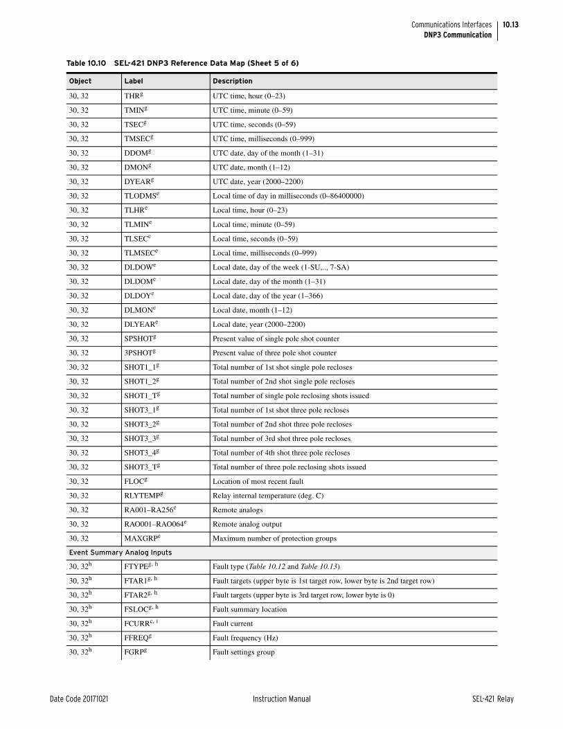
10.13
Date Code 20171021 Instruction Manual SEL-421 Relay
Communications InterfacesDNP3 Communication
30, 32 THRg UTC time, hour (0–23)
30, 32 TMINg UTC time, minute (0–59)
30, 32 TSECg UTC time, seconds (0–59)
30, 32 TMSECg UTC time, milliseconds (0–999)
30, 32 DDOMg UTC date, day of the month (1–31)
30, 32 DMONg UTC date, month (1–12)
30, 32 DYEARg UTC date, year (2000–2200)
30, 32 TLODMSe Local time of day in milliseconds (0–86400000)
30, 32 TLHRe Local time, hour (0–23)
30, 32 TLMINe Local time, minute (0–59)
30, 32 TLSECe Local time, seconds (0–59)
30, 32 TLMSECe Local time, milliseconds (0–999)
30, 32 DLDOWe Local date, day of the week (1-SU,.., 7-SA)
30, 32 DLDOMe Local date, day of the month (1–31)
30, 32 DLDOYe Local date, day of the year (1–366)
30, 32 DLMONe Local date, month (1–12)
30, 32 DLYEARe Local date, year (2000–2200)
30, 32 SPSHOTg Present value of single pole shot counter
30, 32 3PSHOTg Present value of three pole shot counter
30, 32 SHOT1_1g Total number of 1st shot single pole recloses
30, 32 SHOT1_2g Total number of 2nd shot single pole recloses
30, 32 SHOT1_Tg Total number of single pole reclosing shots issued
30, 32 SHOT3_1g Total number of 1st shot three pole recloses
30, 32 SHOT3_2g Total number of 2nd shot three pole recloses
30, 32 SHOT3_3g Total number of 3rd shot three pole recloses
30, 32 SHOT3_4g Total number of 4th shot three pole recloses
30, 32 SHOT3_Tg Total number of three pole reclosing shots issued
30, 32 FLOCg Location of most recent fault
30, 32 RLYTEMPg Relay internal temperature (deg. C)
30, 32 RA001–RA256e Remote analogs
30, 32 RAO001–RAO064e Remote analog output
30, 32 MAXGRPe Maximum number of protection groups
Event Summary Analog Inputs
30, 32h FTYPEg, h Fault type (Table 10.12 and Table 10.13)
30, 32h FTAR1g, h Fault targets (upper byte is 1st target row, lower byte is 2nd target row)
30, 32h FTAR2g, h Fault targets (upper byte is 3rd target row, lower byte is 0)
30, 32h FSLOCg, h Fault summary location
30, 32h FCURRc, i Fault current
30, 32h FFREQg Fault frequency (Hz)
30, 32h FGRPg Fault settings group
Table 10.10 SEL-421 DNP3 Reference Data Map (Sheet 5 of 6)
Object Label Description

10.14
SEL-421 Relay Instruction Manual Date Code 20171021
Communications InterfacesDNP3 Communication
Binary OutputsUse the Trip and Close, Latch On/Off and Pulse On operations with Object 12 control relay output block command messages to operate the points shown in Table 10.11. Pulse operations provide a pulse with duration of one protection processing interval. Cancel an operation in progress by issuing a NUL Trip/Close Code with a NUL Operation Type.
30, 32h FTIMEH, FTIMEM, FTIMELg, h
Fault time (local) in DNP3 format (high, middle, and low 16 bits)
30, 32f FTIMEUH, FTIMEUM, FTIMEULg
Fault time (UTC) in DNP format (high, middle, and low 16 bits)
30, 32h FSHOT1g Recloser single-pole reclose count
30, 32h FSHOT2g Recloser three-pole reclose count
30, 32h FUNRg, h Number of unread fault summaries
Analog Outputs
40, 41 ACTGRP0 Active settings group
40, 41 TECORRj Time-error preload value
40, 41 RA001–RA256 Remote analogs
a The counters use 1 as default or per point counter dead-band setting for the actual counter dead band.b Convert the absolute value to force the counter to a positive value.c Default current scaling DECPLA on magnitudes and scale factor of 100 on angles. Dead band ANADBA on magnitudes and ANADBM on angles.d Default voltage scaling DECPLV on magnitudes and scale factor of 100 on angles. Dead band ANADBV on magnitudes and ANADBM on angles.e Default miscellaneous scaling DECPLM and dead band ANADBM.f Default scale factor of 100 and dead-band ANADBM.g Default scale factor of 1 and dead-band ANADBM.h Event data shall be generated for all Event Summary Analog Inputs if any of them change beyond their dead band after scaling.i Default dead band of 0.j In milliseconds, –30000 time 30000. Relay Word bit PLDTE asserts for approximately 1.5 cycles after this value is written.
Table 10.10 SEL-421 DNP3 Reference Data Map (Sheet 6 of 6)
Object Label Description
Table 10.11 SEL-421 Object 12 Control Operations (Sheet 1 of 2)
Label Close/Any Trip/Any NUL/Latch On NUL/Latch Off NUL/Pulse On NUL/Pulse Off
RB01–RB32
Pulse Remote Bit RB01–RB32
Pulse Remote Bit RB01–RB32
Set Remote Bit RB01–RB32
Clear Remote Bit RB01–RB32
Pulse Remote Bit RB01–RB32
Clear Remote Bit RB01–RB32
RBxx: RByy
Pulse RByy RB01–RB32
Pulse RBxx RB01–RB32
Pulse RByy Pulse RBxx Pulse RByy Pulse RBxx
OCx Open circuit breaker x (Pulse OCx)x = 1–2
Open circuit breaker x (Pulse OCx) x = 1–2
Set OCx x = 1–2
Clear OCx x = 1–2
Open circuit breaker x (Pulse OCx) x = 1–2
Clear OCx x = 1–2
CCx Close circuit breaker x (Pulse CCx) x = 1–2
Close circuit breaker x (Pulse CCx) x = 1–2
Set CCx x = 1–2
Clear CCx x = 1–2
Close circuit breaker x (Pulse CCx) x = 1–2
Clear CCx x = 1–2
OCx: CCx Close circuit breaker x (Pulse CCx) x = 1–2
Open circuit breaker x (Pulse OCx) x = 1–2
Pulse CCx Pulse OCx Pulse CCx Pulse OCx
89OC01–89OC10
Pulse Disconnect open 89OC01–89OC10
Pulse Disconnect open 89OC01–89OC10
Set Disconnect open 89OC01–89OC10
Clear Disconnect open 89OC01–89OC10
Pulse Disconnect open 89OC01–89OC10
Clear Disconnect open 89OC01–89OC10

10.15
Date Code 20171021 Instruction Manual SEL-421 Relay
Communications InterfacesDNP3 Communication
Fault Summary DataWhen a relay event occurs, (TRIP asserts, ER asserts, or TRI asserts) whose fault location is in the range of MINDIST to MAXDIST, the data shall be made avail-able to DNP. If MINDIST is set to OFF, then there is no minimum. Similarly, if MAXDIST is set to OFF, there is no maximum.
89CC01–89CC10
Pulse Disconnect close 89CC01–89CC10
Pulse Disconnect close 89CC01–89CC10
Set Disconnect close 89CC01–89CC10
Clear Disconnect close 89CC01–89CC10
Pulse Disconnect close 89CC01–89CC10
Clear Disconnect close 89CC01–89CC10
89OCx: 89CCx
Pulse 89CCx, Dis-connect Close bit x = 01–10
Pulse 89OCx, Dis-connect Open bit x = 01–10
Pulse 89CCx Pulse 89OCx Pulse 89CCx Pulse 89OCx
RST_DEM Reset demand meter data
Reset demand meter data
Reset demand meter data
No action Reset demand meter data
No action
RST_PDM Reset peak demand meter data
Reset peak demand meter data
Reset peak demand meter data
No action Reset peak demand meter data
No action
RST_ENE Reset accumulated energy meter data
Reset accumulated energy meter data
Reset accumulated energy meter data
No action Reset accumulated energy meter data
No action
RSTMML Reset min/max meter data for the line
Reset min/max meter data for line
Reset min/max meter data for the line
No action Reset min/max meter data for the line
No action
RSTMMB1 Reset min/max meter data for breaker 1
Reset min/max meter data for breaker 1
Reset min/max meter data for breaker 1
No action Reset min/max meter data for breaker 1
No action
RSTMMB2 Reset min/max meter data for breaker 2
Reset min/max meter data for breaker 2
Reset min/max meter data for breaker 2
No action Reset min/max meter data for breaker 2
No action
RST_BK1 Reset breaker monitor 1 data
Reset breaker monitor 1 data
Reset breaker monitor 1 data
No action Reset breaker monitor 1 data
No action
RST_BK2 Reset breaker monitor 2 data
Reset breaker monitor 2 data
Reset breaker monitor 2 data
No action Reset breaker monitor 2 data
No action
RST_BAT Reset Battery Monitoring
Reset Breaker Monitoring
Reset Battery Monitoring
No action Reset Battery Monitoring
No action
RST_79C Reset recloser shot counters
Reset recloser shot counters
Reset recloser shot counters
No action Reset recloser shot counters
No action
RSTFLOC Reset fault loca-tion
Reset fault loca-tion
Reset fault loca-tion
No action Reset fault loca-tion (Pulse RSS-FLOC)
No action
RST_HAL Reset hardware alarm
Reset hardware alarm
Reset hardware alarm
No action Reset hardware alarm
No action
RSTTRGT Reset front-panel targets
Reset front-panel targets
Reset front-panel targets
No action Reset front-panel targets
No action
RSTDNPE Reset DNP3 Event Summary
Reset DNP3 Event Summary
Reset DNP3 Event Summary
No action Reset DNP3 Event Summary
No action
NXTEVE Load oldest relay event (FIFO)
Load oldest relay event (FIFO)
Load oldest relay event (FIFO)
Load newest relay event (LIFO)
Load oldest relay event (FIFO)
Load newest event summary (LIFO)
Table 10.11 SEL-421 Object 12 Control Operations (Sheet 2 of 2)
Label Close/Any Trip/Any NUL/Latch On NUL/Latch Off NUL/Pulse On NUL/Pulse Off
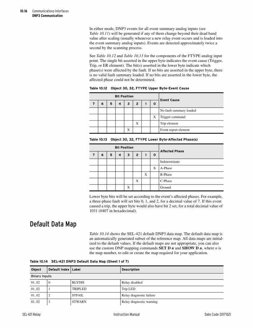
10.16
SEL-421 Relay Instruction Manual Date Code 20171021
Communications InterfacesDNP3 Communication
In either mode, DNP3 events for all event summary analog inputs (see Table 10.11) will be generated if any of them change beyond their dead band value after scaling (usually whenever a new relay event occurs and is loaded into the event summary analog inputs). Events are detected approximately twice a second by the scanning process.
See Table 10.12 and Table 10.13 for the components of the FTYPE analog input point. The single bit asserted in the upper byte indicates the event cause (Trigger, Trip, or ER element). The bit(s) asserted in the lower byte indicate which phase(s) were affected by the fault. If no bits are asserted in the upper byte, there is no valid fault summary loaded. If no bits are asserted in the lower byte, the affected phase could not be determined.
Lower byte bits will be set according to the event’s affected phases. For example, a three-phase fault will set bits 0, 1, and 2, for a decimal value of 7. If this event caused a trip, the upper byte would also have bit 2 set, for a total decimal value of 1031 (0407 in hexadecimal).
Default Data MapTable 10.14 shows the SEL-421 default DNP3 data map. The default data map is an automatically generated subset of the reference map. All data maps are initial-ized to the default values. If the default maps are not appropriate, you can also use the custom DNP mapping commands SET D n and SHOW D n, where n is the map number, to edit or create the map required for your application.
Table 10.12 Object 30, 32, FTYPE Upper Byte-Event Cause
Bit PositionEvent Cause
7 6 5 4 3 2 1 0
No fault summary loaded
X Trigger command
X Trip element
X Event report element
Table 10.13 Object 30, 32, FTYPE Lower Byte-Affected Phase(s)
Bit PositionAffected Phase
7 6 5 4 3 2 1 0
Indeterminate
X A-Phase
X B-Phase
X C-Phase
X Ground
Table 10.14 SEL-421 DNP3 Default Data Map (Sheet 1 of 7)
Object Default Index Label Description
Binary Inputs
01, 02 0 RLYDIS Relay disabled
01, 02 1 TRIPLED Trip LED
01, 02 2 STFAIL Relay diagnostic failure
01, 02 3 STWARN Relay diagnostic warning

10.17
Date Code 20171021 Instruction Manual SEL-421 Relay
Communications InterfacesDNP3 Communication
01, 02 4 STSET Settings change or relay restart
01, 02 5 SALARM Software alarm
01, 02 6 HALARM Hardware alarm
01, 02 7 BADPASS Invalid password attempt alarm
01, 02 8 UNRDEV New relay event available
01, 02 9 SPO One or two poles open
01, 02 10 3PO All three poles open
01, 02 11 BK1RS Circuit Breaker 1 in ready state
01, 02 12 BK2RS Circuit Breaker 2 in ready state
01, 02 13 BK1LO Circuit Breaker 1 in lockout state
01, 02 14 BK2LO Circuit Breaker 2 in lockout state
01, 02 15 52AA1 Circuit Breaker 1, Pole A status
01, 02 16 52AB1 Circuit Breaker 1, Pole B status
01, 02 17 52AC1 Circuit Breaker 1, Pole C status
01, 02 18 52AAL1 Circuit Breaker 1, Pole A alarm
01, 02 19 52BAL1 Circuit Breaker 1, Pole B alarm
01, 02 20 52CAL1 Circuit Breaker 1, Pole C alarm
01, 02 21 52AA2 Circuit Breaker 2, Pole A status
01, 02 22 52AB2 Circuit Breaker 2, Pole B status
01, 02 23 52AC2 Circuit Breaker 2, Pole C status
01, 02 24 52AAL2 Circuit Breaker 2, Pole A alarm
01, 02 25 52BAL2 Circuit Breaker 2, Pole B alarm
01, 02 26 52CAL2 Circuit Breaker 2, Pole C alarm
01, 02 27 TLED_1 Front-panel target LED 1
01, 02 28 TLED_2 Front-panel target LED 2
01, 02 29 TLED_3 Front-panel target LED 3
01, 02 30 TLED_4 Front-panel target LED 4
01, 02 31 TLED_5 Front-panel target LED 5
01, 02 32 TLED_6 Front-panel target LED 6
01, 02 33 TLED_7 Front-panel target LED 7
01, 02 34 TLED_8 Front-panel target LED 8
01, 02 35 TLED_9 Front-panel target LED 9
01, 02 36 TLED_10 Front-panel target LED 10
01, 02 37 TLED_11 Front-panel target LED 11
01, 02 38 TLED_12 Front-panel target LED 12
01, 02 39 TLED_13 Front-panel target LED 13
01, 02 40 TLED_14 Front-panel target LED 14
01, 02 41 TLED_15 Front-panel target LED 15
01, 02 42 TLED_16 Front-panel target LED 16
01, 02 43 LDATPFW Leading true power factor A-Phase Terminal W
01, 02 44 LDBTPFW Leading true power factor B-Phase Terminal W
Table 10.14 SEL-421 DNP3 Default Data Map (Sheet 2 of 7)
Object Default Index Label Description

10.18
SEL-421 Relay Instruction Manual Date Code 20171021
Communications InterfacesDNP3 Communication
01, 02 45 LDCTPFW Leading true power factor C-Phase Terminal W
01, 02 46 LD3TPFW Leading true power factor three-phase Terminal W
01, 02 47 IN101 Main board Input 1
01, 02 48 IN102 Main board Input 2
01, 02 49 IN103 Main board Input 3
01, 02 50 IN104 Main board Input 4
01, 02 51 IN105 Main board Input 5
01, 02 52 IN106 Main board Input 6
01, 02 53 IN107 Main board Input 7
01, 02 54 PSV01 Protection SELOGIC Variable 1
01, 02 55 PSV02 Protection SELOGIC Variable 2
01, 02 56 PSV03 Protection SELOGIC Variable 3
01, 02 57 PSV04 Protection SELOGIC Variable 4
01, 02 58 PSV05 Protection SELOGIC Variable 5
01, 02 59 PSV06 Protection SELOGIC Variable 6
01, 02 60 PSV07 Protection SELOGIC Variable 7
01, 02 61 PSV08 Protection SELOGIC Variable 8
01, 02 62 ASV001 Automation SELOGIC Variable 1
01, 02 63 ASV002 Automation SELOGIC Variable 2
01, 02 64 ASV003 Automation SELOGIC Variable 3
01, 02 65 ASV004 Automation SELOGIC Variable 4
01, 02 66 ASV005 Automation SELOGIC Variable 5
01, 02 67 ASV006 Automation SELOGIC Variable 6
01, 02 68 ASV007 Automation SELOGIC Variable 7
01, 02 69 ASV008 Automation SELOGIC Variable 8
01, 02 70 OUT101 Main board Output 1
01, 02 71 OUT102 Main board Output 2
01, 02 72 OUT103 Main board Output 3
01, 02 73 OUT104 Main board Output 4
01, 02 74 OUT105 Main board Output 5
01, 02 75 OUT106 Main board Output 6
01, 02 76 OUT107 Main board Output 7
Binary Outputs
10, 12 0–31 RB01–RB32 Remote bits RB01–RB32
10, 12 32 OC1 Pulse Open Circuit Breaker 1 command
10, 12 33 CC1 Pulse Close Circuit Breaker 1 command
10, 12 34 OC2 Pulse Open Circuit Breaker 2 command
10, 12 35 CC2 Pulse Close Circuit Breaker 2 command
10, 12 36 89OC01 Open Disconnect Switch Control 1
10, 12 37 89CC01 Close Disconnect Switch Control 1
10, 12 38 89OC02 Open Disconnect Switch Control 2
Table 10.14 SEL-421 DNP3 Default Data Map (Sheet 3 of 7)
Object Default Index Label Description

10.19
Date Code 20171021 Instruction Manual SEL-421 Relay
Communications InterfacesDNP3 Communication
10, 12 39 89CC02 Close Disconnect Switch Control 2
10, 12 40 89OC03 Open Disconnect Switch Control 3
10, 12 41 89CC03 Close Disconnect Switch Control 3
10, 12 42 89OC04 Open Disconnect Switch Control 4
10, 12 43 89CC04 Close Disconnect Switch Control 4
10, 12 44 89OC05 Open Disconnect Switch Control 5
10, 12 45 89CC05 Close Disconnect Switch Control 5
10, 12 46 89OC06 Open Disconnect Switch Control 6
10, 12 47 89CC06 Close Disconnect Switch Control 6
10, 12 48 89OC07 Open Disconnect Switch Control 7
10, 12 49 89CC07 Close Disconnect Switch Control 7
10, 12 50 89OC08 Open Disconnect Switch Control 8
10, 12 51 89CC08 Close Disconnect Switch Control 8
10, 12 52 89OC09 Open Disconnect Switch Control 9
10, 12 53 89CC09 Close Disconnect Switch Control 9
10, 12 54 89OC10 Open Disconnect Switch Control 10
10, 12 55 89CC10 Close Disconnect Switch Control 10
10, 12 56 RST_DEM Reset demands
10, 12 57 RST_PDM Reset demand peaks
10, 12 58 RST_ENE Reset energies
10, 12 59 RST_BK1 Reset Breaker 1 monitor data
10, 12 60 RST_BK2 Reset Breaker 2 monitor data
10, 12 61 RSTTRGT Reset front-panel targets
10, 12 62 RSTMML Reset min/max metering data for the line
10, 12 63 RSTDNPE Reset (clear) DNP3 event summary analog inputs
Binary Counters
20, 22 0 ACTGRP Active settings group
20, 22 1 BKR1OPA Number of breaker operations on Circuit Breaker 1 A-Phase
20, 22 2 BKR1OPB Number of breaker operations on Circuit Breaker 1 B-Phase
20, 22 3 BKR1OPC Number of breaker operations on Circuit Breaker 1 C-Phase
20, 22 4 BKR2OPA Number of breaker operations on Circuit Breaker 2 A-Phase
20, 22 5 BKR2OPB Number of breaker operations on Circuit Breaker 2 B-Phase
20, 22 6 BKR2OPC Number of breaker operations on Circuit Breaker 2 C-Phase
20, 22a, b 7 KWHAOUT Positive (export) A-Phase energy, kilowatt hours
20, 22a, b 8 KWHBOUT Positive (export) B-Phase energy, kilowatt hours
20, 22a, b 9 KWHCOUT Positive (export) C-Phase energy, kilowatt hours
20, 22a, b 10 KWHAIN Negative (import) A-Phase energy, kilowatt hours
20, 22a, b 11 KWHBIN Negative (import) B-Phase energy, kilowatt hours
20, 22a, b 12 KWHCIN Negative (import) C-Phase energy, kilowatt hours
20, 22a, b 13 3KWHOUT Positive (export) three-phase energy, kilowatt hours
20, 22a, b 14 3KWHIN Negative (import) three-phase energy, kilowatt hours
Table 10.14 SEL-421 DNP3 Default Data Map (Sheet 4 of 7)
Object Default Index Label Description

10.20
SEL-421 Relay Instruction Manual Date Code 20171021
Communications InterfacesDNP3 Communication
20, 22 15 MWHAOUT Positive A-Phase energy (export), MWh
20, 22 16 MWHBOUT Positive B-Phase energy (export), MWh
20, 22 17 MWHCOUT Positive C-Phase energy (export), MWh
20, 22 18 MWHAIN Negative A-Phase energy (import), MWh
20, 22 19 MWHBIN Negative B-Phase energy (import), MWh
20, 22 20 MWHCIN Negative C-Phase energy (import), MWh
20, 22 21 3MWHOUT Positive three-phase energy (export), MWh
20, 22 22 3MWHIN Negative three-phase energy (export), MWh
Analog Inputs
30, 32 0, 1 LIAFM, LIAFA Line A-Phase current magnitude (amperes) and angle
30, 32 2, 3 LIBFM, LIBFA Line B-Phase current magnitude (amperes) and angle
30, 32 4, 5 LICFM, LICFA Line C-Phase current magnitude (amperes) and angle
30, 32 6, 7 B1IAFM, B1IAFA Circuit Breaker 1 A-Phase current magnitude (amperes) and angle
30, 32 8, 9 B1IBFM, B1IBFA Circuit Breaker 1 B-Phase current magnitude (amperes) and angle
30, 32 10, 11 B1ICFM, B1ICFA Circuit Breaker 1 C-Phase current magnitude (amperes) and angle
30, 32 12, 13 B2IAFM, B2IAFA Circuit Breaker 2 A-Phase current magnitude (amperes) and angle
30, 32 14, 15 B2IBFM, B2IBFA Circuit Breaker 2 B-Phase current magnitude (amperes) and angle
30, 32 16, 17 B2ICFM, B2ICFA Circuit Breaker 2 C-Phase current magnitude (amperes) and angle
30, 32 18, 19 VAFM, VAFA Line A-Phase voltage magnitude (kV) and angle
30, 32 20, 21 VBFM, VBFA Line B-Phase voltage magnitude (kV) and angle
30, 32 22, 23 VCFM, VCFA Line C-Phase voltage magnitude (kV) and angle
30, 32 24 VPM Polarizing voltage magnitude (volts)
30, 32 25 NVS1M Synchronizing Voltage 1 magnitude (volts)
30, 32 26 NVS2M Synchronizing Voltage 2 magnitude (volts)
30, 32 27, 28 LIGM, LIGA Line zero-sequence current (3I0) magnitude in amperes and angle
30, 32 29, 30 LI1M, LI1A Line positive-sequence current magnitude (amperes) and angle
30, 32 31, 32 L3I2M, L3I2A Line negative-sequence current (3I2) magnitude in amperes and angle
30, 32 33, 34 3V0M, 3V0A Zero-sequence voltage magnitude (3V0) in kV and angle
30, 32 35, 36 V1M, V1A Positive-sequence voltage magnitude (V1) in kV and angle
30, 32 37, 38 3V2M, 3V2A Negative-sequence voltage magnitude (3V2) in kV and angle
30, 32 39 PA_F A-Phase real power in MW
30, 32 40 PB_F B-Phase real power in MW
30, 32 41 PC_F C-Phase real power in MW
30, 32 42 3P_F Three-phase real power in MW
30, 32 43 QA_F A-Phase reactive power in MVAR
30, 32 44 QB_F B-Phase reactive power in MVAR
30, 32 45 QC_F C-Phase reactive power in MVAR
30, 32 46 3Q_F Three-phase reactive power in MVAR
30, 32 47 DPFA A-Phase displacement power factor
30, 32 48 DPFB B-Phase displacement power factor
30, 32 49 DPFC C-Phase displacement power factor
Table 10.14 SEL-421 DNP3 Default Data Map (Sheet 5 of 7)
Object Default Index Label Description

10.21
Date Code 20171021 Instruction Manual SEL-421 Relay
Communications InterfacesDNP3 Communication
30, 32 50 3DPF Three-phase displacement power factor
30, 32 51 DC1 DC Battery 1 voltage (V)
30, 32 52 DC2 DC Battery 2 voltage (V)
30, 32 53 FREQ Frequency (Hz)
30, 32 54, 55 MWHAIN, MWHAOUT A-Phase total energy in and out (MWh)
30, 32 56, 57 MWHBIN, MWHBOUT B-Phase total energy in and out (MWh)
30, 32 58, 59 MWHCIN, MWHCOUT C-Phase total energy in and out (MWh)
30, 32 60, 61 3MWHIN, 3MWHOUT Three-phase total energy in and out (MWh)
30, 32 62 IAD A-Phase demand current (amperes)
30, 32 63 IBD B-Phase demand current (amperes)
30, 32 64 ICD C-Phase demand current (amperes)
30, 32 65 3I2D Demand negative-sequence current (amperes)
30, 32 66 IGD Demand zero-sequence current (amperes)
30, 32 67–69 PAD, PBD, PCD A-Phase, B-Phase, and C-Phase demand power (MW)
30, 32 70 3PD Three-phase demand power (MW)
30, 32 71 IAPKD Peak A-Phase demand current (amperes)
30, 32 72 IBPKD Peak B-Phase demand current (amperes)
30, 32 73 ICPKD Peak C-Phase demand current (amperes)
30, 32 74 IGPKD Peak zero-sequence demand current (amperes)
30, 32 75 3I2PKD Peak negative-sequence demand current (amperes)
30, 32 76 PAPKD A-Phase peak demand power (MW)
30, 32 77 PBPKD B-Phase peak demand power (MW)
30, 32 78 PCPKD C-Phase peak demand power (MW)
30, 32 79 3PPKD Three-phase peak demand power (MW)
30, 32 80–82 B1BCWPA, B1BCWPB, B1BCWPC
Circuit Breaker 1 contact wear percentage multiplied by 100
30, 32 83–85 B2BCWPA, B2BCWPB, B2BCWPC
Circuit Breaker 2 contact wear percentage multiplied by 100
30, 32 86 FTYPE Fault type (Table 10.12 and Table 10.13)
30, 32 87 FTAR1 Fault targets (upper byte is 1st target row, lower byte is 2nd target row)
30, 32 88 FTAR2 Fault targets (upper byte is 3rd target row, lower byte is 0)
30, 32 89 FSLOC Fault summary location
30, 32 90 FCURR Fault current
30, 32 91 FFREQ Fault frequency (Hz)
30, 32 92 FGRP Fault settings group
30, 32 93–95 FTIMEH, FTIMEM, FTIMEL Fault time in DNP3 format (high, middle, and low 16 bits)
30, 32 96 FSHOT1 Recloser single-pole reclose count
30, 32 97 FSHOT2 Recloser three-pole reclose count
30, 32 98 FUNR Number of unread fault summaries
30, 32 99 SHOT3_T Total number of three pole reclosing shots issued
30. 32 100 RLYTEMP Relay internal temperature (degrees C)
Table 10.14 SEL-421 DNP3 Default Data Map (Sheet 6 of 7)
Object Default Index Label Description

10.22
SEL-421 Relay Instruction Manual Date Code 20171021
Communications InterfacesIEC 61850 Communication
IEC 61850 CommunicationGeneral IEC 61850 operation is described in Section 17: IEC 61850 Communica-tion in the SEL-400 Series Relays Instruction Manual. This section describes characteristics of IEC 61850 that are specific to the SEL-421.
Logical NodesTable 10.15–Table 10.16 show the logical nodes (LNs) supported in the SEL-421 and the Relay Word bits or Measured Values mapped to those LNs. Additionally, the relay supports the CON and ANN Logical Device logical nodes as described in Section 17: IEC 61850 Communication in the SEL-400 Series Relays Instruc-tion Manual.
Table 10.15 shows the LNs associated with protection elements, defined as Logi-cal Device PRO.
Analog Outputs
40, 41 0 ACTGRP Active settings group
a The counters use 1 as default or per point Counter dead-band setting for the actual counter dead band.b Convert the absolute value to force the counter to a positive value.
Table 10.14 SEL-421 DNP3 Default Data Map (Sheet 7 of 7)
Object Default Index Label Description
Table 10.15 Logical Device: PRO (Protection) (Sheet 1 of 6)
Logical Node Attribute Data Source Comment
Functional Constraint = CO
BKR1CSWI1 Pos.Oper.ctlVal CC1:OC1 Circuit Breaker 1 close/open command
BKR2CSWI2 Pos.Oper.ctlVal CC2:OC2 Circuit Breaker 2 close/open command
DC10CSWI10 Pos.Oper.ctlVal 89CC10:89OC10 ASCII Close/Open Disconnect 10 command
DC1CSWI1 Pos.Oper.ctlVal 89CC01:89OC01 ASCII Close/Open Disconnect 1 command
DC2CSWI2 Pos.Oper.ctlVal 89CC02:89OC02 ASCII Close/Open Disconnect 2 command
DC3CSWI3 Pos.Oper.ctlVal 89CC03:89OC03 ASCII Close/Open Disconnect 3 command
DC4CSWI4 Pos.Oper.ctlVal 89CC04:89OC04 ASCII Close/Open Disconnect 4 command
DC5CSWI5 Pos.Oper.ctlVal 89CC05:89OC05 ASCII Close/Open Disconnect 5 command
DC6CSWI6 Pos.Oper.ctlVal 89CC06:89OC06 ASCII Close/Open Disconnect 6 command
DC7CSWI7 Pos.Oper.ctlVal 89CC07:89OC07 ASCII Close/Open Disconnect 7 command
DC8CSWI8 Pos.Oper.ctlVal 89CC08:89OC08 ASCII Close/Open Disconnect 8 command
DC9CSWI9 Pos.Oper.ctlVal 89CC09:89OC09 ASCII Close/Open Disconnect 9 command
Functional Constraint = ST
BFR1RBRF1 OpEx.general FBF1a Circuit Breaker 1 circuit breaker failure
BFR1RBRF1 OpEx.phsA FBFA1a Circuit Breaker 1 A-Phase circuit breaker failure
BFR1RBRF1 OpEx.phsB FBFB1a Circuit Breaker 1 B-Phase circuit breaker failure
BFR1RBRF1 OpEx.phsC FBFC1a Circuit Breaker 1 C-Phase circuit breaker failure
BFR1RBRF1 OpIn.general RT1a Circuit Breaker 1 retrip
BFR1RBRF1 OpIn.phsA RTA1a Circuit Breaker 1 A-Phase retrip

10.23
Date Code 20171021 Instruction Manual SEL-421 Relay
Communications InterfacesIEC 61850 Communication
BFR1RBRF1 OpIn.phsB RTB1a Circuit Breaker 1 B-Phase retrip
BFR1RBRF1 OpIn.phsC RTC1a Circuit Breaker 1 C-Phase retrip
BFR1RBRF1 Str.general CSV02 BFI3P1 OR BFIA1 OR BFIB1 OR BFIC1
BFR2RBRF2 OpEx.general FBF2a Circuit Breaker 2 circuit breaker failure
BFR2RBRF2 OpEx.phsA FBFA2a Circuit Breaker 2 A-Phase circuit breaker failure
BFR2RBRF2 OpEx.phsB FBFB2a Circuit Breaker 2 B-Phase circuit breaker failure
BFR2RBRF2 OpEx.phsC FBFC2a Circuit Breaker 2 C-Phase circuit breaker failure
BFR2RBRF2 OpIn.general RT2a Circuit Breaker 2 retrip
BFR2RBRF2 OpIn.phsA RTA2a Circuit Breaker 2 A-Phase retrip
BFR2RBRF2 OpIn.phsB RTB2a Circuit Breaker 2 B-Phase retrip
BFR2RBRF2 OpIn.phsC RTC2a Circuit Breaker 2 C-Phase retrip
BFR2RBRF2 Str.general CSV03 BFI3P2 OR BFIA2 OR BFIB2 OR BFIC2
BK1AXCBR1 Pos.stVal 52ACL1?1:2a Circuit Breaker 1, Pole A closed
BK1BXCBR2 Pos.stVal 52BCL1?1:2a Circuit Breaker 1, Pole B closed
BK1CXCBR3 Pos.stVal 52CCL1?1:2a Circuit Breaker 1, Pole C closed
BK2AXCBR4 Pos.stVal 52ACL2?1:2a Circuit Breaker 2, Pole A closed
BK2BXCBR5 Pos.stVal 52BCL2?1:2a Circuit Breaker 2, Pole B closed
BK2CXCBR6 Pos.stVal 52CCL2?1:2a Circuit Breaker 2, Pole C closed
BKR1CSWI1 OpCls.general CC1a Circuit Breaker 1 close command
BKR1CSWI1 OpOpn.general OC1a Circuit Breaker 1 open command
BKR1CSWI1 Pos.stVal 52ACL1?1:2a Circuit Breaker 1, Pole A closed
BKR1PTRC2 Tr.general CSV06 TPA1 OR TPB1 OR TPC1
BKR1PTRC2 Tr.phsA TPA1a Circuit Breaker 1 Trip A
BKR1PTRC2 Tr.phsB TPB1a Circuit Breaker 1 Trip B
BKR1PTRC2 Tr.phsC TPC1a Circuit Breaker 1 Trip C
BKR2CSWI2 OpCls.general CC2a Circuit Breaker 2 close command
BKR2CSWI2 OpOpn.general OC2a Circuit Breaker 2 open command
BKR2CSWI2 Pos.stVal 52ACL2?1:2a Circuit Breaker 2, Pole A closed
BKR2PTRC3 Tr.general CSV07 TPA2 OR TPB2 OR TPC2
BKR2PTRC3 Tr.phsA TPA2a Circuit Breaker 2 Trip A
BKR2PTRC3 Tr.phsB TPB2a Circuit Breaker 2 Trip B
BKR2PTRC3 Tr.phsC TPC2a Circuit Breaker 2 Trip C
DC10CSWI10 OpCls.general 89CC10a ASCII Close Disconnect 10 command
DC10CSWI10 OpOpn.general 89OC10a ASCII Open Disconnect 10 command
DC10CSWI10 Pos.stVal 89CL10|89OPN10?0:1:2:3a Disconnect 10 status
DC1CSWI1 OpCls.general 89CC01a ASCII Close Disconnect 1 command
DC1CSWI1 OpOpn.general 89OC01a ASCII Open Disconnect 1 command
DC1CSWI1 Pos.stVal 89CL01|89OPN01?0:1:2:3a Disconnect 1 status
DC2CSWI2 OpCls.general 89CC02a ASCII Close Disconnect 2 command
DC2CSWI2 OpOpn.general 89OC02a ASCII Open Disconnect 2 command
DC2CSWI2 Pos.stVal 89CL02|89OPN02?0:1:2:3a Disconnect 2 status
Table 10.15 Logical Device: PRO (Protection) (Sheet 2 of 6)
Logical Node Attribute Data Source Comment

10.24
SEL-421 Relay Instruction Manual Date Code 20171021
Communications InterfacesIEC 61850 Communication
DC3CSWI3 OpCls.general 89CC03a ASCII Close Disconnect 3 command
DC3CSWI3 OpOpn.general 89OC03a ASCII Open Disconnect 3 command
DC3CSWI3 Pos.stVal 89CL03|89OPN03?0:1:2:3a Disconnect 3 status
DC4CSWI4 OpCls.general 89CC04a ASCII Close Disconnect 4 command
DC4CSWI4 OpOpn.general 89OC04a ASCII Open Disconnect 4 command
DC4CSWI4 Pos.stVal 89CL04|89OPN04?0:1:2:3a Disconnect 4 status
DC5CSWI5 OpCls.general 89CC05a ASCII Close Disconnect 5 command
DC5CSWI5 OpOpn.general 89OC05a ASCII Open Disconnect 5 command
DC5CSWI5 Pos.stVal 89CL05|89OPN05?0:1:2:3a Disconnect 5 status
DC6CSWI6 OpCls.general 89CC06a ASCII Close Disconnect 6 command
DC6CSWI6 OpOpn.general 89OC06a ASCII Open Disconnect 6 command
DC6CSWI6 Pos.stVal 89CL06|89OPN06?0:1:2:3a Disconnect 6 status
DC7CSWI7 OpCls.general 89CC07a ASCII Close Disconnect 7 command
DC7CSWI7 OpOpn.general 89OC07a ASCII Open Disconnect 7 command
DC7CSWI7 Pos.stVal 89CL07|89OPN07?0:1:2:3a Disconnect 7 status
DC8CSWI8 OpCls.general 89CC08a ASCII Close Disconnect 8 command
DC8CSWI8 OpOpn.general 89OC08a ASCII Open Disconnect 8 command
DC8CSWI8 Pos.stVal 89CL08|89OPN08?0:1:2:3a Disconnect 8 status
DC9CSWI9 OpCls.general 89CC09a ASCII Close Disconnect 9 command
DC9CSWI9 OpOpn.general 89OC09a ASCII Open Disconnect 9 command
DC9CSWI9 Pos.stVal 89CL09|89OPN09?0:1:2:3a Disconnect 9 status
DCBPSCH2 Op.general RXPRMa Receiver trip permission
DCBPSCH2 RxPrm1.general BTXa Block extension picked up
DCBPSCH2 TxBlk.general Z3RBa Current reversal guard asserted
DCBPSCH2 TxPrm.general CSV01 DSTRT OR NSTRT
DCUBPSCH3 EchoWei.stVal EKEYa Echo received permissive trip signal
DCUBPSCH3 EchoWeiOp.stVal ECTTa Echo conversion to trip signal
DCUBPSCH3 Op.general RXPRMa Receiver trip permission
DCUBPSCH3 RxPrm1.general PTRXa Permissive trip received Channel 1 and Channel 2
DCUBPSCH3 TxBlk.general Z3RBa Current reversal guard asserted
DCUBPSCH3 TxPrm.general KEYa Transmit permissive trip signal
F32GRDIR1 Dir.dirGeneral 32GF?0:1a Forward ground directional element
F32GRDIR1 Dir.general 32GFa Forward ground directional element
F32PRDIR5 Dir.dirGeneral F32P?0:1a Forward phase directional declaration
F32PRDIR5 Dir.general F32Pa Forward phase directional declaration
F32QRDIR3 Dir.dirGeneral F32Q?0:1a Forward negative-sequence phase directional declaration
F32QRDIR3 Dir.general F32Qa Forward negative-sequence phase directional declaration
FLTRDRE1 FltNum.stVal FLRNUM Event number
FLTRDRE1 RcdMade.stVal FLREP Event report present
G1PIOC2 Op.general 50G1a Level 1 residual overcurrent element
G1PTOC2 Op.general 67G1Ta Level 1 residual delayed directional overcurrent element
Table 10.15 Logical Device: PRO (Protection) (Sheet 3 of 6)
Logical Node Attribute Data Source Comment

10.25
Date Code 20171021 Instruction Manual SEL-421 Relay
Communications InterfacesIEC 61850 Communication
G1PTOC2 Str.general 67G1a Level 1 residual directional overcurrent element
G2PIOC5 Op.general 50G2a Level 2 residual overcurrent element
G2PTOC5 Op.general 67G2Ta Level 2 residual delayed directional overcurrent element
G2PTOC5 Str.general 67G2a Level 2 residual directional overcurrent element
G3PIOC8 Op.general 50G3a Level 3 residual overcurrent element
G3PTOC8 Op.general 67G3Ta Level 3 residual delayed directional overcurrent element
G3PTOC8 Str.general 67G3a Level 3 residual directional overcurrent element
G4PIOC11 Op.general 50G4a Level 4 residual overcurrent element
G4PTOC11 Op.general 67G4Ta Level 4 residual delayed directional overcurrent element
G4PTOC11 Str.general 67G4a Level 4 residual directional overcurrent element
OSB1RPSB2 BlkZn.stVal OSB1a Block Zone 1 during an out-of-step condition
OSB1RPSB2 Str.general OSBa Out-of-step block
OSB2RPSB3 BlkZn.stVal OSB2a Block Zone 2 during an out-of-step condition
OSB2RPSB3 Str.general OSBa Out-of-step block
OSB3RPSB4 BlkZn.stVal OSB3a Block Zone 3 during an out-of-step condition
OSB3RPSB4 Str.general OSBa Out-of-step block
OSB4RPSB5 BlkZn.stVal OSB4a Block Zone 4 during an out-of-step condition
OSB4RPSB5 Str.general OSBa Out-of-step block
OSB5RPSB6 BlkZn.stVal OSB5a Block Zone 5 during an out-of-step condition
OSB5RPSB6 Str.general OSBa Out-of-step block
OSTRPSB1 Op.general OSTa Out-of-step tripping
P1PIOC1 Op.general 50P1a Level 1 phase overcurrent element
P1PTOC1 Op.general 67P1Ta Level 1 phase-delayed directional overcurrent element
P1PTOC1 Str.general 67P1a Level 1 phase directional overcurrent element
P2PIOC4 Op.general 50P2a Level 2 phase overcurrent element
P2PTOC4 Op.general 67P2Ta Level 2 phase-delayed directional overcurrent element
P2PTOC4 Str.general 67P2a Level 2 phase directional overcurrent element
P3PIOC7 Op.general 50P3a Level 3 phase overcurrent element
P3PTOC7 Op.general 67P3Ta Level 3 phase-delayed directional overcurrent element
P3PTOC7 Str.general 67P3a Level 3 phase directional overcurrent element
P4PIOC10 Op.general 50P4a Level 4 phase overcurrent element
P4PTOC10 Op.general 67P4Ta Level 4 phase-delayed directional overcurrent element
P4PTOC10 Str.general 67P4a Level 4 phase directional overcurrent element
POTTPSCH1 EchoWei.stVal EKEYa Echo received permissive trip signal
POTTPSCH1 EchoWeiOp.stVal ECTTa Echo conversion to trip signal
POTTPSCH1 Op.general RXPRMa Receiver trip permission
POTTPSCH1 RxPrm1.general PTRXa Permissive trip received Channel 1 and Channel 2
POTTPSCH1 TxBlk.general Z3RBa Current reversal guard asserted
POTTPSCH1 TxPrm.general KEYa Transmit permissive trip signal
Q1PIOC3 Op.general 50Q1a Level 1 negative-sequence overcurrent element
Q1PTOC3 Op.general 67Q1Ta Level 1 negative sequence delayed directional overcurrent element
Table 10.15 Logical Device: PRO (Protection) (Sheet 4 of 6)
Logical Node Attribute Data Source Comment

10.26
SEL-421 Relay Instruction Manual Date Code 20171021
Communications InterfacesIEC 61850 Communication
Q1PTOC3 Str.general 67Q1a Level 1 negative-sequence directional overcurrent element
Q2PIOC6 Op.general 50Q2a Level 2 negative-sequence overcurrent element
Q2PTOC6 Op.general 67Q2Ta Level 2 negative-sequence delayed directional overcurrent element
Q2PTOC6 Str.general 67Q2a Level 2 negative-sequence directional overcurrent element
Q3PIOC9 Op.general 50Q3a Level 3 negative-sequence overcurrent element
Q3PTOC9 Op.general 67Q3Ta Level 3 negative-sequence delayed directional overcurrent element
Q3PTOC9 Str.general 67Q3a Level 3 negative-sequence directional overcurrent element
Q4PIOC12 Op.general 50Q4a Level 4 negative-sequence overcurrent element
Q4PTOC12 Op.general 67Q4Ta Level 4 negative-sequence delayed directional overcurrent element
Q4PTOC12 Str.general 67Q4a Level 4 negative-sequence directional overcurrent element
R32GRDIR2 Dir.dirGeneral 32GR?0:2a Reverse ground directional element
R32GRDIR2 Dir.general 32GRa Reverse ground directional element
R32PRDIR6 Dir.dirGeneral R32P?0:2a Reverse phase directional declaration
R32PRDIR6 Dir.general R32Pa Reverse phase directional declaration
R32QRDIR4 Dir.dirGeneral R32Q?0:2a Reverse negative-sequence phase directional declaration
R32QRDIR4 Dir.general R32Qa Reverse negative-sequence phase directional declaration
S1PTOC13 Op.general 51S1Ta Inverse-Time Overcurrent Element 1 timed out
S1PTOC13 Str.general 51S1a Inverse-Time Overcurrent Element 1 pickup
S2PTOC14 Op.general 51S2Ta Inverse-Time Overcurrent Element 2 timed out
S2PTOC14 Str.general 51S2a Inverse-Time Overcurrent Element 2 pickup
S3PTOC15 Op.general 51S3Ta Inverse-Time Overcurrent Element 3 timed out
S3PTOC15 Str.general 51S3a Inverse-Time Overcurrent Element 3 pickup
TRIPPTRC1 Tr.general TRIPa TPA OR TPB OR TPC
TRIPPTRC1 Tr.phsA TPAa Trip A
TRIPPTRC1 Tr.phsB TPBa Trip B
TRIPPTRC1 Tr.phsC TPCa Trip C
Z1GPDIS2 Op.general Z1GTa Zone 1 ground distance, time-delayed
Z1GPDIS2 Str.general Z1Ga Zone 1 ground distance element
Z1PPDIS1 Op.general Z1PTa Zone 1 phase distance, time-delayed
Z1PPDIS1 Str.general Z1Pa Zone 1 phase distance element
Z2GPDIS4 Op.general Z2GTa Zone 2 ground distance, time-delayed
Z2GPDIS4 Str.general Z2Ga Zone 2 ground distance element
Z2PPDIS3 Op.general Z2PTa Zone 2 phase distance, time-delayed
Z2PPDIS3 Str.general Z2Pa Zone 2 phase distance element
Z3GPDIS6 Op.general Z3GTa Zone 3 ground distance, time-delayed
Z3GPDIS6 Str.dirGeneral RVRS3?1:2 Asserts when Global setting DIR3=R
Z3GPDIS6 Str.general Z3Ga Zone 3 ground distance element
Z3PPDIS5 Op.general Z3PTa Zone 3 phase distance, time-delayed
Z3PPDIS5 Str.dirGeneral RVRS3?1:2 Asserts when Global setting DIR3=R
Z3PPDIS5 Str.general Z3Pa Zone 3 phase distance element
Z4GPDIS8 Op.general Z4GTa Zone 4 ground distance, time-delayed
Table 10.15 Logical Device: PRO (Protection) (Sheet 5 of 6)
Logical Node Attribute Data Source Comment

10.27
Date Code 20171021 Instruction Manual SEL-421 Relay
Communications InterfacesIEC 61850 Communication
Table 10.16 shows the LNs associated with measuring elements, defined as Logi-cal Device MET.
Z4GPDIS8 Str.dirGeneral RVRS4?1:2 Asserts when Global setting DIR4=R
Z4GPDIS8 Str.general Z4Ga Zone 4 ground distance element
Z4PPDIS7 Op.general Z4PTa Zone 4 phase distance, time-delayed
Z4PPDIS7 Str.dirGeneral RVRS4?1:2 Asserts when Global setting DIR4=R
Z4PPDIS7 Str.general Z4Pa Zone 4 phase distance element
Z5GPDIS10 Op.general Z5GTa Zone 5 ground distance, time-delayed
Z5GPDIS10 Str.dirGeneral RVRS5?1:2 Asserts when Global setting DIR5=R
Z5GPDIS10 Str.general Z5Ga Zone 5 ground distance element
Z5PPDIS9 Op.general Z5PTa Zone 5 phase distance, time-delayed
Z5PPDIS9 Str.dirGeneral RVRS5?1:2 Asserts when Global setting DIR5=R
Z5PPDIS9 Str.general Z5Pa Zone 5 phase distance element
a Data source is high-speed GOOSE data if included in an outgoing GOOSE dataset.
Table 10.15 Logical Device: PRO (Protection) (Sheet 6 of 6)
Logical Node Attribute Data Source Comment
Table 10.16 Logical Device: MET (Metering) (Sheet 1 of 3)
Logical Node Attribute Data Source Comment
Functional Constraint = MX
DCZBAT1 Vol.instMag.f DC1 Filtered Station Battery DC Voltage 1
DCZBAT2 Vol.instMag.f DC2 Filtered Station Battery DC Voltage 2
DMDMDST1 A.phsA.instCVal.mag.f IAD Demand A-Phase current
DMDMDST1 A.phsB.instCVal.mag.f IBD Demand B-Phase current
DMDMDST1 A.phsC.instCVal.mag.f ICD Demand C-Phase current
DMDMDST1 SeqA.c1.instMag.f 3I2D Demand negative sequence current
DMDMDST1 SeqA.c2.instMag.f 3I2D Demand negative sequence current
DMDMDST1 SeqA.c3.instMag.f IGD Demand zero sequence current
DMDMDST1 TotVA.instMag.f 3UD Demand three-phase apparent power
DMDMDST1 TotVAr.instMag.f 3QD Demand three-phase reactive power
DMDMDST1 TotW.instMag.f 3PD Demand three-phase real power
DMDMDST1 VA.phsA.instCVal.mag.f UAD Demand A-Phase apparent power
DMDMDST1 VA.phsB.instCVal.mag.f UBD Demand B-Phase apparent power
DMDMDST1 VA.phsC.instCVal.mag.f UCD Demand C-Phase apparent power
DMDMDST1 VAr.phsA.instCVal.mag.f QAD Demand A-Phase reactive power
DMDMDST1 VAr.phsB.instCVal.mag.f QBD Demand B-Phase reactive power
DMDMDST1 VAr.phsC.instCVal.mag.f QCD Demand C-Phase reactive power
DMDMDST1 W.phsA.instCVal.mag.f PAD Demand A-Phase real power
DMDMDST1 W.phsB.instCVal.mag.f PBD Demand B-Phase real power
DMDMDST1 W.phsC.instCVal.mag.f PCD Demand C-Phase real power
METMMXU1 A1.phsA.instCVal.ang.f LIAFA 10-cycle average fundamental A-Phase current (angle)
METMMXU1 A1.phsA.instCVal.mag.f LIAFM 10-cycle average fundamental A-Phase current (magnitude)
METMMXU1 A1.phsB.instCVal.ang.f LIBFA 10-cycle average fundamental B-Phase current (angle)

10.28
SEL-421 Relay Instruction Manual Date Code 20171021
Communications InterfacesIEC 61850 Communication
METMMXU1 A1.phsB.instCVal.mag.f LIBFM 10-cycle average fundamental B-Phase current (magnitude)
METMMXU1 A1.phsC.instCVal.ang.f LICFA 10-cycle average fundamental C-Phase current (angle)
METMMXU1 A1.phsC.instCVal.mag.f LICFM 10-cycle average fundamental C-Phase current (magnitude)
METMMXU1 A2.phsA.instCVal.ang.f B1IAFA 10-cycle average fundamental A-Phase current angle (Breaker 1)
METMMXU1 A2.phsA.instCVal.mag.f B1IAFM 10-cycle average fundamental A-Phase current magnitude (Breaker 1)
METMMXU1 A2.phsB.instCVal.ang.f B1IBFA 10-cycle average fundamental B-Phase current angle (Breaker 1)
METMMXU1 A2.phsB.instCVal.mag.f B1IBFM 10-cycle average fundamental B-Phase current magnitude (Breaker 1)
METMMXU1 A2.phsC.instCVal.ang.f B1ICFA 10-cycle average fundamental C-Phase current angle (Breaker 1)
METMMXU1 A2.phsC.instCVal.mag.f B1ICFM 10-cycle average fundamental C-Phase current magnitude (Breaker 1)
METMMXU1 A3.phsA.instCVal.ang.f B2IAFA 10-cycle average fundamental A-Phase current angle (Breaker 2)
METMMXU1 A3.phsA.instCVal.mag.f B2IAFM 10-cycle average fundamental A-Phase current magnitude (Breaker 2)
METMMXU1 A3.phsB.instCVal.ang.f B2IBFA 10-cycle average fundamental B-Phase current angle (Breaker 2)
METMMXU1 A3.phsB.instCVal.mag.f B2IBFM 10-cycle average fundamental B-Phase current magnitude (Breaker 2)
METMMXU1 A3.phsC.instCVal.ang.f B2ICFA 10-cycle average fundamental C-Phase current angle (Breaker 2)
METMMXU1 A3.phsC.instCVal.mag.f B2ICFM 10-cycle average fundamental C-Phase current magnitude (Breaker 2)
METMMXU1 Hz.instMag.f FREQ Tracking frequency
METMMXU1 PF.phsA.instCVal.mag.f DPFA A-Phase displacement power factor
METMMXU1 PF.phsB.instCVal.mag.f DPFB B-Phase displacement power factor
METMMXU1 PF.phsC.instCVal.mag.f DPFC C-Phase displacement power factor
METMMXU1 PhV.phsA.instCVal.ang.f VAFA A-Phase 10-cycle average fundamental phase voltage angle
METMMXU1 PhV.phsA.instCVal.mag.f VAFM A-Phase 10-cycle average fundamental phase voltage magnitude
METMMXU1 PhV.phsB.instCVal.ang.f VBFA B-Phase 10-cycle average fundamental phase voltage angle
METMMXU1 PhV.phsB.instCVal.mag.f VBFM B-Phase 10-cycle average fundamental phase voltage magnitude
METMMXU1 PhV.phsC.instCVal.ang.f VCFA C-Phase 10-cycle average fundamental phase voltage angle
METMMXU1 PhV.phsC.instCVal.mag.f VCFM C-Phase 10-cycle average fundamental phase voltage magnitude
METMMXU1 TotPF.instMag.f 3DPF Three-phase displacement power factor
METMMXU1 TotVA.instMag.f 3S_F Fundamental apparent three-phase power
METMMXU1 TotVAr.instMag.f 3Q_F Fundamental reactive three-phase power
METMMXU1 TotW.instMag.f 3P_F Fundamental real three-phase power
METMMXU1 VAr.phsA.instCVal.mag.f QA_F A-Phase fundamental reactive power
METMMXU1 VAr.phsB.instCVal.mag.f QB_F B-Phase fundamental reactive power
METMMXU1 VAr.phsC.instCVal.mag.f QC_F C-Phase fundamental reactive power
METMMXU1 W.phsA.instCVal.mag.f PA_F A-Phase fundamental real power
METMMXU1 W.phsB.instCVal.mag.f PB_F B-Phase fundamental real power
METMMXU1 W.phsC.instCVal.mag.f PC_F C-Phase fundamental real power
PKDMDMDST1 A.phsA.instCVal.mag.f IAPKD Peak demand A-Phase current
PKDMDMDST1 A.phsB.instCVal.mag.f IBPKD Peak demand B-Phase current
Table 10.16 Logical Device: MET (Metering) (Sheet 2 of 3)
Logical Node Attribute Data Source Comment

10.29
Date Code 20171021 Instruction Manual SEL-421 Relay
Communications InterfacesIEC 61850 Communication
PKDMDMDST1 A.phsC.instCVal.mag.f ICPKD Peak demand C-Phase current
PKDMDMDST1 SeqA.c1.instMag.f 3I2PKD Peak demand negative-sequence current
PKDMDMDST1 SeqA.c2.instMag.f 3I2PKD Peak demand negative-sequence current
PKDMDMDST1 SeqA.c3.instMag.f IGPKD Peak demand zero-sequence current
PKDMDMDST1 TotVA.instMag.f 3UPKD Peak demand 3-Phase apparent power
PKDMDMDST1 TotVAr.instMag.f 3QPKD Peak demand 3-Phase reactive power
PKDMDMDST1 TotW.instMag.f 3PPKD Peak demand 3-Phase real power
PKDMDMDST1 VA.phsA.instCVal.mag.f UAPKD Peak demand A-Phase apparent power
PKDMDMDST1 VA.phsB.instCVal.mag.f UBPKD Peak demand B-Phase apparent power
PKDMDMDST1 VA.phsC.instCVal.mag.f UCPKD Peak demand C-Phase apparent power
PKDMDMDST1 VAr.phsA.instCVal.mag.f QAPKD Peak demand A-Phase reactive power
PKDMDMDST1 VAr.phsB.instCVal.mag.f QBPKD Peak demand B-Phase reactive power
PKDMDMDST1 VAr.phsC.instCVal.mag.f QCPKD Peak demand C-Phase reactive power
PKDMDMDST1 W.phsA.instCVal.mag.f PAPKD Peak demand A-Phase real power
PKDMDMDST1 W.phsB.instCVal.mag.f PBPKD Peak demand B-Phase real power
PKDMDMDST1 W.phsC.instCVal.mag.f PCPKD Peak demand C-Phase real power
SEQMSQI1 SeqA.c1.instCVal.ang.f LI1A 10-cycle average positive-sequence current (angle)
SEQMSQI1 SeqA.c1.instCVal.mag.f LI1M 10-cycle average positive-sequence current (magnitude)
SEQMSQI1 SeqA.c2.instCVal.ang.f L3I2A 10-cycle average negative-sequence current (angle)
SEQMSQI1 SeqA.c2.instCVal.mag.f L3I2M 10-cycle average negative-sequence current (magnitude)
SEQMSQI1 SeqA.c3.instCVal.ang.f LIGA 10-cycle average zero-sequence current (angle)
SEQMSQI1 SeqA.c3.instCVal.mag.f LIGM 10-cycle average zero-sequence current (magnitude)
SEQMSQI1 SeqV.c1.instCVal.ang.f V1A 10-cycle average positive-sequence voltage (angle)
SEQMSQI1 SeqV.c1.instCVal.mag.f V1M 10-cycle average positive-sequence voltage (magnitude)
SEQMSQI1 SeqV.c2.instCVal.ang.f 3V2A 10-cycle average negative-sequence voltage (angle)
SEQMSQI1 SeqV.c2.instCVal.mag.f 3V2M 10-cycle average negative-sequence voltage (magnitude)
SEQMSQI1 SeqV.c3.instCVal.ang.f 3V0A 10-cycle average zero-sequence voltage (angle)
SEQMSQI1 SeqV.c3.instCVal.mag.f 3V0M 10-cycle average zero-sequence voltage (magnitude)
Functional Constraint = DC
DMDMDST1 NamPlt.swRev VERFID Relay FID string
LLN0 NamPlt.swRev VERFID Relay FID string
METLPHD1 PhyNam.model PARNUM Relay part number string
METLPHD1 PhyNam.serNum SERNUM Relay serial number string
PKDMDMDST1 NamPlt.swRev VERFID Relay FID string
Table 10.16 Logical Device: MET (Metering) (Sheet 3 of 3)
Logical Node Attribute Data Source Comment

10.30
SEL-421 Relay Instruction Manual Date Code 20171021
Communications InterfacesSynchrophasors
SynchrophasorsGeneral synchrophasor operation is described in the Section 18: Synchrophasors in the SEL-400 Series Relays Instruction Manual. This section describes charac-teristics of synchrophasors that are unique to the SEL-421.
The SEL-421 has 6 current channels and 6 voltage channels. Current Terminals W, X and voltage terminals Y, Z are three-phase channels. The PMU combines channels W and X to create a pseudo Terminal S.
From these 12 channels, the PMU can measure as many as 20 synchrophasors; 15 phase synchrophasors, and 5 positive-sequence synchrophasors. Synchrophasors are always in primary, so set the CT and PT ratios in the group settings appropri-ately. Note that CTRW applies to all the channels in Terminal S.
Table 10.17 shows the voltage synchrophasor name, enable conditions and the PT ratio used to scale to the Primary values.
Table 10.18 shows the current synchrophasor names, enable conditions, and the CT ratio used to scale to the Primary values.
Table 10.19 describes the order of synchrophasors inside the data packet when operating in legacy mode (LEGACY = Y).
Table 10.17 Voltage Synchrophasor Names
Phasor Name Phasor Enable Conditions PT Ratio
V1YPM PHDVq = V1 or ALL AND Terminal Y included PTRY
VAYPM PHDVq = PH or ALL AND Terminal Y included PTRY
VBYPM PHDVq = PH or ALL AND Terminal Y included PTRY
VCYPM PHDVq = PH or ALL AND Terminal Y included PTRY
V1ZPM PHDVq = V1 or ALL AND Terminal Z included PTRZ
VAZPM PHDVq = PH or ALL AND Terminal Z included PTRZ
VBZPM PHDVq = PH or ALL AND Terminal Z included PTRZ
VCZPM PHDVq = PH or ALL AND Terminal Z included PTRZ
Table 10.18 Current Synchrophasor Names
Phasor Name Phasor Enable Conditions CT Ratio
I1SPM PHDIq = I1 or ALL AND Terminal S included CTRW
IASPM PHDIq = PH or ALL AND Terminal S included CTRW
IBSPM PHDIq = PH or ALL AND Terminal S included CTRW
ICSPM PHDIq = PH or ALL AND Terminal S included CTRW
I1WPM PHDIq = I1 or ALL AND Terminal W included CTRW
IAWPM PHDIq = PH or ALL AND Terminal W included CTRW
IBWPM PHDIq = PH or ALL AND Terminal W included CTRW
ICWPM PHDIq = PH or ALL AND Terminal W included CTRW
I1XPM PHDIq = I1 or ALL AND Terminal X included CTRX
IAXPM PHDIq = PH or ALL AND Terminal X included CTRX
IBXPM PHDIq = PH or ALL AND Terminal X included CTRX
ICXPM PHDIq = PH or ALL AND Terminal X included CTRX

10.31
Date Code 20171021 Instruction Manual SEL-421 Relay
Communications InterfacesSynchrophasors
Table 10.19 Synchrophasor Order in Data Stream (Voltages and Currents)
Synchrophasorsa (Analog Quantity Names)
a Synchrophasors are included in the order shown (i.e., voltages, if selected, will always precede currents).
Included When Global Settings Are as Follows:
Polarb
b Polar coordinate values are sent when PHFMT := P.
Rectangularc
c Rectangular (real and imaginary) values are sent when PHFMT := R.
Magnitude Angle Real Imaginary
V1mPMMd
d Where: m = Y if PHVOLT includes Ym = Z if PHVOLT includes Z.
V1mPMA V1mPMR V1mPMI PHDATAV := V1 or ALL
VAmPMM VAmPMA VAmPMR VAmPMI
VBmPMM VBmPMA VBmPMR VBmPMI PHDATAV := PH or ALL
VCmPMM VCmPMA VCmPMR VCmPMI
I1nPMMe
e Where: n = W if PHCURR includes Wn = X if PHCURR includes Xn = S if PHCURR includes S.
I1nPMA I1nPMR I1nPMI PHDATAI := I1 or ALL
IAnPMM IAnPMA IAnPMR IAnPMI
IBnPMM IBnPMA IBnPMR IBnPMI PHDATAI := PH or ALL
ICnPMM ICnPMA ICnPMR ICnPMI

This page intentionally left blank

Date Code 20171021 Instruction Manual SEL-421 Relay
SEL-421 RelayInstruction ManualS E C T I O N 1 1
Relay Word Bits
This section contains tables of the Relay Word bits available within the SEL-421 Relay. Table 11.1 lists the Relay Word bits in alphabetic order; Table 11.2 through Table 11.73 list every Relay Word bit row and the bits contained within each row.
Alphabetical List
Table 11.1 Alphabetic List of Relay Word Bits (Sheet 1 of 34)
Name Description Row
25A1BK1 Circuit Breaker 1 voltages within Synchronism Angle 1 38
25A1BK2 Circuit Breaker 2 voltages within Synchronism Angle 1 40
25A2BK1 Circuit Breaker 1 voltages within Synchronism Angle 2 39
25A2BK2 Circuit Breaker 2 voltages within Synchronism Angle 2 40
25ENBK1 Circuit Breaker 1 synchronism-check element enable 38
25ENBK2 Circuit Breaker 2 synchronism-check element enable 40
25W1BK1 Circuit Breaker 1 Angle 1 within Window 1 38
25W1BK2 Circuit Breaker 2 Angle 1 within Window 1 40
25W2BK1 Circuit Breaker 1 Angle 2 within Window 2 38
25W2BK2 Circuit Breaker 2 Angle 2 within Window 2 40
271P1 Undervoltage Element 1, Level 1 asserted 384
271P1T Undervoltage Element 1, Level 1 timed out 384
271P2 Undervoltage Element 1, Level 2 asserted 384
272P1 Undervoltage Element 2, Level 1 asserted 384
272P1T Undervoltage Element 2, Level 1 timed out 384
272P2 Undervoltage Element 2, Level 2 asserted 384
273P1 Undervoltage Element 3, Level 1 asserted 385
273P1T Undervoltage Element 3, Level 1 timed out 385
273P2 Undervoltage Element 3, Level 2 asserted 385
274P1 Undervoltage Element 4, Level 1 asserted 385
274P1T Undervoltage Element 4, Level 1 timed out 385
274P2 Undervoltage Element 4, Level 2 asserted 385
275P1 Undervoltage Element 5, Level 1 asserted 386
275P1T Undervoltage Element 5, Level 1 timed out 386
275P2 Undervoltage Element 5, Level 2 asserted 386
276P1 Undervoltage Element 6, Level 1 asserted 386
276P1T Undervoltage Element 6, Level 1 timed out 386

11.2
SEL-421 Relay Instruction Manual Date Code 20171021
Relay Word BitsAlphabetical List
276P2 Undervoltage Element 6, Level 2 asserted 386
27APO A-Phase undervoltage, pole-open 78
27AWI A-Phase undervoltage condition 58
27B81 Undervoltage supervision for frequency elements 392
27BPO B-Phase undervoltage, pole-open 78
27BWI B-Phase undervoltage condition 58
27CPO C-Phase undervoltage, pole-open 79
27CWI C-Phase undervoltage condition 58
27TC1 Undervoltage Element 1, torque control 384
27TC2 Undervoltage Element 2, torque control 384
27TC3 Undervoltage Element 3, torque control 385
27TC4 Undervoltage Element 4, torque control 385
27TC5 Undervoltage Element 5, torque control 386
27TC6 Undervoltage Element 6, torque control 386
2POBK1 Two poles open Circuit Breaker 1 48
2POBK2 Two poles open Circuit Breaker 2 48
32GF Forward ground directional element 30
32GR Reverse ground directional element 30
32IE 32I internal enable 29
32QE 32Q internal enable 29
32QF Forward negative-sequence overcurrent directional declaration 28
32QGE 32QG internal enable 29
32QR Reverse negative-sequence overcurrent directional declaration 28
32SPOF Forward open-pole directional declaration 28
32SPOR Reverse open-pole directional declaration 28
32VE 32V internal enable 29
3P1CLS Three-pole Circuit Breaker 1 reclose supervision (SELOGIC control equation) 45
3P2CLS Three-pole Circuit Breaker 2 reclose supervision (SELOGIC control equation) 45
3PARC Three-pole reclose initiate qualified 42
3PLSHT Three-pole reclose last shot 43
3PO All three poles open 78
3POBK1 Three-pole open Circuit Breaker 1 42
3POBK2 Three-pole open Circuit Breaker 2 43
3POI Three-pole open interval timing 50
3POISC Three-pole open interval supervision condition 50
3POLINE Three-pole open line 43
3PRCIP Three-pole reclaim in progress 48
3PRI Three-pole reclose initiation (SELOGIC control equation) 42
3PS Trip logic three-phase selected 54
3PSHOT0–3PSHOT4 Three-pole shot counter = 0–4 49
3PT Three-pole trip 55
Table 11.1 Alphabetic List of Relay Word Bits (Sheet 2 of 34)
Name Description Row
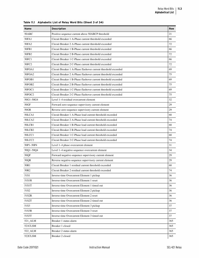
11.3
Date Code 20171021 Instruction Manual SEL-421 Relay
Relay Word BitsAlphabetical List
50ABC Positive-sequence current above 50ABCP threshold 21
50FA1 Circuit Breaker 1 A-Phase current threshold exceeded 66
50FA2 Circuit Breaker 2 A-Phase current threshold exceeded 72
50FB1 Circuit Breaker 1 B-Phase current threshold exceeded 66
50FB2 Circuit Breaker 2 B-Phase current threshold exceeded 72
50FC1 Circuit Breaker 1 C-Phase current threshold exceeded 66
50FC2 Circuit Breaker 2 C-Phase current threshold exceeded 72
50FOA1 Circuit Breaker 1 A-Phase flashover current threshold exceeded 69
50FOA2 Circuit Breaker 2 A-Phase flashover current threshold exceeded 75
50FOB1 Circuit Breaker 1 B-Phase flashover current threshold exceeded 69
50FOB2 Circuit Breaker 2 B-Phase flashover current threshold exceeded 75
50FOC1 Circuit Breaker 1 C-Phase flashover current threshold exceeded 69
50FOC2 Circuit Breaker 2 C-Phase flashover current threshold exceeded 75
50G1–50G4 Level 1–4 residual overcurrent element 32
50GF Forward zero-sequence supervisory current element 29
50GR Reverse zero-sequence supervisory current element 29
50LCA1 Circuit Breaker 1 A-Phase load current threshold exceeded 68
50LCA2 Circuit Breaker 2 A-Phase load current threshold exceeded 74
50LCB1 Circuit Breaker 1 B-Phase load current threshold exceeded 68
50LCB2 Circuit Breaker 2 B-Phase load current threshold exceeded 74
50LCC1 Circuit Breaker 1 C-Phase load current threshold exceeded 68
50LCC2 Circuit Breaker 2 C-Phase load current threshold exceeded 74
50P1–50P4 Level 1–4 phase overcurrent element 31
50Q1–50Q4 Level 1–4 negative-sequence overcurrent element 34
50QF Forward negative-sequence supervisory current element 29
50QR Reverse negative-sequence supervisory current element 29
50R1 Circuit Breaker 1 residual current threshold exceeded 68
50R2 Circuit Breaker 2 residual current threshold exceeded 74
51S1 Inverse-time Overcurrent Element 1 pickup 36
51S1R Inverse-time Overcurrent Element 1 reset 36
51S1T Inverse-time Overcurrent Element 1 timed out 36
51S2 Inverse-time Overcurrent Element 2 pickup 36
51S2R Inverse-time Overcurrent Element 2 reset 36
51S2T Inverse-time Overcurrent Element 2 timed out 36
51S3 Inverse-time Overcurrent Element 3 pickup 37
51S3R Inverse-time Overcurrent Element 3 reset 37
51S3T Inverse-time Overcurrent Element 3 timed out 37
521_ALM Breaker 1 status alarm 365
521CLSM Breaker 1 closed 365
522_ALM Breaker 2 status alarm 365
522CLSM Breaker 2 closed 365
Table 11.1 Alphabetic List of Relay Word Bits (Sheet 3 of 34)
Name Description Row

11.4
SEL-421 Relay Instruction Manual Date Code 20171021
Relay Word BitsAlphabetical List
523_ALM Breaker 3 status alarm 365
523CLSM Breaker 3 closed 365
52AA1 Circuit Breaker 1, Pole A status 80
52AA2 Circuit Breaker 2, Pole A status 82
52AAL1 Circuit Breaker 1, Pole A alarm 80
52AAL2 Circuit Breaker 2, Pole A alarm 81
52AB1 Circuit Breaker 1, Pole B status 80
52AB2 Circuit Breaker 2, Pole B status 82
52AC1 Circuit Breaker 1, Pole C status 81
52AC2 Circuit Breaker 2, Pole C status 82
52ACL1 Circuit Breaker 1, Pole A closed 80
52ACL2 Circuit Breaker 2, Pole A closed 81
52BAL1 Circuit Breaker 1, Pole B alarm 80
52BAL2 Circuit Breaker 2, Pole B alarm 81
52BCL1 Circuit Breaker 1, Pole B closed 80
52BCL2 Circuit Breaker 2, Pole B closed 81
52CAL1 Circuit Breaker 1, Pole C alarm 80
52CAL2 Circuit Breaker 2, Pole C alarm 81
52CCL1 Circuit Breaker 1, Pole C closed 80
52CCL2 Circuit Breaker 2, Pole C closed 81
591P1 Overvoltage Element 1, Level 1 asserted 387
591P1T Overvoltage Element 1, Level 1 timed out 387
591P2 Overvoltage Element 1, Level 2 asserted 387
592P1 Overvoltage Element 2, Level 1 asserted 387
592P1T Overvoltage Element 2, Level 1 timed out 387
592P2 Overvoltage Element 2, Level 2 asserted 387
593P1 Overvoltage Element 3, Level 1 asserted 388
593P1T Overvoltage Element 3, Level 1 timed out 388
593P2 Overvoltage Element 3, Level 2 asserted 388
594P1 Overvoltage Element 4, Level 1 asserted 388
594P1T Overvoltage Element 4, Level 1 timed out 388
594P2 Overvoltage Element 4, Level 2 asserted 388
595P1 Overvoltage Element 5, Level 1 asserted 389
595P1T Overvoltage Element 5, Level 1 timed out 389
595P2 Overvoltage Element 5, Level 2 asserted 389
596P1 Overvoltage Element 6, Level 1 asserted 389
596P1T Overvoltage Element 6, Level 1 timed out 389
596P2 Overvoltage Element 6, Level 2 asserted 389
59TC1–59TC2 Overvoltage Element 1–2, torque control 387
59TC3–59TC4 Overvoltage Element 3–4, torque control 388
59TC5–59TC6 Overvoltage Element 5–6, torque control 389
Table 11.1 Alphabetic List of Relay Word Bits (Sheet 4 of 34)
Name Description Row

11.5
Date Code 20171021 Instruction Manual SEL-421 Relay
Relay Word BitsAlphabetical List
59VDIF1 Circuit Breaker 1 synchronizing voltage difference less than limit 39
59VDIF2 Circuit Breaker 2 synchronizing voltage difference less than limit 41
59VP VP within healthy voltage window 38
59VS1 VS1 within healthy voltage window 38
59VS2 VS2 within healthy voltage window 40
67G1 Level 1 residual directional overcurrent element 33
67G1T Level 1 residual delayed directional overcurrent element 33
67G2 Level 2 residual directional overcurrent element 33
67G2T Level 2 residual delayed directional overcurrent element 33
67G3 Level 3 residual directional overcurrent element 33
67G3T Level 3 residual delayed directional overcurrent element 33
67G4 Level 4 residual directional overcurrent element 33
67G4T Level 4 residual delayed directional overcurrent element 33
67P1 Level 1 phase directional overcurrent element 31
67P1T Level 1 phase-delayed directional overcurrent element 32
67P2 Level 2 phase directional overcurrent element 31
67P2T Level 2 phase-delayed directional overcurrent element 32
67P3 Level 3 phase directional overcurrent element 31
67P3T Level 3 phase-delayed directional overcurrent element 32
67P4 Level 4 phase directional overcurrent element 31
67P4T Level 4 phase-delayed directional overcurrent element 32
67Q1 Level 1 negative-sequence directional overcurrent element 34
67Q1T Level 1 negative-sequence delayed directional overcurrent element 35
67Q2 Level 2 negative-sequence directional overcurrent element 34
67Q2T Level 2 negative-sequence delayed directional overcurrent element 35
67Q3 Level 3 negative-sequence directional overcurrent element 34
67Q3T Level 3 negative-sequence delayed directional overcurrent element 35
67Q4 Level 4 negative-sequence directional overcurrent element 34
67Q4T Level 4 negative-sequence delayed directional overcurrent element 35
67QG2S Negative-sequence and residual directional overcurrent short delay element 60
67QUBF Forward direction supervised output from 50QUBP 23
67QUBR Reverse direction supervised output from 50QUBP 23
79CY1 Relay in single-pole reclose cycle state 43
79CY3 Relay in three-pole reclose cycle state 43
79STRT Relay in start state 50
81D1 Level 1 definite-time frequency element pickup 392
81D1OVR Level 1 overfrequency element pick up 392
81D1T Level 1 definite-time frequency element delay 392
81D1UDR Level 1 underfrequency element pick up 392
81D2 Level 2 definite-time frequency element pickup 393
81D2OVR Level 2 overfrequency element pick up 393
Table 11.1 Alphabetic List of Relay Word Bits (Sheet 5 of 34)
Name Description Row

11.6
SEL-421 Relay Instruction Manual Date Code 20171021
Relay Word BitsAlphabetical List
81D2T Level 2 definite-time frequency element delay 393
81D2UDR Level 2 underfrequency element pick up 393
81D3 Level 3 definite-time frequency element pickup 393
81D3OVR Level 3 overfrequency element pick up 393
81D3T Level 3 definite-time frequency element delay 393
81D3UDR Level 3 underfrequency element pick up 393
81D4 Level 4 definite-time frequency element pickup 394
81D4OVR Level 4 overfrequency element pick up 394
81D4T Level 4 definite-time frequency element delay 394
81D4UDR Level 4 underfrequency element pick up 394
81D5 Level 5 definite-time frequency element pickup 394
81D5OVR Level 5 overfrequency element pick up 394
81D5T Level 5 definite-time frequency element delay 394
81D5UDR Level 5 underfrequency element pick up 394
81D6 Level 6 definite-time frequency element pickup 395
81D6OVR Level 6 overfrequency element pick up 395
81D6T Level 6 definite-time frequency element delay 395
81D6UDR Level 6 underfrequency element pick up 395
89AL Any disconnect alarm 332
89AL01 Disconnect 1 alarm 332
89AL02 Disconnect 2 alarm 333
89AL03 Disconnect 3 alarm 334
89AL04 Disconnect 4 alarm 335
89AL05 Disconnect 5 alarm 336
89AL06 Disconnect 6 alarm 337
89AL07 Disconnect 7 alarm 338
89AL08 Disconnect 8 alarm 339
89AL09 Disconnect 9 alarm 340
89AL10 Disconnect 10 alarm 341
89AM01 Disconnect 1 N/O auxiliary contact 332
89AM02 Disconnect 2 N/O auxiliary contact 333
89AM03 Disconnect 3 N/O auxiliary contact 334
89AM04 Disconnect 4 N/O auxiliary contact 335
89AM05 Disconnect 5 N/O auxiliary contact 336
89AM06 Disconnect 6 N/O auxiliary contact 337
89AM07 Disconnect 7 N/O auxiliary contact 338
89AM08 Disconnect 8 N/O auxiliary contact 339
89AM09 Disconnect 9 N/O auxiliary contact 340
89AM10 Disconnect 10 N/O auxiliary contact 341
89BM01 Disconnect 1 N/C auxiliary contact 332
89BM02 Disconnect 2 N/C auxiliary contact 333
Table 11.1 Alphabetic List of Relay Word Bits (Sheet 6 of 34)
Name Description Row

11.7
Date Code 20171021 Instruction Manual SEL-421 Relay
Relay Word BitsAlphabetical List
89BM03 Disconnect 3 N/C auxiliary contact 334
89BM04 Disconnect 4 N/C auxiliary contact 335
89BM05 Disconnect 5 N/C auxiliary contact 336
89BM06 Disconnect 6 N/C auxiliary contact 337
89BM07 Disconnect 7 N/C auxiliary contact 338
89BM08 Disconnect 8 N/C auxiliary contact 339
89BM09 Disconnect 9 N/C auxiliary contact 340
89BM10 Disconnect 10 N/C auxiliary contact 341
89CBL01 Disconnect 01 close block 364
89CBL02 Disconnect 02 close block 366
89CBL03 Disconnect 03 close block 368
89CBL04 Disconnect 04 close block 370
89CBL05 Disconnect 05 close block 372
89CBL06 Disconnect 06 close block 374
89CBL07 Disconnect 07 close block 376
89CBL08 Disconnect 08 close block 378
89CBL09 Disconnect 09 close block 380
89CBL10 Disconnect 10 close block 382
89CC01 ASCII Close Disconnect 1 command 344
89CC02 ASCII Close Disconnect 2 command 346
89CC03 ASCII Close Disconnect 3 command 348
89CC04 ASCII Close Disconnect 4 command 350
89CC05 ASCII Close Disconnect 5 command 352
89CC06 ASCII Close Disconnect 6 command 354
89CC07 ASCII Close Disconnect 7 command 356
89CC08 ASCII Close Disconnect 8 command 358
89CC09 ASCII Close Disconnect 9 command 360
89CC10 ASCII Close Disconnect 10 command 362
89CCM01 Mimic Disconnect 1 close control 344
89CCM02 Mimic Disconnect 2 close control 346
89CCM03 Mimic Disconnect 3 close control 348
89CCM04 Mimic Disconnect 4 close control 350
89CCM05 Mimic Disconnect 5 close control 352
89CCM06 Mimic Disconnect 6 close control 354
89CCM07 Mimic Disconnect 7 close control 356
89CCM08 Mimic Disconnect 8 close control 358
89CCM09 Mimic Disconnect 9 close control 360
89CCM10 Mimic Disconnect 10 close control 362
89CCN01 Close Disconnect 1 344
89CCN02 Close Disconnect 2 346
89CCN03 Close Disconnect 3 348
Table 11.1 Alphabetic List of Relay Word Bits (Sheet 7 of 34)
Name Description Row

11.8
SEL-421 Relay Instruction Manual Date Code 20171021
Relay Word BitsAlphabetical List
89CCN04 Close Disconnect 4 350
89CCN05 Close Disconnect 5 352
89CCN06 Close Disconnect 6 354
89CCN07 Close Disconnect 7 356
89CCN08 Close Disconnect 8 358
89CCN09 Close Disconnect 9 360
89CCN10 Close Disconnect 10 362
89CIM01 Disconnect 01 close immobility timer timed out 365
89CIM02 Disconnect 02 close immobility timer timed out 367
89CIM03 Disconnect 03 close immobility timer timed out 369
89CIM04 Disconnect 04 close immobility timer timed out 371
89CIM05 Disconnect 05 close immobility timer timed out 373
89CIM06 Disconnect 06 close immobility timer timed out 375
89CIM07 Disconnect 07 close immobility timer timed out 377
89CIM08 Disconnect 08 close immobility timer timed out 379
89CIM09 Disconnect 09 close immobility timer timed out 381
89CIM10 Disconnect 10 close immobility timer timed out 383
89CIR01 Disconnect 01 close immobility timer reset 364
89CIR02 Disconnect 02 close immobility timer reset 366
89CIR03 Disconnect 03 close immobility timer reset 368
89CIR04 Disconnect 04 close immobility timer reset 370
89CIR05 Disconnect 05 close immobility timer reset 372
89CIR06 Disconnect 06 close immobility timer reset 374
89CIR07 Disconnect 07 close immobility timer reset 376
89CIR08 Disconnect 08 close immobility timer reset 378
89CIR09 Disconnect 09 close immobility timer reset 380
89CIR10 Disconnect 10 close immobility timer reset 382
89CL01 Disconnect 1 closed 332
89CL02 Disconnect 2 closed 333
89CL03 Disconnect 3 closed 334
89CL04 Disconnect 4 closed 335
89CL05 Disconnect 5 closed 336
89CL06 Disconnect 6 closed 337
89CL07 Disconnect 7 closed 338
89CL08 Disconnect 8 closed 339
89CL09 Disconnect 9 closed 340
89CL10 Disconnect 10 closed 341
89CLB01–89CLB08 Disconnect 1–8 bus-zone protection 342
89CLB09–89CLB10 Disconnect 9–10 bus-zone protection 343
89CLS01 Disconnect Close 1 output 344
89CLS02 Disconnect Close 2 output 346
Table 11.1 Alphabetic List of Relay Word Bits (Sheet 8 of 34)
Name Description Row

11.9
Date Code 20171021 Instruction Manual SEL-421 Relay
Relay Word BitsAlphabetical List
89CLS03 Disconnect Close 3 output 348
89CLS04 Disconnect Close 4 output 350
89CLS05 Disconnect Close 5 output 352
89CLS06 Disconnect Close 6 output 354
89CLS07 Disconnect Close 7 output 356
89CLS08 Disconnect Close 8 output 358
89CLS09 Disconnect Close 9 output 360
89CLS10 Disconnect Close 10 output 362
89CRS01 Disconnect 01 close reset 364
89CRS02 Disconnect 02 close reset 366
89CRS03 Disconnect 03 close reset 368
89CRS04 Disconnect 04 close reset 370
89CRS05 Disconnect 05 close reset 372
89CRS06 Disconnect 06 close reset 374
89CRS07 Disconnect 07 close reset 376
89CRS08 Disconnect 08 close reset 378
89CRS09 Disconnect 09 close reset 380
89CRS10 Disconnect 10 close reset 382
89CSI01 Disconnect 01 close seal-in timer timed out 364
89CSI02 Disconnect 02 close seal-in timer timed out 366
89CSI03 Disconnect 03 close seal-in timer timed out 368
89CSI04 Disconnect 04 close seal-in timer timed out 370
89CSI05 Disconnect 05 close seal-in timer timed out 372
89CSI06 Disconnect 06 close seal-in timer timed out 374
89CSI07 Disconnect 07 close seal-in timer timed out 376
89CSI08 Disconnect 08 close seal-in timer timed out 378
89CSI09 Disconnect 09 close seal-in timer timed out 380
89CSI10 Disconnect 10 close seal-in timer timed out 382
89OBL01 Disconnect 01 open block 364
89OBL02 Disconnect 02 open block 366
89OBL03 Disconnect 03 open block 368
89OBL04 Disconnect 04 open block 370
89OBL05 Disconnect 05 open block 372
89OBL06 Disconnect 06 open block 374
89OBL07 Disconnect 07 open block 376
89OBL08 Disconnect 08 open block 378
89OBL09 Disconnect 09 open block 380
89OBL10 Disconnect 10 open block 382
89OC01 ASCII Open Disconnect 1 command 344
89OC02 ASCII Open Disconnect 2 command 346
89OC03 ASCII Open Disconnect 3 command 348
Table 11.1 Alphabetic List of Relay Word Bits (Sheet 9 of 34)
Name Description Row

11.10
SEL-421 Relay Instruction Manual Date Code 20171021
Relay Word BitsAlphabetical List
89OC04 ASCII Open Disconnect 4 command 350
89OC05 ASCII Open Disconnect 5 command 352
89OC06 ASCII Open Disconnect 6 command 354
89OC07 ASCII Open Disconnect 7 command 356
89OC08 ASCII Open Disconnect 8 command 358
89OC09 ASCII Open Disconnect 9 command 360
89OC10 ASCII Open Disconnect 10 command 362
89OCM01 Mimic Disconnect 1 open control 344
89OCM02 Mimic Disconnect 2 open control 346
89OCM03 Mimic Disconnect 3 open control 348
89OCM04 Mimic Disconnect 4 open control 350
89OCM05 Mimic Disconnect 5 open control 352
89OCM06 Mimic Disconnect 6 open control 354
89OCM07 Mimic Disconnect 7 open control 356
89OCM08 Mimic Disconnect 8 open control 358
89OCM09 Mimic Disconnect 9 open control 360
89OCM10 Mimic Disconnect 10 open control 362
89OCN01 Open Disconnect 1 344
89OCN02 Open Disconnect 2 346
89OCN03 Open Disconnect 3 348
89OCN04 Open Disconnect 4 350
89OCN05 Open Disconnect 5 352
89OCN06 Open Disconnect 6 354
89OCN07 Open Disconnect 7 356
89OCN08 Open Disconnect 8 358
89OCN09 Open Disconnect 9 360
89OCN10 Open Disconnect 10 362
89OIM01 Disconnect 01 open immobility timer timed out 365
89OIM02 Disconnect 02 open immobility timer timed out 367
89OIM03 Disconnect 03 open immobility timer timed out 369
89OIM04 Disconnect 04 open immobility timer timed out 371
89OIM05 Disconnect 05 open immobility timer timed out 373
89OIM06 Disconnect 06 open immobility timer timed out 375
89OIM07 Disconnect 07 open immobility timer timed out 377
89OIM08 Disconnect 08 open immobility timer timed out 379
89OIM09 Disconnect 09 open immobility timer timed out 381
89OIM10 Disconnect 10 open immobility timer timed out 383
89OIP Any disconnect operation in-progress 333
89OIP01 Disconnect 1 operation in-progress 332
89OIP02 Disconnect 2 operation in-progress 333
89OIP03 Disconnect 3 operation in-progress 334
Table 11.1 Alphabetic List of Relay Word Bits (Sheet 10 of 34)
Name Description Row

11.11
Date Code 20171021 Instruction Manual SEL-421 Relay
Relay Word BitsAlphabetical List
89OIP04 Disconnect 4 operation in-progress 335
89OIP05 Disconnect 5 operation in-progress 336
89OIP06 Disconnect 6 operation in-progress 337
89OIP07 Disconnect 7 operation in-progress 338
89OIP08 Disconnect 8 operation in-progress 339
89OIP09 Disconnect 9 operation in-progress 340
89OIP10 Disconnect 10 operation in-progress 341
89OIR01 Disconnect 01 open immobility timer reset 364
89OIR02 Disconnect 02 open immobility timer reset 366
89OIR03 Disconnect 03 open immobility timer reset 368
89OIR04 Disconnect 04 open immobility timer reset 370
89OIR05 Disconnect 05 open immobility timer reset 372
89OIR06 Disconnect 06 open immobility timer reset 374
89OIR07 Disconnect 07 open immobility timer reset 376
89OIR08 Disconnect 08 open immobility timer reset 378
89OIR09 Disconnect 09 open immobility timer reset 380
89OIR10 Disconnect 10 open immobility timer reset 382
89OPE01 Disconnect Open 1 output 344
89OPE02 Disconnect Open 2 output 346
89OPE03 Disconnect Open 3 output 348
89OPE04 Disconnect Open 4 output 350
89OPE05 Disconnect Open 5 output 352
89OPE06 Disconnect Open 6 output 354
89OPE07 Disconnect Open 7 output 356
89OPE08 Disconnect Open 8 output 358
89OPE09 Disconnect Open 9 output 360
89OPE10 Disconnect Open 10 output 362
89OPN01 Disconnect 1 open 332
89OPN02 Disconnect 2 open 333
89OPN03 Disconnect 3 open 334
89OPN04 Disconnect 4 open 335
89OPN05 Disconnect 5 open 336
89OPN06 Disconnect 6 open 337
89OPN07 Disconnect 7 open 338
89OPN08 Disconnect 8 open 339
89OPN09 Disconnect 9 open 340
89OPN10 Disconnect 10 open 341
89ORS01 Disconnect 01 open reset 364
89ORS02 Disconnect 02 open reset 366
89ORS03 Disconnect 03 open reset 368
89ORS04 Disconnect 04 open reset 370
Table 11.1 Alphabetic List of Relay Word Bits (Sheet 11 of 34)
Name Description Row

11.12
SEL-421 Relay Instruction Manual Date Code 20171021
Relay Word BitsAlphabetical List
89ORS05 Disconnect 05 open reset 372
89ORS06 Disconnect 06 open reset 374
89ORS07 Disconnect 07 open reset 376
89ORS08 Disconnect 08 open reset 378
89ORS09 Disconnect 09 open reset 380
89ORS10 Disconnect 10 open reset 382
89OSI01 Disconnect 01 open seal-in timer timed out 364
89OSI02 Disconnect 02 open seal-in timer timed out 366
89OSI03 Disconnect 03 open seal-in timer timed out 368
89OSI04 Disconnect 04 open seal-in timer timed out 370
89OSI05 Disconnect 05 open seal-in timer timed out 372
89OSI06 Disconnect 06 open seal-in timer timed out 374
89OSI07 Disconnect 07 open seal-in timer timed out 376
89OSI08 Disconnect 08 open seal-in timer timed out 378
89OSI09 Disconnect 09 open seal-in timer timed out 380
89OSI10 Disconnect 10 open seal-in timer timed out 382
A3PT Assert three-pole trip 54
ACCESS A user is logged in at Access Level B or above 207
ACCESSP Pulsed alarm for logins to Access Level B or above 207
ACN01Q–ACN08Q Automation Counter 1–8 output 194
ACN09Q–ACN16Q Automation Counter 9–16 output 195
ACN17Q–ACN24Q Automation Counter 17–24 output 196
ACN25Q–ACN32Q Automation Counter 25–32 output 197
ACN01R–ACN08R Automation Counter 1–8 reset 198
ACN09R–ACN16R Automation Counter 9–16 reset 199
ACN17R–ACN24R Automation Counter 17–24 reset 200
ACN25R–ACN32R Automation Counter 25–32 reset 201
AFRTEXA Automation SELOGIC control equation first execution after automation settings change 204
AFRTEXP Automation SELOGIC control equation first execution after protection settings change, group switch, or source switch selection.
204
ALT01–ALT08 Automation Latch 1–8 182
ALT09–ALT16 Automation Latch 9–16 183
ALT17–ALT24 Automation Latch 17–24 184
ALT25–ALT32 Automation Latch 25–32 185
ALTI Alternate current source (SELOGIC control equation) 269
ALTS2 Alternate synchronism source for Circuit Breaker 2 269
ALTV Alternate voltage source (SELOGIC control equation) 269
ANOKA Analog transfer OK on MIRRORED BITS Communications Channel A 229
ANOKB Analog transfer OK on MIRRORED BITS Communications Channel B 230
APS Trip logic A-Phase selected 54
AST01Q–AST08Q Automation Sequencing Timer 1–8 output 186
Table 11.1 Alphabetic List of Relay Word Bits (Sheet 12 of 34)
Name Description Row

11.13
Date Code 20171021 Instruction Manual SEL-421 Relay
Relay Word BitsAlphabetical List
AST09Q–AST16Q Automation Sequencing Timer 9–16 output 187
AST17Q–AST24Q Automation Sequencing Timer 17 output 188
AST25Q–AST32Q Automation Sequencing Timer 25–32 output 189
AST01R–AST08R Automation Sequencing Timer 1–8 reset 190
AST09R–AST16R Automation Sequencing Timer 9–16 reset 191
AST17R–AST24R Automation Sequencing Timer 17 reset 192
AST25R–AST32R Automation Sequencing Timer 25–32 reset 193
ASV001–ASV008 Automation SELOGIC Variable 1–8 150
ASV009–ASV016 Automation SELOGIC Variable 9–16 151
ASV017–ASV024 Automation SELOGIC Variable 17–24 152
ASV025–ASV032 Automation SELOGIC Variable 25–32 153
ASV033–ASV040 Automation SELOGIC Variable 33–40 154
ASV041–ASV048 Automation SELOGIC Variable 41–48 155
ASV049–ASV056 Automation SELOGIC Variable 49–56 156
ASV057–ASV064 Automation SELOGIC Variable 57–64 157
ASV065–ASV072 Automation SELOGIC Variable 65–72 158
ASV073–ASV080 Automation SELOGIC Variable 73–80 159
ASV081–ASV088 Automation SELOGIC Variable 81–88 160
ASV089–ASV096 Automation SELOGIC Variable 89–96 161
ASV097–ASV104 Automation SELOGIC Variable 97–104 162
ASV105–ASV112 Automation SELOGIC Variable 105–112 163
ASV113–ASV120 Automation SELOGIC Variable 113–120 164
ASV121–ASV128 Automation SELOGIC Variable 121–128 165
ASV129–ASV136 Automation SELOGIC Variable 129–136 166
ASV137–ASV144 Automation SELOGIC Variable 137–144 167
ASV145–ASV152 Automation SELOGIC Variable 145–152 168
ASV153–ASV160 Automation SELOGIC Variable 153–160 169
ASV161–ASV168 Automation SELOGIC Variable 161–168 170
ASV169–ASV176 Automation SELOGIC Variable 169–176 171
ASV177–ASV184 Automation SELOGIC Variable 177–184 172
ASV185–ASV192 Automation SELOGIC Variable 185–192 173
ASV193–ASV200 Automation SELOGIC Variable 193–200 174
ASV201–ASV208 Automation SELOGIC Variable 201–208 175
ASV209–ASV216 Automation SELOGIC Variable 209–216 176
ASV217–ASV224 Automation SELOGIC Variable 217–224 177
ASV225–ASV232 Automation SELOGIC Variable 225–232 178
ASV233–ASV240 Automation SELOGIC Variable 233–240 179
ASV241–ASV248 Automation SELOGIC Variable 241–248 180
ASV249–ASV256 Automation SELOGIC Variable 249–256 181
ATPA–ATPC Assert Trip A–Trip C 54
AUNRLBL Automation SELOGIC control equation unresolved label 204
Table 11.1 Alphabetic List of Relay Word Bits (Sheet 13 of 34)
Name Description Row

11.14
SEL-421 Relay Instruction Manual Date Code 20171021
Relay Word BitsAlphabetical List
B1BCWAL Circuit Breaker 1 contact wear monitor alarm 83
B1BITAL Circuit Breaker 1 inactivity time alarm 84
B1ESOAL Circuit Breaker 1 electrical slow operation alarm 84
B1KAIAL Circuit Breaker 1 interrupted current alarm 84
B1MRTAL Circuit Breaker 1 motor running time alarm 84
B1MRTIN Motor run time contact input, Circuit Breaker 1 (SELOGIC control equation) 83
B1MSOAL Circuit Breaker 1 mechanical slow operation alarm 84
B1OPHA Circuit Breaker 1 A-Phase open 77
B1OPHB Circuit Breaker 1 B-Phase open 77
B1OPHC Circuit Breaker 1 C-Phase open 77
B1PDAL Circuit Breaker 1 pole discrepancy alarm 84
B1PSAL Circuit Breaker 1 pole scatter alarm 84
B2BCWAL Circuit Breaker 2 contact wear monitor alarm 85
B2BITAL Circuit Breaker 2 inactivity time alarm 86
B2ESOAL Circuit Breaker 2 electrical slow operation alarm 86
B2KAIAL Circuit Breaker 2 interrupted current alarm 86
B2MRTAL Circuit Breaker 2 motor running time alarm 86
B2MRTIN Motor run time contact input, Circuit Breaker 2 (SELOGIC control equation) 85
B2MSOAL Circuit Breaker 2 mechanical slow operation alarm 86
B2OPHA Circuit Breaker 2 A-Phase open 77
B2OPHB Circuit Breaker 2 B-Phase open 77
B2OPHC Circuit Breaker 2 C-Phase open 77
B2PDAL Circuit Breaker 2 pole discrepancy alarm 86
B2PSAL Circuit Breaker 2 pole scatter alarm 86
BADPASS Invalid password attempt alarm 206
BFI3P1 Circuit Breaker 1 three-pole circuit breaker failure initiation 65
BFI3P2 Circuit Breaker 2 three-pole circuit breaker failure initiation 71
BFI3PT1 Circuit Breaker 1 extended three-pole extended circuit breaker failure initiation 65
BFI3PT2 Circuit Breaker 2 three-pole extended circuit breaker failure initiation 71
BFIA1 Circuit Breaker 1 A-Phase circuit breaker failure initiation 65
BFIA2 Circuit Breaker 2 A-Phase circuit breaker failure initiation 71
BFIAT1 Circuit Breaker 1 A-Phase extended circuit breaker failure initiation 65
BFIAT2 Circuit Breaker 2 A-Phase extended circuit breaker failure initiation 71
BFIB1 Circuit Breaker 1 B-Phase circuit breaker failure initiation 65
BFIB2 Circuit Breaker 2 B-Phase circuit breaker failure initiation 71
BFIBT1 Circuit Breaker 1 B-Phase extended circuit breaker failure initiation 65
BFIBT2 Circuit Breaker 2 B-Phase extended circuit breaker failure initiation 71
BFIC1 Circuit Breaker 1 C-Phase circuit breaker failure initiation 65
BFIC2 Circuit Breaker 2 C-Phase circuit breaker failure initiation 71
BFICT1 Circuit Breaker 1 C-Phase extended circuit breaker failure initiation 65
BFICT2 Circuit Breaker 2 C-Phase extended circuit breaker failure initiation 71
Table 11.1 Alphabetic List of Relay Word Bits (Sheet 14 of 34)
Name Description Row

11.15
Date Code 20171021 Instruction Manual SEL-421 Relay
Relay Word BitsAlphabetical List
BFILC1 Circuit Breaker 1 load current circuit breaker failure initiation 68
BFILC2 Circuit Breaker 2 load current circuit breaker failure initiation 74
BFIN1 Circuit Breaker 1 no current circuit breaker failure initiation 68
BFIN2 Circuit Breaker 2 no current circuit breaker failure initiation 74
BFTR1 Circuit breaker failure trip, Circuit Breaker 1 (SELOGIC control equation) 70
BFTR2 Circuit breaker failure trip, Circuit Breaker 2 (SELOGIC control equation) 76
BFTRIP1 Circuit Breaker 1 failure trip output asserted 70
BFTRIP2 Circuit Breaker 2 failure trip output asserted 76
BFULTR1 Circuit breaker failure unlatch trip, Circuit Breaker 1 (SELOGIC control equation) 70
BFULTR2 Circuit breaker failure unlatch trip, Circuit Breaker 2 (SELOGIC control equation) 76
BK1BFT Indicates Circuit Breaker 1 breaker failure trip 224
BK1CFT Circuit Breaker 1 close failure delay timed out 46
BK1CL Circuit Breaker 1 close command 44
BK1CLSS Circuit Breaker 1 in close supervision state 46
BK1CLST Circuit Breaker 1 close supervision timer timed out 46
BK1EXT Circuit Breaker 1 closed externally 50
BK1LO Circuit Breaker 1 in lockout state 43
BK1RCIP Circuit Breaker 1 reclaim in progress (lockout state) 48
BK1RS Circuit Breaker 1 in ready state 43
BK2BFT Indicates Circuit Breaker 2 breaker failure trip 224
BK2CFT Circuit Breaker 2 close failure delay timed out 46
BK2CL Circuit Breaker 2 close command 44
BK2CLSS Circuit Breaker 2 in close supervision state 46
BK2CLST Circuit Breaker 2 close supervision timer timed out 46
BK2EXT Circuit Breaker 2 closed externally 50
BK2LO Circuit Breaker 2 in lockout state 44
BK2RCIP Circuit Breaker 2 reclaim in progress (lockout state) 48
BK2RS Circuit Breaker 2 in ready state 43
BLKFOA1 Circuit Breaker 1 block A-Phase flashover detection 69
BLKFOA2 Circuit Breaker 2 block A-Phase flashover detection 75
BLKFOB1 Circuit Breaker 1 block B-Phase flashover detection 69
BLKFOB2 Circuit Breaker 2 block B-Phase flashover detection 75
BLKFOC1 Circuit Breaker 1 block C-Phase flashover detection 69
BLKFOC2 Circuit Breaker 2 block C-Phase flashover detection 75
BLKLPTS Block low-priority source from updating relay time 210
BM1CLSA Circuit breaker monitor A-Phase close, Circuit Breaker 1 (SELOGIC control equation) 83
BM1CLSB Circuit breaker monitor B-Phase close, Circuit Breaker 1 (SELOGIC control equation) 83
BM1CLSC Circuit breaker monitor C-Phase close, Circuit Breaker 1 (SELOGIC control equation) 83
BM1TRPA Circuit breaker monitor A-Phase trip, Circuit Breaker 1 (SELOGIC control equation) 83
BM1TRPB Circuit breaker monitor B-Phase trip, Circuit Breaker 1 (SELOGIC control equation) 83
BM1TRPC Circuit breaker monitor C-Phase trip, Circuit Breaker 1 (SELOGIC control equation) 83
Table 11.1 Alphabetic List of Relay Word Bits (Sheet 15 of 34)
Name Description Row
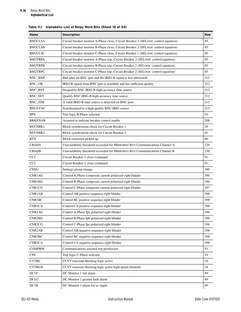
11.16
SEL-421 Relay Instruction Manual Date Code 20171021
Relay Word BitsAlphabetical List
BM2CLSA Circuit breaker monitor A-Phase close, Circuit Breaker 2 (SELOGIC control equation) 85
BM2CLSB Circuit breaker monitor B-Phase close, Circuit Breaker 2 (SELOGIC control equation) 85
BM2CLSC Circuit breaker monitor C-Phase close, Circuit Breaker 2 (SELOGIC control equation) 85
BM2TRPA Circuit breaker monitor A-Phase trip, Circuit Breaker 2 (SELOGIC control equation) 85
BM2TRPB Circuit breaker monitor B-Phase trip, Circuit Breaker 2 (SELOGIC control equation) 85
BM2TRPC Circuit breaker monitor C-Phase trip, Circuit Breaker 2 (SELOGIC control equation) 85
BNC_BNP Bad jitter on BNC port and the IRIG-B signal is lost afterwards 212
BNC_OK IRIG-B signal from BNC port is available and has sufficient quality 212
BNC_RST Disqualify BNC IRIG-B high-accuracy time source 212
BNC_SET Qualify BNC IRIG-B high-accuracy time source 212
BNC_TIM A valid IRIG-B time source is detected on BNC port 213
BNCSYNC Synchronized to a high quality BNC IRIG source 213
BPS Trip logic B-Phase selected 54
BRKENAB Asserted to indicate breaker control enable 208
BSYNBK1 Block synchronism check for Circuit Breaker 1 39
BSYNBK2 Block synchronism check for Circuit Breaker 2 41
BTX Block extension picked up 60
CBADA Unavailability threshold exceeded for MIRRORED BITS Communications Channel A 229
CBADB Unavailability threshold exceeded for MIRRORED BITS Communications Channel B 230
CC1 Circuit Breaker 1 close command 91
CC2 Circuit Breaker 2 close command 91
CHSG Settings group change 100
CNR1AG Control A-Phase composite current polarized right blinder 396
CNR1BG Control B-Phase composite current polarized right blinder 396
CNR1CG Control C-Phase composite current polarized right blinder 397
CNR1AB Control AB positive-sequence right blinder 398
CNR1BC Control BC positive-sequence right blinder 398
CNR1CA Control CA positive-sequence right blinder 398
CNR2AG Control A-Phase Ipa polarized right blinder 396
CNR2BG Control B-Phase Ipb polarized right blinder 396
CNR2CG Control C-Phase Ipc polarized right blinder 396
CNR2AB Control AB negative-sequence right blinder 398
CNR2BC Control BC negative-sequence right blinder 398
CNR2CA Control CA negative-sequence right blinder 398
COMPRM Communications-assisted trip permission 53
CPS Trip logic C-Phase selected 54
CVTBL CCVT transient blocking logic active 18
CVTBLH CCVT transient blocking logic active high-speed elements 18
DC1F DC Monitor 1 fail alarm 89
DC1G DC Monitor 1 ground fault alarm 89
DC1R DC Monitor 1 alarm for ac ripple 89
Table 11.1 Alphabetic List of Relay Word Bits (Sheet 16 of 34)
Name Description Row
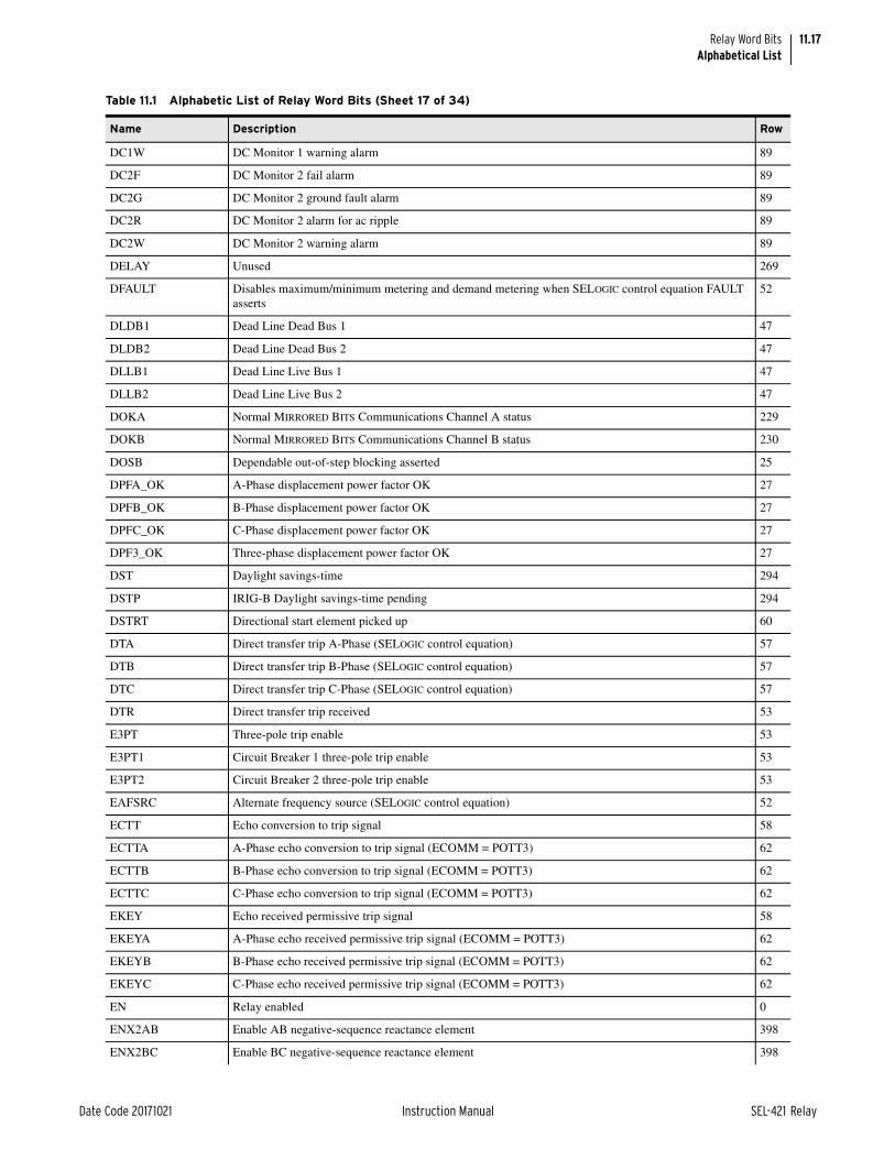
11.17
Date Code 20171021 Instruction Manual SEL-421 Relay
Relay Word BitsAlphabetical List
DC1W DC Monitor 1 warning alarm 89
DC2F DC Monitor 2 fail alarm 89
DC2G DC Monitor 2 ground fault alarm 89
DC2R DC Monitor 2 alarm for ac ripple 89
DC2W DC Monitor 2 warning alarm 89
DELAY Unused 269
DFAULT Disables maximum/minimum metering and demand metering when SELOGIC control equation FAULT asserts
52
DLDB1 Dead Line Dead Bus 1 47
DLDB2 Dead Line Dead Bus 2 47
DLLB1 Dead Line Live Bus 1 47
DLLB2 Dead Line Live Bus 2 47
DOKA Normal MIRRORED BITS Communications Channel A status 229
DOKB Normal MIRRORED BITS Communications Channel B status 230
DOSB Dependable out-of-step blocking asserted 25
DPFA_OK A-Phase displacement power factor OK 27
DPFB_OK B-Phase displacement power factor OK 27
DPFC_OK C-Phase displacement power factor OK 27
DPF3_OK Three-phase displacement power factor OK 27
DST Daylight savings-time 294
DSTP IRIG-B Daylight savings-time pending 294
DSTRT Directional start element picked up 60
DTA Direct transfer trip A-Phase (SELOGIC control equation) 57
DTB Direct transfer trip B-Phase (SELOGIC control equation) 57
DTC Direct transfer trip C-Phase (SELOGIC control equation) 57
DTR Direct transfer trip received 53
E3PT Three-pole trip enable 53
E3PT1 Circuit Breaker 1 three-pole trip enable 53
E3PT2 Circuit Breaker 2 three-pole trip enable 53
EAFSRC Alternate frequency source (SELOGIC control equation) 52
ECTT Echo conversion to trip signal 58
ECTTA A-Phase echo conversion to trip signal (ECOMM = POTT3) 62
ECTTB B-Phase echo conversion to trip signal (ECOMM = POTT3) 62
ECTTC C-Phase echo conversion to trip signal (ECOMM = POTT3) 62
EKEY Echo received permissive trip signal 58
EKEYA A-Phase echo received permissive trip signal (ECOMM = POTT3) 62
EKEYB B-Phase echo received permissive trip signal (ECOMM = POTT3) 62
EKEYC C-Phase echo received permissive trip signal (ECOMM = POTT3) 62
EN Relay enabled 0
ENX2AB Enable AB negative-sequence reactance element 398
ENX2BC Enable BC negative-sequence reactance element 398
Table 11.1 Alphabetic List of Relay Word Bits (Sheet 17 of 34)
Name Description Row

11.18
SEL-421 Relay Instruction Manual Date Code 20171021
Relay Word BitsAlphabetical List
ENX2CA Enable CA negative-sequence reactance element 398
ENX2AG Enable A-Phase Ipa polarized reactance element 396
ENX2BG Enable B-Phase Ipb polarized reactance element 396
ENX2CG Enable C-Phase Ipc polarized reactance element 396
ER Event report trigger equation (SELOGIC control equation) 52
EVELOCK Lock DNP events 286
F32I Forward current polarized zero-sequence directional element 30
F32P Forward phase directional declaration 28
F32Q Forward negative-sequence phase directional declaration 28
F32QG Forward negative-sequence ground directional element 30
F32V Forward voltage polarized zero-sequence directional element 30
FAST1 fs1 > fp 39
FAST2 fs2 > fp 41
FBF1 Circuit Breaker 1 circuit breaker failure 67
FBF2 Circuit Breaker 2 circuit breaker failure 73
FBFA1 Circuit Breaker 1 A-Phase circuit breaker failure 67
FBFA2 Circuit Breaker 2 A-Phase circuit breaker failure 73
FBFB1 Circuit Breaker 1 B-Phase circuit breaker failure 67
FBFB2 Circuit Breaker 2 B-Phase circuit breaker failure 73
FBFC1 Circuit Breaker 1 C-Phase circuit breaker failure 67
FBFC2 Circuit Breaker 2 C-Phase circuit breaker failure 73
FIDEN Fault identification logic enabled 51
FOA1 Circuit Breaker 1 A-Phase flashover detected 69
FOA2 Circuit Breaker 2 A-Phase flashover detected 75
FOB1 Circuit Breaker 1 B-Phase flashover detected 69
FOB2 Circuit Breaker 2 B-Phase flashover detected 75
FOBF1 Circuit Breaker 1 flashover detected 70
FOBF2 Circuit Breaker 2 flashover detected 76
FOC1 Circuit Breaker 1 C-Phase flashover detected 70
FOC2 Circuit Breaker 2 C-Phase flashover detected 76
FOLBK0 No follower circuit breaker 44
FOLBK1 Follower circuit breaker = Circuit Breaker 1 44
FOLBK2 Follower circuit breaker = Circuit Breaker 2 45
FOP1_01–FOP1_08 Fast-operate output control bits for Port 1, Bit 1–8 320
FOP1_09–FOP1_16 Fast-operate output control bits for Port 1, Bit 9–16 321
FOP1_17–FOP1_24 Fast-operate output control bits for Port 1, Bit 17–24 322
FOP1_25–FOP1_32 Fast-operate output control bits for Port 1, Bit 25–32 323
FOP2_01–FOP2_08 Fast-operate output control bits for Port 2, Bit 1–8 324
FOP2_09–FOP2_16 Fast-operate output control bits for Port 2, Bit 9–16 325
FOP2_17–FOP2_24 Fast-operate output control bits for Port 2, Bit 17–24 326
FOP2_25–FOP2_32 Fast-operate output control bits for Port 2, Bit 25–32 327
Table 11.1 Alphabetic List of Relay Word Bits (Sheet 18 of 34)
Name Description Row
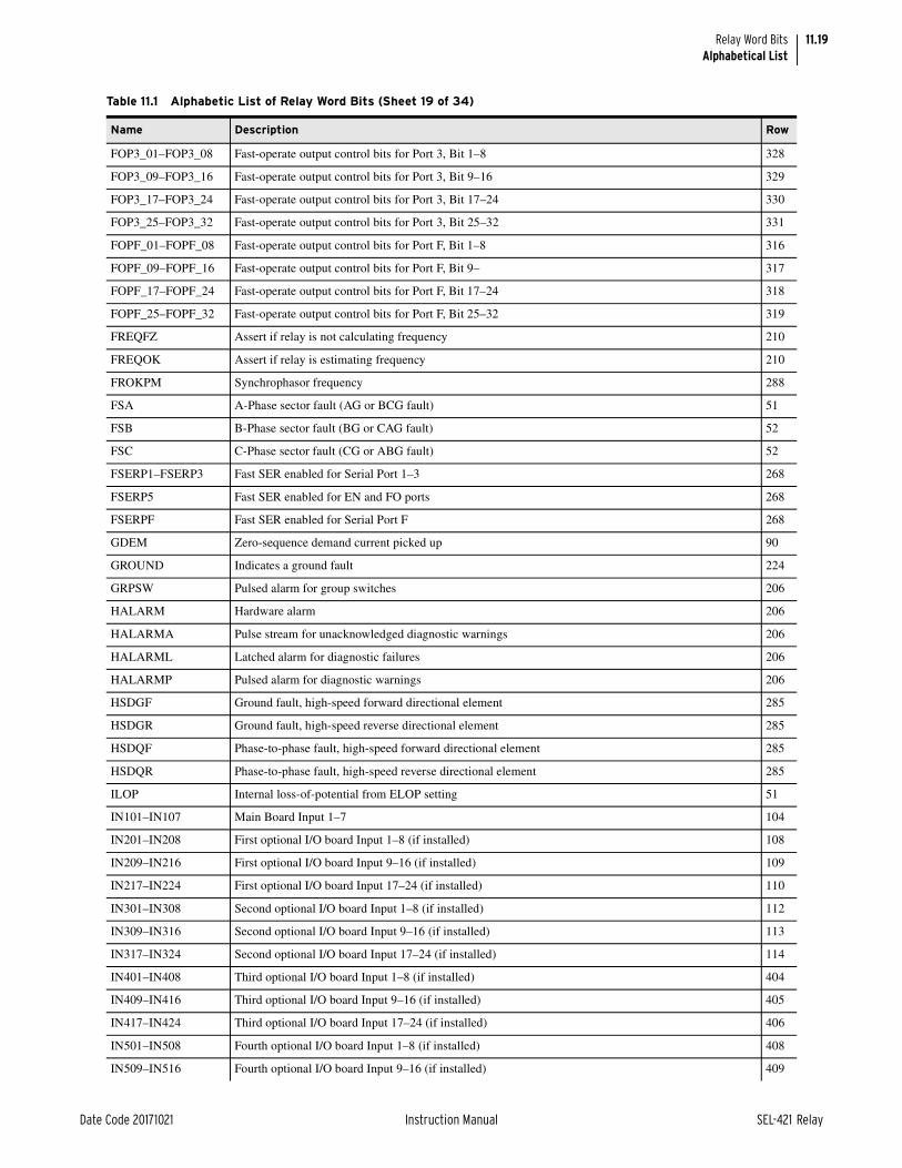
11.19
Date Code 20171021 Instruction Manual SEL-421 Relay
Relay Word BitsAlphabetical List
FOP3_01–FOP3_08 Fast-operate output control bits for Port 3, Bit 1–8 328
FOP3_09–FOP3_16 Fast-operate output control bits for Port 3, Bit 9–16 329
FOP3_17–FOP3_24 Fast-operate output control bits for Port 3, Bit 17–24 330
FOP3_25–FOP3_32 Fast-operate output control bits for Port 3, Bit 25–32 331
FOPF_01–FOPF_08 Fast-operate output control bits for Port F, Bit 1–8 316
FOPF_09–FOPF_16 Fast-operate output control bits for Port F, Bit 9– 317
FOPF_17–FOPF_24 Fast-operate output control bits for Port F, Bit 17–24 318
FOPF_25–FOPF_32 Fast-operate output control bits for Port F, Bit 25–32 319
FREQFZ Assert if relay is not calculating frequency 210
FREQOK Assert if relay is estimating frequency 210
FROKPM Synchrophasor frequency 288
FSA A-Phase sector fault (AG or BCG fault) 51
FSB B-Phase sector fault (BG or CAG fault) 52
FSC C-Phase sector fault (CG or ABG fault) 52
FSERP1–FSERP3 Fast SER enabled for Serial Port 1–3 268
FSERP5 Fast SER enabled for EN and FO ports 268
FSERPF Fast SER enabled for Serial Port F 268
GDEM Zero-sequence demand current picked up 90
GROUND Indicates a ground fault 224
GRPSW Pulsed alarm for group switches 206
HALARM Hardware alarm 206
HALARMA Pulse stream for unacknowledged diagnostic warnings 206
HALARML Latched alarm for diagnostic failures 206
HALARMP Pulsed alarm for diagnostic warnings 206
HSDGF Ground fault, high-speed forward directional element 285
HSDGR Ground fault, high-speed reverse directional element 285
HSDQF Phase-to-phase fault, high-speed forward directional element 285
HSDQR Phase-to-phase fault, high-speed reverse directional element 285
ILOP Internal loss-of-potential from ELOP setting 51
IN101–IN107 Main Board Input 1–7 104
IN201–IN208 First optional I/O board Input 1–8 (if installed) 108
IN209–IN216 First optional I/O board Input 9–16 (if installed) 109
IN217–IN224 First optional I/O board Input 17–24 (if installed) 110
IN301–IN308 Second optional I/O board Input 1–8 (if installed) 112
IN309–IN316 Second optional I/O board Input 9–16 (if installed) 113
IN317–IN324 Second optional I/O board Input 17–24 (if installed) 114
IN401–IN408 Third optional I/O board Input 1–8 (if installed) 404
IN409–IN416 Third optional I/O board Input 9–16 (if installed) 405
IN417–IN424 Third optional I/O board Input 17–24 (if installed) 406
IN501–IN508 Fourth optional I/O board Input 1–8 (if installed) 408
IN509–IN516 Fourth optional I/O board Input 9–16 (if installed) 409
Table 11.1 Alphabetic List of Relay Word Bits (Sheet 19 of 34)
Name Description Row

11.20
SEL-421 Relay Instruction Manual Date Code 20171021
Relay Word BitsAlphabetical List
IN517–IN524 Fourth optional I/O board Input 17–24 (if installed) 410
IO300OK Communications status of Interface Board 300 when installed or commissioned 403
IO400OK Communications status of Interface Board 400 when installed or commissioned 403
IO500OK Communications status of Interface Board 500 when installed or commissioned 403
KEY Transmit permissive trip signal 58
KEY1 Transmit general permissive trip 59
KEY3 Transmit three-phase permissive trip 59
KEYA Transmit A-Phase permissive trip (ECOMM = POTT3) 61
KEYB Transmit B-Phase permissive trip (ECOMM = POTT3) 61
KEYC Transmit C-Phase permissive trip (ECOMM = POTT3) 61
KEYD Transmit Directional permissive trip (ECOMM = POTT, EPTDIR = Y) 61
LB_DP01–LB_DP08 Local Bit 01–08 status display (SELOGIC Equation) 308
LB_DP09–LB_DP16 Local Bit 09–16 status display (SELOGIC Equation) 309
LB_DP17–LB_DP24 Local Bit 17–24 status display (SELOGIC Equation) 310
LB_DP25–LB_DP32 Local Bit 25–32 status display (SELOGIC Equation) 311
LB_SP01–LB_SP08 Local Bit 01–08 supervision (SELOGIC Equation) 304
LB_SP09–LB_SP16 Local Bit 09–16 supervision (SELOGIC Equation) 305
LB_SP17–LB_SP24 Local Bit 17–24 supervision (SELOGIC Equation) 306
LB_SP25–LB_SP32 Local Bit 25–32 supervision (SELOGIC Equation) 307
LB01–LB08 Local Bit 1–8 92
LB09–LB16 Local Bit 9–16 93
LB17–LB24 Local Bit 17–24 94
LB25–LB32 Local Bit 25–32 95
LBOKA Normal MIRRORED BITS Communications Channel A status while in loopback mode 229
LBOKB Normal MIRRORED BITS Communications Channel B status while in loopback mode 230
LCBF1 Circuit Breaker 1 load current circuit breaker failure 68
LCBF2 Circuit Breaker 2 load current circuit breaker failure 74
LD_DPFA Leading A-Phase displacement power factor 26
LD_DPFB Leading B-Phase displacement power factor 26
LD_DPFC Leading C-Phase displacement power factor 26
LD_DPF3 Leading three-phase displacement power factor 26
LEADBK0 No lead circuit breaker 44
LEADBK1 Lead circuit breaker = Circuit Breaker 1 44
LEADBK2 Lead circuit breaker = Circuit Breaker 2 44
LG_DPFA Lagging A-Phase displacement power factor 26
LG_DPFB Lagging B-Phase displacement power factor 26
LG_DPFC Lagging C-Phase displacement power factor 26
LG_DPF3 Lagging three-phase displacement power factor 26
LINK5A Link status of Port 5A connection 264
LINK5B Link status of Port 5B connection 264
LINK5C Link status of Port 5C connection 264
Table 11.1 Alphabetic List of Relay Word Bits (Sheet 20 of 34)
Name Description Row

11.21
Date Code 20171021 Instruction Manual SEL-421 Relay
Relay Word BitsAlphabetical List
LINK5D Link status of Port 5D connection 264
LLDB1 Live Line Dead Bus 1 47
LLDB2 Live Line Dead Bus 2 47
LNKFAIL Link status of the active port 264
LOADTE Load TECORR factor (SELOGIC Equation). When a rising edge is detected, the accumulated time-error value TE is loaded with the TECORR factor (preload value).
296
LOCAL Local front-panel control 334
LOP Loss-of-potential detected 51
LOPHA Line A-Phase open 77
LOPHB Line B-Phase open 77
LOPHC Line C-Phase open 78
LPHDSIM IEC 61850 logical node for physical device simulation 231
LPSEC Direction of the upcoming leap second. During the time that LPSECP is asserted, if LPSEC is asserted, the upcoming leap second is deleted; otherwise, the leap second is added.
294
LPSECP Leap second pending 294
M1P Zone 1 Mho phase-distance element 18
M1PT Zone 1 Mho phase-distance, time-delayed 19
M2P Zone 2 Mho phase-distance element 18
M2PT Zone 2 Mho phase-distance, time-delayed 19
M3P Zone 3 Mho phase-distance element 19
M3PT Zone 3 Mho phase-distance, time-delayed 19
M4P Zone 4 Mho phase-distance element 19
M4PT Zone 4 Mho phase-distance, time-delayed 19
M5P Zone 5 Mho phase-distance element 19
M5PT Zone 5 Mho phase-distance, time-delayed 19
MAB1 Zone 1 Mho A-B phase element 8
MAB1F Zone 1 filtered Mho A-B phase element 274
MAB1H High-speed Zone 1 Mho A-B phase element 282
MAB2 Zone 2 Mho A-B phase element 8
MAB2F Zone 2 filtered Mho A-B phase element 274
MAB2H High-speed Zone 2 Mho A-B phase element 282
MAB3 Zone 3 Mho A-B phase element 9
MAB3F Zone 3 filtered Mho A-B phase element 275
MAB3H High-speed Zone 3 Mho A-B phase element 282
MAB4 Zone 4 Mho A-B phase element 9
MAB4F Zone 4 filtered Mho A-B phase element 276
MAB5 Zone 5 Mho A-B phase element 10
MAB5F Zone 5 filtered Mho A-B phase element 277
MAG1 Zone 1 Mho A-Phase-to-ground element 13
MAG1F Zone 1 filtered Mho A-Phase-to-ground element 270
MAG1H High-speed Zone 1 Mho A-G ground element 278
MAG2 Zone 2 Mho A-Phase-to-ground element 13
Table 11.1 Alphabetic List of Relay Word Bits (Sheet 21 of 34)
Name Description Row

11.22
SEL-421 Relay Instruction Manual Date Code 20171021
Relay Word BitsAlphabetical List
MAG2F Zone 2 filtered Mho A-Phase-to-ground element 270
MAG2H High-speed Zone 2 Mho A-G ground element 278
MAG3 Zone 3 Mho A-Phase-to-ground element 14
MAG3F Zone 3 filtered Mho A-Phase-to-ground element 271
MAG3H High-speed Zone 3 Mho A-G ground element 278
MAG4 Zone 4 Mho A-Phase-to-ground element 14
MAG4F Zone 4 filtered Mho C-Phase-to-ground element 272
MAG5 Zone 5 Mho A-Phase-to-ground element 15
MAG5F Zone 5 filtered Mho A-Phase-to-ground element 273
MATHERR SELOGIC control equation math error 202
MBC1 Zone 1 Mho B-C phase element 8
MBC1F Zone 1 filtered Mho B-C phase element 274
MBC1H High-speed Zone 1 Mho B-C phase element 282
MBC2 Zone 2 Mho B-C phase element 8
MBC2F Zone 2 filtered Mho B-C phase element 274
MBC2H High-speed Zone 2 Mho B-C phase element 282
MBC3 Zone 3 Mho B-C phase element 9
MBC3F Zone 3 filtered Mho B-C phase element 275
MBC3H High-speed Zone 3 Mho B-C phase element 282
MBC4 Zone 4 Mho B-C phase element 9
MBC4F Zone 4 filtered Mho B-C phase element 276
MBC5 Zone 5 Mho B-C phase element 10
MBC5F Zone 5 filtered Mho B-C phase element 277
MBG1 Zone 1 Mho B-Phase-to-ground element 13
MBG1F Zone 1 filtered Mho B-Phase-to-ground element 270
MBG1H High-speed Zone 1 Mho BG ground element 278
MBG2 Zone 2 Mho B-Phase-to-ground element 13
MBG2F Zone 2 filtered B-Phase-to-ground Mho element asserted 270
MBG2H High-speed Zone 2 Mho BG ground element 278
MBG3 Zone 3 Mho B-Phase-to-ground element 14
MBG3F Zone 3 filtered Mho B-Phase-to-ground element 271
MBG3H High-speed Zone 3 Mho BG ground element 278
MBG4 Zone 4 Mho B-Phase-to-ground element 14
MBG4F Zone 4 filtered Mho B-Phase-to-ground element 272
MBG5 Zone 5 Mho B-Phase-to-ground element 15
MBG5F Zone 5 filtered Mho B-Phase-to-ground element 273
MCA1 Zone 1 Mho C-A phase element 8
MCA1F Zone 1 filtered Mho C-A phase element 274
MCA1H High-speed Zone 1 Mho C-A phase element 282
MCA2 Zone 2 Mho C-A phase element 8
MCA2F Zone 2 filtered Mho C-A phase element 275
Table 11.1 Alphabetic List of Relay Word Bits (Sheet 22 of 34)
Name Description Row

11.23
Date Code 20171021 Instruction Manual SEL-421 Relay
Relay Word BitsAlphabetical List
MCA2H High-speed Zone 2 Mho C-A phase element 282
MCA3 Zone 3 Mho C-A phase element 9
MCA3F Zone 3 filtered Mho C-A phase element 275
MCA3H High-speed Zone 3 Mho C-A phase element 283
MCA4 Zone 4 Mho C-A phase element 9
MCA4F Zone 4 filtered Mho C-A phase element 276
MCA5 Zone 5 Mho C-A phase element 10
MCA5F Zone 5 filtered Mho C-A phase element 277
MCG1 Zone 1 Mho C-Phase-to-ground element 13
MCG1F Zone 1 filtered Mho C-Phase-to-ground element 270
MCG1H High-speed Zone 1 Mho C-G ground element 278
MCG2 Zone 2 Mho C-Phase-to-ground element 13
MCG2F Zone 2 filtered Mho C-Phase-to-ground element 271
MCG2H High-speed Zone 2 Mho C-G ground element 278
MCG3 Zone 3 Mho C-Phase-to-ground element 14
MCG3F Zone 3 filtered Mho C-Phase-to-ground element 271
MCG3H High-speed Zone 3 Mho C-G ground element 279
MCG4 Zone 4 Mho C-Phase-to-ground element 14
MCG4F Zone 4 filtered Mho C-Phase-to-ground element 272
MCG5 Zone 5 Mho C-Phase-to-ground element 15
MCG5F Zone 5 filtered Mho C-Phase-to-ground element 273
NBF1 Circuit Breaker 1 no current circuit breaker failure 68
NBF2 Circuit Breaker 2 no current circuit breaker failure 74
NBK0 No circuit breakers active in reclose scheme 45
NBK1 One circuit breaker active in reclose scheme 45
NBK2 Two circuit breakers active in reclose scheme 45
NSTRT Nondirectional start element picked up 60
OC1 Circuit Breaker 1 open command 91
OC2 Circuit Breaker 2 open command 91
OOSDET Out-of-step condition detected 23
OSB Out-of-step block 22
OSB1–OSB5 Block Zone 1–5 during an out-of-step condition 21
OSBA A-Phase out-of-step block 21
OSBB B-Phase out-of-step block 21
OSBC C-Phase out-of-step block 21
OST Out-of-step tripping 22
OSTI Incoming out-of-step tripping 22
OSTO Outgoing out-of-step tripping 22
OUT101–OUT108 Main Board Output 1–8 215
OUT201–OUT208 Optional I/O Board 1 Output 1–8 216
OUT209–OUT216 Optional I/O Board 1 Output 9–16 217
Table 11.1 Alphabetic List of Relay Word Bits (Sheet 23 of 34)
Name Description Row

11.24
SEL-421 Relay Instruction Manual Date Code 20171021
Relay Word BitsAlphabetical List
OUT301–OUT308 Optional I/O Board 2 Output 1–8 218
OUT309–OUT316 Optional I/O Board 2 Output 9–16 219
OUT401–OUT408 Optional I/O Board 3 Output 1–8 412
OUT409–OUT416 Optional I/O Board 3 Output 9–16 413
OUT501–OUT508 Optional I/O Board 4 Output 1–8 414
OUT509–OUT516 Optional I/O Board 4 Output 9–16 415
P5ABSW Port 5A or 5B has just become active 400
P5ASEL Port 5A active/inactive 265
P5BSEL Port 5B active/inactive 265
P5CSEL Port 5C active/inactive 265
P5DSEL Port 5D active/inactive 265
PASSDIS Asserted to indicate PW disable 208
PB_CLSE Auxiliary CLOSE pushbutton 301
PB_TRIP Auxiliary TRIP pushbutton 301
PB1–PB8 Pushbutton 1–8 214
PB1_LED–PB8_LED Pushbutton 1–8 LED 221
PB1_PUL–PB8_PUL Pushbutton 1–8 pulse (on for one processing interval when button is pushed) 220
PB9–PB12 Pushbutton 9–12 301
PB9_LED–PB12LED Pushbutton 9–12 LED 302
PB9_PUL–PB12PUL Pushbutton 9–12 pulse (on for one processing interval when button is pushed) 303
PCN01Q–PCN08Q Protection Counter 1–8 output 142
PCN09Q–PCN16Q Protection Counter 9–16 output 143
PCN17Q–PCN24Q Protection Counter 17–24 output 144
PCN25Q–PCN32Q Protection Counter 25–32 output 145
PCN01R–PCN08R Protection Counter 1–8 reset 146
PCN09R–PCN16R Protection Counter 9–16 reset 147
PCN17R–PCN24R Protection Counter 17–24 reset 148
PCN25R–PCN32R Protection Counter 25–32 reset 149
PCT01Q–PCT08Q Protection Conditioning Timer 1–8 output 128
PCT09Q–PCT16Q Protection Conditioning Timer 9–16 output 129
PCT17Q–PCT24Q Protection Conditioning Timer 17–24 output 130
PCT25Q–PCT32Q Protection Conditioning Timer 25–32 output 131
PDEM Phase current demand picked up 90
PF3_OK Three-phase power factor OK 27
PFA_OK A-Phase power factor OK 27
PFB_OK B-Phase power factor OK 27
PFC_OK C-Phase power factor OK 27
PFRTEX Protection SELOGIC control equation first execution 202
PHASE_A Indicates an A-Phase fault 224
PHASE_B Indicates a B-Phase fault 224
PHASE_C Indicates a C-Phase fault 224
Table 11.1 Alphabetic List of Relay Word Bits (Sheet 24 of 34)
Name Description Row

11.25
Date Code 20171021 Instruction Manual SEL-421 Relay
Relay Word BitsAlphabetical List
PLDTE Asserts for approximately 1.5 cycles when the TEC command is used to load a new time-error correction factor (preload value) into the TECORR analog quantity.
296
PLT01–PLT08 Protection Latch 1–8 124
PLT09–PLT16 Protection Latch 9–16 125
PLT17–PLT24 Protection Latch 17–24 126
PLT25–PLT32 Protection Latch 25–32 127
PMDOK Assert if data acquisition system is operating correctly 209
PMTEST Synchrophasor test mode 288
PMTRIG Trigger (SELOGIC control equation) 288
PST01Q–PST08Q Protection Sequencing Timer 1–8 output 134
PST09Q–PST16Q Protection Sequencing Timer 9–16 output 135
PST17Q–PST24Q Protection Sequencing Timer 17–24 output 136
PST25Q–PST32Q Protection Sequencing Timer 25–32 output 137
PST01R–PST08R Protection Sequencing Timer 1–8 reset 138
PST09R–PST16R Protection Sequencing Timer 9–16 reset 139
PST17R–PST24R Protection Sequencing Timer 17–24 reset 140
PST25R–PST32Q Protection Sequencing Timer 25–32 reset 141
PSV01–PSV08 Protection SELOGIC Variable 1–8 116
PSV09–PSV16 Protection SELOGIC Variable 9–16 117
PSV17–PSV24 Protection SELOGIC Variable 17–24 118
PSV25–PSV32 Protection SELOGIC Variable 25–32 119
PSV33–PSV40 Protection SELOGIC Variable 33–40 120
PSV41–PSV48 Protection SELOGIC Variable 41–48 121
PSV49–PSV56 Protection SELOGIC Variable 49–56 122
PSV57–PSV64 Protection SELOGIC Variable 57–64 123
PT Permissive trip received 58
PTA A-Phase permissive trip received (ECOMM = POTT3) 63
PTB B-Phase permissive trip received (ECOMM = POTT3) 63
PTC C-Phase permissive trip received (ECOMM = POTT3) 63
PTDRX Directional permissive trip received (ECOMM = POTT, EPTDIR = Y) 63
PTP_BNP Bad jitter on PTP signals and the PTP signal is lost afterwards 400
PTP_OK PTP is available and has sufficient quality 400
PTP_RST Disqualify PTP high accuracy time source 400
PTP_SET Qualify PTP high accuracy time source 400
PTP_TIM A valid PTP time source is detected 400
PTPSYNC Synchronized to a high quality PTP source 400
PTRX Permissive trip received Channel 1 and Channel 2 60
PTRX1 Permissive trip received Channel 1 59
PTRX2 Permissive trip received Channel 2 59
PUNRLBL Protection SELOGIC control equation unresolved label 202
QDEM Negative-sequence demand current picked up 90
Table 11.1 Alphabetic List of Relay Word Bits (Sheet 25 of 34)
Name Description Row

11.26
SEL-421 Relay Instruction Manual Date Code 20171021
Relay Word BitsAlphabetical List
R1T Positive-sequence resistance within Zone 7 left resistance blinder 25
R32I Reverse current polarized zero-sequence directional element 30
R32P Reverse phase directional declaration 28
R32Q Reverse negative-sequence phase directional declaration 28
R32QG Reverse negative-sequence ground directional element 30
R32V Reverse voltage polarized zero-sequence directional element 30
R3PTE Recloser three-pole trip enable 47
R3PTE1 Recloser three-pole trip enable Circuit Breaker 1 47
R3PTE2 Recloser three-pole trip enable Circuit Breaker 2 48
R6T Positive-sequence resistance within Zone 6 resistance blinder 24
R7T Positive-sequence resistance within Zone 7 resistance blinder 24
RB01–RB08 Remote Bit 1–8 99
RB09–RB16 Remote Bit 9–16 98
RB17–RB24 Remote Bit 17–24 97
RB25–RB32 Remote Bit 25–32 96
RBADA Outage too long on MIRRORED BITS Communications Channel A 229
RBADB Outage too long on MIRRORED BITS Communications Channel B 230
RL6 Positive-sequence resistance within Zone 6 left resistance blinder 24
RL7 Positive-sequence resistance within Zone 7 left resistance blinder 24
RMB1A–RMB8A Channel A receive MIRRORED BITS 1–8 225
RMB1B–RMB8B Channel B receive MIRRORED BITS 1–8 227
ROKA Normal MIRRORED BITS Communications Channel A status while not in loopback mode 229
ROKB Normal MIRRORED BITS Communications Channel B status while not in loopback mode 230
RR6 Positive-sequence resistance within Zone 6 right resistance blinder 24
RR7 Positive-sequence resistance within Zone 7 right resistance blinder 24
RST_79C Reset recloser shot count accumulators (SELOGIC control equation) 223
RST_BAT Reset battery monitoring (SELOGIC control equation) 223
RST_BK1 Reset Circuit Breaker 1 monitor 222
RST_BK2 Reset Circuit Breaker 2 monitor 222
RST_DEM Reset demand metering 222
RST_ENE Reset energy metering data 222
RST_HAL Reset hardware alarm (SELOGIC control equation) 223
RST_PDM Reset peak demand metering 222
RSTDNPE Reset DNP fault summary data (SELOGIC control equation) 223
RSTFLOC Reset fault locator (SELOGIC control equation) 223
RSTMMB1 Reset max/min Circuit Breaker 1 (SELOGIC control equation) 222
RSTMMB2 Reset max/min Circuit Breaker 2 (SELOGIC control equation) 222
RSTMML Reset max/min line (SELOGIC control equation) 222
RSTTRGT Target reset (SELOGIC control equation) 223
RT1 Circuit Breaker 1 retrip 67
RT2 Circuit Breaker 2 retrip 73
Table 11.1 Alphabetic List of Relay Word Bits (Sheet 26 of 34)
Name Description Row
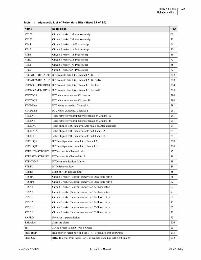
11.27
Date Code 20171021 Instruction Manual SEL-421 Relay
Relay Word BitsAlphabetical List
RT3P1 Circuit Breaker 1 three-pole retrip 66
RT3P2 Circuit Breaker 2 three-pole retrip 72
RTA1 Circuit Breaker 1 A-Phase retrip 66
RTA2 Circuit Breaker 2 A-Phase retrip 72
RTB1 Circuit Breaker 1 B-Phase retrip 66
RTB2 Circuit Breaker 2 B-Phase retrip 72
RTC1 Circuit Breaker 1 C-Phase retrip 66
RTC2 Circuit Breaker 2 C-Phase retrip 72
RTCAD01–RTCAD08 RTC remote data bits, Channel A, Bit 1–8 312
RTCAD09–RTCAD16 RTC remote data bits, Channel A, Bit 9–16 313
RTCBD01–RTCBD08 RTC remote data bits, Channel B, Bit 1–8 314
RTCBD09–RTCBD16 RTC remote data bits, Channel B, Bit 9–16 315
RTCCFGA RTC data in sequence, Channel A 290
RTCCFGB RTC data in sequence, Channel B 290
RTCDLYA RTC delay exceeded, Channel A 291
RTCDLYB RTC delay exceeded, Channel B 291
RTCENA Valid remote synchrophasors received on Channel A 291
RTCENB Valid remote synchrophasors received on Channel B 291
RTCROK Valid aligned RTC data available on all enabled channels 291
RTCROKA Valid aligned RTC data available on Channel A 291
RTCROKB Valid aligned RTC data available on Channel B 291
RTCSEQA RTC configuration complete, Channel A 290
RTCSEQB RTC configuration complete, Channel B 290
RTD01ST–RTD08ST RTD status for Channel 1–8 87
RTD09ST–RTD12ST RTD status for Channel 9–12 88
RTDCOMF RTD communication failure 88
RTDFL RTD device failure 88
RTDIN State of RTD contact input 88
RTS3P1 Circuit Breaker 1 current-supervised three-pole retrip 66
RTS3P2 Circuit Breaker 2 current-supervised three-pole retrip 72
RTSA1 Circuit Breaker 1 current-supervised A-Phase retrip 67
RTSA2 Circuit Breaker 2 current-supervised A-Phase retrip 73
RTSB1 Circuit Breaker 1 current-supervised B-Phase retrip 67
RTSB2 Circuit Breaker 2 current-supervised B-Phase retrip 73
RTSC1 Circuit Breaker 1 current-supervised C-Phase retrip 67
RTSC2 Circuit Breaker 2 current-supervised C-Phase retrip 73
RXPRM Receiver trip permission 53
SALARM Software alarm 206
SD Swing center voltage slope detected 25
SER_BNP Bad jitter on serial port and the IRIG-B signal is lost afterwards 213
SER_OK IRIG-B signal from serial Port 1 is available and has sufficient quality 212
Table 11.1 Alphabetic List of Relay Word Bits (Sheet 27 of 34)
Name Description Row

11.28
SEL-421 Relay Instruction Manual Date Code 20171021
Relay Word BitsAlphabetical List
SER_RST Disqualify serial IRIG-B high-accuracy time source 212
SER_SET Qualify serial IRIG-B high-accuracy time source 212
SER_TIM A valid IRIG-B time source is detected on serial port 213
SERCA Series-compensated line A-Phase output 20
SERCAB Series-compensated line AB-Phase output 20
SERCB Series-compensated line B-Phase output 20
SERCBC Series-compensated line BC-Phase output 20
SERCC Series-compensated line C-Phase output 20
SERCCA Series-compensated line CA-Phase output 20
SERSYNC Synchronized to a high quality serial IRIG source 213
SETCHG Pulsed alarm for settings changes 206
SFBK1 5 mHz Circuit Breaker 1 slip frequency < 25SFBK1 38
SFBK2 5 mHz Circuit Breaker 2 slip frequency < 25SFBK2 40
SFZBK1 Circuit Breaker 1 slip frequency less than 5 mHz 38
SFZBK2 Circuit Breaker 2 slip frequency less than 5 mHz 40
SG1–SG6 Settings Group 1–6 active 100
SLOW1 fs1 < fp 39
SLOW2 fs2 < fp 41
SOTFE Switch-onto-fault enable 51
SOTFT Switch-onto-fault trip 53
SP1CLS Single-pole Circuit Breaker 1 reclose supervision (SELOGIC control equation) 45
SP2CLS Single-pole Circuit Breaker 2 reclose supervision (SELOGIC control equation) 45
SPARC Single-pole reclose initiate qualified 42
SPCER1 Synchrophasor configuration error on Port 1 298
SPCER2 Synchrophasor configuration error on Port 2 298
SPCER3 Synchrophasor configuration error on Port 3 298
SPCERF Synchrophasor configuration error on Port F 298
SPEN Signal profiling enabled 267
SPLSHT Single-pole reclose last shot 42
SPO One or two poles open 78
SPOA A-Phase open 78
SPOB B-Phase open 78
SPOBK1 Single-pole open Circuit Breaker 1 42
SPOBK2 Single-pole open Circuit Breaker 2 42
SPOC C-Phase open 78
SPOI Single-pole open interval timing 50
SPOISC Single-pole open interval supervision condition 50
SPRCIP Single-pole reclaim in progress 48
SPRI Single-pole reclose initiation (SELOGIC control equation) 42
SPSHOT0 Single-pole shot counter = 0 49
SPSHOT1 Single-pole shot counter = 1 49
Table 11.1 Alphabetic List of Relay Word Bits (Sheet 28 of 34)
Name Description Row

11.29
Date Code 20171021 Instruction Manual SEL-421 Relay
Relay Word BitsAlphabetical List
SPSHOT2 Single-pole shot counter = 2 49
SPT Single-pole trip 55
SSD Out-of-step swing signature detected 25
STALLTE Stall time-error calculation (SELOGIC Equation). When asserted, the time-error calculation is stalled, or frozen.
296
STOP Stop element picked up 60
TBBK Time between circuit breakers timing 50
TBNC Time is based on a valid BNC IRIG-B source 211
TESTDB Communications card database Test Bit 231
TESTDB2 Communications card database Test Bit 2 231
TESTFM Fast meter test bit 231
TESTPUL Pulse test bit 231
TGLOBAL Relay calendar clock and ADC sampling synchronized to C37.118 high-accuracy IRIG-B time source 210
TIRIG Assert while time is based on IRIG for both mark and value 209
TLED_1–TLED_8 Target LED 1–8 1
TLED_9–TLED_16 Target LED 9–16 2
TLED_17–TLED_24 Target LED 17–24 300
TMB1A–TMB8A Channel A transmit MIRRORED BITS 1–8 226
TMB1B–TMB8B Channel B transmit MIRRORED BITS 1–8 228
TOP Trip during open pole timer is asserted 56
TPA Trip A 55
TPA1 Circuit Breaker 1 Trip A 55
TPA2 Circuit Breaker 2 Trip A 56
TPB Trip B 55
TPB1 Circuit Breaker 1 Trip B 55
TPB2 Circuit Breaker 2 Trip B 56
TPC Trip C 55
TPC1 Circuit Breaker 1 Trip C 56
TPC2 Circuit Breaker 2 Trip C 56
TPLLEXT Update PLL using external signal 210
TPTP Time is based on a valid PTP source 211
TQUAL1 Time quality, binary, add 1 when asserted 294
TQUAL2 Time quality, binary, add 2 when asserted 294
TQUAL4 Time quality, binary, add 4 when asserted 294
TQUAL8 Time quality, binary, add 8 when asserted 294
TREA1–TREA4 Trigger Reason Bit 1–4 (SELOGIC Equation) 288
TRGTR Reset all active target relay words 224
TRIP Trip A or Trip B or Trip C 55
TRIPLED Trip LED 0
TRPRM Trip permission 53
TSER Time is based on a valid Serial IRIG-B source 211
Table 11.1 Alphabetic List of Relay Word Bits (Sheet 29 of 34)
Name Description Row

11.30
SEL-421 Relay Instruction Manual Date Code 20171021
Relay Word BitsAlphabetical List
TSNTPB Asserts if time was synchronized with backup NTP server before SNTP timeout period expired 209
TSNTPP Asserts if time was synchronized with primary NTP server before SNTP timeout period expired 209
TSOK Assert if current time source accuracy is sufficient for synchronized phasor measurements 209
TSSW High-priority time source switching 210
TSYNC Assert when ADC sampling is synchronized to an IRIG-B time source 210
TSYNCA Assert while the time mark from time source or fixed internal source is not synchronized 209
TUPDH Assert if update source is high-accuracy time source 209
TUTC1 IRIG-B Offset hours from UTC time, binary, add 1 if asserted 293
TUTC2 IRIG-B Offset hours from UTC time, binary, add 2 if asserted 293
TUTC4 IRIG-B Offset hours from UTC time, binary, add 4 if asserted 293
TUTC8 IRIG-B Offset hours from UTC time, binary, add 8 if asserted 293
TUTCH IRIG-B Offset half-hour from UTC time, binary, add 0.5 if asserted 293
TUTCS IRIG-B Offset hours sign from UTC time, subtract the UTC offset if TUTCS is asserted, add otherwise 293
UBB Block permissive trip Receiver 1 or 2 59
UBB1 Blocks permissive trip Receiver 1 59
UBB2 Blocks permissive trip Receiver 2 59
UBOSB Unblock out-of-step blocking 21
ULCL1 Unlatch closing for Circuit Breaker 1 (SELOGIC control equation) 46
ULCL2 Unlatch closing for Circuit Breaker 2 (SELOGIC control equation) 46
ULMTR1 Circuit Breaker 1 unlatch manual trip 56
ULMTR2 Circuit Breaker 2 unlatch manual trip 56
ULTR Unlatch all protection trips 56
ULTRA Unlatch Trip A 57
ULTRB Unlatch Trip B 57
ULTRC Unlatch Trip C 57
UPD_BLK Block updating internal clock period and Master Time 212
UPD_EN Enable updating internal clock with selected external time source 209
VB001–VB008 Virtual Bit 001–008 263
VB009–VB016 Virtual Bit 009–016 262
VB017–VB024 Virtual Bit 017–024 261
VB025–VB032 Virtual Bit 025–032 260
VB033–VB040 Virtual Bit 033–040 259
VB041–VB048 Virtual Bit 041–048 258
VB049–VB056 Virtual Bit 049–056 257
VB057–VB064 Virtual Bit 057–064 256
VB065–VB072 Virtual Bit 065–072 255
VB073–VB080 Virtual Bit 073–080 254
VB081–VB088 Virtual Bit 081–088 253
VB089–VB096 Virtual Bit 089–096 252
VB097–VB104 Virtual Bit 097–104 251
VB105–VB112 Virtual Bit 105–112 250
Table 11.1 Alphabetic List of Relay Word Bits (Sheet 30 of 34)
Name Description Row

11.31
Date Code 20171021 Instruction Manual SEL-421 Relay
Relay Word BitsAlphabetical List
VB113–VB120 Virtual Bit 113–120 249
VB121–VB128 Virtual Bit 121–128 248
VB129–VB136 Virtual Bit 129–136 247
VB137–VB144 Virtual Bit 137–144 246
VB145–VB152 Virtual Bit 145–152 245
VB153–VB160 Virtual Bit 153–160 244
VB161–VB168 Virtual Bit 161–168 243
VB169–VB176 Virtual Bit 169–176 242
VB177–VB184 Virtual Bit 177–184 241
VB185–VB192 Virtual Bit 185–192 240
VB193–VB200 Virtual Bit 193–200 239
VB201–VB208 Virtual Bit 201–208 238
VB209–VB216 Virtual Bit 209–216 237
VB217–VB224 Virtual Bit 217–224 236
VB225–VB232 Virtual Bit 225–232 235
VB233–VB240 Virtual Bit 233–240 234
VB241–VB248 Virtual Bit 241–248 233
VB249–VB256 Virtual Bit 249–256 232
VMEMC Polarizing memory voltage control 3
VPOLV Polarizing voltage valid 18
WFC Weak infeed condition detected 59
X6ABC Impedance inside Zone 6 out-of-step 21
X6T Positive-sequence reactance within Zone 6 reactance blinder 24
X7ABC Impedance inside Zone 7 out-of-step 21
X7T Positive-sequence reactance within Zone 7 reactance blinder 24
XAB1 Zone 1 quad A-B phase element 10
XAB1F Zone 1 quad A-B phase element 274
XAB1H High-speed Zone 1 high-speed quad A-B phase element 283
XAB2 Zone 2 quad A-B phase element 11
XAB2F Zone 2 quad A-B phase element 275
XAB2H High-speed Zone 2 high-speed quad A-B phase element 283
XAB3 Zone 3 quad A-B phase element 11
XAB3F Zone 3 quad A-B phase element 275
XAB3H High-speed Zone 3 high-speed quad A-B phase element 283
XAB4 Zone 4 quad A-B phase element 12
XAB4F Zone 4 quad A-B phase element 276
XAB5 Zone 5 quad A-B phase element 12
XAB5F Zone 5 quad A-B phase element 277
XAG1 Zone 1 quad A-Phase-to-ground element 16
XAG1F Zone 1 quad A-Phase-to-ground element 270
XAG1H High-speed Zone 1 quad A-G ground element 279
Table 11.1 Alphabetic List of Relay Word Bits (Sheet 31 of 34)
Name Description Row

11.32
SEL-421 Relay Instruction Manual Date Code 20171021
Relay Word BitsAlphabetical List
XAG2 Zone 2 quad A-Phase-to-ground element 16
XAG2F Zone 2 quad A-Phase-to-ground element 271
XAG2H High-speed Zone 2 quad A-G ground element 279
XAG3 Zone 3 quad A-Phase-to-ground element 17
XAG3F Zone 3 quad A-Phase-to-ground element 271
XAG3H High-speed Zone 3 high-speed quad A-G ground element 279
XAG4 Zone 4 quad A-Phase-to-ground element 17
XAG4F Zone 4 quad A-Phase-to-ground element 272
XAG5 Zone 5 quad A-Phase-to-ground element 18
XAG5F Zone 5 quad A-Phase-to-ground element 273
XBC1 Zone 1 quad B-C phase element 10
XBC1F Zone 1 quad B-C phase element 274
XBC1H High-speed Zone 1 high-speed quad B-C phase element 283
XBC2 Zone 2 quad B-C phase element 11
XBC2F Zone 2 quad B-C phase element 275
XBC2H High-speed Zone 2 high-speed quad B-C phase element 283
XBC3 Zone 3 quad B-C phase element 11
XBC3F Zone 3 quad B-C phase element 276
XBC3H High-speed Zone 3 high-speed quad B-C phase element 284
XBC4 Zone 4 quad B-C phase element 12
XBC4F Zone 4 quad B-C phase element 276
XBC5 Zone 5 quad B-C phase element 12
XBC5F Zone 5 quad B-C phase element 277
XBG1 Zone 1 quad B-Phase-to-ground element 16
XBG1F Zone 1 quad B-Phase-to-ground element 270
XBG1H High-speed Zone 1 quad B-G ground element 279
XBG2 Zone 2 quad B-Phase-to-ground element 16
XBG2F Zone 2 quad B-Phase-to-ground element 271
XBG2H High-speed Zone 2 quad B-G ground element 279
XBG3 Zone 3 quad B-Phase-to-ground element 17
XBG3F Zone 3 quad B-Phase-to-ground element 272
XBG4 Zone 4 quad B-Phase-to-ground element 17
XBG4F Zone 4 quad B-Phase-to-ground element 272
XBG5 Zone 5 quad B-Phase-to-ground element 18
XBG5F Zone 5 quad B-Phase-to-ground element 273
XCA1 Zone 1 quad C-A phase element 10
XCA1F Zone 1 quad C-A phase element 274
XCA1H High-speed Zone 1 high-speed quad C-A phase element 283
XCA2 Zone 2 quad C-A phase element 11
XCA2F Zone 2 quad C-A phase element 275
XCA2H High-speed Zone 2 high-speed quad C-A phase element 283
Table 11.1 Alphabetic List of Relay Word Bits (Sheet 32 of 34)
Name Description Row

11.33
Date Code 20171021 Instruction Manual SEL-421 Relay
Relay Word BitsAlphabetical List
XCA3 Zone 3 quad C-A phase element 11
XCA3F Zone 3 quad C-A phase element 276
XCA3H High-speed Zone 3 high-speed quad C-A phase element 284
XCA4 Zone 4 quad C-A phase element 12
XCA4F Zone 4 quad C-A phase element 276
XCA5 Zone 5 quad C-A phase element 12
XCA5F Zone 5 quad C-A phase element 277
XCG1 Zone 1 quad C-Phase-to-ground element 16
XCG1F Zone 1 quad C-Phase-to-ground element 270
XCG1H High-speed Zone 1 quad C-G ground element 279
XCG2 Zone 2 quad C-Phase-to-ground element 16
XCG2F Zone 2 quad C-Phase-to-ground element 271
XCG2H High-speed Zone 2 quad C-G ground element 279
XCG3 Zone 3 quad C-Phase-to-ground element 17
XCG3F Zone 3 quad C phase-to-ground element 272
XCG4 Zone 4 quad C-Phase-to-ground element 17
XCG4F Zone 4 quad C-Phase-to-ground element 272
XCG5 Zone 5 quad C-Phase-to-ground element 18
XCG5F Zone 5 quad C-Phase-to-ground element 273
YEAR1 IRIG-B year information, binary-coded-decimal, add 1 if asserted 292
YEAR10 IRIG-B year information, binary-coded-decimal, add 10 if asserted 292
YEAR2 IRIG-B year information, binary-coded-decimal, add 2 if asserted 292
YEAR20 IRIG-B year information, binary-coded-decimal, add 20 if asserted 292
YEAR4 IRIG-B year information, binary-coded-decimal, add 4 if asserted 292
YEAR40 IRIG-B year information, binary-coded-decimal, add 40 if asserted 292
YEAR8 IRIG-B year information, binary-coded-decimal, add 8 if asserted 292
YEAR80 IRIG-B year information, binary-coded-decimal, add 80 if asserted 292
Z1G Zone 1 ground-distance element 5
Z1GT Zone 1 ground-distance, time-delayed 6
Z1P Zone 1 phase-distance element 3
Z1PT Zone 1 phase-distance, time-delayed 4
Z1T Zone 1 phase- or ground-distance, time-delayed 7
Z2G Zone 2 ground-distance element 5
Z2GT Zone 2 ground-distance, time-delayed 6
Z2P Zone 2 phase-distance element 3
Z2PGS Zone 2 phase and ground short delay element 60
Z2PT Zone 2 phase-distance, time-delayed 4
Z2T Zone 2 phase- or ground-distance, time-delayed 7
Z3G Zone 3 ground-distance element 5
Z3GT Zone 3 ground-distance, time-delayed 6
Z3P Zone 3 phase-distance element 3
Table 11.1 Alphabetic List of Relay Word Bits (Sheet 33 of 34)
Name Description Row

11.34
SEL-421 Relay Instruction Manual Date Code 20171021
Relay Word BitsRow Lists
Row Lists
Z3PT Zone 3 phase-distance, time-delayed 4
Z3RB Current reversal guard asserted 58
Z3RBA A-Phase current reversal guard asserted (ECOMM = POTT3) 61
Z3RBB B-Phase current reversal guard asserted (ECOMM = POTT3) 61
Z3RBC C-Phase current reversal guard asserted (ECOMM = POTT3) 61
Z3T Zone 3 phase- or ground-distance, time-delayed 7
Z3XT Current reversal guard timer picked up 60
Z4G Zone 4 ground-distance element 5
Z4GT Zone 4 ground-distance, time-delayed 6
Z4P Zone 4 phase-distance element 3
Z4PT Zone 4 phase-distance, time-delayed 4
Z4T Zone 4 phase or ground-distance, time-delayed 7
Z5G Zone 5 ground-distance element 5
Z5GT Zone 5 ground-distance, time-delayed 6
Z5P Zone 5 phase-distance element 3
Z5PT Zone 5 phase-distance, time-delayed 4
Z5T Zone 5 phase or ground-distance, time-delayed 7
ZLIN Load-encroachment load-in element 51
ZLOAD ZLOUT or ZLIN element picked up 51
ZLOUT Load-encroachment load-out element 51
Table 11.2 Relay Word Bits: Enable and Tripping Bits
Row Name Description
0 EN Relay enabled
0 TRIPLED Trip LED
0 * Reserved
0 * Reserved
0 * Reserved
0 * Reserved
0 * Reserved
0 * Reserved
1 TLED_1–TLED_8 Target LED 1–Target LED 8
2 TLED_9–TLED_16 Target LED 9–Target LED 16
Table 11.3 Relay Word Bits: Distance Elements (Sheet 1 of 4)
Row Name Description
3 Z1P–Z5P Zone 1–Zone 5 phase-distance element
3 * Reserved
Table 11.1 Alphabetic List of Relay Word Bits (Sheet 34 of 34)
Name Description Row

11.35
Date Code 20171021 Instruction Manual SEL-421 Relay
Relay Word BitsRow Lists
3 VMEMC Polarizing memory voltage control
3 * Reserved
4 Z1PT–Z5PT Zone 1–Zone 5 phase-distance, time-delayed
4 * Reserved
4 * Reserved
4 * Reserved
5 Z1G–Z5G Zone 1–Zone 5 ground-distance element
5 * Reserved
5 * Reserved
5 * Reserved
6 Z1GT–Z5GT Zone 1–Zone 5 ground-distance, time-delayed
6 * Reserved
6 * Reserved
6 * Reserved
7 Z1T–Z5T Zone 1–Zone 5 phase- or ground-distance, time-delayed
7 * Reserved
7 * Reserved
7 * Reserved
8 MAB1 Zone 1 Mho A-B phase element
8 MBC1 Zone 1 Mho B-C phase element
8 MCA1 Zone 1 Mho C-A phase element
8 * Reserved
8 MAB2 Zone 2 Mho A-B phase element
8 MBC2 Zone 2 Mho B-C phase element
8 MCA2 Zone 2 Mho C-A phase element
8 * Reserved
9 MAB3 Zone 3 Mho A-B phase element
9 MBC3 Zone 3 Mho B-C phase element
9 MCA3 Zone 3 Mho C-A phase element
9 * Reserved
9 MAB4 Zone 4 Mho A-B phase element
9 MBC4 Zone 4 Mho B-C phase element
9 MCA4 Zone 4 Mho C-A phase element
9 * Reserved
10 MAB5 Zone 5 Mho A-B phase element
10 MBC5 Zone 5 Mho B-C phase element
10 MCA5 Zone 5 Mho C-A phase element
10 * Reserved
10 XAB1 Zone 1 quad A-B phase element
10 XBC1 Zone 1 quad B-C phase element
10 XCA1 Zone 1 quad C-A phase element
Table 11.3 Relay Word Bits: Distance Elements (Sheet 2 of 4)
Row Name Description

11.36
SEL-421 Relay Instruction Manual Date Code 20171021
Relay Word BitsRow Lists
10 * Reserved
11 XAB2 Zone 2 quad A-B phase element
11 XBC2 Zone 2 quad B-C phase element
11 XCA2 Zone 2 quad C-A phase element
11 * Reserved
11 XAB3 Zone 3 quad A-B phase element
11 XBC3 Zone 3 quad B-C phase element
11 XCA3 Zone 3 quad C-A phase element
11 * Reserved
12 XAB4 Zone 4 quad A-B phase element
12 XBC4 Zone 4 quad B-C phase element
12 XCA4 Zone 4 quad C-A phase element
12 * Reserved
12 XAB5 Zone 5 quad A-B phase element
12 XBC5 Zone 5 quad B-C phase element
12 XCA5 Zone 5 quad C-A phase element
12 * Reserved
13 MAG1 Zone 1 Mho A-Phase-to-ground element
13 MBG1 Zone 1 Mho B-Phase-to-ground element
13 MCG1 Zone 1 Mho C-Phase-to-ground element
13 * Reserved
13 MAG2 Zone 2 Mho A-Phase-to-ground element
13 MBG2 Zone 2 Mho B-Phase-to-ground element
13 MCG2 Zone 2 Mho C-Phase-to-ground element
13 * Reserved
14 MAG3 Zone 3 Mho A-Phase-to-ground element
14 MBG3 Zone 3 Mho B-Phase-to-ground element
14 MCG3 Zone 3 Mho C-Phase-to-ground element
14 * Reserved
14 MAG4 Zone 4 Mho A-Phase-to-ground element
14 MBG4 Zone 4 Mho B-Phase-to-ground element
14 MCG4 Zone 4 Mho C-Phase-to-ground element
14 * Reserved
15 MAG5 Zone 5 Mho A-Phase-to-ground element
15 MBG5 Zone 5 Mho B-Phase-to-ground element
15 MCG5 Zone 5 Mho C-Phase-to-ground element
15 * Reserved
15 * Reserved
15 * Reserved
15 * Reserved
15 * Reserved
Table 11.3 Relay Word Bits: Distance Elements (Sheet 3 of 4)
Row Name Description

11.37
Date Code 20171021 Instruction Manual SEL-421 Relay
Relay Word BitsRow Lists
16 XAG1 Zone 1 quad A-Phase-to-ground element
16 XBG1 Zone 1 quad B-Phase-to-ground element
16 XCG1 Zone 1 quad C-Phase-to-ground element
16 * Reserved
16 XAG2 Zone 2 quad A-Phase-to-ground element
16 XBG2 Zone 2 quad B-Phase-to-ground element
16 XCG2 Zone 2 quad C-Phase-to-ground element
16 * Reserved
17 XAG3 Zone 3 quad A-Phase-to-ground element
17 XBG3 Zone 3 quad B-Phase-to-ground element
17 XCG3 Zone 3 quad C-Phase-to-ground element
17 * Reserved
17 XAG4 Zone 4 quad A-Phase-to-ground element
17 XBG4 Zone 4 quad B-Phase-to-ground element
17 XCG4 Zone 4 quad C-Phase-to-ground element
17 * Reserved
18 XAG5 Zone 5 quad A-Phase-to-ground element
18 XBG5 Zone 5 quad B-Phase-to-ground element
18 XCG5 Zone 5 quad C-Phase-to-ground element
18 CVTBLH CCVT transient blocking logic active—high-speed elements
Note: The SEL-421-4 does not provide high-speed distance elements, so the CVTBLH Relay Word bit is unavailable.
18 CVTBL CCVT transient blocking logic active
18 VPOLV Polarizing voltage valid
18 M1P–M2P Zone 1–2 Mho phase-distance element
19 M3P–M5P Zone 3-5 Mho phase-distance element
19 M1PT–M5PT Zone 1–5 Mho phase-distance, time-delayed
Table 11.4 Relay Word Bits: Series-Compensated Line Logic
Row Name Description
20 SERCAB Series-compensated line AB-Phase output
20 SERCBC Series-compensated line BC-Phase output
20 SERCCA Series-compensated line CA-Phase output
20 SERCA Series-compensated line A-Phase output
20 SERCB Series-compensated line B-Phase output
20 SERCC Series-compensated line C-Phase output
20 * Reserved
20 * Reserved
Table 11.3 Relay Word Bits: Distance Elements (Sheet 4 of 4)
Row Name Description

11.38
SEL-421 Relay Instruction Manual Date Code 20171021
Relay Word BitsRow Lists
Table 11.5 Relay Word Bits: Out-of-Step Elements (Sheet 1 of 2)
Row Name Description
21 X6ABC Impedance inside Zone 6 out-of-step
21 X7ABC Impedance inside Zone 7 out-of-step
21 50ABC Positive-sequence current above 50ABCP threshold
21 UBOSB Unblock out-of-step blocking
21 OSBA A-Phase out-of-step block
21 OSBB B-Phase out-of-step block
21 OSBC C-Phase out-of-step block
21 OSB1 Block Zone 1 during an out-of-step condition
22 OSB2–OSB5 Block Zone 2–5 during an out-of-step condition
22 OSB Out-of-step block
22 OSTI Incoming out-of-step tripping
22 OSTO Outgoing out-of-step tripping
22 OST Out-of-step tripping
23 67QUBF Forward direction supervised output from 50QUBP
23 67QUBR Reverse direction supervised output from 50QUBP
23 OOSDET Out-of-step condition detected
23 * Reserved
23 * Reserved
23 * Reserved
23 * Reserved
23 * Reserved
24 X6T Positive-sequence reactance within Zone 6 reactance blinder
24 R6T Positive-sequence resistance within Zone 6 resistance blinder
24 RR6 Positive-sequence resistance within Zone 6 right resistance blinder
24 RL6 Positive-sequence resistance within Zone 6 left resistance blinder
24 X7T Positive-sequence reactance within Zone 7 reactance blinder
24 R7T Positive-sequence resistance within Zone 7 resistance blinder
24 RR7 Positive-sequence resistance within Zone 7 right resistance blinder
24 RL7 Positive-sequence resistance within Zone 7 left resistance blinder
25 DOSB Dependable out-of-step blocking asserted
25 * Reserved
25 * Reserved
25 SSD Out-of-step swing signature detected
25 * Reserved
25 SD Swing center voltage slope detected
25 * Reserved
25 R1T Positive-sequence resistance within Zone 7 left resistance blinder
26 LG_DPFA Lagging A-Phase displacement power factor
26 LG_DPFB Lagging B-Phase displacement power factor
26 LG_DPFC Lagging C-Phase displacement power factor
26 LG_DPF3 Lagging three-phase displacement power factor

11.39
Date Code 20171021 Instruction Manual SEL-421 Relay
Relay Word BitsRow Lists
26 LD_DPFA Leading A-Phase displacement power factor
26 LD_DPFB Leading B-Phase displacement power factor
26 LD_DPFC Leading C-Phase displacement power factor
26 LD_DPF3 Leading three-phase displacement power factor
26 * Reserved
27 PFA_OK A-Phase power factor OK
27 PFB_OK B-Phase power factor OK
27 PFC_OK C-Phase power factor OK
27 PF3_OK Three-phase power factor OK
27 DPFA_OK A-Phase displacement power factor OK
27 DPFB_OK B-Phase displacement power factor OK
27 DPFC_OK C-Phase displacement power factor OK
27 DPF3_OK Three-phase displacement power factor OK
27 * Reserved
Table 11.6 Relay Word Bits: Directional Elements
Row Name Description
28 F32P Forward phase directional declaration
28 R32P Reverse phase directional declaration
28 F32Q Forward negative-sequence phase directional declaration
28 R32Q Reverse negative-sequence phase directional declaration
28 32QF Forward negative-sequence overcurrent directional declaration
28 32QR Reverse negative-sequence overcurrent directional declaration
28 32SPOF Forward open-pole directional declaration
28 32SPOR Reverse open-pole directional declaration
29 50QF Forward negative-sequence supervisory current element
29 50QR Reverse negative-sequence supervisory current element
29 50GF Forward zero-sequence supervisory current element
29 50GR Reverse zero-sequence supervisory current element
29 32QE 32Q internal enable
29 32QGE 32QG internal enable
29 32VE 32V internal enable
29 32IE 32I internal enable
30 F32I Forward current polarized zero-sequence directional element
30 R32I Reverse current polarized zero-sequence directional element
30 F32V Forward voltage polarized zero-sequence directional element
30 R32V Reverse voltage polarized zero-sequence directional element
30 F32QG Forward negative-sequence ground directional element
30 R32QG Reverse negative-sequence ground directional element
30 32GF Forward ground directional element
30 32GR Reverse ground directional element
Table 11.5 Relay Word Bits: Out-of-Step Elements (Sheet 2 of 2)
Row Name Description
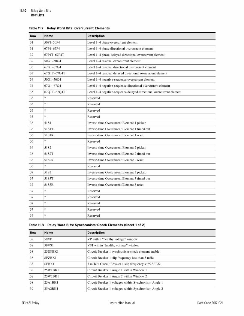
11.40
SEL-421 Relay Instruction Manual Date Code 20171021
Relay Word BitsRow Lists
Table 11.7 Relay Word Bits: Overcurrent Elements
Row Name Description
31 50P1–50P4 Level 1–4 phase overcurrent element
31 67P1–67P4 Level 1–4 phase directional overcurrent element
32 67P1T–67P4T Level 1–4 phase-delayed directional overcurrent element
32 50G1–50G4 Level 1–4 residual overcurrent element
33 67G1–67G4 Level 1–4 residual directional overcurrent element
33 67G1T–67G4T Level 1–4 residual delayed directional overcurrent element
34 50Q1–50Q4 Level 1–4 negative-sequence overcurrent element
34 67Q1–67Q4 Level 1–4 negative-sequence directional overcurrent element
35 67Q1T–67Q4T Level 1–4 negative-sequence delayed directional overcurrent element
35 * Reserved
35 * Reserved
35 * Reserved
35 * Reserved
36 51S1 Inverse-time Overcurrent Element 1 pickup
36 51S1T Inverse-time Overcurrent Element 1 timed out
36 51S1R Inverse-time Overcurrent Element 1 reset
36 * Reserved
36 51S2 Inverse-time Overcurrent Element 2 pickup
36 51S2T Inverse-time Overcurrent Element 2 timed out
36 51S2R Inverse-time Overcurrent Element 2 reset
36 * Reserved
37 51S3 Inverse-time Overcurrent Element 3 pickup
37 51S3T Inverse-time Overcurrent Element 3 timed out
37 51S3R Inverse-time Overcurrent Element 3 reset
37 * Reserved
37 * Reserved
37 * Reserved
37 * Reserved
37 * Reserved
Table 11.8 Relay Word Bits: Synchronism-Check Elements (Sheet 1 of 2)
Row Name Description
38 59VP VP within “healthy voltage” window
38 59VS1 VS1 within “healthy voltage” window
38 25ENBK1 Circuit Breaker 1 synchronism-check element enable
38 SFZBK1 Circuit Breaker 1 slip frequency less than 5 mHz
38 SFBK1 5 mHz Circuit Breaker 1 slip frequency < 25 SFBK1
38 25W1BK1 Circuit Breaker 1 Angle 1 within Window 1
38 25W2BK1 Circuit Breaker 1 Angle 2 within Window 2
38 25A1BK1 Circuit Breaker 1 voltages within Synchronism Angle 1
39 25A2BK1 Circuit Breaker 1 voltages within Synchronism Angle 2
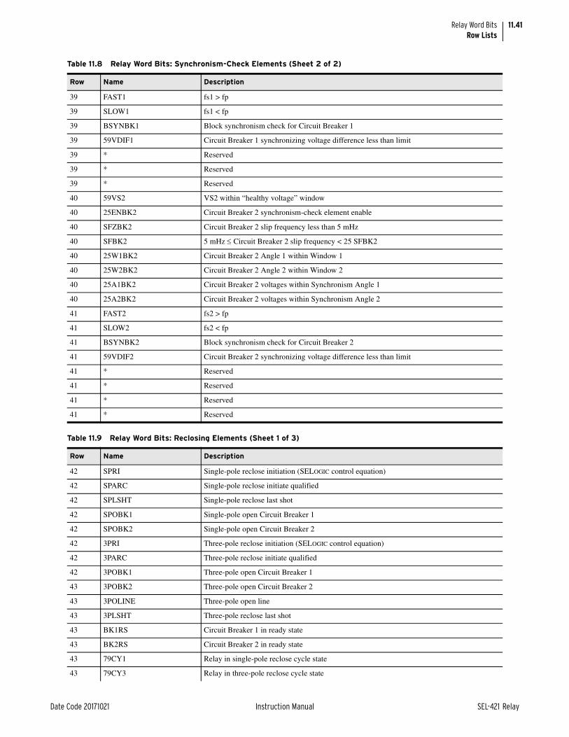
11.41
Date Code 20171021 Instruction Manual SEL-421 Relay
Relay Word BitsRow Lists
39 FAST1 fs1 > fp
39 SLOW1 fs1 < fp
39 BSYNBK1 Block synchronism check for Circuit Breaker 1
39 59VDIF1 Circuit Breaker 1 synchronizing voltage difference less than limit
39 * Reserved
39 * Reserved
39 * Reserved
40 59VS2 VS2 within “healthy voltage” window
40 25ENBK2 Circuit Breaker 2 synchronism-check element enable
40 SFZBK2 Circuit Breaker 2 slip frequency less than 5 mHz
40 SFBK2 5 mHz Circuit Breaker 2 slip frequency < 25 SFBK2
40 25W1BK2 Circuit Breaker 2 Angle 1 within Window 1
40 25W2BK2 Circuit Breaker 2 Angle 2 within Window 2
40 25A1BK2 Circuit Breaker 2 voltages within Synchronism Angle 1
40 25A2BK2 Circuit Breaker 2 voltages within Synchronism Angle 2
41 FAST2 fs2 > fp
41 SLOW2 fs2 < fp
41 BSYNBK2 Block synchronism check for Circuit Breaker 2
41 59VDIF2 Circuit Breaker 2 synchronizing voltage difference less than limit
41 * Reserved
41 * Reserved
41 * Reserved
41 * Reserved
Table 11.9 Relay Word Bits: Reclosing Elements (Sheet 1 of 3)
Row Name Description
42 SPRI Single-pole reclose initiation (SELOGIC control equation)
42 SPARC Single-pole reclose initiate qualified
42 SPLSHT Single-pole reclose last shot
42 SPOBK1 Single-pole open Circuit Breaker 1
42 SPOBK2 Single-pole open Circuit Breaker 2
42 3PRI Three-pole reclose initiation (SELOGIC control equation)
42 3PARC Three-pole reclose initiate qualified
42 3POBK1 Three-pole open Circuit Breaker 1
43 3POBK2 Three-pole open Circuit Breaker 2
43 3POLINE Three-pole open line
43 3PLSHT Three-pole reclose last shot
43 BK1RS Circuit Breaker 1 in ready state
43 BK2RS Circuit Breaker 2 in ready state
43 79CY1 Relay in single-pole reclose cycle state
43 79CY3 Relay in three-pole reclose cycle state
Table 11.8 Relay Word Bits: Synchronism-Check Elements (Sheet 2 of 2)
Row Name Description

11.42
SEL-421 Relay Instruction Manual Date Code 20171021
Relay Word BitsRow Lists
43 BK1LO Circuit Breaker 1 in lockout state
44 BK2LO Circuit Breaker 2 in lockout state
44 BK1CL Circuit Breaker 1 close command
44 BK2CL Circuit Breaker 2 close command
44 LEADBK0 No lead circuit breaker
44 LEADBK1 Lead circuit breaker = Circuit Breaker 1
44 LEADBK2 Lead circuit breaker = Circuit Breaker 2
44 FOLBK0 No follower circuit breaker
44 FOLBK1 Follower circuit breaker = Circuit Breaker 1
45 FOLBK2 Follower circuit breaker = Circuit Breaker 2
45 NBK0 No circuit breakers active in reclose scheme
45 NBK1 One circuit breaker active in reclose scheme
45 NBK2 Two circuit breakers active in reclose scheme
45 SP1CLS Single-pole Circuit Breaker 1 reclose supervision (SELOGIC control equation)
45 SP2CLS Single-pole Circuit Breaker 2 reclose supervision (SELOGIC control equation)
45 3P1CLS Three-pole Circuit Breaker 1 reclose supervision (SELOGIC control equation)
45 3P2CLS Three-pole Circuit Breaker 2 reclose supervision (SELOGIC control equation)
46 BK1CFT Circuit Breaker 1 close failure delay timed out
46 BK2CFT Circuit Breaker 2 close failure delay timed out
46 BK1CLSS Circuit Breaker 1 in close supervision state
46 BK2CLSS Circuit Breaker 2 in close supervision state
46 BK1CLST Circuit Breaker 1 close supervision timer timed out
46 BK2CLST Circuit Breaker 2 close supervision timer timed out
46 ULCL1 Unlatch closing for Circuit Breaker 1 (SELOGIC control equation)
46 ULCL2 Unlatch closing for Circuit Breaker 2 (SELOGIC control equation)
47 LLDB1 Live Line Dead Bus 1
47 LLDB2 Live Line Dead Bus 2
47 DLLB1 Dead Line Live Bus 1
47 DLLB2 Dead Line Live Bus 2
47 DLDB1 Dead Line Dead Bus 1
47 DLDB2 Dead Line Dead Bus 2
47 R3PTE Recloser three-pole trip enable
47 R3PTE1 Recloser three-pole trip enable Circuit Breaker 1
48 R3PTE2 Recloser three-pole trip enable Circuit Breaker 2
48 BK1RCIP Circuit Breaker 1 reclaim in progress (lockout state)
48 BK2RCIP Circuit Breaker 2 reclaim in progress (lockout state)
48 SPRCIP Single-pole reclaim in progress
48 3PRCIP Three-pole reclaim in progress
48 2POBK1 Two poles open Circuit Breaker 1
48 2POBK2 Two poles open Circuit Breaker 2
48 * Reserved
Table 11.9 Relay Word Bits: Reclosing Elements (Sheet 2 of 3)
Row Name Description

11.43
Date Code 20171021 Instruction Manual SEL-421 Relay
Relay Word BitsRow Lists
49 SPSHOT0 Single-pole shot counter = 0
49 SPSHOT1 Single-pole shot counter = 1
49 SPSHOT2 Single-pole shot counter = 2
49 3PSHOT0 Three-pole shot counter = 0
49 3PSHOT1 Three-pole shot counter = 1
49 3PSHOT2 Three-pole shot counter = 2
49 3PSHOT3 Three-pole shot counter = 3
49 3PSHOT4 Three-pole shot counter = 4
50 SPOI Single-pole open interval timing
50 3POI Three-pole open interval timing
50 79STRT Relay in start state
50 TBBK Time between circuit breakers timing
50 BK1EXT Circuit Breaker 1 closed externally
50 BK2EXT Circuit Breaker 2 closed externally
50 SPOISC Single-pole open interval supervision condition
50 3POISC Three-pole open interval supervision condition
Table 11.10 Relay Word Bits: Miscellaneous Elements
Row Name Description
51 SOTFE Switch-onto-fault enable
51 ILOP Internal loss-of-potential from ELOP setting
51 LOP Loss-of-potential detected
51 ZLOAD ZLOUT or ZLIN element picked up
51 ZLIN Load-encroachment “load in” element
51 ZLOUT Load-encroachment “load out” element
51 FIDEN Fault identification logic enabled
51 FSA A-Phase sector fault (AG or BCG fault)
52 FSB B-Phase sector fault (BG or CAG fault)
52 FSC C-Phase sector fault (CG or ABG fault)
52 DFAULT Disables maximum/minimum metering and demand metering when SELOGIC control equa-tion FAULT asserts
52 ER Event report trigger equation (SELOGIC control equation)
52 EAFSRC Alternate frequency source (SELOGIC control equation)
52 * Reserved
52 * Reserved
52 * Reserved
Table 11.11 Relay Word Bits: Trip Logic Elements (Sheet 1 of 2)
Row Name Description
53 RXPRM Receiver trip permission
53 COMPRM Communications-assisted trip permission
Table 11.9 Relay Word Bits: Reclosing Elements (Sheet 3 of 3)
Row Name Description

11.44
SEL-421 Relay Instruction Manual Date Code 20171021
Relay Word BitsRow Lists
53 TRPRM Trip permission
53 DTR Direct transfer trip received
53 SOTFT Switch-onto-fault trip
53 E3PT Three-pole trip enable
53 E3PT1 Circuit Breaker 1 three-pole trip enable
53 E3PT2 Circuit Breaker 2 three-pole trip enable
54 APS Trip logic A-Phase selected
54 BPS Trip logic B-Phase selected
54 CPS Trip logic C-Phase selected
54 3PS Trip logic three-phase selected
54 ATPA Assert Trip A
54 ATPB Assert Trip B
54 ATPC Assert Trip C
54 A3PT Assert three-pole trip
55 TPA Trip A
55 TPB Trip B
55 TPC Trip C
55 TRIP Trip A or Trip B or Trip C
55 3PT Three-pole trip
55 SPT Single-pole trip
55 TPA1 Circuit Breaker 1 Trip A
55 TPB1 Circuit Breaker 1 Trip B
56 TPC1 Circuit Breaker 1 Trip C
56 TPA2 Circuit Breaker 2 Trip A
56 TPB2 Circuit Breaker 2 Trip B
56 TPC2 Circuit Breaker 2 Trip C
56 TOP Trip during open pole timer is asserted
56 ULTR Unlatch all protection trips
56 ULMTR1 Circuit Breaker 1 unlatch manual trip
56 ULMTR2 Circuit Breaker 2 unlatch manual trip
57 ULTRA Unlatch Trip A
57 ULTRB Unlatch Trip B
57 ULTRC Unlatch Trip C
57 DTA Direct transfer trip A-Phase (SELOGIC control equation)
57 DTB Direct transfer trip B-Phase (SELOGIC control equation)
57 DTC Direct transfer trip C-Phase (SELOGIC control equation)
57 * Reserved
57 * Reserved
Table 11.11 Relay Word Bits: Trip Logic Elements (Sheet 2 of 2)
Row Name Description

11.45
Date Code 20171021 Instruction Manual SEL-421 Relay
Relay Word BitsRow Lists
Table 11.12 Relay Word Bits: Pilot Tripping Elements (Sheet 1 of 2)
Row Name Description
58 PT Permissive trip received
58 Z3RB Current reversal guard asserted
58 KEY Transmit permissive trip signal
58 EKEY Echo received permissive trip signal
58 ECTT Echo conversion to trip signal
58 27AWI A-Phase undervoltage condition
58 27BWI B-Phase undervoltage condition
58 27CWI C-Phase undervoltage condition
59 WFC Weak infeed condition detected
59 KEY1 Transmit general permissive trip
59 KEY3 Transmit three-phase permissive trip
59 UBB1 Blocks permissive trip Receiver 1
59 PTRX1 Permissive trip received Channel 1
59 UBB2 Blocks permissive trip Receiver 2
59 PTRX2 Permissive trip received Channel 2
59 UBB Block permissive trip received 1 or 2
60 PTRX Permissive trip received Channel 1 and Channel 2
60 Z3XT Current reversal guard timer picked up
60 Z2PGS Zone 2 phase and ground short delay element
60 67QG2S Negative-sequence and residual directional overcurrent short delay element
60 DSTRT Directional start element picked up
60 NSTRT Nondirectional start element picked up
60 STOP Stop element picked up
60 BTX Block extension picked up
61 Z3RBA A-Phase current reversal guard asserted (ECOMM = POTT3)
61 Z3RBB B-Phase current reversal guard asserted (ECOMM = POTT3)
61 Z3RBC C-Phase current reversal guard asserted (ECOMM = POTT3)
61 KEYA Transmit A-Phase permissive trip (ECOMM = POTT3)
61 KEYB Transmit B-Phase permissive trip (ECOMM = POTT3)
61 KEYC Transmit C-Phase permissive trip (ECOMM = POTT3)
61 KEYD Transmit directional permissive trip (ECOMM = POTTZD)
61 * Reserved
62 EKEYA A-Phase echo received permissive trip signal (ECOMM = POTT3)
62 EKEYB B-Phase echo received permissive trip signal (ECOMM = POTT3)
62 EKEYC C-Phase echo received permissive trip signal (ECOMM = POTT3)
62 ECTTA A-Phase echo conversion to trip signal (ECOMM = POTT3)
62 ECTTB B-Phase echo conversion to trip signal (ECOMM = POTT3)
62 ECTTC C-Phase echo conversion to trip signal (ECOMM = POTT3)
62 * Reserved
62 * Reserved
63 PTA A-Phase permissive trip received (ECOMM = POTT3)

11.46
SEL-421 Relay Instruction Manual Date Code 20171021
Relay Word BitsRow Lists
63 PTB B-Phase permissive trip received (ECOMM = POTT3)
63 PTC C-Phase permissive trip received (ECOMM = POTT3)
63 PTDRX Directional permissive trip received (ECOMM = POTTZD)
63 * Reserved
63 * Reserved
63 * Reserved
63 * Reserved
Table 11.13 Relay Word Bits: Future Breaker Open-Phase Detector
Row Name Description
64 * Reserved
Table 11.14 Relay Word Bits: Breaker 1 Failure (Sheet 1 of 2)
Row Name Description
65 BFI3P1 Circuit Breaker 1 three-pole circuit breaker failure initiation
65 BFIA1 Circuit Breaker 1 A-Phase circuit breaker failure initiation
65 BFIB1 Circuit Breaker 1 B-Phase circuit breaker failure initiation
65 BFIC1 Circuit Breaker 1 C-Phase circuit breaker failure initiation
65 BFI3PT1 Circuit Breaker 1 extended three-pole extended circuit breaker failure initiation
65 BFIAT1 Circuit Breaker 1 A-Phase extended circuit breaker failure initiation
65 BFIBT1 Circuit Breaker 1 B-Phase extended circuit breaker failure initiation
65 BFICT1 Circuit Breaker 1 C-Phase extended circuit breaker failure initiation
66 50FA1 Circuit Breaker 1 A-Phase current threshold exceeded
66 50FB1 Circuit Breaker 1 B-Phase current threshold exceeded
66 50FC1 Circuit Breaker 1 C-Phase current threshold exceeded
66 RT3P1 Circuit Breaker 1 three-pole retrip
66 RTA1 Circuit Breaker 1 A-Phase retrip
66 RTB1 Circuit Breaker 1 B-Phase retrip
66 RTC1 Circuit Breaker 1 C-Phase retrip
66 RTS3P1 Circuit Breaker 1 current-supervised three-pole retrip
67 RTSA1 Circuit Breaker 1 current-supervised A-Phase retrip
67 RTSB1 Circuit Breaker 1 current-supervised B-Phase retrip
67 RTSC1 Circuit Breaker 1 current-supervised C-Phase retrip
67 RT1 Circuit Breaker 1 retrip
67 FBFA1 Circuit Breaker 1 A-Phase circuit breaker failure
67 FBFB1 Circuit Breaker 1 B-Phase circuit breaker failure
67 FBFC1 Circuit Breaker 1 C-Phase circuit breaker failure
67 FBF1 Circuit Breaker 1 circuit breaker failure
68 50R1 Circuit Breaker 1 residual current threshold exceeded
68 BFIN1 Circuit Breaker 1 no current circuit breaker failure initiation
68 NBF1 Circuit Breaker 1 no current circuit breaker failure
Table 11.12 Relay Word Bits: Pilot Tripping Elements (Sheet 2 of 2)
Row Name Description

11.47
Date Code 20171021 Instruction Manual SEL-421 Relay
Relay Word BitsRow Lists
68 50LCA1 Circuit Breaker 1 A-Phase load current threshold exceeded
68 50LCB1 Circuit Breaker 1 B-Phase load current threshold exceeded
68 50LCC1 Circuit Breaker 1 C-Phase load current threshold exceeded
68 BFILC1 Circuit Breaker 1 load current circuit breaker failure initiation
68 LCBF1 Circuit Breaker 1 load current circuit breaker failure
69 50FOA1 Circuit Breaker 1 A-Phase flashover current threshold exceeded
69 50FOB1 Circuit Breaker 1 B-Phase flashover current threshold exceeded
69 50FOC1 Circuit Breaker 1 C-Phase flashover current threshold exceeded
69 BLKFOA1 Circuit Breaker 1 block A-Phase flashover detection
69 BLKFOB1 Circuit Breaker 1 block B-Phase flashover detection
69 BLKFOC1 Circuit Breaker 1 block C-Phase flashover detection
69 FOA1 Circuit Breaker 1 A-Phase flashover detected
69 FOB1 Circuit Breaker 1 B-Phase flashover detected
70 FOC1 Circuit Breaker 1 C-Phase flashover detected
70 FOBF1 Circuit Breaker 1 flashover detected
70 BFTRIP1 Circuit Breaker 1 failure trip output asserted
70 BFTR1 Circuit breaker failure trip, Circuit Breaker 1 (SELOGIC control equation)
70 BFULTR1 Circuit breaker failure unlatch trip, Circuit Breaker 1 (SELOGIC control equation)
70 * Reserved
70 * Reserved
Table 11.15 Relay Word Bits: Breaker 2 Failure (Sheet 1 of 2)
Row Name Description
71 BFI3P2 Circuit Breaker 2 three-pole circuit breaker failure initiation
71 BFIA2 Circuit Breaker 2 A-Phase circuit breaker failure initiation
71 BFIB2 Circuit Breaker 2 B-Phase circuit breaker failure initiation
71 BFIC2 Circuit Breaker 2 C-Phase circuit breaker failure initiation
71 BFI3PT2 Circuit Breaker 2 three-pole extended circuit breaker failure initiation
71 BFIAT2 Circuit Breaker 2 A-Phase extended circuit breaker failure initiation
71 BFIBT2 Circuit Breaker 2 B-Phase extended circuit breaker failure initiation
71 BFICT2 Circuit Breaker 2 C-Phase extended circuit breaker failure initiation
72 50FA2 Circuit Breaker 2 A-Phase current threshold exceeded
72 50FB2 Circuit Breaker 2 B-Phase current threshold exceeded
72 50FC2 Circuit Breaker 2 C-Phase current threshold exceeded
72 RT3P2 Circuit Breaker 2 three-pole retrip
72 RTA2 Circuit Breaker 2 A-Phase retrip
72 RTB2 Circuit Breaker 2 B-Phase retrip
72 RTC2 Circuit Breaker 2 C-Phase retrip
72 RTS3P2 Circuit Breaker 2 current-supervised three-pole retrip
73 RTSA2 Circuit Breaker 2 current-supervised A-Phase retrip
73 RTSB2 Circuit Breaker 2 current-supervised B-Phase retrip
Table 11.14 Relay Word Bits: Breaker 1 Failure (Sheet 2 of 2)
Row Name Description

11.48
SEL-421 Relay Instruction Manual Date Code 20171021
Relay Word BitsRow Lists
73 RTSC2 Circuit Breaker 2 current-supervised C-Phase retrip
73 RT2 Circuit Breaker 2 retrip
73 FBFA2 Circuit Breaker 2 A-Phase circuit breaker failure
73 FBFB2 Circuit Breaker 2 B-Phase circuit breaker failure
73 FBFC2 Circuit Breaker 2 C-Phase circuit breaker failure
73 FBF2 Circuit Breaker 2 circuit breaker failure
74 50R2 Circuit Breaker 2 residual current threshold exceeded
74 BFIN2 Circuit Breaker 2 no current circuit breaker failure initiation
74 NBF2 Circuit Breaker 2 no current circuit breaker failure
74 50LCA2 Circuit Breaker 2 A-Phase load current threshold exceeded
74 50LCB2 Circuit Breaker 2 B-Phase load current threshold exceeded
74 50LCC2 Circuit Breaker 2 C-Phase load current threshold exceeded
74 BFILC2 Circuit Breaker 2 load current circuit breaker failure initiation
74 LCBF2 Circuit Breaker 2 load current circuit breaker failure
75 50FOA2 Circuit Breaker 2 A-Phase flashover current threshold exceeded
75 50FOB2 Circuit Breaker 2 B-Phase flashover current threshold exceeded
75 50FOC2 Circuit Breaker 2 C-Phase flashover current threshold exceeded
75 BLKFOA2 Circuit Breaker 2 block A-Phase flashover detection
75 BLKFOB2 Circuit Breaker 2 block B-Phase flashover detection
75 BLKFOC2 Circuit Breaker 2 block C-Phase flashover detection
75 FOA2 Circuit Breaker 2 A-Phase flashover detected
75 FOB2 Circuit Breaker 2 B-Phase flashover detected
76 FOC2 Circuit Breaker 2 C-Phase flashover detected
76 FOBF2 Circuit Breaker 2 flashover detected
76 BFTRIP2 Circuit Breaker 2 failure trip output asserted
76 BFTR2 Circuit breaker failure trip, Circuit Breaker 2 (SELOGIC control equation)
76 BFULTR2 Circuit breaker failure unlatch trip, Circuit Breaker 2 (SELOGIC control equation)
76 * Reserved
76 * Reserved
Table 11.16 Relay Word Bits: 52 Status and Open-Phase Detector (Sheet 1 of 2)
Row Name Description
77 B1OPHA Circuit Breaker 1 A-Phase open
77 B1OPHB Circuit Breaker 1 B-Phase open
77 B1OPHC Circuit Breaker 1 C-Phase open
77 B2OPHA Circuit Breaker 2 A-Phase open
77 B2OPHB Circuit Breaker 2 B-Phase open
77 B2OPHC Circuit Breaker 2 C-Phase open
77 LOPHA Line A-Phase open
77 LOPHB Line B-Phase open
78 LOPHC Line C-Phase open
Table 11.15 Relay Word Bits: Breaker 2 Failure (Sheet 2 of 2)
Row Name Description
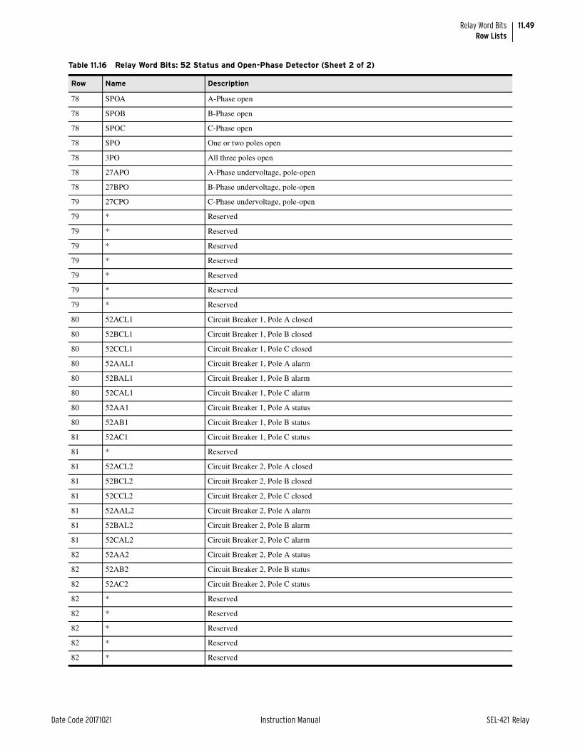
11.49
Date Code 20171021 Instruction Manual SEL-421 Relay
Relay Word BitsRow Lists
78 SPOA A-Phase open
78 SPOB B-Phase open
78 SPOC C-Phase open
78 SPO One or two poles open
78 3PO All three poles open
78 27APO A-Phase undervoltage, pole-open
78 27BPO B-Phase undervoltage, pole-open
79 27CPO C-Phase undervoltage, pole-open
79 * Reserved
79 * Reserved
79 * Reserved
79 * Reserved
79 * Reserved
79 * Reserved
79 * Reserved
80 52ACL1 Circuit Breaker 1, Pole A closed
80 52BCL1 Circuit Breaker 1, Pole B closed
80 52CCL1 Circuit Breaker 1, Pole C closed
80 52AAL1 Circuit Breaker 1, Pole A alarm
80 52BAL1 Circuit Breaker 1, Pole B alarm
80 52CAL1 Circuit Breaker 1, Pole C alarm
80 52AA1 Circuit Breaker 1, Pole A status
80 52AB1 Circuit Breaker 1, Pole B status
81 52AC1 Circuit Breaker 1, Pole C status
81 * Reserved
81 52ACL2 Circuit Breaker 2, Pole A closed
81 52BCL2 Circuit Breaker 2, Pole B closed
81 52CCL2 Circuit Breaker 2, Pole C closed
81 52AAL2 Circuit Breaker 2, Pole A alarm
81 52BAL2 Circuit Breaker 2, Pole B alarm
81 52CAL2 Circuit Breaker 2, Pole C alarm
82 52AA2 Circuit Breaker 2, Pole A status
82 52AB2 Circuit Breaker 2, Pole B status
82 52AC2 Circuit Breaker 2, Pole C status
82 * Reserved
82 * Reserved
82 * Reserved
82 * Reserved
82 * Reserved
Table 11.16 Relay Word Bits: 52 Status and Open-Phase Detector (Sheet 2 of 2)
Row Name Description

11.50
SEL-421 Relay Instruction Manual Date Code 20171021
Relay Word BitsRow Lists
Table 11.17 Relay Word Bits: Breaker Monitoring
Row Name Description
83 BM1TRPA Circuit breaker monitor A-Phase trip, Circuit Breaker 1 (SELOGIC control equation)
83 BM1TRPB Circuit breaker monitor B-Phase trip, Circuit Breaker 1 (SELOGIC control equation)
83 BM1TRPC Circuit breaker monitor C-Phase trip, Circuit Breaker 1 (SELOGIC control equation)
83 BM1CLSA Circuit breaker monitor A-Phase close, Circuit Breaker 1 (SELOGIC control equation)
83 BM1CLSB Circuit breaker monitor B-Phase close, Circuit Breaker 1 (SELOGIC control equation)
83 BM1CLSC Circuit breaker monitor C-Phase close, Circuit Breaker 1 (SELOGIC control equation)
83 B1BCWAL Circuit Breaker 1 contact wear monitor alarm
83 B1MRTIN Motor run time contact input, Circuit Breaker 1 (SELOGIC control equation)
84 * Reserved
84 B1MSOAL Circuit Breaker 1 mechanical slow operation alarm
84 B1ESOAL Circuit Breaker 1 electrical slow operation alarm
84 B1PSAL Circuit Breaker 1 pole scatter alarm
84 B1PDAL Circuit Breaker 1 pole discrepancy alarm
84 B1BITAL Circuit Breaker 1 inactivity time alarm
84 B1MRTAL Circuit Breaker 1 motor running time alarm
84 B1KAIAL Circuit Breaker 1 interrupted current alarm
85 BM2TRPA Circuit breaker monitor A-Phase trip, Circuit Breaker 2 (SELOGIC control equation)
85 BM2TRPB Circuit breaker monitor B-Phase trip, Circuit Breaker 2 (SELOGIC control equation)
85 BM2TRPC Circuit breaker monitor C-Phase trip, Circuit Breaker 2 (SELOGIC control equation)
85 BM2CLSA Circuit breaker monitor A-Phase close, Circuit Breaker 2 (SELOGIC control equation)
85 BM2CLSB Circuit breaker monitor B-Phase close, Circuit Breaker 2 (SELOGIC control equation)
85 BM2CLSC Circuit breaker monitor C-Phase close, Circuit Breaker 2 (SELOGIC control equation)
85 B2BCWAL Circuit Breaker 2 contact wear monitor alarm
85 B2MRTIN Motor run time contact input, Circuit Breaker 2 (SELOGIC control equation)
86 * Reserved
86 B2MSOAL Circuit Breaker 2 mechanical slow operation alarm
86 B2ESOAL Circuit Breaker 2 electrical slow operation alarm
86 B2PSAL Circuit Breaker 2 pole scatter alarm
86 B2PDAL Circuit Breaker 2 pole discrepancy alarm
86 B2BITAL Circuit Breaker 2 inactivity time alarm
86 B2MRTAL Circuit Breaker 2 motor running time alarm
86 B2KAIAL Circuit Breaker 2 interrupted current alarm
Table 11.18 Relay Word Bits: RTD Status Bits
Row Name Description
87 RTD01ST–RTD08ST RTD status for Channel 1–8
88 RTDIN State of RTD contact input
88 RTDCOMF RTD communication failure
88 RTDFL RTD device failure
88 * Reserved
88 RTD09ST–RTD12ST RTD status for Channel 9–12

11.51
Date Code 20171021 Instruction Manual SEL-421 Relay
Relay Word BitsRow Lists
Table 11.19 Relay Word Bits: Battery Monitor
Row Name Description
89 DC1F DC Monitor 1 fail alarm
89 DC1W DC Monitor 1 warning alarm
89 DC1G DC Monitor 1 ground fault alarm
89 DC1R DC Monitor 1 alarm for ac ripple
89 DC2F DC Monitor 2 fail alarm
89 DC2W DC Monitor 2 warning alarm
89 DC2G DC Monitor 2 ground fault alarm
89 DC2R DC Monitor 2 alarm for ac ripple
Table 11.20 Relay Word Bits: Metering Elements
Row Name Description
90 PDEM Phase current demand picked up
90 QDEM Negative-sequence demand current picked up
90 GDEM Zero-sequence demand current picked up
90 * Reserved
90 * Reserved
90 * Reserved
90 * Reserved
90 * Reserved
Table 11.21 Relay Word Bits: Open and Close
Row Name Description
91 CC2 Circuit Breaker 2 close command
91 OC2 Circuit Breaker 2 open command
91 CC1 Circuit Breaker 1 close command
91 OC1 Circuit Breaker 1 open command
91 * Reserved
91 * Reserved
91 * Reserved
91 * Reserved
Table 11.22 Relay Word Bits: Local Bits
Row Name Description
92 LB01–LB08 Local Bit 1–8
93 LB09–LB16 Local Bit 9–16
94 LB17–LB24 Local Bit 17–24
95 LB25–LB32 Local Bit 25–32

11.52
SEL-421 Relay Instruction Manual Date Code 20171021
Relay Word BitsRow Lists
Table 11.23 Relay Word Bits: Remote Bits
Row Name Description
96 RB25–RB32 Remote Bit 25–32
97 RB17–24 Remote Bit 17–24
98 RB09–16 Remote Bit 9–16
99 RB01–RB08 Remote Bit 1–8
Table 11.24 Relay Word Bits: Settings Group Bits
Row Name Description
100 SG1–SG6 Settings Group 1–6 active
100 CHSG Settings group change
100 * Reserved
Table 11.25 Relay Word Bits: Future Breaker Failure Bits
Row Name Description
101–103 * Reserved
Table 11.26 Relay Word Bits: Input Elements
Row Name Description
104 * Reserved
104 IN101–IN107 Main Board Input 1–7
105–107 * Reserved
108 IN201–IN208 First optional I/O board Input 1–8 (if installed)
109 IN209–IN216 First optional I/O board Input 9–16 (if installed)
110 IN217–IN224 First optional I/O board Input 17–24 (if installed)
111 * Reserved
112 IN301–IN308 Second optional I/O board Input 1–8 (if installed)
113 IN309–IN316 Second optional I/O board Input 9–16 (if installed)
114 IN317–IN324 Second optional I/O board Input 17–24 (if installed)
115 * Reserved
Table 11.27 Relay Word Bits: Protection SELOGIC Variables
Row Name Description
116 PSV01–PSV08 Protection SELOGIC Variable 1–8
117 PSV09–PSV16 Protection SELOGIC Variable 9–16
118 PSV17–PSV24 Protection SELOGIC Variable 17–24
119 PSV25–PSV32 Protection SELOGIC Variable 25–32
120 PSV33–PSV40 Protection SELOGIC Variable 33–40
121 PSV41–PSV48 Protection SELOGIC Variable 41–48
122 PSV49–PSV56 Protection SELOGIC Variable 49–56
123 PSV57–PSV64 Protection SELOGIC Variable 57–64

11.53
Date Code 20171021 Instruction Manual SEL-421 Relay
Relay Word BitsRow Lists
Table 11.28 Relay Word Bits: Protection SELOGIC Latches
Row Name Description
124 PLT01–PLT08 Protection Latch 1–8
125 PLT09–PLT16 Protection Latch 9–16
126 PLT17–PLT24 Protection Latch 17–24
127 PLT25–PLT32 Protection Latch 25–32
Table 11.29 Relay Word Bits: Protection SELOGIC Conditioning Timers
Row Name Description
128 PCT01Q–PCT08Q Protection Conditioning Timer 1–8 output
129 PCT09Q–PCT16Q Protection Conditioning Timer 9–16 output
130 PCT17Q–PCT24Q Protection Conditioning Timer 17–24 output
131 PCT25Q–PCT32Q Protection Conditioning Timer 25–32 output
132–133 * Reserved
Table 11.30 Relay Word Bits: Protection SELOGIC Sequencing Timers
Row Name Description
134 PST01Q–PST08Q Protection Sequencing Timer 1–8 output
135 PST09Q–PST16Q Protection Sequencing Timer 9–16 output
136 PST17Q–PST24Q Protection Sequencing Timer 17–24 output
137 PST25Q–PST32Q Protection Sequencing Timer 25–32 output
138 PST01R–PST08R Protection Sequencing Timer 1–8 reset
139 PST09R–PST16R Protection Sequencing Timer 9–16 reset
140 PST17R–PST24R Protection Sequencing Timer 17–24 reset
141 PST25R–PST32R Protection Sequencing Timer 25–32 reset
Table 11.31 Relay Word Bits: Protection SELOGIC Counters
Row Name Description
142 PCN01Q–PCN08Q Protection Counter 1–8 output
143 PCN09Q–PCN16Q Protection Counter 9–16 output
144 PCN17Q–PCN24Q Protection Counter 17–24 output
145 PCN25Q–PCN32Q Protection Counter 25–32 output
146 PCN01R–PCN08R Protection Counter 1–8 reset
147 PCN09R–PCN16R Protection Counter 9–16 reset
148 PCN17R–PCN24R Protection Counter 17–24 reset
149 PCN25R–PCN32R Protection Counter 25–32 reset
Table 11.32 Relay Word Bits: Automation SELOGIC Variables
Row Name Description
150–181 ASV001–ASV256 Automation SELOGIC Variable 01–256

11.54
SEL-421 Relay Instruction Manual Date Code 20171021
Relay Word BitsRow Lists
Table 11.33 Relay Word Bits: Automation SELOGIC Latches
Row Name Description
182 ALT01–ALT08 Automation Latch 1–8
183 ALT09–ALT16 Automation Latch 9–16
184 ALT17–ALT24 Automation Latch 17–24
185 ALT25–ALT32 Automation Latch 25–32
Table 11.34 Relay Word Bits: Automation Sequencing Timers
Row Name Description
186 AST01Q–AST08Q Automation Sequencing Timer 1–8 output
187 AST09Q–AST16Q Automation Sequencing Timer 9–16 output
188 AST17Q–AST24Q Automation Sequencing Timer 17–24 output
189 AST25Q–AST32Q Automation Sequencing Timer 25–32 output
190 AST01R–AST08R Automation Sequencing Timer 1–8 reset
191 AST09R–AST16R Automation Sequencing Timer 9–16 reset
192 AST17R–AST24R Automation Sequencing Timer 17–24 reset
193 AST25R–AST32R Automation Sequencing Timer 25–32 reset
Table 11.35 Relay Word Bits: Automation SELOGIC Counters
Row Name Description
194 ACN01Q–ACN08Q Automation Counter 1–8 output
195 ACN09Q–ACN16Q Automation Counter 9–16 output
196 ACN17Q–ACN24Q Automation Counter 17–24 output
197 ACN25Q–ACN32Q Automation Counter 25–32 output
198 ACN01R–ACN08R Automation Counter 1–8 reset
199 ACN09R–ACN16R Automation Counter 9–16 reset
200 ACN17R–ACN24R Automation Counter 17–24 reset
201 ACN25R–ACN32R Automation Counter 25–32 reset
Table 11.36 Relay Word Bits: SELOGIC Control Equation Error and Status Reporting (Sheet 1 of 2)
Row Name Description
202 PUNRLBL Protection SELOGIC control equation unresolved label
202 PFRTEX Protection SELOGIC control equation first execution
202 MATHERR SELOGIC control equation math error
202 * Reserved
202 * Reserved
202 * Reserved
202 * Reserved
202 * Reserved
203 * Reserved
204 AUNRLBL Automation SELOGIC control equation unresolved label
204 AFRTEXP Automation SELOGIC control equation first execution after protection settings change, group switch, or source switch selection.
204 AFRTEXA Automation SELOGIC control equation first execution after automation settings change
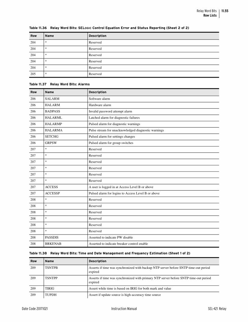
11.55
Date Code 20171021 Instruction Manual SEL-421 Relay
Relay Word BitsRow Lists
204 * Reserved
204 * Reserved
204 * Reserved
204 * Reserved
204 * Reserved
205 * Reserved
Table 11.37 Relay Word Bits: Alarms
Row Name Description
206 SALARM Software alarm
206 HALARM Hardware alarm
206 BADPASS Invalid password attempt alarm
206 HALARML Latched alarm for diagnostic failures
206 HALARMP Pulsed alarm for diagnostic warnings
206 HALARMA Pulse stream for unacknowledged diagnostic warnings
206 SETCHG Pulsed alarm for settings changes
206 GRPSW Pulsed alarm for group switches
207 * Reserved
207 * Reserved
207 * Reserved
207 * Reserved
207 * Reserved
207 * Reserved
207 ACCESS A user is logged in at Access Level B or above
207 ACCESSP Pulsed alarm for logins to Access Level B or above
208 * Reserved
208 * Reserved
208 * Reserved
208 * Reserved
208 * Reserved
208 * Reserved
208 PASSDIS Asserted to indicate PW disable
208 BRKENAB Asserted to indicate breaker control enable
Table 11.38 Relay Word Bits: Time and Date Management and Frequency Estimation (Sheet 1 of 2)
Row Name Description
209 TSNTPB Asserts if time was synchronized with backup NTP server before SNTP time-out period expired
209 TSNTPP Asserts if time was synchronized with primary NTP server before SNTP time-out period expired
209 TIRIG Assert while time is based on IRIG for both mark and value
209 TUPDH Assert if update source is high-accuracy time source
Table 11.36 Relay Word Bits: SELOGIC Control Equation Error and Status Reporting (Sheet 2 of 2)
Row Name Description

11.56
SEL-421 Relay Instruction Manual Date Code 20171021
Relay Word BitsRow Lists
209 TSYNCA Assert while the time mark from time source or fixed internal source is not synchronized
209 TSOK Assert if current time source accuracy is sufficient for synchronized phasor measurements
209 PMDOK Assert if data acquisition system is operating correctly
209 UPD_EN Asserts when updating of the internal clock with the selected external time source is enabled
210 FREQOK Assert if relay is estimating frequency
210 FREQFZ Assert if relay is not estimating frequency
210 TSYNC Asserts when the ADC sampling is synchronized to an IRIG-B time source
210 BLKLPTS Asserts when the relay blocks a low-priority time source from updating the relay time
210 TLOCAL Asserts when the relay internal clock and ADC sampling are synchronized to a non-C37.118 compliant high-accuracy IRIG-B time source
210 TPLLEXT Asserts when the phase-locked loop (PLL) is updating from an external time source
210 TSSW Asserts when high-priority time source switching is in progress
210 TGLOBAL Asserts when the relay internal clock and ADC sampling are synchronized to a C37.118-com-pliant high-accuracy IRIG-B time source
211 TPTP Time is based on a valid PTP source
211 TBNC Time is based on a valid BNC IRIG-B source
211 TSER Time is based on a valid Serial IRIG-B source
211 * Reserved
212 SER_SET Asserts when the serial IRIG-B source is the qualified high-accuracy time source
212 SER_RST Asserts when the serial IRIG-B source is disqualified as the high-accuracy time source
212 BNC_SET Asserts when the BNC IRIG-B source is the qualified high-accuracy time source
212 BNC_RST Asserts when the BNC IRIG-B source is disqualified as the high-accuracy time source
212 BNC_OK Asserts when an IRIG-B signal of sufficient quality is available from the BNC port
212 SER_OK Asserts when an IRIG-B signal of sufficient quality is available from serial Port 1
212 UPD_BLK Asserts when the relay blocks the updating of the internal clock period and Master Time
212 BNC_BNP Asserts for excessive jitter on the BNC port, resulting in the loss of the IRIG-B signal
213 SER_BNP Asserts for excessive jitter on the serial port, resulting in the loss of the IRIG-B signal
213 BNC_TIM Asserts when a valid IRIG-B time source is detected on the BNC port
213 SER_TIM Asserts when a valid IRIG-B time source is detected on the serial port
213 SERSYNC Synchronized to a high quality serial IRIG-B source
213 BNCSYNC Synchronized to a high quality BNC IRIG-B source
213 * Reserved
213 * Reserved
213 * Reserved
Table 11.39 Relay Word Bits: Pushbuttons and Outputs (Sheet 1 of 2)
Row Name Description
214 PB1–PB8 Pushbutton 1–8
215 OUT101–OUT108 Main Board Output 1–8
216 OUT201–OUT208 Optional I/O Board 1 Output 1–8
217 OUT209–OUT216 Optional I/O Board 1 Output 9–16
Table 11.38 Relay Word Bits: Time and Date Management and Frequency Estimation (Sheet 2 of 2)
Row Name Description

11.57
Date Code 20171021 Instruction Manual SEL-421 Relay
Relay Word BitsRow Lists
218 OUT301–OUT308 Optional I/O Board 2 Output 1–8
219 OUT309–OUT316 Optional I/O Board 2 Output 9–16
Table 11.40 Relay Word Bits: Pushbuttons
Row Name Description
220 PB1_PUL–PB8_PUL Pushbutton 1–8 pulse (on for one processing interval when button is pushed)
Table 11.41 Relay Word Bits: Pushbutton LED Bits
Row Name Description
221 PB1_LED–PB8_LED Pushbutton 1–8 LED
Table 11.42 Relay Word Bits: Data Reset Bits
Row Name Description
222 RST_DEM Reset demand metering
222 RST_PDM Reset peak demand metering
222 RST_ENE Reset energy metering data
222 RSTMML Reset max/min line (SELOGIC control equation)
222 RSTMMB1 Reset max/min Circuit Breaker 1 (SELOGIC control equation)
222 RSTMMB2 Reset max/min Circuit Breaker 2 (SELOGIC control equation)
222 RST_BK1 Reset Circuit Breaker 1 monitor
222 RST_BK2 Reset Circuit Breaker 2 monitor
223 RST_BAT Reset battery monitoring (SELOGIC control equation)
223 RSTFLOC Reset fault locator (SELOGIC control equation)
223 RSTDNPE Reset DNP fault summary data (SELOGIC control equation)
223 RST_79C Reset recloser shot count accumulators (SELOGIC control equation)
223 RSTTRGT Target reset (SELOGIC control equation)
223 RST_HAL Reset warning alarm processing
223 * Reserved
223 * Reserved
Table 11.43 Relay Word Bits: Target Logic Bits
Row Name Description
224 PHASE_A Indicates an A-Phase fault
224 PHASE_B Indicates a B-Phase fault
224 PHASE_C Indicates a C-Phase fault
224 GROUND Indicates a ground fault
224 BK1BFT Indicates Circuit Breaker 1 breaker failure trip
224 BK2BFT Indicates Circuit Breaker 2 breaker failure trip
224 TRGTR Reset all active target relay words
224 * Reserved
Table 11.39 Relay Word Bits: Pushbuttons and Outputs (Sheet 2 of 2)
Row Name Description

11.58
SEL-421 Relay Instruction Manual Date Code 20171021
Relay Word BitsRow Lists
Table 11.44 Relay Word Bits: MIRRORED BITS
Row Name Description
225 RMB1A–RMB8A Channel A receive MIRRORED BITS 1–8
226 TMB1A–TMB8A Channel A transmit MIRRORED BITS 1–8
227 RMB1B–RMB8B Channel B receive MIRRORED BITS 1–8
228 TMB1B–TMB8B Channel B transmit MIRRORED BITS 1–8
229 ROKA Normal MIRRORED BITS Communications Channel A status while not in loopback mode
229 RBADA Outage too long on MIRRORED BITS Communications Channel A
229 CBADA Unavailability threshold exceeded for MIRRORED BITS Communications Channel A
229 LBOKA Normal MIRRORED BITS Communications Channel A status while in loopback mode
229 ANOKA Analog transfer OK on MIRRORED BITS Communications Channel A
229 DOKA Normal MIRRORED BITS Communications Channel A status
229 * Reserved
229 * Reserved
230 ROKB Normal MIRRORED BITS Communications Channel B status while not in loopback mode
230 RBADB Outage too long on MIRRORED BITS Communications Channel B
230 CBADB Unavailability threshold exceeded for MIRRORED BITS Communications Channel B
230 LBOKB Normal MIRRORED BITS Communications Channel B status while in loopback mode
230 ANOKB Analog transfer OK on MIRRORED BITS Communications Channel B
230 DOKB Normal MIRRORED BITS Communications Channel B status
230 * Reserved
230 * Reserved
Table 11.45 Relay Word Bits: Test Bits
Row Name Description
231 TESTDB2 Communications card database Test Bit 2
231 TESTDB Communications card database Test Bit
231 TESTFM Fast meter test bit
231 TESTPUL Pulse test bit
231 LPHDSIM IEC 61850 logical node for physical device simulation
231 * Reserved
231 * Reserved
231 * Reserved
Table 11.46 Relay Word Bits: Virtual Bits (Sheet 1 of 2)
Row Name Description
232 VB249–VB256 Virtual Bits 249–256
233 VB241–VB248 Virtual Bits 241–248
234 VB233–VB240 Virtual Bits 233–240
235 VB225–VB232 Virtual Bits 225–232
236 VB217–VB224 Virtual Bits 217–224
237 VB209–VB216 Virtual Bits 209–216
238 VB201–VB208 Virtual Bits 201–208
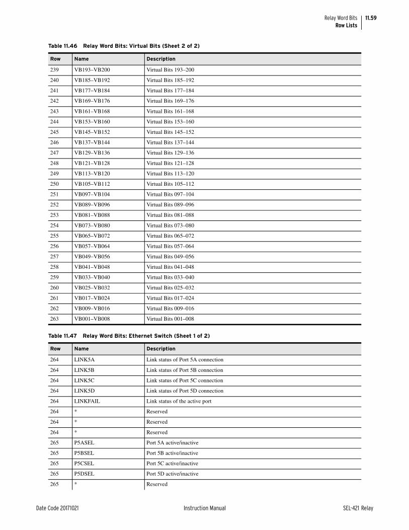
11.59
Date Code 20171021 Instruction Manual SEL-421 Relay
Relay Word BitsRow Lists
239 VB193–VB200 Virtual Bits 193–200
240 VB185–VB192 Virtual Bits 185–192
241 VB177–VB184 Virtual Bits 177–184
242 VB169–VB176 Virtual Bits 169–176
243 VB161–VB168 Virtual Bits 161–168
244 VB153–VB160 Virtual Bits 153–160
245 VB145–VB152 Virtual Bits 145–152
246 VB137–VB144 Virtual Bits 137–144
247 VB129–VB136 Virtual Bits 129–136
248 VB121–VB128 Virtual Bits 121–128
249 VB113–VB120 Virtual Bits 113–120
250 VB105–VB112 Virtual Bits 105–112
251 VB097–VB104 Virtual Bits 097–104
252 VB089–VB096 Virtual Bits 089–096
253 VB081–VB088 Virtual Bits 081–088
254 VB073–VB080 Virtual Bits 073–080
255 VB065–VB072 Virtual Bits 065–072
256 VB057–VB064 Virtual Bits 057–064
257 VB049–VB056 Virtual Bits 049–056
258 VB041–VB048 Virtual Bits 041–048
259 VB033–VB040 Virtual Bits 033–040
260 VB025–VB032 Virtual Bits 025–032
261 VB017–VB024 Virtual Bits 017–024
262 VB009–VB016 Virtual Bits 009–016
263 VB001–VB008 Virtual Bits 001–008
Table 11.47 Relay Word Bits: Ethernet Switch (Sheet 1 of 2)
Row Name Description
264 LINK5A Link status of Port 5A connection
264 LINK5B Link status of Port 5B connection
264 LINK5C Link status of Port 5C connection
264 LINK5D Link status of Port 5D connection
264 LINKFAIL Link status of the active port
264 * Reserved
264 * Reserved
264 * Reserved
265 P5ASEL Port 5A active/inactive
265 P5BSEL Port 5B active/inactive
265 P5CSEL Port 5C active/inactive
265 P5DSEL Port 5D active/inactive
265 * Reserved
Table 11.46 Relay Word Bits: Virtual Bits (Sheet 2 of 2)
Row Name Description

11.60
SEL-421 Relay Instruction Manual Date Code 20171021
Relay Word BitsRow Lists
265 * Reserved
265 * Reserved
265 * Reserved
266 * Reserved
Table 11.48 Relay Word Bits: Signal Profiling
Row Name Description
267 SPEN Signal profiling enabled
267 * Reserved
267 * Reserved
267 * Reserved
267 * Reserved
267 * Reserved
267 * Reserved
267 * Reserved
Table 11.49 Relay Word Bits: Fast SER Enable Bits
Row Name Description
268 FSERP1 Fast SER enabled for Serial Port 1
268 FSERP2 Fast SER enabled for Serial Port 2
268 FSERP3 Fast SER enabled for Serial Port 3
268 FSERPF Fast SER enabled for Serial Port F
268 FSERP5 Fast SER enabled for EN and FO ports
268 * Reserved
268 * Reserved
268 * Reserved
Table 11.50 Relay Word Bits: Source Selection Elements
Row Name Description
269 ALTI Alternate current source (SELOGIC control equation)
269 ALTV Alternate voltage source (SELOGIC control equation)
269 ALTS2 Alternate synchronism source for Circuit Breaker 2
269 DELAY Unused
269 * Reserved
269 * Reserved
269 * Reserved
269 * Reserved
Table 11.47 Relay Word Bits: Ethernet Switch (Sheet 2 of 2)
Row Name Description

11.61
Date Code 20171021 Instruction Manual SEL-421 Relay
Relay Word BitsRow Lists
Table 11.51 Relay Word Bits: Full-Cycle Mho and Quad Ground-Distance
Row Name Description
270 MBG2F Zone 2 filtered B-Phase-to-ground Mho element asserted
270 MAG2F Zone 2 filtered Mho A-Phase-to-ground element
270 XCG1F Zone 1 quad C-Phase-to-ground element
270 XBG1F Zone 1 quad B-Phase-to-ground element
270 XAG1F Zone 1 quad A-Phase-to-ground element
270 MCG1F Zone 1 filtered Mho C-Phase-to-ground element
270 MBG1F Zone 1 filtered Mho B-Phase-to-ground element
270 MAG1F Zone 1 filtered Mho A-Phase-to-ground element
271 XAG3F Zone 3 quad A-Phase-to-ground element
271 MCG3F Zone 3 filtered Mho C-Phase-to-ground element
271 MBG3F Zone 3 filtered Mho B-Phase-to-ground element
271 MAG3F Zone 3 filtered Mho A-Phase-to-ground element
271 XCG2F Zone 2 quad C-Phase-to-ground element
271 XBG2F Zone 2 quad B-Phase-to-ground element
271 XAG2F Zone 2 quad A-Phase-to-ground element
271 MCG2F Zone 2 filtered Mho C-Phase-to-ground element
272 XCG4F Zone 4 quad C-Phase-to-ground element
272 XBG4F Zone 4 quad B-Phase-to-ground element
272 XAG4F Zone 4 quad A-Phase-to-ground element
272 MCG4F Zone 4 filtered Mho C-Phase-to-ground element
272 MBG4F Zone 4 filtered Mho B-Phase-to-ground element
272 MAG4F Zone 4 filtered Mho C-Phase-to-ground element
272 XCG3F Zone 3 quad C-Phase-to-ground element
272 XBG3F Zone 3 quad B-Phase-to-ground element
273 * Reserved
273 * Reserved
273 XCG5F Zone 5 quad C-Phase-to-ground element
273 XBG5F Zone 5 quad B-Phase-to-ground element
273 XAG5F Zone 5 quad A-Phase-to-ground element
273 MCG5F Zone 5 filtered Mho C-Phase-to-ground element
273 MBG5F Zone 5 filtered Mho B-Phase-to-ground element
273 MAG5F Zone 5 filtered Mho A-Phase-ground element
Table 11.52 Relay Word Bits: Full-Cycle Mho and Phase Quad Phase-Distance (Sheet 1 of 2)
Row Name Description
274 MBC2F Zone 2 filtered Mho BC phase element
274 MAB2F Zone 2 filtered Mho AB phase element
274 XCA1F Zone 1 quad CA phase element
274 XBC1F Zone 1 quad BC phase element
274 XAB1F Zone 1 quad AB phase element
274 MCA1F Zone 1 filtered Mho CA phase element

11.62
SEL-421 Relay Instruction Manual Date Code 20171021
Relay Word BitsRow Lists
274 MBC1F Zone 1 filtered Mho BC phase element
274 MAB1F Zone 1 filtered Mho AB phase element
275 XAB3F Zone 3 quad AB phase element
275 MCA3F Zone 3 filtered Mho CA phase element
275 MBC3F Zone 3 filtered Mho BC phase element
275 MAB3F Zone 3 filtered Mho AB phase element
275 XCA2F Zone 2 quad CA phase element
275 XBC2F Zone 2 quad BC phase element
275 XAB2F Zone 2 quad AB phase element
275 MCA2F Zone 2 filtered Mho CA phase element
276 XCA4F Zone 4 quad CA phase element
276 XBC4F Zone 4 quad BC phase element
276 XAB4F Zone 4 quad AB phase element
276 MCA4F Zone 4 filtered Mho CA phase element
276 MBC4F Zone 4 filtered Mho BC phase element
276 MAB4F Zone 4 filtered Mho AB phase element
276 XCA3F Zone 3 quad CA phase element
276 XBC3F Zone 3 quad BC phase element
277 * Reserved
277 * Reserved
277 XCA5F Zone 5 quad CA phase element
277 XBC5F Zone 5 quad BC phase element
277 XAB5F Zone 5 quad AB phase element
277 MCA5F Zone 5 filtered Mho CA phase element
277 MBC5F Zone 5 filtered Mho BC phase element
277 MAB5F Zone 5 filtered Mho AB phase element
Table 11.53 Relay Word Bits: High-Speed Mho and Quad Ground-Distance (Sheet 1 of 2)
Row Name Description
278 MBG3H High-speed Zone 3 Mho BG ground element
278 MAG3H High-speed Zone 3 Mho AG ground element
278 MCG2H High-speed Zone 2 Mho CG ground element
278 MBG2H High-speed Zone 2 Mho BG ground element
278 MAG2H High-speed Zone 2 Mho AG ground element
278 MCG1H High-speed Zone 1 Mho CG ground element
278 MBG1H High-speed Zone 1 Mho BG ground element
278 MAG1H High-speed Zone 1 Mho AG ground element
279 XAG3H High-speed Zone 3 high-speed quad A-G ground element
279 XCG2H High-speed Zone 2 quad CG ground element
279 XBG2H High-speed Zone 2 quad BG ground element
279 XAG2H High-speed Zone 2 quad AG ground element
Table 11.52 Relay Word Bits: Full-Cycle Mho and Phase Quad Phase-Distance (Sheet 2 of 2)
Row Name Description

11.63
Date Code 20171021 Instruction Manual SEL-421 Relay
Relay Word BitsRow Lists
279 XCG1H High-speed Zone 1 quad CG ground element
279 XBG1H High-speed Zone 1 quad BG ground element
279 XAG1H High-speed Zone 1 quad AG ground element
279 MCG3H High-speed Zone 3 Mho CG ground element
280 * Reserved
280 * Reserved
280 * Reserved
280 * Reserved
280 * Reserved
280 * Reserved
280 XCG3H High-speed Zone 3 quad CG ground element
280 XBG3H High-speed Zone 3 quad BG ground element
281 * Reserved
Table 11.54 Relay Word Bits: High-Speed Mho and Quad Phase-Distance (Sheet 1 of 2)
Row Name Description
282 MBC3H High-speed Zone 3 Mho BC phase element
282 MAB3H High-speed Zone 3 Mho AB phase element
282 MCA2H High-speed Zone 2 Mho CA phase element
282 MBC2H High-speed Zone 2 Mho BC phase element
282 MAB2H High-speed Zone 2 Mho AB phase element
282 MCA1H High-speed Zone 1 Mho CA phase element
282 MBC1H High-speed Zone 1 Mho BC phase element
282 MAB1H High-speed Zone 1 Mho AB phase element
283 XAB3H High-speed Zone 3 high-speed quad AB phase element
283 XCA2H High-speed Zone 2 high-speed quad CA phase element
283 XBC2H High-speed Zone 2 high-speed quad BC phase element
283 XAB2H High-speed Zone 2 high-speed quad AB phase element
283 XCA1H High-speed Zone 1 high-speed quad CA phase element
283 XBC1H High-speed Zone 1 high-speed quad BC phase element
283 XAB1H High-speed Zone 1 high-speed quad AB phase element
283 MCA3H High-speed Zone 3 Mho CA phase element
284 * Reserved
284 * Reserved
284 * Reserved
284 * Reserved
284 * Reserved
284 * Reserved
284 XCA3H High-speed Zone 3 high-speed quad C–A phase element
284 XBC3H High-speed Zone 3 high-speed quad B–C phase element
285 * Reserved
Table 11.53 Relay Word Bits: High-Speed Mho and Quad Ground-Distance (Sheet 2 of 2)
Row Name Description

11.64
SEL-421 Relay Instruction Manual Date Code 20171021
Relay Word BitsRow Lists
285 * Reserved
285 * Reserved
285 * Reserved
285 HSDQR Phase-to-phase fault, high-speed reverse directional element
285 HSDQF Phase-to-phase fault, high-speed forward directional element
285 HSDGR Ground fault, high-speed reverse directional element
285 HSDGF Ground fault, high-speed forward directional element
Table 11.55 Relay Word Bits: DNP Event Lock
Row Name Description
286 EVELOCK Lock DNP events
286 * Reserved
286 * Reserved
286 * Reserved
286 * Reserved
286 * Reserved
286 * Reserved
286 * Reserved
287 * Reserved
Table 11.56 Relay Word Bits: Synchrophasor SELOGIC Equations/RTC Synchrophasors Status Bits (Sheet 1 of 2)
Row Name Description
288 PMTRIG Trigger (SELOGIC control equation)
288 TREA1–TREA4 Trigger Reason Bit 1–4 (SELOGIC Equation)
288 FROKPM Synchrophasor frequency
288 PMTEST Synchrophasor test mode
288 * Reserved
289 * Reserved
290 * Reserved
290 * Reserved
290 * Reserved
290 * Reserved
290 RTCSEQB RTC configuration complete, Channel B
290 RTCSEQA RTC configuration complete, Channel A
290 RTCCFGB RTC data in sequence, Channel B
290 RTCCFGA RTC data in sequence, Channel A
291 * Reserved
291 RTCDLYB RTC delay exceeded, Channel B
291 RTCDLYA RTC delay exceeded, Channel A
291 RTCROK Valid aligned RTC data available on all enabled channels
291 RTCROKB Valid aligned RTC data available on Channel B
Table 11.54 Relay Word Bits: High-Speed Mho and Quad Phase-Distance (Sheet 2 of 2)
Row Name Description

11.65
Date Code 20171021 Instruction Manual SEL-421 Relay
Relay Word BitsRow Lists
291 RTCROKA Valid aligned RTC data available on Channel A
291 RTCENB Valid remote synchrophasors received on Channel B
291 RTCENA Valid remote synchrophasors received on Channel A
Table 11.57 Relay Word Bits: IRIG-B Control
Row Name Description
292 YEAR80 IRIG-B year information, binary-coded-decimal, add 80 if asserted
292 YEAR40 IRIG-B year information, binary-coded-decimal, add 40 if asserted
292 YEAR20 IRIG-B year information, binary-coded-decimal, add 20 if asserted
292 YEAR10 IRIG-B year information, binary-coded-decimal, add 10 if asserted
292 YEAR8 IRIG-B year information, binary-coded-decimal, add 8 if asserted
292 YEAR4 IRIG-B year information, binary-coded-decimal, add 4 if asserted
292 YEAR2 IRIG-B year information, binary-coded-decimal, add 2 if asserted
292 YEAR1 IRIG-B year information, binary-coded-decimal, add 1 if asserted
293 * Reserved
293 * Reserved
293 TUTCH IRIG-B Offset half-hour from UTC time, binary, add 0.5 if asserted
293 TUTC8 IRIG-B Offset hours from UTC time, binary, add 8 if asserted
293 TUTC4 IRIG-B Offset hours from UTC time, binary, add 4 if asserted
293 TUTC2 IRIG-B Offset hours from UTC time, binary, add 2 if asserted
293 TUTC1 IRIG-B Offset hours from UTC time, binary, add 1 if asserted
293 TUTCS IRIG-B Offset hours sign from UTC time, subtract the UTC offset if TUTCS is asserted, add otherwise
294 DST Daylight saving time
294 DSTP IRIG-B Daylight saving time pending
294 LPSEC Direction of the upcoming leap second. During the time that LPSECP is asserted, if LPSEC is asserted, the upcoming leap second is deleted; otherwise, the leap second is added.
294 LPSECP Leap second pending
294 TQUAL8 Time quality, binary, add 8 when asserted
294 TQUAL4 Time quality, binary, add 4 when asserted
294 TQUAL2 Time quality, binary, add 2 when asserted
294 TQUAL1 Time quality, binary, add 1 when asserted
295 * Reserved
Table 11.58 Relay Word Bit: Time-Error Calculation (Sheet 1 of 2)
Row Name Description
296 LOADTE Load TECORR factor (SELOGIC Equation). When a rising-edge is detected, the accumulated time-error value TE is loaded with the TECORR factor (preload value).
296 STALLTE Stall time-error calculation (SELOGIC Equation). When asserted, the time-error calculation is stalled, or frozen.
296 PLDTE Asserts for approximately 1.5 cycles when the TEC command is used to load a new time-error correction factor (preload value) into the TECORR analog quantity.
296 * Reserved
Table 11.56 Relay Word Bits: Synchrophasor SELOGIC Equations/RTC Synchrophasors Status Bits (Sheet 2 of 2)
Row Name Description

11.66
SEL-421 Relay Instruction Manual Date Code 20171021
Relay Word BitsRow Lists
296 * Reserved
296 * Reserved
296 * Reserved
296 * Reserved
297 * Reserved
Table 11.59 Relay Word Bits: Synchrophasor Configuration Error
Row Name Description
298 SPCER1–SPCER3 Synchrophasor configuration error on Port 1–3
298 SPCERF Synchrophasor configuration error on Port F
298 * Reserved
298 * Reserved
298 * Reserved
298 * Reserved
299 * Reserved
Table 11.60 Relay Word Bits: Pushbuttons, Pushbutton LEDs, and Target LEDs for New HMI
Row Name Description
300 TLED_17–TLED_24 Target LED 17–24
301 PB9–PB12 Pushbutton 9–12
301 * Reserved
301 * Reserved
301 PB_TRIP Auxiliary TRIP pushbutton
301 PB_CLSE Auxiliary CLOSE pushbutton
302 PB9_LED Pushbutton 9 LED
302 PB10LED Pushbutton 10 LED
302 PB11LED Pushbutton 11 LED
302 PB12LED Pushbutton 12 LED
302 * Reserved
302 * Reserved
302 * Reserved
302 * Reserved
303 PB9_PUL Pushbutton 9 pulse (on for one processing interval when button is pushed)
303 PB10PUL Pushbutton 10 pulse (on for one processing interval when button is pushed)
303 PB11PUL Pushbutton 11 pulse (on for one processing interval when button is pushed)
303 PB12PUL Pushbutton 12 pulse (on for one processing interval when button is pushed)
303 * Reserved
303 * Reserved
303 * Reserved
303 * Reserved
Table 11.58 Relay Word Bit: Time-Error Calculation (Sheet 2 of 2)
Row Name Description

11.67
Date Code 20171021 Instruction Manual SEL-421 Relay
Relay Word BitsRow Lists
Table 11.61 Relay Word Bits: Local Bit Supervision
Row Name Description
304 LB_SP01–LB_SP08 Local Bit 01–08 supervision (SELOGIC Equation)
305 LB_SP09–LB_SP16 Local Bit 09–16 supervision (SELOGIC Equation)
306 LB_SP17–LB_SP24 Local Bit 17–24 supervision (SELOGIC Equation)
307 LB_SP25–LB_SP32 Local Bit 25–32 supervision (SELOGIC Equation)
Table 11.62 Relay Word Bits: Local Bit Status
Row Name Description
308 LB_DP01–LB_DP08 Local Bit 01–08 status display (SELOGIC Equation)
309 LB_DP09–LB_DP16 Local Bit 09–16 status display (SELOGIC Equation)
310 LB_DP17–LB_DP24 Local Bit 17–24 status display (SELOGIC Equation)
311 LB_DP25–LB_DP32 Local Bit 25–32 status display (SELOGIC Equation)
Table 11.63 Relay Word Bits: RTC Remote Digital Status
Row Name Description
312 RTCAD01–RTCAD08 RTC remote data bits, Channel A, Bit 1–8
313 RTCAD09–RTCAD16 RTC remote data bits, Channel A, Bit 9–16
314 RTCBD01–RTCBD08 RTC remote data bits, Channel B, Bit 1–8
315 RTCBD09–RTCBD16 RTC remote data bits, Channel B, Bit 9–16
Table 11.64 Relay Word Bits: Fast Operate Transmit Bits
Row Name Description
316 FOPF_01–FOPF_08 Fast-operate output control bits for Port F, Bit 1–8
317 FOPF_09–FOPF_16 Fast-operate output control bits for Port F, Bit 9–16
318 FOPF_17–FOPF_24 Fast-operate output control bits for Port F, Bit 17–24
319 FOPF_25–FOPF_32 Fast-operate output control bits for Port F, Bit 25–32
320 FOP1_01–FOP1_08 Fast-operate output control bits for Port 1, Bit 1–8
321 FOP1_09–FOP1_16 Fast-operate output control bits for Port 1, Bit 9–16
322 FOP1_17–FOP1_24 Fast-operate output control bits for Port 1, Bit 17–24
323 FOP1_25–FOP1_32 Fast-operate output control bits for Port 1, Bit 25–32
324 FOP2_01–FOP2_08 Fast-operate output control bits for Port 2, Bit 1–8
325 FOP2_09–FOP2_16 Fast-operate output control bits for Port 2, Bit 9–16
326 FOP2_17–FOP2_24 Fast-operate output control bits for Port 2, Bit 17–24
327 FOP2_25–FOP2_32 Fast-operate output control bits for Port 2, Bit 35–32
328 FOP3_01–FOP3_08 Fast-operate output control bits for Port 3, Bit 1–8
329 FOP3_09–FOP3_16 Fast-operate output control bits for Port 3, Bit 9–16
330 FOP3_17–FOP3_24 Fast-operate output control bits for Port 3, Bit 17–24
331 FOP3_25–FOP3_32 Fast-operate output control bits for Port 3, Bit 25–32

11.68
SEL-421 Relay Instruction Manual Date Code 20171021
Relay Word BitsRow Lists
Table 11.65 Relay Word Bits: Bay Control Disconnect Status (Sheet 1 of 2)
Row Name Description
332 89AM01 Disconnect 1 N/O auxiliary contact
332 89BM01 Disconnect 1 N/C auxiliary contact
332 89CL01 Disconnect 1 closed
332 89OPN01 Disconnect 1 open
332 89OIP01 Disconnect 1 operation in-progress
332 89AL01 Disconnect 1 alarm
332 * Reserved
332 89AL Any disconnect alarm
333 89AM02 Disconnect 2 N/O auxiliary contact
333 89BM02 Disconnect 2 N/C auxiliary contact
333 89CL02 Disconnect 2 closed
333 89OPN02 Disconnect 2 open
333 89OIP02 Disconnect 2 operation in-progress
333 89AL02 Disconnect 2 alarm
333 * Reserved
333 89OIP Any Disconnect operation in-progress
334 89AM03 Disconnect 3 N/O auxiliary contact
334 89BM03 Disconnect 3 N/C auxiliary contact
334 89CL03 Disconnect 3 closed
334 89OPN03 Disconnect 3 open
334 89OIP03 Disconnect 3 operation in-progress
334 89AL03 Disconnect 3 alarm
334 * Reserved
334 LOCAL Local front-panel control
335 89AM04 Disconnect 4 N/O auxiliary contact
335 89BM04 Disconnect 4 N/C auxiliary contact
335 89CL04 Disconnect 4 closed
335 89OPN04 Disconnect 4 open
335 89OIP04 Disconnect 4 operation in-progress
335 89AL04 Disconnect 4 alarm
335 * Reserved
335 * Reserved
336 89AM05 Disconnect 5 N/O auxiliary contact
336 89BM05 Disconnect 5 N/C auxiliary contact
336 89CL05 Disconnect 5 closed
336 89OPN05 Disconnect 5 open
336 89OIP05 Disconnect 5 operation in-progress
336 89AL05 Disconnect 5 alarm
336 * Reserved
336 * Reserved
337 89AM06 Disconnect 6 N/O auxiliary contact

11.69
Date Code 20171021 Instruction Manual SEL-421 Relay
Relay Word BitsRow Lists
337 89BM06 Disconnect 6 N/C auxiliary contact
337 89CL06 Disconnect 6 closed
337 89OPN06 Disconnect 6 open
337 89OIP06 Disconnect 6 operation in-progress
337 89AL06 Disconnect 6 alarm
337 * Reserved
337 * Reserved
338 89AM07 Disconnect 7 N/O auxiliary contact
338 89BM07 Disconnect 7 N/C auxiliary contact
338 89CL07 Disconnect 7 closed
338 89OPN07 Disconnect 7 open
338 89OIP07 Disconnect 7 operation in-progress
338 89AL07 Disconnect 7 alarm
338 * Reserved
338 * Reserved
339 89AM08 Disconnect 8 N/O auxiliary contact
339 89BM08 Disconnect 8 N/C auxiliary contact
339 89CL08 Disconnect 8 closed
339 89OPN08 Disconnect 8 open
339 89OIP08 Disconnect 8 operation in-progress
339 89AL08 Disconnect 8 alarm
339 * Reserved
339 * Reserved
340 89AM09 Disconnect 9 N/O auxiliary contact
340 89BM09 Disconnect 9 N/C auxiliary contact
340 89CL09 Disconnect 9 closed
340 89OPN09 Disconnect 9 open
340 89OIP09 Disconnect 9 operation in-progress
340 89AL09 Disconnect 9 alarm
340 * Reserved
340 * Reserved
341 89AM10 Disconnect 10 N/O auxiliary contact
341 89BM10 Disconnect 10 N/C auxiliary contact
341 89CL10 Disconnect 10 closed
341 89OPN10 Disconnect 10 open
341 89OIP10 Disconnect 10 operation in-progress
341 89AL10 Disconnect 10 alarm
341 * Reserved
341 * Reserved
Table 11.65 Relay Word Bits: Bay Control Disconnect Status (Sheet 2 of 2)
Row Name Description

11.70
SEL-421 Relay Instruction Manual Date Code 20171021
Relay Word BitsRow Lists
Table 11.66 Relay Word Bits: Bay Control Disconnect Bus-Zone Compliant
Row Name Description
342 89CLB01–89CLB08 Disconnect 1–8 bus-zone protection
343 89CLB09–89CLB10 Disconnect 9–10 bus-zone protection
343 * Reserved
343 * Reserved
343 * Reserved
343 * Reserved
343 * Reserved
343 * Reserved
Table 11.67 Relay Word Bits: Bay Control Disconnect Control (Sheet 1 of 3)
Row Name Description
344 89OC01 ASCII Open Disconnect 1 command
344 89CC01 ASCII Close Disconnect 1 command
344 89OCM01 Mimic Disconnect 1 open control
344 89CCM01 Mimic Disconnect 1 close control
344 89OPE01 Disconnect Open 1 output
344 89CLS01 Disconnect Close 1 output
344 89OCN01 Open Disconnect 1
344 89CCN01 Close Disconnect 1
345 * Reserved
346 89OC02 ASCII Open Disconnect 2 command
346 89CC02 ASCII Close Disconnect 2 command
346 89OCM02 Mimic Disconnect 2 open control
346 89CCM02 Mimic Disconnect 2 close control
346 89OPE02 Disconnect Open 2 output
346 89CLS02 Disconnect Close 2 output
346 89OCN02 Open Disconnect 2
346 89CCN02 Close Disconnect 2
347 * Reserved
348 89OC03 ASCII Open Disconnect 3 command
348 89CC03 ASCII Close Disconnect 3 command
348 89OCM03 Mimic Disconnect 3 open control
348 89CCM03 Mimic Disconnect 3 close control
348 89OPE03 Disconnect Open 3 output
348 89CLS03 Disconnect Close 3 output
348 89OCN03 Open Disconnect 3
348 89CCN03 Close Disconnect 3
349 * Reserved
350 89OC04 ASCII Open Disconnect 4 command
350 89CC04 ASCII Close Disconnect 4 command
350 89OCM04 Mimic Disconnect 4 open control

11.71
Date Code 20171021 Instruction Manual SEL-421 Relay
Relay Word BitsRow Lists
350 89CCM04 Mimic Disconnect 4 close control
350 89OPE04 Disconnect Open 4 output
350 89CLS04 Disconnect Close 4 output
350 89OCN04 Open Disconnect 4
350 89CCN04 Close Disconnect 4
351 * Reserved
352 89OC05 ASCII Open Disconnect 5 command
352 89CC05 ASCII Close Disconnect 5 command
352 89OCM05 Mimic Disconnect 5 open control
352 89CCM05 Mimic Disconnect 5 close control
352 89OPE05 Disconnect Open 5 output
352 89CLS05 Disconnect Close 5 output
352 89OCN05 Open Disconnect 5
352 89CCN05 Close Disconnect 5
353 * Reserved
354 89OC06 ASCII Open Disconnect 6 command
354 89CC06 ASCII Close Disconnect 6 command
354 89OCM06 Mimic Disconnect 6 open control
354 89CCM06 Mimic Disconnect 6 close control
354 89OPE06 Disconnect Open 6 output
354 89CLS06 Disconnect Close 6 output
354 89OCN06 Open Disconnect 6
354 89CCN06 Close Disconnect 6
355 * Reserved
356 89OC07 ASCII Open Disconnect 7 command
356 89CC07 ASCII Close Disconnect 7 command
356 89OCM07 Mimic Disconnect 7 open control
356 89CCM07 Mimic Disconnect 7 close control
356 89OPE07 Disconnect Open 7 output
356 89CLS07 Disconnect Close 7 output
356 89OCN07 Open Disconnect 7
356 89CCN07 Close Disconnect 7
357 * Reserved
358 89OC08 ASCII Open Disconnect 8 command
358 89CC08 ASCII Close Disconnect 8 command
358 89OCM08 Mimic Disconnect 8 open control
358 89CCM08 Mimic Disconnect 8 close control
358 89OPE08 Disconnect Open 8 output
358 89CLS08 Disconnect Close 8 output
358 89OCN08 Open Disconnect 8
358 89CCN08 Close Disconnect 8
Table 11.67 Relay Word Bits: Bay Control Disconnect Control (Sheet 2 of 3)
Row Name Description

11.72
SEL-421 Relay Instruction Manual Date Code 20171021
Relay Word BitsRow Lists
359 * Reserved
360 89OC09 ASCII Open Disconnect 9 command
360 89CC09 ASCII Close Disconnect 9 command
360 89OCM09 Mimic Disconnect 9 open control
360 89CCM09 Mimic Disconnect 9 close control
360 89OPE09 Disconnect Open 9 output
360 89CLS09 Disconnect Close 9 output
360 89OCN09 Open Disconnect 9
360 89CCN09 Close Disconnect 9
361 * Reserved
362 89OC10 ASCII Open Disconnect 10 command
362 89CC10 ASCII Close Disconnect 10 command
362 89OCM10 Mimic Disconnect 10 open control
362 89CCM10 Mimic Disconnect 10 close control
362 89OPE10 Disconnect Open 10 output
362 89CLS10 Disconnect Close 10 output
362 89OCN10 Open Disconnect 10
362 89CCN10 Close Disconnect 10
363 * Reserved
Table 11.68 Relay Word Bits: Bay Control Disconnect Timers and Breaker Status (Sheet 1 of 5)
Row Name Description
364 89CBL01 Disconnect 01 close block
364 89OSI01 Disconnect 01 open seal-in timer timed out
364 89CSI01 Disconnect 01 close seal-in timer timed out
364 89OIR01 Disconnect 01 open immobility timer reset
364 89CIR01 Disconnect 01 close immobility timer reset
364 89OBL01 Disconnect 01 open block
364 89ORS01 Disconnect 01 open reset
364 89CRS01 Disconnect 01 close reset
365 89OIM01 Disconnect 01 open immobility timer timed out
365 89CIM01 Disconnect 01 close immobility timer timed out
365 521CLSM Breaker 1 closed
365 521_ALM Breaker 1 status alarm
365 522CLSM Breaker 2 closed
365 522_ALM Breaker 2 status alarm
365 523CLSM Breaker 3 closed
365 523_ALM Breaker 3 status alarm
366 89CBL02 Disconnect 02 close block
366 89OSI02 Disconnect 02 open seal-in timer timed out
366 89CSI02 Disconnect 02 close seal-in timer timed out
Table 11.67 Relay Word Bits: Bay Control Disconnect Control (Sheet 3 of 3)
Row Name Description

11.73
Date Code 20171021 Instruction Manual SEL-421 Relay
Relay Word BitsRow Lists
366 89OIR02 Disconnect 02 open immobility timer reset
366 89CIR02 Disconnect 02 close immobility timer reset
366 89OBL02 Disconnect 02 open block
366 89ORS02 Disconnect 02 open reset
366 89CRS02 Disconnect 02 close reset
367 89OIM02 Disconnect 02 open immobility timer timed out
367 89CIM02 Disconnect 02 close immobility timer timed out
367 * Reserved
367 * Reserved
367 * Reserved
367 * Reserved
367 * Reserved
367 * Reserved
368 89CBL03 Disconnect 03 close block
368 89OSI03 Disconnect 03 open seal-in timer timed out
368 89CSI03 Disconnect 03 close seal-in timer timed out
368 89OIR03 Disconnect 03 open immobility timer reset
368 89CIR03 Disconnect 03 close immobility timer reset
368 89OBL03 Disconnect 03 open block
368 89ORS03 Disconnect 03 open reset
368 89CRS03 Disconnect 03 close reset
369 89OIM03 Disconnect 03 open immobility timer timed out
369 89CIM03 Disconnect 03 close immobility timer timed out
369 * Reserved
369 * Reserved
369 * Reserved
369 * Reserved
369 * Reserved
369 * Reserved
370 89CBL04 Disconnect 04 close block
370 89OSI04 Disconnect 04 open seal-in timer timed out
370 89CSI04 Disconnect 04 close seal-in timer timed out
370 89OIR04 Disconnect 04 open immobility timer reset
370 89CIR04 Disconnect 04 close immobility timer reset
370 89OBL04 Disconnect 04 open block
370 89ORS04 Disconnect 04 open reset
370 89CRS04 Disconnect 04 close reset
371 89OIM04 Disconnect 04 open immobility timer timed out
371 89CIM04 Disconnect 04 close immobility timer timed out
371 * Reserved
371 * Reserved
Table 11.68 Relay Word Bits: Bay Control Disconnect Timers and Breaker Status (Sheet 2 of 5)
Row Name Description

11.74
SEL-421 Relay Instruction Manual Date Code 20171021
Relay Word BitsRow Lists
371 * Reserved
371 * Reserved
371 * Reserved
371 * Reserved
372 89CBL05 Disconnect 05 close block
372 89OSI05 Disconnect 05 open seal-in timer timed out
372 89CSI05 Disconnect 05 close seal-in timer timed out
372 89OIR05 Disconnect 05 open immobility timer reset
372 89CIR05 Disconnect 05 close immobility timer reset
372 89OBL05 Disconnect 05 open block
372 89ORS05 Disconnect 05 open reset
372 89CRS05 Disconnect 05 close reset
373 89OIM05 Disconnect 05 open immobility timer timed out
373 89CIM05 Disconnect 05 close immobility timer timed out
373 * Reserved
373 * Reserved
373 * Reserved
373 * Reserved
373 * Reserved
373 * Reserved
374 89CBL06 Disconnect 06 close block
374 89OSI06 Disconnect 06 open seal-in timer timed out
374 89CSI06 Disconnect 06 close seal-in timer timed out
374 89OIR06 Disconnect 06 open immobility timer reset
374 89CIR06 Disconnect 06 close immobility timer reset
374 89OBL06 Disconnect 06 open block
374 89ORS06 Disconnect 06 open reset
374 89CRS06 Disconnect 06 close reset
375 89OIM06 Disconnect 06 open immobility timer timed out
375 89CIM06 Disconnect 06 close immobility timer timed out
375 * Reserved
375 * Reserved
375 * Reserved
375 * Reserved
375 * Reserved
375 * Reserved
376 89CBL07 Disconnect 07 close block
376 89OSI07 Disconnect 07 open seal-in timer timed out
376 89CSI07 Disconnect 07 close seal-in timer timed out
376 89OIR07 Disconnect 07 open immobility timer reset
376 89CIR07 Disconnect 07 close immobility timer reset
Table 11.68 Relay Word Bits: Bay Control Disconnect Timers and Breaker Status (Sheet 3 of 5)
Row Name Description

11.75
Date Code 20171021 Instruction Manual SEL-421 Relay
Relay Word BitsRow Lists
376 89OBL07 Disconnect 07 open block
376 89ORS07 Disconnect 07 open reset
376 89CRS07 Disconnect 07 close reset
377 89OIM07 Disconnect 07 open immobility timer timed out
377 89CIM07 Disconnect 07 close immobility timer timed out
377 * Reserved
377 * Reserved
377 * Reserved
377 * Reserved
377 * Reserved
377 * Reserved
378 89CBL08 Disconnect 08 close block
378 89OSI08 Disconnect 08 open seal-in timer timed out
378 89CSI08 Disconnect 08 close seal-in timer timed out
378 89OIR08 Disconnect 08 open immobility timer reset
378 89CIR08 Disconnect 08 close immobility timer reset
378 89OBL08 Disconnect 08 open block
378 89ORS08 Disconnect 08 open reset
378 89CRS08 Disconnect 08 close reset
379 89OIM08 Disconnect 08 open immobility timer timed out
379 89CIM08 Disconnect 08 close immobility timer timed out
379 * Reserved
379 * Reserved
379 * Reserved
379 * Reserved
379 * Reserved
379 * Reserved
380 89CBL09 Disconnect 09 close block
380 89OSI09 Disconnect 09 open seal-in timer timed out
380 89CSI09 Disconnect 09 close seal-in timer timed out
380 89OIR09 Disconnect 09 open immobility timer reset
380 89CIR09 Disconnect 09 close immobility timer reset
380 89OBL09 Disconnect 09 open block
380 89ORS09 Disconnect 09 open reset
380 89CRS09 Disconnect 09 close reset
381 89OIM09 Disconnect 09 open immobility timer timed out
381 89CIM09 Disconnect 09 close immobility timer timed out
381 * Reserved
381 * Reserved
381 * Reserved
381 * Reserved
Table 11.68 Relay Word Bits: Bay Control Disconnect Timers and Breaker Status (Sheet 4 of 5)
Row Name Description

11.76
SEL-421 Relay Instruction Manual Date Code 20171021
Relay Word BitsRow Lists
381 * Reserved
381 * Reserved
382 89CBL10 Disconnect 10 close block
382 89OSI10 Disconnect 10 open seal-in timer timed out
382 89CSI10 Disconnect 10 close seal-in timer timed out
382 89OIR10 Disconnect 10 open immobility timer reset
382 89CIR10 Disconnect 10 close immobility timer reset
382 89OBL10 Disconnect 10 open block
382 89ORS10 Disconnect 10 open reset
382 89CRS10 Disconnect 10 close reset
383 89OIM10 Disconnect 10 open immobility timer timed out
383 89CIM10 Disconnect 10 close immobility timer timed out
383 * Reserved
383 * Reserved
383 * Reserved
383 * Reserved
383 * Reserved
383 * Reserved
Table 11.69 Under/Overvoltage Elements (Sheet 1 of 2)
Row Name Description
384 271P1 Undervoltage Element 1, Level 1 asserted
384 271P1T Undervoltage Element 1, Level 1 timed out
384 271P2 Undervoltage Element 1, Level 2 asserted
384 27TC1 Undervoltage Element 1, torque control
384 272P1 Undervoltage Element 2, Level 1 asserted
384 272P1T Undervoltage Element 2, Level 1 timed out
384 272P2 Undervoltage Element 2, Level 2 asserted
384 27TC2 Undervoltage Element 2, torque control
385 273P1 Undervoltage Element 3, Level 1 asserted
385 273P1T Undervoltage Element 3, Level 1 timed out
385 273P2 Undervoltage Element 3, Level 2 asserted
385 27TC3 Undervoltage Element 3, torque control
385 274P1 Undervoltage Element 4, Level 1 asserted
385 274P1T Undervoltage Element 4, Level 1 timed out
385 274P2 Undervoltage Element 4, Level 2 asserted
385 27TC4 Undervoltage Element 4, torque control
386 275P1 Undervoltage Element 5, Level 1 asserted
386 275P1T Undervoltage Element 5, Level 1 timed out
386 275P2 Undervoltage Element 5, Level 2 asserted
386 27TC5 Undervoltage Element 5, torque control
Table 11.68 Relay Word Bits: Bay Control Disconnect Timers and Breaker Status (Sheet 5 of 5)
Row Name Description

11.77
Date Code 20171021 Instruction Manual SEL-421 Relay
Relay Word BitsRow Lists
386 276P1 Undervoltage Element 6, Level 1 asserted
386 276P1T Undervoltage Element 6, Level 1 timed out
386 276P2 Undervoltage Element 6, Level 2 asserted
386 27TC6 Undervoltage Element 6, torque control
387 591P1 Overvoltage Element 1, Level 1 asserted
387 591P1T Overvoltage Element 1, Level 1 timed out
387 591P2 Overvoltage Element 1, Level 2 asserted
387 59TC1 Overvoltage Element 1, torque control
387 592P1 Overvoltage Element 2, Level 1 asserted
387 592P1T Overvoltage Element 2, Level 1 timed out
387 592P2 Overvoltage Element 2, Level 2 asserted
387 59TC2 Overvoltage Element 2, torque control
388 593P1 Overvoltage Element 3, Level 1 asserted
388 593P1T Overvoltage Element 3, Level 1 timed out
388 593P2 Overvoltage Element 3, Level 2 asserted
388 59TC3 Overvoltage Element 3, torque control
388 594P1 Overvoltage Element 4, Level 1 asserted
388 594P1T Overvoltage Element 4, Level 1 timed out
388 594P2 Overvoltage Element 4, Level 2 asserted
388 59TC4 Overvoltage Element 4, torque control
389 595P1 Overvoltage Element 5, Level 1 asserted
389 595P1T Overvoltage Element 5, Level 1 timed out
389 595P2 Overvoltage Element 5, Level 2 asserted
389 59TC5 Overvoltage Element 5, torque control
389 596P1 Overvoltage Element 6, Level 1 asserted
389 596P1T Overvoltage Element 6, Level 1 timed out
389 596P2 Overvoltage Element 6, Level 2 asserted
389 59TC6 Overvoltage Element 6, torque control
390–391 * Reserved
Table 11.70 Relay Word Bits: 81 Frequency Elements (Sheet 1 of 2)
Row Name Description
392 81D1 Level 1 definite-time frequency element pickup
392 81D1T Level 1 definite-time frequency element delay
392 81D1OVR Level 1 overfrequency element pickup
392 81D1UDR Level 1 underfrequency element pickup
392 27B81 Undervoltage supervision for frequency elements
392 * Reserved
392 * Reserved
392 * Reserved
393 81D2 Level 2 definite-time frequency element pickup
Table 11.69 Under/Overvoltage Elements (Sheet 2 of 2)
Row Name Description

11.78
SEL-421 Relay Instruction Manual Date Code 20171021
Relay Word BitsRow Lists
393 81D2T Level 2 definite-time frequency element delay
393 81D2OVR Level 2 overfrequency element pickup
393 81D2UDR Level 2 underfrequency element pickup
393 81D3 Level 3 definite-time frequency element pickup
393 81D3T Level 3 definite-time frequency element delay
393 81D3OVR Level 3 overfrequency element pickup
393 81D3UDR Level 3 underfrequency element pickup
394 81D4 Level 4 definite-time frequency element pickup
394 81D4T Level 4 definite-time frequency element delay
394 81D4OVR Level 4 overfrequency element pickup
394 81D4UDR Level 4 underfrequency element pickup
394 81D5 Level 5 definite-time frequency element pickup
394 81D5T Level 5 definite-time frequency element delay
394 81D5OVR Level 5 overfrequency element pickup
394 81D5UDR Level 5 underfrequency element pickup
395 81D6 Level 6 definite-time frequency element pickup
395 81D6T Level 6 definite-time frequency element delay
395 81D6OVR Level 6 overfrequency element pickup
395 81D6UDR Level 6 underfrequency element pickup
395 * Reserved
395 * Reserved
395 * Reserved
395 * Reserved
Table 11.71 Full-Cycle Mho and Quad Distance (Sheet 1 of 2)
Row Name Description
396 ENX2AG Enable A-Phase Ipa polarized reactance element
396 ENX2BG Enable B-Phase Ipb polarized reactance element
396 ENX2CG Enable C-Phase Ipc polarized reactance element
396 CNR2AG Control A-Phase Ipa polarized right blinder
396 CNR2BG Control B-Phase Ipb polarized right blinder
396 CNR2CG Control C-Phase Ipc polarized right blinder
396 CNR1AG Control A-Phase composite current polarized right blinder
396 CNR1BG Control B-Phase composite current polarized right blinder
397 CNR1CG Control C-Phase composite current polarized right blinder
398 ENX2AB Enable AB negative-sequence reactance element
398 ENX2BC Enable BC negative-sequence reactance element
398 ENX2CA Enable CA negative-sequence reactance element
398 CNR1AB Control AB positive-sequence right blinder
398 CNR1BC Control BC positive-sequence right blinder
398 CNR1CA Control CA positive-sequence right blinder
Table 11.70 Relay Word Bits: 81 Frequency Elements (Sheet 2 of 2)
Row Name Description

11.79
Date Code 20171021 Instruction Manual SEL-421 Relay
Relay Word BitsRow Lists
398 CNR2AB Control AB negative-sequence right blinder
398 CNR2BC Control BC negative-sequence right blinder
399 CNR2CA Control CA negative-sequence right blinder
Table 11.72 Time and Date Management
Row Name Description
400 PTPSYNC Synchronized to a high quality PTP source
400 PTP_TIM A valid PTP time source is detected
400 PTP_SET Qualify PTP high accuracy time source
400 PTP_RST Disqualify PTP high accuracy time source
400 PTP_OK PTP is available and has sufficient quality
400 PTP_BNP Bad jitter on PTP signals and the PTP signal is lost afterwards
400 P5ABSW Port 5A or 5B has just become active
Table 11.73 Remote Axion Status
Row Name Description
403 IO300OK Communications status of Interface Board 300 when installed or commissioned
403 IO400OK Communications status of Interface Board 400 when installed or commissioned
403 IO500OK Communications status of Interface Board 500 when installed or commissioned
* Reserved
* Reserved
* Reserved
* Reserved
* Reserved
Table 11.74 Additional Inputs and Outputs
Row Name Description
404 IN401-408 Optional I/O Board 3 Input 1–8
405 IN409-416 Optional I/O Board 3 Input 9-16
406 IN417-424 Optional I/O Board 3 Input 17–24
407 * Reserved
408 IN501-508 Optional I/O Board 4 Input 1–8
409 IN509-516 Optional I/O Board 4 Input 9-16
410 IN517-524 Optional I/O Board 4 Input 17–24
411 * Reserved
412 OUT401-408 Optional I/O Board 3 Output 1–8
413 OUT409-416 Optional I/O Board 3 Output 9-16
414 OUT501-508 Optional I/O Board 4 Output 1–8
415 OUT509-516 Optional I/O Board 4 Output 9-16
Table 11.71 Full-Cycle Mho and Quad Distance (Sheet 2 of 2)
Row Name Description

This page intentionally left blank

Date Code 20171021 Instruction Manual SEL-421 Relay
SEL-421 RelayInstruction ManualS E C T I O N 1 2
Analog Quantities
This section contains tables of the analog quantities available within the SEL-421 Relay.
Use Table 12.1 and Table 12.2 as a reference for labels in this manual and as a resource for quantities you use in SELOGIC control equation relay settings. Table 12.1 lists the analog quantities alphabetically, and Table 12.2 groups the analog quantities by function.
Table 12.1 Analog Quantities Sorted Alphabetically (Sheet 1 of 12)
Label Description Unit
3DPF Three-phase displacement power factor NA
3I0WFA Terminal W, zero-sequence filtered current, angle Degrees [°] (±180°)
3I0WFI Terminal W, zero-sequence filtered current, imaginary component Amperes [A] (secondary)
3I0WFM Terminal W, zero-sequence filtered current, magnitude Amperes [A] (secondary)
3I0WFR Terminal W, zero-sequence filtered current, real component Amperes [A] (secondary)
3I0XFA Terminal X, zero-sequence filtered current, angle Degrees [°] (±180°)
3I0XFI Terminal X, zero-sequence filtered current, imaginary component Amperes [A] (secondary)
3I0XFM Terminal X, zero-sequence filtered current, magnitude Amperes [A] (secondary)
3I0XFR Terminal X, zero-sequence filtered current, real component Amperes [A] (secondary)
3I2D Demand negative-sequence current Amperes [A] (secondary)
3I2PKD Peak demand negative-sequence current Amperes [A] (primary)
3IA2WFA Terminal W, negative-sequence filtered current, angle Degrees [°] (±180°)
3IA2WFI Terminal W, negative-sequence filtered current, imaginary component Amperes [A] (secondary)
3IA2WFM Terminal W, negative-sequence filtered current, magnitude Amperes [A] (secondary)
3IA2WFR Terminal W, negative-sequence filtered current, real component Amperes [A] (secondary)
3IA2XFA Terminal X, negative-sequence filtered current, angle Degrees [°] (±180°)
3IA2XFI Terminal X, negative-sequence filtered current, imaginary component Amperes [A] (secondary)
3IA2XFM Terminal X, negative-sequence filtered current, magnitude Amperes [A] (secondary)
3IA2XFR Terminal X, negative-sequence filtered current, real component Amperes [A] (secondary)
3MWH3T Total three-phase energy; Megawatt-hours Megawatt-hour [MWh] (primary)
3MWHIN Negative (import) three-phase energy, Megawatt-hours Megawatt-hour [MWh] (primary)
3MWHOUT Positive (export) three-phase energy, Megawatt-hours Megawatt-hour [MWh] (primary)
3P Three-phase real power Megawatts [MW] (primary)
3P_F Fundamental real power (three-phase) Megawatts [MW] (primary)
3PD Demand three-phase real power Megawatts [MW] (primary)
3PF Three-phase power factor N/A
3PPKD Peak demand three-phase real power Megawatts [MW] (primary)
3PSHOT Present value of three-pole shot counter N/A

12.2
SEL-421 Relay Instruction Manual Date Code 20171021
Analog Quantities
3Q_F Fundamental reactive three-phase power Megavars [MVAr] (primary)
3QD Demand three-phase reactive power Megavars [MVAr] (primary)
3QPKD Peak demand three-phase reactive power Megavars [MVAr] (primary)
3S_F Fundamental apparent three-phase power Megavolt-amperes [MVA] (primary)
3U Apparent three-phase power Megavolt-amperes [MVA] (primary)
3UD Demand three-phase apparent power Megavolt-amperes [MVA] (primary)
3UPKD Peak demand three-phase apparent power Megavolt-amperes [MVA] (primary)
3V0A 10-cycle average zero-sequence voltage (angle) Degrees [°] (±180)
3V0FIA Zero-sequence instantaneous voltage angle Degrees [°] (±180)
3V0FIM Zero-sequence instantaneous voltage magnitude Volts [V] (secondary)
3V0M 10-cycle average zero-sequence voltage (magnitude) Kilo-volts [kV] (primary)
3V0YFA Terminal Y, zero-sequence filtered voltage, angle Degrees [°] (±180°)
3V0YFI Terminal Y, zero-sequence filtered voltage, imaginary component Volts [V] (secondary)
3V0YFM Terminal Y, zero-sequence filtered voltage, magnitude Volts [V] (secondary)
3V0YFR Terminal Y, zero-sequence filtered voltage, real component Volts [V] (secondary)
3V0ZFA Terminal Z, zero-sequence filtered voltage, angle Degrees [°] (±180°)
3V0ZFI Terminal Z, zero-sequence filtered voltage, imaginary component Volts [V] (secondary)
3V0ZFM Terminal Z, zero-sequence filtered voltage, magnitude Volts [V] (secondary)
3V0ZFR Terminal Z, zero-sequence filtered voltage, real component Volts [V] (secondary)
3V2A 10-cycle average negative-sequence voltage angle Degrees [°] (±180)
3V2FIA Negative-sequence instantaneous voltage angle Degrees [°] (±180)
3V2FIM Negative-sequence instantaneous voltage magnitude Volts [V] (secondary)
3V2M 10-cycle average negative-sequence voltage magnitude Kilo-volts [kV] (primary)
3VA2YFA Terminal Y, negative-sequence filtered voltage, angle Degrees [°] (±180°)
3VA2YFI Terminal Y, negative-sequence filtered voltage, imaginary component Volts [V] (secondary)
3VA2YFM Terminal Y, negative-sequence filtered voltage, magnitude Volts [V] (secondary)
3VA2YFR Terminal Y, negative-sequence filtered voltage, real component Volts [V] (secondary)
3VA2ZFA Terminal Z, negative-sequence filtered voltage, angle Degrees [°] (±180°)
3VA2ZFI Terminal Z, negative-sequence filtered voltage, imaginary component Volts [V] (secondary)
3VA2ZFM Terminal Z, negative-sequence filtered voltage, magnitude Volts [V] (secondary)
3VA2ZFR Terminal Z, negative-sequence filtered voltage, real component Volts [V] (secondary)
51P01–51P10 51 element pickup value Amperes [A] (secondary)
51TD01–51D10 51 element time dial setting N/A
ACN01CV–ACN32CV Automation SELOGIC counter current value N/A
ACN01PV–ACN32PV Automation SELOGIC counter preset value N/A
ACTGRP Active group setting N/A
AMV001–AMV256 Automation SELOGIC math variable N/A
ANG1DIF, ANG1DIF VSnang-VPang Degrees [°] (±180)
Table 12.1 Analog Quantities Sorted Alphabetically (Sheet 2 of 12)
Label Description Unit

12.3
Date Code 20171021 Instruction Manual SEL-421 Relay
Analog Quantities
AST01ET–AST32ET Automation SELOGIC math sequencing timer elapsed time Seconds (s)
AST01PT–AST32PT Automation SELOGIC sequencing timer preset time Seconds (s)
B1BCWPA, B1BCWPBA, B1BCWPC
Breaker contact wear (Breaker 1) Percent
B1IAFA, B1IBFA, B1ICFA
10-cycle average fundamental phase current angle (Breaker 1) Degrees [°] (±180)
B1IAFIM, B1IBFIM, B1ICFIM
Breaker 1 filtered instantaneous phase current magnitude Amperes [A] (secondary)
B1IAFM, B1IBFM, B1ICFM
10-cycle average fundamental phase current magnitude (Breaker 1) Amperes [A] (primary)
B1IARMS, B1IARMS, B1IARMS
10-cycle average rms phase-current (Breaker 1) Amperes [A] (primary)
B1IGFIM Breaker 1 zero-sequence instantaneous current magnitude Amperes [A] (secondary)
B1IMAXM Breaker 1 maximum filtered instantaneous breaker phase current magnitude
Amperes [A] (secondary)
B21IAFA, B21IBFA, B2ICFA
10-cycle average fundamental phase current angle (Breaker 2) Degrees [°] (±180)
B2BCWPA, B2BCWPBA, B2BCWPC
Breaker contact wear (Breaker 2) Percent
B2IAFIM, B2IBFIM, B2ICFIM
Breaker 2 filtered instantaneous phase current magnitude Amperes [A] (secondary)
B2IAFM, B2IBFM, B2ICFM
10-cycle average fundamental phase current magnitude (Breaker 2) Amperes [A] (primary)
B2IARMS, B2IARMS, B2IARMS
10-cycle average rms phase-current (Breaker 2) Amperes [A] (primary)
B2IGFIM Breaker 2 zero-sequence instantaneous current magnitude Amperes [A] (secondary)
B2IMAXM Breaker 2 maximum filtered instantaneous breaker phase current magnitude
Amperes [A] (secondary)
BNCDSJI BNC port 100 PPS data stream jitter µs
BNCOTJF Fast converging BNC port ON TIME marker jitter, coarse accuracy µs
BNCOTJS Slow converging BNC port ON TIME marker jitter, fine accuracy µs
BNCTBTW Time between BNC 100 PPS pulses µs
CTRW Current transformer ratio, Terminal W N/A
CTRX Current transformer ratio, Terminal X N/A
CUR_SRC Current high-accuracy time source N/A
DC1, DC2 Filtered station batt. dc voltage Volts [V]
DC1MAX, DC2MAX Maximum dc voltage Volts [V]
DC1MIN, DC2MIN Minimum dc voltage Volts [V]
DC1NE, DC2NE Average Negative to Ground dc voltage Volts [V]
DC1PO, DC2PO Average Positive to Ground dc voltage Volts [V]
DC1RI, DC2RI AC ripple of dc voltage Volts [V]
DDOM Date, day of the month (1–31) Day
DDOW Date, day of the week (1–SU,..., 7–SA) Day
DDOY Date, day of the year (1–366) Day
DFDTP Rate-of-change of frequency Hertz/seconds [Hz/s]
Table 12.1 Analog Quantities Sorted Alphabetically (Sheet 3 of 12)
Label Description Unit

12.4
SEL-421 Relay Instruction Manual Date Code 20171021
Analog Quantities
DFDTPM Rate-of-change of frequency for synchrophasor data Hertz/seconds [Hz/s]
DFDTPMD Rate-of-change of frequency for synchrophasor data, delayed for RTC alignment
Hertz/seconds [Hz/s]
DLDOM Local date, day of the month (1–31) Day
DLDOW Local date, day of the week (1-SU,..., 7-SA) N/A
DLDOY Local date, day of the year (1–366) Day
DLMON Local date, month (1–12) Month
DLYEAR Local date, year (2000–2200) Year
DMON Date, month (1–12) Month
DPFA, DPFB, DPFC Phase displacement power factor N/A
DYEAR Date, year (2000–2200) Year
FLOC Fault location Per unit (pu)
FOSPM Fraction of second of the synchrophasor data packet Seconds [s]
FOSPMD Fraction of second of the synchrophasor data packet, delayed for RTC alignment
Seconds [s]
FREQa Tracking frequency Hertz [Hz]
FREQPa Frequency for under-/overfrequency elements Hertz [Hz]
FREQPM Frequency for synchrophasor data Hertz [Hz]
FREQPMD Frequency for synchrophasor data, delayed for RTC alignment Hertz [Hz]
I1SPMA Positive-sequence synchrophasor current angle, Terminal S Degrees [°] (±180)
I1SPMAD Positive sequence synchrophasor current angle, Terminal S, delayed for RTC alignment
Degrees [°] (±180)
I1SPMI Positive-sequence synchrophasor current imaginary component, Terminal S
Amperes [A] (primary)
I1SPMID Positive sequence synchrophasor current imaginary component, Terminal S, delayed for RTC alignment
Amperes [A] (primary)
I1SPMM Positive-sequence synchrophasor current magnitude, Terminal S Amperes [A] (primary)
I1SPMMD Positive sequence synchrophasor current magnitude, Terminal S, delayed for RTC alignment
Amperes [A] (primary)
I1SPMR Positive-sequence synchrophasor current real component, Terminal S Amperes [A] (primary)
I1SPMRD Positive sequence synchrophasor current real component, Terminal S, delayed for RTC alignment
Amperes [A] (primary)
I1WPMA Positive-sequence synchrophasor current angle, Terminal W Degrees [°] (±180)
I1WPMAD Positive sequence synchrophasor current angle, Terminal W, delayed for RTC alignment
Degrees [°] (±180)
I1WPMI Positive-sequence synchrophasor current imaginary component, Terminal W
Amperes [A] (primary)
I1WPMID Positive sequence synchrophasor current imaginary component, Terminal W, delayed for RTC alignment
Amperes [A] (primary)
I1WPMM Positive-sequence synchrophasor current magnitude, Terminal W Amperes [A] (primary)
I1WPMMD Positive sequence synchrophasor current magnitude, Terminal W, delayed for RTC alignment
Amperes [A] (primary)
I1WPMR Positive-sequence synchrophasor current real component, Terminal W Amperes [A] (primary)
I1WPMRD Positive sequence synchrophasor current real component, Terminal W, delayed for RTC alignment
Amperes [A] (primary)
Table 12.1 Analog Quantities Sorted Alphabetically (Sheet 4 of 12)
Label Description Unit

12.5
Date Code 20171021 Instruction Manual SEL-421 Relay
Analog Quantities
I1XPMA Positive-sequence synchrophasor current angle, Terminal X Degrees [°] (±180)
I1XPMAD Positive sequence synchrophasor current angle, Terminal X, delayed for RTC alignment
Degrees [°] (±180)
I1XPMI Positive-sequence synchrophasor current imaginary component, Terminal X
Amperes [A] (primary)
I1XPMID Positive sequence synchrophasor current imaginary component, Terminal X, delayed for RTC alignment
Amperes [A] (primary)
I1XPMM Positive-sequence synchrophasor current magnitude, Terminal X Amperes [A] (primary)
I1XPMMD Positive sequence synchrophasor current magnitude, Terminal X, delayed for RTC alignment
Amperes [A] (primary)
I1XPMR Positive-sequence synchrophasor current real component, Terminal X Amperes [A] (primary)
I1XPMRD Positive sequence synchrophasor current real component, Terminal X, delayed for RTC alignment
Amperes [A] (primary)
IA1WFA Terminal W, positive-sequence filtered current, angle Degrees [°] (±180°)
IA1WFI Terminal W, positive-sequence filtered current, imaginary component Amperes [A] (secondary)
IA1WFM Terminal W, positive-sequence filtered current, magnitude Amperes [A] (secondary)
IA1WFR Terminal W, positive-sequence filtered current, real component Amperes [A] (secondary)
IA1XFA Terminal X, positive-sequence filtered current, angle Degrees [°] (±180°)
IA1XFI Terminal X, positive-sequence filtered current, imaginary component Amperes [A] (secondary)
IA1XFM Terminal X, positive-sequence filtered current, magnitude Amperes [A] (secondary)
IA1XFR Terminal X, positive-sequence filtered current, real component Amperes [A] (secondary)
IAD, IBD, ICD Demand phase current Amperes [A] (primary)
IAPKD, IBPKD, ICPKD Peak demand phase current Amperes [A] (primary)
IASPMA, IBSPMA, ICSPMA
Synchrophasor current angle, Terminal S Degrees [°] (±180)
IASPMAD, IBSPMAD, ICSPMAD
Synchrophasor current angle, Terminal S, delayed for RTC alignment Degrees [°] (±180)
IASPMI, IBSPMI, ICSPMI
Synchrophasor current imaginary component, Terminal S Amperes [A] (primary)
IASPMID, IBSPMID, ICSPMID
Synchrophasor current imaginary component, Terminal W, delayed for RTC alignment
Amperes [A] (primary)
IASPMM, IBSPMM, ICSPMM
Synchrophasor current magnitude, Terminal S Amperes [A] (primary)
IASPMMD, IBSPMMD, ICSPMMD
Synchrophasor current magnitude, Terminal S, delayed for RTC alignment
Amperes [A] (primary)
IASPMR, IBSPMR, ICSPMR
Synchrophasor current real component, Terminal S Amperes [A] (primary)
IASPMRD, IBSPMRD, ICSPMRD
Synchrophasor current real component, Terminal S, delayed for RTC alignment
Amperes [A] (primary)
IAWFA A-Phase, Terminal W, filtered current, angle Degrees [°] (±180°)
IAWFI A-Phase Terminal W, filtered current, imaginary component Amperes [A] (secondary)
IAWFM A-Phase, Terminal W, filtered current, magnitude Amperes [A] (secondary)
IAWFR A-Phase Terminal W, filtered current, real component Amperes [A] (secondary)
IAWM, IBWM, ICWM Filtered instantaneous current magnitude, Terminal W Amperes [A] (secondary)
IAWPMA, IBWPMA, ICWPMA
Synchrophasor current angle, Terminal W Degrees [°] (±180)
Table 12.1 Analog Quantities Sorted Alphabetically (Sheet 5 of 12)
Label Description Unit

12.6
SEL-421 Relay Instruction Manual Date Code 20171021
Analog Quantities
IAWPMAD, IBWPMAD, ICWPMAD
Synchrophasor current angle, Terminal W, delayed for RTC alignment Degrees [°] (±180)
IAWPMI, IBWPMI, ICWPMI
Synchrophasor current imaginary component, Terminal W Amperes [A] (primary)
IAWPMID, IBWPMID, ICWPMID
Synchrophasor current imaginary component, Terminal W, delayed for RTC alignment
Amperes [A] (primary)
IAWPMM, IBWPMM, ICWPMM
Synchrophasor current magnitude, Terminal W Amperes [A] (primary)
IAWPMMD, IBWPMMD, ICWPMMD
Synchrophasor current magnitude, Terminal W, delayed for RTC alignment
Amperes [A] (primary)
IAWPMR, IBWPMR, ICWPMR
Synchrophasor current real component, Terminal W Amperes [A] (primary)
IAWPMRD, IBWPMRD, ICWPMRD
Synchrophasor current real component, Terminal W, delayed for RTC alignment
Amperes [A] (primary)
IAXFA A-Phase, Terminal X, filtered current, angle Degrees [°] (±180°)
IAXFI A-Phase Terminal X, filtered current, imaginary component Amperes [A] (secondary)
IAXFM A-Phase, Terminal X, filtered current, magnitude Amperes [A] (secondary)
IAXFR A-Phase Terminal X, filtered current, real component Amperes [A] (secondary)
IAXM, IBXM, ICXM Filtered instantaneous current magnitude, Terminal X Amperes [A] (secondary)
IAXPMA, IBXPMA, ICXPMA
Synchrophasor current angle, Terminal X Degrees [°] (±180)
IAXPMAD, IBXPMAD, ICXPMAD
Synchrophasor current angle, Terminal X, delayed for RTC alignment Degrees [°] (±180)
IAXPMI, IBXPMI, ICXPMI
Synchrophasor current imaginary component, Terminal X Amperes [A] (primary)
IAXPMID, IBXPMID, ICXPMID
Synchrophasor current imaginary component, Terminal X, delayed for RTC alignment
Amperes [A] (primary)
IAXPMM, IBXPMM, ICXPMM
Synchrophasor current magnitude, Terminal X Amperes [A] (primary)
IAXPMMD, IBXPMMD, ICXPMMD
Synchrophasor current magnitude, Terminal X, delayed for RTC alignment
Amperes [A] (primary)
IAXPMR, IBXPMR, ICXPMR
Synchrophasor current real component, Terminal X Amperes [A] (primary)
IAXPMRD, IBXPMRD, ICXPMRD
Synchrophasor current real component, Terminal X, delayed for RTC alignment
Amperes [A] (primary)
IBWFA B-Phase, Terminal W, filtered current, angle Degrees [°] (±180°)
IBWFI B-Phase, Terminal W, filtered current, imaginary component Amperes [A] (secondary)
IBWFM B-Phase, Terminal W, filtered current, magnitude Amperes [A] (secondary)
IBWFR B-Phase, Terminal W, filtered current, real component Amperes [A] (secondary)
IBXFA B-Phase, Terminal X, filtered current, angle Degrees [°] (±180°)
IBXFI B-Phase, Terminal X, filtered current, imaginary component Amperes [A] (secondary)
IBXFM B-Phase, Terminal X, filtered current, magnitude Amperes [A] (secondary)
IBXFR B-Phase, Terminal X, filtered current, real component Amperes [A] (secondary)
ICWFA C-Phase, Terminal W, filtered current, angle Degrees [°] (±180°)
ICWFI C-Phase, Terminal W, filtered current, imaginary component Amperes [A] (secondary)
ICWFM C-Phase, Terminal W, filtered current, magnitude Amperes [A] (secondary)
Table 12.1 Analog Quantities Sorted Alphabetically (Sheet 6 of 12)
Label Description Unit

12.7
Date Code 20171021 Instruction Manual SEL-421 Relay
Analog Quantities
ICWFR C-Phase, Terminal W, filtered current, real component Amperes [A] (secondary)
ICXFA C-Phase, Terminal X, filtered current, angle Degrees [°] (±180°)
ICXFI C-Phase, Terminal X, filtered current, imaginary component Amperes [A] (secondary)
ICXFM C-Phase, Terminal X, filtered current, magnitude Amperes [A] (secondary)
ICXFR C-Phase, Terminal X, filtered current, real component Amperes [A] (secondary)
IGD Demand zero-sequence current Amperes [A] (primary)
IGPKD Peak demand zero-sequence current Amperes [A] (primary)
IN201A–IN208A Digital input values available as floating point quantities 0.0–255.0 A/D Counts
IN201V–IN208V Contact input A/D counts converted to calibrated voltage V
IN301A–IN308A Digital input values available as floating point quantities 0.0–255.0 A/D Counts
IN301V–IN308V Contact input A/D counts converted to calibrated voltage V
IPFIM Filtered instantaneous polarizing current magnitude Amperes [A] (secondary)
L3I2A 10-cycle average negative-sequence current angle (line) Degrees [°] (±180)
L3I2FIA Negative-sequence instantaneous current angle Degrees [°] (±180)
L3I2FIM Negative-sequence instantaneous current magnitude Amperes [A] (secondary)
L3I2M 10-cycle average negative-sequence current magnitude (line) Amperes [A] (primary)
LI1A 10-cycle average positive-sequence current angle (line) Degrees [°] (±180)
LI1FIA Positive-sequence instantaneous current angle Degrees [°] (±180)
LI1FIM Positive-sequence instantaneous current magnitude Amperes [A] (secondary)
LI1M 10-cycle average positive-sequence current magnitude (line) Amperes [A] (primary)
LIAFA, LIBFA, LICFA 10-cycle average fundamental current angle (line) Degrees [°] (±180)
LIAFIA, LIBFIA, LICFIA Filtered instantaneous current angles Degrees [°] (±180)
LIAFIM, LIBFIM, LICFIM
Filtered instantaneous phase current magnitude Amperes [A] (secondary)
LIAFM, LIBFM, LICFM 10-cycle average fundamental current magnitude (line) Amperes [A] (primary)
LIARMS, LIBRMS, LICRMS
10-cycle average RMS current (line) Amperes [A] (primary)
LIGA 10-cycle average zero-sequence current angle (line) Degrees [°] (±180)
LIGFIA Zero-sequence instantaneous current angle Degrees [°] (±180)
LIGFIM Zero-sequence instantaneous current magnitude Amperes [A] (secondary)
LIGM 10-cycle average zero-sequence current magnitude (line) Amperes [A] (primary)
LIMAXM Filtered instantaneous maximum phase current magnitude Amperes [A] (secondary)
MAB, MBC, MCA Mho phase-to-phase impedance calculation Ohms (secondary)
MAGZ1, MBGZ1, MCGZ1
Zone 1 mho ground impedance calculation Ohms (secondary)
MAGF, MBGF, MCGF Forward mho ground calculation (excludes Zone 1) Ohms (secondary)
MAGR, MBGR, MCGR Reverse mho ground calculation (all reverse zones) Ohms (secondary)
MB1A–MB7A Channel A received MIRRORED BITS analog values N/A
MB1B–MB7B Channel B received MIRRORED BITS analog values N/A
MWHAIN, MWHBIN, MWHCIN
Negative (import) phase energy, Megawatt-hours Megawatt-hour [MWh] (primary)
MWHAOUT, MWH-BOUT, MWHCOUT
Positive (export) phase energy, Megawatt-hours Megawatt-hour [MWh] (primary)
Table 12.1 Analog Quantities Sorted Alphabetically (Sheet 7 of 12)
Label Description Unit

12.8
SEL-421 Relay Instruction Manual Date Code 20171021
Analog Quantities
MWHAT, MWHBT, MWHCT
Total phase energy; Megawatt-hours Megawatt-hour [MWh] (primary)
NEW_SRC Selected high-accuracy time source N/A
NVS1M, NVS2M Voltage magnitude Volts [V] (secondary)
PA, PB, PC Real phase power Megawatts [MW] (primary)
PA_F, PB_F, PC_F Fundamental real power Megawatts [MW] (primary)
PAD, PBD, PCD Demand phase real power Megawatts [MW] (primary)
PAPKD, PBPKD, PCPKD Peak demand phase real power Megawatts [MW] (primary)
PCN01CV–PCN32CV Protection SELOGIC counter current value N/A
PCN01PV–PCN32PV Protection SELOGIC counter preset value N/A
PCT01–PCT32 Protection SELOGIC conditioning timer pickup time Cycles
PCT01DO–PCT32DO Protection SELOGIC conditioning timer dropout time Cycles
PFA, PFB, PFC Power factor (phase) N/A
PMV01–PMV64 Protection SELOGIC math variable N/A
PST01ET–PST32ET Protection SELOGIC sequencing timer elapsed time Cycles
PST01PT–PST32PT Protection SELOGIC sequencing timer preset time Cycles
PTPDSJI PTP 100PPS data stream jitter in µs µs
PTPMCC PTP master clock class enumerated value N/A
PTPOTJS Slow converging PTP ON TIME marker jitter in µs, fine accuracy µs
PTPOTJF Fast converging PTP ON TIME marker jitter in µs, coarse accuracy µs
PTPOFST Raw clock offset between PTP master and relay time ns
PTPPORT Active PTP port number N/A
PTPTBTW Time between PTP 100PPS pulses in µs µs
PTPSTEN PTP Port State enumerated value N/A
PTRY Y-Potential transformer ratio setting (divided by 1000) N/A
PTRZ Z-Potential transformer ratio setting (divided by 1000) N/A
QA_F, QB_F, QC_F Fundamental reactive power (phase) Megavars [MVAr] (primary)
QAD, QBD, QCD Demand phase reactive power Megavars [MVAr] (primary)
QAPKD, QBPKD, QCPKD
Peak demand phase reactive power Megavars [MVAr] (primary)
RA001–RA256 Remote analogs N/A
RAO01–RAO64 Remote analog output N/A
RLYTEMP Relay temperature (temperature of the enclosure) °C (degrees Celsius)
RTCAA01–RTCAA08 Channel A remote synchrophasor analogs (unit depends on remote synchrophasor contents)
N/A
RTCAP01–RTCAP32 Channel A remote synchrophasor phasors (unit depends on remote synchrophasor contents)
N/A
RTCBA01–RTCBA08 Channel B remote synchrophasor analogs (unit depends on remote synchrophasor contents)
N/A
RTCBP01–RTCBP32 Channel B remote synchrophasor phasors (unit depends on remote synchrophasor contents)
N/A
RTCDFA Rate-of-change of Channel A remote frequency (from remote synchrophasors)
Hertz/seconds [Hz/s]
Table 12.1 Analog Quantities Sorted Alphabetically (Sheet 8 of 12)
Label Description Unit

12.9
Date Code 20171021 Instruction Manual SEL-421 Relay
Analog Quantities
RTCDFB Rate-of-change of Channel B remote frequency (from remote synchrophasors)
Hertz/seconds [Hz/s]
RTCFA Channel A remote frequency (from remote synchrophasors) Hertz [Hz]
RTCFB Channel B remote frequency (from remote synchrophasors) Hertz [Hz]
RTD01–RTD12 Instantaneous temperatures from external SEL-2600 °C (degrees Celsius)
SA_F, SB_F, SC_F Fundamental apparent power (phase) Megavolt-amperes [MVA] (primary)
SCV Unfiltered swing center voltage Per unit (pu)
SERDSJI Serial port 100 PPS data stream jitter µs
SEROTJF Fast converging serial port ON TIME marker jitter, coarse accuracy µs
SEROTJS Slow converging serial port ON TIME marker jitter, fine accuracy µs
SERTBTW Time between serial 100 PPS pulses µs
SHOT1_1 Total number of 1st shot single-pole recloses N/A
SHOT1_2 Total number of 2nd shot single-pole recloses N/A
SHOT1_T Total number of single-pole reclosing shots Issued N/A
SHOT3_1 Total number of 1st shot three-pole recloses N/A
SHOT3_2 Total number of 2nd shot three-pole recloses N/A
SHOT3_3 Total number of 3rd shot three-pole recloses N/A
SHOT3_4 Total number of 4th shot three-pole recloses N/A
SHOT3_T Total number of three-pole recloses N/A
SLIP1, SLIP2 Slip (fs1/2-fp) Hertz [Hz]
SODPM Second of day of the synchrophasor data packet Seconds [s]
SODPMD Second of day of the synchrophasor data packet, delayed for RTC alignment
Seconds [s]
SPSHOT Present value of single-pole shot counter N/A
SQUAL IRIG-B synchronization accuracy µs
TE Time error Seconds (s)
TECORRb Time error correction preload value Seconds (s)
THR UTC time, hour (0–23) Hour (hr)
TLHR Local time, hour (0–23) Hour (hr)
TLMIN Local time, minute (0–59) Minutes (min)
TLMSEC Local time, milliseconds (0–999) Milliseconds (ms)
TLNSEC Local time, nanoseconds (0–999999) Nanoseconds (ns)
TLODMS Local time of day, milliseconds (0–86400000) Milliseconds (ms)
TLSEC Local time, seconds (0–59) Seconds (s)
TMIN UTC time, minute (0–59) Minutes (min)
TMSEC UTC time, milliseconds (0–999) Milliseconds (ms)
TNSEC UTC time, nanoseconds (0–999999) Nanoseconds (ns)
TODMS UTC time of day in milliseconds (0–86400000) Milliseconds (ms)
TQUAL Worst case IRIG-B clock time error Seconds (s)
TSEC UTC time, seconds (0–59) Seconds (s)
TUTC Offset from IRIG-B time to UTC time Hour
Table 12.1 Analog Quantities Sorted Alphabetically (Sheet 9 of 12)
Label Description Unit

12.10
SEL-421 Relay Instruction Manual Date Code 20171021
Analog Quantities
UA, UB, UC Apparent power (phase) Megavolt-amperes [MVA] (primary)
UAD, UBD, UCD Demand phase apparent power Megavolt-amperes [MVA] (primary)
UAPKD, UBPKD, UCPKD
Peak demand phase apparent power Megavolt-amperes [MVA] (primary)
V1A 10-cycle average positive-sequence voltage angle Degrees [°] (±180)
V1FIA Positive-sequence instantaneous voltage angle Degrees [°] (±180)
V1FIM Positive-sequence instantaneous voltage magnitude Volts [V] (secondary)
V1M 10-cycle average positive-sequence voltage magnitude Kilo-volts [kV] (primary)
V1YPMA Positive-sequence synchrophasor voltage angle, Terminal Y Degrees [°] (±180)
V1YPMAD Positive sequence synchrophasor voltage angle, Terminal Y, delayed for RTC alignment
Degrees [°] (±180)
V1YPMI Positive-sequence synchrophasor voltage imaginary component, Terminal Y
Kilo Volts [kV] (primary)
V1YPMID Positive-sequence synchrophasor voltage imaginary component, Terminal Y, delayed for RTC alignment
Kilo Volts [kV] (primary)
V1YPMM Positive-sequence synchrophasor voltage magnitude, Terminal Y Kilo Volts [kV] (primary)
V1YPMMD Positive-sequence synchrophasor voltage magnitude, Terminal Y, delayed for RTC alignment
Kilo Volts [kV] (primary)
V1YPMR Positive-sequence synchrophasor voltage real component, Terminal Y Kilo Volts [kV] (primary)
V1YPMRD Positive-sequence synchrophasor voltage real component, Terminal Y, delayed for RTC alignment
Kilo Volts [kV] (primary)
V1ZPMA Positive-sequence synchrophasor voltage angle, Terminal Z Degrees [°] (±180)
V1ZPMAD Positive sequence Synchrophasor voltage angle, Terminal Z, delayed for RTC alignment
Degrees [°] (±180)
V1ZPMI Positive-sequence synchrophasor voltage imaginary component, Terminal Z
Kilo Volts [kV] (primary)
V1ZPMID Positive-sequence synchrophasor voltage imaginary component, Terminal Z, delayed for RTC alignment
Kilo Volts [kV] (primary)
V1ZPMM Positive-sequence synchrophasor voltage magnitude, Terminal Z Kilo Volts [kV] (primary)
V1ZPMMD Positive-sequence synchrophasor voltage magnitude, Terminal Z, delayed for RTC alignment
Kilo Volts [kV] (primary)
V1ZPMR Positive-sequence synchrophasor voltage real component, Terminal Z Kilo Volts [kV] (primary)
V1ZPMRD Positive-sequence synchrophasor voltage real component, Terminal Z, delayed for RTC alignment
Kilo Volts [kV] (primary)
VA1YFA Terminal Y, positive-sequence filtered voltage, angle Degrees [°] (±180°)
VA1YFI Terminal Y, positive-sequence filtered voltage, imaginary component Volts [V] (secondary)
VA1YFM Terminal Y, positive-sequence filtered voltage, magnitude Volts [V] (secondary)
VA1YFR Terminal Y, positive-sequence filtered voltage, real component Volts [V] (secondary)
VA1ZFA Terminal Z, positive-sequence filtered voltage, angle Degrees [°] (±180°)
VA1ZFI Terminal Z, positive-sequence filtered voltage, imaginary component Volts [V] (secondary)
VA1ZFM Terminal Z, positive-sequence filtered voltage, magnitude Volts [V] (secondary)
VA1ZFR Terminal Z, positive-sequence filtered voltage, real component Volts [V] (secondary)
VABFA, VBCFA, VCAFA 10-cycle average fundamental phase-to-phase voltage angle Degrees [°] (±180)
Table 12.1 Analog Quantities Sorted Alphabetically (Sheet 10 of 12)
Label Description Unit

12.11
Date Code 20171021 Instruction Manual SEL-421 Relay
Analog Quantities
VABFM, VBCFM, VCAFM
10-cycle average fundamental phase-to-phase voltage magnitude Kilo-volts [kV] (primary)
VABRMS, VBCRMS, VCARMS
10-cycle average RMS phase-to-phase voltage magnitude Kilo-volts [kV] (primary)
VAFA, VBFA, VCFA 10-cycle average fundamental phase voltage angle Degrees [°] (±180)
VAFIA, VBFIA, VCFIA Filtered instantaneous voltage angles Degrees [°] (±180)
VAFIM, VBFIM, VCFIM Filtered instantaneous phase voltage magnitude Volts [V] (secondary)
VAFM, VBFM, VCFM 10-cycle average fundamental phase voltage magnitude Kilo-volts [kV] (primary)
VARMS, VBRMS, VCRMS
10-cycle average RMS phase-voltage Kilo-volts [kV] (primary)
VAYFA A-Phase Terminal Y, filtered voltage, angle Degrees [°] (±180°)
VAYFI A-Phase Terminal Y, filtered voltage, imaginary component Volts [V] (secondary)
VAYFM A-Phase Terminal Y, filtered voltage, magnitude Volts [V] (secondary)
VAYFR A-Phase Terminal Y, filtered voltage, real component Volts [V] (secondary)
VAYM, VBYM, VCYM Filtered instantaneous voltage magnitude, Terminal Y Volts [V] (secondary)
VAYPMA, VBYPMA, VCYPMA
Synchrophasor voltage angle, Terminal Y Degrees [°] (±180)
VAYPMAD, VBYPMAD, VCYPMAD
Synchrophasor voltage angle, Terminal Y, delayed for RTC alignment Degrees [°] (±180)
VAYPMI, VBYPMI, VCYPMI
Synchrophasor voltage imaginary component, Terminal Y Kilo Volts [kV] (primary)
VAYPMID, VBYPMID, VCYPMID
Synchrophasor voltage imaginary component, Terminal Y, delayed for RTC alignment
Kilo Volts [kV] (primary)
VAYPMM, VBYPMM, VCYPMM
Synchrophasor voltage magnitude, Terminal Y Kilo Volts [kV] (primary)
VAYPMMD, VBYPMMD, VCYPMMD
Synchrophasor voltage magnitude, Terminal Y, delayed for RTC alignment
Kilo Volts [kV] (primary)
VAYPMR, VBYPMR, VCYPMR
Synchrophasor voltage real component, Terminal Y Kilo Volts [kV] (primary)
VAYPMRD, VBYPMRD, VCYPMRD
Synchrophasor voltage real component, Terminal Y, delayed for RTC alignment
Kilo Volts [kV] (primary)
VAZFA A-Phase, Terminal Z, filtered voltage, angle Degrees [°] (±180°)
VAZFI A-Phase, Terminal Z, filtered voltage, imaginary component Volts [V] (secondary)
VAZFM A-Phase, Terminal Z, filtered voltage, magnitude Volts [V] (secondary)
VAZFR A-Phase, Terminal Z, filtered voltage, real component Volts [V] (secondary)
VAZM, VBZM, VCZM Filtered instantaneous voltage magnitude, Terminal Z Volts [V] (secondary)
VAZPMA, VBZPMA, VCZPMA
Synchrophasor voltage angle, Terminal Z Degrees [°] (±180)
VAZPMAD, VBZPMAD, VCZPMAD
Synchrophasor voltage angle, Terminal Z, delayed for RTC alignment Degrees [°] (±180)
VAZPMID, VBZPMID, VCZPMID
Synchrophasor voltage imaginary component, Terminal Z, delayed for RTC alignment
Kilo Volts [kV] (primary)
VAZPMM, VBZPMM, VCZPMM
Synchrophasor voltage magnitude, Terminal Z Kilo Volts [kV] (primary)
VAZPMMD, VBZP-MMD, VCZPMMD
Synchrophasor voltage magnitude, Terminal Z, delayed for RTC alignment
Kilo Volts [kV] (primary)
Table 12.1 Analog Quantities Sorted Alphabetically (Sheet 11 of 12)
Label Description Unit

12.12
SEL-421 Relay Instruction Manual Date Code 20171021
Analog Quantities
VAZPMRD, VBZPMRD, VCZPMRD
Synchrophasor voltage real component, Terminal Z, delayed for RTC alignment
Kilo Volts [kV] (primary)
VAZYPMI, VBZPMI, VCZYPMI
Synchrophasor voltage imaginary component, Terminal Z Kilo Volts [kV] (primary)
VAZYPMR, VBZPMR, VCZPMR
Synchrophasor voltage real component, Terminal Z Kilo Volts [kV] (primary)
VBYFA B-Phase, Terminal Y, filtered voltage, angle Degrees [°] (±180°)
VBYFI B-Phase, Terminal Y, filtered voltage, imaginary component Volts [V] (secondary)
VBYFM B-Phase, Terminal Y, filtered voltage, magnitude Volts [V] (secondary)
VBYFR B-Phase, Terminal Y, filtered voltage, real component Volts [V] (secondary)
VBZFA B-Phase, Terminal Z, filtered voltage, angle Degrees [°] (±180°)
VBZFI B-Phase, Terminal Z, filtered voltage, imaginary component Volts [V] (secondary)
VBZFM B-Phase, Terminal Z, filtered voltage, magnitude Volts [V] (secondary)
VBZFR B-Phase, Terminal Z, filtered voltage, real component Volts [V] (secondary)
VCYFA C-Phase, Terminal Y, filtered voltage, angle Degrees [°] (±180°)
VCYFI C-Phase, Terminal Y, filtered voltage, imaginary component Volts [V] (secondary)
VCYFM C-Phase, Terminal Y, filtered voltage, magnitude Volts [V] (secondary)
VCYFR C-Phase, Terminal Y, filtered voltage, real component Volts [V] (secondary)
VCZFA C-Phase, Terminal Z, filtered voltage, angle Degrees [°] (±180°)
VCZFI C-Phase, Terminal Z, filtered voltage, imaginary component Volts [V] (secondary)
VCZFM C-Phase, Terminal Z, filtered voltage, magnitude Volts [V] (secondary)
VCZFR C-Phase, Terminal Z, filtered voltage, real component Volts [V] (secondary)
VNMAXF Instantaneous filtered maximum phase-to-neutral voltage magnitude Volts [V] (secondary)
VNMINF Instantaneous filtered minimum phase-to-neutral voltage magnitude Volts [V] (secondary)
VPM VP voltage magnitude Volts [V] (secondary)
VPMAXF Instantaneous filtered maximum phase-to-phase voltage magnitude Volts [V] (secondary)
VPMINF Instantaneous filtered minimum phase-to-phase voltage magnitude Volts [V] (secondary)
Z1FA Positive-sequence instantaneous impedance angle Degrees [°] (±180)
Z1FM Positive-sequence instantaneous impedance magnitude Ohms [ohm] (secondary)
a Measured value if the relay can track frequency, otherwise FREQ = nominal frequency setting NFREQ, and DFDT is undefined.b Copy of last value set by TEC command or DNP3.
Table 12.2 Analog Quantities Sorted by Function (Sheet 1 of 13)
Labels Description Unit
Instantaneous Currents and Voltages (After Source Selection)
LIAFIM, LIBFIM, LICFIM Filtered instantaneous phase current magnitude Amperes [A] (secondary)
LIMAXM Filtered instantaneous maximum phase current magnitude Amperes [A] (secondary)
IPFIM Filtered instantaneous polarizing current magnitude Amperes [A] (secondary)
B1IAFIM, B1IBFIM, B1ICFIM
Breaker 1 filtered instantaneous phase current magnitude Amperes [A] (secondary)
B2IAFIM, B2IBFIM, B2ICFIM
Breaker 2 filtered instantaneous phase current magnitude Amperes [A] (secondary)
Table 12.1 Analog Quantities Sorted Alphabetically (Sheet 12 of 12)
Label Description Unit

12.13
Date Code 20171021 Instruction Manual SEL-421 Relay
Analog Quantities
B1IMAXM Breaker 1 maximum filtered instantaneous breaker phase current magnitude
Amperes [A] (secondary)
B2IMAXM Breaker 2 maximum filtered instantaneous breaker phase current magnitude
Amperes [A] (secondary)
VAFIM, VBFIM, VCFIM Filtered instantaneous phase voltage magnitude Volts [V] (secondary)
LIAFIA, LIBFIA, LICFIA Filtered instantaneous current angles Degrees [°] (±180)
VAFIA, VBFIA, VCFIA Filtered instantaneous voltage angles Degrees [°] (±180)
LI1FIM Positive-sequence instantaneous current magnitude Amperes [A] (secondary)
L3I2FIM Negative-sequence instantaneous current magnitude Amperes [A] (secondary)
LIGFIM Zero-sequence instantaneous current magnitude Amperes [A] (secondary)
V1FIM Positive-sequence instantaneous voltage magnitude Volts [V] (secondary)
3V2FIM Negative-sequence instantaneous voltage magnitude Volts [V] (secondary)
3V0FIM Zero-sequence instantaneous voltage magnitude Volts [V] (secondary)
B1IGFIM Breaker 1 zero-sequence instantaneous current magnitude Amperes [A] (secondary)
B2IGFIM Breaker 2 zero-sequence instantaneous current magnitude Amperes [A] (secondary)
Z1FM Positive-sequence instantaneous impedance magnitude Ohms [ohm] (secondary)
L3I2FIA Negative-sequence instantaneous current angle Degrees [°] (±180)
LIGFIA Zero-sequence instantaneous current angle Degrees [°] (±180)
V1FIA Positive-sequence instantaneous voltage angle Degrees [°] (±180)
3V2FIA Negative-sequence instantaneous voltage angle Degrees [°] (±180)
3V0FIA Zero-sequence instantaneous voltage angle Degrees [°] (±180)
LI1FIA Positive-sequence instantaneous current angle Degrees [°] (±180)
Z1FA Positive-sequence instantaneous impedance angle Degrees [°] (±180)
Real and Imaginary Analog Quantities
IAWFR, IBWFR, ICWFR A-Phase, B-Phase, C-Phase Terminal W, filtered current, real component
Amperes [A] (secondary)
IAXFR, IBXFR, ICXFR A-Phase, B-Phase, C-Phase Terminal X, filtered current, real component
Amperes [A] (secondary)
IAWFI, IBWFI, ICWFI A-Phase, B-Phase, C-Phase Terminal W, filtered current, imaginary component
Amperes [A] (secondary)
IAXFI, IBXFI, ICXFI A-Phase, B-Phase, C-Phase Terminal X, filtered current, imaginary component
Amperes [A] (secondary)
VAYFR, VBYFR, VCYFR A-Phase, B-Phase, C-Phase, Terminal Y, filtered voltage, real component
Volts [V] (secondary)
VAZFR, VBZFR, VCZFR A-Phase, B-Phase, C-Phase, Terminal Z, filtered voltage, real component
Volts [V] (secondary)
VAYFI, VBYFI, VCYFI A-Phase, B-Phase, C-Phase, Terminal Y, filtered voltage, imaginary component
Volts [V] (secondary)
VAZFI, VBZFI, VCZFI A-Phase, B-Phase, C-Phase, Terminal Z, filtered voltage, imaginary component
Volts [V] (secondary)
IA1WFR Terminal W, positive-sequence filtered current, real component Amperes [A] (secondary)
IA1XFR Terminal X, positive-sequence filtered current, real component Amperes [A] (secondary)
IA1WFI Terminal W, positive-sequence filtered current, imaginary component
Amperes [A] (secondary)
IA1XFI Terminal X, positive-sequence filtered current, imaginary component Amperes [A] (secondary)
Table 12.2 Analog Quantities Sorted by Function (Sheet 2 of 13)
Labels Description Unit

12.14
SEL-421 Relay Instruction Manual Date Code 20171021
Analog Quantities
VA1YFR Terminal Y, positive-sequence filtered voltage, real component Volts [V] (secondary)
VA1ZFR Terminal Z, positive-sequence filtered voltage, real component Volts [V] (secondary)
VA1YFI Terminal Y, positive-sequence filtered voltage, imaginary component Volts [V] (secondary)
VA1ZFI Terminal Z, positive-sequence filtered voltage, imaginary component Volts [V] (secondary)
3IA2WFR Terminal W, negative-sequence filtered current, real component Amperes [A] (secondary)
3IA2XFR Terminal X, negative-sequence filtered current, real component Amperes [A] (secondary)
3IA2WFI Terminal W, negative-sequence filtered current, imaginary component
Amperes [A] (secondary)
3IA2XFI Terminal X, negative-sequence filtered current, imaginary component
Amperes [A] (secondary)
3VA2YFR Terminal Y, negative-sequence filtered voltage, real component Volts [V] (secondary)
3VA2ZFR Terminal Z, negative-sequence filtered voltage, real component Volts [V] (secondary)
3VA2YFI Terminal Y, negative-sequence filtered voltage, imaginary component
Volts [V] (secondary)
3VA2ZFI Terminal Z, negative-sequence filtered voltage, imaginary component
Volts [V] (secondary)
3I0WFR Terminal W, zero-sequence filtered current, real component Amperes [A] (secondary)
3I0XFR Terminal X, zero-sequence filtered current, real component Amperes [A] (secondary)
3I0WFI Terminal W, zero-sequence filtered current, imaginary component Amperes [A] (secondary)
3I0XFI Terminal X, zero-sequence filtered current, imaginary component Amperes [A] (secondary)
3V0YFR Terminal Y, zero-sequence filtered voltage, real component Volts [V] (secondary)
3V0ZFR Terminal Z, zero-sequence filtered voltage, real component Volts [V] (secondary)
3V0YFI Terminal Y, zero-sequence filtered voltage, imaginary component Volts [V] (secondary)
3V0ZFI Terminal Z, zero-sequence filtered voltage, imaginary component Volts [V] (secondary)
IAWFM, IBWFM, ICWFM A-Phase, B-Phase, C-Phase, Terminal W, filtered current, magnitude Amperes [A] (secondary)
IAXFM, IBXFM, ICXFM A-Phase, B-Phase, C-Phase, Terminal X, filtered current, magnitude Amperes [A] (secondary)
VAYFM, VBYFM, VCYFM A-Phase, B-Phase, C-Phase, Terminal Y, filtered voltage, magnitude Volts [V] (secondary)
VAZFM, VBZFM, VCZFM A-Phase, B-Phase, C-Phase, Terminal Z, filtered voltage, magnitude Volts [V] (secondary)
IA1WFM Terminal W, positive-sequence filtered current, magnitude Amperes [A] (secondary)
IA1XFM Terminal X, positive-sequence filtered current, magnitude Amperes [A] (secondary)
VA1YFM Terminal Y, positive-sequence filtered voltage, magnitude Volts [V] (secondary)
VA1ZFM Terminal Z, positive-sequence filtered voltage, magnitude Volts [V] (secondary)
3IA2WFM Terminal W, negative-sequence filtered current, magnitude Amperes [A] (secondary)
3IA2XFM Terminal X, negative-sequence filtered current, magnitude Amperes [A] (secondary)
3VA2YFM Terminal Y, negative-sequence filtered voltage, magnitude Volts [V] (secondary)
3VA2ZFM Terminal Z, negative-sequence filtered voltage, magnitude Volts [V] (secondary)
3I0WFM Terminal W, zero-sequence filtered current, magnitude Amperes [A] (secondary)
3I0XFM Terminal X, zero-sequence filtered current, magnitude Amperes [A] (secondary)
3V0YFM Terminal Y, zero-sequence filtered voltage, magnitude Volts [V] (secondary)
3V0ZFM Terminal Z, zero-sequence filtered voltage, magnitude Volts [V] (secondary)
IAWFA, IBWFA, ICWFA A-Phase, B-Phase, C-Phase, Terminal W, filtered current, angle Degrees [°] (±180°)
IAXFA, IBXFA, ICXFA A-Phase, B-Phase, C-Phase, Terminal X, filtered current, angle Degrees [°] (±180°)
Table 12.2 Analog Quantities Sorted by Function (Sheet 3 of 13)
Labels Description Unit

12.15
Date Code 20171021 Instruction Manual SEL-421 Relay
Analog Quantities
VAYFA, VBYFA, VCYFA A-Phase, B-Phase, C-Phase, Terminal Y, filtered voltage, angle Degrees [°] (±180°)
VAZFA, VBZFA, VCZFA A-Phase, B-Phase, C-Phase, Terminal Z, filtered voltage, angle Degrees [°] (±180°)
IA1WFA Terminal W, positive-sequence filtered current, angle Degrees [°] (±180°)
IA1XFA Terminal X, positive-sequence filtered current, angle Degrees [°] (±180°)
VA1YFA Terminal Y, positive-sequence filtered voltage, angle Degrees [°] (±180°)
VA1ZFA Terminal Z, positive-sequence filtered voltage, angle Degrees [°] (±180°)
3IA2WFA Terminal W, negative-sequence filtered current, angle Degrees [°] (±180°)
3IA2XFA Terminal X, negative-sequence filtered current, angle Degrees [°] (±180°)
3VA2YFA Terminal Y, negative-sequence filtered voltage, angle Degrees [°] (±180°)
3VA2ZFA Terminal Z, negative-sequence filtered voltage, angle Degrees [°] (±180°)
3I0WFA Terminal W, zero-sequence filtered current, angle Degrees [°] (±180°)
3I0XFA Terminal X, zero-sequence filtered current, angle Degrees [°] (±180°)
3V0YFA Terminal Y, zero-sequence filtered voltage, angle Degrees [°] (±180°)
3V0ZFA Terminal Z, zero-sequence filtered voltage, angle Degrees [°] (±180°)
Current and Potential Transformer Ratios
CTRW Current transformer ratio, Terminal W N/A
CTRX Current transformer ratio, Terminal X N/A
PTRY Y-Potential transformer ratio setting (divided by 1000) N/A
PTRZ Z-Potential transformer ratio setting (divided by 1000) N/A
Instantaneous Currents and Voltages (Before Source Selection)
IAWM, IBWM, ICWM Filtered instantaneous current magnitude, Terminal W Amperes [A] (secondary)
IAXM, IBXM, ICXM Filtered instantaneous current magnitude, Terminal X Amperes [A] (secondary)
VAYM, VBYM, VCYM Filtered instantaneous voltage magnitude, Terminal Y Volts [V] (secondary)
VAZM, VBZM, VCZM Filtered instantaneous voltage magnitude, Terminal Z Volts [V] (secondary)
10-Cycle Averaged Fundamental Current and Voltage Magnitudes
LIAFM, LIBFM, LICFM 10-cycle average fundamental current magnitude (line) Amperes [A] (primary)
LIAFA, LIBFA, LICFA 10-cycle average fundamental current angle (line) Degrees [°] (±180)
LIARMS, LIBRMS, LICRMS
10-cycle average rms current (line) Amperes [A] (primary)
LI1M 10-cycle average positive-sequence current magnitude (line) Amperes [A] (primary)
LI1A 10-cycle average positive-sequence current angle (line) Degrees [°] (±180)
L3I2M 10-cycle average negative-sequence current magnitude (line) Amperes [A] (primary)
L3I2A 10-cycle average negative-sequence current angle (line) Degrees [°] (±180)
LIGM 10-cycle average zero-sequence current magnitude (line) Amperes [A] (primary)
LIGA 10-cycle average zero-sequence current angle (line) Degrees [°] (±180)
B1IAFM, B1IBFM, B1ICFM
10-cycle average fundamental phase current magnitude (Breaker 1) Amperes [A] (primary)
B2IAFM, B2IBFM, B2ICFM
10-cycle average fundamental phase current magnitude (Breaker 2) Amperes [A] (primary)
B1IAFA, B1IBFA, B1ICFA 10-cycle average fundamental phase current angle (Breaker 1) Degrees [°] (±180)
B21IAFA, B21IBFA, B2ICFA
10-cycle average fundamental phase current angle (Breaker 2) Degrees [°] (±180)
Table 12.2 Analog Quantities Sorted by Function (Sheet 4 of 13)
Labels Description Unit
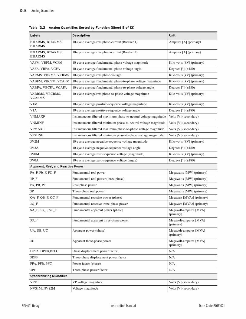
12.16
SEL-421 Relay Instruction Manual Date Code 20171021
Analog Quantities
B1IARMS, B1IARMS, B1IARMS
10-cycle average rms phase-current (Breaker 1) Amperes [A] (primary)
B2IARMS, B2IARMS, B2IARMS
10-cycle average rms phase-current (Breaker 2) Amperes [A] (primary)
VAFM, VBFM, VCFM 10-cycle average fundamental phase voltage magnitude Kilo-volts [kV] (primary)
VAFA, VBFA, VCFA 10-cycle average fundamental phase voltage angle Degrees [°] (±180)
VARMS, VBRMS, VCRMS 10-cycle average rms phase-voltage Kilo-volts [kV] (primary)
VABFM, VBCFM, VCAFM 10-cycle average fundamental phase-to-phase voltage magnitude Kilo-volts [kV] (primary)
VABFA, VBCFA, VCAFA 10-cycle average fundamental phase-to-phase voltage angle Degrees [°] (±180)
VABRMS, VBCRMS, VCARMS
10-cycle average rms phase-to-phase voltage magnitude Kilo-volts [kV] (primary)
V1M 10-cycle average positive-sequence voltage magnitude Kilo-volts [kV] (primary)
V1A 10-cycle average positive-sequence voltage angle Degrees [°] (±180)
VNMAXF Instantaneous filtered maximum phase-to-neutral voltage magnitude Volts [V] (secondary)
VNMINF Instantaneous filtered minimum phase-to-neutral voltage magnitude Volts [V] (secondary)
VPMAXF Instantaneous filtered maximum phase-to-phase voltage magnitude Volts [V] (secondary)
VPMINF Instantaneous filtered minimum phase-to-phase voltage magnitude Volts [V] (secondary)
3V2M 10-cycle average negative-sequence voltage magnitude Kilo-volts [kV] (primary)
3V2A 10-cycle average negative-sequence voltage angle Degrees [°] (±180)
3V0M 10-cycle average zero-sequence voltage (magnitude) Kilo-volts [kV] (primary)
3V0A 10-cycle average zero-sequence voltage (angle) Degrees [°] (±180)
Apparent, Real, and Reactive Power
PA_F, Pb_F, PC_F Fundamental real power Megawatts [MW] (primary)
3P_F Fundamental real power (three-phase) Megawatts [MW] (primary)
PA, PB, PC Real phase power Megawatts [MW] (primary)
3P Three-phase real power Megawatts [MW] (primary)
QA_F, QB_F, QC_F Fundamental reactive power (phase) Megavars [MVAr] (primary)
3Q_F Fundamental reactive three-phase power Megavars [MVAr] (primary)
SA_F, SB_F, SC_F Fundamental apparent power (phase) Megavolt-amperes [MVA] (primary)
3S_F Fundamental apparent three-phase power Megavolt-amperes [MVA] (primary)
UA, UB, UC Apparent power (phase) Megavolt-amperes [MVA] (primary)
3U Apparent three-phase power Megavolt-amperes [MVA] (primary)
DPFA, DPFB,DPFC Phase displacement power factor N/A
3DPF Three-phase displacement power factor N/A
PFA, PFB, PFC Power factor (phase) N/A
3PF Three-phase power factor N/A
Synchronizing Quantities
VPM VP voltage magnitude Volts [V] (secondary)
NVS1M, NVS2M Voltage magnitude Volts [V] (secondary)
Table 12.2 Analog Quantities Sorted by Function (Sheet 5 of 13)
Labels Description Unit

12.17
Date Code 20171021 Instruction Manual SEL-421 Relay
Analog Quantities
ANG1DIF, ANG1DIF VSnang-VPang Degrees [°] (±180)
SLIP1, SLIP2 Slip (fs1/2-fp) Hertz [Hz]
Overcurrent Elements
51P01–51P10 51 element pickup value Amperes [A] (secondary)
51TD01–51D10 51 element time dial setting N/A
Battery Monitoring
DC1, DC2 Filtered station battery dc voltage Volts [V]
DC1PO, DC2PO Average positive-to-ground dc voltage Volts [V]
DC1NE, DC2NE Average negative-to-ground dc voltage Volts [V]
DC1RI, DC2RI AC ripple of dc voltage Volts [V]
DC1MIN, DC2MIN Minimum dc voltage Volts [V]
DC1MAX, DC2MAX Maximum dc voltage Volts [V]
Demand and Peak Demand Quantities
IAPKD, IBPKD, ICPKD Peak demand phase current Amperes [A] (primary)
3I2PKD Peak demand negative-sequence current Amperes [A] (primary)
IGPKD Peak demand zero-sequence current Amperes [A] (primary)
PAPKD, PBPKD, PCPKD Peak demand phase real power Megawatts [MW] (primary)
3PPKD Peak demand three-phase real power Megawatts [MW] (primary)
QAPKD QBPKD QCPKD Peak demand phase reactive power Megavars [MVAr] (primary)
3QPKD Peak demand three-phase reactive power Megavars [MVAr] (primary)
UAPKD, UBPKD, UCPKD Peak demand phase apparent power Megavolt-amperes [MVA] (primary)
3UPKD Peak demand three-phase apparent power Megavolt-amperes [MVA] (primary)
IAD, IBD, ICD Demand phase current Amperes [A] (primary)
3I2D Demand negative-sequence current Amperes [A] (primary)
IGD Demand zero-sequence current Amperes [A] (primary)
PAD, PBD, PCD Demand phase real power Megawatts [MW] (primary)
3PD Demand three-phase real power Megawatts [MW] (primary)
QAD, QBD, QCD Demand phase reactive power Megavars [MVAr] (primary)
3QD Demand three-phase reactive power Megavars [MVAr] (primary)
UAD, UBD, UCD Demand phase apparent power Megavolt-amperes [MVA] (primary)
3UD Demand three-phase apparent power Megavolt-amperes [MVA] (primary)
Import/Export Power Quantities
MWHAOUT, MWHBOUT, MWHCOUT
Positive (export) phase energy, Megawatt-hours Megawatt-hour [MWh] (primary)
MWHAIN, MWHBIN, MWHCIN
Negative (import) phase energy, Megawatt-hours Megawatt-hour [MWh] (primary)
MWHAT, MWHBT, MWHCT
Total phase energy; Megawatt-hours Megawatt-hour [MWh] (primary)
3MWHOUT Positive (export) three-phase energy, Megawatt-hours Megawatt-hour [MWh] (primary)
Table 12.2 Analog Quantities Sorted by Function (Sheet 6 of 13)
Labels Description Unit

12.18
SEL-421 Relay Instruction Manual Date Code 20171021
Analog Quantities
3MWHIN Negative (import) three-phase energy, Megawatt-hours Megawatt-hour [MWh] (primary)
3MWH3T Total three-phase energy; Megawatt-hours Megawatt-hour [MWh] (primary)
MHO Calculations
MAGZ1, MBGZ1, MCGZ1 Zone 1 mho ground impedance calculation Ohms (secondary)
MAGF, MBGF, MCGF Forward mho ground calculation (excludes Zone 1) Ohms (secondary)
MAGR, MBGR, MCGR Reverse mho ground calculation (all reverse zones) Ohms (secondary)
MAB, MBC, MCA Mho phase-to-phase impedance calculation Ohms (secondary)
MIRRORED BITS
MB1A–MB7A Channel A received MIRRORED BITS analog values N/A
MB1B–MB7B Channel B received MIRRORED BITS analog values N/A
Programming
PMV01–PMV64 Protection SELOGIC math variable N/A
PCT01–PCT32 Protection SELOGIC conditioning timer pickup time Cycles
PCT01DO–PCT32DO Protection SELOGIC conditioning timer dropout time Cycles
PST01ET–PST32ET Protection SELOGIC sequencing timer elapsed time Cycles
PST01PT–PST32PT Protection SELOGIC sequencing timer preset time Cycles
PCN01CV–PCN32CV Protection SELOGIC counter current value N/A
PCN01PV–PCN32PV Protection SELOGIC counter preset value N/A
AMV001–AMV256 Automation SELOGIC math variable N/A
AST01ET–AST32ET Automation SELOGIC math sequencing timer elapsed time Seconds (s)
AST01PT–AST32PT Automation SELOGIC sequencing timer preset time Seconds (s)
ACN01CV–ACN32CV Automation SELOGIC counter current value N/A
ACN01PV–ACN32PV Automation SELOGIC counter preset value N/A
Active Group Setting
ACTGRP Active group setting N/A
Breaker Contact Wear
B1BCWPA, B1BCWPBA, B1BCWPC
Breaker contact wear (Breaker 1) Percent
B2BCWPA, B2BCWPBA, B2BCWPC
Breaker contact wear (Breaker 2) Percent
Time and Date Management
TODMS UTC time of day in milliseconds (0–86400000) Milliseconds (ms)
THR UTC time, hour (0–23) Hour (hr)
TMIN UTC time, minute (0–59) Minutes (min)
TSEC UTC time, seconds (0–59) Seconds (s)
TMSEC UTC time, milliseconds (0–999) Milliseconds (ms)
TNSEC UTC time, nanoseconds (0–999999) Nanoseconds (ns)
TLHR Local time, hour (0–23) Hour (hr)
TLMIN Local time, minute (0–59) Minutes (min)
TLMSEC Local time, millisecond (0–999) Milliseconds (ms)
TLNSEC Local time, nanoseconds (0–999999) Nanoseconds (ns)
TLODMS Local time of day in milliseconds (0–86400000) Milliseconds (ms)
Table 12.2 Analog Quantities Sorted by Function (Sheet 7 of 13)
Labels Description Unit

12.19
Date Code 20171021 Instruction Manual SEL-421 Relay
Analog Quantities
TLSEC Local time, seconds (0–59) Seconds (s)
DDOW UTC date, day of the week (1–SU,..., 7–SA) Day
DDOM UTC date, day of the month (1–31) Day
DDOY UTC date, day of the year (1–366) Day
DMON UTC date, month (1–12) Month
DYEAR UTC date, year (2000–2200) Year
Reclosing Relay
SPSHOT Present value of single-pole shot counter N/A
3PSHOT Present value of three-pole shot counter N/A
SHOT1_1 Total number of 1st shot single-pole recloses N/A
SHOT1_2 Total number of 2nd shot single-pole recloses N/A
SHOT1_T Total number of single-pole reclosing shots issued N/A
SHOT3_1 Total number of 1st shot three-pole recloses N/A
SHOT3_2 Total number of 2nd shot three-pole recloses N/A
SHOT3_3 Total number of 3rd shot three-pole recloses N/A
SHOT3_4 Total number of 4th shot three-pole recloses N/A
SHOT3_T Total number of three-pole recloses N/A
Fault Location
FLOC Fault location Per unit (pu)
Contact Inputs
IN201A–IN208A Digital input values available as floating point quantities 0.0–255.0 A/D Counts
IN301A–IN308A Digital input values available as floating point quantities 0.0–255.0 A/D Counts
IN201V–IN208V Contact input A/D counts converted to calibrated voltage V
IN301V–IN308V Contact input A/D counts converted to calibrated voltage V
RTD
RTD01–RTD12 Instantaneous temperatures from external SEL-2600 °C (degrees Celsius)
IRIG-B Control Function Bits for Synchrophasor Measurement
TUTC Offset from IRIG-B time to UTC time Hour
TQUAL Worst case IRIG-B clock time error Seconds [s]
NEW_SRC Selected high-accuracy time source N/A
CUR_SRC Current high-accuracy time source N/A
SQUAL IRIG-B synchronization accuracy µs
BNCDSJI BNC port 100 PPS data stream jitter µs
BNCTBTW Time between BNC 100 PPS pulses µs
SERTBTW Time between serial 100 PPS pulses µs
BNCOTJS Slow converging BNC port ON TIME marker jitter, fine accuracy µs
BNCOTJF Fast converging BNC port ON TIME marker jitter, coarse accuracy µs
SERDSJI Serial Port 100 PPS data stream jitter µs
SEROTJS Slow converging serial port ON TIME marker jitter, fine accuracy µs
SEROTJF Fast converging serial port ON TIME marker jitter, coarse accuracy µs
Table 12.2 Analog Quantities Sorted by Function (Sheet 8 of 13)
Labels Description Unit

12.20
SEL-421 Relay Instruction Manual Date Code 20171021
Analog Quantities
IEEE 1588 PTP Status
PTPDSJI PTP 100PPS data stream jitter in µs µs
PTPMCC PTP master clock class enumerated value N/A
PTPOTJS Slow converging PTP ON TIME marker jitter in µs, fine accuracy µs
PTPOTJF Fast converging PTP ON TIME marker jitter in µs, coarse accuracy µs
PTPOFST Raw clock offset between PTP master and relay time ns
PTPPORT Active PTP port number N/A
PTPTBTW Time between PTP 100PPS pulses in µs µs
PTPSTEN PTP Port State enumerated value N/A
Time Error Connection Factor Command
TECORR Time error correction preload value Seconds [s]
TE Time error Seconds [s]
Synchrophasor Quantities
VAYPMM, VBYPMM, VCYPMM
Synchrophasor voltage magnitude, Terminal Y Kilo Volts [kV] (primary)
VAZPMM, VBZPMM, VCZPMM
Synchrophasor voltage magnitude, Terminal Z Kilo Volts [kV] (primary)
VAYPMA, VBYPMA, VCYPMA
Synchrophasor voltage angle, Terminal Y Degrees [°] (±180)
VAZPMA, VBZPMA, VCZPMA
Synchrophasor voltage angle, Terminal Z Degrees [°] (±180)
VAYPMR, VBYPMR, VCYPMR
Synchrophasor voltage real component, Terminal Y Kilo Volts [kV] (primary)
VAZYPMR, VBZPMR, VCZPMR
Synchrophasor voltage real component, Terminal Z Kilo Volts [kV] (primary)
VAYPMI, VBYPMI, VCYPMI
Synchrophasor voltage imaginary component, Terminal Y Kilo Volts [kV] (primary)
VAZYPMI, VBZPMI, VCZYPMI
Synchrophasor voltage imaginary component, Terminal Z Kilo Volts [kV] (primary)
V1YPMM Positive-sequence synchrophasor voltage magnitude, Terminal Y Kilo Volts [kV] (primary)
V1ZPMM Positive-sequence synchrophasor voltage magnitude, Terminal Z Kilo Volts [kV] (primary)
V1YPMA Positive-sequence synchrophasor voltage angle, Terminal Y Degrees [°] (±180)
V1ZPMA Positive-sequence synchrophasor voltage angle, Terminal Z Degrees [°] (±180)
V1YPMR Positive-sequence synchrophasor voltage real component, Terminal Y
Kilo Volts [kV] (primary)
V1ZPMR Positive-sequence synchrophasor voltage real component, Terminal Z
Kilo Volts [kV] (primary)
V1YPMI Positive-sequence synchrophasor voltage imaginary component, Terminal Y
Kilo Volts [kV] (primary)
V1ZPMI Positive-sequence synchrophasor voltage imaginary component, Terminal Z
Kilo Volts [kV] (primary)
IAWPMM, IBWPMM, ICWPMM
Synchrophasor current magnitude, Terminal W Amperes [A] (primary)
IAXPMM, IBXPMM, ICXPMM
Synchrophasor current magnitude, Terminal X Amperes [A] (primary)
Table 12.2 Analog Quantities Sorted by Function (Sheet 9 of 13)
Labels Description Unit

12.21
Date Code 20171021 Instruction Manual SEL-421 Relay
Analog Quantities
IASPMM, IBSPMM, ICSPMM
Synchrophasor current magnitude, Terminal S Amperes [A] (primary)
IAWPMA, IBWPMA, ICWPMA
Synchrophasor current angle, Terminal W Degrees [°] (±180)
IAXPMA, IBXPMA, ICXPMA
Synchrophasor current angle, Terminal X Degrees [°] (±180)
IASPMA, IBSPMA, ICSPMA
Synchrophasor current angle, Terminal S Degrees [°] (±180)
IAWPMR, IBWPMR, ICWPMR
Synchrophasor current real component, Terminal W Amperes [A] (primary)
IAXPMR, IBXPMR, ICXPMR
Synchrophasor current real component, Terminal X Amperes [A] (primary)
IASPMR, IBSPMR, ICSPMR
Synchrophasor current real component, Terminal S Amperes [A] (primary)
IAWPMI, IBWPMI, ICWPMI
Synchrophasor current imaginary component, Terminal W Amperes [A] (primary)
IAXPMI, IBXPMI, ICXPMI Synchrophasor current imaginary component, Terminal X Amperes [A] (primary)
IASPMI, IBSPMI, ICSPMI Synchrophasor current imaginary component, Terminal S Amperes [A] (primary)
I1WPMM Positive-sequence synchrophasor current magnitude, Terminal W Amperes [A] (primary)
I1XPMM Positive-sequence synchrophasor current magnitude, Terminal X Amperes [A] (primary)
I1SPMM Positive-sequence synchrophasor current magnitude, Terminal S Amperes [A] (primary)
I1WPMA Positive-sequence synchrophasor current angle, Terminal W Degrees [°] (±180)
I1XPMA Positive-sequence synchrophasor current angle, Terminal X Degrees [°] (±180)
I1SPMA Positive-sequence synchrophasor current angle, Terminal S Degrees [°] (±180)
I1WPMR Positive-sequence synchrophasor current real component, Terminal W
Amperes [A] (primary)
I1XPMR Positive-sequence synchrophasor current real component, Terminal X
Amperes [A] (primary)
I1SPMR Positive-sequence synchrophasor current real component, Terminal S
Amperes [A] (primary)
I1WPMI Positive-sequence synchrophasor current imaginary component, Terminal W
Amperes [A] (primary)
I1XPMI Positive-sequence synchrophasor current imaginary component, Ter-minal X
Amperes [A] (primary)
I1SPMI Positive-sequence synchrophasor current imaginary component, Terminal S
Amperes [A] (primary)
SODPM Second of day of the synchrophasor data packet Seconds [s]
FOSPM Fraction of second of the synchrophasor data packet Seconds [s]
Synchrophasor Frequency
FREQPM Frequency for synchrophasor data Hertz [Hz]
DFDTPM Rate-of-change of frequency for synchrophasor data Hertz/seconds [Hz/s]
Synchrophasor RTC
VAYPMMD, VBYPMMD, VCYPMMD
Synchrophasor voltage magnitude, Terminal Y, delayed for RTC alignment
Kilo Volts [kV] (primary)
VAZPMMD, VBZPMMD, VCZPMMD
Synchrophasor voltage magnitude, Terminal Z, delayed for RTC alignment
Kilo Volts [kV] (primary)
Table 12.2 Analog Quantities Sorted by Function (Sheet 10 of 13)
Labels Description Unit

12.22
SEL-421 Relay Instruction Manual Date Code 20171021
Analog Quantities
VAYPMAD, VBYPMAD, VCYPMAD
Synchrophasor voltage angle, Terminal Y, delayed for RTC alignment
Degrees [°] (±180)
VAZPMAD, VBZPMAD, VCZPMAD
Synchrophasor voltage angle, Terminal Z, delayed for RTC alignment
Degrees [°] (±180)
VAYPMRD, VBYPMRD, VCYPMRD
Synchrophasor voltage real component, Terminal Y, delayed for RTC alignment
Kilo Volts [kV] (primary)
VAZPMRD, VBZPMRD, VCZPMRD
Synchrophasor voltage real component, Terminal Z, delayed for RTC alignment
Kilo Volts [kV] (primary)
VAYPMID, VBYPMID, VCYPMID
Synchrophasor voltage imaginary component, Terminal Y, delayed for RTC alignment
Kilo Volts [kV] (primary)
VAZPMID, VBZPMID, VCZPMID
Synchrophasor voltage imaginary component, Terminal Z, delayed for RTC alignment
Kilo Volts [kV] (primary)
V1YPMMD Positive sequence synchrophasor voltage magnitude, Terminal Y, delayed for RTC alignment
Kilo Volts [kV] (primary)
V1ZPMMD Positive sequence Synchrophasor voltage magnitude, Terminal Z, delayed for RTC alignment
Kilo Volts [kV] (primary)
V1YPMAD Positive sequence synchrophasor voltage angle, Terminal Y, delayed for RTC alignment
Degrees [°] (±180)
V1ZPMAD Positive sequence synchrophasor voltage angle, Terminal Z, delayed for RTC alignment
Degrees [°] (±180)
V1YPMRD Positive sequence synchrophasor voltage real component, Terminal Y, delayed for RTC alignment
Kilo Volts [kV] (primary)
V1ZPMRD Positive sequence synchrophasor voltage real component, Terminal Z, delayed for RTC alignment
Kilo Volts [kV] (primary)
V1YPMID Positive sequence synchrophasor voltage imaginary component, Terminal Y, delayed for RTC alignment
Kilo Volts [kV] (primary)
V1ZPMID Positive sequence synchrophasor voltage imaginary component, Terminal Z, delayed for RTC alignment
Kilo Volts [kV] (primary)
IAWPMMD, IBWPMMD, ICWPMMD
Synchrophasor current magnitude, Terminal W, delayed for RTC alignment
Amperes [A] (primary)
IAXPMMD, IBXPMMD, ICXPMMD
Synchrophasor current magnitude, Terminal X, delayed for RTC alignment
Amperes [A] (primary)
IASPMMD, IBSPMMD, ICSPMMD
Synchrophasor current magnitude, Terminal S, delayed for RTC alignment
Amperes [A] (primary)
IAWPMAD, IBWPMAD, ICWPMAD
Synchrophasor current angle, Terminal W, delayed for RTC alignment
Degrees [°] (±180)
IAXPMAD, IBXPMAD, ICXPMAD
Synchrophasor current angle, Terminal X, delayed for RTC alignment
Degrees [°] (±180)
IASPMAD, IBSPMAD, ICSPMAD
Synchrophasor current angle, Terminal S, delayed for RTC alignment
Degrees [°] (±180)
IAWPMRD, IBWPMRD, ICWPMRD
Synchrophasor current real component, Terminal W, delayed for RTC alignment
Amperes [A] (primary)
IAXPMRD, IBXPMRD, ICXPMRD
Synchrophasor current real component, Terminal X, delayed for RTC alignment
Amperes [A] (primary)
IASPMRD, IBSPMRD, ICSPMRD
Synchrophasor current real component, Terminal S, delayed for RTC alignment
Amperes [A] (primary)
IAWPMID, IBWPMID, ICWPMID
Synchrophasor current imaginary component, Terminal W, delayed for RTC alignment
Amperes [A] (primary)
IAXPMID, IBXPMID, ICXPMID
Synchrophasor current imaginary component, Terminal X, delayed for RTC alignment
Amperes [A] (primary)
Table 12.2 Analog Quantities Sorted by Function (Sheet 11 of 13)
Labels Description Unit

12.23
Date Code 20171021 Instruction Manual SEL-421 Relay
Analog Quantities
IASPMID, IBSPMID, ICSPMID
Synchrophasor current imaginary component, Terminal W, delayed for RTC alignment
Amperes [A] (primary)
I1WPMMD Positive sequence synchrophasor current magnitude, Terminal W, delayed for RTC alignment
Amperes [A] (primary)
I1XPMMD Positive sequence synchrophasor current magnitude, Terminal X, delayed for RTC alignment
Amperes [A] (primary)
I1SPMMD Positive sequence synchrophasor current magnitude, Terminal S, delayed for RTC alignment
Amperes [A] (primary)
I1WPMAD Positive sequence synchrophasor current angle, Terminal W, delayed for RTC alignment
Degrees [°] (±180)
I1XPMAD Positive sequence synchrophasor current angle, Terminal X, delayed for RTC alignment
Degrees [°] (±180)
I1SPMAD Positive sequence synchrophasor current angle, Terminal S, delayed for RTC alignment
Degrees [°] (±180)
I1WPMRD Positive sequence synchrophasor current real component, Terminal W, delayed for RTC alignment
Amperes [A] (primary)
I1XPMRD Positive sequence synchrophasor current real component, Terminal X, delayed for RTC alignment
Amperes [A] (primary)
I1SPMRD Positive sequence synchrophasor current real component, Terminal S, delayed for RTC alignment
Amperes [A] (primary)
I1WPMID Positive sequence synchrophasor current imaginary component, Terminal W, delayed for RTC alignment
Amperes [A] (primary)
I1XPMID Positive sequence synchrophasor current imaginary component, Terminal X, delayed for RTC alignment
Amperes [A] (primary)
I1SPMID Positive sequence synchrophasor current imaginary component, Terminal S, delayed for RTC alignment
Amperes [A] (primary)
SODPMD Second of day of the synchrophasor data packet, delayed for RTC alignment
Seconds [s]
FOSPMD Fraction of second of the synchrophasor data packet, delayed for RTC alignment
Seconds [s]
FREQPMD Frequency for synchrophasor data, delayed for RTC alignment Hertz [Hz]
DFDTPMD Rate-of-change of frequency for synchrophasor data, delayed for RTC alignment
Hertz/seconds [Hz/s]
RTCAP01–RTCAP32 Channel A remote synchrophasor phasors (unit depends on remote synchrophasor contents)
N/A
RTCBP01–RTCBP32 Channel B remote synchrophasor phasors (unit depends on remote synchrophasor contents)
N/A
RTCAA01–RTCAA08 Channel A remote synchrophasor analogs (unit depends on remote synchrophasor contents)
N/A
RTCBA01–RTCBA08 Channel B remote synchrophasor analogs (unit depends on remote synchrophasor contents)
N/A
RTCFA Channel A remote frequency (from remote synchrophasors) Hertz [Hz]
RTCFB Channel B remote frequency (from remote synchrophasors) Hertz [Hz]
RTCDFA Rate-of-change of Channel A remote frequency (from remote synchrophasors)
Hertz/seconds [Hz/s]
RTCDFB Rate-of-change of Channel B remote frequency (from remote synchrophasors)
Hertz/seconds [Hz/s]
Table 12.2 Analog Quantities Sorted by Function (Sheet 12 of 13)
Labels Description Unit

12.24
SEL-421 Relay Instruction Manual Date Code 20171021
Analog Quantities
Protection Frequency
DFDTP Rate-of-change of frequency Hertz/seconds [Hz/s]
FREQ Tracking frequency Hertz [Hz]
FREQP Frequency for under-/overfrequency elements Hertz [Hz]
Remote Analogs
RA001–RA256 Remote analogs N/A
RAO01–RAO64 Remote analog output N/A
Out-Of-Step
SCV Unfiltered swing center voltage Per unit (pu)
Relay Temperature
RLYTEMP Relay temperature (temperature of the enclosure) °C (degrees Celsius)
Table 12.2 Analog Quantities Sorted by Function (Sheet 13 of 13)
Labels Description Unit

Date Code 20171021 Instruction Manual SEL-421 Relay
Instruction ManualA P P E N D I X A
Firmware, ICD File, and Manual Versions
FirmwareDetermining the Firmware Version
To determine the firmware version, view the status report by using the serial port ID command or the front-panel LCD View Configuration menu option. The sta-tus report displays the Firmware Identification (FID) number.
NOTE: The SEL-421-4, -5 relays (firmware version R3xx) are incompatible with the previous SEL-421-0, -1, -2, -3 relays (firmware versions R1xx and R2xx). Do not attempt to load R3xx firmware on the previous hardware or R1xx or R2xx firmware on the new hardware.
The firmware version will be either a standard release or a point release. A standard release adds new functionality to the firmware beyond the specifica-tions of the existing version. A point release is reserved for modifying firmware functionality to conform to the specifications of the existing version.
A standard release is identified by a change in the R-number of the device FID number.
Existing firmware:
FID=SEL-421-x-R100-V0-Z001001-Dxxxxxxxx
Standard release firmware:
FID=SEL-421-x-R101-V0-Z001001-Dxxxxxxxx
A point release is identified by a change in the V-number of the device FID num-ber.
Existing firmware:
FID=SEL-421-x-R100-V0-Z001001-Dxxxxxxxx
Point release firmware:
FID=SEL-421-x-R100-V1-Z001001-Dxxxxxxxx
The release date is after the D. For example, the following is firmware version number R100, release date December 10, 2003.
FID=SEL-421-x-R100-V0-Z001001-D20031210
Similarly, the device SELBOOT firmware revision (BFID) will be reported as:
BFID=SLBT-4XX-Rxx-Vx-Zxxxxxx-Dxxxxxxxx

A.2
SEL-421 Relay Instruction Manual Date Code 20171021
Firmware, ICD File, and Manual VersionsFirmware
Revision HistoryTable A.1 lists the firmware versions, revision descriptions, and corresponding instruction manual date codes.
Table A.1 Firmware Revision History (Sheet 1 of 7)
Firmware Identification (FID) Number Summary of RevisionsManual
Date Code
SEL-421-4-R323-V0-Z024013-D20171008
SEL-421-5-R323-V0-Z024013-D20171008
➤ Added a new analog quantity, PTPMCC, to indicate the clock class of the PTP master.
➤ Enhanced memory read diagnostics.
➤ DNP3 data are now reported with a LOCAL_FORCED flag when they have been overridden through use of the TEST DB2 command.
➤ Updated IEC 61850 protocol implementation to IEC 61850 Edition 2.
➤ Modified the relay response to an MMS identify request so that it will respond with the firmware ID (FID) string.
➤ Improved MMS file services performance with successive file transfers.
➤ Enhanced wild card parsing used in MMS file transfer operations.
➤ Modified the ID command to display a string that uniquely identifies the IEC 61850 firmware present in the relay.
➤ Modified firmware to replace non-printable characters with question marks in settings that are sent to the front panel of the HMI.
➤ Modified firmware to allow SNTPPIP to be set to 0.0.0.0 when ESNTP = BROADCAST.
20171008
➤ The ETH command now shows both MAC addresses.
➤ Modified firmware to indicate an enabled or disable transition of the IEC 61850 Buffer Report Control Block (BRCB) by sending an over-flow flag on the next report sent after the transition.
➤ Modified IEEE-1588 PTP power profile to be supported in Parallel Redundancy Protocol (PRP) mode.
➤ Modified firmware to only reset breaker monitor data for the breaker selected. In prior firmware, some data were being reset for all breakers.
➤ Modified firmware to avoid false GOOSE out of sequence errors while in PRP mode.
➤ Modified firmware to use only the first synchrophasor data configura-tion if the number of output data configurations exceeds the number of data configurations.
➤ Modified firmware to allow all settings changes when the relay is dis-abled.
SEL-421-4-R322-V3-Z024013-D20171021
SEL-421-5-R322-V3-Z024013-D20171021
Includes all the functions of SEL-421-4-R322-V2-Z024013-D20170810 and SEL-421-5-R322-V2-Z024013-D20170820 with the following addition:
➤ Enhanced memory read diagnostics.
20171021
SEL-421-4-R322-V2-Z024013-D20170810
SEL-421-5-R322-V2-Z024013-D20170810
Includes all the functions of SEL-421-4-R322-V1-Z024013-D20170525 and SEL-421-5-R322-V1-Z024013-D20170525 with the following addi-tion:
➤ Resolved an issue where certain Ethernet traffic could cause diagnostic restarts.
20170810
SEL-421-4-R322-V1-Z024013-D20170525
SEL-421-5-R322-V1-Z024013-D20170525
Includes all the functions of SEL-421-4-R322-V0-Z024013-D20170327 and SEL-421-5-R322-V0-Z024013-D20170327 with the following addi-tion:
➤ Modified firmware to allow the relay to synchronize to an external time source more responsively.
20170525

A.3
Date Code 20171021 Instruction Manual SEL-421 Relay
Firmware, ICD File, and Manual VersionsFirmware
SEL-421-4-R322-V0-Z024013-D20170327
SEL-421-5-R322-V0-Z024013-D20170327
➤ Added an event report digital setting, ERDIG, which can be set to S (some) or A (all) to allow the option for all Relay Word bits to be added to COMTRADE event reports.
➤ Added the AUTO2 option to the directional control enable setting (E32).
➤ Extended the resistance reach for Zones 4 and 5 of both the ground and phase quadrilateral distance elements.
➤ Improved Simple Network Time Protocol (SNTP) accuracy to ± 1 ms in an ideal network.
➤ Expanded the allowable reach for Zones 6 and 7 of the conventional out-of-step logic.
20170327
➤ Added time-domain link (TiDL) technology.
➤ Added digital input and digital output Relay Word bits to accommodate I/O from remote data acquisition modules.
➤ Added Zone 1 fault detector settings (Z50P1 and Z50G1) to phase- and ground-distance elements.
➤ Modified alpha voltage (VALPHA) calculation to be forced to zero when all poles are open.
➤ Enhanced frequency tracking to freeze for two cycles during toggling open-pole conditions.
➤ Modified firmware to prevent delays in periodic MMS reports.
➤ Modified firmware to allow the MMS inactivity time-out to be turned off.
➤ Enhanced the frequency tracking algorithm to update more responsively after a low frequency event.
SEL-421-4-R321-V2-Z023013-D20171021
SEL-421-5-R321-V2-Z023013-D20171021
Includes all the functions of SEL-421-4-R321-V1-Z023013-D20170820 and SEL-421-5-R321-V1-Z023013-D20170820 with the following addition:
➤ Enhanced memory read diagnostics.
20171021
SEL-421-4-R321-V1-Z023013-D20170820
SEL-421-5-R321-V1-Z023013-D20170820
Includes all the functions of SEL-421-4-R321-V0-Z023013-D20160624 and SEL-421-5-R321-V0-Z023013-D20160624 with the following addition:
➤ Resolved an issue where certain Ethernet traffic could cause diagnostic restarts.
20170820
SEL-421-4-R321-V0-Z023013-D20160624
SEL-421-5-R321-V0-Z023013-D20160624
➤ Added EVEMODn (where n = 1–6 for DNP LAN/WAN or empty for DNP serial) setting to force the relay to start in single- or multiple-event mode.
➤ Improved MIRRORED BITS performance under high level of GOOSE traffic.
➤ Modified DNP Object 0, Variation 242 to report the firmware V-number.
➤ Modified GOOSE subscription to update data after the messages transi-tion from bad to good quality.
➤ Improved relay start-up time.
➤ Modified Virtual Bits to reset upon a successful CID file download.
➤ Added support for IEEE 1588-2008, Precision Time Protocol (PTP) time synchronization.
➤ Added ordering option to select Ethernet Ports 5A/5B if a customer needs PTP.
➤ Added setting EPOLDIS to enable/disable the pole discrepancy breaker status for the HMI Bay Control when the breaker type is set to single pole. EPOLDIS = Y by default, which maintains the same behavior as previous firmware.
20160624
Table A.1 Firmware Revision History (Sheet 2 of 7)
Firmware Identification (FID) Number Summary of RevisionsManual
Date Code

A.4
SEL-421 Relay Instruction Manual Date Code 20171021
Firmware, ICD File, and Manual VersionsFirmware
➤ Enhanced front panel operations to show settings warnings, in addition to settings errors already displayed, during settings changes.
➤ Modified the handling of a leap year when the relay setting and clock disagree.
SEL-421-4-R320-V2-Z022013-D20170820
SEL-421-5-R320-V2-Z022013-D20170820
Includes all the functions of SEL-421-4-R320-V1-Z022013-D20160504 and SEL-421-5-R320-V1-Z022013-D20160504 with the following addition:
➤ Resolved an issue where certain Ethernet traffic could cause diagnostic restarts.
20170820
SEL-421-4-R320-V1-Z022013-D20160504
SEL-421-5-R320-V1-Z022013-D20160504
Includes all the functions of SEL-421-4-R320-V0-Z022013-D20160111 and SEL-421-5-R320-V0-Z022013-D20160111 with the following addi-tion:
➤ Modified programmable digital inputs to drop out at specified setting threshold.
20160504
SEL-421-4-R320-V0-Z022013-D20160111
SEL-421-5-R320-V0-Z022013-D20160111
➤ Modified the TEST DB2 OFF command to disable the overridden remote analog output and digital values in IEC 61850 GOOSE mes-sages.
➤ Modified the TEST DB2 functionality to override Relay Word bits that are in the Sequential Events Recorder (SER).
➤ Added two new breaker failure settings options, Y1 and Y2.
➤ Added additional synchronism-check schemes and a synchronous volt-age difference setting, 25VDIF.
➤ Enhanced positive-sequence directional element (F32P) for high-resis-tance faults.
20160111
SEL-421-4-R319-V2-Z021013-D20170820
SEL-421-5-R319-V2-Z021013-D20170820
Includes all the functions of SEL-421-4-R319-V1-Z021013-D20160506 and SEL-421-5-R319-V1-Z021013-D20160506 with the following addition:
➤ Resolved an issue where certain Ethernet traffic could cause diagnostic restarts.
20170820
SEL-421-4-R319-V1-Z021013-D20160506
SEL-421-5-R319-V1-Z021013-D20160506
Includes all the functions of SEL-421-4-R319-V0-Z021013-D20150504 and SEL-421-5-R319-V0-Z021013-D20150504 with the following addi-tion:
➤ Modified programmable digital inputs to drop out at specified setting threshold.
20160506
SEL-421-4-R319-V0-Z021013-D20150504
SEL-421-5-R319-V0-Z021013-D20150504
➤ Enhanced the out-of-step blocking logic to be more dependable during single-pole open conditions.
➤ Added supervision to the quadrilateral phase and ground-distance ele-ments for unusual unbalanced load conditions.
➤ Modified code to maintain VMEMC setting value during an upgrade.
➤ Added polarization voltage validation check to supervise quadrilateral phase-distance elements
➤ Added the option to change settings groups with IEC 61850.
➤ Added the LPHD.Sim logical node so the relay will accept GOOSE messages with the test flag asserted.
➤ Added Relay Word bits to indicate leading and lagging power factor.
➤ Added support for the stSeld attribute in IEC 61850 SBO controls.
➤ Added total energy analog quantities to the DNP3 analog input refer-ence map, and added the imported and exported energy scaled and labeled to KW to the binary counter reference data map.
20150504
Table A.1 Firmware Revision History (Sheet 3 of 7)
Firmware Identification (FID) Number Summary of RevisionsManual
Date Code

A.5
Date Code 20171021 Instruction Manual SEL-421 Relay
Firmware, ICD File, and Manual VersionsFirmware
➤ Added Isolated IP mode (NETMODE = ISOLATEIP) which permits IEC 61850 GOOSE messages on two ports but restricts IP traffic to just one port.
➤ Added pulsed remote bits in Automation SELOGIC.
➤ Added FRQST and PMLEGCY settings to maintain backward settings compatibility.
➤ Added aliasing capability for the phasors, analogs, and digitals in the synchrophasor data.
➤ Enhanced the report time records to save the active UTC offset (UTCOFF) value with each report. Now, when the relay collects a report, it assigns the time stamp based on the UTC time and the UTCOFF value at the time the relay stores the report.
➤ Removed the port uniqueness requirements for the PMOUDP1 and PMOUDP2 settings.
➤ Enhanced the embedded HTTP server user interface to be consistent with other SEL relays.
➤ Improved the Sequential Events Recorder (SER) resolution to 0.5 ms for level sensitive contact inputs.
➤ Modified the relay to support MMS file transfer service even if the relay contains an invalid CID file.
➤ Modified the embedded HTTP server web access to always require a valid relay Access Level 1 (ACC) password.
➤ Updated the maximum and minimum line metering data (MET M com-mands) to display local time for all data.
➤ Reset the port timeout on transmitted Telnet messages.
➤ Updated the profile and compressed profile commands (PRO and CPRO, respectively) to display the available analog signal profiling records regardless of the state of the signal profile enable (SPEN) set-ting.
➤ Changed the result of a SELOGIC control equation math error from NAN (not a number) to the previously stored valid result.
➤ Improved Port 5 functionality to disable auto-messages when the auto-messages setting is equal to no (AUTO=N).
➤ Changed the IEC 61850 Configured IED Description (CID) file to sup-port non-Relay Word bit binary elements included in a GOOSE mes-sage.
➤ Improved dual breaker applications by allowing different CT ratios for all functions.
➤ Modified the relay to continue to send synchrophasors data after a change in port settings.
➤ Changed the Global Setting Message Format (MFRMT) so that when it is set to Fast Message (FM), the freeform settings PMAQ, PMAA, PMDG, and PMDA are hidden.
➤ Changed the Station ID label in the COMTRADE configuration (.cfg) file to prevent non-alphanumeric characters per the IEEE C37.111-1999 COMTRADE standard.
➤ Modified the firmware to prevent IP traffic from becoming unresponsive when the Parallel Redundancy Protocol (PRP) is enabled.
➤ Clarified the message generated by the relay in response to an invalid CID file.
➤ Added local time and date analog quantities.
➤ Improved relay performance during certain incorrect memory reads.
Table A.1 Firmware Revision History (Sheet 4 of 7)
Firmware Identification (FID) Number Summary of RevisionsManual
Date Code

A.6
SEL-421 Relay Instruction Manual Date Code 20171021
Firmware, ICD File, and Manual VersionsFirmware
➤ Enhanced performance to ensure that the relay does not become unre-sponsive when MIRRORED BITS communications is used on the front port. In previous firmware, the relay could become unresponsive on rare occasions if the front port is set to MIRRORED BITS communications protocol.
➤ Changed the minimum increment value of the Pickup and Dropout Delay of the Main Board and Interface Board Control Inputs settings (INxxxPU and INxxxDO) from 0.0625 cycles to 0.0001 cycles.
➤ Improved Close Immobility dropoff to be 60 cycles.
SEL-421-4-R318-V0-Z020013-D20150504
SEL-421-5-R318-V0-Z020013-D20150504
Note: This firmware did not production release. —
SEL-421-4-R317-V1-Z020013-D20170820
SEL-421-5-R317-V1-Z020013-D20170820
Includes all the functions of SEL-421-4-R317-V0-Z020013-D20131231 and SEL-421-5-R317-V0-Z020013-D20131231 with the following addition:
➤ Resolved an issue where certain Ethernet traffic could cause diagnostic restarts.
20170820
SEL-421-4-R317-V0-Z020013-D20131231
SEL-421-5-R317-V0-Z020013-D20131231
➤ Updated new bay screens to allow longer name lengths.
➤ Modified how 10-cycle analog quantities are initialized.
➤ Added setting EFID to enable/disable Fault Identification Logic.
➤ Added MIRRORED BITS Group Protocol Setting (MBG).
➤ Added extra directional supervision to High Speed Quadrilateral Ground- and Phase-Distance elements. This enhancement applies to the SEL-421-5 Relay only.
20131231
SEL-421-4-R316-V0-Z019013-D20130627
SEL-421-5-R316-V0-Z019013-D20130627
➤ Increased the pickup timer for the dSCV1_S comparison logic in the relay three-phase fault detector (DTF logic) to 20 cycles to ensure proper operation during very slow power swings.
➤ Added a VMEMC setting that selects between short or medium length memory voltage as the polarizing quantity in distance calculations. The relay uses the medium length memory when ESERCMP = Y to ensure proper operation during voltage inversions. This addresses an issue with revisions R313–R315 for system faults that cause voltage inversions on series-compensated lines.
➤ Provided additional current and voltage quantities to the list of analog quantities.
➤ Closed an outgoing UDP port that was reported as open by a port scan-ner when IEC 61850 was enabled.
➤ Corrected handling of unrecognized Ethertypes that can cause Ethernet ports to stop responding.
20130627
SEL-421-4-R315-V0-Z018013-D20130522
SEL-421-5-R315-V0-Z018013-D20130522
Note: This firmware did not production release. 20130522
SEL-421-4-R314-V0-Z017013-D20130222
SEL-421-5-R314-V0-Z017013-D20130222
➤ Corrected breaker inactivity time measurement in the circuit breaker report.
➤ Changed the 81UVSP default setting from 56 V to 85 V.
➤ Improved Read/Write resources to avoid communications interruptions.
➤ Improved firmware revision upgrade algorithm to avoid loss of relay settings during firmware revision upgrades.
➤ Improved memory usage by eliminating chattering binary GOOSE data.
➤ Improved diagnostic record management to avoid erroneous warnings following a firmware upgrade.
20130222
Table A.1 Firmware Revision History (Sheet 5 of 7)
Firmware Identification (FID) Number Summary of RevisionsManual
Date Code

A.7
Date Code 20171021 Instruction Manual SEL-421 Relay
Firmware, ICD File, and Manual VersionsFirmware
SEL-421-4-R313-V0-Z017013-D20121214
SEL-421-5-R313-V0-Z017013-D20121214
➤ Added support for MMS authentication.
➤ Added MMS file transfer.
➤ Reduced the normal time constant of the distance element polarizing voltage memory to more closely follow changes in power system fre-quency; the time constant automatically adapts to provide security for zero-voltage three-phase faults.
➤ Increased number of buffered and unbuffered reports to seven for MMS reporting.
➤ Added max/min voltage quantities to the 27/59 operate quantity list.
➤ Added Parallel Redundancy Protocol (PRP).
➤ Increased the number of Goose subscriptions to 128.
20121214
➤ Increased the number of binary outputs to 100 for DNP map.
➤ Changed A/D offset failures to warnings.
➤ Added setting to three-pole recloser initiate logic instead of hard coded 15 cycles.
➤ Added ALTI and ALTV indication to SER report.
➤ Added rate-of-change of frequency (DFDTP) analog value.
➤ Added the high-speed directional elements to supervise pilot tripping elements.
➤ Made mho calculation analogs available to the Event Report.
➤ Enhanced the fault identification logic to be secure during weak infeed conditions.
➤ Implemented multiple updates to the DNP3 control point operation.
SEL-421-4-R312-V0-Z016013-D20120919
SEL-421-5-R312-V0-Z016013-D20120919
➤ Changed the default Group Setting ARESE from Y to N. 20120919
SEL-421-4-R311-V0-Z016013-D20120827
SEL-421-5-R311-V0-Z016013-D20120827
➤ Added security to the ground quadrilateral element’s adaptive resistance blinder.
20120827
SEL-421-4-R310-V0-Z016013-D20120223
SEL-421-5-R310-V0-Z016013-D20120223
➤ Added bay control screen panning feature.
➤ Expanded bay control power system symbols.
➤ Added user-selectable analog and digital quantities to synchrophasor data.
➤ Increased synchrophasor message capability from 1 to 5 unique data sets.
➤ Added third pass-band filter to synchrophasor filter selections.
➤ Added test-mode status indication to synchrophasor data.
➤ Added local time displayed with reference to UTC time.
➤ Added simple network time protocol (SNTP) to relays equipped with Ethernet.
20120223
Table A.1 Firmware Revision History (Sheet 6 of 7)
Firmware Identification (FID) Number Summary of RevisionsManual
Date Code

A.8
SEL-421 Relay Instruction Manual Date Code 20171021
Firmware, ICD File, and Manual VersionsFirmware
➤ Added web server capability to relays equipped with Ethernet.
➤ Improved relay password change management.
➤ Added mho Relay Word bits.
➤ Improved Ethernet communication when using UDP.
➤ Added Relay Word bits for relay access and main board jumper status.
➤ Added ACSELERATOR QuickSet template storage in relay nonvolatile memory.
➤ Relay will now show the DNP settings labels for DNP Maps 1–5.
➤ Added EPORT setting to relay front serial port (PORT F).
➤ Improved undervoltage supervision for frequency (81) elements.
➤ Added Ethernet card IP address to front-panel HMI relay configuration information.
➤ Increased number of analog quantities available to DNP reference map.
➤ SELBOOT was updated to S208 from S205.
➤ Added code to restart the relay in case of FPGA FAILURE.
➤ Changed the operating quantity for frequency tracking and undervoltage supervision from the positive-sequence voltage to the alpha component voltage. This change impacts the 81UVSP setting by a factor of 1.5 •2 for three-phase voltages (see Undervoltage Supervision Logic on page 5.17 for more information).
➤ Updated the DNP Fault Time values so they can no longer report incor-rect time stamps.
➤ Added over- and under-voltage elements.
SEL-421-4-R309-V0-Z014013-D20110923
SEL-421-5-R309-V0-Z014013-D20110923
➤ Improved performance of the Ethernet port.
➤ Reduced DNP current magnitude zeroing from 5% to 0.5% of INOM.
20110923
SEL-421-4-R307-V0-Z014013-D20110628
SEL-421-5-R307-V0-Z014013-D20110628
➤ Fixed the relay file system to handle all errors that can happen during FTP file transfers, including those that may occur with simultaneous relay SHO or SET commands.
20110628
SEL-421-4-R306-V0-Z014013-D20101221
SEL-421-5-R306-V0-Z014013-D20101221
➤ Corrected a problem where the relay would not accept different CTRW and CTRX ratio settings.
20101221
SEL-421-4-R305-V0-Z014013-D20100917
SEL-421-5-R305-V0-Z014013-D20100917
➤ Improved out-of-step handling during single pole-open condition. 20100917
SEL-421-4-R303-V0-Z014013-D20100520
SEL-421-5-R303-V0-Z014013-D20100520
➤ Improved the phase selection logic of the quadrilateral distance element. 20100520
SEL-421-4-R302-V0-Z013012-D20100319
SEL-421-5-R302-V0-Z013012-D20100319
➤ Corrected A-Phase analog quantity. 20100319
SEL-421-4-R301-V0-Z013012-D20100308
SEL-421-5-R301-V0-Z013012-D20100308
➤ Initial version. 20100308
Table A.1 Firmware Revision History (Sheet 7 of 7)
Firmware Identification (FID) Number Summary of RevisionsManual
Date Code

A.9
Date Code 20171021 Instruction Manual SEL-421 Relay
Firmware, ICD File, and Manual VersionsSELBOOT
SELBOOT
SELBOOT is a firmware package inside the relay that handles hardware initializa-tion and provides the functions needed to support firmware upgrades. Table A.4 lists the SELBOOT releases used with the SEL-421, their revision and a descrip-tion of modifications. The most recent SELBOOT revision is listed first.
ICD FileTo find the ICD revision number in your relay, view the configVersion by using the serial port ID command. The configVersion is the last item displayed in the information returned from the ID command.
configVersion = ICD-451-R201-V0-Z310004-D20140321
The ICD revision number is after the R (e.g., 201) and the release date is after the D. This revision number is not related to the relay firmware revision number. The configVersion revision displays the ICD file version used to create the CID file that is loaded in the relay.
NOTE: The Z-number representation is implemented with ClassFileVersion 004. Previous ClassFileVersions do not provide an informative Z-number.
The configVersion contains other useful information. The Z-number consists of six digits. The first three digits following the Z represent the minimum IED firm-ware required to be used with the ICD (e.g., 310). The second three digits repre-sent the ICD ClassFileVersion (e.g., 004). The ClassFileVersion increments when there is a major addition or change to the IEC 61850 implementation of the relay.
Table A.3 lists the ICD file versions, a description of modifications, and the instruction manual date code that corresponds to the versions. The most recent version is listed first.
NOTE: All revisions of SELBOOT listed in this table are compatible with all versions of firmware available for this relay.
Table A.2 SELBOOT Revision History
SELBOOT Firmware Identification (BFID) Summary of Revisions
SLBT-4XX-R209-V0-Z001002-D20150130 ➤ Added support for a new main board variant.
➤ Fixed issue that could cause relay to disable (i.e., become unresponsive).
SLBT-4XX-R208-V0-Z001002-D20120220 ➤ Added support for a new main board variant.
SLBT-4XX-R205-V0-Z001002-D20100128 ➤ First revision used with SEL-421-4,-5.
Table A.3 ICD File Revision History (Sheet 1 of 2)
configVersiona Summary of RevisionsMinimum
Relay Firmware
ClassFileVersionManual
Date Code
ICD-421-R400-V0-Z323006-D20170731 ➤ IEC 61850 Edition 2 Conformance.
➤ Updated ClassFileVersion to 006.
➤ Increased the default MMS inactivity timeout value to 900 seconds.
➤ Updated data set and MMS report names.
R323 006 20171008
ICD-421-R301-V0-Z322005-D20170315 ➤ Added the ability to turn off the MMS inactivity timeout.
R322-V0 005 20170327
ICD-421-R300-V0-Z318005-D20150413 ➤ Added support for IEC 61850 group switch, Simulated GOOSE, and stSeld.
R318 005 20150429
ICD-421-R203-V0-Z313005-D20150323 ➤ Conformance enhancements. R313 005 20150429

A.10
SEL-421 Relay Instruction Manual Date Code 20171021
Firmware, ICD File, and Manual VersionsInstruction Manual
Instruction ManualThe date code at the bottom of each page of this manual reflects the creation or revision date.
Table A.4 lists the instruction manual versions and revision descriptions. The most recent instruction manual version is listed first.
ICD-421-R202-V0-Z310004-D20150323 ➤ Fix for RVRS3 and RVRS4 set dirGeneral Data change true.
R310 004 20150429
ICD-421-R201-V0-Z000000-D20130430b ➤ Certified by KEMA for IEC 61850 Conformance.
R313 005 20130627
ICD-421-R201-V0-Z000000-D20121207b ➤ Added support for 128 incoming GOOSE subscriptions, MMS authenti-cation, and user-configurable GOOSE filtering.
R313 005 20121214
ICD-421-R200-V0-Z000000-D20120220b ➤ SEL-421-4/-5 ICD file for firmware R310 or higher.
R310 004 20120223
ICD-421-R102-V0-Z000000-D20100118b ➤ SEL-421-4/-5 ICD file for firmware R300 or higher.
R300 003 20100308
configVersion Details:ICD-[PN]-R[RN]-V[VS]-Z[FC]-D[RD] where:
[PN] = Product Name (e.g., 421)
[RN]c = Revision Number (e.g., 102)
[VS] = Version Specifications (e.g., 9)
[FC]d = Minimum Relay Firmware and Class File Version (e.g., 311005)
[RD] = Release Date Code (e.g., 20150219)
a The configVersion can be determined for the IED by performing an "ID" ASCII command from a terminal connection.b The FC in this configVersion does not have a meaningful value.c This is the ICD file revision number, not IED firmware revision number.d FC consists of six digits. The first three following the Z represent the minimum IED firmware required to be used with the ICD (e.g., 516). The
second three represent the ICD ClassFileVersion (e.g., 005).
Table A.3 ICD File Revision History (Sheet 2 of 2)
configVersiona Summary of RevisionsMinimum
Relay Firmware
ClassFileVersionManual
Date Code
Table A.4 Instruction Manual Revision History (Sheet 1 of 3)
Date Code Summary of Revisions
20171021 Appendix A
➤ Updated for firmware versions R321-V2 and R322-V3.
20171008 Section 10
➤ Updated Table 10.15 Logical Device: PRO (Protection) and Table 10.16 Logical Device: MET (Metering).
Section 12
➤ Updated Table 12.1: Analog Quantities Sorted Alphabetically and Table 12.2: Analog Quantities Sorted by Func-tion for PRPMCC and PTPPORT.
Appendix A
➤ Updated for firmware version R323.
➤ Updated for ICD firmware version R300.
20170820 Appendix A
➤ Updated for firmware versions R317-V1, R319-V2, R320-V2, and R321-V1.

A.11
Date Code 20171021 Instruction Manual SEL-421 Relay
Firmware, ICD File, and Manual VersionsInstruction Manual
20170810 Appendix A
➤ Updated for firmware version R322-V2.
20170525 Appendix A
➤ Updated for firmware version R322-V1.
20170428 Cover
➤ Updated copyright information.
Section 1
➤ Updated Specifications.
Section 2
➤ Updated Figure 2.39: SEL-2243 Power Coupler.
20170327 Section 1
➤ Updated Specifications.
➤ Modified the range of the resistance reach for quadrilateral phase-distance elements and quadrilateral ground-distance elements.
➤ Modified the range of the blinders (R1) for the conventional out-of-step elements.
Section 2
➤ Removed Figure 2.20: IRIG-B Terminating Resistors and the IRIG-B Jumper section.
➤ Added TiDL Connections.
Section 5
➤ Added AUTO2 to Table 5.32: Ground Directional Element Settings.
➤ Modified the range of the blinders (R1) for the conventional out-of-step elements in Table 5.45: OOS Logic Relay Settings.
➤ Modified the range of the resistance reach for quadrilateral ground-distance elements in Table 5.51: Quadrilat-eral Ground-Distance Element Settings.
➤ Modified the range of the resistance reach for quadrilateral phase-distance elements in Table 5.56 Quadrilateral Phase-Distance Element Settings.
Section 6
➤ Modified the range of the resistance reach for the quadrilateral distance elements in the examples.
➤ Modified the range of the blinders (R1) for the conventional out-of-step elements.
Section 7
➤ Updated Table 7.8: Event Report Nonvolatile Storage Capability when ERDIG=S.
➤ Added Table 7.9: Event Report Nonvolatile Storage Capability when ERDIG=A.
Section 8
➤ Added AUTO2 to Table 8.36: Relay Configuration.
➤ Updated ranges for RP4 and RP5 in Table 8.38: Quadrilateral Phase-Distance Element Reach.
➤ Updated ranges for RG4 and RG5 in Table 8.41: Quad Ground-Distance Element Reach.
➤ Updated ranges for X1T7, R1R7, R1R6, X1B7, X1B6, R1L7, and R1L6 in Table 8.47: Out-of-Step Tripping/Blocking.
➤ Updated default values in Table 8.65: Directional Control Element.
Section 9
➤ Added CFG CTNOM and CFG NFREQ to Table 9.1: SEL-421 List of Commands.
Section 11
➤ Updated Table 11.1: Alphabetical List of Relay Word Bits.
➤ Updated Table 11.2: Row List of Relay Word Bits.
Section 12
➤ Updated Table 12.2: Analog Quantities Sorted by Function.
Appendix A
➤ Updated Table A.1: Firmware Revision History and Table A.3: ICD File Revision History.
Table A.4 Instruction Manual Revision History (Sheet 2 of 3)
Date Code Summary of Revisions

A.12
SEL-421 Relay Instruction Manual Date Code 20171021
Firmware, ICD File, and Manual VersionsInstruction Manual
Command Summary
➤ Added COM PTP, CFG CTNOM, and CFG NFREQ.
20160615 ➤ Initial version.
Table A.4 Instruction Manual Revision History (Sheet 3 of 3)
Date Code Summary of Revisions

Date Code 20171021 Instruction Manual SEL-421 Relay
SEL-421 RelayInstruction ManualA P P E N D I X B
Converting Settings From SEL-421-0, -1, -2, -3 to SEL-421-4, -5
Because of hardware changes and feature enhancements between the SEL-421-0, -1, -2, -3 and the SEL-421-4, -5, the handling of a number of settings has changed. In particular, the replacement of the SEL-2702 Ethernet Processor with integrated Ethernet has significantly changed the handling of Ethernet related set-tings. This appendix describes the key differences to aid users who need to con-vert their settings from an SEL-421-0, -1, -2, -3 to an SEL-421-4, -5.
Relay Word Bit ChangesRelay Word bits are used in SELOGIC control equations and many other settings.
The SEL-421-4, -5 relays offer the following protection functions in addition to the proven protection elements of the SEL-421-2, -3 relays.
SEL-421-4:
➤ Zero-setting out-of-step (power swing) element
➤ Standard phase-quadrilateral distance elements
SEL-421-5:
➤ Zero-setting out-of-step (power swing) element
➤ High-speed and standard phase-quadrilateral distance elements
Table B.1 Relay Word Bit Differences
SEL-421-2, -3 SEL-421-4, -5
Z1P (setting) Z1MP
Z2P (setting) Z2MP
Z3P (setting) Z3MP
Z4P (setting) Z4MP
Z5P (setting) Z5MP
E21P E21MP
E21XP (new setting)
TANG TANGG
TANGP (new setting)
TESTDNP TESTDB2
CCIN001–CCIN128 VB001–VB128
CCOUT01–CCOUT32 Removed—use any visible Relay Word bit

B.2
SEL-421 Relay Instruction Manual Date Code 20171021
Converting Settings From SEL-421-0, -1, -2, -3 to SEL-421-4, -5Analog Quantity Changes
Analog Quantity ChangesIn the SEL-421-4, -5, some of the Analog Quantity names have changed. Because the SEL-421-4, -5 no longer supports two main boards there are no lon-ger ADC-style inputs available on the main board. As a result, the quantities IN101A–IN107A and IN101V–IN107V are no longer available. Furthermore, whereas the old SEL-421 only supported synchrophasor voltage quantities on the line (Y or Z), the SEL-421-4, -5 supports synchrophasor voltage on both Y and Z. The following table shows the old line quantities and the new Y and Z quanti-ties.
Table B.2 Analog Quantity Differences (Sheet 1 of 2)
Old Line Name New Y Terminal Name New Z Terminal Name
VALPMMD VAYPMMD VAZPMMD
VBLPMMD VBYPMMD VBZPMMD
VALPMM VAYPMM VAZPMM
VBLPMM VBYPMM VBZPMM
VCLPMM VCYPMM VCZPMM
VALPMA VAYPMA VAZPMA
VBLPMA VBYPMA VBZPMA
VCLPMA VCYPMA VCZPMA
VALPMR VAYPMR VAZPMR
VBLPMR VBYPMR VBZPMR
VCLPMR VCYPMR VCZPMR
VALPMI VAYPMI VAZPMI
VBLPMI VBYPMI VBZPMI
VCLPMI VCYPMI VCZPMI
V1LPMM V1YPMM V1ZPMM
V1LPMA V1YPMA V1ZPMA
V1LPMR V1YPMR V1ZPMR
V1LPMI V1YPMI V1ZPMI
VALPMMD VAYPMMD VAZPMMD
VBLPMMD VBYPMMD VBZPMMD
VCLPMMD VCYPMMD VCZPMMD
VALPMAD VAYPMAD VAZPMAD
VBLPMAD VBYPMAD VBZPMAD
VCLPMAD VCYPMAD VCZPMAD
VALPMRD VAYPMRD VAZPMRD
VBLPMRD VBYPMRD VBZPMRD
VCLPMRD VCYPMRD VCZPMRD
VALPMID VAYPMID VAZPMID
VBLPMID VBYPMID VBZPMID
VCLPMID VCYPMID VCZPMID
V1LPMMD V1YPMMD V1ZPMMD
V1LPMAD V1YPMAD V1ZPMAD

B.3
Date Code 20171021 Instruction Manual SEL-421 Relay
Converting Settings From SEL-421-0, -1, -2, -3 to SEL-421-4, -5Global Settings Changes
The following analog quantities have changed names.
Global Settings Changes
Group Settings Changes
V1LPMRD V1YPMRD V1ZPMRD
V1LPMID V1YPMID V1ZPMID
Old Name New Name
DFDTD DFDTPMD
DFDT DFDTPM
Table B.2 Analog Quantity Differences (Sheet 2 of 2)
Old Line Name New Y Terminal Name New Z Terminal Name
Table B.3 Global Settings Differences
Previous SEL-421 Relays
SEL-421-4, -5 Notes
IN101P NA The SEL-421-4, -5 does not support these inputs
IN102P NA
IN103P NA
IN104P NA
IN105P NA
IN106P NA
IN107P NA
VCOMP VYCOMP, VZCOMP
Replaced VCOMP with VYCOMP and VZCOMP
Table B.4 Group Settings Differences
Previous SEL-421 Relays SEL-421-4, -5 Comments
E21P E21MP Renamed
Z1P Z1MP Renamed
Z2P Z2MP Renamed
Z3P Z3MP Renamed
Z4P Z4MP Renamed
Z5P Z5MP Renamed
TANG TANGG Renamed

B.4
SEL-421 Relay Instruction Manual Date Code 20171021
Converting Settings From SEL-421-0, -1, -2, -3 to SEL-421-4, -5Front-Panel Settings Changes
Front-Panel Settings ChangesIn the SEL-421-4, -5, the LED alias settings (TnLEDA) have been removed. Their equivalent functionality is available by aliasing the TLED_n bits using SET T. The only difference is that the old alias settings accept eight character aliases whereas the SET T aliases only accept seven characters.
Port Settings ChangesSerial Port Settings
The following table highlights key differences in the Serial Port settings between the SEL-421-1, -2, -3 and the SEL-421-4, -5.
Ethernet Port (Port 5) SettingsIn the SEL-421-1, -2, -3, Ethernet was supplied by different Ethernet hardware. This has significant impact on the settings, as described in Table B.6.
Table B.5 Serial Port Settings Differences
Old SEL-421 Settings New SEL-421 Settings Notes
N/A DNPCL This is a new setting. It needs to be set to Y to enable control operations on a DNP port. in the old SEL-421, control was always enabled.
Table B.6 Ethernet Port Settings Differences (Sheet 1 of 2)
Old SEL-421 Settings New SEL-421 Settings Notes
IPADDR
SUBNETM
IPADDR This setting now operates using CIDR rules, which consolidates the old SUB-NETM setting into the IPADDR setting.
FAILOVER NETMODE A FAILOVER of N is equivalent to a NETMODE of FIXED. A FAILOVER of Y is equivalent to a NETMODE of FAILOVER. NETMODE also has a SWITCHED open, which enables both ports.
NETPORT NETPORT The old setting had choices of A, B, and D, for ports A, B, and to disable. The new setting has choices of C and D, for ports C and D.
NETASPD NETCSPD
NETBSPD NETDSPD
HOSTn
IPADRn
The HOST and IPADR settings no longer exist.
T1RECV ETELNET
T1CBAN TCBAN
T1INIT This setting no longer exists.
T1PNUM TPORT
T2CBAN
T2RECV
T2PNUM
These settings have been eliminated. They existed for access to the SEL-2702 local interface, which no longer exists.
ENDNP EDNP The old setting was a Y, N selection. The new setting selects the number of enabled DNP sessions, from 0 to 6. The old choice of N is equivalent to the new choice of 0 and the old choice of Y is equivalent to the new choice of 6.
DNPPNUM DNPPNUM The range is slightly more restrictive in the new implementation. The lowest assignable port is 1025.

B.5
Date Code 20171021 Instruction Manual SEL-421 Relay
Converting Settings From SEL-421-0, -1, -2, -3 to SEL-421-4, -5Port Settings Changes
DNPMAP This setting has been eliminated. Maps are now always custom.
RPADR01–RPADR06 REPADR1–REPADR6
RPADR07–RPADR10 No longer exist.
DNIP01–DNPIP06 DNPIP1–DNPIP6 Note that HOSTn aliases may have been used instead of actual IP addresses.
DNPIP07–DNPIP10 No longer exist.
DNPTR01–DNPTR06 DNPTR1–DNPTR6
DNPTR07–DNPTR10 No longer exist.
DNPUP01–DNPUP06 DNPUDP1–DNPUDP6 The range is slightly more restrictive in the new implementation. The lowest assignable port is 1025.
DNPUP07–DNPUP10 No longer exist.
UNSL01–UNSL06 UNSOL1–UNSOL6
UNSL07–UNSL10 No longer exist.
PUNSL01–PUNSL06 PUNSOL1–PUNSOL6
PUNSL07–PUNSL10 No longer exist.
DNPMP01–DNPMP06 DNPMAP1–DNPMAP6
DNPMP07–DNPMP10 No longer exist.
DNPCL01–DNPCL06 DNPCL1–DNPCL6
DNPCL07–DNPCL10 No longer exist.
ECLASSA CLASSA1–CLASSA6 Old setting allowed 0–3. New setting has OFF, 1–3. Old setting 0 is equivalent to new setting OFF.
ECLASSB CLASSB1–CLASSB6 Old setting allowed 0–3. New setting has OFF, 1–3. Old setting 0 is equivalent to new setting OFF.
ECLASSC CLASSC1–CLASSC6 Old setting allowed 0–3. New setting has OFF, 1–3. Old setting 0 is equivalent to new setting OFF.
DECPL DECPLA1–DECPLA6
DECPLV1–DECPLV6
DECPLM1–DECPLM6
ANADB ANADBA1–ANADBA6
ANADBV1–ANADBV6
ANADBM1–ANADBM6
16BIT AIVAR1–AIVAR6 The old setting let one pick between 16-bit and 32-bit variations. The new set-tings let one pick any of the 6 valid analog input variations. The old setting of 16 is equivalent to 2 and 32 is equivalent to 1.
STIMEO STIMEO1–STIMEO6 The new settings accept integers only.
DNPPAIR This setting no longer exists. Selections of paired controls are now a function of configuring the map.
DNPINA DNPINA1–DNPINA6
NUMEVE NUMEVE1–NUMEVE6
ETIMEO ETIMEO1–ETIMEO6
URETRY URETRY1–URETRY6
UTIMEO UTIMEO1–UTIMEO6
PMOIPA1–PMOIPA2 PMOIPA1–PMOIPA2 Note that HOSTn aliases may have been used instead of actual IP addresses.
PMOUDP1–PMOUDP2 PMOUDP1–PMOUDP2 The range is slightly more restrictive in the new implementation. The lowest assignable port is 1025
Table B.6 Ethernet Port Settings Differences (Sheet 2 of 2)
Old SEL-421 Settings New SEL-421 Settings Notes

B.6
SEL-421 Relay Instruction Manual Date Code 20171021
Converting Settings From SEL-421-0, -1, -2, -3 to SEL-421-4, -5DNP3 Mapping Changes
DNP3 Mapping ChangesDNP3 Settings Classes
In previous versions of DNP3, there was one map for serial DNP3, SET_D1.TXT, and five maps for Ethernet DNP3, CARD\SET_DNPn.TXT. Now there are simply five maps that can be used for serial or Ethernet DNP3: SET_Dn.TXT. When mapping from old to new, it is a good practice to drop SET_DNP5.TXT and then map the other four old DNP3 maps to the new maps, 2 through 5.
Serial DNP Map Value ChangesThe previous serial DNP3 map was based on numeric references for all data. The new DNP3 mapping uses labels. The following tables show the relationships between the old numeric references and the labels.
Binary Inputs (MAPSEL = B)For numeric references 0–799 and 800–1599, see Table 6.11 from the SEL-421-0, -1, -2, -3 Reference Manual. The labels from this table will work in the SEL-421-4, -5, with the exception of those noted in the Relay Word bit mapping Table B.7. Indexes that correspond to reserved points (*) can be treated as a fixed ‘0’ in the new map.
For numeric reference 1600–1615, see Table 6.12 from the SEL-421-0, -1, -2, -3 Reference Manual.
Table B.8 lists the mapping for points 1616–1639.
Table B.7 Binary Inputs Point Mapping for MAPSEL = B
Numeric Reference Label Reference Notes
1616 RLYDIS
1617 STFAIL
1618 STWARN
1619 UNRDEV
1620 STSET
1621–1631 0
1632 LDATPFW
1633 LDBTPFW
1634 LDCTPFW
1635 LD3TPFW
1636–1639 0

B.7
Date Code 20171021 Instruction Manual SEL-421 Relay
Converting Settings From SEL-421-0, -1, -2, -3 to SEL-421-4, -5DNP3 Mapping Changes
Binary Inputs (MAPSEL = E)Table B.8 lists the mapping for points 0–15.
References 16–265 do not have a good equivalent because they were dependent on the SER settings. For automatic remapping purposes, these references can be extracted from the SER settings. For example, reference 16 would correspond to setting SITM001, 17 to SITM002, etc.
References 266–271 are reserved and can map to hard ‘0’.
References 272 and above map to the Relay Word, starting at bit 0, with the exception of those noted in Table B.8. See Section 11: Relay Word Bits for the Relay Word.
Binary Outputs
Table B.8 Binary Inputs Point Mapping for MAPSEL = E
Numeric Reference Label Reference Notes
0 RLYDIS
1 STFAIL
2 STWARN
3 UNRDEV
4 STSET
5–11 0
12 No equivalent
13 No equivalent
14 No equivalent
15 No equivalent
Table B.9 Binary Outputs Point Mapping (Sheet 1 of 3)
Numeric Reference Label Reference Notes
0 RB01
1 RB02
2 RB03
3 RB04
4 RB05
5 RB06
6 RB07
7 RB08
8 RB09
9 RB10
10 RB11
11 RB12
12 RB13
13 RB14
14 RB15
15 RB16

B.8
SEL-421 Relay Instruction Manual Date Code 20171021
Converting Settings From SEL-421-0, -1, -2, -3 to SEL-421-4, -5DNP3 Mapping Changes
16 OC1
17 CC1
18 OC2
19 CC2
20–23 NOOP
24 RB01:RB02
25 RB03:RB04
26 RB05:RB06
27 RB07:RB08
28 RB09:RB10
29 RB11:RB12
30 RB13:RB14
31 RB15:RB16
32 OC1:CC1
33 OC2:CC2
34–35 NOOP
36 RST_DEM
37 RST_PDM
38 RST_ENE
39 Operated both RST_BK1 and RST_BK2
40 RSTTRGT
41 NXTEVE
42 Operated RST-MML, RSTMMB1, and RSTMMB2
43 NOOP
44 RB17
45 RB18
46 RB19
47 RB20
48 RB21
49 RB22
50 RB23
51 RB24
52 RB25
53 RB26
54 RB27
55 RB28
56 RB29
57 RB30
58 RB31
59 RB32
Table B.9 Binary Outputs Point Mapping (Sheet 2 of 3)
Numeric Reference Label Reference Notes

B.9
Date Code 20171021 Instruction Manual SEL-421 Relay
Converting Settings From SEL-421-0, -1, -2, -3 to SEL-421-4, -5DNP3 Mapping Changes
Counters
Analog Inputs
60 RB17:RB18
61 RB19:RB20
62 RB21:RB22
63 RB23:RB24
64 RB25:RB26
65 RB27:RB28
66 RB29:RB30
67 RB31:RB32
Table B.9 Binary Outputs Point Mapping (Sheet 3 of 3)
Numeric Reference Label Reference Notes
Table B.10 Counters Point Mapping
Numeric Reference Label Reference Notes
0 ACTGRP
1 0
2 0
3 No equivalent defined
4 BKR1OPA
5 BKR1OPB
6 BKR1OPC
7 BKR2OPA
8 BKR2OPB
9 BKR2OPC
Table B.11 Analog Inputs Point Mapping (Sheet 1 of 5)
Numeric Reference Label Reference Notes
0 LIAFM
1 LIAFA
2 LIBFM
3 LIBFA
4 LICFM
5 LICFA
6 0
7 0
8 B1IAFM
9 B1IAFA
10 B1IBFM
11 B1IBFA
12 B1ICFM

B.10
SEL-421 Relay Instruction Manual Date Code 20171021
Converting Settings From SEL-421-0, -1, -2, -3 to SEL-421-4, -5DNP3 Mapping Changes
13 B1ICFA
14 0
15 0
16 B2IAFM
17 B2IAFA
18 B2IBFM
19 B2IBFA
20 B2ICFM
21 B2ICFA
22–35 0
36 VAFM
37 VAFA
38 VBFM
39 VBFA
40 VCFM
41 VCFA
42 VPM
43 0
44 NVS1M
45 0
46 NVS2M
47 0
48 LIGM
49 LIGA
50 LI1M
51 LI1A
52 L3I2M
53 L3I2A
54–71 0
72 3V0M
73 3V0A
74 V1M
75 V1A
76 3V2M
77 3V2A
78–83 0
84 PA_F
85 PB_F
86 PC_F
87 3P_F
88 QA_F
Table B.11 Analog Inputs Point Mapping (Sheet 2 of 5)
Numeric Reference Label Reference Notes

B.11
Date Code 20171021 Instruction Manual SEL-421 Relay
Converting Settings From SEL-421-0, -1, -2, -3 to SEL-421-4, -5DNP3 Mapping Changes
89 QB_F
90 QC_F
91 3Q_F
92 DPFA
93 DPFB
94 DPFC
95 3DPF
96–99 0
100 DC1
101 0
102 DC2
103 0
104 FREQ
105 0
106 MWHAIN
107 MWHAOUT
108 MWHBIN
109 MWHBOUT
110 MWHCIN
111 MWHCOUT
112 3MWHIN
113 3MWHOUT
114–121 0
122 IAD
123 IBD
124 ICD
125 IGD
126 3I1D
127 0
128 PAD
129 PBD
130 PCD
131 3PD
132–143 0
144 IAPKD
145 IBPKD
146 ICPKD
147 IGPKD
148 3I2PKD
149 0
150 PAPKD
Table B.11 Analog Inputs Point Mapping (Sheet 3 of 5)
Numeric Reference Label Reference Notes

B.12
SEL-421 Relay Instruction Manual Date Code 20171021
Converting Settings From SEL-421-0, -1, -2, -3 to SEL-421-4, -5DNP3 Mapping Changes
151 PBPKD
152 PCPKD
153 3PPKD
154–165 0
166 B1BCWPA
167 B1BCWPB
168 B1BCWPC
169 B2BCWPA
170 B2BCWPB
171 B2BCWPC
172–175 0
176 FTYPE
177 FTAR1
178 FSLOC
179 FCURR
180 FFREQ
181 FGRP
182 FTAR2
183 0
184 FTIMEH
185 FTIMEM
186 FTIMEL
187 0
188 FSHOT2
189–195 0
196 AMV001
197 AMV002
198 AMV003
199 AMV004
200 AMV005
201 AMV006
202 AMV007
203 AMV008
204 AMV009
205 AMV010
206 AMV011
207 AMV012
208 AMV013
209 AMV014
210 AMV015
211 AMV016
Table B.11 Analog Inputs Point Mapping (Sheet 4 of 5)
Numeric Reference Label Reference Notes
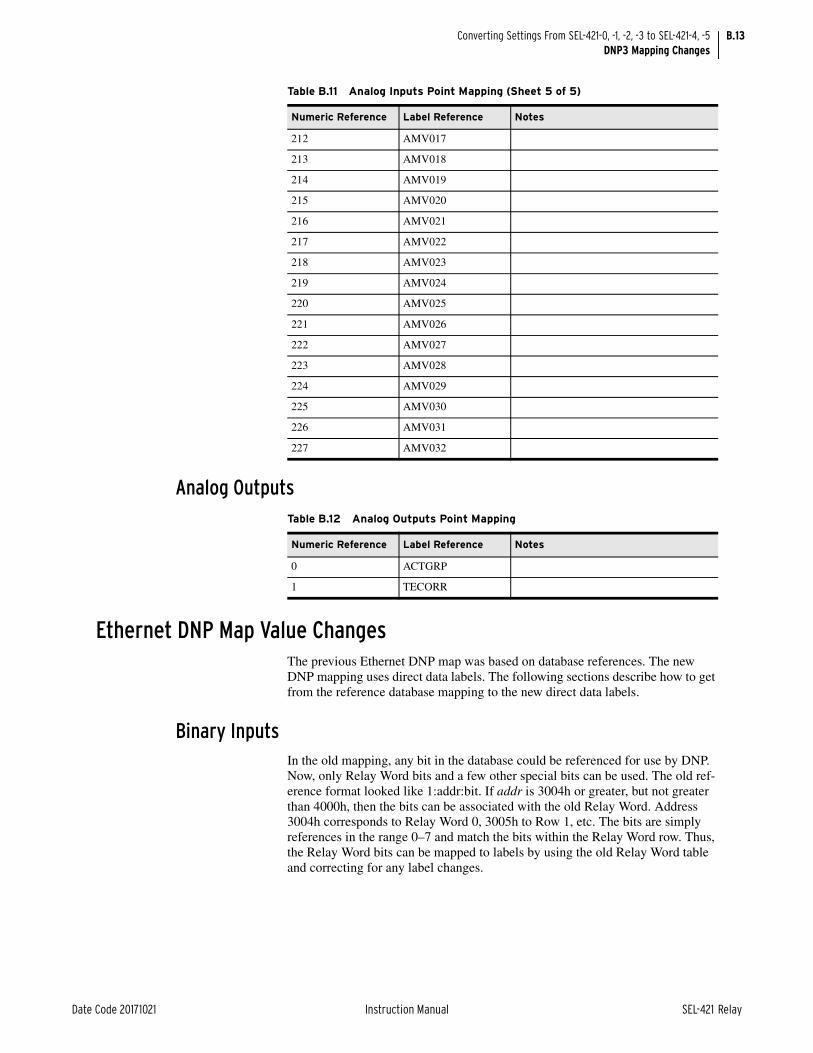
B.13
Date Code 20171021 Instruction Manual SEL-421 Relay
Converting Settings From SEL-421-0, -1, -2, -3 to SEL-421-4, -5DNP3 Mapping Changes
Analog Outputs
Ethernet DNP Map Value ChangesThe previous Ethernet DNP map was based on database references. The new DNP mapping uses direct data labels. The following sections describe how to get from the reference database mapping to the new direct data labels.
Binary InputsIn the old mapping, any bit in the database could be referenced for use by DNP. Now, only Relay Word bits and a few other special bits can be used. The old ref-erence format looked like 1:addr:bit. If addr is 3004h or greater, but not greater than 4000h, then the bits can be associated with the old Relay Word. Address 3004h corresponds to Relay Word 0, 3005h to Row 1, etc. The bits are simply references in the range 0–7 and match the bits within the Relay Word row. Thus, the Relay Word bits can be mapped to labels by using the old Relay Word table and correcting for any label changes.
212 AMV017
213 AMV018
214 AMV019
215 AMV020
216 AMV021
217 AMV022
218 AMV023
219 AMV024
220 AMV025
221 AMV026
222 AMV027
223 AMV028
224 AMV029
225 AMV030
226 AMV031
227 AMV032
Table B.11 Analog Inputs Point Mapping (Sheet 5 of 5)
Numeric Reference Label Reference Notes
Table B.12 Analog Outputs Point Mapping
Numeric Reference Label Reference Notes
0 ACTGRP
1 TECORR

B.14
SEL-421 Relay Instruction Manual Date Code 20171021
Converting Settings From SEL-421-0, -1, -2, -3 to SEL-421-4, -5DNP3 Mapping Changes
Binary OutputsIndexes 0–127 used to map the CCIN bits. These were general-purpose, high-speed bits, but they are no longer available. The end user will need to remap these to remote bits.
Table B.13 describes the mapping for the remaining bits.
Table B.13 Binary Outputs Mapping for DNP3 LAN/WAN (Sheet 1 of 2)
Numeric Reference Label Reference Notes
128 RB01
129 RB02
130 RB03
131 RB04
132 RB05
133 RB06
134 RB07
135 RB08
136 RB09
137 RB10
138 RB11
139 RB12
140 RB13
141 RB14
142 RB15
143 RB16
144 RB17
145 RB18
146 RB19
147 RB20
148 RB21
149 RB22
150 RB23
151 RB24
152 RB25
153 RB26
154 RB27
155 RB28
156 RB29
157 RB30
158 RB31
159 RB32
160 RB01:RB02
161 RB03:RB04
162 RB05:RB06

B.15
Date Code 20171021 Instruction Manual SEL-421 Relay
Converting Settings From SEL-421-0, -1, -2, -3 to SEL-421-4, -5DNP3 Mapping Changes
CountersIn the SEL-421-0, -1, -2, -3 counters were referenced as points in the database. None of these can be directly assigned to the counter values that are now avail-able.
Analog InputsIn the SEL-421-0, -1, -2, -3 analog inputs were referenced as points in the data-base with optional type qualifiers. It is impractical to define a mapping from these points to the data that is now available.
Analog OutputsIn the SEL-421-0, -1, -2, -3 analog outputs were referenced by index: 0–255. These mapped to remote analogs: RA001–RA256. In the SEL-421-4, -5 these same remote analogs are available. So, if previously, Index 0 was referenced, the new reference is RA001. Similarly, Index 1 goes to RA002, etc.
163 RB07:RB08
164 RB09:RB10
165 RB11:RB12
166 RB13:RB14
167 RB15:RB16
168 RB17:RB18
169 RB19:RB20
170 RB21:RB22
171 RB23:RB24
172 RB25:RB26
173 RB27:RB28
174 RB29:RB30
175 RB31:RB32
176 OC1:CC1
177 OC2:CC2
178 89OC01:89CC01
179 89OC02:89CC02
180 89OC03:89CC03
181 89OC04:89CC04
182 89OC05:89CC05
183 89OC06:89CC06
184 89OC07:89CC07
185 89OC08:89CC08
186 89OC09:89CC09
187 89OC10:89CC10
Table B.13 Binary Outputs Mapping for DNP3 LAN/WAN (Sheet 2 of 2)
Numeric Reference Label Reference Notes

B.16
SEL-421 Relay Instruction Manual Date Code 20171021
Converting Settings From SEL-421-0, -1, -2, -3 to SEL-421-4, -5IEC 61850 Object Changes
IEC 61850 Object ChangesThe SEL-421-0, -1, -2, -3 implementation of the IEC 61850 protocol suite differs slightly from the SEL-421-4, -5 implementation. Table B.14 lists the main func-tional changes between the two.
Default datasets may be used for MMS Reports or for GOOSE message transmis-sion. Table B.15 lists the default dataset changes in the new ICD file version. Note that the contents of any dataset may be modified via ACSELERATOR Archi-tect SEL-5032 Software.
Most of the Logical Nodes and Attributes remain the same between the two implementations. Table B.16 lists the mapping changes in the new ICD file.
Table B.14 IEC 61850 Functional Differences
Topic SEL-421-0, -1, -2, -3 SEL-421-4, -5
ICD File Version Version 001, 002 Version 003
Incoming GOOSE Mappable to CCIN001–CCIN128 (binary data)
VB001–VB256 (binary data) RA001–RA256 (analog data)
Outgoing GOOSE Relay Word bits mapped to CCOUT001 (binary data)
N/A (Relay Word bits can be sent directly without intermediate mapping; Analog outputs also available (RAO01–RAO64)
SER Time stamps SER-quality time stamps available only for LNs included in the SER dataset
Any points in the SER list will have SER-quality time stamps. Otherwise, accuracy is within 500 ms.
Controls Normal Security Only Enhanced Security and Select-before-operate (SBO) available
Table B.15 Default Dataset Differences
Default Dataset SEL-421-0, -1, -2, -3 SEL-421-4, -5
DSet03, DSet09 Includes LNs mapped from Relay Word Bits BK1A, BK1B, BK1C, BK2A, BK2B, BK2C
Includes LNs mapped from Relay Word Bits DC1–DC8
DSet13 CCOUT Status Control and Annunciation
Table B.16 Logical Node Mapping Differences (Sheet 1 of 2)
LD SEL-421-1, -2, -3 PathSEL-421-1, -2, -3 Mapping
SEL-421-4, -5 Path SEL-421-4, -5 Mapping
PRO BKR1PTRC2$ST$tr$general TRIP BKR1PTRC2$ST$tr$general Set (1) if TPA1 or TPB1 or TPC1 are set
PRO BKR2PTRC3$ST$tr$general TRIP BKR2PTRC3$ST$tr$general Set (1) if TPA2 or TPB2 or TPC2 are set
PRO BFR1RBRF1$ST$Str$general BFI3P1 BFR1RBRF1$ST$Str$general TRUE if (BFI3P1 OR BFIA1 OR BFIB1 OR BFIC1), FALSE oth-erwise
PRO BFR2RBRF2$ST$Str$general BFI3P2 BFR2RBRF2$ST$Str$general TRUE if (BFI3P2 OR BFIA2 OR BFIB2 OR BFIC2), FALSE oth-erwise
CON RBGGIO1$CO$SPCSO09 RB09 RBGGIO2$CO$SPCSO09 RB09
CON RBGGIO1$CO$SPCSO10 RB10 RBGGIO2$CO$SPCSO10 RB10
CON RBGGIO1$CO$SPCSO11 RB11 RBGGIO2$CO$SPCSO11 RB11

B.17
Date Code 20171021 Instruction Manual SEL-421 Relay
Converting Settings From SEL-421-0, -1, -2, -3 to SEL-421-4, -5IEC 61850 Object Changes
CON RBGGIO1$CO$SPCSO12 RB12 RBGGIO2$CO$SPCSO12 RB12
CON RBGGIO1$CO$SPCSO13 RB13 RBGGIO2$CO$SPCSO13 RB13
CON RBGGIO1$CO$SPCSO14 RB14 RBGGIO2$CO$SPCSO14 RB14
CON RBGGIO1$CO$SPCSO15 RB15 RBGGIO2$CO$SPCSO15 RB15
CON RBGGIO1$CO$SPCSO16 RB16 RBGGIO2$CO$SPCSO16 RB16
CON RBGGIO1$CO$SPCSO17 RB17 RBGGIO3$CO$SPCSO17 RB17
CON RBGGIO1$CO$SPCSO18 RB18 RBGGIO3$CO$SPCSO18 RB18
CON RBGGIO1$CO$SPCSO19 RB19 RBGGIO3$CO$SPCSO19 RB19
CON RBGGIO1$CO$SPCSO20 RB20 RBGGIO3$CO$SPCSO20 RB20
CON RBGGIO1$CO$SPCSO21 RB21 RBGGIO3$CO$SPCSO21 RB21
CON RBGGIO1$CO$SPCSO22 RB22 RBGGIO3$CO$SPCSO22 RB22
CON RBGGIO1$CO$SPCSO23 RB23 RBGGIO3$CO$SPCSO23 RB23
CON RBGGIO1$CO$SPCSO24 RB24 RBGGIO3$CO$SPCSO24 RB24
CON RBGGIO1$CO$SPCSO25 RB25 RBGGIO4$CO$SPCSO25 RB25
CON RBGGIO1$CO$SPCSO26 RB26 RBGGIO4$CO$SPCSO26 RB26
CON RBGGIO1$CO$SPCSO27 RB27 RBGGIO4$CO$SPCSO27 RB27
CON RBGGIO1$CO$SPCSO28 RB28 RBGGIO4$CO$SPCSO28 RB28
CON RBGGIO1$CO$SPCSO29 RB29 RBGGIO4$CO$SPCSO29 RB29
CON RBGGIO1$CO$SPCSO30 RB30 RBGGIO4$CO$SPCSO30 RB30
CON RBGGIO1$CO$SPCSO31 RB31 RBGGIO4$CO$SPCSO31 RB31
CON RBGGIO1$CO$SPCSO32 RB32 RBGGIO4$CO$SPCSO32 RB32
ANN CCINGGIO20$ST$Ind001–
CCINGGIO20$ST$Ind128
CCIN001–CCIN128 N/A
ANN CCOUTGGIO21$ST$Ind01–
CCOUTGGIO21$ST$Ind32
CCOUT01–CCOUT32 N/A
Table B.16 Logical Node Mapping Differences (Sheet 2 of 2)
LD SEL-421-1, -2, -3 PathSEL-421-1, -2, -3 Mapping
SEL-421-4, -5 Path SEL-421-4, -5 Mapping

This page intentionally left blank

Date Code 20171021 Instruction Manual SEL-421 Relay
Instruction ManualSEL-421-4, -5 Relay Command Summary
Commanda, b Description
2ACCESS Go to Access Level 2 (complete relay monitoring and control)
89CLOSE Close disconnect switch n (n = 1–10)
89OPEN Open disconnect switch n (n = 1–10)
AACCESS Go to Access Level A (automation configuration)
ACCESS Go to Access Level 1 (monitor relay)
BACCESS Go to Access Level B (monitor relay and control circuit breakers)
BNAME List ASCII names of Fast Meter status bits
BREAKER n Display the circuit breaker report and breaker history; preload and reset breaker monitor data (n = 1 is BK1; n = 2 is BK2)
CASCII Generate the Compressed ASCII response configuration message
CBREAKER Display Compressed ASCII breaker status report
CEVENT Display Compressed ASCII event report
CFG CTNOM i For TiDL relays, configure the nominal CT input value i to 1 or 5
CFG NFREQ f In TiDL relays, set the nominal frequency, f (50 or 60)
CHISTORY Display Compressed ASCII history report
CLOSE n Close the circuit breaker (n = 1 is BK1; n = 2 is BK2)
COM c Display relay-to-relay MIRRORED BITS communications or remote synchrophasor data (c = A is channel A; c = B is channel B; c = M is either enabled single channel)
COM RTC Display statistics for synchrophasor client channels
COM PTP Display a report on PTP data sets and statistics
CONTROL nn Set, clear, or pulse an internal remote bit (nn is the remote bit number from 01–32)
COPY m n Copy settings between instances in the same class (m and n are instance numbers; for example: m = 1 is Group 1; n = 2 is Group 2)
CPR Display Compressed ASCII signal profiling report
CSER Display Compressed ASCII sequential events report
CSTATUS Display Compressed ASCII relay status report
CSUMMARY Display Compressed ASCII summary event report
DATE Display and set the date
DNAME X List ASCII names of all relay digital points reported via Fast Meter
ETHERNET Display Ethernet port (Port 5) configuration and status
EVENT Display and acknowledge event reports
EXIT Terminate a Telnet session
FILE Transfer files between the relay and external software
GOOSE Display transmit and receive GOOSE messaging information
GROUP Display the active group number or select the active group
HELP List and describe available commands at each access level
HISTORY View event summaries/histories; clear event summary data
ID Display the firmware id, user id, device code, part number, and configuration information
LOOPBACK Connect MIRRORED BITS data from transmit to receive on the same port

2
SEL-421 Relay Instruction Manual Date Code 20171021
SEL-421-4, -5 Relay Command Summary
MAC Display the MAC addresses
MAP 1 View the relay database organization
METER Display metering data and internal relay operating variables
OACCESS Go to Access Level O (output configuration)
OPEN n Open the circuit breaker (n = 1 is BK1; n = 2 is BK2)
PACCESS Go to Access Level P (protection configuration)
PASSWORD n Change relay passwords for access level n
PING Send an ICMP echo request message to the provided IP address to confirm connectivity
PORT Connect to a remote relay via MIRRORED BITS virtual terminal (for port number p = 1–3, and F)
PROFILE Display signal profile records
PULSE OUTnnn Pulse a relay control output (OUTnnn is a control output)
QUIT Reduce access level to Access Level 0 (exit relay control)
RTC Display configuration of received remote synchrophasors
SER View Sequential Events Recorder report
SET Set or modify relay settings
SHOW Display relay settings
SNS Display Sequential Events Recorder settings name strings (Fast SER)
STATUS Report or clear relay status and SELOGIC control equation errors
SUMMARY Display a summary event report
TARGET Display relay elements for a row in the Relay Word table
TEC Display time-error estimate; display or modify time-error correction value
TEST DB Test interfaces to a virtual device database
TEST DB2 Test all communications protocols, except Fast Message
TEST FM Display or place values in metering database (Fast Meter)
TIME Display and set the internal clock
TIME Q Display detailed information on the relay internal clock
TRIGGER Initiate a data capture and record an event report
VERSION Display the relay hardware and software configurations
VIEW 1 View data from the Fast Message database
a See Section 9: ASCII Command Reference.b For help on a specific command, type HELP [command] <Enter> at an ASCII terminal communicating with the relay.
Commanda, b Description
Instruction Manual
*PM400-01-NB*
SEL-400 SeriesRelays
Instruction Manual
20171006

SEL-400 Series Relays Instruction Manual Date Code 20171006
© 2016–2017 by Schweitzer Engineering Laboratories, Inc. All rights reserved.
All brand or product names appearing in this document are the trademark or registered trademark of their respective holders. No SEL trademarks may be used without written permission. SEL products appearing in this document may be covered by U.S. and Foreign patents.
Schweitzer Engineering Laboratories, Inc. reserves all rights and benefits afforded under federal and international copyright and patent laws in its products, including without limitation software, firmware, and documentation.
The information in this document is provided for informational use only and is subject to change without notice. Schweitzer Engineering Laboratories, Inc. has approved only the English language document.
This product is covered by the standard SEL 10-year warranty. For warranty details, visit selinc.com or contact your customer service representative. PM400-01

Date Code 20171006 Instruction Manual SEL-400 Series Relays
SEL-400 Series RelaysInstruction Manual Table of Contents
List of Tables................................................................................................................................................................................v
List of Figures ......................................................................................................................................................................... xiii
Preface .........................................................................................................................................................................................xxi
Manual Overview ................................................................................................................................................ xxiSafety Information ............................................................................................................................................ xxiiiGeneral Information............................................................................................................................................ xxv
Section 1: IntroductionCommon Features .................................................................................................................................................1.1
Section 2: PC SoftwareQuickSet Setup .....................................................................................................................................................2.1Settings Database Management and Drivers ........................................................................................................2.4QuickSet Main Menu............................................................................................................................................2.8Create and Manage Relay Settings .......................................................................................................................2.9QuickSet HMI.....................................................................................................................................................2.19Analyze Events ...................................................................................................................................................2.22QuickSet Help.....................................................................................................................................................2.32
Section 3: Basic Relay OperationsInspecting a New Relay ........................................................................................................................................3.1Establishing Communication................................................................................................................................3.3Access Levels and Passwords ...............................................................................................................................3.7Checking Relay Status ........................................................................................................................................3.11Making Simple Settings Changes .......................................................................................................................3.15Examining Metering Quantities..........................................................................................................................3.35Examining Relay Elements.................................................................................................................................3.43Reading Oscillograms, Event Reports, and SER ................................................................................................3.48Operating the Relay Inputs and Outputs.............................................................................................................3.61Configuring Timekeeping ...................................................................................................................................3.75Readying the Relay for Field Application ..........................................................................................................3.77
Section 4: Front-Panel OperationsFront-Panel Layout ...............................................................................................................................................4.1Front-Panel Menus and Screens..........................................................................................................................4.14Front-Panel Automatic Messages .......................................................................................................................4.31Operation and Target LEDs ................................................................................................................................4.33Front-Panel Operator Control Pushbuttons.........................................................................................................4.34
Section 5: ControlCircuit Breaker Status and Control .......................................................................................................................5.1Disconnect Logic ..................................................................................................................................................5.1Remote Bits.........................................................................................................................................................5.11Bay Control Front-Panel Operations ..................................................................................................................5.12QuickSet Bay Control Screens ...........................................................................................................................5.27Customizable Screens .........................................................................................................................................5.34Bay Control Example Application......................................................................................................................5.35
Section 6: AutoreclosingAutoreclosing States .............................................................................................................................................6.2One-Circuit-Breaker Autoreclosing......................................................................................................................6.4Two-Circuit-Breaker Autoreclosing ...................................................................................................................6.10

ii
SEL-400 Series Relays Instruction Manual Date Code 20171006
Table of Contents
Autoreclose Logic Diagrams ..............................................................................................................................6.26Manual Closing...................................................................................................................................................6.40Voltage Checks for Autoreclosing and Manual Closing.....................................................................................6.43Settings and Relay Word Bits for Autoreclosing and Manual Closing ..............................................................6.45
Section 7: MeteringInstantaneous Metering.........................................................................................................................................7.2Maximum/Minimum Metering .............................................................................................................................7.5Demand Metering .................................................................................................................................................7.6Energy Metering .................................................................................................................................................7.10Synchrophasor Metering.....................................................................................................................................7.10Battery Metering .................................................................................................................................................7.11RTD Metering .....................................................................................................................................................7.12Protection Math Variable Metering.....................................................................................................................7.12Automation Math Variable Metering ..................................................................................................................7.13MIRRORED BITS Remote Analog Metering.........................................................................................................7.13
Section 8: MonitoringCircuit Breaker Monitor........................................................................................................................................8.1Station DC Battery System Monitor ...................................................................................................................8.21
Section 9: ReportingData Processing.....................................................................................................................................................9.1Triggering Data Captures and Event Reports .......................................................................................................9.6Duration of Data Captures and Event Reports......................................................................................................9.7Oscillography........................................................................................................................................................9.9Event Reports, Event Summaries, and Event Histories ......................................................................................9.13Sequential Events Recorder (SER) .....................................................................................................................9.28Signal Profiling ...................................................................................................................................................9.31
Section 10: Testing, Troubleshooting, and MaintenanceTesting Philosophy..............................................................................................................................................10.1Testing Features and Tools..................................................................................................................................10.5Test Methods .......................................................................................................................................................10.7Relay Self-Tests ................................................................................................................................................10.15Relay Troubleshooting......................................................................................................................................10.18Maintenance......................................................................................................................................................10.22TiDL Module Replacement ..............................................................................................................................10.30Technical Support .............................................................................................................................................10.31
Section 11: Time and Date ManagementIRIG-B Timekeeping ..........................................................................................................................................11.1PTP Timekeeping................................................................................................................................................11.2Time Source Selection ........................................................................................................................................11.4Time Quality Indications ....................................................................................................................................11.5Time-Synchronized Events .................................................................................................................................11.9
Section 12: SettingsSettings Structure ................................................................................................................................................12.1Multiple Setting Groups......................................................................................................................................12.4Port Settings ........................................................................................................................................................12.6DNP3 Settings—Custom Maps ........................................................................................................................12.15Front-Panel Settings..........................................................................................................................................12.15Alias Settings ....................................................................................................................................................12.20Protection Freeform SELOGIC Control Equations ............................................................................................12.21Automation Freeform SELOGIC Control Equations .........................................................................................12.21Output Settings .................................................................................................................................................12.22Report Settings..................................................................................................................................................12.23Notes Settings ...................................................................................................................................................12.24

iii
Date Code 20171006 Instruction Manual SEL-400 Series Relays
Table of Contents
Section 13: SELOGIC Control Equation ProgrammingSeparation of Protection and Automation Areas ................................................................................................13.1SELOGIC Control Equation Setting Structure.....................................................................................................13.2SELOGIC Control Equation Capacity..................................................................................................................13.5SELOGIC Control Equation Programming..........................................................................................................13.6SELOGIC Control Equation Elements .................................................................................................................13.9SELOGIC Control Equation Operators ..............................................................................................................13.24Effective Programming .....................................................................................................................................13.34SEL-311 and SEL-351 Series Users .................................................................................................................13.36
Section 14: ASCII Command ReferenceCommand Description ........................................................................................................................................14.1
Section 15: Communications InterfacesSerial Communication ........................................................................................................................................15.2Serial Port Hardware Protocol ............................................................................................................................15.5Ethernet Communications...................................................................................................................................15.6Virtual File Interface .........................................................................................................................................15.18Software Protocol Selections ............................................................................................................................15.22SEL Protocol.....................................................................................................................................................15.23SEL MIRRORED BITS Communication..............................................................................................................15.31SEL Distributed Port Switch Protocol (LMD)..................................................................................................15.37SEL-2600A RTD Module Operation ................................................................................................................15.39Direct Networking Example .............................................................................................................................15.40
Section 16: DNP3 CommunicationIntroduction to DNP3..........................................................................................................................................16.1DNP3 in the Relay ..............................................................................................................................................16.7DNP3 Documentation.......................................................................................................................................16.12DNP3 Serial Application Example ...................................................................................................................16.26DNP3 LAN/WAN Application Example ..........................................................................................................16.31
Section 17: IEC 61850 CommunicationIntroduction to IEC 61850 ..................................................................................................................................17.2IEC 61850 Operation ..........................................................................................................................................17.3Sampled Values.................................................................................................................................................17.15Simulation Mode...............................................................................................................................................17.21IEC 61850 Configuration..................................................................................................................................17.22Logical Nodes ...................................................................................................................................................17.29Protocol Implementation Conformance Statement...........................................................................................17.44ACSI Conformance Statements ........................................................................................................................17.50Potential Client and Automation Application Issues With Edition 2 Upgrades ...............................................17.54
Section 18: SynchrophasorsIntroduction.........................................................................................................................................................18.1Synchrophasor Measurement..............................................................................................................................18.3Settings for Synchrophasors ...............................................................................................................................18.6Synchrophasor Quantities .................................................................................................................................18.18View Synchrophasors by Using the MET PM Command ................................................................................18.21C37.118 Synchrophasor Protocol .....................................................................................................................18.23SEL Fast Message Synchrophasor Protocol .....................................................................................................18.29Control Capabilities ..........................................................................................................................................18.33PMU Recording Capabilities ............................................................................................................................18.42
Section 19: Remote Data AcquisitionTime-Domain Link (TiDL) .................................................................................................................................19.1IEC 61850-9-2 Sampled Values (SV) .................................................................................................................19.5
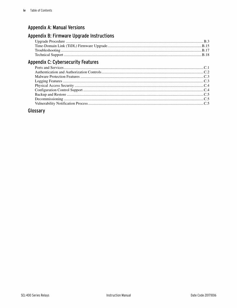
iv
SEL-400 Series Relays Instruction Manual Date Code 20171006
Table of Contents
Appendix A: Manual Versions
Appendix B: Firmware Upgrade InstructionsUpgrade Procedure ..............................................................................................................................................B.3Time-Domain Link (TiDL) Firmware Upgrade.................................................................................................B.15Troubleshooting .................................................................................................................................................B.17Technical Support ..............................................................................................................................................B.18
Appendix C: Cybersecurity FeaturesPorts and Services ................................................................................................................................................C.1Authentication and Authorization Controls .........................................................................................................C.2Malware Protection Features ...............................................................................................................................C.3Logging Features .................................................................................................................................................C.3Physical Access Security .....................................................................................................................................C.4Configuration Control Support ............................................................................................................................C.4Backup and Restore .............................................................................................................................................C.5Decommissioning ................................................................................................................................................C.5Vulnerability Notification Process .......................................................................................................................C.5
Glossary

Date Code 20171006 Instruction Manual SEL-400 Series Relays
SEL-400 Series RelaysInstruction Manual List of Tables
Table 2.1 QuickSet Submenu Options.........................................................................................................2.8Table 2.2 QuickSet HMI Tree View Functions.........................................................................................2.19Table 2.3 Accessing QuickSet Help ..........................................................................................................2.32Table 3.1 General Serial Port Settings.........................................................................................................3.4Table 3.2 SEL-400 Series Relay Access Levels..........................................................................................3.8Table 3.3 Access Level Commands and Passwords ....................................................................................3.8Table 3.4 SEL-451 Settings Classes and Instances ...................................................................................3.16Table 3.5 Actions at Settings Prompts.......................................................................................................3.20Table 3.6 Actions at Text-Edit Mode Prompts ..........................................................................................3.22Table 3.7 Phase Instantaneous Overcurrent Pickup...................................................................................3.44Table 3.8 Control Input Characteristics.....................................................................................................3.70Table 3.9 Communications Port Commands That Clear Relay Buffers....................................................3.78Table 4.1 Front-Panel Inactivity Time-Out Setting .....................................................................................4.4Table 4.2 SER Point Settings.......................................................................................................................4.8Table 4.3 Display Point Settings—Boolean ..............................................................................................4.11Table 4.4 Display Point Settings—Analog................................................................................................4.11Table 4.5 Display Point Settings—Boolean and Analog Examples................................................................4.11Table 4.6 Front-Panel Pushbutton Functions While Viewing SER Events...............................................4.18Table 4.7 Local Bit Control Settings .........................................................................................................4.23Table 4.8 Local Bit SELOGIC ....................................................................................................................4.24Table 4.9 Settings Available From the Front Panel...................................................................................4.25Table 5.1 Circuit Breaker and Disconnect Switch Definitions..................................................................5.14Table 5.2 Circuit Breaker State Representations .......................................................................................5.15Table 5.3 Disconnect Switch State Representations..................................................................................5.15Table 5.4 Three-Position Disconnect Switch State Representations.........................................................5.24Table 5.5 Three-Position Disconnect Switch Control Screen Status and Control Options.......................5.26Table 5.6 Application Example Bay Control Settings for Bus 1, Bus 2, and Transfer Bus Bay With
Ground Switch Application......................................................................................................5.41Table 5.7 Application Example Front-Panel Settings ...............................................................................5.42Table 5.8 Application Example Output Settings, Output SELOGIC Control Equations ...................................5.43Table 6.1 Autoreclose Logical States for Circuit Breaker 1........................................................................6.4Table 6.2 One-Circuit-Breaker Three-Pole Reclosing Initial Settings ........................................................6.8Table 6.3 One-Circuit-Breaker Single-Pole Reclose Initial Settings ..........................................................6.8Table 6.4 One Circuit Breaker Modes of Operation....................................................................................6.9Table 6.5 Dynamic Leader/Follower Settings ...........................................................................................6.16Table 6.6 Leader/Follower Selection.........................................................................................................6.18Table 6.7 Example One: Reset and 79CY3 States ....................................................................................6.18Table 6.8 Example One: Lockout State .....................................................................................................6.18Table 6.9 Example One: Reset State After Reclaim Time ........................................................................6.19Table 6.10 Leader/Follower Selection.........................................................................................................6.19Table 6.11 Example Two: Initial Reset State ..............................................................................................6.19Table 6.12 Example Two: Final Reset State ...............................................................................................6.20Table 6.13 Leader/Follower Selection.........................................................................................................6.20Table 6.14 Example Three: Reset State.......................................................................................................6.20Table 6.15 Example Three: Three-Pole Cycle State....................................................................................6.21Table 6.16 Example Three: Lockout State, BK...........................................................................................6.21Table 6.17 Leader/Follower Selection.........................................................................................................6.22Table 6.18 Two Circuit Breakers: Circuit Breaker BK1 Out of Service............................................................6.22Table 6.19 Two-Circuit-Breaker Three-Pole Reclose Initial Settings.........................................................6.23Table 6.20 Two-Circuit-Breaker Single-Pole Reclose Initial Settings...............................................................6.23Table 6.21 Circuit Breaker BK1 Modes of Operation.................................................................................6.23Table 6.22 Circuit Breaker BK2 Modes of Operation.................................................................................6.24Table 6.23 Trip Logic Enable Options ........................................................................................................6.25

vi
SEL-400 Series Relays Instruction Manual Date Code 20171006
List of Tables
Table 6.24 Autoreclose Logic Relay Word Bits..........................................................................................6.45Table 7.1 MET Command ...........................................................................................................................7.1Table 7.2 Instantaneous Metering Accuracy—Voltages, Currents, and Frequency ............................................7.3Table 7.3 Instantaneous Metering Accuracy—Power .................................................................................7.4Table 7.4 Rolling Demand Calculations......................................................................................................7.7Table 7.5 Information Available With the MET ANA Command............................................................7.13Table 8.1 Circuit Breaker Monitor Configuration .......................................................................................8.2Table 8.2 Circuit Breaker Maintenance Information—Example.................................................................8.3Table 8.3 Contact Wear Monitor Settings—Circuit Breaker 1 ...................................................................8.4Table 8.4 Circuit Breaker Monitor Initiate SELOGIC Control Equations ....................................................8.7Table 8.5 Circuit Breaker Monitor Close SELOGIC Control Equations ......................................................8.9Table 8.6 BRE Command..........................................................................................................................8.18Table 8.7 DC Monitor Settings and Relay Word Bit Alarms....................................................................8.22Table 8.8 Example DC Battery Voltage Conditions .................................................................................8.23Table 8.9 Example DC Battery Monitor Settings—125 Vdc for Vdc1 and 48 Vdc for Vdc2 ..................8.23Table 8.10 Example DC Battery Monitor Settings—AC Ripple Voltages .................................................8.24Table 8.11 Example DC Battery Monitor Settings—Ground Detection Factor (EGADVS := Y)..............8.25Table 9.1 Report Settings ............................................................................................................................9.8Table 9.2 SUM Command.........................................................................................................................9.26Table 9.3 HIS Command ...........................................................................................................................9.28Table 9.4 SER Commands.........................................................................................................................9.30Table 10.1 Acceptance Testing....................................................................................................................10.2Table 10.2 Commissioning Testing.............................................................................................................10.2Table 10.3 Maintenance Testing..................................................................................................................10.4Table 10.4 Selectable Operating Quantity Time-Overcurrent Element (51S1) Test Settings...................10.10Table 10.5 Alarm Relay Word Bits ...........................................................................................................10.15Table 10.6 Troubleshooting Procedures ....................................................................................................10.19Table 10.7 Troubleshooting for Relay Self-Test Warnings and Failures ..................................................10.20Table 11.1 Relay Timekeeping Modes ........................................................................................................11.2Table 11.2 CUR_SRC Encoding .................................................................................................................11.5Table 11.3 Time Quality Encoding (PTP Default Profile or IRIG) ............................................................11.5Table 11.4 Time Quality Encoding (PTP Power Profile)............................................................................11.6Table 11.5 Date/Time Last Update Sources ................................................................................................11.8Table 11.6 SEL-421 Voltage and Current Measurement ..........................................................................11.12Table 12.1 Typical Settings Classes and Instances .....................................................................................12.2Table 12.2 Definitions for Active Setting Group Indication Relay Word Bits SG1 Through SG6 ............12.4Table 12.3 Definitions for Active Setting Group Switching SELOGIC Control Equation Settings SS1
Through SS6.............................................................................................................................12.5Table 12.4 Port Settings Categories.............................................................................................................12.6Table 12.5 Protocol Selection......................................................................................................................12.7Table 12.6 Communications Settings ..........................................................................................................12.7Table 12.7 SEL Protocol Settings................................................................................................................12.7Table 12.8 Fast Message Read Data Access................................................................................................12.7Table 12.9 IP Configuration ........................................................................................................................12.8Table 12.10 FTP Configuration .....................................................................................................................12.8Table 12.11 HTTP Server Configuration ......................................................................................................12.9Table 12.12 Telnet Settings ...........................................................................................................................12.9Table 12.13 IEC 61850 Configuration ..........................................................................................................12.9Table 12.14 SV Receiver Configuration .......................................................................................................12.9Table 12.15 SV Transmitter Configuration ...................................................................................................12.9Table 12.16 DNP3 Serial Protocol Settings ................................................................................................12.10Table 12.17 DNP3 LAN/WAN Settings .....................................................................................................12.11Table 12.18 Phasor Measurement Configuration ........................................................................................12.12Table 12.19 MIRRORED BITS Protocol Settings...........................................................................................12.12Table 12.20 RTD Protocol Settings.............................................................................................................12.13Table 12.21 PMU Protocol Settings ............................................................................................................12.14Table 12.22 Simple Network Time Protocol (SNTP) Selection..................................................................12.14Table 12.23 PTP Settings ............................................................................................................................12.14

vii
Date Code 20171006 Instruction Manual SEL-400 Series Relays
List of Tables
Table 12.24 DNP3 Settings Categories .......................................................................................................12.15Table 12.25 Minimum and Maximum Fault Location ................................................................................12.15Table 12.26 DNP3 Map Category Headers .................................................................................................12.15Table 12.27 Front-Panel Settings Categories ..............................................................................................12.15Table 12.28 Front-Panel Settings ................................................................................................................12.16Table 12.29 Selectable Screens for the Front Panel ....................................................................................12.18Table 12.30 Selectable Operator Pushbuttons .............................................................................................12.19Table 12.31 Front-Panel Event Display.......................................................................................................12.19Table 12.32 Local Bit SELOGIC ..................................................................................................................12.20Table 12.33 SER Parameters .......................................................................................................................12.20Table 12.34 Output Settings Categories ......................................................................................................12.22Table 12.35 Remote Analog Outputs ..........................................................................................................12.22Table 12.36 MIRRORED BITS Transmit Equations.......................................................................................12.22Table 12.37 87L Communications Bits .......................................................................................................12.23Table 12.38 Report Settings Categories ......................................................................................................12.23Table 12.39 SER Chatter Criteria ................................................................................................................12.23Table 12.40 Signal Profile ...........................................................................................................................12.24Table 12.41 Event Reporting .......................................................................................................................12.24Table 13.1 Summary of SELOGIC Control Equation Elements ...................................................................13.9Table 13.2 First Execution Bit Operation on Power-Up ...........................................................................13.10Table 13.3 First Execution Bit Operation on Automation Settings Change..............................................13.10Table 13.4 First Execution Bit Operation on Protection Settings Change, Group Switch, and Source
Selection .................................................................................................................................13.10Table 13.5 SELOGIC Control Equation Boolean Variable Quantities .......................................................13.10Table 13.6 SELOGIC Control Equation Math Variable Quantities ............................................................13.11Table 13.7 Latch Bit Quantities.................................................................................................................13.12Table 13.8 Latch Bit Parameters ...............................................................................................................13.13Table 13.9 Conditioning Timer Quantities ................................................................................................13.16Table 13.10 Conditioning Timer Parameters...............................................................................................13.16Table 13.11 Sequencing Timer Quantities ..................................................................................................13.19Table 13.12 Sequencing Timer Parameters .................................................................................................13.20Table 13.13 Counter Quantities ...................................................................................................................13.22Table 13.14 Counter Parameters..................................................................................................................13.22Table 13.15 Operator Precedence From Highest to Lowest........................................................................13.24Table 13.16 Boolean Operator Summary ....................................................................................................13.25Table 13.17 Parentheses Operation in Boolean Equation ...........................................................................13.25Table 13.18 NOT Operator Truth Table......................................................................................................13.26Table 13.19 AND Operator Truth Table .....................................................................................................13.26Table 13.20 OR Operator Truth Table ........................................................................................................13.26Table 13.21 Comparison Operations ...........................................................................................................13.28Table 13.22 Math Operator Summary .........................................................................................................13.29Table 13.23 Math Error Examples...............................................................................................................13.30Table 13.24 SEL-351 Series Relays and SEL-400 Series SELOGIC Control Equation Programming
Equivalent Functions ..............................................................................................................13.37Table 13.25 SEL-400 Series SELOGIC Control Equation Programming Summary....................................13.37Table 13.26 SEL-351 Series Relays and SEL-400 Series SELOGIC Control Equation Boolean
Operators ................................................................................................................................13.37Table 14.1 2AC Command ..........................................................................................................................14.1Table 14.2 89CLOSE n Command..............................................................................................................14.2Table 14.3 89OPEN n Command ................................................................................................................14.3Table 14.4 AAC Command .........................................................................................................................14.3Table 14.5 ACC Command .........................................................................................................................14.3Table 14.6 BAC Command .........................................................................................................................14.3Table 14.7 BNA Command .........................................................................................................................14.4Table 14.8 BRE n Command.......................................................................................................................14.4Table 14.9 BRE n C and BRE n R Commands ...........................................................................................14.4Table 14.10 BRE C A and BRE R A Commands..........................................................................................14.5Table 14.11 BRE n H Command...................................................................................................................14.5

viii
SEL-400 Series Relays Instruction Manual Date Code 20171006
List of Tables
Table 14.12 BRE n P Command....................................................................................................................14.5Table 14.13 CAL Command..........................................................................................................................14.5Table 14.14 CAS Command..........................................................................................................................14.5Table 14.15 CBR Command..........................................................................................................................14.6Table 14.16 CBR TERSE Command ............................................................................................................14.6Table 14.17 CEV Command..........................................................................................................................14.7Table 14.18 CEV ACK Command ................................................................................................................14.7Table 14.19 CEV C Command......................................................................................................................14.7Table 14.20 CEV L Command ......................................................................................................................14.7Table 14.21 CEV Lyyy Command.................................................................................................................14.8Table 14.22 CEV N Command......................................................................................................................14.8Table 14.23 CEV NSET Command...............................................................................................................14.8Table 14.24 CEV NSUM Command .............................................................................................................14.9Table 14.25 CEV Sx Command.....................................................................................................................14.9Table 14.26 CEV TERSE Command ............................................................................................................14.9Table 14.27 CEV Command Option Groups...............................................................................................14.10Table 14.28 CFG CTNOM Command ........................................................................................................14.10Table 14.29 CFG NFREQ Command..........................................................................................................14.11Table 14.30 CHI Command.........................................................................................................................14.11Table 14.31 CHI TERSE Command ...........................................................................................................14.11Table 14.32 CLOSE n Command................................................................................................................14.12Table 14.33 COM c Command....................................................................................................................14.12Table 14.34 COM c C and COM c R Command.........................................................................................14.13Table 14.35 COM c L Command ................................................................................................................14.13Table 14.36 COM PTP Command...............................................................................................................14.14Table 14.37 COM RTC Command..............................................................................................................14.16Table 14.38 COM RTC c C and COM RTC c R Command .......................................................................14.16Table 14.39 CON nn Command ..................................................................................................................14.16Table 14.40 COPY Command.....................................................................................................................14.17Table 14.41 CPR Command ........................................................................................................................14.17Table 14.42 CSE Command ........................................................................................................................14.18Table 14.43 CSE TERSE Command ...........................................................................................................14.19Table 14.44 CST Command ........................................................................................................................14.19Table 14.45 CSU Command........................................................................................................................14.20Table 14.46 CEV ACK Command ..............................................................................................................14.20Table 14.47 CSU MB Command.................................................................................................................14.20Table 14.48 CSU N Command....................................................................................................................14.20Table 14.49 CSU TERSE Command...........................................................................................................14.21Table 14.50 DATE Command.....................................................................................................................14.21Table 14.51 DNA Command.......................................................................................................................14.21Table 14.52 DNP Command........................................................................................................................14.22Table 14.53 ETH Command........................................................................................................................14.22Table 14.54 ETH C and ETH R Command.................................................................................................14.23Table 14.55 EVE Command........................................................................................................................14.23Table 14.56 EVE A Command....................................................................................................................14.24Table 14.57 EVE ACK Command ..............................................................................................................14.24Table 14.58 EVE C Command ....................................................................................................................14.24Table 14.59 EVE D Command....................................................................................................................14.24Table 14.60 EVE L Command ....................................................................................................................14.25Table 14.61 EVE Lyyy Command ...............................................................................................................14.25Table 14.62 EVE N Command....................................................................................................................14.25Table 14.63 EVE NSET Command.............................................................................................................14.25Table 14.64 EVE NSUM Command ...........................................................................................................14.26Table 14.65 EVE Sx Command...................................................................................................................14.26Table 14.66 EVE Command Option Groups ...............................................................................................14.26Table 14.67 EVE Command Examples .......................................................................................................14.27Table 14.68 EXIT Command ......................................................................................................................14.27Table 14.69 FILE Command .......................................................................................................................14.27

ix
Date Code 20171006 Instruction Manual SEL-400 Series Relays
List of Tables
Table 14.70 GOOSE Command ..................................................................................................................14.28Table 14.71 Accessible GOOSE IED Information......................................................................................14.28Table 14.72 GOO S Command....................................................................................................................14.29Table 14.73 GROUP Command ..................................................................................................................14.31Table 14.74 HELP Command......................................................................................................................14.32Table 14.75 HIS Command .........................................................................................................................14.32Table 14.76 HIS C and HIS R Commands ..................................................................................................14.32Table 14.77 HIS CA and HIS RA Commands ............................................................................................14.33Table 14.78 ID Command ...........................................................................................................................14.33Table 14.79 IRIG Command .......................................................................................................................14.34Table 14.80 LOOP Command .....................................................................................................................14.35Table 14.81 LOOP DATA Command .........................................................................................................14.36Table 14.82 LOOP R Command .................................................................................................................14.36Table 14.83 MAC Command ......................................................................................................................14.36Table 14.84 MAP 1 Command....................................................................................................................14.37Table 14.85 MAP 1 region Command.........................................................................................................14.37Table 14.86 MET AMV Command.............................................................................................................14.38Table 14.87 MET ANA Command .............................................................................................................14.38Table 14.88 MET BAT Command ..............................................................................................................14.38Table 14.89 MET D Command ...................................................................................................................14.39Table 14.90 MET M Command...................................................................................................................14.39Table 14.91 MET PM Command ................................................................................................................14.39Table 14.92 MET PMV Command .............................................................................................................14.40Table 14.93 MET RTC Command ..............................................................................................................14.41Table 14.94 MET T Command....................................................................................................................14.41Table 14.95 OAC Command .......................................................................................................................14.41Table 14.96 OPEN n Command ..................................................................................................................14.42Table 14.97 PAC Command........................................................................................................................14.42Table 14.98 PAS level New_Password Command......................................................................................14.42Table 14.99 PAS level DISABLE Command..............................................................................................14.43Table 14.100 PING Command ......................................................................................................................14.43Table 14.101 PORT p Command ..................................................................................................................14.44Table 14.102 PORT KILL n Command ........................................................................................................14.44Table 14.103 PRO Command........................................................................................................................14.45Table 14.104 PUL OUTnnn Command.........................................................................................................14.45Table 14.105 QUIT Command ......................................................................................................................14.46Table 14.106 RTC Command........................................................................................................................14.46Table 14.107 SER Command ........................................................................................................................14.47Table 14.108 SER C and SER R Commands ................................................................................................14.47Table 14.109 SER CA and SER RA Commands ..........................................................................................14.47Table 14.110 SER CV or SER RV Commands .............................................................................................14.48Table 14.111 SER D Command ....................................................................................................................14.48Table 14.112 SET Command Overview........................................................................................................14.49Table 14.113 SET TERSE Command Examples ..........................................................................................14.49Table 14.114 SHO Command Overview.......................................................................................................14.50Table 14.115 SNS Command ........................................................................................................................14.50Table 14.116 STA Command ........................................................................................................................14.51Table 14.117 STA A Command ....................................................................................................................14.51Table 14.118 STA C and STA R Command .................................................................................................14.51Table 14.119 STA S Command.....................................................................................................................14.51Table 14.120 STA SC and STA SR Command.............................................................................................14.52Table 14.121 SUM Command.......................................................................................................................14.52Table 14.122 SUM ACK Command .............................................................................................................14.52Table 14.123 SUM N Command ...................................................................................................................14.53Table 14.124 TAR Command........................................................................................................................14.53Table 14.125 TAR ALL Command...............................................................................................................14.53Table 14.126 TAR R Command....................................................................................................................14.54Table 14.127 TAR X Command....................................................................................................................14.54

x
SEL-400 Series Relays Instruction Manual Date Code 20171006
List of Tables
Table 14.128 TEC Command ........................................................................................................................14.54Table 14.129 TEST DB Command ...............................................................................................................14.55Table 14.130 TEST DB OFF Command .......................................................................................................14.56Table 14.131 TEST DB2 Command .............................................................................................................14.56Table 14.132 TEST DB2 OFF Command .....................................................................................................14.57Table 14.133 TEST FM Command ...............................................................................................................14.57Table 14.134 TEST FM DEM Command .....................................................................................................14.58Table 14.135 TEST FM OFF Command.......................................................................................................14.58Table 14.136 TEST FM PEAK Command....................................................................................................14.58Table 14.137 TIME Command......................................................................................................................14.59Table 14.138 TIME Q Command..................................................................................................................14.59Table 14.139 TIME DST Command .............................................................................................................14.60Table 14.140 TRI Command .........................................................................................................................14.61Table 14.141 VEC Command........................................................................................................................14.61Table 14.142 VER Command........................................................................................................................14.61Table 14.143 VIEW 1 Commands—Region .................................................................................................14.63Table 14.144 VIEW 1 Commands—Register Item.......................................................................................14.63Table 14.145 VIEW 1 Commands—Bit........................................................................................................14.64Table 15.1 Relay Communications Protocols .............................................................................................15.1Table 15.2 EIA-232 Pin Assignments .........................................................................................................15.3Table 15.3 Hardware Handshaking .............................................................................................................15.5Table 15.4 Ethernet Card Network Configuration Settings.........................................................................15.7Table 15.5 CIDR Notation...........................................................................................................................15.8Table 15.6 DEFRTR Address Setting Examples.........................................................................................15.9Table 15.7 FTP Settings ............................................................................................................................15.12Table 15.8 Telnet Settings .........................................................................................................................15.13Table 15.9 Settings Associated With SNTP ..............................................................................................15.14Table 15.10 Web Server Settings ................................................................................................................15.18Table 15.11 Virtual File Structure ...............................................................................................................15.18Table 15.12 Typical Settings Directory Files ..............................................................................................15.20Table 15.13 REPORTS Directory Files.......................................................................................................15.21Table 15.14 EVENTS Directory Files (for Event 10001) ...........................................................................15.21Table 15.15 SYNCHROPHASORS Directory File Sample........................................................................15.22Table 15.16 Supported Serial Command Sets .............................................................................................15.22Table 15.17 Selected ASCII Control Characters .........................................................................................15.24Table 15.18 Typical Compressed ASCII Commands..................................................................................15.25Table 15.19 Fast Commands and Response Descriptions ...........................................................................15.28Table 15.20 Fast Operate Command Types ................................................................................................15.29Table 15.21 Fast Message Command Function Codes Used With Fast Messages (A546 Message)
and Relay Response Descriptions ..........................................................................................15.29Table 15.22 Commands in Recommended Sequence for Automatic Configuration...................................15.30Table 15.23 MIRRORED BITS Communications Features ............................................................................15.31Table 15.24 General Port Settings Used With MIRRORED BITS Communications .....................................15.35Table 15.25 MIRRORED BITS Communications Protocol Settings ..............................................................15.36Table 15.26 MIRRORED BITS Communications Message Transmission Period..........................................15.37Table 15.27 MIRRORED BITS Communications ID Settings for Three-Terminal Application....................15.37Table 15.28 SEL-2885 Initialization String [MODE PREFIX ADDR:SPEED].........................................15.38Table 15.29 RTD Status Bits .......................................................................................................................15.39Table 15.30 MET T Command Status Messages ........................................................................................15.40Table 15.31 SEL-421 PORT 5 Direct Networking Settings........................................................................15.42Table 16.1 DNP3 Implementation Levels ...................................................................................................16.1Table 16.2 Selected DNP3 Function Codes ................................................................................................16.2Table 16.3 DNP3 Access Methods ..............................................................................................................16.4Table 16.4 TCP/UDP Selection Guidelines.................................................................................................16.7Table 16.5 Relay DNP3 Feature Summary .................................................................................................16.7Table 16.6 DNP3 Access Methods ..............................................................................................................16.8Table 16.7 Relay Event Buffer Capacity .....................................................................................................16.9Table 16.8 Relay DNP3 Object List ..........................................................................................................16.12

xi
Date Code 20171006 Instruction Manual SEL-400 Series Relays
List of Tables
Table 16.9 Relay DNP3 Reference Data Map...........................................................................................16.18Table 16.10 Sample Custom DNP3 Analog Input Map ..............................................................................16.25Table 16.11 DNP3 Application Example Data Map ...................................................................................16.27Table 16.12 SEL-421 Port 3 Example Settings ...........................................................................................16.29Table 16.13 DNP3 Application Example Data Map ...................................................................................16.31Table 16.14 DNP3 LAN/WAN Application Example Protocol Settings....................................................16.32Table 17.1 IEC 61850 Document Set ..........................................................................................................17.2Table 17.2 Example IEC 61850 Descriptor Components ...........................................................................17.4Table 17.3 Relay Logical Devices...............................................................................................................17.4Table 17.4 AddCause Descriptions .............................................................................................................17.7Table 17.5 Buffered Report Control Block Client Access ........................................................................17.10Table 17.6 Unbuffered Report Control Block Client Access ....................................................................17.11Table 17.7 Mechanism of Determining smpSynch Values With an IRIG-B Time Source.......................17.17Table 17.8 Mechanism of Determining smpSynch Values With a PTP Time Source ..............................17.17Table 17.9 IEC 61850 Settings ..................................................................................................................17.22Table 17.10 Logical Device: CFG (Configuration).....................................................................................17.30Table 17.11 Logical Device: CON (Remote Control).................................................................................17.31Table 17.12 Logical Device: ANN (Annunciation).....................................................................................17.33Table 17.13 SEL Nameplate Data ...............................................................................................................17.43Table 17.14 PICS for A-Profile Support .....................................................................................................17.44Table 17.15 PICS for T-Profile Support......................................................................................................17.44Table 17.16 MMS Service Supported Conformance...................................................................................17.44Table 17.17 MMS Parameter CBB..............................................................................................................17.47Table 17.18 AlternateAccessSelection Conformance Statement ................................................................17.47Table 17.19 VariableAccessSpecification Conformance Statement ...........................................................17.48Table 17.20 VariableSpecification Conformance Statement.......................................................................17.48Table 17.21 Read Conformance Statement .................................................................................................17.48Table 17.22 GetVariableAccessAttributes Conformance Statement...........................................................17.48Table 17.23 DefineNamedVariableList Conformance Statement ...............................................................17.48Table 17.24 GetNamedVariableListAttributes Conformance Statement ....................................................17.49Table 17.25 DeleteNamedVariableList Conformance Statement................................................................17.49Table 17.26 GOOSE Conformance .............................................................................................................17.49Table 17.27 Basic Conformance Statement.................................................................................................17.50Table 17.28 ACSI Models Conformance Statement ...................................................................................17.50Table 17.29 ACSI Service Conformance Statement ...................................................................................17.52Table 18.1 Synchrophasor Analog Quantities Frequency ...........................................................................18.6Table 18.2 Global Settings for Configuring the PMU.................................................................................18.6Table 18.3 Serial Port 1, 2, 3, F Settings for Synchrophasors ...................................................................18.12Table 18.4 Ethernet Port 5 Settings for Synchrophasors ...........................................................................18.14Table 18.5 User-Defined Analog Values Selected by NUMANA Setting................................................18.17Table 18.6 User-Defined Digital Status Words Selected by the NUMDSW Setting ........................................18.18Table 18.7 Synchrophasor Trigger Relay Word Bits ................................................................................18.18Table 18.8 Time-Synchronization Relay Word Bits .................................................................................18.18Table 18.9 Synchrophasor Client Status Bits for Real-Time Control .......................................................18.19Table 18.10 Remote Synchrophasor Data Bits for Real-Time Control.......................................................18.19Table 18.11 Synchrophasor Analog Quantities ...........................................................................................18.20Table 18.12 Synchrophasor Aligned Analog Quantities for Real-Time Control ........................................18.20Table 18.13 Size of a C37.118 Synchrophasor Message.............................................................................18.24Table 18.14 Serial Port Bandwidth for Synchrophasors (in Bytes).............................................................18.24Table 18.15 Example Synchrophasor Global Settings ................................................................................18.28Table 18.16 Example Synchrophasor Protection Freeform Logic Settings .......................................................18.29Table 18.17 Example Synchrophasor Port Settings ....................................................................................18.29Table 18.18 Fast Message Command Function Codes for Synchrophasor Fast Write ...............................18.29Table 18.19 PMU Settings in the Relay for SEL Fast Message Protocol (in Global Settings)...................18.30Table 18.20 Size of an SEL Fast Message Synchrophasor Message...........................................................18.31Table 18.21 Serial Port Bandwidth for Synchrophasors (in Bytes).............................................................18.31Table 18.22 Serial Port Settings for RTC....................................................................................................18.36Table 18.23 Global Settings for RTC ..........................................................................................................18.37

xii
SEL-400 Series Relays Instruction Manual Date Code 20171006
List of Tables
Table 18.24 Synchrophasor Client Status Bits ............................................................................................18.37Table 18.25 Remote Synchrophasor Data Bits ............................................................................................18.38Table 18.26 PMU Recording Settings .........................................................................................................18.43Table A.1 Instruction Manual Revision History .........................................................................................A.1Table B.1 Firmware Upgrade Files ............................................................................................................ .B.3Table C.1 IP Port Numbers ........................................................................................................................ .C.1

Date Code 20171006 Instruction Manual SEL-400 Series Relays
SEL-400 Series RelaysInstruction Manual List of Figures
Figure 2.1 QuickSet Communication Parameters Dialog Box .....................................................................2.3Figure 2.2 QuickSet Database Manager Relay Database..............................................................................2.5Figure 2.3 QuickSet Database Manager Copy/Move ...................................................................................2.6Figure 2.4 QuickSet Software Driver Information in the FID String..................................................................2.7Figure 2.5 Relay Settings Driver Version Number............................................................................................2.8Figure 2.6 Retrieving the Device Part Number...........................................................................................2.10Figure 2.7 Setting the Relay Part Number in QuickSet ..............................................................................2.10Figure 2.8 SECINC Setting.........................................................................................................................2.11Figure 2.9 SEL-487E Nominal Current Selection ......................................................................................2.11Figure 2.10 SECINC Disabled......................................................................................................................2.12Figure 2.11 Station DC Settings ...................................................................................................................2.13Figure 2.12 Enable EDCMON in Global Settings ........................................................................................2.13Figure 2.13 DC Monitor Settings Enabled....................................................................................................2.14Figure 2.14 QuickSet Settings Editor ...........................................................................................................2.15Figure 2.15 Ellipsis Button ...........................................................................................................................2.16Figure 2.16 Location of Ellipsis Button........................................................................................................2.17Figure 2.17 QuickSet Expression Builder.....................................................................................................2.18Figure 2.18 Virtual Relay Front Panel ..........................................................................................................2.19Figure 2.19 Control Window ........................................................................................................................2.21Figure 2.20 Retrieving an Event History ......................................................................................................2.23Figure 2.21 Event Waveform Window .........................................................................................................2.23Figure 2.22 Sample Event Oscillogram ........................................................................................................2.24Figure 2.23 Retrieving Event Report Waveforms ........................................................................................2.24Figure 2.24 Sample Phasors Event Waveform Screen..................................................................................2.24Figure 2.25 Sample Harmonic Analysis Event Waveform Screen ...............................................................2.25Figure 2.26 Sample Event Report Summary Screen.....................................................................................2.25Figure 2.27 Sample Event Waveform Settings Screen .................................................................................2.26Figure 2.28 Combine Time-Synchronized Events Submenu Screen ............................................................2.27Figure 2.29 Selection of the First Event Report............................................................................................2.28Figure 2.30 First Event of the Analysis ........................................................................................................2.28Figure 2.31 Screen After Reading All Three Events ....................................................................................2.29Figure 2.32 Screen for Selecting Analog Channels and Digital Relay Word Bits .......................................2.29Figure 2.33 Selection of Analog Channels and Digital Relay Word Bits.....................................................2.30Figure 2.34 Data From Three Separate Event Reports Combined in a Single Report..........................................2.31Figure 2.35 Traces of the Three Analog Channels .......................................................................................2.31Figure 3.1 Sample Relay Serial Number Label ............................................................................................3.2Figure 3.2 PORT F, LCD Display, and Navigation Pushbuttons .................................................................3.3Figure 3.3 Report Header..............................................................................................................................3.5Figure 3.4 HTTP Server Login Screen .........................................................................................................3.6Figure 3.5 Example HTTP Server Meter Page .............................................................................................3.7Figure 3.6 Access Level Structure ................................................................................................................3.8Figure 3.7 Relay Status ...............................................................................................................................3.12Figure 3.8 QuickSet Communication Parameters and Password Entry......................................................3.13Figure 3.9 Retrieving Relay Status in QuickSet .........................................................................................3.14Figure 3.10 Checking Relay Status From the Front-Panel LCD ..................................................................3.14Figure 3.11 Example Relay Settings Structure Overview ............................................................................3.16Figure 3.12 Default Alias Settings ................................................................................................................3.18Figure 3.13 Using Text-Edit Mode Line Editing to Set Aliases ...................................................................3.19Figure 3.14 Using Text-Edit Mode Line Editing to Set Protection Logic ....................................................3.19Figure 3.15 Components of SET Commands ...............................................................................................3.20Figure 3.16 Example Global Settings ...........................................................................................................3.21

xiv
SEL-400 Series Relays Instruction Manual Date Code 20171006
List of Figures
Figure 3.17 Using Text-Edit Mode Line Editing to Set Display Points .......................................................3.24Figure 3.18 Leave a Note in the Relay..........................................................................................................3.26Figure 3.19 Read a Note in the Relay ...........................................................................................................3.26Figure 3.20 Using Text-Edit Mode Line Editing to Delete a Display Point.................................................3.27Figure 3.21 QuickSet Global Settings Window............................................................................................3.29Figure 3.22 Uploading Global Settings to the Relay ....................................................................................3.30Figure 3.23 DATE and TIME Settings From Front-Panel LCD...................................................................3.31Figure 3.24 SET/SHOW Menus ...................................................................................................................3.34Figure 3.25 Setting ESS in the Terminal ......................................................................................................3.36Figure 3.26 Setting CTRW and PTRY in the Terminal................................................................................3.36Figure 3.27 Test Connections Using Three Voltage Sources/Three Current Sources...........................................3.37Figure 3.28 Test Connections Using Two Current Sources for Three-Phase Faults and METER Test .......3.37Figure 3.29 Terminal Screen MET Metering Quantities ..............................................................................3.38Figure 3.30 Global Alternate Source Selection Settings in QuickSet...........................................................3.39Figure 3.31 Group 1 Terminal Configuration Settings in QuickSet .............................................................3.40Figure 3.32 HMI Phasors View in QuickSet ................................................................................................3.41Figure 3.33 Instantaneous Metering Quantities in QuickSet HMI ...............................................................3.42Figure 3.34 Front-Panel Screens for METER...............................................................................................3.43Figure 3.35 Sample Targets Display on a Serial Terminal ...........................................................................3.44Figure 3.36 Viewing Relay Word Bits From the Front-Panel LCD .............................................................3.45Figure 3.37 Setting Pushbutton LED Response in QuickSet........................................................................3.47Figure 3.38 Uploading Front-Panel Settings to the Relay ............................................................................3.48Figure 3.39 QuickSet HMI Tree View..........................................................................................................3.49Figure 3.40 QuickSet HMI Control Window................................................................................................3.50Figure 3.41 Event Trigger Prompt in QuickSet ............................................................................................3.50Figure 3.42 Relay Event History Dialog Box ...............................................................................................3.51Figure 3.43 Sample HIS Command Output in the Terminal ........................................................................3.52Figure 3.44 EVENTS Folder Files................................................................................................................3.53Figure 3.45 Relay Event History Dialog Box in QuickSet ...........................................................................3.54Figure 3.46 QuickSet Event Waveform Window .........................................................................................3.54Figure 3.47 Sample Event Oscillogram ........................................................................................................3.55Figure 3.48 Selecting SER Points and Aliases Settings in QuickSet............................................................3.57Figure 3.49 SER Points and Aliases Settings in QuickSet ...........................................................................3.57Figure 3.50 Uploading Report Settings to the Relay ....................................................................................3.58Figure 3.51 Retrieving SER Records With QuickSet ...................................................................................3.59Figure 3.52 SER Records in the QuickSet HMI ...........................................................................................3.59Figure 3.53 Setting an SER Element: Terminal............................................................................................3.60Figure 3.54 Example Reports File Structure.................................................................................................3.61Figure 3.55 Terminal Display for PULSE Command...................................................................................3.62Figure 3.56 Front-Panel Menus for Pulsing OUT104...................................................................................3.63Figure 3.57 Password Entry Screen ..............................................................................................................3.64Figure 3.58 Using Text-Edit Mode Line Editing to Set Local Bit 3.............................................................3.65Figure 3.59 Setting Control Output OUT105 in the Terminal......................................................................3.66Figure 3.60 Front-Panel LOCAL CONTROL Screens.................................................................................3.67Figure 3.61 Assigning an Additional Close Output in QuickSet ..................................................................3.68Figure 3.62 Uploading Output Settings to the SEL-451 ...............................................................................3.69Figure 3.63 Setting 52AA1 in the Terminal .................................................................................................3.71Figure 3.64 Accessing Control Inputs Settings in QuickSet.........................................................................3.72Figure 3.65 Control Input Pickup and Dropout Delay Settings in QuickSet ................................................3.73Figure 3.66 Setting 52AA1 in QuickSet .......................................................................................................3.74Figure 3.67 Programming a PSV to Monitor HIRIG in QuickSet................................................................3.76Figure 3.68 Setting OUT108 in QuickSet.....................................................................................................3.77Figure 4.1 SEL-451 Front Panel (8-Pushbutton Model)...............................................................................4.2Figure 4.2 SEL-451 Front Panel (12-Pushbutton Model) with Optional Auxiliary Trip/Close Buttons......4.2Figure 4.3 SEL-487E Front Panel.................................................................................................................4.3Figure 4.4 LCD Display and Navigation Pushbuttons..................................................................................4.4

xv
Date Code 20171006 Instruction Manual SEL-400 Series Relays
List of Figures
Figure 4.5 RELAY ELEMENTS Highlighted in Example MAIN MENU ..................................................4.5Figure 4.6 Sample ROTATING DISPLAY..................................................................................................4.6Figure 4.7 Sample Alarm Points Screen .......................................................................................................4.7Figure 4.8 Deasserted Alarm Point ...............................................................................................................4.9Figure 4.9 Clear Alarm Point Confirmation Screen .....................................................................................4.9Figure 4.10 No Alarm Points Screen ..............................................................................................................4.9Figure 4.11 Alarm Points Data Loss Screen .................................................................................................4.10Figure 4.12 Sample Display Points Screen...................................................................................................4.10Figure 4.13 Fast Meter Display Points Sample Screen.................................................................................4.13Figure 4.14 Contrast Adjustment ..................................................................................................................4.14Figure 4.15 Enter Password Screen ..............................................................................................................4.15Figure 4.16 Invalid Password Screen............................................................................................................4.16Figure 4.17 MAIN MENU............................................................................................................................4.16Figure 4.18 Events Menu Screen ..................................................................................................................4.17Figure 4.19 Example EVENT SUMMARY Screens....................................................................................4.17Figure 4.20 SER Events Screen ....................................................................................................................4.18Figure 4.21 No SER Events Screen ..............................................................................................................4.18Figure 4.22 RELAY ELEMENTS Screen ....................................................................................................4.19Figure 4.23 ELEMENT SEARCH Screen ....................................................................................................4.19Figure 4.24 LOCAL CONTROL Initial Menu .............................................................................................4.20Figure 4.25 Example BREAKER CONTROL Screens ................................................................................4.21Figure 4.26 LOCAL CONTROL Example Menus .......................................................................................4.23Figure 4.27 Local Bit Supervision Logic......................................................................................................4.24Figure 4.28 OUTPUT TESTING Screen ......................................................................................................4.25Figure 4.29 Example SET/SHOW Screens...................................................................................................4.27Figure 4.30 Sample Settings Input Screens ..................................................................................................4.28Figure 4.31 Changing the ACTIVE GROUP................................................................................................4.28Figure 4.32 DATE/TIME Screen..................................................................................................................4.29Figure 4.33 Edit DATE and Edit TIME Screens ..........................................................................................4.29Figure 4.34 Relay STATUS Screens ............................................................................................................4.30Figure 4.35 DISPLAY TEST Screens ..........................................................................................................4.30Figure 4.36 RESET ACCESS LEVEL Screen .............................................................................................4.31Figure 4.37 One-Line Diagram Screen .........................................................................................................4.31Figure 4.38 Sample Status Warning and Trip EVENT SUMMARY Screens..............................................4.32Figure 4.39 Sample Status Warning in the LCD Message Area...................................................................4.32Figure 4.40 SEL-451 Factory-Default Front-Panel Target Areas (16 or 24 LEDs) .....................................4.33Figure 4.41 SEL-451 Default Operator Control Pushbuttons and LEDs (8 or 12 Pushbuttons) ..................4.35Figure 5.1 Disconnect Switch Close Logic...................................................................................................5.2Figure 5.2 Disconnect Switch Open Logic ...................................................................................................5.2Figure 5.3 Disconnect Switch Status and Alarm Logic ................................................................................5.6Figure 5.4 Close Immobility Timer Logic ....................................................................................................5.8Figure 5.5 Open Immobility Timer Logic ....................................................................................................5.8Figure 5.6 Disconnect in Transition............................................................................................................5.11Figure 5.7 SEL-487E Default One-Line Diagram ......................................................................................5.12Figure 5.8 Bay Control One-Line Diagram ................................................................................................5.13Figure 5.9 Screens for Circuit Breaker Selection........................................................................................5.17Figure 5.10 Screens During a Pole-Discrepancy Condition .........................................................................5.18Figure 5.11 Screens for Disconnect Switch Selection ..................................................................................5.19Figure 5.12 HMI Disconnect Operation Initiation........................................................................................5.21Figure 5.13 HMI Disconnect Operation in Progress.....................................................................................5.22Figure 5.14 HMI Disconnect Operation Completed .....................................................................................5.23Figure 5.15 Bay Control One-Line Diagram With Three-Position Disconnect Open..........................................5.24Figure 5.16 Three-Position Disconnect Control Screens..............................................................................5.25Figure 5.17 Bay Control One-Line Diagram With Three-Position Disconnect Closed In-Line ..................5.27Figure 5.18 Interactive Bay Control Setting Form .......................................................................................5.28Figure 5.19 Local and Remote Control Logic With Key Control ................................................................5.29
xvi
SEL-400 Series Relays Instruction Manual Date Code 20171006
List of Figures
Figure 5.20 Setting Busbar Names in QuickSet ...........................................................................................5.29Figure 5.21 Disconnect Assignment Dialog Box, SW1................................................................................5.30Figure 5.22 Breaker Settings, Breaker S.......................................................................................................5.32Figure 5.23 Analog Quantity Setting Form ..................................................................................................5.33Figure 5.24 Analog Quantity Setting Form ..................................................................................................5.33Figure 5.25 Example of an Analog Quantity Expression .............................................................................5.33Figure 5.26 Interactive Transformer Image Number ....................................................................................5.34Figure 5.27 Different Types of Circuit Breakers and Disconnects...............................................................5.34Figure 5.28 Power System Components .......................................................................................................5.35Figure 5.29 Illustration of One-Line Diagram After Entering Example Settings.........................................5.36Figure 5.30 Local and Remote Control Logic With Key Control ................................................................5.39Figure 6.1 Autoreclose State Diagram for Circuit Breaker 1........................................................................6.4Figure 6.2 Multiple Circuit Breaker Arrangement......................................................................................6.15Figure 6.3 Multiple Circuit Breaker Arrangement......................................................................................6.17Figure 6.4 Leader/Follower Selection by Relay Input ................................................................................6.22Figure 6.5 Circuit Breaker Pole-Open Logic Diagram—Single-Pole Relays.............................................6.26Figure 6.6 Circuit Breaker Pole-Open Logic Diagrams—Three-Pole Relays............................................6.27Figure 6.7 Line-Open Logic Diagram When E79 := Y ..............................................................................6.27Figure 6.8 Line-Open Logic Diagram When E79 := Y1 ............................................................................6.27Figure 6.9 Single-Pole Reclose Enable.......................................................................................................6.28Figure 6.10 Three-Pole Reclose Enable........................................................................................................6.28Figure 6.11 One Circuit Breaker Single-Pole Cycle State (79CY1).............................................................6.29Figure 6.12 One Circuit Breaker Three-Pole Cycle State (79CY3)..............................................................6.30Figure 6.13 Two Circuit Breakers Single-Pole Cycle State (79CY1) When E79 := Y ................................6.31Figure 6.14 Two Circuit Breakers Single-Pole Cycle State (79CY1) When E79 := Y1 ..............................6.33Figure 6.15 Two Circuit Breakers Three-Pole Cycle State (79CY3) When E79 := Y .................................6.35Figure 6.16 Two Circuit Breakers Three-Pole Cycle State (79CY3) When E79 := Y1 ...............................6.38Figure 6.17 Manual Close Logic...................................................................................................................6.42Figure 6.18 Voltage Check Element Applications........................................................................................6.44Figure 6.19 Voltage Check Element Logic...................................................................................................6.45Figure 7.1 Complex Power (P/Q) Plane........................................................................................................7.3Figure 7.2 Typical Current Measuring Accuracy .........................................................................................7.4Figure 7.3 Thermal Demand Metering .........................................................................................................7.7Figure 7.4 Rolling Demand Metering ...........................................................................................................7.8Figure 7.5 Demand Current Logic Outputs ..................................................................................................7.9Figure 7.6 Battery Metering: Terminal .......................................................................................................7.11Figure 7.7 RTD Report ...............................................................................................................................7.12Figure 7.8 PMV Report...............................................................................................................................7.12Figure 7.9 AMV Report ..............................................................................................................................7.13Figure 8.1 Intelligent Circuit Breaker Monitor .............................................................................................8.2Figure 8.2 Circuit Breaker Maintenance Curve (Manufacturer’s Data) .......................................................8.4Figure 8.3 Circuit Breaker Contact Wear Curve With Relay Settings .........................................................8.5Figure 8.4 Trip Bus Sensing With Relay Input IN206 .................................................................................8.8Figure 8.5 Mechanical Operating Time for Circuit Breaker 1 A-Phase .....................................................8.10Figure 8.6 Electrical Operating Time for Circuit Breaker 1 A-Phase.........................................................8.12Figure 8.7 Timing Illustration for Pole Scatter at Trip ...............................................................................8.13Figure 8.8 Pole Discrepancy Measurement ................................................................................................8.16Figure 8.9 SEL-411L Breaker Report (for the Most Recent Operation) ....................................................8.19Figure 8.10 Breaker History Report..............................................................................................................8.19Figure 8.11 Circuit Breaker Preload Data.....................................................................................................8.20Figure 8.12 Typical Station DC Battery System...........................................................................................8.21Figure 8.13 Ground Detection Factor Areas .................................................................................................8.25Figure 9.1 Input Processing ..........................................................................................................................9.3Figure 9.2 Input Processing of SEL-400 Series Relays With SV Remote Data Acquisition .......................9.5Figure 9.3 Data Capture/Event Report Times...............................................................................................9.8Figure 9.4 Sample Oscillogram ....................................................................................................................9.9

xvii
Date Code 20171006 Instruction Manual SEL-400 Series Relays
List of Figures
Figure 9.5 Sample COMTRADE .HDR Header File..................................................................................9.11Figure 9.6 Fixed Analog Section of an Example SEL-421 Event Report ..................................................9.15Figure 9.7 Event Report Current Column Data and RMS Current Magnitude...........................................9.18Figure 9.8 Event Report Current Column Data and RMS Current Angle ..................................................9.20Figure 9.9 Digital Section of the SEL-411L Event Report.........................................................................9.22Figure 9.10 Sample Digital Portion of the Event Report ..............................................................................9.23Figure 9.11 Example Summary Section of the SEL-411L Event Report .....................................................9.24Figure 9.12 Settings Section of the Event Report .........................................................................................9.24Figure 9.13 Sample SEL-411L Event History ..............................................................................................9.27Figure 9.14 Sample SER Report ...................................................................................................................9.29Figure 9.15 Sample Compressed ASCII SER Report...................................................................................9.30Figure 10.1 Remote Module Interface ..........................................................................................................10.3Figure 10.2 Setting Main Board Outputs: QuickSet .....................................................................................10.8Figure 10.3 Uploading Output Settings to the SEL-451 ...............................................................................10.9Figure 10.4 Checking the 51S1 Overcurrent Element: QuickSet ...............................................................10.12Figure 10.5 Setting SER Points and Aliases: QuickSet ..............................................................................10.13Figure 10.6 Uploading Group 1 and Report Settings to SEL-451 ..............................................................10.14Figure 10.7 SER Report: QuickSet HMI ....................................................................................................10.15Figure 10.8 Relay Status: QuickSet HMI ...................................................................................................10.17Figure 10.9 Relay Status From a STATUS A Command on a Terminal....................................................10.17Figure 10.10 Example Compressed ASCII Status Message .........................................................................10.18Figure 10.11 PS30 Power Supply Fuse Location .........................................................................................10.24Figure 10.12 SEL-400 Series Relay Rear Panel ...........................................................................................10.25Figure 10.13 Front-Panel Ribbon Cable Connector With Clasps Open .......................................................10.25Figure 10.14 Main Board Cable Connections...............................................................................................10.26Figure 10.15 I/O Board Jumper Configuration .............................................................................................10.26Figure 10.16 Screw-Terminal Connector Receptacles..................................................................................10.27Figure 10.17 Screw-Terminal Connector Keying.........................................................................................10.27Figure 10.18 Screw-Terminal Connector With Webs...................................................................................10.28Figure 10.19 I/O Board Installation Error Message in the Terminal Window .............................................10.29Figure 10.20 Axion Notch Alignment ..........................................................................................................10.30Figure 10.21 Axion Retaining Screw............................................................................................................10.31Figure 11.1 PTP Time Synchronization Over a PRP Network.....................................................................11.4Figure 11.2 Confirming the High-Accuracy Timekeeping Relay Word Bits ...............................................11.6Figure 11.3 TLOCAL and TGLOBAL Logic...............................................................................................11.7Figure 11.4 Sample TIM Q Command Response .........................................................................................11.8Figure 11.5 Setting PMV64 With the Expression Builder Dialog Box ......................................................11.10Figure 11.6 230 kV Transmission Line System..........................................................................................11.11Figure 11.7 500 kV Three-Bus Power System ...........................................................................................11.12Figure 11.8 Power Flow Solution ...............................................................................................................11.14Figure 12.1 Typical Relay Settings Structure Overview ..............................................................................12.2Figure 12.2 Changing a Default Name to an Alias .....................................................................................12.21Figure 13.1 Protection and Automation Separation......................................................................................13.2Figure 13.2 SELOGIC Control Equation Programming Areas ......................................................................13.3Figure 13.3 Conditioning Timer With Pickup and No Dropout Timing Diagram .....................................13.16Figure 13.4 Conditioning Timer With Pickup Not Satisfied Timing Diagram ..........................................13.17Figure 13.5 Conditioning Timer With Dropout and No Pickup Timing Diagram .....................................13.17Figure 13.6 Conditioning Timer With Pickup and Dropout Timing Diagram ...........................................13.18Figure 13.7 Conditioning Timer Timing Diagram for Example 13.7 .........................................................13.19Figure 13.8 Sequencing Timer Timing Diagram ........................................................................................13.20Figure 13.9 R_TRIG Timing Diagram .......................................................................................................13.27Figure 13.10 F_TRIG Timing Diagram........................................................................................................13.28Figure 14.1 Sample COM PTP Command Response .................................................................................14.14Figure 14.2 Sample ETH Command Response ..........................................................................................14.23Figure 14.3 GOOSE Command Response ..................................................................................................14.29Figure 14.4 Example GOO S Command Response ....................................................................................14.30

xviii
SEL-400 Series Relays Instruction Manual Date Code 20171006
List of Figures
Figure 14.5 Example GOO S ALL L Command Response ........................................................................14.30Figure 14.6 Sample ID Command Response From Ethernet Card .............................................................14.34Figure 14.7 Sample MAC Command Response .........................................................................................14.36Figure 14.8 Sample PING Command Response .........................................................................................14.43Figure 14.9 Sample TIME Q Command Response With IRIG ..................................................................14.60Figure 14.10 Sample Time Q Command Response With PTP .....................................................................14.60Figure 14.11 Sample VER Command Response ..........................................................................................14.62Figure 15.1 Relay 4U Chassis Front-Panel Layout.......................................................................................15.2Figure 15.2 Example 3U Rear-Panel Layout ................................................................................................15.3Figure 15.3 Example 4U Rear-Panel Layout in Relay With Bay Cards.......................................................15.3Figure 15.4 EIA-232 Connector Pin Numbers..............................................................................................15.3Figure 15.5 Failover Network Topology ....................................................................................................15.10Figure 15.6 Using Internal Ethernet Switch to Add Networked Devices ...................................................15.11Figure 15.7 SEL-2600A RTD Module and the Relay ................................................................................15.39Figure 15.8 MET T Command Response ...................................................................................................15.40Figure 15.9 MET T Command Response for Status Problem ....................................................................15.40Figure 15.10 Example Direct Networking Topology ...................................................................................15.41Figure 15.11 Example FTP Session ..............................................................................................................15.43Figure 15.12 Partial Contents of SET_P5.TXT ............................................................................................15.44Figure 15.13 Telnet Connection Dialog Box ................................................................................................15.44Figure 15.14 Example Telnet Session...........................................................................................................15.45Figure 16.1 DNP3 Multidrop Network Topology ........................................................................................16.4Figure 16.2 DNP3 Star Network Topology ..................................................................................................16.5Figure 16.3 DNP3 Network With Communications Processor ....................................................................16.5Figure 16.4 Sample Response to SHO D Command ..................................................................................16.24Figure 16.5 Sample Custom DNP3 Analog Input Map Settings ................................................................16.26Figure 16.6 DNP3 Application Network Diagram .....................................................................................16.26Figure 16.7 SEL-421 Example DNP Map Settings ....................................................................................16.28Figure 16.8 DNP3 LAN/WAN Application Example Ethernet Network...................................................16.31Figure 16.9 Add Binary Inputs to SER Point List ......................................................................................16.33Figure 17.1 MMS Client View of the CON Logical Device ........................................................................17.7Figure 17.2 Relay Predefined Reports ........................................................................................................17.10Figure 17.3 GOOSE Quality Attributes ......................................................................................................17.13Figure 17.4 Independent Bus Mode With PTP Time Synchronization on the Process Bus .......................17.19Figure 17.5 Independent Bus Mode With PTP Time Synchronization on the Station Bus ........................17.20Figure 17.6 Independent Bus Mode With IRIG Time Synchronization .....................................................17.20Figure 17.7 Merged Bus Mode With PTP Time Synchronization..............................................................17.20Figure 17.8 Use Ethernet Switch to Engineer Network Path for GOOSE Messages. ................................17.21Figure 17.9 Add ICD to Project Tree..........................................................................................................17.23Figure 17.10 Configure an SV Publication ...................................................................................................17.24Figure 17.11 Example SV Publication Dataset.............................................................................................17.24Figure 17.12 Configure SV Subscription......................................................................................................17.25Figure 17.13 Send SEL-401 CID File...........................................................................................................17.25Figure 17.14 Send SEL-421-7 CID File .......................................................................................................17.26Figure 17.15 SEL-401 Publication Status.....................................................................................................17.26Figure 17.16 SEL-421 SV Subscription Status.............................................................................................17.26Figure 18.1 Synchrophasor Processing Block Diagram ...............................................................................18.3Figure 18.2 Magnitude Frequency Response................................................................................................18.3Figure 18.3 TCP Connection ......................................................................................................................18.14Figure 18.4 UDP_T and UDP_U Connections ...........................................................................................18.15Figure 18.5 UDP_S Connection..................................................................................................................18.15Figure 18.6 Sample SEL-487E MET PM Command Response .................................................................18.22Figure 18.7 Synchrophasor Control Application ........................................................................................18.34Figure 18.8 PMU Global Settings...............................................................................................................18.35Figure 18.9 Enabling Fast Operate Messages on Port 5 .............................................................................18.35Figure 18.10 Ethernet Port 5 Settings for Communications Using C37.118 Extended Fame......................18.35
xix
Date Code 20171006 Instruction Manual SEL-400 Series Relays
List of Figures
Figure 18.11 Example COM RTC Command Response ..............................................................................18.39Figure 18.12 Real-Time Control Application ...............................................................................................18.39Figure 18.13 Local Relay SELOGIC Settings ................................................................................................18.40Figure 18.14 Remote Relay SELOGIC Settings.............................................................................................18.40Figure 18.15 Remote Relay Global Settings.................................................................................................18.40Figure 18.16 Local Relay Global Settings ....................................................................................................18.41Figure 18.17 Remote Relay Port Settings .....................................................................................................18.41Figure 18.18 Local Relay Port Settings ........................................................................................................18.41Figure 18.19 Example COM RTC Command Response ..............................................................................18.42Figure 19.1 Sample TiDL System Topology ................................................................................................19.2Figure 19.2 Rear Panel of Relays With TiDL...............................................................................................19.2Figure 19.3 Axion Chassis ............................................................................................................................19.3Figure 19.4 SEL-2243 Power Coupler..........................................................................................................19.3Figure 19.5 SEL-2244-2 Digital Input Module ............................................................................................19.4Figure 19.6 SEL-2244-5 Fast High-Current Digital Output Module............................................................19.4Figure 19.7 SEL-2245-42 AC Analog Input Module ...................................................................................19.5Figure 19.8 Example SV Network ................................................................................................................19.6Figure 19.9 Example Architect SV Publication Configuration ....................................................................19.8Figure 19.10 SEL-421-7 SV Subscriber Relay, 4U Rear Panel....................................................................19.10Figure 19.11 Example Architect SV Subscription Configuration ................................................................19.11Figure B.1 Prepare the Device (Step 1 of 4)................................................................................................ .B.5Figure B.2 Load Firmware (Step 2 of 4) ..................................................................................................... .B.6Figure B.3 Load Firmware (Step 3 of 4) ..................................................................................................... .B.7Figure B.4 Verify Device Settings (Step 4 of 4) ......................................................................................... .B.7Figure B.5 Transferring New Firmware .................................................................................................... .B.11Figure B.6 EtherCAT Cal Board (ECB) FID ............................................................................................ .B.15Figure B.7 TiDL Interface Board SD Card Slot ........................................................................................ .B.16

This page intentionally left blank

Date Code 20171006 Instruction Manual SEL-400 Series Relays
Instruction Manual Preface
This manual provides information and instructions for operating the SEL-400 series relays. This manual is for use by power and integration engineers and oth-ers experienced in protective relaying applications and SCADA integration. This manual describes features common to most SEL-400 series relays. Each SEL-400 series product includes its own instruction manual that describes the protection features and unique characteristics of that specific relay.
Manual OverviewThis manual is a comprehensive work covering common aspects of SEL-400 series relay application and use. Read the sections that pertain to your application to gain valuable information about using SEL-400 series relays. An overview of each manual section and section topics follows.
Preface. Describes manual organization and conventions used to present information, as well as safety information.
Section 1: Introduction. Introduces SEL-400 series relay common features.
Section 2: PC Software. Explains how to use ACSELERATOR QuickSet SEL-5030 Software.
Section 3: Basic Relay Operations. Describes how to perform fundamental operations such as applying power and communicating with the relay, set-ting and viewing passwords, checking relay status, viewing metering data, reading event reports and Sequential Events Recorder (SER) records, operating relay control outputs and control inputs, and using relay features to make relay commissioning easier.
Section 4: Front-Panel Operations. Describes the LCD display messages and menu screens. Shows you how to use front-panel pushbuttons and read targets. Provides information about local substation control and how to make relay settings via the front panel.
Section 5: Control. Describes various control features of the relay, including circuit breaker operation, disconnect operation, remote bits, and one-line diagrams.
Section 6: Autoreclosing. Explains how to operate the two-circuit breaker multishot recloser. Describes how to set the relay for single-pole reclos-ing, three-pole reclosing, or both. Shows selection of the lead and follow circuit breakers.
Section 7: Metering. Provides information on viewing current, voltage, power, and energy quantities. Describes how to view other common internal operating quantities.
Section 8: Monitoring. Describes how to use the circuit breaker monitors and the substation dc battery monitors.
Section 9: Reporting. Explains how to obtain and interpret high-resolution raw data oscillograms, filtered event reports, event summaries, history reports, and SER reports. Discusses how to enter SER trigger settings.

xxii
SEL-400 Series Relays Instruction Manual Date Code 20171006
PrefaceManual Overview
Section 10: Testing, Troubleshooting, and Maintenance. Describes techniques for testing, troubleshooting, and maintaining the relay. Includes the list of status notification messages and a troubleshooting chart.
Section 11: Time and Date Management. Explains timekeeping principles, syn-chronized phasor measurements, and estimation of power system states using the high-accuracy time-stamping capability. Presents real-time load flow/power flow application ideas.
Section 12: Settings. Provides a list of all common SEL-400 series relay set-tings and defaults.
Section 13: SELOGIC Control Equation Programming. Describes multiple setting groups and SELOGIC control equations and how to apply these equations. Discusses expanded SELOGIC control equation features such as PLC-style commands, math functions, counters, and conditioning timers. Pro-vides a tutorial for converting older format SELOGIC control equations to new freeform equations.
Section 14: ASCII Command Reference. Provides an alphabetical listing of all ASCII commands with examples for each ASCII command option.
Section 15: Communications Interfaces. Explains the physical connection of the relay to various communications network topologies. Describes the various software protocols and how to apply these protocols to substation integration and automation. Includes details about Ethernet IP protocols, SEL ASCII, SEL Compressed ASCII, SEL Fast Meter, SEL Fast Operate, SEL Fast SER, and enhanced MIRRORED BITS communications.
Section 16: DNP3 Communication. Describes the DNP3 communications proto-col and how to apply this protocol to substation integration and automa-tion. Provides a Job Done example for implementing DNP3 in a substation.
Section 17: IEC 61850 Communication. Describes the IEC 61850 protocol and how to apply this protocol to substation automation and integration. Includes IEC 61850 protocol compliance statements.
Section 18: Synchrophasors. Describes the basic concepts of remote data acquisition systems. This includes both the Time-Domain Link (TiDL) remote data acquisition system, which uses SEL-2440 Axion modules to provide remote data acquisition and I/O communication, and UCA 61850-9-2LE Sampled Values.
Section 19: Remote Data Acquisition. Describes the basic concepts of remote data acquisition systems. This includes both the Time-Domain Link (TiDL) remote data acquisition system, which uses SEL-2440 Axion modules to provide remote data acquisition and I/O communication, and UCA 61850-9-2LE Sampled Values.
Appendix A: Manual Versions. Lists the current manual version and details dif-ferences between the current and previous versions.
Appendix B: Firmware Upgrade Instructions. Describes the procedure to update the firmware stored in Flash memory.
Appendix C: Cybersecurity Features. Describes the various features of the relay that impact cybersecurity.
Glossary. Defines various technical terms used in the SEL-400 series instruc-tion manuals.

xxiii
Date Code 20171006 Instruction Manual SEL-400 Series Relays
PrefaceSafety Information
Safety InformationDangers, Warnings, and Cautions
This manual uses three kinds of hazard statements, defined as follows:
Safety SymbolsThe following symbols are often marked on SEL products.
Safety MarksThe following statements apply to this device.
DANGERIndicates an imminently hazardous situation that, if not avoided, will result in death or serious injury.
WARNINGIndicates a potentially hazardous situation that, if not avoided, could result in death or serious injury.
CAUTIONIndicates a potentially hazardous situation that, if not avoided, may result in minor or moderate injury or equipment damage.
CAUTIONRefer to accompanying documents.
ATTENTIONSe reporter à la documentation.
Earth (ground) Terre
Protective earth (ground) Terre de protection
Direct current Courant continu
Alternating current Courant alternatif
Both direct and alternating current Courant continu et alternatif
Instruction manual Manuel d’instructions
General Safety Marks
CAUTIONThere is danger of explosion if the battery is incorrectly replaced. Replace only with Ray-O-Vac® no. BR2335 or equivalent recommended by manufacturer. See Owner's Manual for safety instructions. The battery used in this device may present a fire or chemical burn hazard if mis-treated. Do not recharge, disassemble, heat above 100°C or incinerate. Dispose of used batteries according to the manufacturer’s instructions. Keep battery out of reach of children.
ATTENTIONUne pile remplacée incorrectement pose des risques d’explosion. Rem-placez seulement avec un Ray-O-Vac® no BR2335 ou un produit équiva-lent recommandé par le fabricant. Voir le guide d’utilisateur pour les instructions de sécurité. La pile utilisée dans cet appareil peut présenter un risque d’incendie ou de brûlure chimique si vous en faites mauvais usage. Ne pas recharger, démonter, chauffer à plus de 100°C ou incinérer. Éliminez les vieilles piles suivant les instructions du fabricant. Gardez la pile hors de la portée des enfants.
For use in Pollution Degree 2 environment. Pour l'utilisation dans un environnement de Degré de Pollution 2.

xxiv
SEL-400 Series Relays Instruction Manual Date Code 20171006
PrefaceSafety Information
Other Safety Marks (Sheet 1 of 2)
DANGERDisconnect or de-energize all external connections before opening this device. Contact with hazardous voltages and currents inside this device can cause electrical shock resulting in injury or death.
DANGERDébrancher tous les raccordements externes avant d’ouvrir cet appareil. Tout contact avec des tensions ou courants internes à l’appareil peut cau-ser un choc électrique pouvant entraîner des blessures ou la mort.
DANGERContact with instrument terminals can cause electrical shock that can result in injury or death.
DANGERTout contact avec les bornes de l’appareil peut causer un choc électrique pouvant entraîner des blessures ou la mort.
WARNINGUse of this equipment in a manner other than specified in this manual can impair operator safety safeguards provided by this equipment.
AVERTISSEMENTL’utilisation de cet appareil suivant des procédures différentes de celles indiquées dans ce manuel peut désarmer les dispositifs de protection d’opérateur normalement actifs sur cet équipement.
WARNINGHave only qualified personnel service this equipment. If you are not qual-ified to service this equipment, you can injure yourself or others, or cause equipment damage.
AVERTISSEMENTSeules des personnes qualifiées peuvent travailler sur cet appareil. Si vous n’êtes pas qualifiés pour ce travail, vous pourriez vous blesser avec d’autres personnes ou endommager l’équipement.
WARNINGThis device is shipped with default passwords. Default passwords should be changed to private passwords at installation. Failure to change each default password to a private password may allow unauthorized access. SEL shall not be responsible for any damage resulting from unauthorized access.
AVERTISSEMENTCet appareil est expédié avec des mots de passe par défaut. A l’installa-tion, les mots de passe par défaut devront être changés pour des mots de passe confidentiels. Dans le cas contraire, un accés non-autorisé á l’équi-pement peut être possible. SEL décline toute responsabilité pour tout dommage résultant de cet accés non-autorisé.
WARNINGDo not look into the fiber ports/connectors.
AVERTISSEMENTNe pas regarder vers les ports ou connecteurs de fibres optiques.
WARNINGDo not look into the end of an optical cable connected to an optical output.
AVERTISSEMENTNe pas regarder vers l’extrémité d’un câble optique raccordé à une sortie optique.
WARNINGDo not perform any procedures or adjustments that this instruction man-ual does not describe.
AVERTISSEMENTNe pas appliquer une procédure ou un ajustement qui n’est pas décrit explicitement dans ce manuel d’instruction.
WARNINGDuring installation, maintenance, or testing of the optical ports, use only test equipment qualified for Class 1 laser products.
AVERTISSEMENTDurant l’installation, la maintenance ou le test des ports optiques, utilisez exclusivement des équipements de test homologués comme produits de type laser de Classe 1.
WARNINGIncorporated components, such as LEDs and transceivers are not user serviceable. Return units to SEL for repair or replacement.
AVERTISSEMENTLes composants internes tels que les leds (diodes électroluminescentes) et émetteurs-récepteurs ne peuvent pas être entretenus par l'usager. Retourner les unités à SEL pour réparation ou remplacement.
CAUTIONEquipment components are sensitive to electrostatic discharge (ESD). Undetectable permanent damage can result if you do not use proper ESD procedures. Ground yourself, your work surface, and this equipment before removing any cover from this equipment. If your facility is not equipped to work with these components, contact SEL about returning this device and related SEL equipment for service.
ATTENTIONLes composants de cet équipement sont sensibles aux décharges élec-trostatiques (DES). Des dommages permanents non-décelables peuvent résulter de l’absence de précautions contre les DES. Raccordez-vous cor-rectement à la terre, ainsi que la surface de travail et l’appareil avant d’en retirer un panneau. Si vous n’êtes pas équipés pour travailler avec ce type de composants, contacter SEL afin de retourner l’appareil pour un service en usine.
CAUTIONEquipment damage can result from connecting ac circuits to Hybrid (high-current interrupting) control outputs. Do not connect ac circuits to Hybrid control outputs. Use only dc circuits with Hybrid control outputs.
ATTENTIONDes dommages à l’appareil pourraient survenir si un circuit CA était rac-cordé aux contacts de sortie à haut pouvoir de coupure de type “Hybrid.” Ne pas raccorder de circuit CA aux contacts de sortie de type “Hybrid.” Utiliser uniquement du CC avec les contacts de sortie de type “Hybrid.”
CAUTIONSubstation battery systems that have either a high resistance to ground (greater than 10 k) or are ungrounded when used in conjunction with many direct-coupled inputs can reflect a dc voltage offset between bat-tery rails. Similar conditions can exist for battery monitoring systems that have high-resistance balancing circuits or floating grounds. For these applications, SEL provides optional ground-isolated (optoisolated) contact inputs. In addition, SEL has published an application advisory on this issue. Contact the factory for more information.
ATTENTIONLes circuits de batterie de postes qui présentent une haute résistance à la terre (plus grande que 10 k) ou sont isolés peuvent présenter un biais de tension CC entre les deux polarités de la batterie quand utilisés avec plusieurs entrées à couplage direct. Des conditions similaires peuvent exister pour des systèmes de surveillance de batterie qui utilisent des circuits d’équilibrage à haute résistance ou des masses flottantes. Pour ce type d’applications, SEL peut fournir en option des contacts d’entrée isolés (par couplage optoélectronique). De surcroît, SEL a publié des recommandations relativement à cette application. Contacter l’usine pour plus d’informations.

xxv
Date Code 20171006 Instruction Manual SEL-400 Series Relays
PrefaceGeneral Information
General InformationThe SEL-400 Series Relays Instruction Manual uses certain conventions that identify particular terms and help you find information. To benefit fully from reading this manual, take a moment to familiarize yourself with these conven-tions.
CAUTIONIf you are planning to install an INT4 I/O interface board in your relay, first check the firmware version of the relay. If the firmware version is R111 or lower, you must first upgrade the relay firmware to the newest ver-sion and verify that the firmware upgrade was successful before install-ing the new board. Failure to install the new firmware first will cause the I/O interface board to fail, and it may require factory service. Complete firmware upgrade instructions are provided when new firmware is ordered.
ATTENTIONSi vous avez l’intention d’installer une Carte d’Interface INT4 I/O dans votre relais, vérifiez en premier la version du logiciel du relais. Si la ver-sion est R111 ou antérieure, vous devez mettre à jour le logiciel du relais avec la version la plus récente et vérifier que la mise à jour a été correc-tement installée sur la nouvelle carte. Les instructions complètes de mise à jour sont fournies quand le nouveau logiciel est commandé.
CAUTIONField replacement of I/O boards INT1, INT2, INT5, INT6, INT7, or INT8 with INT4 can cause I/O contact failure. The INT4 board has a pickup and dropout delay setting range of 0–1 cycle. For all other I/O boards, pickup and dropout delay settings (IN201PU–IN224PU, IN201DO–IN224DO, IN301PU–IN324PU, and IN301DO–IN324DO) have a range of 0–5 cycles. Upon replacing any I/O board with an INT4 board, manually confirm reset of pickup and dropout delays to within the expected range of 0–1 cycle.
ATTENTIONLe remplacement en chantier des cartes d’entrées/sorties INT1, INT2, INT5, INT6, INT7 ou INT8 par une carte INT4 peut causer la défaillance du contact d’entrée/sortie. La carte INT4 présente un intervalle d’ajuste-ment pour les délais de montée et de retombée de 0 à 1 cycle. Pour toutes les autres cartes, l’intervalle de réglage du délai de montée et retombée (IN201PU–IN224PU, IN201DO– IN224DO, IN301PU–IN324PU, et IN301DO–IN324DO) est de 0 à 5 cycles. Quand une carte d’entrées/sorties est remplacée par une carte INT4, vérifier manuellement que les délais de montée et retombée sont dans l’intervalle de 0 à 1 cycle.
CAUTIONDo not install a jumper on positions A or D of the main board J21 header. Relay misoperation can result if you install jumpers on positions J21A and J21D.
ATTENTIONNe pas installer de cavalier sur les positions A ou D sur le connecteur J21 de la carte principale. Une opération intempestive du relais pourrait résulter suite à l’installation d’un cavalier entre les positions J21A et J21D.
CAUTIONInsufficiently rated insulation can deteriorate under abnormal operating conditions and cause equipment damage. For external circuits, use wiring of sufficiently rated insulation that will not break down under abnormal operating conditions.
ATTENTIONUn niveau d’isolation insuffisant peut entraîner une détérioration sous des conditions anormales et causer des dommages à l’équipement. Pour les circuits externes, utiliser des conducteurs avec une isolation suffi-sante de façon à éviter les claquages durant les conditions anormales d’opération.
CAUTIONRelay misoperation can result from applying other than specified second-ary voltages and currents. Before making any secondary circuit connec-tions, check the nominal voltage and nominal current specified on the rear-panel nameplate.
ATTENTIONUne opération intempestive du relais peut résulter par le branchement de tensions et courants secondaires non conformes aux spécifications. Avant de brancher un circuit secondaire, vérifier la tension ou le courant nominal sur la plaque signalétique à l’arrière.
CAUTIONSevere power and ground problems can occur on the communications ports of this equipment as a result of using non-SEL cables. Never use standard null-modem cables with this equipment.
ATTENTIONDes problèmes graves d’alimentation et de terre peuvent survenir sur les ports de communication de cet appareil si des câbles d’origine autre que SEL sont utilisés. Ne jamais utiliser de câble de modem nul avec cet équi-pement.
CAUTIONDo not connect power to the relay until you have completed these proce-dures and receive instruction to apply power. Equipment damage can result otherwise.
ATTENTIONNe pas mettre le relais sous tension avant d’avoir complété ces procé-dures et d’avoir reçu l’instruction de brancher l’alimentation. Des dom-mages à l’équipement pourraient survenir autrement.
CAUTIONUse of controls or adjustments, or performance of procedures other than those specified herein, may result in hazardous radiation exposure.
ATTENTIONL’utilisation de commandes ou de réglages, ou l’application de tests de fonctionnement différents de ceux décrits ci-après peuvent entraîner l’exposition à des radiations dangereuses.
Other Safety Marks (Sheet 2 of 2)

xxvi
SEL-400 Series Relays Instruction Manual Date Code 20171006
PrefaceGeneral Information
Typographic ConventionsThere are three ways users typically communicate with SEL-400 series relays:
➤ Using a command line interface on a PC terminal emulation window
➤ Using the front-panel menus and pushbuttons
➤ Using ACSELERATOR QuickSet Software
The instructions in this manual indicate these options with specific font and for-matting attributes. The following table lists these conventions:
Example Description
STATUS Commands, command options, and command variables typed at a command line interface on a PC.
nSUM n
Variables determined based on an application (in bold if part of a command).
<Enter> Single keystroke on a PC keyboard.
<Ctrl+D> Multiple/combination keystroke on a PC keyboard.
Start > Settings PC software dialog boxes and menu selections.The > character indicates submenus.
ENABLE Relay front- or rear-panel labels and pushbuttons.
MAIN > METER Relay front-panel LCD menus and relay responses visible on the PC screen. The > character indicates submenus.

xxvii
Date Code 20171006 Instruction Manual SEL-400 Series Relays
PrefaceGeneral Information
Logic DiagramsLogic diagrams in this manual follow the conventions and definitions shown below.
TrademarksAll brand or product names appearing in this document are the trademark or reg-istered trademark of their respective holders. No SEL trademarks may be used without written permission.
SEL trademarks appearing in this manual are shown in the following table.
EtherCAT is registered trademark and patented technology, licensed by Beckhoff Automation GmbH, Germany.
A
BC
CA
B
S
RQ
A
A B
B
Y
X
X
Y
A
BC
A
BC
NAME SYMBOL FUNCTION
COMPARATOR
OR
AND
NAND
TIME DELAYED PICK UP AND/ORTIME DELAYED DROP OUT
EDGE TRIGGER TIMER
SET RESET FLIP FLOP
Input A is compared to input B. Output C assertsif A is greater than B.
Either input A or input B asserted cause output Cto assert.
Input A and input B must assert to assert output C.
If A and/or B are deasserted, output C is asserted.
X is a time-delay-pickup value; Y is a time-delay-dropout value. B asserts time X after input Aasserts; B will not assert if A does not remainasserted for time X. If X is zero, B will assertwhen A asserts. If Y is zero, B will deassert whenA deasserts.
Rising edge of A starts timers. Output B will asserttime X after the rising edge of A. B will remainasserted for time Y. If Y is zero, B will assert for asingle processing interval. Input A is ignored whilethe timers are running.
Input S asserts output Q until input R asserts.Output Q deasserts or resets when R asserts.
EXCLUSIVE OR
B
AIf either A or B is asserted, output C is asserted. If A and B are of the same state, C is deasserted.
C
NOR
B
AIf neither A nor B asserts, output C asserts.C
AND W/ INVERTED INPUT
B
AIf input A is asserted and input B is deasserted,output C asserts. Inverter "O" inverts any inputor output on any gate.
C
INPUT FLAG Input A comes from other logic.A
—
+
B asserts at the falling edge of input A.FALLING EDGE A B
RISING EDGE A B B asserts at the rising edge of input A.
ACSELERATOR Analytic Assistant® SEL-2407®
ACSELERATOR Architect® SELOGIC®
ACSELERATOR QuickSet® SEL Compass®
Best Choice Ground Directional Element® SYNCHROWAVE®
MIRRORED BITS®

xxviii
SEL-400 Series Relays Instruction Manual Date Code 20171006
PrefaceGeneral Information
Technical SupportWe appreciate your interest in SEL products and services. If you have questions or comments, please contact us at:
Schweitzer Engineering Laboratories, Inc.2350 NE Hopkins CourtPullman, WA 99163-5603 U.S.A. Tel: +1.509.338.3838Fax: +1.509.332.7990 Internet: selinc.com/supportEmail: [email protected]

Date Code 20171006 Instruction Manual SEL-400 Series Relays
Instruction ManualInstruction ManualS E C T I O N 1
Introduction
The SEL-400 series family of relays feature high-performance protection for a variety of applications. All relays feature extensive metering, monitoring, and data recording, including high-resolution data capture and reporting.
Relays feature expanded SELOGIC control equation programming for easy and flexible implementation of custom protection and control schemes. The relays have separate protection and automation SELOGIC control equation programming areas with extensive protection and automation programming capability.
Relays provide extensive communications interfaces from standard SEL ASCII and enhanced MIRRORED BITS communications protocols to Ethernet connectiv-ity with the optional Ethernet card. With the Ethernet card, you can employ com-mon industry communications tools, including Telnet, FTP, DNP3 (serial and LAN/WAN), and the IEC 61850 Edition 2 standard suite of protocols.
Relays interface with ACSELERATOR QuickSet SEL-5030 Software. QuickSet assists you in setting, controlling, and acquiring data from the relays, both locally and remotely. ACSELERATOR Architect SEL-5032 Software is included with pur-chase of the optional Ethernet card with IEC 61850 protocol support. Architect enables you to view and configure IEC 61850 settings via a GUI.
Most relays support synchrophasor measurement. Synchrophasor measurements are available when a high-accuracy time source is connected to the relay. The relay supports the IEEE C37.118, Standard for Synchrophasors for Power Sys-tems.
Most relays feature bay control functionality. The mimic display selected is dis-played on the front-panel screen in one-line diagram format. The number of dis-connects and breakers that can be controlled by the relay are a function of the selected mimic display screen. Control of the breakers and disconnects is avail-able through front-panel pushbuttons, ASCII interface, Fast Message protocol, or SELOGIC control equations.
A simple and robust hardware design features efficient digital signal processing. Combined with extensive self-testing, these features provide relay reliability and enhance relay availability.
Common FeaturesAutomation. Take advantage of enhanced automation features that include
programmable elements for local control, remote control, protection latching, and automation latching. Local metering on the large-format front-panel LCD eliminates the need for separate panel meters. Use serial and Ethernet links to efficiently transmit key information, including metering data, protection element and control I/O status, Sequential Events Recorder (SER) reports, breaker monitor, relay summary event reports, and time synchronization. Use expanded SELOGIC control equa-
NOTE: Some SEL-400 series devices are compliant with Edition 1 of the IEC 61850 standard.

1.2
SEL-400 Series Relays Instruction Manual Date Code 20171006
IntroductionCommon Features
tions with math and comparison functions in control applications. Incor-porate as many as 1000 lines of automation logic to speed and improve control actions.
Oscillography and Event Reporting. Record voltages, currents, and internal logic points as fast as an 8 kHz sampling rate. Phasor and harmonic anal-ysis features allow investigation of relay and system performance.
Sequential Events Recorder (SER). Record the last 1000 entries, including set-ting changes, startups, and selectable logic elements.
High-Accuracy Time Stamping. Time-stamp binary COMTRADE event reports with real-time accuracy of better than 10 µs. View system state informa-tion to an accuracy of better than 1/4 of an electrical degree.
Digital Relay-to-Relay Communication. Use enhanced MIRRORED BITS com-munications to monitor internal element conditions between relays within a station, or between stations, using SEL fiber-optic transceivers. Send digital, analog, and virtual terminal data over the same MIRRORED BITS channel.
Ethernet Access. Access all relay functions with the optional Ethernet card. Interconnect with automation systems using IEC 61850 or DNP3 LAN/WAN protocols directly or through an SEL-3530 RTAC. Use File Trans-fer Protocol (FTP) for high-speed data collection.
Time-Domain Link (TiDL). Reduce costs with TiDL technology. With this sim-ple-to-configure solution, the relay ac inputs and most of its digital inputs and outputs are distributed using SEL-2240 Axion modules. The Axion modules are connected to the relay through use of direct fiber connec-tions. By placing the Axion modules near the primary equipment, you can achieve significant reductions in copper cabling while remaining cyberse-cure.
Parallel Redundancy Protocol (PRP). Provide seamless recovery from any sin-gle Ethernet network failure with this protocol, in accordance with IEC 62439-3. The Ethernet network and all traffic are fully duplicated with both copies operating in parallel.
Increased Security. Set unique passwords for each access level. The relay divides control and settings into seven relay access levels. The relay has separate breaker, protection, automation, and output access levels, among others.
Rules-Based Settings Editor. Communicate with and set the relay using an ASCII terminal, or use the PC-based QuickSet software to configure the relay and analyze fault records with relay element response.
Settings Reduction. Show only the settings for the functions and elements you have enabled using internal relay programming.
Alias Settings. Use as many as 200 aliases to rename any digital or analog quantity in the relay. The aliases are available for use in customized pro-gramming, making initial programming and maintenance easy.

Date Code 20171006 Instruction Manual SEL-400 Series Relays
Instruction ManualS E C T I O N 2
PC Software
This section provides information on the following topics:
➤ QuickSet Setup on page 2.1
➤ Settings Database Management and Drivers on page 2.4
➤ QuickSet Main Menu on page 2.8
➤ Create and Manage Relay Settings on page 2.9
➤ QuickSet HMI on page 2.19
➤ Analyze Events on page 2.22
➤ QuickSet Help on page 2.32
SEL-400 series relays come with ACSELERATOR QuickSet SEL-5030 Software, a powerful relay settings, analysis, and measurement tool, to aid you in applying and using the relay. QuickSet reduces engineering costs for relay settings, logic programming, and system analysis. QuickSet makes it easier for you to do the following:
➤ Create and manage relay settings
➢ Create settings for one or more relays
➢ Store and retrieve settings with Windows-based PCs
➢ Upload and download relay settings files to and from relays
➤ Analyze events
➢ Use the integrated waveform (single event reports) analysis tools
➤ Control the relay
➢ Command relay operation through use of a GUI environment
➢ Execute relay serial port commands in terminal mode
➤ Configure the serial port and passwords
SEL provides QuickSet for easier, more efficient configuration of the relay set-tings. However, you do not have to use QuickSet to configure a relay; you can use an ASCII terminal or a computer running terminal emulation software to access all relay settings and metering. QuickSet gives you the advantages of rules-based settings checks, SELOGIC control equation Expression Builder, and event analysis.
QuickSet SetupObtaining QuickSet
QuickSet can be obtained from the Download area of the SEL website. To have the software automatically update as new relay drivers are released, download and install SEL Compass Software, and then use Compass to download and install QuickSet. When you download QuickSet within Compass, you will be asked to select which relay drivers you wish to include. Select drivers for all SEL

2.2
SEL-400 Series Relays Instruction Manual Date Code 20171006
PC SoftwareQuickSet Setup
relays that you may be required to set. If later you find that additional drivers are required, QuickSet provides an easy method to request new drivers and updates (see Updating QuickSet on page 2.2).
QuickSet is also available on CD upon request.
Updating QuickSetThe QuickSet software consists of a core application plus driver files for individ-ual devices. As new device firmware versions are released, you may need to update QuickSet to add new driver files. This may be accomplished several ways:
➤ When the Enable Update Notifications check box is selected in the Tools > Options menu of SEL Compass, the Compass software will automatically check for updates on a specified schedule and facilitate the update process.
➤ The Update icon on the QuickSet startup screen starts SEL Compass and checks for updates.
➤ The Install Devices button on the Settings Editor Selection window starts SEL Compass and presents a menu of available drivers.
➤ Check for updates in the Help menu starts SEL Compass and checks for updates.
An Internet connection is required to add new drivers and to receive update noti-fications.
Serial Communication ParametersQuickSet can communicate with a relay via any relay serial port set to SEL proto-col or via Ethernet. Use the Communication Parameters dialog box to config-ure relay communications settings.
Step 1. Select the Communication menu on the top QuickSet toolbar.
Step 2. Click Parameters to open this dialog box.
Figure 2.1 shows the QuickSet Communication Parameters dialog box.

2.3
Date Code 20171006 Instruction Manual SEL-400 Series Relays
PC SoftwareQuickSet Setup
You can use serial communication via relay Ports 1, 2, 3, and F (front panel). Figure 2.1 shows the default serial port parameters (9600, 8, N, 1).
Step 1. Enter your relay Access Level One and Access Level Two passwords in the respective text boxes.
Step 2. If you choose a connection type from the Active Connection Type drop-down list that is a telephone modem, enter the dial-up telephone number in the Phone Number text box.
Ethernet CardUse the optional Ethernet card for FTP and Telnet network communications.
FTP SetupStep 1. Access the Network dialog box from the Active Connection Type
drop-down menu.
Step 2. Click the FTP File Transfer Option button to select FTP as the net-work communications protocol.
Step 3. Enter the IP address of the relay Ethernet port as the Host IP address.
Step 4. Enter the FTP port number.
Step 5. Enter the relay Access Level One and Access Level Two passwords in the respective text boxes.
See Changing the Default Passwords in the Terminal on page 3.10.
Figure 2.1 QuickSet Communication Parameters Dialog Box

2.4
SEL-400 Series Relays Instruction Manual Date Code 20171006
PC SoftwareSettings Database Management and Drivers
Step 6. Use the Save to Address Book button to save the entered informa-tion with a Connection Name for later use.
Step 7. Set the relay Ethernet port setting FTPSERV to Y.
Telnet SetupStep 1. Access the Network dialog box from the Active Connection Type
drop-down menu.
Step 2. Click the Telnet File Transfer Option button to select Telnet as the network communications protocol.
The Telnet session uses the relay passwords on the Communication Parameters dialog box (Figure 2.1). See Telnet on page 15.13 for more information on Tel-net.
Terminal WindowThe terminal window provides an ASCII interface on which you can communi-cate with the relay. This is a basic terminal emulation. Many third-party terminal emulation programs are available with file transfer encoding schemes.
Step 1. Click the QuickSet Communication menu.
Step 2. Click Terminal to start the terminal window.
Another convenient method to start the terminal is to press <Ctrl+T>.
Terminal Logging When you select the Terminal Logging check box in the Communication menu, QuickSet records communications events and errors in a log.
Step 1. Click Communication > Logging > Connection Log to view the log.
Step 2. Clear the log by selecting Communication > Logging > Clear Con-nection Log.
Settings Database Management and DriversDatabase Manager
QuickSet uses a relay database to save relay settings. QuickSet contains sets of all settings files for each relay that you specify in the Database Manager. Choose appropriate storage backup methods and a secure location for storing your relay database files. Use the File > Database Manager menu to retrieve a relay database from computer memory.

2.5
Date Code 20171006 Instruction Manual SEL-400 Series Relays
PC SoftwareSettings Database Management and Drivers
Relay DatabaseThe default relay database file already configured in QuickSet is Relay.rdb. This database contains example settings files for the SEL products with which you can use QuickSet.
Step 1. Open the Database Manager to access the database.
a. Click File in the QuickSet top toolbar.
b. Select and click the Database Manager menu item. You will see a dialog box similar to Figure 2.2.
Step 2. If you wish, you can enter descriptions of the database and/or relay in the Database Description and/or Settings Description text boxes.
A relay description would consist of special operating characteristics that describe the relay settings including the protection scheme settings and communications settings.
Step 3. Highlight one of the relays listed in Settings.
Step 4. Click Copy to create a new collection of relay settings.
QuickSet prompts you to provide a new name.
Copy/Move Relays Between DatabasesYou can create multiple relay databases with the Database Manager; these data-bases are useful for grouping similar protection schemes or geographic areas.
Step 1. Select the Copy/Move Relays Between Settings Databases tab to access the dialog box shown in Figure 2.3.
Step 2. Click the ellipsis next to Settings Database B to open a relay database.
Step 3. Navigate to the desired database location.
Step 4. Click Open.
For example, Relay2.rdb is the B relay database in Figure 2.3.
Step 5. Highlight a relay in the A database.
Figure 2.2 QuickSet Database Manager Relay Database

2.6
SEL-400 Series Relays Instruction Manual Date Code 20171006
PC SoftwareSettings Database Management and Drivers
Step 6. Select Copy or Move.
Step 7. Click the > button to create a new relay in the B database.
Reverse this process to take relays from the B database to the A database.
Copy creates an identical relay that appears in both databases. Move removes the relay from one database and places the relay in another database.
Create a New DatabaseStep 1. To create and copy an existing database of relays to a new database,
select the File > Database Manager menu.
Step 2. Select Copy/Move Relays Between Databases on the Database Manager dialog box.
QuickSet opens the last active database and assigns it as Database A (see Figure 2.3).
Step 3. Click on the ellipsis next to Settings Database B.
QuickSet prompts you for a file location.
Step 4. Type a new database name.
Step 5. Click Open.
Step 6. Answer Yes.
The program creates a new empty database.
Step 7. Load relays into the new database as in Copy/Move Relays Between Databases on page 2.5.
Figure 2.3 QuickSet Database Manager Copy/Move

2.7
Date Code 20171006 Instruction Manual SEL-400 Series Relays
PC SoftwareSettings Database Management and Drivers
Drivers Relay settings folders in QuickSet are closely associated with the QuickSet relay driver that you used to create the settings. The relay settings and the QuickSet drivers must match.
Step 1. Use one of the following methods to view the relay FID (firmware identification) number to determine the active QuickSet drivers.
➢ Enter Access Level 1 and use the STATUS command from the serial port terminal emulation window.
➢ Type ID <Enter> in the computer emulation software window (<Ctrl+T> from QuickSet).
Step 2. Locate and record the Z-number in the FID string.
The Z-number helps determine the proper QuickSet relay settings driver version when creating or editing relay settings files.
Step 3. View the QuickSet settings driver information at the bottom of the Settings Editor window.
The first portion of the Z-number is the QuickSet settings driver version number (see Figure 2.4).
Step 4. Compare the QuickSet driver number and the relay FID number.
This QuickSet driver Z-number and the corresponding part of the relay FID must match.
Use the first portion of the Z-number (Z001XXX, for example) to determine the correct Settings Editor version to select.
Step 5. View the top of the Settings Editor window to check the Settings Editor driver number (see Figure 2.5).
Figure 2.4 QuickSet Software Driver Information in the FID String
FID = SEL-487B-1-R306-V0-Z007005-D20130606
Relay Settings Driver Version Number
HMI Version Number

2.8
SEL-400 Series Relays Instruction Manual Date Code 20171006
PC SoftwareQuickSet Main Menu
As SEL develops new drivers, you can update your existing QuickSet with spe-cific relay drivers for each SEL product that uses QuickSet. Use SEL Compass (selinc.com/products/compass/) to download the latest QuickSet drivers.
QuickSet Main MenuThe main menu provides the following options and submenu options. Selected submenu options are explained in detail in Table 2.1.
Figure 2.5 Relay Settings Driver Version Number
Settings Editor Tree View Driver Version
Table 2.1 QuickSet Submenu Options (Sheet 1 of 2)
File
➤ New—Create new settings for a connected device or offline.
➤ Open—Open existing settings stored in a Relay Database (RDB) file.
➤ Close—Close settings instance that is open in the QuickSet window.
➤ Save/Save As—Save settings instance that is open in the QuickSet window to the active Relay Database (RDB) file.
➤ Print Device Settings—Print standard or custom settings reports.
➤ Read—Read settings from a connected device and display the settings in the QuickSet window.
➤ Send—Send settings instance that is open in the QuickSet window to a connected device.
➤ Active Database—Change which Relay Database (RDB) file is used for the Open and Save/Save As commands.
➤ Database Manager—Open Database Manager to create a new Relay Database (RDB) file, copy settings within the active Relay Database (RDB) file, add descriptions to settings within the database, and copy and move settings between different databases.
➤ Exit—Quit the QuickSet software.

2.9
Date Code 20171006 Instruction Manual SEL-400 Series Relays
PC SoftwareCreate and Manage Relay Settings
Create and Manage Relay SettingsQuickSet enables you to create settings for one or more relays. You can store existing relay settings downloaded from relays with QuickSet, creating a library of relay settings (see Database Manager on page 2.4). You can then modify and upload these settings from your settings library to a relay. QuickSet makes setting the relay easy and efficient.
Relay Part Number The relay part number determines the settings that QuickSet displays and the func-tions that the software controls. When configuring QuickSet to control a particular relay, you should confirm that the QuickSet part number matches the relay part number so that you can access all of the settings you need for your relay.
Configuring the Relay Part NumberStep 1. Select the QuickSet Edit menu.
Step 2. Click Part Number in the drop down menu, as shown in Figure 2.6.
Edit
➤ Copy—Copy settings from one Settings Group to another.
➤ Search—Search for a text string within the settings instance.
➤ Compare—Compare the settings instance that is open in the QuickSet window to another settings instance in the Relay Database file.
➤ Merge—Merge the settings instance that is open in the QuickSet window with another settings instance in the Relay Database file.
➤ Part Number—Change the current part number for the settings instance that is open in the QuickSet window.
Communications
➤ Connect—Request QuickSet to attempt to connect to a device using the current Connection Parameters.
➤ Parameters—Modify the Communications Parameters, including connection type (Serial, Network, or Modem), PC port numbers, speed, and settings, device passwords, IP addresses, ports, and file transfer options, and modem phone numbers and speeds.
➤ Network Address Book—Select from a list of Ethernet-connected devices. Add or modify devices by specifying the Connection Name, IP Address, Telnet Port Number, User ID, and Password.
➤ Terminal—Open terminal window to issue ASCII commands directly to a connected relay.
➤ Logging—Initiate terminal logging to record terminal communications. View and clear the connection log.
Tools
➤ Settings—Convert settings between settings versions. Import and export settings from and to text files.
➤ HMI—Open HMI for connected device and manage custom HMI Device Overviews.
➤ Events—Collect event and view reports from connected devices.
➤ Options—Control QuickSet options, including Setting Comments, Event Viewer, and Terminal Options.
➤ Firmware Loader—Upgrade relay firmware.
Help ➤ Access program and settings help.
Table 2.1 QuickSet Submenu Options (Sheet 2 of 2)

2.10
SEL-400 Series Relays Instruction Manual Date Code 20171006
PC SoftwareCreate and Manage Relay Settings
You will see the Device Part Number dialog box, similar to the one shown in Figure 2.7 for the SEL-487B.
Step 3. Use the arrows inside the text boxes to match corresponding portions of the Device Part Number dialog box to your relay. Alternatively, click Edit in the lower left corner of the Device Part Number screen and paste in the desired part number.
Figure 2.6 Retrieving the Device Part Number
Figure 2.7 Setting the Relay Part Number in QuickSet

2.11
Date Code 20171006 Instruction Manual SEL-400 Series Relays
PC SoftwareCreate and Manage Relay Settings
Remote Data Acquisition SettingsIn relays that support remote data acquisition, such as Time-Domain Link (TiDL), there are configurable settings that are specific to those applications. These settings are needed to help configure QuickSet and control attributes such as setting ranges, defaults, and functionality. These settings are not part of the actual relay firmware, and therefore are not sent to the relay at the time the set-tings transfer. SECINC is one of these configurable settings. SECINC determines the nominal current input for the remotely connected SEL-2240 Axion units used in TiDL applications for remote data acquisition. In the relay, the user issues an ASCII command, CFG CTNOM n, to set the relay firmware to the correct nom-inal current being received from the remote TiDL Axion units. Once the com-mand has been used to set the nominal current value from the remote data acquisition units, use QuickSet to set SECINC (see Figure 2.8) to that same nom-inal value to adjust all QuickSet setting ranges to the appropriate scales.
Some relays, such as the SEL-487E, have multiple setting combinations. The QuickSet settings for the SEL-487E, CURSTU and CURWXY, are shown in Figure 2.9. and are used instead of SECINC. For more information on the set-tings options, review the CFG CTNOM command operation in Section 2: Instal-lation of the product-specific instruction manual.
If at the time the relay settings are transferred, the QuickSet settings SECINC, CURSTU, or CURWXY do not match the nominal current set in the relay by the CFG CTNOM command, the settings transfer is rejected and an error message is displayed.
Figure 2.8 SECINC Setting
Figure 2.9 SEL-487E Nominal Current Selection
NOTE: The relay must be configured using the CFG CTNOM n command before the settings are transferred to the relay to avoid erasing the transferred settings. The commands used to set the nominal current in the relay will default all settings after the commands are issued. Changing the SECINC, CURSTU, or CURWXY settings in QuickSet will not change the rest of the settings in QuickSet back to default but will provide an error if any of the current settings are now out of range. In addition, when the relay is connected to QuickSet, the software reads the configuration of the relay and appropriately updates this setting automatically; however, this setting must work offline and develop settings when not connected to the relay.

2.12
SEL-400 Series Relays Instruction Manual Date Code 20171006
PC SoftwareCreate and Manage Relay Settings
For relays that do not support remote data acquisition, the SECINC setting is grayed out in QuickSet (see Figure 2.10). Settings CURSTU and CURWXY are also grayed out in the SEL-487E.
Settings OverviewQuickSet arranges relay settings in easy-to-understand categories (for an expla-nation of settings organization, see Making Simple Settings Changes on page 3.15). These categories of collected settings help you quickly set the relay. Figure 2.11 is an example of relay settings categories in the Settings Editor tree view.
QuickSet shows all of the settings categories in the settings tree view. When you enable and disable settings categories, the tree view remains constant, but when you click on the tree view to access the settings in a disabled category, the dis-abled settings are dimmed. For example try the following steps:
Step 1. Select Global > Station DC Monitoring and observe that the set-tings are dim.
Step 2. To enable the Station DC Monitor settings, select the Global > Gen-eral Global Settings/Enables branch of the settings tree view.
Step 3. Change the EDCMON Station DC Battery Monitor setting to Y.
Step 4. Figure 2.11 through Figure 2.13 illustrates this feature of QuickSet.
Figure 2.10 SECINC Disabled

2.13
Date Code 20171006 Instruction Manual SEL-400 Series Relays
PC SoftwareCreate and Manage Relay Settings
Figure 2.11 Station DC Settings
Figure 2.12 Enable EDCMON in Global Settings

2.14
SEL-400 Series Relays Instruction Manual Date Code 20171006
PC SoftwareCreate and Manage Relay Settings
Figure 2.13 DC Monitor Settings Enabled

2.15
Date Code 20171006 Instruction Manual SEL-400 Series Relays
PC SoftwareCreate and Manage Relay Settings
Settings EditorUse the Settings Editor to enter relay settings. Figure 2.14 illustrates the import-ant features of the editor. These features include the QuickSet settings driver ver-sion number (the first three digits of the Z-number) in the lower left corner of the Settings Editor.
Entering SettingsStep 1. Click the arrows to expand the Settings Tree View (see Figure 2.14).
Step 2. Click the circle buttons to select the settings class, instance, and cate-gory that you want to change.
Step 3. Use the <Tab> key to move to the setting text book and from setting to setting when entering and editing.
Step 4. The right-click mouse button allows access to two special functions when you are editing settings: Previous Value and Default Value. It also allows the user to Add a Comment to the selected setting or Search for Selected Text.
Figure 2.14 QuickSet Settings Editor
Settings Tree View Ellipsis Button Settings Dialog Box Text BoxRelay SettingsDriver Version Number
Error Text Region

2.16
SEL-400 Series Relays Instruction Manual Date Code 20171006
PC SoftwareCreate and Manage Relay Settings
Step 5. Use the following methods to edit the settings from QuickSet.
➢ Restore previous values. Right click the mouse over the setting and select Previous Value.
➢ Restore default values. Right click in the setting dialog box and select Default Value.
If you enter a setting that is out of range or has an error, an error message appears at the bottom of the Settings Editor window. To correct the error, proceed to Step 6.
Step 6. Correct settings errors.
a. Double-click on the error listing in the Settings Editor window.
b. Enter a valid input for the setting where the error appears.
Ellipsis ButtonQuickSet includes a feature called an ellipsis button (see Figure 2.15).
The ellipsis button is a square button with three dots, as shown in Figure 2.16. Use the ellipsis button to build expressions or assist with entering settings in the relay. Whether the ellipsis button is an expression builder or a setting assistant depends on the selected relay function and is preprogrammed in the relay. For example, Figure 2.16 shows the ellipsis button as a setting assistant, entering settings for the SER.
Step 1. Enter the SER settings by clicking on the Report > SER Settings in the Tree View.
Step 2. Click on the SITM1 SER Points and Alias, Point 1 ellipsis button, which makes the R1-SITM1 window available.
Step 3. Click on the Relay Word bit ellipsis button in the R1-SITM1 win-dow.
The software displays a list of Relay Word bits available in the relay that you can select to enter in the SER report.
Figure 2.15 Ellipsis Button

2.17
Date Code 20171006 Instruction Manual SEL-400 Series Relays
PC SoftwareCreate and Manage Relay Settings
Expression BuilderThe ellipsis button also allows access to an expression builder. SELOGIC control equations are a powerful means for customizing relay performance. Creating these equations can be difficult because of the large number of relay elements (Relay Word bits) and analog quantities in the relay. QuickSet simplifies this pro-cess with the expression builder, a rules-based editor for programming SELOGIC control equations. The expression builder organizes relay elements, analog quan-tities, and SELOGIC control equation variables and focuses your equation deci-sion making.
Expression Builder OrganizationThe Expression Builder dialog box is organized into two main parts represent-ing the left side (LVALUE) and right side (RVALUE) of the SELOGIC control equation. (The LVALUE is fixed for all settings except Protection Free-Form SELOGIC and Automation Free-Form SELOGIC control equation settings—see Fixed SELOGIC Control Equations on page 13.6.) Figure 2.17 shows the two sides of the Expression Builder, with the SELOGIC control equation that you are constructing at the top of the dialog box. Note the dark vertical line and the equals sign (:=) separating the equation’s left and right sides.
Figure 2.16 Location of Ellipsis Button

2.18
SEL-400 Series Relays Instruction Manual Date Code 20171006
PC SoftwareCreate and Manage Relay Settings
Using the Expression BuilderStep 1. For Protection Free-Form SELOGIC and Automation Free-Form
SELOGIC control equations, select the type of result (LVALUE) for the SELOGIC control equation to use the Expression Builder.
QuickSet shows Relay Word bits available for use in compiling expressions. The program shows the relay elements for each type of SELOGIC control equation (e.g., Boolean Variables, Math Variables).
On the right side of the equation (RVALUE), you can select broad categories of relay elements, analog quantities, counters, timers, latches, Boolean variables, and math variables.
Step 2. Select a category in the RVALUE tree view.
The Expression Builder displays all elements for that category in the list box at the bottom right side. Directly underneath the right side of the equation, you can choose operations to include in the RVALUE. These operations include basic logic functions, rising and falling edge triggers, expression compares, and math functions. For more information on programming SELOGIC control equations, see Section 13: SELOGIC Control Equation Programming.
Figure 2.17 QuickSet Expression Builder

2.19
Date Code 20171006 Instruction Manual SEL-400 Series Relays
PC SoftwareQuickSet HMI
QuickSet HMIUse the QuickSet human-machine interface (HMI) feature to view real-time relay information in a graphical format. Use the virtual relay front panel to read meter-ing and targets (see Figure 2.18) for a representative example.
Open the QuickSet HMISelect Tools > HMI > HMI in the QuickSet menu bar. QuickSet opens the HMI window and downloads the interface data. The HMI can also be accessed using the HMI icon.
QuickSet HMI FeaturesTable 2.2 lists typical functions in the HMI tree view and a brief explanation of each function. The specific options available for any specific relay depend on the features available in that relay.
Figure 2.18 Virtual Relay Front Panel
Table 2.2 QuickSet HMI Tree View Functions (Sheet 1 of 2)
Function Description
Device Overview View general metering, selected targets, control input, control outputs, and the virtual front panel
Contact I/O View status of contact inputs and contact outputs

2.20
SEL-400 Series Relays Instruction Manual Date Code 20171006
PC SoftwareQuickSet HMI
Phasors A graphical and textual representation of phase and sequence voltages and currents.
Time and Communications
View for Time Quality, MIRRORED BITS Channel A or B, RTC Channel. PTP, or Sampled Values status.
Fundamental Metering A table of instantaneous voltages, currents, powers, and fre-quency.
Zone Metering View active Zone meter reports.
Differential Metering View differential currents of all active zones.
Unbalance Metering View the differential and unbalanced metering data.
Synchrophasor A table of synchrophasor data.
Demand/Peak A table showing demand and peak demand values. This display also allows demand and peak demand values to be reset.
Min/Max A table showing maximum/minimum metering quantities. This display also allows maximum/minimum metering quantities to be reset.
Energy A table showing energy import/export. This display also allows energy values to be reset.
Temperature View the temperature measurements received from the SEL-2600A.
Protection Math Variables View the protection math variable values.
Automation Math Vari-ables
View the automation math variable values.
MIRRORED BITS Commu-nications
View the MIRRORED BITS communications analog quantities.
Through Faults View the through-fault data.
Thermal Monitoring View the most recent saved thermal report of the transformer(s) monitored by the device.
Breaker n Monitoring (n can be S,T,U,W, or X)
View a comprehensive circuit breaker report that includes inter-rupted currents, number of operations, and mechanical and elec-trical operating times.
Analog Signal Profile View the Signal Profile data for as many as 20 user-selectable analog values.
VSSI Report View the voltage sag, swell, and interruption report.
Targets View Relay Word bits in a row/column format.
Status A list of relay status conditions.
LDP View load profile data.
SER Sequential Events Recorder (SER) data listed oldest to newest, top to bottom.
Set the range of SER records with the dialog boxes at the bottom of the display.
SSI View voltage Sag, Swell, and Interruption data.
Breaker Monitor Data A table showing the latest circuit breaker monitor data.
Control Window Metering and records reset buttons, trip and close control, output pulsing, target reset, time and date set, group switch, and remote bit control.
Table 2.2 QuickSet HMI Tree View Functions (Sheet 2 of 2)
Function Description

2.21
Date Code 20171006 Instruction Manual SEL-400 Series Relays
PC SoftwareQuickSet HMI
The flashing LED representation in the lower left of the QuickSet window indi-cates an active data update via the communications channel (see Figure 2.18). Click the button marked Disable Update to suspend HMI use of the communica-tions channel.
HMI Device OverviewSelect the Device Overview branch to display an overview of the relay operation. This view includes a summary of information from many of the other HMI branches, including fundamental metering, contact input/output status, and front-panel LED status.
The Device Overview colors and text can be customized. White LED symbols indicate a deasserted condition and LED symbols with any other color indicate an asserted condition. Click an LED symbol to change its assert color.
HMI Control WindowSelect the Control Window branch to reset metering values, clear event records, trip and close reclosers/breakers, pulse output contacts, and set and clear remote bits (see Figure 2.19) for a representative example.
Other HMI BranchesThe remaining HMI branches display metering, targets, status, reporting, and monitoring information.
Figure 2.19 Control Window

2.22
SEL-400 Series Relays Instruction Manual Date Code 20171006
PC SoftwareAnalyze Events
HMI ConfigurationsCustomized Device Overviews can be saved as HMI Configurations. To save the current configuration, select Tools > HMI > Save Configuration to save the configuration under the current name, or Tools > HMI > Save Configuration As to specify a configuration name.
HMI configurations are identified by relay type and a configuration name. To use an existing configuration, select Tools > HMI > Select Configuration. To view available configurations, select Tools > HMI > Manage Configurations. To make an existing configuration the default configuration for a given relay type, select the configuration in the Manage Configurations window, select Edit, and select the Default check box.
Analyze EventsQuickSet has integrated analysis tools that help you retrieve information about protection system operations quickly and easily. Use the protection system event information that relays store to evaluate the performance of a protection system.
Event WaveformsRelays record power system events for all trip situations and for other operating conditions programmed with SELOGIC control equations.
The relays provide two types of event data captures:
➤ Event report oscillography that uses filtered sample-per-cycle data
➤ Unfiltered (raw) data
Use QuickSet to view event report oscillograms, phasor diagrams, harmonic analysis, and settings.
Read HistoryYou can retrieve event files stored in the relay and transfer these files to a com-puter. To download event files from the relay, open the QuickSet Tools > Events menu on the QuickSet toolbar and click Get Event Files. The Event History dialog box will appear (similar to Figure 2.20).

2.23
Date Code 20171006 Instruction Manual SEL-400 Series Relays
PC SoftwareAnalyze Events
Get EventHighlight the event you want to view and click the Get Selected Event button. The Event Options dialog box allows selection of Event Type and Event Length. When downloading is complete, QuickSet asks for a location to save the file on your computer. Select Tools > Events> View Event Files and select an event file to view events saved on your computer. QuickSet displays the Event Waveform dialog box and the event oscillogram (see Figure 2.21 and Figure 2.22).
When viewing the event oscillogram, use keyboard function keys to measure the time of oscillogram occurrences. These function keys and related functions help in event analysis.
➤ <F2>: go to trigger
➤ <F3>: Cursor 1
➤ <F4>: Cursor 2
The display shows the time difference between Cursor 1 and Cursor 2.
To see high-accuracy time-stamp information on the event oscillogram, click the Pref button at the bottom of the oscillogram, select Time (under Time Units, Starting/Ending Row), and click OK. Click on any point in a graph to observe the Event Time in microseconds of that data point at the bottom of the oscillo-gram.
Figure 2.20 Retrieving an Event History
Downloads selected events from
the relays and saves in the format
indicated in the Event Type
drop-down menu.
Sends a trigger command to the
connected relay and updates the
event history list.
Checks the connected relay for new
event records and updates the
event history list.
Figure 2.21 Event Waveform Window

2.24
SEL-400 Series Relays Instruction Manual Date Code 20171006
PC SoftwareAnalyze Events
Other event displays are available through the Event Waveform dialog box. Select the View menu and click Phasors, as shown in Figure 2.23, to view a sam-ple-by-sample phasor display. The phasor display should be similar to Figure 2.24.
QuickSet also presents a harmonic analysis of power system data for raw data event captures. From the View menu, click Harmonic Analysis. The window will be similar to Figure 2.25. On the left side of the Harmonic Analysis screen, choose the relay voltage and current channels to monitor for harmonic content. Click the arrows of the Data Scroll box or the # Cycles box to change the data analysis range.
Figure 2.22 Sample Event Oscillogram
Figure 2.23 Retrieving Event Report Waveforms
Figure 2.24 Sample Phasors Event Waveform Screen
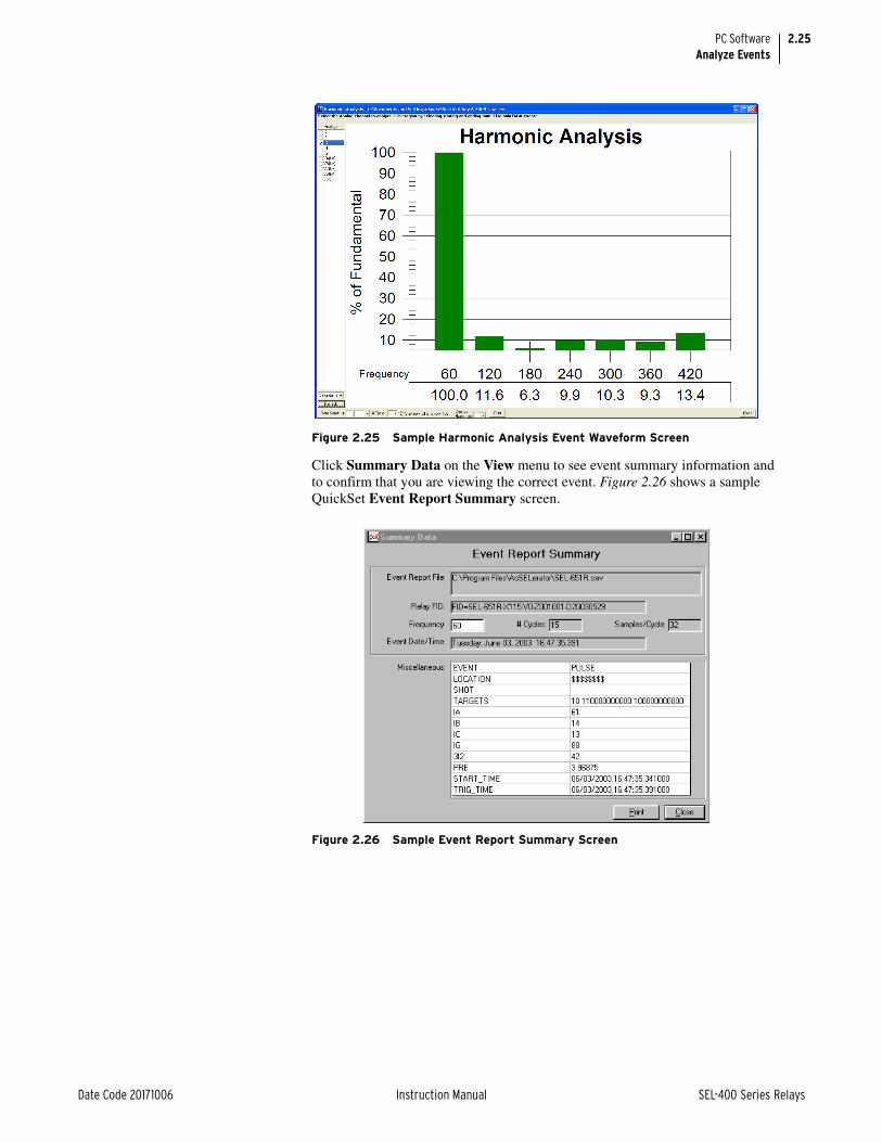
2.25
Date Code 20171006 Instruction Manual SEL-400 Series Relays
PC SoftwareAnalyze Events
Click Summary Data on the View menu to see event summary information and to confirm that you are viewing the correct event. Figure 2.26 shows a sample QuickSet Event Report Summary screen.
Figure 2.25 Sample Harmonic Analysis Event Waveform Screen
Figure 2.26 Sample Event Report Summary Screen

2.26
SEL-400 Series Relays Instruction Manual Date Code 20171006
PC SoftwareAnalyze Events
Click Relay Settings on the View menu to view the relay settings that were active at the time of the event. Figure 2.27 shows a sample CEV-type event Settings screen.
Aligning EventsThere are times when it is desirable to look at data from multiple device event reports simultaneously. This is especially valuable with the SEL-487B when a set of three relays are acting as single-phase relays on a single system. Once you have the event reports retrieved and saved, you can view them together using the following procedure.
Figure 2.27 Sample Event Waveform Settings Screen

2.27
Date Code 20171006 Instruction Manual SEL-400 Series Relays
PC SoftwareAnalyze Events
Step 1. In ACSELERATOR Analytic Assistant SEL-5601 Software, select File > Combine Time-Synchronized Events files to combine the three event reports into one event, as shown in Figure 2.28.
Three placeholders are available for as many as three events. Next to each place-holder is a color-coded horizontal line called an event time control line. These event time control lines also appear at the bottom of the screen where they show the relative overall time relationship between the events, the trigger time of each event, and the number of cycles of each event. The event time control lines are color-coded, with red (Event 1) on top, green (Event 2) in the center, and blue (Event 3) at the bottom. A flashing arrow points to a button for Event 1.
Step 2. Click the button for Event 1.
The software selects the directory where you last stored an event report.
Step 3. Click the event you want to analyze.
Step 4. Click the Open button, as shown in Figure 2.29.
Figure 2.28 Combine Time-Synchronized Events Submenu Screen
Event Time Control Line

2.28
SEL-400 Series Relays Instruction Manual Date Code 20171006
PC SoftwareAnalyze Events
The software reads the selected event report and places the event report in the first placeholder, as shown in Figure 2.30.
Notice that the actual event control line of the first events now appears at the bot-tom of the screen and becomes the reference time position. All other events must overlap the reference time position by at least one data point. The software posi-tions the subsequent events relative to the position of the first event.
Figure 2.29 Selection of the First Event Report
Figure 2.30 First Event of the Analysis

2.29
Date Code 20171006 Instruction Manual SEL-400 Series Relays
PC SoftwareAnalyze Events
If the subsequent event does not overlap the first event by at least one data point, the software does not allow the events to be combined.
Step 5. Click on the button for Event 2 and repeat the steps described for selecting Event 1.
Step 6. Repeat the steps for Event 3. Figure 2.31 shows the screen after reading all three events.
The information displayed at the bottom of the screen shows that we have opened three events, but have not yet selected any analog channels or digital Relay Word bits from these events.
Step 7. Click on the Select Channels tab to select analog channels and digi-tal Relay Word bits. Figure 2.32 shows the screen for selecting the channels.
Figure 2.31 Screen After Reading All Three Events
Figure 2.32 Screen for Selecting Analog Channels and Digital Relay Word Bits

2.30
SEL-400 Series Relays Instruction Manual Date Code 20171006
PC SoftwareAnalyze Events
The three events appear in the window labeled Event Analogs.
Step 8. Click the + of Event 1 to see a list of the analog channels in the event report.
Step 9. Click 1_FDR_1(A), the first analog channel in the list.
Step 10. A trace of channel 1_ FDR _1 appears on the right hand window next to the Combined Analogs list.
Step 11. Right-click on channel 1_ FDR _1.
Step 12. Hold the mouse button down.
Step 13. Drag the cursor to the Combined Analogs window.
Alternatively, press the <A> key to add the selected channel to the list.
Step 14. Release the mouse button to complete the transfer of channel 1_ FDR _1 from the Event Analogs window to the Combine Analogs window.
Alternatively, select the channels to be removed and press the <Delete> key.
Drag and drop is similarly supported for digital channels.
Step 15. Select a channel.
Step 16. Drop the selection into the Event Analogs or Event Digitals window to remove channels from the Combined Analogs or Combined Dig-itals windows.
Figure 2.33 shows the screen with Analog Channel 1_ FDR _1 from Event Report 1, 2_ FDR _1 from Event Report 2, and 3_ FDR _1 from Event Report 3 selected for analysis and appearing in the Combined Analogs window.
Figure 2.33 also shows the differential element from each event report: Relay Word bit 1_Z1_TRIP from Event Report 1, Relay Word bit, 2_ Z1_TRIP from Event Report 2, and Relay Word bit, 3_ Z1_TRIP from Event Report 3.
Figure 2.33 Selection of Analog Channels and Digital Relay Word Bits

2.31
Date Code 20171006 Instruction Manual SEL-400 Series Relays
PC SoftwareAnalyze Events
Step 17. Click on the Combine button to create a single, combined report comprising the selected analog and digital selections from three indi-vidual event reports.
Step 18. On the graph preference form, select the values of interest from the Analogs window.
Step 19. Drop these selections in any one of the six available Axis windows.
You can select as many as 12 analog channels.
Figure 2.34 shows an example after selecting all three analog channels on Axis 1 for analysis.
Step 20. Click OK to view the report.
The software displays the three traces on the same graph, as shown in Figure 2.35.
Figure 2.34 Data From Three Separate Event Reports Combined in a Single Report
Figure 2.35 Traces of the Three Analog Channels

2.32
SEL-400 Series Relays Instruction Manual Date Code 20171006
PC SoftwareQuickSet Help
QuickSet HelpVarious forms of QuickSet help are available as shown in Table 2.3. Press <F1> to open a context-sensitive help file with the appropriate topic as the default. Other ways to access help are shown in Table 2.3.
Table 2.3 Accessing QuickSet Help
Help Description
General ACSELERATOR QuickSet
Select Help > Contents from the main menu bar.
HMI Application Select Help > HMI Help from the main menu bar.
Relay Settings Select Help > Settings Help from the from the main menu bar.
Database Manager Select Help from the bottom of the Database Manager window.
Communications Parameters Select Help from the bottom of the Communications Parame-ters window.

Date Code 20171006 Instruction Manual SEL-400 Series Relays
Instruction ManualS E C T I O N 3
Basic Relay Operations
SEL-400 series relays are power tools for power system protection and control. Understanding basic relay operation principles and methods will help you use the relay effectively. This section presents the fundamental knowledge you need to operate the relay, organized by task. These tasks help you become familiar with the relay and include the following:
➤ Inspecting a New Relay on page 3.1
➤ Establishing Communication on page 3.3
➤ Access Levels and Passwords on page 3.7
➤ Checking Relay Status on page 3.11
➤ Making Simple Settings Changes on page 3.15
➤ Examining Metering Quantities on page 3.35
➤ Examining Relay Elements on page 3.43
➤ Reading Oscillograms, Event Reports, and SER on page 3.48
➤ Operating the Relay Inputs and Outputs on page 3.61
➤ Configuring Timekeeping on page 3.75
➤ Readying the Relay for Field Application on page 3.77
Perform these tasks to gain a good understanding of relay operation, be able to confirm that the relay is properly connected, and be more effective when using the relay. To work through the examples in this section, you need to install the relay either in a final installation or in a laboratory configuration. See Section 2: Installation in the product-specific instruction manual for more information.
Inspecting a New RelayNOTE: Do not connect power to the relay until you have completed your inspection of the relay. See the product-specific Installation section for details on applying power. Failure to follow these instructions can lead to equipment damage.
The following items are included in your shipment from SEL:
➤ Relay
➤ CD-ROM containing the electronic version of the entire Relay Manual and the Customer Label Templates
➤ CD-ROM containing the ACSELERATOR QuickSet SEL-5030 Software program
➤ Configurable Front-Panel Label Kit
➤ SEL Contact Card
If any item is missing or damaged, please contact your distributor or SEL immediately.

3.2
SEL-400 Series Relays Instruction Manual Date Code 20171006
Basic Relay OperationsInspecting a New Relay
Initial InspectionPerform the following initial inspection when the relay arrives:
Step 1. Remove the protective wrapping from the relay.
Step 2. Observe the outside of the front cover and the rear panel.
Step 3. Check that no significant scratches or dents are evident on any outer surface.
Step 4. Confirm that all terminal strips on the rear panel are secure.
Perform the following steps and use care when cleaning the relay:
Step 1. Use a mild soap or detergent solution and a damp cloth to clean the relay chassis.
Be careful cleaning the front and rear panels because a permanent plastic sheet covers each panel; do not use abrasive materials, polishing compounds, or harsh chemical solvents (such as xylene or acetone) on any relay surface.
Step 2. Allow the relay to air dry, or wipe dry with a soft dry cloth.
Verify Relay ConfigurationWhen you first inspect the relay, confirm that the relay power supply voltage and nominal ac signal magnitudes are appropriate for your application. Examine the serial number label on the relay rear panel. Figure 3.1 shows a sample rear-panel serial number label.
NOTE: Do not use this page for ordering a relay. For ordering information, refer to the relay Model Option Table available at selinc.com, or contact your SEL Sales Representatives.
Figure 3.1 shows a serial number label for an SEL-451 with additional I/O in a 4U horizontal chassis. This example serial number label is for a 5 A-per-phase secondary CT input relay. For information on CT and PT inputs, Do not use this page for ordering a relay. For ordering information, refer to the SEL-451 Model Option Table available at selinc.com/products/, or contact your SEL Sales Repre-sentatives.
The power supply specification in Figure 4.1 indicates that this relay is equipped with a power supply that accepts a nominal 48–125 Vdc input. This power supply also accepts a 110–120 Vac input. Refer to the serial number label affixed to the back of your relay to determine the power supply voltage you should apply to the relay power supply input terminals. As this label indicates, the voltage source should be capable of providing at least 35 W for dc inputs and 90 VA for ac inputs. See Section 1: Introduction and Specifications in the product-specific instruction manual for more information on power supply specifications.
Figure 3.1 Sample Relay Serial Number Label
Part NumberSerial Number
Power Supply InputSpecifications
Secondary Current Input
Secondary Voltage Input
I/O Interface Board(s)Logic Input Rating(See Logic Input Ratings, below)

3.3
Date Code 20171006 Instruction Manual SEL-400 Series Relays
Basic Relay OperationsEstablishing Communication
The serial number label does not list power system phase rotation and frequency ratings, because you can use relay settings to configure these parameters. The factory defaults are ABC phase rotation and 60 Hz nominal frequency. See Mak-ing Settings Changes in Initial Global Settings on page 3.20 for details on setting these parameters.
Logic Input RatingsThe serial number label in Figure 3.1 only lists control input voltages for I/O Interface Boards that have optoisolated inputs, which is determined at ordering time. The other types of control inputs (Direct Coupled) have settable pickup voltages, and do not appear on the serial number label. See Control Input Assign-ment on page 3.69 for more information.
Establishing CommunicationOnce you have applied the correct power input successfully, you are ready to operate the relay. Use the relay front panel and the communications ports to com-municate with the relay.
Front-panel control of relay functions involves use of a menu system that you access through the LCD and the six navigational pushbuttons shown in Figure 3.2. For complete instructions on using the front-panel menu system, see Front-Panel Menus and Screens on page 4.14.
Fast and efficient communication with the relay is available through communica-tions ports such as PORT F, also shown in Figure 3.2. A design philosophy for all SEL relays is that an ASCII or open terminal is all that you need to communicate with the relay. Many off-the-shelf computer programs provide terminal emula-tion. These programs are inexpensive and widely available.
Use the cable connections appropriate for your terminal configuration. See Section 15: Communications Interfaces for more information on communica-tions ports.
All ASCII commands you send to the relay must terminate with a carriage return or carriage return/line feed; the terminal emulation program appends the neces-sary carriage return when you press <Enter>.
Figure 3.2 PORT F, LCD Display, and Navigation Pushbuttons
NavigationPushbuttons
TitleArea
SerialCommunications Port
LCD Display Main Area
PORT F
Message Area
5 4 3 2 1
9 8 7 6

3.4
SEL-400 Series Relays Instruction Manual Date Code 20171006
Basic Relay OperationsEstablishing Communication
You can truncate commands to the first three characters: EVENT 1 becomes EVE 1. Use upper- and lowercase characters without distinction, except in passwords, which are case sensitive. For a list of ASCII commands see Section 14: ASCII Command Reference.
HelpWhen you are using a terminal, you can access built-in relay help for each ASCII command. Relay help is access-level sensitive; you see only the ASCII com-mands for the present access level when you type HELP <Enter>. For in-depth information on a particular ASCII command, enter the command name after typ-ing HELP. For example, for help on the EVENT ASCII command, type HELP EVE <Enter>.
When you are using QuickSet, press <F1> to get help, or select the Help menu from the QuickSet toolbars. The help information in QuickSet gives detailed information and sample screens in a GUI format.
Making an EIA-232 Serial Port ConnectionThe following steps use any popular computer terminal emulation software and SEL serial cables to connect to the relay.
Use an SEL-C234A cable to connect a 9-pin computer serial port to the relay. Use an SEL-C227A cable to connect a 25-pin computer serial port to the relay. For computers with USB ports, use an SEL-C662 USB-to-serial cable to connect to the relay. See Section 15: Communications Interfaces for further information on serial communications connections. These and other cables are available from SEL. Contact the factory or your local distributor for more information.
Step 1. Use the serial cable to connect the computer to the relay via PORT F on the relay front panel.
Step 2. Apply power to both the computer and to the relay.
Step 3. Start the computer terminal emulation program.
Step 4. Set your computer terminal emulation program serial communica-tions parameters.
The default relay communications port settings are listed in Table 3.1.
Also set the terminal program to emulate either VT100 or VT52 terminals. These terminal emulations work best with SEL relays.
Table 3.1 General Serial Port Settings
Name Description Default
PROTO Protocol (SEL, DNP, MBA, MBB, RTD, PMU) SEL
SPEED Data speed (300 to 57600, SYNC) 9600
DATABIT Data bits (7, 8 bits) 8
PARITY Parity (Odd, Even, None) N
STOPBIT Stop bits (1, 2 bits) 1
RTSCTS Enable Hardware Handshaking (Y, N) N

3.5
Date Code 20171006 Instruction Manual SEL-400 Series Relays
Basic Relay OperationsEstablishing Communication
Step 5. To check the communications link, press <Enter> to confirm that you can communicate with the relay.
You will see the Access Level 0 = prompt at the left side of your computer screen (column 1).
If you do not see the prompt, check the cable connections and confirm the settings in your terminal emulation program match the default communications parameters shown in Table 3.1.
Step 6. Type QUIT <Enter> to view the relay report header.
You will see a computer screen display similar to that shown in Figure 3.3. (Text that you type is emphasized in bold letters.)
If you see jumbled characters, change the terminal emulation type in the computer terminal program.
When you communicate with the relay at the Access Level 0 = prompt, you are in security Access Level 0. You cannot view or control relay functions at this level.
Higher access levels are password-protected and allow increased control over relay operation. For more information on access levels and password protection, see Changing the Default Passwords in the Terminal on page 3.10.
Making an Ethernet Telnet ConnectionFactory-default settings for the Ethernet ports disable all Ethernet protocols, including PING. Enable the Telnet protocol with the SET P 5 command using any of the serial ports. Command SET P 5 accesses settings for all Ethernet ports on the relay.
Make the following settings using the SET P 5 command:
➤ EPORT = Y
➤ IPADDR = IP Address assigned by network administrator in CIDR notation
➤ DEFRTR = Default router gateway IP Address assigned by network administrator
➤ NETMODE = SWITCHED
➤ ETELNET = Y
NOTE: Telnet works with other NETMODE settings also, but NETMODE = SWITCHED is easiest to begin communications.
Leave all other settings at their default values.
Connect an Ethernet cable between your PC or a network switch and any Ether-net port on the relay. Verify that the amber Link LED illuminates on the connected relay port. Many computers and most Ethernet switches support autocrossover, so nearly any Cat 5 Ethernet cable with RJ45 connectors, such as an SEL-C627 cable, will work. When the computer does not support auto crossover, use a crossover cable, such as an SEL-C628 cable. For fiber-optic Ethernet ports, use an SEL-C808 cable (62.5/125 µm multimode fiber-optic cable). If your relay is equipped with dual Ethernet ports, connect to either port. Use a Telnet client or QuickSet on the host PC to communicate with the relay. During Ethernet transmit or receive activity, the green Activity LED blinks on the relay Ethernet port. To terminate a Telnet session, use the command EXI <Enter> from any access level.
=QUIT <Enter>
Relay 1 Date: 04/16/2004 Time: 00:01:05.209Station A Serial Number: 2001001234
=
Figure 3.3 Report Header

3.6
SEL-400 Series Relays Instruction Manual Date Code 20171006
Basic Relay OperationsEstablishing Communication
Making an Ethernet Web Server (HTTP) ConnectionWhen Port 5 setting EHTTP = Y, the relay serves read-only webpages displaying certain settings, metering, and status reports. The relay-embedded HTTP server has been optimized and tested to work with the most popular web browsers, but should work with any standard web browser. As many as four users can access the embedded HTTP server simultaneously.
To begin using the embedded read-only HTTP server, launch your web browser, and browse to http://IPADDR, where IPADDR is the Port 5 setting IPADDR (e.g., http://192.168.1.2). The relay responds with a login screen as shown in Figure 3.4.
Choose ACC for the username, type in the relay Access Level 1 password, and click Submit. The only username allowed is ACC. The relay responds with the homepage shown in Figure 3.5. While you remain logged in to the relay, the web-page displays the approximate time as determined by the relay time-of-day clock, and increments the displayed time once per second based on the clock contained in your PC.
Once the user is logged in, the HTTP server displays the Meter webpage. This page will refresh within five seconds and includes all metering options available and enabled on the relay.
Figure 3.4 HTTP Server Login Screen

3.7
Date Code 20171006 Instruction Manual SEL-400 Series Relays
Basic Relay OperationsAccess Levels and Passwords
Click on any menu selection in the left pane to navigate through the available webpages.
Access Levels and PasswordsNOTE: Perform the password change steps described in Changing the Default Passwords in the Terminal on page 3.10.
It is extremely important that you change the factory-default passwords pro-grammed in the relay. Setting unique passwords for the relay access levels increases the security of your substation and the power system.
This subsection begins with information on the access level/password system in SEL-400 relays and includes an example of changing the default passwords.
Access LevelsAccess levels control whether you can perform different operations within the relay. These security levels are labeled 0, 1, B, P, A, O, 2, and C. Figure 3.6 pres-ents an overview of the general access level structure in the relay.
Figure 3.5 Example HTTP Server Meter Page

3.8
SEL-400 Series Relays Instruction Manual Date Code 20171006
Basic Relay OperationsAccess Levels and Passwords
Access Level 0 is the least secure and most limited access level, and Access Level 2 is the most secure level at which you have total relay functionality (Level C is reserved for SEL factory operations. Only go to level C to change the level C password or under the direction of an SEL employee). For example, from Access Level 1, you can view settings, but you cannot change settings unless you are at a higher access level.
Table 3.2 lists access levels and operator functions for the relay.
The relay performs command interpretation and execution according to your val-idated access level. Each access level has a password that the relay must verify before you can control the relay at that level. Table 3.3 lists the access level com-mands with corresponding passwords.
Figure 3.6 Access Level Structure
Table 3.2 SEL-400 Series Relay Access Levels
Access Level Prompt Allowed Operations
0 = Log in to Access Level 1.
1 => View data and status information.
B ==> Access Level 1 functions plus breaker control and data.
P P=> Access Level B functions plus protection settings.
A A=> Access Level B functions plus automation settings.
O O=> Access Level B functions plus output settings.
2 =>> Perform all relay access level functions.
C ==>> SEL factory-specific functions. For a list of commands available, contact SEL.
Table 3.3 Access Level Commands and Passwords
Access Level Command Factory-Default Password
0 QUIT (None)
1 ACCESS OTTER
B BACCESS EDITH
P PACCESS AMPERE
A AACCESS VOLTA
O OACCESS WATT
2 2ACCESS TAIL
C CAL Sel-1
AccessLevel 0
Access Level x
(Note: Use xAC to switchbetween any of the access
levels x, where x = B,P,A,O,2)
ACC
QUIT
QUIT
ACC
QUIT
ACC
xACAccessLevel 1
xAC
CAL(from 2AC only)
AccessLevel C

3.9
Date Code 20171006 Instruction Manual SEL-400 Series Relays
Basic Relay OperationsAccess Levels and Passwords
WARNING
Communications Ports Access Levels
This device is shipped with default passwords. Default passwords should be changed to private passwords at installation. Failure to change each default password to a private pass-word may allow unauthorized access. SEL shall not be responsible for any damage resulting from unauthorized access.
Entrance to the higher security levels is sequential. You must first enter a correct password to move from Access Level 0 to Access Level 1.
To enter Access Levels B, P, A, O, and 2, you must enter a correct password from Access Level 1. For example, to go to the O (Output) Access Level from Access Level 1, type OAC <Enter>. At the Password: ? prompt, type your Access Level O password.
To enter level C, you must enter a correct password from Access Level 2.
Use the relay QUIT command from any access level to return the relay to Access Level 0. To reestablish control at a previous access level from Access Level 1, you must use the access level commands and passwords to log in to that previous access level.
When a connection with the relay times out, the relay reduces the access level to Access Level 0 for that communications port connection.
The MAXACC port setting can be used to limit the maximum access level per-mitted on a port. This can be useful to restrict what remote users can do.
Front-Panel Access LevelsThe lowest access level for the front panel is Access Level 1. To enter Access Levels B, P, A, O, and 2, you must enter a correct password from Access Level 1.
The front-panel LCD displays a password prompt when you attempt to control the relay at any access level higher than Access Level 1. (For more information on entering passwords from the front panel, see PASSWORD on page 14.42.)
The front-panel MAIN MENU item RESET ACCESS LEVEL returns the relay to Access Level 1. In addition, when the front-panel inactivity timer times out (indicated by the ROTATING DISPLAY on the front-panel LCD), the relay returns the front-panel access level to Access Level 1.
ACCESS CommandNOTE: You can shorten relay commands to the first three letters of the full command. Section 14: ASCII Command Reference for more information.
Enter the ACCESS (ACC) command to change to Access Level 1. Passwords are case sensitive; you must enter a password exactly as set.
If you enter the password correctly, the relay moves to Access Level 1 and the Access Level 1 => prompt appears. If you are at a higher access level (B, P, A, O, and 2), you can reduce the access level to Access Level 1 by entering the ACC command. The relay performs no password validation to reduce the present access level.
Higher Access Level CommandsEnter the commands in Table 3.3 to enter access levels above Access Level 1. For example, enter the 2ACCESS (2AC) command to change to Access Level 2.
If you are presently at Access Level 1, B, P, A, or O, typing 2AC <Enter> causes the relay to prompt you to type the Access Level 2 password. If the present level is Access Level 0, the relay responds with Invalid Access Level. The relay pulses alarm Relay Word bit SALARM when entering Access Level B, P, A, O, and 2 from a lower access level.

3.10
SEL-400 Series Relays Instruction Manual Date Code 20171006
Basic Relay OperationsAccess Levels and Passwords
WARNING
If an incorrect password is entered three times, the relay asserts the BADPASS and SALARM Relay Word bits for one second and displays on a communica-tions terminal screen the following error message:
WARNING: ACCESS BY UNAUTHORIZED PERSONS STRICTLY PROHIBITED
In addition, you cannot make further access level entry attempts for 30 seconds. The relay terminates the communications connection after the third failed attempt when you use Ethernet via an Ethernet card, DNP3 (Distributed Network Proto-col version 3.0), or MIRRORED BITS communications virtual terminal mode. For more information on these protocols, see Section 15: Communications Interfaces and Section 16: DNP3 Communication.
If your connection to the relay has an inactivity time-out (in the SET P port set-tings), the relay automatically closes the communications connection and changes to Access Level 0 when the time-out occurs.
PasswordsValid passwords are character sequences of as many as twelve characters. Valid password characters are any printable ASCII character. HMI password entry is limited to upper- and lowercase letters, numbers, underscore, and period, so you must limit your password to these characters if you need to do privileged opera-tions from the front panel. Passwords are case-sensitive.
This device is shipped with default passwords. Default passwords should be changed to private passwords at installation. Failure to change each default password to a private pass-word may allow unauthorized access. SEL shall not be responsible for any damage resulting from unauthorized access.
It is important that you change all of the passwords from their default values. This will protect you from unauthorized access.
Use strong passwords. Strong passwords contain a mix of the valid password characters in a combination that does not spell common words in any portion of the password.
Changing the Default Passwords in the TerminalStep 1. Confirm that the relay is operating (see Establishing Communication on
page 3.3).
Step 2. Establish communication with the relay (see Making an EIA-232 Serial Port Connection on page 3.4 to learn how to use a terminal to communicate with the relay).
Step 3. Enter Access Level C (level 2 is sufficient except when changing the level C password).
a. Using a communications terminal, type ACC <Enter>.
b. Type the Access Level 1 password OTTER and press <Enter>.
You will see the Access Level 1 => prompt.
c. Type 2AC <Enter>.
NOTE: Passwords are case sensitive; you must enter passwords exactly as set.
d. At the password prompt, type TAIL <Enter>.
e. You will see the Access Level 2 =>> prompt.
f. Type CAL <Enter>.
g. At the password prompt, type Sel-1 <Enter>.
You will see the Access Level C ==>> prompt.
Step 4. To set a new password for Access Level 2, type the following:
PAS 2 <Enter>.

3.11
Date Code 20171006 Instruction Manual SEL-400 Series Relays
Basic Relay OperationsChecking Relay Status
Step 5. Before you can change to a new password, the relay prompts you to first confirm the existing password. Enter the existing password and press <Enter>.
Step 6. The relay prompts you for the new password, and a confirmation of the new password, as follows:
Notice that the new password is not displayed. After the confirmation, the new password is in effect. The relay will issue a weak password warning if the new password does not include at least one special character, number, lowercase letter, and uppercase letter.
Step 7. Set new passwords for each access level.
In a similar manner as the previous step, create new strong passwords for each access level.
Step 8. Commit these passwords to memory, permanently record your new passwords, and store this permanent record in a secure location.
To eliminate password verification for an access level, enter DISABLE in place of the new password. This action will disable the password of that level; there-fore, the relay does not check for a password upon entering that access level.
If you forget a password or encounter difficulty changing the default passwords, you can temporarily disable password verification. See Section 2: Installation in the product specific instruction manual for information on the password disable jumper.
Checking Relay StatusWith continual self-testing, the relay monitors the internal operation of all cir-cuits to verify optimal performance of relay functions. If an internal circuit, pro-tection algorithm, or automation algorithm enters an out-of-tolerance operating range, the relay reports a status warning. In the unlikely event that an internal failure occurs, the relay reports a status failure. For more information on relay status, see Relay Self-Tests on page 10.15.
You can check relay status through a communications port by using a terminal, terminal emulation computer program, or QuickSet. In addition, you can use the relay front panel to view status information.
Old Password: ?**** <Enter>
New Password: ?**** <Enter>
Confirm New Password: ?**** <Enter>Password ChangedCAUTION: This password can be strengthened. Strong Pass-words do not include a name, date, acronym or word. They consist of the maximum allowable characters, with at least one special character, number, lower-case letter, and upper-case letter. A change in password is recommended.

3.12
SEL-400 Series Relays Instruction Manual Date Code 20171006
Basic Relay OperationsChecking Relay Status
Checking Relay Status Using the TerminalThe procedure in the following steps assumes that you have successfully estab-lished communication with the relay (see Making an EIA-232 Serial Port Con-nection on page 3.4). In addition, you must be familiar with relay access levels and passwords (see Changing the Default Passwords in the Terminal on page 3.10 to change the default access level passwords).
Step 1. Enter Access Level 1.
a. Using a communications terminal, type ACC <Enter>.
b. Type the Access Level 1 password and press <Enter>.
You will see the Access Level 1 => prompt.
Step 2. Type STA <Enter>. The relay returns a status terminal screen simi-lar to that in Figure 3.7.
Step 3. Type STA A <Enter> to view all relay status entries.
For more information on relay status report items, see STATUS on page 14.50.
Checking Relay Status in QuickSetYou can use QuickSet to check relay status. Use the HMI > Meter Control menu to view status conditions.
The procedure in the following steps assumes that you have successfully estab-lished communication with the relay (see Making an EIA-232 Serial Port Con-nection on page 3.4). In addition, you must be familiar with relay access levels and passwords (see Changing the Default Passwords in the Terminal on page 3.10 to change the default access level passwords). You should also be familiar with QuickSet (see Section 2: PC Software).
Step 1. Configure the communications port.
a. Start QuickSet.
NOTE: The DTR parameter has no effect on communications with the relay.
b. On the top toolbar, click Communications > Parameters.
You will see the Communication Parameters dialog box similar to that shown in Figure 3.8.
=>STA <Enter> Relay 1 Date: mm/dd/yyyy
Time:07:02:50.776Station A Serial Number: 000000000FID=SEL-451-1-Rxxx-V0-Zxxxxxx-Dyyyymmdd CID=0x9aed
Failures No Failures Warnings No Warnings
SELogic Relay Programming Environment Errors No Errors Relay Enabled =>
Figure 3.7 Relay Status

3.13
Date Code 20171006 Instruction Manual SEL-400 Series Relays
Basic Relay OperationsChecking Relay Status
c. Select the Data Speed, Data Bits, Stop Bits, Parity, and RTS/CTS that match the relay settings.
The defaults are 9600, 8, 1, None, and Off, respectively.
d. Click OK to update the QuickSet communications parameters and connect to the relay.
e. Confirm that the Communications Status bar at the bottom of the QuickSet window says Connected.
Step 2. Confirm that you have loaded the correct passwords in QuickSet.
a. Enter your Access Level 1 password in the Level One Password text box, and your Access Level 2 password in the Level Two Password text box.
b. Click OK to accept changes and close the dialog box.
Step 3. Click Tools in the top toolbar and select the HMI menu to start the QuickSet operator interface.
Step 4. Click the Status button of the HMI tree view (see Figure 3.9).
QuickSet displays the relay status with a display similar to that in Figure 3.9.
Figure 3.8 QuickSet Communication Parameters and Password Entry

3.14
SEL-400 Series Relays Instruction Manual Date Code 20171006
Basic Relay OperationsChecking Relay Status
Checking Relay Status From the Front PanelUse the front-panel display and navigation pushbuttons to check relay status. See Section 4: Front-Panel Operations for information on using the relay front panel.
Step 1. Apply power to the relay, and note that the LCD shows a sequence of screens called the ROTATING DISPLAY.
(If you do not operate the front panel for a certain period, the relay will enter front-panel time-out mode and you will see the sequential screens of the ROTATING DISPLAY.)
Step 2. Press the ENT pushbutton to display the MAIN MENU as shown in Figure 3.10.
Step 3. View the relay status.
a. Press the Up Arrow and Down Arrow navigation pushbuttons to highlight the RELAY STATUS action item (see Figure 3.10).
b. Press the ENT pushbutton.
You will see the RELAY STATUS screen (the second screen of Figure 3.10).
Step 4. Press the ESC pushbutton to return to the MAIN MENU.
Step 5. Press ESC pushbutton again to return to the ROTATING DISPLAY.
Figure 3.9 Retrieving Relay Status in QuickSet
Figure 3.10 Checking Relay Status From the Front-Panel LCD
(a)
(b)
METEREVENTSBREAKER MONITORRELAY ELEMENTSLOCAL CONTROLSET/SHOWRELAY STATUSVIEW CONFIGURATIONDISPLAY TESTRESET ACCESS LEVEL
MAIN MENU
RELAY STATUSSEL-451-5-Rxxx-V0- Zxxxxxx-Dyyyymmdd
S/N=0000000000RELAY ENABLEDNO FAILURES ORWARNINGS

3.15
Date Code 20171006 Instruction Manual SEL-400 Series Relays
Basic Relay OperationsMaking Simple Settings Changes
WARNING
For more information on the front-panel screen presentations and the items in the RELAY STATUS screens, see Relay Status on page 4.29.
Making Simple Settings Changes
Isolate the relay trip circuits while changing settings. When changing set-tings for multiple classes, it is possible to be in an intermediate state that will cause an unexpected trip.
The relay settings structure makes setting the relay easy and efficient. Settings are grouped logically, and relay elements that are not used in your selected pro-tection scheme are hidden. QuickSet uses a similar method to focus your atten-tion on the active settings. Unused relay elements and inactive settings are dimmed (grayed) in the QuickSet menus. See Section 2: PC Software for more information on QuickSet.
Settings StructureSEL-400 series relays use a settings structure that assigns each relay setting to a specific location based on the setting type. A top-down organization allocates relay settings into these layers:
➤ Class
➤ Instance
➤ Category
➤ Setting
Examine Figure 3.11 to understand the settings structure in a typical relay. The top layer of the settings structure contains classes and instances. Class is the pri-mary sort level; all classes have at least one instance, and some classes have mul-tiple instances. Settings classes and related instances for the SEL-451, which are typical of SEL-400 series relays, are listed in Table 3.4. See Section 8: Settings of the product-specific instruction manual for details on the classes and instances for a given relay.

3.16
SEL-400 Series Relays Instruction Manual Date Code 20171006
Basic Relay OperationsMaking Simple Settings Changes
Figure 3.11 Example Relay Settings Structure Overview
Class
Instance
Category
Category
Category
Setting
Setting
Setting
Global
Settings
General
Group
Settings
Group 1
Line Config.
Group 2
CTRWCTRW
CTRXCTRX
PTRY
Line Config.
Relay Config. Relay Config.
PTRY
SID
RID
NUMBK
ESOTFESOTF
ELOADELOAD
E50PE50P
Enables
EDCMON
EICIS
EDRSTC
DC1 Mon
DC1LFP
DC1LWP
Setting
LoadEncroachment
LoadEncroachment
ZLFZLF
ZLRZLR
SettingSetting
Table 3.4 SEL-451 Settings Classes and Instances (Sheet 1 of 2)
Class Description Instance Description ASCII Command Access Level
Global Relay-wide applications settings Global SET G P, A, O, 2
Group Individual scheme settings Group 1
•••
Group 6
Group 1 settings
•••
Group 6 settings
SET 1, SET S 1
•••
SET 6, SET S 6
P, 2
Breaker Monitor Circuit breaker monitoring set-tings
Breaker Monitor
SET M P, 2
Port Communications port settings PORT F
PORT 1
•••
PORT 3
PORT 5
Front-panel port
PORT 1 settings
•••
PORT 3 settings
Communications card settings
SET P F
SET P 1
•••
SET P 3
SET P 5
P, A, O, 2
Report Report settings Report SET R P, A, O, 2

3.17
Date Code 20171006 Instruction Manual SEL-400 Series Relays
Basic Relay OperationsMaking Simple Settings Changes
Note that some settings classes have only one instance and you do not specify the instance designator when accessing these classes. An example is the Global set-tings class. You can view or modify Global settings with a communications ter-minal by entering SET G as shown in the ASCII Command column of Table 3.4. The relay presents the Global settings categories at the SET G command; no instance numbers follow SET G. Conversely, the Port settings command has five instances (PORT F, PORT 1, PORT 2, PORT 3, and PORT 5). To access the PORT 1 settings, type SET P 1 <Enter>. If you do not specify which port to set, the relay defaults to the active port (the port you are presently using).
The Group settings can have the optional one-letter acronym S attached to the command; you can enter SET 1 or SET S 1 for Group 1 settings, SET 2 or SET S 2 for Group 2 settings, etc. If you do not specify which group to set, the relay defaults to the present active group. If Group 6 is the active group, and you type SET <Enter>, for example, you will see the settings prompts for the Group 6 settings.
Alias SettingsAlthough the relay provides extensive programming facilities and opportunity for comments, troubleshooting customized programs is sometimes difficult. Aliases provide an opportunity to assign more meaningful names to the generic variable names in order to improve the readability of the program.
Front Panel Front-panel HMI settings Front Panel SET F P, A, O, 2
Protection SELOGIC control equations
Protection-related SELOGIC control equations
Group 1
•••
Group 6
Group 1 protection SELOGIC control equations
•••
Group 6 protection SELOGIC control equations
SET L 1
•••
SET L 6
P, 2
Automation SELOGIC control equations
Automation-related SELOGIC control equations
Block 1
•••
Block 10
Block 1 automation SELOGIC control equations
•••
Block 10 automation SELOGIC control equations
SET A 1
•••
SET A 10
A, 2
DNP3 Direct Network Protocol data remapping
Map 1•••
Map 5
SET D 1•••
SET D 5
P, A, O, 2
Output SELOGIC control equations
Relay control output settings and MIRRORED BITS commu-nication transmit equations
Output SET O O, 2
Bay Bay control settings Bay SET B P, 2
Alias Set aliases Analog or digi-tal quantities
SET T P, A, O, 2
Notes Freeform programming to leave notes in the relay
Notes 100 lines SET N P, A, O, 2
Table 3.4 SEL-451 Settings Classes and Instances (Sheet 2 of 2)
Class Description Instance Description ASCII Command Access Level

3.18
SEL-400 Series Relays Instruction Manual Date Code 20171006
Basic Relay OperationsMaking Simple Settings Changes
Rename, or assign as many as 200 alias names to any Relay Word bit or analog quantity in the relay. The maximum length of an alias is seven characters. Valid characters are 0–9, A–Z (only uppercase), and _ (underscore), and must contain at least one alphabetic character. Ensure that no Relay Word bit or analog quan-tity appears more than once in the alias settings. Each alias name must be unique, i.e., you cannot use the name of an existing Relay Word bit or analog quantity. If you remove the alias name, all settings that referenced that alias revert to the original name.
Use the SHO T command to view the default settings, as shown in Figure 3.12.
Making Text-Edit Mode Alias ChangesAssign the alias name THETA to math variable PMV01 and the alias TAN to math variable PMV02. These variables are then used in calculating the tangent of theta, using their alias names in the equation.
Step 1. Prepare to control the relay at Access Level 2.
a. Type ACC <Enter> at a communications terminal.
b. Type the Access Level 1 password and press <Enter>.
You will see the Access Level 1 => prompt.
c. Type 2AC <Enter>.
d. Type the correct password to go to Access Level 2.
You will see the =>> prompt.
Step 2. Type SET T <Enter> to access the alias settings.
Figure 3.13 shows a representative computer terminal screen.
Step 3. Type > <Enter> for the relay to display the first line that you can edit.
Step 4. Type PMV01,THETA <Enter> at the Line 2 ? settings prompt to set the alias for PMV01.
The relay verifies that this is a valid entry, then responds with the next line prompt 3: followed by the ? settings prompt.
Step 5. Type PMV02,TAN <Enter> at the Line 3 ? settings prompt to set the alias for PMV02.
The relay verifies that this is a valid entry, then responds with the next line prompt 4: followed by the ? settings prompt.
Step 6. Type END <Enter> to end the settings session.
The relay scrolls a readback of all the front-panel settings, eventually displaying the Save settings (Y, N) ? prompt. At the end of the readback information, just before the Save settings (Y, N) ? prompt, you can verify the new display point information.
Step 7. Type Y <Enter> to save the new settings.
=>>SHO T <Enter>AliasRelay Aliases(RW Bit or Analog Qty. 7 Character Alias [0-9 A-Z _])1: EN,"RLY_EN"=>>
Figure 3.12 Default Alias Settings

3.19
Date Code 20171006 Instruction Manual SEL-400 Series Relays
Basic Relay OperationsMaking Simple Settings Changes
Use the alias names, instead of the Relay Word bits, in SELOGIC control equation programming. Figure 3.14 shows an example of an alias used in protection logic programming.
Changing Settings Using the TerminalWhen you change settings (with any SET command) from a terminal, the relay shows the setting category, prompt, present value, and action prompt.
Figure 3.15 shows two settings examples: multiple-line settings (SID and RID) and an in-line setting (NUMBK) for relay Global settings from Access Level P (protection). The relay prompts you for input by presenting an action prompt. You have many options for navigating the settings at the ? prompt.
Table 3.5 lists the operations possible from a settings action prompt.
=>>SET T <Enter>AliasRelay Aliases(RW Bit or Analog Qty. 7 Character Alias [0-9 A-Z _])1: EN,"RLY_EN"? <Enter>2:? PMV01,THETA <Enter>3:? PMV02,TAN <Enter>
4:? END <Enter>AliasRelay Aliases(RW Bit or Analog Qty. 7 Character Alias [0-9 A-Z _])1: EN,"RLY_EN"2: PMV01,"THETA"3: PMV02,"TAN"
Save settings (Y,N) ?Y <Enter>Saving Settings, Please Wait...........Settings Saved
=>>
Figure 3.13 Using Text-Edit Mode Line Editing to Set Aliases
=>>SET L <Enter>Protection 11: PLT01S := PB1_PUL AND NOT PLT01 #GROUND ENABLED? > <Enter>15:? THETA:=I01FA <Enter>
16:? TAN:=SIN(THETA)/COS(THETA) <Enter>17:? END <Enter>Protection 1...
Save settings (Y,N) ?Y <Enter>Saving Settings, Please Wait...........Settings Saved
=>>
Figure 3.14 Using Text-Edit Mode Line Editing to Set Protection Logic

3.20
SEL-400 Series Relays Instruction Manual Date Code 20171006
Basic Relay OperationsMaking Simple Settings Changes
When you exit settings entry from the SET commands, the relay responds with Save settings (Y,N)?. If you answer Y <Enter>, the relay writes the new set-tings to nonvolatile storage. If you answer N <Enter>, the relay discards any set-tings changes you have made.
Making Settings Changes in Initial Global SettingsYou must configure SEL-400 series relays for specific conditions found in the power system where you are connecting the relay. For example, in most SEL-400 series relays you must set the nominal frequency and phase rotation.
The procedure in the following steps assumes that you have successfully estab-lished communication with the relay; see Making an EIA-232 Serial Port Con-nection on page 3.4 for a step-by-step procedure. In addition, you must be familiar with relay access levels and passwords. See Changing the Default Pass-words in the Terminal on page 3.10 to change the default access level passwords.
This example jumps to a Global setting that is not at the beginning of the Global settings list. Thus, you enter SET G, the setting name, and <Enter>. To start at the beginning of the Global settings, simply type SET G <Enter> without a set-tings name.
Step 1. Prepare to control the relay at Access Level 2.
a. Using a communications terminal, type ACC <Enter>.
b. Type the Access Level 1 password and press <Enter>.
You will see the Access Level 1 => prompt.
Figure 3.15 Components of SET Commands
Table 3.5 Actions at Settings Prompts
Action Relay Response
<Enter> Accept setting and move to the next setting; if at the last setting, exit settings.
[value] <Enter> Enter the given value and move to the next setting if valid; if at the last set-ting, exit settings.
^ <Enter> Move to the previous setting; if at the top of settings, stay at the present setting.
< <Enter> Move to the top of the previous settings category; if at the top of settings, stay at the present setting.
> <Enter> Move to the top of the next settings category; if in the last category, exit settings.
END <Enter> Go to the end of the present settings session. Prepare to exit settings via the Save settings (Y,N) ? prompt.
<Ctrl+X> Abort the editing session without saving changes.
==>SET G <Enter>
Global
General Global Settings
Station Identifier (40 characters)
SID := "Station A"
? <Enter>
Relay Identifier (40 characters)
RID := "Relay 1"
? <Enter>
Number of Breakers in Scheme (1,2) NUMBK := 1 ? <Enter>
Category
Prompt
Present Value
Action Prompt
Present
Value
Prompt Action
Prompt

3.21
Date Code 20171006 Instruction Manual SEL-400 Series Relays
Basic Relay OperationsMaking Simple Settings Changes
c. Type 2AC <Enter>.
d. Type the correct password to go to Access Level 2.
You will see the Access Level 2 =>> prompt.
Step 2. Type SET G NFREQ <Enter> (this sets the nominal system frequency using the NFREQ setting, which has options of 50 Hz and 60 Hz).
The relay responds with a terminal screen display similar to that shown in Figure 3.16.
Step 3. Accept the default settings.
a. For a 60 Hz system, press <Enter> to accept the NFREQ exist-ing value of 60 (Hz).
The relay presents the next setting, which is the PHROT (phase rotation) setting.
b. Type <Enter> to accept the ABC phase rotation default.
Step 4. Set the date format:
The relay can report dates in three formats: MDY, YMD, and DMY (where M = month, D = date, and Y = year).
a. For this procedure, type YMD <Enter>.
At each setting in turn, the relay presents the settings prompt, name, present value, and action prompt.
Note that SELOGIC control equation settings, such as FAULT in Figure 3.16, can appear on multiple lines.
b. If you make a mistake or want to go backward through the settings, type the ^ character (on most computer keyboards, this is a shifted numeral 6) and <Enter>.
Refer to Table 3.5 for this and other navigational aids.
Step 5. End the settings session.
a. Type END <Enter> at the FAULT action prompt.
(The Fault SELOGIC control equation remains unchanged.)
The relay next scrolls a readback of all the Global settings, eventually displaying the following prompt:Save settings (Y,N) ?
(In Figure 3.16, a vertical ellipsis represents the relay information during readback.)
b. Examine the settings readback to verify your new settings.
c. Answer Y <Enter> to save your new settings.
=>>SET G NFREQ <Enter>Global
General Global Settings
Nominal System Frequency (50,60 Hz) NFREQ := 60 ? <Enter>System Phase Rotation (ABC,ACB) PHROT := ABC ? <Enter>Date Format (MDY,YMD,DMY) DATE_F := MDY ? YMD <Enter>Fault Condition Equation (SELogic Equation)FAULT := 51S1 OR 51S2 OR 50P1? END <Enter>
•••
Save settings (Y,N) ? Y <Enter>Saving Settings, Please Wait...........Settings Saved=>>
Figure 3.16 Example Global Settings

3.22
SEL-400 Series Relays Instruction Manual Date Code 20171006
Basic Relay OperationsMaking Simple Settings Changes
The TERSE Option
You can avoid viewing the entire class settings summary the relay displays when you type END <Enter> midway through a settings class or instance.
On slow data speed links, waiting for the complete settings readback can clog your automation control system or take too much of your time for a few settings changes. Eliminate the settings readback by appending TERSE to the SET command.
Text-Edit Mode Line EditingSome relay settings present multiple input lines to your terminal; you use basic line text editing commands to construct the setting. For display, the relay refer-ences each line of the setting by line number, not by the setting name. See Mak-ing Text-Edit Mode Settings Changes on page 3.22 for an example of a text-edit mode setting.
While in the text-edit mode, you see a prompt consisting of the line number and the present setting for that line. You can keep the setting, enter a new setting, or delete the setting. Table 3.6 lists the commands for text-edit mode.
Use commas to separate the items in a text-edit mode setting when you are enter-ing multiple items per line. After you enter each line, the relay checks the validity of the setting. If the entered setting is invalid, the relay responds with an error message and prompts you again for the setting.
Making Text-Edit Mode Settings ChangesThe procedure in the following steps familiarizes you with basic text-edit mode line editing.
Table 3.6 Actions at Text-Edit Mode Prompts
Action Relay Response
<Enter> Accept the setting and move to the next line; if at the last line or at a blank line, exit settings.
>n <Enter> Move to line n. If this is beyond the end of the list, move to a blank line following the last line.
^ <Enter> Move to the previous line; if at the first line, stay at the present line.
< <Enter> Move to the first line.
> <Enter> Move to a blank line following the last line.
LIST <Enter> List all settings and return to the present action prompt.
DELETE [n] <Enter>
Delete the present line and subsequent lines for a total of n lines; n = 1 if not provided. Lines after deletion shift upward by the number of lines deleted.
INSERT <Enter> Insert a blank line at the present location; the present line and subse-quent lines shift downward.
END <Enter> Go to the end of the present settings session. Prepare to exit settings via the Save settings (Y,N) ? prompt.
<Ctrl+X> Abort editing session without saving changes.
NOTE: To begin an entry with one of these keywords, especially in notes settings, put the string in quotes: e.g. "END OF REPORT".

3.23
Date Code 20171006 Instruction Manual SEL-400 Series Relays
Basic Relay OperationsMaking Simple Settings Changes
Example 3.1 Text-Edit Mode Line Editing
Set Display Point 1 through Display Point 3 to show the status of Circuit Breaker 1, Circuit Breaker 2, and the operational state (on or off) of the transformer cooling fans near the circuit breaker bay where you have installed the relay. See Display Points on page 4.10 for information on pro-gramming display points.
For this example, use inputs IN101, IN102, and IN105. You can use other inputs for your particular application.
This procedure assumes that you have successfully established communica-tion with the relay (see Making an EIA-232 Serial Port Connection on page 3.4). In addition, you must be familiar with relay access levels and passwords (see Changing the Default Passwords in the Terminal on page 3.10) to change the default access level passwords.
Step 1. Prepare to control the relay at Access Level 2.
a. Using a communications terminal, type ACC <Enter>.
b. Type the Access Level 1 password and press <Enter>.
You will see the Access Level 1 => prompt.
c. Type 2AC <Enter>.
d. Type the Access Level 2 password and press <Enter>.
You will see the Access Level 2 =>> prompt.
Step 2. Access the display point settings.
a. Type SET F <Enter> to modify the front-panel settings.
b. Advance through the front-panel settings (repeatedly type > and then <Enter>) until you reach the Display Points category.
Figure 3.17 shows a representative terminal screen. The relay displays the first line that you can edit. For the case of display points, the line number is the display point number.
Step 3. At the Line 1 settings ? prompt, type the following to create Dis-play Point 1:
IN101,CB1,CLOSED,OPEN <Enter>
The relay verifies that this is a valid entry, then responds with the next line prompt 2: followed by the settings ? prompt (see Figure 3.17).
Step 4. At the Line 2 settings ? prompt, type the following to create Dis-play Point 2:
IN102,CB2,CLOSED,OPEN <Enter>
The relay verifies that this is a valid entry, then responds with the next line prompt 3: followed by the settings ? prompt (see Figure 3.17).
Step 5. At the Display Points prompt, use the text-edit mode line edit-ing commands to list the active display points. Type the follow-ing:
LIST <Enter>
After showing the active display points, the relay returns to Line 3 followed by the settings ? prompt.

3.24
SEL-400 Series Relays Instruction Manual Date Code 20171006
Basic Relay OperationsMaking Simple Settings Changes
Step 6. Type the following to create Display Point 3:
IN105,“5 MVA XFMR Fans”,ON,OFF <Enter>
The relay verifies that this is a valid entry, then responds with the next line prompt 4: followed by the settings ? prompt (see Figure 3.17).
Step 7. Type END <Enter> to end the editing session.
The relay scrolls a readback of all the front-panel settings, eventually displaying the Save settings (Y,N) ? prompt. (A vertical ellipsis in Figure 3.17 represents the readback.)
At the end of the readback information, just before the Save settings (Y,N) ? prompt, you can verify the new display point information.
Step 8. Answer Y <Enter> to save the new settings.
This procedure proposes connecting the transformer bank fan sensor to relay input IN105. In the SET G (GLOBAL) command, verify that the debounce time settings IN105PU and IN105DO are correct for your fan-running sen-sor. To access separate input parameters, you must first enable independent control input settings with setting EICIS. To change the input conditioning, enter the following settings:
EICIS := Y Enable Independent Control Input Settings (Y, N)
IN105PU := 0.3750 Pickup Delay for Contact Input IN105 (0.0000–5 cyc)
IN105DO := 0.3750 Dropout Delay for Contact Input IN105 (0.0000–5 cyc)
Use the appropriate interface hardware to connect the fan-running sensor to IN105. Choose any relay input that conforms to your requirements.
Example 3.1 Text-Edit Mode Line Editing (Continued)
NOTE: Use quotation marks when entering alias strings that contain spaces or punctuation marks, as shown in the IN105 sample, Step 6.
Display Points(Boolean) : RWB Name, “Label”, “Set String”, “Clear String”, “Text Size”(Analog) : Analog Quantity Name, “User Text and Formatting”, “Text Size”
1: ? IN101,CB1,CLOSED,OPEN <Enter>2: ? IN102,CB2,CLOSED,OPEN <Enter>3:? LIST <Enter>1: IN101,"CB1","CLOSED","OPEN",S2: IN102,"CB2","CLOSED","OPEN",S
3:? IN105,“5 MVA XFMR Fans”,ON,OFF <Enter>4:? END <Enter> • • •
Display Points(Boolean) : RWB Name, “Label”, “Set String”, “Clear String”, “Text Size”(Analog) : Analog Quantity Name, “User Text and Formatting”, “Text Size”1: IN101,"CB1","CLOSED","OPEN",S2: IN102,"CB2","CLOSED","OPEN",S3: IN105,"5 MVA XFMR Fans","ON","OFF",S • • •
Save settings (Y,N) ? Y <Enter>Saving Settings, Please Wait...........Settings Saved=>>
Figure 3.17 Using Text-Edit Mode Line Editing to Set Display Points

3.25
Date Code 20171006 Instruction Manual SEL-400 Series Relays
Basic Relay OperationsMaking Simple Settings Changes
Example 3.2 Leaving a Note in the Relay
For this example, assume you are testing a line, but you will be away for a few days. You want to leave your colleague, Marius, a note telling him where you left the drawings and settings. Use the Notes function in the relay to leave the note, as shown in Figure 3.18. All relevant procedures in this sec-tion assume that you have successfully established communication with the relay. In addition, you must be familiar with relay access levels and pass-words to change the default access level passwords. Furthermore, Step 1 below applies to all relevant tests, and is not repeated for each test.
Step 1. Prepare to control the relay at Access Level 2.
a. Using a communications terminal, type ACC <Enter>.
b. Type the Access Level 1 password and press <Enter>.
You will see the Access Level 1 => prompt.
c. Type 2AC <Enter>.
d. Type the correct password to go to Access Level 2.
You will see the Access Level 2 =>> prompt.
Step 2. Access the Notes settings.
a. Type SET N <Enter> to access the Notes settings.
b. At the Line 1 settings ? prompt, type the Line 1 text shown in Figure 3.18 (as many as 70 characters without wrap), and press <Enter>.
The relay verifies that this is a valid entry, then responds with the next line prompt 2: followed by the settings ? prompt.
Step 3. At the Line 2 settings ? prompt, type the Line 2 text shown in Figure 3.18.
Because there are more than 70 characters, the relay rejects the entry.
Re-enter the text, but keep the number of characters at 70 or fewer.
Step 4. After the last entry, type END <Enter>.
This tells the relay that you have completed the setting change.
Step 5. Type Y <Enter> at the prompt Save settings (Y,N) to save the settings.

3.26
SEL-400 Series Relays Instruction Manual Date Code 20171006
Basic Relay OperationsMaking Simple Settings Changes
To read the note, type SHO N <Enter>, as shown in Figure 3.19.
=>>SET N <Enter>Notes1:? Marius, this is the relay for CARR substation <Enter>2:? The Sacramento line drawings and setting sheets are in the top drawer in the sub\station. <Enter>Note cannot exceed 70 chars
2:? The Sacramento line drawings and settings are in the <Enter>3:? top drawer in the substation. <Enter>4:? END <Enter>Notes1: Marius, this is the relay for CARR substation2: The Sacramento line drawings and settings are in the3: top drawer in the substation.
Save settings (Y,N) ?Y <Enter>Saving Settings, Please Wait...........Settings Saved
Figure 3.18 Leave a Note in the Relay
=>>SHO N <Enter>Notes1: Marius, this is the relay for CARR substation2: Capacitor Bank 1 drawings and settings are in the3: top drawer in the substation.=>>
Figure 3.19 Read a Note in the Relay
Example 3.3 Deleting a Display Point
This example shows you how to delete a previously used display point. In the SET F command, at the Display Points and Aliases prompt, use the text-edit mode line editing commands to set and delete the display points. This proce-dure shows two previously programmed display points that indicate on the front-panel LCD the status of Circuit Breaker 1 and Circuit Breaker 2. Relay control inputs IN101 and IN102 are the Relay Word bits for the Circuit Breaker 1 and Circuit Breaker 2 display points, respectively (see Making Text-Edit Mode Settings Changes on page 3.22). You can use other inputs for your particular application.
The procedure in the following steps assumes that you have successfully established communication with the relay (see Making an EIA-232 Serial Port Connection on page 3.4). In addition, you must be familiar with relay access levels and passwords (see Changing the Default Passwords in the Ter-minal on page 3.10).
Step 1. Prepare to control the relay at Access Level 2.
a. Using a communications terminal, type ACC <Enter>.
b. Type the Access Level 1 password and press <Enter>.
You will see the Access Level 1 => prompt.
c. Type 2AC <Enter>.
d. Type the correct password to go to Access Level 2.
You will see the Access Level 2 =>> prompt.

3.27
Date Code 20171006 Instruction Manual SEL-400 Series Relays
Basic Relay OperationsMaking Simple Settings Changes
Step 2. Access the Display Points and Aliases prompt.
a. Enter the SET F command.
b. Advance through the front-panel settings (repeatedly type > and then <Enter>) until you reach the Display Points and Aliases category.
Figure 3.20 shows a representative terminal screen. The relay displays the first line that you can edit. For display points, the line number is the display point number.
Step 3. List the present display points.
a. Type LIST <Enter> at the Display Points ? prompt.
b. After showing the active display points, the relay returns to Line 1 followed by the settings ? prompt.
Step 4. Type <Enter> once to proceed to the Line 2 present value and settings ? prompt.
Step 5. Type DELETE <Enter> to delete Display Point 2.
Step 6. Type LIST <Enter> to examine the remaining display points.
Former Display Point 2 is eliminated, and Display Point 3 moves up to position 2.
The relay returns to Line 2 followed by the settings ? prompt.
Example 3.3 Deleting a Display Point (Continued)
Display Points(Boolean) : RWB Name, “Label”, “Set String”, “Clear String”, “Text Size”(Analog) : Analog Quantity Name, “User Text and Formatting”, “Text Size”1: IN101,"CB1","CLOSED","OPEN",S? LIST <Enter>1: IN101,"CB1","CLOSED","OPEN",S2: IN102,"CB2","CLOSED","OPEN",S3: IN105,"5 MVA XFMR Fans","ON","OFF",S
1: IN101,"CB1","CLOSED","OPEN",S? <Enter>2: IN102,"CB2","CLOSED","OPEN",S? DELETE <Enter>2: IN105,"5 MVA XFMR Fans","ON","OFF",S? LIST <Enter>
1: IN101,"CB1","CLOSED","OPEN",S2: IN105,"5 MVA XFMR Fans","ON","OFF",S2: IN105,"5 MVA XFMR Fans","ON","OFF",S? END <Enter> • • •
Display Points(Boolean) : RWB Name, “Label”, “Set String”, “Clear String”, “Text Size”(Analog) : Analog Quantity Name, “User Text and Formatting”, “Text Size”1: IN101,"CB1","CLOSED","OPEN",S2: IN105,"5 MVA XFMR Fans","ON","OFF",S • • •
Save settings (Y,N) ? Y <Enter>Saving Settings, Please Wait...........Settings Saved=>>
Figure 3.20 Using Text-Edit Mode Line Editing to Delete a Display Point

3.28
SEL-400 Series Relays Instruction Manual Date Code 20171006
Basic Relay OperationsMaking Simple Settings Changes
Settings in QuickSetYou can use QuickSet to develop settings for the relay offline. QuickSet automat-ically checks interrelated settings and alerts you to out-of-range settings. Upload the offline QuickSet settings to the relay via the communications ports. See Checking Relay Status in QuickSet on page 3.12 for an introductory tutorial on using QuickSet.
You can also use QuickSet as a terminal program to interact in real time with the relay. For an introduction to QuickSet and all of features of this software, see Section 2: PC Software.
Making Initial Global Settings in QuickSetQuickSet makes setting the relay an easy task. The purpose of the procedure in the following steps is to familiarize you with reading, modifying, and sending settings with QuickSet.
This example assumes that you have successfully established communication with the relay (see Making an EIA-232 Serial Port Connection on page 3.4). In addition, you must be familiar with relay access levels and passwords (see Changing the Default Passwords in the Terminal on page 3.10 to change the default access level passwords). You should also be familiar with QuickSet; see Section 2: PC Software and Checking Relay Status in QuickSet on page 3.12.
Step 1. Start QuickSet and establish a connection with the relay. See Step 1 and Step 2 of Checking Relay Status in QuickSet on page 3.12 for detailed steps.
Step 2. In the File menu, click Read to read the present configuration in the relay.
The relay sends all configuration and settings data to QuickSet.
Step 3. Select Global settings.
a. Click the arrow next to the Global branch of the left-hand Quick-Set tree structure shown in Figure 3.21.
b. Click General Global Settings.
You will see the Global Settings window (see Figure 3.21).
Step 7. Type END <Enter> to end the settings process.
The relay next scrolls a readback of all the Front-Panel settings, eventually displaying the Save settings (Y,N) ? prompt. (In Figure 3.20, a vertical ellipsis represents this scrolling readback.)
At the end of the readback information, just before the Save settings (Y,N) ? prompt, you can verify the new display point information.
Step 8. Answer Y <Enter> to save your new settings.
Example 3.3 Deleting a Display Point (Continued)

3.29
Date Code 20171006 Instruction Manual SEL-400 Series Relays
Basic Relay OperationsMaking Simple Settings Changes
Step 4. Change settings.
a. Click the button for the correct option for NFREQ and PHROT to specify your system frequency and phase rotation.
When you tab or click to the next field, the relay validates the new setting.
b. The right-click mouse button performs two special functions when you are editing settings: Previous Value and Default Value.
➢ Right-click in the setting dialog box and select Previous Value if you want to revert to the setting value before you made a change.
➢ Right-click in the setting dialog box and select Default Value if you want to restore the factory-default setting value.
Step 5. Save the new settings in QuickSet.
a. In the File menu, click Save.
b. Specify a Settings Name.
c. Click OK.
Step 6. Upload the new settings to the relay.
a. On the File menu, click Send.
QuickSet prompts you for the settings class or instance you want to send to the relay, as shown in the first dialog box of Figure 3.22.
b. Click the check box for Global.
Figure 3.21 QuickSet Global Settings Window

3.30
SEL-400 Series Relays Instruction Manual Date Code 20171006
Basic Relay OperationsMaking Simple Settings Changes
c. Click OK.
QuickSet responds with the second dialog box shown in Figure 3.22.
If you see no error message, the new settings are loaded in the relay.
Settings From the Front PanelYou can use the relay front panel to enter some of the relay settings. The relay presents the settings in order from class to instance (if applicable) to category to the particular setting, in a manner similar to setting the relay using a terminal.
Use the LCD and the adjacent navigation pushbuttons to enter each character of the setting in sequence. This can be a laborious process for some settings (e.g., long SELOGIC control equations). However, if you need to make a quick correc-tion or have no faster means to make settings, settings functions are available at the front panel. For more information on making settings changes from the front panel, see Set/Show on page 4.25.
Entering DATE and TIME From the Front PanelThe purpose of the procedure in the following steps is to familiarize you with entering data from the relay front panel.
Step 1. Prepare to use the front panel by applying power to the relay.
Note that the relay front-panel display shows a sequence of LCD screens called the ROTATING DISPLAY. (If you do not operate the front panel for a certain period, the relay will enter front-panel time-out mode and you will see the sequential screens of the ROTATING DISPLAY.)
Step 2. Press the ENT pushbutton to display the MAIN MENU of Figure 3.23.
Figure 3.22 Uploading Global Settings to the Relay
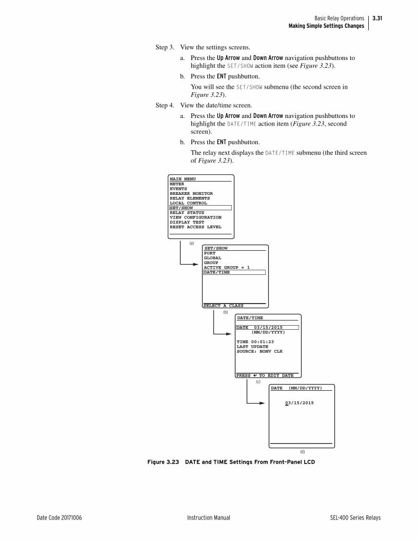
3.31
Date Code 20171006 Instruction Manual SEL-400 Series Relays
Basic Relay OperationsMaking Simple Settings Changes
Step 3. View the settings screens.
a. Press the Up Arrow and Down Arrow navigation pushbuttons to highlight the SET/SHOW action item (see Figure 3.23).
b. Press the ENT pushbutton.
You will see the SET/SHOW submenu (the second screen in Figure 3.23).
Step 4. View the date/time screen.
a. Press the Up Arrow and Down Arrow navigation pushbuttons to highlight the DATE/TIME action item (Figure 3.23, second screen).
b. Press the ENT pushbutton.
The relay next displays the DATE/TIME submenu (the third screen of Figure 3.23).
Figure 3.23 DATE and TIME Settings From Front-Panel LCD
(a)
(b)
METEREVENTSBREAKER MONITORRELAY ELEMENTSLOCAL CONTROLSET/SHOWRELAY STATUSVIEW CONFIGURATIONDISPLAY TESTRESET ACCESS LEVEL
MAIN MENU
SET/SHOW
PORTGLOBALGROUPACTIVE GROUP = 1DATE/TIME
(c)
DATE/TIME
DATE 03/15/2015 (MM/DD/YYYY)
TIME 00:01:23LAST UPDATESOURCE: NONV CLK
03/15/2015
(d)
DATE (MM/DD/YYYY)
PRESS TO EDIT DATE
SELECT A CLASS

3.32
SEL-400 Series Relays Instruction Manual Date Code 20171006
Basic Relay OperationsMaking Simple Settings Changes
Step 5. Set the date.
a. Press the ENT pushbutton.
The relay shows the last screen of Figure 3.23, the DATE edit screen.
b. Use the Up Arrow and Down Arrow navigation pushbuttons to increase and decrease the date position numbers.
Step to the next or previous position by using the Left Arrow and Right Arrow pushbuttons.
c. When finished adjusting the new date, press ENT.
The relay returns the display to the DATE/TIME submenu. Note that the relay reports the TIME SOURCE as FP DATE (front-panel date).
Step 6. Press ESC repeatedly to normalize the front-panel display.
Changing a Relay Setting From the Front PanelThe purpose of the procedure in the following steps is to provide additional prac-tice at entering relay settings from the front panel. In this example, you change the PORT F front-panel communications port settings.
Step 1. View the MAIN MENU.
a. If you have been using the front panel (as in the previous exam-ple), press the ESC key repeatedly until you see the MAIN MENU.
b. If the relay is displaying the ROTATING DISPLAY, press the ENT pushbutton to display the MAIN MENU.
Figure 3.24(a) shows the MAIN MENU at the beginning of the front-panel settings process.
Step 2. View the settings screens.
a. Press the Up Arrow and Down Arrow navigation pushbuttons to highlight the SET/SHOW action item, as shown in Figure 3.24(a).
b. Press the ENT pushbutton. You will see the SET/SHOW submenu screen, as shown in Figure 3.24(b).
Step 3. Select PORT F.
a. Highlight PORT and press the ENT pushbutton.
The relay displays the PORT instances screen, as shown in Figure 3.24(c).
b. Choose the port you want to configure by using the Up Arrow and Down Arrow navigation pushbuttons to move the screen arrow.
For this example, select PORT F and press ENT.
Step 4. View the Communications Settings category screen.
a. The relay displays the Port F category screen, as shown in Figure 3.24(d). Use the Up Arrow and Down Arrow navigation push-buttons to select the settings category.
b. For this example, highlight Communications Settings and press ENT.
The relay displays the Communications Settings screen, as shown in Figure 3.24(e).

3.33
Date Code 20171006 Instruction Manual SEL-400 Series Relays
Basic Relay OperationsMaking Simple Settings Changes
Step 5. Change settings.
a. Highlight the SPEED setting.
b. Press ENT.
(The relay possibly requires a password here; see Passwords on page 3.10 and Section 4: Front-Panel Operations.)
The LCD displays the SPEED selection submenu that has all the possible choices for serial data speeds.
The highlighted selection in Figure 3.24(f) indicates the default setting of 9600 (bps).
c. Use the Up Arrow and Down Arrow navigation pushbuttons to select a different speed.
d. Once you have selected a data speed, press the ENT pushbutton.
NOTE: Once you have changed communications parameters, you must change the corresponding parameters in your terminal emulation program to communicate with the relay via a communications port.
Step 6. End the settings session.
a. The relay returns to the previous category settings list screen. Press ESC to return to the categories screen where you see the Save Settings item at the bottom of the screen.
b. Use the Up Arrow and Down Arrow pushbuttons to highlight Save Settings and press ENT.
c. Highlight YES, and then press ENT.
The relay validates the setting and returns to the PORT screen, as shown in Figure 3.24(c).
Step 7. Press ESC repeatedly to return to the MAIN MENU.

3.34
SEL-400 Series Relays Instruction Manual Date Code 20171006
Basic Relay OperationsMaking Simple Settings Changes
Figure 3.24 SET/SHOW Menus
123F
Port
Protocol SelectionCommunications SettiSEL Protocol SettingSave Settings
Port F
SPEED :=9600DATABIT :=8PARITY :=NSTOPBIT :=1RTSCTS :=N
Communications Setti
Data Speed (300 to 53006001200240048009600192003840057600
SPEED
(a)
(b)
(c)
(d)
(e)
(f)
METEREVENTSBREAKER MONITORRELAY ELEMENTSLOCAL CONTROLSET/SHOWRELAY STATUSVIEW CONFIGURATIONDISPLAY TESTRESET ACCESS LEVEL
MAIN MENU
SET/SHOW
PORTGLOBALGROUPACTIVE GROUP = 1DATE/TIME
SELECT A CATEGORY
SELECT AN INSTANCE
SELECT A CLASS
SELECT A SETTING
SELECT AN OPTION

3.35
Date Code 20171006 Instruction Manual SEL-400 Series Relays
Basic Relay OperationsExamining Metering Quantities
Examining Metering QuantitiesSEL-400 series relays feature high-accuracy power system metering. You can view fundamental and rms quantities by using a communications terminal, QuickSet, or the front panel. For more information on relay metering, see Section 7: Metering, Monitoring, and Reporting in the product-specific instruc-tion manual.
View Metering Using the TerminalThe procedure in the following steps shows how to use a terminal or terminal emulation computer program to view power system metering. In this example, you connect specific voltages and currents for a 5 A, 60 Hz relay. Scale these quantities appropriately for your particular relay.
This example assumes that you have successfully established communication with the relay (see Making an EIA-232 Serial Port Connection on page 3.4). In addition, you must be familiar with relay access levels and passwords (see Changing the Default Passwords in the Terminal on page 3.10 to change the default access level passwords). Step 1 through Step 7 are necessary if you have not yet configured the relay and want to test metering using a test source. If the relay is already connected to the system, you may jump to Step 8 to view the sys-tem metering information.
Step 1. Prepare to control the relay at Access Level 2.
a. Using a communications terminal, type ACC <Enter>.
b. Type the Access Level 1 password and press <Enter>.
You will see the Access Level 1 => prompt.
c. Type 2AC <Enter>.
d. Type the correct password to go to Access Level 2.
You will see the Access Level 2 =>> prompt.
Step 2. Set the relay to a nominal operation mode.
a. Use a terminal to perform the initial Global settings relay setup in Making Settings Changes in Initial Global Settings on page 3.20.
b. Set the relay for 60 Hz operation, ABC phase rotation.
Step 3. Some SEL-400 series relays support voltage and current source selection. In these relays, configure the source selection appropriate for metering testing. The following shows how to do this in an SEL-451 (see Figure 3.25). Use the terminal to set Global setting ESS := 1.
a. Type SET G ESS TERSE <Enter>.
b. Type 1 <Enter>.
c. Type END <Enter> to finish this settings session.
d. Answer Y <Enter> to the save settings prompt.

3.36
SEL-400 Series Relays Instruction Manual Date Code 20171006
Basic Relay OperationsExamining Metering Quantities
Step 4. Set CT and PT ratios. The specific CT and PT configuration settings depends on the relay. The following shows a typical set of configura-tion choices. Use the terminal to set Group 1 setting CTRW := 200 (the CT W-input ratio), and PTRY := 2000.0 (the PT Y-input ratio).
a. Type SET CTRW TERSE <Enter>.
b. If the CTRW setting is not 200, type 200 <Enter>.
c. Proceed as shown in Figure 3.26 to PTRY and change PTRY to 2000.0, if needed.
d. Type END <Enter> to finish this settings session.
e. Answer Y <Enter> to the save settings prompt.
Step 5. Turn the relay off.
Step 6. Connect analog inputs. The specific connections depend on the relay. The following illustrates a typical set of voltage and current connec-tions.
a. If three voltage sources and three current sources are available, connect the sources to the relay as shown in Figure 3.27.
If three voltage sources and two current sources are available, use the connection diagram of Figure 3.28.
b. Apply 67 V per phase (line-to-neutral) in ABC phase rotation.
c. Apply 2.0 A per phase, in phase with the applied phase voltages.
=>>SET G ESS TERSE <Enter> Global
Current and Voltage Source Selection
Current and Voltage Source Selection (Y,N,1,2,3,4) ESS := N ? 1 <Enter>Line Current Source (IW,COMB) LINEI := IW ? END <Enter>
Save settings (Y,N) ? Y <Enter> Saving Settings, Please Wait........... Settings Saved =>>
Figure 3.25 Setting ESS in the Terminal
=>>SET CTRW TERSE <Enter> Group 1 Line Configuration Current Transformer Ratio - Input W (1-50000) CTRW := 120 ?200 <Enter>Current Transformer Ratio - Input X (1-50000) CTRX := 120 ? <Enter>Potential Transformer Ratio - Input Y (1.0-10000) PTRY := 180.0 ?2000.0 <Enter>PT Nominal Voltage (L-L) - Input Y (60-300 V,sec) VNOMY := 115 ?END <Enter>
Save settings (Y,N) ? Y <Enter> Saving Settings, Please Wait........... Settings Saved =>>
Figure 3.26 Setting CTRW and PTRY in the Terminal
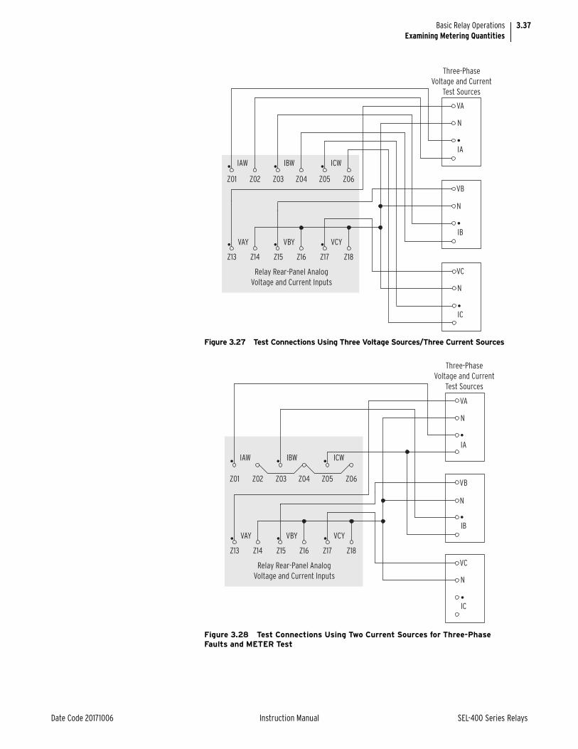
3.37
Date Code 20171006 Instruction Manual SEL-400 Series Relays
Basic Relay OperationsExamining Metering Quantities
Figure 3.27 Test Connections Using Three Voltage Sources/Three Current Sources
Figure 3.28 Test Connections Using Two Current Sources for Three-Phase Faults and METER Test
Three-Phase
Voltage and Current
Test Sources
IA
VB
IB
VC
IC
VA
IAW
Z01 Z02 Z03 Z04 Z05 Z06
Z13 Z14 Z15 Z16 Z17 Z18
IBW ICW
VAY VBY VCY
Relay Rear-Panel Analog
Voltage and Current Inputs
N
N
N
Three-Phase
Voltage and Current
Test Sources
IAW
Z01 Z02 Z03 Z04 Z05 Z06
Z13 Z14 Z15 Z16 Z17 Z18
IBW ICW
VAY VBY VCY
Relay Rear-Panel Analog
Voltage and Current Inputs
IA
VB
IB
VC
IC
VA
N
N
N

3.38
SEL-400 Series Relays Instruction Manual Date Code 20171006
Basic Relay OperationsExamining Metering Quantities
Step 7. Turn the relay on.
Step 8. View metering.
a. Type ACC <Enter> to log in to the relay at Access Level 1.
b. Type the password and press <Enter>.
c. Type MET <Enter>.
The relay displays the fundamental frequency (50 Hz or 60 Hz) metering information in a manner similar to that shown in Figure 3.29.
The metering quantities of View Metering Using the Terminal on page 3.35 are the fundamental line quantities. Other variants of the MET command give differ-ent relay metering quantities. See Section 8: Metering, Monitoring, and Report-ing of the product-specific instruction manual for more information on the specific metering options available in a specific relay.
View Metering Using QuickSetUse the procedures in the following steps to examine the relay metering with the QuickSet HMI.
This example assumes that you have successfully established communication with the relay (see Making an EIA-232 Serial Port Connection on page 3.4). In addition, you must be familiar with relay access levels and passwords (see Changing the Default Passwords in the Terminal on page 3.10 to change the default access level passwords). You should also be familiar with QuickSet (see Checking Relay Status in QuickSet on page 3.12 and Section 2: PC Software).
Step 1. Start QuickSet and establish a connection with the relay. See Step 1 and Step 2 of Checking Relay Status in QuickSet on page 3.12 for details on how to do this.
Step 2. Set the relay to a nominal operation mode. Perform the initial Global settings relay setup of Making Initial Global Settings in QuickSet on page 3.28 to set the relay for 60-Hz operation, ABC phase rotation.
=>>MET <Enter> Relay 1 Date: 02/26/2015 Time: 01:35:05.221Station A Serial Number: 0000000000 Phase Currents IA IB ICI MAG (A) 398.882 399.041 398.784I ANG (DEG) -1.18 -120.97 119.21
Phase Voltages Phase-Phase Voltages VA VB VC VAB VBC VCAV MAG (kV) 133.994 133.986 133.953 231.903 231.815 232.450V ANG (DEG) -0.17 -120.02 120.18 29.91 -89.92 150.01
Sequence Currents (A) Sequence Voltages (kV) I1 3I2 3I0 V1 3V2 3V0MAG 398.901 2.159 2.588 133.977 0.692 0.713ANG (DEG) -0.98 -62.68 -115.80 0.00 -53.25 -120.79
A B C 3PP (MW) 53.44 53.46 53.41 160.31Q (MVAR) 0.95 0.89 0.91 2.75S (MVA) 53.45 53.47 53.42 160.33POWER FACTOR 1.00 1.00 1.00 1.00 LAG LAG LAG LAG FREQ (Hz) 60.00 VDC1(V) 125.00 VDC2(V) 48.00 =>>
Figure 3.29 Terminal Screen MET Metering Quantities

3.39
Date Code 20171006 Instruction Manual SEL-400 Series Relays
Basic Relay OperationsExamining Metering Quantities
Step 3. Set a basic voltage and current configuration.
a. In the QuickSet Settings tree view, click the drop down arrow next to Global to expand the Global branch (see Figure 3.30).
b. Click the Current and Voltage Source Selection branch.
You will see the Current and Voltage Source Selection dialog box as shown in Figure 3.30.
c. Choose 1 from the drop-down menu under ESS Current and Voltage Source Selection.
Step 4. Set PT and CT ratios.
a. In the QuickSet Settings tree view, click the drop down arrow next to Group 1 to expand this branch (see Figure 3.31).
b. Click the drop down arrow next to Set 1.
c. Click Line Configuration.
You will see the Line Configuration window similar to Figure 3.31.
d. Enter setting CTRW Current Transformer Ratio - Input W as 200, and the PTRY Potential Transformer Ratio - Input Y as 2000.
e. Save the settings and send the Group 1 settings if you change the settings (see Step 6 and Step 7).
Figure 3.30 Global Alternate Source Selection Settings in QuickSet

3.40
SEL-400 Series Relays Instruction Manual Date Code 20171006
Basic Relay OperationsExamining Metering Quantities
Step 5. Start the QuickSet operator interface.
Step 6. In the top toolbar select Tools > HMI > HMI to start the GUI.
Step 7. Click the Phasors button of the HMI tree view (see Figure 3.32) to view phasors.
QuickSet displays fundamental line metering quantities with a display similar to Figure 3.33. (The test setup is adjusted for an approximately 30-degree lagging current.)
Figure 3.31 Group 1 Terminal Configuration Settings in QuickSet

3.41
Date Code 20171006 Instruction Manual SEL-400 Series Relays
Basic Relay OperationsExamining Metering Quantities
Figure 3.32 HMI Phasors View in QuickSet

3.42
SEL-400 Series Relays Instruction Manual Date Code 20171006
Basic Relay OperationsExamining Metering Quantities
Step 8. Click the Instantaneous button of the HMI tree view to see metering information similar to Figure 3.33.
View Metering From the Front PanelIn most SEL-400 series relays, you can use the front-panel display and naviga-tion pushbuttons to view the metering quantities of the relay (see Meter on page 4.16 for more information on viewing metering on the relay front panel). The screens in this procedure are for an SEL-451 with one circuit breaker, and this example assumes that you have not enabled the demand metering or synchro-nism-check features.
Step 1. Prepare to use the front panel by applying power to the relay.
Note that the LCD shows a sequence of screens called the ROTATING DISPLAY. (If you do not operate the front panel for a certain period, the relay will enter front-panel time-out mode and you will see the sequential screens of the ROTATING DISPLAY.)
Step 2. Press the ENT pushbutton to display the MAIN MENU at the top of Figure 3.34.
Step 3. View the metering selection screen.
a. Highlight the METER action item (see the first screen of Figure 3.34).
b. Press the ENT pushbutton.
The relay displays the METER submenu (the second screen in Figure 3.34).
Figure 3.33 Instantaneous Metering Quantities in QuickSet HMI

3.43
Date Code 20171006 Instruction Manual SEL-400 Series Relays
Basic Relay OperationsExamining Relay Elements
Step 4. View the metering screens.
a. Press the Up Arrow and Down Arrow navigation pushbuttons to highlight the FUNDAMENTAL METER action item, as shown in Figure 3.34(b).
b. Press the ENT pushbutton.
The relay displays the first FUNDAMENTAL METER screen, shown in Figure 3.34(c).
c. Use the Up Arrow and Down Arrow navigation pushbuttons to move among the fundamental line quantities metering screens.
Step 5. Press the ESC pushbutton repeatedly to return to the MAIN MENU.
Examining Relay ElementsUse the communications port TAR command or the front panel to display the state of relay elements, control inputs, and control outputs. Viewing a change in relay element (Relay Word bit) status is a good way to verify the pickup settings you have entered for protection elements.
Figure 3.34 Front-Panel Screens for METER
VOLTAGE (kV) VA = 133.9 0° VB = 133.9 -120° VC = 133.9 120°CURRENT (A) IA = 400.5 -31° IB = 397.4 -151° IC = 400.1 90°FREQ = 60.00 HzVDC1 = 9.2 VVDC2 = 10.7 V
FUND LINE METER
VOLTAGE (kV) VAB = 231.8 30° VBC = 231.8 -90° VCA = 232.2 150°
FUND LINE METER
METEREVENTSBREAKER MONITORRELAY ELEMENTSLOCAL CONTROLSET/SHOWRELAY STATUSVIEW CONFIGURATIONDISPLAY TESTRESET ACCESS LEVEL
MAIN MENU METER MENU
RMS METERFUNDAMENTAL METERENERGY METERMAX/MIN
METER SUBMENU
LINEBREAKER 1
•••
(a) (b) (c)
(d)
(e)

3.44
SEL-400 Series Relays Instruction Manual Date Code 20171006
Basic Relay OperationsExamining Relay Elements
View Relay Elements in the TerminalThe procedure in the following steps shows you how to view a change in state for the SEL-451 50P1 Phase-Instantaneous Overcurrent element from a communica-tions port.
For this procedure, you must have a serial terminal or computer with terminal emulation software and a variable current source for relay testing.
This example assumes that you have successfully established communication with the relay (see Making an EIA-232 Serial Port Connection on page 3.4). In addition, you must be familiar with relay access levels and passwords (see Changing the Default Passwords in the Terminal on page 3.10 to change the default access level passwords and enter higher relay access levels).
Step 1. Type ACC <Enter> at a communications terminal.
Step 2. Type the Access Level 1 password and press <Enter>.
You will see the Access Level 1 => prompt.
Step 3. Connect a test source to the relay.
a. Set the current output of a test source to zero output level.
b. Connect a single-phase current output of the test source to the IAW analog input.
Step 4. Type TAR 50P1 <Enter> to view the initial element status.
The relay returns a target terminal screen similar to that shown in Figure 3.35.
Step 5. View the element status change.
a. Type TAR 50P1 1000 <Enter> (this command causes the relay to repeat the TAR 50P1 command 1000 times). For more infor-mation on the TAR command see Section 14: ASCII Command Reference.
b. Increase the current source to produce a current magnitude greater than 15.00 A secondary in the relay.
You will see the 50P1 element status change to 1 when the input current exceeds the 50P1P setting threshold.
c. Type <Ctrl+X> to stop the relay from presenting the target display before completion of the 1000 target repeats.
View Relay Elements From the Front-Panel LCDYou can use the front-panel display and navigation pushbuttons to check Relay Word bit elements. See Section 4: Front-Panel Operations for more information on using the relay front panel.
Table 3.7 Phase Instantaneous Overcurrent Pickup
Setting Description Default
50P1P Level 1 Pickup (OFF, 0.25–100 A secondary) 15.00
=>TAR 50P1 <Enter>50P1 50P2 50P3 50P4 67P1 67P2 67P3 67P40 0 0 0 0 0 0 0 =>
Figure 3.35 Sample Targets Display on a Serial Terminal

3.45
Date Code 20171006 Instruction Manual SEL-400 Series Relays
Basic Relay OperationsExamining Relay Elements
This procedure uses the SEL-451 50P1 Phase-Instantaneous Overcurrent element.
Step 1. Display the MAIN MENU.
Step 2. If the relay LCD is in the ROTATING DISPLAY, press the ENT pushbut-ton to display the MAIN MENU similar to that in Figure 3.36.
Step 3. Press the Down Arrow navigation pushbutton to highlight the RELAY ELEMENTS action item, as shown in Figure 3.36(a).
Step 4. Press the ENT pushbutton.
You will see a RELAY ELEMENTS screen, as shown in Figure 3.36(b).
Step 5. Display the 50P1 Relay Word bit on the front-panel LCD screen.
a. Press ENT to go to the ELEMENT SEARCH submenu of Figure 3.36(c).
b. Use the navigation keys to highlight 5 and then press ENT to enter the character 5 in the text input field.
c. Enter the 0, P, and 1 characters in the same manner.
d. Highlight ACCEPT and press ENT.
The relay displays the LCD screen containing the 50P1 element, as shown Figure 3.36(d).
Figure 3.36 Viewing Relay Word Bits From the Front-Panel LCD
ELEMENT SEARCH
A B C D E F G H I J K LM N O P Q RS T U V W XY Z 0 1 2 34 5 6 7 8 9-ACCEPT BACKSPACE
METEREVENTSBREAKER MONITORRELAY ELEMENTSLOCAL CONTROLSET/SHOWRELAY STATUSVIEW CONFIGURATIONDISPLAY TESTRESET ACCESS LEVEL
MAIN MENU
PRESS TO SEARCH
RELAY ELEMENTS
SEARCH
PRESS TO SEARCH
RELAY ELEMENTS
SEARCH
ROW 22 ROW 2332GR =0 67P4 =032GF =0 67P3 =0R32QG =0 67P2 =0F32QG =0 67P1 =0R32V =0 50P4 =0F32V =0 50P3 =0R32I =0 50P2 =0F32I =0 50P1 =0
ROW 0 ROW 1* =0 TLED_8 =0* =0 TLED_7 =0* =0 TLED_6 =0* =0 TLED_5 =0* =0 TLED_4 =0* =0 TLED_3 =0TRIPLED=0 TLED_2 =0REL_EN =1 TLED_1 =0
(a)
(b)
(c)

3.46
SEL-400 Series Relays Instruction Manual Date Code 20171006
Basic Relay OperationsExamining Relay Elements
Step 6. Connect a test source to the relay.
a. Set the current output of a test source to zero output level.
b. Connect a single-phase current output of the test source to the IAW analog input.
Step 7. View the target status change.
a. Increase the current source to produce a current magnitude greater than 15.00 A secondary in the relay.
b. Observe the 50P1 target on the front-panel display.
You will see the 50P1 element status change to 1 when the input current exceeds the 50P1P setting threshold.
Step 8. Press ESC to return to the MAIN MENU.
View Relay Elements Using the Front-Panel LEDThe procedure in the following steps shows you how to use a front-panel LED to view a change-in-state for the SEL-451 50P1 Phase-Instantaneous Overcurrent element.
In this example, use QuickSet to configure the relay. You must have a computer that is communicating with the relay and running QuickSet (see Making Settings Changes in Initial Global Settings on page 3.20). In addition, you need a variable current source suitable for relay testing.
Step 1. Prepare to control the relay with QuickSet by establishing communi-cation, checking passwords, and reading relay settings.
Step 2. Set a pushbutton LED SELOGIC control equation.
a. Expand the Front Panel branch of the Settings tree view and click Pushbuttons (see Figure 3.37).
QuickSet displays the Pushbuttons dialog box similar to that shown in Figure 3.37.
b. Click in the PB6_LED text box and type 50P1.
c. Tab or click to any other text box.
QuickSet checks the validity of the setting.

3.47
Date Code 20171006 Instruction Manual SEL-400 Series Relays
Basic Relay OperationsExamining Relay Elements
Step 3. Click File > Save to save the new settings in QuickSet.
Step 4. Upload the new settings to the SEL-451.
a. Click File > Send.
QuickSet prompts you for the settings class you want to send to the relay, as shown in the Group Select dialog box of Figure 3.38.
b. Click the check box for Front Panel.
c. Click OK.
The relay responds with the Transfer Status dialog box shown in Figure 3.38.
If you see no error message, the new settings are loaded in the relay.
Figure 3.37 Setting Pushbutton LED Response in QuickSet

3.48
SEL-400 Series Relays Instruction Manual Date Code 20171006
Basic Relay OperationsReading Oscillograms, Event Reports, and SER
Step 5. Connect a test source to the relay.
a. Set the current output of a test source to zero output level.
b. Connect a single-phase current output of the test source to the IAW analog input.
Step 6. View the target status change.
a. Increase the current source to produce a current magnitude greater than 15.00 A secondary in the relay.
b. Observe the LED next to Pushbutton 6 on the SEL-451 front panel.
You will see the LED illuminate when the input current exceeds the 50P1P setting threshold.
Reading Oscillograms, Event Reports, and SERSEL-400 series relays have great capabilities for storing and reporting power sys-tem events. These include high-resolution oscillography with sampling as high as 8 kHz, event reports that encompass important variables in the power system, and the SER that reports changing power system conditions and relay operating states.
You can view oscillograms taken from high-resolution raw data or from filtered event report data. Each type of presentation gives you a unique view of the power system. High-resolution oscillograms are useful for viewing system transients and dc artifacts outside the relay filter system; event report oscillograms give you a picture of the quantities that the relay used in the protection algorithms.
The examples listed in this subsection give step-by-step procedures to acquaint you with these features. Section 9: Reporting provides a complete discussion of these relay features.
Figure 3.38 Uploading Front-Panel Settings to the Relay

3.49
Date Code 20171006 Instruction Manual SEL-400 Series Relays
Basic Relay OperationsReading Oscillograms, Event Reports, and SER
Generating an EventTo view high-resolution raw data oscillograms and event reports, you must gener-ate a relay event. High-resolution oscillography and event reports use the same event triggering methods. The relay uses multiple sources to initiate a data cap-ture, including any of the following: Relay Word bit TRIP asserts, SELOGIC con-trol equation ER (event report trigger), or the TRI command. (Factory-default setup does not include the PUL command as an event report trigger. You can add the PUL command by entering the Relay Word bit TESTPUL in the ER SELOGIC control equation.)
You can use an event trigger to initiate capturing power system data. The proce-dure in the following steps shows how to use the QuickSet HMI to generate the TRI command, which triggers an event capture. In this example, the relay uses default parameters to record the event. These parameters are at a sampling rate (SRATE) of 2000 samples per second (2 kHz), a pretrigger or prefault recording length (PRE) of 0.1 seconds, and an event report length (LER) of 0.5 seconds. See Duration of Data Captures and Event Reports on page 9.7 for complete information on changing these default settings to match your application.
This example assumes that you have successfully established communication with the relay (see Making an EIA-232 Serial Port Connection on page 3.4). In addition, you must be familiar with relay access levels and passwords (see Changing the Default Passwords in the Terminal on page 3.10 to change the default access level passwords). You should also be familiar with QuickSet (see Checking Relay Status in QuickSet on page 3.12 and Section 2: PC Software). In addition, you should perform the steps described in View Metering Using the Ter-minal on page 3.35 to connect secondary test voltages and currents, and to set the relay to meter these quantities correctly.
Step 1. Connect voltage and current sources to the relay secondary voltage and secondary current inputs (use the connections of View Metering Using the Terminal on page 3.35 and Figure 3.27 or Figure 3.28).
Step 2. Apply power to the relay, start QuickSet, and establish a connection with the relay. See Step 1 and Step 2 of Checking Relay Status in QuickSet on page 3.12 for detailed steps.
NOTE: The Trigger New Event button in the Event History dialog box may also be used (see Figure 3.42).
Step 3. In the top toolbar menu, select Tools > HMI > HMI to start the QuickSet operator interface.
Step 4. Click Control Window in the HMI tree view (see Figure 3.39).
QuickSet displays the Control Window similar to that shown in Figure 3.40.
Figure 3.39 QuickSet HMI Tree View

3.50
SEL-400 Series Relays Instruction Manual Date Code 20171006
Basic Relay OperationsReading Oscillograms, Event Reports, and SER
Step 5. Trigger an Event.
a. Click the Event Trigger box to trigger an event.
QuickSet displays a prompt in a dialog box similar to that in Figure 3.41.
b. Click Yes to trigger an event.
Reading the Event HistoryThe relay has multiple convenient methods for checking whether you success-fully captured power system data. The following describes how to view the event history data with QuickSet and how to examine the history data through use of the ASCII terminal interface.
Reading the Event History in QuickSet The procedure in the following steps shows how to use the QuickSet HMI to gather relay event history information. See Event History on page 9.27 for more information on event history.
This example assumes that you have successfully established communication with the relay (see Making an EIA-232 Serial Port Connection on page 3.4). In addition, you must be familiar with relay access levels and passwords (see
Figure 3.40 QuickSet HMI Control Window
Figure 3.41 Event Trigger Prompt in QuickSet

3.51
Date Code 20171006 Instruction Manual SEL-400 Series Relays
Basic Relay OperationsReading Oscillograms, Event Reports, and SER
Changing the Default Passwords in the Terminal on page 3.10 to change the default access level passwords). You should also be familiar with QuickSet (see Checking Relay Status in QuickSet on page 3.12 and Section 2: PC Software).
Step 1. Start QuickSet and establish a connection with the relay. See Step 1 and Step 2 of Checking Relay Status in QuickSet on page 3.12 for detailed steps.
Step 2. To view the event history report, open the QuickSet Tools menu and click Events > Get Event Files.
You will see the Relay Event History dialog box similar to that shown in Figure 3.42.
Reading the Event History in the TerminalThe procedure in the following steps shows how to use the relay HIS command to confirm that you captured power system data with an event trigger. This exam-ple assumes that you have successfully established communication with the relay (see Making an EIA-232 Serial Port Connection on page 3.4). In addition, you must be familiar with relay access levels and passwords (see Changing the Default Passwords in the Terminal on page 3.10 to change the default access level passwords).
Step 1. Prepare to monitor the relay at Access Level 1.
a. Using a communications terminal, type ACC <Enter>.
b. Type the Access Level 1 password and press <Enter>.
You will see the Access Level 1 => prompt.
Step 2. Type HIS <Enter> to examine the event history
You will see a screen display similar to Figure 3.43.
Figure 3.42 Relay Event History Dialog Box

3.52
SEL-400 Series Relays Instruction Manual Date Code 20171006
Basic Relay OperationsReading Oscillograms, Event Reports, and SER
For more information on the event history, see Event History on page 9.27.
Viewing High-Resolution OscillogramsOnce you have successfully generated an event, you can view high-resolution oscillograms and event report oscillograms about this event. When gathered from a field-installed relay, this information helps you assess power system operating conditions. In addition, when you first install the relay, this reporting information helps you confirm that you have connected the relay correctly.
The relay provides high-resolution oscillography data in the binary COMTRADE file format (IEEE/ANSI standard C37.111-1999). File transfer is the only mecha-nism for retrieving high-resolution COMTRADE data from the relay.
The SEL-5601 SYNCHROWAVE Event is a program you can use to view COM-TRADE data. Many third-party software suppliers can provide you with pro-grams to display and manipulate COMTRADE files.
Retrieving High-Resolution COMTRADE Data in the TerminalThe relay recorded the event triggered in Generating an Event on page 3.49. The procedure in the following steps shows you how to retrieve the high-resolution raw oscillography data for this event.
Perform the steps listed in Generating an Event on page 3.49 before executing the instructions in this example. For this procedure, you must use a communica-tions terminal emulation computer program capable of file transfers.
If you need help finding a terminal emulation program, contact the SEL factory or your local Technical Service Center.
Step 1. Prepare to monitor the relay at Access Level 1.
a. Using a communications terminal, type ACC <Enter>.
b. Type the Access Level 1 password and press <Enter>.
You will see the Access Level 1 => prompt.
=>HIS <Enter> Relay 1 Date: 03/03/2015 Time: 17:27:44.140Station A Serial Number: 0000000000
# DATE TIME EVENT LOCAT CURR GRP TARGETS10024 03/03/2015 08:33:29.201 TRIP $$$$.$$ 0 110023 03/02/2015 15:41:35.777 ER $$$$.$$ 0 110022 03/02/2015 15:41:35.227 ER $$$$.$$ 0 110021 03/02/2015 15:41:34.577 ER $$$$.$$ 0 110020 03/02/2015 15:41:34.152 ER $$$$.$$ 0 110019 03/02/2015 15:41:32.702 ER $$$$.$$ 0 110018 02/24/2015 15:22:19.496 TRIG $$$$.$$ 1 3
10017 02/24/2015 15:22:17.705 TRIG $$$$.$$ 1 310016 02/23/2015 17:42:56.581 TRIG $$$$.$$ 1 310015 02/20/2015 19:23:41.369 BCG 0.02 3442 310014 02/20/2015 17:14:40.056 CA T 7.28 2449 3 TIME A_FAULT C_FAULT
=>
Figure 3.43 Sample HIS Command Output in the Terminal

3.53
Date Code 20171006 Instruction Manual SEL-400 Series Relays
Basic Relay OperationsReading Oscillograms, Event Reports, and SER
Step 2. Type FILE DIR EVENTS <Enter> to view the contents of the events file directory.
The relay lists file names for recently recorded events in a manner similar to that shown in Figure 3.44.
The relay shows three high-resolution oscillography files with the file extensions .HDR, .CFG, and .DAT for each event.
This procedure uses HR_10014 as the number of the event that you recently triggered; use the event number corresponding to your triggered event.
Step 3. Type FILE READ EVENTS HR_10014.* <Enter> to ready the relay to transfer the HR_10014.HDR, HR_10014.CFG, and HR_10014.DAT files to your computer.
Step 4. Download the files. Perform the steps necessary for your terminal emulation program to receive a file.
Typically, these are the file transfer steps:
➢ Specify the destination file location in your computer file storage system and file name.
➢ Select the transfer type as YModem (if this transfer type is not already enabled).
➢ Click Receive.
You will usually see a confirmation message when the file transfer is complete.
When these files have transferred successfully, you have the entire COMTRADE file for the high-resolution raw data capture.
Step 5. Use ACSELERATOR Analytic Assistant SEL-5601 Software, SYN-CHROWAVE Event, QuickSet, or other COMTRADE-capable pro-grams to play back high-resolution raw data oscillograms of the high-resolution raw data capture files you just transferred.
Retrieving High-Resolution COMTRADE Data in QuickSet The procedure in the following steps shows how to use QuickSet to view the event that you triggered in Generating an Event on page 3.49. You can use this procedure to view other events stored in the relay.
This example assumes that you have successfully established communication with the relay (see Making an EIA-232 Serial Port Connection on page 3.4). In addition, you must be familiar with relay access levels and passwords (see Changing the Default Passwords in the Terminal on page 3.10 to change the default access level passwords). You should also be familiar with QuickSet (see Checking Relay Status in QuickSet on page 3.12 and Section 2: PC Software).
=>FILE DIR EVENTS <Enter>C4_10014.TXT R 02/20/2004 17:14:40C8_10014.TXT R 02/20/2004 17:14:40CHISTORY.TXT RE4_10014.TXT R 02/20/2004 17:14:40E8_10014.TXT R 02/20/2004 17:14:40HISTORY.TXT R
HR_10014.CFG R 02/20/2004 17:14:40HR_10014.DAT R 02/20/2004 17:14:40HR_10014.HDR R 02/20/2004 17:14:40=>
Figure 3.44 EVENTS Folder Files
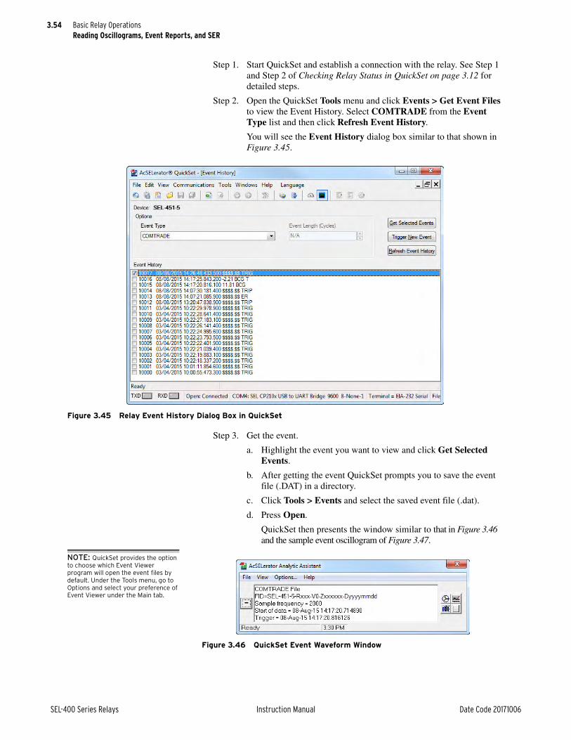
3.54
SEL-400 Series Relays Instruction Manual Date Code 20171006
Basic Relay OperationsReading Oscillograms, Event Reports, and SER
Step 1. Start QuickSet and establish a connection with the relay. See Step 1 and Step 2 of Checking Relay Status in QuickSet on page 3.12 for detailed steps.
Step 2. Open the QuickSet Tools menu and click Events > Get Event Files to view the Event History. Select COMTRADE from the Event Type list and then click Refresh Event History.
You will see the Event History dialog box similar to that shown in Figure 3.45.
Step 3. Get the event.
a. Highlight the event you want to view and click Get Selected Events.
b. After getting the event QuickSet prompts you to save the event file (.DAT) in a directory.
c. Click Tools > Events and select the saved event file (.dat).
d. Press Open.
QuickSet then presents the window similar to that in Figure 3.46 and the sample event oscillogram of Figure 3.47.
NOTE: QuickSet provides the option to choose which Event Viewer program will open the event files by default. Under the Tools menu, go to Options and select your preference of Event Viewer under the Main tab.
Figure 3.45 Relay Event History Dialog Box in QuickSet
Figure 3.46 QuickSet Event Waveform Window

3.55
Date Code 20171006 Instruction Manual SEL-400 Series Relays
Basic Relay OperationsReading Oscillograms, Event Reports, and SER
You can also examine a phasors display, an event harmonic analysis display, and the event summary from the Event Waveform View menu. See Section 9: Reporting for more information.
Viewing Event Report DataExamine relay event reports to inspect the operating quantities the relay used at each triggered event. Unlike the raw data samples/second high-resolution oscil-lography files, these reports contain the filtered samples/cycle data the relay uses to make protection decisions. Event reports are useful for determining why the relay operated for a particular set of power system conditions. For more informa-tion on event reports, see Event Report on page 9.14.
The relay recorded the event triggered in Generating an Event on page 3.49. The procedure in the following steps shows you how to retrieve the event report data files for this event. Perform the steps listed in Generating an Event on page 3.49 before executing the instructions in this example. For this procedure, you must use a terminal program capable of Ymodem protocol file transfer.
Step 1. Prepare to monitor the relay at Access Level 1.
a. Using a communications terminal, type ACC <Enter>.
b. Type the Access Level 1 password and press <Enter>.
You will see the Access Level 1 => prompt.
Step 2. Type FILE DIR EVENTS <Enter> to view the events file directory.
The relay lists file names for recently recorded events in a manner similar to that shown in Figure 3.44.
In the figure, the relay shows two event report files: E4_10014.TXT and E8_10014.TXT, and two Compressed ASCII event report files: C4_10014.TXT and C8_10014.TXT.
Step 3. Type FILE READ EVENTS C8_10014.TXT <Enter> to transfer the Compressed ASCII event report file to your computer.
Figure 3.47 Sample Event Oscillogram

3.56
SEL-400 Series Relays Instruction Manual Date Code 20171006
Basic Relay OperationsReading Oscillograms, Event Reports, and SER
Step 4. Download the file. Perform the steps necessary for your terminal emulation program to receive a file.
Typically, these are the file transfer steps:
➢ Specify the destination file location in your computer file storage system and file name.
➢ Select the transfer type as YModem (if not already enabled).
➢ Click Receive.
You will usually see a confirmation message when the file transfer is complete.
Step 5. When this file has transferred successfully, use Analytic Assistant or SYNCHROWAVE Event to play back the event report oscillograms of the 8-samples/cycle event report file you just transferred.
Viewing SER RecordsThe relay SER records relay operating changes and relay element states. In response to an element change of state, the SER logs the element, the element state, and a time stamp. Program the relay elements that the relay stores in the SER records, thus capturing significant system events such as an input/output change of state, element pickup/dropout, recloser state changes, etc.
The relay stores the latest 1000 entries to a nonvolatile record. Use the relay com-munications ports or QuickSet to view the SER records. For more information on the SER, see Section 9: Reporting.
The latest 200 SER events are viewable from the front panel. For more informa-tion, see Section 4: Front-Panel Operations.
Setting the SER and Examining an SER Record in QuickSetThe procedure in the following steps shows you how to use QuickSet to program relay elements into the SER. Also, use these procedures to review SER records with QuickSet.
This example assumes that you have successfully established communication with the relay (see Making an EIA-232 Serial Port Connection on page 3.4). In addition, you must be familiar with relay access levels and passwords (see Changing the Default Passwords in the Terminal on page 3.10 to change the default access level passwords). You should also be familiar with QuickSet (see Section 2: PC Software).
Step 1. Start QuickSet and establish a connection with the relay. See Step 1 and Step 2 of Checking Relay Status in QuickSet on page 3.12 for detailed steps.
Step 2. Download the present configuration in the relay by clicking File > Read.
The relay sends all configuration and settings data to QuickSet.
Step 3. Click the Report branch of the QuickSet Settings tree view structure (see Figure 3.48) to view the SER settings entry screen.
You will see the SER Points and Aliases window similar to Figure 3.49.

3.57
Date Code 20171006 Instruction Manual SEL-400 Series Relays
Basic Relay OperationsReading Oscillograms, Event Reports, and SER
Figure 3.48 Selecting SER Points and Aliases Settings in QuickSet
Figure 3.49 SER Points and Aliases Settings in QuickSet

3.58
SEL-400 Series Relays Instruction Manual Date Code 20171006
Basic Relay OperationsReading Oscillograms, Event Reports, and SER
Step 4. Enter SER settings.
a. For this example, open the entry form by clicking the button beside the SITM1 SER Points and Aliases, Point 1 entry field. We will change this SER point to report the operation of the Tar-get Reset pushbutton.
b. Click the button beside the Relay Word Bit entry field.
c. Select Target Logic Bits, and then double-click on TRGTR to copy the TRGTR name into the Relay Word Bit field. This also copies TRGTR to the Reporting Name (or alias) field.
d. Type Target Reset PB in the Alias Name field.
e. Type TEST in the Set Alias field.
f. Type OFF in the Clear Alias field.
g. Click OK.
Step 5. Click File > Save to save the new settings in QuickSet.
Step 6. Upload the new settings to the relay.
a. Click File > Send.
QuickSet prompts you for the settings class you want to send to the relay, as shown in the first dialog box of Figure 3.50.
b. Click the Report check box.
c. Click OK.
QuickSet responds with the second dialog box of Figure 3.50.
If you see no error message, the new settings are loaded in the relay.
Step 7. Press and release the front-panel TARGET RESET pushbutton to generate an SER record.
Step 8. View the SER report.
a. Start the QuickSet operator interface.
b. In the top toolbar Tools menu, click HMI > HMI.
c. Click the SER button of the HMI tree view (see Figure 3.51).
QuickSet displays the SER records with a display similar to Figure 3.52.
Figure 3.50 Uploading Report Settings to the Relay
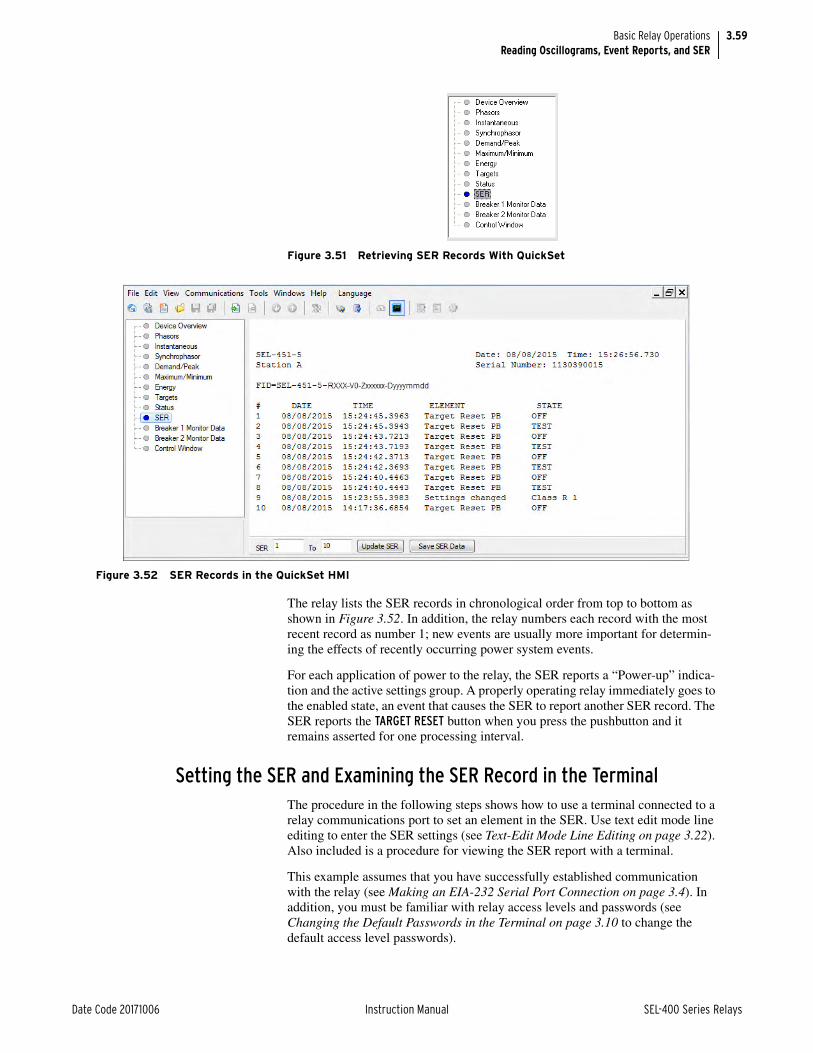
3.59
Date Code 20171006 Instruction Manual SEL-400 Series Relays
Basic Relay OperationsReading Oscillograms, Event Reports, and SER
The relay lists the SER records in chronological order from top to bottom as shown in Figure 3.52. In addition, the relay numbers each record with the most recent record as number 1; new events are usually more important for determin-ing the effects of recently occurring power system events.
For each application of power to the relay, the SER reports a “Power-up” indica-tion and the active settings group. A properly operating relay immediately goes to the enabled state, an event that causes the SER to report another SER record. The SER reports the TARGET RESET button when you press the pushbutton and it remains asserted for one processing interval.
Setting the SER and Examining the SER Record in the TerminalThe procedure in the following steps shows how to use a terminal connected to a relay communications port to set an element in the SER. Use text edit mode line editing to enter the SER settings (see Text-Edit Mode Line Editing on page 3.22). Also included is a procedure for viewing the SER report with a terminal.
This example assumes that you have successfully established communication with the relay (see Making an EIA-232 Serial Port Connection on page 3.4). In addition, you must be familiar with relay access levels and passwords (see Changing the Default Passwords in the Terminal on page 3.10 to change the default access level passwords).
Figure 3.51 Retrieving SER Records With QuickSet
Figure 3.52 SER Records in the QuickSet HMI

3.60
SEL-400 Series Relays Instruction Manual Date Code 20171006
Basic Relay OperationsReading Oscillograms, Event Reports, and SER
Step 1. Prepare to control the relay at Access Level 2.
a. Using a communications terminal, type ACC <Enter>.
b. Type the Access Level 1 password and press <Enter>.
You will see the Access Level 1 => prompt.
c. Type 2AC <Enter>.
d. Type the correct password to go to Access Level 2.
You will see the Access Level 2 =>> prompt.
Step 2. Enter SER trigger data.
a. Type SET R TERSE <Enter> to access the Report settings (see Figure 3.53).
b. Press <Enter> to move past the SER Chatter Criteria setting.
c. At the SER Points ? prompt line, type the following:
TRGTR,“TARGET RESET PB”,TEST,OFF,N <Enter>.
At the next line, type END <Enter>.
d. The relay prompts you to save the new setting; type Y <Enter>.
Step 3. Press and release the front-panel TARGET RESET pushbutton to generate an SER record.
Step 4. Type SER <Enter> (at the Access Level 1 prompt or higher) to view the SER report.
The relay presents a screen similar to the SER display of Figure 3.52.
Downloading an SER Report FileThe procedure in the following steps shows you how to retrieve the SER report stored in the relay as a file. For this procedure, you must use a terminal emulation program with file transfer capability.
Step 1. Prepare to monitor the relay at Access Level 1.
a. Using a communications terminal, type ACC <Enter>.
b. Type the Access Level 1 password and press <Enter>.
You will see the Access Level 1 => prompt.
Step 2. Type FILE DIR REPORTS <Enter> to view the events file direc-tory.
The terminal lists the file names for standard reports as shown in Figure 3.54.
=>>SET R TERSE <Enter>ReportSER Chatter CriteriaAutomatic Removal of Chattering SER Points (Y,N) ESERDEL := N ? <Enter>
SER Points(Relay Word Bit, Reporting Name, Set State Name, Clear State Name, HMI Alarm) 1:? TRGTR,“TARGET RESET PB”,TEST,OFF,N <Enter>2:? END <Enter>
Save settings (Y,N) ? Y <Enter>Saving Settings, Please Wait...........Settings Saved=>>
Figure 3.53 Setting an SER Element: Terminal

3.61
Date Code 20171006 Instruction Manual SEL-400 Series Relays
Basic Relay OperationsOperating the Relay Inputs and Outputs
Step 3. Prepare the relay to download the SER report.
a. Type FILE READ REPORTS SER.TXT <Enter>.
b. If you want the Compressed ASCII file, type the following:
FILE READ REPORTS CSER.TXT <Enter>
Step 4. Download the SER report. Perform the steps necessary for your ter-minal emulation program to receive a file.
Typically, these are the file transfer steps:
NOTE: Transferring SER files (or CSER files) with the FILE READ REPORTS SER.TXT command, performs an SER CV command as part of the transfer. SER CV clears the SER information from the present port. With the SER information cleared, there are no data available for subsequent SER or CSER transfers from the same port.
➢ Specify the destination file location in your computer file storage system and file name.
➢ Select the transfer type as YModem (if not already enabled).
➢ Click Receive.
You will usually see a confirmation message when the file transfer is complete.
Step 5. When the SER.txt file has transferred successfully, use a word-pro-cessing program to view the contents of the file.
You will see the SER records in a format similar to Figure 3.52.
Operating the Relay Inputs and OutputsSEL-400 series relays give you great ability to perform control actions at bay and substation locations via the relay control outputs. The control outputs close and open circuit breakers, switch disconnects, and operate auxiliary station equip-ment such as fans and lights. The relay reads data from the power system and interfaces with external signals (contact closures and data) through the control inputs. This subsection is an introduction to operating the control outputs and control inputs. For more information on connecting and applying the control out-puts and control inputs, see Section 2: Installation in the product-specific instruc-tion manual.
Control OutputThe relay features standard, hybrid (high-current interrupting), and high-speed high-current interrupting control outputs that you can use to control circuit break-ers and other devices in an equipment bay or substation control house.
=>FILE DIR REPORTS <Enter>BRE_1.TXT R BRE_2.TXT R BRE_S1.TXT R BRE_S2.TXT R CBRE.TXT R CHISTORY.TXT R CPRO.TXT R CSER.TXT R HISTORY.TXT R PRO.TXT R SER.TXT R =>
Figure 3.54 Example Reports File Structure

3.62
SEL-400 Series Relays Instruction Manual Date Code 20171006
Basic Relay OperationsOperating the Relay Inputs and Outputs
Pulsing a Control Output in the TerminalWhen first connecting the relay, or at any time that you want to test relay control outputs, perform the following procedure. The procedure in the following steps shows how to use a communications terminal to pulse the control output contacts. Perform the steps in this example to become familiar with relay control and serial communication. For more information on the PULSE command, see PULSE on page 14.45.
This example assumes that you have successfully established communication with the relay; see Making an EIA-232 Serial Port Connection on page 3.4 for a step-by-step procedure. In addition, you must be familiar with relay access levels and passwords (see Changing the Default Passwords in the Terminal on page 3.10 to change the default access level passwords).
NOTE: To pulse an output, the circuit breaker control enable jumper must be installed on the main board.
Step 1. Prepare to control the relay at Access Level B.
a. Using a communications terminal, type ACC <Enter>.
b. Type the Access Level 1 password and press <Enter>.
You will see the Access Level 1 => prompt.
c. Type BAC <Enter>.
d. Type the correct password to go to Access Level B.
You will see the Access Level B ==> prompt.
Step 2. Attach an indicating device (ohmmeter with a beep sounder or a test set) to the terminals for control output OUT104.
This output is a standard control output and is not polarity-sensitive.
Step 3. Perform the pulse operation.
a. Type PULSE OUT104 <Enter>.
The relay confirms your request to pulse an output with a prompt such as that shown in Figure 3.55.
b. Type Y <Enter> at the prompt.
You will see or hear the indicating device turn on for a second and then turn off.
You can also pulse an output for longer than the default one-second period. If you enter a number after the PULSE command, that number specifies the duration in seconds for the pulse. For example, if you enter PULSE OUT104 3 <Enter>, the relay pulses OUT104 for three seconds.
Pulsing a Control Output on the Front PanelThe procedure in the following steps shows you how to use the front-panel dis-play and navigation pushbuttons to check for proper operation of the relay con-trol outputs. See Section 4: Front-Panel Operations for information on using the relay front panel.
Step 1. Attach an indicating device (an ohmmeter with a beep sounder or a test set) to the terminals for control output OUT104.
This output is a standard control output and is not polarity-sensitive.
==>PULSE OUT104 <Enter>Pulse contact OUT104 for 1 seconds(Y/N) ? Y <Enter>==>
Figure 3.55 Terminal Display for PULSE Command

3.63
Date Code 20171006 Instruction Manual SEL-400 Series Relays
Basic Relay OperationsOperating the Relay Inputs and Outputs
Step 2. View the front-panel display.
After applying power to the relay, note that the LCD shows a sequence of screens called the ROTATING DISPLAY.
(Also, if you do not operate the front panel for a certain period, the relay will enter front-panel time-out mode and you will see the sequential screens of the ROTATING DISPLAY.)
Step 3. Press the ENT pushbutton to view the MAIN MENU, similar to that in Figure 3.56(a).
Step 4. View the LOCAL CONTROL screen.
a. Press the Up Arrow and Down Arrow navigation pushbuttons to highlight the LOCAL CONTROL action item, as shown in Figure 3.56(a).
b. Press the ENT pushbutton.
You will see the LOCAL CONTROL submenu as shown in Figure 3.56(b).
Step 5. View the OUTPUT TESTING screen.
a. Press the Up Arrow and Down Arrow navigation pushbuttons to highlight the --OUTPUT TESTING-- action item, as shown in Figure 3.56(b).
b. Press the ENT pushbutton.
The relay displays the OUTPUT TESTING submenu, as shown in Figure 3.56(c).
Figure 3.56 Front-Panel Menus for Pulsing OUT104
OUT101OUT102OUT103OUT104OUT105OUT106OUT107OUT108 PULSE OUTPUT?
OUTPUT TESTING
NO YES
METEREVENTSBREAKER MONITORRELAY ELEMENTSLOCAL CONTROLSET/SHOWRELAY STATUSVIEW CONFIGURATIONDISPLAY TESTRESET ACCESS LEVEL
MAIN MENU
LOCAL CONTROL
--BREAKER CONTROL--5 MVA XFMR Fans--OUTPUT TESTING--
(a)
(b)
(c)

3.64
SEL-400 Series Relays Instruction Manual Date Code 20171006
Basic Relay OperationsOperating the Relay Inputs and Outputs
Step 6. Command the relay to pulse the control output.
a. Press the Up Arrow and Down Arrow navigation pushbuttons to highlight OUT104 as shown in Figure 3.56(c).
b. Press the Right Arrow navigation pushbutton to highlight YES under PULSE OUTPUT?
c. Press the ENT pushbutton.
The relay detects your request for a function at an access level for which you do not yet have authorization. Whenever this condition occurs, the relay displays the password access screen as shown in Figure 3.57.
Step 7. Input a password and pulse the output.
a. Enter a valid Access Level B, P, A, O, or 2 password.
(The front panel is always at Access Level 1, so you do not enter the Access Level 1 password.)
Enter a valid password by using the navigation pushbuttons to select, in sequence, the alphanumeric characters that correspond to your password.
b. Press the ENT pushbutton at each password character.
(If you make a mistake, highlight the BACKSPACE option and press ENT to reenter a character or characters.)
c. After entering all password characters, press the Up Arrow or Down Arrow pushbuttons to highlight ACCEPT, and press ENT.
The relay pulses the output, and you will see the indicating device turn on for a second and then turn off.
Controlling a Relay Control Output With a Local Bit in the TerminalIn this example, you set Local Bit 3 to start the transformer cooling fans near the breaker bay where you have installed the SEL-451. Thus, you can use the LCD screen and navigation pushbuttons to toggle relay Local Bit 3 to control the state of the cooling fans. Relay Word bit LB_SP03 provides supervision for Local Bit 3. Relay Word bit LB_SP03 must be asserted for successful Local Bit 3 operations. For more information on local bits, see Local Control Bits on page 4.22.
The procedure in the following steps proposes connecting the transformer bank fan control to relay output OUT105. You can choose any relay output that conforms to your requirements.
This example assumes that you have successfully established communication with the relay (see Making an EIA-232 Serial Port Connection on page 3.4). In addition, you must be familiar with relay access levels and passwords (see Changing the Default Passwords in the Terminal on page 3.10 to change the default access level passwords).
Figure 3.57 Password Entry Screen
A B C D E F G HI J K L M N O PQ R S T U V W XY Z a b c d e fg h i j k l m no p q r s t u vw x y z 0 1 2 34 5 6 7 8 9 _ .ACCEPT BACKSPACE
PASSWORD REQUIRED

3.65
Date Code 20171006 Instruction Manual SEL-400 Series Relays
Basic Relay OperationsOperating the Relay Inputs and Outputs
Step 1. Prepare to control the relay at Access Level 2.
a. Using a communications terminal, type ACC <Enter>.
b. Type the Access Level 1 password and press <Enter>.
You will see the Access Level 1 => prompt.
c. Type 2AC <Enter>.
d. Type the correct password to go to Access Level 2.
You will see the Access Level 2 =>> prompt.
Step 2. Access the local control settings.
a. Type SET F <Enter>.
b. Repeatedly type > and then <Enter> to advance through the front-panel settings until you reach the Local Control category.
Figure 3.58 shows a representative terminal screen.
Step 3. Type LIST <Enter> at the Local Control ? prompt to list the active control points.
This example assumes that you are using no local bits, so the relay returns you to Line 1 followed by the settings ? prompt.
Step 4. Type LB03,“5 MVA XFMR Fans”,ON,OFF,N <Enter> at the Line ? prompt.
The relay checks that this is a valid entry and responds with the next line prompt 2: followed by the settings ? prompt.
Step 5. End the settings session.
a. Type END <Enter>.
The relay displays a readback of all the front-panel settings, eventually displaying the Save settings (Y,N) ? prompt. (In Figure 3.58 a vertical ellipsis represents the readback.)
At the end of the readback information, just before the Save settings (Y,N) ? prompt, you can see the new local bit information.
b. Type Y <Enter> to save your new settings.
Step 6. Set OUT105 to respond to Local Bit 3.
a. Type SET O OUT105 <Enter> (see Figure 3.59).
b. At the ? prompt, type LB03 <Enter>.
c. At the next ? prompt, type END <Enter>.
d. When prompted to save settings, type Y <Enter>.
Local Control(Local Bit, Local Label, Local Set State, Local Clear State, Pulse Enable)
1:? LIST <Enter>1:? LB03,"5 MVA XFMR Fans",ON,OFF,N <Enter>2:? END <Enter>
• • •Local Control(Local Bit, Local Label, Local Set State, Local Clear State, Pulse Enable)
1: LB03,"5 MVA XMFR Fans","ON","OFF",N Save settings (Y,N) ? Y <Enter> Saving Settings, Please Wait........... Settings Saved =>>
Figure 3.58 Using Text-Edit Mode Line Editing to Set Local Bit 3

3.66
SEL-400 Series Relays Instruction Manual Date Code 20171006
Basic Relay OperationsOperating the Relay Inputs and Outputs
Step 7. Test the connection and programming.
a. Use the appropriate interface hardware to connect the fan control start circuit to OUT105.
b. At the relay front-panel MAIN MENU, select LOCAL CONTROL and press the ENT pushbutton as shown in Figure 3.60(a).
c. Select 5 MVA XFMR Fans on the LOCAL CONTROL screen as shown in Figure 3.60(b).
d. Press ENT to see the 5 MVA XFMR Fans as shown in Figure 3.60(c).
e. Highlight 1 ON and press ENT.
The graphical local control handle moves to the 1 position. At this time, the transformer fans will begin running.
=>>SET O OUT105 <Enter> Output Main Board OUT105 :== NA ? LB03 <Enter> OUT106 := NA ? END <Enter> Output
Main Board OUT101 := T3P1 #BREAKER 1 TRIP OUT102 := T3P1 #EXTRA BREAKER 1 TRIP OUT103 := BK1CL #BREAKER 1 CLOSE OUT104 := NAOUT105 := LB03OUT106 := NAOUT107 := NAOUT108 := NOT (HALARM OR SALARM)
Save settings (Y,N) ? Y <Enter> Saving Settings, Please Wait........... Settings Saved =>>
Figure 3.59 Setting Control Output OUT105 in the Terminal

3.67
Date Code 20171006 Instruction Manual SEL-400 Series Relays
Basic Relay OperationsOperating the Relay Inputs and Outputs
Setting Outputs for Tripping and ClosingTo actuate power system circuit breakers, you must configure the control outputs to operate the trip bus and close bus. The relay uses internal logic and SELOGIC control equations to activate the control outputs.
Trip Output SignalsAll SEL-400 series relays are capable of three-pole tripping and some are capable of single-pole tripping. There are many Relay Word bits (e.g., T3P1, T3P2, and 3PT) that you can program to drive control outputs to trip circuit breakers. See Section 5: Protection in the product-specific instruction manual for complete information on tripping equations and settings. For target illumination at tripping, see Section 4: Front-Panel Operations.
Close Output SignalsSome SEL-400 series relays feature an automatic recloser for single-circuit breaker and two-circuit breaker applications, with as many as four autoreclose shots. See Section 6: Autoreclosing for more information.
Figure 3.60 Front-Panel LOCAL CONTROL Screens
1 ON0 OFF
5 MVA XFMR Fans
1
0
METEREVENTSBREAKER MONITORRELAY ELEMENTSLOCAL CONTROLSET/SHOWRELAY STATUSVIEW CONFIGURATIONDISPLAY TESTRESET ACCESS LEVEL
MAIN MENU
LOCAL CONTROL
--BREAKER CONTROL--5 MVA XFMR Fans--OUTPUT TESTING--
(a)
(b)
(c)

3.68
SEL-400 Series Relays Instruction Manual Date Code 20171006
Basic Relay OperationsOperating the Relay Inputs and Outputs
Assigning Control Outputs for Tripping and ClosingThe procedure in the following steps shows a method for setting the relay to operate the trip bus and the close bus at a typical substation. This procedure assigns a close output at OUT106. This example is specific to the SEL-451 relay, but similar configuration changes can be made in all SEL-400 series relays.
This example assumes that you have successfully established communication with the relay (see Making an EIA-232 Serial Port Connection on page 3.4). In addition, you must be familiar with relay access levels and passwords (see Changing the Default Passwords in the Terminal on page 3.10 to change the default access level passwords). You should also be familiar with QuickSet (see Section 2: PC Software).
Step 1. Start QuickSet and establish a connection with the relay. See Step 1 and Step 2 of Checking Relay Status in QuickSet on page 3.12 for detailed steps.
Step 2. Click File > Read.
The relay sends all configuration and settings data to QuickSet.
Step 3. Access the Main Board output settings.
a. Expand the Outputs branch of the Settings tree view.
b. Click Main Board (see Figure 3.61).
Figure 3.61 Assigning an Additional Close Output in QuickSet

3.69
Date Code 20171006 Instruction Manual SEL-400 Series Relays
Basic Relay OperationsOperating the Relay Inputs and Outputs
Step 4. Assign a control output for the close bus.
a. In the Main Board Outputs dialog box, click the OUT106 text box and type the following:
BK1CL #ADDITIONAL BREAKER 1 CLOSE
(The # indicates that a comment follows.)
b. Click or tab to another text box.
QuickSet checks that your entry is valid.
Step 5. Click File > Save to save the new settings in QuickSet.
Step 6. Upload the new settings to the relay.
a. Click File > Send.
QuickSet prompts you for the settings class or instance you want to send to the relay.
b. Click the check box for Outputs as shown in the first dialog box shown in Figure 3.62.
c. Click OK.
QuickSet responds with the second dialog box of Figure 3.62.
If you see no error message, the new settings are loaded in the relay.
Control Input AssignmentMost SEL-400 series relays have control inputs on the main board (IN101–IN107), and on one or more optional I/O interface boards (IN201–IN2xx, IN301–IN3xx, etc.), if so equipped.
Figure 3.62 Uploading Output Settings to the SEL-451
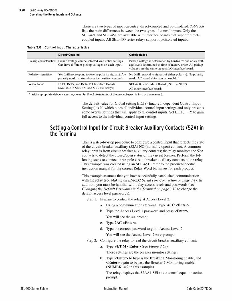
3.70
SEL-400 Series Relays Instruction Manual Date Code 20171006
Basic Relay OperationsOperating the Relay Inputs and Outputs
There are two types of input circuitry: direct-coupled and optoisolated. Table 3.8 lists the main differences between the two types of control inputs. Only the SEL-421 and SEL-451 are available with interface boards that support direct-coupled inputs. All SEL-400 series relays support optoisolated inputs.
The default value for Global setting EICIS (Enable Independent Control Input Settings) is N, which hides all individual control input settings and only presents some overall settings that will apply to all control inputs. Set EICIS := Y to gain full access to the individual control input settings.
Setting a Control Input for Circuit Breaker Auxiliary Contacts (52A) in the Terminal
This is a step-by-step procedure to configure a control input that reflects the state of the circuit breaker auxiliary (52A) NO (normally open) contact. A common relay input is from circuit breaker auxiliary contacts; the relay monitors the 52A contacts to detect the closed/open status of the circuit breaker. Perform the fol-lowing steps to connect three-pole circuit breaker auxiliary contacts to the relay. This example was created using an SEL-451. Refer to the product-specific instruction manual for the correct Relay Word bit names for each product.
This example assumes that you have successfully established communication with the relay (see Making an EIA-232 Serial Port Connection on page 3.4). In addition, you must be familiar with relay access levels and passwords (see Changing the Default Passwords in the Terminal on page 3.10 to change the default access level passwords).
Step 1. Prepare to control the relay at Access Level 2.
a. Using a communications terminal, type ACC <Enter>.
b. Type the Access Level 1 password and press <Enter>.
You will see the => prompt.
c. Type 2AC <Enter>.
d. Type the correct password to go to Access Level 2.
You will see the Access Level 2 =>> prompt.
Step 2. Configure the relay to read the circuit breaker auxiliary contact.
a. Type SET M <Enter> (see Figure 3.63).
These settings are the breaker monitor settings.
b. Type <Enter> to bypass the Breaker 1 Monitoring enable, and <Enter> again to bypass the Breaker 2 Monitoring enable (NUMBK := 2 in this example).
The relay displays the 52AA1 SELOGIC control equation action prompt.
Table 3.8 Control Input Characteristics
Direct-Coupled Optoisolated
Pickup characteristics: Pickup voltage can be selected via Global settings. Can have different pickup voltages on each input.
Pickup voltage is determined by hardware: one of six volt-age levels determined at time of factory order. All pickup voltages are the same on each I/O interface board.
Polarity- sensitive: Yes (will not respond to reverse polarity signals). A + polarity mark is printed over the positive terminals.
No (will respond to signals of either polarity). No polarity mark. AC signal detection is possible.a
Where found: INT1, INT5, and INT6 I/O Interface Boards (available in SEL-421 and SEL-451 relays)
SEL-400 Series Main Board (IN101–IN107)
All other interface boards
a With appropriate debounce settings (see Section 2: Installation of the product-specific instruction manual).

3.71
Date Code 20171006 Instruction Manual SEL-400 Series Relays
Basic Relay OperationsOperating the Relay Inputs and Outputs
c. Type IN101 <Enter> at the ? prompt to specify input IN101 as the control input that represents the close/open state of Circuit Breaker 1.
Press <Enter> until the relay displays the 52AA2 SELOGIC control equation action prompt.
d. Type IN102 <Enter> at the ? prompt to specify input IN102 as the control input that represents the close/open state of Circuit Breaker 2.
Step 3. End the settings process. The relay next scrolls a readback of all the Global settings, eventually displaying the Save settings (Y,N) ? prompt.
a. In the readback information, just before the Save settings (Y,N) ? prompt, confirm the new control input information.
b. Answer Y <Enter> to save your new settings.
Setting a Control Input for Circuit Breaker Auxiliary Contacts (52A) in QuickSet
The procedure in the following steps shows how to program the relay control input IN101 to read the state of circuit breaker auxiliary contacts. This example uses a single three-pole tripping breaker. Modify the procedure listed here for your application.
This example assumes that you have successfully established communication with the relay (see Making an EIA-232 Serial Port Connection on page 3.4). In addition, you must be familiar with relay access levels and passwords (see Changing the Default Passwords in the Terminal on page 3.10 to change the default access level passwords). You should also be familiar with QuickSet (see Section 2: PC Software).
Step 1. Start QuickSet and establish a connection with the relay. See Step 1 and Step 2 of Checking Relay Status in QuickSet on page 3.12 for detailed steps.
Step 2. On the File menu, click Read.
The relay sends all configuration and settings data to QuickSet.
=>>SET M <Enter> Breaker Monitor Breaker Configuration Breaker 1 Monitoring (Y,N) EB1MON := N ? <Enter> Breaker 2 Monitoring (Y,N) EB2MON := N ? <Enter> Breaker 1 Inputs
N/O Contact Input -BK1 (SELogic Equation) 52AA1 := NA ? IN101 <Enter> Breaker 2 Inputs N/O Contact Input -BK2 (SELogic Equation) 52AA2 := NA ? IN102 <Enter> Breaker Monitor
Breaker Configuration EB1MON := N EB2MON := NBreaker 1 Inputs 52AA1 := IN101 Breaker 2 Inputs 52AA2 := IN102 Save settings (Y,N) ? Y <Enter> Saving Settings, Please Wait........... Settings Saved=>>
Figure 3.63 Setting 52AA1 in the Terminal

3.72
SEL-400 Series Relays Instruction Manual Date Code 20171006
Basic Relay OperationsOperating the Relay Inputs and Outputs
Step 3. Access the Control Inputs settings.
a. Click the arrow next to the Global branch of the Settings tree view.
b. Click the arrow next to the Control Inputs branch of the Settings tree view (see Figure 3.64).
Step 4. Set EICIS Independent Control Input Settings to Y.
Figure 3.64 Accessing Control Inputs Settings in QuickSet

3.73
Date Code 20171006 Instruction Manual SEL-400 Series Relays
Basic Relay OperationsOperating the Relay Inputs and Outputs
Step 5. Set the control input IN101 debounce time.
For this example, assume that the auxiliary contacts are slow and noisy; you must provide a slightly longer debounce time for these contacts.
a. Double-click the mouse cursor (or press <Tab>) to highlight IN101PU Pickup Delay for Contact Input.
b. Delete the present setting by pressing <Delete>.
c. Type 0.25 <Enter>.
d. Similarly change the IN101DO Input IN101 Dropout Delay to 0.25.
The relay checks the new value and enters the value in the QuickSet database.
Step 6. Configure the relay to read the circuit breaker auxiliary contact.
a. Expand the Breaker Monitor branch of the Settings tree view by clicking the + button (see Figure 3.66).
b. In the tree view, click Breaker 1 to select circuit breaker monitor settings for Circuit Breaker 1.
c. Set the 52AA1 SELOGIC control equation by clicking in the text box labeled 52AA1 N/O Contact Input.
d. Type IN101, and then click or <Tab> to another field to specify input IN101 as the control input that represents the close/open state of Circuit Breaker 1.
Figure 3.65 Control Input Pickup and Dropout Delay Settings in QuickSet

3.74
SEL-400 Series Relays Instruction Manual Date Code 20171006
Basic Relay OperationsOperating the Relay Inputs and Outputs
Step 7. Click File > Save to save the new settings in QuickSet.
Step 8. Upload the new settings to the SEL-451.
a. Click File > Send.
QuickSet prompts you for the settings class or instance you want to send to the relay.
b. Select the Global check box and the Breaker Monitor check box.
c. Click OK.
d. QuickSet responds with a Transfer Status dialog box.
If you see no error message, the new settings are loaded in the relay.
Special Considerations for TiDLIn Time-Domain Link (TiDL) systems, IN301–IN324, OUT301–OUT316, IN401–IN424, OUT401–OUT416, IN501–IN524, and OUT501–OUT516 are provided by remotely connected Axion modules. (See the installation section of the product-specific instruction manual for details on how these are configured and mapped internally.) Within the relay, the inputs behave just like local inputs. They will be accurately time-tagged in SER. Similarly, the outputs will behave like local outputs, except that the communications channel will add a slight time delay to the operating time (less than one millisecond).
The one difference to consider is that it is possible to lose communication with a remote Axion, which will cause all of the mapped inputs and outputs to stop updating. There are special Relay Word bits to indicate this loss of communica-tion: IO300OK, IO400OK, and IO500OK. Use these bits to condition the opera-
Figure 3.66 Setting 52AA1 in QuickSet

3.75
Date Code 20171006 Instruction Manual SEL-400 Series Relays
Basic Relay OperationsConfiguring Timekeeping
tion of the corresponding inputs to sustain appropriate operation when there is a loss of communication. You may also want to map these bits to an alarm so someone is notified of the loss of communication.
Configuring TimekeepingThe relay features high-accuracy timekeeping when supplied with an IRIG-B or Ethernet PTP signal. When the supplied clock signal is sufficiently accurate, most SEL-400 series relays can act as a phasor measurement unit (PMU) and transmit synchrophasor data representative of the power system at fixed time periods to an external data processor. The relay can also record COMTRADE event report data using the high-accuracy time stamp. See Oscillography on page 9.9 and Time-Synchronized Triggers on page 11.9 for details on these appli-cations.
IRIG-B and PTPThe relay has two input connectors that accept IRIG-B (Inter-Range Instrumenta-tion Group-B) demodulated time-code format: the IRIG-B pins of Serial Port 1, and the IRIG-B BNC connector. In relays with Ethernet, Precision Time Protocol (PTP) can also be used to provide high-accuracy time. See Section 11: Time and Date Management for more information on using IRIG-B and PTP.
Monitoring High-Accuracy Time Source StatusThe purpose of the procedure in the following steps is to show one method for deriving the TIME Q Time Source information from Relay Word bits TSOK and TIRIG when using an IRIG Time Source. The TSOK Relay Word bit is at logical 1 when the relay is in HIRIG time mode. For this application example, use a pro-tection SELOGIC variable (PSV) to monitor timekeeping status.
PSV02 asserts when the relay is synchronized to the HIRIG source. A departure from this condition asserts the relay alarm output (OUT108 for this application example).
This example assumes that you have successfully established communication with the relay (see Making an EIA-232 Serial Port Connection on page 3.4). In addition, you must be familiar with relay access levels and passwords (see Changing the Default Passwords in the Terminal on page 3.10 to change the default access level passwords). Also, you should be familiar with QuickSet (see Section 2: PC Software).
Step 1. Start QuickSet and establish a connection with the relay. See Step 1 and Step 2 of Checking Relay Status in QuickSet on page 3.12 for detailed steps.
Step 2. Read the present configuration in the relay. Click File > Read.
The relay sends all configuration and settings data to QuickSet.
Step 3. Access the protection free-form SELOGIC settings.
a. Click the arrow next to Group 1 in the Settings tree view.
b. Click the Protection Logic 1 settings (see Figure 3.67).
Step 4. Enter the two lines of SELOGIC control equation programming in the Protection Free-Form Logic Settings shown in Figure 3.67.

3.76
SEL-400 Series Relays Instruction Manual Date Code 20171006
Basic Relay OperationsConfiguring Timekeeping
Step 5. Configure a control output to alarm a loss of HIRIG mode.
a. In the Settings tree view, click Outputs and then click Main Board (see Figure 3.68).
b. In the OUT108 Main Board Outputs text box, enter the OR NOT PSV02 condition to the preexisting OUT108 := NOT (SALARM OR HALARM) equation, as shown in Figure 3.68.
Figure 3.67 Programming a PSV to Monitor HIRIG in QuickSet

3.77
Date Code 20171006 Instruction Manual SEL-400 Series Relays
Basic Relay OperationsReadying the Relay for Field Application
Step 6. Click File > Save to save the new settings in QuickSet.
Step 7. Upload the new settings to the relay.
a. Click File > Send.
QuickSet prompts you for the settings class or instance you want to send to the relay.
b. Select the Group 1 check box and the Output check box, as shown in the first dialog box of Figure 3.62.
c. Click OK.
QuickSet responds with a display similar to the second dialog box shown in Figure 3.62.
If you see no error message, the new settings are loaded in the relay.
To confirm that you have prepared an out-of-synchronization/loss-of-HIRIG mode alarm, disconnect the IRIG-B input. The relay alarm will activate.
Readying the Relay for Field ApplicationBefore applying the relay in your power system, set the relay for your particular field application. Be sure to modify the relay factory-default settings for your power system conditions to enable relay features to help you protect and control your system.
Figure 3.68 Setting OUT108 in QuickSet

3.78
SEL-400 Series Relays Instruction Manual Date Code 20171006
Basic Relay OperationsReadying the Relay for Field Application
This procedure is a guide to help you ready the relay for field application. If you are unfamiliar with the steps in this procedure, see the many relay usage exam-ples presented in this section. This is a suggested procedure; modify the proce-dure as necessary to conform to your standard company practices.
Step 1. Open the appropriate low-voltage breaker(s) and remove fuses to ver-ify removal of control power and ac signals from the relay.
Step 2. Isolate the relay TRIP control output.
Step 3. Perform point-to-point continuity checks on the circuits associated with the relay to verify the accuracy and correctness of the ac and dc connections.
Step 4. Apply power to the relay.
The green ENABLED LED on the front panel will illuminate.
Step 5. Use an SEL-C234A cable to connect a serial terminal to the relay.
Step 6. Start the terminal (usually a PC with terminal emulation software).
Step 7. Establish communication with the relay at Access Level 0.
Step 8. Proceed to Access Level 2 (see Changing the Default Passwords in the Terminal on page 3.10).
Step 9. Change the default passwords (see Changing the Default Passwords in the Terminal on page 3.10).
Step 10. Set the DATE and TIME (see Making Simple Settings Changes on page 3.15).
Step 11. Use test sources to verify relay ac connections (see Examining Metering Quantities on page 3.35).
Step 12. Verify control input connections.
Step 13. Verify control output connections.
Step 14. Perform protection element tests.
Step 15. Set the relay (see Making Simple Settings Changes on page 3.15, Section 12: Settings, and Section 6: Protection and Protection Appli-cation Examples in the product-specific instruction manual.
Step 16. Connect the relay for tripping/closing duty.
Step 17. From Access Level 2, use a communications terminal to issue appli-cable commands (listed in Table 3.9) to clear the relay data buffers.
Step 18. Connect the secondary voltage and current inputs.
Step 19. Use the MET command or the QuickSet HMI to view relay metering to confirm secondary connections (see Examining Metering Quantities on page 3.35).
Table 3.9 Communications Port Commands That Clear Relay Buffers
Communications Port Command Task Performed
MET RD Reset demand meter data
MET RP Reset peak demand meter data
MET RE Reset energy meter data
MET RM Reset maximum/minimum meter data
HIS CA Reset event report and history buffers
SER CA Reset Sequential Events Recorder data

Date Code 20171006 Instruction Manual SEL-400 Series Relays
Instruction ManualS E C T I O N 4
Front-Panel Operations
The relay front panel makes power system data collection and system control quick and efficient. Using the front panel, you can analyze power system operat-ing information, view and change relay settings, and perform relay control func-tions. The relay features a straightforward menu-driven control structure presented on the front-panel LCD. Front-panel targets and other LED indicators provide a quick look at relay operation status. You can perform often-used con-trol actions rapidly by using the large direct-action pushbuttons. All of these fea-tures help you operate the relay from the front panel and include:
➤ Reading metering
➤ Inspecting targets
➤ Accessing settings
➤ Controlling relay operations
This section describes features found in many, but not necessarily all, SEL-400 series relays. See the relay-specific instruction manuals to determine which front-panel features are supported in that relay. This section includes the following:
➤ Front-Panel Layout on page 4.1
➤ Front-Panel Menus and Screens on page 4.14
➤ Front-Panel Automatic Messages on page 4.31
➤ Operation and Target LEDs on page 4.33
➤ Front-Panel Operator Control Pushbuttons on page 4.34
Front-Panel LayoutSome SEL-400 series relays come with a front panel with 16 target LEDs and 8 operator pushbuttons. Others come with 24 target LEDs and 12 operator pushbut-tons. Refer to the product-specific instruction manual to see which displays are available for any specific relay. Figure 4.1, Figure 4.2, and Figure 4.3 show what these front panel options look like in the SEL-451 and the SEL-487E relays. Some relays are also available with direct action pushbuttons for breaker control, which is illustrated in Figure 4.2.
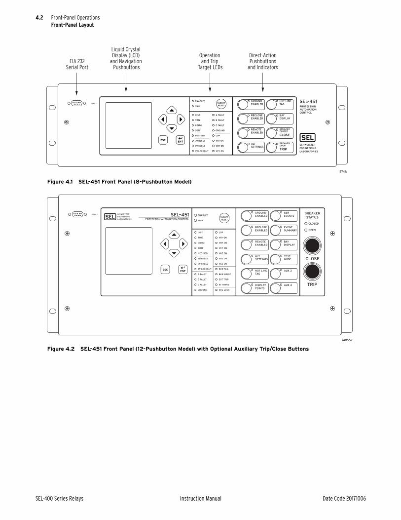
4.2
SEL-400 Series Relays Instruction Manual Date Code 20171006
Front-Panel OperationsFront-Panel Layout
Figure 4.1 SEL-451 Front Panel (8-Pushbutton Model)
Figure 4.2 SEL-451 Front Panel (12-Pushbutton Model) with Optional Auxiliary Trip/Close Buttons
Liquid CrystalDisplay (LCD)
and NavigationPushbuttons
Operationand Trip
Target LEDs
Direct-ActionPushbuttons
and IndicatorsEIA-232
Serial Port
i4055c
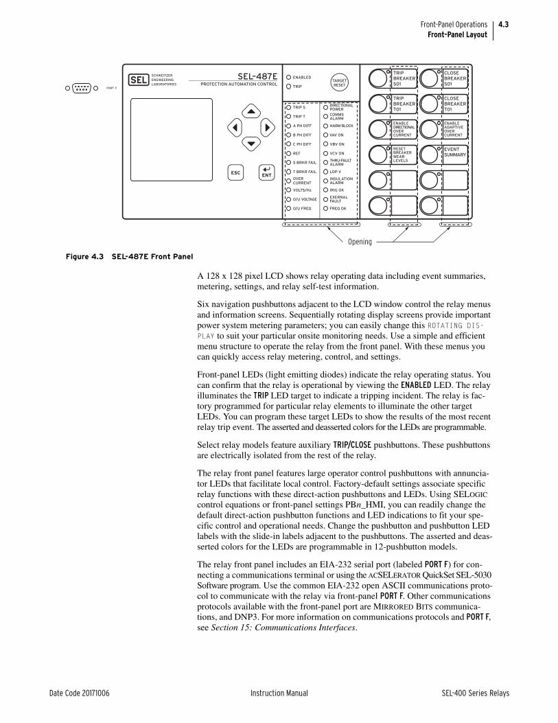
4.3
Date Code 20171006 Instruction Manual SEL-400 Series Relays
Front-Panel OperationsFront-Panel Layout
A 128 x 128 pixel LCD shows relay operating data including event summaries, metering, settings, and relay self-test information.
Six navigation pushbuttons adjacent to the LCD window control the relay menus and information screens. Sequentially rotating display screens provide important power system metering parameters; you can easily change this ROTATING DIS-PLAY to suit your particular onsite monitoring needs. Use a simple and efficient menu structure to operate the relay from the front panel. With these menus you can quickly access relay metering, control, and settings.
Front-panel LEDs (light emitting diodes) indicate the relay operating status. You can confirm that the relay is operational by viewing the ENABLED LED. The relay illuminates the TRIP LED target to indicate a tripping incident. The relay is fac-tory programmed for particular relay elements to illuminate the other target LEDs. You can program these target LEDs to show the results of the most recent relay trip event. The asserted and deasserted colors for the LEDs are programmable.
Select relay models feature auxiliary TRIP/CLOSE pushbuttons. These pushbuttons are electrically isolated from the rest of the relay.
The relay front panel features large operator control pushbuttons with annuncia-tor LEDs that facilitate local control. Factory-default settings associate specific relay functions with these direct-action pushbuttons and LEDs. Using SELOGIC control equations or front-panel settings PBn_HMI, you can readily change the default direct-action pushbutton functions and LED indications to fit your spe-cific control and operational needs. Change the pushbutton and pushbutton LED labels with the slide-in labels adjacent to the pushbuttons. The asserted and deas-serted colors for the LEDs are programmable in 12-pushbutton models.
The relay front panel includes an EIA-232 serial port (labeled PORT F) for con-necting a communications terminal or using the ACSELERATOR QuickSet SEL-5030 Software program. Use the common EIA-232 open ASCII communications proto-col to communicate with the relay via front-panel PORT F. Other communications protocols available with the front-panel port are MIRRORED BITS communica-tions, and DNP3. For more information on communications protocols and PORT F, see Section 15: Communications Interfaces.
Figure 4.3 SEL-487E Front Panel
Opening
SEL–487E
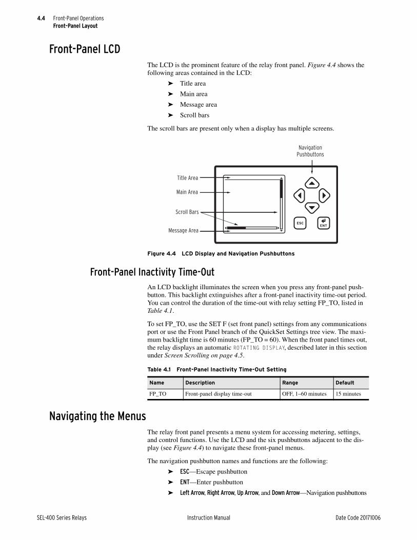
4.4
SEL-400 Series Relays Instruction Manual Date Code 20171006
Front-Panel OperationsFront-Panel Layout
Front-Panel LCDThe LCD is the prominent feature of the relay front panel. Figure 4.4 shows the following areas contained in the LCD:
➤ Title area
➤ Main area
➤ Message area
➤ Scroll bars
The scroll bars are present only when a display has multiple screens.
Front-Panel Inactivity Time-OutAn LCD backlight illuminates the screen when you press any front-panel push-button. This backlight extinguishes after a front-panel inactivity time-out period. You can control the duration of the time-out with relay setting FP_TO, listed in Table 4.1.
To set FP_TO, use the SET F (set front panel) settings from any communications port or use the Front Panel branch of the QuickSet Settings tree view. The maxi-mum backlight time is 60 minutes (FP_TO = 60). When the front panel times out, the relay displays an automatic ROTATING DISPLAY, described later in this section under Screen Scrolling on page 4.5.
Navigating the MenusThe relay front panel presents a menu system for accessing metering, settings, and control functions. Use the LCD and the six pushbuttons adjacent to the dis-play (see Figure 4.4) to navigate these front-panel menus.
The navigation pushbutton names and functions are the following:
➤ ESC—Escape pushbutton
➤ ENT—Enter pushbutton
➤ Left Arrow, Right Arrow, Up Arrow, and Down Arrow—Navigation pushbuttons
Figure 4.4 LCD Display and Navigation Pushbuttons
NavigationPushbuttons
Title Area
Main Area
Scroll Bars
Message Area
Table 4.1 Front-Panel Inactivity Time-Out Setting
Name Description Range Default
FP_TO Front-panel display time-out OFF, 1–60 minutes 15 minutes

4.5
Date Code 20171006 Instruction Manual SEL-400 Series Relays
Front-Panel OperationsFront-Panel Layout
Menus show lists of items that display information or control the relay. A rectan-gular box around an action or choice indicates the menu item you have selected. This rectangular box is the menu item highlight.
Figure 4.5 shows an example of RELAY ELEMENTS highlighted in an example MAIN MENU. When you highlight a menu item, pressing the ENT pushbutton selects the highlighted item.
The Up Arrow pushbutton and Down Arrow pushbutton scroll the highlight box to the previous or next menu selection, respectively. When there is more than one screen of menu items, pressing the Up Arrow while at the first menu item causes the display to show the previous set of full-screen menu items, with the last menu item highlighted. Pressing the Down Arrow while at the bottom menu item causes the display to show the next set of full-screen menu items, with the first menu item highlighted.
Pressing the ESC pushbutton reverts the LCD display to the previous screen. Pressing ESC repeatedly returns you to the MAIN MENU. If a status warning, alarm condition, or event condition is active (not acknowledged or reset), the relay dis-plays the full-screen status warning, alarm screen, or trip event screen in place of the MAIN MENU.
Screen ScrollingSEL-400 series relays have two screen scrolling modes: autoscrolling mode and manual-scrolling mode. After front-panel time-out, the LCD presents each of the display screens in this sequence:
➤ One-line diagram (if applicable)
➤ Any active (filled) alarm points screens
➤ Any active (filled) display points screens
➤ Other enabled screens
See the product-specific instruction manual for the details of the other screens that are supported and how they are enabled.
Figure 4.5 RELAY ELEMENTS Highlighted in Example MAIN MENU
METEREVENTSBREAKER MONITORRELAY ELEMENTSLOCAL CONTROLSET/SHOWRELAY STATUSVIEW CONFIGURATIONDISPLAY TESTRESET ACCESS LEVEL
MAIN MENU

4.6
SEL-400 Series Relays Instruction Manual Date Code 20171006
Front-Panel OperationsFront-Panel Layout
Figure 4.6 illustrates an example rotating display sequence. The active alarm points are the first screens in the ROTATING DISPLAY (see Alarm Points on page 4.7). Each alarm points screen shows as many as 11 alarm conditions. The relay can present a maximum of six alarm points screens.
The active display points are the next screens in the ROTATING DISPLAY after alarm points (see Display Points on page 4.10). Each display points screen shows as many as 11 enabled display points (with 96 display points, the relay can pres-ent a maximum of nine display points screens). If a display point does not have text to display, the screen space for that display point is maintained.
Figure 4.6 Sample ROTATING DISPLAY
Circuit Breaker 1 --Closed--
ROTATING DISPLAY
Press for menu
Line Current (A) RMS
IA = 119.6IB = 119.7IC = 119.5FREQ = 60.00 Hz
ROTATING DISPLAY
Press for menu
Line Quantities FUNDROTATING DISPLAY
Press for menu
Voltage (kV) VA = 130.4 + 6˚ VB = 130.3 -114˚ VC = 130.5 -126˚Current (A) IA = 119.6 35˚ IB = 119.7 -95˚ IC = 119.5 155˚FREQ = 60.00 Hz
Circuit BK1 SF6 Gas --Alarm--
Circuit Breaker 2 A PH= 119.6 A pri
*Circuit BK1 SF6 Gas
ROTATING DISPLAY
Press for menu
SF6 ALARM

4.7
Date Code 20171006 Instruction Manual SEL-400 Series Relays
Front-Panel OperationsFront-Panel Layout
Autoscrolling ModeAutoscrolling mode shows each screen for a user-configurable period of time. Front Panel setting SCROLD defines the period of time for which each screen is shown. When you first apply power to the relay, the LCD shows the autoscrolling ROTATING DISPLAY. With SCROLD := OFF, the screen remains on the first screen in the rotating display order; automatic rotation of additional screens is disabled.
The autoscrolling ROTATING DISPLAY also appears after a front-panel inactivity time-out (see Front-Panel Inactivity Time-Out on page 4.4). The relay retrieves data prior to displaying each new screen. The relay does not update screen infor-mation during the display interval. At any time during autoscrolling mode, press-ing ENT takes you to the MAIN MENU. Pressing any of the four navigation pushbuttons switches the display to manual-scrolling mode.
Manual-Scrolling ModeIn manual-scrolling mode, you can use the directional navigation arrow pushbut-tons to select the next or previous screen. Pressing the Down Arrow or Right Arrow pushbuttons switches the display to the next screen; pressing the Up Arrow or Left Arrow pushbuttons switches the display to the previous screen.
In manual-scrolling mode, the display shows arrows at the top and bottom of the vertical scroll bar. The screen arrows indicate that you can navigate between the different screens at will. The relay retrieves data prior to displaying each new screen. Unlike the autoscrolling mode, the relay continues to update screen infor-mation while you view it in the manual-scrolling mode. To return to autoscrolling mode, press ESC or wait for a front-panel time-out.
Alarm PointsYou can display messages on the front-panel LCD that indicate alarm conditions in the power system. The relay uses alarm points to place these messages on the LCD.
Figure 4.7 shows a sample alarm points screen. The relay is capable of displaying as many as 66 alarm points. The relay automatically displays new alarm points while in manual-scrolling mode and in autoscrolling mode. While you navigate the HMI menu structure, the relay does not automatically display the alarm points. Instead, ALARM EVENT displays in the footer. When you escape the HMI menu structure, the relay will display the alarm points screen.
Figure 4.7 Sample Alarm Points Screen
*Circuit BK1 SF6 Gas
ALARM POINTS
Press to acknldge

4.8
SEL-400 Series Relays Instruction Manual Date Code 20171006
Front-Panel OperationsFront-Panel Layout
The alarm point setting is an element of the SER settings. To enable an alarm point, enable the HMI alarm parameter of the SER Point Settings listed in Table 4.2. The format for entering the SER point data is the following comma-delimited string:
Relay Word Bit, Reporting Name, Set State Name, Clear State Name, HMI Alarm
Names can contain any valid ASCII character. Enclose the name within quotation marks. See Example 4.1 for particular information on the format for entering SER point data.
If you enter a Relay Word bit that does not match a valid relay element, the relay displays: Unknown relay word reference. If you enter an alias or name that is too long, the relay displays: Alias label too long.
The relay displays alarm points in a similar fashion as the SER. As many as 19 characters of the given alias are displayed, with one character reserved for the “*.” The asterisk denotes if the element is asserted. Initially, an alarm point must be asserted in order to be displayed; after the corresponding element deasserts, the asterisk is removed, but the alias is not. The relay displays alarm points in reverse chronological order, just as in the SER, with the most recently asserted alarm displayed on the top. Deasserted alarms may be removed from the display with user acknowledgment, as shown in Example 4.1.
Table 4.2 SER Point Settings
Description Range
Relay Word Bit Any valid relay element
Reporting Name 20-character maximum ASCII string
SET State Name (logical 1) 20-character maximum ASCII string
CLR State Name (logical 0) 20-character maximum ASCII string
HMI Alarm Y, N
Example 4.1 Creating an Alarm Point
Alarm points screens provide operator feedback about the status of system conditions. An alarm points screen contains 11 alarm points; this example demonstrates a method to set the alarm point message that is shown in Figure 4.7. This example is based on the Relay Word bit IN101 asserting when circuit breaker 1 is in an alarm condition.
In the Report settings (SET R), enter the following after the SER Points Line 1 prompt:
1: IN101,“Circuit BK1 SF6 Gas”,“Alarm”,“Normal”,“Y”
The circuit breaker alarm condition is indicated by the set state, "Alarm" and the circuit breaker normal condition is indicated by the clear state "Normal." The HMI Alarm parameter is set to “Y” in order to enable alarm points screen display of this element.
While in the scrolling mode, the assertion of IN101 will cause the alarm points screen (as shown in Figure 4.7) to be automatically displayed. Upon the deassertion of IN101, the asterisk will disappear, as shown in Figure 4.8.

4.9
Date Code 20171006 Instruction Manual SEL-400 Series Relays
Front-Panel OperationsFront-Panel Layout
Pressing the ENT pushbutton will allow the user to acknowledge and clear deasserted alarms. Before clearing, you will be prompted to confirm that this is the intended action, as shown in Figure .
In the case that all alarms are deasserted, pressing the ENT pushbutton will allow the user to acknowledge and clear all alarms. After clearing, a screen showing the results of the action will be shown, as in Figure 4.10.
Alarm points are not updated for a particular element if it has been deleted from the SER because of chatter criteria (see Automatic Deletion and Rein-sertion on page 9.31). Upon reinsertion, the element state will be updated on the alarm point display. If the relay enters a period of SER data loss, the sta-tus of alarm points cannot be determined. The screen shown in Figure 4.11 will appear until you exit the data loss condition, at which point the alarm point elements will be polled and displayed if asserted. Subsequent alarm point assertions will be displayed above the data loss message.
Example 4.1 Creating an Alarm Point (Continued)
Figure 4.8 Deasserted Alarm Point
Circuit BK1 SF6 Gas
ALARM POINTS
Press to acknldge
Figure 4.9 Clear Alarm Point Confirmation Screen
Circuit BK1 SF6 Gas
ALARM POINTS
Press to acknldge
Are you sure youwant to clearinactive alarms?Press to clear
Figure 4.10 No Alarm Points Screen
NO ALARM POINTSEXIST.
ALARM POINTS

4.10
SEL-400 Series Relays Instruction Manual Date Code 20171006
Front-Panel OperationsFront-Panel Layout
Display PointsYou can display messages on the relay front-panel LCD that indicate conditions in the power system. The relay uses display points to place these messages on the LCD.
Figure 4.12 shows a sample display points screen. Display points can show the status of Relay Word bits or display the value of analog quantities. The relay has 96 possible display points; Table 4.3 and Table 4.4 list the display points settings. The relay updates the display points data once per second if you are viewing the display points in manual-scrolling mode; in autoscrolling mode the relay updates the display points information each time the screen appears in the ROTATING DIS-PLAY sequence.
To enable a display point, enter the display point settings listed in Table 4.3 or Table 4.4. All display points occupy one, and only one, line on the display at all times. The height of the line is determined by the “Text Size” setting parameter. Display points of single-line height span one screen in total width. Display points of double-line height span two screens in total width. You can use multiple dis-play points to simulate multiple lines.
Use the following syntax to display the given Relay Word bit exactly as seen in the navigational menu (name and value).
DPxx := Name
Use the following syntax to display the given Relay Word bit as seen in the navi-gational menu, replacing the name of the value with the given alias string. The text size determines if the display will be in single font or double font. If the text size is empty, the display will be in single font.
DPxx := Name, “Alias”, “Text Size”
Example 4.1 Creating an Alarm Point (Continued)
Figure 4.11 Alarm Points Data Loss Screen
##SER DATA LOSS##
ALARM POINTS
Press to acknldge
Figure 4.12 Sample Display Points Screen
Circuit Breaker 1 --Closed--
DISPLAY POINTS
Circuit BK1 SF6 Gas --Alarm--
Circuit Breaker 2 A PH= 119.6 A pri
SF6 ALARM

4.11
Date Code 20171006 Instruction Manual SEL-400 Series Relays
Front-Panel OperationsFront-Panel Layout
Use the following syntax to display the given Relay Word bit with the given alias. If the Relay Word bit is asserted (logical 1), the LCD displays the set string in the place of the value. If the Relay Word bit is deasserted (logical 0), the LCD dis-plays the clear string in the place of the value. One or all of Alias, Set String, or Clear String can be empty. If Alias is empty, then the LCD displays only the Set or Clear Strings. If either Set String or Clear String is empty, then an empty line is displayed when the bit matches that state. The text size determines if the dis-play will be in single font or double font. If the text size is empty, the display will be in single font.
DPxx := Name, “Alias”, “Set String”, “Clear String”, “Text Size”
Use the following syntax to display the given analog quantity with the given text and formatting. Formatting must be in the form Width.Decimal,Scale with the value of Name, scaled by “Scale,” formatted with total width “Width” and “Deci-mal” decimal places. The width value includes the decimal point and sign charac-ter, if applicable. The “scale” value is optional; if omitted, the scale factor is processed as 1. If the numeric value is smaller than the field size requested, the field is padded with spaces to the left of the number. If the numeric value will not fit within the field width given, “$” characters are displayed. The text size deter-mines if the display will be in single font or double font. If the text size is empty, the display will be in single font.
DPxx := Name, “(Text1 Width.Decimal,Scale) Text2”, “Text Size”
Table 4.3 Display Point Settings—Boolean
Description Range
Relay Word Bit Name See the relay-specific instruction manual for a list of Relay Word bits available in that relay.
Alias ASCII string
Set String ASCII string
Clear String ASCII string
Text Size S, D
Table 4.4 Display Point Settings—Analog
Description Range
Analog Quantity Name See the relay-specific instruction manual for a list of avail-able analog quantities
“User Text and Formatting” ASCII string
Text Size S, D
Table 4.5 Display Point Settings—Boolean and Analog Examples (Sheet 1 of 2)
Example Display Point Setting Value Example Display
IN101 IN101=1IN101=0
MWHAIN,“{7.2}” 1234.56
50P1,Overcurrent,, Overcurrent=1Overcurrent=0
PSV01,Control,On,Off Control=OnControl=Off
PSV02,Breaker,Tripped, Breaker=TrippedEmpty Line

4.12
SEL-400 Series Relays Instruction Manual Date Code 20171006
Front-Panel OperationsFront-Panel Layout
If you enter a Relay Word bit or Analog Quantity that does not match a valid relay element, the relay displays: Invalid element. If you enter a display point that exceeds the allowable length, the relay displays: Too many characters. If you enter an invalid scale factor, invalid width, too many parameters, or omit nec-essary quotation marks or brackets, the relay displays an error message. If a dis-play point was used previously and you want to remove the display point, you can delete the display point. In the Front Panel settings (SET F), at the Display Points and Aliases prompt, use the text-edit mode line editing commands to set the display points (see Text-Edit Mode Line Editing on page 3.22for information on text-edit mode line editing). To delete Display Point 1, type DELETE <Enter> at the Front Panel settings Line 1 prompt.
50P1,,,Overcurrent Empty Line
Overcurrent
MWHAIN,“A Ph Import={7.2}” A Ph Import=1234.56
MWHAIN,“A Ph Import={7.3}” A Ph Import=$$$.$$$
MWHAIN,“A Ph Imp {4}MWh” A Ph Imp 1234MWh
PAD,“{7.2}” 1234.56
PAD,“A Ph Dem Pwr={4.1}” A Ph Dem Pwr=1234.5
ICD,“C Demand={5}” C Demand= 1230
ICD,“C Demand={4.2,0.001} kA” C Demand=1.23 kA
MWHAOUT,“A Phase Out={3, 1000}” A Phase Out=1234
MWHAOUT,“A Phase Out={3, 1000} kWH” A Phase Out=$$$ kWh
1,“Fixed Text” Fixed Text
0,“Fixed Text” Fixed Text
1, Empty Line
0, Empty Line
Display Point is hidden
Example 4.2 Creating a Display Point
Display points screens can be used to provide operator feedback about the readiness of equipment connected to the relay. A display points screen con-tains 11 display points; this example demonstrates a method to set the dis-play point messages that are shown in Figure 4.12. This example uses an SEL-451 with an additional I/O interface board.
This example is based on a three-pole circuit breaker. Relay Word bit 52AA1 will assert when Circuit Breaker 1 is in the closed position.
IN109 will assert when Circuit Breaker 1 is in an alarm condition. B2IAFIM is the filtered instantaneous magnitude for the A-Phase current through Circuit Breaker 2.
In the Front Panel settings (SET F), enter the following after the Display Points and Aliases Line 1 prompt:
1: 1,“Circuit Breaker 1”
2: 52AA1,,“ --Closed--”,“ --Open--”
Table 4.5 Display Point Settings—Boolean and Analog Examples (Sheet 2 of 2)
Example Display Point Setting Value Example Display

4.13
Date Code 20171006 Instruction Manual SEL-400 Series Relays
Front-Panel OperationsFront-Panel Layout
3: 0
4: 0,“Circuit BK1 SF6 Gas”
5: IN109,,“ --Alarm--”,“ --Normal--”
6: 1
7: 1,“Circuit Breaker 2”
8: B2IAFIM,“ A PH=(6.1,1) A pri”
9: IN109,, “SF6 ALARM”, D
Fixed text is set by assigning an alias to a “1” or “0.” Blank lines are set by assigning a blank alias to a “1” or “0.” The circuit breaker closed condition is indicated by the set state, “--Closed--” where leading spaces are added to center the set state message. Add a clear state named “--Open--” to show that the circuit breaker is open. The circuit breaker alarm condition is indicated by the set state, “--Alarm--” where leading spaces are added to center the set state message. Add a clear state named “--Normal--” to show that the circuit breaker is not in alarm. User text “A PH=” and “A pri” allows for customized display of the Circuit Breaker 2 A-Phase current, which has been formatted to display numerically as XXXX.X. Double font display is used to give greater visibility to the SF6 Alarm. A horizontal scroll appears while in man-ual-scrolling mode regardless of whether or not the display point label width requires two full screens to display.
Example 4.3 Monitoring Test Modes With Display Points
This example uses the Relay Word bit TESTFM (Fast Meter test running) to activate a front-panel display point that alerts an onsite operator that the relay is in Fast Meter test mode.
In the Front Panel settings (SET F), enter the following after the Line 10 prompt:
10: TESTFM,,“FAST METER TEST!!!!”
The LCD displays the screen shown in Figure 4.13 as a part of the ROTATING DISPLAY if the Fast Meter test is running. (Instruct the operator to view the relay front panel for messages or warnings as the last item on a “Leaving the Substation” checklist.)
Again, this display point application example does not require a clear state, so the clear state is blank. If the Fast Meter test is not running and no other display points are active, the relay shows a blank screen in the ROTATING DISPLAY.
Example 4.2 Creating a Display Point (Continued)
Figure 4.13 Fast Meter Display Points Sample Screen
FAST METER TEST!!!!
ROTATING DISPLAY
Press for menu

4.14
SEL-400 Series Relays Instruction Manual Date Code 20171006
Front-Panel OperationsFront-Panel Menus and Screens
Front-Panel Menus and ScreensOperate the relay front panel through a sequence of menus that you view on the front-panel display. The MAIN MENU is the introductory menu for other front-panel menus (see Figure 4.5). These additional menus allow you onsite access to metering, control, and settings for configuring the relay to your specific applica-tion needs. The following menus and screens are representative of what is typi-cally found in SEL-400 series relays, but each relay has a slightly different list. See the relay-specific instruction manual to see what is available in that relay.
➤ Support Screens➢ Contrast➢ Password
➤ MAIN MENU ➢ METER➢ EVENTS➢ BREAKER MONITOR➢ RELAY ELEMENTS➢ LOCAL CONTROL➢ SET/SHOW➢ RELAY STATUS➢ VIEW CONFIGURATION➢ DISPLAY TEST➢ RESET ACCESS LEVEL➢ ONE LINE DIAGRAM
Support ScreensThe relay displays special screens over the top of the menu or screen that you are using to control the relay or view data. These screens are the ADJUST CONTRAST screen and the PASSWORD REQUIRED screen.
ContrastYou can adjust the LCD screen contrast to suit your viewing angle and lighting conditions. To change screen contrast, press and hold the ESC pushbutton for one second. The relay displays a contrast adjustment box superimposed over the dis-play.
Figure 4.14 shows the contrast adjustment box with the MAIN MENU screen in the background. Pressing the Right Arrow pushbutton increases the contrast. Pressing the Left Arrow pushbutton decreases the screen contrast. When finished adjusting the screen contrast, press the ENT pushbutton.
Figure 4.14 Contrast Adjustment
METEREVENTSBREAKER MONITORRELAY ELEMENTSLOCAL CONTROLSET/SHOWRELAY STATUSVIEW CONFIGURATIONDISPLAY TESTRESET ACCESS LEVEL
MAIN MENU
Adjust Contrast
Press when done

4.15
Date Code 20171006 Instruction Manual SEL-400 Series Relays
Front-Panel OperationsFront-Panel Menus and Screens
WARNING
PasswordThe relay uses passwords to control access to settings and control menus. The relay has six access-level passwords. See Access Levels and Passwords on page 3.7 for more information on access levels and setting passwords. The relay front panel is at Access Level 1 upon initial power-up and after front-panel time out.
This device is shipped with default passwords. Default passwords should be changed to private passwords at installation. Failure to change each default password to a private pass-word may allow unauthorized access. SEL shall not be responsible for any damage resulting from unauthorized access.
Password validation occurs only when you request a menu function that is at a higher access level than the presently authorized level. At this point, the relay dis-plays a password entry screen, shown in Figure 4.15. This screen has a blank password field and an area containing alphabetic, numeric, and special password characters with a movable highlight box.
Enter the password by pressing the navigation pushbuttons to move the highlight box through the alphanumeric field. When at the desired character, press ENT. The relay enters the selected character in the password field and moves the dark box cursor one space to the right. You can backspace at any time by highlighting the BACKSPACE character and then pressing ENT. When finished, enter the password by highlighting the ACCEPT option and then pressing ENT.
If you entered a valid password for an access level greater than or equal to the required access level, the relay authorizes front-panel access to the combination of access levels (new level and all lower levels) for which the password is valid. The relay replaces the password screen with the menu screen that was active before the password validation routine. When you enter Access Levels B, P, A, O, and 2, the Relay Word bit SALARM pulses for one second.
If you did not enter a valid password, the relay displays the error screen shown in Figure 4.16. Entering a valid password for an access level below the required access level also causes the relay to generate the error screen. In both password failure cases, the relay does not change the front-panel access level (it does not reset to Access Level 1 if at a higher access level). The relay displays the PASSWORD INVALID screen for five seconds. If you do not want to wait for the relay to remove the message, press any of the six navigational pushbuttons during the five-second error message to return to the previous screen in which you were working.
Figure 4.15 Enter Password Screen
A B C D E F G HI J K L M N O PQ R S T U V W XY Z a b c d e fg h i j k l m no p q r s t u vw x y z 0 1 2 34 5 6 7 8 9 _ .ACCEPT BACKSPACE
Password Required PasswordField

4.16
SEL-400 Series Relays Instruction Manual Date Code 20171006
Front-Panel OperationsFront-Panel Menus and Screens
Main MenuThe MAIN MENU is the starting point for all other front-panel menus. A representa-tive relay MAIN MENU is shown in Figure 4.17. When the front-panel LCD is in the ROTATING DISPLAY, press the ENT pushbutton to show the MAIN MENU.
MeterThe relay displays metering screens on the LCD. Highlight METER and press ENT on the MAIN MENU screen to select these screens. The metering screens available are relay specific and are described in each relay-specific instruction manuals.
EventsThe relay front panel features summary event reporting, which simplifies post-fault analysis. These summary event reports include all trip events, event and data capture triggering (via the ER SELOGIC control equation), and manual triggers. The relay displays event reports based on the Relay Word bit elements in the ER (event report trigger) SELOGIC control equation. See Event Report on page 9.14 for more information on event reports.
The front-panel event buffer size is 100 summaries. The relay numbers summary events in order from 10000 through 42767 and displays the most recent summa-ries on the LCD.
You can view summary event reports from the relay front-panel display by select-ing EVENTS from the MAIN MENU. The relay presents the Events Menu as shown in Figure 4.18. Select Event Summary from the Events Menu to view event sum-mary data. Figure 4.19 shows sample Event Summary screens for a phase-to-phase-to-ground fault. Use the Right Arrow and Left Arrow pushbuttons to show each of the summary screens for the event. Event reports can also be viewed via a front-panel automatic message (see Front-Panel Automatic Messages on page 4.31) or programmable front-panel operator control pushbutton (see Front-Panel Operator Control Pushbuttons on page 4.34).
Figure 4.16 Invalid Password Screen
The Password EnteredIs Not Sufficient forThe Required AccessLevel.
Password Invalid
Figure 4.17 MAIN MENU
METEREVENTSBREAKER MONITORRELAY ELEMENTSLOCAL CONTROLSET/SHOWRELAY STATUSVIEW CONFIGURATIONDISPLAY TESTRESET ACCESS LEVEL
MAIN MENU

4.17
Date Code 20171006 Instruction Manual SEL-400 Series Relays
Front-Panel OperationsFront-Panel Menus and Screens
The horizontal scroll bar indicates that you can view other event 10002 screens. Use the Up Arrow and Down Arrow pushbuttons to move among the events in the summary buffer. Press ESC to return to the Events Menu and ESC again to return to the MAIN MENU.
SERThe Sequential Events Recorder (SER) records state changes of user-program-mable Relay Word bits. State changes are time-tagged for future analysis of relay operations during an event. See Sequential Events Recorder (SER) on page 9.28 for more information on SER events. To view SER events from the front panel, select EVENTS from the MAIN MENU and SER Events from the Events Menu as shown in Figure 4.18. SER events are also viewable using programmable front-panel operator-control pushbuttons; see Front-Panel Operator Control Pushbut-tons on page 4.34.
Figure 4.20 illustrates the SER Events display screen. Data reported in this screen for each event are the SER Point Alias Name, Asserted or Deasserted state, and the Date and Time of the event. When in the SER Events screen, three SER records are displayed on one screen. Using the navigation pushbuttons, the most recent 200 SER events are viewable on the front-panel display. The top event is the most recent event, and the bottom event is the oldest. The upper right of the screen displays the sequential indexes of the SER events currently being viewed. If a new event occurs while viewing the SER events, the display does not update with the new event automatically. To include the new SER event in the display, exit the SER screen by pressing ESC and re-enter the SER Events screen by pressing ENT with the SER Events selection highlighted. This rebuilds the SER Events display and contains the latest SER events triggered.
Figure 4.18 Events Menu Screen
Figure 4.19 Example EVENT SUMMARY Screens
Event SummarySER Events
Events Menu
03/15/2001 GROUP 100:00:05.387
EVENT: BCG TLOCATION: 48.47FREQ: 60.00SHOT: 3P=1BK1 OPENBK2 CLOSED
EVENT SUMMARY 10002TARGETS:COMM PHASE BPHASE CGROUND50
EVENT SUMMARY 10002FAULT QUANTITIES(kV/A)VA = 131 0.7˚VB = 113 -123.4˚VC = 113 124.7˚
IA = 200 -0.5˚IB = 2478 172.3˚IC = 2480 6.7˚IG = 212 -11.3˚
EVENT SUMMARY 10002

4.18
SEL-400 Series Relays Instruction Manual Date Code 20171006
Front-Panel OperationsFront-Panel Menus and Screens
If no SER events are available, the message shown in Figure 4.21 is displayed.
While viewing the SER events, front-panel pushbuttons provide navigation and control functions as indicated in Table 4.6.
Hold down either the Up Arrow or Down Arrow to achieve accelerated scrolling. Holding down the Up Arrow or Down Arrow navigates one screen at a time for the first five screens, and then increases to five screens at a time if the button remains pressed. Accelerated scrolling stops at the newest or oldest SER event record available, depending on the direction of the scrolling.
When the upper limit of the SER events is reached, press the Down Arrow one more time and the report will wrap around to display the screen containing the first SER event. Similarly, when the lower limit of the SER events is reached, press the Up Arrow one more time and the report will wrap around to display the screen containing the last SER event.
By default, three SER events are shown per screen. You can change this to five per screen by setting SER_PP to Y. This will cause the element name and state information to be shown on the same line, with the element name truncated to ten characters and the state truncated to eight characters.
Figure 4.20 SER Events Screen
Figure 4.21 No SER Events Screen
Table 4.6 Front-Panel Pushbutton Functions While Viewing SER Events
Pushbutton Description
Up Arrow, Down Arrow
Navigates one screen at a time up or down. Each screen contains three SER events. Accelerated scrolling is obtained when the pushbutton remains pressed (see accelerated scrolling behavior below).
Left Arrow, Right Arrow
Navigates between SER events to allow adjacent SER events to be displayed on one screen. For example, if events 1, 2, and 3 are displayed, press the Right Arrow once to display events 2, 3, and 4 in the same screen. No acceler-ated scrolling is provided with the Left Arrow and Right Arrow pushbuttons.
ESC Returns to the Events Menu
ENT Does nothing
Local Disabled02/16/06 11:11:01.993
LocalEnabled02/16/06 10:11:19.090
IN101Asserted02/16/06 03:22:01.988
SER Events 001-003
No SER EventsAvailable
SER Events

4.19
Date Code 20171006 Instruction Manual SEL-400 Series Relays
Front-Panel OperationsFront-Panel Menus and Screens
Breaker MonitorSome SEL-400 series relays feature an advanced circuit breaker monitor. Select BREAKER MONITOR from the MAIN MENU to view circuit breaker monitor alarm data on the front-panel display. See the relay-specific instruction manual for the sup-ported options and example screens.
Relay Elements (Relay Word Bits)You can view the RELAY ELEMENTS screen to check the state of the Relay Word bits in the relay. The relay has two unique manual-scrolling features for viewing these elements:
➤ Accelerated navigation
➤ Search
These Relay Word bit scrolling features make selecting elements from among the many relay targets easy and efficient. Figure 4.22 shows an example of the RELAY ELEMENTS screen. If an alias exists for an element, the alias name is displayed instead of the element name. An asterisk character (*—shown in Figure 4.22) indicates that this Relay Word bit position is reserved for future use.
When you move item by item through the Relay Word bit table, pressing the Up Arrow or Down Arrow pushbuttons shows each previous or next screen in turn.
Accelerated navigation occurs when you press and hold the Up Arrow or Down Arrow pushbuttons. Holding the Up Arrow or Down Arrow pushbuttons repeats the regular pushbutton action at two rows every second for the first ten rows. Con-tinue pressing the Up Arrow or Down Arrow pushbutton to cause the relay screen scrolling to accelerate to 20 rows per second. When you are scrolling up in accel-erated scrolling, scrolling will stop at the first relay elements screen. When you are scrolling down, scrolling will stop at the last screen.
Search mode allows you to find a specific relay target element quickly. Figure 4.23 shows the menu screen that the relay displays when you select the SEARCH option of the RELAY ELEMENTS initial menu.
Figure 4.22 RELAY ELEMENTS Screen
Figure 4.23 ELEMENT SEARCH Screen
ROW 28 ROW 29* *51S2R =1 *51S2T =0 *51S2 =0 ** *51S1R =1 51S3R =151S1T =0 51S3T =051S1 =0 51S3 =0
SEARCH
RELAY ELEMENTS
Press to search
A B C D E FG H I J K LM N O P Q RS T U V W XY Z 0 1 2 34 5 6 7 8 9_
ACCEPT BACKSPACE
ELEMENT SEARCH ElementNameField

4.20
SEL-400 Series Relays Instruction Manual Date Code 20171006
Front-Panel OperationsFront-Panel Menus and Screens
When you first enter this search menu, the block cursor is at the beginning of the element name field and the highlight box in the alphanumeric field is around the letter A. Use the navigation pushbuttons to move through the alphanumeric char-acters. If the highlight is on one of the characters, pressing ENT enters the charac-ter at the block cursor location in the element name field. Next, the block cursor moves automatically to the character placeholder to the right. If the block cursor was already at the first character position on the left, the block cursor remains at the end of the name field. To backspace the cursor in the element name field, move the highlight to BACKSPACE and press ENT. When you have finished entering an element name, move the highlight to ACCEPT and press ENT. At any time, press-ing ESC returns the display to the RELAY ELEMENTS screen.
If the highlight is on ACCEPT, the relay finds the matching relay element when you press ENT. The relay first searches for alias names, seeking an exact match. If the relay does not find an exact alias name match, it searches for an exact primitive name match. If there is no exact primitive name match, the relay initiates a partial alias name string search, followed by a partial primitive name string search. If the relay finds no match, the screen displays an error message and stays in the ELE-MENT SEARCH screen. If the relay finds a match, the screen displays the element row containing the matching element.
Local ControlThe relay provides great flexibility in power system control through the LOCAL CONTROL menus. You can use the front-panel LOCAL CONTROL menus to perform these relay functions:
➤ Trip and close circuit breakers (password required)
➤ Assert, deassert, and pulse relay control outputs to command station control actions
➤ Test relay outputs (password required)
In the first LOCAL CONTROL submenu of Figure 4.24, you can choose BREAKER CONTROL, LOCAL BITS CONTROL, or OUTPUT TESTING. You must install the circuit breaker control enable jumper to enable circuit breaker control and output testing capability. The submenu will not display the --BREAKER CONTROL-- option and the --OUTPUT TESTING-- option if the breaker jumper is not installed. (The relay checks the status of the breaker jumper whenever you activate the front-panel set-tings and at power-up.) If the breaker jumper is not installed, and there are no local bits enabled, the relay displays an information message when you attempt to enter LOCAL CONTROL and the screen returns to the MAIN MENU after a short delay.
Local bit names that you have programmed (see Example 4.4) appear in the local control bit names field between --BREAKER CONTROL-- and --OUTPUT TESTING--, as shown in Figure 4.24. Use the Up Arrow and Down Arrow pushbuttons to high-light the local control action you want to perform. Pressing ENT takes you to the specific LOCAL CONTROL screen.
Figure 4.24 LOCAL CONTROL Initial Menu
LOCAL CONTROL--BREAKER CONTROL--
Enable Bus Switching
North Bus MOD
South Bus MOD
Bus Tie Interlock
Alternate Settings 3
--OUTPUT TESTING--

4.21
Date Code 20171006 Instruction Manual SEL-400 Series Relays
Front-Panel OperationsFront-Panel Menus and Screens
Breaker ControlThe BREAKER CONTROL option presents a circuit breaker selection submenu if the relay is configured to control multiple breakers. Use the navigation pushbuttons and ENT to select the circuit breaker you want to control.
Figure 4.25 shows the BREAKER CONTROL submenu and sample circuit breaker control screens for BREAKER 1. Use the Up Arrow and Down Arrow pushbuttons to highlight the TRIP BREAKER 1 or CLOSE BREAKER 1 control actions.
When you highlight the trip option and press ENT, the relay displays the confirma-tion message OPEN COMMAND ISSUED and trips Circuit Breaker 1 (Relay Word bit OC1 pulses). The BREAKER 1 STATUS changes to OPEN.
When you highlight the close option and press ENT, the relay displays the confir-mation message CLOSE COMMAND ISSUED and closes Circuit Breaker 1 (Relay Word bit CC1 pulses). The BREAKER 1 STATUS changes to CLOSED. (Be aware that not all SEL-451 relays support breaker close operations.)
Figure 4.25 Example BREAKER CONTROL Screens
--BREAKER CONTROL--
--OUTPUT TESTING--
LOCAL CONTROL
Enable Bus Switching
North Bus MOD
South Bus MOD
Bus Tie Interlock
Alternate Settings 3
BREAKER 1BREAKER 2
SELECT A BREAKER
BREAKER CONTROL
TRIP BREAKER 1CLOSE BREAKER 1
BREAKER 1
CLOSED
BREAKER 1 STATUS
TRIP BREAKER 1CLOSE BREAKER 1
BREAKER 1
OPEN
BREAKER 1 STATUS
PRESS TO ACTIVATE
PRESS TO ACTIVATE

4.22
SEL-400 Series Relays Instruction Manual Date Code 20171006
Front-Panel OperationsFront-Panel Menus and Screens
Local Control BitsThe relay provides 32 local control bits with SELOGIC control equation supervi-sion. These local bits replace substation control handles to perform switching functions such as bus transfer switching. The relay saves the states of the local bits in nonvolatile memory and restores the local bit states at relay power-up.
NOTE: The default settings for LB_SPnn are “1”. The default settings satisfy the local bit supervision logic so that local bit operations can take place.
Local control bit supervision is available through a SELOGIC control equation provided in the Front Panel settings (LB_SPnn). For local bit operations to take place, the corresponding LB_SPnn must be asserted. Table 4.8 defines the local bit SELOGIC settings available in the Front Panel settings class. Figure 4.27 illus-trates the logic that supervises all local bit operations (Set, Clear, Pulse).
NOTE: The default settings for LB_DPnn are LBnn. The default settings cause the local bit switch to move to the corresponding state of the local bit (asserted = 1, deasserted = 0).
The SELOGIC control equation local bit status (LB_DPnn) is provided to return the status of a device that is being controlled by the local bit. The LB_DPnn Relay Word bit drives the state of the graphical switch on the display (i.e., with LB_DPnn deasserted, the switch points to 0).
Any unused local control bits default to the clear (logical 0) state. Also, any reconfigured local bit retains the existing bit state after you change the bit setting. Deleting a local bit sets that bit to the clear (logical 0) state.
In the top part of Figure 4.26, the following custom labeled functions are those controlled by local control bit operation.
➤ Enable Bus Switching
➤ North Bus MOD
➤ South bus MOD
➤ Bus Tie Interlock
➤ Alternate Settings 3
In addition, Figure 4.26 gives an example of a custom-labeled function, Bus Tie Interlock. The LCD shows a graphic representation of a substation control han-dle. The LB_DPnn SELOGIC control equation determines the state of the switch position on the LCD. If the LB_DPnn Relay Word bit is deasserted, the graphic control handle points to 0; if the LB_DPnn Relay Word bit is asserted, the switch points to 1.
You can program names or aliases for the local bit clear and set states—these appear next to logical 0 and logical 1, respectively, in the lower portion of the sample Bus Tie Interlock screens of Figure 4.26. Use the Up Arrow and Down Arrow pushbuttons to highlight the set (1) or clear (0) control actions. Highlighting the set option (shown in Figure 4.26 as Closed (OK to TIE)) and pressing ENT changes the local control bit and performs the required control action. If the LB_DPnn Relay Word bit asserts, the graphical switch moves to 1 to indicate the asserted local bit status.

4.23
Date Code 20171006 Instruction Manual SEL-400 Series Relays
Front-Panel OperationsFront-Panel Menus and Screens
To enable a local bit, enter the local bit settings in Table 4.7. The format for entering the local bit data is the comma-delimited string:
local bit,control function name,alias for the set state,alias for the clear state,pulse enable
Names or aliases can contain any printable ASCII character except double quota-tion marks. Use double quotation marks to enclose the name or alias. See Example 4.4 for particular information on enabling a local control bit.
The pulse state enable setting at the end of the setting string is optional. If your application requires a pulsed or momentary output, you can activate an output pulse by setting the option at the end of the local bit command string to Y (for Yes). The default for the pulse state is N (for No); if you do not specify Y, the local bit defaults at N and gives a continuous set or clear switch level.
If you enter an invalid setting, the relay displays an error message prompting you to correct your input. If you do not enter a valid local bit number, the relay dis-plays A local bit element must be entered. If you enter a local bit number and that
Figure 4.26 LOCAL CONTROL Example Menus
Table 4.7 Local Bit Control Settingsa
a n = 1–32.
Description Range Default
Local Bit n 1–32 1
Local Bit n Name 20-character maximum ASCII string (blank)
Local Bit n Set Alias (1 state) 20-character maximum ASCII string (blank)
Local Bit n Clear Alias (0 state) 20-character maximum ASCII string (blank)
Pulse Local Bit n Y, N N
--BREAKER CONTROL--
--OUTPUT TESTING--
LOCAL CONTROL
Enable Bus Switching
North Bus MOD
South Bus MOD
Bus Tie Interlock
Alternate Settings 3
1 Closed (OK to TIE)0 Open (No TIE)
BUS TIE INTERLOCK
PRESS TO ACTIVATE
1
0
1 Closed (OK to TIE)0 Open (No TIE)
BUS TIE INTERLOCK
1
0

4.24
SEL-400 Series Relays Instruction Manual Date Code 20171006
Front-Panel OperationsFront-Panel Menus and Screens
local bit is already in use, the relay displays The local bit element is already in use. Likewise, if you do not enter valid local bit name, set alias, and clear alias, the relay returns an error message. If an alias is too long, the relay displays the message Too many characters.
The Local Bit Supervision SELOGIC control equation provides supervision of Local Bit Set, Clear, and Pulse operations.
The Local Bit Status Display SELOGIC control equation returns the status of the local bit switch state.
Table 4.8 Local Bit SELOGICa
a n = 1–32, and only available if the corresponding local bit is defined.
Description Range Default
Local Bit Supervision n SELOGIC Equation, NA 1
Local Bit Status Display n SELOGIC Equation, NA LBn
Figure 4.27 Local Bit Supervision Logic
Example 4.4 Enabling Local Bit Control
This application example demonstrates a method to create one of the control points in the LOCAL CONTROL screens of Figure 4.26 to control the interlock on a power bus tie circuit breaker. Perform the following actions to create a local control bit:
➤ Eliminate previous usage of the local bit and condition the state of the local bit
➤ Set the local bit
➤ Assign the local bit to a relay output
If you are using a previously used local bit, delete all references to the local bit from the SELOGIC control equations already programmed in the relay. A good safety practice would be to disconnect any relay output that was pro-grammed to that local bit.
Logic to Set,
Clear, or
Pulse LBnLBn
Set
Clear
Pulse
LB_SPn*
*SELOGIC Control Equation

4.25
Date Code 20171006 Instruction Manual SEL-400 Series Relays
Front-Panel OperationsFront-Panel Menus and Screens
Output TestingNOTE: The circuit breaker control enable jumper BREAKER must be installed to perform output testing.
You can check for proper operation of the relay control outputs by using the OUT-PUT TESTING submenu of the LOCAL CONTROL menu. A menu screen similar to Figure 4.28 displays a list of the control outputs available in your relay configuration.
Set/ShowYou can use the SET/SHOW menus to examine or modify relay port settings, Global settings, active group settings, and date/time. See Table 4.9 for a list of settings classes and settings that you can change from the front panel.
To change the local bit state, select the bit and set it to the state you want. In addition, you can delete the local bit, which changes the state of this local bit to logical 0 when you save the settings. To delete, use the front-panel set-tings. When using a communications port and terminal, use the text-edit mode line setting editing commands at the Local Bits and Aliases prompt to go to the line that lists Local Bit 9. (See Text-Edit Mode Line Editing on page 3.22 for information on text-edit mode line editing.) To delete Local Bit 9, type DELETE <Enter> after the line that displays Local Bit 9 infor-mation. For example, if a previously programmed Local Bit 9 appears in the SET F line numbered listings on Line 1, then typing DELETE <Enter> at Line 1 deletes Local Bit 9.
Next, set the local bit. In the Front Panel settings (SET F), enter the following:
1: LB09,“Bus Tie Interlock”,“Closed (OK to TIE)”,“Open (No TIE)”,N
This sets Local Bit 9 to “Bus Tie Interlock” with the set state as “Closed (OK to TIE)” and the clear state as “Open (No TIE).”
Assign the local bit to a relay output. In the Output settings (SET O), set the SELOGIC control equation, OUT201, to respond to Local Bit 9.
OUT201 := LB09
Use the appropriate interface hardware to connect the circuit breaker inter-lock to OUT201.
Example 4.4 Enabling Local Bit Control (Continued)
Figure 4.28 OUTPUT TESTING Screen
OUTPUT TESTING
OUT201 OUT202 OUT203 OUT204 OUT205 OUT206 OUT207 OUT208
NO YESPULSE OUTPUT?
PRESS TO PULSE
Table 4.9 Settings Available From the Front Panel (Sheet 1 of 2)
Class/Setting Description
PORT Relay communications port settings
GLOBAL Global relay settings
GROUP Relay group settings

4.26
SEL-400 Series Relays Instruction Manual Date Code 20171006
Front-Panel OperationsFront-Panel Menus and Screens
Figure 4.29 shows an example of entering the SEL-451 setting CTRW (Terminal W CT ratio) from the front panel. At the MAIN MENU, select the SET/SHOW item and press ENT. The LCD screen displays the SET/SHOW screen as shown in Figure 4.29. You can use the navigation pushbuttons to select the relay settings class (PORT, GROUP, and GLOBAL) or to change the ACTIVE GROUP or the DATE/TIME. For this example, select the GROUP class.
Next, select the particular instance of the settings class. For the PORT settings class, the instances are PORT 1, PORT 2, PORT 3, PORT F, and PORT 5. For the GROUP class, the instances are the numbered groups from 1 through 6 and M, the breaker monitor (see the GROUP screen in Figure 4.29). The class GLOBAL, the set-ting ACTIVE GROUP = n (where n is a number from 1 to 6), and the settings for DATE/TIME have no settings instance screens. In the GROUP screen, move the high-light box to 3 and press ENT.
Proceed to selecting the settings category. The GROUP submenu in Figure 4.29 is an example of settings Group 3 categories. Once you have highlighted the set-tings category, pressing ENT causes the relay to display the particular settings in that category. The LINE CONFIGURATION screen in Figure 4.29 shows the settings that you can set in the line configuration settings category.
To edit or examine a setting, use the Up Arrow and Down Arrow pushbuttons to highlight that setting, then press ENT. The relay displays a settings entry screen with the existing setting value (see the SET CTRW screen in Figure 4.29). If the prompt for the selected setting does not fit on the line, the relay scrolls the setting prompt across the screen.
Enter the setting name using a method similar to the method described in Relay Elements (Relay Word Bits) on page 4.19. Place characters in the element name field (with the block cursor) using the navigation pushbuttons.
If the data you entered are valid (within settings range checks), the front-panel display returns to the settings category screen that shows each setting and corre-sponding present value (see the LINE CONFIGURATION screen of Figure 4.29). If the data you entered are invalid, the relay displays an error message screen, then returns to the particular settings entry screen so you can attempt a valid settings entry (see the CTRW screen of Figure 4.29).
When finished entering the new settings data, press ESC. The relay prompts you with a Save Settings screen. Using the navigation pushbuttons, answer YES to make the settings change(s), or NO to abort the settings change(s).
ACTIVE GROUP Active settings group number 1–6
DATE/TIME Date and time settings
Table 4.9 Settings Available From the Front Panel (Sheet 2 of 2)
Class/Setting Description
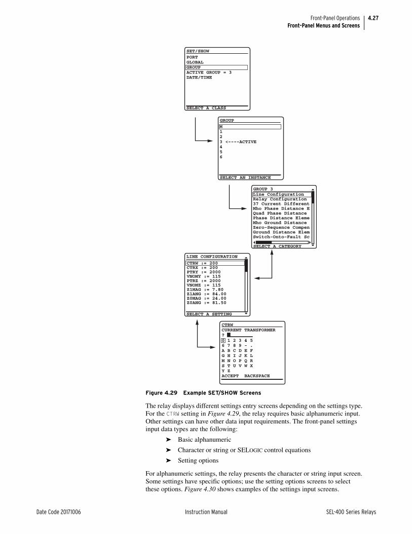
4.27
Date Code 20171006 Instruction Manual SEL-400 Series Relays
Front-Panel OperationsFront-Panel Menus and Screens
The relay displays different settings entry screens depending on the settings type. For the CTRW setting in Figure 4.29, the relay requires basic alphanumeric input. Other settings can have other data input requirements. The front-panel settings input data types are the following:
➤ Basic alphanumeric
➤ Character or string or SELOGIC control equations
➤ Setting options
For alphanumeric settings, the relay presents the character or string input screen. Some settings have specific options; use the setting options screens to select these options. Figure 4.30 shows examples of the settings input screens.
Figure 4.29 Example SET/SHOW Screens
SET/SHOW
PORTGLOBALGROUPACTIVE GROUP = 3DATE/TIME
GROUP
SELECT AN INSTANCE
SELECT A CLASS
M123 <----ACTIVE456
GROUP 3
SELECT A CATEGORY
Line ConfigurationRelay Configuration37 Current DifferentMho Phase Distance EQuad Phase DistancePhase Distance ElemeMho Ground DistanceZero-Sequence CompenGround Distance ElemSwitch-Onto-Fault Sc
SELECT A SETTING
LINE CONFIGURATION
CTRW := 200CTRX := 200PTRY := 2000VNOMY := 115PTRZ := 2000VNOMZ := 115Z1MAG := 7.80Z1ANG := 84.00Z0MAG := 24.00Z0ANG := 81.50
CTRW
? CURRENT TRANSFORMER
0 1 2 3 4 56 7 8 9 - .A B C D E FG H I J K LM N O P Q RS T U V W XY ZACCEPT BACKSPACE

4.28
SEL-400 Series Relays Instruction Manual Date Code 20171006
Front-Panel OperationsFront-Panel Menus and Screens
Active GroupPerform the following steps to change the active setting group:
Step 1. Select the ACTIVE GROUP option of the SET/SHOW submenu screen (shown in Figure 4.29) to change the settings group.
The relay performs a password validation test at this point to confirm that you have Breaker Access Level authorization or above.
Step 2. If access is allowed, and all the results of SELOGIC control equations SS1–SS6 are not logical 1 (asserted), then the relay displays the EDIT ACTIVE GROUP screen in Figure 4.31
The relay shows the active group and underlines the group number after NEW GROUP =.
Step 3. Use the Up Arrow and Down Arrow pushbuttons to increase or decrease the NEW GROUP number.
Step 4. Once you have selected the new active group, press ENT to change the relay settings to this new settings group.
Date/TimeAnother submenu item of the SET/SHOW first screen (Figure 4.29) is the DATE/TIME screen shown in Figure 4.32. By default, the relay generates date and time information internally; you can also use external high-accuracy time modes with time sources such as a GPS receiver.
Figure 4.30 Sample Settings Input Screens
Character or String or SELOGIC control equations
RID
? A B C D E F G H I J K L M N O P Q R S T U V W X Y Z 0 1 2 3 4 5 6 7 8 9 - . ( ) ^ & * _ + - / ; : `< > , { } [ ] |ACCEPT BACKSPACE
Relay Identifier (40
Basic Alphanumeric
CTRW
? CURRENT TRANSFORMER
0 1 2 3 4 56 7 8 9 - .A B C D E FG H I J K LM N O P Q RS T U V W XY ZACCEPT BACKSPACE
Setting Options
51S1O
SELECT AN OPTION
51S1 Op. Qty. (IAn,IBIALIBLICLIMAXLI1L3I2L310LIA1IB1
Figure 4.31 Changing the ACTIVE GROUP
EDIT ACTIVE GROUP
ACTIVE GROUP = 3NEW GROUP = 3
SET/SHOWPORTGLOBALGROUPACTIVE GROUP = 3DATE/TIME
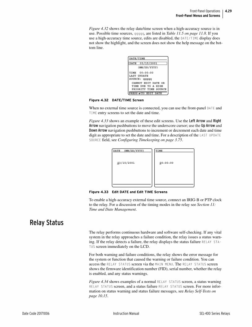
4.29
Date Code 20171006 Instruction Manual SEL-400 Series Relays
Front-Panel OperationsFront-Panel Menus and Screens
Figure 4.32 shows the relay date/time screen when a high-accuracy source is in use. Possible time sources, qqqqq, are listed in Table 11.5 on page 11.8. If you use a high-accuracy time source, edits are disabled, the DATE/TIME display does not show the highlight, and the screen does not show the help message on the bot-tom line.
When no external time source is connected, you can use the front-panel DATE and TIME entry screens to set the date and time.
Figure 4.33 shows an example of these edit screens. Use the Left Arrow and Right Arrow navigation pushbuttons to move the underscore cursor; use the Up Arrow and Down Arrow navigation pushbuttons to increment or decrement each date and time digit as appropriate to set the date and time. For a description of the LAST UPDATE SOURCE field, see Configuring Timekeeping on page 3.75.
To enable a high-accuracy external time source, connect an IRIG-B or PTP clock to the relay. For a discussion of the timing modes in the relay see Section 11: Time and Date Management.
Relay StatusThe relay performs continuous hardware and software self-checking. If any vital system in the relay approaches a failure condition, the relay issues a status warn-ing. If the relay detects a failure, the relay displays the status failure RELAY STA-TUS screen immediately on the LCD.
For both warning and failure conditions, the relay shows the error message for the system or function that caused the warning or failure condition. You can access the RELAY STATUS screen via the MAIN MENU. The RELAY STATUS screen shows the firmware identification number (FID), serial number, whether the relay is enabled, and any status warnings.
Figure 4.34 shows examples of a normal RELAY STATUS screen, a status warning RELAY STATUS screen, and a status failure RELAY STATUS screen. For more infor-mation on status warning and status failure messages, see Relay Self-Tests on page 10.15.
Figure 4.32 DATE/TIME Screen
Figure 4.33 Edit DATE and Edit TIME Screens
DATE/TIME
DATE 03/15/2001
PRESS TO EDIT DATE
(MM/DD/YYYY)
TIME 00:00:00LAST UPDATESOURCE: qqqqq
CANNOT EDIT DATE ORTIME DUE TO A HIGHPRIORITY TIME SOURCE
DATE (MM/DD/YYYY)
03/15/2001
TIME
00:00:00

4.30
SEL-400 Series Relays Instruction Manual Date Code 20171006
Front-Panel OperationsFront-Panel Menus and Screens
View ConfigurationYou can use the front panel to view detailed information about the configuration of the firmware and hardware components in the relay. In the MAIN MENU, high-light the VIEW CONFIGURATION option by using the navigation pushbuttons. A series of screens will be presented describing the relay configuration. See the relay-specific instruction manual to see the specific information provided in that relay.
Display TestYou can use the DISPLAY TEST option of the MAIN MENU to confirm operation of all of the LCD pixels. The LCD screen alternates the on/off state of the display pixels once every time you press ENT. Figure 4.35 shows the resulting two screens. The DISPLAY TEST option also illuminates all of the front-panel LEDs. To exit the test mode, press ESC.
NOTE: The LCD DISPLAY TEST does NOT reset the front-panel LED targets.
Reset Access LevelThe relay uses various passwords to control access to front-panel functions. As you progress through these menus, the relay detects the existing password level and prompts you for valid passwords before allowing you access to levels greater than Access Level 1 (see Password on page 4.15). When you want to return the front-panel to the lowest access level (Access Level 1), highlight RESET ACCESS LEVEL item on the MAIN MENU. Pressing ENT momentarily displays the screen of Figure 4.36 and places the front panel at Access Level 1.
The relay automatically resets the access level to Access Level 1 upon front-panel time-out (setting FP_TO is not set to OFF). Use this feature to reduce the front-panel access level before the time-out occurs.
Figure 4.34 Relay STATUS Screens
RELAY STATUS RELAY STATUS RELAY STATUSSEL-421-R101-V0-Z001001-D20010315
Normal Status Warning Status Failure
S/N=2001001234
RELAY ENABLEDNO FAILURES ORWARNINGS
SEL-421-R101-V0-Z001001-D20010315
S/N=2001001234
RELAY ENABLEDTEMPERATURE WARNING
SEL-421-R101-V0-Z001001-D20010315
S/N=2001001234
RELAY DISABLEDMASTER OFFSET FAILED
Figure 4.35 DISPLAY TEST Screens
DISPLAY TEST
All LEDs shouldbe lit.
DISPLAY TEST
All LEDs shouldbe lit.

4.31
Date Code 20171006 Instruction Manual SEL-400 Series Relays
Front-Panel OperationsFront-Panel Automatic Messages
One-Line DiagramMost SEL-400 series relays support one-line diagrams on the front-panel LCD. The ONE-LINE DIAGRAM option from the front-panel MAIN MENU displays the one-line diagram that has been selected in the Bay settings class. From this screen, disconnect switch open and close operations, as well as breaker open and close operations can be performed. This screen also displays labels for the different apparatus in the bay configuration and Analog Quantity metering values. The one-line diagram, display labels, and Analog Quantities are settable in the Bay class settings. See Figure 4.37 for an illustration of the one-line diagram.
For navigation and control operations in the one-line diagram screen, see Bay Control Front-Panel Operations on page 5.12.
Front-Panel Automatic MessagesThe relay automatically displays alert messages. Any message generated because of an alert condition takes precedence over the normal ROTATING DISPLAY and the MAIN MENU. Alert conditions include these significant events:
➤ Alarm Point asserts
➤ Event reports and trips (user-defined)
➤ Status warnings
➤ Status failures
To display event reports automatically from the ROTATING DISPLAY, you must set front-panel setting DISP_ER to Y. Front-panel setting TYPE_ER allows the user to define which types of event reports will be automatically displayed from the normal ROTATING DISPLAY; ALL will display all event types defined in the relay, and TRIP will display only the event types that include the assertion of the TRIP Relay Word bit.
Figure 4.36 RESET ACCESS LEVEL Screen
RESET ACCESS LEVEL
Front panel accesslevel reset.
Figure 4.37 One-Line Diagram Screen
BAYNAME
ESCNAVIG
ANALOGSI:9999AV:999kVF:99.9HzP:999MVQ:999MVR
BUS 1
Dis 4
Dis 5
Bkr 1Dis 3
Dis 1 Dis 2BUS 2
BUS T

4.32
SEL-400 Series Relays Instruction Manual Date Code 20171006
Front-Panel OperationsFront-Panel Automatic Messages
For alarm point assertions, qualified event reports (including trip events) and sta-tus warnings, the relay displays the corresponding full-screen automatic message, only if the front-panel display is in the time-out or standby condition (the relay is scrolling through the default display points/enabled metering screens of the ROTATING DISPLAY or is displaying the MAIN MENU). When a status warning, alarm, or event is triggered, the relay full-screen presentation is similar to the screens of Figure 4.38.
If you are on site using the relay front panel in menus and screens other than the MAIN MENU and a status warning occurs, an alarm point asserts, or an event report triggers, the relay shows automatic messages at the bottom of the active screen in the message area.
For example, the message area shows RELAY STATUS WARNING for a status warn-ing. Figure 4.39 is an example of a status warning notification that appears in the message area of a LOCAL CONTROL (local bit) screen. If an alarm point asserts while you are using a front-panel screen, the message area notification reads: ALARM EVENT. If a trip event occurs while you are using a front-panel screen, the message area notification reads RELAY EVENT. When you repeatedly press ESC (as if returning to the MAIN MENU) during this warning or trip alert situation, the relay displays the corresponding full-screen automatic message concerning the warn-ing or trip in place of the MAIN MENU. If the front-panel display is at the MAIN MENU and a status warning occurs, the full-screen warning replaces the MAIN MENU. After you view the warning, alarm, or trip screen, pressing ESC returns the LCD to the MAIN MENU.
For a status failure, the relay immediately displays the full-screen status alert regardless of the present front-panel operating state. The relay displays no further LCD screens until the status failure clears. Should an unlikely status failure event occur, contact your local Technical Service Center or an SEL factory representa-tive (see Technical Support on page 10.31).
Figure 4.38 Sample Status Warning and Trip EVENT SUMMARY Screens
Figure 4.39 Sample Status Warning in the LCD Message Area
03/15/01 GROUP 100:00:05.387
EVENT: BCG TLOCATION: 48.47FREQ: 60.00SHOT: 1P=0 3P=1BK1 OPENBK2 CLOSED
EVENT SUMMARY 10002RELAY STATUSSEL-421-R101-V0- Z001001-D20010315
S/N=0001001234
RELAY ENABLEDTEMPERATURE WARNING
*Circuit BK1 SF6 Gas
ALARM POINTS
Press to acknldge
1 Closed (OK to TIE)0 Open (No TIE)
BUS TIE INTERLOCK
1
0
RELAY STATUS WARNING

4.33
Date Code 20171006 Instruction Manual SEL-400 Series Relays
Front-Panel OperationsOperation and Target LEDs
Operation and Target LEDsThe relay gives you at-a-glance confirmation of relay conditions via operation and target LEDs. These LEDs are located in the middle of the relay front panel. SEL-400 series relays provide either 16 or 24 LEDs depending on ordering option.
You can reprogram all of these indicators except the ENABLED and TRIP LEDs to reflect other operating conditions than the factory-default programming described in this subsection. Settings Tn_LED are SELOGIC control equations that, when asserted during a relay trip event, light the corresponding LED (n = 1–24). LED positions are described in parentheses next to each LED in Figure 4.40.
Set TnLEDL := Y to latch the LEDs during trip events; when you set TnLEDL := N, the trip latch supervision has no effect and the LED follows the state of the Tn_LED SELOGIC control equation. The relay reports these targets in event reports; set the alias name listed in the report (as many as seven characters) by aliasing the Tn_LED bits with the SET T command or with QuickSet. In 12-pushbutton models, the asserted and deasserted colors for the LED are deter-mined with settings TnLEDC. Options include red, green, amber, or off. In some SEL-400 series relays, if TnLEDL = Y, the relay latches the target on the rising edge of the target bit. In these relays, to cause the bits to latch with trip, modify the equation to include AND R_TRIG TRIP. Refer to the Target LEDs subsection in the relay-specific Front-Panel Operations section to determine if the LED latches with the rising edge of TRIP or on the rising edge of Tn_LED.
After setting the target LEDs, issue the TAR R command to reset the target LEDs. For a description of the default LED behavior for a specific relay, see the Front Panel Operations section in the relay-specific instruction manual.
Use the slide-in labels to mark the LEDs with custom names. Configurable label templates included on relay-specific Product Literature CDs allow you to cus-tomize the front-panel labels.
Figure 4.40 SEL-451 Factory-Default Front-Panel Target Areas (16 or 24 LEDs)
(1)
(2)
(3)
(4)
(5)
(6)
(7)
(8)
(9)
(10)
(11)
(12)
(13)
(14)
(15)
(16)
(1)
(2)
(3)
(4)
(5)
(6)
(7)
(8)
(9)
(10)
(11)
(12)
(13)
(14)
(15)
(16)
(17)
(18)
(19)
(20)
(21)
(22)
(23)
(24)

4.34
SEL-400 Series Relays Instruction Manual Date Code 20171006
Front-Panel OperationsFront-Panel Operator Control Pushbuttons
OperationalThe ENABLED LED indicates that the relay is active. Trip events illuminate the TRIP LED. The prominent location of the TRIP LED in the top target area helps you recognize a trip event quickly. Program settings EN_LEDC and TR_LEDC to determine the color of the respective LED. Options include red or green.
TARGET RESET and Lamp TestFor a trip event, the relay latches the trip-involved target LEDs. Press the TARGET RESET pushbutton to reset the latched target LEDs. When a new trip event occurs and you have not reset the previously latched trip targets, the relay clears the latched targets and displays the new trip targets.
Pressing the TARGET RESET pushbutton illuminates all the LEDs. Upon releasing the TARGET RESET pushbutton, two possible trip situations can exist: the conditions that caused the relay to trip have cleared, or the trip conditions remain present at the relay inputs. If the trip conditions have cleared, the latched target LEDs turn off. If the trip event conditions remain, the relay re-illuminates the corresponding target LEDs. The TARGET RESET pushbutton also removes the trip automatic mes-sage displayed on the LCD menu screens if the trip conditions have cleared.
Lamp Test Function With TARGET RESET
The TARGET RESET pushbutton also provides a front-panel lamp test. Pressing TAR-GET RESET illuminates all the front-panel LEDs, and these LEDs remain illumi-nated for as long as you press TARGET RESET. The target LEDs return to a normal operational state after you release the TARGET RESET pushbutton.
Other Target Reset Options
You can reset the target LEDs with the ASCII command TAR R; see TARGET on page 14.53 for more information.
The TAR R command and the TARGET RESET pushbutton also control the TRGTR Relay Word bit, which can be used for other functions. TRGTR is the factory-default setting for the unlatch trip SELOGIC control equation, ULTR, in group settings.
You can reset the targets from the QuickSet Control branch of the HMI tree view. Programming specific conditions in the SELOGIC control equation RST-TRGT is another method to reset the relay targets. Access RSTTRGT in the relay Global settings (Data Reset Control); to use RSTTRGT, you must enable data reset control with Global setting EDRSTC := Y.
Front-Panel Operator Control PushbuttonsThe relay front panel features large operator control pushbuttons coupled with amber annunciator LEDs for local control. Figure 4.41 shows this region of the relay front panel with example factory-default configurable front-panel label text. SEL-400 series relays provide either 8 or 12 pushbuttons depending on the prod-uct and ordering option.

4.35
Date Code 20171006 Instruction Manual SEL-400 Series Relays
Front-Panel OperationsFront-Panel Operator Control Pushbuttons
See Section 4: Front-Panel Operations of the product-specific instruction manual for a description of the default configuration of operator control pushbuttons and LEDs.
Figure 4.41 SEL-451 Default Operator Control Pushbuttons and LEDs (8 or 12 Pushbuttons)
OperatorControl
Pushbutton
Annunciator LED

This page intentionally left blank

Date Code 20171006 Instruction Manual SEL-400 Series Relays
Instruction ManualInstruction ManualS E C T I O N 5
Control
SEL-400 series relays provide many control features, including circuit breaker controls, disconnect controls, remote bit controls, and bay control. This section describes these control capabilities.
➤ Circuit Breaker Status and Control on page 5.1
➤ Disconnect Logic on page 5.1
➤ Remote Bits on page 5.11
➤ Bay Control Front-Panel Operations on page 5.12
➤ QuickSet Bay Control Screens on page 5.27
➤ Customizable Screens on page 5.34
➤ Bay Control Example Application on page 5.35
See the specific relay instruction manuals to see how many breakers, disconnects, and remote bits are available and to determine whether or not bay control is sup-ported.
Circuit Breaker Status and ControlSEL-400 series relays include circuit breaker status logic for all supported circuit breakers. The circuit breaker status logic uses the 52A_k setting (SELOGIC equa-tion) and open-phase detection logic to determine the state of Circuit Breaker k, and declare Circuit Breaker k alarm conditions. See Section 5: Protection of the product-specific instruction manual for a description of circuit breaker status logic Relay Word bits and circuit breaker status logic diagrams.
SEL-400 series relays support opening and closing breakers. These operations can be controlled via the terminal commands OPEN and CLOSE, the binary ter-minal Fast Operate messages, various supported communications protocols, the front-panel menus, and through the bay control one-line screens. These controls operate the open control (OCk) and close control (CCk) bits. These bits are used in the relay trip and close logic to integrate these external controls with the relay automatic trip and close behavior. See Section 6: Protection Application Exam-ples in the product-specific instruction manual for more information on the trip and close logic.
Disconnect LogicDisconnect Switch Close and Open Control Logic
Figure 5.1 and Figure 5.2 shows the Disconnect Logic that generates open and close output signals necessary to perform the open and close disconnect opera-tions. Use the seal-in timers (89CSTm and 89OSTm) to monitor and control dis-

5.2
SEL-400 Series Relays Instruction Manual Date Code 20171006
ControlDisconnect Logic
connect operations. All disconnect control methods (HMI, ASCII, SELOGIC control equations, and Fast Operate) drive the Close and Open Control Logic in the relay.
Disconnect Switch Close and Open Control Logic Status Inputs89CLSm, 89OPEm
Disconnect Switch Close Logic (Figure 5.1) and Open Logic (Figure 5.2) gener-ate Relay Word bits 89CLSm and 89OPEm which drive the open and close oper-ations. To ensure that an open and close disconnect signal cannot occur at the same time, 89CLSm and 89OPEm also block operation of the opposing logic. Therefore, Relay Word bit 89CLSm is an input to the Disconnect Open Logic, and Relay Word bit 89OPEm is an input to the Disconnect Close Logic.
Figure 5.1 Disconnect Switch Close Logic
Close Immobility Timer
89CITm
0 CYC
*89CIRm(default setting:
NOT 89OPNm)
89ALm*89CRSm
(default setting:89CLm OR 89CSIm)
RelayWordBits
* SELOGIC control equation** This SELOGIC control equation processed at 1/8 cycle
89CIMm
89CLSm
(Reset)
0 CYC
60CYC
52
3
Close Seal-in Timer
89CSTm
0CYC
*89CBLm
89OPEm
89CCMm
89CCm (ASCII)**89CCNm (k – 1/8 cyc.)
**89CCNm (k)
*LOCAL
89CSIm34
2
11
Figure 5.2 Disconnect Switch Open Logic
Open Immobility Timer
89OITm
60CYC
*89OIRm(default setting:
NOT 89CLm)
89ALm*89ORSm
(default setting:89OPNm OR 89OSIm)
RelayWordBits
* SELOGIC control equation** This SELOGIC control equation processed at 1/8 cycle
89OIMm
89OPEm
(Reset)
52
3
Open Seal-in Timer
89OSTm
0CYC
*89OBLm
89CLSm
89OCMm
89OCm (ASCII)**89OCNm (k – 1/8 cyc.)
**89OCNm (k)
*LOCAL
89OSIm34
2
11

5.3
Date Code 20171006 Instruction Manual SEL-400 Series Relays
ControlDisconnect Logic
89CBLm, 89OBLmThe 89CBLm and 89OBLm SELOGIC control equations provide an alternative customizable method for blocking the initiation of a disconnect switch open or close command, respectively.
89CRSm, 89ORSm
The 89CRSm and 89ORSm SELOGIC control equations provide the flexibility to select the signals that reset the close (89CLSm) or open (89OPEm) outputs. 89CRSm defaults to (89CLm OR 89CSIm), and 89ORSm defaults to (89OPNm OR 89OSIm).
89CSIm, 89OSImSet 89CSTm and 89OSTm to seal in the open and close signals for each individ-ual installation. Relay Word bits 89CSIm and 89OSIm are the outputs of the close and open seal-in timers, and assert after the appropriate timers expire. By default, 89CSIm and 89OSIm are used in the 89CRSm and 89ORSm SELOGIC control equations to reset the close and open signals, 89CLSm and 89OPEm, that drive the disconnect switch motor.
89CLm, 89OPNmThe 89CLm and 89OPNm Relay Word bits report the state of the disconnect switches. If the disconnect switch is closed, Relay Word bit 89CLm is asserted; if the disconnect switch is open, Relay Word bit 89OPNm is asserted. See Figure 5.3 for a description of these inputs. With the default settings, when Relay Word bit 89CLm asserts, the close seal-in circuit is blocked, causing 89CLSm to deassert. Likewise, with the default settings, when Relay Word bit 89OPNm asserts, the open seal-in circuit is blocked, causing 89OPEm to deassert.
89ALmThe disconnect switch status and alarm logic in Figure 5.3 generates the 89ALm Relay Word bit. When Relay Word bit 89ALm asserts, it resets the seal-in cir-cuits, deasserting the 89CLSm/89OPEm signals.
LOCAL
The LOCAL Relay Word bit asserts when LOCAL SELOGIC control equation asserts to a logical 1. When the LOCAL Relay Word bit asserts, only the HMI commands (89CCMm and 89OCMm), can initiate close and open operations. When the LOCAL Relay Word bit is deasserted, the 89CLOSE, 89OPEN, SELOGIC disconnect close/open, and Fast Operate disconnect close/open com-mands can perform disconnect close and open operations. The default value for this setting is NA.
Disconnect Switch Close and Open Control Logic Action Inputs89CCNm, 89OCNm
89CCNm and 89OCNm SELOGIC control equations are for programmable close and open disconnect switch operations. The LOCAL Relay Word bit must be deasserted for the close or open SELOGIC equations to initiate a disconnect switch operation. Use care when using SELOGIC control equations for disconnect
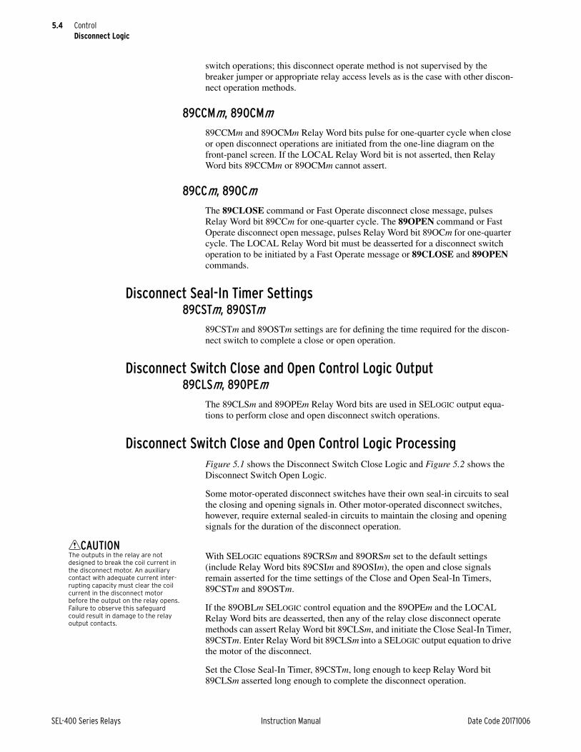
5.4
SEL-400 Series Relays Instruction Manual Date Code 20171006
ControlDisconnect Logic
CAUTION
switch operations; this disconnect operate method is not supervised by the breaker jumper or appropriate relay access levels as is the case with other discon-nect operation methods.
89CCMm, 89OCMm89CCMm and 89OCMm Relay Word bits pulse for one-quarter cycle when close or open disconnect operations are initiated from the one-line diagram on the front-panel screen. If the LOCAL Relay Word bit is not asserted, then Relay Word bits 89CCMm or 89OCMm cannot assert.
89CCm, 89OCmThe 89CLOSE command or Fast Operate disconnect close message, pulses Relay Word bit 89CCm for one-quarter cycle. The 89OPEN command or Fast Operate disconnect open message, pulses Relay Word bit 89OCm for one-quarter cycle. The LOCAL Relay Word bit must be deasserted for a disconnect switch operation to be initiated by a Fast Operate message or 89CLOSE and 89OPEN commands.
Disconnect Seal-In Timer Settings89CSTm, 89OSTm
89CSTm and 89OSTm settings are for defining the time required for the discon-nect switch to complete a close or open operation.
Disconnect Switch Close and Open Control Logic Output89CLSm, 89OPEm
The 89CLSm and 89OPEm Relay Word bits are used in SELOGIC output equa-tions to perform close and open disconnect switch operations.
Disconnect Switch Close and Open Control Logic ProcessingFigure 5.1 shows the Disconnect Switch Close Logic and Figure 5.2 shows the Disconnect Switch Open Logic.
Some motor-operated disconnect switches have their own seal-in circuits to seal the closing and opening signals in. Other motor-operated disconnect switches, however, require external sealed-in circuits to maintain the closing and opening signals for the duration of the disconnect operation.
The outputs in the relay are not designed to break the coil current in the disconnect motor. An auxiliary contact with adequate current inter-rupting capacity must clear the coil current in the disconnect motor before the output on the relay opens. Failure to observe this safeguard could result in damage to the relay output contacts.
With SELOGIC equations 89CRSm and 89ORSm set to the default settings (include Relay Word bits 89CSIm and 89OSIm), the open and close signals remain asserted for the time settings of the Close and Open Seal-In Timers, 89CSTm and 89OSTm.
If the 89OBLm SELOGIC control equation and the 89OPEm and the LOCAL Relay Word bits are deasserted, then any of the relay close disconnect operate methods can assert Relay Word bit 89CLSm, and initiate the Close Seal-In Timer, 89CSTm. Enter Relay Word bit 89CLSm into a SELOGIC output equation to drive the motor of the disconnect.
Set the Close Seal-In Timer, 89CSTm, long enough to keep Relay Word bit 89CLSm asserted long enough to complete the disconnect operation.

5.5
Date Code 20171006 Instruction Manual SEL-400 Series Relays
ControlDisconnect Logic
To account for slow operate times because of cold weather or low battery voltage, set the 89CSTm time 10 to 15 percent longer than the expected operate time. This guarantees that the disconnect switch has fully operated before the 89CLSm sig-nal is removed. When the 89CSTm seal-in timer expires, 89CSIm asserts, or the disconnect switch normally open contact closes (89CLm asserted), the 89CLSm output deasserts. This completes an open-to-close cycle of the Disconnect Close Logic; the Disconnect Open Logic in Figure 5.2 behaves in the same manner.
Disconnect switch status and alarm logic in Figure 5.3 generates Relay Word bit 89ALm. When Relay Word bit 89ALm asserts, a disconnect alarm condition exists. The 89ALm Relay Word bit ensures that the close or open signal does not remain asserted when a disconnect switch alarm condition exists. When Relay Word bit 89ALm asserts or the seal-in timer expires, the 89CLSm or 89OPEm signals deassert.
When a close operation is inadvertently initiated with the disconnect switch already closed, and the 89CRSm SELOGIC control equation is set as defaulted (89CLm OR 89CSIm), the asserted 89CLm Relay Word bit (close status) will block the seal-in circuit before the timer expires. This will deassert the 89CLSm Relay Word bit, which drives the disconnect switch motor. In this way, 89CLSm asserts for only one processing interval.
If an open command was sent within the 89CSIm time, an open and close signal could be sent to the disconnect switch at the same time. The 89CLSm Relay Word bit input to the Disconnect Switch Open Logic guarantees that open and close commands are not transmitted to the disconnect switch simultaneously. When the 89CLSm Relay Word bit deasserts, an open command can be per-formed. The 89OBLm SELOGIC control equation provides an additional custom-izable method for blocking the initiation of a close command. The Relay Word bit 89OPEm, and 89CBLm inputs to the Disconnect Switch Close Logic serves the same purpose.
Disconnect Switch Status and Alarm LogicThe disconnect switch auxiliary contacts are inputs to the Disconnect Switch Sta-tus and Alarm Logic as shown in Figure 5.3. SELOGIC control equation 89AMm is the input for the normally open an auxiliary contact, and SELOGIC control equation 89BMm is the input for the normally closed Form B auxiliary contact. For the Status and Alarm Logic to function correctly, wire the Form A and Form B contacts each to separate inputs on the relay. When ordering a relay, consider the number of inputs required for the disconnects being controlled. The number of auxiliary contacts for some systems may require that the relay be configured with additional I/O boards.
Disconnect operations are possible with only one auxiliary contact input, but with this implementation the Status and Alarm Logic will not provide accurate Alarm, Operation in Progress, or Bus-zone protection reporting. When only one auxiliary contact is available for input, set one SELOGIC control equation to the available auxiliary contact input and invert the other SELOGIC control equation:
89AMm := IN102
89BMm := NOT IN102
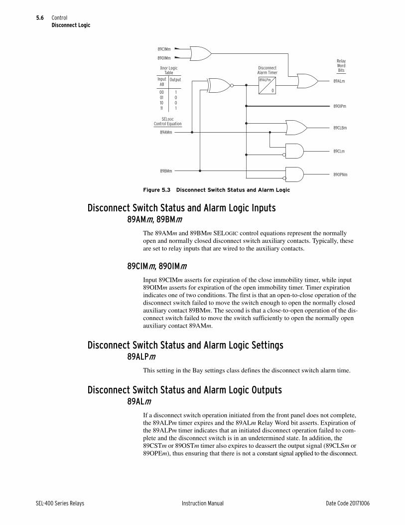
5.6
SEL-400 Series Relays Instruction Manual Date Code 20171006
ControlDisconnect Logic
Disconnect Switch Status and Alarm Logic Inputs 89AMm, 89BMm
The 89AMm and 89BMm SELOGIC control equations represent the normally open and normally closed disconnect switch auxiliary contacts. Typically, these are set to relay inputs that are wired to the auxiliary contacts.
89CIMm, 89OIMmInput 89CIMm asserts for expiration of the close immobility timer, while input 89OIMm asserts for expiration of the open immobility timer. Timer expiration indicates one of two conditions. The first is that an open-to-close operation of the disconnect switch failed to move the switch enough to open the normally closed auxiliary contact 89BMm. The second is that a close-to-open operation of the dis-connect switch failed to move the switch sufficiently to open the normally open auxiliary contact 89AMm.
Disconnect Switch Status and Alarm Logic Settings89ALPm
This setting in the Bay settings class defines the disconnect switch alarm time.
Disconnect Switch Status and Alarm Logic Outputs89ALm
If a disconnect switch operation initiated from the front panel does not complete, the 89ALPm timer expires and the 89ALm Relay Word bit asserts. Expiration of the 89ALPm timer indicates that an initiated disconnect operation failed to com-plete and the disconnect switch is in an undetermined state. In addition, the 89CSTm or 89OSTm timer also expires to deassert the output signal (89CLSm or 89OPEm), thus ensuring that there is not a constant signal applied to the disconnect.
Figure 5.3 Disconnect Switch Status and Alarm Logic
RelayWordBits
89ALPm
0
89CIMm
89OIMm
89ALm
89AMm
89BMm
DisconnectAlarm Timer
Xnor LogicTable
Input
ABOutput
00
01
10
11
1
0
0
1 89OIPm
89CLBm
89CLm
89OPNm
SELOGIC
Control Equation
5.7
Date Code 20171006 Instruction Manual SEL-400 Series Relays
ControlDisconnect Logic
89OIPmWhen Relay Word bit 89OIPm asserts, a disconnect switch operation is in prog-ress. Relay Word bit 89OIP asserts when the states of the 89BMm and 89AMm Relay Word bits are the same, i.e., both asserted or both deasserted.
89CLBmThis Relay Word bit is used for bus-zone protection and asserts when the discon-nect is no longer open (89BMm deasserted).
89CLmWhen Relay Word bit 89CLm asserts, the disconnect switch is closed.
89OPNmWhen Relay Word bit 89OPNm asserts, the disconnect switch is open.
Disconnect Switch Status and Alarm Logic ProcessingFigure 5.3 shows the Disconnect Switch Status and Alarm Logic. Inputs to this logic are the normally open (89AMm) and normally closed (89BMm) disconnect switch auxiliary contacts.
To understand the logic in Figure 5.3, consider an open-to-close operation. The first disconnect operation scenario looks at a successful open-to-close disconnect switch operation; a successful close-to-open operation is similar. In the open state, 89AMm is deasserted and 89BMm is asserted. Once a close command is initiated in the relay, the disconnect switch starts to move and 89BMm deasserts. When 89BMm deasserts, the 89ALPm pickup timer starts to time. With 89BMm deasserted, the state of the disconnect switch cannot be determined, because both disconnect switch auxiliary contacts are deasserted. Set the 89ALPm timer longer than the expected undetermined disconnect state time, but less than the 89CSTm or 89OSTm seal-in timers. If the 89ALPm timer expires, the 89ALm Relay Word bit asserts. Relay Word bit 89ALm asserts when the disconnect operation does not complete successfully. When the 89ALPm timer begins timing, the operation in progress, Relay Word bit 89OIPm, and Relay Word bit 89CLBm assert. The 89CLBm Relay Word bit is for bus-zone protection, this bit asserts when the 89BMm input deasserts.
During the disconnect switch operation-in-progress condition, Relay Word bits 89CLm and 89OPNm are both deasserted because the state of the disconnect switch is undetermined. Once the disconnect switch auxiliary contact Relay Word bit 89AMm asserts, the condition has been met to declare the disconnect switch closed. When 89AMm asserts, the 89CLm Relay Word bit asserts, 89ALPm stops timing, Relay Word bit 89OIPm deasserts, and Relay Word bit 89CLBm remains asserted. This sequence completes a successful open-to-close disconnect switch operation.
The second disconnect operation scenario is for an unsuccessful open-to-close operation, which, until 89ALPm starts timing, is identical to the successful oper-ation in the previously discussed first scenario.
During operation of the 89ALPm timer, the disconnect switch begins moving. The close disconnect switch output signal 89CLSm clears upon expiration of the 89CSTm seal-in timer. The logic then provides the disconnect switch additional time to complete the close operation, in case some inertia from the motor rotor keeps the disconnect motor in motion. By setting the 89ALPm timer longer than

5.8
SEL-400 Series Relays Instruction Manual Date Code 20171006
ControlDisconnect Logic
the 89CSTm seal-in timer, you can ensure retention of the close signal until the disconnect switch closes completely. If there is no complete disconnect switch operation during the time 89ALPm defines, the relay asserts Relay Word bit 89ALm and reports that the disconnect switch is in an undetermined state.
The scenario in which both 89AMm and 89BMm are asserted simultaneously would occur on a rare disconnect switch failure or a short-circuited auxiliary con-tact wire connection. When this condition occurs for 89ALPm seconds, the 89ALm alarm status output will assert.
Disconnect Switch Close and Open Immobility Timer LogicThe Close and Open Immobility Timer Logic detects when a disconnect opera-tion failed to initiate.
Close and Open Immobility Timer Logic Inputs LOCAL
The LOCAL Relay Word bit supervises local disconnect control and is based on the LOCAL SELOGIC control equation in the Bay settings class. Disconnect switch operations from the front panel are possible when the LOCAL Relay Word bit is asserted, in other words, the LOCAL Relay Word bit prevents control from the HMI without proper supervision.
89CBLm, 89OBLmThe 89CBLm and 89OBLm SELOGIC control equations provide an alternative customizable method for blocking the initiation of a disconnect switch open or close command, respectively.
Figure 5.4 Close Immobility Timer Logic
Close Immobility Timer
89CITm
60CYC
89CIRm(default setting:
NOT 89OPNm)RelayWordBits
* SELOGIC control equation
89CIMm
(Reset)
89CBLm
89OPEm
89CCMm
89CCm (ASCII)*89CCNm (k – 1/8 cyc.)
*89CCNm (k)
*LOCAL
Figure 5.5 Open Immobility Timer Logic
Open Immobility Timer
89OITm
60CYC
89OIRm(default setting:
NOT 89CLm)RelayWordBits
89OIMm
(Reset)
89OBLm
89CLSm
89OCMm
89OCm (ASCII)*89OCNm (k – 1/8 cyc.)
*89OCNm (k)
*LOCAL * SELOGIC control equation

5.9
Date Code 20171006 Instruction Manual SEL-400 Series Relays
ControlDisconnect Logic
89CIRm, 89OIRmThe 89CIRm and 89OIRm SELOGIC control equations provide the flexibility to customize resetting the Close and Open Immobility Timers. By default, 89CIRm is set to NOT 89OPNm, and 89OIRm is set to NOT 89CLm.
89CLm, 89OPNmThe 89CLm and 89OPNm Relay Word bits report the state of the disconnect switches. If the disconnect switch is closed, Relay Word bit 89CLm is asserted; if the disconnect switch is open, Relay Word bit 89OPNm is asserted. See Figure 5.3 for a description of these inputs.
Disconnect Switch Close and Open Control Logic Action Inputs89CCNm, 89OCNm
89CCNm and 89OCNm SELOGIC control equations are for programmable close and open disconnect switch operations. The LOCAL Relay Word bit must be deasserted for the SELOGIC close or open to initiate a disconnect switch opera-tion. Use care when using SELOGIC control equations for disconnect switch oper-ations; this disconnect operate method is not supervised by the breaker jumper or appropriate relay access levels as is the case with other disconnect operation methods.
89CCMm, 89OCMm89CCMm and 89OCMm Relay Word bits pulse for one-quarter cycle when close or open disconnect operations are executed from the one-line diagram on the front-panel screen. The LOCAL Relay Word bit must be asserted, for Relay Word bits 89CCMm or 89OCMm to assert.
89CCm, 89OCmThe 89CLOSE command or Fast Operate disconnect close message, pulses Relay Word bit 89CCm for one-quarter cycle. The 89OPEN command or Fast Operate disconnect open message, pulses Relay Word bit 89OCm for one-quarter cycle. The LOCAL Relay Word bit must be deasserted for a disconnect switch operation to be initiated by a Fast Operate message or 89CLOSE and 89OPEN commands.
Disconnect Switch Close and Open Immobility Timer Logic Settings 89CITm, 89OITm
89CITm and 89OITm timer settings in the Bay settings class define the close and open immobility timers.
Disconnect Switch Close and Open Immobility Timer Logic Outputs 89CIMm, 89OIMm
When 89CIMm or 89OIMm asserts, the close or open immobility timer has expired.

5.10
SEL-400 Series Relays Instruction Manual Date Code 20171006
ControlDisconnect Logic
Disconnect Switch Close and Open Immobility Timer Logic ProcessingThe Close and the Open Immobility Timer Logic detect when one of the close or open disconnect switch methods does not initiate successfully. In other words, it reports when the disconnect switch failed to start moving. The open and close immobility timer logic circuits are similar. When a close operation is initiated, the rising-edge-triggered Close Immobility Timer starts timing. Once the discon-nect switch starts to move away from its open position, Relay Word bit 89OPNm deasserts (see Figure 5.3). If the 89OPNm Relay Word bit deasserts, the close immobility timer resets and 89CIMm remains deasserted. On the other hand, if the 89OPNm Relay Word bit stays asserted, the close immobility timer does not reset. After the close immobility timer expires, 89CIMm asserts for one second. When 89CIMm asserts, the close operation is considered to have failed to initiate. 89CIMm is an input to the disconnect switch status and alarm logic for alarm condition indications.
This logic also uses the LOCAL Relay Word bit to supervise front-panel opera-tions. With the LOCAL Relay Word bit deasserted, no disconnect operations can be initiated from the one-line diagram. With the LOCAL Relay Word bit asserted, Relay Word bit 89CCMm asserts for one-quarter cycle when the ENT pushbutton is pressed and a disconnect switch is highlighted in the one-line diagram.
Close, Open, and Undetermined State IndicationsThis subsection discusses the way the close and open immobility timers work in conjunction with the disconnect alarm timer to provide disconnect control and alarm indications. When the disconnect switch main contact is stationary (closed or open) the state of the disconnect switch is easily determined.
If the disconnect switch main contact is open:
➤ normally closed Form B auxiliary contact (89BMm asserted) is closed
➤ normally open Form A auxiliary contact (89AMm deasserted) is open
If the disconnect switch main contact is closed:
➤ normally closed Form B auxiliary contact (89BMm deasserted) is open
➤ normally open Form A auxiliary contact (89AMm asserted) is closed
If an operation of the disconnect switch is in progress, the state of the disconnect switch main contact is undetermined:
➤ normally closed Form B auxiliary contact (89BMm deasserted) is open
➤ normally open Form A auxiliary contact (89AMm deasserted) is open
Any undetermined state of the disconnect switch main contact should be moni-tored. The relay can be configured to wait for the disconnect switch operation to complete, and issue an alarm if the disconnect switch remains in the undeter-mined state longer than the 89ALPm time. Figure 5.6 illustrates how the state of the auxiliary contacts change for an open-to-close operation in progress and how the 89CSTm, 89CITm, and 89ALPm timers are configured to manage the unde-termined time. The close-to-open scenario would be similar.
With the disconnect switch in the open state, the normally closed Form B auxil-iary contact is closed (89BMm asserted) and the normally open Form A auxiliary contact is open (89AMm deasserted). The 89CSTm seal-in timer starts timing when a disconnect switch close command is issued. The output of the 89CSTm seal-in timer keeps the close signal asserted for the duration of the expected dis-

5.11
Date Code 20171006 Instruction Manual SEL-400 Series Relays
ControlRemote Bits
connect switch operate time. Set the seal-in timer 10 to 15 percent longer than the expected disconnect operate time, to allow for slow disconnect operation times caused by cold temperatures or low battery voltages.
When the normally closed auxiliary contact (SELOGIC input 89BMm) deasserts, the disconnect switch is in an undetermined state. No proper position indication from either of the disconnect switch auxiliary contacts (89BMm or 89AMm) is available. Once the auxiliary normally closed contact (SELOGIC input 89BMm) deasserts, the 89ALPm timer starts timing. The 89ALPm timer monitors the undetermined state of the disconnect switch. For the 89ALPm timer to initialize, the disconnect switch has to move a minimum distance to open the normally closed auxiliary contact (open-to-close operation). Set the 89ALPm timer longer than the expected undetermined state time, but less than the 89CSTm seal-in timer. If the normally open auxiliary contact fails to close within the undeter-mined state time, the 89ALPm timer expires and an alarm condition is declared.
The Close Immobility Logic starts the Close Immobility Timer for an operation where the disconnect switch does not move the minimum distance to open the normally closed auxiliary contact (open-to-close operation). When the close immobility timer expires, an alarm condition is declared and Relay Word bit 89ALm asserts. If the disconnect moves enough to open the normally closed aux-iliary contact, the Close Immobility timer resets and no alarm condition is declared (see Figure 5.4).
Remote Bits Remote bits provide a means for sending remote control commands to relay logic. As indicated in CONTROL nn on page 14.16, remote bits have three oper-ating states: clear, set, and pulse. It is important to understand the differences between the use of pulsed remote bits in automation and protection SELOGIC
Figure 5.6 Disconnect in Transition
Disconnect CloseCommand Issued
Disconnect Main
Contact in Transition
Disconnect Close
Operation Completed
Normally Closed Form B
Contact (89BMm)
Normally Open Form A
Contact (89AMm)
Expected Disconnect Operate Time
89BMm Form B Contact
Closed
89BMm deasserts and
89ALPm begins timing89AMm Form A
Contact Closed
89ALPm Alarm
Timer Duration
Undetermined State
89CSTm Seal-In Timer

5.12
SEL-400 Series Relays Instruction Manual Date Code 20171006
ControlBay Control Front-Panel Operations
control equations. Remote bits can be operated from multiple communications interfaces, including the CON command from a terminal (serial or Telnet), Fast Operate messages, and DNP3.
A pulsed remote bit will assert the respective remote bit Relay Word bit (RBnn, nn = 01–32) for one processing interval (1/8 of a power system cycle). When used in Protection SELOGIC, which also executes at one processing interval, pulsed remote bits provide a momentary means for operating a variety of logic functions, including Protection Latches, Boolean logic expressions, and Protec-tion Logic Counters. Because the pulsed remote bit and Protection processing both operate within the same processing interval, the use of pulsed remote bits is reliable and deterministic.
To provide reliable detection of pulsed remote bits that assert for one protection logic processing interval within automation logic, conditioning is applied to the remote bit to extend the momentary assertion through the automation processing interval. This conditioning ensures the reliable detection of remote bit (RB01–RB32) assertion in automation logic. Remote bits that assert and deassert multi-ple times within the same automation logic processing interval will be processed as asserting continuously for the entire automation logic processing interval.
Bay Control Front-Panel OperationsEach relay has a default one-line diagram. Sometimes these diagrams fit on a sin-gle screen and sometimes they require more than one screen that you can pan across. For example, Figure 5.7 shows the default one-line diagram for the SEL-487E. You can display either of two parts of the diagram by using the Up Arrow and Down Arrow pushbuttons to pan between an upper screen and a lower screen. The upper screen shows the HV equipment and transformer, while the lower screen shows the transformer and LV equipment. The relay displays the upper screen by default.
NOTE: Not all SEL-400 series relays support bay control operations.
Figure 5.7 SEL-487E Default One-Line Diagram
BUSNAM 1
BUSNAM 2
SW2
AQ_1
AQ_2
AQ_3
AQ_4
SW1
BKS
SW3
SW4
EQ1
BAY 1
EQ1
SW5
SW6
BKT
SW7 SW8
AQ _5
AQ _6
AQ _7
AQ _8
BUSNAM3
BUSNAM4
BAY 1
Upper Pan Area Lower Pan Area

5.13
Date Code 20171006 Instruction Manual SEL-400 Series Relays
ControlBay Control Front-Panel Operations
One-Line Diagram and LabelsFigure 5.8 is an example of a default one-line diagram. The Bay settings class has settings for defining labels and analog quantities. One-line diagrams are com-prised of the following:
➤ Bay Names and Bay Labels
➤ Busbars and Busbar Labels
➤ Breakers and Breaker Labels
➤ Disconnect Switches and Disconnect Switch Labels
➤ Equipment and Equipment Labels
➤ Analog Display Points
Front-Panel Pushbutton Navigation Operations in the One-Line DiagramNavigation within the one-line diagram requires that the front-panel access level be at Breaker Access Level or higher and the Breaker Jumper be installed. If nav-igation is attempted when:
➤ The front panel is not at the Breaker Access Level or higher and passwords are enabled, the relay prompts you to enter the appropriate passwords.
➤ The Breaker Jumper is not installed, the Breaker Control Disabled Please Install the Breaker Jumper message briefly appears on the screen.
Use the arrow pushbuttons on the front panel to navigate within the one-line dia-gram. When you first select the one-line diagram, none of the apparatus on the one-line diagram are highlighted. Press the Left Arrow or Right Arrow pushbutton to enter the one-line diagram and highlight the apparatus. Once you enter the one-line diagram, navigation between the disconnect switch and circuit breaker sym-bols as follows:
➤ Pressing the Right Arrow pushbutton highlights the elements from left-to-right and top-to-bottom.
➤ When reaching the right-most bottom element, the following Right Arrow keystroke “rolls over” and again highlights the left-most top element.
Figure 5.8 Bay Control One-Line Diagram
BUSNAM1
BUSNAM2
SW2
AQ_1
AQ_2
AQ_3
AQ_4
SW1
BKS
SW3
SW4
EQ1
BAY 1
Bay Name
Bus Label
Disconnect Switch Label
Breaker Label
Equipment Label
Analog Display Points

5.14
SEL-400 Series Relays Instruction Manual Date Code 20171006
ControlBay Control Front-Panel Operations
➤ The Left Arrow pushbutton operates in reverse, i.e., from right-to-left, and bottom-to-top.
➤ Pressing the ENT pushbutton selects the highlighted symbol.
➤ Pressing the ESC pushbutton returns you to the previous screen.
Additionally, if the one-line diagram spans multiple screens, you can pan between the portions of the diagram using the up and down arrows:
➤ Pressing the Down Arrow pushbutton while displaying the top bay control screen, displays the bottom bay control screen.
➤ Pressing the Down Arrow pushbutton while displaying the bottom bay control screen or the Up Arrow pushbutton while displaying the top bay control screen, does nothing.
➤ Pressing the Up Arrow pushbutton while displaying the bottom bay control screen displays the top bay control screen.
Circuit Breaker and Disconnect Definitions and State RepresentationsTable 5.1 shows the apparatus definitions and symbols displayed on the one-line diagram.
NOTE: The intermediate states only apply to disconnect switches because circuit breaker operations have a short duration.
Each apparatus (circuit breaker or disconnect switch) can be in one of the follow-ing six states:
➤ Open, not highlighted
➤ Open, highlighted
➤ Closed, not highlighted
➤ Closed, highlighted
➤ Intermediate, not highlighted (intermediate = transition between open and closed states)
➤ Intermediate, highlighted
Table 5.2 describes how the one-line diagram represents the different states of the breakers, and how highlighting the breaker affects the display of the symbol.
Table 5.1 Circuit Breaker and Disconnect Switch Definitions
Circuit Breaker Open
Circuit Breaker Closed
Disconnect Open Disconnect Closed

5.15
Date Code 20171006 Instruction Manual SEL-400 Series Relays
ControlBay Control Front-Panel Operations
Table 5.3 describes how the one-line diagram represents the different states of the disconnect switches, and how highlighting the disconnect switch affects the dis-play of the symbol. Unlike the fast operation time of the circuit breaker, the dis-connect switch operation-in-progress time is longer than the breaker operation time. Table 5.3 describes how apparatus appear in the one-line diagram when a disconnect operation is in progress.
Table 5.2 Circuit Breaker State Representations
Apparatus Position SymbolAsserted Relay
Word Bit
Circuit breaker open, not highlighted NOT 52CLSMm
Circuit breaker open, highlighteda
a When the circuit breaker is highlighted, the two symbols shown alternate in the display.
NOT 52CLSMm
Circuit breaker closed, not highlighted 52CLSMm
Circuit breaker closed, highlighted 52CLSMm
Table 5.3 Disconnect Switch State Representations (Sheet 1 of 2)
Apparatus Position SymbolAsserted Relay
Word Bit
Disconnect open, not highlighted 89OPNm
Disconnect closed, not highlighted 89CLm
Disconnect open, highlighteda 89OPNm
Disconnect closed, highlighteda 89CLm

5.16
SEL-400 Series Relays Instruction Manual Date Code 20171006
ControlBay Control Front-Panel Operations
The one-line diagram indicates highlighted text with a box around the current selection.
Circuit Breaker and Disconnect Switch Operations From the Front PanelCircuit Breaker Open/Close
Figure 5.9 shows the Breaker Control Screens available after pressing the ENT pushbutton (ONELINE bay control screen), with the circuit breaker highlighted (Only highlighted breakers on the one-line diagram can initiate breaker open or close operations). Pressing the ENT pushbutton with the breaker highlighted and the LOCAL Relay Word bit asserted displays the Breaker Control Screen in Figure 5.9(b). If the LOCAL Relay Word bit is not asserted when the ENT push-button is pressed, the relay displays the screen in Figure 5.9(c) for three seconds and then returns to the screen in Figure 5.9(a).
Disconnect Operation In Progress, not highlightedb
89OIPm
Disconnect Operation In Progress, highlightedc
89OIPm
a When the disconnect switch is highlighted and no operation is in progress, a square box alternately frames the switch symbol.
b For a disconnect switch operation in progress where the disconnect switch is not highlighted, the symbol displayed is the present state symbol and then the opposite state symbol. This sequence repeats until the disconnect switch operation completes.
c For a disconnect switch operation in progress where the disconnect is highlighted, the symbol displayed is the present state symbol, then the present state symbol highlighted, then the opposite state symbol, and finally the opposite state symbol highlighted. This sequence repeats until the disconnect switch operation completes.
Table 5.3 Disconnect Switch State Representations (Sheet 2 of 2)
Apparatus Position SymbolAsserted Relay
Word Bit

5.17
Date Code 20171006 Instruction Manual SEL-400 Series Relays
ControlBay Control Front-Panel Operations
Single-Pole TrippingWith a single-pole breaker, the individual poles operate independently, and nor-mal operation is for one pole to be open for a short period, while the other two poles are closed. However, it is possible that one (or more) poles may fail to com-plete a particular operation, resulting in a pole-discrepancy condition. For exam-ple, if the breaker is issued a CLOSE command, two poles may close but one pole may remain open. If this condition lasts for longer than 1.5 seconds, the HMI displays the pole discrepancy screen shown in Figure 5.10(c) so that the operator can immediately identify the offending pole. You can operate the breaker from the pole discrepancy screen after the discrepancy has been rectified. All other screens are the same as when you set the relay to three-pole operations.
Figure 5.9 Screens for Circuit Breaker Selection
<BAYNAME> <BAYNAME>
TRIP BREAKERCLOSE BREAKER
STATUS
<BmCTLNM>
PRESS TO ACTIVATE
BAY not inLOCAL Control!Cannot issuecontrols.
Press Enter with breaker
highlighted
Highlighted
(breaker
example)
(a) Bay Screen
(c) LOCAL bit NOT asserted(b) Breaker Control Screen
If LOCAL
bit assertedIf LOCAL bit
NOT asserted
After message timeout,
screen (a) is displayed
m = S, T, U, W, X
<BAYNAME>
NAVIG M. MENULV
I:99999AV:99999kVP:99999MWQ:99999MW
HVBUSN1
HVBUSN2<DmHMINM>
<BkHMINM>
<DmHMINM>
<DmHMINM>
<DmHMINM>
<DmHMINM>

5.18
SEL-400 Series Relays Instruction Manual Date Code 20171006
ControlBay Control Front-Panel Operations
Disconnect Switch Open/CloseFigure 5.11(a) shows the Disconnect Control Screens available when you press the ENT pushbutton, in ONELINE bay control screen, with the disconnect switch highlighted. If the LOCAL Relay Word bit is asserted and the disconnect switch is highlighted when you press the ENT pushbutton, the Disconnect Control Screen in Figure 5.110(b) appears. Use the Up Arrow and Down Arrow pushbuttons to navi-gate between the disconnect control functions in Figure 5.11(b). If the LOCAL Relay Word bit is not asserted when the ENT pushbutton is pressed, the relay dis-plays screen in Figure 5.11(c) for three seconds and then returns to the screen in Figure 5.11(a).
Figure 5.10 Screens During a Pole-Discrepancy Condition
(a) Bay Screen POLE DISCREPANCY
(1.5 seconds delay)
<BAYNAME>
TRIP BREAKERCLOSE BREAKER
STATUS
<BkCTLNM>
PRESS TO ACTIVATE
(c) Discrepancy Screen
<BAYNAME>
TRIP BREAKER
BREAKER 1 STATUS
CLOSE BREAKER
POLE DISCREPANCY A B COPEN CLOSED CLOSED
PRESS TO ACTIVATE
<BAYNAME>HVBUSN1HVBUSN2
NAVIG
I:99999 AV:99999 kVP:99999 MWQ:99999 MV
(a) Bay Screen
<BAYNAME>HVBUSN1HVBUSN2
NAVIG
I:99999 AV:99999 kVP:99999 MWQ:99999 MV
ESC

5.19
Date Code 20171006 Instruction Manual SEL-400 Series Relays
ControlBay Control Front-Panel Operations
Figure 5.12, Figure 5.13, and Figure 5.14 show all the possible screens during an open-to-close operation of Disconnect 1. Operation of the remaining disconnects is identical. Close-to-open operations are similar, the only difference being that the open Relay Word bits apply instead of the close Relay Word bits. The screen in Figure 5.12(a) is displayed after you press the ENT pushbutton with Disconnect 1 open and highlighted in the one-line diagram.
When you enter the disconnect screen in Figure 5.12(a), the state that the discon-nect switch is in is highlighted, in other words, if Relay Word bit 89OPN1 is asserted, the OPEN DISCONNECT text has a box drawn around it.
To close the disconnect switch, use the Up Arrow or Down Arrow pushbutton to highlight the CLOSE DISCONNECT text.
Figure 5.11 Screens for Disconnect Switch Selection
<BAYNAME> <BAYNAME>
OPEN DISCONNECTCLOSE DISCONNECT
STATUS
<DmCTLNM>
PRESS TO ACTIVATE
BAY not inLOCAL Control!Cannot issuecontrols.
Press Enter with disconnect
highlighted
Highlighted
(disconnect
highlighted)
(a) Bay Screen
(c) LOCAL bit NOT asserted(b) Disconnect Control Screen
If LOCAL
bit assertedIf LOCAL bit
NOT asserted
After message timeout,
screen (a) is displayed
<BAYNAME>
NAVIG M. MENULV
I:99999AV:99999kVP:99999MWQ:99999MW
HVBUSN1
HVBUSN2<DmHMINM>
<BkHMINM>
<DmHMINM>
<DmHMINM>
<DmHMINM>
<DmHMINM>
m = 1 through 10

5.20
SEL-400 Series Relays Instruction Manual Date Code 20171006
ControlBay Control Front-Panel Operations
If Relay Word bit 89CCM1 asserts after you press the ENT key, the relay displays the screen with the caption CLOSE COMMAND ISSUED in Figure 5.12(c) for three seconds. While the disconnect operation is in progress, the relay displays the screen with the caption IN PROGRESS in Figure 5.13(a) and the disconnect sym-bol alternately displays the present state symbol and the opposite state symbol. If another disconnect operation attempt is made while a disconnect operation is in progress, the relay displays the screen with the caption *NOT ALLOWED* in Figure 5.13(b) for three seconds and then the relay returns to the screen in Figure 5.13(a).
If Relay Word bit 89CCM1 does not assert, the relay displays the *NOT ALLOWED* error message shown in Figure 5.12(d) for three seconds and then displays again the screen in Figure 5.12(b).
When Relay Word bit 89CCMD1 asserts, the Close Immobility Timer starts. If Relay Word bit 89CCMD1 asserts, two scenarios are possible: the disconnect fails to close, or the disconnect closes successfully. In the case of a successful close operation, the relay displays the screen in Figure 5.14(b).
Failing to close also has two possible scenarios: the disconnect starts to move, but does not complete the operation, or the disconnect switch operation does not initiate.
When Relay Word bit 89OPN1 deasserts, the Close Immobility timer resets, indi-cating that the disconnect switch has started to move. If Relay Word bit 89CL1 fails to assert in the expected operation time, the disconnect switch has failed to complete the close operation in the expected time. Failure of the 89CL1 Relay Word bit to assert in the expected disconnect switch operation time causes the 89AL1 Relay Word bit to assert. When Relay Word bit 89AL1 asserts, the relay displays the screen Figure 5.14(a) (see Disconnect Switch Status and Alarm Logic on page 5.5).
If Relay Word bit 89OPN1 fails to deassert before the Close Immobility Timer expires, Relay Word bit 89ICM1 asserts and the relay displays the screen with the caption STATUS UNKNOWN in Figure 5.14(a). See Disconnect Switch Close and Open Immobility Timer Logic on page 5.8 for more information regarding the close and open immobility timer logic.
When the disconnect operation completes successfully, the relay displays the screen in Figure 5.14(b) until the front-panel timer times out or the ESC pushbut-ton is pressed.

5.21
Date Code 20171006 Instruction Manual SEL-400 Series Relays
ControlBay Control Front-Panel Operations
Figure 5.12 HMI Disconnect Operation Initiation
BAYNAME
OPEN DISCONNECTCLOSE DISCONNECT
CLOSE COMMAND ISSUED
OPEN
DmCTLNM
IN PROGRESS
(d) Disconnect Control Screen(c) Disconnect Control Screen
After three seconds,
screen (b) is displayed
Down button pressed
BAYNAME
OPEN DISCONNECTCLOSE DISCONNECT*NOT ALLOWED*
OPEN
DmCTLNM
NO LOCAL CONTROL
BAYNAME
OPEN DISCONNECTCLOSE DISCONNECT
OPEN
DmCTLNM
PRESS TO ACTIVATE
(b) Disconnect Control Screen
BAYNAME
OPEN DISCONNECTCLOSE DISCONNECT
OPEN
DmCTLNM
PRESS TO ACTIVATE
(a) Disconnect Control Screen
89OPN1
asserted
89OPN1
asserted
If 89CCM1
asserts, screen
(c) is displayed
89OIP1 asserted
and 89AL1 deasserted
If 89CCM1 does
not assert,
screen (d) is
displayed
Press ENTER with CLOSE
DISCONNECT highlighted

5.22
SEL-400 Series Relays Instruction Manual Date Code 20171006
ControlBay Control Front-Panel Operations
When you initially enter the Disconnect Control Screen, the disconnect switch is in one of four states: disconnect open (89OPNm), disconnect closed (89CLm), disconnect undetermined without alarm (89OIPm), or disconnect undetermined with alarm (89ALm). If Relay Word bit 89OIPm is asserted, the relay displays the screen in Figure 5.13(a); if Relay Word bit 89ALm is asserted, the relay displays the screen in Figure 5.14(a). If both Relay Word bits 89OIPm and 89ALm are asserted, Relay Word bit 89ALm takes priority. If Relay Word bit 89OPNm is asserted, the relay displays the screen in Figure 5.12(a). This is the initial screen for an open-to-close operation. If Relay Word bit 89CLm is asserted, the relay displays the screen in Figure 5.14(b). This is the initial screen for a close-to-open operation.
Figure 5.13 HMI Disconnect Operation in Progress
(b) Disconnect Control Screen
After three seconds, return to
the previous screen
BAYNAME
OPEN DISCONNECTCLOSE DISCONNECT*NOT ALLOWED*
INPROGRESS
DmCTLNM
BAYNAME
OPEN DISCONNECTCLOSE DISCONNECT
INPROGRESS
DmCTLNM
IN PROGRESS
IN PROGRESS
(a) Disconnect Control Screen
89OPN1
asserted
ENTER pressed
with 89OIP asserted

5.23
Date Code 20171006 Instruction Manual SEL-400 Series Relays
ControlBay Control Front-Panel Operations
Three-Position Disconnect State Representation and Operations From the Front Panel
A three-position disconnect switch consists of two standard disconnects that operate together to form a three-position disconnect. All logic diagrams of the standard disconnect apply to the three-position disconnect, including all settings and Relay Word bits associated with the two individual disconnects. The three-position disconnect has two labels, one for the in-line branch and one for the ground (perpendicular) branch. In the example shown in Figure 5.15, the three-position disconnect is made up of Disconnect SW3 and Disconnect SW4. As with the standard disconnect, be sure to correlate the disconnect wiring and set-tings with the disconnects assigned to the three-position disconnect image on the one-line diagram.
Figure 5.14 HMI Disconnect Operation Completed
(b) Disconnect Control Screen(a) Disconnect Control Screen
BAYNAME
OPEN DISCONNECTCLOSE DISCONNECT
STATUSUNKNOWN
DmCTLNM
PRESS TO ACTIVATE
BAYNAME
OPEN DISCONNECTCLOSE DISCONNECT
CLOSE
DmCTLNM
PRESS TO ACTIVATE
89AL1 or
89ICM1
asserted
89CL1
asserted

5.24
SEL-400 Series Relays Instruction Manual Date Code 20171006
ControlBay Control Front-Panel Operations
Table 5.4 displays how the bay screen one-line diagram represents the different states of the three-position disconnect switch.
Figure 5.15 Bay Control One-Line Diagram With Three-Position Disconnect Open
BAYNAME
ESCNAVIG
I:9999AV:99999kVP:99999MWQ:99999MV
BUS 1
SW3SW4
BK1
SW1 SW2
BUS 2
Table 5.4 Three-Position Disconnect Switch State Representations
Apparatus Position Symbol Asserted Relay Word Bits
Both disconnects open 89OPN3 and 89OPN4
Disconnect 3 (in-line) closed
Disconnect 4 (ground) opened
89CL3 and 89OPN4
Disconnect 3 (in-line) opened
Disconnect 4 (ground) closed
89OPN3 and 89CL4
Disconnect 3 (in-line) intermediatea
Disconnect 4 (ground) opened
b (89OIP3 or 89AL3) and 89OPN4
Disconnect 3 (in-line) opened
Disconnect 4 (ground) intermediatea
b 89OPN3 and (89OIP4 or 89AL4)
All other status combinations
Disconnect 3 closed, Disconnect 4 closed
Disconnect 3 closed, Disconnect 4 intermediatea
Disconnect 3 intermediatea, Disconnect 4 closed
Disconnect 3 intermediatea, Disconnect 4 intermediatea
b
89CL3 and 89CL4
89CL3 and (89OIP4 or 89AL4)
(89OIP3 or 89AL3) and 89CL4
(89OIP3 or 89AL3) and (89OIP4 or 89AL4)
a Intermediate = transition between open and closed states.b The image alternates between the two symbols shown.

5.25
Date Code 20171006 Instruction Manual SEL-400 Series Relays
ControlBay Control Front-Panel Operations
Similar to the standard disconnect, if a three-position disconnect is highlighted on the one-line diagram and the ENT pushbutton is pressed, a control screen is dis-played. The control screen shows the present status of the disconnect based on the disconnect status bits (89CLm, 89OPNm, 89OIPm, and 89ALm) from both disconnects that make up the three-position disconnect. The status is shown via the disconnect symbol and the status labels as shown in Figure 5.16(a).
Figure 5.16(a) shows the control screen of a three-position disconnect with both disconnects in the open state. Figure 5.16(b) shows the control screen of a three-position disconnect with the in-line disconnect closed and the ground disconnect open. Likewise, Figure 5.16(c) shows the control screen of a three-position dis-connect with the in-line disconnect open and the ground disconnect closed.
The three-position disconnect logic is identical to two standard disconnects, but control actions are limited as shown in Table 5.5. A control action is only avail-able if the disconnect name is listed next to the action as indicated in the Control Options Displayed column. For example, in the second set of control actions, where Disconnect SW3 is closed and Disconnect SW4 is open, the only control actions available are to open or close Disconnect SW3. Figure 5.16(b) shows the control screen for this condition.
Figure 5.16 Three-Position Disconnect Control Screens
BAYNAME
OPENCLOSE SW3
CLOSE SW4
OPENED SW3OPENED SW4SW3
SW4
PRESS TO ACTIVATE
In-Line DisconnectGround (perpendicular) Disconnect
BAYNAME
OPEN SW4CLOSE
CLOSE SW4
OPENED SW3CLOSED SW4SW3
SW4
PRESS TO ACTIVATE
BAYNAME
OPEN SW3 CLOSE SW3
CLOSE
CLOSED SW3OPENED SW4SW3
SW4
PRESS TO ACTIVATE
Status of the in-line
disconnect SW3
Status of the ground
disconnect SW4
(a) Three-Position Disconnect Open
(b) Three-Position Disconnect Closed In-Line (c) Three-Position Disconnect Closed to Ground
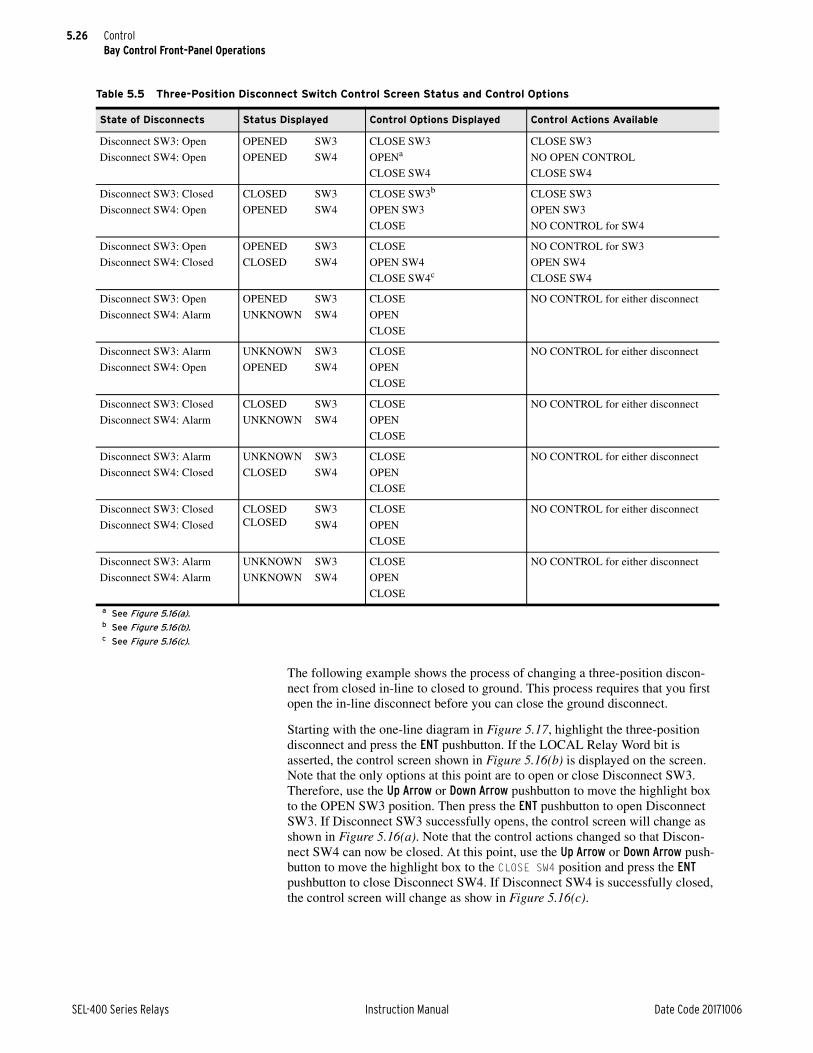
5.26
SEL-400 Series Relays Instruction Manual Date Code 20171006
ControlBay Control Front-Panel Operations
The following example shows the process of changing a three-position discon-nect from closed in-line to closed to ground. This process requires that you first open the in-line disconnect before you can close the ground disconnect.
Starting with the one-line diagram in Figure 5.17, highlight the three-position disconnect and press the ENT pushbutton. If the LOCAL Relay Word bit is asserted, the control screen shown in Figure 5.16(b) is displayed on the screen. Note that the only options at this point are to open or close Disconnect SW3. Therefore, use the Up Arrow or Down Arrow pushbutton to move the highlight box to the OPEN SW3 position. Then press the ENT pushbutton to open Disconnect SW3. If Disconnect SW3 successfully opens, the control screen will change as shown in Figure 5.16(a). Note that the control actions changed so that Discon-nect SW4 can now be closed. At this point, use the Up Arrow or Down Arrow push-button to move the highlight box to the CLOSE SW4 position and press the ENT pushbutton to close Disconnect SW4. If Disconnect SW4 is successfully closed, the control screen will change as show in Figure 5.16(c).
Table 5.5 Three-Position Disconnect Switch Control Screen Status and Control Options
State of Disconnects Status Displayed Control Options Displayed Control Actions Available
Disconnect SW3: Open
Disconnect SW4: Open
OPENED
OPENED
SW3
SW4
CLOSE SW3
OPENa
CLOSE SW4
CLOSE SW3
NO OPEN CONTROL
CLOSE SW4
Disconnect SW3: Closed
Disconnect SW4: Open
CLOSED
OPENED
SW3
SW4
CLOSE SW3b
OPEN SW3
CLOSE
CLOSE SW3
OPEN SW3
NO CONTROL for SW4
Disconnect SW3: Open
Disconnect SW4: Closed
OPENED
CLOSED
SW3
SW4
CLOSE
OPEN SW4
CLOSE SW4c
NO CONTROL for SW3
OPEN SW4
CLOSE SW4
Disconnect SW3: Open
Disconnect SW4: Alarm
OPENED
UNKNOWN
SW3
SW4
CLOSE
OPEN
CLOSE
NO CONTROL for either disconnect
Disconnect SW3: Alarm
Disconnect SW4: Open
UNKNOWN
OPENED
SW3
SW4
CLOSE
OPEN
CLOSE
NO CONTROL for either disconnect
Disconnect SW3: Closed
Disconnect SW4: Alarm
CLOSED
UNKNOWN
SW3
SW4
CLOSE
OPEN
CLOSE
NO CONTROL for either disconnect
Disconnect SW3: Alarm
Disconnect SW4: Closed
UNKNOWN
CLOSED
SW3
SW4
CLOSE
OPEN
CLOSE
NO CONTROL for either disconnect
Disconnect SW3: Closed
Disconnect SW4: Closed
CLOSED CLOSED
SW3
SW4
CLOSE
OPEN
CLOSE
NO CONTROL for either disconnect
Disconnect SW3: Alarm
Disconnect SW4: Alarm
UNKNOWN
UNKNOWN
SW3
SW4
CLOSE
OPEN
CLOSE
NO CONTROL for either disconnect
a See Figure 5.16(a).b See Figure 5.16(b).c See Figure 5.16(c).

5.27
Date Code 20171006 Instruction Manual SEL-400 Series Relays
ControlQuickSet Bay Control Screens
The relay does not include any default bay mimic screens with three-position dis-connects. Should your application require different bay mimic screens with three-position disconnects, contact SEL.
QuickSet Bay Control ScreensQuickSet provides an easy and intuitive way to configure and set the bay control function.
Select the Bay Control button from the tree to see the first interactive bay forms in QuickSet, as shown in Figure 5.18.
Figure 5.17 Bay Control One-Line Diagram With Three-Position Disconnect Closed In-Line
BAYNAME
ESCNAVIG
I:9999AV:99999kVP:99999MWQ:99999MV
BUS 1
SW3
SW4
BK1
SW1 SW2
BUS 2

5.28
SEL-400 Series Relays Instruction Manual Date Code 20171006
ControlQuickSet Bay Control Screens
MIMICIn most SEL-400 series relays, a single one-line diagram needs to be selected. However, in some relays, such as the SEL-487E, multiple screens need to be selected to build up the total composite one-line diagram.
Bay NameThere are 20 characters available for the bay name. This name appears on all the bay control screens.
LocalThe LOCAL SELOGIC control equation enables local and remote control of the disconnect switch. This example illustrates how the input contact IN107 can accommodate existing bay controls that use a key to manually change from remote to local control. The key switch is made to actuate a contact when the key is turned, as shown in Figure 5.19. With the contact of the switch wired to the input, the key switch provides local and remote control. Make the following set-ting to enable LOCAL control when IN107 is asserted.
LOCAL := IN107
Figure 5.18 Interactive Bay Control Setting Form

5.29
Date Code 20171006 Instruction Manual SEL-400 Series Relays
ControlQuickSet Bay Control Screens
Bus NamesFigure 5.20 shows the dialog box that appears when you click on the busbar name. Enter the name of the busbar (e.g., 132 Bus No 1), and click OK.
Disconnect AssignmentsTo configure disconnects, click the box next to the disconnect switch. A dialog box appears, as shown in Figure 5.21.
Figure 5.19 Local and Remote Control Logic With Key Control
-
+
Rated DC
Input Voltage
Contact closed = Local control
Contact open = Remote control
IN107
Figure 5.20 Setting Busbar Names in QuickSet

5.30
SEL-400 Series Relays Instruction Manual Date Code 20171006
ControlQuickSet Bay Control Screens
D01HMIN
Enter a Disconnect 1 label on the HMI (Figure 5.21). The number of characters is limited to a maximum string width of 18 pixels (approximately four characters).
D01CTLN
Enter a Disconnect 1 label on the control screen. Enter a descriptive name (there are 15 characters available) that clearly identifies the disconnect.
89AM01, 89BM01
These SELOGIC control equations report the state of Disconnect 1 auxiliary con-tacts. Both equations must be programmed for the Disconnect Switch Status and Alarm Logic to function correctly.
Figure 5.21 Disconnect Assignment Dialog Box, SW1

5.31
Date Code 20171006 Instruction Manual SEL-400 Series Relays
ControlQuickSet Bay Control Screens
89ALP01
This timer counts down when both 89AM01 and 89BM01 are in the same state (both asserted or both deasserted). When this disconnect alarm timer expires, an alarm condition exists and the 89AL01 Relay Word bit asserts.
Set the 89ALP01 timer longer than the expected operation (undetermined state) time, but less than the 89CST01 or 89OST01 seal-in timers.
89CCN01, 89OCN01
These SELOGIC control equations close or open Disconnect 1. Take care when programming these equations, because there is no breaker jumper supervision or access level safeguard in place for this disconnect operate method. These settings only work when the LOCAL Relay Word bit is deasserted.
89CST01, 89OST01
These seal-in timers are intended to keep the close or open signal asserted long enough to allow the Disconnect 1 operation to complete. Set the seal-in timers 10 to 15 percent longer than the expected disconnect operate time to give the discon-nect switch time to complete the operation.
Cold weather and low battery voltages can impact disconnect switch operation times. Be sure to consider these conditions when setting the seal-in timers.
89CIT01, 89OIT01
The close/open Disconnect 1 immobility timers are triggered at the same time as the seal-in timers. Expiration of these immobility timers indicates that the Dis-connect 1 auxiliary contact status failed to change state within the expected time frame.
Set the immobility timers longer than the expected time for the disconnect to leave the initial state (as reported by the 89AM01 and 89BM01 Relay Word bits), but less than the seal-in timer.
Cold weather and low battery voltages can impact disconnect switch operation times. Be sure to consider these conditions when setting the immobility timers.
89CRS01, 89ORS01
These settings reset the seal-in circuit when either the seal-in timer expires or the intended open/close status signal asserts. This is intended to stop driving the Dis-connect 1 motor to close or open when the desired state has been reached.
89CBL01, 89OBL01
These SELOGIC control equations provide an optional custom method for block-ing all means of close/open control for Disconnect 1.
89CIR01, 89OIR01
These SELOGIC control equations reset the Disconnect 1 close/open immobility timers.

5.32
SEL-400 Series Relays Instruction Manual Date Code 20171006
ControlQuickSet Bay Control Screens
Breaker AssignmentsConfigure the breaker by clicking the box next to the breakers. A dialog box appears, as shown in Figure 5.22.
BKqIn some relays, each numbered breaker (q = 1, 2, 3, 4, or 5) can be assigned to NA or one of the terminals. No terminal can be assigned twice. Unused breaker numbers are forced to NA.
BmHMINM
Enter a Breaker m label on the HMI (one-line diagram). The number of charac-ters is limited to a maximum string width of 17 pixels (approximately four char-acters).
BmCTLNM
Enter a Breaker m label on the control screen. Enter a descriptive breaker name (as many as 15 characters).
52mCLSM, 52m_ALM
These SELOGIC control equations report breaker close status and breaker alarm status. Any bit in the Relay Word, as well as logical operators, can be pro-grammed into these SELOGIC control equations.
Analog DisplayIf analog display points are not required, leave the setting(s) blank, because the relay displays only the defined display points.
Click on analog display label MDELE1 in the interactive one-line diagram to dis-play the form shown in Figure 5.23. Click on the Expression Builder button to display the form shown in Figure 5.24. The Expression Builder helps build the analog quantity setting string. Press the Expression Builder button on the form shown in Figure 5.24 to find the Analog or Fixed Element to be displayed.
Figure 5.22 Breaker Settings, Breaker S

5.33
Date Code 20171006 Instruction Manual SEL-400 Series Relays
ControlQuickSet Bay Control Screens
To display fixed text instead of analog quantities, enter the number 1 in the Ana-log or Fixed Element field.
Select the FREQ System Frequency (see Figure 5.25). Enter a Pre-Text, for example 'Frq=', as shown in Figure 5.25. Set the numerical display format to 5.2; this displays frequency up to two decimal places. You can scale the numerical value of FREQ to display a scaled value of the analog quantity. For example, a scaling value of 0.5 displays only half the value of FREQ, while a scaling value of 2 displays twice the value of FREQ. Enter text, such as the units of the analog quantity in the Post-Text field. Test the entries by typing a value of 60.51 in the preview analog display field. Click the Preview button, and verify that all entries are correct and will fit on the screen.
Equipment NameEdit the equipment name by clicking the text box next to the equipment. A dialog screen appears, as shown in Figure 5.26.
Figure 5.23 Analog Quantity Setting Form
Figure 5.24 Analog Quantity Setting Form
Figure 5.25 Example of an Analog Quantity Expression

5.34
SEL-400 Series Relays Instruction Manual Date Code 20171006
ControlCustomizable Screens
Customizable ScreensSEL-400 series relays support custom mimic display screens. Custom mimic dis-play screens are developed by the SEL factory using your requirements, and then added to the QuickSet relay driver. The images below show the breaker and power system variants supported in custom mimic display screens.
Available Circuit BreakersFigure 5.27 shows the different types of circuit breakers and disconnects available.
Figure 5.26 Interactive Transformer Image Number
Figure 5.27 Different Types of Circuit Breakers and Disconnects
Circuit breaker,
ANSI type,
Closed, vertical
Circuit breaker,
ANSI type,
Open, vertical
Circuit breaker,
ANSI type,
Closed, horizontal
Circuit breaker,
ANSI type,
Open, horizontal
Circuit breaker,
IEC type,
Closed, vertical
Circuit breaker,
IEC type,
Open, vertical
Circuit breaker,
IEC type,
Closed, horizontal
Circuit breaker,
IEC type,
Open, horizontal
Circuit breaker,
Rack type,
Closed, vertical
Circuit breaker,
Rack type,
Open, vertical
Standard Disconnect, open
Standard Disconnect, closed
3-Position Disconnect, open
3-Position Disconnect,
Closed to Ground
3-Position Disconnect,
Closed In-Line
Circuit breaker,
Rack type,
Closed, horizontal
Circuit breaker,
Rack type,
Open, horizontal

5.35
Date Code 20171006 Instruction Manual SEL-400 Series Relays
ControlBay Control Example Application
Available Power System ComponentsFigure 5.28 shows the different types of power system components available.
Bay Control Example ApplicationThis example demonstrates configuring a bay control screen for an SEL-451. Similar configurations can be done with other SEL-400 series relays.
Bus 1, Bus 2, and Transfer BUS Bay With Ground Switch (MIMIC := 4)Figure 5.29 illustrates the Bus 1, Bus 2, and Transfer Bus Bay with Ground Switch (MIMIC := 4). The Bay configuration used in this example provides five disconnect switches, one breaker, and the ability to display as many as six Analog Quantities. The labels and Analog Quantities shown in Figure 5.29 are all a result of the settings entered in this example. See Table 5.6 for a complete list of Bay settings for this application.
Figure 5.28 Power System Components
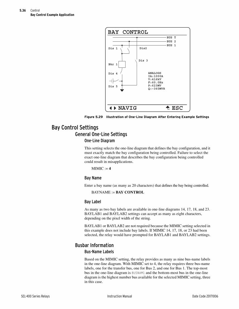
5.36
SEL-400 Series Relays Instruction Manual Date Code 20171006
ControlBay Control Example Application
Bay Control SettingsGeneral One-Line Settings
One-Line Diagram
This setting selects the one-line diagram that defines the bay configuration, and it must exactly match the bay configuration being controlled. Failure to select the exact one-line diagram that describes the bay configuration being controlled could result in misapplications.
MIMIC := 4
Bay Name
Enter a bay name (as many as 20 characters) that defines the bay being controlled.
BAYNAME := BAY CONTROL
Bay Label
As many as two bay labels are available in one-line diagrams 14, 17, 18, and 23. BAYLAB1 and BAYLAB2 settings can accept as many as eight characters, depending on the pixel width of the string.
BAYLAB1 or BAYLAB2 are not required because the MIMIC setting selected in this example does not include bay labels. If MIMIC 14, 17, 18, or 23 had been selected, the relay would have prompted for BAYLAB1 and BAYLAB2 settings.
Busbar InformationBus-Name Labels
Based on the MIMIC setting, the relay provides as many as nine bus-name labels in the one-line diagram. With MIMIC set to 4, the relay requires three bus-name labels, one for the transfer bus, one for Bus 2, and one for Bus 1. The top-most bus in the one-line diagram is BUSNAM1 and the bottom-most bus in the one-line diagram is the highest number bus available for the selected MIMIC setting, three in this case.
Figure 5.29 Illustration of One-Line Diagram After Entering Example Settings
BAY CONTROL
ESCNAVIG
ANALOGS IA:1000AV:416kVF:60.0HzP:623MV Q:–360MVR
BUS 2
Dis 4
Dis 5
Bkr 1Dis 3
Dis 1 Dis2BUS 1
BUS T
5.37
Date Code 20171006 Instruction Manual SEL-400 Series Relays
ControlBay Control Example Application
Enter bus-name labels (as many as ten characters) that describe each bus in the one-line diagram.
The actual number of characters accepted depends on the pixel width of the string.
BUSNAM1 := Bus T
BUSNAM2 := Bus 2
BUSNAM3 := Bus 1
Breaker Information
The relay displays breaker information for as many as three breakers. For the bay configuration in this example, the relay displays one. If more breakers were sup-ported, based on the MIMIC setting selected, the settings associated with addi-tional breakers would follow Breaker 1 settings.
Breaker Name Label
Enter a breaker name (as many as six characters) that describes each circuit breaker in the one-line diagram.
The actual number of characters accepted depends on pixel width of the string.
B1HMINM := Bkr 1
Breaker Status
This SELOGIC control equation reports breaker close status and breaker alarm status. Any bit in the Relay Word can be programmed into this SELOGIC control equation, as well as logical operators. The equations below return the state of the Bkr 1 status and any Bkr 1 alarm conditions.
521CLSM := 52ACL1
521_ALM := 52AAL1
Disconnect Information
The relay provides disconnect switch information for as many as ten disconnect switches. For the bay configuration selected in this example, the relay supports five disconnect switches.
Disconnect Name Label
Enter disconnect labels of as many as six characters in length that describe each disconnect switch in the one-line diagram. The actual number of characters accepted depends on pixel width of the string.
D01HMIN := Dis 1
Disconnect Status
Wire the normally open and normally closed auxiliary contacts from the discon-nect switch to relay inputs, and program the relay inputs into 89AM01 and 89BM01 SELOGIC control equations. These equations report the state of the dis-connect switch auxiliary contacts. Both equations must be programmed for the Disconnect Switch Status and Alarm Logic to function correctly.
89AM01 := IN103
89BM01 := IN104
5.38
SEL-400 Series Relays Instruction Manual Date Code 20171006
ControlBay Control Example Application
Disconnect Alarm Pickup Delay
This setting monitors disconnect open/close operations (the undetermined time) of the disconnect switch. When the disconnect alarm timer expires, an alarm con-dition exists and the 89AL1 Relay Word bit asserts. Set the 89ALPm timer longer than the expected operation (undetermined state) time, but less than the 89CSITm or 89OSITm seal-in timers. The expected disconnect operation time in this exam-ple is 250 cycles. 89ALPm is entered in cycles and has a range of 1–99999.
89ALP01 := 260
Disconnect Close/Open Control
Program SELOGIC control equations 89CCNn and 89OCNn to close or open dis-connect switch n, respectively. Great care needs to be used when programming these equations because there are no breaker jumper supervision or access level safeguards in place for this disconnect operate method. The settings in this exam-ple close the disconnect switch when Remote Bit 1 is set and open the disconnect switch when Remote Bit 1 is cleared. The 89CCN01 SELOGIC example below also includes additional supervision logic where the close operation only operates if Breaker 1 is open (NOT 52CLS1) and the disconnect switch is in the opposite state (89OPN1). When these conditions are met, a close disconnect operation will initiate. Relay Word bit 89CLS1 is the output of the seal-in timer and asserts when Relay Word bit 89CCN01 asserts. Relay Word bit 89OPN1 deasserts as soon as the disconnect switch starts to move. The OR combination of Relay Word bit 89CLS1 and 89OPN1 keeps the close disconnect signal asserted until the dis-connect operation has completed. The SELOGIC control equations below demon-strate disconnect lockout control in the relay. The 89OCN01 SELOGIC control equation illustrates the same type of supervision for the disconnect switch open logic.
89CCN01 := RB01 AND (89OPN1 OR 89CLS1) AND NOT 52CLSM1
89OCN01 := NOT RB01 AND (89CL1 OR 89OPEN1) AND NOT 52CLSM1
Disconnect Close/Open Seal-in Timers
The seal-in timers assert the close or open signal long enough to allow the dis-connect operation to complete. Set the seal-in timer 10 to 15 percent longer than the expected disconnect operate time to give the disconnect switch time to com-plete the operation. 89CSTm and 89OSTm are entered in cycles and have a range of 1–99999. The example shown anticipates a disconnect switch operate time of approximately 250 cycles.
Cold weather and low battery voltages can impact operation times. Be sure to consider these conditions when setting the seal-in timers.
The output contacts must not be used to break the motor coil current. An auxil-iary contact with adequate current interrupting capacity must first interrupt cur-rent supply to the motor before the relay contact opens. Include the auxiliary contact clearing time when setting the disconnect seal-in timer.
89CST01 := 280
89OST01 := 280
Disconnect 2–5
Disconnect switch settings 2–5 are similar to the Disconnect Switch 1 examples above. See Table 5.6 for a complete list of Bay Class settings for this application.

5.39
Date Code 20171006 Instruction Manual SEL-400 Series Relays
ControlBay Control Example Application
One-Line Analog Display
One-line diagrams in the relay can contain as many as six Analog Quantity dis-play points. The MIMIC setting selected in this example displays six Analog Dis-play points. See Display Points on page 4.10 for Display Point programming. The settings below illustrate how to display text and Analog Quantities available in the mimic display. If analog display points are not required to appear in the one-line diagram, leave the setting(s) blank, and the relay will only display the defined display points.
1. 1, “Analogs”
2. IAWM, “IA:(4.0,1)A”
3. VABFM, “V:(3.0,1)kV”
4. FREQ, “F:(4.1,1)Hz”
5. 3P, “P:(3.0,1)MW”
6. 3Q_F, “Q:(3.0,1)MVR”
Control Selection
The LOCAL SELOGIC control equation enables local and remote control of the disconnect switch. This example illustrates how the SEL-451 input contact IN107 can accommodate existing bay controls that use a key to manually change from remote to local control. The key switch is made to actuate a contact when the key is turned, as shown in Figure 5.30. With the contact of the switch wired to the SEL-451 input, the key switch provides local and remote control. Make the following setting to enable LOCAL control when IN107 is asserted.
LOCAL := IN107
Front-Panel SettingsThe one-line diagram is one of the screens that are available for display in the rotating display. To display RMS_V, RMS_I, and ONELINE screens on the rotat-ing display every five seconds, make the following Front-Panel settings.
SCROLD := 5
RMS_V := Y
RMS_I := Y
RMS_VPP := N
Figure 5.30 Local and Remote Control Logic With Key Control
-
+
Rated SEL-451
DC Input Voltage
Contact closed = Local control
Contact open = Remote control
SEL-451
IN107

5.40
SEL-400 Series Relays Instruction Manual Date Code 20171006
ControlBay Control Example Application
CAUTION
RMS_W := N
FUNDVAR := N
RMS_VA := N
RMS_PF := N
RMS_BK1 := N
RMS_BK2 := N
STA_BAT := N
FUND_VI := N
FUNDSEQ := N
FUND_BK := N
ONELINE := Y
The following settings in the Front-Panel settings provide immediate display of the one-line diagram screen when Pushbutton 2 is pressed.
PB2_HMI := BC
Output SettingsOutput Logic Settings
This illustrates the ability to program disconnect lockout protection for the selected one-line diagram. To eliminate the danger of closing or opening the ground switch on an energized line, the disconnect switch cannot operate unless Breaker 1 is open. When the Disconnect 1 close command is executed (89CLS1), OUT103 only asserts if the state of Breaker 1 is open (NOT 52CLS1). This illus-trates disconnect switch lockout protection through SELOGIC control equations. The SELOGIC control equation for OUT104 below illustrates similar lockout pro-tection for the disconnect switch open operation. Wire OUT103 to the disconnect switch closing circuit and OUT104 to the disconnect switch opening circuit.
OUT103 := 89CLS1 AND NOT 52CLSM1
OUT104 := 89OPEN1 AND NOT 52CLSM1
The outputs in the relay are not designed to break the coil current in the disconnect motor. An auxiliary contact with adequate current-interrupting capacity must clear the coil current in the disconnect motor before the output opens. Failure to observe this safeguard could result in damage to the output contacts.
Another example of disconnect lockout would be to ensure that Dis 3 never closes when the ground disconnect switch Dis 5 is closed. Enter the SELOGIC control equation below for Dis 3 switch lockout protection. 89CLS3 is the close disconnect switch Relay Word bit for Disconnect 3 and the 89OPN5 Relay Word bit is the status of Disconnect 5. The SELOGIC control equation below will not assert OUT201 unless both conditions are true.
OUT201 := 89CLS3 AND 89OPN5
These are just a few examples of disconnect lockout control. Use Relay Word bits and SELOGIC programming to design lockout control scenarios required for the configuration being controlled.
The SELOGIC Output settings listed in Table 5.6 are example close and open dis-connect equations with disconnect lockout control for Switches 1–5.

5.41
Date Code 20171006 Instruction Manual SEL-400 Series Relays
ControlBay Control Example Application
Table 5.6 Application Example Bay Control Settings for Bus 1, Bus 2, and Transfer Bus Bay With Ground Switch Application (Sheet 1 of 2)
Setting Description Entry
General One-Line Settings
MIMIC One-line Screen Number (1–999) 4
BAYNAME Bay Name (20 characters) BAY CONTROL
Busbar Information
BUSNAM1 Busbar 1 Name (40 pixels, 6–10 characters) Bus T
BUSNAM2 Busbar 2 Name (40 pixels, 6–10 characters) Bus 2
BUSNAM3 Busbar 3 Name (40 pixels, 6–10 characters) Bus 1
Breaker Information
B1HMINM Breaker 1 HMI Name (max 3–17 characters) Bkr 1
B1CTLNM Breaker 1 HMI Cntl Scr. Name (max. 15 characters) Bkr 1
521CLSM Breaker 1 Close Status (SELOGIC Equation) 52ACL1
521_ALM Breaker 1 Alarm Status (SELOGIC Equation) 52AAL1
Disconnect Information
D1HMIN Disconnect 1 HMI Name (max 3–17 characters) D1
D1CTLN Disconnect 1 Name (25 pixels, max. 15 characters) Dis 1
89AM1 Disconnect 1 N/O Contact (SELOGIC Equation) IN103
89BM1 Disconnect 1 N/C Contact (SELOGIC Equation) IN104
89ALP1 Disconnect 1 Alarm Pickup Delay (1–99999 cyc) 260
89CCN1 Disconnect 1 Close Control (SELOGIC Equation) 89CC01
89OCN1 Disconnect 1 Open Control (SELOGIC Equation) 89OC01
89CST1 Disconnect 1 Close Seal-in Time (1–99999 cyc) 280
89OST1 Disconnect 1 Open Seal-in Time (1–99999 cyc) 280
D2HMIN Disconnect 2 HMI Name (max. 3–17 characters) D2
D2CTLN Disconnect 2 Name (25 pixels, 4–6 characters) Dis 2
89AM2 Disconnect 2 N/O Contact (SELOGIC Equation) 1
89BM2 Disconnect 2 N/C Contact (SELOGIC Equation) 0
89ALP2 Disconnect 2 Alarm Pickup Delay (1–99999 cyc) 260
89CCN2 Disconnect 2 Close Control (SELOGIC Equation) 89CC02
89OCN2 Disconnect 2 Open Control (SELOGIC Equation) 89OC02
89CST2 Disconnect 2 Close Seal-in Time (1–99999 cyc) 280
89OST2 Disconnect 2 Open Seal-in Time (1–99999 cyc) 280
D3HMIN Disconnect 3 HMI Name (max. 3–17 characters) D3
D3CTLN Disconnect 3 Name (25 pixels, 4–6 characters) Dis 3
89AM3 Disconnect 3 N/O Contact (SELOGIC Equation) 1
89BM3 Disconnect 3 N/C Contact (SELOGIC Equation) 0
89ALP3 Disconnect 3 Alarm Pickup Delay (1–99999 cyc) 260
89CCN3 Disconnect 3 Close Control (SELOGIC Equation) 89CC03
89OCN3 Disconnect 3 Open Control (SELOGIC Equation) 89OC03
89CST3 Disconnect 3 Close Seal-in Time (1–99999 cyc) 280
89OST3 Disconnect 3 Open Seal-in Time (1–99999 cyc) 280

5.42
SEL-400 Series Relays Instruction Manual Date Code 20171006
ControlBay Control Example Application
D4HMIN Disconnect 4 HMI Name (1–99999 cyc) D4
D4CTLN Disconnect 4 Name (25 pixels, 4–6 characters) Dis 4
89AM4 Disconnect 4 N/O Contact (SELOGIC Equation) 1
89BM4 Disconnect 4 N/C Contact (SELOGIC Equation) 0
89ALP4 Disconnect 4 Alarm Pickup Delay (1–99999 cyc) 260
89CCN4 Disconnect 4 Close Control (SELOGIC Equation) 89CC04
89OCN4 Disconnect 4 Open Control (SELOGIC Equation) 89OC04
89CST4 Disconnect 4 Close Seal-in Time (1–99999 cyc) 280
89OST4 Disconnect 4 Open Seal-in Time (1–99999 cyc) 280
D5HMIN Disconnect 5 HMI Name (1–9999) D5
89AM5 Disconnect 5 N/O Contact (SELOGIC Equation) 0
89BM5 Disconnect 5 N/C Contact (SELOGIC Equation) 0
89ALP5 Disconnect 5 Alarm Pickup Delay (1–99999 cyc) 260
89CCN5 Disconnect 5 Close Control (SELOGIC Equation) 89CC05
89OCN5 Disconnect 5 Open Control (SELOGIC Equation) 89OC05
89CST5 Disconnect 5 Close Seal-in Time (1–99999 cyc) 280
89OST5 Disconnect 5 Open Seal-in Time (1–99999 cyc) 280
One-Line Analog Display
1 1, “Analogs”
2 IAWM, “IA:(4.0,1)A”
3 VABFM, “V:(3.0,1)kV”
4 FREQ, “F:(4.1,1)Hz”
5 3P, “P:(3.0,1)MW”
6 3Q_F, “Q:(3.0,1)MVR”
Control Selection
LOCAL Local Control (SELOGIC control equation) IN107
Table 5.7 Application Example Front-Panel Settings (Sheet 1 of 2)
Setting Description Entry
Selectable Screens for the Front Panel
SCROLD Front Panel Display Update Rate (OFF, 1–15 secs) 5
RMS_V RMS Line Voltage Screen (Y, N) Y
RMS_I RMS Line-Current Screen (Y, N) Y
RMS_VPP RMS Line Voltage Phase-to-Phase Screen N
RMS_W RMS Active Power Screen N
FUNDVAR Fundamental Reactive Power Screen N
RMS_VA RMS Apparent Power Screen N
RMS_PF RMS Power Factor Screen N
RMS_BK1 RMS Breaker 1 Currents Screen N
RMS_BK2 RMS Breaker 2 Currents Screen N
Table 5.6 Application Example Bay Control Settings for Bus 1, Bus 2, and Transfer Bus Bay With Ground Switch Application (Sheet 2 of 2)
Setting Description Entry

5.43
Date Code 20171006 Instruction Manual SEL-400 Series Relays
ControlBay Control Example Application
STA_BAT Station Battery Screen N
FUND_VI Fundamental Voltage and Current Screen N
FUNDSEQ Fundamental Sequence Quantities Screen N
FUND_BK Fundamental Breaker Currents Screen N
ONELINE One-Line Bay Control Diagram Y
Selectable Operator Pushbuttons
PB2_HMI Pushbutton 2 HMI Screen BC
Table 5.8 Application Example Output Settings, Output SELOGIC Control Equations
Setting Description Entry
OUT103 OUT103 SELOGIC control equation 89CLS1 AND NOT 52CLSM1
OUT104 OUT104 SELOGIC control equation 89OPEN1 AND NOT 52CLSM1
OUT105 OUT105 SELOGIC control equation 89CLS2 AND NOT 52CLSM1
OUT106 OUT106 SELOGIC control equation 89OPEN2 AND NOT 52CLSM1
OUT201 OUT201 SELOGIC control equation 89CLS3 AND 89OPN5
OUT202 OUT202 SELOGIC control equation 89OPEN3 AND 52CLSM1
OUT203 OUT203 SELOGIC control equation 89CLS4 AND NOT 52CLSM1
OUT204 OUT204 SELOGIC control equation 89OPEN4 AND NOT 52CLSM1
OUT205 OUT205 SELOGIC control equation 89CLS5 AND NOT 52CLSM1
OUT206 OUT206 SELOGIC control equation 89OPEN5 AND NOT 52CLSM1
Table 5.7 Application Example Front-Panel Settings (Sheet 2 of 2)
Setting Description Entry

This page intentionally left blank

Date Code 20171006 Instruction Manual SEL-400 Series Relays
Instruction ManualS E C T I O N 6
Autoreclosing
This section describes the operation of autoreclose logic in SEL-4XX relays that include an autorecloser. This section covers the following topics:
➤ Autoreclosing States on page 6.2
➤ One-Circuit-Breaker Autoreclosing on page 6.4
➤ Two-Circuit-Breaker Autoreclosing on page 6.10
➤ Autoreclose Logic Diagrams on page 6.26
➤ Manual Closing on page 6.40
➤ Voltage Checks for Autoreclosing and Manual Closing on page 6.43
➤ Settings and Relay Word Bits for Autoreclosing and Manual Closing on page 6.45
The relay autoreclose function provides complete control for single circuit breaker and two circuit breaker reclosing schemes. The autoreclose function accommodates both single-pole and three-pole reclosing. Some SEL-400 series relays only support three-pole operations. See the Features subsection in Section 1: Introduction and Specifications in the product-specific instruction manual to determine the reclosing capability of each relay. Relays that support single-pole breaker operations can be set for a total of two single-pole reclose shots. Three-pole breaker operations can be set for as many as four three-pole reclose shots.
You can designate the leader and follower circuit breakers in a two-circuit breaker configuration. The relay recloser can dynamically change leader and fol-lower designations based on settings and operating conditions.
You can program the autoreclose logic to perform one shot of high-speed three-pole reclose. This high-speed three-pole shot replaces one of the four delayed time three-pole shots. There is no difference between a shot of high-speed three-pole reclose and a shot of delayed three-pole autoreclose; simply select the open interval time accordingly.
NOTE: The relay voltage check elements (for bus and line voltages) may be used without the synchronism check feature, however, for certain voltage connections, some of the synchronism check settings need to be entered to ensure that the correct voltages are used.
Two autoreclose modes are available when using the relay to control two circuit breakers:
➤ Combined two-breaker mode (setting E79 := Y)—both circuit breakers must trip before any reclosing can occur.
➤ Independent two-breaker mode (setting E79 := Y1)—the follower circuit breaker can trip and reclose even when the lead breaker has not operated. This is useful on both ring bus and breaker-and-a-half schemes, where the follower breaker is a tie breaker that can be tripped by protection on either side.
For single circuit breaker applications, use setting E79 := Y.

6.2
SEL-400 Series Relays Instruction Manual Date Code 20171006
AutoreclosingAutoreclosing States
Autoreclosing StatesThe autoreclose logic for either circuit breaker can be in one of the following five states (see Figure 6.1):
➤ Start (common to both circuit breakers) (79STRT)
➤ Reset per circuit breaker (BK1RS, BK2RS)
➤ Single-pole autoreclose cycle (common to both circuit breakers) (79CY1)
➤ Three-pole autoreclose cycle (common to both circuit breakers) (79CY3)
➤ Lockout, per circuit breaker (BK1LO, BK2LO)
Start (79STRT)The autoreclose logic is in the Start state for both circuit breakers during the fol-lowing conditions:
➤ Startup
➤ Restart
➤ Any relay settings change
The relay stores the previous reclosing state for Relay Word bits 79CY1, 79CY3, BK1LO, BK2LO, BK1RS, and BK2RS when a restart or any relay settings change occurs.
At startup, the recloser logic goes from the start state to the lockout state. For a restart or a settings change, the recloser logic enters the start state, then goes to lockout if the circuit breakers were open before the restart or settings change. If the circuit breakers were previously closed, then the recloser logic proceeds through the 3PMRCD (Manual Close Reclaim Time Delay) time and then goes to the ready state.
Reset (BK1RS, BK2RS)The autoreclose logic is in the reset or ready state for either circuit breaker when the circuit breaker is ready to begin an autoreclose cycle. There are three reset state timers. After a successful reclose cycle, the relay goes to the reset state after reclaim times SPRCD (Single-Pole Reclaim Time Delay) for single-pole auto-matic and 3PRCD (Three-Pole Reclaim Time Delay) for three-pole automatic reclosing. If the recloser has been in a lockout condition, the Ready or Reset state cannot occur until the 3PMRCD (Manual Close Reclaim Time Delay) timer has expired. You can only block the reclaim time after a successful reclose cycle. Set-ting 79BRCT (Block Reclaim Timer) prevents timing of reclaim timers SPRCD, 3PRCD, and 3PMRCD.
Single-Pole Autoreclose (79CY1)This state does not apply to relays that only support three-pole reclosing. The autoreclose logic is in a single-pole autoreclose cycle for either circuit breaker if all of the following conditions are satisfied:
➤ Single-pole trip occurs
➤ Condition(s) to initiate a single-pole autoreclose cycle are satisfied
➤ Circuit breaker(s) is in-service and ready to begin a single-pole autoreclose cycle (that is, reset)

6.3
Date Code 20171006 Instruction Manual SEL-400 Series Relays
AutoreclosingAutoreclosing States
Three-Pole Autoreclose (79CY3)The autoreclose logic is in a three-pole autoreclose cycle for either circuit breaker if all of the following conditions are satisfied:
➤ Three-pole trip occurs
➤ Condition(s) to initiate a three-pole autoreclose cycle are satisfied
➤ Circuit breaker(s) is in-service and ready to begin a three-pole autoreclose cycle (that is, reset)
Lockout (BK1LO, BK2LO)The lockout state is the default state of any circuit breaker after startup. Other conditions place the recloser in the LO state. The relay recloser has a drive-to-lockout function that you can program for any external or internal condition—use setting 79DTL. A circuit breaker can go to lockout by two methods. The circuit breaker enters the lockout state if either of the following occur:
➤ Supervisory Relay Word bits SPnCLS or 3PnCLS do not assert within the BKnCLSD time
➤ The circuit breaker does not close within the BKCFD time
The timer for both supervisory Relay Word bits SPnCLS and 3PnCLS is setting BKnCLSD. Setting BKnCLSD = OFF disables the BKnCLSD delay timer, requiring either SPnCLS or 3PnCLS to assert before transitioning to the next state.
In applications using two circuit breakers, you can designate one circuit breaker as the leader and the other circuit breaker as the follower. The relay freezes the leader/follower decision during an autoreclose cycle unless the autoreclose logic receives another initiation.
If the recloser receives another initiation, the logic reevaluates the leader and fol-lower circuit breakers to determine the number of circuit breakers in a scheme (NBKn), the leader circuit breaker (LEADBKn), and the follower circuit breaker (FOLBKn). This determination is based on the service status of the circuit break-ers. The logic considers a circuit breaker out of service if the circuit breaker goes to lockout. The logic considers a circuit breaker to be in service as soon as the circuit breaker closes and is no longer in lockout.
State DiagramNOTE: The autoreclose function runs once per power-system cycle. To ensure that the logic detects transient element state changes that initiate closing, you should extend the assertion time of transient element states to 1 cycle.
Figure 6.1 illustrates how the autoreclose logic moves from one state to another with respect to Circuit Breaker 1. (This diagram is identical for Circuit Breaker 2; replace the 1 in the Relay Word bits with 2.) The Relay Word bits that correspond to each state are shown (see Table 6.1). A solid path between two states indicates that the logic can move in only one direction. Two broken paths between two states indicate the logic can move in either direction between the two states. The dashed vertical line that runs through the center of the figure indicates the states common to both circuit breakers.
Table 6.1 describes each of the five states with respect to Circuit Breaker 1, along with the corresponding Relay Word bits.

6.4
SEL-400 Series Relays Instruction Manual Date Code 20171006
AutoreclosingOne-Circuit-Breaker Autoreclosing
One-Circuit-Breaker AutoreclosingModes
The autoreclose logic can operate in one of three modes, depending upon the relay autoreclose capabilities:
➤ Single-pole mode (SPAR)
➤ Three-pole mode (3PAR)
➤ Single- and three-pole mode (SPAR/3PAR)
Relay settings ESPR1 (Single-Pole Reclose Enable—BK1) and E3PR1 (Three-Pole Reclose Enable—BK1) determine the autoreclose mode (see Recloser Mode Enables on page 6.8). These settings are inputs to the recloser initiation Relay Word bits SPARC (Single-Pole Reclose Initiate Qualified) and 3PARC (Three-Pole Reclose Initiate Qualified); see Figure 6.8 and Figure 6.9. SPARC asserts when all necessary conditions to begin a single-pole autoreclose cycle are satis-fied (ESPR1, for example) and the recloser receives a single-pole reclose initia-tion SPRI (see Figure 6.8). Relay Word bit 3PARC asserts when all necessary conditions to begin a three-pole autoreclose cycle are satisfied (E3PR1, for exam-ple) and the recloser receives a three-pole reclose initiation 3PRI (see Figure 6.9).
Figure 6.1 Autoreclose State Diagram for Circuit Breaker 1
Table 6.1 Autoreclose Logical States for Circuit Breaker 1
State Description Relay Word Bit
Start Startup, or relay settings change 79STRT
Reset Circuit Breaker 1 reset BK1RS
Single-pole autoreclose cyclea
a 79CY1 is only available in relays that support single-pole breaker operations.
Single-pole autoreclose 79CY1
Three-pole autoreclose cycle Three-pole autoreclose cycle 79CY3
Lockout Lockout BK1LO
79CY1
79CY3
79STRT
BK1LO
Breaker 1 Reset or Ready
Breaker 1 Lockout
1-Pole Auto-Reclose
Start
3-Pole Auto-Reclose
BK1RS

6.5
Date Code 20171006 Instruction Manual SEL-400 Series Relays
AutoreclosingOne-Circuit-Breaker Autoreclosing
Other recloser settings include the initial recloser settings (see Enable Autore-close Logic for Two Circuit Breakers on page 6.22) and the trip logic enable set-tings E3PT, E3PT1, and E3PT2. When SELOGIC control equations E3PT, E3PT1, and E3PT2 are deasserted, a single-pole reclose follows a single-pole trip; when these SELOGIC control equations are asserted, only three-pole tripping and reclosing result (see Trip Logic and Reclose Sources for Single-Pole Breaker Applications on page 6.9).
Single-Pole ModeNOTE: Single-pole mode is only supported in relays that provide single-pole breaker control.
Figure 6.11 shows the one circuit breaker single-pole autoreclose cycle 79CY1. The cycle starts when Relay Word bit SPARC asserts. The recloser waits as long as 10 cycles for the circuit breaker to open (indicated by Relay Word bit SPO) and then begins timing SPOID (Single-Pole Open Interval Delay) when the cir-cuit breaker opens. After single-pole open interval time SPOID expires, the relay recloses the circuit breaker if supervisory condition SP1CLS (Single-Pole BK1 Reclose Supervision) is satisfied within the duration of timer BK1CLSD (BK1 Reclose Supervision Delay).
At the reclose command, the recloser starts timer BKCFD (Breaker Close Failure Delay). If the circuit breaker fails to close, the recloser goes to lockout (BK1LO) after timer BKCFD expires.
SPRCD Reclaim Timing
If the circuit breaker closes, the recloser starts timer SPRCD (Single-Pole Reclaim Time Delay). The recloser determines subsequent state transitions during reclaim timing according to the status of Relay Word bit SPLSHT (Single-Pole Reclose Last Shot). When SPLSHT is asserted, the recloser forces all subse-quent relay trips to three-pole only mode.
SPLSHT Asserted (Last Shot)
The recloser exits the 79CY1 state via one of the following three methods while SPLSHT is asserted:
➤ If no further trip conditions occur, the recloser goes to the reset state BK1RS after reclaim timer SPRCD expires.
➤ If a fault occurs during the SPRCD reclaim time, then the recloser asserts Relay Word bit 3PARC if all three-pole reclose conditions are satisfied and proceeds to the autoreclose three-pole cycle state 79CY3.
➤ If a fault occurs during the SPRCD reclaim time, and the three-pole reclose conditions are not satisfied (E3PR1 is logical 0, for example) the recloser exits the 79CY1 cycle state and goes to the lockout state BK1LO.
SPLSHT Deasserted (Single-Pole Shot Remains)
The recloser exhibits four possible state transitions when SPLSHT is not asserted:
➤ If no further trip conditions occur, the recloser goes to the reset state BK1RS after timer SPRCD expires.
➤ If a single-phase fault occurs while the SPRCD reclaim timer is timing, the recloser asserts SPARC for single-pole initiate conditions and returns to the beginning of the 79CY1 cycle state; the recloser increments the shot counter and begins the next open interval timer.

6.6
SEL-400 Series Relays Instruction Manual Date Code 20171006
AutoreclosingOne-Circuit-Breaker Autoreclosing
➤ If a multiphase fault occurs during the SPRCD reclaim time, then the recloser asserts Relay Word bit 3PARC if all three-pole reclose conditions are satisfied (E3PR1 is logical 1, for example) and proceeds to the autoreclose three-pole cycle state 79CY3.
➤ If a multiphase fault occurs during the SPRCD reclaim time, and the three-pole reclose conditions are not satisfied (E3PR1 is logical 0, for example), the recloser exits the 79CY1 cycle state and goes to the lockout state BK1LO.
Lockout State From 79CY1
The recloser goes to lockout (BK1LO) when any of the following occur:
➤ The number of trips exceeds the maximum number of shots (NSPSHOT).
➤ Supervision condition SP1CLS fails to assert in BK1CLSD time.
➤ Relay Word bit 3POLINE asserts (for a circuit breaker manual opening).
➤ The circuit breaker fails to close within BKCFD time.
➤ Any time Relay Word bit 79DTL asserts.
Three-Pole Mode Figure 6.12 shows the one circuit breaker autoreclose cycle 79CY3. The cycle starts when Relay Word bit 3PARC asserts. The recloser checks SELOGIC control equation 79SKP at this point to determine whether to increment the shot counter. The recloser waits indefinitely for the circuit breaker to open, as indicated by Relay Word bit 3POLINE. The recloser begins timing 3POID1 (Three-Pole Open Interval 1 Delay) when the circuit breaker opens. After the open interval time 3POID1 expires, the relay asserts Relay Word bit BK1CL to reclose the circuit breaker if supervisory condition 3P1CLS (Three-Pole BK1 Reclose Supervision) is satisfied within the duration of timer BK1CLSD (BK1 Reclose Supervision Delay).
At the reclose command, the recloser starts timer BKCFD (Breaker Close Failure Delay). If the circuit breaker fails to close, the recloser goes to lockout (BK1LO) after timer BKCFD expires.
3PRCD Reclaim Timing
If the circuit breaker closes, the recloser starts timer 3PRCD (Three-Pole Reclaim Time Delay). The recloser determines subsequent state transitions during reclaim timing according to the status of Relay Word bit 3PLSHT (Three-Pole Reclose Last Shot).
3PLSHT Asserted (Last Shot)
The recloser exits the 79CY3 state via one of the following two methods while 3PLSHT is asserted:
➤ If no further trip conditions occur, the recloser goes to the reset state BK1RS after reclaim timer 3PRCD expires.
➤ If a fault occurs during the 3PRCD reclaim time, then the recloser exits the 79CY3 cycle state and goes to the lockout state BK1LO.

6.7
Date Code 20171006 Instruction Manual SEL-400 Series Relays
AutoreclosingOne-Circuit-Breaker Autoreclosing
3PLSHT Deasserted (Three-Pole Shot Remains)
The recloser exhibits three possible state transitions when 3PLSHT is not asserted:
➤ If no further trip conditions occur, the recloser goes to the reset state BK1RS after timer 3PRCD expires.
➤ If a fault occurs during the 3PRCD reclaim time, then the recloser asserts Relay Word bit 3PARC if all three-pole reclose conditions are satisfied (E3PR1 is logical 1, for example) and returns to the beginning of the 79CY3 cycle state; the recloser increments the shot counter and begins the next open interval timer.
➤ If a fault occurs during the 3PRCD reclaim time, and the three-pole reclose conditions are not satisfied (E3PR1 is logical 0, for example), the recloser exits the 79CY3 cycle state and goes to the lockout state BK1LO.
Lockout State From 79CY3
The recloser goes to lockout (BK1LO) when any of the following occur:
➤ The number of trips exceeds the maximum number of shots (N3PSHOT)
➤ Supervision condition 3P1CLS fails to assert in BK1CLSD time
➤ Relay Word bit 3POLINE asserts (for a circuit breaker manual opening)
➤ The circuit breaker fails to close within BK1CFD time
➤ Relay Word bit 79DTL asserts
Single- and Three-Pole ModeNOTE: Single- and three-pole mode is only supported in breakers that provide single-pole breaker control.
The single- and three-pole mode (SPAR/3PAR) uses elements of both the single-pole mode (SPAR) and the three-pole mode (3PAR). Reclosing begins after a sin-gle-pole trip in the single-pole cycle 79CY1 with a valid SPARC as described in Single-Pole Mode on page 6.5. The recloser closes the circuit breaker and pro-ceeds to the reclaim timer SPRCD. If a fault occurs during the SPRCD reclaim time and SPLSHT is asserted, then the recloser asserts Relay Word bit 3PARC if all three-pole reclose conditions are satisfied. Upon asserting 3PARC, the recloser exits the 79CY1 cycle state and goes to the beginning of the three-pole autoreclose cycle state 79CY3. The recloser proceeds through the 79CY3 state and exits this state as described in Three-Pole Mode on page 6.6.
Three-Pole Priority If a single-pole autoreclose cycle 79CY1 is in progress and the relay receives an initiation for three-pole reclosing 3PRI, the recloser immediately starts a three-pole autoreclose cycle 79CY3.
Active Circuit BreakersTwo Relay Word bits describe when Circuit Breaker 1 is active for the autore-close logic:
➤ NBK0, No Breaker Active in Reclose Scheme
➤ NBK1, One Breaker Active in Reclose Scheme

6.8
SEL-400 Series Relays Instruction Manual Date Code 20171006
AutoreclosingOne-Circuit-Breaker Autoreclosing
NBK1 equals logical 1 when Circuit Breaker 1 is closed and the autoreclose logic is reset, or if the autoreclose logic is in an autoreclose cycle (79CY1 or 79CY3). NBK0 equals logical 1 when Circuit Breaker 1 is open and not in an autoreclose cycle (79CY1 or 79CY3), or if the autoreclose logic is locked out (BK1LO).
Enable Autoreclose Logic for One Circuit BreakerThree-Pole Trip Circuit Breaker
The initial settings necessary to enable autoreclose for a single three-pole trip cir-cuit breaker are shown in Table 6.2.
Single-Pole Trip Circuit BreakerThe initial settings necessary to enable autoreclose for one single-pole trip circuit breaker are shown in Table 6.3.
Recloser Mode EnablesThe SELOGIC control equations E3PR1 and ESPR1 are used to set the relay auto-reclose modes. Table 6.4 illustrates how to enable the autoreclose modes for Cir-cuit Breaker 1.
Table 6.2 One-Circuit-Breaker Three-Pole Reclosing Initial Settings
Setting Description Entry
General Global Settings (Global)
NUMBK Number of Breakers in Scheme 1
Breaker Configuration (Breaker Monitor)
BK1TYPa
a Only applies to relays that support single-pole breaker operations.
Breaker 1 Trip Type 3
Breaker 1 Inputs (Breaker Monitor)
52AA1 N/O Contact Input—BK1 (SELOGIC control equation) IN101
Relay Configuration (Group)
E79 Reclosing Y
Table 6.3 One-Circuit-Breaker Single-Pole Reclose Initial Settings
Setting Description Entry
General Global Settings (Global)
NUMBK Number of Breakers in Scheme 1
Breaker Configuration (Breaker Monitor)
BK1TYP Breaker 1 Trip Type 1
Breaker 1 Inputs (Breaker Monitor)
52AA1 A-Phase N/O Contact Input—BK1 (SELOGIC Equation) IN101
52AB1 B-Phase N/O Contact Input—BK1 (SELOGIC Equation) IN102
52AC1 C-Phase N/O Contact Input—BK1 (SELOGIC Equation) IN103
Relay Configuration (Group)
E79 Reclosing Y

6.9
Date Code 20171006 Instruction Manual SEL-400 Series Relays
AutoreclosingOne-Circuit-Breaker Autoreclosing
E3PR1 is the SELOGIC control equation that enables three-pole autoreclose for Circuit Breaker 1. You can assign this setting to a control input. When E3PR1 equals logical 1, the relay can attempt a three-pole autoreclose cycle for Circuit Breaker 1. If E3PR1 equals logical 0, the relay goes to lockout following a three-pole trip for Circuit Breaker 1.
ESPR1 is the SELOGIC control equation that enables single-pole autoreclose for Circuit Breaker 1. You can assign this setting to a control input. When ESPR1 equals logical 1, the relay can attempt a single-pole autoreclose cycle for Circuit Breaker 1. If ESPR1 equals logical 0, the relay cannot initiate a single-pole auto-reclose cycle.
Set either or both E3PR1 and ESPR1 according to your reclosing requirements and relay reclosing capabilities. For single-pole reclosing, set ESPR1 to evaluate to logical 1 and set NSPSHOT to the desired number of single-pole reclose shots. For three-pole reclosing, set E3PR1 to evaluate to logical 1 and set N3PSHOT for the desired number of three-pole shots. For both single-pole and three-pole reclosing, set ESPR1 to evaluate to logical 1, set E3PR1 to evaluate to logical 1, and configure settings NSPSHOT and N3PSHOT for the desired number of reclose shots of each type (see Recloser Mode Enables on page 6.8).
Trip Logic and Reclose Sources for Single-Pole Breaker ApplicationsInternal Recloser
Program the recloser function to drive the trip logic with Relay Word bits R3PTE (recloser three-pole trip enable) and R3PTE1 (recloser three-pole trip enable Cir-cuit Breaker 1) as follows:
E3PT := R3PTE Three-Pole Trip Enable (SELOGIC equation)
E3PT1 := R3PTE1 Breaker 1 3PT (SELOGIC equation)
These settings connect the internal recloser for both three-pole reclosing and sin-gle-pole reclosing. Enter enable settings ESPR1 and E3PR1 as appropriate for your application.
Relay Word bits R3PTE and R3PTE1 are logical 1 for either of the following conditions when the setting NUMBK (number of breakers in scheme) is logical 1 and SPLSHT (single-pole last shot) is asserted (see Figure 6.9):
➤ BK1TYP := 3 (Breaker 1 Trip Type)
➤ NSPSHOT := N (Number of Single-Pole Reclosures)
Table 6.4 One Circuit Breaker Modes of Operation
E3PR1 ESPR1a
a ESPR1 only applies to relays that support single-pole reclosing.
Result
0 0 Autoreclose disabled
0 1 Single-pole autoreclose only enabled
1 0 Three-pole autoreclose only enabled
1 1 Single- and three-pole autoreclose enabled

6.10
SEL-400 Series Relays Instruction Manual Date Code 20171006
AutoreclosingTwo-Circuit-Breaker Autoreclosing
External RecloserIf reclosing is performed by an external relay, assert SELOGIC control equations E3PT and E3PT1 via a control input (for example):
E3PT := NOT IN104 Three-Pole Trip Enable (SELOGIC equation)
E3PT1 := NOT IN104 Breaker 1 3PT (SELOGIC equation)
Connect the external recloser single-pole trip output signal to IN104. Other exter-nal recloser signals are required; consult the external recloser documentation for interconnection with the relay.
Two-Circuit-Breaker AutoreclosingModes
The autoreclose logic can operate in one of three modes, depending upon the relay reclose capabilities:
➤ Single-pole mode (SPAR)
➤ Three-pole mode (3PAR)
➤ Single- and three-pole mode (SPAR/3PAR)
NOTE: In the following discussion, n = 1 or 2 for Circuit Breaker BK1 or BK2.
Relay settings ESPRn (Single-Pole Reclose Enable—BKn) and E3PRn (Three-Pole Reclose Enable—BKn) determine the autoreclose mode (see Recloser Mode Enables on page 6.8). These settings are inputs to the recloser initiation Relay Word bits SPARC (Single-Pole Reclose Initiate Qualified) and 3PARC (Three-Pole Reclose Initiate Qualified); see Figure 6.9 and Figure 6.10. SPARC asserts when all necessary conditions to begin a single-pole autoreclose cycle are satis-fied (ESPRn, for example) and the recloser receives a single-pole reclose initia-tion SPRI (see Figure 6.9). Relay Word bit 3PARC asserts when all necessary conditions to begin a three-pole autoreclose cycle are satisfied (E3PRn, for exam-ple) and the recloser receives a three-pole reclose initiation 3PRI (see Figure 6.10).
Single-pole recloser settings also include the initial recloser settings (see Enable Autoreclose Logic for One Circuit Breaker on page 6.8) and the trip logic enable settings E3PT, E3PT1, and E3PT2. When SELOGIC control equations E3PT, E3PT1, and E3PT2 are deasserted, a single-pole reclose follows a single-pole trip; when these SELOGIC control equations are asserted, only three-pole tripping and reclosing result (see Trip Logic and Reclose Sources for Single-Pole Breaker Applications on page 6.25).
Single-Pole ModeFigure 6.13 and Figure 6.14 show the two circuit breaker single-pole autoreclose cycle 79CY1 when E79 := Y and E79 := Y1, respectively. The cycle starts when Relay Word bit SPARC asserts. The recloser freezes calculation of the number of breakers, the leader circuit breaker, and the follower circuit breaker. Depending on the calculation, the recloser asserts the appropriate Relay Word bits NBK0, NBK1, NBK2, LEADBK0, LEADBK1, LEADBK2, FOLBK0, FOLBK1, and FOLBK2.
The recloser checks for an SPO (Single-Pole Open) condition for either the leader or follower, and waits as long as 10 cycles for the circuit breakers to open. If the leader or follower shows a single-pole open inside the 10-cycle window, the

6.11
Date Code 20171006 Instruction Manual SEL-400 Series Relays
AutoreclosingTwo-Circuit-Breaker Autoreclosing
recloser proceeds to timing SPOID (Single-Pole Open Interval Delay). The recloser goes to lockout if the circuit breakers fail to open (no close attempts fol-low). If an evolving fault results in a three-pole trip condition that asserts 3PARC, then the recloser exits the 79CY1 cycle and goes to the three-pole cycle 79CY3. When E79 := Y1, a Single-Pole Open Interval Supervision Condition (SPOISC) must be satisfied before the recloser can proceed to timing SPOID. If the supervi-sory condition is not met within the duration of timer SPOISD (Single-Pole Open Interval Supervision Delay), the recloser goes to lockout.
After single-pole open interval time SPOID expires, the recloser closes the leader if the single-pole open condition is still in effect and supervisory condition SPnCLS (Single-Pole BKn Reclose Supervision) is satisfied within the duration of timer BKnCLSD (BKn Reclose Supervision Delay). If the leader circuit breaker has more than one pole open at the end of the SPOID time, the recloser sends the leader to lockout BKnLO.
At the leader close command, the recloser starts timer BKCFD (Breaker Close Failure Delay). If the leader fails to close, the recloser sends the leader to lockout after timer BKCFD expires. If the leader closes within the BKCFD time, the recloser goes to SPRCD (Single-Pole Reclaim Time Delay) reclaim timing if NBK1 is asserted, or prepares to close the follower circuit breaker if NBK2 is asserted.
To close the follower circuit breaker, the recloser checks for two active circuit breakers in the scheme. If NBK2 is asserted, the recloser checks for a single-pole open on the follower and starts timer TBBKD (Time Between Breakers For ARC). If multiple poles of the follower circuit breaker are open, the recloser sends the follower to lockout BKnLO. When TBBKD expires, the recloser closes the follower breaker if FBKCEN (Follower Breaker Closing Enable) is asserted and supervisory condition SPnCLS is satisfied within the duration of timer BKnCLSD. At the follower close command, the recloser starts timer BKCFD (Breaker Close Failure Delay). If the follower fails to close, the recloser sends the follower to lockout after timer BKCFD expires. If the leader circuit breaker is not in lockout, the recloser begins timing SPRCD reclaim time for the leader.
If the follower breaker closes successfully, the recloser starts the SPRCD (Single-Pole Reclaim Time Delay) timer if 79BRCT (Block Reclaim Timer) is not asserted.
SPRCD Reclaim Timing
The recloser determines subsequent state transitions during reclaim timing according to the status of Relay Word bit SPLSHT (Single-Pole Reclose Last Shot). When SPLSHT is asserted, the recloser forces all subsequent relay trips to three-pole only mode.
SPLSHT Deasserted (Single-Pole Shot Remains)
The recloser exhibits four possible state transitions when SPLSHT is not asserted:
➤ If no further trip conditions occur and timer SPRCD expires, the recloser returns to the reset states BKnRS.
➤ If a single-phase fault occurs while the SPRCD reclaim timer is timing, then the recloser asserts SPARC if all single-pole initiate conditions are satisfied and goes to the beginning of the 79CY1 cycle. The recloser then recalculates and freezes the calculation for the number of active circuit breakers, the leader, and the follower. The recloser then increments the shot counter and begins the next open interval timer.

6.12
SEL-400 Series Relays Instruction Manual Date Code 20171006
AutoreclosingTwo-Circuit-Breaker Autoreclosing
➤ If a multiphase fault occurs during the SPRCD reclaim time, then the recloser asserts Relay Word bit 3PARC if all three-pole reclose conditions are satisfied (E3PRn is logical 1, for example) and recalculates the number of active circuit breakers, the leader, and the follower before proceeding to the autoreclose three-pole cycle state 79CY3.
➤ If a multiphase fault occurs during the SPRCD reclaim time, SPLSHT is not asserted, and the three-pole reclose conditions are not satisfied (E3PRn is logical 0, for example) and the recloser exits the 79CY1 cycle state and goes to the lockout state BKnLO.
SPLSHT Asserted (Last Shot)
The recloser exits the 79CY1 state via three methods while SPLSHT is asserted:
➤ If no further trip conditions occur and timer SPRCD expires, the recloser returns to the reset states BKnRS.
➤ If a fault occurs during the SPRCD reclaim time, then the recloser asserts Relay Word bit 3PARC if all three-pole reclose conditions are satisfied and proceeds to the autoreclose three-pole cycle state 79CY3.
➤ If a fault occurs during the SPRCD reclaim time and the three-pole reclose conditions are not satisfied (E3PRn is logical 0, for example), then the recloser exits the 79CY1 cycle state and goes to the lockout state BknLO.
Lockout State From 79CY1
The recloser goes to lockout (BKnLO) when the number of trips exceeds the maximum number of shots (NSPSHOT), supervision condition SPnCLS fails to assert in BKnCLSD time, Relay Word bit 3POLINE asserts (for a circuit breaker manual opening), the circuit breaker fails to close within BKCFD time, or any time Relay Word bit 79DTL asserts.
Three-Pole ModeFigure 6.15 and Figure 6.16 show the two circuit breaker three-pole autoreclose cycle 79CY3 when E79 := Y and E79 := Y1, respectively. The cycle starts when Relay Word bit 3PARC asserts. The recloser freezes calculation of the number of breakers, the leader circuit breaker, and the follower circuit breaker. Depending on the calculation, the recloser asserts the appropriate Relay Word bits NBK0, NBK1, NBK2, LEADBK0, LEADBK1, LEADBK2, FOLBK0, FOLBK1, and FOLBK2. The recloser checks SELOGIC control equation 79SKP at this point to determine whether to increment the shot counter.
The recloser waits for 3POLINE to assert:
➤ if E79 := Y, 3POLINE asserts when both breakers (leader and follower) open (see Figure 6.15)
➤ if E79 := Y1, 3POLINE asserts when at least one breaker (leader or follower) opens (see Figure 6.16)
If 3POLINE asserts within the 3PRIH time delay, the recloser proceeds to timing 3POID1 (Three-Pole Open Interval 1 Delay). If 3POLINE fails to assert within the 3PRIH time-delay setting, the recloser goes to lockout. If the 3PRIH setting = OFF, the recloser will wait indefinitely for 3POLINE to assert before proceeding to timing 3POID1. If SELOGIC control equation 3PFARC (Three-Pole Fast ARC Enable) is asserted, the recloser times the open interval time from setting 3PFOID (Three-Pole Fast Open Interval Delay). When E79 := Y1, a Three-Pole Open Interval Supervision Condition (3POISC) must be satisfied

6.13
Date Code 20171006 Instruction Manual SEL-400 Series Relays
AutoreclosingTwo-Circuit-Breaker Autoreclosing
before the recloser can proceed to timing 3POID1. If the supervisory condition is not met within the duration of timer 3POISD (Three-Pole Open Interval Supervi-sion Delay), the recloser goes to lockout.
After three-pole open interval time 3POID or 3PFOID expires.
➤ and E79 := Y, the recloser attempts to close the leader breaker, as discussed below (first checking the supervisory condition 3PnCLS).
➤ and E79 := Y1, the recloser checks if the leader breaker is open. If open, it attempts to close the leader breaker, as discussed below (first checking the supervisory condition 3PnCLS). If the leader breaker is closed (it never opened at the outset), the recloser skips the leader breaker close logic and attempts to close the follower breaker, as discussed further below (first checking for two active breakers and an open follower breaker, before starting timer TBBKD [Time Between Breakers for ARC]).
The recloser closes the leader if supervisory condition 3PnCLS (Three-Pole BKn Reclose Supervision) is satisfied within the duration of timer BKnCLSD (BKn Reclose Supervision Delay).
At the leader close command, the recloser starts timer BKCFD (Breaker Close Failure Delay). If the leader fails to close, the recloser sends the leader to lockout BKnLO after timer BKCFD expires. If the leader closes within the BKCFD time, the recloser goes to 3PRCD (Three-Pole Reclaim Time Delay) reclaim timing if NBK1 is asserted, or prepares to close the follower circuit breaker if NBK2 is asserted.
To close the follower circuit breaker, the recloser checks for two active circuit breakers in the scheme. If NBK2 is asserted, the recloser checks for a three-pole open on the follower and starts timer TBBKD (Time Between Breakers For ARC). When TBBKD expires, the recloser closes the follower breaker if FBK-CEN (Follower Breaker Closing Enable) is asserted and supervisory condition 3PnCLS is satisfied within the duration of timer BKnCLSD. At the follower close command, the recloser starts timer BKCFD (Breaker Close Failure Delay). If the follower fails to close, the recloser sends the follower to lockout after timer BKCFD expires. If the leader circuit breaker is not in lockout, the recloser begins timing 3PRCD reclaim time for the leader.
If the follower breaker closes successfully, the recloser starts the 3PRCD (Three-Pole Reclaim Time Delay) timer if 79BRCT (Block Reclaim Timer) is not asserted.
3PRCD Reclaim Timing
The recloser determines subsequent state transitions during reclaim timing according to the status of Relay Word bit 3PLSHT (Three-Pole Reclose Last Shot).
3PLSHT Deasserted (Three-Pole Shot Remains)
The recloser exhibits two possible state transitions when 3PLSHT is not asserted:
➤ If no further trip conditions occur and timer 3PRCD expires, the recloser returns to the reset states BKnRS.
➤ If a fault occurs while the 3PRCD reclaim timer is timing, then the recloser asserts 3PARC if all three-pole initiate conditions are satisfied and goes to the beginning of the 79CY3 cycle. The recloser then recalculates and freezes the number of active circuit breakers, the leader, and the follower. The recloser then increments the shot counter and begins the next open interval timer.

6.14
SEL-400 Series Relays Instruction Manual Date Code 20171006
AutoreclosingTwo-Circuit-Breaker Autoreclosing
3PLSHT Asserted (Last Shot)
The recloser exits the 79CY3 state via two methods while 3PLSHT is asserted:
➤ If no further trip conditions occur and timer 3PRCD expires, the recloser returns to the reset states BKnRS.
➤ If a fault occurs during the 3PRCD reclaim time and 3PLSHT is asserted, then the recloser goes to lockout BKnLO.
Lockout State From 79CY3
The recloser goes to lockout (BKnLO) when any of the following occur:
➤ The number of trips exceeds the maximum number of shots (N3PSHOT)
➤ Supervision condition 3PnCLS fails to assert in BKnCLSD time
➤ Relay Word bit 3POLINE asserts for a circuit breaker manual opening (no qualified autoreclose initiation 3PARC)
➤ The circuit breaker fails to close within BKCFD time
➤ SELOGIC equation 79DTL asserts
Single- and Three-Pole Mode The single- and three-pole mode (SPAR/3PAR) uses elements of both the single-pole mode (SPAR) and the three-pole mode (3PAR). Reclosing begins after a sin-gle-pole trip in the single-pole cycle 79CY1 with a valid SPARC as described in Single-Pole Mode on page 6.10. The recloser closes the circuit breakers and pro-ceeds to the reclaim timer SPRCD. If a fault occurs during the SPRCD reclaim time and SPLSHT is asserted, then the recloser asserts Relay Word bit 3PARC if all three-pole reclose conditions are satisfied. Upon asserting 3PARC, the recloser exits the 79CY1 cycle state and goes to the beginning of the three-pole autoreclose cycle state 79CY3. The recloser proceeds through the 79CY3 state and exits this state as described in Three-Pole Mode on page 6.12.
Three-Pole PriorityIf a single-pole autoreclose cycle is in progress (79CY1) and the relay receives an initiation for three-pole reclosing (3PRI), the recloser immediately starts a three-pole autoreclose cycle (79CY3).
Active Circuit BreakersThe following three Relay Word bits describe when Circuit Breaker BK1 and Circuit Breaker BK2 are active for the autoreclose logic:
➤ NBK0, No Breaker Active in Reclose Scheme
➤ NBK1, One Breaker Active in Reclose Scheme
➤ NBK2, Two Breakers Active in Reclose Scheme
Leader and Follower Circuit BreakersOne circuit breaker is the leader and the other is the follower for circuit breaker-and-a-half and ring-bus arrangements. Figure 6.2 illustrates a multiple circuit breaker arrangement. The leader recloses first. If the leader recloses successfully, the follower also typically recloses.

6.15
Date Code 20171006 Instruction Manual SEL-400 Series Relays
AutoreclosingTwo-Circuit-Breaker Autoreclosing
Choose Circuit Breaker BK1 as the leader and Circuit Breaker BK2 as the fol-lower. If Circuit Breaker BK1 is out of service (for maintenance, for example), the relay can automatically make Circuit Breaker BK2 the leader.
The relay freezes the leader, follower, and number of active circuit breaker desig-nations during an autoreclose cycle. If the logic receives another reclose initia-tion, the relay reevaluates the leader, follower, and number of active circuit breaker designations. The logic considers a circuit breaker out of service if the circuit breaker goes to lockout, and declares a circuit breaker to be in service as soon as the circuit breaker closes and is no longer in lockout.
Leader LogicRelay settings SLBK1 (Leader Breaker = Breaker 1) and SLBK2 (Leader Breaker = Breaker 2) SELOGIC control equations determine the criteria for relay selection of the active leader. Set SLBK1 := 1 to select Circuit Breaker BK1 as the leader; set SLBK2 := 1 to select Circuit Breaker BK2 as the leader. SLBK1 has priority over SLBK2; if you set both settings to 1 or both to 0, Circuit Breaker BK1 is the leader.
Circuit Breaker BK1 is the leader for the following conditions:
➤ BK1 is the only circuit breaker in service
➤ BK1 and BK2 are in service and BK1 is selected as the leader (SLBK1 := 1)
➤ BK1 and BK2 are in service and the setting combination SLBK1 := 0 and SLBK2 := 1 is not in effect
Circuit Breaker BK2 is the leader for the following conditions:
➤ BK2 is the only circuit breaker in service
➤ BK1 and BK2 are in service and BK2 is selected as the leader (SLKBK1 := 0 and SLBK2 := 1)
➤ If neither circuit breaker is in service, there is no leader
The following three Relay Word bits describe which circuit breaker is the leader:
➤ LEADBK0, No Breaker In Service
➤ LEADBK1, Leader Breaker = Breaker 1
➤ LEADBK2, Leader Breaker = Breaker 2
The relay loads the corresponding circuit breaker settings into the leader Relay Word bits (LEADBK0, LEADBK1, and LEADBK2). If there is no leader (no cir-cuit breaker is active), the relay loads a logical 0 into LEADBK1 and LEADBK2, and a logical 1 into LEADBK0.
Figure 6.2 Multiple Circuit Breaker Arrangement
Bus 1
(Leader) (Follower)
Line
Bus 2
BK2BK1

6.16
SEL-400 Series Relays Instruction Manual Date Code 20171006
AutoreclosingTwo-Circuit-Breaker Autoreclosing
Follower LogicThe FBKCEN SELOGIC control equation, Follower Breaker Closing Enable, defines the conditions necessary for the follower breaker to reclose.
The relay selects the follower as follows:
➤ If Circuit Breaker BK1 is the leader and Circuit Breaker BK2 is not locked out, then Circuit Breaker BK2 is the follower.
➤ If Circuit Breaker BK2 is the leader and Circuit Breaker BK1 is not locked out, then Circuit Breaker BK1 is the follower.
➤ If fewer than two circuit breakers are in service (NBK0 or NBK1 is asserted), then there is no follower.
The following three Relay Word bits describe which circuit breaker is the follower:
➤ FOLBK0, No Follower Breaker
➤ FOLBK1, Follower Breaker = Breaker 1
➤ FOLBK2, Follower Breaker = Breaker 2
If there is no follower (in the case of only one circuit breaker, for example), the relay loads a logical 0 into the follower SELOGIC control equation FBKCEN.
Dynamic Selection of Leader and Follower Circuit BreakersThe relay dynamically selects the leader and follower circuit breakers during the reclose cycle. The relay calculates the leader in the ready (reset) state. At the start of the reclose cycle, the relay freezes this calculation and sets circuit breaker des-ignations. The leader/follower designation can dynamically change in the cycle if the leader circuit breaker goes to lockout and FBKCEN is asserted.
Set the initial leader/follower designation and follower close conditions with set-tings SLBK1 (Lead Breaker = Breaker 1), SLBK2 (Lead Breaker = Breaker 2), and FBKCEN (Follower Breaker Closing Enable). Table 6.5 shows the permuta-tions of these settings.
Table 6.5 Dynamic Leader/Follower Settings (Sheet 1 of 2)
SLBK1 SLBK2 FBKCEN Comments
0 0 0 BK1 is the leader; BK2 is the leader only if BK1 LO and BK2 is closed. BK2 will not close as the follower upon successful close of leader BK1.
0 0 1 BK1 is the leader; BK2 is the leader only if BK1 LO and BK2 is closed. BK2 will close as the follower if BK1 LO after BKCFD. BK2 will close as the follower upon suc-cessful close of the leader BK1.
0 1 0 BK2 is the leader; BK1 is the leader only if BK2 LO and BK1 is closed. BK1 will not close as the follower upon successful close of leader BK2.
0 1 1 BK2 is the leader; BK1 is the leader only if BK2 LO. BK1 will close if BK2 LO after BKCFD. BK1 will close as the follower after TBBKD upon successful close of the leader BK1.
1 0 0 BK1 is the leader; BK2 is the leader only if BK1 LO and BK2 is closed. BK2 will not close as the follower upon successful close of leader BK1.

6.17
Date Code 20171006 Instruction Manual SEL-400 Series Relays
AutoreclosingTwo-Circuit-Breaker Autoreclosing
Circuit Breaker BK1 is always the leader if SLBK1 is asserted and BK1 is not locked out. Circuit Breaker BK2 is the leader if SLBK2 is asserted, BK2 is not locked out, and SLBK1 is not asserted. The second circuit breaker can become the leader when the leader is locked out.
Setting FBKCEN does not pick the follower, but decides when the second circuit breaker can reclose. If the leader goes to lockout, then the follower goes to lock-out if FBKCEN := 0. If, however, the leader is manually opened, the follower breaker can become the leader (after being manually closed) and can close via a reclose cycle if FBKCEN := 1. If you want the follower breaker to close only for specific conditions, use the enable settings to force this close requirement. For example, Circuit Breaker BK2 can dynamically become the leader if BK1 is locked out and BK2 is closed. If you do not want BK2 to become the leader, set FBKCEN := 52AA1. Also see Example One: No Follower on page 6.17 for another method to prevent BK2 from becoming the leader.
The following examples help illustrate how the relay autoreclose logic dynami-cally determines the leader and follower circuit breakers. These examples describe a two circuit breaker scheme (such as used in a circuit breaker-and-a-half arrangement) as shown in Figure 6.3.
Example One: No FollowerThis example describes recloser states when Circuit Breaker BK1 fails to reclose following the first three-pole open interval delay. Set the FBKCEN SELOGIC control equation to prevent Circuit Breaker BK2 from closing as the follower. The leader and follower selection settings are shown in Table 6.6.
1 0 1 BK1 is the leader; BK2 is the leader only if BK1 LO and BK2 is closed. BK2 will close as the follower if BK1 LO after BKCFD. BK2 will close as the follower upon suc-cessful close of the leader BK1.
1 1 0 Same as 1/0/0.
1 1 1 Same as 1/0/1.
1 0 52AA1 BK1 is the leader; BK2 to LO is the leader if BK1 LO. BK2 will close as the follower after TBBKD upon success-ful close of the leader BK1.
Table 6.5 Dynamic Leader/Follower Settings (Sheet 2 of 2)
SLBK1 SLBK2 FBKCEN Comments
Figure 6.3 Multiple Circuit Breaker Arrangement
Bus 1
(Leader) (Follower)
Line
Three-phase fault
Bus 2
BK2BK1
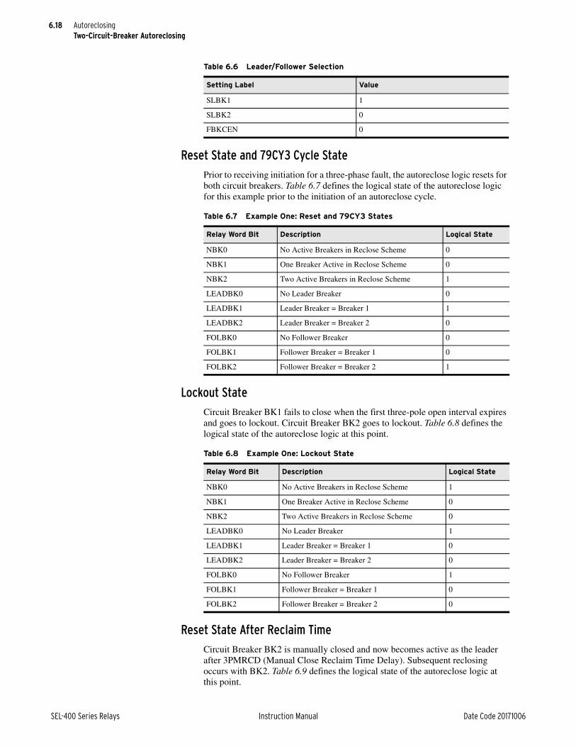
6.18
SEL-400 Series Relays Instruction Manual Date Code 20171006
AutoreclosingTwo-Circuit-Breaker Autoreclosing
Reset State and 79CY3 Cycle State
Prior to receiving initiation for a three-phase fault, the autoreclose logic resets for both circuit breakers. Table 6.7 defines the logical state of the autoreclose logic for this example prior to the initiation of an autoreclose cycle.
Lockout State
Circuit Breaker BK1 fails to close when the first three-pole open interval expires and goes to lockout. Circuit Breaker BK2 goes to lockout. Table 6.8 defines the logical state of the autoreclose logic at this point.
Reset State After Reclaim Time
Circuit Breaker BK2 is manually closed and now becomes active as the leader after 3PMRCD (Manual Close Reclaim Time Delay). Subsequent reclosing occurs with BK2. Table 6.9 defines the logical state of the autoreclose logic at this point.
Table 6.6 Leader/Follower Selection
Setting Label Value
SLBK1 1
SLBK2 0
FBKCEN 0
Table 6.7 Example One: Reset and 79CY3 States
Relay Word Bit Description Logical State
NBK0 No Active Breakers in Reclose Scheme 0
NBK1 One Breaker Active in Reclose Scheme 0
NBK2 Two Active Breakers in Reclose Scheme 1
LEADBK0 No Leader Breaker 0
LEADBK1 Leader Breaker = Breaker 1 1
LEADBK2 Leader Breaker = Breaker 2 0
FOLBK0 No Follower Breaker 0
FOLBK1 Follower Breaker = Breaker 1 0
FOLBK2 Follower Breaker = Breaker 2 1
Table 6.8 Example One: Lockout State
Relay Word Bit Description Logical State
NBK0 No Active Breakers in Reclose Scheme 1
NBK1 One Breaker Active in Reclose Scheme 0
NBK2 Two Active Breakers in Reclose Scheme 0
LEADBK0 No Leader Breaker 1
LEADBK1 Leader Breaker = Breaker 1 0
LEADBK2 Leader Breaker = Breaker 2 0
FOLBK0 No Follower Breaker 1
FOLBK1 Follower Breaker = Breaker 1 0
FOLBK2 Follower Breaker = Breaker 2 0
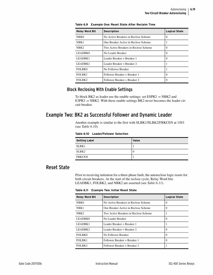
6.19
Date Code 20171006 Instruction Manual SEL-400 Series Relays
AutoreclosingTwo-Circuit-Breaker Autoreclosing
Block Reclosing With Enable Settings
To block BK2 as leader use the enable settings; set ESPR2 := NBK2 and E3PR2 := NBK2. With these enable settings BK2 never becomes the leader cir-cuit breaker.
Example Two: BK2 as Successful Follower and Dynamic LeaderAnother example is similar to the first with SLBK1/SLBK2/FBKCEN at 1/0/1 (see Table 6.10).
Reset State Prior to receiving initiation for a three-phase fault, the autoreclose logic resets for both circuit breakers. At the start of the reclose cycle, Relay Word bits LEADBK1, FOLBK2, and NBK2 are asserted (see Table 6.11).
Table 6.9 Example One: Reset State After Reclaim Time
Relay Word Bit Description Logical State
NBK0 No Active Breakers in Reclose Scheme 0
NBK1 One Breaker Active in Reclose Scheme 1
NBK2 Two Active Breakers in Reclose Scheme 0
LEADBK0 No Leader Breaker 0
LEADBK1 Leader Breaker = Breaker 1 0
LEADBK2 Leader Breaker = Breaker 2 1
FOLBK0 No Follower Breaker 1
FOLBK1 Follower Breaker = Breaker 1 0
FOLBK2 Follower Breaker = Breaker 2 0
Table 6.10 Leader/Follower Selection
Setting Label Value
SLBK1 1
SLBK2 0
FBKCEN 1
Table 6.11 Example Two: Initial Reset State
Relay Word Bit Description Logical State
NBK0 No Active Breakers in Reclose Scheme 0
NBK1 One Breaker Active in Reclose Scheme 0
NBK2 Two Active Breakers in Reclose Scheme 1
LEADBK0 No Leader Breaker 0
LEADBK1 Leader Breaker = Breaker 1 1
LEADBK2 Leader Breaker = Breaker 2 0
FOLBK0 No Follower Breaker 0
FOLBK1 Follower Breaker = Breaker 1 0
FOLBK2 Follower Breaker = Breaker 2 1

6.20
SEL-400 Series Relays Instruction Manual Date Code 20171006
AutoreclosingTwo-Circuit-Breaker Autoreclosing
When BK1 successfully recloses, BK2 closes as the follower after timer TBBKD (Time Between Breakers for ARC).
If BK1 goes to lockout during a reclose cycle (after BKCFD time), then BK2 will close as the follower. After timer 3PRCD (Three-Pole Reclaim Time Delay) expires, the recloser enters the reset state for BK2 (BK2RS). The recloser dynam-ically recalculates the leader and follower circuit breakers. BK2 becomes the leader with Relay Word bits LEADBK2, FOLBK0, and NBK1 asserted (see Table 6.12). When BK2 becomes the leader, the recloser immediately issues the close command to BK2 and does not add any additional SPOID or 3POID inter-val time.
Example Three: BK2 as Conditional FollowerOne method to program BK2 for closing only after a successful BK1 close is to set SLBK1/SLBK2/FBKCEN as in Table 6.13.
Reset State
Prior to receiving initiation for a three-phase fault, the autoreclose logic resets for both circuit breakers. Table 6.14 defines the logical state of the autoreclose logic for this example prior to the initiation of an autoreclose cycle.
Table 6.12 Example Two: Final Reset State
Relay Word Bit Description Logical State
NBK0 No Active Breakers in Reclose Scheme 0
NBK1 One Breaker Active in Reclose Scheme 1
NBK2 Two Active Breakers in Reclose Scheme 0
LEADBK0 No Leader Breaker 0
LEADBK1 Leader Breaker = Breaker 1 0
LEADBK2 Leader Breaker = Breaker 2 1
FOLBK0 No Follower Breaker 1
FOLBK1 Follower Breaker = Breaker 1 0
FOLBK2 Follower Breaker = Breaker 2 0
Table 6.13 Leader/Follower Selection
Setting Label Value
SLBK1 1
SLBK2 0
FBKCEN 52AA1
Table 6.14 Example Three: Reset State (Sheet 1 of 2)
Relay Word Bit Description Logical State
NBK0 No Active Breakers in Reclose Scheme 0
NBK1 One Breaker Active in Reclose Scheme 0
NBK2 Two Active Breakers in Reclose Scheme 1
LEADBK0 No Leader Breaker 0
LEADBK1 Leader Breaker = Breaker 1 1
LEADBK2 Leader Breaker = Breaker 2 0

6.21
Date Code 20171006 Instruction Manual SEL-400 Series Relays
AutoreclosingTwo-Circuit-Breaker Autoreclosing
79CY3 Cycle State
The autoreclose logic receives a three-pole initiation. Table 6.15 defines the logi-cal state of the autoreclose logic for this example during the three-pole autore-close cycle.
BK2 closes as the follower when BK1 successfully closes (after timer TBBKD).
Lockout State
Circuit Breaker BK1 must close before Circuit Breaker BK2. If Circuit Breaker BK1 fails to close and goes to lockout, then Circuit Breaker BK2 goes to lockout as well because BK2 cannot close as the follower and cannot dynamically become the leader. Table 6.16 defines the logical state of the autoreclose logic for this example following the unsuccessful reclose attempt.
FOLBK0 No Follower Breaker 0
FOLBK1 Follower Breaker = Breaker 1 0
FOLBK2 Follower Breaker = Breaker 2 1
Table 6.14 Example Three: Reset State (Sheet 2 of 2)
Relay Word Bit Description Logical State
Table 6.15 Example Three: Three-Pole Cycle State
Relay Word Bit Description Logical State
NBK0 No Active Breakers in Reclose Scheme 0
NBK1 One Breaker Active in Reclose Scheme 0
NBK2 Two Active Breakers in Reclose Scheme 1
LEADBK0 No Leader Breaker 0
LEADBK1 Leader Breaker = Breaker 1 1
LEADBK2 Leader Breaker = Breaker 2 0
FOLBK0 No Follower Breaker 0
FOLBK1 Follower Breaker = Breaker 1 0
FOLBK2 Follower Breaker = Breaker 2 1
Table 6.16 Example Three: Lockout State, BK
Relay Word Bit Description Logical State
NBK0 No Active Breakers in Reclose Scheme 1
NBK1 One Breaker Active in Reclose Scheme 0
NBK2 Two Active Breakers in Reclose Scheme 0
LEADBK0 No Leader Breaker 1
LEADBK1 Leader Breaker = Breaker 1 0
LEADBK2 Leader Breaker = Breaker 2 0
FOLBK0 No Follower Breaker 1
FOLBK1 Follower Breaker = Breaker 1 0
FOLBK2 Follower Breaker = Breaker 2 0

6.22
SEL-400 Series Relays Instruction Manual Date Code 20171006
AutoreclosingTwo-Circuit-Breaker Autoreclosing
Example Four: Input Selection of LeaderFigure 6.4 illustrates a circuit breaker-and-a half configuration for this particular example. The leader and follower selection settings are shown in Table 6.17. Cir-cuit Breaker BK1 is out of service for maintenance and Disconnect Switch 1 is open.
Table 6.18 defines the logical state of the autoreclose logic for this example prior to the initiation of an autoreclose cycle. These conditions are frozen during an autoreclose cycle. The relay autoreclose logic can unfreeze these conditions if the relay receives another initiation.
Enable Autoreclose Logic for Two Circuit BreakersThree-Pole Trip Circuit Breakers
The initial settings necessary to enable autoreclose for two three-pole trip circuit breakers are shown in Table 6.19.
Table 6.17 Leader/Follower Selection
Setting Label Setting
SLBK1 IN106 (Disconnect 1 a contacts)
SLBK2 IN107 (Disconnect 2 a contacts)
FBKCEN 0
Figure 6.4 Leader/Follower Selection by Relay Input
Table 6.18 Two Circuit Breakers: Circuit Breaker BK1 Out of Service
Relay Word Bit Description Logical State
NBK0 No Active Breakers in Reclose Scheme 0
NBK1 One Breaker Active in Reclose Scheme 1
NBK2 Two Active Breakers in Reclose Scheme 0
LEADBK0 No Leader Breaker 0
LEADBK1 Leader Breaker = Breaker 1 0
LEADBK2 Leader Breaker = Breaker 2 1
FOLBK0 No Follower Breaker 1
FOLBK1 Follower Breaker = Breaker 1 0
FOLBK2 Follower Breaker = Breaker 2 0
Bus 1
(Leader)
Line
to IN106 to IN107
Out of Service (maintenance) Bus 2
BK2BK1

6.23
Date Code 20171006 Instruction Manual SEL-400 Series Relays
AutoreclosingTwo-Circuit-Breaker Autoreclosing
Single-Pole Trip Circuit BreakersThe initial settings necessary to enable autoreclose for two single-pole trip circuit breakers are shown in Table 6.20.
Recloser Mode EnablesThe SELOGIC control equations E3PRn and ESPRn set the relay for the three autoreclose modes. Table 6.21 and Table 6.22 illustrate how to enable the autore-close modes per circuit breaker.
Table 6.19 Two-Circuit-Breaker Three-Pole Reclose Initial Settings
Setting Description Entry
NUMBK Number of Breakers in Scheme 2
Breaker Configuration (Breaker Monitor)
BK1TYPa
a Only applicable to products that support single-pole tripping and reclosing.
Breaker 1 Trip Type 3
BK2TYPa Breaker 2 Trip Type 3
Breaker 1 Inputs (Breaker Monitor)
52AA1 N/O Contact Input—BK1 (SELOGIC Equation) IN101
Breaker 2 Inputs (Breaker Monitor)
52AA2 N/O Contact Input—BK2 (SELOGIC Equation) IN102
Relay Configuration (Group)
E79 Reclosing Y or Y1
Table 6.20 Two-Circuit-Breaker Single-Pole Reclose Initial Settings
Setting Description Entry
NUMBK Number of Breakers in Scheme 2
Breaker Configuration (Breaker Monitor)
BK1TYP Breaker 1 Trip Type 1
BK2TYP Breaker 2 Trip Type 1
Breaker 1 Inputs (Breaker Monitor)
52AA1 A-Phase N/O Contact Input—BK1 (SELOGIC Equation) IN101
52AB1 B-Phase N/O Contact Input—BK1 (SELOGIC Equation) IN102
52AC1 C-Phase N/O Contact Input—BK1 (SELOGIC Equation) IN103
Breaker 2 Inputs (Breaker Monitor)
52AA2 A-Phase N/O Contact Input—BK2 (SELOGIC Equation) IN104
52AB2 B-Phase N/O Contact Input—BK2 (SELOGIC Equation) IN105
52AC2 C-Phase N/O Contact Input—BK2 (SELOGIC Equation) IN106
Relay Configuration (Group)
E79 Reclosing Y or Y1
Table 6.21 Circuit Breaker BK1 Modes of Operation (Sheet 1 of 2)
E3PR1 ESPR1a Result
0 0 Autoreclose disabled
0 1 Single-pole autoreclose only enabled

6.24
SEL-400 Series Relays Instruction Manual Date Code 20171006
AutoreclosingTwo-Circuit-Breaker Autoreclosing
E3PR1 is the SELOGIC control equation that enables three-pole autoreclose for Circuit Breaker BK1. You can assign this setting to a control input. ESPR1 is the SELOGIC control equation that enables single-pole autoreclose for Circuit Breaker BK1. You can assign this setting to a control input.
When ESPR1 equals logical 1, the relay can attempt a single-pole autoreclose cycle for Circuit Breaker BK1. If ESPR1 equals logical 0, the relay cannot initi-ate a single-pole autoreclose cycle for Circuit Breaker BK1.
When E3PR1 equals logical 1, the relay can attempt a three-pole autoreclose cycle for Circuit Breaker BK1. If E3PR1 equals logical 0, the relay goes to lock-out following a three-pole trip for Circuit Breaker BK1 and the corresponding leader logic transfers automatically to Circuit Breaker BK2.
E3PR2 is the SELOGIC control equation that enables three-pole autoreclose for Circuit Breaker BK2. You can assign this setting to a control input. ESPR2 is the SELOGIC control equation that enables single-pole autoreclose for Circuit Breaker BK2. You can assign this setting to a control input.
When ESPR2 equals logical 1, the relay can attempt a single-pole autoreclose cycle for Circuit Breaker BK2. If ESPR2 equals logical 0, the relay cannot initi-ate a single-pole autoreclose cycle for Circuit Breaker BK2.
When E3PR2 equals logical 1, the relay can attempt a three-pole autoreclose cycle for Circuit Breaker BK2. If E3PR2 equals logical 0, the relay goes to lock-out following a three-pole trip for Circuit Breaker BK2.
Assert one or all SELOGIC control equations E3PR1, E3PR2, ESPR1, and ESPR2 according to your reclosing requirements.
For single-pole reclosing, set ESPR1 := 1 and set NSPSHOT to the desired num-ber of single-pole reclose shots. For three-pole reclosing, set E3PR1 := 1 and set N3PSHOT for the desired number of three-pole shots. For both single-pole and three-pole reclosing, set ESPR1 := 1, E3PR1 := 1, and configure settings NSP-SHOT and N3PSHOT for the desired number of reclose shots of each type (see Recloser Mode Enables on page 6.8).
1 0 Three-pole autoreclose only enabled
1 1 Single- and three-pole autoreclose enabled
a Only applicable to relays that support single-pole reclosing.
Table 6.22 Circuit Breaker BK2 Modes of Operation
E3PR2 ESPR2a
a Only applicable to relays that support single-pole reclosing.
Result
0 0 Autoreclose disabled
0 1 Single-pole autoreclose only enabled
1 0 Three-pole autoreclose only enabled
1 1 Single- and three-pole autoreclose enabled
Table 6.21 Circuit Breaker BK1 Modes of Operation (Sheet 2 of 2)
E3PR1 ESPR1a Result

6.25
Date Code 20171006 Instruction Manual SEL-400 Series Relays
AutoreclosingTwo-Circuit-Breaker Autoreclosing
Trip Logic and Reclose Sources for Single-Pole Breaker ApplicationsInternal Recloser
Program the recloser function to drive the trip logic with Relay Word bits R3PTE (Recloser Three-Pole Trip Enable), R3PTE1 (Circuit Breaker BK1 Recloser Three-Pole Trip Enable) and R3PTE2 (Circuit Breaker BK2 Recloser Three-Pole Trip Enable) as follows:
E3PT := R3PTE Three-Pole Trip Enable (SELOGIC Equation)
E3PT1 := R3PTE1 Breaker 1 Three-Pole Trip (SELOGIC Equation)
E3PT2 := R3PTE2 Breaker 2 Three-Pole Trip (SELOGIC Equation)
These settings connect the internal recloser for both three-pole reclosing and sin-gle-pole reclosing.
Enter enable settings ESPR1 and E3PR1 as appropriate for your application. By default, the relay is a single-pole tripping relay; that is, if E3PT is logical 0 and E3PT1 equals logical 0, the relay can single-pole trip Circuit Breaker BK1. If E3PT1 equals logical 1, the relay can only three-pole trip Circuit Breaker BK1. The same conditions apply to setting E3PT2 and Circuit Breaker BK2.
Table 6.23 summarizes the relay trip logic enable options.
Relay Word bits R3PTE1 and R3PTE2 both equal logical 1 for any of the follow-ing conditions when Global setting NUMBK (Number of Breakers in Scheme) is 2 and SPLSHT (Single-Pole Last Shot) is asserted (see Figure 6.9):
➤ BK1TYP and BK2TYP equal 3 (Circuit Breaker 1 and Circuit Breaker 2 Trip Type)
➤ NSPSHOT := N (Number of Single-Pole Reclosures)
Example 6.1 Conditional Three-Pole Tripping for Circuit Breaker BK2
Your system reclosing requirement is that Circuit Breaker BK2 always three-pole trips, unless Circuit Breaker BK2 is the leader. (This occurs when Cir-cuit Breaker BK1 is out of service.) Program SELOGIC control equation ESPR2 as follows:
ESPR2 := LEADBK2 AND BK1LO Single-Pole Reclose Enable—BK2 (SELOGIC Equation)
Table 6.23 Trip Logic Enable Options
Enable Condition Circuit Breaker BK1 Circuit Breaker BK2
E3PT E3PT1 E3PT2Single-
Pole TripThree-
Pole TripSingle-
Pole TripThree-Pole
Trip
0 0 0 x x
0 0 1 x x
0 1 0 x x
0 1 1 x x
1 0 0 x x
1 0 1 x x
1 1 0 x x
1 1 1 x x

6.26
SEL-400 Series Relays Instruction Manual Date Code 20171006
AutoreclosingAutoreclose Logic Diagrams
External RecloserIf reclosing is performed by an external relay, assert SELOGIC control equations E3PT, E3PT1, and E3PT2 via control inputs (for example):
E3PT := IN104 Three-Pole Trip Enable (SELOGIC Equation)
E3PT1 := IN105 Breaker 1 Three-Pole Trip (SELOGIC Equation)
E3PT2 := IN106 Breaker 2 Three-Pole Trip (SELOGIC Equation)
Connect the external recloser single-pole trip output signal to IN104, the Circuit Breaker BK1 trip type signal to IN105, and the Circuit Breaker BK2 trip type sig-nal to IN106. Other external recloser signals are required; consult the external recloser documentation for interconnection with the relay.
In installations where the external reclosing relay does not provide three-phase trip control signals, the TOP (Trip during Open-Pole) Relay Word bit can be used in the E3PT setting. This Relay Word bit will assert just after a single- or two-pole trip, and remain asserted until the TOPD timer expires. If a new trip occurs during this time, the E3PT := TOP setting would then cause a three-pole trip.
Autoreclose Logic Diagrams
Figure 6.5 Circuit Breaker Pole-Open Logic Diagram—Single-Pole Relays
52AA1
52AB1
52AC1
SPOBK1
3POBK1
52AA1D
52AB1D
52AC1D
Timers in cycles
2POBK1
Note: Similar logic for Breaker 2
0
1.0
0
1.0
0
1.0
Relay
Word Bits
Relay
Word Bits

6.27
Date Code 20171006 Instruction Manual SEL-400 Series Relays
AutoreclosingAutoreclose Logic Diagrams
Figure 6.6 Circuit Breaker Pole-Open Logic Diagrams—Three-Pole Relays
Figure 6.7 Line-Open Logic Diagram When E79 := Y
Figure 6.8 Line-Open Logic Diagram When E79 := Y1
52AA1 3POBK1
Timer in cycles
0.0
1.0
52AA2 3POBK2
Timer in cycles
0.0
1.0
SettingRelay
Word Bit
Breaker 1
SettingRelay
Word Bit
Breaker 2
NBK2
NBK1
3POBK13POBK2
3POLINE
LEADBK1
3POBK1
LEADBK2
3POBK2
Relay
Word Bits
Relay
Word Bits
NBK23POBK1
3POBK2
NBK1
3POLINE
LEADBK1
3POBK1
LEADBK2
3POBK2
Relay
Word Bits
Relay
Word Bits

6.28
SEL-400 Series Relays Instruction Manual Date Code 20171006
AutoreclosingAutoreclose Logic Diagrams
Figure 6.9 Single-Pole Reclose Enable
SPLSHT79STRTBK1EXTBK2EXT
ESPR179CY3
BK1LO
BK2LO
SPARC
SPRI
S
R
Q
R3PTE1
R3PTE2
R3PTE
ESPR2
NSPSHOT =N
NUMBK := 2
NUMBK := 2
NUMBK := 1
3PARC
SPARC(Drop Out)
SPOIT(Time out)
79DTL3POLINE
(R has precedence over S)
BK1TYP := 3
BK1TYP := 3BK2TYP := 3
0
2CYC
Figure 6.10 Three-Pole Reclose Enable
3PLSHT
BK1LO
BK2LO
E3PR1
E3PR2
NUMBK := 2
3PARC
3PRI
0
4 CYC

6.29
Date Code 20171006 Instruction Manual SEL-400 Series Relays
AutoreclosingAutoreclose Logic Diagrams
Figure 6.11 One Circuit Breaker Single-Pole Cycle State (79CY1)
Yes
79CY3
79DTL
3POLINE
3PARC
3PARC
SPARC
Wait forBreakerto Open
Single PoleOpen Interval
(SPOID)
79CY1
Is Breaker Allowedto Close (SP1CLS)?
SPO
Single Pole Open Time Out
No
TimedOut
Single PoleReclaim Time
(SPRCD)
Breaker CloseFailure Time
(BKCFD)
Ready State(BK1RS)
to Beginningof 79CY3
to Beginningof 79CY1
Lockout(BK1LO)3PARC
SPARC
Timed Out
Timing
No
Lockout(BK1LO)
Lockout(BK1LO)
Timed Out
Timing
Issue CLOSE Command (BK1CL)
Did Breaker Close?
BK1CL
12
3
6
9
12
3
6
9
12
3
6
9
12
3
6
9
12
3
6
9
Recalculate NBKn, Leader, and Follower
Is 79BRCT Asserted?
Timing
NoYes
79CY3
SPARC
3PARC
Yes
Close SupervisionDelay (BK1CLSD)

6.30
SEL-400 Series Relays Instruction Manual Date Code 20171006
AutoreclosingAutoreclose Logic Diagrams
Figure 6.12 One Circuit Breaker Three-Pole Cycle State (79CY3)
12
3
6
9
12
3
6
9
12
3
6
9
12
3
6
9
to Beginningof 79CY3
Reset State(BK1RS)
Lockout(BK1LO)
Lockout(BK1LO)
3PARC
Is Breaker Allowed to Close?
(3P1CLS=1?)
Is Block ReclaimTime (79BRCT) Asserted?
Did Breaker Close?
Yes
TimedOut
TimedOut
Timed Out
Breaker Open
Close Supervision Delay
Three-Pole Open Interval Timer
(3POIDn)
No
Timing
BK1CL
NoTiming
Yes
3PARCTiming
Breaker CloseFailure Timer (BKCFD)
Three-Pole Reclaim Timer
(3PRCD)
(BK1CLSD)
No Yes
Increment Shot Counterand Issue CLOSE Command
3PARC
Lockout(BK1LO)Timed Out
79CY3
79CY3Yes
NoNo
3POLINE
Is Skip ShotAsserted?
Has the Line Opened 3 Pole?
Increment Shot.Is Shot Count GreaterThan or Equal to the
Number of set Reclosures?
Yes
(3PLSHT)
Lockout (BKnLO)3PRIH
Timeout
12
3
6
9
3PRIH = OFF
Yes
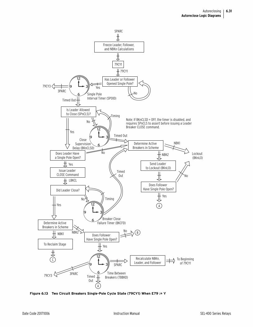
6.31
Date Code 20171006 Instruction Manual SEL-400 Series Relays
AutoreclosingAutoreclose Logic Diagrams
Figure 6.13 Two Circuit Breakers Single-Pole Cycle State (79CY1) When E79 := Y
Has Leader or Follower Opened Single Pole?
12
3
6
9
12
3
6
9
12
3
6
9
SPARC
79CY3
79CY1
79CY1
Timed Out
Single Pole Interval Timer (SPOID)
Close Supervision
Delay (BKnCLSD)
Freeze Leader, Follower, and NBKn Calculations
Does Leader Have a Single Pole Open?
Does Follower Have Single Pole Open?
Does Follower Have Single Pole Open?
Issue Leader CLOSE Command
Did Leader Close?
Determine Active Breakers in Scheme
Determine Active Breakers in Scheme
Is Leader Allowed to Close (SPnCLS)?
To Reclaim Stage
Timed Out
No
No
No
No
NBK1
Yes3PARC
Yes
No
Timing
NBK2
Timing
Breaker CloseFailure Timer (BKCFD)
Time BetweenBreakers (TBBKD)
TimedOut
Yes
Yes
Yes
Yes
LBKCL
NBK1
Send Leader to Lockout (BKnLO)
NBK2
C
A
A
B
Lockout (BKnLO)
12
3
6
9 SPARC
79CY33PARC
TimedOut
To Beginningof 79CY1
Recalculate NBKn,Leader, and Follower
No
Note: If BKnCLSD = OFF, the timer is disabled, andrequires SPnCLS to assert before issuing a LeaderBreaker CLOSE command.

6.32
SEL-400 Series Relays Instruction Manual Date Code 20171006
AutoreclosingAutoreclose Logic Diagrams
Figure 6.13 Two Circuit Breakers Single-Pole Cycle State (79CY1) When E79 := Y (Continued)
Yes Yes
No
No
FBKCL
Yes
Yes
FOLBKR = L/O
FOLBKR = L/O
C
A B
Is Follower ClosingEnabled (FBKCEN = 1)?
Is Leader in Lockout State?
Is Follower Allowedto Close (SPnCLS)?
Follower Breaker CloseSupervision Delay (BKnCLSD)Issue Follower
CLOSE Command
Is Follower Closed?
No
Timing
Timed Out
Timed Out
Follower Breaker CloseFailure Timer (BKCFD)
Send Follower toLockout State
Send Followerto Lockout
Leader toReclaim Stage
Lockout(BKnLO)
12
3
6
9
No
Timing
12
3
6
9
12
3
6
9
79CY3 Is 79BRCT Asserted?Recalculate NBKn,
Leader, and Follower
DetermineActive Breakers
Determine Leader
SPARC
Timing
SPARC
To Beginningof 79CY1
*Send Both Breakersto Ready State
Breaker #1Ready State (BK1RS)
Breaker #2Ready State (BK2RS)
NoYes
NBK1
LEADBK1LEADBK2
NBK2
Timed Out
Reclaim Timer(SPRCD)
3PARC
3PARC
Note: If BKnCLSD = OFF, thetimer is disabled, andrequires SPnCLS to assertbefore issuing a LeaderBreaker CLOSE command.

6.33
Date Code 20171006 Instruction Manual SEL-400 Series Relays
AutoreclosingAutoreclose Logic Diagrams
Figure 6.14 Two Circuit Breakers Single-Pole Cycle State (79CY1) When E79 := Y1
Has Leader or Follower Opened Single Pole?
12
3
6
9
12
3
6
9
12
3
6
9
SPARC
79CY3
79CY1
79CY1
Timed Out
Single Pole Interval Timer (SPOID)
Close Supervision
Delay (BKnCLSD)
Freeze Leader, Follower, and NBKn Calculations
Does Leader Have a Single Pole Open?
Does Follower Have Single Pole Open?
Does Follower Have Single Pole Open?
Issue Leader CLOSE Command
Did Leader Close?
Determine Active Breakers in Scheme
Determine Active Breakers in Scheme
Is Leader Allowed to Close (SPnCLS)?
To Reclaim Stage
Timed Out
No
No
No
No
NBK1
Yes3PARC
Yes
No
Timing
NBK2
Timing
Breaker CloseFailure Timer (BKCFD)
Time BetweenBreakers (TBBKD)
TimedOut
Yes
Yes
Yes
Yes
LBKCL
NBK1
Send Leader to Lockout (BKnLO)
NBK2
C
A
A
B
Lockout (BKnLO)
12
3
6
9 SPARC
79CY33PARC
TimedOut
To Beginningof 79CY1
Recalculate NBKn,Leader, and Follower
No
Note: If BKnCLSD = OFF, the timer is disabled, andrequires SPnCLS to assert before issuing a LeaderBreaker CLOSE command.

6.34
SEL-400 Series Relays Instruction Manual Date Code 20171006
AutoreclosingAutoreclose Logic Diagrams
Figure 6.14 Two Circuit Breakers Single-Pole Cycle State (79CY1) When E79 := Y1 (Continued)
Yes Yes
No
No
FBKCL
Yes
Yes
FOLBKR = L/O
FOLBKR = L/O
C
A B
Is Follower ClosingEnabled (FBKCEN = 1)?
Is Leader in Lockout State?
Is Follower Allowedto Close (SPnCLS)?
Follower Breaker CloseSupervision Delay (BKnCLSD)Issue Follower
CLOSE Command
Is Follower Closed?
No
Timing
Timed Out
Timed Out
Follower Breaker CloseFailure Timer (BKCFD)
Send Follower toLockout State
Send Followerto Lockout
Leader toReclaim Stage
Lockout(BKnLO)
12
3
6
9
No
Timing
12
3
6
9
12
3
6
9
79CY3 Is 79BRCT Asserted?Recalculate NBKn,
Leader, and Follower
DetermineActive Breakers
Determine Leader
SPARC
Timing
SPARC
To Beginningof 79CY1
*Send Both Breakersto Ready State
Breaker #1Ready State (BK1RS)
Breaker #2Ready State (BK2RS)
NoYes
NBK1
LEADBK1LEADBK2
NBK2
Timed Out
Reclaim Timer(SPRCD)
3PARC
3PARC
Note: If BKnCLSD = OFF, thetimer is disabled, andrequires SPnCLS to assertbefore issuing a LeaderBreaker CLOSE command.

6.35
Date Code 20171006 Instruction Manual SEL-400 Series Relays
AutoreclosingAutoreclose Logic Diagrams
Figure 6.15 Two Circuit Breakers Three-Pole Cycle State (79CY3) When E79 := Y
12
3
6
9
12
3
6
9
79CY3
79CY3Yes
Yes
NoNo
Timed Out
3 Pole Open IntervalTimer (3POIDn)
LEADBKR Closed(by external means)
CloseSupervision
Delay (BKnCLSD)
3POLINE
Is Skip ShotAsserted?
Has the Line Opened 3 Pole?
Increment Shot.Is Shot Count GreaterThan or Equal to the
Number of set Reclosures?
Breaker CloseFailure Timer (BKCFD)
Is Leader Allowedto Close (3PnCLS)?
Is Leader Closed?
Issue LeaderCLOSE Command
YesNo
Yes
Timing
12
3
6
9
NoTiming
Timed Out, or 3-Pole Reclosing Disabled for Lead Breaker (E3PRn=0)
TimedOut
LBKCL
C
A
Determine ActiveBreakers in Scheme
NBK2 NBK1
Lockout(BKnLO)
A
Freeze
3PARC
3-Pole Reclose Initiation (3PARC)from Ready States (BK1RS and/or
BK2RS) or from Single-Pole RecloseCycle State (79CY1)
3-Pole Reclose Initiation (3PARC)while in 3-Pole Reclose Cycle
State (79CY3)
Yes(3PLSHT)
Lockout (BKnLO)3PRIH
Timeout
12
3
6
9
3PRIH = OFF
Recalculate Leader, Follower, and Number of Active Breakerslogic, then freeze calculations. If 3-Pole Reclosing is disabledfor Breaker n (E3PRn = 0), send Breaker n to lockout (BKnLO).
Note: If BKnCLSD = OFF, the timer is disabled,and requires3PnCLS to assert before issuinga Leader Breaker CLOSE command.

6.36
SEL-400 Series Relays Instruction Manual Date Code 20171006
AutoreclosingAutoreclose Logic Diagrams
Figure 6.15 Two Circuit Breakers Three-Pole Cycle State (79CY3) When E79 := Y (Continued)
12
3
6
9
12
3
6
9
12
3
6
9
C
D
A
Send Followerto Lockout
Lockout (BKnLO)
To Beginningof 79CY3
NBK2NBK1
No
No
Timed Out
Follower Breaker Close Supervision Timer (BKnCLSD)
BKR Close FailureTimer (BKCFD)
3PARC
Time BetweenBreaker (TBBKD)
To Beginningof State
To Beginningof State
3PARC
3PARC
Yes
Is the Follower Closed?
Has the Follower Closed?
Is Follower Closing
Enabled (FBKCEN = 1)?
Is the Leader in
the Lockout State?
Have Follower Close
Supervision Conditions
Been Met (3PnCLS)?
Is the Follower Closed?
Determine Active Breakers in Scheme
Issue Follower CLOSE Command
LEADBKR=L/O
FOLBKR=L/O
Determine Leaderand Send Leaderto Lockout State
To Reclaim Stage
Is the Leader in
the Lockout State?
Yes
YesYes
YesYes
FBKCL
Yes
No
No
No
No
No
D
Timing
Timed Out, or 3-pole reclosing
disabled for follower breaker
(E3PRn = 0)
TimingTimed
Out
Send Follower to Lockout (BKnLO)
To Reclaim Stage
Send Followerto Lockout
Lockout (BKnLO)
D
Leader To Reclaim Stage
D
To Reclaim Stage
Note: If BKnCLSD = OFF, thetimer is disabled, andrequires 3PnCLS to assertbefore issuing a LeaderBreaker CLOSE command.
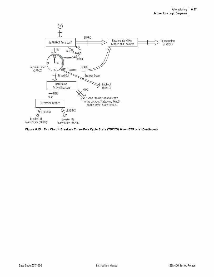
6.37
Date Code 20171006 Instruction Manual SEL-400 Series Relays
AutoreclosingAutoreclose Logic Diagrams
Figure 6.15 Two Circuit Breakers Three-Pole Cycle State (79CY3) When E79 := Y (Continued)
D
12
3
6
9
Is 79BRCT Asserted?Recalculate NBKn,
Leader, and Follower
DetermineActive Breakers
Determine Leader
Timing
3PARC
3PARC
To beginning of 79CY3
*Send Breakers (not already in the Lockout State, e.g., BKnL0)
to the Reset State (BKnRS)
Breaker #1Ready State (BK1RS)
Breaker #2Ready State (BK2RS)
NoYes
NBK1
LEADBK1LEADBK2
NBK2
Timed Out
Reclaim Timer(3PRCD)
Breaker Open
Lockout(BKnLO)

6.38
SEL-400 Series Relays Instruction Manual Date Code 20171006
AutoreclosingAutoreclose Logic Diagrams
Figure 6.16 Two Circuit Breakers Three-Pole Cycle State (79CY3) When E79 := Y1
12
3
6
9
12
3
6
9
79CY3
79CY3Yes
NoNo
LEADBKR Closed(by external means)
CloseSupervision
Delay (BKnCLSD)
Is Skip ShotAsserted?
Has the Line Opened 3 Pole?
Increment Shot.Is Shot Count GreaterThan or Equal to the
Number of set Reclosures?
Breaker CloseFailure Timer (BKCFD)
Is Leader Allowedto Close (3PnCLS)?
Is Leader Closed?
Issue LeaderCLOSE Command
YesNo
Yes
Timing
12
3
6
9
NoTiming
Timed Out, or 3-Pole ReclosingDisabled for Lead Breaker (E3PRn=0)
TimedOut
LBKCL
C
A
Determine ActiveBreakers in Scheme
NBK2 NBK1
Lockout(BKnLO)
A
Freeze
3PARC
3-Pole Reclose Initiation (3PARC)from Ready States (BK1RS and/or
BK2RS) or from Single-Pole RecloseCycle State (79CY1)
3-Pole Reclose Initiation (3PARC)while in 3-Pole Reclose Cycle
State (79CY3)
If 3-Pole Reclosing is disabled for Breaker n (E3PRn = 0), sendBreaker n to lockout (BKnLO). Recalculate Leader, Follower, and
Number of Active Breakers logic, then freeze calculations
Yes(3PLSHT)
Lockout (BKnLO)3PRIH
Timeout
12
3
6
9
3PRIH = OFF
Timed Out
3 Pole Open IntervalTimer (3POIDn)
Is Leader Open?
Yes
No
Yes
12
3
6
9
Yes
No
Timing
Timed Out(BKnLO)
Is 3-Pole Open Interval Supervision (3POISC)
Satisfied?3POLINE
Note: If BKnCLSD = OFF, the timer is disabled, andrequires 3pnCLS to assert before issuing a LeaderBreaker CLOSE command.

6.39
Date Code 20171006 Instruction Manual SEL-400 Series Relays
AutoreclosingAutoreclose Logic Diagrams
Figure 6.16 Two Circuit Breakers Three-Pole Cycle State (79CY3) When E79 := Y1 (Continued)
12
3
6
9
12
3
6
9
12
3
6
9
C
D
A
Send Followerto Lockout
Lockout (BKnLO)
To Beginningof 79CY3
NBK2NBK1
No
No
Timed Out
Follower Breaker Close Supervision Timer (BKnCLSD)
BKR Close FailureTimer (BKCFD)
3PARC
Time BetweenBreaker (TBBKD)
To Beginningof State
To Beginningof State
3PARC
3PARC
Yes
Is the Follower Closed?
Has the Follower Closed?
Is Follower Closing
Enabled (FBKCEN = 1)?
Is the Leader in
the Lockout State?
Have Follower Close
Supervision Conditions
Been Met (3PnCLS)?
Is the Follower Closed?
Determine Active Breakers in Scheme
Issue Follower CLOSE Command
LEADBKR=L/O
FOLBKR=L/O
Determine Leaderand Send Leaderto Lockout State
To Reclaim Stage
Is the Leader in
the Lockout State?
Yes
YesYes
YesYes
FBKCL
Yes
No
No
No
No
No
D
Timing
Timed Out, or 3-pole reclosing
disabled for follower breaker
(E3PRn = 0)
TimingTimed
Out
Send Follower to Lockout (BKnLO)
To Reclaim Stage
Send Followerto Lockout
Lockout (BKnLO)
D
Leader To Reclaim Stage
D
To Reclaim Stage
Note: If BKnCLSD = OFF, thetimer is disabled, andrequires 3PnCLS to assertbefore issuing a LeaderBreaker CLOSE command.

6.40
SEL-400 Series Relays Instruction Manual Date Code 20171006
AutoreclosingManual Closing
Manual ClosingManual closing is available via the relay to issue a close to the circuit breaker(s) via the same close logic outputs used in autoreclosing (Relay Word bits BK1CL and BK2CL for as many as two circuit breakers). The manual close logic can be user-configured in most any manner with SELOGIC settings BK1MCL and BK2MCL. Figure 6.17 is a flowchart of the manual close logic. This logic is enabled with Manual Closing enable setting EMANCL := Y.
Figure 6.17 only details the manual close logic for one circuit breaker (breaker BK1). The manual close logic for a second circuit breaker (breaker BK2), if enabled (Global setting NUMBK := 2), is similar. The only difference between the breaker BK1 and breaker BK2 manual close logic in Figure 6.17 is the substi-tution of settings and logic outputs (BK2MCL for BK1MCL, ULCL2 for ULCL1, etc.). A manual close is issued for breaker BK1 if all of the following are true:
➤ A new manual close signal for breaker BK1 is detected (rising edge assertion of SELOGIC setting BK1MCL)
➤ No unlatch close conditions are present (SELOGIC setting ULCL1 deasserted)
➤ No close is presently in progress for breaker BK1 (Relay Word bit output BK1CL is deasserted)
If a manual close is successfully issued for breaker BK1, then:
➤ Close logic output BK1CL asserts
➤ The close failure timer starts timing
Figure 6.16 Two Circuit Breakers Three-Pole Cycle State (79CY3) When E79 := Y1 (Continued)
D
12
3
6
9
Is 79BRCT Asserted?Recalculate NBKn,
Leader, and Follower
DetermineActive Breakers
Determine Leader
Timing
3PARC
3PARC
To beginning of 79CY3
*Send Breakers (not already in the Lockout State, e.g., BKnL0)
to the Reset State (BKnRS)
Breaker #1Ready State (BK1RS)
Breaker #2Ready State (BK2RS)
NoYes
NBK1
LEADBK1LEADBK2
NBK2
Timed Out
Reclaim Timer(3PRCD)
Breaker Open
Lockout(BKnLO)

6.41
Date Code 20171006 Instruction Manual SEL-400 Series Relays
AutoreclosingManual Closing
If breaker BK1 closes successfully, then:
➤ The unlatch close condition asserts (indicating breaker closure)
➤ Close logic output BK1CL deasserts
If breaker BK1 does not close successfully, then:
➤ The close failure timer times out (Relay Word bit BK1CFT asserts momentarily)
➤ Close logic output BK1CL deasserts
Note in Figure 6.17 that if breaker BK1 manual close logic is actively operating (as described in the preceding steps), then breaker BK2 manual close logic can-not be actively operating. Breaker BK2 manual close logic only has a chance to operate if breaker BK1 manual close logic is not actively operating and two breakers are enabled for the scheme (Global setting NUMBK := 2). Thus, manual closing can only be attempted for one breaker at a time.

6.42
SEL-400 Series Relays Instruction Manual Date Code 20171006
AutoreclosingManual Closing
Figure 6.17 Manual Close Logic
START
Manual Close Logic Enabled?
EMANCL := Y
Assert Close Output(BK1CL := 1)
Load Breaker Close Failure TimerWith Value of BKCFD
Unlatch Close Output?(ULCL1 := 1 ?)
Deassert Close Output(BK1CL := 0)
END
Number of Breakersin Scheme?
NUMBK := ?
Decrement BreakerClose Failure Timer
Assert Breaker CloseFailure output(BK1CFT := 1)
Breaker BK1Y
Y
N
YY
N
N
N
1
Breaker BK2
From Breaker BK2 logic
Breaker 2 Manual Close Logic Similar to Breaker 1
Breaker Close FailureTimer Timed Out ?
New Manual Close signaland
No Unlatch Close Conditionand
No Close in Progress?
(BK1MCL and Not (ULCL1)and Not (BK1CL))
2

6.43
Date Code 20171006 Instruction Manual SEL-400 Series Relays
AutoreclosingVoltage Checks for Autoreclosing and Manual Closing
Voltage Checks for Autoreclosing and Manual ClosingVoltage elements are available for a final check of line and bus voltages before an autoreclose or manual close is issued. These voltage elements and corresponding pickup settings are enabled with Reclosing Voltage Check enable setting EVCK := Y. Figure 6.18 shows the application of these voltage elements and Figure 6.19 shows their implementation. Check voltages for arrangements of as many as two circuit breakers (Global setting NUMBK := 2), as shown in Figure 6.18. If the relay is only connected to a single breaker (Global setting NUMBK := 1), then settings 27BK2P and 59BK2P and their associated elements (LLDB2, DLDB2, and DLLB2) are not available.
Voltages VP, VS1, and VS2 in Figure 6.18 and Figure 6.19 come from corre-sponding voltage source selection settings SYNCP, SYNCS1, and SYNCS2. Review details of synchronism checking in the Protection section of the desired product-specific Instruction Manual.
The pickup settings in Figure 6.19 are made on the VP voltage base. VP is the voltage reference for voltage angle and magnitude. Only voltage magnitude is of concern for the settings in Figure 6.19, not voltage angle.
Figure 6.18 implies that three-phase voltage is available from the line PTs. But, resultant voltage VP corresponds to only one phase of this three-phase voltage (e.g., setting SYNCP = VAY; VP is the normalized voltage from voltage input VAY). All the voltage elements in Figure 6.19 are single-phase voltage elements, detecting live or dead voltage on the bus side with a single-phase voltage ele-ment, and likewise on the line side.
Whether or not synchronism-check logic is used, it still has to be enabled for the respective breaker (E25BK1 := Y, Y1, or Y2 and E25BK2 := Y, Y1, or Y2) to allow the corresponding voltage source selection settings (SYNCP, SYNCS1, and SYNCS2) to be made.
Live Line/Live BusNote in Figure 6.18 that live line/live bus is not available for either circuit breaker. Voltage elements 59VP, 59VS1, and 59VS2, described in the Section 5: Protection Functions of the desired product-specific instruction man-ual, are available for such a function (e.g., 59VP AND 59VS1 for live line/live bus 1).
Supervising Circuit Breaker Closing with Voltage ChecksSupervising Autoreclosing
For a fault on the line in Figure 6.18, both breakers trip open and the lead breaker recloses first. For example, presume the lead breaker closes only if its respective bus is live and the line is dead (dead line/live bus; see Figure 6.18). Then, after successful reclose of the lead breaker, the follower breaker closes on synchro-nism check. Such reclose supervision logic is realized as follows for respective breakers BK1 and BK2:
3P1CLS := LEADBK1 AND DLLB1 OR FOLBK1 AND 25A1BK1 OR …
3P2CLS := LEADBK2 AND DLLB2 OR FOLBK2 AND 25A1BK2 OR …

6.44
SEL-400 Series Relays Instruction Manual Date Code 20171006
AutoreclosingVoltage Checks for Autoreclosing and Manual Closing
Note that the lead breaker and follower breaker supervision (Relay Word bits LEADBKn and FOLBKn, respectively) provides dynamic control for reclose supervision. One, but not both, of the breakers can reclose for a dead line/live bus condition (lead breaker), while the other then closes for a synchronism-check condition (follower breaker).
Supervising Manual Closing
Voltage checks can also be used to supervise manual closing. For example, pre-sume that manual closing of breaker BK1 (Figure 6.18) should not be allowed if the respective bus is dead (dead line/dead bus or live line/dead bus condition):
BK1MCL := NOT(DLDB1 OR AND LLDB1) AND (…)
Figure 6.18 Voltage Check Element Applications
Bus 2
VS1
(Bus 1 Potential)
VS2
(Bus 2 Potential)
BK1 BK2
1 1
3VP
(Line Potential)
Dead Line/ Live Bus 2
(DLLB2)
Dead Line/ Dead Bus 2
(DLDB2)
Live Line/Dead Bus 2
(LLDB2)
Dead Line/ Live Bus 1
(DLLB1)
Dead Line/ Dead Bus 1
(DLDB1)
Live Line/Dead Bus 1
(LLDB1)Bus 1
Line

6.45
Date Code 20171006 Instruction Manual SEL-400 Series Relays
AutoreclosingSettings and Relay Word Bits for Autoreclosing and Manual Closing
Settings and Relay Word Bits for Autoreclosing and Manual Closing
See the product-specific instruction manual Group Settings tables related to Reclose under the Settings section for a complete list of all autoreclose related settings. Table 6.24 provides all of the Relay Word bits for autoreclosing.
Figure 6.19 Voltage Check Element Logic
—
+
—
+
—
+
—
+
—
+
—
+
27BK2P
27BK1P
VS1
59BK1P
VS2
59BK2P
LLDB2
DLDB2
DLLB1
LLDB1
DLLB2
DLDB1
27LP
VP
59LP
Settings Voltages
RelayWordBits
Table 6.24 Autoreclose Logic Relay Word Bits (Sheet 1 of 3)
Name Description
BK1RS Breaker 1 in Reset State
BK2RS Breaker 2 in Reset State
79CY1a Relay in Single-Pole Reclose Cycle State
79CY3 Relay in Three-Pole Reclose Cycle State
BK1LO Breaker 1 in Lockout State
BK2LO Breaker 2 in Lockout State
SPARCa Single-Pole Reclose Initiate Qualified
SPOISCa Single-Pole Open Interval Supervision Condition
SPOIa Single-Pole Open Interval Timing
SPSHOT0a Single-Pole Shot Counter = 0
SPSHOT1a Single-Pole Shot Counter = 1
SPSHOT2a Single-Pole Shot Counter = 2

6.46
SEL-400 Series Relays Instruction Manual Date Code 20171006
AutoreclosingSettings and Relay Word Bits for Autoreclosing and Manual Closing
SPLSHTa Single-Pole Reclose Last Shot
SPRCIPa Single-Pole Reclaim In-Progress
3PARC Three-Pole Reclose Initiate Qualified
3POISC Three-Pole Open Interval Supervision Condition
3POI Three-Pole Open Interval Timing
3PSHOT0 Three-Pole Shot Counter = 0
3PSHOT1 Three-Pole Shot Counter = 1
3PSHOT2 Three-Pole Shot Counter = 2
3PSHOT3 Three-Pole Shot Counter = 3
3PSHOT4 Three-Pole Shot Counter = 4
3PLSHT Three-Pole Reclose Last Shot
3PRCIP Three-Pole Reclaim In-Progress
SPOBK1a Single-Pole Open Breaker 1
2POBK1a Two Poles Open Breaker 1
3POBK1 Three-Pole Open Breaker 1
SPOBK2a Single-Pole Open Breaker 2
2POBK2a Two Poles Open Breaker 2
3POBK2 Three-Pole Open Breaker 2
3POBK1 Three-Pole Open Breaker 1
3POLINE Three-Pole Open Line
R3PTE Three-Pole Tripping and Reclosing Only
R3PTE1 Recloser Three-Pole Trip Enable -BK1
R3PTE2 Recloser Three-Pole Trip Enable -BK2
BK1CL Breaker 1 Close Command
BK2CL Breaker 2 Close Command
BK1CLST Breaker 1 Close Supervision Delay Timed Out
BK2CLST Breaker 2 Close Supervision Delay Timed Out
BK1CFT Breaker 1 Close Failure Delay Timed Out
BK2CFT Breaker 2 Close Failure Delay Timed Out
BK1CLSS Breaker 1 in Close Supervision State
BK2CLSS Breaker 2 in Close Supervision State
BK1EXT Breaker 1 Closed Externally
BK2EXT Breaker 2 Closed Externally
BK1RCIP BK1 Reclaim in Progress
BK2RCIP BK2 Reclaim in Progress
79STRT Relay in Start State
TBBK Time Between Breakers Timing
LEADBK0 No Leader Breaker
LEADBK1 Leader Breaker = Breaker 1
LEADBK2 Leader Breaker = Breaker 2
FOLBK0 No Follower Breaker
Table 6.24 Autoreclose Logic Relay Word Bits (Sheet 2 of 3)
Name Description

6.47
Date Code 20171006 Instruction Manual SEL-400 Series Relays
AutoreclosingSettings and Relay Word Bits for Autoreclosing and Manual Closing
FOLBK1 Follower Breaker = Breaker 1
FOLBK2 Follower Breaker = Breaker 2
NBK0 No Breaker Active in Reclose Scheme
NBK1 One Breaker Active in Reclose Scheme
NBK2 Two Breakers Active in Reclose Scheme
LLDB1 Live Line—Dead Bus 1 (59L AND 27BK1)
DLLB1 Dead Line—Live Bus 1 (27L AND 59BK1)
DLDB1 Dead Line—Dead Bus 1 (27L AND 27BK1)
LLDB2 Live Line—Dead Bus 2 (59L AND 27BK2)
DLLB2 Dead Line—Live Bus 2 (27L AND 59BK2)
DLDB2 Dead Line—Dead Bus 2 (27L AND 27BK2)
a Only applicable to products that support single-pole reclosing.
Table 6.24 Autoreclose Logic Relay Word Bits (Sheet 3 of 3)
Name Description

This page intentionally left blank

Date Code 20171006 Instruction Manual SEL-400 Series Relays
Instruction ManualS E C T I O N 7
Metering
The relay provides extensive capabilities for metering important power system parameters.
This section provides basic information about metering capabilities in typical SEL-400 series relays. Not all SEL-400 series relays support every metering fea-ture described in this section. See Section 7: Metering, Monitoring, and Reports of the product-specific instruction manual for information on the specific meter-ing capabilities of a specific relay.
SEL-400 series relays typically provide the following metering modes for measur-ing power system operations:
➤ Instantaneous Metering on page 7.2
➤ Maximum/Minimum Metering on page 7.5
➤ Demand Metering on page 7.6
➤ Energy Metering on page 7.10
➤ Synchrophasor Metering on page 7.10
➤ Battery Metering on page 7.11
➤ RTD Metering on page 7.12
➤ Protection Math Variable Metering on page 7.12
➤ Automation Math Variable Metering on page 7.13
➤ MIRRORED BITS Remote Analog Metering on page 7.13
Monitor present power system operating conditions with instantaneous metering. Maximum/Minimum metering displays the largest and smallest system devia-tions since the last reset. Demand metering includes either thermal or rolling ana-lyzes of the power system and peak demand metering. Energy metering displays the megawatt-hours imported, megawatt-hours exported, and total megawatt-hours. Time-synchronized metering displays the line voltage and current syn-chrophasors.
The relay processes various sets of currents and voltages, depending on the spe-cific relay.
Use the MET command to access the metering functions. Issuing the MET com-mand with no options returns fundamental measurement quantities. The MET command followed by a number, MET k, specifies the number of times the com-mand will repeat (k can range from 1–32767). This is useful for troubleshooting or investigating uncharacteristic power system conditions.
Table 7.1 lists some common MET command variants.
Table 7.1 MET Command (Sheet 1 of 2)
Name Description
MET Display fundamental line metering information
MET RMS Display rms line metering information

7.2
SEL-400 Series Relays Instruction Manual Date Code 20171006
MeteringInstantaneous Metering
Instantaneous MeteringUse instantaneous metering to monitor power system parameters in real time. The relay typically provides these fundamental frequency readings:
➤ Fundamental frequency phase voltages and currents
➤ Phase-to-phase voltages
➤ Sequence voltages and currents
➤ Fundamental real, reactive, and apparent power
➤ Displacement power factor
NOTE: After startup, automatic restart, or a warm start, including settings change and group switch, in the beginning period of 20 cycles, the 10-cycle average values are initialized with the latest calculated 1-cycle average values.
You can also typically monitor these real-time rms quantities (with harmonics included):
➤ RMS phase voltages and currents
➤ Real and apparent rms power
➤ True power factor
PowerThe instantaneous power measurements are derived from 10-cycle averages that the relay reports by using the generator condition of the positive power flow con-vention; for example, real and reactive power flowing out (export) is positive, and real and reactive power flowing in (import) is negative (see Figure 7.1).
NOTE: The SEL-487B does not include power and power factor in its metering reports.
For power factor, LAG and LEAD refer to whether the current lags or leads the applied voltage. The reactive power Q is positive when the voltage angle is greater than the current angle (V > I), which is the case for inductive loads where the current lags the applied voltage. Conversely, Q is negative when the voltage angle is less than the current angle V < I); this is when the current leads the voltage, as in the case of capacitive loads.
MET M Display line maximum/minimum metering information
MET RM Reset line maximum/minimum metering information
MET D Display demand line metering information
MET RD Reset demand line metering information
MET RP Reset peak demand line metering information
MET E Display energy line metering information
MET RE Reset energy line metering information
MET BAT Display dc battery monitor information
MET RBM Reset battery monitor min/max measurements
MET PM Display phasor measurement (synchrophasor) metering information
MET RTD Display SEL-2600 temperature quantities
MET PMV Display protection math variable values
MET AMV Display automation math variable values
MET ANA Display remote analogs received from MIRRORED BITS
Table 7.1 MET Command (Sheet 2 of 2)
Name Description

7.3
Date Code 20171006 Instruction Manual SEL-400 Series Relays
MeteringInstantaneous Metering
Some products include Relay Word bits to indicate the leading or lagging power factor (see Section 11: Relay Word Bits in the product-specific instruction man-ual). In the case of a unity power factor or loss of phase or potential condition, the resulting power factor angle would be on this axis of the complex power (P/Q) plane shown in Figure 7.1. This would cause the power factor Relay Word bits to rapidly change state (chatter). Be aware of expected system conditions when monitoring the power factor Relay Word bits. It is not recommended to use chat-tering Relay Word bits in the SER or anything that will trigger an event.
High-Accuracy Instantaneous MeteringThe relay is a high-accuracy metering instrument. Table 7.2 and Table 7.3 show the metering accuracy for the relay instantaneous metering quantities at nominal power system frequency and at 20°C. Use a method similar to that in Example 7.1 to compute exact error coefficients.
Figure 7.1 Complex Power (P/Q) Plane
Q
P
+P+Q
Complex Power S 1
Complex Power S2
pf = Lead
pf = Lag
—P+Q
+P—Q
—P—Q
Export power andexport reactive power(inductive load)
Export power andimport reactive power(capacitive load)
Table 7.2 Instantaneous Metering Accuracy—Voltages, Currents, and Frequency
QuantityMagnitude Accuracy
Phase AccuracyRange Specification
V, V 33.5 – 200 VL–N ± 0.1% +0.05°
3V0, V1, 3V2 33.5 – 200 VL–N ± 0.15% +0.10°
I (0.5 – 3)• INOM ±0.2% ± (0.8 mA) • INOM +0.20°
3I0, I1, 3I2 (0.5 – 3)• INOM ± 0.3% ± (1.0 mA) • INOM +0.30°
40–65 Hz ±0.01 Hz
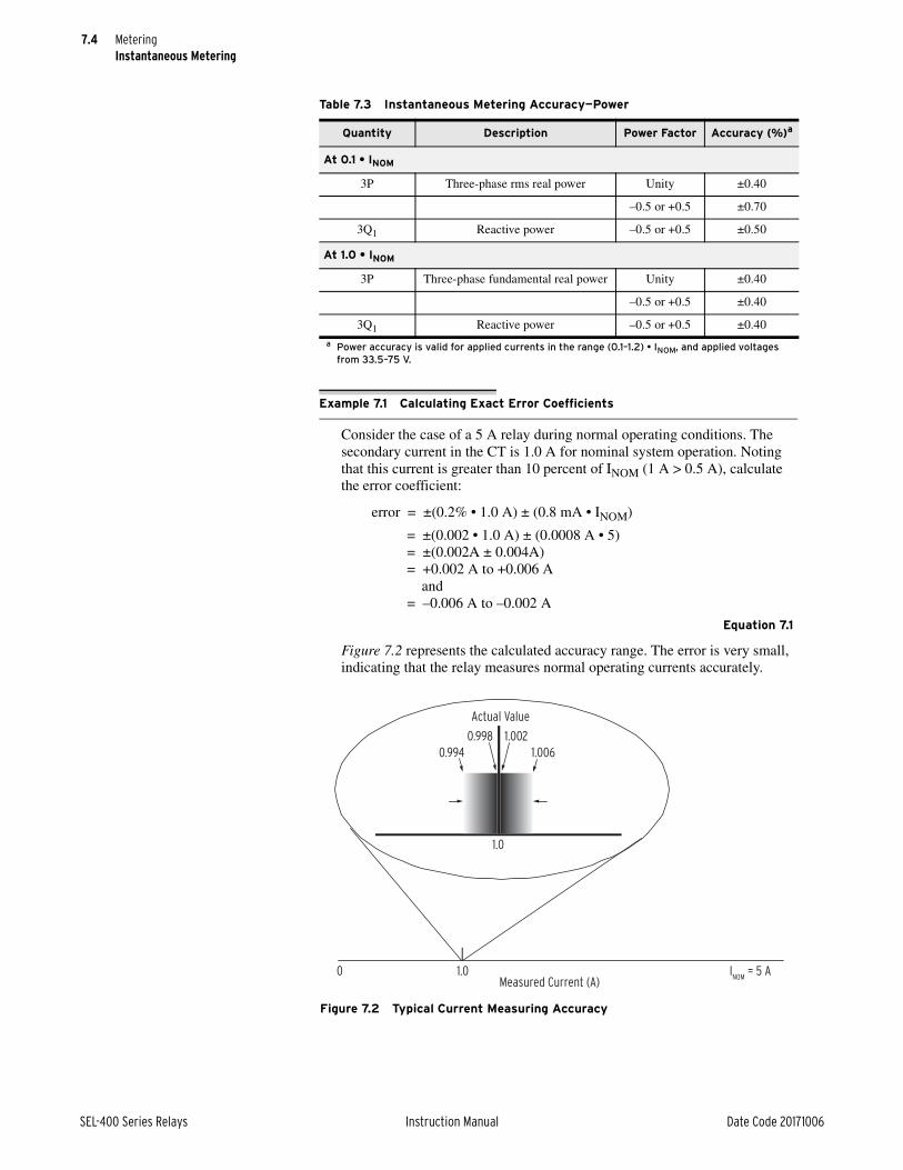
7.4
SEL-400 Series Relays Instruction Manual Date Code 20171006
MeteringInstantaneous Metering
Table 7.3 Instantaneous Metering Accuracy—Power
Quantity Description Power Factor Accuracy (%)a
a Power accuracy is valid for applied currents in the range (0.1–1.2) • INOM, and applied voltages from 33.5–75 V.
At 0.1 • INOM
3P Three-phase rms real power Unity ±0.40
–0.5 or +0.5 ±0.70
3Q1 Reactive power –0.5 or +0.5 ±0.50
At 1.0 • INOM
3P Three-phase fundamental real power Unity ±0.40
–0.5 or +0.5 ±0.40
3Q1 Reactive power –0.5 or +0.5 ±0.40
Example 7.1 Calculating Exact Error Coefficients
Consider the case of a 5 A relay during normal operating conditions. The secondary current in the CT is 1.0 A for nominal system operation. Noting that this current is greater than 10 percent of INOM (1 A > 0.5 A), calculate the error coefficient:
error = ±(0.2% • 1.0 A) ± (0.8 mA • INOM)
= ±(0.002 • 1.0 A) ± (0.0008 A • 5) = ±(0.002A ± 0.004A) = +0.002 A to +0.006 A and = –0.006 A to –0.002 A
Equation 7.1
Figure 7.2 represents the calculated accuracy range. The error is very small, indicating that the relay measures normal operating currents accurately.
Figure 7.2 Typical Current Measuring Accuracy
Measured Current (A)
0.994
0.998
1.006
1.002
0 1.0
1.0
INOM
= 5 A
Actual Value

7.5
Date Code 20171006 Instruction Manual SEL-400 Series Relays
MeteringMaximum/Minimum Metering
Maximum/Minimum MeteringThe relay measures and retains the deviations of the power system since the last maximum/minimum reset. Knowing these maximum and minimum quantities can help you operate your power system more effectively in a variety of ways. For example, you can benefit from maximum/minimum metering information by using it to track power flow for troubleshooting, planning future expansion, and scheduling maintenance.
NOTE: Not all SEL-400 series relays support maximum/minimum metering.
The relay provides maximum/minimum metering for a variety of line and breaker quantities, as well as for dc battery voltage. The relay also records the maximum values of the sequence voltages and sequence currents.
View or Reset Maximum/Minimum Metering InformationThe relay shows time stamped maximum/minimum quantities when you use a communications port or ACSELERATOR QuickSet SEL-5030 Software to view these quantities. In addition, you can read the maximum/minimum quantities on the relay front-panel LCD screen.
To reset the maximum/minimum values, use the MET RM command from a communications terminal, or use the RESET button in the QuickSet HMI > Meter and Control > Maximum/Minimum window, or answer Y and press ENT at the Maximum/Minimum submenu reset prompt on the front-panel LCD screen. You can also reset maximum/minimum metering with Global settings (typically RST-MML, RSTMMB1, and RSTMMB2).
Maximum/Minimum Metering Updating and StorageThe relay updates maximum/minimum values once per power system cycle. The relay stores maximum/minimum values and the corresponding dates and times to nonvolatile storage once per day. If greater than a previously stored maximum or less than a previously stored minimum, the new value overwrites the previous value. Should the relay lose control power, it will restore the maximum/minimum information saved at 23:50 hours on the previous day.
The relay updates maximum/minimum values under the following conditions:
➤ DFAULT is deasserted (equals logical 0)
➤ The metering value is greater than the previous maximum, or less than the previous minimum, for 2 cycles
➤ Voltage input is greater than 13 V secondary
➤ Current input is greater than 0.05 • INOM (in secondary amperes)
Megawatt and megavar maximum/minimum values are subject to the above volt-age thresholds, current thresholds, and conditions.
When you use Equation 7.1, you add an error amount related to the nominal current rating of the relay, INOM. Use just the numeric portion of INOM, either “5” for a 5 A relay or “1” for a 1 A relay; do not use the unit (A). The errors in Equation 7.1 are very small and qualify the relay as a high-accuracy meter.
Example 7.1 Calculating Exact Error Coefficients (Continued)

7.6
SEL-400 Series Relays Instruction Manual Date Code 20171006
MeteringDemand Metering
FAULT SELOGIC Control EquationThe relay suspends updating maximum/minimum metering when SELOGIC con-trol equation FAULT asserts to logical 1. If there is a fault, the elements pro-grammed in FAULT pick up and assert Relay Word bit DFAULT (Delayed FAULT Suspend). This Relay Word bit remains asserted for one minute after SELOGIC control equation FAULT deasserts. While DFAULT is asserted, the relay does not record maximum/minimum data.
In addition, the relay also suspends demand metering during the time that Relay Word bit DFAULT is asserted.
Demand MeteringEconomic operation of the power system involves the proper allocation of the load demand among the available generating units. By knowing the demand requirements at different points in the system and at different times of the day you can optimize your system generation resources or your consumption of elec-tric power. The relay provides you this demand information and enables you to operate your power system with an effective economic strategy.
NOTE: Not all SEL-400 series relays support demand metering.
The relay uses longer-term accumulations of the metering quantities for reliable demand data.
Thermal Demand and Rolling DemandTwo methods exist for measuring power system current and power demand. These methods are thermal demand metering and rolling demand metering. Figure 7.3 and Figure 7.4 illustrate the step input response of the two demand measuring methods with setting DMTC (demand meter time constant) at 15 min-utes.
Thermal DemandThermal demand is a continuous exponentially increasing or decreasing accumu-lation of metered quantities. Thermal demand measurement is similar to parallel RC network integration. Thermal demand metering response is at 90 percent (0.9 per unit) of the full applied value after a period equal to the DMTC setting (15 minutes in Figure 7.3).
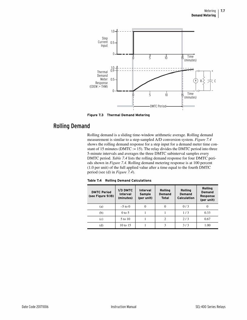
7.7
Date Code 20171006 Instruction Manual SEL-400 Series Relays
MeteringDemand Metering
Rolling DemandRolling demand is a sliding time-window arithmetic average. Rolling demand measurement is similar to a step-sampled A/D conversion system. Figure 7.4 shows the rolling demand response for a step input for a demand meter time con-stant of 15 minutes (DMTC := 15). The relay divides the DMTC period into three 5-minute intervals and averages the three DMTC subinterval samples every DMTC period. Table 7.4 lists the rolling demand response for four DMTC peri-ods shown in Figure 7.4. Rolling demand metering response is at 100 percent (1.0 per unit) of the full applied value after a time equal to the fourth DMTC period (see (d) in Figure 7.4).
Figure 7.3 Thermal Demand Metering
StepCurrent
Input
ThermalDemand
MeterResponse
(EDEM := THM)
1.0
1.00.9
0.5
0
0.5
0
0 5 10 15
0 5 10 15
Time(minutes)
DMTC Period
Time(minutes)
R C
—
+
Table 7.4 Rolling Demand Calculations
DMTC Period (see Figure 9.18)
1/3 DMTC Interval
(minutes)
Interval Sample
(per unit)
Rolling Demand
Total
Rolling Demand
Calculation
Rolling Demand
Response (per unit)
(a) –5 to 0 0 0 0 / 3 0
(b) 0 to 5 1 1 1 / 3 0.33
(c) 5 to 10 1 2 2 / 3 0.67
(d) 10 to 15 1 3 3 / 3 1.00
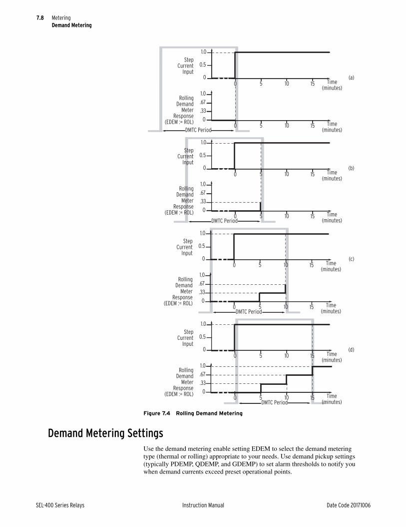
7.8
SEL-400 Series Relays Instruction Manual Date Code 20171006
MeteringDemand Metering
Demand Metering SettingsUse the demand metering enable setting EDEM to select the demand metering type (thermal or rolling) appropriate to your needs. Use demand pickup settings (typically PDEMP, QDEMP, and GDEMP) to set alarm thresholds to notify you when demand currents exceed preset operational points.
Figure 7.4 Rolling Demand Metering
StepCurrent
Input
RollingDemand
MeterResponse
(EDEM := ROL)
1.0
1.0
.67
.33
0
0.5
0
DMTC Period
(a)0 5 10 15 Time
(minutes)
0 5 10 15 Time(minutes)
StepCurrent
Input
RollingDemand
MeterResponse
(EDEM := ROL)
1.0
1.0
.67
.33
0
0.5
0
DMTC Period
(b)0 5 10 15 Time
(minutes)
0 5 10 15 Time(minutes)
StepCurrent
Input
RollingDemand
MeterResponse
(EDEM := ROL)
1.0
1.0
.67
.33
0
0.5
0
DMTC Period
(c)0 5 10 15 Time
(minutes)
0 5 10 15 Time(minutes)
StepCurrent
Input
RollingDemand
MeterResponse
(EDEM := ROL)
1.0
1.0
.67
.33
0
0.5
0
DMTC Period
0 5 10 15 Time(minutes)
0 5 10 15 Time(minutes)
(d)

7.9
Date Code 20171006 Instruction Manual SEL-400 Series Relays
MeteringDemand Metering
NOTE: Changing EDEM or DMTC resets the demand meter values to zero. This also applies to changing the active settings group where either setting EDEM or DMTC is different in the new active settings group. (Changing demand current pickup settings PDEMP, GDEMP, and QDEMP will not affect the demand meters.)
Figure 7.5 shows how the relay applies the demand current pickup settings over time. When residual ground demand current IG(DEM) exceeds the correspond-ing demand pickup setting GDEMP, Relay Word bit GDEM asserts to logical 1. Use these demand current logic outputs (PDEM, GDEM, and QDEM) for control or alarm for high loading or unbalance conditions.
View or Reset Demand Metering InformationThe relay shows demand metering quantities and time-stamped peak demand quantities when you use a communications port or QuickSet to view these quanti-ties. In addition, you can read the demand and peak demand quantities on the relay front-panel LCD screen.
To reset the demand metering values use the MET RD command from a commu-nications terminal, or use the RESET button in the QuickSet HMI > Meter and Control > Demand/Peak window, or answer Y and press ENT at the Demand Sub-menu reset demand prompt on the front-panel LCD screen. The relay begins the demand meter sampling period from the time of the demand meter reset.
To reset the peak demand metering values, enter the MET RP command from a communications terminal, or use the RESET button in the QuickSet HMI > Meter and Control > Demand/Peak window, or answer Y and press ENT at the Demand Submenu reset peak demand prompt on the front-panel LCD screen. You can also reset demand metering with Global settings RST_DEM and RST_PDM (for demand and peak demand) when EDRSTC (Data Reset Control) is Y.
Figure 7.5 Demand Current Logic Outputs
setting EDEM change,or setting DMTC change
Demand Function
Thermal (EDEM := THM)or
Rolling (EDEM := ROL)
Demand Function
Thermal (EDEM := THM)or
Rolling (EDEM := ROL)
Demand Function
Thermal (EDEM := THM)or
Rolling (EDEM := ROL)
IA
IG
(Residual)
3I2
3I2(DEM)
(Residual)
Command
MET RD,
_
+
_
+
max.phase
demandcurrent
DemandCurrents
Relay Word Bits
Demand Currents Pickup Settings
IA(DEM)
IB(DEM)
IC(DEM)
IG(DEM)
PDEMP
GDEMP
_
+
QDEMP
Reset Demand
Reset Demand
Reset Demand
PDEM
GDEM
QDEM
Instantaneous Currents

7.10
SEL-400 Series Relays Instruction Manual Date Code 20171006
MeteringEnergy Metering
Demand Metering Updating and StorageThe relay updates demand and peak demand values once per second. The relay also stores peak demand values and the date and time these occurred to nonvola-tile storage once per day (it overwrites the previous stored value if it is exceeded). Should the relay lose control power, it will restore the peak demand information saved at 23:50 hours on the previous day.
Demand metering updating and peak recording is suspended during the time that SELOGIC control equation FAULT asserts Relay Word bit DFAULT (Delayed FAULT Suspend).
Energy MeteringEnergy is the power consumed or developed in the electric power system mea-sured over time. You can use accurate accounting of power system energy flow to manage billing revenues, whether your system is a net energy producer or con-sumer. Time-synchronized demand and energy measurements make demand and energy metering information even more useful for power system status applica-tions.
NOTE: Not all SEL-400 series relays support energy metering.
The relay integrates energy imported and exported on a per-phase basis every second. As in demand metering, the relay uses the longer-term accumulations of rms or true real power for reliable energy data.
View or Reset Energy Metering InformationYou can read the energy metering quantities by using a communications port, QuickSet, or the relay front-panel LCD screen.
To reset the energy values, use the MET RE command from a communications terminal, or use the RESET button in the QuickSet HMI > Meter and Control > Energy window, or answer Y and press ENT at the Energy Meter submenu reset prompt on the front-panel LCD screen. You can also reset energy metering with Global setting RST_ENE when EDRSTC (Data Reset Control) is Y.
Energy Metering Updating and StorageThe relay updates energy values once per second. The relay also stores energy values to nonvolatile storage once every four hours, referenced from 23:50 hours (it overwrites the previously stored value if it is exceeded). Should the relay lose control power, it restores the energy values saved at the end of the last four-hour period.
Synchrophasor MeteringThe relay provides synchrophasor measurement with an angle reference accord-ing to IEEE C37.118. The relay calculates the phasor measurement quantities 50 or 60 times per second, depending on the nominal system frequency contained in Global setting NFREQ.

7.11
Date Code 20171006 Instruction Manual SEL-400 Series Relays
MeteringBattery Metering
NOTE: Not all SEL-400 series relays support synchrophasor measurements.
When you issue the MET PM time command, the relay captures the time-syn-chronized data for the given trigger time (specify time in 24-hour format). The relay displays the synchrophasor data immediately after the time trigger.
The synchrophasor measurements are only valid when a suitable high-accuracy IRIG-B or PTP time source is connected to the relay, as indicated by Relay Word bit TSOK = logical 1.
The MET PM command is only available when the relay is configured for phasor measurement functions (Global settings) and the relay is in high-accuracy time-keeping mode.
Battery MeteringThe relay monitors battery system voltages and records time stamps for voltage excursions. In addition, the relay records maximum and minimum battery volt-ages. Figure 7.6 shows a sample dc battery monitor meter report. Use the MET BAT command from a communications terminal to obtain this report.
Any battery voltage between setting DCLWP and the dc battery monitor low limit of 15 Vdc is in the L-Zone. Battery voltages in the H-Zone are voltages higher than the DCHWP setting.
Use the MET RBM command from a communications terminal to reset the dc battery monitor. You can program a SELOGIC control equation RST_BAT (in Monitor settings) to control dc battery monitor reset.
=>>MET BAT <Enter> Relay 1 Date: 06/07/2008 Time: 22:51:47.067 Station A Serial Number: 2008030645 Station Battery VDC VDCPO VDCNE VAC VDC1 (V) 115.86 57.32 -58.54 0.01 VDC1(V) Date Time Minimum 105.86 04/07/2008 22:43:04.022Enter L-Zone 04/07/2008 22:40:14.162Exit L-Zone 04/07/2008 22:44:09.223
Maximum 125.86 04/09/2008 12:34:14.321 Enter H-Zone 04/09/2008 12:31:32.543 Exit H-Zone 04/09/2008 12:35:12.657 LAST DC RESET: 01/15/2008 20:10:31.427 =>>
Figure 7.6 Battery Metering: Terminal

7.12
SEL-400 Series Relays Instruction Manual Date Code 20171006
MeteringRTD Metering
RTD MeteringUse the MET RTD command to display the RTD values, as shown in Figure 7.7.
Protection Math Variable MeteringUse the MET PMV command to display all 64 PMV values, as shown in Figure 7.8.
=>>MET RTD <Enter> Relay 1 Date: 04/12/2008 Time: 06:06:31.366 Station A Serial Number: 2008030645 RTD Input Temperature Data (deg. C)RTD 1 = -50RTD 2 = 250
RTD 3 = 0RTD 4 = 45RTD 5 = 34RTD 6 = 65RTD 7 = -23RTD 8 = 39RTD 9 = 23RTD 10 = 11RTD 11 = 54RTD 12 = 78 =>>
Figure 7.7 RTD Report
=>>MET PMV <Enter> Relay 1 Date: 04/07/2008 Time: 21:03:40.451 Station A Serial Number: 2008030645 Protection Analog Quantities PMV01 = 0.000 PMV02 = 0.000 PMV03 = 0.000 PMV04 = 0.000 PMV05 = 0.000 PMV06 = 0.000 PMV07 = 0.000 PMV08 = 0.000 PMV09 = 0.000 PMV10 = 0.000 PMV11 = 0.000 PMV12 = 0.000 PMV13 = 0.000 PMV14 = 0.000 PMV15 = 0.000 PMV16 = 0.000 PMV17 = 0.000 PMV18 = 0.000
PMV19 = 0.000 PMV20 = 0.000 PMV21 = 0.000 PMV22 = 0.000 PMV23 = 0.000 PMV24 = 0.000 PMV25 = 0.000 PMV26 = 0.000 PMV27 = 0.000 PMV28 = 0.000 PMV29 = 0.000 PMV30 = 0.000 PMV31 = 0.000 PMV32 = 0.000 PMV33 = 0.000 PMV34 = 0.000 PMV35 = 0.000 PMV36 = 0.000 PMV37 = 0.000 PMV38 = 0.000 PMV39 = 0.000 PMV40 = 0.000 PMV41 = 0.000 PMV42 = 0.000
PMV43 = 0.000 PMV44 = 0.000 PMV45 = 0.000 PMV46 = 0.000 PMV47 = 0.000 PMV48 = 0.000 PMV49 = 0.000 PMV50 = 0.000 PMV51 = 0.000 PMV52 = 0.000 PMV53 = 0.000 PMV54 = 0.000 PMV55 = 0.000 PMV56 = 0.000 PMV57 = 0.000 PMV58 = 0.000 PMV59 = 0.000 PMV60 = 0.000 PMV61 = 0.000 PMV62 = 0.000 PMV63 = 0.000 PMV64 = 0.000 =>>
Figure 7.8 PMV Report

7.13
Date Code 20171006 Instruction Manual SEL-400 Series Relays
MeteringAutomation Math Variable Metering
Automation Math Variable MeteringUse the MET AMV command to display all 256 AMV values, as shown in Figure 7.9.
MIRRORED BITS Remote Analog MeteringUse the MET ANA command to display the analog values used with MIRRORED BITS communications, as shown in Table 7.5.
=>>MET AMV <Enter> Relay 1 Date: 04/07/2008 Time: 21:04:33.579 Station A Serial Number: 2008030645 Automation Analog Quantities AMV001 = 0.000 AMV002 = 0.000 AMV003 = 0.000 AMV004 = 0.000 AMV005 = 0.000 AMV006 = 0.000 AMV007 = 0.000 AMV008 = 0.000 AMV009 = 0.000 AMV010 = 0.000 AMV011 = 0.000 AMV012 = 0.000
AMV013 = 0.000 AMV014 = 0.000 AMV015 = 0.000 . . .
AMV238 = 0.000 AMV239 = 0.000 AMV240 = 0.000 AMV241 = 0.000 AMV242 = 0.000 AMV243 = 0.000 AMV244 = 0.000 AMV245 = 0.000 AMV246 = 0.000 AMV247 = 0.000 AMV248 = 0.000 AMV249 = 0.000
AMV250 = 0.000 AMV251 = 0.000 AMV252 = 0.000 AMV253 = 0.000 AMV254 = 0.000 AMV255 = 0.000 AMV256 = 0.000 =>>
Figure 7.9 AMV Report
Table 7.5 Information Available With the MET ANA Command
Command Information
MET ANA Analog value in channel A
Analog value in channel B

This page intentionally left blank

Date Code 20171006 Instruction Manual SEL-400 Series Relays
Instruction ManualS E C T I O N 8
Monitoring
The relay provides extensive capabilities for monitoring substation components. Most SEL-400 series relays provide the following useful features:
➤ Circuit Breaker Monitor on page 8.1
➤ Station DC Battery System Monitor on page 8.21
This section describes monitoring capabilities that are common to many SEL-400 series relays. Some relays include additional monitoring capabilities that are not common to other SEL-4 series relays. See the relay specific instruction manuals to determine the specific monitoring features available in each relay.
Circuit Breaker MonitorThe relay features advanced circuit breaker monitoring. Figure 8.1 shows that the relay processes phase currents, circuit breaker auxiliary contacts, and the substa-tion dc battery voltages to detect out-of-tolerance and maximum life circuit breaker parameters. These parameters include current interrupted, operating times, and contact wear. By using relay monitoring, maintenance personnel can determine the extent of a developing circuit breaker problem and select an appro-priate response to correct the problem. These monitoring features are available online in real-time; you can detect impending problems immediately. The result is better power system reliability and improved circuit breaker life expectancy.
NOTE: This section lists settings for Circuit Breaker 1. The number of circuit breakers and the circuit breaker references vary between relays. See the product-specific instruction manual for the specific breakers available for circuit breaker monitoring.
One of the many circuit breaker monitor features is the circuit breaker contact wear monitor. The relay tracks the number of circuit breaker close-open opera-tions and respective fault interrupting levels for each of two circuit breakers. The relay uses data from the circuit breaker manufacturer to compare the recorded operational data with the manufacturer’s recommended maintenance require-ments. The relay notifies you when each set of circuit breaker pole contacts exceeds preset wear thresholds. Using this information, you can operate your substation more economically by accurately scheduling circuit breaker mainte-nance.
You can also collect the following data on these circuit breaker parameters:
➤ Circuit breaker wear
➤ Electrical operating time
➤ Mechanical operating time
➤ Circuit breaker inactivity time
➤ Interrupted current
➤ Pole scatter (for single-pole breakers only)
➤ Pole discrepancy (for single-pole breakers only)
➤ Motor run time

8.2
SEL-400 Series Relays Instruction Manual Date Code 20171006
MonitoringCircuit Breaker Monitor
You can program the relay to alarm when any of the above quantities exceed a preset threshold. In addition, the relay stores a 128-event circuit breaker history in nonvolatile memory. The circuit breaker history report includes circuit breaker mechanical operation times, electrical operation times, interrupted currents, and other important parameters. The alarm and reporting features help you operate your substation safely and reliably.
Enabling the Circuit Breaker MonitorNOTE: Some SEL-400 series relays do not support single-pole tripping breakers. In these cases, the corresponding BKnTYP setting is not available and only information related to three-pole breakers will be available.
Enable and configure the relay circuit breaker monitor by using the settings listed in Table 8.1 for each of two possible circuit breakers. Power system circuit break-ers are either single-pole tripping or three-pole tripping circuit breakers; set the relay for the circuit breaker type that the relay controls. For a single-pole tripping circuit breaker, set BK1TYP := 1, and for a three-pole tripping circuit breaker, set BK1TYP := 3. The factory default setting is BK1TYP := 1. Be sure to configure the relay with the settings that match your circuit breakers.
NOTE: Some SEL-400 series relays use a BK_SEL setting to list enabled breakers, rather than the EBnMON settings shown here.
Circuit Breaker Contact Wear MonitorThe circuit breaker contact wear monitor in the relay provides information that helps you schedule circuit breaker maintenance. This monitoring function accu-mulates the number of close-open operations and integrates the per-phase current during each opening operation. The relay compares this information to a pre-defined circuit breaker maintenance curve to calculate the percent contact wear on a per-pole basis.
Figure 8.1 Intelligent Circuit Breaker Monitor
Relay
Circuit
Breaker
Monitor
Aux. Contact Inputs
Phase Currents
Excess BreakerContact Wear
Excess MechanicalOperating Time
Excess ElectricalOperating Time
Excess Pole Scatteror Pole Discrepancy
Excess BreakerInactivity Time
Excess MotorRunning Time
Excess kA Interrupted
Deviations in StationBattery Voltages
Station Battery Voltages
Table 8.1 Circuit Breaker Monitor Configuration
Name Description Range
EB1MON Enable Circuit Breaker 1 monitoring Y, N
BK1TYP Circuit Breaker 1 type 1, 3
EB2MON Enable Circuit Breaker 2 monitoring Y, N
BK2TYP Circuit Breaker 2 type 1, 3

8.3
Date Code 20171006 Instruction Manual SEL-400 Series Relays
MonitoringCircuit Breaker Monitor
The circuit breaker maintenance curve also incorporates the accumulated fault current arcing time (I2t), assuming an identical arcing time for each trip. You can obtain the one-cycle arcing time from circuit breaker manufacturer data.
The relay updates and stores the contact wear information and the number of trip operations in nonvolatile memory. You can view this information through any communications port.
Any phase wear percentage that exceeds the threshold setting B1BCWAT asserts the alarm Relay Word bit, B1BCWAL, for Circuit Breaker 1. You can use this Relay Word bit in a SELOGIC control equation to alert operations personnel, or you can control other functions such as blocking reclosing. The relay limits the maximum reported circuit breaker wear percentage to 150 percent.
NOTE: In the following discussion, three elements are specified, one for each phase: = A, B, and C.
The relay integrates currents and increments the trip counters for the contact wear monitor each time the SELOGIC control equation BM1TRP asserts. Set the logic for this function from a communications port with the SET M ASCII command, with the ACSELERATOR QuickSet SEL-5030 software program Breaker Moni-tor Settings tree view, or by using the front-panel SET/SHOW menu. (See Making Simple Settings Changes on page 3.15 for information on setting the relay using these methods.) The default settings cause the contact wear monitor to integrate and increment each time the relay trip logic asserts.
Perform the following specific steps to use the circuit breaker contact wear monitor:
Step 1. Enable the circuit breaker monitor.
Step 2. Load the manufacturer’s circuit breaker maintenance data.
Step 3. Preload any existing circuit breaker wear (if setting up the contact wear monitor on a circuit breaker with preexisting service time).
Step 4. Program the SELOGIC control equations for trip and close conditions.
Enable the Circuit Breaker MonitorYou must enable the circuit breaker monitor before you load the manufacturer’s data, preload any existing circuit breaker wear, and set the trip initiate and close initiate SELOGIC control equations. Set the circuit breaker monitor enable setting EBxMON to Y (for Yes) for Breaker x.
Load Manufacturer Circuit Breaker Maintenance DataLoad the maintenance data supplied by the circuit breaker manufacturer. Circuit breaker maintenance information lists the number of permissible operating cycles (close/open operations) for a given current interruption level. Table 8.2 shows typical circuit breaker maintenance information from an actual SF6 circuit breaker. The Figure 8.2 log/log plot is the circuit breaker maintenance curve, pro-duced from the Table 8.2 data.
Table 8.2 Circuit Breaker Maintenance Information—Example (Sheet 1 of 2)
Current Interruption Level (kA) Permissible Close/Open Operations
0.00–1.2 10000
2.00 3700
3.00 1500
5.00 400
8.00 150

8.4
SEL-400 Series Relays Instruction Manual Date Code 20171006
MonitoringCircuit Breaker Monitor
The three set points necessary to reproduce this circuit breaker maintenance curve in the relay are listed in Table 8.3 for Circuit Breaker 1. Figure 8.3 shows how to determine these three set points from the maintenance curve shown in Figure 8.2.
10.00 85
20.00 12
Figure 8.2 Circuit Breaker Maintenance Curve (Manufacturer’s Data)
Table 8.3 Contact Wear Monitor Settings—Circuit Breaker 1
Setting Definition Range
B1COSP1 Close/open set point 1—max 0–65000 close/open operations
B1COSP2 Close/open set point 2—mid 0–65000 close/open operations
B1COSP3 Close/open set point 3—min 0–65000 close/open operations
B1KASP1a
a The ratio of settings B1KASP3/B1KASP1 must be in the range: 5 B1KASP3/B1KASP1 100.
kA interrupted set point 1—min 1.0–999 kA in 0.1-kA steps
B1KASP2 kA interrupted set point 2—mid 1.0–999 kA in 0.1-kA steps
B1KASP3a kA interrupted set point 3—max 1.0–999 kA in 0.1-kA steps
Table 8.2 Circuit Breaker Maintenance Information—Example (Sheet 2 of 2)
Current Interruption Level (kA) Permissible Close/Open Operations
1 10 100
kA Interrupted per Operation (kA)
Num
ber o
f Clo
se/O
pen
Oper
atio
ns
10000
1000
100
10

8.5
Date Code 20171006 Instruction Manual SEL-400 Series Relays
MonitoringCircuit Breaker Monitor
Circuit Breaker Contact Wear Curve DetailsCircuit breaker maintenance information from the two end values of Table 8.2 or Figure 8.2 determine set point (B1KASP1, B1COSP1) and set point (B1KASP3, B1COSP3) for the contact wear curve of Figure 8.3. Set point (B1KASP2, B1COSP2) is the middle maintenance point in these data. There are two philoso-phies for selecting the middle set point. One method places the middle set point to provide the best “curve-fit” for your plot of the manufacturer’s circuit breaker maintenance data (shown in Figure 8.2). Another philosophy is to set the middle point based on actual experience or fault studies of the typical system faults.
There are two other notable portions of the circuit breaker contact wear curve in Figure 8.3. The curve is horizontal below the left set point (B1KASP1, B1CO-SP1). This is the close/open operation limit regardless of interrupted current value (for the Example 8.1 circuit breaker, this is at B1COSP1 := 10000). Some manufacturers call this point the mechanical circuit breaker service life.
Figure 8.3 Circuit Breaker Contact Wear Curve With Relay Settings
B1COSP2
1 10 100
kA Interrupted per Operation (kA)
Num
ber
of C
lose
/Ope
n O
pera
tion
s
10000
1000
100
10B1COSP3
B1KASP1 B1KASP2 B1KASP3
(B1KASP1, B1COSP1)
(B1KASP2, B1COSP2)
(B1KASP3, B1COSP3)
B1COSP1
Example 8.1 Creating the Circuit Breaker Contact Wear Curve
Acquire the manufacturer’s maintenance information (this example uses the data of Table 8.2 for Circuit Breaker 1). If you receive the data in tabular form, plot the manufacturer’s maintenance information on log/log paper in a manner similar to Figure 8.2.
Choose the left and right set points from the extremes of the curve you just plotted. Select the left set point on the contact wear curve corresponding to (B1KASP1, B1COSP1) by setting B1KASP1 := 1.2 and B1COSP1 := 10000. Plot the right set point (B1KASP3, B1COSP3) by setting B1KASP3 := 20.0 and B1COSP3 := 12.
Choose the midpoint of the contact wear curve based on your experience and system fault studies. The majority of operations for a typical circuit breaker are to interrupt single-line-to-ground faults. Therefore, plot the midpoint (B1KASP2, B1COSP2) by setting B1KASP2 at or slightly greater than the expected single-line-to-ground fault current: B1KASP2 := 8.0 and B1COSP2 := 150.

8.6
SEL-400 Series Relays Instruction Manual Date Code 20171006
MonitoringCircuit Breaker Monitor
Another part of the circuit breaker maintenance curve falls vertically at the right set point (B1KASP3, B1COSP3). This is the maximum interrupted current limit (for the Example 8.1 circuit breaker, this is at B1KASP3 := 20.0). If the inter-rupted current exceeds setting B1KASP3, the relay sets contact wear at 105 percent.
Preloading Contact Wear DataUpon the first commissioning of the relay, the associated circuit breakers can already have some wear. You can preload a separate amount of wear for each pole of each circuit to preload existing contact wear data. The relay accepts integer values of percentage wear as great as 100 percent. The relay adds the incremental contact wear at the next circuit breaker monitor initiation (and at all subsequent initiations) to the preloaded value to obtain a total wear value. The limit for reporting circuit breaker contact wear is 150 percent for each pole.
Example 8.2 I2t Criteria Application
Some circuit breaker manufacturers do not provide a circuit breaker mainte-nance curve, but specify the accumulated fault current arcing time (I2t) for circuit breaker maintenance. For example, manufacturer’s data specify I2t per phase at 750 kA2 seconds for a particular circuit breaker, at a rated arcing duration for each trip of 1 cycle. The circuit breaker maximum interrupting current rating is 40 kA, and the continuous load current rating is 2 kA.
You can construct the contact wear curve for this circuit breaker from the specified I2t. Choose B1KASP1 := 2.0 (the continuous current rating) and B1KASP3 := 40.0 (the maximum interrupting current rating). Choose the middle of the contact wear curve based on experience and system fault stud-ies. The majority of faults a typical circuit breaker interrupts are single-line-to-ground faults. Therefore, set BnKASP2 at or slightly greater than the expected single-line-to-ground fault current (B1KASP2 := 10.0 kA in this example). Using the following equations, calculate these settings points to obtain the number of close/open operations:
Equation 8.1
Equation 8.2
Equation 8.3
In these equations, tarc is the arcing time in seconds; tarc = (1/fNOM)• (arc duration in cycles); fNOM is the nominal power system frequency (50 Hz or 60 Hz). These calculations show the number of close/open operations rounded to the nearest unit.
B1COSP1 = I2t
(B1KASP1)2 • tarc
----------------------------------------------750
22• (0.01667 • 1)----------------------------------------- := 11250=
B1COSP2 = I2t
(B1KASP2)2• tarc
--------------------------------------------750
102• (0.01667 • 1)-------------------------------------------- := 450=
B1COSP3 = I2t
(B1KASP3)2• tarc
--------------------------------------------750
402• (0.01667 • 1)-------------------------------------------- := 28=

8.7
Date Code 20171006 Instruction Manual SEL-400 Series Relays
MonitoringCircuit Breaker Monitor
Program the SELOGIC Control Equations for Trip and Close ConditionsCircuit Breaker Monitor Trip Initiation Settings: BM1TRP
NOTE: In the following discussion, three elements are specified. There is one element for each phase: = A, B, and C. With three-pole breakers, only phase A is used to represent the entire breaker. Some three-pole relays include A in the names and others disregard it.
The relay employs SELOGIC control equations to initiate the circuit breaker mon-itor. For Circuit Breaker 1, this setting is BM1TRP. These SELOGIC control equations use Relay Word bits to determine when the circuit breaker monitor accumulates circuit breaker operating parameters from phases A, B, and C. When detecting a rising edge (a transition from logical 0 to logical 1) of the initiation settings, the relay accumulates the interrupted rms currents and advances the trip counter by one count. There are separate current accumulators and trip counters for each circuit breaker pole. Table 8.4 shows the factory-default settings for cir-cuit breaker monitor initiation.
NOTE: Factory defaults differ for single-pole tripping and three-pole tripping. Three-pole tripping uses the single setting BM1TRPA for all three poles.
Initiation settings can include both internal and external tripping conditions. To capture trip information initiated by devices other than the relay, you must pro-gram the SELOGIC control equation BM1TRP to sense these trips.
Table 8.4 Circuit Breaker Monitor Initiate SELOGIC Control Equations
Name Description Commenta
a See Table 8.1.
BM1TRPA BK1 monitor initiate equation If BK1TYP := 3
BM1TRPA A-Phase BK1 monitor initiate equation If BK1TYP := 1
BM1TRPB B-Phase BK1 monitor initiate equation If BK1TYP := 1
BM1TRPC C-Phase BK1 monitor initiate equation If BK1TYP := 1
Example 8.3 Circuit Breaker Monitor External Trip Initiation
Connect external trip signals to the relay control inputs. This example uses input IN201; you can use any control inputs that are appropriate for your installation. Control Input IN201, an optoisolated input, is located on the relay I/O Interface Board #1.
If you want Circuit Breaker Monitor 1 to initiate for the trip elements TPA1, TPB1, and TPC1, or for external trips, set these SELOGIC control equations from the SET M ASCII command or the QuickSet Breaker Monitor Set-tings tree view:
BK1TYP := 1 Breaker 1 Trip Type (Single Pole = 1, Three Pole = 3)
BM1TRPA := TPA1 OR IN201 Breaker Monitor A-Phase Trip Initiate—BK1
BM1TRPB := TPB1 OR IN202 Breaker Monitor B-Phase Trip Initiate—BK1
BM1TRPC := TPC1 OR IN203 Breaker Monitor C-Phase Trip Initiate—BK1

8.8
SEL-400 Series Relays Instruction Manual Date Code 20171006
MonitoringCircuit Breaker Monitor
Example 8.4 Using a Control Input to Capture External and Internal Trip Commands
You can also capture all trip information for circuit breaker trips by using a relay control input to monitor the trip bus for the given circuit breaker. Figure 8.4 shows an illustration of this method in which IN206 connects to the Circuit Breaker 1 A-Phase trip bus (via a parallel connection across the trip bus), and asserts for any trip from any source. This example uses inputs IN206; you can use any control inputs that are appropriate for your installa-tion. Vdc for this example is 125 Vdc.
Many U.S. substation trip bus configurations have an incandescent trip indi-cator lamp from the battery + terminal to the trip bus. This lamp presents an impedance that can provide sufficient “pull-up” on the trip bus to falsely assert the control input. The worst case for this condition occurs when the circuit breaker is open (auxiliary circuit breaker (52A) contact in Figure 8.4 is open). You can change the input debounce time IN206PU for slow or noisy mechanical switches; the default debounce time of 1/8 cycle should be sufficient for most trip bus arrangements.
Use the SET G (GLOBAL) command or the QuickSet Global > Control Inputs Settings tree view to confirm that the debounce time (settings IN206PU and IN206DO) are correct for your trip bus control voltage. You must enable independent control input conditioning by using Global setting EICIS. Enter these settings:
EICIS := Y Independent Control Input Settings (Y, N)
IN206PU := 0.1250 Input IN206 Pickup Delay (0.0000–5 cyc)
IN206DO := 0.1250 Input IN206 Dropout Delay (0.0000–5 cyc)
BM1TRPA := IN206 Breaker Monitor Trip—BK1 (SELOGIC Equation)
Use this procedure to cause the circuit breaker monitor to initiate for either external or internal Circuit Breaker 1 A-Phase trips.
Figure 8.4 Trip Bus Sensing With Relay Input IN206
Other
External
Trips
CS/T
(Control Switch Trip)
52A
Trip
Coil
(+)
(-)
IN206
Relay
OUT201 := TRIP
TC
Trip Bus
Incandescent Lamp

8.9
Date Code 20171006 Instruction Manual SEL-400 Series Relays
MonitoringCircuit Breaker Monitor
Circuit Breaker Monitor Close Initiation Settings: BM1CLSNOTE: In the following discussion, three elements are specified. There is one element for each phase: = A, B, and C. With three-pole breakers, only phase A is used to represent the entire breaker. Some three-pole relays include A in the names and others drop it.
The relay employs SELOGIC control equations to initiate the circuit breaker mon-itor duration timers for close functions. For Circuit Breaker 1, this setting is BM1CLS. These SELOGIC control equations use Relay Word bits to determine when the circuit breaker monitor times mechanical closing, electrical closing, and pole scatter. Table 8.5 shows the factory-default settings for circuit breaker monitor close initiation.
As in Example 8.4 (connection of the trip bus to a control input), you can also capture the circuit breaker close information by using a relay input to monitor the close bus for the given circuit breaker.
Other Circuit Breaker Monitor FunctionskA Interrupt Monitoring
The relay monitors the amount of phase current that each pole of the circuit breaker interrupts at each trip operation. The relay records the interrupted current as a percentage of the circuit breaker maximum interrupting rating specified by the manufacturer. Set the maximum interruption current with setting B1MKAI (Maximum kA Interrupt Rating—BK1). If the percent of current interrupt that the relay records exceeds threshold setting B1KAIAT (kA Interrupt Capacity Alarm Threshold—BK1), the relay asserts breaker monitor alarm Relay Word bit B1KAIAL.
Mechanical Operating TimeThe mechanical operating time is the time between trip initiation or close initia-tion and the associated phase circuit breaker 52A normally open contact status change. (Assertion of 52A1 indicates that a particular circuit breaker phase has closed). The relay measures the tripping times for each phase from the assertion of the respective BM1TRPRelay Word bit to the dropout of the respective 52A1 Relay Word bit. Similarly, for mechanical closing time, the relay mea-sures the closing times for each phase from the assertion of the BM1CLS Relay Word bit to the pickup of the 52A1 Relay Word bit. The relay compares these tripping or closing times to the mechanical slow operation time thresholds for tripping and closing, B1MSTRT and B1MSCLT, respectively. The relay issues a mechanical slow operation alarm, B1MSOAL, for 5 seconds when trip or close times exceed these thresholds. See Figure 8.5 for a Circuit Breaker 1 A-Phase timing diagram.
Table 8.5 Circuit Breaker Monitor Close SELOGIC Control Equations
Name Description Commenta
a See Table 8.1.
BM1CLSA Breaker Monitor 1 close equation If BK1TYP := 3
BM1CLSA Breaker Monitor 1 A-Phase close equation If BK1TYP := 1
BM1CLSB Breaker Monitor 1 B-Phase close equation If BK1TYP := 1
BM1CLSC Breaker Monitor 1 C-Phase close equation If BK1TYP := 1

8.10
SEL-400 Series Relays Instruction Manual Date Code 20171006
MonitoringCircuit Breaker Monitor
Figure 8.5 Mechanical Operating Time for Circuit Breaker 1 A-Phase
Example 8.5 Mechanical Operating Time Settings
Use Circuit Breaker 1, a single-pole tripping circuit breaker, for this exam-ple. Connect the circuit breaker normally open 52A contacts through station battery power to IN201, IN202, and IN203. This example uses inputs IN201, IN202, and IN203 for A-, B-, and C-Phases, respectively; you can use any control inputs that are appropriate for your installation. The control voltage for this example is 125 Vdc.
Control Inputs IN201–IN203 are direct-coupled inputs.
Set the Relay Word bits to respond to these inputs.
52AA1 := IN201 A-Phase N/O Control Input—BK1 (SELOGIC Equation)
52AB1 := IN202 B-Phase N/O Control Input—BK1 (SELOGIC Equation)
52AC1 := IN203 A-Phase N/O Control Input—BK1 (SELOGIC Equation)
Connect external trip signals to IN301, IN302, and IN303, and external close signals to IN304, IN305, and IN306 for the A-, B-, and C-Phases, respec-tively. Use the default settings for input conditioning (debounce time and assertion level), as with inputs IN201 to IN203 above.
Set the mechanical operating time threshold for the slow trip alarm (B1MSTRT) to 30 ms, and the slow close alarm threshold (B1MSCLT) to 70 ms. Use your company standard practices to determine these settings for your application. For this example, enter the following settings:
B1MSTRT := 30 Mechanical Slow Trip Alarm Threshold—BK1(1–999 ms)
B1MSCLT := 70 Mechanical Slow Close Alarm Threshold—BK1(1–999 ms)
EB1MON := Y Breaker 1 Monitoring (Y, N)
BK1TYP := 1 Breaker 1 Trip Type (Single Pole = 1, Three Pole = 3)
BM1TRPA := TPA1 OR IN301 Breaker Monitor A-Phase Trip—BK1 (SELOGIC Equation)
BM1TRPB := TPB1 OR IN302 Breaker Monitor B-Phase Trip—BK1 (SELOGIC Equation)
BM1TRPC := TPC1 OR IN303 Breaker Monitor C-Phase Trip—BK1 (SELOGIC Equation)
BM1TRPA(A-Phase Trip)
52AA1
Mechanical Tripping Time
BM1CLSA(A-Phase Close)
52AA1Mechanical Closing Time

8.11
Date Code 20171006 Instruction Manual SEL-400 Series Relays
MonitoringCircuit Breaker Monitor
The relay makes a further check on the auxiliary circuit breaker (52A) contacts by testing whether these circuit breaker contacts have changed state within approximately 100 ms after the end of the trip or close threshold times. Thus, this additional check serves as the trip time-out and close time-out condition. This check verifies that the circuit breaker actually closed or opened, and it alerts you if maintenance is required on the circuit breaker mechanical linkages or auxiliary (52) contacts.
Electrical Operating TimeThe electrical operating time is the time between trip or close initiation and an open-phase status change. For both circuit breakers, the relay measures the trip-ping time for each phase from the assertion of the BM1TRP Relay Word bit to the time the relay detects an open-phase condition. Similarly, the relay measures electrical operating time for closing each phase from the assertion of BM1CLS to the restoration of phase quantities. The relay compares these tripping or clos-ing times to the electrical slow operation time thresholds for tripping and closing, B1ESTRT and B1ESCLT, respectively. The relay issues an electrical slow opera-tion alarm, B1ESOAL, for 5 seconds when trip or close times exceed these thresh-olds. Figure 8.6 shows the timing diagram for the A-Phase pole of Circuit Breaker 1.
BM1CLSA := BK1CL OR IN304 Breaker Monitor A-Phase Close—BK1 (SELOGIC Equation)
BM1CLSB := BK1CL OR IN305 Breaker Monitor B-Phase Close—BK1 (SELOGIC Equation)
BM1CLSC := BK1CL OR IN306 Breaker Monitor C-Phase Close—BK1 (SELOGIC Equation)
Assertion of the Relay Word bit B1MSOAL indicates any one of the follow-ing four conditions:
➤ The mechanical operating time for a trip operation exceeds 30 ms (the slow trip alarm setting)
➤ The mechanical operating time for a close operation exceeds 70 ms (the slow close setting)
➤ No 52A1 status change occurred during the time B1MSTRT plus approximately 100 ms after trip initiation (a trip time-out condition)
➤ No 52A1 status change occurred during the time B1MSCLT plus approximately 100 ms after close initiation (a close time-out condition)
Example 8.5 Mechanical Operating Time Settings (Continued)

8.12
SEL-400 Series Relays Instruction Manual Date Code 20171006
MonitoringCircuit Breaker Monitor
Primary load/fault current can indicate contact closing, contact opening, and arc extinction, depending upon the actual circuit breaker monitor setup. You can detect problems within the circuit breaker arcing chamber by timing the interval from trip/close initiation to electric arc extinction.
Figure 8.6 Electrical Operating Time for Circuit Breaker 1 A-Phase
Example 8.6 Electrical Operating Time Settings
Use Circuit Breaker 1, a single-pole tripping circuit breaker, for this exam-ple. Connect external trip signals to IN201, IN202, and IN203, and external close signals to IN204, IN205, and IN206 for the A-, B-, and C-Phases, respectively. This example uses control inputs IN201–IN206; you can use any control inputs that are appropriate for your installation. The control volt-age for this example is 125 Vdc.
Control Inputs IN201–IN206 are located on the relay I/O Interface board #1.
Set the electrical operating time threshold for the slow trip alarm (B1ESTRT) at 25 ms, and the slow close alarm threshold (B1ESCLT) at 65 ms. Use your company standard practices to determine these settings for your application. For this example, enter the following settings.
B1ESTRT := 25 Electrical Slow Trip Alarm Threshold—BK1 (1–999 ms)
B1ESCLT := 65 Electrical Slow Close Alarm Threshold—BK1 (1–999 ms)
EB1MON := Y Breaker 1 Monitoring (Y, N)
BK1TYP := 1 Breaker 1 Trip Type (Single Pole = 1, Three Pole = 3)
BM1TRPA := TPA1 OR IN201 Breaker Monitor A-Phase Trip—BK1 (SELOGIC Equation)
BM1TRPB := TPB1 OR IN202 Breaker Monitor B-Phase Trip—BK1 (SELOGIC Equation)
BM1TRPC := TPC1 OR IN203 Breaker Monitor C-Phase Trip—BK1 (SELOGIC Equation)
BM1CLSA := BK1CL OR IN204 Breaker Monitor A-Phase Close—BK1 (SELOGIC Equation)
BM1TRPA
(A-Phase A Close)
A-Phase Open
A-Phase Open
Electrical Closing Time
BM1CLSA
(A-Phase A Trip)
Electrical Tripping Time

8.13
Date Code 20171006 Instruction Manual SEL-400 Series Relays
MonitoringCircuit Breaker Monitor
The relay further checks the circuit breaker by testing whether the circuit breaker has interrupted or restored current within 100 ms after the end of the trip or close threshold times. Thus, this additional check serves as the trip time-out and close time-out condition. This verifies that the circuit breaker actually closed or opened, and alerts you if maintenance is required on circuit breaker mechanical linkages.
Pole ScatterThe relay records and compares the operation time of each circuit breaker pole to detect time deviations between pairs of circuit breaker poles when tripping and closing all three poles simultaneously on single-pole-capable circuit breakers. The relay measures the differences in operating times resulting from auxiliary circuit breaker (52A) contact status changes. The logic compares the operation time of each individual circuit breaker pole against the time for each of the other poles. The relay triggers an alarm, B1PSAL, for any time deviation greater than the preset time threshold settings B1PSTRT and B1PSCLT for Circuit Breaker 1.
NOTE: Pole scatter applies only to single-pole mechanism circuit breakers (BK1TYP := 1). These circuit breakers have an auxiliary circuit breaker (52A) contact for each phase.
Figure 8.7 shows the operating time for each pole (A, B, and C) of Circuit Breaker 1. TAB represents the operating time deviation between poles A and B. TBC is the time between B and C, and TCA is the time between C and A. Once activated, the pole scatter alarm remains asserted for five seconds.
BM1CLSB := BK1CL OR IN205 Breaker Monitor B-Phase Close—BK1 (SELOGIC Equation)
BM1CLSC := BK1CL OR IN206 Breaker Monitor C-Phase Close—BK1 (SELOGIC Equation)
Assertion of the Relay Word bit B1ESOAL indicates any one of the follow-ing four conditions:
➤ The electrical operating time for a trip operation exceeds 25 ms (the slow trip alarm setting)
➤ The electrical operating time for a close operation exceeds 65 ms (the slow close setting)
➤ No pole-open logic status change occurred during the time B1ESTRT plus approximately 100 ms after trip initiation (a trip time-out condition)
➤ No pole-open logic status change occurred during the time B1ESCLT plus approximately 100 ms after close initiation (a close time-out condition)
Example 8.6 Electrical Operating Time Settings (Continued)
Figure 8.7 Timing Illustration for Pole Scatter at Trip
All Poles Closed All Poles Open
Pole B: 52AB1
Pole C: 52AC1
Pole A: 52AA1
TBCTCA
TAB

8.14
SEL-400 Series Relays Instruction Manual Date Code 20171006
MonitoringCircuit Breaker Monitor
Example 8.7 Pole Scatter Settings
Use Circuit Breaker 1, a single-pole tripping circuit breaker, for this exam-ple. This example uses control inputs IN301, IN302, and IN303 for the A-, B-, and C-Phases, respectively; you can use any control inputs that are appropriate for your installation.
The control voltage for this example is 125 Vdc. Control Inputs IN301–IN303 are located on I/O Board #3. Connect the circuit breaker normally open auxiliary circuit breaker (52A) contacts through station battery power to IN301, IN302, and IN303.
Set the relay to respond to these inputs by using the QuickSet Breaker Mon-itor (SET M) settings:
52AA1 := IN301 A-Phase Normally Open Control Input—BK1 (SELOGIC Equation)
52AB1 := IN302 B-Phase Normally Open Control Input—BK1 (SELOGIC Equation)
52AC1 := IN303 C-Phase Normally Open Control Input—BK1 (SELOGIC Equation)
Connect external trip signals to IN201, IN202, and IN203, and external close signals to IN204, IN205, and IN206 for the A-, B-, and C-Phases, respec-tively. This example uses control inputs IN201–IN206; you can use any con-trol inputs that are appropriate for your installation.
Set the pole scatter trip alarm time threshold (B1PSTRT) at 4 ms, the pole scatter close alarm time threshold (B1PSCLT) at 6 ms, and the pole discrep-ancy time delay (B1PDD) at 1400 ms. Use your company standard practices to determine these settings for your application. For this example, enter the following settings:
B1PSTRT := 4 Pole Scatter Trip Alarm Threshold—BK1 (1–999 ms)
B1PSCLT := 6 Pole Scatter Close Alarm Threshold—BK1 (1–999 ms)
B1PDD := 1400 Pole Discrepancy Time Delay—BK1 (1–9999 ms)
EB1MON := Y Breaker 1 Monitoring (Y, N)
BK1TYP := 1 Breaker 1 Trip Type (Single Pole = 1, Three Pole = 3)
BM1TRPA := TPA1 OR IN201 Breaker Monitor A-Phase Trip—BK1 (SELOGIC Equation)
BM1TRPB := TPB1 OR IN202 Breaker Monitor B-Phase Trip—BK1 (SELOGIC Equation)
BM1TRPC := TPC1 OR IN203 Breaker Monitor C-Phase Trip—BK1 (SELOGIC Equation)
BM1CLSA := BK1CL OR IN204 Breaker Monitor A-Phase Close—BK1 (SELOGIC Equation)
BM1CLSB := BK1CL OR IN205 Breaker Monitor B-Phase Close—BK1 (SELOGIC Equation)
BM1CLSC := BK1CL OR IN206 Breaker Monitor C-Phase Close—BK1 (SELOGIC Equation)

8.15
Date Code 20171006 Instruction Manual SEL-400 Series Relays
MonitoringCircuit Breaker Monitor
Note that the relay provides a time out of approximately 200 ms after the trip or 300 ms after the close threshold to end detection of pole scatter alarms.
Pole DiscrepancyThe relay continuously monitors the status of each circuit breaker pole to detect open or close deviations among the three poles. In addition, at tripping and clos-ing, the relay measures the differences in operating times during the auxiliary cir-cuit breaker (52A) contact status changes or open-phase logic operation. The relay triggers an alarm Relay Word bit, B1PDAL, if the status of any pole com-pared to another pole exceeds the time window setting B1PDD for the circuit breaker.
NOTE: Pole discrepancy applies only to single-pole mechanism circuit breakers (BK1TYP := 1). These circuit breakers have an auxiliary circuit breaker (52A) contact output for each phase.
You can set the relay to use the current flowing through the circuit breaker to supervise pole discrepancy timing of the auxiliary circuit breaker (52A) contacts. Enable this supervision by setting E1PDCS to Y for Circuit Breaker 1.
Pole discrepancy setting B1PDD should be longer than the single-pole reclosing dead time.
B1PDD := (SPOID + circuit breaker pole operating time + contact latency) • 1.2
Equation 8.4
where:
SPOID is the single-pole open interval time and the factor 1.2 is a safety factor.
Round this time to the next higher hundreds of milliseconds value to give the pole discrepancy setting.
Figure 8.8 shows a Circuit Breaker 1 operation where Pole B closes first, fol-lowed by Pole C; Pole A closes slowly. If the time from a change in 52AB1 to the change in 52AA1 exceeds the pole discrepancy time threshold setting B1PDD, then the relay asserts the B1PDAL alarm. Once activated, the relay asserts the pole discrepancy alarm for five seconds.
If any of the pole-open times (TAB, TBC, and TCA in Figure 8.7) exceed 4 ms, or if any of the pole close times exceed 6 ms, the relay asserts the Relay Word bit B1PSAL. Assertion of B1PSAL indicates any one of the fol-lowing four conditions:
➤ The pole scatter time for trip operation exceeds the alarm setting time (4 ms)
➤ The pole scatter time for close operation exceeds the alarm setting time (6 ms)
➤ One phase auxiliary circuit breaker (52A) contact status change exceeds B1PSTRT plus approximately 5 ms after the trip initiation
➤ One phase auxiliary circuit breaker (52A) contact status change exceeds B1PSCLT plus approximately 5 ms after the close initiation
Example 8.7 Pole Scatter Settings (Continued)

8.16
SEL-400 Series Relays Instruction Manual Date Code 20171006
MonitoringCircuit Breaker Monitor
Figure 8.8 Pole Discrepancy Measurement
Example 8.8 Pole Discrepancy Alarm for Circuit Breaker 1—No Other Circuit Breaker Monitor Functions
Use Circuit Breaker 1, a single-pole tripping circuit breaker, for this exam-ple. This example uses control inputs IN301, IN302, and IN303 for the A-, B-, and C-Phases, respectively; you can use any control inputs that are appropriate for your installation.
The control voltage for this example is 125 Vdc. Control Inputs IN301–IN303 are located on I/O Board #2. Connect the circuit breaker normally open auxiliary circuit breaker (52A) contacts through station battery power to IN301, IN302, and IN303.
Set the relay internal Relay Word bits to respond to these inputs by using the QuickSet Breaker Monitor (SET M) settings:
52AA1 := IN301 A-Phase Normally Open Control Input—BK1 (SELOGIC Equation)
52AB1 := IN302 B-Phase Normally Open Control Input—BK1 (SELOGIC Equation)
52AC1 := IN303 C-Phase Normally Open Control Input—BK1 (SELOGIC Equation)
Connect external trip signals to IN301, IN302, and IN303, and external close signals to IN304, IN305, and IN306 for the A-, B-, and C-Phases, respec-tively. This example uses control inputs IN301–IN306; you can use any con-trol inputs that are appropriate for your installation.
Set the pole discrepancy time delay (B1PDD) at 1400 ms. This time delay assumes a dead time of 1000 ms plus a pole closing time of 100 ms (includ-ing contact latency), plus 20 percent (for security), rounded to the next higher hundreds of milliseconds value. This pole discrepancy time is longer than the single-pole open interval time default of 900 ms; confirm that this is the case for your application settings.
Enter the following settings:
B1PDD := 1400 Pole Discrepancy Time Delay—BK1 (1–9999 ms)
EB1MON := Y Breaker 1 Monitoring (Y, N)
BK1TYP := 1 Breaker 1 Trip Type (Single Pole = 1, Three Pole = 3)
The pole discrepancy timing window is B1PDD := 1400 (ms). Assertion of the Relay Word bit B1PDAL indicates that the status of the three Circuit Breaker 1 poles disagrees for 1400 ms or longer.
All Poles Open
Pole B: 52AB1
Pole C: 52AC1
Pole A: 52AA1
PoleDiscrepancy

8.17
Date Code 20171006 Instruction Manual SEL-400 Series Relays
MonitoringCircuit Breaker Monitor
Circuit Breaker Inactivity Time ElapsedThe relay circuit breaker inactivity time monitor detects the elapsed time (mea-sured in days) since the last trip or close operation of a circuit breaker. Use set-ting B1ITAT to set the circuit breaker inactivity time. An alarm Relay Word bit, B1BITAL, asserts if the elapsed time exceeds a predefined setting. This alarm is useful to detect circuit breakers that are not operated on a regular basis. These circuit breakers can fail to operate when needed to perform a protection trip.
When testing the inactivity timer, you must measure actual relay clock transitions across time 00:00:00.000 (to increment the day counter). If you set the relay to a specific date, enable the circuit breaker monitor (EB1MON := Y), then advance the date setting to a new date, the inactivity timer shows only one day of elapsed time.
Motor Running TimeThe relay circuit breaker monitor measures circuit breaker motor running time. Depending on your circuit breaker, you can use the motor running time to moni-tor the charge time of the circuit breaker springs or the running time of the com-pressed air motor. An alarm asserts if the elapsed motor running time exceeds the predefined threshold setting B1MRTAT.
Setting B1MRTIN is a SELOGIC control equation to activate the motor-running timer. The rising edge of B1MRTIN indicates the motor starting time; a falling edge indicates the motor stop time. The motor running time logic asserts the alarm Relay Word bit, B1MRTAL, for 5 seconds when the motor running time exceeds the predefined threshold. Setting B1MRTIN to logical 0 disables the motor running time feature of the circuit breaker monitor.
Example 8.9 Inactivity Time Settings
Use Circuit Breaker 1 for this example. To assert an alarm if Circuit Breaker 1 has not operated within the last 365 days, enter the following settings:
EB1MON := Y Breaker 1 Monitoring (Y, N)
B1ITAT := 365 Inactivity Time Alarm Threshold—BK1 (N, 1–9999 days)
Assertion of the Relay Word bit B1BITAL indicates that it has been more than 365 days since the last Circuit Breaker 1 operation.
Example 8.10 Motor Running Time Settings
Use Circuit Breaker 1 for this example.
Connect the motor control contact to IN207. This example uses control input IN207; you can use any control inputs that are appropriate for your installation.
To determine the motor run time value, take the circuit breaker out of service using your company standard circuit breaker maintenance policy. Issue a trip and close command while you measure the time that the circuit breaker motor requires for recharging the spring or reestablishing the return air pres-sure to normal. Add 20 percent to this time measurement to avoid false alarms. Use the resulting time value for the motor running time alarm setting B1MRTAL.

8.18
SEL-400 Series Relays Instruction Manual Date Code 20171006
MonitoringCircuit Breaker Monitor
BREAKER CommandUse the BRE command to access vital information about the condition of substa-tion circuit breakers and preset or reset circuit breaker monitor data. The relay monitors two separate circuit breakers; you must specify Circuit Breaker 1 and Circuit Breaker 2 for most BRE commands. Table 8.6 shows the BRE com-mands. For more information on the BRE command, see BREAKER on page 14.4.
The BRE n C command resets the accumulated circuit breaker monitor data for Circuit Breaker n. The clear command BRE C A clears all data for both circuit breakers.
The BRE n command displays the circuit breaker report for the most recent Cir-cuit Breaker n operation.
You can also reset the circuit breaker report with Global SELOGIC setting RST_BKn for the Circuit Breaker n report. You must first set EDRSTC (Data Reset Control) to Y to access these Global settings.
The relay also displays the operation summary and the circuit breaker alarms. When the circuit breaker maintenance curve reaches 150 percent for a particular pole, the percentage wear for this pole remains at 150 percent (even if additional current is interrupted) until reset. However, the relay continues to advance the operation counter to as many as 9999999 operations per pole until reset. Accu-mulated circuit breaker wear/operations data are retained if the relay loses power or if the circuit breaker monitor is disabled (EBnMON := N).
The control voltage for this example is 125 Vdc. Control Input IN207 is located on the relay I/O Interface board #1.
The recharge time measurement for this circuit breaker was 20 seconds; add 20 percent (4 seconds) to give an alarm time of 24 seconds. To set the motor running time alarm threshold at 24 seconds, enter the following settings:
EB1MON := Y Breaker 1 Monitoring (Y, N)
B1MRTIN := IN207 Motor Run Time Control Input—BK1 (SELOGIC Equation)
B1MRTAT := 24 Motor Run Time Alarm Threshold—BK1 (1–9999 seconds)
Assertion of the Relay Word bit B1MRTAL indicates the following condi-tion: motor running time exceeds 24 seconds because IN207 was asserted for more than 24 seconds.
Example 8.10 Motor Running Time Settings (Continued)
Table 8.6 BRE Command
Command Description Access Level
BRE C A Clear all circuit breaker monitor data to zero. B, P, A, O, 2
BRE n Ca
a n is the breaker reference.
Clear Circuit Breaker n data to zero. B, P, A, O, 2
BRE na Display the breaker report for the most recent Circuit Breaker n operation.
1, B, P, A, O, 2
BRE n Ha Display history data for the last 128 Circuit Breaker n operations. 1, B, P, A, O, 2
BRE n Pa Preload previously accumulated Circuit Breaker n data. B, P, A, O, 2

8.19
Date Code 20171006 Instruction Manual SEL-400 Series Relays
MonitoringCircuit Breaker Monitor
Circuit Breaker ReportFigure 8.9 shows a sample breaker report (with typical data). The relay reports dc battery monitor voltages for the minimum dc voltage during a 20-cycle period at circuit breaker monitor trip initiation (BM1TRP) and for a 30-cycle window at circuit breaker monitor close initiation (BM1CLS). The circuit breaker report contains data only for options that you have enabled.
Breaker HistoryThe relay displays the circuit breaker history report when you issue the BRE n H command. The report consists of as many as 128 circuit breaker monitor events stored in nonvolatile memory. These events are determined by settings BMnTRP and BMnCLS. The breaker history report is similar to that shown in Figure 8.10 (shown with typical data).
=>BRE 1 <Enter>
Relay 1 Date: 03/20/2001 Time: 17:21:42.577Station A Serial Number: 2001001234Breaker 1Breaker 1 Report
Trip A Trip B Trip C Cls A Cls B Cls CAvg Elect Op Time (ms) 5.8 7.5 8.4Last Elect Op Time (ms) 18.2 20.0 17.9 8.4 10.4 8.4Avg Mech Op Time (ms)Last Mech Op Time (ms) 25.8 24.4 26.5 30.1 26.3 34.2Inactivity Time (days) 1 1 1 1 1 1
3 Pole Trip 3 Pole Close AB BC CA AB BC CAMax Pole Scatter (ms) 5.1 3.1 5.0 6.3 4.1 2.1Last Pole Scatter (ms) 2.1 1.0 3.1 4.1 2.1 2.1
Pole A Pole B Pole CAccum Pri Current (kA) 3.13657 0.43533 0.41785Accum Contact Wear (%) 0.5 0.5 0.5Max Interrupted Current (%) 1.6 0.2 0.2Last Interrupted Current(%) 1.6 0.2 0.2Number of Operations 5 5 5
Alarm Total CountMechanical Operating Time MSOAL 4Electrical Operating Time ESOAL 3Breaker Inactivity Time BITAL 0Pole Scatter PSAL 2Pole Discrepancy PDAL 1Current (kA) Interrupted KAIAL 0LAST BREAKER MONITOR RESET 03/15/2001 07:21:31.067
=>
Figure 8.9 SEL-411L Breaker Report (for the Most Recent Operation)
=>BRE 1 H <Enter>Breaker 1 History Report Relay 1 Date: 03/15/2001 Time: 07:19:27.156 Station A Serial Number: 01001234
No. Date Time Bkr.Op Op Time(ms) Pri I VDC1 VDC2 Elect Mech (A) (V) (V)1 06/01/2000 12:24:36.216 Trp A 26 28 5460 119 1182 06/01/2000 12:24:36.216 Trp B 26 28 5260 119 1183 06/01/2000 12:24:36.216 Trp C 26 28 5160 119 1194 09/26/1999 16:24:36.214 Cls A 39 35 1020 118 1185 09/26/1999 16:24:36.214 Cls B 39 35 990 118 1186 09/26/1999 16:24:36.214 Cls C 39 35 1010 118 1187 03/26/1999 11:24:36.218 Cls C 39 35 1100 117 1158 03/26/1999 11:24:31.218 Trp C 26 28 3460 116 112128=>
Figure 8.10 Breaker History Report

8.20
SEL-400 Series Relays Instruction Manual Date Code 20171006
MonitoringCircuit Breaker Monitor
Preload Breaker WearYou can preload a separate contact wear value for each pole of each circuit breaker by using the command BRE n P for Circuit Breaker n. The relay adds the incremental contact wear at all subsequent circuit breaker monitor initiations to your preloaded value to obtain a total wear value. You can enter integer values of percentage wear from 1 to 100 percent. In addition to preloading contact wear data, you can enter values for previous operations and accumulated currents. The maximum number of operations or accumulated primary current (in kA) you can enter is 9999999. The circuit breaker preload terminal screen is similar to Figure 8.11 for both the terminal and QuickSet.
When performing circuit breaker testing, capture the BRE n P information (write the date or use a terminal screen capture) before testing. Test the circuit breaker, then enter the previously recorded preload data with the BRE n P command. Using this method, you can eliminate testing operations from actual usage data in the circuit breaker monitor.
SEL Compressed ASCII Circuit Breaker ReportYou can retrieve a Compressed ASCII circuit breaker report by using the CBR command from any communications port.
The relay arranges items in the Compressed ASCII circuit breaker report in a spe-cial order. For the purpose of improving products and services, SEL sometimes changes the items and item order.
The information presented below explains the message and serves as a guide to the items in a Compressed ASCII configuration circuit breaker report.
The format of the Compressed ASCII CBR message is the following.
=>BRE 1 P <Enter>Accum Contact Wear (%) A-phase % := 5 ? 12 <Enter> B-phase % := 10 ? 15 <Enter> C-phase % := 7 ? 10 <Enter>Accum Num of Operations: A-phase := 25 ? 11 <Enter> B-phase := 25 ? 11 <Enter> C-phase := 25 ? 11 <Enter>
Accum Pri Current (kA) Trip A := 99.0 ? 299 <Enter> Trip B := 98.0 ? 254 <Enter> Trip C := 98.0 ? 257 <Enter> Pole A Pole B Pole CAccum Contact Wear (%) 12 15 10Accum Num of Operations 11 11 11Accum Pri Current (kA) 299 254 257
Figure 8.11 Circuit Breaker Preload Data
“RID”,“SID”,“FID”,“yyyy”relayid,station,fidstring,"yyyy""BID","yyyy"breakerid,"yyyy""AVG_TR_ELE","LST_TR_ELE","AVG_TR_MEC","LST_TR_MEC","LST_TRmDC1",
"LST_TRmDC2","TR_INAC(d)","MAX_TR_SCA","LST_TR_SCA", "AVG_CL_ELE", "LST_CL_ELE","AVG_CL_MEC","LST_CL_MEC","LST_CLmDC1", "LST_CLmDC2","CL_INAC(d)","MAX_CL_SCA","LST_CL_SCA", "ACC_I(kA)", "ACC_WEAR(%)","MAX_INT_I(%)","LAST_INT_I(%)","NUM_OPS","yyyy"
fff,fff,fff,fff,fff,fff,iii,fff,fff,fff,fff,fff,fff,fff,fff,iii,fff,fff, fff,fff,fff,fff,iii,"yyyy"
fff,fff,fff,fff,fff,fff,iii,fff,fff,fff,fff,fff,fff,fff,fff,iii,fff,fff, fff,fff,fff,fff,iii,"yyyy"
fff,fff,fff,fff,fff,fff,iii,fff,fff,fff,fff,fff,fff,fff,fff,iii,fff,fff, fff,fff,fff,fff,iii,"yyyy"
"AVG_MOT_RT","LST_MOT_RT","RST_MONTH","RST_DAY","RST_YEAR","RST_HOUR","RST_MIN", "RST_SEC","yyyy"iii,iii,iii,iii,iii,iii,iii,iii,"yyyy"

8.21
Date Code 20171006 Instruction Manual SEL-400 Series Relays
MonitoringStation DC Battery System Monitor
Definitions for the items and fields in the Compressed ASCII configuration are the following:
➤ yyyy is the checksum
➤ iii is an integer value
➤ fff is a floating-point value
The relay reports the data as A-Phase in the first line, B-Phase in the second line, and C-Phase in the third line. Pole scatter data are slightly different: TAB is in the first line, TBC is in the second line, and TCA is in the third line.
Station DC Battery System MonitorNOTE: This section lists settings for Station DC Battery Monitor 1; settings for Station DC Battery Monitor 2 are similar; replace 1 in the setting with 2.
The relay automatically monitors station battery system health by measuring the dc voltage, ac ripple, and voltage between each battery terminal and ground. SEL-400 series relays provide either one or two dc monitor channels. See the product-specific instruction manual to see how many breaker monitor channels the relay supports. Four voltage thresholds give you the ability to create five sens-ing zones (low failure, low warning, normal, high warning, and high failure) for the dc voltage.
The ac ripple quantity indicates battery charger health. When configuring the ac ripple setting DC1RP, we can define the ripple content of a dc supply as the peak-to-peak ac component of the output supply waveform.
The relay also makes measurements between the battery terminal voltages and station ground to detect positive and negative dc ground faults. Figure 8.12 shows a typical dual-battery dc system.
Figure 8.12 Typical Station DC Battery System
Station Service
ChassisGround
Power
Battery Charger
125 Vdc
Relay
Comm.Equipment
+
–
Vdc 1
–
+
Vdc 2
–
+Battery Charger
48 Vdc
Power
+
–

8.22
SEL-400 Series Relays Instruction Manual Date Code 20171006
MonitoringStation DC Battery System Monitor
The dc battery monitor measures the station battery voltage applied at the rear-panel terminals labeled Vdc1 (+ and –) and Vdc2 (+ and –). Monitoring dc volt-age during circuit breaker operation gives a quick test of the battery system, which includes wiring and junctions from the batteries to the circuit breaker. In the breaker report and in the breaker history report, the relay displays the mini-mum value of station battery voltage during circuit breaker operation on a per-pole basis.
NOTE: First enable Station DC Monitoring (with the Global setting EDCMON) to access station dc battery monitor settings.
Table 8.7 lists the station dc battery monitor settings and the corresponding Relay Word bits that assert when battery quantities exceed these settings thresholds. Use the SET G ASCII command from a terminal or use the QuickSet Global > Station DC Monitoring branch of the Settings tree view to access the DC Moni-tor settings.
Station DC Battery System Monitor ApplicationIn addition to providing a view of how much the station dc battery voltage dips when tripping, closing, and when other dc control functions occur, the dc monitor also alarms for under- or overvoltage dc battery conditions in five sensing regions. The following describes how to apply the dc battery monitor to a typical 125 Vdc protection battery system with a 48 Vdc communications equipment battery system. Adjust the values used here to meet the specifications of your company.
Battery VoltageWhen setting the station dc battery monitor, you must determine the minimum and maximum dc levels in the battery system. In addition, you must also establish the threshold levels for different battery system states or conditions. The follow-ing voltage levels describe these battery system conditions:
➤ Trip/Close—the lowest dc voltage point at which circuit breaker trip and close operations occur
➤ Open-circuit—the dc battery voltage when all cells are fully charged and not connected to the battery charger
➤ Float low—the lowest charging voltage supplied by the battery charger
➤ Float high—the highest charging voltage supplied by the battery charger
➤ Equalize mode—a procedure during which the batteries are overcharged intentionally for a preselected time in order to bring all cells to a uniform output
Table 8.7 DC Monitor Settings and Relay Word Bit Alarms
Settinga
a For DC2 Monitor Settings and Relay Word bit Alarms, substitute 2 for 1 in the setting names and Relay Word bit names.
Definition Relay Word Bita
DC1LFP Low Level Fail Pickup (OFF, 15–300 Vdc) DC1F
DC1LWP Low Level Warn Pickup (OFF, 15–300 Vdc) DC1W
DC1HWP High Level Warn Pickup (OFF, 15–300 Vdc) DC1W
DC1HFP High Level Fail Pickup (OFF, 15–300 Vdc) DC1F
DC1RP Peak to Peak AC Ripple Pickup (1–300 Vac) DC1R
DC1GF Ground Detection Factor (1.00–2.00) (advanced setting) DC1G

8.23
Date Code 20171006 Instruction Manual SEL-400 Series Relays
MonitoringStation DC Battery System Monitor
Set the low end of the allowable dc battery system voltage according to the rec-ommendations of C37.90–1989 (R1994) IEEE Standard for Relays and Relay Systems Associated with Electric Power. Section 6.4 in this standard is titled Allowable Variation from Rated Voltage for Voltage Operated Auxiliary Relays. This section calls for an 80 percent low-end voltage and 28, 56, 140, or 280 Vdc high-end voltages for the popular nominal station battery voltages. Table 8.8 lists expected battery voltages under various conditions using commonly accepted per-cell voltages.
Use the expected battery voltages of Table 8.9 to determine the relay station dc battery monitor threshold settings. Table 8.9 shows these threshold settings for a nominal 125-Vdc battery system (the Vdc1 input) and a nominal 48-Vdc battery system (the Vdc2 input).
AC RippleAnother method for determining whether the substation battery charger has failed is to monitor the amount of ac ripple on the station dc battery system. The IEEE C37.90-1989 standard also identifies an “Allowable AC Component in DC Con-
Table 8.8 Example DC Battery Voltage Conditions
Condition Calculation Battery Voltage (Vdc)
Trip/Close 80% • 125 Vdc 100.0
Open-Circuit 60 (cells) • 2.06 (volts/cell) 123.6
Float Low 60 (cells) • 2.15 (volts/cell) 129.0
Float High 60 (cells) • 2.23 (volts/cell) 133.8
Equalize Mode 60 (cells) • 2.33 (volts/cell) 139.8
Trip/Close 80% • 48 Vdc 38.4
Open-Circuit 24 (cells) • 2.06 (volts/cell) 49.4
Float Low 24 (cells) • 2.15 (volts/cell) 51.6
Float High 24 (cells) • 2.23 (volts/cell) 53.5
Equalize Mode 24 (cells) • 2.33 (volts/cell) 55.9
Trip/Close 80% • 24 Vdc 19.2
Open-Circuit 12 (cells) • 2.06 (volts/cell) 24.7
Float Low 12 (cells) • 2.15 (volts/cell) 25.8
Float High 12 (cells) • 2.23 (volts/cell) 26.8
Equalize Mode 12 (cells) • 2.33 (volts/cell) 28.0
Table 8.9 Example DC Battery Monitor Settings—125 Vdc for Vdc1 and 48 Vdc for Vdc2
Setting Description Indication Value (Vdc)
DC1LFP Low-fail threshold, Mon. 1 Poor battery performance 100
DC1LWP Low-warning threshold, Mon. 1 Charger malfunction 127
DC1HWP High-warning threshold, Mon. 1 Equalization 137
DC1HFP High-fail threshold, Mon. 1 Charger malfunction 142
DC2LFP Low-fail threshold, Mon. 2 Poor battery performance 38
DC2LWP Low-warning threshold, Mon. 2 Charger malfunction 50
DC2HWP High-warning threshold, Mon. 2 Equalization 55
DC2HFP High-fail threshold, Mon. 2 Charger malfunction 57

8.24
SEL-400 Series Relays Instruction Manual Date Code 20171006
MonitoringStation DC Battery System Monitor
trol Voltage Supply” (Section 6.5) as an alternating component (ripple) of 5 per-cent peak or less. (This definition is valid if the minimum instantaneous voltage is not less than 80 percent of the rated voltage.) The relay measures ac ripple as a peak-to-peak waveform, consequently, DC1RP and DC2RP should be set at or greater than 10 percent (2 • 5% peak) of the equalizing voltage. Table 8.10 shows the ac ripple threshold settings for this example.
DC GroundIf a battery system is centered around chassis ground, then the magnitude of the voltage measured from the positive terminal to ground and from the negative ter-minal of the battery to ground should be approximately one-half of the nominal battery system voltage. The ratio of the positive-to-ground battery voltage to the negative-to-ground battery voltage is 1 to 1, or 1.00. Equation 8.5 is the balanced (no grounding) ratio for a 125-Vdc battery system.
Equation 8.5
If either terminal is partially or completely shorted to chassis ground, then the terminal voltage will be less than the nominal terminal-to-ground voltage. This causes the ratio of positive voltage to negative voltage to differ from 1.00. Equation 8.6 is an example of the unbalanced (grounding) ratio for a partial short circuit to ground on the negative side of a 125-Vdc battery system.
Equation 8.6
The relay uses this voltage ratio to calculate a ground detection factor. Figure 8.13 shows a graphical representation of the ground detection factor set-ting and battery system performance.
Table 8.10 Example DC Battery Monitor Settings—AC Ripple Voltages
Setting Description Indication Value (Vac)
DC1RP AC ripple threshold, Mon. 1 Charger malfunction 14
DC2RP AC ripple threshold, Mon. 2 Charger malfunction 6
kVdc1posVdc1neg--------------------- 62.50 V
62.50 V------------------- 1.00===
kVdc1posVdc1neg--------------------- 62.50 V
59.10 V------------------- 1.06===

8.25
Date Code 20171006 Instruction Manual SEL-400 Series Relays
MonitoringStation DC Battery System Monitor
NOTE: Only the upper ground detection factor in Figure 8.12 is entered as a setting. The relay calculates the lower factor by taking the reciprocal of the upper factor:1/1.05 = 0.952 in this case.
If the ground detection factor ratio exceeds a setting threshold, the relay asserts the DCIG Relay Word bit. To set the ground detection factor threshold, enable the advanced Global settings (set EGADVS := Y), and set the DC1GF and the DC2GF thresholds at a value close to 1.05 (the factory-default setting) to allow for some slight battery system unbalance of around 5 percent. Table 8.11 lists the ground detection factor threshold settings for this example.
DC Battery Monitor AlarmYou can use the battery monitor Relay Word bits to alert operators for out-of-tol-erance conditions in the battery systems. Add the appropriate Relay Word bit to the SELOGIC control equation that drives the relay control output you have selected for alarms. For example, use the Form B contact of control output OUT214. Set the SELOGIC control equation to include the battery monitor thresholds.
OUT214 := NOT (HALARM OR SALARM OR DC1F OR DC1W OR DC1R OR DC1G) (Output SELOGIC Equation)
This is one method; you can implement many other methods as well.
Figure 8.13 Ground Detection Factor Areas
|Vdc positive|(volts)
|Vdc negative|(volts)
Relay Word bitDC1G alarm area
Relay Word bitDC1G alarm area
Normal operating area
k =
1.05
k =
1.00
k =
0.95
DC1GF := 1.05
Table 8.11 Example DC Battery Monitor Settings—Ground Detection Factor (EGADVS := Y)
Setting Description Indication Value
DC1GF Ground detection factor, Mon. 1 Battery wiring ground(s) 1.05
DC2GF Ground detection factor, Mon. 2 Battery wiring ground(s) 1.05

This page intentionally left blank

Date Code 20171006 Instruction Manual SEL-400 Series Relays
Instruction ManualS E C T I O N 9
Reporting
The relay features comprehensive power system data analysis capabilities. The relay provides these useful analysis tools:
➤ Data Processing on page 9.1
➤ Triggering Data Captures and Event Reports on page 9.6
➤ Duration of Data Captures and Event Reports on page 9.7
➤ Oscillography on page 9.9
➤ Event Reports, Event Summaries, and Event Histories on page 9.13
➤ Sequential Events Recorder (SER) on page 9.28
➤ Signal Profiling on page 9.31
An event is a representation of the operating conditions of the power system at a specific time. Events include instances such as a relay trip, an abnormal situation in the power system that triggers a relay element, or an event capture command.
Information from oscillograms, relay event reports, SER, and signal profiling data are very valuable if you are responsible for outage analysis, outage manage-ment, or relay settings coordination.
The relay accepts high-accuracy timing, such as IRIG-B. When a suitable exter-nal clock is used (such as the SEL-2407), the relay synchronizes the data acquisi-tion system to the received signal. Knowledge of the precise time of sampling allows comparisons of data across the power system. Use a coordinated network of time-synchronized relays to create moment-in-time “snapshots” of the power system. These data are useful for determining power system dynamic voltage and current phasors, impedances, load flow, and system states.
Data ProcessingSEL-400 series relays are numeric, or microprocessor-based, relays that sample power system conditions. The relay converts analog inputs received via CT and PT inputs or remote data acquisition to digital information for processing to determine relaying quantities for protection and automation. Figure 9.1 shows a general overview of the input processing diagram for the relay. Figure 9.2 shows a general overview of the input processing for a relay with Sampled Values (SV) remote data acquisition.
The relay outputs two types of analytical data: high-resolution raw data and fil-tered data. Figure 9.1 shows the path a power system VT and CT signals take through relay input processing. A CT or PT analog input begins at hardware acquisition and sampling, continues through software filtering, and progresses to protection and automation processing. The initial hardware low-pass filter half-power or –3 dB point is 3.0 kHz. Next, the relay samples the power system volt-age or current with an 8000 samples/second A/D (analog to digital) converter. This is the tap point for high-resolution raw data captures. You can select 8000

9.2
SEL-400 Series Relays Instruction Manual Date Code 20171006
ReportingData Processing
samples/second, 4000 samples/second, 2000 samples/second, and 1000 samples/second effective sampling rates for presentation and storage of the high-resolu-tion raw data COMTRADE format (see Oscillography on page 9.9).
Figure 9.2 shows the path a power system signal received via SV remote data acquisition takes through relay processing. The received SV messages are first filtered, decoded, scaled, and resampled. The resampled data then continues through software filtering and progresses to protection and automation process-ing. The relay resamples the 4.8 kHz/4 kHz SV messages to 8 kHz analog sam-ples. This is the tap point for high-resolution raw data captures.

9.3
Date Code 20171006 Instruction Manual SEL-400 Series Relays
ReportingData Processing
The software portion of input signal processing receives the high-resolution raw data sampled quantities and passes these to the Anti-Aliasing Digital Filter. The half-power or –3 dB point of the anti-aliasing filter is 640 Hz. Subsequent pro-cessing decimates the sampled data to the processing interval using additional digital filtering. This information is the filtered data for event reports and other relay functions. The relay downsamples the filtered data to present 4-samples/cycle event reports.
Figure 9.1 Input Processing
8 kHz
A/D
Low Pass Filter
Hi-Res DataCOMTRADE
BreakerMonitor
8000 samples/second
Anti-AliasDigital LPF
Voltages/Currents
Control Inputs
Optoisolated
V&I SourceSelect
Debounce
A/D
Hardware
Software
FilteredEvent
ReportMetering
SERProtection and Automation
RMSDigital Filter
Half-CycleDigital Filter
1-Cycle CosineDigital Filter
Dig
ital
Ele
men
ts
Ana
log
Qua
ntit
ies
Sync
IRIG-B(BNC)
Time of Sample
High-AccuracyClock
PROTO := PMU serial port(s)
Filter and Down-Sample, Correlated to
GPS TimeReference
Sync
hrop
haso
rs
(50
or
60 p
er s
econ
d,
depe
ndin
g on
NFR
EQ s
etti
ng)
Dig
ital
Ele
men
ts (
exce
pt c
ontr
ol in
puts
)
Settable Pickup and Dropout Voltage
Debounce
Direct-Coupled
Downsampling
4.8 kHz/4 kHz
Scaling
Build SVPacket
SV Publication Process Bus
Ethernet Ports
Only applicable to relays with SV publication capabilities.

9.4
SEL-400 Series Relays Instruction Manual Date Code 20171006
ReportingData Processing
The relay samples the control inputs at a rate of 2 kHz. The raw input digital sta-tus is available in high-resolution (COMTRADE) data files. Contact bounce may be visible when the raw data are viewed.
The relay filters both types of control inputs with settable debounce timers, and updates the resulting Relay Word bits every processing interval. Event reports can include the filtered control input Relay Word bits.
Control input state changes will appear to occur faster in COMTRADE oscillog-raphy files than in event reports (EVE command) or Sequential Events Recorder reports (SER command) because of the control input debounce time delays.

9.5
Date Code 20171006 Instruction Manual SEL-400 Series Relays
ReportingData Processing
Figure 9.2 Input Processing of SEL-400 Series Relays With SV Remote Data Acquisition
Hi-Res DataCOMTRADE
BreakerMonitor
8000 samples/second
Anti-AliasDigital LPF
Control Inputs
Optoisolated
V&I SourceSelect
Debounce
A/D
Hardware
Software
FilteredEvent
ReportMetering
SERProtection and Automation
RMSDigital Filter
Half-CycleDigital Filter
1-Cycle CosineDigital Filter
Dig
ital
Ele
men
ts
Ana
log
Qua
ntit
ies
Sync
IRIG-B(BNC)
Time of Sample
High-AccuracyClock
PROTO := PMU serial port(s)
Filter and Down-Sample, Correlated to
GPS TimeReference
Sync
hrop
haso
rs
(50
or
60 p
er s
econ
d,
depe
ndin
g on
NFR
EQ s
etti
ng)
Dig
ital
Ele
men
ts (
exce
pt c
ontr
ol in
puts
)
Settable Pickup and Dropout Voltage
Debounce
Direct-Coupled
SV Filtering and Decoding
Scaling
Resampling
4.8 kHz/4 kHz SV
8 kHz
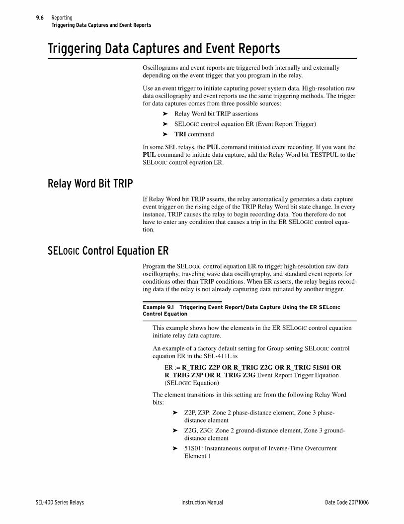
9.6
SEL-400 Series Relays Instruction Manual Date Code 20171006
ReportingTriggering Data Captures and Event Reports
Triggering Data Captures and Event ReportsOscillograms and event reports are triggered both internally and externally depending on the event trigger that you program in the relay.
Use an event trigger to initiate capturing power system data. High-resolution raw data oscillography and event reports use the same triggering methods. The trigger for data captures comes from three possible sources:
➤ Relay Word bit TRIP assertions
➤ SELOGIC control equation ER (Event Report Trigger)
➤ TRI command
In some SEL relays, the PUL command initiated event recording. If you want the PUL command to initiate data capture, add the Relay Word bit TESTPUL to the SELOGIC control equation ER.
Relay Word Bit TRIPIf Relay Word bit TRIP asserts, the relay automatically generates a data capture event trigger on the rising edge of the TRIP Relay Word bit state change. In every instance, TRIP causes the relay to begin recording data. You therefore do not have to enter any condition that causes a trip in the ER SELOGIC control equa-tion.
SELOGIC Control Equation ERProgram the SELOGIC control equation ER to trigger high-resolution raw data oscillography, traveling wave data oscillography, and standard event reports for conditions other than TRIP conditions. When ER asserts, the relay begins record-ing data if the relay is not already capturing data initiated by another trigger.
Example 9.1 Triggering Event Report/Data Capture Using the ER SELOGIC Control Equation
This example shows how the elements in the ER SELOGIC control equation initiate relay data capture.
An example of a factory default setting for Group setting SELOGIC control equation ER in the SEL-411L is
ER := R_TRIG Z2P OR R_TRIG Z2G OR R_TRIG 51S01 OR R_TRIG Z3P OR R_TRIG Z3G Event Report Trigger Equation (SELOGIC Equation)
The element transitions in this setting are from the following Relay Word bits:
➤ Z2P, Z3P: Zone 2 phase-distance element, Zone 3 phase-distance element
➤ Z2G, Z3G: Zone 2 ground-distance element, Zone 3 ground-distance element
➤ 51S01: Instantaneous output of Inverse-Time Overcurrent Element 1

9.7
Date Code 20171006 Instruction Manual SEL-400 Series Relays
ReportingDuration of Data Captures and Event Reports
TRI (Trigger Event Report) CommandUse the TRI command from any communications port to trigger the relay to begin recording high-resolution raw data, traveling wave data, and event report data. When testing with the TRI command, you can gain information on power system operating conditions that occur immediately after you issue the TRI com-mand.
Duration of Data Captures and Event ReportsThe relay stores unfiltered, high-resolution raw data (sampled at either 8 kHz, 4 kHz, 2 kHz, or 1 kHz), filtered event reports (available at both 4 samples/power system cycle and at the relay processing interval, typically 8 samples/cycle), and traveling wave data (1.5625 MHz). The number of stored high-resolution raw data captures and event reports is a function of the amount of data contained in each capture. You can configure the relay to record long data captures at high sampling rates, although this reduces the total number of stored events you can retrieve from the relay.
The rising-edge operator, R_TRIG, occurs in front of each of the elements in the factory default ER equation. Rising-edge operators are especially useful for generating an event report at fault inception. The triggering element causes ER to assert, then clears the way for other elements to assert ER because the relay uses only the beginning of a long element assertion. The starting element in a continuously occurring fault does not mask other possi-ble element triggers. This allows another rising-edge sensitive element to generate another event report later in that same continuously occurring fault (such as an overcurrent situation with the R_TRIG 51S01 element).
In the example factory default ER SELOGIC control equation, if the Z3G ele-ment remains asserted for the duration of the ground fault, the rising-edge operator, R_TRIG, in front of Z3G causes ER to assert for only one process-ing interval (a 1/8-cycle pulse). Other elements in the ER SELOGIC control equation can trigger event reports while the Z3G element remains asserted throughout the fault duration.
You can also use the falling-edge operator, F_TRIG, to initiate data captures.
Example 9.2 Including PUL Command Triggering in the ER SELOGIC Control Equation
This example shows you how to add the effect of the PUL command to emu-late previous SEL relays. The relay asserts Relay Word bit, TESTPUL, when any output is pulsed via the PUL command.
Program the Group settings SELOGIC control equation ER as follows:
ER := R_TRIG Z2P OR R_TRIG Z2G OR R_TRIG 51S01 OR R_TRIG Z3P OR R_TRIG Z3G OR TESTPUL Event Report Trig-ger Equation (SELOGIC Equation)
Example 9.1 Triggering Event Report/Data Capture Using the ER SELOGIC Control Equation (Continued)

9.8
SEL-400 Series Relays Instruction Manual Date Code 20171006
ReportingDuration of Data Captures and Event Reports
To use the data capture functions, select the effective sampling rate and data cap-ture times. Relay setting SRATE, listed in Table 9.1, determines the number of data points the relay records per second. You can set SRATE to 8 kHz, 4 kHz, 2 kHz, and 1 kHz. The effective sampling rate (SRATE) and the event report length (LER) are related as follows:
➤ 8 kHz sampling—3.00 seconds total event report
➤ 4 kHz sampling—6.00 seconds total event report
➤ 2 kHz sampling—9.00 seconds total event report
➤ 1 kHz sampling—12.00 seconds total event report
The length of the data capture/event report (setting LER) and the pretrigger or prefault time (setting PRE) are related, as shown in Figure 9.3. The LER setting is the overall length of the event report data capture; the PRE setting determines the time reserved in the LER period when the relay records pretrigger (prefault) data. Typically, you set the PRE time to 20 percent of the total LER period. Table 9.1 shows the relay settings for the data capture recording times at each effective sampling rate. Traveling wave records have a fixed sampling rate of 1.5625 MHz and a fixed event length of 7.5 ms.
NOTE: PRE has a dynamic range based on the current value of LER. The upper range of PRE = LER – 0.05.
The relay stores all data captures to volatile RAM and then moves these data to nonvolatile memory storage. There is enough volatile RAM to store one maxi-mum length capture (maximum LER time) for a given SRATE. No data captures can be triggered while the volatile RAM is full; the relay must move at least one data capture to nonvolatile storage to reenable data capture triggering. Thus, to record sequential events, you must set LER to half or less of the maximum LER setting. The relay stores more sequential data captures as you set LER smaller.
Table 9.1 Report Settings
Label Description Range Default
SRATE Effective sample rate of event report 1, 2, 4, 8 kHz 2 kHz
SRATE = 8 kHz
LER Length of event report 0.25–3.00 seconds 0.5 seconds
PRE Length of prefault 0.05–2.95 seconds 0.1 seconds
SRATE = 4 kHz
LER Length of event report 0.25–6.00 seconds 0.5 seconds
PRE Length of prefault 0.05–5.95 seconds 0.1 seconds
SRATE = 2 kHz
LER Length of event report 0.25–9.00 seconds 0.5 seconds
PRE Length of prefault 0.05–8.95 seconds 0.1 seconds
SRATE = 1 kHz
LER Length of event report 0.25–12.00 seconds 0.5 seconds
PRE Length of prefault 0.05–11.95 seconds 0.1 seconds
Figure 9.3 Data Capture/Event Report Times
PRE
LER
Event Trigger

9.9
Date Code 20171006 Instruction Manual SEL-400 Series Relays
ReportingOscillography
See Section 7: Metering, Monitoring, and Reports in the product-specific instruc-tion manual, to determine the event storage capacity for any specific relay. The relay automatically overwrites the oldest events with the newest events when the nonvolatile storage capacity is exceeded.
OscillographyThe relay features the following types of oscillography:
➤ Raw data oscillography—effective sampling rate as fast as 8000 samples/second
➤ Event report oscillography from filtered data—either a processing interval or 4 samples/cycle—including 20 settable analog quantities
Use high-resolution raw data oscillography to view transient conditions in the power system. You can set the relay to report these high-resolution oscillograms at 8000 samples/second, 4000 samples/second, 2000 samples/second, and 1000 samples/second effective sampling rates. The high-resolution raw data and travel-ing wave data oscillograms are available as files through the use of Ymodem file transfer and File Transfer Protocol (FTP) in the binary COMTRADE file format output (IEEE Std C37.111-1999, Common Format for Transient Data Exchange (COMTRADE) for Power Systems).
The filtered data oscillograms give you accurate information on the relay protec-tion and automation processing quantities. The relay outputs filtered event reports through a terminal or as files in ASCII format and Compressed ASCII format, through FTP and Ymodem file transfers. Figure 9.4 shows a sample fil-tered-data oscillogram.
Raw Data OscillographyRaw data oscillography produces oscillograms that track power system anoma-lies that occur outside relay digital filtering. If the relay receives signals via CT and PT, raw data oscillography captures data with content ranging from dc to greater than 3.0 kHz; the –3 dB point of the low-pass analog input filter is 3.0 kHz (with response rolling off at –20 dB per decade). The frequency of raw data oscil-
Figure 9.4 Sample Oscillogram

9.10
SEL-400 Series Relays Instruction Manual Date Code 20171006
ReportingOscillography
lography of the SEL-400 series relays with SV remote data acquisition depends on the remote data acquisition unit. Furthermore, the received 4.8 kHz/4.0 kHz data are resam-pled to 8 kHz for raw data oscillography recording.
COMTRADE files always include all eight Relay Word bits from each row of the Relay Word used as the base set for the relay (see Section 7: Metering, Monitor-ing, and Reporting in the product-specific instruction manual for a list of these bits). Additionally, it includes the rows containing those Relay Word bits config-ured for inclusion by the ERDG setting.
The relay stores high-resolution raw data oscillography in binary format and uses COMTRADE file types to output these data:
➤ .HDR—header file
➤ .CFG—configuration file
➤ .DAT—high-resolution raw data file
The .HDR file contains summary information about the event in ASCII format. The .CFG file is an ASCII configuration file that describes the layout of the .DAT file. The .DAT file is in binary format and contains the values for each input channel for each sample in the record. These data conform to the IEEE C37.111-1999 COMTRADE standard.
.HDR FileThe .HDR file contains the summary and relay settings information that appears in the event report for the data capture (see Event Summary Section of the Event Report on page 9.23 and Settings Section of the Event Report on page 9.24). The settings portion is as illustrated in Figure 9.5.

9.11
Date Code 20171006 Instruction Manual SEL-400 Series Relays
ReportingOscillography
.CFG FileThe .CFG file contains data such as sample rates, number of channels, line fre-quency, channel information, and transformer ratios (see Figure ). A <CR><LF> follows each line. If control inputs or control outputs are not available because of board loading and configuration, the relay does not report these inputs and out-puts in the analog and digital sections of the .CFG file.
Relay 1 Date: 02/02/2011 Time: 14:11:21.000Station A Serial Number: 2010265004
Event: ABG T Location: 59.61 (mi) From: LOCAL FLM: TW Time Source: HIRIGEvent Number: 10121 Shot 1P: 0 Shot 3P: 0 Freq: 59.99 Group: 1Targets: Breaker 1: CLOSEDBreaker 2: OPEN PreFault: IA IB IC IG 3I2 VA VB VC V1memMAG(A/kV) 200 200 200 1 1 133.946 133.938 133.941 133.935ANG(DEG) -0.7 -120.5 119.4 -51.7 -88.7 0.0 -119.9 120.2 0.1
Fault:MAG(A/kV) 2200 2200 2200 7 376 133.937 133.926 133.957 133.933ANG(DEG) -0.7 -120.6 119.5 -102.0 -83.5 0.0 -119.9 120.2 0.1
87 Differential CurrentsPreFault: IA IB IC IQ IGMAG(pu) 0.00 0.00 0.00 0.00 0.00 ANG(DEG) 0.0 0.0 0.0 0.0 0.0
Fault:MAG(pu) 0.00 0.00 0.00 0.00 0.00 ANG(DEG) 0.0 0.0 0.0 0.0 0.0
Summary Event Information
SET_G1.TXT[INFO]RELAYTYPE=SEL-411LFID=SEL-411L-X136-V0-Z001001-D20110114BFID=SLBT-4XX-R205-V0-Z001002-D20100128PARTNO=0411L0X6X1B6BCXH5C4E4XX[IOBOARDS]INT4_E, , , 24, 8, 0, 0, 1CFSINT8, , , 8, 8, 0, 0, 2[G1]"SID","Station A""RID","Relay 1""NUMBK",2"BID1","Breaker 1""BID2","Breaker 2""NFREQ",60..."AR197","AR198","AR199","AR200",
Relay Settings
Figure 9.5 Sample COMTRADE .HDR Header File
Station A,FID=SEL-411L-1-R100-V0-Z001001-D20110311,1999 Relay Information (1999 = COMTRADE Standard)
398,14A,384D 398 = sum of analogs and digitals14A = total number of analog channels384D = total number of digital pointsa
1,IAW,A,,A,0.324059,0,0,-32767,32767,200.0,1,P2,IBW,B,,A,0.324059,0,0,-32767,32767,200.0,1,P3,ICW,C,,A,0.324059,0,0,-32767,32767,200.0,1,P4,IAX,A,,A,0.324059,0,0,-32767,32767,200.0,1,P5,IBX,B,,A,0.324059,0,0,-32767,32767,200.0,1,P6,ICX,C,,A,0.324059,0,0,-32767,32767,200.0,1,P7,VAY,A,,kV,0.032406,0,0,-32767,32767,2000.0,1,P8,VBY,B,,kV,0.032406,0,0,-32767,32767,2000.0,1,P9,VCY,C,,kV,0.032406,0,0,-32767,32767,2000.0,1,P10,VAZ,A,,kV,0.032406,0,0,-32767,32767,2000.0,1,P11,VBZ,B,,kV,0.032406,0,0,-32767,32767,2000.0,1,P12,VCZ,C,,kV,0.032406,0,0,-32767,32767,2000.0,1,P13,VDC1,,,V,0.011178,-0.000000,0,-32767,32767,1,1,P14,VDC2,,,V,0.011178,-0.000000,0,-32767,32767,1,1,P
14 Analog Channels
COMTRADE .CFG Configuration File Data

9.12
SEL-400 Series Relays Instruction Manual Date Code 20171006
ReportingOscillography
The configuration file has the following format:
➤ Station name, device identification, COMTRADE standard year
➤ Number and type of channels
➤ Channel name units and conversion factors
➤ Line frequency
➤ Sample rate and number of samples
➤ Date and time of first data point
➤ Date and time of trigger point
➤ Data file type
➤ Time stamp multiplication factor
.DAT FileNOTE: The analog data are time-aligned to when the data changed on the input terminals. Similarly, the contact inputs are time-aligned to when the data changed on the input terminals. All other digital data are time-aligned to when the value changed in the relay.
The .DAT file follows the COMTRADE binary standard. The format of the binary data files is sample number, time stamp, data value for each analog channel, and grouped status channel data for each sample in the file. There are no data separa-tors in the binary file, and the file contains no carriage return/line feed characters. The sequential position of the data in the binary file determines the data transla-tion. Refer to the IEEE Std C37.111-1999, Common Format for Transient Data Exchange (COMTRADE) for Power Systems for more information. Programs that read the binary COMTRADE files include ACSELERATOR Analytic Assis-tant SEL-5601 Software and ACSELERATOR QuickSet SEL-5030 Software.
1,87USAFE,,,02,UNUSED2,,,03,UNUSED3,,,04,UNUSED4,,,05,OC1,,,06,CC1,,,07,OC2,,,08,CC2,,,09,87LA,,,010,87LB,,,011,87LC,,,012,87LQ,,,013,87LG,,,014,87FLSOK,,,015,87DTTRX,,,0...382,PCT06Q,,,0383,PCT07Q,,,0384,PCT08Q,,,0
384 Digital Points
60 Nominal System Frequency (INFREQ Setting)
1
2000,1000 2000 = Sample Rate (SRATE setting)1000 = Length of the Report x Sample Rate (LER x SRATE)
17/03/2011,08:36:38.697687 Time Stamp of the First Data Point
17/03/2011,08:36:38.799850 Time Stamp of the Trigger Point
BINARY
1
a If ERDIG is set to S, the digital points are all the Relay Word bits set in ERDG as well as the Relay Word bits that are always included in the event report. If ERDIG is set to A, the digital points are all the Relay Word bits in the device.
COMTRADE .CFG Configuration File Data (Continued)

9.13
Date Code 20171006 Instruction Manual SEL-400 Series Relays
ReportingEvent Reports, Event Summaries, and Event Histories
Generating Raw Data OscillogramsTo use high-resolution raw data oscillography, select the type of triggering event and use a trigger event method described in Triggering Data Captures and Event Reports on page 9.6. Use the settings SRATE, LER, and PRE to set the relay for the appropriate data sampling rate and data capture time (see Duration of Data Captures and Event Reports on page 9.7).
Retrieving Raw Data OscillogramsUse a computer terminal emulation program and the FILE commands at any communications port to retrieve the stored high-resolution raw data capture from the relay file structure. If the relay has an Ethernet port, you can also use FTP to retrieve these files. You can also use QuickSet.
Event Report OscillographyNOTE: In an SV subscriber relay, the event report analog channels are delayed by the CH_DLY setting relative to the raw oscillography.
Use a terminal or SEL-supplied PC software to retrieve filtered event report files stored in the relay and transfer these files to your computer. SEL-5601 SYNCHRO-WAVE Event or the ACSELERATOR Analytic Assistant SEL-5601 Software can be used to read the compressed event files that the relay generates for an event.
Event Reports, Event Summaries, and Event HistoriesEvent reports simplify post-fault analysis and help you improve your understand-ing of protection scheme operations. Event reports also aid in testing and trouble-shooting relay settings and protection schemes because these reports contain detailed data on voltage, current, and relay element status. For further analysis assistance, the relay appends the active relay settings to each event report. The relay stores event reports in nonvolatile memory, and you can clear the event report memory on a port-by-port basis.
You decide the amount of information and length in an event report (see Duration of Data Captures and Event Reports on page 9.7).
The relay records the filtered power system data that the relay uses in protection and automation processing. You can view filtered information about an event in one or more of the following forms.
➤ Event report
➤ Event summary
➤ Event history
Alias NamesNOTE: If Alias names were changed after an event was recorded, the relay uses the present alias names in subsequent event reports.
To customize your event report, rename any Relay Word bit or analog quantity with more meaningful names to improve the readability of fault analysis and cus-tomized programming. After renaming the primitive quantities, the alias names rather than the primitive names appear in the event reports for the user-selectable analog and digital channels. The primitive names of the analog channels still appear in the event reports.

9.14
SEL-400 Series Relays Instruction Manual Date Code 20171006
ReportingEvent Reports, Event Summaries, and Event Histories
Event ReportThe relay generates event reports to display analog data, digital data (control inputs, control outputs, and the state of Relay Word bits), and relay settings. The event report is a complete description of the data that the relay recorded in response to an event trigger. Each event report includes these components:
➤ Report header and analog section—Currents and voltages, sometimes including calculated quantities such as differential currents
➤ Digital section—Relay Word bit elements, control outputs, control inputs
➤ Event summary
➤ Settings
➢ Group settings
➢ Global settings
➢ Output settings
➢ SELOGIC control equations protection logic
Viewing the Event ReportAccess event reports from the communications ports and communications cards at Access Level 1 and higher. (You cannot view event reports at the front panel, although you can view event summary information at the front-panel display.) You can independently acknowledge the oldest event report at each communica-tions port (EVE ACK command) so that you and users at other ports (SCADA, Engineering, etc.) can retrieve complete sets of event reports. To acknowledge the oldest event report, you must first view that event report at a particular port by using the EVE N(EXT) command.
You can use the EVE command and a terminal to retrieve event reports by event order or by event serial number. (The relay labels each new event with a unique serial number as reported in the HIS command history report [see Event History on page 9.27].)
Events are referenced two ways: by relative reference or by event serial number. Relative references are in the range 1–9999, where 1 refers to the most recent event, 2 to the next most recent, and so on. Event serial numbers are in the range 10000–42767. You can find the event serial number in the event history report. With the EVE and CEV commands, you can retrieve events using either type of reference. Event files are names based on the event serial number.
By applying modifiers to the EVE command, you can retrieve only analog or digital information, and you can exclude the summary or settings portions of the report. The default EVE command event report data resolution is 4 samples/cycle and the default report length is 0.5 seconds (30 cycles at 60 Hz or 25 cycles at 50 Hz) with the factory default setting for LER.
See the EVE command description in Section 9: ASCII Command Reference in the product-specific instruction manual for a complete list of options.
You can retrieve event reports with the QuickSet Tools > Events > View Event Files menu. The Analysis > View Event Files menu gives you oscillogram/element displays, phasor displays, harmonic analysis, and an event summary for each event you select in the Event History dialog box.

9.15
Date Code 20171006 Instruction Manual SEL-400 Series Relays
ReportingEvent Reports, Event Summaries, and Event Histories
You can also download event report files from the relay using a terminal emula-tion program with file transfer capability. At an Access Level 1 prompt or higher, type FILE READ EVENTS E8_nnnnn.TXT <Enter> for the 8-samples/cycle event report and type FILE READ EVENTS E4_nnnnn.TXT <Enter> for the 4-samples/cycle event report (nnnnn is the event serial number). Start the termi-nal download routine to store the file on your computer. If you want the Com-pressed ASCII file, use the C8_nnnnn.TXT and C4_nnnnn.TXT file names for the 8-samples/cycle and 4-samples/cycle Compressed ASCII event reports, respectively.
The following discussion shows sample portions of an event report that you download from the relay using a terminal and the EVE command. An event report contains analog, digital, summary, and settings sections without breaks.
Report Header and Analog Section of the Event ReportThe first portion of an event report is the report header and the analog section. Some relays have more than one analog section. See Section 7: Metering, Moni-toring, and Reports in the product-specific instruction manual for details on what the event reports look like in each relay. See Figure 9.6 for an example of a SEL-421 event report.
The report header is the standard relay header listing the relay identifiers, date, and time. Report headers help you organize report data. Each event report begins with information about the relay and the event. The report lists the RID setting (Relay ID) and the SID setting (Station ID). The FID string identifies the relay model, flash firmware version, and the date code of the firmware. The relay reports a date and time stamp to indicate the internal clock time when the relay triggered the event. The relay reports the firmware checksum as CID.
The event report column labels follow the header. The data underneath the analog column labels contain samples of power system voltages and currents.
Relay 1 Date: 03/15/2001 Time: 23:30:49.026Station A Serial Number: 2001001234FID=SEL-421-R101-V0-Z001001-D20010315 Event Number = 10007 CID=0x3425
HeaderFirmware ID in bold
Currents (Amps Pri) Voltages (kV Pri) IA IB IC IG VA VB VC VS1 VS2 V1mem
[1] -267 167 44 -56 -288.0 337.7 -47.8 215.3 144.9 -287.9 -76 -203 241 -37 -223.7 -138.4 361.3 -290.5 331.3 -223.7 266 -166 -45 55 288.2 -337.5 47.5 -215.2 -145.0 288.1 76 202 -242 36 223.4 138.7 -361.4 290.5 -331.2 223.5
1 Cycle of DataSee Figure 9.7 and Figure 9.8 to calculate phasors for the data in bold.
•
•
•
[6] -269 167 46 -56 -289.3 336.9 -45.8 215.5 144.7 -289.4 -74 -202 240 -35 -222.2 -140.2 361.5 -290.2 331.4 -221.8 268 -165 -45 57 289.4 -336.7 45.6 -215.4 -144.6 289.5 93 151 -888 -643 221.1 133.5 -335.0 290.2 -331.4 220.8
[7] -208 2701 -3760 -1267 -288.7 293.7 -24.1 215.5 144.5 -286.3 -146 2941 173 2968 -219.6 -87.6 261.6 -290.1 331.4 -214.0> 134 -5748 8310 2696 286.9 -232.4 3.5 -215.6 -144.4 273.3 179 -6677 1811 -4688 219.8 47.4 -214.2 290.0 -331.5 202.8
Trigger
[8] -125 5661 -8506 -2971 -286.1 213.6 -3.8 215.8 144.2 -256.5 -177 6857 -1950 4730 -220.8 -46.9 214.2 -289.9 331.6 -193.2* 129 -5508 8382 3003 286.9 -213.8 3.6 -216.0 -144.0 243.9 174 -6726 1839 -4712 220.4 47.2 -214.2 289.8 -331.6 185.9
Largest Current (to Event Summary)
Figure 9.6 Fixed Analog Section of an Example SEL-421 Event Report
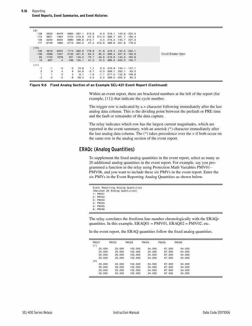
9.16
SEL-400 Series Relays Instruction Manual Date Code 20171006
ReportingEvent Reports, Event Summaries, and Event Histories
Within an event report, there are bracketed numbers at the left of the report (for example, [11]) that indicate the cycle number.
The trigger row is indicated by a > character following immediately after the last analog data column. This is the dividing point between the prefault or PRE time and the fault or remainder of the data capture.
The relay indicates which row has the largest current magnitudes, which are reported in the event summary, with an asterisk (*) character immediately after the last analog data column. The (*) takes precedence over the > if both occur on the same row in the analog section of the event report.
ERAQc (Analog Quantities)
To supplement the fixed analog quantities in the event report, select as many as 20 additional analog quantities in the event report. For example, say you pro-grammed a function in the relay using Protection Math Variables PMV01–PMV06, and you want to include these six PMVs in the event report. Enter the six PMVs in the Event Reporting Analog Quantities as shown below.
The relay correlates the freeform line number chronologically with the ERAQc quantities. In this example, ERAQ01 = PMV01, ERAQ02 = PMV02, etc.
In the event report, the ERAQ quantities follow the fixed analog quantities.
[9] -128 5623 -8479 -2984 -287.1 213.9 -3.5 216.1 143.8 -234.5 -173 6821 -1924 4724 -219.8 -47.3 214.0 -289.7 331.7 -180.4 126 -5540 8404 2990 286.6 -213.7 3.5 -216.3 -143.7 227.3 177 -6749 1860 -4713 220.0 47.4 -212.9 289.6 -331.8 176.2
[10] -126 4616 -6204 -1714 -282.9 178.6 41.9 216.4 143.5 -222.1 -106 4288 -1047 3135 -231.6 -64.5 95.3 -289.4 331.9 -162.6 65 -1722 1878 221 140.2 -72.1 -43.6 -216.6 -143.3 194.6 16 -807 4 -786 105.1 41.3 10.5 289.2 -332.0 130.7
Circuit Breaker Open
[11] -1 -1 -2 -5 13.8 1.1 0.3 216.8 143.1 -147.1 2 3 4 9 54.8 -0.7 -0.3 -289.1 332.1 -93.5 1 1 2 5 -8.1 -1.6 -1.1 -217.0 -142.8 109.8 -2 -2 -3 -8 -58.2 0.2 0.2 289.0 -332.2 65.3
Figure 9.6 Fixed Analog Section of an Example SEL-421 Event Report (Continued)
Event Reporting Analog Quantities(Maximum 20 Analog Quantities)1: PMV012: PMV023: PMV034: PMV045: PMV056: PMV06
PMV01 PMV02 PMV03 PMV04 PMV05 PMV06 [1] 20.000 25.000 102.000 34.000 67.000 54.000 20.000 25.000 102.000 34.000 67.000 54.000 20.000 25.000 102.000 34.000 67.000 54.000 20.000 25.000 102.000 34.000 67.000 54.000 [2] 20.000 25.000 102.000 34.000 67.000 54.000 20.000 25.000 102.000 34.000 67.000 54.000 20.000 25.000 102.000 34.000 67.000 54.000 20.000 25.000 102.000 34.000 67.000 54.000

9.17
Date Code 20171006 Instruction Manual SEL-400 Series Relays
ReportingEvent Reports, Event Summaries, and Event Histories
Obtaining RMS Phasors From 4-Samples/Cycle Event Reports
Use the column data in an event report to calculate rms values. You can use a cal-culator to convert rectangular data to phasor data, or use hand-calculations to sep-arately determine the magnitude and angle of the rms phasor.
Hand Calculation Method
The procedure in the following steps explains a method for obtaining a current phasor from the IA channel data in the event report of Figure 9.6. You can pro-cess voltage data columns similarly. The drawings in Figure 9.7 and Figure 9.8 show 1 cycle of A-Phase current in detail. Figure 9.7 shows how to relate the event report ac current column data to the sampled waveform and rms values. Figure 9.8 shows how to find the phasor angle. If you use the larger 8-samples/cycle event report, take every other sample and apply those values in this procedure.
This examples assumes you have captured an event report and are prepared to calculate phasors from it.
Step 1. Calculate the phasor magnitude:
a. Select a cycle of data from the IA column of the event report.
Figure 9.6 Cycle [1] data for this example are shown in Figure 9.7.
There are three pairs of scaled instantaneous current samples from Cycle [1].
Compute phasor magnitude using the following expression:
Equation 9.1
b. In Equation 9.1, Y is the first row of IA column current of a data pair, and the next row is X, the present value of the pair.
For this example, the computation shown in Figure 9.7 yields 277.0 A.
c. Compute phasor magnitudes from the remaining data pairs for Cycle [1].
d. Confirm that all values are similar.
X2 Y2+ Phasor=

9.18
SEL-400 Series Relays Instruction Manual Date Code 20171006
ReportingEvent Reports, Event Summaries, and Event Histories
Figure 9.7 Event Report Current Column Data and RMS Current Magnitude
0t
—378
—107 378
107
—267
—267
—76
266
76 •••
IA
Y = previous 1/4 cycle
X = present sample
Y =
—26
7
θ
X = —76—7
6
266 76
1/4 cycle
Raw Waveform
multiply by22
Even
t R
epor
t Co
lum
n D
ata
(—76
)2 +
(—2
67)2
= 2
76.6 θ = arctan( )Y
X
= arctan( )—267
—76
= —105.9 degrees
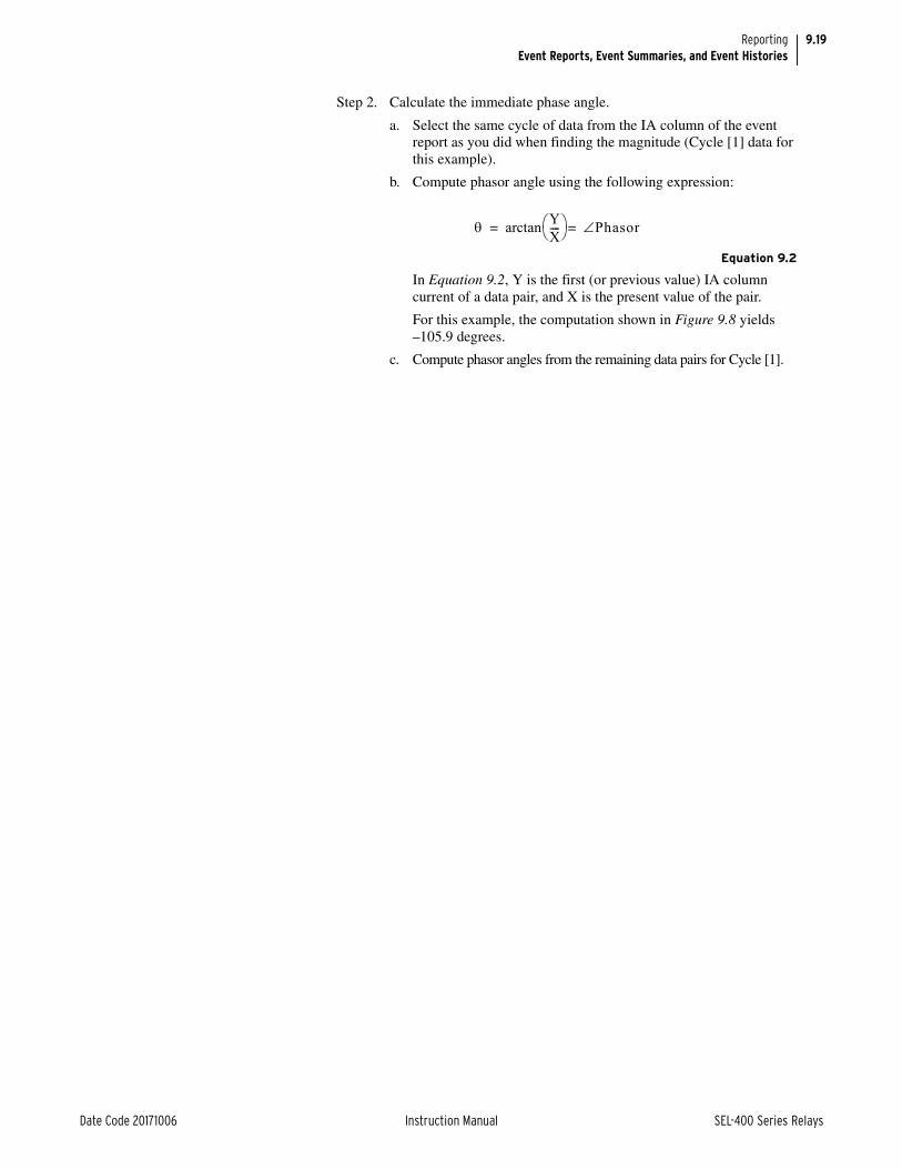
9.19
Date Code 20171006 Instruction Manual SEL-400 Series Relays
ReportingEvent Reports, Event Summaries, and Event Histories
Step 2. Calculate the immediate phase angle.
a. Select the same cycle of data from the IA column of the event report as you did when finding the magnitude (Cycle [1] data for this example).
b. Compute phasor angle using the following expression:
Equation 9.2
In Equation 9.2, Y is the first (or previous value) IA column current of a data pair, and X is the present value of the pair.
For this example, the computation shown in Figure 9.8 yields–105.9 degrees.
c. Compute phasor angles from the remaining data pairs for Cycle [1].
arctan YX---- Phasor==

9.20
SEL-400 Series Relays Instruction Manual Date Code 20171006
ReportingEvent Reports, Event Summaries, and Event Histories
NOTE: The arctan function of many calculators and computing programs does not return the correct angle for the second and third quadrants (when X is negative). When in doubt, graph the X and Y quantities to confirm that the angle that your calculator reports is correct.
Figure 9.8 Event Report Current Column Data and RMS Current Angle
0t
—378
—107 378
107
—267
—267
—76
266
76 •••
IA
Y = previous 1/4 cycle
X = present sample
Y =
—26
7
θ
X = —76—7
6
266 76
1/4 cycle
Raw Waveform
multiply by22
Even
t R
epor
t Co
lum
n D
ata
(—76
)2 +
(—2
67)2
= 2
76.6 θ = arctan( )Y
X
= arctan( )—267
—76
= —105.9 degrees

9.21
Date Code 20171006 Instruction Manual SEL-400 Series Relays
ReportingEvent Reports, Event Summaries, and Event Histories
Step 3. Calculate the reference phase angle. Usually, you compare power system angles to a reference phasor (positive-sequence A-Phase volt-age, for example):
Repeat Step 2 for the row data in the VA column that correspond to the IA column data values you used in Step 2.
The angle calculation for the VA data is the following:
Equation 9.3
(This is an example of an arctan calculation that yields the incorrect answer from some calculators and math programs.)
Step 4. Calculate the absolute phase angle:
Subtract the IA angle from the VA angle to obtain the A-Phase-referenced phasor angle for IA.
Equation 9.4
IA leads VA; thus, the rms phasor for current IA at the present sample is 277.0 A 21.9°, referenced to VA.
In the procedure above, you use two rows of current data from the event report to calculate an rms phasor current. At the first sample pair of Cycle [1], the rms pha-sor is IA = 277.0 A –105.9°.
The present sample of the sample pair (X = –76) is a scaled instantaneous current value (not an rms quantity) that relates to the rms phasor current value by the expression.
Equation 9.5
Polar Calculator Method
A method for finding the phasor magnitude and angle from event report quarter-cycle data pairs is to use a polar-capable calculator or computer program. Many calculators and computer programs convert Cartesian (X and Y) coordinate data to polar data. Key or enter the X value (present value or lower value of a column pair) and the Y value (later value or upper value in a column pair) as Cartesian (rectangular) coordinates. Perform the keystrokes necessary for your calculator or computing program to convert to polar coordinates. This is the phasor value for the data pair.
Digital Section of the Event ReportThe second portion of an event report is the digital section. Inspect the digital data to evaluate relay element response during an event. See Figure 9.9 for an example from the SEL-411L. If you want to view only the digital portion of an event report, use the EVE D command. In the digital portion of the event report, the relay indicates deasserted elements with a period (.) and asserted elements with an asterisk (*) character.
VA=
arctan YX---- =
arctan 288.0–223.7–
---------------- =
127.8–=
VA IA 127.8– 105.9– 21.9– =–=–
X 76– 277.0 105.9– cos= =

9.22
SEL-400 Series Relays Instruction Manual Date Code 20171006
ReportingEvent Reports, Event Summaries, and Event Histories
The element and digital information labels are single character columns. Read these columns from top to bottom. The trigger row includes a > character follow-ing immediately after the last digital element column to indicate the trigger point. The relay marks the row used to report the maximum fault current with an aster-isk (*) character at the right of the last digital element column. Event reports that are 4-samples/cycle reports show the OR combination of digital elements in the two 8-samples/cycle rows to make the quarter-cycle entry.
The digital report arranges the event report digital settings into 79 column pages. For every 79 columns, the relay generates a new report that follows the previous report.
The report displays the digital label header for each column in a vertical fashion, aligned on the last character. For example, if the first digital section elements are IN201, #, RMBA5, Z2P, LBOKA, #, OUT203, OUT204, and HALARM, the header appears as in Figure 9.10. If the Relay Word bits included in the header were assigned aliases, the alias names appear in the report.
22 B B C 55 F F VZ S 66 66 55 O BBBBBB AA T T MMM ZZZ PL 3333 O5 666 77 666 77 511 Z M KKKKKK 11 RFRFTTT MMMM 234 ZZZZ 234 OOL OO 3S 2222 T0 777 GG 777 QQ 1SS 3KP 121212 BB IBIBPPP 1234 PPP 1234 GGG LAO SS PP QQGG FP GGG 23 QQQ 23 S11 PRER RRLLCC KK PFPFABC PPPP TTT GGGG TTT VDP BT OO FRFR T1 123 TT 123 TT 1TR TBYM SSOOLL 12 1122
Digital Column Labels
[1]
... .... ... .... ... *.. .. .. .... .. ... .. ... .. ... .... ...... .. ....
... .... ... .... ... *.. .. .. .... .. ... .. ... .. ... .... ...... .. ....
... .... ... .... ... *.. .. .. .... .. ... .. ... .. ... .... ...... .. ....
... .... ... .... ... *.. .. .. .... .. ... .. ... .. ... .... ...... .. ....
1 Cycle of Data
•
•
•
[6]... .... ... .... ... *.. .. .. .... .. ... .. ... .. ... .... ...... .. ....... .... ... .... ... *.. .. .. .... .. ... .. ... .. ... .... ...... .. ....... .... ... .... ... *.. .. .. .... .. ... .. ... .. ... .... ...... .. ....... .... ... .... ... *.. .. .. .... .. ... .. ... .. ... .... ...... .. ....[7]*** **.. ... .... ... *.. .. .. .... .. ... .. ... .. ... .... ...... .. ....
*** **.. ... .... ... *.. .. .. *.*. .. ... .. ... .. ... .... ...... .. ....> Trigger
*** **.. ... .... ... *.. .. .. *.*. .. ... .. ... .. ... .... ...... .. ....*** **.. ... .... ... *.. .. .. *.*. .. ... .. ... .. ... .... ...... .. ....[8]*** **.. ... .... ... *.. .. .. *.*. .. ... .. ... .. ... .... ...... .. ....
*** **.. ... .... ... *.. .. .. *.*. .. ... .. ... .. ... .... ...... .. ....* Values used in the Event Summary
*** **.. ... .... ... *.. .. .. *.*. .. ... .. ... .. ... .... ...... .. ....*** **.. ... .... ... *.. .. .. *.*. .. ... .. ... .. ... .... ...... .. ....[9]*** **.. ... .... ... *.. .. .. *.*. .. ... .. ... .. ... .... ...... .. ....*** **.. ... .... ... *.. .. .. *.*. .. ... .. ... .. ... .... ...... .. ....*** **.. ... .... ... *.. .. .. *.*. .. ... .. ... .. ... .... ...... .. ....*** **.. ... .... ... *.. .. .. *.*. .. ... .. ... .. ... .... ...... .. ....[10]*** **.. ... .... ... *.. .. .. *.*. .. ... .. ... .. ... .... ...... .. ....*** **.. ... .... ... *.. .. .. *.*. .. ... .. ... .. ... .... ...... .. ....*** .... ... .... ... *.. .. .* .... .. ... .. ... .. ... .... ...... .. ....*** .... ... .... ... *.. .. *. .... .. ... .. ... .. ... .... ...... .. ....
[11] Circuit Breaker Open
*** .... ... .... ... *.. .. *. *.*. .. ... .. ... .. ... .... ...... .. ....*** .... ... .... ... *.. .. *. .... .. ... .. ... .. ... .... ...... .. ....*** .... ... .... ... *.. .. *. .... .. ... .. ... .. ... .... ...... .. ....*** .... ... .... ... *.. .. *. .... .. ... .. ... .. ... .... ...... .. ....
Figure 9.9 Digital Section of the SEL-411L Event Report

9.23
Date Code 20171006 Instruction Manual SEL-400 Series Relays
ReportingEvent Reports, Event Summaries, and Event Histories
Selecting Event Digital ElementsNOTE: The compressed event reports and COMTRADE files from the relay may contain additional digital elements as compared to standard (ASCII) event reports (see CEVENT on page 9.25).
Specify the digital elements in the digital section of the event report by using the Event Reporting Digital Elements settings found in the Report settings (the SET R command from a terminal or the Report branch of the Settings tree view of QuickSet). You can enter as many as 800 Relay Word bits from a maximum of 100 target rows. The # symbol places a blank column in the digital report. Use the # symbol to organize the digital section of the event report.
Digital Section INnnn Times
Reported assertion times for input digital elements differ, although these ele-ments have the same name in both high-resolution raw data reports and in the fil-tered event reports. When you enter an input (INnnn) in the event digitals list, the relay displays the filtered input with time latency in the event report and the Compressed ASCII event report. However, in the binary COMTRADE file event report, the relay reports the actual high-sample rate capture time for relay inputs.
Event Summary Section of the Event ReportThe third portion of an event report is the summary section. See Figure 9.11 for the locations of items included in an example summary section of an event report. The specific values available depend on the specific relay. See Section 7: Meter-ing, Monitoring, and Reports in the product-specific instruction manual to see what specific data are reported in the summary of a relay. If you want to exclude the summary portion from an event report, use the EVE NSUM command.
The information in the summary portion of the event report is the same informa-tion in the event summary, except that the report header does not appear immedi-ately before the event information when you view a summary in the event report.
Figure 9.10 Sample Digital Portion of the Event Report
00HI R UUAN M L TTL2 BM0 22A0 A2K 00R1 5PA 34M
. ... ... .. ...
* ..* ...* ..* ...
IN201#RMBA5Z2PLBOKA#OUT203OUT204HALARM

9.24
SEL-400 Series Relays Instruction Manual Date Code 20171006
ReportingEvent Reports, Event Summaries, and Event Histories
Settings Section of the Event ReportThe final portion of an event report is the settings section. See Figure 9.12 for the locations of items included in a sample settings section of an event report. If you want to exclude the settings portion from an event report, use the EVE NSET command.
The settings portion of the event report lists important relay settings at the time the relay event triggered. The event report shows group, global, output, protec-tion SELOGIC control equation settings and alias settings. For the group settings and the protection SELOGIC settings, the relay reports only the active group. The settings order in the event report is the same order as when you issue a SHOW command from a terminal.
Event: TRIP Location: $$$$.$$ From: LOCAL FLM: SE Time Source: OTHEREvent Number: 10030 Shot 1P: 0 Shot 3P: 0 Freq: 60.00 Group: 1Targets: INST COMM 87LBreaker 1: CLOSED Trip Time: 11:18:49.016Breaker 2: NA
Event Information
PreFault: IA IB IC IG 3I2 VA VB VC V1mem
MAG(A/kV) 426 426 427 1 0 286.420 286.638 286.302 286.453 Prefault Data
ANG(DEG) 1.3 -118.7 121.3 130.6 -99.2 0.0 -120.0 120.0 0.0
Fault:
MAG(A/kV) 426 426 427 1 1 286.397 286.632 286.298 286.450 Fault Data
ANG(DEG) 1.3 -118.7 121.3 106.1 -92.6 0.0 -120.0 120.0 0.0
87 Differential Currents
PreFault: IA IB IC IQ IGMAG(pu) 0.36 0.35 0.36 0.00 0.00ANG(DEG) 1.4 -118.9 120.9 92.9 59.5
Fault:MAG(pu) 0.00 0.00 0.00 0.00 0.00ANG(DEG) -20.6 -20.6 -20.6 -20.6 -20.6
Line-Current Differential Status
Figure 9.11 Example Summary Section of the SEL-411L Event Report
Group 1Line ConfigurationCTRW := 400 CTRX := 400 PTRY := 3636 VNOMY := 115PTRZ := 3636 VNOMZ := 115 Z1MAG := 4.72 Z1ANG := 82.60Z0MAG := 14.50 Z0ANG := 75.70 EFLOC := Y
•
•
•
Active Group Settings
GlobalGeneral Global SettingsSID := "Station A"RID := "Relay 1"NUMBK := 2BID1 := "Breaker 1"BID2 := "Breaker 2"NFREQ := 60 PHROT := ABC DATE_F := MDYFAULT := NA
•
•
•
Global Settings
Figure 9.12 Settings Section of the Event Report

9.25
Date Code 20171006 Instruction Manual SEL-400 Series Relays
ReportingEvent Reports, Event Summaries, and Event Histories
CEVENT The relay provides a Compressed ASCII event report for SCADA and other auto-mation applications. QuickSet uses Compressed ASCII commands to gather event report data. If you want to view the Compressed ASCII event report data, use a terminal to issue ASCII command CEV. This is a comma-delimited ASCII file. The relay appends a four-digit hex checksum at the end of the lines in the Compressed ASCII report.
Items included in the Compressed ASCII event report are similar to the event report, although the relay reports the items in a special order. CEV files (like COMTRADE files) include all eight Relay Word bits from each row of the Relay Word used as the base set for the relay (see Section 7: Metering, Monitoring, and Reporting in the product-specific instruction manual for a list of these bits). Additionally, it includes the rows containing those Relay Word bits configured for inclusion by the ERDG setting. For the purpose of improving products and services, SEL sometimes changes the items and item order.
OutputInterface Board #1OUT201 := 3PTOUT202 := BK1CLOUT203 := BK2CLOUT204 := NAOUT205 := NAOUT206 := NAOUT207 := NAOUT208 := NA
•
•
•
Output Settings
Remote Analog Outputs
RAO01 := NARAO02 := NA
•
•
•RAO61 := NARAO62 := NARAO63 := NARAO64 := NA
Remote Analog Settings
Mirrored Bits Transmit Equations
TMB1A := NA
•
•
•TMB8B := NA
MIRRORED BITS Settings
Protection 1Freeform Protection SELOGIC1: ### PROTECTION FREEFORM AUTOMATION EXAMPLE2: ###3: ### SET CONTROL VARIABLE 14: ### ASSERTS WHEN PRIMARY POSITIVE SEQUENCE IS5: ### GREATER THAN 90% OF 230 KV DIVIDED BY SQRT 36: PSV01 := V1M >= 119.5 #90% OF 230 KV DIVIDED BY SQRT 3
Active Protection Logic Settings
Alias
Relay Aliases(Relay Word Bit or Analog Quantity name, 7 Character Alias [0-9 A-Z _])
1: EN,"REL_EN"
Alias Settings
Figure 9.12 Settings Section of the Event Report (Continued)

9.26
SEL-400 Series Relays Instruction Manual Date Code 20171006
ReportingEvent Reports, Event Summaries, and Event Histories
Event SummaryYou can retrieve a summary version of stored event reports as event summaries. These short-form reports present vital information about a triggered event. The relay generates an event in response to power system faults and other trigger events (see Triggering Data Captures and Event Reports on page 9.6). The sum-mary information available depends on the specific relay. See Section 7: Meter-ing, Monitoring, and Reports in the product-specific instruction manual for the details of the summary event report for a specific relay.
The relay can be configured to automatically send an event summary on serial ports (see Automatic Messages on page 15.27).
Viewing the Event SummaryAccess the event summary from the communications ports and communications cards. View and download event summaries from Access Level 1 and higher. You can independently acknowledge a summary (with the SUM ACK command) at each communications port so that you and users at other ports (SCADA, Engi-neering, etc.) can retrieve a complete set of summary reports. To acknowledge and remove a summary, you must first use the SUM N(EXT) command to view that summary.
You can use the SUM command to retrieve event summaries by date or date range, and by event number. (The relay labels each new event with a unique num-ber as reported in the HIS command history report; see Event History on page 9.27.)
Table 9.2 lists the SUM commands. See SUMMARY on page 14.52 for complete information on the SUM command.
You can also view event summaries using the Analytic Assistant tool built into QuickSet, or with SYNCHROWAVE Event.
CSUMMARYThe relay outputs a Compressed ASCII summary report for SCADA and other automation applications. Issue ASCII command CSU to view the Compressed ASCII summary report. This is a comma-delimited ASCII file. The relay appends a four-digit hex checksum at the end of the lines in the Compressed ASCII report.
Items included in the Compressed ASCII summary report are similar to those included in the summary report, although the relay reports the items in a special order. For the purpose of improving products and services, SEL sometimes changes the items and item order.
Table 9.2 SUM Command
Command Description
SUM Return the most recent event summary (with header).
SUM n Return a particular na event summary (with header).
a The parameter n indicates event order or serial number.
SUM ACK Acknowledge the event summary on the present communications port.
SUM N View the oldest unacknowledged event summary (N = next).

9.27
Date Code 20171006 Instruction Manual SEL-400 Series Relays
ReportingEvent Reports, Event Summaries, and Event Histories
Event HistoryThe event history gives you a quick look at recent relay activity. The relay labels each new event with a unique number from 10000 to 42767. (At 42767 the relay returns to 10000 for the next event number and then continues to increment.) See Figure 9.13 for a sample event history.
The event history typically contains the following:
➤ Standard report header
➢ Relay and terminal identification
➢ Date and time of report
➤ Event number
➤ Event date and time
➤ Event type
➤ Location of fault (if applicable)
➤ Maximum phase current from summary fault data
➤ Active group at the trigger instant
➤ Targets
Figure 9.13 is a sample event history from a terminal.
The event types in the event history are the same as the event types in the event summary.
The event history report indicates events stored in relay nonvolatile memory. The relay places a blank row in the history report output; items that are above the blank row are available for viewing (use the EVE and CEV commands). Items that are below the blank row are no longer in relay memory; these events appear in the history report to indicate past power system performance. The relay does not ordinarily modify the numerical or time order in the history report. However, if an event report is corrupted (power was lost during storage, for example), the relay lists the history report line for this event after the blank row.
Viewing the Event HistoryAccess the history report from the communications ports and communications cards. View and download history reports from Access Level 1 and higher. You can also clear or reset history data from Access Levels 1 and higher. You can independently clear/reset history data at each communications port so that you and users at other ports (SCADA, Engineering, etc.) can retrieve complete history reports. You can also clear all history data from all ports (with the HIS CA com-mand).
Figure 9.13 Sample SEL-411L Event History
Event
Number
Event
Type
Fault
Location
Active
Group
Relay 1 Date: 03/16/2001 Time: 11:57:27.803Station A Serial Number: 2001001234# DATE TIME EVENT LOCAT CURR GRP TARGETS10007 03/15/2001 23:30:49.026 BCG T 48.17 8892 1 INST TIME ZONE_1 B_PHASE 10006 03/15/2001 07:15:00.635 ABC T 22.82 8203 1 INST ZONE_1 A_PHASE bk1rs 10005 03/15/2001 06:43:53.428 TRIG $$$$.$$ 0 1

9.28
SEL-400 Series Relays Instruction Manual Date Code 20171006
ReportingSequential Events Recorder (SER)
Use the HIS command from a terminal to obtain the event history. You can view event histories by date or by date range, or you can specify the number of the most recent events that the relay returns. See HISTORY on page 14.32 for infor-mation on the HIS command. Table 9.3 lists the HIS commands.
You can use QuickSet to retrieve the relay event history. Use the Tools > Events > Get Event Files menu to view the Event History dialog box. See Ana-lyze Events on page 2.22 for information and examples.
CHISTORYThe relay outputs a Compressed ASCII history report for SCADA and other automation applications. Issue the CHI command to view the Compressed ASCII history report. This is a comma-delimited ASCII file. The relay appends a four-digit hex checksum at the end of each history in the Compressed ASCII history report.
Items included in the Compressed ASCII history report are similar to those included in the history report, although the relay reports the items in a special order. For the purpose of improving products and services, SEL sometimes changes the items and item order.
History File DownloadYou can also download the history report file from the relay. Use a terminal emu-lation program with file transfer capability. At an Access Level 1 prompt or higher type FILE READ REPORTS HISTORY.TXT <Enter>. Start the termi-nal download routine to store the file on your computer. If you want the Com-pressed ASCII file, type FILE READ REPORTS CHISTORY.TXT <Enter>. In addition, you can use QuickSet to download history files.
Sequential Events Recorder (SER)The Sequential Events Recorder (SER) gives you detailed information on relay states and relay element operation. The SER captures and time-tags state changes of Relay Word bit elements and relay conditions. These conditions include power-up, relay enable and disable, group changes, settings changes, memory
Table 9.3 HIS Command
Command Description
HIS Return event histories with the oldest at the bottom of the list and the most recent at the top of the list.
HIS k Return the k most recent event summaries with the oldest at the bottom of the list and the most recent at the top of the list.
HIS date1 Return the event summaries on date date1a.
a Use the same date format as Global setting DATE_F.
HIS date1 date2 Return the event summaries from date1 to date2, with date1 at the bot-tom of the list and date2 at the top of the list.
HIS C Clear all event data on the present port.
HIS R Clear all event data on the present port.
HIS CA Clear event data for all ports.
HIS RA Clear event data for all ports.

9.29
Date Code 20171006 Instruction Manual SEL-400 Series Relays
ReportingSequential Events Recorder (SER)
overflow, diagnostic restarts, and SER autoremoval/reinsertion. The relay stores the latest 1000 SER entries to nonvolatile memory. Figure 9.14 is a sample SER report.
The SER report contains the following:
➤ Standard report header
➢ Relay and terminal identification
➢ Date and time of report
➤ SER number
➤ SER date and time
➤ Relay element or condition
➤ Element state
In the SER report, the oldest information has the highest number. The newest information is always #1. When using a terminal you can order the positions of the SER records in the SER report.
Viewing the SER ReportThe relay displays the SER records in ASCII and binary formats.
Access the SER report from the communications ports and communications cards in Access Level 1 and higher. You can independently clear/reset already viewed SER data at each communications port (with the SER CV or SER RV command) so that users at other ports (SCADA, Engineering, for example) can retrieve complete SER reports. The SER CV or SER RV command will not clear any SER data that has been recorded, but not viewed, on a particular serial port. To clear all SER data on a serial port, use the SER C or SER R command.
To clear all SER data from all serial ports, use the SER CA or SER RA com-mand, available only from Access Levels P, A, O, and 2. This procedure would normally be used after relay commissioning or testing.
Use an ASCII terminal or QuickSet to examine SER records. You can use the SER command to view the SER report by date, date range, SER number, or SER number range. The relay labels each new SER record with a unique number.
Figure 9.14 Sample SER Report
Relay 1 Date: 03/16/2001 Time: 13:09:29.341Station A Serial Number: 2001001234FID=SEL-411L-R101-V0-Z001001-D20010315# DATE TIME ELEMENT STATE6 03/15/2001 00:00:00.004 Power-up Group 15 03/15/2001 00:00:00.022 Relay Enabled4 03/15/2001 00:30:00.021 GROUND O/C 1 LINE 1 51S1 PICKED UP3 03/15/2001 00:30:03.221 GROUND O/C 1 LINE 1 51S1 TIMEOUT2 03/15/2001 00:32:00.114 GROUND O/C 1 LINE 1 51S1 RESET1 03/15/2001 00:32:00.114 GROUND O/C 1 LINE 1 51S1 DROPOUT
# 6 5 4 3 2 1
ELEMENT Power-up Relay GROUND O/C 1 LINE 1 GROUND O/C 1 LINE 1 GROUND O/C 1 LINE 1 GROUND O/C 1 LINE 1
SER
Number
Relay Element
or Condition

9.30
SEL-400 Series Relays Instruction Manual Date Code 20171006
ReportingSequential Events Recorder (SER)
You can retrieve SER records with QuickSet. The HMI > Meter and Control menu item gives you the SER report. The latest 200 SER events are viewable on the front-panel display through the front-panel EVENTS MENU.
CSERThe relay outputs a Compressed ASCII SER report for SCADA and other auto-mation applications. Issue the CSE command to view the Compressed ASCII SER report. A sample of the SER report appears in Figure 9.15; this is a comma-delimited ASCII file. The relay appends a four-digit hex checksum at the end of the lines in the Compressed ASCII report.
Items included in the Compressed ASCII SER report are similar to the SER report, although the relay reports the items in a special order. For the purpose of improving products and services, SEL sometimes changes the items and item order.
Table 9.4 SER Commands
Command Description
SER Return the 20 most recent records from the SER, with the oldest (highest number) at the top of the list and the most recent (lowest number) at the bottom of the list.
SER k Return the k most recent records from the SER, with the oldest (highest number) at the top of the list and the most recent (lowest number) at the bottom of the list.
SER m na
a The parameters m and n indicate SER numbers that the relay assigns at each SER trigger.
Return the SER records from m to n.
If m is greater than n, records appear with the oldest (highest number) at the top of the list and the most recent (lowest number) at the bottom of the list.
If m is less than n, records appear with the most recent (lowest number) at the top of the list and the oldest (highest num-ber) at the bottom of the list.
SER date1b
b Use the same date format as Global setting DATE_F.
Return the SER records on date date1.
SER date1 date2 Return the SER records from date1 at the top of the list to date2 at the bottom of the list.
SER C or SER R Clear SER records on the present port.
SER CA or SER RA Clear SER data for all ports.
SER CV or SER RV Clear viewed SER records on the present port.
SER D List chattering SER elements that the relay is removing from the SER records.
"RID","SID","FID","03e2""Relay 1","Station A","SEL-411L-R101-V0-Z001001-D20010315","0dfc" Report Header
"#","MONTH","DAY","YEAR","HOUR","MIN","SEC","MSEC","ELEMENT","STATE","0FC8"1,3,15,2001,00,32,00,114,"GROUND_O/C_1_LINE_1","51S1_DROPOUT","09D2"2,3,15,2001,00,32,00,114,"GROUND_O/C_1_LINE_1","51S1_RESET","08E7"3,3,15,2001,00,30,03,221,"GROUND_O/C_1_LINE_1","51S1_TIMEOUT","09B0"4,3,15,2001,00,30,00,021,"GROUND_O/C_1_LINE_1","51S1_PICK_UP","097B"5,3,15,2001,00,00,00,222,"Relay","Enabled","09BA"6,3,15,2001,00,00,00,004,"Power-up","Group 1","0A0A"
SER Data (six records)
Figure 9.15 Sample Compressed ASCII SER Report

9.31
Date Code 20171006 Instruction Manual SEL-400 Series Relays
ReportingSignal Profiling
SER File DownloadYou can also download the SER data as a file from the relay. Use a terminal emu-lation program with file transfer capability. At an Access Level 1 prompt or higher type FILE READ REPORTS SER.TXT <Enter>. Start the terminal download routine to store the file on your computer. If you want the Compressed ASCII file, type FILE READ REPORTS CSER.TXT <Enter>.
Setting SER PointsNOTE: The relay is limited to storing SER points at a rate of approximately 6000 per hour. Be careful to select points that will not lead to this rate being exceeded.
You program the relay elements that trigger an SER record. You can select as many as 250 elements. These triggers, or points, can include control input and control output state changes, element pickups and dropouts, recloser state changes, and so on. Use the SET R command from a terminal, or use QuickSet Report branch of the Settings tree view to enter SER Points.
Use the text-edit line mode settings method to enter or delete SER elements. To set an SER element, enter the five items of this comma-delimited string (all but the first parameter are optional): Relay Word Bit, Reporting Name, Set State Name, Clear State Name, HMI Alarm.
The relay defaults to the element name when you do not provide a reporting name. The default names for the set and clear states are Asserted and Deasserted, respectively. By default, SER Points are not configured for HMI alarm display. The relay always creates an SER record for power-up, relay enable and relay dis-able, any group change and settings change, diagnostic restart, and memory over-flow.
Automatic Deletion and ReinsertionThe SER also includes an automatic deletion and reinsertion function. The relay automatically deletes oscillating SER items from SER recording. This function prevents overfilling the SER buffer with “chattering” information. Set Report set-ting ESERDEL (Enable SER Delete) to Y to enable this function, and select val-ues for the setting SRDLCNT (SER Delete Count) and the setting SRDLTIM (SER Delete Time) that mask the chattering SER element. The relay removes an item from all SER recordings once a point has changed state more than SRDLCNT times in an SRDLTIM period. Once deleted from SER recording, the relay ignores the item for a 10 • SRDLTIM period. At the end of this period, the relay checks the chatter criteria and, if the point does not exceed the criteria, the relay automatically reinserts the item into SER recording. To see a list of deleted SER points, use the SER D command.
Signal ProfilingUse the analog signal profiling function to record and track values of as many as 20 analog quantities. This function provides data in CASCII that is compatible to import directly into applications like spreadsheets. Specify the specific analog quantities for profiling with the SPAQ Report settings. At the data acquisition rate of 5 minutes, the relay stores at least 10 days of all analog signals selected for profiling in nonvolatile memory. The report includes the time of acquisitions and the magnitude of each selected analog quantity. By defining conditions in the signal profiling enable SELOGIC variable setting (SPEN), you can record analog values at particular periods or conditions of interest.
9.32
SEL-400 Series Relays Instruction Manual Date Code 20171006
ReportingSignal Profiling
SPAQgg (Analog Quantities for Signal Profiling)Enter any analog quantity available in the relay from the Analog Quantity list in this freeform setting.
SPAR (Signal Profile Acquisition Rate)Although you can select as many as 20 analog quantities, the signal acquisition rate is the same for all analog quantities. Select an acquisition rate of 1, 5, 15, 30, or 60 minutes.
SPEN (Signal Profile Enable)Use this SELOGIC control equation to specify conditions under which the profil-ing must take place. If there are no conditions, be sure to set SPEN = 1, or else no data are recorded (default value of NA disables the function).

Date Code 20171006 Instruction Manual SEL-400 Series Relays
Instruction ManualS E C T I O N 1 0
Testing, Troubleshooting, and Maintenance
This section address the philosophy of relay testing, general approaches to testing and troubleshooting, troubleshooting common problems, and a few maintenance items. This section begins with guidelines for determining and establishing test routines for SEL-400 series relays. Follow the standard practices of your com-pany in choosing testing philosophies, methods, and tools. The relay incorporates self-tests to help you diagnose potential difficulties should they occur. The sub-section Relay Troubleshooting contains a quick-reference table for common relay operation problems.
Topics presented in this section include the following:
➤ Testing Philosophy on page 10.1
➤ Testing Features and Tools on page 10.5
➤ Test Methods on page 10.7
➤ Relay Self-Tests on page 10.15
➤ Relay Troubleshooting on page 10.18
➤ Maintenance on page 10.22
➤ Technical Support on page 10.31
All SEL-400 series relays are factory calibrated; this section contains no calibra-tion information. If you suspect that the relay is out of calibration, contact your Technical Service Center or the SEL factory.
Testing PhilosophyProtective relay testing generally consists of three categories: acceptance testing, commissioning testing, and maintenance testing. The categories differ in testing complexity and according to when these activities take place in the life of the relay.
Each testing category includes particular details as to when to perform the test, the testing goals at that time, and the relay functions that you need to test. This information is a guide to testing SEL-400 series relays; be sure to follow the practices of your company for relay testing.
Acceptance TestingSEL performs detailed acceptance testing on all new relay models and versions. We are certain that your relay meets published specifications. Even so, you can perform acceptance testing on a new relay model to become familiar with the relay operating theory and settings; this familiarity helps you apply the relay accurately and correctly. A summary of acceptance testing guidelines is pre-sented in Table 10.1.

10.2
SEL-400 Series Relays Instruction Manual Date Code 20171006
Testing, Troubleshooting, and MaintenanceTesting Philosophy
Commissioning TestingSEL performs a complete functional check and calibration of each SEL-400 series relay before shipment so that your relay operates correctly and accurately. You should perform commissioning tests to verify proper connection of the relay to the power system and all auxiliary equipment. Check control signal inputs and outputs. Check breaker auxiliary inputs, SCADA control inputs, and monitoring outputs. Use an ac connection test to verify that the relay current and voltage inputs are the proper magnitude and phase rotation.
Brief fault tests confirm that the relay settings and protection scheme logic are correct. You do not need to test every relay element, timer, and function in these tests.
At commissioning, use the relay METER command to verify the ac current and voltage magnitude and phase rotation (see Examining Metering Quantities on page 3.35).
Use the PUL command to pulse relay control output operation. Use the TAR command to view relay targets and verify that control inputs are operational. Use TEST DB, TEST DB2, and TEST FM to check SCADA interfaces. (See TEST DB on page 14.55, TEST DB2 on page 14.56, and TEST FM on page 14.57 for information on these relay commands.)
Table 10.2 lists guidelines for commissioning testing. For further discussion of these tests, see Checking Relay Operation in Section 3: Testing of the product-specific instruction manual.
Table 10.1 Acceptance Testing
Details Description
Time Test when qualifying a relay model for use on the utility system.
Goals a) Confirm that the relay meets published critical performance specifications such as operating speed and element accuracy.
b) Confirm that the relay meets the requirements of the intended application.
c) Gain familiarity with relay settings and capabilities.
Test Test all protection elements and logic functions critical to your intended application.
Table 10.2 Commissioning Testing
Details Description
Time Test when installing a new protection system.
Goals a) Validate all system ac and dc connections.
b) Confirm that the relay functions as intended using your settings.
c) Check that all auxiliary equipment operates as intended.
d) Check SCADA interface.
Tests Test all connected/monitored inputs and outputs, and the polarity and phase rota-tion of ac connections. Make simple checks of protection elements. Test commu-nications interfaces.

10.3
Date Code 20171006 Instruction Manual SEL-400 Series Relays
Testing, Troubleshooting, and MaintenanceTesting Philosophy
TiDL CommissioningThe Time-Domain Link (TiDL) system uses a commissioning feature to identify that the connected remote Axion nodes meet the requirements of the supported topologies for the applied relay. These topologies are a balance between copper reduction and number of nodes. The nodes must be connected in one of the sup-ported topologies so that the relay will map the voltages and currents accordingly.
The SEL-400 series relay will have a new interface on its back panel that replaces the original CT and PT input connections. These standard inputs are replaced with a remote module interface that supports eight fiber-optic ports, labeled PORT 6A–PORT 6H (see Figure 10.1).
Once all of the remote Axion nodes are connected to the relay, press the COMMIS-SION pushbutton on the remote module interface. This process will verify that the connected ports and Axion nodes are installed according to one of the supported topologies. Once the process is complete, the topology will be stored in memory. At each additional startup of the relay, the firmware will validate that the con-nected modules match those of the stored configuration. It will recognize if any of the CT/PT modules within the node have changed. If the topology needs to be changed (e.g., modules are added or replaced), the system will need to be recom-missioned by pressing the COMMISSION pushbutton.
When the commissioning and validation of the topology is complete, the voltages and currents will be mapped according to the topology assignments (see Section 2: Installation in the product-specific instruction manual). Secondary injection testing will take place at each Axion node. Test sources will be required to inject voltages and currents into the Axion node to verify the correct installa-tion and mapping. Monitoring of the voltages and currents will remain in the con-trol house with the relay.
In a TiDL application, the relay will have I/O on both the main board (100-level inputs and outputs) and one additional I/O board (200-level inputs and outputs). All other I/O will be received from the remote Axion modules and are mapped to the 300-, 400-, and 500-level inputs and outputs in the relay.
Use the METER command on the relay to verify the ac current and voltage mag-nitude and phase rotation (see Examining Metering Quantities on page 3.35). Use the PUL command on the relay to pulse relay control output operation and monitor the outputs on the relay and at the Axion node. Using a test set, voltages and currents can be applied to the remote inputs on the Axion and then monitored on the relay interface.
Figure 10.1 Remote Module Interface
Commissioning Button
Commission LED for Network Status
Eight Fiber-Optic 100 Mbps EtherCAT Ports
LEDs for Remote Node Status

10.4
SEL-400 Series Relays Instruction Manual Date Code 20171006
Testing, Troubleshooting, and MaintenanceTesting Philosophy
Maintenance TestingAll SEL-400 series relays use extensive self-testing routines and feature detailed metering and event reporting functions. These features reduce your dependence on routine maintenance testing. When you want to perform maintenance testing, follow the recommendations in Table 10.3.
You can use the relay reporting features as maintenance tools. Periodically com-pare the relay METER command output to other meter readings on a line to ver-ify that the relay measures currents and voltages correctly and accurately. Use the circuit breaker monitor, for example, to detect slow breaker auxiliary contact operations and increasing or varying breaker pole operating times. For details on these features, see Circuit Breaker Monitor on page 8.1.
Each occurrence of a fault tests the protection system and relay application. Review relay event reports in detail after each fault to determine the areas need-ing your attention. Use the event report current, voltage, and relay element data to determine that the relay protection elements and communications channels oper-ate properly. Inspect event report input and output data to determine whether the relay asserts outputs at the correct times and whether auxiliary equipment oper-ates properly.
At each maintenance interval, the only items to be tested are those that have not operated (via fault conditions and otherwise) during the maintenance interval. The basis for this testing philosophy is simple: you do not need to perform fur-ther maintenance testing for a correctly set and connected relay that measures the power system properly and for which no relay self-test has failed.
SEL-400 series relays are based on microprocessor technology; the relay internal processing characteristics do not change over time. For example, if time-overcur-rent element operating times change, these changes occur because of alterations to relay settings and/or differences in the signals applied to the relay. You do not need to verify relay element operating characteristics as a part of maintenance checks.
SEL recommends that you limit maintenance tests on SEL relays according to the guidelines listed in Table 10.3. You will spend less time checking relay oper-ations that function correctly. You can use the time you save to analyze event data and thoroughly test systems needing more attention.
Table 10.3 Maintenance Testing
Details Description
Time Test at scheduled intervals or when there is an indication of a problem with the relay or power system.
Goals a) Confirm that the relay is measuring ac quantities accurately.
b) Check that scheme logic and protection elements function correctly.
c) Verify that auxiliary equipment functions correctly.
Tests Test all relay features/power system components that did not operate during an actual fault within the past maintenance interval.

10.5
Date Code 20171006 Instruction Manual SEL-400 Series Relays
Testing, Troubleshooting, and MaintenanceTesting Features and Tools
Testing Features and ToolsAll SEL-400 series relays provide the following features that can assist you during relay testing:
➤ Metering
➤ High-resolution oscillography
➤ Event reports
➤ Event summary reports
➤ Sequential Events Recorder (SER) reports
Certain relay commands are useful in confirming relay operation. The following commands, for example, aid you in testing the relay:
➤ TAR
➤ PUL
➤ TEST DB
➤ TEST DB2
➤ TEST FM
In addition, the relay incorporates a low-level test interface where you can inter-rupt the connection between the relay input transformers and the input processing module. Use the low-level test interface to apply reduced-scale test quantities from the SEL-4000 Relay Test System; you do not need to use large power amplifiers to perform relay testing.
MeteringNOTE: Some relays support a single dc battery monitor. See the relay-specific instruction manual to determine whether one or two dc battery monitors are supported.
The specific metering data available depends on the relay model. See Section 7: Metering, Monitoring, and Reporting in the product-specific instruction manual for detailed information. In general, the metering data show the ac currents and voltages (magnitude and phase angle) connected to the relay in primary values. In addition, metering shows many other quantities including the power system fre-quency (FREQ) and the voltage input to the station dc battery monitors (Vdc1 and Vdc2). Compare these quantities against quantities from other devices of known accuracy. The metering data are available at the serial ports, from the ACSELERATOR QuickSet SEL-5030 Software HMI, and at the front-panel LCD METER menu. See METER on page 14.37, Meter on page 4.16, QuickSet HMI on page 2.19, Examining Metering Quantities on page 3.35 for more information.
High-Resolution OscillographyNOTE: Control Inputs are sampled at 2 kHz, and the raw binary data (prior to debounce timer conditioning) is available in high-resolution oscillography. The COMTRADE data labels for raw control input data are IN101–IN107, IN201–IN2nn, IN301–IN3nn,IN401–IN4nn, IN501–IN5nn, based on installed hardware, where nn = 01–08 or 01–24.
The relay takes an unfiltered data snapshot of the power system at each event trigger or trip. The relay samples power system data at high sample rates from 1 kHz to 8 kHz. You can use the ACSELERATOR Analytic Assistant SEL-5601 Software or other COMTRADE viewing program to export and view these raw data in a binary COMTRADE file format. Use high-resolution oscillography to capture fast power system transients or to examine low-frequency anomalies in the power system. See Raw Data Oscillography on page 9.9 for more information.

10.6
SEL-400 Series Relays Instruction Manual Date Code 20171006
Testing, Troubleshooting, and MaintenanceTesting Features and Tools
Event ReportsNOTE: Control Inputs are sampled at 2 kHz, and then conditioned by a debounce timer. The resulting Relay Word bits are updated 8 times/cycle and are available in standard event report files.
The relay also generates a filtered-quantities event report in response to faults or disturbances. Each event report contains information on current and voltage, relay element states, control inputs, and control outputs. If you are unsure of the relay response or your test method, the event report provides you with informa-tion on the operating quantities that the relay used at the event trigger. The relay provides oscillographic displays of the filtered event report data, which give you a visual tool for testing relay operating quantities. You can use the serial ports and QuickSet to view event reports. See Event Reports, Event Summaries, and Event Histories on page 9.13 for a complete discussion of event reports.
Event Summary ReportsThe relay generates an event summary for each event report; use these event sum-maries to quickly verify proper relay operation. With event summaries, you can quickly compare the reported fault current and voltage magnitudes and angles against the reported fault location and fault type. If you question the relay response or your test method, you can obtain the full event report and the high-resolution oscillographic report for a more detailed analysis. See Event Summary on page 9.26 for more information on the event summary.
SER ReportsThe relay provides an SER report that time tags changes in relay elements, con-trol inputs, and control outputs. Use the SER for convenient verification of the pickup and dropout of any relay element. For a complete discussion of the SER, see Sequential Events Recorder (SER) on page 9.28.
Test Commands
TAR CommandUse the TAR command to view the state of relay control inputs, relay outputs, and relay elements individually during a test. You can see relay targets at the serial ports, and from the front-panel LCD (see TARGET on page 14.53 and Operation and Target LEDs on page 4.33).
PUL CommandUse the PUL command to test the control output circuits. The specified output closes if open, or opens if closed. You can use the PUL command at the serial ports, in the QuickSet HMI, and from the front-panel LCD (see PULSE on page 14.45, QuickSet HMI on page 2.19, and Operation and Target LEDs on page 4.33).
TEST DB CommandUse the TEST DB command for testing the relay database, which is used for Fast Message Data Access. The TEST DB command can be used to override any value in the relay database. Use the MAP 1 command and the VIEW 1 command to inspect the relay database (see MAP on page 14.37). You must be familiar with

10.7
Date Code 20171006 Instruction Manual SEL-400 Series Relays
Testing, Troubleshooting, and MaintenanceTest Methods
the relay database structure to use the TEST DB command effectively; see Section 10: Communications Interfaces in the product-specific instruction man-ual for more information.
TEST DB2 CommandUse the TEST DB2 command to test the DNP3 and IEC 61850 interfaces. Values you enter are “override values.” For more information on DNP3, see Section 16: DNP3 Communication. For more information on IEC 61850, see Section 17: IEC 61850 Communication.
TEST FM CommandUse the TEST FM command to override normal Fast Meter quantities for testing purposes. You can only override “reported” Fast Meter values (per-phase volt-ages and currents). You cannot directly test Fast Meter values that the relay derives from the reported values (power, sequence components, etc.). For more information on Fast Meter, see SEL Fast Meter, Fast Operate, Fast SER Mes-sages, and Fast Message Data Access on page 15.28.
Test MethodsUse the following methods to conveniently test the pickup and dropout of relay elements and other relay functions:
➤ Target indications (element pickup/dropout)
➤ Control output closures
➤ SER reports
The tests and procedures in the following subsections are for 5 A relays. Scale values appropriately for 1 A relays.
Once you have completed a test, return the relay settings that you modified for the test to default or operational values.
Testing With Relay Word BitsUse the communications port TAR command or the front panel to display the state of relay elements, control inputs, and control outputs. Viewing a change in relay element (Relay Word bit) status is a good way to verify the pickup settings you have entered for protection elements. See Examining Relay Elements on page 3.43 for more information on examining relay elements using a terminal and from the front panel.
Testing With Control OutputsYou can set the relay to operate a control output to test a single element. Set the SELOGIC control equation for a particular output (OUT101–OUT108, for exam-ple) to respond to the Relay Word bit for the element under test. See Operating the Relay Inputs and Outputs on page 3.61 for configuring control inputs and control outputs. Section 11: Relay Word Bits in the product-specific instruction manual lists the names of the relay element logic outputs.

10.8
SEL-400 Series Relays Instruction Manual Date Code 20171006
Testing, Troubleshooting, and MaintenanceTest Methods
Example: Testing the 50P1 Element With a Control OutputThis procedure shows how to set control output OUT105 to test the SEL-451 50P1 Phase Instantaneous Overcurrent element.
For this test, you must have a computer with QuickSet for the relay, a variable current source for relay testing, and a control output closure indicating device such as a test set or a VOM (volt ohmmeter).
In this example, use QuickSet to configure the relay. You must have a computer that is communicating with the relay and running QuickSet (see Making Settings Changes in Initial Global Settings on page 3.20).
Step 1. Prepare to control the relay with QuickSet by establishing communi-cation, checking passwords, and reading relay settings.
Step 2. Click the Outputs > Main Board branch of the QuickSet Settings tree structure to view output settings (shown in Figure 10.2).
The Main Board Outputs dialog box appears.
Step 3. Set OUT105 to respond to the 50P1 element pickup.
a. Move the cursor to the OUT105 Main Board Output105 (SELOGIC) text box and double-click the left (regular) mouse button.
b. Delete the NA default setting.
c. Type 50P1.
d. Press <Tab> or click in any other text box.
Figure 10.2 Setting Main Board Outputs: QuickSet

10.9
Date Code 20171006 Instruction Manual SEL-400 Series Relays
Testing, Troubleshooting, and MaintenanceTest Methods
e. The relay checks the validity of the setting you entered.
An invalid setting (you could have mistyped the element name) causes the OUT105 text box to turn red.
If the setting is valid, the text box displays the new setting on a white background.
Step 4. Click File > Save to save the new settings in QuickSet.
Step 5. Upload the new settings to the SEL-451.
a. Click File > Send.
QuickSet prompts you for the settings class you want to send to the relay, as shown in the Group Select dialog box in Figure 10.3.
b. Click the Output check box.
c. Click OK.
The relay responds with the Transfer Status dialog box, as shown in Figure 10.3.
If you see no error message, the new settings are loaded in the relay.
Step 6. Connect an indicating device to OUT105 on the relay rear panel.
A VOM multi-tester on a low resistance scale can indicate an OUT105 control output closure.
Step 7. Connect a test source to the relay.
a. Set the current output of a test source to zero output level.
b. Connect a single-phase current output of the test source to the IAW analog input.
Step 8. Increase the current source to produce a current magnitude greater than 15.00 A secondary in the relay (to test the element).
When the 50P1 element picks up, the relay changes the 50P1 Relay Word bit to logical 1 and closes the output contacts of control output OUT105.
The indicating device operates.
Figure 10.3 Uploading Output Settings to the SEL-451

10.10
SEL-400 Series Relays Instruction Manual Date Code 20171006
Testing, Troubleshooting, and MaintenanceTest Methods
Testing With SERYou can set the relay to generate a report from the SER to test relay elements; include the element that you want to test in the SER Points and Aliases list. Set aliases for the element name, set state, and clear state in the relay SER to simplify reading the SER report. See Sequential Events Recorder (SER) on page 9.28 for complete information on the SER.
Example: Testing the SEL-451 51S1 Element Using the SERThe SER gives exact time data for testing time-overcurrent element time-outs. Subtract the 51S1T assertion time from the 51S1 assertion time to check the operation time for this element. Use the factory defaults for the operating quan-tity, pickup level, curve, time dial, electromechanical reset, and torque control (Table 10.4).
The procedure in the following steps shows how to set the SER trigger lists to capture the selectable operating quantity time-overcurrent element 51S1 operat-ing times. The procedure also shows how to set the torque control supervision for the 51S1 element.
The relay uses Equation 10.1 and Equation 10.2 to determine the operating time for the 51S1 element. For a current input 50 percent greater than the default pickup, the test value, ITEST, is:
Equation 10.1
where M is the pickup multiple and 51S1P is the element pickup value (see Table 10.4).
Table 10.4 Selectable Operating Quantity Time-Overcurrent Element (51S1) Test Settings
Setting Description 5A
51S1O 51S1 Operating Quantity (IAn, IBn, ICn, IMAXn, IAnR, IBnR, ICnR, IMAXnR, I1L, 3I2L, 3I0n)a
a n = L, 1, and 2 for Line, Circuit Breaker 1, and Circuit Breaker 2, respectively. R suffix selects rms quantities. For more information on rms, refer to RMS in the Glossary.
3I0L
51S1P 51S1 Overcurrent Pickup (0.25–16 A, secondary) 0.75
51S1C 51S1 Inverse-Time Overcurrent Curve (U1–U5, C1–C5) U3
51S1TD 51S1 Inverse-Time Overcurrent Time Dial (0.50–15.00) 1.00
51S1RS 51S1 Inverse-Time Overcurrent EM Reset (Y, N) N
51S1TC 51S1 Torque Control (SELOGIC control equation) 1
ITEST M • (51S1P)=
1.5 • (0.75 A) =
1.125 A=

10.11
Date Code 20171006 Instruction Manual SEL-400 Series Relays
Testing, Troubleshooting, and MaintenanceTest Methods
The operating time (tp) for a time dial (TD) equal to 1 for the U3 (Very Inverse) Curve is:
Equation 10.2
In this example, use QuickSet to configure the relay. You must have a computer that is communicating with the SEL-451 and running the QuickSet (see Making Settings Changes in Initial Global Settings on page 3.20). You also need a vari-able current source for relay testing.
Step 1. Prepare to control the relay with QuickSet by establishing communi-cation, checking passwords, and reading relay settings.
Step 2. Set the selectable operating quantity time-overcurrent element for test operation.
a. Open the Group 1 > Set 1> Relay Configuration > Time Over-current branch of the Settings tree view (see Figure 10.4).
b. Verify that enable setting E51S (Selectable Inverse-Time Overcurrent Element) is set to 1, or greater.
c. In the Time Overcurrent dialog box, change setting 51S1O Operating Quantity to 3I0L.
d. Change the remaining element configurations to match Table 10.4.
tp TD • 0.0963 3.88
M2 1–----------------+
=
1 • 0.0963 3.881.52 1–-------------------+=
3.2 seconds=

10.12
SEL-400 Series Relays Instruction Manual Date Code 20171006
Testing, Troubleshooting, and MaintenanceTest Methods
Step 3. View the SER settings.
a. Click the + next to the Report branch of the QuickSet Settings tree view structure shown in Figure 10.5.
b. Click on the SER Points and Aliases branch.
Figure 10.4 Checking the 51S1 Overcurrent Element: QuickSet

10.13
Date Code 20171006 Instruction Manual SEL-400 Series Relays
Testing, Troubleshooting, and MaintenanceTest Methods
Step 4. Enter SER element names and aliases.
a. Scroll down to find SITM1 SER Points and Aliases, Point 1 entry field, and then click the button beside the entry box.
b. Click the button beside the Relay Word Bit entry field.
c. Select Overcurrent Element Bits.
d. Double-click on 51S1T to copy the name into the Relay Word Bit field.
e. Type GROUND O/C 1 LINE 1 in the Reporting Name field.
f. Type 51S1 TIMEOUT in the Set State Name field.
g. Type 51S1 DROPOUT in the Clear State Name field.
h. Click on the OK button.
i. Repeat Step a–Step h for SITM2 SER Points and Aliases, Point 2, with setting values 51S1, GROUND O/C 1 LINE 1, 51S1 PICKED UP, 51S1 RESET. Figure 10.5 shows the entry field for SITM2 just before pressing the OK button.
You can enter as many as 250 relay elements in the SER Points and Aliases list (see Sequential Events Recorder (SER) on page 9.28).
Step 5. Click File > Save to save the new settings in QuickSet.
Step 6. Upload the new settings to the SEL-451.
a. Click File > Send.
b. QuickSet prompts you for the settings class you want to send to the relay, as shown in the Group Select dialog box of Figure 10.6.
c. Select the check box for Group 1 and for Report.
d. Click OK.
QuickSet responds with a Transfer Status dialog box as in Figure 10.7.
If you see no error message, the new settings are loaded in the relay.
Figure 10.5 Setting SER Points and Aliases: QuickSet
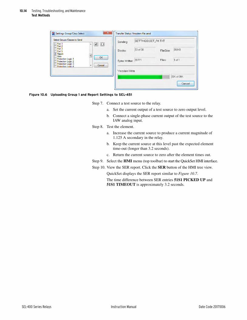
10.14
SEL-400 Series Relays Instruction Manual Date Code 20171006
Testing, Troubleshooting, and MaintenanceTest Methods
Step 7. Connect a test source to the relay.
a. Set the current output of a test source to zero output level.
b. Connect a single-phase current output of the test source to the IAW analog input.
Step 8. Test the element.
a. Increase the current source to produce a current magnitude of 1.125 A secondary in the relay.
b. Keep the current source at this level past the expected element time-out (longer than 3.2 seconds).
c. Return the current source to zero after the element times out.
Step 9. Select the HMI menu (top toolbar) to start the QuickSet HMI interface.
Step 10. View the SER report. Click the SER button of the HMI tree view.
QuickSet displays the SER report similar to Figure 10.7.
The time difference between SER entries 51S1 PICKED UP and 51S1 TIMEOUT is approximately 3.2 seconds.
Figure 10.6 Uploading Group 1 and Report Settings to SEL-451

10.15
Date Code 20171006 Instruction Manual SEL-400 Series Relays
Testing, Troubleshooting, and MaintenanceRelay Self-Tests
Relay Self-TestsThe relay continuously runs many self-tests to detect out-of-tolerance conditions. These tests run at the same time as relay protection and automation logic, but do not degrade relay performance.
The relay provides a number of alarms to indicate different conditions, as shown in Table 10.5.
The relay reports out-of-tolerance conditions as a status warning or status failure. For conditions that do not compromise relay protection, yet are beyond expected limits, the relay issues a status warning and continues to operate. A severe out-of-tolerance condition causes the relay to declare a status failure and enter a protec-
Figure 10.7 SER Report: QuickSet HMI
Table 10.5 Alarm Relay Word Bits
Alarm Relay Word Bit
Description
HALARML Latches for any relay failures.
HALARMP Asserts for five seconds when a warning condition occurs.
HALARMA Starts pulsing for five seconds every minute whenever a new warning condi-tion occurs and continues to pulse until the RST_HAL logic reset is asserted.
RST_HAL Resets the HALARMA operation (similar to the other logic resets in the relay).
HALARM Equivalent to HALARML OR HALARMP.
SETCHG Pulses for one second whenever settings are changed.
GRPSW Pulses for one second whenever groups are switched.
ACCESS This bit is set when a user is logged in at access Level B or higher.
BADPASS Pulses for one second whenever a user enters three successive bad passwords.
SALARM BADPASS OR SETCHG OR GRPSW.

10.16
SEL-400 Series Relays Instruction Manual Date Code 20171006
Testing, Troubleshooting, and MaintenanceRelay Self-Tests
tion-disabled state. During a protection-disabled state, the relay suspends protec-tion element processing and trip logic processing and de-energizes all control outputs. When disabled, the ENABLED front-panel LED is not illuminated.
The relay signals a status warning by pulsing the HALARMP, HALARMA, and HALARM Relay Word bits (hardware alarm) to logical 1 for five seconds. For a status failure, the relay latches the HALARML and HALARM Relay Word bits at logical 1. Some hardware failures prevent the relay from operating. In such cases, Relay Word bits HALARML and HALARM do not assert.
Once HALARMP pulses, Relay Word bit HALARMA continues to assert for approximately five seconds once per minute to indicate that a hardware warning has occurred. HALARMA continues to pulse until it is reset by pulsing SELOGIC control equation RST_HAL. Restarting the relay also resets HALARMA. HALARMP does not assert again for the same alarm condition, unless the condi-tion is cleared and returns.
The relay will automatically restart as many as two times on certain diagnostic failures. In many instances, this will correct the failure. When this occurs, the relay will log a Diagnostic Restart in the SER.
To provide remote status indication, connect the b contact of OUT108 to your control system remote alarm input and program the output SELOGIC control equation to respond to NOT (SALARM OR HALARM).
If you repeatedly receive status warnings, check relay operating conditions as soon as possible. Take preventive action early during the development of poten-tial problems to avoid system failures. For any status failure, contact your Techni-cal Service Center or the SEL factory immediately (see Technical Support on page 10.31).
The relay generates an automatic status report at the serial ports for a self-test sta-tus failure if you set Port setting AUTO := Y. The relay issues a status message with a format identical to the STATUS command output, but includes the power supply information from the STA A response. The relay also displays status warning and status failure automatic messages on the front-panel LCD. Use the serial port STATUS and CSTATUS commands and the front-panel RELAY STA-TUS menu to display status warnings and status failures. See STATUS on page 14.50, Checking Relay Status on page 3.11, and Relay Status on page 4.29 for more information on automatic status notifications and on viewing relay status.
The relay includes self-diagnostics that monitor settings, hardware, and commu-nication. The settings diagnostic checks if an internal error may have caused the calibration settings to be lost or corrupted, which would introduce errors in the magnitude and angles of the voltages and currents measured. The hardware diag-nostics monitor any component change that does not match the part number, as well as hardware failures in the power supply, processors, and digital samplers. For relays that support remote data acquisition, such as TiDL, the relay will mon-itor the connection to the remote data or the communication board in the relay that receives the remote data. Finally, the diagnostics monitor communications such as Ethernet, serial, and 87L connections. The STATUS command notifies the user if any of the diagnostics trigger a warning or a failure. In cases where the issue is a failure the relay will become disabled and protection will be inhibited.
StatusFigure 10.8 is a sample STATUS screen from the Status option of the QuickSet HMI > Meter and Control tree view (the terminal STATUS report is similar). Figure 10.9 is the STATUS A report showing all status information on a terminal.

10.17
Date Code 20171006 Instruction Manual SEL-400 Series Relays
Testing, Troubleshooting, and MaintenanceRelay Self-Tests
CSTATUSThe relay also reports status information in the Compressed ASCII format when you issue the CST command. An example Compressed ASCII status message is shown in Figure 10.10.
Figure 10.8 Relay Status: QuickSet HMI
=>>STA A <Enter>Relay 1 Date: 03/15/2015 Time: 04:48:49.938Station A Serial Number: 0000000000FID=SEL-451-5-Rxxx-V0-Zxxxxxx-Dyyyymmdd CID=0xxxxx
Failures No FailuresWarnings No WarningsChannel Offsets (mV) W=Warn F=Fail CH1 CH2 CH3 CH4 CH5 CH6 CH7 CH8 CH9 CH10 CH11 CH12 MOF 0 0 0 0 0 0 0 0 0 0 0 0 0
Power Supply Voltages (V) W=Warn F=Fail 3.3V_PS 5V_PS N5V_PS 15V_PS N15V_PS 3.28 4.91 -4.93 14.70 -14.79Temperature 23.7 degrees CelsiusCommunication Interfaces
Active High Accuracy Time Synchronization Source: IRIG-B IRIG-B Source PRESENTSELogic Relay Programming Environment Errors No ErrorsRelay Enabled=>>
Figure 10.9 Relay Status From a STATUS A Command on a Terminal

10.18
SEL-400 Series Relays Instruction Manual Date Code 20171006
Testing, Troubleshooting, and MaintenanceRelay Troubleshooting
Definitions for the items and fields in the Compressed ASCII configuration are listed below:
➤ yyyy is the checksum
➤ x is text in the FID (Firmware ID) string
➤ (description) is text that the relay supplies
➤ (Ok or W or F) is normal, warning, or failure, respectively
Firmware Version NumberAt the top of each status report the relay displays the present firmware version number that identifies the software program that controls relay functions. The firmware version is the four-place designator immediately following the relay model number (the first characters in the firmware identification or FID string). The first character in the four-place firmware version number is R (representing Release).
Figure 10.8 and Figure 10.9 show the location of the FID sting, with a blank or generic response. To see the actual FID string for the firmware version described in this manual, see Appendix A: Firmware, ICD File, and Manual Versions in the product-specific instruction manual for firmware version information.
Relay Troubleshooting
Inspection ProcedureComplete the following inspection procedure before disturbing the system. After you finish the inspection, proceed to Troubleshooting Procedures on page 10.19.
Step 1. Confirm that the power is on. Do not turn the relay off.
Step 2. Measure and record the control power voltage at the relay POWER ter-minals marked + and – on the rear-panel terminal strip.
Step 3. Measure and record the voltages at all control inputs.
Step 4. Measure and record the state of all control outputs.
Step 5. Inspect the serial communications ports cabling to be sure that a communications device is connected to at least one communications port.
"RID","SID","FID","yyyy","relay_name","station_name","SEL-451-x-Rxx-Vx-Zxxxxxx-Dxxxxxxxx","yyyy""MONTH","DAY","YEAR","HOUR","MIN","SEC","MSEC","yyyy"(Month),(Day),(Year),(Hour),(Min),(Sec),(MSec),"yyyy"
"CPU_RAM","CPU_PROG","SELBOOT","CPU_SET","DSP_RAM","DSP","DSP_CSUM","DSP_T_OUT","CPUDSP_RAM","FRNT_PNL","CAL_BOARDA","CCRD_CHG","COMM_CARD","ANA_CONV","IO_1","IO_2","yyyy"
"(Ok or F)","(Ok or F)","(Ok or F)","(Ok or F)","(Ok or F)","(Ok or F)","(Ok or F)","(Ok or F)","(Ok or F)","(Ok or F)","(Ok or F)","(Ok or F)","(Ok or F)","(Ok or F)","(Ok or F)","(Ok or F)","yyyy"
"ATOD_OFFST","MSTR_OFFST","3.3V_PS","5V_PS","N5V_PS","15V_PS","N15V_PS","TEMP_STA","TEMP","PRT_O_LOAD","LCD_ERROR","FPGA","yyyy"
"(Ok or F)","(Ok or F)","(Ok or F)","(Ok or F)","(Ok or F)","(Ok or F)","(Ok or F)","(Ok or F)",(Temp value),"(Ok or F)","(Ok or F)","(Ok or F)","yyyy"
"MBA","MBB","ACTTIM_SRC","SELOG_MATH","FM_TEST","DB_TEST","DB2_TEST","RLY_STA","PRT_F_TP","PRT_1_TP","PRT_2_TP","PRT_3_TP","PRT_5_TP","yyyy"
(Inac or Ok or F),(Inac or Ok or F),(HIRIG or IRIG or " "),(Enabled or Disabled), (Enabled or Disabled), (Enabled or Disabled), (Enabled or Disabled),(F,0-5), (F,0-5), (F,0-5), (F,0-5), (F,0-5),"yyyy"
Figure 10.10 Example Compressed ASCII Status Message

10.19
Date Code 20171006 Instruction Manual SEL-400 Series Relays
Testing, Troubleshooting, and MaintenanceRelay Troubleshooting
Troubleshooting ProceduresTroubleshooting procedures for common problems are listed in Table 10.6 and Table 10.7. The table lists each symptom, possible causes, and corresponding diagnoses/solutions. Related ASCII commands are listed in bold capitals. See Section 14: ASCII Command Reference for details on SEL-400 series commands and Section 12: Settings for details on relay settings.
Table 10.6 Troubleshooting Procedures (Sheet 1 of 2)
Symptom/Cause Diagnosis/Solution
Dark Front Panel
Power is off. Verify that substation battery power is operational.
Input power is not present. Verify that power is present at the rear-panel terminal strip.
Blown power supply fuse. Replace the fuse (see Power Supply Fuse Replacement on page 10.23).
Poor HMI contrast. Press and hold ESC for two seconds. Press Up Arrow and Down Arrow pushbuttons to adjust contrast.
Status Failure Notice on Front Panel
Self-test failure. See Table 10.7 for guidance on the specific failure type.
The OUT108 relay control output b contacts will be closed if you programmed NOT HALARM to OUT108.
Alarm Output Asserts
Power is off. Restore power.
Blown power supply fuse. Replace the fuse (see Power Supply Fuse Replacement on page 10.23).
Power supply failure. LCD displays STATUS FAILURE screen. See Table 10.7.
Main board or interface board failure. LCD displays STATUS FAILURE screen. See Table 10.7.
Other self-test failure. LCD displays STATUS FAILURE screen. See Table 10.7.
System Does Not Respond to Commands
NOTE: If Port setting PROTO := PMU, that serial port will not respond to ASCII commands. Additionally, a PROTO := PMU port will not respond to any messages when Global setting EPMU := N.
No communication. Confirm cable connections and types. If correct, type <Ctrl+X> <Enter>. This resets the termi-nal program.
Communications device is not con-nected to the system.
Connect a communications device.
Incorrect data speed (baud rate) or other communications parameters.
Configure your terminal port parameters to the particular relay port settings. Use the front panel to check port settings (see Set/Show on page 4.25).
Incorrect communications cables. Use SEL communications cables, or cables you build according to SEL specifications (see Serial Communication on page 15.2).
Communications cabling error. Check cable connections.
Handshake line conflict; system is attempting to transmit information, but cannot do so.
Check communications cabling. Use SEL communications cables, or cables you build accord-ing to SEL specifications (see Serial Communication on page 15.2).
System is in the XOFF state, halting communications.
Type <Ctrl+Q> to put the system in the XON state.
Terminal Displays Meaningless Characters
Data speed (baud rate) is set incorrectly. Check the terminal parameters configuration (see Serial Communication on page 15.2).
Terminal emulation is not optimal. Try other terminal types, including VT-100 and VT-52 terminal emulations.
System Does Not Respond to Faults
Relay is set improperly. Review the relay settings.
Improper test settings. Restore operating settings.

10.20
SEL-400 Series Relays Instruction Manual Date Code 20171006
Testing, Troubleshooting, and MaintenanceRelay Troubleshooting
PT or CT connection wiring error. Confirm PT and CT wiring.
Input voltages and currents phasing, and rotation errors.
Use relay metering. Use the TRI event trigger command and examine the generated event report (see Examining Metering Quantities on page 3.35).
The analog input (flat multipin ribbon) cable between the input module board and the main board is loose or defective.
Reseat both ends of the analog input cable, observing proper ESD precautions (see Installing Optional I/O Interface Boards on page 10.24).
Check the relay self-test status. Take preventive action as directed by relay Status Warning and Status Failure information (see Checking Relay Status on page 3.11).
Sequence of Events Recorder
SER DATA LOSS Reported This is caused by an internal buffer overrun, which can occur if SER points are being triggered faster than they can be processed. It will recover as soon as the SER processing can catch up. SER data loss can also be caused by excessive SER triggering (>6000 points per hour), causing the relay to temporarily suspend storing points. In this case, it will normally recover within an hour, but the SER DATA LOSS END message will not be reported until the first SER point is triggered after the suspension ends.
Tripping Output Relay Remains Closed Following a Fault
Auxiliary contact control inputs are improperly wired.
Check circuit breaker auxiliary contacts wiring.
Control output relay contacts have burned closed.
Remove relay power. Remove the control output connection. Check continuity—Form A con-tacts should be open and Form B contacts should be closed. Contact the SEL factory or your Technical Service Center if continuity checks fail.
I/O interface board failure. LCD displays STATUS FAILURE screen. Contact the SEL factory or your Technical Service Center.
Time/Date Errors
External IRIG time source error. Check IRIG-B time source or cables. Check TIME Q command or HMI SET/SHOW | Date/Time screen.
A low-priority time source error. Check last update source (TIME Q command or HMI SET/SHOW | Date/Time screen) (see Table 11.5 on page 11.8).
Lithium clock battery failure. Verify that the battery has failed before replacing the battery–it should last for 10 years if the relay is energized (see Replacing the Lithium Battery on page 10.22).
TiDL Applications
Relay will not successfully commis-sion.
Check the configuration of axion CT/PT modules and verify that they match a supported topol-ogy (see Section 2: Installation in the product-specific instruction manual).
Relay disabled. Check the CT/PT modules for failure. If a module is identified as failed, replace the CT/PT module and then press the commissioning button on the back of the relay (see TiDL Commis-sioning on page 10.3).
Table 10.7 Troubleshooting for Relay Self-Test Warnings and Failures (Sheet 1 of 2)
Diagnostic Message Diagnosis/Solution
Memory Failures
RAM Failurea This indicates a failure of a memory device. Contact the SEL factory or your Technical Service Center.
Flash Failure
Settings Failed
Default Settings Failure
Default Cal Settings This indicates that something has occurred that has caused the relay to lose its calibration. Con-tact the SEL factory or your Technical Service Center.
Table 10.6 Troubleshooting Procedures (Sheet 2 of 2)
Symptom/Cause Diagnosis/Solution

10.21
Date Code 20171006 Instruction Manual SEL-400 Series Relays
Testing, Troubleshooting, and MaintenanceRelay Troubleshooting
Line Current Differential Warnings
87L Watchdog Alarm This alarm indicates that the relay has received more than three unwarranted 87L pickup opera-tions associated with 87L communication channel impairments. This logic asserts Relay Word bit 87ALARM and does not inhibit 87L protection. This alarm can be reset at Access Level 2 by issuing a COM 87L WD C command.
87L Watchdog Error 1 This error indicates that the relay has received more than five unwarranted 87L pickup opera-tions associated with 87L communication channel impairments. This logic asserts Relay Word bit 87ERR1 and inhibits 87L protection. This alarm can be reset at Access Level 2 by issuing a COM 87L WD C command.
87L Watchdog Error 2 This error indicates that the relay has received more than ten unwarranted 87L pickup opera-tions associated with 87L communications channel impairments and non-channel related issues. This logic asserts Relay Word bit 87ERR2 and inhibits 87L protection. This alarm can be reset at Access Level 2 by issuing a COM 87L WD C command.
NOTE: In firmware R105 and older, this alarm can only be reset at Access Level C.
87L Watchdog Reset This warning occurs when the COM 87L WD C command is issued.
Hardware Changes
Card or Board Change This indicates that the installed hardware does not match the part number. If the hardware was intentionally changed, use the STA command from Access Level 2 to accept the new hardware configuration. If the hardware was not changed, make sure all connections are fully seated and then restart the relay. If the error persists, contact the SEL factory or your Technical Service Center.
Power Supply Voltage Status Warning
Power supply voltage(s) are out-of-tolerance.
Log the Status Warning. If repeated warnings occur, take preventive action.
A/D converter failure. LCD displays STATUS FAILURE screen. Contact the SEL factory or your Technical Service Center.
Power Supply Voltage Status Failure
Power supply voltage(s) are out-of-tolerance.
LCD displays STATUS FAILURE screen. Contact the SEL factory or your Technical Service Center.
A/D OFFSET WARN Status Warning
Loose ribbon cable between the input module board and the main board.
Reseat both ends of the analog input cable.
A/D converter drift. Log the Status Warning. If repeated warnings occur, contact the SEL factory or your Technical Service Center.
Master offset drift. LCD displays STATUS FAILURE screen. Contact the SEL factory or your Technical Service Center.
FPGA Failure
FPGA diagnostics failed during either power up or run time.a
In this rare event, the relay will automatically restart. If the failure occurs three times in seven days, the LCD displays the FPGA FAIL screen. Contact the SEL factory or your Technical Ser-vice Center.
NOTE: In older firmware versions, the relay did not automatically restart. Contact the SEL factory or your Technical Service Center.
Serial Port Power Overload
+5V EIA-232 Overload The relay rear serial ports are capable of providing +5V power to an external transceiver, but have a limited power output. This warning indicates that the power limit has been exceeded and the current has been limited. Check what is connected to the serial ports to ensure that there is no unintentional load on the +5V outputs.
All Other Warnings and Failures
Contact the SEL factory or your Technical Service Center.
a The relay will automatically restart for some of these failures. Contact the factory if the failure recurs.
Table 10.7 Troubleshooting for Relay Self-Test Warnings and Failures (Sheet 2 of 2)
Diagnostic Message Diagnosis/Solution

10.22
SEL-400 Series Relays Instruction Manual Date Code 20171006
Testing, Troubleshooting, and MaintenanceMaintenance
Maintenance
Instructions for CleaningUse care when cleaning the relay. Use a mild soap or detergent solution and a damp cloth to clean the chassis. Do not use abrasive materials, polishing com-pounds, or harsh chemical solvents (such as xylene or acetone) on any surface.
Replacing the Lithium BatteryYou can replace the lithium battery in the relay. Perform the following steps to replace the lithium battery.
Step 1. Remove the relay from service.
a. Follow your company standard procedure for removing a relay from service.
b. Disconnect power from the relay.
c. Remove the relay from the rack or panel.
d. Retain the GND connection, if possible, and ground the equipment to an ESD mat.
Step 2. Remove the front panel from the relay.
Step 3. Disconnect the front-panel cable from the front panel.
Step 4. Disconnect the power cable, interface board cable(s), and input board analog cable from the main board.
Step 5. Pull out the drawout tray containing the main board. In some SEL-400 series relays, the main board is not in a drawout tray. In these cases, you will need to remove the top cover to access the bat-tery.
Step 6. Locate the lithium battery.
The lithium battery is at the front of the main board.
Step 7. Remove the spent battery from beneath the clip of the battery holder.
Step 8. Replace the battery with an exact replacement.
Use a 3 V lithium coin cell, Ray-O-Vac No. BR2335 or equivalent. The positive side (+) of the battery faces up.
Step 9. Reinstall the relay main board drawout tray.
Step 10. Reattach the power cable, interface board cable(s), and input board analog cable.
Step 11. Reconnect the front-panel cable to the front panel.
Step 12. Reattach the front panel.
Step 13. Set the relay date and time via the communications ports or front panel (see Making Simple Settings Changes on page 3.15).
Step 14. Follow your company’s standard procedure to return the relay to ser-vice.
CAUTIONThere is danger of explosion if the bat-tery is incorrectly replaced. Replace only with Ray-O-Vac no. BR2335 or equivalent recommended by manufac-turer. See Owner's Manual for safety instructions. The battery used in this device may present a fire or chemical burn hazard if mistreated. Do not recharge, disassemble, heat above 100°C or incinerate. Dispose of used batteries according to the manufac-turer’s instructions. Keep battery out of reach of children.
CAUTIONEquipment components are sensitive to electrostatic discharge (ESD). Unde-tectable permanent damage can result if you do not use proper ESD proce-dures. Ground yourself, your work sur-face, and this equipment before removing any cover from this equip-ment. If your facility is not equipped to work with these components, contact SEL about returning this device and related SEL equipment for service.

10.23
Date Code 20171006 Instruction Manual SEL-400 Series Relays
Testing, Troubleshooting, and MaintenanceMaintenance
Power Supply Fuse ReplacementYou can replace a bad fuse in a relay power supply, or you can return the relay to SEL for fuse replacement. If you decide to replace the fuse, perform the follow-ing steps:
Step 1. Follow your company standard to remove the relay from service.
Step 2. Disconnect power from the relay.
Step 3. Remove the relay from the rack or panel.
Step 4. Retain the GND connection, if possible, and ground the equipment to an ESD mat.
Step 5. Remove the communications cable connected to the front-panel serial port, if applicable.
Step 6. Remove the rear-panel EIA-232 PORT mating connectors.
Unscrew the keeper screws and disconnect any serial cables connected to the PORT 1, PORT 2, and PORT 3 rear-panel receptacles.
Step 7. Loosen the four front-panel screws (they remain attached to the front panel), and remove the relay front panel.
Step 8. Remove the 34-pin ribbon cable from the front panel by pushing the extraction ears away from the connector.
Step 9. Disconnect the power, the interface board, and the analog input board cables from the main board.
Step 10. Remove the screw terminal connectors.
a. Loosen the attachment screws at each end of the 100-addresses, 200-addresses, and 300-addresses screw terminal connectors.
b. Pull straight back to remove.
Step 11. Remove the top chassis plate by unscrewing seven screws from the chassis.
Step 12. Pull out the drawout tray containing the main board.
Step 13. Pull out the drawout tray containing the I/O interface board(s).
Step 14. Locate the power supply. Fuse F1 is at the rear of the power supply circuit board (see Figure 10.11).
Step 15. Examine the power supply for blackened parts or other damage. If you can see obvious damage, reinstall all boards and contact SEL to arrange return of the relay for repair.
Step 16. Remove the spent fuse from the fuse clips.
Step 17. Replace the fuse with an exact replacement (see Section 2: Installa-tion in the product-specific instruction manual for the proper fuse for your power supply).
Step 18. Reinstall the interface board.
Step 19. Reinstall the main board, and reconnect the power, the interface board, and the analog input board cables.
Step 20. Replace the chassis top on the relay and secure it with seven screws.
Step 21. Reconnect the cable removed in Step 8 and reinstall the relay front-panel cover.
Step 22. Reattach the rear-panel connections.
Affix the screw terminal connectors to the appropriate 100-addresses, 200-addresses, and 300-addresses locations on the rear panel.
DANGERDisconnect or de-energize all external connections before opening this device. Contact with hazardous volt-ages and currents inside this device can cause electrical shock resulting in injury or death.
WARNINGHave only qualified personnel service this equipment. If you are not quali-fied to service this equipment, you can injure yourself or others, or cause equipment damage.
CAUTIONEquipment components are sensitive to electrostatic discharge (ESD). Undetectable permanent damage can result if you do not use proper ESD procedures. Ground yourself, your work surface, and this equipment before removing any cover from this equipment. If your facility is not equipped to work with these compo-nents, contact SEL about returning this device and related SEL equip-ment for service.

10.24
SEL-400 Series Relays Instruction Manual Date Code 20171006
Testing, Troubleshooting, and MaintenanceMaintenance
CAUTION
Step 23. Reconnect any serial cables that you removed from the EIA-232 PORTS in the disassembly process.
Step 24. Follow your company standard procedure to return the relay to service.
NOTE: Some versions of this relay will have the PS50 power supply. The fuse is located in the same location as the PS30, but it is rotated 90 degrees.
Installing Optional I/O Interface BoardsPerform the following steps to install SEL-400 series relay I/O interface boards.
Equipment components are sensitive to electrostatic discharge (ESD). Per-manent damage can result if you do not use proper ESD procedures. Ground yourself, your work surface, and this equipment before removing any cover from this equipment. If your facility is not equipped to work with these components, contact SEL about returning this device and related SEL equipment for service.
Step 1. Follow your company standard to remove the relay from service. It will be necessary to remove power from the relay as part of this pro-cess.
Step 2. Disconnect power from the relay. Isolate any contact inputs or out-puts that will be affected by the installation of the I/O interface board.
Step 3. Retain the GND connection, located to the right of the power supply terminals to the relay, and ground the equipment to an ESD mat, or other grounding point.
Step 4. Remove the communications cable connected to the front-panel serial port, if applicable.
Step 5. Remove the rear-terminal block connectors for the I/O board that is being installed. Two screws are used to retain each connector. Once these screws are loosened, pull the connector firmly to remove it from the rear of the relay. Note that these connectors are keyed to their mating connectors in the relay.
Figure 10.11 PS30 Power Supply Fuse Location
J1
F1
J2J3
FuseF1

10.25
Date Code 20171006 Instruction Manual SEL-400 Series Relays
Testing, Troubleshooting, and MaintenanceMaintenance
Step 6. Remove the front panel.
a. Unscrew the front cover of the relay.
b. Slowly pull the front cover off of the relay.
There will be a short ribbon cable between the front panel of the relay and the main board of the relay that will prevent the relay front panel from being pulled more than five inches from the relay. Do not let the relay front panel hang from this ribbon cable.
c. Remove the ribbon cable at the front panel by pushing the cable retention levers toward the back of the front panel, as shown in Figure 10.13.
If your front panel is equipped with auxiliary trip and close pushbuttons, remove the connectors to the pushbuttons connected at the front panel and the expansion I/O board.
Step 7. Remove the power supply, expansion I/O and calibration board rib-bon cables from their connectors on the main board (see Figure 10.14).
Figure 10.12 SEL-400 Series Relay Rear Panel
Terminal
Block
Connector
Screws
Figure 10.13 Front-Panel Ribbon Cable Connector With Clasps Open

10.26
SEL-400 Series Relays Instruction Manual Date Code 20171006
Testing, Troubleshooting, and MaintenanceMaintenance
Step 8. Remove the main board power cable (white connector) from the main board by lifting up the retaining tabs on top of the header and sliding the connector out.
Do not bend the retaining tabs any higher than is necessary to remove the connector as this could damage the tabs.
Step 9. Use the Jumper Configuration table shown in Figure 10.15 to con-firm that the jumper arrangement on the I/O board matches the cor-rect jumper configuration for the interface board being installed. For example, the jumper configuration in Figure 10.15 (a) is for an inter-face board being installed at the 300 level (i.e., the jumpers are set to ON, OFF, ON, OFF).
Step 10. Install the drawout tray with the I/O interface board.
a. Position the drawout tray edges into the left-side and right-side internally mounted slots.
b. Slide the I/O interface board into the relay by pushing the front edge of the board drawout tray.
Figure 10.14 Main Board Cable Connections
Ribbon
Cables
Main Board
Power Cable
Figure 10.15 I/O Board Jumper Configuration
JMP49A = ON
JMP49B = OFF
JMP50A = ON
JMP50B = OFF
Jumper Configuration Table Jumper Configuration Table
JMP2A = ON
JMP2B = OFF
JMP1B = OFF
JMP1A = ON
(a) (b)

10.27
Date Code 20171006 Instruction Manual SEL-400 Series Relays
Testing, Troubleshooting, and MaintenanceMaintenance
c. Apply firm pressure to fully seat the I/O interface board.
If you encounter resistance, STOP and withdraw the board.
Inspect the drawout tray edge guide slots for damage.
If you see no damage, take all of the precautions outlined above and try again to insert the board.
Step 11. Confirm screw-terminal connector keying.
a. Inspect the screw-terminal connector receptacles on the rear of the I/O interface board.
Figure 10.16 shows the I/O board section without terminal blocks. The yellow dividers are the connector keying for each terminal block.
b. Refer to Figure 10.17 for the corresponding key positions inside the receptacle.
Figure 10.16 Screw-Terminal Connector Receptacles
Figure 10.17 Screw-Terminal Connector Keying
Key
A B C 21 3 CA B B21 3 A C 1 2 3
200-AddressesRow B
A B C 1 2 3 A B C 1 2 3
100-AddressesRow A
D E F 1 2 3 D E F 1 2 3 ED F 1 2 3
500-AddressesRow E
D E F 1 2 3 D E F 1 2 3 ED F 1 2 3
400-AddressesRow D
Insert KeyP/N 090-2915
(One Pair for Each Screw-Terminal Connector)
A B C 21 3 CA B B1 2 3 A C 1 2 3
300-Addresses Row C

10.28
SEL-400 Series Relays Instruction Manual Date Code 20171006
Testing, Troubleshooting, and MaintenanceMaintenance
c. If the keys inside the I/O interface board receptacles are not in the positions indicated in Figure 10.17, grasp the key edge with long-nosed pliers to remove the key and reinsert the key in the correct position.
d. Break the webs of the screw-terminal connectors in the position that matches the receptacle key, as shown in Figure 10.18.
Step 12. Attach the screw-terminal connector.
a. Mount the screw-terminal connectors to the rear panel of the relay.
b. Tighten the screw-terminal connector mounting screws to between 7 in-lb and 12 in-lb (0.8 Nm to 1.4 Nm).
Step 13. Reconnect the power, the interface board, and the analog input board cables to the relay main board.
Step 14. Reconnect the cables removed in Step 6–Step 8 and reinstall the relay front-panel cover.
Step 15. Apply power.
Step 16. Reconnect any serial cables that you removed from the communica-tions ports in the disassembly process.
Step 17. Establish a terminal emulation session with the relay using QuickSet SEL-5030 Software or other terminal emulation program.
Step 18. Using the terminal emulation program, enter Access Level 2.
Step 19. From Access Level 2, issue the STA command, and answer Y <Enter> if prompted to accept the new hardware configuration. (Note: If the I/O board was replaced with exactly the same board, you will not be prompted to accept new hardware.)
Figure 10.18 Screw-Terminal Connector With Webs
WebbingWebbing
Removed

10.29
Date Code 20171006 Instruction Manual SEL-400 Series Relays
Testing, Troubleshooting, and MaintenanceMaintenance
Step 20. Inspect the relay targets to confirm that the relay reads the I/O inter-face board(s).
a. Verify the I/O interface board control inputs and outputs in the target listings by using a terminal or the QuickSet software.
b. Use a communications terminal to issue the following commands.
TAR INn01 <Enter>
TAR OUTn01 <Enter>
n = 1–5 for boards in the 100–500 address slots
Step 21. Follow your company’s standard procedure to return the relay to ser-vice.
TroubleshootingStep 1. If the I/O board jumpers were not correctly configured in Step 9 and
Step 10, the front panel will display the error RELAY DISABLED SET-TINGS FAILED. You will also receive a SETTINGS FAILED failure in the terminal emulation window following an STA command, as shown in Figure 10.19.
Step 2. Disconnect power to the relay and return to Step 8 to verify you have correctly configured the jumpers (Step 9). If the jumpers are not cor-rect, repeat the I/O board installation instructions, beginning with Step 9.
Step 3. If the jumpers are correct, enter the CAL level.
a. Enter the VEC D command.
b. If you see the error SETTINGS FAILURE in C n
(n = 1–4), enter the SET C n command.
c. When prompted to do so, save the settings.
d. Return to Access Level 2, and enter the STA command to verify that the status is free of warnings.
If the problem persists, please contact your SEL representative.
Level 2=>>sta
Relay 1 Date: 01/10/2000 Time: 18:13:10.769Station A Serial Number: 1130320464
FID=SEL-487B-1-R305-V0-Z007005-D20121221 CID=0XF3A0
Failures SETTINGS FAILED
Warnings No Warnings
SELogic Relay Programming Environment Errors No Errors
Relay Disabled
Figure 10.19 I/O Board Installation Error Message in the Terminal Window

10.30
SEL-400 Series Relays Instruction Manual Date Code 20171006
Testing, Troubleshooting, and MaintenanceTiDL Module Replacement
TiDL Module ReplacementTo replace a module in the SEL-2240 Axion, perform the following steps:
Step 1. De-energize any power source connected to the power coupler(s) in the Axion node.
NOTE: The modules are hot pluggable; however, if a module is removed, the TiDL system will be disabled, the same as powering off the unit.
Step 2. Loosen the chassis retaining screw at the top of the module.
Step 3. Tip the top of the module away from the chassis and lift it from the bottom lip.
Step 4. Install the new module, inserting the bottom lip first by using the notch on the module to help with alignment (see Figure 10.20). Then push in the top of the module to align with the chassis slot and tighten the retaining screw (see Figure 10.21).
Figure 10.20 Axion Notch Alignment

10.31
Date Code 20171006 Instruction Manual SEL-400 Series Relays
Testing, Troubleshooting, and MaintenanceTechnical Support
Step 5. Make all necessary connections to the module.
Step 6. If in Step 1 you chose to disconnect power, apply power to the Axion module and then skip to Step 8. Otherwise, proceed to Step 7.
Step 7. Cycle power to the SEL relay.
Step 8. When startup is complete, press and hold the COMMISSION button on the back of the relay for two seconds for the relay to verify the con-nected topology.
Technical SupportWe appreciate your interest in SEL products and services. If you have questions or comments, please contact us at:
Schweitzer Engineering Laboratories, Inc.2350 NE Hopkins CourtPullman, WA 99163-5603 U.S.A. Tel: +1.509.338.3838Fax: +1.509.332.7990 Internet: selinc.com/supportEmail: [email protected]
Figure 10.21 Axion Retaining Screw

This page intentionally left blank

Date Code 20171006 Instruction Manual SEL-400 Series Relays
Instruction ManualInstruction ManualS E C T I O N 1 1
Time and Date Management
SEL-400 series relays can determine the time from a variety of sources, including IRIG-B, PTP (IEEE 1588), Simple Network Time Protocol (SNTP), DNP3, MIR-RORED BITS, terminal TIME and DATE commands, and HMI settings. (Refer to the appropriate sections in the product-specific instruction manual to learn about using these various time sources.) Most of these sources provide only an approx-imate measure of time. For high-accuracy time synchronization, which is needed to support synchrophasors and to ease comparison of system-wide events, a high-accuracy time source must be provided, such as IRIG-B with C37.118 extensions or PTP with power system profile. This section focuses on issues related to high-accuracy timekeeping. The relay records power system events with very high accuracy when you provide high-accuracy clock input signals. Relays placed at key substations can give you information on power system operating conditions in real time.
NOTE: Not all SEL-400 series relays support synchrophasors.
Based on the high-accuracy time input, the relay calculates synchrophasors for currents and line voltages (for each phase and for positive-sequence), as specified in IEEE C37.118, Standard for Synchrophasor Measurements for Power Sys-tems. You can then perform detailed analysis and calculate load flow from the synchrophasors. See Section 18: Synchrophasors for more information about phasor measurement functions in the relay.
This section presents details on these measurements as well as suggestions for further application areas. The topics of this section are the following:
➤ IRIG-B Timekeeping on page 11.1
➤ PTP Timekeeping on page 11.2
➤ Time Source Selection on page 11.4
➤ Time Quality Indications on page 11.5
➤ Time-Synchronized Events on page 11.9
IRIG-B TimekeepingThe relay is capable of high-accuracy timekeeping when supplied with an IRIG-B signal. When the supplied clock signal is sufficiently accurate, the relay can act as a phasor measurement unit (PMU) and transmit synchrophasor data representative of the power system at fixed time periods to an external data pro-cessor. The relay can also record COMTRADE event report data using the high-accuracy time stamp.
The relay has two input connectors that accept IRIG-B demodulated time-code format: the IRIG-B pins of Serial Port 1, and the IRIG-B BNC connector. See Section 2: Installation in the product-specific instruction manual for more infor-mation on connecting these inputs.

11.2
SEL-400 Series Relays Instruction Manual Date Code 20171006
Time and Date ManagementPTP Timekeeping
NOTE: The SEL-2407 Satellite-Synchronized Clock meets both the relay accuracy and IEEE C37.118 requirements for a high-accuracy time source.
The IRIG-B inputs can be used for high-accuracy timekeeping purposes with as high as 1 ms accuracy with an appropriate time source. See Table 11.1 for relay timekeeping mode details.
NOTE: If the time-code signal connected to the BNC connector degrades in quality, the relay will not switchover to the IRIG-B pins of Serial Port 1. The relay will only switch to Serial Port 1 if the signal on the BNC connector completely fails or the accuracy is better on Serial Port 1 than on the BNC input (e.g., the cable is unplugged).
Only one IRIG-B time source can be used by the relay, and the signal connected to the IRIG-B BNC connector takes priority over the Serial Port 1 IRIG-B pins. If a signal is detected on the IRIG-B BNC input, the IRIG-B pins of Serial Port 1 will be ignored, unless the Serial Port 1 IRIG-B has better quality than the BNC input.
The relay determines the suitability of the IRIG-B signal connected to the BNC connector for high-accuracy timekeeping by applying two tests:
➤ Measuring whether the jitter between positive-transitions (rising edges) of the clock signal is less than 500 ns.
➤ Decoding the time-error information contained in the IR IG-B control field and determining that analog quantity TQUAL is less than 10–6 seconds (1 s).
If a valid source is detected on the BNC or serial port IRIG inputs, then BNC_TIM or SER_TIM will be set, respectively. Similarly, if a high-quality source is detected on the BNC or serial port IRIG inputs, then BNC_OK or SER_OK will be set, respectively.
PTP TimekeepingIn addition to IRIG-B, Precision Time Protocol (PTP), as specified in IEEE 1588-2008, can be used for high-accuracy timekeeping. The relay can only be synchronized by a grandmaster on the PTP timescale, not an arbitrary (ARB) timescale. With the ARB timescale, the epoch is set by an administrative procedure and can change at any time during normal operation. The PTP timescale uses the PTP epoch of Jan-uary 1 1970 00:00:00 TAI (International Atomic Time), which corresponds to December 31 1969 23:59:51.999918 UTC (Coordinated Universal Time). Its unit of time is the SI second and accounts for leap seconds. As of June 2016, TAI is 36 seconds ahead of UTC.
The offset between TAI and UTC time is included in the PTP announce message, along with a flag that indicates whether or not the offset is valid. The relay will use the offset sent by the Grand Master (GM) clock to determine UTC time
Table 11.1 Relay Timekeeping Modes
Item Internal Clock IRIG HIRIG (or High-Accuracy IRIG) PTP HPTP
Best accuracy (condition)
Depends on last method of set-ting, or synchro-nizationa
500 µs (when time-source jitter is less than 3 ms)
1 µs (when time-source jitter is less than 500 ns, and time-error is less than 1 µs)b
Determined by PTP master (Master clock sync and announce interval <= 4s)
1 µs (Master clock sync and announce interval <= 4 s, and TQUAL <1 µs)
IRIG-B connec-tion required
None BNC connector (pre-ferred), or Serial Port 1
BNC connector (preferred), or Serial Port 1
PTP time source connected
PTP time source connected
Relay Word bits TIRIG = 0TSOK = 0BNC_TIM = 0SER _TIM = 0BNC_OK = 0SER_OK = 0
TIRIG = 1TSOK = 0BNC_TIM = 1 or SER_TIM = 1BNC_OK = 0SER_OK = 0
TIRIG = 1TSOK = 1BNC_TIM = 1 or SER_TIM = 1BNC_OK = 1 orSER_OK = 1
TPTP = 1
TSOK = 0
TPTP = 1
TSOK = 1
a The internal clock in the relay can be synchronized via SNTP, DNP3, SEL-2030 Communications Processor, or MIRRORED BITS communications.b The time source must include the IEEE C37.118 IRIG-B control bit assignments and the Global setting IRIGC must be set to C37.118 to provide
the time-error estimate for the clock. In products that support line-current differential protection, the jitter requirement for HIRIG is 50 ns.

11.3
Date Code 20171006 Instruction Manual SEL-400 Series Relays
Time and Date ManagementPTP Timekeeping
regardless of validity. Because of this, all SEL devices (and other slave devices that share this behavior) synchronized with the GM will retain relational accuracy with each other even if, in certain cases, the GM may be incorrect in relation to UTC.
The announce message may also include the current TAI to Local offset value (required in the C37.238 profile). In accordance with IEEE 1588-2008 16.3.3.4, this value must include the TAI to UTC offset to reflect local time at the node, or slave device. If the relay receives a TAI to Local offset value that does not include the TAI to UTC offset, it may incorrectly calculate UTC and Local time. Also, if the announce message does not include the TAI to Local offset value, the relay will use its configured Time and Date settings (UTCOFF, BEG_DST, and END_DST) to calculate local time. This is one reason that the relay Time and Date settings must match the settings in the GM clock, or devices that are syn-chronized may have issues with time alignment.
To use PTP, the relay part number must include the Ethernet card option that sup-ports PTP and PTP must be enabled in Port 5 settings (EPTP = Y) and properly configured. The relay must be connected to a network containing an appropriate PTP master, and all intervening switches must be IEEE 1588 aware. For all SEL-400 series relays, PTP is only available on Ethernet Ports 5A and 5B. PTPPORT is an analog quantity that can be used to identify the active port. PTPPORT = 1 if Port A is the active port, PTPPORT = 2 if Port B is the active port, and PTPPORT = 0 if PTP is not synchronized. See Precision Time Protocol (PTP) on page 15.15 for more information on configuring the relay and the Ethernet network for PTP.
To achieve basic synchronization to PTP, the master clock sync and announce interval must not exceed four seconds. The Relay Word bit PTP_TIM indicates that this basic level of synchronization has been achieved. If the master clock reports an accuracy of 1 s or better and the network is not introducing excessive jitter in the time-synchronized messages, PTP_OK will be set indicating the presence of high-accuracy time synchronization. The analog quantity PTPSTEN can be used to indicate the state of the PTP Port as follows: 1 = Initializing, 2 = Faulty, 3 = Disabled, 4 = Listening, 8 = Uncalibrated, 9 = Slave.
Depending on the Port 5 configurations, the supported PTP profile may be restricted to C37.238 power profile. When PTP time synchronization is configured on the process bus ports (NETPORT = C or D), the only available PTP profile is C37.238. Refer to Station Bus and Process Bus on page 17.19 for definitions of a process bus.
PTP Over PRP NetworksSEL-400 series relays support PTP time synchronization over a PRP network. When the relay operates in this network mode, the only available PTP profile is C37.238.
The SEL-400 series relays support PTP time synchronization over Parallel Redundancy Protocol (PRP) networks. In a PRP network, a dual attached node (DAN) receives a pair of duplicated packets. It processes the first frame and discards the duplicated frame based on the information in the redundancy controller trailer (RCT).
This method of using RCTs to distinguish packets does not apply to PTP messages. PTP messages that transverse through two distinct networks suffer a different amount of delays. Figure 11.1 shows that path delays via LAN A and LAN B are different. These delays include link delays and residence time. PTP-capable Ethernet switches in these LANs should update PTP messages with the actual residence time and request/reply to path delay messages. It should not alter PTP messages by appending RCTs. The dual attached slave clock receives two different sets of PTP messages, as shown in Figure 11.1. The two ports independently determine its port state.

11.4
SEL-400 Series Relays Instruction Manual Date Code 20171006
Time and Date ManagementTime Source Selection
The relay can only synchronize to a PTP clock. If two PTP masters are available. SEL-400 series relays first use the Best Master Clock Algorithm (BMCA) to select the best master. If the locally derived offsets between the relay and the BMCA- selected master is less or equal to 1 s, the relay synchronizes itself with the BMCA-selected master time information. Otherwise, the relay uses the time information from the other master if this master has locally derived offsets less than or equal to 1 s. If not, the relay continues using the BMCA-selected master. SEL-400 series relays use the analog quantity PTPPORT to indicate the port to which the relay is synchronized. If PTPPORT = 1, the relay is synchronized via Ethernet Port 5A. If PTPPORT = 2, the relay is synchronized via Ethernet Port 5B. The ASCII command COM PTP also displays the port status in COM PTP on page 14.14. If a port is selected to synchronize the relay, the port status is ACTIVE; otherwise, it is PASSIVE.
Time Source SelectionIRIG-B via BNC connection, IRIG-B via Serial Port 1, and PTP can all be con-nected to the relay. Each of these can provide a high-quality time value. The relay selects between these sources using the following priority scheme:
1. IRIG-B BNC high quality (BNC_OK = 1)
2. IRIG-B serial port high quality (SER_OK = 1)
Figure 11.1 PTP Time Synchronization Over a PRP Network
LAN A LAN B
Master Clock A Master Clock B
Port A Port B
Residence Time Residence Time
Ordinary Clock
Transparent Clock Transparent Clock
SEL-400 Series Relay
Delay_Req_A Delay_Req_B
Link Delay Link Delay
Announce_A Announce_B
Sync_A
Sync_BFollow_up_A
Follow_up_B

11.5
Date Code 20171006 Instruction Manual SEL-400 Series Relays
Time and Date ManagementTime Quality Indications
3. PTP high quality (PTP_OK = 1)
4. PTP nominal quality (PTP_TIM = 1)
5. IRIG-B BNC nominal quality (BNC_TIM = 1)
6. IRIG-B serial port nominal quality (SER_TIM = 1)
The TIME command indicates what source is being used. This is also available in the analog quantity CUR_SRC as shown in Table 11.2.
If IRIG-B and PTP are not available, then the time can be set via any low-priority time source: SNTP, DNP3, TIME and DATE commands, front-panel set date/time, and extended MIRRORED BITS.
Time Quality IndicationsAnalog Quantities and Relay Word Bits
You can check the status of timekeeping by checking the relevant analog quanti-ties or relay word bits. Once a time source is connected, wait at least 20 seconds to allow for a solid synchronization to take place.
If you are using a time source that provides time-quality information (IRIG-B with C37.118 or PTP), then the presently reported time quality is available via the TQUAL analog quantity and the TQUAL1, TQUAL2, TQUAL4, and TQUAL8 Relay Word bits. Table 11.3 and Table 11.4 show how these are encoded for IRIG and the two supported PTP Profiles.
Table 11.2 CUR_SRC Encoding
Source CUR_SRC value
BNC IRIG-B 1
Serial Port IRIG-B 2
PTP 4
None of the above 8
Table 11.3 Time Quality Encoding (PTP Default Profile or IRIG)
PTP v2 Default Profile Or IRIG (PTPPRO = Default)
Master Clock Accuracy (ns) TQUAL8 TQUAL4 TQUAL2 TQUAL1 TQUAL (seconds)
Clock failure, time not reliable 1 1 1 1 1038
10 seconds 1 0 1 1 10
1 second 1 0 1 0 1
100 milliseconds 1 0 0 1 0.1
10 milliseconds 1 0 0 0 0.01
1 millisecond 0 1 1 1 0.001
100 microseconds 0 1 1 0 0.0001
10 microseconds 0 1 0 1 0.00001
1 microsecond 0 1 0 0 0.000001
100 nanoseconds 0 0 1 1 0.0000001
10 nanosecondsa
a This does not apply to PTP default Profile.
0 0 1 0 0.00000001
1 nanoseconda 0 0 0 1 0.000000001

11.6
SEL-400 Series Relays Instruction Manual Date Code 20171006
Time and Date ManagementTime Quality Indications
PTP supports two power profiles and is set by the PORT 5 setting PTPPRO. The two profiles are DEFAULT and C37.238. PTP reports the time quality through TQUAL1, TQUAL2, TQUAL4, and TQUAL8 Relay Word bits, which are the same bits used if IRIG-B is the time source. If PTPPRO = DEFAULT, the time quality is reported based only on the accuracy of the master clock. If PTPPRO = C37.238, the time quality is reported based on the accuracy of the master clock (Grandmaster timein-accuracy) plus the inaccuracy of the network (Network timeinaccuracy). For this pro-file, if either Grandmaster timeinaccuracy or Network timeinaccuracy is the maximum value, the relay will set all TQUAL bits to 1.
NOTE: If the Global setting IRIGC is changed from NONE to C37.118, the relay asserts TGLOBAL before completely assessing the time-synchronization state. The assessment completes and TGLOBAL has the correct value approximately 5 seconds after you make such a settings change.
If the relay is synchronized to an IRIG-B or PTP time source, the TSYNC bit will be set. If the quality of this synchronization is 1 s or better, then TSOK is set, indicating this bit has sufficient accuracy for synchrophasors. TGLOBAL will assert if a high-accuracy source is being used and the source indicates it is providing 1 s or better accuracy, and the Global setting IRIGC = C37.118 for BNC IRIG. If the relay is syn-chronized to IRIG-B without the quality extensions indicated by the Global setting IRIGC, or PTP without the grandmaster clock sending announce and synchronization messages at least every four seconds, TLOCAL bit will be asserted.
As an example of checking IRIG status, use the command TAR TIRIG to view the relevant Relay Word bits, as shown in Figure 11.2. Only the state of the TIRIG and TSOK Relay Word bits are discussed in the troubleshooting steps below. The other Relay Word bits of interest to this discussion are TUPDH, which indicates that the relay internal clock is presently being updated by the HIRIG source, TSYNCA, which acts as an alarm bit that asserts when the relay is not synchronized to either an internal or an external source. TSYNCA will only assert briefly when the HIRIG time source is connected or disconnected.
The TIRIG and TSOK Relay Word bits should be asserted (logical 1), indicating that the relay is in the high-accuracy IRIG timekeeping mode (HIRIG).
Table 11.4 Time Quality Encoding (PTP Power Profile)
PTP v2 Power Profile (PTPPRO = C37.238)
Time_inaccuracy = Grandmaster timeinaccuracy + Network timeinaccuracy (ns)
TQUAL8 TQUAL4 TQUAL2 TQUAL1 TQUAL (seconds)
Grandmaster timeinaccuracy = 4294967295 or Networktimeinaccuracy = 4294967295
1 1 1 1 Grandmaster timeinaccuracy
+
Network timeinaccuracy
1,000,000,000 time_inaccuracy < 10,000,000,000 1 0 1 1
100,000,000 time_inaccuracy < 1,000,000,000 1 0 1 0
10,000,000 time_inaccuracy < 100,000,000 1 0 0 1
1,000,000 time_inaccuracy < 10,000,000 1 0 0 0
100,000 time_inaccuracy < 1,000,000 0 1 1 1
10,000 time_inaccuracy < 100,000 0 1 1 0
1,000 time_inaccuracy < 10,000 0 1 0 1
100 time_inaccuracy < 1,000 0 1 0 0
10 time_inaccuracy < 100 0 0 1 1
1 time_inaccuracy < 10 0 0 1 0
time_inaccuracy = 0 0 0 0 0
=>TAR TIRIG <Enter>
* * TIRIG TUPDH TSYNCA TSOK PMDOK FREQOK0 0 1 1 0 1 1 0=>
Figure 11.2 Confirming the High-Accuracy Timekeeping Relay Word Bits

11.7
Date Code 20171006 Instruction Manual SEL-400 Series Relays
Time and Date ManagementTime Quality Indications
If TSOK is not asserted, but TIRIG is asserted, the relay is in regular IRIG time-keeping mode. Following is a list of possible reasons for not entering HIRIG mode:
➤ The IRIG-B clock does not use the IEEE C37.118 control bit assignments, or the IRIG-B signal is not of sufficient accuracy.
➤ The termination resistor, required by some IRIG clocks, is not installed.
➤ The time-source clock is reporting that its time error is greater than 1 s.
If neither TSOK nor TIRIG is asserted, the relay is not in an IRIG time-source mode. Following is a list of possible reasons for not entering IRIG mode:
➤ The IRIG-B clock signal is not of sufficient accuracy or is improperly configured.
➤ The termination resistor, required by some IRIG clocks, is not installed.
NOTE: At startup, TPTP can assert as fast as 1.5 seconds after PTP_TIM asserts.
TBNC asserts when BNC IRIG is used to update the relay master time. Likewise, TSER asserts when serial IRIG is selected and TPTP asserts when PTP is the active source updating the relay master time. At any given time, only one of these three bits can equal logical 1.
Global Time Source vs Local Time SourceAn SEL-400 series relay indicates that it is synchronized with either a Global or local time source according to the logic as shown in Figure 11.3. When CUR_SRC is IRIG or PTP and TSOK is asserted, the relay determines the status of TGLOBAL or TLOCAL following the logic diagram in Figure 11.3. TGLOBAL asserts when the relay is synchronized to high-accuracy IRIG-B (accuracy 1 us and IRIGC = C37.118) or PTP (accuracy 1 us, master_clock_class = 6). A holdover timer keeps TGLOBAL asserted for five seconds if the relay loses its global time source after being synchronized. TLO-CAL asserts when the relay is synchronized to high-accuracy IRIG-B (accuracy 1 us and IRIGC = None) or PTP (accuracy 1 us) and TGLOBAL is not asserted.
Figure 11.3 TLOCAL and TGLOBAL Logic
5 S
CUR_SRC = IRIG
CUR_SRC = PTP
TSOK
TSOK
IRIGC = None
IRIGC = C37.118
master_clock_class ≠ 6
master_clock_class = 6
5 S
Holdover Timer
Holdover Timer
To TLOCAL
To TGLOBAL
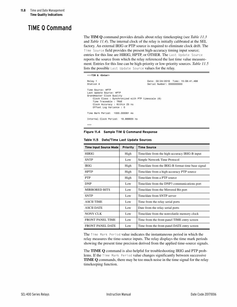
11.8
SEL-400 Series Relays Instruction Manual Date Code 20171006
Time and Date ManagementTime Quality Indications
TIME Q CommandThe TIM Q command provides details about relay timekeeping (see Table 11.3 and Table 11.4). The internal clock of the relay is initially calibrated at the SEL factory. An external IRIG or PTP source is required to eliminate clock drift. The Time Source field provides the present high-accuracy timing input source; entries for this line are HIRIG, HPTP, or OTHER. The Last Update Source reports the source from which the relay referenced the last time value measure-ment. Entries for this line can be high-priority or low-priority sources. Table 11.5 lists the possible Last Update Source values for the relay.
The Time Mark Period value indicates the instantaneous period in which the relay measures the time-source inputs. The relay displays the time mark periods showing the present time precision derived from the applied time-source signals.
The TIME Q command is also helpful for troubleshooting IRIG and PTP prob-lems. If the Time Mark Period value changes significantly between successive TIME Q commands, there may be too much noise in the time signal for the relay timekeeping function.
=>>TIM Q <Enter>
Relay 1 Date: 02/24/2016 Time: 15:08:41.468Station A Serial Number: 0000000000
Time Source: HPTPLast Update Source: HPTPGrandmaster Clock Quality Clock Class : Synchronized with PTP timescale (6) Time Traceable : TRUE Clock Accuracy : Within 25 ns Offset Log Variance : 0
Time Mark Period: 1000.000061 ms
Internal Clock Period: 19.999935 ns
=>>
Figure 11.4 Sample TIM Q Command Response
Table 11.5 Date/Time Last Update Sources
Time Input Source Mode Priority Time Source
HIRIG High Time/date from the high-accuracy IRIG-B input
SNTP Low Simple Network Time Protocol
IRIG High Time/date from the IRIG-B format time base signal
HPTP High Time/date from a high-accuracy PTP source
PTP High Time/date from a PTP source
DNP Low Time/date from the DNP3 communications port
MIRRORED BITS Low Time/date from the Mirrored Bit port
SNTP Low Time/date from SNTP server
ASCII TIME Low Time from the relay serial ports
ASCII DATE Low Date from the relay serial ports
NONV CLK Low Time/date from the nonvolatile memory clock
FRONT PANEL TIME Low Time from the front-panel TIME entry screen
FRONT PANEL DATE Low Time from the front-panel DATE entry screen

11.9
Date Code 20171006 Instruction Manual SEL-400 Series Relays
Time and Date ManagementTime-Synchronized Events
Adaptive Internal Clock Period AdjustmentThe Internal Clock Period, as shown in the TIME Q command response in Figure 11.4, is the internal relay timekeeping period. The relay adjusts this mas-ter internal clock when you apply HIRIG or HPTP mode timekeeping, adapting the internal relay clock for your installation temperature conditions. If you lose the timing lock, the relay internal clock operates at this precisely adapted clock period until HIRIG or HPTP mode is restored. Time tags for event reports during a loss of high-accuracy timekeeping remain very accurate. Lower-accuracy time sources do not adaptively adjust the internal relay clock period.
COM PTP CommandThe COM PTP command provides a report of the PTP data sets maintained by the device as well as statistics for the measured time offsets with the parent (mas-ter) clock. The PTP data sets contain information about the state, identity, and configuration of the local, parent, and grandmaster clocks in addition to proper-ties of the time being distributed by the grandmaster clock. See COM PTP on page 14.14 for more information on this command.
Daylight-Saving Time (DST)The status of DST time can be determined by one of three possible high-priority sources (BNC, SER, or PTP). The daylight-saving time pending Relay Word bit (DSTP) is valid only when IRIG is the active source. When PTP is selected, it sets the DSTP bit to zero at all times. If no high-priority source with daylight-saving time information is available, the DST bit is determined based on the BEG_DST and END_DST Global settings.
When using PTP as the Time Synchronization source, the PTP master may not provide valid DST information as the relay powers up. To ensure the relay pow-ers up with the correct time when synced to a PTP source, you must ensure that the relay Time and Date Management settings and the PTP master configuration are in agreement.
Time-Synchronized EventsTime-Synchronized Triggers
You can program the relay to perform data captures at specific times. Relays that are time-locked using HIRIG mode provide high-accuracy time-synchronized data captures. When you use this method on multiple relays, the actual trigger times can differ by as much as 5 ms, but the information in the binary COM-TRADE file outputs from each relay is time-stamped at very high accuracy. Do not assume that the relay triggers are locked with high accuracy; rather, compare corresponding time-stamped data points from each COMTRADE file.
Time Triggering the RelayPerform the following steps to trigger an event data capture in the relay at a spe-cific time. These settings cause the relay to initiate a data capture at 12:00:30 p.m. Use other SELOGIC control equations in a similar manner to trigger relay event recordings.
NOTE: The MET PM time command can be used to capture synchrophasor data at a specific time if synchrophasors are enabled with Global setting EPMU := Y.

11.10
SEL-400 Series Relays Instruction Manual Date Code 20171006
Time and Date ManagementTime-Synchronized Events
Step 1. Start ACSELERATOR QuickSet SEL-5030 Software and establish communications with the relay.
Step 2. Click Settings > Read to read the present configuration in the relay.
The relay sends all configuration and settings data to QuickSet.
Step 3. Click the + mark next to the Group you want to program on the Set-tings tree view.
This example uses Group 1.
You will see the Protection Free-Form Logic Settings dialog box.
Step 4. Enter time trigger settings:
a. Click the button beside the first unused Protection SELOGIC control equation row entry field to start the Expression Builder.
b. On the left side of the SELOGIC control equation, select Math Variables and double-click PMV64.
c. On the right side of the equation, select Analog Quantities > Time and Date Management.
d. Double-click THR (Time in Hours).
e. Use the # character to add a comment to the line.
f. When finished, click Accept.
Step 5. In a similar manner, build a freeform SELOGIC control equation pro-gram in Protection Logic that causes protection freeform SELOGIC control equation variable PSV02 to assert to logical 1 at 12:00:30.005 p.m. Use the following expressions:
NOTE: In this example, the event report trigger will occur between 12:30:00.002 and 12:30:00.005 because of the method of relay protection logic processing.
PMV64 := THR # Clock hours
PMV63 := TMIN # Clock minutes
PMV62 := TSEC # Clock seconds
PSV02 := (PMV64=12) AND (PMV63=00) AND (PMV62=30) # Set PSV02 at 12:00:30
Figure 11.5 Setting PMV64 With the Expression Builder Dialog Box

11.11
Date Code 20171006 Instruction Manual SEL-400 Series Relays
Time and Date ManagementTime-Synchronized Events
Step 6. Select settings.
a. Click the + mark next to Relay Configuration.
b. Click the Trip Logic and ER Trigger branch.
You will see the Trip Logic and ER Trigger Settings dialog box.
Step 7. Click in the ER Event Report Trigger Equation (SELOGIC) text box and add OR R_TRIG PSV02 to the end of elements already in this SELOGIC control equation.
Step 8. Click File > Save to save the new settings in QuickSet.
NOTE: You should be careful to remove this event report trigger once you have completed your testing. Otherwise, the relay will continue to trigger new events every day at the programmed time.
Step 9. Upload the new settings to the relay:
a. Click File > Send.
QuickSet prompts you for the settings class or instance you want to send to the relay.
b. Click the check box for Group 1 (or the settings group that you are programming).
c. Click OK.
If you see no error message, the new settings are loaded in the relay.
COMTRADE File InformationRetrieve the COMTRADE files for the time-triggered data captures from each relay with the FILE READ command.
Parse the binary COMTRADE data for the power system currents and voltages you need to calculate system quantities.
Fault AnalysisUse the relay measurement and communications capabilities to obtain precise simultaneous measurements from the power system at different locations. Com-bining system measurements from a number of key substations gives you a snap-shot picture of the phasor relationships in the power system at a particular time. You can perform extensive fault analysis by evaluating the simultaneous mea-surements gathered at a central computer or data server.
Install at least two relays in the power system to implement dynamic phasor determination. Figure 11.6 shows an example of a 230 kV overhead transmission line with a relay at each terminal. Connect GPS clocks (such as the SEL-2407) at each substation to provide high-accuracy time-signal inputs for each relay.
With synchronized and time-stamped binary COMTRADE data, you can develop automated computer algorithms for comparing these data from different locations in the power system.
Figure 11.6 230 kV Transmission Line System
Relay Relay
Z1L, Z0LZ1S, Z0SBK1
GPS Rx
S (Harvard) R (Princeton)
BK2Z1R, Z0R
GPS Rx

11.12
SEL-400 Series Relays Instruction Manual Date Code 20171006
Time and Date ManagementTime-Synchronized Events
In particular, you can use fault data extracted from two relays. Use third-party software to filter the binary COMTRADE data so that the signals are composed of fundamental quantities only (50 Hz or 60 Hz). You can also use third-party software to convert the binary COMTRADE data to ASCII COMTRADE files. Use the Phasor Diagram in the SEL-5601 SYNCHROWAVE Event to select the appropriate prefault and post-fault quantities.
Power Flow AnalysisUse SEL-400 series relays to develop instantaneous power flow data. Obtain the voltage and current phasors from different power system buses at the same instant and use these measurements to determine power flow at that instant. Use the synchronized phasor measurement capabilities of the relay and the METER PM command or a Synchrophasor Protocol to collect synchronized voltage and current data. Use this information to confirm your power flow models.
For example, consider four SEL-421 Relays installed in the power system as shown in Figure 11.7. Substations S and R provide generation for the load at Substation T.
Table 11.8 lists the voltage and current measured by the four SEL-421 Relays at one particular time.
Figure 11.7 500 kV Three-Bus Power System
Table 11.6 SEL-421 Voltage and Current Measurement (Sheet 1 of 2)
Voltage Current
SEL-421 at Substation S
VAS 288.675 kV 0° IAS 238.995 A 41.9°
VBS 288.675 kV 240° IBS 238.995 A –78.1°
VCS 288.675 kV 120° ICS 238.995 A 161.9°
SEL-421 at Substation R
VAR 303.109 kV –0.2° IAR 234.036 A –44.2°
VBR 303.109 kV 239.8° IBR 234.036 A 195.8°
VCR 303.109 kV 119.8° ICR 234.036 A 75.8°
S
R
T
SEL-421
GPS Rx
SEL-421
GPS Rx
SEL-421
GPS Rx
SEL-421
GPS Rx

11.13
Date Code 20171006 Instruction Manual SEL-400 Series Relays
Time and Date ManagementTime-Synchronized Events
Use Equation 11.1 to calculate the generation supplied from Substation S and Substation R, plus the load at Substation T.
Equation 11.1
The complex power generation supplied by Substation S is:
The complex power generation supplied by Substation R is:
The load at Substation T supplied by Substation S is:
The load at Substation T supplied by Substation R is:
The total load at Substation T is:
SEL-421 at Substation T Looking Toward Substation S
VAT–S 295.603 kV –1.6° IAT–S 238.995 A –138.1°
VBT–S 295.603 kV 238.4° IBT–S 238.995 A 101.9°
VCT–S 295.603 kV 118.4° ICT–S 238.995 A –18.1°
SEL-421 at Substation T Looking Toward Substation R
VAT–R 295.603 kV –1.6° IAT–R 234.036 A 135.8°
VBT–R 295.603 kV 238.4° IBT–R 234.036 A 15.8°
VCT–R 295.603 kV 118.4° ICT–R 234.036 A –104.2°
where:S3 = Three-phase complex power (MVA)P3 = Three-phase real power (MW)Q3 = Three-phase imaginary power (MVAR)Vpp = Phase-to-phase voltageVp = Phase-to-neutral voltageI*L = Complex conjugate of the line current
Table 11.6 SEL-421 Voltage and Current Measurement (Sheet 2 of 2)
Voltage Current
S3ø P3ø jQ3ø +=
3 Vpp IL• • =
3 Vp IL• • =
SS 3 288.675 kV 0• 238.995 A 41.9– • =
154.1 MW j138.2 MVAR–=
SR 3 303.109 kV 0.2– • 234.036 A 44.2 • =
152.6 MW j148.3 MVAR+=
ST S– 3 295.603 kV 1.6– • 238.995 A 138.1 • =
153.7– MW j145.9 MVAR+=
ST R– 3 295.603 kV 1.6– • 234.036 A 135.8– • =
152.8– MW j140.5 MVAR–=
ST ST S– ST R–+=
306.5– MW j5.4 MVAR+=

11.14
SEL-400 Series Relays Instruction Manual Date Code 20171006
Time and Date ManagementTime-Synchronized Events
Use the power flow solution to verify the instantaneous positive-sequence imped-ances of your system transmission lines.
State Estimation VerificationElectric utility control centers have used state estimation to monitor the state of the power system for the past 20 years. The state estimator calculates the state of the power system using measurements such as complex power, voltage magni-tudes, and current magnitudes received from different substations. State estima-tion uses an iterative, nonlinear estimation technique. The state of the power system is the set of all positive-sequence voltage phasors in the network. Typi-cally, several seconds or minutes elapse from the time of the first measurement to the time of the first estimation. Therefore, state estimation is a steady-state repre-sentation of the power system.
Consider using precise simultaneous positive-sequence voltage measurements from the power system to verify your state estimation model. Take time-synchro-nized high-resolution positive-sequence voltage measurements at all substations. Send the relay synchrophasor messages to a central database to determine the power system state.
Power system contingency analysis models rely on state-estimation techniques, and may have inaccuracies caused by incorrect present-state information, or errors in system characteristics, such as incorrect line and source impedance esti-mates. The simultaneous event-report triggering technique described earlier in this section can be used to verify present models.
NOTE: Not all SEL-400 series relays support synchrophasors.
With SEL-400 series relays acting as phasor measurement units (PMUs) installed in several substations, synchrophasor measurements can be transmitted to a cen-tral processor in near-real time, providing very accurate snapshots of the power system. This type of data processing system provides system-state measurements that are a few seconds old, rather than state estimates that may be several minutes old. In addition, the synchrophasor results are real measurements, rather than estimates.
See Section 18: Synchrophasors for information on the PMU settings and the communications protocols available for synchrophasor data collection.
Figure 11.8 Power Flow Solution
P = 154.1 MW
Q = 138.2 MVAR
P = 153.1 MW
Q = 147.8 MVAR
P = 153.7 MW
Q = 145.9 MVAR
P = 152.8 MW
Q = 140.5 MVAR
P = 306.5 MW
Q = 5.4 MVAR
Line LossP = 0.4 MWQ = 7.7 MVAR
Line LossP = 0.3 MWQ = 7.3 MVAR
S T
R

Date Code 20171006 Instruction Manual SEL-400 Series Relays
WARNING
Instruction ManualS E C T I O N 1 2
Settings
This section contains tables of relay settings that are common to most SEL-400 series relays. See the product-specific instruction manuals for details of all set-tings available in the relay.
The relay hides some settings based upon other settings. If you set an enable set-ting to OFF, for example, the relay hides all settings associated with that enable setting. This section does not explain rules for hiding settings; these rules are dis-cussed in Section 6: Protection Application Examples in the product-specific instruction manuals, where appropriate.
Isolate the relay trip circuits while changing settings. When changing set-tings for multiple classes, it is possible to be in an intermediate state that will cause an unexpected trip.
The settings prompts in this section are similar to the ASCII terminal and ACSELERATOR QuickSet SEL-5030 software prompts. The prompts in this sec-tion are unabbreviated and show all possible setting options.
This section describes how settings are organized, explains the concept of set-tings groups, and then describes some common relay settings:
➤ Settings Structure on page 12.1
➤ Multiple Setting Groups on page 12.4
➤ Port Settings on page 12.6
➤ DNP3 Settings—Custom Maps on page 12.15
➤ Front-Panel Settings on page 12.15
➤ Alias Settings on page 12.20
➤ Protection Freeform SELOGIC Control Equations on page 12.21
➤ Automation Freeform SELOGIC Control Equations on page 12.21
➤ Output Settings on page 12.22
➤ Report Settings on page 12.23
➤ Notes Settings on page 12.24
Settings StructureThe settings structure assigns each relay setting to a specific location based on the setting type. A top-down organization allocates relay settings into these layers:
➤ Class
➤ Instance
➤ Category
➤ Setting
Examine Figure 12.1 to understand the settings structure in a typical SEL-400 series relay. The top layer of the settings structure contains classes and instances. Class is the primary sort level; all classes have at least one instance, and some classes have multiple instances. Typical settings classes and related instances are listed in Table 12.1.

12.2
SEL-400 Series Relays Instruction Manual Date Code 20171006
SettingsSettings Structure
Figure 12.1 Typical Relay Settings Structure Overview
Class
Instance
Category
Category
Category
Setting
Setting
Setting
Global
Settings
General
Group
Settings
Group 1
Line Config.
Group 2
CTRWCTRW
CTRXCTRX
PTRY
Line Config.
Relay Config. Relay Config.
PTRY
SID
RID
NUMBK
E21PE21P
E21MGE21MG
E21XGE21XG
Enables
EDCMON
EICIS
EDRSTC
DC1 Mon
DC1LFP
DC1LWP
Setting
Mho Phase Dist.
Mho Phase Dist.
Z1MPZ1MP
Z2MPZ2MP
SettingSetting
Table 12.1 Typical Settings Classes and Instances (Sheet 1 of 2)
Class Description Instance Description ASCII CommandAccess Level
Global Relay-wide applications settings Global SET G P, A, O, 2
Group Individual scheme settings Group 1
•
•
•
Group 6
Group 1 settings
•
•
•
Group 6 settings
SET 1, SET S 1
•
•
•
SET 6, SET S 6
P, 2
Breaker Monitor Circuit breaker monitoring Breaker Mon-itor
SET M P, 2
Bay Control Bay Control Settings 1 SET B 1 P, A, O, 2

12.3
Date Code 20171006 Instruction Manual SEL-400 Series Relays
SettingsSettings Structure
Note that some settings classes have only one instance and you do not specify the instance designator when accessing these classes. An example is the Global set-tings class. You can view or modify Global settings with a communications ter-minal by entering SET G as shown in the ASCII Command column of Table 12.1. The relay presents the Global settings categories at the SET G com-mand; no instance numbers follow SET G. Conversely, the Port settings com-mand has five instances (PORT F, PORT 1, PORT 2, PORT 3, and PORT 5). To access the PORT 1 settings, type SET P 1 <Enter>. If you do not specify which port to set, the relay defaults to the active port (the port you are presently using).
The Group settings can have the optional one-letter acronym S attached to the command; you can enter SET 1 or SET S 1 for Group 1 settings, SET 2 or SET S 2 for Group 2 settings, etc. If you do not specify which group to set, the
Port Communications port settings PORT F
PORT 1
•
•
•
PORT 3
PORT 5
Front-panel port
PORT 1 settings
•
•
•
PORT 3 settings
Ethernet card settings
SET P F
SET P 1
•
•
•
SET P 3
SET P 5
P, A, O, 2
Report Event report and SER settings Report SET R P, A, O, 2
Front Panel Front-panel HMI settings Front Panel SET F P, A, O, 2
Protection SELOGIC control equations
Protection-related SELOGIC con-trol equations
Group 1
•
•
•
Group 6
Group 1 protection SELOGIC control equations•
•
•
Group 6 protection SELOGIC control equations
SET L 1
•
•
•
SET L 6
P, 2
Automation SELOGIC control equations
Automation-related SELOGIC control equations
Block 1
•
•
•
Block 10
Block 1 automation SELOGIC control equations
•
•
•
Block 10 automation SELOGIC control equations
SET A 1
•
•
•
SET A 10
A, 2
DNP3 Distributed Network Protocol data remapping
Map1
•
•
•
Map 5
SET D 1
•
•
•
SET D 5
P, A, O, 2
Output SELOGIC control equations
Relay control output settings and MIRRORED BITS communications transmit equations
Output SET O O, 2
Alias Set aliases Analog or digital quanti-ties
SET T P, A, O, 2
Notes Freeform programming to leave notes in the relay
Notes 100 lines SET N P, A, O, 2
Table 12.1 Typical Settings Classes and Instances (Sheet 2 of 2)
Class Description Instance Description ASCII CommandAccess Level

12.4
SEL-400 Series Relays Instruction Manual Date Code 20171006
SettingsMultiple Setting Groups
relay defaults to the present active group. If Group 6 is the active group, and you type SET <Enter>, for example, you will see the settings prompts for the Group 6 settings.
Multiple Setting GroupsSEL-400 series relays have six independent setting groups. Each setting group has complete relay settings and protection SELOGIC settings. The active setting group can be:
➤ Shown or selected with the SEL ASCII serial port GROUP command—see GROUP on page 14.31.
➤ Shown or selected from the front-panel LCD with the MAIN menu Set/Show menu item and the Active Group submenu item as described in Figure 4.31 on page 4.28.
➤ Selected with SELOGIC control equation settings SS1 through SS6. Settings SS1 through SS6 have priority over all other selection methods. Use remote bits in these equations to select setting groups with Fast Operate commands as described in SEL Fast Meter, Fast Operate, Fast SER Messages, and Fast Message Data Access on page 15.28.
➤ Shown with DNP3 Objects 20 and 22 and selected with Objects 40 and 41.
Setting Groups: Application IdeasSetting groups can be used for such applications as:
➤ Environmental conditions such as winter storms, periods of high summer heat, etc.
➤ Hot-line tag that disables closing and sensitizes protection
➤ Commissioning and operation
Active Setting Group IndicationOnly one setting group can be active at a time. Relay Word bits SG1 through SG6 indicate the active setting group, as shown in Table 12.2.
Table 12.2 Definitions for Active Setting Group Indication Relay Word Bits SG1 Through SG6
Relay Word Bit Definition
CHSG Indication that a group switch timer is operating or a group switch change is underway
SG1 Indication that setting Group 1 is the active setting group
SG2 Indication that setting Group 2 is the active setting group
SG3 Indication that setting Group 3 is the active setting group
SG4 Indication that setting Group 4 is the active setting group
SG5 Indication that setting Group 5 is the active setting group
SG6 Indication that setting Group 6 is the active setting group

12.5
Date Code 20171006 Instruction Manual SEL-400 Series Relays
SettingsMultiple Setting Groups
For example, if setting Group 4 is the active setting group, Relay Word bit SG4 asserts to logical 1, and the other Relay Word bits SG1, SG2, SG3, SG5, and SG6 are all deasserted to logical 0.
Active Setting Group SelectionThe Global settings class contains the SELOGIC control equation settings SS1 through SS6, as shown in Table 12.3.
NOTE: The settings group switching settings are checked once per cycle. When setting TGR := 0, in order for a transient assertion to be recognized, it should be conditioned to remain asserted for at least 1 cycle.
The operation of these settings is explained with the following example.
Assume the active setting group starts out as setting Group 3. Corresponding Relay Word bit SG3 is asserted to logical 1 as an indication that setting Group 3 is the active setting group.
With setting Group 3 as the active setting group, setting SS3 has priority. If set-ting SS3 is asserted to logical 1, setting Group 3 remains the active setting group, regardless of the activity of settings SS1, SS2, SS4, SS5, and SS6. With settings SS1 through SS6 all deasserted to logical 0, setting Group 3 still remains the active setting group.
With setting Group 3 as the active setting group, if setting SS3 is deasserted to logical 0 and one of the other settings (e.g., setting SS5) asserts to logical 1, the relay switches from setting Group 3 as the active setting group to another setting group (e.g., setting Group 5) as the active setting group, after qualifying time set-ting TGR (Global settings):
NOTE: The CHSG Relay Word bit does not operate for settings changes initiated by the serial port or front panel methods.
In this example, TGR qualifies the assertion of setting SS5 before it can change the active setting group. Relay Word bit CHSG asserts when the TGR timer is picked-up and timing, and also when a setting group change has been initiated.
Active Setting Group ChangesThe relay is disabled for less than one second while in the process of changing active setting groups. Relay elements, timers, and logic are reset, unless indicated otherwise in the specific logic description. For example, local bit (LB01 through LB32), remote bit (RB01 through RB32), and latch bit (PLT01 through PLT32) states are retained during an active setting group change. The output contacts do not change state until the relay enables in the new settings group and the SELOGIC control equations are processed to determine the output contact status for the new group.
Table 12.3 Definitions for Active Setting Group Switching SELOGIC Control Equation Settings SS1 Through SS6
Setting Definition
SS1 Go to (or remain in) setting Group 1
SS2 Go to (or remain in) setting Group 2
SS3 Go to (or remain in) setting Group 3
SS4 Go to (or remain in) setting Group 4
SS5 Go to (or remain in) setting Group 5
SS6 Go to (or remain in) setting Group 6
TGR Group Change Delay Setting
(settable from 0 to 54000 cycles)

12.6
SEL-400 Series Relays Instruction Manual Date Code 20171006
SettingsPort Settings
After a group change, an automatic message will be sent to any serial port that has setting AUTO := Y (see Table 12.7).
Active Setting: Nonvolatile StatePower Loss
The active setting group is retained if power to the relay is lost and then restored. If a particular setting group is active (e.g., setting Group 5) when power is lost, the same setting group is active when power is restored.
Settings ChangeIf individual settings are changed for the active setting group or one of the other setting groups, the active setting group is retained, much like in the preceding explanation.
If individual settings are changed for a setting group other than the active setting group, there is no interruption of the active setting group, so the relay is not momentarily disabled.
If the individual settings change causes a change in one or more SELOGIC control equation settings SS1 through SS6, the active setting group can be changed, sub-ject to the newly enabled SS1 through SS6 settings.
Port Settings
Table 12.4 Port Settings Categories
Settings Reference
Protocol Selection See Table 12.5.
Communications Settings See Table 12.6.
SEL Protocol Settings See Table 12.7.
Fast Message Read Data Access See Table 12.8.
IP Configuration See Table 12.9.
FTP Configuration See Table 12.10.
HTTP Server Configuration See Table 12.11.
Telnet Configuration See Table 12.12.
IEC 61850 Configuration See Table 12.13.
SV Receiver Configuration See Table 12.14
SV Transmitter Configuration See Table 12.15
DNP3 Protocol Settings See Table 12.16.
DNP3 Protocol LAN/WAN Settings See Table 12.17.
Phasor Measurement Configuration See Table 12.18.
MIRRORED BITS Protocol Settings See Table 12.19.
RTD Protocol Settings See Table 12.20.
PMU Protocol Settings See Table 12.21.
Simple Network Time Protocol (SNTP) Selection See Table 12.22.

12.7
Date Code 20171006 Instruction Manual SEL-400 Series Relays
SettingsPort Settings
Make Table 12.6 settings for serial ports if preceding setting PROTO RTD.
Make Table 12.7 settings if Port setting PROTO := SEL, DNP, or PMU.
Table 12.5 Protocol Selection
Label Prompt Default Value
EPORTa
a Setting EPORT to N on Port 1 has no effect on the operation of IRIG-B on Port 1.
Enable Port (Y, N) Y
MAXACC Maximum Access Level (1, B, P, A, 0, 2, C) C
PROTOb
b Does not apply to Ethernet (Port 5). Subsequent SEL protocol settings apply to Telnet.
Protocol (SEL, DNP, MBA, MBB, MBGA, MBGB, RTD, PMU) SEL
Table 12.6 Communications Settings
Label Prompt Default Value
MBTa
a Only applicable if PROTO := MBA, MBB, MBGA, or MBGB.
Using Pulsar 9600 modem? (Y, N) N
SPEEDb
b For PROTO := MBA, MBB, MBGA, or MBGB, 57600 not available.
Data Speed (300, 600, 1200, 2400, 4800, 9600, 19200, 38400, 57600, SYNCc)
c SYNC option only available for PROTO := MBA, MBB, MBGA, or MBGB on rear-panel serial ports.
9600
DATABITd
d For PROTO := SEL only.
Data Bits (7, 8 bits) 8
PARITYc Parity (Odd, Even, None) N
STOPBITe
e For PROTO := SEL, MBA, MBB, or PMU only.
Stop Bits (1, 2 bits) 1
RTSCTSf
f For PROTO := SEL or PMU only.
Enable Hardware Handshaking (Y, N) N
Table 12.7 SEL Protocol Settings
Label Prompt Default Value
TIMEOUTa
a Hidden for PROTO := PMU.
Port Time-Out (OFF, 1–60 minutes) 5
AUTOb
b Hidden for PROTO := DNP or PMU.
Send Auto-Messages to Port (Y, N) Y
FASTOPc
c Hidden for PROTO := DNP.
Enable Fast Operate Messages (Y, N) N
TERTIM1a Initial Delay-Disconnect Sequence (0–600 seconds) 1
TERSTRNa Termination String-Disconnect Sequence(9 characters maximum)d
d TERSTRN set at /005 is <Ctrl+E>.
“\005”
TERTIM2a Final Delay-Disconnect Sequence (0–600 seconds) 0
Table 12.8 Fast Message Read Data Access (Sheet 1 of 2)
Label Prompt Default Value
FMRENAB Enable Fast Message Read Data Access (Y/N) Y
FMRLCL Enable Local Region for Fast Message Access (Y/N) N
FMRMTR Enable Meter Region for Fast Message Access (Y/N) Y
FMRDMND Enable Demand Region for Fast Message Access (Y/N) Y
FMRTAR Enable Target Region for Fast Message Access (Y/N) Y
NOTE: Not all of these settings are available in every SEL-400 series relay. Just those that apply to features in the relay are available.

12.8
SEL-400 Series Relays Instruction Manual Date Code 20171006
SettingsPort Settings
Make Table 12.9 settings on the Ethernet port (Port 5).
NOTE: SEL advises against enabling anonymous FTP logins (FTPANMS = Y) except under test conditions. The Ethernet card does not require a password for the special FTP user name “anonymous”. If you enable anonymous FTP logins, you are allowing unrestricted access to the SEL-400 series relay and host files.
FMRHIS Enable History Region for Fast Message Access (Y/N) N
FMRBRKR Enable Breaker Region for Fast Message Access (Y/N) N
FMRSTAT Enable Status Region for Fast Message Access (Y/N) N
FMRANA Enable Analog Region for Fast Message Access (Y/N) Y
Table 12.9 IP Configuration
Label Prompt Default Value
IPADDR Device IP Address / CIDR Prefix (w.x.y.z/t) 192.168.1.2/24
DEFRTR Default router (w.x.y.z) 192.168.1.1
ETCPKA Enable TCP Keep-Alive (Y,N) Y
KAIDLE TCP Keep-Alive Idle Range (1–20 seconds) 10
KAINTV TCP Keep-Alive Interval Range (1–20 seconds) 1
KACNT TCP Keep-Alive Count Range (1–20) 6
BUSMODEa
a Available on devices with IEC 61850 Sampled Values (SV) publication or subscription capability.
Bus Operating Mode (INDEPEND, MERGED) INDEPEND
NETMODE Operating Mode (FIXED, FAILOVER, SWITCHED, PRP...) FAILOVER
NETPORT Primary Network Port (A, B, C, D)b
b The specific options available depend on the physical ports installed in the hardware.
C
PRPTOUT PRP Entry Timeout (100–10000 milliseconds) 500
PRPINTV PRP Supervision TX Interval (1–10 seconds) 2
PRPADDR PRP Destination Addr LSB (0–255) 0
FTIME Failover Time-Out (0–65535 milliseconds) 5
NETASPDc
c This setting applies only if the port is installed and it is a twisted-pair port (10/100BASE-T).
Port 5A Speed (Auto, 10, 100) Auto
NETBSDPc Port 5B Speed (Auto, 10, 100) Auto
NETCSPDc Port 5C Speed (Auto, 10, 100) Auto
NETDSPDc Port 5D Speed (Auto, 10, 100) Auto
Table 12.8 Fast Message Read Data Access (Sheet 2 of 2)
Label Prompt Default Value
Table 12.10 FTP Configuration
Label Prompt Default
FTPSERVa
a If you change these settings and accept the new settings, the Ethernet card closes all active network connections and briefly pauses network operation.
Enable FTP Server (Y, N) N
FTPCBAN FTP Connect Banner FTP SERVER:
FTPIDLEa Idle Time-Out (5–255 minutes) 5
FTPANMSa Enable Anonymous FTP login (Y, N) N
FTPAUSR Anonymous User Access Level 0

12.9
Date Code 20171006 Instruction Manual SEL-400 Series Relays
SettingsPort Settings
Make the Table 12.14 settings in relays that support IEC 61850-9-2 Sampled Val-ues (SV) subscriptions.
Make Table 12.15 settings in relays that support IEC 61850-9-2 SV publications.
Table 12.11 HTTP Server Configuration
Label Prompt Default Value
EHTTP Enable HTTP Server (Y,N) N
HTTPPOR HTTP Port Number (1–65534) 80
HIDLE HTTP Session Idle Timeout in minutes (1–30) 5
Table 12.12 Telnet Settings
Label Prompt Default
ETELNET Enable Telnet (Y, N) N
TCBAN Telnet Connect Banner TERMINAL SERVER:
TPORTa
a If you change these settings and accept the new settings, the relay closes all active network connections and briefly pauses network operation.
Telnet Port (23, 1025–65534) 23
TIDLE Telnet Port Time-Out (1–30 minutes) 15
Table 12.13 IEC 61850 Configuration
Label Prompt Default
E61850 Enable IEC 61850 Protocol (Y, N) N
EGSEa
a Settings EGSE and EMMSFS are hidden when E61850 is set to N.
Enable IEC 61850 GSE (Y, N) N
EMMSFSa Enable MMS File Services (Y, N) N
Table 12.14 SV Receiver Configuration
Label Prompt Default Value
SVRXEN Enable SV Reception (Number of streams 0–7) 0
SVRADRsa
a s represents the subscription number. Seven subscriptions are supported. Only settings for subscriptions enabled by SVRXEN will be visible.
SV Stream s Subscribed MAC Addressb
b Layer 2 multicast address only. Broadcast address is not allowed.
01-0C-CD-04-00-0s
RAPPIDsa SV Stream s Rx APPID (0x4000–0x7FFF)c
c The 0x prefix is used to indicate that this setting is in hexadecimal.
0x4000
SVRsICHa SVRXs Channel Current Terminal (OFF,W,X) W
SVRsVCHa SVRXs Channel Voltage Terminal (OFF,Y,Z) Y
Table 12.15 SV Transmitter Configuration (Sheet 1 of 2)
Label Prompt Default Value
SVTXEN Enable SV Transmission (Number of streams 0–7) 0
SVTADRpa SVT p Destination MAC Addressb 01-0C-CD-04-00-0p
TAPPIDpa SV Stream p Tx APPID (0x4000–0x7FFF)c 0x4000
TSVIDpa SVID p (String of 63 characters a–z,A–Z,_,0–9) "4000"
TVLANpa SV p Transmit VLAN ID (0x000–0xFFF)c 0x000
TPRIOpa SV p Transmit VLAN Priority (0–7) 4

12.10
SEL-400 Series Relays Instruction Manual Date Code 20171006
SettingsPort Settings
Make Table 12.16 settings if Port setting PROTO := DNP.
SVTpICHa SVTXp Channel Current Terminal (W,X) W
SVTpVCHa SVTXp Channel Voltage Terminal ([range]) Y
a p represents the publication number. Seven publications are supported. Only settings for publications enabled by SVTXEN will be visible.
b Layer 2 multicast address only. Broadcast address is not allowed.c The 0x prefix is used to indicate that this setting is in hexadecimal.
Table 12.16 DNP3 Serial Protocol Settings (Sheet 1 of 2)
Label Prompt Default Value
DNPADR DNP Address (0–65519) 0
DNPID DNP ID for Object 0, Var 246 (20 characters) “Relay 1-DNP”
DNPMAP DNP Session Map (1–5) 1
ECLASSB Class for Binary Event Data (OFF, 1–3) 1
ECLASSC Class for Counter Event Data (OFF, 1–3) OFF
ECLASSA Class for Analog Event Data (OFF, 1–3) 2
ECLASSV Class for Virtual Terminal Data (OFF, 1–3) OFF
TIMERQ Time-Set Request Interval (I, M, 1–32767 minutes) I
DECPLA Currents Scaling (0–3 decimal places) 1
DECPLV Voltages Scaling (0–3 decimal places) 1
DECPLM Misc Data Scaling (0–3 decimal places) 1
STIMEO Select/Operate Time-Out (0.0–60.0 seconds) 1.0
DRETRY Data Link Retries (OFF, 1–15) OFF
DTIMEO Data Link Time-Out (0.0–30.0 seconds) 1
MINDLY Minimum Delay from DCD to TX (0.00–1.00 seconds) 0.05
MAXDLY Maximum Delay from DCD to TX (0.00–1.00 seconds) 0.10
PREDLY Settle Time-RTS On to TX (OFF, 0.00–30.00 seconds) 0.00
PSTDLY Settle Time-TX to RTS Off (0.00–30.00 seconds) 0.00
DNPCL Enable Control Operations (Y, N) N
AIVAR Default Variation for Analog Inputs (1–6) 2
ANADBA Analog Reporting Deadband for Currents (0–32767) 100
ANADBV Analog Reporting Deadband for Voltages (0–32767) 100
ANADBM Analog Reporting Deadband (0–32767) 100
ETIMEO Event Message Confirm Time-Out (1–50 seconds) 2
UNSOL Enable Unsolicited Reporting (Y, N) N
PUNSOL Enable Unsolicited Reporting at Power-Up (Y, N) N
REPADR DNP Address to Report to (0–65519) 1
NUMEVE Number of Events to Transmit On (1–200) 10
AGEEVE Age of Oldest Event to Transmit On (0–99999) 2
URETRY Unsolicited Message Max Retry Attempts (2–10) 3
UTIMEO Unsolicited Message Offline Time-Out (OFF, 1–5000 sec) 60
EVEMOD Event Mode (SINGLE, MULTI) SINGLE
Table 12.15 SV Transmitter Configuration (Sheet 2 of 2)
Label Prompt Default Value

12.11
Date Code 20171006 Instruction Manual SEL-400 Series Relays
SettingsPort Settings
Make Table 12.17 settings if configuring DNP3 LAN/WAN.
MODEM Modem Connected to Port (Y, N) N
MSTR Modem Startup String (30 chars max) “E0X0&D0S0=4”
PH_NUM1 Phone Number for Dial-Out (30 chars max) “”
PH_NUM2 Backup Phone Number for Dial-Out (30 chars max) “”
RETRY1 Retry Attempts for Phone 1 Dial-Out (1–20) 5
RETRY2 Retry Attempts for Phone 2 Dial-Out (1–20) 5
MDTIME Time to Attempt Dial (5–300 seconds) 60
MDRET Time Between Dial-Out Attempts (5–3600 seconds) 120
Table 12.17 DNP3 LAN/WAN Settings (Sheet 1 of 2)
Label Prompt Default Value
EDNP Enable DNP Sessions (0–6) 0
DNPADR DNP Address (0–65519) 0
DNPPNUM DNP TCP and UDP Port (1025–65534) 20000
DNPID DNP ID for Object 0, Var 246 (20 characters) “RELAY1-DNP”
Ethernet DNP3 Master n Configuration, n = 1 to value of EDNP, max 6a
DNPIPn IP Address (w.x.y.z) 192.168.1.[100+n]
DNPTRn Transport Protocol (UDP, TCP) TCP
DNPUDPnb UDP Response Port (REQ, 1025–65534) 20000
DNPMAPn DNP Session Map (1–5) 1
CLASSBn Class for Binary Event Data (OFF,1–3) 1
CLASSCn Class for Counter Event Data (OFF,1–3) OFF
CLASSAn Class for Analog Event Data (OFF,1–3) 2
TIMERQn Time-Set Request Interval (I,M,1–32767 mins) I
DECPLAn Currents Scaling (0–3 decimal places) 1
DECPLVn Voltages Scaling (0–3 decimal places) 1
DECPLMn Misc Data Scaling (0–3 decimal places) 1
STIMEOn Select/Operate Time-Out (0.0–60.0 seconds) 1.0
DNPINAnc Seconds to Send Data Link Heartbeat (0–7200) 120
DNPCLn Enable Control Operations (Y, N) N
AIVARn Default Variation for Analog Inputs (1–6) 2
ANADBAnd Analog Reporting Dead band for Currents (0–32767) 100
ANADBVnd Analog Reporting Dead band for Voltages (0–32767) 100
ANADBMnd Analog Reporting Dead band (0–32767) 100
ETIMEOn Event Message Confirm Time-Out (1–50 seconds) 2
UNSOLne Enable Unsolicited Reporting (Y,N) N
PUNSOLnf Enable Unsolicited Reporting at Power-Up (Y, N) N
REPADRn DNP Address to Report to (0–65519) 1
NUMEVEnf Number of Events to Transmit On (1–200) 10
AGEEVEnf Age of Oldest Event to Transmit On (0–99999) 2
Table 12.16 DNP3 Serial Protocol Settings (Sheet 2 of 2)
Label Prompt Default Value

12.12
SEL-400 Series Relays Instruction Manual Date Code 20171006
SettingsPort Settings
Make Table 12.19 settings if Port setting PROTO := MBA, MBB, MBGA, or MBGB.
URETRYnf Unsolicited Message Max Retry Attempts (2–10) 3
UTIMEOnf Unsol. Message Offline Time-Out (1–5000 sec) 60
EVEMODn Event Mode (SINGLE, MULTI) SINGLE
a Hidden if EDNP := 0.b Hidden if DNPTRn := TCP.c Hidden if DNPTRn := UDP.d Hidden if CLASSAn := OFF.e Hidden if CLASSAn := CLASSBn := CLASSCn := OFF.f Hidden if UNSOLn := N.
Table 12.18 Phasor Measurement Configuration
Setting Prompt Default
EPMIP Enable C37.118 Communications (Y, N)a
a Set EPMIP := Y to access remaining settings.
N
PMOTS1 PMU Output 1 Scheme (OFF, TCP, UDP_S, UDP_T, UDP_U) OFF
PMODC1 PMU Output 1 Data Configuration (1–5) 1
PMOIPA1 PMU Output 1 Client IP Address (w.x.y.z)b
b Setting hidden when PMOTS1 := OFF.
192.168.1.3
PMOTCP1 PMU Output 1TCP/IP Port Number (1–65534)b, c, d
c Setting hidden when PMOTSI := UDP_S.d Port # must be unique compared to TPORT and DNPPNUM.
4712
PMOUDP1 PMU Output 1 UDP/IP Data Port Number (1–65534)b, e
e Setting hidden when PMOTS1 := TCP.
4713
PMOTS2 PMU Output 2 Scheme (OFF, TCP, UDP_S, UDP_T, UDP_U) OFF
PMODC2 PMU Output 2 Data Configuration (1–5) 1
PMOIPA2 PMU Output 2 Client IP Address (w.x.y.z)f
f Setting hidden when PMOTS2 := OFF.
192.168.1.4
PMOTCP2 PMU Output 2 TCP/IP Port Number (1–65534)d, f, g
g Setting hidden when PMOTS2 := UDP_S.
4722
PMOUDP2 PMU Output 2 UDP/IP Data Port Number (1–65534)f, h
h Setting hidden when PMOTS2 := TCP.
4714
Table 12.19 MIRRORED BITS Protocol Settings (Sheet 1 of 2)
Label Prompt Default Value
TX_ID MIRRORED BITS ID of This Device (1–4) 2
RX_ID MIRRORED BITS ID of Device Receiving From (1–4) 1
RBADPU Outage Duration to Set RBAD (0–10000 seconds) 10
CBADPU Channel Unavailability to Set CBAD (1–100000 ppm) 20000
TXMODE Transmission Mode (N-Normal, P-Paced) N
MBNUM Number of MIRRORED BITS Channels (0–8) 8
RMB1FL RMB1 Channel Fail State (0, 1, P) P
RMB1PU RMB1 Pickup Time (1–8 messages) 1
RMB1DO RMB1 Dropout Time (1–8 messages) 1
RMB2FL RMB2 Channel Fail State (0, 1, P) P
Table 12.17 DNP3 LAN/WAN Settings (Sheet 2 of 2)
Label Prompt Default Value

12.13
Date Code 20171006 Instruction Manual SEL-400 Series Relays
SettingsPort Settings
Make Table 12.20 settings if Port setting PROTO := RTD.
RMB2PU RMB2 Pickup Time (1–8 messages) 1
RMB2DO RMB2 Dropout Time (1–8 messages) 1
RMB3FL RMB3 Channel Fail State (0, 1, P) P
RMB3PU RMB3 Pickup Time (1–8 messages) 1
RMB3DO RMB3 Dropout Time (1–8 messages) 1
RMB4FL RMB4 Channel Fail State (0, 1, P) P
RMB4PU RMB4 Pickup Time (1–8 messages) 1
RMB4DO RMB4 Dropout Time (1–8 messages) 1
RMB5FL RMB5 Channel Fail State (0, 1, P) P
RMB5PU RMB5 Pickup Time (1–8 messages) 1
RMB5DO RMB5 Dropout Time (1–8 messages) 1
RMB6FL RMB6 Channel Fail State (0, 1, P) P
RMB6PU RMB6 Pickup Time (1–8 messages) 1
RMB6DO RMB6 Dropout Time (1–8 messages) 1
RMB7FL RMB7 Channel Fail State (0, 1, P) P
RMB7PU RMB7 Pickup Time (1–8 messages) 1
RMB7DO RMB7 Dropout Time (1–8 messages) 1
RMB8FL RMB8 Channel Fail State (0, 1, P) P
RMB8PU RMB8 Pickup Time (1–8 messages) 1
RMB8DO RMB8 Dropout Time (1–8 messages) 1
MBTIME Accept MIRRORED BITS Time Synchronization (Y, N) N
MBNUMAN Number of Analog Channels (0–7) 0
MBANA1 Selection for Analog Channel 1 (analog label) a
MBANA2 Selection for Analog Channel 2 (analog label) a
MBANA3 Selection for Analog Channel 3 (analog label) a
MBANA4 Selection for Analog Channel 4 (analog label) a
MBANA5 Selection for Analog Channel 5 (analog label) a
MBANA6 Selection for Analog Channel 6 (analog label) a
MBANA7 Selection for Analog Channel 7 (analog label) a
MBNUMVT Number of Virtual Terminal Channels (OFF, 0–7) OFF
a The default value of the MBANAn settings is relay specific. See the product-specific instruction manual to find these defaults.
Table 12.20 RTD Protocol Settings
Label Prompt Default Value
RTDNUM RTD Number of Inputs (0–12) 12
RTDnTYa
a Where n is the number of RTD inputs enabled in the RTDNUM setting.
RTD n Type (NA, PT100, NI100, NI120, CU10)b
b NA designates an input that is not connected to an RTD device.
PT100
Table 12.19 MIRRORED BITS Protocol Settings (Sheet 2 of 2)
Label Prompt Default Value
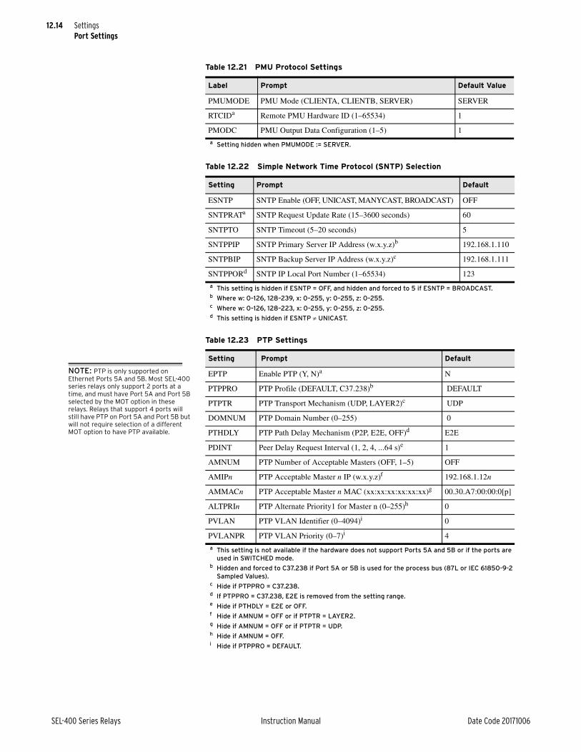
12.14
SEL-400 Series Relays Instruction Manual Date Code 20171006
SettingsPort Settings
Table 12.21 PMU Protocol Settings
Label Prompt Default Value
PMUMODE PMU Mode (CLIENTA, CLIENTB, SERVER) SERVER
RTCIDa
a Setting hidden when PMUMODE := SERVER.
Remote PMU Hardware ID (1–65534) 1
PMODC PMU Output Data Configuration (1–5) 1
Table 12.22 Simple Network Time Protocol (SNTP) Selection
Setting Prompt Default
ESNTP SNTP Enable (OFF, UNICAST, MANYCAST, BROADCAST) OFF
SNTPRATa
a This setting is hidden if ESNTP = OFF, and hidden and forced to 5 if ESNTP = BROADCAST.
SNTP Request Update Rate (15–3600 seconds) 60
SNTPTO SNTP Timeout (5–20 seconds) 5
SNTPPIP SNTP Primary Server IP Address (w.x.y.z)b
b Where w: 0–126, 128–239, x: 0–255, y: 0–255, z: 0–255.
192.168.1.110
SNTPBIP SNTP Backup Server IP Address (w.x.y.z)c
c Where w: 0–126, 128–223, x: 0–255, y: 0–255, z: 0–255.
192.168.1.111
SNTPPORd
d This setting is hidden if ESNTP UNICAST.
SNTP IP Local Port Number (1–65534) 123
Table 12.23 PTP Settings
Setting Prompt Default
EPTP Enable PTP (Y, N)a
a This setting is not available if the hardware does not support Ports 5A and 5B or if the ports are used in SWITCHED mode.
N
PTPPRO PTP Profile (DEFAULT, C37.238)b
b Hidden and forced to C37.238 if Port 5A or 5B is used for the process bus (87L or IEC 61850-9-2 Sampled Values).
DEFAULT
PTPTR PTP Transport Mechanism (UDP, LAYER2)c
c Hide if PTPPRO = C37.238.
UDP
DOMNUM PTP Domain Number (0–255) 0
PTHDLY PTP Path Delay Mechanism (P2P, E2E, OFF)d
d If PTPPRO = C37.238, E2E is removed from the setting range.
E2E
PDINT Peer Delay Request Interval (1, 2, 4, ...64 s)e
e Hide if PTHDLY = E2E or OFF.
1
AMNUM PTP Number of Acceptable Masters (OFF, 1–5) OFF
AMIPn PTP Acceptable Master n IP (w.x.y.z)f
f Hide if AMNUM = OFF or if PTPTR = LAYER2.
192.168.1.12n
AMMACn PTP Acceptable Master n MAC (xx:xx:xx:xx:xx:xx)g
g Hide if AMNUM = OFF or if PTPTR = UDP.
00.30.A7:00:00:0[p]
ALTPRIn PTP Alternate Priority1 for Master n (0–255)h
h Hide if AMNUM = OFF.
0
PVLAN PTP VLAN Identifier (0–4094)i
i Hide if PTPPRO = DEFAULT.
0
PVLANPR PTP VLAN Priority (0–7)i 4
NOTE: PTP is only supported on Ethernet Ports 5A and 5B. Most SEL-400 series relays only support 2 ports at a time, and must have Port 5A and Port 5B selected by the MOT option in these relays. Relays that support 4 ports will still have PTP on Port 5A and Port 5B but will not require selection of a different MOT option to have PTP available.

12.15
Date Code 20171006 Instruction Manual SEL-400 Series Relays
SettingsDNP3 Settings—Custom Maps
DNP3 Settings—Custom Maps
The fault location minimum and maximum settings determine what fault data are sent to a DNP3 master. This affects all DNP3 sessions using the current DNP3 map.
NOTE: MINDIST and MAXDIST only apply to relays that provide a fault location.
The remainder of this settings class consists of a set of freeform categories for configuring the map for the various DNP3 data types. The category headers indi-cate the syntax of the entries. Table 12.26 shows these headers. All entries require a data label. The dead-band and scale-factor parameters are optional. The defaults are relay specific, so refer to the product-specific instruction manual to see the defaults for these settings.
Front-Panel Settings
Table 12.24 DNP3 Settings Categories
Settings Reference
DNP3 Fault Location Min and Max Table 12.25
Binary Input Map Table 12.26
Binary Output Map Table 12.26
Counter Map Table 12.26
Analog Input Map Table 12.26
Analog Output Map Table 12.26
Table 12.25 Minimum and Maximum Fault Location
Label Prompt Default Value
MINDIST Min Fault Location to Capture (OFF, –1000.0 to 1000.0) OFF
MAXDIST Max Fault Location to Capture (OFF, –1000.0 to 1000.0) OFF
Table 12.26 DNP3 Map Category Headers
Binary Input Map (Binary Input Label)
Binary Output Map (Binary Output Label)
Counter Map (Counter Label, Deadband)
Analog Input Map (Analog Input Label, Scale Factor, Deadband)
Analog Output Map (Analog Output Label)
Table 12.27 Front-Panel Settings Categories (Sheet 1 of 2)
Settings Reference
Front-Panel Settings Table 12.28
Selectable Screens for the Front Panel Table 12.29
Selectable Operator Pushbuttons Table 12.30
Front-Panel Event Display Table 12.31
Display Points
Local Control
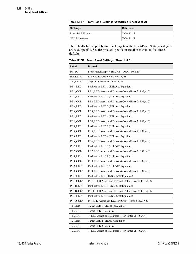
12.16
SEL-400 Series Relays Instruction Manual Date Code 20171006
SettingsFront-Panel Settings
The defaults for the pushbuttons and targets in the Front-Panel Settings category are relay specific. See the product-specific instruction manual to find these defaults.
Local Bit SELOGIC Table 12.32
SER Parameters Table 12.33
Table 12.28 Front-Panel Settings (Sheet 1 of 3)
Label Prompt
FP_TO Front Panel Display Time-Out (OFF,1–60 min)
EN_LEDC Enable LED Asserted Color (R,G)
TR_LEDC Trip LED Asserted Color (R,G)
PB1_LED Pushbutton LED 1 (SELOGIC Equation)
PB1_COL PB1_LED Assert and Deassert Color (Enter 2: R,G,A,O)
PB2_LED Pushbutton LED 2 (SELOGIC Equation)
PB2_COL PB2_LED Assert and Deassert Color (Enter 2: R,G,A,O)
PB3_LED Pushbutton LED 3 (SELOGIC Equation)
PB3_COL PB3_LED Assert and Deassert Color (Enter 2: R,G,A,O)
PB4_LED Pushbutton LED 4 (SELOGIC Equation)
PB4_COL PB4_LED Assert and Deassert Color (Enter 2: R,G,A,O)
PB5_LED Pushbutton LED 5 (SELOGIC Equation)
PB5_COL PB5_LED Assert and Deassert Color (Enter 2: R,G,A,O)
PB6_LED Pushbutton LED 6 (SELOGIC Equation)
PB6_COL PB6_LED Assert and Deassert Color (Enter 2: R,G,A,O)
PB7_LED Pushbutton LED 7 (SELOGIC Equation)
PB7_COL PB7_LED Assert and Deassert Color (Enter 2: R,G,A,O)
PB8_LED Pushbutton LED 8 (SELOGIC Equation)
PB8_COL PB8_LED Assert and Deassert Color (Enter 2: R,G,A,O)
PB9_LEDa Pushbutton LED 9 (SELOGIC Equation)
PB9_COLa PB9_LED Assert and Deassert Color (Enter 2: R,G,A,O)
PB10LEDa Pushbutton LED 10 (SELOGIC Equation)
PB10COLa PB10_LED Assert and Deassert Color (Enter 2: R,G,A,O)
PB11LEDa Pushbutton LED 11 (SELOGIC Equation)
PB11COLa PB11_LED Assert and Deassert Color (Enter 2: R,G,A,O)
PB12LEDa Pushbutton LED 12 (SELOGIC Equation)
PB12COLa PB_LED Assert and Deassert Color (Enter 2: R,G,A,O)
T1_LED Target LED 1 (SELOGIC Equation)
T1LEDL Target LED 1 Latch (Y, N)
T1LEDC T_LED Assert and Deassert Color (Enter 2: R,G,A,O)
T2_LED Target LED 2 (SELOGIC Equation)
T2LEDL Target LED 2 Latch (Y, N)
T2LEDC T_LED Assert and Deassert Color (Enter 2: R,G,A,O)
Table 12.27 Front-Panel Settings Categories (Sheet 2 of 2)
Settings Reference

12.17
Date Code 20171006 Instruction Manual SEL-400 Series Relays
SettingsFront-Panel Settings
T3_LED Target LED 3 (SELOGIC Equation)
T3LEDL Target LED 3 Latch (Y, N)
T3LEDC T_LED Assert and Deassert Color (Enter 2: R,G,A,O)
T4_LED Target LED 4 (SELOGIC Equation)
T4LEDL Target LED 4 Latch (Y, N)
T4LEDC T_LED Assert and Deassert Color (Enter 2: R,G,A,O)
T5_LED Target LED 5 (SELOGIC Equation)
T5LEDL Target LED 5 Latch (Y, N)
T5LEDC T_LED Assert and Deassert Color (Enter 2: R,G,A,O)
T6_LED Target LED 6 (SELOGIC Equation)
T6LEDL Target LED 6 Latch (Y, N)
T6LEDC T_LED Assert and Deassert Color (Enter 2: R,G,A,O)
T7_LED Target LED 7 (SELOGIC Equation)
T7LEDL Target LED 7 Latch (Y, N)
T7LEDC T_LED Assert and Deassert Color (Enter 2: R,G,A,O)
T8_LED Target LED 8 (SELOGIC Equation)
T8LEDL Target LED 8 Latch (Y, N)
T8LEDC T_LED Assert and Deassert Color (Enter 2: R,G,A,O)
T9_LED Target LED 9 (SELOGIC Equation)
T9LEDL Target LED 9 Latch (Y, N)
T9LEDC T_LED Assert and Deassert Color (Enter 2: R,G,A,O)
T10_LED Target LED 10 (SELOGIC Equation)
T10LEDL Target LED 10 Latch (Y, N)
T10LEDC T_LED Assert and Deassert Color (Enter 2: R,G,A,O)
T11_LED Target LED 11 (SELOGIC Equation)
T11LEDL Target LED 11 Latch (Y, N)
T11LEDC T_LED Assert and Deassert Color (Enter 2: R,G,A,O)
T12_LED Target LED 12 (SELOGIC Equation)
T12LEDL Target LED 12 Latch (Y, N)
T12LEDC T_LED Assert and Deassert Color (Enter 2: R,G,A,O)
T13_LED Target LED 13 (SELOGIC Equation)
T13LEDL Target LED 13 Latch (Y, N)
T13LEDC T_LED Assert and Deassert Color (Enter 2: R,G,A,O)
T14_LED Target LED 14 (SELOGIC Equation)
T14LEDL Target LED 14 Latch (Y, N)
T14LEDC T_LED Assert and Deassert Color (Enter 2: R,G,A,O)
T15_LED Target LED 15 (SELOGIC Equation)
T15LEDL Target LED 15 Latch (Y, N)
T15LEDC T_LED Assert and Deassert Color (Enter 2: R,G,A,O)
T16_LED Target LED 16 (SELOGIC Equation)
T16LEDL Target LED 16 Latch (Y, N)
Table 12.28 Front-Panel Settings (Sheet 2 of 3)
Label Prompt

12.18
SEL-400 Series Relays Instruction Manual Date Code 20171006
SettingsFront-Panel Settings
T16LEDC T_LED Assert and Deassert Color (Enter 2: R,G,A,O)
T17_LEDb Target LED 17 (SELOGIC Equation)
T17LEDLb Target LED 17 Latch (Y, N)
T17LEDCb T_LED Assert and Deassert Color (Enter 2: R,G,A,O)
T18_LEDb Target LED 18 (SELOGIC Equation)
T18LEDLb Target LED 18 Latch (Y, N)
T18LEDCb T_LED Assert and Deassert Color (Enter 2: R,G,A,O)
T19_LEDb Target LED 19 (SELOGIC Equation)
T19LEDLb Target LED 19 Latch (Y, N)
T19LEDCb T_LED Assert and Deassert Color (Enter 2: R,G,A,O)
T20_LEDb Target LED 20 (SELOGIC Equation)
T20LEDLb Target LED 20 Latch (Y, N)
T20LEDCb T_LED Assert and Deassert Color (Enter 2: R,G,A,O)
T21_LEDb Target LED 21 (SELOGIC Equation)
T21LEDLb Target LED 21 Latch (Y, N)
T21LEDCb T_LED Assert and Deassert Color (Enter 2: R,G,A,O)
T22_LEDb Target LED 22 (SELOGIC Equation)
T22LEDLb Target LED 22 Latch (Y, N)
T22LEDCb T_LED Assert and Deassert Color (Enter 2: R,G,A,O)
T23_LEDb Target LED 23 (SELOGIC Equation)
T23LEDLb Target LED 23 Latch (Y, N)
T23LEDCb T_LED Assert and Deassert Color (Enter 2: R,G,A,O)
T24_LEDb Target LED 24 (SELOGIC Equation)
T24LEDLb Target LED 24 Latch (Y, N)
T24LEDCb T_LED Assert and Deassert Color (Enter 2: R,G,A,O)
a PB9–PB12 settings are only available on 12 pushbutton models.b T17–T24 settings are only available on 12 pushbutton models.
Table 12.29 Selectable Screens for the Front Panel (Sheet 1 of 2)
Label Prompt Default Value
SCROLD Front-Panel Display Update Rate (OFF, 1–15 sec) 5
ONELINE One-Line Bay Control Diagram (Y,N) Y
RMS_V RMS Line Voltage Screen (Y,N) N
RMS_I RMS Line Current Screen (Y,N) Y
RMS_VPP RMS Line Voltage Phase to Phase Screen (Y,N) N
RMS_W RMS Active Power Screen (Y,N) N
FUNDVAR Fundamental Reactive Power Screen (Y,N) N
RMS_VA RMS Apparent Power Screen (Y,N) N
RMS_PF RMS Power Factor Screen (Y,N) N
RMS_BK1 RMS Breaker 1 Currents Screen (Y,N) N
RMS_BK2 RMS Breaker 2 Currents Screen (Y,N) N
Table 12.28 Front-Panel Settings (Sheet 3 of 3)
Label Prompt
NOTE: The specific settings available in this category for a relay depends on the features of that relay.
NOTE: In some relays, rather than picking from a list of screens, as shown here, there is a freeform settings block in which you can list the screens you want in the order you want them displayed.

12.19
Date Code 20171006 Instruction Manual SEL-400 Series Relays
SettingsFront-Panel Settings
Boolean display points are selected using freeform settings fields. Two types of display points can be entered: Boolean and analog. For Boolean display points, the entry syntax is:
Bit name, "Label", "Set String", "Clear String", Text Size"
STA_BAT Station Battery Screen (Y,N) N
FUND_VI Fundamental Voltage and Current Screen (Y,N) Y
FUNDSEQ Fundamental Sequence Quantities Screen (Y,N) N
FUND_BK Fundamental Breaker Currents Screen (Y,N) N
DIFF_L Differential Metering Local Currents Screen (Y,N) Y
DIFF_T Differential Metering Total Currents Screen (Y,N) Y
DIFF Differential Metering (Y,N) Y
ZONECFG Terminals Associated with Zones (Y,N) Y
Table 12.30 Selectable Operator Pushbuttons
Label Prompt Default Value
PB1_HMI Pushbutton 1 HMI Screen (OFF,AP,DP,EVE,SER)a, b
a PBn_HMI can only be set to DP if a valid display point has been set.b Each instance (AP, DP, EVE, SER) can only be set to a single operator pushbutton.
OFF = No HMI Pushbutton OperationAP = Alarm PointsDP = Display PointsEVE = Event SummariesSER = SER HMI Display
OFF
PB2_HMI Pushbutton 2 HMI Screen (OFF,AP,DP,EVE,SER)a, b OFF
PB3_HMI Pushbutton 3 HMI Screen (OFF,AP,DP,EVE,SER)a, b OFF
PB4_HMI Pushbutton 4 HMI Screen (OFF,AP,DP,EVE,SER)a, b OFF
PB5_HMI Pushbutton 5 HMI Screen (OFF,AP,DP,EVE,SER)a, b OFF
PB6_HMI Pushbutton 6 HMI Screen (OFF,AP,DP,EVE,SER)a, b OFF
PB7_HMI Pushbutton 7 HMI Screen (OFF,AP,DP,EVE,SER)a, b OFF
PB8_HMI Pushbutton 8 HMI Screen (OFF,AP,DP,EVE,SER)a, b OFF
PB9_HMIc
c PB9–PB12 settings are only available on 12-pushbutton models.
Pushbutton 9 HMI Screen (OFF,AP,DP,EVE,SER)a, b OFF
PB10HMIc Pushbutton 10 HMI Screen (OFF,AP,DP,EVE,SER)a, b OFF
PB11HMIc Pushbutton 11 HMI Screen (OFF,AP,DP,EVE,SER)a, b OFF
PB12HMIc Pushbutton 12 HMI Screen (OFF,AP,DP,EVE,SER)a, b OFF
Table 12.31 Front-Panel Event Display
Label Prompt Default Value
DISP_ER Enable HMI Auto Display of Events Summaries (Y,N) Y
TYPE_ER Types of Events for HMI Auto Display (ALL,TRIP)a
a Setting is only available if DISP_ER := Y.
ALL
NUM_ER Operator Pushbutton Events to Display (1–100)b
b Setting is only available if an operator pushbutton has been set to EVE.
10c
c Some relays default NUM_ER to 3.
Table 12.29 Selectable Screens for the Front Panel (Sheet 2 of 2)
Label Prompt Default Value

12.20
SEL-400 Series Relays Instruction Manual Date Code 20171006
SettingsAlias Settings
For an analog display point, the syntax is:
Analog name, "User Text and Formatting", "Text Size"
See the Front-Panel Operations section for more information on configuring dis-play points.
Local control bits are configured using the Local Control category. This is a freeform category. Each entry has the following syntax:
Local bit name, "Label", "Set State", "Clear State", Pulse enable
See Local Control on page 4.20 for more information on configuring local con-trol bits.
Alias SettingsAlthough SEL-400 series relays provide extensive programming facilities and opportunity for comments, troubleshooting customized programs is sometimes difficult. Aliases provide an opportunity to assign more meaningful names to the generic variable names to improve the readability of the program. These aliases can be used in settings and SELOGIC equations and are used in most relay reports. Assign a valid seven-character alias name to any Relay Word bit or any Analog Quantity. (Some SEL-400 series relays support aliasing additional types of data.)
Invalid alias names include the following keywords used by settings and SELOGIC control equations:
➤ END
➤ INSERT
➤ DELETE
➤ LIST
➤ NA
➤ OFF
SELOGIC control equation operators (e.g., NOT, AND, OR, COS) cannot be used as alias names. A quantity may only be assigned one alias. An alias cannot match an existing relay word or analog quantity name.
Alias names are valid when the following are true:
➤ They consist of a maximum of seven characters.
➤ They are constructed using characters 0–9, uppercase A–Z, or the underscore (_).
Table 12.32 Local Bit SELOGICa
a Settings in Table Table 12.32 appear if the associated local bit is defined. If no local bits are defined, the whole category is hidden.
Label Prompt Default Value
LB_SPmm Local Bit Supervision (SELOGIC Equation, NA) 1
LB_DPmm Local Bit Status Display (SELOGIC Equation, NA) LBmm
Table 12.33 SER Parameters
Label Prompt Default Value
SER_PP Five Events per SER Events page? (Y for 5, N for 3) N

12.21
Date Code 20171006 Instruction Manual SEL-400 Series Relays
SettingsProtection Freeform SELOGIC Control Equations
For example, the default name for contact output OUT101 is OUT101. You could change the default name to an alias, BK1_TR, for example.
Alias settings consists of a single freeform settings category. As many as 200 aliases may be assigned. The default alias configuration is relay specific. See the relay instruction manual for the default aliases. Figure 12.2 shows an example using the SET T command to set two aliases.
Protection Freeform SELOGIC Control EquationsProtection freeform SELOGIC control equations are in Classes 1 through 6 corre-sponding to settings Groups 1 through Group 6 (see Multiple Setting Groups on page 12.4).
As many as 250 lines of freeform equations may be entered in each of six settings groups, although the actual maximum capacity may be less. See SELOGIC Con-trol Equation Capacity on page 13.5 for more information. The default configu-ration of the protection SELOGIC control equations is relay specific. See the product-specific instruction manual to see the defaults.
Automation Freeform SELOGIC Control EquationsAutomation freeform SELOGIC control equations are in Blocks 1 through 10.
NOTE: Some versions of some SEL-400 series relays have only one automation setting block with a capacity of 100 lines of automation freeform SELOGIC control equations.
SEL-400 series relays do not contain any automation freeform SELOGIC settings in the factory-default settings.
The relay has a capacity of 100 lines of automation freeform SELOGIC control equations in each of 10 automation setting blocks. See SELOGIC Control Equa-tion Capacity on page 13.5 for more information.
=>>SET T <Enter>AliasRelay Aliases(RW Bit or Analog Qty. 7 Character Alias [0-9 A-Z _])
1: EN,"RLY_EN"? <Enter>2: ? OUT101, BK1_TR3:? END <Enter>
AliasRelay Aliases(RW Bit or Analog Qty. 7 Character Alias [0-9 A-Z _])1: EN,"RLY_EN"2: OUT101,"BK1_TR"...Save settings (Y,N) ?Y <Enter>Saving Settings, Please Wait...........Settings Saved
=>>
Figure 12.2 Changing a Default Name to an Alias
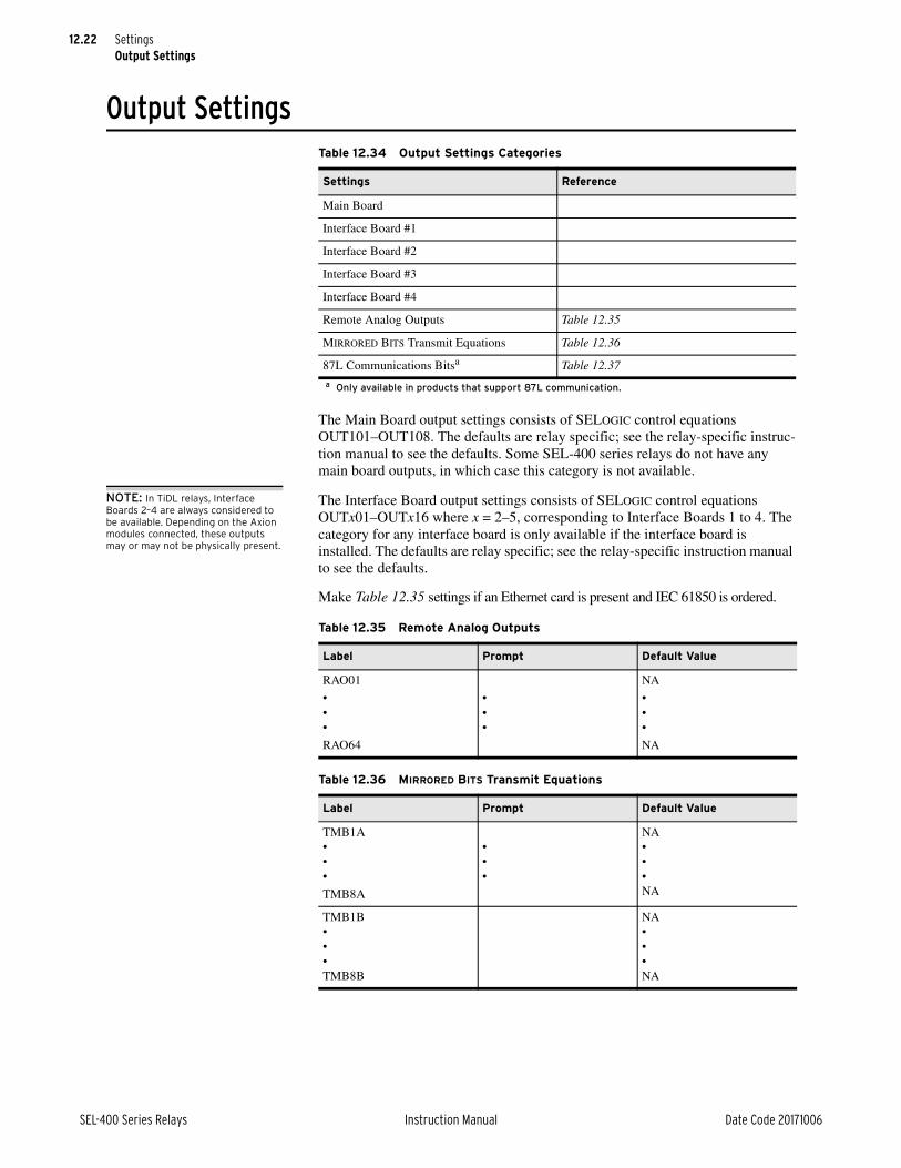
12.22
SEL-400 Series Relays Instruction Manual Date Code 20171006
SettingsOutput Settings
Output Settings
The Main Board output settings consists of SELOGIC control equations OUT101–OUT108. The defaults are relay specific; see the relay-specific instruc-tion manual to see the defaults. Some SEL-400 series relays do not have any main board outputs, in which case this category is not available.
NOTE: In TiDL relays, Interface Boards 2–4 are always considered to be available. Depending on the Axion modules connected, these outputs may or may not be physically present.
The Interface Board output settings consists of SELOGIC control equations OUTx01–OUTx16 where x = 2–5, corresponding to Interface Boards 1 to 4. The category for any interface board is only available if the interface board is installed. The defaults are relay specific; see the relay-specific instruction manual to see the defaults.
Make Table 12.35 settings if an Ethernet card is present and IEC 61850 is ordered.
Table 12.34 Output Settings Categories
Settings Reference
Main Board
Interface Board #1
Interface Board #2
Interface Board #3
Interface Board #4
Remote Analog Outputs Table 12.35
MIRRORED BITS Transmit Equations Table 12.36
87L Communications Bitsa
a Only available in products that support 87L communication.
Table 12.37
Table 12.35 Remote Analog Outputs
Label Prompt Default Value
RAO01
•••
RAO64
•••
NA
•••
NA
Table 12.36 MIRRORED BITS Transmit Equations
Label Prompt Default Value
TMB1A•••
TMB8A
•••
NA•••NA
TMB1B•••TMB8B
NA•••NA

12.23
Date Code 20171006 Instruction Manual SEL-400 Series Relays
SettingsReport Settings
NOTE: This category is only available in relays that support 87L communications.
Report Settings
The SER Points category is a freeform category for listing points to record in the SER. Each point can be given a reporting name, a set state name, and a clear state name. You can also indicate whether or not to make this point visible as an alarm point on the front-panel LCD. The syntax for entry is:
Relay Word Bit Label, "Reporting Name", "Set State Name", "Clear State Name", HMI Alarm Indication
Each of the names may consist of any printable ASCII character. The HMI alarm condition is a Y/N choice. By default, there are no SER points configured.
The signal profile settings category consists of a freeform block for selecting ana-log quantities to include in the signal profile followed by the settings described in Table 12.40. Any of the analog quantities listed in Section 12:Analog Quantities in the product-specific instruction manual may be selected. As many as 20 analog quantities can be included in the signal profile.
Table 12.37 87L Communications Bits
Labela, b
a x = 1–4. These settings are hidden when E87CH = N or 2E or 3E or 4E. Also hidden if there is no serial communications card installed.
b nn = 01–32. These settings are visible when E87CH = 2E, 3E, or 4E, and are hidden in all other cases.
Prompt Default Value
87TxP1 • NA
87TxP2 • NA
87TnnE • NA
Table 12.38 Report Settings Categories
Settings Reference
SER Chatter Criteria Table 12.39
SER Points
Signal Profile Table 12.40
Event Reporting Table 12.41
HIF Event Reporting
Event Reporting Analog Quantities
Event Reporting Digital Elements
Table 12.39 SER Chatter Criteria
Label Prompt Default Value
ESERDEL Automatic Removal of Chattering SER Points (Y, N) N
SRDLCNTa
a Setting is only available if ESERDEL := Y.
Number of Counts Before Auto-Removal (2–20) 5
SRDLTIMa Time for Auto-Removal (0.1–30 seconds) 1.0
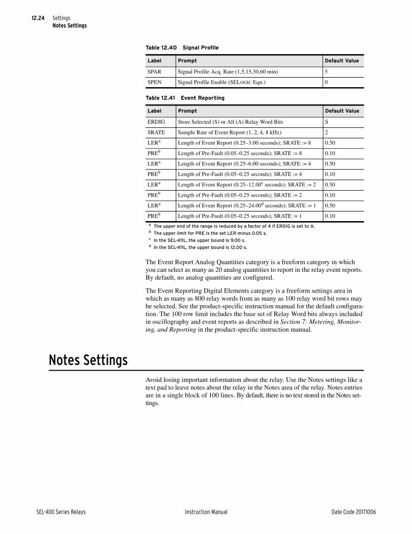
12.24
SEL-400 Series Relays Instruction Manual Date Code 20171006
SettingsNotes Settings
The Event Report Analog Quantities category is a freeform category in which you can select as many as 20 analog quantities to report in the relay event reports. By default, no analog quantities are configured.
The Event Reporting Digital Elements category is a freeform settings area in which as many as 800 relay words from as many as 100 relay word bit rows may be selected. See the product-specific instruction manual for the default configura-tion. The 100 row limit includes the base set of Relay Word bits always included in oscillography and event reports as described in Section 7: Metering, Monitor-ing, and Reporting in the product-specific instruction manual.
Notes SettingsAvoid losing important information about the relay. Use the Notes settings like a text pad to leave notes about the relay in the Notes area of the relay. Notes entries are in a single block of 100 lines. By default, there is no text stored in the Notes set-tings.
Table 12.40 Signal Profile
Label Prompt Default Value
SPAR Signal Profile Acq. Rate (1,5,15,30,60 min) 5
SPEN Signal Profile Enable (SELOGIC Eqn.) 0
Table 12.41 Event Reporting
Label Prompt Default Value
ERDIG Store Selected (S) or All (A) Relay Word Bits S
SRATE Sample Rate of Event Report (1, 2, 4, 8 kHz) 2
LERa
a The upper end of the range is reduced by a factor of 4 if ERDIG is set to A.
Length of Event Report (0.25–3.00 seconds); SRATE := 8 0.50
PREb
b The upper limit for PRE is the set LER minus 0.05 s.
Length of Pre-Fault (0.05–0.25 seconds); SRATE := 8 0.10
LERa Length of Event Report (0.25–6.00 seconds); SRATE := 4 0.50
PREb Length of Pre-Fault (0.05–0.25 seconds); SRATE := 4 0.10
LERa Length of Event Report (0.25–12.00c seconds); SRATE := 2
c In the SEL-411L, the upper bound is 9.00 s.
0.50
PREb Length of Pre-Fault (0.05–0.25 seconds); SRATE := 2 0.10
LERa Length of Event Report (0.25–24.00d seconds); SRATE := 1
d In the SEL-411L, the upper bound is 12.00 s.
0.50
PREb Length of Pre-Fault (0.05–0.25 seconds); SRATE := 1 0.10
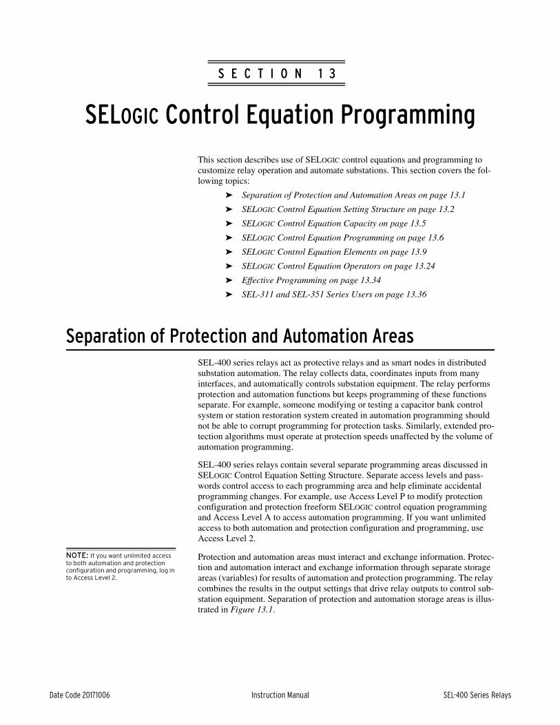
Date Code 20171006 Instruction Manual SEL-400 Series Relays
Instruction ManualS E C T I O N 1 3
SELOGIC Control Equation Programming
This section describes use of SELOGIC control equations and programming to customize relay operation and automate substations. This section covers the fol-lowing topics:
➤ Separation of Protection and Automation Areas on page 13.1
➤ SELOGIC Control Equation Setting Structure on page 13.2
➤ SELOGIC Control Equation Capacity on page 13.5
➤ SELOGIC Control Equation Programming on page 13.6
➤ SELOGIC Control Equation Elements on page 13.9
➤ SELOGIC Control Equation Operators on page 13.24
➤ Effective Programming on page 13.34
➤ SEL-311 and SEL-351 Series Users on page 13.36
Separation of Protection and Automation AreasSEL-400 series relays act as protective relays and as smart nodes in distributed substation automation. The relay collects data, coordinates inputs from many interfaces, and automatically controls substation equipment. The relay performs protection and automation functions but keeps programming of these functions separate. For example, someone modifying or testing a capacitor bank control system or station restoration system created in automation programming should not be able to corrupt programming for protection tasks. Similarly, extended pro-tection algorithms must operate at protection speeds unaffected by the volume of automation programming.
SEL-400 series relays contain several separate programming areas discussed in SELOGIC Control Equation Setting Structure. Separate access levels and pass-words control access to each programming area and help eliminate accidental programming changes. For example, use Access Level P to modify protection configuration and protection freeform SELOGIC control equation programming and Access Level A to access automation programming. If you want unlimited access to both automation and protection configuration and programming, use Access Level 2.
NOTE: If you want unlimited access to both automation and protection configuration and programming, log in to Access Level 2.
Protection and automation areas must interact and exchange information. Protec-tion and automation interact and exchange information through separate storage areas (variables) for results of automation and protection programming. The relay combines the results in the output settings that drive relay outputs to control sub-station equipment. Separation of protection and automation storage areas is illus-trated in Figure 13.1.

13.2
SEL-400 Series Relays Instruction Manual Date Code 20171006
SELOGIC Control Equation ProgrammingSELOGIC Control Equation Setting Structure
Figure 13.1 illustrates how the SEL-400 series relays keep protection and auto-mation programming separate while still exchanging information. The arrows indicate data flow between components. The Relay Word Bits and Analog Quan-tities are visible to protection, automation, and output programming. Protection programming uses the Relay Word Bits, Analog Quantities, Protection Variables, and Automation Variables as inputs, but only writes and stores information to the Protection Variables. Similarly, automation programming uses data from all parts of the relay, but only stores data in the Automation Variables.
The Output SELOGIC control equation settings use the Relay Word Bits, Analog Quantities, Protection Variables, and Automation Variables to control outputs and other information leaving the relay. Use the output settings to create a custom combination of the results of protection and automation operations. For example, an OR operation will activate an output when protection or automation program-ming results necessitate activating the output. You can use more complicated logic to supervise control of the output with other external and internal informa-tion. For example, use a command from the SCADA master to supervise auto-mated control of a motor-operated disconnect in the substation.
SELOGIC Control Equation Setting StructureSEL-400 series relays use SELOGIC control equations in three major areas. First, you can customize protection operations with SELOGIC control equation settings and freeform programming. Second, there is a freeform programming area for more sophisticated automation SELOGIC control equation programming. Third, there is a fixed area for relay output programming. The SELOGIC control equa-tion programming areas are shown in Figure 13.2. There are also a small number of fixed SELOGIC control equations in other settings areas including front-panel settings that allow you to customize relay features not directly related to protec-tion or automation.
Figure 13.1 Protection and Automation Separation
Protection
SELOGIC
Control Equation
Programming
Relay Word
Bits/
Analog
Quantities
Protection
Boolean/
Math
Variables
Output
SELOGIC
Control Equation
Settings
Automation
SELOGIC
Control Equation
Programming
Automation
Boolean/
Math
Variables

13.3
Date Code 20171006 Instruction Manual SEL-400 Series Relays
SELOGIC Control Equation ProgrammingSELOGIC Control Equation Setting Structure
NOTE: Some versions of some SEL-400 series relays only support one block of Automation SELOGIC Control Equations.
ProtectionProtection SELOGIC control equation programming includes a fixed area and a freeform area. You can configure many protection settings within the relay (for example TR) with fixed SELOGIC control equation programming. Use these set-tings to control protection operation and customize relay operation. The pro-gramming and operation of fixed SELOGIC control equations in this area is very similar to programming in SEL-300 series relays.
There is a freeform SELOGIC control equation programming area associated with protection. Because this area operates at the protection processing interval along with protection algorithms and outputs, use this area to extend and customize protection operation. Protection freeform SELOGIC control equation program-ming includes a complete set of timers, counters, and variables.
For all protection settings, including protection SELOGIC control equation pro-gramming, there are six groups of settings that you activate with the protection settings group selection. Only one group is active at a time. When you switch groups, for example, you can activate completely different programming that cor-responds to the conditions indicated by the active group. See Multiple Setting Groups on page 12.4 for more information.
If you want the programming to operate identically in all groups, develop the set-tings in one group and copy these to all groups. You can copy settings using the COPY command documented in COPY on page 14.17. You can also perform cut-and-paste operations in the ACSELERATOR QuickSet SEL-5030 software.
Figure 13.2 SELOGIC Control Equation Programming Areas
Automation SELOGIC Control Equation Programming
Block 10
Block 9
Block 8
Block 7
Block 6
Block 5
Block 4
Block 3
Block 2
Free-Form SELOGIC Control Equation ProgrammingBlock 1
Fixed SELOGIC
Control Equation
Settings
Free-Form SELOGIC
Control Equation
Programming
Fixed SELOGIC
Control Equation
Settings
Output Settings
Protection Settings Group 6
Protection Settings Group 5
Protection Settings Group 4
Protection Settings Group 3
Protection Settings Group 2
Protection Settings Group 1

13.4
SEL-400 Series Relays Instruction Manual Date Code 20171006
SELOGIC Control Equation ProgrammingSELOGIC Control Equation Setting Structure
NOTE: Perform operations that are not time critical in automation SELOGIC control equation programming. You can use this automation to reduce the demand and complexity of protection SELOGIC control equation programming.
All of the SELOGIC control equation programming in the protection area executes at the same deterministic interval as the protection algorithms. Because of this type of programming execution, you can use protection freeform and fixed pro-gramming to extend and customize protection operation.
AutomationAutomation SELOGIC control equation programming is a large freeform pro-gramming area that provides as many as ten blocks. The relay executes each block sequentially from the first block to the last. You do not need to fill a block completely or enter any equations in a block before starting to write SELOGIC control equations in the following blocks.
SEL-400 series relays dedicate a minimum processing time when executing auto-mation SELOGIC control equations. If the processing load is light, the relay uses more processing time for executing automation programming. This means that the overall execution time fluctuates. You can display the average and peak exe-cution time with the STATUS S ASCII command. Use the STATUS SC com-mand to reset the peak execution time.
NOTE: Organize automation SELOGIC control equation programming into blocks based on function. It is easier to edit and troubleshoot small partially filled blocks that contain related programming.
Use automation SELOGIC control equation programming to automate tasks that do not require time-critical, deterministic execution. For example, if you are coordinating control inputs from a substation HMI and SCADA master, use auto-mation freeform SELOGIC control equations and set the output contact setting to the automation SELOGIC control equation variable that contains the result.
Perform time-critical tasks with protection freeform SELOGIC control equations. For example, if you require a SELOGIC control equation for TR (trip) that con-tains more than 15 elements, you must perform that calculation in several steps. Because detection of a TR condition is a time-critical activity, perform the calcu-lation with protection freeform SELOGIC control equations and set TR to the pro-tection SELOGIC control equation variable that contains the result.
Because automation runs at a slower rate than protection, you must be careful when using protection bits within automation equations. Protection bits can assert and deassert again too fast for automation equations to consistently see them. Therefore, you may need to hold protection bits asserted for a second, by using conditioning timers, before using them in SELOGIC equations.
OutputsTo provide protection and automation area separation, the output settings are in a fixed SELOGIC control equation area separate from protection and automation programming. You can take advantage of this separation to combine protection and automation in a manner that best fits your application. Outputs include the relay control outputs, outgoing MIRRORED BITS points, and remote analog out-puts. The relay executes output logic and processes outputs at the protection pro-cessing interval.

13.5
Date Code 20171006 Instruction Manual SEL-400 Series Relays
SELOGIC Control Equation ProgrammingSELOGIC Control Equation Capacity
SELOGIC Control Equation CapacitySELOGIC control equation capacity is a measure of how much remaining space you have available for programming. In both protection and automation, SELOGIC control equation capacity includes execution capacity and settings stor-age capacity.
The relay will reject any setting that exceeds the available settings storage capac-ity and execution capacity. You can then accept the previous settings you have entered and examine your settings.
ProtectionSEL-400 series relays typically provide storage space for as many as 250 lines of protection freeform programming. See the product-specific instruction manual for the number of lines limit for any specific product. Because the relay executes protection fixed and freeform logic at a deterministic interval, there is a limit to the amount of SELOGIC control equation programming that the relay can execute. The relay calculates total capacity in terms of settings capacity and execution capacity.
NOTE: The SEL-487B supports 100 lines of protection freeform programming.
Rather than limit parameters to guarantee that your application not exceed the maximum processing requirements, the relay measures and calculates the avail-able capacity when you enter SELOGIC control equations. The relay will not allow you to enter programming that will cause the relay to be unable to complete all protection SELOGIC control equations each protection processing interval.
There are six protection settings groups. Only one protection settings group can be active. When a protection settings group is active, the relay executes SELOGIC control equations in the Global Settings, Protection Group Settings, Protection Freeform Settings, Output Settings, and several other settings areas. The relay calculates protection capacities based on the total amount of SELOGIC control equation programming executed when the protection settings group is active. Use the STATUS S command to display the remaining settings capacity and execu-tion capacity for protection fixed and freeform logic.
AutomationSEL-400 series relays provide storage space for as many as 10 blocks of as many as 100 lines of automation freeform programming each. Use the STATUS S com-mand to display the remaining settings capacity and execution capacity for auto-mation freeform logic.
There is a maximum execution capacity and settings storage capacity. If you enter a setting that exceeds maximum capacity, the relay will reject the setting. You will have the opportunity to reenter the setting or save any other settings you entered during that session.

13.6
SEL-400 Series Relays Instruction Manual Date Code 20171006
SELOGIC Control Equation ProgrammingSELOGIC Control Equation Programming
SELOGIC Control Equation ProgrammingThere are two major areas where SEL-400 series relays use SELOGIC control equations. First, fixed SELOGIC control equations define the operation of fixed protection elements or outputs. As with SEL-300 series relay programming, pro-tection programming and outputs use fixed SELOGIC control equations. Second, you can use freeform SELOGIC control equations for freeform programming that includes mathematical operations, custom logic execution order, extended relay customization, and automated operation.
Fixed SELOGIC Control EquationsFixed result SELOGIC control equations are equations in which the left side (result storage location), or LVALUE, is fixed. Programming in SEL-300 series relays consists of all fixed SELOGIC control equations. Fixed equations include protection and output settings that you set with SELOGIC control equations.
Fixed SELOGIC control equations are Boolean equations. Fixed result control equations can be as simple as a single element reference (for example PSV01) or can include a complex equation. An example of fixed programming is shown in Example 13.1.
Freeform SELOGIC Control EquationsFreeform SELOGIC control equations provide advanced relay customization and automation programming. There are freeform SELOGIC control equation pro-gramming areas used for protection and automation. You can use freeform SELOGIC control equation programming to enter program steps sequentially so that the relay will perform steps in the order that you specify. You can refer to storage locations multiple times and build up intermediate results in successive
Example 13.1 Fixed SELOGIC Control Equations
The following equations are examples of fixed SELOGIC control equations for relay Output OUT101. The text after the # character is a comment included in the equation and stored in the relay for future reference and doc-umentation.
OUT101 := 1 # Turn on OUT101
OUT101 := NA # Do not evaluate an equation for OUT101
OUT101 := OUT102 AND RB02 # Turn on OUT101 if OUT102 and RB02 are on
Fixed SELOGIC control equations include expressions that evaluate to a Boolean value, True or False, represented by a logical 1 or logical 0.
OUT101 := PSV04 # Turn on OUT101 if protection PSV04 is on
More complex programming in the freeform area controls OUT101. The result of the freeform programming is available as an element in a fixed equation.
OUT101 := AMV003 > 5 # Turn on OUT101 if AMV003 is greater than 5
While you cannot perform mathematical operations in fixed programming, you can perform comparisons on the results of mathematical operations per-formed elsewhere.
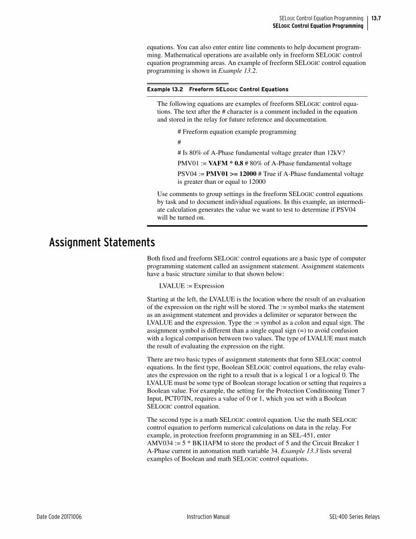
13.7
Date Code 20171006 Instruction Manual SEL-400 Series Relays
SELOGIC Control Equation ProgrammingSELOGIC Control Equation Programming
equations. You can also enter entire line comments to help document program-ming. Mathematical operations are available only in freeform SELOGIC control equation programming areas. An example of freeform SELOGIC control equation programming is shown in Example 13.2.
Assignment StatementsBoth fixed and freeform SELOGIC control equations are a basic type of computer programming statement called an assignment statement. Assignment statements have a basic structure similar to that shown below:
LVALUE := Expression
Starting at the left, the LVALUE is the location where the result of an evaluation of the expression on the right will be stored. The := symbol marks the statement as an assignment statement and provides a delimiter or separator between the LVALUE and the expression. Type the := symbol as a colon and equal sign. The assignment symbol is different than a single equal sign (=) to avoid confusion with a logical comparison between two values. The type of LVALUE must match the result of evaluating the expression on the right.
There are two basic types of assignment statements that form SELOGIC control equations. In the first type, Boolean SELOGIC control equations, the relay evalu-ates the expression on the right to a result that is a logical 1 or a logical 0. The LVALUE must be some type of Boolean storage location or setting that requires a Boolean value. For example, the setting for the Protection Conditioning Timer 7 Input, PCT07IN, requires a value of 0 or 1, which you set with a Boolean SELOGIC control equation.
The second type is a math SELOGIC control equation. Use the math SELOGIC control equation to perform numerical calculations on data in the relay. For example, in protection freeform programming in an SEL-451, enter AMV034 := 5 * BK1IAFM to store the product of 5 and the Circuit Breaker 1 A-Phase current in automation math variable 34. Example 13.3 lists several examples of Boolean and math SELOGIC control equations.
Example 13.2 Freeform SELOGIC Control Equations
The following equations are examples of freeform SELOGIC control equa-tions. The text after the # character is a comment included in the equation and stored in the relay for future reference and documentation.
# Freeform equation example programming
#
# Is 80% of A-Phase fundamental voltage greater than 12kV?
PMV01 := VAFM * 0.8 # 80% of A-Phase fundamental voltage
PSV04 := PMV01 >= 12000 # True if A-Phase fundamental voltage is greater than or equal to 12000
Use comments to group settings in the freeform SELOGIC control equations by task and to document individual equations. In this example, an intermedi-ate calculation generates the value we want to test to determine if PSV04 will be turned on.

13.8
SEL-400 Series Relays Instruction Manual Date Code 20171006
SELOGIC Control Equation ProgrammingSELOGIC Control Equation Programming
CommentsInclude comment statements in SELOGIC control equations to help document SELOGIC control equation programming. The relay provides the following two type of comments:
➤ in-line comments: (*comment*)
➤ end-of-line comments: #xxx
Example of in-line comment:
PCT01IN := (*this is an in-line comment*) PMV04 (*this is an in-line comment *)
Example of end-of-line comment:
PCT01IN := 10 # this is an end-of-line comment
If you begin a SELOGIC control equation with an end-of-line comment character, then the entire line is a comment.
NOTE: During troubleshooting or testing, reenter a line and insert the comment character to disable it. Enter the line without the comment character to enable the line later when you want it to be executed.
Comments are a powerful documentation tool for helping both you and others understand the intent of programming and configuration of the settings. You can use comments liberally; comments do not reduce SELOGIC control equation exe-cution capacity.
Example 13.3 Boolean and Math SELOGIC Control Equations
The equations below are examples of Boolean SELOGIC control equations.
# Example Boolean SELOGIC control equations
PSV01 := IN101 # Store the value of IN101 in PSV01
PSV02 := IN101 AND RB03 # Store result of logical AND in PSV02
PST01IN := IN104 # Use IN104 as the input value for PST01
PSV03 := PMV33 >= 7 # Set PSV03 when PMV33 greater than or equal to 7
The lines below are examples of math SELOGIC control equations.
# Example math SELOGIC control equations
PMV01 := 5 # Store the constant 5 in PMV01
PMV02 := 0.5 * VAFM # Store the product of A-Phase voltage and 0.5 in PMV02

13.9
Date Code 20171006 Instruction Manual SEL-400 Series Relays
SELOGIC Control Equation ProgrammingSELOGIC Control Equation Elements
SELOGIC Control Equation ElementsSELOGIC control equation elements are a collection of storage locations, timers, and counters that you can use to customize the operation of your relay and to automate substation operation. The elements that you can use in SELOGIC control equations are summarized in Table 13.1. The specific number of the various types of elements varies between SEL-400 series relays. See the product-specific instruction manual to determine the number of each type of element in that relay.
Relay Word Bits and Analog QuantitiesData within the relay are available for use in SELOGIC control equations. Relay Word bits are binary data that include protection elements, input status, and out-put status. See Section 11: Relay Word Bits in each product-specific instruction manual to view a list of Relay Word bits available within that relay. Analog quan-tities are analog values within the relay including measured and calculated val-ues. Section 12: Analog Quantities in each product-specific instruction manual contains a list of analog quantities available within the relay.
Special Condition BitsSeveral Relay Word bits are available for special conditions related to SELOGIC control equation programming in the relay. You can use these bits in SELOGIC control equation programming to react to these conditions. You can also send these bits to other devices through relay interfaces including MIRRORED BITS communications and DNP3. The special condition bits are shown in Table 13.2
The relay sets the first execution bits AFRTEXA, AFRTEXP, and PFRTEX momentarily to allow you to detect changes in the relay operation. The relay sets these bits and clears them as described in Table 13.2, Table 13.3, and Table 13.4. You can use these bits to force logic and calculations to reset or take a known state on power-up or settings change operations.
Table 13.1 Summary of SELOGIC Control Equation Elements
Element Description
Relay Word bits Boolean value data
Analog quantities Received, measured, and calculated values
Special condition bits Bits that indicate special SELOGIC control equation execution conditions
SELOGIC control equation variables
Storage locations for the results of Boolean SELOGIC control equations
SELOGIC control equation math variables
Storage locations for the results of math SELOGIC control equations
Latch bits Nonvolatile storage for the results of Boolean SELOGIC control equations
Conditioning timers Pickup and dropout style timers similar to those used in SEL-300 series relays
Sequencing timers On-delay timers similar to those used in programmable logic con-trollers
Counters Counters that count rising edges of Boolean value inputs

13.10
SEL-400 Series Relays Instruction Manual Date Code 20171006
SELOGIC Control Equation ProgrammingSELOGIC Control Equation Elements
SELOGIC Control Equation VariablesThere are two types of SELOGIC control equation variables: Boolean and math.
SELOGIC Control Equation Boolean VariablesSELOGIC control equation Boolean variables are binary storage locations. Each variable equals either logical 1 or logical 0. This manual refers to these variables and the relay displays these as 1 and 0, respectively. Think also of the states 1 and 0 as True and False, respectively, when you evaluate Boolean logic statements. The quantities of SELOGIC control equation Boolean variables available in the different programming areas are listed in Table 13.5.
Use the SELOGIC control equation Boolean variables in freeform logic state-ments in any order you want. Use a SELOGIC control equation Boolean variable more than once in freeform logic programming, and use SELOGIC control equa-tion Boolean variables as arguments in SELOGIC control equations. Example 13.4 illustrates SELOGIC control equation variable usage. You can view the status of individual control equation Boolean bits in the Relay Word using the TARGET
Table 13.2 First Execution Bit Operation on Power-Up
Name Description
AFRTEXA Relay sets on power-up and clears after each automation programming block has been executed once.
AFRTEXP Relay sets on power-up. Relay clears after it enables protection and all auto-mation programming blocks have been executed once.
PFRTEX Relay sets on startup. Relay clears after protection runs for 1 cycle.
Table 13.3 First Execution Bit Operation on Automation Settings Change
Name Description
AFRTEXA Relay sets on settings change and clears after each automation programming block has been executed once.
AFRTEXP Relay sets on settings change. Relay clears after it enables protection and all automation programming blocks have been executed once.
PFRTEX Relay sets on settings change. Relay clears after protection runs for 1 cycle.
Table 13.4 First Execution Bit Operation on Protection Settings Change, Group Switch, and Source Selection
Name Description
AFRTEXA Relay does not set.
AFRTEXP Relay sets when listed event occurs. Relay clears after it enables protection and all automation programming blocks have been executed once.
PFRTEX Relay sets when listed event occurs. Relay clears after protection runs for 1 cycle.
Table 13.5 SELOGIC Control Equation Boolean Variable Quantities
Type Typical Quantity Name Range
Protection SELOGIC control equation Boolean variables
64 PSV01–PSV64
Automation SELOGIC control equation Boolean variables
256 ASV001–ASV256

13.11
Date Code 20171006 Instruction Manual SEL-400 Series Relays
SELOGIC Control Equation ProgrammingSELOGIC Control Equation Elements
command. Use the TAR PSVnn command or the TAR ASVnnn command to view the Relay Word row containing the protection or automation Boolean bit specified by the number nn. You can also view the status of Boolean bits through the relay LCD front-panel display by selecting RELAY ELEMENTS from the Main Menu and scrolling through the rows of Relay Word bits.
SELOGIC Control Equation Math VariablesSELOGIC control equation math variables are math calculation storage results. As with protection and automation SELOGIC control equation Boolean variables, there are separate storage areas for protection and automation math calculations. The quantities of SELOGIC control equation math variables available in the SEL-400 series relays are shown in Table 13.6.
Use math variables in freeform programming to store the results of math calcula-tions as arguments in math calculations and comparisons. Example 13.5 illus-trates SELOGIC control equation math variable usage. You can view the results of protection and automation math variables using the METER command. Use the MET PMV command to see all protection math variable results (PMV01–PMV64). Similarly, use the MET AMV command to see all automation math variable results (AMV001–AMV256).
Example 13.4 SELOGIC Control Equation Boolean Variables
The equations below show freeform SELOGIC control equation program-ming examples that use SELOGIC control equation Boolean variables. Each line has a comment after the # that provides additional detail.
PSV01 := 1 # Set PSV01 to 1 always
PSV09 := PSV54 AND ASV005 # Set to result of Boolean AND
PSV02 := PMV05 > 5 # Set if PMV05 is greater than 5
You can use SELOGIC control equation variables more than once in freeform programming. The SELOGIC control equations below use ASV100 and ASV101 to calculate intermediate results.
# Remote control 1
ASV100 := RB14 AND ALT01 # Supervise remote control with ALT01
ASV101 := RB15 AND PLT07 # Supervise remote control with PLT07
ASV201 := ASV100 OR ASV101 # Store desired control in ASV201
# Remote control 2
ASV100 := RB18 AND ALT09 # Supervise remote control with ALT09
ASV101 := RB19 AND PLT13 # Supervise remote control with PLT13
ASV202 := ASV100 OR ASV101 # Store desired control in ASV202
Table 13.6 SELOGIC Control Equation Math Variable Quantities
Type Typical Quantity Name Range
Protection SELOGIC control equation math variables
64 PMV01–PMV64
Automation SELOGIC control equa-tion math variables
256 AMV001–AMV256

13.12
SEL-400 Series Relays Instruction Manual Date Code 20171006
SELOGIC Control Equation ProgrammingSELOGIC Control Equation Elements
Latch BitsLatch bits are nonvolatile storage locations for Boolean information. Latch bits are in several settings areas of the relay, as shown in Table 13.7. Latch bits have two input parameters, Reset and Set, and one Latched Value, as shown in Table 13.8.
Example 13.5 SELOGIC Control Equation Math Variables
The equations below show freeform SELOGIC control equation program-ming examples that use SELOGIC control equation math variables using ana-log quantities available in the SEL-421. Each line has a comment after the # that provides additional description.
PMV01 := 378.62 # Store 387.62 in PMV01
PMV09 := 5 + VAFM # Store sum of 5 and A-Phase voltage in kV in PMV09
You can use SELOGIC control equation math variables more than once in freeform programming. Use AMV010 in the following SELOGIC control equations to calculate intermediate results.
# Determine if any phase voltage is greater than 13 kV
# A-Phase
AMV010 := VAFIM/1000 # VA in kV
ASV010 := AMV010 > 13 # Set if greater than 13 kV
# B-Phase
AMV010 := VBFIM/1000 # VB in kV
ASV011 := AMV010 > 13 # Set if greater than 13 kV
# C-Phase
AMV010 := VCFIM/1000 # VC in kV
ASV012 := AMV010 > 13 # Set if greater than 13 kV
# Combine phase results
ASV013 := ASV010 OR ASV011 OR ASV012
Table 13.7 Latch Bit Quantities
TypeTypical Quantity
Name Range
Protection freeform latch bits 32 PLT01–PLT32
Automation latch bits 32 ALT01–ALT32

13.13
Date Code 20171006 Instruction Manual SEL-400 Series Relays
SELOGIC Control Equation ProgrammingSELOGIC Control Equation Elements
Latch bits provide nonvolatile storage of binary information. A latch can have the value of logical 0 or logical 1. Latch bits also retain their state through changes in the active protection settings group. Because storage of latch bits is in nonvolatile memory, the state of latch bits remains unchanged indefinitely, even when power is lost to the relay.
As with logic latches used in digital electronics, each latch bit has a Set input and a Reset input. The relay evaluates the latch bit value at the end of each logic pro-cessing interval using the values for Set and Reset calculated during the process-ing interval. Latch bits are reset dominant. If the Set and Reset inputs are both asserted, the relay will reset the latch.
Latch bits are available in two different programming areas of the relay. First, there are 32 latch bits, PLT01–PLT32, that are associated with protection set-tings. Second, there are 32 latch bits, ALT01–ALT32, available in automation freeform programming. You can view the status of individual latch bits in the Relay Word using the TARGET command. Use the TAR PLTnn command or the TAR ALTnn command to view the Relay Word row containing the protec-tion or automation latch bit specified by the two-digit number, nn. You can also view the status of latch bits through the relay LCD front-panel display by select-ing RELAY ELEMENTS from the Main Menu and scrolling through the rows of Relay Word bits.
Protection Latch BitsProgram the 32 latch bits, PLT01–PLT32, in the protection freeform SELOGIC control equation programming area. There is a separate protection freeform SELOGIC control equation programming area associated with each protection set-tings group. The latches in protection can have separate programming for Set and Reset in each protection settings group. While each protection latch value remains unchanged for a change in the active protection settings group, you can enter different Set and Reset programming for each protection settings group.
There are Set and Reset settings for each latch bit available in each group. For example, PLT01R and PLT01S are available in all six freeform settings groups and all control the same Latch Bit, PLT01. This structure allows you to either program each latch to operate in the same way for each group or behave differ-ently based on the active protection settings group. For example, you could pro-gram the protection latch to set on IN107 when Protection Settings Group 1 is active and program the latch to set on IN106 when Protection Settings Group 2 is active. If you do not enter a setting for the Reset and Set in a protection settings group, the latch bit will remain unchanged when that protection settings group is active. Example 13.6 illustrates protection latch bit usage.
Table 13.8 Latch Bit Parameters
Type Item Description SettingName Examples
Input Reset Reset latch when on Boolean SELOGIC control equation PLT01R
ALT01R
Input Set Set latch when on Boolean SELOGIC control equation PLT01S
ALT01S
Output Latched Value
Latched Value of 0 or 1 Value for use in Boolean SELOGIC control equations
PLT01
ALT24

13.14
SEL-400 Series Relays Instruction Manual Date Code 20171006
SELOGIC Control Equation ProgrammingSELOGIC Control Equation Elements
Example 13.6 Protection Latch Bits
This example studies the factory settings for the HOT LINE TAG operator control logic in the SEL-451. Protection Latch Bit 4 (PLT04) is used as a close enable signal, which is deasserted during Hot Line Tag conditions. When the HOT LINE TAG operator control is pressed, Relay Word bit PB5_PUL pulses for one processing interval, and one of two actions will occur, depending on the previous state of PLT04:
➤ If PLT04 was previously asserted, the PB5_PUL is ANDed with PLT04 in the PLT04R SELOGIC equation, causing PLT04 to deassert. In this state, closing is blocked.
➤ If PLT04 was previously deasserted, the PB5_PUL is ANDed with NOT PLT04 in the PLT04S SELOGIC equation, causing PLT04 to assert. In this state, closing is permitted.
The settings below are duplicated in the Protection SELOGIC control equation freeform programming areas corresponding to each of six setting groups:
# Store HOT LINE TAG state in PLT04, controlled by front panel pushbutton
#
PLT04S := PB5_PUL AND NOT PLT04
PLT04R := PB5_PUL AND PLT04 # HOT LINE TAG (WHEN PLT04 DEASSERTED)
#
# PLT04 defeats the RECLOSE ENABLED operator control function
PLT02R := PB2_PUL AND PLT02 OR NOT PLT04 # HOT LINE TAG DISABLES RECLOSE
In the factory settings for PLT04S and PLT04R, rising edge operators are not required because Relay Word bit PB5_PUL only asserts for one processing interval. If the application required control input IN103 to set or clear the Hot Line Tag function in addition to the operator control pushbutton, the set-tings would look like this:
PLT04S := (PB5_PUL OR R_TRIG IN103) AND NOT PLT04
PLT04R := (PB5_PUL OR R_TRIG IN103) AND PLT04 # HOT LINE TAG (WHEN PLT04 DEASSERTED)
If the R_TRIG operators were not present, Protection Latch Bit 4 (PLT04) would oscillate whenever IN103 was asserted, and the final state after IN103 deasserts would be indeterminate. To prevent contact bounce sensed by Con-trol Input IN103 from triggering multiple rising edges, make appropriate debounce time settings.
Protection Latch Bit 4 (PLT04) appears in the factory settings for several SELOGIC control equations in the SEL-451:
➤ In the Protection SELOGIC control equation freeform programming area, PLT04 defeats the RECLOSE ENABLED operator control function
PLT02R := PB2_PUL AND PLT02 OR NOT PLT04 # HOT LINE TAG DISABLES RECLOSE
➤ In the front-panel settings, PB5_LED follows the inverted state of PLT04:
PB5_LED := NOT PLT04 #HOT LINE TAG

13.15
Date Code 20171006 Instruction Manual SEL-400 Series Relays
SELOGIC Control Equation ProgrammingSELOGIC Control Equation Elements
Evaluation of the latch bit value occurs at the end of the protection SELOGIC con-trol equation execution cycle. The values evaluated for Reset (PLTnnR) and Set (PLTnnS) during SELOGIC control equation execution remain unchanged until after the evaluation of all SELOGIC control equations, when the relay evaluates the latch bit value (PLTnn). For example, if you have multiple SELOGIC control equations for set, the last equation in the protection freeform area dominates, and the relay uses this equation to evaluate the latch.
Automation Latch BitsThe automation latch bits, ALT01–ALT32, are available in automation freeform settings. Write freeform SELOGIC control equations to set and reset these bits. As with protection latch bits, the relay stores automation latch bits in nonvolatile memory and preserves these through a relay power cycle and group change oper-ations. With protection latch bits, you can implement Set and Reset programming for each protection settings group. Automation SELOGIC control equation pro-gramming, however, has only one programming area active for all protection set-tings groups.
The relay evaluates the latch bit value at the end of the automation freeform SELOGIC control equation execution cycle. The values for Reset (ALTnnR) and Set (ALTnnS) remain unchanged until evaluation of all SELOGIC control equa-tions, when the relay evaluates the latch (ALTnn). For example, if you have mul-tiple SELOGIC control equations for set, the last equation in the automation freeform area dominates, and the relay uses this equation to evaluate the latch.
Conditioning TimersUse conditioning timers to condition Boolean values. Conditioning timers either stretch incoming pulses or allow you to require that an input take a state for a cer-tain period before reacting to the new state. Conditioning timers are available in the protection freeform area, as shown in Table 13.9. Conditioning timers have the three input parameters and one output shown in Table 13.10.
➤ In group settings, PLT04 supervises close and reclose conditions:
➢ Autoreclose enable
E3PR1 := PLT02 AND PLT04
➢ Autoreclose drive-to-lockout
79DTL := NOT (PLT02 AND PLT04) AND (3PT OR NOT 52AA1)
➢ Manual close
BK1MCL := (CC1 OR PB7_PUL) AND PLT04
The above settings allow the HOT LINE TAG operator control pushbutton to enable or disable close operations in the SEL-451. Any changes to these fac-tory settings should be carefully designed and tested to ensure proper opera-tion.
Example 13.6 Protection Latch Bits (Continued)

13.16
SEL-400 Series Relays Instruction Manual Date Code 20171006
SELOGIC Control Equation ProgrammingSELOGIC Control Equation Elements
NOTE: Times for protection timers must not exceed 2,000,000 cycles for proper operation.
A conditioning timer output turns on and becomes logical 1, after the input turns on and the Pickup Time expires. An example timing diagram for a conditioning timer, PCT01, with a Pickup Time setting greater than zero and a Dropout Time setting of zero is shown in Figure 13.3. In the example timing diagram, the Input, PCT01IN, turns on and the timer Output, PCT01Q, turns on after the Pickup Time, PCT01PU, expires. Because the Dropout Time setting is zero, the Output turns off when the Input turns off.
If the Pickup Time is not satisfied, the timer Output never turns on, as illustrated in Figure 13.4. If the input reasserts again, one or more processing intervals later, the conditioning timer pickup timer begins timing again from zero.
Table 13.9 Conditioning Timer Quantities
Type Typical Quantity Name Range
Protection freeform conditioning timers 32 PCT01–PCT32
Table 13.10 Conditioning Timer Parameters
Type Item Description SettingName Examples
Input Input Value that the relay times Boolean SELOGIC control equation setting
PCT01IN
Input Pickup Time
Time that the input must be on before the output turns on
Time value in cycles PCT01PU
Input Dropout Time
Time that the output stays on after the input turns off
Time value in cycles PCT01DO
Output Output Timer output Value for Boolean SELOGIC control equations
PCT01Q
Figure 13.3 Conditioning Timer With Pickup and No Dropout Timing Diagram
PCT01IN
PCT01Q
Input Changes from 0 to 1
Input Changes from 1 to 0
PickupTime
PCT01PU
Pickup Time Expires

13.17
Date Code 20171006 Instruction Manual SEL-400 Series Relays
SELOGIC Control Equation ProgrammingSELOGIC Control Equation Elements
A conditioning timer output turns off when the input turns off and the Dropout Time expires. An example timing diagram for a conditioning timer, PCT02, with a Pickup Time setting of zero and a Dropout Time setting greater than zero is shown in Figure 13.5. Because the Pickup Time, PCT02PU, setting is zero, the Output, PCT02Q, turns on when the Input, PCT02IN, turns on. The Output turns off after the Input turns off and the Dropout Time, PCT02DO, expires. If the input reasserts before the dropout time expires, the dropout timer resets so it begins timing again from zero when the input drops out again.
Combining the features shown above, Figure 13.6 illustrates conditioning timer operation for use of both the pickup and dropout characteristics. The Output, PCT03Q, turns on after the Input, PCT03IN, turns on and the Pickup Time, PCT03PU, expires. The Output turns off after the Input turns off and the Dropout Time, PCT03DO, expires.
Figure 13.4 Conditioning Timer With Pickup Not Satisfied Timing Diagram
Figure 13.5 Conditioning Timer With Dropout and No Pickup Timing Diagram
PCT01IN
PCT01Q
Input Changes from 0 to 1
PickupTime
PCT01PU
PCT02IN
PCT02Q
Input Changes from 0 to 1
Input Changes from 1 to 0
Dropout TimeExpires
Dropout TimePCT02DO

13.18
SEL-400 Series Relays Instruction Manual Date Code 20171006
SELOGIC Control Equation ProgrammingSELOGIC Control Equation Elements
Set the conditioning timer settings for Pickup and Dropout in cycles and fractions of a cycle (represented in decimal form). The relay processes conditioning timers once for each protection processing interval. The relay asserts the timer output on the first processing interval when the elapsed time exceeds the setting. In most SEL-400 series relays, the protection processing interval is 1/8 cycle (or 0.125 cycles). See the product-specific instruction manual to determine the specific processing inter-val. Actual settings, programming, and operation are illustrated in Example 13.7.
Figure 13.6 Conditioning Timer With Pickup and Dropout Timing Diagram
Example 13.7 Conditioning Timer Programming and Operation
This example uses protection freeform conditioning timer seven, PCT07. The freeform settings are as shown here:
PCT07PU := 5.3 # Pickup set to 5.3 cycles
PCT07D0 := 6.0 # Dropout set to 6.0 cycles
PCT07IN := IN101 # Operate on the first input on the main board
PSV29 := PCT07Q # Protection SELOGIC control equation variable fol-lows the timer output
The operation of the timer when IN101 turns on for 7 cycles is shown in the timing diagram in Figure 13.7. Because the pickup setting is an uneven num-ber of protection processing intervals (1/8 cycle), the pickup occurs on the first 1/8th cycle after the Pickup Time of 5.3 cycles expires.
PCT03IN
PCT03Q
Input Changes from 0 to 1
Input Changes from 1 to 0
Dropout TimeExpires
Pickup TimeExpires
Dropout TimePCT03DO
PickupTime
PCT03PU

13.19
Date Code 20171006 Instruction Manual SEL-400 Series Relays
SELOGIC Control Equation ProgrammingSELOGIC Control Equation Elements
In protection freeform programming, the relay evaluates the timer at execution of the timer Input SELOGIC control equation (PCTnnIN). The relay loads the Pickup Time (PCTnnPU) and Dropout Time (PCTnnDO) into the timer when the relay observes the appropriate edge in the input. If you enter a math expression for Pickup Time or Dropout Time, the relay uses the value calculated before the Input SELOGIC control equation. If your Pickup Time or Dropout Time equation is below the Input equation (has a higher expression line number), the relay will use the value calculated on the previous SELOGIC control equation execution interval. Because the relay calculates the last value for pickup or dropout in this manner, we recommend for most applications that you enter the Pickup Time, Dropout Time, and Input statements together in the order shown in Example 13.7. You can view the status of the protection conditioning timer output Relay Word bits using the TAR PCTnnQ command, where nn is the number of the protection conditioning timer. You can also view the status of these timer elements through the relay front-panel LCD display by selecting RELAY ELEMENTS from the Main Menu and scrolling through the rows of Relay Word bits.
Sequencing TimersNOTE: Times for protection timers must not exceed 2,000,000 cycles for proper operation.
Sequencing timers are useful for sequencing operation. There are two main dif-ferences between sequencing timers and conditioning timers. First, sequencing timers integrate pulses of the input to count up a total time. Second, the elapsed time a sequencing timer counts is visible; you can use this time in other SELOGIC control equation programming or make this time visible through one of the relay communications protocol interfaces. Sequencing timers are available in the pro-tection freeform area and automation freeform area as shown in Table 13.11. Sequencing timers have three input parameters and two outputs listed in Table 13.12.
Example 13.7 Conditioning Timer Programming and Operation (Continued)
Figure 13.7 Conditioning Timer Timing Diagram for Example 13.7
IN101
PSV29
DropoutPickup
Dropout TimePickupTime
5.375 Cycles6.0 Cycles
Table 13.11 Sequencing Timer Quantities
Type Typical Quantity Name Range
Protection freeform sequencing timers 32 PST01–PST32
Automation freeform sequencing timers 32 AST01–AST32

13.20
SEL-400 Series Relays Instruction Manual Date Code 20171006
SELOGIC Control Equation ProgrammingSELOGIC Control Equation Elements
A sequencing timer counts time by incrementing the Elapsed Time when SELOGIC control equation execution reaches the Input equation if the Reset is off and the Input is on. The Output turns on when the Elapsed Time reaches or exceeds the Preset Time. Whenever the Reset is on, the relay sets the Output to zero, then clears the Elapsed Time, and stops accumulating time (even if Input is on).
Figure 13.8 is a timing diagram for typical sequencing timer operation.
Timers in protection programming operate in cycles, while timers in automation programming operate in seconds. As with sequencing timers, operation depends on the logic processing interval. For example, in most SEL-400 series relays the logic processing interval is 1/8 cycle, so the relay effectively rounds up all opera-tion to the nearest 0.125 cycles. With automation programming, the execution interval depends on the amount of automation programming. Determine the aver-age automation execution interval with the STATUS S command.
Table 13.12 Sequencing Timer Parameters
Type Item Description SettingName Examples
Input Input Value that the relay times
Boolean SELOGIC control equation setting
PST01IN
AST07IN
Input Preset Time
Time the input must be on before the output turns on
Time value. Protection uses cycles, while automation uses seconds.
PST01PT
AST07PT
Input Reset Timer reset Boolean SELOGIC control equation setting
PST01R
AST07R
Output Elapsed Time
Time accumulated since the last reset
Value for math SELOGIC con-trol equations. Protection uses cycles, while automation uses seconds.
PST01ET
AST07ET
Output Output Timer output Value for Boolean SELOGIC control equations
PST01Q
AST07Q
Figure 13.8 Sequencing Timer Timing Diagram
Elapsed TimeIncreases While
Input Is On
Elapsed Time Does Not Reset
When Input Is Off
Elapsed Time Reaches Preset Value
Elapsed Time PST01ET
InputPST01IN
Reset PST01R
Output PST01Q
Preset ValuePST01PT

13.21
Date Code 20171006 Instruction Manual SEL-400 Series Relays
SELOGIC Control Equation ProgrammingSELOGIC Control Equation Elements
The automation timers operate using a real time clock. Each time the relay evalu-ates the Input (ASTnnIN) the relay adds the elapsed time since the last execution to the Elapsed Time (ASTnnET). The accuracy of the timer in stopping and start-ing when the input of the timer turns on averages half an automation execution cycle. If you change automation freeform programming, you must also check the new automation average execution cycle to verify that you will obtain satisfac-tory accuracy for your application. Example 13.8 describes typical timer pro-gramming and describes the resulting operation.
In freeform programming, the relay evaluates the timer at the timer Input SELOGIC control equation (PSTnnIN or ASTnnIN). If you enter an expression for the timer Reset (PSTnnR or ASTnnR) or Preset Time (PSTnnPT or ASTnnPT), the values for Reset and Preset Time that the relay uses are the last values that the relay calculates before the input SELOGIC control equation calculation. Because the relay uses the last values for Reset and Preset Time value in this manner, we recommend for most applications that you enter the Preset Time, Reset, and Input statements together in the order shown in Example 3.8. You can view the current state of the timer by assigning the elapsed time output of the sequencing timer to a math variable. Example 13.8 shows how you would assign the elapsed time out-put for automation sequence timer AST01 to automation math variable AMV256. To see the elapsed time value, issue the MET AMV command to display the val-ues of the automation math variables. Likewise, you can assign the elapsed time output of a protection sequence timer to a protection math variable.
The elapsed time output is stored in volatile memory. Elapsed time resets to zero for both protection and automation sequential timers when relay power cycles, you change settings or settings groups, or you perform any function that reboots the relay.
Example 13.8 Automation Sequencing Timer Programming
The equations below are an example of programming for an automation sequencing timer, AST01. Each timer input is programmed as a separate statement in automation SELOGIC control equation programming.
# Example programming of sequencing timer to time Input IN101 and IN102
AST01PT := 7.5 # Timer Preset Time of 7.5 seconds
AST01R := RB03 # Reset timer when RB03 turns on
AST01IN := IN101 AND IN102 # Timing time when IN101 and IN102 are on
ASV001 := AST01Q # ASV001 tracks output of timer
AMV256 := AST01ET # AMV256 tracks timing progress
In this example, timer AST01 times the quantity IN101 AND IN102 and turns on when the total time reaches 7.5 seconds. If the Input, AST01IN, is on for approximately 1 second every minute, the Output, AST01Q, will turn on during the eighth minute, when the accumulated elapsed time exceeds 7.5 seconds.

13.22
SEL-400 Series Relays Instruction Manual Date Code 20171006
SELOGIC Control Equation ProgrammingSELOGIC Control Equation Elements
CountersNOTE: Preset values for counters must not exceed 8,000,000 for proper operation.
Use counters to count changes or edges in Boolean values. Each time the value changes from logical 0 to logical 1 (a rising edge), the counter Current Value increments. Counters are available in the protection freeform area and automa-tion freeform area, as shown in Table 13.13. Counters have three input parame-ters, Input, Preset Value, and Reset; and two outputs, Current Value and Output, as listed in Table 13.14.
In freeform programming, the relay evaluates the counter at execution of the counter Input SELOGIC control equation (PCNnnIN or ACNnnIN). If you enter an expression for the counter Reset (PCNnnR) or the counter Preset (PCNnnPV), the values for Reset and Preset that the relay uses are the last values the relay cal-culates before the input SELOGIC control equation calculation. Because the relay uses the last values for Reset and Preset in this manner, we recommend for most applications that you enter the Preset, Reset, and Input statements together in the order shown in Example 13.9. You can view the current value of the counter by assigning the protection counter current value, PCVnnCV, to a protection math variable or by assigning the automation counter current value, ACVnnCV, to an automation math variable. View the math variable values by issuing the appropri-ate MET PMV or MET AMV commands.
The current value count is stored in volatile memory. Elapsed time resets to zero for both protection and automation sequential timers when relay power cycles, you change settings or settings groups, or you perform any function that reboots the relay.
Table 13.13 Counter Quantities
Type Typical Quantity Name Range
Protection counters 32 PCN01–PCN32
Automation counters 32 ACN01–ACN32
Table 13.14 Counter Parameters
Type Item Description SettingName Examples
Input Input Value that the relay counts
Boolean SELOGIC control equation setting
PCN01IN
CN09IN
Input Preset Value Number of counts before the output turns on
Constant or expression for the number of counts
PCN01PV
ACN09PV
Input Reset Counter reset Boolean SELOGIC control equation setting
PCN01R
ACN09R
Output Current Value
Current accumulated count
Value for math SELOGIC control equations
PCN01CV
ACN09CV
Output Output Counter output Value for Boolean SELOGIC control equations
PCN01Q
ACN09Q
Example 13.9 Counter Programming
The freeform programming equations that follow demonstrate how to enter settings to control a protection counter in protection freeform SELOGIC con-trol equation programming. Programming for an automation counter is similar.

13.23
Date Code 20171006 Instruction Manual SEL-400 Series Relays
SELOGIC Control Equation ProgrammingSELOGIC Control Equation Elements
Protection Counter 1 counts close operations of the circuit breaker associ-ated with the 52AA1 element. Initially, the current value, PCN01CV, is zero. The relay increments the current value each time the circuit breaker closes. The relay increases the count value, PCN01CV, each time the circuit breaker closes and the element 52AA1 value changes from 0 to 1 (a rising edge). When the count reaches 1000, the timer automatically resets and begins counting again.
# Example protection counter programming
#
# This example counts how many times a circuit breaker closes
# The counter automatically resets every 1,000 operations
PCN01PV := 1000
PCN01R := PCN01Q
PCN01IN := 52AA1
The SELOGIC control equations below provide multiple-change detection counting both close and open operations of the circuit breaker. The interme-diate value PSV01 turns on for one processing interval each time the circuit breaker closes. The intermediate value PSV02 turns on for one processing interval each time the circuit breaker opens. The OR combination of PSV01 and PSV02 contains a rising edge for each circuit breaker operation, open or closed, that Protection Counter 1 counts.
# Example protection counter programming
#
# This example counts how many times a circuit breaker operates either open or closed
#
# Detect OPEN and CLOSE and combine
PSV01 := R_TRIG 52AA1 # Pulse for each close
PSV02 := F_TRIG 52AA1 # Pulse for each open
PSV03 := PSV01 OR PSV02 # Pulse for each open or close
#
# The counter automatically resets every 1,000 operations
PCN01PV := 1000
PCN01R := PCN01Q
PCN01IN := PSV03 # Count open and close operations
PSV04 := PCN01CV >900 # PSV04 signals impending reset
Example 13.9 Counter Programming (Continued)

13.24
SEL-400 Series Relays Instruction Manual Date Code 20171006
SELOGIC Control Equation ProgrammingSELOGIC Control Equation Operators
SELOGIC Control Equation OperatorsThere are two types of SELOGIC control equations. Boolean SELOGIC control equations comprise the first type. These equations are expressions that evaluate to a Boolean value of 0 or 1. Math SELOGIC control equations constitute the second type. The relay evaluates these equations to yield a result having a numerical value (for example, 6.25 or 1055).
Left value, LVALUE, determines the type of SELOGIC control equation you need for a setting or for writing freeform programming. If the LVALUE is a Boolean type (ER, ASV001, etc.) then the type of expression you need is a Boolean SELOGIC control equation. If the LVALUE is a numerical (non-Boolean) value (PMV12, PCT01PV, etc.), the type of expression you need is a math SELOGIC control equation.
Writing SELOGIC control equations requires that you use the appropriate opera-tors and correct SELOGIC control equation syntax to combine relay elements including analog values, Relay Word bits, incoming control points, and SELOGIC control equation elements within the relay. The operators are grouped into two types, according to the type of SELOGIC control equation in which you can apply these operators.
Operator PrecedenceWhen you combine several operators and operations within a single expression, the relay evaluates the operations from left to right, starting with the highest pre-cedence operators working down to the lowest precedence. This means that if you write an equation with three AND operators, for example PSV01 AND PSV02 AND PSV03, each AND will be evaluated from the left to the right. If you substitute NOT PSV04 for PSV03 to make PSV01 AND PSV02 AND NOT PSV04, the relay evaluates the NOT operation of PSV04 first and uses the result in subsequent evaluation of the expression. While you cannot use all operators in any single equation, the overall operator precedence follows that shown in Table 13.15.
Table 13.15 Operator Precedence From Highest to Lowest (Sheet 1 of 2)
Operator Description
(Expression) Parenthesis
Identifier (argument list) Function evaluation
– Negation
NOT Complement
R_TRIG
F_TRIG Edge Trigger
SQRT, LN, EXP, LOG, COS, SIN, ACOS, ASIN, ABS, CEIL, FLOOR
Math Functions
* Multiply
/ Divide
+ Add
– Subtract
<, >, <=, >= Comparison
= Equality
<> Inequality
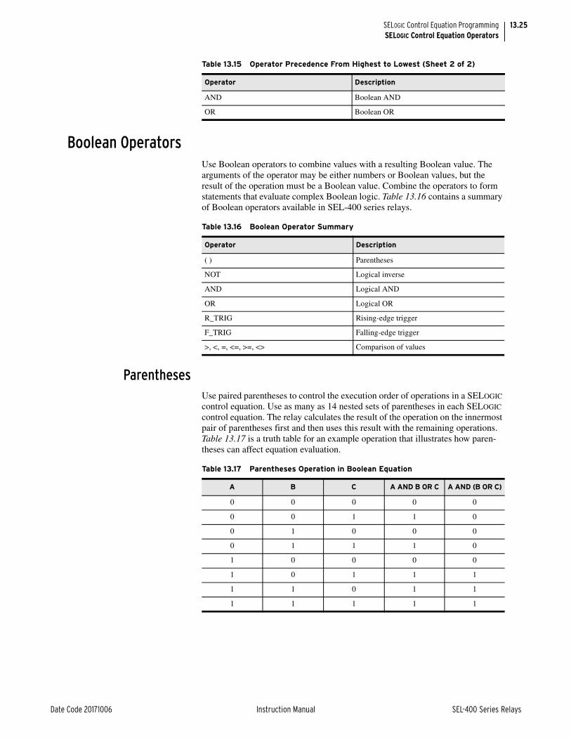
13.25
Date Code 20171006 Instruction Manual SEL-400 Series Relays
SELOGIC Control Equation ProgrammingSELOGIC Control Equation Operators
Boolean OperatorsUse Boolean operators to combine values with a resulting Boolean value. The arguments of the operator may be either numbers or Boolean values, but the result of the operation must be a Boolean value. Combine the operators to form statements that evaluate complex Boolean logic. Table 13.16 contains a summary of Boolean operators available in SEL-400 series relays.
ParenthesesUse paired parentheses to control the execution order of operations in a SELOGIC control equation. Use as many as 14 nested sets of parentheses in each SELOGIC control equation. The relay calculates the result of the operation on the innermost pair of parentheses first and then uses this result with the remaining operations. Table 13.17 is a truth table for an example operation that illustrates how paren-theses can affect equation evaluation.
AND Boolean AND
OR Boolean OR
Table 13.15 Operator Precedence From Highest to Lowest (Sheet 2 of 2)
Operator Description
Table 13.16 Boolean Operator Summary
Operator Description
( ) Parentheses
NOT Logical inverse
AND Logical AND
OR Logical OR
R_TRIG Rising-edge trigger
F_TRIG Falling-edge trigger
>, <, =, <=, >=, <> Comparison of values
Table 13.17 Parentheses Operation in Boolean Equation
A B C A AND B OR C A AND (B OR C)
0 0 0 0 0
0 0 1 1 0
0 1 0 0 0
0 1 1 1 0
1 0 0 0 0
1 0 1 1 1
1 1 0 1 1
1 1 1 1 1

13.26
SEL-400 Series Relays Instruction Manual Date Code 20171006
SELOGIC Control Equation ProgrammingSELOGIC Control Equation Operators
NOTUse NOT to calculate the inverse of a Boolean value according to the truth table shown in Table 13.18.
ANDUse AND to combine two Boolean values according to the truth table shown in Table 13.19.
ORUse OR to combine two Boolean values according to the truth table shown in Table 13.20.
R_TRIGR_TRIG is a time-based function that creates a pulse when another value changes, as shown in Figure 13.9 Use R_TRIG to sense when a value changes from logical 0 to logical 1 and take action only once when the value changes. The R_TRIG output is a pulse of one protection processing interval duration (typi-cally 1/8th cycle). This rising-edge pulse output asserts one processing interval after the monitored element asserts.
Table 13.18 NOT Operator Truth Table
Value A NOT A
0 1
1 0
Table 13.19 AND Operator Truth Table
Value A Value B A AND B
0 0 0
0 1 0
1 0 0
1 1 1
Table 13.20 OR Operator Truth Table
Value A Value B A OR B
0 0 0
0 1 1
1 0 1
1 1 1

13.27
Date Code 20171006 Instruction Manual SEL-400 Series Relays
SELOGIC Control Equation ProgrammingSELOGIC Control Equation Operators
The argument of an R_TRIG statement must be a single bit within the relay. An example of the relay detecting a rising edge of a calculated quantity is shown in Example 13.10.
F_TRIGF_TRIG is a time-based function that creates a pulse when another value changes, as shown in Example 13.10. Use F_TRIG to sense when a value changes from logical 1 to logical 0 and take action only after the value changes state. The F_TRIG output is a pulse of one protection processing interval dura-tion (typically 1/8th cycle). This pulse output asserts one processing interval after the monitored element deasserts.
Figure 13.9 R_TRIG Timing Diagram
Example 13.10 R_TRIG Operation
The SELOGIC control equation below is invalid.
PSV15 := R_TRIG (PSV01 AND PSV23) # Invalid statement, do not use
Use a SELOGIC control equation variable to calculate the quantity and then use the R_TRIG operation on the result, as shown below.
PSV14 := PSV01 AND PSV23 # Calculate quantity in an intermediate result variable
PSV15 := R_TRIG PSV14 # Perform an R_TRIG on the quantity
Relay Word bit A
R_TRIG A
R_TRIG ADeasserts
R_TRIG AAsserts
Relay Word bit A Changesfrom 0 to 1
1 Processing
Interval
1 Processing
Interval

13.28
SEL-400 Series Relays Instruction Manual Date Code 20171006
SELOGIC Control Equation ProgrammingSELOGIC Control Equation Operators
The argument of an F_TRIG statement must be a single bit within the relay. An example of the relay detecting a falling edge of a calculated quantity is shown in Example 13.11.
ComparisonComparison is a mathematical operation that compares two numerical values with a result of logical 0 or logical 1. AND and OR operators compare Boolean values; comparison functions compare floating-point values such as currents and other quantities. Comparisons and truth tables for operation of comparison func-tions are shown in Table 13.21.
NOTE: Be careful how you use the equal (=) and the inequality (<>) operators. Because the relay uses a floating-point format to calculate analog values, only integer numbers will match exactly. Allow a small hysteresis of the following form: PSV01 := I01FM < 10.002 AND I01FM > 9.988.
Figure 13.10 F_TRIG Timing Diagram
Example 13.11 F_TRIG Operation
The SELOGIC control equation below shows an invalid use of the F_TRIG operation.
ASV015 := F_TRIG (ASV001 AND ALT11) # Invalid statement, do not use
Use a SELOGIC control equation variable to calculate the quantity and then use the F_TRIG operation on the result, as shown below.
ASV014 := ASV001 AND ALT11 # Calculate quantity in an intermedi-ate result variable
ASV015 := F_TRIG ASV14 # Perform an F_TRIG on the quantity
Relay Word bit A
F_TRIG A
F_TRIG ADeasserts
F_TRIG AAsserts
Relay Word bit A Changesfrom 1 to 0
1 Processing
Interval
1 Processing
Interval
Table 13.21 Comparison Operations
A B A > B A B A = B A <> B A B A < B
6.35 7.00 0 0 0 1 1 1
5.10 5.10 0 1 1 0 1 0
4.25 4.00 1 1 0 1 0 0

13.29
Date Code 20171006 Instruction Manual SEL-400 Series Relays
SELOGIC Control Equation ProgrammingSELOGIC Control Equation Operators
Math OperatorsUse math operators when writing math SELOGIC control equations. Math SELOGIC control equations manipulate numerical values and provide a numerical base 10 result. Table 13.22 summarizes the operators available for math SELOGIC control equations.
ParenthesesUse parentheses to control the order in which the relay evaluates math operations within a math SELOGIC control equation. Also use parentheses to group expres-sions that you use as arguments to function operators such as SIN and COS. Include as many as 14 levels of nested parentheses in your math SELOGIC control equation. Example 13.12 shows how parentheses affect the operation and evalua-tion of math operations.
Math Error DetectionIf a math operation results in an error, the relay turns on the math error bit, MATHERR, in the Relay Word. A settings change or the STATUS SC command resets this bit. For example, if you attempt to take the square root of a negative number (SQRT –5), the math error bit will be asserted until you clear the bit with a STATUS SC command or change settings.
Table 13.22 Math Operator Summary
Operator Description
( ) Parentheses
+, –, *, / Arithmetic
SQRT Square root
LN, EXP, LOG Natural logarithm, exponentiation of e, base 10 loga-rithm
COS, SIN, ACOS, ASIN Cosine, sine, arc cosine, arc sine
ABS Absolute value
CEIL Rounds to the nearest integer toward infinity
FLOOR Rounds to the nearest integer toward minus infinity
– Negation
Example 13.12 Using Parentheses in Math Equations
The freeform math SELOGIC control equations below show examples of parentheses usage.
# Examples of parenthesis usage
AMV001 := AMV005 * (AMV004 + AMV003) # Calculate sum first, then product
AMV002 := AMV010 * (AMV009 + (AMV016 / AMV015)) # Nest parentheses
AMV003 := SIN (AMV037 + PMV42) # Group terms for a function

13.30
SEL-400 Series Relays Instruction Manual Date Code 20171006
SELOGIC Control Equation ProgrammingSELOGIC Control Equation Operators
ArithmeticUse arithmetic operators to perform basic mathematical operations on numerical values. Arguments of an arithmetic operation can be either Boolean or numerical values. In a numerical operation, the relay converts logical 0 or logical 1 to the numerical value of 0 or 1. For example, multiply numerical values by Boolean values to perform a selection operation. Use parentheses to group terms in math SELOGIC control equations and control the evaluation order and sequence of arithmetic operations.
NOTE: IEEE 32-bit floating point numbers have a precision of approximately 7 significant digits. This means that numbers bigger than 10,000,000 will lose precision in the least significant digit. Do not implement counters expecting them to get bigger than 10,000,000. Do not expect precise accuracy in analog quantities when they get bigger than 10,000,000.
The relay uses IEEE 32-bit floating-point numbers to perform SELOGIC control equation mathematical operations. If an operation results in a quantity that is not a numerical value, the SELOGIC control equation status bit that signals a math error, MATHERR, asserts. The value that the relay stored previously in the speci-fied result location is not replaced. The relay clears the corresponding math error bits if you change SELOGIC control equation settings (protection or automation), or if you issue a STATUS SC command. Example 13.13 contains examples of arithmetic operations in use.
Table 13.23 Math Error Examples
Example Value in PMV01 Type MATHERR
PMV01 := PMV02 / 0 0a
a Evaluation of expression results in an error and prevents storage of new result. In the example, PMV01 remains 0. If the argument were a variable, PMV01 would contain the result of the last evaluation when the argument is valid.
Divide by zero Yes
PMV01 := LN ( 0 ) 0a LN of 0 Yes
PMV01 := LN ( -1) 0a LN of negative number Yes
PMV01 := SQRT ( -1) 0a Square root of a negative number Yes
Example 13.13 Using Arithmetic Operations
The freeform math SELOGIC control equations below show examples of arithmetic operator usage.
# Arithmetic examples
AMV001 := AMV005 + AMV034 # Calculate sum
AMV002 := AMV005 – AMV034 # Calculate difference
AMV003 := AMV005 * AMV034 # Calculate product
AMV004 := AMV005 / AMV034 # Calculate quotient
The lines below demonstrate the use of Boolean values with the multiplica-tion operation.
# Use of multiplication to select numerical values based on active set-tings group
# Use 7 if protection settings group 1 active
# Use 5 if protection settings group 2 active
AMV005 := 7 * SG1 + 5 * SG2

13.31
Date Code 20171006 Instruction Manual SEL-400 Series Relays
SELOGIC Control Equation ProgrammingSELOGIC Control Equation Operators
SQRTUse the SQRT operation to calculate the square root of the argument. Use paren-theses to delimit the argument of a SQRT operation. A negative argument for the SQRT operation results in a math error and assertion of the corresponding math error bit described in Arithmetic. Example 13.14 shows examples of the SQRT operator in use.
LN, EXP, and LOGLN and EXP are complementary functions for operating with natural logarithms or logarithms calculated to the natural base e. LN calculates the natural logarithm of the argument. LOG calculates the base 10 logarithm of the argument. A nega-tive or zero argument for the LN and LOG operation results in a math error and assertion of the corresponding math error bit described in Arithmetic. EXP calcu-lates the value of e raised to the power of the argument. Example 13.15 shows examples of expressions that use the LN, EXP, and LOG operators. Use parenthe-ses to delimit the argument of a LN, EXP, or LOG operation.
The lines below demonstrate math calculation error detection.
# The line below results in a math error if AMV029 becomes 0
AMV006 := 732 / AMV029
In the second line, if AMV029 is 6 on the first pass through the automation programming, the relay stores the result 122 in AMV006. If on the next pass AMV029 is 0, the MATHERR bit asserts and the value in AMV006 does not update.
Example 13.13 Using Arithmetic Operations (Continued)
Example 13.14 Using the SQRT Operator
The freeform math SELOGIC control equations below show examples of SQRT operator usage.
# SQRT examples
AMV001 := SQRT (AMV005) # Single argument version of SQRT
AMV002 := SQRT (AMV005 + AMV034) # Calculates the square root of the sum
AMV003 := SQRT (AMV007) # Produces a math error if AMV007 is negative
Example 13.15 Using the LN, EXP, and LOG Operators
The freeform math SELOGIC control equations below are examples of LN, EXP, and LOG operator usage.
# LN examples
AMV001 := LN (AMV009) # Natural logarithm of AMV009
AMV002 := LN (AMV009 + AMV034) # Natural logarithm of the sum
AMV003 := LN (AMV010) # Produces error if AMV010 is 0 or negative
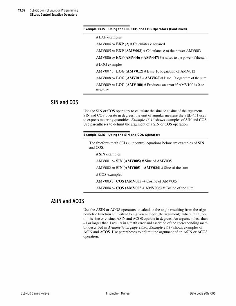
13.32
SEL-400 Series Relays Instruction Manual Date Code 20171006
SELOGIC Control Equation ProgrammingSELOGIC Control Equation Operators
SIN and COSUse the SIN or COS operators to calculate the sine or cosine of the argument. SIN and COS operate in degrees, the unit of angular measure the SEL-451 uses to express metering quantities. Example 13.16 shows examples of SIN and COS. Use parentheses to delimit the argument of a SIN or COS operation.
ASIN and ACOSUse the ASIN or ACOS operators to calculate the angle resulting from the trigo-nometric function equivalent to a given number (the argument), where the func-tion is sine or cosine. ASIN and ACOS operate in degrees. An argument less than –1 or larger than 1 results in a math error and assertion of the corresponding math bit described in Arithmetic on page 13.30. Example 13.17 shows examples of ASIN and ACOS. Use parentheses to delimit the argument of an ASIN or ACOS operation.
# EXP examples
AMV004 := EXP (2) # Calculates e squared
AMV005 := EXP (AMV003) # Calculates e to the power AMV003
AMV006 := EXP (AMV046 + AMV047) # e raised to the power of the sum
# LOG examples
AMV007 := LOG (AMV012) # Base 10 logarithm of AMV012
AMV008 := LOG (AMV012 + AMV022) # Base 10 logarithm of the sum
AMV009 := LOG (AMV100) # Produces an error if AMV100 is 0 or negative
Example 13.15 Using the LN, EXP, and LOG Operators (Continued)
Example 13.16 Using the SIN and COS Operators
The freeform math SELOGIC control equations below are examples of SIN and COS.
# SIN examples
AMV001 := SIN (AMV005) # Sine of AMV005
AMV002 := SIN (AMV005 + AMV034) # Sine of the sum
# COS examples
AMV003 := COS (AMV005) # Cosine of AMV005
AMV004 := COS (AMV005 + AMV006) # Cosine of the sum
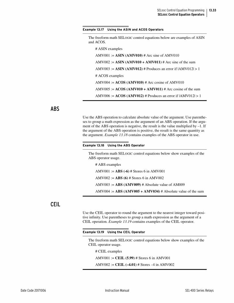
13.33
Date Code 20171006 Instruction Manual SEL-400 Series Relays
SELOGIC Control Equation ProgrammingSELOGIC Control Equation Operators
ABSUse the ABS operation to calculate absolute value of the argument. Use parenthe-ses to group a math expression as the argument of an ABS operation. If the argu-ment of the ABS operation is negative, the result is the value multiplied by –1. If the argument of the ABS operation is positive, the result is the same quantity as the argument. Example 13.18 contains examples of the ABS operator in use.
CEILUse the CEIL operator to round the argument to the nearest integer toward posi-tive infinity. Use parentheses to group a math expression as the argument of a CEIL operation. Example 13.19 contains examples of the CEIL operator.
Example 13.17 Using the ASIN and ACOS Operators
The freeform math SELOGIC control equations below are examples of ASIN and ACOS.
# ASIN examples
AMV001 := ASIN (AMV010) # Arc sine of AMV010
AMV002 := ASIN (AMV010 + AMV011) # Arc sine of the sum
AMV003 := ASIN (AMV012) # Produces an error if |AMV012| > 1
# ACOS examples
AMV004 := ACOS (AMV010) # Arc cosine of AMV010
AMV005 := ACOS (AMV010 + AMV011) # Arc cosine of the sum
AMV006 := ACOS (AMV012) # Produces an error if |AMV012| > 1
Example 13.18 Using the ABS Operator
The freeform math SELOGIC control equations below show examples of the ABS operator usage.
# ABS examples
AMV001 := ABS (-6) # Stores 6 in AMV001
AMV002 := ABS (6) # Stores 6 in AMV002
AMV003 := ABS (AMV009) # Absolute value of AM009
AMV004 := ABS (AMV005 + AMV034) # Absolute value of the sum
Example 13.19 Using the CEIL Operator
The freeform math SELOGIC control equations below show examples of the CEIL operator usage.
# CEIL examples
AMV001 := CEIL (5.99) # Stores 6 in AMV001
AMV002 := CEIL (–4.01) # Stores –4 in AMV002

13.34
SEL-400 Series Relays Instruction Manual Date Code 20171006
SELOGIC Control Equation ProgrammingEffective Programming
FLOORUse the FLOOR operator to round the argument to the nearest integer toward minus infinity. Use parentheses to group a math expression as the argument of a FLOOR operation. Example 13.20 contains examples of the FLOOR operator.
NegationUse the negation (–) operation to change the sign of the argument. The argument of the negation operation is multiplied by –1. Negation of a positive value results in a negative value, while negation of a negative value results in a positive value. Example 13.21 contains examples of expressions that utilize the negation operator.
Effective ProgrammingThis section contains several ideas useful for creating, maintaining, and trouble-shooting programming in SEL-400 series relays protection and automation SELOGIC control equation programming environments.
Planning and DocumentationWhen you begin to configure the relay to perform a new automation task or cus-tomize protection operation, take time to design, document, and implement your project. Scale the planning effort to match the overall size of the project, but spend sufficient time planning to do the following:
➤ Document the inputs and outputs of your programming. This may include protection elements, physical inputs and outputs, metering quantities, user inputs, and other information within the relay.
➤ Document the processing or outcome of the programming. List the major tasks you want the relay to perform and provide detail about the algorithm you will use for each task. For example, if you need a timer or a counter, make a note of the requirements and how you will use these elements.
Example 13.20 Using the FLOOR Operator
The freeform math SELOGIC control equations below show examples of the FLOOR operator usage.
# FLOOR examples
AMV001 := FLOOR (5.99) # Stores 5 in AMV001
AMV002 := FLOOR (–4.01) # Stores –5 in AMV002
Example 13.21 Using the Negation Operator
The freeform math SELOGIC control equations below show examples of negation operator usage.
# Negation examples
AMV001 := -AMV009 # If AMV009 is 5, stores –5 in AMV001
AMV002 := -AMV009 # If AMV009 is –5, stores 5 in AMV002
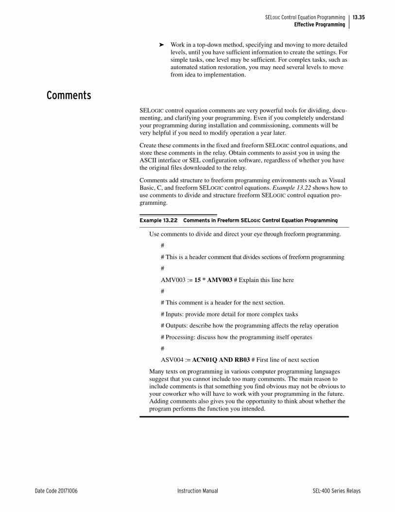
13.35
Date Code 20171006 Instruction Manual SEL-400 Series Relays
SELOGIC Control Equation ProgrammingEffective Programming
➤ Work in a top-down method, specifying and moving to more detailed levels, until you have sufficient information to create the settings. For simple tasks, one level may be sufficient. For complex tasks, such as automated station restoration, you may need several levels to move from idea to implementation.
CommentsSELOGIC control equation comments are very powerful tools for dividing, docu-menting, and clarifying your programming. Even if you completely understand your programming during installation and commissioning, comments will be very helpful if you need to modify operation a year later.
Create these comments in the fixed and freeform SELOGIC control equations, and store these comments in the relay. Obtain comments to assist you in using the ASCII interface or SEL configuration software, regardless of whether you have the original files downloaded to the relay.
Comments add structure to freeform programming environments such as Visual Basic, C, and freeform SELOGIC control equations. Example 13.22 shows how to use comments to divide and structure freeform SELOGIC control equation pro-gramming.
Example 13.22 Comments in Freeform SELOGIC Control Equation Programming
Use comments to divide and direct your eye through freeform programming.
#
# This is a header comment that divides sections of freeform programming
#
AMV003 := 15 * AMV003 # Explain this line here
#
# This comment is a header for the next section.
# Inputs: provide more detail for more complex tasks
# Outputs: describe how the programming affects the relay operation
# Processing: discuss how the programming itself operates
#
ASV004 := ACN01Q AND RB03 # First line of next section
Many texts on programming in various computer programming languages suggest that you cannot include too many comments. The main reason to include comments is that something you find obvious may not be obvious to your coworker who will have to work with your programming in the future. Adding comments also gives you the opportunity to think about whether the program performs the function you intended.

13.36
SEL-400 Series Relays Instruction Manual Date Code 20171006
SELOGIC Control Equation ProgrammingSEL-311 and SEL-351 Series Users
AliasesSEL-400 series relays provide the ability to alias relay word bit and analog quan-tity names. To make SELOGIC programming more understandable, alias the names of variables being used to something meaningful. For example, you could assign PMV01 an alias of THETA and PMV02 an alias of TAN and then write a SELOGIC equation of:
TAN := SIN(THETA)/COS(THETA)
See Alias Settings on page 12.20 for more information on creating aliases.
TestingAfter documentation and comments, the next essential element of an effective approach to programming is testing. Two types of testing are critical for deter-mining if programming for complex tasks operates properly. First, test and observe whether the program performs the function you want under the condi-tions you anticipated. Second, look for opportunities to create conditions that are abnormal and determine how your program reacts to unusual conditions.
For example, test your system in unanticipated, but possible conditions such as loss of power, loss of critical field inputs, unexpected operator inputs, and condi-tions that result from likely failure scenarios of the equipment in your system. It is unlikely that you will find every possible weakness, but careful consideration and testing for abnormal conditions will help you avoid a failure and may reveal deficiencies in the normal operation of your system. Alternatively, you can sub-stitute a remote bit or local bit that you can manually control to help exercise your logic.
Modify your SELOGIC control equations to simulate the process. While you may be unable to change the state of a discrete input easily, such as IN101, you can substitute a logical 1 or logical 0 in your logic to simulate the operation of IN101 and observe the results. Alternatively, you can substitute a remote bit or local bit that you can manually control to help exercise your logic.
Use the SER capabilities of the relay to monitor and record inputs, internal calcu-lations, and outputs. For operations that occur very quickly, use the SER during testing to reconstruct the operation of your logic.
Use the MET PMV and MET AMV commands to display the contents of the protection or automation math variables.
SEL-311 and SEL-351 Series UsersYou can convert logic that you have used in SEL-311 and SEL-351 series relays to logic for an SEL-400 series relay. In the SEL-351 series relays, SELOGIC con-trol equation programming is restricted to equations where the left side value, LVALUE, is fixed. SEL-400 series relays use a combination of fixed and freeform programming. Table 13.24 shows comparable features between the fixed logic settings of the SEL-351-5, -6, -7 series relays and the corresponding logic elements that can be programmed in an SEL-400 series relay using freeform logic programming.

13.37
Date Code 20171006 Instruction Manual SEL-400 Series Relays
SELOGIC Control Equation ProgrammingSEL-311 and SEL-351 Series Users
Table 13.25 is a summary that compares SELOGIC control equation programming in SEL-351 series relays and SEL-311 series relays with typical SEL-400 series relays.
Table 13.26 shows the SEL-400 series Boolean operators compared to the opera-tors used in the SEL-351 series relays.
In the SEL-351 series relays, SELOGIC control equation variables and timers are connected. Each SELOGIC control equation variable is the input to a timer. In SEL-400 series relays, timers and SELOGIC control equation variables are independent.
The SELOGIC control equation Boolean operators in SEL-400 series relays are different from those used in SEL-300 series relays. For example, if you wish to convert programming from an SEL-311 or SEL-351 series relay to an SEL-400 series relay, you must convert the operators. Example 13.23 and Example 13.24 demonstrate conversion of several settings to the SEL-451 setting.
Table 13.24 SEL-351 Series Relays and SEL-400 Series SELOGIC Control Equation Programming Equivalent Functions
Feature SEL-351 Series SEL-400 Series Protection Freeform Style
SELOGIC control equation variables SV1–SV16 PSV01–PSV64
Timer Input SV1–SV16 PCT01–PCT32
Timer Pickup settings SV1PU–SV16PU PCT01PU–PCT32PU
Timer Dropout settings SV1DO–SV16DO PCT01DO–PCT32DO
Timer Outputs SV1T–SV16T PCT01Q–PCT32Q
Latch Bit Set Control SET1–SET16 PLT01S–PLT16S
Latch Bit Reset Control RST1–RST16 PLT01R–PLT16R
Latch Bit LT1–LT16 PLT01–PLT16
Table 13.25 SEL-400 Series SELOGIC Control Equation Programming Summary
ElementSEL-351 Series/SEL-311 Series
Typical SEL-400 Series
Protection Free Form
Automation Free Form
SELOGIC control equation variables 16 64 256
SELOGIC math variables 0 64 256
Conditioning timersa
a Similar to SEL-300 series relay SELOGIC control equation programming.
16 32 0
Sequencing timers 0 32 32
Counters 0 32 32
Latch bits 16 32 32
Table 13.26 SEL-351 Series Relays and SEL-400 Series SELOGIC Control Equation Boolean Operators
Feature SEL-351 Series SEL-400 Series
Logical AND operator * AND
Logical OR operator + OR
Logical NOT operator ! NOT
Parentheses ( ) ( )
Rising, falling edge operators /, \ R_TRIG, F_TRIG

13.38
SEL-400 Series Relays Instruction Manual Date Code 20171006
SELOGIC Control Equation ProgrammingSEL-311 and SEL-351 Series Users
Example 13.23 Converting SEL-351 Series Relay SELOGIC Control Equation Variables
If you have the following SELOGIC control equation in an SEL-351 series relay, convert it as shown below.
In an SEL-400 series relay, use the line shown below.
PSV01 := IN101 OR RB03 AND PLT04 # Freeform example
In the example above, first convert the + and * operators in the expression to the OR and AND operators. In the freeform example, use a protection SELOGIC control equation variable for the result. In the protection group set-tings example, use the input of a timer, as shown in Table 13.21.
Example 13.24 Converting SEL-351 Series Relay SELOGIC Control Equation Timers
If you have the following SELOGIC control equation timer in an SEL-351 series relay, convert it as shown below.
In an SEL-400 series relay, use the format shown below.
#
# Freeform programming conversion of timer
#
PCT01PU := 5.25 # Pickup of 5.25 cycles
PCT01DO := 3.5 # Dropout of 3.5 cycles
PCT01IN := IN101 # Use the timer to monitor IN101
In the output settings, set OUT101 as shown below:
OUT101 := PCT01Q
Example 13.25 Converting SEL-351 Series Relay Latch Bits
If you have the following SELOGIC control equation latch programming in an SEL-351 series relay, convert it as shown below.
SV1 = IN101 + RB3 * LT4
SV1 = IN101SV1PU = 5.25SV1DO = 3.50OUT101 = SV1T
SET1 = RB4RST1 = RB5OUT101 = LT1

13.39
Date Code 20171006 Instruction Manual SEL-400 Series Relays
SELOGIC Control Equation ProgrammingSEL-311 and SEL-351 Series Users
In an SEL-400 series relay, use the format shown below.
Protection freeform style settings:
#
# Freeform programming conversion of latch bit
#
PLT01S := RB04 # Set if RB04
PLT01R := RB05 # Reset if RB05
In the output settings, set OUT101 as shown below:
OUT101 := PLT01
Example 13.25 Converting SEL-351 Series Relay Latch Bits (Continued)

This page intentionally left blank
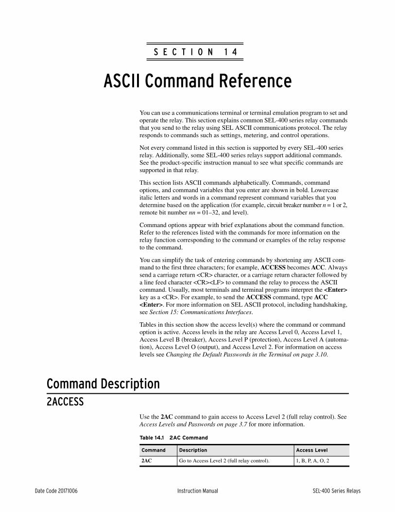
Date Code 20171006 Instruction Manual SEL-400 Series Relays
Instruction ManualInstruction ManualS E C T I O N 1 4
ASCII Command Reference
You can use a communications terminal or terminal emulation program to set and operate the relay. This section explains common SEL-400 series relay commands that you send to the relay using SEL ASCII communications protocol. The relay responds to commands such as settings, metering, and control operations.
Not every command listed in this section is supported by every SEL-400 series relay. Additionally, some SEL-400 series relays support additional commands. See the product-specific instruction manual to see what specific commands are supported in that relay.
This section lists ASCII commands alphabetically. Commands, command options, and command variables that you enter are shown in bold. Lowercase italic letters and words in a command represent command variables that you determine based on the application (for example, circuit breaker number n = 1 or 2, remote bit number nn = 01–32, and level).
Command options appear with brief explanations about the command function. Refer to the references listed with the commands for more information on the relay function corresponding to the command or examples of the relay response to the command.
You can simplify the task of entering commands by shortening any ASCII com-mand to the first three characters; for example, ACCESS becomes ACC. Always send a carriage return <CR> character, or a carriage return character followed by a line feed character <CR><LF> to command the relay to process the ASCII command. Usually, most terminals and terminal programs interpret the <Enter> key as a <CR>. For example, to send the ACCESS command, type ACC <Enter>. For more information on SEL ASCII protocol, including handshaking, see Section 15: Communications Interfaces.
Tables in this section show the access level(s) where the command or command option is active. Access levels in the relay are Access Level 0, Access Level 1, Access Level B (breaker), Access Level P (protection), Access Level A (automa-tion), Access Level O (output), and Access Level 2. For information on access levels see Changing the Default Passwords in the Terminal on page 3.10.
Command Description2ACCESS
Use the 2AC command to gain access to Access Level 2 (full relay control). See Access Levels and Passwords on page 3.7 for more information.
Table 14.1 2AC Command
Command Description Access Level
2AC Go to Access Level 2 (full relay control). 1, B, P, A, O, 2

14.2
SEL-400 Series Relays Instruction Manual Date Code 20171006
ASCII Command ReferenceCommand Description
89CLOSE nUse the 89CLOSE n command to close disconnect switches. (The number of disconnects supported, n, depends on the relay.) The main board circuit breaker jumper (on jumper BREAKER) must be in place.
NOTE: The SEL-487B does not support disconnect control operations.
If the disconnect switch is open and Relay Word bit LOCAL is deasserted, the 89CLOSE n command asserts Relay Word bit 89CLSn for the 89CSITn time. See Disconnect Switch Close and Open Control Logic on page 5.1. If the Relay Word bit 89OIPn asserts, indicating that the disconnect has started to close, the relay displays Operation in Progress... With Relay Word bit 89OIPn asserted and Relay Word bit 89ALPn deasserted, a dot (.) is appended to the above mes-sage every half second to show progress. While the operation is in progress, com-munications are unavailable on the port where the 89CLOSE command was executed. Assertion of Relay Word bit 89OIPn starts the 89ALPn alarm timer. The relay waits for the 89ALPn timer to expire and then checks the status of the 89AMn and 89BMn disconnect inputs. If the 89ALPn timer does not expire within 30 seconds, the relay exits the 89CLOSE command and reads the status of the disconnect inputs. The state of Relay Word bits 89AMn and 89BMn deter-mine which disconnect status message the relay displays (Disconnect OPEN, Disconnect CLOSED, or Status Undetermined - check wiring). Use the 89CLSn Relay Word bit as part of a SELOGIC Output control equation to close the appropriate disconnect switch.
If the relay is disabled and you attempt an 89CLOSE n command, the relay responds with Command aborted because the relay is disabled. If the cir-cuit breaker control enable jumper J18C (BREAKER) is not in place, the relay aborts the command and responds, Aborted: the breaker jumper is not installed.
When the 89CLOSE n command is issued and the circuit breaker control enable jumper is in place, the relay responds, CLOSE DISNAMn (Y/N)?. If you answer Y <Enter>, the relay responds with Are you sure (Y/N)?. If you answer Y <Enter>, the command is executed. If the response to either prompt is not y or Y, the relay responds with Command Aborted.
89OPEN nUse the 89OPEN n command to open disconnect switches. (The number of dis-connects supported, n, depends on the relay.) The main board circuit breaker jumper (on jumper BREAKER) must be in place.
NOTE: The SEL-487B does not support disconnect control operations.
If the disconnect switch is closed and Relay Word bit LOCAL is deasserted, the 89OPEN n command asserts Relay Word bit 89OPENn for the 89OSITn time. See Disconnect Switch Close and Open Control Logic on page 5.1. If the Relay Word bit 89OIPn asserts, indicating that the disconnect has started to open, the relay displays Operation in Progress... With Relay Word bit 89OIPn asserted and Relay Word bit 89ALPn deasserted, a dot (.) is appended to the above mes-sage every half second to show progress. While the operation is in progress, com-munications are unavailable on the port where the 89OPEN command was executed. Assertion of Relay Word bit 89OIPn starts the 89ALPn alarm timer. The relay waits for the 89ALPn timer to expire and then checks the status of the 89AMn and 89BMn disconnect inputs. If the 89ALPn timer does not expire
Table 14.2 89CLOSE n Command
Command Description Access Level
89CLOSE n Set Relay Word bit 89CLSn B, P, A, O, 2

14.3
Date Code 20171006 Instruction Manual SEL-400 Series Relays
ASCII Command ReferenceCommand Description
within 30 seconds, the relay exits the 89OPEN command and reads the status of the disconnect inputs. The state of Relay Word bits 89AMn and 89BMn deter-mine which disconnect status message the relay displays (Disconnect OPEN, Disconnect CLOSED, or Status Undetermined - check wiring). Use Relay Word bit 89OPENn as part of a SELOGIC Output control equation to open the appropriate disconnect switch.
If the relay is disabled and you attempt an 89OPEN n command, the relay responds with Command Aborted because the relay is disabled. If the circuit breaker control enable jumper J18C (BREAKER) is not in place, the relay aborts the command and responds Aborted: the breaker jumper is not installed.
When the 89OPEN n command is issued and the circuit breaker control enable jumper is in place, the relay responds with Open DISNAMn (Y/N)?. If you answer Y <Enter>, the relay responds Are you sure (Y/N)?. If you answer Y <Enter>, the command is executed. If the response to either prompt is not y or Y, the relay responds with Command Aborted.
AACCESSUse the AAC command to gain access to Access Level A (automation). See Access Levels and Passwords on page 3.7 for more information.
ACCESSUse the ACC command to gain access to Access Level 1 (monitor). See Access Levels and Passwords on page 3.7 for more information.
BACCESSUse the BAC command to gain access to Access Level B (breaker). See Access Levels and Passwords on page 3.7 for more information.
Table 14.3 89OPEN n Command
Command Description Access Level
89OPEN n Set Relay Word bit 89OPENn B, P, A, O, 2
Table 14.4 AAC Command
Command Description Access Level
AAC Go to Access Level A (automation). 1, B, P, A, O, 2
Table 14.5 ACC Command
Command Description Access Level
ACC Go to Access Level 1 (monitoring). 0, 1, B, P, A, O, 2
Table 14.6 BAC Command
Command Description Access Level
BAC Go to Access Level B (breaker). 1, B, P, A, O, 2
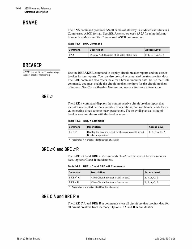
14.4
SEL-400 Series Relays Instruction Manual Date Code 20171006
ASCII Command ReferenceCommand Description
BNAMEThe BNA command produces ASCII names of all relay Fast Meter status bits in a Compressed ASCII format. See SEL Protocol on page 15.23 for more informa-tion on Fast Meter and the Compressed ASCII command set.
BREAKERNOTE: Not all SEL-400 series relays support breaker monitoring.
Use the BREAKER command to display circuit breaker reports and the circuit breaker history reports. You can also preload accumulated breaker monitor data. The BRE command also resets the circuit breaker monitor data. To use the BRE command, you must enable the circuit breaker monitors for the circuit breakers of interest. See Circuit Breaker Monitor on page 8.1 for more information.
BRE nThe BRE n command displays the comprehensive circuit breaker report that includes interrupted currents, number of operations, and mechanical and electri-cal operating times, among many parameters. The relay displays a listing of breaker monitor alarms with the breaker report.
BRE n C and BRE n RThe BRE n C and BRE n R commands clear/reset the circuit breaker monitor data. Options C and R are identical.
BRE C A and BRE R AThe BRE C A and BRE R A commands clear all circuit breaker monitor data for all circuit breakers from memory. Options C A and R A are identical.
Table 14.7 BNA Command
Command Description Access Level
BNA Display ASCII names of all relay status bits. 0, 1, B, P, A, O, 2
Table 14.8 BRE n Command
Command Description Access Level
BRE na
a Parameter n = breaker identification character.
Display the breaker report for the most recent Circuit Breaker n operation.
1, B, P, A, O, 2
Table 14.9 BRE n C and BRE n R Commands
Command Description Access Level
BRE na C
a Parameter n = breaker identification character.
Clear Circuit Breaker n data to zero. B, P, A, O, 2
BRE n R Clear Circuit Breaker n data to zero. B, P, A, O, 2

14.5
Date Code 20171006 Instruction Manual SEL-400 Series Relays
ASCII Command ReferenceCommand Description
BRE n HDisplay the circuit breaker monitor history report with the BRE n H command. The breaker history report is a summary of recent circuit breaker operations.
BRE n PUse the BRE n P command to preload existing circuit breaker contact wear, operation counts, and accumulated currents to the circuit breaker monitor.
CALUse the CAL command to gain access to Access Level C. See Access Levels and Passwords on page 3.7 for more information. Only go to Level C to modify the default password or under the direction of an SEL employee. The additional com-mands available at Level C are not intended for normal operational purposes.
CASCIIThe CAS command produces the Compressed ASCII configuration message. This configuration instructs an external computer on the method for extracting data from other Compressed ASCII commands. See SEL Compressed ASCII Commands on page 15.24 for an example of the CAS command configuration message and for further information on the Compressed ASCII command set.
Table 14.10 BRE C A and BRE R A Commands
Command Description Access Level
BRE C A Clear all circuit breaker data. B, P, A, O, 2
BRE R A Clear all circuit breaker data. B, P, A, O, 2
Table 14.11 BRE n H Command
Command Description Access Level
BRE na H
a Parameter n = breaker identification character.
Display history data for the last 128 Circuit Breaker n operations.
1, B, P, A, O, 2
Table 14.12 BRE n P Command
Command Description Access Level
BRE na Pa Parameter n = breaker identification character.
Preload previously accumulated Breaker n data. B, P, A, O, 2
Table 14.13 CAL Command
Command Description Access Level
CAL Go to Access Level C. 2, C
Table 14.14 CAS Command
Command Description Access Level
CAS Return the Compressed ASCII configuration message. 0, 1, B, P, A, O, 2

14.6
SEL-400 Series Relays Instruction Manual Date Code 20171006
ASCII Command ReferenceCommand Description
CBREAKERNOTE: Not all SEL-400 series relays support breaker monitoring
The CBREAKER command provides a Compressed ASCII response circuit breaker report that is similar to the BREAKER command. You must enable the Breaker Monitor function for at least one breaker to generate the Compressed ASCII report. You can specify a specific circuit breaker to retrieve a report for one circuit breaker only. See SEL Compressed ASCII Commands on page 15.24 for information on the Compressed ASCII command set.
CBRUse the CBR command to gather the comprehensive circuit breaker report in Compressed ASCII format.
CBR TERSEThe CBR TERSE command omits the breaker report labels.
CEVENTThe CEVENT command provides a Compressed ASCII response similar to the EVENT command. See SEL Compressed ASCII Commands on page 15.24 for information on the Compressed ASCII command set.
CEVUse the CEV command to gather relay event reports. When parameter n is 1–9999, n indicates the order of the event report. The most recent event report is 1, the next most recent report is 2, and so on. When parameter n is 10000–42767, n indicates the absolute serial number of the event report.
Table 14.15 CBR Command
Command Description Access Level
CBR Return the most recent circuit breaker reports for all circuit breakers in Compressed ASCII format.
1, B, P, A, O, 2
CBR na
a Parameter n = breaker identification character.
Return the most recent circuit breaker report for Circuit Breaker n in Compressed ASCII format.
1, B, P, A, O, 2
Table 14.16 CBR TERSE Command
Command Description Access Level
CBR TERSE Return the most recent circuit breaker report for all cir-cuit breakers in Compressed ASCII format; suppress the labels; transmit only the data lines.
1, B, P, A, O, 2
CBR na TERSE
a Parameter n = breaker identification character.
Return the most recent circuit breaker report for Circuit Breaker n in Compressed ASCII format; suppress the labels; transmit only the data lines.
1, B, P, A, O, 2

14.7
Date Code 20171006 Instruction Manual SEL-400 Series Relays
ASCII Command ReferenceCommand Description
CEV ACKUse CEV ACK to acknowledge viewing the oldest unacknowledged event on the present communications port. View this event with the CEV NEXT or EVE NEXT commands.
CEV CUse CEV C to return a 15-cycle length event report with analog and digital infor-mation in Compressed ASCII format. The Lyyy option overrides the C option (see CEV Lyyy).
CEV LUse CEV L to return a large resolution event report in Compressed ASCII for-mat. The Sx option overrides the L option (see CEV Sx).
NOTE: Not all SEL-400 series relays support the CEV L option.
Table 14.17 CEV Command
Command Description Access Level
CEV Return the most recent event report (including settings and summary) at full length with 4-samples/cycle data in Com-pressed ASCII format.
1, B, P, A, O, 2
CEV na
a Parameter n indicates event order or serial number.
Return particular n event report (including settings and sum-mary) at full length with 4-samples/cycle data in Com-pressed ASCII format.
1, B, P, A, O, 2
Table 14.18 CEV ACK Command
Command Description Access Level
CEV ACK Acknowledge the oldest unacknowledged event at the present communications port.
1, B, P, A, O, 2
Table 14.19 CEV C Command
Command Description Access Level
CEV C Return the most recent event report at a 15-cycle length with 8-samples/cycle data in Compressed ASCII format.
1, B, P, A, O, 2
CEV C n Return particular n event report at a 15-cycle length with 8-samples/cycle data in Compressed ASCII format.
1, B, P, A, O, 2
Table 14.20 CEV L Command
Commanda
a Parameter n indicates event order or serial number; see CEV on page 14.6.
Description Access Level
CEV L Return the most recent event report at full length with large resolution data in Compressed ASCII format.
1, B, P, A, O, 2
CEV n L Return particular n event report at full length with large res-olution data in Compressed ASCII format.
1, B, P, A, O, 2

14.8
SEL-400 Series Relays Instruction Manual Date Code 20171006
ASCII Command ReferenceCommand Description
CEV LyyyCommand CEV Lyyy returns a specified length event report in Compressed ASCII format, where Lyyy indicates a length of yyy cycles. You can specify yyy from 1 cycle to a value including and beyond the event report total cycle length. If yyy is longer than the total length, the relay returns the full event report. The Lyyy option overrides the C option.
CEV NEXTCEV NEXT returns the oldest unacknowledged event report on the present com-munications port in Compressed ASCII format.
CEV NSETThe CEV NSET command returns the Compressed ASCII event report with no relay settings.
Table 14.21 CEV Lyyy Command
Command Description Access Level
CEV Lyyy Return yyy cycles of the most recent event report (includ-ing settings) with 4-samples/cycle data in Compressed ASCII format.
1, B, P, A, O, 2
CEV na Lyyy
a Parameter n indicates event order or serial number; see CEV on page 14.6.
Return yyy cycles of a particular n event report with 4-samples/cycle data in Compressed ASCII format.
1, B, P, A, O, 2
Table 14.22 CEV N Command
Command Description Access Level
CEV N Return the oldest unacknowledged event report with 4-sam-ples/cycle sampling in Compressed ASCII format.
1, B, P, A, O, 2
Table 14.23 CEV NSET Command
Command Description Access Level
CEV NSET Return the most recent event report without settings at full length with 4-samples/cycle data in Compressed ASCII format.
1, B, P, A, O, 2
CEV na NSET
a Parameter n indicates event order or serial number.
Return a particular n event report without settings at full length with 4-samples/cycle data in Compressed ASCII format.
1, B, P, A, O, 2

14.9
Date Code 20171006 Instruction Manual SEL-400 Series Relays
ASCII Command ReferenceCommand Description
CEV NSUMThe CEV NSUM returns the Compressed ASCII event report with no event summary.
CEV SxUse the CEV Sx command to specify the sample data resolution of the Com-pressed ASCII event report. The sample data resolution x can be 4, 8, or 12, depend-ing on the relay; the default value is 4-samples/cycle if you do not specify Sx. The Sx option overrides the L option.
CEV TERSEThe CEV TERSE command returns a Compressed ASCII event report without the event report labels.
Use the TERSE option with any of the CEV commands except CEV ACK.
Table 14.24 CEV NSUM Command
Command Description Access Level
CEV NSUM Return the most recent event report without the event summary at full length with 4-samples/cycle data in Compressed ASCII format.
1, B, P, A, O, 2
CEV na NSUM
a Parameter n indicates event order or serial number; see CEV on page 14.6.
Return a particular n event report without the event sum-mary at full length with 4-samples/cycle data in Com-pressed ASCII format.
1, B, P, A, O, 2
Table 14.25 CEV Sx Command
Command Description Access Level
CEV Sx Return the most recent event report at full length with x-samples/cycle data in Compressed ASCII format.
1, B, P, A, O, 2
CEV na Sx
a Parameter n indicates event order or serial number: see CEV on page 14.6.
Return a particular n event report at full length with x-sam-ples/cycle data in Compressed ASCII format.
1, B, P, A, O, 2
Table 14.26 CEV TERSE Command
Command Description Access Level
CEV TERSE Return the most recent event report at full length with-out the report labels with 4-samples/cycle data in Compressed ASCII format.
1, B, P, A, O, 2
CEV na TERSE
a Parameter n indicates event order or serial number.
Return a particular n event report at full length without the report labels with 4-samples/cycle data in Com-pressed ASCII format.
1, B, P, A, O, 2

14.10
SEL-400 Series Relays Instruction Manual Date Code 20171006
ASCII Command ReferenceCommand Description
CEV Command Option CombinationsYou can combine options C, L, Lyyy, n, NSET, NSUM, Sx, and TERSE in one command. Enter the options according to the following guidelines:
➤ The Lyyy option overrides the C option
➤ The Sx option overrides the L option
➤ Enter the options in any order
Table 14.27 lists the choices you can make in the CEV command. Combine options on each row, selecting one option from each column, to create a CEV command.
The following examples illustrate some possible option combinations.
CFGIn TiDL and IEC Sampled Values (SV) subscriber relays, certain aspects of the relay must be configured before the relay can be set. This command is used to perform this configuration.
CFG CTNOMIn TiDL and IEC SV subscriber relays, use the CFG CTNOM command to inform the relay which CT inputs are 1 A nominal and which are 5 A nominal. (By default, the relay assumes all CT inputs are 5 A nominal.) This is necessary so the relay scales the information correctly. See Section 2: Installation of the product-specific instruction manual for more information on using this command as part of configuring the relay. This will restart the relay and force all settings to default, so this command must be made before making any other settings in the relay.
Table 14.27 CEV Command Option Groups
AcknowledgeEvent Number
Data Resolution
Report Type
Report Length
Omit
ACK n, NEXT Sx, L C Lyyy, C NSET, NSUM, TERSE
Example Description
CEV L10 S8 Return 10 cycles of an 8-samples/cycle Compressed ASCII event report for the most recent event.
CEV L10 L Return 10 cycles of an large resolution Compressed ASCII event report for the most recent event (same as above).
CEV 2 C NSUM TERSE
For the second most recent event, return 15 cycles of the event in Com-pressed ASCII format with no event summary and no report label lines with large resolution data.
Table 14.28 CFG CTNOM Command
Command Description Access Level
CFG CTNOM na
a The parameter n (or parameters) is relay-specific.
Change nominal CT configuration to selected value 2

14.11
Date Code 20171006 Instruction Manual SEL-400 Series Relays
ASCII Command ReferenceCommand Description
CFG NFREQIn TiDL relays, use the CFG NFREQ command to set the nominal frequency of the relay (which is 60 Hz by default). In relays that do not support TiDL, the nominal frequency is controlled by the NFREQ Global setting. This should be configured after the nominal currents are configured (through the use of the CFG CTNOM command) and before settings are loaded into the relay. This will restart the relay.
CHISTORYThe CHISTORY command provides a HISTORY report in the Compressed ASCII format.
CHIUse the CHI command to gather one-line descriptions of event reports.
CHI TERSEThe CHI TERSE command returns a Compressed ASCII event report without the event report label lines.
CLOSE nUse the CLOSE n command to close a circuit breaker. The main board circuit breaker jumper (on jumper BREAKER) must be in place. Further, you must enable breaker control for any breakers you want to control.
Table 14.29 CFG NFREQ Command
Command Description Access Level
CFG NFREQ f Change nominal frequency to f (50 or 60) 2
Table 14.30 CHI Command
Command Description Access Level
CHI Return the data as contained in the History report (short form descriptions) for the most recent 100 event reports in Compressed ASCII format (for SEL-2030 compatibility).
1, B, P, A, O, 2
CHI A Return one-line descriptions of the most recent 100 event reports in Compressed ASCII format.
1, B, P, A, O, 2
CHI k Return one-line descriptions of the most recent k number of event reports in Compressed ASCII format.
1, B, P, A, O, 2
Table 14.31 CHI TERSE Command
Command Description Access Level
CHI TERSE Return one-line descriptions for the most recent 100 event reports without the label lines in Compressed ASCII format.
1, B, P, A, O, 2
CHI k TERSE Return one-line descriptions for the most recent k num-ber of event reports without the label lines in Com-pressed ASCII format.
1, B, P, A, O, 2

14.12
SEL-400 Series Relays Instruction Manual Date Code 20171006
ASCII Command ReferenceCommand Description
NOTE: The SEL-487B does not support the CLOSE command.
The CLOSE n command asserts Relay Word bit CCn. The CCn bit must be included in the close SELOGIC equation for breaker n (BKnMCL) for this com-mand to effect a close operation. The relay uses these equations and additional relay logic to assert a control output (for example, OUT103 := BK1CL) to close a circuit breaker.
If the circuit breaker control enable jumper BREAKER is in place, the relay responds with Close breaker (Y/N)?. When you answer Y <Enter> (for yes), the relay prompts, Are you sure (Y/N)?. If you again answer Y <Enter>, the relay asserts the Relay Word bit for one processing interval.
If you have assigned a circuit breaker auxiliary contact (52A) to a relay control input (based on the 52AAn, 52ABn, 52ACn settings), the relay waits 0.5 second, checks the state of the circuit breaker, and issues either a Breaker OPEN or Breaker CLOSED message.
If circuit breaker control enable jumper BREAKER is not in place, the relay aborts the command and responds, Aborted: the breaker jumper is not installed. If the relay is disabled, the relay responds with Command aborted because relay is disabled. If Breaker n is not enabled and you issue the CLOSE n command, the relay responds with Breaker n is not available.
COMMUNICATIONSThe COMMUNICATIONS command displays communications statistics for the MIRRORED BITS communications channels and for synchrophasor client channels. Some relays support additional options to the COM command besides those described here.
COM cUse the COM c command to view records of the MIRRORED BITS communica-tions buffers for specific relay communications channels.
The c option in the COM command is A for MIRRORED BITS communications Channel A, B for MIRRORED BITS communications Channel B, and Channel M for the MIRRORED BITS communications channels in general. If both MIRRORED BITS communications channels are in use, then the M option does not function and you must specify A or B.
Table 14.32 CLOSE n Command
Command Description Access Level
CLOSE n Command the relay to close Circuit Breaker n. B, P, A, O, 2
Table 14.33 COM c Commanda
a Parameter c is A, B, or M for Channel A, Channel B, and MIRRORED BITS communications channels, respectively.
Command Description Access Level
COM A Return a summary report of the last 255 records in the commu-nications buffer for MIRRORED BITS communications Channel A.
1, B, P, A, O, 2
COM B Return a summary report of the last 255 records in the commu-nications buffer for MIRRORED BITS communications Channel B.
1, B, P, A, O, 2
COM M Return a summary report of the last 255 records in the commu-nications buffer for either MIRRORED BITS communications Channel A or Channel B when only one channel is enabled.
1, B, P, A, O, 2

14.13
Date Code 20171006 Instruction Manual SEL-400 Series Relays
ASCII Command ReferenceCommand Description
COM c C and COM c RThe COM c C and COM c R commands clear/reset the communications buffer data for the specified Channel c. Options C and R are identical.
COM c L m n and COM c L date1 date2Use COM c L to list the records in the communications buffer in a specified manner. The relay returns the list of records in rows. You can specify a range of buffer records in forward or reverse chronological order or in forward or reverse date order. Date parameter entries depend on the setting DATE_F format you chose in the relay Global settings.
The relay organizes the records in rows in a 256-entry buffer in newest to oldest time order. The relay puts the newest record in the buffer and discards the oldest record if the buffer is full.
Table 14.35 is a representative list of options for listing records in the communi-cations buffer.
Table 14.34 COM c C and COM c R Command
Command Description Access Level
COM A C Clear/reset communications buffer data for MIRRORED BITS communications Channel A.
P, A, O, 2
COM B R Clear/reset communications buffer data for MIRRORED BITS communications Channel B.
P, A, O, 2
COM M C Clear/reset communications buffer data for either MIRRORED BITS communications Channel A or Channel B when only one channel is enabled.
P, A, O, 2
Table 14.35 COM c L Command
Command Description Access Level
COM A L Display all available records from MIRRORED BITS com-munications Channel A; the most recent record is Row 1 (at the top of the report) and the oldest record is at the bottom of the report.
1, B, P, A, O, 2
COM B L ka
a Parameter k indicates a specific number of communications buffer records.
Display the first k records for MIRRORED BITS commu-nications Channel B; the most recent record is Row 1 (at the top of the report) and the oldest record is at the bot-tom of the report.
1, B, P, A, O, 2
COM M L m nb
b Parameters m and n are communications buffer row numbers.
Display the records for either MIRRORED BITS commu-nications Channel A or Channel B when only one chan-nel is enabled; show the records with Record m at the top of the report through Record n at the bottom of the report.
1, B, P, A, O, 2
COM A L date1c
c Enter date1 and date2 in the same format as Global setting DATE_F.
Display the records from MIRRORED BITS communica-tions Channel A on the date date1.
1, B, P, A, O, 2
COM B L date1 date2c
Display the records from MIRRORED BITS communica-tions Channel B between the dates date1 and date2. The date listed first, date1, is at the top of the report; the date listed second, date2, is at the bottom of the report.
1, B, P, A, O, 2

14.14
SEL-400 Series Relays Instruction Manual Date Code 20171006
ASCII Command ReferenceCommand Description
COM PTPThe COM PTP command provides a report of the PTP data sets maintained by the device as well as statistics for the measured time offsets with the parent (mas-ter) clock. The PTP data sets contain information about the state, identity, and configuration of the local, parent, and grandmaster clocks in addition to proper-ties of the time being distributed by the grandmaster clock.
If EPTP = N or the relay hardware does not support PTP, then the COM PTP command will respond with PTP Not Enabled. If a settings change is in progress or if the hardware is not yet initialized, then the COM PTP command will respond with Data unavailable, please try again later.
Table 14.36 COM PTP Command
Command Description Access Level
COM PTP Display PTP data sets and offset statistics 2
COM PTP C Clears PTP offset statistics 2
=>>COM PTP <Enter>
Relay 1 Date: 02/24/2016 Time: 15:08:43.516Station A Serial Number: 0000000000
PTP offset statistics previously cleared on 02/24/2016 14:08:36.303 (UTC)
Settings Data Set PTP Profile : Default Transport Mechanism : Layer2 Path Delay : P2P
Default Data Set Two Step : true Clock Identity : 00 30 A7 FF FE 44 55 66 Number of Ports : 1 Clock Quality Clock Class : 255 Clock Accuracy : 254 Offset Log Variance : 0 Priority1 : 255 Priority2 : 255 Domain Number : 1 Slave Only : true
Current Data Set Steps Removed : 1 Offset from Master : -5 ns Mean Path Delay : 0 ns
Parent Data Set Parent Port Identity Clock Identity : 00 30 A7 FF FE 04 7C 22 Port Number : 1 Grandmaster Clock Identity : 00 30 A7 FF FE 04 7C 22 Grandmaster Clock Quality Clock Class : Synchronized with PTP timescale (6) Clock Accuracy : Within 25 ns Offset Log Variance : 0 Grandmaster Priority1 : 0 Grandmaster Priority2 : 0
Figure 14.1 Sample COM PTP Command Response

14.15
Date Code 20171006 Instruction Manual SEL-400 Series Relays
ASCII Command ReferenceCommand Description
Time Properties Data Set Current UTC Offset : 0 Current UTC Offset Valid : true Leap59 : false Leap61 : false Time Traceable : true Frequency Traceable : true PTP Timescale : true Time Source : PTP Local Time Offset Offset Valid : true Name : PST Current Offset : 3600 Jump Seconds : 3600 Time of Next Jump : 1456797635
Port Data Set Port Identity Clock Identity : 00 30 A7 FF FE 44 55 66 Port Number: 1 Port State : SLAVE Log Pdelay Request Interval : 0 Peer Mean Path Delay : 0 ns Announce Receipt Timeout : 2 intervals Path Delay Mechanism : Peer-to-Peer Failed to Receive Response : true Received Multiple Pdelay Responses : false Reason for Non-synchronization :
Time Offset Statistics Mean : -0.013393 ns Standard Deviation : 5.291062 ns Latest Time Offsets with respect to Reference Time (in ns) #1 : -5 #2 : -1 #3 : 0 #4 : 1 #5 : -1 #6 : 2 #7 : 8 #8 : 3 #9 : 1
#10 : -9 #11 : 2 #12 : 0 #13 : 3 #14 : -4 #15 : -9 #16 : 5 #17 : -1 #18 : -4 #19 : -4 #20 : 1 #21 : 5 #22 : 7 #23 : -7 #24 : -1 #25 : 6 #26 : -2 #27 : -2 #28 : 8 #29 : -5 #30 : 2 #31 : 0 #32 : -2
=>>
Figure 14.1 Sample COM PTP Command Response (Continued)

14.16
SEL-400 Series Relays Instruction Manual Date Code 20171006
ASCII Command ReferenceCommand Description
COM RTCUse the COM RTC to get a report on the status of the configured synchrophasor client channels.
NOTE: Not all SEL-400 series relays support synchrophasors.
COM RTC c C and COM RTC c RThe COM RTC C and COM RTC R commands clear/reset the maximum packet delay. The C and R options are identical.
CONTROL nnUse the CONTROL nn command to set, clear, or pulse internal Relay Word bits. Remote bits in SELOGIC control equations are similar to hardwired control inputs, in that you use these bits to affect relay operation from outside sources. For control inputs, external input to the relay comes through the rear panel; in the case of the CON nn command, external control signals come through the com-munications ports. See Remote Bits on page 5.11 for information on remote bits.
If you enter CON nn with no set, clear, or pulse option specified, the relay responds, Control RBnn:. You must then provide the control action (set, clear, or pulse) that you want to perform. (The relay checks only the first character; you can type Set and Clear.) When you issue a valid CON command, the relay per-forms the control action immediately and displays Remote Bit Operated.
Table 14.37 COM RTC Command
Commanda
a Parameter c is A, B, or absent for Channel A, Channel B, or all enabled channels, respectively.
Description Access Level
COM RTC Return a report describing the communications on all enabled synchrophasor client channels.
1, B, P, A, O, 2
COM RTC A Return a report describing the communications on syn-chrophasor client Channel A.
1, B, P, A, O, 2
COM RTC B Return a report describing the communications on syn-chrophasor client Channel B.
1, B, P, A, O, 2
Table 14.38 COM RTC c C and COM RTC c R Command
Command Description Access Level
COM RTC C Clear/reset the maximum packet delay on all enabled synchrophasor client channels.
P, A, O, 2
COM RTC A R Clear/reset the maximum packet delay on synchrophasor client Channel A.
P, A, O, 2
COM RTC B C Clear/reset the maximum packet delay on synchrophasor client Channel B.
P, A, O, 2
Table 14.39 CON nn Command
Command Description Access Level
CON nna C
a Parameter nn is the remote bit reference for RBnn.
Clear Remote Bit nn. P, A, O, 2
CON nn P Pulse Remote Bit nn for one processing cycle. P, A, O, 2
CON nn S Set Remote Bit nn. P, A, O, 2

14.17
Date Code 20171006 Instruction Manual SEL-400 Series Relays
ASCII Command ReferenceCommand Description
COPYThe COPY command copies the settings from one class instance to another instance in the same class. For example, you can copy Group settings from one group to another. You cannot copy Group settings to Port settings.
This command is limited to the same access level as the SET command for the class of settings you are copying.
The parameters m and n must be valid and distinct (not the same) instance num-bers. You can typically choose from classes of group (S), port (P), and protection SELOGIC control equations (L). Some SEL-400 series relays support copying additional classes. The COPY command is not available within the Automation class and is not available for the Breaker Monitor settings.
In addition, port settings instances must be compatible; you cannot copy from/to Port 5 and the other communications ports settings. You cannot copy to a port that is presently in transparent communication. If you attempt such a copy, the relay responds with Cannot copy to a port involved in transparent com-munication. In addition, you cannot copy to the present port (the port you are using to communicate with the relay). If you attempt such a copy, the relay responds with Cannot copy port settings to present port.
When you enter the COPY command with valid parameters, the relay responds with Are you sure (Y/N)?. Answer Y <Enter> (for yes) to complete copying.
If the destination instance is the active group, the relay changes to the new set-tings and pulses the SALARM Relay Word bit.
CPRUse the CPR command to access the Signal Profile data for as many as 20 user selectable analog values in Compressed ASCII format. Notice that the CPR records are in reverse chronological progression as compared to the PRO reports.
Table 14.40 COPY Command
Command Description Access Level
COPY m na
a Parameters m and n are 1 to 6 for the Group class and 1, 2, 3, and F for the Port class.
Copy settings from instance m of the Group settings to instance n of the Group settings.
P, A, O, 2
COPY class m nb
b Parameter class is S, P, and L for group settings, port settings, and protection SELOGIC control equations, respectively.
Copy settings from instance m of Class class to instance n of Class class.
P, A, O, 2
Table 14.41 CPR Command (Sheet 1 of 2)
Command Description Access Level
CPR Displays the first 20 rows of the profile report, with the oldest row at the bottom and the latest row at the top.
1, B, P, A, O, 2
CPR m Displays the first m rows of the profile report, with the oldest row at the bottom and the latest row at the top.
1, B, P, A, O, 2
CPR m n (m > n) Displays the row between m and n, (including m and n). 1, B, P, A, O, 2
CPR date1 Displays all the rows that were recorded on that date, with the latest row at the bottom and the oldest row at the top.
1, B, P, A, O, 2

14.18
SEL-400 Series Relays Instruction Manual Date Code 20171006
ASCII Command ReferenceCommand Description
CSERThe CSER command provides an SER report in Compressed ASCII format. The default order of the CSER command (chronologically newest to oldest from list top to list bottom) is the reverse of the SER command (oldest to newest from list top to list bottom).
CSEUse the CSE command to gather Sequential Events Recorder (SER) records. You can sort these records in numerical or date order.
CPR date1 date2 Displays all the rows that were recorded on and between (including) date1 and date2 (date1 chrono-logically precedes date2), with the latest row at the bottom and the oldest row at the top.
1, B, P, A, O, 2
CPR date2 date1 Displays all the rows that were recorded on and between (including) date1 and date2 (date2 chrono-logically precedes date1), with the latest row at the bottom and the oldest row at the top.
1, B, P, A, O, 2
CPR TERSE The CPR TERSE command omits the report labels. 1, B, P, A, O, 2
Table 14.41 CPR Command (Sheet 2 of 2)
Command Description Access Level
Table 14.42 CSE Command
Command Description Access Level
CSE Return all records from the SER in Compressed ASCII format, with the most recent (lowest number) at the beginning of the list and the oldest (highest number) at the end of the list.
1, B, P, A, O, 2
CSE ka
a Parameter k indicates a specific number of SER records.
Return the k most recent records from the SER in Com-pressed ASCII format, with the most recent (lowest number) at the beginning of the list and the oldest (high-est number) at the end of the list.
1, B, P, A, O, 2
CSE m nb
b Parameters m and n indicate an SER record number.
Return the SER records in Compressed ASCII format from m to n.
If m is greater than n, then records appear with the oldest (highest number) at the beginning of the list and the most recent (lowest number) at the end of the list.
If m is less than n, then records appear with the most recent (lowest number) at the beginning of the list and the oldest (highest number) at the end of the list.
1, B, P, A, O, 2
CSE date1c
c Enter date1 and date2 in the same format as Global setting DATE_F.
Return the SER records in Compressed ASCII format on date date1.
1, B, P, A, O, 2
CSE date1 date2c Return the SER records in Compressed ASCII format from date date1 to date date2.
1, B, P, A, O, 2

14.19
Date Code 20171006 Instruction Manual SEL-400 Series Relays
ASCII Command ReferenceCommand Description
CSE TERSEThe CSE TERSE command returns a SER report in Compressed ASCII format without labels; the relay sends only the data (including header data). You can apply the TERSE option with any of the CSE commands.
CSTATUSThe CSTATUS command provides a STATUS report in the Compressed ASCII format. The TERSE option eliminates the report label lines.
CSUMMARYThe CSUMMARY provides the same information as the SUMMARY command but in Compressed ASCII format. You can combine the n, ACK, MB, and TERSE options.
Table 14.43 CSE TERSE Command
Command Description Access Level
CSE TERSE Return all SER records without the label lines in Compressed ASCII format.
1, B, P, A, O, 2
CSE k TERSEa
a Parameter k indicates a specific number of SER records.
Return the k most recent SER records without the label lines in Compressed ASCII format.
1, B, P, A, O, 2
CSE m n TERSEb
b Parameters m and n indicate an SER record number.
Return the SER records in Compressed ASCII for-mat from m to n without the label lines in Com-pressed ASCII format.
If m is greater than n, then records appear with the oldest (highest number) at the beginning of the list and the most recent (lowest number) at the end of the list.
If m is less than n, then records appear with the most recent (lowest number) at the beginning of the list and the oldest (highest number) at the end of the list.
1, B, P, A, O, 2
CSE date1 TERSEc
c Enter date1 and date2 in the same format as Global setting DATE_F.
Return the SER records in Compressed ASCII for-mat on date date1 without the label lines in Com-pressed ASCII format.
1, B, P, A, O, 2
CSE date1 date2 TERSEc
Return the SER records in Compressed ASCII for-mat from date date1 to date date2 without the label lines in Compressed ASCII format.
1, B, P, A, O, 2
Table 14.44 CST Command
Command Description Access Level
CST Return the relay status in Compressed ASCII. 1, B, P, A, O, 2
CST TERSE Return the relay status in Compressed ASCII; suppress the label lines and transmit only the data lines.
1, B, P, A, O, 2

14.20
SEL-400 Series Relays Instruction Manual Date Code 20171006
ASCII Command ReferenceCommand Description
CSUUse the CSU command to gather event report summaries.
When parameter n is 1–9999, n indicates the order of the event report. The most recent event report is 1, the next most recent report is 2, and so on. When param-eter n is 10000–42767, n indicates the absolute serial number of the event report.
CSU ACKUse the CSU ACK command to acknowledge an event summary that you recently retrieved with the CSU NEXT command on the present communications port.
CSU MBThe CSU MB command causes the relay to output the labels for the MIRRORED BITS communications channel data in Compressed ASCII format.
CSU NEXTUse the CSU NEXT command to view the oldest unacknowledged event sum-mary in Compressed ASCII format.
Table 14.45 CSU Command
Command Description Access Level
CSU Return the most recent event summary (with label lines) in Compressed ASCII format.
1, B, P, A, O, 2
CSU na
a Parameter n indicates event order or serial number.
Return a particular n event summary (with label lines) in Compressed ASCII format.
1, B, P, A, O, 2
Table 14.46 CEV ACK Command
Command Description Access Level
CSU ACK Acknowledge the oldest unacknowledged event summary at the present communications port for Compressed ASCII format.
1, B, P, A, O, 2
Table 14.47 CSU MB Command
Command Description Access Level
CSU MB Return the MIRRORED BITS communications channel labels. 1, B, P, A, O, 2
Table 14.48 CSU N Command
Command Description Access Level
CSU N View the oldest unacknowledged event summary. 1, B, P, A, O, 2

14.21
Date Code 20171006 Instruction Manual SEL-400 Series Relays
ASCII Command ReferenceCommand Description
CSU TERSEThe TERSE command option returns an event summary report in Compressed ASCII format without labels; the relay sends only the data (including header data).
You can apply the TERSE option with any of the CSU commands except CSU ACK and CSU MB.
DATEUse the DATE command to view and set the relay date. The relay can overwrite the date that you enter by using other time sources, such as IRIG and DNP3. Enter the DATE command with a date to set the internal clock date. You can sep-arate the month, day, and year parameters with spaces, commas, slashes, colons, and semicolons.
Set the year in two-digit form (for dates 2000–2099) or four-digit form. If you enter the year as 12, the relay date is 2012. You must enter the data in the format specified in the Global setting DATE_F.
If an IRIG-B time synchronization signal is connected to the relay, the DAT com-mand cannot alter the month or day portion of the date. If the IRIG-B time source is IEEE C37.118 compliant and Global setting IRIGC = C37.118, or if an Simple Network Time Protocol (SNTP) time source is connected, the DAT command cannot alter any time setting.
DNAME XThe DNA X command produces the ASCII names of all relay digital I/O (input/output) quantities reported in a Fast Meter message in Compressed ASCII format.
Table 14.49 CSU TERSE Command
Command Description Access Level
CSU TERSE Return the event summary report without the label lines in Compressed ASCII format.
1, B, P, A, O, 2
CSU na TERSE
a Parameter n indicates event number or serial order.
Return a particular n event summary report without the label lines in Compressed ASCII format.
1, B, P, A, O, 2
CSU N TERSE View the oldest unacknowledged event summary without the label lines in Compressed ASCII format.
1, B, P, A, O, 2
Table 14.50 DATE Command
Command Description Access Level
DATE Display the internal clock date. 1, B, P, A, O, 2
DATE datea
a Enter date parameters in the same order as Global setting DATE_F.
Set the internal clock date. 1, B, P, A, O, 2
Table 14.51 DNA Command
Command Description Access Level
DNA X Display ASCII names of all relay digital I/O. 0, 1, B, P, A, O, 2

14.22
SEL-400 Series Relays Instruction Manual Date Code 20171006
ASCII Command ReferenceCommand Description
DNPThe DNP command accesses the serial port DNP3 settings and is similar to the SHOW D command. Use the DNP or DNP VIEW command to show the relay serial port DNP3 settings beginning at the first setting label just like SHOW D. Issue the DNP command with any parameter param to set the serial port DNP3 settings; the relay begins at the first DNP3 setting just like SET D.
ETHERNETThe ETH command displays the current Ethernet port (Port 5) configuration and status. Communications statistics, such as the number of packets, bytes, and errors received and sent, are displayed for the ports that carry standard Ethernet, DNP3 or optional IEC 61850 communications. Other commands are available to display similar statistics for ports that exclusively carry other types of traffic, for example, COM 87L for 87L traffic.
ETHUse the ETH command when troubleshooting Ethernet connections.
Figure 14.2 shows a sample ETH command response for a relay with four cop-per Ethernet ports and Port 5 setting NETMODE = SWITCHED. Different Ethernet configurations and different NETMODE settings result in slightly dif-ferent information being displayed. See Ethernet Communications on page 15.6 for a description of the settings and operating modes related to the Ethernet port.
Table 14.52 DNP Command
Command Description Access Level
DNP Show the serial port DNP3 settings (same as SHOW D). 1, B, P, A, P, O, 2
DNP VIEW Show the serial port DNP3 settings (same as SHOW D). 1, B, P, A, P, O, 2
DNP param Set the serial port DNP3 settings (same as SET D); begin at the first DNP3 setting.
P, A, O, 2
Table 14.53 ETH Command
Command Description Access Level
ETH Displays information about Ethernet port(s) 1, B, P, A, O, 2

14.23
Date Code 20171006 Instruction Manual SEL-400 Series Relays
ASCII Command ReferenceCommand Description
ETH C and ETH RThe ETH C and ETH R commands clear the Ethernet connection statistics. Option C and R are identical.
When you issue the ETH C and ETH R command, the relay sends the following prompt: Are you sure (Y/N)?. If you answer Y <Enter>, the relay clears the Ethernet statistics and response: Ethernet Statistics Cleared.
EVENTUse the EVENT command to view the relay filtered event reports (see Event Report on page 9.14 for information on event reports).
EVEThe EVE command displays the full-length event reports stored in relay memory. When parameter n is 1–9999, n indicates the order of the event report. The most recent event report is 1, the next most recent report is 2, and so on. When param-eter n is 10000–42767, n indicates the absolute serial number of the event report.
==>>ETH <Enter>
Relay 1 Date: 11/04/2010 Time: 10:22:19.984Station A Serial Number: 0000000000
MAC 1: 00-30-A7-01-E3-0AMAC 2: 00-30-A7-01-E3-0BIP ADDRESS: 10.201.5.27/16DEFAULT GATEWAY: 10.201.0.1
NETMODE: SWITCHED
PRIMARY 87L PORT: 5AACTIVE 87L PORT: 5A
LINK SPEED DUPLEX MEDIAPORT 5A Down --- --- TXPORT 5B Down --- --- TXPORT 5C Up 100M Full TXPORT 5D Down --- --- TX
PACKETS BYTES ERRORS SENT RCVD SENT RCVD SENT RCVD 0 8 0 512 0 4
Figure 14.2 Sample ETH Command Response
Table 14.54 ETH C and ETH R Command
Command Description Access Level
ETH C Clears the statistics on Port 5 Ethernet connection 1, B, P, A, O, 2
ETH R Clears the statistics on Port 5 Ethernet connection 1, B, P, A, O, 2
Table 14.55 EVE Command
Command Description Access Level
EVE Return the most recent event report (including settings and summary) at full length with 4-samples/cycle data.
1, B, P, A, O, 2
EVE na
a Parameter n indicates event order or serial number.
Return a particular n event report (including settings and sum-mary) at full length with 4-samples/cycle data.
1, B, P, A, O, 2

14.24
SEL-400 Series Relays Instruction Manual Date Code 20171006
ASCII Command ReferenceCommand Description
EVE AThe EVE A command returns only the analog information in the event report.
EVE ACKUse EVE ACK to acknowledge the oldest unacknowledged event that you recently viewed with the EVE NEXT or the CEV NEXT commands on the pres-ent communications port.
If you attempt to acknowledge an event summary that you have not viewed on the present port with the EVE NEXT command, the relay responds with Event sum-mary number n has not been viewed with the NEXT option.
EVE CUse EVE C to return a 15-cycle length event report with both analog and digital data. You cannot mix the A and D options with the EVE C command. The Lyyy option overrides the C option (see EVE Lyyy on page 14.25).
EVE DUse EVE D to return only the digital information in the event report.
Table 14.56 EVE A Command
Command Description Access Level
EVE A Return only the analog information for the most recent event report with 4-samples/cycle data.
1, B, P, A, O, 2
EVE A na
a Parameter n indicates event order or serial number; see EVE on page 14.23.
Return only the analog information for a particular n event report with 4-samples/cycle data.
1, B, P, A, O, 2
Table 14.57 EVE ACK Command
Command Description Access Level
EVE ACK Acknowledge the oldest unacknowledged event at the present communications port.
1, B, P, A, O, 2
Table 14.58 EVE C Command
Command Description Access Level
EVE C Return the most recent event report at a 15-cycle length with large resolution data.
1, B, P, A, O, 2
EVE C na
a Parameter n indicates event order or serial number; see EVE on page 14.23.
Return a particular n event report at a 15-cycle length with large resolution data.
1, B, P, A, O, 2
Table 14.59 EVE D Command
Command Description Access Level
EVE D Return only the digital information for the most recent event report with 4-samples/cycle data.
1, B, P, A, O, 2
EVE D na
a Parameter n indicates event order or serial number (see EVE on page 14.23).
Return only the digital information for a particular n event report with 4-samples/cycle data.
1, B, P, A, O, 2

14.25
Date Code 20171006 Instruction Manual SEL-400 Series Relays
ASCII Command ReferenceCommand Description
EVE LUse EVE L to return a large resolution event report. The Sx option overrides the L option (see EVE Sx on page 14.26).
EVE LyyyCommand EVE Lyyy returns a specified length event report, where Lyyy indi-cates a length of yyy cycles. You can specify yyy from 1 cycle up to a value including and exceeding the event report total cycle length. If yyy is longer than the total length, the relay returns the full duration event report. The Lyyy option overrides the C option.
EVE NEXTEVE NEXT returns the oldest unacknowledged event report on the present com-munications port.
EVE NSETThe EVE NSET command returns the event report with no relay settings.
Table 14.60 EVE L Command
Command Description Access Level
EVE L Return the most recent event report at full length with large resolution data.
1, B, P, A, O, 2
EVE na L
a Parameter n indicates event order or serial number.
Return a particular n event report at full length with large resolution data.
1, B, P, A, O, 2
Table 14.61 EVE Lyyy Command
Commanda
a Parameter n indicates event order or serial number; see EVE on page 14.23.
Description Access Level
EVE Lyyy Return yyy cycles of the most recent event report (including settings) with 4-samples/cycle data.
1, B, P, A, O, 2
EVE n Lyyy Return yyy cycles of a particular n event report with 4-sam-ples/cycle data.
1, B, P, A, O, 2
Table 14.62 EVE N Command
Command Description Access Level
EVE N Return the oldest unacknowledged event report with 4-sam-ples/cycle data.
1, B, P, A, O, 2
Table 14.63 EVE NSET Command
Command Description Access Level
EVE NSET Return the most recent event report without settings at full length with 4-samples/cycle data.
1, B, P, A, O, 2
EVE na NSETa Parameter n indicates event order or serial number; see EVE on page 14.23.
Return a particular n event report without settings at full length with 4-samples/cycle data.
1, B, P, A, O, 2

14.26
SEL-400 Series Relays Instruction Manual Date Code 20171006
ASCII Command ReferenceCommand Description
EVE NSUMThe EVE NSUM returns the event report with no event summary.
EVE SxUse the EVE Sx command to specify the sample data resolution of the event report. The sample data resolution x is either 4-samples/cycle or large resolution; the default value is 4-samples/cycle if you do not specify Sx. The Sx option over-rides the L option.
EVE Command Option CombinationsYou can combine options C, L, Lyyy, n, NSET, NSUM, and Sx, in one com-mand. Enter the options according to the following guidelines:
➤ The Lyyy option overrides the C option.
➤ The Sx option overrides the L option.
➤ When choosing option A or option D as a report type, you cannot use option C to specify the report length at 15 cycles. Use option Lyyy at L015 to specify a 15-cycle report.
➤ Enter the options in any order.
Table 14.66 lists the choices you can make in the EVE command. Combine options on each row, selecting one option from each column, to create an EVE command.
Table 14.64 EVE NSUM Command
Command Description Access Level
EVE NSUM Return the most recent event report without the event sum-mary at full length with 4-samples/cycle data.
1, B, P, A, O, 2
EVE na NSUMa Parameter n indicates event order or serial number.
Return a particular n event report without the event sum-mary at full length with 4-samples/cycle data.
1, B, P, A, O, 2
Table 14.65 EVE Sx Command
Command Description Access Level
EVE Sx Return the most recent event report at full length with x-sam-ples/cycle data.
1, B, P, A, O, 2
EVE na Sx
a Parameter n indicates event order or serial number; x is 4, 8, or 12 to represent data at 4 samples/cycle, 8 samples/cycle, or 12 samples/cycle respectively. See the product-specific instruction manual to see whether 8 or 12 samples/cycle are supported for larger resolution reports.
Return a particular n event report at full length with x-sam-ples/cycle data.
1, B, P, A, O, 2
Table 14.66 EVE Command Option Groups
AcknowledgeEvent Number
Data Resolution
Report Type
Report Length
Omit
ACK n, NEXT Sx, L C, A, D Lyyy, C NSET, NSUM

14.27
Date Code 20171006 Instruction Manual SEL-400 Series Relays
ASCII Command ReferenceCommand Description
The following examples illustrate some possible option combinations.
EXITUse the EXIT command to terminate a Telnet session and revert to Access Level 0 (exit relay control).
FILEThe FILE command provides a safe and efficient means of transferring files between IEDs and external support software (ESS) by providing Ymodem file transfer. The FILE commands are especially useful for retrieving high-resolution sampled data in binary COMTRADE format from the relay.
All text enclosed in [brackets] indicates optional command line parameters. The specific directories available in the relay depends on the relay model, but typi-cally includes EVENTS, REPORTS, SETTINGS, and SYNCHROPHASOR directories. For FILE READ operations, specify the directory parameters as needed. The FILE WRITE command is available only for the SETTINGS directory.
Table 14.67 EVE Command Examples
Example Description
EVE L010 S8 Return 10 cycles of an 8-samples/cycle event report for the most recent event.
EVE L10 A Return 10 cycles of the analog portion only of the most recent event report at 4-samples/cycle resolution.
EVE 2 C NSUM For the second most recent event, return the event with 8-samples/cycle data, and omit the event summary.
Table 14.68 EXIT Command
Command Description Access Level
EXIT Terminate the Ethernet port Telnet sessions and go to Access Level 0 (exit relay control)
0, 1, B, P, A, O, 2
Table 14.69 FILE Command
Command Description Access Level
FILE DIRdirectory
Returns a list of filenames in specified directory (direc-tory). If not specified, then the list of files and directories in the root directory is returned.
1, B, P, A, O, 2
FILE READ directoryfilename
Initiates a file transfer of the file filename (in the folder directory) from the relay to external support software. The filename parameter is required.
1, B, P, A, O, 2
FILE WRITE SETTINGSfilename
Initiates a file transfer of the file filename from external support software to the relay. If the filename parameter is not specified, the file name must be given in the Ymodem header.
P, A, O, 2

14.28
SEL-400 Series Relays Instruction Manual Date Code 20171006
ASCII Command ReferenceCommand Description
GOOSEUse the GOOSE command to display transmit and receive GOOSE messaging information, which can be used for troubleshooting.
The information displayed for each GOOSE IED is described in Table 14.71.
Table 14.70 GOOSE Command
Command Description Access Level
GOOSE Displays GOOSE information 1, B, P, A, O, 2
GOOSE k Displays GOOSE information successively for k times 1, B, P, A, O, 2
Table 14.71 Accessible GOOSE IED Information (Sheet 1 of 2)
IED Description
Transmit GOOSE Control Reference
This field represents the GOOSE control reference information that includes the IED name, ldInst (Logical Device Instance), LN0 lnClass (Logical Node Class), and GSEControl name (GSE Control Block Name) (e.g., SEL_411L_OtterCFG/LLN0$DSet13).
Receive GOOSE Control Reference
This field shall contain the goCbRef (GOOSE Control Block Refer-ence) information that includes the iedName (IED name), ldInst (Logi-cal Device Instance), LN0 lnClass (Logical Node Class) and cbName (GSE Control Block Name) (e.g., SEL_411L_1CFG/LLN0$DSet13)
Multicast Address (MultiCastAddr)
This hexadecimal field represents the GOOSE multicast address.
Priority Tag (Ptag) This three-bit decimal field represents the priority tag value, where spaces are used if the priority tag is unknown.
VLAN (Vlan) This 12-bit decimal field represents the virtual LAN (Local Area Net-work) setting, where spaces are used if the virtual LAN is unknown.
State Number (StNum)
This hexadecimal field represents the state number that increments with each state change.
Sequence Number (SqNum)
This hexadecimal field represents the sequence number that increments with each GOOSE message sent.
Time to Live (TTL) This field contains the time (in ms) before the next message is expected.
Code This text field indicates warning or error conditions that are abbreviated as follows:
Code Abbreviation Explanation
OUT OF SEQUENC Out of sequence error
CONF REV MISMA Configuration Revision mismatch
NEED COMMISSIO Needs Commissioning
TEST MODE Test Mode
MSG CORRUPTED Message Corrupted
TTL EXPIRED Time to live expired
HOST DISABLED Optional code for when the host is disabled or becomes unresponsive after the GOOSE command has been issued

14.29
Date Code 20171006 Instruction Manual SEL-400 Series Relays
ASCII Command ReferenceCommand Description
An example response to the GOOSE commands is shown in Figure 14.3.
If the GOOSE command is issued during CID file processing, the relay responds with CID file is currently being processed. No GOOSE statistics available. When GOOSE is disabled by settings (EGSE = N), the relay sends Command is not available in responding to a GOOSE command. If an error is detected during the processing of the IEC 61850 file, the relay responds with Error detected in parsing the CID file. All GOOSE processing dis-abled to a GOOSE command.
GOO SThe GOO S command provides statistics for GOOSE subscriptions.
Transmit Data Set Reference
This field represents the datSetRef (Data Set Reference) that includes the IED name, LN0 lnClass (Logical Node Class), and GSEControl datSet (Data Set Name) (e.g., SEL_411L_1CFG/LLN0$DSet13).
Receive Data Set Reference
This field represents the datSetRef (Data Set Reference) that includes the iedName (IED name), ldInst (Logical Device Instance), LN0 lnClass (Logical Node Class) and datSet (Data Set Name) (e.g., SEL_411L_1CFG/LLN0$DSet13).
=>>GOOSE <Enter>
GOOSE Transmit Status
MultiCastAddr Ptag:Vlan StNum SqNum TTL Code-----------------------------------------------------------------------------
SEL_411L_OtterCFG/LLN0$GO$GooseDSet13 01-0C-CD-01-00-10 4:1 1 166 457 Data Set: SEL_411L_OtterCFG/LLN0$DSet13
GOOSE Receive Status
MultiCastAddr Ptag:Vlan StNum SqNum TTL Code-----------------------------------------------------------------------------
SEL_411L_1CFG/LLN0$GO$GooseDSet13 01-0C-CD-01-00-04 : 0 0 0 TTL EXPIRED Data Set: SEL_487B_1CFG/LLN0$DSet13
SEL_2440_1CFG/LLN0$GO$GooseDSet13 01-0C-CD-01-00-0A : 0 0 0 TTL EXPIRED Data Set: SEL_2440_1CFG/LLN0$DSet13
SEL_487E_1CFG/LLN0$GO$GooseDSet13 01-0C-CD-01-00-10 : 0 0 0 TTL EXPIRED Data Set: SEL_487E_1CFG/LLN0$DSet13
SEL_710_1CFG/LLN0$GO$GooseDSet13 01-0C-CD-01-00-08 : 0 0 0 TTL EXPIRED Data Set: SEL_710_1CFG/LLN0$DSet13
Figure 14.3 GOOSE Command Response
Table 14.71 Accessible GOOSE IED Information (Sheet 2 of 2)
IED Description
Table 14.72 GOO S Command (Sheet 1 of 2)
Command Description Access Level
GOO S Display a list of GOOSE subscriptions with their ID. 1,B,P,A,O,2
GOO S n Display GOOSE statistics for subscription ID n. 1,B,P,A,O,2
GOO S ALL Display GOOSE statistics for all subscriptions. 1,B,P,A,O,2
GOO S n L Display GOOSE statistics for subscription ID n includ-ing error history.
1,B,P,A,O,2

14.30
SEL-400 Series Relays Instruction Manual Date Code 20171006
ASCII Command ReferenceCommand Description
When reporting a list of subscriptions with the GOO S command, the response includes the subscription ID, the application identifier, and the GOOSE control block reference. The other variants of GOO S provide statistics on the selected subscriptions. Figure 14.4 and Figure 14.5 illustrates this.
GOO S ALL L Display GOOSE statistics for all subscriptions including error history.
1,B,P,A,O,2
GOO S n C Clear GOOSE statistics for subscription ID n. 1,B,P,A,O,2
GOO S ALL C Clear GOOSE statistics for all subscriptions. 1,B,P,A,O,2
==>goo s 2 <Enter>
SubsID 2----------------------------------------------------------------------------- Ctrl Ref: GOOSE_SIM_CFG/LLN0$GO$GooseDSet02 AppID : 4114 From : 06/30/2014 10:59:29.760 To: 06/30/2014 11:10:32.817
Accumulated downtime duration : 0000:10:59.325 Maximum downtime duration : 0000:10:59.325 Date & time maximum downtime began : 06/30/2014 10:59:33.492 Number of messages received out-of-sequence(OOS) : 0 Number of time-to-live(TTL) violations detected : 1 Number of messages incorrectly encoded or corrupted: 654 Number of messages lost due to receive overflow : 0 Calculated max. sequential messages lost due to OOS: 0 Calculated number of messages lost due to OOS : 0
Figure 14.4 Example GOO S Command Response
=>>GOO S ALL L <Enter>
SubsID 1----------------------------------------------------------------------------- Ctrl Ref: GOOSE_SIM_CFG/LLN0$GO$GooseDSet01 AppID : 4113 From : 07/01/2014 11:23:13.851 To: 07/01/2014 11:37:54.790
Figure 14.5 Example GOO S ALL L Command Response (Sheet 1 of 2)
Table 14.72 GOO S Command (Sheet 2 of 2)
Command Description Access Level

14.31
Date Code 20171006 Instruction Manual SEL-400 Series Relays
ASCII Command ReferenceCommand Description
GROUPUse the GROUP command to view the present group number or to change the active group.
When you change the active group, the relay responds with a confirmation prompt: Are you sure (Y/N)?. Answer Y <Enter> to change the active group. The relay asserts the Relay Word bit SALARM for one second when you change the active group.
If any of the SELOGIC control equations SS1–SS6 are set when you issue the GROUP n command, the group change will fail. The relay responds with No group change: SELogic equations SS1-SS6 have priority over GROUP command.
Accumulated downtime duration : 0000:00:34.002 Maximum downtime duration : 0000:00:13.000 Date & time maximum downtime began : 07/01/2014 11:35:36.048 Number of messages received out-of-sequence(OOS) : 4 Number of time-to-live(TTL) violations detected : 0 Number of messages incorrectly encoded or corrupted: 0 Number of messages lost due to receive overflow : 0 Calculated max. sequential messages lost due to OOS: 12 Calculated number of messages lost due to OOS : 30
# Date Time Duration Failure 1 07/01/2014 11:37:02.051 0000:00:01.000 OUT OF SEQUENCE 2 07/01/2014 11:36:59.051 0000:00:03.000 CONF. REV. MISMATCH 3 07/01/2014 11:36:38.050 0000:00:00.999 OUT OF SEQUENCE 4 07/01/2014 11:36:29.049 0000:00:09.000 NEEDS COMMISSIONING 5 07/01/2014 11:36:09.049 0000:00:00.999 OUT OF SEQUENCE 6 07/01/2014 11:36:03.049 0000:00:06.000 CONF. REV. MISMATCH 7 07/01/2014 11:35:48.048 0000:00:00.999 OUT OF SEQUENCE 8 07/01/2014 11:35:36.048 0000:00:12.000 TEST MODE
SubsID 2----------------------------------------------------------------------------- Ctrl Ref: GOOSE_SIM_CFG/LLN0$GO$GooseDSet02 AppID : 4114 From : 07/01/2014 11:37:45.158 To: 07/01/2014 11:37:54.796
Accumulated downtime duration : 0000:00:09.638 Maximum downtime duration : 0000:00:09.638 Date & time maximum downtime began : 07/01/2014 11:37:45.158 Number of messages received out-of-sequence(OOS) : 0 Number of time-to-live(TTL) violations detected : 0 Number of messages incorrectly encoded or corrupted: 0 Number of messages lost due to receive overflow : 0 Calculated max. sequential messages lost due to OOS: 0 Calculated number of messages lost due to OOS : 0
# Date Time Duration Failure
Figure 14.5 Example GOO S ALL L Command Response (Sheet 2 of 2)
Table 14.73 GROUP Command
Command Description Access Level
GROUP Display the presently active group. 1, B, P, A, O, 2
GROUP na
a Parameter n indicates group numbers 1–6.
Change the active group to Group n. B, P, A, O, 2
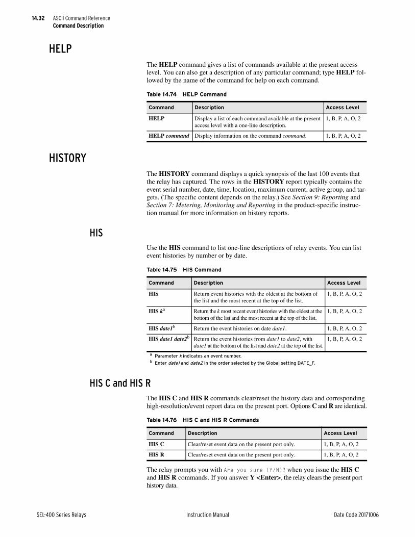
14.32
SEL-400 Series Relays Instruction Manual Date Code 20171006
ASCII Command ReferenceCommand Description
HELPThe HELP command gives a list of commands available at the present access level. You can also get a description of any particular command; type HELP fol-lowed by the name of the command for help on each command.
HISTORYThe HISTORY command displays a quick synopsis of the last 100 events that the relay has captured. The rows in the HISTORY report typically contains the event serial number, date, time, location, maximum current, active group, and tar-gets. (The specific content depends on the relay.) See Section 9: Reporting and Section 7: Metering, Monitoring and Reporting in the product-specific instruc-tion manual for more information on history reports.
HISUse the HIS command to list one-line descriptions of relay events. You can list event histories by number or by date.
HIS C and HIS RThe HIS C and HIS R commands clear/reset the history data and corresponding high-resolution/event report data on the present port. Options C and R are identical.
The relay prompts you with Are you sure (Y/N)? when you issue the HIS C and HIS R commands. If you answer Y <Enter>, the relay clears the present port history data.
Table 14.74 HELP Command
Command Description Access Level
HELP Display a list of each command available at the present access level with a one-line description.
1, B, P, A, O, 2
HELP command Display information on the command command. 1, B, P, A, O, 2
Table 14.75 HIS Command
Command Description Access Level
HIS Return event histories with the oldest at the bottom of the list and the most recent at the top of the list.
1, B, P, A, O, 2
HIS ka
a Parameter k indicates an event number.
Return the k most recent event histories with the oldest at the bottom of the list and the most recent at the top of the list.
1, B, P, A, O, 2
HIS date1b
b Enter date1 and date2 in the order selected by the Global setting DATE_F.
Return the event histories on date date1. 1, B, P, A, O, 2
HIS date1 date2b Return the event histories from date1 to date2, with date1 at the bottom of the list and date2 at the top of the list.
1, B, P, A, O, 2
Table 14.76 HIS C and HIS R Commands
Command Description Access Level
HIS C Clear/reset event data on the present port only. 1, B, P, A, O, 2
HIS R Clear/reset event data on the present port only. 1, B, P, A, O, 2

14.33
Date Code 20171006 Instruction Manual SEL-400 Series Relays
ASCII Command ReferenceCommand Description
HIS CA and HIS RAThe HIS CA and HIS RA commands clear all history data and event reports from memory. Use these commands to completely delete high-resolution/event report data captures.
If you issue the HIS CA and HIS RA commands, the relay prompts you with Are you sure (Y/N)?. If you answer Y <Enter>, the relay clears all history data and event reports. The relay resets the event report number to 10000.
IDUse the ID command to extract relay identification codes.
Each line of the ID command report contains an identification code and a line checksum. The relay presents these codes in the following order:
FID: the Firmware Identification string
BFID: the Boot Firmware Identification string
CID: the checksum of the firmware
DEVID: the RID string as stored in the relay settings of the IED
DEVCODE: a unique Device Code (for Modbus identification purposes)
PARTNO: the Part Number
SERIALNO: the serial number of the relay
CONFIG: abcdef
The designator positions indicate a specific relay configuration:
“a” represents the nominal frequency, where 0 = N/A, 1 = 60 Hz, and 2 = 50 Hz.
“b” represents the phase rotation, where 0 = N/A, 1 = ABC, and 2 = ACB.
“c” represents the phase input current scaling, where 0 = N/A, 1 = 5 A, and 2 = 1 A.
“d” represents the neutral input current scaling, where 0 = N/A, 1 = 5 A, 2 = 1 A.
“e” represents the voltage input connection, where 0 = N/A, 1 = Delta, and 2 = Wye.
“f” represents the current input connection, where 0 = N/A, 1 = Delta, and 2 = Wye.
SPECIAL: the Special Configuration Designators—a mechanism for antici-pating future product enhancements
Table 14.77 HIS CA and HIS RA Commands
Command Description Access Level
HIS CA Clear all event data for all ports. P, A, O, 2
HIS RA Clear all event data for all ports. P, A, O, 2
Table 14.78 ID Command
Command Description Access Level
ID Return a list of relay identification codes. 0, 1, B, P, A, O, 2

14.34
SEL-400 Series Relays Instruction Manual Date Code 20171006
ASCII Command ReferenceCommand Description
If the device supports IEC 61850 and the IEC 61850 protocol is enabled, the ID command will display the following additional information.
➤ iedName: the IED name (e.g., SEL-411L_OtterTail)
➤ type: the IED type (e.g., SEL-411L)
➤ configVersion: the CID file configuration version (e.g., ICD-411L-R100-V0-Z001001-20060512)
➤ LIB61850ID: an eight-character code indicating the IEC 61850 library version within the product
A sample ID command response from the relay (with IEC 61850 enabled) is shown in Figure 14.6.
IRIGThe IRIG command directs the relay to use the next available demodulated IRIG-B time code to update the relay internal clock. For information on the IRIG time mode, see IRIG-B Timekeeping on page 11.1.
NOTE: Not all SEL-400 series relays support the IRIG command.
The IRIG command was originally provided in the relay as a testing aid. The IRIG command was used to update the relay internal clock with the IRIG-B time value without waiting for the 30-second confirmation time delay.
There is no longer a 30-second confirmation time delay—the relay uses the IRIG time source as soon as it determines that the signal is valid, a process that may take several seconds. Once the IRIG signal is verified, the relay clock is updated once per second. The IRIG command is still available, but is no longer neces-sary. To check IRIG status, use the TIME Q command instead—see TIME Q Command on page 11.8.
If the relay has no valid IRIG-B time code at the rear panel, or if the TIME Q command reports a relay time source other than IRIG or HIRIG, the relay responds to the IRIG command with the following error message, IRIG-B DATA ERROR. See the TIME command for more information.
=ID <ENTER>"FID=SEL-451-5-R319-V0-Z024013-D20170608","0916""BFID=SLBT-4XX-R209-V0-Z001002-D20150130","097C""CID=85F4","0264""DEVID=Relay 1","0467""DEVCODE=40","030B""PARTNO=04515415XC4X4H60X0XXX","07B3""SERIALNO=1234567890","0517""CONFIG=11102200","03EA""SPECIAL=000000","03CE""iedName=SEL_451_1","05CD""type=SEL_451","044C""configVersion=ICD-451-R301-V0-Z316006-D20170130","0D1C""LIB61850ID=9048BE8A","04EA"
=
Figure 14.6 Sample ID Command Response From Ethernet Card
Table 14.79 IRIG Command
Command Description Access Level
IRIG Lock the relay internal clock to the IRIG-B time code input. 1, B, P, A, O, 2

14.35
Date Code 20171006 Instruction Manual SEL-400 Series Relays
ASCII Command ReferenceCommand Description
LOOPBACKUse the LOOPBACK command to instruct the relay to receive the transmitted MIRRORED BITS communications data on the same serial port. See SEL MIR-RORED BITS Communication on page 15.31 for more information on MIRRORED BITS communications.
LOOPThe LOOP command puts the relay serial port in loopback if you have previ-ously configured the port for MIRRORED BITS communications. If you have enabled both of the MIRRORED BITS communications channels (A and B), then you must specify the channel parameter. If you have only one of the channels enabled, then the relay assumes that channel if you do not specify that channel in the command. If you do not specify a time-out period, the relay provides a 5-min-ute time-out.
You can enter the options in any order. If you operate the relay using both MIR-RORED BITS communications channels (A and B), then you must specify the channel parameter by using the LOOP A command and the LOOP B command.
When you issue the LOOP command, the relay responds with statements about the loopback time, status of the RMB (Receive MIRRORED BITS), and Are you sure (Y/N)?. If you answer Y <Enter>, the relay responds with Loopback Mode Started.
In the loopback mode, ROK drops out and the relay uses LBOK to indicate whether the data transmissions are satisfactory. The relay collects COM data as usual. Time synchronization and virtual terminal modes are not available during loopback. The relay continues passing analog quantities.
Table 14.80 LOOP Command
Command Description Access Level
LOOP Begin loopback of a single enabled MIRRORED BITS commu-nications channel (either Channel A or Channel B) for 5 minutes; ignore input data and force receive bits (RMB) to defaults.
P, A, O, 2
LOOP ca
a Parameter c is A or B, representing Channel A or Channel B.
Begin loopback of MIRRORED BITS communications Channel c for 5 minutes; ignore input data and force receive bits (RMB) to defaults.
P, A, O, 2
LOOP t Begin loopback of a single MIRRORED BITS communications channel (either Channel A or Channel B) and end the loop-back after time-out t minutes; ignore input data and force receive bits (RMB) to defaults; t range is 1–5000 minutes.
P, A, O, 2
LOOP t c Begin loopback of a single MIRRORED BITS communications channel (either Channel A or Channel B) and end the loop-back after time-out t minutes; ignore input data and force receive bits (RMB) to defaults; t range is 1–5000 minutes.
P, A, O, 2

14.36
SEL-400 Series Relays Instruction Manual Date Code 20171006
ASCII Command ReferenceCommand Description
LOOP DATAThe LOOP DATA command tells the relay to pass input MIRRORED BITS com-munications data through to the receive (RMB) bits, as in the nonloopback mode.
The relay ignores received values if you do not specify the DATA option. You can enter the options in any order.
LOOP RThe LOOP R command terminates the loopback condition on MIRRORED BITS communications channels in loopback. If you do not specify a Channel c, then the relay disables loopback on both channels. If you specify a channel, you can enter the options in any order.
MACThe MAC command returns the Media Access Control (MAC) addresses of the Ethernet ports.
A sample MAC command response for a relay with dual copper Ethernet ports is shown in Figure 14.7.
Table 14.81 LOOP DATA Command
Command Description Access Level
LOOP DATA Begin loopback of a single MIRRORED BITS communica-tions channel (either Channel A or Channel B) for 5 min-utes: pass input data to receive data as in nonloopback mode.
P, A, O, 2
LOOP c DATA Begin loopback of MIRRORED BITS communications Channel c only for 5 minutes: pass input data to receive data as in nonloopback mode.
P, A, O, 2
LOOP c DATA t Begin loopback of MIRRORED BITS communications Channel c only for t minutes: pass input data to receive data as in nonloopback mode.
P, A, O, 2
Table 14.82 LOOP R Command
Command Description Access Level
LOOP R Cease loopback on all MIRRORED BITS communications channels. (Reset the channels to normal use.)
P, A, O, 2
LOOP c R Cease loopback on MIRRORED BITS communications Channel c. (Reset Channel c to normal use.)
P, A, O, 2
Table 14.83 MAC Command
Command Description Access Level
MAC Display all Ethernet ports MAC addresses 1, B, P, A, O, 2
=>>MAC <Enter>Port 5-1 MAC Address: 01-30-A7-00-F2-SAPort 5-2 MAC Address: 01-30-A7-00-F2-9B
Figure 14.7 Sample MAC Command Response

14.37
Date Code 20171006 Instruction Manual SEL-400 Series Relays
ASCII Command ReferenceCommand Description
MAPUse the MAP command to view the organization of the relay database. The MAP command in the relay is very similar to the MAP command in the SEL-2020 and SEL-2030 Communications Processors.
MAP 1The MAP 1 command lists the relay database regions. Typical database region names are LOCAL, METER, DEMAND, TARGET, HISTORY, BREAKER, STATUS, and ANALOGS.
MAP 1 region and MAP 1 region BLUse the MAP 1 command with the region option to view the layout of a specific region.
The region option is the database region name shown in the simple MAP 1 com-mand response. The region map consists of columns for data item labels, data-base address, and data type.
If you specify the BL option and the region contains items with bit labels, the relay lists these bit labels in MSB (most significant bit) to LSB (least significant bit) order. The TARGET region is usually the only region containing bit labels.
METERThe METER command displays reports about quantities the relay measures in the power system (voltages, currents, frequency, remote analogs, and so on) and internal relay operating quantities (math variables and synchronism-check values).
All SEL-400 series relays support a METER command, but the options and responses are device specific. See the product-specific instruction manual for details of the METER command. Included below are the variants of the METER command that are common.
Table 14.84 MAP 1 Command
Command Description Access Level
MAP 1 List the database regions in the relay. 1, B, P, A, O, 2
Table 14.85 MAP 1 region Command
Command Description Access Level
MAP 1 region List the data labels, database address, and data type. 1, B, P, A, O, 2
MAP 1 region BL List the data labels, database address, and data type; list the bit labels, if assigned.
1, B, P, A, O, 2

14.38
SEL-400 Series Relays Instruction Manual Date Code 20171006
ASCII Command ReferenceCommand Description
MET AMVThe MET AMV command lists automation math variables.
The relay displays three places after the decimal point for these numerals. The relay shows variables with absolute value greater than 99999.999 or less than 0.100 as scientific notation (for example, –1.002E+22).
MET ANAUse the MET ANA command to view the analog quantities from the MIRRORED BITS communications channels.
If you have not enabled the MIRRORED BITS communications channels and the remote analog data, the relay response to this command will not include any val-ues. If MIRRORED BITS communications is enabled but not communicating, the relay will display ERROR under the RMBA or RMBB entries, depending on settings.
MET BATUse the MET BAT command to view the station dc monitor quantities for the battery voltages.
NOTE: Some relays provide one battery monitor channel and some support two.
If you have not enabled the Station DC Battery Monitor, the relay responds with DC Monitor Is Not Enabled. (Enable the dc monitor with the Global setting EDCMON.)
The reset command, MET RBM, resets the dc monitor maximum/minimum metering quantities. When you issue the MET RBM command, the relay responds with Reset Max/Min Battery Metering (Y/N)?. If you answer Y <Enter>, the relay responds, Max/Min Battery Reset.
Table 14.86 MET AMV Command
Command Description Access Level
MET AMV Display all automation math variables. 1, B, P, A, O, 2
MET AMV k Display all automation math variables successively for k times. 1, B, P, A, O, 2
Table 14.87 MET ANA Command
Command Description Access Level
MET ANA Display the MIRRORED BITS communications analog quanti-ties.
1, B, P, A, O, 2
MET ANA k Display the MIRRORED BITS communications analog quan-tities successively for k times.
1, B, P, A, O, 2
Table 14.88 MET BAT Command
Command Description Access Level
MET BAT Display station battery measurements. 1, B, P, A, O, 2
MET BAT k Display station battery measurements successively for k times. 1, B, P, A, O, 2
MET RBM Reset station battery measurements. P, A, O, 2
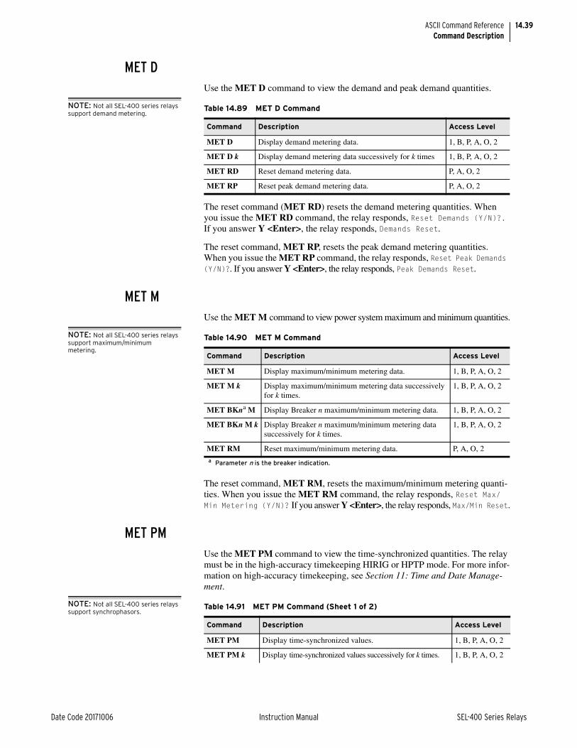
14.39
Date Code 20171006 Instruction Manual SEL-400 Series Relays
ASCII Command ReferenceCommand Description
MET DUse the MET D command to view the demand and peak demand quantities.
NOTE: Not all SEL-400 series relays support demand metering.
The reset command (MET RD) resets the demand metering quantities. When you issue the MET RD command, the relay responds, Reset Demands (Y/N)?. If you answer Y <Enter>, the relay responds, Demands Reset.
The reset command, MET RP, resets the peak demand metering quantities. When you issue the MET RP command, the relay responds, Reset Peak Demands (Y/N)?. If you answer Y <Enter>, the relay responds, Peak Demands Reset.
MET MUse the MET M command to view power system maximum and minimum quantities.
NOTE: Not all SEL-400 series relays support maximum/minimum metering.
The reset command, MET RM, resets the maximum/minimum metering quanti-ties. When you issue the MET RM command, the relay responds, Reset Max/Min Metering (Y/N)? If you answer Y <Enter>, the relay responds, Max/Min Reset.
MET PMUse the MET PM command to view the time-synchronized quantities. The relay must be in the high-accuracy timekeeping HIRIG or HPTP mode. For more infor-mation on high-accuracy timekeeping, see Section 11: Time and Date Manage-ment.
NOTE: Not all SEL-400 series relays support synchrophasors.
Table 14.89 MET D Command
Command Description Access Level
MET D Display demand metering data. 1, B, P, A, O, 2
MET D k Display demand metering data successively for k times 1, B, P, A, O, 2
MET RD Reset demand metering data. P, A, O, 2
MET RP Reset peak demand metering data. P, A, O, 2
Table 14.90 MET M Command
Command Description Access Level
MET M Display maximum/minimum metering data. 1, B, P, A, O, 2
MET M k Display maximum/minimum metering data successively for k times.
1, B, P, A, O, 2
MET BKna M
a Parameter n is the breaker indication.
Display Breaker n maximum/minimum metering data. 1, B, P, A, O, 2
MET BKn M k Display Breaker n maximum/minimum metering data successively for k times.
1, B, P, A, O, 2
MET RM Reset maximum/minimum metering data. P, A, O, 2
Table 14.91 MET PM Command (Sheet 1 of 2)
Command Description Access Level
MET PM Display time-synchronized values. 1, B, P, A, O, 2
MET PM k Display time-synchronized values successively for k times. 1, B, P, A, O, 2
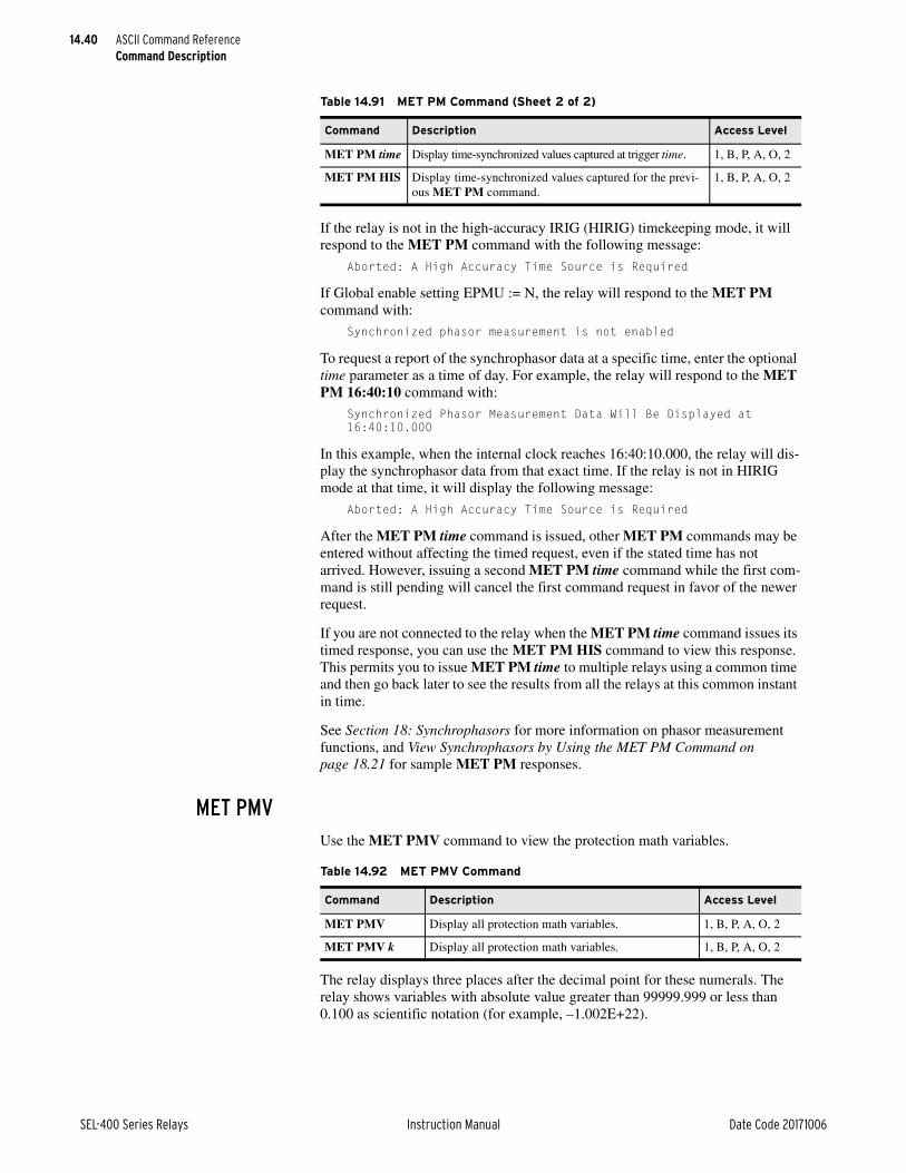
14.40
SEL-400 Series Relays Instruction Manual Date Code 20171006
ASCII Command ReferenceCommand Description
If the relay is not in the high-accuracy IRIG (HIRIG) timekeeping mode, it will respond to the MET PM command with the following message:
Aborted: A High Accuracy Time Source is Required
If Global enable setting EPMU := N, the relay will respond to the MET PM command with:
Synchronized phasor measurement is not enabled
To request a report of the synchrophasor data at a specific time, enter the optional time parameter as a time of day. For example, the relay will respond to the MET PM 16:40:10 command with:
Synchronized Phasor Measurement Data Will Be Displayed at 16:40:10.000
In this example, when the internal clock reaches 16:40:10.000, the relay will dis-play the synchrophasor data from that exact time. If the relay is not in HIRIG mode at that time, it will display the following message:
Aborted: A High Accuracy Time Source is Required
After the MET PM time command is issued, other MET PM commands may be entered without affecting the timed request, even if the stated time has not arrived. However, issuing a second MET PM time command while the first com-mand is still pending will cancel the first command request in favor of the newer request.
If you are not connected to the relay when the MET PM time command issues its timed response, you can use the MET PM HIS command to view this response. This permits you to issue MET PM time to multiple relays using a common time and then go back later to see the results from all the relays at this common instant in time.
See Section 18: Synchrophasors for more information on phasor measurement functions, and View Synchrophasors by Using the MET PM Command on page 18.21 for sample MET PM responses.
MET PMVUse the MET PMV command to view the protection math variables.
The relay displays three places after the decimal point for these numerals. The relay shows variables with absolute value greater than 99999.999 or less than 0.100 as scientific notation (for example, –1.002E+22).
MET PM time Display time-synchronized values captured at trigger time. 1, B, P, A, O, 2
MET PM HIS Display time-synchronized values captured for the previ-ous MET PM command.
1, B, P, A, O, 2
Table 14.91 MET PM Command (Sheet 2 of 2)
Command Description Access Level
Table 14.92 MET PMV Command
Command Description Access Level
MET PMV Display all protection math variables. 1, B, P, A, O, 2
MET PMV k Display all protection math variables. 1, B, P, A, O, 2
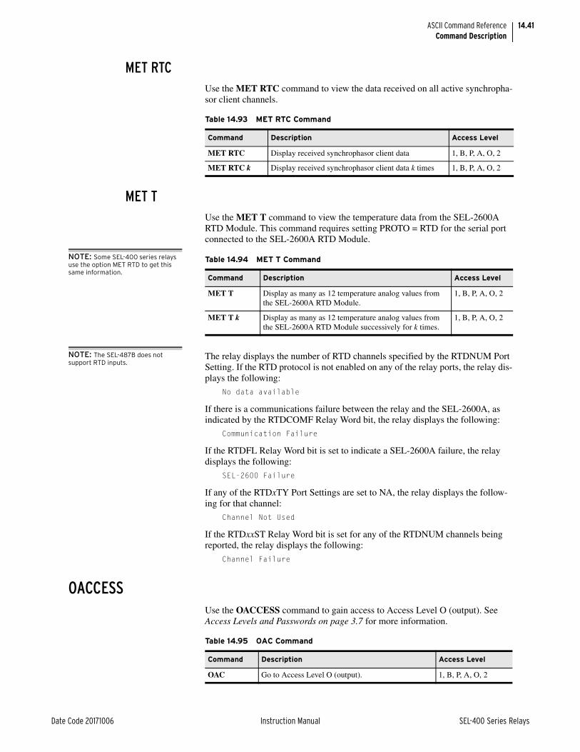
14.41
Date Code 20171006 Instruction Manual SEL-400 Series Relays
ASCII Command ReferenceCommand Description
MET RTCUse the MET RTC command to view the data received on all active synchropha-sor client channels.
MET TUse the MET T command to view the temperature data from the SEL-2600A RTD Module. This command requires setting PROTO = RTD for the serial port connected to the SEL-2600A RTD Module.
NOTE: Some SEL-400 series relays use the option MET RTD to get this same information.
NOTE: The SEL-487B does not support RTD inputs.
The relay displays the number of RTD channels specified by the RTDNUM Port Setting. If the RTD protocol is not enabled on any of the relay ports, the relay dis-plays the following:
No data available
If there is a communications failure between the relay and the SEL-2600A, as indicated by the RTDCOMF Relay Word bit, the relay displays the following:
Communication Failure
If the RTDFL Relay Word bit is set to indicate a SEL-2600A failure, the relay displays the following:
SEL-2600 Failure
If any of the RTDxTY Port Settings are set to NA, the relay displays the follow-ing for that channel:
Channel Not Used
If the RTDxxST Relay Word bit is set for any of the RTDNUM channels being reported, the relay displays the following:
Channel Failure
OACCESSUse the OACCESS command to gain access to Access Level O (output). See Access Levels and Passwords on page 3.7 for more information.
Table 14.93 MET RTC Command
Command Description Access Level
MET RTC Display received synchrophasor client data 1, B, P, A, O, 2
MET RTC k Display received synchrophasor client data k times 1, B, P, A, O, 2
Table 14.94 MET T Command
Command Description Access Level
MET T Display as many as 12 temperature analog values from the SEL-2600A RTD Module.
1, B, P, A, O, 2
MET T k Display as many as 12 temperature analog values from the SEL-2600A RTD Module successively for k times.
1, B, P, A, O, 2
Table 14.95 OAC Command
Command Description Access Level
OAC Go to Access Level O (output). 1, B, P, A, O, 2

14.42
SEL-400 Series Relays Instruction Manual Date Code 20171006
ASCII Command ReferenceCommand Description
WARNING
OPEN nUse the OPEN n command to open a circuit breaker(s). The OPEN n command pulses Relay Word bit OCn. Usually, you configure these Relay Word bits as part of the SELOGIC control equations that trip the appropriate circuit breaker. See Trip Logic in Section 5: Protection of the product-specific instruction manual for information on trip SELOGIC control equations.
If you have disabled the relay and attempt an OPEN n command, the relay responds, Command aborted because the relay is disabled. If the circuit breaker control enable jumper BREAKER is not in place, the relay aborts the command and responds, Aborted: the breaker jumper is not installed.
When you issue the OPEN n command, and the circuit breaker control enable jumper is in place, the relay responds, Open breaker (Y/N)?. If you answer Y <Enter>, the relay responds, Are you sure (Y/N)?. If you answer Y <Enter>, the relay asserts OCn for one processing interval.
If you have assigned auxiliary contact 52A inputs for this circuit breaker, the relay waits 0.5 seconds, checks the state of the breaker auxiliary contacts, and responds Breaker OPEN or Breaker CLOSED, as appropriate.
If Breaker n is not enabled, the relay responds, Breaker n is not available.
PACCESSUse the PACCESS command to gain access to Access Level P (protection). See Access Levels and Passwords on page 3.7 for more information.
PASSWORDUse the PASSWORD command to control password protection for relay access levels.
PAS levelThe relay changes the existing password for the specified access level that you specify when you issue the PAS level command.
This device is shipped with default passwords. Default passwords should be changed to private passwords at installation. Failure to change each default password to a private pass word may allow unauthorized access. SEL shall not be responsible for any damage resulting from unauthorized access.
Table 14.96 OPEN n Command
Command Description Access Level
OPEN n Pulse Relay Word bit OCn. B, P, A, O, 2
Table 14.97 PAC Command
Command Description Access Level
PAC Go to Access Level P (protection). 1, B, P, A, O, 2
Table 14.98 PAS level New_Password Command
Command Description Access Levels
PAS n Set a new password for Access Level n. 2

14.43
Date Code 20171006 Instruction Manual SEL-400 Series Relays
ASCII Command ReferenceCommand Description
Relay access levels that have passwords are 1, B, P, A, O, 2, and C. Valid pass-words are character sequences of as many as 12 characters. Valid characters are any printable ASCII character. HMI password entry is limited to upper- and lowercase letters, numbers, underscore, and period, so you must limit your pass-word to these characters if you need to do privileged operations from the front panel.
All passwords are case sensitive. When you successfully enter a new password, the relay pulses the Relay Word bit SALARM for one second, and responds, Set.
PAS level DISABLEIssuing the PAS level DISABLE command disables password checking for the specified access level. You must type DISABLE in upper case.
When you successfully disable password checking, the relay pulses the SALARM Relay Word bit for one second, and responds, Password Disabled. SEL does not recommend disabling passwords.
PINGUse the PING command to determine whether the network is connected properly and other network devices are reachable.
When the IP address parameter is not of a valid format, the relay responds with Invalid IP address. After a valid PING command is issued, the relay sends out an ICMP echo request messages at one second intervals until receiving a carriage return <CR> or five minutes elapses. A sample PING command response is shown in Figure 14.8.
Table 14.99 PAS level DISABLE Command
Commanda
a Parameter n represents the relay Access Levels 1, B, P, A, O, or 2.
Description Access Levels
PAS n DISABLE Disable password protection for the Access Level n. 2
Table 14.100 PING Command
Command Description Access Level
PING addra
a IP address of device to ping in the format of four decimal numbers (0–255) separated by periods.
Send ICMP echo request messages to remote device at addr. 1, B, P, A, O, 2
=>>PING 192.9.201.1 <Enter>
Pinging 192.9.201.1Press <Enter> to Terminate Ping Test.
Ping Echo Message Received.Ping Echo Message Received.Ping Echo Message Received.Ping Echo Message Received.
Ping Results:
Number of Ping Messages: Transmitted: 4 Received: 4
Elapsed Time: 11 seconds
=>>
Figure 14.8 Sample PING Command Response

14.44
SEL-400 Series Relays Instruction Manual Date Code 20171006
ASCII Command ReferenceCommand Description
PORTThe PORT command can be used to connect to a remote relay.
PORT pThe PORT p command connects a relay serial port to another device through a virtual terminal session.
NOTE: The BAY1 and BAY2 options only apply to relays that support 87L communications and have the corresponding bay card installed.
In the relay, serial port virtual terminal capability is available in MIRRORED BITS communications. You must have previously configured the serial port for MIR-RORED BITS communications operation, set port setting MBNUM less than 8, and have at least one virtual terminal session available (set MBNUMVT to 0 or greater). Choosing MBNUMVT to 0 uses virtual terminal within the synchroni-zation channel only. See SEL MIRRORED BITS Communication on page 15.31 for information on the MIRRORED BITS communications protocol.
When the relay establishes a connection, the relay responds, Transparent ses-sion to Port p established. To quit the transparent connection, type the con-trol string that you specify in port setting TERSTRN; the default is <Ctrl+E>. Only one transparent port connection to each MIRRORED BITS communications port is possible at one time. If you issue a PORT p command when the selected session is already active, the relay responds, Transparent session already in use.
If you issue the PORT p command to ports 1, 2, 3, or F or BAY1 or BAY2 (87L ports) and you have not properly configured the MIRRORED BITS communica-tions port, the MBNUMVT is not set to 1 or larger, Invalid destination port.
PORT KILL nIt is possible to forcefully disconnect a transparent session from another port (a port not involved in the present transparent connection) by using the PORT KILL n command (shown in Table 14.102).
The port parameter n can refer to either of the ports involved in the session you want to kill. When you issue the PORT KILL n command, the relay responds, Kill connection between ports m and n (Y/N)? Answer Y <Enter> to ter-minate the connection. The relay sends a character sequence to the remote relay (to make sure the remote device is left in a known state) and responds, Connec-tion between ports m and n disconnected.
Table 14.101 PORT p Command
Command Description Access Level
PORT pa
a Parameter p is 1, 2, 3, and F to indicate Communications PORT 1 — PORT 3 and PORT F, or BAY1 or BAY2 for 87L ports.
Connect to a remote device through Port p (over MIRRORED BITS communications virtual terminal mode).
1, B, P, A, O, 2
Table 14.102 PORT KILL n Command
Command Description Access Level
PORT KILL na
a Parameter n is 1, 2, 3, or F or BAY1 or BAY2 (for 87L ports) to indicate communications PORT 1–3 or PORT F; n is not the present port.
Terminate the virtual terminal connection with a remote device through port n by using a port not involved in the connection.
P, A, O, 2

14.45
Date Code 20171006 Instruction Manual SEL-400 Series Relays
ASCII Command ReferenceCommand Description
PROFILEUse the PROFILE command (PRO) to access the Signal Profile data for as many as 20 user selectable analog values.
PULSEUse the PULSE OUTnnn command to pulse any of the relay control outputs for a specified time. This function aids you in relay testing and commissioning. If the output is open, the PUL command momentarily closes the output; if the output is closed, the PUL command momentarily opens the output. The control outputs are OUTnnn, where nnn represents the 100-series, 200-series, 300-series, 400-series, and 500-series addresses.
Table 14.103 PRO Command
Command Description Access Level
PRO Displays the first 20 rows of the profile report, with the oldest row at the top and the latest row at the bottom.
1, B, P, A, O, 2
PRO m Displays the first m rows of the report, with the oldest row at the top and the latest row at the bottom.
1, B, P, A, O, 2
PRO m n (m > n) Displays the row between m and n, (including m and n) with the oldest row at the top and the latest row at the bottom.
1, B, P, A, O, 2
PRO date1 Displays all the rows that were recorded on that date, with the oldest row at the top and the latest row at the bottom.
1, B, P, A, O, 2
PRO date1 date2 Displays all the rows that were recorded on and between (including) date1 and date2 (date1 chronolog-ically precedes date2, with the oldest row (date1) at the top and the latest row (date2) at the bottom.
1, B, P, A, O, 2
PRO date2 date1 Displays all the rows that were recorded on and between (including) date1 and date2 (date2 chronolog-ically precedes date1, with the oldest row (date2) at the top and the latest row (date1) at the bottom.
1, B, P, A, O, 2
PRO D Displays, for each port, the maximum number of days data may be acquired with the present settings before data overwrite occurs.
1, B, P, A, O, 2
PRO C or R Clears the signal profile data from nonvolatile memory on a per-port basis. The data are still visible to other ports and to file transfer accesses and is cleared inde-pendently for those points-of-view.
B, P, A, O, 2
PRO CA or RA Completely clears all signal profile data from nonvola-tile memory.
P, A, O, 2
Table 14.104 PUL OUTnnn Command
Command Description Access Level
PUL OUTnnna
a Parameter nnn is a control output number.
Pulse output OUTnnn for 1 second. B, P, A, O, 2
PUL OUTnnn sb
b Parameter s is time in seconds, with a range of 1–30.
Pulse output OUTnnn for s seconds. B, P, A, O, 2

14.46
SEL-400 Series Relays Instruction Manual Date Code 20171006
ASCII Command ReferenceCommand Description
If the circuit breaker control enable jumper BREAKER is not in place, the relay aborts the command and responds, Aborted: the breaker jumper is not installed.
When you issue the PUL command and the breaker jumper is in place, the relay responds, Pulse contact OUTnnn for s seconds (Y/N)?. If you answer Y <Enter>, the relay asserts OUTnnn for the time you specify.
During the PUL operation, the Relay Word bit corresponding to the control out-put you specified (OUTnnn) asserts; Relay Word bit TESTPUL also asserts during any PUL command, so you can monitor pulse operation by programming TESTPUL into event triggers and alarm outputs.
QUITUse the QUIT command to revert to Access Level 0 (exit relay control).
Access Level 0 is the lowest access level; the relay performs no password check to descend to this level (or remain at this level).
In a Telnet session, QUIT terminates the connection.
RTCUse the RTC command to display a description of all data being received on syn-chrophasor client channels. This report will list the analog quantity and Relay Word bits the data gets stored in locally, matched up with a label provided by the sending PMU. Use this information as aid to understanding the local values.
NOTE: Not all SEL-400 series relays support synchrophasors.
SERThe SER command retrieves SER records. The relay SER captures state changes of Relay Word bit elements and relay conditions. Relay conditions include startup, relay enable/disable, group changes, settings changes, memory queue overflow, and SER autoremoval/reinsertion. For more information on the SER, see Sequential Events Recorder (SER) on page 9.28.
Table 14.105 QUIT Command
Command Description Access Level
QUIT Go to Access Level 0 (exit relay control). 0, 1, B, P, A, O, 2
Table 14.106 RTC Command
Command Description Access Level
RTC Display report of all configured synchrophasor client data labels.
1, B, P, A, O, 2

14.47
Date Code 20171006 Instruction Manual SEL-400 Series Relays
ASCII Command ReferenceCommand Description
SERThe default order of the SER command is oldest to newest from list top to list bottom. You can view the SER records in numerical or date order.
SER C and SER RThe SER C and SER R commands clear/reset the SER records for the present port. Options C and R are identical.
The relay prompts you with Clear the sequential events recorder for this port. Are you sure (Y/N)? when you issue the SER C or SER R com-mand. If you answer Y <Enter>, the relay clears the particular port SER records.
SER CA and SER RAThe SER CA and SER RA commands clear all SER records from memory.
If you issue the SER CA or SER RA command, the relay prompts you with Clear the sequential events recorder for all ports. Are you sure (Y/N)? commands. If you answer Y <Enter>, the relay clears all SER records in nonvolatile memory.
Table 14.107 SER Command
Command Description Access Level
SER Return the 20 most recent records from the SER, with the oldest (highest number) at the top of the list and the most recent (lowest number) at the bottom of the list.
1, B, P, A, O, 2
SER k Return the k most recent records from the SER, with the oldest (highest number) at the top of the list and the most recent (lowest number) at the bottom of the list.
1, B, P, A, O, 2
SER m na
a Parameters m and n indicate an SER number, which the relay assigns at each SER trigger.
Return the SER records from m to n.
If m is greater than n, records appear with the oldest (highest number) at the top of the list and the most recent (lowest number) at the bottom of the list.
If m is less than n, records appear with the most recent (lowest number) at the top of the list and the oldest (highest number) at the bottom of the list.
1, B, P, A, O, 2
SER date1b
b Enter date1 and date2 in the same format as Global setting DATE_F.
Return the SER records on date date1. 1, B, P, A, O, 2
SER date1 date2b Return the SER records from date1 at the top of the list, to date2 at the bottom of the list.
1, B, P, A, O, 2
Table 14.108 SER C and SER R Commands
Command Description Access Level
SER C Clear/reset SER records on the present port. 1, B, P, A, O, 2
SER R Clear/reset SER records on the present port. 1, B, P, A, O, 2
Table 14.109 SER CA and SER RA Commands
Command Description Access Level
SER CA Clear SER data for all ports. P, A, O, 2
SER RA Clear SER data for all ports. P, A, O, 2

14.48
SEL-400 Series Relays Instruction Manual Date Code 20171006
ASCII Command ReferenceCommand Description
SER CV and SER RVThe SER CV and SER RV commands clear any SER data records that have been viewed from the present port. The two commands are equivalent.
If you issue the SER CV or SER RV command, the relay prompts you with Clear viewed SER records for this port. Are you sure (Y/N)?. If you answer Y <Enter>, the relay clears all SER records viewed from this port. The data are still visible to other ports and to file transfer accesses, and they must be cleared independently for those ports. Data not yet viewed remain available.
SER DThe SER D command shows a list of SER items that the relay has automatically removed. These are “chattering” elements. You can automatically remove chat-tering SER elements in the SER Chatter Criteria category of the Report settings; the enable setting is ESERDEL.
If you issue the SER D command and you have not enabled automatic removal of chattering SER elements (Report setting ESERDEL), the relay responds, Auto-matic removal of chattering SER elements not enabled.
SETUse the SET command to change relay settings. The relay settings structure is ordered and contains these items (in structure order): classes, instances, catego-ries, and settings. An outline of the relay settings structure is as follows:
Classes (Global, Group, Breaker Monitor, Protection, Automation, Outputs, Front Panel, Report, DNP3, and Ports)
Instances (some classes have instances: Group = 1–6; Protection = 1–6; Automation = 1–10; PORTs = 1–3, F, 5)
Categories (collections of similar settings)
Settings (specific relay settings with values)
The SET and SHOW commands contain these settings structure items, which you must specify in order from class to instance (if applicable) to setting. The order that specific settings appear in the relay settings structure is factory pro-grammed.
Table 14.110 SER CV or SER RV Commands
Command Description Access Level
SER CV Clear viewed SER data for this port. 1, B, P, A, O, 2
SER RV Clear viewed SER data for this port. 1, B, P, A, O, 2
Table 14.111 SER D Command
Command Description Access Level
SER D List chattering SER elements that the relay is remov-ing from the SER records.
1, B, P, A, O, 2

14.49
Date Code 20171006 Instruction Manual SEL-400 Series Relays
ASCII Command ReferenceCommand Description
SETThe SET command with no options or parameters accesses the relay settings Group class and the instance corresponding to the active group. To set a different instance, specify the instance number (1–6).
The specific classes and instances available depends on the relay. See the relay-specific instruction manual for the specific options that are available. The relay validates your settings entries as you enter each setting. At the end of a settings instance session, the relay responds with a readback of all the settings in the set-tings instance, then prompts you with Save settings (Y,N)?. If you answer Y <Enter>, the relay pulses the Relay Word bit SALARM, and responds, Saving Settings, Please Wait........... The relay saves the new settings, then responds, Settings Saved. If you answer N <Enter> to the save settings prompt, the relay responds, Settings aborted.
SET TERSEUse the TERSE option to inhibit the relay from sending the settings class or instance readback when you end a settings session. SEL recommends that you use the TERSE option sparingly; you should review the readback information to confirm that you have entered the settings that you intended.
Table 14.112 SET Command Overview
Commanda
a Parameter n = 1–6, representing Group 1–6. c = settings class (relay specific).i = class instance (choices depends on the class).
Description Access Level
SET Set the Group relay settings, beginning at the first setting in the active group.
P, 2
SET n Set the Group n relay settings, beginning at the first setting n each instance.
P, 2
SET label Set the Group relay settings, beginning at the active group setting label label.
P, 2
SET n label Set the Group n relay settings, beginning at setting label label.
P, 2
SET c Set class c, using the default instance beginning at the first setting.
P,A,O,2
SET c i Set class c, instance i, beginning at the first setting. P,A,O,2
SET c i label Set class c, instance i, beginning at setting label. P,A,O,2
Table 14.113 SET TERSE Command Examples
Command Description Access Level
SET TERSE SET Group relay settings for the active group, beginning at the first setting in this instance; omit settings readback.
P, 2
SET 3 TEa label
a TERSE may be entered as TE, as shown in this example.
SET Group 3 settings, beginning at the settings label label; omit settings readback.
P, 2
SET P p label TERSE Set the communications Port relay settings for Port p, beginning at the settings label label; omit readback.
P, A, O, 2

14.50
SEL-400 Series Relays Instruction Manual Date Code 20171006
ASCII Command ReferenceCommand Description
You can use the TERSE option in any SET command at any position after typing SET. When you end the settings edit session, the relay responds, Save settings (Y,N)?. If you answer Y <Enter>, the relay pulses the Relay Word bit SAL-ARM, and responds, Saving Settings, Please Wait............ The relay saves the new settings, then responds, Settings Saved. If you answer N <Enter> to the save settings prompt, the relay responds, Settings aborted.
SHOWThe SHOW command shows the relay settings. When showing settings, the relay displays the settings label and the present value from nonvolatile memory.
The relay organizes settings in classes, instances, categories, and specific set-tings; see SET on page 14.48 for information on settings organization. The relay displays each setting in the order specified in the settings tables. When you are using a terminal and you specify a setting in the middle of a settings category, the relay displays the category title, then proceeds with the class or instance settings from the setting that you specified.
SNSIn response to the SNS command, the relay sends the names of the SER ele-ments. This is a comma-delimited string used to support the SEL Fast SER report.
STATUSThe STATUS command reports relay status information that the relay derives from internal diagnostic routines and self-tests. See Relay Self-Tests on page 10.15 for information on relay diagnostics.
Table 14.114 SHO Command Overview
Commanda
a Parameter n = 1–6, representing Group 1–6.c = settings class (relay specific).i = class instance (choices depends on the class).
Description Access Level
SHO Show the Group relay settings, beginning at the first setting in the active group.
1, B, P, A, O, 2
SHO n Show the Group n relay settings, beginning at the first set-ting in each instance.
1, B, P, A, O, 2
SHO label Show the Group relay settings, beginning at the active group settings label label.
1, B, P, A, O, 2
SHO n label Show the Group n relay settings, beginning at the settings label label.
1, B, P, A, O, 2
SHO c Show class c using the default instance beginning at the first setting.
P, A, O, 2
SHO c i Show class c, instance i beginning at the first setting. P, A, O, 2
SHO c i label Show class c, instance i, beginning at setting label. P, A, O, 2
Table 14.115 SNS Command
Command Description Access Level
SNS Send the names of SER elements. 0, 1, B, P, A, O, 2

14.51
Date Code 20171006 Instruction Manual SEL-400 Series Relays
ASCII Command ReferenceCommand Description
STAThe STA command with no options displays a short-form relay status report. Items in the STA report are the header, failures, warnings, SELOGIC control equa-tion programming environment errors, and relay operational status. See Checking Relay Status on page 3.11 for information on relay status reports.
If you change an I/O interface board, the relay detects the new configuration and initiates a status warning. When you issue the STA command at Access Level 2, the relay responds to this situation with Accept new hardware configuration (Y/N)?. If you answer Y <Enter>, the relay responds, New configuration accepted. If you answer N <Enter>, the relay responds, Command aborted.
STA AUse the STA A command to view the entire relay status report. Items in the full status report include the short-form status report items plus data on A/D (analog/digital) channel offsets, power supply voltages, temperature, communications interfaces, and time-source synchronization.
STA C and STA RThe STA C and STA R commands reboot the relay. Thus, these commands clear a transient failure should this unlikely event occur. Options C and R are identical. Contact your Technical Service Center or the SEL Factory before using this command.
STA SUse the STA S command to view all SELOGIC control equation storage and exe-cution capacity and operating errors.
Table 14.116 STA Command
Command Description Access Level
STA Return the relay status. 1, B, P, A, O
STA Return the relay status and show a new hardware configura-tion prompt.
2
Table 14.117 STA A Command
Command Description Access Level
STA A Display all items of the status report. 1, B, P, A, O, 2
Table 14.118 STA C and STA R Command
Command Description Access Level
STA C Reset the relay. 2
STA R Reset the relay. 2
Table 14.119 STA S Command
Command Description Access Level
STA S Display detailed SELOGIC control equation error information. 1, B, P, A, O, 2

14.52
SEL-400 Series Relays Instruction Manual Date Code 20171006
ASCII Command ReferenceCommand Description
STA SC and STA SRThe STA SC and STA SR commands clear/reset the SELOGIC control equation operating errors from the status report if the errors are no longer present. In addi-tion, these commands reset the Automation SELOGIC Peak and Average Execu-tion Cycle Time statistics.
SUMMARYThe SUMMARY command displays a summary event report. See Event Sum-mary on page 9.26 for information on summary event reports.
SUMUse the SUM command to view the event summary reports in the relay memory.
When parameter n is 1–9999, n indicates the order of the event report. The most recent event report is 1, the next most recent report is 2, and so on. When param-eter n is 10000–42767, n indicates the absolute serial number of the event report.
SUM ACKUse SUM ACK to acknowledge an event summary that you recently viewed with the SUM NEXT command on the present communications port. Acknowledge the oldest summary (specify no event number).
If you attempt to acknowledge an event summary that you have not viewed on the present port with the SUM NEXT command, the relay responds, Event summary number n has not been viewed with the NEXT option.
Table 14.120 STA SC and STA SR Command
Command Description Access Level
STA SC Clear SELOGIC control equation errors and reset SELOGIC cycle time statistics.
P, A, O, 2
STA SR Clear SELOGIC control equation errors and reset SELOGIC cycle time statistics.
P, A, O, 2
Table 14.121 SUM Command
Command Description Access Level
SUM Return the most recent event summary. 1, B, P, A, O, 2
SUM na
a Parameter n indicates event order or serial number; see the event history report (HIS on page 14.32 command).
Return an event summary for event n. 1, B, P, A, O, 2
Table 14.122 SUM ACK Command
Command Description Access Level
SUM ACK Acknowledge the oldest unacknowledged event sum-mary at the present communications port.
1, B, P, A, O, 2

14.53
Date Code 20171006 Instruction Manual SEL-400 Series Relays
ASCII Command ReferenceCommand Description
SUM NEXTUse the SUM N command to view the oldest (next) unacknowledged event summary.
TARGETThe TARGET command displays the elements for a selected row in the Relay Word bit table.
TARUse the TAR command to view a row of Relay Word bit elements or aliases. When using the TAR command, you can specify the row number or element name.
The relay memorizes the latest target row input conditioned by your present access level. The relay displays Row 0 if you have not specified a row since the relay was turned on, the access level has timed out, or you have issued the QUIT command.
If you specify the repeat count k at a number greater than 8, the relay displays the repeated target rows on the terminal screen in groups of eight, with the target row elements listed above each grouping.
TAR ALLUse the TAR ALL command to display all of the relay targets.
Table 14.123 SUM N Command
Command Description Access Level
SUM N View the oldest unacknowledged event summary at the present communications port.
1, B, P, A, O, 2
Table 14.124 TAR Command
Command Description Access Level
TAR Display target Row 0 or display the most recently viewed target row.
1, B, P, A, O, 2
TAR n Display target Row n. 1, B, P, A, O, 2
TAR n ka
a Parameter k is the repeat count from 1–32767.
Display target Row n and repeat for k times; the repeat count k must follow the row number.
1, B, P, A, O, 2
TAR name Display the target row with the element name name. 1, B, P, A, O, 2
TAR name k Display the target row with the element name name and repeat for k times; the repeat count k can be before or after the name option.
1, B, P, A, O, 2
Table 14.125 TAR ALL Command
Command Description Access Level
TAR ALL Display all target rows. 1, B, P, A, O, 2

14.54
SEL-400 Series Relays Instruction Manual Date Code 20171006
ASCII Command ReferenceCommand Description
TAR RThe TAR R command has two functions. Use this command to reset any latched relay targets resulting from a tripping event. Also employ the TAR R command to reset to Row 0 the memorized target row that the relay reports when you issue a simple TAR command.
TAR XUse the TAR X command to view a different target row in the Relay Word bit table than the target row in the target row repeat memory. This function is useful for relay testing. See Testing With Relay Word Bits on page 10.7 for more infor-mation.
You can place the X option at any position in the TAR command.
TECEnter the TEC (time-error calculation) command to display the present time-error estimate and the status of the time-error control equations, and to modify the time-error correction value.
NOTE: Not all SEL-400 series relays support the TEC command.
Use the TEC n command to preload the time-error correction value, TECORR. If the value n is within range, the relay will prompt you with Are you sure (Y/N)?. If the prompt is acknowledged, the relay sets analog quantity TECORR = n, and asserts Relay Word bit PLDTE for approximately 1.5 cycles. The relay then displays the new TECORR value, along with the remaining TEC command data.
The TECORR value does not affect the TE (time-error) estimate until the LOADTE SELOGIC equation asserts.
Table 14.126 TAR R Command
Command Description Access Level
TAR R Reset latched targets and return memorized row to Row 0. 1, B, P, A, O, 2
Table 14.127 TAR X Command
Commanda
a Parameter k is the repeat count from 1–32767.
Description Access Level
TAR n X Display target Row n, but do not memorize Row n. 1, B, P, A, O, 2
TAR X n k Display target Row n and repeat for k times, but do not memorize Row n. The repeat count k must follow the row number.
1, B, P, A, O, 2
TAR name X Display the target row with the element name name, but do not memorize the row number.
1, B, P, A, O, 2
TAR name X k Display the target row with the element name name and repeat for k times, but do not memorize the row number. The repeat count k can be at any position in the com-mand after TAR.
1, B, P, A, O, 2
Table 14.128 TEC Command
Command Description Access Level
TEC Display time-error data. 1, B, P, A, O, 2
TEC n Preload time-error correction value n, where –30.000 <= n <= 30.000.
B, P, A, O, 2

14.55
Date Code 20171006 Instruction Manual SEL-400 Series Relays
ASCII Command ReferenceCommand Description
TEST DBThe TEST DB command is used for testing access of the virtual device database used for Fast Message Data Access.
TEST DBUse the TEST DB command to write temporary values to the virtual device data-base to verify the database values. The relay contains a database that describes the relay to external devices. When other devices access the relay via the Fast Message protocol, the relay appears as a virtual device described by the database. The relay is Virtual Device 1.
The virtual database is accessible to master stations of supported Fast Message protocol connected to the relay through serial communication or Ethernet net-work. You can therefore test the read functionality of the Fast Message protocol in the serial port or Ethernet interface with this command.
Use the TEST DB 1 command to override any value in the relay database. You must understand the relay database structure to effectively use the TEST DB command. Use the MAP and VIEW commands to see the organization and con-tents of the database.
Values you enter in the relay database are override values. Use the TEST DB command to write override values in the database accessed through the Fast Mes-sage Data Access operations.
The database address addr can be any legitimate decimal or hexadecimal address. (A hexadecimal address is a numeral with an “h” suffix or a “0x” prefix.)
You can enter the override value value1 as an integer, a floating-point number (which overrides two registers), a character (which must be in single quotes), or a string (which must be in double quotes and overrides the number of registers cor-responding to the length of the string).
If a date/time stamp is also provided (M D Y h m s), the relay will change the static state given and, for any bits being changed by this operation, queued entries will be pushed with the provided date/time stamp. If no queue is associated with the database region (determined by addr), the date/time stamp will be ignored.
The order that the date should be entered on the command line depends upon the DATE_F (Global) setting. For example, if DATE_F := DMY, you would enter TEST DB 1 addr value D M Y h m s.
While there are active test data, the relay asserts Relay Word bit TESTDB.
Table 14.129 TEST DB Command
Command Description Access Level
TEST DB Display present override values by virtual device number and address.
1, B, P, A, O, 2
TEST DB 1 addr value1
Write new data value1 to the database at an address addr.
B, P, A, O, 2
TEST DB 1 addr value1 M D Y h m s
Write new data value1 to the database at an address addr and include the provided date/time stamp M D Y h m s.
B, P, A, O, 2

14.56
SEL-400 Series Relays Instruction Manual Date Code 20171006
ASCII Command ReferenceCommand Description
TEST DB OFFUse the TEST DB OFF command to end the testing session and remove the override values. The relay returns the database registers to the pretest values.
TEST DB2The TEST DB2 command is used to test DNP3 and IEC 61850 MMS communi-cation protocols.
TEST DB2Other than Fast Message Protocol, all the communication protocols supported by the relay (DNP3, IEC 61850, GOOSE) retrieve data from a storage area called the CADI2 database. These data include both digital quantities and analog quan-tities. All Relay Word bits along with additional binary input points in DNP3 map are available in CADI2 database as digital quantities.
Use the TEST DB2 command to override any value in the CADI2 database. Val-ues you enter in the CADI2 database are override values read by the master sta-tions.
The override value value1 can be logical 0 or logical 1 for digital and status ele-ments. The analog value2 can be an integer or a floating-point number.
The Relay Word bit TESTDB2 will be asserted while there are points in this test mode.
Table 14.130 TEST DB OFF Command
Command Description Access Level
TEST DB OFF Clear all override testing values from all virtual devices. B, P, A, O, 2
TEST DB OFF 1 Clear all override testing values from Virtual Device 1 (the relay).
B, P, A, O, 2
TEST DB OFF 1 region
Clear all override testing values from the region region in Virtual Device 1 (the relay).
B, P, A, O, 2
Table 14.131 TEST DB2 Command
Command Description Access Level
TEST DB2 Display present analog and digital override names and values.
1, B, P, A, O, 2
TEST DB2 D name1a value1
a Digital name1 can be any Relay Word bits or additional binary input points in DNP3 map.
Write the specified override value value1 into the digital quantity name1.
B, P, A, O, 2
TEST DB2 A name2b value2
b The analog name2 is any analog available in the DNP3 reference map and any analog listed as a data source for IEC 61850 logical devices.
Write the specified override value value2 into the analog quantity name2.
B, P, A, O, 2

14.57
Date Code 20171006 Instruction Manual SEL-400 Series Relays
ASCII Command ReferenceCommand Description
TEST DB2 OFFUse the TEST DB2 OFF command to end the CADI2 database testing session and remove the override values. The relay returns the CADI2 database registers to the pretest values.
3
When removing all existing digital override values, the relay responds, Digital Overrides Removed. If no digital override is ever configured, the Overrides Not Found message will be displayed. The analog override removal acknowledgment messages are similar.
TEST FMThe TEST FM command overrides normal Fast Meter quantities for testing pur-poses. You can override only “reported” Fast Meter values. For more information on Fast Meter and the relay, see SEL Fast Meter, Fast Operate, Fast SER Mes-sages, and Fast Message Data Access on page 15.28.
TEST FMValues you enter in Fast Meter storage are “override values.” Use the TEST FM command to display override values and write override values in the Fast Meter report.
When you display Fast Meter data overrides with the TEST FM command, the relay shows the item label, and override values.
To force a value, use the TEST FM label value1 value2 command. The item label label is any analog channel label in the Fast Meter configuration (if avail-able), any digital element label (from the DNA command), and any status ele-ment label (from the BNA command) except the TEST and FMTEST items.
Table 14.132 TEST DB2 OFF Command
Command Description Access Level
TEST DB2 D OFF
Clear all digital override testing values from the CADI2 database.
B, P, A, O, 2
TEST DB2 D name1a OFF
a Digital name1 can be any Relay Word bits or additional binary input points in DNP3 map.
Clear digital override testing value specified by name name1 from the CADI2 database.
B, P, A, O, 2
TEST DB2 A OFF
Clear all analog override testing values from the CADI2 database.
B, P, A, O, 2
TEST DB2 A name2b OFF
b See Section 12: Analog Quantities in the product-specific instruction manual for available analog name2.
Clear analog override testing value specified by name name2 from the CADI2 database.
B, P, A, O, 2
Table 14.133 TEST FM Command
Command Description Access Level
TEST FM Display present override values. 1, B, P, A, O, 2
TEST FM label value1 value2
Write new data value1 and value2 to the Fast Meter report at the item label label. Parameter value2 is optional.
B, P, A, O, 2

14.58
SEL-400 Series Relays Instruction Manual Date Code 20171006
ASCII Command ReferenceCommand Description
The value value1 can be logical 0 or logical 1 for digital and status elements, or a floating-point value for all meter quantities. For meter items that report a pair of values in the Fast Meter message, value1 is the magnitude and value2, if pro-vided, is the angle. If you do not specify value2, the relay uses an angle of 0.
When you have successfully added a new Fast Meter test value (for example, TEST FM IA1 3.7 0.0), the relay responds, Override Added.
The relay asserts Relay Word bit TESTFM while any Fast Meter override data are present in the relay.
Fast Meter Status Byte
Bits labeled TEST and FMTEST reside in the Fast Meter status byte. If any item within the Fast Meter message is in test mode, the relay sets the TEST bit. Simi-larly, if any item in any Fast Meter message is in test mode, the FMTEST is set in all three Fast Meter responses.
TEST FM DEMUse the TEST FM DEM command to insert override values in Fast Meter demand metering.
NOTE: Not all SEL-400 series relays support demand metering. These relays will not support the TEST FM DEM command.
TEST FM OFFUse the TEST FM OFF command to remove override values. The relay returns the Fast Meter registers to the pretest values.
When you have successfully removed a Fast Meter test value (for example, TEST FM IA1 OFF), the relay responds, Override Removed. When an attempt to remove an FM test value fails, the relay responds, Override Not Found. When removing all FM test values (for example, TEST FM OFF), the relay responds, All Overrides Removed.
TEST FM PEAKUse the TEST FM PEAK command to insert override values in Fast Meter peak demand metering.
NOTE: Not all SEL-400 series relays support demand metering. These relays will not support the TEST FM PEAK command.
Table 14.134 TEST FM DEM Command
Command Description Access Level
TEST FM DEM label value1
Write new data value1 to the Fast Meter demand meter report at the item label label.
B, P, A, O, 2
Table 14.135 TEST FM OFF Command
Command Description Access Level
TEST FM label OFF Clear the override values for the Fast Meter item label. B, P, A, O, 2
TEST FM OFF Clear all override testing values from Fast Meter. B, P, A, O, 2
Table 14.136 TEST FM PEAK Command
Command Description Access Level
TEST FM PEAK label value1
Write new data value1 to the Fast Meter peak demand meter report at the item label label.
B, P, A, O, 2

14.59
Date Code 20171006 Instruction Manual SEL-400 Series Relays
ASCII Command ReferenceCommand Description
TIMEUse the TIME command to view and set the relay time clock. The ASCII inter-face is just one source by which you can set the internal clock. Other sources can override the ASCII TIME command; overriding occurs in HIRIG time mode, IRIG time mode, and when using DNP3. See Section 11: Time and Date Man-agement for more information on configuring time functions.
TIMEThe TIME command returns information about the internal relay clock. You can also set the clock to local time if you specify hours and minutes (seconds data are optional). Separate the hours, minutes, and seconds with colons, semicolons, spaces, commas, or slashes.
If a valid IRIG-B or SNTP signal is connected to the relay, the TIM command cannot be used to set the relay time.
Use the TIME hh:mm and TIME hh:mm:ss commands to set the relay internal clock time. The value hh is for hours from 0–23, the value mm is for minutes from 0–59, and the value ss is for seconds from 0–59. If you enter a valid time, the relay updates and saves the time in the nonvolatile clock, and displays the time you just entered. If you enter an invalid time, the relay responds, Invalid Time.
TIME QThe TIME Q command returns detailed information on the relay internal clock. Use this command to query the status of high-accuracy time source inputs and the present clock time mode.
When you issue the TIME Q command, the relay reports statistics on the relay time sources. These statistics include the present time source and the last time value update source (see TIME Q Command on page 11.8).
=>>TIME <Enter>local: 16:48:33 UTC: 23:48:33 UTC Offset: -07.0 hrs
Table 14.137 TIME Command
Command Description Access Level
TIME Display the present relay internal clock time, in three formats: local, UTC, and UTC offset.
1, B, P, A, O, 2
TIME hh:mm Set the relay internal clock to hh:mm. 1, B, P, A, O, 2
TIME hh:mm:ss Set the relay internal clock to hh:mm:ss. 1, B, P, A, O, 2
Table 14.138 TIME Q Command
Command Description Access Level
TIME Q Display detailed information about the internal relay clock; query relay time.
1, B, P, A, O, 2
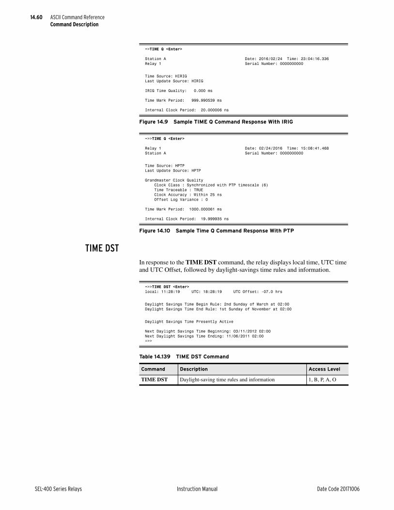
14.60
SEL-400 Series Relays Instruction Manual Date Code 20171006
ASCII Command ReferenceCommand Description
TIME DSTIn response to the TIME DST command, the relay displays local time, UTC time and UTC Offset, followed by daylight-savings time rules and information.
=>TIME Q <Enter>
Station A Date: 2016/02/24 Time: 23:04:16.336Relay 1 Serial Number: 0000000000
Time Source: HIRIGLast Update Source: HIRIG
IRIG Time Quality: 0.000 ms
Time Mark Period: 999.990539 ms
Internal Clock Period: 20.000006 ns
Figure 14.9 Sample TIME Q Command Response With IRIG
=>>TIME Q <Enter>
Relay 1 Date: 02/24/2016 Time: 15:08:41.468Station A Serial Number: 0000000000
Time Source: HPTPLast Update Source: HPTP
Grandmaster Clock Quality Clock Class : Synchronized with PTP timescale (6) Time Traceable : TRUE Clock Accuracy : Within 25 ns Offset Log Variance : 0
Time Mark Period: 1000.000061 ms
Internal Clock Period: 19.999935 ns
Figure 14.10 Sample Time Q Command Response With PTP
=>>TIME DST <Enter>local: 11:28:19 UTC: 18:28:19 UTC Offset: -07.0 hrs
Daylight Savings Time Begin Rule: 2nd Sunday of March at 02:00Daylight Savings Time End Rule: 1st Sunday of November at 02:00
Daylight Savings Time Presently Active
Next Daylight Savings Time Beginning: 03/11/2012 02:00Next Daylight Savings Time Ending: 11/06/2011 02:00=>>
Table 14.139 TIME DST Command
Command Description Access Level
TIME DST Daylight-saving time rules and information 1, B, P, A, O

14.61
Date Code 20171006 Instruction Manual SEL-400 Series Relays
ASCII Command ReferenceCommand Description
TRIGGERThe TRIGGER command initiates data captures for high-resolution oscillogra-phy and event reports. For information on high-resolution oscillography and event reports see Triggering Data Captures and Event Reports on page 9.6.
Use the TRI command to trigger the relay to record data for high-resolution oscillography and event reports.
When you issue the TRI command, the relay responds, Triggered. If the event did not trigger within 1 second, the relay responds, Did not trigger.
VECTORThe VECTOR command displays information useful to the factory for trouble-shooting purposes.
Use the VEC command to view the exception and diagnostics records in the relay.
VERSIONThe VERSION command displays the relay hardware and software configuration.
Use the VER command to list the part numbers, serial numbers, checksums, soft-ware release numbers, and other important relay configuration information.
When you issue the VER command, the relay displays the latest release numbers for various items, typically including:
➤ FID
➤ CID
➤ Part number
➤ Serial number
➤ SELBOOT BFID
➤ Mainboard memory types and sizes
➤ Front-panel hardware
➤ Analog inputs ratings
➤ Interface board inputs and outputs
➤ Extended relay features list
Table 14.140 TRI Command
Command Description Access Level
TRI Trigger relay data capture. 1, B, P, A, O, 2
Table 14.141 VEC Command
Command Description Access Level
VEC Report relay internal diagnostics information. 2
Table 14.142 VER Command
Command Description Access Level
VER Display the hardware and software configurations. 1, B, P, A, O, 2

14.62
SEL-400 Series Relays Instruction Manual Date Code 20171006
ASCII Command ReferenceCommand Description
A sample VER command response is shown in Figure 14.11.
If an item is not installed, the VER report indicates Not installed at the appro-priate line. If a detected hardware configuration does not match the component part number, the relay adds the statement Warning - hardware does not match part number on the corresponding line.
VIEWUse the VIEW command to examine data within the relay database. You can view these data in three ways:
➤ Region
➤ Register item
➤ Bit
The VIEW command in the relay is very similar to the VIEW command in SEL Communications Processors. See Section 10: Communications Interfaces in the product-specific instruction manual for more information on the relay database regions and data types.
Typical relay regions are LOCAL, METER, DEMAND, TARGET, HISTORY, BREAKER, STATUS, and ANALOGS; view this list with the MAP 1 command.
The relay is Virtual Device 1; all commands begin with VIEW 1. In all database views, if a data item is in test mode (controlled by TEST DB command), the relay displays an asterisk (*) mark following the data value.
=>VER <Enter>FID=SEL-411L-R101-V0-Z013012-D20101111CID=B66BPart Number: 0411L5415XC0X4H343XX22Serial Number: 2010123234SELboot: BFID= SLBT-4XX-R205-V0-Z001002-D20100128 Checksum: A92C
Mainboard: Code FLASH Size: 12 MB Data FLASH Size: 52 MB RAM Size: 32 MB EEPROM Size: 128 kB
Front Panel: installedAnalog Inputs: W: Currents: 5 Amp X: Currents: 5 Amp Y: Voltage: 67 Volts Z: Voltage: 67 Volts
Interface Boards: Board 1: 24 inputs 8 outputs Board 2: not installedE4 Configuration: 0
Extended Relay Features: IEC 61850 If the above information is not as expected, contact SEL for assistance.
=>
Figure 14.11 Sample VER Command Response

14.63
Date Code 20171006 Instruction Manual SEL-400 Series Relays
ASCII Command ReferenceCommand Description
VIEW 1 Commands—RegionUse the commands in Table 14.143 to view the contents of the database regions.
VIEW 1 Commands—Register ItemUse the commands in Table 14.144 to view register items in the relay database. Typical examples of register items in the METER region are IA1, I0_1, VB, and PF. Examples of register items in the LOCAL region are FID, SER_NUM, and PART_NUM.
In the VIEW 1 addr commands, option addr is the register address. Use the MAP 1 region command to find the register address. You can specify register addresses as a decimal or hexadecimal number. (A hexadecimal address is a numeral with an “h” suffix or a “0x” prefix.) If you specify the data by address or by offset with the addr and offset options, the relay returns the data in hexadeci-mal number format. The NR option specifies the number of registers m that the relay includes in the data listing.
Table 14.143 VIEW 1 Commands—Region
Command Description Access Level
VIEW 1 region Display the data in the relay database in the region region. 1, B, P, A, O, 2
VIEW 1 region BL Display the data in the region region and include bit labels. 1, B, P, A, O, 2
Table 14.144 VIEW 1 Commands—Register Item
Command Description Access Level
VIEW 1 addr Display the data in the relay database at register address addr.
1, B, P, A, O, 2
VIEW 1 addr NR ma
a Parameter m is an integer value representing the number of registers.
Display the data beginning at register address addr and continue for m registers.
1, B, P, A, O, 2
VIEW 1 region item_label
Display the data for the addresses in the region item_label area of the database.
1, B, P, A, O, 2
VIEW 1 region item_label NR m
Display the data for addresses in the region item_label area of the database; begin at the start of item_label and proceed for m registers.
1, B, P, A, O, 2
VIEW 1 region offset
Display the data for the address in the database region region at the offset offset from the beginning of the region.
1, B, P, A, O, 2
VIEW 1 region offset NR m
Display the data for the addresses in the database region region; begin at the offset offset from the begin-ning of the region and proceed for m registers.
1, B, P, A, O, 2

14.64
SEL-400 Series Relays Instruction Manual Date Code 20171006
ASCII Command ReferenceCommand Description
VIEW 1 Commands—BitUse commands in Table 14.145 to inspect a specific bit in the relay database. The relay displays bit data as the bit label or number and the value logical 1 or logical 0. An example of a relay response for bit commands is 1:TARGET:ALTI = 0, where ALTI is the bit label and 0 is the bit value.
The command option bit is the bit number. If you access bit data, the relay dis-plays the bit label or number and the value (logical 0 or logical 1). If you refer-ence the data by label with the BL and bit_label options, the relay returns the data according to the data type.
Use the VIEW 1 bit_label command as a shorthand method to inspect a specific data bit in the relay database. The relay searches the entire relay database struc-ture for the bit label you specified; this process takes more time and processing than narrowing the search by using the VIEW 1 region command and the VIEW 1 addr command with the bit label option bit_label.
Table 14.145 VIEW 1 Commands—Bita
a Parameter bit is a number from 0–15, with 0 as the LSB (least significant bit).
Command Description Access Level
VIEW 1 addr bit Display the value at register address addr for the bit number bit.
1, B, P, A, O, 2
VIEW 1 bit_label Display the value for the bit with the bit label bit_label. 1, B, P, A, O, 2
VIEW 1 region bit_label
Display the value for the particular bit with the bit label bit_label in the region region.
1, B, P, A, O, 2
VIEW 1 region offset bitb
b Parameter offset is a decimal or hexadecimal number to indicate the offset.
Display the value for the bit bit in the region region that is offset from the beginning of the region by offset offset.
1, B, P, A, O, 2

Date Code 20171006 Instruction Manual SEL-400 Series Relays
Instruction ManualInstruction ManualS E C T I O N 1 5
Communications Interfaces
This section provides information on communications interface options for SEL-400 series relays. The following topics are discussed:
➤ Serial Communication on page 15.2
➤ Serial Port Hardware Protocol on page 15.5
➤ Ethernet Communications on page 15.6
➤ Virtual File Interface on page 15.18
➤ Software Protocol Selections on page 15.22
➤ SEL Protocol on page 15.23
➤ SEL MIRRORED BITS Communication on page 15.31
➤ SEL Distributed Port Switch Protocol (LMD) on page 15.37
➤ SEL-2600A RTD Module Operation on page 15.39
➤ Direct Networking Example on page 15.40
The relay collects, stores, and calculates a variety of data. These include electri-cal power system measurements, calculated quantities, diagnostic data, equip-ment monitoring data, fault oscillography, and sequential event reports. You must enter settings to configure the relay to protect and monitor your power system properly. A communications interface is the physical connection on the relay that you can use to collect data from the relay, set the relay, and perform relay test and diagnostic functions.
The relay has three rear-panel serial ports and one front-panel serial port. These serial ports conform to the EIA-232 standard (often called RS-232). Several optional SEL devices are available to provide alternative physical interfaces, including EIA-485 and fiber-optic cable. The relay also has a Ethernet card slot for the optional Ethernet card.
Once you have established a physical connection, you must use a communica-tions protocol to interact with the relay. A communications protocol is a language that you can use to perform relay operations and collect data. For information on protocols that you can use with the relay, see the instruction manual sections listed in Table 15.1.
Table 15.1 Relay Communications Protocols (Sheet 1 of 2)
Communications Protocol Communications Interface For More Information See
ASCII Commands EIA-232a or Telnet using Ethernet
Section 14: ASCII Command Reference
Distributed Port Switch (LMD)
SEL-2885 EIA-232 to EIA-485 transceiver on an EIA-232 port
SEL Distributed Port Switch Protocol (LMD) on page 15.37
DNP3 EIA-232a or Ethernet Section 16: DNP3 Communication
FTP Ethernet FTP on page 15.12
HTTP Ethernet HTTP (Hypertext Transfer Pro-tocol) Server on page 15.17

15.2
SEL-400 Series Relays Instruction Manual Date Code 20171006
Communications InterfacesSerial Communication
Serial CommunicationEach relay has four serial ports that you can use for serial communication with other devices. While these ports are all EIA-232, you can add transceivers or con-verters to operate on different physical media including EIA-485 and fiber-optic cable.
EIA-232 InterfacesThe relay has four EIA-232 communications interfaces. The serial port locations for the 4U chassis are shown in Figure 15.1, Figure 15.2, and Figure 15.3; other chassis sizes are similar. The port on the front panel is PORT F and the three rear-panel ports are PORT 1, PORT 2, and PORT 3.
IEC 61850 Ethernet Section 17: IEC 61850 Communication
MIRRORED BITS Communications
EIA-232a SEL MIRRORED BITS Communi-cation on page 15.31
Phasor Measurement Proto-cols (C37.118 and SEL Fast Message)
EIA-232a
EthernetbSection 18: Synchrophasors
PTP Ethernet Precision Time Protocol (PTP) on page 15.15
SEL Binary Protocols (Fast Meter, Fast Operate, Fast SER)
EIA-232a or Telnet using Ethernet
SEL Fast Meter, Fast Operate, Fast SER Messages, and Fast Message Data Access on page 15.28
SEL Fast Message RTD Protocol
EIA-232a SEL Fast Meter, Fast Operate, Fast SER Messages, and Fast Message Data Access on page 15.28
SNTP Ethernet Simple Network Time Protocol (SNTP) on page 15.13
Telnet Ethernet Telnet on page 15.13
a You can add converters to transform EIA-232 to other physical interfaces.b Phasor Measurement over the Ethernet card is only C37.118 protocol.
Table 15.1 Relay Communications Protocols (Sheet 2 of 2)
Communications Protocol Communications Interface For More Information See
Figure 15.1 Relay 4U Chassis Front-Panel Layout
Port F
i5036c

15.3
Date Code 20171006 Instruction Manual SEL-400 Series Relays
Communications InterfacesSerial Communication
The EIA-232 ports are standard female 9-pin connectors with the pin numbering shown in Figure 15.4. The pin functions are listed in Table 15.2. Pin 1 can pro-vide power to an external device.
Figure 15.2 Example 3U Rear-Panel Layout
Figure 15.3 Example 4U Rear-Panel Layout in Relay With Bay Cards
Figure 15.4 EIA-232 Connector Pin Numbers
Table 15.2 EIA-232 Pin Assignments
Pin Signal Name Description Comments
1 5 Vdc Modem power Jumper selectable on PORT 1–PORT 3. No connection on PORT F.
2 RXD Receive data
3 TXD Transmit data
4 +IRIG-B Time code signal positive PORT 1 only. No connection on PORT F, PORT 2, and PORT 3.
5 GND Signal ground Also connected to chassis ground.
6 –IRIG-B Time code signal negative PORT 1 only. No connection on PORT F, PORT 2, and PORT 3.
7 RTS Request to send
8 CTS Clear to send (input)
8 TX/RX CLK (for SPEED := SYNC,
only available when PROTO := MBA or MBB)
Transmit and receive clock (input)
Rear-panel serial ports only
9 GND Chassis ground
i3359c
Ports 1 – 3
i3359c
Ports 1 – 3
5 4 3 2 1
9 8 7 6
NOTE: Pins 5 and 9 are not intended to provide a chassis ground connection.
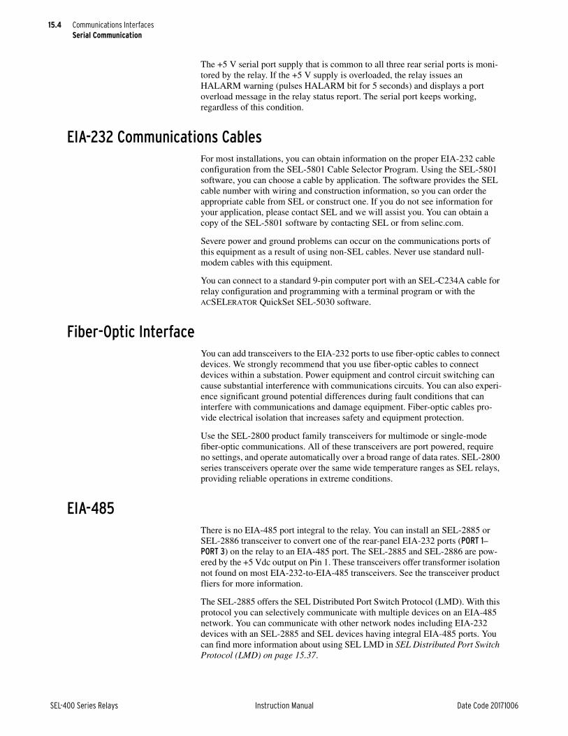
15.4
SEL-400 Series Relays Instruction Manual Date Code 20171006
Communications InterfacesSerial Communication
The +5 V serial port supply that is common to all three rear serial ports is moni-tored by the relay. If the +5 V supply is overloaded, the relay issues an HALARM warning (pulses HALARM bit for 5 seconds) and displays a port overload message in the relay status report. The serial port keeps working, regardless of this condition.
EIA-232 Communications CablesFor most installations, you can obtain information on the proper EIA-232 cable configuration from the SEL-5801 Cable Selector Program. Using the SEL-5801 software, you can choose a cable by application. The software provides the SEL cable number with wiring and construction information, so you can order the appropriate cable from SEL or construct one. If you do not see information for your application, please contact SEL and we will assist you. You can obtain a copy of the SEL-5801 software by contacting SEL or from selinc.com.
Severe power and ground problems can occur on the communications ports of this equipment as a result of using non-SEL cables. Never use standard null-modem cables with this equipment.
You can connect to a standard 9-pin computer port with an SEL-C234A cable for relay configuration and programming with a terminal program or with the ACSELERATOR QuickSet SEL-5030 software.
Fiber-Optic InterfaceYou can add transceivers to the EIA-232 ports to use fiber-optic cables to connect devices. We strongly recommend that you use fiber-optic cables to connect devices within a substation. Power equipment and control circuit switching can cause substantial interference with communications circuits. You can also experi-ence significant ground potential differences during fault conditions that can interfere with communications and damage equipment. Fiber-optic cables pro-vide electrical isolation that increases safety and equipment protection.
Use the SEL-2800 product family transceivers for multimode or single-mode fiber-optic communications. All of these transceivers are port powered, require no settings, and operate automatically over a broad range of data rates. SEL-2800 series transceivers operate over the same wide temperature ranges as SEL relays, providing reliable operations in extreme conditions.
EIA-485There is no EIA-485 port integral to the relay. You can install an SEL-2885 or SEL-2886 transceiver to convert one of the rear-panel EIA-232 ports (PORT 1–PORT 3) on the relay to an EIA-485 port. The SEL-2885 and SEL-2886 are pow-ered by the +5 Vdc output on Pin 1. These transceivers offer transformer isolation not found on most EIA-232-to-EIA-485 transceivers. See the transceiver product fliers for more information.
The SEL-2885 offers the SEL Distributed Port Switch Protocol (LMD). With this protocol you can selectively communicate with multiple devices on an EIA-485 network. You can communicate with other network nodes including EIA-232 devices with an SEL-2885 and SEL devices having integral EIA-485 ports. You can find more information about using SEL LMD in SEL Distributed Port Switch Protocol (LMD) on page 15.37.

15.5
Date Code 20171006 Instruction Manual SEL-400 Series Relays
Communications InterfacesSerial Port Hardware Protocol
Serial Port Hardware ProtocolThe serial ports comply with the EIA-232 Standard (formerly known as RS-232). The serial ports support RTS/CTS hardware flow control. See also Software Flow Control on page 15.27.
Hardware Flow ControlHardware handshaking is one form of flow control that two serial devices use to prevent input buffer information overflow and loss of characters. To support hardware handshaking, connect the RTS output pin of each device to the CTS input pin of the other device. To enable hardware handshaking, use the SET P command (or front-panel SET pushbutton sequence) to set RTSCTS := Y. Disable hardware handshaking by setting RTSCTS := N. Table 15.3 shows actions the relay takes for the RTSCTS setting values and the conditions relevant to hard-ware flow control.
Note that the relay must assert the RTS pin to provide power for some modems, fiber-optic transceivers, and hardware protocol converters that are port powered. Check the documentation for any port-powered device to determine if the device supports hardware handshaking or if you must always assert RTS (RTSCTS := N) for proper operation.
Data FrameThe relay ports use asynchronous data frames to represent each character of data. Four port settings influence the framing: SPEED, DATABIT, PARITY, and STOPBIT. The time allocated for one bit is the reciprocal of the SPEED. For example, at 9600 bits per second, one bit-time is 0.104 milliseconds (ms).
The default port framing uses one start bit, eight data bits, no parity bit, and one stop bit. The transmitter asserts the TXD line for one data frame, as described in the following steps:
The TXD pin is normally in a deasserted state.
➤ To send a character, the transmitter first asserts the TXD pin for one bit time (start bit).
➤ For each data bit, if the bit is set, the transmitter asserts TXD for one bit time. If the bit is not set, it deasserts the pin for one bit time (data bits).
Table 15.3 Hardware Handshaking
Setting RTSCTS Value
Condition Relay Action
N All Assert RTS output pin and ignore CTS input pin.
Y Normal input reception Assert RTS output pin.
Y Local input buffer is close to full Deassert RTS pin to signal remote device to stop transmitting.
Y Normal transmission Sense CTS input is asserted, transmit normally.
Y Remote device buffer is close to full, so remote device deasserts RTS
Sense CTS input is deasserted, stop transmitting.

15.6
SEL-400 Series Relays Instruction Manual Date Code 20171006
Communications InterfacesEthernet Communications
➤ If the PARITY setting is E, the transmitter asserts or deasserts the parity bit so that the number of asserted data bits plus the parity bit is an even number. If the PARITY setting is O, the transmitter asserts or deasserts the parity bit so that the number of asserted data bits plus the parity bit is an odd number. If the PARITY setting is N, the data frame does not include a parity bit.
➤ At the completion of the data bits and parity bit (if any), the transmitter deasserts the line for one bit time (stop bit). If STOPBIT is set to 2, the transmitter deasserts the line for one more bit time (stop bit).
➤ Until the relay transmits another character, the TXD pin will remain in the unasserted state.
Ethernet CommunicationsEthernet Card
SEL-400 series relays support an optional Ethernet Card. In some SEL-400 series devices, this is a daughter card to the mainboard. In others, it goes into Bay 3. You can either field install the optional communications card or order the relay with the card installed at the factory. As with other SEL products, SEL has designed and tested SEL Ethernet cards for operation in harsh environments.
The optional Ethernet card provides Ethernet communications for the relay. The Ethernet card is available with standard twisted-pair and fiber-optic physical interfaces. The Ethernet card includes redundant physical interfaces with the capability to automatically transfer communications to the backup interface in the event that the primary network fails. For information on substation integration architectures, see Section 16: DNP3 Communication and Section 17: IEC 61850 Communication.
Once installed in a relay, the settings needed for network operation and data exchange protocols, including DNP3 and IEC 61850, are available in the PORT 5 settings.
Ethernet Network OperationYou should carefully design your Ethernet network to maximize reliability, mini-mize system administration effort, and provide adequate security. SEL recom-mends that you work with a networking professional to design your substation Ethernet network.
Several settings control how the relay with the optional Ethernet card operates on an Ethernet network. These settings include IP addressing information, network port failover options, and network speed.
NOTE: Only some SEL-400 series relays are available with four Ethernet ports.
Use the network configuration settings shown in Table 15.4 to configure the relay for operation on an IP network and to set other parameters affecting the physical Ethernet network interface operation. The relay is equipped with either two or four Ethernet ports: A, B, C, and D. Ports A and B support PTP protocol, ports C and D do not. If the relay has two ports without the PTP option, they will support standard Ethernet, DNP3, and optional IEC 61850 communications. If the relay has four ports, the additional two ports can be used for relay-specific functions.

15.7
Date Code 20171006 Instruction Manual SEL-400 Series Relays
Communications InterfacesEthernet Communications
The relay IPADDR setting uses Classless Inter-Domain Routing (CIDR) notation and a variable-length subnet mask (VLSM) to define its local network and host address.
An IP address consists of two parts: a prefix that identifies the network followed by a host address within that network. Early network devices used a subnet mask to define the network prefix of an associated host address. Within the mask, sub-net boundaries were defined by the 8-bit segments of the 32-bit IP address. These boundaries constrained network prefixes to 8, 16, or 24 bits, defining Class A, B, and C networks, respectively.
This classful networking often created subnetworks that were not sized effi-ciently for actual requirements. CIDR allows more effective usage of a given range of IP addresses. In CIDR notation, you enter the IPADDR setting in the form a.b.c.d/p, where a.b.c.d is the host address in standard dotted decimal form and p is the network prefix expressed as the number of “1” bits in the mask. For example, if IPADDR := 192.168.1.2/24, the host address is 192.168.1.2 and the network prefix is the first 24 bits of the address, or 192.168.1. The network address is derived by applying the network prefix to IPADDR and filling the remaining bits with zeros (in our example, it is 192.168.1.0). The broadcast address is derived similarly, but the remaining bits are filled with ones (192.168.1.255 for the example above). Neither the network (base) address nor the broadcast address can be used for any host or router addresses on the network.
Table 15.4 Ethernet Card Network Configuration Settings
Label Description Range Default
EPORT Enable Ethernet port communication Y, N N
IPADDR IP network address/CIDR network prefix IP address w.x.y.z/t
where:
w = 0–126, 128–223
x = 0–255
y = 0–255
z = 0–255
t = 1–30
192.168.1.2/24
DEFRTR Default router w = 0–126, 128–223
x = 0–255
y = 0–255
z = 0–255
192.168.1.1
ETCPKA Enable TCP keep-alive functionality in all TCP communication sup-ported by the relay
Y, N Y
KAIDLE Length of time to wait with no detected activity before sending a keep alive packet
1–20 s 10
KAINTV Length of time to wait between sending keep-alive packets after receiv-ing no response for the prior keep-alive packet
1–20 s (must be less than or equal to KAIDLE)
1
KACNT Maximum number of keep-alive packets to send 1–20 6
NETMODE Network operating mode FIXED, FAILOVER, SWITCHED, PRP, ISOLATEIP
FAILOVER
NETPORT Primary network port A, B, C, D C
FTIME Failover time out 0–65535 ms 1
NETASPD Network speed or autodetect on Port A AUTO, 10 Mbps, 100 Mbps AUTO
NETBSPD Network speed or autodetect on Port B AUTO, 10 Mbps, 100 Mbps AUTO
NETCSPD Network speed or autodetect on Port C AUTO, 10 Mbps, 100 Mbps AUTO
NETDSPD Network speed or autodetect on Port D AUTO, 10 Mbps, 100 Mbps AUTO

15.8
SEL-400 Series Relays Instruction Manual Date Code 20171006
Communications InterfacesEthernet Communications
The relay uses the DEFRTR address setting to determine how to communicate with nodes on other local networks. The relay communicates with the default router to send data to nodes on other local networks. The default router must be on the same local network as the relay or the relay will reject the DEFRTR set-ting. You must also coordinate the default router with your general network implementation and administration plan. See Table 15.6 for examples of how IPADDR and SUBNETM define the network and node and how these settings affect the DEFRTR setting.
If there is no router on the network, enter a null string (“”).
Table 15.5 CIDR Notation
CIDR Value Subnet Mask
/32 255.255.255.255
/31 255.255.255.254
/30 255.255.255.252
/29 255.255.255.248
/28 255.255.255.240
/27 255.255.255.224
/26 255.255.255.192
/25 255.255.255.128
/24 255.255.255.000
/23 255.255.254.000
/22 255.255.252.000
/21 255.255.248.000
/20 255.255.240.000
/19 255.255.224.000
/18 255.255.192.000
/17 255.255.128.000
/16 255.255.000.000
/15 255.254.000.000
/14 255.252.000.000
/13 255.248.000.000
/12 255.240.000.000
/11 255.224.000.000
/10 255.192.000.000
/9 255.128.000.000
/8 255.000.000.000
/7 254.000.000.000
/6 252.000.000.000
/5 248.000.000.000
/4 240.000.000.000
/3 224.000.000.000
/2 192.000.000.000
/1 128.000.000.000
/0 000.000.000.000

15.9
Date Code 20171006 Instruction Manual SEL-400 Series Relays
Communications InterfacesEthernet Communications
NOTE: The ETCPKA setting applies to all TCP traffic on Ethernet ports, including TELNET, FTP, DNP3, IEC 61850 MMS, and C37.118.
The ETCPKA setting, along with the KAIDLE, KAINTV, and KACNT settings, can be used to verify that the computer at the remote end of a TCP connection is still available. If ETCPKA is enabled and the relay does not transmit any TCP data within the interval specified by the KAIDLE setting, the relay sends a keep-alive packet to the remote computer. If the relay does not receive a response from the remote computer within the time specified by KAINTV, the keep-alive packet is re-transmitted as many as KACNT times. After this count is reached, the relay considers the remote device no longer available, so the relay can terminate the connection without waiting for the idle timer (TIDLE or FTPIDLE) to expire.
The relay monitors MMS inactivity to identify and disconnect MMS clients that have stopped communicating with it. You can set it from 0 to 42000000 seconds via the IED Properties MMS Settings in ACSELERATOR Architect SEL-5032 Software. The MMS Inactivity default value is either 120 seconds or 900 sec-onds, depending on the relay. Setting this value to 0 disables the MMS Inactivity timer. If enabled, the relay starts a timer for an MMS session after it receives an MMS request from the client on that session. It resets the timer whenever it receives a new MMS request from that client. When the timer runs out, the relay disconnects the MMS session, making it available for other MMS clients.
This feature was implemented in addition to the TCP keep-alive timer to specifi-cally handle MMS clients that do not disconnect properly. As there are a limited number of MMS sessions available, this ensures that misbehaving MMS clients do not take up multiple MMS sessions. Note that the MMS inactivity time-out can still disconnect an MMS session even if the relay receives TCP keep-alive messages from that MMS client.
The relay Ethernet card operates over either twisted-pair or fiber-optic media. Each Ethernet card is equipped with two or four network ports. With an initial ordering option, you can select the medium for each port (10/100 Mbps twisted-pair or 100 Mbps fiber-optic). Speeds for the physical media are fixed for fiber-optic connections. For twisted-pair connections, the Ethernet card can autodetect the network speed or you can set a fixed speed.
Table 15.6 DEFRTR Address Setting Examples
IPADDR (CIDR)SUBNET Mask
(Non-CIDR)Network Address
Broadcast Address
DEFRTR Rangea
a DEFRTR cannot be the same as IPADDR, Network Address, or Broadcast Address.
192.168.1.2/28 255.255.255.240 192.168.1.0 192.168.1.15 192.168.1.0–192.168.1.15
192.168.1.2/24 255.255.255.0 192.168.1.0 192.168.1.255 192.168.1.ab
b Value in the range 0–255.
192.168.1.2/20 255.255.240.0 192.168.0.0 192.168.15.255 192.168.0.ab–192.168.15.ab
192.168.1.2/16 255.255.0.0 192.168.0.0 192.168.255.255 192.168.ab.bb
192.168.1.2/12 255.240.0.0 192.160.0.0 192.175.255.255 192.160.ab.bb–192.175.ab.bb
192.168.1.2/8 255.0.0.0 192.0.0.0 192.255.255.255 192.ab.bb.cb
192.168.1.2/4 240.0.0.0 192.0.0.0 207.255.255.255 192.ab.bb.cb–207.ab.bb.cb

15.10
SEL-400 Series Relays Instruction Manual Date Code 20171006
Communications InterfacesEthernet Communications
Using Redundant Ethernet PortsRelays may have as many as four Ethernet ports, which work together in pairs: A and B, C and D. One pair of ports are for TDP/I/P or UDP/IP Ethernet communi-cations, including FTP, TELNET, DNP3 LAN/WAN, etc., and IEC 61850 GOOSE. You can configure these ports for redundant network architectures, or force the relay to use a single Ethernet port for these protocols. If the relay has four ports, the second pair of ports can be used for relay specific functionality. PTP is only available on ports A and B.
Redundant Ethernet Network Using FAILOVER ModeMake the following settings in Port 5 to configure the relay for FAILOVER mode.
➤ NETMODE := FAILOVER
➤ FTIME := desired time-out for the active port before failover to the backup port
➤ NETPORT := the preferred primary network interface (C for Port 5C, D for Port 5D)
Use the internal failover switch to connect the relay to redundant networks as shown in Figure 15.5.
On startup, the relay communicates using the primary network interface selected by the NETPORT setting. If the relay detects a link failure on the primary inter-face, it asserts the LNKFAIL Relay Word bit. If the link status on the standby interface is healthy, the relay activates the standby network interface after time FTIME. If the link status on the primary interface returns to normal before time FTIME, the failover timer resets and operation continues on the primary network interface.
After failover, while communicating via the standby interface, if the relay detects a link failure on the standby interface and the link status on the primary interface is healthy, the relay activates the primary network interface after time FTIME. The choice of active port is reevaluated after settings change, and after relay restart.
In either case, if the relay detects a link failure on the interface on which it is cur-rently communicating, it asserts the LNKFAIL Relay Word bit. In relays that support process bus functionality, FAILOVER is the only supported mode. If the relay detects a failure on its current process bus interface, it will assert the LNK-
Figure 15.5 Failover Network Topology
Relay
Relay
Relay
Network
SEL-2725 SEL-2725

15.11
Date Code 20171006 Instruction Manual SEL-400 Series Relays
Communications InterfacesEthernet Communications
FL2 Relay Word bit. Note that for very small values of FTIME, or for a failover event on the process bus, the assertion or deassertion of LNKFAIL and LNKFL2 can be too short for a state change to register in the SER.
Network Connection Using Isolated IP Connection ModeThe Isolated IP mode (NETMODE = ISOLATEIP) permits IEC 61850 GOOSE messages on two ports, but restricts IP traffic to just one port. This mode is useful for cases where it is desired to connect one port to a secured network (the IP port) but have the other port leave the security perimeter.
NOTE: If NETMODE = ISOLATEIP, Precision Time Protocol (PTP) is only supported on the port designated as the IP port.
The NETPORT setting selects which port will be the IP port. The other port will only support GOOSE traffic. IP transmissions will only go out the IP port. IP receptions will only be processed from the IP port. GOOSE publications will go out both ports. GOOSE subscriptions will be accepted from either port. Any non-GOOSE traffic received on the non-IP port will be ignored. No traffic will go from one external port to the other.
Redundant Ethernet Network Using SWITCHED ModeMake Port 5 setting NETMODE = SWITCHED to activate the internal Ethernet switch. The internal switch connects a single Ethernet stack inside the relay to two external Ethernet ports. The combination of relay and internal switch operate the same as if a single Ethernet port on a relay were connected to an external unmanaged Ethernet switch. Use the internal switch to add devices to a network, as shown in Figure 15.6.
Using this topology, the internal network switch of the relay supports connecting Ethernet devices in series. This configuration is only recommended for tempo-rary use.
When using this switched mode, take care not to connect the last device back to the Managed Ethernet Switch, thereby creating a loop or ring.
In switched mode, the internal Ethernet switch of the relay is an unmanaged Ethernet switch and does not provide RSTP functionality. You will experience very large RSTP healing times in such a network.
Network Connection Using Fixed Connection ModeForce the relay to use a single Ethernet port even when it is equipped with two or more Ethernet ports by making setting NETMODE := FIXED. When NETMODE := FIXED, only the interface selected by NETPORT is active. The other interfaces are disabled.
Figure 15.6 Using Internal Ethernet Switch to Add Networked Devices
Relay
Network
ManagedEthernetSwitch
Relay Relay Relay Relay

15.12
SEL-400 Series Relays Instruction Manual Date Code 20171006
Communications InterfacesEthernet Communications
Network Connection Using PRP Connection ModeParallel Redundancy Protocol (PRP) is part of an IEC standard for high availabil-ity automation networks (IEC 62439-3). The purpose of the protocol is to provide seamless recovery from any single Ethernet network failure.
The basic concept is that the Ethernet network and all traffic are fully duplicated with the two copies operating in parallel.
NOTE: PTP cannot be used in combination with PRP.
Make the following settings in Port 5 to configure the relay for PRP mode.
➤ NETMODE := PRP
➤ PRPTOUT := desired time-out for PRP frame entry
➤ PRPADDR := PRP destination MAC address LSB 01-15-4E-00-01-XX
➤ PRPINTV := desired supervision frame transmit interval
When NETMODE is not set to PRP, the PRP settings are hidden.
When PRP is enabled, SEL recommends reducing the maximum number of incoming GOOSE subscriptions to 64. Incoming GOOSE buffers are sized to accommodate a maximum of 128 GOOSE messages. The number of messages doubles when PRP is enabled.
Ethernet ProtocolsNOTE: The relay prioritizes processing IEC 61850 GOOSE data over the data access protocols listed above. With GOOSE enabled, high GOOSE traffic to and from the relay sustained over long periods may cause slowed responsiveness to data transfer requests via TCP/IP protocols.
Access data using either the standard TCP/IP Telnet and FTP interfaces or, optionally, through the (Web) HTTP Server, DNP3 LAN/WAN or IEC 61850 interface. You cannot access all data through all interfaces. See the appropriate interface section below for details on data access.
FTPFTP is a standard application-level protocol for exchanging files between com-puters over a TCP/IP network. The relay Ethernet card operates as an FTP server, presenting files to FTP clients. The relay Ethernet card supports one FTP connec-tion at a time. Subsequent requests to establish FTP sessions will be denied. If your FTP client does not work properly, be sure to set your client to use a single session.
Table 15.7 lists the settings that affect FTP server operation.
NOTE: SEL advises against enabling anonymous FTP logins (FTPANMS = Y) except under test conditions. The Ethernet card does not require a password for the special FTP user name “anonymous”. If you enable anonymous FTP logins, you are allowing unrestricted access to the relay and host files.
Table 15.7 FTP Settings
Label Description Range Default
FTPSERVa
a If you change these settings and accept the new settings, the Ethernet card closes all active network connections and briefly pauses network operation.
FTP session enable Y, N N
FTPCBAN FTP connect banner 254 characters FTP SERVER:
FTPIDLEa FTP connection time-out 5–255 minutes 5
FTPANMSa Anonymous login enable Y, N N
FTPAUSR User level from which anonymous FTP client inherits access rights
0, 1, B, P, A, O, 2 0

15.13
Date Code 20171006 Instruction Manual SEL-400 Series Relays
Communications InterfacesEthernet Communications
File StructureThe basic file structure is organized as a directory and subdirectory tree similar to that used by Unix, DOS, Windows, and other common operating systems. See Virtual File Interface on page 15.18 for information on the basic file structure.
Access ControlThe standard FTP logins consist of the three-character access level command (e.g., ACC, BAC) with their respective passwords. For example, with default passwords, if you use the user name of 2AC and password of TAIL, you will con-nect with Access Level 2 privileges.
FTP settings control anonymous file access features. The special FTP user name “anonymous” does not require a password. It has the access rights of the access level selected by the FTPAUSR setting. For example, if FTPAUSR is set to 1 (for Access Level 1), the FTP anonymous user has Access Level 1 rights.
SEL advises against enabling anonymous FTP logins (FTPANMS = Y) except under test conditions. The Ethernet card does not require a password for the spe-cial FTP user name “anonymous”. If you enable anonymous FTP logins, you are allowing unrestricted access to the relay and host files.
TelnetTelnet is part of the TCP/IP protocol suite. A Telnet connection provides access to the relay user interface. When you connect with Telnet and log into the relay, you can use all of the ASCII and Compressed ASCII commands described in Section 14: ASCII Command Reference to configure and interact with the relay. You can also use the SEL binary Fast Meter and Fast Operate commands described in SEL Fast Meter, Fast Operate, Fast SER Messages, and Fast Mes-sage Data Access on page 15.28.
Use a Telnet client or QuickSet on the host PC to communicate with the relay. To terminate a Telnet session, use the EXI command from any access level.
Telnet settings available when ETELNET := Y are listed in Table 15.8.
Simple Network Time Protocol (SNTP)When SNTP is enabled (Port 5 setting ESNTP is not OFF), the relay internal clock conditionally synchronizes to the time of day served by a Network Time Protocol (NTP) server. The relay uses a simplified version of NTP called the Simple Network Time Protocol (SNTP). SNTP is not as accurate as IRIG-B or PTP. The relay can use SNTP as a less accurate primary time source, or as a backup to the higher accuracy IRIG-B or PTP time sources.
If an IRIG-B time source is connected and either Relay Word bits TSOK or TIRIG assert, then the relay synchronizes the internal time-of-day clock to the incoming IRIG-B time code signal, even if SNTP is configured in the relay and
Table 15.8 Telnet Settings
Label Description Range Default
TCBAN Telnet connect banner 254 characters TERMINAL SERVER:
TPORT Telnet TCP/IP port 23, 1025–65534 23
TIDLE Telnet Port connection time-out 1–30 minutes 15

15.14
SEL-400 Series Relays Instruction Manual Date Code 20171006
Communications InterfacesEthernet Communications
an NTP server is available. If the IRIG-B source is disconnected (TIRIG deas-sert) then the relay synchronizes the internal time-of-day clock to the NTP server if available. In this way an NTP server acts as either the primary time source, or as a backup time source to the more accurate IRIG-B time source. The above is also true if the relay is connected to an accurate PTP time source, but TPTP (not TIRIG) will deassert when the PTP time source is disconnected.
Three SEL application notes available from the SEL web site describe how to create an NTP server.
➤ AN2009-10: Using an SEL-2401, SEL-2404, or SEL-2407 to Serve NTP Via the SEL-3530 RTAC
➤ AN2009-38: Using SEL Satellite-Synchronized Clocks With the SEL-3332 or SEL-3354 to Output NTP
➤ AN2010-03: Using an SEL-2401, SEL-2404, or SEL-2407 to Create a Stratum 1 Linux NTP Server
Configuring SNTP Client in the RelayTo enable SNTP in the relay make Port 5 setting ESNTP = UNICAST, MANY-CAST, or BROADCAST. Table 15.9 shows each setting associated with SNTP.
SNTP Operation ModesThe following sections explain the setting associated with each SNTP operation mode (UNICAST, MANYCAST, and BROADCAST).
Table 15.9 Settings Associated With SNTP
Setting Prompt Range Default Description
ESNTP SNTP Enable (OFF, UNICAST, MANYCAST, BROADCAST)
UNICAST, MANYCAST, BROADCAST
OFF Selects the mode of operation of SNTP. See descriptions in SNTP Operation Modes on page 15.14.
SNTPRATa SNTP Request Update Rate (15–3600 s)
15–3600 s 60 Determines the rate at which the relay asks for updated time from the NTP server when ESNTP = UNICAST or MANYCAST. Determines the time the relay will wait for an NTP broadcast when ENSTP = BROADCAST.
SNTPTO SNTP Timeout (5–20 s) 5–20 s 5 Determines the time the relay will wait for the NTP master to respond when ENSTP = UNICAST or MANYCAST.
SNTPPIP SNTP Primary Server IP Address (w.x.y.z)b
Valid IP Address 192.168.1.110 Selects primary NTP server when ENSTP = UNICAST, or broadcast address when ESNTP = MANYCAST or BROADCAST.
SNTPBIP SNTP Backup Server IP Address (w.x.y.z)c
Valid IP Address 192.168.1.111 Selects backup NTP server when ESNTP = UNICAST.
SNTPPORd SNTP IP Local Port Number (1–65534)
1–65534 123 Ethernet port used by SNTP. Leave at default value unless otherwise required.
a This setting is hidden if ESNTP = OFF and hidden and forced to 5 if ESNTP = BROADCAST.b Where w: 0–126, 128–239, x: 0–255, y: 0–255, z: 0–255.c Where w: 0–126, 128–223, x: 0–255, y: 0–255, z: 0–255.d This setting is hidden if ESNTP UNICAST.

15.15
Date Code 20171006 Instruction Manual SEL-400 Series Relays
Communications InterfacesEthernet Communications
ESNTP = UNICAST
In unicast mode of operation the SNTP client in the relay requests time updates from the primary (IP address setting SNTPPIP) or backup (IP address setting SNTPBIP) NTP server at a rate defined by setting SNTPRAT. If the NTP server does not respond with the period defined by the sum of setting SNTPTO and SNTPRAT then the relay tries the other SNTP server. When the relay success-fully synchronizes to the primary NTP time server, Relay Word bit TSNTPP asserts. When the relay successfully synchronizes to the backup NTP time server, Relay Word bit TSNTPB asserts.
ESNTP = MANYCAST
In manycast mode of operation the relay initially sends an NTP request to the broadcast address contained in setting SNTPPIP. The relay continues to broad-cast requests at a rate defined by setting SNTPRAT. When a server replies, the relay considers that server to be the primary NTP server, and switches to UNI-CAST mode, asserts Relay Word bit TSNTPP, and thereafter requests updates from the primary server. If the NTP server stops responding for time SNTPTO, the relay deasserts TSNTPP and begins to request time from the broadcast address again until a server responds.
ESNTP = BROADCAST
Setting SNTPPIP = 0.0.0.0 while ESNTP = BROADCAST, the relay will listen for and synchronize to any broadcasting NTP server. If setting SNTPPIP is set to a specific IP address while setting ESNTP = BROADCAST, then the relay will listen for and synchronize to only NTP server broadcasts from that address. When synchronized the relay asserts Relay Word bit TSNTPP. Relay Word bit TNSTPP deasserts if the relay does not receive a valid broadcast within the SNTPT0 setting value after the period defined by setting SNTPRAT.
SNTP Accuracy Considerations
SNTP time synchronization accuracy is limited by the accuracy of the SNTP Server and by the networking environment. The highest degree of SNTP time synchronization can be achieved by minimizing the number of switches and rout-ers between the SNTP Server and the relay.
When installed on a network with low burden configured with one Ethernet switch between the relay and the SNTP Server, and when using ESNTP = UNICAST or MANYCAST, the relay time synchronization error to the SNTP server is typically less than ±1 millisecond.
Precision Time Protocol (PTP)If the optional Ethernet card is installed and it includes ports A and B, then the relay supports Precision Time Protocol version 2 (PTPv2) as a slave-only clock as defined by IEEE-1588-2008 on ports A and B. PTP provides high accuracy timing over an Ethernet network, eliminating the need for a separate IRIG-B cable and connection. To achieve the best accuracy (<1 µs), it is necessary to have one or more PTP master clocks and that all intervening equipment (e.g., Ethernet switches) need to be 1588-aware (i.e. all intervening network devices need to be transparent or boundary clocks).

15.16
SEL-400 Series Relays Instruction Manual Date Code 20171006
Communications InterfacesEthernet Communications
NOTE: The SEL-2488 with the PTP option is a PTP grandmaster clock capable GPS receiver.
In PTP, a clock that provides time to other devices, typically based on GPS input, is a master clock. The intervening switches are transparent clocks. It is also possi-ble to connect networks together and pass time from one network to another using boundary clocks. Transparent and boundary clocks are important because they provide time correction in the PTP messages that pass through them, whereas devices that are not 1588 aware would not provide this correction. Because it is possible for a network to have multiple master clocks, PTP clocks implement algorithms to select the best available clock. The one selected for use by an end device is the grandmaster clock. A complete description of possible PTP networking configurations is beyond the scope of this manual. You can learn more about configuring a PTP network in these application guides:
“Using the SEL-2488 to Provide IEEE 1588 Version 2 Grandmaster Func-tionality in a Redundant Network Topology” (AN2015-07)
“Using the SEL-2488 to Provide IEEE 1588 Version 2 Grandmaster Func-tionality to Isolated Ethernet Networks” (AN2015-06)
NOTE: PTP is not available when Parallel Redundancy Protocol (PRP) is enabled.
To configure PTP, update the Port 5 PTP settings as described in Table 12.23. By default, PTP is disabled in the relay. Set EPTP to Y to enable PTP and make the other PTP settings available.
Within PTP, there are multiple clock profiles available. A profile defines the set of PTP features available in a specific application domain. SEL-400 series relays support two profiles: Default and Power System profile (C37.238-2011).
The Default profile has many optional features. It was intended to address com-mon applications, so has been implemented by most PTP capable devices. The Default profile supports both UDP or layer 2 (802.3) Ethernet transport, and can use either end-to-end (E2E) or peer-to-peer (P2P) Delay Mechanism. Grandmas-ter clocks can send Announce, Sync, and Delay request messages over a wide range of intervals. A Default profile network can consist of boundary clocks or transparent clocks anywhere between the grandmaster and the end devices. The only performance requirement for the Default profile is that a master clock must maintain frequency accurate to within 0.01%. A well designed Default profile network with an accurate grandmaster can come close to the 1 s accuracy avail-able to Power profile networks.
The Power profile was created to minimize the number of optional features to facilitate interoperability and predictable performance in order to provide the required time accuracy for Synchrophasors and for SCADA. The Power profile is only supported on layer 2 networks and exclusively uses the peer-to-peer Delay Mechanism. All messages must be sent at 1-second intervals, must have 802.1Q VLAN tags, and announce messages must include grandmaster ID and (maxi-mum) inaccuracy fields. Transparent clocks are mandatory in a power profile net-work; boundary clocks are not allowed. For a network with less than 16 hops between Grandmaster and IED, the Power profile can deliver time with better accuracy than 1 s. Select the profile using the PTPPRO setting.
PTP defines a logical grouping of clocks in a network as a clock domain. This allows a logical separation between clocks that participate in different application domains to coexist on the same network. Domains are identified by domain num-bers. The domain number for the relay is selected by the DOMNUM setting. Set DOMNUM to match the domain number configured in the master clocks the relay should synchronize with.
The relay supports transport of PTP messages over UDP or layer 2 (Ethernet). Use the PTPTR setting to select the PTP transport mechanism. This needs to match the transport mechanism used in the master clocks. Only layer 2 is avail-able with the Power System profile. If operating in a UDP network, PTP will

15.17
Date Code 20171006 Instruction Manual SEL-400 Series Relays
Communications InterfacesEthernet Communications
operate on port 320. Except for peer delay messages, the relay sets the time allowed to live (TTL) value in the UDP/IP header of PTP messages to 64. This allows the possibility of synchronizing relay time through routers across a WAN to a PTP master. High-accuracy synchronization may not be achievable across the WAN, so it is left to the user to determine if the accuracy meets the needs of their application.
When using the Power System profile, use the VLAN number and priority set-tings PVLAN and PVLANPR to set the VLAN ID and priority, respectively, of the Ethernet frames. Be sure to set PVLAN unique from other VLANs used within the relay.
PTP defines two methods for calculating and correcting for the communications path delay between the relay and the master clock: end-to-end (Delay Request-Response) and peer-to-peer (Peer Delay Request-Response). The end-to-end mechanism calculates the total path delay between the relay and the master clock. The peer-to-peer mechanism calculates the total path delay in a piecemeal fash-ion between each device in the path. Peer-to-peer is the more accurate method and is recommended for use in SEL relays. The relay periodically initiates path delay calculations. Use the PTHDLY and PDINT settings to configure the path delay method and the path delay request rate. If PTHDLY is set to OFF, then the relay will not calculate and correct for path delay. Only the peer-to-peer mecha-nism is available for Power System profile.
By default, the relay will synchronize to any clock on the network that it evalu-ates to be the best clock based on the Best Master Clock Algorithm. Use the Acceptable Master Table settings to specify a list of master (grandmaster or boundary) clocks to which the relay may synchronize. The relay will not syn-chronize to any master clock that is not in the list. It is recommended to use this feature for additional security. The AMNUM setting selects the number of master clocks you will list in this table. The default value is OFF, which means the relay will synchronize to any master clock on the network. If AMNUM is set to a value other than OFF, that number of allowable masters must be identified in accor-dance with the PTP transport chosen, i.e., MAC address for 802.3 or IP address for UDP transport.
If the PTP transport (PTPTR) is set to UDP, use the AMIPn settings to specify the IP addresses of the clocks the relay is permitted to synchronize to. If PTP trans-port is set to layer 2, use the AMMACn settings to specify the MAC addresses of the clocks the relay is permitted to synchronize to.
NOTE: The Acceptable Master Table feature may not work for transport over layer 2 if the intervening Ethernet switch(es) modify the source MAC address of Announce messages passing through them. With transport over layer 2, the relay uses the source MAC address to identify if an Announce message is coming from a master clock in the table.
If the ALTPRIn (alternate priority1 for master n) setting is set to a positive value, the priority1 value in received Announce messages from the corresponding mas-ter clock will be replaced by the ALTPRIn value before applying the Best Master Clock Algorithm. The ALTPRIn values reprioritize the master clocks locally. A discussion of reasons to apply alternate priorities is beyond the scope of this man-ual. If you are not familiar with the Best Master Clock Algorithm, leave the set-ting set to 0.
HTTP (Hypertext Transfer Protocol) ServerThe relay provides an HTTP (Web) server to provide read-only access to selected settings, metering, and reports. The HTTP server is disabled by default. To enable the HTTP server, make the following settings using the SET P 5 command.

15.18
SEL-400 Series Relays Instruction Manual Date Code 20171006
Communications InterfacesVirtual File Interface
When enabled, the HTTP server opens TCP/IP Port 80 by default. Set HTTPPOR to configure any other port as needed.
Virtual File InterfaceYou can retrieve and send data as files through the virtual file interface of the relay. Devices with embedded computers can also use the virtual file interface. When using serial ports or virtual terminal links, use the FILE DIR command. When you use an Ethernet card, the FTP protocol supported by Ethernet presents the file structure and sends and receives files.
The relay has a two-level file structure. There are a few files at the root level and three or more subdirectories or folders. Some SEL-400 series relays support directories in addition to those listed here. Table 15.11 shows the directories and the contents of each directory.
System Data FormatSettings files and the CFG.TXT file use the system data format (SDF) unless oth-erwise specified. The files may contain keywords to aid external support software parsing. A keyword is defined as a string surrounded by the open and close bracket characters, followed by a carriage return and line feed. Only one keyword is allowed per line in the file. For example, the keyword INFO would look like this in the file: [INFO]<CR><LF>.
Records are defined as comma-delimited text followed by a carriage return and line feed. One line in a text file equals one record. Fields are defined as comma-delimited text strings.
Comma-Delimited Text RulesField strings are separated by commas or spaces and may be enclosed in optional double quotation marks. Double quotes within the field string are repeated to dis-tinguish these double quotes from the quotes that surround the field string.
Table 15.10 Web Server Settings
Label Description Range Default
EHTTP Enable or disable Web Server Y, N N
HTTPPOR Web Server TCP/IP Port Number 1–65535 80
HIDLE Web server inactivity time-out (minutes) 1–30 5
Table 15.11 Virtual File Structure
Directory Usage Access Level
Root CFG.TXT file, CFG.XMLa file, SWCFG.ZIP file and the following directories
a Present only if the optional Ethernet card is installed.
1
SETTINGS Relay Settings 1
REPORTS SER, circuit breaker, protection and history reports 1
EVENTS EVE, CEV, COMTRADE and history reports 1
SYNCHROPHASORSb
b Only present in SEL-400 series relays that support synchrophasors.
Synchrophasor recording files 1

15.19
Date Code 20171006 Instruction Manual SEL-400 Series Relays
Communications InterfacesVirtual File Interface
Delimiters are spaces and commas that are not contained within double quotes. Two adjacent commas indicate an empty string, but spaces that appear next to another delimiter are ignored. Consider the following examples for converting a list of fields to comma-delimited text. Consider the following list of fields.
Stri,ng 1
Stri"ng 2
String 3
String4
The translation to comma-delimited text is as follows:
"Stri,ng 1","Stri""ng 2","String 3","String4"
Root DirectoryThe root directory contains three or more subdirectories and two or three files (CFG.TXT, CFG.XML, and SWCFG.ZIP). CFG.XML is only present if the optional Ethernet card is installed. SWCFG.ZIP is for internal use.
CFG.TXT File (Read-Only)The CFG.TXT file contains general configuration information about the relay and each setting class. External support software retrieves the CFG.TXT file to interact automatically with the connected relay.
CFG.XML File (Read-Only)Present only in units with the optional Ethernet card installed, the CFG.XML file is supplementary to the CFG.TXT file. The CFG.XML file describes the IED configuration, any options such as the Ethernet port, and includes firmware iden-tification, settings class names, and configuration file information.
SWCFG.ZIP File (Read/Write)The SWCFG.ZIP file is a compressed file used to store external support software settings. It is readable at Access Level 1 and above, and writable at Access Level 2 and above.
Settings Directory You can access the relay settings through files in the SETTINGS directory. We recommend that you use support software to access the settings files, rather than directly accessing them via other means. External settings support software reads settings from all of these files to perform its functions. The relay only allows you to write to the individual SET_cn files, where c is the settings class code and n is the settings instance. Except for the SET_61850 CID file, changing settings with external support software involves the following steps:
Step 1. The PC software reads the CFG.TXT and SET_ALL.TXT files from the relay.
Step 2. You modify the settings at the PC. For each settings class that you modify, the software sends a SET_cn.TXT file to the relay.
Step 3. The PC software reads the ERR.TXT file. If it is not empty, the relay detects errors in the SET_cn.TXT file.

15.20
SEL-400 Series Relays Instruction Manual Date Code 20171006
Communications InterfacesVirtual File Interface
Step 4. For any detected errors, modify the settings and send the settings until the relay accepts your settings.
Step 5. Repeat Step 2–Step 4 for each settings class that you want to modify.
Step 6. Test and commission the relay.
SET_ALL.TXT File (Read-Only)The SET_ALL.TXT file contains the settings for all of the settings classes in the relay.
SET_cn.TXT Files (Read and Write)There is a file for each instance of each setting class. Table 15.12 summarizes the typical settings files. The exact list of settings files depends on the specific set-tings classes available in each relay model. The settings class is designated by c, and the settings instance number is n.
BAY_SCREEN.TXTNOTE: Not all SEL-400 series relays support bay mimic screens.
The BAY_SCREEN.TXT file describes the content of the custom bay mimic screen that can be selected for display on the HMI. This file is generated by QuickSet and may be downloaded to the relay when Bay Control settings are changed.
ERR.TXT (Read-Only)The ERR.TXT file contents are based on the most recent SET_cn.TXT or SET_61850.CID file written to the relay. If there were no errors, the file is empty. If errors occurred, the relay logs these errors in the ERR.TXT file.
SET_61850.CIDPresent if ordered with the IEC 61850 protocol option, the SET_61850.CID file contains the IEC 61850 configured IED description in XML. This file is gener-ated by Architect and downloaded to the relay. See Section 17: IEC 61850 Com-munication for more information on the SET_61850.CID file.
Table 15.12 Typical Settings Directory Files (Sheet 1 of 2)
Settings Class Filename Settings Description Read Access Level Write Access Level
A SET_An.TXT Automation; n in range 1–10For relay-0, n = 1
1, B, P, A, O, 2 A, 2
B SET_B1.TXT Bay Control 1, B, P, A, O, 2 P, A, O, 2
D SET_Dn.TXT DNP3 remapping; n in range 1–5 1, B, P, A, O, 2 P, A, O, 2
F SET_F1.TXT Front panel 1, B, P, A, O, 2 P, A, O, 2
G SET_G1.TXT Global 1, B, P, A, O, 2 P, A, O, 2
L SET_Ln.TXT Protection logic; n in range 1–6 1, B, P, A, O, 2 P, 2
M SET_SM.TXT Breaker monitor settings 1, B, P, A, O, 2 P, 2
N SET_N1.TXT Notes 1, B, P, A, O, 2 P, A, O, 2
O SET_O1.TXT Contact outputs 1, B, P, A, O, 2 O, 2
P SET_Pn.TXT Port; n in range 1, 2, 3, 5, F 1, B, P, A, O, 2 P, A, O, 2
R SET_R1.TXT Report 1, B, P, A, O, 2 P, A, O, 2

15.21
Date Code 20171006 Instruction Manual SEL-400 Series Relays
Communications InterfacesVirtual File Interface
Reports DirectoryUse the REPORTS directory to retrieve files that contain the reports shown in Table 15.13. Note that the relay provides a report file that contains the latest information each time you request the file.
NOTE: Not all SEL-400 series relays support breaker monitoring and corresponding breaker files.
Events DirectoryNOTE: Most SEL-400 series relays provide large resolution event reports of 8 samples/cycle. The SEL-487B provides large resolution event reports of 12 samples/cycle.
The relay provides history, event reports, and oscillography files in the EVENTS directory. Event reports are available in the following formats: SEL ASCII 4- or 8-samples/cycle reports and Compressed ASCII 4- or 8-samples/cycle reports. The size of each event report file is determined by the LER setting in effect at the time the event is triggered. Higher resolution oscillography is available in binary COMTRADE (IEEE C37.111-1999) format at the sample rate (SRATE) and length (LER) settings in effect at the time the event is triggered.
The 4- and 8-samples/cycle report files (files with names that begin with E or C) are text files with the same format as the EVENT and CEVENT command responses. Event file names start with the prefix E4_, E8_, E12, C4_, C8_, C12, or HR_, followed by a unique event serial number. For example, if one event is triggered, with serial number of “10001”, the EVENTS directory contains the files shown in Table 15.14. Event oscillography in COMTRADE format consists of three files (.CFG, .DAT, and .HDR) that conform to the COMTRADE standard.
S SET_Sn.TXT Group n; n in range 1–6 1, B, P, A, O, 2 P, 2
T SET_T1.TXT Alias settings 1, B, P, A, O, 2 P, A, O, 2
All SET_ALL.TXT All instances of all setting classes 1, B, P, A, O, 2 N/A
All ERR.TXT Error log for most recently written settings file 1, B, P, A, O, 2 N/A
NA SET_61850.CID IEC 61850 configured IED description file 1, B, P, A, O, 2 2
NA BAY_SCREEN.TXT Custom bay mimic screen content 1, B, P, A, O, 2 P, A, O, 2
Table 15.12 Typical Settings Directory Files (Sheet 2 of 2)
Settings Class Filename Settings Description Read Access Level Write Access Level
Table 15.13 REPORTS Directory Files
File Usage: All Are Read-Only Files
SER.TXT ASCII SER report, clears SER when read
CSER.TXT Compressed ASCII SER report
BRE_n.TXT BRE n H report, n is the breaker reference
BRE_Sn BRE Sn report, n is the breaker reference
CBRE.TXT Compressed ASCII CBR report
HISTORY.TXT History file
CHISTORY.TXT Compressed ASCII History file
PRO.TXT ASCII Profiling report
CPRO.TXT Compressed ASCII profiling report
Table 15.14 EVENTS Directory Files (for Event 10001) (Sheet 1 of 2)
File Usage
HISTORY.TXT History file; read-only
CHISTORY.TXT Compressed ASCII history file; read-only

15.22
SEL-400 Series Relays Instruction Manual Date Code 20171006
Communications InterfacesSoftware Protocol Selections
Synchrophasors Directory Table 15.15 shows an example SYNCHROPHASORS directory. Synchrophasor data recording is enabled when synchrophasors are enabled and EPMDR := Y. The filename includes a time stamp based on the first data frame in the file. The data in the file conforms to the C37.118 data format.
Software Protocol SelectionsThe relay supports the protocols and command sets shown in Table 15.16.
C4_10001.TXT 4-samples/cycle Compressed ASCII event report; read-only
C8_10001.TXTa 8-samples/cycle Compressed ASCII event report; read-only
E4_10001.TXT 4-samples/cycle event report; read-only
E8_10001.TXTb 8-samples/cycle event report; read-only
HR_10001.CFG Sample/second COMTRADE configuration file; read-only
HR_10001.DAT Sample/second COMTRADE binary data file; read-only
HR_10001.HDR Sample/second COMTRADE header file; read-only
a In the SEL-487B, this is replaced with C1210001.TXT which provides a 12-samples/cycle Compressed ASCII event report.
b In the SEL-487B, this is replaced with E1210001.TXT which provides a 12-samples/cycle event report.
Table 15.14 EVENTS Directory Files (for Event 10001) (Sheet 2 of 2)
File Usage
Table 15.15 SYNCHROPHASORS Directory File Sample
File Description
080528,160910,0,ONA,1,ABC.PMU 080528 = date
160910 = time
0 = GMT (no time offset)
ONA = Last three letter (spaces removed) of the PMSTN setting
1 = PMID setting
ABC = CONAM setting (company name)
PMU = file extension indicating synchrophasor recording file
Table 15.16 Supported Serial Command Sets (Sheet 1 of 2)
PROTO Setting Value
Command Set Description
SEL SEL ASCII Commands and responses
SEL SEL Compressed ASCII Commands and comma-delimited responses
SEL SEL Fast Meter Binary meter and digital element commands and responses
SEL SEL Fast Operate Binary operation commands
SEL SEL Fast Message Fast Message database access, binary SER commands and responses
MBA, MBB, MBGA, or MBGB
SEL MIRRORED BITS communications
Binary high-speed control commandsNOTE: Not all SEL-400 series relays support MBGA and MBGB

15.23
Date Code 20171006 Instruction Manual SEL-400 Series Relays
Communications InterfacesSEL Protocol
Virtual Serial PortsActual serial ports are described in Serial Port Hardware Protocol on page 15.5. In addition to actual serial ports, the relay supports several virtual serial ports. A virtual serial port does the following:
➤ Transmits and receives characters through a different mechanism than the physical serial port
➤ “Encapsulates” characters in virtual terminal messages of a different protocol
➤ Simulates an actual serial port with setting PROTO := SEL
➤ May have restrictions imposed by the protocol that encapsulates the virtual serial data
You can set the relay to use virtual serial ports encapsulated in SEL MIRRORED BITS communications links, DNP3 links, and through Telnet over Ethernet.
SEL ProtocolThis subsection describes the command sets that are active when the port setting PROTO := SEL. You can also access these protocols through virtual serial ports that simulate ports with PROTO := SEL.
SEL ASCII CommandsSEL originally designed the SEL ASCII commands for communication between the relay and a human operator via a keyboard and monitor or a printing terminal. A computer with a serial port can also use the SEL ASCII protocol to communi-cate with the relay, collect data, and issue commands.
The ASCII character set specifies numeric codes that represent printing charac-ters and control characters. The complete ASCII command set is shown in Section 14: ASCII Command Reference. Table 15.17 shows the subset of the ASCII control characters used in this section.
PMU Phasor Measurement Unit Binary Synchrophasor Protocol, as selected by Port Setting PMUMODE and Global Setting MFRMT (see Section 18: Synchrophasors).
PMU SEL Fast Operate Binary operation commands
RTD SEL Fast Message protocol for Resistance Temperature Detector (RTD) data
As many as 12 analog temperature readings from the SEL-2600A.
DNP DNP3 Level 2 Outstation Binary commands and responses (see Section 16: DNP3 Communication).
Table 15.16 Supported Serial Command Sets (Sheet 2 of 2)
PROTO Setting Value
Command Set Description
NOTE: Not all SEL-400 series relays support synchrophasors (the PMU protocol choice).
NOTE: Not all SEL-400 series relays support RTD communications with the SEL-2600A.

15.24
SEL-400 Series Relays Instruction Manual Date Code 20171006
Communications InterfacesSEL Protocol
The <Enter> key on standard keyboards sends the ASCII character CR for a car-riage return. This manual instructs you to press the <Enter> key after commands to send the proper ASCII code to the relay. A correctly formatted command transmitted to the relay consists of the command, including optional parameters, followed by either a CR character (carriage return) or CR and LF characters (car-riage return and line feed). The following line contains this information in the format this manual uses to describe user input:
<command> <Enter> or <command> <Enter> <CR>
You may truncate commands to the first three characters. For example, EVENT 1 <Enter> is equivalent to EVE 1 <Enter>. You may use upper- and lowercase characters without distinction, except in passwords.
In response to a command, the relay may respond with an additional dialog line or message. The relay transmits dialog lines in the following format:
<DIALOG LINE ><CR><LF>
The relay transmits messages in the following format:
<STX><MESSAGE LINE 1><CR><LF>
<MESSAGE LINE 2><CR><LF>
…
<LAST MESSAGE LINE><CR><LF>< ETX>
Each message begins with the start-of-transmission character, STX, and ends with the end-of-transmission character, ETX. Each line of the message ends with a carriage return, CR, and line feed, LF.
Send the CAN character to the relay to abort a transmission in progress. For example, if you request a long report and want to terminate transmission of this report, depress the <Ctrl> and <X> keys (<Ctrl+X>) to terminate the report.
SEL Compressed ASCII CommandsThe relay supports a subset of SEL ASCII commands identified as Compressed ASCII commands. Each of these commands results in a comma-delimited mes-sage that includes a checksum field. Most spreadsheet and database programs can directly import comma-delimited files. Devices with embedded processors con-nected to the relay can execute software to parse and interpret comma-delimited messages without expending the customization and maintenance labor needed to interpret nondelimited messages. The relay calculates a checksum for each line by numerically summing all of the bytes that precede the checksum field in the message. The program that uses the data can detect transmission errors in the message by summing the characters of the received message and comparing this sum to the received checksum.
Table 15.17 Selected ASCII Control Characters
Decimal Code Name Usage Keystroke(s)
13 CR Carriage return <Enter> or <RETURN> or <Ctrl+M>
10 LF Line feed <Ctrl+J>
02 STX Start of transmission <Ctrl+B>
03 ETX End of transmission <Ctrl+C>
24 CAN Cancel <Ctrl+X>
17 XON Flow control on <Ctrl+Q>
19 XOFF Flow control off <Ctrl+S>

15.25
Date Code 20171006 Instruction Manual SEL-400 Series Relays
Communications InterfacesSEL Protocol
Most commands are available only in SEL ASCII format. Selected commands have versions in both standard SEL ASCII and Compressed ASCII formats. Compressed ASCII reports generally have fewer characters than conventional SEL ASCII reports, because the compressed reports reduce blanks, tabs, and other white space between data fields to a single comma.
Compressed ASCII Message Format
Each message begins with the start-of-transmission character, STX, and ends with the end-of-transmission character, ETX:
<STX><MESSAGE LINE 1><CR><LF>
<MESSAGE LINE 2><CR><LF>
...
<LAST MESSAGE LINE><CR><LF><ETX>
Each line in the message consists of one or more data fields, a checksum field, and a CRLF. Commas separate adjacent fields. Each field is either a number or a string. Number fields contain base-10 numbers using the ASCII characters 0–9, plus (+), minus (-), and period (.). String fields begin and end with quote marks and contain standard ASCII characters. Hexadecimal numbers are contained in string fields.
The checksum consists of four ASCII characters that are the hexadecimal repre-sentation of the two-byte binary checksum. The checksum value is the sum of the first byte on a line (first byte following <STX>, <CR>, or <CR><LF>) through the comma preceding the checksum.
If you request data with a Compressed ASCII command and these data are not available, (in the case of an empty history buffer or invalid event request), the relay responds with the following Compressed ASCII format message:
<STX>“No Data Available”,“0668”<CR><ETX>
Table 15.18 lists the typical Compressed ASCII commands and contents of the command responses. The Compressed ASCII commands are described in Section 14: ASCII Command Reference.
where:No Data Available is a text string field.
0668 is the checksum field, which is a hexadecimal number represented by a character string.
Table 15.18 Typical Compressed ASCII Commands (Sheet 1 of 2)
Command Response Access Level
BNAME ASCII names of Fast Meter status bits 0
CASCII Configuration data of all Compressed ASCII commands available at access levels > 0
0
CBREAKER Circuit breaker data 1
CEVENT Event report 1
CHISTORY List of events 1
CPR Displays the first 20 rows of the profile report, with the oldest row at the bottom and the latest row at the top
CSER Sequential Events Recorder report 1
CSTATUS Self-diagnostic status 1
CSUMMARY Summary of an event report 1
DNAME ASCII names of digital I/O reported in Fast Meter 0

15.26
SEL-400 Series Relays Instruction Manual Date Code 20171006
Communications InterfacesSEL Protocol
CASCII Configuration Message for Compressed ASCII Commands
The CASCII message provides a block of data for each of the Compressed ASCII commands supported by an SEL device. The block of data for each command provides message description information to allow automatic data extraction. The relay arranges items in the Compressed ASCII configuration message in a pre-defined order. For the purpose of improving products and services, SEL some-times changes the items and item order. The information presented below explains the message and serves as a guide to the items in Compressed ASCII configuration messages.
NOTE: Compressed ASCII is self-describing and may vary with the firmware version of your relay. Before you program a master device to send and parse Compressed ASCII commands and responses, you should perform a CASCII command on your relay or contact SEL for more detailed information.
A Compressed ASCII command can require multiple header and data configura-tion lines. The general format of a Compressed ASCII configuration message is the following:
Definitions for the items and fields in a Compressed ASCII configuration mes-sage are the following:
➤ n is the number of Compressed ASCII command descriptions to follow.
➤ COMMAND is the ASCII name for the Compressed ASCII command that the requesting device (terminal or external software) sends. The naming convention for the Compressed ASCII commands is a C character preceding the typical command. For example, CSTATUS, abbreviated to CST, is the Compressed ASCII STATUS command.
➤ #H identifies a header line to precede one or more data lines; the # character represents the number of subsequent ASCII names. For example, 21H identifies a header line with 21 ASCII labels.
➤ xxxxx is an ASCII name for corresponding data on following data lines. Maximum ASCII name width is ten characters.
➤ #D identifies a data format line; the # character represents the maximum number of data lines in command response.
➤ ddd identifies a format field containing one of the following type designators:
➢ I—Integer data
➢ F—Floating point data
➢ zS—String of maximum z characters (for example, enter 10S for a 10-character string)
➤ yyyy is the 4-byte hex ASCII representation of the checksum. Every checksum is followed by a new line indication (<CR><LF>).
ID Relay identification 0
SNS ASCII names for SER data reported in Fast Meter 0
Table 15.18 Typical Compressed ASCII Commands (Sheet 2 of 2)
Command Response Access Level
<STX>"CAS",n,"yyyy"<CR><LF>"COMMAND 1",ll,"yyyy"<CR><LF>"#H","xxxxx","xxxxx",......,"xxxxx","yyyy"<CR><LF>
"#D","ddd","ddd","ddd","ddd",......,"ddd","yyyy"<CR><LF>•••
"COMMAND n",ll,"yyyy"<CR><LF>"#H","xxxxx","xxxxx",......,"xxxxx","yyyy"<CR><LF>"#D","ddd","ddd","ddd","ddd",......,"ddd","yyyy"<CR><LF><ETX>
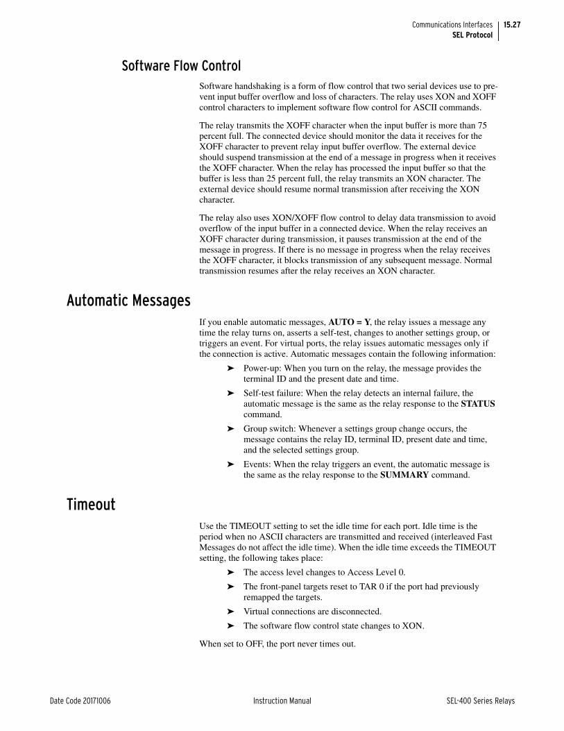
15.27
Date Code 20171006 Instruction Manual SEL-400 Series Relays
Communications InterfacesSEL Protocol
Software Flow ControlSoftware handshaking is a form of flow control that two serial devices use to pre-vent input buffer overflow and loss of characters. The relay uses XON and XOFF control characters to implement software flow control for ASCII commands.
The relay transmits the XOFF character when the input buffer is more than 75 percent full. The connected device should monitor the data it receives for the XOFF character to prevent relay input buffer overflow. The external device should suspend transmission at the end of a message in progress when it receives the XOFF character. When the relay has processed the input buffer so that the buffer is less than 25 percent full, the relay transmits an XON character. The external device should resume normal transmission after receiving the XON character.
The relay also uses XON/XOFF flow control to delay data transmission to avoid overflow of the input buffer in a connected device. When the relay receives an XOFF character during transmission, it pauses transmission at the end of the message in progress. If there is no message in progress when the relay receives the XOFF character, it blocks transmission of any subsequent message. Normal transmission resumes after the relay receives an XON character.
Automatic MessagesIf you enable automatic messages, AUTO = Y, the relay issues a message any time the relay turns on, asserts a self-test, changes to another settings group, or triggers an event. For virtual ports, the relay issues automatic messages only if the connection is active. Automatic messages contain the following information:
➤ Power-up: When you turn on the relay, the message provides the terminal ID and the present date and time.
➤ Self-test failure: When the relay detects an internal failure, the automatic message is the same as the relay response to the STATUS command.
➤ Group switch: Whenever a settings group change occurs, the message contains the relay ID, terminal ID, present date and time, and the selected settings group.
➤ Events: When the relay triggers an event, the automatic message is the same as the relay response to the SUMMARY command.
TimeoutUse the TIMEOUT setting to set the idle time for each port. Idle time is the period when no ASCII characters are transmitted and received (interleaved Fast Messages do not affect the idle time). When the idle time exceeds the TIMEOUT setting, the following takes place:
➤ The access level changes to Access Level 0.
➤ The front-panel targets reset to TAR 0 if the port had previously remapped the targets.
➤ Virtual connections are disconnected.
➤ The software flow control state changes to XON.
When set to OFF, the port never times out.

15.28
SEL-400 Series Relays Instruction Manual Date Code 20171006
Communications InterfacesSEL Protocol
Interleaved ASCII and Binary MessagesSEL relays have two separate data streams that share the same physical serial port. Human data communications with the relay consist of ASCII character commands and reports that you view using a terminal or terminal emulation package. The binary data streams can interrupt the ASCII data stream to obtain information; the ASCII data stream continues after the interruption. This mecha-nism uses a single communications channel for ASCII communication (transmis-sion of an event report, for example) interleaved with short bursts of binary data to support fast acquisition of metering data. The device connected to the other end of the link requires software that uses the separate data streams to exploit this feature. However, you do not need a device to interleave data streams in order to use the binary or ASCII commands. Note that XON, XOFF, and CAN operations operate on only the ASCII data stream.
An example of using these interleaved data streams is when the relay communi-cates with an SEL communications processor. The communications processor performs autoconfiguration by using a single data stream and SEL Compressed ASCII and binary messages. In subsequent operations, the communications pro-cessor uses the binary data stream for Fast Meter, Fast Operate, and Fast SER messages to populate a local database and to perform SCADA operations. At the same time, you can use the ASCII data stream for commands and responses.
SEL Fast Meter, Fast Operate, Fast SER Messages, and Fast Message Data Access
SEL Fast Meter is a binary message that you solicit with binary commands. Fast Operate is a binary message for control. The relay can also send unsolicited Fast SER messages and unsolicited synchrophasor messages automatically. If the relay is connected to an SEL communications processor, these messages provide the mechanism that the communications processor uses for SCADA or DCS functions that occur simultaneously with ASCII interaction.
This section summarizes the binary commands and messages and includes our recommendation for using Fast Commands and Compressed ASCII configura-tion information to communicate with the relay. You need this information to develop or specify the software an external device uses to communicate using Fast Messages with the relay. To support this type of development, you will also need to contact SEL for Fast Message protocol details.
Table 15.19 lists the two-byte Fast Commands and the actions the relay takes in response to each command.
Table 15.19 Fast Commands and Response Descriptions (Sheet 1 of 2)
Command (Hex)
Name Response Description
A5B9h Status acknowledge message Clears Fast Meter status byte and sends cur-rent status.
A5C0h Relay Fast Meter definition block Defines available Fast Meter messages and general relay configuration information.
A5C1h Fast Meter configuration block Defines contents of Fast Meter data message.
A5C2h Demand Fast Meter configuration block
Defines contents of demand Fast Meter data message.
A5C3h Peak demand Fast Meter config-uration block
Defines contents of peak demand Fast Meter data message.
NOTE: Not all SEL-400 series relays support demand metering and the corresponding fast commands.

15.29
Date Code 20171006 Instruction Manual SEL-400 Series Relays
Communications InterfacesSEL Protocol
Fast Operate commands use one of the two-byte command types shown in Table 15.20. Each Fast Operate command also includes additional bytes that specify a remote bit or circuit breaker bit.
The Fast Operate messages transfer control commands through the binary data stream. You must enable Fast Operate messages for a port before the relay accepts these messages on that port. In the port settings, when the protocol is set to SEL, the FASTOP setting is visible. Set FASTOP :=Y to enable Fast Operate commands or to N to disable Fast Operate commands.
General Fast Messages have a two byte identifier (A546h) and a function code. Fast SER messages are general Fast Messages that transport Sequential Event Recorder report information. The Fast SER messages include function codes to accomplish different tasks. Table 15.21 lists the Fast SER function codes and the actions the relay takes in response to each command.
A5CEh Fast Operate configuration block Defines available circuit breaker, remote bits, and associated commands.
A5D1h Fast Meter data message Defines present values of analog and digital data.
A5D2h Demand Fast Meter data message Defines values of most recently completed demand period.
A5D3h Peak demand Fast Meter data message
Defines values for peak demands as of end of most recently completed demand periods.
Table 15.20 Fast Operate Command Types
Command (Hex)
Name Description
A5E0h Fast Operate command for remote bits
Sends command code that will change the state of a remote bit, if setting FASTOP :=Y for this port.
A5E3h Fast Operate command for cir-cuit breaker bits
Sends command code that will change the state of a circuit breaker control bit, if setting FASTOP :=Y for this port.
Table 15.21 Fast Message Command Function Codes Used With Fast Messages (A546 Message) and Relay Response Descriptions (Sheet 1 of 2)
Function Code (Hex)
Function Relay Action
00h Fast Message definition block request
Relay transmits Fast Message definition request acknowledge (Function Code 80).
01h Enable unsolicited transfers Relay transmits Fast SER command acknowl-edged message (Function Code 81) and sets relay element bit FSERx. Relay will transmit subsequent SER events (Unsolicited SER broadcast, Function Code 18).
02h Disable unsolicited transfers Relay sends Fast SER command acknowl-edged message (Function Code 82) and clears relay element bit FSERx. Relay will not transmit subsequent SER messages.
05h Ping—determine channel is operable
Relay aborts unsolicited message in progress and transmits ping acknowledge message (Function Code 85).
Table 15.19 Fast Commands and Response Descriptions (Sheet 2 of 2)
Command (Hex)
Name Response Description

15.30
SEL-400 Series Relays Instruction Manual Date Code 20171006
Communications InterfacesSEL Protocol
The SEL Fast Message Synchrophasor Protocol is described in Section 18: Syn-chrophasors.
Recommended Use of Relay Self-Description Messages for Automatic Configuration
Compressed ASCII and Fast Message commands provide information to allow an external computer-based device to adapt to the special messages for each relay. The SEL communications processors use the self-description messages to config-ure a database and name the elements in the database.
Table 15.22 lists commands and command usage in the recommended order of execution for automatic configuration.
98h Fast SER Message acknowl-edge
Relay completes dialog processing for unso-licited message sequence.
30h Device description request Relay sends summary of data blocks avail-able (Function Code B0h).
31h Data format request Relay sends description of requested data block, including data labels and types (Func-tion Code B1h).
33h Bit label request Relay sends set of bit labels for specific data item (Function Code B3h).
10h Data request Relay responds with set of requested data (Function Code 90h).
Table 15.21 Fast Message Command Function Codes Used With Fast Messages (A546 Message) and Relay Response Descriptions (Sheet 2 of 2)
Function Code (Hex)
Function Relay Action
Table 15.22 Commands in Recommended Sequence for Automatic Configuration
Command ASCII or hexadecimal (h suffix)
Response Usage
ID Relay identification ID and FID
A5C0h Relay Fast Meter definition block
Defines available Fast Meter mes-sages and general relay configuration information
A5C1h, A5C2h,A5C3h
Fast Meter configuration blocks
Defines contents of Fast Meter data messages
BNAME Binary names ASCII names of status bits
DNAME Digital I/O name ASCII names of digital I/O points
SNS SER names ASCII names for SER data points
CASCII Compressed ASCII configu-ration block
Configuration data for Compressed ASCII commands with access levels > 0
A5CEh Fast Operate configuration block
Defines available circuit breaker and remote bits, and associated commands, if setting FASTOP :=Y for this port

15.31
Date Code 20171006 Instruction Manual SEL-400 Series Relays
Communications InterfacesSEL MIRRORED BITS Communication
SEL MIRRORED BITS CommunicationWith SEL-patented MIRRORED BITS communications protocol, protective relays and other devices can directly exchange information quickly, securely, and with minimal cost. Use MIRRORED BITS communications for remote control, remote sensing, or communications-assisted protection schemes such as POTT and DCB.
SEL products support several variations of MIRRORED BITS communications pro-tocols. Through port settings, you can set the relay for compatible operation with SEL-300 series relays, the SEL-2505 or SEL-2506 Remote I/O Modules, and the SEL-2100 Protection Logic Processors. These devices use MIRRORED BITS com-munications to exchange the states of eight logic bits. You can also use settings to select extensions of the MIRRORED BITS communications protocols, available only in SEL-400 series relays, to exchange analog values, synchronize clocks, and engage in virtual terminal dialogs. Table 15.23 summarizes MIRRORED BITS communications features.
Communications Channels and Logical Data ChannelsThe relay supports two MIRRORED BITS communications channels, designated A and B. Use the port setting PROTO to assign one of the MIRRORED BITS commu-nications channels to a serial port: PROTO := MBA or MBGA for MIRRORED BITS communications Channel A or PROTO := MBB or MBGB for MIRRORED BITS communications Channel B.
Transmitted bits include TMB1A–TMB8A and TMB1B–TMB8B. The last letter (A or B) designates with which channel the bits are associated. These bits are controlled by SELOGIC control equations. Received bits include RMB1A–RMB8A and RMB1B–RMB8B. You can use received bits as arguments in SELOGIC control equations. The channel status bits are ROKA, RBADA, CBADA, LBOKA, ROKB, RBADB, CBADB, LBOKB, DOKA, ANOKA, DOKB, and ANOKB. You can also use these bits as arguments in SELOGIC con-trol equations. Use the COM command for additional channel status information.
Within each MIRRORED BITS communications message for a given channel (A or B), there are eight logical data channels (1–8). In operation compatible with other SEL products, you can use the eight logical data channels for TMB1–TMB8. If you use fewer than eight transmit bits, Data Channel 8 is reserved to support data framing and time synchronization features. You can assign the eight logical data channels as follows:
Table 15.23 MIRRORED BITS Communications Features
Feature Compatibility
Transmit and receive logic bits SEL-300 series relays, SEL-2505, SEL-2506, SEL-2100, SEL-400 series relays
Transmit and receive analog values SEL-400 series relays
Synchronize time SEL-400 series relays
Send and receive virtual serial port characters SEL-400 series relays
Support synchronous communications channel SEL-400 series relays

15.32
SEL-400 Series Relays Instruction Manual Date Code 20171006
Communications InterfacesSEL MIRRORED BITS Communication
➤ Logic bits: Setting MBNUM controls the number of channels used for logic bits, TMB1–TMB8, inclusive.
➢ If you set MBNUM to 8, then you cannot use channels for any of the following features.
➢ If you set MBNUM to less than 8, you can use the remaining channels (as many as eight total) for the features listed below.
➤ Message and time synchronization: If MBNUM is less than 8, the relay dedicates a logical data channel to message framing and time synchronization.
➤ Analog channels: Setting MBNUMAN controls the number of analog channels. It is not guaranteed that multiple analog quantities will come from the same relay sampling interval.
➢ If MBNUM := 8, all channels are used for logic bits and MBNUMAN is forced to 0.
➢ If MBNUM := 7, seven channels are used for logic bits and one channel is used for message and time synchronization.
➢ If MBNUM is less than 7, you can use the remaining channels for analog channels by setting the desired number of channels in MBNUMAN (1 to 7 – MBNUM).
Note: Analog quantities are converted to Integer values for transmission via MIRRORED BITS. Because of this, they will lose any fractional value they may have had. To maintain a fixed resolution, multiply the analog quantity by a set value before transmission, and divide by the same quantity upon reception. To maintain accuracy, add 0.5 to the analog quantity after any scaling.
➤ Virtual terminal sessions: Setting MBNUMVT controls the number of additional channels available for the virtual terminal session.
➢ If MBNUMVT := OFF, the relay does not dedicate any additional channels to the virtual terminal session.
➢ If there are spare channels (7 – MBNUM – MBNUMAN > 0), you can use MBNUMVT to dedicate these additional channels to the virtual terminal session.
➢ With MBNUM = 7 or less and MBNUMVT = 0, virtual terminal is still possible because the relay uses the eighth element for time synchronization and virtual terminal.
The virtual terminal session uses channels differently than other data exchange mechanisms. There can be only one active virtual terminal session across a MIRRORED BITS link. One channel, included in the synchronization data, is always dedicated to this virtual terminal session. If you assign additional channels to the virtual terminal session (set MBNUMVT > 0), you will improve the performance of the virtual terminal session. The relay uses the additional channels to exchange data more quickly.
OperationMBG Protocol
The MBG protocol selection allows the user to move the MIRRORED BITS Trans-mit equations to the Group settings for more flexibility in bus transfer schemes. Using MBG will allow the MIRRORED BITS settings to transfer with a Group Switch when it occurs.

15.33
Date Code 20171006 Instruction Manual SEL-400 Series Relays
Communications InterfacesSEL MIRRORED BITS Communication
NOTE: The MBG protocol option is only available in some SEL-400 series relays.
To enable the MBG protocol, set the Port setting PROTO := MBGA to enable Channel A MIRRORED BITS, or PROTO := MBGB for Channel B MIRRORED BITS. Next, the protocol will need to be enabled in the Group settings.
Under Group settings, enable the MBG protocol for Channel A by setting EMBA := Y. When this setting is enabled, the transmit equation settings TX_IDA, RX_IDA, and TMBnA will be available in the Group settings and will be hidden from the Port settings.
The MBG protocol can also be enabled for Channel B by setting EMBB := Y. When this setting is enabled, the transmit equation settings TX_IDB, RX_IDB, and TMBnB will be available in the Group settings and will be hidden from the Port settings.
MB8While the relay does not have a setting for the MB8 protocol implemented in some SEL products, you can configure the relay to communicate with devices set to MB8A or MB8B (such as the SEL-351S or SEL-2505). Set the protocol set-ting PROTO to MBA or MBB. Set the STOPBIT setting to 2. Set all other set-tings to match those in the other device.
Message TransmissionThe relay transmits a MIRRORED BITS communications message as fast as it can for the configured data rate. At 9600 bps, this is approximately one message every 1/4-cycle. At 19200 bps, it is approximately every 1/8-cycle. At 38400 bps, it is approximately two every 1/8-cycle. However, if pacing is enabled, it slows to one message every 3 ms at 19200 and 38400 bps (see Table 15.26). Each message contains the most recent values of the transmit bits. If you enabled any of the extended features through the settings, note that the relay transmits a portion of the extended data in each message.
If you have specified virtual terminal data channels for this port, the designated data channels are normally idle. If you use the PORT command to open a virtual terminal session for this port and type characters, the relay transmits these char-acters through the virtual terminal logical data channels.
Message Reception OverviewWhen the devices are synchronized and the MIRRORED BITS communications channel is in a normal state, the relay decodes and checks each received message. If the message is valid, the relay performs the following operations:
➤ Sends each received logic bit (RMBn) to the corresponding pickup and dropout security counters, that in turn set or clear the RMBnc relay element bits.
NOTE: c represents the MIRRORED BITS channel (A or B), n represents the MIRRORED BITS data channel data number (1–8).
➤ Accumulates the analog data, and every 18th message, updates the received analog quantities.
➤ Accumulates the virtual terminal information, and every 18th message, makes the received character or characters available to the virtual terminal.

15.34
SEL-400 Series Relays Instruction Manual Date Code 20171006
Communications InterfacesSEL MIRRORED BITS Communication
Message Decoding and Integrity ChecksThe relay provides indication of the status of each MIRRORED BITS communica-tions channel, with element bits ROKA and ROKB. During normal operation, the relay sets the ROKc bit. The relay clears the bit upon detecting any of the follow-ing conditions:
➤ Parity, framing, or overrun errors
➤ Receive data redundancy error
➤ Receive message identification error
➤ No message received in the time three messages have been sent
The relay will assert ROKc only after successful synchronization as described below and two consecutive messages pass all of the data checks described above. After ROKc is reasserted, received data may be delayed while passing through the security counters described below.
While ROKc is not set, the relay does not transfer new RMB data to the pickup-dropout security counters described below. Instead, the relay sends one of the user-definable default values to the security counter inputs. For each RMBn, specify the default value with setting RMBnFL, as follows:
➤ 1
➤ 0
➤ P (to use last valid value)
Individual pickup and dropout security counters supervise the movement of each received data bit into the corresponding RMBn element. You can set each pickup/dropout security counter from 1 to 8. A setting of 1 causes a security counter to pass every occurrence, while a setting of 8 causes a counter to wait for eight con-secutive occurrences in the received data before updating the data bits. The pickup and dropout security count settings are separate. Control the security count settings with the settings RMBnPU and RMBnDO.
A pickup/dropout security counter operates identically to a pickup/dropout timer, except that the counter uses units of counted received messages instead of time. An SEL relay communicating with another SEL relay typically sends and receives MIRRORED BITS communications messages eight times per power sys-tem cycle. Therefore, a security counter set to two counts will delay a bit by approximately 1/4 of a power system cycle. Reference Table 15.26 for the mes-sage rates based on the settings. You must consider the impact of the security counter settings in the receiving device to determine the channel timing perfor-mance.
Channel SynchronizationWhen an SEL relay detects a communications error, it deasserts ROKA or ROKB. The relay transmits an attention message until it receives an attention message that includes a match to the TX_ID setting value. If the attention mes-sage is successful, the relay has properly synchronized and data transmission will resume. If the attention message is not successful, the relay will repeat the atten-tion message until it is successful.
Loopback TestingUse the LOOP command to verify the communications channel. In this mode, the relay expects the transmitted data to be looped back to the relay to test the data transmissions, including communications data. At the remote end, jumper

15.35
Date Code 20171006 Instruction Manual SEL-400 Series Relays
Communications InterfacesSEL MIRRORED BITS Communication
the send and receive communications channels to complete the path for the test. While in loopback mode, ROKc is deasserted, and LBOKc asserts and deasserts based on the received data checks.
Channel MonitoringBased on the results of data checks (described above), the relay collects informa-tion regarding the 255 most recent communications errors. Each record contains at least the following fields:
➤ Dropout Time/Date
➤ Pickup Time/Date
➤ Time elapsed during dropout
➤ Reason for dropout
Use the COM command to generate a long or summary report of the communi-cations errors.
NOTE: Combine error conditions including RBADA, RBADB, CBADA, and CBADB with other alarm conditions using SELOGIC control equations. You can use these alarm conditions to program the relay to take appropriate action when it detects a communications channel failure.
There is a single record for each outage, but an outage can evolve. For example, the initial cause could be a data disagreement, but framing errors can extend the outage. If the channel is presently down, the COMM record will only show the initial cause, but the COMM summary will display the present cause of failure.
When the duration of an outage on Channel A or B exceeds a user-definable threshold, the relay will assert a user-accessible flag, RBADA or RBADB. When channel unavailability exceeds a user-definable threshold for Channel A or B, the relay asserts a user-accessible flag, CBADA or CBADB.
MIRRORED BITS Communications Protocol for the Pulsar 9600-BPS ModemNOTE: Use an SEL-C272 or SEL-C273 cable.
To use a Pulsar MBT modem, set setting MBT := Y. Setting MBT := Y hides set-ting SPEED and forces it to 9600, and hides setting RTSCTS and forces it to a value of N. The relay also injects a delay (idle time) of 3 ms between messages.
NOTE: You must consider the idle time in the calculations of data transfer latency through a Pulsar MBT modem system.
The relay sets RTS to a negative voltage at the EIA-232 connector to signify that MIRRORED BITS communications matches this specification. Other relays may set RTS to a positive voltage at the EIA-232 connector to signify usage of the R6 version or the R version of MIRRORED BITS communications.
SettingsThe port settings associated with MIRRORED BITS communications are shown in Table 15.24 and Table 15.25.
Set PROTO := MBA or MBGA to enable the MIRRORED BITS communications protocol Channel A on this port. Set PROTO := MBB or MBGB to enable the MIRRORED BITS communications protocol Channel B on this port.
Table 15.24 General Port Settings Used With MIRRORED BITS Communications (Sheet 1 of 2)
Name Description Range Default
PROTO Protocol None, SEL, DNP, MBA, MBB, MBGA, MBGB, RTD, PMU
SEL
MBT Enable Pulsar 9600 modem Y, N N

15.36
SEL-400 Series Relays Instruction Manual Date Code 20171006
Communications InterfacesSEL MIRRORED BITS Communication
Setting SPEED := SYNC (available only on the rear-panel serial ports for which PROTO := MBA, MBB, MBGA, or MBGB) places the serial port in synchronous (or externally-clocked) mode. The serial port hardware will synchronize transmit and receive data (TX/RX) to a clock signal applied to the Pin 8 input at any effec-tive data rate as high as 64000. This setting choice will suit certain synchronous communications networks.
The relay uses the RBADPU setting to determine how long a channel error must persist before the relay asserts RBADA or RBADB. The relay deasserts RBADA and RBADB immediately when it no longer detects a channel error.
The relay uses the CBADPU setting to determine when to assert CBADA and CBADB. If the short-term channel down time ratio exceeds CBADPU, the relay asserts the appropriate CBAD bit.
The TXMODE setting provides compatibility with SEL devices that are not SEL-400 series relays. The relay can send messages more quickly than the SEL-300 series relays and other SEL devices can process these messages. This could lead to loss of data and a failure to communicate properly. When you set TXMODE to P, the relay sends new MIRRORED BITS messages every 3 ms even if the selected data speed (SPEED setting) would allow more frequent messages.
As a function of the settings for SPEED, TXMODE, and MBT, the message transmission periods are shown in Table 15.26.
SPEED Data speed. Hidden and set to 9600 if MBT := Y
300, 600, 1200, 2400, 4800, 9600, 19200, 38400, SYNC
9600
STOPBIT Stop bits. Hidden and set to 1 if MBT := Y 1, 2 1
Table 15.25 MIRRORED BITS Communications Protocol Settings (Sheet 1 of 2)
Name Description Range
TX_ID MIRRORED BITS communications ID of this device
1–4
RX_ID MIRRORED BITS communications ID of device connected to this port
1–4 (must be different than TX_ID)
RBADPU Outage duration to set RBAD 1–10000 seconds
CBADPU Channel unavailability to set CBAD 1–100000 parts per million
TXMODE Transmission modea N (normal), P (paced)
MBNUM Number of MIRRORED BITS communications data channels used for logic bits
0–8
RMB1FLb RMB1 channel fail state 0, 1, P
RMB1PUb RMB1 pickup message count 1–8
RMB1DOb RMB1 dropout message count 1–8
•
•
•
•
•
•
RMB8FLb RMB8 channel fail state 0, 1, P
RMB8PUb RMB8 pickup message count 1–8
RMB8DOb RMB8 dropout message count 1–8
MBTIME MIRRORED BITS time synchronize enable Y, N
Table 15.24 General Port Settings Used With MIRRORED BITS Communications (Sheet 2 of 2)
Name Description Range Default

15.37
Date Code 20171006 Instruction Manual SEL-400 Series Relays
Communications InterfacesSEL Distributed Port Switch Protocol (LMD)
Set the RX_ID of the local relay to match the TX_ID of the remote relay. In a three-terminal case, Relay X transmits to Relay Y, Relay Y transmits to Relay Z, and Relay Z transmits to Relay X. Table 15.27 lists the MIRRORED BITS commu-nications ID settings for Relays X, Y, and Z.
SEL Distributed Port Switch Protocol (LMD) SEL Distributed Port Switch Protocol (LMD) permits multiple devices to share a common communications channel. This protocol is appropriate for low-cost, low-speed port switching applications where updating a real-time database is not a requirement. The relay does not have built in LMD protocol, but you can con-nect this relay to an SEL-2885 EIA-232/485 Protocol Converter and connect the SEL-2885 to an EIA-485 multidrop network. See the SEL-2885 EIA-232 to
MBNUMAN Number of analog data channels
(hidden and set to 0 if MBNUM := 7 or 8)
0–n, n = 7–MBNUM
MBANA1c Selection for analog Channel 1 Analog quantity label
MBANA2c Selection for analog Channel 2 Analog quantity label
MBANA3c Selection for analog Channel 3 Analog quantity label
MBANA4c Selection for analog Channel 4 Analog quantity label
MBANA5c Selection for analog Channel 5 Analog quantity label
MBANA6c Selection for analog Channel 6 Analog quantity label
MBANA7c Selection for analog Channel 7 Analog quantity label
MBNUMVT Number of virtual terminal channels OFF, 0–n,n = 7–MBNUM–MBNUMAN
a Must be P for connections to devices that are not SEL-400 series relays.b Hidden based on MBNUM setting.c Hidden based on MBNUMAN setting.
Table 15.26 MIRRORED BITS Communications Message Transmission Period
Speed in Bits per Second
TXMODE := NORMAL MBT := N
TXMODE := PACED MBT := N
MBT :=Y
38400 1.0 ms 3.0 ms N/A
19200 2.0 ms 3.0 ms N/A
9600 4.0 ms 4.0 ms 7.0 ms
4800 8.0 ms 8.0 ms N/A
Table 15.27 MIRRORED BITS Communications ID Settings for Three-Terminal Application
Relay TX_ID RX_ID
X 1 3
Y 2 1
Z 3 2
Table 15.25 MIRRORED BITS Communications Protocol Settings (Sheet 2 of 2)
Name Description Range

15.38
SEL-400 Series Relays Instruction Manual Date Code 20171006
Communications InterfacesSEL Distributed Port Switch Protocol (LMD)
EIA-485 Transceiver product flier for more information on the settings, configu-ration, and application of the SEL-2885. (Contact your local technical service center, the SEL factory, or visit our website at selinc.com for a copy of the SEL-2885 product flier.)
InitializationFor the first 30 seconds after applying power to the relay, the SEL-2885 listens for an initialization string from the relay. The initialization string must be enclosed in square brackets ([ ]). The following table describes the initialization string fields. To send this string automatically, set AUTO to Y and append the initialization string to the relay ID setting so that it is included in the relay power-up header.
OperationThe following steps describe how to use the LMD operation of the SEL-2885:
Step 1. When you send the prefix and address, the SEL-2885 enables echo and message transmission.
You must wait until you receive a prompt before entering commands to avoid losing echoed characters while the external transmitter is warming up.
Step 2. You can use the commands that are available for the protocol setting of the port where the SEL-2885 is installed.
Step 3. If the port PROTO setting is set to SEL, you can use the QUIT com-mand to terminate the connection.
If no data are sent to the relay before the port time-out period, this command automatically terminates the connection.
Step 4. If all relays in the multidrop network do not have the same prefix set-ting, enter the sequence <Ctrl+X> OR QUIT <Enter> before enter-ing the prefix character to connect to another device.
Table 15.28 SEL-2885 Initialization String [MODE PREFIX ADDR:SPEED]
Field Optional or Required
Value Description
[ Required [ Opening bracket is start of string
Mode Optional Not specified
N
B
Treat as N, below
Addressing for ASCII device
Addressing for binary devices
PREFIX Required @, #, $, %, or & Prefix character
ADDR Required 01–99 Two digit address in the range 01–99
: Optional. Needed if SPEED is specified
Colon “:” Colon “:”, then one of the following codes to match the port SPEED setting
SPEED Optional 12
24
48
96
1200 bps
2400 bps
4800 bps
9600 bps
] Required ] Closing bracket is end of string

15.39
Date Code 20171006 Instruction Manual SEL-400 Series Relays
Communications InterfacesSEL-2600A RTD Module Operation
SEL-2600A RTD Module OperationThe SEL-2600A RTD Module Protocol (RTD) enables communication with an SEL-2600A via an SEL-2800 (EIA-232 to Fiber-Optic) Transceiver.
NOTE: Not all SEL-400 series relays support communication with SEL-2600A RTD Modules.
This protocol supports data acquisition of as many as 12 temperature channels and places the results directly into predefined analog quantities (RTD01–RTD12) inside the relay for use in freeform SELOGIC applications. For more information on the SEL-2600A or SEL-2800, contact your local technical service center, the SEL factory, or visit the SEL website at selinc.com for a copy of the SEL-2600A and SEL-2800 product fliers.
InitializationPerform the following steps to prepare the relay for communicating with an SEL-2600A RTD module:
Step 1. Set the desired port to RTD protocol.
Step 2. Set the port setting RTDNUM to the number of RTDs attached to the SEL-2600A.
Step 3. Set the RTD type settings (RTDnnTY) to the appropriate RTD type.
Step 4. Connect the SEL-2600A RTD Module to the port via the SEL-2800 (EIA-232 to Fiber-Optic) Transceiver.
OperationThe SEL-2600A RTD module sends all temperature measurements to the relay every 0.5 seconds. The relay places the received temperature measurements into analog quantities RTD01–RTD12 for use in freeform SELOGIC applications. The data range is from –50 to +250 °C.
NOTE: When a channel status bit is not asserted, the data in the respective analog quantity is the last valid temperature, not the current temperature.
If the relay stops receiving valid analog quantities from a certain channel, the temperature stored in the relay freezes at the last received value. Fifteen status bits help supervise decisions based on temperature measurements. Table 15.29 describes how to interpret the status bits.
Figure 15.7 SEL-2600A RTD Module and the Relay
SEL-2800 RelaySEL-2600A
RTD Module
RTD
RTD
Table 15.29 RTD Status Bits
RTD Status Bit Description
RTDFL Asserts if the SEL-2600A experiences an internal problem.
RTDCOMF Asserts if the relay does not receive a valid measurement from the SEL-2600A for 1.25 seconds.
RTD01ST–RTD12ST Assert when an RTD is attached to a channel and the SEL-2600A is able to read RTD.
RTDIN SEL-2600 input status bit. Asserts when the SEL-2600 is healthy and the received data indicates the assertion of the input.

15.40
SEL-400 Series Relays Instruction Manual Date Code 20171006
Communications InterfacesDirect Networking Example
To view the temperature measurements received from the SEL-2600A, issue the MET T command, as depicted in Figure 15.8.
NOTE: In some SEL-400 series relays, you must use MET RTD instead of MET T.
The MET T command displays the following messages:
➤ Channel Failure: This message is displayed for each channel whose channel status bit is not asserted.
➤ Channel Not Used: This message is displayed for each channel whose channel type is set to NA.
When there is a status problem with the SEL-2600A RTD module, the MET T command will respond with an informational message, as shown in Figure 15.9.
The four possible messages for status problems, with their interpretation, are indicated in Table 15.30.
Direct Networking ExampleThis direct networking example demonstrates direct networking to the relay using the Ethernet card. Figure 15.10 shows the Ethernet network topology. This examples uses a SEL-421, but the same concepts apply to any SEL-400 series relay.
=>>MET T <Enter>Relay 1 Date: 05/17/2003 Time: 13:42:13.220Station A Serial Number: 0000000000RTD Input Temperature Data (deg. C)RTD 1 = -48
RTD 2 = Channel FailureRTD 3 = 0RTD 4 = 24RTD 5 = Channel Not UsedRTD 6 = 72RTD 7 = Channel FailureRTD 8 = 120
RTD 9 = Channel Not UsedRTD 10 = 168RTD 11 = 192RTD 12 = 216
Figure 15.8 MET T Command Response
=>>MET TSEL-2600 Failure
Figure 15.9 MET T Command Response for Status Problem
Table 15.30 MET T Command Status Messages
Message Interpretation
SEL-2600 Failure RTDFL status bit asserted
Communication Failure RTDCOMF status bit asserted
No data available Port Protocol not set to RTD
Channel Failure RTDxxST status bit deasserted

15.41
Date Code 20171006 Instruction Manual SEL-400 Series Relays
Communications InterfacesDirect Networking Example
ApplicationIn this application, all IEDs connect to the Ethernet network. The SEL-421 Relays and the SEL-2030 each have an Ethernet card installed. In this example, the Ethernet network is used primarily for an engineering connection to the devices in the substation either across the WAN or from the local computer. The engineer can use FTP to collect settings, oscillography, and other file data directly from the SEL-421 Relays. The engineer can also use Telnet to establish a terminal connection to the SEL-421 Relays or through the SEL-2030 to one of the serial IEDs in order to configure these devices or obtain diagnostic information.
NOTE: The IRIG-B time signal available from SEL communications processors is not suitable for high-accuracy IRIG (HIRIG) timekeeping mode, which is required for synchrophasor functions.
There is a serial cable from the SEL-2030 to the SEL-421 Relays. This cable pro-vides IRIG-B time synchronization from the SEL-2030 that is synchronized by the GPS clock attached to the SEL-2030. The SEL-2030 provides its output syn-chronization signal from its internal clock, so that loss of the signal from the GPS will not result in a loss of synchronization between substation devices as they will all be synchronized to the SEL-2030 clock. During long periods of loss of synchronization, the SEL-2030 clock drift will become noticeable, but all substa-tion devices will remain synchronized relative to each other and the SEL-2030 clock. The serial cables also allow the SEL-2030 to provide a single point for dial-in communications with the substation IEDs avoiding the high cost of high bandwidth connections (for example, ISDN or DSL) for this backup to the Ether-net network engineering connection.
SettingsThis example focuses on the relay labeled Line 1 shown in Figure 15.10. PORT 5 settings for the SEL-421 configure the Ethernet card. PORT 5 settings for this example are shown in Table 15.31.
Figure 15.10 Example Direct Networking Topology
SEL-2030
EIA-232
Ethernet
EngineeringWorkstation
SEL-421
Line 1 Line 2
Ethernet Hub
RouterTo WAN
SEL-421 SEL-351S SEL-387 Serial IED
GPS Clock
Modem
IRIG-B
EIA-232

15.42
SEL-400 Series Relays Instruction Manual Date Code 20171006
Communications InterfacesDirect Networking Example
FTP SessionFigure 15.11 is a screen capture of an FTP session with the relay. The FTP client used for this example is included with the Windows operating system and acces-sible through a command prompt window. The operator connects to the relay, moves to the SETTINGS directory, and collects the PORT 5 settings. Figure 15.11 shows a portion of the PORT 5 settings in the SET_P5.TXT file.
Table 15.31 SEL-421 PORT 5 Direct Networking Settings
Setting Name Setting Description
TIMEOUT 5 Port inactivity time-out in minutes (drops to Access Level 0 on Telnet connections when this expires)
AUTO N Automessage disabled because engineering connection will not require unsolicited messages from SEL-2030
FASTOP N Fast Operate messages disabled because they are not required on engineering connection
TERTIM1 1 Length of time the channel must be idle before checking for the termination string in seconds
TERSTRN \005 Transparent communications termination string default of CTRL+E
TERTIM2 0 Length of time the channel must be idle before accepting the termination string in seconds
IPADDR 10.201.0.112/16 IP network address
DEFRTR 10.201.0.1 Default router
ETCPKA N Disable TCP keep-alive functionality (IEC 61850 only)
KAIDLE 10 Length of time to wait with no detected activity before sending a keep-alive packet (must be greater than or equal to KAINTV)
KAINTV 1 Length of time to wait between sending keep-alive packets after receiving no response for the prior keep-alive packet (must be less than or equal to KAIDLE)
KACNT 6 Maximum number of keep-alive packets to send
NETPORT A Primary network port selected to Port A
FTIME 5 Fail over time-out—not used in this application
NETCSPD A Automatically detect network speed on Port C
NETDSPD A Automatically detect network speed on Port D—not used in this application
FTPSERV Y FTP sessions enabled
FTPCBAN FTP SERVER: FTP connect banner
FTPIDLE 5 FTP connection time-out in minutes
FTPANMS N Anonymous login disabled so that passwords are required for all FTP users
FTPAUSR “” Host user from which anonymous FTP client inherits access rights—not used in this application
TCBAN HOST TERMINAL SERVER:
Host Telnet connect banner
TPORT 23 Host Telnet TCP/IP port
TIDLE 5 Telnet connection time-out in minutes

15.43
Date Code 20171006 Instruction Manual SEL-400 Series Relays
Communications InterfacesDirect Networking Example
C:\>ftp 10.201.0.112 <Enter>Connected to 10.201.0.112.220 FTP SERVER:User (10.201.0.112:(none)): 2AC331 User name okay, need password.Password:230 User logged in, proceed.ftp> ls200 PORT Command okay.150 File status okay; about to open data connection.CFG.TXTCFG.XMLEVENTSREPORTSSETTINGSSWCFG.ZIP
SYNCHROPHASORS226 Closing data connection.ftp: 72 bytes received in 0.00Seconds 72.00Kbytes/sec.ftp> cd SETTINGS250 CWD requested file action okay, completed.ftp> ls200 PORT Command okay.150 File status okay; about to open data connection.BAY_SCREEN.TXTERR.TXT
SET_A1.TXTSET_A10.TXTSET_A2.TXTSET_A3.TXTSET_A4.TXTSET_A5.TXTSET_A6.TXTSET_A7.TXTSET_A8.TXTSET_A9.TXTSET_ALL.TXT
SET_B1.TXTSET_D1.TXTSET_D2.TXTSET_D3.TXTSET_D4.TXTSET_D5.TXTSET_F1.TXTSET_G1.TXTSET_L1.TXTSET_L2.TXTSET_L3.TXTSET_L4.TXTSET_L5.TXTSET_L6.TXT
SET_N1.TXTSET_O1.TXTSET_P1.TXTSET_P2.TXTSET_P3.TXTSET_P5.TXTSET_PF.TXTSET_R1.TXTSET_S1.TXTSET_S2.TXTSET_S3.TXTSET_S4.TXTSET_S5.TXTSET_S6.TXTSET_SM.TXTSET_T1.TXT
UPGRADE_RPT.TXT226 Closing data connection.ftp: 536 bytes received in 0.01Seconds 53.60Kbytes/sec.ftp> get SET_P5.TXT200 PORT Command okay.150 File status okay; about to open data connection.226 Closing data connection.ftp: 3853 bytes received in 0.01Seconds 428.11Kbytes/sec.ftp> quit221 Goodbye.
C:\>
Figure 15.11 Example FTP Session

15.44
SEL-400 Series Relays Instruction Manual Date Code 20171006
Communications InterfacesDirect Networking Example
Telnet SessionThis section contains screen captures of a Telnet session with the Line 1 SEL-421. The Telnet application is included with the Windows operating system. Figure 15.13 shows the login dialog box and the entries required to connect to the SEL-421.
Figure 15.14 is a screen capture of a Telnet session with the relay. The operator connects to the relay, and displays the PORT 5 settings. Only a portion of the PORT 5 settings are shown.
[INFO]RELAYTYPE=SELFID=SEL-421-X045-V0-Z001001-D20010106BFID=SLBT-CFS-X000PARTNO=SEL-400H1234[IOBOARDS][COMCARDS], SEL-2701-X061-V0-Z000000-D20010117, SLBT-2701-X021-V0-Z000000-D20010109, 1[P5]
"TIMEOUT",5"AUTO",Y"FASTOP",N"TERTIM1",1"TERSTRN","\005""TERTIM2",0
"IPADDR","10.201.0.112""SUBNETM","255.255.0.0""DEFRTR","10.201.0.1""NETPORT","A""FAILOVR","N"
"FTIME",5"NETASPD","A""NETBSPD","A""FTPSERV","Y"
"FTPCBAN","FTP SERVER:""FTPIDLE",5"FTPANMS","N""FTPAUSR","ACC"
"T1CBAN","HOST TERMINAL SERVER:""T1INIT","N""T1RECV","Y""T1PNUM",23
"T2CBAN","CARD TERMINAL SERVER:""T2RECV","Y""T2PNUM",1024"TIDLE",5Remaining settings not shown
Figure 15.12 Partial Contents of SET_P5.TXT
Figure 15.13 Telnet Connection Dialog Box

15.45
Date Code 20171006 Instruction Manual SEL-400 Series Relays
Communications InterfacesDirect Networking Example
TERMINAL SERVER:=ACC <Enter>
Password: ?OTTER <Enter>
Relay 1 Date: 02/04/2016 Time: 01:17:08.142Station A Serial Number: 0000000000
Level 1
=>2AC <Enter>
Password: ?TAIL <Enter>
Relay 1 Date: 02/04/2016 Time: 01:17:23.082Station A Serial Number: 0000000000
Level 2
=>>SHO P 5 <Enter>Port 5
Protocol Selection
EPORT := Y MAXACC := C
SEL Protocol Settings
AUTO := Y FASTOP := N TERTIM1 := 1TERSTRN := "\005"TERTIM2 := 0
Fast Message Read Data Access
FMRENAB := Y FMRLCL := N FMRMTR := Y FMRDMND := YFMRTAR := Y FMRHIS := N FMRBRKR := N FMRSTAT := NFMRANA := Y
IP Configuration
IPADDR := 10.201.0.112/16DEFRTR := "10.201.0.1"ETCPKA := Y KAIDLE := 10 KAINTV := 1 KACNT := 6NETMODE := FIXED NETPORT := A NETASPD := AUTO NETBSPD := AUTONETCSPD := AUTO NETDSPD := AUTO
FTP Configuration
FTPSERV := N
HTTP Server Configuration
EHTTP := N
Telnet Configuration
ETELNET := YTCBAN := "TERMINAL SERVER:"TPORT := 23 TIDLE := 15
DNP Configuration
EDNP := 0
Phasor Measurement Configuration
EPMIP := N
SNTP Protocol Selection
ESNTP := OFF
PTP Settings
EPTP := N=>>QUI <Enter>
Figure 15.14 Example Telnet Session

This page intentionally left blank

Date Code 20171006 Instruction Manual SEL-400 Series Relays
Instruction ManualS E C T I O N 1 6
DNP3 Communication
The relay provides a DNP3-2009 Level 2 outstation interface for direct network connections to the relay. This section covers the following topics:
➤ Introduction to DNP3 on page 16.1
➤ DNP3 in the Relay on page 16.7
➤ DNP3 Documentation on page 16.12
➤ DNP3 Serial Application Example on page 16.26
➤ DNP3 LAN/WAN Application Example on page 16.31
Introduction to DNP3A SCADA (supervisory control and data acquisition) manufacturer developed DNP3 from the lower layers of IEC 60870-5. Originally designed for use in tele-control applications, version 3 of the protocol has also become popular for local substation data collection. DNP3 has been standardized as IEEE 1815.
Rather than wiring individual input and output points from the station RTU to the station IEDs, many stations use DNP3 to convey measurement and control data over a single serial or Ethernet cable to the RTU. The RTU then forwards data to the offsite master station. By using a data communications protocol rather than hard wiring, designers have reduced installation, commissioning, and mainte-nance costs while increasing remote control and monitoring flexibility.
The DNP User’s Group maintains and publishes DNP3 standards in cooperation with IEEE. See the DNP User’s Group web site (www.dnp.org) for more infor-mation on DNP3 standards, implementers of DNP3, and tools for working with DNP3.
DNP3 SpecificationsDNP3 is a feature-rich protocol with many ways to accomplish tasks. The Interoperability section of IEEE 1815 defines four levels of subsets to help improve interoperability. The levels are listed in Table 16.1.
Table 16.1 DNP3 Implementation Levels
Level Description Equipment Types
1 Simple: limited communications requirements Meters, simple IEDs
2 Moderately complex: monitoring and metering devices and multifunction devices that contain more data
Protective relays, RTUs
3 Sophisticated: devices with great amounts of data or complex communications requirements
Large RTUs, SCADA masters
4 Enhanced: additional data types and functionality for more complex requirements
Large RTUs, SCADA masters

16.2
SEL-400 Series Relays Instruction Manual Date Code 20171006
DNP3 CommunicationIntroduction to DNP3
Each level is a proper superset of the next lower-numbered level. A higher level device can act as a master to a lower level device, but can only use the data types and functions implemented in the lower level device. For example, a typical SCADA master is a Level 3 device and can use Level 2 (or lower) functions to poll a Level 2 (or lower) device by using only the data types and functions that the lower-level device uses. A lower-level device can also poll a higher-level device, but the lower level device can only access the features and data available to its level.
Data HandlingObjects
DNP3 uses a system of data references called object types, commonly referred to as objects. Each subset level specification requires a minimum implementation of objects and also recommends several optional objects. DNP3 objects are specifi-cations for the type of data the object carries. An object can include a single value or more complex data. Some objects serve as shorthand references for collections of data or even all data within the DNP3 device.
Each instance of the object includes an index that makes it unique. For example, each binary status point (Object 1) has an index. If there are 16 binary status points, these points are Object 1, Index 0 through Object 1, Index 15. Note that index numbers are 0-based.
Each object also includes multiple versions called variations. For example, Object 1 has three variations: 0, 1, and 2. Variation 0 is used to request Object 1 data from a DNP3 device using its default variation. Variation 1 is used to specify binary input values only and Variation 2 is used to specify binary input values with status information.
Each DNP3 device has both a list of objects and a map of object indices. The list of objects defines the available objects, variations, and qualifier codes. The map defines the indices for objects that have multiple instances and what data or con-trol points correspond with each index.
A master initiates all DNP3 message exchanges except unsolicited data. DNP3 terminology describes all points from the perspective of the master. Binary points for control that move from the master to the outstation are called binary outputs, while binary status points within the outstation are called binary inputs.
Function CodesEach DNP3 message includes a function code. Each object has a limited set of function codes that a master may use to manipulate the object. The object listing for the device shows the permitted function codes for each type of object. The most common DNP3 function codes are listed in Table 16.2.
Table 16.2 Selected DNP3 Function Codes
Function Code Function Description
1 Read Request data from the outstation
2 Write Send data to the outstation
3 Select First part of a select-before-execute operate
4 Execute Second part of a select-before-execute operate
5 Direct operate One-step operation with acknowledgment
6 Direct operate, no ack. One-step operation with no acknowledgment
16.3
Date Code 20171006 Instruction Manual SEL-400 Series Relays
DNP3 CommunicationIntroduction to DNP3
Qualifier Codes and RangesDNP3 masters use qualifier codes and ranges to make requests for specific objects by index. Qualifier codes specify the style of range, and the range speci-fies the indices of the objects of interest. DNP3 masters use qualifier codes to compose the shortest, most concise message possible when requesting points from a DNP3 remote.
For example, the qualifier code 01 specifies that the request for points will include a start address and a stop address. Each of these two addresses uses two bytes. An example request using qualifier code 01 might have the four-hexadeci-mal byte range field, 00h 04h 00h 10h, that specifies points in the range 4–16.
Access MethodsDNP3 has many features that help it obtain maximum possible message effi-ciency. DNP3 Masters send requests with the least number of bytes using special objects, variations, and qualifiers that reduce the message size. Other features eliminate the continual exchange of static (unchanging) data values. These fea-tures optimize use of bandwidth and maximize performance over a connection of any speed.
DNP3 event data collection eliminates the need to use bandwidth to transmit val-ues that have not changed. Event data are time-stamped records that show when observed measurements changed. For binary points, the outstation device logs changes from logical 1 to logical 0 and from logical 0 to logical 1. For analog points, the remote device logs changes that exceed a dead band. DNP3 outstation devices collect event data in a buffer that either the master can request or the device can send to the master without a request message. Data sent from the out-station to the master without a polling request are called unsolicited data.
DNP3 data fit into one of four event classes: 0, 1, 2, or 3. Class 0 is reserved for reading the present value (static data). Classes 1, 2, and 3 are event data classes. The meaning of Classes 1 to 3 is arbitrary and defined by the application at hand. With remotes that contain great amounts of data or in large systems, the three event classes provide a framework for prioritizing different types of data. For example, you can poll once a minute for Class 1 data, once an hour for Class 2 data, and once a day for Class 3 data.
Class 0 polling is also known as static polling, or simple polling of the present value of data points within the outstation. By combining event data polls, unsolic-ited messaging, and static polling, you can operate your system in one of the four access methods shown in Table 16.3.
The access methods listed in Table 16.3 are in order of increasing communica-tions efficiency. With various trade-offs, each method is less demanding of com-munications bandwidth than the previous one. For example, unsolicited report-by-exception consumes less communications bandwidth because of the elimina-tion of polling messages from the master required by polled report-by-exception. You must also consider overall system size and the volume of data communica-tion expected in order to properly evaluate which access method provides opti-mum performance for your application.

16.4
SEL-400 Series Relays Instruction Manual Date Code 20171006
DNP3 CommunicationIntroduction to DNP3
Binary Control OperationsDNP3 masters use Object 12 control relay output block to perform binary control operations. The control relay output block has both a trip/close selection and a code selection. The trip/close selection allows a single index to operate two related control points, such as trip and close or raise and lower. Trip/close pair operation is not recommended for new DNP3 devices, but is often included for interoperability with older DNP3 master implementations.
The control relay output block code selection specifies either a latch or pulse operation on the point. In many cases, DNP3 outstations have only a limited sub-set of the possible combinations of the code field. Sometimes, DNP3 outstations assign special operation characteristics to the latch and pulse selections.
Conformance TestingIn addition to the protocol specifications, the DNP User’s Group has approved conformance testing requirements for all levels of outstation devices. Some implementers perform their own conformance specification testing, while some contract with independent companies to perform conformance testing.
Conformance testing does not always guarantee that a master and remote will be fully interoperable (work together properly for all implemented features). Con-formance testing does help to standardize the testing procedure and move the DNP3 implementers toward a higher level of interoperability.
DNP3 Serial Network IssuesYou can build a DNP3 network using either a multidrop or star topology. Each DNP3 network has one or more DNP3 masters and DNP3 outstations. Figure 16.1 shows the DNP3 multidrop network topology.
Table 16.3 DNP3 Access Methods
Access Method Description
Polled static Master polls for present value (Class 0) data only.
Polled report-by-exception
Master polls frequently for event data and occasionally for Class 0 data.
Unsolicited report-by-exception
Remote devices send unsolicited event data to the master, and the master occasionally polls for Class 0 data.
Quiescent Master never polls and relies on unsolicited reports only.
Figure 16.1 DNP3 Multidrop Network Topology
Master
Remote 2Remote 1 Remote n

16.5
Date Code 20171006 Instruction Manual SEL-400 Series Relays
DNP3 CommunicationIntroduction to DNP3
Figure 16.2 shows the DNP3 star network topology.
DNP3 multidrop networks that are used within substations often use an EIA-485 physical layer. The multidrop network is vulnerable to the failure of a single transmitter. If any one transmitter fails in a state that disrupts signals on the net-work, the network will fail. The DNP3 star network topology eliminates the net-work transmitters and other single points of failure related to the physical medium.
If you are planning either a DNP3 star or network topology, you should consider the benefits of including an SEL communications processor such as the SEL-2032 or SEL-3530 RTAC in your design. A network with a communications processor is shown in Figure 16.3. A DNP3 network that includes a communica-tions processor has a lower data latency and shorter scan time than comparable networks through two primary mechanisms. First, the communications processor collects data from all remotes in parallel rather than one-by-one. Second, the master can collect all data with one message and response, drastically reducing message overhead.
In the communications processor DNP3 network, you can also collect data from devices that do not support the DNP3 protocol. The communications processor can collect data and present it to the master as DNP3 data regardless of the proto-col between the communications processor and the remote device.
Data Link Layer OperationDNP3 employs a three-layer version of the seven-layer OSI (open systems inter-connect) model called the enhanced performance architecture. The layer defini-tion helps to categorize functions and duties of various software components that make up the protocol. The middle layer, the data link layer, includes several func-tions for error checking and media access control.
Figure 16.2 DNP3 Star Network Topology
Figure 16.3 DNP3 Network With Communications Processor
Master
Remote 2Remote 1 Remote n
CommunicationsProcessor
Master
Remote 2Remote 1 Remote n

16.6
SEL-400 Series Relays Instruction Manual Date Code 20171006
DNP3 CommunicationIntroduction to DNP3
A feature called data link confirmation is a mechanism that provides positive confirmation of message receipt by the receiving DNP3 device. While this fea-ture helps you recognize a failed device or failed communications link quickly, it also adds significant overhead to the DNP3 conversation. Consider for your indi-vidual application whether you require this link integrity function at the expense of overall system speed and performance.
The DNP3 specification recommends against using data link confirmations because these processes can add to traffic in situations where communications are marginal. The increased traffic will reduce connection throughput further, possibly preventing the system from operating properly.
Network Medium ContentionWhen more than one device requires access to a single network medium, you must provide a mechanism to resolve the resulting network medium contention. For example, unsolicited reporting results in network medium contention if you do not design your network as a star topology of point-to-point connections or use carrier detection on a multidrop network.
To avoid collisions among devices trying to send messages, DNP3 includes a col-lision avoidance feature. Before sending a message, a DNP3 device listens for a carrier signal to verify that no other node is transmitting data. The device trans-mits if there is no carrier or waits for a random time before rechecking for a car-rier signal. However, if two nodes both detect a lack of carrier at the same instant, these two nodes could begin simultaneous transmission of data and cause a data collision. If your network allows for spontaneous data transmission including unsolicited event data transmissions, you also must use application confirmation to provide a retry mechanism for messages lost as a result of data collisions.
DNP3 LAN/WAN ConsiderationsThe main process for carrying DNP3 over an Ethernet network (LAN/WAN) involves encapsulating the DNP3 data link layer data frames within the transport layer frames of the IP suite. This allows the IP stack to deliver the DNP3 data link layer frames to the destination in place of the original DNP3 physical layer.
➤ The DNP User’s Group Technical Committee has recommended the following guidelines for carrying DNP3 over a network:
➤ DNP3 shall use the IP suite to transport messages over a LAN/WAN
➤ Ethernet is the recommended physical link, though others may be used
➤ TCP must be used for WANs
➤ TCP is strongly recommended for LANs
➤ UDP may be used for highly reliable single segment LANs
➤ UDP is necessary if broadcast messages are required
➤ The DNP3 protocol stack shall be retained in full
➤ Link layer confirmations shall be disabled
The Technical Committee has registered a standard port number, 20000, for DNP3 with the Internet Assigned Numbers Authority (IANA). This port is used for either TCP or UDP.
The Committee recommends the selection of TCP or UDP protocol as per the guidelines in Table 16.4.

16.7
Date Code 20171006 Instruction Manual SEL-400 Series Relays
DNP3 CommunicationDNP3 in the Relay
DNP3 in the RelayThe relay is a DNP3-2009 Level 2 outstation device. The relay DNP3 interface has the capabilities summarized in Table 16.5.
Data AccessYou can use any of the data access methods listed in Table 16.6. Table 16.6 also lists the relay DNP3 settings. You must configure the DNP3 master for the data access method you select.
Table 16.4 TCP/UDP Selection Guidelines
Use in the case of… TCP UDP
Most situations X
Non-broadcast or multicast X
Mesh Topology WAN X
Broadcast X
Multicast X
High-reliability single-segment LAN X
Pay-per-byte, non-mesh WAN, for example, Cellular Digital Packet Data (CDPD) X
Low priority data, for example, data monitor or configuration information X
Table 16.5 Relay DNP3 Feature Summary
Feature Application
DNP3 event data reporting More efficient polling through event collection or unsolic-ited data
Time-tagged events Time-stamped SER data
Control output relay blocks Operator-initiated control
Write analog set point Change the active protection settings group
Time synchronization Set the relay time from the master station or automatically request time synchronization from the master
Custom mapping Increase communications efficiency by organizing data and reducing available data to what you need for your applica-tion
Modem support Reduce the cost of the communications channel by either master dialing to relay or relay dialing to master
Analog dead-band settings per session
Dead bands may be set to different values per session depending on desired application
Virtual Terminal Provides engineering access for configuration, diagnostics, and other tasks over the existing DNP3 connection
TEST DB2 command Test DNP3 protocol interface without disturbing protection
Support for Object 0 Device Attributes
Provides Device Attributes (Device ID, Number of binary, analog and counter points, Manufacturer information, etc.) for the device specific to the current connected DNP3 ses-sion in use
XML DNP3 Device Profile Document
The DNP3 Device Profile document contains the complete information on DNP3 Protocol support in the relay. This information is available in XML format.

16.8
SEL-400 Series Relays Instruction Manual Date Code 20171006
DNP3 CommunicationDNP3 in the Relay
NOTE: Because unsolicited messaging only operates properly in some situations, for maximum performance and minimum risk of configuration problems, SEL recommends the polled report-by-exception access method.
In both the unsolicited report-by-exception and quiescent polling methods shown in Table 16.6, you must make a selection for the PUNSOL setting. This setting enables or disables unsolicited data reporting when you turn the relay on. If your master can send the DNP3 message to enable unsolicited reporting from the relay, you should set PUNSOL to No.
NOTE: The DNP3 LAN/WAN settings have names similar to the serial port settings above, but include the session number n as a suffix ranging from 1 to 6 (for example, CLASSB1, UNSOL1, PUNSOL1). All settings with the same numerical suffix comprise the complete DNP3 LAN/WAN session configuration.
While automatic unsolicited data transmission on power-up is convenient, prob-lems can result if your master is not prepared to start receiving data immediately when you turn on the relay. If the master does not acknowledge the unsolicited data with an application confirm, the relay will resend the data until it is acknowl-edged. On a large system, or in systems where the processing power of the master is limited, you may have problems when several outstations simultaneously begin sending data and waiting for acknowledgment messages.
Collision AvoidanceIf your application requires unsolicited reporting from multiple devices on a sin-gle (serial) network medium, you must select a half-duplex medium or a medium that supports carrier detection to avoid data collisions. EIA-485 two-wire net-works are half-duplex. EIA-485 four-wire networks do not provide carrier detec-tion.
The relay uses application confirmation messages to guarantee delivery of unso-licited event data before erasing the local event data buffer. Data collisions are typically resolved when messages are repeated until confirmed.
The relay pauses for a random delay between the settings MAXDLY and MINDLY when it detects a carrier through data on the receive line or the CTS pin. If you use the settings of 0.10 seconds for MAXDLY and 0.05 seconds for MINDLY, the relay will insert a random delay of 50 to 100 ms (milliseconds) between the end of carrier detection and the start of data transmission.
Transmission ControlIf you use a media transceiver (for example, EIA-232 to EIA-485) or a radio sys-tem for your serial DNP3 network, you may need to adjust data transmission properties. Use the PREDLY and POSTDLY settings to provide a delay between RTS signal control and data transmission. For example, an EIA-485 transceiver typically requires 10–20 ms to change from receive to transmit. If you set the pre-delay to 30 ms, you will avoid data loss resulting from data transmission begin-ning at the same time as RTS signal assertion.
Table 16.6 DNP3 Access Methods
Access Method Master Polling Relay Settings
Polled static Class 0 Set ECLASSB, ECLASSC, ECLASSA, ECLASSV to OFF, UNSOL to N.
Polled report-by-exception
Class 0 occasionally, Class 1, 2, 3 frequently
Set ECLASSB, ECLASSC, ECLASSA, ECLASSV to the desired event class, UNSOL to N.
Unsolicited report-by-exception
Class 0 occasionally, optional Class 1, 2, 3 less frequently, mainly relies on unsolicited messages
Set ECLASSB, ECLASSC, ECLASSA, ECLASSV to the desired event class, set UNSOL to Y and PUN-SOL to Y or N.
Quiescent Class 0, 1, 2, 3 never, relies completely on unsolicited messages
Set ECLASSB, ECLASSC, ECLASSA, ECLASSV to the desired event class, set UNSOL and PUNSOL to Y.

16.9
Date Code 20171006 Instruction Manual SEL-400 Series Relays
DNP3 CommunicationDNP3 in the Relay
Event DataDNP3 event data objects contain change-of-state and time-stamp information that the relay collects and stores in a buffer. You can configure the relay to either report the data without a polling request from the master (unsolicited data) or hold the data until the master requests it with an event poll message.
With the event class settings ECLASSB, ECLASSC, ECLASSA, and ECLASSV you can set the event class for binary, counter, analog, and virtual terminal infor-mation. You can use the classes as a simple priority system for collecting event data. The relay does not treat data of different classes differently with respect to unsolicited messages, but the relay does allow the master to perform independent class polls.
NOTE: Most RTUs that act as substation DNP3 masters perform an event poll that collects event data of all classes simultaneously. Confirm that the polling configuration of your master allows independent polling for each class before implementing separate classes in the relay.
For event data collection you must also consider and enter appropriate settings for dead band and scaling operation on analog points shown in DNP3 Settings—Custom Maps on page 12.15. You can either set and use default dead band and scaling according to data type or use a custom data map to select dead bands on a point-by-point basis. See Configurable Data Mapping on page 16.23 for a dis-cussion of how to set scaling and dead-band operation on a point-by-point basis.
The serial port settings ANADBA, ANADBV, and ANADBM (ANADBAn, ANADBVn, and ANADBMn for Ethernet port settings on session n) control default dead-band operation for the specified data type. Because DNP3 Objects 30 and 32 use integer data by default, you can use scaling to send digits after the decimal point and avoid truncating to a simple integer value.
With no scaling, the value of 12.632 would be sent as 12. With a scaling setting of 1, the value transmitted is 126. With a scaling setting of 3, the value transmit-ted is 12632. You must make certain that the maximum value does not exceed 32767 if you are polling the default 16-bit variations for Objects 30 and 32, but you can send some decimal values using this technique. You must also configure the master to perform the appropriate division on the incoming value to display it properly.
Set the default analog value scaling with the DECPLA, DECPLV, and DECPLM settings (DECPLAn, DECPLVn, and DECPLMn for Ethernet port settings on session n). Application of event reporting dead bands occurs after scaling in the DECPLA, DECPLV, and DECPLM. For example, if you set DECPLA to 2 and ANADBA to 10, a measured current of 10.14 amperes would be scaled to the value 1014 and would have to increase to more than 1024 or decrease to less than 1004 (a dead band of 0.2 amperes) for the relay to report a new event value.
The relay uses the NUMEVE and AGEEVE settings (NUMEVEn and AGEEVEn Ethernet port settings for session n) to decide when to send unsolicited data to the master. The relay sends an unsolicited report when the total number of events accumulated in the event buffer reaches NUMEVE. The relay also sends an unso-licited report if the age of the oldest event in the buffer exceeds AGEEVE. The relay has the buffer capacities listed in Table 16.7.
Table 16.7 Relay Event Buffer Capacity
Type Maximum Number of Events
Binary 1024
Analog One event per analog input in the DNP3 Map
Counters One event per counter input in the DNP3 Map
Virtual Terminal Objects 5

16.10
SEL-400 Series Relays Instruction Manual Date Code 20171006
DNP3 CommunicationDNP3 in the Relay
Binary ControlsThe relay provides more than one way to control individual points within the relay. The relay maps incoming control points either to remote bits within the relay or to internal command bits that cause circuit breaker operations.
NOTE: The port setting DNPCL (or DNPCLn for DNP3 LAN/WAN session n) must be set to Y to enable binary controls for the DNP3 session. Binary Output Status requests (Object 10, Variation 2) and Class 0 requests will have no Binary Outputs in the response unless DNPCL := Y.
A DNP3 technical bulletin (Control Relay Output Block Minimum Implementa-tion 9701-002) recommends that you use one point per Object 12, control block output relay. You can use this method to perform pulse on, latch on, and latch off operations on selected remote bits.
If your master does not support the single-point-per-index messages or single-operation database points, you can use the trip/close operation or use the code field in the DNP3 message to specify operation of the points shown in Control Point Operation on page 16.20.
Time SynchronizationThe accuracy of DNP3 time synchronization is insufficient for most protection and oscillography needs. DNP3 time synchronization provides backup time syn-chronization in the event the relay loses primary synchronization through the IRIG-B TIME input or some other high accuracy source.
Enable time synchronization with the TIMERQ setting (TIMERQn for DNP3 LAN/WAN Session n) and use Object 50, Variation 1, and Object 52, Variation 2 (Object 50, Variation 3 for DNP3 LAN/WAN), to set the time via a DNP3 master.
TIMERQ can be set in one of three ways:
➤ A numeric setting of 1–32767 minutes specifies the rate at which the relay shall request a time synchronization.
➤ A setting of M disables the relay from requesting a time synchronization, but still allows the relay to accept and apply time synchronization messages from the master.
➤ A setting of I disables the relay from requesting a time synchronization, and sets the relay to ignore time synchronization messages from the master.
Effective January 1, 2008, the DNP3 standard requires that DNP3 time corre-spond to Coordinated Universal Time (UTC). To help ease into the transition to this standard, you can use the DNPSRC Global setting to determine whether the relay will use local or UTC time for DNP3.
When requesting time synchronization with DNPSRC := UTC, the relay will treat incoming DNP3 time set messages as UTC time. All DNP3 event time-stamps (binary input changes with time, analog input changes with time, etc.) will be in UTC time.
When requesting time synchronization with DNPSRC := LOCAL, the relay will treat incoming time set by the DNP3 master as local time. All DNP3 event time-stamps will be in local time.
When setting the time with local time, there is an ambiguity during the last hour of daylight-saving time (DST) and to resolve this ambiguity, if the relay accepts a Time Set request in this hour, it will assume the time is in DST.

16.11
Date Code 20171006 Instruction Manual SEL-400 Series Relays
DNP3 CommunicationDNP3 in the Relay
Modem SupportThe relay DNP3 implementation includes modem support. Your DNP3 master can dial-in to the relay and establish a DNP3 connection. The relay can automati-cally dial out and deliver unsolicited DNP3 event data. When the relay dials out, it waits for the CONNECT message from the local modem and for assertion of the relay CTS line before continuing the DNP3 transaction. This requires a con-nection from the modem DCD to the relay CTS line.
NOTE: Contact SEL for information on serial cable configurations and requirements for connecting your relay to other devices.
Either connect the modem to a computer and configure it before connecting it to the relay, or program the appropriate modem setup string in the modem startup string setting MSTR. Use the PH_NUM1 setting to set the phone number that you want the relay to dial. The relay will automatically send the ATDT modem dial command and then the contents of the PH_NUM1 setting when dialing the modem. PH_NUM1 is a text setting that must conform to the AT modem com-mand set dialing string standard. Use a comma (,) for a pause of four seconds. You may need to include a nine to reach an outside line or a one if the number requires long distance access. You can also insert other special codes your tele-phone service provider designates for block call waiting and other telephone line features.
The relay supports backup dial-out to a second phone number. If PH_NUM2 is set, the RETRY1 setting is used to configure the number of times the relay tries to dial PH_NUM1 before dialing PH_NUM2. Similarly, the RETRY2 setting configures the number of times the relay tries to dial PH_NUM2 before trying PH_NUM1. MDTIME sets the length of time from initiating the call to declaring it failed because of no connection, and MDRET sets the time between dial-out attempts.
DNP3 SettingsDNP3 configuration involves both Global (SET G) and Port (SET P) settings. The Global settings govern behavior for all DNP3 sessions, serial or LAN/WAN. The Port settings apply to specific DNP3 sessions only.
There are two Global settings that directly configure DNP3. These settings, EVE-LOCK and DNPSRC, define the behavior of Fault Summary event retrieval and the DNP3 session time base. See Reading Relay Event Data on page 16.21 for more information on EVELOCK. The DNPSRC setting can be either LOCAL or UTC (default). See Time Synchronization on page 16.10 for more information on the DNPSRC setting.
The DNP3 protocol settings are shown in Table 12.16 on page 12.10 and Table 12.17 on page 12.11. The DNP3 protocol settings are in the port settings for the port that you select for the DNP3 protocol. You can use DNP3 on any of the serial ports (PORT F and PORT 1–PORT 3) or Ethernet port (PORT 5), but you can only enable DNP3 on one serial port at a time. You may enable as many as six DNP3 sessions on the Ethernet port, independent of the number of serial DNP3 sessions enabled.
Warm Start and Cold StartThe DNP3 function codes for warm start and cold start reset the relay serial port or DNP3 Ethernet session. These function codes do not interrupt protection pro-cesses within the relay.
NOTE: RTS/CTS hardware flow control is not available for a DNP3 modem connection. You must set the port data speed slower than the effective data rate of the modem.

16.12
SEL-400 Series Relays Instruction Manual Date Code 20171006
DNP3 CommunicationDNP3 Documentation
TestingUse the TEST DB2 command to test the data mapping from the relay to your DNP3 master. You can use the TEST DB2 command to force DNP3 values by object type and label. Although the relay reports forced values to the DNP3 host, these values do not affect protection processing within the relay. The TEST DB2 command operates by object type and label, so it works equally well with custom mapping and the default DNP3 maps. See TEST DB2 on page 14.56 for more information.
When you are using the TEST DB2 command to test DNP3 operation, the Relay Word bit TESTDB2 will be asserted to indicate that test mode is active. The DNP3 status bit will also show forced status for any object variations that include status.
DNP3 DocumentationObject List
Table 16.8 lists the objects and variations with supported function codes and qualifier codes available in the relay. The list of supported objects conforms to the format laid out in the DNP3 specifications and includes both supported and unsupported objects. Those that are supported include the function and qualifier codes. The objects that are not supported are shown without any corresponding function and qualifier codes.
NOTE: The TEST DB2 command will override the state of all instances of the forced bit or value for all active CADI2 protocols. This includes DNP3 serial and LAN/WAN and IEC 61850 GOOSE and MMS. Before using the command, take precautions to ensure against unintended operations from inadvertent messages sent as the result of a TEST DB2 override, for example, a bit used to trip a breaker on a remote relay via IEC 61850 GOOSE.
Table 16.8 Relay DNP3 Object List (Sheet 1 of 6)
Obj. Var. DescriptionRequesta Responsea
Funct. Codes Qual. Codes Funct. Codes Qual. Codes
0 211 Device attributes—User-specific sets of attributes 1 0 129 0, 17
0 212 Device attributes—Master data set prototypes 1 0 129 0, 17
0 213 Device attributes—Outstation data set prototypes 1 0 129 0, 17
0 214 Device attributes—Master data sets 1 0 129 0, 17
0 215 Device attributes—Outstation data sets 1 0 129 0, 17
0 216 Device attributes—Max. binary outputs per request 1 0 129 0, 17
0 219 Device attributes—Support for analog output events 1 0 129 0, 17
0 220 Device attributes—Max. analog output index 1 0 129 0, 17
0 221 Device attributes—Number of analog outputs 1 0 129 0, 17
0 222 Device attributes—Support for binary output events 1 0 129 0, 17
0 223 Device attributes—Max. binary output index 1 0 129 0, 17
0 224 Device attributes—Number of binary outputs 1 0 129 0, 17
0 225 Device attributes—Support for frozen counter events 1 0 129 0, 17
0 226 Device attributes—Support for frozen counters 1 0 129 0, 17
0 227 Device attributes—support for counter events 1 0 129 0, 17
0 228 Device attributes—Max. counter index 1 0 129 0, 17
0 229 Device attributes—Number of counters 1 0 129 0, 17
0 230 Device attributes—Support for frozen analog inputs 1 0 129 0, 17
0 231 Device attributes—Support for analog input events 1 0 129 0, 17

16.13
Date Code 20171006 Instruction Manual SEL-400 Series Relays
DNP3 CommunicationDNP3 Documentation
0 232 Device attributes—Max. analog input index 1 0 129 0, 17
0 233 Device attributes—Number of analog inputs 1 0 129 0, 17
0 234 Device attributes—Support for double-bit events 1 0 129 0, 17
0 235 Device attributes—Max. double-bit binary index 1 0 129 0, 17
0 236 Device attributes—Number of double-bit binaries 1 0 129 0, 17
0 237 Device attributes—Support for binary input events 1 0 129 0, 17
0 238 Device attributes—Max. binary input index 1 0 129 0, 17
0 239 Device Attributes—Number of binary inputs 1 0 129 0, 17
0 240 Device attributes—Max. transmit fragment size 1 0 129 0, 17
0 241 Device attributes—Max. receive fragment size 1 0 129 0, 17
0 242 Device attributes—Device manufacturer’s software version 1 0 129 0, 17
0 243 Device attributes—Device manufacturer’s hardware version 1 0 129 0, 17
0 245 Device attributes—User-assigned location name 1 0 129 0, 17
0 246 Device attributes—User assigned ID code/number 1 0 129 0, 17
0 247 Device attributes—User-assigned device name 1 0 129 0, 17
0 248 Device attributes—Device serial number 1 0 129 0, 17
0 249 Device attributes—DNP3 subset and conformance 1 0 129 0, 17
0 250 Device attributes—Device manufacturer’s product name and model
1 0 129 0, 17
0 252 Device attributes—Device manufacturer’s name 1 0 129 0, 17
0 254 Device attributes—Non-specific all attributes request 1 0, 6 129 0, 17
0 255 Device attributes—List of attribute variations 1 0, 6 129 0, 17
1 0 Binary input—All variations 1 0, 1, 6, 7, 8, 17, 28
1 1 Binary input 1 0, 1, 6, 7, 8, 17, 28
129 0, 1, 17, 28
1 2a Binary input with status 1 0, 1, 6, 7, 8, 17, 28
129 0, 1, 17, 28
2 0 Binary input change—All variations 1 6, 7, 8
2 1 Binary input change without time 1 6, 7, 8 129 17, 28
2 2 Binary input change with time 1 6, 7, 8 129, 130 17, 28
2 3 Binary input change with relative time 1 6, 7, 8 129 17, 28
10 0 Binary output—All variations 1 0, 1, 6, 7, 8
10 1 Binary output
10 2a Binary output status 1 0, 1, 6, 7, 8 129 0, 1
12 0 Control block—All variations
12 1 Control relay output block 3, 4, 5, 6 17, 28 129 echo of request
12 2 Pattern control block 3, 4, 5, 6 7 129 echo of request
12 3 Pattern mask 3, 4, 5, 6 0, 1 129 echo of request
Table 16.8 Relay DNP3 Object List (Sheet 2 of 6)
Obj. Var. DescriptionRequesta Responsea
Funct. Codes Qual. Codes Funct. Codes Qual. Codes

16.14
SEL-400 Series Relays Instruction Manual Date Code 20171006
DNP3 CommunicationDNP3 Documentation
20 0 Binary counter—All variations 1, 7, 8, 9, 10 0, 1, 6, 7, 8, 17, 28
20 1 32-Bit binary counter 1, 7, 8, 9, 10 0, 1, 6, 7, 8, 17, 28
20 2 16-Bit binary counter 1, 7, 8, 9, 10 0, 1, 6, 7, 8, 17, 28
20 3 32-Bit delta counter
20 4 16-Bit delta counter
20 5 32-Bit binary counter without flag 1, 7, 8, 9, 10 0, 1, 6, 7, 8, 17, 28
129 0, 1, 17, 28
20 6a 16-Bit binary counter without flag 1, 7, 8, 9, 10 0, 1, 6, 7, 8, 17, 28
129 0, 1, 17, 28
20 7 32-Bit delta counter without flag
20 8 16-Bit delta counter without flag
21 0 Frozen counter—All variations
21 1 32-Bit frozen counter
21 2 16-Bit frozen counter
21 3 32-Bit frozen delta counter
21 4 16-Bit frozen delta counter
21 5 32-Bit frozen counter with time of freeze
21 6 16-Bit frozen counter with time of freeze
21 7 32-Bit frozen delta counter with time of freeze
21 8 16-Bit frozen delta counter with time of freeze
21 9 32-Bit frozen counter without flag
21 10 16-Bit frozen counter without flag
21 11 32-Bit frozen delta counter without flag
21 12 16-Bit frozen delta counter without flag
22 0 Counter change event—All variations 1 6, 7, 8
22 1 32-Bit counter change event without time 1 6, 7, 8 129 17, 28
22 2a 16-Bit counter change event without time 1 6, 7, 8 129, 130 17, 28
22 3 32-Bit delta counter change event without time
22 4 16-Bit delta counter change event without time
22 5 32-Bit counter change event with time 1 6, 7, 8 129 17, 28
22 6 16-Bit counter change event with time 1 6, 7, 8 129 17, 28
22 7 32-Bit delta counter change event with time
22 8 16-Bit delta counter change event with time
23 0 Frozen counter event—All variations
23 1 32-Bit frozen counter event without time
23 2 16-Bit frozen counter event without time
23 3 32-Bit frozen delta counter event without time
23 4 16-Bit frozen delta counter event without time
Table 16.8 Relay DNP3 Object List (Sheet 3 of 6)
Obj. Var. DescriptionRequesta Responsea
Funct. Codes Qual. Codes Funct. Codes Qual. Codes

16.15
Date Code 20171006 Instruction Manual SEL-400 Series Relays
DNP3 CommunicationDNP3 Documentation
23 5 32-Bit frozen counter event with time
23 6 16-Bit frozen counter event with time
23 7 32-Bit frozen delta counter event with time
23 8 16-Bit frozen delta counter event with time
30 0 Analog input—All variations 1 0, 1, 6, 7, 8, 17, 28
30 1b 32-Bit analog input with flag 1 0, 1, 6, 7, 8, 17, 28
129 0, 1, 17, 28
30 2b 16-Bit analog input with flag 1 0, 1, 6, 7, 8, 17, 28
129, 130 0, 1, 17, 28
30 3b 32-Bit analog input without flag 1 0, 1, 6, 7, 8, 17, 28
129 0, 1, 17, 28
30 4b 16-Bit analog input without flag 1 0, 1, 6, 7, 8, 17, 28
129 0, 1, 17, 28
30 5b Single-precision floating point analog input with flag 1 0, 1, 6, 7, 8, 17, 28
129 0, 1, 17, 28
30 6b Double-precision floating point analog input with flag 1 0, 1, 6, 7, 8, 17, 28
129 0, 1, 17, 28
31 0 Frozen analog input—All variations
31 1 32-Bit frozen analog input
31 2 16-Bit frozen analog input
31 3 32-Bit frozen analog input with time of freeze
31 4 16-Bit frozen analog input with time of freeze
31 5 32-Bit frozen analog input without flag
31 6 16-Bit frozen analog input without flag
32 0 Analog change event—All variations 1 6, 7, 8
32 1b 32-Bit analog change event without time 1 6, 7, 8 129 17, 28
32 2b 16-Bit analog change event without time 1 6, 7, 8 129, 130 17, 28
32 3 32-Bit analog change event with time 1 6, 7, 8 129 17, 28
32 4 16-Bit analog change event with time 1 6, 7, 8 129 17, 28
32 5b Single-precision floating point analog change event with-out time
1 6, 7, 8 129 17, 18
32 6b Double-precision floating point analog change event without time
1 6, 7, 8 129 17, 18
32 7b Single-precision floating point analog change event with time
1 6, 7, 8 129 17, 28
32 8b Double-precision floating point analog change event with time
1 6, 7, 8 129 17, 28
33 0 Frozen analog event—All variations
33 1 32-Bit frozen analog event without time
33 2 16-Bit frozen analog event without time
33 3 32-Bit frozen analog event with time
33 4 16-Bit frozen analog event with time
Table 16.8 Relay DNP3 Object List (Sheet 4 of 6)
Obj. Var. DescriptionRequesta Responsea
Funct. Codes Qual. Codes Funct. Codes Qual. Codes
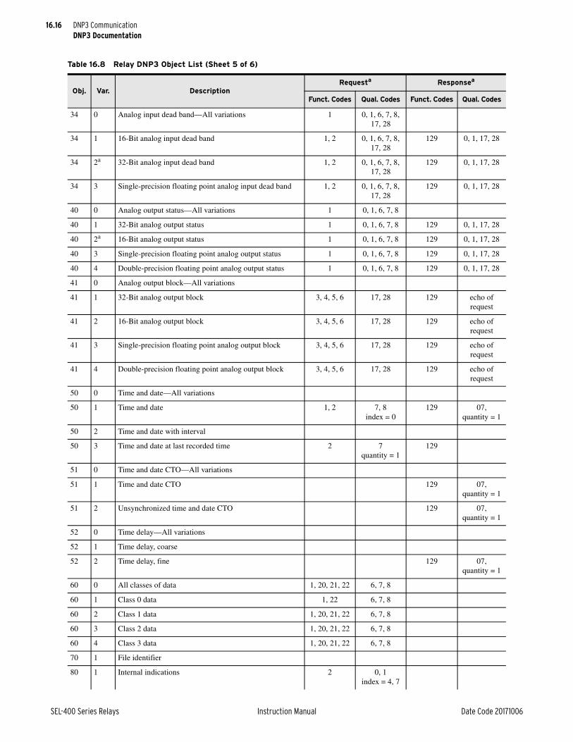
16.16
SEL-400 Series Relays Instruction Manual Date Code 20171006
DNP3 CommunicationDNP3 Documentation
34 0 Analog input dead band—All variations 1 0, 1, 6, 7, 8, 17, 28
34 1 16-Bit analog input dead band 1, 2 0, 1, 6, 7, 8, 17, 28
129 0, 1, 17, 28
34 2a 32-Bit analog input dead band 1, 2 0, 1, 6, 7, 8, 17, 28
129 0, 1, 17, 28
34 3 Single-precision floating point analog input dead band 1, 2 0, 1, 6, 7, 8, 17, 28
129 0, 1, 17, 28
40 0 Analog output status—All variations 1 0, 1, 6, 7, 8
40 1 32-Bit analog output status 1 0, 1, 6, 7, 8 129 0, 1, 17, 28
40 2a 16-Bit analog output status 1 0, 1, 6, 7, 8 129 0, 1, 17, 28
40 3 Single-precision floating point analog output status 1 0, 1, 6, 7, 8 129 0, 1, 17, 28
40 4 Double-precision floating point analog output status 1 0, 1, 6, 7, 8 129 0, 1, 17, 28
41 0 Analog output block—All variations
41 1 32-Bit analog output block 3, 4, 5, 6 17, 28 129 echo of request
41 2 16-Bit analog output block 3, 4, 5, 6 17, 28 129 echo of request
41 3 Single-precision floating point analog output block 3, 4, 5, 6 17, 28 129 echo of request
41 4 Double-precision floating point analog output block 3, 4, 5, 6 17, 28 129 echo of request
50 0 Time and date—All variations
50 1 Time and date 1, 2 7, 8 index = 0
129 07, quantity = 1
50 2 Time and date with interval
50 3 Time and date at last recorded time 2 7quantity = 1
129
51 0 Time and date CTO—All variations
51 1 Time and date CTO 129 07, quantity = 1
51 2 Unsynchronized time and date CTO 129 07, quantity = 1
52 0 Time delay—All variations
52 1 Time delay, coarse
52 2 Time delay, fine 129 07, quantity = 1
60 0 All classes of data 1, 20, 21, 22 6, 7, 8
60 1 Class 0 data 1, 22 6, 7, 8
60 2 Class 1 data 1, 20, 21, 22 6, 7, 8
60 3 Class 2 data 1, 20, 21, 22 6, 7, 8
60 4 Class 3 data 1, 20, 21, 22 6, 7, 8
70 1 File identifier
80 1 Internal indications 2 0, 1 index = 4, 7
Table 16.8 Relay DNP3 Object List (Sheet 5 of 6)
Obj. Var. DescriptionRequesta Responsea
Funct. Codes Qual. Codes Funct. Codes Qual. Codes

16.17
Date Code 20171006 Instruction Manual SEL-400 Series Relays
DNP3 CommunicationDNP3 Documentation
Device ProfileThe DNP3 Device Profile document, available on the supplied CD or as a down-load from the SEL website, contains the standard device profile information for the relay. This information is also available in XML format. Please refer to this document for complete information on DNP3 Protocol support in the relay.
Reference Data MapTable 16.9 shows the common portions of the relay DNP3 reference data map. See Section 10: Communications Interfaces in the product-specific instruction manual for a complete DNP3 reference map for that relay. You can use the default map or the custom DNP3 mapping functions of the relay to include only the points required by your application.
The entire Relay Word (see Section 11: Relay Word Bits in the product-specific instruction manual) is part of the DNP3 reference map. You may include any label in the Relay Word as part of a DNP3 custom map.
The relay scales analog values by the indicated settings or fixed scaling. Analog inputs for event (fault) summary reporting use a default scale factor of 1 and dead band of ANADBM. Per-point scaling and dead band settings specified in a cus-tom DNP3 map will override defaults.
81 1 Storage object
82 1 Device profile
83 1 Private registration object
83 2 Private registration object descriptor
90 1 Application identifier
100 1 Short floating point
100 2 Long floating point
100 3 Extended floating point
101 1 Small packed binary—Coded decimal
101 2 Medium packed binary—Coded decimal
101 3 Large packed binary—Coded decimal
112 All Virtual terminal output block 2 6
113 All Virtual terminal event data 1 6 129, 130 17, 28
N/A No object required for the following function codes:
13 cold start
14 warm start
23 delay measurement
13, 14, 23
a Default variation.b Setting AIVAR determines default variation.
Table 16.8 Relay DNP3 Object List (Sheet 6 of 6)
Obj. Var. DescriptionRequesta Responsea
Funct. Codes Qual. Codes Funct. Codes Qual. Codes

16.18
SEL-400 Series Relays Instruction Manual Date Code 20171006
DNP3 CommunicationDNP3 Documentation
Table 16.9 Relay DNP3 Reference Data Map (Sheet 1 of 2)
Object Label Description
Binary Inputs
01, 02 RLYDIS Relay disabled
01, 02 STFAIL Relay diagnostic failure
01, 02 STWARN Relay diagnostic warning
01, 02 STSET Settings change or relay restart
01, 02 UNRDEV New relay event available
01, 02 NUNREV An unread event exists, newer than the event in the event summary AIs
01, 02 LDATPFW Leading true power factor A-Phase, Terminal W (1 if leading, 0 if lagging or zero)
01, 02 LDBTPFW Leading true power factor B-Phase, Terminal W (1 if leading, 0 if lagging or zero)
01, 02 LDCTPFW Leading true power factor C-Phase, Terminal W (1 if leading, 0 if lagging or zero)
01, 02 LD3TPFW Leading true power factor three-phase, Terminal W (1 if leading, 0 if lagging or zero)
01, 02 Relay Word Relay Word bit label
Binary Outputs
10, 12 RB01–RBnn Remote bits RB01–RBnna
10, 12 RB01:RB02
RB03:RB04
RB05:RB06
•
•
•
RB29:RB30
RB31:RBnn
Remote bit pairs RB01–RBnna
10, 12 OCm Pulse open Circuit Breaker m commandb
10, 12 CCm Pulse close Circuit Breaker m commandb
10, 12 OCm:CCm Open/close pair for Circuit Breaker mb
10, 12 89OC01–89OCdd Open Disconnect Switch Control 1–ddc
10, 12 89CC01–89CCdd Close Disconnect Switch Control 1–ddc
10, 12 89OC01:89CC01 89OC02:89CC02 89OC03:89CC03
•
•
•
89OCdd:89CCdd
Open/close Disconnect Switch Control Pair 1–ddc
10, 12 RST_DEM Reset demandsd
10, 12 RST_PDM Reset demand peaksd
10, 12 RST_ENE Reset energiesd
10, 12 RSTMML Reset min/max metering data for the lined
10, 12 RSTMMBm Reset min/max metering data for Circuit Breaker md
10, 12 RST_BKm Reset Breaker m monitor datad
10, 12 RST_BAT Reset battery monitor datad
10, 12 RST_79C Reset recloser shot counterd
10, 12 RSTFLOC Reset fault location datad
10, 12 RSTTRGT Reset front-panel targetsd

16.19
Date Code 20171006 Instruction Manual SEL-400 Series Relays
DNP3 CommunicationDNP3 Documentation
Device Attributes (Object 0)Table 16.8 includes the supported Object 0 device attributes and variations. In response to Object 0 requests, the relay will send attributes that apply to that par-ticular DNP3 session. Because the relay supports custom DNP3 maps, these val-ues will likely be different for each session.
The relay uses its internal settings for the following variations:
➤ Variation 245—SID Global setting
➤ Variation 246—DNPID port setting
➤ Variation 247—RID Global setting
Binary InputsBinary inputs (Objects 1 and 2) are supported as defined by Table 16.8. The default variation for both static and event inputs is 2. Only the Read function code (1) is allowed with these objects. The relay will respond to an Object 2, Variation 3 request, but the response will contain no data.
The relay scans binary inputs approximately twice per second to generate DNP3 change events. When time is reported with these event objects, it is the time at which the scanner observed the bit change. This may be significantly delayed from when the original source changed and should not be used for sequence-of-events determination. Binary inputs registered with SER are derived from the SER process and carry the time stamp of actual occurrence. Some additional binary inputs are available to DNP3, most without SER time stamps. For exam-ple, RLYDIS is derived from the relay status variable, STWARN and STFAIL are derived from the diagnostic task data, and UNRDEV and NUNREV are derived from the event queue. Another binary input, STSET, is derived from the SER and carries the time stamp of actual occurrence.
10, 12 RSTDNPE Reset (clear) DNP3 event summary AIsd
10, 12 NXTEVE Load next fault event into DNP3 event summary AIs
Binary Counters
20, 22 ACTGRP Active settings group
NOTE: Additional binary counters are relay specific. See the relay instruction manual to see what counter objects are available.
Analog Inputs
NOTE: The analog inputs available is relay dependent. See the relay instruction manual to determine what analog inputs are available.
Analog Outputs
40, 41 ACTGRP0 Active settings group
40, 41 TECORRe Time-error preload value
40, 41 RA001–RA256 Remote analogs
a The number of remote bits available, nn, depends on the specific relay. See the relay instruction manual to see how many are available.b The number of breakers to control and their designations, m, depends on the specific relay. See the relay instruction manual to determine
which breakers are available.c The number of disconnect controls, dd, available depends on the relay. See the relay instruction manual to determine how many disconnects
are supported. Not all SEL-400 series relays support disconnect controls.d Not all SEL-400 series relays support all of these resets. See the relay instruction manual to see which specific controls are available.e In milliseconds, –30000 time 30000. Relay Word bit PLDTE asserts for approximately 1.5 cycles after this value is written.
Table 16.9 Relay DNP3 Reference Data Map (Sheet 2 of 2)
Object Label Description

16.20
SEL-400 Series Relays Instruction Manual Date Code 20171006
DNP3 CommunicationDNP3 Documentation
Binary OutputsBinary output status (Object 10, Variation 2) is supported as defined by Table 16.8. Static reads of points RB01–RBnn, OCm, CCm, 89OC01–89OCdd, and 89CC01–89CCdd respond with the online bit set and the state of the requested bit. Reads from control-only binary output points (such as the data reset controls RSTTRGT and RSTDNPE) respond with the online bit set and a state of 0.
The relay supports control relay output block objects (Object 12, Variation 1). The control relays correspond to the remote bits and other functions as shown above. Each DNP3 control message contains a trip/close code (TRIP, CLOSE, or NUL) and an operation type (PULSE ON, LATCH ON, LATCH OFF, or NUL). The trip/close code works with the operation type to produce set, clear, and pulse operations.
Control operations differ slightly for single-point controls compared to paired outputs. Paired outputs correspond to the complementary two-output model, and single-point controls follow the complementary latch or activation model. In the complementary two-output model, paired points only support close or trip opera-tions, which, when issued, will pulse on the first or second point in the pair, respectively. Latch commands and pulse operations without a trip code are not supported. An operation in progress may be canceled by issuing a NUL trip/close code with a NUL operation type. Single output points support both pulse and latch operations. See Control Point Operation on page 16.20 for details on con-trol operations.
The status field is used exactly as defined. All other fields are ignored. A pulse operation is asserted for a single processing interval. You should exercise caution if sending multiple remote bit pulses in a single message (i.e., point count > 1), because this may result in some of the pulse commands being ignored and the return of an already active status message. The relay will only honor the first ten points in an Object 12, Variation 1 request. Any additional points in the request will return the DNP3 status code TOO_MANY_OBJS.
The relay also supports pattern control blocks (Object 12, Variations 2 and 3) to control multiple binary output points. Variation 2 defines the control type (trip/close, set/clear, or pulse) and the range of points to operate. Variation 3 provides a pattern mask that indicates which points in that range should be operated. Object 12, Variations 2 and 3 define the entire control command: the DNP3 mas-ter must send both for a successful control. For example, the DNP3 master sends an Object 12, Variation 2 message to request a trip of the range of indices 0–7. The DNP3 master then sends an Object 12, Variation 3 message with a hexadeci-mal value of “BB” as the pattern mask (converted to binary notation: 10111011). Read right to left in increasing bit order, the pattern block control command will result in a TRIP of indexes 0, 1, 3 to 5, and 7.
Control Point OperationUse the trip and close, latch on/off and pulse on operations with Object 12 con-trol relay output block command messages to operate the binary output points. See Section 10: Communications Interfaces in the product-specific instruction manual for a complete table of object 12 controls available in that relay. Pulse operations provide a pulse with duration of one protection processing interval. Cancel an operation in progress by issuing a NUL trip/close code with a NUL operation type.

16.21
Date Code 20171006 Instruction Manual SEL-400 Series Relays
DNP3 CommunicationDNP3 Documentation
Analog InputsAnalog inputs (Objects 30 and 32) are supported as defined by Table 16.8 The default variation for both static and event inputs is defined by the AIVAR (AIVARn for DNP3 LAN/WAN session n) setting. Only the Read function code (1) is allowed with these objects.
Unless otherwise indicated, analog values are reported in primary units. Voltage magnitudes below 0.10 volts and current magnitudes below 5 percent of INOM are forced to 0, as are their corresponding angles. Default scaling is indicated in the product-specific instruction manual, but default scaling can be overridden by per-point scaling in a custom DNP3 map. The DECPLA, DECPLV, and DECPLM settings are the default scaling factors (in powers of 10) for current magnitudes, voltage magnitudes, and miscellaneous magnitudes, respectively. See Configu-rable Data Mapping on page 16.23 for more information.
Default dead bands are also indicated in the product-specific instruction manual and may be overridden by per-point dead-band configuration. In general, the ANADBA, ANADBV, and ANADBM settings are the default dead bands for cur-rent magnitudes, voltage magnitudes, and miscellaneous magnitudes, respec-tively. Dead bands are applied after any custom or default scaling factors. Events are generated when values exceed dead bands.
Reading Relay Event DataThe relay provides protective relay event history information in one of two modes: single-event or multiple-event access. Each DNP3 session begins in the mode specified by Port setting EVEMODn (where n = 1–6 for Ethernet sessions and not present for serial sessions). The selected mode is entered when the relay is first enabled, when there is a DNP3 settings change, a DNP3 map change, or an SER settings change. When EVEMODn = SINGLE, the relay powers up in single-event mode. When EVEMODn = MULTI, the relay powers up in multiple-event mode. A DNP3 session will switch to multiple-event mode if the session DNP3 master sends a control to the NXTEVE binary output control point. The DNP3 session will revert to the default mode after a power cycle or relay restart.
When a relay event occurs, (TRIP asserts, ER asserts, or TRI asserts) whose fault location is in the range of MINDIST to MAXDIST, the data shall be made avail-able to DNP3. If MINDIST is set to OFF, then there is no minimum. Similarly, if MAXDIST is set to OFF, there is no maximum. Only SEL-4XX line relays sup-port the MINDIST and MAXDIST settings.
In either mode, DNP3 events for all event summary analog inputs will be gener-ated if any of them change beyond their dead band value after scaling (usually whenever a new relay event occurs and is loaded into the event summary analog inputs). Events are detected approximately twice a second by the scanning pro-cess.
The specific fault data available and its encoding is relay specific. See Section 10: Communications Interfaces in the product-specific instruction manual for infor-mation on the relay reports fault data.
Single-Event ModeSingle-event mode provides the most recent tripping event. When a relay event occurs and FLOC is in range of MINDIST and MAXDIST, these data are copied to the DNP3 fault summary analog inputs, generating appropriate DNP3 events. The relay shall then ignore any subsequent events for EVELOCK (Global set-
16.22
SEL-400 Series Relays Instruction Manual Date Code 20171006
DNP3 CommunicationDNP3 Documentation
ting) time. When the EVELOCK setting is zero, single-event mode effectively acts as a zero-buffer FIFO queue. In this mode, relay events are presented to gen-erate DNP3 events for the fault summary analog inputs as they occur. Fault sum-mary analog inputs shall be reset to 0 on a rising edge of RSTDNPE (Global SELOGIC equation result). The relay element EVELOCK shall be set when a relay event is triggered and reset when EVELOCK time expires.
Multiple-Event ModeRelay multiple-event summary data can be read in two ways: first in, first out (FIFO); or last in, first out (LIFO).
See FIFO on page 16.22 and LIFO on page 16.22 below for procedures to retrieve relay events that occur when FLOC is in range of MINDIST and MAX-DIST. Event retrieval as shown below is a manual monitor, control, and poll pro-cess. A DNP3 master can collect relay event summaries using event data rather than the static data polling described below. For best results, the master must con-trol the NXTEVE binary output no faster than once every two seconds to load a new event into the event summary analog inputs. If the NXTEVE binary output is controlled at a faster rate, some DNP3 events may not be recognized and pro-cessed by the DNP3 event scanner.
FIFOMultiple-event FIFO mode shall be initiated if the DNP3 session master operates the NXTEVE (next event) control. The master should monitor the UNRDEV binary input point, which will be asserted when there is an unread relay event summary. The NUNREV bit will also be asserted as long as there remain any unread events newer than the currently loaded event summary. To read the oldest unread relay event summary, the master should send a close, latch on, or pulse-on control to the NXTEVE binary output point. This will load the relay event sum-mary analogs with information from the oldest relay event summary, discarding the values from the previous load.
After reading the analogs, the master should again check the UNRDEV binary input point, which will be on if there is another unread relay event summary. The master should continue this process until the UNRDEV binary input point deas-serts. If the master attempts to load values by controlling the NXTEVE output point when the UNRDEV binary input point is deasserted, the relay event type analog (FTYPE) will be loaded with zero. With the FIFO method, the relay event summaries will always be collected in chronological order.
LIFOMultiple-event LIFO mode event summary retrieval is similar to FIFO retrieval, with the following difference: to read the newest unread relay event summary, the master should send a latch off control to the NXTEVE binary output point. As with FIFO retrieval, the master should monitor the UNRDEV binary input to determine if there are any unread events. Users must be aware of one caveat with LIFO retrieval: if an event occurs while in the process of reading the newest event(s) event collection will no longer continue in reverse chronological order. The next event read will be the newest event, and will proceed with the next new-est, but any events that have already been read shall be skipped. The NUNREV bit will be asserted if this happens, signifying that the currently loaded event summary is no longer the newest event.

16.23
Date Code 20171006 Instruction Manual SEL-400 Series Relays
DNP3 CommunicationDNP3 Documentation
Analog OutputsAnalog outputs (Objects 40 and 41) are supported as defined by Table 16.8. The default variation for both static and event inputs is Variation 2. If an invalid value is written, the relay will ignore the value without generating an error.
The relay will only honor the first ten points in a request. Any additional points in the request will be ignored without generating an error.
CountersCounters (Object 20 and 22) are supported as defined by Table 16.8. The default variation for Object 20 is Variation 6, and Variation 2 is the default for Object 22. Counters shall only support the Read function code (1). A Read of Object 21 will receive a Null response. The default dead band is 0, which may be overridden by a per-point dead band in a custom map. Scaling for counters is always 1.
Default Data MapSee Section 10: Communications Interfaces in the product-specific instruction manual to see the relay default map. If the default maps are not appropriate, you can also use the custom DNP3 mapping commands SET D n and SHOW D n, where n is the map number, to edit or create the map required for your application.
Configurable Data MappingOne of the most powerful features of the relay DNP3 implementation is the abil-ity to remap DNP3 data and, for analog and counter inputs, specify per-point scaling and dead bands. Remapping is the process of selecting data from the default or reference map and organizing it into a dataset optimized for your appli-cation. The relay uses point labels rather than point indexes in a reference map to streamline the remapping process. This enables you to quickly create a custom map without having to search for point indexes in a large reference map.
You may use any of the six available DNP3 maps to exchange data with any DNP3 master. Each map is initially populated with default data points, as described in the Default DNP3 Map. You may remap the points in a default map to create a custom map with as many as:
➤ 400 binary inputs
➤ 100 binary outputs
➤ 20 counters
➤ 200 analog inputs
➤ 100 analog outputs
Use the settings Class D to access the relay DNP3 map settings shown in DNP3 Settings—Custom Maps on page 12.15. There are five DNP3 maps available to customize, or leave as default.
The mapping settings are entered in a line-based freeform format. An example of these settings is shown in Figure 16.4. You can program a custom scaling and dead band for each point where indicated. If you do not specify a custom scaling or dead band, the relay will use the default for the type of value you are mapping. For example, if you enter the label 3P_F in Row 1 of the custom analog map with
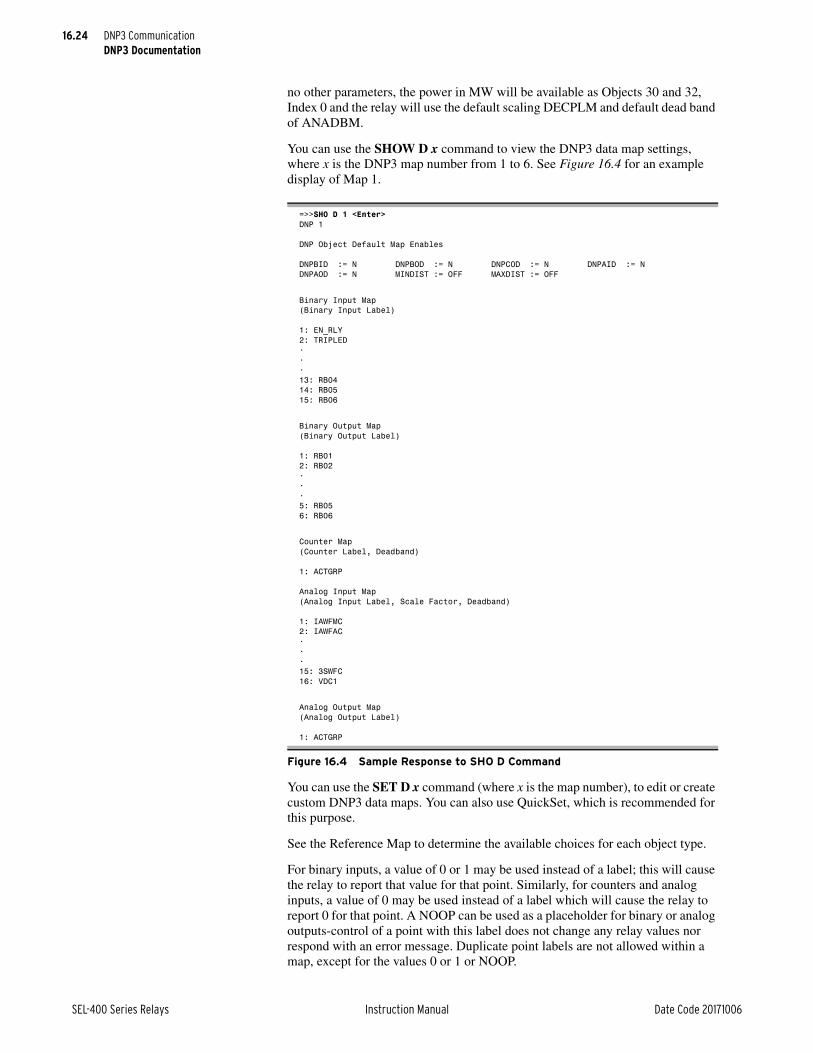
16.24
SEL-400 Series Relays Instruction Manual Date Code 20171006
DNP3 CommunicationDNP3 Documentation
no other parameters, the power in MW will be available as Objects 30 and 32, Index 0 and the relay will use the default scaling DECPLM and default dead band of ANADBM.
You can use the SHOW D x command to view the DNP3 data map settings, where x is the DNP3 map number from 1 to 6. See Figure 16.4 for an example display of Map 1.
You can use the SET D x command (where x is the map number), to edit or create custom DNP3 data maps. You can also use QuickSet, which is recommended for this purpose.
See the Reference Map to determine the available choices for each object type.
For binary inputs, a value of 0 or 1 may be used instead of a label; this will cause the relay to report that value for that point. Similarly, for counters and analog inputs, a value of 0 may be used instead of a label which will cause the relay to report 0 for that point. A NOOP can be used as a placeholder for binary or analog outputs-control of a point with this label does not change any relay values nor respond with an error message. Duplicate point labels are not allowed within a map, except for the values 0 or 1 or NOOP.
=>>SHO D 1 <Enter>DNP 1
DNP Object Default Map Enables
DNPBID := N DNPBOD := N DNPCOD := N DNPAID := NDNPAOD := N MINDIST := OFF MAXDIST := OFF
Binary Input Map(Binary Input Label)
1: EN_RLY2: TRIPLED•••13: RB0414: RB0515: RB06
Binary Output Map(Binary Output Label)
1: RB012: RB02•••5: RB056: RB06
Counter Map(Counter Label, Deadband)
1: ACTGRP
Analog Input Map(Analog Input Label, Scale Factor, Deadband)
1: IAWFMC2: IAWFAC•••15: 3SWFC16: VDC1
Analog Output Map(Analog Output Label)
1: ACTGRP
Figure 16.4 Sample Response to SHO D Command

16.25
Date Code 20171006 Instruction Manual SEL-400 Series Relays
DNP3 CommunicationDNP3 Documentation
You can customize the DNP3 analog input map with per-point scaling and dead-band settings. Class scaling (DECPLAn, DECPLVn, and DECPLMn) and dead-band settings (ANADBAn, ANADBVn, and ANADBMn) are applied to indices that do not have per-point entries. Per-point scaling overrides any class scaling and dead-band settings. Unlike per-point scaling, class-level scaling is specified by an integer in the range 0–3 (inclusive), which indicates the number of decimal place shifts. In other words, you should select 0 to multiply by 1, 1 for 10, 2 for 100, or 3 for 1000.
NOTE: The settings above contain the DNP3 LAN/WAN session suffix n. This suffix is not present in serial port DNP3 settings.
Scaling factors allow you to overcome the limitations imposed, by default, of the integer nature of Objects 30 and 32. For example, DNP3, by default, truncates a value of 11.4 A to 11 A. You may use scaling to include decimal point values by multiplying by a power of 10. For example, if you use 10 as a scaling factor, 11.4 A will be transmitted as 114. You must divide the value by 10 in the master to see the original value including one decimal place.
You can also use scaling to avoid overflowing the 16-bit maximum integer value of 32767. For example, if you have a value that can reach 157834, you cannot send it using DNP3 16-bit analog object variations. You could use a scaling factor of 0.1 so that the maximum value reported is 15783. You can then multiply the value by 10 in the master to see a value of 157830. You will lose some precision as the last digit is dropped in the scaling process, but you can transmit the scaled value using the default variations for DNP3 Objects 30 and 32.
If your DNP3 master has the capability to request floating-point analog input variations, the relay will support them. These floating point variations, 5 and 6 for Object 30 and 5–8 for Object 32, allow the transmission of 16- or 32-bit float-ing point values to DNP3 masters. When used, these variations eliminate the need for scaling and maintain the resolution of the relay analog values. Note that this support is greater than DNP3 Level 4 functionality, so you must confirm that your DNP3 master can work with these variations before you consider using floating point analog variations.
The following example describes how to create a custom DNP3 map by point type. The example demonstrates the SET D command for analog inputs. Alter-nately, you can use the QuickSet software to simplify custom data map creation. The example uses quantities available in the SEL-411L, but similar operations can be performed on any SEL-400 series relay.
Consider a case where you want to set the analog input points in a map as shown in Table 16.10.
To set these points as part of custom map 1, you can use the SET D 1 TERSE command as shown in Figure 16.5.
Table 16.10 Sample Custom DNP3 Analog Input Map
Point Index Description Label Scaling Dead band
0 Fundamental IA magnitude LIAFM Default Default
1 Fundamental IB magnitude LIBFM Default Default
2 Fundamental IC magnitude LICFM Default Default
3 Fundamental IC magnitude LIAFM Default Default
4 Fundamental three-phase power 3P_F 5 Default
5 Fundamental A-Phase magnitude VAFM Default Default
6 Fundamental A-Phase angle VAFA 1 15
7 Frequency FREQ 0.01 1

16.26
SEL-400 Series Relays Instruction Manual Date Code 20171006
DNP3 CommunicationDNP3 Serial Application Example
DNP3 Serial Application ExampleApplication
This example uses an SEL-421 connected to an RTU over an EIA-485 network. The RTU collects basic metering information from the relay. The network for this example is shown in Figure 16.6.
The metering and status data that the RTU collects from the relay are listed in Table 16.11.
=>>SET D 1 TERSE <Enter>DNP 1
DNP Object Default Map Enables
Use default DNP map for Binary Inputs (Y/N) DNPBID := Y ?<Enter>Use default DNP map for Binary Outputs (Y/N) DNPBOD := Y ?<Enter>Use default DNP map for Counters (Y/N) DNPCOD := Y ?<Enter>Use default DNP map for Analog Inputs (Y/N) DNPAID := Y ?N <Enter>Use default DNP map for Analog Outputs (Y/N) DNPAOD := Y ?<Enter>Min Fault Location to Capture (OFF,-10000 - 10000) MINDIST := OFF ?Max Fault Location to Capture (OFF,-10000 - 10000) MAXDIST := OFF ?
Analog Input Map(Analog Input Label, Scale Factor, Deadband)1:? LIBFM <Enter>2:? LICFM <Enter>3:? LIAFM <Enter>4:? 3P_F,5 <Enter>
5:? VAFM <Enter>6:? VAFA,1,15 <Enter>7:? FREQ,.01,1 <Enter>8:? ENDSave settings (Y,N) ?Y <Enter>Saving Settings, Please Wait...........Settings Saved
Figure 16.5 Sample Custom DNP3 Analog Input Map Settings
Figure 16.6 DNP3 Application Network Diagram
SEL-421 DNP3 IED
Non-DNP3 IED
To SCADA Control CenterRTU
...
...
SEL-2030
Non-DNP3 IED

16.27
Date Code 20171006 Instruction Manual SEL-400 Series Relays
DNP3 CommunicationDNP3 Serial Application Example
Table 16.11 DNP3 Application Example Data Map
Label ObjectCustom
Map IndexDescription
EN 1, 2 0 Relay enabled
TRIPLED 1, 2 1 Circuit Breaker tripped
IN101 1, 2 2 Relay Discrete Input 1
IN102 1, 2 3 Relay Discrete Input 2
IN103 1, 2 4 Relay Discrete Input 3
IN104 1, 2 5 Relay Discrete Input 4
SALARM 1, 2 6 Relay software alarm
HALARM 1, 2 7 Relay hardware alarm
TESTDB2 1, 2 8 Test mode enabled
RB01 10, 12 0 Remote Bit 1
RB02 10, 12 1 Remote Bit 2
RB03 10, 12 2 Remote Bit 3
RB04 10, 12 3 Remote Bit 4
RB05 10, 12 4 Remote Bit 5
RB06 10, 12 5 Remote Bit 6
OC1:CC1 10, 12 6 Circuit Breaker 1 trip/close pair
LIAFM 30, 32 0 IA magnitude
LIAFA 30, 32 1 IA angle
LIBFMa
a Assume the largest expected current is 2000 A and scale the analog value by a factor of 10 to provide a resolution of 0.1 A and a maximum current of 3276.7 A. Report change events on a change of 5 A.
30, 32 2 IB magnitude
LIBFAb
b Angles are scaled to 1/100 of a degree. Report change events on a change of 2 degrees.
30, 32 3 IB angle
LICFMa 30, 32 4 IC magnitude
LICFAb 30, 32 5 IC angle
VAFMc
c For a nominal voltage of 230 kV, scale the analog value by a factor of 100 to provide a resolution of 10 V and a maximum value of 327.67 kV. Report 1 kV for change event reporting.
30, 32 6 VAY magnitude
VAFAb 30, 32 7 VAY angle
VBFMc 30, 32 8 VBY magnitude
VBFAb 30, 32 9 VBY angle
VCFMc 30, 32 10 VCY magnitude
VCFAb 30, 32 11 VCY angle
3P_Fd
d For a maximum load of 800 MW (or 800 mVar), scale the power by a factor of 40 to provide a resolution of 0.025 MW and a maximum value of 819.175 MW. Report 1 MW for change event reporting.
30, 32 12 Three-phase real power in MW
3Q_Fd 30, 32 13 Three-phase reactive power in MVAR
DC1e
e VDC1 is scaled by a factor of 1/100 of a volt. Report change events on a change of 2 V.
30, 32 14 DC1 voltage multiplied by 100
ACTGRP 40 0 Active settings group

16.28
SEL-400 Series Relays Instruction Manual Date Code 20171006
DNP3 CommunicationDNP3 Serial Application Example
SettingsFigure 16.7 shows how to enter the new map into the relay. Use the SET D com-mand and enter N at the prompts shown in Figure 16.7 to allow changes to the existing maps. Press <Enter> at the empty line prompt to advance to the next map. For example, press <Enter> at line 10 of the Binary Input Map to advance to the Binary Output Map. If the prompt contains an entry, you can enter the greater-than symbol (>) and press <Enter> to advance to the next step.
=>>SET D 1 TERSE <Enter>DNP 1
DNP Object Default Map Enables
Min Fault Location to Capture (OFF,-10000 - 10000) MINDIST := OFF ? <Enter>Max Fault Location to Capture (OFF,-10000 - 10000) MAXDIST := OFF ? <Enter>
Binary Input Map(Binary Input Label)
1: RLYDIS? DELETE 100 <Enter>1:? EN <Enter>2:? TRIPLED <Enter>3:? IN101 <Enter>4:? IN102 <Enter>5:? IN103 <Enter>
6:? IN104 <Enter>7:? SALARM <Enter>8:? HALARM <Enter>9:? TESTDB2 <Enter>10:? <Enter>
Binary Output Map(Binary Output Label)
1: RB01? DELETE 100 <Enter>1:? RB01 <Enter>2:? RB02 <Enter>3:? RB03 <Enter>4:? RB04 <Enter>5:? RB05 <Enter>6:? RB06 <Enter>7:? OC1:CC1 <Enter>8:? <Enter>
Counter Map(Counter Label, Deadband)
1: ACTGRP?2: BKR1OPA? DELETE 100 <Enter>2: ? <Enter>
Figure 16.7 SEL-421 Example DNP Map Settings

16.29
Date Code 20171006 Instruction Manual SEL-400 Series Relays
DNP3 CommunicationDNP3 Serial Application Example
Table 16.12 lists the settings for PORT 3 for this example. The physical connection between the relay and the DNP3 master is an EIA-485 network. An SEL-2884 interface converter on the relay PORT 3 provides conversion from EIA-232 to EIA-485. Unsolicited reporting has been disabled because the network is wired as a four-wire connection and does not provide carrier detection or the opportu-nity to monitor for data traffic on the network.
Analog Input Map(Analog Input Label, Scale Factor, Deadband)
1: LIAFM? <Enter>2: LIAFA? LIAFA,1,200 <Enter>3: LIBFM? <Enter>4: LIBFA? LIBFA,1,200 <Enter>5: LICFM? <Enter>6: LICFA? LICFA,1,200 <Enter>7: B1IAFM? VAFM <Enter>8: B1IAFA? VAFA,1,200 <Enter>
9: B1IBFM? VBFM <Enter>10: B1IBFA? VBFA,1,200 <Enter>11: B1ICFM? VCFM <Enter>12: B1ICFA? VCFA,1,200 <Enter>13: B2IAFM? 3P_F,40,40 <Enter>14: B2IAFA? 3Q_F,40,40 <Enter>15: B2IBFM? DC1,,200 <Enter>16: B2IBFA? DELETE 200 <Enter>16:? <Enter>
Analog Output Map(Analog Output Label)
1: ACTGRP? <Enter>2:? <Enter>
Save settings (Y,N) ?Y <Enter>Saving Settings, Please Wait...........Settings Saved=>>
Table 16.12 SEL-421 Port 3 Example Settings (Sheet 1 of 2)
Setting Name Setting Description
EPORT Y Enable port
MAXACC 2 Maximum access level for virtual terminal sessions
PROTO DNP DNP3 protocol
SPEED 9600 Data speed
PARITY N No parity bit
STOPBIT 1 1 stop bit
TIMEOUT 5 Time out virtual terminal session after 5 minutes
TERTIM1 1 Check for termination after 1 second idle time
TERSTRN “\005” Virtual terminal termination string
Figure 16.7 SEL-421 Example DNP Map Settings (Continued)

16.30
SEL-400 Series Relays Instruction Manual Date Code 20171006
DNP3 CommunicationDNP3 Serial Application Example
In this example, the polling method employed by the RTU DNP3 master is polled report-by-exception. The master device normally polls for events only. Once every 25 event polls, the master polls for Class 0 data (status of all points). This polling method allows the master to collect data efficiently from the IEDs by not continuously polling and receiving data that are not changing.
TERTIM2 0 No delay before accepting termination string
DNPADR 101 DNP3 address = 101
DNPID “RELAY1-DNP” DNP ID for Object 0 self-description
DNPMAP 1 Use DNP3 Map 1
ECLASSB 1 Event Class 1 for binary event data
ECLASSC 1 Event Class 1 for counter event data
ECLASSA 1 Event Class 1 for analog event data
ECLASSV OFF Disable virtual terminal event data (this feature is not supported by the DNP3 master)
TIMERQ I Ignore time-set request because IRIG-B is used for time synchronization
DECPLA 1 Scale current, multiplying by 10 to send amperes and tenths of an ampere. The relay would report a value of 10.4 as 104, which would remain unscaled at the mas-ter.
DECPLV 2 Scale voltage, multiplying by 100 to send kilovolts, tenths, and hundredths of a kilovolt
DECPLM 2 Scale miscellaneous analog data, multiplying by 100 to send whole numbers and hundredths. The relay would report a value of 5.25 as 525, which would remain unscaled at the master.
STIMEO 10.0 10 second select before operate time-out
DRETRY OFF Turn off data link retries
MINDLY 0.05 Minimum delay from DCD to TX
MAXDLY 0.10 Maximum delay from DCD to TX
PREDLY 0.025 Settle time from RTS on to TX to allow EIA-485 transceiver to switch to transmit mode
PSTDLY 0.00 Settle time from TX to RTS off—not required in this application
DNPCL Y Enable controls for DNP3
AIVAR 2 Default AI variation
ANADBA 50 Analog reporting dead band for currents, 5 A based on DECPLA scaling factor
ANADBV 100 Analog reporting dead band for voltages, 1 kV based on DECPLV scaling factor
ANADBM 100 Miscellaneous analog value dead band, based on DECPLM scaling factor
ETIMEO 10 Event Message Confirm Time-Out, 10 seconds
UNSOL N Unsolicited reporting disabled (data retrieval method is polled report-by-exception)
MODEM N No modem connected to port
Table 16.12 SEL-421 Port 3 Example Settings (Sheet 2 of 2)
Setting Name Setting Description

16.31
Date Code 20171006 Instruction Manual SEL-400 Series Relays
DNP3 CommunicationDNP3 LAN/WAN Application Example
DNP3 LAN/WAN Application ExampleApplication
This example uses an SEL-487E connected to an RTU over an Ethernet (TCP) network. The RTU collects basic metering information from the relay. The net-work for this example is shown in Figure 16.8.
The polling method employed by the RTU DNP3 master is polled report-by-exception, so it normally only does event polls. Once every 25 event polls, the master polls for Class 0 data (status of all points). This polling method allows the master to collect data efficiently from the IEDs by only polling and receiving data that has changed.
The RTU, which will act as the DNP3 master to the SEL-487E outstation, has an IP address of 192.9.0.3 and a DNP3 address of 12. The SEL-487E should be assigned an IP address of 192.9.0.2, default router of 192.9.0.1, and DNP3 address of 101.
All event data (analog, binary, counter) should be assigned to CLASS 1. All Binary Inputs should have SOE-quality time stamps.
The desired DNP3 data map is shown in Table 16.13.
Figure 16.8 DNP3 LAN/WAN Application Example Ethernet Network
Table 16.13 DNP3 Application Example Data Map (Sheet 1 of 2)
Label ObjectCustom Map
IndexDescription
EN 1, 2 0 Relay enabled
TRIPLED 1, 2 1 Circuit Breaker tripped
IN101 1, 2 2 Relay Discrete Input 1
IN102 1, 2 3 Relay Discrete Input 2
IN103 1, 2 4 Relay Discrete Input 3
IN104 1, 2 5 Relay Discrete Input 4
SALARM 1, 2 6 Relay software alarm
HALARM 1, 2 7 Relay hardware alarm
TESTDB2 1, 2 8 Test mode enabled
RB01 10, 12 0 Remote Bit 1
RB02 10, 12 1 Remote Bit 2
RB03 10, 12 2 Remote Bit 3
RB04 10, 12 3 Remote Bit 4
RTU
SEL-487E
Non-DNP3 IED
To SCADA Network Switch
...
SEL-2030
Non-DNP3 IED

16.32
SEL-400 Series Relays Instruction Manual Date Code 20171006
DNP3 CommunicationDNP3 LAN/WAN Application Example
SettingsUse QuickSet to enter the DNP3 protocol settings and new data map into the relay.
RB05 10, 12 4 Remote Bit 5
RB06 10, 12 5 Remote Bit 6
OCS:CCS 10, 12 6 Circuit Breaker S trip/close pair
IASFMC 30, 32 0 A-Phase Current magnitude
IASFAC 30, 32 1 A-Phase Current angle
IBSFMCa 30, 32 2 B-Phase Current magnitude
IBSFACb 30, 32 3 B-Phase Current angle
ICSFMCa 30, 32 4 C-Phase Current magnitude
ICSFACb 30, 32 5 C-Phase Current angle
VAVFMC 30, 32 6 VA Phase Voltage magnitude, Terminal V
VAVFACb 30, 32 7 VA Phase Voltage angle, Terminal V
VBVFMCc 30, 32 8 VB Phase Voltage magnitude, Terminal V
VBVFACb 30, 32 9 VB Phase Voltage angle, Terminal V
VCVFMCc 30, 32 10 VC Phase Voltage magnitude, Terminal V
VCVFACb 30, 32 11 VC Phase Voltage angle, Terminal V
VDCd 30, 32 12 VDC voltage multiplied by 100
ACTGRP 40 0 Active settings group
a Assume the largest expected current is 2000 A, scale the analog value by a factor of 10 to provide a resolution of 0.1 A and a maximum current of 3276.7 A. Report change events on a change of 5 A.
b Angles are scaled to 1/100 of a degree. Report change events on a change of 2 degrees.c For a nominal voltage of 230 kV, scale the analog value by a factor of 100 to provide a resolution
of 10 V and a maximum value of 327.67 kV. Report 1 kV for change event reporting.d VDC1 is scaled by a factor of 1/100 of a volt. Report change events on a change of 2 V.
Table 16.13 DNP3 Application Example Data Map (Sheet 2 of 2)
Label ObjectCustom Map
IndexDescription
Table 16.14 DNP3 LAN/WAN Application Example Protocol Settings (Sheet 1 of 2)
Setting Name Setting Description
EPORT Y Enable Ethernet port
IPADDR 192.9.0.2/16 Relay IP address and network in CIDR notation
DEFRTR 192.9.0.1 Default router
EDNP 1 Enable DNP3 LAN/WAN Session 1
DNPADR 101 DNP3 address for relay is 101
DNPPNUM 20000a DNP3 port number for TCP
DNPID RELAY1DNP DNP3 ID for Object 0 self-description
DNPIP1 192.9.0.3 DNP3 Master (RTU) IP address
DNPTR1 TCP Use TCP transport
DNPMAP1 1 Use DNP3 Map 1 for DNP3 LAN/WAN Session 1
CLASSB1 1 Binary event data = Class 1
CLASSC1 1 Counter event data = Class 1

16.33
Date Code 20171006 Instruction Manual SEL-400 Series Relays
DNP3 CommunicationDNP3 LAN/WAN Application Example
To meet the requirement for SOE-quality time stamps, enter all binary inputs into the SER report. See Figure 16.9 for a screen shot of the process.
CLASSA1 1 Analog event data = Class 1
TIMERQ1 1 Ignore time synchronization requests from DNP3 Master
DECPLA1 2 Scale analog current data, multiplying by 10 to send whole numbers and tenths. The relay would report a value of 5.25 as 525, which would remain unscaled at the master. (102 = 100)
DECPLV1 2 Scale analog voltage data, multiplying by 10 to send whole numbers and tenths. The relay would report a value of 5.25 as 525, which would remain unscaled at the master. (102 = 100)
DECPLM1 2 Scale analog miscellaneous data, multiplying by 10 to send whole numbers and tenths. The relay would report a value of 5.25 as 525, which would remain unscaled at the master. (102 = 100)
STIMEO1 1.0a 1.0 second to select before operate time-out
DNPINA1 120a Wait 120 seconds to send inactive heartbeat
DNPCL1 Y Allow DNP3 controls for this session
AIVAR1 2 Default AI variation
ANADBA1 200 Analog dead band counts, set to 2 engineering units, based on DECPLA scaling factor
ANADBV1 200 Analog dead band counts, set to 2 engineering units, based on DECPLV scaling factor
ANADBM1 200 Analog dead band counts, set to 2 engineering units, based on DECPLM scaling factor
ETIMEO1 2a Event message confirm time-out (2 s)
UNSOL1 N Disable unsolicited reporting for Master 1
a Default value.
Table 16.14 DNP3 LAN/WAN Application Example Protocol Settings (Sheet 2 of 2)
Setting Name Setting Description
Figure 16.9 Add Binary Inputs to SER Point List

This page intentionally left blank

Date Code 20171006 Instruction Manual SEL-400 Series Relays
Instruction ManualS E C T I O N 1 7
IEC 61850 Communication
The relay supports the following features using Ethernet and IEC 61850.
➤ SCADA—Connect as many as seven simultaneous IEC 61850 MMS client sessions. The relay also supports as many as seven buffered and seven unbuffered report control blocks. See Table 17.16 for logical node mapping that enables SCADA control (including Setting Group Switch) via a manufacturing messaging specification (MMS) browser. Controls support the Direct Normal Security and Enhanced Security (Direct or Select Before Operate) control models.
➤ Peer-to-Peer Real-Time Status and Control—Use GOOSE with as many as 128 incoming (receive) and 8 outgoing (transmit) messages. Virtual Bits (VB001–VB256) and Remote Analogs (RA001–RA256) can be mapped from incoming GOOSE messages. Remote Analog Outputs (RAO01–RAO64) provide peer-to-peer real-time analog data transmission.
NOTE: Not all SEL-400 series relays support SV publication or subscription.
➤ Sampled Values—Use Sampled Values (SV) to replace the traditional copper wiring between instrument transformers and the relay. Connect an SEL SV publisher to CTs and VTs to publish Sampled Values. Use SV subscriber relays to subscribe to these SV messages. SEL-400 series SV products are compliant to the UCA 61850 9-2LE guidelines. In accordance with the guideline, each publication includes one application service data unit (ASDU), with four current and four voltage channels. Supported publication rates are 4.8 kHz for a 60 Hz power system and 4 kHz for a 50 Hz power system. SEL SV publishers support as many as seven SV streams. SEL SV subscriber relays support subscribing to as many as seven streams.
NOTE: The relay ships with a default CID file installed which supports basic IEC 61850 functionality. A new CID file should be loaded if a change in the relay configuration is required. If an invalid CID file is transferred, the relay will reject the file and revert to the previous valid CID file.
➤ Configuration—Use FTP client software or ACSELERATOR Architect SEL-5032 Software to transfer the Substation Configuration Language (SCL) Configured IED Description (CID) file to the relay. SEL-400 series SV products also support SV configuration via Port 5 settings.
➤ Commissioning and Troubleshooting—Use software such as MMS Object Explorer and AX-S4 MMS from Sisco, Inc., to browse the relay logical nodes and verify functionality.
This section presents the information you need to use the IEC 61850 features of the relay.
➤ Introduction to IEC 61850 on page 17.2
➤ IEC 61850 Operation on page 17.3
➤ IEC 61850 Configuration on page 17.22
➤ Logical Nodes on page 17.29
➤ Protocol Implementation Conformance Statement on page 17.44
➤ ACSI Conformance Statements on page 17.50

17.2
SEL-400 Series Relays Instruction Manual Date Code 20171006
IEC 61850 CommunicationIntroduction to IEC 61850
Introduction to IEC 61850In the early 1990s, the Electric Power Research Institute (EPRI) and the Institute of Electrical and Electronics Engineers, Inc. (IEEE) began to define a Utility Communications Architecture (UCA). They initially focused on inter-control center and substation-to-control center communications and produced the Inter-Control Center Communications Protocol (ICCP) specification. This specifica-tion, later adopted by the IEC as 60870-6 TASE.2, became the standard protocol for real-time exchange of data between databases.
In 1994, EPRI and IEEE began work on UCA 2.0 for Field Devices (simply referred to as UCA2). In 1997, they combined efforts with Technical Committee 57 of the IEC to create a common international standard. Their joint efforts cre-ated the current IEC 61850 standard.
The IEC 61850 standard, a superset of UCA2, contains most of the UCA2 speci-fication, plus additional functionality. The standard describes client/server and peer-to-peer communications, substation design and configuration, testing, and project standards.
The IEC 61850 standard consists of the parts listed in Table 17.1. These parts were first published between 2001 and 2004, and they are often referred to as IEC 61850 Edition 1 (Ed1). Selected parts of these standards were released in 2011 and tagged as Edition 2 (Ed2). Some SEL-400 series devices are compliant with Ed2. Please refer to the product-specific manual to identify such devices.
It is possible and even likely, that an installation can have a mixture of devices that conform to either Ed1 or Ed2. The standard supports backwards compatibil-ity, i.e., Ed2 devices can send and receive messages to and from Ed1 devices. However, there are important considerations to be made when adding Ed2 devices to an existing Ed1 system. Please refer to Potential Client and Automa-tion Application Issues With Edition 2 Upgrades on page 17.54 for more infor-mation.
Table 17.1 IEC 61850 Document Set (Sheet 1 of 2)
IEC 61850 Sections Definitions
IEC 61850-1 Introduction and overview
IEC 61850-2 Glossary
IEC 61850-3 General requirements
IEC 61850-4 System and project management
IEC 61850-5 Communication requirements
IEC 61850-6 Configuration description language for substation IEDs
IEC 61850-7-1 Basic communication structure for substations and feeder equipment—Principles and models
IEC 61850-7-2 Basic communication structure for substations and feeder equipment—Abstract communication service interface (ACSI)
IEC 61850-7-3 Basic communication structure for substations and feeder equipment—Common data classes
IEC 61850-7-4 Basic communication structure for substations and feeder equipment—Compatible logical node (LN) classes and data classes
IEC 61850-8-1 SCSM—Mapping to Manufacturing
Messaging Specification (MMS)
(ISO/IEC 9506-1 and ISO/IEC 9506-2 over ISO/IEC 8802-3)
IEC 61850-9-1 SCSM—Sampled values over serial multidrop point-to-point link

17.3
Date Code 20171006 Instruction Manual SEL-400 Series Relays
IEC 61850 CommunicationIEC 61850 Operation
The IEC 61850 document set, available directly from the IEC at www.iec.ch, contains information necessary for successful implementation of this protocol. SEL strongly recommends that anyone involved with the design, installation, configuration, or maintenance of IEC 61850 systems be familiar with the appro-priate sections of this standard.
IEC 61850 OperationIEC 61850 and Ethernet networking model options are available when ordering a new relay and may also be available as field upgrades to relays equipped with the Ethernet card. In addition to IEC 61850, the Ethernet card provides support pro-tocols and data exchange, including FTP and Telnet, to SEL devices. Access the relay Port 5 settings to configure all of the Ethernet settings, including IEC 61850 network settings.
The relay supports IEC 61850 services, including transport of logical node objects, over TCP/IP. The relay can coordinate a maximum of seven concurrent IEC 61850 MMS sessions.
Object ModelsThe IEC 61850 standard relies heavily on the Abstract Communication Service Interface (ACSI) models to define a set of services and the responses to those ser-vices. In terms of network behavior, abstract modeling enables all IEDs to act identically. These abstract models are used to create objects (data items) and ser-vices that exist independently of any underlying protocols. These objects are in conformance with the common data class (CDC) specification IEC 61850-7-3, which describes the type and structure of each element within a logical node. CDCs for status, measurements, controllable analogs and statuses, and settings all have unique CDC attributes. Each CDC attribute belongs to a set of functional constraints that groups the attributes into specific categories such as status (ST) and description (DC). Functional constraints, CDCs, and CDC attributes are used as building blocks for defining logical nodes.
UCA2 used GOMSFE (Generic Object Models for Substation and Feeder Equip-ment) to present data from station IEDs as a series of objects called models or bricks. The IEC working group has incorporated GOMSFE concepts into the standard, with some modifications to terminology; one change was the renaming of bricks to logical nodes. Each logical node represents a group of data (controls, status, measurements, etc.) associated with a particular function. For example, the MMXU logical node (polyphase measurement unit) contains measurement data and other points associated with three-phase metering including voltages and currents. Each IED may contain many functions such as protection, meter-ing, and control. Multiple logical nodes represent the functions in multifunction devices.
IEC 61850-9-2 SCSM—Sampled values over ISO/IEC 8802-3
IEC 61850-10 Conformance testing
Table 17.1 IEC 61850 Document Set (Sheet 2 of 2)
IEC 61850 Sections Definitions

17.4
SEL-400 Series Relays Instruction Manual Date Code 20171006
IEC 61850 CommunicationIEC 61850 Operation
Logical nodes can be organized into logical devices that are similar to directories on a computer disk. As represented in the IEC 61850 network, each physical device can contain many logical devices and each logical device can contain many logical nodes. Many relays, meters, and other IEC 61850 devices contain one primary logical device where all models are organized.
IEC 61850 devices are capable of self-description. You do not need to refer to the specifications for the logical nodes, measurements, and other components to request data from another IEC 61850 device. IEC 61850 clients can request and display a list and description of the data available in an IEC 61850 server device. Simply run an MMS browser to query devices on an IEC 61850 network and dis-cover what data are available. Self-description also permits extensions to both standard and custom data models. Instead of having to look up data in a profile stored in its database, an IEC 61850 client can simply query an IEC 61850 device and receive a description of all logical devices, logical nodes, and available data.
Unlike other supervisory control and data acquisition protocols (SCADA) that present data as a list of addresses or indices, IEC 61850 presents data with descriptors in a composite notation made up of components. Table 17.2 shows how the A-Phase current expressed as MMXU$A$phsA$cVal is broken down into its component parts.
Data MappingDevice data are mapped to IEC 61850 logical nodes (LN) according to rules defined by SEL. Refer to IEC 61850-5:2013(E) and IEC 61850-7-4:2010(E) for the mandatory content and usage of these LNs. The relay logical nodes are grouped under Logical Devices for organization based on function. See Table 17.3 for descriptions of the logical devices in a relay. See Logical Nodes on page 17.29 for a description of the LNs that make up these logical devices.
Table 17.2 Example IEC 61850 Descriptor Components
Component Description
MMXU Logical Node Polyphase measurement unit
A Data Object Phase-to-ground amperes
PhsA Subdata Object A-Phase
cVal Data Attribute Complex value
Table 17.3 Relay Logical Devices
Logical Device Description
CFG Configuration elements—datasets and report control blocks
PRO Protection elements—protection functions and breaker control
MET Metering or Measurement elements—currents, voltages, power, etc.
CON Control elements—remote bits
ANN Annunciator elements—alarms, status values
MUa
a This only applies to merging units.
Merging unit elements—voltage and current channels

17.5
Date Code 20171006 Instruction Manual SEL-400 Series Relays
IEC 61850 CommunicationIEC 61850 Operation
MMSManufacturing messaging specification (MMS) provides services for the applica-tion-layer transfer of real-time data within a substation LAN. MMS was devel-oped as a network independent data exchange protocol for industrial networks in the 1980s and standardized as ISO 9506.
In theory, you can map IEC 61850 to any protocol. However, it can become unwieldy and quite complicated to map objects and services to a protocol that only provides access to simple data points via registers or index numbers. MMS supports complex named objects and flexible services that enable mapping to IEC 61850 in a straightforward manner. This was why the UCA users group used MMS for UCA from the start, and why the IEC chose to keep it for IEC 61850. MMS associations are discussed within IEC61850-8-1, clause 10 of the edition 1 standard.
If MMS authentication is enabled, the device will authenticate each MMS associ-ation by requiring the client to provide the password authentication parameter with a value that is equal to the 2AC password of the relay.
➤ If the correct password authentication parameter value is not received, the device will return a not authenticated error code.
➤ If the correct password authentication parameter value is received, the device will provide a successful association response. The device will allow access to all supported MMS services for that association.
ControlIEC 61850 Controls
An IEC 61850 server may allow a client to manipulate data related to its outputs, external devices, or internal functions. This is accomplished by the IEC 61850 control model, which provides services to execute control commands. The con-trol models are defined in IEC 61850-7-2 and the mapping to the MMS (Manu-facturing Message Specification) application protocol is defined in IEC 61850-8-1. The former describes control functionality while the latter maps the IEC 61850 control primitives to MMS.
SEL-400 series relays support four different control models:
➤ Status Only
➤ Direct with Normal Security
➤ Direct with Enhanced Security
➤ SBO with Enhanced Security
SEL-400 series devices support the above control models for SPC and DPC con-trollable common data classes (CDCs) as defined in IEC 61850-8-1:2004. Other controllable CDCs defined in the standard are either unsupported or must be con-figured with the status-only control model. Supported CDCs include remote bits RBGGIOn in the CON Logical Device (LD), and breaker and disconnect switch controls xxXCBRnn and xxXSWInn in the PRO LD. One control model must be selected during initial IED configuration in Architect and is applied throughout the CID file. This control model will apply to all controls in the IED.
17.6
SEL-400 Series Relays Instruction Manual Date Code 20171006
IEC 61850 CommunicationIEC 61850 Operation
Direct Control Models
The “Direct” control models provide the simplest means to initiate actions on the server. In these models, the client issues a control request via MMS, the server validates the request. Once validated, the server attempts to act upon the request. Note that if multiple clients are trying to perform control actions, the server will do nothing to prevent this.
SBO Control Model
The SBO control model supports the Select or SelectWithValue Service and can be used to prevent multiple clients from performing simultaneous control actions. In this mode, a client has to “reserve” the control object by sending a “select” control command. Once an object is selected, only the client that made the selec-tion is allowed to perform control actions on it. If that client does not send a valid operate request for the object by the time the ten-second selection timer runs out, the object becomes available for selection again. The relay will support as many as ten pending control object selections at any time.
NOTE: When an IED is configured with the SBO with Enhanced Security control model, the sboTimeout attribute of the controllable CDCs in the CID file is set to ten seconds. This time-out is not configurable via Architect.
The attribute stSeld (selected status) of the controllable CDC is set to TRUE when a client successfully selects the control object. The attribute is reset to FALSE when either the control (operate) command is successfully executed, an error occurs, or no operate command is received within the select time-out period. The stSeld attribute may trigger a report just like any data attribute with trigger option.
Security in Control Models
“Security” in the control model context refers to additional supervision of the sta-tus value by the control object. The “enhanced security” models report additional error information on failed operations to the requesting client than the models with “normal security”. Enhanced security control models also provide a com-mand termination report indicating if the control actually reached the new state as commanded within a configurable time-out period.
NOTE: The maximum time required for a control operation to be completed should be less than the configured time-out period in order to avoid erroneous command termination reports indicating failure.
The time-out period between the execution of a control and the generation of a command termination report indicating failure has a default value of 1 s and is configurable via the CID file. This time-out is not configurable via Architect.
Optional Control Configurations
SEL-400 series relays do not support (by default) the pulse configuration option specified in Clause 6.7 of IEC 61850-7-3. However, control objects may be con-figured to be pulsed by direct modification of the CID file of the device.
SEL-400 series relays do not support the concept of local/remote control author-ity defined in Annex B of IEC 61850-7-4:2010. However, a similar behavior can be achieved by associating some variable device data with the appropriate origi-nator categories (orCats) by direct modification of the CID file of the device.
Contact the factory if any of these features is necessary for your application.
Control RequestsIEC 61850 control services are implemented by reading and writing to pseudo-variables in the relay in response to MMS requests. Similar to how client requests are generated and mapped to MMS read or write service requests, server actions

17.7
Date Code 20171006 Instruction Manual SEL-400 Series Relays
IEC 61850 CommunicationIEC 61850 Operation
are also mapped to internal commands, read and write actions and MMS infor-mation report messages. In the case of an unsuccessful control request, the relay will send the appropriate response PDU indicating that there was a problem and an MMS information report that contains more detailed information about the problem that occurred.
When writing controls, the client must select and write the entire Oper, SBOw or Cancel structure to the relay. See Figure 17.1 for the attributes of the CON Logi-cal Device and ST and CO functional constraints (FC) of LN RBGGIO1 used for controls of RB01 through RB08.
Control Error MessagesIf a control request results in an error condition, the relay will respond with an AddCause value in an MMS information report. See Clause 20.5.2.9 of IEC 61850-7-2 for additional information on the AddCause values.
SEL-400 series relays support the AddCause values in Table 17.4 as part of the LastApplError information report.
Figure 17.1 MMS Client View of the CON Logical Device
Table 17.4 AddCause Descriptions (Sheet 1 of 2)
AddCause Enumeration
AddCause Description
Error Condition
0 Unknown No other AddCause value defined within this section applies
2 Blocked-by-switch-ing-hierarchy
Logical node is set to local mode, i.e. Loc.stVal = true
3 Select-failed Originator category not allowed to issue control com-mands or SelectWithValue operation fails
4 Invalid-position For controls with enhanced security, an AddCause of “Invalid-position” (4) will be sent if the control status changes to an unexpected value. If no control status change is detected after the operate time-out period, an AddCause of “Time-limit-over” (16) will be sent.
5 Position-reached Control status is already at the desired state

17.8
SEL-400 Series Relays Instruction Manual Date Code 20171006
IEC 61850 CommunicationIEC 61850 Operation
Any AddCause value not specified above is not supported. Control CDC data attributes which are associated with unsupported AddCause values and are not part of a control structure will be accepted but ignored. For example, the attribute CmdBlk.stVal which is associated with the AddCause value “blocked-by-com-mand” and is not part of a SBOw, Oper or Cancel structure will be ignored.
Group Switch Via MMSThe Group Switch feature in IEC 61850 is primarily a convenience feature for users so that they can institute a settings group switch from an IEC 61850 client without having to revert to the command line or some other tool. However, this has great potential for integration with IEC 61850 SCADA systems which would be able to control setting groups through IEC 61850 MMS.
The IEC 61850 specification outlines a method for switching the current settings group to another preconfigured settings group. The setting group control block, or SGCB, contains the SettingControl element which enables settings group con-trol. An SEL-400 series CID file that supports group switch functionality will only contain one SGCB. The SGCB contains the number of settings groups in the relay and may also contain the current active setting group, ActSG. Note that if the CID file contains a value for ActSG, it will be ignored and the relay will use the actual active setting group value for ActSG at the time of CID file download.
When the IEC 61850 functions of the relay are enabled, the selectActiveSG ser-vice allows an MMS client to request that the relay change the active setting group. The MMS client can request a group switch by writing a valid setting group number to ActSG. The relay updates the ActSG value under the following conditions:
➤ The value written to ActSG is valid and not the current active group
➤ There is no group switch in progress
➤ The setting of the active group was successful.
Note that if the value written to ActSG is the same as the current group, the relay will not attempt to switch settings groups. Please refer to Multiple Setting Groups on page 12.4 for more information on group settings.
6 Parameter-change-in-execution
Control object is already selected by the client, and
1. Logical node is set to local mode i.e., Loc.stVal = true, or
2. Originator category not allowed to issue control commands
8 Blocked-by-mode Mode of logical device or node is not ON
12 Command-already-in-execution
Execution of a previous control is not completed
13 Blocked-by-health Health of logical device or node is not OK
16 Time-limit-over CommandTermination gives a negative response. (The control failed to reach its intended state prior to time-out.)
18 Object-not-selected Cancel operation fails
Table 17.4 AddCause Descriptions (Sheet 2 of 2)
AddCause Enumeration
AddCause Description
Error Condition

17.9
Date Code 20171006 Instruction Manual SEL-400 Series Relays
IEC 61850 CommunicationIEC 61850 Operation
File ServicesThe Ethernet file system allows reading or writing data as files. The file system supports FTP and MMS file transfer. The file system provides:
➤ A means for the device to transfer data as files.
➤ A hierarchal file structure for the device data.
The relay supports MMS file transfer with or without authentication. Note that the MMS File Transfer service will still be supported even if the relay contains an invalid CID file. The service is intended to support:
➤ Settings file download and upload
➤ CID file download and upload
➤ Event report retrieval
MMS File Services are enabled or disabled via Port 5 settings, EMMSFS. Per-missions for the 2AC level apply to MMS File Services requests. All files and directories that are available at the 2AC access level via any supported file trans-fer mechanism (FTP, file read/write, etc.) are also available for transfer via MMS File Services.
SCL FilesSubstation Configuration Language (SCL) is an XML-based configuration lan-guage used to support the exchange of database configuration data between dif-ferent tools, which may come from different manufacturers. There are four types of SCL files:
➤ IED Capability Description file (.ICD)
➤ System Specification Description (.SSD) file
➤ Substation Configuration Description file (.SCD)
➤ Configured IED Description file (.CID)
The ICD file describes the capabilities of an IED, including information on LN and GOOSE support. The SSD file describes the single-line diagram of the sub-station and the required LNs. The SCD file contains information on all IEDs, communications configuration data, and a substation description. The CID file, of which there may be several, describes a single instantiated IED within the project, and includes address information.
ReportsThe relay supports buffered and unbuffered report control blocks in the report model as defined in IEC 61850-8-1:2011. The predefined reports shown in Figure 17.2 are available by default via IEC 61850.

17.10
SEL-400 Series Relays Instruction Manual Date Code 20171006
IEC 61850 CommunicationIEC 61850 Operation
There are 14 report control blocks (7 each of buffered and unbuffered reports). For each report control block, there can be just one client association, i.e., only one client can be associated to a report control block (BRCB or URCB) at any given time. The number of reports (14) and the type of reports (buffered or unbuffered) cannot be changed. However, by using Architect, you can reallocate data within each report dataset to present different data attributes for each report beyond the predefined datasets.
For buffered reports, connected clients may edit the report parameters shown in Table 17.5.
Figure 17.2 Relay Predefined Reports
Table 17.5 Buffered Report Control Block Client Access
RCB AttributeUser Changeable (Report Disabled)
User Changeable (Report Enabled)
Default Values
RptID YES BRep01–BRep07
RptEna YES YES FALSE
OptFlds YES seqNum
timeStamp
dataSet
reasonCode
entryID
BufTm YES 500
TrgOps YES dchg
qchg
period
IntgPd YES 0
GI YESa, b
a Exhibits a pulse behavior. Write a one to issue the command. Once command is accepted will return to zero. Always read as zero.
b When disabled, a GI will be processed and the report buffered if a buffer has been previously established. Buffered reports begin buffering at startup.
YESa 0
PurgeBuf YESa FALSE
EntryId YES 0

17.11
Date Code 20171006 Instruction Manual SEL-400 Series Relays
IEC 61850 CommunicationIEC 61850 Operation
Similarly, for unbuffered reports, connected clients may edit the report parame-ters shown in Table 17.6.
For buffered reports, only one client can enable the RptEna attribute of the BRCB at a time resulting in a client association for that BRCB. Once enabled, the asso-ciated client has exclusive access to the BRCB until the connection is closed or the client disables the RptEna attribute. Once enabled, all unassociated clients have read only access to the BRCB.
For unbuffered reports, as many as seven clients can enable the RptEna attribute of an URCB at a time resulting in multiple client associations for that URCB. Once enabled, each client has independent access to a copy of that URCB.
The Resv attribute is writable, however, the relay does not support reservations. Writing any field of the URCB causes the client to obtain their own copy of the URCB-in essence, acquiring a reservation.
Reports are serviced at a 2 Hz rate. The client can set the IntgPd to any value with a resolution of 1 ms. However, the integrity report is only sent when the period has been detected as having expired. The report service rate of 2 Hz results in a report being sent within 500 ms of expiration of the IntgPd. The new IntgPd will begin at the time that the current report is serviced.
DatasetsIEC 61850 datasets are lists of references to DataObject attributes for the purpose of efficient observation and transmission of data. Architect ICD files come with predefined datasets that can be used to transfer data via GOOSE messages, SV messages, or MMS reports.
➤ GOOSE: You can use predefined or edited datasets, or create new datasets for outgoing GOOSE transmission.
➤ SV: Four predefined datasets are provided. Each dataset includes three phase currents and the neutral current as well as three phase voltages and the neutral voltage.
Table 17.6 Unbuffered Report Control Block Client Access
RCB AttributeUser Changeable (Report Disabled)
User Changeable (Report Enabled)
Default Values
RptID YES URep01–URep07
RptEna YES YES FALSE
Resv YES FALSE
OptFlds YES seqNum
timeStamp
dataSet
reasonCode
BufTm YES 250
TrgOps YES dchg
qchg
period
IntgPd YES 0
GI YESa
a Exhibits a pulse behavior. Write a one to issue the command. Once command is accepted will return to zero. Always read as zero.
FALSE

17.12
SEL-400 Series Relays Instruction Manual Date Code 20171006
IEC 61850 CommunicationIEC 61850 Operation
➤ Reports: Fourteen predefined datasets (BRDSet01–BRDSet07 and URDSet01–URDSet07) correspond to the default seven buffered and seven unbuffered reports. Note that you cannot change the number (14) of each type of report (buffered or unbuffered) within Architect. However, you can alter the data attributes that a dataset contains or even create new datasets, and so define what data an IEC 61850 client receives with a report.
Supplemental Software SupportExamine the data structure and values of the supported IEC 61850 LNs with an MMS browser such as MMS Object Explorer and AX-S4 61850 from Sisco, Inc.
The settings needed to browse the relay with an MMS browser are shown below.
Time Stamps and QualityIn addition to the various data values, the two attributes quality and t (time stamp) are available at any time. The time stamp is determined when data or quality change is detected. A change in the quality attribute can also be used to issue an internal event.
The time stamp is applied to all data and quality attributes (Boolean, Bstrings, Analogs, etc.) in the same fashion when a data or quality change is detected. However, there is a difference in how the change is detected between the different attribute types. For points in a dataset that are also listed in the SER, the change is detected by the SER process. For all other Booleans or Bstrings, the change is detected via the scanner, which compares the last state against the previous state to detect the change. For analogs, the scanner looks at the amount of change rela-tive to the dead band configured for the point to indicate a change and apply the time stamp. In all cases, these timestamps are used for the reporting model.
LN data attributes listed in the SER will have SER timestamps of 1 ms accuracy for data change events. All other LN data attributes are scanned on a 1/2-second interval for data change and have 1/2-second time stamp accuracy.
The relay uses GOOSE quality attributes to indicate the quality of the data in its transmitted GOOSE messages. Under normal conditions, all attributes are zero, indicating good quality data. Figure 17.3 shows the GOOSE quality attributes available to devices that subscribe to GOOSE messages from relay datasets that contain them. Internal status indicators provide the information necessary for the device to set these attributes. For example, if the device becomes disabled, as shown via status indications (e.g., an internal self-test failure), the relay will set the Validity attribute to INVALID and the Failure attribute to TRUE. Note that the relay does not set any of the other quality attributes. These attributes will always indicate FALSE (0). See the Architect help for additional information on GOOSE Quality attributes.
OSI-PSEL (Presentation Selector) 00000001
OSI-SSEL (Session Selector) 0001
OSI-TSEL (Transport Selector) 0001

17.13
Date Code 20171006 Instruction Manual SEL-400 Series Relays
IEC 61850 CommunicationIEC 61850 Operation
GOOSEThe Generic Object Oriented Substation Event (GOOSE) object within IEC 61850 is for high-speed control messaging. IEC 61850 GOOSE automatically broadcasts messages containing status, controls, and measured values onto the network for use by other devices. IEC 61850 GOOSE sends the message several times, increasing the likelihood that other devices receive the messages.
IEC 61850 GOOSE objects can quickly and conveniently transfer status, con-trols, and measured values between peers on an IEC 61850 network. Configure SEL devices to respond to GOOSE messages from other network devices with Architect. Also, configure outgoing GOOSE messages for SEL devices in Archi-tect. See the Architect help for more information.
Each IEC 61850 GOOSE sender includes a text identification string (GOOSE Control Block Reference) in each outgoing message and an Ethernet multicast group address. Devices that receive GOOSE messages use the text identification and multicast group to identify and filter incoming GOOSE messages.
Virtual bits (VB001–VB256) are control inputs that you can map to values from incoming GOOSE messages using the Architect software. See the VBnnn bits in Table 17.10, Table 17.11, and Table 17.12 for details on which logical nodes and names are used for these bits. This information can be useful when searching through device data with MMS browsers. If you intend to use any relay Virtual bits for controls, you must create SELOGIC equations to define these operations. The relay is capable of receiving and sending analog values via peer-to-peer GOOSE messages. Remote Analogs (RA001–RA256) are analog inputs that you can map to values from incoming GOOSE messages. Remote Analog Outputs (RAO01–RAO64) can be used to transmit analog values via GOOSE messages. You must create SELOGIC control equations to assign internal relay values to RAO points in order to transmit them via GOOSE.
Figure 17.3 GOOSE Quality Attributes

17.14
SEL-400 Series Relays Instruction Manual Date Code 20171006
IEC 61850 CommunicationIEC 61850 Operation
GOOSE ProcessingSEL devices support GOOSE processing as defined by IEC 61850-7-1:2011(E), IEC 61850-7-2:2010(E), and IEC 61850-8-1:2011(E) via the installed Ethernet port.
Outgoing GOOSE messages are processed in accordance with the following con-straints.
➤ The user can define as many as eight datasets for outgoing GOOSE messages consisting of any data attribute (DA) from any logical node. A single DA can be mapped to one or more outgoing GOOSE datasets, or one or more times within the same outgoing GOOSE dataset. A user can also map a single GOOSE dataset to multiple GOOSE control blocks. The number of unique Boolean variables is limited to a combined total of 512 digital bits across all eight outgoing messages.
➤ High-speed GOOSE messaging (as defined under GOOSE Performance) is available for GOOSE messages that contain either all Boolean data or a combination of Boolean data and remote analog output (RAO01–RAO64) data.
➤ The relay will transmit all configured GOOSE immediately upon successful initialization. If a GOOSE message is not retriggered, then following the initial transmission, the relay shall retransmit that GOOSE based on the Min. Time and Max. Time configured for that GOOSE message. The first transmission shall occur immediately upon triggering of an element within the GOOSE dataset. The second transmission shall occur Min. Time later. The third shall occur Min. Time after the second. The fourth shall occur twice Min. Time after the third. All subsequent transmissions shall occur at the Max Time interval. For example, a message with a Min. Time of 4 ms and Max. Time of 1000 ms, will be transmitted upon triggering, then retransmitted at intervals of 4 ms, 4 ms, 8 ms, and then at 1000 ms indefinitely or until another change triggers a new GOOSE message (See IEC 61850-8-1, Sec. 18.1).
➤ Each outgoing GOOSE includes communications parameters (VLAN, Priority, and Multicast Address) and is transmitted entirely in a single network frame.
➤ The relay will maintain the configuration of outgoing GOOSE through a power cycle and device reset.
Incoming GOOSE messages are processed in accordance with the following con-straints.
➤ The user can configure the relay to subscribe to as many as 128 incoming GOOSE messages.
➤ Control bits in the relay get data from incoming GOOSE messages which are mapped to Virtual Bits (VBnnn). Virtual bits are volatile and are reset to zero when a new CID file is loaded, the device is restarted, or they are overwritten by data from a subscribed GOOSE message.
➤ The relay will recognize incoming GOOSE messages as valid based on the following content:
➢ Source broadcast MAC address
➢ Dataset Reference

17.15
Date Code 20171006 Instruction Manual SEL-400 Series Relays
IEC 61850 CommunicationSampled Values
➢ Application ID
➢ GOOSE Control Reference
Any GOOSE message that fails these checks shall be rejected.
➤ Every received and validated GOOSE message that indicates a data change, by an incremented status number, is evaluated as follows:
➢ Data within the received GOOSE dataset that are mapped to host data bits are identified.
➢ Mapped bits are compared against a local version of the available host data bits.
➢ If the state of the received bits is different than the local version:
➣ Update the local version with the new state for that bit.
➣ Pass the new state for the bit to the relay.
➤ Reject all DA contained in an incoming GOOSE based on the presence of the following error indications created by inspection of the received GOOSE:
➢ Configuration Mismatch: The configuration number of the incoming GOOSE changes.
➢ Needs Commissioning: This Boolean parameter of the incoming GOOSE is true.
➢ Test Mode: This Boolean parameter of the incoming GOOSE is true.
➢ Decode Error: The format of the incoming GOOSE is not as configured.
➤ The relay will discard incoming GOOSE under the following conditions:
➢ After a permanent (latching) self-test failure
➢ When EGSE is set to No
Link-layer priority tagging and virtual LAN is supported as described in Annex C of IEC 61850-8-1:2011.
GOOSE PerformanceFor outgoing high-speed data (as identified under GOOSE Processing), transmis-sion of GOOSE begins within 2 ms of transition of digital data within the relay. Note that you can include RAO points in outgoing GOOSE for high-speed trans-mission—only the transition of a digital point will trigger the transmission within 2 ms. Please refer to Logical Nodes for data attributes that can trigger high-speed GOOSE, if included in a dataset for outgoing GOOSE transmission. For all other data contained in outgoing GOOSE, transmission of GOOSE begins within 500 ms of transition of data within the relay. Appropriate control commands are issued to the relay within 2 ms of a GOOSE reception.
Sampled ValuesNOTE: Not all SEL-400 series products support SV.
IEC 61850 9-2, also known as Sampled Values (SV), describes a service that brings digital analog samples from the substation yard to the control house. Mul-tiple components are essential to successful implementation of such a service. SV publishers, also known as merging units, locally sample and convert analog sam-ples to digital samples with a time stamp. They then publish these samples with

17.16
SEL-400 Series Relays Instruction Manual Date Code 20171006
IEC 61850 CommunicationSampled Values
minimum delays via an Ethernet connection. Fiber-optic based Ethernet connec-tions are established between SV publishers and SV subscribers for transmitting SV samples and GOOSE messages. This network is also called the process bus network. The information exchange between the SV publisher and the SV subscribing relays is based on a publisher/subscriber mechanism that is similar to GOOSE messaging. The SV subscribing relay receives the time-stamped SV messages and checks the timeliness of the samples. Messages are buffered and then used by the relays.
To promote interoperability and fast deployment of SV, UCA International Users Group released “Implementation Guideline for Digital Interface to Instrument Transformers Using IEC 61850-9-2” and described a subset of IEC 61850-9-2, also known as UCA 61850 9-2LE or simply 9-2LE. The SEL-400 series SV products are compliant with the 9-2LE guideline, also known as the 9-2LE pro-file in this manual.
You can configure the SEL-400 series SV products via Architect or using Port 5 settings. See IEC 61850 Configuration on page 17.22 for more information on SV product configuration.
SV ProcessingSV Publication
An SV publisher is an interface to the non-conventional instrument transformers (NCIT) and traditional instrument transformers. When an SV publisher is con-nected to a traditional instrument transformer, it is also called a standalone merg-ing unit. The SV publisher samples the analog data at 8 kHz and down-samples to 4.8 kHz/4.0 kHz when the nominal frequency is 60 Hz/50 Hz. A time stamp representation, known as smpCnt, is encoded with each published SV message. Given the sampling rate and the need to maintain the time coherence of samples from multiple merging units, merging units must be time-synchronized to high-accuracy time source. See Section 11: Time and Date Management for time-syn-chronization methods. The difference between the time encoded by the smpCnt in an SV message and the time that the message is published at the Ethernet inter-face is the merging unit processing delay. This delay and the transmitting delay over a process bus network is the total network delay. See SV Network Delays on page 17.18 for more about network delay.
SV Dataset
SEL SV publishers can transmit multiple SV data streams. Each SV message includes four currents and four voltages. For example, the SEL-401 has inputs for 12 analog measurements (6 currents and 6 voltages). This means that the merging unit function requires at least two streams to send all available voltage/current inputs. Merging units support as many as seven output streams, allowing unmatched flexibility with measurement channel assignment and precise routing of duplicate streams.
Primary/Secondary Scale Factor
The analog measurements inside SV messages represent the primary side of the instrumental transformer. When connecting a standalone merging unit to a con-ventional transformer, a scale factor should be applied such that the measured secondary quantity is scaled to primary values. For example, if the SEL-401 IW terminal is connected to an ANSI C600 1200/5 CT, the merging unit CT ratio CTRW should be set as 1200/5 = 240. Once CTRW is set, the measured second-ary quantity on IW is scaled by CTRW before it is transmitted.

17.17
Date Code 20171006 Instruction Manual SEL-400 Series Relays
IEC 61850 CommunicationSampled Values
Time Synchronization
SmpCnt is a representation of the time stamp, which is encoded in each SV mes-sage. If SV messages from multiple merging units are used for an application, the smpCnt from these merging units must represent the same time instance to cor-rectly align the data. High-accuracy time synchronization is critical. SEL-400 series relays can be synchronized with high-quality IRIG-B or high-quality Preci-sion Time Protocol (PTP). The quality of smpCnt at the time the sample was taken is indicated by the SmpSynch value included in each SV message. When a merging unit is not time synchronized to any time source, its sample time error is unknown. Without time synchronization, the relay sets the smpSynch to 0. When the merging unit is synchronized to a high-quality local time source (TLOCAL = 1), the smpSynch is set to 1. When the merging unit is synchronized to a high-quality global time source (TGLOBAL = 1), the smpSynch is set to 2. TLOCAL and TGLOBAL are indicators of the time-synchronization source. See Section 11: Time and Date Management for information about TLOCAL and TGLOBAL.
SEL merging units use the information in Table 17.7 and Table 17.8 to determine the quality of sample timing and the smpSynch values. See Table 17.7 and Table 17.8 for smpSynch values.
When high-quality IRIG-B is the current time source (CUR_SRC = BNC_IRIG or CUR_SRC = SER_IRIG):
When high-quality PTP is the current time source (CUR_SRC = PTP):
SV SubscriptionAn SEL SV relay can receive one or more SV streams from one or more merging units. SEL SV relays only support receiving 9-2LE-compliant SV messages. Once messages are received, samples are buffered to ensure that samples used to calculate protection elements are from the same time. The SV message attribute, smpCnt, is used to check and align samples. SV messages can be published at different frequencies based on the nominal frequency. The SEL SV relay nominal frequency setting must match the merging unit nominal frequency.
Table 17.7 Mechanism of Determining smpSynch Values With an IRIG-B Time Source
Time Synchronization Status smpSynch Value
TGLOBAL = 1 2
TLOCAL = 1 1
TGLOBAL = 0
TLOCAL = 0
0
Table 17.8 Mechanism of Determining smpSynch Values With a PTP Time Source
Profile MU Sync State smpSynch Value
Power System or Default Profile TGLOBAL = 1 2
Power System Profile TLOCAL = 1 GMIDa
a Grand Master ID
Default Profile TLOCAL = 1 1
Power System or Default Profile TGLOBAL = 0
TLOCAL = 0
0

17.18
SEL-400 Series Relays Instruction Manual Date Code 20171006
IEC 61850 CommunicationSampled Values
Primary/Secondary Scale Factor
SV messages provide current and voltage measurements in terms of the primary side of the instrumental transformers. SEL SV relay protection calculations are based on traditional secondary quantities. Thus, the received digital samples must be scaled to the secondary properly. For example, if the SV stream comes from a merging unit that is connected to a 1200/5 CT, the SEL SV relay CT ratio settings should be 240.
SV Network Delays
The SV merging unit and process bus network act as the remote data acquisition system for an SV relay. There are time delays introduced by this remote data acquisition system. The delays of an SV stream include the merging unit process-ing delay and the process bus network delay. The sum of these is called the net-work delay. SEL SV relays measure and report this network delay. The measured network delay for each SV subscription is stored as an analog quantity and reported via the COM SV ASCII command. See Section 9: ASCII Command Reference in the product-specific instruction manual for more detailed informa-tion.
SEL SV relays buffer samples, and the buffer length is controlled by the CH_DLY settings. Set the CH_DLY settings to at least one sample interval greater than the total network delay. SEL SV relays wait to start resampling until samples arrive for the configured CH_DLY. This design also provides a consis-tent delay (CH_DLY) to protection and control operations, which overcomes the non-deterministic delays caused by the Ethernet process bus network.
If SV messages of the first SV subscription, which is listed first in the COM SV command response, are delayed by more than CH_DLY, they are considered lost. If less than three consecutive messages are delayed or missing, the SEL SV relay interpolates for these delayed or lost messages. If more than three samples are delayed or missing, the SEL relay ASCII command COM SV reports SV STREAM LOST for this scenario.
The protection and control operation times are delayed by the configured CH_DLY. Use caution when setting the relay coordination times to account for this added delay.
Coupled Clocks ModeSEL recommends configuring a high-quality time source for the SV relays. Depending on the time-synchronization status, an SEL SV relay operates in one of two modes: the freewheeling mode and the coupled clock mode. SEL SV sub-scribers use the same logic as SEL SV publishers to determine a local smpSynch based on its time-synchronization status. When the incoming smpSynch of the first SV subscription is non-zero and matches the local smpSynch, the relay oper-ates in coupled clocks mode and SVCC asserts. When operating in coupled clocks mode, the relay can calculate the network delay for incoming SV streams. These delays are stored in analog quantities SVNDmm where mm is the subscrip-tion number. The delays are also reported in the COM SV command response. When operating in the freewheeling mode, the SV relay will not provide the net-work delay statistics.

17.19
Date Code 20171006 Instruction Manual SEL-400 Series Relays
IEC 61850 CommunicationSampled Values
Subscription Reference StreamSEL SV relays store the smpSynch of each subscribed SV stream in analog quan-tities SVmmSNC, where mm is the subscription number. If a CID file is used, the first subscription stream in the CID file is used as the smpSynch reference. If the Port 5 SV setting is used, the subscription with the subscribed MAC address set by SVRADR1 is the first subscription and is used as the smpSynch reference. In coupled clock mode, any subsequent streams that do not have the same smpSynch as the time reference are discarded. If the relay stops receiving data for the first subscription stream, the last smpSynch value received from the first subscription stream continues to remain as the time reference. If the smpSynch value of the first subscription stream is zero, only the first subscription stream is accepted. If the relay operates in freewheeling mode, only the first subscription stream is accepted.
Station Bus and Process BusNOTE: The MERGED BUSMODE is not recommended for long-term operations, as the large amount of process bus traffic can adversely affect station bus functions when the buses are combined.
The SEL SV publishers and subscribers allow flexible station bus and process bus configurations. If BUSMODE := INDEPEND, station bus traffic (typically MMS and GOOSE) will only be transmitted out on the station bus ports, and pro-cess bus traffic (typically SV and GOOSE) will only be transmitted on process bus ports. If BUSMODE := MERGED, all communications use Port 5A and Port 5B, with process bus and station bus traffic merged on the same physical net-work, and the process bus ports are disabled. The designation of station bus and process bus is controlled by NETPORT settings. The station bus port is the same as the primary port, as specified by NETPORT settings. If NETPORT := A or NETPORT := B, then Port 5A and Port 5B are used for station bus communica-tion and Port 5C and Port 5D are used for process bus communication. If NETPORT := C or NETPORT := D, then Port 5C and Port 5D are used for sta-tion bus communication and Port 5A and Port 5B are used for process bus com-munication. IEEE 1588-based time synchronization is only available on Port 5A and Port 5B. If you want PTP time synchronization on the process bus, use Port 5A and Port 5B for process-bus communications. Figure 17.4 shows some common network configurations, including the NETPORT and BUSMODE set-tings used.
Figure 17.4 shows an independent bus mode network schematic with PTP time synchronization on the process bus. In this schematic, the merging unit has set-tings BUSMODE := INDEPEND and NETPORT := C.
Figure 17.5 shows an independent bus mode network schematic with PTP time synchronization on the station bus. In this schematic, the merging unit has set-tings BUSMODE := INDEPEND and NETPORT := A.
Figure 17.4 Independent Bus Mode With PTP Time Synchronization on the Process Bus
Process Bus
Station Bus
SV RelaySV Relay
Merging Unit
Ethernet SwitchEthernet Switch
SCADA
Merging Unit
A B C D A B C D
A B C D A B C D
PTP Time
Source

17.20
SEL-400 Series Relays Instruction Manual Date Code 20171006
IEC 61850 CommunicationSampled Values
Figure 17.6 shows an independent bus mode network schematic with local IRIG time source. In this schematic, the merging unit has settings BUSMODE := INDEPEND and NETPORT := A.
Figure 17.7 shows a merged bus mode network schematic with PTP time syn-chronization. Process bus and station bus traffic are all processed in Port A. In this schematic, the merging unit has settings BUSMODE := MERGED and NETPORT := A.
GOOSE and SV MessagingSEL-400 series SV products publish and subscribe GOOSE messages on both the station bus and the process bus ports. GOOSE subscription error out of sequence may be reported. For example, Figure 17.8 shows an SEL merging unit publish-ing two GOOSE messages from the station bus and process bus. Without proper GOOSE messages routing on the Ethernet switch, the SV relay receives GOOSE
Figure 17.5 Independent Bus Mode With PTP Time Synchronization on the Station Bus
Figure 17.6 Independent Bus Mode With IRIG Time Synchronization
Figure 17.7 Merged Bus Mode With PTP Time Synchronization
Process Bus
Station Bus
SV RelaySV Relay
Merging Unit
Ethernet SwitchEthernet Switch
SCADA
Merging Unit
A B C D A B C D
A B C D A B C D
PTP Time
Source
Process Bus
Station Bus
SV RelaySV Relay
Merging Unit
Ethernet Switch
Merging Unit
A B C D A B C D
A B C D A B C D
IRIG IRIG
IRIG IRIG
SCADA
Ethernet Switch
Process Bus and Station Bus
SV RelaySV Relay
Merging Unit
Ethernet Switch
SCADA
Merging Unit
A B C D A B C D
A B C D A B C D
PTP Time
Source
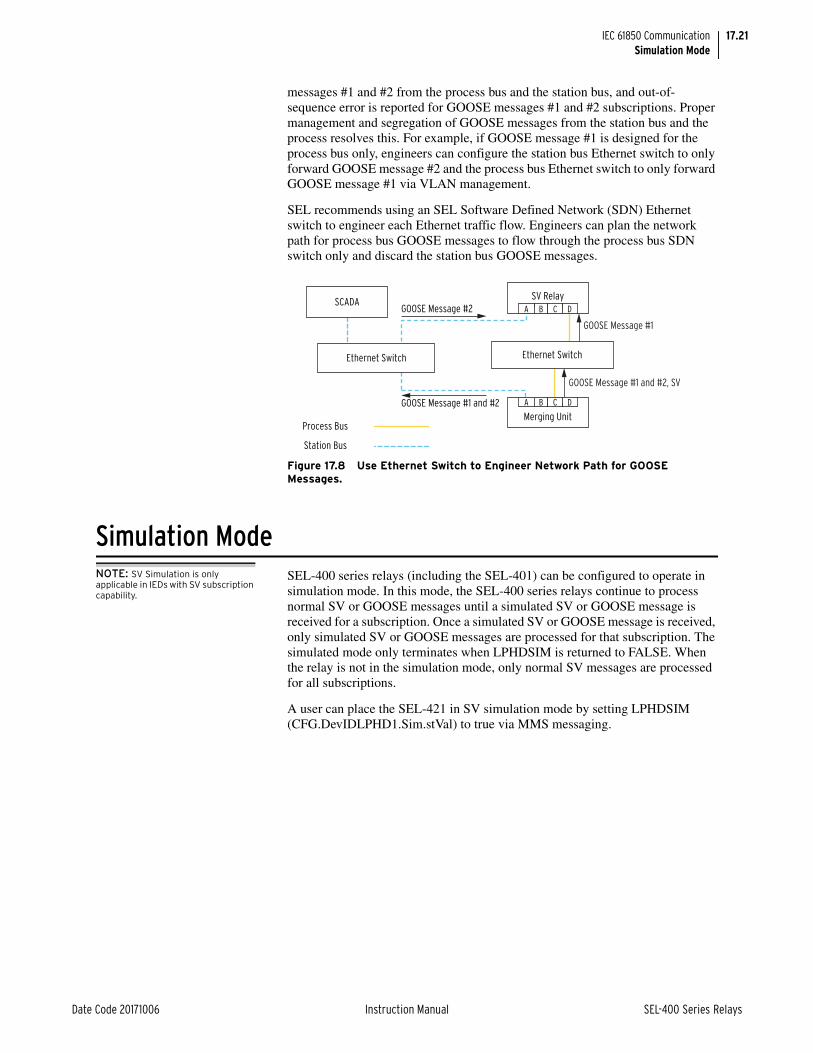
17.21
Date Code 20171006 Instruction Manual SEL-400 Series Relays
IEC 61850 CommunicationSimulation Mode
messages #1 and #2 from the process bus and the station bus, and out-of-sequence error is reported for GOOSE messages #1 and #2 subscriptions. Proper management and segregation of GOOSE messages from the station bus and the process resolves this. For example, if GOOSE message #1 is designed for the process bus only, engineers can configure the station bus Ethernet switch to only forward GOOSE message #2 and the process bus Ethernet switch to only forward GOOSE message #1 via VLAN management.
SEL recommends using an SEL Software Defined Network (SDN) Ethernet switch to engineer each Ethernet traffic flow. Engineers can plan the network path for process bus GOOSE messages to flow through the process bus SDN switch only and discard the station bus GOOSE messages.
Simulation ModeNOTE: SV Simulation is only applicable in IEDs with SV subscription capability.
SEL-400 series relays (including the SEL-401) can be configured to operate in simulation mode. In this mode, the SEL-400 series relays continue to process normal SV or GOOSE messages until a simulated SV or GOOSE message is received for a subscription. Once a simulated SV or GOOSE message is received, only simulated SV or GOOSE messages are processed for that subscription. The simulated mode only terminates when LPHDSIM is returned to FALSE. When the relay is not in the simulation mode, only normal SV messages are processed for all subscriptions.
A user can place the SEL-421 in SV simulation mode by setting LPHDSIM (CFG.DevIDLPHD1.Sim.stVal) to true via MMS messaging.
Figure 17.8 Use Ethernet Switch to Engineer Network Path for GOOSE Messages.
Process Bus
Station Bus
SV Relay
Merging Unit
Ethernet Switch
A B C D
A B C DGOOSE Message #2SCADA
Ethernet Switch
GOOSE Message #1 and #2
GOOSE Message #1
GOOSE Message #1 and #2, SV

17.22
SEL-400 Series Relays Instruction Manual Date Code 20171006
IEC 61850 CommunicationIEC 61850 Configuration
IEC 61850 ConfigurationSettings
Table 17.9 lists IEC 61850 settings. These settings are only available if your device includes the optional IEC 61850 protocol.
ArchitectNOTE: Not all SEL-400 series relays support SV.
The Architect software enables protection and integration engineers to design and commission IEC 61850 substations containing SEL IEDs.
Engineers can use Architect to perform the following configuration tasks.
➤ Organize and configure all SEL IEDs in a substation project.
➤ Configure incoming and outgoing GOOSE messages.
➤ Configure SV publication and subscription, if supported.
➤ Edit and create GOOSE and SV datasets.
➤ Read non-SEL IED Capability Description (ICD) and Configured IED Description (CID) files and determine the available IEC 61850 messaging options.
➤ Use or edit preconfigured datasets for reports.
➤ Load device settings as part of IEC 61850 CID files into SEL IEDs.
➤ Generate ICD files that will provide SEL IED descriptions to other manufacturers’ tools so they can use SEL GOOSE messages and reporting features.
NOTE: Other manufacturers’ ICD and CID files must have IEC 61850 outgoing GOOSE messages with Application IDs (APPIDs) of exactly four characters and VLAN IDs of exactly three characters so that the relay can successfully subscribe to them. If you attempt to configure a relay to subscribe to a GOOSE message that does not meet this criteria, the relay will reject the CID file upon download. Edit other manufacturers’ ICD and CID files prior to importing them into Architect by adding leading zeros to the APPID and VLAN ID of outgoing GOOSE messages, as necessary.
Architect provides a GUI for engineers to select, edit, and create IEC 61850 GOOSE messages important for substation protection, coordination, and control schemes. Typically, the engineer first places icons representing IEDs in a substa-tion container, then edits the outgoing GOOSE messages or creates new ones for each IED. The engineer may also select incoming GOOSE messages for each IED to receive from any other IEDs in the domain. Architect has the capability to read other manufacturers’ ICD and CID files, enabling the engineer to map the data seamlessly into SEL IED logic. See the Architect help for more information.
Architect also provides a GUI for engineers to configure SV publications and SV subscriptions when the IED supports SV. The process is similar to that described for GOOSE, except that SEL SV devices can either publish or subscribe to SV, but not both. The engineer edits or creates SV publication datasets to configure the SEL SV publisher(s). Architect then displays the available SV publications in the project, using any SV publications defined in the project, including those from imported CID files from other manufacturers' SV publishers. The engineer then configures subscriptions by mapping the published data to the available ana-log channels in the SEL SV subscriber.
Table 17.9 IEC 61850 Settings
Label Description Range Default
E61850 IEC 61850 interface enable Y, N N
EGSE Outgoing IEC 61850 GSE message enable Y, N N
EMMSFS Enable MMS File Services Y, N N

17.23
Date Code 20171006 Instruction Manual SEL-400 Series Relays
IEC 61850 CommunicationIEC 61850 Configuration
The following example includes configurations via the Architect software. The software supports IEC 61850 MMS, GOOSE, and SV configurations. This exam-ple shows how to use the software to configure two SV publications on an SEL-401 and an SEL-421.
Example 17.1 SV Application
Step 1. Open Architect.
Step 2. Insert the SEL-401 ICD and the SEL-421-7 SV Subscriber Relay ICD in the project tree.
Step 3. Create an SV Publication for the SEL-401. Configure SVID, MAC address, APP ID, and VLAN information as desired. Select an SV dataset to associate it with the SV publication.
Figure 17.9 Add ICD to Project Tree

17.24
SEL-400 Series Relays Instruction Manual Date Code 20171006
IEC 61850 CommunicationIEC 61850 Configuration
Step 4. To view the content of the dataset, click the … icon next to the dataset.
Example 17.1 SV Application (Continued)
Figure 17.10 Configure an SV Publication
Figure 17.11 Example SV Publication Dataset

17.25
Date Code 20171006 Instruction Manual SEL-400 Series Relays
IEC 61850 CommunicationIEC 61850 Configuration
Step 5. Select the SEL-421 and click the SV Receive tab to configure the SV subscriptions as shown in Figure 17.12.
Step 6. Right-click the IED, and choose to send the CID file. Ensure that the FTP function is enabled on the IEDs before sending CID files.
Example 17.1 SV Application (Continued)
Figure 17.12 Configure SV Subscription
Figure 17.13 Send SEL-401 CID File

17.26
SEL-400 Series Relays Instruction Manual Date Code 20171006
IEC 61850 CommunicationIEC 61850 Configuration
Load Device Setting With CID File DownloadNOTE: CID file settings are applied only when the file is initially downloaded to the relay. If a file is downloaded to the relay that is identical to one it already has, it will not be processed.
One of the features of the Architect software is enabling users to send device set-tings as part of the CID file. Refer to Settings in QuickSet on page 3.28 for steps on how to establish communication with the device and how to modify and save settings using ACSELERATOR QuickSet SEL-5030 Software. The procedure in the following steps shows how to use Architect to open the settings file previ-ously saved in QuickSet and include it in the CID file to be sent to the device.
Step 7. Issue the COM SV command on the merging unit and the relay to verify successful publication and subscription.
Example 17.1 SV Application (Continued)
Figure 17.14 Send SEL-421-7 CID File
=>>COM SV <Enter>
TEST SV Mode: OFF
SV Publication Information
MultiCastAddr Ptag:Vlan AppID smpSynch_________________________________________________________________________________A0401_006_ICD_ExampleCFG/LLNO$MS$MSVCB0101-0C-CD-04-00-11 4:1 4001 0SV ID: 4001Data Set: A0401_006_ICD_ExampleCFG/LLNO$PhsMeas1
Figure 17.15 SEL-401 Publication Status
=>>COM SV <Enter>
TEST SV Mode: OFF
SIMULATED Mode: OFF
SV Subscription Status
MultiCastAddr Ptag:Vlan AppID smpSynch Code Network Delay (ms)_________________________________________________________________________________A0401_006_ICD_ExampleCFG/LLNO$MS$MSVCB0101-0C-CD-04-00-11 4:1 4001 1SV ID: 4001Data Set: A0401_006_ICD_ExampleCFG/LLNO$PhsMeas1
Figure 17.16 SEL-421 SV Subscription Status

17.27
Date Code 20171006 Instruction Manual SEL-400 Series Relays
IEC 61850 CommunicationIEC 61850 Configuration
Step 1. Open Architect.
Step 2. Click on the Settings Link tab, and then click on Create Settings Link.
Step 3. Select the settings file and then press OK.
Step 4. Select which settings to embed in the CID file. You can also save a local CID file with settings by clicking on Save CID with Settings.

17.28
SEL-400 Series Relays Instruction Manual Date Code 20171006
IEC 61850 CommunicationIEC 61850 Configuration
Step 5. In the ACSELERATOR project editor window, right-click on the device to send the CID file. Make sure to check the Include Device Settings box.

17.29
Date Code 20171006 Instruction Manual SEL-400 Series Relays
IEC 61850 CommunicationLogical Nodes
SEL ICD File VersionsArchitect version 1.1.69.0 and higher supports multiple ICD file versions for each IED in a project. Because relays with different firmware may require differ-ent CID file versions, this allows users to manage the CID files of all IEDs within a single project.
Ensure that you work with the appropriate version of Architect relative to your current configuration, existing project files, and ultimate goals. If you desire the best available IEC 61850 functionality for your SEL relay, obtain the latest ver-sion of Architect and select the appropriate ICD version(s) for your needs. Archi-tect generates CID files from ICD files so the ICD file version Architect uses also determines the CID file version generated.
As of this writing, Architect comes with several versions of relay ICD files. ICD file descriptions in Architect indicate the minimum firmware versions required to use that particular file. Unless otherwise indicated, ICD files will work with firm-ware higher than the firmware in the description. but not with lower firmware versions.
See Appendix A: Firmware, ICD File, and Manual Versions in the product-spe-cific instruction manual for a list of ICD versions and corresponding firmware versions.
Logical NodesEach logical device (LD) has a set of common data objects at the top level LN0. These represent the current state of the device, as well as some informational data. These data objects are: Mod (Mode), Beh (Behavior), Health, and NamPlt. See below for a brief description of each object.
ModeSEL-400 series relay includes at the top-level LN0 within each LD the following enumerations for Mod stVal:
The top-level logical node of each LD also includes the following Mod attributes:
Mod q and Mod t per the Time Stamps and Quality subsection.
Mod ctlModel enumeration 0 (Status-only).
BehaviorSEL-400 series relay LNs include the following enumerations for Beh stVal:
Mod stVal Enumeration Mod stVal Value Description
1 on EN Relay Word bit = 1
5 off EN Relay Word bit = 0
Beh stVal Enumeration Beh stVal Value Description
1 on EN Relay Word bit = 1
5 off EN Relay Word bit = 0

17.30
SEL-400 Series Relays Instruction Manual Date Code 20171006
IEC 61850 CommunicationLogical Nodes
Logical nodes also include the following Beh attributes:
Beh q and Beh t per the Time Stamps and Quality subsection.
HealthThe SEL-400 series relay includes at the top-level LN0 within each LD the fol-lowing enumerations for Health stVal:
The top-level logical node of each LD also includes the following Health attri-butes:
Health q and Health t per the Time Stamps and Quality subsection.
NamPltThe top-level LN0 of each LD includes the following NamPlt attributes:
➤ NamPlt vendor which is set to “SEL”.
➤ NamPlt swRev which contains the relay FID string value.
➤ NamPlt d, which is the LD description.
Common Logical NodesTable 17.10–Table 17.13 show the logical nodes (LNs) supported in all SEL-400 series relays. See the respective product-specific instruction manuals to see which additional logical nodes are available in that relay.
Table 17.10 shows the LNs associated with the Logical Node CFG.
Health stVal Enumeration Health stVal Value Description
1 Ok EN Relay Word bit = 1
5 Alarm EN Relay Word bit = 0
Table 17.10 Logical Device: CFG (Configuration)
Logical Node Attribute Data Source Comment
Functional Constraint = CO
DevIDLPHD1 Sim.Oper.ctlVal LPHDSIM IEC 61850 Logical Node for Physical Device Simulation
Functional Constraint = DC
DevIDLPHD1 PhyNam.model PARNUM Relay Part Number String
DevIDLPHD1 PhyNam.serNum SERNUM Relay Serial Number String
LLN0 NamPlt.swRev VERFID Relay FID String
Functional Constraint = ST
DevIDLPHD1 Sim.stVal LPHDSIM IEC 61850 Logical Node for Physical Device Simulation

17.31
Date Code 20171006 Instruction Manual SEL-400 Series Relays
IEC 61850 CommunicationLogical Nodes
Table 17.11 shows the LNs associated with control elements, defined as Logical Device CON.
Table 17.11 Logical Device: CON (Remote Control) (Sheet 1 of 2)
Logical Node AttributeData Source
Comment
Functional Constraint = CO
RBGGIO1 SPCSO01.Oper.ctlVal RB01 Remote Bit 1
RBGGIO1 SPCSO02.Oper.ctlVal RB02 Remote Bit 2
RBGGIO1 SPCSO03.Oper.ctlVal RB03 Remote Bit 3
RBGGIO1 SPCSO04.Oper.ctlVal RB04 Remote Bit 4
RBGGIO1 SPCSO05.Oper.ctlVal RB05 Remote Bit 5
RBGGIO1 SPCSO06.Oper.ctlVal RB06 Remote Bit 6
RBGGIO1 SPCSO07.Oper.ctlVal RB07 Remote Bit 7
RBGGIO1 SPCSO08.Oper.ctlVal RB08 Remote Bit 8
RBGGIO2 SPCSO09.Oper.ctlVal RB09 Remote Bit 9
RBGGIO2 SPCSO10.Oper.ctlVal RB10 Remote Bit 10
RBGGIO2 SPCSO11.Oper.ctlVal RB11 Remote Bit 11
RBGGIO2 SPCSO12.Oper.ctlVal RB12 Remote Bit 12
RBGGIO2 SPCSO13.Oper.ctlVal RB13 Remote Bit 13
RBGGIO2 SPCSO14.Oper.ctlVal RB14 Remote Bit 14
RBGGIO2 SPCSO15.Oper.ctlVal RB15 Remote Bit 15
RBGGIO2 SPCSO16.Oper.ctlVal RB16 Remote Bit 16
RBGGIO3 SPCSO17.Oper.ctlVal RB17 Remote Bit 17
RBGGIO3 SPCSO18.Oper.ctlVal RB18 Remote Bit 18
RBGGIO3 SPCSO19.Oper.ctlVal RB19 Remote Bit 19
RBGGIO3 SPCSO20.Oper.ctlVal RB20 Remote Bit 20
RBGGIO3 SPCSO21.Oper.ctlVal RB21 Remote Bit 21
RBGGIO3 SPCSO22.Oper.ctlVal RB22 Remote Bit 22
RBGGIO3 SPCSO23.Oper.ctlVal RB23 Remote Bit 23
RBGGIO3 SPCSO24.Oper.ctlVal RB24 Remote Bit 24
RBGGIO4 SPCSO25.Oper.ctlVal RB25 Remote Bit 25
RBGGIO4 SPCSO26.Oper.ctlVal RB26 Remote Bit 26
RBGGIO4 SPCSO27.Oper.ctlVal RB27 Remote Bit 27
RBGGIO4 SPCSO28.Oper.ctlVal RB28 Remote Bit 28
RBGGIO4 SPCSO29.Oper.ctlVal RB29 Remote Bit 29
RBGGIO4 SPCSO30.Oper.ctlVal RB30 Remote Bit 30
RBGGIO4 SPCSO31.Oper.ctlVal RB31 Remote Bit 31
RBGGIO4 SPCSO32.Oper.ctlVal RB32 Remote Bit 32
Functional Constraint = DC
CTRLLPHD1 PhyNam.model PARNUM Relay part number string
Functional Constraint = ST
RBGGIO1a SPCSO01.stVal RB01 Remote Bit 1
RBGGIO1a SPCSO02.stVal RB02 Remote Bit 2

17.32
SEL-400 Series Relays Instruction Manual Date Code 20171006
IEC 61850 CommunicationLogical Nodes
RBGGIO1a SPCSO03.stVal RB03 Remote Bit 3
RBGGIO1a SPCSO04.stVal RB04 Remote Bit 4
RBGGIO1a SPCSO05.stVal RB05 Remote Bit 5
RBGGIO1a SPCSO06.stVal RB06 Remote Bit 6
RBGGIO1a SPCSO07.stVal RB07 Remote Bit 7
RBGGIO1a SPCSO08.stVal RB08 Remote Bit 8
RBGGIO2a SPCSO09.stVal RB09 Remote Bit 9
RBGGIO2a SPCSO10.stVal RB10 Remote Bit 10
RBGGIO2a SPCSO11.stVal RB11 Remote Bit 11
RBGGIO2a SPCSO12.stVal RB12 Remote Bit 12
RBGGIO2a SPCSO13.stVal RB13 Remote Bit 13
RBGGIO2a SPCSO14.stVal RB14 Remote Bit 14
RBGGIO2a SPCSO15.stVal RB15 Remote Bit 15
RBGGIO2a SPCSO16.stVal RB16 Remote Bit 16
RBGGIO3a SPCSO17.stVal RB17 Remote Bit 17
RBGGIO3a SPCSO18.stVal RB18 Remote Bit 18
RBGGIO3a SPCSO19.stVal RB19 Remote Bit 19
RBGGIO3a SPCSO20.stVal RB20 Remote Bit 20
RBGGIO3a SPCSO21.stVal RB21 Remote Bit 21
RBGGIO3a SPCSO22.stVal RB22 Remote Bit 22
RBGGIO3a SPCSO23.stVal RB23 Remote Bit 23
RBGGIO3a SPCSO24.stVal RB24 Remote Bit 24
RBGGIO4a SPCSO25.stVal RB25 Remote Bit 25
RBGGIO4a SPCSO26.stVal RB26 Remote Bit 26
RBGGIO4a SPCSO27.stVal RB27 Remote Bit 27
RBGGIO4a SPCSO28.stVal RB28 Remote Bit 28
RBGGIO4a SPCSO29.stVal RB29 Remote Bit 29
RBGGIO4a SPCSO30.stVal RB30 Remote Bit 30
RBGGIO4a SPCSO31.stVal RB31 Remote Bit 31
RBGGIO4a SPCSO32.stVal RB32 Remote Bit 32
a Data source is high-speed GOOSE data if included in an outgoing GOOSE dataset.
Table 17.11 Logical Device: CON (Remote Control) (Sheet 2 of 2)
Logical Node AttributeData Source
Comment

17.33
Date Code 20171006 Instruction Manual SEL-400 Series Relays
IEC 61850 CommunicationLogical Nodes
Table 17.12 shows the LNs associated with the annunciation element, defined as Logical Device ANN.
Table 17.12 Logical Device: ANN (Annunciation) (Sheet 1 of 11)
Logical Node AttributeData Source
Comment
Functional Constraint = DC
STALPHD1 PhyNam.model PARNUM Relay part number string
Functional Constraint = MX
ACNGGIO2 AnIn001.instMag.f ACN01CV Automation SELOGIC Counter 01 current value
ACNGGIO2 AnIn002.instMag.f ACN02CV Automation SELOGIC Counter 02 current value
ACNGGIO2 AnIn003.instMag.f ACN03CV Automation SELOGIC Counter 03 current value
•••
ACNGGIO2 AnIn014.instMag.f ACN14CV Automation SELOGIC Counter 14 current value
ACNGGIO2 AnIn015.instMag.f ACN15CV Automation SELOGIC Counter 15 current value
ACNGGIO2 AnIn016.instMag.f ACN16CV Automation SELOGIC Counter 16 current value
AMVGGIO1 AnIn001.instMag.f AMV001 Automation SELOGIC Math Variable 001
AMVGGIO1 AnIn002.instMag.f AMV002 Automation SELOGIC Math Variable 002
AMVGGIO1 AnIn003.instMag.f AMV003 Automation SELOGIC Math Variable 003
•••
AMVGGIO1 AnIn062.instMag.f AMV062 Automation SELOGIC Math Variable 062
AMVGGIO1 AnIn063.instMag.f AMV063 Automation SELOGIC Math Variable 063
AMVGGIO1 AnIn064.instMag.f AMV064 Automation SELOGIC Math Variable 064
AMVGGIO2 AnIn065.instMag.f AMV065 Automation SELOGIC Math Variable 065
AMVGGIO2 AnIn066.instMag.f AMV066 Automation SELOGIC Math Variable 066
AMVGGIO2 AnIn067.instMag.f AMV067 Automation SELOGIC Math Variable 067
•••
AMVGGIO2 AnIn126.instMag.f AMV126 Automation SELOGIC Math Variable 126
AMVGGIO2 AnIn127.instMag.f AMV127 Automation SELOGIC Math Variable 127
AMVGGIO2 AnIn128.instMag.f AMV128 Automation SELOGIC Math Variable 128
PCNGGIO1 AnIn001.instMag.f PCN01CV Protection SELOGIC Counter 01 current value
PCNGGIO1 AnIn002.instMag.f PCN02CV Protection SELOGIC Counter 02 current value
PCNGGIO1 AnIn003.instMag.f PCN03CV Protection SELOGIC Counter 03 current value
NOTE: Some products support only 64 AMVs in their ANN Logical Device.

17.34
SEL-400 Series Relays Instruction Manual Date Code 20171006
IEC 61850 CommunicationLogical Nodes
•••
PCNGGIO1 AnIn014.instMag.f PCN14CV Protection SELOGIC Counter 14 current value
PCNGGIO1 AnIn015.instMag.f PCN15CV Protection SELOGIC Counter 15 current value
PCNGGIO1 AnIn016.instMag.f PCN16CV Protection SELOGIC Counter 16 current value
PMVGGIO3 AnIn01.instMag.f PMV01 Protection SELOGIC Math Variable 01
PMVGGIO3 AnIn02.instMag.f PMV02 Protection SELOGIC Math Variable 02
PMVGGIO3 AnIn03.instMag.f PMV03 Protection SELOGIC Math Variable 03
•••
PMVGGIO3 AnIn62.instMag.f PMV62 Protection SELOGIC Math Variable 62
PMVGGIO3 AnIn63.instMag.f PMV63 Protection SELOGIC Math Variable 63
PMVGGIO3 AnIn64.instMag.f PMV64 Protection SELOGIC Math Variable 64
RAGGIO1 Ra001.instMag.f RA001 Remote Analog Input 001
RAGGIO1 Ra002.instMag.f RA002 Remote Analog Input 002
RAGGIO1 Ra003.instMag.f RA003 Remote Analog Input 003
•••
RAGGIO1 Ra030.instMag.f RA030 Remote Analog Input 030
RAGGIO1 Ra031.instMag.f RA031 Remote Analog Input 031
RAGGIO1 Ra032.instMag.f RA032 Remote Analog Input 032
RAGGIO2 Ra033.instMag.f RA033 Remote Analog Input 033
RAGGIO2 Ra034.instMag.f RA034 Remote Analog Input 034
RAGGIO2 Ra035.instMag.f RA035 Remote Analog Input 035
•••
RAGGIO2 Ra062.instMag.f RA062 Remote Analog Input 062
RAGGIO2 Ra063.instMag.f RA063 Remote Analog Input 063
RAGGIO2 Ra064.instMag.f RA064 Remote Analog Input 064
RAGGIO3 Ra065.instMag.f RA065 Remote Analog Input 065
RAGGIO3 Ra066.instMag.f RA066 Remote Analog Input 066
RAGGIO3 Ra067.instMag.f RA067 Remote Analog Input 067
•••
RAGGIO3 Ra094.instMag.f RA094 Remote Analog Input 094
RAGGIO3 Ra095.instMag.f RA095 Remote Analog Input 095
RAGGIO3 Ra096.instMag.f RA096 Remote Analog Input 096
Table 17.12 Logical Device: ANN (Annunciation) (Sheet 2 of 11)
Logical Node AttributeData Source
Comment

17.35
Date Code 20171006 Instruction Manual SEL-400 Series Relays
IEC 61850 CommunicationLogical Nodes
RAGGIO4 Ra097.instMag.f RA097 Remote Analog Input 097
RAGGIO4 Ra098.instMag.f RA098 Remote Analog Input 098
RAGGIO4 Ra099.instMag.f RA099 Remote Analog Input 099
•••
RAGGIO4 Ra126.instMag.f RA126 Remote Analog Input 126
RAGGIO4 Ra127.instMag.f RA127 Remote Analog Input 127
RAGGIO4 Ra128.instMag.f RA128 Remote Analog Input 128
RAGGIO5 Ra129.instMag.f RA129 Remote Analog Input 129
RAGGIO5 Ra130.instMag.f RA130 Remote Analog Input 130
RAGGIO5 Ra131.instMag.f RA131 Remote Analog Input 131
•••
RAGGIO5 Ra158.instMag.f RA158 Remote Analog Input 158
RAGGIO5 Ra159.instMag.f RA159 Remote Analog Input 159
RAGGIO5 Ra160.instMag.f RA160 Remote Analog Input 160
RAGGIO6 Ra161.instMag.f RA161 Remote Analog Input 161
RAGGIO6 Ra162.instMag.f RA162 Remote Analog Input 162
RAGGIO6 Ra163.instMag.f RA163 Remote Analog Input 163
•••
RAGGIO6 Ra190.instMag.f RA190 Remote Analog Input 190
RAGGIO6 Ra191.instMag.f RA191 Remote Analog Input 191
RAGGIO6 Ra192.instMag.f RA192 Remote Analog Input 192
RAGGIO7 Ra193.instMag.f RA193 Remote Analog Input 193
RAGGIO7 Ra194.instMag.f RA194 Remote Analog Input 194
RAGGIO7 Ra195.instMag.f RA195 Remote Analog Input 195
•••
RAGGIO7 Ra222.instMag.f RA222 Remote Analog Input 222
RAGGIO7 Ra223.instMag.f RA223 Remote Analog Input 223
RAGGIO7 Ra224.instMag.f RA224 Remote Analog Input 224
RAGGIO8 Ra225.instMag.f RA225 Remote Analog Input 225
RAGGIO8 Ra226.instMag.f RA226 Remote Analog Input 226
RAGGIO8 Ra227.instMag.f RA227 Remote Analog Input 227
•••
RAGGIO8 Ra254.instMag.f RA254 Remote Analog Input 254
RAGGIO8 Ra255.instMag.f RA255 Remote Analog Input 255
Table 17.12 Logical Device: ANN (Annunciation) (Sheet 3 of 11)
Logical Node AttributeData Source
Comment
NOTE: Some products support only 128 Remote Analogs in their ANN Logical Device.

17.36
SEL-400 Series Relays Instruction Manual Date Code 20171006
IEC 61850 CommunicationLogical Nodes
RAGGIO8 Ra256.instMag.f RA256 Remote Analog Input 256
RAOGGIO1 Rao01.instMag.f RAO01 Remote Analog Output 01
RAOGGIO1 Rao02.instMag.f RAO02 Remote Analog Output 02
RAOGGIO1 Rao03.instMag.f RAO03 Remote Analog Output 03
•••
RAOGGIO1 Rao30.instMag.f RAO30 Remote Analog Output 30
RAOGGIO1 Rao31.instMag.f RAO31 Remote Analog Output 31
RAOGGIO1 Rao32.instMag.f RAO32 Remote Analog Output 32
RAOGGIO2 Rao33.instMag.f RAO33 Remote Analog Output 33
RAOGGIO2 Rao34.instMag.f RAO34 Remote Analog Output 34
RAOGGIO2 Rao35.instMag.f RAO35 Remote Analog Output 35
•••
RAOGGIO2 Rao62.instMag.f RAO62 Remote Analog Output 62
RAOGGIO2 Rao63.instMag.f RAO63 Remote Analog Output 63
RAOGGIO2 Rao64.instMag.f RAO64 Remote Analog Output 64
Functional Constraint = STa
ALTGGIO5 Ind01.stVal ALT01 Automation Latch 1
ALTGGIO5 Ind02.stVal ALT02 Automation Latch 2
ALTGGIO5 Ind03.stVal ALT03 Automation Latch 3
•••
ALTGGIO5 Ind30.stVal ALT30 Automation Latch 30
ALTGGIO5 Ind31.stVal ALT31 Automation Latch 31
ALTGGIO5 Ind32.stVal ALT32 Automation Latch 32
ASVGGIO4 Ind001.stVal ASV001 Automation SELOGIC Variable 1
ASVGGIO4 Ind002.stVal ASV002 Automation SELOGIC Variable 2
ASVGGIO4 Ind003.stVal ASV003 Automation SELOGIC Variable 3
•••
ASVGGIO4 Ind126.stVal ASV126 Automation SELOGIC Variable 126
ASVGGIO4 Ind127.stVal ASV127 Automation SELOGIC Variable 127
ASVGGIO4 Ind128.stVal ASV128 Automation SELOGIC Variable 128
ETHGGIO1 Ind01.stVal P5ASEL Port 5A active/inactive
ETHGGIO1 Ind02.stVal LINK5A Link status of Port 5A connection
ETHGGIO1 Ind03.stVal P5BSEL Port 5B active/inactive
ETHGGIO1 Ind04.stVal LINK5B Link status of Port 5B connection
ETHGGIO1 Ind05.stVal P5CSEL Port 5C active/inactive
Table 17.12 Logical Device: ANN (Annunciation) (Sheet 4 of 11)
Logical Node AttributeData Source
Comment
NOTE: Some relays support only 64 Automation SELOGIC Variables.
NOTE: Some relays do not support the ETHGGIO1 Logical Node.

17.37
Date Code 20171006 Instruction Manual SEL-400 Series Relays
IEC 61850 CommunicationLogical Nodes
ETHGGIO1 Ind06.stVal LINK5C Link status of Port 5C connection
ETHGGIO1 Ind07.stVal P5DSEL Port 5D active/inactive
ETHGGIO1 Ind08.stVal LINK5D Link status of Port 5D connection
ETHGGIO1 Ind09.stVal LNKFAIL Link status of the active port
IN1GGIO14b Ind01.stVal IN101 Main Board Input 1
IN1GGIO14b Ind02.stVal IN102 Main Board Input 2
IN1GGIO14b Ind03.stVal IN103 Main Board Input 3
IN1GGIO14b Ind04.stVal IN104 Main Board Input 4
IN1GGIO14b Ind05.stVal IN105 Main Board Input 5
IN1GGIO14b Ind06.stVal IN106 Main Board Input 6
IN1GGIO14b Ind07.stVal IN107 Main Board Input 7
IN2GGIO15 Ind01.stVal IN201 First Optional I/O Board Input 1 (if installed)
IN2GGIO15 Ind02.stVal IN202 First Optional I/O Board Input 2 (if installed)
IN2GGIO15 Ind03.stVal IN203 First Optional I/O Board Input 3 (if installed)
•••
IN2GGIO15 Ind22.stVal IN222 First Optional I/O Board Input 22 (if installed)
IN2GGIO15 Ind23.stVal IN223 First Optional I/O Board Input 23 (if installed)
IN2GGIO15 Ind24.stVal IN224 First Optional I/O Board Input 24 (if installed)
IN3GGIO16 Ind01.stVal IN301 Second Optional I/O Board Input 1 (if installed)
IN3GGIO16 Ind02.stVal IN302 Second Optional I/O Board Input 2 (if installed)
IN3GGIO16 Ind03.stVal IN303 Second Optional I/O Board Input 3 (if installed)
•••
IN3GGIO16 Ind22.stVal IN322 Second Optional I/O Board Input 22 (if installed)
IN3GGIO16 Ind23.stVal IN323 Second Optional I/O Board Input 23 (if installed)
IN3GGIO16 Ind24.stVal IN324 Second Optional I/O Board Input 24 (if installed)
IN4GGIO18c Ind01.stVal IN401 Third Optional I/O Board Input 1 (if installed)
IN4GGIO18c Ind02.stVal IN402 Third Optional I/O Board Input 2 (if installed)
IN4GGIO18c Ind03.stVal IN403 Third Optional I/O Board Input 3 (if installed)
•••
Table 17.12 Logical Device: ANN (Annunciation) (Sheet 5 of 11)
Logical Node AttributeData Source
Comment
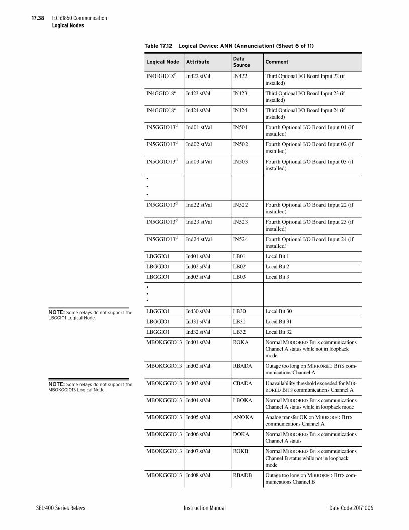
17.38
SEL-400 Series Relays Instruction Manual Date Code 20171006
IEC 61850 CommunicationLogical Nodes
IN4GGIO18c Ind22.stVal IN422 Third Optional I/O Board Input 22 (if installed)
IN4GGIO18c Ind23.stVal IN423 Third Optional I/O Board Input 23 (if installed)
IN4GGIO18c Ind24.stVal IN424 Third Optional I/O Board Input 24 (if installed)
IN5GGIO13d Ind01.stVal IN501 Fourth Optional I/O Board Input 01 (if installed)
IN5GGIO13d Ind02.stVal IN502 Fourth Optional I/O Board Input 02 (if installed)
IN5GGIO13d Ind03.stVal IN503 Fourth Optional I/O Board Input 03 (if installed)
•
•
•
IN5GGIO13d Ind22.stVal IN522 Fourth Optional I/O Board Input 22 (if installed)
IN5GGIO13d Ind23.stVal IN523 Fourth Optional I/O Board Input 23 (if installed)
IN5GGIO13d Ind24.stVal IN524 Fourth Optional I/O Board Input 24 (if installed)
LBGGIO1 Ind01.stVal LB01 Local Bit 1
LBGGIO1 Ind02.stVal LB02 Local Bit 2
LBGGIO1 Ind03.stVal LB03 Local Bit 3
•••
LBGGIO1 Ind30.stVal LB30 Local Bit 30
LBGGIO1 Ind31.stVal LB31 Local Bit 31
LBGGIO1 Ind32.stVal LB32 Local Bit 32
MBOKGGIO13 Ind01.stVal ROKA Normal MIRRORED BITS communications Channel A status while not in loopback mode
MBOKGGIO13 Ind02.stVal RBADA Outage too long on MIRRORED BITS com-munications Channel A
MBOKGGIO13 Ind03.stVal CBADA Unavailability threshold exceeded for MIR-RORED BITS communications Channel A
MBOKGGIO13 Ind04.stVal LBOKA Normal MIRRORED BITS communications Channel A status while in loopback mode
MBOKGGIO13 Ind05.stVal ANOKA Analog transfer OK on MIRRORED BITS communications Channel A
MBOKGGIO13 Ind06.stVal DOKA Normal MIRRORED BITS communications Channel A status
MBOKGGIO13 Ind07.stVal ROKB Normal MIRRORED BITS communications Channel B status while not in loopback mode
MBOKGGIO13 Ind08.stVal RBADB Outage too long on MIRRORED BITS com-munications Channel B
Table 17.12 Logical Device: ANN (Annunciation) (Sheet 6 of 11)
Logical Node AttributeData Source
Comment
NOTE: Some relays do not support the LBGGIO1 Logical Node.
NOTE: Some relays do not support the MBOKGGIO13 Logical Node.
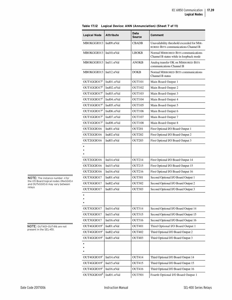
17.39
Date Code 20171006 Instruction Manual SEL-400 Series Relays
IEC 61850 CommunicationLogical Nodes
MBOKGGIO13 Ind09.stVal CBADB Unavailability threshold exceeded for MIR-RORED BITS communications Channel B
MBOKGGIO13 Ind10.stVal LBOKB Normal MIRRORED BITS communications Channel B status while in loopback mode
MBOKGGIO13 Ind11.stVal ANOKB Analog transfer OK on MIRRORED BITS communications Channel B
MBOKGGIO13 Ind12.stVal DOKB Normal MIRRORED BITS communications Channel B status
OUT1GGIO17e Ind01.stVal OUT101 Main Board Output 1
OUT1GGIO17e Ind02.stVal OUT102 Main Board Output 2
OUT1GGIO17e Ind03.stVal OUT103 Main Board Output 3
OUT1GGIO17e Ind04.stVal OUT104 Main Board Output 4
OUT1GGIO17e Ind05.stVal OUT105 Main Board Output 5
OUT1GGIO17e Ind06.stVal OUT106 Main Board Output 6
OUT1GGIO17e Ind07.stVal OUT107 Main Board Output 7
OUT1GGIO17e Ind08.stVal OUT108 Main Board Output 8
OUT2GGIO16 Ind01.stVal OUT201 First Optional I/O Board Output 1
OUT2GGIO16 Ind02.stVal OUT202 First Optional I/O Board Output 2
OUT2GGIO16 Ind03.stVal OUT203 First Optional I/O Board Output 3
•••
OUT2GGIO16 Ind14.stVal OUT214 First Optional I/O Board Output 14
OUT2GGIO16 Ind15.stVal OUT215 First Optional I/O Board Output 15
OUT2GGIO16 Ind16.stVal OUT216 First Optional I/O Board Output 16
OUT3GGIO17 Ind01.stVal OUT301 Second Optional I/O Board Output 1
OUT3GGIO17 Ind02.stVal OUT302 Second Optional I/O Board Output 2
OUT3GGIO17 Ind03.stVal OUT303 Second Optional I/O Board Output 3
•••
OUT3GGIO17 Ind14.stVal OUT314 Second Optional I/O Board Output 14
OUT3GGIO17 Ind15.stVal OUT315 Second Optional I/O Board Output 15
OUT3GGIO17 Ind16.stVal OUT316 Second Optional I/O Board Output 16
OUT4GGIO19c Ind01.stVal OUT401 Third Optional I/O Board Output 1
OUT4GGIO19c Ind02.stVal OUT402 Third Optional I/O Board Output 2
OUT4GGIO19c Ind03.stVal OUT403 Third Optional I/O Board Output 3
•••
OUT4GGIO19c Ind14.stVal OUT414 Third Optional I/O Board Output 14
OUT4GGIO19c Ind15.stVal OUT415 Third Optional I/O Board Output 15
OUT4GGIO19c Ind16.stVal OUT416 Third Optional I/O Board Output 16
OUT5GGIO18d Ind01.stVal OUT501 Fourth Optional I/O Board Output 1
Table 17.12 Logical Device: ANN (Annunciation) (Sheet 7 of 11)
Logical Node AttributeData Source
Comment
NOTE: The instance number n for the I/O Board logical nodes (INxGGIOn and OUTxGGIOn) may vary between relays
NOTE: OUT401–OUT416 are not present in the SEL-451.

17.40
SEL-400 Series Relays Instruction Manual Date Code 20171006
IEC 61850 CommunicationLogical Nodes
OUT5GGIO18d Ind02.stVal OUT502 Fourth Optional I/O Board Output 2
OUT5GGIO18d Ind03.stVal OUT503 Fourth Optional I/O Board Output 3
•••
OUT5GGIO18d Ind14.stVal OUT514 Fourth Optional I/O Board Output 14
OUT5GGIO18d Ind15.stVal OUT515 Fourth Optional I/O Board Output 15
OUT5GGIO18d Ind16.stVal OUT516 Fourth Optional I/O Board Output 16
PBLEDGGIO8 Ind01.stVal PB1_LED Pushbutton 1 LED
PBLEDGGIO8 Ind02.stVal PB2_LED Pushbutton 2 LED
PBLEDGGIO8 Ind03.stVal PB3_LED Pushbutton 3 LED
PBLEDGGIO8 Ind04.stVal PB4_LED Pushbutton 4 LED
PBLEDGGIO8 Ind05.stVal PB5_LED Pushbutton 5 LED
PBLEDGGIO8 Ind06.stVal PB6_LED Pushbutton 6 LED
PBLEDGGIO8 Ind07.stVal PB7_LED Pushbutton 7 LED
PBLEDGGIO8 Ind08.stVal PB8_LED Pushbutton 8 LED
PBLEDGGIO8 Ind09.stVal PB9_LED Pushbutton 9 LED
PBLEDGGIO8 Ind10.stVal PB10LED Pushbutton 10 LED
PBLEDGGIO8 Ind11.stVal PB11LED Pushbutton 11 LED
PBLEDGGIO8 Ind12.stVal PB12LED Pushbutton 12 LED
PLTGGIO2 Ind01.stVal PLT01 Protection Latch 1
PLTGGIO2 Ind02.stVal PLT02 Protection Latch 2
PLTGGIO2 Ind03.stVal PLT03 Protection Latch 3
•••
PLTGGIO2 Ind30.stVal PLT30 Protection Latch 30
PLTGGIO2 Ind31.stVal PLT31 Protection Latch 31
PLTGGIO2 Ind32.stVal PLT32 Protection Latch 32
PSVGGIO1 Ind01.stVal PSV01 Protection SELOGIC Variable 1
PSVGGIO1 Ind02.stVal PSV02 Protection SELOGIC Variable 2
PSVGGIO1 Ind03.stVal PSV03 Protection SELOGIC Variable 3
•••
PSVGGIO1 Ind62.stVal PSV62 Protection SELOGIC Variable 62
PSVGGIO1 Ind63.stVal PSV63 Protection SELOGIC Variable 63
PSVGGIO1 Ind64.stVal PSV64 Protection SELOGIC Variable 64
RMBAGGIO9 Ind01.stVal RMB1A Channel A Receive Mirrored Bit 1
RMBAGGIO9 Ind02.stVal RMB2A Channel A Receive Mirrored Bit 2
RMBAGGIO9 Ind03.stVal RMB3A Channel A Receive Mirrored Bit 3
RMBAGGIO9 Ind04.stVal RMB4A Channel A Receive Mirrored Bit 4
Table 17.12 Logical Device: ANN (Annunciation) (Sheet 8 of 11)
Logical Node AttributeData Source
Comment

17.41
Date Code 20171006 Instruction Manual SEL-400 Series Relays
IEC 61850 CommunicationLogical Nodes
RMBAGGIO9 Ind05.stVal RMB5A Channel A Receive Mirrored Bit 5
RMBAGGIO9 Ind06.stVal RMB6A Channel A Receive Mirrored Bit 6
RMBAGGIO9 Ind07.stVal RMB7A Channel A Receive Mirrored Bit 7
RMBAGGIO9 Ind08.stVal RMB8A Channel A Receive Mirrored Bit 8
RMBBGGIO11 Ind01.stVal RMB1B Channel B Receive Mirrored Bit 1
RMBBGGIO11 Ind02.stVal RMB2B Channel B Receive Mirrored Bit 2
RMBBGGIO11 Ind03.stVal RMB3B Channel B Receive Mirrored Bit 3
RMBBGGIO11 Ind04.stVal RMB4B Channel B Receive Mirrored Bit 4
RMBBGGIO11 Ind05.stVal RMB5B Channel B Receive Mirrored Bit 5
RMBBGGIO11 Ind06.stVal RMB6B Channel B Receive Mirrored Bit 6
RMBBGGIO11 Ind07.stVal RMB7B Channel B Receive Mirrored Bit 7
RMBBGGIO11 Ind08.stVal RMB8B Channel B Receive Mirrored Bit 8
RTCAGGIO1 Ind01.stVal RTCAD01 RTC Remote Data Bits, Channel A, bit 1
RTCAGGIO1 Ind02.stVal RTCAD02 RTC Remote Data Bits, Channel A, bit 2
RTCAGGIO1 Ind03.stVal RTCAD03 RTC Remote Data Bits, Channel A, bit 3
•••
RTCAGGIO1 Ind14.stVal RTCAD14 RTC Remote Data Bits, Channel A, bit 14
RTCAGGIO1 Ind15.stVal RTCAD15 RTC Remote Data Bits, Channel A, bit 15
RTCAGGIO1 Ind16.stVal RTCAD16 RTC Remote Data Bits, Channel A, bit 16
RTCBGGIO2 Ind01.stVal RTCBD01 RTC Remote Data Bits, Channel B, bit 1
RTCBGGIO2 Ind02.stVal RTCBD02 RTC Remote Data Bits, Channel B, bit 2
RTCBGGIO2 Ind03.stVal RTCBD03 RTC Remote Data Bits, Channel B, bit 3
•••
RTCBGGIO2 Ind14.stVal RTCBD14 RTC Remote Data Bits, Channel B, bit 14
RTCBGGIO2 Ind15.stVal RTCBD15 RTC Remote Data Bits, Channel B, bit 15
RTCBGGIO2 Ind16.stVal RTCBD16 RTC Remote Data Bits, Channel B, bit 16
RTDHGGIO1 Ind01.stVal RTD01ST RTD Status for Channel 1
RTDHGGIO1 Ind02.stVal RTD02ST RTD Status for Channel 2
RTDHGGIO1 Ind03.stVal RTD03ST RTD Status for Channel 3
RTDHGGIO1 Ind04.stVal RTD04ST RTD Status for Channel 4
RTDHGGIO1 Ind05.stVal RTD05ST RTD Status for Channel 5
RTDHGGIO1 Ind06.stVal RTD06ST RTD Status for Channel 6
RTDHGGIO1 Ind07.stVal RTD07ST RTD Status for Channel 7
RTDHGGIO1 Ind08.stVal RTD08ST RTD Status for Channel 8
RTDHGGIO1 Ind09.stVal RTD09ST RTD Status for Channel 9
RTDHGGIO1 Ind10.stVal RTD10ST RTD Status for Channel 10
RTDHGGIO1 Ind11.stVal RTD11ST RTD Status for Channel 11
RTDHGGIO1 Ind12.stVal RTD12ST RTD Status for Channel 12
Table 17.12 Logical Device: ANN (Annunciation) (Sheet 9 of 11)
Logical Node AttributeData Source
Comment
NOTE: Not all relays support the RMBAGGIO9 and RMBBGGIO11 logical nodes.
NOTE: Not all relays support synchrophasor real time control (RTC) logical nodes.
NOTE: Not all relays support logical node RTDHGGIO1 for RTD inputs.

17.42
SEL-400 Series Relays Instruction Manual Date Code 20171006
IEC 61850 CommunicationLogical Nodes
SGGGIO1 Ind01.stVal SG1 Settings Group 1 active
SGGGIO1 Ind02.stVal SG2 Settings Group 2 active
SGGGIO1 Ind03.stVal SG3 Settings Group 3 active
SGGGIO1 Ind04.stVal SG4 Settings Group 4 active
SGGGIO1 Ind05.stVal SG5 Settings Group 5 active
SGGGIO1 Ind06.stVal SG6 Settings Group 6 active
TLEDGGIO7 Ind01.stVal EN Relay Enabled
TLEDGGIO7 Ind02.stVal TRIPLED Trip LED
TLEDGGIO7 Ind03.stVal TLED_1 Target LED 1
TLEDGGIO7 Ind04.stVal TLED_2 Target LED 2
TLEDGGIO7 Ind05.stVal TLED_3 Target LED 3
TLEDGGIO7 Ind06.stVal TLED_4 Target LED 4
TLEDGGIO7 Ind07.stVal TLED_5 Target LED 5
TLEDGGIO7 Ind08.stVal TLED_6 Target LED 6
TLEDGGIO7 Ind09.stVal TLED_7 Target LED 7
TLEDGGIO7 Ind10.stVal TLED_8 Target LED 8
TLEDGGIO7 Ind11.stVal TLED_9 Target LED 9
TLEDGGIO7 Ind12.stVal TLED_10 Target LED 10
TLEDGGIO7 Ind13.stVal TLED_11 Target LED 11
TLEDGGIO7 Ind14.stVal TLED_12 Target LED 12
TLEDGGIO7 Ind15.stVal TLED_13 Target LED 13
TLEDGGIO7 Ind16.stVal TLED_14 Target LED 14
TLEDGGIO7 Ind17.stVal TLED_15 Target LED 15
TLEDGGIO7 Ind18.stVal TLED_16 Target LED 16
TLEDGGIO7 Ind19.stVal TLED_17 Target LED 17
TLEDGGIO7 Ind20.stVal TLED_18 Target LED 18
TLEDGGIO7 Ind21.stVal TLED_19 Target LED 19
TLEDGGIO7 Ind22.stVal TLED_20 Target LED 20
TLEDGGIO7 Ind23.stVal TLED_21 Target LED 21
TLEDGGIO7 Ind24.stVal TLED_22 Target LED 22
TLEDGGIO7 Ind25.stVal TLED_23 Target LED 23
TLEDGGIO7 Ind26.stVal TLED_24 Target LED 24
TMBAGGIO10 Ind01.stVal TMB1A Channel A Transmit Mirrored Bit 1
TMBAGGIO10 Ind02.stVal TMB2A Channel A Transmit Mirrored Bit 2
TMBAGGIO10 Ind03.stVal TMB3A Channel A Transmit Mirrored Bit 3
TMBAGGIO10 Ind04.stVal TMB4A Channel A Transmit Mirrored Bit 4
TMBAGGIO10 Ind05.stVal TMB5A Channel A Transmit Mirrored Bit 5
TMBAGGIO10 Ind06.stVal TMB6A Channel A Transmit Mirrored Bit 6
TMBAGGIO10 Ind07.stVal TMB7A Channel A Transmit Mirrored Bit 7
TMBAGGIO10 Ind08.stVal TMB8A Channel A Transmit Mirrored Bit 8
Table 17.12 Logical Device: ANN (Annunciation) (Sheet 10 of 11)
Logical Node AttributeData Source
Comment

17.43
Date Code 20171006 Instruction Manual SEL-400 Series Relays
IEC 61850 CommunicationLogical Nodes
SEL Nameplate DataThe CID file contains information that describes the physical device attributes according to IEC 61850 standards. The LN0 logical node of each logical device contains the Nameplate DOI (instantiated data object) with the following data.
TMBBGGIO12 Ind01.stVal TMB1B Channel B Transmit Mirrored Bit 1
TMBBGGIO12 Ind02.stVal TMB2B Channel B Transmit Mirrored Bit 2
TMBBGGIO12 Ind03.stVal TMB3B Channel B Transmit Mirrored Bit 3
TMBBGGIO12 Ind04.stVal TMB4B Channel B Transmit Mirrored Bit 4
TMBBGGIO12 Ind05.stVal TMB5B Channel B Transmit Mirrored Bit 5
TMBBGGIO12 Ind06.stVal TMB6B Channel B Transmit Mirrored Bit 6
TMBBGGIO12 Ind07.stVal TMB7B Channel B Transmit Mirrored Bit 7
TMBBGGIO12 Ind08.stVal TMB8B Channel B Transmit Mirrored Bit 8
VBGGIO1 Ind001.stVal VB001 Virtual Bit 001
VBGGIO1 Ind002.stVal VB002 Virtual Bit 002
VBGGIO1 Ind003.stVal VB003 Virtual Bit 003
•••
VBGGIO1 Ind126.stVal VB126 Virtual Bit 126
VBGGIO1 Ind127.stVal VB127 Virtual Bit 127
VBGGIO1 Ind128.stVal VB128 Virtual Bit 128
VBGGIO2 Ind129.stVal VB129 Virtual Bit 129
VBGGIO2 Ind130.stVal VB130 Virtual Bit 130
VBGGIO2 Ind131.stVal VB131 Virtual Bit 131
•••
VBGGIO2 Ind254.stVal VB254 Virtual Bit 254
VBGGIO2 Ind255.stVal VB255 Virtual Bit 255
VBGGIO2 Ind256.stVal VB256 Virtual Bit 256
a Data attributes in the ST FC will provide high-speed GOOSE data if included in an outgoing GOOSE dataset.
b Not all SEL-400 series relays support main board inputs.c Not all SEL-400 series relays support a third interface board.d Not all SEL-400 series relays support four interface boards.e Not all SEL-400 series relays support main board outputs.
Table 17.12 Logical Device: ANN (Annunciation) (Sheet 11 of 11)
Logical Node AttributeData Source
Comment
Table 17.13 SEL Nameplate Data (Sheet 1 of 2)
Data Attribute Value
vendor “SEL”
swRev Contents of FID string from ID command
d Description of LD

17.44
SEL-400 Series Relays Instruction Manual Date Code 20171006
IEC 61850 CommunicationProtocol Implementation Conformance Statement
Protocol Implementation Conformance StatementTable 17.14 and Table 17.15 are as shown in the IEC 61850 standard, Part 8-1, Section 24. Note that because the standard explicitly dictates which services and functions must be implemented to achieve conformance, only the optional ser-vices and functions are listed.
Refer to the ACSI Conformance Statements on page 17.50 for information on the supported services.
MMS ConformanceThe manufacturing message specification (MMS) stack provides the basis for many IEC 61850 protocol services. Table 17.16 defines the service support requirement and restrictions of the MMS services in the SEL-400 series devices. Generally, only those services whose implementation is not mandatory are shown. Refer to the IEC 61850 standard Part 8-1 for more information.
configRev Always 0
1dNs IEC 61850-7-4:2007A
Table 17.13 SEL Nameplate Data (Sheet 2 of 2)
Data Attribute Value
Table 17.14 PICS for A-Profile Support
Profile Client Server Value/Comment
A1 Client/Server N Y
A2 GOOSE/GSE management Y Y Only GOOSE, not GSSE management
A3 GSSE N N
A4 Time Sync N N
Table 17.15 PICS for T-Profile Support
Profile Client Server Value/Comment
T1 TCP/IP N Y
T2 OSI N N
T3 GOOSE/GSE Y Y Only GOOSE, not GSSE
T4 GSSE N N
T5 Time Sync N N
Table 17.16 MMS Service Supported Conformance (Sheet 1 of 4)
MMS Service Supported CBBClient-CR Server-CR
Supported Supported
status Y
getNameList Y
identify Y
rename
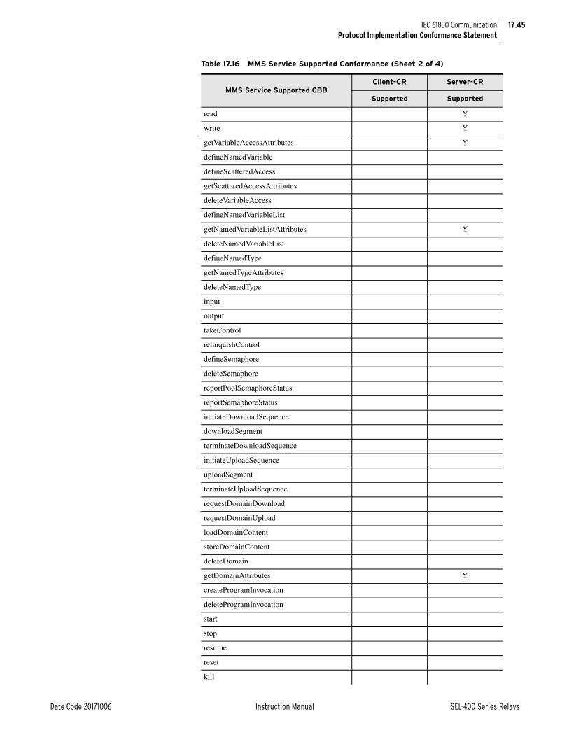
17.45
Date Code 20171006 Instruction Manual SEL-400 Series Relays
IEC 61850 CommunicationProtocol Implementation Conformance Statement
read Y
write Y
getVariableAccessAttributes Y
defineNamedVariable
defineScatteredAccess
getScatteredAccessAttributes
deleteVariableAccess
defineNamedVariableList
getNamedVariableListAttributes Y
deleteNamedVariableList
defineNamedType
getNamedTypeAttributes
deleteNamedType
input
output
takeControl
relinquishControl
defineSemaphore
deleteSemaphore
reportPoolSemaphoreStatus
reportSemaphoreStatus
initiateDownloadSequence
downloadSegment
terminateDownloadSequence
initiateUploadSequence
uploadSegment
terminateUploadSequence
requestDomainDownload
requestDomainUpload
loadDomainContent
storeDomainContent
deleteDomain
getDomainAttributes Y
createProgramInvocation
deleteProgramInvocation
start
stop
resume
reset
kill
Table 17.16 MMS Service Supported Conformance (Sheet 2 of 4)
MMS Service Supported CBBClient-CR Server-CR
Supported Supported

17.46
SEL-400 Series Relays Instruction Manual Date Code 20171006
IEC 61850 CommunicationProtocol Implementation Conformance Statement
getProgramInvocationAttributes
obtainFile Y
defineEventCondition
deleteEventCondition
getEventConditionAttributes
reportEventConditionStatus
alterEventConditionMonitoring
triggerEvent
defineEventAction
deleteEventAction
alterEventEnrollment
reportEventEnrollmentStatus
getEventEnrollmentAttributes
acknowledgeEventNotification
getAlarmSummary
getAlarmEnrollmentSummary
readJournal
writeJournal
initializeJournal
reportJournalStatus
createJournal
deleteJournal
fileOpen Y
fileRead Y
fileClose Y
fileRename
fileDelete Y
fileDirectory Y
unsolicitedStatus
informationReport Y
eventNotification
attachToEventCondition
attachToSemaphore
conclude Y
cancel Y
getDataExchangeAttributes
exchangeData
defineAccessControlList
getAccessControlListAttributes
reportAccessControlledObjects
Table 17.16 MMS Service Supported Conformance (Sheet 3 of 4)
MMS Service Supported CBBClient-CR Server-CR
Supported Supported

17.47
Date Code 20171006 Instruction Manual SEL-400 Series Relays
IEC 61850 CommunicationProtocol Implementation Conformance Statement
Table 17.17 lists specific settings for the MMS parameter conformance building block (CBB).
The following variable access conformance statements are listed in the order specified in the IEC 61850 standard, Part 8-1. Generally, only those services whose implementation is not mandatory are shown. Refer to the IEC 61850 stan-dard Part 8-1 for more information.
deleteAccessControlList
alterAccessControl
reconfigureProgramInvocation
Table 17.17 MMS Parameter CBB
MMS Parameter CBBClient-CR Server-CR
Supported Supported
STR1 Y
STR2 Y
VNAM Y
VADR Y
VALT Y
TPY Y
VLIS Y
CEI
Table 17.18 AlternateAccessSelection Conformance Statement
AlternateAccessSelectionClient-CR Server-CR
Supported Supported
accessSelection Y
component Y
index
indexRange
allElements
alternateAccess Y
selectAccess Y
component Y
index
indexRange
allElements
Table 17.16 MMS Service Supported Conformance (Sheet 4 of 4)
MMS Service Supported CBBClient-CR Server-CR
Supported Supported

17.48
SEL-400 Series Relays Instruction Manual Date Code 20171006
IEC 61850 CommunicationProtocol Implementation Conformance Statement
Table 17.19 VariableAccessSpecification Conformance Statement
VariableAccessSpecificationClient-CR Server-CR
Supported Supported
listOfVariable Y
variableSpecification Y
alternateAccess Y
variableListName Y
Table 17.20 VariableSpecification Conformance Statement
VariableSpecificationClient-CR Server-CR
Supported Supported
name Y
address
variableDescription
scatteredAccessDescription
invalidated
Table 17.21 Read Conformance Statement
ReadClient-CR Server-CR
Supported Supported
Request
specificationWithResult
variableAccessSpecification
Response
variableAccessSpecification Y
listOfAccessResult Y
Table 17.22 GetVariableAccessAttributes Conformance Statement
GetVariableAccessAttributesClient-CR Server-CR
Supported Supported
Request
name
address
Response
mmsDeletable
address
typeSpecification
Table 17.23 DefineNamedVariableList Conformance Statement (Sheet 1 of 2)
DefineVariableAccessAttributesClient-CR Server-CR
Supported Supported
Request
variableListName

17.49
Date Code 20171006 Instruction Manual SEL-400 Series Relays
IEC 61850 CommunicationProtocol Implementation Conformance Statement
GOOSE Services Conformance Statement
listOfVariable
variableSpecification
alternateAccess
Response
Table 17.24 GetNamedVariableListAttributes Conformance Statement
GetNamedVariableListAttributesClient-CR Server-CR
Supported Supported
Request
ObjectName
Response
mmsDeletable Y
listOfVariable Y
variableSpecification Y
alternateAccess Y
Table 17.25 DeleteNamedVariableList Conformance Statement
DeleteNamedVariableListClient-CR Server-CR
Supported Supported
Request
Scope
listOfVariableListName
domainName
Response
numberMatched
numberDeleted
DeleteNamedVariableList-Error
Table 17.23 DefineNamedVariableList Conformance Statement (Sheet 2 of 2)
DefineVariableAccessAttributesClient-CR Server-CR
Supported Supported
Table 17.26 GOOSE Conformance
Subscriber Publisher Value/Comment
GOOSE Services Y Y
SendGOOSEMessage Y
GetGoReference
GetGOOSEElementNumber
GetGoCBValues Y
SetGoCBValues
GSENotSupported
GOOSE Control Block (GoCB) Y

17.50
SEL-400 Series Relays Instruction Manual Date Code 20171006
IEC 61850 CommunicationACSI Conformance Statements
ACSI Conformance Statements
Table 17.27 Basic Conformance Statement
ServicesClient/
Subscribera
a Y = supportedN or blank = not supported
Server/Publishera
Value/Commentsa
Client-Server Roles
B11 Server side (of TWO-PARTY-APPLICATION-ASSOCIATION) Y
B12 Client side (of TWO-PARTY-APPLICATION-ASSOCIATION)
SCSMs Supported
B21 SCSM: IEC 6185-8-1 used Y
B22 SCSM: IEC 6185-9-1 used Deprecated in Edition 2
B23 SCSM: IEC 6185-9-2 used
B24 SCSM: other
Generic Substation Event (GSE) Model
B31 Publisher side Y
B32 Subscriber side Y
Transmission of Sampled Value Model (SVC)
B41 Publisher side
B42 Subscriber side Y
Table 17.28 ACSI Models Conformance Statement (Sheet 1 of 2)
Client/Subscribera Server/Publishera Value/Comments
If Server Side (B11) and/or Client Side (B12) Supported
M1 Logical device Y
M2 Logical node Y
M3 Data Y
M4 Data set Y
M5 Substitution
M6 Setting group control Y
Reporting
M7 Buffered report control Y
M7–1 sequence-number Y
M7–2 report-time-stamp Y
M7–3 reason-for-inclusion Y
M7–4 data-set-name Y
M7–5 data-reference Y
M7–6 buffer-overflow Y
M7–7 entryID Y
M7–8 BufTim Y
M7–9 IntgPd Y
M7–10 GI Y

17.51
Date Code 20171006 Instruction Manual SEL-400 Series Relays
IEC 61850 CommunicationACSI Conformance Statements
M7–11 conf-revision Y
M8 Unbuffered report control Y
M8–1 sequence-number Y
M8–2 report-time-stamp Y
M8–3 reason-for-inclusion Y
M8–4 data-set-name Y
M8–5 data-reference Y
M8–6 BufTim Y
M8–7 IntgPd Y
M8–8 GI Y
M8–9 conf-revision Y
Logging
M9 Log control
M9–1 IntgPd
M10 Log
M11 Control Y
M17 File transfer Y
M18 Application association
M19 GOOSE control block Y
M20 Sampled Value control block
If GSE (B31/32) Is Supported
M12 GOOSE Y
M13 GSSE Deprecated in Edition 2
If SVC (B41/42) Is Supported
M14 Multicast SVC
M15 Unicast SVC
For All IEDs
M16 Time Y Time source with required accuracy shall be available.
Only the time master is an SNTP (Mode 4 response) time server.
All other client/server devices require SNTP (Mode 3 request) clients.
a Y = supportedN or blank = not supported
Table 17.28 ACSI Models Conformance Statement (Sheet 2 of 2)
Client/Subscribera Server/Publishera Value/Comments

17.52
SEL-400 Series Relays Instruction Manual Date Code 20171006
IEC 61850 CommunicationACSI Conformance Statements
Table 17.29 ACSI Service Conformance Statement (Sheet 1 of 3)
Services AA: TP/MC Client (C) Server (S) Comments
Server
S1 1, 2 GetServerDirectory
(LOGICAL-DEVICE)
TP Y
Application Association
S2 1, 2 Associate Y
S3 1, 2 Abort Y
S4 1, 2 Release Y
Logical Device
S5 1, 2 GetLogicalDeviceDirectory TP Y
Logical Node
S6 1, 2 GetLogicalNodeDirectory TP Y
S7 1, 2 GetAllDataValues TP Y
Data
S8 1, 2 GetDataValues TP Y
S9 1, 2 SetDataValues TP
S10 1, 2 GetDataDirectory TP Y
S11 1, 2 GetDataDefinition TP Y
Data Set
S12 1, 2 GetDataSetValues TP Y
S13 1, 2 SetDataSetValues TP
S14 1, 2 CreateDataSet TP
S15 1, 2 DeleteDataSet TP
S16 1, 2 GetDataSetDirectory TP Y
Substitution
S17 1 SetDataValues TP
Setting Group Control
S18 1, 2 SelectActiveSG TP Y
S19 1, 2 SelectEditSG TP
S20 1, 2 SetEditSGValues TP
S21 1, 2 ConfirmEditSGValues TP
S22 1, 2 GetEditSGValues TP
S23 1, 2 GetSGCBValues TP Y
Reporting
Buffered Report Control Block (BRCB)
S24 1, 2 Report TP Y
S24–1 1, 2 data-change (dchg) Y
S24–2 1, 2 quality-change (qchg) Y
S24–3 1, 2 data-update (dupd)
S25 1, 2 GetBRCBValues TP Y
S26 1, 2 SetBRCBValues TP Y

17.53
Date Code 20171006 Instruction Manual SEL-400 Series Relays
IEC 61850 CommunicationACSI Conformance Statements
Unbuffered Report Control Block (URCB)
S27 1, 2 Report TP Y
S27–1 1, 2 data-change (dchg) Y
S27–2 1, 2 quality-change (qchg) Y
S27–3 1, 2 data-update (dup)
S28 1, 2 GetURCBValues TP Y
S29 1, 2 SetURCBValues TP Y
Logging
Log Control Block
S30 1, 2 GetLCBValues TP
S31 1, 2 SetLCBValues TP
Log
S32 1, 2 QueryLogByTime TP
S33 1, 2 QueryLogAfter TP
S34 1, 2 GetLogStatusValues TP
Generic Substation Event Model (GSE)
GOOSE
S35 1, 2 SendGOOSEMessage MC Y
GOOSE-CONTROL-BLOCK
S36 1, 2 GetGoReference TP
S37 1, 2 GetGOOSEElementNumber TP
S38 1, 2 GetGoCBValues TP Y
S39 1, 2 SetGoCBValues TP
GSSE
S40 1 SendGSSEMessage MC Deprecated in Edition 2
GSSE-CONTROL-BLOCK
S41 1 GetReference TP Deprecated in Edition 2
S42 1 GetGSSEElementNumber TP Deprecated in Edition 2
S43 1 GetGsCBValues TP Deprecated in Edition 2
S44 1 SetGsCBValues TP Deprecated in Edition 2
Transmission of Sampled Value Model (SVC)
Multicast SV
S45 1, 2 SendMSVMessage MC
Multicast Sampled Value Control Block
S46 1, 2 GetMSVCBValues TP
S47 1, 2 SetMSVCBValues TP
Unicast SV
S48 1, 2 SendUSVMessage TP
Unicast Sampled Value Control Block
S49 1, 2 GetUSVCBValues TP
S50 1, 2 SetUSVCBValues TP
Table 17.29 ACSI Service Conformance Statement (Sheet 2 of 3)
Services AA: TP/MC Client (C) Server (S) Comments

17.54
SEL-400 Series Relays Instruction Manual Date Code 20171006
IEC 61850 CommunicationPotential Client and Automation Application Issues With Edition 2 Upgrades
Potential Client and Automation Application Issues With Edition 2 Upgrades
The following are issues that IEC 61850 Edition 1 (Ed1)-based client or automa-tion applications may experience with IEC 61850 Edition 2 (Ed2) ICD and firm-ware changes. However, such issues may be resolved by reconfiguring the client or automation application or worked around by restoring the Ed1 (CID) configu-ration. None of these should prevent a client application from dynamically dis-covering the data in the IED as long as the application adheres to the
Control
S51 1, 2 Select
S52 1, 2 SelectWithValue TP Y
S53 1, 2 Cancel TP Y
S54 1, 2 Operate TP Y
S55 1, 2 CommandTermination TP Y
S56 1, 2 TimeActivatedOperate TP
File Transfer
S57 1, 2 GetFile TP Y
S58 1, 2 SetFile TP
S59 1, 2 DeleteFile TP
S60 1, 2 GetFileAttributeValues TP Y
S61 1, 2 GetServerDirectory
(FILE SYSTEM)
TP Y
Time
T1 1, 2 Time resolution of internal clock 20 Nearest negative power of 2 in seconds
(Number 0 . . . 24)
T2 1, 2 Time accuracy of internal clock IRIG-B
T4
PTP
T4
SNTP
T0
TL (ms) (low accuracy), T3 < 7) (only Ed. 2)
T0 (ms) ( 10 ms), 7 T3 < 10
T1 (µs) ( 1 ms), 10 T3 < 13
T2 (µs) ( 100 µS), 13 T3 < 15
T3 (µs) ( 25 µS), 15 T3 < 18
T4 (µs) ( 25 µS), 15 T3 < 18
T5 (µs) ( 1 µS), T3 20
T3 1, 2 Supported TimeStamp resolution IRIGB
18
PTP
18
SNTP
7
Nearest value of 2n in seconds
(Number 0 . . . 24)
Table 17.29 ACSI Service Conformance Statement (Sheet 3 of 3)
Services AA: TP/MC Client (C) Server (S) Comments

17.55
Date Code 20171006 Instruction Manual SEL-400 Series Relays
IEC 61850 CommunicationPotential Client and Automation Application Issues With Edition 2 Upgrades
specification of the standard. Note that upgrading to Ed2 firmware will not break existing Ed1 configurations (CID files) in the field, nor require loading an Ed2 version of the CID file.
Unexpected Error MessagesSome MMS and control errors have been changed in Ed2. Hence, the firmware now issues only the Ed2-compliant errors. Clients or automation applications that rely on the Ed1-compliant errors will not function correctly. You can resolve this by reconfiguring the client or automation application to accept Ed2-compliant errors.
Missing or Unknown Data Objects and AttributesEd2 has changed some data object and attribute names, as well as the data types of some attributes. Ed2 also prohibits the use of proprietary CDCs. See Common Logical Nodes on page 17.30 and the logical nodes tables in each product-spe-cific manual to determine the Ed2 names. This may cause the failure of clients or automation applications that rely on the Ed1 names. A workaround is to use the Ed1 version of the CID file, if available, to configure the IED. You can also resolve this by reconfiguring the client or automation application to accept the Ed2 names.
Unable to Find Operate Time-OutA proprietary method was used to specify the operate time-out of control objects in the CID files. A client or automation application that relies on this proprietary method will fail to find the operate time-out in the CID file. A workaround is to use the Ed1 CID file to configure the IED. You can also resolve this by reconfig-uring the client or automation application to accept the Ed2 control object operate time-outs.
Unexpected Control Block Data Attribute TypeThe string type data attributes in control blocks (RptID, DatSet, etc.) have been changed from a maximum length of 65 to 129 characters, i.e., VisString65 to Vis-String129. Some clients and automation applications might see this as an error when the type is reported in the MMS GetVariableAccessAttributes response. You can resolve this by reconfiguring the client or automation application.
Unexpected ReportsEd2 requires report buffering to start when the device is turned on, unlike in the Ed1 implementation where report buffering started after the first report enable. If a client or automation application relies on the Ed1 behavior, it might fail or indi-cate an error if the IED sends buffered reports immediately after the first enable. You can resolve this by reconfiguring the client or automation application.
Failure to Reselect a Control Object Before the TimeoutIn Ed1, if a client reselected a control object before the select-before-operate time-out expired, the reselection would succeed and cause the selected time-out to restart. According to Ed2, this reselection is supposed to fail. Ed1-based cli-

17.56
SEL-400 Series Relays Instruction Manual Date Code 20171006
IEC 61850 CommunicationPotential Client and Automation Application Issues With Edition 2 Upgrades
ents or automation applications that rely on successful reselection might operate incorrectly. You can resolve this by reconfiguring the client or automation appli-cation.
Test Control Commands Fail ImmediatelyIn Ed1, if the test attribute was set in a control command structure, the relay would accept the command but perform no action on the target control object. With enhanced control models, the IED would eventually report an operate time-out error after the operate time-out expired. However, in Ed2, any such test com-mands will fail immediately with an error indicating that the command is blocked because the IED is not in the appropriate mode. Clients or automation applica-tions that depend on the Ed1 behavior might fail. You can resolve this by recon-figuring the client or automation application.
No ReportsEd2 specifies that no reports are to be generated for a dead-banded attribute if the dead band is set to 0. Previously in Ed1, a dead band of 0 would cause the relay to generate reports for any change in the instantaneous value. Ed1-based clients or automation applications might not operate correctly because of the lack of reports. You can resolve this by reconfiguring the client or automation applica-tion.

Date Code 20171006 Instruction Manual SEL-400 Series Relays
Instruction ManualInstruction ManualS E C T I O N 1 8
Synchrophasors
Most SEL-400 series relays can be configured to function as a phasor measure-ment unit (PMU).
This section covers:
➤ Synchrophasor Measurement on page 18.3
➤ Settings for Synchrophasors on page 18.6
➤ Synchrophasor Quantities on page 18.18
➤ View Synchrophasors by Using the MET PM Command on page 18.21
➤ C37.118 Synchrophasor Protocol on page 18.23
➤ SEL Fast Message Synchrophasor Protocol on page 18.29
➤ Control Capabilities on page 18.33
➤ PMU Recording Capabilities on page 18.42
Introduction The word synchrophasor is derived from two words: synchronized phasor. Syn-chrophasor measurement refers to the concept of providing measurements taken on a synchronized schedule in multiple locations. A high-accuracy clock, com-monly a Global Positioning System (GPS) receiver such as the SEL-2407 Satel-lite-Synchronized Clock, makes synchrophasor measurement possible.
The availability of an accurate time reference over a large geographic area allows multiple devices, such as a number of relays, to synchronize the gathering of power system data. The accurate clock allows precise event report triggering and other offline analysis functions.
The Global settings class contains the synchrophasor settings, including the choice of Synchrophasor Protocol and the synchrophasor data set the relay will transmit. The Port settings class selects which port(s) are configured for Synchro-phasor Protocol use.
The high-accuracy timekeeping function generates status Relay Word bits and time-quality information that is important for synchrophasor measurement. Some protection SELOGIC variables, and programmable digital trigger information (C37.118 protocol only) is also added to the Relay Word bits for synchrophasors (see Synchrophasor Relay Word Bits).
When synchrophasor measurement is enabled, the relay creates the synchropha-sor data set at a rate of either 50 or 60 times per second, depending on the nomi-nal system frequency (Global setting NFREQ). This dataset, including time-of-sample, is available in analog quantities in the relay (see Synchrophasor Analog Quantities). You can view synchrophasor data over the relay ASCII terminal interface (see View Synchrophasors by Using the MET PM Command on page 18.21).

18.2
SEL-400 Series Relays Instruction Manual Date Code 20171006
SynchrophasorsIntroduction
The value of synchrophasor data increases greatly when the data can be shared over a communications network in real time. Two Synchrophasor Protocols are available in the relay that allow for a centralized device to collect data efficiently from several phasor measurement units (PMUs). Some possible uses of a system-wide synchrophasor system include the following:
➤ Power-system state measurement
➤ Wide-area network protection and control schemes
➤ Small-signal analysis
➤ Power-system disturbance analysis
The SEL-5078-2 SYNCHROWAVE Central Software quickly translates power sys-tem data into visual information. It is a powerful yet easy-to-use solution for dis-playing and analyzing real-time streaming data, archived data, and relay event data, and provides a time-synchronized, wide-area view of your system. SYN-CHROWAVE Central includes Event Viewer, providing engineers and operators the ability to view PMU data and perform event analysis by viewing relay event reports directly from SYNCHROWAVE Central.
The SEL-3378 synchrophasor vector processor (SVP) is a real-time synchropha-sor programmable logic controller. Use the SVP to collect synchrophasor mes-sages from relays and phasor measurement units (PMUs). The SVP time-aligns incoming messages, processes these messages with an internal logic engine, and sends control command to external devices to perform user-defined actions. Additionally, the SVP can send calculated or derived data to devices such as other SVPs, phasor data concentrators (PDCs), and monitoring systems.
In any installation, the relay can use only one of the synchrophasor message for-mats, SEL Fast Message Synchrophasor, or C37.118, as selected by Global set-ting MFRMT. The chosen format is available on multiple serial ports when port setting(s) PROTO := PMU. C37.118 is available over Ethernet when the Port 5 setting EPMIP = Y.
With either the SEL Fast Message or C37.118 synchrophasor format, the relay can receive control operation commands over the same channel used for synchro-phasor data transmission. These commands are SEL Fast Operate messages, which are described in SEL Fast Meter, Fast Operate, Fast SER Messages, and Fast Message Data Access on page 15.28.
After enabling the data recording function with the Global EPMDR settings, record synchrophasor data using the PMTRIG setting. When PMTRIG asserts, the relay records synchrophasor data in binary format (IEEE C37.118 data format compliant) for the duration specified with the PMLER setting. The relay stores these files in the synchrophasor subdirectory in the relay.
You can configure the relay to receive C37.118 protocol synchrophasor data. The relay receives the data over a serial connection and stores these data in Analog Quantities. Time-alignment is automatic. Use the local phasor data and as many as two remote sets of phasor data in SELOGIC equations.

18.3
Date Code 20171006 Instruction Manual SEL-400 Series Relays
SynchrophasorsSynchrophasor Measurement
Synchrophasor MeasurementThe PMU uses the signal processing shown in Figure 18.1 to measure the syn-chrophasors. The input signal passes through a traditional anti-aliasing low-pass filter (LPF). This filter has a cutoff frequency of 250 Hz. The PMU decimates this 8 kHz filtered data by eight and then processes the resulting data at 1 kHz.
The PMU then modulates the 1 kHz data with two sinusoids, each 90 degrees apart to produce real and imaginary components of the synchrophasor. The mod-ulating sinusoids are synchronized to absolute time to provide an absolute time reference for the synchrophasor. Also an angular compensation factor compen-sates for the phase shift introduced by the PMU hardware and software.
The modulated data are filtered using low-pass filters. The filter coefficients are based on NFREQ, PMAPP, and MRATE. The filtered data provides good attenu-ation for harmonics and interharmonics. For PMAPP = F and N the attenuation is 20 dB. For PMAPP = 1 the attenuation is 40 dB.
Figure 18.2 shows the magnitude frequency response of the synchronized phasor measurement for PMAPP = F, N, and 1 for MRATE = 60.
Figure 18.1 Synchrophasor Processing Block Diagram
V kmI kn
Filter A
Filter B
Time
FREQPM
Time
1 kHzData
LowpassFilter andDecimateto 1 kHz
8 kHzData
1 kHzReal Data
1 kHzImaginary
Data
Downsampleto NFREQ
Magnitudeand Angle
Compensationj
V km SF
I kn SF
Figure 18.2 Magnitude Frequency Response

18.4
SEL-400 Series Relays Instruction Manual Date Code 20171006
SynchrophasorsSynchrophasor Measurement
After low-pass filtering, the data are decimated to the nominal power system fre-quency (NFREQ).
If frequency-based phasor compensation is enabled (PHCOMP = Y), the relay calculates a compensation factor based on the measured synchrophasor fre-quency (FREQPM) and filter configuration (based on NFREQ, MRATE, and PMAPP). The PMU then corrects the measured synchrophasors by this factor.
Using the VmCOMP and InCOMP settings, the PMU compensates the voltage and current synchrophasors for any externally introduced phase angle errors. The PMU adds the user-entered phase angle to the phase angle of the measured syn-chrophasor.
The PMU converts the synchrophasor data to primary units by multiplying them with the respective PT or CT ratios. Note that the resulting data VkmSF and IknSF is in complex form (A + jB). The PMU calculates the positive-sequence synchrophasor with the three-phase synchrophasors.
The PMU then converts all synchrophasor data to polar and rectangular quanti-ties. The data are available as analog quantities as well as for the synchrophasor data frames. The synchrophasor data are updated at the nominal power system frequency.
AccuracyThe following phasor measurement accuracy is valid when frequency-based pha-sor compensation is enabled (Global setting PHCOMP := Y), and when the pha-sor measurement application setting is in the narrow bandwidth mode (Global setting PMAPP := N).
NOTE: When the PMU is in the fast response mode (Global setting PMAPP := F), the TVE is within specified limits only when the out of band interfering signals influence quantity is not included.
TVE (total vector error) 1% for one or more of the following influence quantities.
➤ For PMAPP = N Signal Frequency Range: ±5 Hz of nominal (50 or 60 Hz)
➤ For PMAPP = 1 Signal Frequency Range: ±2 Hz of 60 Hz
➤ Voltage Magnitude Range: 30 V–150 V
➤ Current Magnitude Range: (0.1–2) • INOM, (INOM = 1 A or 5 A)
➤ Phase Angle Range: –179.99° to 180°
➤ Harmonic distortion 10 percent (any harmonic)
➤ Out of band interfering signals 10 percent
The out-of-band interfering signal frequency (fi) must satisfy:
| fi – NFREQ | > MRATE/2,
where NFREQ is nominal system frequency and MRATE is the message rate, as defined in IEEE C37.118.
It is important to note that the synchrophasors can only be correlated when the PMU is in HIRIG or HPTP timekeeping mode, which can be verified by monitor-ing the TSOK Relay Word bit. When TSOK = logical 1, the PMU timekeeping is synchronized to the high-accuracy IRIG-B signal or PTP time source, and the synchrophasor data are precisely time-stamped. See Section 11: Time and Date Management for details.

18.5
Date Code 20171006 Instruction Manual SEL-400 Series Relays
SynchrophasorsSynchrophasor Measurement
PMU Data Block Status In a PMU data frame, each data block is headed by a two-byte STAT field. This field indicates the status of the PMU data block. Bit 15 of the STAT field indi-cates the validity of data. SEL-400 series relays assert bit 15 of the STAT when synchrophasor test mode indicator PMTEST asserts or SVBLK asserts in SEL-400 series Sampled Values (SV)-subscriber relays.
For SV-subscribing relays, configure Global setting SVBLK to assert on errors encountered in SV data acquisition. For example, set SVBLK := IAWBK OR IBWBK OR ICWBK. In this example, if SV data for any Terminal W current is lost, SVBLK asserts, which then asserts bit 15 in the STAT field, indicating cur-rent data have errors and, therefore, synchrophasor data are invalid.
For an explanation of other bits in the STAT field, refer to the IEEE C37.118 standard.
Synchrophasor FrequencyThe PMU calculates frequency deviation and rate-of-change of frequency from the synchrophasor positive-sequence voltage angle (V1nPMA where n = PMFRQST) as follows.
First the PMU calculates the frequency deviation from nominal using the follow-ing formula.
Equation 18.1
Where k is the V1nPMA and k-1 is V1nPMA calculated 1 cycle previously. t is the time difference between the angle calculations (k increments once a nominal power system cycle).
Next, the PMU averages the frequency deviation as shown in Equation 18.2 and Equation 18.3.
If the frequency application is smooth (PMFRQA = S)
Equation 18.2
If the frequency application is fast (PMFRQA = F)
Equation 18.3
fkk k 1–– t 360
-----------------------------=
favgk
fk n–
n 0=
9
fmax1– fmax2– fmin1– fmin2–
6---------------------------------------------------------------------------------------------------------=
favgk
fk n–
n 0=
3
fmax– fmin–
2--------------------------------------------------------------=

18.6
SEL-400 Series Relays Instruction Manual Date Code 20171006
SynchrophasorsSettings for Synchrophasors
The PMU then calculates rate-of-change of frequency, dƒdt from the averaged frequencies deviations (Equation 18.4).
Equation 18.4
If the frequency value is equal to or within ±20 Hz and V1nMPM/PTRn (secondary) is larger than 0.1 • VNOMn then:
If the frequency value exceeds ±20 Hz or the V1nMPM/PTRn (secondary) is below 0.1 • VNOMn then:
The frequency and rate-of-change of frequency are available as analog quantities as well as for the synchrophasor data frames. The data are updated at the nominal power system frequency.
Settings for SynchrophasorsEach SEL-400 series relay supports a variety of current and voltage terminals. See the product-specific instruction manuals to see which terminals are available to synchrophasors. Synchrophasors are primarily configured through the Global settings. There are also a few port settings necessary to enable synchrophasor communications.
Global SettingsThe Global enable setting EPMU must be set to Y before the remaining synchro-phasor settings are available. The PMU is disabled when EPMU := N.
FREQPMk = favgk + NFREQ <analog>
DFDTPMk = dfdtk <analog>
After six consecutive cycles
FROKPMk = 1 <digital>
FREQPMk = FREQPMk-1 <analog>
DFDTPMk = 0 <analog>
FROKPMk = 0 <digital>
Table 18.1 Synchrophasor Analog Quantities Frequency
Name Description Units
FREQPM Measured system frequency Hz
DFDTPM Rate-of-change of frequency Hz/s
dfdtkfavgk favgk 1––
t---------------------------------------------=
Table 18.2 Global Settings for Configuring the PMU (Sheet 1 of 2)
Setting Setting Prompt
EPMU Synchronized Phasor Measurement (Y, N)
MFRMT Message Format (C37.118, FM)
MRATE Messages per Second (1, 2, 4, 5, 10, 12, 15, 20, 30, 60)a
PMAPP PMU Application (F, N, 1)
PMLEGCY Synchrophasor Legacy Settings (Y, N, N1b)

18.7
Date Code 20171006 Instruction Manual SEL-400 Series Relays
SynchrophasorsSettings for Synchrophasors
Descriptions for some of the settings in Table 18.2 are as follows.
MFRMT
Selects the message format for synchrophasor data.
SEL recommends the use of MFRMT := C37.118 for any new PMU applications because of increased setting flexibility and the expected availability of software for synchrophasor processors. The PMU still includes the MFRMT := FM setting choice to maintain compatibility in any systems presently using SEL Fast Mes-sage synchrophasors.
MRATE
Selects the message rate in messages per second for synchrophasor data.
Choose the MRATE setting that suits the needs of your PMU application. The PMU supports as many as 60 messages per second if NFREQ = 60 and as many as 50 messages per second if NFREQ = 50.
NUMPHDC Number of Data Configurations (1–5)
PMSTNqc Station Name (16 characters)
PMIDqc PMU Hardware ID (1–65534)
PHDVqc Phasor Data Set, Voltages (V1, PH, ALL)
PHDIqc Phasor Data Set, Currents (I1, PH, ALL)
PHNRqc Phasor Num. Representation (I = Integer, F = Float)
PHFMTqc Phasor Format (R = Rectangular, P = Polar)
FNRqc Freq. Num. Representation (I = Integer, F = Float)
TREA[1–4] Trigger Reason Bit [1–4] (SELOGIC Equation)
PMTRIG Trigger (SELOGIC Equation)
PMTEST PMU in Test Mode (SELOGIC Equation)
VkCOMPd Comp. Angle Terminal k (–179.99° to 180°)
InCOMPe Comp. Angle Terminal n (–179.99° to 180°)
PMFRQST PMU Primary Frequency Source Terminal
PMFRQA PMU Frequency Application (F, S)
PHCOMP Freq. Based Phasor Compensation (Y, N)
a If NFREQ = 50 then the range is 1, 2, 5, 10, 25, 50.b PMLEGCY option of N1 only applies to the SEL-487E.c q = 1–NUMPHDC.d k = voltage terminal.e n = current terminal.
Table 18.2 Global Settings for Configuring the PMU (Sheet 2 of 2)
Setting Setting Prompt

18.8
SEL-400 Series Relays Instruction Manual Date Code 20171006
SynchrophasorsSettings for Synchrophasors
PMAPP
Selects the type of digital filters used in the synchrophasor measurement.
➤ The Narrow Bandwidth setting (N) represents filters with a cutoff frequency approximately 1/4 of MRATE. The response in the frequency domain is narrower, and response in the time domain is slower. This method results in synchrophasor data that are free of aliasing signals and well suited for post-disturbance analysis.
➤ The Fast Response setting (F) represents filters with a higher cutoff frequency. The response in the frequency domain is wider and the response in the time domain is faster. This method results in synchrophasor data that can be used in synchrophasor applications requiring more speed in tracing system parameters.
➤ The Filter One setting (1) represents filters that have a response much narrower than the narrow bandwidth filters. This method has a better step response with overshoot within 7.5 percent. This filter is available only for MRATE = 60.
PMLEGCY
This setting is provided for supporting legacy synchrophasor settings. Set this to N to access the latest features. See Legacy Settings on page 18.16 to see a description of the legacy settings. The remainder of this subsection describes the non-legacy settings.
NUMPHDC
Enables as many as five unique synchrophasor data configurations.
The four serial ports (Port 1, 2, 3, and F) and two Ethernet sessions (TCP/UDP sessions 1 and 2) can be mapped to any of these five data configurations. In other words each port can be configured to send unique synchrophasor data streams.
PMSTNq and PMIDqDefines the station name and number of the PMU for data configuration q.
The PMSTNq setting is an ASCII string with as many as 16 characters. The PMIDq setting is a numeric value. Use your utility or synchrophasor data con-centrator naming convention to determine these settings. PMSTNq allows all printable characters.
Phasors Included in the Data qTerminal Name, Relay Word Bit, Alternate Terminal Name
Specify the terminal for Synchrophasor measurement and transmission in the synchrophasor data stream q.
This is a freeform setting category for enabling the terminals for synchrophasor measurement and transmission. This freeform setting has three arguments. Spec-ify the terminal name (any one of the valid terminals for the relay) for the first argument. Specify any Relay Word bit for the second argument. Specify the alter-nate terminal name (any one of the valid terminals for the relay) for the third argument.
The second and third arguments are optional unless switching between terminals is required. Whenever the Relay Word bit in the second argument is asserted the terminal synchrophasor data are replaced by the alternate terminal data.

18.9
Date Code 20171006 Instruction Manual SEL-400 Series Relays
SynchrophasorsSettings for Synchrophasors
PHDVqSelects the type of voltages to be included in the synchrophasor data stream q.
This setting affects the synchrophasor data packet size.
➤ PHDVq := V1, sends only positive-sequence voltage synchrophasors of selected terminals.
➤ PHDVq := PH, sends only phase voltage synchrophasors of selected terminals.
➤ PHDVq := ALL, sends phase and positive-sequence voltage synchrophasors of selected terminals.
PHDIqSelects the type of currents to be included in the synchrophasor data stream q.
This setting affects the synchrophasor data packet size.
➤ PHDIq := I1, sends only positive-sequence current synchrophasors of selected terminals.
➤ PHDIq := PH, sends only phase current synchrophasors of selected terminals.
➤ PHDIq := ALL, sends phase and positive-sequence current synchrophasors of selected terminals.
PHNRqSelects the numeric representation, integer (I) or floating-point (F), of voltage and current phasor data in the synchrophasor data stream q. This setting affects the synchrophasor data packet size.
➤ PHNRq := I sends each voltage and/or current synchrophasor as 2 two-byte integer values. The PMU uses ((7 • INOM • CT Ratio) / 32768) • 100000)) for the current phasor scaling factor and uses ((150 • PTR) / 32768) • 100000)) for the voltage phasor scaling factor. INOM is 1 A or 5 A.
➤ PHNRq := F sends each voltage and/or current synchrophasor as 2 four-byte floating-point values.
PHFMTqSelects the phasor representation of voltage and current phasor data in the syn-chrophasor data stream q.
➤ PHFMTq := R (rectangular) sends each voltage and/or current synchrophasor as a pair of signed real and imaginary values.
➤ PHFMTq := P (polar) sends each voltage and/or current synchrophasor as a magnitude and angle pair. The angle is in radians when PHNRq := F, and in radians • 104 when PHNRq := I. The range is – < angle .
In both the rectangular and polar representations, the values are scaled in root mean square (rms) units. For example, a synchrophasor with a magnitude of 1.0 at an angle of –30 degrees will have a real component of 0.866, and an imaginary component of –0.500.

18.10
SEL-400 Series Relays Instruction Manual Date Code 20171006
SynchrophasorsSettings for Synchrophasors
FNRqSelects the numeric representation, integer (I) or floating-point (F), of the two frequency values in the synchrophasor data stream q.
This setting affects the synchrophasor data packet size.
➤ FNRq := I sends the frequency data as a difference from nominal frequency, NFREQ, with the following formula.
(FREQPM – NFREQ) • 1000,
represented as a signed, two-byte value. See Synchrophasor Frequency on page 18.5 for details.
➤ FNRq := I also sends the rate-of-change of frequency data with scaling.
DFDTPM • 100,
represented as a signed, two-byte value. See Synchrophasor Frequency on page 18.5 for details.
➤ FNRq := F sends the measured frequency data and rate-of-change-of-frequency as two four-byte, floating point values.
Phasor Aliases in Data Configuration qPhasor Name, Alias Name
This is a freeform setting category with two arguments. Specify the phasor name and a 16 character descriptive name to be included in the synchrophasor data stream q. If a phasor is not assigned a descriptive name, it will be described using the phasor name.
Analog Quantities in Data Configuration qAnalog Quantity Name, Alias Name
This is a freeform setting category with two arguments. Specify the analog quan-tity name and an optional 16 character descriptive name to be included in the syn-chrophasor data stream q. See Section 12: Analog Quantities in the product-specific instruction manual for a list of analog quantities that the PMU supports. The PMU can be configured for as many as 16 unique analog quantities for each data configuration q. The analog quantities are floating point values, so each ana-log quantity the PMU includes will take four bytes.
Digitals in Data Configuration q Relay Word Bit Name, Alias Name
This is a freeform setting category with two arguments. Specify the Relay Word bit name and an optional 16 character descriptive name that you need to include in the synchrophasor data stream q. See the Relay Word Bits section of the relay-specific instruction manual for a list of Relay Word bits that the PMU supports. You can configure the PMU for as many as 64 unique digitals for each data con-figuration.

18.11
Date Code 20171006 Instruction Manual SEL-400 Series Relays
SynchrophasorsSettings for Synchrophasors
TREA1, TREA2, TREA3, TREA4, and PMTRIG
Defines the programmable trigger bits as allowed by IEEE C37.118.
Each of the four Trigger Reason settings, TREA1–TREA4, and the PMU Trigger setting, PMTRIG, are SELOGIC control equations. The PMU evaluates these equations and places the results in Relay Word bits with the same names: TREA1–TREA4 and PMTRIG.
NOTE: Select PMTRIG trigger conditions to assert PMTRIG no more frequently than once every four hours if EPMDR = Y (i.e., synchrophasor recording is enabled).
The Trigger Reason equations represent the Trigger Reason bits in the STAT field of the data packet. After the Trigger Reason bits are set to convey a message, the PMTRIG Equation should be asserted for a reasonable amount of time, to allow the synchrophasor processor to read the TREA1–TREA4 fields.
The IEEE C37.118 standard defines the first 8 of 16 binary combinations of these trigger reason bits (Bits 0–3).
The remaining eight binary combinations are available for user definition.
The PMU does not automatically set the TREA1–TREA4 or PMTRIG Relay Word bits—these bits must be programmed.
These bits may be used to send various messages at a low bandwidth via the syn-chrophasor message stream. Digital Status Words may also be used to send binary information directly, without the need to manage the coding of the trigger reason messages in SELOGIC.
Use these Trigger Reason bits if your synchrophasor system design requires these bits. The PMU synchrophasor processing and protocol transmission are not affected by the status of these bits.
PMTEST
Program this SELOGIC setting to force the PMU to test mode. The SELOGIC eval-uation of this setting, PMTEST is mapped to the data valid bit (i.e., bit 15) in the STAT field.
VkCOMP
The VkCOMP (k = voltage terminals) setting allows correction for any steady-state voltage phase errors (from the PTs or wiring characteristics). See Synchro-phasor Measurement on page 18.3 for details on this setting.
InCOMP
The InCOMP (n = current terminals) settings allow correction for any steady-state phase errors (from the CTs or wiring characteristics). See Synchrophasor Measurement on page 18.3 for details on these settings.
PMFRQST
Selects the voltage terminal that will be the primary source of the system fre-quency for the PMU calculations. For example, if PMFRQST = Z, then the Z PT terminal is the source for frequency estimation.

18.12
SEL-400 Series Relays Instruction Manual Date Code 20171006
SynchrophasorsSettings for Synchrophasors
PMFRQA
Selects the PMU frequency application. A setting of S sets a smooth frequency application. A setting of F selects a fast frequency application.
The frequency application is used in the calculation of the rate of change of fre-quency for a given analog signal. A smooth frequency application setting (PMFRQA = S) uses 9 cycles of data for the rate of change calculation. A fast frequency application setting (PMFRQA = F) uses 3 cycles of data for the rate of change calculation.
The fast frequency application will detect rapid changes in frequency faster, but will also contain more low-level oscillations. The slow frequency application will provide a rate of change profile that is smoother, but slower to respond to rapid frequency fluctuations.
PHCOMP
Enables or disables frequency-based compensation for synchrophasors.
For most applications, set PHCOMP := Y to activate the algorithm that compen-sates for the magnitude and angle errors of synchrophasors for frequencies that are off nominal.
For PMAPP = F or N, the PMU only compensates if the estimated frequency is ±5 Hz of nominal frequency. For PMAPP = 1 the PMU compensates if the fre-quency is ±2 Hz of nominal frequency.
Serial Port SettingsThe port settings found in Table 18.3 are used for configuring synchrophasor data transmission over a serial port.
Descriptions for some of the settings in Table 18.3 are as follows.
Table 18.3 Serial Port 1, 2, 3, F Settings for Synchrophasors
Setting Description
PROTO Protocol (SEL, DNP, MBA, MBB, PMUa)
a The specific protocol choices available depends on the relay.
SPEED Data Speed (300–57600)
STOPBIT Stop Bits (1, 2)
RTSCTS Enable Hardware Handshaking (Y, N)
FASTOP Enable Fast Operate Messages (Y, N)
PMUMODE PMU Mode (CLIENTA, CLIENTB, SERVER)
PMODC PMU Output Data Configuration (1–5)

18.13
Date Code 20171006 Instruction Manual SEL-400 Series Relays
SynchrophasorsSettings for Synchrophasors
PROTO
Setting this to PMU enables synchrophasor data transmission on the specific serial port. Once set to PMU that specific serial port cannot be used for accessing settings or issuing any ASCII commands.
If PROTO := PMU and MFRMT := C37.118, then the serial port will only respond to C37.118 commands.
➤ Stop synchrophasor data
➤ Start synchrophasor data
➤ Send header data
➤ Send Configuration 1 data
➤ Send Configuration 2 data
➤ Process extended frame data
If PROTO := PMU or SEL and MFRMT := FM, then the serial port will only respond to SEL Fast Message synchrophasor commands.
SPEED
Select the data rate (300–57600) for synchrophasor data transmission on the spe-cific serial port. This setting affects the synchrophasor data packet size. See Com-munications Bandwidth on page 18.24 for detailed information.
PMUMODE
Set PMUMODE := SERVER if the serial port is intended to send synchrophasor data. Client applications are described in Real-Time Control on page 18.36.
PMODCNOTE: If PMODC is set to a number that exceeds the setting for NUMPHDC, the port sends the data for the first PMU configuration.
Select the data configuration (1-NUMPHDC) for synchrophasor data transmis-sion on the specific serial port. This setting affects the synchrophasor data packet size. See Communications Bandwidth on page 18.24 for detailed information. Through the use of this setting each serial port can be configured to stream unique synchrophasor data.
EPMU := N Supersedes Synchrophasor Port Settings
The PROTO := PMU settings choice can be made even when Global setting EPMU := N. However, in this situation, the serial port will not respond to any commands or requests. Either enable synchrophasors by setting EPMU to Y, or change the port PROTO setting to SEL.
If you use a computer terminal session or ACSELERATOR QuickSet SEL-5030 Software connected to a serial port, and then set that same serial port PROTO set-ting to PMU, you will lose the ability to communicate with the relay through ASCII commands or virtual file interface commands. If this happens, either con-nect via another serial port (that has PROTO := SEL) or use the front-panel HMI SET/SHOW screen to change the disabled port PROTO setting back to SEL.

18.14
SEL-400 Series Relays Instruction Manual Date Code 20171006
SynchrophasorsSettings for Synchrophasors
Ethernet Port SettingsThe settings found in Table 18.4 are used for configuring synchrophasor data transmission over an Ethernet port.
Descriptions for some of the settings in Table 18.4 are as follows.
EPMIP
Setting this to Y enables synchrophasor data transmission over Ethernet port. Set-ting this to N disables the synchrophasor data transmission over Ethernet port. The EPMIP := Y settings choice can be made when Global setting EPMU := N. This setting combination will result in the relay ignoring any incoming synchro-phasor requests regardless of whether the Ethernet port settings are correct or not.
PMOTS[2]
Selects the PMU Output transport scheme for session 1 and 2, respectively.
➤ PMOTS[2] := TCP establishes a single, persistent TCP socket for transmitting and receiving synchrophasor messages (both commands and data), as illustrated in Figure 18.3.
Table 18.4 Ethernet Port 5 Settings for Synchrophasors
Setting Description Default
EPMIP Enable PMU Processing (Y, N) N
PMOTS1 PMU Output 1 Transport Scheme (OFF, TCP, UDP_S, UDP_T, UDP_U)
OFF
PMODC1 PMU Output 1 Data Configuration (1–5) 1
PMOIPA1 PMU Output 1 Client IP (Remote) Address (www.xxx.yyy.zzz) 192.168.1.3
PMOTCP1 PMU Output 1TCP/IP (Local) Port Number (1–65534) 4712
PMOUDP1 PMU Output 1 UDP/IP Data (Remote) Port Number (1–65534) 4713
PMOTS2 PMU Output 2 Transport Scheme (OFF, TCP, UDP_S, UDP_T, UDP_U)
OFF
PMODC2 PMU Output 2 Data Configuration (1–5) 1
PMOIPA2 PMU Output 2 Client IP (Remote) Address (www.xxx.yyy.zzz) 192.168.1.4
PMOTCP2 PMU Output 2 TCP/IP (Local) Port Number (1–65534) 4722
PMOUDP2 PMU Output 2 UDP/IP Data (Remote) Port Number (1–65534) 4714
Figure 18.3 TCP Connection
C37.118 - Synchrophasor Command Start Request - Synchrophasor Command Stop Request - Synchrophasor Command Configuration Request 1 - Synchrophasor Command Configuration Request 2 - Synchrophasor Command Header Frame Request - Synchrophasor Command Extended Frame
C37.118 - Synchrophasor Measurement - Synchrophasor Configuration Response 1 - Synchrophasor Configuration Response 2 - Synchrophasor Header Frame
TCP Socket
(Persistent)
SEL-400

18.15
Date Code 20171006 Instruction Manual SEL-400 Series Relays
SynchrophasorsSettings for Synchrophasors
➤ PMOTS[2] := UDP_T establishes two socket connections. A nonpersistent TCP connection is used for receiving synchrophasor command messages as well as synchrophasor configuration and header response messages. A persistent UDP connection is used to transmit synchrophasor data messages. Figure 18.4 depicts the UDP_T connection.
➤ PMOTS[2] := UDP_U uses the same connection scheme as the UDP_T except the synchrophasor configuration and header response messages are sent over the UDP connection, as shown in Figure 18.4.
➤ PMOTS[2] := UDP_S establishes a single persistent UDP socket to transmit synchrophasor messages. Synchrophasor data are transmitted whenever new data are read. With this communications scheme, the relay sends a “Synchrophasor Configuration Response 2” once every minute, as shown in Figure 18.5.
PMODC[2]NOTE: If PMODC is set to a number that exceeds the setting for NUMPHDC, the port sends the data for the first PMU configuration.
Select the data configuration (1-NUMPHDC) for synchrophasor data transmis-sion on the specific session 1 and 2. Using this setting, each Ethernet session can be configured to stream unique synchrophasor data.
PMOIPA[2]
Defines the PMU Output Client IP address for session 1 and 2, respectively.
PMOTCP[2]
Defines the TCP/IP (Local) port number for session 1 and 2, respectively. These port numbers must all be unique.
PMOUDP[2]
Defines the UDP/IP (Remote) port number for session 1 and 2, respectively.
Figure 18.4 UDP_T and UDP_U Connections
Figure 18.5 UDP_S Connection
C37.118 - Synchrophasor Command Start Request - Synchrophasor Command Stop Request - Synchrophasor Command Configuration Request 1 - Synchrophasor Command Configuration Request 2 - Synchrophasor Command Header Frame Request - Synchrophasor Command Extended Frame If PMOTS[2] is UDP_T - Synchrophasor Configuration Response 1 - Synchrophasor Configuration Response 2 - Synchrophasor Header Frame Response
C37.118 - Synchrophasor Measurement If PMOTS[2] is UDP_U - Synchrophasor Configuration Response 1 - Synchrophasor Configuration Response 2 - Synchrophasor Header Frame Response
TCP Socket
(Persistent)
UDP Socket
(Persistent)
SEL-400
C37.118 - Synchrophasor Measurement - Synchrophasor Configuration Response 2 (Sent once per minute)
UDP Socket
(Persistent)
SEL-400

18.16
SEL-400 Series Relays Instruction Manual Date Code 20171006
SynchrophasorsSettings for Synchrophasors
Legacy SettingsThe PMU provides the following legacy synchrophasor settings that can be enabled by setting PMLEGCY = Y.
PMSTN and PMID
Defines the name and number of the PMU. The PMSTN setting is an ASCII string with as many as 16 characters. The PMID setting is a numeric value (1–65534). Use your utility or synchrophasor data concentrator naming convention to determine these settings.
PHVOLT and PHDATAV
PHDATAV and PHVOLT select which voltage synchrophasors to include in the data packet. If MFRMT = FM, the only options available are V1 and ALL.
➤ PHDATAV := V1 will transmit only positive-sequence voltage,V1
➤ PHDATAV = PH will transmit phase voltages only (VA, VB, VC)
➤ PHDATAV := ALL will transmit V1, VA, VB, and VC
➤ PHDATAV := NA will not transmit any voltages
PHVOLT selects the voltage sources for the synchrophasor data selected by PHDATAV.
Use the PHVOLT setting to select any combination of available voltage terminals.
PHCURR and PHDATAI
PHDATAI and PHCURR select which current synchrophasors to include in the data packet.
➤ PHDATAI := I1 will transmit only positive-sequence current, I1
➤ PHDATAI := PH transmits phase currents (IA, IB, IC)
➤ PHDATAI := ALL will transmit I1, IA, IB, and IC
➤ PHDATAI := NA will not transmit any currents
PHCURR selects the source current(s) for the synchrophasor data selected by PHDATAI.
Use the PHCURR setting to select any combination of available current termi-nals. If MFRMT = FM, only a single terminal can be selected.
PHNR
Selects the numerical representation of voltage and current phasor data in the synchrophasor data stream. If MFRMT = FM, this setting is forced to F, a float-ing point value.
PHFMT
Selects the phasor representation of voltage and current phasor data in the syn-chrophasor data stream. If MFRMT = FM, this setting is forced to P, for polar phasor format. This setting is hidden if PHDATAV and PHDATAI = NA.

18.17
Date Code 20171006 Instruction Manual SEL-400 Series Relays
SynchrophasorsSettings for Synchrophasors
FNR
Selects the numeric representation of the two frequency values in the synchro-phasor data stream. If MFRMT = FM, this setting is forced to F, a floating point value.
NUMANA
Selects the number of user-definable analog values to be included in the synchro-phasor data stream.
➤ Setting NUMANA := 0 sends no user-definable analog values.
➤ Setting NUMANA := 1–16 sends the user-definable analog values, as listed in Table 18.5.
The format of the user-defined analog data is always floating point, and each value occupies four bytes. If MFRMT = FM, this setting is forced to 0 and the relay does not send any user-definable analog values.
NUMDSW
Selects the number of user-definable digital status words to be included in the synchrophasor data stream.
Setting NUMDSW := 0 sends no user-definable binary status words.
Setting NUMDSW := 1, 2, 3, or 4 sends the user-definable binary status words, as listed in Table 18.6. If MFRMT = FM, this is forced to 1.
Table 18.5 User-Defined Analog Values Selected by NUMANA Setting
NUMANA Setting Analog Quantities SentTotal Number of Bytes Used for Analog Values
0 None 0
1 PMV64 4
2 Above, plus PMV63 8
3 Above, plus PMV62 12
4 Above, plus PMV61 16
5 Above, plus PMV60 20
6 Above, plus PMV59 24
7 Above, plus PMV58 28
8 Above, plus PMV57 32
9 Above, plus PMV56 36
10 Above, plus PMV55 40
11 Above, plus PMV54 44
12 Above, plus PMV53 48
13 Above, plus PMV52 52
14 Above, plus PMV51 56
15 Above, plus PMV50 60
16 Above, plus PMV49 64

18.18
SEL-400 Series Relays Instruction Manual Date Code 20171006
SynchrophasorsSynchrophasor Quantities
Synchrophasor QuantitiesRelay Word Bits
This subsection describes the Relay Word bits that are related to synchrophasor measurement.
The Synchrophasor Trigger Relay Word bits in Table 18.7 follow the state of the SELOGIC control equations of the same name. These Relay Word bits are included in the IEEE C37.118 synchrophasor data frame STAT field. See Table 18.6 for standard definitions for these settings.
The Time-Synchronization Relay Word bits in Table 18.8 indicate the present sta-tus of the high-accuracy timekeeping function of the relay.
Table 18.6 User-Defined Digital Status Words Selected by the NUMDSW Setting
NUMDSW Setting Digital Status Words Sent Total Number of Bytes Used for Digital Values
0 None 0
1 [PSV64, PSV63 … PSV49] 2
2 [PSV64, PSV63 … PSV49]
[PSV48, PSV47 … PSV33]
4
3 [PSV64,PSV63 … PSV49]
[PSV48,PSV47 … PSV33]
[PSV32,PSV31 … PSV17]
6
4 [PSV64,PSV63 … PSV49]
[PSV48,PSV47 … PSV33]
[PSV32,PSV31 … PSV17]
[PSV16,PSV15 … PSV01]
8
Table 18.7 Synchrophasor Trigger Relay Word Bits
Name Description
PMTRIG Trigger (SELOGIC control equation)
TREA4 Trigger Reason Bit 4 (SELOGIC control equation)
TREA3 Trigger Reason Bit 3 (SELOGIC control equation)
TREA2 Trigger Reason Bit 2 (SELOGIC control equation)
TREA1 Trigger Reason Bit 1 (SELOGIC control equation)
Table 18.8 Time-Synchronization Relay Word Bits
Name Description
TIRIG Asserts while relay time is based on IRIG-B time source.
PTP Synchronized to a PTP source.
TSOK Time synchronization OK. Asserts while time is based on high-accuracy IRIG-B or PTP time source (HIRIG or HPTP mode) of sufficient accuracy for synchrophasor measurement.
PTPSYNC Asserts while the relay is synchronized to a high-quality PTP time source.
PMDOK Phasor measurement data OK. Asserts when the relay is enabled and syn-chrophasors are enabled (Global setting EPMU := Y).

18.19
Date Code 20171006 Instruction Manual SEL-400 Series Relays
SynchrophasorsSynchrophasor Quantities
When using the relay as a synchrophasor client, the Relay Word bits in Table 18.9 indicate the state of the synchronization.
When received, synchrophasor messages contain digital data. These data are stored in the Remote Synchrophasor Relay Word bits in Table 18.10.
Analog QuantitiesThe synchrophasor measurements in Table 18.11 are available whenever Global setting EPMU := Y. When EPMU := N, these analog quantities are set to 0.0000.
It is important to note that the synchrophasors are only valid when the relay is in HIRIG or HPTP timekeeping mode, which can be verified by monitoring the TSOK Relay Word bit. When TSOK = logical 1, the relay timekeeping is syn-chronized to the high-accuracy IRIG-B signal or PTP time source, and the syn-chrophasor data are precisely time-stamped.
Table 18.9 Synchrophasor Client Status Bits for Real-Time Control
Name Description
RTCENA Asserts for one processing interval when a valid message is received on Channel A.
RTCENB Asserts for one processing interval when a valid message is received on Channel B.
RTCROKA Asserts for one processing interval when data are aligned for Channel A. Use this bit to condition usage of the Channel A data.
RTCROKB Asserts for one processing interval when data are aligned for Channel B. Use this bit to condition usage of the Channel B data.
RTCROK Asserts for one processing interval when data for all enabled channels are aligned. Use this bit to condition general usage of the aligned synchrophasor data.
RTCDLYA This bit is asserted when the last received valid message on Channel A is older than MRTCDLY.
RTCDLYB This bit is asserted when the last received valid message on Channel B is older than MRTCDLY.
RTCSEQA This bit is asserted when the processed received message on Channel A is the expected next-in-sequence. It is deasserted if it is not. The deassertion implies that one or more packets of information were lost. Use this bit to condition usage of channel A data in applications where sequential data are required.
RTCSEQB This bit is asserted when the processed received message on Channel B is the expected next-in-sequence. It is deasserted if it is not. The deassertion implies that one or more packets of information were lost. Use this bit to condition usage of channel B data in applications where sequential data are required.
RTCCFGA Indicates Channel A is successfully configured.
RTCCFGB Indicates Channel B is successfully configured.
Table 18.10 Remote Synchrophasor Data Bits for Real-Time Control
Name Description
RTCAD01–RTCAD16 First sixteen digitals received in synchrophasor message on Channel A. Only valid when RTCROKA is asserted.
RTCBD01–RTCBD16 First sixteen digitals received in synchrophasor message on Channel B. Only valid when RTCROKB is asserted.
NOTE: Sampled Values-subscribing relays experience a communication delay in their analog data. Time-stamping of synchrophasor data is adjusted by the Port 5 channel delay setting CH_DLY.

18.20
SEL-400 Series Relays Instruction Manual Date Code 20171006
SynchrophasorsSynchrophasor Quantities
When using the relay for synchrophasor acquisition, the delayed and aligned ana-log quantities listed in Table 18.11 are available. Be aware that these quantities are only valid when RTCROK is asserted and only for the enabled channels. The spe-cific channel quantities are also valid whenever their respective RTCROKc Relay Word bit is set.
Table 18.11 Synchrophasor Analog Quantities
Name Description Units
Frequency
FREQPM Measured system frequencya
a Measured value if the voltages are valid and EMPU = Y, otherwise FREQPM = nominal frequency setting NFREQ, and DFDT is zero.
Hz
DFDTPM Rate-of-change of frequency, df/dta Hz/s
Synchrophasor Measurements
VkmPMM, VkmPMA, VkmPMR, VkmPMIb, c
b k = A, B, or C.c m = voltage terminal.
Phase k synchrophasor voltage (M-magnitude, A-Angle, R-Real, I-Imaginary) Terminal m
kV Primary, degrees, kV Primary, kV Primary
V1mPMM, V1mPMA, V1mPMR, V1mPMI
Positive-sequence synchrophasor voltage (M-magnitude, A-Angle, R-Real, I-Imaginary) Terminal m
kV Primary, degrees, kV Primary, kV Primary
IknPMM, IknPMA, IknPMR, IknPMId
d n = current terminal.
Phase k synchrophasor current (M-magnitude, A-Angle, R-Real, I-Imaginary) Terminal n
A Primary, degrees, A Primary, A Primary
I1nPMM, I1nPMA, I1nPMR, I1nPMI
Positive-sequence synchrophasor current (M-magnitude, A-Angle, R-Real, I-Imaginary) Terminal n
A Primary, degrees, A Primary, A Primary
SODPM Second of the day of the PM data s
FOSPM Fraction of the second of the PM data s
Table 18.12 Synchrophasor Aligned Analog Quantities for Real-Time Control (Sheet 1 of 2)
Name Description Units
RTCAP01–RTCAP32 Remote phasor pairs for Channel A. Only those chan-nels provided by the remote are valid to use. Use the RTC command to confirm interpretation of these quantities.
RTCBP01–RTCBP32 Remote phasor pairs for Channel B. Only those chan-nels provided by the remote are valid to use. Use the RTC command to confirm interpretation of these quantities.
RTCAA01–RTCAA08 Remote analogs for Channel A. Only those channels provided by the remote are valid to use. Use the RTC command to confirm interpretation of these quantities.
RTCBA01–RTCBA08 Remote analogs for Channel B. Only those channels provided by the remote are valid to use. Use the RTC command to confirm interpretation of these quantities.
RTCFA Remote frequency for Channel A. Hz
RTCFB Remote frequency for Channel B. Hz
RTCDFA Remote frequency rate-of-change for Channel A. Hz/s

18.21
Date Code 20171006 Instruction Manual SEL-400 Series Relays
SynchrophasorsView Synchrophasors by Using the MET PM Command
View Synchrophasors by Using the MET PM CommandThe MET PM serial port ASCII command may be used to view the PMU syn-chrophasor measurements. See METER on page 14.37 for general information on the MET command.
The MET PM command can be used as follows.
➤ As a test tool, to verify connections, phase rotation, and scaling.
➤ As an analytical tool, to capture synchrophasor data at an exact time, to compare it with similar data captured in other phasor measurement unit(s) at the same time.
➤ As a method of periodically gathering synchrophasor data through a communications processor.
Figure 18.6 shows a sample MET PM command response. The synchrophasor data are also available via the HMI > Synchrophasor Metering menu in Quick-Set, and has a similar format to Figure 18.6.
The MET PM command can work even when no serial or Ethernet ports are con-figured for sending synchrophasor data.
The MET PM command will only operate when the relay is in the HIRIG time-keeping mode, as indicated by Relay Word bit TSOK = logical 1.
RTCDFB Remote frequency rate-of-change for Channel B. Hz/s
VkmPMMD,VkmPMAD,VkmPMRD,VkmPMIDa, b
Aligned phase k synchrophasor voltage (M-magnitude, A-Angle, R-Real, I-Imaginary) Terminal m.
kV Primary, degrees, kV Primary, kV Primary
V1mPMMD,V1mPMAD,V1mPMRD,V1mPMIDb
Aligned positive-sequence synchrophasor voltage (M-magnitude, A-Angle, R-Real, I-Imaginary) Terminal m.
kV Primary,
degrees,
kV Primary,
kV Primary
IknPMMD,IknPMAD,IknPMRD,IknPMIDa, c
Aligned phase k synchrophasor current (M-magnitude, A-Angle, R-Real, I-Imaginary) Terminal n.
A Primary,
degrees,
A Primary,
A Primary
I1nPMMD,
I1nPMAD,
I1nPMRD,
I1nPMIDc
Aligned positive-sequence synchrophasor current (M-magnitude, A-Angle, R-Real, I-Imaginary) Terminal n.
A Primary,
degrees,
A Primary,
A Primary
SODPMD Second-of-day for all aligned data. Seconds
FOSPMD Fraction-of-second for all aligned data. Seconds
FREQPMD Aligned local system frequency. Hz
DFDTPMD Aligned local rate-of-change of frequency. Hz/s
a k = A, B, or C.b m = voltage terminal.c n = current terminal.
Table 18.12 Synchrophasor Aligned Analog Quantities for Real-Time Control (Sheet 2 of 2)
Name Description Units

18.22
SEL-400 Series Relays Instruction Manual Date Code 20171006
SynchrophasorsView Synchrophasors by Using the MET PM Command
The MET PM command shows if there is a serial port configuration error. If any of the SPCERp bits assert, then the command displays Y. Otherwise, it displays N.
The MET PM command checks for assertion of the PMTEST bit to show whether the PMU is in a test mode. If the bit is asserted then the command dis-plays Y. Otherwise, it displays N.
The MET PM time command can be used to direct the PMU to display the syn-chrophasor for an exact specified time, in 24-hour format. For example, entering the command MET PM 14:14:12 will result in a response similar to Figure 18.6 occurring just after 14:14:12, with the time stamp 14:14:12.000000.
If you are not connected to the PMU when the MET PM time command issues its timed response, you can use the MET PM HIS command to view this response. This permits you to issue MET PM time to multiple PMUs at a certain point in time and then go back later to see the results from all the PMUs at that point in time.
See MET PM on page 14.39 for complete command options, and error messages.
=>>MET PM <Enter> Relay 1 Date: 04/20/2015 Time: 22:02:12.000 Station A Serial Number: 1152490016
Time Quality Maximum time synchronization error: 0.000 (ms) TSOK = 1Serial Port Configuration Error: N PMU in TEST MODE = N
Synchrophasors VV Phase Voltages Pos. Sequence Voltage VA VB VC V1 MAG (kV) 127.266 126.972 127.148 127.128 ANG (DEG) 73.542 -46.400 -166.103 73.677
VZ Phase Voltages Pos. Sequence Voltage VA VB VC V1 MAG (kV) 76.383 76.103 76.277 76.254 ANG (DEG) 73.623 -46.319 -166.175 73.707
IS Phase Currents IS Pos. Sequence Current IA IB IC I1S MAG (A) 221.707 221.851 221.661 221.740 ANG (DEG) 57.667 -62.223 177.875 57.767
T Phase Currents IT Pos. Sequence Current IA IB IC I1T MAG (A) 440.487 441.507 440.698 440.897 ANG (DEG) -122.055 118.057 -1.933 -121.983
I IU Phase Currents IU Pos. Sequence Current IA IB IC I1U I1U MAG (A) 0.000 0.000 0.000 0.000 ANG (DEG) 0.000 0.000 0.000 0.000
IW Phase Currents IW Pos. Sequence Current IA IB IC I1W MAG (A) 0.000 0.000 0.000 0.000 ANG (DEG) 0.000 0.000 0.000 0.000
IX Phase Currents IX Pos. Sequence Current IA IB IC I1X MAG (A) 0.000 0.000 0.000 0.000 ANG (DEG) 0.000 0.000 0.000 0.000
IY Phase Currents IY Pos. Sequence Current IA IB IC I1Y MAG (A) 0.000 0.000 0.000 0.000 ANG (DEG) 0.000 0.000 0.000 0.000
Figure 18.6 Sample SEL-487E MET PM Command Response

18.23
Date Code 20171006 Instruction Manual SEL-400 Series Relays
SynchrophasorsC37.118 Synchrophasor Protocol
C37.118 Synchrophasor ProtocolThe relay complies with IEEE C37.118, Standard for Synchrophasor Measure-ments for Power Systems, when Global setting MFRMT := C37.118. The proto-col is available on Serial Ports 1, 2, 3, and F by setting the corresponding Port setting PROTO := PMU. The protocol is available on the Ethernet port when EPMIP := Y.
This subsection does not cover the details of the protocol, but highlights some of the important features and options that are available.
Settings Affect Message ContentsThe relay allows several options for transmitting synchrophasor data. These are controlled by Global settings described in Settings for Synchrophasors. You can select how often to transmit the synchrophasor messages (MRATE), which syn-chrophasors to transmit, which numeric representation to use, and which coordi-nate system to use.
The relay automatically includes the frequency and rate-of-change-of-frequency in the synchrophasor messages. Global setting FNRq selects the numeric format to use for these two quantities.
The relay can include as many as sixteen user-programmable analog values in the synchrophasor message and 0, 16, 32, 48, or 64 digital status values.
The relay always includes the results of four synchrophasor trigger reason SELOGIC equations TREA1, TREA2, TREA3, and TREA4, and the trigger SELOGIC control equation result PMTRIG, in the synchrophasor message.
FREQ (Hz) 59.990 Frequency Tracking = Y Rate-of-change of FREQ (Hz/s) 0.00
Digitals PSV08 PSV07 PSV06 PSV05 PSV04 PSV03 PSV02 PSV01 0 0 0 0 0 0 0 0 PSV16 PSV15 PSV14 PSV13 PSV12 PSV11 PSV10 PSV09 0 0 0 0 0 0 0 0 PSV24 PSV23 PSV22 PSV21 PSV20 PSV19 PSV18 PSV17 0 0 0 0 0 0 0 0 PSV32 PSV31 PSV30 PSV29 PSV28 PSV27 PSV26 PSV25 0 0 0 0 0 0 0 0 PSV40 PSV39 PSV38 PSV37 PSV36 PSV35 PSV34 PSV33 0 0 0 0 0 0 0 0 PSV48 PSV47 PSV46 PSV45 PSV44 PSV43 PSV42 PSV41 0 0 0 0 0 0 0 0 PSV56 PSV55 PSV54 PSV53 PSV52 PSV51 PSV50 PSV49 0 0 0 0 0 0 0 0 PSV64 PSV63 PSV62 PSV61 PSV60 PSV59 PSV58 PSV57 0 0 0 0 0 0 0 0
Analogs PMV49 0.000 PMV50 0.000 PMV51 0.000 PMV52 0.000 PMV53 0.000 PMV54 0.000 PMV55 0.000 PMV56 0.000 PMV57 0.000 PMV58 0.000 PMV59 0.000 PMV60 0.000 PMV61 0.000 PMV62 0.000 PMV63 0.000 PMV64 0.000 =>>
Figure 18.6 Sample SEL-487E MET PM Command Response (Continued)

18.24
SEL-400 Series Relays Instruction Manual Date Code 20171006
SynchrophasorsC37.118 Synchrophasor Protocol
Communications BandwidthA phasor measurement unit (PMU) that is configured to transmit a single syn-chrophasor (positive-sequence voltage, for example) at a message rate of once per second places little burden on the communications channel. As more syn-chrophasors, analog values, or digital status words are added, or if the message rate is increased, some communications channel restrictions come into play.
If the SPEED setting on any serial port set with PROTO := PMU is insufficient for the PMU Global settings, the relay or QuickSet will display an error message and fail to save settings until the error is corrected.
The C37.118 synchrophasor message format always includes 16 bytes for the message header and terminal ID, time information, and status bits. The selection of synchrophasor data, numeric format, programmable analog, and programma-ble digital data will add to the byte requirements. Table 18.13 can be used to cal-culate the number of bytes in a synchrophasor message.
Table 18.14 lists the bps settings available on any relay serial port (setting SPEED), and the maximum message size that can fit within the port bandwidth. Blank entries indicate bandwidths of less than 20 bytes.
Table 18.13 Size of a C37.118 Synchrophasor Message
ItemPossible number of quantities
Bytes per quantity
Minimum number of bytes
Maximum number of bytes
Fixed 18 18
Synchrophasorsa
a Some SEL relays have a smaller number of possible synchrophasors.
0, 1, 2…32 4 (PHNR := I)
8 (PHNR := F)
0 256
Frequency 2 (fixed) 2 (FNR := I)
4 (FNR := F)
4 8
Analog Values 0 – 16 4 0 64
Digital Status Words 0 – 4 2 0 8
Total (Minimum and Maximum) 22 354
Table 18.14 Serial Port Bandwidth for Synchrophasors (in Bytes) (Sheet 1 of 2)
Global Setting MRATE
Port Setting SPEED
300 600 1200 2400 4800 9600 19200 38400 57600
1 21 42 85 170 340 680 1360 2720 4080
2 21 42 85 170 340 680 1360 2040
4 (60 Hz only) 21 42 85 170 340 680 1020
5 34 68 136 272 544 816
10 34 68 136 272 408
12 (60 Hz only) 28 56 113 226 340
15 (60 Hz only) 21 45 90 181 272
20 (60 Hz only) 34 68 136 204
25 (50 Hz only) 27 54 108 163

18.25
Date Code 20171006 Instruction Manual SEL-400 Series Relays
SynchrophasorsC37.118 Synchrophasor Protocol
Referring to Table 18.13 and Table 18.14, it is clear that the lower SPEED set-tings are very restrictive.
The smallest practical synchrophasor message would be comprised of one syn-chrophasor and one digital status word, and this message would consume between 26 and 34 bytes, depending on the numeric format settings. This type of message could be sent at any message rate (MRATE) when SPEED := 38400 or 57600, as fast as MRATE := 50 or 30 when SPEED := 19200, and as fast as MRATE := 25 or 20 when SPEED := 9600.
Another example application has messages comprised of eight synchrophasors, one digital status word, and two analog values. This type of message would con-sume between 62 and 98 bytes, depending on the numeric format settings. The 62-byte version, using integer numeric representation, could be sent at any mes-sage rate (MRATE) when SPEED := 57600. The 98-byte version, using floating-point numeric representation, could be sent at as fast as MRATE := 30 when SPEED := 57600, as fast as MRATE := 25 when SPEED := 38400, and as fast as MRATE := 12 when SPEED := 19200.
Protocol OperationThe relay will only transmit synchrophasor messages over serial ports that have setting PROTO := PMU. The connected device will typically be a synchrophasor processor. The synchrophasor processor controls the PMU functions of the relay, with IEEE C37.118 commands, including commands to start and stop synchro-phasor data transmission, and commands to request a configuration block from the relay, so the synchrophasor processor can automatically build a database structure.
Transmit Mode ControlThe relay will not begin transmitting synchrophasors until an enable message is received from the synchrophasor processor. The relay will stop synchrophasor transmission when the appropriate command is received from the synchrophasor processor. The relay can also indicate when a configuration change occurs, so the synchrophasor processor can request a new configuration block and keep its data-base up-to-date.
The relay will only respond to configuration block request messages when it is in the nontransmitting mode.
Independent PortsEach serial port with the PROTO := PMU setting is independently configured and enabled for synchrophasor and Fast Operate commands. For example, if there are two serial ports set to PROTO := PMU, the status of one port has no effect on the other port. One port might be commanded to start transmitting syn-chrophasor messages, while the other port is idle, responding to a configuration block or Fast Operate request, or transmitting synchrophasors. The ports are not
30 (60 Hz only) 22 45 90 136
50 (50 Hz only) 27 54 81
60 (60 Hz only) 22 45 68
Table 18.14 Serial Port Bandwidth for Synchrophasors (in Bytes) (Sheet 2 of 2)
Global Setting MRATE
Port Setting SPEED

18.26
SEL-400 Series Relays Instruction Manual Date Code 20171006
SynchrophasorsC37.118 Synchrophasor Protocol
required to have the same SPEED setting, although the slowest SPEED setting on a PROTO := PMU port will affect the maximum Global MRATE setting that can be used.
Ethernet OperationC37.118 Synchrophasors may be used over Ethernet if an Ethernet card is installed in the relay. Four transport methods are supported: UDP_U, UDP_S, UDP_T, and TCP.
UDP_U, UDP_S, UDP_TUDP stands for User Datagram Protocol and is a network protocol used for the Internet. UDP uses a simple transmission model without implicit handshaking interchanges for guaranteeing reliability, ordering, or data integrity. As such, UDP minimizes additional overhead needed to send messages. Time-sensitive applications often use UDP because dropping packets is preferable to waiting for delayed packets, which may not be an option in a real-time system. UDP_S is a version of UDP that only sends data; no reverse messaging is used, thus provid-ing streaming data in one direction only. UDP_T uses a TCP socket to command and configure PMU measurements, and then uses a UDP socket for sending data out. A user may choose to use UDP to minimize the additional overhead bits added and thus minimize the communications bandwidth needed to send PMU information out of a substation. UDP_S uses the least amount of overhead (and provides some additional security as the PMU or PDC using this method is only sending data and ignores any messages coming in).
TCPTCP stands for Transmission Control Protocol and is a connection-oriented pro-tocol, which means that it requires handshaking to set up end-to-end communica-tions. Once a connection is set up, user data may be sent bi-directionally over the connection. TCP manages message acknowledgment, retransmission, and time-outs. With TCP, there are no lost data; the server will request the lost portion to be resent. Additionally, TCP ensures that the messages are received in the order sent. TCP provides the most robust connection, but it also adds additional over-head bits to any message data.
PMU Setting ExampleA power utility is upgrading the line protection on its 230 kV system to use the SEL-421 relay as main protection. The grid operator also wants the utility to install phasor measurement units (PMUs) in each 230 kV substation to collect data for a new remedial action scheme, and to eventually replace their present state-estimation system.
The PMU data collection requirements call for the following data, collected at 10 messages per second:
➤ Frequency
➤ Positive-sequence voltage from the bus in each substation
➤ Three-phase and positive-sequence current for each line terminal
➤ Indication when the line breaker is open
➤ Indication when the voltage or frequency information is unusable
➤ Ambient temperature (one reading per station)

18.27
Date Code 20171006 Instruction Manual SEL-400 Series Relays
SynchrophasorsC37.118 Synchrophasor Protocol
➤ Station battery voltage
➤ No relay control from the PMU communications port, for the initial stage of the project
The utility is able to meet the grid operator requirements with the relay, an SEL-2600A RTD Module, an SEL-2407 Satellite-Synchronized Clock, and an SEL-3373 Station Phasor Data Concentrator (PDC) in each substation.
This example will cover the PMU settings in one of the relays.
Some system details:
➤ The nominal frequency is 60 Hz.
➤ The line is protected by a breaker-and-a-half scheme.
➤ The station ambient temperature is collected by an SEL-2600A, Channel RTD01.
➤ The line pts and wiring have a phase error of 4.20 degrees (lagging) at 60 Hz.
➤ The Breaker 1 cts and wiring have a phase error of 3.50 degrees (lagging) at 60 Hz.
➤ The Breaker 2 cts and wiring have a phase error of 5.50 degrees (lagging) at 60 Hz.
➤ The synchrophasor data will be using Port 3, and the maximum bps allowed is 19200.
➤ The system designer specified floating point numeric representation for the synchrophasor data, and rectangular coordinates.
➤ The system designer specified integer numeric representation for the frequency data.
➤ The system designer specified fast synchrophasor response, because the data are being used for system monitoring.
The protection settings and RTD serial port settings will not be shown.
Determining SettingsThe protection engineer performs a bandwidth check, using Table 18.13, and determines the required message size. The system requirements, in order of appearance in Table 18.13, are as follows.
➤ 5 Synchrophasors, in floating point representation
➤ Integer representation for the frequency data
➤ 2 analog values
➤ 3 digital status bits, which require one status word
The message size is 16 + 5 • 8 + 2 • 2 + 2 • 4 + 1 • 2 = 70 bytes. Using Table 18.14, the engineer verifies that the port bps of 19200 is adequate for the message, at 10 messages per second.
Protection Math Variables PMV64 and PMV63 will be used to transmit the RTD01 ambient temperature data and the station battery voltage DC1, respectively.
The Protection SELOGIC Variables PSV64, PSV63, and PSV62 will be used to transmit the breaker status, loss-of-potential alarm, and frequency measurement status, respectively.
The Port 3 FASTOP setting will be set to N, to disable any control attempts from the PMU port.

18.28
SEL-400 Series Relays Instruction Manual Date Code 20171006
SynchrophasorsC37.118 Synchrophasor Protocol
Make the Global settings as shown in Table 18.15.
Table 18.15 Example Synchrophasor Global Settings
Setting Description Value
NFREQ Nominal System Frequency (50, 60 Hz) 60
NUMBK Number of Breakers in Scheme (1, 2) 2
EPMU Enable Synchronized Phasor Measurement (Y, N) Y
MFRMT Message Format (C37.118, FM) C37.118
MRATE Messages per Second (1, 2, 4, 5, 10, 12, 15, 20, 30, 60) 10
PMAPP PMU Application (F = Fast Response, N = Narrow Bandwidth, 1 = Extra Narrowa)
a Option 1 is available only if MRATE = 60.
F
PMLEGCY Synchrophasor Legacy Settings N
NUMPHDC Number of Phasor Data Configurations 1
PMFRQA PMU Frequency Application (F = Fast, S = Slow) S
PHCOMP Frequency-Based Phasor Compensation (Y, N) Y
PMSTN Station Name (16 characters) SAMPLE1
PMID PMU Hardware ID (1–65534) 14
PHVI111 Phasor 1 (S, W, X, Y, Z) Y
PHVT112 Phasor 2 (S, W, X, Y, Z) W
PHVI113 Phasor 3 (S, W, X, Y, Z) X
PHDV1 Phasor Data Set, Voltages (I1, PH, ALL) V1
VYCOMP Voltage Angle Compensation Factor (–179.99 to 180 degrees) 4.20
PHDI1 Phasor Data Set, Currents (I1, PH, ALL) ALL
IWCOMP IW Angle Compensation Factor (–179.99 to 180 degrees) 3.50
IXCOMP IX Angle Compensation Factor (–179.99 to 180 degrees) 5.50
PHNR1 Phasor Numeric Representation (I = Integer, F = Floating point) F
PHFMT1 Phasor Format (R = Rectangular coordinates, P = Polar coordinates) R
FNR1 Frequency Numeric Representation (I = Integer, F = Float) I
PMAQ11 Any Analog Quantity or alias RTD01
PMAA11 Alias Name for the analog quantity AmbientTemp
PMAQ12 Any Analog Quantity or alias DC1
PMAA12 Alias Name for the analog quantity StationBattery
PMDG11 Any Relay Word bit or alias PSV64
PMDA11 Alias Name of Relay Word bit LineBKStatus
PMDG12 Any Relay Word bit or alias LOP
TREA1 Trigger Reason Bit 1 (SELOGIC Equation) NA
TREA2 Trigger Reason Bit 2 (SELOGIC Equation) NA
TREA3 Trigger Reason Bit 3 (SELOGIC Equation) NA
TREA4 Trigger Reason Bit 4 (SELOGIC Equation) NA
PMTRIG Trigger (SELOGIC Equation) NA
EPMDR Enable PMU Data Recording N
PMTEST PMU Test Mode Equation (SELOGIC Equation) NA

18.29
Date Code 20171006 Instruction Manual SEL-400 Series Relays
SynchrophasorsSEL Fast Message Synchrophasor Protocol
The line breaker status must be created with a protection SELOGIC variables. Make the Protection Freeform logic settings in Table 18.16 in all six settings groups.
Make the Table 18.17 settings for Serial Port 3, using the SET P 3 command.
SEL Fast Message Synchrophasor ProtocolSEL Fast Message Unsolicited Write (synchrophasor) messages are general Fast Messages (A546h) that transport measured synchrophasor information. The relay can send unsolicited write messages as fast as every 50 ms on a 60 Hz system, and 100 ms on a 50 Hz system. When MFRMT = FM, set PMLEGCY = Y to use Global settings PHDATAV, PHDATAI, PHVOLT, and PHCURR to select the voltage and current data to include in the Fast Message. Not all messages are sup-ported at all data speeds. If the selected data rate is not sufficient for the given message length, the relay responds with an error message.
Table 18.18 lists the Synchrophasor Fast Message Write function codes and the actions the relay takes in response to each command.
Table 18.16 Example Synchrophasor Protection Freeform Logic Settings
Setting Value
PSV64 NOT (3PO OR SPO) # Line breaker status
Table 18.17 Example Synchrophasor Port Settings
Setting Description Value
PROTO Protocol (SEL, DNP, MBA, MBB, MBGA, MBGB, RTD, PMU) PMU
SPEED Data Speed (300 to 57600) 19200
STOPBIT Stop Bits (1, 2 bits) 1
RTSCTS Enable Hardware Handshaking (Y, N) N
FASTOP Enable Fast Operate Messages (Y, N) N
PMU MODE PMU Mode (CLIENTA, CLIENTB, SERVER) SERVER
PMODC PMU Output Data Configuration 1
Table 18.18 Fast Message Command Function Codes for Synchrophasor Fast Write
Function Code (Hex)
Function Relay Action
00h Fast message defini-tion block request
Relay transmits Fast Message definition request acknowledge (Function Code 80)
01h Enable unsolicited transfer
Relay transmits Fast Message command acknowledged message (Function Code 81). Relay transmits Synchro-phasor Measured Quantities (function to enable: Unso-licited Write broadcast, Function Code 20)
02h Disable unsolicited transfer
Relay sends Fast Message command acknowledge mes-sage (Function Code 82) and discontinues transferring unsolicited synchrophasor messages (function to disable: Unsolicited Write broadcast, Function Code 20)
05h Ping: determine if channel is operable
Relay aborts unsolicited message in progress and trans-mits ping acknowledge message (Function Code 85)

18.30
SEL-400 Series Relays Instruction Manual Date Code 20171006
SynchrophasorsSEL Fast Message Synchrophasor Protocol
See the SEL application guide “Using SEL-421 Relay Synchrophasors in Basic Applications” (AG2002-08) for more information on the SEL Fast Message Syn-chrophasor protocol.
Fast Message Synchrophasor SettingsThe settings for SEL Fast Message synchrophasors are listed in Table 18.19. Many of these settings are identical to the settings for the C37.118 format (see Settings for Synchrophasors on page 18.6).
Certain settings in Table 18.19 are hidden, depending on the status of other set-tings. For example, if PHDATAI := NA, the PHCURR setting is hidden to limit the number of settings for your synchrophasor application.
The SEL Fast Message Synchrophasor Protocol always includes the frequency information in floating-point representation, and fourteen user-programmable SELOGIC variables PSV49–PSV64. There are no user-programmable analog quantities in the SEL Fast Message Synchrophasor Protocol.
Communications BandwidthA phasor measurement unit (PMU) that is configured to transmit a single syn-chrophasor (positive-sequence voltage, for example) at a message period of one second places little burden on the communications channel. As more synchro-phasors are added, or if the message rate is increased, some communications channel restrictions come into play.
Table 18.19 PMU Settings in the Relay for SEL Fast Message Protocol (in Global Settings)
Setting Description
EPMU Enable Synchronized Phasor Measurement (Y, N)
MFRMT Message Format (C37.118, FM)a
a C37.118 = IEEE Std C37.118. FM := SEL Fast Message. Set MFRMT := FM to enter the Fast Message settings.
PMAPP PMU Application (F = Fast Response, N = Narrow Bandwidth, 1 = Extra Narrowb)
b Option 1 is not available when MFRMT = FM.
PMLEGCYc
c PMLEGCY must be set to Y to access the data configuration settings shown in this table.
Synchrophasor Legacy Settings (Y, N)
PHCOMP Frequency-Based Phasor Compensation (Y, N)
PMID PMU Hardware ID (0–4294967295)
PHVOLT Include Voltage Terminal
PHDATAV Phasor Data Set, Voltages (V1, ALL)
VkCOMPd
d k = voltage terminal.
Vk Voltage Angle Compensation Factor (–179.99 to +180 degrees)
PHCURRe
e Setting hidden when PHDATAI := NA.
Current Source
PHDATAIf
f When PHDATAV:= V1, this setting is forced to NA and cannot be changed.
Phasor Data Set, Currents (ALL, NA)
InCOMPg
g n = current terminal.
In Angle Compensation Factor (–179.99 to +180 degrees)

18.31
Date Code 20171006 Instruction Manual SEL-400 Series Relays
SynchrophasorsSEL Fast Message Synchrophasor Protocol
In the SEL Fast Message Synchrophasor Protocol, the master device determines the message period (the time among successive synchrophasor message time-stamps) in the enable request. If the relay can support the requested message period on that serial port, the relay acknowledges the request (if an acknowledge was requested) and commences synchrophasor data transmission. If the relay cannot support the requested message period, the relay responds with a response code indicating bad data (if an acknowledge was requested).
The SPEED setting on any serial port set with PROTO := PMU should be set as high as possible, to allow for the largest number of possible message period requests to be successful.
The relay Fast Message synchrophasor format always includes 32 bytes for the message header and terminal ID, time information, frequency, and status bits. The selection of synchrophasor data will add to the byte requirements. Table 18.20 can be used to calculate the number of bytes in a synchrophasor message.
Table 18.21 lists the bps settings available on any relay serial port (setting SPEED), and the maximum message size that can fit within the port bandwidth. Blank entries indicate bandwidths of less than 40 bytes.
Referring to Table 18.20 and Table 18.21, it is clear that the lower SPEED set-tings are very restrictive.
Some observations from Table 18.21 follow.
➤ A serial port set with SPEED := 38400 or 57600 can handle any size message at any data rate.
➤ A serial port set with SPEED := 19200 can handle a single-synchrophasor or four-synchrophasor message at any data rate, and any size message as fast as 10 messages per second.
Table 18.20 Size of an SEL Fast Message Synchrophasor Message
ItemPossible Number of Quantities
Bytes per Quantity
Minimum Number of Bytes
Median Number of Bytes
Maximum Number of Bytes
Fixed 32 32 32
Synchrophasors 1, 4, or 8 8 8 32 64
Total (Minimum, Median, and Maximum) 40 64 96
Table 18.21 Serial Port Bandwidth for Synchrophasors (in Bytes)
Requested Message Period (ms)
Equivalent Message Rate (messages per second)
Port Setting SPEED
300 600 1200 2400 4800 9600 19200 38400 57600
1000 1 41 83 166 333 666 1332 2665 3998
500 2 41 83 166 333 666 1332 1999
250 (60 Hz only) 4 41 83 166 333 666 999
200 5 66 133 266 533 799
100 10 66 133 266 399
50 (60 Hz only) 20 66 133 199

18.32
SEL-400 Series Relays Instruction Manual Date Code 20171006
SynchrophasorsSEL Fast Message Synchrophasor Protocol
➤ A serial port set with SPEED := 9600 can handle a single-synchrophasor message at any data rate, a four-synchrophasor message at as fast as 10 messages per second, and any size message at as fast as 5 messages per second.
➤ A serial port set with SPEED := 300 cannot be used for Fast Message synchrophasors.
Protocol OperationThe relay will only transmit synchrophasor messages over serial ports that have setting PROTO := PMU. The connected device will typically be a synchrophasor processor. The synchrophasor processor controls the PMU functions of the relay, with SEL Fast Message commands, including commands to start and stop syn-chrophasor data transmission, and commands to request a configuration block from the relay, so the synchrophasor processor determine the correct configura-tion for storing the synchrophasor data.
Transmit Mode ControlThe relay will not begin transmitting synchrophasors until an enable message is received from the synchrophasor processor. The relay will stop synchrophasor transmission on a particular serial port when the disable command is received from the synchrophasor processor, or when the relay settings for that port are changed. The relay will stop synchrophasor transmission on all serial ports when any Global or Group settings change is made.
The relay will respond to configuration block request messages regardless of the present transmit status, waiting only as long as it takes for any partially-sent mes-sages to be completely transmitted.
The relay will respond to a ping request immediately upon receipt, terminating any partially sent messages.
Independent PortsEach serial port with the PROTO := PMU setting is independently configured and enabled for synchrophasor and Fast Operate commands. For example, if there are two serial ports set to PROTO := PMU, the status of one port has no effect on the other port. One port might be commanded to start transmitting syn-chrophasor messages, while the other port is idle, responding to a configuration block or Fast Operate request, or transmitting synchrophasors. The ports are not required to have the same SPEED setting, although the SPEED setting on each PROTO := PMU port will affect the minimum synchrophasor message data period that can be used on that port.

18.33
Date Code 20171006 Instruction Manual SEL-400 Series Relays
SynchrophasorsControl Capabilities
Control CapabilitiesSerial Port Fast Operate Operation
The PMU can be configured to process SEL Fast Operate commands received on serial ports that have the Port setting PROTO := PMU, when the Port setting FASTOP := Y, and Global Settings EPMU := Y and PMAPP := F.
This functionality can allow a remote device (client) to initiate control actions in a serially connected PMU without the need for a separate communications inter-face. The client should enable Fast Operate Transmit on the serial port connected to the PMU. This can be accomplished with Global Setting EPMU := Y, Port Set-tings PROTO := PMU, FASTOP := Y, and PMUMODE set to either CLIENTA or CLIENTB.
The client can request a Fast Operate Configuration Block when the relay is in the nontransmitting mode, and the relay will respond with a message, which includes codes that define the circuit breaker and remote bit control points that are available via Fast Operate commands.
Once the control points are identified, the Fast Operate Output (FOP) Control Bits can be assigned to SELOGIC equations in the client’s SELOGIC freeform pro-tection logic settings. FOP Control Bits take the form FOPp_n, where p is the serial port (F, 1, 2, or 3) and n is the bit number from 01–32. The bit number can correspond to a circuit breaker or remote bit control in the local relay, identified in the Fast Operate Configuration Block.
A change to any FOPp_n value will cause the client to transmit a Fast Operate remote bit control message on Port p. If the FOP control bit asserts, the message will contain the opcode to set the corresponding control bit in the PMU. If it deasserts, the message will contain the opcode to clear the control bit. The remote device will send a Fast Operate message no later than 20 ms after it detects a change in the FOP bit.
The PMU will process Fast Operate requests regardless of whether synchropha-sors are being transmitted, as long as serial port setting FASTOP := Y and PMU-MODE is set to SERVER. When FASTOP := N, the relay will ignore Fast Operate commands. Use the FASTOP := N option to lock out any control actions from that serial port if required by your company operating practices.
SEL Fast Operate commands are discussed in SEL Fast Meter, Fast Operate, Fast SER Messages, and Fast Message Data Access on page 15.28.
The PMU can also process the Fast Operate commands embedded in the extended frame of the C37.118 command frame. This way you can accomplish both synchrophasor measurement and control using the same C37.118 protocol on both serial and Ethernet interfaces. This way is also independent of the FAS-TOP setting. The SEL-3378 is capable of sending the extended frame commands.
Ethernet Fast Operate OperationFast Operate commands can be issued from a host device to control the function of remote bits and breaker operation in the relay. When coupled with synchro-phasor measurements, Fast Operate commands can provide control to system events when using an SEL-3378.

18.34
SEL-400 Series Relays Instruction Manual Date Code 20171006
SynchrophasorsControl Capabilities
The implementation using the extended frame in the C37.118 synchrophasor packet makes it possible to send Fast Operate commands and synchrophasor data over the same Ethernet session. The Fast Operate command is embedded in the extended frame of the C37.118 command frame. See the following example for configuration and setup of the C37.118 extended frame implementation.
Should you need to change the relay protection scheme because of system con-figuration or to shed bus load to maintain voltage quality, you can use the SEL-3378 to send control commands to the relay according to a programmed algorithm. You can set a remote bit in the relay to change the group settings for an alternate protection scheme or send a PULSE command to the circuit breaker to disconnect load from the system.
To set the relay for such a control scenario, first configure synchrophasors for the C37.118 protocol. Figure 18.8 depicts one way to configure synchrophasors for transport. In this SEL-487E example all of the S- and T-terminal phase currents and Z-terminal voltages along with the positive-sequence values are being trans-mitted in polar floating point format at a message rate of 60 messages per second. The filter settings are configured for a fast response with phase compensation.
Example 18.1 Synchrophasor Control Application
Refer to Table 18.15 for an example of a PMU communications network with a synchrophasor vector processor (SVP) collecting and analyzing syn-chrophasor data in the network, based on a programmed power flow and voltage regulation scheme. Each of the depicted PMU/IEDs are connected to a load, feeder line, or generation facility streaming synchrophasors to the SVP.
Figure 18.7 Synchrophasor Control Application
SEL–3378
SVP
Relay
Synchrophasor
Measurem
ents
Fast
Op
Com
man
ds
PMU/IED
PMU/IED
PMU/IED
PMU/IED
PMU/IED
PMU/IED
Relay

18.35
Date Code 20171006 Instruction Manual SEL-400 Series Relays
SynchrophasorsControl Capabilities
Next, configure the Ethernet port to transmit synchrophasor data and accept Fast Operate commands. To enable an Ethernet port to accept Fast Operate com-mands, simply set FASTOP := Y.
Using the C37.118 extended frame option to transport Fast Operate commands it is necessary to setup only one TCP/UDP session (see Figure 18.10).
Synchronized Phasor Configuration Settings
MFRMT := C37.118 MRATE := 60 PMAPP := 1 PMLEGCY := NNUMPHDC := 1
Synchrophasor Data Configuration 1
PMSTN1 := "PMU Control"PMID1 := 1
Phasors Included in the Data 1
Terminal Name, Relay Word Bit, Alternate Terminal Name
1: Z2: S3: T
PHDV1 := ALL PHDI1 := ALL PHNR1 := F PHFMT1 := PFNR1 := F
Phasor Aliases in Data Configuration 1 (Phasor Name, Alias Name)
Synchrophasor Analog Quantities in Data Configuration 1 (Analog Quantity Name, Alias Name)
Synchrophasor Digitals in Data Configuration 1 (Digital Name, Alias Name)
TREA1 := NATREA2 := NATREA3 := NATREA4 := NAPMTRIG := NAPMTEST := NAVZCOMP := 0.00 ISCOMP := 0.00 ITCOMP := 0.00 PMFRQA := SPHCOMP := Y
Synchronized Phasor Recorder Settings
EPMDR := N
Synchronized Phasor Real Time Control Settings
RTCRATE := 2 MRTCDLY := 500
Figure 18.8 PMU Global Settings
SEL Protocol Settings
AUTO := Y FASTOP := Y TERTIM1 := 1TERSTRN := "\005"TERTIM2 := 0
Figure 18.9 Enabling Fast Operate Messages on Port 5
Phasor Measurement Configuration
EPMIP := Y PMOTS1 := UDP_TPMOIPA1 := "192.168.1.3"PMOTCP1 := 4712 PMOUDP1 := 4713 PMOTS2 := OFF
Figure 18.10 Ethernet Port 5 Settings for Communications Using C37.118 Extended Fame
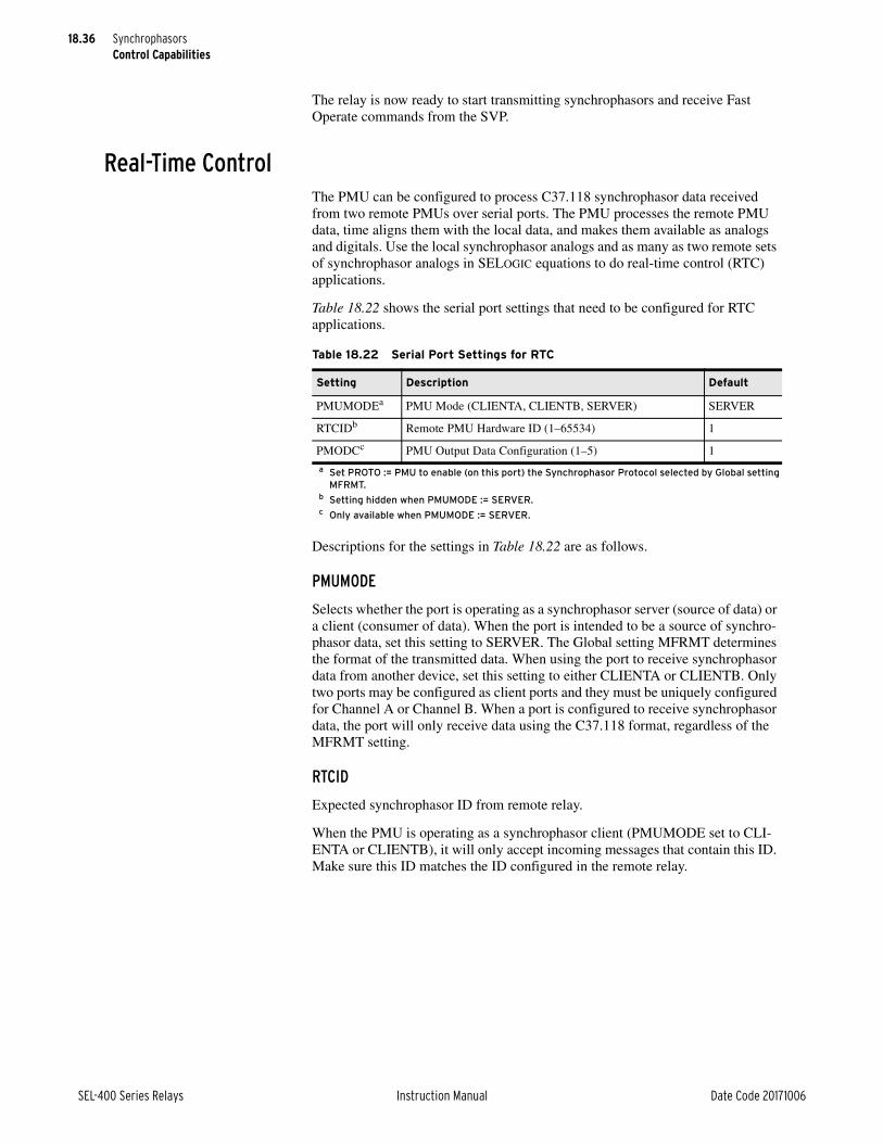
18.36
SEL-400 Series Relays Instruction Manual Date Code 20171006
SynchrophasorsControl Capabilities
The relay is now ready to start transmitting synchrophasors and receive Fast Operate commands from the SVP.
Real-Time ControlThe PMU can be configured to process C37.118 synchrophasor data received from two remote PMUs over serial ports. The PMU processes the remote PMU data, time aligns them with the local data, and makes them available as analogs and digitals. Use the local synchrophasor analogs and as many as two remote sets of synchrophasor analogs in SELOGIC equations to do real-time control (RTC) applications.
Table 18.22 shows the serial port settings that need to be configured for RTC applications.
Descriptions for the settings in Table 18.22 are as follows.
PMUMODE
Selects whether the port is operating as a synchrophasor server (source of data) or a client (consumer of data). When the port is intended to be a source of synchro-phasor data, set this setting to SERVER. The Global setting MFRMT determines the format of the transmitted data. When using the port to receive synchrophasor data from another device, set this setting to either CLIENTA or CLIENTB. Only two ports may be configured as client ports and they must be uniquely configured for Channel A or Channel B. When a port is configured to receive synchrophasor data, the port will only receive data using the C37.118 format, regardless of the MFRMT setting.
RTCID
Expected synchrophasor ID from remote relay.
When the PMU is operating as a synchrophasor client (PMUMODE set to CLI-ENTA or CLIENTB), it will only accept incoming messages that contain this ID. Make sure this ID matches the ID configured in the remote relay.
Table 18.22 Serial Port Settings for RTC
Setting Description Default
PMUMODEa
a Set PROTO := PMU to enable (on this port) the Synchrophasor Protocol selected by Global setting MFRMT.
PMU Mode (CLIENTA, CLIENTB, SERVER) SERVER
RTCIDb
b Setting hidden when PMUMODE := SERVER.
Remote PMU Hardware ID (1–65534) 1
PMODCc
c Only available when PMUMODE := SERVER.
PMU Output Data Configuration (1–5) 1

18.37
Date Code 20171006 Instruction Manual SEL-400 Series Relays
SynchrophasorsControl Capabilities
PMODC
Select the data configuration set to be sent out from that port. This setting is only available when the PMUMODE=SERVER.
Table 18.23 shows the Global settings that need to be configured for RTC applications.
NOTE: The maximum channel delay is available in the COM RTC command.
Descriptions for the settings in Table 18.23 are as follows.
RTCRATE
Rate at which to expect messages from the remote synchrophasor device.
When the PMU is operating as a synchrophasor client (PMUMODE set to CLIENTA or CLIENTB), the relay will only accept incoming messages at this rate. Make sure the remote synchrophasor source(s) is configured to send mes-sages at this same rate.
MRTCDLY
Selects the maximum acceptable delay for received synchrophasor messages.
When the PMU is operating as a synchrophasor client (PMUMODE set to CLI-ENTA or CLIENTB), the relay only accepts incoming messages that are not older than allowed by this setting. When determining an appropriate value for this setting, consider the channel delay, the transfer time at the selected baud rate, plus add some margin for internal delays in both the remote and local relay.
When you use the PMU for synchrophasor acquisition, the delayed and aligned analog quantities specific to that relay are available. Be aware that these quanti-ties are only valid when RTCROK is asserted and only for the enabled channels. The specific channel quantities are also valid whenever their respective RTCROKp Relay Word bit is set (see Table 18.11).
When using the relay as a synchrophasor client, the Relay Word bits in Table 18.24 indicate the state of the synchronization.
Table 18.23 Global Settings for RTC
Setting Description Default
RTCRATE Remote Messages per Second
(1, 2, 5, 10, or 50 when NFREQ := 50)
(1, 2, 4, 5, 10, 12, 15, 20, 30, or 60 when NFREQ := 60)
2
MRTCDLY Maximum RTC Synchrophasor Packet Delay (20–1000 ms) 500
Table 18.24 Synchrophasor Client Status Bits
Name Description
RTCENpa Asserts for one processing interval when a valid message is received on Channel p.
RTCROKpa Asserts for one processing interval when data are aligned for Channel p. Use this bit to condition usage of the Channel p data.
RTCROK Asserts for one processing interval when data for all enabled channels are aligned. Use this bit to condition general usage of the aligned synchrophasor data.
RTCDLYpa This bit is asserted when the last received valid message on Channel p is older than MRTCDLY.

18.38
SEL-400 Series Relays Instruction Manual Date Code 20171006
SynchrophasorsControl Capabilities
When received, synchrophasor messages contain digital data. These data are stored in the Remote Synchrophasor Relay Word bits in Figure 18.25.
Set MRTCDLY for the maximum expected communications channel delay in milliseconds. Any data arriving later than this time are rejected. The RTCDLYp Relay Word bit indicates this condition. Use the MRTCDLY to constrain the maximum longest operating time of the system. Set the RTCRATE to the rate of synchrophasor data being sent by remote relay. This is the MRATE setting on the remote relay.
Several Relay Word bits are useful for monitoring system status. Add RTCCFGp and RTCDLYp to the SER.
The RTCCFGp Relay Word bit is asserted after the two relays have communi-cated configuration data successfully. RTCCFGp deassertion indicates that the system has changed, perhaps because of a setting change in one of the relays.
If the RTCCFGp Relay Word bit indicates a new configuration, you can issue the RTC command to ensure that the data being received have not changed. The RTC command displays a description of the synchrophasor data being received. Use this command to ensure that the remote value that you chose for the SELOGIC equation is the correct value to compare with the local synchrophasor value.
The RTCDLYA bit asserts when synchrophasor data have not been received on Channel A within the window you set with the local MRTCDLY setting (100 ms in this example). If the RTCDLYA asserts, consider three options. First, the MRTCDLY setting can be increased. However, the MRTCDLY setting is your way of guaranteeing operation within a certain time. Increasing MRTCDLY allows for communications channels with longer transmission delay, but at the cost of increasing the maximum time of operation. A second option is to improve the communications channel so that it operates within the required MRTCDLY setting time. A final option is available if the assertion of MRTCDLY results from a temporary communications channel disruption. In this case, putting RTC-DLYA in the SER provides warning.
The COM RTC command also provides information for monitoring system sta-tus. Figure 18.11 shows a COM RTC command response. Use the maximum packet delay field to monitor the communications channel delay. This informa-tion can help you choose an appropriate value for the MRTCDLY setting.
RTCSEQpa This bit is asserted when the processed received message on Channel p is the expected next-in-sequence. It is deasserted if it is not. The deassertion implies that one or more packets of information were lost. Use this bit to con-dition usage of Channel p data in applications where sequential data are required.
RTCCFGpa Indicates Channel p is successfully configured.
a p = A or B.
Table 18.25 Remote Synchrophasor Data Bits
Name Description
RTCpD[16]a
a p = A or B.
First sixteen digitals received in synchrophasor message on Channel p. Only valid when RTCROKp is asserted.
Table 18.24 Synchrophasor Client Status Bits
Name Description

18.39
Date Code 20171006 Instruction Manual SEL-400 Series Relays
SynchrophasorsControl Capabilities
Real-Time Control ExampleFigure 18.12 shows an application example using SEL-411L relays. In this exam-ple, Area 2 supplies power to Area 1 and Area 3. An important contingency is loss of both Link 1 and Link 2. In such a case, the generators in Area 2 accelerate. Alternate paths between Area 2 and Area 1 can also become stressed beyond their design limits. A simple solution is to measure the phase angle between Area 1 and Area 2. When the angle exceeds a predetermined limit, control the generation to avoid exceeding system limits.
Figure 18.13 shows the SELOGIC for the relay controlling the generator (called the local relay in this example). Lines 1 and 2 store phasor data into PMV53 and PMV54 so they can be viewed through use of the MET PMV command. Line 3 computes the angle difference between the local and remote relays. RTCAP02 is the remote V1Y angle. Lines 4–10 unwrap the phase angle when the difference exceeds ±180 degrees.
RTCROKA pulses true whenever a good synchrophasor message is received. For purposes of this example, we need it to hold true until the next message is received. To achieve this, lines 11-13 implement a timer to extend this bit by 1.75 cycles. A message is expected every 1 cycle; the additional 0.75 cycles covers any jitter that may occur in the rate or message receipt. Line 14 calculates a qual-ification signal consisting of the local and remote quality indicators. RTCROKA is the local indicator which has been extended as PCT01. RTCAD16 is the remote quality indicator. Figure 18.14 shows its construction at the remote relay.
Line 15 computes absolute value of the angle. Line 16 checks the angle against the reference value. In this case, the reference value is 10 degrees.
The final result, PSV03, asserts when the relay receives a synchrophasor message with an angle difference exceeding 10 degrees.
Summary for RTC channel APort: 2ID: 8Present Status: ReceivingMax Packet Delay: 50 msecMessage Rate: 60 msgs/sec
Summary for RTC channel BPort: 1ID: 9Present Status: ReceivingMax Packet Delay: 40 msecMessage Rate: 60 msgs/sec
Figure 18.11 Example COM RTC Command Response
Figure 18.12 Real-Time Control Application
SEL-411LSEL-411L
Area 2
Link 1
Link 2
Area 1
Heavy Load
Area 3
Light LoadSynchrophasorsControl
Generation

18.40
SEL-400 Series Relays Instruction Manual Date Code 20171006
SynchrophasorsControl Capabilities
Figure 18.14 shows the SELOGIC settings for the remote relay. Set PSV64 to indicate that the sending data are correct. These data are sent with the synchro-phasor data in the C37.118 data packet and are received by the local relay as RTCAD16. The RTCAD16 qualification on line 11 of the local relay (see Figure 18.13) contains this remote data quality indicator. A local relay quality indicator also qualifies line 11.
Set the remote relay Global settings according to Figure 18.15. Set the number of digitals (NUMDSW) to one. In this case, the relay sends SELOGIC values PSV49–PSV64 in the C37.118 data packet. This is how the remote TSOK AND PMDOK qualification maps to the local RTCAD16 Relay Word bit. Set the PMU application (PMAPP) to fast, because this is a protection application. Therefore, you must choose a filter for faster response. Also set the synchrophasor enable Global setting to yes (EPMU = Y). The MRTCDLY and RTCRATE settings are set but not used by the remote relay.
Set the local relay Global settings according to Figure 18.16. It is important for synchrophasors to be enabled (EPMU = Y), the application to be fast (PMAPP = F), the compensation settings to be set correctly (VYCOMP, VZCOMP, IWCOMP, and IXCOMP), and for IRIGC = C37.118.
Set MRTCDLY for the maximum expected communications channel delay in milliseconds. Any data arriving later than this time are rejected. The RTCDLYA Relay Word bit indicates this condition. Use the MRTCDLY to constrain the
Protection 11: PMV53 := V1YPMAD2: PMV54 := RTCAP023: PMV55 := V1YPMAD - RTCAP024: PSV01 := PMV55 >= 180.0000005: PMV01 := -180.0000006: PSV02 := PMV55 <= PMV017: PMV01 := PMV55 + 360.000000
8: PMV02 := PMV55 - 360.0000009: PMV55 :=NOT PSV01*PMV55+PSV01*PMV0210: PMV55 :=NOT PSV02*PMV55+PSV02*PMV0111: PCT01PU := 0.00000012: PCT01DO := 1.75000013: PCT01N := R_TRIG RTCROKA14: PSV01 := PCT01Q AND RTCAD1615: PMV56 := ABS(PMV55)16: PSV03 :=(PMV56 > 10.000000) AND PSV01
Figure 18.13 Local Relay SELOGIC Settings
1: PSV64 := TSOK AND PMDOK
Figure 18.14 Remote Relay SELOGIC Settings
Synchronized Phasor Measurement Settings
MFRMT := C37.118 MRATE := 60 PMAPP := F PHCOMP := YPMSTN := "REMOTE RTC"PMID := 8PHDATAV := V1 VCOMP := 0.00 PHDATAI := NA IWCOMP := 0.00IXCOMP := 0.00 PHNR := F PHFMT := P FNR := FNUMANA := 0 NUMDSW := 1
TREA1 := NATREA2 := NATREA3 := NATREA4 := NAPMTRIG := NAMRTCDLY := 100RTCRATE := 60
Time and Date Management
IRIGC := C37.118
Figure 18.15 Remote Relay Global Settings

18.41
Date Code 20171006 Instruction Manual SEL-400 Series Relays
SynchrophasorsControl Capabilities
maximum longest operating time of the system. Set the RTCRATE to the rate of synchrophasor data being sent by remote relay. This is the MRATE setting on the remote relay.
The other Global settings are not relevant to this application.
Set the port settings for the port that sends the synchrophasor data on the remote relay, according to Figure 18.17.
Set the port settings for the port that receives the synchrophasor data on the local relay, according to Figure 18.18. Notice that the RTCID setting must match the PMID setting of the remote relay.
Several Relay Word bits are useful for monitoring system status. Add RTCCFGA and RTCDLYA to the SER.
The RTCCFGA Relay Word bit is asserted after the two relays have communi-cated configuration data successfully. RTCCFGA deassertion indicates that the system has changed, perhaps because of a setting change in one of the relays.
Synchronized Phasor Measurement Settings
MFRMT := C37.118 MRATE := 60 PMAPP := F PHCOMP := YPMSTN := "LOCAL RTC"PMID := 4PHDATAV := V1 VCOMP := 0.00 PHDATAI := NA IWCOMP := 0.00IXCOMP := 0.00 PHNR := F PHFMT := P FNR := FNUMANA := 0 NUMDSW := 0
TREA1 := NATREA2 := NATREA3 := NATREA4 := NAPMTRIG := NA MRTCDLY := 100RTCRATE := 60
Time and Date Management
IRIGC := C37.118
Figure 18.16 Local Relay Global Settings
Protocol Selection
PROTO := PMU
Communications Settings
SPEED := 57600 STOPBIT := 1 RTSCTS := N
SEL Protocol Settings
FASTOP := N
PMUMODE := SERVER
Figure 18.17 Remote Relay Port Settings
Protocol Selection
PROTO := PMU
Communications Settings
SPEED := 57600 STOPBIT := 1 RTSCTS := N
SEL Protocol Settings
FASTOP := N
PMUMODE := CLIENTARTCID := 8
Figure 18.18 Local Relay Port Settings

18.42
SEL-400 Series Relays Instruction Manual Date Code 20171006
SynchrophasorsPMU Recording Capabilities
If the RTCCFGA Relay Word bit indicates a new configuration, you can issue the RTC command to ensure that the data being received have not changed. The RTC command displays a description of the synchrophasor data being received. Use this command to ensure that the remote value that you chose for the SELOGIC equation (for example, RTCAP02 in Figure 18.13) is the correct value to compare with the local synchrophasor value.
The RTCDLYA bit asserts when synchrophasor data have not been received within the window you set with the local MRTCDLY setting (100 ms in this example). If the RTCDLYA asserts, consider three options. First, the MRTCDLY setting can be increased. However, the MRTCDLY setting is your way of guaran-teeing operation within a certain time. Increasing MRTCDLY allows for commu-nications channels with longer transmission delay, but at the cost of increasing the maximum time of operation. A second option is to improve the communica-tions channel so that it operates within the required MRTCDLY setting time. A final option is available if the assertion of RTCDLY results from a temporary communications channel disruption. In this case, putting RTCDLYA in the SER provides warning.
The COM RTC command also provides information for monitoring system sta-tus. Figure 18.19 shows a COM RTC command response. Use the maximum packet delay field to monitor the communications channel delay. This informa-tion can help you choose an appropriate value for the MRTCDLY setting.
PMU Recording CapabilitiesThe PMU can be configured to record synchrophasor data by setting EPMDR := Y. Select one of the data configuration q you want to record using SPMDR setting where q = 1–NUMPHDC. Create a recording trigger using PMTRIG SELOGIC setting. On the rising edge of PMTRIG, the PMU starts recording synchrophasor data. The duration and the pretrigger duration of the recording are user settable.
NOTE: Select PMTRIG trigger conditions to assert PMTRIG only once during a four-hour period if EPMDR = Y (i.e., synchrophasor recording is enabled).
The PMU stores these files in the SYNCHROPHASOR subdirectory with .PMU extension. Use FILE READ or FTP to retrieve these stored data files. The file is in binary format and IEEE C37.118 data format compliant.
The file starts with a Configuration 2 frame followed by the data frames as shown below.
<Configuration 2 Frame>
<Data Frame 1>
<Data Frame 2>
.
Summary for RTC channel APort: 2ID: 8Present Status: ReceivingMax Packet Delay: 50 msecMessage Rate: 60 msgs/sec
Summary for RTC channel BPort: 1ID: 9Present Status: ReceivingMax Packet Delay: 40 msecMessage Rate: 60 msgs/sec
Figure 18.19 Example COM RTC Command Response

18.43
Date Code 20171006 Instruction Manual SEL-400 Series Relays
SynchrophasorsPMU Recording Capabilities
.
.
<Data Frame t>
<Data Frame t+1>
.
.
.
<Data Frame n>
where:
t = the number of pretrigger data frames, and is equal to PMPRE • MRATE.
n = the total number of data frames, and is equal to PMLER • MRATE.
<Data Frame t+1> is the first data frames with Bit 11 in the STAT field (PMTRIG) asserted.
The recorded file has the following file naming convention.
yymmdd,hhmmss,0,aaa,bbb,ccc.PMU
where,
yymmdd, hhmmss = the UTC time stamp of the first data frame in the file with bit 11 (PMTRIG) asserted
aaa = the last three characters of the PMSTNq setting (after removing char-acters “ / \ < > * | : ; [ ] $ % { } and the spaces)
bbb = the last three characters of the PMIDq
ccc = the CONAM setting (after removing the spaces)
Additional PMTRIG assertions are ignored during recording.
Table 18.26 shows the setting name, description, and default value to help config-ure the data recording.
Descriptions for the settings in Table 18.26 are as follows.
EPMDR
Use the EPMDR setting to enable synchrophasor data recording. This setting is hidden when EPMU := N. When EPMDR = Y, phasor measurement data record-ing will begin on the rising edge of PMTRIG. Any subsequent PMTRIG asser-tions during the allotted recording period (PMLER) will not result in another PMU data recording being started. The relay will store synchrophasor measure-
Table 18.26 PMU Recording Settings
Setting Description
EPMDRa
a This setting is forced to N if MFRMT = FM.
Enable PMU Data Recording (Y, N)
SPMDRb
b This setting is hidden if EPMRD = N.
Select Data Configuration for PMU Recording (1–NUMPHDC)
CONAMb Company Name (1–3 characters)
PMLERb Length of PMU Triggered Data (2–120 s)
PMPREb Length of PMU Pretriggered Data (1–20 s)

18.44
SEL-400 Series Relays Instruction Manual Date Code 20171006
SynchrophasorsPMU Recording Capabilities
ment data as a C37.118 binary format file that can be retrieved from the relay using File Transfer Protocol. Synchrophasor data are recorded into a file with extension *.PMU.
SPMDR
The SPMDR setting provides a means for selecting any one of the enabled data configuration 1–NUMPHDC for synchrophasor data recording.
CONAM
The CONAM setting provides a means for inserting the company name into the recorded synchrophasor data file name. The CONAM setting is three characters long. The settings allows all printable characters except “ / \ < > * | : ; [ ] $ % { }.
PMLER
PMLER sets the total length of the synchrophasor data recording, in seconds. The PMLER time includes the PMPRE time. For example, if PMLER is set for 30 seconds of PMU recorded data, and PMPRE is set for 10 seconds of pretrigger data, the final recording will contain 10 seconds of pretrigger data and 20 seconds of triggered data for a total report time of 30 seconds.
PMPRE
The PMPRE setting sets the length of the pretrigger data within the synchropha-sor data recording. The PMPRE data begins at the PMTRIG point of the record-ing, and extends back in time (previous time to the trigger event) for the designated amount of time.

Date Code 20171006 Instruction Manual SEL-400 Series Relays
SEL-400 Series RelaysInstruction ManualS E C T I O N 1 9
Remote Data Acquisition
SEL-400 series relays can receive analog and binary inputs from remote data acquisition systems. This technology provides flexible solutions, reduces the cost of copper, and improves overall safety in the substation.
Time-Domain Link (TiDL)Some SEL-400 series relays can receive remote analog and binary inputs from the SEL-2240 Axion. The Axion provides the remote analog and binary data over an IEC 61158 EtherCAT, TiDL network. This technology provides very low and deterministic latency over point-to-point architecture. Point-to-point architecture eliminates the need for time synchronization between the remote data acquisition units and the relay. In addition, it eliminates the complex communications net-work often associated with remote data acquisition and simplifies the program-ming and installation process.
Some of the benefits of a TiDL system include:
➤ Use ACSELERATOR QuickSet SEL-5030 Software to set the relay as you would conventional SEL-400 series relays. Firmware for the SEL-400 series relays was modified for the implementation of TiDL; however, the settings and protection algorithms were unchanged.
➤ Decrease costs through copper reduction.
➤ Simplify the installation process.
➤ Increase safety in the substation by removing high-energy cables from the control house. This also eliminates the concern of an open circuited CT when a relay is removed from service.
SEL-400 series relays with TiDL can receive as many as eight fiber links from as many as eight Axion remote data acquisition nodes. Not all nodes have to supply analog data—some can supply digital input and output (I/O) only. The firmware will recognize and validate the connected Axion modules and determine if they match a predefined supported topology. The supported topologies are balanced between copper reduction and the number of required remote Axion nodes. Refer to Section 2: Installation in the product-specific instruction manuals to review the supported TiDL topologies.

19.2
SEL-400 Series Relays Instruction Manual Date Code 20171006
Remote Data AcquisitionTime-Domain Link (TiDL)
SEL-400 series relays that support TiDL are only available in a 4U chassis. These relays support an I/O board on the relay, and, when applicable, main board I/O. These I/Os will be mapped to the 100- and 200-level inputs and outputs. Axion remote modules provide additional I/O by using the internal digital Relay Word bits for the 300, 400, and 500 levels of the relays. Note that when the relay part number supports TiDL, all output settings for I/O are available. Correctly set these outputs for what is installed because all output settings will be available but all may not be physically installed in your system.
Relay Word bits IO300OK, IO400OK, and IO500OK indicate the status of installed I/O boards in standard relays or whether a remote module is commis-sioned, such as in a TiDL system. These bits can also identify whether a board is installed or when a remote I/O module fails.
Figure 19.1 Sample TiDL System Topology
SEL Relay
SEL Axion
SEL AxionSEL Axion
SEL Axion SEL Axion
IAWIBWICW
VAYVBYVCY
IAXIBXICX
1 Phase(VBZ)
1 Phase(VAZ)
Line
Substation Yard
Control House
Figure 19.2 Rear Panel of Relays With TiDL

19.3
Date Code 20171006 Instruction Manual SEL-400 Series Relays
Remote Data AcquisitionTime-Domain Link (TiDL)
TiDL applications use the SEL-2240 Axion, which is a fully integrated analog and digital I/O control solution suitable for remote data acquisition. An Axion node consists of a 10-slot, 4-slot, or dual 4-slot chassis that is configurable to contain a power module and combinations of CT/PT, digital input (DI), or digital output (DO) modules.
Each chassis requires a SEL-2243 Power Coupler (see Figure 19.4). This module supplies power to the rest of the node and transmits the data to the relay through fiber-optic communication. See the SEL-2240 Axion Instruction Manual for more information.
The SEL-2244-2 Digital Input Module (see Figure 19.5) consists of 24 optoiso-lated inputs that are not polarity-dependent. These inputs can be configured to respond to ac or dc control signals. The TiDL system maps as many as 72 DI points to the relay. For more information on DI mapping, refer to Section 2: Installation in the product-specific instruction manuals.
Figure 19.3 Axion Chassis
Figure 19.4 SEL-2243 Power Coupler

19.4
SEL-400 Series Relays Instruction Manual Date Code 20171006
Remote Data AcquisitionTime-Domain Link (TiDL)
The SEL-2244-5 Fast High-Current Digital Output Module (see Figure 19.6) consists of ten fast, high-current output contacts. The TiDL system can map as many as 48 DO points to the relay. For more information on DO mapping, refer to Section 2: PC Software.
The SEL-2245-42 AC Analog Input Module (see Figure 19.7) provides protec-tion-class ac analog input (CT/PT) and can accept three voltage and three current inputs. The module samples at 24 kHz and is 1 A or 5 A software-selectable. Depending on the supported fixed topology, multiple CT/PT input modules can function in each node. Some topologies only support one CT/PT module per node. See the supported topologies in Section 2: Installation in the product-spe-cific instruction manual for more information.
Figure 19.5 SEL-2244-2 Digital Input Module
Figure 19.6 SEL-2244-5 Fast High-Current Digital Output Module

19.5
Date Code 20171006 Instruction Manual SEL-400 Series Relays
Remote Data AcquisitionIEC 61850-9-2 Sampled Values (SV)
A simple commissioning process identifies the connected TiDL system and veri-fies it matches one of the supported relay topologies. Once the commissioning process is complete, the topology is stored in memory. At each additional relay startup, the firmware validates that the connected modules match those of the stored configuration. It recognizes if any CT/PT modules within the node have changed. See Section 2: PC Software in the product-specific instruction manual for more information on commissioning.
Secondary injection testing takes place at each Axion node. Test sources are required to inject voltages and current to the Axion node to verify correct instal-lation and mapping. Monitoring of the voltages and currents will remain in the control house at the relay location.
IEC 61850-9-2 Sampled Values (SV)Some SEL-400 series relays are available with the capability to either publish or subscribe to remote analogs in accordance with the UCA International Users Group’s “Implementation Guideline for Digital Interface to Instrument Trans-formers Using IEC 61850-9-2,” This type of remote data acquisition is a subset of IEC 61850-9-2 and specifies, among other things, logical devices, dataset con-tents, sampling rates, the time-synchronization method, and the message format. The 9-2LE guideline clarified ambiguities in the 9-2 standard, improving interop-erability between SV devices from different manufacturers.
Architecture9-2LE uses OSI Layer 2 multicast messages on standard Ethernet network archi-tecture. Merging units such as the SEL-421-7 with SV publication capability enabled or the SEL-401 Merging Unit sample remote analog values, convert them to digital signals, and then publish them over the Ethernet network. Two key components of SV messages (besides the current and voltage data) are the
Figure 19.7 SEL-2245-42 AC Analog Input Module
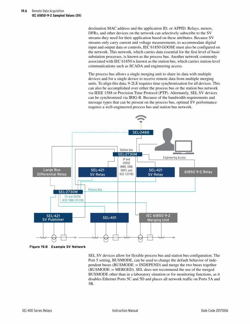
19.6
SEL-400 Series Relays Instruction Manual Date Code 20171006
Remote Data AcquisitionIEC 61850-9-2 Sampled Values (SV)
destination MAC address and the application ID, or APPID. Relays, meters, DFRs, and other devices on the network can selectively subscribe to the SV streams they need for their application based on these attributes. Because SV streams only carry current and voltage measurements, to accommodate digital input and output data or controls, IEC 61850 GOOSE must also be configured on the network. This network, which carries data essential for the first level of basic substation processes, is known as the process bus. Another network commonly associated with IEC 61850 is known as the station bus, which carries station-level communications such as SCADA and engineering access.
The process bus allows a single merging unit to share its data with multiple devices and for a single device to receive remote data from multiple merging units. To align this data, 9-2LE requires time synchronization for all devices. This can also be accomplished over either the process bus or the station bus network via IEEE 1588 or Precision Time Protocol (PTP). Alternately, SEL SV devices can be synchronized via IRIG-B. Because of the bandwidth requirements and message types that can be present on the process bus, optimal SV performance requires a well-engineered process bus and station bus network.
SEL SV devices allow for flexible process bus and station bus configuration. The Port 5 setting, BUSMODE, can be used to change the default behavior of inde-pendent buses (BUSMODE := INDEPEND) and merge the two buses together (BUSMODE := MERGED). SEL does not recommend the use of the merged BUSMODE other than in a laboratory situation or for monitoring functions, as it disables Ethernet Ports 5C and 5D and places all network traffic on Ports 5A and 5B.
Figure 19.8 Example SV Network
IEC 61850 9-2
Merging Unit
IP and GOOSE
(MMS, 1588, DNP3, and
IEEE C37.118)
Station bus
Engineering Access
Process Bus
SV and GOOSE(IEEE 1588 C37.238)
SEL-2730M
SEL-2488
SEL-421SV Publisher
SEL-2730M
SEL-421
SV Relay
SEL-421
SV Relay
SEL-401
Large Bus
Differential Relay61850 9-2 Relay

19.7
Date Code 20171006 Instruction Manual SEL-400 Series Relays
Remote Data AcquisitionIEC 61850-9-2 Sampled Values (SV)
The Port 5 settings NETMODE and NETPORT determine and configure the Ethernet ports used for the station bus and the process bus. The NETMODE set-ting applies only to the station bus, and gives the user the ability to set the desired network redundancy mode in the device. The NETPORT setting determines which pair of Ethernet ports the SV device will use for its station bus. The SV device will use the other pair of Ethernet ports for the process bus. For example, if NETPORT = A or B, the station bus will be on Ethernet Ports 5A and 5B with the process bus on Ports 5C and 5D. SV process bus ports only operate in FAILOVER mode. Refer to Ethernet Communications on page 15.6 for more information on Ethernet network operation and using redundant Ethernet ports.
Benefits of a 9-2LE SV SystemSome of the benefits of a 9-2LE SV system include:
➤ Set the relay as you would conventional SEL-400 series relays through use of QuickSet and ACSELERATOR Architect SEL-5032 Software.
➤ Decrease costs through copper reduction and data sharing.
➤ Increase safety in the substation by removing high-energy cables from the control house. This also eliminates the concern of an open circuited CT when a relay is removed from service.
SV Publication SV Publication Capability
Some SEL-400 series relays are available with the capability for SV publication. Enabling SV publication through settings (Port 5 setting SVTXEN > 0 or via CID file) enables the merging unit functionality of the device. The SV publica-tion capability of each SEL SV publishing devices is identical, so throughout this section, SEL devices with SV publication enabled are referred to as SV publish-ers.
The SV publisher digitizes the data from its voltage and current inputs, records its current state of time synchronization, scales these values to primary units by using the CT and PT ratio settings, and then transmits these values in accordance with the 9-2LE guideline. SEL SV publishers support the “MSVCB01” model of the multicast SV control block described in the guideline, which includes a single application service data unit (ASDU). The transmission rate is 80 samples per nominal frequency cycle. If the nominal frequency setting of the SV publisher NFREQ = 50 Hz or 60 Hz, the SV transmission rate is 4000 or 4800 samples per second, respectively.
The SV publisher can publish as many as seven SV streams simultaneously. SV publication is independent of the protection elements, so protection functionality remains secure even when the SV publisher is publishing the maximum number of SV streams.
Because multiple SV streams may be received by a single subscriber, all streams usually require time-alignment to a time source with an accuracy of <1 µs. SV messages indicate the synchronization state of the SV publisher at the time the sample was taken. This value, smpSynch in the SV message, will be 0, 1, or 2, to indicate whether the merging unit was synchronized with a global time source (2), a local time source (1), or an internal clock (0). If the SV publisher is syn-chronized with an IEEE 1588 Precision Time Protocol (PTP) time source that uses the PTP Power Profile (C37.238), the smpSynch value is equal to the ID of the grandmaster clock, usually a value between 5 and 254.

19.8
SEL-400 Series Relays Instruction Manual Date Code 20171006
Remote Data AcquisitionIEC 61850-9-2 Sampled Values (SV)
Though SV messages do not contain an actual time stamp, they do include a value, smpcnt (sample count), that the publisher increments for each message that it transmits, which represents the time at which the sample was taken. For every SV message that the SV publisher transmits, smpcnt increments until it reaches a value of 4799 on a 60 Hz system, or 3999 on a 50 Hz system. At the top of the second, smpcnt resets to 0. Smpcnt can be used to calculate the time stamp of the message in relation to the most recent top of a second by multiplying it by the transmission interval (208.33 µs for a 60 Hz system or 250 µs for a 50 Hz sys-tem). For example, a message with smpcnt=699 on a 50 Hz system was taken 699 • 250 µs = 174.75 ms after the top of the second.
SV Publisher ConfigurationArchitect provides support for the configuration of the SEL SV publisher via a GUI. This interface provides the most flexible configuration of SV publications, including the creation of customized SV datasets. This mechanism is very similar to the configuration of GOOSE publications. For more information, see IEC 61850 Configuration on page 17.22.
Architect includes an ICD file for the SEL-401 and an ICD file for the SEL-421 with SV publication capability. ICD files of both SV publishers contain default SV datasets, which contain combinations of the current and voltage terminals available on the publisher, i.e. W and Y, W and Z, X and Y, or X and Z. You can choose to publish any of these preconfigured datasets or create and publish a cus-tom dataset that conforms to the 9-2LE guideline. This feature is useful if you need the SV publisher to send anything other than all phases (A, B, C, and neu-tral) of a current or voltage terminal in an SV stream.
SV publications may also be configured via Port 5 settings through QuickSet or an ASCII terminal window. You can use Port 5 settings to quickly configure SV streams that do not require much customization. All phases (A, B, C, and neutral)
Figure 19.9 Example Architect SV Publication Configuration

19.9
Date Code 20171006 Instruction Manual SEL-400 Series Relays
Remote Data AcquisitionIEC 61850-9-2 Sampled Values (SV)
of a current or voltage terminal must be mapped to an SV stream, and each stream must contain at least one set of voltage or current terminal phase quanti-ties.
SV Publisher Startup When initially turned on, the SV publisher ENABLED LED illuminates as soon as protection functionality is enabled, typically within 10 seconds, but there can be an additional delay of approximately 6 seconds before the initial SV publication is transmitted. Once the SV publisher has begun transmitting SV streams, they can be temporarily disabled for the following conditions:
➤ Port 5 settings are modified
➤ A new CID file configuration is enabled
➤ Power is cycled
SV publications stop if the SV publisher is disabled (EN Relay Word bit = False), the Port 5 setting EPORT is set to “N”, or the processor fails. SV publications will not resume unless the disabling condition is addressed.
SV Publisher Diagnostics and TestingOnce SV publication is configured and enabled, new commands are available to verify configuration, diagnose and troubleshoot SV communications, and aid in commissioning and testing: COM SV and TEST SV.
The COM SV command displays information about the SV streams that the unit is configured to publish. The data includes the SV destination MAC address, Application ID, message name, dataset name, VLAN ID, and priority if the SV publisher is configured via CID file. If the publisher is configured via Port 5 set-tings, the dataset name remains blank because it is not used in Port 5 settings, and therefore unavailable. For more information on the COM SV command, see Section 9: ASCII Command Reference in the product-specific manual.
The TEST SV command places the SV publisher into TEST SV mode. In this mode, it replaces the current and voltage data of all SV configured streams with predefined signals for a period of 15 minutes. Also, the SV publisher asserts the test bit in the quality attribute of each current and voltage to identify it as test data. Note that the SV publisher remains in normal mode, and does not enter IEC 61850 Test mode. This does not affect metering or protection functions on the SV publisher. The COM SV command indicates whether the SV publisher is in TEST SV mode by displaying the information at the top of the response. Refer to the TEST SV command description in Section 9: ASCII Command Reference in the product-specific manual for more information.
SV SubscriberSV Subscriber Functionality
SEL SV subscriber relays do not have current or voltage input terminals like con-ventional relays. SV subscriber relays also do not have internal instrument trans-formers. Conventional relays are typically ordered from the factory with either 1 A or 5 A nominal CTs, which provide the full range of measured values for the current input terminals. Before or during installation, SEL SV subscriber relays must be configured with the same nominal current value of the merging unit for proper operation. The ASCII command CFG CTNOM n, where n is 1 or 5, must be used to configure the SV subscriber with the nominal current value of the sub-

19.10
SEL-400 Series Relays Instruction Manual Date Code 20171006
Remote Data AcquisitionIEC 61850-9-2 Sampled Values (SV)
scribed merging unit. Refer to the Section 9: ASCII Command Reference in the SEL-421-7 Instruction Manual for more information on the CFG CTNOM com-mand.
SV Subscribers, such as the SEL 421-7 SV Subscriber Relay, must be configured to subscribe to 9-2LE-compliant SV streams to enable any protection functions. When configured via Port 5 settings, all phases (A, B, and C) of a current or volt-age terminal must come from an SV stream, and terminals cannot be mapped more than once. Because of this, SEL SV relays that use Port 5 SV configuration can subscribe to as many as four SV streams from one or more merging units. When configured via Architect, which allows the selection of individual phases from each SV stream, SEL SV relays can subscribe to as many as seven SV streams.
Once SV subscriptions are configured and are being received, the SV subscriber relay provides a suite of protection functionality. Please refer to the specific prod-uct instruction manual for a list of available protection functions.
Note that IEC 61850-9-2LE only covers the publication and subscription of remote analog data. To communicate digital input and output data or controls, IEC 61850 GOOSE must be configured and optimized on either the process bus or the station bus.
SV Subscriber Configuration Architect provides support for the configuration of the SEL SV subscriber via a GUI. This interface provides the most flexible configuration of SV publications, including the creation of customized SV datasets. This mechanism is very similar to the configuration of GOOSE publications. For more detailed information, see IEC 61850 Configuration on page 17.22.
Figure 19.10 SEL-421-7 SV Subscriber Relay, 4U Rear Panel
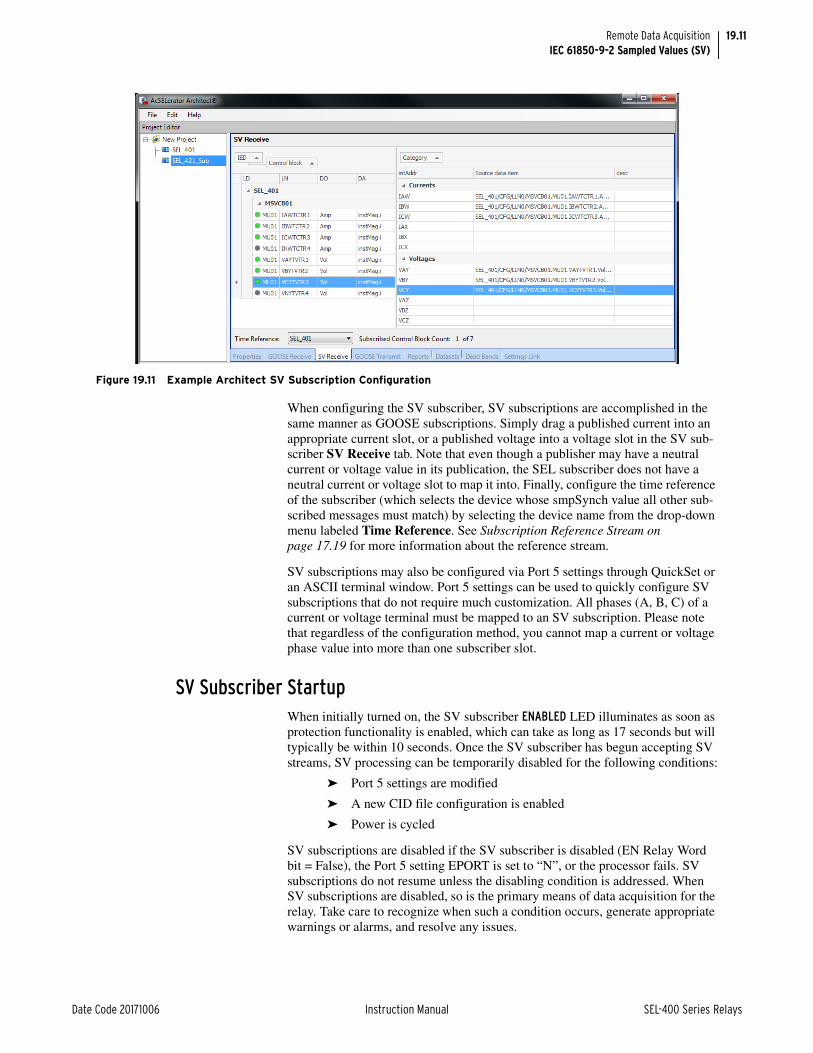
19.11
Date Code 20171006 Instruction Manual SEL-400 Series Relays
Remote Data AcquisitionIEC 61850-9-2 Sampled Values (SV)
When configuring the SV subscriber, SV subscriptions are accomplished in the same manner as GOOSE subscriptions. Simply drag a published current into an appropriate current slot, or a published voltage into a voltage slot in the SV sub-scriber SV Receive tab. Note that even though a publisher may have a neutral current or voltage value in its publication, the SEL subscriber does not have a neutral current or voltage slot to map it into. Finally, configure the time reference of the subscriber (which selects the device whose smpSynch value all other sub-scribed messages must match) by selecting the device name from the drop-down menu labeled Time Reference. See Subscription Reference Stream on page 17.19 for more information about the reference stream.
SV subscriptions may also be configured via Port 5 settings through QuickSet or an ASCII terminal window. Port 5 settings can be used to quickly configure SV subscriptions that do not require much customization. All phases (A, B, C) of a current or voltage terminal must be mapped to an SV subscription. Please note that regardless of the configuration method, you cannot map a current or voltage phase value into more than one subscriber slot.
SV Subscriber Startup When initially turned on, the SV subscriber ENABLED LED illuminates as soon as protection functionality is enabled, which can take as long as 17 seconds but will typically be within 10 seconds. Once the SV subscriber has begun accepting SV streams, SV processing can be temporarily disabled for the following conditions:
➤ Port 5 settings are modified
➤ A new CID file configuration is enabled
➤ Power is cycled
SV subscriptions are disabled if the SV subscriber is disabled (EN Relay Word bit = False), the Port 5 setting EPORT is set to “N”, or the processor fails. SV subscriptions do not resume unless the disabling condition is addressed. When SV subscriptions are disabled, so is the primary means of data acquisition for the relay. Take care to recognize when such a condition occurs, generate appropriate warnings or alarms, and resolve any issues.
Figure 19.11 Example Architect SV Subscription Configuration

19.12
SEL-400 Series Relays Instruction Manual Date Code 20171006
Remote Data AcquisitionIEC 61850-9-2 Sampled Values (SV)
SV Subscriber Diagnostics and TestingOnce SV subscriptions are configured and enabled, new commands are available to verify configuration, diagnose and troubleshoot SV communications, and aid in commissioning and testing: COM SV and TEST SV.
The COM SV command displays information about the SV streams to which the unit has been configured to subscribe. The data includes the SV destination MAC address, Application ID, message name, dataset name, VLAN ID, and priority if the information is available. If information is not available, the field remains blank. The COM SV command also provides statistics for individual subscribed SV streams and any error conditions that are currently present or were present during the previous 30 seconds. For more information on the COM SV com-mand, see Section 9: ASCII Command Reference in the product-specific manual.
As the SV subscriber receives subscribed SV messages, it places them into a buf-fer that has a capacity of about 3 ms for each subscribed stream. The Port 5 CH_DLY SV channel setting determines how long the subscriber waits to receive data from all subscribed streams and will use the channel data from its buffer that corresponds to this instant in its past. If a subscribed message arrives so late (> 3 ms) that the SV subscriber does not have a place for it in its buffer, or it never arrives, the message is considered lost. If SV messages are delayed by more than CH_DLY but arrive in time to be received into the buffer of the sub-scriber, these messages are not considered lost, but their data are not used. The COM SV command uses the warning CH_DLY EXCEEDED to indicate this condition. If one to three consecutive messages are delayed or lost, the SEL SV subscriber interpolates the missing data. The COM SV command uses the INTERPOLATED warning code to indicate when it has had to interpolate for missing or lost data. If more than three consecutive SV packets are delayed or missing, the COM SV command uses the error message SV STREAM LOST to indicate any subscriptions in this condition.
If any subscribed SV streams are lost, the SV subscriber can still be able to pro-vide some subset of metering and protection functionality, depending on what data are in the missing stream(s). For example, consider an SV subscriber that has two active subscriptions with the first one providing one set of terminal cur-rents and voltages, and the other providing another set of currents. If the second subscription is lost, the SV subscriber can still provide metering data and some degree of overcurrent and LOP protection with the data available from the first stream. Refer to the product-specific instruction manual for available protection features.
The TEST SV command places the SV subscriber into TEST SV mode. In this mode, it accepts any subscribed messages with or without the test bit of the qual-ity attribute set. The data that the SV subscriber receives while in TEST SV mode are processed as valid data, so take care to ensure that outputs are blocked to pre-vent any undesired operations. The MET command reflects the received data as actual data, even with the test bit asserted. The COM SV command indicates whether the SV subscriber is in TEST SV mode by displaying the information at the top of the response. Refer to the TEST SV command description in Section 9: ASCII Command Reference of the product-specific manual for more information.
The health of the incoming SV subscription data channels can be monitored with the SV subscription Relay Word bits SVSALM, SVSmmOK, and SVCC, and the SVNDmm (where mm is the SV stream number 01–07) analog quantities. The SVSmmOK Relay Word bits are asserted when subscription mm is configured and data conforming with the 9-2LE guideline is being actively received from it. The SVCC (SV coupled clocks mode) Relay Word bit is asserted when the SV subscriber is synchronized with the same smpSynch value as the subscription ref-

19.13
Date Code 20171006 Instruction Manual SEL-400 Series Relays
Remote Data AcquisitionIEC 61850-9-2 Sampled Values (SV)
erence stream. The SVNDmm analog quantities indicate the measured channel delay of each subscription and are compared with the Port 5 CH_DLY setting to generate an alarm condition as described in the following.
The SVSALM Relay Word bit is a general purpose alarm that will assert for the following conditions:
➤ The SV subscriber has lost sync with the device providing its reference stream
➤ One or more subscribed SV streams network delays exceed the CH_DLY setting
➤ One or more subscribed SV streams are no longer being received (lost)
➤ One or more subscribed SV streams have a subscription status SVSmmOK bit that is not set.
The SV subscriber also provides analog channel status Relay Word bits, which are useful for supervising protection based on the state of SV communications for each current and voltage channel. These bits include nnnOK and nnnBK bits, where nnn is the product-specific current or voltage channel that can potentially be mapped to data from an incoming SV stream, for example, IAW, IBW, ICW, VAY, VBY, VCY, etc. in the SEL-421 SV Subscriber Relay. The nnnOK bits asserts for all data channels that are mapped to a subscribed SV stream and have data actively being received from it. The nnnBK bits are the inverse of the nnnOK bits.
See Section 5: Protection Functions of the product-specific manual for more information on SV status logic.

This page intentionally left blank

Date Code 20171006 Instruction Manual SEL-400 Series Relays
Instruction ManualA P P E N D I X A
Manual Versions
The date code at the bottom of each page of this manual reflects the creation or revision date.
Table A.1 lists the firmware versions, revision descriptions, and corresponding instruction manual date codes.
Table A.1 Instruction Manual Revision History (Sheet 1 of 3)
Date Code Summary of Revisions
20171006 Section 16
➤ Updated Table 16.8: Relay DNP3 Object List.
Section 17
➤ Updated for IEC 61850 configuration.
Appendix B
➤ Updated to help preserve IEC 61850 configuration during a firmware upgrade.
20170714 Section 2
➤ Updated Table 2.2: QuickSet HMI Tree View Functions.
➤ Updated Figure 2.20: Retrieving an Event History and Figure 2.22: Sample Event Oscillogram.
Section 9
➤ Updated Figure 9.1: Input Processing to include Sampled Values data acquisition.
➤ Added Figure 9.2: Input Processing of SEL-400 Series Relays With SV Remote Data Acquisition.
➤ Updated Generating Raw Data Oscillograms, and added Figure 9.7: An Overcurrent Application Via Remote Data Acquisition through Figure 9.9: Filtered Event Reports From SEL-401 and SEL-421.
Section 10
➤ Added Sequence of Events Recorder to Table 10.6: Troubleshooting Procedures.
➤ Added Table 10.7: Troubleshooting for Relay Self-Test Warnings and Failures.
Section 11
➤ Added PTP Over PRP Networks.
➤ Added Global Time Source vs Local Time Source.
Section 12
➤ Added a footnote to Table 12.5: Protocol Selection for the EPORT setting.
➤ Added Table 12.14: SV Receiver Configuration and Table 12.15: SV Transmitter Configuration.
➤ Added a footnote to Table 12.23: PTP Settings for setting PTPPRO.
➤ Removed note that PTP is not supported in PRP mode.
Section 14
➤ Added references to IEC Sampled Values.
➤ Added a note that the CFG NFREQ command is not available in IEC Sampled Values relays.
➤ Updated Figure 14.2: Sample ETH Command Response.
➤ Updated Figure 14.11: Sample VER Command Response.
Section 15
➤ Updated Figure 15.6: Using Internal Ethernet Switch to Add Networked Devices.
Section 16
➤ Updated Table 16.8: Relay DNP Object List.

A.2
SEL-400 Series Relays Instruction Manual Date Code 20171006
Manual Versions
Section 17
➤ Added text for IEC Sampled Values.
➤ Updated Table 17.3: Relay Logical Devices.
➤ Added Sampled Values.
➤ Added Simulation Mode.
➤ Added Example 17.1: SV Application.
➤ Updated Table 17.27: Basic Conformance Statement.
➤ Updated Table 17.28: ACSI Models Conformance Statement.
➤ Updated Table 17.29: ACSI Service Conformance Statement.
Section 18
➤ Added a note regarding Sampled Values-subscribing relays.
Section 19
➤ Added IEC 61850-9-2 Sampled Values (SV).
Appendix C
➤ Updated text for LNKFAIL and LNKFL2.
Glossary
➤ Added terms for IEC Sampled Values, Parallel Redundancy Protocol, and real-time control.
20170428 Section 19
➤ Updated Figure 19.4: SEL-2243 Power Coupler.
20170326 Section 15
➤ Updated Ethernet Communications for information on MMS inactivity.
Appendix B
➤ Updated TiDL Firmware Upgrade.
20161215 Preface
➤ Updated to describe the new section, Section19: Remote Data Acquisition.
Section 1
➤ Updated to introduce TiDL technology.
Section 3
➤ Added information on TiDL system input and output handling.
Section 7
➤ Added information about leading and lagging power factor Relay Word bits.
Section 9
➤ Described the impact of the ERDIG setting on event report handling.
➤ Added a note about SER storage limitations.
Section 10
➤ Added information on TiDL system commissioning.
➤ Described additional diagnostics.
➤ Described module replacement in Axion nodes for the TiDL system.
Section 11
➤ Improved the description of the TSOK Relay Word bit.
Section 12
➤ Added the ERDIG report setting.
Section 14
➤ Added CFG CTNOM and CFG NFREQ commands.
➤ Clarified the TEST DB2 A operation.
Section 15
➤ Updated SNTP accuracy.
Table A.1 Instruction Manual Revision History (Sheet 2 of 3)
Date Code Summary of Revisions

A.3
Date Code 20171006 Instruction Manual SEL-400 Series Relays
Manual Versions
Section 18
➤ Updated typographical information in Figure 18.5: UDP_S Connection.
Section 19
➤ Added as a new section.
Appendix B
➤ Updated to describe firmware upgrades to the TiDL system.
Appendix C
➤ Updated to describe cybersecurity aspects of EtherCAT ports.
Glossary
➤ Added terms related to TiDL systems.
20160518 ➤ Initial version.
Table A.1 Instruction Manual Revision History (Sheet 3 of 3)
Date Code Summary of Revisions

This page intentionally left blank

Date Code 20171006 Instruction Manual SEL-400 Series Relays
Instruction ManualA P P E N D I X B
Firmware Upgrade Instructions
These instructions guide you through the process of upgrading the firmware in the device. Note that these instructions are only intended for upgrading firmware from an older revision to a newer revision. Downgrading firmware—going from a newer to an older revision—should not be attempted. It will result in the loss of relay calibration, MAC addresses, and other device configuration information. Please contact SEL if you need to downgrade the firmware in a relay.
The firmware upgrade will be either a standard release or a point release. A stan-dard release adds new functionality to the firmware beyond the specifications of the existing version. A point release is reserved for modifying firmware function-ality to conform to the specifications of the existing version.
A standard release is identified by a change in the R-number of the device firm-ware identification (FID) string.
Existing firmware:
FID=SEL-411L-R100-V0-Z001001-Dxxxxxxxx, or
FID=SEL-411L-1-R100-V0-Z001001-Dxxxxxxxx
Standard release firmware:
FID=SEL-411L-R101-V0-Z001001-Dxxxxxxxx, or
FID=SEL-411L-1-R101-V0-Z001001-Dxxxxxxxx
A point release is identified by a change in the V-number of the device FID string.
Existing firmware:
FID=SEL-411L-R100-V0-Z001001-Dxxxxxxxx, or
FID=SEL-411L-1-R100-V0-Z001001-Dxxxxxxxx
Point release firmware:
FID=SEL-411L-R100-V1-Z001001-Dxxxxxxxx, or
FID=SEL-411L-1-R100-V1-Z001001-Dxxxxxxxx

B.2
SEL-400 Series Relays Instruction Manual Date Code 20171006
Firmware Upgrade Instructions
Required EquipmentYou will need the following items before beginning the firmware upgrade process:
➤ Personal computer (PC)
➤ Terminal emulation software that supports Xmodem/CRC protocol
➤ SEL-C234A cable, SEL-C662 USB to EIA-232, or equivalent
➤ Disc containing the firmware upgrade file(s)
➢ .z19 or .s19 firmware upgrade file (.z19 requires SELBOOT R205 or newer)
➢ SELBOOT firmware upgrade file (if necessary; based on the existing SELBOOT revision of the relay)
➢ EtherCAT communications board firmware file (SEL-ECB-Rxxx-Vx-Zxxxxxx-Dxxxxxxxx.zds)
➢ Remote SEL Axion firmware file (SEL-2245-42-Rxxx-Vx-Zxxxxxx-Dxxxxxxxx.zds)
➤ Relay Firmware Upgrade Instructions
➤ SD Card with Time-Domain Link (TiDL) interface firmware if upgrading a relay that uses remote data acquisition through TiDL technology.
Optional EquipmentThese items help you manage relay settings and understand procedures in the relay upgrade process:
➤ ACSELERATOR QuickSet SEL-5030 Software (contains a firmware upload tool that helps to automate this process)
➤ ACSELERATOR Architect SEL-5032 Software (manages IEC 61850 GOOSE, MMS, and SV CID files)
➤ Appropriate SEL-400 series relay manual
Important ConsiderationsIf upgrading an SEL-451-5, SEL-421-4, or SEL-421-5 relay from firmware revi-sion R309 or earlier to firmware revision R312 and later, make sure you save all relay settings (including IEC 61850 CID configurations, if applicable) prior to the firmware upgrade, as indicated in Save Settings and Other Data on page B.4 and Save Settings and Other Data on page B.9. Upon completion of the upgrade process, the relay settings will reset to default values and the IEC 61850 CID file may be removed. These files will need to be reloaded.
If you are upgrading an SEL-451-5, SEL-421-4, or SEL-421-5 relay from firm-ware revision R309 or earlier to firmware revision R311, you must first upgrade the relay firmware to R310 before upgrading to R311. This requirement is only needed if upgrading specifically to R311. Failure to do so will result in the reset of all relay MAC address settings back to factory defaults.
In some unusual cases, such as loss of relay power during the firmware file trans-fer process, it is possible for data, including relay settings and the IEC 61850 CID file to be lost. Before beginning the firmware upgrade process, save relay settings and, if applicable, the IEC 68150 CID file that has been configured for the relay.

B.3
Date Code 20171006 Instruction Manual SEL-400 Series Relays
Firmware Upgrade InstructionsUpgrade Procedure
Upgrade ProcedureThe upgrade kit you received contains the firmware needed to upgrade the SEL-400 series relay. The kit may also contain firmware needed to upgrade the SELBOOT program. See Table B.1 to identify which firmware files you received in the upgrade kit.
NOTE: The .z19 files are compressed versions of the .s19 files. These will load into the relay much faster than the .s19 files, but you must have relay SELBOOT version R205 or newer to use these files.
NOTE: SEL strongly recommends that you upgrade firmware at the location of the relay and with a direct connection from the PC to one of the relay serial ports. Do not load firmware from a remote location; problems can arise that you will not be able to address from a distance. When upgrading at the substation, do not attempt to load the firmware into the relay through an SEL communications processor.
The firmware upgrade can be performed in one of two ways:
➤ Method One: Use the Firmware Loader provided within QuickSet. The Firmware Loader automates the firmware upgrade process and is the preferred method. The Firmware Loader can be used to upgrade only relay firmware (Rnnn4xx files or Rnnn-Vy-4xx). If upgrading SELBOOT (Snnn4xx) firmware is required, use Method Two.
➤ Method Two: Connect to the relay in a terminal session and upgrade the firmware using the steps documented in Method Two: Using a Terminal Emulator on page B.8.
Method One: Using QuickSet Firmware LoaderTo use the QuickSet Firmware Loader, you must have QuickSet. See Section 2: PC Software for instructions on how to obtain and install the software. Once the software is installed, perform the firmware upgrade as follows.
A Obtain Firmware FileNOTE: The Firmware Loader can be used to load only relay firmware (Rnnn4xx or Rnnn-Vy4xx). If you need to upgrade relay SELBOOT firmware, use Method Two.
The firmware file is usually provided on a CD-ROM. Locate the firmware file on the disc. The file name is of the form Rnnn4xx or Rnnn-Vy4xx, where Rnnn is the firmware revision number, Vy indicates the point release number, 4xx indicates the relay type, and .s19 or .z19 is the firmware file extension. Copy the firmware file to an easily accessible location on the PC.
Firmware is designed to be used with specific relays. A list of relay serial num-bers is provided as part of the firmware upgrade package. The firmware provided is for use with the listed relays only. Attempts to upgrade relays not listed might not be successful and can result in relay failure.
B Remove Relay From ServiceStep 1. If the relay is in use, follow your company practices for removing a
relay from service. Typically, these practices include disabling input and output control functions.
Step 2. Apply power to the relay.
Table B.1 Firmware Upgrade Files
Product File Namea
a nnn in the file name will always represent the device firmware revision number.y represents that point release version number.4xx represents the product name.
File Type
SEL-400 series relays SELBOOT Snnn4xx.s19 SEL-400 series SELBOOT firmware
SEL-400 series relays Rnnn4xx.s19 or Rnnn4xx.z19
SEL-400 series relay firmware
SEL-400 series relays following the start of point releases
Rnnn-Vy4xx.s19 or Rnnn-Vy4xx.z19
SEL-400 series relay firmware

B.4
SEL-400 Series Relays Instruction Manual Date Code 20171006
Firmware Upgrade InstructionsUpgrade Procedure
Step 3. Connect a communications cable and determine the port speed.
If using the EIA-232 front port to upgrade firmware, determine the port speed as follows:
a. From the relay front panel, press the ENT pushbutton.
b. Use the arrow pushbuttons to navigate to SET/SHOW.
c. Press the ENT pushbutton.
d. Use the arrow pushbuttons to navigate to PORT.
e. Press the ENT pushbutton.
f. Use the arrow pushbuttons to navigate to the relay serial port you plan to use (usually the front port, Port F).
g. Press the ENT pushbutton.
h. Use the arrow pushbuttons to navigate to Communication Settings.
i. Press the ENT pushbutton to view the selected port communications settings. Write down the value for each setting.
j. Once the port settings have been recorded, press the ESC pushbutton four times to return to the MAIN MENU.
k. Connect an SEL-C234A EIA-232 serial cable, SEL-C662 USB to EIA-232 converter, or equivalent communications cable to the relay serial port and to the PC.
C Establish Communications With the RelayNOTE: Once serial port communication is established, it is recommended to set the SELBOOT Max Baud setting to the highest possible port speed available (typically 115200 bps). This will reduce the time needed to read settings and events from the relay.
Use the Communications > Parameters menu of QuickSet to establish a con-nection using the communications settings determined in Step 3 under B Remove Relay From Service on page B.3. See Section 2: PC Software for additional infor-mation.
D Save Settings and Other Data
It is possible for data to be lost during the firmware upgrade process. Follow the steps in this section carefully to ensure that important data are saved.
Step 1. For SEL-400 series relays with optional IEC 61850 protocol config-ured, follow the steps in section Verify IEC 61850 Operation (Optional) on page B.13 to save the CID file and send it back to the relay after the firmware upgrade.
Step 2. Select Tools > Firmware Loader and follow the onscreen prompts.
Step 3. In the Step 1 of 4 window of the Firmware Loader (as shown in Figure B.1), click the ellipsis button and browse to the location of the firmware file. Select the file and click Open.

B.5
Date Code 20171006 Instruction Manual SEL-400 Series Relays
Firmware Upgrade InstructionsUpgrade Procedure
Step 4. Select the Save calibration settings check box in the Step 1 of 4 window of the Firmware Loader. These factory settings are required for proper operation of the relay and must be reentered in the unlikely event they are erased during the firmware upgrade process. The Firmware Loader saves the settings in a text file on the PC.
Step 5. Select the Save device settings check box if you do not have a copy of the relay settings. It is possible for relay settings to be lost during the upgrade process.
Step 6. Select the Save events check box if there are any event reports that have not been previously saved. The event history is cleared during the upgrade process.
Step 7. Click Next.
The Firmware Loader reads the calibration settings and saves them in a text file on the PC. Make note of the file name and the location.
If Save device settings was selected, the Firmware Loader reads all of the settings from the relay. The software may ask if you want to merge the settings read from the relay with existing design templates on the PC. Click No, do not merge settings with Design Template. The Firmware Loader will suggest a name for the settings, but the suggested name can be modified as desired.
If Save events was selected, the Event History window will open to allow the events to be saved. See Section 2: PC Software for more information.
Step 8. If you use the Breaker Wear Monitor, click the Terminal button in the lower left portion of the Firmware Loader to open the terminal window. From the Access Level 1 prompt, issue the BRE command and record the internal and external trip counters, internal and exter-nal trip currents for each phase, and breaker wear percentages for each phase.
Step 9. Enable Terminal Logging capture (see Section 2: PC Software) and issue the following commands to save stored data. It is possible for these data to be lost during the firmware upgrade process.
a. MET E—accumulated energy metering
b. MET D—demand and peak demand
Figure B.1 Prepare the Device (Step 1 of 4)

B.6
SEL-400 Series Relays Instruction Manual Date Code 20171006
Firmware Upgrade InstructionsUpgrade Procedure
c. MET M—maximum/minimum metering
d. COMM A and COMM B—MIRRORED BITS communications logs
e. PROFILE—Load Profile
f. SER—Sequential Events Records
E Start SELBOOT
In the Step 2 of 4 window of the Firmware Loader, click Next to disable the relay and enter SELBOOT (see Figure B.2).
F Maximize Port Data Rate
This step is performed automatically by the software.
G Upload New Relay Firmware
This step is performed automatically by the software. The software will erase the existing firmware and start the file transfer to upload the new firmware. Upload progress will be shown in the Transfer Status window. The entire firmware upload process can take longer than 10 minutes to complete.
When the firmware upload is complete, the relay will restart. The Firmware Loader automatically re-establishes communications and issues an STA com-mand to the relay.
In cases where the relay does not restart within two minutes of the firmware upload completion (as indicated by the PC application), and no error messages appear on the relay HMI, turn the relay off and back on again. The firmware loader application should then resume. Answer Yes if the Firmware Loader prompts you to continue.
H Verify Relay Self-Tests
The Step 3 of 4 window of the Firmware Loader will indicate that it is checking the device status and when the check is complete (see Figure B.3).
Figure B.2 Load Firmware (Step 2 of 4)

B.7
Date Code 20171006 Instruction Manual SEL-400 Series Relays
Firmware Upgrade InstructionsUpgrade Procedure
The software will notify you if any problems are detected. You can view the relay status by opening the terminal using the Terminal button in the lower left portion of the Firmware Loader. If status failures are shown, open the terminal and see Troubleshooting on page B.17.
Click Next to go to the completion step.
I Verify Relay Settings
If there are no failures, the relay will enable. In the Step 4 of 4 window (see Figure B.4), the Firmware Loader will give you the option to compare the device settings. If any differences are found, the software will provide the opportunity to restore the settings.
Figure B.3 Load Firmware (Step 3 of 4)
Figure B.4 Verify Device Settings (Step 4 of 4)

B.8
SEL-400 Series Relays Instruction Manual Date Code 20171006
Firmware Upgrade InstructionsUpgrade Procedure
J Return Relay to ServiceStep 1. Open the terminal window using the Terminal button in the lower
left portion of the Firmware Loader.
Step 2. Use the ACC command with the associated password to enter Access Level 1.
Step 3. Issue the ID command and compare the firmware revision (Rnnn or Rnnn-Vy) displayed in the FID string against the number from the firmware envelope label. If the numbers match, proceed to Step 5.
Step 4. For a mismatch between a displayed FID and the firmware envelope label, re-attempt the upgrade or contact SEL for assistance.
Step 5. If you use the Breaker Wear Monitor, type BRE <Enter> to check the data to see if the relay retained breaker wear data through the upgrade procedure. If the relay did not retain these data, use the BRE W command to reload the percent contact wear values recorded in D Save Settings and Other Data on page B.4.
Step 6. Apply current and voltage signals to the relay.
Step 7. Type MET <Enter> or use the QuickSet HMI to verify that the cur-rent and voltage signals are correct.
Step 8. Use the TRI and EVE/CEV commands or Tools > Events > Get Events menu in QuickSet to verify that the magnitudes of the current and voltage signals you applied to the relay match those displayed in the event report. If these values do not match, check the relay settings and wiring.
Step 9. Autoconfigure the SEL communications processor port if you have an SEL communications processor connected to the relay. This step re-establishes automatic data collection between the SEL communi-cations processor and the relay. Failure to perform this step can result in automatic data collection failure when cycling communications processor power.
Step 10. Follow your company procedures for returning a relay to service.
Method Two: Using a Terminal EmulatorThese instructions assume you have a working knowledge of your PC terminal emulation software. In particular, you must be able to modify the serial commu-nications parameters (data speed, data bits, parity, and similar parameters), dis-able any hardware or software flow control in the computer terminal emulation software, select a transfer protocol (1K Xmodem, for example), and transfer files (send and receive binary files).
The programs (firmware) that run in the SEL-400 series relays reside in Flash memory. To load new firmware versions, follow these instructions. SEL-400 series relays have two programs that you may need to upgrade: the regular, or “executable” program and the SELBOOT program.
A Obtain Firmware File
The firmware file is usually provided on a CD-ROM. Locate the firmware file on the disc. The file name is of the form Rnnn4xx or Rnnn-Vy4xx, where Rnnn is the firmware revision number, Vy indicates the point release number, 4xx indicates the relay type, and .s19 or .z19 is the firmware file extension. Copy the firmware file to an easily accessible location on the PC.

B.9
Date Code 20171006 Instruction Manual SEL-400 Series Relays
Firmware Upgrade InstructionsUpgrade Procedure
Firmware is designed to be used with specific relays. A list of relay serial num-bers is provided as part of the firmware upgrade package. The firmware provided is for use with the listed relays only. Attempts to upgrade relays not listed might not be successful and can result in relay failure.
B Prepare the Relay
If the relay is in service, follow your company practices for removing a relay from service. Typically, these practices include disabling input and output control functions.
C Save Settings and Other Data
It is possible for data to be lost during the firmware upgrade process. Follow the steps in this section carefully to ensure that important data are saved.
Enter Access Level 2
NOTE: Once serial port communication is established, it is recommended to set the port SPEED setting to the highest possible port speed available (typically 57600 bps in Access Level 2). This will reduce the time needed to read settings and events from the relay.
Step 1. Using the communications terminal, at Access Level 0, type ACC <Enter>.
Step 2. Type the Access Level 1 password and press <Enter>.
You will see the Access Level 1 => prompt.
Step 3. Type 2AC <Enter>, and then type the correct password to go to Access Level 2.
You will see the Access Level 2 =>> prompt.
For more information, see Making an EIA-232 Serial Port Connection on page 3.4.
Backup Relay Settings
The relay preserves the settings and passwords during the firmware upgrade pro-cess. However, if relay power is interrupted during the firmware upgrade process, the relay can lose the settings. Make a copy of the original relay settings in case you need to reenter settings.
Use one of the following methods to backup relay settings.
➤ If you have not already saved copies of the relay settings, use QuickSet to read and save the relay settings.
See Create and Manage Relay Settings on page 2.9.
➤ Alternatively, you can use the terminal to download all the relay settings.
See the FILE READ command under FILE on page 14.27.
For file retrieval procedures see Reading Oscillograms, Event Reports, and SER on page 3.48.
➤ If you have IEC 61850 configurations and you have not already saved copies of the CID file, use Architect to read and save the CID file. See Verify IEC 61850 Operation (Optional) on page B.13 for details.
D Start SELBOOTStep 1. Establish/confirm binary transfer terminal communication.
Use a terminal program that supports 1K Xmodem transfer protocol to communicate with the relay.
NOTE: In addition to all of the normal settings classes, log in to Access Level C and save the SET_CM.TXT file.

B.10
SEL-400 Series Relays Instruction Manual Date Code 20171006
Firmware Upgrade InstructionsUpgrade Procedure
Step 2. Prepare to control the relay at Access Level 2. If the relay is not already at Access Level 2, use the procedure in Enter Access Level 2 on page B.9.
Step 3. Start the relay SELBOOT program.
a. Type L_D <Enter>.
The relay responds with the following message:Disable relay to send or receive firmware (Y/N)?
b. Type Y <Enter>.
The relay responds with the following message:Are you sure (Y/N)?
c. Type Y <Enter>.
The relay responds with the following message:Relay Disabled
Step 4. Wait for the SELBOOT program to load.
The front-panel LCD screen displays the SELBOOT Ryyy firmware number (e.g., SELBOOT R100). Ryyy is the SELBOOT revision number and is a different revision number from the relay firmware revision number. The LCD also displays the present relay firmware (e.g., SEL-451-R102), and INITIALIZING.
When finished loading the SELBOOT program, the relay responds to the terminal with the SELBOOT !> prompt; the LCD shows the SELBOOT and relay firmware revision numbers.
Step 5. Press <Enter> to confirm that the relay is in SELBOOT; you will see another SELBOOT !> prompt.
Establish a High-Speed Serial Connection Step 1. At the SELBOOT prompt, type BAU 115200 <Enter> (see
Figure B.5).
Step 2. Set your terminal program for a data speed of 115200 bps.
Step 3. Press <Enter> to check for the SELBOOT !> prompt indicating that serial communication at 115200 bps is successful.
E Upload New SELBOOT Firmware to the RelayNOTE: Loading the incorrect SELBOOT firmware to the relay may cause the relay to malfunction, requiring factory repair.
Upgrading SELBOOT firmware in SEL-400 series relays is typically not required as part of a normal relay firmware upgrade process. However, core functions of the relay are occasionally enhanced, and the SELBOOT firmware must be upgraded to enable the enhanced functions. If a SELBOOT upgrade for the relay is not indicated in your upgrade kit, skip this step and continue on to G Upload New Relay Firmware on page B.6. See Table B.1 for file names.
NOTE: Do not cycle power to the relay during the SELBOOT firmware upgrade process. Doing so may cause the relay to malfunction, requiring factory repair.
To begin the relay SELBOOT upgrade, start at the SELBOOT !> prompt.
Step 1. Type REC BOOT command at the SELBOOT prompt, and answer Y when prompted to erase the existing SELBOOT firmware.
Step 2. The relay will prompt you to begin the file transfer. Press any key to begin the file transfer to the relay.
!>REC BOOT <Enter>Caution! - This command erases the SELboot firmware.Are you sure you want to erase the existing firmware? (Y/N)
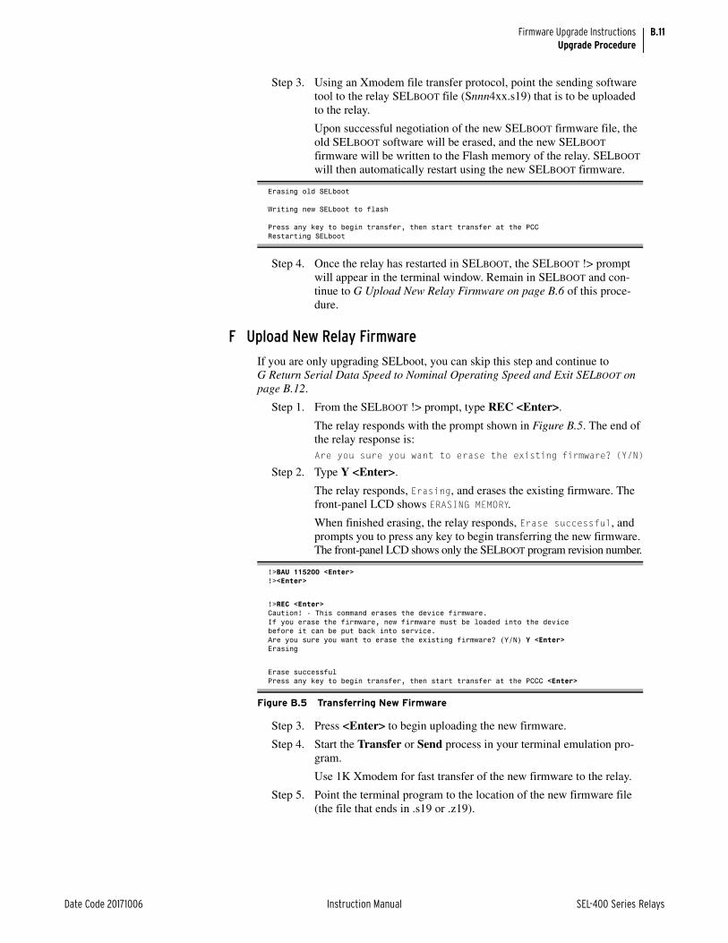
B.11
Date Code 20171006 Instruction Manual SEL-400 Series Relays
Firmware Upgrade InstructionsUpgrade Procedure
Step 3. Using an Xmodem file transfer protocol, point the sending software tool to the relay SELBOOT file (Snnn4xx.s19) that is to be uploaded to the relay.
Upon successful negotiation of the new SELBOOT firmware file, the old SELBOOT software will be erased, and the new SELBOOT firmware will be written to the Flash memory of the relay. SELBOOT will then automatically restart using the new SELBOOT firmware.
Step 4. Once the relay has restarted in SELBOOT, the SELBOOT !> prompt will appear in the terminal window. Remain in SELBOOT and con-tinue to G Upload New Relay Firmware on page B.6 of this proce-dure.
F Upload New Relay Firmware
If you are only upgrading SELboot, you can skip this step and continue to G Return Serial Data Speed to Nominal Operating Speed and Exit SELBOOT on page B.12.
Step 1. From the SELBOOT !> prompt, type REC <Enter>.
The relay responds with the prompt shown in Figure B.5. The end of the relay response is:Are you sure you want to erase the existing firmware? (Y/N)
Step 2. Type Y <Enter>.
The relay responds, Erasing, and erases the existing firmware. The front-panel LCD shows ERASING MEMORY.
When finished erasing, the relay responds, Erase successful, and prompts you to press any key to begin transferring the new firmware. The front-panel LCD shows only the SELBOOT program revision number.
Step 3. Press <Enter> to begin uploading the new firmware.
Step 4. Start the Transfer or Send process in your terminal emulation pro-gram.
Use 1K Xmodem for fast transfer of the new firmware to the relay.
Step 5. Point the terminal program to the location of the new firmware file (the file that ends in .s19 or .z19).
Erasing old SELboot
Writing new SELboot to flash
Press any key to begin transfer, then start transfer at the PCCRestarting SELboot
!>BAU 115200 <Enter>!><Enter>
!>REC <Enter>Caution! - This command erases the device firmware.If you erase the firmware, new firmware must be loaded into the devicebefore it can be put back into service.Are you sure you want to erase the existing firmware? (Y/N) Y <Enter>Erasing
Erase successfulPress any key to begin transfer, then start transfer at the PCCC <Enter>
Figure B.5 Transferring New Firmware

B.12
SEL-400 Series Relays Instruction Manual Date Code 20171006
Firmware Upgrade InstructionsUpgrade Procedure
NOTE: The relay displays one or more “C” characters while waiting for your PC terminal emulation program to send the new firmware. If you do not start the transfer quickly (within about 18 seconds), the relay times out and responds Remote system is not responding. If this happens, begin again at F Upload New Relay Firmware on page B.11.
Step 6. Begin the file transfer.
The typical transfer time at 115200 bps with 1K Xmodem is 10 to 20 minutes. The LCD screen shows SELBOOT Ryyy LOADING CODE while the relay loads the new firmware.
Step 7. Wait for firmware load completion.
If the relay responds with the message Transfer failed — Model mismatch, please refer to Troubleshooting on page B.17.
When finished loading the new firmware, the relay responds, Transfer completed successfully and displays the SELBOOT !> prompt. The LCD screen displays SELBOOT Ryyy SEL-4xx-Rnnn, where yyy is the SELBOOT revision number, 4xx is the particular model of the SEL-400 series relay being upgraded, and nnn is the firmware revision number of the relay, e.g., R100 SEL-421-R105.
G Return Serial Data Speed to Nominal Operating Speed and Exit SELBOOT
Step 1. Type <Enter> to confirm relay communication.
The terminal displays the SELBOOT !> prompt.
Step 2. Type BAU 9600 <Enter> to reduce the data speed to your nominal serial communications speed (9600 bps in this example).
Step 3. Set your terminal emulation program to match the nominal data speed.
Step 4. Type <Enter> to confirm that you have reestablished communication with the relay.
The relay responds with the SELBOOT !> prompt.
Step 5. Type EXI <Enter> to exit the SELBOOT program.
After a slight delay, the relay responds with the following message:CAUTION: Initial relay restart. DO NOT cycle power during this time. Please wait 3 minutes for restart completion.
H Verify Relay Self-TestsStep 1. Press <Enter> and confirm that the Access Level 0 = prompt appears
on your terminal screen.
Step 2. Remove input power to the relay.
a. Allow at least 10 seconds during the removal of relay power to ensure that the power supply has shut down.
b. Reapply input power to the relay.
c. Wait 10 minutes after startup of the relay to allow the relay to detect any hardware changes made during the upgrade process.
Step 3. Enter Access Level 1 using the ACC command and Access Level 1 password.
Step 4. Enter Access Level 2 using the 2AC command and Access Level 2 password.
Step 5. Type STA <Enter> to check the relay status and accept new hard-ware changes if needed.
Step 6. Verify that all relay self-test parameters are within tolerance. (The relay compares the settings before and after the upgrade process and displays an upgrade warning if settings are dissimilar. You can find details in the upgrade report file.)

B.13
Date Code 20171006 Instruction Manual SEL-400 Series Relays
Firmware Upgrade InstructionsUpgrade Procedure
Step 7. View the front-panel ENABLED LED and confirm that the LED is illu-minated.
Unless there is a serious problem, the ENABLED LED illuminates without any intervention, and the relay retains all settings.
If the relay does not enable within five minutes of the Initial relay restart message, contact your Technical Service Center or the SEL factory for assistance (see Technical Support on page B.18).
I Verify Relay SettingsStep 1. Prepare to control the relay at Access Level 2; use the procedure in
Enter Access Level 2 on page B.9.
Step 2. Type VER <Enter> to confirm the new firmware.
Step 3. Match the firmware revision number with the FID number on the screen.
Step 4. Use one of the following methods to review your settings.
➢ Use the QuickSet Read menu.
If the settings do not match the settings that you recorded in Backup Relay Settings on page B.9, use QuickSet to restore relay settings.
➢ Type SHOW <Enter>.
You can reissue the settings with the SET commands (see Section 9: ASCII Command Reference of the product-specific instruction manual for information on the SHOW and SET commands).
Step 5. Type STA <Enter> to check relay status.
Step 6. Verify that all relay self-test parameters are within tolerance.
J Return the Relay to ServiceStep 1. Follow your company procedures for returning a relay to service.
Step 2. Type MET <Enter> to view power system metering.
Step 3. Verify that the current and voltage signals are correct.
Step 4. Type TRI <Enter> and then type EVE <Enter> to view the event report for the event just triggered.
Step 5. Verify that the current and voltage signals are correct in the event report.
Step 6. Autoconfigure the communications processor port if an SEL commu-nications processor is connected to the relay.
This step reestablishes automatic data collection between the SEL communications processor and the SEL-400 series relay. Failure to perform this step can result in automatic data collection failure when cycling communications processor power.
The relay is now ready for your commissioning procedure.
Verify IEC 61850 Operation (Optional)SEL-400 series relays with optional IEC 61850 protocol require the presence of one valid CID file to enable the protocol. You should only transfer a CID file to the relay if you want to implement a change in the IEC 61850 configuration or restore the relay CID file after a firmware upgrade in which the CID file is

B.14
SEL-400 Series Relays Instruction Manual Date Code 20171006
Firmware Upgrade InstructionsUpgrade Procedure
removed. If you transfer an invalid CID file, the relay will disable the IEC 61850 protocol because it no longer has a valid configuration. To restart IEC 61850 pro-tocol operation, you must transfer a valid CID file to the relay.
Perform the following steps to verify that the IEC 61850 protocol is still opera-tional and if not, re-enable it. This procedure assumes that IEC 61850 was opera-tional with a valid CID file immediately before initiating the firmware upgrade. If the IEC 61850 protocol was not configured prior to the upgrade, skip to J Return Relay to Service on page B.8. Refer to the Section 17: IEC 61850 Communica-tion for help with IEC 61850 configuration.
Step 1. Issue the STA, ID, and GOO commands.
Step 2. Verify that there are no error messages regarding IEC 61850 or CID file parsing.
If the responses to the STA, ID, or GOO commands contain IEC 61850 or CID error messages, continue with the following steps to re-enable the IEC 61850 protocol. Otherwise, skip to J Return Relay to Service on page B.8.
If the IEC 61850 protocol has been disabled because of an upgrade-induced CID file incompatibility, you can use Architect to convert the existing CID file and make it compatible again.
a. Install the Architect upgrade that supports your required CID file version.
b. Run Architect, and open the project that contains the existing CID file for the relay. Use Architect to download the CID from the relay, and select File > Download CID in the menu bar to save the CID file.
c. If using embedded settings, create an updated .rdb file with the settings read in I Verify Relay Settings on page B.7. Update the reference in the Settings Link tab and save the new CID file.
d. In the Project Editor in Architect, select and right-click the CID file. Click Send CID to download the CID file to the relay. Download the CID file to the relay.
Upon connecting to the relay, Architect will detect the upgraded Ethernet port firmware and prompt you before converting the existing CID file to a supported version. Once converted, downloaded, and processed, the valid CID file allows the relay to re-enable the IEC 61850 protocol.
Step 3. In the Telnet session, issue the STA, ID, and GOO commands.
Step 4. Verify that no IEC 61850 error messages are in the STA or ID com-mand responses.
Step 5. Verify the GOOSE transmitted and received messages are as expected.
Relays being upgraded from firmware that did not support a local-time UTC off-set setting (UTCOFF) to firmware that does support the UTCOFF setting may show incorrect time stamps in Demand Metering and Breaker Monitor report data that was recorded by the relay prior to the firmware upgrade.
The time stamps shown for the Demand Metering and Breaker Monitor data recorded prior to the firmware upgrade will show UTC time plus an eight-hour local time offset, along with any applicable daylight-saving time adjustment.

B.15
Date Code 20171006 Instruction Manual SEL-400 Series Relays
Firmware Upgrade InstructionsTime-Domain Link (TiDL) Firmware Upgrade
This only affects time stamps recorded and stored by the relay prior to the firm-ware upgrade. All time stamps in Demand Metering and Breaker Monitoring fol-lowing the firmware upgrade will be UTC time with the local time offset setting (UTCOFF) and daylight-saving time applied.
No other reports (Event History, Event Summary, SER, etc.) are affected.
Time-Domain Link (TiDL) Firmware UpgradeThe relay firmware will be upgraded through the standard upgrade process shown above. The TiDL interface board has its own firmware upgrade process, and the firmware for the TiDL interface board is stored on an SD card. This procedure will upgrade the TiDL interface board as well as the connected Axion modules. The firmware for the TiDL interface board can be determined by issuing the VERSION command in the relay (see Figure B.6).
To upgrade the firmware, perform the following steps.
Remove From ServiceStep 1. Remove the unit from service.
Step 2. Turn the unit off.
Step 3. Remove the front panel.
UpgradeStep 1. Copy the ECB and SEL-2245 firmware .zds files from the upgrade
CD to an SD card.
Step 2. Install the SD card in the SD card slot indicated in Figure B.7.
Step 3. Turn the unit on.
Step 4. Wait for the upgrade to complete. (See the accompanying note.)
=>>VER <ENTER>FID=SEL-451-5-R317-V0-Z022012-D20160728CID=FFE8Part Number: 0451543RRC4X4H60X0XXXSerial Number: 0000000000SELboot: BFID= SLBT-4XX-R209-V0-Z001002-D20150130 Checksum: 0000
ECB FID= R100
Mainboard: Code FLASH Size: 12 MB Data FLASH Size: 52 MB RAM Size: 64 MB EEPROM Size: 128 kBFront Panel: not installedAnalog Inputs (provided by remote Axion Nodes): W: Currents: 5 Amp X: Currents: 5 Amp Y: Voltage: 67 Volts Z: Voltage: 67 VoltsInterface Boards: Board 1: not installed Remote I/O: 72 inputs 48 outputsE4 Configuration: 4Extended Relay Features: IEC 61850
Figure B.6 EtherCAT Cal Board (ECB) FID

B.16
SEL-400 Series Relays Instruction Manual Date Code 20171006
Firmware Upgrade InstructionsTime-Domain Link (TiDL) Firmware Upgrade
CAUTION
Step 5. The LEDs located next to the SD card slot will indicate the status of the upgrade.
Equipment components are sensitive to electrostatic discharge (ESD). Undetectable permanent damage can result if you do not use proper ESD procedures. Ground yourself, your work surface, and this equipment before removing any cover from this equipment. If your facility is not equipped to work with these compo-nents, contact SEL about returning this device and related SEL equipment for service.
Note: During the upgrade of the TiDL interface board, the eight LEDs will toggle sequentially from left to right. During the remote module upgrade, the eight LEDs correspond to each port, 6A is the left-most LED and 6H is the right-most LED. As each module is updated, its corresponding LED blinks four times per second.
The upgrade process usually completes in less than 10 minutes. (If remote Axion modules are being upgraded and there is more than one Axion module connected to a port, the upgrade may take longer.)
The upgrade has successfully completed when all of the LEDs are either on or off (not blinking). The left four LEDs are on if the interface board upgrade succeeded; they are off if the upgrade was not necessary. The right four LEDs are on if the module upgrade succeeded; they are off if the upgrade was not necessary. If the interface board upgrade failed, the left four LEDs blink twice per second. If the module upgrade failed, the right four LEDs blink twice per second.
RecommissionStep 1. Turn the unit off.
Step 2. Remove the SD card (recommended but not required).
Step 3. Replace the front panel.
Step 4. Turn the unit on.
Step 5. Perform the TiDL commissioning process and return the unit to ser-vice.
Figure B.7 TiDL Interface Board SD Card Slot

B.17
Date Code 20171006 Instruction Manual SEL-400 Series Relays
Firmware Upgrade InstructionsTroubleshooting
TroubleshootingResolving Model Mismatch
When uploading a new firmware file to the relay, SELBOOT checks the relay model number (for example, 451, 421, 487) to ensure that the firmware being loaded into the relay is correct for the relay model. If the relay responds with Transfer failed — Model mismatch when a firmware download is attempted, it is because the relay model number does not match. This may be because the firmware file is not correct, or the relay model number stored in the relay mem-ory was corrupted by an interruption of the file download.
To remedy this problem, first ensure you are sending the correct file to the relay. Table B.1 shows the file names used for the firmware files. Verify that the model number in the firmware file matches the model of the relay being upgraded. After confirming that the file is correct, restart the relay into SELBOOT. Do this by turn-ing the relay off and back on while holding down the front-panel left and right arrow navigation keys. The LCD will display SELBOOT Ryyy once the power cycle is complete. The data rate will reset to 9600 during this process. To increase the data rate to the highest speed possible on the port, type BAU 115200 <Enter> at the SELBOOT !> prompt (see Figure B.5). Switch the port communications parameters data rate to 115200 and verify the SELBOOT prompt in the terminal screen. At the SELBOOT prompt, issue a REC OVERRIDE command to the relay. This tells the relay to bypass the model number check at the start of the firmware upload process. Once the REC OVERRIDE command is issued, the firmware upload process can be continued following the procedures in F Upload New Relay Firmware on page B.11, starting with Step 2 on page B.11.
Resolving Status Failure Message Response to STA CommandIf a status failure message is returned in response to the STA command, perform the following steps.
Step 1. Use the ACC and 2AC commands with the associated passwords to enter Access Level 2.
Step 2. Type STA C <Enter>. Answer Y <Enter> to the Reboot the relay and clear status prompt. The relay will respond with Rebooting the relay. Wait for about 30 seconds, then press <Enter> until you see the Access Level 0 = prompt.
Step 3. Use the ACC command with the associated password to enter Access Level 1.
Step 4. Type STA <Enter>.
If there are no fail messages and you are using Method One, click Next in Step 3 of 4 of the Firmware Loader and go to I Verify Relay Settings on page B.13.
If there are no fail messages and you are using Method Two, go to I Verify Relay Settings on page B.13.
If there are fail messages, continue with Step 5.
NOTE: Step 6 will cause the loss of settings and other important data. Be sure to retain relay settings and other data downloaded from the relay at the start of the firmware upgrade process. Relay calibration level settings will not be lost.
Step 5. Use the 2AC command with the associated password to enter Access Level 2.
Step 6. Type R_S <Enter> to restore factory default settings in the relay.
The relay asks whether to restore default settings. If the relay does not accept the R_S command, contact SEL for assistance.

B.18
SEL-400 Series Relays Instruction Manual Date Code 20171006
Firmware Upgrade InstructionsTechnical Support
Step 7. Type Y <Enter>.
The relay can take as long as two minutes to restore default settings. The relay then reinitializes, and the ENABLED LED illuminates. This LED is labeled either EN or ENABLED, depending on the relay model.
Step 8. Press <Enter> to check for the Access Level 0 = prompt indicating that serial communication is successful.
Step 9. Use the ACC and 2AC commands and type the corresponding pass-words to reenter Access Level 2.
Step 10. Use the CAL command and type the corresponding password to enter the relay Calibration settings level.
Step 11. Type SHO C <Enter> to verify the relay calibration settings.
If using Method One and the settings do not match the settings contained in the text file you recorded in C Save Settings and Other Data on page B.9, contact SEL for assistance.
If using Method Two and the settings do not match the settings contained in the text file you recorded in B Prepare the Relay on page B.9, contact SEL for assistance.
Step 12. Use the PAS n (n = 0, 1, 2, B, P, A, O, C) command to set the relay passwords.
Step 13. Restore the relay settings:
a. If you have SEL-5010 Relay Assistant software or QuickSet, restore the original settings by following the instructions for the respective software.
b. If you do not have the SEL-5010 Relay Assistant software or QuickSet, restore the original settings by issuing the necessary SET n commands.
Step 14. If any failure status messages still appear on the relay display, see the Testing and Troubleshooting section in your relay instruction manual or contact SEL for assistance.
Technical SupportWe appreciate your interest in SEL products and services. If you have questions or comments, please contact us at:
Schweitzer Engineering Laboratories, Inc.2350 NE Hopkins CourtPullman, WA 99163-5603 U.S.A. Tel: +1.509.338.3838Fax: +1.509.332.7990 Internet: selinc.com/supportEmail: [email protected]

Date Code 20171006 Instruction Manual SEL-400 Series Relays
Instruction ManualA P P E N D I X C
Cybersecurity Features
The SEL-400 series relays have a number of security features to assist users with meeting their cybersecurity design requirements.
Ports and ServicesPhysical Ports
SEL-400 series relays include four serial ports and as many as four Ethernet ports. Each physical serial port and Ethernet port can be individually disabled using the EPORT setting. By default, all of the ports are enabled.
SEL recommends that unused communications ports be disabled.
SEL-400 series relays with a TiDL configuration also have eight EtherCAT ports. These are always enabled, but they have a very limited functionality, as described below.
IP PortsWhen using Ethernet, there are a number of possible IP ports available within the relay. Many of these IP port numbers are configurable. All IP ports can be dis-abled and are disabled by default. Table C.1 describes each of these.
Note that IP traffic is only supported on station bus ports, so process bus ports have no open IP ports. See Ethernet Communications on page 15.6 for more infor-mation on these settings.
Table C.1 IP Port Numbers
IP Port Default
Port Selection Setting
Network Protocol
Default Port State
Port Enable Setting
Purpose
21 -- TCP Disabled FTPSERV FTP protocol access for file transfer of settings and reports
23 TPORT TCP Disabled ETELNET Telnet access for general engineering terminal access
80 HTTPPOR TCP Disabled EHTTP Web server access to read various relay information
102 -- TCP Disabled E61850 IEC 61850 MMS for SCADA functionality
123 SNTPPOR UDP Disabled ESNTP SNTP time synchronization
319/320 -- UDP Disabled EPTP PTP time synchronization
4712/ 4713 PMOTCP1/ PMOUDP1
TCP/UDP Disabled PMOTS1 Synchrophasor data output, session 1
4712/ 4713 PMOTCP2/ PMOUDP2
TCP/UDP Disabled PMOTS2 Synchrophasor data output, session 2
20000 DNPPNUM TCP/UDP Disabled EDNP DNP3 for SCADA functionality

C.2
SEL-400 Series Relays Instruction Manual Date Code 20171006
Cybersecurity FeaturesAuthentication and Authorization Controls
Segregating Ethernet PortsIn most modes, the enabled Ethernet ports support both IP traffic and layer 2 pro-tocols (i.e. IEC 61850 GOOSE). If NETMODE = ISOLATEIP, then one port only permits GOOSE traffic. This allows this port to be routed outside of a security perimeter while retaining the ability to perform basic monitoring and control. See Using Redundant Ethernet Ports on page 15.10 for more information on this mode.
EtherCAT PortsSEL-400 series relays with a TiDL configuration have eight EtherCAT ports. These communicate with remote Axion nodes. The ports are used exclusively for exchanging analog and digital data with Axions; they will not recognize any other types of communication.
Once the system is configured and commissioned, the relay will only communi-cate with recognized Axions. Any other traffic on these ports will be ignored. After commissioning, the loss of communications to any configured Axion or Axion module will cause the relay to disable.
Authentication and Authorization ControlsLocal Accounts
SEL-400 series relays support eight levels of access, as described in the Access Levels and Passwords on page 3.7. Refer to this section to learn how each level is accessed and what the default passwords are. It is good security practice to change the default passwords of each access level and to use a unique password for each level.
Relays have the capability to limit the level of access on a port basis. The MAX-ACC setting may be used on each port to restrict these authorization levels. This permits you to operate under the principle of “least privilege,” restricting ports to the levels needed for the functions performed on those ports.
Each relay supports strong passwords of as many as 12 characters including any printable character, allowing users to select complex passwords if they so choose. SEL recommends that passwords contain a minimum of eight characters contain-ing at least one of each of the following: lowercase letter, uppercase letter, num-ber, and special character.
Authentication FailuresWhen three successive login attempts fail as a result of an incorrect password entry, the relay locks out login attempts on that port for 30 seconds. It also pulses the BADPASS Relay Word bit.

C.3
Date Code 20171006 Instruction Manual SEL-400 Series Relays
Cybersecurity FeaturesMalware Protection Features
Malware Protection FeaturesFirmware Hash Verification
SEL provides firmware hashes as an additional tool to verify the integrity of SEL firmware upgrade files. This helps ensure that the firmware received from the factory is complete and unaltered prior to sending the firmware to the SEL device. Verify that the firmware file in your possession is a known good SEL firmware release by comparing the calculated hash value of the firmware in your possession with the hash value provided at selinc.com/products/firmware/.
Operating System/FirmwareSEL-400 series relays are embedded devices that do not allow additional soft-ware to be installed. SEL-400 series relays include a self-test that continually checks running code against the known good baseline version of code in nonvol-atile memory. This process is outlined in more detail in the document titled The SEL Process for Mitigating Malware Risk to Embedded Devices located at selinc.com/mitigating_malware/.
SEL-400 series relays run in an embedded environment for which there is no commercial anti-virus software available.
Software/Firmware VerificationSEL-400 series relays have the ability to install firmware updates in the field. Authenticity and integrity of firmware updates can be verified by using the Firm-ware Hash page at selinc.com/products/firmware/.
Logging FeaturesInternal Log Storage
The Sequential Event Recorder (SER) log is a useful tool for capturing a variety of relay events. In addition to capturing state changes of user selected Relay Word bits, it captures all startups, settings changes, and group switches. See Sequential Events Recorder (SER) on page 9.28 for more information about SER.
Alarm ReportingThe relay provides the following Relay Word bits that are useful for monitoring relay access:
➤ BADPASS—Pulses for one second if a user enters three successive bad passwords.
➤ ACCESS—Set while any user is logged into Access Level B or higher.
➤ ACCESSP—Pulses for one second whenever a user gains access to an Access Level of B or higher.
➤ PASSDIS—Set if the password disable jumper is installed.
➤ BRKENAB—Set if the breaker control enable jumper is installed.

C.4
SEL-400 Series Relays Instruction Manual Date Code 20171006
Cybersecurity FeaturesPhysical Access Security
➤ LINK5A, LINK5B, LINK5C, LINK5D—Set while the link is active on the respective Ethernet port. Loss-of-link can be an indication that an Ethernet cable has been disconnected.
NOTE: The relay can take as long as 6 ms to detect and report the loss of link on an active port (assert LNKFAIL or LNKFL2).
➤ LNKFAIL—Set if link is lost on any active station bus port. For relays with only two Ethernet ports, LNKFAIL asserts if link is lost on either port.
➤ LNKFL2—Set if link is lost on the active process bus port (Ethernet 87L ports or Sampled Values (SV) ports in devices with those capabilities). Once detected, the loss of the active port on the process bus causes immediate failover if the backup port has a good data link. If this is the case, failover may occur too quickly for the SER scanner to register the assertion and deassertion of LNKFL2.
These bits can be mapped for SCADA monitoring via DNP3, IEC 61850, or SEL Fast Message. They can also be added to the SER log for later analysis and assigned to output contacts for alarm purposes.
Physical Access SecurityPhysical security of cybersecurity assets is a common concern. Typically, relays are installed within a control enclosure that provides physical security. Other times, they are installed in boxes within the switch yard. The relay provides some tools that may be useful to help manage physical security, especially when the unit is installed in the switch yard.
You can monitor physical ingress by wiring a door sensor to one of the relay con-tact inputs. This input can then be mapped for SCADA monitoring or added to the SER log so that you can detect when physical access to the relay occurs.
It is also possible to wire an electronic latch to a relay contact output. You could then map this input for SCADA control.
Configuration Control SupportProduct Version Information
The SEL-400 series relay firmware revision number (FID) provides the current firmware version/patch level. The FID can be obtained using the STATUS com-mand.
Settings Version InformationAll settings changes are logged to the SER log. Analysis of this log will let you determine if any unauthorized settings changes occurred.
The relay also stores a hash code for each settings class in the CFG.txt file. After configuring the device, you can read the CFG.txt file and store it for future refer-ence. You can then periodically read this file from the relay and compare it to the stored reference. If any of the hash codes have changed, then you know that a set-tings class has been modified.

C.5
Date Code 20171006 Instruction Manual SEL-400 Series Relays
Cybersecurity FeaturesBackup and Restore
Backup and RestoreSEL-400 series relays support the export and import of settings and configuration using ACSELERATOR QuickSet SEL-5030 Software and ACSELERATOR Archi-tect SEL-5032 Software. Settings can also be imported and exported as files using any file transfer mechanism.
DecommissioningNOTE: Do not do this when sending in the relay for service at the factory. SEL needs to be able to see how the relay was configured in order to properly diagnose any problems.
It is often desirable to erase the settings from the relay when it is removed from service. You can completely erase all the configuration settings from the relay using the following procedure.
Step 1. Go to Access Level 2.
Step 2. Execute the R_S command to restore the device to factory-default settings.
Step 3. Allow the relay to restart.
Step 4. Go to Access Level 2.
Step 5. Execute the R_S command again to set the backup copy of settings to factory default.
Step 6. Allow the relay to restart.
Once this procedure is complete, all internal instances of all user settings and passwords will be erased.
Vulnerability Notification ProcessSecurity Vulnerability Process
SEL provides security disclosure alerts to customers, and SEL instruction manu-als document all releases. SEL security vulnerability disclosures are described in The SEL Process for Disclosing Security Vulnerabilities located at selinc.com.
Emailed Security NotificationYou can sign up to receive email notifications when SEL releases security vulner-ability notices and service bulletins at selinc.com/support/security-notifications/.

This page intentionally left blank

Date Code 20171006 Instruction Manual SEL-400 Series Relays
SEL-400 Series RelaysInstruction Manual Glossary
a Contact A breaker auxiliary contact (ANSI Standard Device Number 52A) that closes when the breaker is closed and opens when the breaker is open.
a Output A relay control output that closes when the output relay asserts.
b Contact A breaker auxiliary contact (ANSI Standard Device Number 52B) that opens when the breaker is closed and closes when the breaker is open.
b Output A relay control output that opens when the output relay asserts.
c Contact A breaker auxiliary contact that can be set to serve either as an a contact or as a b contact.
c Output An output with both an a output and b output sharing a common post.
3U, 4U, 5U, 6U, 7U, 9U The designation of the vertical height of a device in rack units. One rack unit, U, is approximately 1.75 inches or 44.45 mm.
A Abbreviation for amps or amperes—a unit of electrical current flow.
ABS Operator An operator in math SELOGIC control equations that provides absolute value.
AC Ripple The peak-to-peak ac component of a signal or waveform. In the station dc battery system, monitoring ac ripple provides an indication of whether the substation battery charger has failed.
Acceptance Testing Testing that confirms that the relay meets published critical performance specifications and requirements of the intended application. Such testing involves testing protection elements and logic functions when qualifying a relay model for use on the utility system.
Access Level A relay command level with a specified set of relay information and commands. Except for Access Level 0, you must have the correct password to enter an access level.
Access Level 0 The least secure and most limited access level. No password protects this level. From this level, you must enter a password to go to a higher level.
Access Level 1 A relay command level you use to monitor (view) relay information. The default access level for the relay front panel.
Access Level 2 The most secure access level where you have total relay functionality and control of all settings types.
Access Level A A relay command level you use to access all Access Level 1 and Access Level B (Breaker) functions plus Automation, Alias, Global, Front Panel, Report, Port, and DNP3 settings.
Access Level B A relay command level you use for Access Level 1 functions plus circuit breaker control and data.
Access Level O A relay command level you use to access all Access Level 1 and Access Level B (Breaker) functions plus Output, Alias, Global, Front Panel, Report, Port, and DNP3 settings.

GL.2
SEL-400 Series Relays Instruction Manual Date Code 20171006
GlossaryAccess Level P—ANSI Standard Device Numbers
Access Level P A relay command level you use to access all Access Level 1 and Access Level B (Breaker) functions plus Protection, SELOGIC, Alias, Global, Group, Breaker Monitor, Front Panel, Report, Port, and DNP3 settings.
ACSELERATOR ArchitectSEL-5032 Software
ACSELERATOR Architect is an add-on to the ACSELERATOR QuickSet Suite that uses the IEC 61850 Substation Configuration Language to configure SEL IEDs.
ACSELERATOR QuickSetSEL-5030 Software
A Windows-based program that simplifies settings and provides analysis support.
ACSI Abstract Communications Service Interface for the IEC 61850 protocol. Defines a set of objects, a set of services to manipulate and access those objects, and a base set of data types for describing objects.
Active Settings Group The settings group that the relay is presently using from among six settings groups available in the relay.
ADC Analog to Digital Converter. A device that converts analog signals into digital signals.
Admittance The reciprocal of impedance, I/V.
Advanced Settings Settings for customizing protection functions; these settings are hidden unless you set EADVS := Y and EGADVS := Y.
Alias An alternative name assigned to Relay Word bits, analog quantities, default terminals, and bus-zone names.
Analog Quantities Variables represented by such fluctuating measurable quantities as temperature, frequency, current, and voltage.
AND Operator Logical AND. An operator in Boolean SELOGIC control equations that requires fulfillment of conditions on both sides of the operator before the equation is true.
ANSI StandardDevice Numbers
A list of standard numbers used to represent electrical protection and control relays. The standard device numbers used in this instruction manual include the following:
21 Distance element
24 Volts/Hertz Element
25 Synchronism-check element
27 Undervoltage Element
32 Directional Elements
49 Thermal Element
50 Overcurrent Element
51 Inverse-Time Overcurrent Element
52 AC Circuit Breaker
59 Overvoltage Element
67 Definite-Time Overcurrent
79 Recloser
86 Breaker Failure Lockout
89 Disconnect

GL.3
Date Code 20171006 Instruction Manual SEL-400 Series Relays
GlossaryAnti-Aliasing Filter—AX-S4 MMS
These numbers are frequently used within a suffix letter to further designate their application. The suffix letters used in this instruction manual include the following:
P Phase Element
G Residual/Ground Element
N Neutral/Ground Element
Q Negative-Sequence (3I2) Element
Anti-Aliasing Filter A low-pass filter that blocks frequencies too high for the given sampling rate to accurately reproduce.
Apparent Power, S Complex power expressed in units of volt-amperes (VA), kilovolt-amperes (kVA), or megavolt-amperes (MVA). Accounts for both real (P) and reactive (Q) power dissipated in a circuit: S = P + jQ. This is power at the fundamental frequency only; no harmonics are included in this quantity.
Arcing Resistance The resistance in the arc resulting from a power line fault.
ASCII Abbreviation for American Standard Code for Information Interchange. Defines a standard set of text characters. The relay uses ASCII text characters to communicate using front-panel and rear-panel EIA-232 serial ports on the relay and through virtual serial ports.
ASCII Terminal A terminal without built-in logic or local processing capability that can only send and receive information.
Assert To activate. To fulfill the logic or electrical requirements needed to operate a device. To set a logic condition to the true state (logical 1) of that condition. To apply a closed contact to a relay input. To close a normally open output contact. To open a normally closed output contact.
AT Modem Command SetDialing String Standard
The command language standard that Hayes Microcomputer Products, Inc. developed to control autodial modems from an ASCII terminal (usually EIA-232 connected) or a PC containing software allowing emulation of such a terminal.
Autoconfiguration The ability to determine relay type, model number, metering capability, port ID, data rate, passwords, relay elements, and other information that an IED (an SEL-2020/2030 communications processor) needs to automatically communicate with relays.
Automatic Messages Messages including status failure and status warning messages that the relay generates at the serial ports and displays automatically on the front-panel LCD.
Automatic Reclose Automatic closing of a circuit breaker after a breaker trip by a protective relay.
Automation Variables Variables that you include in automation SELOGIC control equations.
Autoreclose-Drive-to-Lockout
A logical condition that drives the autoreclose function out of service with respect to a specific circuit breaker.
Autotransformer A transformer with at least two common windings.
AX-S4 MMS “Access for MMS” is an IEC 61850, UCA2, and MMS client application produced by SISCO, Inc., for real-time data integration in Microsoft Windows-based systems supporting OPC and DDE. Included with AX-S4 MMS is the interactive MMS Object Explorer for browser-like access to IEC 61850/UCA2 and MMS device objects.

GL.4
SEL-400 Series Relays Instruction Manual Date Code 20171006
GlossaryAxion—Busbar
Axion Another term for the SEL-2240. The Axion is an integrated, modular input/output and control solution suited for utility and industrial applications. In TiDL systems, it is used for remote data acquisition and control.
Bandpass Filter A filter that passes frequencies within a certain range and blocks all frequencies outside this range.
Bay Primary plant including disconnects, circuit breaker, CTs, PTs, power transformer, etc.
Bay Control Front-panel control (open and close) of the transformer circuit breakers and disconnects (isolators).
Best Choice GroundDirectional Element Logic
An SEL logic that determines the directional element that the relay uses for ground faults.
Bit Label The identifier for a particular bit.
Bit Value Logical 0 or logical 1.
Block Trip Extension Continuing the blocking signal at the receiving relay by delaying the dropout of Relay Word bit BT.
Blocking Signal Extension The blocking signal for the DCB (directional comparison blocking) trip scheme is extended by a time delay on dropout timer to prevent unwanted tripping following current reversals.
Bolted Fault A fault with essentially zero impedance or resistance between the shorted conductors.
Boolean Logic Statements Statements consisting of variables that behave according to Boolean logic operators such as AND, NOT, and OR.
Breaker Auxiliary Contact An electrical contact associated with a circuit breaker that opens or closes to indicate the breaker position. A Form A breaker auxiliary contact (ANSI Standard Device Number 52A) closes when the breaker is closed and opens when the breaker is open. A Form B breaker auxiliary contact (ANSI Standard Device Number 52B) opens when the breaker is closed and closes when the breaker is open.
Breaker-and-a-halfConfiguration
A switching station arrangement of three circuit breakers per two circuits; the two circuits share one of the circuit breakers.
Breaker Differential Differential zone of protection configured exclusively across the tie breaker; the breaker differential protects only the area between the two tie-breaker CTs.
Buffered Report IEC 61850 IEDs can issue buffered reports of internal events (caused by trigger options data-change, quality-change, and data-update). These event reports can be sent immediately or buffered (to some practical limit) for transmission, such that values of data are not lost because of transport flow control constraints or loss of connection. Buffered reporting provides sequence-of-events (SOE) functionality.
Busbar Electrical junction of two or more primary circuits. For a single busbar, there could be multiple bus-zones; there can be more bus-zones than busbars, but not more busbars than bus-zones.

GL.5
Date Code 20171006 Instruction Manual SEL-400 Series Relays
GlossaryBus Coupler (see also Tie Breaker)—Circuit Breaker Report
Bus Coupler(see also Tie Breaker)
Equipment with at least a CT and circuit breaker, connecting two busbars when the circuit breaker is closed. Disconnects of other terminals at the station (feeders, lines, etc.) are normally arranged in parallel with the bus coupler. Closing two or more disconnects of the other terminals bypasses the bus coupler, forming a connection without a circuit breaker between two or more busbars.
BusbarProtection Element
Each busbar protection elements comprise a differential element, a directional element, and a fault detection logic.
Bus Sectionalizer(see also Buscoupler)
Equipment with at least a CT and circuit breaker, connecting two busbars when the circuit breaker is closed.
Bus-Zone-to-Bus-ZoneConnection Variable
SELOGIC variable stating the conditions when the relay merges two zones to form a single protection zone.
Bus-Zone(see also Protection Zone)
Area of protection formed by a minimum of two terminals.
C37.118 IEEE C37.118, Standard for Synchrophasor Measurements for Power Systems.
C37.238 IEEE C37.238, Standard Profile for Use of IEEE 1588 Precision Time Protocol in Power System Applications.
Capacitor Bank Assembly of a number of capacitor units.
Capacitor Element Device consisting of two electrodes separated by a dielectric.
Capacitor Unit Assembly of a number of capacitor elements.
Category A collection of similar relay settings.
CCVT Coupling-capacitor voltage transformer that uses a capacitive voltage divider to reduce transmission voltage to a level safe for metering and relaying devices. See CVT.
Checksum A method for checking the accuracy of data transmission involving summation of a group of digits and comparison of this sum to a previously calculated value.
Check Zone Protection zone formed by two or more terminals where the differential calculation is independent of the status of the disconnect auxiliary contacts.
CID Checksum identification of the firmware.
CID File IEC 61850 Configured IED Description file. XML file that contains the configuration for a specific IED.
Circuit BreakerFailure Logic
This logic within the relay detects and warns of failure or incomplete operation of a circuit breaker in clearing a fault or in performing a trip or close sequence.
Circuit BreakerHistory Report
A concise circuit breaker event history that contains as many as 128 events. This breaker history report includes circuit breaker mechanical operation times, electrical operation times, interrupted currents, and dc battery monitor voltages.
Circuit Breaker Report A full report of breaker parameters for the most recent operation. These parameters include interrupted currents, number of operations, and mechanical and electrical operating times among many parameters.

GL.6
SEL-400 Series Relays Instruction Manual Date Code 20171006
GlossaryClass—Contact Output
Class The first level of the relay settings structure including Global, Group, Breaker Monitor, Port, Report, Front Panel, DNP3 settings, Protection SELOGIC control equations, Automation SELOGIC control equations, and Output SELOGIC control equations.
Cold Start Turning a system on without carryover of previous system activities.
Combined Winding Mathematical combination (in the SEL-400) of currents from two separate sets of CT on the same voltage level, typical of breaker-and-a-half busbar configurations.
Commissioning Assistant Software used during transformer commissioning that checks for typical (single-contingency) wiring errors; The software uses load current to calculate the correct matrix combinations for as many as five windings.
Commissioning Testing Testing that serves to validate all system ac and dc connections and confirm that the relay, auxiliary equipment, and SCADA interface all function as intended with your settings. Perform such testing when installing a new protection system.
CommonClass Components
Composite data objects that contain instances of UCA standard data types.
Common Data Class IEC 61850 grouping of data objects that model substation functions. Common Data Classes include Status information, Measured information, Controllable status, Controllable analog, Status settings, Analog settings, and Description information.
Common Inputs Relay control inputs that share a common terminal.
Common Time Delay Both ground- and phase-distance protection follow a common time delay on pickup.
Common Zone Timing Both ground- and phase-distance protection follow a common time delay on pickup.
Communications Protocol A language for communication between devices.
Communications-AssistedTripping
Circuit breaker tripping resulting from the transmission of a control signal over a communications medium.
Comparison Boolean SELOGIC control equation operation that compares two numerical values. Compares floating-point values such as currents, total counts, and other measured and calculated quantities.
Computer TerminalEmulation Software
Software such as Microsoft HyperTerminal or ProComm Plus that can be used to send and receive ASCII text messages and files via a computer serial port.
COMTRADE Abbreviation for Common Format for Transient Data Exchange. The relay supports the IEEE Std C37.111–1999, Common Format for Transient Data Exchange (COMTRADE) for Power Systems.
Conditioning Timers Timers for conditioning Boolean values. Conditioning timers either stretch incoming pulses or allow you to require that an input take a state for a certain period before reacting to the new state.
Contact Input See Control Input.
Contact Output See Control Output.

GL.7
Date Code 20171006 Instruction Manual SEL-400 Series Relays
GlossaryControl Input—Data Object
Control Input Relay inputs for monitoring the state of external circuits. Connect auxiliary relay and circuit breaker contacts to the control inputs.
Control Output Relay outputs that affect the state of other equipment. Connect control outputs to circuit breaker trip and close coils, breaker failure auxiliary relays, communications-assisted tripping circuits, and SCADA systems.
Coordination Timer A timer that delays an overreaching element so that a downstream device has time to operate.
COS Operator Operator in math SELOGIC control equations that provides the cosine function.
Counter Variable or device such as a register or storage location that either records or represents the number of times an event occurs.
Cross-country fault A cross-country fault consists of simultaneous separate single phase-to-ground faults on parallel lines.
CT Current transformer.
CT Subsidence Current Subsidence current appears as a small exponentially decaying dc current with a long time constant. This current results from the energy trapped in the CT magnetizing branch after the circuit breaker opens to clear a fault or interrupt load.
CTR Current transformer ratio.
Current Compensation Adjustment of the current signals to nullify any standing unbalance current.
CurrentReversal Guard Logic
Under this logic, the relay does not key the transmitter and ignores reception of a permissive signal from the remote terminal when a reverse-looking element detects an external fault.
CurrentTransformer Saturation
The point of maximum current input to a CT; any change of input beyond the saturation point fails to produce any appreciable change in output.
CVT Capacitive voltage transformer that uses a capacitive voltage divider to reduce transmission voltage to a level safe for metering and relaying devices. See CCVT.
CVT Transient Blocking Logic that prevents transient errors on capacitive voltage transformers from causing false operation of Zone 1 mho elements.
CVT TransientDetection Logic
Logic that detects transient errors on capacitive voltage transformers.
Data Attribute In the IEC 61850 protocol, the name, format, range of possible values, and representation of values being communicated.
Data Bit A single unit of information that can assume a value of either logical 0 or logical 1 and can convey control, address, information, or frame check sequence data.
Data Class In the IEC 61850 protocol, an aggregation of classes or data attributes.
Data Label The identifier for a particular data item.
Data Object In the IEC 61850 protocol, part of a logical node representing specific information (status or measurement, for example). From an object-oriented point of view, a data object is an instance of a data class.

GL.8
SEL-400 Series Relays Instruction Manual Date Code 20171006
GlossaryDC Offset—Disconnect (Isolator)
DC Offset A dc component of fault current that results from the physical phenomenon preventing an instantaneous change of current in an inductive circuit.
DCB (DirectionalComparison Blocking)
A communications-assisted protection scheme. A fault occurring behind a sending relay causes the sending relay to transmit a blocking signal to a remote relay; the blocking signal interrupts the tripping circuit of the remote relay and prevents tripping of the protected line.
DCE Devices Data communications equipment devices (modems).
DCUB (DirectionalComparison Unblocking)
A communications-assisted tripping scheme with logic added to a POTT scheme that allows high-speed tripping of overreaching elements for a brief time during a loss of channel. The logic then blocks trip permission until the communications channel guard returns for a set time.
Dead Band The range of variation an analog quantity can traverse before causing a response.
Deassert To deactivate. To remove the logic or electrical requirements needed to operate a device. To clear a logic condition to its false state (logical 0). To open the circuit or open the contacts across a relay input. To open a normally open output contact. To close a normally closed output contact.
Debounce Time The time that masks the period when relay contacts continue to move after closing; debounce time covers this indeterminate state.
Default Data Map The default map of objects and indices that the relay uses in DNP3 protocol.
Delta A phase-to-phase series connection of circuit elements, particularly voltage transformers or loads.
Demand Meter A measuring function that calculates a rolling average or thermal average of instantaneous measurements over time.
Differential Element The differential element calculates current differences across a zone of protection.
Direct Tripping Local or remote protection elements provide tripping without any additional supervision.
Directional Element The directional element determines the direction of power flow at a point in the power system.
Directional Start A blocking signal provided by reverse reaching elements to a remote terminal used in DCB communications-assisted tripping schemes. If the fault is internal (on the protected line), the directional start elements do not see the fault and do not send a blocking signal. If the fault is external (not on the protected line), the directional start elements start sending the block signal.
Directional Supervision The relay uses directional elements to determine whether protective elements operate based on the direction of a fault relative to the relay.
Disabling Time Delay A DCUB scheme timer (UBDURD) that prevents high-speed tripping following a loss-of-channel condition.
Disconnect (Isolator) Mechanical switch that isolates primary equipment such as circuit breakers from the electrical system.

GL.9
Date Code 20171006 Instruction Manual SEL-400 Series Relays
GlossaryDistance Calculation Smoothness—EIA-232
DistanceCalculation Smoothness
A relay algorithm that determines whether the distance-to-fault calculation varies significantly or is constant.
Distance Protection Zone The area of a power system where a fault or other application-specific abnormal condition should cause operation of a protective relay.
DMTC Period The time of the demand meter time constant in demand metering.
DNP (DistributedNetwork Protocol)
Manufacturer-developed, hardware-independent communications protocol.
Dropout Time The time measured from the removal of an input signal until the output signal deasserts. You can set the time, in the case of a logic variable timer, or the dropout time can be a result of the characteristics of an element algorithm, as in the case of an overcurrent element dropout time.
DTE Devices Data terminal equipment (computers, terminals, printers, relays, etc.).
DTT (Direct TransferTrip)
A communications-assisted tripping scheme. A relay at one end of a line sends a tripping signal to the relay at the opposite end of the line.
Dumb Terminal See ASCII terminal.
DUTT(Direct Underreaching
Transfer Trip)
A communications-assisted tripping scheme. Detection of a Zone 1 fault at either end of a line causes tripping of the local circuit breaker as well as simultaneous transmission of a tripping signal to the relay at the opposite end of the line. The scheme is said to be underreaching because the Zone 1 relays at both ends of the line reach only 80 percent (typically) of the entire line length.
Dynamic Zone Selection The process by which the currents from the CTs are assigned to or removed from the differential calculations as a function of the Boolean value (logical 0 or logical 1) of a particular SELOGIC equation.
ECB(EtherCAT
Communications Board)
A circuit board mounted within the relay that has eight EtherCAT fiber connections for creating a TiDL system.
Echo The action of a local relay returning (echoing) the remote terminal permissive signal to the remote terminal when the local breaker is open or a weak infeed condition exists.
Echo Block Time Delay A time delay that blocks the echo logic after dropout of local permissive elements.
Echo Duration Time Delay A time delay that limits the duration of the echoed permissive signal.
ECTT(Echo Conversion to Trip)
An element that allows a weak terminal, after satisfaction of specific conditions, to trip by converting an echoed permissive signal to a trip signal.
EEPROM Electrically Erasable Programmable Read-Only Memory. Nonvolatile memory where relay settings, event reports, SER records, and other nonvolatile data are stored.
EHV Extra high voltage. Voltages greater than 230 kV.
EIA-232 Electrical definition for point-to-point serial data communications interfaces, based on the standard EIA/TIA-232. Formerly known as RS-232.

GL.10
SEL-400 Series Relays Instruction Manual Date Code 20171006
GlossaryEIA-485—Fast Hybrid Control Output
EIA-485 Electrical standard for multidrop serial data communications interfaces, based on the standard EIA/TIA-485. Formerly known as RS-485.
Electrical Operating Time Time between trip or close initiation and an open-phase status change.
Electromechanical Reset Setting of the relay to match the reset characteristics of an electromechanical overcurrent relay.
End-Zone Fault A fault at the farthest end of a zone that a relay is required to protect.
Energy Metering Energy metering provides a look at imported power, exported power, and net usage over time; measured in MWh (megawatt hours).
Equalize Mode A procedure where substation batteries are overcharged intentionally for a preselected time in order to bring all cells to a uniform output.
ESD(Electrostatic Discharge)
The sudden transfer of charge between objects at different potentials caused by direct contact or induced by an electrostatic field.
EtherCAT(Ethernet for Control
Automation Technology)
An Ethernet-based network protocol for high-speed control networks that require real-time performance and ease of network configuration.
Ethernet A network physical and data link layer defined by IEEE 802.2 and IEEE 802.3.
Event History A quick look at recent relay activity that includes a standard report header; event number, date, time, and type; fault location; maximum fault phase current; active group at the trigger instant; and targets.
Event Report A text-based collection of data stored by the relay in response to a triggering condition, such as a fault or ASCII TRI command. The data show relay measurements before and after the trigger, in addition to the states of protection elements, relay inputs, and relay outputs each processing interval. After an electrical system fault, use event reports to analyze relay and system performance.
Event Summary A shortened version of stored event reports. An event summary includes items such as event date and time, event type, fault location, time source, recloser shot counter, prefault and fault voltages, currents, and sequence current, and MIRRORED BITS communications channel status (if enabled).
The relay sends an event report summary (if auto messaging is enabled) to the relay serial port a few seconds after an event.
External Fuse Fuse external to a capacitor unit (usually mounted on the unit).
EXP Operator Math SELOGIC control equation operator that provides exponentiation.
F_TRIG Falling-edge trigger. Boolean SELOGIC control equation operator that triggers an operation upon logic detection of a falling edge.
Fail-Safe Refers to an output that is open during normal relay operation and closed when relay power is removed or if the relay fails. Configure alarm outputs for fail-safe operation.
Falling Edge Transition from logical 1 to logical 0.
Fast Hybrid ControlOutput
A control output similar to, but faster than, the hybrid control output. The fast hybrid output uses an insulated-gate bipolar junction transistor (IGBT) to

GL.11
Date Code 20171006 Instruction Manual SEL-400 Series Relays
GlossaryFast Meter—Functional Component
interrupt (break) high inductive dc currents and to very rapidly make and hold the current until a metallic contact operates, at which time the IGBT turns off and the metallic contact holds the current. Unlike the hybrid control output, this output is not polarity sensitive—reversed polarity causes no misoperations.
Fast Meter SEL binary serial port command used to collect metering data with SEL relays.
Fast Operate SEL binary serial port command used to perform control with SEL relays.
Fast Message SEL binary serial port protocol used for Fast SER, Fast Message Synchrophasors, and RTD communications.
Fault Detection Logic Logic that distinguishes between internal and external faults.
Fault TypeIdentification Selection
Logic the relay uses to identify balanced and unbalanced faults (FIDS).
FID Relay firmware identification string. Lists the relay model, firmware version and date code, and other information that uniquely identifies the firmware installed in a particular relay.
Firmware The nonvolatile program stored in the relay that defines relay operation.
Flash Memory A type of nonvolatile relay memory used for storing large blocks of nonvolatile data.
Flashover A disruptive discharge over the surface of a solid dielectric in a gas or liquid.
Float High The highest charging voltage supplied by a battery charger.
Float Low The lowest charging voltage supplied by a battery charger.
Free-Form Logic Custom logic creation and execution order.
Free-Form SELOGICControl Equations
Free-form relay programming that includes mathematical operations, custom logic execution order, extended relay customization, and automated operation.
FTP File Transfer Protocol.
Function In IEC 61850, task(s) performed by the substation automation system, i.e., by application functions. Generally, functions exchange data with other functions. Details are dependent on the functions involved.
Functions are performed by IEDs (physical devices). A function may be split into parts residing in different IEDs but communicating with each other (distributed function) and with parts of other functions. These communicating parts are called logical nodes.
Function Code A code that defines how you manipulate an object in DNP3 protocol.
Functional Component Portion of a UCA GOMSFE brick dedicated to a particular function including status, control, and descriptive tags.
Fundamental Frequency The component of the measured electrical signal with a frequency equal to the normal electrical system frequency, usually 50 Hz or 60 Hz. Generally used to differentiate between the normal system frequency and any harmonic frequencies present.

GL.12
SEL-400 Series Relays Instruction Manual Date Code 20171006
GlossaryFundamental Power—GUI
Fundamental Power Power calculated with components of the measured electrical signal with a frequency equal to the normal electrical system frequency, usually 50 Hz or 60 Hz.
Fuse Device that opens the circuit in which it is connected to provide overcurrent protection.
Fuseless Capacitor Bank A capacitor bank without internal or external fuses.
Global Settings General settings including those for relay and station identifiers, number of breakers, date format, phase rotation, nominal system frequency, enables, station dc monitoring, control inputs, settings group selection, data reset controls, frequency tracking, time and date management, and current and voltage source selection.
GOMSFE Generic Object Model for Substation and Feeder Equipment; a system for presenting and exchanging IED data.
GOOSE IEC 61850 Generic Object Oriented Substation Event. GOOSE objects can quickly and conveniently transfer status, controls, and measured values among peers on an IEC 61850 network.
GPS Global Positioning System. Source of position and high-accuracy time information.
Ground DirectionalElement Priority
The order the relay uses to select directional elements to provide ground directional decisions (relay setting ORDER).
Ground-Distance Element A mho or quadrilateral distance element the relay uses to detect faults involving ground along a transmission line.
Ground FaultLoop Impedance
The impedance in a fault-caused electric circuit connecting two or more points through ground conduction paths.
GroundOvercurrent Elements
Elements that operate by comparing a residual ground calculation of the three-phase inputs with the residual overcurrent threshold setting. The relay asserts ground overcurrent elements when a relay residual current calculation exceeds ground current setting thresholds.
Ground QuadrilateralDistance Protection
Ground-distance protection consisting of a four-sided characteristic on an R-X diagram.
Ground Return Resistance Fault resistance that can consist of ground path resistance typically in tower footing resistance and tree resistance.
Grounded Capacitor Bank Capacitor bank with a solid connection to ground.
Guard-Present Delay A timer that determines the minimum time before the relay reinstates permissive tripping following a loss-of-channel condition in the DCUB communications-assisted tripping scheme (relay setting GARD1D).
GUI Graphical user interface.
Harmonics Frequencies that are multiples of the frequency of the power system; 100 Hz is the second harmonic of a 50 Hz power system.
Harmonic Restraint Method by which harmonics are used to desensitize differential elements, thereby avoiding misoperations during inrush conditions.

GL.13
Date Code 20171006 Instruction Manual SEL-400 Series Relays
GlossaryHexadecimal Address—Infinite Bus
Harmonic Blocking Method by which harmonics are used to block differential elements thereby avoiding misoperations during inrush conditions.
Hexadecimal Address A register address consisting of a numeral with an “h” suffix or a “0x” prefix.
High-ResolutionData Capture
Reporting of 3 kHz low-pass analog filtered data from the power system at each event trigger or trip at high sample rates of 8000 samples/second, 4000 samples/second, 2000 samples/second, and 1000 samples/second.
High-Speed,High-Current
InterruptingControl Output
A control output similar to, but faster than, the hybrid control output. The high-speed, high-current interrupting output uses an insulated-gate bipolar junction transistor (IGBT) to interrupt (break) high inductive dc currents and to very rapidly make and hold the current until a metallic contact operates, at which time the IGBT turns off and the metallic contact holds the current. Unlike the hybrid control output, this output is not polarity sensitive—reversed polarity causes no misoperations.
HMI Human-machine interface.
Homogeneous System A power system with nearly the same angle (less than 5° difference) for the impedance angles of the local source, the protected line, and the remote source.
HV High voltage. System voltage greater than or equal to 100 kV and less than 230 kV.
Hybrid Control Output Contacts that use an insulated-gate bipolar junction transistor (IGBT) in parallel with a mechanical contact to interrupt (break) high inductive dc currents. The contacts can carry continuous current, while eliminating the need for heat sinking and providing security against voltage transients. These contacts are polarity-dependent and cannot be used to switch ac control signals.
IA, IB, IC Measured A-Phase, B-Phase, and C-Phase currents.
ICD File IEC 61850 IED Capability Description file. XML file that describes IED capabilities, including information on logical node and GOOSE support.
IEC 61850 Internationally standardized method of communications and integration conceived with the goal of supporting systems of multivendor IEDs networked together to perform protection, monitoring, automation, metering, and control.
IEC 61850-9-2 IEC 61850 standard that defines mapping of Sampled Values data onto ISO 8802-3.
IED Intelligent electronic device.
IEEE Institute of Electrical and Electronics Engineers, Inc.
IG Residual current, calculated from the sum of the phase currents. In normal, balanced operation, this current is very small or zero.
IGBT Insulated-gate bipolar junction transistor.
Inboard CT (bushing CT) Current transformer physically positioned in such a way that the CT is bypassed when the feeder is on transfer.
Independent Zone Timing The provision of separate zone timers for phase and ground-distance elements.
Infinite Bus A constant-voltage bus.

GL.14
SEL-400 Series Relays Instruction Manual Date Code 20171006
GlossaryInput Conditioning—Logical 1
Input Conditioning The establishment of debounce time and assertion level.
Instance A subdivision of a relay settings class. Group settings have several subdivisions (Group 1–Group 6), while the Global settings class has one instance.
Instantaneous Meter Type of meter data presented by the relay that includes the present values measured at the relay ac inputs. The word “Instantaneous” is used to differentiate these values from the measurements presented by the demand, thermal, energy, and other meter types.
Internal Fuse Fuse inside a capacitor unit.
IP Address An identifier for a computer or device on a TCP/IP network. Networks using the TCP/IP protocol route messages based on the IP address of the destination. The format of an IP address is a 32-bit numeric address written as four numbers separated by periods. Each number can be zero to 255. For example, 1.160.10.240 could be an IP address.
IRIG-B A time code input that the relay can use to set the internal relay clock.
ISO 8802-3 Defines Ethernet for local area and metropolitan area networks.
Jitter Time, amplitude, frequency, or phase-related abrupt, spurious variations in duration, magnitude, or frequency.
L/R Circuit inductive/resistive ratio.
LAN Local Area Network. A network of IEDs interconnected in a relatively small area, such as a room, building, or group of buildings.
Latch Bits Nonvolatile storage locations for binary information.
LED Light-emitting diode. Used as indicators on the relay front panel.
Left-Side Value LVALUE. Result storage location of a SELOGIC control equation.
Line Impedance The phasor sum of resistance and reactance in the form of positive-sequence, negative-sequence, and zero-sequence impedances of the protected line.
LMD SEL distributed port switch protocol.
LN Operator Math SELOGIC control equation operator that provides natural logarithm.
Load Encroachment The load-encroachment feature allows setting of phase overcurrent elements and phase-distance elements independent of load levels.
Local Bits The Relay Word bit outputs of local control switches that you access through the front panel of the relay. Local control switches replace traditional panel-mounted control switches.
Lockout Relay An auxiliary relay that prevents operation of associated devices until it is reset either electrically or by hand.
Logical 0 A false logic condition, dropped out element, or deasserted control input or control output.
Logical 1 A true logic condition, picked up element, or asserted control input or control output.

GL.15
Date Code 20171006 Instruction Manual SEL-400 Series Relays
GlossaryLogical Node—Model
Logical Node In IEC 61850, the smallest part of a function that exchanges data. A logical node (LN) is an object defined by its data and methods. Each logical node represents a group of data (controls, status, measurements, etc.) associated with a particular function.
Loss of Channel Loss of guard and no permissive signal from communications gear in a DCUB (directional comparison unblocking scheme) for either two or three terminal lines.
Loss of Guard No guard signal from communications gear.
Loss of Potential Loss of one or more phase voltage inputs to the relay secondary inputs.
Low-Level Test Interface An interface that provides a means for interrupting the connection between the relay input transformers and the input processing module and allows inserting reduced-scale test quantities for relay testing.
MAC Address The Media Access Control (hardware) address of a device connected to a shared network medium, most often used with Ethernet networks.
Maintenance Testing Testing that confirms that the relay is measuring ac quantities accurately and verifies correct functioning of auxiliary equipment, scheme logic, and protection elements.
Math Operations Calculations for automation or extended protection functions.
Math Operators Operators that you use in the construction of math SELOGIC control equations to manipulate numerical values and provide a numerical base-10 result.
Maximum Dropout Time The maximum time interval following a change of input conditions between the deassertion of the input and the deassertion of the output.
Maximum/MinimumMeter
Type of meter data presented by the relay that includes a record of the maximum and minimum of each value, along with the date and time that each maximum and minimum occurred.
Mechanical OperatingTime
Time between trip initiation or close initiation and the change in status of an associated circuit breaker auxiliary 52A normally open contacts.
Merging Unit A device that converts analog signals to digital signals and transmits them as IEC 61850-9-2 data.
Mho Characteristic A directional distance relay characteristic that plots a circle for the basic relay operation characteristic on an R-X diagram.
MIRRORED BITSCommunications
Patented relay-to-relay communications technique that sends internal logic status, encoded in a digital message, from one relay to the other. Eliminates the need for some communications hardware.
MMS Manufacturing messaging specification, a data exchange protocol used by UCA.
MOD Motor-operated disconnect.
Model Model of device (or component of a device) including the data, control access, and other features in UCA protocol.

GL.16
SEL-400 Series Relays Instruction Manual Date Code 20171006
GlossaryMotor Running Time—NOT Operator
Motor Running Time The circuit breaker motor running time. Depending on your particular circuit breaker, you can use the motor running time to monitor the charge time of the circuit breaker springs or the running time of the compressor motor.
MOV Metal-oxide varistor.
MVA Mega Volt-Ampere. Typical unit for expressing the capacity of a power transformer, e.g., 100MVA.
Negation Operator A SELOGIC control equation math operator that changes the sign of the argument. The argument of the negation operation is multiplied by –1.
Negative-Sequence A configuration of three-phase currents and voltages. The currents and voltages have equal magnitude and a phase displacement of 120°, and have clockwise phase rotation with current and voltage maxima that occur differently from that for positive-sequence configuration. If positive-sequence maxima occur as ABC, negative-sequence maxima occur as ACB.
Negative-SequenceCurrent Supervision
Pickup
An element allowed to operate only when a negative-sequence current exceeds a threshold.
Negative-SequenceDirectional Element
An element that provides directivity by the sign, plus or minus, of the measured negative-sequence impedance.
Negative-SequenceImpedance
Impedance of a device or circuit that results in current flow with a balanced negative-sequence set of voltage sources.
Negative-SequenceOvercurrent Elements
Elements that operate by comparing a negative-sequence calculation of the three-phase secondary inputs with negative-sequence overcurrent setting thresholds. The relay asserts these elements when a relay negative-sequence calculation exceeds negative-sequence current setting thresholds.
Negative-SequenceVoltage-Polarized
Directional Element
These directional elements are 32QG and 32Q. 32QG supervises the ground-distance elements and residual directional overcurrent elements; 32Q supervises the phase-distance elements.
NEMA National Electrical Manufacturers’ Association.
Neutral Impedance An impedance from neutral to ground on a device such as a generator or transformer.
No Current/ResidualCurrent Circuit BreakerFailure Protection Logic
Logic for detecting and initiating circuit breaker failure protection with a logic transition, or when a weak source drives the fault or a high-resistance ground fault occurs.
Nondirectional Start A blocking signal provided by nondirectional overcurrent elements to a remote terminal used in DCB communications-assisted tripping schemes. The nondirectional start elements start sending the block signal.
Nonhomogeneous System A power system with a large angle difference (>5° difference) for the impedance angles of the local source, the protected line, and the remote source.
Nonvolatile Memory Relay memory that persists over time to maintain the contained data even when the relay is de-energized.
NOT Operator A logical operator that produces the inverse value.

GL.17
Date Code 20171006 Instruction Manual SEL-400 Series Relays
GlossaryOperate Current—Phase Rotation
Operate Current Differential current (vector sum) between current(s) that enter a point, and current(s) that leave that point.
OR Operator Logical OR. A Boolean SELOGIC control equation operator that compares two Boolean values and yields either a logical 1 if either compared Boolean value is logical 1 or a logical 0 if both compared Boolean values are logical 0.
OSI Open Systems Interconnect. A model for describing communications protocols. Also an ISO suite of protocols designed to this model.
Out-of-Step Blocking Blocks the operation of phase-distance elements during power swings.
Out-of-Step Tripping Trips the circuit breaker(s) during power swings.
Outboard CT Current transformer physically positioned in such a way that the CT remains in circuit when the feeder is on transfer.
Over/UnderpowerElements
Elements that calculate the forward and reverse power flow and compare the result against settable thresholds.
Over/UndervoltageElements
Elements that calculate the system voltage and compare the result against settable thresholds.
Over/UnderfrequencyElements
Elements that calculate the power system frequency and compare the result against settable thresholds.
Overlap Configuration Configuration of the tie-breaker protection whereby the area between the tie-breaker CTs are part of two bus-zones, i.e., a fault between the tie-breaker CTs is common to two bus-zones.
Override Values Test values you enter in Fast Meter, DNP3, and communications card database storage.
Parentheses Operator Math operator. Use paired parentheses to control the execution of operations in a SELOGIC control equation.
PC Personal computer.
Peak Demand Metering Maximum demand and a time stamp for phase currents, negative-sequence and zero-sequence currents, and powers. The relay stores peak demand values and the date and time these occurred to nonvolatile storage once per day, overwriting the previously stored value if the new value is larger. Should the relay lose control power, the relay restores the peak demand information saved at 23:50 hours on the previous day.
Phase-Distance Element A mho distance element the relay uses to detect phase-to-phase and three-phase faults at a set reach along a transmission line.
Phase OvercurrentElement
Elements that operate by comparing the phase current applied to the secondary current inputs with the phase overcurrent setting. The relay asserts these elements when any combination of the phase currents exceeds phase current setting thresholds.
Phase Rotation The sequence of voltage or current phasors in a multiphase electrical system. In an ABC phase rotation system, the B-Phase voltage lags the A-Phase voltage by 120°, and the C-Phase voltage lags B-Phase voltage by 120°. In an ACB phase rotation system, the C-Phase voltage lags the A-Phase voltage by 120°, and the B-Phase voltage lags the C-Phase voltage by 120°.

GL.18
SEL-400 Series Relays Instruction Manual Date Code 20171006
GlossaryPhase Selection—Process Bus
Phase Selection Ability of the relay to determine the faulted phase or phases.
Pickup Time The time measured from the application of an input signal until the output signal asserts. You can set the time, as in the case of a logic variable timer, or the pickup time can be a result of the characteristics of an element algorithm, as in the case of an overcurrent element pickup time.
Pinout The definition or assignment of each electrical connection at an interface. Typically refers to a cable, connector, or jumper.
PMU Phasor measurement unit. A device that measures and publishes synchrophasor data.
Polarizing Memory A circuit that provides a polarizing source for a period after the polarizing quantity has changed or gone to zero.
Pole Discrepancy A difference in the open/closed status of circuit breaker poles. The relay continuously monitors the status of each circuit breaker pole to detect open or close conditions among the three poles.
Pole-Open Logic Logic that determines the conditions that the relay uses to indicate an open circuit breaker pole.
Pole Scatter Deviation in operating time between pairs of circuit breaker poles.
Port Settings Communications port settings such as Data Bits, Speed, and Stop Bits.
Positive-Sequence A configuration of three-phase currents and voltages. The currents and voltages have equal magnitude and a phase displacement of 120°. With conventional rotation in the counter-clockwise direction, the positive-sequence current and voltage maxima occur in ABC order.
Positive-SequenceCurrent Restraint
Factor, a2
This factor compensates for highly unbalanced systems with many untransposed lines and helps prevent misoperation during CT saturation. The a2 factor is the ratio of the magnitude of negative-sequence current to the magnitude of positive-sequence current (I2/I1).
Positive-SequenceCurrent Supervision
Pickup
An element that operates only when a positive-sequence current exceeds a threshold.
Positive-SequenceImpedance
Impedance of a device or circuit that results in current flow with a balanced positive-sequence set of voltage sources.
POTT (PermissiveOverreaching
Transfer Trip)
A communications-assisted line protection scheme. At least two overreaching protective relays must receive a permissive signal from the other terminal(s) before all relays trip and isolate the protected line.
Power Factor The cosine of the angle by which phase current lags or leads phase voltage in an ac electrical circuit. Power factor equals 1.0 for power flowing to a pure resistive load.
PPS Pulse per second from a GPS receiver. Previous relays had a TIME 1k PPS input.
Primitive Name The predefined name of a quantity within the relay.
Process Bus Network bus for IED communication at the bay level.

GL.19
Date Code 20171006 Instruction Manual SEL-400 Series Relays
GlossaryProtection and Automation Separation—Report Settings
Protection andAutomation Separation
Segregation of protection and automation processing and settings.
Protection Settings Group Individual scheme settings for as many as six different schemes (or instances).
Protection-Disabled State Suspension of relay protection element and trip/close logic processing and de-energization of all control outputs.
Protection Zone(also see Bus-Zone)
Area of protection formed by a minimum of one bus-zone. A protection zone can include more than one bus-zone. For example, merging two bus-zones results in a single protection zone. When no bus-zones are merged, a protection zone and a bus-zone have the same meanings.
PRP Parallel Redundancy Protocol, as defined in IEC 62439-3 for network redundancy and seamless failover.
PT Potential transformer. Also referred to as a voltage transformer or VT.
PTP Precision Time Protocol, as defined in IEEE 1588 for high-accuracy clock synchronization.
PTR Potential transformer ratio.
QuadrilateralCharacteristic
A distance relay characteristic on an R-X diagram consisting of a directional measurement, reactance measurement, and two resistive measurements.
Qualifier Code Specifies type of range for DNP3 objects. With the help of qualifier codes, DNP3 master devices can compose the shortest, most concise messages.
R_TRIG Rising-edge trigger. Boolean SELOGIC control equation operator that triggers an operation upon logic detection of a rising edge.
RAM Random Access Memory. Volatile memory where the relay stores intermediate calculation results, Relay Word bits, and other data.
Reactance Reach The reach of a distance element in the reactive (X) direction in the R-X plane.
Real Power Power that produces actual work. The portion of apparent power that is real, not imaginary.
Reclose The act of automatically closing breaker contacts after a protective relay trip has opened the circuit breaker contacts and interrupted current through the breaker.
Relay Word Bit A single relay element or logic result. A Relay Word bit can equal either logical 1 or logical 0. Logical 1 represents a true logic condition, picked up element, or asserted control input or control output. Logical 0 represents a false logic condition, dropped out element, or deasserted control input or control output. Use Relay Word bits in SELOGIC control equations.
Remapping The process of selecting data from the default map and configuring new indices to form a smaller data set optimized to your application.
Remote Bit A Relay Word bit with a state that is controlled by serial port commands, including the CONTROL command, a binary Fast Operate command, DNP3 binary output operation, or a UCA control operation.
Report Settings Event report and Sequential Events Recorder (SER) settings.

GL.20
SEL-400 Series Relays Instruction Manual Date Code 20171006
GlossaryResidual Current—Self-Description
Residual Current The sum of the measured phase currents. In normal, balanced operation, this current is very small or zero.
Residual DirectionalOvercurrent Element
A residual overcurrent element allowed to operate in only the forward or reverse direction.
ResidualOvercurrent Protection
Overcurrent protection that operates at conditions exceeding a threshold of system unbalance (3I0 = IA + IB + IC).
Resistance Blinder An operate boundary in the resistive direction of a ground quadrilateral distance element.
Resistive Reach The reach of a distance element in the resistive (R) direction in the R-X plane.
Restraint Current Sum of the absolute values of current(s) entering a point, and leaving that point. Used as basis to calculate the reference (setting) value for differential elements.
Restricted Earth Fault Differential element that augments the phase differential element by providing sensitive protection against ground faults close to the neutral of a grounded-wye transformer. The element compares the phase angle of zero-sequence quantities from the transformer neutral with zero-sequence quantities from as many as five line CTs.
Retrip A subsequent act of attempting to open the contacts of a circuit breaker after the failure of an initial attempt to open these contacts.
Reverse Fault A fault operation behind a relay terminal.
Rising Edge Transition from logical 0 to logical 1, or the beginning of an operation.
RMS Root-mean-square. This is the effective value of the current and voltage measured by the relay, accounting for the fundamental frequency and higher-order harmonics in the signal.
Rolling Demand A sliding time-window arithmetic average in demand metering.
RTC Real Time Control. A method for exchanging synchrophasor control data.
RTD Resistance Temperature Detector.
RTU Remote Terminal Unit.
RXD Received data.
SCADA Supervisory control and data acquisition.
SCD File IEC 61850 Substation Configuration Description file. XML file that contains information on all IEDs within a substation, communications configuration data, and a substation description.
SCL IEC 61850 Substation Configuration Language. An XML-based configuration language that supports the exchange of database configuration data among different software tools that can be from different manufacturers. There are four types of SCL files used within IEC 61850: CID, ICD, SCD, and SSD.
SDN Software-defined networking.
Self-Description A feature of GOMSFE in the UCA2 protocol. A master device can request a description of all of the GOMSFE models and data within the IED.

GL.21
Date Code 20171006 Instruction Manual SEL-400 Series Relays
GlossarySelf-Test—SNTP
Self-Test A function that verifies the correct operation of a critical device subsystem and indicates detection of an out-of-tolerance condition. The relay has self-tests that validate the relay power supply, microprocessor, memory, and other critical sys-tems.
SELOGICControl Equation
A relay setting that allows you to control a relay function (such as a control output) using a logical combination of relay element outputs and fixed logic outputs.
SELOGICExpression Builder
A rules-based editor within the ACSELERATOR QuickSet software program for programming SELOGIC control equations.
SELOGIC Math Variables Math calculation result storage locations.
Sequencing Timers Timers designed for sequencing automated operations.
Sequential EventsRecorder
A relay function that stores a record of the date and time of each assertion and deassertion of every Relay Word bit in a list that you set in the relay. A Sequential Events Recorder (SER) provides a useful way to determine the order and timing of events of a relay operation.
SER Sequential Events Recorder or the relay serial port command to request a report of the latest 1000 sequential events.
Series-Compensated Line A power line on which the addition of series capacitance compensates for excessive inductive line impedance.
Settle/Settling Time Time required for an input signal to result in an unvarying output signal within a specified range.
Shot Counter A counter that records the number of times a recloser attempts to close a circuit breaker.
Shunt Admittance The admittance resulting from the presence of a device in parallel across other devices or apparatus that diverts some current away from these devices or apparatus.
Shunt Capacitance The capacitance between a network connection and any existing ground.
Shunt Current The current that a parallel-connected high-resistance or high-impedance device diverts away from devices or apparatus.
SIN Operator Operator in math SELOGIC control equations that provides the sine function.
Single-CT Application Tie breaker with only one CT available for busbar protection.
Single-Pole Trip A circuit breaker trip operation that occurs when one pole of the three poles of a circuit breaker opens independently of the other poles.
Single Relay Application(Bus Protection)
Stations with as many as 21 per-phase CTs require only one SEL-487B. Stations with more than 21 and as many as 54 per-phase CTs require three SEL-487B relays.
SIR Source-to-line impedance ratio.
SNTP Simple Network Time Protocol. A network protocol for time synchronization.

GL.22
SEL-400 Series Relays Instruction Manual Date Code 20171006
GlossarySOTF (Switch-Onto-Fault Protection Logic)—TAP
SOTF(Switch-Onto-Fault
Protection Logic)
Logic that provides tripping if a circuit breaker closes into a zero voltage bolted fault, such as would happen if protective grounds remained on the line following maintenance.
Source Impedance The impedance of an energy source at the input terminals of a device or network.
SQRT Operator Math SELOGIC control equation operator that provides square root.
SSD File IEC 61850 System Specification Description file. XML file that describes the single-line diagram of the substation and the required logical nodes.
Stable Power Swing A change in the electrical angle between power systems. A control action can return the angular separation between systems to less than the critical angle.
Station Bus Network bus for IED communication between the bay and station levels.
Status Failure A severe out-of-tolerance internal operating condition. The relay issues a status failure message and enters a protection-disabled state.
Status Warning Out-of-tolerance internal operating conditions that do not compromise relay protection, yet are beyond expected limits. The relay issues a status warning message and continues to operate.
Strong Password A mix of valid password characters in a six-character combination that does not spell common words in any portion of the password. Valid password characters are numbers, upper- and lowercase alphabetic characters, “.” (period), and “-” (hyphen).
Subnet Mask The subnet mask divides the local node IP address into two parts, a network number and a node address on that network. A subnet mask is four bytes of information and is expressed in the same format as an IP address.
Subsidence Current See CT subsidence current.
SV Sampled Values, as defined in Part 9-2 of IEC 61850.
SV Channel A single-phase voltage or current transmitted as an integer value containing its magnitude and phase angle.
SV Stream Multicast packets containing a fixed dataset transmitted periodically. In the case of 9-2LE, SV streams contain four currents and four voltages and are transmitted at a rate of 80 samples per cycle.
Synch Reference A phasor the relay uses as a polarizing quantity for synchronism-check calculations.
Synchronism-Check Verification by the relay that system components operate within a preset frequency difference and within a preset phase angle displacement between voltages.
Synchronized Phasor A phasor calculated from data samples using an absolute time signal as the reference for the sampling process. The phasors from remote sites have a defined common phase relationship. Also known as Synchrophasor.
TAP Full-load secondary current that the relay uses to convert Ampere values to dimensionless per-unit values.

GL.23
Date Code 20171006 Instruction Manual SEL-400 Series Relays
GlossaryTAP—Tower Footing Resistance
TAP Tappings on some power transformer windings, used for voltage/reactive power flow control.
TAP (Point) Point in each phase that divides the capacitor bank into two parts.
Telnet An IP for exchanging terminal data that connects a computer to a network server and allows control of that server and communication with other servers on the network.
Terminal-to-Bus-ZoneConnection Variable
SELOGIC variable stating the conditions when the relay considers the current input from a particular terminal in the differential calculations of a particular bus-zone.
TerminalEmulation Software
Software that can be used to send and receive ASCII text messages and files via a computer serial port.
Thermal Demand Thermal demand is a continuous exponentially increasing or decreasing accumulation of metered quantities (used in demand metering).
ThermalWithstand Capability
The capability of equipment to withstand a predetermined temperature value for a specified time.
Three-Phase Fault A fault involving all three phases of a three-phase power system.
Three-Pole Trip A circuit breaker operation that occurs when the circuit breaker opens all three poles at the same time.
Three-Relay Application Stations with more than 21 and as many as 54 per-phase CTs require three SEL-487B relays. Stations with as many as 21 per-phase CTs require only one SEL-487B.
Tie Breaker See Bus Coupler and Bus Sectionalizer.
Time Delay on Pickup The time interval between initiation of a signal at one point and detection of the same signal at another point.
Time Dial A control that governs the time scale of the time-overcurrent characteristic of a relay. Use the time-dial setting to vary relay operating time.
Time-Delayed Tripping Tripping that occurs after expiration of a predetermined time.
Time-Domain Link (TiDL) A technology that uses remote Axion units to provide CT and PT inputs that are communicated to the relay by using direct fiber EtherCAT connections.
Time Error A measurement of how much time an ac powered clock would be ahead or behind a reference clock, as determined from system frequency measurements.
Time-OvercurrentElement
An element that operates according to an inverse relationship between input current and time, with higher current causing faster relay operation.
Time Quality An indication from a GPS clock receiver that specifies the maximum error in the time information. Defined in IEEE C37.118.
Torque Control A method of using one relay element to supervise the operation of another.
Total Clearing Time The time interval from the beginning of a fault condition to final interruption of the circuit.
Tower Footing Resistance The resistance between true ground and the grounding system of a tower.

GL.24
SEL-400 Series Relays Instruction Manual Date Code 20171006
GlossaryTransformer Impedance—VG
Transformer Impedance The resistive and reactive parameters of a transformer looking in to the transformer primary or secondary windings. Use industry accepted open-circuit and short-circuit tests to determine these transformer equivalent circuit parameters.
Tree Resistance Resistance resulting from a tree in contact with a power line.
TVE Total Vector Error. A measurement of accuracy for phasor quantities that combines magnitude and angle errors into one quantity. Defined in IEEE C37.118.
TXD Transmitted data.
UCA2 Utility Communications Architecture. A network-independent protocol suite that serves as an interface for individual IEDs.
UCA 61850-9-2LE Guideline for implementation of IEC 61850-9-2 created by the UCAIug to facilitate interoperability. The guideline can be considered a subset, or profile, of the IEC 61850-9-2 standard, which defines requirements for certain parts of the standard, including data mode implementation, data set descriptions, time synchronization, transfer rates, and sampling rates. Also referred to as 9-2LE.
UCAIug Utility Communications Architecture International Users Group.
Unbalanced CurrentElement
Element that calculates the percentage difference between the three phase currents.
Unbalanced Fault All faults that do not include all three phases of a system.
Unbuffered Report IEC 61850 IEDs can issue immediate unbuffered reports of internal events (caused by trigger options data-change, quality-change, and data-update) on a “best efforts” basis. If no association exists, or if the transport data flow is not fast enough to support it, events may be lost.
Unconditional Tripping Protection element tripping that occurs apart from conditions such as those involving communication, switch-onto-fault logic, etc.
Ungrounded CapacitorBank
Capacitor bank with no intentional connection to ground. (A bank with a PT connected between the bank’s neutral point and ground is considered ungrounded.)
Unstable Power Swing A change in the electrical angle between power systems for which a control action cannot return the angular separation between systems to an angle less than the critical angle.
Untransposed Line A transmission line with phase conductors that are not regularly transposed. The result is an unbalance in the mutual impedances between phases.
User ST Region in GOOSE for user-specified applications.
VA, VB, VC Measured A-Phase-to-neutral, B-Phase-to-neutral, and C-Phase-to-neutral voltages.
VAB, VBC, VCA Measured or calculated phase-to-phase voltages.
VG Residual voltage calculated from the sum of the three phase-to-neutral voltages, if connected.

GL.25
Date Code 20171006 Instruction Manual SEL-400 Series Relays
GlossaryVirtual Terminal Connection—Zone Time Delay
VirtualTerminal Connection
A mechanism that uses a virtual serial port to provide the equivalent functions of a dedicated serial port and a terminal.
Volatile Storage A storage device that cannot retain data following removal of relay power.
Voltage Compensation Adjustment of the voltage signals to nullify any standing unbalance voltage.
VT Voltage transformer. Also referred to as a potential transformer or PT.
Warm Start The reset of a running system without removing and restoring power.
Weak Infeed Logic Logic that permits rapid tripping for internal faults when a line terminal has insufficient fault current to operate protective elements.
Winding Transformer winding, synonymous with “terminal.”
Wye A phase-to-neutral connection of circuit elements, particularly voltage transformers or loads. To form a wye connection using transformers, connect the nonpolarity side of each of three voltage transformer secondaries in common (the neutral), and take phase to neutral voltages from each of the remaining three leads. When properly phased, these leads represent the A-Phase-, B-Phase-, and C-Phase-to-neutral voltages. This connection is frequently called ‘four-wire wye,’ alluding to the three phase leads plus the neutral lead.
XML Extensible Markup Language. This specification developed by the W3C (World Wide Web Consortium) is a pared-down version of SGML designed especially for web documents. It allows designers to create their own customized tags, enabling the definition, transmission, validation, and interpretation of data among applications and organizations.
Zero-Sequence A configuration of three-phase currents and voltages with currents and voltages that occur simultaneously, are always in phase, and have equal magnitude (3I0 = IA + IB + IC).
Zero-SequenceCompensation Factor
A factor based on the zero-sequence and positive-sequence impedance of a line that modifies a ground-distance element to have the same reach as a phase-distance element.
Zero-Sequence Impedance Impedance of a device or circuit resulting in current flow when a single voltage source is applied to all phases.
Zero-SequenceMutual Coupling
Zero-sequence current in an unbalanced circuit in close proximity to a second circuit induces voltage into the second circuit. When not controlled by protection system design and relay settings, this situation can cause improper operation of relays in both systems.
Zero-SequenceOvercurrent Element
Overcurrent protection that operates at conditions exceeding a threshold of system unbalance.
Zero-SequenceVoltage-Polarized
Directional Element
An element that provides directionality by the sign, plus or minus, of the measured zero-sequence impedance.
Z-Number That portion of the relay FID string that identifies the proper ACSELERATOR QuickSet software relay driver version and HMI driver version when creating or editing relay settings files.
Zone Time Delay Time delay associated with the forward or reverse step distance and zone protection.

This page intentionally left blank