see page 1010... - ELECTRONICS WORLD
94
-
Upload
khangminh22 -
Category
Documents
-
view
0 -
download
0
Transcript of see page 1010... - ELECTRONICS WORLD

Seven pages of circuit ideas - see page 1010...
ELECTRONICS WORLD INCORPORATING WIRELESS WORLD
DECEMBER 1998 £2.45
Austria Asch. 68.00
Denmark DKr. 69.00
Germany DM 18.00
Greece Dra.1300.00
Holland Dfl. 12.50
Italy L. 9000.00
Malta Lm. 1.65
IR £3.30
Singapore S$7.50
Spain Pts. 900
USA $6.50
A REED BUSINESS PUBLICATION SOR DISTRIBUTION
Win a Grundig 30MHz oscilloscope worth over £400 Stars on film Motor drive for ultra-long exposures Electronics in music
Using ecl
Measuring antennas
CCD update
RMS watts, or not?
Speaker coil design
9 770959 833042
2>

Welcome to our
Hi-Speed
Components by Alcatel
at electronica 98
in Munich.
When it comes to Hi-Speed and reliability, our components set the standard.
Whatever your task might be, we have the right solution for the job.
• Optoelectronics for fiberoptic communications
• Custom switch mode converters
and power supplies • Inductive Components • Printed Circuit Boards v Equipped Casing Systems
Microsystems • Switches
• Dunkermotoren
• Cable Harnesses • Wires and Components
Vehicle electrical systems ASICS and communication standard ICs
Feel free to compare component performance — we're looking forward to your visit.
Alcatel Components
electronic« 98 Munich, Nov. 10. — 13.
Hall A2, Stand 536
www.alcatel.com
• ALCATEL
The Hi-Speed Company
E-Mail: [email protected] Fax: (4- 49) 911/4230 455
CIRCLE NO. 101 ON REPLY CARD

Contents • • 00 • • 00 • • • • • • • • • • • • • • • • • • •
987 COMMENT Super highway or yellow brick road?
989 NEWS • Web access on a chip... • ...and on a phone • Economic forecast • Mobile phone health research • Programmable op-amp • Y2000
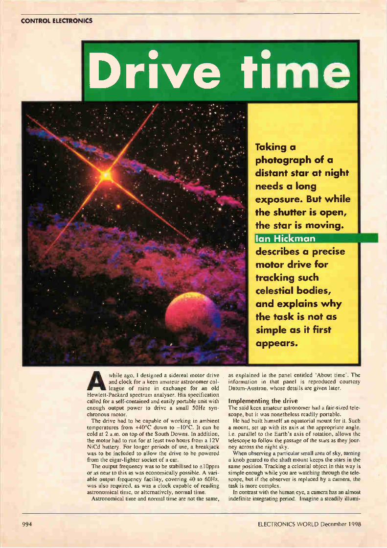
994 DRIVE TIME Taking a photograph of a distant star at night needs a long exposure. But the star moves. Find out how Ian Hickman tackled the problem, and why it wasn't easy.
This shot of the Moon was photographed with a domestic set-up. Find out how on page 994.
1000 SPARKS MAY FLY Irving Gottlieb asks could continuous exposure to electrostatic discharge be affecting our health?
1002 MEASURING YAGIS Paolo Antoniazzi and Marco Arecco have devised a simple yet accurate method of measuring the gain of Yagis for 2m.
1010 CIRCUIT IDEAS • Monitoring two temperatures • Super zener voltage clamp • Differential instrumentation amplifier • Temporary RS232 hookup • Long-delay generator • Linear pwm • White-light leds operate to 1.5V • Optically isolated I2C interface • Simple wideband detector for I0.7MHz • Insulation and earth continuity tester • Single-transistor constant-current • Cellphone ringer repeater
1024 CCD DEVELOPMENTS Leslie Warwick looks at two breakthroughs in ccd technology for imaging — one the smallest pixel, the other the largest ccd sensor module.
Is there a link between the Eagle magazine and ISDN? Andy Emmerson explains on page 987.
1028 SPEAKERS' CORNER John Watkinson considers the choices facing the loudspeaker coil designer.
1031 LOOKING IN... Building on his previous work describing the BBC's first television service and the earliest-known recording of broadcast television, Donald McLean reveals how he restored that recording.
1035 ULTRA-FAST PULSES Nick Wheeler outline, how eel can produce very fast pulses whose width is accurately determined by a length of coaxial cable.
1038 NOTES ON ECL Using a frequency-doubler design example that runs from a +5V supply, Nick Wheeler discusses the benefits of eel.
1043 RMS WATTS, OR NOT? When you see a power amplifier advertised as delivering 100W rms what — if anything — does it mean? Lawrence Woolf explains.
1048 FLYING COMMS LINKS TAKE OFF Could aeroplanes replace satellites for wireless comms? Trials are already underway, reports Tom Foremski
1050 ELECTRONICS IN MUSIC From the Theramin to the electric guitar: Richard Brice looks at instruments that involve electronics and discusses their uses in modern music.
1055 NEW PRODUCTS Over forty new product outlines, rendered by Phil Darrington
1061 DIGITAL OUTLOOK The introduction of digital tv services could be a soap opera in itself. Richard Wilson checks out the viewing figures.
Have you heard Ruby Wax explaining the BBC's digital tv services? Why not read Richard Wilson's side of the story on page 1061?
This Grundig 30MHz oscilloscope worth £450 is ours to give away. Want it? See page 1007.
December 1998 ELECTRONICS WORLD 985

Schematic Capture
NEW Version
151, I. yysu re 1 LI
zoom Marl Frow
.9:0 1350 0,
*Produces attractive schematics like you see in the magazines. •Netlist, Parts List & ERC reports. *Hierarchical Design. *Full support for buses including bus pins. *Extensive component/model libraries. *Advanced Property Management. *Seamless integration with simulation and PCB design.
Simulation .012,100.Meel501,31"
• 1,1, Wondow , kohl, Ironp4.11.
r. lassoler Do* pain fiffli, T.IDed• 53dd, 1d*.
PIPE*
ZENO rnizre rE-rr FrETZ
RPM •.R.P.. .PROBE iPROSE
T;R TER,.
•Non-Linear & Linear Analogue Simulation. •Event driven Digital Simulation with modelling language. *Partitioned simulation of large designs with multiple analogue & digital sections. *Graphs displayed directly on the schematic.
cbcenen
The IV t h
Generation
New Features *1111111.111111111F
Component Auto-Placer Pinswap/Gateswan Optimizer
Background Regeneration of Power Planes Enhanced Autorouting with Tidy Pass Full Control of Schematic Appearance Extensive New Component Libraries
Available in 5 levels - prices from £295 to £1875 + VAT. Call now for further information & upgrade prices.
PCB Design ID Ain 5 he tehte
fie Putout Pdid Ed 1dt
*Automatic Component Placement. •Rip-Up & Retry Autorouter with tidy pass. •Pinswap/Gateswap Optimizer & Backannotation. 032 bit high resolution database. *Full DRC and Connectivity Checking. *Shape based gridless power planes. *Gerber and DXF Import capability.
EVVVV January 1997
Wrtté, gieorié OrMireirjritur mo s , or i a. , our me:dui. fin Tel: 01756 753440. Fax: 01756 752857. EMAIL: [email protected] 53-55 Main St, Grassington. BD23 5AA. WWW: http://www.labcentenco.uk
Fully interactive demo versions available for download from our VVWW site. Call for educational, multi-user and dealer pricing - new dealers always wanted. Prices exclude VAT and delivery . All manufacturer's trademarks acknowledged.
CIRCLE NO. 104 ON REPLY CARD

EDITOR
Martin Eccles 0181 652 3128
CONSULTANTS
Ian Hickman Philip Darrington Frank Ogden
EDITORIAL ADMINISTRATION
Jackie Lowe 0181-652 3614
E-MAIL ADDRESS
ADVERTISEMENT MANAGER
Richard Napier 0181-652 3620
DISPLAY SALES EXECUTIVE
Joannah Cox 0181-652 3620
ADVERTISING PRODUCTION
0181-652 3620
PUBLISHER
Mick Elliott
EDITORIAL FAX
0181-652 8111
CLASSIFIED FAX
0181-652 8938
NEWSTRADE ENQUIRIES
0171 261 7704
ISSN 0959-8332
SUBSCRIPTION HOTLINE
01622 778000
SUBSCRIPTION QUERIES
[email protected] Tel 01444 445566 Fax 01444 445447
For a full listing of RBI magazines: http//www.reedbusiness.com
edeineAbh. REED Wei BUSINESS \11.- INFORMATION
1'14-1
elf k Super highway or yellow brick road? A re you old enough to remember the Meccano InMagazine, the Eagle and those Boy's Book of Modern Marvels publications? Can you recall those spectacular artist's impressions and hand-crafted cutaway drawings depicting miracles of technology that were just around the corner? Those were the days. Aircraft refuelling stations that
floated in mid-Atlantic, towering cities of the future with autogiros circling skyscrapers like moths around a light bulb. Magical pictures portrayed us using motorways surfaced with rubber, "for reduced noise and better roadholding." And people living in fabulous ranch-style houses with personal helicopter pads atop the garage roof. Atomic power and fuel cells would bring us cheap,
abundant electricity, while high-speed hovertrains would replace normal railways, with multi-lane motorway bridges spanning the English Channel.
All spilling good stuff in the Tomorrow's World mould — but also all so hopelessly over-optimistic. How could professional engineers and seasoned futurologists manage to get things wrong each time? Never mind. At least this stupidity was confined to civil and mechanical engineering. Information-technology people and other denizens of the electronics world always kept their feet on the ground — not in their mouths.
Actually, if you believe that, you'll believe anything. The fields of computing and communications are thoroughly littered with comparable cock-ups. Flashback to the early eighties: Kenneth Baker, Minister of State for Industry and Information Technology, talks confidently about wiring every house and office to a national grid of optical fibres. Did it happen? Flashback to autumn 1996: the Financial Times reports
that cable modems will, "change publishing, telecommunications and working habits all over the world" and Telewest announces at the European Cable Communications Show that its cable modems will "show any doubting Thomases what we can do with cable and the right technology". My name's definitely Thomas — and cable modems
have yet to make any serious impact. How on Earth do these highly paid — I almost wrote
'qualified' — pundits manage to get things so wrong? Oh never mind, we must move on. Now journey back to a year ago and to this very
magazine. In this self-same editorial slot I described how a solution had finally arrived for small office and home users waiting for a cost-effective connection to the information superhighway. The prospect of 'real' ISDN at an affordable price had been made possible by new
technology, being rolled out a year later by BT under the service names Home Highway and Business Highway. And was it all worth waiting for? Huh! Once again the
dream of low-cost ISDN service for the mass market of small business and residential customers has eluded us. The tariffs that BT has published for Home Highway are uncompetitive and totally unrealistic for all bar the most self-indulgent of telecomms junkies. The prices may indeed reflect the costs involved but
they will certainly not attract the vast majority of those previously tempted to join the digital revolution.
Naturally BT will say that its operating licence clauses forbidding cross-subsidy prevent a lower-cost launch of Highway services. It may also point to the fact that its competitors are not exactly rushing in to fill the vacuum by providing alternative low-cost ISDN services. Nonetheless, a major window of opportunity has been missed and the dream of ubiquitous ISDN connection still eludes us. Was ISDN just a wild dream then? Not at all.
According to Margrit Sessions, managing director of consultancy Phillips Tarifica Ltd, "most of Europe has recognised the benefits of ISDN, and in Germany and France business applications such as teleworking and videoconferencing are almost commonplace." The problem lies entirely in pricing and a report just
issued by Tarifica indicates that ISDN connection and rental charges in Britain are up to six times higher than in other leading European nations. "The UK is in danger of becoming a technological outcast; [ISDN] prices must come down further to ensure that British businesses are given the opportunity to remain competitive on every level — including technologically," warns Sessions. Should we be concerned? I think we should. The ISDN
fiasco is not unique; I could cite many more marketing foul-ups. And we should not tolerate them. Sure, we can live with the enthusiasm of technologists for their latest developments; after all, most technology relies on the successful fulfilment of dreams. The danger arises when technologists allow their
dreams to be hijacked by others. Some product managers have a distorted view of reality and then innocent customers are misled because the marketeers fail to deliver their promises. Credibility is at stake — not to mention the livelihoods of all those who depend on technology for a living. We should be selling science fact, not science fiction. Or am I taking things too seriously? Is there a problem
at all? Perhaps I need to lighten up and take a holiday. I'd really love to know.
Andrew Emmerson
Electronics World is published monthly. By post, current issue £2.45, back issues (if available £3.00). Orders, payments and general correspondence to L333, Electronics World, Quadrant House, The Quadrant, Sutton, Surrey SM2 SAS. Tlx:892984 REED BP G. Cheques should be made payable to Reed Business Information Ltd Newstrade: Distributed by Marketforce (UK) Ltd, 247 Tottenham Court Road London W1P OAU 0171 261-5108. Subscriptions: Quadrant Subscription Services, Oakfield House Perrymount Road, Haywards Heath, Sussex RH16 3DH. Telephone 01444 445566. Please notify change of address. Subscription rates 1 year UK £4.00 2 years £54.00 3 years £68.00. Europe/Eu 1 year £49.00 2 years £78.00 3 years £98.00 ROW 1 year £59.00 2 years £94.00 3 years £119
Overseas advertising agents: France and Belgium: Pierre Mussard, 18-20 Place de la Madeleine, Paris 75008. United States of America: Ray Barnes, Reed Business Publishing Ltd, 475 Park Avenue South, 2nd Fl New York, NY 10016 Tel; (212) 679 8888 Fax; (212) 679 9455 USA mailing agents: Mercury Airfreight International Ltd Inc, 10(b) Englehard Ave, Avenel NJ 07001. Periodicles Postage Paid at Rahway NJ Postmaster. Send address changes to above. Printed by BPCC Magazines (Carlisle) Ltd, Newtown Trading Estate Carlisle. Cumbria, CA2 7NR Filmsetting by JJ Typographics Ltd, Unit 4 Boron Court, Chandlers Way, Southend-on-Sea, Essex SS2 SSE.
0 Reed Business Information Ltd 1997 ISSN 0959 8332
December 1998 ELECTRONICS WORLD 987

THE RACK RANGE' MAINS DISTRIBUTION PANELS FOR
19" RACK MOUNTING
HORIZONTAL
11190 TEL: 018S
OLSON HOUSE, 490 HONEYPOT LANE, ELECTRONICS LIMITE 1T-A9N05M70273, MIDDLESEX HA7 1JX FAX: 0181-952 1232
CIRCLE NO. 105 ON REPLY CARD

UP DATE • • • • • • • • • • • • • • • • • •
Web access on a chip... Toshiba launched its first Internet I tuner chips in Autumn '98. These deliver Internet functionality for any electronics product. The so-called Internet tuner ICs are based on a core from Santa Clara start-up iReady Corporation. Seiko is to use the same iReady
core in a range of miniature lcds, with 240 by 160 or 320 by 240 pixels, which will have Internet tuners built into the display. "We have four licensees all
working on products," said Ryo Koyama, founder and president of the two year old iReady adding,
"we'll announce a fifth licensee next month." The iReady core gives any product
the ability to surf the Web, receive e-mail instructions or deliver faxes over the Internet. "The joke everyone makes is 'Why send e-mails to your refrigerator?'," said Koyama. But one benefit of the system is that there are some household appliances which would benefit-from being capable of remote operation. Early next year, a toy
manufacturer will bring out an Internet-connected toy using an
Asic incorporating the iReady and fabricated by Toshiba. Koyama said that the iReady is
implemented in 120000 logic gates which, he said, only cost $6. This means that Internet capability can be added to a product for a cost of $10 compared to the $40+ solutions offered by a microprocessor, operating system and applications software. iReady has raised $8.5m in two
rounds of venture capital funding and is now looking for a third round from corporate investors. David Manners, Electronics Weekly
Electronic book standard sought
M ajor computer, software and book publishers have
launched an initiative to set standards for the first electronic books. Known as eBook, the hand held
terminal could become a mass market electronics product fuelling demand for chips and displays. "The Open eBook standard
announced today is designed so that early purchasers of eBook titles will be able to read their 'books' on all devices supporting the standard," said Microsoft v-p Dick Brass, in charge of Microsoft's eBook projects. Japanese electronics giant Sharp
teamed up with US firm NuvoMedia to develop Rocket eBooks. These will be 600g hand-held computer devices with a high resolution Sharp lcd screen. Rocket eBooks will hold 4000 pages of text.
Mobile phone health research... The absorption from mobile phones is
being tested using an anatomically
correct head. The experiment is part of an EU funded testing programme
involving 14 partners and led by the
University of Rome. The head has been constructed at Bristol
University from new dielectric simulation materials using forensic
techniques to simulate the bone, brain, muscle, skin and eye. The University of Bradford and the
National Physical Laboratory are involved in the measurements for the
project.
...and on a phone
Motorola has unveiled its VoxML technology which allows people
to access Web sites via the telephone. Using voice commands, users can
navigate to Web sites and hear the pages' contents. "VoxML will revolutionise the way people access on-line information and Web content," claimed Motorola v-p Maria Martinez.
Motorola gives the example of a user checking an airline departure time. They would ask "Is ABC Airline's flight from Washington DC on time? The airline's VoxML application interprets the the voice request and translates it to a Web request. The application locates and publishes the requested information in VoxML, which is then translated from text to speech for the user.
Edwin demonstration goes ahead After enjoying the Edwin CAD package tour on the CD presented with last month's issue, some readers found that they could not load the working demonstration under Windows 95. If you have experienced such problems,
click on the Windows 95 'Start' button and select Run'. Clear any file path entry text in the panel that appears. Now type d:\edwinceworkdemo\setup2.exe in the 'Run' window, where d: is the letter belonging to your CD
drive. When asked where the Visionics Products source files are, type d:\edwincd\workdemo\, again making sure that d: is the letter of your cd rom drive. This should work regardless of how your version of Windows 95 is set up, and as a bonus, it also works for
Windows 98 users.We trust that you will find the working demonstration worth the wait.
December 1998 ELECTRONICS WORLD 989

UPDATE
Fab closures could spark UK talent drain
The UK is set to lose some of the most skilled engineers anywhere
in the semiconductor industry unless potential buyers are quickly found for the two North Tyneside wafer fabrication plants. A Siemens manager said it would
be a tragedy if the engineering talent at North Tyneside was lost, and that many of those employed at Siemens, and at Fujitsu's fabrication plant in Newton Aycliffe, were preparing to leave the country for jobs overseas.
Siemens' personnel director Llew Aviss confirmed that up to 150 Tyneside staff have been offered jobs at other Siemens plants. "There are 500 openings with Siemens worldwide, from Taiwan to the US," he said. Employees were encouraged to
apply for those positions. "One hundred to 150 are settling on those jobs. They are visiting the locations at the moment," Aviss added. Siemens will start moving
equipment out of the plant later this
month. "But no equipment essential to manufacturing will move until the end of November," said Aviss. Taiwanese foundry TSMC has
been linked with the Siemens fab after it was announced it is considering a formal offer of a fab from a European company. "We will not comment on any
organisation until we get to the point where we have a firm interest," said Aviss. "We will not confirm or deny any talks with TSMC."
First programmable dual op-amp Xicor has introduced a digitally
programmable dual op-amp, which it claims to be the first of its kind. "Our customers throughout the
electronics industry are calling for a single chip that integrates many of the traditional building blocks of
analogue and digital non-volatile memory," said Bob Anderson, product line manager. Called the X9430, it is
programmable for gain, offset and power level through either SP 1 or I2C serial busses. No performance figures have been
released, but the company does say that it can replace 741, 301A and OP07 amplifiers. Xicor sees the chip being used for
applications such as pagers, cellular telephones, DVD players, printers and copiers. It comes in a 24-pin SOIC.
135000 horses... At 101MW, ABB is claiming to have made the world's largest variable speed ac drive and motor system. It runs up to 600rev/min and will power NASA's transonic wind tunnel at the Langley Research Centre in Virginia. The drive is a 'load commutated inverter' type and fills a 10 by 10 by 10cm cube. The motor, anchored 10m away, is 6 by 6 by 7m, excluding its cooling and ancillary system. It weighs 360 tonnes.
New technology and life quality There has been a call for an I 'informed' pubic debate over the
quality of life implications of new technologies like smartcards and the Internet. Dr John Taylor, in his inaugural address as president of the Institute of Electrical Engineers, told some of the UK's most influential engineers that an individual's life will be tracked with ever greater precision. "Might we need a right to fuzziness which outlaws such accurate and fine-grained surveillance," said Taylor, who is director of Hewlett-Packard's European research laboratories.
Digital radio licence The Radio Authority has awarded a
national digital radio licence to the Digital One consortium. Nil, one of three companies that makes up the consortium, will build the national transmitter network for commercial digital radio.
UK votes for TV voting
Sixty per cent of the British adult population would be happy to
vote for a future prime minister via the television. The survey, from set-top manufacturer Pace Micro technology, also found that 41 per cent would welcome the opportunity to interact with their local MPs through the tv.
Spot the antenna... Tiny mobile phone base stations just a few inches high are being introduced by Vodafone. Known as Street Furniture, the antennas are attached to street lamps, sign posts or CCTV poles. Twenty sites are now on-air, including the pictured site in Bristol.
990 ELECTRONICS WORLD December 1998
r1 Ele Edit Yew o
Ir,hfine4 E.:pryer
IAddress r
Fervoites Help
e Stop Refresh Home Search Favorites History Channels Print Fort Edit
I Links
PLUG IN AND MEASURE Specluna anally,eq !MID
F,epenc? Iltzors fir4cences ïeretne det,
TI Li re gej 4096 semi,
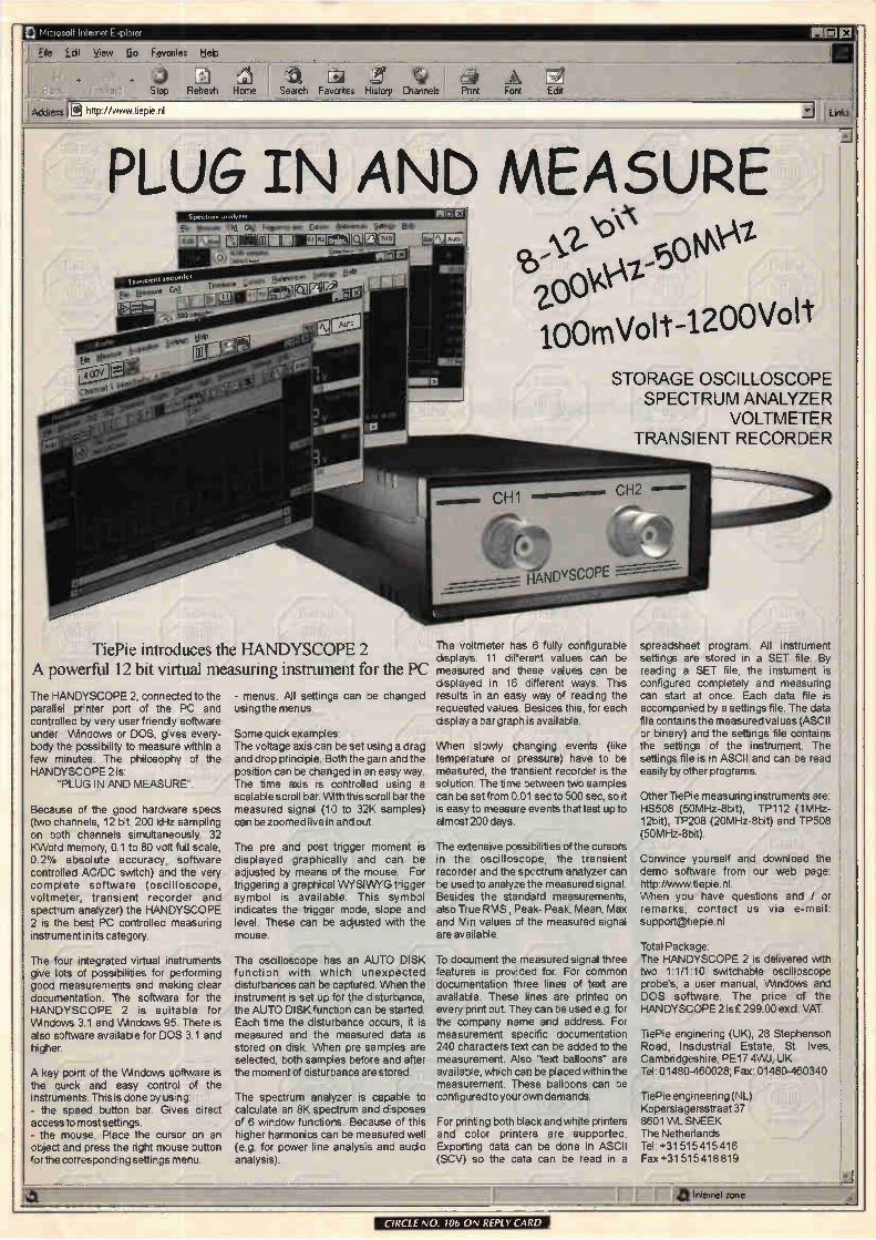
TiePie introduces the HANDYSCOPE 2 A powerful 12 bit virtual measuring instrument for the PC
The HANDYSCOPE 2, connected to the parallel printer port of the PC and controlled by very user friendly software under Windows or DOS, gives every-body the possibility to measure within a few minutes. The philosophy of the HANDYSCOPE 2 is
"PLUG IN AND MEASURE".
Because of the good hardware specs (two channels, 12 bit. 200 kHz sampling on both channels simultaneously. 32 KVVord memory, 0.1 to 80 volt full scale, 0.2% absolute accuracy, software controlled AC/DC switch) and the very complete software (oscilloscope, voltmeter, transient recorder and spectrum analyzer) the HANDYSCOPE 2 is the best PC controlled measuring instrument in its category.
The four integrated virtual instruments give lots of possibilities for performing good measurements and making clear documentation. The software for the HANDYSCOPE 2 is suitable for Wridows 3.1 and VMndows 95. There is also software available for DOS 3.1 and higher.
A key point of the VMndows software is the quick and easy control of the instruments. This is done by using: - the speed button bar. Gives direct access to most settings. - the mouse Place the cursor on an object and press the right mouse button for the corresponding settings menu.
- menus. All settings can be changed using the menus
Some quick examples. The voltage axis can be set using a drag and drop principle. Both the gain and the position can be changed in an easy way. The time axis is controlled using a scalable scroll bar. VMth this scroll bar the measured signal (10 to 32K samples) can be zoomed live in and out.
The pre and post trigger moment is displayed graphically and can be adjusted by means of the mouse. For triggering a graphical VVYSIVVYG trigger symbol is available This symbol indicates the trigger mode, slope and level. These can be adjusted with the mouse
The oscilloscope has an AUTO DISK function with which unexpected disturbances can be captured. Men the instrument is set up for the disturbance, the AUTO DISK function can be started. Each time the disturbance occurs, it is measured and the measured data is stored on disk. VVhen pre samples are selected, both samples before and after the moment of disturbance are stored
The spectrum analyzer is capable to calculate an 8K spectrum and disposes of 6 window functions. Because of this higher harmonics can be measured well (e.g. for power line analysis and audio analysis).
100mVolt-1200Volt
STORAGE OSCILLOSCOPE SPECTRUM ANALYZER
VOLTMETER TRANSIENT RECORDER
The voltmeter has 6 fully configurable displays. 11 different values can be measured and these values can be displayed in 16 different ways. This results in an easy way of reading the requested values Besides this, for each display a bar graph is available.
When slowly changing events (like temperature or pressure) have to be measured, the transient recorder is the solution. The time between two samples can be set from 001 sec to 500 sec, so it is easy to measure events that last up to almost 200 days.
The extensive possibilities of the cursors in the oscilloscope, the transient recorder and the spectrum analyzer can be used to analyze the measured signal. Besides the standard measurements, also True RMS, Peak- Peak, Mean, Max and Min values of the measured signal are available
To document the measured signal three features is provided for. For common documentation three lines of text are available. These lines are printed on every print out They can be used e.g. for the company name and address. For measurement specific documentation 240 characters text can be added to the measurement. Also "text balloons" are available, which can be placed within the measurement. These balloons can be configured to your own demands.
For printing both black and white printers and color printers are supported. Exporting data can be done in ASCII (SCV) so the data can be read in a
spreadsheet program. AM instrument settings are stored in a SET file By reading a SET file, the instument is configured completely and measuring can start at once. Each data file is accompanied by a settings file The data file contains the measured values (ASCII or binary) and the settings file contains the settings of the instrument The settings file is in ASCII and can be read easily by other programs.
Other TiePie measuring instruments are. HS508 (50MHz-8bit), TP112 (1MHz-12bit), TP208 (20MHz-8bit) and TP508 (50MHz-8bit).
Convince yourself and download the demo software from our web page. http //www tiepie nl When you have questions and / or remarks, contact us via e-mail: support@tiepie nl
Total Package: The HANDYSCOPE 2 is delivered with two 1-1/1 10 switchable oscilloscope probe's, a user manual, Wndows and DOS software The price of the HANDYSCOPE 2 is £ 299.00 excl VAT
TiePie enginenng (UK), 28 Stephenson Road, I nsdustnal Estate, St Ives, Cambridgeshire, PE17 4WJ. UK Tel 01480-460028, Fax 01480-460340
TiePie engineering (NO Koperslagersstraat 37 8601 WL SNEEK The Netherlands Tel +31 515 415 416 Fax +31 515 418 819
1 Pfl metzone zone
CIRCLE NO. 106 ON REPLY CARD

UPDATE
"Start planning for Year 2000 failures" call abinet Millennium bug supremo Margaret Beckett is urging
public and private sectors to start planning for failures in the Year 2000. She said contingency plans for equipment that will not be Millennium compliant by the year 2000 had to start being made now. The leader of the Commons was
speaking in an exclusive interview after she admitted at the Labour conference in Blackpool that it was too late to ensure that computers and electronics systems in both sectors
could be made safe from the Year 2000 time-bomb. She told the fringe meeting at the
gathering organised by Labour Industry Forum: "I have come late and reluctantly to the view that we cannot be confident we can deal with all the problems." Afterwards she said "Obviously we need to continue to work towards compliance but some systems will not be able to cope. It may not be the firm or department's computers but those of a supplier."
The international situation is not good: "Both public and private sector organisations need to start to identify those areas which will not be ready and plan for how to deal with any problems that arise," she said. While Robin Guenier, head of the
Year 2000 taskforce said her comments were refreshingly honest, Tory trade and industry spokesman John Redwood said the government was to blame for there now being too little time to deal with the bug.
It's getting better, say analysts Latest semiconductor market figures herald a brighter future from next year. But chip manufacturers must do more to reduce oversupply in the memory market. Dataquest, Future Horizons and IC
Insights have all reported an improved outlook for 1999. Europe could even rebound this year, but Asia's problems will delay any world-wide bounce back until mid-1999. Dataquest is most optimistic,
stating an overall decline of six per cent this year will turn into growth of 12 per cent in 1999. "A stronger dynamic ram market is
fuelled primarily by the move to the PC100 specification," said Richard Gordon, memory analyst at Dataquest. The IC Insight report believes the bottom of the cycle has been reached and echoes Dataquest
Are you there? The first thing you get
asked when you answer a mobile phone is: "Where are you?" But if mobile phone operator Orange has its way this won't
happen again. The downside is that it will be
difficult to lie about where you are. The full colour mobile videophone to
make this possible will be available by Christmas
1999. Co-developed with the University of
Strathclyde, the phone will work over all the networks, via a data
capability that Orange's phones use.
with a ten per cent growth forecast next year. Year 200 will be very good, says Future Horizons' MD Malcolm Penn: "The long term is going to be fantastic." IC Insight says the average selling
price of ICs has increased. It believes dynamic-ram manufacturers are breaking even, rather than loosing money. Future Horizons, the European
analyst, believes the opposite, that all dynamic-ram manufacturers are selling below cost of production. A few fab closures have done little
to affect over supply. "We need at least three Siemens type fabs to close," said Penn. Oversupply will continue, says
Dataquest, for another 18 months in foundries and two years for dynamic ram. Fortunately, the transition to 0.8pm
processing is delayed due to the increased number of defects. This will help demand catch up with supply. Richard Ball Electronics Weekly
Chip sales saw autumn rise
w orld-wide chip sales showed signs of an upturn last August,
according to the Semiconductor Industry Association (SIA). Global chip sales rose by 1.5 per
cent — the first month-on-month gain this year — but were 16 per cent below the same month last year. Total sales increased by $147m from July to $9.81bn in August. The sales increase came despite a large drop in sales in Japan, down 30 per cent from last year's figures. "We are cautiously optimistic about
the industry's prospects for additional gains in the fourth quarter," said SIA president George Scalise.
Output declines... There has been a sharp decline in engineering output for the second consecutive quarter, according to a survey by the Engineering Employers' Federation (EEF). Export orders also fell steeply for the seventh consecutive quarter. "Our survey shows that the recession in engineering is becoming deeply entrenched," said Graham Mackenzie, EEF's director general.
...but pay is stable Pay settlements in the engineering sector have remained stable in the three month period up till August. According to the latest EEF survey,
the average settlement level was 3.5 per cent. This follows a fall in settlement rates during the previous three month period.
992 ELECTRONICS WORLD December 1998

lke p.py•pba RADi0 _17/1,e ie JJ1 j5
VViNRADi0 now brings you a complete choice in computer controlled radio scanning and reception.
With either the internal or external versions, you can couple all the power of the latest Windows PCs (not just the fraction that you can squeeze down an RS232 connection) to the latest synthesised receiver design techniques, and you'll get the ultimate in wide range, all mode programmable radio reception.
New external WiNRADiOTM (VVR1000e and WR1500e) provide complete comms systems connecting either via the basic RS232 - or with an optional PCMCIA adapter, for high speed control. Power from existing 12v supplies, or our optional NiMH rechargeable 12v battery pack.
Use WiNRADi0 scanning PC comms receiver systems for... Broadcast • Media monitoring • Professional & amateur radio communications • Scanning • Spot frequency & whole spectrum monitoring • Instrumentation Surveillance (and recording)
Model No Construction
Frequency range Modes
If you still want the ultimate receiver-in-a-PC with full DSP, then you need the WR3000-DSP with its hardware for real-time recording, signal conditioning and decoding app-lications. (This is available as an ISA card only).
WWII... bed.*
VisiTune TM spectrum tuning display
434 635 MHz eig'
MIMI Ill
111111111
WiNRADiCt
8 Ill Wave tilher.
WR-1000 WR-1500 VVR-1000i/VVR-1500i - Internal full length ISA cards VVR-1000e/WR-1500e - external RS232/PCMCIA (optional) 0.5-1300 MHz 0.15-1500 MHz AM,SSB/CVV.FM-N.FM-W AM.LSB,USB,CVV,FM-N.FM-W
Your choice of virtual front panel
Tuning step size IF bandwidths
100 Hz (5 Hz BFO) 100 Hz (10 Hz for SSB and OW) 6 kHz (AM/SSB). 17 kHz (FM-N) 270 kHz (FM-W)
Receiver type Scanning speed Audio output on card Max on one motherboard Dynamic range IF shift (passband tuning) DSP in hardware IRQ required Spectrum Scope Visitune Published software API Internal ISA cards External units PCMCIA adapter (external) PPS NiMH 12v battery pack & charger: £79 with 'e' series unit, otherwise: £139
2.5 kHz(SSB/CW) 9 kHz (AM) 17 kHz (FM-N) 270 kHz (FM-W)
PLL-based triple-cony. superhet 10 ch/sec (AM), 50 ch/sec (FM) 200mW 200mW 8 cards 65 dB no
8 cards 70 dB ±2 kHz
no - use optional DS software no yes yes yes £299 inc vat £389 inc vat £30 with e' series
no yes yes yes £399 inc vat £449 inc vat
unit, otherwise: £69 inc.
P Bereipm F
r Npse Reaucto,
r Aulo Noe
r Tone .
Gon
•Ik113
.6d6
• 1213
*GC
Seengs
Sce l Deetel
2C00
PRI Feet
Ced
FT San. ' DSP, DSP
The DSP applet provided with the
WR3000 spectrum monitor ISA card
(£995+VAT) allows continuous
control of. audio bandwidth and
other signal. conditioning functions
Digital Suite Software
1. VVEFAX / HF Fax 2. Packet Radio for HF and VHF 3. Aircraft Addressing and Reporting System
(ACARS) 4. Audio Oscilloscope, real time Spectrum
Analyzer with calibration cursors 5. Squelch-controlled AF Recorder 6. DTMF, CTSS decode and analyse
£81.05 inc VAT
(requires SoundBlaster 16 compatible sound card)
For your free info pack and software emulation demo disk contact Broadercasting Communication Systems
http://www.broadercasting.com FREEPHONE: 0800 0746 263
email: [email protected] Fax: 01245 287057
Unit B, Chelford Court, Robjohns Road, Widford Industrial Estate, Chelmsford, Essex CM1 3AG
CIRCLE NO. 107 ON REPLY CARD
CONTROL ELECTRONICS
Awhile ago, I designed a sidereal motor drive and clock for a keen amateur astronomer col-league of mine in exchange for an old
Hewlett-Packard spectrum analyser. His specification called for a self-contained and easily portable unit with enough output power to drive a small 50Hz syn-chronous motor. The drive had to be capable of working in ambient
temperatures from +40°C down to —10°C. It can be cold at 2 a.m. on top of the South Downs. In addition, the motor had to run for at least two hours from a 12V NiCd battery. For longer periods of use, a breakjack was to be included to allow the drive to be powered from the cigar-lighter socket of a car. The output frequency was to be stabilised to ±lOppm
or as near to this as was economically possible. A vari-able output frequency facility, covering 40 to 60Hz, was also required, as was a clock capable of reading astronomical time, or alternatively, normal time. Astronomical time and normal time are not the sanie,
Taking a photograph of a distant star at night needs a long exposure. But while the shutter is open, the star is moving.
Ian Hickman describes a precise motor drive for tracking such celestial bodies, and explains why the task is not as simple as it first appears.
as explained in the panel entitled About time'. The information in that panel is reproduced courtesy Datum-Austron, whose details are given later.
Implementing the drive The said keen amateur astronomer had a fair-sized tele-scope, but it was nonetheless readily portable. He had built himself an equatorial mount for it. Such a mount, set up with its axis at the appropriate angle, i.e. parallel to the Earth's axis of rotation, allows the telescope to follow the passage of the stars as they jour-ney across the night sky. When observing a particular small area of sky, turning a knob geared to the shaft mount keeps the stars in the same position. Tracking a celestial object in this way is simple enough while you are watching through the tele-scope, but if the observer is replaced by a camera, the task is more complex. In contrast with the human eye, a camera has an almost
indefinite integrating period. Imagine a steadily illumi-
994 ELECTRONICS WORLD December 1998

CONTROL ELECTRONICS
Typical results Photo 1 is of the Pleiades or 'Seven Sisters', 300 light years away. Six of these are visible with the naked eye. The photo was taken with a ten-inch reflector telescope, with a five minute exposure, on 400 ASA Ektachrome, home developed. The sidereal drive has completely eliminated blurring due to apparent motion of the subject across the sky. A longer exposure would show the famous nebulous veils surrounding the bright stars. All photos here courtesy Rod Armstrong.
Photo 2 shows the M42 Nebula in Orion. Taken with a 10 inch Newtonian reflector, using a seven minute exposure. Again on home processed Ektachrome, and using the sidereal drive.
Photo 4 is a long-exposure negative of the night sky taken using a fixed camera and is included to illustrate why the sidereal drive is necessary.
,.....••••••°••
.1
Photo 3 shows the moon. Not perhaps a great test for the accuracy of the quartz drit en motor peed, but to obtain cnstal sharp images, the moon is a difficult subject. The sidereal drive is necessary to avoid blurring due to movement, even at the comparatively short exposure of 1/8th of a second, on Kodachrome. With this length exposure, great care is needed to avoid blurring caused by vibration due to the firing of the shutter. This shot was taken with a 4 inch GRUBB refractor, the image being magnified with a x2 photographic multiplier attached to the camera. The effective aperture of around f32 required the longish exposure.
December 1998 ELECTRONICS WORLD

CONTROL ELECTRONICS
16
Cl CD4060
11 10 13 •-,vVvVe 10M
12p _122p
S.D.-7120p
3 2768MHz crystal
Fig. I. Clock generation and display circuitry comprising an ordinary digital clock with lcd. The 32kHz crystal is removed from the clock and the crystal's function is replaced by reference pulses derived from the clock generator shown.
8 12 IC3B TT/
6400Hz +12V from to Fig. 2 Fig. 2
4
14
16
IC2 CD4018
2. 3, 7, 8. 9. 10,12,15
13
-0
14
2
IC3A CD4070
7
10
16
IC4 CD4040
OD-
5 o 2
12
4
4
5 11
6
9 2
IC5 14 7
CD4068
8
12 8
3 Mr,
IC3C
11
2 o S1A
nated light at the lower limit of visibility to the dark-adapted eye.
If instead the light is flashed on for a short period, it may in fact be invisible. This is because the human eye is a 'leaky integrator', integrating only over about one to two hundred milliseconds. If you can't see the light after you have been looking at it for that amount of time, you won't see it at all. But a camera does not have this limitation. With the fastest available film and an exposure time of
minutes — or even hours — the amateur astronomer can record stars, nebulae, comets and other astronomical curiosi-ties invisible to the naked eye. Normally, such objects could only be observed directly via the largest telescopes in the world — and perhaps not even then. A proviso is of course that the telescope can be panned to
follow the progress of the stars. To do so, it is only necessary to fit a small synchronous motor to the gearing of the equa-torial mount, with the right gear ratio, and hey presto. For this application, the motor runs at 50Hz, supplied by
the NiCd-powered inverter mentioned earlier. There is how-ever just one small complication. The 50 cycles per second must be 50 cycles per sidereal second — not per GMT sec-ond. A sidereal day lasts 23 hours 56 minutes and 4.09 seconds,
reckoned by GMT, so the required motor drive frequency must run a little fast, at 50x1.00273792Hz. A variable fre-quency is also handy. This enables the motor to be run faster or slower than the sidereal rate. By altering the speed in this way, a vernier position control is provided enabling the field of view to be accurately centred on the precise area of sky to be studied.
The solution Figure 1 shows the timekeeping part of the circuitry. With the aid of a 3.2768MHz crystal, /CI produces a clock fre-quency of 216x50Hz. Components /C2 and /C5, both dividing by ten, tear this
down to the 32.768kHz needed for a small clock with digital lcd. At least, they do while 51A is in position 2, which caus-es the lcd clock to display GMT. Counter /C4 counts to 365 and then resets itself, cycling round repeatedly. When Si A is in position 3, an extra clock pulse is fed to /C5
for every 365 pulses from /C2. In this way, the clock reads faster than GMT by the ratio 365/366=1.002739726. This is within the specified 1.8 parts per million. In addition, the dif-ference is also small compared with the accuracy that you could expect from the crystal over the operating temperature range. I mounted the small lcd clock on the front panel of the
enclosure. Normally powered by a small watch type button cell, here it is fed with the appropriate supply voltage via a 1001S1 resistor and a BC109.
i5PT 1M2
13
2 IC3D
11
16
14
IC5 CD4018
2, 3, 7, 8, 9, 10,12,15
13
4M7
82k
68k
BC109
LCD clock
68k
100k
BC 56k 109
3 S1B t: IN
5401 1
10p
9V PP3
270k S.0 T
The clock's original internal 32.768kHz crystal was removed, and external clock pulses gently fed in via another BC109 and a 681d1 resistor. Switch 51 provides a choice of GMT or sidereal time. Its third position allows you to turn the unit off, although off does not mean disconnected from the supply. More on this later. Figure 2 shows the equatorial mount drive part of the cir-
cuitry. The divide-by-512 output from /CI provides a 6400Hz clock to /C7,8. These ICs provide the same 365/366 choice as in Fig. I. The GMT or sidereal-time clock frequency is then divid-
ed by 128 in /C 1, to provide a 50Hz output. Timer /Clo pro-vides an alternative frequency range at /CH. This is adjustable between 40 and 60Hz. Gate /C7B provides the alternative phase. The Phase A and
Phase B signals drive a simple inverter involving a standard mains transformer working in reverse. The low voltage windings are 15V nominal, corresponding
to 21.2V peak, and the average value of a 21.2V peak sinewave is 13.5V, the form factor of a sinewave being 1.11. With this arrangement, the 12V squarewave applied by the
fets is well clear of exceeding the allowable volt-second product, avoiding any possibility of core saturation. The resulting 240V output at nominal 50Hz was a little on the low side. But the synchronous motor ran perfectly happily, easily coping with turning the mount in view of the mechan-ical advantage provided by enormous gear ratio. After all, at one revolution per day, the speed of the output shaft is only 0.000696347rev/min! When 53 is on, the I2V NiCd battery pack powers the
inverter. With it in the 'off position, in the absence of base drive waveforms to the fets, the inverter is effectively off, although it is still connected to the supply. Either way, the NiCd battery pack keeps the clock running
continuously, via the /A/4/48 diode. The clock will register GMT or sidereal time according to the setting of SiA. Provided that Si is not in position 1, the 9V PP3 battery will keep the clock running, even if the NiCd battery should become exhausted or be removed. The clock and the motor drive can each be set either to
GMT or sidereal time, independently of the other. In practice,
996 ELECTRONICS WORLD December 1998

CONTROL ELECTRONICS 6400Hz
from Fig. 1
22p
ml• 1M8
1M2
82k 14
BC109
10p
2
IC7A CD4070
16
IC8 CD4040
50
2
12
4
4
5 6
9
912 18
23
IC9 i4,, 7
CD4068 1
IC7C
11
12
+12V to Fig.
... 1N4148
IC7D
14
3 S2b
4k7
IC11 CD4024
2, 7
4, 8
2 o
IC10 555
S3
4k7
4k7
10k
2, 6
„7n2
IC7B
10
s Phase A
Phase B
Ski Ext 12V
there is not much call for GMT on the motor drive, except perhaps to demonstrate — streakily — how it is not appropriate to a long exposure. A useful refinement is to connect a suitable resistor across
the normally closed contacts of SK I. A voltage in excess of 12V, but within the Vdd rating of the cmos, can the be inject-ed via the breakjack, to recharge the NiCd batteries in situ.
Using the sidereal drive For short exposures, say up to 30 seconds using a 35mm camera with 50mm lens, sidereal tracking of the telescope to follow your star is not necessary. For longer exposure times and or longer focal lengths, some form of tracking is neces-sary, to avoid trailed star images. The sidereal motor drive does the job, provided that the rest of the kit is up to the mark. In use, the telescope support pillar will typically be driven a metre into the ground, to provide a firm, vibration-free sup-port. The axis must be accurately aligned, for the single axis drive can only follow the object of interest in azimuth, pre-venting horizontal trailing of the image.
Phase A
Phase B
100n
270k
100n
Neon
AC out
Ti
With the telescope aligned parallel to the axis of rotation, it is set to view the pole star in the centre of the field of view. If the axis of the telescope is not accurately aligned, there will still be some trailing of the image on long exposures, but in the vertical direction. At high magnifications, such as two hundred times and
greater, clear images on long exposures will only be obtain-able with very high quality mechanics. The final drive to the telescope shaft will typically be a worm and wormwheel, and these are crucial. If not of the best precision, they will impart
In
— 12V NICAD
470p
nfrr TT/
Fig. 2. Synchronous motor inverter circuitry for the equatorial drive. The output transformer is a mains isolating transformer used back to front.
.Abauttinie. Until fairly recently in man's history, the Sun's position defined the time of day. When the Sun was not visible it was impossible to know exactly what time it was. So man developed clocks to mea-sure out the hours between checks with the sun. All clocks measure time, but different
clocks can have different statuses or importance. For example, a clock can be a primary reference, like the Sun's posi-tion. Or it can be a secondary reference, which only interpolates. Such a device provides an approximation of the time between periodic checks with the prima-ry clock or time standard.
Date, duration and synchronisation The word 'time' can mean either date or time interval — i.e. duration. An example of a date is 15 November 1978, 15h, 35m, 14.2s EST (Eastern Standard Time), where h, m and s denote hours, minutes,
and seconds. An example of a time interval, or dura-
tion, is the length of time taken to fly between a certain pair of cities, say 3h, 51m, 2s. This example gives no indica-tion of when the flight occurred, only that it lasted for almost four hours. Note that hours, minutes, and seconds can indicate either time of day or duration. Synchronisation is the third important
time concept. For example, it is not nor-mally crucial for an orchestra to begin its concert at a precise hour of the day. But it is essential that all members of the orchestra begin and stay on the same beat. Many electronic navigation systems, computer networks — and even television receivers — require synchronisation to transmitted signals with an accuracy of a millionth of a second or better.
Time scales A time scale is a system of assigning dates
to events. The Sun's apparent motion in the sky provides one of the most familiar time scales, but it is certainly not the only one.
In order to completely specify a solar date, you must count days — i.e. make a calendar — from some agreed upon begin-ning. In addition, depending on the accu-racy needed, you must measure the frac-tions of days, commonly in hours, minutes, and seconds. In summary, you must count cycles and fractions of cycles of the Sun's daily apparent motion around the Earth. Time derived from the Sun's apparent
position is called apparent solar time. A sundial indicates the fractions of cycles, i.e. time of day, directly. Calendars, like the Gregorian calendar we commonly use, are an aid for counting the days and naming them. Another system, used by astronomers, is
called the Julian day. It numbers the days that have occurred since noon, January 1, 4713 BC. In this system — which is not related to the Julian calendar — noon on
December 1998 ELECTRONICS WORLD 997

CONTROL ELECTRONICS
a tiny rocking motion to the telescope, in sympathy with each revolution of the worm, blurring the picture.
Taiepiece What happened to that elderly HP spectrum analyser that I received in exchange for this design? Unfortunately, owing to the need for a new backward-wave oscillator, plus a host of
other less fundamental faults, it proved beyond economic repair. But as it represented somewhat of a milestone in elec-tronics, being probably the earliest true spectrum analyser and dating form the mid sixties, I was loath to scrap it. In the event, the Science Museum was more than happy to accept it as a donation, where I trust it enjoys a happy and permanent retire-ment. •
January 1, 1986 began Julian day 2 446 796. This time scale is useful for calcu-lating the number of days between two events.
Universal time Since the Earth's orbit around the sun is not a perfect circle, apparent solar time cannot be a uniform time scale. That is, the time interval between successive, apparent, noons changes throughout the year. The length of this solar day is also affected by the inclination of the Earth's spin axis to the plane of the Earth's orbit. To correct for the non-uniformities,
astronomers calculated the effects of the Earth's noncircular orbit and the polar inclination on apparent solar time. Universal Time (UTO) is apparent solar time corrected for these two effects. The correction used to obtain UTO is called the Equation of Time. It is often engraved on sundials, a correction which adds, or subtracts, up to 15 minutes to - or from - apparent solar time, depending on the season. Astronomers actually measure Universal
Time using the stars rather than the Sun. If you count cycles - and fractions - of a distant star's apparent position, you get a different time scale - sidereal time. Since the Earth circles the Sun once
each year but does not circle the distant star, sidereal time accumulates one more 'day' each year than Universal Time, and our calendar. The 'clock' for both Universal Time and
sidereal time is the spinning Earth; only the counting methods differ. In practice, astronomers observe sidereal time and correct it to get Universal Time.
Time and navigation Time is essential to navigation. In effect, a navigator, using a sextant, determines local time based on the Sun's apparent position. The difference between the nav-igator's local time and Universal, or Greenwich, time is equivalent to his lon-gitude, since zero longitude passes through Greenwich, England. Even though we express longitude in
degrees, not hours, minutes, and seconds, the difference in time is proportional to the difference in longitude. Since the earth makes about one revolution relative to the Sun in 24 hours, the translation to degrees is simple: 360°/24 hrs=15°/h. The navigator's sextant is his means of
determining local apparent solar time and the navigator's clock, or chronometer, is his means of determining Universal Time. As a result of using Universal Time for navigation, scientists developed two refinements of UTO, namely UT1 and UT2.
UT1 Scientists discovered many years ago that the Earth is not fixed on its axis. In effect, what one sees is a wandering of the poles relative to the fixed astronomical obser-vatories, which causes UTO to vary. The logical response to such a situation
is to calculate a correction for polar motion and apply it to UTO. UT1 is the result of this correction. The difference between UTO and UT1 is quite small; only about ±0.3s.
UT2 As the accuracy and constancy of pen-dulum and quartz-crystal clocks improved, scientists discovered many years ago that UT1 had periodic fluctua-tions of unknown origin with periods of one year and one-half year. Since these periodic variations are predictable, astronomers are able to correct UT1 to get a still more uniform time scale, UT2. Again, the corrections are small: about ±0.3s. Thus, there exists a family of uni-versal times based on the Earth's spin and other refinements:
UTO is apparent solar time corrected for the Earth's noncircular orbit and inclined axis.
UT1 is the true navigator's time scale related to the Earth's actual angular posi-tion relative to the sun.
UT2 is a smoothed time scale and does not reflect the real periodic variations in the Earth's angular position. At least in principle, if not in practice, UT2 passed by the navigator's needs. UT2 is not used much any more.
Ephemeris time Near the end of the 19th century, Simon Newcombe at the US Naval Observatory compiled a set of tables which predicted the future positions of the Sun, Moon, and some planets. He based these predictions on the best data and physical principals available at that time. A table of this sort
is called an ephemeris. Newcombe discovered that the actual
positions gradually departed from the pre-dicted positions in a fashion too signifi-cant to be explained either by observa-tional errors or approximations in the theory. He noted that if the time were somehow in error, all the tables agreed well with the observations. At this point he correctly determined that in addition to all the variations noted above, there are random fluctuations in the Earth's rota-tional rate. Later, quartz and atomic clocks confirmed that the variations exist. The astronomer's natural response to
this was, in effect, to use Newcombe's tables for the Sun in reverse to determine time, a time scale called Ephemeris Time, or ET. The Earth's orbital (not rotational) position determine Ephemeris Time, and ET should be more uniform than Universal Time because geometrical changes in the earth's shape do not affect the orbital motion. Ephemeris Time is not very convenient
to use because an accurate determination of it requires literally years of astronomi-cal observations. In the early fifties, more convenient and precise clocks were developed: atomic clocks. The atomic clocks provide the uniformity of ET, but are far more convenient to use.
Atomic time It was mentioned earlier that counting the number and fractions of cycles of the apparent Sun determines a date on the Universal Time scale. Similarly, counting the number of cycles of an electronic sig-nal whose frequency is controlled by an atomic or molecular resonance deter-mines date on an atomic time scale.
In most atomic clocks, electronic cir-cuits steer a radio frequency into reso-nance with a specific atomic or molecular transition - i.e. vibration. The resonance is an atomic or molecular property, and its frequency can be relatively insensitive to temperature, magnetic fields, and other experimental conditions. Thus, these res-onances form natural standards of fre-quency. Atomic clocks are formed by counting
the cycles of these atomically or molecu-larly controlled radio signals. Today scientists and engineers have
perfected clocks based on a resonance in caesium atoms to an accuracy of better than one part in 10-13 - one part in 10
wUi ELECTRONICS WORLD December 1998

CONTROL ELECTRONICS
More time The information on time scales in this article is reproduced from the Austron Timing Reference Handbook, by kind permission of Datum-Austron. Contact information: e-mail [email protected].
Web address: www.datum.com, tel. 512 721 4038. In UK, contact Sematron UK Limited, Sandpiper House, Aviary Court, Wade Road, Basingstoke, RG24 8GX, Tel. 01256 812222 or Fax 0125'6 812666. Web address: www.sematron.com.
trillion. Expressed another way, these clocks keep pace with each other to with-in two or three millionths of a second over a year's time. The Earth on the other hand, might ran-
domly accumulate nearly a full second's error during a year. Since there are now literally thousands of atomic clocks in use, and since they all agree well with each other, the variations in the Earth's rotation rate are easily measurable.
International Atomic Time, or TAI, is an atomic time scale maintained by the Bureau International de l'Heure (BIH) in Paris, France. BIH forms TAI from an aver-age of nearly one hundred atomic clocks located in many countries. The BIH initially synchronised TAI with
UT2 at zero hours 1 January, 1958. Since that time TAI and UT2 have accumulated a difference of about 23 seconds (July 1, 1985). The difference is partly due to variations
in the Earth's spin, but mostly to the fact that atomic time was simply defined to run slightly faster than UT2. Even if TAI had been defined to have exactly the same rate as UT2 in the beginning, i.e. 1958, it would soon begin to diverge, because TAI is very constant, while UT2 is always varying with the erratic Earth's rotation. During the past 27 years, two conflicting
demands on standard time have devel-oped. On one hand, science, communi-cations systems and electronic navigation systems have needed and exploited the extreme stabilities offered by atomic clocks. On the other hand, astronomy and celestial navigation still need time related to Earth position, no matter how erratic it might be relative to atomic clocks.
Co-ordinated universal time To achieve a workable compromise between these two opposing demands, the International Radio Consultative Committee (CCIR) created a compromise time scale called Coordinated Universal Time (UTC), which became effective January 1, 1972. The rate of UTC is exactly the same as
TAI. In fact, the 'ticks' that mark the begin-ning of each second of TAI and UTC are precisely synchronous. However, the date of any given event on the UTC scale must agree with its date on the UT1 scale — not TAI or UT2 — to within 0.9 seconds. Offsetting UTC from TAI by a precise,
whole number of seconds accomplishes both requirements; as of 1 July, 1985, UTC was 23 seconds behind TAI. However, since the Earth continuously changes its rate of rotation, this 23-second time offset cannot be permanent. In order to keep UTC within 0.9 seconds of UT1, the BIH will occasionally add (or delete) a second to (or from) the UTC scale. Every standard time system in the world follows suit. The CCIR recommended that these
"leap seconds" should occur at the end of December or at the end of June of any year that they are needed. In fact, leap seconds were added at the end of June, 1972 and at the end of every December from 1972 through 1979, and on June 30, 1981. No leap second was added in 1980. Since the Earth's rotation rate is not per-
fectly predictable, scientists cannot forecast leap seconds more than a few months in advance. We will always have to use leap seconds
as long as we use UTC and desire to keep our clocks approximately in step with the Sun. Otherwise, our clocks would grad-ually show the Sun rising later and later until after thousands of years, our clocks would say the Sun was rising at noon.
Local time In most places, local time differs from UTC by a whole number of hours, depending on the local time zone. For example, you subtract five hours from UTC to get Eastern Standard Time (EST).
In the summer, from 2:00 a.m. on the last Sunday in April until 2:00 a.m. on the last Sunday in October, local time, EST is advanced one hour. Hence, you subtract only four hours from UTC.
Formal definitions of time interval The Treaty of the Meter, which the US signed in 1875, established an interna-tional organisation to oversee and admin-ister the International System of units — i.e. the metric system. This international organisation determines the definitions of the various units of measure, including the unit of time interval, the second.
Prior to 1956, the second was defined to be 1/86 400 of a mean solar day, or 86 400=24x60x60. From 1956 to 1967, the second was defined in terms of Ephemeris Time: 1/31 556925.9747 of the tropical year 1900. In 1967 atomic clocks took over the role of defining time inter-
val. The new definition reads:
"The second is the duration of 9192631 770 periods of the radiation corresponding to the transition between the two hyperfine levels of the ground state of the caesium 133 atom." (13th General Conference of Weights and Measures (CGPM) (1967), Resolution 1)
The definition of the International Atomic Time scale (TAI) incorporates the defini-tion of the second. The formal definition of TAI reads:
"International Atomic Time (TAI) is the time reference co-ordinate estab-lished by the Bureau International de l'Heure (BIN) on the basis of the read-ings of atomic clocks operating in accordance with the definition of the second, the time unit of the International System of Units." (14th CGPM) (1971), Resolution 1)
Accurate time: a summary It was mentioned earlier that local time typically differs from UTC by an integral number of hours, and UTC differs from TAI by an integral number of seconds. Since standard time broadcasts all use UTC by international agreement, almost the whole world runs on UTC.
In many countries the legal basis of 'standard time' is UTC. Thus, from a legal point of view, accurate time must mean UTC, adjusted by the appropriate number of hours to give local time. To a navigator on the oceans however,
accurate time really means UT1. UTC may be close enough — give or take 0.9 seconds — for many navigators but, strict-ly speaking, navigators need UT1. To a scientist who doesn't want to be bothered with leap seconds, accurate time means TAI. So, in a very real sense, accurate time
has different meanings to different people. The idea of accuracy relates to the use made of the time information. Fortunately, most of us do not need to
bother with all these different time scales, since the time we get from the telephone, radio, or television is adequate. If we trace the telephone, radio, or television time back to its source, however, we would actually find that UTC is the mas-ter clock in our lives.
December 1998 ELECTRONICS WORLD 999

HEALTH ISSUES
Sparks may fly Irvin Gottlieb asks could continuous exposure to electrostatic
discharge be affecting our health?
At one time, the marginally-safe level of soft-X-ray radiation from tube-type television receivers was a matter of concern. Not only the
picture-tube emitted this form of ionising radiated. The rectifier, damper and regulator tubes gave off X-rays too. In modern solid-state sets, the problem has been largely alleviated; besides, a more-respectable viewing distance is now dictated by the larger display-screens. But we may be overlooking an elusive, yet possibly
health-affecting source of ionising radiation that has always been with us. A useful aspect of the ensuing speculation is that you can make a reasonable appraisal of its merit without having a degree in the life-sciences. Having had a long-time interest in radiation, I sensed
particular relevance in Darren Heywood's article in the May 1998 edition. His allusion to ultra-violet radiation "and perhaps X-rays" resonated my own thought-patterns and experiments. High-voltage spark discharges can give rise to an
extremely wide band of electromagnetic radiation encompassing audio, rf, microwave infra-red and visible-light frequencies. Any ionising radiation in the ultra-violet and soft
X-ray portion of the spectrum could logically be anticipated to be negligibly small. It is here that we come to the gist of this article - is 'negligibly small' always negligible? Imagine a camera with a 'negligibly-small' light leak.
We know that in due time, the film will be thoroughly fogged, as if subjected to a single intense burst of light. It may also be that a cumulative effect of long-time bodily exposure to weak ionising radiation could be damage to cell tissue. The high-voltages required to cause such sparkovers
can stem from electrostatically charged dielectric surfaces. Mixing the wrong combinations of clothing textiles, wool and linen for example, causes sparkovers. Synthetic textiles make particularly good generators. One can envisage weather conditions favourable to
round-the-clock discharge of static-electricity. Despite the low energy-level and dose-rate of the accompanying ionising radiation, the intimate proximity of the spark-overs to the skin may be significant. Is it mere coincidence that the relatively small radius of the female breast favours concentration of charge-density? Not long ago, it was considered that there was a
threshold of radiation below which the risk of any adverse health effects were negligible. Today, the prevailing thought is that it is best to avoid exposure altogether, if it is possible and practicable. •
Wavelength (m)
- 105
104
103
102
-10
-1
-10-1
-10-2
-10-3
Ionising radiation
-
VLF
É. UHF
SHF
EHF
Ultra--10-8 violet
-10-9
Infrared
Vs
Gamma _10-10 I rays
Radio waves
b I e
X-rays
Frequency (Hz) 103
04
1 06
106
07
108
109
1 01°
10 11
1 012
1 0 13
1 0 14
1 016-
1 016-
1017_
1018_
10 19_
Salient features of this significant portion of the electromagnetic spectrum are: • The visible spectrum is relatively narrow • Ionising radiation commences with long-wave ultra-violet at around 10-7m. Any longer wavelength cannot ionise water molecules or bodily tissue. • Short ultra-violet radiation and 'soft' X-rays merge. They both exhibit penetrating and ionising characteristics. • Similar overlapping occurs with X and gamma rays.
1000 ELECTRONICS WORLD December 1998
R QUICKROUTE
www.quickroute.co.uk
THE QU.T.CKROUTE
Simulation Circuit Capture PCB Autorouting CADCAM Imagine an electronics design system that lets you draw schematics onto the screen and then simulate them at the touch of a button. Now imagine pressing another button and seeing the schematic replaced with a PCB rats-nest. Pressing another button starts the autorouter, and finally you can click on File then Save As to create a complete set of CADCAM
Too easy? We hope so. Quickroute has always been designed first and foremost to be easy to use. That's why simulation, circuit capture, PCB autorouting and CADCAM support are all integrated into one package, so that you only have to learn one package.
If you would like to find out more about Quicicroute, why not call us on FREEphone 0800 731 28 24, or visit our web site on www.quickroute.co.uk. Prices start at under £100 including UK P&P and VAT for a complete system.
et) 'mods«, powerful and easy to use" 1»0« &atone 97 TEP
FREEphone
0800 731 28 24 le +44 161 476 0282 Fax 0161 476 8585
(a,pyright C 1998 Quickroute Systems Ltd Regent House Heaton Lane Stockport SK4 IBS UK
CIRCLE NO.108 ON REPLY CARD
Trafrefoners Led Toroda/ Transformers
Large standard range + custom designs on 15 core sizes approved to EN60742
(KEMA agreement 919691)
Large standard range + custom designs on 23 core sizes approved to UL506 & C22.2
No.66-1988 (UL file no.E179800)
Medical isolation transformers approved to
EN60601-1
Audio grade, 100V line, valve output & valve psu transformers
Lead time typically 3 weeks, minimum batch size of 10 off
Rapid quotation & prototype service
V EMA E UR
100% UK manufactured C
UL File No. E179800
US
Ten 01.2.2P 4508_10 fax" 01.22P P64609
CONTROL & frnm Milford
ROBOTICS Instruments BASIC Stamps-• Re-Programmable • BASIC language
• RS232 Serial ports
• 8 or 16 I/O lines
• SPI/DTMF
• Fast development
Serial LCDs • RS232 Serial interface
• 2x16 to 4x40 • Simple 3-pin connection
• Integral Keypad option • Large Numerics option
• Driver chips available for OEM use
Scenix • Fastest 8-bit micro
• 50MIPS
• Flash Eprom
• 18/28 pins
• PIC16C5x pin replacement
" HIqh-Oublit,d SuPertviO, 2'1:6
3-Axis Machine • Stamp 2 based
• Drills PCBs
• 3-Axis movement • Stepper drive
• 4 thou resolution
• Win 3.1
software
f f7
Robotics • Humanoid
• 5-Axis Arm
• Walking Insect
Servo Controller • Control up
to 8 servos • RS232 Commands
IR Decoder • Uses any remote
• 7 digital outputs
• Toggle/momentary • Re-Programmable
Milford Instruments 01977 683665 www.milinst.demon.co.uk
11« II N.4 tt's RI PI 1 110)
December 1998 ELECTRONICS WORLD
CIRCLE NO.110 ON REPLY CARD
I
RF DESIGN
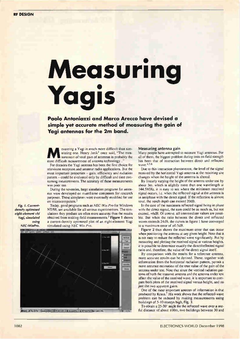
Measuring Yogis Paolo Antoniazzi and Marco Arecco have devised a simple yet accurate method of measuring the gain of Yagi antennas for the 2m band.
Fig. 1. Current-density optimised eight-element yid
Yagi, simulated using
NEC-WinPro.
Measuring a Yagi is much more difficult than sim-ulating one. Henry Jasikl once said, "The mea-surement of total gain of antennas is probably the
most difficult measurement of antenna technology..." For decades the Yagi antenna has been the first choice for
television reception and amateur radio applications. But the most important properties — gain, efficiency and radiation pattern — could be evaluated only by difficult and time con-suming measurements. The accuracy of these measurements was poor too. During the seventies, large simulation programs for anten-
nas were developed on mainframe computers for research purposes. These simulators were eventually modified for use on microcomputers.2 Today, good programs such as NEC-Win Pro for Windows
NT/98, are available for all serious experimenters. The sim-ulations they produce are often more accurate than the results obtained from making field measurements.3 Figure 1 shows a current-density optimised plot of an eight-element Yagi simulated using NEC Win Pro.
Measuring antenna gain Many people have attempted to measure Yagi antennas. For all of them, the biggest problem during tests on field strength has been that of interaction between direct and reflected wave.4•5•6 Due to this interaction phenomenon, the level of the signal
received by the horizontal Yagi antenna at the receiving site changes when the height of the antenna is altered. By linearly varying the height of the antenna under test by
about 3m, which is slightly more than one wavelength at 144.5MHz, it is easy to see where the minimum received signal occurs, i.e. when the reflected signal at the antenna is in antiphase with the direct signal. If the reflection is almost total, the notch depth can exceed 20dB. In the case of the maximum reflected signal being in phase
with the direct signal, the sum could be as much as, but not exceed, +6dB. Of course, all intermediate values are possi-ble. But when the ratio between the direct and reflected waves exceeds 24dB, the curves in figure 1 have converged to a maximum error of ±0.5dB. Figure 2 thus shows the maximum error that can occur
when positioning the antenna at any given height. Note that it is not easy to reduce the reflected wave significantly. But by measuring and plotting the received signal at various heights, it is possible to determine exactly the direct/reflected signal ratio and, therefore, the value of the direct signal itself. By comparison with the results for a reference antenna,
more accurate results can be derived. These, together with information from the horizontal radiation pattern, permit a more accurate estimation of the true value of the gain of the antenna under test. Note that since the vertical radiation pat-terns of both the transmit antenna and the antenna under test affect the value of the received wave, it is important to com-pare both plots of the received signal versus height, and no just the two apparent gains. One of the most important sources of information is that
produced by Kraus.7 His work shows that the reflected-wave problem can be reduced by making measurements using buildings of 5-10 storeys high, Fig. 3. To obtain a 25-30° angle for the reflected wave over a use-
ful distance of about 100m, two buildings between 30 and
1002 ELECTRONICS WORLD December 1998

RF DESIGN
50m high are needed. As you we will see later, the 100m dis-tance necessary for long-Yagis. We carried out such testing using a 16-element high-gain
Yagi. We placed the transmitting antenna on the roof of a 14m high house and orientated it towards a park with no obstacle around, Fig. 4. This diagram allows you to calculate the effective radiation angles and the path of direct and reflected signal for the 6dBd reference yagi and for the eight-element antenna under test. The test antenna was 3.2m long and had a simulated gain of about 10.6dBd.
Analysing the theory The following considerations assume a horizontally polarised wave since horizontal polarisation is most widely used in both television broadcasting, ssb, cw and tropospheric links at 300-1000km. As is well known, the electrical field received from the
antenna is given by the vectorial sum of direct and reflected wave. The electrical field equation is,5
E = + k2 + 2k cos(71-22r8 + 7c)
where,
E is intensity of the resulting field in Vim, Ed is field intensity of the direct wave in V/m, k, which is less than unity, is the ratio between reflected and direct electrical field, Ic is 180° rotation of the reflected wave relative to the direct one (horizontal polarisation) 8 is the difference of path in metres between direct and reflected wave (-2h,hrld) .1 is wavelength in metres.
There is an accurate expression for calculating the differ-ence in distance between direct and reflected wave, 8. This expression was the starting point for a simplified formula that can be used when (ho-hr)2/d2 and (ht—hr)2/d2 are both much less than one,
= + h,)2 + d — .‘1(h, — h,)2 + d
Here, ht is the height of transmitting antenna, h, is the height of receiving antenna and dis the distance between the foot of the two antennas. All three distances are in metres. We used this expression for our analyses. Thanks to per-
sonal computers, it can be applied for very complicated designs. We estimated that the simplified formula results in an error of about 7%. To reduce measurement errors, the distance between trans-
mitting and receiving antennas has to be considered. To determine this distance, you need to be able to measure the signal level easily with a filtered if voltmeter having a 30-40dB dynamic range. Also, the wave reaching the receiving antenna should be as planar as possible. The first condition can be easy established starting with the
received power and calculating the attenuation experienced by the wave in the open space,
a = 32.4 + 20 log(f) f)+ 20 log(d) — G, — G,
Here, a is attenuation in decibels, f is frequency in mega-hertz, d is distance in km, G, is the gain of transmitting
antenna in dBi and G, is the gain of receiving antenna, also in dBi, obtained by simulation. There is also a simple, easy to remember method of cal-
culating the attenuation by considering the distance between the two antennas in terms of wavelengths. When d=X, a is always 22dB between isotropic antennas.
This equates to 2.08m at 144MHz. The attenuation increas-es by 6dB for each doubling of the path distance. This means that the free space attenuation is 22dB at 2m, 28dB at 4m, 34dB at 8m, etc. To make the wave reaching the receiving antenna as planar
as possible, the capture area in square metres of the receiv-ing antenna and the maximum acceptable phase error are needed,
A2
A " 4ir
This expression is valid for an antenna with no thermal losses and was certainly useful for our experiments. Assuming that the capture area is circular, the minimum
6 9 12 15 18 21 Direct/Reflected ratio (dB)
24 27
-7
distance in meters between the two antennas will he.
Transmitting 4++.1 Yagi
14m
•
Fig. 2. Absolute maximum test error versus direct/reflected signal ratio. This is the maximum possible gain measurement error when moving the antenna up and down the mast. As you can see, the error in decibels can be positive or negative, depending on the relative phase of the two signals.
Fig. 3. Kraus suggests that Yagi tests should be carried out using two reasonably high buildings to reduce reflection errors.
Fig. 4. Layout of the test site with
transmitting and receiving antennas.
Test or reference - antenna
If : 2.5 to 5.5m
43m
December 1998 ELECTRONICS WORLD 100.1

RF DESIGN
Fig. 5. Calculated and measured
values of signal level versus
antenna height and direct-to-
reflected signal ratio. These values are for the three-element reference Yagi at 144.5MHz.
Fig. 6. Performance of
the eight-element Yagi at 144.5MHz.
As with the previous graph,
these are calculated and
measured values of signal level versus
antenna height and direct-to-
reflected signal ratio.
Fig. 7. Rhombic reference dipole
realised for comparison tests.
13, d >
For a maximum phase difference of 22.5°, which is usually enough, n=2. If a phase error of only 5° is required, n=9. In the case of Yagi antennas, where one dimension prevails over the other ones, the maximum length, instead of the cap-ture diameter, is used. In this case, the minimum distance in metres becomes,4"
d > n7,
where L is the maximum Yagi length in metres.
2 -
(dB) o
htx = 14m d = 43m
70mV (G = 6dB)_ Measurements YA3
- -Theory -D/R = 5 5dB
2.7 3.1 3.5 3.9 4.3
hrx(m)
4.7 5.1 55
2 -o
(dB) o
htx = 14m d = 43m
114mV (G = 10.2dB)
o
Measurements YA8
Theory -D/R = 7dB
3.7 3.1 3.5 3.9 4.3
hrx(m)
4.7 51.1 5.5
Siting and antenna height The minimum height from ground of the antenna under test is another parameter to be controlled during the measure-ments. This is because the proximity of ground can modify the radiation resistance. In our case, the minimum height is hr is more than X., but
the relevant points of the curve have been measured at 2X and above. Note that the simulation software that we used used (NEC-WinPro) does not take into account the ground plane. Also, the typical parameters of the antenna — gain, radiation angles, impedance — are calculated in the free space. To define the correct receiving height, it must be consid-
ered that the electrical field, and hence the voltage measured by the millivoltmeter — have maximum and minimum values due to the different path of direct and reflected wave, sum or difference. To be confident about the measurements, it is necessary to
find at least a maximum and the nearest minimum using the first two formulas. This was done allow us to draw the curves of Figs 5, 6. A suggestion from an article that appeared in VHF
Communication l° convinced us to incline the antenna to be measured with respect to ground. This allowed us to have the maximum signal for the direct wave and the maximum atten-uation for the reflected one, exploiting the shape of Yagi radiation diagram. In particular, the approximate 40° angle of reflected wave relative to the receiving antenna attenuates it by around 2 to 4dB. We decided not to incline the transmitting antenna to
improve the ratio between reflected and direct wave. Instead, we exploited the directivity of the antenna. The advantage is about 5dB as the reflected wave is about 23° under the plane of maximum radiation and 13° under the direct wave path. Another way to reduce the reflected wave, which we did
not try, is to place a metal screen near the reflection point. This plate needs to have significant dimensions with respect to the wavelength: 2 by 4m for instance. According to previous considerations and the availability
of a suitable area for field testing, the conditions of the mea-surement site are defined as follows:
Transmitting Yagi, — 16 elements, G=13dBi, ht=l4m with the boom parallel to the earth plane.
1004 ELECTRONICS WORLD December 1998

RF DESIGN
e=0.1dB E =0.3dB
Fig. 8. Planar wave concept and phase error.
0.6
0.5
0.4
dB 0.3
Reference antenna — home-made three-element Yagi, G=6dBd, calibrated by the reference dipole described next and shown in Fig. 7, h1=2.5 to 5.5m. Minimum received signal was at 3.4m and maximum at 5.1m. The boom had a 13° angle with respect to the ground plane.
Antenna under test — this was a 3.2m long (1.8X.) eight-ele-ment home-made Yagi.
The site we selected is useful for measurements of antennas up to 6m long. This equates to about 3X at 144.5MHz). For accurate antenna gain measurements, the distance
between the transmitting and receiving (test) antennas should be greater than that needed to satisfy the far-field conditions for d>52‘. and greater than the approximate uniform plane wave. So if you want to measure a 10m long Yagi, it is necessary
to increase the distance using,
d>n—Â2
to maintain the error due to a non-uniform plane wave with-in a fraction of decibel, Fig. 8. To detect the received signal at the receiving antenna we
used a Boonton 92B millivoltmeter. This meter is well suit-ed for these applications but it is possible to make your own instruments with good sensitivity and accuracy. The signal under test ranged from 143 to 146MHz and was swept by means of a small remote control. To conclude, Figs 5 and 6 show the obtained values super-
imposed with the curves calculated with the first two for-mulas, normalised to the direct wave and given in decibels. The difference in signal between the 6dBd reference Yagi
YA3 and YA8 at the null point — i.e. with no reflected wave — is 4.2dB. This allowed us to conclude, after a critical anal-ysis, that the gain of the 1.8X. long eight-element Yagi is 10.2dB. The analysis considered the optimum matching between
measured and simulated radiation diagram was ±20° at —3dB. The maximum test error is probably around 0.5dB. The measured value of front-to-back ratio at 180° is
21.5dB.
Error sources Most errors that occur during antenna measurements are related to the reflected wave. The total error can vary from a maximum of +6dB, when the direct wave is summed to the
0.2
0.1 _
00
1.2 1.4 1 6 SWR
1.8
D1=902
D=985
R=1020
155
2
All dimensions in mm
Fig. 10. Three-element reference Yagi dimensions.
reflected one, to —20dB or less when the two components of received signal are subtracted each other according to the first mathematic relation we presented. Broadcast fm signals received by the antenna under test
can affect the measured voltage significantly. To minimise this problem, we performed the measurements as near to the antenna as possible. How close the measurements can be made depends on the antenna dimensions and the planar wave effect must be catered for. We incorporated a good helical filter for 144.5MHz, t5MHz to reduce interference and obtained a useful received signal of about 100mV. Another source of error is related to the antenna impedance
mismatch, relative to 50i2. The mathematical relationship that describes the signal loss on the receiving antenna output or on the load is given by the following equation when the antenna impedance is greater than 50e,
V 1 °(dB) = 20 log[2 Z.
1+ SWR Z„
Here, V. is antenna voltage in volts when Za≥50S2 V. is antenna voltage when 4=5011 SWR is standing wave ratio Z. is antenna radiation impedance Z. is load impedance (50L1)
308
416
Fig. 9. Maximum error versus standing-wave ratio of the antenna under test.
December 1998 ELECTRONICS WORLD 1005

RF DESIGN
When Za>7.0, SWR=417.0. For an antenna impedance of less than 50Q, the equation becomes,
V 11 (dB) = 201o42 SWR
1+ SWR_\
Here, SWR=ZdZa when 4>Za. The behaviour of the maxi-mum error versus receiving antenna standing-wave ratio is shown in Fig. 9. A load impedance different from 50f2 can also introduce a
measurement error which is minimised using a 10dB fixed attenuator connected directly to the antenna output. In our practical case, load standing-wave ratio was better than 1.05 with a tiny error of less than 0.03 dB. A 10MHz-wide band-pass filter is normally included to
screen out possible out-of-band strong signals mainly from fm broadcasting stations.
Reference antenna The reference antenna is a log-periodic wide-band type that is frequently used in this type of application. Its approximate bandwidth can be calculated by using the lengths of shorter and longer elements. Bandwidth is about half of the maxi-mum and the minimum wavelength at which the antenna can be used. When working at a single frequency, only part of the
whole antenna is active: the elements have a physical dimen-sion nearest to one half of the wavelength. It is important to remember that input impedance and radiation properties of this antenna are repeated periodically with the logarithm of the frequency. Commercial log-periodic antennas often used in electro-
magnetic-compatibility measurements are manufactured by companies including Hewlett Packard and Emco and are available with calibration graphs. The HP11966D for exam-ple covers the range 300-1000MHz and costs around £1500 pounds. Considering the narrow band involved in our measure-
ments, and the consequent small variation of standing wave ratio versus frequency we decided to build-in a reference Yagi with similar behaviour and accuracy as the log-peri-odic. We calibrated our Yagi with reference to a half-wave
dipole, the performance of which is well documented.9 Assuming no losses, the features of a half-wave dipole are,
Horizontal half-power beamwidth 78.1° Directivity 2.14dBi Receiving area 0.131X Effective length 0.318X.
The main characteristic needed for our reference dipole is a standing-wave ratio lower than 1.2 with a negligible error of ±0.05dB. As a result, we made our dipole rhombic in shape. Its length is 798mm, its width is 18Ormn and it is made from 4mm diameter aluminium wire.
It is necessary to 'balance' the antenna using a choke com-prising six turns of teflon-coated cable on a 20min diameter insulated support. Due to the addition of this cable, 0.2dB must be subtracted from the gain of the dipole, making it -0.2dBd instead of the OdBd theoretical value. We do not advise the use a dipole for repeated tests since
it is omnidirectional. It also has a significant gain in the fin broadcast range, which contains strong unwanted signals. A dipoles" can be useful as a reference, but it does not
have the flexibility and measurement reliability of a Yagi with more than 25dB of front-to-back ratio. At the beginning we though of a two element Yagi, i.e. a
dipole plus reflector, but its front-to-back ratio was not high enough for our needs. Also, to optimise standing-wave ratio,
we would have had to work with many different values of gain. After may hours of simulation with NEC-Win Pro 1.13 and
some field measurements, our choice was a three-element Yagi built with 10nun diameter rod. It had a gamma match-er made from copper and teflon.l° Its gain was 6dBd and it had a high front-to-back ratio. The passive elements have insulated supports 30nun high,
while the dipole has an aluminium support, connected elec-trically with the boom via a type-N connector. The final reference antenna, Fig. 10, is easy to make and
repeatable. When made precisely to the drawing and well trimmed for standing-wave ratio, it meets the design require-ments of 6dBd gain at 144.5MHz.
In summary There are many potential sources of error when performing Yagi gain measurements and there has been a great deal of optimism when analysing them.
If you consider that a typical site for professional mea-surements described in reference 12 certifies the gains of the antennas under test within ±2dB between 30 and 1000MHz, you can better understand the difficulties that arise. We have examined the subject of dipole calibration and
presented a three-element reference yagi for easy comparison tests at very high frequencies. We believe that by averaging repeated measurements, it is
possible to obtain results with maximum error of around ±0.5 dB. •
References 1. Jasik, H, 'Antenna Engineering Handbook,' McGraw Hill,
1961. 2. BertelSmeier, R, DJ9BV and Hoch, G, DL6WU, ̀ Yagi
Simulation by Computer,' DUBUS, 3/91-4/91-1/92-3/92. 3. NEC-Win Pro Antenna Analysis Software, version 1.1,
Nittany Scientific Inc, 1997, www.nittany-scientific.com 4. ARRL Antenna Book, 1991, VHF and UHF Antenna
Measurements, pp. 27.43 to 27.48 and p. 3.11. 5. Aubin, JF, Berlelcamp, JD & Frey, DT 'Antenna
Measurements in Commercial World,' Proceedings of AMTA 1995, pp. 69-74.
6. Knott, EF, 'Radar Cross Section ( RCS ) Tests Utilize Ground-Plane Effects,' Microwave & RF, March 1984, pp. 79-84.
7. Kraus, JD, 'Antennas,' Second Edition, McGraw-Hill 1988, pp. 44-46, pp. 60-61 and pp. 809-813.
8. White, DRJ, 'Electromagnetic Interference and Compatibility,' Vol.2, 1980.
9. Reference Data for Engineers, 7th edition, Sams 1989, pp. 32.14 and 33.17 to 33.19*
10. Asbrink, L, SM5BSZ, 'The Optimum 6-element Yagi,' VHF Communications, No 1/82.
11. Littlefield, R, K1BQT, 'A Reference Dipole for 2-Meters,' Communications Quarterly, Fall 1997, pp. 90-91.
12. Walsh, DP & Kremer, D, 'Design and Verification of an Antenna Measurement Facility at 30-1000 MHz,' Proc. AMTA 1996, pp. 235-238.
Further reading Brown, F, W6HPH, 'Antenna Gain Measurements,' QST, Nov. and Dec. 1982.
* Reference Data for Engineers is now published by Newnes and available via Electronics Worlds editorial offices. E-mail jackie.lowe@ rbi.cosuk or fax 0181 652 8111 for details.
1006 ELECTRONICS WORLD December 1998

sawr) a 30MHz oscilloscope worth £450 or one of two superb £70 dnims Simply tell us what topic you enjoy reading about most in any electronics magazine and you could win an oscilloscope or digital multimeter. Send your entry
- including your name and address - by post only to 1998 Prize Draw, Electronics World Editorial,
Quadrant House, The Quadrant, Sutton, Surrey SM2 5AS. The draw will take place on 4 January 1999.
LP310 professional hand-held dmm
The LP310 3.5 digit hand-held digital multimeter retails at
just under £70.
Features 44 ranges Frequency to 20MHz AC & DC current to 10A AC & DC volts3.5 digit
Gold plated switch contacts - long life Auto power off Data & peak hold Input warning beeper Overload protection Logic test
Diode, continuity & transistor test Protective rubber holster Resistance & capacitance
Key specifications Frequency: 2k, 20k, 200k, 2M, 20MHz auto range Capacitance : 2n, 20n, 200n, 2p, 20pF Resistance : 200, 2k, 20, 200, 2M, 20M52, 2000M11 AC current: 200p, 2m, 20m, 200m, 20A, 2A, 10A DC current: 200p, 2m, 20m, 200m, 20A, 2A, 10A AC volts : 200m, 2, 20, 200, 750V basic accuracy 1.2% DC volts: 200m, 2, 20, 200, 1kV basic accuracy 0.25%
Ready to use complete with test leads, rubber holster, battery, instructions.
Grundig M030 30MHz oscilloscope Selling at over £450, the M030 features two channels, a
3dB bandwidth of 30MHz, 2kV accelerating voltage, 8 by
10cm screen, and X/Y modes. Vertical sensitivity is 5mV to
20V/div in 1-2-5 sequence and the time base covers the
range 0.5ps to 200ms also in 1-2-5 sequence.
Features • Peak-value trigger, trigger filter 2mV/cm, addition and
subtraction measurement. Both channels invertible, CRT with internal graticule.
• Automatic peak-value trigger ensures stationary displays without the need of manual trigger level adjustments.
• AC/DC trigger, high-pass filter (HF) and low-pass filter(LF) for a clear display of complex signals.
• Triggers on field and line frequency of video signals. No manual adjustments in case of changing amplitudes or varying video contents.
• 2mV/cm with full bandwidth. Addition and subtraction. • Both channels invertible. Important for characteristic curves
in X/Y node. • Free choice of X deflections by trigger source selector
switch. This enables dual-channel Y displays in X/Y mode. • Non-parallax reading due to CRT with internal graticule. • Automatic focusing.
Rules: Anyone can enter, subject to the proviso hereunder, but only one entry per person is allowed • This draw is not open to employees of Reed Elsevier • No correspondence relating to this draw will be entered into • The winners will be announced and notified as
soon as possible after the draw. • Each of the three prizes will go to a different entrant • Entries arriving after the closing date of 4 January will not be considered • No responsibility for lost entries will be taken by Reed Elsevier

Dictionary of Communications Technology
new edition
lebonary of
communicationâ technology
third edition
• gilbert held
y didn't know yap needed es know AlleXvf communicators technology
8.0 nw 400. ....no tr..
- 1 . 11:Lcs÷s11:1
4
• ea...a V7roe" rer 1.0 tee
bar. carnet.. arnunoreues
rastu,blateh An telbute set.. mommong wrote
madded!, lInseplea.Inc Worn, 1111 'ale. NI
coneotena.0 1 T. linktng trarornotion
hannela subnetwork% end toe. The Ilnk,
ot blocka ol wer data or pnetuol In ober 'rnut technology. the Intercorme. turn of
tko oe mote 'Wert Into on< contanuout leng.
coecte.tion Collestmn of data at intermsrnate
Inon tesentl kw • and medlum meed tort lot ...soon Aar. one lugh•speedhrn
emceed-War A deoce abed co do 'de a data t harm,
In. two or mots .hannelt or average lower spread. W... all, talked, apace ACCCrdln, so the
demand In °Met to mum.a data throughput st
'
n` n
cardkelomed dn. A cm. Wu hat ..en
slernrually esered to ea. tlx denred chanc dnetica rna wee and semnssron T. reader
Ls refer« so du swim C1 Wore r•g and I sad 611« ma. Isionsalboa on C level and
131evel earratiasan.
roraftnraed leap Aron N. casalstloody
...omens 'audits ',Wm« rand to «his
• «surd tA heneen«, la («IMO «in «
cannon« 1. lans^ «Ms at «pap es« ro «grow Ise
or «Jay or • lem« wain« No •• N. Is
me« «signior lot dos Inamintra
i- t.)
fLr medmpeallni Menton' of • PAPX•nd altos.
noes mancatiœsprodursehe gem. watintren ton --Imeord h, group ot
loom «OP lo
modem. multaport A dense tldi contd., •
mulbplas, and • modem alkm,ng rno or mort 13,, to te onne,md ea the same hre Ado glit
stream meter,
modem. quick turnaround A modem Anh enmantal
turnaround tone o hen the Me is wed In à hall-
dopea mode Ahe Quuk11,111QraFass IFS',
mode, non WM ',summon tel lbeh h. even
unl limited trounce modem.
mode« Maenad A modem deugned IAoperate
at aseeds greater Wan Woe used nun Mgh speed modems. suth at 192 of 56 Ktqat
modems .1 nee osurate ovfl value grade 'Arsons
hut req.< à a...and cos.
stIodem, rOmmunuationa mentor prograrn Sup
potung the ,h1n,lornant X molern.
rnoecting hle tabular protocol Thts sermon ol A-tandem lIS motor", translet carnal-eat
node. ranee 1, name wed in DNA
..lasant aornmunneatans hnla amen. by Mourn
...retards modem connechon
modem nausea A deans wed to own., •
local terminal and • stormed( rye in hen ot
We pad tar modems that dry mauld expect to
connect lo lITF.-tollTb. data and control signal connectx,. otherrne not sasaly àshaesed
by standard cable, te tonne, ton Mobbed tables
Icrossovernableat or omneetontadapten /can also
,norm tho hum.
oaken matt... eharAterldlo het page 2,/
maim due« mat A desk,. splits • signal
sung • clutter ol irnminala and •lloso them to
imam mere
«edam...nano seals An external option that
anon you b rem. you, dad through a -her spose mo«ro ear ts already postatdrd up (DADA
mat the anginal modern lath
madeneur A p•marant en It tn 'huge ol •
confatlICP.Amhdentoro respotuable rot keeps,
Mc «roam ors lot allestating hp., and
iOf UMW hoe...
MODES [berme opto•I ornses dud tan propagate
opocal ...strode. Whereas. AI • ones mode
fibee. colt. onc mode. the fundamental mode .an
rep«. Their or teseral hunt,. 1110.• In •
multimode Phet sates h dads, an held pattern and propagannn rnloott Imultorade dopenton1
upper load t. num115 ol mode+ ta determined by Ilse core 'hamster and numensal aperture tat Ow
kaveguele
ma .11 La.tatonsa-parented poxes. that utes 'ugh
temperaturt, to treed the a.? I. rat la,
quaratmel of lIbtr helpmate The glad o mule
dkustng 1. apes lorm • "unity 'node a nabs ol heated urn o laterdrasot Into hIser TernfentlIfelreAh artota deg.. l• The Inch,
pnant of steel is 2.1/ deg., Ft
Madded rim« Jodamess 'MU, 1, 'OP,' Fern-.
Court nahns that drnermtned the rules govetrung
the doseshmrs Ill Me .11 Oyeratmg rnmpanes from ATAT and whet ant.. and Jet:potent.'
lasues Neut. ornr Judge liar. Greene. ab
.ak ATAT Lettermen.. h the /API mochfied lodge Oacene ...morn. has inornemene
enlorung and interpret, the prosta.0 of WI%
settlement
modular «warn «omens Aden, weal to referents tplatter, naiad.5 amd mat.?
With over 9000 entries and 250 illustrations, this book is an invaluable reference work for anyone involved with electronics and communications. Dictionary of Communications Technology provides comprehensive coverage of data and communications and has entries on PC Ions, the Internet, communications testing and client-server applications - in 500 pages. Over 20 major companies helped prepare the Dictionary
of Communications Technology, including AT&T, IBM and Digital Equipment Corporation. Gilbert Held, author of Dictionary of Communications
Technology, is an internationally author who has used his enormous expertise to make this work one of the most comprehensive sources of telecommunications information.
UK Price: £38.95 Europe £42.95 ROW £46.95
** Price includes delivery and package **
Fax your order to 0181 6528111 or post to Room 1333, Quadrant House, The Quadrant, Sutton, Surrey, SM2 5AS
Please supply the following title:
Dictionary of Communications Technology
Total
Name
Address
Postcode Telephone
Method of payment (please circle)
Access/Mastercard/Visa/Cheque/PO
Cheques should be made payable to Reed Business Information
Credit card no
Card expiry date
Signed
Please allow up to 28 days for delivery

Have you got the capacity
to resist this inducement?
ELECTRONICS pY0.9.14.P
I 2 ISSUES free

Subscribe to Electronics World for 3 years but pay for just 2!
Please enter my subscription for: (tick one of the following)
1 year
2 years
3 years
UK
£34
£54
£68
Europe Rest of World
£49 £59
£78 £94 SAVE 20%
£98 £119 I year FREE!
In every monthly issue • Detailed circuit diagrams
• New product reviews
• Informative design-oriented explanations
• CAE software
• and more 1
Full money back guaranteé If you're not completely satisfied with Electronics World
within the first 60 days we'll refund your money in full - no questions asked.
Please allow 28 days for delivery of your first issue.
Li Please tick here if you do not wish to receive direct marketing promotions from other relevant companies.
Three ways to pay 1 I enclose a cheque for £ made payable to
Electronics World.
2 Please charge my Visa/Mastercard/American Express/Diners Club (please delete as appropriate)
1 Card Number
Expiry date I
Signed
I 1
Date
3 Please invoice me/my company. Purchase Order No.
Name
Job Title Company
Address
Tel. No.
Company VAT registration number
Return your completed form to:
Electronics World Subscriptions, FREEPOST RCC 2619,
PO Box 302, HAYVVARDS HEATH, UK, RH16 3BR
-edit t 'e-dth Tel: +44 (0) 1444 445566 (quoting code 087)
087

Te net Tel: 01203 650702
Hewlett Packard 8920A Comms Test (various options) 8922 BGH G.S.M. Test
£4995 £P0A
Rohde & Schwartz CM5 54 Radio Comms service monitor (0.4 to1000MHz) CMTA94 GSM Radio Comms Analyser
£6250 £7500
Schlumberger - Stabilock 4031 Radio comms test (0.4 to 10.00MHz) £4995 4040 'High accuracy' Radio comms test £2995
Wandel & Goltermann PFJ-8 Error & jitter test set (All options fited) PCM4 PCM Channel measurement set
£ 12500
£P0A
Marconi 2305 Modulation Meter £1995
Racal 6111 GSM test sets £P0
Hewlett Packard 8642A High Performance R/F Synthesiser - 0.1 to 1050Mhz £8500
Textronix 2467B 400Mhz - 4 channels - high writing speed oscilloscope £8500
OSCILLOSCOPES Beckman 9020 - 20MHz - Dual channel Hewlett Packard 54100D - IGHz Digitizing Hewlett Packard 54200A - 50MHZ Digitizing Hewlett Packard 54201A - 300MHz Digitizing Hitachi V152N212N222N302BN302FN353FN550BN650F Hitachi VI 100A - 100MHZ - 4 channel Intron 2020 - 20MHz. Dual channel D.S.O. (new) lwatstu SS 5710/SS 5702 - Kikusui COS 5100 • 100MHz - Dual channel Lecroy 9450A - 300MHz/400 MS/s D.S.O. 2 channel Meguro MSO 1270A - 20MHz - D.S.O. (new) Philips 3055 - 50MHz .Dual channel Philips PM 3335 - 50MHZ - D.S.O. Dual channel Philips 3295A - 400MHz - Dual channel Panasonic VP5741 A - 100MHZ D.S.O. Dual channel Tektronix 455 - 50MHZ - Dual channel Tektronix 465 -100MHZ - Dual channel Tektronix 464/466 -100MHZ - (with AN. storage) Tektronix 475/475A - 200MHz/250MHz - Tektronix 468 -100MHZ - D.S.O. Tektronix 2213/2215 - 60MHz - Dual channel Tektronix 2220 - 60MHZ - Dual channel D.S.O Tektronix 2225 - 50MHZ - Dual channel Tektronix 2235 -100MHZ - Dual channel Tektronix 2221 - 60MHz - Dual channel D.S.O Tektronix 2245A - 100MHZ - 4 channel Tektmnix 2440 - 300MHz/500 MS/s D.S.O. Tektronix 2445A - 150MHz - 4 channel Tektronix 2445 - 150MHZ - 4 channel + DMM Tektronix TAS 475 - 100MHZ - 4 channel Tektronix 7000 Series (100MHZ to 500MHZ)
SPECTRUM ANALYSERS Ando AC 821 1 - 1.7GHz Avcom PSA-65A - 2 to 1000MHz Anritsu MS 628 • 50Hz to 1700MHz Anritsu MS 6108 10KHz - 2GHz Advantest/TAKEDA RIKEN - 4132 -100KHz -1000MHz Hewlett Packard 3561A - Dynamic Signal Analyser Hewlett Packard 3562A Dual channel dynamic signal analyser
£150 £1500 £500
£1250 from £125
£1000 £450
from £125 £350
£2250 £450 £450
£1200 £1750 £1750 £275 £350 £350
from £450 £650 £350
£1250 £395 £600
£1250 £900
£3750 £1250 £1200 £995
from £200
£2250 £850
£2500 £4750 £2500 £4750
Quality second-user test 8t measurement equipment Marconi Radio Communications Test Sets
11/11.,ACCM.10•1111,111.1111«111
•
..... • • t__t_r•t7
"'re •
..... r::; ,
• • ....
-••••••
o a o
11111101113111• 1:111001ilie
El Ell001111111111• 113011•1110
El •. w
et; Ct; Qs 0 1.5_,1
2955 £2250 2955A £2500 2958 (TACS) £2750 2960 (TACS + Band III) £2750
2960A (TACS) £2950 2955B £4000 with 2960B added £4250
Fax 01203 650 773 64pHz - 100KHz Hewlett Packard 3585A 20Hz to 40MHz Hewlett Packard 8591A 9KHz - 1.8GHz with tracking generator,
option 10 Hewlett Packard 8505A - 1.3GHz - Network Analyser Hewlett Packard 8753A - 3GHz - Network Analyser Hewlett Packard 8753B + 85047A - 6GHz - Network Analyser 6GHz 5
parameter test set Hewlett Packard 8756/V8757A Scaler Network Analyser 1FR A7550 - 10KHz-1GHz - Portable Meguro - MSA 4901 - 30MHz • Spec.Analyser Meguro - MSA 4912 -1MHz - IGHZ Spec.Analyser Tektronix 495P Spec analyser prog. - 1.8GHz Tektronix 469P - 1KHz to 1.8GHz Wiltron 6409 - 10-2000MHz R/F Analyser
MISCELLANEOUS IFR 1200S - Radio comms test set £2995 GN ELM1 EPR31 - PCM Signalling Recorder £3000 HP 339A Distortion measuring set £1500 HP 3488A - Switch/Control unit £650 HP4279A - 1MHz - C-V meter £4500 HP 436A Power meter + lead + sensor various available from £995 HP 435A + 435B Power meters from £200 HP 8656A Synthesised signal generator £1500 HP 86566 Synthesised signal generator £2750 HP 8657A - Signal generator 100KHZ - 1040MHZ £3250 HP 37900D • Signalling test set £5000 HP 5385A • 1 GHZ Frequency counter £750 HP 890113 - Modulation Analyser £4000 HP 8903E - Distortion Analyser £2000 HP 8903B - (add with 8903E) from £2000 HP 5359A • High Resolution Time Synthesiser £4000 HP 3488A - Switch/Control unit £650 Marconi 2610 True RMS Voltmeter £700 Philips PM 5193 Synthesised Function Gen 50MHz £1500 Philips 5515 - TN - Colour TV pattern generator £1500 Leader 3216 Signal generator 100KHz - 140MHz - AM/FM/OW with built in FM
stereo modulator (as new) a snip at £995 Racal 9087 - 1.3Ghz Synthesised Signal Generator, low noise £2,250 Tektronix 1751 PAL WaveformNector Monitor £2200 Wiltron 6747A-20 - 10MHz-20GHz - Swept Frequency Synthesiser £6000
£6250 £4500
£6500 £1995 £6000
£12000 from £1000
£2950 £850 £1250 £5000 £4500 £2000
All equipment is used - with 30 days guarantee.
Add carriage and VAT to all goods.
Telnet, 8 Cavans Way, Binley Industrial Estate,
Coventry CV3 2SF.
Tel: 01203 650702 Fax: 01203 650 773
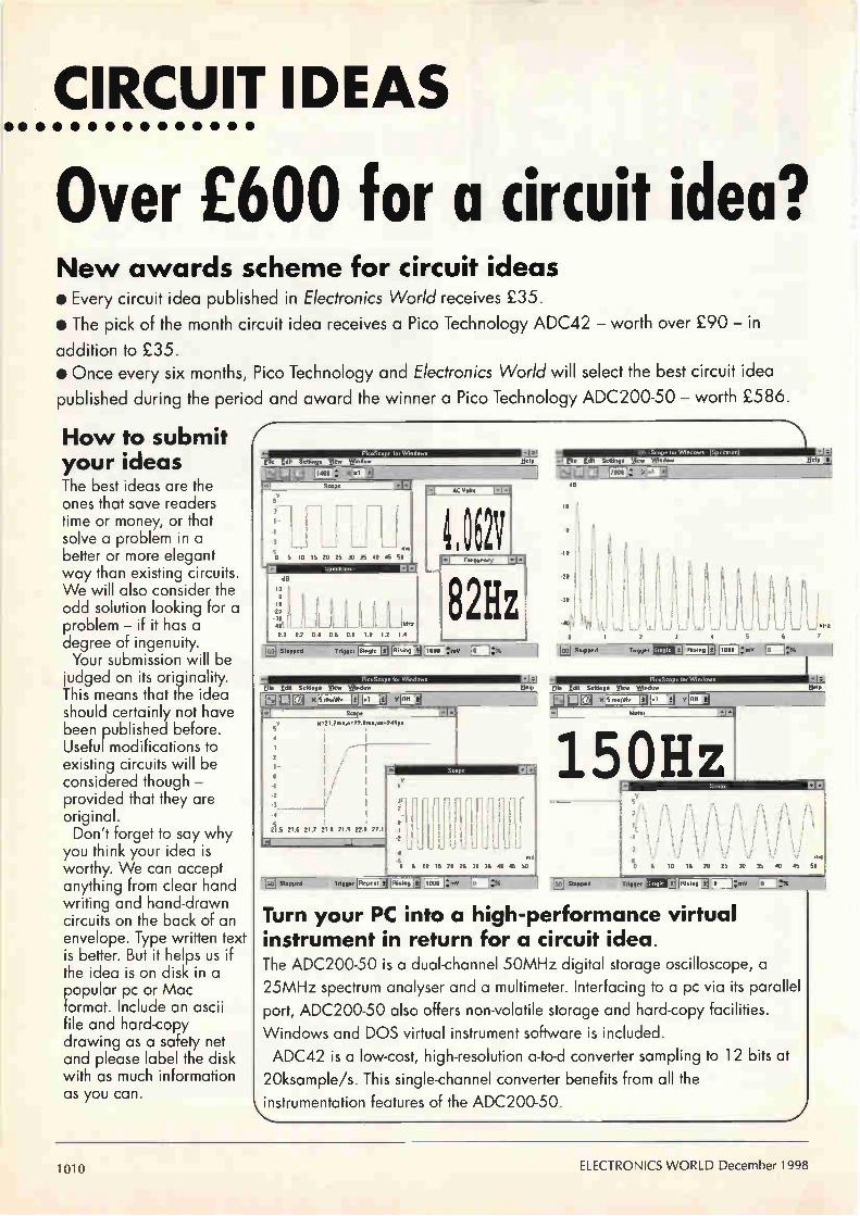
CIRCUIT IDEAS • • • • • • • • • • • • • • •
Over £600 for a circuit idea? New awards scheme for circuit ideas • Every circuit idea published in Electronics World receives £35.
• The pick of the month circuit idea receives a Pico Technology ADC42 — worth over £90 — in
addition to £35. • Once every six months, Pico Technology and Electronics World will select the best circuit idea
published during the period and award the winner a Pico Technology ADC200-50 — worth £586.
How to submit Í your ideas The best ideas are the ones that save readers time or money, or that solve a problem in a better or more elegant way than existing circuits. We will also consider the odd solution looking for a problem — if it has a degree of ingenuity. Your submission will be
judged on its originality. This means that the idea should certainly not have been published before. Useful modifications to existing circuits will be considered though — provided that they are original. Don't forget to say why
you think your idea is worthy. We can accept anything from clear hand writing and hand-drawn circuits on the back of an envelope. Type written text is better. But it helps us if the idea is on disk in a popular pc or Mac format. Include an ascii file and hard-copy drawing as a safety net and please label the disk with as much information as you can.
.50
82Hz
ms
5 10 15 20 25 30 35 40 15 50
Elie Edit Settings
dB
10
6
3 4
RHIN IMO
150Hz
Turn your PC into a high-performance virtual instrument in return for a circuit idea. The ADC200-50 is a dual-channel 50MHz digital storage oscilloscope, a 25MHz spectrum analyser and a multimeter. Interfacing to a pc via its parallel port, ADC200-50 also offers non-volatile storage and hard-copy facilities. Windows and DOS virtual instrument software is included. ADC42 is a low-cost, high-resolution a-to-d converter sampling to 12 bits at
20ksample/s. This single-channel converter benefits from all the instrumentation features of the ADC200-50.
1010 ELECTRONICS WORLD December 1998

CIRCUIT IDEAS
Monitoring two temperatures APICI6C72 controls the unit, being chosen for its 8-bit
a-to-d converter to give the 1°C resolution wanted and because it will drive the four-digit display and the a-to-d conversion simultaneously.
All the PIC's B port is taken up with drive for the 4511 decoder/driver and the four cathode resistors, port A accepting analogue input from the sensors and 2.55V reference. The 2.55V would give 255 10mV steps, but only 100 of them are used to give 1°C steps from 10mV to 990m V.
Temperature sensing is carried out by the two LM35Zs, which give an output of 10mV/°C, taken to the PIC analogue input. If this input exceeds 990m V, a subroutine detects the fact and blinks the display with a reading of 99. To ensure PIC reset, I used the HT7044A 4.4V detector,
the output of which zero if its input is less than that level. Jose Luis Cavasassi Buenos Aires Argentina B93
Object code in hexadecimal form.
:040000008316FF293B
080008008207633462346134A5 1000100060345F345E345D345C345B345A3459345C 10002000583457345634553454345334523451348C 1000300050344F344E344D344C344B344A344934BC 1000400048344734463445344434433442344134EC 1000500040343F343E343D343C343B343A3439341C 10006000383437343634353434343334323431344C
1000700030342F342E342D342C342B342A3429347C 1000800028342734263425342434233422342134AC 1000900020341F341E341D341C341B341A341934DC 1000A000183417341634153414341334123411340C 1000B00010340F340E340D340C340B340A3409343C 10000000083407340634053404340334023401346C 0400D00000340034C4 0203FE000030CD
1004000086001F30850000306200081488108312F7 100410008501A00186019B01633099000F2A80307D 100420008800081488102010000000000815881C9F 10043000172A09081902031C202AA0139800B72ABA
1004400000309800A017B72A18088D00883088005F
100450000814881020140000000000000815881CF3 100460002F2A09081902031C382A20139800B72ADA 10047000003098002017B72A18088E000D08812236 10048000432A0E088122C8309B000000A01B522A7C
100490000F08860006169A22860110088600861626 1004A0009A2286010000201B662A1508860006177E 1004B0009A2286011A08860086179A2286019BOBCB 1004C000452AA01B6722201B74220F2A5F2AA01A2C 1004D000732A193086009A229A22860129308600D2 1004E0009A229A2286010034201A802A49308600F6 1004F0009A229A228601893086009A229A228601BF 1005000000340D0897000A30922216089000170850 100510008F000E0897000A30922216089A001708DA 100520009500003496019702031C982A960A932A94 1005300097070034043093000A3094000000000054 100540000000940B9E2A930B9C2A0034FF309200EB 1005500OFF309100000000000000000000000000DB
1005600000000000910BA82A920BAA2A0034180858 0A05700004209800201C242A3C2AD5 00000001FF
Temperature 2
7-segment disp ays - common cathode Temperature 1 Temperatu e 2
a a a
,Ok BC337
10k WA,
BC337
d
10k
BC337
LM35Z
Temperature 1
I I
1k
+gv .01g
1k LM35Z
—L.
Reference
All 33OR
10k
BC337
2.55V
A
D
E
G
A 7
PIC16C71 controls measurement and display of two temperatures from 0°C to 99°C to within ±1°C.
17
5k6
18
1
2
6 D
Fr 3 Fr 4
LE
4511
5
10
11
12
13
PORTAO OSC1
PORTAI
POFITA2 2
3 RP°RCTA3 TC
6 PORTB1 7 PORTB1
PORTB2
9 PORTB3
PORTB4
PORTB5
PORTB6
PORTB7
mcLR
22p
15 OSC2 —
RTCC
HT044A
in
PIC16C71
<4.4V del
(B93)
December 1998 ELECTRONICS WORLD 1011

CIRCUIT IDEAS
Variable-gain, differential
input/output instrumentation
amplifier.
non-inverting
inverting
(B81)
Super zener voltage clamp To absorb more pulse energy than a
zener diode or transient voltage suppressor alone is able to, a mosfet and resistor across the zener "amplifies" the zener's power rating. A 33V zener (more of an avalanche diode at this voltage) turns the mosfet on, R2 dissipating most of the power and ensuring that the mosfet is safe. Current pulses of 20-25A at 10kFlz were clamped at 41-45V; at lower currents, the mosfet does not saturate and the clamp voltage barely rises over 39V. Before the
mostet turns on, there is an initial transient of about 100ns, which may be absorbed by the addition of C1 and, if the duty cycle is likely to be more than 0.2%, both mosfet and R2 may well need heatsinks. CID Callo Cambridge B88
Extending the pulse-clamping capabilities of a zener with a mosfet and
resistor.
(B88) —V
Cl 330n 100V
R2 = two 3R3/1W resistors in parallel
Variable-gain, differential instrumentation amplifier
nlike many such circuits, this one has differential input and output,
which reduces noise caused by large ground currents. Voltage drop across R1 is amplified
by A1, which controls the Tr5,6 pair, driving them to the state in which the collector currents of Tr3 4 are equal. This feedback greatly reduces the effect of the non-linear base voltage/collector current characteristic of the transistors. Op-amp Ai also drives Tr7 to produce a
current signal proportional to input voltage, after which A2 provides a voltage output. Circuit gain is,
Av = (Isz / 41) (R2 + R3) / RI.
If R2=R3, this is equal to 2R242/R141. The current sources may be formed
by op-amp circuits or by current mirrors and made variable, if required. Transistors Tria were used instead of resistors to remove the effect of 41 and varying temperature
A1
VVVV
A
R2
on the stage gain. Current 41, together with RI, sets
the differential input range. It must not be set so low that the transistor f1 is low enough to affect the phase margin round the feedback loop; resistor Rb prevents the inputs exceeding their common-mode range. For best distortion performance,
transistors Tr5, 6, 7, 8 should be matched. The bias voltage may be a simple resistive voltage divider and the current sources may use the same reference, since gain depends on their ratio, not magnitude. Lee Szymanski Stamford Lincolnshire B81
ADC42 Winner
R3
0 out
.---/V\AN---C)Vref
Is,
-r Vbi
a8 Is2
—vee
1012 ELECTRONICS WORLD December 1998

Win95 PIC PROGRAMMER • Uses standard printer port. • Requires 15 to I8v AC or DC • Versions for Dos, Linux, Acorn RiscOS, AmigaOS
Call for details. Chips Supported PIC 16C84, I6F84 ,I2C508,12C509,14000 PICI6C61, 62, 62A, 63, 64, 64A ,65, 65A PIC' 6C620,621,622,PICI6C71,72,73,74
£39.95 ittc Vat,P&P
Programmers also available for Anse) AVR Devices
EVALUATION BOARDS • Evaluation boards available for many types of Microprocessor / DSP chips.
LCD Display and Controllers • RS232 interface or I2C Serial interface • Displays from 1 x 16 to 4 x 40 Character Displays. • High contrast supertwist display. • Software controlled backlight.
Ft/C SERVO CONTROLLER Control R/C servos using the RS232 port of any computer. • Each board can control up to 8 Ft/C servos. • Up to 256 servo motors using multiple controller
boards. • Computers supported PC, Sun Solaris, Linux , Acorn
RiscOS, Amiga0S, Etc.
CD-ROMs
From £19.95 lac Vat, P&P
£25.95 it. Vat, P&P
Red Hat 5.1 Box sel ( 3 CDs & Book) 29.95 Walnut Creek Slackware 3.5 ( 4 CDs ) E 19.95 Red Hat Power Tools v5.I 1. 19.95 Complete FreeBSD 2.2.8 (4 CDs & book) £A4.95 Red Hat Linux Complete Command Ref 46.95 Aquila Budget Linux CD's from £ 2.00 Red Hat Motif £129.95 Simtel for MSDOS ( 2 CDs ) E 19.95 S.u.S.E. 5.3 Box Set (3 CDs & Book) E 29.95 CICA 32 for Windows 95/98/NT ( 4 CDs ) 19.95
S.u.S.E. Decathlon (13 CDs) .E 31.95 Electronics 2000 E 11.06 12.99 Linux Developes Resource E 21.95 Hardware Technician 2000£ 11.06 £ 12.99
This in just a small selection of titles from our 'Missive catalogue Covering Windom, Dos, Lhasa, FreeBSD, Unix, ele.
These products are a small selection of the products available visit our web site or phone for a catalogue :-
VISA Aquila Vision (Dept EW) 46 Gaisby Lane, Shipley, Bradford, BDIS lAX
Tel 01274 775117 (24 Hour Order line) Fax 01274 775116
www.aquila-vision.co.uk
CIRCLE NO.112 ON REPLY CARD
PHONE
0181 684
1166
LANGREX SUPPLIES LTD DISTRIBUTORS OF ELECTRONIC VALVES FAX TUBES AND SEMICONDUCTORS AND I.C.S. 0181 684
1 MAYO ROAD • CROYDON • SURREY CRO 20P 3056
24 HOUR EXPRESS MAIL ORDER SERVICE ON STOCK ITEMS
email: [email protected]
E P KT66 China 10.00 5Z4GT 3.00 6V6G 8.00 8231 6.00 KT88 China 12.00 6A05 2.00 6V6GT 5.00 CL33 10.00 N78 8.00 6AR5 20.00 6X4 3.00 E88CC 8.50 0A2 3.00 6AS7G 7.50 6X5GT 3.00 E1 80F 3.50 OB2 3.00 6AU5GT 4.00 12AT7 3.00 E810F 20.00 003 3.00 6106 2.00 12AU7 3.50 EABC80 2.00 0D3 3.00 6AW8A 4.00 12AX7 5.00 £B91 1.50 PCF80 2.00 6134G 22.00 12AX7A 7.50 EBF80 1.50 PCL82 2.00 6BA6 1.50 12AX7W 6.00 EBF89 1.50 PCL85/805 2.50 66E6 1.50 12BA6 2.00 EBL31 15.00 PCL86 2.50 6E1616 2.00 12E1E6 2.00 ECC33 12.00 PD500 6.00 6807A 2.00 12BH7/1 10.00 ECC35 12.00 PL38 3.00 6BR7 4.00 12BY7A 7.00 ECC81 3.00 PL81 2.00 OBRO 4.00 12DVV7 15.00 ECC82 3.50 PL504 3.00 6BW6 4.00 12E1 10.00 ECC83 5.00 PL508 3.00 6BW7 3.00 13E1 85.00 ECC85 3.50 PL509/519 10.00 6B26 3.00 5728 85.00 ECC88 6.00 PL802 4.00 6C4 2.00 805 45.00 ECC808 15.00 PY500A 3.00 6CB6A 3.00 807 7.50 ECF80 1.50 PY800/801 1.50 6DC6G 5.00 811A 25.00 ECH35 3.50 00V02-6 12.00 6CL6 100 812A 55.00 ECH42 3.50 00V03-10 5.00 6CG7 7-50 813 27.50 ECH81 3.00 00V03-20A 10.00 6CH6 300 833A 85.00 ECL82 3.50 00V06-40A 12.00 6CW4 6.00 866A 20.00 ECL86 3.50 U19 8.00 6005 17.50 872A 30.00 ECLL8130 25.00 UABC80 1.50 6D06B 10.00 931A 25.00 FE37A 3.50 UCH42 5.50 6F6G 500 20508 12.50 EF39 2.75 UCL82 2.00 6F07 7-50 5751 6.00 EF40 4.00 UCL83 2.00 6GK6 4.00 5763 6.00 EF86 10.00 UF89 4.00 6J5G 6.00 58148 5.00 EF91 2.00 UL41 12.00 6J5M 4.00 5842 12.00 EF183/4 2.00 UL84 3.00 6J7 3-00 6072A 6.00 EL33 15.00 UY41 4.00 6JB6A 27.50 6090 6.00 EL34 8.00 UY85 2.00 6JE6C 27.50 61466 15.00 EL34G 6.00 VR105/30 3.00 5.1S6C 27.50 6201 8.50 EL36 5.00 VR150/30 3.00 6K6GT 4.00 6336A 35.00 EL41 3.50 Z759 10.00 6L6G 15.00 6550A 25.00 ELM 2.25 Z803U 15.00 6L6GC 15.00 68838 15.00 EL95 2.00 2021 3.50 6L6WGB 10.00 7025 7.50 EL360 15.00 31328 12.00 607 3.00 7027A 25.00 EL509/519 12.00 4CX25013 45.00 6SA7 3.00 7199 15.00 EM34 15.00 5R4GY 7.50 6SC7 3.00 7360 25.00 EM814/7 4.00 5U4G 10.00 6SG7 3.00 7581A 15.00 EN91 7.50 5U4GB 10.00 6SJ7 3.00 7586 15.00 EZ80/81 3.50 5V4G 4.00 6SK7 3.00 ysgy 20.00 0232 8.50 5Y3GT 2.50 6SL7GT 5.00 GZ33/37 6.00 5Z3 5.00 6SN7GT 5.00 Prices correct when KT61 15.00 5Z4G 6.00 6U8A 1.50 going to press.
OPEN TO CALLERS MON-FRI 9AM-4PM. CLOSED SATURDAY This is a selection from our stock of over 6,000 types. Please enquire for types not listed. Obsolete items are our speciality. Valves are new mainly original British or
American brands. Terms CWO/rnin order C10 for credit cards. P&P 1-3 valves £2.00 4-5 valves £3.00 j,I Add 17.5% VAT to total including P&P.
CROWNHILL ASSOCIATES LIMITED The Old Bakery, New Barns Road,
Ely Cambs. CB4 7PW Tel: +44 (0)1353 666709 Fax: +44 (0)1353 666710
Low cost professional quality Smart Card Systems
CHIPDRIVE EXTERN Intelligent programmer for Smart Cards using the International Standard T=0 or T=1 protocols also Memory and Secure Memory using 12C, 2-wire & 3-wire interfaces. Supplied with software to read and write to most popular secure smart cards, inc GSM, PAY PHONE and ACCESS CONTROL cards. T=0 or T=1 @ 3.579MHz RS232 @ 9600 - 11500 bps £69+vAT Internal Supply / Ni-MH P&P £7.50 Size: 100x70x8Omm Weight 660 Gram Supplied with CARDSERVER API for easy development of SmartCard Applications using Visual Basic, Delphi or C++. Supplied with Sample Memory cards and Secure Smart cards
CE Compliant
Chip Drive Intern 3.5" floppy bay version of the CHIPDRIVE Applications are available to provide SmartCard controlled access of data on Hard Drives or PC-LOCK", to control access to the whole PC Fully Compatible with TOOLBOX for systems develoment. Supplied with CARD-SERVER API
£85.00 + £5 P&P + VAT
CE Compliant
NEW CHIPDRIVE - micro Fully Compatible with TOOLBOX for application development. Featuring the same functionality as Chip Drive Extern but in a small neat low cost package, similar in size to a smart card. Supplied with CARDSERVER API £65 + £5 P&P + VAT
NEW APP-LOCK Use a CHIPDRIVE and SMART CARD to protect applications from Unauthorised access under Win 95/98/NT £125 inc Chipdrive + Smart Card
FREE GSM CARD READING Application
CHIPDRIVE Developer Kit CDK consists of: CD ROM containing cardserver.d11, Applications and Source code examples. CHIPDRIVE-micro a selection of Smart Cards offering protected memory, processor and memory cards, Typical uses are Control access, Pay Phone cards and Data transport. PIN codes for the cards are supplied along with data sheets and programming data for use with cardserver.d11. A useful application with source code shows how the CHIPDRIVE can be used to identify and Smart card inserted, giving manufacturer info, and memory map if available. Applications produced with the developer kit will operate under Windows 3.11/95/NT and are compatible with the whole CHIPDRIVE family. The CDK uses easy to use 16 bit or 32 bit DLLs with just one function call to the "CardServer" to identify the card or carry out any instruction. Card-server is a powerful Background task which relieves the application programmer from device and card administration. Featuring automatic protocol and card type
detection. Allowing several applications to access one terminal dependent only on the type of card inserted.
CDK - Everything that you require to start using Smart Cards NOW!
£99.95 + P&P + VAT
http://www.tovvitoko.co.uk http://www.crownhill.co.uk
http://edsim.cambs.net
SMARTCARDS Available from Stock: GemPlus, Atmel, Xicor, Siemans, SGS Crownhill and more SLE4442, 4432, 4418, 4428, 4404. AT88SCzu, AT24c01-16.
GPM103, GEM1K, 2K, 4K, GPM416 Phone Cards, Loyalty Cards
THE SMARTEST SOLUTION
Crownhill can offer a broad range of smart cards from just £1.00 and Smart Card sockets for just £1.45 ea. PIC Microchip based Smart Cards now available from just £3.50 ea DEVELOP YOUR OWN SMART CARD!
Crownhill can supply over 150 different types of IC from more than 12 silicon suppliers, which can all be incorporated into smart card format. Some cards are available from stock, most are manufactured to the customers specification.
CIRCLE NO. I I I ON REPLY CARD
December 1998 ELECTRONICS WORLD
CIRCLE NO.114 ON REPLY CARD
1013

CIRCUIT IDEAS
Temporary RS232 hookup
Using a host computer to hold register contents and data during the development
of a microprocessor
system, when the target has no
RS232 interface or available voltage
supplies.
Delays of more than a week
without the use of huge capacitors or high impedances, using a 24-stage
frequency divider and oscillator.
I t can be convenient, when I developing software for a microprocessor project, to be able to dump register contents and data to a computer terminal from which commands may also be obtained. If,
PL4 RXDO
All diodes 1N4148
Vs+
D2
0 2+ + 0 3
22µ 1=22µ
PL5 GROUND',
3
TXD
R5
22k WA
R4
22k
however, the project in question needs no RS232 interface and does not have the relevant voltages available, it presents a difficulty. This device takes its voltages from the host without overloading it.
Vs—
Vs+
o
1()0R7 1<
R6
22k
R3
10k
PL3 ()DATA OUT
PL2oGROUND
Tri BC549C
D4
DATA IN
(B89)
In essence, it is a level shifter and inverter between the logic levels of target and host, which needs symmetrical voltages. For most of the time, the TXD line is held at —12V idle line voltage, which can vary. Capacitor C1 charges via DI to this voltage, which is the negative power rail to IC2 and the rest of the circuit. IC2, an ¡CL 7660, acts as a voltage doubler and generates the positive supply. Diode drops prevent the rails being symmetrical, but they are near enough. Level shifting is performed by the
LM393 comparator. Data Out from the microprocessor idles at 5V in its logic 1 state, which is higher than the comparison level at R6,7 junction and RXD is held at idle low. When data takes Data Out to ground, RXD is taken high by the emitter follower, the bootstrap C4 making the output as near +12V as possible. This is effective for the short duty cycles needed. For data coming back from the
terminal, the idle TXD and the junction of R1.2 is below ground, turning Q1 off and allowing Data In to the processor to float high. Data takes TXD high therefore turns Qi on and pulls Data In low. Peter Levesley Walsall West Midlands B89
Long-delay generator
W hile not being totally original, this timer avoids the need to
design a circuit using electrolytic
+V
1N4004 Trigger
oA B X
capacitors or high-impedance circuitry. The MCI4521B is a 24-stage
4k7
z1N4148
1M • 'VVV\.,
BC337
15V
°Relay
(B82)
frequency divider with an input usable as an oscillator. With ground or no signal applied to the trigger input, the relay output goes low after a delay determined by the potentiometer setting and the range selected. Connecting point X to C gives a
delay between 1m4Os and 18m30s, while at B the delay obtained is 13m2Os to 2h28m. Connection to point A results in delays variable between 1h47m and 20h and using a bigger capacitor will give delays of over a week. A positive signal at the trigger input resets the divider. Timing is reliable and stable, but a regulated power rail is to be recommended, producing 6-15V. The above results were obtained using 12V. D Di Mario Milan Italy B82
1014 ELECTRONICS WORLD December 1998
Technical products The Electromail CD-ROM Catalogue provides a virtual technical superstore, product encyclopaedia, and a help line with round-the-clock service - the moment you slip it into your computer!
It's quite amazing just how much you can get out of it. Products from batteries to bearings, fuses to fans, semi -conductors to computers, hand to power tools On-line advice, and access to a full library of data sheets, providing detailed information on almost every product in our range. But the best thing about Electromail, is that it's open just when you want to go shopping. 24 hours a day . 365 days a year. And in most cases your order will be despatched on the very
EIECTROIllfill a more professional choice
some day you order (failing that, the next working day).
The Electromail CD-ROM Catalogue offers you more products and services than any of the alternatives. Send for your copy and get a head
start in your business, your home or hobby ... and at just £3.99 with free delivery, it's not worth struggling on without it!
HOW TO ORDER
Tel 01536 204555 or Fax 01536 405555
When ordering by fax or phone quote stock no 322-9973 and have your credit card details handy . Alternatively , you con open your own Electromail account please ask for details
Electromail, P.O. Box 33, Corby, Northants, NN17 9EL. Tel: 01536 204555 Fax: 01536 405555
CIRCLE NO. 115 ON REPLY CARD
The Alternative oscilloscope Pico Technology provides an alternative to costly, bulky and complicated oscilloscopes. Our range of virtual instrumentation
enables your PC to perform as an oscilloscope, spectrum analyser and digital multimeter.
VUpto 100 MS/s sampling and 50 MHz spectrum analysis
VA fraction of the price of comparable benchtop DSOs
vSimple Windows based user interface
The practical alternative Connection to a PC gives virtual instruments the edge over traditional
"...the most powerful, flexible test equipment in my lab."
oscilloscopes: the ability to print and save waveforms is just one example. Advanced trigger modes, such as save to disk on trigger, make tracking
down elusive intermittent faults easy. Combining several instruments into one small unit means it is lighter and more
portable. When used with a notebook computer, field engineers can carry a complete electronics lab in their PC.
The simple alternative Virtual instruments eradicate the need for bewildering arrays of switches and dials associated with traditional 'benchtop' scopes. The units are supplied with PicoScope for Windows software. Controlled using the standard Windows interface, the software is easy to use with full on line help. 4: Installation is easy and no configuration is required; simply plug into the parallel '• port and it is ready to go. We provide a two year guarantee and free technical support via phone, fax or E-mail.
• •
,
The low cos? alternative The Pico range of PC based
oscilloscopes work with your PC - anything from a dustbin-ready 8086 to the atest pentium. The PicoScope software utilises
your monitor to display data. This gives you a larger, clearer display than any scope, at a fraction of the price. The savings don't stop there: All those expensive upgrades needed for traditional oscilloscopes: such as FFT maths, disk drives and printers are already built into your computer. The PC has made computing affordable, now Pico has made test equipment affordable too. Seein is understae-
Call for a FREE demo disk o
0 19 - a . ; • e : (0)1 E:mail: [email protected] http:www.picotech.com Broadway House 149-151 St Neots Road Hardwick Cambridge CB3 7QJ UK
•
our web sit
10.4V .1 'wow.. l•
310kHz
CIRCLE NO.116 ON REPLY CARD
December 1998 ELECTRONICS WORLD 1015

CIRCUIT IDEAS
Simple pwm modulator for communications or control use.
OV
(B92)
MSB
Analogue input va
System clock (256 x fs)
Bistable device
Linear pulse-width modulator
The output Q of the flip-flop consists of positive-going pulses
whose width is dependent on the voltage at the analogue input, the circuit therefore constituting a pulse-width modulator. At a frequency of 256 times the
signal frequency, the system clock drives an 8-bit counter, whose outputs go to an analogue-to-digital converter driving a comparator with the resultant staircase
waveform. A monostable, triggered by the
falling edge of the most significant bit of the counter, presets the flip-flop with its /Q output, so setting the rising edge of the width-modulated output pulse. As the analogue output from the
digital-to-analogue converter reaches the level of the analogue input, the comparator flips and terminates the output pulse from
Sampling clock (fs)
>PWM pulses
the flip-flop, the width of which is therefore dependent only on the analogue input. Sampling clock signals are
produced by the Q1 monostable output. K Balasubramanian Husseyin Camur European University of Lefke Turkish Republic of Northern Cyprus B92
20µS 4.3v
-3.6V
Tr3 S9012
replaced by 2N4403
or ZTX753
470µ1-1 Newport (Maplin)
Circuit operation down to 1.5V battery voltage
Switched 3V battery
1 3 or 5 white leds
Tri BC543 2N4401 S9013 \
Switched 3V battery
2N6028 Mot AA
Flasher circuit
Ge/ Schottky 2N5820
27k (22k)
02 to 0.3s 2k7 OV ulses
(8k2) Only effective down to 2.2V battery
On/off latch 1-1
Flashoi
Off 0—
Constant ' 3k3 20 - 30µs
Tr2 BC543 2N4401 S9013
(B86)
White-light leds operate down to 1.5V
Two 1.5V cells are enough to operate three or five white leds, the
original circuit, from which most of the components have been discarded, being a Vistalite 300 cycle lamp. The inductor increases the forward
bias on the leds, since white leds need between 3 and 3.6V; it is also a more efficient method. If flashing is wanted, the circuit shown dotted may be used to switch the multivibrator on and off, a programmable unijunction providing the waveform, but the battery voltage needed for this is a little higher at 2.4V. The original Tr3 was replaced by the one shown to obtain a better saturation voltage. At an operating frequency of
20kHz, the free-running multivibrator causes a little interference with long-wave radio at distances under lm. Robert Comer Edinburgh B86
A much-modified cycle lamp was the starting point for this two-cell white led driver and flasher.
1016 ELECTRONICS WORLD December 1998

Easy-P Neel
Electronics CAD
for Windows 95, 98 and NT
Marli11118ffltelaii. uru
-..7.12Li I
From £49.95
MOOR. 1
j • 2nrook.r. fle.. I /Ma. :ne
No Quibble 30 Day Money back
.1a,12.1
Guarantee
• True Windows graphical user interface • Multi-sheet Schematics - Projects. • New, Sub-circuit re-use facility allows copying of
sectiOns of designs from proven projects. • Now with Multiple level Undo / Re-do • Full links to our Analogue. Digital and
Electromagnetic Simulators. • Impressive, high speed, gridless, shape-based
autorouter options. • Full Design rule and connectivity checks. • Full Windows outputs. • Gerber. Excellon and DXF outputs. • Free technical support! No dongles or maintenance
contracts. • Trade up allowance from other products • Entry level version available • New Demo' available - please call. • Overseas dealer enquiries welcome
Number One Systems Ref: \AM/ Harding Way, St. Ives, Cambridgeshire, PE17 4WR,
United Kingdom Tel: 01480 461778 Fax: 01480 494042 International: +44 1480 461778/494042
email: [email protected] http://www.numberone.com
CIRCLE NO.117 ON REPLY CARD
FM Embedded Controllers at a grounddierealking price!
http cms ce2
The range range of FM-Controllers provide most of the features required for embedded control at a very low cost
FEATURES FM-200 Controller • 68K Micro-Controller 14 MHz clock • 512 Kbytes Flash EEPROM • 512 Kbytes SRAM Battery Backed • 2 RS232 Serial Ports • 1 RS232/RS485 Serial Port • Real Time Calendar Clock (Y2K Compliant)
• Watchdog & Power fail detect • 10 Digital I/O Lines • 2-16 bit Counter/Timers • I2C Bus or M-Bus * Expansion Bus • Size 100 x 80 mm
OTHER FEATURES • Up/Download removable card for data
logging and or re-programming • STE VO Bus, 68000 and PC Interface • Designed, Manufactured and supported
in the UK
• .42:122:
eletLii
S__io a A oti,
t • PLS S I PLC S ., -
e C-067-01
0
iig ti, '1..1 «41 e
r2L, .1 -4141
:
C0.6,,d00 Mtcrop,00e.uo, Swstum0 Lta
L
C20,
PER 100 UNITS
OPTIONAL EXTRAS Additional extra features to the FM 200
• LCD Port Graphics or Alphanumeric • Up to 32 Digital VO Channels • Key Pad Port 64 Keys 8 x 8 • Up to 8 Mbytes of SRAM Battery • 8 Channels 8 bit analogue in Backed • 2 Channels 8 bit analogue out • Up to 512 Kbytes of Flash EEPROM • 8 Channels 13 bit analogue in • 1 Mbyte EPROM Space
CAMBRIDGE MICROPROCESSOR
SYSTEMS LIMITED
Units 17-18, Zone D Chelmsford Road Industrial Estate, Great Dunmow,
Essex UK C M6 1XG Tel +44 (0) 1371 875644 Fax +44 (0) 1371 876077
DEVELOPMENT The PC Starter Pack provides the quickest method to get your application up and running
Operating System
• Real Time Multi Tasking • Unlimited copy licence
Languages
• 'C', Modula -2 and Assembler • Full libraries & device drivers provided
Expansion
• Easy to expand to a wide range of peripheral and I/O cards
Support • Free unlimited telephone, FAX, email and Internet support
Custom Design • CMS will design and manufacture to
customers requirements
CIRCLE NO.118 ON REPLY CARD
December 1998 ELECTRONICS WORLD

CIRCUIT IDEAS
Optically isolated I2C interface The I2C interface format uses data and clock
wires to transfer addresses, data, read/write commands and acknowledgements and, in some applications, the two users of the bus must be isolated. This circuit performs that function. Both ics are high-speed optocouplers by
Siemens, the SFH636, which has a gallium aluminium arsenide infra-red-emitting diode and integrated photodetector and transistor. When there is no signal, both SDA (data) and
SCL (clock) lines are held up by R1.6, so that, although the internal transistors are on, no current passes since the emitting diode is off. A low on, say, SDA/SCL turns /Ci's emitting
diode on, its current going through R3 and Tri. /Ci's internal transistor turns on, pulling down SDA/SCL2 through D2 and by-passing Tr2's base current from R. This cuts Tr2 off to avoid lockup through feedback from /C2. Propagation delay is 0.8ps low to high and
0.4ps high to low. Yongping Xia Torrance California USA B91
(891) VDDI VDD2
IC2 SFH636
For use when both parties using the I2C interface must be isolated, this symmetrical circuit uses high-speed optocoupling.
Hard copies and floppy-disk databases both avaiable
Whether as a PC data base or as hard copy, SoftCopy can supply a complete index of Electronics World articles going back over the past nine years.
The computerised index of Electronics World magazine covers the nine years from 1988 to 1996, volumes 94 to 102 inclusive is available now. It contains almost 2000 references to articles. circuit ideas and applications - including a synoposis for each.
The EW index data base is easy to use and very fast. It runs on any IBM or compatible PC with 512k ram and a hard disk.
The disk-based index price is still only £20 inclusive. Please specify whether you need 5.25in, 3.5in DD or 3.5in HD format. Existing users can obtain an upgrade for £15 by quoting their serial number with their order.
Photo copies of Electronics World articles from bat issues are available at a flat rate of £3.50 per article, £1 per circuit idea, excluding postage.
Hard copy Electronics World index lIndexes on paper for volumes 100,101, and 102 are available at £2 each, excluding postage.
TABLE OF CONTENTS
Applications .i.iriplications by description
pations by part numbers 'sriy addresses
E cioks ,cuit Ideas
Information Subject Index Analogue Design Audio Avionics Broadcast Communications Components Computing Consumer Electronics Control Electronics Digital & DSP Design History
The Electronics World Soffindex runs from January 1988 to May 1998 and contains references to 1300 articles and 800 circuit ideas. There is a separate author index with full cross references. Reprints can be obtained for all the articles in this index - see the Information section for more details For up to date information about Electronics World see our website at http://www.softcopy.co.uk.
www.softcopertrikilli Ordering details
The EW index data base price of £20 includes UK postage and VAT. Add an extra £1 for overseas EC orders or £5 for non-EC overseas orders Postal charges on hard copy indexes and on photocopies are 50p UK, £1 for the rest of the EC or £2 worldwide. For enquires about photocopies etc please send an sae to SoftCopy Ltd. Send your orders to SoftCopy Ltd, 1 Vineries Close, Cheltenham GL53 ONU. Cheques payable to SoftCopy Ltd, please allow 28 days for delivery.
e-mail at [email protected], tel 01242 241455
1018 ELECTRONICS WORLD December 1998

PROVEN FACILITIES INCUR*:
Schematic Capture, Design Validation, 2D Technical Drawing, SMT, On-line DRC. Bi-directional Modification, Groundplanes b Gluespot/ Testpoint Analysis, Ripup Shape-based Routing, Powerplanes, 3D, Gerber fr DXF in/out, CNC, ATE, Pick h Place and Stack Control, Logic and Analogue Simulation, EMC Analysis, TrueType Fonts.
witiawilzememàuviem.tadearweAr.
VUTRAX" is still the mly. adaptive PC-based modular software that:
• Excels at analogue, RF ft microwave design.
• Facilitates mechanical and electrical design on the same database.
• Ten-fold increased resolution
• Customisable toolbars, function keys Et colours
• Gerber RS-274X support.
• Year 2000 compliant.
Computamation Systems Ltd.
e-mail: [email protected]
01525-378939
lar ff1 Pancon Formerly Illtaurr Electronic Connector Division
Flatcables can be terminated safely with IDC-technique - now also for HI-COlfm female connectors type B1/2.
Pancon enriches its HI-CON"" Connector system in ¡DC-technique for flat cables in AWG 28. Now also female connectors with 32 contacts of type half 13 (series 120) are available. The measurements and technical data are all according to DIN 41612.
These HI.CONTM connectors are available for three performance levels:
Performance level 1 = 500 mating cycles Performance level 2= 400 mating cycles Performance level 3= 50 mating cycles
Furthermore HI-CON" female connectors are manufactured with or without mounting flange. Therefore they are also applicable for backplane-mountings. The locking between cover and connector housing is done with metal clamps so that a high quality termination is granted.
The polarization of HI-COW connectors is also another advantage. Due to the outside-placed polarization pin there is no loss of contact. This outstanding feature can be essential when using high-density-application. A data-sheet is available upon request.
PANCON GMbH Peter Kastner, SteinmühlstraBe 14, 61352 Bad Homburg
Tel.: ++49 (0) 61 72 / 1 75 - 2 51
Good Stuff !
Windows based Universal Programmer programmes over 3000 ICs, including EPROM, EEPROM, Flash and Serial PROM, BPROM, PAL, GAL, PEEL, EPLD, EPL, FPGA, CPLD, MPU/MCU/DSP, etc. ...
• various adapters available, including Gang/Production Modules
• supports 3V and 5V devices from 8 pins up to over 300 pins
• uses fast approved algorithms • high speed RS-232 host interface • comfortable Win 3.1z/VVin95 software • free software and device list updates £695.00
386Ex-Card Embedded (DOS-) PC for control applications • Intel 386EX CPU (enhanced 386SX) • software selectable clock frequency
4 MHz to 25 MHz, 15mA to 280mA • 1 MB SRAM (battery buffered) • 1 MB FLASH memory, expandable
with optional 2 to 16 MB FLASH disk • BIOS with flexible setup options • Datalight ROM-DOS optional • 2x RS-232 (TTL), 3x timer, I x RTC • starter kit with evaluation board, a/c-
adapter and cable available from £95.00
681-letz Welcome Kit Get familiar with a powerful new CPU • Motorola 68HC8I2A4 CPU • 16 MHz crystal, 8 MHz CPU clock • I KB RAM, 4 KB EEPROM (in CPU) • 2x RS-232 (MAX3232), BDM interface • TwinPEEKs target monitor for download
and debugging via RS-232 interface • tools: loader, terminal, cross assembler • docu: hardware manual, tutorial, data books
(software and documentation on a CD-ROM) £65.00
Serial LCD Modules Easy to use LCD displays from Matrix Orbital • alphanumeric LCD displays with
LED backlight • simultaneous RS-232 and I2C
communications • RS-232: 4 baud rates up to 19.2 KB • I2C: up to 16 modules on the same
2-wire interface, up to 400 KBaud • fast! ... write a 20 char x 2 line
message ih as little as 1 msec • software controlled backlight
with timeout setting up to 180 min. • line wrap, auto screen scroll, bar
m- j A le Pen 1 111 III
Juiiuiuus Zed=
Milli3=21111r LCDI52 I• 16 char x 2 lines £35.00 LCD2021 20 char x 2 lines £45.00 LCD2041 20 char x 4 lines £55.00 LCD4021 40 char x 2 lines £65.00
graphs, large digits ... use with PC or any u-processor with RS-232 poil
Curtis ICs f CEN133111, CFAI33211, CEN133311, CENI3350, CEM3360, CENI3365, CEM3371, CENI3372, CENI3374, CEh13378, CEN13379, CP.1113381, CEN133/12,
CE1113387, CEN13389, CFAI3394, CEN13396, CENISSID
all prices exclude shipping and VAT
from £9.90
SySonic Systems Ltd I 84 Royal College Street, London NW1 9NN
Tel: 0171 424 0297, Fax: 0171 267 9555 uN ad: [email protected]
http://www.sysonic.com CIRCLE NO.I20 ON REPLY (4 RI)
December 1998 ELECTRONICS WORLD
CIRCLE NO.121 ON REPLY CARD

CIRCUIT IDEAS
Simple wideband detector for 10.7MHz
Wideband detector for 10.7MHz uses only a Nand gate.
This wideband fm detector for 10.7MHz needs only a single
quad 74LSOO NAND gate. It works in a similar way to a zero crossing or pulse-count detector. Incoming limited signal at
10.7MHz intermediate frequency is NANDed with itself through the delay of around 27ns caused by the three in-line gates. This greatly narrows the rectangular pulse. Pulses are formed between 19 and
21.5ns wide at the extremes of the
74SLOO
Limited IF>—•--• ICib
deviation which is ±90kHz as compared to an original width of 46.7ns. Higher frequencies give more pulses than lower frequencies. These pulses are converted to
audio frequency by the low-pass filter after the IC. An alternative although equivalent explanation is that the action in the IC is a differentiation of the signal together with rectification. This is the exact reverse of the process giving rise to frequency modulation.
Low pass filter AF
Because the pulse widths are also a function of deviation, the detector is not ideally linear. But as most of the deviation in normal broadcast signals lies well within ±90kHz, the average variation is not more than 6%. This means that in practice, the signal distortion is unnoticeable. The detector is approximately
linear over 180kHz deviation. It has two major advantages over the standard quadrature and ratio detectors in that it is both cheap and requires no adjustment or external parts other than the very simple low-pass audio filter. Michael Slifkin and David Papirov Jerusalem College of Technology Jerusalem
Insulation and earth continuity tester
After an embarrassing experience involving an rcd, a recording
studio and red faces, this test set was built to avoid a repetition. Clearly the rcd must not be tripped by the test set and that is achieved by the use of independent supplies of 500V dc at 2mA maximum and 12V ac limited to 3.5A. Leakage current and earth resistance are shown simultaneously on two meters. Operation is simple. Firstly, test
the instrument itself: place the probe on the hv test pin and obtain the normal reading; with the probe on the zero ohms check pin confirm continuity with the bulb in circuit then put the probe on the 112 check
Thermal cut-out
12V
1k E0 • VV‘A,
12V 21W bulb
Simultaneous continuity and leakage indicator, using salvaged components. Any anomaly found should be investigated with reference to the IEE wiring regulations.
pin and confirm continuity with the 1S1 resistor in circuit. To test an appliance, plug it into the
test socket and switch it on. Place the probe on any metal part that should be earthed, when the continuity meter should read near zero ohms for Class 1 appliances. For most appliances and electronic equipment, there should be no leakage wherever the probe is placed in either Class 1 or Class 2 equipment. A defined leakage current is
allowed by the regulations for some domestic appliances such as heaters but, if leakage is shown it should be investigated. As regards components, the
transformers shown could take the
10k
1N4007
1mA
Continuity
1k
1k
12V
lu A 500V+ 1N4007
form of a dual secondary type, if one is available. Capacitors must be of at least 500V wkg and it might be borne in mind that they will hold a charge for some time. The 27012 and 2.2MS2 resistors should be suitable for high-voltage use and a pair of car stop-lamp bulbs are used to limit continuity test current to 3A. I find that older, more massive meters are helpful in their ability to smooth out half-wave rectified input and to withstand overload. Points a, b and c go to a small socket for a data recorder. M Mucklow Newport Pagne!! Buckinghamshire B94
200V
5W
o o 1S1 0S1
o HV
Probe Check pins
1- >
1k
2M2 500V
1k
13A outlet
ct 270k 2W
+
1mA HV
(B94)
1020 ELECTRONICS WORLD December 1998

MARCONI TF 2019A Synthesised Signal Generators
80Hz to 1040Mhz AM/FM, Memories, LCD
A REAL Anchor Special ONLY £750
tre 13 . • . 111 g . • . We A et
Ax..117 v KM • . •N - Viti • • - .
Frequency Counters
Racal Dana 9903/4 7 segment 30Mhz £24
Racal Dana 9916 8 segment 520Mhz £65
Racal Dana 9918 9 segment 560Mhz £75
HP 5314A 7 segment 100Mhz £50
Signal Generators
Marconi TF2019A 10Hz to 1040Mhz Synthesised NOW ONLY £750
HP 8640A To 512Mhz NOW ONLY £245
HP 8683A 2.3-6.5 GHz AM/FM NOW ONLY £499
Marconi TF2015 10-520Mhz NOW ONLY £95
Marconi TF2171 Synchronizer for 2015 NOW ONLY £95 BOTH TF2015 and TF2171
ONLY £180
Conference Equipment
Elite OHP's Choice of 4 types from ONLY £35
UNICOL Stands Choice from ONLY £45
KODAK SAV1030 Carousel Slide Proj ONLY £175
KODAK EKTAPRO 3000 Carousel Slide Projectors
NOW ONLY £225
Video Equipment
Panasonic AG6200 VHS ONLY £99
Panasonic AG6810 HiFi Duplication machines VHS NOW ONLY £99 SONY V05630
Low Band Umatic ONLY £225 PANASONIC AG6100 VHS Players ONLY £100
Audio Equipment
Sonifex Cartridge Decks Only £75
Marantz Cassette decks. Choice of 2
Only £45
Oscilloscopes
HP 1741A 100Mhz Storage Dual Time base only £350
TEK 465B 100Mhz Dual Trace/ Timebase Now Only £295
TEK 465M scope as 46513 but built only for Military. Only £350
TEK 475 200Mhz Dual Trace/Timebase Now Only £395
TEK 2445 150Mhz Four Trace/2 Time base with Cursors, etc. Now Only £495
TEK 2445A 150Mhz Four Trace/2 Time base with Cursors, etc. Now Only £995
TEK 2465 300Mhz Four Trace/2 timebase Now Only £1250
IWATSU SS-5711 100Mhz Four Trace Dual Time base
Now Only £345
Philips PM 3217 50Mhz Dual Trace Dual timebase
NOW ONLY £275
Hameg 1005 100Mhz Dual Trace/Timebase Now Only £295
GOULD 0S300 20Mhz Dual Trace NOW ONLY £125
NICOLET 2090-111 1Mhz Digital Scope, Cursor ctrl
NOW ONLY £150
GOULD 0S3500 with DM3010 DMM fitted, 60Mhz Dual Trace, Dual Timebase
NOW ONLY £350
TEK T922R 20Mhz Dual Trace, Single Timebase
ONLY £225
Miscellaneous
EIP 451 Microwave Pulse Counter To 18Ghz, Auto sweep.
Variable sample rate. £350. GIGA Pulse internal counter
2-8Ghz ONLY £150
FARNELL AMM Auto Modulation Meters
110Khz to 2.5Ghz NOW ONLY £195
FARNELL SSG 520 Synthesised Signal Generator 10Mhz - 520Mhz AM-FM-Sinad
ONLY £425
FARNELL TTS620 Transmitter Test Set which Matches SSG 520 (above)
ONLY £425 BOTH SSG520 and TTS620
For ONLY £795
AVO Model 8 Mk 5/Mk 6 Multimeters THE Standard
ONLY £85
NEW EQUIPMENT
DTA20 Oscilloscope 20Mhz Twin trace incl probes ONLY £225
DTA40 Oscilloscope 40Mhz Twin Trace incl probes ONLY £299
DTS40 Oscilloscope 40Mhz Digital Storage twin channel
Cursors + readouts Incl. Probes. ONLY £399
DSM3850A Multiscope Digital Scope, Multimeter, Logic anal in one box, 5" LCD panel. Ind case
ONLY £399
AMM265 Automatic Mod Meter 1.5Mhz to 2Ghz, LCD IEEE488 ONLY £495
SCG50 Synth Clock Gen. To 50Mhz, LED display
ONLY £125
Black Star Meteor 100 Counters With fitted TX0 option to 100Mhz REDUCED NOW - ONLY £50
SCOPE PROBES X1/X10 switchable to 100Mhz
Complete with adaptors ONLY £9.95
THIS MONTH'S SPECIALS
TEK 2445 Scopes DC-150Mhz 4 Trace/2 Timebase
and Cursors
A REAL Anchor Special ONLY
£495
ei=
Philips PM3217 Scopes DC-50Mhz 2 Trace/2 Timebase A REAL Anchor Special ONLY
£295
Marconi TF2955B Radio Comms Test Sets
SPECIAL NOW ONLY
£3995
GOULD 0S300 Scopes DC-20Mhz 2 Trace
Special NOW ONLY
£125
ANCHOR SUPPLIES LTD
The Cattle Market Depot
Nottingham NG2 3GY, UK
Tel: (0115) 986 4902
Fax: (0115) 986 4667
http://www.anchor-supplies.ltd.uk
MAIL ORDER A PLEASURE
Also at
Peasehill Road, Ripley, Derbys
All prices are EX VAT and Carriage
CIRCLE NO. 122 ON REPLY CARD

CIRCUIT IDEAS
Single-transistor constant-current generator
TI This may not be the last word in constant-current generators, but it is simple and
cheap and is well suited to use as a bias current generator with a small compliance, in which less than perfect accuracy and a certain temperature dependence are not problems. It is an obvious application for what appears to be an emitter-follower. Choose R, to give the required output
current /g; then,
V 0.65 ± 0.1V — —
R,,
Then choose R, so that, at maximum compliance, the current in Re> 0;
Va V be — Vellum > Vb,
R, R„
where Vg is the output voltage. Transistor current variation directly affects
performance; a 10:1 variation in transistor current causes a 10% output current change, a 2:1 variation causing 2.5%. For example, with Rb = 680f2 and Re = 6.8ki2, a supply Va = 15V into a circuit compliance of 1V-3V gives an output of lmA from an equivalent resistance of 1501c.Q. Temperature dependence is —0.3%/°C. Mark Hughes Ashby de la Zouche, Leicestershire
Tri
Low-cost and
ver,
constant-
current
source.
If you find that your mobile phone
ringer doesn't annoy enough
people, this circuit should do the
trick, but may also be used to drive a vibrator or a lamp.
A few inches of wire
(B95)
Cellphone ringer repeater Ringers in some mobile telephones
are so muted that they cannot be heard over traffic noise or through clothes. This circuit rectifies that, producing a screech when the 'phone rings. No modifications to the 'phone are needed; it simply needs to be near the 'phone. Transistors Tru form a Knock-
White oscillator, which is set by the adjustment of VR1 to be just short of oscillation. An electromagnetic disturbance from the 'phone, a pulsed if field, produces damped oscillations appearing as negative-going pulses at Tr2 collector, being converted to current pulses in Tr3,4 to charge C4, which turns Tr5 on and applies power to the sounder drive circuit. Since the waveform applied to the sounder, and in antiphase to its its common terminal, is a rough square wave, the
Detector
DI _5 1N4148
Tr1,2,5,6,8,10 BC548B
Tr3.4,7,5 2SA673_
3k3
normal sinusoidal output from the feedback terminal is replaced by a mass of harmonics. Circuitry around Tr6 low-pass filters this and provides phase shift and gain to allow circuit to oscillate at the sounder's resonant frequency of 31cHz. To set the circuit up, reduce the
resistance of VR1 until the sounder starts and then increase it until the sound just stops. Call a "dummy" number such as a call box on the 'phone and hold it near the circuit, when the sounder should come on and then quiet as the 'phone is moved away.; if the sounder stays on, increase the setting of VR1. Bear in mind that in a good reception areas, the 'phone will start operating at full transmit power and reduce it to the required minimum; if, therefore, the circuit seems to fade out, there is no
Switch
Grounded copper guard 'sea'
or similar general purpose types Low leakage current is important - Gigahertz RF performance is not !
fault. If necessary, increase sensitivity by putting a few inches of wire on the base of Tri. A series of clicks will be heard
when the 'phone receives a call, followed by a squeal as the 'phone transmits continuously; the 'phone will then ring and, when it is picked up, will go out of range of the sounder, which will stop. There is the occasional muttering in periods of inactivity as the 'phone converses with the network. You can replace the sounder with another type of warning device such as a vibrator or lamp, if you feel that a sounder might bring vengeance from those close by. The whole thing draws around
1.5mA when inactive, 4.5mA when sounding, and needs no on/off switch. Chris Bulman Bedford
Sounder drive oscillator
Drive
FB
Piezoelectric sounder r—\— Fres = 3kHz
1022 ELECTRONICS WORLD December 1998

KOMPASS CD-PLUS 1998 The essential source for business information • 57,000 companies on a single CD 41,000 products and services • 18 search criteria
Indispensible for:
cost-effective purchasing • generating new business e market research • financial, credit and sales planning
with nown10-1:.— Pritif:ng Netw ,,-1',ig Functions
NEW for 1998! All of the UK's top 5,000 companies
Please send nie a FREE trial copy of Kompass CD-Phis NOW
' Surname:
Job Title:
Company:
Address:
Post Code.
Nature of Business:
Tel No: Fax No. II4
s
•
nr
Aly•Oldwai
N.
the
To try out this CD FREE simply fill in the coupon and post it back today to: Reed Business Information Windsor Court, East GI-instead House. East Grinstead.West Sussex RH19 IXD. England.
or fax it on: 01342-335998
CIRCLE NO.123 ON REPLY CARD
LOW COST mbedde
4\\\\\1 ...with extra BYTE!
Wirn CAMBRIDGE
MICRO PROCESSOR SYSTEMS LIMITED
Low cost Embedded Control
Control Systems
Custom Design
Micro-Controllers
Logic Controllers
Data Lo ers
Analogue & Digital I/O
Units 17-18, Zone 'D', Chelmsford Road Industrial Estate, Great Dunmow, Essex UK 0.16 1XG Tel: +44 (0) 1371 875644 Fax: +44 (0) 1371 876077
http://www.cms.uk.com
_ Class-
How to Save Thousands on EMC Type Examination Testing!
e Transmitters &TransééVe7i
-{,11 tr \-3Mir 4i4; 411t1re
• ,P"044,:7/
•/'
EMC Certified
Licence Exempt
< 10Km range',
Do you wish to minimise the cost of EMC Type Examination testing on your finished product?
Do you want to use the TCF route to compliance?
Does a 1 0-year product track record give you and your customer the confidence you both need?
Yes! Then it's time to switch to one of our Class-1 EMC Type Examined Radio Data Modules.
Telephone +44(0)1992 576107 Fax +44(0)1992 561994
http://www. radio-tech.co.0 k
adio - Tech Radio-Tech Limited
IRCLE NO.12-I ON REPLY CARD
December 1998 ELECTRONICS WORLD
CIRCLE NO.125 ON REPLY CARD

SENSORS
A 6M wafer containing a 7k by 9k ccd with two 1 k
by 2k frame-transfer ccds on either side.
(CD developments Leslie Warwick looks at two breakthroughs in ccd technology for imaging — one the smallest pixel, the other the largest ccd sensor module.
philips Research has broken world records at the two extremes of ccd technology: for the largest ccd mea-suring 86 by 110mm and, in a separate develop-
ment, for a ccd with pixels of just 2.4 by 2.4pm, compared to 4.5 by 4.5pm previously attained. Both developments open the way to new applications. The largest ccd is modular and consists of an array of
7-by-9 ccds each containing 1024 by 1024 pixels. This equates to over 66 million pixels in total. And each ele-mentary sensor is constructed from component blocks. Joining the individual parts electrically in the silicon is achieved by a patented 'stitching' technique that is claimed not to produce any visible seams in the image. A 7k by 9k array is the maximum at present due to the
choice of 12 by 12pm pixels and the necessity of fitting it onto a 6in silicon wafer. The minimum for this process is obviously one ccd; and there can be any number between that and the maximum to suit the application. By using this construction, the configuration can be
realised in the production phase rather than the design phase. This lowers development time and costs signifi-cantly.
Step and repeat The technology takes advantage of the repetitive structure of ccd imagers to use a step and repeat process. This over-comes the present inability of lithography equipment to produce fine details over a large area. Because the corn-
1024 ELECTRONICS WORLD December 1998

SENSORS
ponent blocks are standardised, a universal mask set can be used. The only unique mask needed is the one used to make the interconnect between the bonding pads. Figure 1 shows how a 3 by 4 layout is produced using
four basic blocks: imaging area blocks, vertical blocks, horizontal output register blocks and output amplifier blocks. Figure 2 shows the functions of the individual blocks. The four phase pixels are constructed using two layers of
polysilicon. Eight variations of the vertical blocks are required and four variations of the 40MHz horizontal blocks are needed to allow for all possible working con-figurations. Figure 3 shows the architecture of a modular sensor.
The vertical and horizontal ccds are divided in the middle of the device. This arrangement allows all the integrated charge packets in each half to be clocked to the same side of the device, or to opposite sides — dividing the ccd into two.
It is possible to read the whole sensor through any one amplifier. Each vertical or horizontal section can be read through two amplifiers and each quadrant can be read through its own amplifier. Using all four amplifiers allows higher frame rates; also the quicker the charge is removed, the less dark current will be generated.
Building in an image buffer Both full-frame and frame-transfer devices can be pro-duced. With the full-frame type, the whole area is used for imaging; with frame-transfer devices, half the area is masked with aluminium to create an opaque charge stor-age area. This area is then used to hold an image while it is clocked out, simultaneously with capturing a new image in the non-masked area.
If larger pixels are required, to increase light sensitivity, then 2 by 2 or 3 by 3 pixels can be combined in a process known as 'binning'. Vertical binning is achieved by clock-ing multiple lines into the horizontal register and hori-zontal binning by clocking multiple pixels under the sum-ming gate used reading the sensor. If the application requires colour, then a colour mask can be added to the ccd. A 7k by 9k ccd is initially being used for astronomy.
The Steward Observatory ccd Laboratory in Arizona has been collaborating with American Digital Imaging to package and characterise the Philips ccd.
Uses for the new devices The device is also expected to be used for digital photog-raphy; here, the current maximum for an area array ccd is 6 by 6cm — the size of a medium format film frame. A lk by 2k ccd is already in production as a progressive-
scan frame-transfer type. It is being used for still imaging, together with medical and scientific applications. Another possibility for modular construction is high
speed imaging, where one block receives the image and eight blocks around it store sequential frames. Applications for ccds based on the 2.4 by 2.411m pixels
include miniaturised cameras that can be used for blood vessel and lung inspection, as well as replacing the exist-ing imagers in the endoscopic field — to the probable relief of patients. The technology is also advantageous when it comes to
fabricating pixels of conventional size: with the function-al parts miniaturised the light-gathering area of the pixels can be maximised, increasing both sensitivity and dynam-ic range.
Block key
1 Image (1 k x lk) 2/3 Amplifier W/X 4/5 Amplifier Y/x 6/8 Horizontal Block
bonding pads continuous routing
7/9 Horizontal Block no bonding pads routing split middle
Vertical
Amplifier
Fig. 1. Block diagram of a 3-by-4
ccd showing the arrangement of
the basic building blocks.
10/13 Vertical Block bonding pads continuous routing
11/14 Vertical Block no bonding pads routing split on edge
12/15 Vertical Block no bonding pads routing split on edge
Image
Horizontal
Fig. 2. Basic distribution of the new ccd's layout. A matrix of 1024-by-1024 pixels forms the image block. Included in the the horizontal block are dark lines, shift register, clock lines and possibly bonding pads. The vertical block has dark columns, clock lines and possibly bonding pads. In the bottom left-hand corner are the amplifier, the end of the register, the summing gate, pixels common to the extra lines and columns, and bonding pads.
December 1998 ELECTRONICS WORLD 1025

SENSORS
Black Ref. columns
A(z)
• A(w)
Active columns
Amp
Horizontal shift register Horizontal clocks
C(y)
Y
Image
•
nK
• mK
1111 1111
Amplifier
J
(1) A(y)
Vertical clocks
A(x)
Black lines
Dummy pixels
Summing gate
Amp
el) C(w) cl) C(x)
Horizontal shift register
Fig. 3. Architecture of the modular ccd. Vertical and horizontal ccds are split in the middle of the device. Each half is capable of clocking in the same or opposite direction. And read-out can be carried out through one, two or four amplifiers. This division means that frame-transfer ccds, which require two sets of vertical clocks, can be made.
Perspective view of a few 2.4 by 2.4pm ccd pixels with their transparent electrodes. Electrode-interconnect lines with their tapered contacts are also visible.
Tapered contact
2.4µm
o
o o
CCD channels
Transparent electrodes (40nm thick)
Interconnect line
Fig. 4. Schematic top view of the world's smallest image pixels, measuring just 2.4 by 2.4pm2.
Is the lens the limit? Figure 4 shows a schematic view of the pixels. Charges are integrated in wells under the central electrode, and then transferred along the ccd channels by appropriate clock voltages applied through the tapered contacts. The elec-tron microscope photograph shows a perspective view of the actual pixels. Very small ccds will create a problem
for manufacturers attempting to design miniature cameras, because the lens will then determine just how small it can be. However, for those applications where lenses are not needed, where there can be direct contact between the ccd and the object, the only limitation is the size of the sensor and the light-gathering capac-ity of such small pixels. Since the announcement of the world's
smallest pixels, Philips Research has conceived a ccd with 1.3 million pixels of 3.7 by 3.7µm. This is intended for use in consumer high-resolution digital still cameras.
On-chip data compression The use of on-chip data compression will also enable the device to operate in lower resolution monitor mode to feed an led viewfinder, and for functions such as aut-ofocus and autoexposure. Switching between still picture and monitor modes is achieved on-chip to obviate the need for additional processing in-camera. The principle of charge coupling was
invented by Teer and Sangster of Philips Research Laboratories in 1966. Their bucket brigade devices were mainly used for analogue delay lines. However, the potential of bucket brigade devices to be turned into solid-state imagers was realised by the inventors before Boyle and Smith of Bell Labs actually managed to construct working ccds in 1972. These latest developments show that
Philips is still keeping its hand in. •
1026 ELECTRONICS WORLD December 1998

Amiga genlcck pcb luncasedi las titling videos it has a 23pin D lead to plug into the computer and pcb pins for composite video en and me When no video input is connected the normal computer display a shown on the composite ndeo me when the video input b added the white areas on he screen are replaced by the video image. The pcb n powered from he computer
.E19.98 WATCH SUDES ON 1V "Liesgang diary" automatic slide viewer aith bat e hir gualty colour In carnera. composite video
'put with a fINC dug In VW) good condition with feu signs of£ 108 00
rd cameras al with 5106582 pixels 4403 Soars sensor with -nposite video ou. Al need to be bused in your own losure and hate fragile exposed surface mount parts and re 10 to 12vdc power supply 47MIR size 60x36x27mm bode red lads (Uses the same illumination as a small torch
.01 .C50.00.vat - £5875 MP nee 39x38x23inm spy castrera with a fixed toms pin . ens for hiding behind a very small hole.E57*vat £66 98 • \IC sire 39.38x2&nm camera for 'C mount lens the gives • •:mh dearer picture than with the small lenses £6879 • dand 'C' moult I.s F1.6 16mm for 40MC
E26 43.vat • £31.06 errand canna with stylish tIlt 8t sward case
...... ..... . ..... ....... ....or 10+ f 89.32 + set f 104.95 IA30 Hand held transistor analyser it tells you whidr lead is the
rIse colettorad emitter and if it is NPN or PNP or faulty. ,1A20 hand held MOSFET analyser identifies gate drain and lice and if P or N channel DTA30 & HMA20 .138.34 each 550 component andyser with kd readout identifies
,,istors models diodes & LEDs lead connections £69 95
.tker cabinets 2 way speaker %stems with 'morale tweeters dia 15' 12" 8"
•avr raling 250WRMS 1751NRMS 1001NRMS • sslance Fawn 8ohm Sohn plency range 40hz-201che • 45hz-20Idu 60hz-20khz
97cE 94dB 92‘113 ••I, mor 500x720340 45át640445 315(4604.30 ,thr 21.1kg 16.8kg 7.4kg e each for black
..1aubng £139.95 £99,99 £54.94 felt coating £159.97" £119.97" £6499 = not normally ir stock allow 1 week for delivery)
forant amplifiers 19' rack muse with gain controls PlIA150 2x160Wrms14c6m load) 14kg f 202.11 STA300 2s190Wrms filohm load) ...... STA900 2x490Wrins (40ilfll load) 154 . £585.00 LEDs 3mm or Soars red or green 7p ea., yam lip each cable ties 1p each ..............................................£5.95 per 1000
f49 50 per 10.000
Rechargeable Batteries AA(HP7) 500mAH .E0.99 AA 500mAH with solder tags £155
AA 950mAH CfHP11) 1 2A1-1 f 2 21, C with solder tags E3 611 D OiP2) 1.2AI-1..............................................02ko D 4AH with sokkr begs Ea 96 PP3 8.4V 110mAH E4.95 1/2AA with solder tags f 1 .55 Sub C with solder tags 2.50 AAA (11P16) 180mAH ...£ 1 75 1/3 AA with tags (philpsCIV) El 95 Nickel Metal Heyde AA cells high capacity with no memory If charged at 100ma and discharged at 25Orna or less 1300mAH capacity (louer capacity for high discharge ratea £2.95 Spadal offers please dleck for availability slick of 4 42 x 16nan nicad batteries 171mmal6mm dia with red & Ned, leads 4.8v
f 595 5 been cell 6V 280inAh battery wills wires Nana 5x250010
f 2 45 Orbitel 866 battery pack 106 1.60A11 contains 10 sub C eels with sokier tags (the size most commonly wed is cordless screwdrivers and drills 22 dia x 42mm tal) it is easy to crack open and was manufactured in 1994. £877 each or f110.50 per box of 14 BC! box 190x106x5Omm with slots to house a pcio the lid contains an edge connector (12 stay 8run pitch) and screw terminals to connect in wires and 5 irk n cable blanks
7segment common anode led display 12mm .. f 0.45 GaAs PET low leakage current S8873 £12,95 eaeR £9.95 .10+ £7.95 100 BC,547A transistor 20 ........... Lf1.00 81952 UHF Limiting amplifier LC 16 surface moulting
DC-DC convertor Reliability model V12P5 106 in Sy 200ne out 300e input to output Isolation with data £495 each or pack d 10039.50 Airpax A82903-C large stepping motor 14v 7.5' step 27ohm 68mm dia body 6.3rivn shalt f 895 or £200.00 for a box of 30 Polyester capacitors bans type 22.5mm lead pitch 0.9111 250.dc 18p each 14p 100+ 9p 1000. lof 2501/dc 20p ea.,15p 100..10p 1000. Polypropylene luf 400,dc Aline MKP10) 27.5mm pitch 32x29x17mm case 75p ea. 60p 100+ Philips 123 series said aluminium anal leads 33td 10v & 2.2u1 406 40p each, 25p 100+ Sorel carbon resistors very low inductance bled for RF circuits 27olvn 21N.68ohin 21N 25p each 15p each 100+ we hue a range of 0.25.v 0.5w lw and 2w solid carbon resistors please send SAE for list MX180 Digital multimeter 17 ranges 1000vdc 750vac 2Molan 200mA transistor Hie 9e and 1.5v battery test ... .£ 9.95
CV2496 gas relay 30a lOrren de cils 3 We terminals will also work as a neon light 20p each or £8.50 per 100 Verbatim 03001111 Streamer tape commonly used as nc mecharen and minting presses etc. it looks like a normal cassette with a slot cut out of the top £495 each 53.75 100.) Heatsink compound tube £095 (-fV3-2405-E5 5-24v 50mA regulator ic 18264vac input 8 pin DIL paduge E3.49 each (100+ 2.25)
AU products advertised are new and unused unless otherwise stated. Wide range of CMOS 111.74HC 74F Linear Transistors kas rechargeable batteries. capacitors took etc always in stock Please add£1 95 towards P&P (orders from the Scottish Highlands.
Northern Ireland. Isle of Man. kle of Wght and merseas may be subject to higher P&P for heaw items). VAT included in el paces
.FG Electronics 276-278 Chatsworth Road Chesterfield 840 28H
Mastercard/Visa Orders (01246) 211202 Fax 550959 Callers wekome 9-30am to 5-30pm Monday to Saturday
( IR( LE NO.126 ON REPLY CARD
The Phantom Power Box 48 volt microphone phantom powering unit
Professional portable units operating from an internal PP3 battery or external mains adaptor
11•11111 * Suitable for converting any microphone amplifier to P48
standard phantom power * High efficiency DC to DC converter for extended battery life * Accurate line balance
for high common mode rejection * Low noise and distortion * Extensive RFI protection
The Balance Box (mic/line amplifier) - The Headphone Amplifier Box - The OneStop DIN rail mounting radio frequency interference filter and voltage transient protector
for voltage and current loop process signal lines
Conford Electronics Conford Liphook Hants GU30 7QW Information line: 01428 751469 Fax: 751223
E-mail [email protected]
Web http://www.confordelec.co.uk/catalogue/
CIRCLE NO.128 ON REPLY CARD
CHELMER VALVE COMPANY
If you need Valves/Tubes or RF Power Transistors e.t.c. ...then try us!
We have vast stocks, widespread sources and 33 years specialist experience in meeting our
customers requirements.
Tuned to the needs of the Professional User
Chelmer Valve Company. 130 New London Road,
Chelmsford. Essex CM2 ORG, England
44-01245-355296/265865 Fax: 44-01245-490064
STEREO STABILIZER 5
• Rack mounting frequency shifter for howl reduction in public address and sound reinforcement.
• Mono box types and 5Hz fixed shift boards also available.
* Broadcast Monitor Receiver 150kHz-30MHz.
* Advanced Active Aerial 4kHz-30MHz.
* Stereo Variable Emphasis Limiter 3.
* 10-Outlet Audio Distribution Amplifier 4.
* PPM10 In-vision PPM and chart recorder.
* Twin Twin PPM Rack and Box Units.
* PPM5 hybrid, PPM9 microprocessor and PPM8
IEC/DIN -50/+6dB drives and movements.
* Broadcast Stereo Coders.
SURREY ELECTRONICS LTD The Forge, Lucks Green, Cranleigh GU6 7BG Telephone: 01483 275997 Fax: 01483 276477
CIRCLE NO.127 ON REPLY CARD
December 1998 ELECTRONICS WORLD
CIRCLE NO.129 ON REPLY CARD
I 027

CORNER The coil is a vital part of an electromagnetic loudspeaker. Here John Watkinson considers the choices facing the coil designer.
ir he coil is the part of the loudspeaker which develops the driving force. This is its only desirable feature; everything else the coil does is a drawback. The coil
designer has to maximise the desirable while minimising the drawbacks. The coil works by allowing a current to flow in a magnet-
ic field. This current reacts against the field to produce a force. Force is obtained by multiplying the current by the length of wire, I, in the magnetic field and then by the field strength, B. The last two parameters are seldom quoted singly as only
their product, known as B1, matters. Unfortunately B1 is not the product of the flux density and the length of the coil. Figure 1 shows that the flux density in the gap is not con-stant, but falls at the edges. Fringing flux effectively extends the gap. Not all of the coil is in the field.
In the case of a woofer, there may be more coil length out-side the field than inside, and the part outside contributes no force. The actual B1 product is found by calculating the inte-gral of the field strength over the length of the coil, or by actual measurement. Above resonance, the moving part of the speaker is mass
controlled. If the moving mass is known, it is not hard to find the acceleration for a given force. If the cone remains a rigid piston, knowing its effective area allows the resulting sound pressure to be calculated. For a given cone area, increasing the B1 product increases
output, whereas increasing the moving mass reduces output. Output is specified as the sensitivity of the driver. This may be power sensitivity or voltage sensitivity. Power sensitivity is independent of coil impedance where-
as voltage sensitivity isn't. In practice both are needed. Power sensitivity allows the necessary amplifier power to be calculated. But it doesn't specify whether that power is deliv-ered as a low current at a high voltage or a high current at a low voltage. Knowing the voltage sensitivity allows that to be worked out. Every coil has a finite resistance and this is undesirable as
it results in heating. Long-throw woofers are especially vul-
nerable. This is because the heat is developed over the whole coil whereas only that part in the field of the gap is produc-ing a force. There is always a penalty associated with the field in the
gap. The gap has a finite volume due to its radial spacing and its length along the coil axis. If the gap spacing is increased, the reluctance goes up and the length of the magnet has to be increased to drive the same amount of flux through the gap. If the gap length is increased, the flux density goes down unless a magnet of larger cross sectional area is used. Thus the magnet volume tends to be proportional to the gap vol-ume. Maximum efficiency — or the lowest magnet cost — is
obtained when the gap is filled with copper. Unfortunately, this ideal can never be reached because some of the gap vol-ume is occupied by clearances to allow motion and by insu-lation and, generally, a coil former. Figure 2a) shows how ordinary circular section wire is
poor at filling the gap because only 78% of the space is con-ducting. Square wire, shown in Fig. 2b), gives a much bet-ter utilisation of the available flux. Using square wire, the coil would only have 78% of the resistance of an identical unit using round wire. For the saine dc resistance and power sensitivity, a square
wire coil could be made 27% longer, allowing longer linear cone travel. As an alternative, coils have been made with hexagonal wire and with flat wire, Figs 2c), d). Both of these methods allow an improvement in packing. The improved packing makes the coil more rigid and
improves heat transfer along the coil. The extra mass of the square wire must reduce the sensitivity slightly, but the mov-ing mass includes the coil former, the cone and dust cap as well as part of the masses of the spider, leadout wires and surround. As a result the increased coil mass does not affect the overall mass significantly. The interaction of mass and wire conductivity leads to
another approach. Copper has very good conductivity, but its specific gravity is quite high: at 8.9 it is not far short of that of lead at 11.3. Thus in some applications, better results may
Fig. 1. Flux
density in the gap
is not constant,
but falls at the
edges. It has to
be integrated to
find the BI Pole product.
A
A
Fringing flux
Pole
Flux density (Tesla) •
Distance along A - A )
1028 ELECTRONICS WORLD Decemberl 998

AUDIO
be obtained by using aluminium whose specific gravity is only 2.7. Although the conductivity of aluminium is only 60% as good as copper, weight for weight the conductivity is twice as good. For a long throw woofer where the coil mass is a significant
part of the moving mass, an aluminium coil can give a significant improvement in efficiency — especially if the wire is square or rectangular. The cross sectional area of the aluminium has to be higher, and this requires a wider gap. However, rectangular alu-
Fig. 2. The more conductive the coil material in the gap, the better. Square and hexagonal cross-section wire reduces the amount of air relative to round cross section. Flat wire goes a step further since it can be wound without needing a coil former.
minium wire can be made self supporting so no coil former is needed, allowing the same gap as for a copper coil to be used. The problem with aluminium wire is that it's difficult to make
connections to it without oxidisation. This is solved by giving it a copper coating. For real perfectionists, a silver coat may go on top of the copper. The presence of the coatings changes the conductivity and the
manufacturers quote it as a percentage of what it would be for solid copper of the same dimensions. •
NOW AVAILABLE RANGER 2 for Windows 95" The Complete, Integrated Schematic & PCB Layout Package Windows Ranger 2 For Windows 95 & NT • New Hierarchical Circuit • Split Devices • Gate & Pin Swap • New Edit Devices in Circuit • Copper Fill • Power Planes • Autorouter • Back Annotation
Windows Ranger 2 with Specctra SP2 Ranger & Specctra Autorouter provide the most cost effective PCB Design system available.A powerful, intuitive system at an outstanding price!
Windows Ranger 2 Upgrade 41 17 1.1e., Upgrade your existing PCB Package to Windows Ranger 2. «%1
Ranger 2 Outputs: Full Windows Outputs
Plus - HP-GL Gerber NC Drill
AutoCod DXF
SPECIAL OFFER Ranger 2 Lite £35 (Prices exc VAT/P&P)
Demo Software -download from http://biz.ukonline.co.uldseetrax
Call 01730 260062 Fax 01730 267273 Old Buriton Limeworks, Kiln Lane.
Buriton. Petersfield,Hants. GU31 5S1
Demo Software - available from our Web Address
The comPlete• red schematic
&I nPtCeBgr ayour Package
Advanced Systems & Technology for PCB Manufacture
CIRCLE NO.130 ON REPLY CARD
December 1998 ELECTRONICS WORLD 1029

SMALL SELECTION ONLY LISTED - EXPORT TRADE AND QUANTITY DISCOUNTS - RING US FOR YOU R REQUIREMENTS WHICH MAY BE IN STOCK
HP New Colour Spectrum Analysers HP141T+ 855213 IF + 85538 RF -1KHZ -110Mc s - £700. HP141T+ 8552B IF + 8554B RF -100KHz -1250M - £900. HP141T+ 8552B IF y 8556A RF - 20Hz-300KHz - £700. HP141T+ 85528 IF + 8555A 10 MC/S-18GHzS - £1200. HP8443A Tracking Gen Counter 100KHz-110Mc/s - £200 HP8445B Tracking Preselector DC to 18GHz - £250. HP8444A Tracking Generator • 5-1300Mc/s - £450. HP8444A OPT 059 Tracking Gen • 5-1500Mc/s - £650. HP35601A Spectrum Anz Interface - £500. HP4953A Protocol Ariz - £400. HP8970A Noise Figure Meter y 346B Noise Head - £3k. HP8755A Scalar Network Anz PI - £250 y MF 180C - Heads 11664 Extra - £150 each. HP8903A Audio Anz - £1000. HP8656A 100KHz - 990 Mc/s, S/G AM-FM - £1000. HP3709B Constellation ANZ £1.5k. HP11715A AM-FM Test Source - £500. FARNELL TVS70MKII PU 0-70V 10 amps - £150. FARNELL PSG 520 S/G 10 Mc/s AM-FM - £150. TEK 475 Oscilloscopes 200Mc/s - £300. TEK 475A Oscilloscopes 250Mc/s - £350. MARCONI 6500 Network Scaler Anz - £500. Heads available to 40GHz many types in stock. HP3580A 5Hz-50KHz Spectrum ANZ f750 - £1000. HP3582A .02Hz to 25.6KHz Spectrum ANZ £1.5k. TEK 715 • L3 - Opt 25 Tracking Gen - £900. TEK 7L12 - 100KHz-1800Mc/s - £1000. TEK 7L18 - 1.5-60GHzs - £1000. Mixers are available for the above ANZs to 60GHz. HP8673D Signal Generator .05-26.5GHz - fl 5k. Systron Donner 1618B Microwave AM FM Synthesizer 50Mc/s - 18GHz £2k. ADRET 3310A EX Synthesizer 300Hz - 60Mc/s - £600. HP Plotters 7470A - 7475A. Up to £250. HP3730A + 3737A Down Convertor Oscillator 3.5 - 6.5GHz. HP Microwave Amps 491-492-493-494-495 -1GHz -12.4GHz-£250 each. HP6034A System Power Supply 0-60V 0-10A - £500. HP6131C Digital Voltage Source -100V7, Amp. HP3779A Primary Multiplex Analyser - £200 qty. HP3779C Primary Multiplex Analyser - £300 qty. HP5316A Universal Counter AyEl. HP8901A Modulation Meter AM-FM - £1000. Marconi TF2374 Zero Loss Probe - £200. Marconi TF2305 Modulation Meter - £1000. Racal/Dana 2101 Microwave Counter - 10Hz-20GHz - with book as new E2k. Racal/Dana 1250-1261 Universal Switch Controller • 200Mc/s PI Cards. Racal/Dana 9303 True RMS Levelmeter + Head - £450. IEEE Interface - £500. TEKA6902A also A6902B Isolator - £300-£400. TEKFG5010 Programmable Function Genr 20Mc/s - £600. TEK2465 300 Mcis Oscilloscope - £2k y Probes- £150. TEK CT-5 High Current Transformer Probe - £250. TEK J16 Digital Photometer y J6523-2 Luminance Probe - £300. HP745Ay746A AC Calibrator - £600. Marconi TF2008 - AM-FM signal generator - also sweeper - 10Kc/s - 510Mc/s - from £250 - tested to £400 as new with manual - probe kit in wooden carrying box. HP Frequency comb generator type 8406 - £400. HP Sweep Oscillators type 8690 AyB « plug-ins from 20Mc/s to 18GHz also 18-40GHz. HP Network Analyser type 8407A 8412A + 8601A - 100Kcis - 110Mcs - £500 - £1000. HP Amplifier type 8447A - 1-400Mc/s £200 - HP8447A Dual - £300. HP Frequency Counter type 5340A - 18GHz £800. HP 8410-A-B-C Network Analyser 110Mc/s to 12 GHz or 18 GHz - plus most other units and displays used in this set-up - 8411a-8412-8413-8414-8418-8740-8741-8742-8743-8746-8650. From £1000. Racal/Dana 9301A-9302 RF millivoltmeter - 1.5-2GHz - qty in stock £250-£400. Racal/Dana Modulation Meter Type 9009-9008 - 8Mc/s - 1.5GHz - £150/£250. Marconi RCL Bridge type TF2700 - £150. Marconi/Saunders Signal Sources type - 605B-6070A-6055A-6059A-6057A-6056- £250-£350. 400Mc/s to 18GHz. Marconi Microwave 6600A 1 sweep osc., mainframe with 6650PI - 18-26.5 GHz or 6651 PI - 26.5-40GHz-£750 or PI only £600. MF only £250. Tektronix Plug-ins 7A13-7A14-7A18-7A24-7A26-7A11-7M11-7511-7D10-7S12-51-52-56-552-PG506-SC504-SG502-5G503-SG504-DC503-DC508-DD501-WR501-DM501A-FG501A-T0501-PG502-DC505A-FG504-71380 y 85 - 7892A. Gould J3B test oscillator y manual - £150. Tektronix Mainframes - 7603-7623A-7613-7704A-7844-7904-TM501-TM503-TM506-7904A-7834-7623-7633-7844-7854-7104. Marconi 6155A Signal Source-1 to 2GHz - LED - £400. Barr & Stroud Variable filter EF3 0.1Hz-100Kcis high pass y low pass - £150. Racal/Dana 9300 RMS voltmeter - f250. HP 8750A storage normalizer - f400 with lead + SA. or N, A Interface. Board fitted. TEKTRONIX - 7514 7T11 7511 7512 S1 S2 S39 S47 S51 S52 553-7M11. Marconi mod meters type TF2304 - £250. Systron Donner counter type 6054B - 20Mc/s - 24GHz - LED readout - Elk.
Farnell electronic load type RB1030-35 - £350. Racal/Dana counters-99904-9905-9906-9915-9916-9917-9921-50Mc/s-3GHz - E100 - £450 - all fitted with EX standards. HP180TR. HP181T, HP182T mainframes f300 - £500. Marconi 6700A sweep oscillator - 18GHz Plu available. Racal/Dana VLF frequency standard equipment. Tracer receiver type 900A n difference meter type 527E « rubidium standard type 9475 - £2750. HP432A-435A or B-436A-power meters + powerheads to 60GHz £150 - £1750 - spare heads. HP8614A signal gen 800Mc/s - 2.4GHz, new colour - f400. HP8616A signal gen 1.8HGz - 4.5GHz, new colour £400. HP3336A or B syn level generator - f500 - £600. HP3586A or C selective level meter - £500. HP8683D SG microwave 2.3-13GHz-opt 001 - 003 - £1k. HP86408 S/G AM-FM 512Mc/s or 1024Mc/s. Opt 001 or 002 or 003 - £800-£1250. HP86222B Sweep PI -01-2.4GHz + ATT £1000-£1250. HP86290A Sweep PI-2 - 18GHz - £1000 - £1250. HP86 Series Pls in stock - splitban from 10Mc/s - 18.6GHz - £250 - Elk. HP8620C Mainframe - £250. IEEE. HP8615A Programmable signal source • 1MHZ - 50Mc/s - opt 002-Elk. HP8601A Sweep generator .1-110Mc/s f300. HP8349A Microwave Amp 2 - 20GHz Solid state - £1500. HP1980B Oscillascope measurement system - £300. HP3455/3456A Digital voltmeter - £400. HP5370A Universal time interval counter - Elk. HP5335A Universal counter - 200Mc/s-£500. HP5328A Universal counter - 500Mc/s - £250. HP6034A Power supply -0-60V-0-10 amps - £500. HP3710A 3715A-3716A-3702B-3703B-3705A-3711A-3791B-3712A-379313 microwave link analyser. HP3552A Transmission test set - £350. HP3763A Error detector - £500. HP3764A Digital transmission analyser - £600. HP3770A Amp delay distortion analyser - £400. HP37708 - £450. HP3780A Pattern generator detector - £400. HP3781A Pattern generator - £400. HP3782A Error detector - £400. TEKTRONIX 577 Curve tracer + adaptors - £900. TEKTRONIX 1502/1503 TDR cable test set - £400. Racal 1991-1992-1998 - 1300Mcis counters - £400-£900. Fluke 80K-40 high voltage probe in case - BN - £50-£75. EIP545 micorwave 18GHz counter - £1200. Fluke 510A AC ref standard - 400Hz-£200. Fluke 355A DC voltage standard - f300. Wiltron 610D Sweep Gen + 6124C PI-4-8GHz-£400. Wiltron 6100 Sweep Generator +61084D PI - 1Mc/s - 1500Mc,s E500 - 10 Mc/s - 18GHz - £1000. HP8699B Sweep PI VIO oscillator .01 - 4GHz - £300. 869013 ME-£250. Both £500. Dummy Loads & Power att up to 2.5 kilowatts FX up to 18GHz • microwave parts new and ex equipt - relays - attenuators - switches - waveguides - Vigo - SMA - APC7 plugs - adaptors etc. qty. in stock. B&K Items in stock - ask for list. Power Supplies Heavy duty + bench in stock - Farnell - HP - Weir - Thurlby - Racal etc. Ask for list. Large quantity in stock, all types to 400 amp - 100Kv. Marconi 2955 Radio Test set - £1800. Marconi 2955 - 2958 Tacs radio test set - f2000. Marconi 2955R Radio test set - £2000. Marconi TF2015 S/G 10Mc/s - 520Mc/s AM/FM - £100. Marconi TF2016A S/G 10Kc/s-120Mc/s. AM/FM - £100. Marconi TF2171 Digital syncronizer for 2015/2016 - £50. Marconi TF2017 S/G .01-1024Mc/s. AM/FM. High grade - low noise - LED readout. - Elk. Marconi TF2018 S/G 80Kc/s-520Mc/s. AM/FM - £600. Marconi TF2018A S/G 80Kc/s-520Mc/s. AM/FM - £800. Marconi TF2019 S/G 80Kc/s-1040Mc/s. AM/FM - £1000. Marconi TF2019A S/G 80Kc/s-1040Mc/s. AM/FM - £1250. Marconi TF2022E S/G 10Kc/s-1.01GHzs. AM/FM - £1250. Marconi TF2022E As above but as new + Cal cert - £1500. Marconi TF6311 Microwave Sweep S/G 10Mc/s - 20GHz c/w TF6501 amplitude Anz. plus heads 10Kc/s-20GHz. Heads available to 40GHz - E4000. Farnell S/G ESG1000 10Hz-1000Mc/s. AM/FM - £800. IFR 1200S Communications radio test set - £2500. TF2370 Spectrum Anz's 30Hz-110Mc/s. Large qty to clear as received from Gov - all sold as is from pile complete or add £100 for basic testing and adjustment. Callers preferred - Pick your own from over sixty units. A. Early Model - Grey - Rear horizontal alloy cooling fins - qty of 5 - f750 lot - singly - £200. B. Late Model - Grey-Vertical alloy cooling fins - £300. Marconi TK2373 Extender to 1.25GHz - E300 - £400. HP3325A Synthesized function generator - £1000 - £1500. HP33256 Synthesized function generator - £2500. HP8405A Vector voltmeter - late colour - £400. HP8508A Vector voltmeter - f2500. HP8505A Network Anz 500KHz-1.3GHz - £1000. HP8505A y 8502A or 8503A test sets- £1200 - £1500. HP8505A Y 8502A or 8503A y 8501A normalizer - £1750-£2000. HP8557A .01Mc/s-350Mc/s - 8558B 0.1-1500Mc/s - 8559A .01-21GHz 180T or 180C-D-T £500 - £2000. TEK492 Spectrum Anz-OPT 2-50Kc/s-21GHz - £2.5k. TEK492P S.A. opt 1-2-3-50 Kc/s - 21GHz £4k. TEK495 S.A. 100Hz - 1.8GHz - £3k. TEKTRONIX - HP Oscilloscopes - 100Mc/s-465-465B-1740-1741 etc - E300 - qty in stock. Phillips 3217 50Mc/s oscilloscopes - £150-£250. Phillips 3296 350Mc/s IR remote oscilloscope - £750.
Hitachi VC6041 Dig storage oscilloscope - 40Mc/s - £500. TEK2430A Dig storage oscilloscope 100Mc/s - £2000. TEK2440 Dig storage oscilloscope 400Mc/s - £2200. TEKTRONIX 2245A Oscilloscope 100Mc/s - £500. TEKTRONIX 2445 , DMM - 250Mo's - £800.
TEKTRONIX 2445A - 150Mc/s - 4 CH - £800. Schaffner NSG 200E Mainframe - NSG203A low volt var simulator - NSG22A. Interface simulator - NSG226 Data line simulator - all six items at £1500. Schaffner NSG200E - NSG203E low volt var simulator - NSG222A Interface simulator - all three - £1000. LIGHT AND OPTICAL EQUIPMENT Anritsu ML93A & Optical Lead Power Meter. Anritsu ML93B & Optical Lead Power Meter. Power Sensors for above MA96A - MA98A - MA913A Battery Pack MZ95A. Anritsu MW97A Pulse Echo Tester. PI available - MH914C 1.3 - MH915B 1.3 - MH913B 0.85 - MH925A 1.3 - MH929A 1.55 - MH925A 1.3GI - MH914C 1.3SM. Anritsu MW98A Time Domain Reflector. PI available - MH914C 1.3 - MH9156 1.3 - MH913B 0.85 - MH925A 1.3 - MH929A 1.55 - MH925A 1.3GI MH914C 1.3SM. Anritsu MZ100A E.'0 Converter. MG912B ILD 1.35) Light Source o MG92B ILD 0.85)
Light Source Anritsu MZ118A 0.E Converter. +MH922A 0 8 0 E unit + MH923 A1.3 0/E unit. Anritsu ML96B Power Meter & Charger. Anritsu MN95I3 Variable Att. 1300. Barr & Stroud LS10 Light Source. BT Power Unit 850 - 1300 - 1500. Photo Dyne 1950 XR Continuous Att. 1300 - 1500. Photo Dyne 1800 FA. Att. NKT Electronic QAM30 Att Meter IMN3032TX) 1300 out. Electo Optic Developments F0-500 TX Laser. Cossor-Raytheon 108L Optical Cable Fault Locator 0-1000M 0-10kM. Intelco 220 Single Mode Att 1532. TEK P6701 Optical Converter 700 MC/S-850. TEK Orionics 7000 Type PI OTDR-103A. HP81512A Head 150MC/S 950-1700. HP84801A Fibre Power Sensor 600-1200. HP8158B ATT OPT 002+011 1300-1550. HP81519A RX DC-400MC/S 550-950. STC OFTX-3 Laser source. SIC OFRX-3. SIC OFR10 Reflectometer. SIC OFSK15 Machine jointing y eye magnifier. Anritsu ME453L RX Microwave ANZ. Anritsu ME453L TX Microwave ANZ. Anritsu MS420B Network Spectrum ANZ. Anritsu MH370A Jitter Mod Oscillator. Anritsu MG642A Pulse Pan Gen, Complete MS65A Error Detector. System MS02A Timer & Digital Printer. Anritsu ML612A Sel Level Meter. Anritsu MS2802A Spectrum ANZ 100Hz-32GHz. Anritsu ML244A Sel Level Meter. Advantest TR98201 Signal Gen, Advantest TR9402 Digital Spectrum ANZ. Siemens 02108 Level Meter. Siemens 02150 Bit Error Meter. W&G PCM3 Auto Measuring Set. W&G SPM14 Sel Level Meter. W&G SPM15 Sel Level Meter. W&G SPM16 Sel Level Meter. W&G PS19 Level Gen - Elk. W&G DA20,DA1 Data ANZ. W&G PMG3 Transmission Measuring Set. W&G PSS16 Generator. W&G PS14 Level Generator. W&G EPM-1 Plus Head Milliwatt Power Meter - £450. W&G DLM3 Phase Jitter & Noise - £500 W&G DLM4 Data Line Test Set - £750. W&G PS10 & PM10 Level Gen. HP8660C S/G AM/FM - Phase • 01-110MC/s - 1300MC/s - 2600 MCis £1-£2k. HP4274A LCR Meter + Adaptor. HP8566A High Performance S.A. - 100Hz - 2.5GHz - 2GHz - 22GHz - 300 GHz with mixers. HP8754A Network ANZ 4-1300MC/s + 8502A + cables. HP8754A Network ANZ H26 - 2600MC/s y 8502A + cables. HP8116A Pulse function Gen £2200. HP3588A S.A. 10Hz - 150MC/s opt 001-003. HP54100A DIG Oscilloscope 1GHz - POR. HP54200A DIG Oscilloscope 1GHz - POR. HP54501A DIG Oscilloscope 100MC/s - POR. R&S CMTA 54 Radio Comms. ANZ - 0.1 - 1000MC/s - £4k. R&S PSA 5 Process Controller 1006-3008. 02. TEK TDS360 200 MC/s Oscilloscope. £1750. TEK OF150 Fibre Optic TDR. MAR S/G 20220 10KC/s - 1GHz - White - £1650. MAR S/G 2022C 10KC/s - 1GHz - £1400. HP1630-1631-1650 Logic ANZs. BELLING LEE rayproof screened rooms. Size: 16ft x 10ft x 8ft, 12ft x Oft x 8h - all inc lighting plus fans.
NEW REVISED LOW PRICES FOR OLDER EOLIMMENT
ITEMS BOUGHT FROM HM GOVERNMENT BEING SURPLUS. PRICE IS EX WORKS. SAE FOR ENQUIRIES. PHONE FOR APPOINTMENT OR FOR DEMONSTRATION OF ANY ITEMS, AVAILABILITY OR PRICE CHANGE. VAT AND CARRIAGE EXTRA. ITEMS MARKED TESTED HAVE 30 DAY WARRANTY. WANTED: TEST EQUIPMENT-VALVES•PLUGS AND SOCKETS-SYNCROS-TRANSMITTING AND RECEIVING EQUIPMENT ETC.
Johns Radio, Whitehall Works, 84 Whitehall Road East, Birkenshaw, Bradford BD11 2ER. Tel: (01274) 684007. Fax: 651160
CIRCLE NO.131 ON REPI 1 CARD

Fig. 1. The photograph that
directly gave rise to identification of the performers and the performance. These are the Paramount
Astoria Girls rehearsing for the programme on the
disc.
HISTORY
)
In last month's issue, Don McLean described the BBC's first television service and the earliest-known recording of broadcast television. This month Don reveals how he restored that video recording.
Looking in. In August 1932, after three years of experimental television broadcasting
by John Logic Baird, the BBC's first Television Service started on the low-definition 30-line format. No means of high quality video
recording was available and no profes-sional broadcast video recordings exist from this period. Some viewers, how-ever, tried recording the broadcast video signal onto audio discs. In April 1933, a mere eight months
after the start of BBC tv broadcasting, one viewer recorded part of a famous pioneering programme — the world's first television revue.
Dancing girls The key to identifying the recording was an 80-second segment of a 'high-kicking' dance group. By chance, I recognised them by their costumes in a
photograph, Fig. 1, in a magazine' that reviewed the highlights of 1933. Ray Herbert identified the dance group in the photograph as the Paramount Astoria Girls and Nicholas Moss of the BBC was able to retrieve the only two dates2 in 1933 when they performed. Matching up the programme with
what I could see from the disc con-firmed the programme was transmitted on 21 April 1933 from the small tele-vision studio BB in the sub-basement of BBC Broadcasting House. This was a television special called "Looking In" — the world's first television revue pro-duced by Eustace Robb.
A myth challenged Despite its poor quality, this recording is arguably even more important than Baird's experimental television record-ings back in 1927-28. It lets us see
• •
exactly what the public saw in the early thirties. And what they saw has come as a great surprise: fast-paced enter-tainment, full of movement. At the start of a sequence totalling
four minutes there's a caption brought towards the camera in a 'zooming' action. Then five individual presenters make their introductions, Fig. 2. Each of six dancers next gives a 'cameo' head and shoulders introduction. Finally there is a long-shot eighty sec-ond dance routine, Fig. 3. This is fol-lowed by an announcer, Fig. 4. Each of the twelve performers and
presenters, Fig. 5, are in shot for no more than twenty seconds — long enough to be recognised but not so long that the viewers get bored. This is unique to 30-line television and would not be out of place in a fast-moving production today.
December 1998 ELECTRONICS WORLD 1031

HISTORY
3rd Presenter 4th Presenter
Fig. 2. The second, third and fourth presenters from the start of the recording. These and other stills from the disc are difficult to recognise and have been colour-tinted to aid recognition. Such poor quality pictures are more to do with the crudeness of the home recorder than the quality of the received video signal.
Fig. 3. Two single frames of the Paramount Astoria Girls in long shot during their dance number. As with the other stills shown here, the action and subjects become clear and recognisable when the pictures are shown as a video sequence.
Fig. 4. This unknown presenter appears a few seconds before the end of the recording and just after the dance sequence.
What the critics said "Looking In" was important enough to be cited by Swift (1950),3 though his dismissive remarks do not match what we see today. Ross (1961)4 also cites this programme but prints a scathing Daily Telegraph review of its technical quality. Viewer's reports on the programme were, by contrast, very positive — and not included by either author. The evidence we have on the disc does not fit well with what these eminent BBC authors
have written. Today, we have the benefit of being truly objective about this historic programme rather than having, as they did, to rely on twenty year-old hearsay to describe it. What this disc has shown us is that, although technically constrained, 30-line BBC
Television was packed with action and as professional and as professionally produced as its higher definition successor.
Production features In 1933, the 'camera' being used, Fig. 6, was based on a mirror-drum. This was a cylinder with 30 angled mirrors around its circumference. The sensitivity and size of the pho-
tocells dictated that the most efficient arrangement was to reverse lighting and sensors. The mirror-drum sprayed a raster of intense light into a pitch-black studio and the photocells, mount-ed where the lights would have been, were fed to a mixing panel in the con-trol room. The camera could pan across the
field-of-view but could not easily be adjusted for tilt.5 Hence for each of the performers we can tell their relative heights. Indeed we can see that the dancers were all much shorter than the other performers as their heads only just appear in frame, Fig. 7. When the girls dance in a line, we
get a perfect example of that bugbear of amateur home videos — 'hose-pip-ing' — panning left and right across the girls, Fig. 8. The producer used two types of shots:
the long-shot for the dancers and the medium close-up of the performers from waist-height up. This loose shot allows us to see not just hand gestures of the presenters but also the heads of the height-challenged dancing girls, Fig. 7. From the action on the disc, the stu-
dio had a movable curtain for close-ups. This obscured the long-shot back-ground — probably for scene changing — and came down to about waist height. Each of the performers entered and exited not from the left or right, but unusually from below, from under-neath this curtain. Viewers from around the country
described detail6 that the disc has not been able to capture. The *recording, Fig. 9, is but a pale echo of the received transmission and can merely hint at what people saw.
If a television producer today had just one television camera that could only pan, had no zoom and was fixed to the floor, and if he were told to make a live 30-minute programme, I would be surprised if he could better the efforts of the BBC in 1933.
Movement — the key to clarity The technical quality of the BBC 30-line transmissions was in itself excel-lent. However, 30 lines are only barely adequate to represent people and not suitable as a broadcast medium for any more complex or obscure subjects. When we watch restored 30-line pro-
grammes, there appears to be much more information present than 30 lines could possibly convey. For facial and body movement, our brain fills in and 'builds up' the detail. We see, and
1032 ELECTRONICS WORLD December 1998
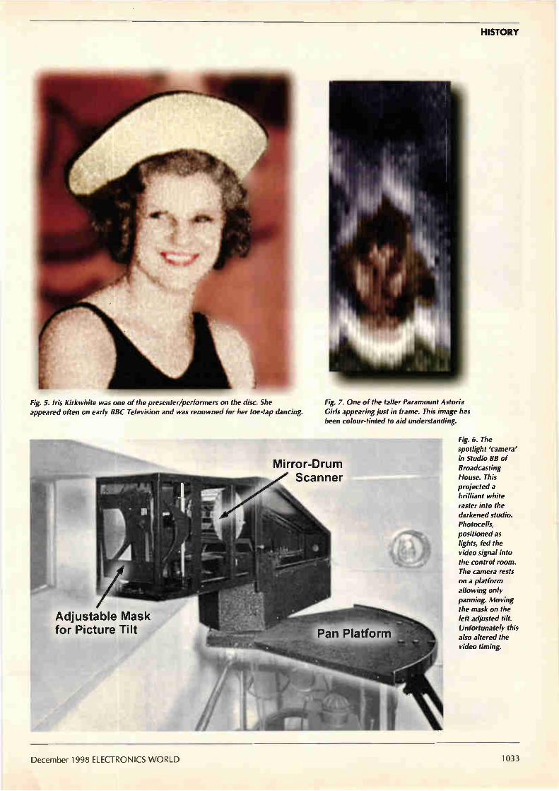
HISTORY
Fig. 5. Iris Kirkwhite was one of the presenter/performers on the disc. She appeared often on early BBC Television and was renowned for her toe-tap dancing.
1 Adjustable Mask for Picture Tilt
Fig. 7. One of the taller Paramount Astoria Girls appearing just in frame. This image has been colour-tinted to aid understanding.
Mirror-Drum Scanner
Fig. 6. The spotlight 'camera' in Studio BB of Broadcasting House. This projected a brilliant white raster into the darkened studio. Photocells, positioned as lights, fed the video signal into the control room. The camera rests on a platform allowing only panning. Moving the mask on the left adjusted tilt. Unfortunately this also altered the video timing.
December 1998 ELECTRONICS WORLD 1033

HISTORY
Fig. 8. A publicity shot of the Paramount Astoria Girls made at the time of the recording. The images off disc do not resolve a chequer-board floor pattern.
Fig. 9. A sequence of the Paramount Astoria Girls from the vision-only disc. The period between the girls' high kicks is 760ms giving a tempo for the music of 79 beats/min.
more importantly recognise, the events in the studio through the limitations of the system. Low-definition television becomes
more effective the more movement there is. From the "Looking In" disc, the producer, Eustace Robb, under-stood very well the limitations of the 30-line system and exploited move-ment to increase its impact. Indeed, the techniques of lighting,
camera work and production were all pioneered on the BBC's 30-line ser-vice. This provided essential experi-ence for the BBC production staff and engineers for the introduction of high definition television in 1936.7
The first age of tv ends Developments and demonstrations in electronically scanned television lead to the BBC's 30-line Television Service being stopped in 1935. The viewing public were keen for trans-missions to continue, even in parallel with a high-resolution service. The service closed however on 11
September 1935. Less than a year later, the BBC started its second Television Service in not one but two new incom-patible high-definition formats with the very latest in technology. In its first few months, the new ser-
vice was far more 'experimental' than its 30-line predecessor.
In summary For now, the amateur video recording of part of a BBC programme has the accolade of being the earliest-known recording of BBC Television or indeed of any broadcast television service. As you might expect, our unknown view-er was selective about making video recordings on his 'write-once' alu-minium discs. Fortunately, he chose for us the
world's first television revue, giving us a marvellous opportunity to share in a historic event. Although he could not have known it at the time, he made the world's oldest time-shifted home video recording in 1933 — not to be seen again for 63 years. The last word will go to a viewer in
London, who, after watching the high-kicking Paramount Astoria Girls in this programme, made this comment on the future of television — "Sound without sight lacks kick".8 My thanks to Dave Mason, Eliot
Levin, Ray Herbert and Nicholas Moss for helping me make this discovery. •
References 1. Television, January 1934, p. 18. 2. Via the BBC Written Archives Centre
at Caversham. 3. Swift J, 'Adventure in Vision',
Lehmann, 1950 p. 58. Incorrect reference to Paramount Victoria Girls.
4. Ross G, 'Television Jubilee', W H Allen, 1961 p. 24.
5. Bridgewater, T H, 1986, private communication.
6. Television, May 1933, pp. 170-171. 7. Bridgewater, T H, 1983 interviewed
by Bruce Norman in `Here's Looking at You', BBC/RTS, 1984 p. 109.
8. Television, May 1933, ibid.
1034 ELECTRONICS WORLD December 1998

INSTRUMENTATION AND TEST
Ultra-fast pulses Emitter-coupled logic offers sub-nanosecond switching times combined with 5012 output capability. Nick Wheeler outlines the benefits of these features in relation to pulse-shaping applications. His simple circuit outputs very fast rise and fall time pulses whose width is easily and accurately determined by a length of coaxial cable.
In its January 1996 issue, Electronics World published a circuit idea of mine entitled 'Fast, precise pulse genera-tor'. What follows is a development of this. By using
some specialised emitter-coupled logic, rather than advanced cmos, I have managed to obtain some very interesting results.
Repetitive pulse theory Mathematical analysis of a series of perfect pulses — i.e. puls-es with zero rise and fall times and flat tops — is simple. It is set out in reference 1. The spectrum is a series of lines separated by the pulse-
repetition frequency F. The amplitude of these lines fluctu-ates similarly to a damped cosine wave, passing through maxima and minima separated by frequencies represented by 1/T, where T is the pulse's duration. I have sketched what one should expect to see on a spectrum analyser at Fig. 1. Emitter-coupled logic, with its sub-nanosecond rise and
fall times, produces results which accord closely with theo-ry. Figure 2, which was extremely difficult to capture, shows a 180MHz segment of the spectrum. The difficulty in cap-turing the segment arises from the interaction between pulse width and repetition frequency. This photo is not perfect but makes the point. It indicates a
pulse width of about 5.5ns. My 100MHz oscilloscope responds to this with very small blips, corresponding with the rising edge of the pulse repetition frequency input. The spectral lines are 11.5MHz apart. The largest-ampli-
tude blip, just right of centre, is a strobe at 310MHz, con-veniently provided by the synthesised source described in reference 3.
Implementing an ecl pulse generator Figure 3 shows the circuit diagram, and Fig. 4 the pcb art-work. The large features at the top of the artwork are the footprints for two SMA sockets (RS 111-712). The ends of the coaxial cable referred to below connect to these sockets. The SY100EL16 differential receiver is manufactured by
F (prf)
I Ili Ii ,1 11 1111 4
T = pulse width
Synergy Semiconductors. It conditions the sinusoidal pulse-repetition frequency input to ecl levels. Output /Q is ground-ed through 56Oû. Output Q goes directly to DI of the SY100EL04 And gate and also directly to DI of the SY100EL07 exclusive-or gate. Output Q also goes to Do of the exclusive-or gate gate via a length of 50S1 coaxial cable. The length of this cable deter-mines the pulse width. In the example described here, it was 95cm long. The traces on the pcb add another 3cm. This amounts to a
delay of about 4.7ns. The velocity factor for solid ptfe dielec-tric is 0.7. There are two transit delays of the order of 250ps in the parts, so it all works according to theory. The Do input to the exclusive-or gate is set at the proper dc
level and termination impedance using the Thévenin method. This calls for 81S2 to Vc, and 130f2 to ground. I used 1001211470i2 and 150S21111d1 standard values for these. This circuit produces a pulse on the positive-going edge of
the prf signal. The And gate prevents another pulse occurring on the negative going transition. The And gate has an inverted Q output, /Q, so a negative
going pulse can be produced if need be.
Finger on the pulse Apart from the fact that the very high speed of ecl produces
Frequency
Fig. 1. Theoretical spectrum of a pulse train with pulse width 1- and pulse-repetition frequency F.
December 1998 ELECTRONICS WORLD 1035

INSTRUMENTATION AND TEST
Fig. 2. Partial spectrum of fast
pulse train with a pulse-repetition
frequency of 11.5MHz and a
pulse duration of around 5.5ns.
Fig. 4. Circuit layout of the pulse generator. Synergy's number is
0121 7338033.
Fig. 3. Fast pulse-shaping circuit using ecl produces pulses with sub-nanosecond rise and fall times at 501.2 impedance. Pulse width is easily and precisely varied by altering the length of co-axial cable between the two points labelled 'Delay line'. The circuit produces a stream of pulses at a prf determined by the frequency of the input to the line receiver. This can be sinusoidal so long as it exceeds 150mV pk-pk. Such a signal is obtainable from most signal generators. The circuit works up in to at least 100MHz. Pulse duration is determined by the transit time down the coaxial cable. An advantage of this circuit is that 50S-2 cable, particularly the semi-rigid kind, is easily cut accurately to length. An XOR gate used this way produces pairs of pulses separated by half the period of the prf. This is usually undesirable and the second pulse is suppressed by the AND gate.
1 n PRF in I
5OR
NC Vc,
DO O ici
Dl
vB,„ VEE
a nice conformity of practice with theory, the main point of this circuit is the convenience with which pulse length can be determined, since this is by transit time down 500 coaxial cable. Moreover, the spectral lines give an easy way of measur-
ing the pulse width to an accuracy of a few percent, by counting the number between minima. This would be diffi-cult even with an oscilloscope with adequate frequency response. Separation between the spectral lines can be accurately set
to any value, to over 100MHz. The circuit is, in effect, a most useful calibrator for spectrum analysis.
If you need to set the pulse width in a stable, permanent, manner, the coaxial link can be made using semi-rigid cable such as RG405. Ordinary general-purpose SMA-terminated laboratory cables of various lengths can be used to determine approximately the right length.
Another, less flexible, approach might be to establish the delay using a convoluted microstripline . A note on how to implement this appears in reference 2.
It occurs to me that the circuit described could form the modulator for a very short range radar, but I leave experi-mentation in that area to you. •
References I. Services textbook of Radio. Vol. 7, HMSO 1960, p. 104. 2. Wheeler, N, 'Microstrip made easy,' Electronics World, Dec. 1997. 3. Wheeler, N. '50-950MHz signal source,' Electronics World,
Oct. 1998.
Vcc +5V
M 00n — DO IC2
ICi SY100 EL16 Line receiver IC2 SY100 EL07 XOR gate IC3 SY100 EL04 AND gate
DI
VCC
VEE
100R
47OR
150R 1k
Delay line (5012)
I termination 'Thevenin'
ooM
DO
DI
IC2
VCC
E
100n
'R (5 places) 56012
100n 1—> Out (50e)
1036 ELECTRONICS WORLD December 1998

1 Surplus always wanted for cash! THE ORIGINAL SURPLUS WONDERLAND!
THIS MONTH'S SELECTION FROM OUR VAST EVER CHANGING STOCKS THE AMAZING TELEBOX
Converts your colour monItOr into a QUALITY COLOUR TM!
TV SOUND & VIDEO TUNER CABLE COMPATIBLE
The TELEBOX is an attractive fully cased mains powered unit, con-taining all electronics ready to plug into a host of video monitors made by makers such as MICROVITEC, ATARI, SANYO, SONY, COMMODORE, PHIUPS, TATUNG, AMSTRAD etc. The composite video output will also plug directly into most video recorders, allowing reception of TV channels not normally receivable on most televi-sion receivers' (TELEBOX MB). Push button controls on the front panel allow reception of 8 fully tuneable 'off air UHF colour television channels. TELEBOX MB covers virtually all television frequencies VHF and UHF including the HYPERBAND as used by most cable TV operators. A composite video output is located on the rear panel for direct connection to most makes of monitor or desktop computer video systems. For compl9te compatibility - even for monitors with-out sound - an integral 4 watt audio amplifier and low level Hi Fi audio output are provided as standard. TELEBOX ST for composite video input type monitors £36.95 TELEBOX STL as ST but fitted with integral speaker £39.50 TELEBOX MB Multiband VHF/UHF/Cable/Hyperband tuner £69.95 For overseas PAL versions state 5.5 or 6 mHz sound specification. 'For cable / hyperband signal reception Telebox MB should be con-nected a cable type service. Shipping on all Teleboxe's, code (B)
State of the art PAL (UK spec) UHF TV tuner module with composite 1V pp video & NICAM hi fi stereo sound
...outputs. Micro electronics all on one small PCB only 73 x x 52 mm enable full software control via a simple 2 wire link
to any IBM type computer. Supplied complete with simple working program and documentation. Requires +12V & + 5V DC to operate.
BRAND NEW - Order as MY00. Only £49.95 coda (B)
FLOPPY DISK DRIVES 21/2" - 14" Massive purchases of standard 51/4" and 31/2 " drives enables us to present prime product at industry beating low prices! All units (unless stated) are BRAND NEW or removed from often brand new equip-ment and are fully tested, aligned and shipped to you with a full 90 day guarantee. Call for over 2000 unlisted drives for spares or repair.
31/2 " Panasonic JU363/4 720K or equivalent RFE £24.95(8 31/2 " Mitsubishi MF355C-L. 1.4 Meg. Laptops only £25.95(B 3W' Mitsubishi MF355C-D, 1.4 Meg. Non laptop £18.97 51/4 " Teac FD-55GFR 1.2 Meg (for IBM pc's) RFE £18.95 B 51/4 ' bac FD-55F-03-U 720K 40/80 (for BBC's etc) RFE £29.95 B 514' BRAND NEW Mitsubishi MF501B 380K £22.95 8 Table top case with integral PSU for HH 51/4" Flopp or HD £29.95 8" Shugart 80W801 8' SS refurbished & tested £210.00 8" Shugart 810 8' SS HH Brand New 8" Shugart 851 8' double sided refurbished & tested 8" Mitsubishi M2894-63 double sided NEW 6" Mitsubishi M2896-63-02U DS slimline NEW Dual 8' cased drives with integral power supply 2 Mb
£195.00 £260.00 £295.00 £295.00 £499.00
HARD DISK DRIVES 2W TOSHIBA.(19 mm H ) MK2101MAN 2.16 Gb. New £199.00 2W" TOSH.(12.5 mm H) MK1002MAV 1.1 Gb laptop. New £115.00 21/2 ' to 3)4" conversion kit for Pc's, complete with connectors £12.95 31/2 ' FUJI FK-309-26 20mb MFM I/F RFE £59.95 31/2 ' CONNER CP3024 20 mb IDE I/F (or equiv.) RFE £59.95 31/2 " CONNER CP3044 40mb IDE VF (or equiv.) RFE £69.00 31/2 ' RODIME R03057S 45mb SCSI VF (Mac & Acorn) £69.00 31/2 QUANTUM 40S Prodrive 42mb SCSI I/F, New RFE £49.00 31/2" WESTERN DIGITAL 850mb IDE I/F New £185.00 5'4' MINISCRIBE 3425 20mb MFM VF (or equiv.) RFE £49.95 5'4' SEAGATE ST-238R 30 mb RLL I/F Refurb £69.95 51/4' CDC 94205-51 40mb HH MFM I/F RFE tested £69.95 51/4 " HP 97548 850 Mb SCSI RFE tested £99.00 54" HP C3010 2 Gbyle SCSI differential RFE tested £195.00 8' NEC 02246 85 Mb SMD interface. New £199.00 t3" FULIFTSU M2322K 160Mb SMD I/F RFE tested £195.00 8' FUJITSU M2392K 2 Gb SMD I/F RFE tested £345.00 Many other drives in stock - Shlipping on all drives is code (D)
ffi.TR-ANSISTORS - DIODES OBSOLETE - SHORT SUPPLY - BULK
6,000,000 items EX STOCK For MAJOR SAVINGS- CALL OR SEE OUR WEBSITE
VIDEO MONITOR SPECIALS
One of the highest specification mt monitors you will ever see - At this price - Don't miss it!!
Mitsubishi FA3415ETKL 1e SVGA Muttlsync colour monitor wifti fine .. 028 dot pitch tube and resolution of 1024 x 768. A
variety of nputs allows connection to a host of ers et' 13M PCs ri CGA, EGA, VGA & SVGA modes, BBC, COMMODORE (inducing Amiga 1200), ARCHIMEDES arid APPLE Many feature& Etched facepLate, text swtcning and LOW kADIAT1ON MPR
specification. Fully guaranteed, supplied in EXCEL-LENT ide used condbon.
Order as & Swivel Base £4.75 Only £119 (E) mrrs-svoa VGA cable for IBM PC included. External cedes for other types of cornputers CALL
As New - Ex Demo 17" 0.28 SVGA Mitsubishi Diamond Pro monitors
Full multisync etc. Full 90 day guarantee. £25.00 (E)
Just In - Microvitec 20" VGA (800 x 600 res.) colour monitors. Good SH condition from £299 - CALL for Info
PHILIPS HCS35 (same style as CM8833) attractively styled 14" colour monitor with keh RGB and standard composite 15.625 Khz video inputs via SCART socket and separate phono jacks. Integral audio power amp and speaker for all audio visual uses. Will connect direct to Amiga and Atarl BBC computers. Ideal for all video monitoring / security applications with direct connection to most colour cameras. High quality with many features such as front concealed flap controls, VCR correction button etc. Good used condition - fully tested - guaranteed ris nrisia Dimensions: W14" x H1214' x 151/2 " D. Limy (E)
PHIUPS HCS31 Ultra compact 9" colour video monitor with stan-dard composite 15.625 Khz video input via SCART socket. Ideal for all monitoring / security applications. High quality, ex-equipment fully tested & guaranteed (possible minor screen bums). In attrac-tive square black plastic case measuring W10" x H10' x 131/2 ' D. 240 V AC mains powered. Only £79.00 (D) KME 10' 15M10009 high definition colour monitors with 0.28' dot pitch. Superb clarity and modern styling.. Operates from any 15.625 khz sync RGB video • source, with RGB analog and composite sync such as Atari, Commodore Amiga. Acorn Archimedes & BBC. Measures only 13W x 12" x 11'. Good used condition. Only £125 (E)
20" 22" and 26" AV SPECIALS Superbly made UK manufacture. PIL all solid state colour monitors, complete with composite video & optional sound input. Attractive teak style case. Perfect for Schools, Shops, Disco, Clubs, stir, EXCELLENT little used condition with full 90 day guarantee.
20"....£135 22"....£155 26"....£185 (F)
DC POWER SUPPLIES Virtually every type of power supply you can Imagine. Over
10,000 Power Supplies Ex Stock Call or see our web site.
LOW COST PC's Always over 1000 PC's from stock. 1000's of spares and accessories. Call or see our web site for info.
TEST EQUIPMENT & SPECIAL INTEREST ITEMS tars. FA3445ETKL 14" Industrial spec SVGA monitors £245 1MN to 400 kW - 400 Hz 3 phase power sources - ex stock £P0A IBM 6230 Type 1, Token ring base unit driver £760 Wayne Kerr RA200 Audio frequency response analyser £2500 IBM 53F5501 Token Ring ICS 20 port lobe modules £750 IBM MAU Token ring distribution panel 8228-23-5050N £95 AIM 501 Low distortion Oscillator 9Hz to 330Khz, IEEE £550 ALLGON 8360.11805-1880 MHz hybrid power combiners £250 Trend OSA 274 Data Analyser with G703(2M) 64 Vo EPOA Marconi 6310 Programmable 2 to 22 GHz sweep generator £6500 Marconi 2022C 10KHz-1GHz RF signal generator £1550 Marconi 2030 opt 03 10KHz-1.3 GHz signal generator,New £5150 HP1650B Logic Analyser £3750 HP3781A Pattern generator & HP3782A Error Detector £P0A HP6621A Dual Programmable GPIB PSU 0-7 V 160 watts £1800 HP6264 Rack mount variable 0-20V 0 20A metered PSU £675 HP54121A DC to 22 GHz four channel test set £P0A HP8130A opt 020 300 MHz pulse generator, GPIB etc £8500 HP Al. AO 8 pen HPGL high speed drum plotters - from £950 EG+G Brookdeal 95035C Precision lock in amp £650 View Eng. Mod 1200 computerised inspection system Sony DXC-3000A High quality CCD colour TV camera Keithley 590 CV capacitor / voltage analyser Racal ICR40 dual 40 channel voice recorder system Fiskers 45KVA 3 ph On Line UPS - New batteries ICI R5030UV34 Cleanline ultrasonic cleaning system Mann Tally MT645 High speed line printer Intel SBC 486/133SE Multibus 486 system. 8Mb Ram Siemens K4400 64Kb to 140Mb demux analyser
Intel SBC 486/125C08 Enhanced Muitibus (MSA) NEW £1450 Zeta 3220-05 AO 4 pen HPGL fast drum plotters £1150 Nikon HFX-11 (Ephiphot) exposure control unit £1450 Motorola VME Bus Boards & Components List. SAE / CALL £P0A Trio 0-18 vdc linear, metered 30 amp bench PSU. New £550 Fujitsu M3041R KO LPM band printer £1950 Fujitsu M3041D 600 LPM printer with network interface £1250 Perkin Elmer 299B Infrared spectrophotometer A £500 Perkin Elmer 597 Infrared spectrophotometer £3500 VG Electronics 1035 TELETEXT Decoding Margin Meter £3750 LightBand 60 output high spec 2u rack mount Video VDA's £495 Sekonic SD 150H 18 channel digital Hybrid chart recorder £1995 Taylor Hobson Tallysurf amplifier / recorder £750 ADC SB200 Carbon dioxide gas detector / monitor £1450 System Video 1152 PAL waveform monitor £485 ANRITSU 9654A Optical DC-2.50/b waveform monitor £5,650 ANRITSU MS9001B1 0.6-1.7 uM optical spectrum analyser £P0A ANRITSU ML93A optical power meter £990 ANRITSU Fibre optic chracateristic test set EPOA VISION ENGINEERING TS3 Dynascopic microscope £1850
£P0A R&S FTDZ Dual sound unit £650 £1100 R&S SBUF-E1 Vision modulator £775 £P0A WILTRON 6630B 12.4 /20GHz RF sweep generator £5750 £3750 TEK 2445 150 MHz 4 trace oscilloscope £1250 £9500 TEK 2465 300 Mhz 300 MHz oscilloscope rack mount £1955 £P0A TEK 1502 Portable TDR (time domain reflectometer) £600 £2200 PHIUPS PW1730/10 65KV XRAY generator & accessories £P0A £945 CLAUDE LYONS 12A 240V single phase auto, volt. regs £325 £2950 CLAUDE LYONS 100A 240/415V 3 phase auto, volt. regs £2900
II Surplus always wanted for cash!
19" RACK CABINETS Superb quality 6 foot 40U
Virtually New, Ultra Smart Less than Half Price!
Top quality 19' rack cabinets made in UK by Optima Enclosures Ltd. Units feature designer, smoked acrylic lockable front door, full height lockable half louvered back door and louvered removable side panels. Fully adjustable internal fixing struts, ready punched for any configuration of equipment mounting plus ready mounted integral 12 way 13 amp socket switched mains distribution strip make these racks some of the most versatile we
have ever sold. Racks may be stacked side by side and therefore require only two side panels to stand singly or in multiple bays. Overall dimensions are: 771/2 ' H x 321/2 " D x 22' W. Order as: OPT Rack 1 Complete with removable side panels. £345.00 (G) OPT Rack 2 Rack Less side .anels £245.00 G
Over 1000 racks, shelves, accessories
19" 22" & 24" wide 3 to 46 U high. Available from stock !!.
32U - High Quality - All steel RakCab Made by Eurocraft Enclosures Ltd to the highest possible spec, rack features all steel construction with removable side, front and back doors. Front and back doors are hinged for easy access and all are lockable with five secure 5 lever barrel locks. The front door is constructed of double walled steel with a 'designer style' smoked acrylic front panel to enable status indicators to be seen through the panel, yet remain unobtrusive. Internally the rack features fully slotted reinforced vertical fixing members to take the heaviest of 19" rack equipment. The two movable vertical fixing struts (extras available) are pre punched for standard 'cage nuts'. A mains distribution panel internal-ly mounted to the bottom rear, provides 8 x IEC 3 pin Euro sockets and 1 x 13 amp 3 pin switched utility socket. Overall ventilation is provided by fully louvered back door and double skinned top section with top and side louvres. The top panel may be removed for fitting of Integral fans to the sub plate etc. Other features include: fitted castors and floor levelers, prepunched utility panel at lower rear for cable / connector access etc. Supplied in excellent, slightly used condition with keys. Colour Royal blue. External dimensions mm-.1625H x 6350 x 603 W. ( 64" H x 25" D x 233/4" W )
Sold at LESS than a third of makers price tl
A superb buy at only £245.00 (G) 42U version of the above only £345 - CALL
BATTERY SCOOP - 50% off!! A special bulk purchase from a cancelled export order brings you the most amazing savings on these ultra high spec 12v DC 14 Ah rechargeable batteries. Made by Hawker Energy Ltd, type SBS15 featuring pure lead plates which offer a far superior shelf & guaran-teed 15 year service life. Fully BT & BS6290 approved. Supplied BRAND NEW and boxed. Dimensions 200 wide, 137 high, 77 deep. M6 bolt terminals. Fully guaranteed. Current makers price over £70
each Our Price £35 each (C) or 4 for £99 (D) RELAYS - 200,000 FROM STOCK
Save ££££'s by choosing your next relay from our Massive stocks covering types such as - Military, Octal, Cradle, Hermetically Sealed, Contactors, Time Delay, Reed, Mercury Wetted, Solid State, Printed Circuit Mounting, CALL US WITH YOUR NEEDS. Many obsolete types from stock. Save f.E.F.Ea
LOW COST RAM & CPU'S INTEL 'ABOVE' Memory Expansion Board. Full length PC-XT and PC-AT compatible card with 2 Mbytes of memory on board. Card is fully selectable for Expanded or Extended (286 processor and above) memory. Full data and driver disks supplied. RFE. Fully, tested and guaranteed. Windows compatible. £59.95 Half length 8 bit memory upgrade cards for PC AT XT expands memory either 256k or 512k in 64k steps. May also be used to fill in RAM above 640k DOS limit. Complete with data. Order as: XT RAM UG. 256k. £34.95 or 512k £39.95
SIMM SPECIALS 1 MB x 9 SIMM 9 chip 12Ons Only £8.50 1 MB x 9 SIMM 3 chip 80 ns £10.50 or 7Ons £11.95 1 MB x 9 SIMM 9 chip 80 ns £10.50 or 7Ons £11.75 4 MB 70 na 72 pin SIMM -with parity- Only £35.00 INTEL 486-DX33 CPU £19.95 INTEL 486-DX66 CPU £59.00 RJLL RANGE OF CO-PROCESSOR'S EX STOCK CALL FOR OM MOTOROLA 25 Mhz 68040 (XC6804ORC25M) CPU'S £59.00
shipping charges for RAM / CPU upgrades is code B
SOFTWARE SPECIALS NT4 WorkStation, complete with service pack 3 and licence - OEM packaged.
Special Price ONLY £99.00 Microsoft - Windows for Workgroups 3.11 & DOS 6.22. Supplied on 31/2 ' disks with licence & concise documentation. £39.95 DOS 5.0 on 31/2 ' disks with concise books c/w OBasic. £14.95 Wordperfect 6 for DOS supplied on 31/2 ' disks with manual £24.95
shipping charges for software is code B
DISTEL on the web II - Over 16,000,000 Items from stock - www.distel.co.uk • ••
•••
••• • • • •••
• • • ••
•••
•••• • • • • ••• • • • • • •
• •
_ci criorisvirc LLLL L11
ALL MAIL & OFFICES Open Mon - Fri 9.00 - 5:30
Dept WW, 32 Biggin Way
Upper Norwood
LONDON SE19 3XF
Open Mon - Sat 9:00 - 5:30 215 Whitehorse Lane
South Norwood On SBA But Route Pi Thornton Heath
S•thurat Park SR Rail Stations •
ILONDON SHOP P r:SI
Visit our web site
wvvw.distel.co.uk email adminedistel.co.uk
DISTELO ALL "Fr ENQUIRIES
0181 679 4414 FAX 0181 679 1927
AI prices for UK Mainland. UK customers add 17.5% VAT to TOTAL order amount Milinum cfcler £10. Bona Fde account orders accepted from Government, Schords. Universities and Local Authalies - mirmum account order £50. Cheques oser are subject to 10 • days dearance. Caniage (AK3.CO, (A1)=£4.CO, (B£5.50, (C 50, (D)=£12.0D, (E).£15.00, (F)L1&00, (G)=CALL Allow aporox 6 days id steing - faster Al goods supplied to our rd Conditions of Sale and unles.s stated guaranteed for 90 days. Al guarantees di a return to base be.sis Ai rights reserved to change prices / specifications without pinot notice. Orders sided to stook Discounts for volume. Top CASH potes paid for surplus goods. AN trademarks, tradenames etc ado:me/edged. Disday Electronics 1998. E & 0E. C6098
›ea' 161116Z11 =
EST
1f5
CIRCLE NO, 132 ON REPL1 CARD

COMPONENTS
Notes on ecl Emitter-coupled logic is inherently very fast and low noise, yet often avoided as it needs a -5.2V supply. But as Nick Wheeler shows here, ecl has moved forward. Nick presents a frequency-doubler design example that runs from a simple 5V rail.
Fig. 1. Basic, traditional ecl gate. Emitter
coupled logic is sometimes called
current-mode logic. It is fast
because, unlike ttl, there's no
transistor storage time involved.
I. his short article is intended to encourage those of you who regard c-mos as the zenith of logic to consider the remarkable features of modern emitter-coupled
logic. To illustrate the article, I will use Synergy's SY100EL16V
differential line receiver. Once you understand this part, you will be able to apply all the basic logic building bricks, and more complex parts such as the SY89430V programmable synthesiser.'
Emitter-coupled logic characteristics The basic circuit element of ecl is a long-tailed-pair com-prising conventional bipolar transistors, Fig. 1. The tail is a constant-current source. As a result, the transistors are never driven far into saturation. It is this fact that gives ecl its out-standingly high speed. Many designers are put off by the apparently odd logic
voltage levels of ecl parts, even though they have usable clock rates of hundreds of megahertz, which is undoubted-ly attractive. The long-tailed-pair configuration calls for voltage excur-
Vcc (GND)
680p
SY100EL16V
01p
sions referenced to the supply voltage Vcc. In the early days of ecl, and because of the small excursions involved, the standard was adopted of grounding the positive Vcc rail and holding VEE at a nominal —5V. This results in a logic-high voltage of about —900mV and a logic Low of about —1680mV. The outputs of most ecl parts are differential and can drive
50C2 transmission lines. These must be properly terminated if more than a few centimetres long. Correct dc conditions are achieved by returning the cold ends of the terminating resistors to —2V dc, a rail normally called Vu. Under such conditions successive stages can be dc coupled. Provided the VC rail is noise free and reasonably well
regulated, a conventional +5V rail can be used, with VEE grounded. This is termed pecl, or positive ecl, and is becom-ing increasingly common. Special translator parts are available which interface
between ecl and ttl and vice versa. Operation in the pecl mode is mandatory for this. Some ecl parts, including the SY100ELI6V, are provided
with a pin termed VEE. This provides a bias voltage to
+5V
M0.1p
'A'
560R
270p
270p
1100R
560R
>I
+5V
220R Diode RS 262-466
Double frequency
2k2 o/p
Diodes BAT64 'A' (RS 287-220)
Fig. 2. Frequency doubler made from emitter-coupled logic. This configuration works between 10MHz and at least 250MHz. Input amplitude must be 150mV or more. Output is a good square wave at twice the input frequency.
2211 0.1µ
Forward bias
1038 ELECTRONICS WORLD Decemper 1998

COMPONENTS
which the inputs can be referenced for ac coupling or single ended operation.
Using the SY100EL 16V ecl receiver The SY100EL16V comprises two cascaded long-tailed pairs followed by dual emitter followers with open emitters. These followers need to be returned to a suitable negative voltage. More on this later. My demonstration circuit diagram is shown in Fig. 2
while Fig. 3 illustrates conventional operation at 60MHz. The lower trace in Fig. 3 shows what a good 60MHz square wave looks like on a 100MHz oscilloscope. A small response at the third harmonic causes the peaki-
ness of the waveform. On a spectrum analyser strong har-monics are detectable up to the 13th. Output amplitude is virtually independent of the sinusoidal
input provided the latter exceeds the specified minimum swing of 150mV. Presence of these high-order harmonics confirms that sub-nanosecond rise and fall times are being achieved. The circuit diagram illustrates how ecl is driven in ac-cou-
pled, single-ended mode. At the frequencies for which ecl is useful, this will usually be via a 50Q transmission line. This is terminated properly by RI. The dc conditions at the two inputs are set by using VBB.
For ecl parts with 100 in their part number, this lies in the range of Vcc-1.38 to licc-1.26 and is thermally compen-sated. One of the inputs, /D, and VBB are grounded for ac as shown. There are three possible ways of setting the correct dc
conditions at Q and /Q. They are fully discussed in reference 2, but are summarised here for completeness. Where the distance to the next stage is less than 2cm or so, a matched transmission line is unnecessary. A suitable resis-tor from each open emitter to VEE is all that is needed to per-mit emitter-follower action. A value of 510Q is often quoted, but anything over this and up to 1k2 works. I used 560Q. As I already mentioned, another method, the use of a ter-
minating voltage, VIT, is most easily implemented, when Vcc is 5V. The 5V rail can be used to feed a low-dropout 3V reg-ulator such as the LP3982-3.0 (RS 285-4124). Output swing of ecl parts is usually specified for a 50Q termination at the Q and /Q outputs. The other end of the termination is returned to Vcc-2V. This sets the emitters at the right voltage, i.e. Vu. Finally there is the Thévenin termination. In a 50Q sys-
tem, at the receiving end, an 81Q resistor goes to licc and a 130Q resistor to Van. In parallel, which these effectively are for signals, they look like 50Q and at the same time set the correct dc level.
Other uses for the SY100EL16V Most logic families are characterised by specifying a max-imum voltage which is recognised as a logic zero or low input and a minimum which is recognised as high or logic one. Between these thresholds is a region of uncertainty. Small input excursions around the middle of this uncertain
region are, in some cases, linearly reproduced at the output. This is the basis of such circuits as crystal oscillators, which are readily be realised with cmos. I decided to test the EL16 using the circuit of Fig. 1 with an input well below the spec-ified minimum of 150mV. A particular attraction of ecl parts with a VBB output is that
using this automatically biasses the inputs correctly for this linear mode of operation. I used of 17.5mV pk-pk. At 60MHz the Q and /Q outputs were a pair of good
sinewaves in antiphase. The voltage gain was 37.5, which,
1\/\,/\\/\ Ne
f\ A A (\ J v \IVV\
A* 10 na
allowing for measurement errors, agrees well with the spec-ified dc gain of 40 for this part. Since the transistors within the device have frequency
responses of the order of a gigahertz, the part can clearly be used as a vhf/uhf phase splitter. There are several applica-tions for such a circuit since it is aperiodic, e.g. as a constant amplitude phase shifter.3 Aperiodic frequency doublers all depend, basically, on
full-wave rectification. They can be passive, using careful-ly constructed trifilar transformers, but use of the EL16 pro-vides a compact alternative. Figure 4 illustrates this at 60MHz input. At such fre-
quencies the smallest differences in stray capacitance pro-duce the effect shown. The circuit works quite well over a 2:1 frequency range, but the time constants need to be opti-mised for best results. Both Q and IQ excursions are about 750mV. These are
capacitively coupled to the two Schottky diodes, which have a forward voltage of about 300mV. I biassed these forward by 180mV. Voltages of this order can be obtained using the forward
voltage of a Schotdcy power rectifier diode. These parts are specially made to keep this figure well below that of the 600mV associated with ordinary diodes.
References 1. Wheeler, N, '50-950MHz frequency source',
Electronics World, Oct. 98. 2. MECL System Design Handbook, Motorola. 3. The Art of Electronics written by Horowitz and Hill,
pub. CUP. (Constant amplitude phase shifter, p. 78.)
Fig. 3.The lower
trace shows what
a good 60MHz square wave looks like on a 100MHz oscilloscope. A
small response at
the third
harmonic causes
the peakiness of
the waveform.
The upper trace is
a good sinewave at 60MHz and 150mV pk-pk.
Fig. 4. Frequency
doubler output
with input at 60MHz, illustrating the
effects of
differences in
stray capacitance.
Technical support For information on
availability of the SY100EL16, contact Nic Houslip via nic_houslip@compu
serve.com or fax him on 0121 7337772. Prototyping boards for the pulse
generator may also be available.
Synergy's number is 0121 7338033.
December 1998 ELECTRONICS WORLD 1039
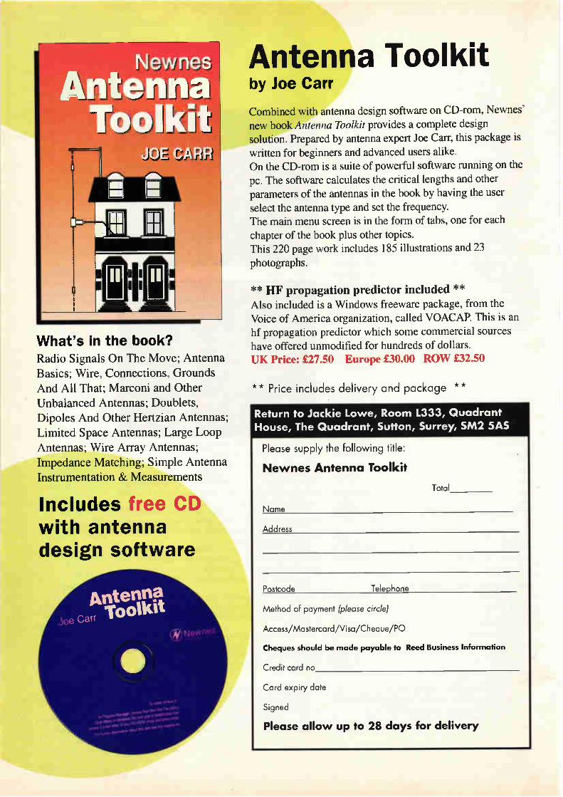
â.L. II
What's in the book? Radio Signals On The Move; Antenna
Basics; Wire, Connections, Grounds
And All That; Marconi and Other
Unbalanced Antennas; Doublets,
Dipoles And Other Hertzian Antennas;
Limited Space Antennas; Large Loop
Antennas; Wire Array Antennas;
Impedance Matching; Simple Antenna
Instrumentation & Measurements
Includes free CD with antenna design software
Antenna Toolkit by Joe Carr
Combined with antenna design software on CD-rom, Newnes'
new book Antenna Toolkit provides a complete design solution. Prepared by antenna expert Joe Carr, this package is written for beginners and advanced users alike. On the CD-rom is a suite of powerful software running on the pc. The software calculates the critical lengths and other
parameters of the antennas in the book by having the user
select the antenna type and set the frequency. The main menu screen is in the form of tabs, one for each
chapter of the book plus other topics.
This 220 page work includes 185 illustrations and 23 photographs.
** HF propagation predictor included ** Also included is a Windows freeware package, from the Voice of America organization, called VOACAP. This is an hf propagation predictor which some commercial sources
have offered unmodified for hundreds of dollars. UK Price: £27.50 Europe £30.00 ROW £32.50
** Price includes delivery and package ,1/4.,
Return to Jackie Lowe, Room 1333, Quadrant House, The Quadrant, Sutton, Surrey, SM2 SAS
Please supply the following title:
Newnes Antenna Toolkit
Total
Name
Address
Postcode Telephone
Method of payment (please circle)
Access/Mastercard/Visa/Cheque/PO
Cheques should be mode payable to Reed Business Information
Credit card no
Card expiry date
Signed
Please allow up to 28 days for delivery

M&B RADIO (LEEDS) THE NORTH'S LEADING USEDTEST EQUIPMENT DEALER
OSCILLOSCOPES HP 541010 IX MOI 2 i27 HP 1740A 103 M.2 channel HP I715A MHe 2 channel TEKTRONIX 7903/7A26 a2/71180 200 M. 4 channel TEKTRONIX 1603/7A1111A a2/71153A 4 clunnel TEKTRONIX 7A26 200 MHz 1 channel um More, new • man.111 TEKTRONIX 1445A I SO MHz 4 Manne TEKTRONIX 2445 150 MHz 4 channel GP-1/1 TEKTRONIX 2246A 101 MHz 4 channel pomal TEKTRONIX 1145 100 MHz 4 Hume INEW1 TEKTRONIX 2235 100 MHz 2 channel TEKTRONIX 2130 102 MHz 2 channe theval storage TEKTRONIX 2225 SO M. 2 cNnnel TEKTRONIX 2220 60 MHz channel 4,01 storage TEKTRONIX 2115 60 MHz 2 <Nnnel TEKTRONIX T11504 4 alot nvonlrarne TEKTRONIX 475A 250 MHz 2 channel TEKTRONIX 475 200 MHz 2 channel TEKTRONIX 444 100 MHz 2 channel doer, storage TEKTRONIX 468 120 MH2 lt hannN TEKTRONIX 44511 101 MHz I d0nneI opt OS TEKTRONIX 445 100 MHz 2 channel PHILIPS PM 1310 60 MHz Net, storage PHILIPS PM 3261X 100 1.1H delay eyents PHILIPS PM 3217 SO MHz 2 -hannel PHILIPS PM 3057 SO M. Ichannel PHILIPS PM 3055,50 MH2 I channel IWATSU SS 5710 60 MHz 4,?,,,.? NICOLET 4094/4562/F4I MITACHIV1100 112C MI, 4,nannei GOULD 4035 20 MHz rhgeal storage • emote keypad GOULD 0S4000 10 MHz Neu? storage 2 channel GOULD 1401 20 MHz dognal storage 2 channel GOULD 1421 20 MHz Ng.? storage 2 channel GOULD 0S300 20 MHz 2 channel GOULD OS1100A 30 MHe 2 channel DrL tonehase GOULD 0S15013 5 MHz 2 channel
iSEEVIIII/FIACIALESCAll TEKTRONIX 496P 10 01-0-11101 MIR TEKTRONIX 494P (0 014,21 GHz (I year CO & warranty TEKTRONIX 4935. 10 KHz-21 GHz OPT 0011002/003 TAKEDA RIKENTR4I72 400 0,1000 MHa spectrurninetwon ana/ner HP 16501 90 channel 100 MHz logn analyser Mew) HP 16531 80 channN 100 MHz • 1 channel 100 MHz 400MSes d'ennong ccom HP CALAN 30100 Hemp/egrets artalper HP 11903A aueo ana&ser HP 8590A 10 MF12.1 5 GHt spectrurn analyser HP 855911182T 10 MHz-2I GFle HP 8551111 IGO SOO ana/yser • rnzonlrame HP 8557A 100 10-0-3S0 MHz analyser • ntennande HP 84070J1141211 network analyser 0 1.110 MHz MP 3582A 0 02 1-1,35 5 KHt dual channel ugnal analyser HP 141T/85528/11555A 10 MI-1,18 GHz HP 141T/0552D/8554B 100 010-1250 MHz HP I 40T11155211855311 10 KHz-110 MIN MARCONI 2380/2382 ICO I-1,400 MHz MARCONI TF2370 30 Hz-110 MHz clognal storage
USUAL ISESIIIIIATORZ HP 8904/1 DC-600 KO, moholuncuon synthemer HP 86830 13 GHell GHz OFT 001001 solid state generator las new: HP 8656A 100 KHz-N10 MIN myna? generator HP 8640A 20 I-1,513 MHz ognal generator HP 8620C/861420 5 9.9 GHt sweeper HP 8630C/8624IA 32-6 5 GHz sweeper HP 8610C/862388 I 8 010-4 2 GIS, sweeper HP 8620C186120A 10,300 MHI sweeper HP 8620C weeper Nonnarnes las ne. HP 9001E 0 .ea 10 ISH: pone generator HP 13361 10 Hz 11 MHz synth...? rneter HP 3320A frequency synthenter 0 I H,13 MHz HP 33144 0 001 Ha.I9 99 MHz luntomsrenvelorm rnOnnOr
(1.500 (350 (400 (450 (350 (125
01,000 (1100 L1000
(600 (1100
(1,100 (325 (ISO (600
frond MO (600 1350 (500
Irons (350 (500 (400 (325 (400 (400 1400 (S00 (750 (600 (190
(400 (195 (160 (130
HP 320011 1011,1,500 M. oHoleator ADRET 74IA 10010-1.-2 4 Gele Om Or TOURIST TG230 2 MHz sweep 'unman gene., TEKTRONIX 3901 tone rnah generator MARCONI TF312122 10 KHz-1000 MHz 0.9042 ,enerator MARCONI 2019 80 KHel MARCONI TF2010 [10100-520 MHz stzna1 generator MARCONI TF2016 10100120 MHz 1200) 1110160 MARCONI TF2015/1171 10 Mele-520 MHz en. smchromie: MARCONI TF2015 10 MHz.S20 MHz FARNELL 550520 10 tielz-520 MHz synths... FLUKE 601IA 101-11-11 MHz Hoehn's. tognal generator RHODES • SCHWARTZ APN62 O I Fla.160 KHz Li gen Mew' GIGA GR110IA 12 01-1.-111 G. pulse generator PHILIPS PPI5190 I Mliel MO, LP syntraswer Ineen WAVETEK 193 20 MHz meep madulabon generate' WAVETEK 182 0002 611-2 RIM honome moentor SAYROSA MA 30 10 10-100 KO,
TEST ECUIPRIENT ANRITSU 31S45A 2 GHz errar detente ANR1TSU MSO9C I voweband mentor lbore, new.. +nth manual, AYO 2151/2 AC DC breakdown rannatran tester AVO CT160 lane msg.? • ego BALL EFRATROM MRT-H rotelturn frequency standard BIRD 8922 SCOOW 50 OHM coacal resistor BIRD 8329 300. 30dB attenuate. BIRD 8323 100W 30d1 menuator BRADLEY 192 osenostope rakbrator BRUEL S 1(JAER 2515 nbracon analyser,A5 NEW, BRUEL SKJAER 1023 vre generator BRUEL & KJAER 2636 meastrang amp.. BRUEL & KJAER 2971 phase meter DATRON 1065 autoral dval macrame, E1P 548A 10 H: 26 5 GHz racrowave counter SIP 331 12 5 G111 autohet mwroware counter FARNELL PDA3501A nu/power supply 0-05.0 arn FARNELL RBI030/35 electronw load
(1000 FARNELL SCG50 synthesned (look generator (13,000 FARNELL TSV70 power suppAr 0-70, 0-1 0 amp (5,500 FARNELL LT30-1 2. 0-10, 2 amp (7000 FARNELL LT305 0 X/r 5 amp (1100 FARNELL 101011 0-100, I amp (1.750 FLUKE 8505A chg., multernmer (1,750 FLUKE 8506.11Mennal ISMS rm.:meter (1,500 FLUKE 5440B <Inert .Mts calnrator L4,000 FLUKE 5205A prerann power amp (3000 FLUKE 5200A AC calrarator (1,250 FLUKE 333011 zurrendra1m1Ie z (ISO HP 59403A HP.173.1common <cram nterace (400 HP 5940IA bus system analyser
(1000 HP 11710A down ronverter (1.500 HP 116651 1 SO MOI,-IR GHz modulator (I 000 14P I I582A attenuator set OC.18 GHt (450 HP 8970A none Sgure meter
(1750 HP 8750A storage nozznahmr (450 HP 8508A rector voltmeter
HP 11477A RF power meter cahbrator HP 6440A DC power suPPly 0-M3070- 1 5 ans0
(1800 HP 6191A DC power supply 0-40y/O-5 amp (2.500 HP 6263A DC power supply 0.20,0-10 amp 01.750 HP 5345A 1 5 MH2-16 5 GM rountec5355.5156A•13 sensors (400 HP 5342A 500 MHz-18 GHz mwrraware Irequeny meter
01,000 HP 5335Aunwersal systems crane? 'ugh ttalhlety OPT (900 14P 5334A unwersal syttems counter (900 HP 5180A werelorm re,order (600 HP 5087A drandmon ampiner mew, (250 HP 5004A s,gneure analyser (ISO HP 50010 cgnature rhultratte, LOIS HP 4954A protocol analy,e. • HP 181350 po, (400 HP 37701 telephone Ine analyser 4400 HP 376IA error detector
L1.250 HP 3754A select. Irael meter
ALL PRICES PLUS VAT AND CARRIAGE • ALL EQUIPMENT SUPPLIED WITH 30 DAYS WARRANTY
L950 (ISO MOO [ISO
L4.000 1.000 (SOO (MO (SOO
(1,000 (1,150
i500 0400
(3,000 (350 (17S (400 (100 (ISO 1 RS
LI 45 (100 L750
01,000 (4.950 (2.750 02,000 (450 0125 [19S
1140 L3S0
L500 (3,500 L300
(2.150 (335 050 6 185 0150
(3.000 Iron, MOO
MOO L500 (750 LSOO (200
(2.000 (SOO (200 (100
86 Bishopsgate Street, Leeds LS I 4BB Tel: (01 I 3) 2435649 Fax: (0 I I 3) 2426881
(400 HP 351160 Fi, HP 358IA 15 Hz 50 KH, sMettwe v.rnmers as new HP 34611A 5 5 Net mulometernuto cal il.001 H• 3466A 4 5 dogd autorangng multanmer HP 3455A 65 de, bench rcultmeter HP 0437*?? new me speed system volt:mete HP 1645 dada error anaheser HP 436A RI power meters POP 43511/84111A/84114A/11708A 10 MO, 18 GHz Ine IP casemanualc HP 435A/8482AH 100 K., 4 2 GH1 lItr prayer meter HP 400 E 10 Hz 10 MHz AC ...meter HP 113A chstort.on analyser HP R1132 terns R controrar KEMO DPI I Hz I CO K. phase meter Men, LINIPLEX F1-2 HI renewer MARCONI 6593A VSWR nraator MARCONI TF295511 RI ...cos.:awns rest set MARCONI TF2871 ClItà CO•rirriunK.Onlmonnor MARCONI TF2610 true RMS voltmeter MARCONI TF1306 programmable Interlace smut MARCONI TF2305 mod meter 50 KHz 2 3 GHz MARCON1TF893 B autho power ,,eter NARDA 30441 10 3 7 GH, 8 3 GH2 10ella chrecuonal roc., 1nen NARDA 300010 410 GSM I Oa nrecuonal coupler RACAL RAI772 30 MH/ recenrers RACAL RA17U 30 MHz valve recewers RACAL DANA 9921 101, MOO MHz frequency coume, RACAL DANA 9919 10 1-1, 1 100 MHz hessuency counter RACAL DANA 9916 10 Hz 520 MHz frepumscr ,C....,e? RACAL DANA 9915 10 Hz 520 MHz frequency counter RACAL DANA 9914 10 11, 200 711-1z frequency counter RACAL DANA 9908 10 Hz 1100 MHz tower., counter nner RACAL DANA 990414 50 Mnz unwenal counter crner RACAL DANA 930IA true RMS RF enahrOlteneger RACAL DANA 930M true RMS RF rnray.rneter 10 K. to I 5 Glsz RACAL DANA 40041 0M? -.crater Ines. RACAL DANA 9300 EM? voltmeter RACAL 9343M SCR databcdge RACAL 9008 1 5 MHz 20O) MHz autornara re...non meter RACAL DANA 1992 10 Hz 1300 MHz nanosecond counter RACAL DANA 1991 10 Fir 160 111-ra un ...roomer tamer 9 Mgn RACAL DANA 6000 rowroprocesung Mgral raluneter RF MICROSYSTEMS INC AI.TRC 176VHF/UHF filters ROOflESS SCHWARTZ GA012 FSK analyser RHODES S SCHWARTZ URE 10 Hz 20 MHz RMS voltmeter RYCOM 6040 select. level meter SAMOS...191 1 5 MHz 2 GIS: automata modulatron meters SCHLUMBERGER 7702 ragnal transrassran analyser Inewl SIEMENS 01108 200 KHz 30 MHz level meter SIEMENS W2108 MO KHz 30 MHz level osnllator TEKTRONIX A6902A mole°, TEKTRONIX 1141 /SPGII/TSGI I pal ndeo generator TEKTRONIX 52IA vector vc0e, TEKTRONIX 145 8,B gen Ipelt test ognal generator TFIURLBY 1503 I 3 GHz frequency counter WAVETEK 1018A log Ion RE prak pone, meter DC 26 GO, WAYNE KERR ̂ mess auto modulatson meter WALLISTIO0 1120 K. onsulmon tester WAG DLAS eau i.ne anat,e, W • G DLM3 data hose test set W 82G 511119 50 1-1,25 MHz level measunng set
(1.500 L500 (400 1200 (495 (200 (195 L650
(1,000 (500 (95
(295 (1,000 0100 (195 L250
(4.000
(600
(MOO (ISO LISO (100 1650 (I 50 Ll SO (29S (150 (95 (85
(400 LIS MOO MIS L250
(395 (300 (MS (295 42S0 4400 (300 4400 (150 (175 L500 (350 (350
(1500 (300
(1.500 L145
(1000 (450
(1000 (P0A (P0A
SPECIAL OFFERS AVO S MI.5 testmeter probes BIRD 43 wammeters FLUKE 25 Ice spec ragrtal rralorneters rath manual 8, prunes Ias new? MARCONI TF1311 1,9tal synehronden :for MARCONI 1015, RACAL RA 17L 10 010, '4140 10!
(75 (95
(75 LISO
Visit our Web site
http://www.mb-radio.co.uk
e-mail infoemb-radio.co.uk
CIRCLE NO.133 ON REPLY CARD
`taeoa Enerrnan
SpicycleTM
eth Vet>
The World is getting onto Spicycles! Jump onto the future today — tomorrow's electronic engineering CAD from the UK's leading simulation author.
• Schematic editing — publication quality images
• Analogue + mixed mode digital simulation with extended SPICE-like functions
• Upgrade path to extensive range of drawing tools each with high definition visuals
• TrueType fonts
• Back annotation of components from simulator
• Simulate directly from your drawings for the ultimate in design checking
• Import & reverse engineer SPICE net lists
• Library includes electronic + mechanical engineering behavioural devices
• Upgrade path from Geswin (existing customers)
• 12 months maintenance included (limited introductory offer)
Please contact Charles Clarke at Those Engineers Ltd, 31 Birkbeck Road, LONDON NW7 4BP. Tel +44 (0) 181 906 0155 Fax +44 (0) 181 906 0960 e-mail [email protected] web http://www.spiceage.com
CIRCLE NO.134 ON REPLY CARD
December 1998 ELECTRONICS WORLD 1041

ADVERTISERAMMAJION: 0181 652 3639 OR E-MAIL: [email protected]
CONNECT WITH THE UKS
NO. 1 READ FOR ELE.CTRONICS
PROFESSIONALS 01\VME
INTERNET Electronics Weekly HyperACTIVE is more than just a magazine on the Web. Check out the site and you'll see why thousands t f electronics professionals around the world regularly log on to www.electronicsweekly.co.uk/
For News HyperACTIVE's Daily News Service brings you the latest news in the industry - as it breaks. For Jobs HyperACTIVE has the largest and most varied collection of jobs available in the electronics market. Now we bring you the improved Jobs and Careers service with a whole range of new and exciting features. All this plus, the latest technology, market information, toolkit's, a searchable archive, and loads more....
Don't miss out.
Point your browser at http://www.electronicsweekly.co.uk/ register now (it's free)
JI
exwerted,"»
;10
Jones mriT„-rer
SPONSORED BY
Tektronix TOSHIBA XILINX® The Programmable Logic Company'

ANALOGUE DESIGN
MS r d
When you see a power amplifier advertised as 100 watts rms, what - if anything - does it mean? Lawrence Woolf explains.
Isometimes see the term 'watts mis' used in published text and advertisements. As 'Ems' may be correctly applied to voltage and current it seemed worth while to examine the
implications and meaning, if any, of applying it to power. This requires a degree of mathematics. Even if you are not interested in the maths, you might still find the summary interesting.
DC power If you apply a constant dc voltage to a fixed resistor, the cur-rent through the resistor and the power dissipated in it are easily calculated using Ohm's law,
, E = — R
(1)
where E is the applied voltage, or electromotive force, R is the resistance in ohms and I is the load current in amps. For power,
W =Exl
or,
E2 w —
R
where W is the power dissipated in watts. This power may be used in various ways but here we only
need to consider that heat is generated. The rise in tempera-ture that results from the power applied will depend on fac-tors such as the power dissipated and the power radiated. After a period of time a steady state is achieved. At this
point, the radiated power balances the applied power and the load stays at a constant temperature somewhere above the ambient temperature. As an example, a soldering iron takes some time to reach
its working temperature and then should maintain it steadily.
(2)
(3)
AC power As far as heating the soldering iron is concerned, it does not matter whether the energy applied involves an alternating voltage or a direct voltage. The next task is to define the
alternating voltage that will supply the same heating energy as the direct voltage. The problem is that the alternating voltage voltage is, by
definition, constantly varying. If the iron is powered by our mains at a frequency of 50Hz then each repeated sinusoidal cycle takes 20ms which is 1/50th of a second, Fig. la). At time 0, the voltage is zero but rising. After 5ms, the voltage reaches its positive peak, which I
will call E. After a further 5ms, at 10ms, the voltage is back to zero but falling. At 15ms the voltage reaches its negative peak, —Er. At 20ms the voltage is back to zero again and ris-ing again as the sequence is repeated. During this cycle the voltage has reached a positive peak
and a negative peak. It has also been zero three times and has passed through every possible intermediate value twice. Which of these values, if any, could be used as a definitive value? What is needed is a value that is numerically the same as
for the direct voltage that will heat the iron to the same tem-perature. This is clearly not the peak value as, for most of the time, the magnitude of the voltage is below this. We need to find a constant that we can multiply the peak
value by to give the equivalent heating power of a known dc voltage. The constant seems likely to be less than one. This now raises the problem of also defining the alternating power which is also varying during the cycle. In Fig. lb) the ac voltage waveform is shown together with
the power waveform. As the power is proportional to E2 both the positive and negative voltage peaks correspond to posi-tive power peaks. When the voltage is zero, so is the power. The resulting waveform is a raised cosine and has a fre-
quency that is twice that of the voltage waveform. The load is assumed to be purely resistive so the power cannot, at any time, have a negative value. A mathematical description is given by saying that,
Et=Ersin(ox) (4)
where Et is the instantaneous voltage at time t, Er is the peak voltage and co is the angular frequency in radians per second. i.e. 27rf where, f is the frequency in hertz.
Lawrence D.
Woolf, BA(Hons),
BSc, Dip. Math.
(Open), GJ3RAX.
December 1998 ELECTRONICS WORLD 104 3

ANALOGUE DESIGN
By using equations 3 and 4, with appropriate subscripts, the power waveform may be defined,
w __. = 2 sin2(cot) , x (5)
1 cos( 2ox) (6)
2R where Wt is the instantaneous power at time t and R is now the resistance of the soldering iron. Equation 6 shows, by using a standard trigonometric sub-
stitution, that the power waveform is indeed a raised cosine at twice the frequency of the voltage waveform. Figure 1c) shows that the average value of the power
waveform is half the peak value. The waveform is symmet-rical about the average power line,
(7)
where Wm/ is the average power and Wp is the peak power. This average power is the heating power provided to the
soldering iron and must be equivalent to the original dc power if it causes the iron to operate at the same temperature.
It is now possible to equate the dc and ac powers to derive the required constant to equate equivalent dc and ac voltages. Using equation 3, but with the peak ac values,
= ' R
so that,
WAv = 2 R
but,
E.,20
where Wd, is the power from the dc source and EEQ is the equivalent direct voltage. We can now use equations 9 and 10 to find the relationship
between the peak alternating voltage, Ep, and the equivalent direct voltage, EEQ.
E2 E2 p = EQ 2R R
This re-arranges to,
E2 E2 = EQ 2
or
so that, EEQ = A
EEQ = E„ x 0.707
We now have our conversion factor that gives us the equiv-alent direct voltage that will produce the same heating effect as an alternating voltage, of known peak value, in a constant resistive load. This equivalent voltage is more commonly known as the rms voltage or ERms which now needs to be defined.
Root-mean-square I have now stated that when an alternating voltage is applied to a resistive load it will have the same heating effect, in that
load, as a direct voltage whose value is numerically the same as the nns value of the alternating voltage. I will next explain rms, and how to calculate it. RMS is the abbreviation for root-mean-square. It is used in
statistics as well as physics so is a useful concept. In order to apply it to a given waveform, such as a sine wave, mis can be considered in stages.
• Divide the waveform into narrow vertical slices, one is shown in Fig 1d). Each slice is narrow enough to consider it as having a single amplitude value.
• Square each value. • Sum the values then divide the sum by the number of
slices. You now have the mean of the squares. • Finally, take the square root. This gives the square root
of the mean of the squares of the sliced waveform.
The equation used in statistics is,
RMS value — , \i (x12 + x 22 + x32 ...x.2 )
(12)
where x is the size of each slice or sample and n is the num-ber of slices. As we are considering a repetitive waveform that is easily
defined mathematically there is a simpler way of performing the calculation. At least it is simpler for those of us who are familiar with integral calculus. The appropriate form of the equation is given by,
l T
Ems = E„ l —1 sin2(ax)dt i T 0
(13)
where T is the time period under consideration. The time period could be any that defines the symmetry of
the waveform. For a sine wave just a quarter cycle is ade-quate as the following quarter cycles may be shown to be rotations or reflections of the first one. Therefore a suitable value for T is it/2, although the same result is achieved using It or 2n. In order to solve equation 13 we can put in this value and
use the same trigonometric substitution used in equation 6.
= E, —2 f2-1(1— cos(2cot))dt r 0 2
= Epii-2 [-1(t — —1 sin(2cet)li g 2 2 o
= Ep _1 sin(cog))— (0 — Isin(0))] it 2 2 2
(14)
g E = 1 x — — E,, x 0.707
it 2 —
This is the same result as found in equation 11. Previously it was found by considering the symmetry of a sine wave. This result has been derived using the definition of nus and may be applied to any waveform. A true-rms voltmeter displays the rms value even if the
waveform is not a sine wave. However most ac voltmeters actually measure the peak value and are scaled to divide by •V2 even if the waveform is not a sine wave. Exactly the same argument applies to defining rms current as voltage.
1044 ELECTRONICS WORLD December 1998

ANALOGUE DESIGN
But rms power? Suppose we now apply the same calculation to the power function as we have done to the voltage function. We have found the ratio of Ep to ERms so we should be able to find the ratio of Wp to Wp. Where we had to integrate a function involving sin2(oX),
we now have to integrate a function involving sin4(«). This is a little more complicated but there are standard trigono-metric substitutions available that make the expression eas-ier to handle.
Start by assuming that there is a meaningful relationship between WRms and Wp. From equations 5 and 8, Wt=Ep2sin2((or)/R=Wpsin2(cor). This leads to the assumption that,
WRMS = WI)/ —1 ST sin° (cor)dt T 0
(15)
Again I am taking Tas ir/2. Using the same substitution as in equation 6,
sin2(art)= 1(1— cos(2cor))
therefore,
sin4 (cot) = 1 (1— 2 cos(2mt) + cos2(2cot)) 4
also,
cos2(2tot)= j-(1+ cos(4art)) 2
so that,
sin4 WO= 1(1— 2 cos(2u) + (1 + cos(4u)))
3 1 1 = — cos(2ort) + cos(4tot) 82 8
Substituting in equation 15 now gives,
2 2r 3 1 W an = WP1 — cos(2cot) + —1 cos(4cot))dt
8 2 8
ii . = W,, —2 [-31- — —1 sin(2cot)+ ---1 sin(4cot)r ir L8 4 32 0
=1V,,e( r)=Wpe-.Wpx0.612 it 16 8
but from equation 7, W Av=Wp/2 or Wp=2WAv. This means that WRms=WAvx1.225.
In summary The implication of all this is that a transmitter that puts out 100W average power might also be said to have an output of 122.5W rms. This is hardly the same thing and would seem to have no practical or physical significance. It is merely a mathematical curiosity. Alternatively one might assume that if someone claims an
output of 100W rms then they are actually transmitting 81.63W average. The fact that it can be calculated does not,
Fig. 1. 50Hz sine wave, a), voltage and power waveforms, b), power waveforms showing peak and average, c) and a sine wave with narrow slice, d).
in itself, imply that it could be useful. The only useful result is that the product of rms voltage and
mis current is average power. It is not rms power — even if it looks like a logical expectation. This is the same for mains frequency power, audio power and radio frequency power. I suspect that those that use the term probably mean 'aver-
age power under continuous sine wave'. In this case a term such as 'continuous average power' would seem more appro-priate, especially if an unregulated power supply is used.
If anyone knows of a genuine reason for using the term 'watts rms' then please let me know (lawrence@itimet). •
December 1998 ELECTRONICS WORLD 1045

TELFORD ELECTRONICS Old Officers Mess. Hoo Farm, Numbers Lane
Horton. Telford, Shropshire TF6 6DJ, UK Phone: (00 44) 01952 605451 Fax: (00 44) 01952 677978
e-mail: [email protected] Web: http://www.telford-electronics.com
Carriage: £10+VAT @17.5% to be added to all UK orders Overseas orders welcome - Please call
ALL OUR EQUIPMENT HAS A 30 DAY GUARANTEE (EXCEPT CLEARANCE ITEMS WHICH ARE SOLD AS-IS)
MICHOWAVF
J1W stepped Atlenuators 0-9 80E3 r 2/6 steps DC-261-9E65.00 JFW Stepped APenuators 0-100 in ldll Steps DC-26Hz £65.00 HP5342A 18000 Frequency Counter £800 00 OPUSO Vector Voltmeter £250.00 HP85020 Transmission/Reflection Test Set 500KHz-1 3GHz........
£750.00 HP87438 Reflection Transmission Test Und 2.12 46Hz..£600.00 Maury Microwave Sliding Termination up to 206Hz ... £600.00 HP11720A Pulse Modulator 2-186Hz. £720.00 HP11722A Sensor Module. f600.00 HP116910 Directional Coupler e600.00 liP116920 Directional Coupler.f70000 HP335D 120d13 Attenuator DC-15Hz... .moo.ca 8P34880 Switch Control Und f800.00 Winton 560 Scaler Analyzer cow Detectors & SWP Bridge.
£1500 00 Semi Rigid Co-Axial Cable Type: UT141/A 0-20GH, 3 Metre Lengths Discount qty. 100es-05130.00 PRICE EACH LENGTH f1000 Continental Microwave Transminw Control 7/ML - 10240 I
£750 00 Digital Microwave 126Hz TX/50( (NEW). £1200.00 HP 07526 Directional Coupler 380 .................................£150.50 HP 03820 Variable Anenuator 0-50dEl 8.2-12.4Gliz.......f120.00 HP117200 Pulse Modulator 2-186Hz. f720.00 HP117220 Sensor Module .f500.00 HP33304A Programmable Attenuator 180018-1108.....£175.60 HP33305A Programmable Aftenuator 180Hz 11-11008...f175.00 1033320A Alternator 11d0 .£260.00 HP333208 Allenuator 21d8 .C250.00 HP33322A Attenuate 120/0 HP5326 Frequency Meter . HP5360 Frequency Meter 3 7-12 4001 HP54111A 26Hz SiS Test Set HP8405A Vector Voltmeter. HP84108
£200 00 £200 00 £56000 £250.00 £200.00 £175 00
0117A TELECOMS
Anritsu MS334A PCM Error Detector .£120.00 BT (FulcrunN T1020 Network Transamos on Performance Analyzer fsoo.00 Cushman CE24 FX Soler/Son Level Meter Datalab DL1000 Programmable Transrent Recorder ON Elm, EPR31 PCM Signalling Recorder. HP13500 Graphics Translator HP1631D Logic Analyzer HP3336A Synthesned/Level Generator
..£400.00
. £250.00 £500000 . mom
£130000
HP3497A Data/Acquisition Control Unit .. C400.00 HP3586B Selective Meter from £850.00 0037170 70MHz Modulator/Demodulator HP37201A HP-IB Extender 0031204 HP-18 Extender £300.03 0037626 Data Generator £350.00 HP37630 Error Detector £300.00 HP3764A Portai Transmission Analyzer C3200.00 HP37700 Telephone Cm, Anahrzer f200.00 037800 Panern Generator/Error Deteclor.... ...C1100.00 HP3781A Pattern Generator. £500.00 HP3782A Error Detector f500.00 HP4935A Transmission Tester.... f1100.00 HP49840 In-service Transmission Impairment Measuring Set....
CPCIA HP50058 Signature Tester F950.00 HP50060 Signature Analyzer.f50.00 HP69420 MuMprogrammer HP8170A Logic Pattern Generator. f1300.00 HP8954A Transceiver Interlace £000.00 lwatsu DM2350 Digital Memory 10 brI/20ns £400.00 Marconi 28284 Digital Simulator £200.00 Marconi 2829 Digital Analyzer £200.00 Marconi 2831 Channel Access Switch f200.00 Marconi 062805 PCM Regenerator Test Set f250.00 Marconi TF2019C Norse Generator - many liners available....... .
£50.00 Marconi TF2092C Noise Receiver C250.00 Marconi TF2808/2 Pattern Generator and SIMS C120.00 Marconi TF2807A PCM Multiplex Tester C200.00 Marconi TF2830 Multiplex Tester £200.00
OSCIILOSCOPIS
Tektronix 060455 60MHz Dual Channel Oscilloscope __MILO() Gould 1602 Digital Storage Oscilloscope 20MHz.......£1250.000 Gould 00300 20MHz Oscilloscope. £120.00 Hitachi VC6015 Diode' Storage Oscilloscope f300.00 Hitachi VC222 20MHz Oscilloscope 022500 lso-Tech ISR640 40MHz C200.00 Philips PM3340 2GHz 03000.00 Philips PM3305 35MHz. C250.00 Philips PM3325A 60Mliz DSO 01000.00
PM3262 100MHz E250.00 Philips PM3352A 50MHz Storage 0900.00 Tek 2215 60MHz. f300.00 Tel, 2225 50eAHz. £350.00 Tek 2235 600MHz £500.00 Tek 2236 100MHz TeX 465 100MHz Tel, 475 200MHz Tek SC502 15MH:
£50.00 f350 .00 £300 00
Tek 468 100MHz DSO HP17410 100MHz HP1742 100MHz Fluke 928 Oscilloscope Meter 60691:
£500.00 £300.00 £275.00 £450.00
Parnell PDA3502A 0-35V 0-28........................................£16000 HP66348 Systems DC Power Supply 0-100V 0-1A 100W...........
.0600.80 HP66530 Systems DC Power Supply 0-35V 0-15A........C803.00 HP62648 0-20V 0-200 .C250.00 HP6181C DC Current Source 0-100V 0-250mA f300.00 Powerline Electronics 0-70V 0-10A..f175.00 Farnell Type- 60f25 0-600 0-25A Metered - Brand New..£404100 General Radio 1265A DC Power Supply 0-400V 0-5/9...S475.00 Famell 05070 MK2 Stabilised Power Supply £180.00 Farnell 30/100 30V 100A .£700.00 Power Ten Systems Power Supply 0-30V 0-606 .C300.00 Powerline Type LAB510 0-30V 0-10A C175.00 Powerhne Type: 188532 5V-50 • 15V-0.5A, -150-0.50. 0.30v-26 moom
SIENA, ANAI if HS
HP89038 Audio Analyzer HP37080 Noise 8 Interlace Test Set £P0A HP3561A Dynamics Signal HP8980A Vector Analyzer Takeda Riker 004172 Spectrum/Network Analyzer 1.86Hz .........
HP8901A Modulation Analyzer...f1500.00 HP5370A Universal Counter/Timer. Philips PM6680 High Resolution Programmable Timer/ Counter option C toted..f1350.00 Philips PM6666 Tirner/Counter.f300.00 Philips PM6666 Option C fitted Tlmer/Counter..E650.00 Marconi 2955 Test Set.......C1850.00 Advantest TR4132 Spectrum Analyzer 1GHz. . ....C1500.00 EISK 2033 Signal Analyzer. C2000.00 1360 2636 Measuring Amplifier f 4030.00 EtáK 5935 Dual Microphone Supply .£650.00 007820e HP85588 Spectrum Analyzer 100KHz-1.56142..
_11200.00 HP334A Distortiœ Analyzer .C250.00 HP339A Distortion Measuring Set......C1200.00 HP3580A 25KHz Spectrum Analyzer .......• • ....• ...E600.00 Marconi 2305 Modulation Meter Marconi 2382 • 2380 400MHz Spectrum Analyzer .......03500.00 Marconi 2601 True RMS Voltmeter._ .f500.00 Marconi TF2370 110MHz Spectrum Analyzer...E603.00 ROS URE RMS Voltmeter .f800.00
R8S CMS52 Comms. Service Tektronix 704004 PrAprAnynalle DISIOrliOn Analyzer .0700.60
SIGNAL GENERATORS
Adret 7100B 300KHz•650MHz Cushman CE12 Two Tone Generator Farnell 0002 Synthesized 0 IMHz-110Kilz........ Plane 43118 12-1860z Fluke 60108 1011z-11MHz Synthesized HP117106 Down Convertor (HP864001 HP214B Pulse Generator 1000 2A 8033250 Synthesized Generator 1, HP4204A Oscillator 10111.1MH., HP654A Test Oscillator inm. HP8005E10 3Hz-10MHz
.£150 00 .....£113.5.00
£50.00 .£17600
....£275.00 £1200.00 £1250.03 ..£125.00 ..£225.00
HP80080 10Hz-200MHz £450.00 HP80150 1H1-50MHz Pm/Ne £450.00 HP81650 Programmable Signal Source.C1200.00 HP8620C • HP852220 0 01-2 46Hz Sweeper.£1200.00 HP8642M 0.1.2100MHz ..f12500.00 HP8657A 0.1-1040MHz .£3500.00 HP86848 5.4-12.56Hz. .f1950.00 Marconi 2019A 80KHz-1040MHz....f1450.00 Marconi 2022 10KHz-IGHz. f900.00 Marconi 6057 Signal Source 5.5-8.56Hz. mew Marconi 6059A 12-186Hz Signal Source. £200.00 Racal 9053 Two Tone f120.00 Systron Donner 1702 Audio-1GHz f600.00 Tektronix 504 0 001-240MHz..... r350.00 Tektronix FG501A 2MHz Function. f250.00 Wavetek 1080 1.1000MHz Sweeper. f 800.00 Wavetek 157 Programmable Wavetorm...f150.00 Wavetek 159 Waveform Generator 1Hz-3MHz f300.00 Wavetek 171 Synthesizer/Function f400.00 Wavetek 185 Sweeper/Function 0-5MHz. f350.00 Wavetek 2001 1.1400MHz f600.00 Wavelet, 9070 7-12.4GHz.... f900.00 Wiltron 610D . 62235 Sweeper 4-12.46Hz Systron Donner 1720 Signal Source 50MHz-186Hz..... 02000.00 HP8091A • 60928 • 80938 (x2) IGH, Pulse Generator System .
7650 00 MarconilF2015 • 002017
taiSCI I I ANEOUS
I. L. X. LIGHTWAVE EQUIPMENT LDT5901B Temperature Controller PDA6424 Photo Diode Amplifier 1003742 Laser Diode Controller L13%320713 Precision Current Source Anritsu MW920A OTDR n MH951A 8505m Plug-in u MH952A 1300nM 3M Fibre Splice Preparation Kit Cossor Optical Cable Fault Locator Type: OFL108L Laser Precision Type, 002900 Single Mode Variable Attenuator Schlurnberger Type S17780 OTDR . S177823 Plug-in Solomat MPM4C00 Matrix Processor c/w Software. Porte bfr, multichannel. datalogger, alarm monitor Ballery/Mains Operated Kane-May KM4003 Air Velocity 0-30 in metres/seconds Air Temperature ICI -3010 .200C Battery Operated. Porter,* MK11: Portable diagonal beam llowmeter Made by Micronics Bacharach Combustion Analyzer/Environmental mondor Type. 30ONSX Kane-May Combustion Analyzer Type. 9004 Kane-May Temperature Sensor Type 1204 ciw 8004 Temperature & humidity sensor. VGA-26 Thermo-Anemometer KM801 Infratrace
Casette Aerosol Monitoring System Type: AMS950 Ranges. 0-20mgim 0-20OrnWm CEL Instruments: Precision Intergrahng Impulse Meter Type: CEL 493 che CEL 296 Octave 8 third octave scan filter set CEL 284/2 Calibrator Hoffmann SWM3 Flow Meter CEL 281 281 Keypad n Programmable Noise Dosemeter Neotronics Exotox 75 Ambilog o Charger. Portable atmosphere monitor.
/ il 11111/S
HP2225A/D Thinkjet Printer HP1B HP7550A Plotter HP Draft Master RU
£95 00 £250 00
CIRCLE NO.136 ON REPLY CARD
ADVERTISE FREE OF CHARGE Subscribers* to Electronics World can advertise their
electronics and electrical equipment completely free of charge Simply write your ad in the form below, using one word per box, up to a maximum of twenty words.
Remember to include your telephone number as one word. You must include your latest mailing label with your form.
* This free offer applies to private subscribers only. Your ad will be placed in the first available issue. This offer applies to private sales of electrical and electronic equipment only.
Trade advertisers - call Joannah Cox on 0181-652 3620 All adverts will be placed as soon as possible. However, we are unable to guarantee insertion dates. We regret that we are unable to enter into correspondence with readers using this service, we also reserve the right to reject adverts
which do not fulfil the terms of this offer.
Please send your completed forms to: Free Classified Offer: Electronics World, L333, Quadrant House, The Quadrant, Sutton, Surrey SM2 5AS
I 04() December 1998 ELECTRONICS WORLD

Vann Draper The test & measurement
specialists Vann Draper has announced that it has signed an agreement with Grundig Test and Measuring Systems of Germany to represent their complete product line. The Grundig range covers three main areas -
Laboratory Measuring Instruments including oscilloscopes, power supplies, function generators, arbitrary function generators, audio signal generators, frequency counters, LF and RF millivolt meters, bench multimeters and RCL meters with a strong emphasis on RS232 and IEEE interfaces.
Video Measuring Instruments including PALplus studio encoders/decoders and PAL/PALplus/NICAM signal generators.
Antenna Measuring Instruments including combination measuring receivers for terrestrial/satellite analogue and digital transmissions.
Brief details and prices (including free delivery) of just some of the products in the Laboratory Measuring Instruments range are shown here. All units with RS232 are available with optional Labview s/w for £45.00 ex vat, inc del.
The meter features 0.5% accuracy, 4 line measurement, 16 digit alphanumeric back
lit display, microprocessor self test and RS232 interface.
Vann Draper Electronics Ltd at Unit 5, Premier Works, Canal Street, South
Wigston, Leicester 1E18 2PL. Tel: 0116 2771400 Fax: 0116 2773945
E-mail [email protected] www.vanndraper.co.uk
Soft workshop - windows 95/NT £209 ex vat, inc del The Soft workshop contains a host of features allowing automated measurements from individual instruments running as virtual instru-ments within the PC environment. The minimum requirements are a 486DX with 15MB free hard disk space, at least one free RS232 interface and Windows 95 or NT.
December 1998 ELECTRONICS WORLD
SC600 System controller £335 ex
vat, inc del Each system controller
allows up to six individual instruments to be con-
trolled via a single RS232 interface. Its cascading
capability allows several controllers to be connect-
ed to increase the number of instruments still further.
UZ2400 2.4GHz frequency counter
£329 ex vat, inc del The frequency counter
covers the range 10Hz to 2.4GHz and features a 16 digit alphanumeric back lit
display, microprocessor self test and RS232
interface.
Electronics Ltd DM100 4.5 digit multimeter £349 ex
vat, inc del The multimeter features 0.05% accuracy, a
16 digit alphanumeric back lit display, microprocessor self test and RS232 interface.
FG100 20MHz function gen £495 ex vat, inc del
The function generator (synthesiser) operates over the range 0.5Hz to 20MHz and features a
2 x 16 digit alphanumeric back lit display, microprocessor self test and RS232 interface.
M030 30MHz oscillosacope £399 ex vat, inc del
The oscilloscope features 2 channels, a 3dB bandwidth of 30MHz, 2kV
accelerating voltage, 8X10cm screen, and X/Y modes. The vertical sensitivity is 5mV to 20V/div in 1-2-5 sequence and the time base covers the range 0.5us to
200ms also in 1-2-5 sequence
......... Fli/ 100 FUNCTION GENE ,
fflEIRSI taw,
RLC 1 00 RCL meter £329 _ ..._ ex vat, inc del -... .. .......
Rieloo '
11111110
" h 6 LI; e •
........
OFROF10.6../...
Sc 600 ONT ROLLE',
1047

Flying comms links take off Iridium and GlobalStar are well known in the wireless communications field as they try to establish a network of low earth orbit communications satellites. But Angel Communications are hoping to leapfrog the big boys by putting wireless datacomms equipment into an airplane. Tom Foremski reports.
In the race to provide low priced, wireless broadband data communications, US firm Angel Technologies stands out from other approaches with a novel solution
based on high flying planes. While competitors such as Iridium, and GlobalStar are
trying to establish a network of hundreds of low Earth orbit, or LEO, satellites, Angel plans to launch what it terms 'atmospheric satellites' above metropolitan areas around the globe. By packing wireless data communications equipment
into an airplane rather than a satellite, Angel believes its can offer cheaper and better services than satellite-based systems. The plane would fly in about a 301un diameter circle above a metropolitan area offering line of sight communications. But finding a plane that can carry a payload of about a
ton of communications equipment with 30kW of electrical power and fly relatively slowly to conserve fuel, while
reaching an altitude of about 16km, well above commercial air traffic, was not easy explains Angel CEO Marc Arnold. The company eventually found what it needed, the
Proteus airplane, an unusual looking craft, 17m with a 28m wing span and a shorter forward wing manufactured by Wyman-Gordon and Raytheon Systems. Designed by Burt Rutan, Proteus is similar to Rutan's famous Voyager aircraft, the first to circle the earth without refuelling. Using Proteus, Angel will build what it calls the High Altitude Long Operation (HALO) network. Because of the shorter distance from Earth to sky, in this
case about 161un compared with more than 600Iun for low earth orbit satellites, there is less transmission delay and it is less costly than launching satellites. In addition LEO satellite networks have to be constantly replenished with satellites since the slight bit of atmosphere at those altitudes eventually brings down the satellites. This is not
1048 ELECTRONICS WORLD December 1998

COMMUNICATIONS
HALO-Proteus Aircraft
Network --Ops Centers
44 Consumer Premise
•
ISP & Content Providers
[120 Km Diameter Footprint]
HALO eh Gateways
Ir/
eigreesT.P' to say that a Proteus can stay up indefinitely of course. The organisation is setting ambitious targets for system
capability. "With the HALO network, we start off with 10Gbit/s data capability, and can offer much higher data densities per square mile than satellites," says Arnold. "In addition, it's easy for us to update the communications equipment as we need, eventually offering as much as 200Gbit/s." Using the stratosphere for a communications platform is
not entirely new. The US venture Sky Station International is proposing a similar idea, but using large blimps carrying telecommunications gear. Operating in the stratosphere, the blimp platforms would relay data traffic in a similar plan to that of Angel's HALO planes. "We share the same view with Sky Station, that the
stratosphere is the best place for locating communications systems. But it will be a challenge for Sky Station to receive the regulatory approval from the FAA (Federal Aviation Administration) for their unmanned vehicles. With the HALO planes, we are using FAA approved systems so there are no regulatory hurdles," says Arnold. The HALO network also avoids regulatory problems on
the ground. Terrestrial wireless data networks need to negotiate a complex and lengthy permit process to establish antennas and relay stations. In addition, increasing numbers of US neighbourhoods are becoming more resistant to allowing a proliferation of antennas on hills and tall buildings. The first inaugural flight of a HALO plane took place in
mid-September. A HALO-Proteus plane, its belly bristling with communications gear, took off from an airstrip in the California Mojave desert, and reached an altitude of 10km. It then proceeded to test out various ariel manoeuvres and its communications equipment. The plane passed all tests with flying colours. "The plane performed flawlessly. It can climb at
1.2km/min, handles beautifully and takes off and lands easily. It is remarkably stable," said chief test pilot Mike Melvill. "We couldn't be more pleased." The communications equipment also performed well.
Angel demonstrated a 52Mbit/s wireless data link with the ground and more than1.5Tbit of data were transported during the eight hour test flight.
High Capacity Business
Premise Equipment
To Remote Metropolitan
Centers
Angel is so pleased with the performance of the HALO Proteus planes that he has signed an agreement with manufacturer Wyman-Gordon for exclusive rights to the plane for communications applications and options for 100 aircraft in a deal worth about $760m. "Making sure that the HALO-Proteus planes can do the
job was an important part of reducing the risk in the venture. We can now concentrate on rolling out the system and raising additional financing," said Arnold. Angel plans to use the best line-of-sight wireless data
technologies available. Currently, that would mean microwave Local Multipoint Distribution Service, or LMDS, systems operating in the 20GHz and 24GHz bands. It is currently negotiating for spectrum licenses and is talking with potential investors interested in its first HALO network which will be for the Los Angeles metropolitan area, with a goal to begin services in 2000. That first HALO network will cost about $250m but additional metropolitan areas will cost under $100m. Angel has plans to roll out similar services in 30 US
metropolitan areas and also in overseas locations. But will a communications system based on aircraft succeed, especially since weather conditions regularly ground aircraft? Angel has it all figured out. "Flying at 52 000 feet
[16km] we are above most weather conditions, including hurricanes. And if we cannot take off or land from our primary airport, we use secondary locations. Even large weather systems are only a couple of hundred miles wide, which is nothing for the range of our HALO planes," points out Arnold. Angel claims that its communications technology can
easily handle interference caused by rain attenuation and that alongside a ground network, it can provide the reliability customers need. The goal is to have three HALO planes for each
metropolitan area, with three shifts of a two person pilot crew. The pilots will handle the take-off and landing but once they reach cruising altitude, an autopilot will hold the plane in a gentle circular flight pattern. "One pilot can snooze while the other monitors the craft
and communications gear," says Arnold. "Plus, they'll have the fastest Internet access on the planet." •
December 1998 ELECTRONICS WORLD 1049

AUDIO
Electronics in music From the Theremin to the electric guitar: Richard Bric looks at instruments that involve electronics and discusses their uses in modern music.
T. he invention of the microphone, the loudspeaker and the electronic valve amplifier, brought about a revo-lution in the art of music making. For several centuries
preceding our own, a firm distinction may be made between large-scale music making and music for intimate entertain-ment; or chamber music. The ability to amplify instruments and solo voices meant
that for the first time 'chamber-music' could become a large-scale musical activity. As I researched and wrote the book' 'Music Engineering,' I became convinced that the cultural revolution of rock-and-roll — and later rock music — is as much about how the music is made as it is about its socio-logical and musicological roots. For the first time in history, and due solely to the progress
in electronics, the world-view of a few young men — in those days it was just men — could capture the hearts and minds of hundreds, thousands of young people. And with the inter-vention of radio, the numbers increased to millions. Little wonder it is then that the establishment has always had an uneasy relationship with rock music! Technologically a stone's-throw from the early micro-
phones is that icon of rock-and-roll rebellion, the electric gui-tar. From Scotty Moore's chiming lead guitar on the early
Elvis records to Hendrix's angst-ridden, tortured perfor-mances, no other instrument characterises the octane-charged sound of rock-and-roll better than the electric guitar. So it is with this symbolic, and seminal musical voice that
we begin our look at electric instruments.
Electric guitars A modern electric guitar is illustrated in Fig. 1. The earliest electric guitars were created by attaching a contact micro-phone to the top sound-board of a conventional acoustic gui-tar, the resulting signal being fed to an external amplifier. The modern electric guitar was born with the invention of
the electro-magnetic pick-up and a typical arrangement is illustrated, diagramatically, in Fig. 2. In principle, all electric guitar pick-ups are formed this way; with a coil wound on a permanent bar-magnet former. The magnet is arranged so that it points with one pole
towards the string and with the opposing pole, away from the string. As the string is excited by the player, and moves in close proximity to the magnetic circuit, the flux in the circuit is disturbed and hence a small electric current is induced in the coil. Early pick-ups used a single magnet for all the strings but
1050 ELECTRONICS WORLD December 1998

AUDIO
ria
later models used separate magnets, or separate pole pieces at different heights relative to the strings. This allowed com-pensation for the different sensitivity of the pick-up in rela-tion to each of the guitar's six open strings.
Pick-up problems Guitar pick-up coils contain very many — often several thou-sand — turns of fine-gauge wire and are thus very sensitive to minute string movements. Unfortunately, this also renders them very sensitive to electromagnetic interference. They are especially sensitive to induced hum due to magnetic fields emanating from the large transformers that find their way into the power supplies of guitar amplifiers. To counter this, Gibson introduced the Humbucker pick-
up. This comprises two magnets and two coils wound elec-trically in series but arranged in magnetic opposition, Fig. 3. The vibrating string will, of course, create a similar signal in both these coils, and these will add due to the series con-nection. But an external field will induce a signal of opposite phase in either coil. These fields will cancel due to the series connection. Most guitars are fitted with a number of pick-ups and fur-
nished with a selector switch to allow players to choose their favoured sound. Pick-ups nearest the bridge tend to sound more 'trebly' and bright. Those nearest the fingerboard have a more 'busy' sound. Because players like to have a local control over amplifi-
cation level and tone-colour, all guitars provide volume and tone controls on the guitar itself. The pick-ups themselves have a relatively high output impedance, so it is necessary that they work into a very high impedance source. For this reason, most guitar volume potentiometers are very high value; perhaps 250 or 500ka Similarly, tone control circuits operate at very Iligh
impedance. As you may have already guessed, because of this, the action of the guitar cable itself — as well as the amplifier input impedance — all have a marked effect on the overall sound of an electric guitar set-up. This situation has helped fuel the enormous mythology which surrounds elec-tric guitars, pick-ups and their associated amplifiers. The circuit schematic for the internal circuitry of the
famous Fender Stratocaster guitar is drawn in Fig. 4.
Hammond and Compton organs At first, electronic organs sought only to emulate the tone of the acoustic organ — a feat which is now so well accom-plished that only experts can tell if the organ in a church is electronic or the acoustic original. But it wasn't long before the designers of these electronic
instruments began experimenting with harmonic combina-tions. The increased flexibility of electronic coupling relative to the traditional mechanical coupling made such experi-mentation easy. Just such an ambition led to the development of the classic Hammond B3 organ. The B3, Fig. 5, was developed before solid state elec-
tronics became widely available. Its designers wisely forewent the use of electronic oscillators to produce the fun-damental sine tones. Instead they opted for an electro-mechanical scheme whereby rotating mechanical discs with shaped edges influenced the magnetic field of electromag-nets wound near the edge of the disc. The principle, illus-trated in Fig. 6, is thus a variable reluctance electro-mechan-ical oscillator and is pretty well unique. Other manufacturers displayed equal lateral thinking.
Compton used rotary tone generators too, but these operated by means of a variable capacitance technique. Identical elec-tromechanical components were used for each note of the scale, the different pitches being achieved by the choice of pulley ratio used to drive the tone generators form a common mechanical drive.
Fig. 1. Technologically a stone's-throw from early microphones is that icon of rock-and-roll rebellion, the electric guitar.
Neck pick-up
Body pick-up
Bridge pick-up
Solid wood body
"%.
...... Pick-up selector switch
Tremolo bar
Volume and tone controls
Signal connection
Hammond's ambitions went far beyond that of reproduc-ing a pipe organ sound. Instead the company aimed at recre-ating the sounds of other instruments. Hammond's additive synthesis technique involved analysing real instrumental sounds — using a Fourier analyser. These sounds were recre-ated by selecting and adding sine waves generated from the continuous oscillator 'bank'. Fascinatingly, it is fair to say that Hammond almost total-
ly failed to achieve what it set out to do with the Hammond organ — that is, to simulate the sounds of other instruments. But they did create a 'classic' sound in its own right.
Theremin One of the earliest electronic instruments, from around 1920, is the Theremin. This is a monophonic melodic instrument originally developed in Russia by Leon Theremin.2 The Theremin player does not touch the instrument and
electrical output
magnetic
pole piece
string
coil
Fig. 2. Electro-magnetic guitar pick-up involves a coil wound on a permanent bar-magnet former. One pole points towards the string. As the string moves, flux is disturbed and a small electric current is induced in the coil.
electrical
output
magnetic pole pieces
Fig. 3. Since guitar pick-up coils contain sometimes thousands of turns, they are sensitive to electromagnetic interference. This arrangement cancels unwanted fields.
string
humbucking
coil
December 1998 ELECTRONICS WORLD 1051

AUDIO
Fig. 4. Internal circuitry of the famous Fender Stratocaster
guitar. Note the high impedances involved.
Neck pickup
Middle pickup
Bridge pickup
Fig. 5. Developed before solid-state electronics, Hammond's B3 organ has no oscillators. It uses electromechanics instead.
250k log
Tone 1
Pickup selector switch
Volume control
20n 250k
log
Tone 2
4 Jack 250k socket log
has only to bring a hand within a small distance of a special aerial to control its pitch. In this way, the Theremin is able to produce an endless range of frequencies from the subsonic to the inaudibly high in long sustained glissandi. Despite being very difficult to play, the Theremin has
achieved limited artistic success. It may be heard in several orchestral pieces and has been used on many film and early tv soundtracks. Furthermore the Theremin remains the emblem of experimental electronic music. It enjoys this sta-tus because it is one of the very few instruments designed in historical memory to employ a truly novel playing technique. The operation of the Theremin is illustrated in schematic
form in Fig. 7. Notice that the instrument contains three radio frequency generators operating in the hundreds of kilo-hertz region. Radio-frequency oscillators 1 and 2 are pre-tuned to exactly the same frequency. Clearly, the resulting output from the non-linear circuit, i.e.
the rf mixer, will be the sum and difference signal; the sum is subsequently filtered, leaving the difference signal alone to be passed on to the following amplifier stage. Oscillator 1 differs from oscillator 2 with the addition of
the extra tuning capacitance, across the main resonant circuit, formed by the metal aerial and its interaction with ground. The player has only to bring a hand within a small distance of the aerial for there to be a change in oscillation frequency and a resultant audible tone issuing from the process of mul-tiplication. The nearer the player gets to the plate, the more depressed
the oscillation frequency of oscillator 1 and the higher the resultant pitch of the Theremin's audio frequency output. The expressive potential of such a system is inevitably lim-
ited, hence the addition of the third oscillator and its asso-
rotating
electrical output tone-wheel) coil
magnetic pole piece
Fig. 6. The Hammond B3 incorporates many rotating cams whose lobes influence a magnetic field.
Pitch aerial
Volume aerial
Fig. 7. The Theremin con ains three rf generators. Oscillators 1 and 2 are pre-tuned to exactly the same frequency. The third oscillator varies output amplitude.
ciated circuitry. This third if circuit produces a tuneable out-put, once again variable by means of the interaction of the player's anatomy in proximity to another metal aerial or wand. But this oscillator does not interact with another oscillator,
instead its output is fed to a resonant circuit, tuned to the lower end of the variable oscillator's range. As the player approaches the aerial, the generated frequency drops and the output across the resonant filter rises. Suitably rectified, this signal becomes a control voltage which is employed to alter the gain of the final audio stage. The complete instrument thus has the ability to change
pitch and volume and thereby produce articulate musical phrases. It is generally played with two hands; one to adjust the pitch, the other to adjust the intensity.
Electric pianos The most famous electric piano is, without doubt, the Fender Rhodes. This — and its many imitators — is actually more of an electronic Glockenspiel, or Vibraphone, than an electronic piano because the sound producing mechanism is formed from struck metal bars. The hammers striking the bars are actuated via a conventional keyboard mechanism. Fender's Rhodes Piano dates from the early forties when
Harold Rhodes, an American serviceman, built a 'baby Piano' in which metal rods were struck directly by the wood-en keys themselves. It was an immediate success with the servicemen, for whom it was built to entertain, and hundreds were constructed. Later on, an adaptation of the electric guitar type pickup
was added so that the piano could be amplified. It was this unit that attracted the attention of guitar maker Leo Fender and thus the Fender Rhodes, as we know it today, was born. The operation of a Rhodes is simple. The wooden key acti-
vates a hammer via a cam. When the key is depressed, the dampers are lifted above the sounding bars which are struck by the hammer. This bar, known as a tine, vibrates and dis-turbs the magnetic circuit formed by the permanent magnet within the pickup. The movement is thereby transduced into an electric current.
1052 ELECTRONICS WORLD December 1 998

AUDIO
1. Tone Generator Assembly
2. Tine (Part of Tone Generator Assembly)
3. Tuning Spring
4. and 5. Tone Bar Adjustment Screws
6. Tone Generator Mounting Bolt
7 Tone Bar
8 Pick-up Assembly
9. Pickup Adjustment Screws
10 Damper Felt
11. Damper Assembly
12. Damper Mounting Screw
13. Hammer Head Tip
14. Hammer Assembly
15. Bridle Strap
16. Hammer Butt Flange
17. Action Felt
18. Key
19. Keyboard Felt
20. Action Support Rail
21. Action Rail
Figure 8 is an illustration of the Fender Rhodes action.3 Compare this illustration with that of the electric guitar pick-up and the waveform generation mechanism of the Hammond organ. The Fender Rhodes was made in two types; a Stage model
which was entirely passive — just like a guitar — and a Suitcase model which required mains to power the integral amplifier. The physical nature of the mechanism permitted a large variation in expressive tone by means of the force used to strike a key. In addition, the keyboard had naturally unlimited polyphony. These factors ensured the Rhodes was, and continues to be, a widely used instrument.
Martenot The Ondes Martenot was invented by Maurice Martenot, professor at the Ecole Normale de Musique in Paris. The words Ondes Martenot literally translate to Martenot waves. The first model was patented in April 1928 under the name
"Perfectionnements aux instruments de musique electriques," which means "improvements to electronic music instru-ments." Early versions bore a close resemblance to the Theremin.
They consisted of two table-mounted units controlled by a performer who manipulated a string attached to a finger ring. They relied on the body's capacitance to control the sound characteristics in a manner very similar to the Theremin. The string device was later incorporated as a fingerboard strip above a standard keyboard. The Ondes Martenot was first demonstrated in Paris 1928
and it won first prize at the 1937 International Exhibition of Art and Technics. Many of the first composers to hear and take up the instrument were fascinated by the sounds it could produce, as it combined great responsiveness to touch with its eerie and ethereal electronic tones. The instrument became popular among members of Les
Six in France — particularly Milhaud and Honegger. One of the early virtuosi of the Ondes was Martenot's sister, Ginette Martenot. Later instruments also had a bank of expression keys that allowed the player to change the timbre and char-acter of the sounds. One version even featured micro-tonal tuning. Martenot's aim, to produce a versatile electronic instru-
ment that was immediately familiar to orchestral musicians,
Rhodes Action
PIANO ACTION IN SECTION
paid off. The Ondes Martenot is probably the most widely accepted of all electronic musical instruments in the classi-cal oevre. The Ondes Martenot therefore has a surprisingly wide
repertoire; far wider than that of the Theremin. Works were written for the instrument by distinguished composers including Olivier Messian and Edgard Varese. Messian orchestrated the Turangalila Symphonie and Trois
Petites Liturgies de la Presence Divine to include the instru-ment. Other composers include Maurice Jarre, Jolivet and Koechlin. The Martenot often figures either as a solo instrument, as
in works such as Marcel Landowski's Jean de la Peur, or as an orchestral instrument. It is employed from time to time within a score for certain special effects. The birdlike calls and trills distinctive of the work of Olivier Messaien are a good example of this usage. Other composers wrote for ensembles of Ondes, some-
times as many as eight at a time.
Mellotron Beatles producer George Martin likened the the Mellotron to a Neanderthal piano that had been impregnated a primitive electronic keyboard.4 But this primitive analogue sampler had a profound effect on the tonal palette of popular music of the nineteen sixties. The Mellotron operated by means of a length of tape with
recordings of real instruments on it. When a key was pressed, the length of tape was drawn over a playback head until it was exhausted, in Martin's words, "whereupon a strong spring snapped it back to the beginning again. This meant that if you held down a note longer than a couple of seconds, the machine would give a loud hiccup and stop while it rewound and reset itself." The Mellotron was conceived by a Californian, Harry
Chamberlin, in the late forties. True to its pedigree as the world first sampler, the original model had 14 loops of drwn patterns and was aimed at the home organ market. For the next ten years, Chamberlin designed and manu-
factured a series of keyboards culminating in a two 35-note console machine; the first console was devoted to the 'sam-pled' instrumental sound, the second to rhythm tapes and sound-effects.
Fig. 8. Fender Rhodes striker. The wooden key activates a hammer via a cam. When the key is pressed, the dampers lift above the sounding bars which are struck by the hammer. This bar vibrates and disturbs the magnetic circuit formed by the permanent magnet within the pickup.
December 1998 ELECTRONICS WORLD 1053

AUDIO
Fig. 9. Inside a Mellotron. This
instrument operated by means of a length of tape with recordings of
real instruments on it. When a key was pressed, the
length of tape was drawn over a
playback head until it was exhausted.
In the sixties, Chamberlin hired a salesman who, frustrat-ed by the inventor's inability to resolve various technical problems, took the idea to Bradmatic Ltd in England, who supplied tape heads for the Mellotron. He suggested they pro-duction engineer a new model of the Mellotron and this they duly did. Unfortunately the salesman failed to tell Bradmatic that the
concept wasn't his and, similarly, omitted to inform Chamberlin about the new 'arrangement'! After much acrimony, in 1966, Chamberlin agreed to sell
the technology to the Bradleys who renamed their company Bradmatic to Streetly Electronics and commenced production of the mature Mellotron keyboard. Chamberlin continued on a parallel development path with a series of instruments known simply as the Chamberlin. But it was the Bradleys' new Mellotron keyboard that attracted the attention of British bands who were searching for new
additions to their tonal palette. Amongst them were The Beatles, The Rolling Stones and The Kinks.
In 1966, John Lennon composed a small phrase which McCartney played on the Mellotron; it was the beginning of Strawberry Fields Forever. This four-bar phrase alone, form-ing as it does the opening of one of the most innovative records of all time, guarantees the Mellotron a place in the annuls of sonic history. The interior of a sixties Mellotron is illustrated in Fig. 9 in
which the individual pieces of tape are clearly visible.
Tape-bow Violin Akin to the Mellotron is the Tape-bow Violin, the invention of Laurie Anderson who was born in 1948 in Chicago Illinois. Anderson studied sculpture at Columbia University and
engaged in various performance artworks while at college. After qualifying, she remained in New York where she met Philip Glass. During work with a number of electronic musicians,
Anderson designed the Tape-bow Violin; an instrument with magnetic tape instead of a bow, and a playback head instead of strings. The musical 'sample' recorded on the bow could be made to play by drawing the bow across the tape head as in conventional violin technique. The invention's power lies in that variations in bowing can
bring about very flexible sample manipulation. •
References I. Brice, R, 'Music Engineering,' Newnes 1988. 2. Theremin, LS., US Patent: 'Method of and apparatus for the
generation of sound.' Serial No. 73,529, 1925. 3. Coates, B, Melbourne Music Centre Web Pages, 1997. 4. Martin, G and Pearson, W, 'Summer of Love — The Making of
Sgt. Pepper,' Macmillan 1994.
Music Engineering The Electronics of Playing and Recording Written by Richard Brice, published by Newnes
• Highly illustrated guide to the technology of music and recording.
e Written in an approachable style using examples of well-known songs, this book is a must-have guide for sound recording engineers and electronic engineers.
If you are an electronics engineer who needs specific information about music reproduction, or if you are a sound recording engineer who needs to get to grips with the electronic technology, Music Engineering is for you. This handy volume is a technical
guide to electric and electronic music, including the essential science, but concentrating on practical equipment, techniques and circuitry. It covers not only basic recording techniques and audio effects, kit such as microphones, amps and
instruments, but also valve technology, stereo and digital audio, sequencers and MIDI, and even a glance at video synchronisation and a review of electronic music. Music Engineering lifts the lid on
the techniques and expertise employed in modern music over the last few decades. Packed with illustrations, the book also refers to well known classic recordings to describe how a particular effect is obtained thanks to the ingenuity of the engineer as well as the musician. Richard Brice has worked as a
senior design engineer in many of Britain's top broadcast companies and has his own music production company. He is the only writer who can provide this unique blend of electronics and music. Contents: Soul Man — Science and sensibility; Good Vibrations — The nature of sound; Stand By Me — Microphones and their
Inclusive hardback price: £22.50 UK, £25 Europe, £28 ROW.
To order by post, send a cheque or postal order to Jackie Lowe at Electronics World, Quadrant House, The Quadrant, Sutton, Surrey SM2 SAS. Please make your cheque payable to Reed Business Information. ,Alternatively, fax full credit card details to 0181 652 8111, e-mail [email protected]. ISBN: 0 7506 3903 Paperback, 256pp, 150 line illustrations.
• Copies of Richard's previous book, Multimedia and Virtual Reality
Engineering, are still available, inclusive hardback price: £27.50 UK, 29.50 Europe, £32 ROW.
applications; Message in a Bottle — Valve technology; Roll over Beethoven — Electric Instruments; Wild Thing — Electronic effects; Pet Sounds — Electronic synthesis; Silver Machine — Sequencers & MIDI; Got to Get You into My Life — Sound recording; Bits 'n' Pieces Digital Audio; Space Odyssey — Stereo and spatial sound; Let's Stick Together — Recording consoles; Unchained Melody — Amplifiers; Shout — Loudspeakers; Synchronicity — Video and synchronisation; Dark Side of the Moon — Electronics and the music of the 20th century.
Richard Brice -
The Electronics of Playing,
and Recording
1054 ELECTRONICS WORLD December 1998

NEW PRODUCTS CLASSIFIED • • • • • • • • • • • • • • • • • • • • • • • • • • • • • •
Please quote "Electronics World"when seeking further information
PASSIVE AND ACTIVE COMPONENTS
Connectors and cabling Floppy wire. Flexiplast by Multi-Contact is insulated with a thermoplastic elastomer, which makes it not only "green", but also very flexible; the fine-stranded copper conductors also make for more flexibility and the result is a low-cost, but environment-friendly cable — two requirements not always compatible. The cables are available with thin walls or with reinforced insulation, the former in sizes from 0.15mm2 to 2.5mm2 and taking voltages to 750V, and the latter in sections of 0.5mm2 to 2.5mm2 and handling up to 1.5kV. Operating temperature is —30°C to 110°C, with short periods at 130°C. Multi-Contact UK Ltd. Tel., 01908 265544; fax, 01908 262080. Enq no 501
Better bga sockets. Aries has a new type of ball-grid array socket that reduces solder-ball deformation. It uses the company's BaIlLock contact pins that are in the form of a two-fingered contact to take the solder ball — a design that eliminates the need for a lid. The other end of the pin is another solder ball for attachment to the ball-grid array footprint in the normal way. The socket will take the SnapAdapt pins
Rf power transistor. Ericsson announces the PTF10120 rf power device for use in the 1.8-2GHz code/time-division multiple-access band. The device is claimed to provide the highest output power currently available at 120W. It is an Idmos type with gold metallisation, giving a linear response to within ±0.5dB over the band. It operates from 28V, has a useful minimum power gain of 11dB at 1.95GHz and at 100W, the Class AB, two-tone, 3rd-order intermodulation distortion figure is —32dB. Efficiency at 120W is 40%. Ericsson Components AB. Tel., 01793 488300; fax, 01793 488301. Enq no 507
already in the device, or added afterwards. Increased height is a mere 1.27mm. Sockets are available in any grid size on pitches of 1.27mm or 1.5mm. Insertion force is 22grams per contact. Aries Electronics (Europe). Tel., 01908 260007; fax, 01908 260008; e-mail, [email protected]. Enq no 502
Data converters Fast, tow-power a-to-d. Combining high speed and low power, the SPT7863 analogue-to-digital converter from SPT is a 10-bit type that is capable of word rates of 10Msample/s while consuming 160mW from 5V. It has on-chip track-and-hold and is pin-compatible with other SPT 10-bit converters to ease up-grading. Output levels are selectable to cope with digital asics, microprocessors and dsp chips. It is a 0°C to 70°C device. Signal Processing Technology. Tel., 01932 254904; fax, 01932 254903; e-mail, [email protected]. Enq no 503
Digital signal processors Dual processor dsp board. Blue Wave introduces the PCl/C6600 dual processor board based on the C6000 chip. This supports either two TMS320C6201s for fixed-point working or two TMS320C6701 for floating-point use at up to 200MHz. Processing power works out at 3200Mips/2Gflops. The two processors are similar to facilitate designs incorporating both, and to allow simpler software or lower cost. Each processor can access 1Mbyte of flash and a 32Mbyte synchronous dram by way of the external memory interface. A shared bus gives both processors access to a bank of up to 1Mbyte of sram for communication. A large amount of i/o is provided, both analogue and digital, and further processors may be added to a mezzanine site. Blue Wave Systems Ltd. Tel., 01509 634444; fax, 01509 634450; web, www.bluews.com. Enq no 504
Discrete active devices Tuning diodes. SOD323-packed tuner diodes in the ZMV830 and ZMV900 ranges by Zetex provide the same performance as alternatives in the larger SOT23 packs. The two new ranges are based on hyperabrupt and high-ratio hyperabrupt junctions. Minimum Q at 50MHz and 3-4V is between 80 and 350, depending on the particular device. Reverse breakdown is 25V in the 830 range, which has a capacitance range of 8.2pF and 68pF at 2V and 1MHz. In
positions where bias voltage is limited, the higher capacitance ratio of the 900 series is of assistance, being five times that of the hyperabrupt types. Zetex plc. Tel., 0161 622 4422; fax, 0161 622 4420; web, www.zetex.com. Enq no 505
Surface-mounted Schottkys. Second-generation, 15V, 30V and 45V Schottky diodes from International Rectifier are in standard SMA packs and are rated at up to 3A dc and have forward voltage drops down to 300mV. Type numbers are 10MQ015N, ..040N, ...060N, ...100N, all being rated at 1.5A and handling reverse voltages as indicated by the name. An additional type, the 15MQ040N, is rated at 2A with a reverse voltage of 40V. International Rectifier. Tel., 01883 732020; fax, 01883 733410 Enq no 508
Minute Schottkys. Rohm's new Schottky barrier diodes, RB521S-30 and RB520S-30, are in the extremely small EMD2 1208 smt pack and also possess the industry's lowest forward voltage and reverse current. The 521S forward voltage is 0.4V and reverse leakage 4pA, while the 520S is rated at 0.5V and 0.1pA. Maximum current for both is 200mA and maximum reverse voltage 30V. Highest allowable junction temperature is 125°C. Rohm Electronics UK Ltd. Tel., 01908 282666; fax, 01908 282528; web, www.rohm.co.jp. Enq no 509
Inmarsat power transistors. Two Idmos transistors from Ericsson are designed for the 1.5-1.65GHz band used in lnmarsat applications.The PTF10011/10045 are in driver/ power-amplifier form and are particularly suitable for use in portable equipment. Gain and stability are increased by the use of the laterally diffused process. Power rating is 30W from 28V dc and gain 11.5dB ±0.15dB, this flatness allowing a higher rate of data transfer. Ericsson Components AB. Tel., 01793 488300; fax, 01793 488301. Enq no 510
Displays Colour lcd. Sanyo's LMU-TF150A1 15in tft lcd colour monitor uses a smoothing function to allow vga/svga images to be expanded without distortion. It also has automatic adjustment for display position and other settings. Power consumption is only 25W maximum and a further attraction is its depth — 20cm. Semicom UK Ltd. Tel., 01279 422224; fax, 01279 433339; e-mail, sales@ semicom.demon.co.uk Enq no 512
Rf power mosfets. Philips has a range of laterally-diffused mos, (Idmos) cf power mosfets for use in cellular base stations and uhf broadcast transmitters. A result of using the Idmos technique is that one transistor now covers the entire 840-960MHz or 1.9-2GHz cellular bands. There are four BLF10xx devices to go up to 1GHz, four BLF20xx types for over 2GHz and the BLF861 for the 470-860MHz broadcast band. The three ranges provide up to 90W, 140W and 120W. Input matching is incorporated and output matching in the higher-power devices. Philips Semiconductors (Eindhoven). Tel., 00 31 40 2722091; fax, 00 31 40 2724825; web www.semiconductors.philips.co
Enq no 506
Filters Dip filters. Multi-line, common-mode and normal-mode chokes by Tokin in the DIP Series are in a dil package and are made in various configurations, from a three-circuit type to one with 10 circuits. Voltage rating is 50V and current ratings between 100mA and 2.3A. Mercator. Tel., 01493 334000; fax, 01493 334050. Enq no 513
Hardware Flange knockout enclosures. Ensto Briticent's CUBO-C range of enclosures has pre-pressed flange knockouts and come in sizes from 200mm square by 130mm to 400mm by 600mm by 130mm, in seven models. They will survive difficult conditions and, in particular, temperatures between —50°C to 130°C. All are supplied with a 30mm deep lid and mounting screws and there are optional steel plates to take heavy components, amongst other accessories. The boxes may be obtained in colours to suit, with printed logos, shielded, drilled, threaded, countersunk and cut.
December 1998 ELECTRONICS WORLD 1055

NEW PRODUCTS CLASSIFIED
Please quote "Electronics World" when seeking further information
Ensto Briticent International. Tel., 01425 474617; lax, 01425 471595; e-mail,[email protected]; web, www.ensto.com. Enq no 514
Linear integrated circuits Better 5532. From New Japan Radio, the NJM2114D-D dual op-amp offering some advantages over the industry-standard 5532 and contained in dil, dmp or sil packs. Noise and distortion are reduced and offset is now 0.2mV typical. The device slews at 15V/ps and unity-gain bandwidth is 13MHz. From ±22V, power dissipation is 800mW. Young-ECC Electronics. Tel., 01494 753500; fax, 01494 753501; e-mail, crown @youngecc.com. Enq no 515
Logic 3.3V logic family. LCXPlus 3.3V logic devices by Quality Semiconductor are 51 in number and
Lcd interface controller. Digital View's SV-N705 is a versatile flat-panel interface controller to drive the whole range of NEC analogue tft displays. It provides quick direct analogue vga-to-svga connection for panels resolving from 640 by 480 to 1280 by 1024 pixels and there is also an optional daughter board to take PAUNTSC video input, composite and S-video connections and audio. The controller supports VESA power saving and provides an on-screen display of various functions such as brightness, contrast and tuning. The controller takes 12V dc and cables and housings are available. Digital View Ltd. Tel., 0181 2361112; fax, 0181 2361116; web, www.digitalview.com. Enq no 511
all offer the bus hold and output resistors as an improvement over the standard 5V-tolerant LCX family. They all perform interface functions in octal, 16-bit and 32-bit form. Bus hold enables a device to hold its last logic state after the removal of signals and avoids the need for external resistors on cmos inputs; output resistors reduce overshoot and undershoot without much effect on speed. Propagation delay is down to 4.1ns. Quality Semiconductor, Inc. Tel., 01420 563333; lax, 01420 561142. Enq no 516
Materials Rubber insulation. Warth's Thermaflex is a silicone rubber, thermally conductive material that conforms to shape of uneven surfaces. It comes in thicknesses from 0.5mm to 2mm and may be specified for shape. Breakdown voltages are in the 8-20kV range, thermal resistance is 0.92°/W and its UL flame retardant rating is 94V-0. It is an alternative to mica and grease and is suitable for power transistor insulation and transformer bases. Warth International Ltd. Tel., 01342 315044; fax, 01342 312969; web, www.warth.co.uk.. Enq no 517
Cable markers. Heat-shrunk cable markers by Raychem may be printed individually or in indexed sets using a dot-matrix printer driven by a pc running Raychem's TMS Total Software. The sleeves come in s format to accommodate a tractor printer feed and, when printed, are shrunk round the cable. Operating temperature is —30°C to 105°C, tensile strength 1200Ib/in2 and flammability to UL224. Abrasion, cleaning solvents and other fluids do not affect the markers. Parnell Components Ltd. Tel., 0113 263 6311; fax, 0113 263 3411, web, ww.lamell.com. Enq no 518
Memory Eprom, flash and sram module. BVM's BVME065 is a 3U memory board for use in development and in data-acquisition systems. There are three separate memory banks which may each have a different type of memory, speed and size, up to 12Mb of eprom, 6Mb of flash and 6Mb of sram, with backup from battery or VMEbus +5STDBY. The battery holds the static ram content when the memory is removed from the system to allow its use as a portable memory card. BVM Ltd. Tel., 01489 780144; fax, 01489 783589; e-mail, [email protected]; web, www.bvmltd.co.uk. Enq no 519
Microprocessors and controllers "Fastest" microprocessor. With a claim from IDT that it is the fastest 64-bit microprocessor on the market, the RC5000 250MHz device is
announced. It is meant for use in embedded applications in exotic communications, office automation and graphics. Its compatibility with RC4xxx and earlier RC5xxx devices extends to the use of existing supporting ics and tools. There are dual 32-Kbyte caches and an on-chip secondary cache controller to give a 500Mflops operation . IDT Europe. Tel., 01372 363339; fax, 01372 378851. Enq no 520
Motors and drivers Dual stepper drivers. Three new dual-circuit stepper driver ics from Ericsson are announced. One of these devices forms a complete controller and driver for a two-phase, bipolar motor; the PBL37751/2/3 provide 500mA/750mA/900mA continuous output current per channel. Each such circuit consists of a fixed-frequency, switched-mode, constant-current driver ic with two channels — one for each motor winding. They will perform microstepping as well as full and half stepping modes of operation, a disable input simplifying half stepping. Supply may be up to 60V and there is a built-in digital filter to avoid the need for external components Ericsson Components AB. Tel., 01793 488300; fax, 01793 488301. Enq no 521
Passive components Aluminium electrolytics. Rubycon YXG aluminium electrolytics are expressly designed for secondary smoothing in resonant power supplies. Ethylene glycol with an added ammonium salt base is the electrolyte solvent. A low-loss, low-density electrolytic paper provides low impedance and high ripple-current tolerance. Typically, in a 12.5mm diameter and 25mm long case, figures are: impedance 0.0270 at 100kHz and 20°C, ripple current 2.23A at 100kHz and 105°C. Surtech Distribution Ltd. Tel., 01256 840055; lax, 01256 479785 Enq no 524
Protection devices Resettable circuit protectors. Surface-mounted, positive temperature coefficient circuit protectors in the 1812 range from Littelfuse have large termination pads
Oscillators Oscillator heaters. Hawco offers a range of proportionally controlled heaters for the thermal stabilisation of oscillators which are believed to be the smallest available. The smallest type produced measures 12.2 by 7 by 2.8mm. These heaters simply need to be attached to the component in question, no external controller being needed and the temperature being set between 0°C and 100°C by the selection of one resistor. Voltage to the heater is 5-50V dc at up to 40W, ac versions providing 80W. Fast stabilisation is achieved by applying full power at switch-on. this being automatically reduced when the temperature set is reached. Hawco Ltd. Tel., 01483 560606; fax. 01483 575973; e-mail. [email protected]; web, www.hawco.co.uk. Enq no 522
to ensure good soldering and subsequent inspection to suit the devices to high-volume production. They measure 3.25mm by 4.55mm and are claimed to be the smallest available. The range covers current ratings of 200mA at 30V dc to 1.1A at 6V dc. DT Electronics Ltd. Tel., 01203 466500; fax, 01203 466501; web, [email protected] Enq no 525
Switches and relays Two specialised relays. International Rectifier announces two new relays: one a semiconductor type to replace mercury-wetted reed relays and the other an electromechanical telecomms relay. PVT442 replaces reeds in positions where higher-powered loads are controlled, such as small motors and heaters. Output switching is by a pair of inverse-series-connected igbts with fast-recovery epitaxial diodes to give low voltage drop in reverse polarity. Input-to-output isolation is 3.75kV and there is no bounce. Maximum load power is 280Wac/400W ac while input
1056 ELECTRONICS WORLD December 1998

NEW PRODUCTS CLASSIFIED
Please quote "Electronics World"when seeking further information
current is 5mA. PVT422 is a spst, normally open relay for use in telephone equipment in which a connection to the line is needed during power failures. International Rectifier. Tel., 01883 732020; fax, 01883 733410. Enq no 526
Coding switches. Type 07 rotary coding switches by Elma are meant for use in positions where they are set and untouched for long periods. They have hard gold-plated contacts and hermetic sealing, which prevents oxidation and provides a contact resistance of under 25m1≥. There are binary-coded decimal and hexadecimal versions. all of which handle 2A at 42V. Radiatron Components Ltd. Tel., 01784 439393; fax, 01784 477333. Enq no 527
Transducers and sensors Dynamic load cell. To prevent the force produced by the mass and acceleration of fixtures and clamps holding lnstron's Dynacell load cell to moving machinery from affecting the load cell output. an accelerometer is built into the cell, measuring the acceleration and compensating for it. In conjunction with the company's FastTrack 8800 electronics. the result is said to be a system with much lower acceleration error than has hitherto been found. lnstron Ltd. Tel.. 01494 464646: Fax. 01494 456123; web. www.instron.corn Enq no 528
Dual-range photosensor. Matsushita's UZD352 has two operating ranges, thereby being effectively two separate sensors. It uses a twin, divided photodiode in the sealed standard UZD3 body, which measures 68 by 40 by 20mm. All sensors in the UZD3 range work over the range 20cm to 2m and use area reflective sensing to avoid the effects of dust, mist, smoke or oil. Colour does not affect them and there is cross-talk protection for the close mounting of two sensors. Matsushita Automation Controls Ltd. Tel., 01908 231555; fax, 01908 231599; e-mail, [email protected]; web. www.mac-europe.com. Enq no 529
EQUIPMENT
Audio products New B&W speaker. B&W announces its new loudspeaker, the Nautilus 801. which incorporates a Madan sphere by Marlan Polylac Holland, to house the mid-range drive. This is said to eliminate, by virtue of its smooth shape and material acoustic properties. the diffraction patterns that are common with baffled designs. The mid-range sphere is floating, decoupled from the bass cabinet and tweeter, by a gel made by Raychem. B&W Loudspeakers Ltd. Tel., 01903
524801; fax, 01903 524832; e-mail, [email protected]. Marian Polylac Holland By. Tel.. 0031 594 515080; fax, 0031 594 515520;
[email protected] Enq no 530
Power supplies Programmable bench supply. XKW bench power supplies combine output powers up to 3kW with GPIB programming facilities, the interface being a single-channel card inside the supply. Connectors and switches are at the rear and front-panel leds provide indication for computer control. The GPIB interface gives 14-bit resolution for control and reading of voltage and current and there is programmable overvoltage protection. Versions are available to give 8V, 350A to 300V. 10A and there is also a lkW range of supplies. Thurlby Thandar Instruments Ltd. Tel.. 01480 412451; fax, 01480 450409; e-mail, [email protected].. Enq no 532
Test and measurement Three-phase power meter. Hioki's 3331 Power Hitester measures and integrates power consumption of
three-phase and single-phase equipment to a basic accuracy of ±0.2%, handles direct currents of up to 50A and covers the 10Hz-50kHz frequency range. It will also measure peak current and provides analytic functions not seen previously. True-rms measurement is available, as is average measurement, via a low-pass filter to obtain the basic component of inverter waveforms. There are GPIB and RS-232C interfaces to allow computer control and management. Telonic Instruments Ltd. Tel., 01734 786911; fax, 01734 792338. Enq no 534
Power harmonic analyser. OR300 by Yokogawa is a hand-held instrument for harmonic analysis and real-time rms measurement in ac power systems. It will handle live voltages up to 500V and its triggering allow the capture of power disturbances. Harmonics up to the 40th may be analysed. voltage. current, phase and active power being shown for each, its four isolated channels allowing three-phase measurement. When used with a fax modem card, a watchdog function
High-resolution ccds. Two high-resolution charge-coupled devices. for use in digital still cameras for example. are announced by Sony. ICX204AK/205AK are 1/3in and 1/2in sensors which have provision for some "tailoring" to fit individual needs. Both use progressive scanning for low distortion in moving objects and both have a square array to give accurate positioning and measurement. Both use rgb colour mosaic filters and monochrome versions are available. The 204 at 800Kpixels and the 205 with 1.45Mpixels have electronic shutters with variable charge storage time to allow the capture of full-frame images without the use of a mechanical shutter. Sony Semiconductor Europe. Tel., 01256 478771; fax, 01256 818194. Enq no 531
may be set up. any fault being captured, recorded and transmitted automatically. the facility then being reset. There is an internal memory, a flash memory card and RS-232 for transfer of data to a pc. Martron Instruments Ltd. Tel., 01494 459200; fax, 01494 535002; e-mail [email protected]; web wvvvv.martron.co.uk Enq no 535
COMPUTER AND DATA HANDLING
Computers Single-board computer. New from Advantech is the PCM-4823/4823L Biscuit PC. a compact sbc with a 16-bit Ethernet interface and 32-bit svga and lcd interfaces, making a complete processing board. There is a 5x86-133 embedded processor, floppy controller, a parallel port, EDO dram simm socket. enhanced IDE, keyboard/mouse connector and two serial ports. Power-saving modes are supported and there is provision for expansion modules for communications, analogue/digital control, data handling, GPS and others. Semicom UK Ltd. Tel., 01279 422224; fax, 01279 433339; e-mail, [email protected] Enq no 536
PC/104 pc. DSP Designs' TB486 module is based on the AMD 66MHz Elan SC410 80486 code-compatible processor and is in effect a full pc, including Ethernet and graphics. There is an on-board, switched-mode supply fed by one 5V input and an Ethernet port for communications. Twisted-pair 10BaseT facilities allow connection to a transformer module with an RJ45 connector and status leds. Hard and floppy-disk and cd-rom interfaces are included. The module also has a solid-state disk with a 2Mbyte flash chip, a 4-channel, 12-bit a-to-d converter and a socket to take up to 64Mbyte of memory. Both lcds and crts may be driven, simultaneously if required, the module having a local bus graphics processor and 2Mbyte of video memory for displays up to svga. All the usual peripherals are supported. DSP Design. Tel., 01246 545910; fax, 01246 545911; e-mail, [email protected]; web, vvww.dspdesign.com. Enq no 537
Tough laptop. Kontron's new IP Lite P II laptop uses a Pentium II 233MHz or 266MHz processor and provides six free PCl/ISA slots. It is contained in a magnesium alloy case for resistance to shock and vibration and has a 12.1in tft display showing 1024 by 768 pixels. Removal storage consists of CD-rom, 650MB MO-drive and hard drive and has a slot cpu board and plug-in Pentium II module
December 1998 ELECTRONICS WORLD 1057

Please quote "Electronics World"when seeking further information
to give additional space for adaptor cards. Power comes from replaceable ac and dc supplies and the display is tiltable, with a detachable keyboard and trackball. There are two serial and one parallel interfaces, a vga connection for an external monitor, two PS/2 connections for mouse or keyboard and a USB connection. Kontron Elektronik Ltd. Tel., 01923 421528; lax, 01923 254118; e-mail newtonc kontron. de Enq no 538
Computer board-level products I/o for PCIbus. Arcom has a versatile i/o board for builders of PCIbus systems, that gives a selection of functions for engineering and industrial use and forms a single-board interface for smaller-scale control and instrumentation needs. APCI-ADADIO provides for analogue input and output, digital i/o and counting/timing. This covers all that is needed for use with most sensors and transducers in addition to the ability to monitor switches, provide digital output and carry out timing for control or the generation of pc
interrupts. The 12-bit a-to-d converter has a 10ps conversion time and fast s/h circuitry handling input at 100kHz for a single channel or 10kHz channel-to-channel. There are 16 ttl-level digital i/o lines and the board will go into any PCIbus expansion slot. Arcom Control Systems Ltd. Tel., 01223 411200; lax, 01223 410457. Enq no 539
Data acquisition PCI data acquisition. Datel's PCI-416L2A 16-channel analogue input board for PCI computers provides 12-bit resolution, the timing of the a-to-d converter being dissociated from the block bursts of the PCIbus by the use of fifo. The 16 channels are single-ended, sampled at up to 400kHz/channel simultaneously; this being to avoid the phase skew, in parallel sampling applications, associated with data converters. The board gives seamless sampling with no data loss and a pre-trigger arrangement collects data continuously to the host's ring buffer of several megabytes, counting down the number of post-trigger samples and stopping when all have been collected.
Radio systems Synthesised Tx/Rx modules. Taking advantage of the new pan-European. licence-free 868-870MHz band for use at short ranges, Wood & Douglas has introduced the 800 version of its synthesised radio transmitter and receiver modules, the ST/SR800. These are compatible with the ST/SR500 range of uhf models, are approved to ETS 300 220 and are suitable for use in data exchange and telemetry, alarms and monitoring. The frequency synthesisers are easily re-programmed by way of a serial interface, frequencies being held in non-volatile memory. Switching bandwidth is 10MHz, channel spacing 25kHz and switching time under 50ms. Wood and Douglas Ltd. Tel., 0118 9811444; lax, 0118 9811567; e-mail, [email protected]; web, www.woodanddouglas.co.uk. Enq no 533
Datel (UK) Ltd. Tel., 01256 880444; lax, 01256 880706; e-mail, [email protected]; web, www.datel.com. Enq no 540
Data communications Wireless evaluation kit. RF Monolithics has an evaluation kit for
low-power, two-way wireless data communications, which uses the company's Virtual Wire technique at 868.35MHz. DR-1012DK consists of two transceiver boards, two host protocol boards, two reference antennas, batteries, application software and a manual. Straight from the box, it may be used to make a
f
Back issues of Electronics World are available, priced at £3.00 UK and £3.50 elsewhere, including postage. Please send your order to Electronics World, Quadrant House, The Quadrant, Sutton, Surrey, SM2 5AS
ee copy of Electronics Engineer's pocket book ith every order while stocks last
Available 1994
January
March
April
May
July
August
September November
December
1995
February
April
May June
September
October
December
issues 1996 January
February
March
May
June
July/August
September
October
November
1997
January
June
August September
December
1998
January
February
March
April
May
June
July
August
September
October
November
Note that stocks of some of the above issues are low and will soon sell out. Please allow 21 days for delivery.
I ELECTRONICS WORLD December 1998

NEW PRODUCTS CLASSIFIED
Please quote "Electronics World" when seeking further information
data link between two RS-232-equipped pcs. When the system is shown to be viable, the boards may then be adapted to exact requirements by the addition of the appropriate protocol and interface. Acal Electronics Ltd. Tel., 01344 727272; fax, 01344 424263. Enq no 541
Development and evaluation H8S evaluation. Hitachi offers the EVB2655 evaluation kit for the H8S family of 16-bit, low-power microcontrollers. It includes a 20MHz H8S/2655 microcontroller, an evaluation board, a copy of the IAR C compiler, source-level debugging, a GNU C compiler and debugger and a cd-rom holding documentation and tutorials. Since the H8S/2655 is the highest-performance device in the family, the kit is suitable for all the other devices. Memory on the board consists of 256Kbyte of expandable sram and there are two RS-232 links for comms and debugging. All Vo is accessible. GD Technik Ltd. Tel., 0118 9342277; fax, 0118 9342896. Enq no 542
Mass storage Fast CompactFlash. Silicon Storage Technology's SST49CFxx CompactFlash cards can cope with a 1.4MB/s write from host to card. They come in densities of 4MB to 24MB and are intended for use in such equipment as digital cameras and mobile 'phones. They may also be used in PCMCIA interfaces via 68-pin Type Il adaptors. Silicon Storage Technology Ltd. Tel., 01932 221212; fax, 01932 230565; e-mail, rsawerassticom; web, www.ssti.com. Enq no 543
Software Shock/vibration recording. Lamerholm Fleming has produced new software for its RD298 ShockLog triaxial shock recorder, which records vibration and shock over a whole journey or static test. The software runs under Windows 95 and NT and the extended recording is seen on a scrollable screen to allow excessive impacts to be identified for analysis by the graphing facility. A 'Timeslot' function in the RD298 provides information on background vibration in three axes as peak readings in any
defined time slot, of which there may be up to 250000 in non-volatile memory. Lamerholm Fleming Ltd. Tel., 01438 728844; fax, 01438 742236; e-mail, [email protected]; web, www.lamerholm.com. Enq no 544
PUBLICATIONS
Catalogues Fans. Papst has up-dated its free Basics catalogue, the new one having 76 pages, in which more than 100 new products are to be found. Megafans, for example, which have smaller motors with bigger impellers resulting in more air and less racket. Also in are new sleeve-bearing fans using the company's Sintec process to give better performance at reduced cost. There is reference information, advice on fan selection and a section on accessories. Papst plc. Tel., 01264 333388; fax, 01264 332182. Enq no 545
Data acquisition. Datel's 1998 data acquisition catalogue presents over 50 new items, those included being high-performance boards for PCI. ISA and VME buses. Features of the products described include on-board dsp c-processors, and filo memory, simultaneous sampling and non-stop data streaming to disk. Free technical assistance is available from Datel on the web site. Datel (UK) Ltd. Tel., 01256 880444; fax, 01256 880706; e-mail, dateLltd ge.geis.com; web, www.datel.com. Enq no 546
Application notes In-circuit testing. Not an application note, but a book from GenRad on the principles of the in-circuit testing of printed-circuit boards, from a review of the manufacturing process and the type of fault often found, to a description of the in-circuit tester and its method of use. For copies, contact MediaMania. Fax, 0171 499 3417.a Enq no 547
HOW DOES YOUR EQUIPMENT MEASURE UP? AT STEWART OF READING THERE'S ALWAYS SCOPE FOR IMPROVEMENT! PHILIPS PM3217 - Dual Trace 50MHz Delay
This is really a very good
oscilloscope including 2 probes, Pouch 8 Front
Only £300
GOULD 05300 Dual trace 20MHz. Lightweight. Very good value
11F741Y b, YAL,̀ ONLY £160
THIS ISTHE BEST CHEAP
SCOPE YOU WILL EVER
BUY!!! GOULD 0S1100 Dual trace, 30MHz delay, very bright. Supplied with manual and 2 probes. £200
TEKTRONIX 2215 - Dual Trace 60 MHz Sweep Delay, Includes 2
probes, Only
£350
TEKTRONIX 400 SERIES
468 Digital Storage Dual Trace 100MHz Delay £550 466 Analogue Storage Dual Trace 100MHz Delay £250 485 Dual Trace 350MHz Delay Sweep £750 475 Dual Trace 200MHz Delay Sweep £450 465 Dual Trace 100MHz Delay Sweep £350
HC 3502 Dual Trace 20MHz
inn
5mV-20/Div; 0.2u secs 0.5 Sec/Div; X-Y: X5 Magnifier; TVSync etc.
Un-Used £180
PHILIPS PM3296A Dual Trace 400Hz Dual TB Delay Cursors IEEE £2250 TEKTRONIX 2465A 4Ch 350MHz Delay Sweep Cursors etc £2500 TEKTRONIX 2445(2445A/B 4Ch, 150MHz Delay Sweep Cursors etc from £900 TEKTRONIX TAS 465 Dual Trace 100MHz Delay Cursors £900 TEKTRONIX 2235 Dual Trace 100MHz Delay Cursors £700 IWATSU SS5711 4ch 100MHz Delay Sweep £550 PHILIPS 3055 2.1 Ch 50MHz Dual TB £475
NOW THIS IS RIDICULOUS!!! — -
MARCONI 2019 Synthesised AM/FM Sig Gen 80KHz-1040MHz LCD Display Keyboard entry.
ONLY £900
MARCONI 2017 Phase Lock AM/FM Sig Gen 10KHz-1024MHZ £1200 MARCONI 2022A/C Synthesised AM/FM Sig Gen 10KHz-lGhlz from £1500 H.P. 8672A Synthesised Sig Gen 2-18GHz £6000
H.P. 8640A AM/FM Sig Gen
500KHZ-1024MHz 500KHz-512MHz Version - £250
£450
FARNELL PSG1000 Syn AM/FM Sig Gen 10KHz-1GHz. Portable £995 Farnell PSG520 Syn AM/FM Sig Gen 10KHz-520MHz Portable £450 RACAL 9081 Syn AM/FM Sig Gen 5-520MHz £400 MARCONI TF2015 AM/FM Sig Gen 5-520MHz £175 MARCONI 6311 Prog Sweep Gen 10MHz-20GHz £4000 H.P 3325A Syn Function Gen 21HMz £950 PHILIPS PM5134 Sweep Func Gen 0.001Hz-20MHz £300 PHILIPS PM5132 Sweep Func Gen 0.1Hz-2MHz .£200 MARCONI 2305 Modulation Meter 500KHz-2GHz from £1200 FARNELL AMM2000 Automatic Mod Meter, 10Hz-2.4GHz. Unused £1250 RACAL 9008 Automatic Mod Meter 1.5MHz-2GHz.£200
SPECTRUM ANALYSERS
H.P 8562A Synthesised 1KHz-22GHz £10.000 H.P 8565A 0.01-22GHz £3.500 H.P 8590A 10KHz-1.8GHz (75ohms) £2500 H.P. 8559A with Main Frame 0.01-21GHz £2500 H.P. 8558B with Main frame 100KHz-1500MHz £1500 ADVANTEST TR4131 10KHz-3.5GHz £3500 ADVANTEST TR4132 100KHz-1GHz £1200 MARCONI 2382 100Hz-400MHz High Resoluson £2300 MARCONI 2370 30HZ-110MHz hum £500 HP141 Systems 8553 IKElz-110MHz from £500, 8554 500KHz-1250MHz from £750; 8555 10MHz-18GHz from £1000
FARNELL LF1 Sine/Sq Oscillator 10Hz-1Mhz CD
LEVELL TG200DMP RC Oscillator 1Hz-1MHz Sine/Square. Meter. Battery Operated (Batteries not supplied) £50
CLASSIC AYO METER
rnA Digital AVO DA 1163.5 digit Complete with Batteries 8 Leads Only ell
METRONM 9A - 500V Battery Meggar (a useful back up for fault finding) Complete with Batteries & Leads.
ONLY
' SOLATRON 7045 4D 4.5 Dig Bench Multimeter with leads
SOLATRON 7150 - DMM 6.5 digit 4/11) True RMS IEEE
WAYNE KERR AMM255 Automatic Modulation Meter raMEj Wail AN/FM 1.5MHz-2GHz 3.5 di it —
Unused MO
GOODWILL GFC 8010G Frequency Counter Range 1Hz 120MHz 8 digit display 15MV RMS sensitivity Unused
STEINART of READING 110 WYKEHAM ROAD, READING, BERKS RG6 1PL Telephone: (0118) 9268041 Fax: (0118) 9351696
Callers welcome 9am-5.30pm Monday to Friday (other times by arrangement)
—
ANALOGUE MULTIMETER Model HC260TR AC/DC volts DC current 10 amps: 17 ranges; Continuity Buzzer; Transistor Tester Unused £15
BRAND NEW OSCILLOSCOPES • NEVER USED
DIAS 3850A Digital StoragaIDMM
Handheld LCD display. 2 Channels 50msis. Auto range 4 Digit DMMiCapacity/frequency counter. Battery operation or external 7.5-9.5V DC ie. AC adaptor pouch complete with 2 scope probes; OMM leads; Manual. For only £400
DTS 40 Dlyltal Storage
Dual Trace 40MHz 20 MS/s Storage. Cursors . On screen readout. Sweep Delay; interface etc etc. Supplied unused in original box complete with 2 probes and manual. Amazing Value £400
DTA 20 Dual Trace 20MHz
All Mug TV Trig etc unused and boxed with 2 probes and manual. £225
100KHz-100MHz; FM 0-100KHz; Output 19dB 99dB AM 0-60%; 32 preset memory; Digital display frequency and output Used £450 Unused £750
Used £400 Unused £500
KEN WOOD FL180A WOW/FLUTTER METER 0.003%-105S: Erect 3KHz/3.15KHz RIASIAVERAGE/PEAK: Weighted filters: Digital display of rpm:4 digit Freq counter 0.01kHz-9.999KHz/0.01KHz-55KHz
Si Pi POWER SUPPLY Model HSP3010 0-30 volts; 0-10 amps current limiting. 2 meters Used £160
GOODWILL GVT427 DUAL CHANNEL AC MILLI VOLTMETER 10pV 300V in 12 ranges Frequency 10Hz-1MHz Used £100 Unused f125
USED EQUIPMENT — GUARANTEED. Manuals supplied This is VERY SMALL SAMPLE OF STOCK. SAE or telephone for lists. Please check availability before
ordering. CARRIAGE all units £16. VAT to be added to total of goods and carriage.
( IN( I I \O.! In 0\ RI I'll ( ,11?1)
December 1998 ELECTRONICS WORLD 1059
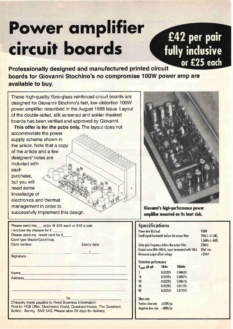
Power amplifier circuit boards
£42 per pair fully inclusive
or £25 each Professionally designed and manufactured printed circuit
boards for Giovanni Stochino's no compromise 100W power amp are available to buy.
These high-quality fibre-glass reinforced circuit boards are
designed for Giovanni Stochino's fast, low-distortion 100W
power amplifier described in the August 1998 issue. Layout
of the double-sided, silk screened and solder masked
boards has been verified and approved by Giovanni.
This offer is for the pcbs only. The layout does not
accommodate the power
supply scheme shown in
the article. Note that a copy
of the article and a few
designers' notes are
included with
each
purchase,
but you will
need some
knowledge of
electronics and thermal
management in order to
successfully implement this design.
Please send me pcbs @ £25 each or £42 a pair.
I enclose my cheque for £
Please debit my credit card for £
Card type MasterCard/Visa.
Card number Expiry date
/ Signature
Name
Address
Tel Cheques made payable to Reed Business Information. Post to: PCB Offer, Electronics World, Quadrant House, The Quadrant, Sutton, Surrey, SM2 5AS. Please alow 28 days for delivery.
Giovanni's high-performance power amplifier mounted on its heat sink.
Specifications Power into 82 load Small-signal bandwidth before the output filter
Unity gain frequency before the output filter Output noise (13W=80kHz, input terminated with 50i2 Measured output offset voltage
Distortion performance
Vout, Pk-Pk 5 10 20 40 80
1 kHz 20kHz
0.0030% 0.0028% 0.0023% 0.0028% 0.0026%
Slew rate Positive slew-rate +320V/ps Negative slew-rate —300V/ps
0.0043% 0.0047% 0.0061% 0.0110% 0.0170%
100W 20Hz (-0.1dB), 1.3MHz (-3dB) 22MHz 42pV rms +32mV

BROADCASTING
Digital outlook The introduction of digital television services could be a soap opera in itself. SkyDigital, BBC and OnDigital are all hoping to be the station of the nation, but all are realistic in realising the British public will have to be convinced digital tv is something worth paying for. Richard Wilson checks out the viewing figures.
What have Manchester United and October 1st in common? Both will be pencilled prominently in Rupert Murdoch's diary. After the takeover
bid for the football team comes the launch of the UK's first satellite digital tv service. When Murdoch's satellite tv broadcaster launched its
UK digital tv service on the first of the month, Sky struck early in a market that is destined to dazzle us all with activity - technical, commercial and social - over the next half year or so. The next date to ink in on the digital tv calendar is 15
November. This is when the first terrestrial digital tv service from OnDigital, the 50-50 joint venture between independent broadcasters Carlton and Granada, goes live. That is by no means the end of the digital-tv story. The
BBC may have launched its first digital channel - BBCChoice - but it has yet to make its big move in the digital-tv market and no one is underestimating the impact super-quality digital tv and interactive services will have in the country's growing cable sector.
Is talk about a digital-tv market just a little premature? No one is foolish enough to write off digital before it has even appeared. The real question is how quickly the market for digital tv and interactive information services will expand. The answer to that question depends on three things; the cost of the hardware - set-top boxes and tvs, the quality of the programme content and how the three broadcast media, satellite, terrestrial and cable will divide up the market. In the run up to the launch of its terrestrial service next
Waxing lyrical... Comedienne Ruby Wax - one of the stars being used, according to the BBC, to, "...guide viewers into the emerging world of digital broadcasting."
December 1998 ELECTRONICS WORLD 1061

BROADCASTING
Action, cameras...
Focusing on the digital tv age.
month, OnDigital estimates that eight million people are prepared to pay £200 for a set-top box that will enable them to receive Coronation Street in glorious digital picture quality. Digital hardware will also become even more attractive,
according to the broadcaster, when the receiver is integrated into the tv set. With around four million people estimated to buy new
tv sets each year in the UK, the change to digital hardware may not be as painful as some have predicted. When buying a new tv consumers may be prepared to absorb the additional cost of the digital receiver.
If getting enough people to buy the wide-screen tv and digital receiver is no longer the major obstacle, then getting the prospective digital viewers to one of the three broadcast media, terrestrial, satellite or cable, will surely remain the big issue for firms like BSkyB, the BBC and OnDigital. Surprisingly, one market researcher is convinced that
terrestrial operator OnDigital will find it difficult to compete with the satellite service of SkyDigital. Consumer market research carried out by Strategy
Analytics forecasts that while SkyDigital could be beaming services to just over a million homes — 5% of the total — by the end of next year. OnDigital's terrestrial service could have just 120 000 viewers. The prediction of 250000 digital tv subscribers for cable
is only slightly more optimistic. Such is the expectation that by 2005, the analysts predict
that 29 per cent of UK households will have digital satellite tv, and 24 per cent digital cable. Only 5 per cent are predicted to be watching digital terrestrial tv. So why the confidence about satellite over terrestrial,
which is the means by which most of us get today's tv? The argument seems to rest on the fact that satellite pay-per-view approach to broadcasting is ideal for applying to the market for digital services, which will be wide-ranging by today's broadcast standards. Terrestrial broadcasters do not charge viewers for
services, the licence fee excepted, television programmes
are just there in the front room, free at the point of use. Digital services will simply not be like that. "OnDigital is boxed into a corner," says David Mercer, a consultant at Strategy Analytics. "It needs pay tv revenues to survive, but is selling to an audience which doesn't want to pay for tv." There is also the more practical argument that terrestrial
broadcasters will be limited by frequencies available in the range of service they will be able to provide, compared to satellite and cable. Predictions are there to be accepted or scoffed at, and
only time will tell whether the arguments hold true. However, it seems that the BBC is already resigned to losing substantial ground to satellite and cable services in the digital revolution. "Terrestrial won't be dominant in the future," said
Charles Evans, the BBC's project director of digital services, speaking in London at last month. The BBC has insisted that it will not charge subscription
fees for many of its digital tv services. If the finances permit such an approach, then it is hard to see how it will not have a major impact on pay-per-view satellite and cable services, as it does in today's analogue tv. The technology may change but history tells us that
human nature is stubborn to conversion. Today Sky's satellite viewers total no more than half the
regular audience for Coronation Street on one of five free terrestrial television channels. This tells us that there is a considerable chunk of the tv
audience which is not used to paying for its programmes. The introduction of digital-tv services means that more
of us must accept that we will have to pay for what came free in the past. However, as long as there is a choice then SkyDigital, OnDigital and the cable firms will have to convince us that digital television is something worth paying for. Rupert Murdoch won't be writing off terrestrial tv just
yet, which is why 15 November is still an important date in his diary.
1062 ELECTRONICS WORLD December 1998

Networks and Telecommunications Design and Operation Second Edition
drab
'Sep'
Martin P. Clark
Networks and Telecommunications Design and Operation
Second Edition Martin P. Clark, Telecommunications Consultant, Frankfurt, Germany
Telecommunications network design and operation is now widely regarded as an issue of business management as well as electrical engineering. In this updated edition, Martin Clark, a pioneer of this perspective, applies it to the increasing complex and diverse realm of voice, and data and multimedia networks. Written in an accessible style and clearly illustrated throughout, this is a basic, practical and intuitive insight into modern network engineering and sections including:
• Technical accounts of modern voice, data and multimedia networks
• Coverage of ATM, B-ISDN, SDH, mobile radio and satellite networks, Internet and TCP/IP
• Practical aspects of running and setting-up networks
• Running a business based on telecommunications
A text specifically for readers new to the whole subject of telecommunications, and professional telecommunications managers who need an introduction and reference work on all aspects of technology, operational techniques and regulation.
ISBN 0 471 973 46 7
UK £80.50 Europe £86 ROW £105
Introduction to Digital Mobile Communication Yoshihiko Akaiwa
A comprehensive treatment of the digital technologies that make personal mobile communication a reality Although today's mobile
communication engineers and designers can build upon the advances in digital telecommunications, specific technical requirements - robustness against fast fading,
11117 SIMI • TOZ.M.Se re Mee
irioC6 titf nAl
MOBILE COMMUNICATION
Yoshihiko Akaiwa
spectrum and power efficiency, and the demand for low-priced equipment- post new technological challenges that demand creative solutions. Introduction to Digital
Mobile Communications is a comprehensive treatment of the digital technologies that are rapidly spawning new advances and applications. Written by a pioneer in the field, this book covers all the important concepts, from the fundamentals of signal analyses and digital communication to descriptions of the latest transmission systems. Rich in detail and broad in its coverage, this remarkable book:
• Describes equipment and circuit implementation methods and their performance characteristics
• Discusses elements of and methods for digital modulation and demodulation schemes
• Provides practical designs and circuits for spectrum-efficient modulations
• Covers mobile radio channels and digital mobile radio systems
• Includes extensive
mathematical treatments and mathematical models
• Presents the latest research results with detailed references
This valuable resource provides a solid introduction to mobile radio communication for the students or professional in related fields. Most important, for design engineers and equipment manufacturers, its up-to-date findings will stimulate new research and creative design and system development efforts. Yoshihiko Akaiwa is a
leading researcher in the digital mobile communication field. Currently a professor at Kyushu University, he worked as a researcher for over twenty years at the NEC Corporation ISBN 0 471 17545 5 UK £57.50 Europe £60.50 ROW £73
Cellular Mobile Radio Systems Designing Systems for Capacity Optimization Husni Hammuda, Ericsson (UK) Ltd
Rapidly increasing demand for mobile radio frequency subscription is already pushing cellular networks to the point of overload. Of the various methods which are being explored to tackle this problem one of the most notable is the integration of advance modulation and multiple access techniques. In this book, Husni Hammuda, a pioneer of this hybrid, shows how it can be applied in practice to optimise the efficiency of mobile radio cells.
• Provides detailed criteria for
the evaluation of combinations of modulation and multiple access techniques
• Includes primary performance data as well as predictive models
• Theoretical material is explained using examples from first and second generation transmission systems
• Covers recent innovations in personal communications
For the practising cellular communications engineer this is a systematic set of solutions for improving traffic flow in cellular networks. It also includes complete theoretical and case material ideal for post-graduate network engineering researchers.
ISBN 0 471 95641 4 UK £37.50 Europe £39.95 ROW £46.95
Network-Based Images A Practical Guide to Acquisition, Storage, Conversion, Compression and Transmission Gilbert Held, 4-Degree Consulting, Macon, Georgia, USA
Network-Based Images offers a fresh approach to the acquisition and manipulation of visual images on computer by focusing on the network application side. This practical Guide
explains the methods used to store images electronically and discusses the popular image-based applications, such as storage, conversion and compression. Gilbert Held reviews the procedures used to minimize the effects of other image-based applications to increase efficiency. This network oriented book
provides detailed information on the transmission of images to other systems and includes an overview of the associated problems. Features include:
• Use of images on LANs includes LAN-based World Wide Web Servers
• Use of HTML image related statements
• Techniques to avoid costly network upgrades
• How to segment LANs • Network modifications to

counter the bandwidth effect of images upon LAN transmission
Essential reading for network managers and administrators as well as Web server administrators and personal computer users. This book will provide unique coverage of images oriented to efficient use on networks: storage, acquisition, and use in applications ISBN 0 471 97357 2 UK £37.50 Europe £39.95 ROW £46.95
Stereophonic Sound Recording Theory and Practice Christian Hugonnet and Pierre Walder
Recent advances in digital audio have heralded substantial innovations in sound recording techniques and increased the importance of applying the latest microphone techniques. The authors of this book focus on these innovations, giving numerous examples of their use within the framework of an analysis-based recording
Stereophonic Sound
Recording 'Theory and Practice
Christian Hugonnet and
Pierre Walder
engineering theory. The book provides a
complete overview of well-known sound recording procedures practised world-wide, whilst also presenting a methodology that will provide the reader with an efficient approach to sound recording of classical music, rock and pop music, drama and speech. The widely illustrated theoretical knowledge is presented in clear and simple language. Building on their
considerable experience of creating innovative recording techniques, the authors
provide an authoritative analysis of the subject that offers valuable, practical guidance that will aid the development of new recording methods. Their inside knowledge of the requirements of the phonographic, broadcasting, film and other media industries ensures expert coverage of new products and approaches including:
• recording techniques for all types o microphones
• in-depth analysis of the principles and use of stereophonics
• influence and role of the venue acoustics on the sound recording
• guidelines for mastering and mixing different levels of sound from different sources
For professional audio engineers, this manual provides systematic advice for getting optimal performance from studio equipment. For students of audio engineering it will form a comprehensive introduction to the area of stereophonic recording, backed up by real-world case studies and a wealth of practical experience. ISBN 0 471 97487 0 UK £32.45 Europe £34.95 ROW £41.95
Protect Your Privacy on the Internet Privacy defense tools and techniques you can use right now Bryan Pfaffenberger
CD-ROM includes a complete collection of Windows privacy software.
Is your complete life story available to anyone with Internet access? It's really not all that hard to snoop in
Continued over page
Protect Your Privacy on the
Internet Prirais detenh•tooL and ¡st irntques you Call 11Sertfihr II011'
•••••••••• •,••••••• •••••.....
.1>rifrilbirytt
All prices are fully inclusive of packaging and delivery Return to Jackie Lowe, Room L333, Quadrant House, The Quadrant, Sutton, Surrey, SM2 SAS
Please
Qty
supply the following titles:
Title or ISBN Price
Name
Address
Total
Postcode
Telephone
Method
Access/Mastercard/Visa/Cheque/PO
Cheques Reed
Credit
Card
Signed
Please
of payment (please circle)
should be made payable to Business Information
card no
expirey
allow up to 28 days for delivery

cyberspace. As more and more business is conducted over the Internet, it has become increasingly difficult for both businesses and individual users to protect private information. Your reputation, Your finances, and your basic right to privacy are on the line every day. What can you do about it? You can fight back. Protect
Your Privacy on the Internet tells you everything you need to know to ensure your privacy and use the same technology that's being used against you to protect yourself. You'll get industrial-strength encryption tools to keep your affairs secret, the way they ought to be. Bryan Pfaffenberger arms
you with privacy defense strategies such as:
• Creating a bullet-proof password
• Getting your name out of the databases
• Cleaning up your browser's trails
Protect Your Privacy on the Internet gives you proven privacy defense strategies and techniques to help you make the Net a safer place to work and play. You'll get the names of Internet privacy organizations that are working to protect your privacy rights and find out what you can do to help. On the accompanying CD-ROM you'll find a collection of Windows Privacy freeware and shareware, including:
Pronto96 - an e-mail program that works in conjunction with encryption software to protect your e-mail
Mutilate - software that thoroughly erases files beyond recovery, even by expert snoopers
Win-Secure-It® - a utility preventing unauthorised access to files on your computer
AMSD AriadnaTM - a full-featured browser that reads tables and Java but ignores "cookies", text files that transparently save where you've been
Random Password Generator - a program enabling you to generate up to 1,000,000 passwords to protect you against unauthorized access to your Internet account
Cyber PatrolTM - parental
control software that prevents kids from uploading personal and demographic information to commercial sites
ISBN 0 471 18143 9 UK £27.45 Europe £29.95 ROW £36.95
Internet Audio Sourcebook
The tcunplete gustie to (men. audio techniques and molt
IM! •••••• gal».
autlw
1.-.«...11M. 41. home. trleelbst• ye...11"m
The complete guide to Internet audio techniques and tools Lee Purcell and Jordan Hemphill
"The World Wide Web has spouted vocal cords, gained a voice, and begun to sing." — Lee Purcell and Jordan Hemphill Internet Audio Sourcebook
offers you a quick, easy way to acquire the knowledge, skills, and some of the tools you need to build cutting-edge audio capabilities into your Web pages, including:
• Music, narration, and sound effects
• Streaming audio for real-time broadcasts
• Automated, spoken-voice instruction
• Audio conferencing and Internet telephony
• MIDI techniques for musical training and analysis
Taking a step-by-step approach, the authors get you up to speed on the latest audio tools and techniques. First they school you in the basics of creating, processing, and storing audio data. You learn the various
methods of working with digital sound and how to use available tools to shape audio content for the Internet. Then they show you how to deliver your digital sound over the Web. They explain the HTML coding used to access audio files and teach you techniques for integrating Java applets,
JavaScript code, and VBScript code into your HTML documents.
Finally, the authors show you how to get the most out of new audio technologies, including streaming audio, MIDI applications, voice synthesis and recognition, and Internet telephony, as well as covering hot new products like the Headspace Beatnik audio engine and Liquid Audio.
The CD-ROM You get fully functional demos of top-of-the-line sound processing applications, including Sonic Foundry's Sound Forge and Hohner Midia's Samplitude Studio. Authoring tools such as Symantec's Visual Café, Aimtech's Jamba, and Acadia Software's Infuse JavaScript editor are also included. ISBN 0 471 19150 7 UK £28.45 Europe £31.95 ROW £39.95
Web Security Sourcebook A Complete Guide to Web Security Threats and Solutions Aviel D. Rubin, Daniel Geer, and Marcus J. Ranum
The front door is unlocked and wide open. The alarm's not working and no one's home. All of your valuable, money, and intimate details of your life are just sitting inside, waiting to be taken. No, it's not your house, it's your computer. The Web now penetrates
every aspect of our lives, from the home PC to the Business office. But with each advance in convenience comes a geometric increase in vulnerability to the integrity of data and software as well as to the confidentiality of information. Although the flaws inherent in the Web are real, solutions are available. Let Aviel Rubin, Daniel Geer, and Marcus Ranum give you the answers. Here's a book that's valuable
today and indispensable for the future. It includes basic and advanced techniques for client-side and server-side security, browser security, writing secure CGI scripts, firewalls, and secure e-commerce. There's a special appendix that demystifies the complex world of cryptography. And the book comes with access to a dedicated Web site containing
up-to-the minute information on the latest security threats and solutions. So whether you're a
Webmaster trying to close the door on sites and applications, or an everyday user hoping to keep your desktop safe, this is your essential source of:
• Protecting and securing Web pages, search engines, servers, and browsers
• Writing impregnable applets and scripts, and avoiding the dangers inherent in every language
• Using (and abusing) firewalls and cryptographic controls
• Securing commerce and payment transactions
SBN 0 471 18148 X UK £7.45 Europe £29.95 ROW £36.95
Encyclopaedia of Acoustics Edited by Dr Malcolm J Crocker, Auburn University
S d
e A
e
a J.
ound Information in 167 etailed Chapters. Now here's a new four-volume eference that covers every maginable area of acoustics, ound and vibration - from he design of a concert hall to he intricacies of the human ar. It's the Encyclopaedia of coustics. In this on-of-a-kind set, dited by well-known coustical expert Dr Malcolm Crocker, you'll get:
• Extensive cross-referencing and indexing
• 2000- plus pages of insights from more than 200 international expert contributors
• An exhaustive examination of the fundamentals of acoustics and vibration in the first two volumes
• A revealing exploration of acoustic applications in Volumes Three and Four
• General Introductions at the start of every section
d fo sc th
a (7 IS
his up-to-date work is the efinitive acoustics resource r students, engineers, ientists, and researchers in e field. Casebound O 1997, four-olume set pprox. 2,000pp. 5Opps./volume) BN 0471 80465 7
UK £372.45 Europe £384.97 ROW £390

ELECTRONICSAPPOINTMENTS Electronics World December 1998 Te1:0181 652 3620
Apple Recruitment The Taste of Success
We currently have many vacancies on our books for RF, Microwave and Antenna Design, Development and Test Engineers. Below is a selection of
some positions we have on our records:
RF Engineers
Herts £23-40k Our client has positions at all levels for engineers with 2.1/1st class honours degrees with a good background in developing transmitters, receivers, filters, LNAs and amplifiers.
Hants £25-36k Our client is looking for several RF engineers with good degrees and several years experience developing mobile telecommunications systems. Knowledge of CSM would be an advantage.
Berks £24-36k Applicants are sought from RF design engineers with a good degree and practical post-grad experience covering some of the following areas — RF to 2GHz, LNA design, PLLS, GSM, Filters, power amps, VCOs or EMC.
Hants £25-36k Our client is looking for several RF engineers with good degrees and several years experience developing mobile telecommunications systems. Knowledge of GSM would be an advantage.
Kent £28-32k Our client is looking to recruit degree qualified RF/Microwave engineers with good post-graduate experience of LNAs, filters, diversity systems and measurement techniques.
Beds £26-34k A designer of cellular radio products is looking for experienced RF engineers to design receivers up to 2GHz. Familiarity with digital modulation and DSP would be beneficial.
Cambs £28-35k Engineers are sought with good degrees and several years post-graduate experience in developing RF circuits and systems. Some of the following skills are needed — GSM, PCN, DECT, wireless I.AN, antennas, superhet receivers, oscillators, synthesisers, amplifiers or EMC.
Microwave Engineers
Hants £25-38k Our client is seeking qualified engineers to carry out circuit design and testing with M/C and Galls MMIC circuits (e.g. low noise amplifiers, phase and gain control units, oscillators and power amps) with operating frequencies from 0.5 to 100GHz.
Scotland £27-35k We are looking for several microwave design engineers with skills in oscillator design, amplifiers, filters and mixer design. Knowledge of HP EEsof design and layout packages would be of help.
Devon £22-34k A major developer of radar systems is looking for experienced engineers to develop circuits and sub-systems up to 40GHz. Knowledge of antennas would be beneficial.
Sussex £22-34k A major developer of radar systems is looking for experienced engineers to develop circuits and sub-systems up to 40GHz. Knowledge of antennas would be benficial.
RF Test Engineers
Surrey £16-21k We have several positions for Test Engineers with 1 year+ experience testing RF systems and circuits using spectrum analysers, oscilloscopes and other test equipment.
Hants £17-19k Applicants with experience of testing RF systems and circuits down to component level are sought by our clients.
Northants £16-20k With an HNC and 2 years experience of testing RF/Microwave products up to 2GHz, you may just be the individual our client is looking for.
lst/2.1 Degree or Ph.D
Nationwide £Attractive
Many of our clients are looking for both fresh and experienced graduates/post graduaters for positions in RF/Analogue/Microwave design and development.
111100fde Recruitment 3 Branksome Way, New Malden, Surrey KT3 3AX
Tel: 0181 549 0100 Fax: 0181 549 9771
email: consulteapplerec.u-neLcom Web: http://applerec.u-net.com/

ELECTRONICSAPPOINTMENTS Electronics World December 1 998 Te1:0181 652 3620
opportunities to Eel,
Test Technician
Test Support
Support Technician
Field Service
Test Technician
Calibration/NAMAS
Test Development
Production Support
ATE Functional Test
Systems Test
Systems WI
Microwave Test
Systems WI
Field Service
RF/GSM
EMC
Production Equip't
Printing Equipment
Avionics
PSU's
Sonar
SMT Equipment
Cellular Radio
SDH
PMR - TETRA
Radar
SDH
Medical
Surrey/Wilts/Herts
Berks
Wilts
Surrey/Cheshire
Sussex
Hants
Berks
Shropshire
Surrey
W. Midlands
Berks
Essex
Oxon
London/Essex
For more information, contact John Darby, quoting ref 2791H, on 01727 818704, fax 01727 838272 or email [email protected]
JPR, The Courtyard, Alban Park, Hatfield Rd, St Albans, Herts AL4 OLA.
f23k
£21K
£22k
£23k
fl 9k
fl 8k
f 20k
f20k
fl 8k
f25k
£28k
fl 9k
f28k
£20k
vb
John Prodger e'etaTe" Recruitment
Connecting people with opportunities

ELECTRON ICSAPPOINTMENTS Electronics World December 1 998 Te1:0181 652 3620
RF Design Engineer Berkshire 1.5GHZ, Integrated Circuits You will need to be degree qualified with at least 3 or more years RF design experience. As my client is one of the world's leading innovators in the area of high performance, integrated circuits, they are looking for an engineer to deal with RF applications on these IC's of up to 1.5GHZ. Experience in CMOS or BICMOS would be advantageous. Please call in quoting reference if you require further information on this vacancy.
Ref: 61058
RF Manager Midlands GSM This global leader in the provision of communications sites and network services to broadcasting and telecommunications industries, is currently looking to recruit a key individual to lead a small team of dedicated special projects staff. The ideal candidate will have a minimum of 2 years experience of live networks and a background in planning and analysis of cellular coverage. Please quote reference for more details. Ref: 61259
RF Design & Development Engineer Northern Home Counties RF, Communications This communications organisation is one of the UK's leading suppliers of hand portables, vehicular mobiles and base station. The ideal applicant will be involved in the design and development of mobile radio equipment, so it is essential that you have several years experience in this field and in RF circuit design. You must be degree qualified in communications or electronics. To find out more about this vacancy, please call in quoting the reference. Ref: 61161
Power Supply Electronics Engineer Northants Switch Mode Power Supplies My client specialises entirely in the design and manufacture of power supplies mainly for the military sector. Due to growth and expansion, they are now seeking to employ a Power Supply Design Electronic Engineer. The ideal candidate will have experience in the design of multi-output switch-mode power supplies. Some of the supplies designed are used in demanding applications, so experience in DEF STAN's and MILL SPEC's would be advantageous. Please quote reference when calling in.
Ref: 61050
ASIC Design Engineer NW London VHDL This London based company is aiming to lead the emerging market for re-usable semiconductor intellectual property for customisable microprocessor cores. They are currently looking for experienced ASIC Design engineers with a minimum 2 years experience of writing VHDL for Synthesis to ASICs, or integrating microprocessor cores into ASIC designs. If you would like more information on this vacancy, please phone in with reference number. Ref: 61424
COMMS 2000
Communications Consultants 11 Harley Street
London WIN 2EQ Telephone: 0171-636 7584
Fax: 0171-580 3734
Comms 2000 is a division of The 2000 Group Plc
e-mail: [email protected]
Analogue Electronics Design Engineer Middlesex Analogue, Digital Circuit Design My client, d large MOD organisation are currently looking to recruit a design engineer to support the VHF and UHF work of their Sonar Products. You will have experience in analogue and digital circuit design and prototypes, PCB design and microprocessor software development and testing. Design experience in UHF and UHF receiver techniques and technology would be preferred as would a sound background in mobile communications. Ref: 61610
LS! Engineers Berkshire LSI Design, VHDL, ASIC My client, a leading developer of chip sets for mobile phones is currently recruiting for engineers with at least 2 years experience of LS! design. You will be required to verify and improve new design flows and definition of design procedures, so knowledge of ASIC design is essential as is VHDL and Verilog HDL coding. Experience and knowledge of DSP techniques and CAE tools such as Cadence and Synopsys is also required. An understanding of mobile communications would be an advantage. Ref: 61714
Hardware Engineers Newport Xilinx, FPGA Our client, the defence division of a major global telecommunications organisation is currently looking to recruit hardware engineers with a working knowledge of Modeltech Simulation Tools and Synopsis Synthesis Tools. Knowledge of Xilirut 4000 Series FPGA's and digital design experience would be advantageous. Ref: 61461
Mixed Signal Engineers M4 Corridor CMOS, BICMOS, CADENCE This global leader in the development of chip sets for mobile phones requires engineers with 5 or more years experience in mixed signal design. You will be
responsible for circuit feasibility studies, circuit design, simulation and layout so a good working knowledge of CMOS or BICMOS processes is essential as is experience of Cadence based mixed signal design flow including Saber and Spice. An understanding of mobile communications would be advantageous. Please call in with reference. Ref: 61715
Digital Design Engineer Birmingham Digital Design, FPGA Your tole \\'ill be to specify, design, implement, test and document all aspects of digital hardware design for a telecommunications equipment developer. You will have 2 years of digital design experience, preferably with a telecomms bias. An understanding of current CAE technology with skills in at least 2 of the following: PLDs, FPGA and Embedded Microprocessor/DSP. You will also be up to date with telecommunications standards and implementations for PDH, SDH, ISDN, l'STN and ATM. Ref: 61470
RF/Microwave Design Engineers West Yorkshire RF/Microwave My client is a leading international manufacturer of microwave and RF products for the mobile communications market. They are looking to employ engineers to be responsible for the design and development of RF components and integrated front-ends for the cellular radio and base station equipment markets. The ideal candidate must have experience of rf/microwave components, low noise amplifiers, filters, rf detectors, mixers, couplers and splitters. Working knowledge of microwave CAD tools is also essential. Ref: 61774
Manufacturing Cell Manager West Yorkshire RF Passive Products A manufacturing cell manager is required by an international manufacturer of passive RF products. You will be responsible for all aspects of the production of these products. You will have 2+ yrs experience in the delivery of 100% defect free products, achievement of deli, ery schedules, improvement within a production cell and day to day management of staff including the selection, training and development of them. Knowledge of Health and Safety procedures is essential. To find out more details regarding this vacancy, please call in with reference. Ref: 61783
CONTRACT VACANCIES Cell Planning Engs GSM, Radio Knowledge UK and Europe Ref: 59745
Telecoms Test Engs AXE-10 Experience UK wide, 6 mths Ref: 59831
GSM Consultants Project Management, Switch Management Radio Cell Planning Worldwide Ref: 60753
Network Development Engs GSM, PMR UK wide Ref: 39734
RF Design Engineer 1.9 GHZ, Transmitter Beds Ref: 59926
Radio Planner Wireless Local Loop Exp Worldwide Ref: 61648

ELECTRON ICSAPPOINTMENTS Electronics World December 1 998 Te1:0181 652 3620
ELECTRONIC PARTS MANAGER
Rutherford Appleton Laboratory, Oxfordshire
The Rutherford Appleton Laboratory Space Science Department is involved in designing, developing and building a variety of Scientific Research Instruments for operation in Space. Electronic parts manufactured to European Space Agency, NASA and US Military high reliability specifications are used.
There is a vacancy for a parts manager to work with the design engineers and the manufacturing facility at all stages of procurement and manufacture within an IS09001 system. Duties will include; advising designers on specifications, procuring and storing parts in a secure area and assembling manufacturing kits and maintaining paper and electronic records. Maintaining good contact with suppliers/manufacturers and the wider parts community in order to keep up to date with changes.
The successful candidate will have some experience in this field, understand the handling requirements for electronic parts and be familiar with ESA and NASA Space Specifications or US Military Specifications for electronic parts. Familiarity with PC use and the Access database would be an advantage, although training will be given. A degree or HND in electronic engineering is desirable or NVQ Level 5 or equivalent.
The salary range is between £15,180 & £24,820 (1998 pay award pending). Progression within the salary range is dependant upon performance. A non contributory pension scheme, flexible working hours and a generous leave allowance are also offered.
Application forms can be obtained from: Recruitment Office, Personnel Division, Rutherford Appleton Laboratory, Chilton, Didcot, Oxfordshire, OX11 OQX. Telephone (01235) 445435
(answerphone) quoting reference VN1698/98. More information about CLRC is available from CCLRC's
cl—FIC
World Wide Web pages at http://www.ccIrc.acuk
All applications must be returned by 16 October 1998.
The CCLRC is committed to Equal Opportunities and to achieving the Investors In People standard. A no smoking policy is in operation.
COUNCIL FOR THE CENTRAL LABORATORY OF THE RESEARCH COUNCILS
ADVERTISERS PLEASE NOTE
FOR ALL YOUR FUTURE ENQUIRIES ON
ADVERTISING RATES
PLEASE CONTACT JOANNAH COX
ON TEL: 0181 652 3620 FAX: 0181 652 8938
Anglia is a well structured, professional organisation determined to offer the electronics manufacturing industry the very best in product, service and support. With STMicroelectronics being our most recent franchise, we need the following people to join our growing
semiconductor team.
2 Field Semiconductor Applications Engineers: Based within easy access of the M62 or M4 corridors, applicants for these positions should be qualified HNC/Degree level in Electronic Engineering. Visiting customers throughout the UK, you will need to specialise in the application and design-in of semiconductors. Previous
experience in writing Assembler and/or 'C' with microcontrollers would also be an advantage. You will
also need to be self-motivated, professional and have excellent all round communication skills.
To apply for either of these positions, call Michelene Hircock for a confidential chat on 01945 47 47 47 between 9am & 5pm. Alternatively, send your CV to Michelene Hircock or e-mail her on mheangliac.co.uk.
We are looking for additional field based sales engineers to develop and maintain an existing customer base in the following locations.
2 Field Sales Engineers: 1 Middx, Hens, Bucks, Berks & NW London area 1 Wilts, Avon, Glos & Somerset Area
Applicants will be expected to sell a wide range of electronic components, both passive and active and work closely with our application engineers to identify design-in opportunities. Applicants must have previous experience of the electronics industry and ideally have an understanding of commercial volume purchasing. Alternatively a commercially orientated design engineer who wants to move to
sales would be considered. Successful applicants should be self-motivated, pro-active and dynamic, with
a good sense of humour.
To apply for either of these positions, call Michelene Hircock for a confidential chat on 01945 47 47 47 between 9am & 5pm. Alternatively, send your CV to Michelene Hircock or e-mail her on mheangliac.co.uk.
Sandal! Rd, Wisbech, Cambs. PE13 2PS
01945 47 48 49 fi' E-MAIL: [email protected]

IIIMM
MasterCard ee. • _i% VISA
SUPPLIER OF QUALITY USED TEST INSTRUMENTS
1 1 1 ! _.. • e , ... .
•
iu .• C.'"..:: ir_i.—T ... -
_ —r------
— ----_ ‘ tell . rog
.....t, :• •:" [ Ell
-- 107.-eià I I .7—
pi ..?.. 4„ •
• • • ......•
4
I [ r
.E. ,,_ .
t i
. .
_
Cooke International Unit Four, Fordingbridge Site, Barnham,
Bognor Regis, West Sussex, P022 OHD, U.K. Tel: (+44)01243 545111/2 Fax: (+44)01243 542457
Web: http://www.cooke-int.com E-mail: [email protected]
catalogue available
CIRCLE NO.139 ON REPLY CARD
VISA
OPERATING & SERVICE MANUAL.)
coome in te rrlitiOnal
O ctet.
t4t.
7Z >.•
.".`?:"" •
u".
Cooke International Unit Four, Fordingbridge Site, Barnham,
Bognor Regis, West Sussex, P022 OHD, U.K. Tel: (+44)01243 545111/2 Fax: (+44)01243 542457
Web: http://vvww.cooke-int.com E-mail: [email protected]
catalogue available
CIRCLE NO.140 ON REPLY CARD
ADVERTISERS' INDEX
ALCATEL IFC
ANCHOR SUPPLIES 1021
ANTRIM TRANSFORMERS 1001 PANCON
CMS 1017 & 1023 PICO
COMPUTUMATION 1019 PS CONSULTANTS
CONFORD ELECTRONICS 1027 QUICKROUTE
CROVVNHILL 1013 RADIO TECH
DATAMAN OBC RALFE ELECTRONICS
DISPLAY ELECTRONICS 1037 SEETRAX
ELECTROMAIL 1015 STEVVART OF READING
EQUINOX TECHNOLOGY IBC SURREY ELECTRONICS
JOHNS RADIO 1030 SYSONIC
JPG ELECTRONICS 1027 TELFORD ELECTRONICS
LABCENTER ELECTRONICS 986 TELNET
LANGREX SUPPLIES 1013 THOSE ENGINEERS
M & B RADIO 1041 TIE PIE
MILFORD INSTRUMENTS 1001 WADDICOR
NUMBER ONE SYSTEMS 1017
OLSON ELECTRONICS 988
1019
1015
993
1001
1023
1072
1029
1059
1027
1019
1046
1009
1041
991
1013
ELECTRONICS WORLD December 1998

Tel: 0181 652 3620 CLASSIFIED Fax 0181 652 8938
SERVICES 48 hour turn-around service
iFiE om Coept Production
Cost-effective electronic design and engineering
services
Designer Systems is an electronic product design firm with over a decade of experience designing innovative products for client companies and individuals. If you need to develop a product from scratch, want to re-develop an old product or need documentation /
software/Internet site authoring, contact us (f)esifiner for more information or see our web site
Tel/Fax: 01872 223389 Email: designer.systems@btinternetcom
Web : www.blintemetcom/-orion.consultants/designer
Sst ems Bespoke electronic solutions
ADVERTISERS PLEASE NOTE
FOR ALL YOUR FUTURE ENQUIRIES ON
ADVERTISING RATES
PLEASE CONTACT JOANNAH COX
ON TEL: 0181 652 3620 FAX: 0181 652 8938
ARTICLES WANTED
VALVES etc WANTED Most types considered but especially KT88, PX4/PX25, KT66, KT77, EL34, EL37, ECC83. Valves must be UK manufacture to achieve top prices. £220
paid for working quad stereo system + II + 22).
COURTEOUS, PROFESSIONAL SERVICE
Ask for a free copy of our wanted List.
BILLINGTON EXPORT LTD., Billingshurst, Sussex RH14 9EZ Tel: 01403 784961 Fax: 01403 783519
Email: [email protected] VISITORS PLEASE PHONE FOR APPOINTMENT
** WANTED ** Test equipment,
Electronic Scrap, Valves, Transmitters/Receivers,
Factory and Warehouse Clearance.
Confidentiality Assured.
TELFORD ELECTRONICS
Phone: 01952 605451 Fax: 01952 677978
TOP PRICES PAID For all your valves,
tubes, semi conductors and IC's.
La n Supplies Limited
1 Mayo Road, Croydon Surrey CRO 2QP
TEL: 0181 684 1166 FAX: 0181 684 3056
ARTICLES FOR SALE
Rack Enclosures New and Used most sizes
16U to SOU side and rear panels mains distribution 19" Panel mounts optima euroaaft. Prices from £45 ovas
M&B Radio 86 Bishopsgate Street Leeds LS1 413B Tel. 0113 2702114 Fax. 0113 2426881
PHILIPS 5390S 1GHz RF SYNTHESIZER WITH SERVICE MANUAL
£1099 + VAT 100KHz to 1020MHz. -127dBm to +130Bm
Unique video modulation v sound at 4 55.5/6.0MHz, int or ext AM (to 1.02GHz) or FM
(to 340MHz) RF sweep - 8 sengs memories - IEEE interface
Anode Laboratories Ltd Tel: 01353 649412 Fax: 01353 648128
PICO ADCIO data aquisition module with Compaq SLT286 laptop PC. £100. Portsmouth 101705) 818034.
4CX 15000J Power Tetrodes - By National Electronics. 2 Pieces New and Boxed offer to
11 1 .0, 0171 798 5532.
PLEASE MENTION
ELECTRONICS WORLD
WHEN REPLYING TO
ADVERTISEMENTS
RF DESIGN
SERVICES
All aspects of RF
hardware development
considered from
concept to production.
WATERBEACH ELECTRONICS
TEL: 01223 862550
FAX: 01223 440853
ADVANTEST TR4131, 4GHz Spectrum Analyser £2,995.00, Anritsu ML522, 300-1000MHz Measuring Rx £2,995.00, Racal 1795 Rx £795.00. Eddystone 1650, 10KHz-30MHz Rx
£995.00, W.J. 340A-6, 1-900KHz Rx £395.00, WA. 373A-10, .5-30MHz Rx £395.00, WA. RSI I I -IB-39, 30-1000MHz Rs £995.00, W.J. 9477, Demodulator £795.00. Tel/Fax: 01908-365726 or Email: [email protected]
UNUSED TMS77C82NL any quantity con-sidered. Tel: 0181 930 0943. Fax: 0181 933 2996.
ELECTRONIC CIRCUIT SIMULATOR
PROGRAM FOR PCs. Calculates gain, phase and impedances. Provides graphical output. Many circuit examples. £10. Montgomery 01753 643384.
WANTED PART-TIME MICROCHIP PIC PROGRAMMER, to work on one-off
interesting projects. Contact Simon on: 01784 457953 (Staines). Email: tecreseglobalnet.cosuk
DISPOSAL SALE of PTFE/FEP s/plate equipment, wires and multicore cables, mixed
specs, colours and sizes. Tel: 01772 435858.
COMPUTER UPS. IKVA 240V including two
I2V 24Ah batteries in fair condition. Tel Bristol 0117 9793883.
December 1998 ELECTRONICS WORLD 1071

HEWLETT PACKARD T & M EQUIPMENT
- •y nite
ADVANTEST TR9407 tft spectrum analyser to 1MHz PRICED TO CLEAR £1500 ANRITSU ME518A pcm error-rate test set 1kbit/sec-I50 Mbit/sec 'PTC'' f500 ANRITSU ML93A optical power meter with MA96A power sensor (0.75-1.8uM) £1000 ANRITSU MN95D fibre-optic attenuator 0-65db f250 BRADLEY 192 oscilloscope calibrator 'PTC'' f250 CHASE LFF11000 interference measuring receiver 9kHz-150kHz
f200 DATRON 1061 voltmeter, 'FTC' £250 DRANETZ 626-PA-6006 ac neutral monitor, c/w TR2018 clamp £250 EIP 575 source locking frequency counter 18GHz GPIB option £1250 FLANN MICROWAVE 27072 frequency meter 73-1136Hz f275 FLANN precision rotary waveguide attenuator 20110 0-60db 113-26GHz
£750 FLANN precision rotary waveguide attenuator 22110 0-70db 26-40GHz
£750 IFR A-7550 1GHz portable spectrum analyser with receiver options AM/FM/SSB f2500 IFR A-7550 spectrum analyser 1GHz with tracking generator option
£2000 KEITHLEY 192 programmable digital multimeter f400 MARCONI 2022A synthesized signal generator 10kHz-IGHz f1503 MARCONI 2380/2382 400MHz high-performance spectrum analyser £2750 PHILIPS PM5518 video pattern generator pentsc/sec am standards
f1500 PHILIPS PM5518 video pattern generator f1500 PHILIPS PM5580 LE modulator (PAL 11/ PM5582 UHF-convertor 'PTC'•
f100 PHILIPS PM5580 LE modulator (PAL 11 'PTC'• £00 RACAL-DANA 1995 option 01, 21X)MHz universal counter/timer 'PTC''
£500 RHODE & SCHWARZ UOS 5, 5.5-digit multimeter IEEE 'PTC'• f250 RHODE & SCHWARZ URE ms digital voltmeter IEEE 'PTC'• f250 SCHLUMBERGER 1254 4-channel frequency response analyser £3500
• ralfe electronics • procifessiioonalfuessisvetnyal Tsavi c
• 36 Eastcote Lane • South Harrow • Middx HA2 8DR • England • TEL 1.441 0181-422 3593 • FAX (+44) 0181-423 4009
EST 45 YRS
DISTRIBUZIONE E ASSISTENZA, ITALY: TLC RADIO, ROMA 1061 871 90254
SCHLUMBERGER 4922 radio code analyser 'PTC'• f250 SCHLUMBERGER SRTG-6A62 selective call test tel 'PTC'• f150 SYSTRON DONNER 6441A 100MHz 8-digit frequency counter IEEE 'PTC'• £100 TEKTRONIX 2432A 100MHz 250M Sa/sec digital storage oscilloscope
f1580 TEKTRONIX 1481R video waveform monitor PAL version f750 TAU-TRON MN302/8813302N bert transmitter/receiver 'PTC'• f250 WANDEL & GOLTERMANN PCM4 test sets.. call for details & options
call WANDEL & GOLTERMANN PCM4 pcm measuring set version 985/01. IEEE opt £10000 WANDEL & GOLTERMANN PF2 error ratio measuring set £400 WANDEL & GOLTERMANN DLM-20 data circuit test set £250 WANDEL & GOLTERMANN SPM31 level meter 'PTV f500 WANDEL 8i GOLTERMANN WM30 level tracer f500 WANDEL & GOLTERMANN PF4 bit error reate tester (BN911/01. Opt 03.01) f2000 WAVETEK 23 synthesized function generator 0.01Hz-12MHz £500 WAVETEK 1080 sweep generator 1-1030MHz f750 WAYNE KERR 3220 20A bias unit (for 3245 inductance analyser) MOO WAYNE KERR SR268 source and detector f250 WILTRON 6637 sweeper generator 2-186Hz (option 03) f2000 WILTRON 6659A sweep generator 10MHz-26.5GHz (options 01/10/13)
f3000 WILTRON 66408 sweep generator 26.5-40GHz (option 031 £3503
NB items marked 'PIC' are "priced to clear" and have been significantly reduced in price as we need the space. Working, no accessories, no guarantees but 7-day right to refuse.
All equipment sold calibration-checked by independent laboratories and carrys un-conditional refund and 90-day guarantees.
FOR EXCLUSIVE ACCESS TO OUR COMPLETE STOCK INVENTORY
AND SPECIAL BARGAIN DISPOSAL DEALS PLEASE CHECK OUR WEBSITE www.ralfe-electronics.co.uk
8713C 300kHz-3GHz vector network analyser £5000 3585A 40MHz spectrum analyser f4000 16408 serial data generator £500 10715A digital interferometer f1000 11857D 7mm test port cables f500 333206/333226 programmable attenuators 4GHz,
with driver 11713A f550 As above but 18GHz set £1000 3552A transmission test set f500 3561A dynamics signal analyser f5000 3586A selective level meter f1250 3771713 communications performance analyser, call for option configs
£0500 £500
f3000 £650
f2500 f1000 £1000 f1000 £1750 f2000 f2000 f6500
f25000 £7500 f2500 f1000 £1500
4948A I/041 in-service TIM set 40938 protocol tester base (PT300) 436A digital power meter 5343A/5344A 26.5GHz frequency counter/synchronizer 54100A 16H: digitizing escope, 40MSa/s c/w Hi-Z probes 84318A serial data generator 5334B frequency counter, option 060 83411C lightwave receiver 100/1550nm 83440C lightwave detector 20GHz 1300nm/1550nm 83508 sweep generator mainframe 835720 sweeper plug-in unit (for 83508) 26.5-400Hz 8924C COMA mobile station test set 8561B portable spectrum analyser 6.5GHz 8590A 1.80Hz spectrum analyser 86222A 10MHz-2.4GHz sweep generator plug-in unit 862908 2-180Hz sweep generator plug-in unit 86848 signal generator 5.40Hz-12.56Hz f1000 89038 audio analyser f2500 - (specify your own filter requirements - add f200 for each filter J2215A FDDI portable multimode test set £1500
_ çt/
Mrigji ,49
CERT T5,013
IS09002 ACCREDITED STOCKIST
MEASUREMENT & TEST EQUIPMENT
CIRCLE NO.141 ON REPLI CARD
Contact Joannah Cox on
0181 652 3620
ELECTRONICUPDATE A regular advertising feature
enabling readers to obtain more information on companies'
products or services.
1999 Measurement and Automation Catalogue
The National Instruments 1999 catalogue features hundreds of software and hardware products for your computer-based measurement and automation applications. New products include additions to our modular Compact PCI (PXI) platform, new computer-based instruments, and the latest versions of our instrumentation and automation software such as LabVIEW. Call to reserve your copy of our FREE 1999 Catalogue!
National Instruments Phone: 01635 523545 Fax: 01635 523154
e-mail: [email protected] Website: www.natinst.com/uk
CIRCLE NO.142 ON REPLY CARD
•
HIOICI u30,3
3522 LCII HITESTER/3631Z WESTER
•01,4*
t bedlam user tells wide test trtquese rangy
• • - - -
LCR & IMPEDANCE METERS
The 3522 LCR HiTESTER and 3531 Z HiTESTER together provide a wide range of test frequencies. The 3522 offers DC and a range from 1 inHz to 100kHz and the 353) covers the range from 42Hz to 5MHz. Test conditions can now come closer to a
component's operating conditions. The high basic accuracy of ±0.08%, combined with ease of use and low price give these impedance meters characteristics.
TELONIC INSTRUMENTS LTD
Tel: 0118 9786911 Fax: 0118 9792338
CIRCLE NO. f44 ON REPLY CARD
Trident Microsystems' new LVDS system, provides the cabling
solution to overcome all the problems associated with driving Digital TFT over long distances.
Trident's new LVDS system now allows for digital drive of up to 20 metres in length.
it,:»V„40.1)>A1111r,
eat/RC...I Wm:40PC Telow.R.1 .1.1.41.61/110-eleml Wad.. PC CU.
PC1/11111.1«.1
The latest ICP catalogue featuring a comprehensive range of CPU boards and enclosures, complete with price list, is now available from Wordsworth.
Further details from:
Wordsworth
Tel: 01732 861000 I
CIRCLE NO.141 ON REPLY CARD CIRCLE NO.145 ON REPLY CARD

DISTRIBUTORS FOR
OIAR SYSTEMS
IAR Microcontroller Development Tools
C-Compilers, Assemblers, Simulator
8051, Atmel AVR, Hitachi H8
IMICRO-PRO DEVICE PROGRAMMER The complete programming solution.
oronse Order Code: MPW-PLUS
Supports:
MICROCONTROLLERS
Atmel 89C,89S, 90S(AVR),
Generic 87C, Dallas 87C520
FLASH MEMORY
Atmel 29C, 49F
SERIAL/PARALLEL EEPROM
Atmel 24C, 25C, 59C, 93C, 28C
CONFIGURATORS
Atmel 17C, Xilinx XC17
Not all devices may be supported within each family
PROFESSIONAL AVRTM STARTER SYSTEM System Contents
• Combined Serial & Parallel Device Programmer
• Evaluation module for 8, 20 & 40-pin DIL devices • In-System Programming (ISP) Cable
• Integrated Windows" Development Environment
• AVRTM Basic LITE (1k bytes code) Compiler • AVRTM Assembler
• Mains Power Supply Adaptor
• PC Serial Cable (Connects to PC COM Port)
• Atmel CD-ROM Datbook
• One AT9051200 DIL Microcontroller
Only...
WRITE IN BASIC RUN IN A FLASH
• Compiled BASIC generates
tight AM"' machine code
• Not a Run-Time Interpreter;
NO code overhead!
• Target speeds comparable
with assembler
• Breaks the cost barrier for
small projects
• Ideal for educational, hobbyist and professional use
IL. SOFTWARE
Order Codes: AVR-BAS-LITE AVR-BAS-8K
et)
Order Code: AVR2-ST
FLASH 8051 Professional Starter System
System Contents • Combined Serial & Parallel Device Programmer
• Evaluation module for 20 & 40-pin DIL devices
• In-System Programming (ISP) Cable • Keil PK51-2K Integrated Windows,'" Development
Environment (2K code limit). Includes C-Compiler, Macro Assembler, Linker, Hex Creator, Editor & Simulator
• Mains Power Supply Adaptor
• PC Serial Cable
• Atmel CD-ROM Datbook
• One AT8958252 40-pin DIL Microcontroller
System layout shown in Fig 1 above only...
Order Code: E0-8051-STI
pVision
Integrated Development Environment for Windows"
•.•••-.,.--.,
ec.. cm car oesed
dScope Software Simulator &
Target Debugger
•••••,,
Optimising Ansi-C
Compiler
Macro Assembler
• Linker
• Software Simulator
• Integrated Editor
• Hex Creator
Starter Systems supplied with 2K Toolset & Development Systems supplied with 8K Toolset are available for Atmel, Dallas, Siemens, Temic 8051 microcontroller derivatives
Micro-ISP cytt'' III
Serial Programming System for the Atmel AVRTM &
895 microcontroller families
re-Typical In-System Programming (ISP)
Scenario shown below:
Supports: Atmel 895, 89LS, 90S(AVR)
10-Way IDC Cable
Target Vcc LED Target Vcc
Serial Clock
GND
Target Power LED ISP 10-Way Header
Target System
system not supplied
Order Code: UISP-53-SYS
CE
EQUINOX TECHNOLOGIES
EQUINOX HE IINEXONIFS
3 Atlas House St Georges Square Bolton BL1 2HB England
For sales tel: +44 (0) 1204 529000, fax: +44 (0) 1204 535555, e•mail: saleseequinox-tech.com, Web Site: www.equinox-tech.com
EQUINOX DISTRIBUTORS: AUSTRALIA Farrell +61 2 9645 81388 AUSTRIA Farrell +43066007 75 BELGIUM Akom Electronics 66/sa +3232273647 Farnell +32 03 227 36 47 BRAZIL Haste( +55 11 522 1799 Anacom +55 11 453 5588 DENMARK Farnell +45 44 53 66 44 EIRE Farrell +353 1 8309277 FINLAND Farrell +35893455 400 FRANCE Parnell +33 474 65 94 66 Newtek +33 1 4687 2200 GERMANY Elektronik Laden +49 52 32 81 71 Farrell +49 89 61 39 39 39 Ineltek GmbH +49 7321 93850, MSC Vertnebs GmbH +49 08 9945532 12 GREECE Microlec +30 1 5395042 4 HONG KONG Famed 800 968 280 (ILK Direct Toll FreelITALY Farrell +44 113 231 1311 Grito Italian Technology +39 51 89 20 52, Newtek Italia +392331053 08 MALAYSIA Farrell +603773 8000 NETHERLANDS Alcom Electronics BV +31 10 4519533 Antratek +31 10 450 4949 Parnell +31 30 241 2323 NEW ZEALAND Famed +649357 0646 NORWAY ACTE NC +47 63898900 Jakob Hatteland Electronic AS +47 53763000 PORTUGAL Anatronk +35 119 371 834 Farnell +44 113 289 0040 SINGAPORE Farrell +65 788 0200 SPAIN Anatronk SA +34 1 366 01 59 Farrell +44 113 231 0447 SWEDEN ACTE NC +46 8 445 28 70 Fumet +4687305000 SWITZERLAND Anatec Ag +41417403241 Farrell +41 1 204 64 64 UNITED KINGDOM Abacus Polar +44 1925 626626, Farrell +44 113 263 6311 Rapid Electronics +441206751166 Quarndon Electronics +44 1332 332651 USA Wools Inc +1 408 298 9077 Newark Electronics +1 800 718 1997, Peachtree Technology +17708084002 Pioneer Standard +1 888 832 3976
Equinox reserves the right to change prices & specifications of any of the above products without prior notice. E&OE. All prices are exclusive of VAT & carriage. AVR" is a trademark of the Atmel Corporation
CIRCLE NO. 102 ON REPLY CARD

Surely not. Surely someone somewhere
has developed a portable programmer that
has even more features, even greater
flexibility and is even better value for money.
Actually, no. But don't take our word for it. Use the feature summary below to see how
other manufacturers' products compare.
Dataman-48LV Plugs straight into parallel port of PC or
laptop
• Programs and verifies at 2, 2.7, 3.3 and 5V • True no-adaptor programming up to 48 pin
DIL devices
• Free universal 44 pin PLCC
adaptor
e Built-in world standard PSU -
for go-anywhere
programming
• Package adaptors
available for TSOP,
PSOP, QFP, SOIC and
PLCC
e Optional EPROM emulator
013 ma III
NEW t'le.1
1 I I 1.• I- I. I- I- I I I I I I I' I' I" I It
f. 1 r r I. 4,-r, r I I I. 1- • f" 1" 1 IT" I- I r It
I 11
£795 PUS HI
Money-Back 30 day Trial If you do not agree that these
truly are the most powerful
portable programmers you
can buy, simply return your Dataman product within 30
days for a full refund
*..0. 10 ON REPLY CARD
still the wor lost
?fä nosrtable rnmer free software
'is IOC ) 320719
Orders received by 4pm will normally be despatched same day.
Order today, get it tomorrow!
Dataman S4 • Programs 8 and 16 bit EPROMs, EEPROMs,
PEROMs, 5 and 12V FLASH, Boot-Block
FLASH, PICs, 8751 microcontrollers and
more • EPROM emulation as standard
• Rechargeable battery power for total
portability
• All-in-one price includes emulation leads,
AC charger, PC software, spare library ROM,
user-friendly manual
• Supplied fully charged and ready to use
S4 GAL module • Programs wide range of 20 and 24 pin logic
devices from the major GAL vendors
• Supports JEDEC files from all popular
compilers
Still as unbeatable as ever! Beware of cheap imitations. Beware of false
promises. Beware of hidden extras.
If you want the best, there's still only one
choice - Dataman.
Order via credit card hotline - phone today,
use tomorrow.
Alternatively, request more detailed information on these and other market-
leading programming solutions.
upgrades +
technical support
for life
r—year GUARANTEE
Support • 3 year parts and labour guarantee
• Windows/DOS software included
• Free technical support for life • Next day delivery - always in stock
• Dedicated UK supplier, established 1978
Delman Dataman Programmers Ltd, Station Road,
Maiden Newton, Dorchester, Dorset, DT2 OAE, UK
Telephone +44/0 1300 320719
Fax +44/0 1300 321012
BBS +44/0 1300 321095 (24hr)
Modem V.34N.FCN.32bis
Home page: http://www.dataman.com
FTP: ftp.dataman.com
Email: [email protected]