![Uvodna riječ [Introductory word.]](https://static.fdokumen.com/doc/165x107/63331824b6829c19b80c4113/uvodna-rijec-introductory-word.jpg)
ASTR 1010 Laboratory Introductory Astronomy I Spring 2020
164
UNIVERSITY OF COLORADO BOULDER DEPARTMENT OF ASTROPHYSICAL AND PLANETARY SCIENCES ASTR 1010 Laboratory Introductory Astronomy I Spring 2020
-
Upload
khangminh22 -
Category
Documents
-
view
6 -
download
0
Transcript of ASTR 1010 Laboratory Introductory Astronomy I Spring 2020

UNIVERSITY OF COLORADO BOULDER
DEPARTMENT OF ASTROPHYSICAL AND PLANETARY SCIENCES
ASTR 1010 Laboratory
Introductory Astronomy I
Spring 2020

IMPORTANT INFORMATION NAME: PHONE: EMAIL: COURSE TITLE: ASTR 1010 | Introductory Astronomy I
Please fill in the blanks below with information from the syllabus and/or lectures.
LECTURE Class Time: Tuesday, Thursday 2:00-3:15pm Location: Duane G1B20 (and sometimes Fiske Planetarium) Instructor: Dr. Seth Hornstein Office Location: Duane D317 Office Hours: E-mail: [email protected] Lecture TA: Tatsuya Akiba Office Location: Office Hours: E-mail: [email protected]
LABORATORY Section Number: Lab Time: Lab Location: Sommers-Bausch Observatory Room S-175 Lab TA (+ LA): Office Location(s): Office Hours: E-mail(s):
NIGHT OBSERVING SESSIONS Dates and Times:
Front Cover: Comet Hale-Bopp over the Flatirons courtesy Niescja Turner and Carter Emmart
Back Cover: Planetary Travel Poster from NASA Jet Propulsion Laboratory

ASTR 1010 Astronomy Lab – Spring 2020 3 University of Colorado
TABLE OF CONTENTS GENERAL INFORMATION ............................................................................ 5
UNITS AND CONVERSIONS ........................................................................................ 8SCIENTIFIC NOTATION & SIG FIGS ...................................................................... 12USEFUL MATH FOR ASTRONOMY ......................................................................... 15PROPORTIONALITY .................................................................................................... 20ASTRONOMICAL WEBSITES ..................................................................................... 21
DAYTIME LABORATORY EXPERIMENTS ................................................ 23THE COLORADO SCALE MODEL SOLAR SYSTEM .......................................... 25APPARENT MOTIONS OF THE SUN & MOON° ................................................. 33KEPLER’S LAWS .............................................................................................................. 45SURVIVOR CHALLENGE ............................................................................................ 53THE ERATOSTHENES EXPERIMENT ................................................................... 59CALCULATING THE MASS OF SATURN ............................................................... 69COLLISIONS, SLEDGEHAMMERS, AND IMPACT CRATERS ....................... 77TELESCOPE OPTICS ..................................................................................................... 89LIGHT AND COLOR .................................................................................................... 103SPECTRAL BARCODES° ............................................................................................ 117TRANSITING EXTRASOLAR PLANETS ............................................................... 127
NIGHTTIME OBSERVING PROJECTS ...................................................... 137MEASURING THE EFFECTS OF LIGHT POLLUTION* ................................. 139KNOWING CONSTELLATIONS & BRIGHT STARS* ....................................... 143OBSERVATIONS OF DEEP-SKY OBJECTS* ....................................................... 149 OBSERVATIONS OF THE MOON* ....................................................................... 157
* = Clear skies are required for this exercise ° = Clear skies are needed for a portion of the exercise

ASTR 1010 Astronomy Lab – Spring 2020 4 University of Colorado

ASTR 1010 Astronomy Lab – Spring 2020 5 University of Colorado
GENERAL INFORMATION You must enroll for both the lecture section and a specific laboratory section. You cannot switch lab sections within the week.
Your lecture section will usually be held in the classroom in Duane Physics & Astrophysics Building (just south of Folsom Stadium). Several lectures will be held instead at the Fiske Planetarium (at the intersection of Regent Drive and Kittridge Loop).
Your laboratory section will meet once per week during the daytime in Room S175 at Sommers-Bausch Observatory (just east of the Fiske Planetarium). Follow the walkway around the south side of Fiske and up the hill to the Observatory.
You will also have nighttime observing sessions using the Sommers-Bausch Observatory telescopes to view and study the constellations, the moon, planets, stars, and other celestial objects.

ASTR 1010 Astronomy Lab – Spring 2020 6 University of Colorado
MATERIALS The following materials are needed:
• ASTR 1010 Astronomy Lab Manual (this booklet), available from the CU Bookstore. Replacement (or print-your-own) copies are available in Acrobat PDF format downloadable from the SBO website, under Education → Courses.
• Calculator. All students should have access to a scientific calculator that can perform scientific notation, exponentials, and trig functions (sines, cosines, etc.).
• A 3-ring binder to hold this lab manual.
THE LABORATORY SECTIONS Your laboratory session will meet for 1 hour and 45 minutes in the daytime once each week in the Sommers-Bausch Observatory (SBO), Classroom S175. Each lab section will be run by a lab instructor (TA) and, possibly, an undergraduate Learning Assistant (LA), who will also grade your lab exercises and assign you scores for the work you hand in. Your lab instructor will give you organizational details and information about grading at the first lab session.
The lab exercises do not exactly follow the lectures or the textbook. We concentrate on how we know what we know; thus, we spend more time making and interpreting observations. Modern astronomers, in practice, spend almost no time at the eyepiece of a telescope. They work with photographs, satellite data, computer images, or computer simulations. In our laboratory, we will explore both the traditional and more modern techniques.
You are expected to attend all lab sessions. Most of the lab exercises can only be done using the equipment and facilities in the SBO classroom. Therefore, if you do not attend the daytime lab sessions, you cannot complete those experiments and cannot get credit. Most of the observational exercises can only be done at night using the Observatory telescopes. If you do not attend the nighttime sessions, you cannot complete these either.
Regardless of your grade in other areas of ASTR 1010, you can not receive a passing grade in the class as a whole without passing the lab portion.
NIGHTTIME OBSERVING You are expected to attend some of the nighttime observing labs. These are held in the evenings approximately every second or third week at the Sommers-Bausch Observatory, Mondays through Thursdays. Your lab instructor will tell you the dates and times. Write the dates and times of the nighttime sessions on your calendar so you do not miss them. If you have a job or other obligations that conflict with the nighttime sessions, it is your responsibility to make arrangements with your instructor to attend at different times.
The telescopes are not in a heated area, so dress warmly for the night observing sessions!
HONOR CODE The University of Colorado Honor Code will be strictly enforced. Plagiarism will not be tolerated and can result in academic and/or non-academic sanctions. Specifically, we point out the following guideline regarding your laboratory assignments:

ASTR 1010 Astronomy Lab – Spring 2020 7 University of Colorado
All work turned in must be your own. You should understand all work that you write on your paper. We encourage you to work in groups if it is helpful, but you must not copy the work of someone else. We encourage you to consult friends for help in understanding problems. However, if you copy answers blindly, it will be considered a breach of the Honor Code.
SOMMERS-BAUSCH OBSERVATORY Sommers-Bausch Observatory (SBO, http://www.colorado.edu/sbo), on the University of Colorado campus, is operated by the Department of Astrophysical and Planetary Sciences (APS). SBO provides hands-on observational experience for CU undergraduate students, and research opportunities for University of Colorado astronomy graduate students and faculty. Telescopes include two 20-inch Cassegrain telescopes installed in 2017, a 24-inch Ritchey-Crétien Cassegrain telescope in its own dome, and a 10.5-inch aperture heliostat. In its teaching role, the Observatory is used by approximately 1500 undergraduate students each year to view celestial objects that might otherwise only be seen on the pages of a textbook or discussed in classroom lectures.
The 10.5-inch aperture heliostat is equipped for viewing sunspots, measuring the solar rotation, implementing solar photography, and studying the solar spectrum. A unique optical system called SCRIBES permits simultaneous observations of the photosphere (using white light) and the solar chromosphere (using red light from hydrogen atoms, and ultraviolet light from calcium atoms which absorb and emit light within the upper solar atmosphere).
Open Houses for free public viewing through the 20-inch telescopes are held every Friday evening that school is in session. Students are encouraged to attend. Call 303-492-5002 for starting times; call 303-492-6732 for general astronomical information.
FISKE PLANETARIUM The Fiske Planetarium and Science Center (http://www.colorado.edu/fiske) is used as a teaching facility for classes in astronomy, planetary science, and other courses that can take advantage of this unique audiovisual environment. The star theater seats 210 under a 62-foot dome that serves as a projection screen, making it the largest planetarium between Chicago and California.
Astronomy programs designed to entertain and to inform are presented to the public on Fridays and Saturdays, and to schoolchildren on weekdays. Laser-light shows rock the theater late Friday nights as well. Following Friday evening star-show presentations, visitors are invited next door to view the celestial bodies at Sommers-Bausch Observatory, weather permitting. The Planetarium provides students with employment opportunities to assist with show production and presentation, and in the daily operation of the facility.

ASTR 1010 Astronomy Lab – Spring 2020 8 University of Colorado
UNITS AND CONVERSIONS Modern science uses the metric system (the SI, Systeme International d'Unites, internationally agreed upon system of units) with the following fundamental units:
• The meter (m) for length. • The kilogram (kg) for mass. • The second (s) for time. Since the primary units are the meter, kilogram, and second, this is sometimes called the mks system. (Astronomers often also use another metric system with centimeters, grams, and seconds as its fundamental units, called the cgs system.)
All of the unit relationships in the metric system are based on multiples of 10, so it is very easy to multiply and divide. This system uses prefixes to make multiples of the units. All of the prefixes represent powers of 10. The table below provides prefixes used in the metric system, along with their abbreviations and values.
Metric Prefixes
Prefix Abbreviation Value Prefix Abbreviation Value deci- d 10-1 decka- da 101 centi- c 10-2 hecto- h 102 milli- m 10-3 kilo- k 103 micro- m 10-6 mega- M 106 nano- n 10-9 giga- G 109 pico- p 10-12 tera- T 1012 femto- f 10-15 peta- P 1015
The United States is one the few countries in the world that has not yet made a complete conversion to the metric system. Even Great Britain has adopted the SI system; so, what are officially called “English” units are now probably better termed “American.” As a result, Americans must often convert between English and metric units, because all science and international commerce is transacted in metric units. Some common conversions are
Imperial to metric metric to Imperial 1 inch = 2.54 cm 1 m = 39.37 inches 1 mile = 1.609 km 1 km = 0.6214 mile 1 lb = 0.4536 kg 1 kg = 2.205 pound 1 gal = 3.785 liters 1 liter = 0.2642 gal
Strictly speaking, the conversion between kilograms and pounds is valid only on the Earth, because kilograms measure mass while pounds measure weight. However, since most of you will be remaining on the Earth for the foreseeable future, we will not yet dwell on this detail here. (Strictly, the unit of weight in the metric system is the newton, and the unit of mass in the English system is the slug.)

ASTR 1010 Astronomy Lab – Spring 2020 9 University of Colorado
Using the "Well-Chosen 1" Many people have trouble converting between units because, even with the conversion factor at hand, they are not sure whether they should multiply or divide by that number. The problem becomes even more confusing if there are multiple units to be converted, or if there is need to use intermediate conversions to bridge two sets of units. We offer a simple and foolproof method for handling the problem.
We all know that any number multiplied by 1 equals itself, and also that the reciprocal of 1 equals 1. We can exploit these simple properties by choosing our 1's carefully so that they will perform a unit conversion for us, so long as we remember to always include our units.
Suppose we wish to know how many kilograms a 170-pound person weighs. We know that 1 kg = 2.205 pounds, and can express this fact in the form of 1's:
1 = 1 kg
2.205 pounds or its reciprocal 1 = 2.205 pounds
1 kg
Note that the 1's are dimensionless. In other words, the quantity (number with units) in the numerator is exactly equal to the quantity (number with units) in the denominator. If we took a shortcut and omitted the units, we would be writing nonsense: of course, without units, neither 1 divided by 2.205, nor 2.205 divided by 1, equals "1"! Now we can multiply any other quantity by these 1's, and the quantity will remain unchanged (even though it will look considerably different).
In particular, we want to multiply the quantity "170 pounds" by 1 so that it will still be equivalent to 170 pounds but expressed in kg units. But which "1" do we choose? Very simply, if the unit we want to "get rid of" is in the numerator, we choose the "1" that has that same unit appearing in the denominator (and vice versa), so that the unwanted units will cancel. In our example, we can write:
170 lbs x 1 = 170 lbs x 1 kg
2.205 lbs = 170 x 12.205 x
lbs x kglbs = 77.1 kg
Be certain not to omit the units, but multiply and divide them just like ordinary numbers. If you have selected a "well-chosen" 1 for your conversion, then your units will nicely cancel, assuring you that the numbers themselves will also have been multiplied or divided properly. This is what makes this method foolproof: if you accidentally used a "poorly-chosen" 1, the expression itself will immediately let you know about it:
170 lbs x 1 = 170 lbs x 2.205 lbs
1 kg = 170 x 2.205
1 x lbs x lbs
kg = 375 x lbs2
kg !
Strictly speaking, this is not really incorrect: 375 lbs2/kg is the same as 170 lbs, but this is not a very useful way of expressing this, and it is certainly not what you were trying to do…
Example: As a passenger on the Space Shuttle, you notice that the inertial navigation system shows your orbital velocity to be 8,042 meters per second. You remember from your astronomy course that a speed of 17,500 miles per hour is the minimum needed to maintain an orbit around the Earth. Should you be worried?
8042 ms =
8042 m1 s x
1 km1000 m x
1 mile1.609 km x
60 s1 min x
60 min1 hr

ASTR 1010 Astronomy Lab – Spring 2020 10 University of Colorado
= 8042 x 1 x 1 x 60 x 60
1 x 1000 x 1.609 x 1 x 1 x m x km x mile x s x mins x m x km x min x hr
= 17,993 mileshour
Your careful analysis using "well-chosen 1's" indicates that you are fine, and so you will be able to perform more unit conversions!
Temperature Scales Scales of temperature measurement are often referenced to the freezing point and boiling point of water. In the United States, the Fahrenheit (F) scale is the most common; water freezes at 32 °F and boils at 212 °F. In Europe, the Celsius system is usually used; water freezes at 0 °C and boils at 100 °C. In scientific work, it is common to use the Kelvin temperature scale. The Kelvin degree is exactly the same "size" increment as the Celsius degree, but it is based on the idea of absolute zero, the unattainable temperature at which all random molecular motions would cease. Absolute zero is defined as 0 K, water freezes at 273 K, and water boils at 373 K. Note that the degree mark is not used with Kelvin temperatures, and the word "degree" is commonly not even mentioned: we say that "water boils at 373 Kelvin."
To convert among these three systems, recognize that 0 K = -273 °C = -459 °F and that the Celsius and Kelvin degree is larger than the Fahrenheit degree by a factor of 180/100 = 9/5. The relationships between the systems are:
K = °C + 273 °C = 5/9 (°F - 32) °F = 9/5 K - 459
Energy and Power: Joules and Watts The SI metric unit of energy is called the joule (abbreviated J). Although you may not have heard of joules before, they are simply related to other units of energy with which you may be more familiar. For example, 1 food Calorie is 4,186 joules. House furnaces are rated in btu (British thermal units), indicating how much heat energy they can produce: 1 btu = 1,054 joules. Thus, a single potato chip (with an energy content of about 9 Calories) could be said to possess 37,674 joules or 35.7 btu of energy.
The SI metric unit of power is called the watt (abbreviated W). Power is defined to be the rate at which energy is used or produced. Power is measured as energy per unit time. The relationship between joules and watts is:
1 watt = 1 joule
second
For example, a 100-watt light bulb uses 100 joules of energy (about 1/42 of a Calorie or 1/10 of a btu) each second it is turned on. One potato chip contains enough chemical energy to operate a 100-watt light bulb for over 6 minutes!
You might be familiar with the unit of power called the horsepower; one horsepower equals 746 watts, which means that energy is consumed or produced at the rate of 746 joules per second. You can calculate (using unit conversions) that if your car has "fifty horsepower" under the hood, they need to be fed 37,300 joules, or the equivalent energy of one potato chip every second, in order to pull you down the road.
ASTR 1010 Astronomy Lab – Spring 2020 11 University of Colorado
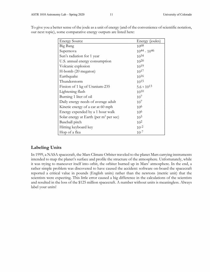
To give you a better sense of the joule as a unit of energy (and of the convenience of scientific notation, our next topic), some comparative energy outputs are listed here:
Energy Source Energy (joules) Big Bang 1068 Supernova 1044 - 1046 Sun’s radiation for 1 year 1034 U.S. annual energy consumption 1020 Volcanic explosion 1019 H-bomb (20 megaton) 1017 Earthquake 1016 Thunderstorm 1015 Fission of 1 kg of Uranium-235 5.6 x 10¹³ Lightening flash 1010 Burning 1 liter of oil 107 Daily energy needs of average adult 107 Kinetic energy of a car at 60 mph 106 Energy expended by a 1 hour walk 106 Solar energy at Earth (per m2 per sec) 103 Baseball pitch 102 Hitting keyboard key 10-2 Hop of a flea 10-7
Labeling Units In 1999, a NASA spacecraft, the Mars Climate Orbiter traveled to the planet Mars carrying instruments intended to map the planet’s surface and profile the structure of the atmosphere. Unfortunately, while it was trying to maneuver itself into orbit, the orbiter burned up in Mars’ atmosphere. In the end, a rather simple problem was discovered to have caused the accident: software on-board the spacecraft reported a critical value in pounds (English units) rather than the newtons (metric unit) that the scientists were expecting. This little error caused a big difference in the calculations of the scientists and resulted in the loss of the $125 million spacecraft. A number without units is meaningless. Always label your units!
ASTR 1010 Astronomy Lab – Spring 2020 12 University of Colorado
SCIENTIFIC NOTATION & SIG FIGS What Is Scientific Notation? Astronomers deal with quantities ranging from the truly microcosmic to the hugely macrocosmic. It would be very inconvenient to always have to write out the age of the universe as 14,000,000,000 years or the distance to the Sun as 149,600,000,000 meters. For simplicity, powers-of-ten notation is used, in which the exponent tells you how many times to multiply by 10. For example, 10 = 101, and 100 = 102. As another example, 10-2 = 1/100; in this case the exponent is negative, so it tells you how many times to divide by 10. One slightly tricky one is to remember that 100 = 1 (see the section on Powers and Roots below). Using powers-of-ten notation, the age of the universe is 1.4 x 10¹⁰ years and the distance to the Sun is 1.496 x 10¹¹ meters.
• The general form of a number in scientific notation is a x 10n, where a (called the coefficient) is a number between 1 and 10, and n (called the exponent) is an integer.
Correct examples of scientific notation: 6 x 10², 4.8 x 10⁵, 8.723 x 10⁻³.
Incorrect examples of scientific notation: 34 x 105, 4.8 x 100.5, 0.2 x 10³.
• If the number is between 1 and 10, so that its coefficient would be multiplied by 100 (=1), then it is not necessary to write the power of 10. For example, the number 4.56 already is in scientific notation (it is not necessary to write it as 4.56 x 100, but you could write it this way if you wish).
• If the number is already a power of 10, then it is not necessary to write that it is multiplied by 1. For example, the number 100 can be written in scientific notation either as 102 or as 1 x 10². (Note, however, that the latter form may be necessary for entering numbers on a calculator.)
The use of scientific notation has several advantages, even for use outside of the sciences:
• Scientific notation makes the expression of very large or very small numbers much simpler. For example, it is easier to express the U.S. federal debt as $2 x 10¹³ rather than as $20,000,000,000,000.
• Because it is so easy to multiply powers of ten in your head (by adding the exponents), scientific notation makes it easy to do “in your head” estimates of answers.
• Use of scientific notation makes it easier to keep track of significant figures; that is, does your answer really need all of those digits that pop up on your calculator?
Converting from "Normal" to Scientific Notation: Place the decimal point after the first non-zero digit and count the number of places the decimal point has moved. If the decimal place has moved to the left then multiply by a positive power of 10; to the right will result in a negative power of 10.
Example: To write 3040 in scientific notation, we must move the decimal point 3 places to the left, so it becomes 3.04 x 10³.
Example: To write 0.00012 in scientific notation, we must move the decimal point 4 places to the right: 1.2 x 10⁻⁴.
ASTR 1010 Astronomy Lab – Spring 2020 13 University of Colorado
Converting from Scientific to "Normal'" Notation: If the power of 10 is positive, then move the decimal point to the right; if it is negative, then move it to the left.
Example: Convert 4.01 x 10². We move the decimal point two places to the right, making 401.
Example: Convert 5.7 x 10⁻³. We move the decimal point three places to the left, making 0.0057.
Addition and Subtraction with Scientific Notation: When adding or subtracting numbers in scientific notation, their powers of 10 must be equal. If the powers are not equal, then you must first write the numbers so that they all have the same power of 10.
Example: (6.7 x 10⁹) + (4.2 x 10⁹) = (6.7 + 4.2) x 109 = 10.9 x 109 = 1.09 x 10¹⁰. (Note that the last step is necessary in order to put the answer into proper scientific notation.)
Example: (4 x 10⁸) - (3 x 10⁶) = (4 x 10⁸) - (0.03 x 10⁸) = (4 - 0.03) x 108 = 3.97 x 10⁸.
Multiplication and Division with Scientific Notation: It is easy to multiply or divide just by rearranging so that the powers of 10 are multiplied together.
Example: (6 x 102) x (4 x 10-5) = (6 x 4) x (102 x 10-5) = 24 x 102-5 = 24 x 10-3 = 2.4 x 10⁻². (Note that the last step is necessary in order to put the answer in scientific notation.)
Example: (9 x 10⁸) ÷ (3 x 10⁶) = 9 x 10⁸
3 x 106 = (9/3) x (108/106) = 3 x 10⁸-6 = 3 x 10².
Approximation with Scientific Notation: Because working with powers of 10 is so simple, use of scientific notation makes it easy to estimate approximate answers. This is especially important when using a calculator since, by doing mental calculations, you can verify whether your answers are reasonable. To make approximations, simply round the numbers in scientific notation to the nearest integer, then do the operations in your head.
Example: Estimate 5,795 x 326. In scientific notation, the problem becomes (5.795 x 103) x (3.26 x 102). Rounding each to the nearest integer makes the approximation (6 x 103) x (3 x 102), which is 18 x 105, or 1.8 x 10⁶. (The exact answer is 1.88917 x 10⁶.)
Example: Estimate (5 x 10¹⁵) + (2.1 x 10⁹). Rounding to the nearest integer this becomes (5 x 10¹⁵) + (2 x 10⁹). We can see that the second number is nearly 1015/109 = 106, or one million, times smaller than the first. Thus, it can be ignored in the addition, and our approximate answer is simply 5 x 10¹⁵. (The exact answer is 5.0000021 x 10¹⁵.)
Significant Figures Numbers should be given only to the accuracy that they are known with certainty, or to the extent that they are important to the topic at hand. For example, your doctor may say that you weigh 130 pounds, when in fact at that instant you might weigh 130.16479 pounds. The discrepancy is unimportant and anyway will change as soon as you drink a glass of water.

ASTR 1010 Astronomy Lab – Spring 2020 14 University of Colorado
If numbers are given to the greatest accuracy that they are known, then the result of a multiplication or division with those numbers cannot be determined any better than to the number of digits in the least accurate number.
Example: Find the circumference of a circle measured to have a radius of 5.23 cm using the formula: C = 2πR. Because the value of pi stored in your calculator is probably 3.141592654, the calculator's numerical solution will be
(2 x 3.141592654 x 5.23 cm) = 32.86105916 = 3.286105916 x 101 cm.
If you write down all 10 digits as your answer, you are implying that you know, with absolute certainty, the circle’s circumference to an accuracy of one part in 10 billion! That would require that your measurement of the radius was in error by no more than 0.000000001 cm. That is, its actual value was at least 5.229999999 cm, but no more than 5.230000001 cm.
In reality, because your measurement of the radius is known to only three decimal places, the circle’s circumference is also known to only (at best) three decimal places as well. You should round the fourth digit and give the result as 32.9 cm or 3.29 x 101 cm. It may not look as impressive, but this is an honest representation of what you know about the figure.
Because the value of "2" was used in the formula, you may wonder why we are allowed to give the answer to three decimal places rather than just one: 3 x 101 cm. The reason is because the number "2" is exact - it expresses the fact that a diameter is exactly twice the radius of a circle - no uncertainty about it at all. Without any exaggeration, the number could have been represented as 2.0000000000000000000, but the shorthand "2" is used for simplicity. This does not violate the rule of using the number that is least accurately known.

ASTR 1010 Astronomy Lab – Spring 2020 15 University of Colorado
USEFUL MATH FOR ASTRONOMY Dimensions of Circles and Spheres • The circumference of a circle of radius R is 2πR. • The area of a circle of radius R is πR2. • The surface area of a sphere of radius R is given by 4πR2. • The volume of a sphere of radius R is 4πR3/3 Notice that the units will make sense if we propagate them through these equations. If we know the radius in units of meters, then the circumference will also have units of meters. Because they both involve R2, the area of a circle and the surface area of a sphere will have units of meters2. The volume will have units of meters3, appropriate for talking about a three-dimensional volume.
Measuring Angles - Degrees and Radians • There are 360° in a full circle.
• There are 60 arcminutes in one degree. The shorthand for arcminute is the single prime (‘), so we can write 3 arcminutes as 3’. By converting units, we can see there are 360° x (60’/1°) = 21,600’ in a full circle.
• There are 60 arcseconds in one arcminute. The shorthand for arcsecond is the double prime (“), so we can write 3 arcseconds as 3”.) Therefore, there are 360° x (60’/1°) x (60”/1’) = 1,296,000” in a full circle. In astronomy we often talk about things that are very far away, so very tiny units of angles can be very useful!
We also often express angles in units of radians instead of degrees. If we were to take the radius (length R) of a circle and bend it so that it conformed to a portion of the circumference of the same circle, the angle covered by that radius is defined to be an angle of one radian.
Because the circumference of a circle has a total length of 2πR, we can fit exactly 2π radii (6 full lengths plus a little over 1/4 of an additional length) along the circumference. Thus, a full 360° circle is equal to an angle of 2π radians. In other words, an angle in radians equals the arclength of a circle intersected by that angle, divided by the radius of that circle. If we imagine a unit circle (where the radius = 1 unit in length), then an angle in radians equals the actual curved distance along the portion of its circumference that is “cut” by the angle.

ASTR 1010 Astronomy Lab – Spring 2020 16 University of Colorado
The conversion between radians and degrees is
1 radian = 3602 π degrees = 57.3° 1° =
2 π360 radians = 0.01745 radians
Trigonometric Functions In this course, we will make occasional use of the basic trigonometric (or "trig") functions: sine, cosine, and tangent. Here is a quick review of the basic concepts.
In any right triangle (where one angle is 90°), the longest side is called the hypotenuse; this is the side that is opposite the right angle. The trigonometric functions relate the lengths of the sides of the triangle to the other (i.e., not the 90°) enclosed angles. In the right triangle figure below, the side adjacent to the angle a is labeled “adj,” the side opposite the angle � is labeled “opp.” The hypotenuse is labeled “hyp.”
• The Pythagorean theorem relates the lengths of the sides of a right triangle to each other:
(opp)2 + (adj)2 = (hyp)2 .
• The trig functions are just ratios of the lengths of the different sides:
sin a = (opp)(hyp) cos a =
(adj)(hyp) tan a =
(opp)(adj) .
Angular Size, Physical Size and Distance The angular size of an object (the angle it "subtends," or appears to occupy from our vantage point) depends on both its true physical size and its distance from us. For example, if you stand with your nose up against a building, it will occupy your entire view; as you back away from the building it will cover a smaller and smaller angular size, even though the building’s physical size is unchanged. Because of the relations between the three quantities (angular size, physical size, and distance), we need know only two in order to calculate the third.
Suppose a tall building has an angular size of 1° (that is, from our location its height appears to span one degree of angle), and we know from a map that the building is located precisely 10 km away. How can we determine the actual physical size (height) of the building?

ASTR 1010 Astronomy Lab – Spring 2020 17 University of Colorado
We imagine that we are standing with our eye at the apex of a triangle, from which point the building covers an angle a = 1° (greatly exaggerated in the drawing). The building itself forms the opposite side of the triangle, which has an unknown height that we will call h. The distance d to the building is 10 km, corresponding to the adjacent side of the triangle.
Because we want to know the opposite side, and already know the adjacent side of the triangle, we only need to concern ourselves with the tangent relationship:
tan a = (opp)(adj) or tan 1° =
hd
which we can reorganize to give
h = d x tan 1° or h = 10 km x 0.017455 = 0.17455 km = 174.55 meters.
Small Angle Approximation We used the adjacent side of the triangle for the distance instead of the hypotenuse because it represented the smallest separation between the building and us. It should be apparent, however, that because we are 10 km away, the distance to the top of the building is only very slightly farther than the distance to the base of the building. A little trigonometry shows that the hypotenuse in this case equals 10.0015 km, or less than 2 meters longer than the adjacent side of the triangle.
In fact, the hypotenuse and adjacent sides of a triangle are always of similar lengths whenever we are dealing with angles that are “not very large.” Thus, we can substitute one for the other whenever the angle between the two sides is small.
Now imagine that the apex of a small angle a is located at the center of a circle that has a radius equal to the hypotenuse of the triangle, as illustrated above. The arclength of the circumference covered by that small angle is only very slightly longer than the length of the corresponding straight (“opposite”) side. In general, then, the opposite side of a triangle and its corresponding arclength are nearly equal whenever we are dealing with small angles.

ASTR 1010 Astronomy Lab – Spring 2020 18 University of Colorado
Now we can go back to our equation for the physical height of our building:
h = d x tan a = d x (opp)(adj) .
Because the angle a is small, the opposite side is approximately equal to the “arclength” covered by the building. Likewise, the adjacent side is approximately equal to the hypotenuse, which is in turn equivalent to the radius of the inscribed circle. Making these substitutions, the above (exact) equation can be replaced by the following (approximate) equation:
h ≈ d x (arclength)
(radius) .
But remember that the ratio (arclength)/(radius) is the definition of an angle expressed in radian units rather than degrees, so we now have the very useful small angle approximation:
For small angles, the physical size h of an object can be determined directly from its distance d and angular size in radians by
h ≈ d x (angular size in radians) .
Or, for small angles, the physical size h of an object can be determined from its distance d and its angular size in degrees by
h ≈ d x 2 π
360° x (angular size in degrees) .
Using the small angle approximation, the height of our building 10 km away is calculated to be 174.53 meters high, an error of only about 2 cm (less than 1 inch)! And best of all, the calculation did not require trigonometry, just multiplication and division!
When can the approximation be used? Surprisingly, the angles do not really have to be very small. For an angle of 1°, the small angle approximation leads to an error of only 0.01%. Even for an angle as great as 10°, the error in your answer will only be about 1%.
Powers and Roots We can express any power or root of a number in exponential notation, in which we say that bn is the “nth power of b”, or “b to the nth power.” The number represented here as b is called the base, and n is called the power or exponent.
The basic definition of a number written in exponential notation states that the base should be multiplied by itself the number of times indicated by the exponent. That is, bn means b multiplied by itself n times. For example: 52 = 5 x 5; b4 = b x b x b x b.
From the basic definition, certain properties automatically follow:
• Zero Exponent: Any nonzero number raised to the zero power is 1. That is, b0 = 1.
Examples: 20 = 100 = -30 = (1/2)0 = 1.

ASTR 1010 Astronomy Lab – Spring 2020 19 University of Colorado
• Negative Exponent: A negative exponent indicates that a reciprocal is to be taken. That is,
b -n = 1
b n 1
b -n = b n a
b -n = a x b n.
Examples: 4-2 = 1 / 42 = 1/16; 10-3 = 1 / 103 = 1/1000; 3 / 2-2 = 3 x 22 = 12.
• Fractional Exponent: A fractional exponent indicates that a root is to be taken.
b1/n = n b ; bm/n = n
bm = èæ
øön b
m
Examples: 81/3 = 3 8 = 2 82/3 = èæ
øö3 8
2 = 22 = 4
24/2 = 24 = 16 = 4 x1/4 = ( )x1/2 1/2
= x

ASTR 1010 Astronomy Lab – Spring 2020 20 University of Colorado
PROPORTIONALITY or How to use the “µ” to simplify math
The µ symbol means “is proportional to”. The use of proportionalities in astronomy is extremely common, for good reasons. This shorthand way of working with equations saves time, prevents calculator mistakes, and helps you quickly check that your answers make sense. Often the main thing you care about is how changing one variable affects your result; proportionalities allow you to answer that question very quickly.
Example: Planet Alphabet has a radius that is twice the radius of Planet Boomerang. How do their volumes compare?
The Long Way: The volume V of a sphere of radius R is V = 4/3πR3 so we might consider calculating the exact volumes of each planet directly, and then taking their ratios:
VB = 4/3πRB3
VA = 4/3πRA3 = 4/3π(2RB)3 = 32/3πRB
3
VA / VB = [32/3πRB3]/[4/3πRB
3] = [32/4] = 8
The Short Way: Instead, we could recognize that the volume of a sphere is “proportional” to the cube of the radius VµR3 so we can simply write that the ratio of the volumes will be
VA / VB = (RA/RB)3 = (2/1)3 = 8
Using proportionalities is really helpful when the answer that you care about in the end is a ratio. You can often take a moment before you start doing math to think about what parts of an equation will cancel out in a ratio, and just do a calculation with the parts you care about. Astronomers use ratios and proportionalities very frequently!

ASTR 1010 Astronomy Lab – Spring 2020 21 University of Colorado
ASTRONOMICAL WEBSITES
Celestial Objects US Naval Observatory http://www.usno.navy.mil/USNO/astronomical-applications/
Lunar Phases https://svs.gsfc.nasa.gov/4537
Meteor Showers http://www.theskyscrapers.org/meteors/
Night Sky Viewing: http://www.seasky.org/astronomy/astronomy-calendar-current.html
Eclipses and Transits of Solar System Objects http://eclipse.gsfc.nasa.gov/eclipse.html
Sky & Telescope At a Glance http://www.skyandtelescope.com/observing/ataglance
Constellations http://www.hawastsoc.org/deepsky/constellations.html
Planets, Near and Far Solar System Simulator http://space.jpl.nasa.gov/
Super Planet Crash http://www.stefanom.org/spc/
Planet Hunters https://www.planethunters.org/
Exoplanets https://exoplanets.nasa.gov/
Some Current (or Recent) Missions Mars Reconnaissance Orbiter http://mars.jpl.nasa.gov/mro/
Mars Exploration Rovers http://mars.nasa.gov/mer/
Mars Odyssey http://mars.jpl.nasa.gov/odyssey/
MAVEN (at Mars) http://lasp.colorado.edu/home/maven/
Dawn (to Vesta and Ceres) http://dawn.jpl.nasa.gov/
Cassini-Huygens Mission (to Saturn) http://saturn.jpl.nasa.gov/
New Horizons Mission (to Pluto) http://pluto.jhuapl.edu/
Juno (to Jupiter) http://missionjuno.swri.edu
Hubble Space Telescope http://hubblesite.org/
Spitzer Space Telescope http://www.spitzer.caltech.edu/
Kepler Space Telescope http://kepler.nasa.gov/
Transiting Exoplanet Survey Satellite http://tess.mit.edu

ASTR 1010 Astronomy Lab – Spring 2020 22 University of Colorado
Space News Astronomy Picture of the Day: https://apod.nasa.gov
The Planetary Society: http://www.planetary.org
Bad Astronomy: http://www.syfy.com/tags/bad-astronomy
Sky & Telescope: http://www.skyandtelescope.com
Space Weather: http://www.swpc.noaa.gov
NASA TV: http://www.nasa.gov/multimedia/nasatv
Daily Space News: http://www.space.com

ASTR 1010 Astronomy Lab – Spring 2020 23 University of Colorado
DAYTIME LABORATORY EXPERIMENTS

ASTR 1010 Astronomy Lab – Spring 2020 24 University of Colorado
The SBO Heliostat …
… and a television image of a solar flare observed with it
ASTR 1010 Astronomy Lab – Spring 2020 25 University of Colorado
THE COLORADO SCALE MODEL SOLAR SYSTEM SYNOPSIS: A walk through a model of our own solar system will give you an appreciation of the immense size of our own local neighborhood and a sense of astronomical distances.
EQUIPMENT: This lab write-up, a pencil, a calculator, eclipse view glasses, and walking shoes. (Since this lab involves walking outside, you should bring a coat if necessary.)
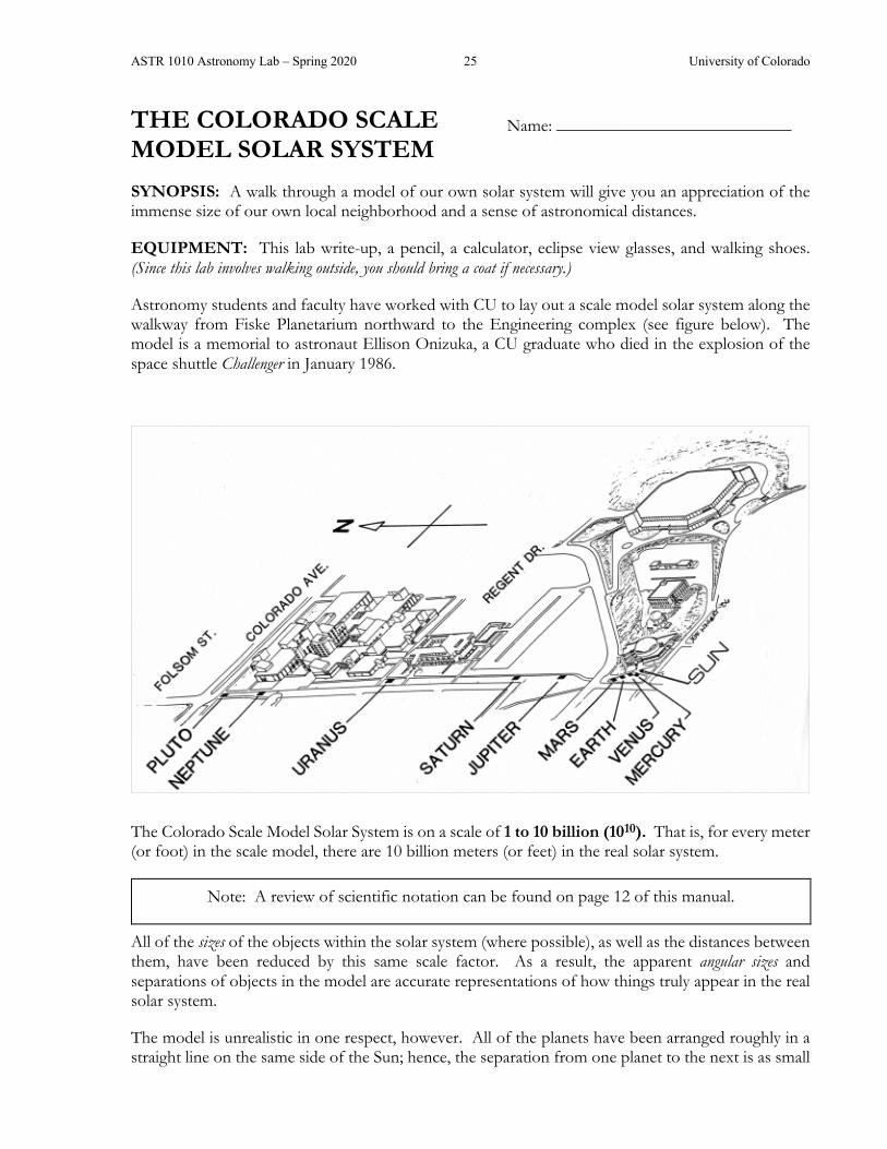
Astronomy students and faculty have worked with CU to lay out a scale model solar system along the walkway from Fiske Planetarium northward to the Engineering complex (see figure below). The model is a memorial to astronaut Ellison Onizuka, a CU graduate who died in the explosion of the space shuttle Challenger in January 1986.
The Colorado Scale Model Solar System is on a scale of 1 to 10 billion (1010). That is, for every meter (or foot) in the scale model, there are 10 billion meters (or feet) in the real solar system.
Note: A review of scientific notation can be found on page 12 of this manual.
All of the sizes of the objects within the solar system (where possible), as well as the distances between them, have been reduced by this same scale factor. As a result, the apparent angular sizes and separations of objects in the model are accurate representations of how things truly appear in the real solar system.
The model is unrealistic in one respect, however. All of the planets have been arranged roughly in a straight line on the same side of the Sun; hence, the separation from one planet to the next is as small
Name: ___________________________

ASTR 1010 Astronomy Lab – Spring 2020 26 University of Colorado
as it can possibly be. The last time all nine planets were lined up this well in the real solar system, the year was 1596 BC.
In a more accurate representation, the planets would be scattered in all different directions (but still at their properly-scaled distances) from the Sun. For example, rather than along the sidewalk to our north, Jupiter could be placed in Kittridge Commons to the south; Uranus might be found on the steps of Regent Hall; Neptune could be in the Police Building (for its crimes?); and Pluto in Folsom Stadium. Of course, the inner planets (Mercury, Venus, Earth, and Mars) will still be in the vicinity of Fiske Planetarium, but could be in any direction from the model Sun.
Before you go out to explore the planets, make some estimates. You won’t be marked off if you are wrong (but WILL if you leave them blank!)
I. Predictions I.1 In this model, the Sun is the size of a grapefruit (13.9 cm or 5.5 inches in diameter). How
large do you predict the Earth will be in this model? What common object (e.g speck of dust, grain of sand, marble, baseball, basketball, etc…) do you think will be approximately the same size as the Earth?
I.2 Which planet do you think is most similar to Earth in size?
I.3 Which planet do you think is most similar to Earth in length of day (rotation period)?
I.4 Jupiter is the largest planet in our solar system. What common object do you think you will be able to use to represent Jupiter?
I.5 How long (in Earth-hours or Earth-days) do you think it takes Jupiter to rotate once (i.e. experience one complete Jupiter-day)?
I.6 Which planet has the most moons? Which has the least?

ASTR 1010 Astronomy Lab – Spring 2020 27 University of Colorado
II. Inner Solar System As you pass each of the four innermost planets, you’ll need to jot down some of the important properties of each planet AND record the number of steps you took between each planet.
(Hint: you should look at the next page to see what things you should be writing down)
Mercury (Steps from the Sun: _____) Venus (Steps from Mercury: _____)
Earth (Steps from Venus: _____) Mars (Steps from Earth: _____)

ASTR 1010 Astronomy Lab – Spring 2020 28 University of Colorado
II.1 Were you right in your estimate for what object you could use to represent Earth? If not, pick a new object now.
II.2 Based on the planets encountered so far:
(a) Which planet is most like the Earth in temperature?
(b) Which planet is most similar to the Earth in size?
(c) Which is the smallest planet?
(d) Which planet has a period of rotation (its day) very much like the Earth’s?
(e) Which planet(s) has/have the least moons?
The real Earth orbits about 93 million miles (150 million km) from the Sun. This distance is known as an astronomical unit, or AU for short. The AU is very convenient for comparing relative distances in the solar system by using the average Earth-Sun separation as a standard distance.
II.3 What fraction of an AU does one of your steps correspond to in the model? How many miles do you cover in each step?
ASTR 1010 Astronomy Lab – Spring 2020 29 University of Colorado
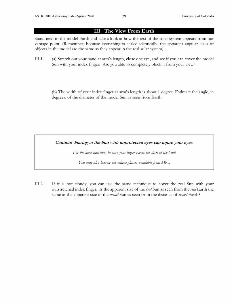
III. The View From Earth Stand next to the model Earth and take a look at how the rest of the solar system appears from our vantage point. (Remember, because everything is scaled identically, the apparent angular sizes of objects in the model are the same as they appear in the real solar system).
III.1 (a) Stretch out your hand at arm’s length, close one eye, and see if you can cover the model Sun with your index finger. Are you able to completely block it from your view?
(b) The width of your index finger at arm’s length is about 1 degree. Estimate the angle, in degrees, of the diameter of the model Sun as seen from Earth.
Caution! Staring at the Sun with unprotected eyes can injure your eyes.
For the next question, be sure your finger covers the disk of the Sun!
You may also borrow the eclipse glasses available from SBO.
III.2 If it is not cloudy, you can use the same technique to cover the real Sun with your outstretched index finger. Is the apparent size of the real Sun as seen from the real Earth the same as the apparent size of the model Sun as seen from the distance of model Earth?
ASTR 1010 Astronomy Lab – Spring 2020 30 University of Colorado
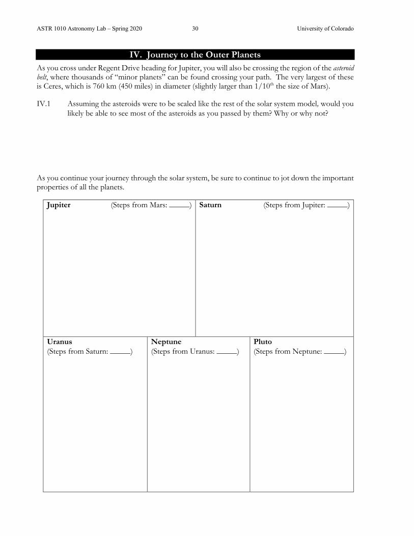
IV. Journey to the Outer Planets As you cross under Regent Drive heading for Jupiter, you will also be crossing the region of the asteroid belt, where thousands of “minor planets” can be found crossing your path. The very largest of these is Ceres, which is 760 km (450 miles) in diameter (slightly larger than 1/10th the size of Mars).
IV.1 Assuming the asteroids were to be scaled like the rest of the solar system model, would you likely be able to see most of the asteroids as you passed by them? Why or why not?
As you continue your journey through the solar system, be sure to continue to jot down the important properties of all the planets.
Jupiter (Steps from Mars: _____) Saturn (Steps from Jupiter: _____)
Uranus (Steps from Saturn: _____)
Neptune (Steps from Uranus: _____)
Pluto (Steps from Neptune: _____)
ASTR 1010 Astronomy Lab – Spring 2020 31 University of Colorado
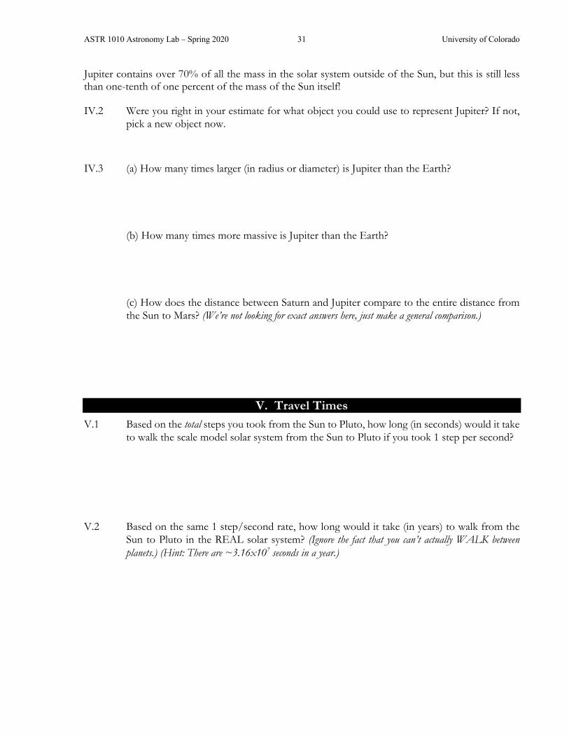
Jupiter contains over 70% of all the mass in the solar system outside of the Sun, but this is still less than one-tenth of one percent of the mass of the Sun itself!
IV.2 Were you right in your estimate for what object you could use to represent Jupiter? If not, pick a new object now.
IV.3 (a) How many times larger (in radius or diameter) is Jupiter than the Earth?
(b) How many times more massive is Jupiter than the Earth?
(c) How does the distance between Saturn and Jupiter compare to the entire distance from the Sun to Mars? (We’re not looking for exact answers here, just make a general comparison.)
V. Travel Times V.1 Based on the total steps you took from the Sun to Pluto, how long (in seconds) would it take
to walk the scale model solar system from the Sun to Pluto if you took 1 step per second?
V.2 Based on the same 1 step/second rate, how long would it take (in years) to walk from the Sun to Pluto in the REAL solar system? (Ignore the fact that you can’t actually WALK between planets.) (Hint: There are ~3.16x10⁷ seconds in a year.)

ASTR 1010 Astronomy Lab – Spring 2020 32 University of Colorado
VI. Beyond Pluto Although we have reached the edge of the solar system as we typically describe it that does not mean that the solar system actually ends here. It does not mean that our exploration of the solar system ends here, either.
Over on Pearl Street Mall to your north, about 125 AU from the Sun, Voyager 1 is still travelling outwards towards the stars, and still sending back data to Earth. It is currently in an area known as the heliosheath (where the Sun’s wind pressure is almost balanced by space pressure itself).
Spacecraft exiting the Solar System (as of January 2020)
In 2000 years, Comet Hale-Bopp (which was visible from Earth in 1997, and is shown on the cover of this lab manual) will reach its farthest distance from the Sun (aphelion), just north of the city of Boulder at our scale. Comet Hyakutake, which was visible from Earth in 1996, will require 23,000 years more to reach its aphelion distance, which is 15 miles to the north in our scale model, near the town of Lyons.
Beyond Hyakutake’s orbit is a great repository of comets-yet-to-be: the Oort cloud, a collection of a billion or more microscopic (at our scale) “dirty snowballs” scattered across the space between Wyoming and the Canadian border. Each of these icy worldlets is slowly orbiting our grapefruit-sized model of the Sun, waiting for a passing star to jostle it into a million-year plunge into the inner solar system.
Other Solar Systems And there is where our solar system really ends. Beyond that, you’ll find nothing but empty space until you encounter Proxima Centauri, a tiny star the size of a cherry, 4,000 km (2,400 miles) from our model Sun (still staying at our 1-to-10 billion scale)! This puts it at about the distance of Fairbanks, Alaska. At this scale, Proxima orbits 160 kilometers (100 miles) around two other stars collectively called Alpha Centauri: one is the size and brightness as the Sun, and the other only half as big (the size of an orange) and one-fourth as bright. The two stars of Alpha Centauri orbit each other at a distance of only 1000 feet (0.3 km) in our scale model.
Now you know why we call it SPACE!

ASTR 1010 Astronomy Lab – Spring 2020 33 University of Colorado
APPARENT MOTIONS OF THE SUN & MOON°
Pre-Lab = please complete before coming to lab Read briefly through the entire lab. Check this box ☐ to indicate that you have done so. Jot down any questions that occurred to you while skimming through the lab description.
1) What is the difference between latitude and longitude? What is the latitude of Boulder?
2) At noon today in Boulder, generally where should you look to see the Sun in the sky? (In the northern, eastern, southern, or western part of the sky?)
3) How can the Sun and the Moon have the same apparent angular size in our sky?
Name: ___________________________

ASTR 1010 Astronomy Lab – Spring 2020 34 University of Colorado
ASTR 1010 Astronomy Lab – Spring 2020 35 University of Colorado
APPARENT MOTIONS OF THE SUN AND MOON SYNOPSIS: The goal is to investigate some of the apparent motions of the Sun & Moon in the sky. You will then use these results to explain why Earth experiences both seasons and phases of the Moon.
EQUIPMENT: A globe of the Earth, a bright light, foam Moon ball, space to move around.
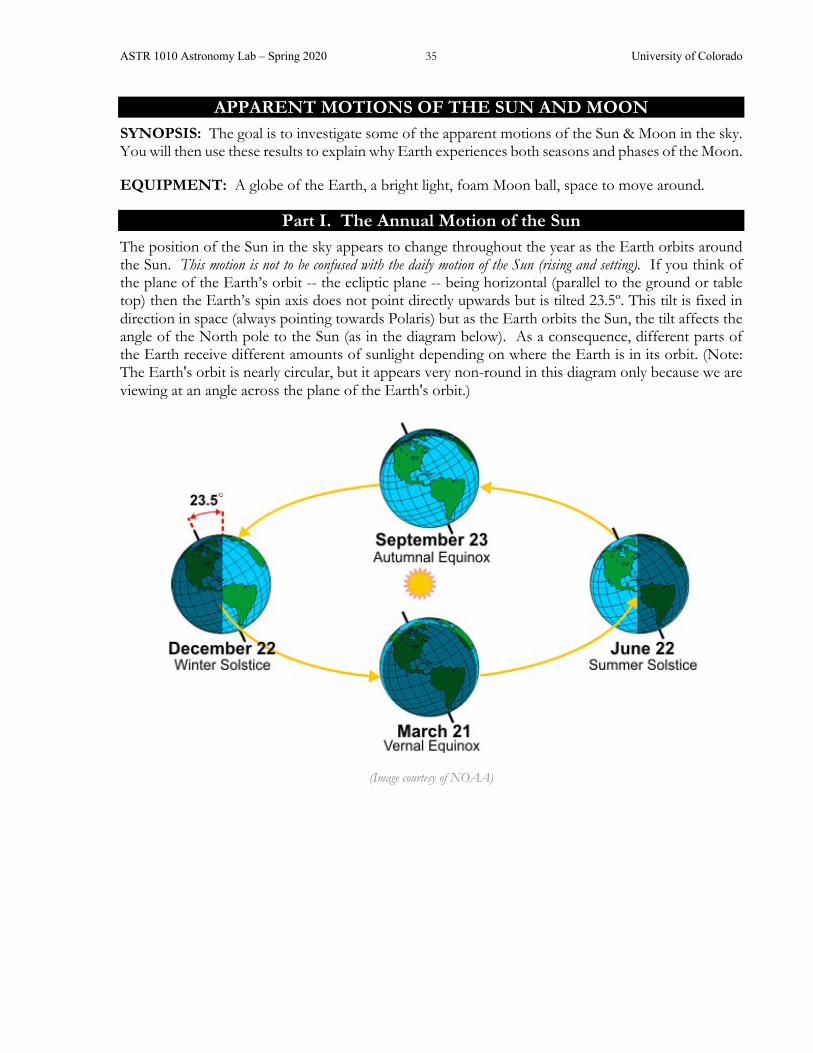
Part I. The Annual Motion of the Sun The position of the Sun in the sky appears to change throughout the year as the Earth orbits around the Sun. This motion is not to be confused with the daily motion of the Sun (rising and setting). If you think of the plane of the Earth’s orbit -- the ecliptic plane -- being horizontal (parallel to the ground or table top) then the Earth’s spin axis does not point directly upwards but is tilted 23.5º. This tilt is fixed in direction in space (always pointing towards Polaris) but as the Earth orbits the Sun, the tilt affects the angle of the North pole to the Sun (as in the diagram below). As a consequence, different parts of the Earth receive different amounts of sunlight depending on where the Earth is in its orbit. (Note: The Earth's orbit is nearly circular, but it appears very non-round in this diagram only because we are viewing at an angle across the plane of the Earth's orbit.)
(Image courtesy of NOAA)

ASTR 1010 Astronomy Lab – Spring 2020 36 University of Colorado
(Image courtesy of User:Blueshade / Wikimedia Commons / CC-BY-SA-2.0)
I.1 We know the Sun (like the stars) looks like it rises in the east and sets in the west. Use your globe to determine which direction the Earth spins. When viewed from above the North Pole, does it rotate clockwise or counterclockwise?
The illustration above question I.1 shows the Earth at the summer solstice for the Northern Hemisphere. Position your globe such that Boulder is at noon and it is the summer solstice.
At noon, the Sun is high in the sky in Boulder and shining (almost) directly down on us, so it is summer for us. At the end of the semester, you’ll investigate this phenomenon in more detail. For today, let’s look at a few other locations on the globe and compare them to Boulder.
I.2 Find a city somewhere in Asia at the same latitude as Boulder. List the city (and country) that you’ve chosen. What season is this part of the world experiencing? (You may want to spin your globe (don’t change the direction of the tilt!) to simulate daytime in that country.)
I.3 The Tropic of Cancer (23.5° north latitude) marks the latitude where the Sun is at the zenith (directly overhead) at noon on the summer solstice. Can the Sun ever be seen at the zenith (at noon) from here in Boulder? If so, when? If not, why not? Use your globe to confirm your answer.
ASTR 1010 Astronomy Lab – Spring 2020 37 University of Colorado
I.4 Is there anywhere in all of the fifty United States where you could see the Sun at the zenith at some time of the year? If so, where?
I.5 The Arctic Circle lies at a latitude of 66.5° north. North of the Arctic Circle, the Sun is above the horizon for 24 continuous hours at least once per year and below the horizon for 24 continuous hours at least once per year. Find the town of Barrow, Alaska. On the summer solstice at what times will the Sun rise and set in Barrow?
Without changing the orientation (tilt) of the globe, rotate it so it is noon in Australia. Study what is happening “down under” in Melbourne, Australia.
I.6 On the Northern Hemisphere's summer solstice is the Sun in the northern or southern portion of the sky, as seen from Melbourne?
I.7 Is it high in their sky or low? (Hint: think about where their zenith point is.)
I.8 What season is Melbourne (and all of Australia) experiencing? Explain.
I.9 The Antarctic Circle is the southern equivalent of the Arctic Circle. On our summer solstice what time does the Sun rise at the South Pole?
I.10 The Tropic of Capricorn lies at 23.5° south latitude. Find Lake Disappointment in the Great Sandy Desert of Australia. Is the Sun ever directly overhead there? If so, when?
I.11 In Australia, do the stars still rise in the east and set in the west? (Hint: Use your globe to verify!) Explain the reason for your answer.

ASTR 1010 Astronomy Lab – Spring 2020 38 University of Colorado
Part II. The Moon’s Orbit Now let’s think about the Moon’s movement around the Earth. The diagram below shows the overhead view of the Earth and Moon with the Sun off to the right. Depending on where you are sitting in the lab room, the Sun (bright light in the center of the classroom) may be coming from a different direction, but the Moon still orbits the Earth counterclockwise when viewed from above the North Pole. For this activity, you can assume that sunrise is at 6am and sunset is at 6pm.
Note that half of the Moon is always illuminated (just like the Earth); even though it may not appear to be from our view here on Earth.
II.1 The picture above does not represent one day. How long (roughly) does it take the Moon to orbit the Earth once? How many times does the Earth rotate in that same period?
Imagine that your head is the Earth and that you live on the tip of your nose. Position yourself such that your head is pointing directly at the “Sun” (the light).
II.2 What time is it for the mini-you living on the tip of your nose?
Slowly turn your head around counterclockwise to simulate the daily cycle: sunrise, noon, sunset, midnight, and back to sunrise. This should give you a feel of what direction in space you are looking during the different times of the day (and entertain your labmates).
II.3 Assuming your head is the Earth and the United States stretches from your right eye to your left eye, which eye represents the East Coast?
The North Pole
ASTR 1010 Astronomy Lab – Spring 2020 39 University of Colorado
Hold your “Moon” foam ball out at arm’s length. Start with the Moon pointed in the direction of the Sun. While holding the Moon out in front of your nose, spin counterclockwise (to your left). Keep your eyes on the Moon the entire time. Stop turning when the portion of the Moon you can see is more than a sliver but not quite half lit. We call this a crescent moon.
II.4 Which side of the Moon (that you can see) is illuminated (right or left)?
II.5 Draw the alignment between the Moon (foam ball), the Earth (your head) and the Sun (light) as seen from above. It may look similar to the diagram at the start of this section, but there should only be one Moon and one person (and it is likely not in any of the places shown on that diagram).
II.6 Based on your drawing, what is the (approximate) angle between the Moon, the Earth and the Sun: 0°, 45°, 90°, 135°, 180°?
II.7 What time is it for mini-you on the tip of your nose? (This is the time you would see that Moon phase highest in the sky.) Explain your reasoning.
If the illuminated portion of the Moon is getting bigger as it progresses through its phases, we call it “waxing.” If it is getting smaller, we call it “waning.”
II.8 Are you looking at a waxing crescent or waning crescent moon?

ASTR 1010 Astronomy Lab – Spring 2020 40 University of Colorado
Continue to turn slowly to your left until the illuminated portion of the Moon you can see, is exactly half lit. Your alignment should match one of the numbered positions in the diagram at the start of this section. This phase is called first quarter.
II.9 Why do you think this phase is called a quarter moon, when it looks half lit?
Continue to turn slowly to your left until the Sun is directly behind you. (You may have to lift the Moon above your head a bit so your head doesn’t block the sunlight.)
II.10 What do we call this phase of the Moon?
If you lower the Moon a little you will probably move it behind the shadow of your head. This is a lunar eclipse, when the shadow of the Earth (in this case, the shadow from your head) covers the Moon. In Part IV, you’ll explore why there isn’t a lunar eclipse every time there is a full moon.
Continue to turn counterclockwise, holding the Moon at arm’s length. Stop when the illuminated portion of the Moon you can see is no longer full but not yet half illuminated. This is known as a “gibbous” moon.
II.11 From your perspective, which side of the Moon is now illuminated?
II.12 Draw the alignment between the Moon, the Earth, and the Sun as seen from above.
II.13 Is this a waxing gibbous or waning gibbous moon? Explain your answer.

ASTR 1010 Astronomy Lab – Spring 2020 41 University of Colorado
II.14 When you are facing directly towards your moon, what time is it for mini-you on the tip of your nose? (This is the time you would see that moon phase highest in the sky.)
Part III. Moonrise and Moonset In reality, the Moon doesn’t orbit as fast as the Earth rotates. So, when you’ve been moving your head with the Moon, you’ve been making the Moon orbit way too fast. (A day is 24 hours, how long is the Moon’s orbit?) Let’s investigate moonrise and moonset.
If your mini-you (living on the tip of your nose) had a horizon, it could be simulated as an imaginary plane that cuts down through your head and goes through both ears. North on the horizon would be the top of your head and south on the horizon would be below your chin.
III.1 Which ear represents the western point of the horizon (your right or left)? (Hint: You might think back to your answer to question II.3.)
While keeping your arm in the same place it was for QII.14 (i.e. don’t move the Moon in its orbit) continue to turn your head to the left (simulating the Earth’s rotation). Stop when the Moon is even with your right ear.
III.2 The Moon is about to cross your horizon. Is this rising or setting?
III.3 What time is it for mini-you on the tip of your nose?
III.4 Use everything you have learned in this section, draw a picture of the alignment of the Moon, the Earth, and Sun as seen from above for a waning crescent moon. Also, draw a mini-you on the Earth that would currently be seeing the moon rising.
You should check your answer with your TA/LA before moving on to make sure you have this concept correct.

ASTR 1010 Astronomy Lab – Spring 2020 42 University of Colorado
Even though it is usually regarded as a nighttime object, some phases of the Moon can be seen during the day. Go outside to see if the Moon is visible right now (your TA/LA can help). If it is up (and it is sunny), hold up your foam Moon ball at arm’s length in the direction of the real Moon.
III.5 Should the foam Moon ball have the same phase as the real Moon? (If weather and lunar phase permit), does it? Explain your thinking; drawings might help.
Part IV. Solar and Lunar Eclipses Because the Sun and Moon have roughly the same angular size (as viewed from Earth), it is possible for the Moon to block out the Sun from our view, causing a solar eclipse.
IV.1 Hold the foam Moon ball at arm’s length and move it through its phases. There is only one phase of the Moon when it is possible for it to block your view of the Sun, causing a solar eclipse. Which phase is this?
IV.2 Now simulate this arrangement with the Moon, the Earth globe, and the Sun. In your lab setup, does the Moon’s shadow cover the entire Earth, or does only a portion of the Earth line in the Moon’s shadow?
IV.3 Does this mean that all people on the sunlit side of the Earth can see a solar eclipse when it happens, or only some people in certain locations? Explain your answer.

ASTR 1010 Astronomy Lab – Spring 2020 43 University of Colorado
The Moon's orbit is not quite circular. The Earth-Moon distance varies between 28 and 32 Earth diameters. If a solar eclipse occurs when the Moon is at the point in its orbit where the distance from Earth is “just right,” then the Moon's apparent size can exactly match the Sun’s apparent size.
IV.4 If the Moon were at its farthest point to the Earth during a solar eclipse, would its angular size appear bigger or smaller than the Sun as seen from Earth?
IV.5 Draw and/or describe what the Sun would look like from the Earth during a solar eclipse, if the Moon is at its farthest possible distance.
It is also possible for the shadow of the Earth to block the sunlight reaching the Moon, causing a lunar eclipse.
IV.6 Once again, move the Moon through its phases around your head and find the one phase where the shadow from the Earth (your head) can fall on the Moon, causing a lunar eclipse. What lunar phase is this? (Or what phase was it just before the eclipse?)
IV.7 During a lunar eclipse, is it possible for one person to see a lunar eclipse and someone far away on Earth to see the Moon not being eclipsed? Explain your answer.
Many people mistakenly think that a lunar and solar eclipse should occur every time that the Moon orbits the Earth. This misconception is due to the fact that we usually show the Moon far closer to the Earth than it actually is, making it appear that an eclipse is unavoidable. However, the Moon’s actual distance is roughly 30 Earth-diameters away, and the Moon’s orbit is tilted slightly (~5°) to the ecliptic plane.
Your TA may have toys set up in the lab to demonstrate the Moon’s orbit around the Earth. Use these demos to visualize the scale and/or tilt of the Moon’s orbit.

ASTR 1010 Astronomy Lab – Spring 2020 44 University of Colorado
Position the foam Moon ball in the full phase and hold it (as close as you can to) a properly scaled distance from the globe of the Earth (30 Earth-diameters away).
IV.8 Compared to when you held the foam Moon at arm’s length from the globe Earth, is it easier or more difficult to align the Moon, Earth, and Sun to cause a lunar eclipse?
IV.9 First using the foam Moon ball, and then by making a sketch below showing the view of the Sun-Earth-Moon system from the side (edge-on), show how the Earth's shadow can miss the Moon, so that a lunar eclipse does not occur.

ASTR 1010 Astronomy Lab – Spring 2020 45 University of Colorado
KEPLER’S LAWS Pre-Lab = please complete before coming to lab
Read briefly through the entire lab. Check this box ☐ to indicate that you have done so. Jot down any questions that occurred to you while skimming through the lab description.
1) Which law states that planets orbit in an ellipse?
2) What is the semi-major axis of an ellipse?
3) Explain why the following statement is false: The orbital period of Mars is longer than the Earth’s orbital period because its orbit is less circular.
4) Mathematically, solve Kepler’s 3rd Law for period.
Name: _____________________

ASTR 1010 Astronomy Lab – Spring 2020 46 University of Colorado

ASTR 1010 Astronomy Lab – Spring 2020 47 University of Colorado
KEPLER’S LAWS
SYNOPSIS: Johannes Kepler formulated three laws that described how the planets orbit around the Sun. His work paved the way for Isaac Newton, who derived the underlying physical reasons why the planets behave as Kepler had described. In this exercise, you will use computer simulations of orbital motions to experiment with various aspects of Kepler's three laws of motion. The learning goal of this lab is to understand what factors control a planet’s motion around the Sun.
EQUIPMENT: Computer with internet connection, stopwatch.
Getting Started Here's how you get your computer up and running:
(1) Launch an internet browser. (If you are using the computers in the scorpius computer lab, click the globe at the bottom of the screen to launch a browser.)
(2) Go to the website http://astro.unl.edu/naap/pos/animations/kepler.html
Part I. Kepler's First Law Kepler's First Law states that a planet moves on an ellipse around the Sun with the Sun at one focus.
If it is not already running, launch the NAAP Planetary Orbit Simulator described in the previous section.
• Click on the Kepler’s 1st Law tab if it is not already highlighted (it should open by default) • One-by-one, enable all 5 check boxes. Make sure you understand what each one is showing. • The white dot is the “simulated planet.” You can click on it and drag it around. • Change the size of the orbit with the semimajor axis slider. Note how the background grid
indicates change in scale while the displayed orbit size remains the same (planet and star sizes don’t change despite zooming in or out.)
• Change the eccentricity using the eccentricity slider. Note the maximum value allowed is not a real physical limitation, but one of practical consideration in the simulator.
• Animate the simulated planet. Select an appropriate animation rate. • The planetary presets set the simulated planet’s parameters to those like our solar system’s
planets (and one dwarf planet). Explore these options.
Name: ___________________________
ASTR 1010 Astronomy Lab – Spring 2020 48 University of Colorado
I.1 Where is the Sun located in the ellipse?
I.2 Can a planet move on a circular orbit? If yes, where would the Sun be with respect to that circle? If no, why not?
I.3 What is meant by the eccentricity of an ellipse? Give a description (in words, rather than using formulae).
I.4 What happens to an ellipse when the eccentricity becomes zero?
I.5 What happens to an ellipse when the eccentricity gets close to one?
I.6 Draw an orbit below with non-zero eccentricity and clearly indicate a point where r1 and r2 are equal in value.

ASTR 1010 Astronomy Lab – Spring 2020 49 University of Colorado
I.7 On planet Blob, the average global temperature stays exactly constant throughout the planet's year. What can you infer about the eccentricity of Blob's orbit? Explain your reasoning.
I.8 On planet Blip, the average global temperature varies dramatically over the planet's year. What can you infer about the eccentricity of Blip's orbit? Explain your reasoning. (Note: This is very different than the cause of seasons on Earth but does happen on some other planets in our solar system.)
I.9 For an ellipse of eccentricity e = 0.7, calculate the ratio of aphelion (the point farthest from the Sun) over perihelion (the point closest to the Sun). Use the grid to read distances directly off the screen (you may need to estimate fractions of a box).
I.10 For e = 0.1?
I.11 Without using the simulation applet, what happens to the ratio of aphelion to perihelion as e gets very close to zero? What about as e gets very close to 1?
The following questions pertain to our own Solar System. Use the built-in presets to explore the characteristics of the members of our system.
I.12 Which of the Sun's planets has the largest eccentricity? (Ignore Pluto.)
I.13 What is the ratio of aphelion to perihelion for this object?
I.14 Which of the Sun's planets has the smallest eccentricity? (Still ignoring poor Pluto.)
ASTR 1010 Astronomy Lab – Spring 2020 50 University of Colorado
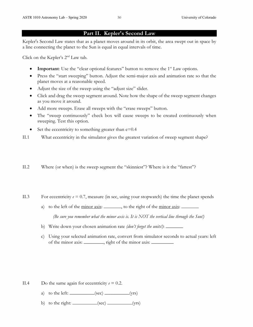
Part II. Kepler's Second Law Kepler's Second Law states that as a planet moves around in its orbit, the area swept out in space by a line connecting the planet to the Sun is equal in equal intervals of time.
Click on the Kepler’s 2nd Law tab.
• Important: Use the “clear optional features” button to remove the 1st Law options. • Press the “start sweeping” button. Adjust the semi-major axis and animation rate so that the
planet moves at a reasonable speed. • Adjust the size of the sweep using the “adjust size” slider. • Click and drag the sweep segment around. Note how the shape of the sweep segment changes
as you move it around. • Add more sweeps. Erase all sweeps with the “erase sweeps” button. • The “sweep continuously” check box will cause sweeps to be created continuously when
sweeping. Test this option.
• Set the eccentricity to something greater than e=0.4
II.1 What eccentricity in the simulator gives the greatest variation of sweep segment shape?
II.2 Where (or when) is the sweep segment the “skinniest”? Where is it the “fattest”?
II.3 For eccentricity e = 0.7, measure (in sec, using your stopwatch) the time the planet spends
a) to the left of the minor axis: _______, to the right of the minor axis: _______
(Be sure you remember what the minor axis is. It is NOT the vertical line through the Sun!)
b) Write down your chosen animation rate (don’t forget the units!): _______
c) Using your selected animation rate, convert from simulator seconds to actual years: left of the minor axis: ________, right of the minor axis: _________
II.4 Do the same again for eccentricity e = 0.2.
a) to the left: __________(sec) __________(yrs)
b) to the right: __________(sec) __________(yrs)

ASTR 1010 Astronomy Lab – Spring 2020 51 University of Colorado
II.5 Where does a planet spend more of its time: near perihelion or near aphelion?
II.6 Where is a planet moving the fastest: near perihelion or near aphelion?
Part III. Kepler's Third Law Kepler's Third Law presents a relationship between the size of a planet's orbit (given by its semi-major axis, a) and the time required for that planet to complete one orbit around the Sun (its period, P). When the semi-major axis is measured in astronomical units (AU) and the period is measured in Earth years (yrs), this relationship is:
P2 = a3
Click on the Kepler’s 3rd Law tab.
• The logarithmic graph has axes marks that are in increasing powers of ten. You will use this type of graph a little more in a future lab. For now, stay on linear.
III.1 Rearrange the equation for Kepler’s 3rd Law to give an expression for the value of the semi-major axis, a, in terms of a given period, P (i.e. solve for a). If the period increases by a factor of two, how much does the semi-major axis change by?
III.2 Does changing the eccentricity in the simulator change the period of the planet? Why or why not?

ASTR 1010 Astronomy Lab – Spring 2020 52 University of Colorado
III.3 Halley’s comet has a semi-major axis of about 17.8 AU and an eccentricity of about 0.97. Compare (in a rough sense) this eccentricity to our Solar System’s planets. What is the period of Halley’s comet? (Food for thought: The last time Halley’s comet came by was 1986. How old will you be when it comes back?)
III.4 How does Kepler’s 2nd Law contribute to why we can only see the comet close to Earth for about 6 months during each of those periods? (Hint: You might look at your answer for II.5)

ASTR 1010 Astronomy Lab – Spring 2020 53 University of Colorado
SURVIVOR CHALLENGE Pre-Lab = please complete before coming to lab
Read briefly through the entire lab. Check this box ☐ to indicate that you have done so. Jot down any questions that occurred to you while skimming through the lab description.
1) In your daily life around Boulder, what reference points do you often use to estimate which direction you are facing or where you are? (There’s no wrong answer here!)
2) Have you ever used the sky to navigate or figure out where you are? (Likewise, no wrong answer!)
Name: ___________________________

ASTR 1010 Astronomy Lab – Spring 2020 54 University of Colorado

ASTR 1010 Astronomy Lab – Spring 2020 55 University of Colorado
SURVIVOR CHALLENGE SYNOPSIS: You will be taken to a random location somewhere on the northern hemisphere of the Earth at a random time of the year. Your goal is to figure out where you are located and what month of the year it is using only basic observations of the sky and your ingenuity. You will be graded primarily on the quality of your plan, not your answers.
Real science involves creativity and imagination to figure things out. Part of the goal of this lab is to provide a better understanding for how scientists actually work.
EQUIPMENT: This lab write-up, a pencil, and a white board and marker to share with your group for brainstorming. Globes, laser pointers, and red flashlights are available to share among the whole class.
TOOLS AT YOUR DISPOSAL: Since you will effectively be in control of the planetarium, here are some tools and superpowers you can utilize to help you figure out your time and location on Earth:
• You will have a chance to observe the Boulder sky on the mystery date for 24 hours before you are taken to a mystery location.
• You have an imaginary watch that is always set to Boulder time during this whole activity. At any time you can ask the planetarium operator “What time is it in Boulder?”
• You may request information from the planetarium operators, for instance, “stop turning the sky at sunset and tell us the time when the sun sets.” Or, “stop the sky at noon.”
• Once you are in the mystery location, you can observe the sky for 24 hours (and stop the sky as you wish). You may also observe any day one month earlier and one month later than the mystery date.
• You DO NOT have superpowers to be able to see lines, grids, degrees, cardinal directions, or other projections on the sky. You must use what you’ve learned in class and your ingenuity to discover some of these things for yourself!
Planning, Observing, Interpreting You will be given some time to discuss with your group what kinds of observations you want to make in the planetarium to try to figure out where and when you are. Once you are ready, you will have time in the planetarium to play and explore, working with the planetarium operator. Have fun!
Name: __________________________

ASTR 1010 Astronomy Lab – Spring 2020 56 University of Colorado
Observations we will make and what they can tell us:

ASTR 1010 Astronomy Lab – Spring 2020 57 University of Colorado
For each item give your answer, what evidence you used and how accurate you think it is. Our latitude is ________________ with an approximate uncertainty of ______________ We know this because: Our longitude is ________________ with an approximate uncertainty of ______________ We know this because: The date is ________________ with an approximate uncertainty of ______________ We know this because: Where do you think you are? (Name or describe the place and what the climate is like.)

ASTR 1010 Astronomy Lab – Spring 2020 58 University of Colorado
Image courtesy of User:TimeZonesBoy / Wikimedia Commons

ASTR 1010 Astronomy Lab – Spring 2020 59 University of Colorado
THE ERATOSTHENES EXPERIMENT
Pre-Lab = please complete before coming to lab Read briefly through the entire lab. Check this box ☐ to indicate that you have done so. Jot down any questions that occurred to you while skimming through the lab description.
1) If the Sun was directly above the town of Syene at solar noon on the summer solstice, at what latitude must Syene be located?
2) In your own words, explain the difference between precision and accuracy.
3) Estimate the order-of-magnitude distance from Sommers-Bausch Observatory to Baseline Road. This can be a very rough estimate, and you will not be penalized if you are wrong.
Name: _____________________

ASTR 1010 Astronomy Lab – Spring 2020 60 University of Colorado

ASTR 1010 Astronomy Lab – Spring 2020 61 University of Colorado
THE ERATOSTHENES EXPERIMENT
SYNOPSIS: The purpose of this observing project is to measure the circumference of the Earth in your paces and then in yards and miles using the ancient methods of Eratosthenes. We will use the results to have you discuss why measurement errors are not mistakes and why systematic errors sometimes are mistakes. If you want to make this a more accurate historical re-enactment, we will give you the opportunity to calibrate your paces in the CU football stadium (since the ancient Greeks measured distances in stadia).
Background: Eratosthenes of Cyrene
Born: 276 BC in Cyrene, North Africa (now Shahhat, Libya). Died: 194 BC in Alexandria, Egypt
Eratosthenes was student of Zeno (founder of the Stoic school of philosophy), invented a mathematical method for determining prime numbers, and … made the first accurate measurement for the circumference of the Earth!
Details were given in his treatise "On the Measurement of the Earth" which is now lost. However, some details of these calculations appear in works by other authors. Apparently, Eratosthenes compared the noon shadow at Midsummer (June 21st) between Syene (now Aswan on the Nile in Egypt) and Alexandria, 500 miles to the North on the Mediterranean Sea. He assumed that the Sun was so far away that its rays were essentially parallel, and then with a knowledge of the distance between Syene and Alexandria, he gave the length of the circumference of the Earth as 250,000 stadia (1 stadium = the length of a Greek stadium).
We still do not know how accurate this measurement is because we still do not know the exact length of a Greek stadium. (Units matter!) However, scholars of the history of science have suggested a value for the stadium and estimate that Eratosthenes’ measurement was 17% too small. Unfortunately, in Renaissance times, the length of a Greek stadium was under-estimated as well, yielding an even smaller circumference for the Earth. This small value led Columbus to believe that the Earth was not nearly as large as it is, so when he sailed to the New World, he was quite confident that he had sailed far enough to reach India.
Name: ___________________________

ASTR 1010 Astronomy Lab – Spring 2020 62 University of Colorado
This figure shows how Eratosthenes made his measurement. He had heard that on the summer solstice the Sun at noon stood directly over Syene, at the zenith, so that the Sun's light penetrated all the way down to the bottom of a well at Syene casting no shadow. Eratosthenes measured the angle of the Sun off the zenith (called the zenith angle; angle "a" in the figure) from Alexandria on that same day. (Unfortunately, his measurement of a was ~6% too small.) As shown in the figure, a is also the difference in latitudes of these two locations.
The angle a is to 360 degrees (a full circle) as the distance between Alexandria and Syene is to the full circumference of the Earth. Eratosthenes had a measurement for the distance between Syene and Alexandria of 5000 stadia. Mathematically:
and so (rearranging):
What do we need to know to make a modern "Eratosthenes measurement"? We need to know the equivalent of the two measurements Eratosthenes had:
1. The difference in latitude between two locations on Earth.
2. The difference in distance between these two locations in an exactly north-south direction.
Eratosthenes measured #1 and had obtained from others a value for #2. We will measure #2 (in paces, then in yards and miles) and obtain a value from others for #1.
Conveniently, we have two nearby locations with well-known latitudes. • Location 1: When Colorado was surveyed in the 1800s, Baseline Road was determined to be
at precisely 40 degrees North Latitude. • Location 2: More recently than that, an astronomical measurement at the Sommers-Bausch
Observatory (SBO) 24-inch telescope (located here at CU just north of Baseline Road) determined the latitude of SBO to be:
• 40.00372 degrees (+40° 00' 13.4") North
€
α360°
=5,000 Stadia
Circumference of the Earth
€
Circumference of the Earth =360°α
× 5,000 Stadia
a
a

ASTR 1010 Astronomy Lab – Spring 2020 63 University of Colorado
Part I – Measuring the Distance to Baseline Rd. Unfortunately, in recent years due to traffic control necessity, the course of Baseline Road has been altered just south of SBO. As shown in the photograph from space overleaf, Baseline curves gently north between Broadway Blvd and 30th Street. The white line is our best estimate for exactly 40 degrees North latitude based upon the course of Baseline Road east and west of this bend. Perhaps realizing that they had altered a geographically (and astronomically) important landmark, the city of Boulder (or maybe RTD?) has painted a red line on the sidewalk near the bus stop in order to mark the exact location of the 40th parallel. (Notice how it splits the rock to the east.)
To measure the north-south distance between SBO and Baseline Road, you will need to:
• Plan a route.
• Walk that route, carefully counting your paces.
• Calibrate the size of your paces using a tape measure.
Each member of your lab group must make these measurements (both pacing between SBO and Baseline and "calibrating" their paces by stepping off 100 yards). Each participant will then use the Eratosthenes Equation to determine how many paces you would need to walk to get all the way around the Earth. By calibrating your paces, you will then determine the circumference of the Earth.
Do not use your smart phones to accomplish this task. Eratosthenes did not have a phone.
THAT’S IT! That's all we are going to tell you, but if you need help be sure to ask the LAs or TA for some pointers. Each individual in each group must make their own measurements using the method agreed to by the group. Good luck. Keep thinking and stay safe! Especially when crossing Baseline and other streets…the cars do not know that you are conducting an historical reenactment!

ASTR 1010 Astronomy Lab – Spring 2020 64 University of Colorado
East
West
Nor
th
Sout
h

ASTR 1010 Astronomy Lab – Spring 2020 65 University of Colorado
I.1 Describe the route you took. You may want to mark your route on the map on the previous page as part of your description, although you must still explain your route in words.
I.2 There are many possible routes you could have taken. How did your group decide on this particular route? What procedures did you use to make sure your measurements were as accurate as possible?
Part II. Explaining your Measurements
The central equation for this lab is !
"#$°= '()*+,-.
/(0-123.0.,-.
II.1 Explain in words why the fraction on the left side of the equation (α/360o) must equal the fraction on the right side of the equation (Distance/Circumference). Include a drawing.
II.2 How did Eratosthenes get a value for α? How did he get a value for the distance?
II.3 How did you get a value for α? How did you get a value for the distance?

ASTR 1010 Astronomy Lab – Spring 2020 66 University of Colorado
II.4 Calculate the circumference of the Earth in meters and kilometers, based on your count of the number of paces between SBO and Baseline. Show all your work.
II.5 Write down what the other members of your group calculated for the circumference based on their paces. You do not need to show the calculations again.
Name:______________________ Circumference:_______________________
Name:______________________ Circumference:_______________________
Name:______________________ Circumference:_______________________
Name:______________________ Circumference:_______________________
II.6 Calculate your group's average value for the Earth’s circumference. Show your work.

ASTR 1010 Astronomy Lab – Spring 2020 67 University of Colorado
Part III. Errors Webster's dictionary defines error as "the difference between an observed or calculated value and the true value". We don't know the true value; otherwise there would be no reason to make the measurement. We wish our measurements to be both ACCURATE and PRECISE.
Accuracy relates to how closely the results of the experiment are to the true result. Thus, accuracy speaks to whether our chosen methods actually work to allow a measurement of the quantity we seek to determine, whether all assumptions have been accounted for and whether these assumptions do not compromise the measurement. Errors in setting up an accurate experiment are called systematic errors, and more and more precise measurements cannot reduce these types of errors.
Precision, on the other hand, refers to the actual measurement process itself. Greater precision in measurement can be accomplished by using a more accurate measuring device or by repeating measurements several times. Uncertainties in precision are called measurement or random uncertainties and repeated measurement can reduce these uncertainties (e.g., independent measurements by equally precise measuring tools or people) but never eliminate them. However, be warned, precise measurements do not yield an accurate result if the experimental setup is inaccurate; i.e., systematic and measurement errors are independent of one another and both must be dealt with to obtain the best value for the true result.
Any scientific measurement has inherent uncertainties and errors (precision in measurement and errors in experimental setup) that limit the ultimate precision of the result. All scientific experiments have these limitations, which must be quoted with the result (for example, even political polling reports results and uncertainties… 54% with an uncertainty of 3 percentage points…but beware, systematic errors are not reported and can be much larger in some cases – what if only men were polled? only rich people were polled?) In this experiment, think about the experimental setup, the specific methods that you and your group employed and the uncertainties and errors which may have limited the ultimate precision of your result.
ASTR 1010 Astronomy Lab – Spring 2020 68 University of Colorado
III.1 Typically, an experimental result is listed as: [value obtained] ± [precision]. Through a comparison of your final results on the circumference of the Earth with the results from the other members of your group, estimate the precision of your measurement, list your group’s result in this format
Circumference = _______________ ± _______________
III.2 Random errors tend to vary… randomly! If we repeated your measurements many times, sometimes it’d be a little too high and sometimes a little too low. Think back on how you got your data – what kinds of errors do you think might have been random, and how big are they? (List at least two.)
III.3 Why does averaging many results reduce the measurement uncertainty (i.e. produce a more precise measurement)?
III.4 Systematic errors are ones that no matter how many times we repeat the measurement, we will be consistently inaccurate. Think back on how you got your data – what kinds of errors do you think might have been systematic, and how big are they? (List at least two.)
III.5 Why does averaging many results not reduce the effects of systematic errors (i.e. not produce a more accurate measurement)?

ASTR 1010 Astronomy Lab – Spring 2020 69 University of Colorado
CALCULATING THE MASS OF SATURN
Pre-Lab = please complete before coming to lab Read briefly through the entire lab. Check this box ☐ to indicate that you have done so. Jot down any questions that occurred to you while skimming through the lab description.
MASS OF SATURN Newton’s Version of Kepler’s 3rd Law (NVK3L) has three variables: the semi-major axis of the orbit (a), orbital period (p), and the mass of whatever is being orbited around (M). If you know any two of these quantities, you can find the third.
Most usefully, this is how we can use the motion of an object due to gravity to determine mass.
This is the third part of a three-part observational lab. Normally you would have been making observations of Saturn through the telescopes on the SBO Observing Deck all semester long. Unfortunately, in the Spring semester, Saturn is up DURING THE DAY! We have provided you with last semester’s observations at the end of this lab.
Part 1 - Expectations
Kepler’s first law tells us that orbits are elliptical. The moons of planets are no exception to this rule. The rings of Saturn are composed of trillions of chunks of ice so they too can be thought of as tiny moons, all orbiting Saturn on elliptical orbits. In the case of Titan and the ring particles, the orbits are almost perfect circles. Furthermore, the rings and most of the large moons (including Titan) orbit in the equatorial plane of Saturn.
Q1.1: In the space below, draw a sketch of what Saturn (the planet), the rings, and the orbit of Titan would look like as viewed from directly above Saturn’s north pole. Titan orbits about ten times farther from the planet than the rings do. Recall the observed pattern in our solar system about what direction objects tend to orbit and rotate. Indicate where the north pole is and which direction Titan and the rings are rotating.
p2 =4�2
GMa3 M =
4�2
G
a3
p2
Name: ___________________________

ASTR 1010 Astronomy Lab – Spring 2020 70 University of Colorado
However, we are viewing Saturn from within the Ecliptic plane not above the north pole. Saturn, like Earth, has a rotation axis which is tilted with respect to the Ecliptic. Saturn’s axial tilt is 27° and, in 2020, is experiencing summer in the northern hemisphere (Saturn’s north pole is tilted toward the Sun (and the Earth) by 27 degrees). Since a Saturnian year is almost 30 Earth years, northern summer will last for a long time!
Q1.2: Sketch what Saturn, the rings, and Titan’s orbit should look like as viewed from Earth. Indicate where the north pole is and which direction Titan and the rings are rotating. [hint, think of what Saturn looks like through a telescope on Earth, as shown at the end of this lab.]
Q1.3: In the observing lab, students measured four quantities: radius of Saturn, radius of the rings, distance to Titan, and Titan’s position angle (the compass direction from Saturn to Titan). Which quantities do you expect to vary as Titan orbits Saturn?
Q1.4: Look at the sketch you made for Q1.2. How will the apparent distance between Titan and Saturn change with time? Draw what you would expect for a graph with time on the x-axis, and distance between Titan and Saturn on the y-axis.

ASTR 1010 Astronomy Lab – Spring 2020 71 University of Colorado
Part 2 - Observational Data We have taken the images and measurements from the Saturn Observing Lab and compiled them into a table of the Saturn-Titan data provided at the end of this lab. Measured distances are in Saturn radii. Please refer to the data table to answer the questions in this section.
Q2.1: The radius of Saturn and its rings shouldn’t change (much) over the course of our observations. How do you explain the variations in measured quantities between groups?
Since observations were taken over a few months, different groups observed Titan at different points in its orbit. By plotting out these points, we can determine the semi-major axis of Titan’s orbit. By looking at how long it takes to complete one orbit, we can find Titan’s orbital period. Since we are interested in plotting how Titan’s distance and position angle vary with time, we have converted observation date into “Day of Semester”. This will make plotting quantities versus time a great deal easier than calendar date.
Q2.2: Use the graph paper below to plot the Saturn-Titan distance on each observation date. Time should go on the horizontal axis (x-axis); 2 days per box is a convenient unit. The vertical axis (y-axis) will be DTitan. Pick a value for the tick marks that make the plot use a good range of the y-axis. Be sure to label your axes.
Free Grid Lined Graph Paper from http://incompetech.com/graphpaper/gridlined/

ASTR 1010 Astronomy Lab – Spring 2020 72 University of Colorado
If we had observations every night, it would be easier to see the orbit in distance versus time plot you created above and your plot might look like your expected behavior. Perhaps you can see a pattern in the data, but maybe not. The data are sparsely-sampled (there are long gaps between observations). However, Titan’s position is periodic; it should appear at the same location every orbit. This allows us to analyze the data in a different way.
Q2.3: Plot distance versus position angle on Figure 2. To visualize Titan’s orbit, it is much more convenient to use a polar plot (radius, angle) on the next page rather than a traditional cartesian (x,y) plot. On a polar plot, data is plotted as a distance from the center (radius) and a specific angle from 0 (angle). In order to fit the data onto one graph, let each circle in radius represent a unit of 2 Saturn radii.
1. Mark the cardinal directions outside of the circle. North should be at 0°, East at 90°, etc.
2. Sketch the “ball” of Saturn by drawing a circle with the appropriate diameter (remember that each ring on the graph represents an increase of 2 Saturn radii.)
3. Sketch the rings of Saturn as you did the planet. Draw an ellipse with the appropriate diameter in the east-west direction. The north-south dimension should be the same as the ball.
4. Now start plotting the Titan distances from the data table. Plot all the data points. Find the appropriate angle and mark at the appropriate distance from the center. Label each point carefully with the group ID or date so you can relate your sketch to the data in the data table.
5. Compare your sketched points to your expectations from Q1.2. Can you draw an elliptical orbit through the data points which looks like your expectation?
Q2.4: In plotting the data, did any of the data points seem suspicious? Two teams’ data have been manipulated to include mistakes in recording their data. Which observations are mistaken? What do you think the mistakes might have been?
Q2.5: From your plot, measure the semi-major axis of Titan’s orbit (be sure to record the units):
Q2.6: Also from your plot, measure the period of Titan’s orbit:
Before continuing, check your previous two answers with your TA or LA.

ASTR 1010 Astronomy Lab – Spring 2020 73 University of Colorado
Free
Pol
ar G
raph
Pap
er fr
om h
ttp://
inco
mpe
tech
.com
/gra
phpa
per/p
olar
/
0
30
60
90
120
150
180
210
240
270
300
330

ASTR 1010 Astronomy Lab – Spring 2020 74 University of Colorado
Part 3 - Determining the Mass of Saturn Use the plots you made in part 2 to determine the two quantities you need to solve for Saturn’s mass.
Q3.1: To use NVK3L, we will need physical units (km) not Saturn radii. Convert your semi-major axis value from Q2.5. Use the fact that Saturn’s average radius is 58,232 km.
a = ______________________ Saturn radii = ____________________ km
Q3.2: What is the period of Titan’s orbit? p = _______________________ days
Q3.3: Now solve for the Mass of Saturn using NVK3L. In the units of km and days, G=4.98 x 10⁻¹⁰ km3/(kg • day2).
M = ___________________________ kg
Q3.4: To put your number in context: How many times Earth’s mass is Saturn? (MEarth = 6.0x1024 kg).
Q3.5: Finally, Calculate Saturn’s density. Use the radius from Q3.1.
VolumeSaturn = 4/3 π R3
Volume = __________________ km3
DensitySaturn = Mass / Volume
Density = ______________________ kg/km3
To convert kg/km3 to the more conventional g/cm3, use the following relationships:
1 kg = 103 g and 1 km3 = 1015 cm3
[therefore, if you calculate a density in kg/km3, multiply the result by 10-12 for g/cm3]
DensitySaturn = Mass / Volume = ______________________ g/cm3
*Hint* You should get a density for Saturn that is LESS dense than water (1 g/cm3)!!
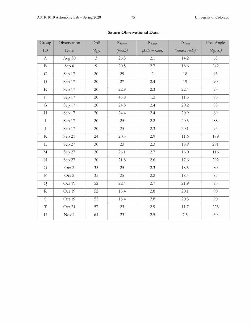
ASTR 1010 Astronomy Lab – Spring 2020 75 University of Colorado
Saturn Observational Data
Group
ID
Observation
Date
DoS
(day)
RSaturn
(pixels)
RRings
(Saturn radii)
DTitan
(Saturn radii)
Pos. Angle
(degrees)
A Aug 30 3 26.5 2.1 14.2 65
B Sep 6 9 20.5 2.7 18.6 242
C Sep 17 20 29 2 18 93
D Sep 17 20 27 2.4 19 90
E Sep 17 20 22.9 2.3 22.4 93
F Sep 17 20 45.8 1.2 11.5 93
G Sep 17 20 24.8 2.4 20.2 88
H Sep 17 20 24.4 2.4 20.9 89
I Sep 17 20 25 2.2 20.5 88
J Sep 17 20 25 2.3 20.1 93
K Sep 21 24 20.5 2.9 11.6 179
L Sep 27 30 23 2.3 18.9 291
M Sep 27 30 26.1 2.7 16.0 116
N Sep 27 30 21.8 2.6 17.6 292
O Oct 2 35 25 2.3 18.5 80
P Oct 2 35 25 2.2 18.4 85
Q Oct 19 52 22.4 2.7 21.9 93
R Oct 19 52 18.4 2.8 20.1 90
S Oct 19 52 18.4 2.8 20.3 90
T Oct 24 57 23 2.9 11.7 225
U Nov 1 64 23 2.5 7.5 30

ASTR 1010 Astronomy Lab – Spring 2020 76 University of Colorado
Actual images of Saturn taking from the SBO 20” telescopes. Different stretches and contrasts used to show various features.
Titan Dione
Tethys
Rhea
North

ASTR 1010 Astronomy Lab – Spring 2020 77 University of Colorado
COLLISIONS, SLEDGEHAMMERS, AND IMPACT CRATERS
Pre-Lab = please complete before coming to lab Read briefly through the entire lab. Check this box ☐ to indicate that you have done so. Jot down any questions that occurred to you while skimming through the lab description.
Your pre-lab here is slightly more substantial than usual, to give more time for playing with sledgehammers during lab.
Power law distributions: Numbers and sizes of asteroids in the asteroid belt are not random, but rather exhibit a fairly well behaved and predictable pattern. For example, smaller asteroids are much more numerous than larger ones. Only three asteroids in the belt have diameters exceeding 500 km, yet twelve have diameters greater than 250 km, and approximately 150 asteroids are greater than 100 km across. Thousands of asteroids tens of kilometers in size have been catalogued. There are also uncountable numbers of smaller ones going all the way down to grain-sizes. The term given to this relationship between number and size in such a system is the size distribution.
1. Using Graph A (a linear plot), try to graph the size distribution of all of the asteroids in the list above. You will probably find that plotting these data on this simplistic scale is extremely difficult. The range of the numbers involved is simply far too large to conveniently be displayed in any meaningful manner on a linear plot.
Name: _____________________
0 200100 300 400 500
10
8
6
4
2
0
Billio
ns o
f Ast
eroi
ds
Asteroid Diameter in Kilometers
Graph A - Linear Plot
Size Distribution of AsteroidsDiameter Number
250 km Ten (1 x 101)500 km Three (3 x 100)
1 km 1,000,000One Million (106)
0.05 km 10,000,000,000Ten Billion (1010)
5,000 (5 x 10³)10 km
100 km 130 (1.3 x 10²)
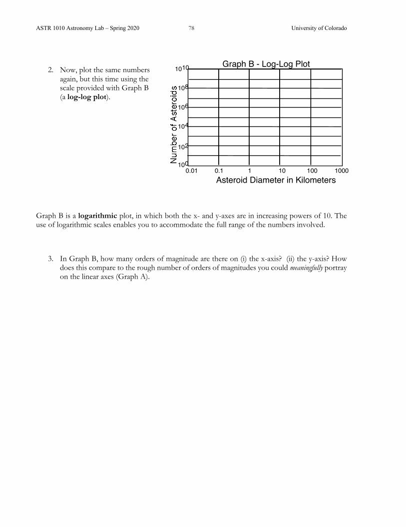
ASTR 1010 Astronomy Lab – Spring 2020 78 University of Colorado
2. Now, plot the same numbers again, but this time using the scale provided with Graph B (a log-log plot).
Graph B is a logarithmic plot, in which both the x- and y-axes are in increasing powers of 10. The use of logarithmic scales enables you to accommodate the full range of the numbers involved.
3. In Graph B, how many orders of magnitude are there on (i) the x-axis? (ii) the y-axis? How does this compare to the rough number of orders of magnitudes you could meaningfully portray on the linear axes (Graph A).
0.1 101 100 1000Asteroid Diameter in Kilometers
Graph B - Log-Log Plot
0.01
104
106
108
1010
102
100

ASTR 1010 Astronomy Lab – Spring 2020 79 University of Colorado
COLLISIONS, SLEDGEHAMMERS, AND IMPACT CRATERS SYNOPSIS: The objectives of this lab are: (a) become familiar with the size distribution of particle fragments resulting from collisions; (b) compare that distribution with that of interplanetary debris found in the asteroid belt; and (c) relate the size distribution of craters on the Moon to the size distribution of fragments in the solar system.
EQUIPMENT: Sledgehammer, brick, denim cloth, sieves, plastic bags, buckets, scale, safety goggles, calculator, graph overlays.
Part I – Size Distributions The occurrence of asteroid sizes in the Solar System approximates a power law of the form
N = A Rb
Here N is the number in a given radius (R) interval on the logarithmic scale, and A is a constant of proportionality. When plotted on a log-log plot, the distribution of objects that follow a power law behavior yield a straight line, the slope of which is equal to the power law exponent b. For objects in the asteroid belt, b has a value of approximately –2. This power law distribution of relative abundance persists over many orders of magnitude.
In the simplest terms, this mathematical relationship means that there are many more small fragments than large fragments resulting from disruptive collisions in the asteroid belt. The surprise is that such a general trend should be so precise that it holds true over objects differing in size by 100 million! The figure at right shows size distributions of impact-shattered rocks, both from the result of laboratory fragmentation experiments and the actual distributions of asteroids. The data points for the “All Asteroids, Inner Belt” population correspond roughly to b ≈ –2.
(From Moons and Planets, W. Hartmann, 4th Ed. 1999)
Name: ___________________________

ASTR 1010 Astronomy Lab – Spring 2020 80 University of Colorado
The power law distribution of the sizes of asteroids therefore suggests a collisional fragmentation process, the consequences of which are fascinating. The sizes continue getting smaller and smaller and the numbers continue to become greater and greater.
The equation N = ARb describes a relationship between the number of objects, N, and their radius, R. But what are the effects of changing the values of the parameters A and b?
I.1 If the value of b becomes "more" negative, does the slope get more or less steep?
Below is a diagram made using a computer simulation of different size distributions for a range in the values from b = –1.5 to –4.0.
I.5 Which value of b creates relatively more big particles? Which creates relatively more small particles? Explain why, in terms of the slopes of the particle size distributions.

ASTR 1010 Astronomy Lab – Spring 2020 81 University of Colorado
Part II. Destructive Learning You will test the hypothesis that asteroid size distributions are the result of collisional processes by simulating such collisions for yourself, using a brick as a rocky asteroid and a sledgehammer to provide the impact(s).
It is anticipated, however, that you will be producing far too many small "asteroids" to count one at a time. To overcome this limitation, it is possible estimate their number, N, by calculation, using the density of your original "asteroid" as a guide.
Density is a measure of the amount of mass in a given volume, and it is measured in units of mass (grams or g) per volume (cubic centimeters or cm3). Water, for comparison, has a density of exactly 1 g/cm3. Thus, one cubic centimeter of water would weigh one gram if placed on a scale. Moreover, if we had a container of water that weighed 100 grams, we would know that we had a volume of 100 cubic centimeters of water.
II.1 Use the metric scale to measure the mass (in grams) of your brick "asteroid":_______
II.2 Measure the sides of the soft-brick and calculate its volume (in cm3):
Length (cm) =
Width (cm) =
Height (cm) =
Volume (cm3) =
II.3 Calculate the density of the soft-brick using the equation: Density = Mass / Volume
Now take your sledgehammer, brick "asteroid," goggles and denim cloth, and find a safe place outside for a smashing good time!
Step 1 Wrap the brick in one sheet of cloth and spread the other out on the ground. Place the wrapped brick in the middle of the spread-out sheet. (Note: The cloth containing the brick will not last for more than a few hits before it rips; its purpose is to hold the pieces together as well as possible so that you won't lose any. Be careful so that any pieces that do come out stay on the other sheet.)
Step 2 Now, the fun part: smash your brick! You will most likely have to hit the brick about 4 to 6 times (representing 4 to 6 "collisions" with other asteroids) to ensure that you end up with enough small pieces for your analysis. (Note: The largest pieces you will be interested in are only one inch across.) Each member of your group should hit the brick at least one time. The person hitting the brick MUST be wearing the goggles!
ASTR 1010 Astronomy Lab – Spring 2020 82 University of Colorado
Step 3 Being careful not to lose any of the pieces, fold up the cloth sheet and bring your sample fragments to the sieves.
Part III. Sorting and Counting Your Fragments Be sure to read and follow EACH step carefully. There are a total of five sieves of differing sizes: 2.54 centimeter diameter sieve, 1.27 cm, 0.64 cm, 0.32 cm, and 0.16 cm. The idea is to separate your material—by following the steps below—according to these sizes. You will begin by putting all the material into the largest sieve, thereby separating out the biggest pieces. Pieces larger than 2.54 centimeters in diameter will stay in the sieve while everything else will fall through. You will then use the second largest sieve, and so on down to the smallest.
III.1 Place the pan below the 2.54 cm sieve. Slowly pour the material into the sieve, gently agitating the sieve as you go. You may need to do a little at a time if there is too much material for the sieve. (Note: Do not be too rough with the sieves. By excessively shaking the sieve you may inadvertently cause unwanted further grinding.)
III.2 Separate your largest pieces—these will not be used in the analysis.
III.3 With the remaining material, use the next-sized sieve to separate out the next-largest pieces and place these in a baggie. These fragments are the largest you will consider in your analysis. Keep track of this material by placing a small piece of paper in the baggie that records the sieve size.
III.4 Repeat the process for each sieve in descending size order. Discard all material that falls through the smallest sieve.
III. 5 Weigh the material in each baggie with your balance scale. Record the results in column 6 of the table in III.7. (Note: You should NOT empty the material onto the scale. Instead, simply put the baggie on the scale. The small mass contribution from the baggie is negligible.)
The next step is to create a plot of the number of objects versus sieve size. Of course, one way to do this would be to count each fragment within each baggie. However, because we know the densities of our brick "asteroid" fragments, there is a much simpler way to estimate these numbers.
You have measured the total mass of all the objects in a certain size range (column 6 of the table). If you divide this number by the mass of a single object of that size, the result will be an estimate of the total number of fragments within that range (and within your baggie).
Assuming that each particle is approximately spherical in shape, and also that the average size of the particles in a baggie is halfway between the two sieve sizes that yielded the sample (the mean particle size from column 5 in the table).
III.6 Write down a formula for the mass of a single spherical object in terms of its density and radius (R):

ASTR 1010 Astronomy Lab – Spring 2020 83 University of Colorado
III.7 Using your answer to III.6, calculate the mass of one object having a size equal to the average size of a particle collected in each sieve using the equation given on the previous page. In column 7 of the table, enter the mass of a single representative particle in each of your four bags. (Remember, you should NOT need to actually weigh a single particle.) Show one example calculation below.
III.7 You now have enough information to estimate the total number of particles in each bag. Enter the estimated total number of particles in each size range in column 8.
Smashing Brick Data Table 1 2 3 4 5 6 7 8
Bag #
Former Sieve Size (cm)
Current Sieve Size (cm)
Mean Particle
Diameter (cm)
Mean Particle Radius R (cm)
Mass of
Bits(+Bag) (grams)
Mass of One
Particle (grams)
Number of
Particles N
1
2.54
1.27
1.91
0.95
2
1.27
0.64
0.96
0.48
3
0.64
0.32
0.48
0.24
4
0.32
0.16
0.24
0.12
III.8 To check the validity of your approach, actually count the number of fragments in one (or more) of the baggies. (You might choose the baggie containing the fewest and largest fragments, but that choice is up to you!) Record your answer below and compare it with your estimate from column 8.

ASTR 1010 Astronomy Lab – Spring 2020 84 University of Colorado
Part IV. Plotting and Analyzing Your Results IV. 1 Using the log-log plot of the graph on the next page, plot your results showing the number
of particles N versus the mean particle radius. (Hint: You will need to use your own data to come up with labels for the Y-axis. Remember this is a log-log plot!) Does your data form roughly a straight line? If not, can you think of any reason why not?
IV.2 Using the transparencies for different exponents (values of b) and overlaying them on your plot, find the one which best matches your plot. (Make sure you keep the X and Y axes of the overlay parallel to the X and Y axes of your graph, then judge by eye which slope seems closest to your data.) What is your estimate of b for your brick fragments?
IV.3 How does this compare with the value of b for the asteroid power law distributions? Does your power-law distribution from smashing particles tend to match those of asteroids? If your power-law distribution differs from that of the asteroids, explain whether your smashing experiment yielded too many large-sized, or too many small-sized particles.
IV.4 What do your results imply about the conditions that existed at the time asteroids were being formed?
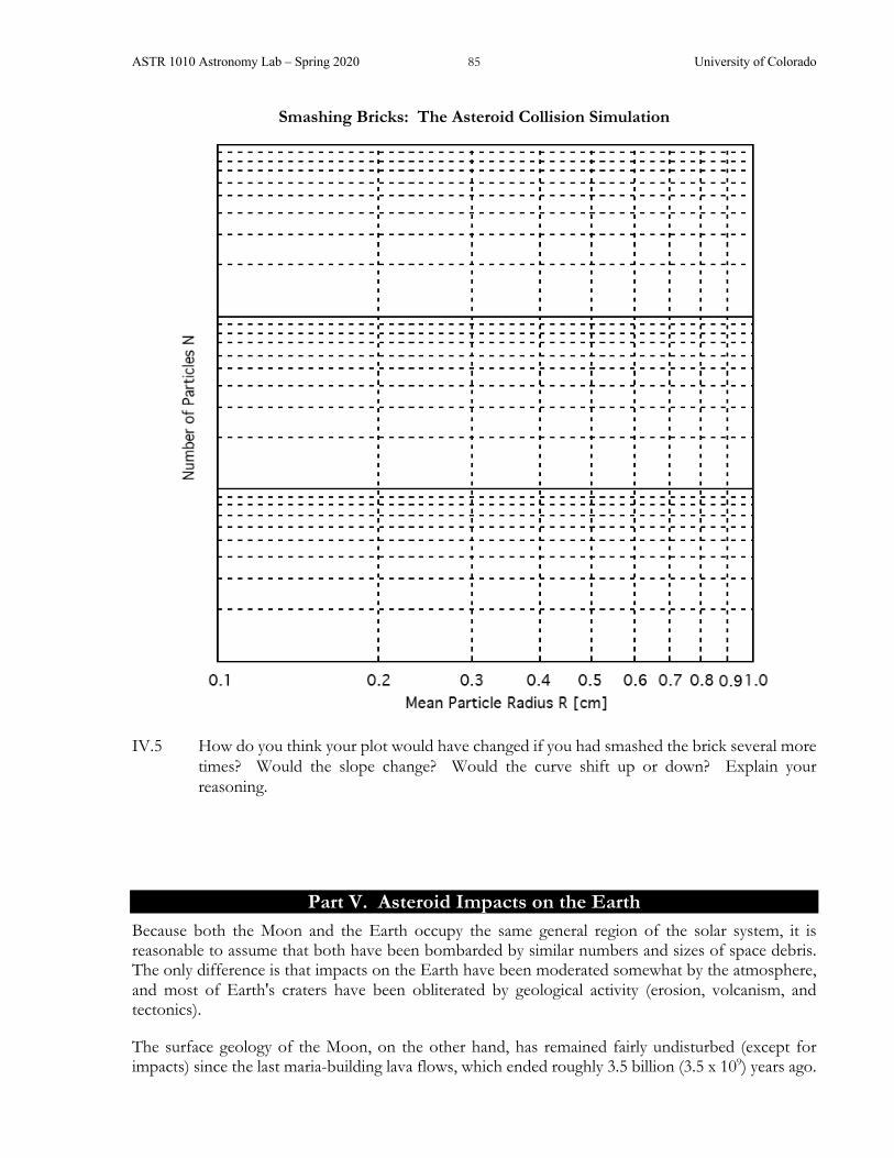
ASTR 1010 Astronomy Lab – Spring 2020 85 University of Colorado
Smashing Bricks: The Asteroid Collision Simulation
IV.5 How do you think your plot would have changed if you had smashed the brick several more times? Would the slope change? Would the curve shift up or down? Explain your reasoning.
Part V. Asteroid Impacts on the Earth Because both the Moon and the Earth occupy the same general region of the solar system, it is reasonable to assume that both have been bombarded by similar numbers and sizes of space debris. The only difference is that impacts on the Earth have been moderated somewhat by the atmosphere, and most of Earth's craters have been obliterated by geological activity (erosion, volcanism, and tectonics).
The surface geology of the Moon, on the other hand, has remained fairly undisturbed (except for impacts) since the last maria-building lava flows, which ended roughly 3.5 billion (3.5 x 10⁹) years ago.

ASTR 1010 Astronomy Lab – Spring 2020 86 University of Colorado
Based on crater counts, approximately 30 objects 1 km in diameter have hit each 100,000 km2 of the lunar surface in the last 3.5 billion years.
(Want to participate in helping astronomers identify craters on the Moon? Check out http://www.moonzoo.org!)
We can, therefore, use the lunar crater record to estimate the numbers and sizes of impacts that have occurred in the past on the Earth. The radius of the Earth is 6368 km. The total surface area of the Earth can be computed from the formula for the area of a sphere of radius R:
Surface Area of a Sphere = 4 p R2
V.1 What is the surface area (in km2) of the Earth?
V.2 How many times bigger is the Earth's surface area than the crater-counting standard area of 100,000 km2 on the Moon?
V.3 So, in the same corresponding period of time that craters have accumulated on the Moon, about how many 1-kilometer diameter impactors (asteroids or comets) have hit the Earth?
V.4 What is the typical frequency that we can expect for Earth to be hit by a 1 km diameter impactor in a one-year time period? (Hint: In question V.3 you calculated the total number of impacts over the last 3.5 billion years.) Is this number larger or smaller than 1? What does that mean?
V.5 On average, about how frequently do such impacts of this size occur on the Earth? (Hint: Question V.4 asked you to calculate impacts per year, this question is asking for years per impact.)

ASTR 1010 Astronomy Lab – Spring 2020 87 University of Colorado
V.6 Based on your calculations, what are the approximate odds that a 1 km diameter object will strike the Earth in your lifetime? (Such an impact, incidentally, would bring about continent-wide devastation, global atmospheric disruption, and likely an end to human civilization!) (Hint: You calculated the annual probability – that’s the chance of a hit in a year – the odds increase if you wait a whole lifetime.) THINK! Does your answer make sense? If not, you may have made an error along the way… go back and check!
V.7 Compare your assessment of typical collision frequency with the estimates shown in the graph below. Based on your answer, do 1 km impactors hit the Earth more or less frequently than the graph suggests?
When finished, please clean up your lab station. Replace all materials so the area appears as when you began. Have your TA check your station before you leave.

ASTR 1010 Astronomy Lab – Spring 2020 88 University of Colorado
Image from the Lunar Reconnaissance Orbiter (launched in 2009) orbiting the Moon. How do you think the
chain of craters called Catena Mendeleev might have been formed?
Another image from the Lunar Reconnaissance Orbiter. That little dot in the middle (casting a shadow) is the Apollo 11 Lunar Module!

ASTR 1010 Astronomy Lab – Spring 2020 89 University of Colorado
TELESCOPE OPTICS Pre-Lab = please complete before coming to lab
Read briefly through the entire lab. Check this box ☐ to indicate that you have done so. Jot down any questions that occurred to you while skimming through the lab description.
1. In your own words, explain what is meant by the terms object, image, focal plane, and magnification as they are used in this lab.
Object Image Focal plane Magnification
Name: ___________________________

ASTR 1010 Astronomy Lab – Spring 2020 90 University of Colorado

ASTR 1010 Astronomy Lab – Spring 2020 91 University of Colorado
TELESCOPE OPTICS SYNOPSIS: You will explore some image-formation properties of a lens, and then assemble and observe through several different types of telescope designs.
EQUIPMENT: Optics bench rail with 3 holders; optics equipment stand (flashlight, mount O, lenses L1 and L2, image screen I, eyepieces E1 and E2, mirror M, diagonal X); object box.
NOTE: Optical components are delicate and are easily scratched or damaged. Please handle the components carefully and avoid touching any optical surfaces.
Part I. The Camera
In optical terminology, an object is any source of light. The object may be self-luminous (such as a lamp or a star) or may simply be a source of reflected light (such as a tree or a planet). If light from an object happens to pass through a lens, those rays will be bent (refracted) and will come to a focus to form an image of the original object.
From each point on the object, light rays are emitted in all directions. Any rays that encounter the lens are bent into a new direction, but in such a manner that they all converge through one single point on the opposite side of the lens. Thus, one point on the actual object will focus into one corresponding point on what's called the focal plane of the lens. The same thing is true for light rays emanating from each other point on the object, although these rays enter the lens at a different angle, and so are bent in a different direction, and again pass through a (different) unique point in the focal plane. The image is composed of an infinite number of points where all of the rays from the different parts of the object converge.
To see what this looks like in “real-life,” arrange the optical bench as follows:
First, loosen the clamping knob of holder #1 and slide it all the way to the left end of the optics rail until it encounters the stop (which prevents the holder from sliding off of the rail). Clamp it in place.
Next, turn on the flashlight (stored in the accessory rack) by rotating its handle, and take a look at its illuminated face. The pattern you see will serve as the physical object in our study.
Insert the large end of the flashlight into the large opening of the Object Mount O and clamp it in place with the gold knob. Install the mount and flashlight into the tall rod holder of holder #1 so that the flashlight points and down the rail. (Allow the rod to drop fully into the holder so that the
Object
Image
Lens
Name: ___________________________

ASTR 1010 Astronomy Lab – Spring 2020 92 University of Colorado
mounting collar determines the height of the flashlight; rod collars are used to ensure that all components are positioned at the same height. Please do not adjust the rod collar unless instructed to by your TA.)
The white mark on the backside of each holder indicates the location of the optical component in that holder; thus, measuring the separation between marks is equivalent to measuring the separation of the optical components themselves. Use the meter stick to measure the separation of the white marks so as to position holder #2 at a distance 180 mm (18 cm) from holder #1; clamp it in place. Install lens L1 in the holder so that one of its glass surfaces faces the flashlight.
Finally, put the image screen I (with white card facing the lens) in holder #3 on the opposite side of the lens from the flashlight. Your arrangement should look like this:
The separation between the lens and the object is called the object distance dobject; because you've positioned the object (flashlight) 180 mm from the center of the lens, the object distance in this case is 180 mm.
On the white screen, you will see a bright circular blob, which is the defocused light from the object that is being bent through the lens. Slowly slide the screen holder #3 back and forth along the rail while observing the pattern of light formed on the screen. At one unique point, the beam of light will coalesce from a fuzzy blob into a sharp image of the object. Clamp the screen at this location where the image is in best focus.
I.1 Predict what will happen to the image if you swap the positions of the flashlight (object) and the image screen. Explain your reasoning. (You will not be marked down if your prediction is wrong, so please make an honest prediction before continuing.)
I.2 Now go ahead and swap the object and image screen (Hint: Leave the holders in place so you can return to this arrangement, just take the posts out of the holders.) Was your prediction correct? If not, explain what you see.
Return to your original setup before continuing.

ASTR 1010 Astronomy Lab – Spring 2020 93 University of Colorado
The term magnification refers to how many times larger the focused image appears, compared to the actual size of the object:
Magnification (definition) = Image SizeObject Size (1)
I.3 What should the units of magnification be?
I.4 What is the magnification produced by this optical arrangement?
Observed magnification = ______________
Explain how you calculated this magnification.
The distance between the lens to the in-focus image is called the image distance, dimage. In optical terminology, distances are always given in terms of how far things are from the main optical component (in this case, the lens). Instead of directly measuring the magnification, you can also calculate it from the ratio of image distance to the object distance:
Magnification (calculated) = dimage / dobject (2)
I.5 Use the meter stick and the two white marks on holders #2 and #3 to determine the image distance from the lens; record your result to the nearest millimeter:
dimage = _________
I.6 Show that Equation (2) gives you (at least approximately) the same value for the magnification that you determined from the image and object sizes:
Calculated magnification = ___________
Now let's find out how things change if the object is a little further from the lens. Unclamp and move holder #2 so that the distance between the object and the lens is somewhat larger than before (say, 200 mm or so). Now move the image screen I to find the new image location.

ASTR 1010 Astronomy Lab – Spring 2020 94 University of Colorado
I.7 (a) When you increased the distance to the object from the lens, did the image distance get closer or farther away from the lens?
(b) Did the magnification increase or decrease?
(c) Move the object a small amount once again and verify that you can still find an in-focus image location on the opposite side. How does the direction of movement of the object relate to the direction of movement of the in-focus image?
Hopefully, you've found that a lens can be used to produce a magnified image of an object, and that the magnification can be varied. But it is also possible to make a de-magnified image instead (that is, smaller than the original object).
I.8 Move lens L1 (by sliding holder #2) to a position so that the image size is less than the original object size.
What is the new object distance? ________
What is the new image distance? ________
What magnification (using Equation 2) does this imply? _________
What is the measured image size? __________
Does the magnification using Equation 1 agree with the magnification you calculated using Equation 2?
Now let's see what will happen if we use a different lens. Replace lens L1 with the lens marked L2, but otherwise leave the positions of the holders in exactly the same place.
I.9 Refocus the image.
What is the new image distance with this lens? dimage = ______
What is the magnification produced by this arrangement? ________
Indicate whether you determined the magnification by definition (Equation 1) or calculation (Equation 2):

ASTR 1010 Astronomy Lab – Spring 2020 95 University of Colorado
Part II. The Lens Equation Because object and image distances from a lens seem to be related in a predictable manner, you probably won't be surprised to learn that there is a mathematical relationship between the two. It is called the lens equation, and for any given lens it looks like this:
1f =
1dobject
+ 1
dimage (3)
The value f in the formula is called the focal length of the particular lens being used. This is a property of the lens itself and doesn’t change regardless of the location of the object or the image. Notice that the formula actually relates the reciprocal of the values of f, dobject, and dimage, instead of the actual values themselves.
Helpful Hint: Be sure you understand what your calculator is doing when you enter fractions. For example, if you enter ½ + ¼ you should get 0.75. If not, you calculator is likely doing the operation
in a different order than you expect.
II.1 Calculate the focal length f of lens L1, using your measured image distance dimage and object distance dobject. You can use either the arrangement from step I.5, or from step I.8, or from both (to see if they give the same answer).
Focal length f of Lens L1 = _______________
II.2 What is the focal length of lens L2 (using the information measured in step I.9)?
Focal length f of Lens L2 = __________________
II.3 Which lens, L1 or L2, has the longer focal length? ___________
Considering what you found out in I.9, does a telephoto lens have a longer or shorter focal length than a “normal” lens?
II.4 Using the Lens Equation (3), why was the image you made in I.2 still in focus?
Part III – Refracting Telescopes In astronomy, we look at objects that are extremely far away. For all practical purposes, we can say that the object distance is infinitely large. This means that the value 1/dobject in the lens equation is extremely small, and can be said to equal zero. Thus, for the special case where an object is very far away, the lens equation simplifies to:

ASTR 1010 Astronomy Lab – Spring 2020 96 University of Colorado
1f = 0 + or simply dimage = f
In other words, when we look at distant objects, images are formed behind the lens at a distance equal to (or very nearly so) its focal length. Because everything we look at in astronomy is very far away, images through a telescope are always formed at the focal length of the lens.
We can now look at an object that is far enough away to treat it as being “at infinity.” Remove the flashlight and mount from holder #1 and replace them in the optics storage rack. Instead, use the large object box at the opposite end of the table for your light source. It should be at least 3 meters (10 feet) from your optics bench. Focus the screen. Your arrangement should look like this:
III.1 Measure the image distance from the markings on the optics rail. Confirm that this is fairly
close to the value of the focal length of lens L2 that you calculated in II.2.
Measured image distance = _____________________
Your measurement will be slightly larger than the true value of f, simply because the illuminated object box isn't really infinitely far away; however, since we can't take this telescope outside, we will treat your measurement in III.1 as the actual focal length of the lens.
If the screen were not present, the light rays would continue to pass through and beyond the image that forms at the focal plane. In fact, the rays would diverge from the image as if it were a real object, suggesting that the image formed by one lens can be used as the object for a second lens.
III.2 Remove the white card from the screen to expose the central hole. Aim the optics bench so that the image passes into the opening.
III.3 From well behind the image screen, look along the optical axis at the opening in the screen. You should be able to see the image once again, "floating in space" in the middle of the opening! If you move your head slightly from side-to-side you should get the visual impression that the image doesn't shift around but instead seems to be fixed in space at the center of the hole. By sliding the screen back and forth along the rail, you can also observe that the opening passes around the image, while the image itself remains stationary as if it were an actual object.
Notice that the image is quite tiny compared to the size of the original object (a situation that is always true when looking at distant objects). In order to see the image more clearly, you will need a magnifying glass:
III.4 Remove screen I from its holder and replace it with the magnifying lens E1. Observe through the magnifier as you slowly slide it back away from the image. (Your eye should be right next to the magnifying lens.) At some point, a greatly enlarged image will come into focus. Clamp the lens in place where the image appears sharpest.
1dimage

ASTR 1010 Astronomy Lab – Spring 2020 97 University of Colorado
Your arrangement should be be as follows:
You have assembled a refracting telescope, which uses two lenses to observe distant objects. The main telescope lens, called the objective lens, takes light from the object at infinity and produces an image exactly at its focal length fobjective behind the lens. Properly focused, the magnifier lens (the eyepiece) does just the opposite: it takes the light from the image and makes it appear to come from infinity. The distance between the two lenses is the lens separation (L). The telescope itself never forms a final image; it requires another optical component (the lens in your eye) to bring the image to a focus on your retina.
To make the image appear to be located at infinity (and hence observable without eyestrain), the eyepiece must be positioned behind the image at a distance exactly equal to its focal length, feye. Therefore, the lens separation, L, between the two lenses must equal the sum of their focal lengths:
L = fobjective + feye (4)
III.5 Measure the separation between the two lenses (L) and use your value for the objective lens focal length (fobjective, measured in step III.1) and equation (4) to calculate the focal length of eyepiece E1 (feye).
L: ____________ feye:___________
Earlier, we used the term "magnification" to refer to the actual physical size of the image compared to the actual physical size of the object. This cannot be applied to telescopes, because no final image is formed (and besides, the physical sizes of objects studied in astronomy, like stars and planets, are huge). Instead, we use the concept of angular magnification: the ratio of the angular size of an image appearing in the eyepiece compared to the object's actual angular size. In other words, we're referring to how much bigger something appears to be, rather than to how big it actually is.
The angular magnification M produced by a telescope can be shown to be equal to the ratio of the focal length of the objective to the focal length of the eyepiece:
(5)
€
M =fobjectivefeye

ASTR 1010 Astronomy Lab – Spring 2020 98 University of Colorado
III.6 Calculate the magnification of the telescope arrangement you're now using (objective lens L2 and eyepiece E1).
Equation 5 implies that if you used a telescope with a longer focal length objective lens (make fobjective bigger), the magnification would be greater. But the equation also implies that you can increase the magnification of your telescope simply by using an eyepiece with a shorter focal length (make feye smaller).
III.7 Eyepiece E2 has a focal length of 18 mm. Without inserting E2 into the actual system yet, use equation 5 to calculate the magnification resulting from using eyepiece E2 with objective lens L2: ____________
III.8 Replace eyepiece E1 with E2, and refocus. Did the image get bigger or smaller than before? _________
Is your observation consistent with the calculation of III.7?
Consumer Tip: Some inexpensive telescopes are advertised as “high power” (a.k.a. “large magnification”) because most consumers think that this means a “good” telescope. You now know
that a telescope can exhibit a large magnification simply by switching to an eyepiece with a very short focal length. Magnification really has nothing to do with the actual quality of the telescope!
Part IV. Reflecting Telescopes
Concave mirrored surfaces can be used in place of lenses to form reflecting telescopes (or reflectors), rather than refracting telescopes. All of the image-forming properties of lenses also apply to reflectors, except that the image is formed in front of a mirror rather than behind. As we will see, this poses some problems! Reflecting telescopes can be organized in a variety of configurations, three of which you will assemble below.
The prime focus arrangement is the simplest form of reflector, consisting of the image-forming objective mirror and a flat surface located at the focal plane. A variation on this arrangement is used in a Schmidt camera to achieve wide-field photography of the sky.

ASTR 1010 Astronomy Lab – Spring 2020 99 University of Colorado
IV.1 Assemble the prime-focus reflector shown above:
° First, return all components from the optical bench to their appropriate locations in the optics storage rack.
° Next, slide holder #3 all the way to the end stop away from the light source, and slide holder #2 as far away from the light source as possible until it is touching holder #3.
° Install the large mirror M into holder #2, and carefully aim it so that the light from the distant object box is reflected straight back down the bench rail.
° Place the mirror/screen X into the tall rod holder #1, with the white screen facing the mirror M.
° Finally, move the screen back and forth along the rail until you find the location where the image of the object box is focused onto the screen. (Tip: you can use the white card from the image screen to find the image that is being reflected from the mirror, which will let you know if you need to rotate the mirror so that the beam is directed at screen X).
IV.2 Is the image right-side-up, or inverted? __________________
IV.3 Measure the focal length f of the mirror M just like you did with the refractor: use your meter stick to measure the distance from the mirror to the image location.
Focal length of the mirror = ____________
Because the screen X obstructs light from the object and prevents it from illuminating the center of the mirror, many people are surprised that the image does not have a "hole" in its middle.
Hold the white card partially in front of the objective mirror in order to block a portion of the beam, as shown below. Note that no matter what portion of the mirror you obscure, the image of the distant object box stays fixed in size and location on the screen. This is because each small portion of the mirror forms a complete and identical image of the object at the focus!
IV.4 As you block more and more of the mirror, what happens to the image? Explain why this occurs.
Lightfrom
Object
White Card
Mirrorlight reaches mirror
FocalPlane
light is blocked

ASTR 1010 Astronomy Lab – Spring 2020 100 University of Colorado
The prime focus arrangement cannot be used for eyepiece viewing, because the image falls inside the telescope tube. If you tried to see the image using an eyepiece, your head would also block all of the incoming light. (This, however, is not the case for an extremely large mirror: for example, the 200-inch diameter telescope at Mount Palomar has a small cage in which the observer can actually sit inside of the telescope at prime focus, as shown here!)
Isaac Newton solved the head-obstruction problem for small telescopes with his Newtonian reflector, which uses a flat mirror oriented diagonally to redirect the light to the side of the telescope, as shown below. The image-forming mirror is called the primary mirror, while the small additional mirror is called the secondary or diagonal mirror.
IV.5 Convert your telescope to a Newtonian arrangement:
° Reverse the mirror/screen X so that the mirror side faces the primary mirror M and is oriented at a 45° angle to it.
° Install eyepiece E1 in the short side rod holder of holder #1, and look through the eyepiece at the diagonal mirror (see diagram above).
° Now rotate the diagonal mirror slightly until you see a flash of light that is the bright but out-of-focus image of the distant object. Clamp the diagonal mirror in place.
Now, while looking through the eyepiece, slowly slide holder #1 towards the mirror until the image comes into sharp focus.
Congratulations! You've constructed a classical Newtonian telescope, one of the most popular forms of telescopes used by amateur astronomers!
IV.6 Use equation 5 and your knowledge of the mirror M's focal length and eyepiece E1's focal length (steps IV.3 and III.5, respectively) to determine this telescope's magnification:
Light fromObject
at Infinity
Eye
Eyepiece
PrimaryMi r ror
DiagonalM i r ror
Focal Plane

ASTR 1010 Astronomy Lab – Spring 2020 101 University of Colorado
Large reflecting telescopes (including the 20-inch and 24-inch diameter telescopes at Sommers-Bausch Observatory) are usually of the Cassegrain design, in which the small secondary redirects the light back towards the primary. A central hole in the primary mirror permits the light to pass to the rear of the telescope, where the image is viewed with an eyepiece, camera, or other instrumentation.
IV.7 Re-arrange the telescope into a Cassegrain configuration as shown above.
° Remove the eyepiece E1 from its short holder in holder #1, and transfer it instead to holder #3 behind the mirror.
° Carefully re-orient the secondary mirror (still in holder #1) so that it reflects light directly back towards the hole in the primary mirror.
° Now slide holder #1 towards the mirror until it is only about 35% of its original separation from the mirror (about 1/3rd of the mirror focal length found in IV.3).
° While looking through the eyepiece, rotate the secondary mirror in holder #1 slightly until you see the flash of light that is the image of the object. Then move holder #1 slightly towards or away from you until you can see an in- focus image.
IV.8 Do you think that the magnification of this image is any different from the magnification you observed with the Newtonian arrangement? Why or why not?
Note: in a real Cassegrain telescope, the magnification would in fact be different because the secondary mirror is not actually flat, but instead is a convex shape. This permits the size of the secondary mirror to be smaller than the flat secondary you are using here, and thus allows more light to strike the primary mirror.
IV.9 Why does the hole in the primary mirror not cause any additional loss in the light-collecting ability of the telescope?
Light fromObject
at Infinity
Eyepiece
EyeSecondaryMi r ror
PrimaryMi r ror

ASTR 1010 Astronomy Lab – Spring 2020 102 University of Colorado

ASTR 1010 Astronomy Lab – Spring 2020 103 University of Colorado
LIGHT AND COLOR Pre-Lab = please complete before coming to lab
Read briefly through the entire lab. Check this box ☐ to indicate that you have done so. Jot down any questions that occurred to you while skimming through the lab description.
1) Explain what the spectroscope does, in general terms (you do not need to explain the quantum mechanics of how the diffraction grating works, just what it does).
2) Explain why the spectrum of white light looks the way it does.
3) Explain why a blue shirt looks blue when viewed in white light. What happens to different wavelengths of light interacting with the blue shirt?
Name: ___________________________

ASTR 1010 Astronomy Lab – Spring 2020 104 University of Colorado
LIGHT AND COLOR SYNOPSIS: The only way for astronomers to study distant objects is to examine the light we receive from them. What can we learn about astronomical objects from their light? This lab walks through how we think about light interacting with matter in different ways.
EQUIPMENT: Light bulb, set of 3 filters, spectroscope, colored marbles.
A spectrum is the intensity of light at different wavelengths. Normally when we receive light from objects, the wavelengths are all mixed together and we can't tell how much of each wavelength is present. A spectroscope allows us to separate the different color components of light, allowing us to examine each wavelength separately. In this way, we can think of a spectrum as organized light -- organized according to wavelength.
Part I – White Light & RGB The goal of this section is to become familiar with how white light is a combination of colors. And to learn the “light verbs” that describe all the ways that light interacts with matter – emit, absorb, transmit, and reflect.
Turn on the light bulb.
1.1 List ALL the objects in the room that are emitting visible light.
1.2 Can you tell what colors are present within white light by simply looking at the bulb with the unaided eye? ® Explain your answer.
Name: ___________________________

ASTR 1010 Astronomy Lab – Spring 2020 105 University of Colorado
A spectroscope is a device designed for viewing a spectrum. Light enters the spectroscope through a slit and strikes a diffraction grating made of a material that splits up each color in the light. The grating splits each color apart at a slightly different angle such that each color forms its own separate image of the light from the opening of the spectroscope. A slit is used that the opening to produce narrow images, so that adjacent colors do not overlap each other. The spectroscope has a numerical scale inside of it that measures the wavelength of the light in units of hundreds of nanometers.
1.3 Use the grating or spectroscope to look at the light bulb. Describe what you see.
Converting the brightness you see to quantitative intensity, we can sketch the visible portion of a spectrum of white light like this:
where all colors have a similar value for intensity because all colors are present in white light.
Red
Green
Violet
Spectrum
Sourceof
Light
Slit
GratingEye
Hand-HeldSpectroscope
or, to simplify, like this
Violet Blue Green Yellow Red B G R 400 500 600 700 nm 4 5 6 7

ASTR 1010 Astronomy Lab – Spring 2020 106 University of Colorado
1.4 Using the spectroscope, look at the light through the various filters. Draw the spectra of the light being transmitted - “let through” - by the different filters. Make sure the filter is covering the slit of your spectroscope.
1.5 What happens when the light passes through 2 filters? Before you try it…on the graphs
below, predict what the intensity curve would look like for 2 combinations of the filters. (Choose 2 different combinations.)
B G R 4 5 6 7
B G R 4 5 6 7
B G R 4 5 6 7
B G R 4 5 6 7
Filter: __________________
Filter: __________________
Filters: _________+_________
Filters: _________+_________

ASTR 1010 Astronomy Lab – Spring 2020 107 University of Colorado
1.6 Now actually try out your 2 combinations from above and sketch your results below. 1.7 • Do your predictions from 1.5 match your findings from 1.6? ® If not, explain why. • Explain, in general, what using a filter does to the light coming into the spectroscope. 1.8 • Now think about the white light
hitting your shirt/sweater. • What color(s) is your shirt/sweater?
___________________ • What colors are reflected by your shirt/sweater? ___________________ • What colors are absorbed by your shirt/sweater? ___________________ • On the graph to the right, draw what you think the spectrum of light reflected by your shirt/sweater is.
B G R
4 5 6 7
B G R 4 5 6 7
B G R 4 5 6 7
Filters: _________+_________
Filters: _________+_________
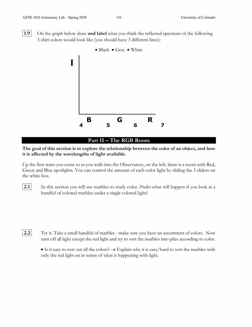
ASTR 1010 Astronomy Lab – Spring 2020 108 University of Colorado
1.9 On the graph below draw and label what you think the reflected spectrum of the following 3 shirt colors would look like (you should have 3 different lines):
• Black • Gray • White
Part II – The RGB Room
The goal of this section is to explore the relationship between the color of an object, and how it is affected by the wavelengths of light available.
Up the first stairs you come to as you walk into the Observatory, on the left, there is a room with Red, Green and Blue spotlights. You can control the amount of each color light by sliding the 3 sliders on the white box.
2.1 In this section you will use marbles to study color. Predict what will happen if you look at a handful of colored marbles under a single colored light?
2.2 Try it. Take a small handful of marbles - make sure you have an assortment of colors. Now turn off all light except the red light and try to sort the marbles into piles according to color.
• Is it easy to sort out all the colors? ® Explain why it is easy/hard to sort the marbles with only the red light on in terms of what is happening with light.
B G R 4 5 6 7
ASTR 1010 Astronomy Lab – Spring 2020 109 University of Colorado
2.3 Once you’ve sorted the marbles under the red light, turn the white room light back on. • Did you sort them all correctly?
• List a few colors you mistook for each other. ® Explain why these colors were mistaken for each other.
2.4 Mix the marbles up again and now try to sort them using the green light only. Once they’re
sorted, turn on the white room light and check you work. • Did you sort them all correctly? • If not, did you mix up the same colors using the green light only as the red light only? 2.5 Keeping the same sorted piles you made in 2.4, turn off all the lights except the red light and
green light. • With both the red and green light on is it easier to tell which colors have been sorted incorrectly? • Explain why it is/is not easier to sort with both the red and green lights on in terms of what is happening with light.
2.6 Now turn on all three colored lights.
• Are you able to clearly distinguish all the marble colors now? ® Explain why or why not.
2.7 Now turn off all lights except the white room light and find the white sheet of paper with the red shape on it.

ASTR 1010 Astronomy Lab – Spring 2020 110 University of Colorado
• Predict - will you be able to see the red shape on the paper under the red light only? 2.8 Now turn off the white room light and look at the sheet of paper under the red light only. • Was your prediction from 2.7 correct? ® Explain what is happening with light in this
situation.
Before you leave, turn off all the colored lights and turn on the white room light.
Part III – The Yellow Room Be sure to bring your spectroscope! The goal of this section is to explore the relationship between the appearance of an object and how it is affected by the wavelengths of light available.
The yellow room is a room illuminated by different types of lights that all emit a very similar yellow color but do it very differently.
3.1 Look at the various objects in the room in each of the following two lights without the spectroscope – be sure to turn off the room light and only open each light’s door one at a time. Describe how a few objects look under each light
Incandescent: Fluorescent:

ASTR 1010 Astronomy Lab – Spring 2020 111 University of Colorado
3.2 Based on your observations in 3.1, predict what each of the lights’ spectra will look like before you look through the spectroscope. Draw your prediction of the spectra for each bulb below. (You may also use words to clarify your prediction below.)
Incandescent: Fluorescent: 3.3 Now use your spectroscope, to examine the spectrum of each light.
• Were your predictions correct? • If not, correct your descriptions below on the graphs.
Incandescent: Fluorescent:
3.4 The next light you will examine is a sodium lamp. The sodium lamp emits yellow light at only one wavelength – this is known as “monochromatic light.”
• Before you look, predict what the multi-colored sweater will look like under the sodium lamp.
B G R 4 5 6 7
B G R 4 5 6 7
B G R 4 5 6 7
B G R 4 5 6 7

ASTR 1010 Astronomy Lab – Spring 2020 112 University of Colorado
3.5 Close all the light doors and make sure the room light is off. Open the sodium light door. • How do things look under the sodium light? • How did the color of the multi-colored sweater change?
3.6 Guess what color some of the other objects are. Then turn on the room light. • Did you guess all the correct colors? ® Explain why or why not. 3.7 Look at the sodium lamp through your spectroscope.
• Explain how the light emitted by the sodium lamp is changing the color you see on the multi-colored sweater and the colored objects in the room. • Use what you observed through the spectroscope to aid your explanation.
3.8 Choose one object in the room and explain why it looks the way it does in each of the 3 lights
– be sure to say which object you chose in your answer.
Before you leave, make sure the sodium lamp is uncovered and all other lights are covered. PLEASE DO NOT TURN OFF THE SODIUM LAMP.

ASTR 1010 Astronomy Lab – Spring 2020 113 University of Colorado
Part IV – Colored Planets The goal of this section is to apply your experience with white light and filters to study planetary objects. You will not need your spectroscope for this section.
4.1 Examine the images provided of planetary objects. These planetary objects are reflecting visible light – that’s why we can see them. • Where is the reflected visible light from the planets originally coming from in our solar system?
4.2 • Sketch the spectra of reflected light from the different objects.
Io (Moon of Jupiter) Mercury
Mars Neptune
B G R 4 5 6 7
B G R 4 5 6 7
B G R 4 5 6 7
B G R 4 5 6 7

ASTR 1010 Astronomy Lab – Spring 2020 114 University of Colorado
4.3 Imagine you had access to a laboratory where you could examine the spectra of each element on the periodic table. • How could you use the laboratory and the four sketches you made above to determine the elemental composition of the surfaces (or outer cloud layers) of the planetary objects above?
In the figure below there are two spectra: one of white (aka visible) light and one of white light that has passed through methane gas (CH4).
4.4 We can observe how methane interacts with white like by looking at the relative difference
between the white light spectrum and the white light viewed through CH4 spectrum. By comparing the two spectra above, determine: • What colors of the visible spectrum are absorbed by methane? • What colors of the visible spectrum transmitted by methane? (To simplify, think about the BGR scale we used above).
B G R Wavelength (nm): 500 700 900
Color:
Rel
ativ
e In
tens
ity 1.0
0.5
White light White light viewed through CH4
0.0

ASTR 1010 Astronomy Lab – Spring 2020 115 University of Colorado
4.5 The 3 plots above are spectra of reflected light from Saturn, Uranus, and Neptune.
• Which planet(s) seem(s) to have significant methane in their atmosphere?
Part V – Planets and People at Infrared Wavelengths Visible light is only one of several types of light that we can study. The goal of this section is to examine another type of light called infrared (IR) light. By using a camera designed to display IR light, you will discover how IR light contains information that otherwise cannot be seen with visible light alone.
In addition to reflecting visible light, planets also emit infrared, or IR light. The figure the right shows what the spectra of a planet looks like. In this section we'll explore some of the properties of IR light.
5.1 Do you think any of the objects in the room are emitting infrared light? • Which one(s)?
Rel
ativ
e In
tens
ity

ASTR 1010 Astronomy Lab – Spring 2020 116 University of Colorado
5.2 Check out the IR camera and TV monitor. Stand in front of the camera. • What parts of the body look warm? • What looks cold? (Note: the colors you see on the IR camera don’t follow the temperature-color relationship aka Wein’s Law)
5.3 Examine the black plastic garbage bags as well as the clear plastic square.
• Describe what you see. Be sure to unfold the garbage bag entirely.
5.4 • Does IR light interact with the black plastic garbage bag in the same way that visible light
does? What about for the clear plastic square? ® Explain why or why not for both objects in term of what is being reflected or absorbed and what is transmitted.
Garbage Bag: Plastic Square: 5.5 The phenomena you just examined above is
related to the greenhouse effect that occurs in Earth’s lower atmosphere. A greenhouse gas is one that is relatively transparent to visible light but good at absorbing infrared light. Which material is the most similar to the greenhouse gases in Earth’s lower atmosphere: the garbage bag or the plastic sheet? ® Explain your answer.
Visible light passes through the atmosphere.
Some visible light is reflected by clouds, haze, and the surface.
The surface absorbs visible light and emits thermal radiation in infrared.
Greenhouse gases absorb and reemit infrared radiation, thereby heating the lower atmosphere.

ASTR 1010 Astronomy Lab – Spring 2020 117 University of Colorado
SPECTRAL BARCODES° Pre-Lab = please complete before coming to lab
Read briefly through the entire lab. Check this box ☐ to indicate that you have done so. Jot down any questions that occurred to you while skimming through the lab description.
1) When electrons move down in energy levels, are they gaining or losing energy? If gaining, where did this energy come from? If losing, where does the energy go?
2) How does an incandescent light bulb differ from a fluorescent light bulb? Why would you expect their spectra to look different?
3) How can a spectrum be used to identify an unknown gas? Why are spectra often referred to as ‘fingerprints’ of a gas?
Name: ___________________________
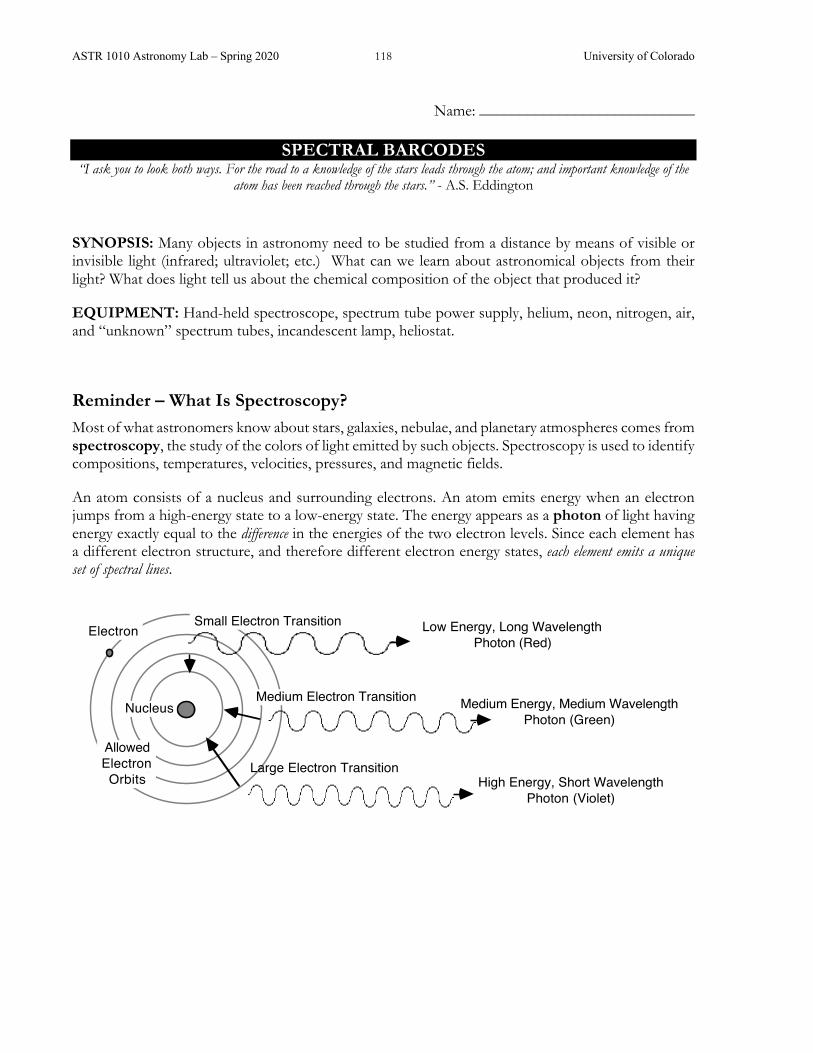
ASTR 1010 Astronomy Lab – Spring 2020 118 University of Colorado
SPECTRAL BARCODES
“I ask you to look both ways. For the road to a knowledge of the stars leads through the atom; and important knowledge of the atom has been reached through the stars.” - A.S. Eddington
SYNOPSIS: Many objects in astronomy need to be studied from a distance by means of visible or invisible light (infrared; ultraviolet; etc.) What can we learn about astronomical objects from their light? What does light tell us about the chemical composition of the object that produced it?
EQUIPMENT: Hand-held spectroscope, spectrum tube power supply, helium, neon, nitrogen, air, and “unknown” spectrum tubes, incandescent lamp, heliostat.
Reminder – What Is Spectroscopy? Most of what astronomers know about stars, galaxies, nebulae, and planetary atmospheres comes from spectroscopy, the study of the colors of light emitted by such objects. Spectroscopy is used to identify compositions, temperatures, velocities, pressures, and magnetic fields.
An atom consists of a nucleus and surrounding electrons. An atom emits energy when an electron jumps from a high-energy state to a low-energy state. The energy appears as a photon of light having energy exactly equal to the difference in the energies of the two electron levels. Since each element has a different electron structure, and therefore different electron energy states, each element emits a unique set of spectral lines.
Small Electron Transition
Medium Electron Transition
Large Electron Transition
Electron
Nucleus
AllowedElectronOrbits
Low Energy, Long WavelengthPhoton (Red)
Medium Energy, Medium WavelengthPhoton (Green)
High Energy, Short WavelengthPhoton (Violet)
Name: ___________________________

ASTR 1010 Astronomy Lab – Spring 2020 119 University of Colorado
Part I – Electron Energy Transitions
Figure 5.12 from the textbook showing the energy levels for an electron in a hydrogen atom.
I.1 (a) Using the model of electron transitions, explain how an atom can give off light.
(b) What can you infer about the transitions if atoms of a single element give off both red light and blue light?
I.2 (a) Using the model of electron transitions, explain how an atom can absorb light.
(b) What can you infer about the transitions if an atom absorbs both red light and blue light?
I.3 Will an atom emit light if all of the atom’s electrons are in the ground state? Explain your
reasoning.
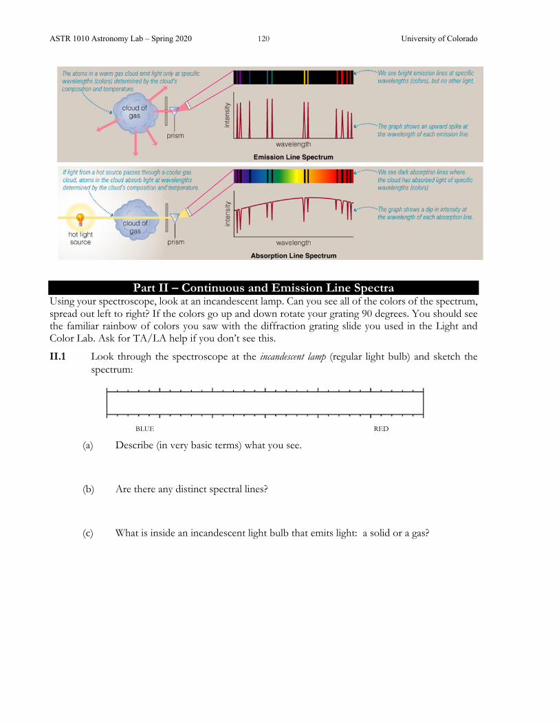
ASTR 1010 Astronomy Lab – Spring 2020 120 University of Colorado
Part II – Continuous and Emission Line Spectra Using your spectroscope, look at an incandescent lamp. Can you see all of the colors of the spectrum, spread out left to right? If the colors go up and down rotate your grating 90 degrees. You should see the familiar rainbow of colors you saw with the diffraction grating slide you used in the Light and Color Lab. Ask for TA/LA help if you don’t see this.
II.1 Look through the spectroscope at the incandescent lamp (regular light bulb) and sketch the spectrum:
(a) Describe (in very basic terms) what you see.
(b) Are there any distinct spectral lines?
(c) What is inside an incandescent light bulb that emits light: a solid or a gas?
BLUE RED BLUE RED

ASTR 1010 Astronomy Lab – Spring 2020 121 University of Colorado
A solid glowing object will not show a characteristic atomic spectrum, since the atoms are not free to act independently of each other. Instead, solid objects produce a continuum spectrum of light regardless of composition; that is, all wavelengths of light are emitted rather than certain specific colors.
For each of these gases (Helium, Neon and Nitrogen):
• Install the element discharge tube in the power supply and turn it on
• Look through the spectroscope at the gas tube.
• Turn off the power supply before changing tubes.
CAUTION! The tubes are powered by 5000 volts! Do NOT touch the sockets when the power supply is on. The tubes also get very HOT! Let the tubes cool, use paper towels to handle them.
II.2 What colors do you see? Use colored pencils or crayons to sketch spectral lines of the light
emitted by the element you are looking at on the frames below. Helium
Neon
Nitrogen
II.3 For each of these elements, how does the overall color of the glowing gas compare with the
specific colors you see split apart in its spectrum?
• Helium
• Neon
• Nitrogen
BLUE RED
BLUE RED
BLUE RED
BLUE RED
BLUE RED

ASTR 1010 Astronomy Lab – Spring 2020 122 University of Colorado
II.4 Judging from the number of visible energy-level transitions (lines) in each, which element would you conclude has the more complex atomic structure: helium or neon? Explain.
Fluorescent lamps operate by passing electric current through a gas in the tube, which glows with its characteristic spectrum. A portion of that light is then absorbed by the solid material lining the tube, causing the solid to glow, or fluoresce, in turn. You therefore get a combination of the spectrum of a solid and a gas.
II.5 Predict: Do you expect to see a continuous spectrum, a line spectrum, or a combination of both?
Point your spectroscope at the fluorescent lights and sketch the spectrum.
II.6 Which components of the spectrum originate from the gas?
II.7 Which components of the spectrum originate from the solid?
Part III - Identifying an Unknown Gas Select one of the unmarked tubes of gas (it will be either hydrogen, mercury, or krypton). Install your "mystery gas" in the holder and inspect the spectrum.
III.1 What is the color of the glowing gas? Make a sketch of the spectrum and label the colors.
III.2 Identify the composition of the gas in the tube by comparing your spectrum to the spectra
described in the tables below. Explain which lines you used to make your identification.
BLUE RED
BLUE RED BLUE RED
BLUE RED

ASTR 1010 Astronomy Lab – Spring 2020 123 University of Colorado
The strongest lines are bold. Wavelengths in nm (10-9 m) are given to left of each color.
Part IV. The Solar Spectrum
If the Sun is shining, the TA will use the Heliostat to bring up the solar spectrum. This involves using mirrors, lenses and a grating to pipe in sunlight from outside and to split the light by wavelength.
IV.1 What do you see? Describe the solar spectrum in terms of continuous, emission and/or absorption components.
IV.2 Based on the (extremely simplistic) model of the Sun above, which component of the spectrum comes from the Sun’s surface? Which is due to its atmosphere?

ASTR 1010 Astronomy Lab – Spring 2020 124 University of Colorado
IV.3 Your TA will also put light from a couple of gas tubes through the same optics that will produce emission lines above/below the solar spectrum. Are these gases present in the solar spectrum? Explain.
IV.4 How many lines of hydrogen can you find in the solar spectrum? (List which ones.)
IV.5 Have your TA identify the sodium absorption lines. What color are they in? What color are
sodium (emission) lamps? (Hint: Think back to the Light and Color lab.) Explain the reason for the similarity.
Part V – The Aurora – What makes the Northern Lights? Install the tube of gas marked “air” and look at the spectrum. Compare it to the other spectra you have looked at.
V.1 What molecule(s) is/are responsible for the spectral lines you see in air?
BLUE RED BLUE RED

ASTR 1010 Astronomy Lab – Spring 2020 125 University of Colorado
The Physics of Auroral Light Formation The high-energy electrons and protons traveling down Earth's magnetic field lines collide with the atmosphere (i.e., oxygen and nitrogen atoms and molecules). The collisions can excite the atmospheric atom or molecule or they can strip the atmospheric particle of its own electron, leaving a positively-charged ion. The result is that the atmospheric atoms and molecules are excited to higher energy states. They relinquish this energy in the form of light upon returning to their initial, lower energy state. The particular colors we see in an auroral display depend on the specific atmospheric gas struck by energetic particles, and the energy level to which it is excited. The two main atmospheric gases involved in the production of auroral lights are oxygen and nitrogen:
• Oxygen is responsible for two primary auroral colors: green-yellow wavelength of 557.7 nm is most common, while the deep red 630.0 nm light is seen less frequently. • Nitrogen in an ionized state will produce blue light, while neutral nitrogen molecules create purplish-red auroral colors. For example, nitrogen is often responsible for the purplish-red lower borders and rippled edges of the aurora.
Auroras typically occur at altitudes of between 95 and 1,000 km above sea level. Auroras stay above 95 km because at that altitude the atmosphere is so dense (and the auroral particles collide so often) that they finally come to rest at this altitude. On the other hand, auroras typically do not reach higher than 500-1,000 km because at that altitude the atmosphere is too thin to cause a significant number of collisions with the incoming particles.
Sometimes you can see multiple colors (coming from different layers of the atmosphere) but more usually only one layer (and chemical constituent) is excited at a time, during a particular auroral storm.
Please do NOT mark on the photographs!
V.2 Look at the 4 auroral pictures provided on a separate sheet (2 taken from the ground, 2 from
space). For each image say what gas is emitting the light and at what height: lower (<100 km), middle (100-200 km) or upper (>200 km) auroral regions of the atmosphere.
A B C D

ASTR 1010 Astronomy Lab – Spring 2020 126 University of Colorado

ASTR 1010 Astronomy Lab – Spring 2020 127 University of Colorado
TRANSITING EXTRASOLAR PLANETS
Pre-Lab = please complete before coming to lab Read briefly through the entire lab. Check this box ☐ to indicate that you have done so. Jot down any questions that occurred to you while skimming through the lab description.
1. Summarize Newton’s form of Kepler’s 3rd Law in words. Then state the law mathematically, explaining the meaning of each symbol in the equation.
2. Let’s imagine an exoplanet transiting one of the closest stars to Earth. Draw a diagram that
shows the exoplanet and its host star, during transit, as seen from Earth. (Pretend you have a magically good telescope so you can actually resolve the image.)
3. Draw another diagram, this time from above, showing the relative arrangement of that
exoplanet, its host star, its orbit, and the Earth. If you have to make any approximations to sizes or scales to fit on the page, please explain what those are.
Name: ___________________________

ASTR 1010 Astronomy Lab – Spring 2020 128 University of Colorado

ASTR 1010 Astronomy Lab – Spring 2020 129 University of Colorado
TRANSITING EXTRASOLAR PLANETS
LEARNING GOALS: Detecting planets around other stars is a very challenging task. What is the transiting planet method of detection? What can we learn about extrasolar planets using this method?
EQUIPMENT: Lamp, ruler, Lego™ orrery (with a variety of detachable planets), light sensor, laptop (or other) computer with LoggerLite™ software, modeling clay (available from your lab instructor for the optional section at the end), calipers
In March 6, 2009, the NASA Kepler spacecraft successfully launched and began monitoring the brightness of more than 100,000 stars. The Kepler mission is NASA's first mission with the precision capable of finding Earth-size and smaller planets around other stars. In this lab, you will discover how Kepler’s instruments work and what we can learn about extrasolar planets.
In this lab, you will occasionally be asked to predict (as a real scientist would) the outcome of an experiment before you try it. Make these predictions BEFORE moving on to the experiment itself. You will not be marked down if your predictions are wrong.
Unfortunately, the Lego orrery does not simulate a true solar system since it does not exactly follow Kepler’s 3rd Law (P2=a3). Keep this in mind.
Part I. Setting up your Kepler Simulation The transit detection method is an indirect detection method in that it is not directly detecting the planet itself but rather the planet’s interactions with its central star. By detecting a repeating dimming of the star’s brightness, scientists can infer that a planet is orbiting around the star and occasionally blocking some of the star’s light from the telescope.
In this lab, the light sensor will simulate both the Kepler telescope and its light detecting hardware. The lamp will simulate the star and the Lego orrery will be configured to simulate various planets moving around that star.
The first thing you’ll need to do is place the star in the middle of the orrery. Adjust the lamp so the bulb is over the middle shaft of the orrery. Be sure the base of the lamp is not blocking the path to the light sensor.
Next you’ll need to align the light sensor so it is pointing directly at the center of the light source. (Make sure none of the planets are between the star and the light sensor during alignment.)
I.1 Using your ruler, measure the height of the star and adjust your light sensor to the same height. Record the height of your star and light sensor: _________________
I.2 Next you’ll need to make sure your light sensor is pointed directly at the center of the light source. Align the sensor roughly by eye, and then use LoggerLite software (if the software is not already running, ask your TA or LA to help start the program) to do it more accurately. Explain how you can use the LoggerLite software to align your sensor.
Name: ___________________________

ASTR 1010 Astronomy Lab – Spring 2020 130 University of Colorado
I.3 Record the value for the peak brightness of your lamp: ____________________ (The light bulb itself might show some small variability. As long as it’s not periodic, this will not affect your measurements. Most real stars actually show some variability.)
Part II. Measuring the Effect of Planet Size II.1 Affix a medium-sized planet to the middle arm of the orrery. Try to get the height of the
planet to be the same height as the center of your star and your light sensor. Turn on the orrery motor and start the LoggerLite data collection. Describe the results.
II.2 (a) Suppose that your planet was ½ the diameter of your star. What percent of the star’s light would you predict that planet would block?
(b) As seen from a distance, planets and stars look like circles. Draw a planet and a star on top of each other below with the planet having a diameter that is ½ that of the star (use circles, don’t do a 3-dimensional drawing). To help make the point even clearer, temporarily pretend the star and planet are squares, with the smaller one ½ the width of the larger (start the square “planet” in the corner of the square “star”). Draw accurately!
Star & Planet Star & Planet (drawn as a squares)
(c) Based on your drawing, how does the area of the star compare to the area of the planet? (You should be able to give actual numbers here, not just bigger or smaller).

ASTR 1010 Astronomy Lab – Spring 2020 131 University of Colorado
II.3 (a) Using the clamps provided, measure your star (in the orrery) and record its size here (be careful not to break your bulb!): ____________
(b) Now measure your planet and record its size here:_______________
(c) What is the ratio of the diameters?________________
(d) What is the ratio of the areas?________________
II.4 What percent of the star’s light do you predict the planet will block? Did you use (c) or (d) above? Explain your choice.
II.5 (a) Use the experimental setup to measure the percentage of the light that is actually blocked. Show your work. (You can use the “Examine” button in LoggerLite to get the exact y-value at any point on your graph. Be sure to run your orrery for at least two complete orbits of the planet.)
(b) How well does your result agree with your predictions?
(c) What might be the cause(s) of any differences? Show your prediction and result to your TA or LA before you proceed.
II.6 Replace the medium planet with a different sized planet, run the orrery, and describe the results. Compare your results to those you found in the previous question.

ASTR 1010 Astronomy Lab – Spring 2020 132 University of Colorado
Part III. Measuring the Effect of Planet Orbital Distance III.1 Other than brightness, predict the effect of changing the orbital distance of the planet and
record your prediction. Be as specific as possible. (Hint: The spacecraft is called the Kepler spacecraft…)
III.2 Move the planet to a different position, run the orrery for at least two orbits, and describe your results.
III.3 How well do your results agree with your prediction? If they disagree, what might be the cause(s) of any differences?
(The reason we ignore brightness variations is that this is a result of not being able to put the star system extremely far away from our detector, as is the case in real astronomy.)
Part IV. Measuring a Complex Planetary System Split your lab group into two teams. Each team will take one turn acting as the extrasolar system creators and one turn acting as the Kepler Science Team. Fill in the appropriate sections when it is your turn to act as that team.
Extrasolar System Creators: Place the cardboard divider between your teams so the Kepler Science Team cannot see the orrery. Using the various planet choices, create a solar system consisting of up to three planets. You don’t have to use all three but try to make it challenging!
IV.1 Record the sizes for the three planets you chose in the table below.
Planet Size
1st Planet (closest to star)
2nd Planet
3rd Planet

ASTR 1010 Astronomy Lab – Spring 2020 133 University of Colorado
IV.2 In the space below, draw your prediction for what the Kepler light curve will look like. Explain, in words, your prediction.
When you are ready, turn on the orrery and tell the Kepler Science Team to begin their analysis.
Kepler Science Team: Your job will be to act as the scientists analyzing Kepler’s data here on Earth. Without seeing the orrery, you will need to determine what kind of solar system the Kepler satellite has discovered.
IV.3 In the space below, make a sketch of the detected light curve. You might need a few minutes of data to recognize the full pattern.

ASTR 1010 Astronomy Lab – Spring 2020 134 University of Colorado
IV.4 Based on the detected light curve, what are the sizes and distances of the planets around the system you’ve detected? Be as specific as possible (can you guess exact sizes?) Explain your reasoning.
IV.5 Once you’ve completed your analysis, check with the other team to see what actual planets were used. Was your analysis correct? If not, why not?
Now switch roles with the others; create a new solar system, and let the others analyze it. If you were the Kepler astronomers, you are now the creators, and should go back and fill in IV.1 and IV.2.
Part V. Summary V.1 What are the difficulties that might be associated with detecting planets using the transit
method? There are several answers to this question; you should list at least two for full credit.
V.2 For each of the following pairs, which type of extrasolar planets would the transit method work best? Large planets or small planets? Planets close to their host star or far from their host star? Highly eccentric orbits or circular orbits? Stars close to Earth or far away? Explain your reasoning.
V.3 If you had a spectrograph instead of a light sensor, how could this method be used to tell if a transiting planet had an atmosphere?

ASTR 1010 Astronomy Lab – Spring 2020 135 University of Colorado
Part VI. Detecting Earth-size Planets VI.1 Earth’s radius is 6,400 km and the Sun’s radius is 700,000 km. Using the reasoning you came
up with in II.4, calculate the percentage of the Sun’s light that Earth would block during a transit.
VI.2 The Kepler spacecraft is able to measure individual brightness changes of as little as 0.002%, and by averaging together many measurements can sometime reach a measurement precision of 0.0002% (two parts per million)! What do you estimate to be the smallest brightness change you could reliably detect with your light sensor and model?
If you wish to explore the concepts a little further, your TA has modeling clay available. Create your own planets and predict what the light curve will look like. Some outcomes may surprise you!
Please clean up your lab station before you leave and leave it setup for the next lab group.
For more information on the Kepler Mission, see http://www.nasa.gov/kepler (or follow the Kepler mission on twitter at http://twitter.com/NASAKepler).

ASTR 1010 Astronomy Lab – Spring 2020 136 University of Colorado

ASTR 1010 Astronomy Lab – Spring 2020 137 University of Colorado
NIGHTTIME OBSERVING PROJECTS
Artemis and Apollo are the two 20-inch optical telescopes at Sommers-Bausch Observatory deck. (Photo by Gary Garzone, BASS)

ASTR 1010 Astronomy Lab – Spring 2020 138 University of Colorado
The Moon
Messier 13, a bright Globular Star Cluster in Hercules imaged with the CCD camera on Apollo, the western SBO 20” telescope.
417 482 610 869 1383 2418 4466 8544 16775 33054 65470

ASTR 1010 Astronomy Lab – Spring 2020 139 University of Colorado
MEASURING THE EFFECTS OF LIGHT POLLUTION* Note: unlike the other labs in this book, this exercise is to be completed on your own time over the course of the semester. It is due to your lab TA by your last lab meeting of the semester or before.
SYNOPSIS: In this observing lab you will observe the night sky from two locations: one dark site and one more suburban/urban to assess the effects of light pollution on what we see in the sky. You will estimate the amount of human-caused light pollution and document the effects on the stars you can see in one or more constellations. You will submit your observational data to the Globe at Night citizen-science program to help monitor light pollution worldwide.
EQUIPMENT: A Smartphone, transportation, warm clothing (optional)
Part I: Preparation Since the moon can be quite bright, YOU MUST OBSERVE DURING ONE OF THESE TIME PERIODS in order to avoid moonlight. Do not put this off until the last minute!
Date Range Constellation January 16 – 25 Orion or Taurus
February 14 – 23 Orion or Gemini March 14 – 24 Orion or Gemini April 14 – 23 Leo
Visit the website for the Globe at Night project: https://www.globeatnight.org//
This program monitors the brightness of the night sky and light pollution by charting how many stars you can see in a particular constellation. They ask you to estimate the “magnitude” of the faintest stars you can see and log this, along with the date/time and your longitude and latitude. This is combined with others’ observations worldwide to create a year-by-year record of light pollution around the globe. The project is sponsored by the National Science Foundation, the Association of Universities for Research in Astronomy, and the National Optical Astronomical Observatories.
Read about the project from their Call to Action under the Learn (about light pollution) tab. Verify which constellation(s) you will be looking for. Familiarize yourself with the “magnitude
charts” for the constellation. Enter your latitude (40oN) to make sure the constellation is oriented properly for an evening observation.
The term “magnitude” dates back to Hipparcos in ancient Greek times, who gauged the brightness of stars from 0 (very bright) to 7 (the faintest he could see). Note that, counter-intuitively, smaller magnitude numbers denote brighter stars! Modern astronomers still use this system and have extended it to very bright objects (Venus is about magnitude -4) and extremely faint objects (the Hubble Space Telescope has recorded stars as faint as magnitude 30). The mathematical definition of a magnitude is that 1 magnitude difference in brightness corresponds to a factor of 2.5 in apparent brightness (i.e. a star of magnitude=4 is 2.5 times brighter than a star of magnitude=5).
For your observations, you will use magnitude charts from the website to estimate the brightness of the faintest stars you can see in a constellation from two different locations. In the middle of a city, the faintest stars you can see may only be magnitude=1 or 2. From a dark site, it may be magnitude=5 or higher.
Preview the “Report” page to see what data you’ll need to enter (an example is shown below).

ASTR 1010 Astronomy Lab – Spring 2020 140 University of Colorado
Make a note of these before you observe so you can fill out the page later. You should be able to locate your position to ~1 city block (1/10 of a mile). Click on the map window to see how this works. Note that you can use your cell phone to access the website and enter your data: your current time and location will be automatically recorded. Test this before you go out at night. Be sure to choose “night mode” if you’re using your phone while observing at night--your phone will turn red which doesn’t hurt your dark-adapted vision.
Part II: Choose your observing locations A bright skies site should be something in a city or suburb (on campus is fine but avoid campus
lights!) Find something as dark as possible (i.e., don’t stand right under a streetlight). If you’re on campus, the middle of Norlin Quad or Farrand Field might be a good choice.
Your dark skies site should be as far from city lights as possible. Ideally, you’d be out in the middle of the desert or mountains. However, this has practicality issues. Anywhere on campus or even most places inside the city of Boulder do NOT count as dark skies sites. If you’re in Boulder, here are a few very good locations:
• West on Baseline Road up over the top of Flagstaff Mountain. Find the pull-off for the Meyers Gulch or Walker Ranch open spaces (about 12 miles by road from Boulder).
• Peak to Peak Highway. Drive west up Boulder Canyon to Nederland. At Nederland go either north or south several miles on Peak-to-Peak Highway (State #72). Find a pull-off where you can see lots of sky.
• North of Boulder. The area near Boulder Reservoir and other open space areas in the rural areas between Boulder, Lyons, and Longmont are pretty dark. Be sure you are not trespassing.
Another possibility is to make a high-impact observation for the Globe at Night project. At the bottom of their home page they show a map showing previous observations for the year. You can get a feel for where the bright (yellow) and darker (orange to red) sites are and choose one for either your bright or dark sites. If you can, choose a site that will “fill in” the map. (Note that a report of a “dark” site within the city of Boulder is probably an error). There is no need to do your bright- and dark-sky observations on the same night or even during the same observing ‘window’. However, be sure you observe during the dates of the observing campaign (listed at the top of this activity), not during a time when the moon is up.

ASTR 1010 Astronomy Lab – Spring 2020 141 University of Colorado
Part III: Make your observations Travel to your observing location between the hours of about 8-11pm. Please be careful - for
your safety and that of others- always bring a friend or two (it’s a lot more fun that way, too!) Be especially careful if walking along roadways and bring a small flashlight for navigation.
For your bright site: try to situate yourself in a place that is not directly under or near a bright light source. Find your constellation and compare it with the magnitude charts from the Globe at Night website. Choose which one corresponds best to the stars that you can see. Fill in the information they require for time/date, location, magnitude chart, sky conditions, and any comments you’d like to add. [Ignore the SQM query unless you want to look into what this means and see if their phone app works- reports are mixed]. Submit your data and log your data on the sheet at the end of this activity.
For your dark site: find the darkest location you can, away from any obvious local lighting. Sit quietly for about 10 minutes to let your eyes adapt (you can close your eyes if you like). If you have a phone, flashlight or other light source with you, either turn it off (!!!) or use “night mode” to turn the display red to help keep your pupils from closing up. Do the same observations for Globe at Night. Can you see the Milky Way?
Part IV: Document your observations Find the web form to report your observations (example on the next page). Fill in the data for
both your bright and dark sites. Either print your report page when you submit it or copy the information on the sheet at the end of this activity.
Next, please answer the questions below: 4a) What is the difference in the faintest magnitude stars you can see between your bright and dark skies? Between your bright skies and the darkest skies (~mag 7)? Converting magnitude to brightness use the scale that each magnitude difference is a factor of 2.5. E.g.,
1 magnitude difference = ~2.5 times fainter 2 magnitudes = 2.5 x 2.5 = 6.25 times fainter
How much fainter (in absolute terms, not magnitudes) are the faintest stars you can see in your dark sky, versus the faintest in your bright sky? 4b) Did one part of the sky seem brighter than another? What might cause this? 4c) Did you see the Milky Way from your dark site? If so, describe it. If not, why not? 4d) Visit the International DarkSky Association website at http://darksky.org/ Write a 1-2 paragraph commentary on a topic discussed on the website pertaining to dark skies or light pollution (i.e., Dark sky parks, problems with LED lighting, nighttime lighting and crime, etc.) Does light pollution affect just professional astronomers or is it a larger, societal issue?

ASTR 1010 Astronomy Lab – Spring 2020 142 University of Colorado
Summary To hand in for your activity: Three pages total. 1) Two (or more!) log sheets printed from the GlobeAtNight website (see example below); one for
your bright sky location and one for your dark sky location. Use the “location comments” box to describe your location. On each one, please write down anyone (whether in our class or not) who you were with at the time.
2) One (typed) page answering the questions in part 4. If you’d like to share your reactions to this exercise or anything interesting you observed, feel free to do so.
HAVE FUN WITH THIS AND BE SAFE!

ASTR 1010 Astronomy Lab – Spring 2020 143 University of Colorado
KNOWING CONSTELLATIONS & BRIGHT STARS* SYNOPSIS: In this self-paced lab, you will teach yourself to recognize and identify a number of constellations, bright stars, planets, and other celestial objects in the current evening sky.
EQUIPMENT: A planisphere (rotating star wheel) or other star chart. A small pocket flashlight may be useful to help you read the chart.
Part I: Preparation, Practice, and Procedures Part II contains a list of 30 or more celestial objects that are visible to the naked eye this semester. You are expected to learn to recognize these objects through independent study, and to demonstrate your knowledge of the night sky by identifying them. On telescope observation nights, your TA will take students (1-by-1) out to the open deck and give you the opportunity to identify 10 of these objects. You will receive 10% credit for each correctly identified object (and will only be allowed 3 mistakes before you start to lose credit.) After all students who have chosen to have complete this “quiz” for the night, the TA will then give any interested students a tour of the night sky so they may return to complete the quiz on another observing night. (You may not complete the quiz AFTER the TA has given the night sky tour for the night.)
If you wait until the end of the semester to take the quiz and then are clouded out, you will not be able to complete this lab. Do not expect your TA to schedule additional time for you. If you have not taken the oral quiz, you will not receive credit for this lab!
You can learn the objects by any method you desire: � Independent stargazing by yourself or with a friend.
� Attending the nighttime observing sessions at the Observatory and receiving assistance from the teaching assistant(s) or classmates.
� Attending Fiske Planetarium sessions.
� All of the above.
Observing and study tips:
� Your textbook may come with access to planetarium software, or you can download free software from http://stellarium.org/. These tools can be a great way to explore the night sky even during the daytime and/or from the comfort of your desk. Then you can go outside to see how the real thing compares with the simulation.
� Learn relationships between patterns in the sky. For example, on a bright night it may be virtually impossible to see the faint stars in the constellation of Pisces; however, you can still point it out as "that empty patch of sky below Andromeda and Pegasus". You can envision Deneb, Vega, and Altair as vertices of "the Summer Triangle", and you might think of Lyra the harp playing "Swan Lake" as Cygnus flies down into the murky pool of the Milky Way.
� Be aware that faint stars are difficult to see on a hazy evening from Boulder, or if there is a bright moon in the sky. On the other hand, a dark moonless night in the mountains can show so many stars that it may be difficult to pick out the constellation patterns. In either
Name: ________________________
ASTR 1010 Astronomy Lab – Spring 2020 144 University of Colorado
case, experience and practice are needed to help you become comfortable with the objects on the celestial sphere.
� If you like a hands-on aid, we recommend using the large, 10" diameter Miller planisphere available from Fiske Planetarium: it is plastic coated for durability, is easiest to read, and includes sidereal times. The smaller Miller planisphere is more difficult to use but is handier to carry. Other planispheres are available from the bookstore or area astronomy stores.
� To set the correct sky view on your planisphere, rotate the top disk until the current time lines up with the current date at the edge of the wheel. Planispheres indicate local "standard" time, not local "daylight savings" time. If daylight savings time is in effect, subtract one hour from the time before you set the wheel. (For example, if you are observing on April 15th at 11 p.m. Mountain Daylight Time, line up 10 p.m. with the April 15th marker).
� The planisphere shows the current appearance of the entire sky down to the horizon. It is correctly oriented when held overhead so that you can read the chart, with North on the chart pointing in the north direction. The center of the window corresponds to the zenith (the point directly overhead). When you face a particular direction, orient the chart so that the corresponding horizon appears at the bottom. As with all flat sky maps, there will be some distortion in appearance, particularly near the horizons.
� If you merely "cram" to pass the quiz, you will be doing yourself a great disservice. The stars will be around for the rest of your life; if you learn them now rather than just memorize them, they will be yours forever.
Good luck, good seeing, and clear skies!

ASTR 1010 Astronomy Lab – Spring 2020 145 University of Colorado
Part II. Spring Naked-Eye Observing List Different stars are visible at night at different times. Be sure to use the right list for the semester. If you’re taking class in the fall, please skip ahead to the Fall Naked-Eye Observing List.
Constellations Bright Stars
Ursa Major (big bear, big dipper) Mizar & Alcor
Ursa Minor (little bear, little dipper) Polaris
Cassiopeia (queen, ‘W’)
Cygnus (swan, northern cross) Albireo, Deneb
Perseus (hero, wishbone)
Taurus (bull) Aldebaran
Auriga (charioteer, pentagon) Capella
Orion (hunter) Betelgeuse, Rigel
Gemini (twins) Castor, Pollux
Canis Major (big dog) Sirius
Canis Minor (small dog) Procyon
Cancer (crab)
Leo (lion) Regulus
Boötes (herdsman, cone, kite) Arcturus
Virgo (virgin) Spica
Other Celestial Objects or Regions
Mercury, Venus, Mars, Jupiter, Saturn (and bright comets if present)
(check the web resources at the beginning of this manual)
Ecliptic or Zodiac trace its path across the sky
Celestial Equator trace its path across the sky
Pointer Stars how to locate Polaris
Great Andromeda Galaxy fuzzy patch in Andromeda
Pleiades (seven sisters) star cluster in Taurus
Hyades (closest star cluster) near Aldebaran
Great Nebula in Orion (M42) center 'star' in Orion's sword

ASTR 1010 Astronomy Lab – Spring 2020 146 University of Colorado
Spring Constellations
(with ecliptic and celestial equator shown)
The Boulder Night Sky 14 March, 10:00 pm

ASTR 1010 Astronomy Lab – Spring 2020 147 University of Colorado
Part II. Fall Naked-Eye Observing List Different stars are visible at night at different times. Be sure to use the right list for the semester. If you’re taking class in the spring, please go back to the Spring Naked-Eye Observing List.
Constellations Bright Stars
Ursa Minor (little bear, little dipper) Polaris
Lyra (lyre, harp) Vega
Cygnus (swan, northern cross) Albireo, Deneb
Aquila (eagle) Altair
Cepheus (king, doghouse)
Capricornus
Aquarius
Pegasus (horse, great square)
Andromeda (princess)
Pisces (fishes)
Aries (ram)
Cassiopeia (queen, ‘W’)
Perseus (hero, wishbone)
Taurus (bull) Aldebaran
Auriga (charioteer, pentagon) Capella
Orion (hunter) Betelgeuse, Rigel
Gemini (twins) Castor, Pollux
Other Celestial Objects or Regions
Mercury, Venus, Mars, Jupiter, Saturn (and bright comets if present)
(check the web resources at the beginning of this manual)
Ecliptic or Zodiac trace its path across the sky
Celestial Equator trace its path across the sky
Pointer Stars how to locate Polaris
Great Andromeda Galaxy fuzzy patch in Andromeda
Pleiades (seven sisters) star cluster in Taurus
Hyades (closest star cluster) near Aldebaran

ASTR 1010 Astronomy Lab – Spring 2020 148 University of Colorado
Great Nebula in Orion (M42) center 'star' in Orion's sword
Fall Constellations (with ecliptic and celestial equator shown)
The Boulder Night Sky 15 October, 10:00 pm

ASTR 1010 Astronomy Lab – Spring 2020 149 University of Colorado
OBSERVATIONS OF DEEP-SKY OBJECTS* SYNOPSIS: You will view and sketch a number of different astronomical objects through the SBO telescopes. The requirements for credit for telescope observing may vary depending on the requirements of your instructor. The following is given only as a guideline.
EQUIPMENT: Observatory telescopes, observing forms, and a pencil.
Be sure to dress warmly - the observing deck is not heated!
Part I. Observing Deep Sky Objects The two main SBO observing telescopes (twin 20-inch telescopes) are both operated by computer. The user may tell the computer to point at, or the observer may specify the coordinates at which the telescope should point. Deep sky objects are easily selected from the catalog (or using the Find window).
Your instructor may point a telescope to at least one of each of the following different types of deep-sky objects (provided that weather cooperates, and the appropriate objects are visible in the sky at the time). Distinguishing characteristics to look for have been included in italics.
� Double or multiple stars. Separation of the stars, relative brightness, orientation, and color of each component.
� Open clusters. Distribution, concentration, and relative brightness and color of the stars.
� Globular clusters. Shape, symmetry, and central condensation of stars.
� Diffuse nebulae. Shape, intensity, color, possible association with stars or clusters.
� Planetary nebulae. Shape (ring, circular, oblong, etc.), size, possible central star visible.
� Galaxies. Type (spiral, elliptical, irregular), components (nucleus, arms), shape and size.
For each of the above objects that you observe:
I.1 In the spaces provided on the observing form, fill in the object's name, type, position in the sky (RA and Dec), the date/time you observed it, and the weather conditions. Make certain to note what constellation the object is in, because this information is almost essential when using the reference books.
I.2 Observe through the telescope and get a good mental image of the appearance of the object. You may wish to try averted vision (looking out of the corner of your eye) to aid you in seeing faint detail. Take your time; the longer you look, the more detail you will be able to see.
Name: ___________________________

ASTR 1010 Astronomy Lab – Spring 2020 150 University of Colorado
I.3 Using a pencil, carefully sketch the object from memory, using the circle on the observing form to represent the view in the eyepiece. Be as detailed and accurate as possible, indicating color, brightness, and relative size.
I.4 Include an "eyepiece impression" of what you observed: a brief statement of your impressions and interpretation. Feel free to draw upon comparisons (for example, "like a smoke ring," or "a little cotton ball," etc.). Express your own enthusiasm or disappointment in the view!
I.5 If you wish (or if your instructor has required it), research some additional information on your objects. The Observatory library has some sources. Specific useful books are Burnham's Celestial Handbook, the Messier Album, and various textbooks. Read about the object, and then provide any additional information that you find is particularly pertinent or interesting.
Part II. Planetary Observations Most of the planets (other than the Earth) are readily observed with the SBO telescopes. The difficult ones are Pluto (tiny and faint) and Mercury (usually too close to the Sun). Provided that they are available in the sky this semester (consult the web resources at the beginning of this manual):
II.1 Observe, sketch, and research at least two of the solar system planets, as in paragraphs I.1 through I.5 above. Pay particular attention to relative size, surface markings, phase, and any special features such as moons, shadows, or rings. You may wish to use different magnifications (different eyepieces) to try to pick out more detail.

ASTR 1010 Astronomy Lab – Spring 2020 151 University of Colorado
DateTimeTelescope size
Constellation
Object NameObject Type
R.A.Dec.
Sky Condition
Description of Observation
Additional Information
NAME:
DateTimeTelescope size
Constellation
Object NameObject Type
R.A.Dec.
Sky Condition
Description of Observation
Additional Information

ASTR 1010 Astronomy Lab – Spring 2020 152 University of Colorado
DateTimeTelescope size
Constellation
Object NameObject Type
R.A.Dec.
Sky Condition
Description of Observation
Additional Information
NAME:
DateTimeTelescope size
Constellation
Object NameObject Type
R.A.Dec.
Sky Condition
Description of Observation
Additional Information
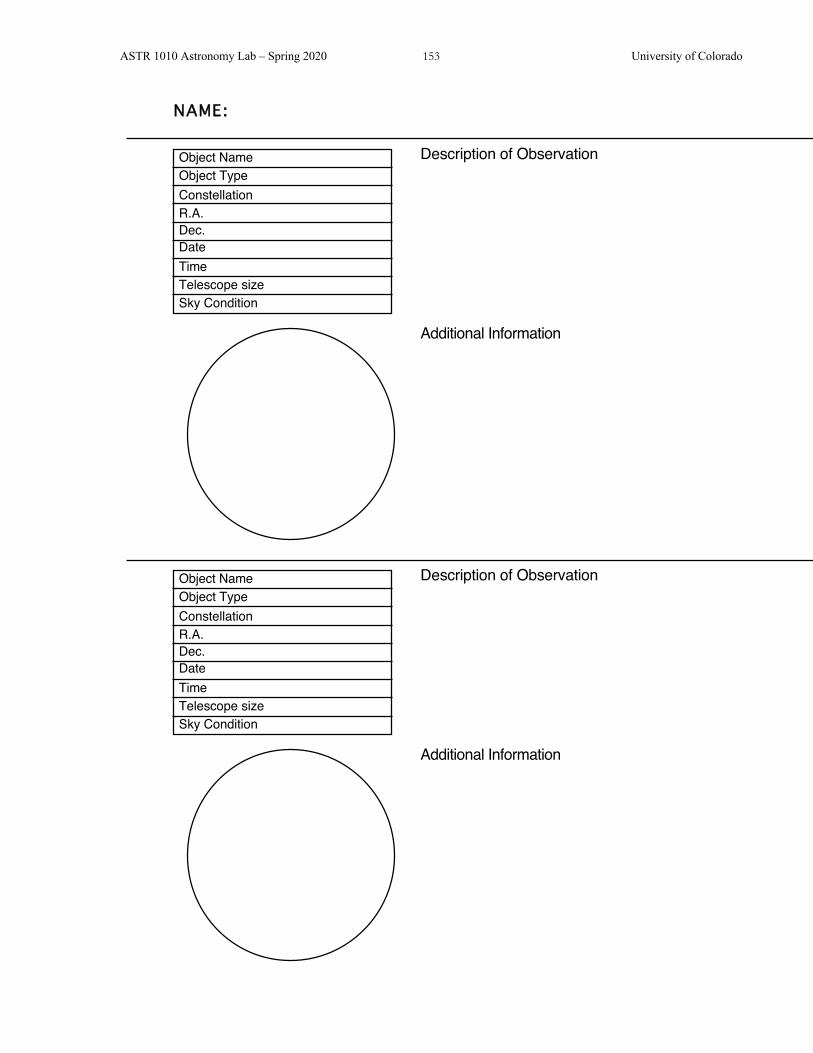
ASTR 1010 Astronomy Lab – Spring 2020 153 University of Colorado
DateTimeTelescope size
Constellation
Object NameObject Type
R.A.Dec.
Sky Condition
Description of Observation
Additional Information
NAME:
DateTimeTelescope size
Constellation
Object NameObject Type
R.A.Dec.
Sky Condition
Description of Observation
Additional Information
ASTR 1010 Astronomy Lab – Spring 2020 154 University of Colorado
DateTimeTelescope size
Constellation
Object NameObject Type
R.A.Dec.
Sky Condition
Description of Observation
Additional Information
NAME:
DateTimeTelescope size
Constellation
Object NameObject Type
R.A.Dec.
Sky Condition
Description of Observation
Additional Information

ASTR 1010 Astronomy Lab – Spring 2020 155 University of Colorado
DateTimeTelescope size
Constellation
Object NameObject Type
R.A.Dec.
Sky Condition
Description of Observation
Additional Information
NAME:
DateTimeTelescope size
Constellation
Object NameObject Type
R.A.Dec.
Sky Condition
Description of Observation
Additional Information
ASTR 1010 Astronomy Lab – Spring 2020 156 University of Colorado
DateTimeTelescope size
Constellation
Object NameObject Type
R.A.Dec.
Sky Condition
Description of Observation
Additional Information
NAME:
DateTimeTelescope size
Constellation
Object NameObject Type
R.A.Dec.
Sky Condition
Description of Observation
Additional Information

ASTR 1010 Astronomy Lab – Spring 2020 157 University of Colorado
OBSERVATIONS OF THE MOON* SYNOPSIS: You will investigate the Moon through telescopes and binoculars, identifying and sketching several of the lunar features.
EQUIPMENT: Sommers-Bausch Observatory telescopes and binoculars, lunar map, lunar observing forms, and a pencil.
Be sure to dress warmly - the observing deck is not heated!
Part I. Lunar Features Listed below are several types of lunar features. Read the description of feature types, and identify at least one example of each, using either a telescope or binoculars. Locate and label each feature on one of the lunar outline charts below. (Note that one of the charts is presented in "normal view," which resembles the appearance of the Moon as seen through binoculars, while the other is a "telescope view," which is a mirror image of the Moon as it may appear through the telescopes. Use either or both charts at your convenience.)
You will encounter additional features not shown on the outline charts, such as small craters. Feel free to add them as you view them. Feature types marked with "T" are best seen through a telescope, while those marked with "B" can be seen with binoculars.
I.1 Maria: These are relatively smooth and dark areas formed by ancient volcanic eruptions that filled even older giant impact craters. The maria make up the "man-in-the-Moon." These were once thought to be seas, during the early days of the telescope. (B) Shade in these dark patches with your pencil.
I.2 Craters with central peaks: Many large craters have mountain peaks in their centers, which can reach 5 km in height. These peaks are produced by a rebound shock wave produced by the impact that formed the crater. (T)
I.3 Craters with terraced walls: As some large craters formed, their inner walls collapsed downward, pulled by gravity. This can happen several times, giving the inner crater wall a stair-stepped appearance. (T)
1.4 Overlapping craters: An impact crater may be partially obliterated by a later impact, giving clear evidence of which impact occurred earlier, and which occurred later. (T)
I.5 Craters with rays: Some younger craters have bright streaks of light material radiating from them. These rays are created by debris tossed out by the impact that formed the crater. Craters with bright rays are relatively "young" (less than 1 billion years old); the rays of older craters have been obliterated by subsequent geologic activity or impacts. Rays are most prominent near the time of the full Moon. (B)
I.6 Walled plains: A few very large craters have bottoms that are partially filled by mare lava. The appearance is that of a large flat area surrounded by a low circular wall. (T)
Name: ___________________________

ASTR 1010 Astronomy Lab – Spring 2020 158 University of Colorado
I.7 Rilles: Rilles are trenches in the lunar surface that can be straight or irregular. Although some of them look like dried riverbeds, they were not formed by water erosion, but rather by ancient flows of liquid lava. Straight rilles are probably geological faults, formed by ancient "moonquakes." (T)
I.8 Mountains and mountain ranges: The Moon's mountains are the remnant rims of ancient giant impact craters. Because of the Moon's low gravity and slow erosion, these mountain peaks can reach heights of 10 km. (B or T)
Part II. The Terminator
The terminator is the sharp dividing line between the sunlit and dark sides of the Moon's face.
II.1 If the Moon is not full on the night of your observations, carefully sketch the terminator on the chart. Include irregularities in the line, which give visual clues to the different heights in the lunar features (high mountains, crater edges, and low plains). (B)
II.2 Inspect the appearance of craters near the terminator, and those that are far from it. How does the angle of sunlight make the craters in the two regions appear different? In which case is it easier to identify the depth and detail of the crater? (If the Moon is full, look for craters near the edge of the Moon, and contrast with those near the center.) (T)
II.3 If you were standing on the Moon at the terminator, describe what event you would be experiencing.
Part III. Lunar Details III.1 Select two lunar features of particular interest to you. Use the attached observations sheets
to make a detailed pencil sketch of their telescopic appearance. Be sure to indicate their locations on the outline chart, so that you can later identify the features. (T)
Part IV. Lunar Map Identification III.1 Compare your finished lunar outline charts and observing sheets with a lunar map and
determine the proper names for the features you have identified and sketched.
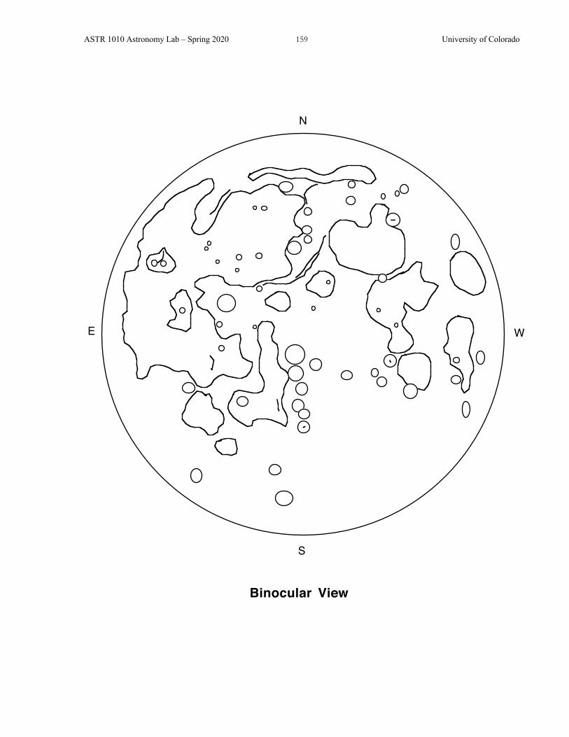
ASTR 1010 Astronomy Lab – Spring 2020 159 University of Colorado
N
WE
S
Binocular View

ASTR 1010 Astronomy Lab – Spring 2020 160 University of Colorado
N
EW
S
Telescope (Inverted) ViewNorth may not be "up" in the eyepiece

ASTR 1010 Astronomy Lab – Spring 2020 161 University of Colorado
DateTimeTelescope size
Constellation
Object NameObject Type
R.A.Dec.
Sky Condition
Description of Observation
Additional Information
NAME:
DateTimeTelescope size
Constellation
Object NameObject Type
R.A.Dec.
Sky Condition
Description of Observation
Additional Information

ASTR 1010 Astronomy Lab – Spring 2020 162 University of Colorado
DateTimeTelescope size
Constellation
Object NameObject Type
R.A.Dec.
Sky Condition
Description of Observation
Additional Information
NAME:
DateTimeTelescope size
Constellation
Object NameObject Type
R.A.Dec.
Sky Condition
Description of Observation
Additional Information

ASTR 1010 Astronomy Lab – Spring 2020 163 University of Colorado
Units Conversion Table
English to metric metric to English
1 inch = 2.54 cm 1 m = 39.37 inches 1 mile = 1.609 km 1 km = 0.6214 mile 1 lb = 0.4536 kg 1 kg = 2.205 pound 1 gal = 3.785 liters 1 liter = 0.2642 gal
Metric Prefixes
Prefix Abbre-viation
Value Prefix Abbre-viation
Value
deci- d 10-1 decka- da 101 centi- c 10-2 hecto- h 102 milli- m 10-3 kilo- k 103 micro- m 10-6 mega- M 106 nano- n 10-9 giga- G 109 pico- p 10-12 tera- T 1012 femto- f 10-15 peta- P 1015 atto- a 10-18
Circles and Spheres
• circumference = 2pR. • area of a circle = pR2. • surface area of a sphere = 4pR2. • volume of a sphere = 4/3 pR3. Triangles
• The Pythagorean theorem: (opp)2 + (adj)2 = (hyp)2 .
• Trigonometry functions are just ratios of the lengths of the different sides:
sin a = (opp)(hyp) cos a = (adj)
(hyp) tan a = (opp)(adj) .