
See MIPS - Second Edition
513
-
Upload
khangminh22 -
Category
Documents
-
view
2 -
download
0
Transcript of See MIPS - Second Edition


See MIPS® RunSecond Edition

This Page Intentionally Left Blank

See MIPS®
RunSecond Edition
Dominic Sweetman
AMSTERDAM • BOSTON • HEIDELBERG • LONDON
NEW YORK • OXFORD • PARIS • SAN DIEGO
SAN FRANCISCO • SINGAPORE • SYDNEY • TOKYO
Morgan Kaufmann Publishers is an imprint of Elsevier
Publisher: Denise E. M. PenrosePublishing Services Manager: George MorrisonSenior Project Manager: Brandy LillyEditorial Assistant: Kimberlee HonjoCover Design: Alisa Andreola and Hannus DesignComposition: diacriTechTechnical Illustration: diacriTechCopyeditor: Denise MooreProofreader: Katherine AntonsenIndexer: Steve RathInterior Printer: The Maple-Vail Book Manufacturing Group, Inc.Cover Printer: Phoenix Color
Morgan Kaufmann Publishers is an imprint of Elsevier.500 Sansome Street, Suite 400, San Francisco, CA 94111
This book is printed on acid-free paper.
© 2007 by Elsevier Inc. All rights reserved.
MIPS, MIPS I, MIPS II, MIPS III, MIPS IV, MIPS V, MIPS16, MIPS16e, MIPS-3D, MIPS32, MIPS64, 4K, 4KE,4KEc, 4KSc, 4KSd, M4K, 5K, 20Kc, 24K, 24KE, 24Kf, 25Kf, 34K, R3000, R4000, R5000, R10000, CorExtend,MDMX, PDtrace and SmartMIPS are trademarks or registered trademarks of MIPS Technologies, Inc. in theUnited States and other countries, and used herein under license from MIPS Technologies, Inc. MIPS, MIPS16,MIPS32, MIPS64, MIPS-3D and SmartMIPS, among others, are registered in the U.S. Patent and Trademark Office.
Linux® is the registered trademark of Linus Torvalds in the U.S. and other countries.
Designations used by companies to distinguish their products are often claimed as trademarks or registered trade-marks. In all instances in which Morgan Kaufmann Publishers is aware of a claim, the product names appear ininitial capital or all capital letters. Readers, however, should contact the appropriate companies for more completeinformation regarding trademarks and registration.
No part of this publication may be reproduced, stored in a retrieval system, or transmitted in any form or by anymeans—electronic, mechanical, photocopying, scanning, or otherwise—without prior written permission of thepublisher.
Permissions may be sought directly from Elsevier’s Science & Technology Rights Department in Oxford,UK: phone: (+44) 1865 843830, fax: (+44) 1865 853333, E-mail: [email protected]. You may also com-plete your request on-line via the Elsevier homepage (http://elsevier.com), by selecting “Support & Contact” then“Copyright and Permission” and then “Obtaining Permissions.”
Library of Congress Cataloging-in-Publication DataApplication Submitted
ISBN 13: 978-0-12-088421-6ISBN 10: 0-12-088421-6
For information on all Morgan Kaufmann publications,visit our Web site at www.mkp.com or www.books.elsevier.com
Printed in the United States of America06 07 08 09 10 5 4 3 2 1

Foreword
The MIPS architecture was born in the early 1980s from the work done byJohn Hennessy and his students at Stanford University. They were exploring
the architectural concept of RISC (Reduced Instruction Set Computing), whichtheorized that relatively simple instructions, combined with excellent compilersand hardware that used pipelining to execute the instructions, could producea faster processor with less die area. The concept was so successful that MIPSComputer Systems was formed in 1984 to commercialize the MIPS architecture.
Over the course of the next 14 years, the MIPS architecture evolved in anumber of ways and its implementations were used very successfully in work-station and server systems. Over that time, the architecture and its implementa-tions were enhanced to support 64-bit addressing and operations, support forcomplex memory-protected operating systems such as UNIX, and very highperformance floating point. Also in that period, MIPS Computer Systems wasacquired by Silicon Graphics and MIPS processors became the standard forSilicon Graphics computer systems. With 64-bit processors, high-performancefloating point, and the Silicon Graphics heritage, MIPS processors became thesolution of choice in high-volume gaming consoles.
In 1998, MIPS Technologies emerged from Silicon Graphics as a stand-alone company focused entirely on intellectual property for embedded markets.As a result, the pace of architecture development has increased to address theunique needs of these markets: high-performance computation, code compres-sion, geometry processing for graphics, security, signal processing, and multi-threading. Each architecture development has been matched by processor coreimplementations of the architecture, making MIPS-based processors thestandard for high-performance, low-power applications.
The MIPS legacy in complex systems such as workstations and serversdirectly benefits today’s embedded systems, which have, themselves, becomevery complex. A typical embedded system is composed of multiple process-ing elements, high-performance memory, and one or more operating systems.
v

vi Foreword
When compared with other embedded architectures, which are just nowlearning what is required to build a complex system, the MIPS architectureprovides a proven base on which to implement such systems.
In many ways, the first edition of See MIPS Run was a ground-breaking bookon the MIPS architecture and its implementations. While other books cov-ered similar material, See MIPS Run focused on what the programmer neededto understand of the architecture and the software environment in order toeffectively program a MIPS chip.
Increasing complexity of embedded systems has been matched by enhance-ments to the MIPS architecture to address the needs of such systems. Thesecond edition of this book is required reading for any current developer ofMIPS-based embedded systems. It adds significant new material, including thearchitectural standardization of the MIPS32 and MIPS64 architectures,brand new application-specific extensions such as multithreading, and a verynice treatment of the implementation of the popular Linux operating systemon the MIPS architecture. Short of the MIPS architecture specifications, thesecond edition of See MIPS Run is the most current description of the state ofthe art of the architecture and is, bar none, the most readable.
I hope that you will find this as worthwhile and as entertaining to readas I did.
Michael Uhler,Chief Technology Officer, MIPS Technologies, Inc.
Mountain View, CAMay 2006

Contents
Foreword vPreface xv
Style and Limits xviiiConventions xviiiAcknowledgments xix
Chapter 1 RISCs and MIPS Architectures 1
1.1 Pipelines 21.1.1 What Makes a Pipeline Inefficient? 31.1.2 The Pipeline and Caching 4
1.2 The MIPS Five-Stage Pipeline 51.3 RISC and CISC 71.4 Great MIPS Chips of the Past and Present 8
1.4.1 R2000 to R3000 Processors 81.4.2 The R6000 Processor: A Diversion 91.4.3 The First CPU Cores 111.4.4 The R4000 Processor: A Revolution 121.4.5 The Rise and Fall of the ACE Consortium 121.4.6 SGI Acquires MIPS 131.4.7 QED: Fast MIPS Processors for Embedded Systems 131.4.8 The R10000 Processor and its Successors 141.4.9 MIPS Processors in Consumer Electronics 151.4.10 MIPS in Network Routers and Laser Printers 151.4.11 MIPS Processors in Modern Times 171.4.12 The Rebirth of MIPS Technologies 201.4.13 The Present Day 21
1.5 MIPS Compared with CISC Architectures 231.5.1 Constraints on MIPS Instructions 231.5.2 Addressing and Memory Accesses 241.5.3 Features You Won’t Find 251.5.4 Programmer-Visible Pipeline Effects 27
vii

viii Contents
Chapter 2 MIPS Architecture 29
2.1 A Flavor of MIPS Assembly Language 332.2 Registers 34
2.2.1 Conventional Names and Uses of General-Purpose Registers 352.3 Integer Multiply Unit and Registers 382.4 Loading and Storing: Addressing Modes 392.5 Data Types in Memory and Registers 39
2.5.1 Integer Data Types 392.5.2 Unaligned Loads and Stores 402.5.3 Floating-Point Data in Memory 41
2.6 Synthesized Instructions in Assembly Language 422.7 MIPS I to MIPS64 ISAs: 64-Bit (and Other) Extensions 43
2.7.1 To 64 Bits 452.7.2 Who Needs 64 Bits? 452.7.3 Regarding 64 Bits and No Mode Switch: Data in Registers 46
2.8 Basic Address Space 472.8.1 Addressing in Simple Systems 492.8.2 Kernel versus User Privilege Level 492.8.3 The Full Picture: The 64-Bit View of the Memory Map 50
2.9 Pipeline Visibility 50
Chapter 3 Coprocessor 0: MIPS Processor Control 53
3.1 CPU Control Instructions 553.2 Which Registers Are Relevant When? 583.3 CPU Control Registers and Their Encoding 59
3.3.1 Status Register (SR) 603.3.2 Cause Register 643.3.3 Exception Restart Address (EPC) Register 653.3.4 Bad Virtual Address (BadVAddr) Register 673.3.5 Count/Compare Registers: The On-CPU Timer 683.3.6 Processor ID (PRId) Register 683.3.7 Config Registers: CPU Resource Information and Configuration 693.3.8 EBase and IntCtl: Interrupt and Exception Setup 733.3.9 SRSCtl and SRSMap: Shadow Register Setup 743.3.10 Load-Linked Address (LLAddr) Register 75
3.4 CP0 Hazards—A Trap for the Unwary 753.4.1 Hazard Barrier Instructions 763.4.2 Instruction Hazards and User Hazards 773.4.3 Hazards between CP0 Instructions 77
Chapter 4 How Caches Work on MIPS Processors 79
4.1 Caches and Cache Management 794.2 How Caches Work 804.3 Write-Through Caches in Early MIPS CPUs 83

Contents ix
4.4 Write-Back Caches in MIPS CPUs 844.5 Other Choices in Cache Design 844.6 Managing Caches 864.7 L2 and L3 Caches 884.8 Cache Configurations for MIPS CPUs 884.9 Programming MIPS32/64 Caches 90
4.9.1 The Cache Instruction 914.9.2 Cache Initialization and Tag/Data Registers 924.9.3 CacheErr, ERR, and ErrorEPC Registers: Memory/Cache Error
Handling 944.9.4 Cache Sizing and Figuring Out Configuration 954.9.5 Initialization Routines 964.9.6 Invalidating or Writing Back a Region of Memory in the Cache 97
4.10 Cache Efficiency 984.11 Reorganizing Software to Influence Cache Efficiency 1004.12 Cache Aliases 102
Chapter 5 Exceptions, Interrupts, and Initialization 105
5.1 Precise Exceptions 1075.1.1 Nonprecise Exceptions—The Multiplier in Historic MIPS CPUs 108
5.2 When Exceptions Happen 1095.3 Exception Vectors: Where Exception Handling Starts 1095.4 Exception Handling: Basics 1135.5 Returning from an Exception 1145.6 Nesting Exceptions 1145.7 An Exception Routine 1155.8 Interrupts 115
5.8.1 Interrupt Resources in MIPS CPUs 1165.8.2 Implementing Interrupt Priority in Software 1185.8.3 Atomicity and Atomic Changes to SR 1205.8.4 Critical Regions with Interrupts Enabled: Semaphores the
MIPS Way 1215.8.5 Vectored and EIC Interrupts in MIPS32/64 CPUs 1235.8.6 Shadow Registers 124
5.9 Starting Up 1245.9.1 Probing and Recognizing Your CPU 1265.9.2 Bootstrap Sequences 1275.9.3 Starting Up an Application 128
5.10 Emulating Instructions 128
Chapter 6 Low-level Memory Management and the TLB 131
6.1 The TLB/MMU Hardware and What It Does 1316.2 TLB/MMU Registers Described 132
6.2.1 TLB Key Fields—EntryHi and PageMask 1346.2.2 TLB Output Fields—EntryLo0-1 136

x Contents
6.2.3 Selecting a TLB Entry—Index, Random, and Wired Registers 1376.2.4 Page-Table Access Helpers—Context and XContext 138
6.3 TLB/MMU Control Instructions 1406.4 Programming the TLB 141
6.4.1 How Refill Happens 1426.4.2 Using ASIDs 1436.4.3 The Random Register and Wired Entries 143
6.5 Hardware-Friendly Page Tables and Refill Mechanism 1436.5.1 TLB Miss Handling 1456.5.2 XTLB Miss Handler 146
6.6 Everyday Use of the MIPS TLB 1476.7 Memory Management in a Simpler OS 149
Chapter 7 Floating-Point Support 151
7.1 A Basic Description of Floating Point 1517.2 The IEEE 754 Standard and Its Background 1527.3 How IEEE Floating-Point Numbers Are Stored 154
7.3.1 IEEE Mantissa and Normalization 1557.3.2 Reserved Exponent Values for Use with Strange Values 1557.3.3 MIPS FP Data Formats 156
7.4 MIPS Implementation of IEEE 754 1587.4.1 Need for FP Trap Handler and Emulator in All MIPS CPUs 159
7.5 Floating-Point Registers 1597.5.1 Conventional Names and Uses of Floating-Point Registers 160
7.6 Floating-Point Exceptions/Interrupts 1617.7 Floating-Point Control: The Control/Status Register 1617.8 Floating-Point Implementation Register 1657.9 Guide to FP Instructions 166
7.9.1 Load/Store 1677.9.2 Move between Registers 1687.9.3 Three-Operand Arithmetic Operations 1697.9.4 Multiply-Add Operations 1707.9.5 Unary (Sign-Changing) Operations 1707.9.6 Conversion Operations 1707.9.7 Conditional Branch and Test Instructions 171
7.10 Paired-Single Floating-Point Instructions and the MIPS-3D ASE 1737.10.1 Exceptions on Paired-Single Instructions 1747.10.2 Paired-Single Three-Operand Arithmetic, Multiply-Add,
Sign-Changing, and Nonconditional Move Operations 1747.10.3 Paired-Single Conversion Operations 1757.10.4 Paired-Single Test and Conditional Move Instructions 1767.10.5 MIPS-3D Instructions 176
7.11 Instruction Timing Requirements 1797.12 Instruction Timing for Speed 1797.13 Initialization and Enabling on Demand 1807.14 Floating-Point Emulation 181

Contents xi
Chapter 8 Complete Guide to the MIPS Instruction Set 183
8.1 A Simple Example 1838.2 Assembly Instructions and What They Mean 185
8.2.1 U and Non-U Mnemonics 1868.2.2 Divide Mnemonics 1878.2.3 Inventory of Instructions 188
8.3 Floating-Point Instructions 2108.4 Differences in MIPS32/64 Release 1 216
8.4.1 Regular Instructions Added in Release 2 2168.4.2 Privileged Instructions Added in Release 2 218
8.5 Peculiar Instructions and Their Purposes 2188.5.1 Load Left/Load Right: Unaligned Load and Store 2188.5.2 Load-Linked/Store-Conditional 2238.5.3 Conditional Move Instructions 2248.5.4 Branch-Likely 2258.5.5 Integer Multiply-Accumulate and Multiply-Add Instructions 2268.5.6 Floating-Point Multiply-Add Instructions 2278.5.7 Multiple FP Condition Bits 2288.5.8 Prefetch 2288.5.9 Sync: A Memory Barrier for Loads and Stores 2298.5.10 Hazard Barrier Instructions 2318.5.11 Synci: Cache Management for Instruction Writers 2328.5.12 Read Hardware Register 232
8.6 Instruction Encodings 2338.6.1 Fields in the Instruction Encoding Table 2338.6.2 Notes on the Instruction Encoding Table 2518.6.3 Encodings and Simple Implementation 251
8.7 Instructions by Functional Group 2528.7.1 No-op 2528.7.2 Register/Register Moves 2528.7.3 Load Constant 2538.7.4 Arithmetical/Logical 2538.7.5 Integer Multiply, Divide, and Remainder 2558.7.6 Integer Multiply-Accumulate 2568.7.7 Loads and Stores 2578.7.8 Jumps, Subroutine Calls, and Branches 2598.7.9 Breakpoint and Trap 2608.7.10 CP0 Functions 2608.7.11 Floating Point 2618.7.12 Limited User-Mode Access to “Under the Hood” Features 261
Chapter 9 Reading MIPS Assembly Language 263
9.1 A Simple Example 2649.2 Syntax Overview 268
9.2.1 Layout, Delimiters, and Identifiers 2689.3 General Rules for Instructions 269

xii Contents
9.3.1 Computational Instructions: Three-, Two-, and One-Register 2699.3.2 Immediates: Computational Instructions with Constants 2709.3.3 Regarding 64-Bit and 32-Bit Instructions 271
9.4 Addressing Modes 2719.4.1 Gp-Relative Addressing 273
9.5 Object File and Memory Layout 2749.5.1 Practical Program Layout, Including Stack and Heap 277
Chapter 10 Porting Software to the MIPS Architecture 279
10.1 Low-Level Software for MIPS Applications: A Checklist ofFrequently Encountered Problems 280
10.2 Endianness: Words, Bytes, and Bit Order 28110.2.1 Bits, Bytes, Words, and Integers 28110.2.2 Software and Endianness 28410.2.3 Hardware and Endianness 28710.2.4 Bi-endian Software for a MIPS CPU 29310.2.5 Portability and Endianness-Independent Code 29510.2.6 Endianness and Foreign Data 295
10.3 Trouble with Visible Caches 29610.3.1 Cache Management and DMA Data 29810.3.2 Cache Management and Writing Instructions: Self-Modifying
Code 29910.3.3 Cache Management and Uncached or Write-Through Data 30010.3.4 Cache Aliases and Page Coloring 301
10.4 Memory Access Ordering and Reordering 30110.4.1 Ordering and Write Buffers 30410.4.2 Implementing wbflush 304
10.5 Writing it in C 30510.5.1 Wrapping Assembly Code with the GNU C Compiler 30510.5.2 Memory-Mapped I/O Registers and “Volatile” 30710.5.3 Miscellaneous Issues When Writing C for MIPS Applications 308
Chapter 11 MIPS Software Standards (ABIs) 311
11.1 Data Representations and Alignment 31211.1.1 Sizes of Basic Types 31211.1.2 Sizes of “long” and Pointer Types 31311.1.3 Alignment Requirements 31311.1.4 Memory Layout of Basic Types and How It Changes with
Endianness 31311.1.5 Memory Layout of Structure and Array Types and Alignment 31511.1.6 Bitfields in Structures 31511.1.7 Unaligned Data from C 318
11.2 Argument Passing and Stack Conventions for MIPS ABIs 31911.2.1 The Stack, Subroutine Linkage, and Parameter Passing 32011.2.2 Stack Argument Structure in o32 32011.2.3 Using Registers to Pass Arguments 321

Contents xiii
11.2.4 Examples from the C Library 32211.2.5 An Exotic Example: Passing Structures 32311.2.6 Passing a Variable Number of Arguments 32411.2.7 Returning a Value from a Function 32511.2.8 Evolving Register-Use Standards: SGIs n32 and n64 32611.2.9 Stack Layouts, Stack Frames, and Helping Debuggers 32911.2.10 Variable Number of Arguments and stdargs 337
Chapter 12 Debugging MIPS Designs—Debug and Profiling Features 339
12.1 The “EJTAG” On-chip Debug Unit 34112.1.1 EJTAG History 34312.1.2 How the Probe Controls the CPU 34312.1.3 Debug Communications through JTAG 34412.1.4 Debug Mode 34412.1.5 Single-Stepping 34612.1.6 The dseg Memory Decode Region 34612.1.7 EJTAG CP0 Registers, Particularly Debug 34812.1.8 The DCR (Debug Control) Memory-Mapped Register 35112.1.9 EJTAG Breakpoint Hardware 35212.1.10 Understanding Breakpoint Conditions 35512.1.11 Imprecise Debug Breaks 35612.1.12 PC Sampling with EJTAG 35612.1.13 Using EJTAG without a Probe 356
12.2 Pre-EJTAG Debug Support—Break Instruction and CP0Watchpoints 358
12.3 PDtrace 35912.4 Performance Counters 360
Chapter 13 GNU/Linux from Eight Miles High 363
13.1 Components 36413.2 Layering in the Kernel 368
13.2.1 MIPS CPU in Exception Mode 36813.2.2 MIPS CPU with Some or All Interrupts off 36913.2.3 Interrupt Context 37013.2.4 Executing the Kernel in Thread Context 370
Chapter 14 How Hardware and Software Work Together 371
14.1 The Life and Times of an Interrupt 37114.1.1 High-Performance Interrupt Handling and Linux 374
14.2 Threads, Critical Regions, and Atomicity 37514.2.1 MIPS Architecture and Atomic Operations 37614.2.2 Linux Spinlocks 377
14.3 What Happens on a System Call 37814.4 How Addresses Get Translated in Linux/MIPS Systems 380

xiv Contents
14.4.1 What’s Memory Translation For? 38214.4.2 Basic Process Layout and Protection 38414.4.3 Mapping Process Addresses to Real Memory 38514.4.4 Paged Mapping Preferred 38614.4.5 What We Really Want 38714.4.6 Origins of the MIPS Design 38914.4.7 Keeping Track of Modified Pages (Simulating “Dirty” Bits) 39214.4.8 How the Kernel Services a TLB Refill Exception 39314.4.9 Care and Maintenance of the TLB 39714.4.10 Memory Translation and 64-Bit Pointers 397
Chapter 15 MIPS Specific Issues in the Linux Kernel 399
15 Explicit Cache Management 39915.1.1 DMA Device Accesses 39915.1.2 Writing Instructions for Later Execution 40115.1.3 Cache/Memory Mapping Problems 40115.1.4 Cache Aliases 402
15.2 CP0 Pipeline Hazards 40315.3 Multiprocessor Systems and Coherent Caches 40315.4 Demon Tweaks for a Critical Routine 406
Chapter 16 Linux Application Code, PIC, and Libraries 409
16.1 How Link Units Get into a Program 41116.2 Global Offset Table (GOT) Organization 412
Appendix A MIPS Multithreading 415
A.1 What Is Multithreading? 415A.2 Why Is MT Useful? 417A.3 How to Do Multithreading for MIPS 417A.4 MT in Action 421
Appendix B Other Optional Extensions to the MIPS Instruction Set 425
B.1 MIPS16 and MIPS16e ASEs 425B.1.1 Special Encodings and Instructions in the MIPS16 ASE 426B.1.2 The MIPS16 ASE Evaluated 427
B.2 The MIPS DSP ASE 428B.3 The MDMX ASE 429
MIPS Glossary 431References 477
Books and Articles 477Online Resources 478
Index 481

Preface
This book is about MIPS, the cult hit from the mid-1980s’ crop of RISC CPUdesigns. These days MIPS is not the highest-volume 32-bit architecture, but
it is in a comfortable second place. Where it wins, hands down, is its range ofapplications. A piece of equipment built around a MIPS CPU might have costyou $35 for a wireless router or hundreds of thousands of dollars for an SGIsupercomputer (though with SGI’s insolvency, those have now reached the endof the line). Between those extremes are Sony and Nintendo games machines,many Cisco routers, TV set-top boxes, laser printers, and so on.
The first edition of this book has sold close to 10,000 English copies over theyears and has been translated into Chinese. I’m pleased and surprised; I didn’tknow there were so many MIPS programmers out there.
This second edition is See MIPS Run . . . Linux. The first edition struggledto motivate some features of the MIPS architecture, because they don’t makesense unless you can see how they help out inside an OS kernel. But now a lotof you have some sense of how Linux works, and I can quote its source code;more importantly, I can refer to it knowing that those of you who get interestedcan read the source code and find out how it’s really done.
So this is a book about the MIPS architecture, but the last three chaptersstroll through the Linux kernel and application-programming system to castlight on what those weird features do. I hope Linux experts will forgive myrelative ignorance of Linux details, but the chance to go for a description ofa real OS running on a real architecture was too good to pass up.
MIPS is a RISC: a useful acronym, well applied to the common features ofa number of computer architectures invented in the 1980s, to realize efficientpipelined implementation. The acronym CISC is vaguer. I’ll use it in a narrowsense, for the kind of features found in x86 and other pre-1982 architectures,designed with microcoded implementations in mind.
Some of you may be up in arms: He’s confusing implementation with archi-tecture! But while computer architecture is supposed to be a contract with the
xv

xvi Preface
programmer about what programs will run correctly, it’s also an engineeringdesign in its own right. A computer architecture is designed to make for goodCPUs. As chip design becomes more sophisticated, the trade-offs change.
This book is for programmers, and that’s the test we’ve used to decide whatgets included—if a programmer might see it, or is likely to be interested, it’shere. That means we don’t get to discuss, for example, the strange system inter-faces with which MIPS has tortured two generations of hardware design engi-neers. And your operating system may hide many of the details we talk abouthere; there is many an excellent programmer who thinks that C is quite lowlevel enough, portability a blessing, and detailed knowledge of the architectureirrelevant. But sometimes you do need to get down to the nuts and bolts—andhuman beings are born curious as to how bits of the world work.
A result of this orientation is that we’ll tend to be rather informal whendescribing things that may not be familiar to a software engineer—particularlythe inner workings of the CPU—but we’ll get much more terse and techni-cal when we’re dealing with the stuff programmers have met before, such asregisters, instructions, and how data is stored in memory.
We’ll assume some familiarity and comfort with the C language. Much ofthe reference material in the book uses C fragments as a way of compress-ing operation descriptions, particularly in the chapters on the details of theinstruction set and assembly language.
Some parts of the book are targeted at readers who’ve seen some assemblylanguage: the ingenuity and peculiarity of the MIPS architecture shows up bestfrom that viewpoint. But if assembly is a closed book to you, that’s probablynot a disaster.
This book aims to tell you everything you need to know about program-ming generic MIPS CPUs. More precisely, it describes the architecture as it’sdefined by MIPS Technologies’ MIPS32 and MIPS64—specifically, the secondrelease of those specifications from 2003. We’ll shorten that to “MIPS32/64.”But this is not just a reference manual: To keep an architecture in your headmeans coming to understand it in the round. I also hope the book will intereststudents of programming (at college or enrolled in the school of life) who wantto understand a modern CPU architecture all the way through.
If you plan to read this book straight through from front to back, you willexpect to find a progression from overview to detail, and you won’t be disap-pointed. But you’ll also find some progression through history; the first timewe talk about a concept we’ll usually focus on its first version. Hennessy andPatterson call this “learning through evolution,” and what’s good enough forthem is certainly good enough for me.
We start in Chapter 1 with some history and background, and set MIPS incontext by discussing the technological concerns and ideas that were uppermostin the minds of its inventors. Then in Chapter 2 we discuss the characteristicsof the MIPS machine language that follow from their approach.

Preface xvii
To help you see the big picture, we leave out the details of processor con-trol until Chapter 3, which introduces the ugly but eminently practical systemthat allows MIPS CPUs to deal with their caches, exceptions and startup, andmemory management. Those last three topics, respectively, become the sub-jects of Chapters 4 through 6.
The MIPS architecture has been careful to separate out the part of theinstruction set that deals with floating-point numbers. That separation allowsMIPS CPUs to be built with various levels of floating-point support, from noneat all through partial implementations to somewhere near the state of the art.So we have also separated out the floating-point functions, and we keep themback until Chapter 7.
Up to this point, the chapters follow a reasonable sequence for getting toknow MIPS. The following chapters change gear and are more like referencemanuals or example-based tutorials.
In Chapter 8, we go through the whole machine instruction set; the inten-tion is to be precise but much more terse than the standard MIPS referenceworks—we cover in 10 pages what takes a hundred in other sources.1 Chapter 9is a brief introduction to reading and writing assembly, and falls far short of anassembly programming manual.
Chapter 10 is a checklist with helpful hints for those of you who have toport software between another CPU and a MIPS CPU. The longest sectiontackles the troublesome problem of endianness in CPUs, software, and systems.
Chapter 11 is a bare-bones summary of the software conventions (regis-ter use, argument passing, etc.) necessary to produce interworking softwarewith different toolkits. Chapter 12 introduces the debug and profiling featuresstandardized for MIPS CPUs.
Then we’re on to seeing how MIPS runs GNU/Linux. We describe relation-ship between the Linux kernel and a computer architecture in Chapter 13; thenChapters 14 and 15 dig down into some of the detail as to how the MIPS archi-tecture does what the Linux kernel needs. Chapter 16 gives you a quick look atthe dynamic linking magic that makes GNU/Linux applications work.
Appendix A covers the MIPS MT (multithreading) extension, probably themost important addition to the architecture in many years. And Appendix Bdescribes the more important add-ons: MIPS16, the new MIPS DSP extensions,and MDMX.
You will also find at the end of this book a glossary of terms—a good placeto look for specialized or unfamiliar usage and acronyms—and a list of books,papers, and online references for further reading.
1. I have taken considerable care in the generation of these tables, and they are mostly right. But ifyour system depends on it, be sure to cross-check this information. An excellent source of fairlyreliable information can be found in the behavior and source code of the GNU tool collection—but I referred to that too, so it’s not completely independent.

xviii Preface
Style and Limits
Every book reflects its author, so we’d better make a virtue of it.Since some of you will be students, I wondered whether I should dis-
tinguish general use from MIPS use. I decided not to; I aim to be specificexcept where it costs the reader nothing to be general. I also try to be con-crete rather than abstract. I don’t worry overmuch about whatever meaningterms like “TLB” have in the wider industry, but I explain them in a MIPScontext. Human beings are great generalizers, and this is unlikely to damageyour learning much.
It’s 20 years since I started working with MIPS CPUs in the fall of 1986.Some of the material in this book goes back as far as 1988, when I started givingtraining courses on MIPS architecture. In 1993, I gathered them together tomake a software manual focused on IDT’s R3051 family CPUs. It took quite alot of extra material to create the first edition, published in 1999.
A lot has happened since 1999. MIPS is now at the very end of its life inservers with SGI but has carved out a significant niche in embedded systems.Linux has emerged as the most-used OS for embedded MIPS, but there’sstill a lot of diversity in the embedded market. The MIPS specifications havebeen reorganized around MIPS32 and MIPS64 (which this edition regardsas the baseline). This second edition has been in the works for about threeyears.
The MIPS story continues; if it did not, we’d only be writing this book forhistorians, and Morgan Kaufmann wouldn’t be very interested in publishing it.MIPS developments that weren’t announced by the end of 2005 are much toolate for this edition.
Conventions
A quick note on the typographical conventions used in this book:
Type in this font (Minion) is running text.
Type in this font (Futura) is a sidebar.
Type in this font (Courier bold) is used for assemblycode and MIPS register names.
Type in this font (Courier) is used for C code and
hexadecimals.
Type in this font (Minion italic, small) is used for hardware signal names.

Preface xix
Acknowledgments
The themes in this book have followed me through my computing career. MikeCole got me excited about computing, and I’ve been trying to emulate his skillin picking out good ideas ever since. In the brief but exciting life of WhitechapelWorkstations (1983–1988), many colleagues taught me something about com-puter architecture and about how to design hardware—Bob Newman and RickFilipkiewicz probably the most. I also have to thank Whitechapel’s salesperson,Dave Gravell, for originally turning me on to MIPS. My fellow engineers dur-ing the lifetime of Algorithmics Ltd. (Chris Dearman, Rick Filipkiewicz, GeraldOnions, Nigel Stephens, and Chris Shaw) have to be doubly thanked, both forall I’ve learned through innumerable discussions, arguments, and designs andfor putting up with the book’s competition for my time.
Many thanks are due to the reviewers who’ve read chapters over a longperiod of time: Phil Bourekas of Integrated Device Technology, Inc.; ThomasDaniel of the LSI Logic Corporation; Mike Murphy of Silicon Graphics, Inc.;and David Nagle of Carnegie Mellon University.
On the second edition: I’ve known Paul Cobb for a long time, as we bothworked around MIPS companies. Paul contributed material updating thehistorical survey of MIPS CPUs and the programming chapter and cleaningup the references. In all cases, though, I’ve had a final edit—so any errorsare mine.
During the preparation of this edition I’ve been employed by MIPS Tech-nologies Inc. It’s dangerous to pick out some colleagues and not others, but I’lldo it anyway.
Ralf Baechle runs the www.linux-mips.org site, which coordinates MIPSwork on the Linux kernel. He’s been very helpful in dispelling some of the illu-sions I’d formed about Linux: I started off thinking it was like other operatingsystems . . . (Robert Love’s Linux Kernel Development book helped too; I warmlyrecommend it to anyone who wants a more educated guidebook to the kernel).Thanks to MIPS Technologies and my various managers for being flexible aboutmy time, and to many colleagues at MIPS Technologies (too many to name)who have read and commented on drafts.
Todd Bezenek has been my most persistent colleague/reviewer of this edi-tion. Reviewers outside MIPS Technologies did it for their love and respect forthe field: notable contributers were Steven Hill (Reality Diluted, Inc.), Jun Sun(DoCoMo USA Labs), Eric DeVolder, and Sophie Wilson.
Denise Penrose is easily the Best Editor Ever. Not many people in FinsburyPark (my home in North London) can say they’re just flying to San Franciscofor brunch with their publisher.
Last but not least, thanks to Carol O’Brien, who was rash enough to marryme in the middle of this rewrite.

This Page Intentionally Left Blank

Chapter
1 RISCs and MIPSArchitectures
MIPS is the most elegant among the effective RISC architectures; even thecompetition thought so, as evidenced by the strong MIPS influence to
be seen in later architectures like DEC’s Alpha and HP’s Precision. Elegance byitself doesn’t get you far in a competitive marketplace, but MIPS microproces-sors have generally managed to be among the most efficient of each generationby remaining among the simplest.
Relative simplicity was a commercial necessity for MIPS Computer Sys-tems Inc., which spun off in 1985 from an academic project to make andmarket the chips. As a result, the architecture had (and perhaps still has)the largest range of active manufacturers in the industry—working fromASIC cores (MIPS Technologies, Philips) through low-cost CPUs (IDT, AMD/Alchemy) to the only 64-bit CPUs in widespread embedded use (PMC-Sierra,Toshiba, Broadcom).
At the low end the CPU has practically disappeared from sight in the“system on a chip”; at the high end Intrinsity’s remarkable processor ran at2 GHz—a speed unmatched outside the unlimited power/heat budget ofcontemporary PCs.
ARM gets more headlines, but MIPS sales volumes remain healthy enough:100 M MIPS CPUs were shipped in 2004 into embedded applications.
The MIPS CPU is one of the RISC CPUs, born out of a particularly fertileperiod of academic research and development. RISC (Reduced Instruction SetComputing) is an attractive acronym that, like many such, probably obscuresreality more than it reveals it. But it does serve as a useful tag for a number ofnew CPU architectures launched between 1986 and 1989 that owe their remark-able performance to ideas developed a few years earlier in a couple of seminalresearch projects. Someone commented that “a RISC is any computerarchitecture defined after 1984”; although meant as a jibe at the industry’s use
1

2 Chapter 1—RISCs and MIPS Architectures
of the acronym, the comment is also true for a technical reason—no computerdefined after 1984 can afford to ignore the RISC pioneers’ work.
One of these pioneering projects was the MIPS project at Stanford. Theproject name MIPS (named for the key phrase “microcomputer without inter-locked pipeline stages”) is also a pun on the familiar unit “millions of instruc-tions per second.” The Stanford group’s work showed that pipelining, althougha well-known technique, had been drastically underexploited by earlier archi-tectures and could be much better used, particularly when combined with 1980silicon design.
1.1 Pipelines
Once upon a time in a small town in the north of England, there was Evie’s fishand chip shop. Inside, each customer got to the head of the queue and asked forhis or her meal (usually fried cod, chips, mushy peas,1 and a cup of tea). Theneach customer waited for the plate to be filled before going to sit down.
Evie’s chips were the best in town, and every market day the lunch queuestretched out of the shop. So when the clog shop next door shut down, Evierented it and doubled the number of tables. But they couldn’t fill them! Thequeue outside was as long as ever, and the busy townsfolk had no time to sitover their cooling tea.
They couldn’t add another serving counter; Evie’s cod and Bert’s chips werewhat made the shop. But then they had a brilliant idea. They lengthened thecounter and Evie, Bert, Dionysus, and Mary stood in a row. As customers camein, Evie gave them a plate with their fish, Bert added the chips, Dionysus spoonedout the mushy peas, and Mary poured the tea and took the money. The cus-tomers kept walking; as one customer got the peas, the next was already gettingchips and the one after that fish. Less hardy folk don’t eat mushy peas—butthat’s no problem; those customers just got nothing but a vacant smile fromDionysus.
The queue shortened and soon they bought the shop on the other side aswell for extra table space.
That’s a pipeline. Divide any repetitive job into a number of sequential partsand arrange them so that the work moves past the workers, with each specialistdoing his or her part for each unit of work in turn. Although the total timeany customer spends being served has gone up, there are four customers beingserved at once and about three times as many customers being served in thatmarket day lunch hour. Figure 1.1 shows Evie’s organization, as drawn by herson Einstein in a rare visit to nonvirtual reality.2
Seen as a collection of instructions in memory, a program ready to rundoesn’t look much like a queue of customers. But when you look at it from
1. Non-English readers should probably not inquire further into the nature of this delicacy.
2. It looks to me as if Einstein has been reading books on computer science.

1.1 Pipelines 3
Custom
er sequence
Evie:plate/fish
Bert:chips
Dionysus:mushy peas
Mary:tea/cashCustomer 1
Customer 2
Customer 3
Evie:plate/fish
Bert:chips
Mary:tea/cash
Evie:plate/fish
Bert:chips
Mary:tea/cash
Dionysus:mushy peas
Dionysus:mushy peas
Time
FIGURE 1.1 Evie’s fish and chip shop pipeline.
the CPU’s point of view, things change. The CPU fetches each instruction frommemory, decodes it, finds any operands it needs, performs the appropriateaction, and stores any results—and then it goes and does the same thing allover again. The program waiting to be run is a queue of instructions waiting toflow through the CPU one at a time.
The various different jobs required to deal with each instruction alreadyrequire different specialized chunks of logic inside the CPU, so building a pipe-line doesn’t even make the CPU much more complicated; it just makes it workharder.
The use of pipelining is not new with RISC microprocessors. What makesthe difference is the redesign of everything—starting with the instruction set—to make the pipeline more efficient.3 So how do you make a pipeline efficient?Actually, that’s probably the wrong question. The right question is this: Whatmakes a pipeline inefficient?
1.1.1 What Makes a Pipeline Inefficient?
It’s not good if one stage takes much longer than the others. The organizationof Evie’s shop depends on Mary’s ability to pour tea with one hand while givingchange with the other—if Mary takes longer than the others, the whole queuewill have to slow down to match her.
3. The first RISC in this sense was probably the CDC6600, designed by Seymour Cray in the 1970s,but the idea didn’t catch on at that time. However, this is straying into the history of computerarchitecture, and if you like this subject you’ll surely want to read Hennessy and Patterson, 1996.

4 Chapter 1—RISCs and MIPS Architectures
In a pipeline, you try to make sure that every stage takes roughly the sameamount of time. A circuit design often gives you the opportunity to trade off thecomplexity of logic; against its speed, and designers can assign work to differentstages: with care, the pipeline is balanced.
The hard problem is not difficult actions, it’s awkward customers. Back inthe chip shop Cyril is often short of cash, so Evie won’t serve him until Maryhas counted his money. When Cyril arrives, he’s stuck at Evie’s position untilMary has finished with the three previous customers and can check his pile ofold bent coins. Cyril is trouble, because when he comes in he needs a resource(Mary’s counting) that is being used by previous customers. He’s a resourceconflict.
Daphne and Lola always come in together (in that order) and share theirmeals. Lola won’t have chips unless Daphne gets some tea (too salty withoutsomething to drink). Lola waits on tenterhooks in front of Bert until Daphnegets to Mary, and so a gap appears in the pipeline. This is a dependency (and thegap is called a pipeline bubble).
Not all dependencies are a problem. Frank always wants exactly the samemeal as Fred, but he can follow him down the counter anyway—if Fred getschips, Frank gets chips.
If you could get rid of awkward customers, you could make a more efficientpipeline. This is hardly an option for Evie, who has to make her living in a townof eccentrics. Intel is faced with much the same problem: The appeal of its CPUsrelies on the customer being able to go on running all that old software. But witha new CPU you get to define the instruction set, and you can define many of theawkward customers out of existence. In section 1.2 we’ll show how MIPS didthat, but first we’ll come back to computer hardware in general with a discussionof caching.
1.1.2 The Pipeline and Caching
We said earlier that efficient pipeline operation requires every stage to take thesame amount of time. But a 2006 CPU can add two 64-bit numbers 50 to 100times quicker than it can fetch a piece of data from memory.
So effective pipelining relies on another technique to speed most mem-ory accesses by a factor of 50—the use of caches. A cache is a small, veryfast, local memory that holds copies of memory data. Each piece of data iskept with a record of its main memory address (the cache tag) and whenthe CPU wants data the cache gets searched and, if the requisite data isavailable, it’s sent back quickly. Since we’ve no way to guess what data theCPU might be about to use, the cache merely keeps copies of data theCPU has had to fetch from main memory in the recent past; data is dis-carded from the cache when its space is needed for more data arriving frommemory.
Even a simple cache will provide the data the CPU wants more than 90 per-centage of the time, so the pipeline design needs only to allow enough time to

1.2 The MIPS Five-Stage Pipeline 5
Instruction 1
Instruction 2
Instruction 3
RDIF ALU WB
RD ALU MEM WB
Time
Instruction sequence
IFfrom
I-cache
MEMfrom
D-cache
RDfrom
registerfile
WBto
registerfile
ALU
IF
MEM
FIGURE 1.2 MIPS five-stage pipeline.
fetch data from the cache; a cache miss is a relatively rare event and we can juststop the CPU when it happens (though cleverer CPUs find more useful thingsto do).
The MIPS architecture was planned with separate instruction and datacaches, so it can fetch an instruction and read or write a memory variable simul-taneously.
CISC architectures have caches too, but they’re most often afterthoughts,fitted in as a feature of the memory system. A RISC architecture makes moresense if you regard the caches as very much part of the CPU and tied firmly intothe pipeline.
1.2 The MIPS Five-Stage Pipeline
The MIPS architecture is made for pipelining, and Figure 1.2 is close to theearliest MIPS CPUs and typical of many. So long as the CPU runs from thecache, the execution of every MIPS instruction is divided into five phases, calledpipestages, with each pipestage taking a fixed amount of time. The fixed amountof time is usually a processor clock cycle (though some actions take only halfa clock, so the MIPS five-stage pipeline actually occupies only four clockcycles).
All instructions are rigidly defined so they can follow the same sequenceof pipestages, even where the instruction does nothing at some stage. The netresult is that, so long as it keeps hitting the cache, the CPU starts an instructionevery clock cycle.

6 Chapter 1—RISCs and MIPS Architectures
Let’s look at Figure 1.2 and consider what happens in each pipestage.
IF (instruction fetch) Gets the next instruction from the instruction cache(I-cache).
RD (read registers) Fetches the contents of the CPU registers whose num-bers are in the two possible source register fields of the instruction.
ALU (arithmetic/logic unit) Performs an arithmetical or logical operation inone clock cycle (floating-point math and integer multiply/divide can’tbe done in one clock cycle and are done differently, but that comeslater).
MEM Is the stage where the instruction can read/write memory variables inthe data cache (D-cache). On average, about three out of four instruc-tions do nothing in this stage, but allocating the stage for each instruc-tion ensures that you never get two instructions wanting the data cacheat the same time. (It’s the same as the mushy peas served byDionysus.)
WB (write back) Stores the value obtained from an operation back to theregister file.
You may have seen other pictures of the MIPS pipeline that look slightlydifferent; it has been common practice to simplify the picture by drawing eachpipestage as if it takes exactly one clock cycle. Some later MIPS CPUs havelonger or slightly different pipelines, but the pipeline with five stages in fourcycles is where the architecture started, and something very like it is still usedby the simpler MIPS CPUs.
The tyranny of the rigid pipeline limits the kinds of things instructions cando. First, it forces all instructions to be the same length (exactly one machineword of 32 bits), so that they can be fetched in a constant time. This itself dis-courages complexity; there are not enough bits in the instruction to encodereally complicated addressing modes, for example. And the fixed-size instruc-tions directly cause one problem; in a typical program built for an architecturelike x86, the average size of instructions is only just over three bytes. MIPS codewill use more memory space.
Second, the pipeline design rules out the implementation of instructionsthat do any operation on memory variables. Data from cache or memory isobtained only in phase 4, which is much too late to be available to the ALU.Memory accesses occur only as simple load or store instructions that movethe data to or from registers (you will see this described as a load/storearchitecture).
The RISC CPUs launched around 1987 worked because the instruction setsdesigned around those restrictions prove just as useful (particularly for com-piled code) as the complicated ones that give so much more trouble to the

1.3 RISC and CISC 7
hardware. A 1987 or later RISC is characterized by an instruction set designedfor efficient pipelining and the use of caches.
The MIPS project architects also attended to the best thinking of the timeabout what makes a CPU an easy target for efficient optimizing compilers. Manyof those requirements are quite compatible with the pipeline requirements, soMIPS CPUs have 32 general-purpose registers and three-operand arithmeti-cal/logical instructions. Happily, the complicated special-purpose instructionsthat particularly upset pipelines are often those that compilers are unwilling togenerate.
The RISC pioneers’ judgment has stood the test of time. More recentinstruction sets have pushed the hardware/software line back even further;they are called VLIW (very long instruction word) and/or EPIC (explicitlyparallel instruction computing). The most prominent is Intel’s IA64 architec-ture, but it has not succeeded despite massive investment; it appears to havegot the hardware/software boundary wrong.
1.3 RISC and CISC
We can now have a go at defining what we mean by these overused terms.For me, RISC is an adjective applied to machine architectures/instructionsets. In the mid-1980s, it became attached to a group of relatively newarchitectures in which the instruction set had been cunningly and effectivelyspecified to make pipelined implementations efficient and successful. It’s auseful term because of the great similarity of approach apparent in SPARC,MIPS, PowerPC, HP Precision, DEC Alpha, and (to a lesser extent) in ARM.
By contrast to this rather finely aimed description, CISC (Complex Instruc-tion Set Computing) is used negatively to describe architectures whose defini-tion has not been shaped by those insights about pipelined implementations.The RISC revolution was so successful that no post-1985 architecture has aban-doned the basic RISC principles;4 thus, CISC architectures are inevitably thoseborn before 1985. In this book you can reasonably assume that something saidabout CISC is being said to apply to both Intel’s x86 family and Motorola’s680x0.
Both terms are corrupted when they are applied not to instruction sets butto implementations. It’s certainly true that Intel accelerated the performance ofits far-from-RISC x86 family by applying implementation tricks pioneered byRISC builders. But to describe these implementations as having a RISC core ismisleading.
4. Even Intel’s complex and innovation-packed IA64 shares some RISC pipeline-friendly features.But the adjective EPIC—as used by Intel—nicely captures both their boundless ambition andthe possibility of a huge flop.

8 Chapter 1—RISCs and MIPS Architectures
1.4 Great MIPS Chips of the Past and Present
It’s time to take a tour through the evolution of MIPS processors and the systemsthat use them, over the span of the past 20 years or so. We’ll look at events inthe order they occurred, roughly speaking, with a few scenic detours. Along theway, we’ll see that although the MIPS architecture was originally devised withUNIX workstations in mind, it has since found its way into all sorts of otherapplications—many of which could hardly have been foreseen during the earlyyears. You’ll get to know some of these names much better in the chapters thatfollow.
And although much has happened to the instruction set as well as the sil-icon, the user-level software from a 1985 R2000 would run perfectly well andquite efficiently on any modern MIPS CPU. That’s possibly the best backward-compatibility achievement of any popular architecture.
1.4.1 R2000 to R3000 Processors
MIPS Becomes a Corporation
MIPS Computer Systems Inc. was formed in 1984 to commercialize the workof Stanford University’s MIPS CPU group; we’ll abbreviate the name to “MIPSInc.” Stanford MIPS was only one of several U.S. academic projects that werebringing together chip design, compiler optimization, and computer architec-ture in novel ways with great success. The commercial MIPS CPU was enhancedwith memory management hardware and first appeared late in 1985 as theR2000.
Chip fabrication plants were very expensive to set up even during the mid-1980s; they were certainly beyond the means of a small start-up company. MIPSgot its designs into production by licensing them to existing semiconductorvendors who’d already committed the sizable investments required. Earlylicensees included Integrated Device Technology (IDT), LSI Logic, PerformanceSemiconductor, and NEC.
An ambitious external math coprocessor chip (the R2010 floating-pointaccelerator, or FPU) first shipped in mid-1987. Since MIPS was intended toserve the vigorous market for engineering workstations, good floating-pointperformance was important, and the R2010 delivered it.
MIPS itself bought some of the devices produced by those vendors, incor-porating them into its own small servers and workstations. The vendors werefree under their licensing agreements to supply the devices to othercustomers.
The R3000 Processor
First shipped in 1988–1989, this took advantage of a more advanced manu-facturing process along with some well-judged hardware enhancements, which

1.4 Great MIPS Chips of the Past and Present 9
combined to give a substantial boost to performance. From the programmer’spoint of view, the R3000 was almost indistinguishable from the R2000, whichmeant the speed of this new design could be unleashed immediately on therapidly growing base of MIPS software. It was soon joined by the R3010 FPU—asimilarly improved version of its predecessor.
By the beginning of the 1990s, a few pioneers were using the R3000 inembedded applications, beginning with high-performance laser printers andtypesetting equipment.
The R2000/R3000 chips include cache controllers—to get a cache, just addcommodity static RAMs. The FPU shared the cache buses to read instructions(in parallel with the integer CPU) and to transfer operands and results. At 1986speeds, this division of function was ingenious, practical, and workable; impor-tantly, it held the number of signal connections on each device within the pincount limitations of the pin-grid array packages commonly used at the time.This made it possible to produce the devices at reasonable cost and also toassemble them into systems using existing manufacturing equipment.
The Challenges of Raising the Clock Rate
Although it made good sense at the time of its introduction, difficulties even-tually arose centering on the partitioning of functions among the R3000, theR3010 FPU, and the external caches.
First, the R3000’s external cache implementation led indirectly to sometricky problems for system designers. To squeeze as much performance as pos-sible from the external cache RAMs, their control signals had to be switched atvery short, very precisely defined time intervals. The responsibility for imple-menting the precision delays was passed along to the system designer: the R3000required four externally generated copies of the input clock, separated by phaseshifts that defined the time intervals essential to correct management of thecache control signals. At 20 MHz that was manageable, but as clock speeds rosethrough 30 MHz and above, the relentless tightening of the accuracy require-ments made the task much harder.
Second, the pressure to increase system clock rates also led to problems forthe RAM vendors: To keep pace with shrinking cycle times at the processor pipe-line, they had to find ways to achieve corresponding improvements in the accesstime of the memory devices.
All these difficulties became increasingly apparent as the 1980s drew to aclose and limited the designs of this generation to a modest rate of improve-ment. Starting at 25 MHz in 1988, R3000 systems eventually reached 40 MHzin 1991—and they weren’t going any faster.
1.4.2 The R6000 Processor: A Diversion
The late 1980s saw lively debates among processor designers about the bestway to increase microprocessor clock rates. Two subjects in particular came

10 Chapter 1—RISCs and MIPS Architectures
to the fore. First: Would it be better for future processor designs to keepthe cache implementation external, or to bring the caches on-chip? Second:Which logic technology would be the most advantageous choice for futuredesigns?
The first-generation RISC CPUs were built using CMOS chips. They rancool and packed a lot of logic into a small space, and all low-cost (pre-RISC)microprocessors used CMOS. CMOS proponents thought they had an advan-tage for many years to come. Yes, CMOS logic was not the fastest, but thatwould get fixed—the necessary investment would certainly be forthcomingfrom companies like Intel. And they argued that CMOS would get even bet-ter at the things it already did well—packing even more logic into a givensilicon area and switching at even higher frequency within a given powerbudget.
Other designers knew how compelling speed was for CPUs, and they con-cluded that high-end processors would be better off using ECL chips like thosethat were already used for mainframe and supercomputer CPUs. Simple ECLlogic gates were faster, and it was much faster at sending signals between chips.But you got less logic into a single chip, and it ran much hotter.
Since the two technologies faced such different challenges, it was very dif-ficult to predict which one was the more likely to emerge as the eventual win-ner. Among the ECL champions was Bipolar Integrated Technology (BIT), andin 1988 it started work on a MIPS CPU called R6000. The project was ambi-tious, and BIT hoped to redefine the performance of “super-minicomputers”in the same way that CMOS RISC microprocessors had redefined workstationperformance.
There were problems. Because of ECL’s density limitations, the processordesign had to be partitioned into multiple devices. And customers were anx-ious about a complete shift to ECL’s chip-to-chip signaling standards. BIT builtBiCMOS hybrids that sought to mix the best of both worlds.
In the end, the problems overwhelmed the project. The R6000 was delayedby one problem after another, and slipped to be later than the R4000: the first ofa new generation of CMOS processors that used their greater density to movethe caches on-chip, gaining clock rate by a different route.
BiCMOS CPUs didn’t die along with BIT: A few years later, a companynamed Exponential Technology made another valiant attempt, creating aPowerPC implementation around 1996 that achieved a very impressive clockrate for its time of over 500 MHz. Like BIT, however, the company waseventually thwarted by a combination of technical and contractual difficultiesand went out of business.
In a really big argument, both sides are often wrong. In the end, severalmore years were to pass before on-chip implementation of the caches becameessential to achieving the highest clock rate. Hewlett Packard stuck with CMOSchips and a (large) external primary cache for its rather MIPS-like Precisionarchitecture. HP eventually pushed its clock rate to around 120 MHz—threetimes the fastest R3000—without using ECL or BiCMOS. HP was its own

1.4 Great MIPS Chips of the Past and Present 11
customer for these processors, using them in its own workstations; thecompany felt this market was best served by an evolutionary approach andcould bear the costs of high pin-count packages and careful high-speed system-level design. This strategy put HP at the top of the performance stakes for along, long time; the winner is not always the most revolutionary.
1.4.3 The First CPU Cores
In the early 1980s, LSI Logic pioneered the idea of adapting high-volume chipdesign and manufacturing techniques so that systems companies could createdevices specifically tailored to the needs of their own products. Those chips werecalled Application-Specific Integrated Circuits (ASICs); by around 1990, theycould contain up to several thousand gates, equivalent to a large board full of1970s-era logic devices. The unit cost was very low, and development costs weremanageable.
We’ve seen already that LSI took a very early interest in MIPS and madesome R2000/R3000 chips. A couple of years later, it was a natural move for thecompany to create an implementation of the MIPS architecture that used itsown in-house ASIC technology; that move opened the door for customers toinclude a MIPS processor within a chip that also incorporated other logic. OtherMIPS licensees, such as IDT, also began to offer products that integrated simpleperipheral functions alongside a MIPS CPU.
Even at the very beginning of the 1990s, you could easily put the basic logicof an R3000-class CPU on an ASIC; but ASICs didn’t have very efficient RAMblocks, so integrating the caches was a problem. But ASIC technology pro-gressed rapidly, and by 1993 it was becoming realistic to think of implementingan entire microprocessor system on a chip—not just the CPU and caches, butalso the memory controllers, the interface controllers, and any small miscella-neous blocks of supporting logic.
The ASIC business depended on customers being able to take a design intoproduction in a relatively short time—much less than that needed to create achip using “custom” methods. While it was obviously attractive to offer cus-tomers the idea of integrating a complete system on a chip, ASIC vendors hadto strike a balance: How could the inevitable increase in complexity still beaccommodated within the design cycles that customers had come to expect?
The ASIC industry’s answer was to offer useful functional elements—suchas an entire MIPS processor—in the form of cores: ready-made building blocksthat conveniently encapsulated all the necessary internal design work and ver-ification, typically presented as a set of machine-readable files in the formatsaccepted by ASIC design software. Systems designs of the future would be cre-ated by connecting several ASIC cores together on a chip; in comparison withexisting systems—created by connecting together devices on a circuit board—the new systems implemented as core-based ASICs would be smaller, faster, andcheaper.

12 Chapter 1—RISCs and MIPS Architectures
Until this time, ASIC designers had naturally thought in terms ofcombining fairly small logic blocks—state machines, counters, decoders, andso forth. With the advent of ASIC cores, designers were invited to work with abroader brush on a much larger canvas, bringing together processors, RAMs,memory controllers, and on-chip buses.
If you suspect that it can’t have been that easy, you have good instincts.It sounded compelling—but in practice, creating cores and connecting themtogether both turned out to be very difficult things to do well. Neverthe-less, these early ASIC cores are of great historical significance; they’re thedirect ancestors of the system-on-a-chip (SoC) designs that have becomepervasive during the early 2000s. We’ll take up the SoC story again a bitlater on, after we’ve followed several threads of MIPS development throughthe 1990s.
1.4.4 The R4000 Processor: A Revolution
The R4000, introduced in 1991, was a brave and ground-breaking develop-ment. Pioneering features included a complete 64-bit instruction set, the largestpossible on-chip caches (dual 8 KB), clock rates that seemed then like sciencefiction (100 MHz on launch), an on-chip secondary cache controller, a systeminterface running at a fraction of the internal CPU clock, and on-chip sup-port for a shared-memory multiprocessor system. The R4000 was among thefirst devices to adopt a number of the engineering developments that were tobecome common by around 1995, though it’s important to note that it didn’ttake on the complexity of superscalar execution.
The R4000 wasn’t perfect. It was an ambitious chip and the design washard to test, especially the clever tricks used for multiprocessor support.Compared with the R3000, it needs more clock cycles to execute a giveninstruction sequence—those clock cycles are so much shorter that it endsup well in front, but you don’t like to give performance away. To win onclock speed the primary caches are on-chip: To keep the cost of each devicereasonable, the size of the caches had to be kept relatively small. The R4000has a longer pipeline, mainly to spread the cache access across multiple clockcycles. Longer pipelines are less efficient, losing time when the pipeline isdrained by a branch.
1.4.5 The Rise and Fall of the ACE Consortium
Around the time of the R4000’s introduction, MIPS had high hopes that thenew design would help it to become an important participant in the market forworkstations, desktop systems, and servers.
This wasn’t mere wishful thinking on the part of MIPS. During the early1990s, many observers predicted that RISC processors would take an increas-ing portion of the market away from their CISC competitors; the bolder

1.4 Great MIPS Chips of the Past and Present 13
prognosticators even suggested that the CISC families would die away entirelywithin a few years.
In 1991, a group of about 20 companies came together to form a consortiumnamed the Advanced Computing Environment (ACE) initiative. Thegroup included DEC (minicomputers), Compaq (PCs), Microsoft, and SCO(then responsible for UNIX System V). ACE’s goal was to define specificationsand standards to let future UNIX or Windows software drop straight onto anyof a range of machines powered by either Intel x86 or MIPS CPUs. Even in 1991,a small percentage of the PC business would have meant very attractive sales forMIPS CPUs and MIPS system builders.
If hype could create a success, ACE would have been a big one. But lookingback on it, Microsoft was more interested in proving that its new Windows NTsystem was portable (and perhaps giving Intel a fright) than in actually breakingup their PC market duopoly. For MIPS, the outcome wasn’t so good; chip vol-umes wouldn’t sustain it and its systems business entered into a decline, whichbefore long became so serious that the future of the company was called intoquestion.
1.4.6 SGI Acquires MIPS
As 1992 progressed, the hoped-for flock of new ACE-compliant systems basedon MIPS processors was proving slow to materialize, and DEC—MIPS’shighest-profile workstation user—decided that future generations of its systemswould instead use its own Alpha processor family.
That left workstation company Silicon Graphics, Inc. (SGI) as by far theleading user of MIPS processors for computer systems. So in early 1993, SGI wasthe obvious candidate to step in and rescue MIPS Inc., as a way of safeguardingthe future of the architecture on which its own business depended. By the endof 1994, late-model R4400 CPUs (a stretched R4000 with bigger caches andperformance tuning) were running at 200–250 MHz and keeping SGI in touchwith the RISC performance leaders.
1.4.7 QED: Fast MIPS Processors for Embedded Systems
Some of MIPS Inc.’s key designers left to start a new company named QuantumEffect Design (QED). The QED founders had been deeply involved in the designof MIPS processors from the R2000 through R4000.
With IDT as a manufacturing partner and early investor, QED’s small teamset out to create a simple, fast 64-bit MIPS implementation. The plan was tocreate a processor that would offer good performance for a reasonable sellingprice, so that the device could find a home in many applications, ranging fromlow-end workstations, through small servers, to embedded systems like top-of-the-range laser printers and network routers.

14 Chapter 1—RISCs and MIPS Architectures
There were determined people who’d applied R4000 chips to embeddedsystems, but it was a fight. QED made sure that the R4600 was much moreappealing to embedded systems designers, and the device soon became a suc-cess. It went back to a simple five-stage pipeline and offered very competitiveperformance for a reasonable price. Winning a place in Cisco routers as well asSGI’s Indy desktops led to another first: The R4600 was the first RISC CPU thatplainly turned in a profit.
The QED design team continued to refine its work, creating the R4650 andR4700 during the mid-1990s. We’ll take up the QED story again a little furtheron, when we talk about the R5000.
1.4.8 The R10000 Processor and Its Successors
During the mid-1990s, SGI placed very high importance on high-end worksta-tions and supercomputers. Absolute performance was a very important sellingpoint, and the MIPS division was called upon to meet this challenge with itsnext processor design.
The SGI/MIPS R10000 was launched in early 1996. It was a major departurefor MIPS from the traditional simple pipeline; it was the first CPU to make trulyheroic use of out-of-order execution, along with multiple instruction issue.Within a few years, out-of-order designs were to sweep all before them, and allreally high-end modern CPUs are out-of-order. But the sheer difficulty of veri-fying and debugging the R10000 convinced both participants and observers toconclude that it had been a mistake for SGI to undertake such an ambitiousdesign in-house.
SGI’s workstation business began to suffer during the latter half of the 1990s,leading inevitably to a decline in its ability to make continuing investments inthe MIPS architecture. Even as this took place, the market for mainstream PCscontinued to expand vigorously, generating very healthy revenue streams tofund the future development of competing architectures—most notably Intel’sPentium family and its descendants and, to a lesser extent, the PowerPC devicesdesigned by Motorola and IBM.
Against this backdrop, SGI started work on MIPS CPUs beyond theR10000; but, because of mounting financial pressures, the projects were can-celed before the design teams were able to complete their work. In 1998, SGIpublicly committed itself to using the Intel IA-64 architecture in its futureworkstations, and the last MIPS design team working on desktop/server prod-ucts was disbanded. In 2006 (as I write) some SGI machines are still depen-dent on the R16000 CPU; while it takes advantage of advances in processtechnology to achieve higher clock rates, the internal design has scarcely beenenhanced beyond that of the 1996 R10000. Meanwhile, IA-64 CPUs have soldwell below Intel’s most pessimistic projections, and the fastest CPUs in theworld are all variants of the x86. SGI seems to be unlucky when it comes tochoosing CPUs!

1.4 Great MIPS Chips of the Past and Present 15
1.4.9 MIPS Processors in Consumer Electronics
LSI Logic and the Sony PlayStation
In 1993, Sony contracted with LSI Logic for the development of the chip thatwas to form the heart of the first PlayStation. Based on LSI’s CW33000 pro-cessor core, it was clocked at 33 MHz and incorporated a number of peripheralfunctions, such as a DRAM controller and DMA engine. The PlayStation’shighly integrated design made it cheap to produce and its unprecedented CPUpower made for exciting gaming. Sony rapidly overtook more established ven-dors to become the leading seller of video game consoles.
The Nintendo64 and NEC’s Vr4300 Processor
Nintendo game consoles lost considerable market share to Sony’s PlayStation.In response, Nintendo formed an alliance with Silicon Graphics and decided toleapfrog 32-bit CPU architectures and go straight for a 64-bit chip—in a $199games machine.
The chip at its heart—the NEC Vr4300—was a cut-down R4000, but notthat cut-down. It did have a 32-bit external bus, to fit in a cheaper package withfewer pins, and it shared logic between integer and floating-point maths. But itwas a lot of power for a $199 box.
The Vr4300’s computing power, low price, and frugal power consumptionmade it very successful elsewhere, particularly in laser printers, and helpedsecure another niche for the MIPS architecture in “embedded” applications.
But the Vr4300 was the last really general-purpose CPU to storm the gamesmarket; by the late 1990s, the CPU designs intended for this market had becomeincreasingly specialized, tightly coupled with dedicated hardware acceleratorsfor 3D rendering, texture mapping, and video playback. When Sony came backwith the PlayStation 2, it had a remarkable 64-bit MIPS CPU at its heart. Builtby Toshiba, it features a floating-point coprocessor whose throughput wouldn’thave disgraced a 1988 supercomputer (though its accuracy would have been aproblem). It has proven too specialized to find applications outside the gamesmarket, but a version of the same CPU is in Sony’s PSP handheld games console,which will certainly be with us for a few years to come.
Cumulative sales of these video game consoles worldwide is well into thetens of millions, accounting for a larger volume of MIPS processors than anyother application—and also causing them to outsell a good many other CPUarchitectures.
1.4.10 MIPS in Network Routers and Laser Printers
The R5000 Processor
Following the success of the R4600 and its derivatives, QED’s next major designwas the R5000. Launched in 1995—the same year as SGI’s R10000—this

16 Chapter 1—RISCs and MIPS Architectures
was also a superscalar implementation, though in terms of general designphilosophy and complexity, the two designs stood in stark contrast to each other.
The R5000 used the classic five-stage pipeline and issued instructionsin-order. It was capable, however, of issuing one integer instruction and onefloating-point instruction alongside each other. The MIPS architecture makesthis scheme relatively easy to implement; the two instruction categories use sep-arate register sets and execution units, so the logic needed to recognize oppor-tunities for dual issue doesn’t have to be very complicated.
Of course, the other side of the same coin is that the performance gain isrelatively modest. Unless the R5000 is used in a system that runs a significantamount of floating-point computation, the superscalar ability goes unused.Even so, the R5000 incorporated other improvements that made it appealingto system designers as an easy upgrade from the R4600 generation.
QED Becomes a Fabless Semiconductor Vendor
During the first few years of its life, QED had operated purely as a seller ofintellectual property, licensing its designs to semiconductor device vendors whothen produced and sold the chips. In 1996, the company decided it could dobetter by selling chips under its own name. The manufacturing was still carriedout by outside partners—the company remained “fabless” (that is, it didn’t haveany fabrication plants under its direct ownership)—but now QED took chargeof testing the chips and handled all of its own sales, marketing, and technicalsupport.
Around this time, QED embarked on a project to develop a PowerPC imple-mentation in the same lean, efficient style as the R4600. Unfortunately, busi-ness and contractual difficulties with the intended customer reared their heads,with the result that the device was never brought to market. After this briefexcursion into PowerPC territory, QED resumed its exclusive focus on the MIPSarchitecture.
QED’s RM5200 and RM7000 Processors
QED’s first “own-brand” CPU was the RM5200 family, a direct descendant ofthe R5000. With a 64-bit external bus it played well in network routers, while a32-bit bus and cheaper package was good for laser printers.
QED built on the RM5200’s success, launching the RM7000 in 1998. Thisdevice marked several important milestones for MIPS implementations: It wasthe first to bring the (256 Kbyte) secondary cache on-chip.5 RM7000 was also aserious superscalar design, which could issue many pairings of integer instruc-tions besides the integer/floating-point combination inherited from the R5000.
5. QED originally hoped to use a DRAM-like memory to make the RM7000’s secondary cache verysmall, but it turned out that an adequate compromise between fast logic and dense DRAM on asingle chip was not then possible. It still isn’t.

1.4 Great MIPS Chips of the Past and Present 17
The RM5200 and RM7000 processor families sold well during the mid tolate 1990s into many high-end embedded applications, finding especiallywidespread use in network routers and laser printers. QED wisely ensured thatthe RM7000 was very closely compatible with the RM5200, both from the pro-grammer’s and system designer’s points of view. This made it fairly straightfor-ward to give aging RM5200 systems a quick midlife boost by upgrading themto the RM7000, and many customers found it useful to follow this path.
SandCraft
Around 1998, the design team that had created the Vr4300 for Nintendo incor-porated as SandCraft, and set out to produce embedded CPUs intended for thehigh-end embedded applications then served by QED’s RM5200 and RM7000families.
SandCraft’s designs were architecturally ambitious and took time to bringto market. Despite several years of continued efforts to build a large enoughcustomer base, the company eventually went out of business. Its assetswere acquired by Raza Technologies, and it remains to be seen whether any sig-nificant portion of SandCraft’s legacy will eventually find its way intoproduction.
1.4.11 MIPS Processors in Modern Times
Alchemy Semiconductor: Low-Power MIPS Processors
By 1999, the markets for cellphones, personal organizers, and digital cameraswere growing rapidly. The priority for such processors is low power con-sumption: Since these appliances need to be small, light, and have to runfrom internal batteries, they must be designed to operate within very tightpower budgets. At the same time, competitive pressures require each genera-tion of appliances to offer more features than its predecessor. Manufacturerssought 32-bit computing power to meet the growing applications’ hungrydemands.
Taken together, these requirements present a moving target for processordesigners: Within a power budget that grows only gradually (with advances inbattery chemistry and manufacturing), they’re called upon to deliver a signifi-cant boost in performance with every design generation.
It is really just a matter of historical accident that nobody had implementeda fast, low-power MIPS processor. But DEC had built a 200-MHz low-powerARM (“StrongARM”) and the ARM company was willing to build less exaltedmachines that would eke out your battery life even longer. When DEC engagedin unwise litigation with Intel over CPU patents, they lost, big-time. Among thethings Intel picked up was the StrongARM development. Amazingly, it seems

18 Chapter 1—RISCs and MIPS Architectures
to have taken Intel a couple of years to notice this jewel, and by that time all thedevelopers had left.
In 1999, Alchemy Semiconductor was founded precisely to exploit thisopportunity. With backing from Cadence, a vendor of chip design tools, somemembers of the design team that had created StrongARM now turned theiringenuity to the design of a very low power 32-bit MIPS CPU. It works verywell, but their designs were too high-end, and perhaps just a bit late, to breakthe ARMlock on cellphones.
Alchemy pinned its hopes on the market for personal organizers, whichcertainly needed faster CPUs than the phones did. But the market didn’tboom in the same way. Moreover, the organizer market seemed to be one inwhich every innovator lost money; and finally Microsoft’s hot-then-cold sup-port of MIPS on Windows CE made the MIPS architecture a handicapin this area.
SiByte
This company was also founded in 1999 around an experienced design team,again including some members who had worked on DEC’s Alpha and Strong-ARM projects.6
SiByte built a high-performance MIPS CPU design—it aimed forefficient dual-issue at 1 GHz. Moreover, this was to be wrapped up for easyintegration into a range of chip-level products; some variants were to empha-size computational capacity, featuring multiple CPU cores, while others laid thestress on flexible interfacing by integrating a number of controllers.
SiByte’s design found considerable interest from networking equipmentmakers who were already using QED’s RM5200 and RM7000 devices; as thecompany began to put the device into production, however, manufacturingdifficulties caused long delays, and the 1-GHz target proved difficult.
Consolidation: PMC-Sierra, Broadcom, AMD
The last years of the 1990s saw the infamous “dotcom bubble.” Many smalltechnology companies went public and saw their stock prices climb to dizzyingheights within weeks.
Networking companies were among the darlings of the stock market andwith their market capitalizations rising into tens of billions, they found it easyto buy companies providing useful technology—and that sometimes meantMIPS CPUs.
This was the climate in which Broadcom acquired SiByte, and PMC-Sierraacquired QED—both in mid-2000. It seemed that the future of high-end MIPS
6. In the U.S. market, a canceled project can have as seminal an effect as a successful one.

1.4 Great MIPS Chips of the Past and Present 19
designs for embedded systems was now doubly safeguarded by the deep pocketsof these two new parent companies.
The collapse of the technology bubble came swiftly and brutally. By late2001, the networking companies saw their stock prices showing unexpectedweakness, and orders from their customers slowing alarmingly; by 2002, theentire industry found itself in the grip of a savage downturn. Some companiessaw their market capitalizations drop to less than a tenth of their peak valuesover one year.
The resulting downdraft inevitably affected the ability of PMC-Sierra andBroadcom to follow through with their plans for the QED and SiByte proces-sor designs. It wasn’t just a matter of money; it became extremely difficult forthese companies even to find a reasonable strategic direction, as sales for manyestablished product lines slowed to a trickle.
Alchemy Semiconductor also felt the cold wind of change, and despite theimpressively low power consumption of its designs, the company had diffi-culty finding high-volume customers. Finally, in 2002, Alchemy was acquiredby Advanced Micro Devices (AMD), which continued to market the Au1000product line for a couple of years. As we go to press, we hear that the Alchemyproduct line has been acquired by Raza Technologies.
Highly Integrated Multiprocessor Devices
Broadcom had initially announced plans for an ambitious evolution of SiByte’s1250 design from two CPU cores to four, along with an extra memory con-troller and much faster interfaces. This project became a casualty of the down-turn, and the evolutionary future of the 1250 product line fell intouncertainty.
Meanwhile, the QED design team—now operating as PMC-Sierra’s MIPSprocessor division—created its own dual-CPU device, the RM9000x2. This alsointegrated an SDRAM controller and various interfaces. Due in part to the chillymarket conditions, the RM9000 family was slow to find customers, though itdid surpass the 1-GHz milestone for CPU clock rate. Subsequent derivativesadded further interfaces, including Ethernet controllers, but the difficulties insecuring large design wins persisted.
In 2006, the future for such highly integrated devices appears doubtful.As the transistors in chips shrink, the amount of logic you can get for theproduction-cost dollar increases. But the one-off cost of getting a new designinto production keeps going up: For the most recent 90-nanometer generation,it’s $1 M or more. If you fill the space available with logic to maximize whatyour chip will do, design and test costs will be tens of millions.
To get that back, you need to sell millions of units of each chip over its prod-uct lifetime. A particular version of a chip like the RM9000x2 or Broadcom’s1250 can sell tens or hundreds of thousands: It isn’t enough. It’s not clear whatsort of device may attract enough volume to fund full-custom embedded-CPUdesign in future.

20 Chapter 1—RISCs and MIPS Architectures
Intrinsity: Taking a MIPS Processor to 2 GHz
Alert readers will have noticed the overall arc of the MIPS story to date: Theearly R2000/R3000 implementations were performance leaders among micro-processors, but competing families eventually caught up and overtookMIPS.
So you might be wondering: Has anyone tried to make a really fast MIPSprocessor in the last few years? The answer is yes: Intrinsity Semiconductorannounced in 2002 its FastMath processor. Using careful design techniques toextract high performance from essentially standard process technologies, Intrin-sity was able to produce a lean 32-bit MIPS design with an impressive clock rateof 2 GHz.
While this was widely recognized as a fine technical achievement, thedevice has struggled to find a market. It’s still not nearly as fast as a modern PCprocessor, and its power consumption and heat dissipation is relatively high byconsumer standards.
1.4.12 The Rebirth of MIPS Technologies
In 1998, SGI—facing mounting cash-flow problems—decided to spin off itsCPU design group, restoring it to independence as MIPS Technologies. The newcompany was chartered to create core CPUs to be used as part of a system-on-a-chip (SoC). You might recall that we encountered the idea of an SoC muchearlier in this section, when we described the appearance of the first ASICcores.
In the early days of SoCs, CPU vendors found that it was very difficultto guarantee a core’s performance—for example, the CPU clock rate—unlessthey provided their customers with a fixed silicon layout for the core internals,predefined for each likely target chip “foundry”—a “hard core.”
MIPS Technologies originally intended to build high-performance hardcores and built and shipped fast 64-bit designs (20 Kc and later 25 Kf). Butthat was the wrong horse. During the last few years, the market has increasinglypreferred its cores to be synthesizable (originally called “soft core”).
A synthesizable core is a set of design files (usually in Verilog) that describesthe circuit and can be compiled into a real hardware design. A synthesizablecore product consists of a lot more than a Verilog design, since the customermust be able to incorporate it in a larger SoC design and validate the CPUand its connections well enough that the whole chip will almost certainlywork.
MIPS Technologies’ first synthesizable core was the modest 32-bit 4-K fam-ily; since then, it has added the 64-bit 5 K, the high-performance 32-bit 24 K,and (launched in early 2006) the multithreading 34 K.
1.4 Great MIPS Chips of the Past and Present 21
1.4.13 The Present Day
MIPS CPUs in use today come in four broad categories:
SoC cores: MIPS CPUs still benefit in size and power consumption fromthe simplicity that came from the Stanford project, and an architecturewith a long history spanning handhelds to supercomputers is an attrac-tive alternative to architectures tailored for the low end. MIPS was thefirst “grown up” CPU to be available as an ASIC core—witness itspresence in the Sony PlayStation games console. The most prominentsupplier is MIPS Technologies Inc., but Philips retains their owndesigns.
Integrated embedded 32-bit CPUs: From a few dollars upward, these chipscontain CPU, caches, and substantial application-oriented blocks (net-work controllers are popular). There’s considerable variation in price,power consumption, and processing power. Although AMD/Alchemyhas some very attractive products, this market seems to be doomed,with devices in the target marketplace finding that an SoC heart doesa better job of maximizing integration, saving vital dollars andmilliwatts.
Integrated embedded 64-bit CPUs: These chips offer a very attractivespeed/power-consumption trade-off for high-end embedded applica-tions: Network routers and laser printers are common applications.But it doesn’t look as though they can sell in sufficient numbers togo on paying for chip development costs.
But somewhere in this category are companies that are trying radicallynew ideas, and it’s a tribute to the MIPS architecture’s clean conceptsthat it often seems the best base for leading-edge exploration. Raza’s XLRseries of multicore, multithreaded processors represent a different kindof embedded CPU, which aims to add more value (and capture more rev-enue per unit) than a “traditional” embedded CPU. Cavium’s Octium isalso pretty exciting.
Server processors: Silicon Graphics, the workstation company that wasthe adoptive parent of the MIPS architecture, continued to ship high-end MIPS systems right up to its insolvency in 2006, even though thatwas seven years after it committed to a future with Intel IA-64. But it’sthe end of the road for these systems: MIPS is destined to be “only” inthe vast consumer and embedded markets.
The major distinguishing features of some milestone products are summa-rized in Table 1.1. We haven’t discussed the instruction set revision levels fromMIPS I through MIPS64, but there’ll be more about them in section 2.7, whereyou’ll also find out what happened to MIPS II.
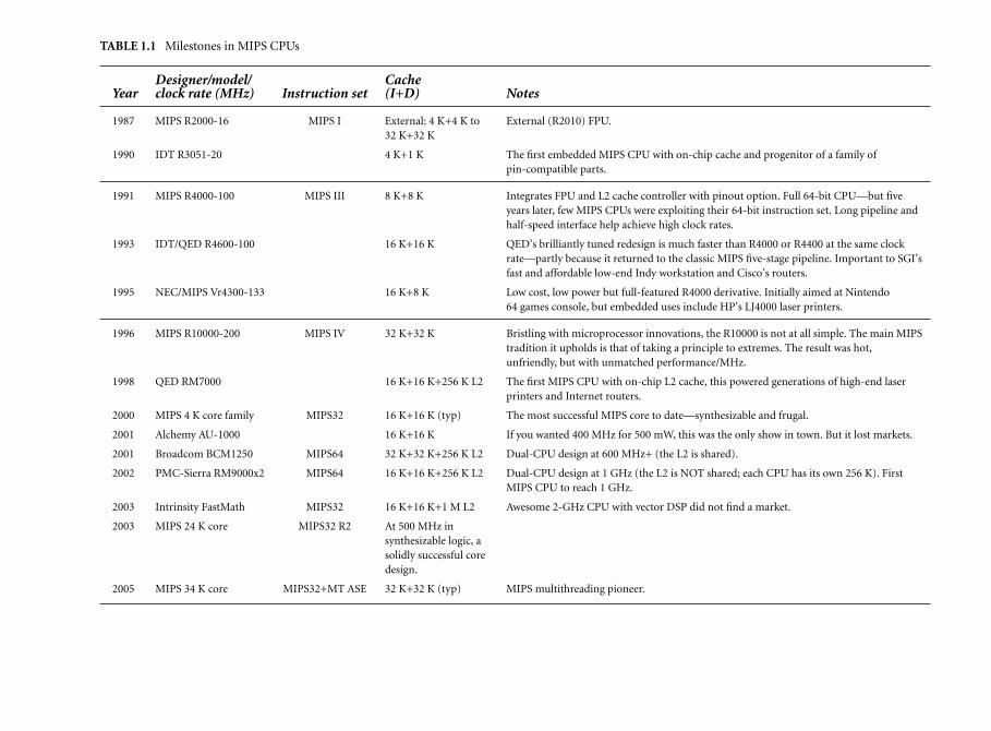
TABLE 1.1 Milestones in MIPS CPUs
Designer/model/ CacheYear clock rate (MHz) Instruction set (I+D) Notes
1987 MIPS R2000-16 MIPS I External: 4 K+4 K to32 K+32 K
External (R2010) FPU.
1990 IDT R3051-20 4 K+1 K The first embedded MIPS CPU with on-chip cache and progenitor of a family ofpin-compatible parts.
1991 MIPS R4000-100 MIPS III 8 K+8 K Integrates FPU and L2 cache controller with pinout option. Full 64-bit CPU—but fiveyears later, few MIPS CPUs were exploiting their 64-bit instruction set. Long pipeline andhalf-speed interface help achieve high clock rates.
1993 IDT/QED R4600-100 16 K+16 K QED’s brilliantly tuned redesign is much faster than R4000 or R4400 at the same clockrate—partly because it returned to the classic MIPS five-stage pipeline. Important to SGI’sfast and affordable low-end Indy workstation and Cisco’s routers.
1995 NEC/MIPS Vr4300-133 16 K+8 K Low cost, low power but full-featured R4000 derivative. Initially aimed at Nintendo64 games console, but embedded uses include HP’s LJ4000 laser printers.
1996 MIPS R10000-200 MIPS IV 32 K+32 K Bristling with microprocessor innovations, the R10000 is not at all simple. The main MIPStradition it upholds is that of taking a principle to extremes. The result was hot,unfriendly, but with unmatched performance/MHz.
1998 QED RM7000 16 K+16 K+256 K L2 The first MIPS CPU with on-chip L2 cache, this powered generations of high-end laserprinters and Internet routers.
2000 MIPS 4 K core family MIPS32 16 K+16 K (typ) The most successful MIPS core to date—synthesizable and frugal.
2001 Alchemy AU-1000 16 K+16 K If you wanted 400 MHz for 500 mW, this was the only show in town. But it lost markets.
2001 Broadcom BCM1250 MIPS64 32 K+32 K+256 K L2 Dual-CPU design at 600 MHz+ (the L2 is shared).
2002 PMC-Sierra RM9000x2 MIPS64 16 K+16 K+256 K L2 Dual-CPU design at 1 GHz (the L2 is NOT shared; each CPU has its own 256 K). FirstMIPS CPU to reach 1 GHz.
2003 Intrinsity FastMath MIPS32 16 K+16 K+1 M L2 Awesome 2-GHz CPU with vector DSP did not find a market.
2003 MIPS 24 K core MIPS32 R2 At 500 MHz insynthesizable logic, asolidly successful coredesign.
2005 MIPS 34 K core MIPS32+MT ASE 32 K+32 K (typ) MIPS multithreading pioneer.

1.5 MIPS Compared with CISC Architectures 23
1.5 MIPS Compared with CISC Architectures
Programmers who have some assembly-language-level knowledge of earlierarchitectures—particularly those brought up on x86 or 680x0 CISC instruc-tion sets—may get some surprises from the MIPS instruction set and registermodel. We’ll try to summarize them here, so you don’t get sidetracked later intodoomed searches for things that don’t quite exist, like a stack with push/popinstructions!
We’ll consider the following: constraints on MIPS operations imposed tomake the pipeline efficient; the radically simple load/store operations; possi-ble operations that have been deliberately omitted; unexpected features of theinstruction set; and the points where the pipelined operation becomes visibleto the programmer.
The Stanford group that originally dreamed up MIPS was paying particularattention to the short, simple pipeline it could afford to build. But it’s a testa-ment to the group’s judgment that many of the decisions that flowed from thathave proven to make more ambitious implementations easier and faster, too.
1.5.1 Constraints on MIPS Instructions
All instructions are 32 bits long: That means that no instruction can fit intoonly two or three bytes of memory (so MIPS binaries are typically 20 per-cent to 30 percent bigger than for 680x0 or 80x86) and no instruction canbe bigger.
It follows that it is impossible to incorporate a 32-bit constant into asingle instruction (there would be no instruction bits left to encode theoperation and the target register). The MIPS architects decided to makespace for a 26-bit constant to encode the target address of a jump orjump to subroutine; but that’s only for a couple of instructions. Otherinstructions find room only for a 16-bit constant. It follows that load-ing an arbitrary 32-bit value requires a two-instruction sequence, andconditional branches are limited to a range of 64-K instructions.
Instruction actions must fit the pipeline: Actions can only be carried out inthe right pipeline phase and must be complete in one clock. For exam-ple, the register write-back phase provides for just one value to be storedin the register file, so instructions can only change one register.
Integer multiply and divide instructions are too important to leave outbut can’t be done in one clock. MIPS CPUs have traditionally providedthem by dispatching these operations into a separately pipelined unitwe’ll talk about later.
Three-operand instructions: Arithmetical/logical operations don’t have tospecify memory locations, so there are plenty of instruction bits to definetwo independent sources and one destination register. Compilers love

24 Chapter 1—RISCs and MIPS Architectures
three-operand instructions, which give optimizers much more scope toimprove code that handles complex expressions.
The 32 registers: The choice of the number of registers is largely driven bysoftware requirements, and a set of 32 general-purpose registers is eas-ily the most popular in modern architectures. Using 16 would definitelynot be as many as modern compilers like, but 32 is enough for a C com-piler to keep frequently accessed data in registers in all but the largestand most intricate functions. Using 64 or more registers requires a big-ger instruction field to encode registers and also increases context-switchoverhead.
Register zero: $0 always returns zero, to give a compact encoding of thatuseful constant.
No condition codes: One feature of the MIPS instruction set that is radi-cal even among the 1985 RISCs is the lack of any condition flags. Manyarchitectures have multiple flags for “carry,” “zero,” and so on. CISCarchitectures typically set these flags according to the result written byany or a large subset of machine instructions, while some RISC architec-tures retain flags (though typically they are only set explicitly, by compareinstructions).
The MIPS architects decided to keep all this information in the registerfile: Compare instructions set general-purpose registers and conditionalbranch instructions test general-purpose registers. That does benefit apipelined implementation, in that whatever clever mechanisms are builtin to reduce the effect of dependencies on arithmetical/logical operationswill also reduce dependencies in compare/branch pairs.
We’ll see later that efficient conditional branching (at least in one favoritesimple pipeline organization) means that the decision about whether tobranch or not has to be squeezed into only half a pipeline stage; the archi-tecture helps out by keeping the branch decision tests very simple. SoMIPS conditional branches test a single register for sign/zero or a pair ofregisters for equality.
1.5.2 Addressing and Memory Accesses
Memory references are always plain register loads and stores: Arithmetic onmemory variables upsets the pipeline, so it is not done. Every memoryreference has an explicit load or store instruction. The large register filemakes this much less of a problem than it sounds.
Only one data-addressing mode: Almost all loads and stores select thememory location with a single base register value modified by a16-bit signed displacement (a limited register-plus-register address modeis available for floating-point data).

1.5 MIPS Compared with CISC Architectures 25
Byte-addressed: Once data is in a register of a MIPS CPU, all operationsalways work on the whole register. But the semantics of languages suchas C fit badly on a machine that can’t address memory locations downto byte granularity, so MIPS gets a complete set of load/store operationsfor 8- and 16-bit variables (we will say byte and halfword). Once the datahas arrived in a register it will be treated as data of full register length,so partial-word load instructions come in two flavors—sign-extend andzero-extend.
Load/stores must be aligned: Memory operations can only load or storedata from addresses aligned to suit the data type being transferred. Bytescan be transferred at any address, but halfwords must be even-alignedand word transfers aligned to four-byte boundaries. Many CISC micro-processors will load/store a four-byte item from any byte address, but thepenalty is extra clock cycles.
However, the MIPS instruction set architecture (ISA) does include a cou-ple of peculiar instructions to simplify the job of loading or storing atimproperly aligned addresses.
Jump instructions: The limited 32-bit instruction length is a particularproblem for branches in an architecture that wants to support very largeprograms. The smallest opcode field in a MIPS instruction is 6 bits, leav-ing 26 bits to define the target of a jump. Since all instructions arefour-byte aligned in memory, the two least significant address bits neednot be stored, allowing an address range of 228 = 256 MB. Rather thanmake this branch PC relative, this is interpreted as an absolute addresswithin a 256-MB segment. That’s inconvenient for single programs largerthan this, although it hasn’t been much of a problem yet!
Branches out of segment can be achieved by using a jump register instruc-tion, which can go to any 32-bit address.
Conditional branches have only a 16-bit displacement field—giving a218-byte range, since instructions are four-byte aligned—which is inter-preted as a signed PC-relative displacement. Compilers can only code asimple conditional branch instruction if they know that the target willbe within 128 KB of the instruction following the branch.
1.5.3 Features You Won’t Find
No byte or halfword arithmetic: All arithmetical and logical operations areperformed on 32-bit quantities. Byte and/or halfword arithmetic requiressignificant extra resources and many more opcodes, and it is rarely reallyuseful. The C language’s semantics cause most calculations to be carriedout with int precision, and for MIPS int is a 32-bit integer.
However, where a program explicitly does arithmetic as short orchar, a MIPS compiler must insert extra code to make sure that the

26 Chapter 1—RISCs and MIPS Architectures
results wrap and overflow as they would on a native 16- or 8-bitmachine.
No special stack support: Conventional MIPS assembly usage does defineone of the registers as a stack pointer, but there’s nothing special to thehardware about sp. There is a recommended format for the stackframe layout of subroutines, so that you can mix modules from differ-ent languages and compilers; you should almost certainly stick to theseconventions, but they have no relationship to the hardware.
A stack pop wouldn’t fit the pipeline, because it would have two regis-ter values to write (the data from the stack and the incremented pointervalue).
Minimal subroutine support: There is one special feature: jump instruc-tions have a jump and link option, which stores the return address intoa register. $31 is the default, so for convenience and by convention$31 becomes the return address register.
This is less sophisticated than storing the return address on a stack, butit has some significant advantages. Two examples will give you a feelingfor the argument: First, it preserves a pure separation between branchand memory-accessing instructions; second, it can aid efficiency whencalling small subroutines that don’t need to save the return address onthe stack at all.
Minimal interrupt handling: It is hard to see how the hardware could doless. It stashes away the restart location in a special register, modifies themachine state just enough to let you find out what happened and to dis-allow further interrupts, then jumps to a single predefined location inlow memory. Everything else is up to the software.
Minimal exception handling: Interrupts are just one sort of exception (theMIPS word exception covers all sorts of events where the CPU may wantto interrupt normal sequential processing and invoke a software han-dler). An exception may result from an interrupt, an attempt to accessvirtual memory that isn’t physically present, or many other things. Yougo through an exception, too, on a deliberately planted trap instruc-tion like a system call that is used to get into the kernel in a protectedOS. All exceptions result in control passing to the same fixed entrypoint.7
On any exception, a MIPS CPU does not store anything on a stack, writememory, or preserve any registers for you.
By convention, two general-purpose registers are reserved so that excep-tion routines can bootstrap themselves (it is impossible to do anything
7. I exaggerate slightly; these days there are quite a few different entry points, and there were alwaysat least two. Details will be given in section 5.3.

1.5 MIPS Compared with CISC Architectures 27
IF
IF RD ALU MEM WB
WBMEMALURDIF
RD MEM WBBranch
instruction
Branchdelay
Branchtarget
Branchaddress
FIGURE 1.3 The pipeline and branch delays.
on a MIPS CPU without using some registers). For a program runningin any system that takes interrupts or traps, the values of these registersmay change at any time, so you’d better not use them.
1.5.4 Programmer-Visible Pipeline Effects
So far, this has all been what you might expect from a simplified CPU. However,making the instruction set pipeline friendly has some stranger effects as well,and to understand them we’re going to draw some pictures.
Delayed branches: The pipeline structure of the MIPS CPU (Figure 1.3)means that when a jump/branch instruction reaches the execute phaseand a new program counter is generated, the instruction after the jumpwill already have been started. Rather than discard this potentially usefulwork, the architecture dictates that the instruction after a branch mustalways be executed before the instruction at the target of the branch. Theinstruction position following any branch is called the branch delay slot.
If nothing special was done by the hardware, the decision to branch ornot, together with the branch target address, would emerge at the endof the ALU pipestage—by which time, as Figure 1.3 shows, you’re toolate to present an address for an instruction in even the next-but-onepipeline slot.
But branches are important enough to justify special treatment, and youcan see from Figure 1.3 that a special path is provided through the ALU tomake the branch address available half a clock cycle early. Together withthe odd half-clock-cycle shift of the instruction fetch stage, that meansthat the branch target can be fetched in time to become the next but one,

28 Chapter 1—RISCs and MIPS Architectures
Loaddelay
Load
Usedata
IF RD ALU MEM WB
IF RD ALU MEM WB
IF RD ALU MEM WB
FIGURE 1.4 The pipeline and load delays.
so the hardware runs the branch instruction, then the branch delay slotinstruction, and then the branch target—with no other delays.
It is the responsibility of the compiler system or the assembly program-ming wizard to allow for and even to exploit the branch delay; it turns outthat it is usually possible to arrange that the instruction in the branch delayslot does useful work. Quite often, the instruction that would otherwisehave been placed before the branch can be moved into the delay slot.
This can be a bit tricky on a conditional branch, where the branch delayinstruction must be (at least) harmless on both paths. Where nothinguseful can be done, the delay slot is filled with a nop instruction.
Many MIPS assemblers will hide this odd feature from you unless youexplicitly ask them not to.
Late data from load (load delay slot): Another consequence of the pipelineis that a load instruction’s data arrives from the cache/memory systemafter the next instruction’s ALU phase starts—so it is not possible to usethe data from a load in the following instruction. (See Figure 1.4 for howthis works.)
The instruction position immediately after the load is called the load delayslot, and an optimizing compiler will try to do something useful with it.The assembler will hide this from you but may end up putting in a nop.
On modern MIPS CPUs the load result is interlocked: If you try to usethe result too early, the CPU stops until the data arrives. But on earlyMIPS CPUs, there were no interlocks, and the attempt to use data in theload delay slot led to unpredictable results.

Chapter
2 MIPS Architecture
The rather grandiose word architecture is used in computing to describe theabstract machine you program, rather than the actual implementation of
that machine. That’s a useful distinction—and one worth defending from thewidespread misuse of the term in marketing hype. The abstract description maybe unfamiliar, but the concept isn’t. If you drive a stick-shift car you’ll find thegas pedal on the right and the clutch on the left, regardless of whether the car isfront-wheel drive or rear-wheel drive. The architecture (which pedal is where)is deliberately kept the same, although the implementation is different.
Of course, if you’re a rally driver concerned with going very fast along slip-pery roads, it’s suddenly going to matter a whole lot which wheels are driven.Computers are like that too—once your performance needs are extreme orunusual, the details of the implementation may become important to you.
In general, a CPU architecture consists of an instruction set and someknowledge about registers. The terms instruction set and architecture are prettyclose to synonymous, and you can get both at once in the acronym ISA (Instruc-tion Set Architecture).
These days the MIPS ISA is best defined by the MIPS32 and MIPS64 archi-tecture specifications published by MIPS Technologies Inc. MIPS32 is a subsetof MIPS64 for CPUs with 32-bit general-purpose registers. “The MIPS32 andMIPS64 architecture specifications” is a bit of a mouthful, so we’ll abbreviate itto “MIPS32/64.”
Most of the companies making MIPS CPUs are now making them com-patible with these specifications—and those that are not strictly compatible aregenerally reducing differences as they can.
Before MIPS32/64, a number of versions of the MIPS architecture werewritten down. But those older definitions formally applied only to theinstructions and resources used by higher-level software—they regarded theCPU control mechanisms necessary to operating systems as implementationdependent. That meant that portable operating system work depended on a
29
30 Chapter 2—MIPS Architecture
gentleman’s agreement to keep the unspecified areas of the MIPS architecturestable, too. The way that worked out was that each architecture version wasnaturally associated with a “parent” implementation:
MIPS I: The instruction set used by the original 32-bit processors (R2000/3000); every MIPS CPU there ever was will run these instructions,so it is still common as a lingua franca.
MIPS II: A minor upgrade defined for the MIPS R6000, which didn’t getbeyond preproduction. But something very like it has been widelyused for 32-bit MIPS CPUs for the embedded market. MIPS II is theimmediate parent of MIPS32.
MIPS III: The 64-bit instruction set introduced by the R4000.
MIPS IV: Adds a few useful instructions (mostly floating point) to MIPS III,appearing in two different implementations (R10000 and R5000).
MIPS V: Adds some surprising two operations at once (“SIMD”) floating-point operations—but no MIPS V CPU was built. Most of it reap-peared as an optional part of MIPS64 called “paired-single.”
MIPS32, MIPS64: Standards promulgated by MIPS Technologies Inc. afterits demerger from Silicon Graphics in 1998. For the first time, thestandards encompassed the “CPU control” functions known ascoprocessor 0. MIPS32 is a superset of MIPS II, while MIPS64—which includes 64-bit instructions—is a superset of MIPS IV (andcontains much of MIPS V as an optional extension).
Most MIPS CPUs designed since 1999 are compatible with thesestandards, so we’ll use MIPS32/64 as the base architectures in thisbook. To be more precise, our base is Release 2 of the MIPS32/64specifications, as published in 2003. Earlier MIPS32/64 CPUs mightbe referred to as Release 1.
The architecture levels define everything the original company documenta-tion chose to define; up to MIPS V, that was typically rather more than enoughto ensure the ability to run the same UNIX application and less than enoughto ensure complete portability of code that uses OS or low-level features. Bycontrast, if a CPU conforms to MIPS32/64, it should run a reasonable portableoperating system.
Early MIPS CPUs (starting with the R3000) had CPU control instructionsand registers that are fairly different from MIPS32; they’re very old now, andthese features aren’t detailed in this book.
Quite a few implementations add some of their own new instructions andinteresting features. It’s not always easy to get software or tools (particularlycompilers) that take advantage of implementation-specific features. We’lldescribe most that I find interesting.

Chapter 2—MIPS Architecture 31
There are two levels of detail at which we can describe the MIPS architecture.The first (this chapter) is the kind of view you’d get if you were writing a userprogram for a workstation but chose to look at your code at the assembly level.That means that the whole normal working of the CPU would be visible.
In the later chapters we’ll take on everything, including all the gory detailsthat a high-level operating system hides—CPU control registers, interrupts,traps, cache manipulation, and memory management. But at least we can cutthe task into smaller pieces.
CPUs are often much more compatible at the user level than wheneverything is exposed. All known MIPS CPUs can run MIPS I user-levelcode.
Bringing Order to Instruction Set Extensions—ASEs
We’ve kept stressing that being RISC has very little to do with keeping theinstruction set small. In fact, RISC simplicity makes it temptingly easy to extendthe instruction set with new twists on three-operand register-to-registercalculations.
When MIPS CPUs began to be used in embedded systems, new instruc-tions aimed at helping out some particular application began to mushroom.MIPS32/64 has included some of those inventions. But it also provides someregulations, in the form of recognized ASEs (Application-Specific instructionset Extensions). ASEs are optional extensions to MIPS32/64 whose presence ismarked in a standard way through configuration registers. There are alreadyquite a lot of them:
MIPS16e: This extension long predates MIPS32 and MIPS Technologies.It was pioneered by LSI Logic in the 1990s, with a view to reducing thesize of MIPS binary programs. MIPS16 encodes a subset of user-privilegeMIPS instructions (and a few special ones added in) in 16-bit op-codes.Such an instruction set is evidently “too small” and programs compileinto significantly more MIPS16 than regular MIPS instructions; how-ever, the half-size instructions lead to much smaller code. The MIPS16instruction set was organized and slightly augmented to be an extensionof MIPS32, and the augmented version is called MIPS16e. This bookhas few details about MIPS16e: It’s a large subject and rarely met upwith even at assembly level, but there are some words on the subject insection B.1.
MDMX: Another old extension, this one championed by SGI. It adds alarge set of SIMD arithmetic operations using the FP (coprocessor 1) reg-ister set. They’re SIMD because each operation runs in parallel on eachof a short array of integer values packed into the 64-bit registers. Many ofthe operations are “saturating”; when a result would otherwise overflow,the destination is filled with the nearest representable value. Saturating

32 Chapter 2—MIPS Architecture
small-integer SIMD operations accelerates a variety of audio and video“media stream” computations. They’re also broadly characteristic of thespecialized CPUs called DSPs (Digital Signal Processors).
MDMX resembles the early versions of Intel’s MMX extension. ButMDMX was never implemented by SGI, and few implementationssurvive: Broadcom’s CPUs seem to be the only ones.
SmartMIPS: A very small extension to the architecture aimed at improv-ing the performance of encryption operations believed to be key to thesmart card market; it is coupled to a bunch of other security- and size-related tweaks to the CPU control system. One day the 32-bit smart cardmarket will be huge, but it hasn’t happened yet.
MT: A rather small extension in terms of instructions but a hugely signif-icant one: This adds hardware multithreading to MIPS cores. It was firstseen in MIPS Technologies’ 34-K family, launched in 2005. Appendix Agives an overview of the MIPS MT system.
DSP: Like MDMX, this is a set of instructions held to be useful foraudio/video processing, with saturating and SIMD arithmetic on smallintegers to the fore—but it already looks more useful in practice thanMDMX. It was also new in 2005, available in MIPS Technologies’ 24-Kand 34-K families. The DSP ASE was made public just in time to includea sketchy description here in section B.2.
There are some other optional parts of the MIPS32/64 specification thatmay not be regarded as primarily instruction set extensions:
Floating point: The oldest are the best. Floating point has been anoptional part of the MIPS instruction set since the earliest days. But it fitswithin the confines of the “coprocessor 1” encodings. It’s well describedin this book.
CP2: The second coprocessor encoding region is free for brave customers.But it’s a lot of design and testing work, and few try it. There’s nothingmore about it here.
CorExtend: MIPS Technologies’ best shot at a relatively easy-to-use user-definable instruction set. The idea was much hyped in 2002/2003, withannouncements from companies such as ARM and Tensilica.
EJTAG: An optional system to improve the debugging facilities, describedin section 12.1.
Paired single: An extension to the floating-point unit that provides SIMDoperations, each of which works simultaneously on two single-precision(32-bit) sets of values.

2.1 A Flavor of MIPS Assembly Language 33
MIPS-3D: Usually associated with paired single, adds a handful ofinstructions to help out with the floating-point matrix operationsheavily used by 3D scene rendering.
2.1 A Flavor of MIPS Assembly Language
Assembly language is the human-writable (and readable) version of the CPU’sraw binary instructions, and Chapter 9 tells you more about how to understandit. Readers who have never seen any assembly language will find some parts ofthis book mystifying—but there’s no time like now to start.
For readers familiar with assembly language, but not the MIPS version, hereare some examples of what you might see:
# this is a comment
entrypoint: # that’s a labeladdu $1, $2, $3 # (registers) $1 = $2 + $3
Like most assembly languages, it is line oriented. The end of a line delimitsinstructions, and the assembly’s native comment convention is that it ignoresany text on a line beyond a “#” character. But it is possible to put more than oneinstruction on a line, separated by semicolons.
A label is a word followed by a colon “:”—word is interpreted loosely, andlabels can contain all sorts of strange characters. Labels are used to define entrypoints in code and to name storage locations in data sections.
MIPS assembly programs interpret a rather stark language, full of registernumbers. Most programmers use the C preprocessor and some standard headerfiles so they can write registers by name; the names of the general-purpose reg-isters reflect their conventional use (which we’ll talk about in section 2.2). If youuse the C preprocessor, you can also use C-style comments.
A lot of instructions are three-operand, as shown. The destination registeris on the left (watch out, that’s opposite to the Intel x86 convention). In general,the register result and operands are shown in the same order you’d use to writethe operation in C or any other algebraic language, so:
subu $1, $2, $3
means exactly:
$1 = $2 - $3;
That should be enough for now.

34 Chapter 2—MIPS Architecture
2.2 Registers
There are 32 general-purpose registers for your program to use: $0 to $31. Two,and only two, behave differently than the others:
$0 Always returns zero, no matter what you store in it.
$31 Is always used by the normal subroutine-calling instruction (jal) for thereturn address. Note that the call-by-register version (jalr) can use anyregister for the return address, though use of anything except $31 wouldbe eccentric.
In all other respects, all these registers are identical and can be used in anyinstruction (you can even use $0 as the destination of instructions, though theresulting data will disappear without a trace).
In the MIPS architecture the program counter is not a register, and it isprobably better for you not to think of it that way—in a pipelined CPU thereare multiple candidates for its value, which gets confusing. The return addressof a jal is the next instruction but one in sequence:
...jal printfmov $4, $6xxx # return here after call
That makes sense, because the instruction immediately after the call is thecall’s delay slot—remember, the rules say it must be executed before the branchtarget. The delay slot instruction of the call is rarely wasted, because it is typicallyused to set up a parameter.
There are no condition codes; nothing in the status register or other CPUinternals is of any consequence to the user-level programmer.
There are two register-sized result ports (called hi and lo) associated withthe integer multiplier. They are not general-purpose registers, nor are they use-ful for anything except multiply and divide operations. However, there areinstructions defined that insert an arbitrary value back into these ports—aftersome reflection, you may be able to see that this is required when restoring thestate of a program that has been interrupted.
The floating-point math coprocessor (floating-point accelerator, or FPU),if available, adds 32 floating-point registers; in simple assembly language, theyare called $f0 to $f31.
Actually, for early 32-bit machines (conforming to MIPS I), only the 16even-numbered registers were usable for math. But each even-numbered reg-ister can be used for either a single-precision (32-bit) or double-precision (64-bit) number; when you do double-precision arithmetic, register $f1 holds theremaining bits of the register identified as $f0, and so on. In MIPS I programs

2.2 Registers 35
you only see odd-numbered math registers when you move data betweeninteger and FPU registers or load/store floating-point register values—and eventhen the assembler helps you forget that complication.
MIPS32/64 CPUs have 32 genuine FP registers. But you may still meet soft-ware that avoids using the odd-numbered registers, preferring to maintain soft-ware compatibility with old CPUs. There’s a mode bit in one of the controlregisters to make a modern FPU behave like an old one.
2.2.1 Conventional Names and Uses of General-Purpose Registers
We’re a couple of pages into an architecture description and here we are talkingabout software. But I think you need to know this now.
Although the hardware makes few rules about the use of registers, theirpractical use is governed by a forest of conventions. The hardware cares nothingfor these conventions, but if you want to be able to use other people’s subrou-tines, compilers, or operating systems, then you had better fit in.
With the conventional uses of the registers go a set of conventional names.Given the need to fit in with the conventions, use of the conventional names ispretty much mandatory. The common names are listed in Table 2.1.
Somewhere about 1996 Silicon Graphics began to introduce compilers thatuse new conventions. The new conventions can be used to build programs thatuse 32-bit or 64-bit addressing, and in those two cases they are called, respec-tively, “n32” and “n64.” We’ll ignore them for now, but there is a terse butfairly complete description of them in section 11.2.8.
Conventional Assembly Names and Usages for Registers
at: This register is reserved for the synthetic instructions generated bythe assembler. Where you must use it explicitly (such as when savingor restoring registers in an exception handler), there’s an assemblydirective to stop the assembly from using it behind your back—but thensome of the assembler’s macro instructions won’t be available.
v0, v1: Used when returning non-floating-point values from a subrou-tine. If you need to return anything too big to fit in two registers, thecompiler will arrange to do it in memory. See section 11.2.1 for details.
a0–a3: Used to pass the first four non-FP parameters to a subroutine.That’s an occasionally false oversimplification—see section 11.2.1 for thegrisly details.
t0–t9: By convention, subroutines may use these values without pre-serving them. This makes them a good choice for “temporaries” whenevaluating expressions—but the compiler/programmer must rememberthat the values stored in them may be destroyed by a subroutine call.

36 Chapter 2—MIPS Architecture
TABLE 2.1 Conventional Names of Registers with Usage Mnemonics
Register number Name Used for
0 zero Always returns 0
1 at (assembly temporary) Reserved for use by assembly
2–3 v0, v1 Value returned by subroutine
4–7 a0–a3 (arguments) First few parameters for a subroutine
8–15 t0–t7 (temporaries) Subroutines can use without saving
24, 25 t8, t9
16–23 s0–s7 Subroutine register variables; a subroutine that writes one of thesemust save the old value and restore it before it exits, so the callingroutine sees the values preserved
26, 27 k0, k1 Reserved for use by interrupt/trap handler; may change under yourfeet
28 gp Global pointer; some runtime systems maintain this to give easyaccess to (some) static or extern variables
29 sp Stack pointer
30 s8/fp Ninth register variable; subroutines that need one can use this as aframe pointer
31 ra Return address for subroutine
s0–s8: By convention, subroutines must guarantee that the values ofthese registers on exit are the same as they were on entry, either by notusing them or by saving them on the stack and restoring them beforeexit. This makes them eminently suitable for use as register variables orfor storing any value that must be preserved over a subroutine call.
k0, k1: Reserved for use by an OS trap/interrupt handlers, which will usethem and not restore their original value; they are of little use to anyoneelse.
gp: This is used for two distinct purposes. In the kind of position-independent code (PIC) used by Linux applications, all out-of-modulecode and data references go through a table of pointers known as theGOT (for Global Offset Table). The gp register is maintained to point tothe GOT. See Chapter 16 for details.
In regular non-PIC code (as is used by simpler embedded systems) gpis sometimes used to point to a link-time-determined location in the

2.2 Registers 37
midst of your static data. This means that loads and stores to data lyingwithin 32 KB of either side of the gp value can be performed in a singleinstruction using gp as the base register.
Without the global pointer, loading data from a static memory area takestwo instructions: one to load the most significant bits of the 32-bit con-stant address computed by the compiler and loader and one to do thedata load.
To create gp-relative references, a compiler must know at compile timethat a datum will end up linked within a 64-KB range of memory loca-tions. In practice it can’t know; it can only guess. The usual practice isto put small global data items (eight bytes and less in size) in the gp areaand to get the linker to complain if it still gets too big.
sp: It takes explicit instructions to raise and lower the stack pointer, soMIPS code usually adjusts the stack only on subroutine entry and exit;it is the responsibility of the subroutine being called to do this. sp isnormally adjusted, on entry, to the lowest point that the stack will needto reach at any point in the subroutine. Now the compiler can access stackvariables by a constant offset from sp. Once again, see section 11.2.1 forconventions about stack usage.
fp: Also known as s8, a frame pointer will be used by a subroutineto keep track of the stack if for any reason the compiler or program-mer was unable or unwilling to compute offsets from the stack pointer.That might happen, in particular, if the program does things that involveextending the stack by an amount that is determined at run time.Some languages may do this explicitly; assembly programmers arealways welcome to experiment; and C programs that use the alloca()library routine will find themselves doing so.
If the stack bottom can’t be computed at compile time, you can’t accessstack variables from sp, so fp is initialized by the function prologue toa constant position relative to the function’s stack frame. Cunning useof register conventions means that this behavior is local to the functionand doesn’t affect either the calling code or any nested function calls.
ra: On entry to any subroutine, return address holds the address towhich control should be returned—so a subroutine typically ends withthe instruction jr ra. In theory, any register could be used, but somesophisticated CPUs use optimization (branch prediction) tricks, whichwork better if you use a jr ra.
Subroutines that themselves call subroutines must first save ra, usuallyon the stack.
There is a corresponding set of standard uses for floating-point registers too,which we’ll summarize in section 7.5. We’ve described here the original conven-tions promulgated by MIPS; some evolution has occurred in recent times and

38 Chapter 2—MIPS Architecture
the old conventions are called o32—but we won’t discuss newer conventionsuntil section 11.2.8.
2.3 Integer Multiply Unit and Registers
The MIPS architects decided that integer multiplication was important enoughto deserve a hardwired instruction. This was not universal in 1980s, RISCs. Onealternative was to implement a multiply step that fits in the standard integerexecution pipeline but mandates software routines for every nontrivial multi-plication; early SPARC CPUs did just that.
Another way of avoiding the complexity of the integer multiplier would beto perform integer multiplication in the floating-point unit—a good solutionused in Motorola’s short-lived 88000 family—but that would compromise theoptional nature of the MIPS floating-point coprocessor.
Instead, a MIPS CPU has a special-purpose integer multiply unit, whichis not quite integrated with the main pipeline. The multiply unit’s basic opera-tion is to multiply two register-sized values together to produce a twice-register-sized result, which is stored inside the multiply unit. The instructions mfhi,mflo retrieve the result in two halves into specified general registers.
Since multiply results are not returned so fast as to be automatically avail-able for any subsequent instruction, the multiply result registers are and alwayswere interlocked. An attempt to read out the results before the multiplication iscomplete results in the CPU being stopped until the operation completes.
The integer multiply unit will also perform an integer division between val-ues in two general-purpose registers; in this case the lo register stores the result(quotient) and the hi register stores the remainder.
You don’t get a multiply unit answer out in one clock: multiply takes 4–12clock cycles and division 20–80 clock cycles (it depends on the implementation,and for some implementations it depends on the size of the operands). SomeCPUs have fully or partially pipelined multiply units—that is, they can starta multiply operation every one or two clocks, even though the result will notarrive for four or five clocks.
MIPS32/64 includes a three-operand mul instruction, which returns thelow half of the multiply result to a general-purpose register. But that instructionmust stall until the operation is finished; highly tuned software will still use sep-arate instructions to start the multiply and retrieve the results. MIPS32/64 CPUs(and most other CPUs still on the market) also have multiply-accumulate oper-ations, where products from successive multiply operations are accumulatedinside the lo/hi pair.
Integer multiply and divide operations never produce an exception: noteven divide by zero (though the result you get from that is unpredictable). Com-pilers will often generate additional instructions to check for and trap on errors,particularly on divide by zero.

2.5 Data Types in Memory and Registers 39
Instructions mthi, mtlo are defined to set up the internal registers fromgeneral-purpose registers. They are essential to restore the values of hi and lowhen returning from an exception but probably not for anything else.
2.4 Loading and Storing: Addressing Modes
As mentioned previously, there is only one addressing mode.1 Any load or storemachine instruction can be written:
lw $1, offset($2)
You can use any registers for the destination and source. The offset is asigned, 16-bit number (and so can be anywhere between −32768 and 32767);the program address used for the load is the sum of $2 and the offset. Thisaddress mode is normally enough to pick out a particular member of a C struc-ture (offset being the distance between the start of the structure and the mem-ber required). It implements an array indexed by a constant; it is enough toreference function variables from the stack or frame pointer and to provide areasonable-sized global area around the gp value for static and extern variables.
The assembler provides the semblance of a simple direct addressing modeto load the values of memory variables whose address can be computed at linktime.
More complex modes such as double-register or scaled index must beimplemented with sequences of instructions.
2.5 Data Types in Memory and Registers
MIPS CPUs can load or store between one and eight bytes in a single opera-tion. Naming conventions used in the documentation and to build instructionmnemonics are as follows.
2.5.1 Integer Data Types
Byte and halfword loads come in two flavors. Sign-extending instructions lband lh load the value into the least significant bits of the 32-bit register but fillthe high-order bits by copying the sign bit (bit 7 of a byte, bit 15 of a halfword).This correctly converts a signed integer value to a 32-bit signed integer, as shownin the following chart.
1. Not entirely true any more; now there is a register+register mode available for floating-pointload and store.

40 Chapter 2—MIPS Architecture
C name MIPS name Size (bytes) Assembly mnemonic
long long dword 8 “d” as in ld
int word 4 “w” as in lw
long2
short halfword 2 “h” as in lh
char byte 1 “b” as in lb
The unsigned instructions lbu and lhu zero-extend the data; they load thevalue into the least significant bits of a 32-bit register and fill the high-order bitswith zeros.
For example, if the byte-wide memory location whose address is in t1contains the value 0xFE (−2, or 254 if interpreted as unsigned), then:
lb t2, 0(t1)lbu t3, 0(t1)
will leave t2 holding the value 0xFFFF.FFFE (−2 as signed 32-bit value) andt3 holding the value 0x0000 00FE (254 as signed or unsigned 32-bit value).
The above description relates to MIPS machines considered as 32-bit CPUs,but many have 64-bit registers. It turns out that all partial-word loads (evenunsigned ones) sign-extend into the top 32 bits; this behavior looks bizarre butis helpful, as is explained in section 2.7.3.
Subtle differences in the way shorter integers are extended to longer ones area historical cause of C portability problems, and the modern C standards havevery definite rules to remove possible ambiguity. On machines like the MIPS,which cannot do 8- or 16-bit precision arithmetic directly, expressions involv-ing short or char variables require the compiler to insert extra instructionsto make sure things overflow when they should; this is nearly always undesir-able and rather inefficient. When porting code that uses small integer variablesto a MIPS CPU, you should consider identifying which variables can be safelychanged to int.
2.5.2 Unaligned Loads and Stores
Normal loads and stores in the MIPS architecture must be aligned; halfwordsmay be loaded only from two-byte boundaries and words only from four-byteboundaries. A load instruction with an unaligned address will produce a trap.
2. Nothing is simple. Recent MIPS compilers offering 64-bit pointers interpret the long data typeas 64 bits (it’s good practice for a C compiler that a long should be big enough to hold a pointer).

2.5 Data Types in Memory and Registers 41
Because CISC architectures such as the MC680x0 and Intel x86 do handleunaligned loads and stores, you may come across this as a problem when port-ing software; in extremity, you may even decide to install a trap handler that willemulate the desired load operation and hide this feature from the application—but that’s going to be horribly slow unless the references are very rare.
All data items declared by C code will be correctly aligned.Where you know in advance that you want to code a transfer from an address
whose alignment is unknown and that may turn out to be unaligned, the archi-tecture does allow for a two-instruction sequence (much more efficient than aseries of byte loads, shifts, and adds). The operation of the constituent instruc-tions is obscure and hard to grasp, but they are normally generated by themacro-instruction ulw (unaligned load word). They’re described fully insection 8.5.1.
A macro-instruction ulh (unaligned load half) is also provided and is syn-thesized by two loads, a shift, and a bitwise “or” operation.
By default, a C compiler takes trouble to align all data correctly, but there areoccasions (e.g., when importing data from a file or sharing data with a differentCPU) when being able to handle unaligned integer data efficiently is a require-ment. Most compilers permit you to flag a data type as potentially unalignedand will generate (reasonably efficient) special code to cope—see section 11.1.5.
2.5.3 Floating-Point Data in Memory
Loads into floating-point registers from memory move data without any inter-pretation—you can load an invalid floating-point number (in fact, an arbitrarybit pattern) and no FP error will result until you try to do arithmetic with it.
On 32-bit processors, this allows you to load single-precision values by aload into an even-numbered floating-point register, but you can also load adouble-precision value by a macro instruction, so that on a 32-bit CPU theassembly instruction:
l.d $f2, 24(t1)
is expanded to two loads to consecutive registers:
lwc1 $f2, 24(t1)lwc1 $f3, 28(t1)
On a 64-bit CPU, l.d is the preferred alias for the machine instructionldc1, which does the whole job.
Any C compiler that complies with the MIPS/SGI rules aligns eight-byte-long double-precision floating-point variables to eight-byte boundaries. The32-bit hardware does not require this alignment, but it’s done for forward com-patibility: 64-bit CPUs will trap if asked to load a double from a location thatis not eight-byte aligned.

42 Chapter 2—MIPS Architecture
2.6 Synthesized Instructions in Assembly Language
MIPS machine code might be rather dreary to write; although there areexcellent architectural reasons why you can’t load a 32-bit constant value intoa register with a single instruction, assembly programmers don’t want to thinkabout it every time. So the GNU assembler (and other good MIPS assemblers)will synthesize instructions for you. You just write an li (load immediate)instruction and the assembler will figure out when it needs to generate twomachine instructions.
This is obviously useful, but it can be abused. Some MIPS assemblers endup hiding the architecture to an extent that is not really necessary. In this book,we will try to use synthetic instructions sparingly, and we will tell you when ithappens. Moreover, in the instruction tables, we will consistently distinguishbetween synthetic and machine instructions.
It is my feeling that these features are there to help human programmers andthat serious compilers should generate instructions that are one-for-one withmachine code.3 But in an imperfect world many compilers will in fact generatesynthetic instructions.
Helpful things the assembler does include the following:
A 32-bit load immediate: You can code a load with any value (including amemory location that will be computed at link time), and the assemblerwill break it down into two instructions to load the high and low half ofthe value.
Load from memory location: You can code a load from a memory-residentvariable. The assembler will normally replace this by loading a temporaryregister with the high-order half of the variable’s address, followed by aload whose displacement is the low-order half of the address. Of course,this does not apply to variables defined inside C functions, which areimplemented either in registers or on the stack.
Efficient access to memory variables: Some C programs contain many ref-erences to static or extern variables, and a two-instruction sequenceto load/store any of them is expensive. Some compilation systems, withthe help of some runtime support, get around this. Certain variablesare selected at compile/assemble time (most commonly the assemblerselects variables that occupy eight or less bytes of storage) and are kepttogether in a single section of memory that must end up smaller than64 KB. The runtime system then initializes one register—$28 or gp byconvention—to point to the middle of this section.
3. This principle was behind the MIPS back end being reworked for the GNU C compiler in2003/2004.

2.7 MIPS I to MIPS64 ISAs: 64-Bit (and Other) Extensions 43
Loads and stores to these variables can now be coded as a singlegp-relative load or store.
More types of branch conditions: The assembler synthesizes a full set ofbranches conditional on an arithmetic test between two registers.
Simple or different forms of instructions: Unary operations such as notand neg are produced as a nor or sub with the zero-valued register $0.You can write two-operand forms of three-operand instructions and theassembler will put the result back into the first-specified register.
Hiding the branch delay slot: In normal coding the assembler will movethe instruction you wrote before the branch around into the delay slot ifit can see it is safe to do so. The assembler can’t see much, so it is not verygood at filling branch delays. An assembly directive .set noreorderis available to tell the assembler that you’re in control and it must notmove instructions about.
Hiding the load delay: Some assemblers may detect an attempt to use theresult of a load in the immediately succeeding instruction and may movean instruction up or back in sequence if it can.
Unaligned transfers: The unaligned load/store instructions (ulh, ulw,etc.) will fetch halfword and word quantities correctly, even if the targetaddress turns out to be unaligned.
Other pipeline corrections: Some instructions (such as those that use theinteger multiply unit) have additional constraints on some old CPUs. Ifyou have such an old CPU, you may find that your assembler helps out.
In general, if you really want to correlate assembly source language (notenclosed by a.set noreorder) with instructions stored in memory, you needhelp. Use a disassembler utility.
2.7 MIPS I to MIPS64 ISAs: 64-Bit (and Other) Extensions
The MIPS architecture has grown since its invention—notably, it’s grown from32 to 64 bits. That growth has been done so neatly that it would be quite possi-ble to describe contemporary MIPS as a 64-bit architecture with a well-defined32-bit subset for lower-cost implementations. We haven’t quite done that, forseveral reasons. First, that is not how it happened, so such a description is indanger of mystifying you. Second, one of the lessons that MIPS has to offerthe world is the art of extending an architecture nicely. And third, the materialin this book was in fact written about 32-bit MIPS before it was extended toencompass 64 bits.

44 Chapter 2—MIPS Architecture
So the approach is a hybrid one. We will usually introduce the 32-bit versionfirst, but once we get down to the details we’ll handle both versions together.We’ll use the acronym ISA for the long-winded term instruction setarchitecture.
Once MIPS started to evolve, the ISA of the original 32-bit MIPS CPUs(the R2000, R3000, and descendants) was retrospectively called MIPS I.4 Thenext variant to be widely used is a substantial enhancement that leads to acomplete 64-bit ISA for the R4000 CPU and its successors; this was calledMIPS III.
Although there has been much ISA evolution, at least at the application level(all the code that you can see when writing applications on a workstation),the newer instruction sets are generally backward compatible, fully support-ing programs written for old ones. 32-bit ISAs obviously don’t run 64-bit pro-grams; otherwise the only ISA version that could cause you trouble is MIPS V,some of which is not available in MIPS64. But then it was never implemented,either.
There was a MIPS II, but it came to nothing because its first implementation(the R6000) ended up being overtaken by the MIPS III R4000. However, MIPS IIwas very close to being the same as the subset of MIPS III that you get by leavingout the 64-bit integer operations. This interpretation of the MIPS II ISA madea bit of a comeback in the 1990s as the ISA of choice for new implementationsof 32-bit MIPS CPUs.
As we mentioned previously, the different ISA levels define whatever theydefine; at a minimum, they define all the instructions usable by a user-level pro-gram in a protected operating system—which includes the floating-point oper-ations.5 To go with the instructions, the ISA defines and describes the integer,floating-point data, and floating-point control register.
Prior to MIPS32/64, ISA definitions were careful to exclude the CPU con-trol (coprocessor 0) registers and the whole CPU control instruction set. I don’tknow how much this helps, though it does create employment for MIPS con-sultants by concealing information; a book called The MIPS IV Instruction Setis no good if you want to know how to program the cache on an R5000.
In practice, coprocessor 0 has evolved in step with the formal ISA, and likethe formal ISA there were two major variants: One associated with the R3000—now pretty much obsolete—and the other deriving from the very first MIPS IIICPU, the R4000. The R4000 family approach has now been standardized asMIPS64. I’ll refer to these family groups as “R3000-style” and “MIPS32/64,”respectively. But you won’t find much material about R3000-style in this editionof the book.
4. This is similar to a film fan asking whether you’ve seen Terminator 1, even thoughthere never was a film called that. Even Beethoven’s Symphony No. 1 was once calledBeethoven’s Symphony.
5. But it’s always been possible to make a CPU that doesn’t implement floating point.

2.7 MIPS I to MIPS64 ISAs: 64-Bit (and Other) Extensions 45
2.7.1 To 64 Bits
With the introduction of the R4000 CPU in 1990, MIPS became the first64-bit RISC architecture to reach production. The MIPS64 ISA6 defines 64-bit general-purpose registers, and some of the CPU control registers are widerthan 32 bits. Moreover, all operations produce 64-bit results, though some of theinstructions carried forward from the 32-bit instruction set do not do anythinguseful on 64-bit data. New instructions are added where the 32-bit operationcan’t be compatibly extended to do the corresponding job for 64-bit operands.
Although a MIPS32 CPU is permitted to have a 32-bit-only FPU, so far nonehas done so. MIPS32 and MIPS64 CPUs have FPUs with real 64-bit FP registers,so you don’t need a pair of them to hold a double-precision value any more.This extension is incompatible with the old MIPS I model (which had 32 32-bitregisters but used in pairs so you seemed to have 16 64-bit registers), so a modeswitch in a CPU control register can be set to make the registers behave like aMIPS I CPU and allow the use of old software.
2.7.2 Who Needs 64 Bits?
By 1996, 32 bits was no longer a big enough address space for the very largestworkstation and server applications. Pundits seem to agree that programs growbigger exponentially, doubling every 18 months or so. So long as this goes on,demand for address space is expanding at about 3
4 of a bit per year. Genuine32-bit CPUs (68020, i386) appeared to replace 16/20-bit machines somewherearound 1984—and indeed, 32 bits really began to look inadequate around 2002.If this makes MIPS’s 1991 move seem premature, that’s probably true—bigMIPS proponent Silicon Graphics did not introduce its first 64-bit-capable OSinto general use until 1995.
MIPS’s early move was spurred by research interest in operating systemsusing large sparse virtual address spaces, which permit objects to be named bytheir virtual address over a long period of time. MIPS was by no means themost prestigious organization to be deceived about the rate at which operatingsystems would evolve; Intel’s world-dominating 32-bit CPU range had to wait11 years before Windows 95 brought 32-bit operation to the mass market.
A side effect of the 64-bit architecture is that such a computer can han-dle more bits at once, which can speed up some data-intensive applications ingraphics and imaging. It’s not clear, though, whether this is really preferable tothe multimedia instruction set extensions exemplified by Intel’s MMX, whichfeatures wide data paths with a new set of wide registers, and some way of oper-ating simultaneously on multiple one-byte or 16-bit chunks of that wide data.MIPS’s DSP ASE is somewhat similar—see section B.2.
6. The R4000 is not 100 percent compatible with the later MIPS64 standard, but it’s close, andwe’re going to focus on the difference between MIPS32 and MIPS64 in this section.

46 Chapter 2—MIPS Architecture
By 1996, any architecture with pretensions to longevity needed a 64-bitimplementation. Maybe getting there early was not a bad thing.
The nature of the MIPS architecture—committed to a flat address space andthe use of general-purpose registers as pointers—means that 64-bit addressingand 64-bit registers go together. Even where the long addresses are irrelevant,the increased bandwidth of the wide registers and ALU may be useful for rou-tines that shovel a lot of data, which are often found in graphics or high-speedcommunication applications.
It’s one of the signs of hope for the MIPS architecture (and certain othersimpler RISC architectures) that the move to 64 bits makes segmentation (whichstill burden even 64-bit versions of x86 and PowerPC architectures) totallypointless.
2.7.3 Regarding 64 Bits and No Mode Switch: Data in Registers
The standard way to extend a CPU to new areas is to do what DEC didlong ago when taking the PDP-11 up to the VAX and Intel did when goingfrom the 8086 to the i286 and i386: They defined a mode switch in the newprocessor that, when turned on, makes the processor behave exactly like itssmaller ancestor.
But mode switches are kludges and in any case are difficult to implement ina machine that is not microcoded. MIPS64 uses a different approach:
All instructions from the 32-bit architecture are preserved.
So long as you only run MIPS32 instructions you get 100 percent com-patibility: Programs behave identically, and the low 32 bits of eachMIPS64 64-bit register hold the same values as would have filled thecorresponding MIPS32 register at this point in your program.
As many as possible of the MIPS32 instructions are defined so as to beboth compatible and still to be useful MIPS64 instructions.
The crucial decision (and an easy one, once you ask the right question) is:What shall be in the high-order 32 bits of a register when we’re being MIPS32compatible? There are a number of choices, but only a few are simple, and onlyone really makes sense.
We could simply decide that the high bits should be undefined; when you’rebeing MIPS32 compatible, the high bits of registers can contain any old garbage.This is easy to achieve but fails the third test above: We would need separateMIPS32 and MIPS64 versions of test instructions and conditional branches(they test registers for equality, or for being negative, by looking at the topbit—and that’s either bit 31 or bit 63).
A second and more promising option would be to decide that the high-register bits should remain zero while we’re running MIPS32 instructions; butagain, this means we’ll have to double up tests for negatives and for comparisons

2.8 Basic Address Space 47
of negative numbers. Also, a MIPS64 nor instruction between two top-half-zero values doesn’t naturally produce a top-half-zero value.
The third, and best, solution is to maintain the top half of the register full ofcopies of bit 31. If (when running only MIPS32 instructions) we ensure thateach register contains the correct low 32 bits and the top half flooded withcopies of bit 31, then all MIPS64 comparisons and tests are compatible withtheir MIPS32 versions—so we can go on using the MIPS32 encodings for thoseinstructions. All bitwise logical instructions must work too (anything thatworks on bit 31 works the same on bits 32–63).
The successful candidate can be described by saying that you keep 32-bitvalues in registers by sign-extending them to 64 bits; but note that this is donewithout regard to whether the 32-bit value is being interpreted as signed orunsigned.
With that decided, MIPS64 needs new 64-bit versions of simple arithmetic(the MIPS32 addu instruction, when confronted by 32-bit overflow, has to pro-duce the overflow value in the low half of the register, and bit 31 copies in thetop half—not the same as a 64-bit add!). It also needs a load-64-bits and newshift instructions, but it’s a modest enough set. Where new instructions areneeded for 64-bit data they get a “d” for double in the instruction mnemonic,generating names like daddu, dsub, dmult, and ld.
Slightly less obvious is that the existing 32-bit load instruction lw is nowmore precisely described as load word signed, so a new zero-extending lwuappears. The number of instructions added is fattened by the need to sup-port existing variants of load and store and (in the case of shift-by-a-constant)the need to use a different opcode to escape the limits of MIPS32’s 5-bit shiftamount field.
All MIPS64 instructions are listed in horrible detail in Chapter 8.
2.8 Basic Address Space
The way MIPS processors use and handle addresses is subtly different from thatof traditional CISC CPUs, and we know that it causes confusion. Read the firstpart of this section carefully. We’ll start off with the original 32-bit picture andthen describe the 64-bit version—if you’ll bear with me you’ll see why.
Here are some guidelines. With a MIPS CPU the addresses you put in yourprograms are never the same as the physical addresses that come out of the chip(sometimes they’re rather simply related, but they’re not the same). We’ll referto them as program addresses7 and physical addresses, respectively.
A MIPS CPU runs at one of two privilege levels: user and kernel.8 We’ll oftentalk about user mode and kernel mode for brevity, but it’s a feature of the MIPS
7. A program address in this sense is exactly the same as a virtual address—but for many peoplevirtual address suggests a lot of operating system complications that aren’t relevant here.
8. MIPS CPUs after R4000 have a third supervisor mode; however, since all MIPS OSs so far haveignored it, we will mostly do so too.

48 Chapter 2—MIPS Architecture
0x0000.0000
0x8000.0000
0xA000.0000
0xC000.0000
1 GB
512 MB
512 MB
2 GB32–bit user space
kuseg
Unmapped cached (kseg0)
Unmapped uncached (kseg1)
Mapped (kseg2)
FIGURE 2.1 MIPS memory map: the 32-bit view.
architecture that the change from kernel to user never makes anything workdifferently; it just sometimes makes it illegal. At the user level, any programaddress with the most significant bit of the address set is illegal and causes atrap. Also, some instructions cause a trap in user mode.
In the 32-bit view (Figure 2.1), the program address space is divided intofour big areas with traditional (and thoroughly meaningless) names; differentthings happen according to the area an address lies in, as follows:
kuseg 0x0000.0000–7FFF.FFFF (low 2 GB): These are the addresses per-mitted in user mode. In machines with an MMU, they will always betranslated (see Chapter 6). You should not attempt to use theseaddresses unless the MMU is set up. Some documentation calls thisregion “useg,” particularly when describing the address space seen by auser program. This book doesn’t use “useg” again.
For machines without an MMU, what happens is implementationdefined; your particular CPU’s manual may tell you about somethinguseful you could do with them. But if you want your code to be portableto and between MMU-less MIPS processors, avoid this area.
kseg0 0x8000.0000–9FFF.FFFF (512MB): These addresses are translatedinto physical addresses by merely stripping off the top bit and mappingthem contiguously into the low 512 MB of physical memory. Since thisis a trivial translation, these addresses are often called “untranslated,”but now you know better!

2.8 Basic Address Space 49
Addresses in this region are almost always accessed through the cache,so they may not be used until the caches are properly initialized. Theywill be used for most programs and data in systems not using the MMUand will be used for the OS kernel for systems that do use the MMU.
kseg1 0xA000.0000–BFFF.FFFF (512MB): These addresses are mappedinto physical addresses by stripping off the leading 3 bits, giving a dupli-cate mapping of the low 512 MB of physical memory. But this time,access will not use the cache.
The kseg1 region is the only chunk of the memory map that is guar-anteed to behave properly from system reset; that’s why the after-resetstarting point (0xBFC0.0000) lies within it. The physical address of thestarting point is 0x1FC0.0000—tell your hardware engineer.9
You will therefore use this region to access your initial program ROM,and most people use it for I/O registers. If your hardware designer pro-poses to map such things outside the low 512 MB of physical memory,apply persuasion.
kseg2 0xC000.0000–FFFF.FFFF (1GB): This area is only accessible in ker-nel mode but is once again translated through the MMU. Don’t accessit before the MMU is set up. Unless you are writing a serious operatingsystem, you will probably never have cause to use kseg2.
You’ll sometimes see this region divided into two halves called kseg2and kseg3, to emphasize that the lower half (kseg2) is accessible toprograms running in supervisor mode. If you ever use supervisormode . . .
2.8.1 Addressing in Simple Systems
MIPS program addresses are never simply the same as physical addresses, butsimple embedded software will probably use addresses in kseg0 and kseg1,where the program address is related in an obvious way to physical addresses.
Physical memory locations from 0x2000.0000 (512 MB) upward are notmapped anywhere in that simple picture, and most simple systems map every-thing below 512 MB. But if you need to, you can reach higher addresses byputting translation entries in the memory management unit (the TLB) or byusing some of the extra spaces available in 64-bit CPUs.
2.8.2 Kernel versus User Privilege Level
With kernel privileges (where the CPU starts up) it can do anything. In usermode, program addresses above 2 GB (top bit set) are illegal and will cause a
9. The engineer wouldn’t be the first to have put the ROM at physical address 0xBFC0.0000 andfound that the system wouldn’t bootstrap.

50 Chapter 2—MIPS Architecture
trap. Note that if the CPU has an MMU, this means that all user addresses mustbe translated by the MMU before reaching physical memory, giving an OS thepower to prevent a user program from running amok. That means, though,that the user privilege level is redundant for a MIPS CPU running without amemory-mapped OS.
Also, in user mode some instructions—particularly the CPU controlinstructions an OS needs—become illegal.
Note that when you change the kernel/user privilege mode bit, it does notchange the interpretation of anything—it just means that some things cease tobe allowed in user mode. At kernel level, the CPU can access low addresses justas if they were in user mode, and they will be translated in the same way.
Note also that, though it can sound as if kernel mode is for operating systemswriters and user mode is the simple everyday mode, the reverse is the truth.Simple systems (including many real-time operating systems) never leave MIPSkernel mode.
2.8.3 The Full Picture: The 64-Bit View of the Memory Map
MIPS addresses are always formed by adding a 16-bit offset to a value in a reg-ister. In 64-bit MIPS CPUs, the register always holds a 64-bit value, so there are64 bits of program address. Such a huge space permits a rather cavalier attitudeto chopping up the address space, and you can see how it’s done in Figure 2.2.
The first thing to notice is that the 64-bit memory map is packed inside ofthe 32-bit map. That’s an odd trick—like Doctor Who’s TARDIS, the inside ismuch bigger than the outside—and it depends upon the rule we described insection 2.7.3: When emulating the 32-bit instruction set, registers always con-tain the 64-bit sign extension of the 32-bit value. As a result, a 32-bit programgets access to the lowest and highest 2 GB of the 64-bit program space. So theextended map assigns those lowest and highest regions to the same purpose asin the 32-bit version, and extension spaces are defined in between.
In practice, the vastly extended user space and supervisor-accessible spacesare not likely to be of much significance unless you’re implementing a vir-tual memory operating system; hence, many MIPS64 users continue to definepointers as 32-bit objects. The large unmapped windows onto physical memorymight be useful to overcome the 512-MB limit of kseg0 and kseg1, but you canachieve the same effect by programming the memory manager unit (the TLB).
2.9 Pipeline Visibility
Any pipelined CPU hardware is always subject to timing delays for operationsthat won’t fit into a strict one-clock-cycle regime. The designers of the archi-tecture, though, get to choose which (if any) of these delays is visible to theprogrammer. Hiding timing foibles simplifies the programmer’s model of what

2.9 Pipeline Visibility 51
"unmapped" uncached (kseg1)
"unmapped" cached (kseg0)
0x0000 0000 0000 0000
0xFFFF FFFF 8000 0000
0xFFFF FFFF A000 0000
0xFFFF FFFF C000 0000
0xFFFF FFFF E000 0000 mapped(kseg2)kernel
supervisor
32–bit user space (kuseg)2 Gbytes
more user space
0x4000 0000 0000 0000
supervisor–accessible
0x9000 0000 0000 0000
window on physical mem(cached)
window on physical mem0x9800 0000 0000 0000 (uncached)
0xC000 0000 0000 0000
0xC000 00FF FFFF FFFF kernel–accessible
inaccessible with32–bit pointers(so only found
in 64–bit CPUs)
0x3FFF FFFF FFFF FFFF
0x8FFF FFFF FFFF FFFF
0xFFFF FFFF FFFF FFFF
402to bytes or more
402 bytes or more
402 bytes or more
xkse
gxk
phys
xsse
gxu
seg
FIGURE 2.2 A 64-bit view of the memory map.
the CPU is doing, but it also loads complexity onto the hardware implementer.Leaving the scheduling problem to programmers and their software tools sim-plifies the hardware but can create development and porting problems.
As we’ve said several times already, the MIPS architecture leaves some pipe-line artifacts visible and makes the programmer or compiler responsible formaking the system work. The following points summarize where the pipelineshows up:
Branch delay: In all MIPS CPUs, the instruction following any branchinstruction (in the branch delay slot) is executed even though the branchis taken. The programmer or compiler should find a useful or at leastharmless instruction for the branch delay slot—at worst, use a nop. Buteven the assembler will hide the branch delay from you unless you specifyotherwise.

52 Chapter 2—MIPS Architecture
In the branch likely variant instructions, introduced as an option by theMIPS II instruction set, the delay slot instruction is executed only if thebranch is taken; see section 8.5.4 for when this is useful.
Load delay: I can’t think of any MIPS CPU where the instruction imme-diately following a load could use the loaded data without causing adelay.10
But optimizing compilers and programmers should always be aware ofhow much time a particular CPU needs to get data ready to use—theload-to-use delay. Long load-to-use delays sap performance, and hard-ware designers will do a lot of work to ensure data is ready for the next-but-one instruction after the load.
Floating-point (coprocessor 1) foibles: Floating-point computations nearlyalways take multiple clock cycles to complete, and typical MIPS FPUhardware has several somewhat independent pipelined units. MIPShardware must hide the FPU pipeline; FP computations are allowed toproceed in parallel with the execution of later instructions, and the CPUis stalled if an instruction reads a result register before the computationfinishes. Really heavyweight optimization requires the compiler to havetables of instruction repeat rates and latencies for each target CPU type,but you won’t want to depend on those for the program to work at all.
CPU control instruction problems: This is where life gets tricky. When youchange CP0 fields like those in the CPU status register, you are potentiallyaffecting things that happen at all pipeline stages.
With MIPS32/64 (at least Release 2) things are better. CP0 interactionshave been divided into two. Those where the previous CP0 operationmight affect the instruction fetch of a later instruction are the most trou-blesome and are called instruction hazards; the rest are execution hazards.Then you are provided with two flavors of hazard barrier instructions:There’s a barrier suitable for execution hazards and a choice of souped-up branch instructions, which make you safe against instruction hazardstoo. You’re guaranteed freedom from half-done CP0 side effects if youput an appropriate hazard barrier between the producer and consumer.See section 3.4.
Prior to the second revision of MIPS32/64, CP0 interactions were firmlyconsigned to being machine dependent. No hazard barrier instructionswere formally available, and programmers must read the CPU manualto discover how to add enough padding instructions to make sure sideeffects are given time to propagate.
10. In very old MIPS I CPUs it was the programmer’s or compilation tool’s job to put in an explicitno-op, but you probably don’t need to worry about that any more.

Chapter
3 Coprocessor 0: MIPSProcessor Control
In addition to its normal computational functions, any CPU needs units tohandle interrupts, configuration options, and some way of observing or
controlling on-chip functions like caches and timers. But it’s difficult to dothis in the neat implementation-independent way that the ISA does for thecomputational instruction set.
It would be desirable and easier for you to follow if we could introduce thisthrough some chapters that separate out the different functions. We’re going todo that. But we have to describe the common mechanisms used to implementthese features first. You should read the first part of this chapter before tacklingthe next three chapters of this book; take particular note of the use of the wordcoprocessor, as explained on the next page.
So what jobs does CP0 on a MIPS CPU do?
CPU configuration: MIPS hardware is often very flexible, and you maybe able to select major features of the CPU (such as its endianness; seeChapter 10) or alter the way the system interface works. One or moreinternal registers provide control and visibility of these options.
Cache control: MIPS CPUs have always integrated cache controllers, andall but the oldest integrate caches too. The CP0 cache instruction isused—in multiple different flavors—to manipulate cache entries. We’lltalk about caches in Chapter 4.
Exception/interrupt control: What happens on an interrupt or any excep-tion, and what you do to handle it, are defined and controlled by CP0registers and a few special instructions. This is described in Chapter 5.
Memory management unit control: This is discussed in Chapter 6.
53

54 Chapter 3—Coprocessor 0: MIPS Processor Control
Special MIPS Use of the Word Coprocessor
The word coprocessor is normally used to mean anoptional part of a processor that takes responsibil-ity for some extension to the instruction set. The MIPSstandard instruction set omits many features neededin any real CPU, but op-codes are reserved andinstruction fields defined for up to four coprocessors.One of these (coprocessor 1) is the floating-pointcoprocessor, which really is a coprocessor in any-one’s language.Another (coprocessor 0 or CP0) is described byMIPS as the system control coprocessor, and its instruc-tions are essential to handle all those functions out-side the responsibility of a user-mode program; theyare the subject of this chapter.Coprocessor 0 has no independent existence andis certainly not optional—you can’t possibly makea MIPS CPU without a CPU status register, forexample. But it does provide a standard wayof coding the instructions that access the statusregister, so that, although the definition of thestatus register has evolved through different MIPSimplementations, you can at least use the sameassembly program for both CPUs.
The OS-only coprocessor 0 functions are deliber-ately corralled off from the MIPS ISA. When MIPSwas young, system suppliers invariably shipped acustomized operating system kernel, so changes inCP0 required changes in the kernel—but only in thekernel; it didn’t affect application compatibility. Sofor MIPS I through MIPS V, the CP0 functions wereregarded as implementation dependent.Not any more. Multiple bodies now build OS codefor MIPS, and it’s a major headache if OS portingwork is required between different MIPS CPUs. Sothe newer standards, MIPS32 and MIPS64, definethe CP0 registers and functions in enough detail thatyou can build a portable OS.Getting back to the architecture: Of the four coproc-essor encoding spaces, CP3 has been invaded byfloating-point instructions from MIPS32/64 and isnow only usable where you are sure you’ll neverwant to implement floating point. CP2 is availableand occasionally used for custom ISA extensions orto provide application-specific registers in a few SoCapplications. CP1 is the floating-point unit itself.
Miscellaneous: There’s always more: timers, event counters, parity errordetection. Whenever additional functions are built into the CPU tootightly to be conveniently accessed as I/O devices, this is where they getattached.
We’ll summarize everything found in MIPS32/64 CPUs in the second halfof this chapter. But first, we’ll leave aside what we’re trying to do and look atthe mechanisms we use to do it. There are relatively few CP0 instructions—wherever possible, low-level control over the CPU involves reading and writingbitfields within special CP0 registers.
Table 3.1 introduces the functions of CPU control registers. It lists every reg-ister that is required for compliance with MIPS32/64, and a few that are optionalbut common.
This is not a complete list; other registers are associated with optionalextensions to the instruction set (ASEs) or with other optional features ofMIPS32/64.
In addition, MIPS CPUs may have implementation-specific registers—thisis a preferred way to add features to the MIPS architecture. Refer to yourparticular CPU’s manuals.

3.1 CPU Control Instructions 55
To avoid burying you in detail at this stage, we’ve banished the bit-by-bitdescription of the CP0 registers required by MIPS32/64 to a separate section,section 3.3. You can skip over that section for now if you’re interested in goingon to the following chapters.
While we’re listing registers, k0 and k1 (general purpose registers $26–27)are worth a mention. These are two general-purpose registers reserved (by soft-ware convention) for use in exception handler code. It’s pretty much essentialto reserve at least one register; the choice of which register is arbitrary, but itmust be one that is embedded in all extant MIPS toolkits and binaries.
3.1 CPU Control Instructions
There are several special CPU control instructions used in the memory manage-ment implementation, but we’ll leave those until Chapter 6. MIPS32/64 definesa set of cache instructions that do everything required to manage caches,described in Chapter 4.
But those aside, MIPS CPU control requires very few instructions. Let’s startwith the ones that give you access to all the registers we just listed:
mtc0 s, <n> # Move to coprocessor 0
This instruction loads coprocessor 0 register number n from CPU generalregister s, with 32 bits of data (even in 64-bit CPUs many of the CP0 regis-ters are only 32 bits long, but for the few long CP0 registers there’s the dmtc0instruction). This is the only way of setting bits in a CPU control register.
When MIPS was new, there could be up to 32 CP0 registers. But MIPS32/64cater for up to 256, and for instruction backward-compatibility that’s been doneby appending a 3-bit select field to the CP0 number (which is in fact encoded ina previously zero part of the instruction). So mtc0 s,$12,1 is interpreted asaccessing “register 12, select 1.” We’ll write that as 12.1.
It is not good practice to refer to CPU control registers by their number inassembly programs; normally, you use the mnemonic names shown in Table 3.1.Most toolchains define these names in a C-style include file and arrange forthe C preprocessor to be run as a front end to the assembler; see your toolkitdocumentation for guidance on how to do this. Although there’s a fair amountof influence from original MIPS standards, there is some variation in the namesused for these registers. We’ll stick to the mnemonics shown in Table 3.1.
Getting data out of CP0 registers is the opposite:
mfc0 d,$n # Move from coprocessor 0
d is loaded with the values from CPU control register number n, and that’s theonly way of inspecting bits in a control register (though again, there’s a dmfc0variant for the few wide CP0 registers in 64-bit machines). So if you want to

56 Chapter 3—Coprocessor 0: MIPS Processor Control
TABLE 3.1 MIPS CPU Control Registers
Register CP0 registermnemonic No. Description
SR 12 The Status Register, which, perversely, consists mostly of writablecontrol fields. Fields determine the CPU privilege level, whichinterrupt pins are enabled, and other CPU modes.
Cause 13 What caused that exception or interrupt?
EPC 14 Exception Program Counter: where to restart after exception /interrupt.
Count 9 Together, these form a simple but useful high-resolution intervaltimer, ticking at (usually) half the CPU pipeline clock rate.Compare 11
BadVAddr 8 The program address that caused the last address-relatedexception. Set by address errors of all kinds, even if there is no MMU.
Context 4 Registers for programming the memory management/translation hardware (the TLB), described in Chapter 6.
EntryHi 10
EntryLo0-1 2–3
Index 0
PageMask 5
Random 1
Wired 6
PRId 15 CPU type and revision level. The type number is managed by MIPSTechnologies and should (at least) change when the coprocessor 0register set changes. There’s a list of values up to mid-2004 in Table 3.3.
Config 16 CPU setup parameters, usually system determined; somewritable here, some read-only. Some CPUs have higher-numberedregisters for implementation-specific purposes.
Config1–3 16.1–3
EBase 15.1 Exception entry point base address and—for multi-CPUsystems—CPU ID.
IntCtl 12.1 Setup for interrupt vector and interrupt priority features.
SRSCtl 12.2 Shadow register control, see section 5.8.6.
SRSMap 12.3 A map of eight shadow register numbers to be used witheach of eight possible interrupt causes, when the CPU is using the“vectored interrupt” feature.
CacheErr 27 Fields for analyzing (and possibly recovering from)a memory error, for CPUs using error-correcting code on the data path.See section 4.9.3 for more details.ECC 26
ErrorEPC 30

3.1 CPU Control Instructions 57
TABLE 3.1 continued
Register CP0 registermnemonic No. Description
TagLo 28.0 Registers for cache manipulation, described in section 4.9.
DataLo 28.1
TagHi 29.0
DataHi 29.1
Debug 23.0 Registers for the EJTAG debug unit, described in section 12.1.7.
DEPC 24.0
DESAVE 31.0
WatchLo 18.0 Data watchpoint facility, which can cause an exception when theCPU attempts to load or store at this address—potentially useful fordebugging. See section 12.2.
WatchHi 19.0
PerfCtl 25.0 Performance counter registers (more control/count pairs atsubsequent odd/even select numbers). See section 12.4.PerfCnt 25.1
LLAddr 17.0 Some CPUs (notably those with coherent caches or themultithreading extension) store an address associated with an ll(“load-linked”) instruction; when they do, it’s visible here, eventhough only diagnostic software will ever read it. See section 8.5.2.
HWREna 7.0 A writable bit map that determines which hardware registers will beaccessible to user-privilege programs—see section 8.5.12.
update a single field inside—for example—the status register SR you’re usuallygoing to have to code something like:
mfc0 t0, SRand t0, <complement of bits to clear>or t0, <bits to set>mtc0 t0, SR
The last crucial component of the control instruction set is a way of undoingthe effect of an exception. We’ll discuss exceptions in detail in Chapter 5, but thebasic problem is shared by any CPU that can implement any kind of secure OS;the problem is that an exception can occur while running user (low-privilege)code, but the exception handler runs at high privilege.1 So when returning from
1. Almost universally, CPUs use a software-triggered exception—a system call—as the only mech-anism that user code can employ to invoke a service from the OS kernel (which runs at a higherprivilege level).

58 Chapter 3—Coprocessor 0: MIPS Processor Control
the exception back to the user program, the CPU needs to steer between twodangers: On the one hand, if the privilege level is lowered before control returnsto the user program, you’ll get an instant and fatal second exception caused bythe privilege violation; on the other hand, if you return to user code beforelowering the privilege level, a malicious nonprivileged program might get thechance to run an instruction with kernel privileges. The return to user modeand the change of privilege level must be indivisible from the programmingviewpoint (or atomic, in architecture jargon).
On all but the oldest MIPS CPUs the instruction eret does this job (onthose long-lost CPUs you needed a jump instruction with an rfe in its delayslot). We’ll go into the details in Chapter 5.
3.2 Which Registers Are Relevant When?
These are the registers you will need to consult in the following circumstances:
After power-up: You’ll need to set up SR to get the CPU into a workablestate for the rest of the bootstrap process. It’s common practice for thehardware to leave many register bits undefined following reset.
MIPS32 CPUs other than the earliest have one or more configurationregisters: Config and Config1–3. Some CPUs may have more, withCPU-specific fields (Config7 is sometimes used for particularly CPU-specific fields).
The first Config register has a few writable fields, which you may needto set before very much will work. Consult your hardware engineer aboutmaking sure that the CPU and system agree enough about configurationto get to the point of writing these registers!
Handling any exception: In the early MIPS CPUs any exception (apartfrom one particular MMU event) invoked a single common “generalexception handler” routine at a fixed address. But in the years since thenmany reasons have been found to add separate handlers for differentpurposes; see section 5.3.
On entry, no program registers have been saved, only the restart addressin EPC. The MIPS hardware knows nothing about stacks. In any case, in asecure OS the privileged exception handler can’t assume anything aboutthe integrity of the user-level code—so, in particular, it can’t assume thatthe stack pointer is valid or that stack space is available.
You need to use at least one of k0 and k1 to point to some memoryspace reserved to the exception handler. Now you can save things, using

3.3 CPU Control Registers and Their Encoding 59
Encoding of Control Registers
A note about reserved fields is in order here.Many unused control register fields are marked“0.” Bits in such fields are guaranteed to readzero, and it is harmless to write them (though thevalue written is ignored). Other reserved fields are
marked “reserved” or “×”; you should take careto always write such a field as either zero or avalue you previously read from it. But you shouldnot assume that you will get back zero or any otherparticular value.
the other k0 or k1 register to stage data from control registers wherenecessary.
Consult the Cause register to find out what kind of exception it was anddispatch accordingly.
Returning from exception: Control must eventually be returned to thevalue stored in EPC on entry. Whatever kind of exception it was, youwill have to adjust SR back when you return, restoring the user-privilegestate, enabling interrupts, and generally unwinding the exception effect.
Finally, the return-from-exception instruction eret combines the returnto user space and resetting of SR(EXL).
Interrupts: SR is used to adjust the interrupt masks, to determine which(if any) interrupts will be allowed higher priority than the current one.The hardware offers no interrupt prioritization, but the software can dowhatever it likes.
Instructions just there to cause exceptions: These are often used (for systemcalls, debug breakpoints, and to emulate some kinds of instruction). AllMIPS CPUs have implemented instructions called break and syscall;some implementations have added extra ones.
3.3 CPU Control Registers and Their Encoding
This section tells you about the format of the control registers, with a sketch ofthe function of each field. In most cases, more information about how thingswork is to be found in separate sections below. However, we’ve left the registersthat are specific to the memory management system to Chapter 6, and those thatare just for cache management in Chapter 4, where we’re dealing with caches ingeneral.
Note that individual CPUs may define extra fields in some registers. Thefields described here are those that are either compulsory in MIPS32/64 or thatseem to be very commonly used.

60 Chapter 3—Coprocessor 0: MIPS Processor Control
31 28 27 26 25 24 23 22 21 20 19 18 16 15 10 9 8 7 6 5 4 3 2 1 0
CU3-0 RP FR RE MX PX BEV TS SR NMI 0 IM7-0 KX SX UX KSU ERL EXL IE
In EIC (external int ctrl) mode IPL IM1-0
FIGURE 3.1 Fields in the SR register (status register).
3.3.1 Status Register (SR)
The MIPS CPU has remarkably few mode bits; those that exist are definedby fields in the very packed CPU status register SR, as shown in Figure 3.1.These are all the fields recognized by the MIPS32/64 standards; some of the
spare fields may be used for implementation-dependent purposes.We emphasize again that there are no nontranslated or uncached modes in
MIPS CPUs; all translation and caching decisions are made on the basis of theprogram address.
Here are the critical shared fields; it would be very bad form for a new imple-mentation to recycle any of them for any purpose, and they are probably nownailed down for the foreseeable future.
CU3-0 Each represents “coprocessor enable” for coprocessors 3–0,respectively.
Coprocessor 1 is the FPU—so CU1 is set 1 to use the FPU if youhave it and 0 to disable it. When 0, all FPU instructions cause anexception. While it’s obviously a bad idea to enable FPU instruc-tions if your CPU lacks FPU hardware, it can be useful to turn offan FPU even when you have one.2
Setting the CU0 bit has the unexpected effect of enabling user-privilege programs to run CP0 instructions. You probably don’twant to do that.
CU3-2 control the usability of coprocessors 3 and 2, respectively.Cores from MIPS Technologies allow system builders to imple-ment a CP2—that could be to add interesting new instructions,but it’s quite likely to be done just to get 32 additional, easilyaccessible registers.
The coprocessor 3 decode space has been invaded by instructionsfrom the standard MIPS32/64 floating-point instruction set, so isreally no longer compatible with a standard CP1.
2. Why turn off a perfectly good FPU? Some operating systems disable FP instructions for everynew task; if the task attempts some floating point, it will trap, and the FPU will be enabled forthat task. But now we can distinguish tasks that never use floating-point instructions, and whensuch a task is suspended and restored we don’t need to save or restore the FP registers; that maysave some time in crucial context-saving code.

3.3 CPU Control Registers and Their Encoding 61
RP Reduced Power—but whether and how it does anything is CPUdependent. It might, for example, reduce the CPU’s operatingfrequency, voltage, or both. Consult your CPU’s manual and talkto your system designer.
FR A mode switch: Set 1 to expose all 32 double-sized floating-pointregisters to software; set 0 to make them act as pairs of 32-bitregisters, as found in MIPS I.
RE (reverse endianness in user mode): The MIPS processors can beconfigured, at reset time, with either endianness (see section 10.2if you don’t know what that means). Since human beings areperverse, there are now two universes of MIPS implementation:DEC and Windows NT led off with little-endian, while SGI andtheir UNIX world was big-endian. Embedded applications origi-nally showed a strong big-endian bias but are now thoroughlymixed.
It could be a useful feature in an operating system to be ableto run software from the opposite universe; the RE bit makesit possible. When RE is active, user-privilege software runs asif the CPU had been configured with the opposite endianness.However, achieving cross-universe running would require a largesoftware effort as well, and to date nobody has done it.
MX Enable for either the DSP or MDMX ASE (instruction setextensions)—you can’t have both in the same CPU. At the timeof writing, the DSP ASE is quite new, and MDMX appears to lacktoolchain and middleware support.
PX See description of SR(UX) below.
BEV Boot exception vectors: When BEV == 1, the CPU uses the ROM(kseg1) space exception entry point (described in section 5.3).BEV is usually set to 0 in running systems.
TS TLB shutdown: See Chapter 6 for details. On some CPUs, TS getsset if a program address simultaneously matches two TLB entries,which is certainly a sign of something horribly wrong in the OSsoftware. Prolonged operation in this state, in some implementa-tions, could cause internal contention and damage to some chips,so the TLB just switches off and ceases to match anything. TLBshutdown is terminal and can be cleared only by a hardware reset.
Some MIPS CPUs have foolproof TLB hardware and may notimplement this bit, or it may indicate an attempt to write a dupli-cate entry that was suppressed. Consult your CPU manual.
SR, NMI Soft reset or nonmaskable interrupt occurred: MIPS CPUs offerseveral different grades of reset, distinguished by hardware sig-nals. In particular, the configuration register Config retains itsvalues across a soft reset but must be reprogrammed after a hard

62 Chapter 3—Coprocessor 0: MIPS Processor Control
reset. MIPS resets are somewhat like exceptions—though a soft orhard reset is an exception from which no CPU ever returns—andreset reuses a lot of the exception machinery.
The field SR(SR) is clear following a hard reset (one where alloperating parameters are reloaded from scratch) but set follow-ing a soft reset or NMI. The field SR(NMI) is set only after anNMI exception.
IM7-0 Interrupt mask: An 8-bit field defining which interrupt sources,when active, will be allowed to cause an exception. Six of theinterrupt sources are generated by signals from outside the CPUcore (one may be used by the FPU, which, although it lives on thesame chip, is logically external); the other two are the software-writable interrupt bits in the Cause register.
If you set your modern CPU to use EIC interrupts, then the inter-pretation of SR(IM) changes; see section 5.8.5.
Unless you’re using the EIC system, no interrupt prioritization isprovided for you: the hardware treats all interrupt bits the same.See section 5.8 for details.
UX, SX, KX Broadly speaking, these enable the much larger address spaceavailable with a 64-bit CPU. There are separate bits for the threedifferent (user, supervisor, kernel) privilege levels; when theappropriate one is set, the most common memory translationexceptions (TLB misses) are redirected to a different entry pointwhere the software will expect to deal with 64-bit addresses.
In addition, when SR(UX) is zero the CPU won’t run 64-bitinstructions from the MIPS64 ISA in user mode. This allows anOS to construct a user-mode “sandbox” within which a 32-bitprogram—even a defective program that executes what ought tobe illegal instructions for a 32-bit CPU—will behave exactly asit would on a MIPS32 CPU. Combining these features may notalways be good: If you want to use 64-bit instructions but stillstick with 32-bit addressing in user mode, you can set SR(PX).
KSU CPU privilege level: 0 for kernel, 1 for supervisor, 2 for user.Regardless of this setting, the CPU is in kernel mode wheneverthe EXL or ERL bits are set following an exception. The supervi-sor privilege level was introduced with the R4x00 but has neverbeen used; see the sidebar for some background.
Some manuals document this field as two separate bits, with thetop bit called UM.
ERL Error level: This gets set when the CPU discovers it has receivedbad data. MIPS CPUs can optionally receive and check extra par-ity or ECC (error-correcting code) bits with each chunk of data

3.3 CPU Control Registers and Their Encoding 63
Why Is There a Supervisor Mode?
The R3000 CPU offered only two privilege levels,which are all that is required by most UNIX imple-mentations and all that has ever been used in anyMIPS OS. So why did the R4000’s designers go toconsiderable trouble to add a feature that has neverbeen used?In 1989–1990, one of the biggest successes forMIPS was the use of the R3000 CPU in DEC’sDECstation product line, and MIPS wanted theR4000 to be selected as DEC’s future workstationCPU. The competition was an in-house develop-ment that evolved into DEC’s Alpha architecture, butthey were coming from behind; R4000 was usableabout 18 months before Alpha.WhicheverCPUwaschosenhad to runnot onlyUNIXbut DEC’s minicomputer operating system, VMS.Alpha’s basic instruction set is almost identical toMIPS’s; its biggest difference was the attempt to do
without any partial-word loads or stores (and thatturned out to be DEC’s mistake, fixed later).In the end, it appears that the VMS software teamwas decisive in choosing Alpha over the R4000—they insisted that R4000’s much simpler CPU con-trol system would make VMS too insecure, or theport too long. Somewhere along the way theycited MIPS’s two-level security system as a particularproblem; the R4000’s supervisor mode was MIPS’sresponse.I am deeply skeptical about the argu-ments; I think this was more down to goodold-fashioned prejudice. Behind the technicalsmokescreen, perhaps DEC was right to believethat control over its microprocessor developmentwas essential, but it’s interesting to speculatehow things might have turned out differently if DEChad stayed on board with the R4000 and exploitedthat 18-month leadership.
from cache or memory. Parity errors are generally fatal (unlessthere’s a known good replacement for the data available). ButECC errors can be software-corrected, so long as no more than 1(perhaps 2) bits have gone wrong.
When that happens, the CPU takes a parity/ECC error exceptionwith this special bit set. This is handled separately from standardexceptions, because a correctable ECC error can happenanywhere—even in the most sensitive part of an ordinary excep-tion routine—and if the system is aiming to patch up ECC errorsand keep running, it must be able to fix them regardless of whenthey occur. That’s challenging, since the ECC error exception rou-tine has no registers it can safely use; with no registers to use aspointers, it can’t start saving register values.
To get us out of this hole, SR(ERL) has drastic effects; all accessto normal user-space-translated addresses disappears, and pro-gram addresses from 0 through 0x7FFF.FFFF become uncachedwindows onto the same physical addresses. The intention is thatthe cache error exception handler can use base + offset address-ing off the zero register to access some uncached memory space(reserved by the OS for this purpose), save some registers, andmake itself room to run.

64 Chapter 3—Coprocessor 0: MIPS Processor Control
EXL Exception level: Set by any exception, this forces kernel mode anddisables interrupts; the intention is to keep EXL on long enoughfor software to decide what the new CPU privilege level andinterrupt mask are to be.
IE Global interrupt enable: Note that either ERL or EXL inhibit allinterrupts, regardless.
3.3.2 Cause Register
Figure 3.2 shows the fields in the Cause register, which you consult to find outwhat kind of exception happened and use to decide which exception routine tocall. Cause is a key register in exception handling and is little changed since thevery earliest MIPS CPUs.
BD Branch delay: EPC is committed to being the address to whichcontrol should return after an exception. Normally, this alsopoints at the exception victim instruction.
But when the exception victim is an instruction in the delay slotfollowing a branch, EPC has to point to the branch instruction;it is harmless to re-execute the branch, but if you returned fromthe exception to the branch delay instruction itself, the branchwould not be taken and the exception would have broken theinterrupted program.
Cause(BD) is set whenever an exception occurs on an instruc-tion in a delay slot and EPC points to the branch. You need onlylook at Cause(BD) if you want to analyze the exception vic-tim instruction (if Cause(BD) == 1, then the instruction is atEPC + 4).
TI (Newer MIPS32/64 CPUs only)—this exception was caused byan interrupt from the internal timer.
CE Coprocessor error: If the exception is taken because a coprocessorformat instruction was not enabled by the correspondingSR(CUx) field, then Cause(CE) has the coprocessor numberfrom that instruction.
31 30 29 28 27 26 25 24 23 22 21 16 15 10 9 8 7 6 2 1 0
BD TI CE DC PCI 0 IV WP 0 IP7-2 IP1- 0 0 ExcCode 0
In EIC (external int ctrl) mode RIPL
FIGURE 3.2 Fields in the Cause register.

3.3 CPU Control Registers and Their Encoding 65
DC (Newer MIPS32/64 CPUs only)—write this bit to 1 to stop theCount register counting, which you might sometimes do to savepower.
PCI (Newer MIPS32/64 CPUs only)—a CP0 performance counteroverflowed and generated this interrupt.
IV Write this bit to 1 to use a special exception entry point for inter-rupts, as described in section 5.8.5.
WP Reads 1 to remember that a watchpoint triggered when the CPUwas already in exception mode (which suppresses the watchpointexception). This bit will cause the CPU to take the watchpointexception as soon as it returns from exception mode to normaloperation, and it must be cleared by your watchpoint exceptionhandler.
Write this bit to 1 to use a special exception entry point for inter-rupts, as described in section 5.8.5.
IP7-0 Interrupt pending: Shows you the interrupts that want to happen.Cause(IP7-2) follow the CPU hardware input signals, whereasCause(IP1-0) (the software interrupt bits) are readable/writable and contain whichever value you last wrote to them. Anyof these 8 bits that are active when enabled by the appropriateSR(IM) bit (and subject to all the other conditions that inhibitinterrupts) will cause an interrupt.
Cause(IP) is subtly different from the rest of the Cause registerfields: It doesn’t tell you what happened when the exception tookplace; instead, it tells you what is happening now.
Note that the interpretation of Cause(IP7-2) changeswhen you use the EIC interrupt system, described insection 5.8.5.
ExcCode This is a 5-bit code that tells you what kind of exception hap-pened, as detailed in Table 3.2. This table needs to be here, butmany of the conditions it describes have not been mentioned inthis book up to this point. For now, please regard this as referencematerial; it may all make sense later!
3.3.3 Exception Restart Address (EPC) Register
This is just a register that holds the address of the return point for this exception.The instruction causing (or suffering) the exception is at EPC, unless Cause(BD), in which case EPC points to the previous (branch) instruction. EPC is64 bits wide if the CPU is.

66 Chapter 3—Coprocessor 0: MIPS Processor Control
TABLE 3.2 ExcCode Values: Different Kinds of Exceptions
ExcCodevalue Mnemonic Description
0 Int Interrupt.
1 Mod Store, but page marked as read-only in the TLB.
2 TLBL No TLB translation (read or store, respectively). That is, no valid entryin the TLB matches the program address used.When there is no matching entry at all (not even an invalid one) and theCPU is not already in exception mode—i.e., SR(EXL) set—this is a TLBmiss, which is handled through a special exception entry point tostreamline handling this common event.
3 TLBS
4 AdEL Address error (on load/I-fetch or store, respectively): This is either anattempt to get outside kuseg when in user mode or an attempt to read adoubleword, word, or halfword at a misaligned address.
5 AdES
6 IBE Bus error (instruction fetch or data read, respectively): Externalhardware has signaled an error of some kind; what you have to do aboutit is system dependent. A bus error on a store can only come aboutindirectly, as a result of a cache read to obtain the cache line to bewritten.
7 DBE
8 Syscall Executed a syscall instruction.
9 Bp Executed a break instruction, used by debuggers.
10 RI Instruction code not recognized (or not legal).
11 CpU Tried to run a coprocessor instruction, but the appropriate coprocessoris not enabled in SR(CU3-0).In particular, this is the exception you get from a floating-pointoperation if the FPU usable bit, SR(CU1), is not set; hence, it is wherefloating-point emulation starts.
12 Ov Overflow from trapping form of integer arithmeticinstructions—possible, for example, with add but not with addu.C programs don’t use overflow-trapping instructions.
13 TRAP Condition met on one of the conditional trap instructions teq, etc.
14 Now unused. On some older CPUs with L2 caches this was used whenhardware detected a possible cache alias, explained in section 4.12.
15 FPE Floating-point exception. (In some very old CPUs, floating-pointexceptions are signaled as interrupts.)

3.3 CPU Control Registers and Their Encoding 67
TABLE 3.2 continued
ExcCodevalue Mnemonic Description
16–17 – Custom exception types, implementation dependent.
18 C2E Exception from coprocessor 2 (which, if fitted, will be a customextension to the instruction set).
19–21 – Reserved for future expansion.
22 MDMX: Tried to run an MDMX instruction, but SR(MX) wasn’t set (most likely,the CPU doesn’t do MDMX).
23 Watch Physical address of load/store matched enabled value inWatchLo/WatchHi registers.
24 MCheck Machine check—CPU detected some disastrous error in the CPUcontrol system. Some MIPS Technologies cores take this exception if youload a second translation matching the same program address into theTLB.
25 Thread Thread-related exception, as described in Appendix A. There’s anotherregister field, VPEControl(EXCPT), that tells you more details about athread-related exception.
26 DSP Tried to run a DSP ASE instruction, but either this CPU does notsupport DSP instructions or SR(MMX) isn’t set to enable DSP.
27–29 – Reserved for future expansion.
30 CacheErr Parity/ECC error somewhere in the core, on either instruction fetch,load, or cache refill. Such errors have their own (uncached-space)exception entry point. In fact you never see this value inCause(ExcCode); but some of the codes in this table, including thisone, can be visible in the debug mode of the EJTAG debug unit—seesection 12.1, and in particular the notes on the Debug register.
31 – Now unused, but historical use like bit 14, above.
3.3.4 Bad Virtual Address (BadVAddr) Register
This register holds the address whose use led to an exception; it is set on anyMMU-related exception, on an attempt by a user program to access addressesoutside kuseg, or if an address is wrongly aligned. After any other exception itis undefined. Note in particular that it is not set after a bus error. BadVAddr is64 bits wide if the CPU is.
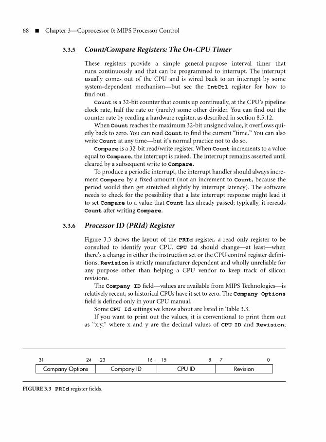
68 Chapter 3—Coprocessor 0: MIPS Processor Control
3.3.5 Count/Compare Registers: The On-CPU Timer
These registers provide a simple general-purpose interval timer thatruns continuously and that can be programmed to interrupt. The interruptusually comes out of the CPU and is wired back to an interrupt by somesystem-dependent mechanism—but see the IntCtl register for how tofind out.
Count is a 32-bit counter that counts up continually, at the CPU’s pipelineclock rate, half the rate or (rarely) some other divider. You can find out thecounter rate by reading a hardware register, as described in section 8.5.12.
When Count reaches the maximum 32-bit unsigned value, it overflows qui-etly back to zero. You can read Count to find the current “time.” You can alsowrite Count at any time—but it’s normal practice not to do so.
Compare is a 32-bit read/write register. When Count increments to a valueequal to Compare, the interrupt is raised. The interrupt remains asserted untilcleared by a subsequent write to Compare.
To produce a periodic interrupt, the interrupt handler should always incre-ment Compare by a fixed amount (not an increment to Count, because theperiod would then get stretched slightly by interrupt latency). The softwareneeds to check for the possibility that a late interrupt response might lead itto set Compare to a value that Count has already passed; typically, it rereadsCount after writing Compare.
3.3.6 Processor ID (PRId) Register
Figure 3.3 shows the layout of the PRId register, a read-only register to beconsulted to identify your CPU. CPU Id should change—at least—whenthere’s a change in either the instruction set or the CPU control register defini-tions. Revision is strictly manufacturer dependent and wholly unreliable forany purpose other than helping a CPU vendor to keep track of siliconrevisions.
The Company ID field—values are available from MIPS Technologies—isrelatively recent, so historical CPUs have it set to zero. The Company Optionsfield is defined only in your CPU manual.
Some CPU Id settings we know about are listed in Table 3.3.If you want to print out the values, it is conventional to print them out
as “x.y,” where x and y are the decimal values of CPU ID and Revision,
31 24 23 16 15 8 7 0
Company Options Company ID CPU ID Revision
FIGURE 3.3 PRId register fields.

3.3 CPU Control Registers and Their Encoding 69
TABLE 3.3 MIPS CPU Implementation Numbers in PRId(Imp)
Id CPU type Id CPU type
1 R2000, R3000 128 MIPS 4KC
2 IDT R305x family 129 MIPS 5KC
3 R6000 130 MIPS 20KC
4 R4000, R4400 131 MIPS 4KMP
5 Early LSI Logic 32-bit CPUs 132 MIPS 4KEc
6 R6000A 133 MIPS 4KEmp
7 IDT R3041 134 MIPS 4KSc
9 R10000 135 MIPS M4K
10 NEC Vr4200 136 MIPS 25Kf
11 NEC Vr4300 137 MIPS 5KE
12 NEC Vr41xx family 144 MIPS 4KEc (MIPS32R2compliant)
16 R8000 145 MIPS 4KEmp (MIPS32R2compliant)
32 R4600 146 MIPS 4KSd
33 IDT R4700 147 MIPS 24K
34 Toshiba R3900 family 149 MIPS 34K
35 R5000 150 MIPS 24KE
40 QED RM5230, RM5260
respectively. Avoid using the contents of this register to establish parameters(like cache size, speed, and so on) or to establish the presence or absenceof particular features; some features have a standard encoding in one of theConfig registers, or you can design code sequences to probe for the existenceof individual features.
3.3.7 Config Registers: CPU Resource Information and Configuration
The MIPS32/64 standard defines four configuration registers for initializationsoftware to use: Config and Config1-3. Most of the register fields are read-only fields, which software interrogates to discover relevant information aboutthe CPU hardware; but (particularly in the original Config register—whichfor historical reasons is not called “Config0”) there are also some writable fields,which select some CPU options that are likely to be made just one way for anysystem.

70 Chapter 3—Coprocessor 0: MIPS Processor Control
31 30 16 15 14 13 12 10 9 7 6 4 3 2 0
M Impl BE AT AR MT 0 VI K0
FIGURE 3.4 Fields in MIPS32/64 Config register.
All MIPS32/64-compliant CPUs have the Config register, as shown inFigure 3.4, with the following fields:
M Continuation bit—reads 1 if there’s at least one more configura-tion register (i.e. Config1) available.
Impl Implementation-dependent configuration flags. Most CPUs willhave some custom fields here, both read-only for informationand writable for system setup. Look at your CPU’s manual.
BE Reads 1 for big-endian, 0 for little-endian.
AT MIPS32 or MIPS64? Encoding:
0 MIPS32
1 MIPS64 instruction set but MIPS32 address map
2 MIPS64 instruction set with full address map
AR Architecture revision level:
0 MIPS32/MIPS64 Release 1
1 MIPS32/MIPS64 Release 2
This book is based on MIPS32/MIPS64 Release 2.
MT MMU type:
0 None
1 MIPS32/64-compliant TLB
2 BAT type
3 MIPS32-standard FMT fixed mapping
The BAT type is for historical compatibility with some old CPUsand is perhaps unlikely to be met with.
VI Set 1 if the L1 I-cache is indexed and tagged with virtual (pro-gram) addresses. A virtual I-cache requires special care by oper-ating systems.
K0 Writable field determining whether the fixed kseg0 region is cach-ed or uncached. And if cached, how exactly does it behave? Thisfield is encoded just like the cache options field of a TLB entry, asseen in EntryLo0-1(C) and described in the notes to Figure 6.3.

3.3 CPU Control Registers and Their Encoding 71
31 30 25 24 22 21 19 18 16 15 13 12 10 9 7 6 5 4 3 2 1 0
L1 I-cache L1 D-cacheIS IL IA DS DL DA
Config1 M MMUSize C2 MD PC WR CA EP FP
31 30 28 27 24 23 20 19 16 15 12 11 8 7 4 3 0
L3 cache L2 cacheTU TS TL TA SU SS SL SA
Config2 M
FIGURE 3.5 Fields in the MIPS32/64 Config1–2 registers.
Figure 3.5 has the following fields:
Config1(M) Continuation bit, 1 if Config2 is implemented.
Config1(MMUSize) The size of the TLB array (the array has MMUSize+1entries).
L1 I-cache, L1 D-cache For each cache, this reports three values:
S Number of cache index positions is 64 × 2S. Multiply byassociativity to get the number of lines in the cache.
L Zero means no cache at all; otherwise, tells you that thecache line size is 2 × 2L bytes.
A Associativity—this cache is (A + 1)-way set-associative.
So if (IS, IL, IA) is (2, 4, 3), the cache has 256 sets/way, 32bytes/line, and is four-way set-associative: That’s a 32-Kbytecache.
Config1(C2) 1 if there’s a coprocessor 2 fitted (that would be likely to besome very application-specific coprocessor).
Config1(MD) 1 if the old MDMX ASE is implemented in the floating-pointunit (see section B.3).
Config1(PC) There is at least one performance counter implemented; seesection 12.4.
Config1(WR) Reads 1 if your CPU has at least one watchpoint register; seesection 12.2.
Config1(CA) Reads 1 when the MIPS16e compressed-code instruction setis available; see section 12.1.
Config1(EP) Reads 1 if an EJTAG debug unit is provided; see section 12.1.
Config1(FP) A floating-point unit is attached.

72 Chapter 3—Coprocessor 0: MIPS Processor Control
Config2(M) Continuation bit, 1 if Config3 is implemented.
Config2(TU) Implementation-specific bits related to L3 cache, iffitted. Might even be writable.
Config2(TS,TL,TA) L3 cache size and shape—encoded just likeConfig1(IS, IL,IA).
Config2(SU) Implementation-specific bits for secondary cache, iffitted. Can be writable.
Config2(SS, SL, SA) Secondary cache size and shape, encoded like Config1(IS, IL,IA), above.
Fields shown in Figure 3.6 include:
Config3(M) Continuation bit, zero if—as is likely—there is no Config4.
LPA Reads 1 when large physical address (LPA) support exists, whichallows for a physical address range larger than 236 bytes. Whenthere is LPA support, there’s an extra CP0 register called Page-Grain, and the layout of the fields in EntryLo0-1 and EntryHichange.
No MIPS32 core (to date) implements LPA, so it’s not describedin this book. Refer to manufacturer’s manuals as required.
DSPP Reads 1 if the MIPS DSP extension is implemented, as describedin section B.2.
VEIC Read-only bit, which indicates the availability of an EIC-comp-atible interrupt controller; see section 5.8.5.
Note that this is not part of the core, so it is typically wired as aninput to the CPU or CPU core by the system designer.
VInt Reads 1 if your CPU can handle vectored interrupts.
SP Reads 1 only if your CPU supports sub-4-Kbyte page sizes. Mostgeneral-purpose MIPS CPUs don’t.
MT Reads 1 if your CPU does multithreading, implementing the MIPSMT extension described in Appendix A.
SM Reads 1 if your CPU handles instructions from the “SmartMIPS”ASE. This extension provides some help to encryption routineson slower CPUs and is mostly aimed at CPUs built for smartcards.
31 30 11 10 98 7 6 5 4 3 2 1 0
Config3 DSPP 0 LPA VEIC VInt SP 0 MT SM TL0M
FIGURE 3.6 Fields in the MIPS32/64 Config3 registers.

3.3 CPU Control Registers and Their Encoding 73
TL Reads 1 if your core can record and output instruction traces.Instruction tracing is an advanced optional feature of the EJTAGdebug unit, described in section 12.1.
3.3.8 EBase and IntCtl: Interrupt and Exception Setup
These registers (new in Release 2 of MIPS32/64) give you control over the newinterrupt capabilities added there.
EBase was added to allow you to relocate all the exception entry points fora CPU; it’s primarily there for multiprocessor systems that share memory, sothat different CPUs are not obliged to use the same exception handlers.
The fields of EBase are shown in Figure 3.7:
1, 0 Read-only bits prefixed to the base address bits to make sure theexception vector ends up in the kseg0 region, conventionally usedfor OS code.
ExceptionBase Is the base address for the exception vectors, adjustable to aresolution of 4 Kbytes. See Table 5.1 for where that leaves all theexception entry points.
That means any of your CPUs (even the “virtual” CPUs of a mul-tithreaded CPU) can have its own unique exception handlers.
CPUNum A number to distinguish this CPU from others in the same multi-processor system. The contents of this field are most likely hard-wired by the designer of your system.
Then in IntCtl, shown in Figure 3.8:
IPTI, IPPCI Are read-only fields, telling you how timer and performancecounter interrupts (generated inside the CPU) are wired up inyour system. It’s relevant in nonvectored and simple-vectored(VI) interrupt modes.
Each is a 3-bit binary number identifying which CPU interruptinput is shared by the internal timer interrupt (IPTI) or the per-formance counter overflow interrupt (IPPCI).
The interrupt is specified by giving the number of the Cause(IPx) bit where the resulting interrupt is seen. Because Cause
1 0 ExceptionBase 0 CPUNum31 30 29 12 11 10 9 0
FIGURE 3.7 Layout of the EBase register.

74 Chapter 3—Coprocessor 0: MIPS Processor Control
31 29 28 26 25 10 9 5 4 0
IPTI IPPCI 0 VS 0
FIGURE 3.8 Layout of the IntCtl register.
31 30 29 26 25 22 21 18 17 16 15 12 11 10 9 6 5 4 3 0
0 HSS 0 E ICSS 0 ESS 0 PSS 0 CSS
FIGURE 3.9 Layout of the SRSCtl register.
(IP0-1) are software interrupt bits, unconnected to any input,the legal values for IntCtl(IPTI) and IntCtl(IPPCI) arebetween 2 and 7.
The timer and performance counter interrupts are taken out tothe CPU interface, where they are generally sent back again downone of the interrupt signals. So this information is not determinedinside the CPU itself and is provided by the system designer.
VS Is writable to give you software control of the vector spacing; thespacing you get between consecutive entries is IntCtl(VS)× 32bytes. Only values of 1, 2, 4, 8, and 16 work (to give spacings of32, 64, 128, 256, and 512 bytes, respectively). A value of zero doesgive a zero spacing, so all interrupts arrive at the same address.
3.3.9 SRSCtl and SRSMap: Shadow Register Setup
Shadow registers are a new feature in Release 2 of MIPS32/64. CPUs areequipped with one or more extra sets of general-purpose registers and switchto a different set on an exception—and in particular, on an interrupt.
In SRSCtl:, shown in Figure 3.9:
HSS The highest-numbered register set available on this VPE/CPU(i.e., the number of available register sets minus one).
On multithreading CPUs this field may be changed by softwarethat assigns shadow register sets. But for most purposes, this fieldis read-only.
CSS The register set currently in use. It’s read-only here; set on anyexception, replaced by the value in SRSCtl(PSS) on an eret.
ESS This writable field is the software-selected register set to be usedfor “all other” exceptions; that’s other than an interrupt in VI or

3.4 CP0 Hazards—A Trap for the Unwary 75
EIC mode (both have their own special ways of selecting a registerset). It’s probably quite unusual for it to be anything other thanzero.
PSS The “previous” register set, which will be used following the nexteret.
You can get at the values of registers in this set using rdpgpr andwrpgpr.
SRSCtl(PSS) is writable, allowing the OS to dispatch code in anew register set; load this value and then execute an eret.
EICSS In EIC mode (see section 5.8.5), an external interrupt controllerproposes a shadow register set number with each requested inter-rupt (nonzero IPL). When the CPU takes an interrupt, the exter-nally supplied set number determines the next set and is madevisible here, until the next interrupt.
Just a note: SRSCtl(PSS) and SRSCtl(CSS) are not updated by all excep-tions, but only those which write a new return address to EPC (or equivalently,those occasions where the exception level bit SR(EXL) goes from zero to one).Exceptions where EPC is not written include:
Exceptions occurring with SR(EXL) already set
Cache error exceptions, where the return address is loaded intoErrorEPC
EJTAG debug exceptions, where the return address is loaded into DEPC
3.3.10 Load-Linked Address (LLAddr) Register
This register holds the physical address of the last-run load-linked operation,which is kept to monitor accesses that may cause a future store conditional tofail; see section 5.8.4. Software access to LLAddr is for diagnostic use only.
3.4 CP0 Hazards—A Trap for the Unwary
Since the CPU is pipelined, the effects of CP0 operations may not reach theirtarget until after the later stages of the CP0 instruction—and even then may takesome number of clocks to filter out to the hardware. But even before our CP0instruction reaches its later stages, other instructions will have been fetched andstarted. How can we be sure that those instructions will be executed in the lightof our CP0 change?

76 Chapter 3—Coprocessor 0: MIPS Processor Control
It would in theory be possible for the hardware engineers to find andinterlock every possible interaction, producing a CPU where the software engi-neer had nothing to worry about on this score. SGI’s R10000 approaches thisideal.
But CP0 operations are obscure, many happen rarely, and all are under thecontrol of OS software, which must already be trusted. So it has seemed rea-sonable to MIPS architects and designers to push some of this trouble onto theshoulders of the software authors.
Historically, they were supposed to do this by analyzing the flow of theirprogram, detect places where the software might malfunction, and apply fixes.The weapons at hand were nop instructions, which safely do nothing whilechanges propagate, and branch/jump instructions, which “invalidate” sequen-tially prefetched instructions, forcing them to be refetched and re-executed.If you look at the back of a manual of a MIPS CPU that doesn’t conform tothe 2003 (second) revision of MIPS32/64, you will usually find a table of CP0hazards, detailing how many clocks various changes take to propagate beforeyou can guarantee they will be seen as done by subsequent instructions.
Even with early CPUs with simple pipelines, this was a bit of a challenge. Asthe pipelines grew longer and more complicated, it became a real nuisance forportable software. Once there were CPUs that executed instructions in parallel(simple dual-issue or even out-of-order), it became difficult to count how manynops were required. For a while, we even got the ssnop (“superscalar no-op”)instruction, guaranteed to burn a whole clock time by issuing alone.
But MIPS32/64 CPUs now have a more sensible approach: hazard barrierinstructions. These are special instructions, which need only be placed whereneeded, where they have the effect of delaying subsequent instructions until allthe side effects of preceding CP0 instructions have propagated.
MIPS32/64 distinguishes two flavors of CP0 hazard, depending on whichstage of a dependent instruction’s operation may be affected. Execution hazardsare those where the dependent instruction will not be affected until it reads aCP0 register value; instruction hazards are those where the dependent instruc-tion is affected in its very earliest stages—at worst, at the time it is fetched fromcache or memory.
Another interesting distinction is between hazards that strictly affect onlyother CP0 instructions (which must be part of the OS) and those (we might callthem user hazards) that can affect ordinary instructions.
3.4.1 Hazard Barrier Instructions
Before we get started, note that any exception clears all hazards (so nothing cango wrong because of something incomplete at the start of an exception handler),and so does an eret—so nothing done by the OS can cause trouble back in theuser program.
There are three explicit hazard barrier instructions. You can clear executionhazards with ehb—which older CPUs will see as a no-op. Instruction hazards

3.4 CP0 Hazards—A Trap for the Unwary 77
are cleared by special jump-register instructions jr.hb and jalr.hb, whichare most often substituted for a normal subroutine return or subroutine call,respectively.
MIPS architects were being smart when they chose special jump-registerinstructions, which will just be decoded as jr or jalr on older CPUs. On thoseCPUs such instructions clear the CPU pipeline (the jump-to-register is inher-ently “unpredictable”), and in most cases will provide the necessary delay onCPUs that don’t comply with later MIPS32/64 specifications.
3.4.2 Instruction Hazards and User Hazards
These typically happen when we make a change to CP0 state (a register, a TLBentry, or perhaps a cache line) that will affect the way we fetch ordinary instruc-tions (or, in a few cases, will affect the way load/store instructions access mem-ory). Such hazards must be safely resolved before we return to any kind of“uncontrolled” code.
In these cases you should put the hazard barrier after the CP0 operation thatchanged the state. Most often you should put it immediately afterwards—butyou might have some other work to do that you know is safe and can run whilethe hazardous operation’s effects percolate out. But that’s on your own head!
These sort of hazards include:
Change of TLB entry => fetch, load, or store in affectedpage
Change of EntryHi (ASIDfield)
=> any non-globally-mapped fetch,load, or store
Change to ERL mode => fetch, load, or store from kuseg
cache instruction alteringcache line
=> fetch, load, or store in affectedline
Change to watchpoint register => fetch, load, or store that matches
Change of shadow registersetting
=> any use of GPR (an executionhazard)
CP0 register change thatdisables interrupt
=> instruction that could still beinterrupted (an executionhazard)
Most of these are instruction hazards—and where there’s no eret to act asan adequate barrier for these instructions, you should use a jr.hb or jalr.hb.The execution hazards can be cleared with an ehb.
3.4.3 Hazards between CP0 Instructions
Any mfc0 instruction is explicitly dependent on the value in a CP0 register, butbecause all TLB information is staged through registers, so are tlbwi, tlbwr,

78 Chapter 3—Coprocessor 0: MIPS Processor Control
and tlbr. Similarly, those cache instructions that read data out of CP0registers are dependent.
Less obviously, tlbp depends on EntryHi because of its ASID field.All these are execution hazards and can be made safe with an ehb, placed
before the consuming CP0 instruction. If you have the chance to put it a fewinstructions early in the sequence, so much the better (some CPUs may inhibitall CP0 operations for a few clocks after an ehb).

Chapter
4 How Caches Workon MIPS Processors
AMIPS CPU without a cache isn’t really a RISC. Perhaps that’s not fair; forspecial purposes you might be able to build a MIPS CPU with a small,
tightly coupled memory that can be accessed in a fixed number of pipelinestages (preferably one). But MIPS CPUs have always had cache hardware builttightly into the pipeline.
This chapter will describe the way MIPS caches work and what the soft-ware has to do to make caches useful and reliable. From reset, almost every-thing about the cache state is undefined, so bootstrap software must be carefulto initialize the caches correctly before relying on them. You might also ben-efit from some hints and tips for use when sizing the caches (it would be badsoftware practice to assume you know how big the cache is). For the diagnosticsprogrammer, we discuss how to test the cache memory and probe for particularentries.
Some real-time applications writers may want to control exactly what willget cached at run time. We discuss how to do that, even though I am skepticalabout the wisdom of using such tricks.
There’s also some evolution to contend with. In early 32-bit MIPS proces-sors, cache management functions relied upon putting the cache into a specialstate and then using ordinary reads and writes whose side effects could initial-ize or invalidate cache locations. But we won’t dwell on that here; even CPUsthat do not fully comply with MIPS32/64 generally use something close to themechanism described in the following text.
4.1 Caches and Cache Management
The cache’s job is to keep a copy of memory data that has been recently read orwritten, so it can be returned to the CPU quickly. For L1 caches, the read mustcomplete in a fixed period of time to keep the pipeline running.
79

80 Chapter 4—How Caches Work on MIPS Processors
MIPS CPUs always have separate L1 caches for instructions and data(I-cache and D-cache, respectively) so that an instruction can be read and aload or store done simultaneously.
Cached CPUs in old-established families (such as the x86) have to be com-patible with code that was written for CPUs that didn’t have any caches. Mod-ern x86 chips contain ingeniously designed hardware to make sure that softwaredoesn’t have to know about the caches at all (if you’re building a machine to runMS-DOS, this is essential to provide backward compatibility).
But because MIPS machines have always had caches, there’s no absoluterequirement for the cache to be so clever. The caches must be transparent toapplication software, apart from the increased speed. But in a MIPS CPU, whichhas always had cache hardware, there is no attempt to make the caches invisibleto system software or device drivers—cache hardware is installed to make theCPU go fast, not to help the system programmer. A UNIX-like operating systemhides the cache from applications, of course, but while a more lightweight OSmight hide the details of cache manipulation from you, you will still probablyhave to know when to invoke the appropriate subroutine.
4.2 How Caches Work
Conceptually, a cache is an associative memory, a chunk of storage where datais deposited and can be found again using an arbitrary data pattern as a key. Ina cache, the key is the full memory address. Produce the same key back to anassociative memory and you’ll get the same data back again. A real associativememory will accept a new item using an arbitrary key, at least until it’s full;however, since a presented key has to be compared with every stored key simul-taneously, a genuine associative memory of any size is either hopelessly resourcehungry, slow, or both.
So how can we make a useful cache that is fast and efficient? Figure 4.1 showsthe basic layout of the simplest kind of cache, the direct-mapped cache used inmost MIPS CPUs up to the 1992 generation.
The direct-mapped arrangement uses a simple chunk of high-speed mem-ory (the cache store) indexed by enough low address bits to span its size. Eachline inside the cache store contains one or more words of data and a cache tagfield, which records the memory address where this data belongs.
On a read, the cache line is accessed, and the tag field is compared with thehigher addresses of the memory address; if the tag matches, we know we’ve gotthe right data and have “hit” in the cache. Where there’s more than one word inthe line, the appropriate word will be selected based on the very lowest addressbits.
If the tag doesn’t match, we’ve missed and the data will be read from mem-ory and copied into the cache. The data that was previously held in the cacheis simply discarded and will need to be fetched from memory again if the CPUreferences it.

4.2 How Caches Work 81
Match?
higher lower
byte–within–lineaddressMemory address
TagIndex
Yes
hit data to use
cache miss,refill frommemory
No
Data
Selector
FIGURE 4.1 Direct-mapped cache.
A direct-mapped cache like this one has the property that, for any givenmemory address, there is only one line in the cache store where that data canbe kept.1 That might be good or bad; it’s good because such a simple structurewill be fast and will allow us to run the whole CPU faster. But simplicity has itsbad side too: If your program makes repeated reference to two data items thathappen to share the same cache location (presumably because the low bits oftheir addresses happen to be close together), then the two data items will keeppushing each other out of the cache and efficiency will fall drastically.
A real associative memory wouldn’t suffer from this kind of thrashing, butit is too slow and expensive.
A common compromise is to use a two-way set-associative cache—which isreally just a matter of running two direct-mapped caches in parallel and lookingup memory locations in both of them, as shown in Figure 4.2.
1. In a fully associative memory, data associated with any given memory address (key) can bestored anywhere; a direct-mapped cache is as far from being content addressable as a cachestore can be.

82 Chapter 4—How Caches Work on MIPS Processors
Cache memory A
Tagstore
Cache memory B
Cache data store
Tagstore Cache data store
Match?
Match?
Select A
Select B
Low bitsHigher bits
A-line data
B-line data
FIGURE 4.2 Two-way set-associative cache.
Now we’ve got two chances of getting a hit on any address. Four-way set-associative caches (where there are effectively four direct-mapped subcaches)are also common in on-chip caches.
In a multiway cache there’s more than one choice of the cache location tobe used in fixing up a cache miss, and thus more than one acceptable choiceof the cache line to be discarded. The ideal solution is probably to keep trackof accesses to cache lines and pick the “least recently used” (“LRU”) line to bereplaced, but maintaining strict LRU order means updating LRU bits in everycache line every time the cache is read. Moreover, keeping strict LRU informa-tion in a more-than-four-way set-associative cache becomes impractical. Realcaches often use compromise algorithms like “least recently filled” to pick theline to discard.
There are penalties, however. Compared with a direct-mapped cache, aset-associative cache requires many more bus connections between the cachememory and controller. That means that caches too big to integrate onto asingle chip are much easier to build direct mapped. More subtly, because thedirect-mapped cache has only one possible candidate for the data you need, it’spossible to keep the CPU running ahead of the tag check (so long as the CPUdoes not do anything irrevocable based on the data). Simplicity and runningahead can translate to a faster clock rate.

4.4 Write-Back Caches in MIPS CPUs 83
Once the cache has been running for awhile it will be full, so capturing newmemory data usually means discarding some previously cached data. If youknow that the data in the cache is already safely in memory, you can just discardthe cached copy; if the data in the cache is more up-to-date than memory, youneed to write it back first.
That brings us to how the cache handles writes.
4.3 Write-Through Caches in Early MIPS CPUs
CPUs don’t just read data (as the above discussion seems to be assuming)—they write it too. Since a cache is intended to be a local copy of some data frommain memory, one obvious way of handling the CPU’s writes is the use of whatis called a write-through cache.
In a write-through cache, the CPU’s data is always written to main memory;if a copy of that memory location is resident in the cache, the cached copy isupdated too. If we always do this, then any data in the cache is known to be inmemory too, so we can discard the contents of a cache line anytime withoutlosing any data.
We would slow the processor down drastically if we waited for the mem-ory write-through to complete, but we can fix that. Writes (address and datatogether) destined for main memory can always be kept in a queue while thememory controller gets itself ready and completes the write. The place wherewrites are queued is organized as a first-in, first-out (FIFO) store and is calleda write buffer.
Early MIPS CPUs had a direct-mapped write-through cache and a writebuffer. So long as the memory system can happily absorb writes at the averagerate produced by a CPU, running a particular program this way works very well.
But CPU speeds have grown much faster than memory speeds, and some-where around the time that the 32-bit MIPS generation was giving way to the64-bit R4000, MIPS speeds passed the point where a memory system couldreasonably hope to absorb every write.2
4.4 Write-Back Caches in MIPS CPUs
While early MIPS CPUs use simple write-through data caches, later CPUs aretoo fast for this approach—they would swamp their memory systems with writesand slow to a (relative) crawl.
2. A very rough rule of thumb for programs is that there is one store per 10 instructions, so a write-through solution may work until the memory cycle time reaches about 5–7 instruction times.With DRAM cycle times then around 180 ns, the simple solution ran out of steam at about30–40 MHz.

84 Chapter 4—How Caches Work on MIPS Processors
The solution is to retain write data in the cache. Write data is stored only tothe cache, and the cache line is marked to make sure we don’t forget to write itback to memory sometime later (a line that needs writing back is called dirty ormodified).3
There’s a subvariant here: If the addressed data is not currently in the cache,we can either write it to main memory and ignore the cache, or we can bringthe data in specially just so we can write it—this is called write-allocate. Write-allocate is not always the best approach: Data that is being written for some I/Odevice to read (and that the CPU will not read or write again) is ideally kept outof the cache. But that only works if the programmers can be relied upon to tellthe operating system.
All except the very lowest-end modern MIPS CPUs have on-chip caches thatare write-back and have line sizes of 16 or 32 bytes.
The R4000 and some later CPUs found uses in large computer servers fromSilicon Graphics and others. Their cache design choices are influenced by theneeds of multiprocessor systems. There’s a short description of typical multi-processor systems in section 15.3.
4.5 Other Choices in Cache Design
The 1980s and 1990s have seen much work and exploration of how to buildcaches. So there are yet more choices:
Physically addressed/virtually addressed: While the CPU is running agrown-up OS, data and instruction addresses in your program (theprogram address or virtual address) are translated before appearing asphysical addresses in the system memory.
A cache that works purely on physical addresses is easier to manage (we’llexplain why below), but raw program (virtual) addresses are available tostart the cache lookup earlier, letting the system run that little bit faster.
So what’s wrong with program addresses? They’re not unique; manydifferent programs running in different address spaces on a CPU mayshare the same program address for different data. We could reinitializethe entire cache every time we switch contexts between different addressspaces; that used to be done some years ago and may be a reasonable solu-tion for very small caches. But for big caches it’s ridiculously inefficient,
3. You might ask: Since we’re going to have to write it back sometime, surely we might as well do itnow? But actually programs often write many times in quick succession to the same small patchof memory, and the write-back cache allows many individual write operations to be combinedinto just one write to memory.

4.6 Managing Caches 85
and we’ll need to include a field identifying the address space in the cachetag to make sure we don’t mix them up.
Many MIPS CPUs use the program (virtual) address to provide a fastindex for their L1 caches. But rather than using the program addressplus an address space identifier to tag the cache line, they use thephysical address. The physical address is unique to the cache line andis efficient because the scheme allows the CPU to translate programaddresses to physical addresses at the same time as it is looking upthe cache.
There’s another, more subtle problem with program addresses, whichthe physical tag does not solve: The same physical location may bedescribed by different addresses in different tasks. In turn, that mightlead to the same memory location being cached in two different cacheentries (because they were referred to by different virtual addressesthat selected different cache indexes). Many MIPS CPUs do not havehardware to detect or avoid these cache aliases and leave them asa problem to be worked around by the OS’s memory manager; seesection 4.12 for details.
Choice of line size: The line size is the number of words of data storedwith each tag. Early MIPS caches had one word per tag, but it’s usuallyadvantageous to store multiple words per tag, particularly when yourmemory system will support fast burst reads (most do). Modern MIPScaches tend to use four- or eight-word line sizes, but large L2 and L3caches may have bigger lines.
When a cache miss occurs, the whole line must be filled from memory.
Split/unified: MIPS L1 caches are always separated into an I- and aD-cache; the selection is done purely by function, in that instructionfetches look in the I-cache and data loads/stores in the D-cache. (Thismeans, by the way, that if you try to execute code that the CPU justcopied into memory, you must both write back those instructions outof the D-cache and invalidate the I-cache locations, to make sure youreally execute the new instructions.)
However, L2 caches are rarely divided up this way—it’s complex, morecostly, and generally performs poorly.
4.6 Managing Caches
I hope you recall from section 2.8 that a MIPS CPU has two fixed 512-MB win-dows onto physical memory, one cached (“kseg0”) and one uncached (“kseg1”).Typically, OS code runs in kseg0 and uses kseg1 to build uncached references.

86 Chapter 4—How Caches Work on MIPS Processors
Physical addresses higher than 512 MB are not accessible here: A 64-bit CPU willhave direct access through another window, or you can set up the TLB (memorymanagement/translation hardware) to map an address. Each TLB entry can bemarked to make accesses either cached or uncached.
The cache hardware, with the help of system software, must be able to ensurethat any application gets the same data as it would have in an uncached systemand that any direct memory access (DMA) I/O controller (getting data directlyfrom memory) obtains the data that the program thinks it has written.
We’ve said before that in PCs and some other integrated systems the assis-tance of system software is often not required; it’s worth spending the money,silicon area, and extra cycles to get the hardware to make the cache genuinelytransparent. Such a hardware-managed cache is said to be coherent.
The contents of the cache arrays of your CPU are typically random followingpower-up. Bootstrap software is responsible for initializing the caches; this canbe quite an intricate process, and there’s some advice about it below. But oncethe system is up and running, there are only three circumstances in which theCPU must intervene:
Before DMA out of memory: If a device is taking data out of memory,it’s vital that it gets the right data. If the data cache is write back and aprogram has recently written some data, some of the correct data maystill be held in the D-cache but not yet be written back to main memory.The CPU can’t see this problem, of course; if it looks at the memorylocations it will get the correct data back from its cache.
So before the DMA device starts reading data from memory, any datafor that range of locations that is currently held in the D-cache must bewritten back to memory if necessary.
DMA into memory: If a device is loading data into memory, it’s importantto invalidate any cache entries purporting to hold copies of the mem-ory locations concerned; otherwise, the CPU reading these locations willobtain stale cached data. The cache entries must be invalidated before theCPU uses any data from the DMA input stream, but it’s quite commonto invalidate them before starting the DMA.
Writing instructions: When the CPU itself is storing instructions intomemory for subsequent execution, you must first ensure that the instruc-tions are written back to memory and then make sure that the corre-sponding I-cache locations are invalidated; the MIPS CPU has noconnection between the D-cache and the I-cache.
In the most modern MIPS CPUs the synci instruction does everythingthat is necessary to make the instructions you’ve just stored usable forexecution—and it’s a user-privilege instruction.

4.6 Managing Caches 87
Why Not Manage Caches in Hardware?
Caches managed with hardware are described as“coherent” (or, more informally, “snoopy.”) Whenanother CPU or some DMA device accesses mem-ory, the cache control logic is notified. With a CPUattached to a shared bus, this is pretty straightfor-ward; the address bus contains most of the infor-mation you need. The cache control logic watches(snoops) the address bus even when the CPU is notusing it and picks out relevant cycles. It does that bylooking up its own cache to see whether it holds acopy of the location being accessed.If someone is writing data that is inside the cache,the controller could pick up the data and update thecache line but is more likely to just invalidate its own,nowstale, copy. If someone is readingdata forwhichupdated information is held in the cache, the con-troller may be able to intervene on the bus, tellingthe memory controller that it has a more up-to-dateversion.One major problem with doing this is that it worksonly within a system designed to operate that way.Not all systems have a single bus where all trans-actions appear, and bought-in I/O controllers areunlikely to conform to the right protocols.Also, that’s a lot of snooping going on. Most of thelocations that CPUs work with are the CPU’s privateareas; they will never be read or written by any otherCPU or device. We’d like not to build hardware inge-nuity into the cache, loading every cache locationandbuscyclewithcomplexity thatwillonlysometimes
be used. It’s easy to suppose that a hardware cachecontrol mechanism must be faster than software, butthat’s not necessarily so. A snoopy cache controllermust look at the cache tags on every external cycle,which could shut the CPU out of its cache and slowit down; snoopy cache controllers usually fix this bykeeping two copies of the cache tags (a private-to-CPU and public version). Software management canoperate on blocks of cache locations in a single fastloop;hardwaremanagementwill interleave invalida-tions or write-backs with CPU accesses at I/O speed,and that usually implies more arbitration overhead.Historically, MIPS designers took the radical RISCposition: MIPS CPUs either had no cache manage-ment hardware or, where designed for multiproces-sors, they had everything.From a 21st-century perspective, the trade-off looksdifferent. Formost classesofCPU, it looksmoreworth-while to accept some hardware complexity to avoidthe system software bugs that occur when program-mers miss a place where the cache needs atten-tion. At the time of writing (2006), there’s a shiftin progress toward implementing “invisible” cacheswith some level of hardware cache managementon all but the smallest MIPS CPUs. If your MIPSCPU is fully coherent, you may not need this chap-ter at all (but very few do the whole job). Andmany MIPS cores that will be in production foryears to come still don’t have coherent cache con-trollers, so the shift will take a long time to complete.
If your software is going to fix these problems, it needs to be able to do twodistinct operations on a cache entry.
The first operation is called write-back. When the data of interest is presentin the cache and is dirty (marked as having been written by the CPU since it waslast obtained from memory or written back to memory), then the CPU copiesthe data from the cache into main memory.
The second is invalidate. When the data of interest is in the cache, the CPUmarks it invalid so that any subsequent access will fetch fresh data frommemory.

88 Chapter 4—How Caches Work on MIPS Processors
It’s tempting to use the more colorful and evocative word “flush” in thiscontext, but it is ambiguously used to mean write-back, invalidate, or the com-bination of the two—so we’ll avoid it.
There are some much more complicated issues involved when two or moreprocessors share memory. Most shared-memory systems are too complex forone CPU to know which locations the other will read or write, so the softwarecan’t figure out exactly which memory regions need to be invalidated or writtenback. Either any shared memory must always be accessed uncached (very slowunless the amount of interaction is very limited), or the caches must have spe-cial hardware that keeps the caches (and memory) coherent. Multi-CPU cachecoherency got less scary after it was systematized by a group of engineers work-ing on the ambitious FutureBus standard in the mid-1980s. There’s a discussionof multiprocessor mechanisms in section 15.3.
4.7 L2 and L3 Caches
In larger systems, there’s often a nested hierarchy of caches. A small andfast L1 or primary cache is close to the CPU. Accesses that miss in theL1 cache are looked up not directly in memory but in an L2 or secondarycache—typically several times bigger and several times slower than the L1(but still several times faster than the main memory). The number of levelsof hierarchy that might be useful depends on how slow main memory iscompared with the CPU’s fastest access; with CPU cycle times falling muchfaster than memory access times, 2006 desktop systems commonly have L3cache. 2006 embedded systems, trailing desktop speeds by several years (anddifferent constraints, particularly for power consumption and heat dissipa-tion) are only just getting around to using L2 caches outside a few specialisthigh-end applications.
4.8 Cache Configurations for MIPS CPUs
We can now classify some landmark MIPS CPUs, ancient and modern, bytheir cache implementations and see how the cache hierarchy has evolved(Table 4.1).
As clock speeds get higher, we see more variety in cache configurations asdesigners try to cope with a CPU that is running increasingly ahead of its mem-ory system. To earn its keep, a cache must improve performance by supplyingdata significantly faster than the next outer memory and must usually succeedin supplying the data (hitting).
CPUs that add a second level of cache reduce the miss penalty for the L1cache—which may then be able to be smaller or simpler. CPUs with on-chip

4.8 Cache Configurations for MIPS CPUs 89
TABLE 4.1 Cache Evolution in MIPS CPUs
L1 L2 L3
CPU Size Direct/ On- Direct/ On- Direct/ On-(MHz) I-cache D-cache n-way chip? Size n-way chip? Size n-way chip?
R3000-33 32 K 32 K Direct Off
R3052-33 8 K 2 K Direct On
R4000-100 8 K 8 K Direct On 1 M Direct Off
R10000-250 32 K 32 K Two-way On 4 M Two-way Off
R5000-200 32 K 32 K Two-way On 1 M Direct Off
RM7000-250 16 K 16 K Four-way On 256 K Four-way On 8 M Direct Off
L2 caches typically have smaller L1s, with dual 16-KB L1 caches a favored “sweetspot.” Until recently, most MIPS CPUs fitted the L1 cache access into one clockcycle. It seems reasonable that, as chip performance grows and clock ratesincrease, the size of memory that can be accessed in one clock period shouldbe more or less constant. But in fact, on-chip memory speed is lagging behindlogic. Modern CPU designs often lengthen the pipeline mainly to allow for atwo-clock cache access.4
Off-chip caches are often direct mapped because a set-associative cacheneeds much wider interfaces to carry multiple tags, so they can be matchedin parallel.
Amidst all this evolution, there have been two main generations of the soft-ware interface to a MIPS cache. There is one style founded by the R3000 andfollowed by most early 32-bit MIPS CPUs; there is another starting with theR4000 and used by all 64-bit CPUs to date. The R4000 style has now become apart of the MIPS32 standard too and is now commonplace—and that’s all wewill describe.
Most modern MIPS CPUs have L1 caches that are write-back, virtuallyindexed, physically tagged, and two- or four-way set-associative. Cache man-agement is done using a special cache instruction.
The first R4000 CPUs had on-chip L2 cache control, and QED’s RM7000(around 1998) introduced on-chip L2 cache, which is now commonplace inhigh-end designs. The cache instruction as defined by MIPS32/64 extends toL2 and L3 caches.
4. This is not a recent invention. Early systems built with the RISC HP-8x00 CPU family accepteda 2-clock-cycle L1 cache latency in return for a huge external L1 cache, and performed very well.

90 Chapter 4—How Caches Work on MIPS Processors
CAUTION! Some system implementations have L2 caches that are not controlled byhardware inside the MIPS CPU but built onto the memory bus. The soft-ware interface to caches like that is going to be system specific and maybe quite different from the CPU-implemented or CPU-controlled cachesdescribed in this chapter.
4.9 Programming MIPS32/64 Caches
The MIPS32/64 specifications define a tidy way of managing caches (followingthe lead of the R4000, which fixed the unseemly cache maintenance of theearlier CPUs).
MIPS32/64 CPUs often have much more sophisticated caches than earlyMIPS CPUs—write-back, and with longer lines. Because it’s a write-back cache,each line needs a status bit that marks it as dirty when it gets written by theCPU (and hence becomes different from the main memory copy of the data).To manage the caches, there are a number of primitive operations we’d reallylike. The actions we need to achieve are:
Invalidate range of locations: Removes any data from this address rangefrom the cache, so that the next reference to it will acquire fresh datafrom memory.
The instruction cache HitInvalidate has the form of a load/storeinstruction, providing a virtual address. It invalidates any single cacheline containing the data referenced by that virtual address. Repeat theinstruction at line-size-separated addresses across the range.
Write-back range of locations: Ensures that any CPU-written data inthis range currently held in dirty cache lines is sent back to mainmemory.
The instruction cache HitWritebackInvalidate writes back anysingle cache line containing the data referenced by that virtual address,and then makes it invalid as a bonus.
Invalidate entire cache: Discards all cached data. This is rarely requiredexcept at initialization, but is sometimes the last resort of operating sys-tem code that is not sure which cached data needs to beinvalidated.
The instruction cache IndexInvalidate is used here. Its addressargument is interpreted only as an index into the memory array underly-ing the cache—successive lines are accessed at index values from 0upward, in cache-line-size increments.

4.9 Programming MIPS32/64 Caches 91
Initialize caches: Whatever is required to get the caches usable from anunknown state. Setting up the cache control fields (the “tag”) usuallyinvolves zeroing the CP0 TagLo register and using a cache Index-StoreTag operation on each line-sized chunk of the cache. Caches withdata check bits may also need to be prefilled with data—even thoughthe lines are invalid, they should not have bad check bits. Prefillingan I-cache would be tricky, but you can usually use a cache Fillinstruction.
4.9.1 The Cache Instruction
The cache instruction has the general form of a MIPS load or store instruc-tion (with the usual register plus 16-bit signed displacement address)—butwhere the data register would have been encoded there’s a 5-bit operationfield, which must encode the cache to be operated on, determine how tofind the line, and figure out what to do with the line when you find it.You write a cache line in assembly as cache OP,addr, where OP is justa numeric value for the operation field.
The best thing to do is to use the C preprocessor to define text “names”representing the numeric values for the operations. There are no standardnames; I’ve arbitrarily used the names of C preprocessor definitions found inheader files from the MIPS Technologies toolkit package.
Of the 5-bit field, the upper 2 bits select which cache to work on:
0 = L1 I-cache1 = L1 D-cache2 = L3 cache, if fitted3 = L2 cache, if fitted
Before we list the individual commands, note that they come in three fla-vors, which differ in how they select the cache entry (the “cache line”) they willwork on:
Hit-type cache operation: Presents an address (just like a load/store),which is looked up in the cache. If this location is in the cache (if it“hits”), the cache operation is carried out on the enclosing line. If thislocation is not in the cache, nothing happens.
Address-type cache operation: Presents an address of some memory data,which is processed just like a cached access. That is, if the line youaddressed was not previously in cache, the data is fetched from memorybefore the cache operation.
Index-type cache operation: Uses as many low bits of the virtual addressas are needed to select the byte within the cache line, then the cache

92 Chapter 4—How Caches Work on MIPS Processors
line address inside one of the cache ways, and then the way.5 You haveto know the size of your cache (discoverable from Config1-2, seesection 3.3.7 for details) to know exactly where the field boundariesare, but your address is used something like this:
31 5 4 0
Unused Way1-0 Index byte-within-line
Once you’ve picked your cache and cache line, you have a choice of opera-tions you can perform on it, as shown in Table 4.2. Three operations must besupported by a CPU to claim MIPS32/64 compatibility: that’s index invalidate,index store tag, and hit write-back invalidate. Other operations are optional—ifyou use them, check your CPU manual carefully.
The synci instruction (new to the MIPS32 Release 2 update) provides aclean mechanism for ensuring that instructions you’ve just written are correctlypresented for execution (it combines a D-cache write-back with anI-cache invalidate). If your CPU supports it, you should use synci in prefer-ence to the traditional alternative (a pair of cache instructions, to do D-cachewrite-back followed by an I-cache invalidate).
4.9.2 Cache Initialization and Tag/Data Registers
For diagnostic and maintenance purposes it’s good to be able to read and writethe cache tags; MIPS32/64 defines a pair of 32-bit registers TagLo and TagHi6
to stage data between the tag part of the cache and management software. TagHiis often not necessary: Until your physical address space is more than 36 bits,there is usually room for the whole tag in TagLo.
The fields in the two registers reflect the tag field in the cache and are CPUdependent. Only one thing is guaranteed: An all-zero value in the tag register(s)corresponds to a legal, properly formed tag for a line that contains no valid data.The CPU implements a cache IndexStoreTag instruction, which copies thecontents of the tag registers into the cache line. So by setting the registers to zero,and storing the tag value, you can start to initialize a cache from an unknownstarting state.
There are “store data” and “load data” cache operations defined byMIPS32/64, but they are optional and should only be used by code that isalready known to be CPU-specific. You can always access the data by “hitting”on it.
5. Some still-in-use MIPS CPUs use the least significant address bits to select the “way.”Those CPUs may need special initialization. I am not aware of any MIPS32/64-compliantCPUs that do this: but it’s another thing to be careful about.
6. Some CPU manuals use different registers to talk to the I- and D-caches, and then call themITagLo, and so on.

4.9 Programming MIPS32/64 Caches 93
TABLE 4.2 Operations on a Cache Line Available with the Cache Instruction
Value Command What it does
0 Index invalidate Sets the line to “invalid.” If it’s a D-cache line that is valid anddirty (has been written by CPU since fetched from memory),then write the contents back to memory first.This is the best and simplest way to invalidate an I-cache wheninitializing the CPU—though if your cache is parity protected,you also need to fill it with good-parity data; see Fill below.And this is not suitable for D-caches, where it might causerandom write-backs: see IndexStoreTag type below.All MIPS32/64 CPUs must provide this operation.
1 Index Load Tag Read the cache line tag bits and addressed doubleword datainto TagLo/TagHi, DataLo/DataHi.This command is obscure, for diagnostics and geeks only.
2 Index Store Tag Set the cache tag from the TagLo/TagHi registers.To initialize a D-cache from an unknown state, set theTagLo/TagHi registers to zero and then do this to each line.All MIPS32/64 CPUs must provide this operation.
4 Hit invalidate Invalidate, but do not write-back the data even if dirty. AllMIPS32/64 CPUs implement this operation on the I-cache.May cause data loss unless you know the line is not dirty.
Hit Writebackinvalidate
5 On a D-cache
Invalidate the line—but only after writing it back, if dirty. Thisis the recommended way of invalidating a D-cache line in arunning cache. All MIPS32/64-compatible CPUs implementthis on the D-cache.
Fill
5 On an I-cache
Address-type operation—fill a suitable cache line from the dataat the supplied address—it will be selected just as if you wereprocessing an I-cache miss at this address.Used to initialize an I-cache line’s data field, which should bedone when setting up the CPU when the cache is parityprotected.
6 Hit writeback If a line is dirty, write it back to memory but leave it valid in thecache.Used in a running system where you want to ensure that data ispushed into memory for access by a DMA device or other CPU.
7 Fetch and Lock An address-type operation. Get the addressed data into thesame line as would be used on a regular cached reference (if thedata wasn’t already cached, that might involve writing back theprevious occupant of the cache line).Then lock the line. Locked lines are not replaced on a cachemiss.It stays locked until explicitly invalidated with a cache“invalidate” of some kind.

94 Chapter 4—How Caches Work on MIPS Processors
A cache tag must hold all the address bits that are not implicitly knownfrom the cache index (look back at Figure 4.1 if this does not seemobvious).
So the L1 cache tag field length is the difference between the number ofbits of physical address supported and the number of bits used to index the L1cache—12 bits for a 16-K four-way set-associative cache. TagLo(PTagLo) hasroom for 24 bits, which would support up to a 36-bit physical address range forsuch a cache.
The field TagLo(PState) contains the state bits. Your CPU manual willtell you more about them; however, for all cache management and initialization,it suffices to know that an all-zero tag is always a legitimate code representingan invalid cache entry.
4.9.3 CacheErr, ERR, and ErrorEPC Registers: Memory/CacheError Handling
The CPU’s caches form a vital part of the memory system, and high-availabilityor trustworthy systems find it worthwhile to use some extra bits to monitor theintegrity of the data stored there.
Data integrity checks should ideally be implemented end to end; check bitsshould be computed as soon as data is generated or introduced to the system,stored with the data, and checked just before it’s used. That way the checkcatches faults not just in the memory array but in the complex buses and gizmosthat data passes through on its way to the CPU and back.
For this reason MIPS CPUs that may be used to implement high-reliabilitysystems often choose to provide error checking in the caches. As in a mainmemory system, you can use either simple parity or an error-correcting code(ECC).
The components used to build memory systems tend to come in multi-ples of 8-bit widths these days, and memory modules that allow for check-ing provide 64 data and 8 check bits. So whatever else we use should followthat lead.
Parity is simple to implement as an extra bit for each byte of mem-ory. A parity error tells the system that data is unreliable and allows asomewhat-controlled shutdown instead of creeping random failure. A crucialrole of parity is that it can be an enormous help during system development,because it unambiguously identifies problems as being due to memory dataintegrity.
But a byte of complete garbage has a 50 percent chance of having correctparity, and random rubbish on the 64-bit bus and its parity bits will still escapedetection 1 time in 256. Some systems want something better.
An error-correcting code (ECC) is more complex to calculate, because itinvolves the whole 64-bit word with 8 check bits used together. It’s morethorough: a 1-bit error can be uniquely identified and corrected, and no

4.9 Programming MIPS32/64 Caches 95
2-bit error can escape detection. ECC is a powerful tool for weeding outrandom errors in very large memory arrays.
Because the ECC bits check the whole 64-bit word at once, ECCmemories can’t perform a partial-word write by just selecting which part ofthe word to operate on but must always merge the new data and recomputethe ECC. MIPS CPUs running uncached require their memory system toimplement partial-word writes, making things complicated. Memory systemhardware must transform partial-word writes into a read-merge-recalculate-write sequence.
For simpler systems, the choice is usually parity or nothing. It can be valu-able to make parity optional, to get the diagnostic benefits during design devel-opment without paying the price in production.
Ideally, whichever check mechanism is implemented in the memory sys-tem will be carried inside the caches. In different CPUs, you may be able to useparity, a per-doubleword 8-bit ECC field, or no protection at all.
If possible, the data check bits are usually carried straight from the sys-tem interface into the cache store: They need not be checked when the dataarrives from memory and is loaded into the cache. The data is checkedwhen it’s used, which ensures that any cache parity exception is deliveredto the instruction that causes it, not just to one that happens to share thesame cache line.
A data check error on the system bus for an uncached fetch is handled by thesame mechanism, which means it will be reported as a “cache parity error”—which can confuse you.
Note that it’s possible for the system interface to mark incoming data ashaving no valid check bits. In this case, the CPU will generate check bits for itsinternal cache.
If an error occurs, the CPU takes the special error trap. This vectorsthrough a dedicated location in uncached space (if the cache contains baddata, it would be foolish to execute code from it). If a system uses ECC,the hardware will either correct the error or present enough informationfor the software to fix the data.
The fields in the CacheErr register are implementation dependent, andyou’ll need to consult your CPU manual. You may be able to get sample cacheerror management routines from your CPU supplier.
4.9.4 Cache Sizing and Figuring Out Configuration
In MIPS32/64-compliant CPUs cache size, cache organization, and line size arereliably reported to you as part of the CP0 Config1-2 registers, described insection 3.3.7.
But for portability it makes sense to write or recycle initialization software,which works robustly across a large range of MIPS CPUs. The next section hassome tried-and-tested solutions.

96 Chapter 4—How Caches Work on MIPS Processors
4.9.5 Initialization Routines
Here’s one good way to do it:
1. Set up some memory you can fill the cache from—it doesn’t matter whatdata you store in it, but it needs to have correct check bits if your systemuses parity or ECC. A good trick is to reserve the bottom 32 K of systemmemory for this purpose, at least until after the cache has been initial-ized. If you fill it with data using uncached writes, it will contain correctparity.
A buffer that size is not going to be big enough to initialize a large L2cache, and you may need to do something more complicated.
2. Set TagLo to zero, which makes sure that the valid bit is unset and thetag parity is consistent (we’d set TagHi on a CPU that needed it).
The TagLo register will be used by the cache IndexStoreTag cacheinstructions to forcibly invalidate a line and clear the tag parity.
3. Disable interrupts if they might otherwise happen.
4. Initialize the I-cache first, then the D-cache. Following is C code forI-cache initialization. (You have to believe in the functions or macroslikeIndex Store Tag I(), which do low-level functions; they’re eithertrivial assembly code subroutines that run the appropriate machineinstructions or—for the brave GNU C user—macros invoking a C asm
statement.)
for (addr = KSEG0; addr < KSEG0 + size; addr += lnsize)
/* clear tag to invalidate */
Index_Store_Tag_I (addr);
for (addr = KSEG0; addr < KSEG0 + size; addr += lnsize)
/* fill once, so data field parity is correct */
Fill_I (addr);
for (addr = KSEG0; addr < KSEG0 + size; addr += lnsize)
/* invalidate again---prudent but not strictly necessary */
Index_Store_Tag_I (addr);
We did the fill operation because some CPUs may detect and trap onparity errors, even on apparently invalid cache lines. Unfortunatelythe Fill I operation is not mandated by MIPS32/64. You can rea-sonably expect that any CPU that implements parity or ECC protec-tion will include it: CPUs that don’t protect cache data need only thefirst store tag loop.
Moreover, we use three separate loops rather than combining them,because you have to be careful about the tags; with a two-way cache, asingle loop would initialize half the cache twice, since the “index store

4.9 Programming MIPS32/64 Caches 97
tag” with a zero tag register will reset the LRU bit, which determineswhich set of the cache line is to be used on the next cache miss.
5. D-cache initialization is slightly more awkward, because there is noD-side equivalent of the “fill” operation; we have to load through thecache and rely on normal miss processing. Here’s how it’s done:
/* clear all tags */
for (addr = KSEG0; addr < KSEG0 + size; addr += lnsize)
Index_Store_Tag_D (addr);
/* load from each line (in cached space) */
for (addr = KSEG0; addr < KSEG0 + size; addr += lnsize)
junk = *addr;
/* clear all tags */
for (addr = KSEG0; addr < KSEG0 + size; addr += lnsize)
Index_Store_Tag_D (addr);
4.9.6 Invalidating or Writing Back a Region of Memory in the Cache
The parameters for an invalidate or write-back will invariably be a range ofprogram or physical addresses corresponding to some I/O buffer.
You will nearly always do this using the hit-style operations, which invali-date or write back only the locations that need it. If you needed to invalidate orwrite back a huge area of memory, it might be faster to use index operations toinvalidate or write back the entire cache, but this is an optimization you maywell choose to ignore.
It’s sufficient to do this:
PI_cache_invalidate (void *buf, int nbytes)
{
char *s;
for (s = (char *)buf; s < buf+nbytes; s += lnsize)
Hit_Invalidate_I (s);
}
There’s no need to generate a special address so long as buf is a programaddress. If you had to invalidate based on a physical address p, then so long asp was in the first 512 MB of physical space, you would just add a constant togenerate the corresponding kseg0 region address:
PI_cache_invalidate (p + 0x80000000, nbytes);

98 Chapter 4—How Caches Work on MIPS Processors
4.10 Cache Efficiency
Ever since the move to on-chip caches in the early 1990s, the performance ofhigh-end CPUs has been to a large extent determined by the efficiency of theircache systems. In many current systems (particularly embedded systems, wherethere’s a need to economize on cache sizes and memory performance) the CPUis waiting for a cache refill for 50 percent to 65 percent of its time. At this point,doubling the performance of the CPU core will deliver only a 15 percent to25 percent increase in application performance.
Cache efficiency depends on the amount of time the system is waiting for acache refill. You can define it as the product of two numbers:
Cache misses per instruction: The number of cache misses divided by thenumber of instructions executed. Scale to “cache misses per thousandinstructions” for a more useful measure.
Cache miss/refill penalty: The time it takes for the memory system to refillthe cache and restart the CPU.
You might think it would be better to consider the cache miss rate—thenumber of misses per CPU memory access. But cache miss rates are affectedby many factors, some of them rather unexpected. For example, x86 CPUs arerather short of registers, so a program compiled for x86 will generate manymore data load and store events than the same program compiled for MIPS.But the extra loads and stores will be of the stack locations that the x86 compileruses as surrogates for registers; this is a very heavily used area of memory andwill be very effectively cached. The number of misses per thousand instructionsis not so affected by this kind of difference.
Even such a trivial analysis is useful in pointing out the following obviousways of making a system go faster.
Reduce the number of cache misses:
– Make the cache bigger. This is always effective, but expensive. A cacheof 64 KB occupies roughly the same space as the whole of the rest ofa simple CPU (excluding floating-point hardware).
– Increase the set associativity of the cache. It’s worth going up to four-way but after that the gains in cache performance are too small tonotice.7
7. There are systems with eight-way or more caches, but that’s usually done for some reason otherthan reducing cache misses. Generous provision of cache ways can be good for power reduction(whole ways can be powered down when not being used) and can sometimes avoid cache aliases,as described in section 4.12.

4.10 Cache Efficiency 99
– Add another level of cache. That makes the calculation much morecomplicated, of course. Apart from the complication of yet anothersubsystem, the miss rate in an L2 cache is often depressingly high;the L1 cache has already “skimmed the cream”8 of the repetitive dataaccess behavior of the CPU. To make it worthwhile, the L2 cache mustbe much larger (typically eight times or greater) than the L1 cache,and an L2 cache hit must be much faster (two times or better) than amemory reference.
– Reorganize your software to reduce the number of cache misses. It’snot clear whether this works in practice: It’s easy to reorganize a smallor trivial program to great effect, but so far nobody has succeededin building a general tool that has any useful effect on an arbitraryprogram. See section 4.11.
Decrease the cache refill penalty:
– Get the first word back to the CPU faster. DRAM memory systemshave to do a lot of work to start up, then tend to provide data quitefast. The closer the memory is to the CPU and the shorter the datapath between them, the sooner the data will arrive.
Increasing bandwidth costs money. Decreasing latency, on the otherhand, is usually achieved by simplifying the system: So this is the onlypoint in this list where you can save money and gain performanceat the same time. Paradoxically, it’s had the least attention, probablybecause it requires more integration between the CPU interface andmemory system design. CPU designers are loath to deal with systemissues when they decide the interface of their chips, perhaps becausetheir job is too complicated already!
– Increase the memory burst bandwidth. This was traditionallyapproached by the expensive technique of bank interleaving, wheretwo or more memories are used to store alternate words; after thestart-up delay, you can take words from each memory bank alter-nately, doubling the available bandwidth. However, while memorylatency has reduced only very slowly as the chips shrink, the band-width available from a single standard memory component hasexploded. And within a DRAM bank, chips expose separate internalbanks where accesses can be pipelined to reduce overall latency. As aresult, physical bank interleaving is now rare.
Restart the CPU earlier: A naive CPU will remain stalled until the wholecache line is filled with new data. But you can arrange that data frommemory is passed both to the cache and directly to the waiting CPU,and have the CPU restart as soon as the data it is waiting for arrives. Therest of the cache refill continues in parallel with CPU activity.
8. Thanks to Hennessy and Patterson for this evocative metaphor.

100 Chapter 4—How Caches Work on MIPS Processors
Many MIPS CPUs enhance this by passing the address of the word whoserequest triggered the cache miss to the memory controller and havingthe critical word of the block returned first (“critical word first”).
Don’t stop the CPU until it must have the data: More radically, you can justlet execution continue through a load; the load operation is handed offto a bus interface unit and the CPU runs on until such time as it actuallyrefers to the register data that was loaded. This is called a nonblockingload and is now common practice.
In normal CPUs, and with most software, you really won’t go very farbefore something wants the value from the load and the CPU stops any-way. But it effectively shaves a few cycles off the latency, which can beparticularly useful when there’s an L2 cache.
Most drastically, you can just keep running any code that isn’t actuallywaiting for data to be loaded, as is done by the out-of-order (OOO) exe-cution R10000. OOO designs use this technique quite generally, not justfor loads but for computational instructions and branches. All the fastesthigh-end CPUs are now implemented with OOO pipelines. It’s true thatOOO is not just complicated but relatively power hungry, which mayslow its arrival in more power-sensitive embedded applications. But itprobably is just a matter of time.
Multithread the CPU: The detrimental effect of cache-miss latency onprogram performance can be mitigated but never avoided. So a trulyradical approach is to run multiple threads on the CPU, which can takeadvantage of idle CPU resources during each others’ waiting times. SeeAppendix A for a brief introduction to the MIPS MT system.
4.11 Reorganizing Software to Influence Cache Efficiency
In systems running an unpredictable mix taken from a very large number ofpossible applications, cache behavior can only be estimated. But where anembedded system runs a single application, the pattern of cache misses is likelyto be very characteristic of a particular build of a particular piece of software.It’s tempting to wonder whether we can massage the application code in a sys-tematic manner to improve caching efficiency. To see how this might work, youcan classify cache misses by their cause:
First-time accesses: Everything has to be read from memory once.
Replacement: The cache has a finite size, and soon after your programstarts, every cache miss and refill will be displacing some other valid data,some of which would have been worth keeping. As the program runs, itwill repeatedly lose data and have to load it again. You can minimize
4.11 Reorganizing Software to Influence Cache Efficiency 101
replacement misses by using a bigger cache or a smaller program (it’sthe ratio of program size to cache size that matters).
Thrashing: In a four-way set-associative cache (more ways are uncom-mon for MIPS CPUs) there are only four positions in the cache that cankeep any particular memory location. (In a direct-mapped cache, there’sjust one).
If your program happens to make heavy use of a number of pieces of datawhose low-order addresses are close enough that they use the same cacheline, then once the number of pieces is higher than the set associativityof the cache you can get periods of very high cache misses as the differentchunks of data keep pushing each other out of the cache.
Thrashing losses diminish rapidly with set associativity; most researchsuggests that going beyond four ways makes little difference to perform-ance (though there are other reasons to build eight-way and more caches).
With this background, what kind of changes to a program will make itbehave better in a cache?
Make it smaller: A good idea if you can do it. You can use modest compileroptimization (exotic optimization often makes programs larger).
Make the heavily used portion of the program smaller: Access density inprograms is not at all uniformly distributed. There’s often a significantamount of code that is almost never used (error handling, obscure sys-tem management), or used only once (initialization code). If you canseparate the rarely used code, you might be able to get better cache hitrates for the remainder.
An approach that has been tried with qualified success is to use a pro-filer to establish the most heavily used functions in a program whilerunning a representative workload, then to arrange the functions inmemory in decreasing order of execution time. That means at leastthat the very most frequently used functions won’t fight each otherfor cache locations.
Force some important code/data to be cache resident: Some vendors pro-vide a mechanism to allow part of the cache to be loaded and then toprotect those contents from replacement. This seems like a way of obtain-ing deterministic performance for interrupt handlers or other crucialpieces of software. This is usually implemented by consuming a set froma multiway set-associative cache.
I am very skeptical about the viability of this approach, and I don’t knowof any research that backs up its usefulness. The loss in performance tothe rest of the system is likely to outweigh the performance gain of thecritical code. Cache locking has been used as a rather dubious marketingtool to tackle customer anxiety about the heuristic nature of caches. The

102 Chapter 4—How Caches Work on MIPS Processors
anxiety is understandable, but faster, more complex, larger systems seemto be inherently unpredictable, and most developers should probablylearn to live with that—caches are only one part of this issue.
Lay out the program to avoid thrashing: Beyond making the active partof the program smaller (see above) this seems to me to cause too muchmaintenance hassle to be a good idea. And a set-associative cache (evenjust two-way) usually makes it quite pointless.
Make some rarely used data or code uncacheable: It seems appealing to justreserve the cache for important code, leaving used-once or used-rarelycode out.
This is almost always a mistake. If the data is really rarely used, it willalmost never get into the cache in the first place. And because caches usu-ally read data in lines of 4–16 words, they often produce a huge speedupeven when traversing data or code that is used only once; the burst refillfrom memory takes little longer than a single-word access and gives youthe next 3–15 words free.
In short, we warmly recommend the following approach as a starting point(tobeabandonedonlyaftermuchmeasurementanddeepthought).Tostartwith,allow everything to be cacheable except I/O registers and lightly used remotememory. See what the cache heuristics do for your application before you tryto second-guess them. Second, fix hardware problems in hardware. There’s nosoftwarebandagethatwill regainperformance lost toexcessivecacherefill latencyor lowmemorybandwidth.Theattemptto lowercachemissratesbyreorganizingsoftware is bound to be lengthy and complicated; be aware at the start that thegains will be small and hard-won. Try to get the hardware fixed too!
4.12 Cache Aliases
This problem afflicts caches where the address used to generate the cache indexis different from the address stored in the cache tag. It’s common practice forthe L1 caches of MIPS CPUs to be indexed using the virtual address and taggedusing the physical address. This is good for performance: If we used a phys-ical index, we couldn’t even start a cache lookup until the address had beentranslated through the TLB. But it can lead to aliases. (See Figure 4.3.)
Most of these CPUs can translate addresses in 4-KB pages. That means thelow 12 bits of the virtual address need no translation. So long as your cache is4 KB or less in size, a virtual index is the same as the physical index would be,and you’re OK. It’s better than that: So long as your cache index spans 4 KB orless, you’re OK. In a set-associative cache, each index accesses a number of cacheslots (one for each way)—so even in a 16-KB four-way set-associative cache, thevirtual index is the same as the physical index, and no alias can occur.

4.12 Cache Aliases 103
cache way
tag data
pointer 1:in–pagehigher virt bits
in–page
page
color
higher physical bits
TLB
FIGURE 4.3 Cache aliases.
But suppose your cache index spans 8 KB (as it does for a 32-KB four-wayset-associative cache). You might have a single physical page accessible at twodifferent virtual addresses: They might be, for example, sequential pages—let’ssay those starting at 0 and 4 KB. If the program accesses data at 0, it will beloaded into one of the cache slots at index 0. If it accesses the same data at thealternate address of 4 KB, it will be fetched again from memory into the cacheat the different index of 4 KB. Now there are two copies of the same cache line,and modifications made at one address will not find their way to the other one.This is a cache alias. Aliases on read-only data are confusing and may lead toerrors, but aliases on data you’re writing are a time-bomb waiting to explode.

104 Chapter 4—How Caches Work on MIPS Processors
MIPS L2 caches are always physically indexed and tagged, so they don’tsuffer from aliases.9
Cache aliases crept into the MIPS world by accident. The original R4000CPU was—as described above—alias-safe so long as you used the external L2cache. But it turned out that the R4000 was a valuable component in smaller,cheaper systems that did without the L2. That exposed the aliases, but the desirefor 64-bit MIPS CPUs to conquer the world overruled caution, and the aliasproblem was redefined as something for system software to work around.
Aliases can’t arise between any pair of translations where the alternative vir-tual addresses produce the same cache index. With 4-KB pages, the low 12 bitsof the cache index are guaranteed to be equal; it’s only necessary to ensure thatany two alternative program addresses for any physical page are separated by amultiple of the largest likely L1 cache set size. If your OS is careful when creatingmultiple virtual mappings to the same page and makes sure that the virtual pageaddresses are a multiple of (say) 64 KB apart, it’s hard to imagine that you’ll everhave any trouble.10
So it’s possible to avoid aliases, so long as the OS is careful about where itputs multiple views of the same physical data. Unfortunately, Linux is a portableOS being actively developed by people who don’t know (or much care) aboutproblems that afflict MIPS CPUs but not any common desktop or server system.So the Linux kernel avoids most aliases, but attempts to live with others.
Simple operating systems either won’t have multiply mapped pages or willbe able to work within such a constraint. But cache aliases are a source of lurk-ing trouble and bugs for operating systems, and it would be good if hardwaredesigners remembered that this is really a bug that was made into a feature forpragmatic reasons 15 years ago.
9. CPUs with on-chip L2 cache controllers can use some bits in the L2 cache to keep track of cachefetches into the L1 cache; R4000 and R4400 CPUs used this to detect cache aliases and takea special exception to allow system software to resolve the problem. But this tradition doesn’tseem to have been carried on in later MIPS CPUs.
10. Although CPUs get relentlessly bigger and faster with every year that passes, it’s unlikely thatL1 cache set sizes will get bigger than the current 16-KB record seen in 64-KB four-way set-associative caches. L1 caches run at the full CPU clock rate, and smaller is faster; in the future,more highly integrated CPUs will go for on-chip L2 caches instead.

Chapter
5 Exceptions, Interrupts,and Initialization
In the MIPS architecture interrupts, traps, system calls, and everything elsethat can disrupt the normal flow of execution are called exceptions and are
handled by a single mechanism. What sort of events are they?
External events: Some event outside the CPU core—that is, from somereal “wire” input signal. These are interrupts.1 Interrupts are used todirect the attention of the CPU to some external event: an essential fea-ture of an OS that attends to more than one different event at a time.
Interrupts are the only exception conditions that arise from somethingindependent of the CPU’s normal instruction stream. Since you can’tavoid interrupts just by being careful, there have to be software mecha-nisms to inhibit the effect of interrupts when necessary.
Memory translation exceptions: These happen when an address needs tobe translated, but no valid translation is available to the hardware orperhaps on a write to a write-protected page.
The OS must decide whether such an exception is an error or not. If theexception is a symptom of an application program stepping outside itspermitted address space, it will be fixed by terminating the applicationto protect the rest of the system. The more common benign memorytranslation exceptions can be used to initiate operating system functionsas complex as a complete demand-paged virtual memory system or assimple as extending the space available for a stack.
Other unusual program conditions for the kernel to fix: Notable amongthese are conditions resulting from floating-point instructions, where the
1. There are some more obscure noninterrupt external events like bus errors reported on aread—for now, just assume that they are a special sort of interrupt.
105

106 Chapter 5—Exceptions, Interrupts, and Initialization
hardware is unable to cope with some difficult and rare combination ofoperation and operands and is seeking the services of a software emulator.
This category is fuzzy, since different kernels have different ideas aboutwhat they’re willing to fix. An unaligned load may be an error on onesystem and something to be handled in software on another.
Program or hardware-detected errors: This includes nonexistent instru-ctions, instructions that are illegal at user-privilege level, coprocessorinstructions executed with the appropriate SR flag disabled, integeroverflow, address alignment errors, and accesses outside kuseg in usermode.
Data integrity problems: Many MIPS CPUs continually check data on thebus or data coming from the cache for a per-byte parity or for word-wide error-correcting code. Cache or parity errors generate an exceptionin CPUs that support data checking.
System calls and traps: These are instructions whose whole purpose is togenerate recognizable exceptions; they are used to build software facil-ities in a secure way (system calls, conditional traps planted by carefulcode, and breakpoints).
Some things do not cause exceptions, though you’d expect them to. Forexample, you will have to use other mechanisms to detect bus errors on writecycles. That’s because most modern systems queue up writes: Any write-associated error would happen much too late to relate to the instruction thatcaused it. Systems that do inform you about errors on writes must use someoutside-the-CPU hardware, probably signaled with an interrupt.
In this chapter, we’ll look at how MIPS CPUs decide to take exceptions andwhat the software has to do to handle them cleanly. We’ll explain why MIPSexceptions are called “precise,” discuss exception entry points, and discuss somesoftware conventions.
Hardware interrupts from outside the CPU are the most common exceptionsfor embedded applications, the most time critical, and the ones most likely tocause subtle bugs. Special problems can arise with a nested exception, one thathappens before you have finished handling an earlier exception.
The way that a MIPS CPU starts up after system reset is implemented as akind of exception and borrows functions from exceptions—so that’s describedin this chapter too.
At the end of the chapter, we’ll look at a couple of related subjects: how toemulate an instruction (as needed by an instruction set extension mechanism)and how to build semaphores to provide robust task-to-task communication inthe face of interrupts. Chapter 14 describes in some detail how interrupts arehandled in a real, grown-up OS for MIPS.

5.1 Precise Exceptions 107
5.1 Precise Exceptions
You will see the phrase precise exceptions used in the MIPS documentation. It isa useful feature, but to understand why, you need to meet its alternative.
In a CPU tuned for the best performance by pipelining (or by more compli-cated tricks for overlapping instruction execution), the architecture’s sequen-tial model of execution is an illusion maintained by clever hardware. Unless thehardware is designed cleverly, exceptions can cause this illusion to unravel.
When an exception suspends its thread of execution, a pipelined CPU hasseveral instructions in different phases of completion. Since we want to be ableto return from the exception and carry on without disruption to the interruptedflow of execution, each instruction in the pipeline must be either completed ormade as though we never saw it.2 Moreover, we need to be able to rememberwhich instruction falls in each of those categories.
A CPU architecture features precise exceptions when it prescribes a solutionto this problem that makes life as easy as possible for the software. In a precise-exception CPU, on any exception we are pointed at one instruction (the excep-tion victim). All instructions preceding the exception victim in executionsequence are complete; but it’s as if the exception victim and any successorswere never started.3 When exceptions are precise, the software that handlesexceptions can ignore all the timing effects of the CPU’s implementation.
The MIPS architecture comes close to prescribing that all exceptions areprecise. Here are the ingredients:
Unambiguous proof of guilt: After any exception, the CPU control registerEPC points to the correct place to restart execution after the exception isdealt with. In most cases, it points to the exception victim, but if thevictim was in a branch delay slot, EPC points to the preceding branchinstruction: Returning to the branch instruction will re-execute the vic-tim instruction, but returning to the victim would cause the branch tobe ignored. When the victim is in a branch delay slot, the cause registerbit Cause(BD) is set.
It may seem obvious that it should be easy to find the victim, but onsome heavily pipelined CPUs it may not be possible.
Exceptions appear in instruction sequence: This would be obvious for anonpipelined CPU, but exceptions can arise at several different stages of
2. You can do something more complicated, where the CPU stores intermediate results and theexception handler unpicks the tangle and reweaves it, but who needs such complexity?
3. This is not quite the same as saying that the exception victim and subsequent instructionshaven’t done anything. But it does require that, when re-executed after the exception, thoseinstructions will behave exactly as they would have done if the exception hadn’t happened.Computer architects say that any side effect must be idempotent—doing it twice is the sameas doing it once.

108 Chapter 5—Exceptions, Interrupts, and Initialization
execution, creating a potential hazard. For example, if a loadinstruction suffers an address exception, this won’t happen until a pipe-line stage where the address translation would have been complete—andthat’s usually late. If the next instruction hits an address problem on aninstruction fetch (right at the start of the pipeline), the exception eventaffecting the second-in-sequence instruction will actually happen first.
To avoid this problem, an exception that is detected early is not actedon immediately; the event is just noted and passed along the pipeline.In most CPU designs, one particular pipeline stage is designated as theplace you detect exceptions. If an older instruction’s late-detected eventreaches this finish line while our exception note is making its way downthe pipeline, the exception note just gets discarded. In the case above,the instruction-fetch address problem is forgotten—it will likely hap-pen again when we finish handling the victim instruction’s problem andre-execute the victim and subsequent instructions.
Subsequent instructions nullified: Because of the pipelining, instructionslying in sequence after the victim at EPC have been started. But you areguaranteed that no effects produced by these instructions will be visiblein the registers or CPU state, and no effect at all will occur that will pre-vent execution, properly restarted at EPC, from continuing just as if theexception had not happened.
The MIPS implementation of precise exceptions is quite costly, because itlimits the scope for pipelining. That’s particularly painful in the FPU, becausefloating-point operations often take many pipeline stages to run. The instruc-tion following a MIPS FP instruction can’t be allowed to commit state (or reachits own exception-determination point) until the hardware can be sure that theFP instruction won’t produce an exception.
5.1.1 Nonprecise Exceptions—The Multiplier in Historic MIPS CPUs
MIPS’s original multiply/divide instructions are started by instructions likemult or div, which take two register operands and feed them into the mul-tiplier machine. The program then issues an mflo instruction (and sometimesalso mfhi, for a 64-bit result or to obtain the remainder) to get the results backinto a general-purpose register. The CPU stalls on mflo if the computation isnot finished.
In MIPS implementations, a multiply takes 4–10 cycles, but divide maytake 15–30.
By dividing these long-latency instructions into two stages (“launch” and“get results”), the instruction set encourages the use of a multiply machine sep-arately pipelined from the regular integer unit. Later CPUs provided a richer setof instructions, including multiply-accumulate instructions, which give soft-ware different ways of exploiting the pipeline—see section 8.5.5 for details.

5.3 Exception Vectors: Where Exception Handling Starts 109
On modern CPUs conforming to MIPS32/64, the instructions behavethemselves. But older CPUs can show a problem. To make the hardware simpler,the original architecture allowed a multiply/divide operation to be unstoppable,even by an exception. That’s not normally a problem, but suppose we have acode sequence like the following, in which we’re retrieving one multiply unitresult and then immediately firing off another operation:
mflo $8mult $9, $10
If we take an exception whose restart address is the mflo instruction, thenthe first execution of mflo will be nullified under the precise-exception rules,and the register $8 will be left as though the mflo had never happened. Unfor-tunately, the mult will already have been started too, and since the multiplyunit knows nothing of the exception it will continue to run. Before the excep-tion returns, the computation will most likely have finished and the mflo willnow deliver the result of the mult that should have followed it.
We can avoid this problem (inherent in most pre-MIPS32 CPUs), byinterposing at least two4 nonmultiply instructions between the mflo/mfhi onthe one hand and the mult (or any other instruction that will write new valuesto hi/lo) on the other.
5.2 When Exceptions Happen
Since exceptions are precise, the programmer’s view of when an exceptionhappens is unambiguous: the last instruction executed before the exception wasthe one before the exception victim. And, if the exception wasn’t an interrupt,the victim is the instruction that caused it.
On an interrupt in a typical MIPS CPU, the last instruction to be completedbefore interrupt processing starts will be the one that has just finished its MEMstage when the interrupt is detected. The exception victim will be the one thathas just finished its ALU stage. However, take care: MIPS architects don’t makepromises about exact interrupt latencies, and signals may be resynchronizedthrough one or more clock stages before reaching the CPU core.
5.3 Exception Vectors: Where Exception Handling Starts
Most CISC processors have hardware (or concealed microcode) that analyzes anexception, dispatching the CPU to different entry points according to what kindof exception happened. When even interrupts are handled at different entry
4. Why two? It just happens to be enough to avoid the mult being started on all pre-MIPS32CPUs.
110 Chapter 5—Exceptions, Interrupts, and Initialization
points according to the interrupt input signal(s) activated, that’s called vectoredinterrupts. Historically, MIPS CPUs did very little of this. If that seems a seriousomission, consider the following.
First, vectored interrupts are not as useful in practice as we might hope. Inmost operating systems, interrupt handlers share code (for saving registers andsuch like), and it is common for CISC microcode to spend time dispatching todifferent interrupt entry points, where OS software loads a code number andspends a little more time jumping back to a common handler.
Second, it’s difficult to envision much exception analysis being done by purehardware rather than microcode; on a RISC CPU, ordinary code is fast enoughto be used in preference.
Here and elsewhere, you should bear in mind just how fast CPUs of the RISCgeneration are compared with their peripherals. A useful interrupt routine isgoing to have to read/write some external registers, and on an early 21st-centuryCPU, that external bus cycle is likely to take 50–200 internal clock cycles. It’seasy to write interrupt dispatch code on a MIPS CPU that will be faster thana single peripheral access, so this is unlikely to be a performance bottleneck.That’s probably emphasized by the fact that a vectored interrupt option in the2003 revision of MIPS32 has found little use yet.
However, even in MIPS not all exceptions were ever equal, and differenceshave grown as the architecture has developed. So we can make somedistinctions:
TLB refill of user-privilege address: There is one particularly frequentexception in a protected OS, related to the address translation system (seeChapter 6). The TLB hardware only holds a modest number of addresstranslations, and in a heavily used system running a virtual memoryOS, it’s common for the application program to run on to an addresswhose translation is not recorded in the TLB—an event called a TLBmiss (because the TLB is used as a software-managed cache).
The use of software to handle this condition was controversial whenRISC CPUs were introduced, and MIPS CPUs provide significant sup-port for a preferred scheme for TLB refill. The hardware helps out enoughthat the exception handler for the preferred refill scheme can run in asfew as 13 clock cycles.
As part of this, common classes of TLB refill are given an entry pointdifferent from all other exceptions, so that the finely tuned refill codedoesn’t have to waste time figuring out what kind of exception hashappened.
TLB refill for 64-bit address spaces: Memory translation for tasks wantingto take advantage of the larger program address space available on 64-bitCPUs uses a slightly different register layout and a different TLB refillroutine; MIPS calls this an XTLB refill (“X” for extended, I guess). Again,a desire to keep this very efficient makes a separate entry point useful.

5.3 Exception Vectors: Where Exception Handling Starts 111
Uncached alternative entry points: For good performance on exceptions,the interrupt entry point must be in cached memory, but this is highlyundesirable during system bootstrap; from reset or power-up, the cachesare unusable until initialized. If you want a robust and self-diagnosingstart-up sequence, you have to use uncached read-only memory entrypoints for exceptions detected in early bootstrap. In MIPS CPUs thereis no uncached “mode”—there are uncached program memory regionsinstead—so there’s a mode bit SR(BEV) that reallocates the exceptionentry points into the uncached, start-up-safe kseg1 region.
Parity/ECC error: MIPS32 CPUs may detect a data error (usually in dataarriving from main memory, but often not noticed until it’s used fromcache) and take a trap. It would be silly to vector through a cached loca-tion to handle a cache error, so regardless of the state of SR(BEV) thecache error exception entry point is in uncached space.
Reset: For many purposes, it makes sense to see reset as anotherexception, particularly when many CPUs use the same entry point forcold reset (where the CPU is completely reconfigured; indistinguishablefrom power-up) and warm reset (where the software is completely reini-tialized). In fact, nonmaskable interrupt (NMI) turns out to be a slightlyweaker version of warm reset, differing only in that it waits for the cur-rent instruction and any pending load/store to finish before taking effect.
Interrupt: As an option in MIPS32 (and some earlier CPUs from IDTand PMC-Sierra), you can set the CPU to dispatch interrupt exceptionsto a separate entry point. This is convenient, though little used: Perhapssoftware authors can’t bring themselves to special-case their OS for afeature that is not universally available.
Further, in some of these CPUs you can enable vectored interruptoperation—multiple entry points to be used by different interrupts. Thisis a more substantial change; as explained elsewhere in this chapter, theMIPS tradition was that interrupts were only prioritized in software.But if you have two active interrupts and have to choose an interruptentry point, the hardware must decide which has the higher priority.This change is therefore significantly more disruptive to software, sincethe software loses control over interrupt priority; your OS maintainerand hardware engineers will have to liaise closely.
All exception entry points lie in untranslated regions of the MIPS memorymap, in kseg1 for uncached entry points and in kseg0 for cached ones. Theuncached entry points used when SR(BEV) is set are fixed, but when SR(BEV)is clear, the EBase register can be programmed to shift all the entry points—together—to some other block. It’s particularly useful to be able to move theinterrupt base when your CPU is part of a multiprocessor system sharing the

112 Chapter 5—Exceptions, Interrupts, and Initialization
TABLE 5.1 Exception Entry Points
Memory region Entry point Exceptions handled here
On-chip debug 0xFF20.0200 EJTAG debug, when mapped to “probe”memory. See section 12.1 for some notes onthe EJTAG on-chip debug system.
0xBFC0.0480 EJTAG debug, when using normal ROMmemory.
Reset (ROM-only) 0xBFC0.0000 Reset and NMI entry point.
ROM entry points(when SR(BEV) isone)
0xBFC0.0400 Dedicated to interrupts—only used whenCause(IV) is set, not available in all CPUs.
0xBFC0.0380 All others.
0xBFC0.0300 Cache Error.
0xBFC0.0200 Simple TLB Refill (SR(EXL) is zero).
“RAM” entry points(SR(BEV) is zero)
BASE+0x200+... Multiple interrupt entry points—seven morein VI mode, 62 in EIC mode.
BASE+0x200 Interrupt special (Cause(IV) is one).
BASE+0x180 All others.
BASE+0x100 Cache error—in RAM but always throughuncached kseg1 window.
BASE+0x000 Simple TLB Refill (SR(EXL) is zero).
kseg0 memory but wants to have separate exception entry points from the otherCPUs in the system.5
In these areas the nominal 32-bit addresses given in Table 5.1 extend to a64-bit memory map by sign extension: The program address 0x8000.0000 inthe 32-bit view is the same as 0xFFFF.FFFF.8000.0000 in the 64-bit view.
Table 5.1 describes the entry points with just 32-bit addresses—you needto accept that BASE stands for the exception base address programmed by theEBase register.
Presumably the default 128-byte (0x80) gap between the original exceptionvectors occurs because the original MIPS architects felt that 32 instructionswould be enough to code the basic exception routine, saving a branch instruc-tion without wasting too much memory! Modern programmers are rarely sofrugal.
5. The EBase register was introduced in Release 2 of the MIPS32/64 specification.

5.4 Exception Handling: Basics 113
Here’s what a MIPS CPU does when it decides to take an exception:
1. It sets up EPC to point to the restart location.
2. It sets SR(EXL), which forces the CPU into kernel (high-privilege) modeand disables interrupts.
3. Cause is set up so that software can see the reason for the exception. Onaddress exceptions, BadVAddr is also set. Memory management systemexceptions set up some of the MMU registers too; more details are givenin Chapter 6.
4. The CPU then starts fetching instructions from the exception entry point,and everything else is up to software.
Very short exception routines can run entirely with SR(EXL) set (inexception mode, as we’ll sometimes say) and need never touch the rest of SR.For more conventional exception handlers, which save state and pass controlover to more complex software, exception level provides a cover under whichsystem software can save essential state—including the old SR value—in safety.
With a couple of tweaks this mechanism can allow a minimal nestedexception within the primitive TLB miss handler, but we’ll talk more about howthat’s done when we get to it.
5.4 Exception Handling: Basics
Any MIPS exception handler routine has to go through the same stages:
Bootstrapping: On entry to the exception handler, very little of the stateof the interrupted program has been saved, so the first job is to makeyourself enough room to do whatever it is you want without overwritingsomething vital to the software that has just been interrupted.
Almost inevitably, this is done by using the k0 and k1 registers (whichare conventionally reserved for the use of low-level exception handlingcode) to reference a piece of memory that can be used for other registersaves.
Dispatching different exceptions: Consult Cause(ExcCode), whose pos-sible values are listed in Table 3.2. It tells you why the exception happened,and allows an OS to define separate functions for the different causes.
Constructing the exception processing environment: Complex exception-handling routines will probably be written in a high-level language, andyou will want to be able to use standard library routines. You will have toprovide a piece of stack memory that isn’t being used by any other pieceof software and save the values of any CPU registers that might be both

114 Chapter 5—Exceptions, Interrupts, and Initialization
important to the interrupted program and that called subroutines areallowed to change.
Some operating systems may do this before dispatching differentexceptions.
Processing the exception: You can do whatever you like now.
Preparing to return: The high-level function is usually called as a subrou-tine and therefore returns into the low-level dispatch code. Here, savedregisters are restored, and the CPU is returned to its safe (kernel mode,exceptions off) state by changing SR back to its postexception value.
Returning from an exception: The end-of-exception processing isanother area where the CPU has changed, and its description followsin section 5.5.
5.5 Returning from an Exception
The return of control to the exception victim and the change (if required) backfrom kernel to a lower-privilege level must be done at the same time (“atomi-cally,” in the jargon of computer science). It would be a security hole if you raneven one instruction of application code at kernel-privilege level; on the otherhand, the attempt to run a kernel instruction with user privileges would lead toa fatal exception.
MIPS CPUs have an instruction, eret, that does the whole job; it bothclears the SR(EXL) bit and returns control to the address stored in EPC.6
5.6 Nesting Exceptions
In many cases, you will want to permit (or will not be able to avoid) furtherexceptions occurring within your exception processing routine; these are callednested exceptions.
Naïvely done, this would cause chaos; vital state from the interruptedprogram is held in EPC and SR, and you might expect another excep-tion to overwrite them. Before you permit anything but a very peculiarnested exception, you must save those registers’ contents. Moreover, onceexceptions are re-enabled, you can no longer rely on the reserved-for-exception-handler general-purpose registers k0 and k1.
6. Very early MIPS I CPUs had a more complex scheme relying on a two-level stack to save andrestore preexception values of the SR(IE,KU) fields. The switch back to preexception mode wasdone by an instruction called rfe, which had to be run in the delay slot of the jr that took youback to the interrupted program.

5.8 Interrupts 115
An exception handler that is going to survive a nested exception must usesome memory locations to save register values. The data structure used is oftencalled an exception frame; multiple exception frames from nested exceptions areusually arranged on a stack.
Stack resources are consumed by each exception, so arbitrarily deep nestingof exceptions cannot be tolerated. Most systems award each kind of exceptiona priority level and arrange that while an exception is being processed, onlyhigher-priority exceptions are permitted. Such systems need have only as manyexception frames as there are priority levels.
You can avoid all exceptions; interrupts can be individually masked bysoftware to conform to your priority rules, masked all at once with the SR(IE)bit, or implicitly masked (for later CPUs) by the exception-level bit. Otherkinds of exceptions can be avoided by appropriate software discipline. Forexample, privilege violations can’t happen in kernel mode (used by most excep-tion processing software), and programs can avoid the possibility of addressingerrors and TLB misses. It’s essential to do so when processing higher-priorityexceptions.
5.7 An Exception Routine
The following MIPS32 code fragment is as simple as an exception routine canbe. It does nothing except increment a counter on each exception:
.set noreorder
.set noatxcptgen:
la k0,xcptcount # get address of counterlw k1,0(k0) # load counteraddu k1,1 # increment countersw k1,0(k0) # store countereret # return to program.set at.set reorder
This doesn’t look very useful: Whichever condition caused the exceptionwill still probably be active on its return, so it might just go round and round.And the counter xcptcount had better be in kseg0 so that you can’t get a TLBMiss exception when you read or write it.
5.8 Interrupts
The MIPS exception mechanism is general purpose, but democraticallyspeaking there are two exception types that happen far more often than all the

116 Chapter 5—Exceptions, Interrupts, and Initialization
rest put together. One is the TLB miss when an application running under amemory-mapped OS like UNIX steps outside the (limited) boundaries of theon-chip translation table; we mentioned that before and will come back to it inChapter 6. The other popular exceptions are interrupts, occurring when a deviceoutside the CPU wants attention. Since we’re dealing with an outside world thatwon’t wait for us, interrupt service time is often critical.
Embedded-system MIPS users are going to be most concerned aboutinterrupts, which is why they get a special section. We’ll talk about the following:
Interrupt resources in MIPS CPUs: This describes what you’ve got to workwith.
Implementing interrupt priority: All interrupts are equal to MIPS CPUs,but in your system you probably want to attend to some of them beforethe others.
Critical regions, disabling interrupts, and semaphores: It’s often necessaryto prevent an interrupt from occurring during critical operations, butthere are particular difficulties about doing so on MIPS CPUs. We lookat solutions.
5.8.1 Interrupt Resources in MIPS CPUs
MIPS CPUs have a set of eight independent7 interrupt bits in their Causeregister. On most CPUs you’ll find five or six of these are signals from exter-nal logic into the CPU, while two of them are purely software accessible. Theon-chip counter/timer (made of the Count and Compare registers, describedin section 3.3.5) will be wired to one of them; it’s sometimes possible to sharethe counter/timer interrupt with an external device, but rarely a good idea todo so.
An active level on any input signal is sensed in each cycle and will cause anexception if enabled.
The CPU’s willingness to respond to an interrupt is affected by bits in SR.There are three relevant fields:
The global interrupt enable bit SR(IE) must be set to 1, or no interruptwill be serviced.
TheSR(EXL) (exception level) andSR(ERL) (error level) bits will inhibitinterrupts if set (as one of them will be immediately after any exception).
The status register also has eight individual interrupt mask bits SR(IM),one for each interrupt bit in Cause. Each SR(IM) bit should be set to 1to enable the corresponding interrupt so that programs can determineexactly which interrupts can happen and which cannot.
7. Not so independent if you’re using EIC mode; see section 5.8.5.
5.8 Interrupts 117
What Are the Software Interrupt Bits For?
Why on earth should the CPU provide 2 bits in theCause register that, when set, immediately causean interrupt unless masked?The clue is in “unless masked.” Typically this is usedas a mechanism for high-priority interrupt routines toflag actions that will be performed by lower-priorityinterrupt routines once the system has dealt with allhigh-priority business. As the high-priority process-ing completes, the software will open up the inter-
rupt mask, and the pending software interrupt willoccur.There is no absolute reason why the same effectshould not be simulated by system software (usingflags in memory, for example) but the soft inter-rupt bits are convenient because they fit in with aninterrupt-handling mechanism that already has to beprovided, at very low hardware cost.
To discover which interrupt inputs are currently active, you look inside theCause register. Note that these are exactly that—current levels—and do notnecessarily correspond to the signal pattern that caused the interrupt excep-tion in the first place. The active input levels in Cause(IP) and the masksin SR(IM) are helpfully aligned to the same bit positions, in case you want to“and” them together. The software interrupts are at the lowest positions, andthe hardware interrupts are arranged in increasing order.
In architectural terms, all interrupts are equal.8 When an interrupt exceptionis taken, an older CPU uses the “general” exception entry point—though MIPS32/64 CPUs and some other modern CPUs offer an optional distinct exceptionentry point reserved for interrupts, which can save a few cycles. You can selectthis with the Cause(IV) register bit.
Interrupt processing proper begins after you have received an exception anddiscovered from Cause(ExcCode) that it was a hardware interrupt. Consult-ing Cause(IP), we can find which interrupt is active and thus which device issignaling us. Here is the usual sequence:
Consult the Cause register IP field and logically “and” it with the cur-rent interrupt masks in SR(IM) to obtain a bit map of active, enabledinterrupt requests. There may be more than one, any of which wouldhave caused the interrupt.
Select one active, enabled interrupt for attention. Most OSs assign thedifferent inputs to fixed priorities and deal with the highest priority first,but it is all decided by the software.
You need to save the old interrupt mask bits in SR(IM), but you probablyalready saved the whole SR register in the main exception routine.
Change SR(IM) to ensure that the current interrupt and all interruptsyour software regards as being of equal or lesser priority are inhibited.
8. That’s not quite true in vectored interrupt and “EIC mode,” described in section 5.8.5, butthey’re not widely used.
118 Chapter 5—Exceptions, Interrupts, and Initialization
If you haven’t already done it in the main exception routine, save thestate (user registers, etc.) required for nested exception processing.
Now change your CPU state to that appropriate to the higher-level part ofthe interrupt handler, where typically some nested interrupts and excep-tions are permitted.
In all cases, set the global interrupt enable bit SR(IE) to allow higher-priority interrupts to be processed. You’ll also need to change the CPUprivilege-level field SR(KSU) to keep the CPU in kernel mode as youclear exception level and, of course, clear SR(EXL) itself to leave excep-tion mode and expose the changes made in the status register.
Call your interrupt routine.
On return you’ll need to disable interrupts again so you can restore thepreinterrupt values of registers and resume execution of the interruptedtask. To do that you’ll set SR(EXL). But in practice you’re likely to do thisimplicitly when you restore the just-after-exception value of the wholeSR register, before getting into your end-of-exception sequence.
When making changes to SR, you need to be careful about changes whoseeffect is delayed due to the operation of the pipeline—“CP0 hazards.” Seesection 3.4 for more details and how to program around the hazards.
5.8.2 Implementing Interrupt Priority in Software
The MIPS CPU (until you use the new vectored interrupt facilities) has a simple-minded approach to interrupt priority; all interrupts are equal.
If your system implements an interrupt priority scheme, then:
At all times the software maintains a well-defined interrupt priority level(IPL) at which the CPU is running. Every interrupt source is allocated toone of these levels.
If the CPU is at the lowest IPL, any interrupt is permitted. This is thestate in which normal applications run.
If the CPU is at the highest IPL, then all interrupts are barred.
Not only are interrupt handlers run with the IPL set to the level appropriateto their particular interrupt cause, but there’s provision for programmers toraise and lower the IPL. Those parts of the application side of a device driverthat communicate with the hardware or the interrupt handler will often needto prevent device interrupts in their critical regions, so the programmer willtemporarily raise the IPL to match that of the device’s interrupt input.
In such a system, high-IPL interrupts can continue to be enabled withoutaffecting the lower-IPL code, so we’ve got the chance to offer better interrupt

5.8 Interrupts 119
response time to some interrupts, usually in exchange for a promise that theirinterrupt handlers will run to completion in a short time.
Most UNIX systems have between four and six IPLs.While there are other ways of doing it, the simplest schemes have the
following characteristics:
Fixed priorities: At any IPL, interrupts assigned to that and lower IPLs arebarred, but interrupts of higher IPLs are enabled. Different interrupts atthe same IPL are typically scheduled first come, first served.
IPL relates to code being run: Any given piece of code always executes atthe same IPL.
Simple nested scheduling (above IPL 0): Except at the lowest level, anyinterrupted code will be returned to as soon as there are no more activeinterrupts at a higher level. At the lowest level there’s quite likely a sched-uler that shares the CPU out among various tasks, and it’s common totake the opportunity to reschedule after a period of interrupt activity.9
On a MIPS CPU a transition between interrupt levels must (at least) beaccompanied by a change in the status register SR, since that register containsall the interrupt control bits. On some systems, interrupt level transitions willrequire doing something to external interrupt control hardware, and most OSshave some global variables to change, but we don’t care about that here; for nowwe’ll characterize an IPL by a particular setting of the SR interrupt fields.
In the MIPS architecture SR (like all coprocessor registers) is not directlyaccessible for bit setting and clearing. Any change in the IPL, therefore,requires a piece of code that reads, modifies, and writes back the SR inseparate operations:
mfc0 t0, SR1:
or t0, things_to_setand t0, ˜(things_to_clear)
2:mtc0 t0, SRehb
(The last instruction, ehb, is a hazard barrier instruction; see section 3.4.)In general, this piece of code may itself be interrupted, and a problem
arises: Suppose we take an interrupt somewhere between label 1 and 2 andthat interrupt routine itself causes a change in SR? Then when we write our
9. Linux systems that reschedule after an interrupt (even when the interrupted task was working inthe kernel) are called pre-emptive, and with the 2004 v2.6 version pre-emption became standardfor Linux.

120 Chapter 5—Exceptions, Interrupts, and Initialization
own altered value of SR at label 2, we’ll lose the change made by the interruptroutine.
It turns out that we can only get away with the code fragment above—someversion of which is pretty much universal in MIPS implementations of OSs—insystems where we can rely on the IPL being constant in any particular piece ofcode (and where we don’t make any other running changes to SR). With thoseconditions, even if we get interrupted in the middle of our read-modify-writesequence, it will do no harm; when the interrupt returns it will do so with thesame IPL, and therefore the same SR value, as before.
Where this assumption breaks down, we need the following discussion.
5.8.3 Atomicity and Atomic Changes to SR
In systems with more than one thread of control—including a single applicationwith interrupt handlers—you will quite often find yourself doing somethingduring which you don’t want to be caught halfway. In more formal language,you may want a set of changes to be made atomically, so that some cooperatingtask or interrupt routine in the system will see either none of them made or allof them, but never anything in between.10 The code implementing the atomicchange is sometimes called a critical region.
On a uniprocessor that runs multiple threads in software, a thread switchthat surprises the current thread can only happen as the consequence of someinterrupt or other. So in a uniprocessor system, any critical region can be simplyprotected by disabling all interrupts around it; this is crude but effective.
But as we saw above, there’s a problem: The interrupt-disabling sequence(requiring a read-modify-write sequence on SR) is itself not guaranteed to beatomic. I know of four ways of fixing this impasse and one way to avoid it.
You can fix it if you know that all CPUs running your software implementMIPS32 Release 2: In that case, you can use the di instruction instead of themfc0. di atomically clears the SR(IE) bit, returning the original value of SR ina general-purpose register.11 But until MIPS32 Release 2 compliance becomesthe rule rather than the exception, you may need to look further.
Amoregeneralfixis to insist thatnointerruptmaychangethevalueofSRheldby any interruptible code; this requires that interrupt routines always restore SRbefore returning, just as they’re expected to restore the state of all the user-levelregisters. If so, the nonatomic RMW sequence above doesn’t matter; even if aninterruptgetsin,theoldvalueofSRyou’reusingwillstillbecorrect.ThisapproachisgenerallyusedinUNIX-likeOSkernelsforMIPSandgoeswellwiththeinterruptpriority system in which every piece of code is associated with a fixed IPL.
10. An old saying goes: “Never show fools and children things half done”—I take it as read thatcomputers and their software are foolish and childish.
11. There’s an ei too for enabling interrupts, but don’t use it—restore the di-returned value of SRinstead, and your “disable interrupts” code will not malfunction if you accidentally invoke itwhen interrupts were already disabled.

5.8 Interrupts 121
But sometimes this restriction is too much. For example, when you’ve sentthe last waiting byte on a byte-at-a-time output port, you’d like to disable theready-to-send interrupt (to avoid eternal interrupts) until you have some moredata to send. And again, some systems like to rotate priorities between differentinterrupts to ensure a fair distribution of interrupt service attention.
Another solution is to use a system call to disable interrupts (probably you’ddefine the system call as taking separate bit-set and bit-clear parameters and getit to update the status register accordingly). Since a syscall instruction worksby causing an exception, it disables interrupts atomically. Under this protectionyour bit-set and bit-clear can proceed cheerfully. When the system call excep-tion handler returns, the global interrupt enable status is restored (once againatomically).
A system call sounds pretty heavyweight, but it actually doesn’t need to takelong to run; however, you will have to untangle this system call from the rest ofthe system’s exception-dispatching code.
The third solution—which all substantial systems should use for at leastsome critical regions—is to use the load-linked and store-conditional instruc-tions to build critical regions without disabling interrupts at all, as describedbelow. Unlike anything described above, that mechanism extends correctly tomultiprocessor or hardware-multithreading systems.
5.8.4 Critical Regions with Interrupts Enabled: Semaphores theMIPS Way
A semaphore12 is a coding convention to implement critical regions (thoughextended semaphores can do more tricks than that). The semaphore is a sharedmemory location used by concurrently running processes to arrange that someresource is only accessed by one of them at once.
Each atomic chunk of code has the following structure:13
wait(sem);
/* do your atomic thing */
signal(sem);
Think of the semaphore as having two values: 1 meaning “in use” and 0meaning “available.” The signal() is simple; it sets the semaphore to 0.14
12. A simple semaphore is also called a mutex and informally just called a “lock.”
13. Dijkstra formulated these ideas back in the 1970s and named it a “semaphore” from a railway-signaling analogy. Hoare set them in the wider context of “cooperating parallel processes”and called essentially the same functions wait() and signal()—and that’s what we’ve used.Dijkstra’s original names are p() and v(), respectively. You can understand why he called them“p” and “v” quite easily, if you speak Dutch.
14. For a thread-to-thread semaphore in an OS, signal() also has to do something to “wake up”any other thread that was waiting on the semaphore.

122 Chapter 5—Exceptions, Interrupts, and Initialization
wait() checks for the variable to have the value 0 and won’t continue untilit does. It then sets the variable to 1 and returns. That should be easy, but youcan see that it’s essential that the process of checking the value of sem and set-ting it again is itself atomic. High-level atomicity (for threads calling wait()) isdependent on being able to build low-level atomicity, where a test-and-set oper-ation can operate correctly in the face of interrupts (or, on a multiprocessor, inthe face of access by other CPUs).
Most mature CPU families have some special instruction for this: 680x0CPUs—and many others—have an atomic test-and-set instruction; x86 CPUshave an “exchange register with memory” operation that can be made atomicwith a prefix “lock” instruction.
For large multiprocessor systems this kind of test-and-set process becomesexpensive; essentially, all shared memory access must be stopped while first thesemaphore user obtains the value and completes the test-and-set operation,and, second, the set operation percolates through to every cached copy in thesystem. This doesn’t scale well to large multiprocessors, because you’re holdingup lots of probably unrelated traffic just to make sure you held up the occasionalthing that mattered.
It’s much more efficient to allow the test-and-set operation to run without aprior guarantee of atomicity so that the “set” succeeds only if it was atomic. Soft-ware needs to be told whether the set succeeded: Then unsuccessful test-and-setsequences can be hidden inside the wait() function and retried as necessary.15
This is what MIPS has, using thell (load-linked) andsc (store-conditional)instructions in sequence. sc will only write the addressed location if the hard-ware confirms that there has been no competing access since the last ll and willleave a 1/0 value in a register to indicate success or failure.
In most implementations this information is pessimistic: Sometimes scwill fail even though the location has not been touched; CPUs will failthe sc when there’s been any exception serviced since the ll,16 and mostmultiprocessors will fail on any write to the same “cache line”-sized blockof memory. It’s only important that the sc should usually succeed whenthere’s been no competing access and that it always fails when there hasbeen one such.
Here’s wait() for the binary semaphore sem:
wait:la t0, sem
TryAgain:ll t1, 0(t0)bne t1, zero, WaitForSem
15. Of course, you’d better make sure that there are no circumstances where it ends up retryingforever—but with other kinds of semaphores, you always have to make sure a waiting taskcomes back sometime.
16. To be precise, if an eret has been executed.

5.8 Interrupts 123
li t1, 1sc t1, 0(t0)beq t1, zero, TryAgain/* got the semaphore... */jr ra
ll/sc was invented for multiprocessors, but even in a uniprocessor sys-tem, this kind of operation can be valuable, because it does not involve shuttingout interrupts. It avoids the interrupt-disabling problem described above andcontributes to a coordinated effort to reduce worst-case interrupt latency, verydesirable in embedded systems.
5.8.5 Vectored and EIC Interrupts in MIPS32/64 CPUs
Release 2 of the MIPS32 specification—first seen in the 4KE and 24K familyCPU cores from MIPS Technologies—adds two new features that can makeinterrupt handling more efficient. The savings are modest and probablywouldn’t be important in a substantial OS, but MIPS CPUs are also usedin very low level embedded environments where these kinds of improve-ments are very welcome. Those features are vectored interrupts and a wayof providing a large number of distinguishable interrupts to the CPU, calledEIC mode.
If you switch on the vectored interrupt feature, an interrupt exception willstart at one of eight addresses according to the interrupt input signal that causedit. That’s slightly ambiguous: There’s nothing to stop two interrupts being activeat once, so the hardware uses the highest-numbered interrupt signal, whichis both active and enabled. Vectored interrupts are set up by programmingIntCtl(VS), which gives you a few choices as to the spacing between the dif-ferent entry points (a zero causes all the interrupts to use the same entry point,as was traditional).
Embedded systems often have a very large number of interrupt events tosignal, far beyond the six hardware inputs of traditional MIPS CPUs. In EICmode, those six formerly independent signals become a 6-bit binary number:Zero means no interrupt, but that leaves 63 distinct interrupt codes. In EICmode, each nonzero code has its own interrupt entry point, allowing anappropriately designed interrupt controller to dispatch the CPU directly to han-dle up to 63 events.
Vectored interrupts (whether with traditional or EIC signaling) are likelyto be most helpful in circumstances where one or two interrupt events in yoursystem are particularly frequent or time-critical. The small number of cyclessaved are likely to be lost in fitting into the interrupt-handling discipline of amore sophisticated OS, so don’t be surprised to find that your favorite OS doesnot use these features.
124 Chapter 5—Exceptions, Interrupts, and Initialization
5.8.6 Shadow Registers
Even with interrupt vectors, an interrupt routine is burdened with the needto avoid trashing the register values of the code it interrupted, and must loadaddresses for itself before it can do any useful work.
Release 2 of the MIPS32/64 specification permits CPUs to provide one ormore distinct sets of general-purpose registers: The extra register sets are calledshadow registers. Shadow registers can be used for any kind of exception but aremost useful for interrupts.
An interrupt handler using a shadow register set has no need to save theinterrupted program’s register values and may keep its own state between invo-cations in its own registers (if more than one interrupt handler uses the shadowset, they’d better agree who gets to use which register).
An interrupt handler using vectored interrupts and a shadow registerset can be unburdened by housekeeping and can run phenomenally fast.But again, that advantage can be lost by the discipline of an OS (inparticular because the OS is likely to disable all interrupts for periods oftime that far exceed our superfast interrupt handler’s run time). Someapplications that would benefit from shadow registers might get the samekind of benefit more cleanly by using a multithreading CPU, but that’s amuch bigger story—see Appendix A.
5.9 Starting Up
In terms of its software-visible effect on the CPU, reset is almost thesame as an exception, though one from which we’re not going to return.In the original MIPS architecture, this is mostly a matter of economyof implementation effort and documentation, but later CPUs have offeredseveral different levels of reset, from a cold reset through to a nonmaskableinterrupt. In MIPS, reset and exception conditions shade imperceptiblyinto each other.
We’re recycling mechanisms from regular exceptions, following reset EPCpoints to the instruction that was being executed when reset was detected, andmost register values are preserved. However, reset disrupts normal operation,and a register being loaded or a cache location being stored to or refilled at themoment reset occurred may be trashed.
It is possible to use the preservation of state through reset to implementsome useful postmortem debugging, but your hardware engineer needs to help;the CPU cannot tell you whether reset occurred to a running system or frompower-up. But postmortem debugging is an exercise for the talented reader; wewill focus on starting up the system from scratch.
The CPU responds to reset by starting to fetch instructions from 0xBFC0.
0000. This is physical address 0x1FC0.0000 in the uncached kseg1 region.

5.9 Starting Up 125
Following reset, enough of the CPU’s control register state is defined that theCPU can execute uncached instructions. “Enough state” is interpretedminimally; note the following points:
Only three things are guaranteed inSR: The CPU is in kernel mode; inter-rupts are disabled; and exceptions will vector through the uncached entrypoints—that is, SR(BEV) = 1. In modern CPUs, the first two conditions(and more beside) are typically guaranteed by setting the exception-modebit SR(EXL), and this is implied by treating reset as an exception.
The caches will be in a random, nonsensical state, so a cached load mightreturn rubbish without reading memory.
The TLB will be in a random state and must not be accessed until initial-ized (in some CPUs the hardware has only minimal protection againstthe possibility that there are duplicate matches in the TLB, and the resultcould be a TLB shutdown, which can be amended only by a further reset).
The traditional start-up sequence is as follows:
1. Branch to the main ROM code. Why do a branch now?
The uncached exception entry points start at 0xBFC0.0100, whichwouldn’t leave enough space for start-up code to get to a “naturalbreak”—so we’re going to have to do a branch soon, anyway.
The branch is a very simple test to see if the CPU is functioning andis successfully reading instructions. If something terrible goes wrongwith the hardware, the MIPS CPU is most likely to keep fetchinginstructions in sequence (and next most likely to get permanentexceptions).
If you use test equipment that can track the addresses of CPU readsand writes, it will show the CPU’s uncached instruction fetches fromreset; if the CPU starts up and branches to the right place, you havestrong evidence that the CPU is getting mostly correct data fromthe ROM.
By contrast, if your ROM program plows straight in and fiddles withSR, strange and undiagnosable consequences may result from simplefaults.
2. Set the status register to some known and sensible state. Now you canload and store reliably in uncached space.
3. You will probably have to run using registers only until you have initial-ized and (most likely) run a quick check on the integrity of some RAMmemory. This will be slow (we’re still running uncached from ROM),so you will probably confine your initialization and check to a chunk ofmemory big enough for the ROM program’s data.

126 Chapter 5—Exceptions, Interrupts, and Initialization
4. You will probably have to make some contact with the outside world(a console port or diagnostic register) so you can report any problemwith the initialization process.
5. You can now assign yourself some stack and set up enough registers tobe able to call a standard C routine.
6. Now you can initialize the caches and run in comfort. Some systems canrun code from ROM cached and some can’t; on most MIPS CPUs, amemory supplying the cache must be able to provide 4/8-word bursts,and your ROM subsystem may or may not oblige.
5.9.1 Probing and Recognizing Your CPU
You can identify your CPU implementation number and a manufacturer-defined revision level from the PRId(Imp) and PRId(Rev) fields. However,it’s best to rely on this information as little as possible; if you rely on PRId, youguarantee that you’ll have to change your program for any future CPU, eventhough there are no new features that cause trouble for your program.
Whenever you can probe for a feature directly, do so. Where you can’tfigure out a reliable direct probe, then for CPUs that are MIPS32/64-compliant,there’s a good deal of useful information encoded in the various Config reg-isters described in section 3.3.7. Only after exhausting all other options shouldyou consider relying on PRId.
Nonetheless, your boot ROM and diagnostic software should certainlydisplay PRId in some readable form. And should you ever need to include atruly unpleasant software workaround for a hardware bug, it’s good practice tomake it conditional on PRId, so your workaround is not used on future, fixed,hardware.
Since we’ve recommended that you probe for individual features, here aresome examples of how you could do so:
Have we got FP hardware? Your MIPS32/64 CPU should tell youthrough the Config1(FP) register bit. For older CPUs one recom-mended technique is to set SR(CU1) to enable coprocessor 1 oper-ations and to use a cfc1 instruction from coprocessor 1 register 0,which is defined to hold the revision ID. A nonzero value in the Proc-essorID field (bits 8–15) indicates the presence of FPU hardware—you’ll most often see the same value as in the PRId(Imp) field.A skeptical programmer17 will probably follow this up by checking thatit is possible to store and retrieve data from the FPU registers. Unlessyour system supports unconditional use of the floating-point unit, don’tforget to reset SR(CU1) afterward.
17. I assume, Gentle Reader, that this is you.

5.9 Starting Up 127
Cache size: On a MIPS32/64-compliant CPU, it probably is better to relyon the values encoded in the configuration registers Config1-2. Butyou can also deduce the size by reading and writing cache tags and look-ing for when the cache size wraps around.
Have we got a TLB? That’s memory translation hardware. The Config(MT) bit tells you whether you have it. But you could also read and writevalues to Index or look for evidence of a continuously counting Randomregister. If it looks promising, you may want to check that you can storeand retrieve data in TLB entries.
CPU clock rate: It is often useful to work out your clock rate. You cando this by running a loop of known length, cached, that will take afixed large number of CPU cycles and then comparing with “before”and “after” values of a counter outside the CPU that increments atknown speed. Do make sure that you are really running cached, oryou will get strange results—remember that some hardware can’t runcached out of ROM.
The Linux kernel does this when it boots and reports a number calledBogoMIPS, to emphasize that any relationship between the number andCPU performance is bogus.
If your CPU is compliant to MIPS32/64 Release 2 (the 2003 specification),the rdhwr instruction gives you access to the divider between the mainCPU clock and the speed with which the Count register increments. It’ssimpler to compare the counter speed with some external reference.
Some maintenance engineer will bless you one day if you make the CPU ID,clock rate, and cache sizes available, perhaps as part of a sign-on message.
5.9.2 Bootstrap Sequences
Start-up code suffers from the clash of two opposing but desirable goals. Onthe one hand, it’s robust to make minimal assumptions about the integrity ofthe hardware and to attempt to check each subsystem before using it (think ofclimbing a ladder and trying to check each rung before putting your weight onit). On the other hand, it’s desirable to minimize the amount of tricky assemblycode. Bootstrap sequences are almost never performance sensitive, so an earlychange to a high-level language is desirable. But high-level language code tendsto require more subsystems to be operational.
After you have dealt with the MIPS-specific hurdles (like setting up SR sothat you can at least perform loads and stores), the major question is how soonyou can make some read/write memory available to the program, which is essen-tial for calling functions written in C.
Sometimes diagnostic suites include bizarre things like the code in the orig-inal PC BIOS, which tests each 8086 instruction in turn. This seems to me like

128 Chapter 5—Exceptions, Interrupts, and Initialization
chaining your bicycle to itself to foil thieves. If any subsystem is implementedinside the same chip as the CPU, you don’t lose much by trusting it.
5.9.3 Starting Up an Application
To be able to start a C application (presumably with its instructions comingsafely from ROM) you need writable memory, for three reasons.
First, you need stack space. Assign a large enough piece of writable memoryand initialize the sp register to its upper limit (aligned to an eight-byte bound-ary). Working out how large the stack should be can be difficult: A generousguess will be more robust.
Then you may need some initialized data. Normally, m= the C data areais initialized by the program loader to set up any variables that have beenallocated values. Most compilation systems that purport to be usable forembedded applications permit read-only data (implicit strings and data itemsdeclared const) to be managed in a separate segment of object code andput into ROM memory.
Initialized writable data can be used only if your compilation system andruntime system cooperate to arrange to copy writable data initializations fromROM into RAM before calling main().
Last, C programs use a different segment of memory for all static andextern data items that are not explicitly initialized—an area sometimes called“BSS,” for reasons long lost. Such variables should be cleared to zero, which isreadily achieved by zeroing the whole data section before starting the program.
If your program is built carefully, that’s enough. However, it can get morecomplicated: Take care that your MIPS program is not built to use the globalpointer register gp to speed access to nonstack variables, or you’ll need to domore initialization.
5.10 Emulating Instructions
Sometimes an exception is used to invoke a software handler that will stand infor the exception victim instruction, as when you are using software to imple-ment a floating-point operation on a CPU that doesn’t support FP in hardware.Debuggers and other system tools may sometimes want to do this too.
To emulate an instruction, you need to find it, decode it, and find itsoperands. A MIPS instruction’s operands were in registers, and by now thosepreexception register values have been put away in an exception frame some-where. Armed with those values, you do the operation in software and patchthe results back into the exception frame copy of the appropriate result reg-ister. You then need to fiddle with the stored exception return address soas to step over the emulated instruction and then return. We’ll go throughthese step by step.

5.10 Emulating Instructions 129
Finding the exception-causing instruction is easy; it’s usually pointed to byEPC, unless it was in a branch delay slot, in which case Cause(BD) is set andthe exception victim is at the address EPC + 4.
To decode the instruction, you need some kind of reverse-assembly table.A big decode-oriented table of MIPS instructions is part of the widely availableGNU debugger gdb, where it’s used to generate disassembly listings. So long asthe GNU license conditions aren’t a problem for you, that will save you timeand effort.
To find the operands, you’ll need to know the location and layout of theexception frame, which is dependent on your particular OS (or exception-handling software, if it’s too humble to be called an OS).
You’ll have to figure out for yourself how to do the operation, and once againyou need to be able to get at the exception frame, to put the results back in thesaved copy of the right register.
There’s a trap for the unwary in incrementing the stored EPC value to stepover the instruction you’ve emulated. If your emulated instruction was in abranch delay slot, you can’t just return to the “next” instruction—that wouldbe as if the branch was not taken, and you don’t know that.
So when your emulation candidate is in a branch delay slot, you also have toemulate the branch instruction, testing for whether the branch should be takenor not. If the branch should be taken, you need to compute its target and returnstraight there from the exception.
Fortunately, all MIPS branch instructions are simple and free of side effects.

This Page Intentionally Left Blank

Chapter
6 Low-level MemoryManagement and the TLB
We’ve tended to introduce most topics in this book from the bottom, whichis perhaps natural in a book about low-level computer architecture. But—
unless you’re already pretty familiar with a virtual memory system and howit’s used by an OS—you’re recommended to turn now to section 14.4, whichdescribes how virtual memory management works in Linux. Once that makessome sense to you, come back here for hardware details and to see how thehardware can be made to work in other contexts.
When we’re thinking top-down, the hardware is often called a memory-management unit or MMU. When we’re looking bottom-up, we focus on themain hardware item, known as the TLB (for “translation lookaside buffer,”which is unlikely to help much).
6.1 The TLB/MMU Hardware and What It Does
The TLB is the hardware that translates an address used by your program(program addresses or virtual addresses) to the physical address, which accessesmemory. The OS’s control over memory translation is the key to all softwaresecurity features.
On MIPS CPUs (and all modern CPUs), translation operates on 4-Kbyte1
chunks called pages. The 12-bit address within the page is simply passed on fromvirtual address to physical address.
Each entry in the table has the virtual address of a page (the VPNfor virtual page number), and a physical page address (PFN for page framenumber). When a program presents a virtual address, it is compared with
1. Page sizes bigger than 4 Kbytes are supported by MIPS hardware and, with memory so cheap, abigger basic page size might be advantageous to software, but the 4-Kbyte habit is proving veryhard to kick. Much larger page sizes are occasionally used for special translations.
131

132 Chapter 6—Low-level Memory Management and the TLB
PageMaskASID GVPN2 PFN PFN
output (pair of physical pages) input (8 K of virtual space)
FlagsCDV
FlagsCDV
EntryHi PageMask EntryLo0 EntryLo1
FIGURE 6.1 A TLB entry.
each VPN in the TLB, and if it matches an entry the corresponding PFNis delivered. The TLB is what is called an associative or content-addressablememory—an entry is selected not by an index but by its contents. It’s afairly complex piece of logic, where each entry has a built-in compara-tor, and complexity and performance scale badly. So the TLB typically hasbetween 16 and 64 entries.
A set of flag bits is stored and returned with each PFN and allows the OS todesignate a page as read-only or to specify how data from that page might becached.
Most modern MIPS CPUs (and all MIPS32/64 CPUs) double up, with eachTLB entry holding two independent physical addresses corresponding to anadjacent pair of virtual pages.
Figure 6.1 shows one TLB entry. The fields are labeled with the names ofthe CP0 registers used when loading and reading TLB entries in software, asdescribed in the next section.
When you’re running a real, complicated OS, the software rapidly coversmore ground than can be accommodated by the TLB’s modest set of trans-lations. That’s fixed by maintaining the TLB as a software-managed cacheof recently used translations. When a needed translation isn’t in the TLB,that generates an exception and the exception handler should figure out andinstall the correct translation. It’s hard to believe this can work efficiently,but it does.
6.2 TLB/MMU Registers Described
Like everything else in a MIPS CPU, MMU control is effected by a rather smallnumber of extra instructions and a set of registers in the coprocessor 0 set.Table 6.1 lists the control registers, and we’ll get around to the instructions insection 6.3. All TLB entries being written or read are staged through the registersEntryHi, EntryLo0-1, and PageMask.

6.2 TLB/MMU Registers Described 133
TABLE 6.1 CPU Control Registers for Memory Management
CP0Register registermnemonic number Description
EntryHi 10 Together these registers hold everything needed for a TLB entry. All readsand writes to the TLB must be staged through them. EntryHi holds theVPN and ASID; in MIPS32/64 CPUs, each entry maps two consecutiveVPNs to different physical pages, so the PFN and access permission flagsare specified independently for the two pages by registers calledEntryLo0 and EntryLo1.The field EntryHi(ASID) does double duty, since it remembers thecurrently active ASID.EntryHi grows to 64 bits in 64-bit CPUs but in such a way as to preservethe illusion of a 32-bit layout for software that doesn’t need longaddresses.PageMask can be used to create entries that map pages bigger than 4 KB;see section 6.2.1. Some CPUs support smaller page sizes, but that’s barelymentioned in this book.
EntryLo0-1 2–3
PageMask 5
Index 0 This determines which TLB entry will be read/written by appropriateinstructions.
Random 1 This pseudorandom value (actually a free-running counter) is used by atlbwr to write a new TLB entry into a randomly selected location. Savestime when processing TLB refill traps for software that likes the idea ofrandom replacement (there is probably no viable alternative).
Context 4 These are convenience registers, provided to speed up the processing ofTLB refill traps. The high-order bits are read/write; the low-order bits aretaken from the VPN of the address that couldn’t be translated.The register fields are laid out so that, if you use the favored arrangementof memory-held copies of memory translation records, then following aTLB refill trap Context will contain a pointer to the page table recordneeded to map the offending address. See section 6.2.4.XContext does the same job for traps from processes using more than32 bits of effective address space; a straightforward extension of theContext layout to larger spaces would be unworkable because of the sizeof the resulting data structures. Some 64-bit CPU software is happy with32-bit virtual address spaces; but for when that’s not enough, 64-bit CPUsare equipped with “mode bits” SR(UX), SR(KX), which can be set toinvoke an alternative TLB refill handler; in turn that handler can useXContext to support a huge but manageable page table format.
XContext 20

134 Chapter 6—Low-level Memory Management and the TLB
6.2.1 TLB Key Fields—EntryHi and PageMask
Figure 6.2 shows these registers, which, with EntryLo (described below), arethe programmer’s only view of a TLB entry. The diagram shows both theMIPS32 and MIPS64 versions of EntryHi, with these fields:
VPN2 (virtual page number): These are the high-order bits of a pro-gram address (with the low, in-page bits 0–13 omitted). Bits 0–12would be the in-page address, but bit 13 of the program address isn’tlooked up either: Each entry is going to map a pair of 4-KB pages,and bit 13 will automatically select between the two possible outputvalues.
Following a refill exception, this field is set up automatically to match theprogram address that could not be translated. When you want to writea different TLB entry, or attempt a TLB probe, you have to set it up byhand.
The MIPS64 version ofEntryHi allows for bigger virtual address regionsthan any implemented so far—to as large as 262 bits, though currentCPUs typically only implement 240 bits. The implemented bits of VPN2go up far enough to cope, and, in fact, you find out how much virtualspace you’ve got through this register. If you write all-ones to EntryHi(Fill/VPN2) and then read it back, the valid bits of EntryHi(VPN2)will be those that read back as 1.
In use, higher bits of VPN2 than are used by your CPU must be writtenas all ones or all zeros, matching the most significant bit of the R field.Equivalently, the higher bits are all 1 when accessing kernel-only addressspaces and all 0 otherwise.
If you are only using the 32-bit instruction set, this will happen auto-matically, because when you work this way all register values contain the64-bit sign extension of a 32-bit number. Therefore, 32-bit software run-ning on 64-bit hardware can pretend it has a 32-bit EntryHi layout.
63 62 61 13 12 8 7 0
R Fill / VPN2 0 ASID
31 13 12 8 7 0
VPN2 0 ASID
31 29 28 13 12 0
0 Mask 0
EntryHi (MIPS64)
EntryHi (MIPS32)
PageMask
FIGURE 6.2 EntryHi and PageMask register fields.

6.2 TLB/MMU Registers Described 135
Note also there are a few unused zero bits below the VPN2 field; in factthey’re not always unused—some CPUs can be configured to support a1-KB page size, in which case VPN2 and the corresponding mask fieldgrow downward by 2 bits.
ASID (address space identifier): This is normally left holding the oper-ating system’s idea of the current address space. This is not changed byexceptions, so after a refill exception, this will still have the right value init for the currently running process.
An OS using multiple address spaces will maintain this field to the cur-rent address space. But because it is tucked into EntryHi, you have tobe careful when using tlbr to inspect TLB entries; that operation over-writes the whole of EntryHi, so you will have to restore the correctcurrent ASID value afterward.
R: (64-bit version only) This is an address region selector. But you canconsistently regard this field as just more bits of EntryHi(VPN2); it’sjust the highest-order bits of the 64-bit MIPS virtual address. However,if you remember the 64-bit extended-memory map (see Figure 2.2 insection 2.8), you can see that these high-order bits select memory regionswith different access privileges:
R Regionvalue name Brief description
0 xuseg User-mode accessible space in lowvirtual memory
1 xsseg Supervisor-mode accessible space(supervisor mode is optional)
2 xkphys Kernel-only large windows onphysical memory (cached anduncached)
3 xkseg Kernel-mode space (includes MIPS32compatibility segments)
The R bits are unlike the high bits of VPN2 because they can indeed takeon different values—an implementation-defined number of high-orderbits of EntryHi(VPN2) may only be all ones or all zeros.
The PageMask register allows you to set up TLB fields that map largerpages. The PageMask(Mask) field represents part of the TLB entry, and1 bits have the effect of causing the corresponding bit of the virtual addressto be ignored when matching the TLB entry (and causing that bit to becarried unchanged to the resulting physical address), effectively matching alarger page size.
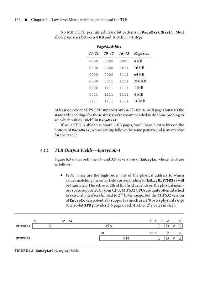
136 Chapter 6—Low-level Memory Management and the TLB
No MIPS CPU permits arbitrary bit patterns in PageMask(Mask). Mostallow page sizes between 4 KB and 16 MB in ×4 steps:
PageMask bits
24–21 20–17 16–13 Page size
0000 0000 0000 4 KB
0000 0000 0011 16 KB
0000 0000 1111 64 KB
0000 0011 1111 256 KB
0000 1111 1111 1 MB
0011 1111 1111 4 MB
1111 1111 1111 16 MB
At least one older MIPS CPU supports only 4-KB and 16-MB pages but uses thestandard encodings for those sizes; you’re recommended to do some probing tosee which values “stick” in PageMask.
If your CPU is able to support 1-KB pages, you’ll have 2 extra bits on thebottom of PageMask, whose setting follows the same pattern and is an exercisefor the reader.
6.2.2 TLB Output Fields—EntryLo0-1
Figure 6.3 shows both the 64- and 32-bit versions of EntryLo, whose fields areas follows:
PFN: These are the high-order bits of the physical address to whichvalues matching the entry field corresponding to EntryHi(VPN2)s willbe translated. The active width of this field depends on the physical mem-ory space supported by your CPU. MIPS32 CPUs are quite often attachedto external interfaces limited to 232 bytes range, but the MIPS32 versionofEntryLo can potentially support as much as a 238 bytes physical range(the 26-bit PFN provides 226 pages, each 4 KB or 212 bytes in size).
63 55 54 6 5 3
(MIPS64) 0 PFN C D V G
31 6 5 3 2 1 0
2 1 0
(MIPS32) PFN C D V G
FIGURE 6.3 EntryLo0-1 register fields.

6.2 TLB/MMU Registers Described 137
C: A 3-bit field originally defined for cache-coherent multiprocessorsystems to set the “cache algorithm” (or “cache coherency attribute”—some manuals call this field CCA). An OS will typically know that somepages will not need to have changes tracked automatically through mul-tiple caches—pages known to be used only by one CPU, or known to beread-only, don’t need so much care. It can make the system more effi-cient to turn off the cache snooping and interaction for accesses to thesepages, and this field is used by the OS to note that the page is, for example,cacheable but doesn’t need coherency management (“cacheable nonco-herent”).
But the field has also been used in CPUs aimed at embedded applica-tions, when it selects how the cache works—for example, marking someparticular page to be managed “write-through” (that is, all writes madethere are sent straight to main memory as well as to any cached copy).
The only universally supported values of this field denote “uncached”(2) and “cacheable noncoherent” (3).
D (dirty): This functions as a write-enable bit. Set 1 to allow writes, 0 tocause any store using this translation to be trapped. See section 14.4.7for an explanation of the term dirty.
V (valid): If set 0, any use of an address matching this entry will cause anexception. Used either to mark a page that is not available for access (ina true virtual memory system) or to mark one EntryLo part of a pairedtranslation as not available.
G (global): When the G bit in a TLB entry is set, that TLB entry will matchsolely on the VPN field, regardless of whether the TLB entry’s ASIDfield matches the value in EntryHi. That provides an efficient mech-anism to implement parts of the address space that are shared betweenall processes. Note that there is really only one “G” bit in a TLB entry,although there are two EntryLo registers: bad things will happen if youhave different values in EntryLo0(G) and EntryLo1(G).
Fields called 0 and unused PFN bits: These fields always return zero, butunlike many reserved fields, they do not need to be written as zero (noth-ing happens regardless of the data written). This is important; it meansthat the memory-resident data used to generate EntryLo when refill-ing the TLB can contain some software-interpreted data in these fields,which the TLB hardware will ignore without the need to spend preciousCPU cycles masking it out.
6.2.3 Selecting a TLB Entry—Index, Random, and Wired Registers
The Index register is used to pick a particular TLB entry—they run from zeroup to the number of entries less one. You set Indexwhen you deliberately want

138 Chapter 6—Low-level Memory Management and the TLB
to read or write a particular entry, and Index is also set automatically when youdo a software search for a TLB entry using tlbp.
Its low bits hold the TLB index.2 Not many bits are needed, since no MIPSCPU has yet had a TLB with more than 128 entries. The high bit (bit 31) ismagic, being set by tlbp when the probe fails to finds a matching entry. Bit 31is a good choice—because it makes the value appear negative, it’s easy totest for.
Randomholds an index into the TLB that counts (downward, if that’s impor-tant to you) with each instruction the CPU executes. It acts as an index into theTLB for the write-entry instruction tlbwr, facilitating a random replacementstrategy when you need to write a new TLB entry.
You never have to read or write the Random register in normal use.The hardware sets the Random field to its maximum value—the highest-numbered entry in the TLB—on reset, and it decrements every clock perioduntil it reaches a floor value, when it wraps back to its maximum and startsagain.
TLB entries from 0 upward whose index is less than the floor value aretherefore immune from random replacement, and an OS can use those slotsfor permanent translation entries—they are referred to as wired in MIPS OSdocumentation. The Wired register allows you to specify that floor and thus todetermine the number of wired entries. When you write Wired, the Randomregister is reset to point to the top of the TLB.
6.2.4 Page-Table Access Helpers—Context and XContext
When the CPU takes an exception because a translation isn’t in the TLB, thevirtual address whose translation wasn’t available is already in BadVAddr. Thepage-resolution address is also reflected in EntryHi(VPN2), which is therebypreset to exactly the value needed to create a new entry to translate the missedaddress.
But to further speed the processing of this exception, the Context orXContext register repackages the page-resolution address in a format that canact as a ready-made pointer to a memory-based page table.
MIPS32 CPUs have just the Context register, which helps out the TLBrefill process for 32-bit virtual address spaces; MIPS64 CPUs add the XContextregister, to be used when using a larger address space (up to 40 bits).
The registers (both MIPS32 and MIPS64 versions) are shown in Figure 6.4.Note that XContext is the only register in which the MIPS64 defi-
nition does not exactly define field boundaries: the XContext(BadVPN2)field grows on CPUs supporting virtual address regions bigger than 240
bits and pushes the R and PTEBase fields left (the latter is squashed to fit).
2. Ancient R2000-compatible CPUs had a different register layout, with the index offset, startingfrom bit 8 upward. You’re unlikely to meet one of those.

6.2 TLB/MMU Registers Described 139
31 23 22 4 3 0
Context (MIPS32) PTEBase BadVPN2 0
63 23 22 4 3 0
Context (MIPS64) PTEBase BadVPN2 0
63 33 32 31 30 4 3 0
XContext PTEBase R BadVPN2 0
FIGURE 6.4 Fields in the MIPS32 and MIPS64 Context registers.
Section 6.2.1, which describes Figure 6.2, explains how to find out howmany bits are used in your CPU. The fields are:
Context(PTEBase): This field just stores what you put in it. To exploitthe register as its designers intended, write in the high-order bits of an(appropriately aligned) starting address of a memory-resident pagetable. The starting address must be picked to have zeros in bits 22 anddownward—that’s a 4-MB boundary. While it would be grossly ineffi-cient to provide that alignment in physical or unmapped memory, theintention is that this table should be put in the kseg2 mapped region.See below for how this works.
Context(BadVPN2)/XContext(BadVPN2): Following a TLB-relatedexception, this holds the page address, which is just the high-order bitsof BadVAddr.
Why the “2” in the name? Recall that in the MIPS32/MIPS64 TLB, eachentry maps an adjacent pair of virtual-address pages onto two independ-ent physical pages.
The BadVPN2 value starts at bit 4, so as to precalculate a pointer intoa table of 16-byte entries whose base address is in PTEBase. If the OSmaintains this table so that the entry implicitly accessed by a particu-lar virtual page address contains exactly the right EntryLo0-1 data tocreate a TLB entry translating that page, then you minimize the work aTLB miss exception handler has to carry out; you can see that insection 6.5. If you’re only translating 32-bit addresses and don’t need toomany bits of software-only state in the page table, you could get by withan eight-byte page-table entry. This turns out to be one of the reasonswhy Linux doesn’t use the Context registers in the prescribed manner.
The XContext(BadVPN2) field may be larger than is shown inFigure 6.4 if your CPU can handle more than 240 bits of user virtualaddress space. When that happens, the R and PTEBase fields are pushedalong to make space.

140 Chapter 6—Low-level Memory Management and the TLB
XContext(PTEBase): The page table base for 64-bit address regionsmust be aligned so that all the bits below those specified by XContext(PTEBase) are zero: That’s 8 GB aligned. That sounds intolerable, butthere is a suitable large, mapped, kernel-only-accessible region (“xkseg”)in the basic MIPS64 memory map.
XContext(R): TLB misses can come from any mapped region of theCPU’s memory map, not just from user space. All regions lie within oneoverarching 64-bit space, but are much smaller than is required to packit full (you might like to refer to Figure 2.2 in section 2.8). Usable 64-bitvirtual addresses are divided into four “xk. . . ” segments within whichyou can use a 62-bit in-segment address.
So as to save space in XContext, the miss address as shown here is kept asa separate 40-bit in-region page address (BadVPN2) and a 2-bit mapped-region selector XContext(R), defined as follows:
R Regionvalue name Brief description
0 xuseg User-mode accessible space in lowvirtual memory
1 xsseg Supervisor-mode accessible space(supervisor mode is optional)
2 Would correspond to unmappedsegments, not used
3 xkseg Kernel-mode mapped space(including old kseg2)
Note that not all operating systems use Context/XContext as originallyenvisaged—notably, Linux doesn’t. We’ll discuss why later.
6.3 TLB/MMU Control Instructions
The instructions:
tlbr # read TLB entry at indextlbwi # write TLB entry at index
move MMU data between the TLB entry selected by the Index register and theEntryHi and EntryLo0-1 registers.
You won’t often read a TLB entry; when you do, remember that you’ll haveoverwritten the EntryHi(ASID) field, which the OS should maintain to selectthe address space of the currently running process. So put it back again.

6.4 Programming the TLB 141
The instruction:
tlbwr # write TLB entry selected by Random
copies the contents of EntryHi (including its ASID field, of course), EntryLo,and PageMask into the TLB entry indexed by the Random register—this savestime if you are adopting a random replacement policy. In practice, tlbwr willbe used to write a new TLB entry in a TLB refill exception handler, but tlbwiwill be used anywhere else.
The instruction:
tlbp # TLB lookup
searches the TLB for an entry whose virtual page number and ASID matchesthose currently in EntryHi and stores the index of that entry in the Indexregister. Bit 31 of Index is set if nothing matches—this makes the value looknegative, which is easy to test.
If more than one entry matches, anything might happen. This is a horribleerror and is never supposed to happen: Software should be very careful neverto install a second translation for any address.
Note that tlbp does not fetch data from the TLB; you have to run asubsequent tlbr instruction to do that.
In most CPUs the TLB is internally pipelined so that translation can proceedefficiently. Management/diagnostic operations like this may not be able to fit inwith the standard pipeline flow, so there may be hazards if instructions usingtranslated addresses are run too soon after TLB maintenance instructions. Seesection 3.4 on CP0 hazards, but to avoid tricky corner cases you normally per-form TLB maintenance with software executed in an untranslated region suchas kseg0.
6.4 Programming the TLB
TLB entries are set up by writing the required fields into EntryHi andEntryLo, then using a tlbwr or tlbwi instruction to copy that entry intothe TLB proper.
When you are handling a TLB refill exception, you will find that EntryHihas been set up for you already.
Be very careful not to create two entries that will match the same programaddress/ASID pair. If the TLB contains duplicate entries, an attempt to translatesuch an address, or probe for it, has the potential to damage the CPU chip. SomeCPUs protect themselves in these circumstances by a TLB shutdown, whichshows up as the SR(TS) bit being set. The TLB will now match nothing until ahardware reset.

142 Chapter 6—Low-level Memory Management and the TLB
System software often won’t need to read TLB entries at all. But if youneed to read them, you can find the TLB entry matching some particularprogram address using tlbp to set up the Index register. Don’t forget tosave EntryHi and restore it afterward—the EntryHi(ASID) field is likelyto be important.
Use a tlbr to read the TLB entry into EntryHi and EntryLo0-1.You’ll see references in the CPU documentation to separate “ITLB” and
“DTLB” (or sometimes collectively “uTLB”—the “u” is for “micro”) structures.The micro-TLBs perform translation for instruction and data addresses, respec-tively; these are tiny hardware-managed caches of translations, whose opera-tion is completely transparent to software—they are automatically invalidatedwhenever you write an entry to the main TLB.
6.4.1 How Refill Happens
When a program makes an access in any of the translated address regions(normally kuseg for application programs under a protected OS and kseg2 forkernel-privilege mappings), and no translation record is present, the CPU takesa TLB refill exception.
The TLB can only map a fraction of the physical memory range of a modernserver or workstation. Large OSs maintain some kind of memory-held pagetable that holds a large number of page translations and uses the TLB as a cacheof recently used translations. For efficiency, it’s common to arrange that thepage table will be an array of ready-to-use TLB entries; for even more efficiency,you can set locate and structure the table so that you can use the Context orXContext register as a pointer into it.
Since MIPS systems usually run OS code in the untranslated kseg0 memoryregion, the common situation will be a miss by a user-privilege program. Severalhardwarefeaturesareprovided,withtheaimofspeedinguptheexceptionhandlerin this common case. First, these refill exceptions are vectored through a low-memory address used for no other exception.3 Second, a series of cunning tricksallows the memory-held page table to be located in kernel virtual memory (thekseg2 region or its 64-bit alternative) so that physical memory space is not neededfor the parts of the page table that map “holes” in the process’s address map.
And to top it off, the Context or XContext register can be used to giveimmediate access to the right entry from a memory-held page table.
We’ll work through this process in section 6.5. But before we get too far intoit, we should note that use of all these features is not compulsory. In a smallersystem the TLB can be used to produce a fixed or rarely changing translationfrom program (virtual) to physical addresses; in these cases it won’t even needto be a cache.
Even some big virtual memory OSs implemented for MIPS have not usedthe “standard” page table—notably Linux. It would be quite against the spirit of
3. On the original MIPS architecture, this is the only event deemed worthy of its own entry point.

6.5 Hardware-Friendly Page Tables and Refill Mechanism 143
the way the Linux kernel uses memory, because the Linux kernel address mapis the same for all processes. See section 14.4.8 for how it’s done.
6.4.2 Using ASIDs
By setting up TLB entries with a particular ASID setting and with the EntryLo0-1(G) bit set 0, those entries will only ever be used when the CPU’s then-current EntryHi(ASID) register field matches the TLB entry’s value. SinceEntryHi (ASID) is an 8-bit field, that allows you to map up to 256 differentaddress spaces simultaneously, without requiring that you clear out the TLB ona context change. If you do run out of ASIDs, you will have to pick some processthat you can completely throw out of the TLB. Once you’ve discarded all itsmappings, you can revoke its ASID value and reapply to some other process.
6.4.3 The Random Register and Wired Entries
The hardware offers you no way of finding out which TLB entries have beenused most recently. When you are using the TLB as a cache and you need toinstall a new mapping, the only practicable strategy is to replace an entry atrandom. The CPU makes this easy for you by maintaining the Random register,which counts (down, actually) with every processor cycle.
Random replacement sounds horribly inefficient; you may end up discard-ing the translation entry that has been in heaviest use recently and that willalmost certainly be needed again very soon. But in fact this doesn’t happen sooften as to be a real problem when you have a reasonable number of possiblevictims to choose from.
However, it can be very useful to have some TLB entries that are guaranteedto stay there until you choose to remove them. These may be useful to mappages that you know will be required very often, but they are really importantbecause they allow you to map pages and guarantee that no refill exception willbe generated on them.
The stable TLB entries are described as wired: They’re the entries whoseindex is lower than whatever value you programmed into the Wired regis-ter. The TLB itself does nothing special about these entries; the magic is in theRandom register, which never takes values 0 through “wired-1”; it counts downbut then steps directly from “wired” to its maximum value. So conventionalrandom replacement leaves TLB entries 0 through “wired-1” unaffected, andentries written there will stay until explicitly removed.
6.5 Hardware-Friendly Page Tables and Refill Mechanism
There’s a particular translation mechanism that the MIPS architects undoubt-edly had in mind for user addresses in a UNIX-like OS. It relies upon building apage table in memory for each address space. The page table consists of a linear

144 Chapter 6—Low-level Memory Management and the TLB
array of entries, indexed by the VPN, whose format is matched to the bitfieldsof the EntryLo register. The paired TLBs need 2 × 64-bit entries, 16 bytes perentry.
That minimizes the load on the critical refill exception handler but opensup other problems. Since each 8 KB of user address space takes 16 bytes of tablespace, the entire 2 GB of user space needs a 4-MB table, which is an embarrass-ingly large chunk of data.4 Of course, most user address spaces are only filledat the bottom (with code and data) and at the top (with a downward growingstack) with a huge gap in between. The solution MIPS adopted is inspired byDEC’s VAX architecture, and is to locate the page table itself in virtual memoryin a kernel-mapped (kseg2 or xkseg) region. This neatly solves two problems atonce:
It saves physical memory: Since the unused gap in the middle of thepage table will never be referenced, no physical memory need actuallybe allocated for those entries.
It provides an easy mechanism for remapping a new user page table whenchanging context, without having to find enough virtual addresses in theOS to map all the page tables at once. Instead, you have a different ker-nel memory map for each different address space, and when you changethe ASID value, the kseg2 pointer to the page table is now automaticallyremapped onto the correct page table. It’s nearly magic.
The MIPS architecture supports this kind of linear page table in the form ofthe Context register (or XContext for extended addressing in 64-bit CPUs).
If you make your page table start at a 4-MB boundary (since it is in virtualmemory, any gap created won’t use up physical memory space) and set up theContext PTEBase field with the high-order bits of the page table starting theaddress, then, following a user refill exception, the Context register will con-tain the address of the entry you need for the refill with no further calculationneeded.
So far so good: But this scheme seems to lead to a fatal vicious circle, wherea TLB refill exception handler may itself get a TLB refill exception, because thekseg2 mapping for the page table isn’t in the TLB. But we can fix that, too.
If a nested TLB refill exception happens, it happens with the CPU already inexception mode. In MIPS CPUs, a TLB refill from exception mode is directed tothe general exception entry point, where it will be detected and can be handledspecially.
Moreover, an exception from exception mode behaves strangely: It does notchange the restart locationEPC, so when the “inner” exception returns, it returnsstraight to the nonexception TLB miss point. It’s rather as if the hardware
4. And of course this is for a 32-bit virtual address space; 64-bit CPUs using larger address spacesneed vast tables.

6.5 Hardware-Friendly Page Tables and Refill Mechanism 145
started processing one exception, then changed its mind and processed another:but the second exception is no longer nested, it has usurped the first one. We’llsee how that works when we look at an example.
6.5.1 TLB Miss Handling
A TLB miss exception always uses a dedicated entry point unless the CPU isalready handling an exception—that is, unless SR(EXL) is set.
Here is the code for a TLB miss handler for a MIPS32 CPU (or a MIPS64CPU handling translations for a 32-bit address space):
.set noreorder
.set noatTLBmiss32:
mfc0 k1,C0_CONTEXT # (1)lw k0,0(k1) # (2)lw k1,8(k1) # (3)mtc0 k0,C0_ENTRYLO0 # (4)mtc0 k1,C0_ENTRYLO1 # (5)ehb # (6)tlbwr # (7)eret # (8).set at.set reorder
Following is a line-by-line analysis of the code:
(1) The k0-1 general-purpose registers are conventionally reserved for theuse of low-level exception handlers; we can just go ahead and use them.
(2–5) There are a pair of physical-side (EntryLo) descriptions in eachTLB entry (you might like to glance back at the TLB entry diagram,Figure 6.1). The layout of the MIPS32/64 Context register shownin Figure 6.4 reserves 16 bytes for each paired entry (eight bytes ofspace for each physical page), even though MIPS32’s EntryLo0-1are 32-bit registers. This is for compatibility with the 64-bit pagetable and to provide some spare fields in the page table to keepsoftware-only information.
Interleaving thelw/mtc0 sequences here will save time: Few MIPS CPUscan keep going without pause if you use loaded data in the very nextinstruction.
These loads are vulnerable to a nested TLB miss if the kseg2 address’stranslation is not in the page table. We’ll talk about that later.

146 Chapter 6—Low-level Memory Management and the TLB
(6) It’s no good writing the entry with tlbwr until it will get the right datafrom EntryLo1. The MIPS32 architecture does not guarantee this willbe ready for the immediately following instruction, but it does guaran-tee that the sequence will be safe if the instructions are separated by anehb (execution hazard barrier) instruction—see section 3.4 for moreinformation about hazard barriers.
(7) This is random replacement of a translation pair as discussed.
(8) MIPS32 (and all MIPS CPUs later than MIPS I) have the eret instruc-tion, which returns from the exception to the address in EPC and unsetsSR(EXL).
So what happens when you get another TLB miss? The miss from excep-tion level invokes not the special high-speed handler but the general-purposeexception entry point. We’re already in exception mode, so we don’t alter theexception return register EPC.
The Cause register and the address-exception registers (BadVAddr,EntryHi, and even Context and XContext) will relate to the TLB misson the page table address in kseg2. But EPC still points back at the instructionthat caused the original TLB miss.
The exception handler will fix up the kseg2 page table miss (so long as thiswas a legal address) and the general exception handler will return into the userprogram. Of course, we haven’t done anything about the translation for theuser address that originally caused the user-space TLB miss, so it will immedi-ately miss again. But the second time around, the page table translation will beavailable and the user miss handler will complete successfully. Neat.
6.5.2 XTLB Miss Handler
MIPS64 CPUs have two special entry points. One—shared with MIPS32CPUs—is used to handle translations for processes using only 32 bits of addressspace; an additional entry point is provided for programs marked as using thebigger address spaces available with 64-bit pointers.
The status register has three fields, SR(UX), SR(SX), and SR(KX), thatselect which exception handler to use based on the CPU privilege level at thetime of the failed translation.5
With the appropriate status bit set (SR(UX) for user mode), a TLB missexception uses a different vector, where we should have a routine that will reloadtranslations for a huge address space. The handler code (of an XTLB miss han-dler for a CPU with 64-bit address space) looks much like the 32-bit version,
5. SR(UX) doubles up as something of a “64-bit mode” bit for user programs; when it’s zero, 64-bitinteger instructions are not available to a user program. But SR(SX,KX) are used only to selectthe TLB refill routine.

6.6 Everyday Use of the MIPS TLB 147
except for the 64-bit-wide registers and the use of the XContext register inplace of Context:
.set noreorder
.set noatTLBmissR4K:
dmfc0 k1,C0_XCONTEXTld k0,0(k1)ld k1,8(k1)dmtc0 k0,C0_ENTRYLO0dmtc0 k1,C0_ENTRYLO1ehbtlbwreret.set at.set reorder
Note, though, that the resulting page table structure in kernel virtualmemory is far bigger and will undoubtedly be in the giant xkseg region.
I should remind you again that this system is not compulsory, and infact is not used by the MIPS version of Linux (which is overwhelmingly themost popular translated-address OS for MIPS applications). It’s a rather deeplyingrained design choice in the Linux kernel that the kernel’s own code anddata are not remapped by a context switch, but exactly that is required for thekseg2/xkseg page table trick described here. See section 14.4.8 for howit’s done.
6.6 Everyday Use of the MIPS TLB
If you’re using a full-scale OS like Linux, then it will use the TLB behind yourback, and you’ll rarely notice. With a less ambitious OS or runtime system, youmay wonder whether it’s useful. But, because the MIPS TLB provides a general-purpose address translation service, there are a number of ways you might takeadvantage of it.
The TLB mechanism permits you to translate addresses (at page granular-ity) from any mapped address to any physical address and therefore to relo-cate regions of program space to any location in your machine’s address map.There’s no need to support a TLB refill exception or a separate memory-heldpage table if your mapping requirements are modest enough that you canaccommodate all the translations you need in the TLB.
The TLB also allows you to define some address as temporarily or per-manently unavailable, so that accesses to those locations will cause an excep-tion that can be used to run some operating system service routine. By using

148 Chapter 6—Low-level Memory Management and the TLB
user-privilege programs you can give some software access only to thoseaddresses you want it to have, and by using address space IDs in the trans-lation entries, you can efficiently manage multiple mutually inaccessible userprograms. You can write-protect some parts of memory.
The applications for this are endless, but here’s a list to indicate therange:
Accessing inconvenient physical address ranges: Hardware registers fora MIPS system are most conveniently located in the physical addressrange 0–512 MB, where you can access them with a correspondingpointer from the kseg1 region. But where the hardware can’t staywithin this desirable area, you can map an arbitrary page of higherphysical memory into a convenient mapped area, such as kseg2. TheTLB flags for this translation should be set to ensure uncached access,but then the program can be written exactly as though the addresswas in the convenient place.
Memory resources for an exception routine: Suppose you’d like to run anexception handler without using the reserved k0/k1 registers to savecontext. If so, you’d have trouble, because a MIPS CPU normally hasnowhere to save any registers without overwriting at least one of these.
You can do loads or stores using the zero register as a base address,but with a positive offset these addresses are located in the first 32 KBof kuseg, and with a negative offset they are located in the last 32 KBof kseg2. Without the TLB, these go nowhere. With the TLB, youcould map one or more pages in this region into read/write mem-ory and then use zero-based stores to save context and rescue yourexception handler.
Extendable stacks and heaps in a non-VM system: Even when you don’thave a disk and have no intention of supporting full demand paging, itcan still be useful to grow an application’s stack and heap on demandwhile monitoring its growth. In this case you’ll need the TLB to mapthe stack/heap addresses, and you’ll use TLB miss events to decidewhether to allocate more memory or whether the application is outof control.
Emulating hardware: If you have hardware that is sometimes present andsometimes not, then accessing registers through a mapped region canconnect directly to the hardware in properly equipped systems andinvoke a software handler on others.
The main idea is that the TLB, with all the ingenuity of a specification thatfits so well into a big OS, is a useful, straightforward general resource forprogrammers.

6.7 Memory Management in a Simpler OS 149
6.7 Memory Management in a Simpler OS
An OS designed for use off the desktop is generally called a real-time OS(RTOS), hijacking a term that once meant something about real time.6 TheUNIX-like system outlined in the first part of this chapter has all the elementsyou’re likely to find in a smaller OS, but many RTOSs are much simpler.
Some OS products you might meet up with are VxWorks from Wind RiverSystems, Thread/X from Express Logic, and Nucleus from Mentor (followingtheir acquisition of Accelerated Technology). All provide multiple threads run-ning in a single address space. There is no task-to-task protection—softwarerunning on these is assumed to be a single tightly integrated application. Inmany cases the OS run time is really quite small, and much of the supplier’seffort is devoted to providing developers with build, debug, and profilingtools.
The jury is still out on whether it’s worth using a more sophisticated OSsuch as Linux for many different kinds of embedded systems. You get a richerprogramming environment, task-to-task protection that can be very valuablewhen integrating a system, and probably cleaner interfaces. Is that worth devot-ing extra memory and CPU power to, and losing a degree of control over timing,for the benefits of the cleverer system? Builders of TV set-top boxes, DVD play-ers, and domestic network routers have found Linux worthwhile: Other systems(not necessarily of very different complexity) are still habitually using simplersystems.
And of course Linux is open source. Sometimes it’s just good that there areno license fees; perhaps, more importantly, if your system doesn’t work becauseof an OS bug, open source means you can fix it yourself or commission any ofa number of experts to fix it for you—right away. It’s paradoxical, but the moresuccessful a commercial OS becomes, the harder it is to find someone to fix iton a reasonable schedule.
But for now, as a developer, you may be faced with almost anything.When you’re trying to understand a new memory management system, thefirst thing is to figure out the memory maps, both the virtual map pre-sented to application software and the physical map of the system. It’s thesimple-minded virtual address map that makes UNIX memory managementrelatively straightforward to describe. But operating systems targeted atembedded applications do not usually have their roots in hardware withmemory management, and the process memory map often has the fossilsof unmapped memory maps hidden inside it. The use of a pencil, paper,and patience will sort it out.
6. Real “real-time” involves programming to deadlines and is hard and interesting but very mucha minority pursuit.

This Page Intentionally Left Blank

Chapter
7 Floating-Point Support
In 1987, the MIPS FPU set a new benchmark for microprocessor mathperformance in affordable workstations. Unlike the CPU, which was mostly
a rather straightforward implementation relying on its basic architecture for itsperformance, the FPU was a heroic silicon design bristling with innovation andingenuity.
Later on, the MIPS FPU was pulled onward by Silicon Graphics’s need formath performance that would once have been the preserve of supercomputers.The use of floating-point computations in embedded systems has grown fairlyslowly; but the trend toward FP is a classic trade-off of clever hardware thatmakes software simpler and more maintainable, and that trade-off (over time)only goes one way. Some day all “main application” processors will requirefloating point.
7.1 A Basic Description of Floating Point
Floating-point math retains a great deal of mystery. You probably have a veryclear idea of what it is for, but you may be hazy about the details. This sectiondescribes the various components of the data and what they mean. In so doingwe are bound to tell most of you things you already know; please skip ahead butkeep an eye on the text!
People who deal with numbers that may be very large or very small are usedto using exponential (scientific) notation; for example, the distance from theearth to the sun is:
93 × 106 miles
The number is defined by 93, the mantissa, and 6, the exponent.The same distance can be written:
9.3 × 10⁷ miles
151

152 Chapter 7—Floating-Point Support
Numerical analysts like to use the second form; a decimal exponent with amantissa between 1.0 and 9.999. . . is called normalized.1 The normalized form isuseful for computer representation, since we don’t have to keep separate infor-mation about the position of the decimal point.
Computer-held floating-point numbers are an exponential form, but in base2 instead of base 10. Both mantissa and exponent are held as binary fields. Justchanging the exponent into a power of 2, the distance quoted above is:
1.38580799102783203125 × 226 miles
The mantissa can be expressed as a binary “decimal,” which is just like a realdecimal; for example:
1.38580799102783203125 = 1 + 3 × 1
10+ 8 × 1
100+ 5 × 1
1000+ · · ·
is the same value as binary:
1.01100010110001000101 = 1 + 0 × 1
2+ 1 × 1
4+ 1 × 1
8+ · · ·
However, neither the mantissa nor the exponent are stored just like this instandard formats—and to understand why, we need to review a little history.
7.2 The IEEE 754 Standard and Its Background
Because floating point deals with the approximate representations of numbers(in the same way as decimals do), computer implementations used to differin the details of their behavior with regard to very small or large numbers.This meant that numerical routines, identically coded, might behave differently.In some sense these differences shouldn’t have mattered: You only got differ-ent answers in circumstances where no implementation could really produce a“correct” answer.
The use of calculators shows the irritating consequences of this: If you takethe square root of a whole number and square it, you will rarely get back thewhole number you put in, but rather something with lots of nines.
Numerical routines are intrinsically hard to write and hard to prove correct.Many heavily used functions (common trigonometric operations, for example)are calculated by repeated approximation. Such a routine might reliably con-verge to the correct result on one CPU and loop forever on another when fed adifficult value.
The ANSI/IEEE 754 Standard—1985 IEEE Standard for Binary FloatingPoint Arithmetic (usually referred to simply as IEEE 754)—was introduced tobring order to this situation. The standard defines exactly which result will be
1. In this form the mantissa may also be called “the fractional part” or “fraction”—it’s certainlyeasier to remember.
7.2 The IEEE 754 Standard and Its Background 153
produced by a small class of basic operations, even under extreme situations,ensuring that programmers can obtain identical results from identical inputsregardless of which machine they are using. Its approach is to require as muchprecision as is possible within each supported data format.
Perhaps IEEE 754 has too many options, but it is a huge improvement on thechaos that motivated it; since it became a real international standard in 1985, ithas become the basis for all new implementations.
The operations regulated by IEEE 754 include every operation thatMIPS FPUs can do in hardware, plus some that must be emulated by software.IEEE 754 legislates the following:
Rounding and precision of results: Even results of the simplest operationsmay not be representable as finite fractions; for example, in decimals:
1
3= 0.33333 . . .
is infinitely recurring and can’t be written precisely. IEEE 754 allowsthe user to choose between four options: round up, round down, roundtoward zero, or round to nearest. The rounded result is what would havebeen achieved by computing with infinite precision and then rounding.This would leave an ambiguity in round to nearest when the infinite-precision result is exactly halfway between two representable forms; therules provide that in this case you should pick the value whose leastsignificant bit is zero.
When is a result exceptional? IEEE 754 has its own meaning for the wordexception. A computation can produce a result that is:
– Nonsense, such as the square root of −1 (“invalid”)
– “Infinite,” resulting from an explicit or implicit division by zero
– Too big to represent (“overflow”)
– So small that its representation becomes problematic and precision islost (“underflow”)
– Not perfectly represented, like 13 (“inexact”)—needless to say, for
most purposes the nearest approximation is acceptable
All of these are bundled together and described as exceptional results.
Action taken when an operation produces an exception result: For eachclass of exceptional results listed above, the user can choose between thefollowing:
– The user can have the computation interrupted and the user pro-gram signaled in some OS- and language-dependent manner. Partlybecause the standard doesn’t actually define a language binding foruser exceptions, they’re pretty much never used. Some FORTRANcompiler systems are wired to cause a fatal error invalid or infiniteresults.

154 Chapter 7—Floating-Point Support
– Most often, the user program doesn’t want to know about the IEEEexception. In this case, the standard specifies which value should thenbe produced. Overflows and division by zero generate infinity (witha positive and negative type); invalid operations generate NaN (nota number) in two flavors called “quiet” and “signaling.” Very smallnumbers get a “denormalized” representation that loses precision andfades gradually into zero.
The standard also defines the result when operations are carried outon exceptional values. Infinities and NaNs necessarily produce furtherNaNs and infinities, but while a quiet NaN as operand will not triggerthe exception-reporting mechanism, a signaling NaN causes a newexception whenever it is used.
Most programs leave the IEEE exception reporting off but do rely on thesystem producing the correct exceptional values.
7.3 How IEEE Floating-Point Numbers Are Stored
IEEE recommends a number of different binary formats for encoding floating-point numbers, at several different sizes. But all of them have some commoningenious features, which are built on the experience of implementers in theearly chaotic years.2
The first thing is that the exponent is not stored as a signed binary number,but biased so that the exponent field is always positive: The exponent value 1represents the tiniest (most negative) legitimate exponent value; for the 64-bitIEEE format the exponent field is 11 bits long and can hold numbers from 0to 2,047. The exponent values 0 and 2,047 (all ones, in binary) are kept backfor special purposes we’ll come to in a moment, so we can represent a range ofexponents from −1,022 to +1,023.
For a number:mantissa × 2exponent
we actually store the binary representation of:
exponent + 1,023
in the exponent field.The biased exponent (together with careful ordering of the fields) has the
useful effect of ensuring that FP comparisons (equality, greater than, less than,etc.) have the same result as is obtained from comparing two signed integers
2. IEEE 754 is a model of how good standardization should be done; a fair period of chaoticexperimentation allowed identifiably good practice to evolve, and it was then standardized by asmall committee of strong-minded users (numerical programmers in this case), who well under-stood the technology. However, the ecology of standards committees, while a fascinating study,is a bit off the point.

7.3 How IEEE Floating-Point Numbers Are Stored 155
composed of the same bits. FP compare operations can therefore be providedby cheap, fast, and familiar logic.
7.3.1 IEEE Mantissa and Normalization
The IEEE format uses a single sign bit separate from the mantissa (0 for positive,1 for negative). So the stored mantissa only has to represent positive numbers.All properly represented numbers in IEEE format are normalized, so:
1 ≤ mantissa < 2
This means that the most significant bit of the mantissa (the single binary digitbefore the point) is always a 1, so we don’t actually need to store it. The IEEEstandard calls this the hidden bit.
So now the number 93,000,000, whose normalized representation has abinary mantissa of 1.01100010110001000101 and a binary exponent of 26, isrepresented in IEEE 64-bit format by setting the fields:
mantissafield = 01100010110001000101000 . . .
exponentfield = 1049 = 10000011001
Looking at it the other way, a 64-bit IEEE number with an exponent fieldof E and a mantissa field of m represents the number f, where:
f = 1.m × 2E−1023
(provided that you accept that 1.m represents the binary fraction with 1 beforethe point and the mantissa field contents after it).
7.3.2 Reserved Exponent Values for Use with Strange Values
The smallest and biggest exponent field values are used to represent otherwise-illegal quantities.
E == 0 is used to represent zero (with a zero mantissa) and denormalizedforms, for numbers too small to represent in the standard form. The denormal-ized number with E zero and mantissa m represents f, where:
f = 0.m × 2−1022
As denormalized numbers get smaller, precision is progressively lost. NoMIPS FPU built to date is able to cope with either generating denormalizedresults or computing with them, and operations creating or involving themwill be punted to the software exception handler. Modern MIPS FPUs canbe configured to replace a denormalized result with a zero and keep going.

156 Chapter 7—Floating-Point Support
E == 111. . . 1 (i.e., the binary representation of 2,047 in the 11-bit field usedfor an IEEE double) is used to represent the following:
With the mantissa zero, it is the illegal values +inf, −inf (distinguishedby the usual sign bit).
With the mantissa nonzero, it is a NaN. For MIPS, the most signifi-cant bit of the mantissa determines whether the NaN is quiet (MS bit 0)or signaling (MS bit 1). This choice is not part of the IEEE standardand is opposite to the convention used by most other IEEE-compatiblearchitectures.3
7.3.3 MIPS FP Data Formats
The MIPS architecture uses two FP formats recommended by IEEE 754:
Single precision: These are fitted into 32 bits of storage. Compilers forMIPS use single precision for float variables.
Double precision: These use 64 bits of storage. C compilers use doubleprecision for C double types.
The memory and register layout is shown in Figure 7.1, with some examplesof how the data works out. Note that the float representation can’t hold anumber as big as 93,000,000 exactly.
The way that the two words making up a double are ordered in memory(most significant bits first, or least significant bits first) is dependent on theCPU’s endianness—discussed to the point of exhaustion in section 10.2. It isalways consistent with the endianness of the integer unit.
The C structure definition below defines the fields of the two FP types fora MIPS CPU (this works on most MIPS toolchains, but note that, in general,C structure layout is dependent on a particular compiler and not just on thetarget CPU):
#if BYTE_ORDER == BIG_ENDIAN
struct ieee754dp_konst {
unsigned sign:1;
unsigned bexp:11;
unsigned manthi:20; /* cannot get 52 bits into ... */
unsigned mantlo:32; /* ... a regular C bitfield */
};
3. I believe only HP Precision makes the same choice as MIPS, suggesting some intellectualinheritance. Arbitrary 1/0 choices are the mitochondrial DNA of computer technology.

7.3 How IEEE Floating-Point Numbers Are Stored 157
SignDouble MantissaExponent31 30 019 0 3120
High-order word Low-order word
0 000 0001 1010 1011 0001 0110 0010 0010 1000 0000 ....
0 000 0000 0000 0000 0000 0000 0000 0000 0000 ....
0 111 1111 1111 0000 0000 0000 0000 0000 0000 ....
1 111 1111 1111 0000 0000 0000 0000 0000 0000 ....
x 111 1111 1111 0xxx xxxx xxxx xxxx xxxx xxxx ....
x
930000000
+Infinity– Infinity
Quiet NaNSignaling NaN 111 1111 1111 1xxx xxxx xxxx xxxx xxxx ....
SignSingle MantissaExponent31 30 02223
0 0001 1010 101 1000 1011 0001 0001
0 0000 0000 000 0000 0000 0000 0000
0 1111 1111 000 0000 0000 0000 0000
1 1111 1111 000 0000 0000 0000 0000
x 1111 1111 0xx xxxx xxxx xxxx xxxx
x
930000000
+Infinity– Infinity
Quiet NaNSignaling NaN 1111 1111 1xx xxxx xxxx xxxx xxxx
FIGURE 7.1 Floating-point data formats.
struct ieee754sp_konst {
unsigned sign:1;
unsigned bexp:8;
unsigned mant:23;
};
#else /* little-endian */
struct ieee754dp_konst {
unsigned mantlo:32;
unsigned manthi:20;
unsigned bexp:11;
unsigned sign:1;
};
struct ieee754sp_konst {
unsigned mant:23;
unsigned bexp:8;
unsigned sign:1;
};
#endif

158 Chapter 7—Floating-Point Support
7.4 MIPS Implementation of IEEE 754
IEEE 754 is quite demanding and sets two major problems. First, building in theability to detect exceptional results makes pipelining harder. You might want todo this to implement the IEEE exception signaling mechanism, but the deeperreason is to be able to detect certain cases where the hardware cannot producethe correct result and needs help.
If the user opts to be told when an IEEE exceptional result is produced,then to be useful this should happen synchronously;4 after the trap, the userwill want to see all previous instructions complete and all FP registers still inthe preinstruction state and will want to be sure that no subsequent instructionhas had any effect.
In the MIPS architecture, hardware traps (as noted in section 5.1) weretraditionally like this. This does limit the opportunities for pipelining FPoperations, because you cannot commit the following instruction until thehardware can be sure that the FP operation will not produce a trap. To avoidadding to the execution time, an FP operation must decide to trap or not in thefirst clock phase after the operands are fetched. For most kinds of exceptionalresults, the FPU can guess reliably and stop the pipeline for any calculation thatmight trap;5 however, if you configure the FPU to signal IEEE inexact excep-tional results, all FP pipelining is inhibited and everything slows down. Youprobably won’t do that.
The second big problem regarding IEEE 754 is the use of exceptionalresults, particularly with denormalized numbers—which are legitimate oper-ands. Chip designs like the MIPS FPU are highly structured pieces of logic,and the exceptional results don’t fit in well. Where correct operation is beyondthe hardware, it traps with an unimplemented operation code in theCause(ExcCode) field. This immediately makes an exception handler com-pulsory for FP applications. Modern MIPS CPUs often include one or moreimplementation-dependent option bits in the FCSR control/status register,which you can set when you’re prepared to trade strict IEEE 754 complianceeither for performance or—more likely—to avoid “unimplemented operation”traps in corner cases.
4. Elsewhere in this book and in the MIPS documentation you will see exactly this conditionreferred to as a “precise exception.” But since both “precise” and “exception” are used to meandifferent things by the IEEE standard, we will instead talk about a “synchronous trap.” Sorry forany confusion.
5. Some CPUs may use heuristics for this that sometimes stop the pipeline for an operation thatin the end does not trap; that’s only a performance issue and is not important if they don’t doit often.

7.5 Floating-Point Registers 159
7.4.1 Need for FP Trap Handler and Emulator in All MIPS CPUs
The MIPS architecture does not prescribe exactly which calculations will beperformed without software intervention. A complete software floating-pointemulator is mandatory for serious FP code.
In practice, the FPU traps only on a very small proportion of the calculationsthat your program is likely to produce. Simple uses of floating point are quitelikely never to produce anything that the hardware can’t handle.
A good rule of thumb, which seems to cover the right cases, follows:
MIPS FPUs take the unimplemented trap whenever an operation shouldproduce any IEEE exception or exceptional result other than inexact andoverflow. For overflow, the hardware will generate an infinity or a largest-possible value (depending on the current rounding mode). The FPUhardware will not accept or produce denormalized numbers or NaNs.
MIPS FPUs (other than the very earliest ones) offer you a non-IEEEoptional mode for underflow, where a denormalized (tiny) result can beautomatically written as zero.
The unimplemented trap is a MIPS architecture implementation trickand is quite different from the IEEE exceptions, which are standardized con-ditions. You can run a program and ignore IEEE exceptions, and offend-ing instructions will produce well-defined exceptional values; but you can’tignore the unimplemented trap without producing results that are nonsense.
7.5 Floating-Point Registers
MIPS CPUs have 32 floating-point registers, usually referred to as $f0–$f31.With the exception of some really old (MIPS I) CPUs, each is a 64-bit registercapable of holding a double-precision value.
The very first MIPS CPUs had only 16 registers. Well, in a sense they had32 32-bit registers, but each even/odd-numbered pair made up a unit for math(including double-precision math, of course). The odd-numbered registers areonly referenced when doing loads, stores, and moves between floating-pointand integer registers.6 If you tell the assembler you’re building code for an oldCPU, it synthesizes double-width move and load/store operations from a pairof machine instructions; you need never see the odd-numbered registers whenwriting MIPS I–compatible code.
6. It may be worth stressing that the role of the odd-numbered registers is not affected by theCPU’s endianness.

160 Chapter 7—Floating-Point Support
TABLE 7.1 FP Register Usage Conventions
ABI
o32 n32 n64
function return values $f0, $f2
argument registers $f12, $f14 $f12–$f19
saved over function call(suitable for registervariables)
evens $f20–$f30 $f24–$f31
temporaries (not savedover function call, or“caller-saved”)
evens $f4–$f10,$f16, $f18
evens $f4–$f10,$f16, $f18, allodds $f1–$f31
$f1, $f3–$f11,$f20–$f23
MIPS I has been gone a long time, but later CPUs are fitted with a“compatibility bit” in SR(FR)—leave it zero and you get MIPS I opera-tion. There is still quite a lot of software out there that works that way.It seems like a no-brainer to prefer more FP registers—but this is not apersonal choice; you need to check what your compiler will support, andthe entire system (including all libraries and other imported code) needs tobe consistent in its register usage.
It’s also worth pointing out that MIPS FP registers sometimes get used forstoring and manipulating signed integer data (32 or 64 bits). In particular, whena program does conversion between integer and FP data, those conversion oper-ations operate entirely within the FPU—integer data in FP registers is convertedto floating-point data in FP registers.
7.5.1 Conventional Names and Uses of Floating-Point Registers
Like the general-purpose registers, the MIPS calling conventions add a wholebunch of rules about register use that have nothing to do with the hardware;they tell you which FP registers are used for passing arguments, which registervalues are expected to be preserved over function calls, and so on. Table 7.1shows these for the three most common ABIs. An ABI (Application BinaryInterface) is a comprehensive statement of conventions that allow modules—perhaps compiled with different toolchains—to be successfully glued togetherinto a program and run under a conforming operating system. We’ll talk moreabout ABIs in section 11.2; for now, it’s enough to say that the o32 conventionis stuck with the 16-register arrangement of old MIPS I CPUs, and the n32 andn64 conventions (despite the former name) are usable only on 64-bit CPUs.
The division of functions is much the same as for the integer registers,without the special cases. But it’s much messier, because of the history of non-existent odd-numbered registers.

7.7 Floating-Point Control: The Control/Status Register 161
7.6 Floating-Point Exceptions/Interrupts
When a floating-point operation can’t produce the right result, or has beenasked to trap on some or all of the IEEE exceptional results, it takes a MIPSexception, as described in Chapter 5, and the Cause register descriptions dis-cussed in section 3.3.2.
The floating-point exceptions are always precise: At the point you arriveat the exception handler, the exception-causing instruction and any instruc-tion later in sequence will appear never to have happened. EPC will point tothe correct place to restart the instruction. As described in Chapter 5, EPC willeither point to the offending instruction or to a branch instruction immedi-ately preceding it. If it is the branch instruction, the status register SR(BD) willbe set.
7.7 Floating-Point Control: The Control/Status Register
Information about the FPU hardware and the controls to change optionalbehavior are provided as coprocessor control registers, accessed with ctc1 andcfc1 instructions, which move data to and from the control registers, respec-tively (into and out of GP registers, of course).
TABLE 7.2 FP Control Register Summary
Conventionalname
CP1 ctrlreg No.
Description
FCSR 31 Extensive control register—the only FPU control register on historicalMIPS CPUs. Contains all the control bits. But, in practice, some ofthem are more conveniently accessed through FCCR, FEXR, and FENR;see below.
FIR 0 FP implementation register: read-only information about thecapability of this FPU, described in the next section.
FCCR 25
FEXR 26
FENR 28
These partial views of FCSR are better structured and allow you toupdate fields without interfering with the operation of independentbits. However, they’re unlikely to be available on any CPU notclaiming full compliance with MIPS32/64.FCCR has FP condition codes, FEXR contains the IEEE exceptional-condition information (cause and flag bits) you read, and FENR hasthe (writable) IEEE exceptional-condition enables.

162 Chapter 7—Floating-Point Support
The most commonly seen of them, the floating-point control/status registerFCSR,7 brings together informational and control fields relating to user optionsabout floating-point operations. Information about the capabilities of the hard-ware and who built it are found in the implementation/revision register FCR0,described in the next section.
Using FCSR had become a bit of a nightmare because of the mix of readableand writable fields: So in MIPS32/64 CPUs there are three auxiliary registersproviding more digestible views: FCCR, FEXR, and FENR.
That makes a fair number of registers, so refer to Table 7.2.The following are notes regarding Figure 7.2. The field marked 0 will read,
and should be written, as zero.
FCC7-1, FCC0: These are condition bits, set by FP compare instruc-tions and tested by conditional branches. FCC0 was there first and usedto be called FCSR(C)—but all modern MIPS FPUs provide all 8 bits.The FCCR register—if your CPU provides it—does you the service ofbringing all the condition bits together.
Note that here, as elsewhere, the floating-point implementation cutsacross the RISC principles we talked about in Chapter 1. There are anumber of reasons for this:
– The original FPU was a separate chip. The conditional branches thattested FP conditions had to execute inside the integer unit (it wasresponsible for finding the address of the branch target), so they wereremote from the FP registers. A single condition bit corresponds to asingle hardware signal.
31 25 24 23 22 21 20 18 17 16 12 11 7 6 2 1 0
FCSR FCC7-1 FS FO FN 0 E Cause RM
31 18 17 16 12 11 7 6 2 1 0
FEXR 0 E Cause 0 0
31 12 11 7 6 3 2 1 0
FENR 0 0 FS RM
31 8 7 0
FCCR 0 FCC7- 0
FCC0 Enables
Enables
Flags
Flags
FIGURE 7.2 FPU control/status register fields.
7. In times past FCSR was referred to as FCR31, but I prefer the mnemonic acronym.

7.7 Floating-Point Control: The Control/Status Register 163
– FP operations are just too computationally demanding to be carriedout in one clock cycle, so the kind of simple pipeline that works sowell on the integer side won’t deliver the best performance.
Both branch and test instructions have an additional 3-bit field thatspecifies which of 8 possible condition bits they will set or test. On aMIPS III or earlier CPU, there was only one condition bit, and all suchfields will be zero. The extra condition bits are valuable for software-pipelining conditional FP code; see section 8.5.7.
FS/FO/FN: These settings affect how the CPU behaves in the face of anumber too small for the standard floating-point representation (adenormalized number). If you set any of them, your system is no longerIEEE754-compliant, but you will avoid some “unimplemented” traps.
If your CPU is MIPS32/64-compliant, it will have all of these. If not, it willimplement FS, but you should check your CPU manual for the others.
FS (flush to zero) causes a result that would be too small for the standardrepresentation (a denormalized result) to be quietly replaced with zero.Since no known MIPS FPU hardware can generate the right answer foryou, this avoids a (slow) trap to emulation software.
FO (flush override) in conjunction with FS detects denormalized oper-ands and internally replaces them with zero. Setting FS alone will notavoid a trap if the inputs are denormalized.
FN (flush to nearest) in conjunction with FS, improves accuracy some-what by forcing denormalized numbers to the closest normalized value(which will sometimes be the smallest representable number, instead ofzero).
E: Following an FPU trap, this bit will be set to mark an unimplementedinstruction exception.8
This bit will be set and an interrupt raised whenever there really is noinstruction like this that the FPU will perform (but the instruction is acoprocessor 1 encoding) or whenever the FPU is not confident that itcan produce an IEEE 754 correct result and/or exception signaling onthis operation, using these operands.
For whatever reason, when E is set, you should arrange for the offendinginstruction to be re-executed by a software emulator.
Any FPU operation that takes an “unimplemented” exception will leavethe destination register unaffected and the FP Cause bits undefined.
Cause/Enables/Flags: Each of these is a 5-bit field, one bit for eachIEEE exception type:
V bit 4 Invalid operation (e.g., square root of –1)
Z bit 3 Divide by zero
8. The MIPS documentation looks slightly different because it treats this as part of the Cause field.

164 Chapter 7—Floating-Point Support
O bit 2 Overflow, result is too large to represent
U bit 1 Underflow, result is too small to represent
I bit 0 Inexact (rarely used—even 1/div 3 is inexact in binary)
The three different fields work as follows:
– Cause: Bits are set (by hardware or emulation software) accordingto the result of the last completed FP instruction. It’s easiest to readthem in FEXR.
– Enables: If one of these bits is set when an operation produces anexceptional result that would have set the corresponding Cause bit,then the CPU will trap so that software can do whatever is necessaryto report the exceptional result. You can set up these bits in eitherFCSR or FENR.
– Flags: Bits are “sticky” versions of the Cause bits and are the logical“or” of the exceptional results that have occurred since the registerwas last cleared. The Flags bits can only be zeroed again by writingFCSR or FEXR.
RM (rounding mode): This is required by IEEE 754. The values are asshown in Table 7.3.
Most systems define RN as the default behavior. You’ll probably neveruse anything else.
The architecture promises you that if an operation doesn’t set the FCSR(E)bit but does set one of the Cause bits, then both the Cause bit setting and theresult produced (if the corresponding Enable bit is off) are in accordance withthe IEEE 754 Standard.
TABLE 7.3 Rounding Modes Encoded in FP Control Registers
RM value Description
0 RN (round to nearest): Round a result to the nearestrepresentable value; if the result is exactly halfway betweentwo representable values, round to zero.
1 RZ (round toward zero): Round a result to the closestrepresentable value whose absolute value is less than orequal to the infinitely accurate result.
2 RP (round up, or toward +infinity): Round a result to thenext representable value up.
3 RN (round down, or toward −infinity): Round a result tothe next representable value down.

7.8 Floating-Point Implementation Register 165
MIPS FPUs rely on software emulation (i.e., use the unimplemented trap)for several purposes:
Any operation that is given a denormalized operand or underflows (pro-duces a denormalized result) will trap to the emulator. The emulatoritself must test whether the enable underflow bit is set and either causean IEEE-compliant exception or produce the correct result.
Operations that should produce the invalid trap are correctly identi-fied, so if the IEEE exception is enabled, the emulator need do noth-ing. But if the IEEE invalid exception is disabled, the software emulatoris invoked, because the hardware is unable to generate the appropriateresult (usually a quiet NaN).
Exactly the same is done with a signaling NaN operand.
Most FP hardware can handle overflow on regular arithmetic (produc-ing either the extreme finite value or a signed infinity, depending on therounding mode). But the software emulator is needed to implement aconvert-to-integer operation that overflows.
The Cause bits are undefined after an unimplemented operation traps tothe emulator.
It is normal practice to provide a full emulator (capable of delivering IEEE-compatible arithmetic on a CPU with no FPU fitted) to back up the FPU hard-ware. If your system provides less than this, it is hard to figure out where it’ssafe to leave functions out.
7.8 Floating-Point Implementation Register
Consult the read-only FIR register after you check Config1(FP) to find outwhether you really have a floating-point unit: FIR’s fields show you what it cando, and (occasionally) what revision it is—see Figure 7.3.
Then the fields are:
FC (full convert range): The hardware will complete any conversionoperation (between floating-point types or between floating-point and
31 25 24 23 22 21 20 19 18 17 16 15 8 7 0
FIR 0 FC 0 F64 L W 3D P S S ProcessorID RevisionD
FIGURE 7.3 FPU implementation/revision register.

166 Chapter 7—Floating-Point Support
integer types) without running out of bits and causing an “unimple-mented” exception.
F64: This indicates that there are 32 full double-precision FP registers—that is, this is not an old MIPS I style floating-point unit.
L/W/D/S: Individual bit flags show whether this CPU implements 64-bitinteger (L), 32-bit integer (W), 64-bit FP double (D), and 32-bit FP single(S) operations. If it doesn’t run all of these, you’re going to need someunusual software support.
3D/PS: Indicate the availability of two optional instruction set exten-sions. PS means you have paired-single SIMD versions of all arithmeticoperations, marked with a .ps suffix: Each does two operations simul-taneously on a pair of single-precision values packed into a register. Seesection 7.10.
3D indicates that you have the MIPS-3D instruction set extension avail-able to you. This is a small extension and only useful if you already havepaired-single, so it’s also described in section 7.10.
ProcessorID: Typically this returns the same value as the integer-sideprocessor ID in the coprocessor zero PRId register. Perhaps moreusefully, it should only ever read nonzero if there really is FPU hard-ware available to your program. Before you read it or succeed in run-ning any floating-point operation, you or your OS needs to switch onthe “coprocessor 1” enable SR(CU1) in the CP0 “status” register.
Revision: This field is at the whim of implementers; it is probablyuseful to make this field visible to commissioning or test engineers, andyou might test it when implementing some bug workaround. Otherwise,software should studiously ignore it.
7.9 Guide to FP Instructions
This section mentions all standard FP instructions, categorized by theirfunction. Optional instructions in the “paired-single” and MIPS-3D extensionsare in the next section.
FP instructions are listed in mnemonic order in Table 8.4, and their binaryencodings are listed with all other MIPS instructions in Table 8.6.
We’ve divided the instructions up into the following categories:
Load/store: Moving data directly between FP registers and memory.
Move between registers: Data movement between FP and general-purposeregisters.
Three-operand arithmetic operations: The regular add, multiply, and so on.

7.9 Guide to FP Instructions 167
Multiply-add operations: Fancy (and distinctly non-RISC) high-performance instructions, not available in MIPS III and earlier.
Sign changing: Simple operations, separated out because their dumbimplementation means no IEEE exceptions.
Conversion operations: Conversion between single, double, and integervalues.
Conditional branch and test instructions: Where the FP unit meets theinteger pipeline again.
7.9.1 Load/Store
These operations load or store 32 or 64 bits of memory in or out of an FPregister. On loads and stores, note the following points:
The data is unconverted and uninspected, so no FP exception will occureven if it does not represent a valid FP value.
MIPS I style 32-bit FPUs only do math operations on the even-numberedregisters. Load/store of an odd-numbered register gives you access to theother half of 64-bit values.
MIPS I and MIPS II CPUs are permitted to take an extra clock beforeFP load data is valid; they are not allowed to interlock any use of thatdata (the same rule applies to data being loaded into general-purposeregisters). The compiler and/or assembler will usually take care of this foryou, but on these old CPUs it is invalid for an FP load to be immediatelyfollowed by an instruction using the loaded value.
When writing assembly, the “synthetic” form of the instruction(e.g.,l.d) is preferred to the native machine instructionldc1); the “syn-thetic” form is easier to read and can be used for all CPUs. The assem-bly may use multiple instructions for CPUs that don’t implement themachine instruction. You can use a synthetic load/store operation withany addressing mode that the assembler can understand (as described insection 9.4).
The address for an FP load/store operation must be aligned to the size ofthe object being loaded—on a four-byte boundary for single-precisionor word values or an eight-byte boundary for double-precision or 64-bitinteger types.
In machine instruction descriptions, (disp is a signed 16-bit quantity, and“*” is the C operator that dereferences a pointer):
lwc1 fd, disp(s) fd = *(s + disp);
swc1 fs, disp(s) *(s + disp) = fs;

168 Chapter 7—Floating-Point Support
All MIPS64/MIPS32-compliant FPUs known to me have 64-bitloads/stores:
ldc1 fd, disp(s) fd = (double)*(s + disp);
sdc1 fs, disp(s) *(s + disp) = (double)fs;
MIPS32/64 adds indexed addressing, with two registers:
lwxc1 fd, i(s) fd = *(s + i);
swxc1 fs, i(s) *(s + i) = fs;
ldxc1 fd, i(s) fd = (double)*(s + i);
sdxc1 fs, i(s) *(s + i) = (double)fs;
But, in fact, you don’t have to remember any of these when you’re writingassembly. Instead, “addr” can be any address mode the assembler understands:
l.d fd, addr fd = (double)*addr;
l.s fd, addr fd = (float)*addr;
s.d fs, addr (double)*addr = fs;
s.s fs, addr (float)*addr = fs;
The assembler will generate the appropriate instructions, including allow-ing a choice of valid address modes. Double-precision loads on a 32-bit CPUwill assemble to two load instructions.
7.9.2 Move between Registers
When data is copied between integer and floating-point registers, no dataconversion is done and no exception results from any value. But when datais moved between floating-point registers, you need to specify the particularfloating-point data type, and an attempt to move a value that has no sensein that type—while it won’t produce an exception—will not necessarily copyall the bits correctly. This makes it possible for FPUs that use a different (per-haps higher-precision) internal representation for FP data to implement moveinstructions without the overhead of back-converting the data.
Even on a MIPS I FPU these instructions can specify the odd-numbered FPregisters:
Between integer and FP registers:
mtc1 s, fd fd = s; /* 32b uninterpreted */
mfc1 d, fs d = fs;
dmtc1 s, fd fd = (long long) s; /* 64 bits */
dmfc1 d, fs d = (long long) fs;

7.9 Guide to FP Instructions 169
Between FP registers:
mov.d fd,fs fd = fs;
/* move 64b between register pairs */
mov.s fd,fs fd = fs; /* 32b between registers */
Conditional moves (missing from MIPS III and earlier)—the .s versionsare omitted to save space:
movt.d fd,fs,cc if (fpcondition(cc)) fd = fs;
movf.d fd,fs,cc if (!fpcondition(cc)) fd = fs;
movz.d fd,fs,t if (t == 0) fd = fs;
/* t is an integer register */
movn.d fd,fs,t if (t != 0) fd = fs;
The FP condition code called fpcondition(cc) is a hard-to-avoidforward reference; you’ll see more in section 7.9.7. If you want to know whyconditional move instructions are useful, see section 8.5.3.
7.9.3 Three-Operand Arithmetic Operations
Note the following points:
All arithmetic operations can cause any IEEE exception type and mayresult in an unimplemented trap if the hardware is not happy with theoperands.
All these instructions come in single-precision (32-bit, C float)and double-precision (64-bit, C double) versions; the instructionsare distinguished by “.s” or “.d” on the op-code. We’ll only show thedouble-precision version. Note that you can’t mix formats: Both sourcevalues and the result will all be either single or double. To mix singlesand doubles you need to use explicit conversion operations.
In all ISA versions:
add.d fd,fs1,fs2 fd = fs1 + fs2;
div.d fd,fs1,fs2 fd = fs1 / fs2;
mul.d fd,fs1,fs2 fd = fs1 × fs2;
sub.d fd,fs1,fs2 fd = fs1 - fs2;
Not in MIPS III and earlier CPUs, fast but not quite IEEE accurate—the error may be as much as that represented by the lowest 2 bits of themantissa (2 ULPs).
recip.dfd,fs fd = 1/fs;
rsqrt.dfd,fs fd = 1/(squarerootof(fs));

170 Chapter 7—Floating-Point Support
7.9.4 Multiply-Add Operations
These were added after MIPS III in response to Silicon Graphics’ interest inachieving supercomputer-like performance in very high end graphics systems(related to the 1995 SGI acquisition of Cray Research, Inc.). IBM’s PowerPC chipsseemed to get excellent FP performance out of their multiply-add, too. Althoughit’s against RISC principles to have a single instruction doing two jobs, a com-bined multiply-add is widely used in common repetitive FP operations (typicallythe manipulation of matrices or vectors). Moreover, it saves a significant amountof time by avoiding the intermediate rounding and renormalization step thatIEEE mandates when a result gets written back into a register.
Multiply-add comes in various forms, all of which take three register oper-ands and an independent result register:
madd.d fd,fs1,fs2,fs3 fd = fs2 × fs3 + fs1;
msub.d fd,fs1,fs2,fs3 fd = fs2 × fs3 - fs1;
nmadd.d fd,fs1,fs2,fs3 fd = -(fs2 × fs3 + fs1);
nmsub.d fd,fs1,fs2,fs3 fd = -(fs2 × fs3 - fs1);
IEEE 754 does not rule specifically for multiply-add operations, so toconform to the standard the result produced should be identical to that comingout of a two-instruction multiply-then-add sequence—tricky! Since every FPoperation may involve some rounding, this also means that IEEE 754 mandatessomewhat poorer precision for multiply-add than could be achieved.
7.9.5 Unary (Sign-Changing) Operations
Although nominally arithmetic functions, these operations only change thesign bit and so can’t produce most IEEE exceptions. They can produce an invalidtrap if fed with a signaling NaN value. They are as follows:
abs.d fd,fs fd = abs(fs)
neg.d fd,fs fd = -fs
7.9.6 Conversion Operations
Note that “convert from single to double” is written “cvt.d.s”—and, as usual,the destination register is specified first. Conversion operators work betweendata in the FP registers: When converting data from CPU integer registers, themove from FP to CPU registers must be coded separately from the conversionoperation. Conversion operations can result in any IEEE exception that makessense in the context.
Originally, all this was done by the one family of instructions:
cvt.x.y fd, fs

7.9 Guide to FP Instructions 171
where x and y specify the destination and source format, respectively, as one ofthe following:
s C float, MIPS/IEEE single, 32-bit floating point
d C double, MIPS/IEEE double, 64-bit floating point
w C int, MIPS “word,” 32-bit integer
l C long long, MIPS “long,” 64-bit integer (64-bit CPUs only)
The instructions are as follows:
cvt.s.d fd,fs /* double fs -> float, leave in fd */
cvt.w.s fd,fs /* float fs -> int, leave in fd */
cvt.d.l fd,fs /* long long fs -> double, leave in fd */
There’s more than one reasonable way of converting from floating point tointeger formats, and the result depends on the current rounding mode (as setup in the FCSR register, described in section 7.7). But FP calculations quite oftenwant to round to the integer explicitly (for example, the ceiling operator roundsupward), and it’s a nuisance trying to generate code to modify and restore FCSR.So except for the earliest MIPS I CPUs, conversions that do explicit roundingare available and often more useful:
Conversions to integer with explicit rounding:
round.x.y fd,fs /* round to nearest */
trunc.x.y fd,fs /* round toward zero */
ceil.x.y fd,fs /* round up */
floor.x.y fd,fs /* round down */
These instructions are only valid with x representing an integer format.
7.9.7 Conditional Branch and Test Instructions
The FP branch and test instructions are separate. We’ll discuss the test instruc-tions below—they have names like c.le.s, and they compare two FP valuesand set the FPU condition bit accordingly.
The branch instructions, therefore, just have to test whether the conditionbit is true (set) or false (zero). They can optionally specify which condition bitto use:
bc1t label if (fpcondition(0)) branch-to-label;
bc1t cc, label if (fpcondition(cc)) branch-to-label;
bc1f label if (!fpcondition(0)) branch-to-label;
bc1f cc, label if (!fpcondition(cc)) branch-to-label;

172 Chapter 7—Floating-Point Support
Like all MIPS branch instructions, each of these has a “branch-likely”variant:9
bc1tl label /* branch-likely form of bc1t ... */
bc1fl label
Like the CPU’s other instructions called branch, the targetlabel is encodedas a 16-bit signed word displacement from the next instruction plus one(pipelining works in strange ways). If labelwas more than 128 KB away, you’dbe in trouble and you would have to resort to a jr instruction.
MIPS CPUs up to and including MIPS III had only one FP condition bit,called “C,” in the FP control/status register FCSR. Mainstream CPUs have7 extra condition bits, called FCC7-1. If you leave the cc specification out ofbranch or compare instructions, you implicitly pick the old “C” bit, which hasthe honorary title of FCC0. That’s compatible with older instruction setversions. (See section 8.5.7 if you’re interested in why this extension was intro-duced.) In all the instruction sets, cc is optional.
But before you can branch, you have to set the condition bit appropriately.The comparison operators are as follows:
c.cond.d fs1,fs2 /* compare fs1 and fs2 and set FCC(0) */
c.cond.d cc,fs1,fs2 /* compare fs1 and fs2; set FCC(cc) */
In these instructions, cond can be a mnemonic for any of 16 conditions.The mnemonic is sometimes meaningful (eq) and sometimes more mysterious(ult). Why so many? It turns out that when you’re comparing FP values thereare four mutually incompatible outcomes:
fs1 < fs2
fs1 == fs2
fs1 > fs2
unordered (fs1, fs2)11
The IEEE standard defines “unordered” as true when either of the operandsis an IEEE NaN value.
It turns out we can always synthesize “greater than” from “less than or equalto” by reversing the order of the operands and/or inverting the test, so we havethree outcomes to allow for. MIPS provides instructions to test for any “or”combination of the three conditions. On top of that, each test comes in twoflavors, one that takes an “invalid” trap if the operands are unordered and onethat never takes such a trap.
9. See section 8.5.4 for more on “likely” branches.

7.10 Paired-Single Floating-Point Instructions and the MIPS-3D ASE 173
TABLE 7.4 FP Test Instructions
Mnemonic
“C” bit is set if. . . No trap Trap
always false f sf
unordered(fs1,fs2) un ngle
fs1 == fs2 eq seq
fs1 == fs2 || unordered(fs1,fs2) ueq ngl
fs1 < fs2 olt lt
fs1 < fs2 || unordered(fs1,fs2) ult nge
fs1 < fs2 || fs1 == fs2 ole le
fs1 < fs2 || fs1 == fs2 || unordered(fs1,fs2) ule ngt
We don’t have to provide tests for conditions like “not equal”; we test forequality, but then use a bc1f rather than a bc1t branch. Table 7.4 tabulates allthe available instruction names:
In many CPU implementations, the compare instruction produces its resulttoo late for a branch instruction to run without delay in the immediately fol-lowing instruction. In MIPS III and earlier CPUs the branch instruction maymisfire if run directly after the test. A compiler or assembler supporting olderCPUs should generate an appropriate delay, inserting a nop if required.
7.10 Paired-Single Floating-Point Instructions and theMIPS-3D ASE
A floating-point unit compliant with MIPS32/64 may choose to implementpaired-single instructions. The base of this extension is a set of arithmeticoperations that work on pairs of IEEE single-precision values, each packed intoa single 64-bit register, and do two operations in parallel on each half.
That sounds like it means building a whole new FPU. But it turns out that itreally isn’t too costly to tinker with the double-precision FPU to provide paired-single operations—at least for the “one-pass” operations like add, multiply,multiply-add, tests, moves, and so on.
We’ll use fs and ft as source registers and fd as a destination. We’ll findit convenient to say that if fs is an FP register containing a paired-single value,then fs.upper and fs.lower stand for the single-precision values in thehigher-numbered and lower-numbered bits, respectively.
To find out if your CPU implements paired-single instructions, see whetherthe FIR(PS) bit is set.

174 Chapter 7—Floating-Point Support
7.10.1 Exceptions on Paired-Single Instructions
Usually, in the circumstances where you want to use paired-single instructions,you probably will take pains to prevent exceptions. But if either of the twofloating-point instructions causes an exception, then the instruction trips anexception: If either of the two instructions needs a MIPS trap, then you take aMIPS “exception” and both halves of the instruction are rolled back as if they’dnever started. An exception is delivered with no indication of whether it appliesto the upper or lower computation, or both.
7.10.2 Paired-Single Three-Operand Arithmetic, Multiply-Add,Sign-Changing, and Nonconditional Move Operations
These all do exactly the same as the corresponding single-precision (.s)version, except they do it twice. That is, an add.ps fd,fs,ft instruction is:
fd.upper = fs.upper + ft.upper;
fd.lower = fs.lower + ft.lower;
These are SIMD instructions (single-instruction, multiple-data) and arevery useful for vector-type operations: They get two operations done in thetime of one.
However, not all instructions are available in .ps form:
Implemented, same mnemonic as single-precision operation: add, sub,mul, abs, mov, and neg.
Not available in paired-single: all the round-in-a-particular-way opera-tors round, trunc, ceil, floor. They probably didn’t seem importantenough in vectorizable applications.
Divide, reciprocal, and square-root—corresponding to div.s,recip.s, sqrt.s, and rsqrt—are not available in paired form (thosefunctions are typically implemented with iterative algorithms, whichcan’t be simply done two-at-once).
The MIPS-3D extension, where available, adds instructions that cancalculate a reciprocal or reciprocal square-root in just two steps. Thoseinstructions are available for PS values too. See section 7.10.5.
The integer-conversion instructions round, trunc, ceil, and floorare not provided. The result of such an operation would be a paired-word, double-integer format, and inventing a whole new data type forsuch purposes seems excessive.

7.10 Paired-Single Floating-Point Instructions and the MIPS-3D ASE 175
7.10.3 Paired-Single Conversion Operations
To build a paired-single value from two single-precision values usecvt.ps.s fd,fs,ft, which does:
fd.upper = fs;
fd.lower = ft;
To extract a single-precision value from either the upper or lower position ofa pair use cvt.s.pl fd,fs (fd = fs.lower;) or cvt.s.pu fd,fs(fd = fs.upper;).
To repack paired-single values into a new paired single, you have a choiceof four instructions. One of these instructions picks one single value from eachof two paired-single registers, and repacks them into a new pair:
pll.ps fd,fs fd.upper = fs.lower;
fd.lower = ft.lower;
plu.ps fd,fs fd.upper = fs.lower;
fd.lower = ft.upper;
pul.ps fd,fs fd.upper = fs.upper;
fd.lower = ft.lower;
puu.ps fd,fs fd.upper = fs.upper;
fd.lower = ft.upper;
alnv.ps fd,fs,ft,s packs together two single-precision values into apaired-single. Its main role—in conjunction with the unaligned load instruc-tion luxc1—is to help software load and pack an array of single-precisionvalues two at a time, even though the memory alignment of the array is such asto get the pairs the wrong way round.
For the purposes of this instruction, it’s helpful to think of paired-singlevalues as packing together singles called “a” and “b,” where “a” has the lowestaddress when the data is stored in memory (the association of “a” and “b” withbit numbers in the register changes with endianness).
The value of the low 3 bits of the general-purpose register s may only be 0or 4 (s is typically the pointer used to load a pair of values from memory)—anyvalue other than 4 will lead to an exception. So it’s like this:
if ((s & 7) == 0) {
fd.a = fs.a; fd.b = fs.b;
}
else {
/* s & 7 == 4 */
fd.a = fs.b; fd.b = ft.a;
}

176 Chapter 7—Floating-Point Support
7.10.4 Paired-Single Test and Conditional Move Instructions
Since there are two values in each paired-single register, each compare instruc-tion sets two condition bits. You specify an even-numbered condition bit, andthe instruction will use it and the next-up odd-numbered condition bit. So ifyou write c.eq.ps 2,fs,ft, that implies:
fcc2 = (fs.upper == ft.upper) ? 1: 0;
fcc3 = (fs.lower == ft.lower) ? 1: 0;
If you can’t remember what all the mysterious tests are, see Table 7.4.MIPS-3D (see below) includes some branch instructions that test more than
one condition code at a time, which may be useful.The conditional move instructions, movf.ps and movt.ps, test two FP
condition codes and do two independent move-if-true operations on the upperand lower halves of the destination, so:
movt.ps fd,fs,2 if (fcc2) fd.upper = fs.upper;
if (fcc3) fd.lower = fs.lower;
Contrastingly, movn.ps and movz.ps do their move conditionally on thevalue of an integer register and treat both halves the same.
7.10.5 MIPS-3D Instructions
The MIPS-3D ASE (instruction set extension) adds a handful of instructionsthat are judged to make the paired-single floating-point extension more effi-cient at high-quality 3D graphics coordinate calculations.
Floating-point “reduction add/multiply” (add/multiply pair):
Adds or multiplies the pairs inside a register. In true SIMD style, it willadd or multiply the pairs inside two different registers at once:
addr.ps fd,fs,ft does:
fd.upper = fs.upper + fs.lower;
fd.lower = ft.upper + ft.lower;
And mulr.ps fd,fs,ft does:
fd.upper = fs.upper * fs.lower;
fd.lower = ft.upper * ft.lower;

7.10 Paired-Single Floating-Point Instructions and the MIPS-3D ASE 177
Comparison operations on absolute values (i.e., ignoring sign bit):
There are a complete set of cabs.xx.x operations:
cabs.eq.dcabs.eq.pscabs.eq.scabs.f.dcabs.f.pscabs.f.scabs.le.dcabs.le.pscabs.le.scabs.lt.dcabs.lt.pscabs.lt.s
cabs.nge.dcabs.nge.pscabs.nge.scabs.ngl.dcabs.ngl.pscabs.ngl.scabs.ngle.pscabs.ngt.dcabs.ngt.pscabs.ngt.scabs.ole.dcabs.ole.ps
cabs.ole.scabs.olt.dcabs.olt.pscabs.olt.scabs.seq.dcabs.seq.pscabs.seq.scabs.sf.dcabs.sf.pscabs.sf.scabs.ueq.dcabs.ueq.ps
cabs.ueq.scabs.ule.dcabs.ule.pscabs.ule.scabs.ult.dcabs.ult.pscabs.ult.scabs.un.dcabs.un.pscabs.un.s
Branch instructions testing multiple condition codes:
bc1any2f, bc1any2t, bc1any4f, and bc1any4t test the OR of somenumber of conditions before branching. You might write bc1any2f N,offset with N being the condition code number between 0 and 6.
The tests performed are:
Instruction Branch test
bc1any2f 2,target if (!fcc2 || !fcc3) goto target
bc1any2t 2,target if (fcc2 || fcc3) goto target
bc1any4f 4,target if (!fcc4 || !fcc5 ||
!fcc6 || !fcc7)
goto target
bc1any4t 4,target if (fcc4 || fcc5 || fcc6 ||
fcc7)
goto target
Reciprocal and square-root calculations: This is motivated mostly by thelack of divide, reciprocal, and square-root operations for paired-single(although single- and double-precision versions of these instructionsare included).
recip1 fd,fs is a quick-and-dirty approximation to a reciprocal. It’sas good as can be done reasonably cheaply without an “under-the-hood”iterative process—iterative processes don’t convert well to paired-singleSIMD. It’s a much worse approximation than you could get with the stan-dard recip.s or recip.d instructions, even though those aren’t IEEEaccurate. The operation of recip1 is unaffected by the current rounding

178 Chapter 7—Floating-Point Support
mode (though it does respect the flags that control generation and useof tiny “denormalized” values).
recip2 fd,fs,ft is not anything like a reciprocal—it’s a custommultiply-add that computes 1--(fs*ft) without you needing to loada register with a constant 1. That function is picked because it means thatthis three-instruction sequence refines recip1’s guess:
recip1.s f1, f0 # f1 =˜ 1/f0recip2.s f2, f1, f0 # f2 = f0 * (error in f1)madd.s f1, f1, f1, f2 # f1 = f1 - f2*f1, a better guess
That’s enough to produce a good result in single precision (you can’trefine it further and reach IEEE accuracy without handling some leastsignificant bits separately, which is a much longer computation). A fur-ther recip2/madd sequence is necessary to get the best available resultfor double precision.
But the really nice thing about this is that the corresponding paired-single calculation just works, producing an excellent pair of reciprocalsfor three instructions:
recip1.ps f1, f0recip2.ps f2, f1, f0madd.ps f1, f1, f1, f2
Thersqrt1/rsqrt2 instructions use a similar approach. In this case theerror function computed by rsqrt2 fd,fs,ft is (1--fs*ft)/2.
This time you need an additional multiplication to produce an excellentpaired-single value (though again, not IEEE exact):
rsqrt1.ps f1,f0mul.ps f2,f1,f0rsqrt2.ps f3, f2, f1madd.ps f1, f1, f1, f3
Again, getting a good-quality double-precision value requires an addi-tional refinement step.
Convert between paired-integer and paired-single values:
Since integer/floating-point conversions have always been done strictlyin floating-point registers, once you’ve got paired-single it seems to makesense to have paired-32-bit-integer support too: But it isn’t in the origi-nal paired-single instruction set.
To convert a packed pair of 32-bit integers to a paired-single (convert-ing both fields at once) use cvt.ps.pw fd,fs; the reverse operationconverts a paired-single to a packed pair of words and is cvt.pw.ps fd,fs.In both cases, the current rounding mode determines how approximateresults are rounded.

7.12 Instruction Timing for Speed 179
7.11 Instruction Timing Requirements
Normal FP arithmetic instructions are interlocked, and there is no need tointerpose nops or to reorganize code for correctness. To get the best perform-ance, the compiler should lay out FP instructions to make the best use of over-lapped execution of integer instructions and of the FP pipeline—but that needsto be sensitive to the details of a particular CPU implementation.
In some older CPUs (not compliant to MIPS32/64) some other interac-tions are not interlocked, and for correct operation, programs must avoid cer-tain sequences of instructions. In this case, your compiler, your assembler, or(in the end) you, the programmer, must take care about the timing of thefollowing:
Operations on the FP control and status register: When altering FCSR,take care with the pipeline. Its fields can affect any FP operation, whichmight be running in parallel. Make sure that at the point you write FCSRthere are no FP operations live (started, but whose results have not yetbeen collected). The register is probably written late, too, so it’s wise toallow one or two instructions to separate the ctc1 rs, FCSR from anaffected computational instruction.
Moves between FP and general-purpose registers: These complete late, andif the subsequent instruction uses the value, you’ll normally lose a cycleor two. On MIPS II and earlier CPUs you are required to avoid thedependency.
FP register loads: Like integer loads, these take effect late. The value can’tbe used in the following instruction.
Test condition and branch: The test of the FP condition bit using thebc1t,bc1f instructions must be carefully coded, because the condition bit istested a clock cycle earlier than you might expect. So the conditionalbranch cannot immediately follow a test instruction.
7.12 Instruction Timing for Speed
All MIPS FPUs take more than one clock cycle for most arithmetic instructions;hence, the pipelining becomes visible. The pipeline can show up in three ways:
Hazards: These occur where the software must ensure the separation ofinstructions to work correctly. There are no hazards of any kind visibleto user-level FP code on a MIPS32/64 CPU.
Even in older CPUs there are no hazards between FP instructions causedby FP data.

180 Chapter 7—Floating-Point Support
Interlocks: These occur where the hardware will protect you by delayinguse of an operand until it is ready. Knowledgeable rearrangement of thecode will improve performance.
Visible pipelining: This occurs where the hardware is prepared to startone operation before another has completed (provided there are no datadependencies). Compilers, and determined assembly programmers, canwrite code that works the hardware to the limit by keeping thepipeline full.
Modern MIPS FPUs are often fully pipelined, allowing a new FP mul-tiply, add, or multiply-add operation to start on every clock (it may beevery second clock for double-precision operations). But if you use theresult of one of those instructions in the next instruction in sequence,you’ll hold up your program: With 2006-era CPUs, that’s likely to be byfour or five clock times. In other language, FP multiplication has a one-or two-clock repeat rate but a four- or five-clock latency. If you can avoidusing FP results until they’re ready, your program will go faster.
With floating point, multiply is generally as fast as addition and subtraction.Divide and square-root instructions are much slower; if you need to repeatedlydivide by the same number, it makes sense to compute a reciprocal and multiplyby it instead.
7.13 Initialization and Enabling on Demand
From reset, you will normally have initialized the CPU’s SR register to disable alloptional coprocessors, which includes the FPU (coprocessor 1). The SR(CU1)bit has to be set for the FPU to work. All modern CPUs have 32 64-bit FP reg-isters, but have a MIPS I compatibility mode, when SR(FR) is zero, where onlyeven-numbered registers can be used for math.
You should read the FPU implementation register; if it reads zero, no FP isfitted and you should run the system with CU1 off.
Once CU1 is switched on, you should set up the control/status register FCSRwith your choice of rounding modes and trap enables. Anything except roundto nearest and all traps disabled is uncommon. There’s also the choice of settingthe SR(FS) bit to cause very small results to be returned as zero, saving a trapto the emulator. This is not IEEE compatible, but the hardware can’t producethe specified denormalized result.
Once the FPU is operating, you need to ensure that the FP registers are savedand restored during interrupts and context switches. Since this is (relatively)time consuming, you can optimize this, as some operating systems do, by doing“lazy context switching,” like this:

7.14 Floating-Point Emulation 181
Leave the FPU disabled by default when running a new task. Since thetask cannot now access the FPU, you don’t have to save and restoreregisters when scheduling or parking it.
On a CU1-unusable trap, mark the task as an FP user and enable the FPbefore returning to it.
Disable FP operations while in the kernel or in any software called directlyor indirectly from an interrupt routine. Then you can avoid saving FPregisters on an interrupt; instead, FP registers need to be saved and resto-red only when you are context-switching to or from an FP-using task.
7.14 Floating-Point Emulation
Some low-cost MIPS CPUs and cores omit the FPU. Floating-point functionsfor these processors are provided by software and are perhaps 50–300 timesslower than the hardware. Software FP is useful for systems where floating pointis employed in some rarely used routines.
There are two approaches:
Soft float: Some compilers can be requested to implement floating-pointoperations with software. FP arithmetic operations are likely to be imple-mented with a hidden library function, but housekeeping tasks such asmoves, loads, and stores can be handled in line.
Trap and emulate: The compiler can produce the regular FP instructionset. The CPU will then take a trap on each FP instruction that is caughtby the FP emulator. The emulator decodes the instruction and performsthe requested operation in software. Part of the emulator’s job will beemulating the FP register set in memory.
As described here, a runtime emulator is also required to back up FP hard-ware for very small operands or obscure operations; since the architecture isdeliberately vague about the limits of the hardware’s responsibility, theemulator is usually complete. However, it will be written to ensure exact IEEEcompatibility and is only expected to be called occasionally, so it will probablybe coded for correctness rather than speed.
Compiled-in floating point is much more efficient; the emulator has a highoverhead on each instruction from the trap handler, instruction decoder, andemulated register file. But of course you have to recompile the world to takeadvantage of it.
There may still be some compilers that don’t offer soft float operation: Thehistory of the MIPS architecture is in workstations, where FP hardware wasmandatory.

This Page Intentionally Left Blank

Chapter
8 Complete Guide to theMIPS Instruction Set
Chapters 8 and 9 are written for the programmer who wants tounderstand or generate assembly code (whether in person or indirectly
because you’re writing or fixing a compiler). While Chapter 9 discusses realassembly language programming, this chapter only concerns itself with assem-bly language instructions; broadly speaking, you can skip Chapter 9 if you onlywant to read disassembly listings. We begin with a simple piece of MIPS codeand an overview.
8.1 A Simple Example
This is an implementation of the C library function strcmp(1), which com-pares two character strings and returns zero on equal, a positive value if thefirst string is greater (in string order) than the second, and a negative valueotherwise. Here’s a naïve C algorithm:
int strcmp (char *str1, char *str2)
{
char c1, c2;
do {
c1 = *str1++;
c2 = *str2++;
} while (c1 != 0 && c2 != 0 && c1 == c2);
return c1 - c2; /* clever: 0, +ve or -ve as required */
}
183

184 Chapter 8—Complete Guide to the MIPS Instruction Set
In assembly code the two arguments of the C function arrive in the registerscalled a0 and a1. (See Table 2.1 if you’ve forgotten about the naming conven-tions for registers; the MIPS standard calling convention is described in detailin section 11.2.1.) A simple subroutine like this one is free to use the tempo-rary registers t0 and so on without saving and restoring their values, so they’rethe obvious choices for temporaries. The function returns a value, which byconvention needs to be in the register v0 at the time we return. So let’s have ago at it:
strcmp:1:
lbu t0, 0(a0)addu a0, a0, 1lbu t1, 0(a1)addu a1, a1, 1
beq t0, zero,.t01 # end of first string?beq t1, zero,.t01 # end of second string?beq t0, t1, 1b
.t01:subu v0, t0, t1j ra
We will examine it from the top:
Labels: strcmp is a familiar named label, which in assembly can definea function entry point, an intermediate branch, or even a data storagelocation.
.t01 is a legitimate label; the full-stop “.” character is legal in labels andmust not be confused with a C name elsewhere in your program.
1: is a numeric label, which many assemblers will accept as a local label.You can have as many labels called “1” as you like in a program; “1f ”refers to the next one in sequence and “1b” the previous one. This is veryuseful, since it avoids inventing unique names for labels only used locally.
Register names: The “dollar-free” names shown here are common usage,but they require that the assembly code be passed through some kindof macro processor before getting to the real MIPS assembler; typically,the C preprocessor is used and most toolkits have ways to make thisstraightforward.
It would hardly be worth writing a function such as this in assembly; thecompiler will probably do a better job. But we’ll see later (in section 9.1) howmuch more clever we could have been.

8.2 Assembly Instructions and What They Mean 185
8.2 Assembly Instructions and What They Mean
This section consists of a long list of all legal assembly instruction names(mnemonics) in most MIPS assemblers, up to and including the MIPS64(Release 2) instruction set. After some agonizing and experimentation, I decidedthat this table should contain a mixture of real machine operations and theassembler’s synthesized instructions. So for each instruction we’ll list thefollowing:
Assembly format: How the instruction is written.
Machine instructions generated: For assembly instructions that are aliasesfor machine code or expanded into a sequence of machine instructions,we’ll put a “=>” to show a macro expansion and list typical instructionsin an expansion.
Function: A description of what the instruction does, in pseudo-C code,which is meant to combine precision with brevity. C typecasts, whereused, are necessary.
Not every possible combination of instruction and operands is listed,because it gets too long. So we won’t list the following:
Two-operand forms of three-operand instructions: For example, MIPSassemblers allow you to write:
addu $1, $2 # $1 = $1 + $2
which would otherwise have to be written as:
addu $1, $1, $2
You can do that pretty much anywhere it makes sense.
All possible load/store address formats (addr): MIPS machine instructionsalways generate addresses for load/store operations using just the con-tents of a register plus a 16-bit signed displacement,1 written, forexample, lw $1,14($2). MIPS assemblers support quite a few otheraddressing mode formats; notablylw $1,thing, which loads data fromthe location whose assembly code label (or external C name) is “thing.”See section 9.4 for details; note that all of these modes are quietly avail-able to any assembly instruction that specifies a memory address. We’lljust write lw t,addr for the assembly instruction and the base+displacement format for the machine code.
1. Someone always has to break things; there are some register+register address formats but onlyfor load/stores with floating-point registers. This is done in deference to the importance ofmultidimensional-array organizations in floating-point codes.

186 Chapter 8—Complete Guide to the MIPS Instruction Set
The la (load address) instruction provided by the assembler uses thesame addressing-mode syntax, even though it loads or stores nothing—itjust generates the address value in the destination register.
When synthesizing some address formats (particularly on stores) theassembler needs a scratch register and quietly uses at. Programmersworking in code where the implicit use of a register might matter (in aninterrupt handler that hasn’t yet saved all preinterrupt register values,for instance) need to take care: The GNU assembler has a .set noatdirective that prevents it.
Immediate versions of instructions: A constant value embedded within aninstruction is, by ancient convention, called an immediate value. MIPSassembly language lets you specify the last source operand as a constant.MIPS CPUs offer some real hardware instructions supporting immedi-ates of up to 16 bits in size for some operations, but you’re recommendedto write the “root” mnemonic instead. Names like addui are recognizedby the assembler as legal mnemonics; but probably only compilers gen-erating assembly intermediate code should ever do so, and you’ll seethese “immediate” forms when we’re discussing machine instructions(Table 8.6, for example) and in disassembly listings.
In assembly language you’re not limited to 16 bits, and you don’t haveto remember which of the “immediate” forms uses signed or unsignedvalues; if you write an arbitrary constant, the assembler will synthesizeaway, as described in section 9.3.2.
Once again, the assembler may need to use the temporary register at forsome complicated cases.
8.2.1 U and Non-U Mnemonics
Before we get started, there’s a particularly confusing thing about the wayinstruction mnemonics are written. A “u” suffix on the assembly mnemonicis usually read as “unsigned.” But that’s not always what it means (at least, notwithout a big stretch of your powers of imagination). There are a number ofsubtly different meanings for a “u” suffix, depending on context:
Overflow trap versus no trap: In most arithmetic operations, U denotes“no overflow test.” Unsuffixed arithmetic operations like add cause aCPU exception if the result overflows into bit 31 (the sign bit when we’rethinking of integers as signed). The suffixed variant addu producesexactly the same result for all combinations of operands but never takesan exception.
C and C++ do not support integer overflow exceptions and alwaysuse the “u” form—it has nothing to do with whether a variable is

8.2 Assembly Instructions and What They Mean 187
signed or unsigned. You should always use addu and so on unlessyou really know why not.
Set if: The universal test operations slt (set if less than) and sltu (setif less than, unsigned) have to produce genuinely different results whenoperands are interpreted as negative numbers.
Multiply and divide: Integer multiply operations produce a result withtwice the precision of the operands, and that means that they need toproduce genuinely different results for signed and unsigned inputs;hence, there are two instructions: mult and multu. Note that the lowpart of the result, left in the lo register, will be the same for both thesigned and the unsigned version; it’s the way that overflows into hi arehandled that differs.
Integer divide instructions are also sign dependent (think about dividing0xFFFF.FFFE by 2), so there’s a div and a divu. The same variationexists for shift-right instructions (shift-right by one is really just divideby two), but this was obviously a U too far; the shift instructions arecalled sra (shift-right arithmetic, suitable for signed numbers) and srl(shift-right logical). The world is indeed a wonderful place.
Partial-register loads: Loads of less-than-register-size chunks of data mustdecide what to do with the excess bits in the register. For the unsignedinstructions, such as lbu, the byte value is loaded into the register andthe remaining bits are cleared to zero (we say that the value has beenzero-extended). If the byte value represented a signed number, its top bitwould tell us if it was negative. In this case, we’ll translate to the corre-sponding register-sized representation by filling the remaining bits of theregister with copies of the sign bit, using the instruction lb. That’s calledsign-extending.
8.2.2 Divide Mnemonics
In machine code for integer multiply and divide, there are separate initiationand result-collecting instructions. The assembler likes to cover this up,generating macro expansions for a three-operand format and doing a divide-by-zero check at the same time. This would be OK except that unfortunatelythe assembly macro name for divide is div, which is also the name for the basicmachine code instruction. That means you need a trick to write a machine codedivide instruction in assembly; a three-operand assembly divide with zero asthe destination should just produce the machine start-divide operation andnothing else.
Some toolchains have offered a better way out of this mess, by defining newmnemonicsdivd (divide direct) to mean just the hardware operation and divo(divide with overflow check) for the complicated macro. This didn’t catch on,but you may see it in some codes.

188 Chapter 8—Complete Guide to the MIPS Instruction Set
8.2.3 Inventory of Instructions
In the assembly descriptions we use the conventions given in Table 8.1.Table 8.2 gives a full inventory of the instruction descriptions in mnemonicorder.
TABLE 8.1 Conventions Used in Instruction Tables
Word Used for
s, t CPU registers used as operands.
d CPU register that receives the result.
j “Immediate” constant.
label The name of an entry point in the instruction stream.
shf For shift/rotate/extract/insert instructions, this is the amount of theimplied shift operation, in bits.
sz For extract/insert instructions, this is the size of the field beingmanipulated, in bits.
offs A signed 16-bit PC-relative word offset representing the distance inwords (one word per instruction) to a label.
addr One of a number of different legitimate data address expressionsusable when writing load/store (or load address) instructions inassembly. (See section 9.4 for a description of how the assemblerimplements the various options.)
at The assembly temporary register, which is really $1.
zero This register, $0, always contains a zero value.
ra The return address register $31.
hilo The double-precision integer multiply result formed by concatenatinghi and lo. Each of hi and lo holds the same number of bits as amachine register, so hilo can hold a 64-bit integer on a 32-bitmachine and a 128-bit result on a 64-bit machine.
MAXNEG32BIT The most negative number representable in twos complementarithmetic, 32- and 64-bit, respectively. It’s a feature of twoscomplement numbers that the positive number −MAXNEG32BIT isnot representable in 32 bits.
MAXNEG64BIT
cd Coprocessor register that is written by instruction.
cs Coprocessor register that is read by instruction.

8.2 Assembly Instructions and What They Mean 189
TABLE 8.1 continued
Word Used for
exception(CAUSE, code) Take a CPU trap; CAUSE determines the setting of theCause(ExcCode) register field. “code” is a value not interpreted bythe hardware, but rather one encoded in a don’t-care field of theinstruction, where system software can find it by reading theinstruction. Not every such instruction sets a “code” value, sosometimes we’ll leave it out.
exception(CAUSE)
const31..16 Denotes the number obtained by just using bits 31 through 16 of thebinary number “const.” The MIPS books use a similar convention.
TABLE 8.2 Assembly Instructions in Alphabetical Order
Assembly/Machine Code Description
abs d,s =>sra $at,s,31xor d,s,$atsubu d,d,$at
d = s < 0 ? -s: s;
add d,s,j =>addi d,s,j
Traps on overflow, rare
d = s + (signed)j;
add d,s,t Traps on overflow, rare
d = s + t;
addu d,s,j =>addiu d,s,j
You can also write this with j outside the range -32768≤j<32768, but the
code generated gets more complicated.
d = s + (signed)j;
addu d,s,t d = s + t;
and d,s,j =>andi d,s,j
For 0 ≤ j < 65535—for larger numbers, extra instructions will be generated.
d = s & (unsigned) j;
and d,s,t d = s & t;
b label =>beq
$zero,$zero,offs
goto label;
bal label =>bgezal $zero,offs
Function call (limited range but PC-relative addressing). Note that the
return address that is left in ra is that of the next instruction but one: The
next instruction in memory order is in the branch delay slot and gets
executed before the function is invoked.

190 Chapter 8—Complete Guide to the MIPS Instruction Set
TABLE 8.2 continued
Assembly/Machine Code Description
bc0f label
bc0fl label
bc0t label
bc0tl label
Branch on coprocessor 0 condition. On old CPUs, this tested the state of a
CPU input pin. No longer part of MIPS32 or MIPS64.
bc1f $fccN,label
bc1fl $fccN,label
bc1t $fccN,label
bc1tl $fccN,label
Branch on floating-point (coprocessor 1) condition set/true (t) or
clear/false (f); described in section 7.9.7. Modern FPUs have multiple FP
condition bits, selected by N = 0..7. Older code only uses condition bit 0,
and then the “$fccN,” can be omitted.
The suffix “l” in bc1fl and so on indicates a branch-likely instruction;
see section 8.5.4 for details, but note that the MIPS32/64 specifications
deprecate branch-likely, and recommend programmers and compilers not
to generate the instruction on code that may be ported to more than one
implementation of the MIPS architecture.
bc1any2f $fccN,label
bc1any2t $fccN,label
bc1any4f $fccN,label
bc1any4t $fccN,label
MIPS-3D instructions, which branch on the “OR” of two or four
conditions. See section 7.10.4.
bc2f label
bc2fl label
bc2t label
bc2tl label
Branch on coprocessor 2 condition. Useful only if a CPU uses the CP2
instruction set or offers an external pin. See bc1f and so on above for
details.
beq s,t,label if (s == t) goto label;
beql s,t,label Deprecated branch-likely variants of conditional branch above.
The delay slot instruction is only executed if the branch is taken; see
section 8.5.4.
beqz s,label =>beq s,$zero,offs
if (s == 0) goto label;
beqzl Branch-likely variant of beqz; see section 8.5.4.
bge s,t,label =>slt at,s,tbeq at,$zero,offs
if ((signed) s ≥ (signed) t) goto label;
bgel s,t,label =>slt at,s,tbeql at,$zero,offs
“Likely” form of bge, even though that instruction is itself a macro. Deeply
deprecated, even though the assembler supports it. See section 8.5.4.

8.2 Assembly Instructions and What They Mean 191
TABLE 8.2 continued
Assembly/Machine Code Description
bgeu s,t,label =>sltu at,s,tbeq at,$zero,offs
if ((unsigned) s ≥ (unsigned) t)
goto label;
bgez s,label if (s ≥ 0) goto label;
bgezal s,label If (s ≥ 0) call to "label()." But note that the “return address” is
unconditionally saved in the register ra ($31).
bgezall s,label Deprecated branch-likely variant; see section 8.5.4. It’s hard to see what this
instruction is good for.
bgezl s,label Deprecated branch-likely variant; see section 8.5.4.
bgt s,t,label =>slt at,t,sbne at,$zero,offs
if ((signed) s > (signed) t)
goto label;
bgtu s,t,label =>slt at,t,sbeq at,$zero,offs
if ((unsigned) s > (unsigned) t)
goto label;
bgtz s,label if (s > 0) goto label;
bgtzl s,label Deprecated branch-likely version of bgtz; see section 8.5.4.
ble s,t,label =>sltu at,t,sbeq at,$zero,offs
if ((signed) s ≤ (signed) t)
goto label;
bleu s,t,label =>sltu at,t,sbeq at,$zero,offs
if ((unsigned) s ≤ (unsigned) t)
goto label;
blez s,label if (s ≤ 0) goto label;
blezl s,label Deprecated branch-likely variant of blez; see section 8.5.4.
blt s,t,label =>slt at,s,tbne at,$zero,offs
if ((signed) s < (signed) t)
goto label;
bltl s,t,label Deprecated branch-likely macro; see section 8.5.4.
bltu s,t,label =>sltu at,s,tbne at,$zero,offs
if ((unsigned) s < (unsigned) t)
goto label;
bltz s,label if (s < 0) goto label;

192 Chapter 8—Complete Guide to the MIPS Instruction Set
TABLE 8.2 continued
Assembly/Machine Code Description
bltzal s,label If s < 0 call function at label. But the “return address” is unconditionally
saved in the register ra ($31), whether the function call is taken or not.
if (s < 0) label();
bltzall s,label Bizarre branch-likely variant; see section 8.5.4.
bltzl s,label Deprecated branch-likely variant; see section 8.5.4.
bne s,t,label if (s != t) goto label;
bnel s,t,label Deprecated branch-likely variant; see section 8.5.4.
bnez s,label if (s != 0) goto label;
bnezl s,t,label Deprecated branch-likely variant; see section 8.5.4.
break code Breakpoint instruction for debuggers. The value code has no hardware
effect, but the breakpoint exception routine can retrieve it by reading the
exception-causing instruction.
cache k,addr Do something to a cache line, as described in section 4.9. Not implemented
on very old MIPS CPUs, where cache management relies on CPU-dependent
tricks.
cfc1 t,cs
cfc2 t,cs
Move data from coprocessor control register cs to general-purpose register
t. Only useful for a coprocessor that uses the auxiliary control register set, as
the floating-point unit (coprocessor 1) does. The cfc0 instruction is not
part of the MIPS32 specification.
ctc1 t,cs
ctc2 t,cs
Move data from general-purpose register t to coprocessor control register
cs.
clo d,s Count leading (high-order) one bits in s considered as a 32-bit word.
clz d,s Count leading (high-order) zero bits in s considered as a 32-bit word.
dabs d,s =>dsra at,s,31xor d,s,atdsub d,d,at
64-bit version
d = s < 0: -s: s;
dadd d,s,t 64-bit version; but this one traps on overflow, and is used rarely.
d = s + t;
daddi d,s,j 64-bit add with overflow trap, rare
d = s + j;
daddiu d,s,j 64-bit add immediate, more often written with a daddu mnemonic.
d = s + j;

8.2 Assembly Instructions and What They Mean 193
TABLE 8.2 continued
Assembly/Machine Code Description
daddu d,s,t 64-bit
d = s + t;
dclo d,s Count leading ones in s starting at bit 63 of register.
dclz d,s Count leading zeros in s starting at bit 63 of register.
ddiv $zero,s,t =>ddiv s,t
Plain 64-bit hardware divide instruction, because we specified $zero as the
destination.
lo = (long long) s / (long long) t;
hi = (long long) s % (long long) t;
ddiv d,s,t =>teq t,$zero,0x7ddiv $zero,s,tdaddiu $at,$zero,-1bne t,$at,1fdaddiu $at,$zero,1dsll32 $at,$at,31teq $t1,$at,0x6
1:mflo d
64-bit signed divide with divide-by-zero and overflow check.
lo = (long long) s / (long long) t;
hi = (long long) s % (long long) t;
if (t == 0) exception (BREAK, 7);
if (t == -1 && s = MAXNEG64BIT)
/* result overflows */
exception (BREAK, 6);
d = lo;
ddivu $zero,s,t =>ddivu s,t
Plain unsigned 64-bit hardware divide instruction.
lo = (unsigned long long) s / (unsigned long long) t;
hi = (unsigned long long) s % (unsigned long long) t;
ddivu d,s,t =>teq t,$zero,0x7ddivu s,tmflo d
64-bit unsigned divide with divide-by-zero check.
lo = (unsigned long long) s / (unsigned long long) t;
hi = (unsigned long long) s % (unsigned long long) t;
if (t == 0) exception(BREAK,7);
d = lo;
deret Return from EJTAG debug exception. Control passes to the instruction at the
location found in the CP0 register DEPC, and the debug mode bit is cleared.
The instruction sequentially after deret is not run (there is no delay-slot
instruction). There’s more about EJTAG in section 12.1.
dext d,s,shf,sz Extract bitfield from 64-bit register. shf is the distance the field needs to be
shifted so it starts at bit 0 in s, and sz is the number of bits in the field.
s = d(sz+shf)..shf;
dext d,s,shf,sz =>dextm d,s,shf,sz
dext d,s,shf,sz =>dextu d,s,shf,sz
The assembler gives you a dextm or dextu machine code as required when
shf or sz is more than 32 bits. In all normal circumstances, just code dextand let the assembler handle it.

194 Chapter 8—Complete Guide to the MIPS Instruction Set
TABLE 8.2 continued
Assembly/Machine Code Description
dextm d,s,shf,sz Machine instruction to encode dext when sz is 32 or more.
dextu d,s,shf,sz Machine instruction to encode dext when shf is 32 or more.
di d Disable interrupts. Clears the global interrupt enable bit in the status
register (SR(IE), see section 3.3.1), leaving the original value of SR in d.
This operation is atomic; the alternative read/modify/write sequence can be
interrupted in the middle with confusing results.
dins d,s,shf,sz Insert bitfield into 64-bit register. The data to insert forms the low bits of s.
shf is the distance the data needs to be shifted left, and sz is the width of
the field in bits.
d = d63..(shf+sz) | s(sz)..0 | (shf > 0 ?
d(shf-1)..0: 0);
dins d,s,shf,sz =>dinsm d,s,shf,sz
dins d,s,shf,sz =>dinsu d,s,shf,sz
The assembler gives you a dinsm or dinsu machine code as required
when shf or sz is more than 32 bits. In all normal circumstances, just
code dins and let the assembler handle it.
dinsm d,s,shf,sz Machine instruction to encode dins when sz is 32 or more.
dinsu d,s,shf,sz Machine instruction to encode dins when shf is 32 or more.
div $zero,s,t =>div s,t
Plain signed 32-bit hardware divide; the assembler doesn’t insert any
divide-by-zero or overflow checks when the destination register is $zero.
lo = s / t;
hi = s % t;
div d,s,t =>teq t,$zero,0x7div $zero,s,tli $at,-1bne t,$at,1flui $at,0x8000teq s,$at,0x6
1f:mflo d
Signed 32-bit division with exceptions generated by divide-by-zero and
overflow conditions:
if (t == 0)
exception(BREAK,7); /* divide by zero */
lo = s/t; hi = s%t;
if (t == -1 && s == MAXNEG32BIT)
exception(BREAK, 6); /* result overflows */
d = lo;
divu $zero,s,t =>divu s,t
/* $zero as destination means no checks */
lo = s/t;
hi = s % t;

8.2 Assembly Instructions and What They Mean 195
TABLE 8.2 continued
Assembly/Machine Code Description
divu d,s,t =>teq t,$zero,0x7divu s,tmflo d
Unsigned divide, but take an exception if you divide by zero:
if (t == 0) exception(BREAK,7);
lo = (unsigned) s / (unsigned) t;
hi = (unsigned) s % (unsigned) t;
d = lo;
dla t,addr =># various ...
Load 64-bit address; see section 9.4.
dli t,const =># biggest case:lui t,const63..48ori t,const47..32dsll t,16ori t,const31..16dsll t,16ori t,const15..0
Load 64-bit constant. Separate mnemonic from li required only for values
between 0x8000.0000 and 0xFFFF.FFFF, where 32=>64-bit
transition rules require li to flood the high-order 32 bits with ones.
dmadd16 s,t Found only on NEC’s Vr41xx family CPUs.
(long long)lo = (long long)lo + ((short)s *
(short)t);
dmfc1 t,fs
dmfc2 t,fs
Move 64 bits from coprocessor register cs to general-purpose register t.
Only needed and implemented, of course, for coprocessors with 64-bit
registers. dmfc1 is for floating-point unit registers; dmfc2 is exceedingly
rare.
dmtc1 t,cs
dmtc2 t,cs
Move 64 bits from general-purpose register t to coprocessor register cs.
Comments as for dmfc1 above.
dmul d,s,t =>dmultu s,tmflo d
64-bit signed multiply instruction; the product of s and t is computed as a
128-bit value, with no overflow possible.
There’s no machine-level single instruction that does a three-register 64-bit
multiply, although there is such an instruction (mul) for 32-bit operands.
hilo = s * t; /* with 128-bit precision */
d = lo;
dmulo d,s,t =>dmult s,tmflo ddsra d,d,63mfhi $attne d,$at,0x6mflo d
Signed multiply, take an exception on overflow.
hilo = s * t; /* with 128-bit precision */
if ((lo≥0 && hi!=0) || (lo<0 &&@hi!=-1))
exception(BREAK, 6);
d = lo;

196 Chapter 8—Complete Guide to the MIPS Instruction Set
TABLE 8.2 continued
Assembly/Machine Code Description
dmulou d,s,t =>dmultu s,tmfhi $atmflo dtne $at,$zero,0x6
Unsigned multiply, take an exception on overflow.
hilo = (long long) s * (long long) t;
if (hi != 0)
exception(BREAK,6);
d = lo;
dmult s,t Real machine-level 64-bit signed integer multiply instruction, result in
hilo.
hilo = (long long) s * (long long) t;
dmultu s,t Unsigned version of real machine-level 64-bit integer multiply.
hilo = (unsigned long long) s * (unsigned long
long) t;
dneg d,s =>dsub d,$zero,s
Unitary negate, which traps on overflow—you probably want dnegu,
below.
(long long) d = -(long long) s; /* trap on
overflow */
dnegu d,s =>dsubu d,$zero,s
(long long) d = -(long long) s;
drem d,s,t =>teq t,$zero,0x7ddiv $zero,s,tdaddiu $at,$zero,-1bne t,$at,1fdaddiu $at,$zero,1dsll $at,$at,63teq s,$at,0x6
1f:mfhi d
64-bit signed integer remainder, with overflow checks.
if (t == 0) exception(BREAK,7);
if (s == MAXNEG64BIT && t == -1)
exception(BREAK,6); /* overflow */
d = (long long) s % (long long) t;
dremu d,s,t =>teq t,$zero,0x7ddivu $zero,s,tmfhi d
64-bit unsigned integer remainder, with overflow check.
if (t == 0) exception(BREAK, 7);
d = (unsigned long long)s % (unsigned long long)t;
dret Out-of-date return-from-exception instruction, used on now-obsolete
R6000 CPU and some “MIPS II” followers.
drol d,s,t =>dnegu $at,tdrotrv d,s,$at
64-bit rotate left, where rotate amount is a variable.
d = (s <<t) | ((unsigned long long)s>>(64-t));

8.2 Assembly Instructions and What They Mean 197
TABLE 8.2 continued
Assembly/Machine Code Description
drol d,s,j =>drotr d,s,64-j
64-bit rotate left by a constant amount.
d = (s <<j) | ((unsigned long long)s>>(64-j));
dror d,s,t =>drotrv d,s,t
64-bit rotate right, where rotate amount is a variable.
d = ((unsigned long long)s>>t) | (s<<(64-t));
dror d,s,j =>drotr d,s,j
64-bit rotate right by a constant amount less than 32 positions.
d = ((unsigned long long)s>>j) | (s<<(64-j));
dror d,s,j =>drotr32 d,s,j
64-bit rotate right by a constant amount of 32 positions or more.
d = ((unsigned long long)s>>j) | (s<<(64-j));
dsbh d,t Swap each pair of bytes in the register (there are four pairs in a 64-bit
register).
dshd d,t Swap each pair of halfwords (16-bit chunks) in the register (there are two
pairs in a 64-bit register).
dsll d,s,t =>dsllv d,s,t
64-bit shift left by variable shift amount.
d = (long long)s << (t % 64);
dsllv d,s,t You can write the name of the machine-code shift-left-by-amount-in-
register instruction like this, but it’s better to just write dsll.
dsll d,s,shf 64-bit shift-left by a constant less than 32.
d = (long long) s <<shf;
dsll d,s,shf =>dsll32 d,s,shf-32
64-bit shift-left by a constant of 32 or more.
d = (long long) s <<shf /* 32 ≤ shf < 63 */
dsra d,s,t =>drsav d,s,t
64-bit shift-right: C semantics for shift-right signed, or an arithmetic
shift—as bits shift down, the top of the register is filled with copies of bit 63,
which gives you a correct implementation of signed divide by a power
of two.
d = (signed long long) s >>(t%64);
dsra d,s,shf 64-bit shift-right arithmetic by a constant (for “arithmetic” see
dsra d,s,t above). Where the constant is less than 32, this is a machine
instruction with the same name.
d = (signed long long) s >>(t%64);
dsra d,s,shf =>dsra32 d,s,shf-32
As above, for 32 ≤ shf < 63. You probably don’t want to ever write
dsra32.

198 Chapter 8—Complete Guide to the MIPS Instruction Set
TABLE 8.2 continued
Assembly/Machine Code Description
dsrl d,s,t =>dsrlv d,s,t
Shift-right logical—that means zeros are drawn in at top, consistent with C
semantics for unsigned integers. This is the variable-shift-amount version.
d = (long long unsigned) s >>(t%64)
dsrl d,s,shf Shift-right by a constant, a constant less than 32.
d = (long long unsigned) s >>shf%32;
dsrl d,s,shf =>dsrl32 d,s,shf-32
As above, when shf is 32 or more.
dsub d,s,t 64-bit subtract, which takes exception on overflow: rare.
d = s - t;
dsubu d,s,t d = s - t; /* 64-bit */
ehb Execution hazard barrier—an instruction when you need to be sure that
any coprocessor zero side effects of previous instructions have completed
before any subsequent instructions get to do anything. See section 8.5.10.
ei d Enable interrupts—well, at least unconditionally set the global interrupt
enable bit in the status register (SR(IE), see section 3.3.1). The old value
of SR is left in d. This operation is atomic. It’s an analog of the (more
useful) di instruction above.
eret Return from exception: a privileged-mode instruction. Clears the
SR(EXL) bit and branches to the location saved in EPC. See section 5.5.
ext d,s,shf,sz Extract bitfield from 32-bit register. shf is the distance the field needs to
be shifted so it starts at bit 0 in s, and sz is the number of bits in the field.
mask = (2**sz - 1) << shf;
d = (s & mask) >> shf;
ins d,s,shf,sz Insert bitfield into 32-bit register. The data to insert forms the low bits of s.
shf is the distance the data needs to be shifted left, and sz is the width of
the field in bits.
mask = (2**sz - 1) << shf;
d = (d & m̃ask) | ((s << shf) & mask);
j label The basic “go-to” instruction. Note that it’s limited to reaching
instructions within a 228-byte “page.”
goto label;
j r =>jr r
Jump to the instruction pointed to by register r. This is the only way of
transferring control to an arbitrary address, since all the
address-in-instruction formats span less than 32 bits.

8.2 Assembly Instructions and What They Mean 199
TABLE 8.2 continued
Assembly/Machine Code Description
jal label Subroutine call, with return address in $ra ($31). Note that the return
address is the next instruction but one—as is usual with MIPS branches,
the immediately following instruction position is the branch delay slot, and
the instruction there is always executed before you reach the subroutine.
jal d,addr =>la $at,addrjalr d,$at
Like function call, but leaves the return address in the register d instead of
the usual $31. Synthesized with jalr. It’s cheating to use the instruction
la in the machine code expansion, as la is itself a macro—but it means
we can avoid explaining addressing modes here (see section 9.4 instead).
jalr d,s Variant of jal d,addr above, when the address syntax is just another
register s. You can write jal or jalr.
jal s =>jalr $ra,s
If you specify just one register, that’s the address to call, and the return
address is put in the usual $ra.
la d,addr =># many options
Load address—always a synthesized instruction, which may produce very
different code sequences according to how addr is written. More about
this in section 9.4.
lb d,addr 8-bit load, sign-extend to fill register.
For this and all load/store instructions, you can write addr in many
ways—see section 9.4—but the load/store instruction can only compute an
address with a register and signed 16-bit offset.
d = *((signed char *) addr);
lbu d,addr 8-bit load, zero-extend to fill register.
d = *((unsigned char *)addr);
ld d,addr 64-bit load: exception if address is not eight-byte-aligned.
d = *((long long *)addr);
ldc1 fd,addr 64-bit load of coprocessor 1 (floating-point) register. More often written as
l.d, see section 8.3.
ldc2 fd,addr 64-bit load of coprocessor 2 register, if coprocessor 2 is used and is 64 bits
wide.
ldl d,addrldr d,addr
Load double “left/right”—used as a pair, these instructions implement a
64-bit unaligned load uld; see below and section 2.5.2.
ldxc1 fd,s(t) 64-bit load of coprocessor 1 (floating-point) register, with two-register
“indexed” addressing. More often written as l.d, see section 8.3.
fd = *((double *)(t+b));

200 Chapter 8—Complete Guide to the MIPS Instruction Set
TABLE 8.2 continued
Assembly/Machine Code Description
lh d,addr 16-bit load, sign-extend to fill register.
t = *((signed short *)addr);
lhu d,addr 16-bit load, zero-extend to fill register.
t = *((unsigned short *)addr);
li d,j =>ori d,$zero,j
Load register with constant value (an “immediate”). This expansion is for
0 ≤ j ≤ 65535.
li d,j =>addiu d,$zero,j
This one is for −32768 ≤ j < 0.
li d,j =>lui d,hi16(j)ori d,d,lo16(j)
This one is for any other value of j that is representable as a 32-bit integer.
ll t,addrlld t,addr
Load-linked. Load 32 bits/64 bits, respectively, with link side effects; used
together with sc or scd to implement a lockless semaphore (see
section 8.5.2).
lui t,u Load upper immediate (constant u is sign-extended into 64-bit registers).
t = u <<16;
lw t,addr 32-bit load, sign-extended for 64-bit CPUs.
t = *((int *)(addr));
lwc1 fd,addr Load FP single to FP register file—more often written l.s. See section 8.3.
lwc2 cd,addr 32-bit load to coprocessor2 register, if implemented. Rare.
lwl t,addr
lwr t,addr
Load word left/right. See ulw below and section 2.5.2 for how these
instructions work together to perform an unaligned 32-bit load operation.
lwu t,addr 32-bit zero-extending load, only found on 64-bit CPUs.
t = (unsigned long long)*((unsigned int *)addr);
lwxc1 fd,t(b) Load 32-bit FP value using indexed (register+register) address. More often
written as l.s, see section 8.3.
fd = *((float *)(t+b));
mad s,t 32-bit integer multiply-accumulate, standard in MIPS32. The two registers
are multiplied with full precision and accumulated:
hilo = hilo + ((long long) s * (long long) t);
madu s,t Same but unsigned:
hilo = hilo+((unsigned long long)s *
(unsigned long long)t);

8.2 Assembly Instructions and What They Mean 201
TABLE 8.2 continued
Assembly/Machine Code Description
madd d,s,tmaddu d,s,t
Integer multiply-accumulate with integral write of result to a general
register (signed and unsigned versions). The general-register write is only
implemented by Toshiba 3900 series cores, with this unique name. But note
that in the case where d is actually zero, this is compatible with the
MIPS32 standard mad/madu.
hilo += (long long) s * (long long) t;
d = lo;
madd16 s,t NEC Vr4100-specific integer multiply-accumulate; handles only 16-bit
operands:
lo = lo + ((short)s * (short)t);
mfc0 t,cs
mfc1 t,fs
mfc2 t,cs
Move 32 bits of data from coprocessor register cs into general-purpose
register t—if cs is 64 bits wide, that will be the low-numbered bits.
mfc0 is vital for access to the CPU control registers, mfc1 for putting
floating-point unit data back into integer registers. mfc2 is only useful if
coprocessor 2 is implemented, which is rare.
mfhc1 t,cs
mfhc2 t,fs
Move the higher 32 bits of the 64-bit coprocessor register cs or fs into
general-purpose register t.
Provided only when a MIPS32 integer unit is partnered by a 64-bit,
otherwise MIPS64-compatible coprocessor. For example, MIPS
Technologies’ 24Kf core has a 64-bit floating-point unit.
mfhi d
mflo d
Move integer multiply unit results to general-purpose register d. locontains the result of a division, the least significant 32 bits of the result of a
mul, or the least significant 64 bits of the result of a dmul. hi contains the
remainder of a division or the most significant bits of a multiplication.
These instructions are always interlocked; even on the earliest CPUs, the
hardware waits for any incomplete multiply/divide to finish.
move d,s =>or d,s,$zero
d = s;
movf d,s,$fccN A variety of conditional-move instructions—more about them in
section 8.5.3.
if (!fcc(N)) d = s;
movn d,s,t if (t) d = s;
movt d,s,$fccN if (fcc(N)) d = s;
movt.d fd,fs,N
movt.s fd,fs,N
Double- and single-precision versions.
if (fcc(N)) fd = fs;
movz d,s,t if (!t) d = s;

202 Chapter 8—Complete Guide to the MIPS Instruction Set
TABLE 8.2 continued
Assembly/Machine Code Description
msub s,t
msubu s,t
The negative version of integer multiply/accumulate, in signed and
unsigned versions.
hilo = hilo - ((long long) s * (long long) t);
mtc0 t,cd
mtc1 t,fd
mtc2 t,cd
Move 32 bits from general-purpose register t to coprocessor register cd.
Note that this instruction doesn’t obey the usual convention of writing the
destination register first.
mtc0 is for the CPU control registers, mtc1 is for putting integer data into
floating-point registers (although they’re more often loaded directly from
memory), and mtc2 is implemented only if the CPU uses coprocessor
2 instructions (very rare).
If the coprocessor register is 64 bits wide, the data is loaded into the low
bits, but the state of the high 32 bits is not defined.
mthc1 t,cd
mthc2 t,fd
Move 32 bits from general-purpose register t to the higher bits of 64-bit
coprocessor register cd, while leaving the low bits unchanged.
Provided only when a MIPS32 integer unit is partnered by a 64-bit,
otherwise MIPS64-compatible coprocessor—for example, MIPS
Technologies’ 32-bit 24Kf core has a 64-bit floating-point unit.
mthi s
mtlo s
Move contents of general-purpose register s into the multiply-unit result
registers hi and lo, respectively. This may not seem useful, but they are
required to restore the CPU state when returning from an exception.
mul d,s,t Genuine three-register 32-bit integer multiply, defined in MIPS32 and
available on some earlier CPUs. The full-precision result is still delivered to
the internal hilo register. There is no unsigned version.
hilo = (long long) s * (long long) t;
d = lo;
mul d,s,t =>mult s,tmflo d
Three-register multiply can be synthesized when the assembler is
generating a pre-MIPS32 instruction set.
mulo d,s,t =>mult s,tmflo dsra d,d,31mfhi $attne d,$at,0x6mflo d
32-bit signed multiply with overflow check.
Overflow is detected by the case where hi does not simply contain the
sign-extension of lo.
hilo = (signed)s * (signed)t;
if ((lo≥0 && hi!=0) || (s<0) && hi!=-1)
exception(BREAK, 6);
mulou d,s,t =>multu s,tmfhi $atmflo dtne $at,$zero,0x6
32-bit unsigned multiply with overflow check:
hilo = (unsigned)s * (unsigned)t;
if (hi != 0)
exception(BREAK, 6);

8.2 Assembly Instructions and What They Mean 203
TABLE 8.2 continued
Assembly/Machine Code Description
mult s,t hilo = (signed)s * (signed)t;
multu s,t hilo = (unsigned)s * (unsigned)t;
neg d,s =>sub d,$zero,s
This version traps on overflow and is very rarely used.
d = -s;
negu d,s =>subu d,$zero,s
No overflow: C always generates this.
d = -s;
nop =>sll $zero,$zero,$zero
No-op, instruction code == 0.
nor d,s,t Like all bitwise operations, there’s no need for a separate op-code for 64-bit
CPUs.
d = ˜(s | t);
not d,s =>nor d,s,$zero
d = ˜s;
nudge addrnudgex s(t)
Shortcuts for prefetch instructions pref nudge and prefx nudge,
see below and section 8.5.8
or d,s,t d = s | t;
ori t,r,j OR with a constant. Machine instruction, but more often written as
or d,s,j:
d = s | (unsigned) j;
pref hint,addr
prefx hint,t(b)
Prefetch instruction for memory reference optimization. A program that
knows in advance it may need data can arrange for it to be brought into the
cache early, with no real side effects. Implementations are always entitled to
treat pref as a no-op.
hint defines which sort of prefetch this is; see section 8.5.8.
prefx is only available with floating-point, where it matches the
register+register address mode available for floating-point load/store
instructions.
r2u s LSI ATMizer-II only; converts to strange floating-point format. Result
appears in lo.
radd s,t LSI ATMizer-II only; strange floating-point add. Result appears in lo.
rdhwr d,$cs Read hardware register: allows unprivileged user-mode software to read
one of a set of CPU registers. See section 8.5.12.
rdpgpr d,s Read register from previous shadow set—see section 5.8.6.

204 Chapter 8—Complete Guide to the MIPS Instruction Set
TABLE 8.2 continued
Assembly/Machine Code Description
rem d,s,t =>teq t,$zero,0x7div $zero,s,tli $at,-1bne t,$at,1flui $at,0x8000teq s,$at,0x6 1f:mfhi d
Signed integer remainder, with divide-by-zero and overflow checks:
if (t==0) exception(BREAK, 7);
if (t==-1 && s==MAXNEG32BIT)
exception(BREAK, 6);
d = s % t;
remu d,s,t =>teq t,$zero,0x7divu $zero,s,tmfhi d
Unsigned integer remainder, with divide-by-zero check:
if (t==0) exception(BREAK, 7);
d = (unsigned)s % (unsigned)t;
rfe Pre-MIPS32 (in fact, MIPS I-only) instruction to restore CPU state when
returning from exception. Now obsolete and not described further here.
rmul s,t LSI ATMizer-II only; strange floating-point multiply. Result appears in lo.
rol d,s,shf =>rotr d,s,32-shf
Rotate left by constant. rotr was new with MIPS32R2; for older ISAs, this
will be synthesized to something longer.
d = (s<<shf) | ((unsigned)s>>(32-shf));
rol d,s,t =>negu $at,trotrv d,s,$at
Rotate left. Instruction sets prior to MIPS32R2 lacked the rotate-right
machine instruction; for older instruction sets, it will be synthesized to a
longer sequence.
d = (s<<t) | ((unsigned)s>>(32-t));
ror d,s,shf =>rotr d,s,shf
Rotate right by constant. Will be synthesized for instruction sets earlier
than MIPS32R2.
d = ((unsigned)s>>shf) | (s<<(32-shf));
ror d,s,t =>rotrv d,s,t
Rotate right by variable amount. Will be synthesized for instruction sets
earlier than MIPS32R2.
d = ((unsigned)s>>t) | (s<<(32-t));
rotr d,s,shf Rotate-right by immediate: machine code, only available in MIPS32R2.
rotrv d,s,t Rotate-right by variable amount: machine code, only available in
MIPS32R2.
rsub s,t LSI ATMizer-II only; strange floating-point multiply. Result appears in lo.
sb t,addr *((char *)addr) = t;
sc t,addr
scd t,addr
Store word/double conditional; explained in section 8.5.2.
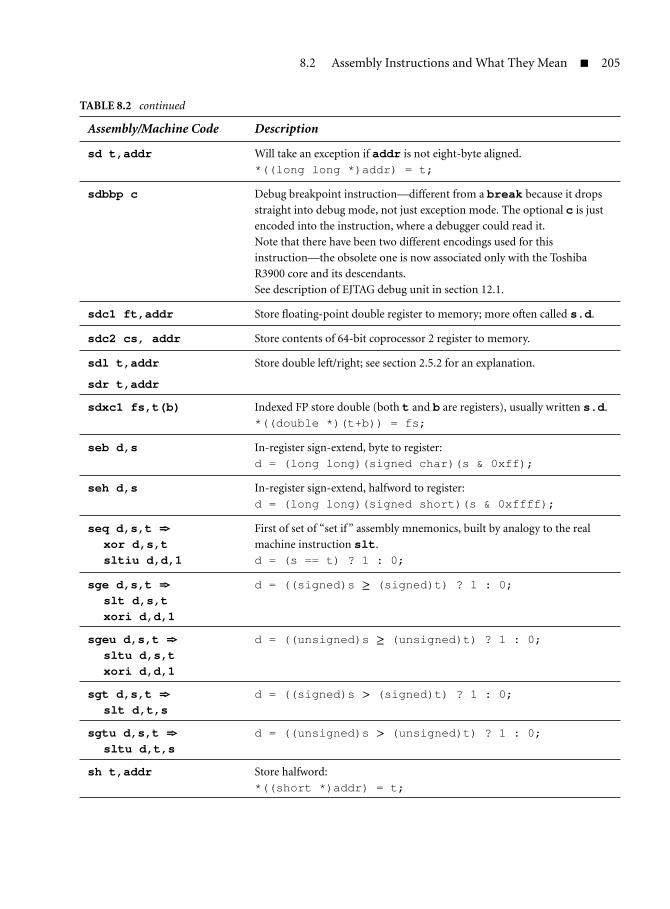
8.2 Assembly Instructions and What They Mean 205
TABLE 8.2 continued
Assembly/Machine Code Description
sd t,addr Will take an exception if addr is not eight-byte aligned.
*((long long *)addr) = t;
sdbbp c Debug breakpoint instruction—different from a break because it drops
straight into debug mode, not just exception mode. The optional c is just
encoded into the instruction, where a debugger could read it.
Note that there have been two different encodings used for this
instruction—the obsolete one is now associated only with the Toshiba
R3900 core and its descendants.
See description of EJTAG debug unit in section 12.1.
sdc1 ft,addr Store floating-point double register to memory; more often called s.d.
sdc2 cs, addr Store contents of 64-bit coprocessor 2 register to memory.
sdl t,addr
sdr t,addr
Store double left/right; see section 2.5.2 for an explanation.
sdxc1 fs,t(b) Indexed FP store double (both t and b are registers), usually written s.d.
*((double *)(t+b)) = fs;
seb d,s In-register sign-extend, byte to register:
d = (long long)(signed char)(s & 0xff);
seh d,s In-register sign-extend, halfword to register:
d = (long long)(signed short)(s & 0xffff);
seq d,s,t =>xor d,s,tsltiu d,d,1
First of set of “set if ” assembly mnemonics, built by analogy to the real
machine instruction slt.
d = (s == t) ? 1 : 0;
sge d,s,t =>slt d,s,txori d,d,1
d = ((signed)s ≥ (signed)t) ? 1 : 0;
sgeu d,s,t =>sltu d,s,txori d,d,1
d = ((unsigned)s ≥ (unsigned)t) ? 1 : 0;
sgt d,s,t =>slt d,t,s
d = ((signed)s > (signed)t) ? 1 : 0;
sgtu d,s,t =>sltu d,t,s
d = ((unsigned)s > (unsigned)t) ? 1 : 0;
sh t,addr Store halfword:
*((short *)addr) = t;

206 Chapter 8—Complete Guide to the MIPS Instruction Set
TABLE 8.2 continued
Assembly/Machine Code Description
sle d,s,t =>slt d,t,sxori d,d,1
d = ((signed)s ≤ (signed)t) ? 1 : 0;
sleu d,s,t =>sltu d,t,sxori d,d,1
d = ((unsigned)s ≤ (unsigned)t) ? 1 : 0;
sll d,s,shf d = s <<shf; /* 0 ≤ shf < 32 */
sll d,t,s =>sllv d,t,s
sllv d,t,s
d = t <<(s % 32);
slt d,s,t d = ((signed) s < (signed) t) ? 1 : 0;
slt d,s,j =>slti d,s,j
slti d,s,j
/* j constant */
d = ((signed) s < (signed) j) ? 1 : 0;
sltiu d,s,j /* j constant */
d = ((unsigned) s < (unsigned) j) ? 1 : 0;
sltu d,s,t d = ((unsigned) s < (unsigned) t) ? 1 : 0;
sne d,s,t =>xor d,s,t
sltu d,$zero,d
d = (s != t) ? 1 : 0;
sra d,s,shf 32-bit shift-right by a constant. C semantics for shift-right signed, an
arithmetic shift—as bits shift down the top of the register is filled with
copies of bit 31, which gives you a correct implementation of signed divide
by a power of 2.
d = (signed) s >>shf;
sra d,s,t =>srav d,s,t
32-bit shift-right arithmetic, by a variable shift amount:
d = (signed) s >>(t%32)
srl d,s,shf 32-bit shift-right logical: like a C shift of an unsigned quantity, where zeros
are shifted in from the top:
d = (unsigned) s >>shf;
srl d,s,t =>slrv d,s,t
32-bit shift-right logical, shift amount in register.
d = (unsigned) s >>(t % 32);

8.2 Assembly Instructions and What They Mean 207
TABLE 8.2 continued
Assembly/Machine Code Description
ssnop =>sll $zero,$zero,1
“Superscalar” no-op; a no-op, but one that no CPU should issue in the
same clock cycle as other instructions. Used for mystical timing purposes.
standby Enter one of the power-down modes, for NEC Vr4100 family CPU only;
wait—see below—is a more widely used instruction.
sub d,s,t Trap on overflow, little used.
d = s - t;
subu d,s,j =>addiu d,s,-j
d = s - j;
subu d,s,t d = s - t;
suspend Enter a Vr4100 CPU’s power-down modes.
sw t,addr Store word.
*((int *)addr) = t;
swc1 ft,addr Floating-point store single; more often written s.s.
swc2 ft,addr Store 32-bit data from coprocessor 2 register, rare.
swl t,addrswr t,addr
Store word left/right; see section 2.5.2.
swxc1 fs,t(b) Store floating-point single using indexed (two-register) addressing; usually
written with s.s.
*((float *)(t + b)) = fs;
sync Load/store barrier, mainly for multiprocessors; see section 8.5.9.
synci addr Synchronize I-cache with D-cache: Run instruction for each
cache-line-sized block after writing instructions but before executing them.
See section 8.5.11.
syscall B Cause a “system call” exception.
exception(SYSCALL, B);
teq s,t Conditional trap instruction: generate a TRAP exception if the appropriate
condition is satisfied; this one is.
if (s == t) exception(TRAP);
teq s,j =>teqi s,j
if (s == j) exception(TRAP);
tge s,t if ((signed) s ≥ (signed) t) exception(TRAP);
tge s,j =>tgei s,j
if ((signed) s ≥ (signed) j) exception(TRAP);
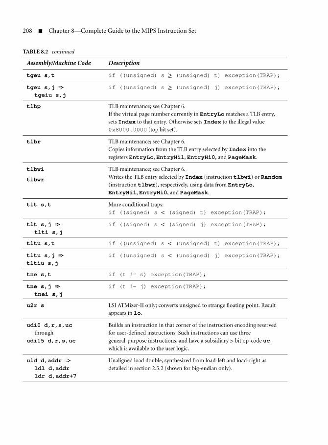
208 Chapter 8—Complete Guide to the MIPS Instruction Set
TABLE 8.2 continued
Assembly/Machine Code Description
tgeu s,t if ((unsigned) s ≥ (unsigned) t) exception(TRAP);
tgeu s,j =>tgeiu s,j
if ((unsigned) s ≥ (unsigned) j) exception(TRAP);
tlbp TLB maintenance; see Chapter 6.
If the virtual page number currently in EntryLo matches a TLB entry,
sets Index to that entry. Otherwise sets Index to the illegal value
0x8000.0000 (top bit set).
tlbr TLB maintenance; see Chapter 6.
Copies information from the TLB entry selected by Index into the
registers EntryLo, EntryHi1, EntryHi0, and PageMask.
tlbwi
tlbwr
TLB maintenance; see Chapter 6.
Writes the TLB entry selected by Index (instruction tlbwi) or Random(instruction tlbwr), respectively, using data from EntryLo,
EntryHi1, EntryHi0, and PageMask.
tlt s,t More conditional traps:
if ((signed) s < (signed) t) exception(TRAP);
tlt s,j =>tlti s,j
if ((signed) s < (signed) j) exception(TRAP);
tltu s,t if ((unsigned) s < (unsigned) t) exception(TRAP);
tltu s,j =>tltiu s,j
if ((unsigned) s < (unsigned) j) exception(TRAP);
tne s,t if (t != s) exception(TRAP);
tne s,j =>tnei s,j
if (t != j) exception(TRAP);
u2r s LSI ATMizer-II only; converts unsigned to strange floating point. Result
appears in lo.
udi0 d,r,s,ucthrough
udi15 d,r,s,uc
Builds an instruction in that corner of the instruction encoding reserved
for user-defined instructions. Such instructions can use three
general-purpose instructions, and have a subsidiary 5-bit op-code uc,
which is available to the user logic.
uld d,addr =>ldl d,addrldr d,addr+7
Unaligned load double, synthesized from load-left and load-right as
detailed in section 2.5.2 (shown for big-endian only).
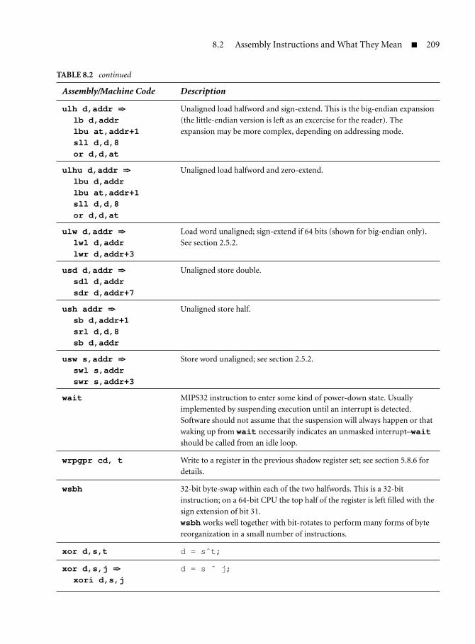
8.2 Assembly Instructions and What They Mean 209
TABLE 8.2 continued
Assembly/Machine Code Description
ulh d,addr =>lb d,addrlbu at,addr+1sll d,d,8or d,d,at
Unaligned load halfword and sign-extend. This is the big-endian expansion
(the little-endian version is left as an excercise for the reader). The
expansion may be more complex, depending on addressing mode.
ulhu d,addr =>lbu d,addrlbu at,addr+1sll d,d,8or d,d,at
Unaligned load halfword and zero-extend.
ulw d,addr =>lwl d,addrlwr d,addr+3
Load word unaligned; sign-extend if 64 bits (shown for big-endian only).
See section 2.5.2.
usd d,addr =>sdl d,addrsdr d,addr+7
Unaligned store double.
ush addr =>sb d,addr+1srl d,d,8sb d,addr
Unaligned store half.
usw s,addr =>swl s,addrswr s,addr+3
Store word unaligned; see section 2.5.2.
wait MIPS32 instruction to enter some kind of power-down state. Usually
implemented by suspending execution until an interrupt is detected.
Software should not assume that the suspension will always happen or that
waking up from wait necessarily indicates an unmasked interrupt–waitshould be called from an idle loop.
wrpgpr cd, t Write to a register in the previous shadow register set; see section 5.8.6 for
details.
wsbh 32-bit byte-swap within each of the two halfwords. This is a 32-bit
instruction; on a 64-bit CPU the top half of the register is left filled with the
sign extension of bit 31.
wsbh works well together with bit-rotates to perform many forms of byte
reorganization in a small number of instructions.
xor d,s,t d = sˆt;
xor d,s,j =>xori d,s,j
d = s ˆ j;

210 Chapter 8—Complete Guide to the MIPS Instruction Set
8.3 Floating-Point Instructions
There’s a reasonable set of MIPS floating-point instructions (see Tables 8.3and 8.4), but they quickly develop their own complications. Note the followingpoints:
Every FP instruction comes in a single-precision version anda double-precision version, distinguished by .s or .d in themnemonic.
If you have the paired-single extension, as described in section 7.10,there will even be .ps versions of instructions, which do exactly thesame thing as the single-precision version, but twice. Paired-singleinstructions that aren’t just .ps versions of instructions in the bigtable are listed there, but will just refer you to the descriptions insection 7.10.
To save space and avoid making your eyes water, Table 8.4 only lists single-precision versions, so long as exactly the same description serves for bothversions.
The basic FP encodings and instruction results conform to the IEEE 754standard. Where the hardware can’t produce the value required byIEEE 754, the default behavior is to take an exception so a software emu-lator can fill in the gaps to produce complete compliance to thestandard.
FP computational and type conversion instructions can cause excep-tions. This is true both in the IEEE sense, where they detect conditionsthat a programmer may be interested in, and in a low-level architec-ture sense: MIPS FP hardware, if faced with a combination of operandsand an operation it can’t do correctly, will take an FP “unimplemented”exception with the aim of getting a software emulator to carry out theFP operation for it.
Data movement instructions (loads, stores, and moves between reg-isters) don’t ever cause exceptions. The neg.s, neg.d, abs.s, orabs.d instructions just flip the sign bit without inspecting thecontents: The only condition that leads to a trap is that a “signal-ing NaN” operand to these instructions produces an IEEE “invalid”exception.

8.3 Floating-Point Instructions 211
TABLE 8.3 Floating-Point Register and Identifier Conventions
Word Used for
fs, ft Floating-point register operands.
fd Floating-point register that receives the result.
fdhi, fdlo Pair of adjacent FP registers in a 32-bit processor, usedtogether to store an FP double. Use of the high-order(odd-numbered) register is implicit in normal arithmeticinstructions.
$fccN One of the floating-point condition bits, found in the FCSRregister and that is tested by instructions like bc1t. There’sbeen evolution here; the MIPS I–III ISAs have only 1condition bit, but modern FPUs have 8. An instruction thatomits to specify which condition bit to use will quietly usethe original “zeroth” one.
fcc(N) The same thing, as seen in C code.
upper, lower The higher and lower values in an FP register holding apaired-single value, as discussed in section 7.10.
TABLE 8.4 Floating-Point Instruction Descriptions in Mnemonic Order
Assemblycode Function
abs.s fd,fs fd = (fs < 0) ? -fs: fs
add.s fd,fs,ft fd = fs + ft;
addr.ps fd,fs,ft /* MIPS 3D "reduction add", see Section 7.10 */
fd.upper = fs.upper + fs.lower;
fd.lower = ft.upper + ft.lower;
alnv.ps fd,fs,ft,rs Pack single-precision values into a paired-single, in either of the two possible
ways as directed by the value of rs.
bc1f $fccN,labelbc1fl $fccN,labelbc1t $fccN,labelbc1tl $fccN,label
Several branch-on-FP-condition instructions, all found in Table 8.2.
bc1any2f $fccN,labelbc1any2t $fccN,labelbc1any4f $fccN,labelbc1any4t $fccN,label
MIPS-3D instructions that branch on the “OR” of two or four conditions.
See section 7.10.4.

212 Chapter 8—Complete Guide to the MIPS Instruction Set
TABLE 8.4 continued
Assemblycode Function
c.eq.s $fccN,fs,ftc.f.s $fccN,fs,ftc.le.s $fccN,fs,ftc.lt.s $fccN,fs,ftc.nge.s $fccN,fs,ftc.ngl.s $fccN,fs,ftc.ngt.s $fccN,fs,ftc.ole.s $fccN,fs,ftc.olt.s $fccN,fs,ftc.seq.s $fccN,fs,ftc.sf.s $fccN,fs,ftc.ueq.s $fccN,fs,ftc.ule.s $fccN,fs,ftc.ult.s $fccN,fs,ftc.un.s $fccN,fs,ft
FP compare instructions, which compare fs and ft and store a result in FP
condition bit $fccN. They are described at length in section 7.9.7.
cabs.xx.s $fccN,fs,ft MIPS-3D extension instructions to compare the absolute value of two FP
values and store the result. The possible tests expressed by “xx” are the same
as for the c.xx.s instructions listed above.
ceil.l.d fd,fsceil.l.s fd,fs
Convert FP to equal or next-higher signed 64-bit integer value.
ceil.w.d fd,fsceil.w.s fd,fs
Convert FP to equal or next-higher signed 32-bit integer value.
cfc1 rt, fs Copy data between a floating-point control register and a general-purpose
register (“f ” is from FP, “t” is to FP). Used for the FCSR register and so on
described in section 7.7.ctc1 rs, fd
cvt.d.l fd,fs Floating-point type conversions, where the types d, l, s, and w (double,
long, float, and int, respectively) are the destination and source type in that
order.
Where the conversion is losing precision, the current rounding mode from
FCSR(RM) is used to determine how the approximation is done. For integer
conversions where the desired approximation is specific to the algorithm,
you’re better off writing instructions like floor.w.s and so on.
cvt.d.s fd,fscvt.d.w fd,fs
cvt.l.d fd,fscvt.l.s fd,fs
cvt.s.d fd,fs
cvt.s.l fd,fs
cvt.s.w fd,fscvt.w.d fd,fscvt.w.s fd,fs

8.3 Floating-Point Instructions 213
TABLE 8.4 continued
Assemblycode Function
cvt.ps.s fd, fs, ft Packs two single-precision values into a paired-single, see section 7.10.
cvt.ps.pw fd, fs, ft MIPS-3D instruction that converts two halves, each representing a 32-bit
integer, to paired-single; see section 7.10.4.
cvt.pw.ps fd, fs, ft MIPS-3D instruction that converts both halves of a paired-single to integers
at once; see section 7.10.4.
cvt.s.pl fd, fs, ft Unpacks half of a paired-single into a conventional single-precision value,
see section 7.10.cvt.s.pu fd, fs, ft
div.s fd,fs,ft fd = fs/ft;
dmfc1 rd,fs Move 64-bit value from floating point (coprocessor 1) to integer register with
no conversion.
dmtc1 rs,fd Move 64-bit value from integer to floating-point (coprocessor 1) register
with no conversion or validity check.
floor.l.d fd,fsfloor.l.s fd,fs
Convert FP to equal or next-lower 64-bit integer value.
floor.w.d fd,fsfloor.w.s fd,fs
Convert FP to equal or next-lower 32-bit integer value.
l.d fd,addr =>ldc1 fd,addr
Load FP double, must be eight-byte aligned.
fd = *((double *)(o+b));
l.s fd,addr =>lwc1 fd,addr
Load FP single, must be four-byte aligned.
fd = *((float *)(o+b));
ldc1 fd, disp(b) Deprecated equivalent of l.d.
l.d fd, t(b) =>ldxc1 fd,t(b)
Indexed load to floating-point register. Best to write with the l.d form.
Note that the role of the two registers is not quite symmetrical—b is
expected to hold an address and t an offset, and it’s an offense for (b+t) to
end up in a different section of the overall MIPS address map than b(defined by the top 2 bits of the 64-bit address).
fd = *((double *) (b+t));
li.s fd,constli.d fd,const
Load floating-point constant, commonly synthesized by placing the constant
in a memory location and loading it.
luxc1 fd, i(b) Double-indexed load-double, exactly like ldxc1 except that if the address
turns out to be misaligned, no exception is taken and the load happens from
the address obtained by zeroing the bottom 3 bits of the effective address.
Used together with alnv to handle misaligned pairs of single-precision
values—see the description of alnv in section 7.10.

214 Chapter 8—Complete Guide to the MIPS Instruction Set
TABLE 8.4 continued
Assemblycode Function
lwc1 fd, disp(b) Deprecated equivalent of l.s.
lwxc1 fd, i(b) Explicit double-indexed load instruction; usually better to use l.s with the
appropriate address mode. See note on ldxc1, above.
madd.s fd,fr,fs,ft fd = fr + fs*ft;
mfc1 rs,fd Move 32-bit value from floating point (coprocessor 1) to integer register with
no conversion.
mfhc1 rs,fd Move 32-bit value from the high 32 bits of a floating-point (coprocessor 1)
register to an integer register. Useful for 32-bit integer CPUs with 64-bit
FPUs.
mov.s fd,fs fd = fs;
movf.s fd,fs,N if (!fcc(N)) fd = fs;
movn.s fd,fs,t if (t != 0) fd = fs; /* t is a GPR */
movt.s fd,fs,N if (fcc(N)) fd = fs;
movz.s fd,fs,t if (t == 0) fd = fs; /* t is a GPR */
msub.s fd,fr,fs,ft fd = fs*ft - fr;
mtc1 rs,fd Move 32-bit value from integer to floating-point (coprocessor 1) register
with no conversion or validity check.
mthc1 rs,fd Move 32-bit value from integer to the high 32 bits of a floating-point
(coprocessor 1) register. Mainly useful for a 32-bit integer CPU with a full
64-bit FPU (the great majority of MIPS CPUs are 64-bit ones).
mul.s fd,fs,ft fd = fs*ft;
mulr.ps fd,fs /* MIPS-3D "Reduction Add", see Section 7.10.4 */
fd.upper = fs.upper * fs.lower;
fd.lower = ft.upper * ft.lower;
neg.s fd,fs fd = -fs;
nmadd.s fd,fr,fs,ft fd = -(fs*ft + fr);
nmsub.s fd,fr,fs,ft fd = -(fr - fs*ft);

8.3 Floating-Point Instructions 215
TABLE 8.4 continued
Assemblycode Function
pll.ps fd, fs, ft Repack paired-single, see section 7.10.
plu.ps fd, fs, ft
pul.ps fd, fs, ft
puu.ps fd, fs, ft
prefx hint, i(b) Register/register address mode cache prefetch instruction. Only available
with floating point (where the same address mode is used for
ldxc1/sdxc1). But it’s also listed in the integer instruction table. See
section 8.5.8 for how it works.
pul.ps fd, fs, ft Repeated in alphabetical sequence—see pll above.
puu.ps fd, fs, ft
recip.s fd,fs Fast reciprocal. Not IEEE accurate, but only wrong by one unit in the least
significant place.
fd = 1/fs;
recip1.s fd,fs MIPS-3D—recip1 is a quick-and-dirty reciprocal approximation, and
recip2 is a special multiply-add that does a reciprocal refinement step. See
section 7.10.4recip2.s fd,fs,ft
round.l.d fd,fsround.l.s fd,fs
Convert FP to equal or closest 64-bit integer value.
round.w.d fd,fsround.w.s fd,fs
Convert FP to equal or closest 32-bit integer value.
rsqrt.s fd,fs Fast and fairly accurate (not wrong by more than 2 bits in the least significant
place) but not IEEE accurate.
fd = sqrt(1/fs);
rsqrt1.s fd,fs MIPS-3D—recip1 is a quick-and-dirty square-root approximation, and
rsqrt2 is a special multiply-add that does a square root refinement step.
See section 7.10.4.rsqrt2.s fd,fs,ft
s.d ft,addr =>sdc1 ft,addr
FP store double; address must be eight-byte aligned. Will be synthesized to
two swc1 instructions on a CPU with a 32-bit FPU.
*((double *)addr) = ft;

216 Chapter 8—Complete Guide to the MIPS Instruction Set
TABLE 8.4 continued
Assemblycode Function
s.s ft,addr =>swc1 ft,addr
FP store single; address must be four-byte aligned.
*((float *)addr) = ft;
sdc1 fd, disp(b) Deprecated equivalent to s.d.
sdxc1 fd, i(b) Explicit double-indexed store double—see notes on ldxc1, above; usually
better to write s.d with an appropriate addressing mode.
sqrt.s fd,fs fd = sqrt(fs); /* IEEE compliant */
sub.s fd,fs,ft fd = fs - ft;
suxc1 fd, i(b) Double-indexed store, exactly like sdxc1 except that no exception results
from a misaligned address. The store proceeds, but to the address rounded
down to an eight-byte boundary.
swc1 fd, disp(b) Deprecated equivalent to s.s.
swxc1 fd, i(b) Explicit double-indexed store of 32-bit FP value; usually better to write s.swith an appropriate addressing mode. See notes on ldxc1 above.
trunc.l.d fd,fstrunc.l.s fd,fs
Convert FP to equal or next-nearest-to-zero 64-bit integer value.
trunc.w.d fd,fstrunc.w.s fd,fs
Convert FP to equal or next-nearest-to-zero 32-bit integer value.
8.4 Differences in MIPS32/64 Release 1
The MIPS32/64 specifications were updated in 2003 to “Revision 2,” whichis what is described here. So all this section needs to do is to provide asummary of what isn’t in CPUs that are compliant to Revision 1 of thespecifications.
8.4.1 Regular Instructions Added in Release 2
The instructions listed here include a few defined for the second release of theMIPS32/64 specifications in 2003. They’re listed here mostly for the benefit ofthose using CPUs compliant to the first release of the specifications, which won’thave these instructions.
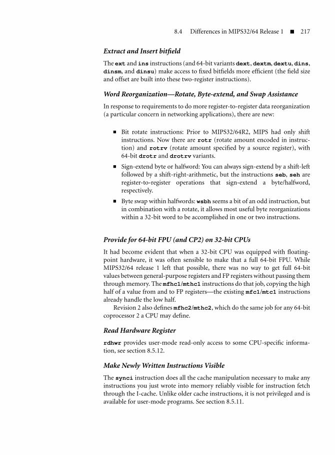
8.4 Differences in MIPS32/64 Release 1 217
Extract and Insert bitfield
The ext and ins instructions (and 64-bit variants dext, dextm, dextu, dins,dinsm, and dinsu) make access to fixed bitfields more efficient (the field sizeand offset are built into these two-register instructions).
Word Reorganization—Rotate, Byte-extend, and Swap Assistance
In response to requirements to do more register-to-register data reorganization(a particular concern in networking applications), there are new:
Bit rotate instructions: Prior to MIPS32/64R2, MIPS had only shiftinstructions. Now there are rotr (rotate amount encoded in instruc-tion) and rotrv (rotate amount specified by a source register), with64-bit drotr and drotrv variants.
Sign-extend byte or halfword: You can always sign-extend by a shift-leftfollowed by a shift-right-arithmetic, but the instructions seb, seh areregister-to-register operations that sign-extend a byte/halfword,respectively.
Byte swap within halfwords: wsbh seems a bit of an odd instruction, butin combination with a rotate, it allows most useful byte reorganizationswithin a 32-bit word to be accomplished in one or two instructions.
Provide for 64-bit FPU (and CP2) on 32-bit CPUs
It had become evident that when a 32-bit CPU was equipped with floating-point hardware, it was often sensible to make that a full 64-bit FPU. WhileMIPS32/64 release 1 left that possible, there was no way to get full 64-bitvalues between general-purpose registers and FP registers without passing themthrough memory. The mfhc1/mthc1 instructions do that job, copying the highhalf of a value from and to FP registers—the existing mfc1/mtc1 instructionsalready handle the low half.
Revision 2 also defines mfhc2/mthc2, which do the same job for any 64-bitcoprocessor 2 a CPU may define.
Read Hardware Register
rdhwr provides user-mode read-only access to some CPU-specific informa-tion, see section 8.5.12.
Make Newly Written Instructions Visible
The synci instruction does all the cache manipulation necessary to make anyinstructions you just wrote into memory reliably visible for instruction fetchthrough the I-cache. Unlike older cache instructions, it is not privileged and isavailable for user-mode programs. See section 8.5.11.

218 Chapter 8—Complete Guide to the MIPS Instruction Set
8.4.2 Privileged Instructions Added in Release 2
There are just a couple of changes in the privileged (kernel-only) instruc-tion set.
Atomic Interrupt Disable/Enable
Prior to Release 2, there was no atomic way of disabling all interrupts in a MIPSCPU: The required RMW sequence on the SR register could itself be interrupted.You could make that safe by OS discipline (see section 5.8.3), but now you havea genuine atomic instruction.
di disables interrupts (clearing SR(IE)) in a single atomic step. It returnsthe old value of SR in its target register, so you generally enable interrupts againby using an mtc0 with the saved value. But for reasons of instruction set sym-metry, R2 also defines an ei instruction, which atomically sets SR(IE).
Shadow Register Support
Shadow registers are one or more duplicate sets of GP registers, which you maychoose to use in an exception handler, most often in an interrupt handler. TheR2 specification provides different ways you can use them, as described insection 5.8.6.
The new instructions involved are rdpgpr/wrpgpr, which, respectively,read from and write to a register in some register set other than the current one.
8.5 Peculiar Instructions and Their Purposes
MIPS has never avoided innovation, and the instruction set contains featureswhose ingenuity might go unheeded (and unused) because they are hard tounderstand and have not been well explained. This section discusses thosefeatures.
8.5.1 Load Left/Load Right: Unaligned Load and Store
Any CPU is going to be more efficient if frequently used data as arranged inmemory is aligned on memory boundaries that fit the hardware. For a machinewith a 32-bit bus, this favors 32-bit data items that are stored on an aligned32-bit boundary; similarly, a 64-bit bus favors 64-bit data items stored on analigned 64-bit boundary.
If a CPU must fetch or store unaligned data that crosses the normal storage-width boundary, it must do a double operation. RISC pipeline simplicity willnot let the CPU perform two operations for one instruction, so an unalignedtransfer will take at least two instructions.

8.5 Peculiar Instructions and Their Purposes 219
The ultimate RISC attitude is that we’ve got byte-sized operations and thatany unaligned operation you like can be built out of those. If a piece of data(formatted as a four- or eight-byte integer value) might be unaligned, the pro-grammer/compiler can always read it as a sequence of byte values and then useshift/mask operations to build it up in a register. The sequence for a word-sized load looks something like this (assuming a big-endian CPU, and withoutoptimizing for the load delay in the CPU pipeline):
lbu rt,o(b)sll rt,rt,24lbu rtmp,o+1(b)sll rtmp,rtmp,16or rt,rt,rtmplbu rtmp,o+2(b)sll rtmp,rtmp,8or rt,rt,rtmplbu rtmp,o+3(b)or rt,rt,rtmp
That’s 10 instructions, four loads, and requires a temporary register. It islikely to be quite a performance hit if you do it a lot.
The MIPS solution to this is a pair of instructions, each of which canobtain as much of the unaligned word as fits into an aligned word-sizedchunk of memory. The instructions invented for the MIPS instruction sethave names like load left and load right: A pair of them is enough todo an unaligned load/store (word or double size) operation. They werementioned in section 2.5.2.
The hardware that accesses the memory (or cache) transfers four or eightbytes of aligned data. Partial-word stores are implemented either by a hardwaresignal that instructs the memory controller to leave certain bytes unchangedor by a read-modify-write (RMW) sequence on the entire word/doubleword.MIPS CPUs mostly have RMW hardware available for writes to the data cache,but don’t do that for memory—the memory controller must implement partial-word writes for itself.
We said that there need to be two instructions, because there are two buscycles. The 32-bit instructions are lwl and lwr, for “load word left” and “loadword right”; the 64-bit instructions are ldl and ldr, for “load double left”and “load double right.” The “left” instruction deals with the high-order bitsof the unaligned integer, and the “right” instruction fetches the low-order bits(“left” is used in the same sense as in “shift-left”). Because the instructions aredefined in terms of more significant and less significant bits, but must deal witha byte-addressed memory, their detailed use depends on the endianness of theCPU (see section 10.2). A big-endian CPU keeps more significant bits earlier, inlower byte addresses, and a little-endian CPU keeps more significant bits later,in higher addresses.

220 Chapter 8—Complete Guide to the MIPS Instruction Set
rb+0
0x11
0x66
rb+7
0x11 0x22 0x33 f
063
0x11 0x22 0x33 0x44 0x55 0x66 0x77 0x88
63 0
Register rd
Register rd
g h
ldl rd, 0(rb)
ldr rd, 7(rb)
0x77 0x88
0x22 0x33 0x44 0x55
0
0
8
In memory
1 2 3 4 5 6 7
0x44 0x55
FIGURE 8.1 Unaligned load double on a big-endian CPU.
Figure 8.1 is an attempt to show what’s happening for a big-endian CPUwhen the unaligned pseudo-operation uld d, 0(b) is coded as:
ldl d, 0(b)ldr d, 7(b)
The address value in b can, of course, be arbitrarily aligned (an unalignedvalue would cause an exception in the conventional ld instruction). So what’sgoing on in Figure 8.1?

8.5 Peculiar Instructions and Their Purposes 221
ldl d, 0(b): The 0 offset marks the lowest-addressed byte of theunaligned doubleword, and since we’re big-endian that’s the 8 most sig-nificant bits. ldl is looking for bits to load into the left (most significantbits) of the register, so it takes the addressed byte and then the ones after itin memory to the end of the word. They’re going up in memory address,so they’re going down in significance; they want to be butted up againstthe high-numbered end of the register, as shown.
ldr d, 7(b): The 7 is a bit odd, but it points at the highest-addressedbyte of the doubleword—b+8 would point at the first byte of thenext doubleword, of course. ldr is concerned with the rightmost,least significant bits; it takes the remaining bytes of our original dataand butts them against the low-numbered bits of the register, andthe job’s done.
If you’re skeptical about whether this works for words in any alignment,go ahead and try it. Note that in the case where the address is, in fact, correctlyaligned (so the data could have been loaded with a conventional ld instruction),uld loads the same data twice; this is not particularly interesting but usuallyharmless.
The situation can get more confusing for people who are used to little-endian integer ordering, because they often write data structures with the leastsignificant bits to the left. Once you’ve done that, the “left” in the instructionname becomes “right” on the picture (though it’s still movement toward moresignificant bits).
On a little-endian CPU the roles of ldl/ldr are exchanged, and the codesequence is:
ldr d, 0(b)ldl d, 7(b)
Figure 8.2 shows you what happens: the most significant bits are reluc-tantly kept on the left, so it’s the mirror image of the diagram I’d naturally havedrawn.
With these figures in front of us, we can try to formulate an exact descriptionof what the instructions do:
Load/store left: Find the addressed byte and enclosing word (or double-word, for 64-bit operations). Operate on the addressed byte and anymore bytes between it and the least significant end of that memory word(higher-byte addresses for big-endian and lower-byte addresses for little-endian).
Load: Grab all those bytes and shift them to higher bit numbers untilthey’re up against the top of the register. Leave any lower-bit-numberedbyte positions within the register unchanged.

222 Chapter 8—Complete Guide to the MIPS Instruction Set
rb+0
rb+7
ldr rd, 0(rb)
ldl rd, 7(rb)
0x44 0x55 0x66 0x77 0x88
0x11 0x22 0x33
7
63
63 0
Register rd
Register rd
h g f
0x11 0x22 0x33 0x44 0x55 0x66 0x77 0x88
0x66 0x77 0x88
0
0
8
In memory
6 5 4 3 2 1 0
0x44 0x55
FIGURE 8.2 Unaligned load double on a little-endian CPU.
Store: Replace those bytes with as many bytes of the register as there’sroom for, starting at the most significant byte in the register.
Load/store right: Find the addressed byte and enclosing word/double-word. Operate on the addressed byte and any more bytes between it andthe most significant end of that memory word (lower-byte addresses forbig-endian and higher-byte addresses for little-endian).

8.5 Peculiar Instructions and Their Purposes 223
Load: Grab all those bytes and shift them to lower bit numbers untilthey’re down against the bottom of the register. Leave any higher-bit-numbered byte positions within the register unchanged.
Store: Replace those bytes with as many bytes of the register as there’sroom for, starting with the least significant byte in the register.
The load/store left/right instructions do not require the memory controllerto offer selective operations on arbitrary groups of bytes within a word; theactive byte lanes are always together at one end of a word or doubleword.
Note that these instructions do not perform all possible realignments;there’s no special support for unaligned load half (which has to be implementedwith byte loads, shifts, masks, and combines).
8.5.2 Load-Linked/Store-Conditional
The instructions ll (load-linked) and sc (store-conditional) provide analternative to the atomic test-and-set sequence that is part of most traditionalinstruction sets. They provide a test-and-set sequence that operates without anyguarantee of atomicity but that succeeds (and tells you it’s succeeded) only ifit turned out to be atomic. That seems more complicated, but ll/sc scale wellwith increasingly large multiprocessors with relatively “distant” shared memory(while atomic operations scale badly).
See section 5.8.4 for what they’re for and how they’re used. But here’s howthey work. The instruction ll d, o(b) performs a 32-bit load from the usualbase+offset address. But as a side effect, it remembers that a load-link has hap-pened (setting an otherwise invisible linked status bit inside the CPU). It alsokeeps the address of the load in the register LLAddr.
A subsequent sc t,o(b) first checks whether it can be sure that the read-modify-write sequence that began with the last-executedllwill complete atom-ically. If it can be sure, then the value of t is stored into the location, and the“true” value 1 is returned in t. If it can’t be sure that the operation was atomic,no store happens and t is set 0.
CAUTION! The test for atomicity is unlikely to be exhaustive. The instruction may failwhen the memory location has not, in fact, been changed, because theCPU detected some condition where it might have been changed.
There are two reasons why sc could fail. The first is that the CPU took anexception somewhere between executing the ll and the sc. Its exception han-dler, or a task switch triggered by the exception, might have done somethingnonatomic.
The second type of failure happens only in a multiprocessor, when anotherCPU has written the memory location or one near it (commonly in the same

224 Chapter 8—Complete Guide to the MIPS Instruction Set
line, but some implementations may monitor the whole memory translationpage). For efficiency reasons, this detector is only enabled when both partici-pating CPUs have agreed to map this data as a shared area—strictly, if the otherCPU has completed a coherent store to the sensitive block.
Let’s emphasize again: The failure of the sc is not proof that some other taskor CPU has in fact written the variable, it just says that might have happened andyou should check; implementations are encouraged to trade off a fair numberof false warnings against simplicity or performance.
Multiprocessor CPUs must keep track of the address used by the last ll, andthey keep it in the coprocessor 0 register LLAddr, where software can read andwrite it. But the only reasons to read and write this register are diagnostic; ona CPU without multiprocessor features, it is redundant. You’re recommendednot to rely on its existence.
Here’s a brief example: an “atomic” increment routine that matches theLinux kernel’s atomic inc(&mycount) call. Concurrent threads—possiblyon different CPUs—can call this knowing that each call will increment thevalue by 1:
atomic_inc:ll v0, 0(a0) # a0 has pointer to ’mycount’addu v0, 1sc v0, 0(a0)beq v0, zero, atomic_inc # retry if sc failsnopjr ranop
NEC omitted ll/sc instructions from its Vr41xx CPU family, probablyunaware that uniprocessors can benefit from these instructions too.
8.5.3 Conditional Move Instructions
A conditional move instruction copies data from one register to another, butonly if some condition is satisfied—otherwise, it does nothing. They were fea-tured in other RISC architectures (ARM may have been first) before making aMIPS debut with the MIPS IV instruction set (first implemented in the R8000,R10000, and R5000 in 1995–1996). Conditional moves allow compilers to gen-erate code with fewer conditional branches—which is good, because condi-tional branches are bad for pipeline efficiency.
CPUs built with the simple five-stage pipeline described in Chapter 1 don’thave much trouble with branches; the branch delay slot instruction is usuallyexecuted, and the CPU then moves straight to the branch target. With thesesimple CPUs, most branches are free (provided the branch delay slot containsa useful instruction) and the others cost only one clock cycle.

8.5 Peculiar Instructions and Their Purposes 225
But more extravagant implementations of the MIPS ISA may lose manyinstruction-execution opportunities while waiting for the branch conditionto be resolved and the target instruction to be fetched. The long-pipelineR4400, for example, always pays a two-clock-cycle penalty on every takenbranch. In the highly superscalar R10000 (which can issue four instructionsper clock cycle) you might lose seven instruction issue opportunities waitingfor the branch condition to be resolved. To reduce the effect of this, theR10000 has special branch prediction circuits that guess the branch outcomeand run ahead accordingly, while keeping the ability to back off from thosespeculative instructions. This is quite complicated: If the compiler can reducethe frequency with which it relies on the complicated features, it will runfaster.
How do conditional move instructions get rid of branches? Consider a pieceof code generating the minimum of two values:
n = (a < b) ? a: b;
Assuming that the compiler has managed to get all the variables into reg-isters, this would normally compile to a sequence like the following (this islogical assembly language sequence, before making pipeline adjustments fordelay slots):
slt t0, a, bmove n, abne zero, t0, 1fmove n, b
1:
can be replaced with:
slt t0, a, bmove n, amovz n, b, t0
Although the conditional move instruction movz looks strange, its role inthe pipeline is exactly like any other register/register computational instruc-tion. A branch has been removed and our highly pipelined CPU will gofaster.
8.5.4 Branch-Likely
Another pipeline optimization, this one introduced with MIPS II, is branch-likely.

226 Chapter 8—Complete Guide to the MIPS Instruction Set
Note that these instructions are hard to implement efficiently on machineswith particularly sophisticated pipelines, so the MIPS32 specification depre-cates their use in portable code.
Compilers are generally reasonably successful in filling branch delay slots,but they have the hardest time at the end of small loops. Such loop-closingbranches are the most frequently executed, so nops in their delay slots are sig-nificant; however, the loop body is often full of dependent code that can’t bereorganized.
The branch-likely instruction nullifies the branch delay slot instructionwhen the branch is not taken. An instruction is nullified by preventing its write-back stage from happening—and in MIPS, that’s as if the instruction had neverbeen executed. By executing the delay slot instruction only when the branch istaken, the delay slot instruction becomes part of the next go around the loop.
So any loop:
loop:firstsecond...blez t0, loopnop
can be transformed to:
loop:first
loop2:second...blezl t0, loop2first
This means we can fill the branch delay slot on loops almost all the time,greatly reducing the number of nops actually executed.
You’ll see it implied in some manufacturers’ documentation that branch-likely instructions, by eliminating nops, make programs smaller; this is a mis-understanding. You can see from the example that the nop is typically replacedby a duplicated instruction, so there’s no gain in program size. The gain is inspeed.
8.5.5 Integer Multiply-Accumulate and Multiply-Add Instructions
Many multimedia algorithms include calculations that are basically a sum ofproducts. In the inner loops of something like a JPEG image decoder, the

8.5 Peculiar Instructions and Their Purposes 227
calculation is intensive enough to keep the CPU’s arithmetic units fully utilized.The calculations break down into a series of multiply-accumulate operations,each of which looks like this:
a = a + b*c;
Although the RISC principles described in Chapter 1 suggest that it mightbe better to build this calculation out of simple, separate functions, this maybe a deserved exception. Multiply is a multiple-clock-cycle operation, leaving asimple RISC with the problem of scheduling the subsequent (quick) add. If youattempt the add too early, the machine stalls; if you leave it until too late, youdon’t keep the critical arithmetic units busy. In a floating-point unit, there’s anadditional advantage in that some housekeeping associated with every instruc-tion can be shared between the multiply and add stages.
Before they were defined by MIPS32/64, multiply-accumulate operationswere vendor-specific extensions. MIPS32/64 was able to bless the compatibleoperations already implemented on IDT, Toshiba, and QED CPUs. They oper-ate in the independently clocked integer multiply unit and so are all multiply-accumulate operations,2 accumulating in the multiply unit output registers loand hi. Confusingly, all vendors have called their instructions mad or maddrather than “mac.”
8.5.6 Floating-Point Multiply-Add Instructions
All the arguments above apply to floating-point calculations too, though thecritical applications here are 3D graphics transformations and heavy-dutymatrix math. In a floating-point unit, there’s an additional benefit—somehousekeeping (normalization and rounding) associated with every nontrivialFP instruction can be shared between the multiply and add stages.
The multiply-add at the heart of most PowerPC floating-point units has cer-tainly produced some very impressive figures, which was obviously an influenceon MIPS’s adoption of these operations.
The floating-point operations madd, msub, nmadd, and nmsub are genuinefour-operand multiply-add instructions, performing operations such as:
a = b + c*d;
They’re aimed at large graphics/numeric-intensive applications on SGIworkstations and heavyweight numerical processing in SGI’s range of super-computers. But they do not always produce exactly the same result as is
2. Toshiba’s R3900 and some other CPUs have a three-operand multiply-add, but even there theaddend is constrained to come from lo/hi. The IDT and QED CPUs offer a two-operandinstruction that is identical to Toshiba’s in the special case where the destination register is $0.

228 Chapter 8—Complete Guide to the MIPS Instruction Set
mandated by the IEEE 754 standard for a sequence of multiply-then-add(because the combined instructions do not round the product before doing theadd, the combined instructions are excessively precise).
8.5.7 Multiple FP Condition Bits
Prior to MIPS IV, all tests on floating-point numbers communicated with themain instruction set through a single condition bit, which was set explicitly bycompare instructions and tested explicitly by special conditional branchinstructions. The architecture grew like this because in the early days thefloating-point unit was a separate chip, and the FP condition bit was imple-mented with a signal wire that passed into the main CPU.
The trouble with the single bit is that it creates dependencies that reduce thepotential for launching multiple instructions in parallel. There is an unavoid-able write-to-read dependency between the compare instruction that createsa condition and the branch instruction that tests it, while there’s an avoid-able read-to-write interaction where a subsequent compare instruction mustbe delayed until the branch has seen and acted on its previous value.
FP array calculations benefit from a compilation technique called softwarepipelining, where a loop is unrolled and the computations of successive loopiterations are deliberately interleaved to make maximum use of multiple FPunits. But if something in the loop body requires a test and branch, the singlecondition unit will make this impossible; hence, multiple conditions can makea big difference.
Modern FPUs provide 8 bits, not just 1; compare and FP conditional branchinstructions specify which condition bit should be used. Older compilersset reserved fields to zero, so old code will run correctly using just conditioncode zero.
8.5.8 Prefetch
pref provides a way for a program to signal the cache/memory system thatdata is going to be needed soon. Implementations that take advantage of thiscan prefetch the data into a cache. It’s not really clear how many applicationscan foresee what references are likely to cause cache misses; prefetch is use-ful for large-array arithmetic functions, however, where chunks of data can beprefetched in one loop iteration so as to be ready for the next go-around.
The first argument to pref is a small-integer coded “hint” about how theprogram intends to use the data. A range of values that have been implementedin some MIPS32/64 CPUs is shown in Table 8.5.
If the CPU does not understand a hint, it is likely to treat it either as aprefetch with a “load” hint or ignore it altogether. In general, CPUs are freeto ignore pref completely, treating it as a nop, so although an optimizationusing hints is aimed at one particular CPU, it should not break any other.

8.5 Peculiar Instructions and Their Purposes 229
TABLE 8.5 Prefetch Hint Codes
Value / MIPS name What might happen When to use it
0 - load Read the cache line into theD-cache if not present.
When you expect to read thedata soon. Use “store” hint ifyou also expect to modify it.
1 - store
4 - load streamed Do something to avoid overwritingwhole cache with a stream of dataitems, each used only “once.”Perhaps use just one cache way.
For data that you expect toprocess sequentially and canafford to discard from thecache once processed.
5 - store streamed
6 - load retained Opposite of streamed (so perhapsuse any other cache way).
For data that you expect to usemore than once and that maybe subject to competition fromstreamed data.
7 - store retained
25 - writeback invalidate/nudge
If the line is in the cache, invalidateit (writing it back first if it wasdirty).
When you know you’vefinished with the data andwant to make sure it loses inany future competition forcache resources.
30 - PrepareForStore If the line is not in the cache, createa cache line—but instead of readingit from memory, fill it with zerosand mark it as dirty.If the line is already in the cache, donothing—this operation cannot berelied upon to zero the line.
When you know you willoverwrite the whole line, soreading the old data frommemory is unnecessary.A recycled line is zero-filledonly because its formercontents could have belongedto a sensitive application—allowing them to be visible tothe new owner would be asecurity breach.
Some MIPS CPUs implement a nonblocking load in which executioncontinues after a load cache miss, just so long as the load target register is not ref-erenced. However, the pref instruction is more useful for longer-range predic-tion of memory accesses (and becoming a no-op in CPUs that don’t implementit is more benign than blocking on a load a program has deliberately performedearly).
8.5.9 Sync: A Memory Barrier for Loads and Stores
Suppose we have a program that consists of a number of cooperating sequen-tial tasks, each running on a different “processor” and sharing memory. We’re

230 Chapter 8—Complete Guide to the MIPS Instruction Set
probably talking about a multiprocessor using sophisticated cache coherencyalgorithms, but the cache management is not relevant right now. And the sameissues can arise when the other “processor” is an I/O controller using DMA.
Any task’s robust shared memory algorithm will be dependent on whenshared data is accessed by other tasks: Did they read that data before I changedit? Have they changed it yet?
Since each task is strictly sequential, why is this a problem? It turns outthat the problem occurs because CPU tuning features often interfere withthe logical sequence of memory operations; by definition, this interferencemust be invisible to the program itself, but it will show up when viewedfrom outside. There can be good reasons for breaking natural sequence. Foroptimum memory performance, reads—where the CPU is stalled waiting fordata—should overtake pending writes. As long as the CPU stores both theaddress and data on a write, it may defer the write for a while. If a CPU doesthat, it had better check that the overtaking read is not for a location for whicha write is pending; that can be done.
Another example is when a CPU that implements nonblocking loads endsup with two reads active simultaneously; for best performance the memorysystem should be allowed to choose which one to complete first.
CPUs that allow neither of these changes of sequence, performing all readsand writes in program order, are called strongly ordered. Many MIPS CPUs,when configured as uniprocessors, are strongly ordered. But there are excep-tions: Even some early R3000 systems would allow reads to overtake pendingwrites (after checking that the read was not for any pending-write location).
A sync instruction defines a load/store barrier. You are guaranteed that allload/stores initiated before the sync will be seen before any load/store initiatedafterward.
Note that in a multiprocessor, we have to insist that the phrase “be seen”means “be seen by any task in the system that correctly implements the sharedmemory caching system.” This is usually done by ensuring that sync producesa reordering barrier for transactions between the CPU and the cache/memory/bus subsystem.
There are limitations. There is no guarantee about the relative timing ofload/stores and the execution of the sync itself; it merely separates load/storesbefore the instruction from those after. sync is not guaranteed to help out withthe problem of ensuring some timing relationship between the CPU’s programexecution and external writes, which we mention in section 10.4.
And inside a system syncworks only on certain access types (uncached andcoherent cached accesses). Much “normal” cached memory is noncoherent; anydata space that is known not to be shared is safe, and so is anything that isread-only to the sharing tasks.
sync does not need to do anything on CPUs that are strongly ordered; insuch cases it may be a nop.
However, it’s not unusual for sync to be much stronger than it needs to be;consult your CPU’s manual.
8.5 Peculiar Instructions and Their Purposes 231
8.5.10 Hazard Barrier Instructions
It’s commonplace for one instruction to use a result obtained by its immediatepredecessor. In a pipelined processor you’d normally read the second instruc-tion’s operand from the register file before its predecessor’s value had been writ-ten back. That’s not a problem, because MIPS instructions only pass data inregisters, and data going to and from the general-purpose and floating-pointregisters is extensively bypassed—that is, the hardware detects the dependencyand arranges to forward the data directly to the second instruction, just as itneeds it.
However, this isn’t done (in general) for CP0 registers. If you write a fieldof a CP0 register, it may affect subsequent instructions, and the MIPS rules donot guarantee how long that might take.
There are two kinds of hazards. The most obvious is where the dependentinstruction uses the value provided by the first: That’s called an exception hazard.
But a more troublesome case is where the write changes some CPU stateso as to affect even the fetch of subsequent instructions: That’s the case, forexample, with a CP0 write that changes the memory translation setup. Thoseare called instruction hazards.
Traditionally, MIPS CPUs left the kernel/low-level software engineer withthe job of designing sequences that are guaranteed to run correctly, usually byadding a sufficient number of nop or ssnop3 instructions between the writeand the dependent instruction.
From Release 2 of the MIPS32 specification, though, this is replaced byhazard barrier instructions. eret, jr.hb, and jalr.hb are barriers to all sideeffects, including execution hazards, while ehb (a kind of no-op on steroids)deals, with less overhead, with exception hazards.
For a longer discussion of hazards and barriers, see section 3.4.
Porting Software to Use the New Instructions
If you know your software will only ever run on a MIPS32 Release 2 or higherCPU, then that’s great. But to maintain software that has to continue runningon older CPUs, you’re guaranteed that:
ehb is a no-op: On all previous CPUs. You can create software that con-tinues to work on old CPUs but is also safe on all future MIPS32/64-compliant CPUs: Just substitute an ehb for the last no-op in yoursequence of “enough no-ops.”
jr.hb and jalr.hb: Are decoded as plain jump-register and call-by-registerinstructions on earlier CPUs. Again, provided you already had enoughno-ops for your worst-case older CPU, your system should now be safeon MIPS32/64 Release 2 CPUs.
3. ssnop is a special sort of no-op that is guaranteed to occupy a whole issue cycle by itself on aCPU that is capable of issuing more than one instruction per clock cycle.

232 Chapter 8—Complete Guide to the MIPS Instruction Set
8.5.11 Synci: Cache Management for Instruction Writers
A program that loads another program into memory is actually writing the D-side cache. The instructions it has loaded can’t be executed until they reach theI-cache. MIPS CPUs have no logic to join up the two caches (both caches areperformance-critical, so it probably doesn’t make much sense to add logic forthis purpose, which would be rarely used).
After the instructions have been written, the loader should arrange to writeback any containing D-cache line and invalidate any locations already in theI-cache. You can certainly do that with cache instructions, as described insection 4.6—but those instructions are only available in kernel mode, and aloader writing instructions for the use of its own process need not be privilegedsoftware.
So, in the latest MIPS32/64 CPUs, MIPS provides the synci instruction,which does the whole job for a cache-line-sized chunk of the memory you justloaded: That is, it arranges a D-cache write-back and an I-cache invalidate.
To employ synci at user level, you need to know the size of a cache line,and that can be obtained with a rdhwr SYNCI Step from one of the standard“hardware registers” described in the next section.
8.5.12 Read Hardware Register
rdhwr provides useful information about the hardware directly to unprivileged(user-mode) software.
The MIPS32/64 specification defines four registers so far. The OS cancontrol access to each register individually through a bitmask in the CP0 reg-ister HWREna (set bit 0 to enable register 0 and so on.) HWREna is cleared to allzeros on reset, so software has to explicitly enable user access. Privileged codecan always read everything, irrespective of zeros in HWREna.
The four registers are:
CPUNum (0): Number of the CPU on which the program is currentlyrunning. This comes directly from the coprocessor 0 EBase(CPUNum)field.
SYNCI Step (1): The effective size of an L1 cache line.4
The line size is important to user programs, because they can now dothings to the caches using the synci instruction to make instructionsyou’ve written visible for execution. ThenSYNCI Step tells you the “stepsize”—the address increment between successive syncis required tocover all the instructions in a range.
IfSYNCI Step returns zero, that means that you don’t need to use synciat all.
4. Strictly, it’s the lesser of the I-cache and D-cache line size, but it’s most unusual to make themdifferent.

8.6 Instruction Encodings 233
CC (2): User-mode read-only access to the CP0 Count register, for high-resolution counting. Which wouldn’t be much good without . . .
CCRes (3): Tells you how fast Count counts. It’s a divider from the pipe-line clock (if you read a value of “2,” then Count increments everytwo cycles, at half the pipeline clock rate).
8.6 Instruction Encodings
All MIPS instructions defined by Release 2 of the MIPS32/64 ISA (and ajudicious choice of different instructions defined by architectural variants) arelisted in order of encoding in Table 8.6. Subsections 8.6.2 and 8.6.3 providefurther notes on the material in this table.
Most MIPS manuals say there are only three instruction formats used.I daresay this corresponds to some reality in the original internal design of thechip, but it never looked like that to the user, to whom it appears that differentinstructions use the fields for quite different purposes. Newer instructions usemore complex encodings.
Table 8.6 tells you the binary encoding and the mnemonic of the instructionin assembly code.
The column headed “ISA not MIPS32?” identifies instructions that are notimplemented by all MIPS32-compliant CPUs: Entries in this column include“R2” for instructions not required until MIPS32/64 Revision 2, “MIPS64” forinstructions only required for 64-bit CPUs, “EJTAG” for instructions associatedwith the debug unit, “3D” and “PS” for the related MIPS-3D and paired-singleoptional extensions to floating point, and “not in MIPS32/64” for instructionsthat were in MIPS I but are now obsolete. Occasionally, this last column willhave the name of a specific CPU that offers a special instruction.
8.6.1 Fields in the Instruction Encoding Table
The following notes describe the fields in Table 8.6.
Field 31–26 The primary op-code “op,” which is 6 bits long. Instructions thatare having trouble fitting in 32 bits (like the “long” j and jalinstructions or arithmetic with a 16-bit constant) have a unique“op” field. Other instructions come in groups that share an “op”value, distinguished by other fields.
Field 5–0 Subcode field used for the three-register arithmetical/logicalgroup of instructions (major op-code zero).
Field 25–21 Yet another extended op-code field, this time used by coproc-essor-type instructions.
s, t, w Fields identifying source registers. Occasionally we’ll use rs, rtwhen you might not be sure it was a general-purpose register.

234 Chapter 8—Complete Guide to the MIPS Instruction Set
o(b), offset “o” is a signed offset that fits in a 16-bit field; “b” is a general-purpose base register whose contents are added to “o” to yieldan address for a load or store instruction.
d The destination register, to be changed by this instruction. Occa-sionally we’ll write rd to remind you it’s a general-purposeregister.
shf How far to shift, used in shift-by-constant instructions.
broffset A signed 16-bit PC-relative word offset representing the distancein words (one word per instruction) to a label. Offset zero is thedelay slot instruction after the branch, so a branch-to-self has anoffset of –1.
target A 26-bit word address to be jumped to (it corresponds to a28-bit byte address, which is always word-aligned). The longjump j instruction is rarely used, so this format is pretty muchexclusively for function calls (jal).
The high-order 4 bits of the target address can’t be specifiedby this instruction and are taken from the address of the jumpinstruction. This means that these instructions can reach any-where in the 256-MB region around the instructions’ location.To jump further, use a jr (jump register) instruction.
constant A 16-bit integer constant for immediate arithmetic or logic oper-ations. It’s interpreted as signed or unsigned according to theinstruction context.
cs/cd Coprocessor register as source or destination, respectively. Eachcoprocessor section of the instruction set may have up to 32 dataregisters and up to 32 control registers.
fr/fs/ft Floating-point unit source registers.
fd Floating-point destination register (written by the instruction).
N/M Selector for FP condition code—“N” when it’s being read, and“M” when it’s being written by a compare instruction. The fieldis zero in older instruction sets that have only one FP condi-tion code, and since older assembly code won’t have the fieldpresent, you can write the instruction without it and get thezeroth condition code.
hint A hint for the prefetch instruction, described in section 8.5.8.
cachop This is used with the cache instruction and encodes an opera-tion to be performed on the cache entry discovered by theinstruction’s address. See Table 4.2 in section 4.9.

8.6 Instruction Encodings 235
TABLE 8.6 Machine Instructions in Order of Encoding
31 26 25 21 20181716 15 11 10 8 7 6 5 0 Assembly name ISA not MIPS32?
0 0 0 0 0 0 nop
0 0 0 0 1 0 ssnop
0 0 w d shf 0 sll d,w,shf
0 s N 0 d 0 1 movf d,s,N
0 s N 1 d 0 1 movt d,s,N
0 0 w d shf 2 srl d,w,shf
0 1 w d shf 2 rotr d,w,shf R2
0 0 w d shf 3 sra d,w,shf
0 s t d 0 4 sllv d,t,s
0 s t d 0 6 srlv d,t,s
0 s t d 1 6 rotrv d,t,s R2
0 s t d 0 7 srav d,t,s
0 s 0 0 0 8 jr s
0 s 0 0 16 8 jr.hb s
0 s 0 31 0 9 jalr s
0 s 0 d 0 9 jalr d,s
0 s 0 d 16 9 jalr.hb d,s
0 s t d 0 10 movz d,s,t
0 s t d 0 11 movn d,s,t
0 code 12 syscall code
0 code × 13 break code
0 code × 14 sdbbp code R3900
0 0 0 0 0 15 sync
0 0 0 d 0 16 mfhi d

236 Chapter 8—Complete Guide to the MIPS Instruction Set
TABLE 8.6 continued
31 26 25 21 20181716 15 11 10 8 7 6 5 0 Assembly name ISA not MIPS32?
0 s 0 0 0 17 mthi s
0 0 0 d 0 18 mflo d
0 s 0 0 0 19 mtlo s
0 s t d 0 20 dsllv d,t,s MIPS64
0 s t d 0 22 dsrlv d,t,s MIPS64
0 s t d 1 22 drotrv d,t,s MIPS64R2
0 s t d 0 23 dsrav d,t,s MIPS64
0 s t 0 0 24 mult s,t
0 s t 0 0 25 multu s,t
0 s t 0 0 26 div s,t
0 s t 0 0 27 divu s,t
0 s t 0 0 28 dmult s,t MIPS64
0 s t 0 0 29 dmultu s,t MIPS64
0 s t 0 0 30 ddiv s,t MIPS64
0 s t 0 0 31 ddivu s,t MIPS64
0 s t d 0 32 add d,s,t
0 s t d 0 33 addu d,s,t
0 s t d 0 34 sub d,s,t
0 s t d 0 35 subu d,s,t
0 s t d 0 36 and d,s,t
0 s t d 0 37 or d,s,t
0 s t d 0 38 xor d,s,t
0 s t d 0 39 nor d,s,t
0 s t 0 0 40 madd16 s,t Vr4100
0 s t 0 0 41 dmadd16 s,t Vr4100
0 s t d 0 42 slt d,s,t

8.6 Instruction Encodings 237
TABLE 8.6 continued
31 26 25 21 20181716 15 11 10 8 7 6 5 0 Assembly name ISA not MIPS32?
0 s t d 0 43 sltu d,s,t
0 s t d 0 44 dadd d,s,t MIPS64
0 s t d 0 45 daddu d,s,t MIPS64
0 s t d 0 46 dsub d,s,t MIPS64
0 s t d 0 47 dsubu d,s,t MIPS64
0 s t × 48 tge s,t
0 s t × 49 tgeu s,t
0 s t × 50 tlt s,t
0 s t × 51 tltu s,t
0 s t × 52 teq s,t
0 s t × 54 tne s,t
0 0 w d shf 56 dsll d,w,shf MIPS64
0 0 w d shf 58 dsrl d,w,shf MIPS64
1 0 w d shf 58 drotr d,w,shf MIPS64R2
0 0 w d shf 59 dsra d,w,shf MIPS64
0 0 w d shf 60 dsll32 d,w,shf MIPS64
0 0 w d shf 62 dsrl32 d,w,shf MIPS64
0 0 w d shf 63 dsra32 d,w,shf MIPS64
1 s 0 broffset bltz s,p
1 s 1 broffset bgez s,p
1 s 2 broffset bltzl s,p
1 s 3 broffset bgezl s,p
1 s 8 constant tgei s,j
1 s 9 constant tgeiu s,j
1 s 10 constant tlti s,j

238 Chapter 8—Complete Guide to the MIPS Instruction Set
TABLE 8.6 continued
31 26 25 21 20181716 15 11 10 8 7 6 5 0 Assembly name ISA not MIPS32?
1 s 11 constant tltiu s,j
1 s 12 constant teqi s,j
1 s 14 constant tnei s,j
1 s 16 broffset bltzal s,p
1 s 17 broffset bgezal s,p
1 s 18 broffset bltzall s,p
1 s 19 broffset bgezall s,p
1 b 31 o synci, o(b) R2
2 target j target
3 target jal target
4 s t broffset beq s,t,p
5 s t broffset bne s,t,p
6 s 0 broffset blez s,p
7 s 0 broffset bgtz s,p
8 s d (signed) const addi d,s,const
9 s d (signed) const addiu d,s,const
10 s d (signed) const slti d,s,const
11 s d (signed) const sltiu d,s,const
12 s d (unsigned) const andi d,s,const
13 s d (unsigned) const ori d,s,const
14 s d (unsigned) const xori d,s,const
15 0 d (unsigned) const lui d,const

8.6 Instruction Encodings 239
TABLE 8.6 continued
31 26 25 21 20181716 15 11 10 8 7 6 5 0 Assembly name ISA not MIPS32?
16 0 t cs 0 0 mfc0 t,cs
16 1 t cs 0 0 dmfc0 t,cs MIPS64
16 2 t cs 0 0 cfc0 t,cs
16 4 t cd 0 0 mtc0 t,cd
16 5 t cd 0 0 dmtc0 t,cd MIPS64
16 10 xt d 0 0 rdpgpr d,xt R2
16 11 t 12 0 0 di t R2
16 11 t 12 0 32 ei t R2
16 14 t xd 0 0 wrpgpr xd,t R2
16 16 0 0 0 1 tlbr
16 16 0 0 0 2 tlbwi
16 16 0 0 0 6 tlbwr
16 16 0 0 0 8 tlbp
16 16 0 0 0 16 rfe MIPS I only
16 16 0 0 0 24 eret
16 16 0 0 0 31 dret MIPS II only
16 16 0 0 0 31 deret EJTAG
16 16 0 0 0 33 standby Vr4100
16 16 0 0 0 34 suspend Vr4100
16 8 0 broffset bc0f p Not in MIPS32/64
16 8 1 broffset bc0t p Not in MIPS32/64
16 8 2 broffset bc0fl p Not in MIPS32/64
16 8 3 broffset bc0tl p Not in MIPS32/64

240 Chapter 8—Complete Guide to the MIPS Instruction Set
TABLE 8.6 continued
31 26 25 21 20181716 15 11 10 8 7 6 5 0 Assembly name ISA not MIPS32?
17 0 t fs 0 0 mfc1 t,fs
17 1 t fs 0 0 dmfc1 t,fs MIPS64
17 2 t cs 0 0 cfc1 t,cs
17 3 t fs 0 0 mfhc1 t,fs R2
17 4 t cs 0 0 mtc1 t,cs
17 5 t cs 0 0 dmtc1 t,cs MIPS64
17 6 t cs 0 0 ctc1 t,cs
17 7 t fs 0 0 mthc1 t,fs R2
17 8 N 0 broffset bc1f N,p
17 8 N 1 broffset bc1t N,p
17 8 N 2 broffset bc1fl N,p
17 8 N 3 broffset bc1tl N,p
17 9 N 0 broffset bc1any2f N,p 3D
17 9 N 1 broffset bc1any2t N,p 3D
17 10 N 0 broffset bc1any4f N,p 3D
17 10 N 1 broffset bc1any4t N,p 3D
17 16 ft fs fd 0 add.s fd,fs,ft
17 17 ft fs fd 0 add.d fd,fs,ft
17 22 ft fs fd 0 add.ps fd,fs,ft PS
17 16 ft fs fd 1 sub.s fd,fs,ft
17 17 ft fs fd 1 sub.d fd,fs,ft
17 22 ft fs fd 1 sub.ps fd,fs,ft PS
17 16 ft fs fd 2 mul.s fd,fs,ft
17 17 ft fs fd 2 mul.d fd,fs,ft
17 22 ft fs fd 2 mul.ps fd,fs,ft PS
17 16 ft fs fd 3 div.s fd,fs,ft

8.6 Instruction Encodings 241
TABLE 8.6 continued
31 26 25 21 20181716 15 11 10 8 7 6 5 0 Assembly name ISA not MIPS32?
17 17 ft fs fd 3 div.d fd,fs,ft
17 16 0 fs fd 4 sqrt.s fd,fs
17 17 0 fs fd 4 sqrt.d fd,fs
17 16 0 fs fd 5 abs.s fd,fs
17 17 0 fs fd 5 abs.d fd,fs
17 22 0 fs fd 5 abs.ps fd,fs PS
17 16 0 fs fd 6 mov.s fd,fs
17 17 0 fs fd 6 mov.d fd,fs
17 22 0 fs fd 6 mov.ps fd,fs PS
17 16 0 fs fd 7 neg.s fd,fs
17 17 0 fs fd 7 neg.d fd,fs
17 22 0 fs fd 7 neg.ps fd,fs PS
17 16 0 fs fd 8 round.l.s fd,fs MIPS64
17 17 0 fs fd 8 round.l.d fd,fs MIPS64
17 16 0 fs fd 9 trunc.l.s fd,fs MIPS64
17 17 0 fs fd 9 trunc.l.d fd,fs MIPS64
17 16 0 fs fd 10 ceil.l.s fd,fs MIPS64
17 17 0 fs fd 10 ceil.l.d fd,fs MIPS64
17 16 0 fs fd 11 floor.l.s fd,fs MIPS64
17 17 0 fs fd 11 floor.l.d fd,fs MIPS64
17 16 0 fs fd 12 round.w.s fd,fs
17 17 0 fs fd 12 round.w.d fd,fs
17 16 0 fs fd 13 trunc.w.s fd,fs
17 17 0 fs fd 13 trunc.w.d fd,fs
17 16 0 fs fd 14 ceil.w.s fd,fs
17 17 0 fs fd 14 ceil.w.d fd,fs
17 16 0 fs fd 15 floor.w.s fd,fs
17 17 0 fs fd 15 floor.w.d fd,fs

242 Chapter 8—Complete Guide to the MIPS Instruction Set
TABLE 8.6 continued
31 26 25 21 20181716 15 11 10 8 7 6 5 0 Assembly name ISA not MIPS32?
17 16 N 0 fs fd 17 movf.s fd,fs,N
17 17 N 0 fs fd 17 movf.d fd,fs,N
17 22 N 0 fs fd 17 movf.ps fd,fs,N PS
17 16 N 1 fs fd 17 movt.s fd,fs,N
17 17 N 1 fs fd 17 movt.d fd,fs,N
17 16 t fs fd 18 movz.s fd,fs,t
17 17 t fs fd 18 movz.d fd,fs,t
17 22 t fs fd 18 movz.ps fd,fs,t PS
17 16 t fs fd 19 movn.s fd,fs,t
17 17 t fs fd 19 movn.d fd,fs,t
17 22 t fs fd 19 movn.ps fd,fs,t PS
17 16 0 fs fd 21 recip.s fd,fs
17 17 0 fs fd 21 recip.d fd,fs
17 16 0 fs fd 22 rsqrt.s fd,fs
17 17 0 fs fd 22 rsqrt.d fd,fs
17 22 0 fs fd 24 addr.ps fd,fs 3D
17 22 0 fs fd 26 mulr.ps fd,fs 3D
17 17 0 fs fd 28 recip2.d fd,fs 3D
17 22 0 fs fd 28 recip2.ps fd,fs 3D
17 17 0 fs fd 29 recip1.d fd,fs 3D
17 22 0 fs fd 29 recip1.ps fd,fs 3D
17 17 0 fs fd 30 rsqrt1.d fd,fs 3D
17 22 0 fs fd 30 rsqrt1.ps fd,fs 3D
17 17 0 fs fd 31 rsqrt2.d fd,fs 3D
17 22 0 fs fd 31 rsqrt2.ps fd,fs 3D

8.6 Instruction Encodings 243
TABLE 8.6 continued
31 26 25 21 20181716 15 11 10 8 7 6 5 0 Assembly name ISA not MIPS32?
17 17 0 fs fd 32 cvt.s.d fd,fs
17 20 0 fs fd 32 cvt.s.w fd,fs
17 21 0 fs fd 32 cvt.s.l fd,fs MIPS64
17 22 0 fs fd 32 cvt.s.pu fd,fs PS
17 16 0 fs fd 33 cvt.d.s fd,fs
17 20 0 fs fd 33 cvt.d.w fd,fs
17 21 0 fs fd 33 cvt.d.l fd,fs MIPS64
17 16 0 fs fd 36 cvt.w.s fd,fs
17 17 0 fs fd 36 cvt.w.d fd,fs
17 22 0 fs fd 36 cvt.pw.ps fd,fs 3D
17 16 0 fs fd 37 cvt.l.s fd,fs MIPS64
17 17 0 fs fd 37 cvt.l.d fd,fs MIPS64
17 16 0 fs fd 38 cvt.ps.s fd,fs PS
17 20 0 fs fd 38 cvt.ps.pw fd,fs 3D
17 21 0 fs fd 38 cvt.ps.pw.l fd,fs PS
17 22 0 fs fd 40 cvt.s.pl fd,fs PS
17 22 0 fs fd 44 pll.ps.ps fd,fs PS
17 22 0 fs fd 45 plu.ps.ps fd,fs PS
17 22 0 fs fd 46 pul.ps.ps fd,fs PS
17 22 0 fs fd 47 puu.ps.ps fd,fs PS
17 16 ft fs M 0 48 c.f.s M,fs,ft
17 17 ft fs M 0 48 c.f.d M,fs,ft
17 22 ft fs M 0 48 c.f.ps M,fs,ft PS
17 16 ft fs M 0 49 c.un.s M,fs,ft
17 17 ft fs M 0 49 c.un.d M,fs,ft
17 22 ft fs M 0 49 c.un.ps M,fs,ft PS

244 Chapter 8—Complete Guide to the MIPS Instruction Set
TABLE 8.6 continued
31 26 25 21 20181716 15 11 10 8 7 6 5 0 Assembly name ISA not MIPS32?
17 16 ft fs M 0 50 c.eq.s M,fs,ft
17 17 ft fs M 0 50 c.eq.d M,fs,ft
17 22 ft fs M 0 50 c.eq.ps M,fs,ft PS
17 16 ft fs M 0 51 c.ueq.s M,fs,ft
17 17 ft fs M 0 51 c.ueq.d M,fs,ft
17 22 ft fs M 0 51 c.ueq.ps M,fs,ft PS
17 16 ft fs M 0 52 c.olt.s M,fs,ft
17 17 ft fs M 0 52 c.olt.d M,fs,ft
17 22 ft fs M 0 52 c.olt.ps M,fs,ft PS
17 16 ft fs M 0 53 c.ult.s M,fs,ft
17 17 ft fs M 0 53 c.ult.d M,fs,ft
17 22 ft fs M 0 53 c.ult.ps M,fs,ft PS
17 16 ft fs M 0 54 c.ole.s M,fs,ft
17 17 ft fs M 0 54 c.ole.d M,fs,ft
17 22 ft fs M 0 54 c.ole.ps M,fs,ft PS
17 16 ft fs M 0 55 c.ule.s M,fs,ft
17 17 ft fs M 0 55 c.ule.d M,fs,ft
17 22 ft fs M 0 55 c.ule.ps M,fs,ft PS
17 16 ft fs M 0 56 c.sf.s M,fs,ft
17 17 ft fs M 0 56 c.sf.d M,fs,ft
17 22 ft fs M 0 56 c.sf.ps M,fs,ft PS
17 16 ft fs M 0 57 c.ngle.s M,fs,ft PS
17 17 ft fs M 0 57 c.ngle.d M,fs,ft PS
17 22 ft fs M 0 57 c.ngle.ps M,fs,ft PS
17 16 ft fs M 0 58 c.seq.s M,fs,ft
17 17 ft fs M 0 58 c.seq.d M,fs,ft

8.6 Instruction Encodings 245
TABLE 8.6 continued
31 26 25 21 20181716 15 11 10 8 7 6 5 0 Assembly name ISA not MIPS32?
17 22 ft fs M 0 58 c.seq.ps M,fs,ft PS
17 16 ft fs M 0 59 c.ngl.s M,fs,ft
17 17 ft fs M 0 59 c.ngl.d M,fs,ft
17 22 ft fs M 0 59 c.ngl.ps M,fs,ft PS
17 16 ft fs M 0 60 c.lt.s M,fs,ft
17 17 ft fs M 0 60 c.lt.d M,fs,ft
17 22 ft fs M 0 60 c.lt.ps M,fs,ft PS
17 16 ft fs M 0 61 c.nge.s M,fs,ft
17 17 ft fs M 0 61 c.nge.d M,fs,ft
17 22 ft fs M 0 61 c.nge.ps M,fs,ft PS
17 16 ft fs M 0 62 c.le.s M,fs,ft
17 17 ft fs M 0 62 c.le.d M,fs,ft
17 22 ft fs M 0 62 c.le.ps M,fs,ft PS
17 16 ft fs M 0 63 c.ngt.s M,fs,ft
17 17 ft fs M 0 63 c.ngt.d M,fs,ft
17 22 ft fs M 0 63 c.ngt.ps M,fs,ft PS
17 16 ft fs M 1 48 cabs.f.s M,fs,ft 3D
17 17 ft fs M 1 48 cabs.f.d M,fs,ft 3D
17 22 ft fs M 1 48 cabs.f.ps M,fs,ft 3D
17 16 ft fs M 1 49 cabs.un.s M,fs,ft 3D
17 17 ft fs M 1 49 cabs.un.d M,fs,ft 3D
17 22 ft fs M 1 49 cabs.un.ps M,fs,ft 3D
17 16 ft fs M 1 50 cabs.eq.s M,fs,ft 3D
17 17 ft fs M 1 50 cabs.eq.d M,fs,ft 3D
17 22 ft fs M 1 50 cabs.eq.ps M,fs,ft 3D

246 Chapter 8—Complete Guide to the MIPS Instruction Set
TABLE 8.6 continued
31 26 25 21 20181716 15 11 10 8 7 6 5 0 Assembly name ISA not MIPS32?
17 16 ft fs M 1 51 cabs.ueq.s M,fs,ft 3D
17 17 ft fs M 1 51 cabs.ueq.d M,fs,ft 3D
17 22 ft fs M 1 51 cabs.ueq.ps M,fs,ft 3D
17 16 ft fs M 1 52 cabs.olt.s M,fs,ft 3D
17 17 ft fs M 1 52 cabs.olt.d M,fs,ft 3D
17 22 ft fs M 1 52 cabs.olt.ps M,fs,ft 3D
17 16 ft fs M 1 53 cabs.ult.s M,fs,ft 3D
17 17 ft fs M 1 53 cabs.ult.d M,fs,ft 3D
17 22 ft fs M 1 53 cabs.ult.ps M,fs,ft 3D
17 16 ft fs M 1 54 cabs.ole.s M,fs,ft 3D
17 17 ft fs M 1 54 cabs.ole.d M,fs,ft 3D
17 22 ft fs M 1 54 cabs.ole.ps M,fs,ft 3D
17 16 ft fs M 1 55 cabs.ule.s M,fs,ft 3D
17 17 ft fs M 1 55 cabs.ule.d M,fs,ft 3D
17 22 ft fs M 1 55 cabs.ule.ps M,fs,ft 3D
17 16 ft fs M 1 56 cabs.sf.s M,fs,ft 3D
17 17 ft fs M 1 56 cabs.sf.d M,fs,ft 3D
17 22 ft fs M 1 56 cabs.sf.ps M,fs,ft 3D
17 22 ft fs M 1 57 cabs.ngle.ps M,fs,ft 3D
17 16 ft fs M 1 58 cabs.seq.s M,fs,ft 3D
17 17 ft fs M 1 58 cabs.seq.d M,fs,ft 3D
17 22 ft fs M 1 58 cabs.seq.ps M,fs,ft 3D
17 16 ft fs M 1 59 cabs.ngl.s M,fs,ft 3D
17 17 ft fs M 1 59 cabs.ngl.d M,fs,ft 3D
17 22 ft fs M 1 59 cabs.ngl.ps M,fs,ft 3D
17 16 ft fs M 1 60 cabs.lt.s M,fs,ft 3D
17 17 ft fs M 1 60 cabs.lt.d M,fs,ft 3D
17 22 ft fs M 1 60 cabs.lt.ps M,fs,ft 3D

8.6 Instruction Encodings 247
TABLE 8.6 continued
31 26 25 21 20181716 15 11 10 8 7 6 5 0 Assembly name ISA not MIPS32?
17 16 ft fs M 1 61 cabs.nge.s M,fs,ft 3D
17 17 ft fs M 1 61 cabs.nge.d M,fs,ft 3D
17 22 ft fs M 1 61 cabs.nge.ps M,fs,ft 3D
17 16 ft fs M 1 62 cabs.le.s M,fs,ft 3D
17 17 ft fs M 1 62 cabs.le.d M,fs,ft 3D
17 22 ft fs M 1 62 cabs.le.ps M,fs,ft 3D
17 16 ft fs M 1 63 cabs.ngt.s M,fs,ft 3D
17 17 ft fs M 1 63 cabs.ngt.d M,fs,ft 3D
17 22 ft fs M 1 63 cabs.ngt.ps M,fs,ft 3D
18 0 t cs 0 0 mfc2 t,cs
18 1 t cs 0 0 dmfc2 t,cs MIPS64
18 2 t cs 0 0 cfc2 t,cs
18 3 t cs 0 0 mfhc2 t,cs R2
18 4 t cs 0 0 mtc2 t,cs
18 5 t cs 0 0 dmtc2 t,cs MIPS64
18 6 t cs 0 0 ctc2 t,cs
18 7 t cs 0 0 mthc2 t,cs R2
18 8 0 broffset bc2f p
18 8 1 broffset bc2t p
18 8 2 broffset bc2fl p
18 8 3 broffset bc2tl p
19 b t 0 fd 0 lwxc1 fd,t(b)
19 b t 0 fd 1 ldxc1 fd,t(b)
19 b t fs 0 8 swxc1 fs,t(b)
19 b t fs 0 9 sdxc1 fs,t(b)
19 b t hint 0 15 prefx hint,t(b) MIPS64 or R2

248 Chapter 8—Complete Guide to the MIPS Instruction Set
TABLE 8.6 continued
31 26 25 21 20181716 15 11 10 8 7 6 5 0 Assembly name ISA not MIPS32?
19 s ft fs fd 30 alnv.ps fd,fs,ft,s MIPS64 or R2
19 fr ft fs fd 32 madd.s fd,fr,fs,ft
19 fr ft fs fd 33 madd.d fd,fr,fs,ft
19 fr ft fs fd 38 madd.ps fd,fr,fs,ft PS
19 fr ft fs fd 40 msub.s fd,fr,fs,ft
19 fr ft fs fd 41 msub.d fd,fr,fs,ft
19 fr ft fs fd 46 msub.ps fd,fr,fs,ft PS
19 fr ft fs fd 48 nmadd.s fd,fr,fs,ft
19 fr ft fs fd 49 nmadd.d fd,fr,fs,ft
19 fr ft fs fd 54 nmadd.ps fd,fr,fs,ft PS
19 fr ft fs fd 56 nmsub.s fd,fr,fs,ft
19 fr ft fs fd 57 nmsub.d fd,fr,fs,ft
19 fr ft fs fd 62 nmsub.ps fd,fr,fs,ft PS
20 s t broffset beql s,t,p
21 s t broffset bnel s,t,p
22 s 0 broffset blezl s,p
23 s 0 broffset bgtzl s,p
24 s d (signed) const daddi d,s,const MIPS64
25 s d (signed) const daddiu d,s,const MIPS64
26 b t offset ldl t,o(b) MIPS64
27 b t offset ldr t,o(b) MIPS64

8.6 Instruction Encodings 249
TABLE 8.6 continued
31 26 25 21 20181716 15 11 10 8 7 6 5 0 Assembly name ISA not MIPS32?
28 s t 0 0 0 madd s,t
28 s t d 0 0 mad d,s,t R3900
28 s t 0 0 1 maddu s,t
28 s t d 0 2 mul d,s,t
28 s t 0 0 4 msub s,t
28 s t 0 0 5 msubu s,t
28 s s d 0 32 clz d,s
28 s s d 0 33 clo d,s
28 s s d 0 36 dclz d,s
28 s s d 0 37 dclo d,s
28 code 63 sdbbp code EJTAG
29 target jalx target MIPS16e
31 s t sz pos 0 ext t,s,pos,sz R2
31 s t sz pos 1 dextm t,s,pos,sz MIPS64R2
31 s t sz pos 2 dextu t,s,pos,sz MIPS64R2
31 s t sz pos 3 dext t,s,pos,sz MIPS64R2
31 s t sz pos 4 ins t,s,pos,sz R2
31 s t sz pos 5 dinsm t,s,pos,sz MIPS64R2
31 s t sz pos 6 dinsu t,s,pos,sz MIPS64R2
31 s t sz pos 7 dins t,s,pos,sz MIPS64R2
31 0 t d 2 32 wsbh d,t R2
31 0 t d 16 32 seb d,t R2
31 0 t d 24 32 seh d,t R2
31 0 t d 2 36 dsbh d,t MIPS64R2
31 0 t d 5 36 dshd d,t MIPS64R2

250 Chapter 8—Complete Guide to the MIPS Instruction Set
TABLE 8.6 continued
31 26 25 21 20181716 15 11 10 8 7 6 5 0 Assembly name ISA not MIPS32?
31 0 t hwr 0 59 rdhwr t,hwr R2
32 b t offset lb t,o(b)
33 b t offset lh t,o(b)
34 b t offset lwl t,o(b)
35 b t offset lw t,o(b)
36 b t offset lbu t,o(b)
37 b t offset lhu t,o(b)
38 b t offset lwr t,o(b)
39 b t offset lwu t,o(b) MIPS64
40 b t offset sb t,o(b)
41 b t offset sh t,o(b)
42 b t offset swl t,o(b)
43 b t offset sw t,o(b)
44 b t offset sdl t,o(b) MIPS64
45 b t offset sdr t,o(b) MIPS64
46 b t offset swr t,o(b)
47 b op offset cache op,o(b)
48 b t offset ll t,o(b)
49 b ft offset l.s t,o(b)
50 b cd offset lwc2 cd,o(b)
51 b hint offset pref hint,o(b)
52 b t offset lld t,o(b) MIPS64
53 b ft offset l.d ft,o(b)
54 b cd offset ldc2 cd,o(b)
55 b t offset ld t,o(b) MIPS64
56 b t offset sc t,o(b)

8.6 Instruction Encodings 251
TABLE 8.6 continued
31 26 25 21 20181716 15 11 10 8 7 6 5 0 Assembly name ISA not MIPS32?
57 b ft offset s.s ft,o(b)
57 b ft offset swc1 ft,o(b)
58 b cs offset swc2 cs,o(b)
60 b t offset scd t,o(b) MIPS64
61 b ft offset s.d ft,o(b)
61 b ft offset sdc1 ft,o(b)
62 b cs offset sdc2 cs,o(b)
63 b t offset sd t,o(b) MIPS64
8.6.2 Notes on the Instruction Encoding Table
Instruction aliases: Mostly, we have suppressed all but one possiblemnemonic for the same instruction, but occasionally we leave them in.Instructions such as nop and l.s are so ubiquitous that it seems simplerto include them than to leave them out.
Coprocessor instructions: Instructions that were once defined but are nolonger have been expunged. Coprocessor 3 was never used by any MIPS ICPU and is not compatible with a MIPS32/64 floating-point unit—andsome of what would be standard coprocessor op-codes, includingmemory loads, have been recycled for different uses.
8.6.3 Encodings and Simple Implementation
If you look at the encodings of the instructions, you can sometimes see how theCPU is designed. Although there are variable encodings, fields that are requiredvery early in the pipeline are encoded in a totally regular way:
Source registers are always in the same place, so that the CPU can fetchtwo operands from the integer register file without any conditional deco-ding. In some instructions, both registers will not be needed, but sincethe register file is designed to provide two source values on every clockcycle, nothing has been lost.
The 16-bit constant is always in the same place, permitting the appro-priate instruction bits to be fed directly into the ALU’s input multiplexerwithout conditional shifts.

252 Chapter 8—Complete Guide to the MIPS Instruction Set
8.7 Instructions by Functional Group
We’ve divided the instruction set into reasonable chunks, in this order:
No-op
Register/register moves: widely used, if not exciting; includes conditionalmoves
Load constant: integer immediate values and addresses
Arithmetical/logical instructions
Integer multiply, divide, and remainder
Integer multiply-accumulate
Loads and stores
Jumps, subroutine calls, and branches
Breakpoint and trap
CP0 functions: instructions for CPU control
Floating point
Limited user-mode access to “under the hood” features: rdhwr andsynci
8.7.1 No-op
nop: The MIPS instruction set is rich in nops, since any instruction with zeroas a destination is guaranteed to do nothing. The favored one is sll zero,zero,0, whose binary encoding is a zero-valued word.
ssnop: Another no-op, whose encoding implies sll zero,zero,1.This instruction must not be issued simultaneously with any other, so is
guaranteed to take at least one cycle period to run. This is irrelevant to simple-pipeline CPUs, but can be useful for enforced programmed delays on moresophisticated implementations.
8.7.2 Register/Register Moves
move: Usually implemented with an or with the $zero register. A few CPUs—where for some reason adding is better supported than logical operations—useaddu.
Conditional Move
Useful branch-minimizing alternative (see section 8.5.3).
movf, movt: Conditional move of integer register, testing floating-pointcondition code.

8.7 Instructions by Functional Group 253
movn, movz: Conditional move of integer register, subject to state of anotherregister.
8.7.3 Load Constant
dla, la: Macro instructions to load the address of some labeled location orvariable in the program. You only need dla when using 64-bit pointers (whichyou’ll only do in big UNIX-like systems). These instructions accept the sameaddressing modes as do all loads and stores (even though they do quite differentthings with them).
dli, li: Load constant immediate. dli is the 64-bit version, not supportedby all toolchains, and is only needed to load unsigned numbers too big to fitin 32 bits. This is a macro whose length varies according to the size of theconstant.
lui: Load upper immediate. The 16-bit constant is loaded into bits 16–31 of aregister, with bits 32–63 (if applicable) set equal to bit 31 and bits 0–15 cleared.This instruction is one-half of the pair of machine instructions that load anarbitrary 32-bit constant. Assembly programmers will probably never write thisexplicitly; it is used implicitly for macros like li (load immediate), la (loadaddress), and above all for implementing useful addressing modes.
8.7.4 Arithmetical/Logical
The arithmetical/logical instructions are further broken down into the follow-ing types:
Add
add, addi, dadd, daddi: Obscure and rarely used alternate forms of addu,which trap when the result would overflow. Probably of use to COBOLcompilers.
addu, addiu, daddu, daddiu: Addition, with separate 32-bit and 64-bit ver-sions. Here and throughout the instruction set, 64-bit versions of instructionsare marked with a leading “d” (for doubleword); also, you don’t need to specifythe “immediate” mnemonic—you just feed the assembler a constant. If the con-stant you need can’t be represented in the 16-bit field provided in the instruc-tion, then the assembler will produce a sequence of instructions.
dsub, sub: Subtract variants that trap on overflow.
dsubu, subu: Regular 64- and 32-bit subtraction (there isn’t a subtract-immediate, of course, because the constant in add-immediate can be negative).

254 Chapter 8—Complete Guide to the MIPS Instruction Set
Miscellaneous Arithmetic
abs, dabs: Absolute value; expands to set and branch (or conditional move ifthere is one).
dneg, neg, dnegu, negu: Unary negate; mnemonics without U will trap onoverflow.
Bitwise Logical Instructions
and, andi, or, ori, xor, xori, nor: Three-operand bitwise logical opera-tions. Don’t write the “immediate” types—the assembler will generate themautomatically when fed a constant operand. Note that there’s no noriinstruction.
not: Two-operand instruction implemented with nor.
Shifts and Rotates
drol, dror, rol, ror: Rotate right and left; expand to a four-instructionsequence.
dsll, dsll32, dsllv: 64-bit (double) shift-left, bringing zeros into low bits.The three different instructions provide for different ways of specifying the shiftamount: by a constant 0–31 bits, by a constant 32–63 bits, or by using the low6 bits of the contents of another register. Assembly programmers should justwrite the dsll mnemonic.
dsra, dsra32, dsrav: 64-bit (double) shift-right arithmetic. This is “arith-metic” in that it propagates copies of bit 63—the sign bit—into high bits. Thatmeans it implements a correct division by a power of 2 when applied tosigned 64-bit integer data. Always write the dsra mnemonic; theassembler will choose the instruction format according to how the shift amountis specified.
dsrl, dsrl32, dsrlv: 64-bit (double) shift-right logical. This is “logical” inthat it brings zeros into high bits. Although there are three different instruc-tions, assembly programmers should always use the dsrl mnemonic; theassembler will choose the instruction format according to how the shift amountis specified.
sll, sllv: 32-bit shift-left. You only need to write the sll mnemonic.
sra,srav: Shift-right arithmetic (propagating the sign bit). Always write sra.
srl,srlv: Shift-right logical (bringing zeros into high bits). Always write srl.
Set if. . .
slt, slti, sltiu, sltu: Hardware instructions, which write a 1 if thecondition is satisfied and a 0 otherwise. Write slt or sltu.

8.7 Instructions by Functional Group 255
seq, sge, sgeu, sgt, sgtu, sle, sleu, sne: Macro instructions to set thedestination according to more complex conditions.
8.7.5 Integer Multiply, Divide, and Remainder
The integer multiply and divide machine instructions are unusual, because theMIPS multiplier is a separate unit not built into the normal pipeline and takesmuch longer to produce results than regular integer instructions. Machineinstructions are available to fire off a multiply or divide, which then proceedsin parallel with the instructions.
The same multiply unit provides integer multiply-accumulate and multiply-add instructions (see section 8.7.6.)
As a result of being handled by a separate unit, multiply/divide instructionsdon’t include overflow or divide-by-zero tests (they can’t causeexceptions because they are running asynchronously) and don’t usually delivertheir results into general-purpose registers (it would complicate the pipeline byfighting a later instruction for the ability to write the register file). Instead, mul-tiply/divide results appear in the two separate registers hi and lo. You can onlyaccess these values with the two special instructions mfhi and mflo. Even inthe earliest MIPS CPUs, the result registers are interlocked: If you try to readthe result before it is ready, the CPU will stall until the data arrives.
However, when you write the usual assembly mnemonics for multiply/divide, the assembler will generate a sequence of instructions that simulate athree-operand instruction and perform overflow checking. A div (signeddivide) may expand into as many as 13 instructions. The extra instructionsare usually placed between the div, which starts the divide, and the mflo,which retrieves the result. The extra instructions look inefficient, but they run inparallel with the hardware divider; the divide itself takes 7–75 cycles on mostMIPS CPUs.
MIPS Inc.’s assembler will convert constant multiplication and division/remainder by constant powers of 2 into the appropriate shifts, masks, and so on.But the assembler found in most toolchains is likely to leave this to the compiler.
By a less-than-obvious convention, a multiply or divide written with thedestination register zero (as in div zero,s,t) will give you the raw machineinstruction.5 It is then up to you to fetch the result from hi and/or lo and todo any checking you need.
Following is the comprehensive list of multiply/divide instructions.
ddiv, ddivu, div, divu: Three-operand macro instruction for integerdivision, with 64-/32-bit and signed/unsigned options. All trap on divide-by-zero; signed types trap on overflow. Use destination zero to obtain just thedivide-start instruction.
5. Some toolkits interpret special mnemonics, mult for multiplication and divd for division, forthe machine instructions. However, specifying zero as the destination, though bizarre, is moreportable.

256 Chapter 8—Complete Guide to the MIPS Instruction Set
ddivd, ddivdu, divd, divdu: Mnemonics for raw machine instructionprovided by some toolchains. It is better to use ddiv zero,... instead.
divo, divou: Explicit name for divide with overflow check, but really just thesame as writing div, divu.
dmul, mul: Three-operand 64-/32-bit multiply instruction. There is no over-flow check; as a result, there doesn’t need to be an unsigned version of themacro—the truncated result is the same for signed and unsigned interpreta-tion. Assemblers will expand it into an equivalent macro if they know they areassembling for pre-MIPS32 CPUs that don’t implement it.
mulo, mulou, dmulo, dmulou: Multiply macros that trap if the result over-flows beyond what will fit in one general-purpose register.
dmult, dmultu, mult, multu: The machine instruction that starts off a mul-tiply, with signed/unsigned and 32-/64-bit variants. The result never overflows,because there’s 64 and 128 bits’ worth of result, respectively. The least significantpart of a result gets stored in lo and the most significant part in hi.
drem, dremu, rem, remu: Remainder operations, implemented as a divide fol-lowed by mfhi. The remainder is kept in the hi register.
mfhi, mflo, mthi, mtlo: Move from hi and so on. These are instructions foraccessing the integer multiply/divide unit result registers hi and lo. You won’twrite the mflo/ mfhi instructions in regular code if you stick to the syntheticmul and div instructions, which retrieve result data for themselves.
MIPS integer multiply, mult or multu, always produces a result with twicethe bit length of the general-purpose registers, eliminating the possibility ofoverflow. The high-order and low-order register-sized pieces of the result arereturned in hi and lo, respectively.
Divide operations put the result in lo and the integer remainder inhi.mthiand mtlo are used only when restoring the CPU state after an exception.
8.7.6 Integer Multiply-Accumulate
Some MIPS CPUs have various forms of integer multiply-accumulate instruc-tions—none of them in a MIPS standard instruction set. All these instructionstake two general-purpose registers and accumulate into lo and hi. As usual,“u” denotes an unsigned variant, but otherwise the mnemonic (and instructioncode) is specific to a particular CPU implementation.
dmadd16, madd16: Specific to NEC Vr4100, these variants gain speed by onlyaccepting 16-bit operands, making them of very limited use to a C compiler.dmadd16 accumulates a 64-bit result in the 64-bit lo register.
mad, madu: Found in Toshiba R3900, IDT R4640/4650, and QED CPUs, thesetake two 32-bit operands and accumulate a 64-bit result split between the lo

8.7 Instructions by Functional Group 257
andhi registers. The Toshiba R3900 allows a three-operand version,madd,s,t,in which the accumulated value is also transferred to the general-purposeregister d.
8.7.7 Loads and Stores
This subsection lists all the assembler’s integer load/store instructions and any-thing else that addresses memory. Note the following points:
There are separate instructions for the different data widths supported:8 bit (byte), 16 bit (halfword), 32 bit (word), and 64 bit (doubleword).
For data types smaller than the machine register, there’s a choice of zero-extending (“u” suffix for unsigned) or sign-extending the operation.
All the instructions listed here may be written with any addressing modethe assembler supports (see section 9.4).
A store instruction is written with the source register first and the addressregister second to match the syntax for loads; this breaks the general rulethat in MIPS instructions the destination is first.
Machine load instructions require that the data be naturally aligned (half-words on a two-byte boundary, words on a four-byte boundary, double-words on an eight-byte boundary). But the assembler supports a com-plete set of macro instructions for loading data that may be unaligned,and these instructions have a “u” prefix (for unaligned).
All data structures that are declared as part of a standard C program willbe aligned correctly. But you may meet unaligned data from addressescomputed at run time, data structures declared using a nonstandardlanguage extension, data read in from a foreign file, and so on.
All load instructions deliver their result at least one clock cycle later in thepipeline than computational instructions. For any MIPS CPU, efficiencyis maximized by filling the load delay slot with a useful but nondepend-ent instruction.
In the oldest (MIPS I) CPUs the programmer was required to ensure aone-clock delay after a load: Assemblers recognizing MIPS I CPUs willautomatically do that by inserting a nop if necessary.
Following is a list of the instructions.
lb, lbu: Load byte then sign-extend or zero-extend, respectively, to fill thewhole register.
ld: Load doubleword (64 bits). This machine instruction is available only on64-bit CPUs, but assemblers for 32-bit targets will often implement it as a macroinstruction that loads 64 bits from memory into two consecutive integer regis-ters. This is probably a really bad idea, but someone wanted some compatibility.

258 Chapter 8—Complete Guide to the MIPS Instruction Set
ldl, ldr, lwl, lwr, sdl, sdr, swl, swr: Load/store left/right, in word/doubleword versions. Used in pairs to implement unaligned load/store oper-ations like ulw, though you can always do it for yourself (see section 8.5.1).
lh, lhu: Load halfword (16 bits), then sign-extend or zero-extend to fill theregister.
ll,lld,sc,scd: Load-linked and store-conditional (32- and 64-bit versions);strange instructions for semaphores (see section 8.5.2).
lw, lwu: Load word (32 bits), then sign-extend or zero-extend to fill the regis-ter. lwu is found only in 64-bit CPUs.
pref, prefx: Prefetch data into the cache (see section 8.5.8). This is not avail-able on MIPS III and earlier CPUs and may be a no-op. While pref takes theusual addressing modes, prefx adds a register+register mode implemented ina single instruction.
sb: Store byte (8 bits).
sd: Store doubleword (64 bits). This may be a macro (storing two consecutiveinteger registers into a 64-bit memory location) for 32-bit CPUs.
sh: Store halfword (16 bits).
sw: Store word (32 bits).
uld, ulh, ulhu, ulw, usd, ush, usw: Unaligned load/store macros. The dou-bleword and word versions are implemented as macro instructions using thespecial load left/load right instructions; halfword operations are built as bytememory accesses, shifts, and ors. Note that normal delay slot rules do not applybetween the constituent load left/load right of an unaligned operation; the pipe-line is designed to let them run head to tail. More on unaligned loads and howthey’re used in section 2.5.2.
Floating-Point Load and Store
l.d, l.s, s.d, s.s: Load/store double (64-bit format) and single (32-bitformat). Alignment is required, and no unaligned versions are given here. On32-bit CPUs, l.d and s.d are two-instruction macros that load/store two32-bit chunks of memory into/from consecutive FP registers (see section 7.5).These instructions are also called ldc1, lwc1, sdc1, and swc1 (load/storeword/double to coprocessor 1), but don’t write them like that.
ldxc1, lwxc1, sdxc1, swxc1: Base register + offset register addressing modeloads and stores. In the instruction ldxc1 fd, i(b), the full address must liein the same program memory region as is pointed to by the base register b orbad things might happen.
If your toolkit will accept syntax like l.d fd,i(b), then use it.

8.7 Instructions by Functional Group 259
8.7.8 Jumps, Subroutine Calls, and Branches
The MIPS architecture follows Motorola nomenclature for these instructions,as follows:
PC-relative instructions are called “branch” and absolute-addressedinstructions “jump”; the operation mnemonics begin with b or j.
A subroutine call is “jump and link” or “branch and link,” and the mne-monics end . . .al.
All the branch instructions, even branch and link, are conditional, test-ing one or two registers. Unconditional versions can be and are readilysynthesized—for example, beq $0, $0, label.
j: This instruction transfers control unconditionally to an absolute address.Actually, j doesn’t quite manage a 32-bit address: The top 4 address bits of thetarget are not defined by the instruction, and the top 4 bits of the current PCvalue are used instead. Most of the time this doesn’t matter; 28 bits still gives amaximum code size of 256 MB.
To reach a long way away, you must use the jr (jump to register) instruc-tion, which is also used for computed jumps. You can write the j mnemonicwith a register, but it’s quite popular not to do so.
jal, jalr: These implement a direct and indirect subroutine call. As well asjumping to the specified address, they store the return address (the instruction’sown address + 8) in register ra, which is the alias for $31.6 Why add eight tothe program counter? Remember that jump instructions, like branches, alwaysexecute the immediately following branch delay slot instruction, so the returnaddress needs to be the instruction after the branch delay slot. Subroutine returnis done with a jump to register, most often jr ra.
PC-relative subroutine calls can use the bal, bgezal, and bltzal instruc-tions. The conditional branch-and-link instructions save their return addressinto ra even when the condition is false, which can be useful when doing acomputation using the current instruction’s address.
b: Unconditional PC-relative (though relatively short-range) branch.
bal: PC-relative function call.
bc0f, bc0fl, bc0t, bc0tl, bc2f, bc2fl, bc2t, bc2tl: Branches that testthe coprocessor 0 or coprocessor 2 condition bit, neither of which exist on mostmodern CPUs. On older CPUs, these test an input pin.
6. In fact the jalr machine instruction allows you to specify a register other than $31 to receivethe return address, but this is seldom useful, and the assembler will automatically put in $31 ifyou do not specify one.

260 Chapter 8—Complete Guide to the MIPS Instruction Set
bc1f, bc1fl, bc1t, bc1tl: Branch on floating-point condition bit (multiplein later CPUs).
beq, beql, beqz, beqzl, bge, bgel, bgeu, bgeul, bgez, bgezl, bgt, bgtl,bgtu,bgtul,bgtz,bgtzl,ble,blel,bleu,bleul,blez,blezl,blt,bltl,bltu, bltul, bltz, bltzl, bne, bnel, bnez, bnezl: A comprehensive set oftwo- and one-operand compare-and-branch instructions, most of them macros.
bgezal, bgezall, bltzal, bltzall: Raw machine instructions for condi-tional function calls, if you ever need to do such a thing.
8.7.9 Breakpoint and Trap
break: Causes an exception of type “break.” It is used in traps from assembler-synthesized code and by debuggers.
sdbbp: Breakpoint instruction that generates an EJTAG exception, as describedin section 12.1.
syscall: Causes an exception type conventionally used for system calls.
teq, teqi, tge, tgei, tgeiu, tgeu, tlt, tlti, tltiu, tltu, tne, tnei:Conditional exception, testing various one- and two-operand conditions. Theseare for compilers and interpreters that want to implement runtime checks toarray bounds and so on.
8.7.10 CP0 Functions
CP0 functions can be classified under the following types:
Move To/From
cfc0, ctc0: Move data in and out of CP0 control registers, of which there arenone in any MIPS CPUs defined to date. But there may be such registers oneday soon.
mfc0, mtc0, dmfc0, dmtc0: Move data between CP0 registers and general-purpose registers.
cfc2, ctc2, dmfc2, dmtc2, mfc2, mtc2: Instructions for coprocessor 2, ifimplemented. It has not often been done.
Special Instructions for CPU Control
eret: Return from exception (see Chapter 5).
dret: Return from exception (R6000 version). This instruction is obsolete andnot described in this book.

8.7 Instructions by Functional Group 261
rfe: Exception-end instruction from MIPS I—essentially obsolete. Curiously,rfe only restores the status register and relies on being placed in the branchdelay slot of a jr instruction, which carries you back to the restart location.
cache: The polymorphic cache control instruction, as described in section 4.9.
sync: Memory access synchronizer for CPUs that might perform load/storesout of order (see section 8.5.9). Unlike all the other instructions in this section,it does not use CP0 encoding and is legal in a user-privilege program.
tlbp,tlbr,tlbwi,tlbwr: Instructions to control the TLB, or memory trans-lation hardware (see section 6.3).
standby, suspend: Enter power-down mode (NEC Vr4100 CPUs).
8.7.11 Floating Point
Floating-point instructions are listed in section 8.3.
8.7.12 Limited User-Mode Access to “Under the Hood” Features
rdhwr (read hardware register): Allows a user-privilege program to read a fewsnippets of information that would normally only be visible to a kernel. Seesection 8.5.12.
synci: User-privilege instruction. It specifies an address like any load/store,and it affects the cache-line-sized, aligned piece of memory that holds theaddressed byte. Use it when writing instructions for subsequent execution.synci does what is necessary to ensure that the CPU will correctly executeany instructions that the program previously wrote in this chunk of memory(often that means a write-back from the L1 D-cache and an invalidate of anypreviously held I-cache contents).
sync: Load/store barrier, listed here to emphasize that it’s not just a kernel-privileged instruction. It’s described in section 8.5.9.

This Page Intentionally Left Blank

Chapter
9 Reading MIPSAssembly Language
This chapter aims to help you read MIPS assembly code—specifically, thatwritten for the MIPS version of the GNU as assembly program, since this
is by far the most widely used assembler for MIPS these days.Since this is just an introduction, we’ll be working here with common 32-bit
MIPS instructions that have been part of the ISA for many years, dating all theway back to MIPS I and MIPS II.
This chapter won’t teach you how to write assembly code—that could easilyfill another book, all by itself. The vast majority of readers will likely do all theirprogramming in C, and will only occasionally run into an existing assemblyfile that they need to understand and perhaps modify in a small way; if youruse of MIPS assembly goes much beyond this, you’ll need to have a look at thedocumentation that comes with your MIPS toolchain.
Learning to read MIPS assembly means more than just gaining familiaritywith the list of machine instructions. There are several reasons why this is so:
MIPS assemblers provide a large number of extra macro instructions,so the assembly instruction set is much more extensive than the list ofmachine instructions. The list in the previous chapter includes all themacro instructions recognized by the GNU toolchain’s assembler,1 aswell as the machine instructions that are recognized directly by the CPUhardware.
MIPS assemblers recognize and interpret a set of special keywords called“directives” or “pseudo-ops” that are used to manage their behavior. Forexample, particular keywords are used to mark the start and end of pro-gram functions; to control instruction ordering and optimization; andso on.
1. At least, those recognized by a summer-2005 snapshot of the assembler as maintained by MIPSTechnologies, which was perhaps a little ahead of the public archives at that time.
263

264 Chapter 9—Reading MIPS Assembly Language
It’s almost universal practice (though not compulsory) to pass assemblysource files as written by a human programmer through the C preproc-essor before handing them to the assembler itself. Used appropriately,this can make for much more readable source files, in which items suchas machine registers are referenced by names that convey meaning to thehuman programmer; the task of converting these names to the less read-able forms required by the assembler itself is best left to the toolchain.
Many programmers find it helpful to follow a simple convention: anassembly source file that’s fed to the preprocessor as input is given a namesuffixed with “.S,” and the preprocessed version generated as output isgiven the same name suffixed with “.s”; this makes it easier to managethe two forms of assembly source files.
Before you read too much further, you may find it useful to go back andrefresh your memory of Chapter 2, which describes the low-level machineinstruction set, data types, addressing modes, and conventional register usage.Even if you’re already familiar with that material, it may still be helpful to insertan extra bookmark there so you can easily refer back to it as we continue.
9.1 A Simple Example
We’ll use the same example as in Chapter 8: an implementation of the C libraryfunction strcmp(1). But this time we’ll include essential elements of assem-bly syntax and also show some hand-optimized and -scheduled code. The algo-rithm shown is somewhat cleverer than a naive strcmp() function; we’ll startwith this code—still in C—in a form that has all the operations separated outto make them easier to play with, as follows:
int
strcmp (char *a0, char *a1)
{
char t0, t1;
while (1) {
t0 = a0[0];
a0 += 1;
t1 = a1[0];
a1 += 1;
if (t0 == 0)
break;
if (t0 != t1)
break;
}
return (t0 - t1);
}

9.1 A Simple Example 265
The execution time for the code in this initial form will suffer because of thetwo conditional branches (corresponding to the two if() statements) and thetwo loads (corresponding to the two array-indexing operations) that appear ineach iteration of the loop; each of these branches and loads introduces a delayslot, and there just isn’t enough work in the body of the loop to fill all them.Furthermore, as the code works its way along a pair of strings, it’s forced to takea loop-closing branch on every pair of bytes compared (corresponding to theclosing brace of the while() statement).
We can make useful improvements to this code before we even begin trans-lating it into assembly. The biggest change is to unroll the loop so that it per-forms two comparisons per iteration; we can also move one of the loads down tothe tail of the loop. With these changes, the delay slot for every load and branchcan be filled with useful work:
int strcmp (char *a0, char *a1) {
char t0, t1, t2;
/* first load moved to loop end,
so load for first iteration here */
t0 = a0[0];
while (1) {
/* first byte */
t1 = a1[0];
if (t0 == 0)
break;
a0 += 2;
if (t0 != t1)
break;
/* second byte */
t2 = a0[-1]; /* we already incremented a0 */
t1 = a1[1]; /* didn’t increment a1 yet */
if (t2 == 0)
/* label t21 in assembler */
return t2-t1;
a1 += 2;
if (t1 != t2)
/* label t21 in assembler */
return t2-t1;
t0 = a0[0];
}
/* label t01 in assembler */
return t0-t1;
}

266 Chapter 9—Reading MIPS Assembly Language
Now that we’ve eliminated the basic inefficiencies from the code, let’stranslate it into MIPS assembly:
#include <mips/asm.h>#include <mips/regdef.h>
LEAF(strcmp).set noreorderlbu t0, 0(a0)
1: lbu t1, 0(a1)beq t0, zero,.t01 # load delay slotaddu a0, a0, 2 # branch delay slotbne t0, t1, .t01lbu t2, -1(a0) # branch delay slotlbu t1, 1(a1) # load delay slotbeq t2, zero,.t21addu a1, a1, 2 # branch delay slotbeq t2, t1, 1blbu t0, 0(a0) # branch delay slot
.t21: j rasubu v0, t2, t1 # branch delay slot
.t01: j rasubu v0, t0, t1 # branch delay slot.set reorder
END(strcmp)
The comments in the example above help to clarify the way the instructionsare scheduled; but before taking a closer look at that, we should explain themany new constructs that appear in the example above. Let’s examine them inthe order they appear:
#include: This file takes advantage of the C preprocessor cpp to give mne-monic names to constants and of defining simple text-substitutionmacros. Here cpp is being used to put two header files in line before sub-mitting the text to the assembler; mips/asm.h defines the macros LEAFand END (discussed further below), and mips/regdef.h defines theconventional register names like t0 and a0, as described in section 2.2.1.
Macros: We’re using two macros defined in mips/asm.h, LEAF andEND. Here is the basic definition for LEAF:
#define LEAF(name) \.text; \.globl name; \.ent name; \
name:

9.1 A Simple Example 267
LEAF is used to define a simple subroutine (one that calls no othersubroutine and hence is a “leaf ” on the calling tree—see section 11.2.9).Nonleaf functions have to do much more work saving variables, return-ing addresses, and so on. Unless you’re involved in very specialized pro-gramming, it’s unlikely that you’ll ever need to write a nonleaf functionin assembly—it will almost certainly make better sense to write it in C,perhaps with a call to a leaf function that encapsulates any work thatreally needs to be coded in assembly. Note the following:
– .text tells the assembler that until further notice, it should directany code that it subsequently produces into the section of the objectfile called “.text”; object files compiled from C use this same name forthe section that holds all the code.
– .globl declares “name” as global, to be included in the module’ssymbol table as a name that should be unique throughout the wholeprogram. This mimics what the C compiler does to function names(unless they are marked static).
– .ent has no effect on the code produced but tells the assembler tomark this point as the beginning of a function called “name” and touse that information in debug records.
– name makes “name” a label for this point in the assembler’s outputand marks the place where a subroutine call to function “name” willstart.
END defines two more assembly items:
#define END(name) \.size name,.-name; \.end name
– .sizemeans that in the symbol table, “name” will now be listed witha size that corresponds to the number of bytes of instructions used.
– .end delimits the function for debug purposes.
.set directives:
These are used to tell the assembler how to do its work. By default, MIPSassemblers try to fill branch and load delay slots automatically by reorder-ing the instructions around them (but don’t worry—the assembler nevermoves instructions around in ways that are unsafe; it leaves delay slotsunfilled if it can’t find a safe rearrangement). Most of the time this ishelpful, because it means you don’t have to worry about filling delay slotsas you write your assembly files.
But what if we need to retain precise control over instruction ordering,as in the case of a heavily used library function? This is the purposeof the .set noreorder directive: It tells the assembler to suppress itsreordering capabilities until the next time it encounters a corresponding.set reorder directive.

268 Chapter 9—Reading MIPS Assembly Language
For the section of code enclosed between this pair of directives, we’retelling the assembler to put the op-codes it generates into the object filein the same order as the instructions are written.
Labels: “1:” is a numeric label, which most assemblers will accept as alocal label. You can have as many labels called “1” as you like in a pro-gram; a reference to “1f ” (forward) will get the next one in sequence and“1b” (back) the previous one. That’s very useful.
Instructions: You’ll notice some unexpected sequences, since the .setnoreorder exposes the underlying branch delay slots, and leaves usto ensure (for efficiency) that load data is never used by the followinginstruction.
For example, note the use of register t2 in the second half of the unrolledloop. It’s necessary to use a second register because the lbu t2,-1(a0)is in the delay slot of the preceding branch instruction and therefore mustnot overwrite t0—if the branch is taken, the code at its target will makeuse of the value in t0.
9.2 Syntax Overview
Working through the preceding example showed you how most of the impor-tant assembly directives are used in practice, and should also have helped youget used to the way MIPS instructions are written in assembly source files. Nowwe’ll summarize these things a bit more systematically. If you’ve used an assem-bler on a UNIX-like system before, then the main ideas should already be rea-sonably familiar.
9.2.1 Layout, Delimiters, and Identifiers
For this, you need to be familiar with C. But when you’re reading assembly code,note that:
Assembly code is line oriented, and an end-of-line delimits an instruc-tion or directive. You can have more than one instruction/directive oneach line, however, as long as they are separated by semicolon (“;”) char-acters.
All text from a “#” to the end of the line is a comment and is ignored.But don’t put a “#” in the leftmost column: The C preprocessor cpp treatssuch lines specially and gets confused, and you will probably want to usecpp. If you know your code is going to be run through cpp, you can useC-style comments: /* . . .*/. These can span multiple lines if you like.
Identifiers for labels and variables can be anything that’s legal in C butcan also contain “$” and “.”.

9.3 General Rules for Instructions 269
In code you can use a number (decimal between 1 and 99) as a label.Conventional textual labels must be unique in the file, but you can usethe same number as many times as you like. In a branch instruction,“1f ” (forward) refers to the next “1:” label in the code, and “1b” (back)refers to the previous “1:” label. This device saves you inventing pointlessnames for little branches and loops. Reserve named labels for subroutineentry points or for exceptionally big jumps.
It’s strongly recommended that you use MIPS conventional registernames as summarized in Table 2.1; to do this, you should pass yoursource through the C preprocessor and #include a file probably calledmips/regdef.h. If you choose not to use the preprocessor, rememberthat the assembler expects general-purpose register names to be writtenin the form “dollar-number,” such as $3 to specify GP register 3, andthat the GP register numbers run from 0 through 31.
There is no direct analog of C’s “pointer” operator. But when the assem-bler is expecting a pointer-size value a label (or any other relocatablesymbol) is replaced with its address. The identifier “.” (dot) representsthe address of the current instruction or data declaration. You can evendo some limited arithmetic with these things.
Character constants and strings can be defined as in C.
9.3 General Rules for Instructions
MIPS assemblers typically allow some convenient shortcuts. You can providefewer operands than the machine instruction needs, and the assembler willinterpret that as a two-operand form. Or you can specify a constant, wherethe machine instruction needs a register, and the assembler will infer that youwanted the immediate variant of the instruction. This section summarizes thecommon cases.
9.3.1 Computational Instructions: Three-, Two-, and One-Register
MIPS computational machine instructions are three-register operations, thatis, they are arithmetic or logical functions with two inputs and one output. Forexample:
d = s + t
is written as addu d,s,t.We mentioned as well that any or all of the register operands may be iden-
tical. To produce a CISC-style two-operand instruction you just have to usethe destination register as a source operand. The assembler will do this for you

270 Chapter 9—Reading MIPS Assembly Language
automatically if you omit s: It will treat addu d,s in exactly the same way asaddu d,d,s.
Unary operations like neg, not are always synthesized from one or moreof the three-register instructions. The assembler expects a maximum of twooperands for these instructions, so negu d,s is the same as subu d,zero,sand not d will be assembled as nor d,zero,d.
Probably the most common register-to-register operation is move d,s. Theassembler implements this ubiquitous instruction as or d,zero,s.
9.3.2 Immediates: Computational Instructions with Constants
In assembly or machine language, a constant value encoded within an instruc-tion is called an immediate value. Many of the MIPS arithmetical and logicaloperations have an alternative form that uses a 16-bit immediate in place oft. The immediate value is first sign-extended or zero-extended to 32 bits; thechoice of how it’s extended depends on the operation, but in general arithmeti-cal operations sign-extend and logical operations zero-extend.
Although an immediate operand produces a different machine instructionfrom its three-register version (e.g., addiu instead of addu), there is no needfor the programmer to write this explicitly. The assembler checks whether thefinal operand is a register or an immediate and chooses the correct machineinstruction accordingly:
addu $2, $4, 64 => addiu $2, $4, 64
If an immediate value is too large to fit into the 16-bit field in the machineinstruction, then the assembler helps out again. It automatically loads the con-stant into the assembler temporary register at/$1 and then uses it to performthe operation:
addu $4, 0x12345 => li at, 0x12345addu $4, $4, at
Note the li (load immediate) instruction, which you won’t find in themachine’s instruction set; li is a heavily used macro instruction that loads anarbitrary 32-bit integer value into a register without the programmer having toworry about how it gets there—the assembler automatically chooses the bestway to code the operation, according to the properties of the integer value.
When the 32-bit value lies between ±32 K, the assembler can use a singleaddiu with $0; when bits 16–31 are all zero, it can use ori; when bits 0–15are all zero, it will use lui; and when none of these is possible, it will choose alui/ori pair:
li $3, -5 => addiu $3, $0, -5li $4, 0x8000 => ori $4, $0, 0x8000

9.4 Addressing Modes 271
li $5, 0x120000 => lui $5, 0x12li $6, 0x12345 => lui $6, 0x1
ori $6, $6, 0x2345
Assembly instructions that expand into multiple machine instructions aretroublesome if you’re using .set noreorder directives to take control ofmanaging branch delay slots. If you write a multi-instruction macro in a delayslot, the assembler should warn you.
9.3.3 Regarding 64-Bit and 32-Bit Instructions
We saw earlier that the extension of the MIPS architecture to 64 bits(section 2.7.3) paid careful attention to ensuring that the behavior of MIPS32programs remains unchanged, even if they’re run on MIPS64 machines; inMIPS64 machines, the execution of MIPS32 instructions always leaves the upper32 bits of any GP register set either to all ones or all zeros (reflecting the valueof bit 31).
Many 32-bit instructions carry over directly to 64-bit systems—all bitwiselogical operations, for example—but arithmetic functions don’t. Adds, sub-tracts, shifts, multiplies, and divides all need new versions. The new instructionsare named by prefixing the old mnemonic with d (double): For example, the32-bit addition instruction addu is augmented by the new instruction daddu,which does full 64-bit-precision arithmetic. A leading “d” in an instructionmnemonic generally means “double.”
9.4 Addressing Modes
As noted previously, the hardware supports only one addressing mode, basereg+offset, where offset is in the range −32768 to 32767. However, the assemblerwill synthesize code to access data at addresses specified in various other ways:
Direct: A data label or external variable name supplied by you
Direct+index: An offset from a labeled location specified with a register
Constant: Just a large number, interpreted as an absolute 32-bit address
Register indirect: Just register+offset with an offset of zero
When these methods are combined with the assembler’s willingness to dosimple constant arithmetic at compile time and the use of a macro processor,you are able to do most of what you might want. Here are some examples:
Instruction Expands to
lw $2, ($3) => lw $2, 0($3)lw $2, 8+4($3) => lw $2, 12($3)

272 Chapter 9—Reading MIPS Assembly Language
lw $2, addr => lui at, %hi(addr)lw $2, %lo(addr)(at)
sw $2, addr($3) => lui at, %hi(addr)addu at, at, $3sw $2, %lo(addr)(at)
The symbol addr in the above examples can be any of the following:
A relocatable symbol—the name of a label or variable (whether in thismodule or elsewhere)
A relocatable symbol ± a constant expression (the assembler/linker canhandle this at system build time)
A 32-bit constant expression (e.g., the absolute address of a device reg-ister)
The constructs %hi() and %lo() represent the high and low 16 bits of theaddress. This is not quite the straightforward division into low and high half-words that it looks, because the 16-bit offset field of an lw is interpreted assigned. So if the addr value is such that bit 15 is a 1, then the %lo(addr) valuewill act as negative, and we need to increment %hi(addr) to compensate:
addr %hi(addr) %lo(addr)
0x1234.5678 0x1234 0x5678
0x1000.8000 0x1001 0x8000
The la (load address) macro instruction provides a similar service foraddresses to that provided for integer constants by li:
la $2, 4($3) => addiu $2, $3, 4
la $2, addr => lui at, %hi(addr)addiu $2, at, %lo(addr)
la $2, addr($3) => lui at, %hi(addr)addiu $2, at, %lo(addr)addu $2, $2, $3
In principle, la could avoid messing around with apparently negative%lo( ) values by using an ori instruction. But load/store instructions havea signed 16-bit address offset, and as a result the linker is already equippedwith the ability to fix up addresses into two parts that can be added correctly.So la uses the add instruction to avoid the linker having to understand twodifferent fix-up types.

9.4 Addressing Modes 273
9.4.1 Gp-Relative Addressing
A consequence of the way the MIPS instruction set is crammed into 32-bitoperations is that accesses to compiled-in locations usually require at least twoinstructions, for example:
lw $2, addr => lui at, %hi(addr)lw $2, %lo(addr)(at)
In programs that make a lot of use of global or static data, this can make thecompiled code significantly fatter and slower.
Early MIPS compilers introduced a fix for this, which has been carried intomost MIPS toolchains. It’s usually called gp-relative addressing. This techniquerequires the cooperation of the compiler, assembler, linker, and start-up code topool all of the “small” variables and constants into a single memory region; thenit sets register $28 (known as the global pointer or gp register) to point to themiddle of this region. (The linker creates a special symbol, gp, whose addressis the middle of this region. The address of gp must then be loaded into the gpregister by the start-up code, before any load or store instructions are used.) Solong as all the variables together take up no more than 64 KB of space, all thedata items are now within 32 KB of the midpoint, so a load turns into:
lw $2, addr => lw $2, addr - _gp(at)
The problem is that the compiler and assembler must decide which vari-ables can be accessed via gp at the time the individual modules are compiled.The usual test is to include all objects of less than a certain size (eight bytesis the usual default). This limit can usually be controlled by the “-G n” com-piler/assembler option; specifying “-G 0” will switch this optimization off alto-gether.
While it is a useful trick, there are some pitfalls to watch out for. You musttake special care when writing assembly code to declare global data items con-sistently and correctly:
Writable, initialized small data items must be put explicitly into the.sdata section.
Global common data must be consistently declared with the correct size:
.comm smallobj, 4
.comm bigobj, 100
Small external variables should also be explicitly declared:
.extern smallext, 4
Most assemblers will not act on a declaration unless it precedes the useof the variable.

274 Chapter 9—Reading MIPS Assembly Language
In C, you must declare global variables correctly in all modules that usethem. For external arrays, either omit the size, like this:
extern int extarray[];
or give the correct size:
int cmnarray[NARRAY];
Sometimes the way programs are run means this method can’t be used.Some real-time operating systems (and many PROM monitors) are built witha separately linked chunk of code implementing the kernel, and applicationsinvoke kernel functions with long-range subroutine calls. There’s no cost-effective method by which you could switch back and forth between the twodifferent values of gp that will be used by the application and OS, respectively.In this case either the applications or the OS (but not necessarily both) must bebuilt with -G 0.
When the -G 0 option has been used for compilation of any set of modules,it is usually essential that all libraries linked in with them should be compiledthat way. If the linker is confronted with modules that disagree on whether anamed variable should be put in the small or regular data sections, it’s likely togive you peculiar and unhelpful error messages.
9.5 Object File and Memory Layout
This chapter concludes with a brief look at the way programs are typically laidout in system memory and notes some important points about the relationshipbetween the memory layout and the object files produced by the toolchain. It’svery useful to have a basic understanding of the way your code should appearafter it’s loaded into the system’s memory, especially if you’re going to face thetask of getting MIPS code to run for the first time on newly developed systemhardware.
The conventional code and data sections defined by MIPS conventions areillustrated (for ROMable programs) in Figure 9.1.
Within an assembly program the sections are selected as described in thegroupings that follow.
.text, .rdata, and .data
Simply put the appropriate section name before the data or instructions, asshown in this example:
.rdatamsg:.asciiz "Hello world!\n"

9.5 Object File and Memory Layout 275
.rdataRead-only data
.textProgram code
etext
_ftext
ROM
StackGrows down from top of memory
HeapGrows up toward stack
end
RAM
.bssUninitialized writable data
.sbssUninitialized writable small data _fbss
edata.lit864-bit floating-point constants
.lit432-bit floating-point constants
.sdataWritable small data
.dataWritable data _fdata
Exception vectors
FIGURE 9.1 ROMable program’s object code segments and typical memory layout.
.datatable:
.word 1
.word 2
.word 3
.textfunc:sub sp, 64
...
.lit4 and .lit8 Sections: Floating-Point Implicit Constants
You can’t write these section names as directives. They are read-only data sec-tions created implicitly by the assembler to hold floating-point constants that

276 Chapter 9—Reading MIPS Assembly Language
are given as arguments to the li.s or li.d macro instructions. Someassemblers and linkers will save space by combining identical constants.
.lit4 and .lit8 may be included in the “small data” region if the appli-cation is built to use gp-relative addressing.
.bss, .comm, and .lcomm Data
This section name is also not used as a directive. It is used to collect all static orglobal uninitialized data declared in C modules. It’s a feature of C that multiplesame-named definitions in different modules are acceptable so long as not morethan one of them is initialized, and the .bss section is often used for data thatis not initialized anywhere. FORTRAN programmers would recognize this aswhat is called common data—that’s where the name of the directive comes from.
You always have to specify a size for the data (in bytes). When the program islinked, the item will get enough space for the largest size. If any module declaresit in an initialized data section, all the sizes are used and that definition is used:
.comm dbgflag, 4 # global common variable, 4 bytes
.lcomm sum, 4 # local common variable, 8 bytes
.lcomm array, 100 # local common variable, 100 bytes
“Uninitialized” is actually a misnomer. In C, static or global variables thatare not explicitly initialized should be set to zero before the program starts—ajob for the operating system or start-up code.
.sdata, Small Data, and .sbss
These sections are used as alternatives to the .data and .bss sections above bytoolchains that want to separate out smaller data objects. Toolchains for MIPSprocessors do this because the resulting small-object section is compact enoughto allow an efficient access mechanism that relies on maintaining a data pointerin a reserved register gp, as described in section 9.4.1.
Note that the .sbss is not a legal directive; the toolchain allocates a dataitem to the .sbss section if the item is declared with .comm or .lcomm and isof size smaller than the -G threshold value fed to the assembly program.
The implicit-constant sections .lit4 and .lit8 may be included in thesmall data region, according to the threshold setting.
When gp-relative addressing is used, gp will be initialized to point some-where close to the midpoint of the “small data” region.
.section
Start an arbitrarily named section and supply control flags (which are objectcode specific and probably toolkit specific). See your toolkit manuals, and alwaysuse the specific section name directives for the common sections.

9.5 Object File and Memory Layout 277
9.5.1 Practical Program Layout, Including Stack and Heap
The program layout illustrated in Figure 9.1 is suitable in most practical systemsin which the code is stored in ROM and runs on a bare CPU (that is, without theservices of any intermediate software such as an operating system). The read-only sections are likely to be located in an area of memory remote from theread/write sections.
The stack and heap are significant as areas of the system’s address space, butit’s important to understand that they’re not known to the assembler or linkerin the same way as, for example, the .text or .data sections. Typically, the stackand the heap are initialized and maintained by the runtime system. The stackis defined by setting the sp register to the top of available memory (alignedto an eight-byte boundary). The heap is defined by a global pointer variableused by functions such as malloc() functions; it’s often initialized to the endsymbol, which the linker has calculated as the highest location used by declaredvariables.
Special Symbols
Figure 9.1 also shows a number of special symbols that are automatically definedby the linker to allow programs to discover the start and end of their varioussections. They are descended from conventions that grew up in UNIX-like OSs,and some are peculiar to the MIPS environment. Your toolkit might or mightnot define all of them; those marked with a
√in the following list are pretty
certain to be there:
Symbol Standard? Value
ftext Start of text (code) segment
etext√
End of text (code) segment
fdata Start of initialized data segment
edata√
End of initialized data segment
fbss Start of uninitialized data segment
end√
End of uninitialized data segment

This Page Intentionally Left Blank

Chapter
10 Porting Software to theMIPS Architecture
Very few projects require absolutely all of their software to be created fromscratch; the vast majority make use of at least some code that already
exists—at the application level, in the operating system, or both. You may wellfind, however, that the existing code you’d like to use in your MIPS system wasoriginally developed for some other microprocessor family. Of course, at a min-imum, you’ll need to recompile the source code to create a new set of binaries forMIPS; but as we’ll see, the task may be more complicated than that. Portabilityrefers to the ease with which a piece of software can be transferred successfullyand correctly to a new environment, particularly a new instruction set. Port-ing a substantial body of software is rarely easy, and the level of difficulty tendsto rise sharply if the software in question is (or includes) an OS or OS-relatedsoftware such as device drivers.
High-level software (Linux application code or the like) will typically havebeen written with at least some notion of portability and will quite probablyhave been used in several environments already, so there’s a reasonable likeli-hood that you’ll be able to recompile it without having to make changes. Low-level software—perhaps a large portion of the source code, for some embeddedsystems—is more troublesome. Software that has been developed exclusively injust one particular environment is especially likely to present portability prob-lems, since its creators may not have recognized any particular need to avoid orresolve them. The object of this chapter is to draw your attention to areas thatare particularly likely to cause problems when you’re porting software to MIPS.
The parts of a system that drive the lowest-level hardware are inevitablynonportable; embedded systems are typically subject to significant designupgrades every couple of years or so, and it’s just not reasonable (and cer-tainly not cost effective) to insist that the original hardware/software interfacesbe preserved throughout such changes.
279

280 Chapter 10—Porting Software to the MIPS Architecture
10.1 Low-Level Software for MIPS Applications: A Checklist ofFrequently Encountered Problems
The following are problems that have come up fairly frequently:
Endianness: The computer world is divided into little- and big-endiancamps, and a gulf of incomprehension falls between them. MostMIPS CPUs can be set up to run either big-endian or little-endian;but even if you already know which way your MIPS system will beconfigured, it’s strongly recommended that you make sure you under-stand this issue thoroughly. It’s caught out many experienced devel-opers before you, and it will catch out some more. Read about it insection 10.2.
Data layout and alignment in memory: Your program may makeunportable assumptions about the memory layout of data declared inC. It’s almost always unportable to use C struct declarations to mapinput files or data received through a communication link, for example.Danger can lurk in a program that employs multiple views of privatedata with differently typed pointers or unions.
However, data layout goes together with a description of other conven-tions (for register use, argument passing, and stack handling) and you’llfind that in the next chapter: If you need to take a peek ahead, it’s insection 11.1.
Need for explicit cache management: You may find that code you’d like toreuse was developed for a microprocessor that didn’t implement cachesat all, or one that used a CPU with caches that are “invisible” to soft-ware (almost all side effects of caching in PC-compatible processors arehidden by clever hardware, for instance). But most MIPS CPUs keeptheir hardware simple by letting some side effects remain visible andmaking software responsible for cache management; we’ll describe whatthis means in section 10.3.
Memory access ordering and reordering: In many modern embedded orconsumer systems, data moving around the system may pass through achain of subsystems as it moves from its source to its final destination.Those subsystems may themselves encapsulate a lot of complicatedhardware, and may present you with unexpected problems. For exam-ple, pieces of information passed between the CPU and I/O devicesmay be forced to wait in queues, incurring variable amounts of delay;or they may be separated into several independent traffic streams, sothe order in which they arrive at their respective destinations can’tbe guaranteed to match the order in which they were originally sent.Typical problems and solutions are discussed in section 10.4.

10.2 Endianness: Words, Bytes, and Bit Order 281
Writing it in C: This is not so much a problem as an opportunity. Butthere are things you can do in C (and probably should do in preferenceto writing assembly code) that are fairly MIPS-specific. This section talksabout inline assembly, using memory-mapped registers, and a ragbag ofpossible pitfalls using MIPS.
10.2 Endianness: Words, Bytes, and Bit Order
The word endianness was introduced to computer science by Danny Cohen(Cohen 1980). In an article of rare humor and readability, Cohen observed thatcomputer architectures had divided up into two camps, based on an arbitrarychoice of the way in which byte addressing and integer definitions are relatedin communications systems.
In Jonathan Swift’s Gulliver’s Travels, the “little-endians” and “big-endians”fought a war over the correct end at which to start eating a boiled egg. Swiftwas satirizing 18th-century religious disputes, and neither of his sides can seethat their difference is entirely arbitrary. Cohen’s joke was appreciated, and theword has stuck. The problem is not just relevant to communications; it hasimplications for portability too.
Computer programs are always dealing with sequence and order of differ-ent types of data: iterating in order over the characters in a string, the words inan array, or the bits in a binary representation. C programmers live with a per-vasive assumption that all these variables are stored in a memory that is itselfvisible as a sequence of bytes—memcpy() will copy any data type. And C’s I/Osystem models all I/O operations as bytes; you can also read() and write()
any chunk of memory containing any data type.So one computer can write out some data, and another computer can read
it; suddenly, we’re interested in whether the second computer can understandwhat the first one wrote.
We understand that we need to be careful with padding and alignment(details in section 11.1). And it’s probably too much to expect that complexdata types like floating-point numbers will always transfer intact. But we’d hopeat least to see simple twos complement integers coming across OK; the curseof endianness is that they don’t. The 32-bit integer whose hexadecimal valuewas written as 0x1234.5678 quite often reads in as 0x7856.3412—it’s been“byte-swapped.” To understand why, let’s go back a bit.
10.2.1 Bits, Bytes, Words, and Integers
A 32-bit binary integer is represented by a sequence of bits, with each bit hav-ing a different significance. The least significant bit is “ones,” then “twos,” then“fours”—just as a decimal representation is “ones,” “tens,” and “hundreds.”When your memory is byte-addressable, your 32-bit integer occupies four bytes.
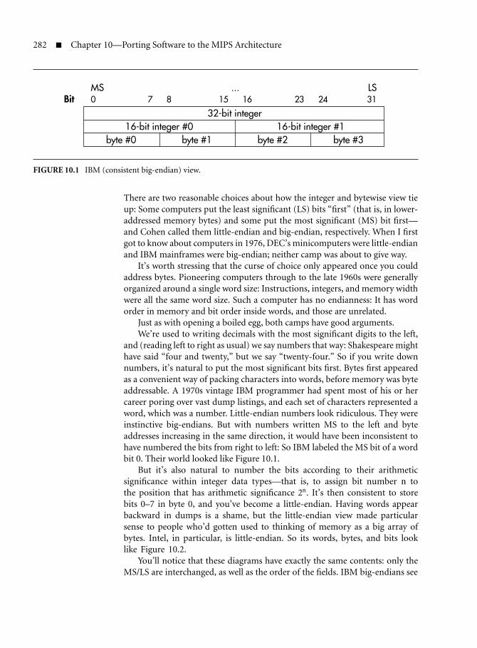
282 Chapter 10—Porting Software to the MIPS Architecture
MS ...Bit 0 7 8 15 16 23 24
32-bit integer16-bit integer #0 16-bit integer #1
byte #0 byte #1 byte #2 byte #3
LS31
FIGURE 10.1 IBM (consistent big-endian) view.
There are two reasonable choices about how the integer and bytewise view tieup: Some computers put the least significant (LS) bits “first” (that is, in lower-addressed memory bytes) and some put the most significant (MS) bit first—and Cohen called them little-endian and big-endian, respectively. When I firstgot to know about computers in 1976, DEC’s minicomputers were little-endianand IBM mainframes were big-endian; neither camp was about to give way.
It’s worth stressing that the curse of choice only appeared once you couldaddress bytes. Pioneering computers through to the late 1960s were generallyorganized around a single word size: Instructions, integers, and memory widthwere all the same word size. Such a computer has no endianness: It has wordorder in memory and bit order inside words, and those are unrelated.
Just as with opening a boiled egg, both camps have good arguments.We’re used to writing decimals with the most significant digits to the left,
and (reading left to right as usual) we say numbers that way: Shakespeare mighthave said “four and twenty,” but we say “twenty-four.” So if you write downnumbers, it’s natural to put the most significant bits first. Bytes first appearedas a convenient way of packing characters into words, before memory was byteaddressable. A 1970s vintage IBM programmer had spent most of his or hercareer poring over vast dump listings, and each set of characters represented aword, which was a number. Little-endian numbers look ridiculous. They wereinstinctive big-endians. But with numbers written MS to the left and byteaddresses increasing in the same direction, it would have been inconsistent tohave numbered the bits from right to left: So IBM labeled the MS bit of a wordbit 0. Their world looked like Figure 10.1.
But it’s also natural to number the bits according to their arithmeticsignificance within integer data types—that is, to assign bit number n tothe position that has arithmetic significance 2n. It’s then consistent to storebits 0–7 in byte 0, and you’ve become a little-endian. Having words appearbackward in dumps is a shame, but the little-endian view made particularsense to people who’d gotten used to thinking of memory as a big array ofbytes. Intel, in particular, is little-endian. So its words, bytes, and bits looklike Figure 10.2.
You’ll notice that these diagrams have exactly the same contents: only theMS/LS are interchanged, as well as the order of the fields. IBM big-endians see

10.2 Endianness: Words, Bytes, and Bit Order 283
Bit 0 7 8 15 16 23 24
byte #0 byte #1 byte #2 byte #316-bit integer #0 16-bit integer #1
32-bit integerLS ...
31
MS
FIGURE 10.2 Consistent (Intel) little-endian view.
words broken into bytes, while little-endians see bytes built into words. Boththese systems seemed unarguably right to different people: There’s lots of meritin both, but you have to choose.
But let’s get back to our observation about the problem above. Our mangledword started as 0x1234.5678, which is 00010010 00110100 01010110
01111000 in binary. If you transfer it naively to a system with the oppositeendianness, you’d surely expect to see all the bits reversed. In that case you’dreceive the number 00011110 01101010 00101100 01001000, which ishex 0x1E6A.2C48. But we said we’d read hex 0x7856.3412.
It’s true that complete bit reversal could arise in some circumstances; thereare communication links that send the MS bit first, and some that send the LSbit first. But sometime in the 1970s 8-bit bytes emerged as a universal base unitboth inside computers and in computer communications systems (where theywere called “octets”). Typically, communication systems build all their messagesout of bytes, and only the lowest-level hardware engineers know which bit goesfirst.
Meanwhile, every microprocessor system got to use 8-bit peripheral con-trollers (wider controllers were reserved for the high-end stuff), and all thoseperipherals have 8-bit ports numbered 0 through 7, and the most significantbit is 7. Somehow, without a shot apparently fired, every byte was little-endian,and has been ever since.
Early microprocessor systems were 8-bit CPUs on 8-bit buses with 8-bitmemory systems, so they had no endianness. Intel’s 8086 was a 16-bit little-endian system. When Motorola introduced the 68000 microprocessor around1978, they greatly admired IBM’s mainframe architecture. Either in admi-ration for IBM or to differentiate themselves from Intel, they thought theyshould be big-endians too. But Motorola couldn’t oppose the prevailing bits-within-bytes convention—every 8-bit Motorola peripheral would have had tobe connected to a 68000 with its data bus bit-twisted. As a result, the 68000family looks like Figure 10.3, with the bits and bytes numbered in oppositedirections.
The 68000 and its successors went on to be used for most successful UNIXservers and workstations (notably with Sun). When MIPS and other RISCsemerged in the 1980s, their designers needed to woo system designers with the

284 Chapter 10—Porting Software to the MIPS Architecture
MS ... LSBit 31 24 23 16 15 8 7 0
32-bit integer16-bit integer #0 16-bit integer #1
byte #0 byte #1 byte #2 byte #3
FIGURE 10.3 Inconsistent big-endian view as founded by the 68000 family.
right endianness, so they designed CPUs that could swing either way. But fromthe 68000 onward, big-endian has meant 68000-style big-endian, with bits andbytes going opposite ways. When you set up a MIPS CPU to be big-endian, itlooks like Figure 10.3. And that’s where the trouble really starts.
One small difficulty comes when you read hardware manuals for your CPUand see register diagrams. Everyone’s convinced that registers are (first andforemost) 32-bit integers, so they’re invariably drawn with the MS bit (bit 31,remember) first. This has some consequences for programmers and hardwaredesigners alike. That picture motivates the difference between “shift-left” and“shift-right” instructions, determines the bit-number arguments of bitfieldinstructions, and even refers to the labeling of the bitfields that make up MIPSinstructions.
Once you get over that, there is serious software trouble when porting soft-ware or moving data between incompatible machines; there is hardware troublewhen connecting incompatible components or buses. We’ll take the softwareand hardware problems separately.
10.2.2 Software and Endianness
Here’s a software-oriented definition of endianness: A CPU/compiler systemwhere the lowest addressed byte of a multibyte integer holds the least significantbits is called little-endian; a system where the lowest addressed byte of a multi-byte integer holds the most significant bits is called big-endian. You can veryeasily find out which sort of CPU you have by running a piece of deliberatelynonportable code:
#include<stdio.h>
main ()
{
union {
int as_int;
short as_short[2];
10.2 Endianness: Words, Bytes, and Bit Order 285
char as_char[4];
} either;
either.as_int = 0x12345678;
if (sizeof(int) == 4 && either.as_char[0] == 0x78) {
printf ("Little endian\n");
}
else if (sizeof(int) == 4 && either.as_char[0] == 0x12) {
printf ("Big endian\n");
}
else {
printf ("Confused\n");
}
}
Strictly speaking, software endianness is an attribute of the compilertoolchain, which could always—if it worked hard enough—produce the effectof either endianness. But on a byte-addressable CPU like MIPS with native32-bit arithmetic it would be unreasonably inefficient to buck the hardware;thus we talk of the endianness of the CPU.
Of course, the question of byte layout within the address space applies toother data types besides integers; it affects any item that occupies more thana single byte, such as floating-point data types, text strings, and even the 32-bit op-codes that represent machine instructions. For some of these nonintegerdata types, the idea of arithmetic significance applies only in a limited way, andfor others it has no meaning at all.
When a language deals in software-constructed data types bigger thanthe hardware can manage, then their endianness is purely an issue of soft-ware convention—they can be constructed with either endianness. I hopethat modern compiler writers appreciate that it’s a good idea to be consistentwith the hardware’s own convention.
Endianness and Program Portability
So long as binary data items are never imported into an application from else-where, and so long as you avoid accessing the same piece of data under twodifferent integer types (as we deliberately did above), your CPU’s endiannessis invisible (and your code is portable). Modern C compilers will try to watchout for you: If you do this by accident, you’ll probably get a compiler error orwarning.
You may not be able to live within those limitations, however; you mayhave to deal with foreign data delivered into your system from elsewhere, orwith memory-mapped hardware registers. For either of these, you need to knowexactly how your compiler accesses memory.

286 Chapter 10—Porting Software to the MIPS Architecture
Bit 31 24 23 16 15 8 7 0as_int
as_short[0] as_short[1]
as_char[0] as_char[1] as_char[2] as_char[3]
Byte offset 0 1 2 3
FIGURE 10.4 Typical big-endian’s picture.
Byte offset 0 1 2 3
Bit 0 7 8 15 16 23 24 31as_int
as_short[0] as_short[1]
as_char[0] as_char[1] as_char[2] as_char[3]
FIGURE 10.5 Little-endian’s picture.
This all seems fairly harmless, but experience shows that of all data-mappingproblems, endianness is uniquely confusing. I think this is because it is diffi-cult even to describe the problem without taking a side. The origin of the twoalternatives lies in two different ways of drawing the pictures and describing thedata; both are natural in different contexts.
As we saw above, big-endians typically draw their pictures organized aroundwords. So that gives us a big-endian picture of the data structure we used inFigure 10.4. It would look a lot prettier with the IBM convention of labeling theMS bit as bit 0, but that’s no longer done.
But little-endians are likely to emphasize a software-oriented, abstractview of computer memory as an array of bytes. So the same data structurelooks like Figure 10.5. Little-endians don’t think of computer data as primarilynumeric, so they tend to put all the low numbers (bits, bytes, or whatever) onthe left.
It’s very difficult to achieve a real grasp of endianness without drawingpictures, but many people find themselves struggling to set aside the conven-tions they’re used to; for example, if you’re used to numbering the bits fromright to left, it can take a real effort of will to number them from left to right(a picture of a little-endian structure as drawn by someone with big-endianhabits can look very illogical). This is the essence of the subject’s capacity to con-fuse: It’s difficult even to think about an unfamiliar convention without gettingcaught up in the ones you know.

10.2 Endianness: Words, Bytes, and Bit Order 287
10.2.3 Hardware and Endianness
We saw previously that a CPU’s native endianness only shows up when it offersdirect support both for word-length numbers and a finer-resolution, byte-sizedmemory system. Similarly, your hardware system acquires a recognizableendianness when a byte-addressed system is wired up with buses that are mul-tiple bytes wide.
When you transfer multibyte data across the bus, each byte of that data hasits own individual address. If the lowest-address byte in the data travels on theeight bus lines (“byte lane”) with the lowest bit numbers, the bus is little-endian.But if the lowest-address byte in the data travels on the byte lane with the highestbit numbers, the bus is big-endian.
There’s no necessary connection between the “native” endianness of a CPUand the endianness of its system interface considered as a bus. However, I don’tknow of any CPUs where the software and interface endianness are different, sowe can talk about “the endianness of a CPU” and mean both internal organi-zation and system interface.
Byte-addressable CPUs announce themselves as either big- or little-endianevery time they transfer data. Intel and DEC CPUs are little-endian; Motorola680x0 and IBM CPUs are big-endian. MIPS CPUs can be either, as configuredfrom power-up; most other RISCs have followed the MIPS lead and chosen tomake endianness configurable—a boon when updating an existing system witha new CPU.
Hardware engineers can hardly be blamed for connecting up different busesby matching up the bit numbers. But trouble strikes when your system includesbuses, CPUs, or peripherals whose endianness doesn’t match. In this case thechoice is not a happy one; the system designer must choose the lesser of twoevils:
Bit number consistent/byte sequence scrambled: Most obviously, thedesigner can wire up the two buses according to their bit numbers, whichwill have the effect of preserving bit numbering within aligned “words.”But since the relationship between bit numbers and bytes-within-wordsis different on the two buses, the two sides will see the sequence of bytesin memory differently.
Any data that is not of bus-width size and bus-width aligned will getmangled when transferred between the connected buses, with bytesswapped within each bus-width-sized unit. This looks and feels worsethan the software problem. With wrong-endianness data in software,you have no problem finding data type boundaries; it’s just that the datadoesn’t make sense. With this hardware problem the boundaries arescrambled too (unless the data are, by chance, aligned on bus-width“word” boundaries).
There’s a catch here. If the data being passed across the interface is alwaysaligned word-length integers, then bit-number-consistent wiring will

288 Chapter 10—Porting Software to the MIPS Architecture
conceal the endianness difference, avoiding the need for softwareconversion of integers. But hardware engineers very rarely know exactlywhich data will be passed across an interface over the lifetime of a system,so be cautious.
Byte address consistent/integers scrambled: The designer can decide to pre-serve byte addressing by connecting byte lanes that correspond to thesame byte-within-word address, even though the bit-numbering of thedata lines in the byte lane doesn’t match at all. Then at least the wholesystem can agree on the data seen as an array of bytes.
However, there are presumably going to be components with mismatchedsoftware endianness in the system. So your consistent byte addressingis guaranteed to expose their disagreement about the representation ofmultibyte integers. And—in particular—even a bus-width-aligned inte-ger (the “natural” unit of transfer) will appear byte-swapped when movedto the other endianness.
For most purposes, byte address scrambling is much more harmful, andwe’d recommend “byte address consistent” wiring. When dealing with datarepresentation and transfer problems, programmers will usually fall back onC’s basic model of memory as an array of bytes, with other data types built upfrom that. When your assumptions about memory order don’t work out, it’svery hard to see what’s going on.
Unfortunately, a bit number consistent/byte address scrambled connectionlooks much more natural on a schematic; it can be very hard to persuade hard-ware engineers to do the right thing.
Not every connection in a system matters. Suppose we have a 32-bit-widememory system bolted directly to a CPU. The CPU’s system interface maynot include a byte-within-word address—the address bus does not specifyaddress bits 1 and 0. Instead, many CPUs have four “byte enables,” whichshow that data is being transferred on particular byte lanes. The memoryarray is wired to the whole bus, and on a write the byte enables tell thememory array which of four possible byte locations within the word willactually get written. Internally, the CPU associates each of the byte lanes witha byte-within-word address, but that has no effect on the operation of thememory system. Effectively, the memory/CPU combination acts together andinherits the endianness of the CPU; where byte-within-word 0 actually goes inmemory doesn’t matter, so long as the CPU can read it back again.1
It’s very important not to be seduced by this helpful characteristic of aRAM memory into believing that there’s no intrinsic endianness in a simple
1. Hardware-familiarized engineers will recognize that this is a consequence of a more general rule:It’s a property of a writable memory array that it continues to work despite arbitrary permu-tations of the address and data lines to it. It doesn’t matter where any particular data goes, solong as when you feed the matching read address into the array you get back the same data youoriginally wrote.

10.2 Endianness: Words, Bytes, and Bit Order 289
CPU/RAM system. You can spot the endianness of any transfer on a wide bus.Here’s a sample list of conditions in which you can’t just ignore the CPU’sendianness when building a memory system:
If your system uses firmware that’s preprogrammed into ROM memory,the hardware address and byte lane connection assignments withinthe system need to match those assumed in the way the ROM wasprogrammed, and the data contained in the ROM needs to match theCPU’s configured endianness. In effect, the contents of the ROM arebeing delivered into your system from somewhere outside it. If the codeis to be executed directly from the ROM, it’s especially important toget the endianness right, because it’s impossible for the CPU to applyany corrective software byte-swapping to the op-codes as it fetchesthem.
When a DMA device gets to transfer data directly into memory, then itsnotions of ordering will matter.
When a CPU interface does not in fact use byte enables, but instead issuesbyte-within-word addresses with a byte-width code (quite common forMIPS CPUs), then at least the hardware that decodes the CPU’s readand write requests must know which endianness the CPU is using. Thiscan be particularly tricky if the CPU allows endianness to be software-configured.
The next section is for you to tell your hardware engineer about how toset up a byte address consistent system—and even how to make that systemconfigurable with the CPU, if some of your users might set up the MIPS CPUboth ways.
Wiring Endianness-Inconsistent Buses
Suppose we’ve got a 64-bit MIPS CPU configured big-endian, and we need toconnect it to a little-endian 32-bit bus such as PCI.
Figure 10.6 shows how we’d wire up the data buses to achieve the recom-mended outcome of consistent byte addresses as seen by the big-endian CPUand the little-endian bus.
The numbers called “byte lane” show the byte-within-bus-width part of theaddress of the byte data traveling there. Writing in the byte lane numbers is thekey to getting one of these connections right.
Since the CPU bus is 64 bits wide and the PCI bus 32 bits, you need to beable to connect each half of the wide bus to the narrow bus according to the“word” address—that’s address bit 2, since address bits 1 and 0 are the byte-within-32-bit-word address. The CPU’s 64-bit bus is big-endian, so its high-numbered bits carry the lower addresses, as you can see from the byte lanenumbers.

290 Chapter 10—Porting Software to the MIPS Architecture
bytelane
bitnumbers
bytelane
bitnumbers
memory
Local
Big-endian MIPS section Little-endianPCI section
MIPS addrSysAd2
PCIAD2
== == 1
MIPS addrSysAd2
PCIAD2
== == 0
4
5
6
7
0
1
2
3 32 – 39
40 – 47
48 – 55
56 – 63
0 – 7
8 – 15
16 – 23
24 – 31
0
1
2
3
0 – 7
8 – 15
16 – 23
24 – 31
64-bit CPU
FIGURE 10.6 Wiring a big-endian CPU to a little-endian bus.
You may find yourself staring at the numbering of the connections aroundthe bus switch for quite some time before they really make sense. Such are thejoys of endianness.
And note that I only showed data. PCI is a multiplexed bus, and in someclock cycles those “byte lanes” are carrying an address. In address cycles, PCIbus wire 31 is carrying the most significant bit of the address. The address-timeconnection from your MIPS-based system should not be swapped.
Wiring an Endianness-Configurable Connection
Suppose you want to build a board or bus switch device that allows you toconfigure a MIPS CPU to run with either endianness. How can we generalizethe advice above?

10.2 Endianness: Words, Bytes, and Bit Order 291
We’d suggest that, if you can persuade your hardware designer, you shouldput a programmable byte lane swapper between the CPU and the I/O system.The way this works is shown diagrammatically in Figure 10.7; note that this isonly a 32-bit configurable interface and it’s an exercise for you to generalize itto a 64-bit CPU connection.
We call this a byte lane swapper, not a byte swapper, to emphasize thatit does not alter its behavior on a per-transfer basis, and in particular toindicate that it is not switched on and off for transfers of different sizes.There are circumstances where it can be switched on and off for transfers todifferent address regions—mapping some part of the system as bit numberconsistent/byte address scrambled—but that’s for you to make work.
24 – 310 – 7 8 – 15 16 – 23
MIPS CPU(little-endian)
MIPS CPU(big-endian)
24 – 310 – 7 8 – 15 16 – 23
“U” “N” “I” “X”
0 1 2 3
0
4
8
IO system
Byte laneswapper
“U” “N” “I” “X” “U”“N”“I”“X”
FIGURE 10.7 Byte lane swapper.

292 Chapter 10—Porting Software to the MIPS Architecture
What a byte lane swapper does achieve is to ensure that whether your CPUis set up to be big- or little-endian, the relationship between the CPU and thenow mismatched external bus or device can still be one where byte sequnce ispreserved.
You normally won’t put the byte-lane swapper between the CPU and itslocal memory—this is just as well, because the CPU/local memory connectionis fast and wide, which would make the byte swapper expensive.
As mentioned above, so long as you can decode the CPU’s system inter-face successfully, you can treat the CPU/local memory as a unit and installthe byte swapper between the CPU/memory unit and the rest of the system.In this case, the relationship between bit number and byte order inside thelocal memory changes with the CPU, but this fact is not visible from therest of the world.
False Cures and False Prophets for Endianness Problems
Every design team facing up to endianness for the first time goes through thestage of thinking that the troubles reflect a hardware deficiency to be solved. It’snever that simple. Here are a few examples.
Configurable I/O controllers: Some newer I/O devices and system con-trollers can themselves be configured into big-endian and little-endianmodes. You’re going to have to read the manual very carefully beforeusing such a feature, particularly if you mean to use it not as a static(design time) option but rather as a jumper (reset time) option.
It is quite common for such a feature to affect only bulk data transfers,leaving the programmer to handle other endianness issues, such as accessto bit-coded device registers or shared memory control fields. Also, thecontroller designer probably didn’t have the benefit of this book—andconfusion about endianness is widespread.
Hardware that byte-swaps according to transfer type: If you’re design-ing in some byte-swap hardware, it seems appealing to try to solvethe whole problem. If we just swapped byte data to preserve itsaddresses, but left words alone, couldn’t we prevent the whole soft-ware problem? The answer is no, there aren’t any hardware fixes forthe software problem. For example, many of the transfers in a realsystem are of data cache lines. They may contain an arbitrary mix-ture of data sizes and alignments; if you think about it for a moment,you’ll see that there simply isn’t any way to know where the bound-aries are, which means there’s no way to determine the required swapconfiguration.
Conditional byte-swapping just adds confusion. Anything more thanunconditional byte lane swapping is snake oil.

10.2 Endianness: Words, Bytes, and Bit Order 293
10.2.4 Bi-endian Software for a MIPS CPU
You may want to create binary code that will run correctly on MIPS CPUswith either endianness—probably for a particular board that may be run eitherway or to create a portable device driver that may run on boards of eitherconfiguration. It’s a bit tricky, and you will probably only do a tiny part of yourbootstrap code like this, but here are some guidelines.
The MIPS CPU doesn’t have to do too much to change endianness. The onlyparts of the instruction set that recognize objects smaller than 32 bits are partial-word loads and stores. On a MIPS CPU with a 32-bit bus, the instruction:
lbu t0, 1(zero)
takes the byte at byte program address 1, loads it into the least significant bits(0 through 7) of register t0, and fills the rest of the register with zero bits. Thisdescription is endianness independent. However, in big-endian mode the dataloaded into the register will be taken from bits 16–23 of the CPU data bus; inlittle-endian mode, the byte is loaded from bits 8–15 of the CPU data bus.
Inside the MIPS CPU, there’s data-steering hardware that the CPU usesto direct all the active bytes in a transfer from their respective byte lanesat the interface to the correct positions within the internal registers. Thissteering logic has to accommodate all permutations of load size, address,and alignment (including the load/store left/right instructions described insection 8.5.1).
It is the change in the relationship between the active byte lane and theaddress on partial-word loads and stores that characterizes the MIPS CPU’sendianness. When you reconfigure your MIPS CPU’s endianness, it’s that steer-ing logic between data and register whose behavior changes.
Complementing the chip’s configurability, most MIPS toolchains can pro-duce code of either endianness, based on a command-line option.
If you set a MIPS CPU to the wrong endianness for its system, then a coupleof things will happen.
First, if you change nothing else, the software will crash quickly, because onany partial-word write the memory system will pick up garbage data from thewrong part of the CPU bus. At the same time as reconfiguring the CPU, we’dbetter reconfigure the logic that decodes CPU cycles.2
If you fix that, you’ll find that the CPU’s view of byte addressing becomesscrambled with respect to the rest of the system; in terms of the descriptionabove, we’ve implicitly opted for a connection that keeps the bit numbers con-sistent, rather than the byte addresses.
Of course, data written by the CPU after a change of endianness will seemfine to the CPU itself; if we allow changes of endianness only at reset time, thenvolatile memory that is private to the CPU won’t give us any trouble.
2. There are some CPU interfaces where partial-word transfers are signaled with independent bytelane enable signals, and in that case this problem doesn’t happen.

294 Chapter 10—Porting Software to the MIPS Architecture
Byte address from BE CPU
Byte address from LE CPU
31 24 23 16 15 8 7 0
Byte address from BE CPU
Byte address from LE CPU
Byte address from BE CPU
Byte address from LE CPU
03
4
c
7
8
x
11
12
56
n
910
x
21
65
e
109
\000
30
74
g
118
y
r e m E
FIGURE 10.8 Garbled string storage when mixing modes; see text.
Note also that the CPU’s view of bit numbering within aligned bus-widthwords continues to match the rest of the system. This is the choice we describedearlier as bit number consistent and that we suggested you should generallyavoid. But in this particular case it has a useful side effect, because MIPS instruc-tions are encoded as bitfields in 32-bit words. An instruction ROM that makessense to a big-endian CPU will make sense to a little-endian CPU too, allow-ing us to share a bootstrap. Nothing works perfectly—in this case, any data inthe ROM that doesn’t consist of aligned 32-bit words will be scrambled. Manyyears ago, Algorithmics’ MIPS boards had just enough bi-endian code in theirboot ROM to detect that the main ROM program does not match the CPU’sendianness and to print the helpful message:
Emergency - wrong endianness configured.
The word Emergency is held as a C string, null-terminated. You shouldnow know enough to understand why the ROM start-up code contains theenigmatic lines:
.align 4
.ascii "remEcneg\000\000\000y"
That’s what the string Emergency (with its standard C terminating null andtwo bytes of essential padding) looks like when viewed with the wrong endian-ness. It would be even worse if it didn’t start on a four-byte-aligned location.Figure 10.8 (drawn from the point of view of a confirmed big-endian) showswhat is going on.
You’ve seen that writing bi-endian code is possible, but be aware that whenyou’re ready to load it into ROM, you’ll be asking your tools to do somethingthey weren’t designed to handle. Typically, big-endian tools pack instruction

10.2 Endianness: Words, Bytes, and Bit Order 295
words into the bytes of a load file with the most significant bits first, and little-endian tools work the other way around. You’ll need to think carefully aboutthe result you need to achieve, and examine the files you generate to make sureeverything went according to plan.
10.2.5 Portability and Endianness-Independent Code
By a fairly well-respected convention, most MIPS toolchains define the symbolBYTE ORDER as follows:
#if BYTE_ORDER == BIG_ENDIAN
/* big-endian version... */
#else
/* little-endian version... */
#endif
So if you really need to, you can put in different code to handle each case. Butit’s better—wherever possible—to write endianness-independent code. Partic-ularly in a well-controlled situation (such as when writing code for a MIPSsystem that may be initialized with the CPU in either mode), you can get ridof a lot of dependencies by good thinking.
All data references that pick up data from an external source or device arepotentially endianness dependent. But according to how your system is wired,you may be able to produce code that works both ways. There are only two waysof wiring the wrong endianness together: One preserves byte addresses and theother bit numbers. For some particular peripheral register access in a particularrange of systems, there’s a good chance that the endianness change consistentlysticks to one of these.
If your device is typically mapped to be byte address compatible, then youshould program it strictly with byte operations. If ever, for reasons of efficiencyor necessity, you want to transfer more than one byte at a time, you need towrite endianness-conditional code that packs or unpacks that data.
If your device is compatible at the word (32-bit) level—for example, it con-sists of registers wired (by however devious and indirect a route) to a fixed setof MIPS data bus bits—then program it with bus-width read/write operations.That will be 32-bit or 64-bit loads and stores. If the device registers are not wiredto MIPS data bus bits starting at 0, you’ll probably want to shift the data after aread and before a write. For example, 8-bit registers on a 32-bit bus in a systemoriginally conceived as big-endian are commonly wired via bits 31–24.
10.2.6 Endianness and Foreign Data
This chapter is about programming, not a treatise on I/O and communi-cations, so we’ll keep this section brief. Any data that is not initialized in

296 Chapter 10—Porting Software to the MIPS Architecture
your code, chosen libraries, and OS is foreign. It may be data you readfrom some memory-mapped piece of hardware, data put into memory byDMA, data in a preprogrammed ROM that isn’t part of your program, oryou may be trying to interpret a byte stream obtained from an “abstract”I/O device under your OS.
The first stage is to figure out what this data looks like in memory; withC, that can usually be accomplished by mapping out what its contents are asan array of unsigned char. Even if you know your data and compiler wellenough to guess which C structure will successfully map to the data, fall back tothe array of bytes when something is not as you expect; it’s far too easy to misswhat is really going on if your data structure is incorrect.
Apart from endianness, the data may consist of data types that are notsupported by your compiler/CPU; it may have similar types but with com-pletely different encodings; it may have familiar data but be incorrectlyaligned; or, falling under this section’s domain, it may have the wrongendianness.
If the chain along which the data has reached you has preserved byte orderat each stage, the worst that will happen is that integer data will be representedwith an opposite order, and it’s easy enough to build a “swap” macro to restorethe two, four, or eight bytes of an integer value.
But if the data has passed over a bit number consistent/byte address scram-bled interface, it can be more difficult. In these circumstances, you need tolocate the boundaries corresponding to the width of the bus where the datagot swapped; then, taking groups of bytes within those boundaries, swap themwithout regard to the underlying data type. If you do it right, the result shouldnow make sense, with the correct byte sequence, although you may still needto cope with the usual problems in the data—including, possibly, the need toswap multibyte integer data again.
10.3 Trouble with Visible Caches
In section 4.6, you learned about the operations you can use to get your cachesinitialized and operating correctly. This section alerts you to some of the prob-lems that can come up and explains what you can do to deal with them.
Most of the time, the caches are completely invisible to software, servingonly to accelerate the system as they should. But especially if you need to dealwith DMA controllers and the like, it can be helpful to think of the caches asindependent buffer memories, as shown in Figure 10.9.3
It’s important to remember that transfers between cache and memory alwayswork with blocks of memory that fit the cache line structure—typically 16- or32-byte-aligned blocks—so the cache may read or write a block because the
3. For MIPS CPUs with simple write-through data caches, the path labeled “write-back” in thefigure doesn’t exist.

10.3 Trouble with Visible Caches 297
CPU
I-fetch
es
Loads & stores
I-cache refills
D-cache re
fills
Write-back
DMA reads
DMA writesMemory
Uncached instructions/data
Uncached writes/write-throughs
D-cache
cacheI-
FIGURE 10.9 Data flow between CPU, memory, and caches.
CPU makes direct reference to just one of the byte addresses contained withinit; even if the CPU never touches any of the other bytes in the cache line, it’llstill include all the bytes in the next transfer of that cache line.
In an ideal system, we could always be certain that the state of the mem-ory is up-to-date with all the operations requested by the CPU, and thatevery valid cache line contains an exact copy of the appropriate memorylocation. Unfortunately, practical systems can’t always live up to this ideal.We’ll assume that you initialize your caches after any reset, and that youavoid (rather than try to live with) the dreaded cache aliases described insection 4.12. Starting from those assumptions, how does a real system’sbehavior fall short of the ideal?
Stale data in the cache: When your CPU writes to memory in cachedspace, it updates the cached copy (and may also write memory at thesame time). But if a a memory location is updated in any other way, anycached copies of its contents continue to hold the old value, and are nowout-of-date. That can happen when a DMA controller writes data. Or,when the CPU writes new instructions for itself, the I-cache may con-tinue to hold whatever was at the same location before. It’s importantfor programmers to realize that the hardware generally doesn’t deal withthese conditions automatically.
Stale data in memory: When the CPU writes some data into a (write-back) cache line, that data is not immediately copied to memory. If thedata is read later by the CPU, it gets the cached copy and is fine; but if

298 Chapter 10—Porting Software to the MIPS Architecture
something that isn’t the CPU reads memory, it may get the old value.That can happen to an outbound DMA transfer.
The software weapons you have to fight problems caused by visible cachesare a couple of standard subroutines that allow you to clean up cache/memoryinconsistency, built on MIPS cache instructions. They operate on cache loca-tions corresponding to a specified area of memory and can write-back up-to-date cache data or invalidate cache locations (or both).
Well, of course, you can always map data uncached. In fact, there are somecircumstances when you will do just that: Some network device controllers,for example, have a memory-resident control structure where they read andwrite bytes and bit flags, and it’s a lot easier if you map that control struc-ture uncached. The same is true, of course, of memory-mapped I/O registers,where you need total control over what gets read and written. You can do thatby accessing those registers through pointers in kseg1 or some other uncachedspace; if you use cached space for I/O, bad things will happen!
If (unusually) you need to use the TLB to map hardware register accesses,you can mark the page translation as uncached. That’s useful if someone hasbuilt hardware whose I/O registers are not in the low 512 MB of the physicalmemory space.
It’s possible that you might want to map a memory-like device (a graphicsframe buffer, perhaps) through cached space so as to benefit from the speed ofthe block reads and writes that the CPU only uses to implement cache refillsand write-backs. But you’d have to explicitly manage the cache by invalidationand write-back on every such access. Some embedded CPUs provide strange andwonderful cache options that can be useful for that kind of hardware—checkyour manual.
10.3.1 Cache Management and DMA Data
This is a common source of errors, and the most experienced programmers willsometimes get caught out. Don’t let that worry you too much: Provided youthink clearly and carefully about what you’re trying to achieve, you’ll be ableto get your caches to behave as they should while your DMA transfers worksmoothly and efficiently.
When a DMA device puts data into memory, for example, on receipt ofnetwork data, most MIPS systems don’t update the caches—even though somecache lines may currently be holding addresses within the region just updatedby the DMA transfer. If the CPU subsequently reads the information in thosecache lines, it’ll pick up the old, stale version in the cache; as far as the CPU cantell, that’s still marked valid, and there’s no indication that the memory has anewer version.
To avoid this, your software must actively invalidate any caches’ lines thatfall within the address range covered by your DMA buffer, before there’s any

10.3 Trouble with Visible Caches 299
chance that the CPU will try to refer to them again. This is much easier tomanage if you round out all your DMA buffers so they start and end exactlyat cache line boundaries.
For outbound transfers, before you allow a DMA device to transfer data frommemory—such as a packet that you’re sending out via a network interface—youmust make absolutely sure that none of the data to be sent is still just sitting inthe cache. After your software has finished writing out the information to betransferred by DMA, it must force the write-back of all cache lines currentlyholding information within the address range that the DMA controller will usefor the transfer. Only then can you safely initiate the DMA transfer.
On some MIPS CPUs, you can avoid the need for explicit write-back oper-ations by configuring your caches to use write-through rather than write-backbehavior, but this cure is really worse than the disease — write-through tendsto be much slower overall and will also raise your system’s power consumption.
You really can get rid of the explicit invalidations and write-backs by access-ing all the memory used for all DMA transfers via an uncached address region.This isn’t recommended either, because it’ll almost certainly degrade your sys-tem’s overall performance far more than you’d like. Even if your software’s accessto the buffers is purely sequential, caching the DMA buffer regions will meanthat information gets read and written in efficient cache-line-sized bursts ratherthan single transfers. The best general advice is to cache everything, with onlythe following exceptions:
I/O device registers: Perhaps obvious, but worth pointing out. MIPS hasno dedicated input/output instructions, so all device registers must bemapped somewhere in the address space, and very strange things willhappen if you accidentally let them be cached.
DMA descriptor arrays: Sophisticated DMA controllers share con-trol/status information with the CPU using small descriptor data struc-tures held in memory. Typically, the CPU uses these to create a long list ofinformation to be transferred, and only then tells the DMA controller tobegin its work. If your system uses descriptors, you’ll want to access thememory region that contains them through an uncached address region.
A portable OS like Linux must deal with a range of caches from the mostsophisticated and invisible to the crude and simple, so it has a fairly well-definedAPI (set of stable function calls) for driver writers to use and some terse docu-mentation on how to use them. See section 15.1.1.
10.3.2 Cache Management and Writing Instructions:Self-Modifying Code
If your code ever tries to write instructions into memory, then execute them,you’ll need to make sure you allow for cache behavior.

300 Chapter 10—Porting Software to the MIPS Architecture
This can surprise you on two levels. First, if you have a write-backD-cache, the instructions that your program writes out may not find their wayto main memory until something triggers a write-back of the relevant cachelines. The instructions that your program wrote out could just be sitting in theD-cache at the time you try to execute them, and the CPU’s fetches simply can’taccess them there. So the first step is to do write-back operations on the cachelines at which you write the instructions; that at least ensures they reach mainmemory.
The second surprise (regardless of which type of D-cache you have) isthat even after writing out the new instructions to some region of mainmemory, your CPU’s I-cache may still hold copies of the information thatused to be held in those addresses. Before you tell the CPU to execute thenewly written instructions, it’s essential that your software first invalidatesall the lines in the I-cache that contain information at the affected addressrange.
Of course, you could avoid the need for these explicit write-back and inval-idate operations by writing and then executing the new instructions within anuncached address region; but that gives up the advantages of caching and isalmost always a mistake.
The general-purpose cache management instructions described insection 4.9 are CP0 instructions, only usable by kernel-privilege software. Thatdoesn’t matter when cache operations are related to DMA operations, whichare also entirely kernel matters. But it does matter with applications like writ-ing instructions and executing them (think of a modern application using a“just-in-time” interpreted/translated language).
So MIPS32/64 provides the synci instruction, which does a D-side write-back and an I-side invalidate of one cache-line-sized piece of your new code.Find out how in section 8.5.11.
10.3.3 Cache Management and Uncached or Write-Through Data
If you mix cached and uncached references that map to the same physical rangeof addresses, you need to think about what this means for the caches. Uncachedwrites will update only the copy of a given address in main memory, possiblyleaving what’s now a stale copy of that location’s contents in the D-cache—or theI-cache. Uncached loads will pick up whatever they find in main memory—evenif that information is, in fact, stale with respect to an up-to-date copy presentonly in cache.
Careful use of cached and uncached references to the same physical regionmay be useful, or even necessary, in the low-level code that brings your sys-tem into a known state following a reset. But for running code, you probablydon’t want to do that. For each region of physical memory, decide whether yoursoftware should access it cached or uncached, then be absolutely consistent intreating it that way.

10.4 Memory Access Ordering and Reordering 301
10.3.4 Cache Aliases and Page Coloring
There’s more about the hardware origin of cache aliases in section 4.12. Theproblem occurs with L1 caches that are virtually indexed but physically tagged,and where the index range is big enough to span two or more page sizes. Theindex range is the size of one “set” of the cache, so with common 4-KB pagesyou can get aliases in an 8-KB direct-mapped cache or a 32-KB four-wayset-associative cache.
The “page color” of a location is the value of those one or more virtualaddress bits that choose a page-sized chunk within the appropriate cache set.Two virtual pointers to the same physical data can produce an alias only if theyhave a different page color. So long as all pointers to the same data have the samecolor, all is well—all the data, even though at different virtual addresses, will bestored in the same physical portion of the cache and will be correctly identifiedby the (common) physical tag.
It’s quite common in Linux (for example) for a physical page to be accessi-ble at multiple virtual locations (shared libraries are routinely shared betweenprograms at different virtual addresses).
Most of the time, the OS is able to overalign virtual address choices for shareddata—the sharing processes may not use the same address, but we’ll make suretheir different virtual addresses are a multiple of, say, 64 KB apart, so the differentvirtual addresses have the same color. That takes up a bit more virtual memory,but virtual memory is fairly cheap.
It’s easy to think that cache aliases are harmless so long as the data is “read-only” (it must have been written once, but that was before there were aliases toit): We don’t care if there are multiple copies of a read-only page. But they’re onlymostly harmless. It is possible to tolerate aliases to read-only data, particularly inthe I-cache: But you need to make sure that cache management software is awarethat data that has been invalidated at one virtual address may still be cached atanother.
With the widespread use of virtual-memory OSs (particularly Linux) in theembedded and consumer computing markets, MIPS CPUs are increasinglybeing built so that cache aliases can’t happen. It’s about time this long-lastingbug was fixed.
Whatever you need to do, the cache primitive operations required for aMIPS32/64 CPU are described in section 4.9.1.
10.4 Memory Access Ordering and Reordering
Programmers tend to think of their code executing in a well-behaved sequence:The CPU looks at an instruction, updates the state of the system in the appro-priate ways, then goes on to the next instruction. But our program can runfaster if we allow the CPU to break out of this purely sequential form of exe-cution, so that operations aren’t necessarily constrained to take place in strict

302 Chapter 10—Porting Software to the MIPS Architecture
program order. This is particularly true of the read and write transactionsperformed at the processor’s interface, triggered by its execution of load andstore instructions.
From the CPU’s point of view, a store requires only an outbound writerequest: Present the memory address and data, and leave the memory controllerto get on with it. Practical memory and I/O devices are relatively slow, and inthe time the write is completed the CPU may be able to run tens or hundreds ofinstructions.
Reads are different, of course: They require two-way communicationin the form of an outbound request and an inbound response. When theCPU needs to know the contents of a memory location or a device regis-ter, there’s probably not much it can do until the system responds with theinformation.
In the quest for higher performance, that means we want to make readsas fast as possible, even at the expense of making writes somewhat slower.Taking this thinking a step further, we can even make write requests wait in aqueue, and pass any subsequent read requests to memory ahead of the bufferedwrites. From the CPU’s point of view, this is a big advantage; by starting theread transaction immediately, it gets the response back as soon as possible.The writes will have to be done sometime, and the queue is of finite size: Butit’s likely that after this read is done there will be a period while the CPU isrunning from cache. And if the queue fills up, we’ll just have to stop whilesome writes happen: That’s certainly no worse than if we’d done the writes insequence.
You can probably see a problem here: Some programs may write a locationand then read it back again. If the read overtakes the write, we may get stale datafrom memory and our program will malfunction. Most of the time we can fix itwith extra hardware that checks an outgoing read request against the addressesof entries in the write queue and doesn’t allow the read to overtake a matchingwrite.4
In systems where tasks that could be really concurrent (that is, they might berunning on different CPUs) share variables, the problem of ordering reads andwrites becomes more dangerous. It’s true that much of the time the tasks haveno expectation of mutual ordering. Ordering matters when the tasks are deliber-ately using shared memory for synchronization and communication, but in thiscase the software will be using carefully crafted OS synchronization operations(locks and semaphores, for example).
But there are some shared-memory communication tricks—often good,cheap, efficient ones—that don’t need so many semaphores or locks but aredisrupted by arbitrary cycle reordering. Suppose, for example, we have two
4. You could, in some circumstances, return data from the write buffer to fulfill the read. But wedon’t have to invent anything to allow the read to wait and then go to memory.

10.4 Memory Access Ordering and Reordering 303
tasks: one is writing a data structure, the other is reading it. They use the datastructure in turn, as shown in Figure 10.10.
For correct operation, we need to know that when the reader sees the updatedvalue in the key field, we can guarantee that all the other updates will be visibleto the reader as well.
Unless we discard all the performance advantages of decoupling reads andwrites from the CPU, it’s not practical for hardware to conceal all ordering issuesfrom the programmer. The MIPS architecture provides the sync instruction forthis purpose: You’re assured that (for all participants in the sharedmemory) all accesses made before the sync will precede those made afterward.It’s worth dwelling on the limited nature of that promise: It only relates to order-ing, and only as seen by participants in uncached or cache-coherent memoryaccesses.
To make the example above reliable on a suitable system, the writer shouldinclude sync just before writing keyfield, and the reader should have a syncjust after reading keyfield. See section 8.5.9 for details. But there’s a lot moreto this subject; if you’re building such a system, you’re strongly recommendedto use an OS that provides suitable synchronization mechanisms, and read upon this subject.
Different architectures make different promises about ordering. At oneextreme, you can require all CPU and system designers to contrive that all thewrites and reads made by one CPU appear to be in exactly the same order fromthe viewpoint of another CPU: That’s called “strongly ordered.” There areweaker promises too (such as “all writes remain in order”); but the MIPS archi-tecture takes the radical position that no guarantees are made at all.
Writing task Reading task
keyfield = WAITINGFORWRITE;
... ...
/* update entries */
keyfield = WRITEDONE;
sendsignaltoreader();
while (keyfield != WRITEDONE) {waitforsignalfromwriter();
}/* read entries */
...
FIGURE 10.10 Tasks sharing a data structure.

304 Chapter 10—Porting Software to the MIPS Architecture
10.4.1 Ordering and Write Buffers
Let’s escape from the lofty theory and describe something rather more practical.The idea of holding outbound requests in a write buffer turns out to work espe-cially well in practice because of the way store instructions tend to be bunchedtogether. For a CPU running compiled MIPS code, it’s typical to find that onlyabout 10 percentage of the instructions executed are stores; but these accessestend to come in bursts—for example, when a function prologue saves a groupof register values.
Most of the time the operation of the write buffer is completely transpar-ent to software. But there are some special situations in which the programmerneeds to be aware of what’s happening:
Timing relations for I/O register accesses: This affects all MIPS CPUs. Afterthe CPU executes a store to update an I/O device register, the outboundwrite request is liable to incur some delay in the write buffer, on its wayto the device. Other events, such as inbound interrupts, may take placeafter the CPU executes the store instruction, but before the write requesttakes effect within the I/O device. This can lead to surprising behavior:For example, the CPU may receive an interrupt from a device “after” youhave told it not to generate interrupts. To give another example: If an I/Odevice needs some software-implemented delay to recover after a write,you must ensure that the write buffer is empty before you start countingout that delay— ensuring also that the CPU waits while the write bufferempties. It’s good practice to define a subroutine that does this job, andit’s traditionally given the name wbflush(). See section 10.4.2 for hintson implementing it.
Reads overtaking writes: The MIPS32/64 architecture permits this behav-ior, discussed above. If your software is to be robust and portable, it shouldnot assume that read and write order is preserved. Where you need toguarantee that two cycles happen in some particular order, you need thesync instruction described in section 8.5.9.
Byte gathering: Some write buffers watch for partial-word writes withinthe same memory word (or even writes within the same cache line) andwill combine those partial writes into a single operation.
To avoid unpleasant symptoms when uncached writes are combined intoa word-width, it’s a good idea to map your I/O registers such that eachregister is in a separate word location (i.e., 8-bit registers should be atleast four bytes apart).
10.4.2 Implementing wbflush
Most write queues can be emptied out by performing an uncached store toany location and then performing an operation that reads the same data back.

10.5 Writing it in C 305
A write queue certainly can’t permit the read to overtake the write—it wouldreturn stale data. Put a sync instruction between the write and the read, andthat should be effective on any system compliant with MIPS32/64.
This is effective, but not necessarily efficient; you can minimize the over-head by loading from the fastest memory available. Perhaps your system offerssomething system-specific but faster. Use it after reading the following note!
CAUTION! Write buffers are often implemented within the CPU, but may also be imple-mented outside it; any system controller or memory interface that boasts ofa write-posting feature introduces another level of write buffering to your sys-tem. Write buffers outside the CPU can give you just the same sort of troubleas those inside it. Take care to find out where all the write buffers are locatedin your system, and to allow for them in your programming.
10.5 Writing it in C
You probably already write almost everything in C or in C++. MIPS’s lack of spe-cial I/O instructions means that I/O register accesses are just normal loads andstores with appropriately chosen addresses; that’s convenient, but I/Oregister accesses are usually somewhat constrained, so you need to make surethe compiler doesn’t get too clever. MIPS’s use of large numbers of CP0 reg-isters also means that OS code can benefit from well-chosen use of C asm()
operations.
10.5.1 Wrapping Assembly Code with the GNU C Compiler
The GNU C Compiler (“GCC”) allows you to enclose snippets of assembly codewithin C source files. GCC’s feature is particularly powerful, but other moderncompilers probably could support the example here. But their syntax is probablyquite different, so we’ll just discuss GCC here.
If you want low-level control over something that extends beyond a handfulof machine instructions, such as a library function that carries out some clevercomputation, you’ll really need to get to grips with writing pure MIPS assembly;but if you just want to insert a short sequence that consists of one or a few spe-cific MIPS instructions, the asm() directive can achieve the desired result quitesimply. Better still, you can leave it to the compiler to manage the selection ofregisters according to its own conventions.
As an example, the following code makes GCC use the three-operand formof multiply, available on more recent MIPS CPUs. If you just use the normal Clanguage * multiplication operator, the work could end up being done by the

306 Chapter 10—Porting Software to the MIPS Architecture
original form of the multiply instruction that accepts only two source operands,implicitly sending its double-length result to the hi/lo register pair.5
The C function mymul() is exactly like the three-operand mul and deliversthe less significant half of the double-length result; the more significant half issimply discarded, and it’s up to you to ensure that overflows are either avoidedor irrelevant.
static int __inline__ mymul(int a, int b)
{
int p;
asm("mul %0, %1, %2"
: "=r" (p)
: "r" (a), "r" (b)
);
return p;
}
The function itself is declared inline, which instructs the compiler thata use of this function should be replaced by a copy of its logic (whichpermits local register optimization to apply). Adding static means thatthe function need not be published for other modules to use, so no binaryof the function itself will be generated. It very often makes sense to wrapan asm() like this: You’d probably usually then put the whole definitionin an include file. You could use a C preprocessor macro, but the inlinedfunction is a bit cleaner.
The declarations inside the asm() parentheses tell GCC to emit a MIPS mulline to the assembler with three operands on the command line—one will be theoutput and two will be inputs.
On the line below, we tell GCC about operand %0, the product: first, that thisvalue will be write-only (meaning that there’s no need to preserve its originalvalue) with the “=” modifier; the “r” tells GCC that it’s free to choose any ofthe general-purpose registers to hold this value. Finally, we tell GCC that theoperand we wrote as %0 corresponds to the C variable p.
On the third line of the asm() construct, we tell GCC about operands %1and%2. Again, we allow GCC to put these in any of the general-purpose registers,and tell it that they correspond to the C variables a and b.
At the end of the example function, the result we obtained from the multiplyinstruction is returned to the C caller.
GCC allows considerable control over the specification of the operands; youcan tell it that certain values are both read and written and that certain hardware
5. At the time of writing there are versions of GCC in circulation that will use MIPS32’s three-operand mul instruction—but this makes for a good example.
10.5 Writing it in C 307
registers are left with meaningless values as a side effect of a particular assemblysequence. You can dig out the details from the MIPS-specific sections of the GCCmanual.
10.5.2 Memory-Mapped I/O Registers and “Volatile”
Most of you will be writing code that accesses I/O registers in C—you certainlyshouldn’t be using assembly code in the absence of any pressing need to do so,and since all I/O registers in MIPS must be memory-mapped, it is never difficultto access them from C. Having said that, you should keep in mind that as com-pilers advance, or if you make significant use of C++, it can become harder topredict exactly the low-level instruction sequences that’ll end up in your code.Here are some well-worn hints.
I might write a piece of code that is intended to poll the status register of aserial port and to send a character when it’s ready:
unsigned char *usart_sr = (unsigned char *) 0xBFF00000;
unsigned char *usart_data = (unsigned char *) 0xBFF20000;
#define TX_RDY 0x40
void putc (ch)
char ch;
{
while ((*usart_sr & TX_RDY) == 0)
;
*usart_data = ch;
}
I’d be upset if this sent two characters and then looped forever, but thatwould be quite likely to happen. The compiler sees the memory-mapped I/Oreference implied by *usart sr as a loop-invariant fetch; there are no stores inthe while loop so it seems safe to pull the load out of the loop. Your compilerhas recognized that your C program is equivalent to:
void putc (ch)
char ch;
{
tmp = (*usart_sr & TX_RDY);
while (tmp)
;
*usart_data = ch;
}

308 Chapter 10—Porting Software to the MIPS Architecture
You could prevent this particular problem by defining your registers as follows:
volatile unsigned char *usart_sr =
(unsigned char *) 0xBFF00000;
volatile unsigned char *usart_data =
(unsigned char *) 0xBFF20000;
A similar situation can exist if you examine a variable that is modified by aninterrupt or other exception handler. Again, declaring the variable as volatileshould fix the problem.
I won’t guarantee that this will always work: The C bible describes theoperation of volatile as implementation dependent. I suspect, though, thatcompilers that ignore the volatile keyword are implicitly not allowed to opti-mize away loads.
Many programmers have trouble using volatile. The thing to rememberis that it behaves just like any other C type modifier—just like unsigned in theexample above. You need to avoid syndromes like this:
typedef char * devptr;
volatile devptr mypointer;
You’ve now told the compiler that it must keep loading the pointer valuefrom the variable devptr, but you’ve said nothing about the behavior of theregister you’re using it to point at. It would be more useful to write the code likethis:
typedef volatile char * devptr;
devptr mypointer;
Once you’ve dealt with this, the most common reason that optimized codebreaks will be that you have tried to drive the hardware too fast. There are oftentiming constraints associated with reads and writes of hardware registers, andyou’ll often have to deliberately slow your code to fit in.
What’s the main lesson of this section? While it’s easier to write andmaintain hardware driver code in C than in assembly, it’s important touse this option responsibly. In particular, you’ll need to understand enoughabout the way the toolchain converts your high-level source code into low-level machine instructions to make sure you get the system behavior thatyou intended.
10.5.3 Miscellaneous Issues When Writing C for MIPS Applications
Negative pointers: When running simple unmapped code on a MIPS CPU,all pointers are in the kseg0 or kseg1 areas, so any data pointer’s 32-bit

10.5 Writing it in C 309
value has the top bit set and looks “negative.” Unmapped programs onmost other architectures are dealing with physical addresses, which areusually a lot smaller than 2 GB!
Such pointer values could cause trouble when pointer values are beingcompared, if the pointer were implicitly converted to a signed integertype. Any implicit conversions between integer and pointer types (quitecommon in C) should be made explicit and should specify an unsignedinteger type (you should use unsigned long for this).
Most compilers will warn about pointer-to-integer conversions, thoughyou may have to specify an option.
Signed versus unsigned characters: In early C compilers, the char typeused for strings was usually equivalent to signed char; this is consistentwith the convention for larger integer values. However, as soon as youhave to deal with character encodings using more than 7-bit values, thisis dangerous when converting or comparing. Modern compilers usuallymake char equivalent to unsigned char instead.
If you discover that your old program depends on the default sign-extension of char types, good compilers offer an option that will restorethe traditional convention.
Moving from 16-bit int: A significant number of programs are beingmoved up from 16-bit x86 or other CPUs where the standard int isa 16-bit value. Such programs may rely, much more subtly than youthink, on the limited size and overflow characteristics of 16-bit val-ues. Although you can get correct operation by translating such typesinto short, that will be inefficient. In most cases you can let vari-ables quietly pick up the MIPS int size of 32 bits, but you shouldbe particularly aware of places where signed comparisons are used tocatch 16-bit overflow.
Programming that depends on the stack: Some kind of function invoca-tion stack and data stack are implicit in C’s block structure.Despite the MIPS hardware’s complete lack of stack support, MIPSC compilers implement a fairly conventional stack structure. Even so,if your program thinks it knows what the stack looks like, it won’t beportable. If possible, don’t just replace the old assumptions with newones: Two of the most common motivations for stack abuse are nowsatisfied with respectable and standards-conforming macro/libraryoperations, which may tackle what your software was trying to dobefore:
– stdargs: Use this include-file-based macro package to implementroutines with a variable number of parameters whose type need notbe predefined at compile time.
– alloca(): To allocate memory at run time, use this library func-tion, which is “on the stack” in the sense that it will be automatically

310 Chapter 10—Porting Software to the MIPS Architecture
freed when the function allocating the memory returns. Some compil-ers implement alloca() as a built-in function that actually extendsthe stack; otherwise, there are pure-library implementations available.But don’t assume that such memory is actually at an address with someconnection with the stack.

Chapter
11 MIPS SoftwareStandards (ABIs)
For most of this book we’ve described the MIPS architecture from the per-spective of how the hardware looks to a programmer. In this chapter, we’re
going to describe some standards about how MIPS binary programs should becreated to make them compatible with each other.
These standards are designed around characteristics of the hardware, butare often just arbitrary—it has to be done some way, and there’s an advantageif every toolchain does it the same. We’ve met one of those standards already:the register usage conventions described way back in section 2.2.
In this chapter, we’re going to look at how compilers represent data for MIPSprograms, at argument passing for functions, and at the use of the stack. In allcases, we’ll draw all our examples from the C language, though essentially thesame conventions apply to other languages. Data representation and functionlinkage are aspects of a formal standard called an ABI (Application Binary Inter-face), and we’re describing the conventions used in the ABI, sometimes calledo32. But the ABI document also specifies the encoding of object files (formatslike ELF used to hold binary programs and libraries), and you won’t find that inthis book.
Linux requires more conventions to allow applications to be dynamicallylinked together out of incomplete programs and shared libraries. We’ll describethat in Chapter 16.
The organization of the data is profoundly affected by the CPU’s endian-ness, which was described at length in section 10.2.
The most important ABIs in MIPS history are:
o32: Grew from traditional MIPS conventions (“o” for old), anddescribed in detail here. o32 is still pretty much universally used byembedded toolchains and for 32-bit Linux.
n64: New formal ABI for 64-bit programs on 64-bit CPUs running underSilicon Graphics’ Irix operating system. SGI’s 64-bit model makes bothpointers and C long integer types into 64-bit data items. However, n64
311

312 Chapter 11—MIPS Software Standards (ABIs)
also changes the conventions for using registers and the rules forpassing parameters; because it puts more arguments in registers, itimproves performance slightly.
n32: A partner ABI to n64, this is really for “32-bit” programs on 64-bitCPUs. It is mostly the same as n64, except for having pointers and the Clong data type implemented as 32 bits. That can be useful—for appli-cations where a 32-bit memory space is already spacious, 64-bit pointersrepresent nothing but extra overhead.
11.1 Data Representations and Alignment
When you define data in C, the data you get in memory is compilation-targetdependent.1 Moreover, while it’s “nonportable” to assume you have a particularlayout, nonportable C is often a more maintainable way of defining a fixed datalayout than anything else at your disposal.
The data layout chosen is constrained by what the hardware will do. MIPSCPUs can only load multibyte data that is “naturally” aligned—a four-byte quan-tity only from a four-byte boundary, and so on—but many CISC architecturesdon’t have this restriction. The MIPS compiler attempts to ensure that data landsin the right place; this requires far-reaching (and not always obvious) behaviors.
For the purposes of this section, memory is taken as an array of unsigned8-bit quantities, whose index is the virtual address. For all known MIPS archi-tecture CPUs, this corresponds to a C definition unsigned char [].
Like all the modern computers I know of, MIPS uses twos-complement rep-resentation for signed integers—so in any data size “-1” is represented by binaryall-ones. The overwhelming advantage of twos-complement numbers is thatthe basic arithmetic operations (add, subtract, multiply, divide) have the sameimplementation for signed and unsigned data types.2
C integer data types come in signed and unsigned versions, which arealways the same size and alignment. When you don’t specify which, you typi-cally get a signed int, long, or long long but often an unsigned char.3
11.1.1 Sizes of Basic Types
Table 11.1 lists fundamental C data types and how they’re implemented forMIPS architecture CPUs. We’ll come back to the long and pointer types a bitlater—their size changes according to which ABI you use.
1. Strictly speaking, it’s also compiler dependent, but in practice MIPS compilers all comply withthe conventions described in this section.
2. At least, until the result has greater precision than the operands.
3. This is an ANSI C feature. In early C char was also signed by default. Most compilers allowyou to change the default for char with a command-line flag—useful when recompiling oldsoftware.

11.1 Data Representations and Alignment 313
TABLE 11.1 Data Types and Memory Representations
C type Assm Name Size (bytes)
char byte 1
short half 2
int word 4
long long dword 8
float word 4
double dword 8
The assembler does not distinguish storage definitions for integer andfloating-point data types.
11.1.2 Size of “long” and Pointer Types
We left those out of the table, because they come out differently in the differentABIs. But they’re also always the same as something else.
So for o32, n32 (and any plausible ABI to be used on 32-bit CPUs), long isimplemented just like an int; for the 64-bit n64 ABI long is implemented justlike a long long.
And in all cases a pointer is always stored just like an unsigned long; theMIPS architecture always boasts a simple “flat” address space.
11.1.3 Alignment Requirements
All these primitive data types can only be directly handled by standard MIPSinstructions if they are naturally aligned: that is, a two-byte datum starts at anaddress that is even (zero modulo 2), a four-byte datum starts at an addressthat is zero modulo 4, and an eight-byte datum starts at an address that is zeromodulo 8.4
11.1.4 Memory Layout of Basic Types and How It Changeswith Endianness
Figure 11.1 shows how each basic type is laid out in our byte-addressed memory;the arrangement is different for big-endian and little-endian software.
4. For MIPS32 CPUs using only 32-bit registers and data paths, eight-byte data types are nothandled by any machine instruction, and the eight-byte alignment restriction is not strictlynecessary. However, it is still imposed in all known ABIs.

314 Chapter 11—MIPS Software Standards (ABIs)
char
short
int
long long
float
double
07
1623
4855 31
1623
mantissasign exp
07
815
2431
5663
2431
5663 4855 31
mantissasign exp
relative byte address
char
short
int
long long
float
double
mantissa signexp
mantissa signexp
relative byte address
Big–
EndianLittle
–Endian
0 1 2 3 4 5 6 7
0 1 2 3 4 5 6 7
15
47
15
47
8
40
8
40
7
39
7
39
0
32
0
32
24
24
23
23
16
16
15
15
8
8
7
7
0
0
0
0
0
0
0
0
7
7
7
7
7
7
8
8
8
8
8
15
15
15
15
15
16
16
16
16
23
23
23
23
24
24
24
24
31
31
31
31
32
32
39
39
40
40
47
47
48
48
55
55
56
56
63
63
FIGURE 11.1 C data types in memory.
I’ve given in to the temptation to reverse the bits between the twoendianness layouts. For memory addressing purposes, this is meaningless;bytes are indivisible 8-bit objects. However, reversing the bit numbers makesthe bitwise depiction of the fields of floating-point numbers easier to absorb(and prettier).
Each of these data types is naturally aligned, as described previously.“Endianness” can be a troubling subject and is discussed at length in
section 10.2.

11.1 Data Representations and Alignment 315
11.1.5 Memory Layout of Structure and Array Types and Alignment
Complex types are built by concatenating simple types but inserting unused(“padding”) bytes between items, so as to respect the alignment rules.5
It’s worth giving a couple of examples. Here’s the byte offsets of data itemsin a struct mixed:
struct mixed {
char c; /* byte 0 */
/* bytes 1-7 are ‘‘padding’’ */
double d; /* bytes 8-15 */
short s; /* bytes 16-17 */
};
It’s worth stressing that the byte offsets of the fields of constructed datatypes (other than those using C bitfields, see section 11.1.6) are unaffected byendianness.
A data structure or array is aligned in memory to the largest alignmentboundary required by any data type inside it. So a struct mixed will starton an eight-byte boundary; and that means that if you build an array of thesestructures you will need padding between each array element. C compilersprovide for this by “tail padding” the structure to make it usable for an array, sosizeof(struct mixed) == 24 and the structure should really beannotated:
struct mixed {
char c; /* byte 0 */
/* bytes 1-7 are ‘‘padding’’ */
double d; /* bytes 8-15 */
short s; /* bytes 16-17 */
/* bytes 18-23 are ‘‘tail padding’’ */
};
Just to remind you: The size and alignment requirement of pointer andlong data types can be four or eight, depending on whether you’re exploiting64-bit operations.
11.1.6 Bitfields in Structures
C allows you to define structures that pack several short “bitfield” membersinto one or more locations of a standard integer type. This is a useful feature
5. Some compiler systems provide mechanisms to alter the alignment rules for particular datadefinitions. This allows you to model more possible data patterns with C data declarations, andthe compiler will generate appropriate code (with some loss of efficiency) to handle the resultingunaligned basic data types. There are some hints in section 11.1.7.

316 Chapter 11—MIPS Software Standards (ABIs)
0
31Bit 30 23 22 0
1 2 3Byte offset
sign bexp mant
FIGURE 11.2 Bitfields from the big-endian viewpoint.
for emulation, for hardware interfacing, and perhaps for defining dense datastructures, but it is fairly incomplete. Bitfield definitions are nominally CPUdependent (but so is everything) but also genuinely endianness dependent.
You may recall that in section 7.9.3 we used a bitfield structure to map thefields of a single-precision IEEE floating-point value (a C float) stored inmemory. An FP single value is multibyte, so you should probably expect thisdefinition to be endianness dependent. The big-endian version looked like this:
struct ieee754sp_konst {
unsigned sign:1;
unsigned bexp:8;
unsigned mant:23;
};
C bitfields are always packed—that is, the fields are not padded out to yieldany particular alignment. But compilers reject bitfields that span the boundariesof the C type used to hold them (in the example, that’s an unsigned, which isshort for unsigned int).
The structure and mapping for a big-endian CPU is shown in Figure 11.2(using a typical big-endian’s picture); a little-endian version is shown inFigure 11.3.
The C compiler insists that, even for bitfields, items declared first in thestructure occupy lower addresses: When you’re little-endian, you need to turnthe declaration backward:
struct ieee754sp_konst {
unsigned mant:23;
unsigned bexp:8;
unsigned sign:1;
};
To see why that works, you can see from Figure 11.3 that in little-endianmode the compiler packs bits into structures starting from low-numbered bits.
Does this make sense? Certainly some; if you tried to implementbitfields in a less endianness-dependent way, then in the following example

11.1 Data Representations and Alignment 317
0 1 2 3Byte offset
signbexpmant
00 22 7
FIGURE 11.3 Bitfields from the little-endian viewpoint.
struct fourbytes would have a memory layout different from struct
fouroctets- and that doesn’t seem reasonable:
\nopagebreak
struct fourbytes {
signed char a; signed char b; signed char c;
signed char d;
}
struct fouroctets {
int a:8; int b:8; int c:8; int d:8;
}
It’s probably not surprising that the CPU’s endianness shows up when look-ing inside a floating-point number; we said earlier that accessing the same datawith different C types often showed up the CPU’s nature. But it reminds us thatendianness remains a real and pervasive issue, even when there’s no foreign dataor hardware to manage.
A field can only be packed inside one storage unit of its defined type; if wetry to define a structure for a MIPS double-precision floating-point number,the mantissa field contains part of two 32-bit int storage units and can’t bedefined in one go. The best we can do is something like this:
struct ieee754dp_konst {
unsigned sign:1;
unsigned bexp:11;
unsigned manthi:20; /* cannot get 52 bits into... */
unsigned mantlo:32; /* .. a regular C bitfield */
};
You’re permitted to leave out the name of the field definition, so you don’thave to invent names for fields that are just there for padding.
With GNU C or other modern compilers, we could have used an unsigned
long long bitfield and defined the double-precision floating-point register inone go. But the ANSI C specification does not require compilers to supportlong long.

318 Chapter 11—MIPS Software Standards (ABIs)
The full alignment rules for bitfields are a little complicated:
As we said above, a bitfield must reside entirely in a storage unit that isappropriate for its declared type. Thus, a bitfield never crosses its unitboundary.
Bitfields can share a storage unit with other struct/union members,including members that are not bitfields (to pack together, the adjacentstructure member must be of a smaller integer type).
Structures generally inherit their own alignment requirement from thealignment requirement of their most demanding type. Named bitfieldswill cause the structure to be aligned (at least) as well as the type requires.
Unnamed fields—regardless of their defined type—only force the stor-age unit or overall structure alignment to that of the smallest integer typethat can accommodate that many bits.
You might want to be able to force subsequent structure members tooccupy a new storage unit. In some compilers you can do that with anunnamed zero-width field. Zero-width fields are otherwise illegal (or atleast pointless).
You now know everything you need to map C data declarations to memoryin a manner compatible with the various ABIs.
11.1.7 Unaligned Data from C
Sometimes the alignment rules that help make MIPS CPUs efficient are a nui-sance, because you’d like to force your C structure to represent an exact byte-for-byte memory layout, perhaps to match some data from another application.
The GNU C compiler (and most other good ones) allows you to controlthe alignment used to find a location for any data, whether simple variable orcomplex structure. In the GNU C dialect, attribute (( packed ))
in a declaration will cause all normal alignment requirements to be ignored andthe data packed, while attribute (( aligned(16) )) insists on a16-byte alignment—greater than that used for any standard data type by a MIPScompiler.6
By a judicious mixture of both attributes, you can set out a data structureany way you like (individual aligned () controls inside a packed structurealignment as specified).
The ANSI standard has a slightly less powerful and flexible syntax for datastructures, though not for basic types (but because it’s a standard, it’s quitelikely to work across different compilers): You use a preprocessor-like directive.
6. While the compiler will respect your wishes for a very large alignment, sometimes the linker orother later part of the toolchain may not do so—go carefully.

11.2 Argument Passing and Stack Conventions for MIPS ABIs 319
So if you bracket a data declaration starting with a #pragma pack(2) line, thecompiler will use no more than a two-byte alignment for those items. Put in a#pragma pack() to restore normal behavior.
So, for example:
int unalignedload (ptr)
void *ptr;
{
#pragma pack (1)
/* define what you like here, with no assumptions about alignment */
struct unaligned {
int conts;
} *ip;
#pragma pack ()
/* back to default behavior */
ip = (struct unaligned *) ptr;
/* can now generate an unaligned load of int size */
return ip->conts;
}
11.2 Argument Passing and Stack Conventions for MIPS ABIs
The compilers for C and all common compiled languages build programs outof many modules, compiled separately. To work together with each other andwith the operating system, the compiled code of a module relies on conven-tions (enforced by compilers, and therefore mandatory for assembly languageprogrammers) about register usage, stack construction, argument passing, andso on.
Some of you may not be writing in C or C++. If your programming is in Javaor some other high-level language that is wholly or partially interpreted, thenthere will be nothing directly relevant to you here. I have written this sectiononly in terms of C code (I don’t understand other languages well enough, andin any case I can’t figure out where I should stop).
This section will cover the stack, subroutine linkage, and argument pass-ing, and how those are managed for MIPS code so as to do everything the pro-grammer needs in a reasonably efficient way. Overall conventions about registeruse were introduced in section 2.2.1, and a description of how the compilerpackages up data for a MIPS CPU was in section 11.1.

320 Chapter 11—MIPS Software Standards (ABIs)
11.2.1 The Stack, Subroutine Linkage, and Parameter Passing
From the very start of MIPS’ existence in the early 1980s, there was a set ofconventions about how to pass arguments to functions (this is C-speak for “passparameters to subroutines”) and about how to return values from functions.
These conventions follow logically from an underlying principle: All argu-ments are allocated space in a data structure on the stack, but the contents thatbelong to the first few stack locations are in fact passed in CPU registers—thecorresponding memory locations are left undefined. In practice, this meansthat for most calls, the arguments are all passed in registers; however, the stackdata structure (even when nothing is put in it) is the best starting point forunderstanding the process.
We’ll describe the argument passing and stack features of the o32 stan-dard in some detail, and then summarize the changes with n32 and n64 insection 11.2.8.
There has been much discussion about improving these standards: o32 isvery old, and programming habits have changed since its invention. We hopesomething good comes out of all these discussions—but at the time of writing(Spring 2006) and for the forseeable future, you will be using o32 compilers forembedded applications on 32-bit MIPS CPUs, and you won’t lose a lot.
11.2.2 Stack Argument Structure in o32
The MIPS hardware does not directly support a stack, but the semantics of Cpretty much mandate it. o32 has a stack that is grown downward, and the cur-rent stack bottom is kept in register sp (an alias for $29). Any OS that is pro-viding protection and security will make no assumptions about the user’s stack,and the value of sp doesn’t really matter except at the point where a functionis called. But it is conventional to keep sp at or below the lowest stack locationyour function has used.
At the point where a function is called, sp must be eight-byte-aligned,matching the alignment of the largest basic types—a long long integer ora floating-point double. The eight-byte alignment is not required by 32-bitMIPS integer hardware, but it’s essential for compatibility with CPUs with 64-bit registers, and thus part of the rules. Subroutines fit in with this by alwaysadjusting the stack pointer by a multiple of eight.7
To call a subroutine according to the MIPS standard, the caller creates a datastructure on the stack to hold the arguments, starting at the location that sp ispointing at. The first argument (leftmost in the C source) is lowest in memory.Each argument occupies at least one word (32 bits); 64-bit values like floating-point double and long long must be aligned on an eight-byte boundary (asare data structures that contain a 64-bit scalar field). The argument structurereally does look like a C struct, but there are some more rules.
7. SGI’s n32 and n64 standards call for the stack to be maintained with 16-byte alignment.

11.2 Argument Passing and Stack Conventions for MIPS ABIs 321
First, you should allocate a minimum of 16 bytes of argument space for anycall, even if the arguments would fit in less.8
In the absence of a function prototype, C rules require that any simple inte-ger argument smaller than an int (that is, any char or short) is “promoted”to an int and passed as a 32-bit object. That’s just done for arguments thatare simple data types: It doesn’t apply to a partial-word field inside a structargument.
11.2.3 Using Registers to Pass Arguments
Any arguments allocated to the first 16 bytes (four words) of the argumentstructure are passed in registers a0-3 ($4-$7), and the caller can and does leavethe first 16 bytes of the structure undefined. The stack-held structure must stillbe reserved; the called function is entitled to save a0-3 back into memory if itneeds to, and is entitled to do so completely blind, without knowing how manyarguments there are, or of what type.
It’s inefficient to carry floating-point (FP) values in integer registers, sothere’s a special test used to identify some function arguments that can be passedin FP registers instead.
The criteria for deciding when and how to use FP registers look peculiar.Old-fashioned C had no built-in mechanism for checking that the caller andcallee agreed on the type of each argument to a function. To help programmerssurvive this, the caller converted arguments to fixed types: int for integer valuesand double for floating point. There was no way of saving a programmer whoconfused floating-point and integer arguments, but at least some possibilitiesfor chaos were averted.
Modern C compilers use function prototypes available when the callingfunction is being compiled, and the prototypes define all the argument types.But even with function prototypes, there are routines—notably the familiarprintf()—where the type of argument is unknown at compile time;printf() discovers the number and type of its arguments at run time.
MIPS made the following rules. Unless the first argument is a floating-pointtype, no arguments can be passed in FP registers. This is a kludge that ensuresthat traditional functions like printf() still work: Its first argument is apointer, so all arguments are allocated to integer registers, and printf() willbe able to find all its argument data regardless of the argument type. The rule isalso not going to make common math functions inefficient, because they mostlytake only FP arguments.
Where the first argument is a floating-point type, it will be passed in an FPregister, and in this case so will any other FP types that fit in the first 16 bytesof the argument structure. Two doubles occupy 16 bytes, so only two FP reg-isters are defined for arguments—fa0 and fa1, or $f12 and $f14. Evidently
8. Why? See section 11.2.3.

322 Chapter 11—MIPS Software Standards (ABIs)
nobody thought that functions explicitly defined to have lots of single-precisionarguments were frequent enough to make another rule.
One of the worst faults caused by the age of o32 is that its use of registers iscompatible with the very earliest MIPS floating-point units, which used only theeven-numbered registers to hold floating-point values. Double-precision valuesquietly extended into the adjacent odd-numbered register; the odd-numberedregisters were used only when reading or writing FP values from memory, orfrom integer registers. o32’s resulting register conventions do not quite preventsoftware from using all 32 registers in later CPUs, but they don’t make for greatefficiency.
Another peculiarity is that if you define a function that returns a structuretype that is too big to be returned in the two registers normally used, then thereturn-value convention involves the invention of a pointer as the implicit firstargument before the first (visible) argument (see section 11.2.7).
If you’re faced with writing an assembly routine with anything but a simpleand obvious calling convention, it’s probably worth building a dummy functionin C and compiling it with the “-S” option to produce an assembly file you canuse as a template.
11.2.4 Examples from the C Library
Here is a code example:
thesame = strncmp("bear", "bearer", 4);
We’ll draw out the argument structure and the registers separately (seeFigure 11.4), though in this case no argument data goes into memory; later,we’ll see examples where it does.9
There are fewer than 16 bytes of arguments, so they all fit in registers.That seems a ridiculously complex way of deciding to put three arguments
into the usual registers! But let’s try something a bit more tricky from the mathlibrary:
double ldexp (double, int);
y = ldexp(x, 23); /* y = x * (2**23) */
Figure 11.5 shows the corresponding structure and register values.
9. After much mental struggle, I decided it was best to have the arguments ordered top to bottomin these figures. Because the stack grows down, that means memory addresses increase down thepage, which is opposite from how I’ve drawn memory elsewhere in the book.

11.2 Argument Passing and Stack Conventions for MIPS ABIs 323
address of "bear"
Contents
undefined
address of "bearer"undefined
4undefined
undefinedundefined
Contents
sp+0
sp+4
sp+8
sp+12
Stack Position
a0
a1
a2
a3
Register
FIGURE 11.4 Argument passing for strncmp(), three non-FP operands.
(double) x
Contents
undefined
23undefined
undefinedundefined
Contents
$f12
$f13
a2
a3
Register
sp+0
sp+4
sp+8
sp+12
Stack Position
FIGURE 11.5 Argument passing for ldexp(): floating-point argument.
11.2.5 An Exotic Example: Passing Structures
C allows you to use structure types as arguments (it is much more commonpractice to pass pointers to structures instead, but the language supports both).To fit in with the MIPS rules, the structure being passed just becomes part of theargument structure, where its internal layout is exactly like its regular memoryimage. Inside a C structure, byte and halfword fields are packed together intosingle words of memory, so when we use a register to pass the data that concep-tually belongs to the stack-resident structure, we have to pack the register withdata to mimic the arrangement of data in memory.
So, if we have:
struct thing {
char letter;
short count;
int value;
} = {"z", 46, 100000};
(void) processthing (thing);
then the arguments shown in in Figure 11.6 will be generated.

324 Chapter 11—MIPS Software Standards (ABIs)
Contents
undefined
100000undefined
Contents
"z" x 46sp+0
sp+4
Stack Position
a0
a1
Register
FIGURE 11.6 Arguments when passing a structure type.
MIPS C structures are laid out with fields so their memory order matchesthe order of definition (though padded where necessary to conform to the align-ment rules), so the placement of fields inside the register follows the byte orderexposed by load/store instructions, which differ according to the CPU’s endi-anness. The layout in Figure 11.6 is inspired by a big-endian CPU, when thechar value in the structure should end up in the most significant 8 bits of theargument register but is packed together with the short.
If you really want to pass structure types as arguments, and they must con-tain partial-word data types, you should try this out and see whether your com-piler gets it right.
11.2.6 Passing a Variable Number of Arguments
Functions for which the number and type of arguments are determined only atrun time stress conventions to their limits. Consider this example:
printf ("length = %f, width = %f, num = %d\n", 1.414, 1.0, 12);
The rules above allow us to see that the argument structure and registercontents will be as shown in Figure 11.7.
There are two things to note. First, the padding at sp+4 is required to getcorrect alignment of the double values (the C rule is that floating-point argu-ments are always passed as double unless you explicitly decide otherwise with atypecast or function prototype). Note that padding to an eight-byte boundarycan cause one of the standard argument registers to be skipped.
Second, because the first argument is not a floating-point value, the rulestell us not to use any FP registers for arguments. So the data for the secondargument (coded as it would be in memory) is loaded into the two registersa2 and a3.
This is much more useful than it looks!The printf() subroutine is defined with the stdarg.h macro package,
which provides a portable cover for the register and stack manipulation involvedin accessing an unpredictable number of operands of unpredictable types. Theprintf() routine picks off the arguments by taking the address of the first orsecond argument and advancing through memory up the argument structureto find further arguments.

11.2 Argument Passing and Stack Conventions for MIPS ABIs 325
(double) 1.414
Contents
undefined
(double) 1.0
format pointerundefined
12
undefinedundefined
Contents
sp+8
sp+12
sp+16
sp+20
sp+0
sp+24
sp+4
Stack Position
a2
a3
a0
a1
Register
FIGURE 11.7 Argument passing for printf().
To make this work, we need to persuade the C compiler working on theprintf() routine to store registers a0 through a3 into their shadow locationsin the argument structure. Some compilers will see you taking the address ofan argument and take the hint; ANSI C compilers should react to “. . . ” in thefunction definition; others may need some horrible “pragma,” which will bedecently concealed by the macro package.
Now you can see why it was necessary to put the double value into theinteger registers; that way stdarg and the compiler can just store the registersa0–a3 into the first 16 bytes of the argument structure, regardless of the typeor number of the arguments.
11.2.7 Returning a Value from a Function
An integer or pointer return value will be in register v0 ($2). By MIPS conven-tion, register v1 ($3) is reserved too, even though many compilers don’t useit. However, expect it to be used in 32-bit code for returning long long (64-bit integer) values. There seems to be some debate about whether a structurevalue that occupies five to eight bytes might be returned using both registers:GNU C always uses a pointer to return bigger-than-register structures, but thespecification is ambiguous.
Any floating-point result comes back in register $f0 (implicitly using $f1in a 32-bit CPU, if the value is double precision).
If a function is declared in C as returning a structure value that is too bigto fit into the return registers v0 and v1, something else has to be done. In thiscase, the caller makes room on its stack for an anonymous structure variable,and a pointer to that structure is prepended to the explicit arguments; the calledfunction copies its return value to the template. Following the normal rules forarguments, the implicit first argument will be in register a0 when the functionis called. On return, v0 points to the returned structure too.

326 Chapter 11—MIPS Software Standards (ABIs)
11.2.8 Evolving Register-Use Standards: SGIs n32 and n64
For the purposes of this section (calling conventions and integer register usage)the n32 and n64 ABIs are identical.10 The n32/n64 ABIs are applicable only toMIPS III CPUs, which have 64-bit registers.
Despite the significant attempts to keep the register conventions similar, o32and n32/n64 are deeply incompatible, and functions compiled in different wayswill not link together successfully. The following points summarize the n32/n64rules:
Up to eight arguments can be passed in registers.
Argument slots and therefore argument registers are 64 bits in size.Shorter integer arguments are promoted to a 64-bit size, exactly as theywould if loaded into a register.
The caller does not allocate stack space for arguments passed in registers.
Any floating-point value that ends up occupying one of the first eightargument slots by itself is passed in an FP register. That even includesaligned double fields in arrays and structures, so long as the field isn’t inaunion and isn’t a variable argument to printf() or a similar variable-argument function.
n32 and n64 recognize 16-byte basic objects (such as long double
floating-point), and such objects are 16-byte aligned. That also meansthat the stack must be realigned to a multiple of 16 bytes for each func-tion’s frame.
When life gets complicated (as when passing structures or arrays), the use ofthe registers is still figured out from a ghostly argument structure, even thoughthere is now no stack space reserved for the first eight slots.
The n32/n64 conventions abandon o32’s first-argument-not-FP kludge,which o32 uses to identify floating-point arguments as special cases forprintf() and so on. The new conventions require that both caller and calleecode be compiled with full knowledge of the number and type of argumentsand therefore that they need function prototypes.
For a function like printf(), where the type of arguments is unknown atcompile time, all the variable arguments are actually passed in integer registers.
The n32/n64 organization has a different set of register-use conventions;Table 11.2 compares the use of integer registers with the o32 system. There isonly one material difference: Four registers that used to be regarded purely astemporaries should now be used to pass the fifth through the eighth arguments.
10. Under the n64 convention long and pointer types are compiled as 64-bit objects; with n32 onlylong long types are 64 bits.

11.2 Argument Passing and Stack Conventions for MIPS ABIs 327
TABLE 11.2 Integer Register Usage Evolution in Newer SGI Tools
Register number Name Use
$0 zero Always zero
$1 at Assembly temporary
$2, $3 v0, v1 Return value from function
$4–$7 a0–a3 Arguments
o32 n32/n64
Name Use Name Use
$8–$11 t0–t3 Temporaries a4–a7 Arguments
$12–$15 t4–t7 t0–t3 Temporaries
$24, $25 t8, t9 t8, t9
$16–$23 s0–s7 Saved registers
$26, $27 k0, k1 Reserved for interrupt/trap handler
$28 gp Global pointer
$29 sp Stack pointer
$30 s8/fp Frame pointer if needed (additionalsaved register if not)
$31 ra Return address for subroutine
I’m puzzled by the arbitrary and apparently unnecessary reallocation of namesamong the temporary registers, but this is how they did it.
You might think that compiled code would suffer from losing four registersthat were previously available for temporary storage, but this is only appear-ance. All argument registers and the v0 and v1 registers are available for thecompiler to use as temporaries most of the time. Also, the change to n32/n64has not affected which of the registers are designated as “saved” (i.e., registerswhose value may be assumed to survive a subroutine call).11
The floating-point register conventions (shown in Table 11.3) change moredramatically; this is not surprising, since the n32/n64 conventions are for laterMIPS CPUs, which have a full 64-bit floating-point unit with 32 fully usableindependent registers.12 While SGI could have interleaved the new registers and
11. This is not quite true. In position-independent code, functions manipulate the gp register totrack a table of data/function addresses (see Chapter 16 for details). In o32, each function coulddo what it liked with gp, which meant that you might have to restore the register after eachfunction call. In n32/n64 the gp register is now defined as “saved.”
12. All MIPS CPUs have a mode switch that makes their FP behavior totally compatible with theold 32-bit CPUs; n32/n64 assume that the CPU is running with that switch off.

328 Chapter 11—MIPS Software Standards (ABIs)
TABLE 11.3 FP Register Usage with o32 and n32/n64 Conventions
Register number o32 use
$f0, $f2 Return values; fv1 is used only for the native complex number datatype used by FORTRAN, but not available in C
$f4, $f6, $f8, $f10 Temporaries—functions can use without any need to save
$f12, $f14 Arguments
$f16, $f18 Temporaries
$f20, $f22, $f24,$f26, $f28, $f30
Saved registers—functions must save and restore any of these registersthey want to write, making them suitable for long-lived values thatpersist across function calls
Register number n32 use n64 use
$f0, $f2 Return values—$f2 is used only when returning a structure of exactlytwo floating-point values; this is a special case that deals withFORTRAN complex numbers
$f1, $f3 Temporaries
$f4–$f10
$f12–$f19 Arguments
$f20–$f23 Evens (from $f20-$f30) are temporary; odds (from$f21-$f31) are saved
Temporaries
$f24–$f31 Saved registers
maintained some vestiges of compatibility, the company decided instead to tearup most of the existing rules and start again.
In addition to the larger number of arguments that can be passed in regis-ters, the n32/n64 standard doesn’t make any rules dependent on whether thefirst argument is a floating-point type. Instead, arguments are allocated to reg-isters according to their position in the argument list. So, to repeat one of theexamples used above:
double ldexp (double, int);
y = ldexp(x, 23); /* y = x * (2**23) */
In n64, the double argument will be in the FP register $f12 and the integervalue 23 (“sign-extended” to 64 bits) will be in $a1, the integer register thatcarries an argument in the second slot. No stack space will be reserved for thesearguments.

11.2 Argument Passing and Stack Conventions for MIPS ABIs 329
Although n32/n64 can handle an arbitrary mix of floating-point and othervalues and still put any double types that are in the first eight arguments in FPregisters, there are some careful rules. Any argument that is touched by a union(and that therefore might not really be a double) is excluded and so are any ofthe variable arguments of a variable-number-of-arguments function. Since thefunction itself and any callers must make the same decision (or things won’twork), this depends on having correct function prototypes. Mostly, these days,that’s a reasonable assumption.
11.2.9 Stack Layouts, Stack Frames, and Helping Debuggers
Figure 11.8 gives a diagrammatic view of the stack frame of a MIPS function.(We’re back to having the stack growing down, with higher memory
this function’sstack frame
space for building argumentsfor nested calls
FP register save area
GPR save area
local stack variablesand temporaries
sp on entry
sp while running
Fram
e si
ze
called function frame
calling function frame
higher addresses
lower addresses
more arguments as required
four 32–bit argument slots
FIGURE 11.8 Stack frame for a nonleaf function.

330 Chapter 11—MIPS Software Standards (ABIs)
at the top.) You should recognize the slots reserved for the first four wordsof the function’s arguments as required by the traditional MIPS function call-ing convention—newer calling conventions will only provide any space theyactually need.
The gray areas of the diagram show stack space used by the function itself;the white area, above the bold line, belongs to the caller. All the gray componentsof the stack frame are optional, and some functions need none of them; sucha simple function does not need to do anything to the stack. We’ll see some ofthose in the examples through the rest of the chapter.
Apart from the arguments (whose layout must be agreed with the caller),the stack structure is private to the function. The only reason we need a stan-dard arrangement is for debugging and diagnostic tools, which want to be ableto navigate the stack. If we interrupt a running program for debugging, we’dvery much like to be able to run backward up the stack, displaying a list of thefunctions that have been called on the way to our breakpoint, and the argumentspassed to those functions. Moreover, we’d like to be able to step the debuggercontext back up the stack a few positions and in that context to discover thevalue of variables—even if that piece of code was maintaining the variable’sdata in a register, as optimizing compilers should.
To perform this analysis, the debugger must know a standard stack layoutand must be fed information that allows it to see the size of each stack framecomponent and the internal layout of each of those components. If a functionsomewhere up the stack saved the value of s0 in order to use it, the debuggerneeds to know where to find the saved value.
In CISC architectures, there is often a complex function call instruction thatmaintains a stack frame similar to that in Figure 11.8 but with an additionalframe pointer register that corresponds to the position marked “sp on entry”on our diagram. In such a CPU, the caller’s frame pointer will be stored at someknown stack position, allowing a debugger to skip up the stack by analyzing asimple linked list. But in a MIPS CPU, all this extra runtime work is eliminated;most of the time, a compiler knows how much to decrement the stack pointerat the head of a function and how much to increment it before return.
So in the minimal MIPS stack frame, where is a debugger to find out wheredata is stored? Some debuggers are quite heroic and will even interpret the firstfew instructions of a function to find how large the stack frame is and to locatethe stored return address. But most toolchains pass at least some stack frameinformation in the object code, written there by suitable assembly directives.
Since the mixture of directives is quite dependent on the toolkit, it’s worthdefining prologue and epilogue macros that both save you from having toremember the details and make it easier to change to another toolkit if you needto. Most toolkits will come with some macros ready to use; you’ll see simple onescalled LEAF and NESTED used in the following examples.
We’ve made no attempt to provide details of the underlying assembly direc-tives for debugging: sorry. Your best bet is probably to compile some code andstudy the assembly output of the compiler.

11.2 Argument Passing and Stack Conventions for MIPS ABIs 331
We can divide up functions into three classes and prescribe three differentapproaches, which will probably cover everything you need.
Leaf Functions
Functions that contain no calls to other functions are called leaf functions. Theydon’t have to worry about setting up argument structures and can safely main-tain data in the nonpreserved registers t0–t7, a0–a3, and v0 and v1. They canuse the stack for storage if they feel like it but can and should leave the returnaddress in register ra and return directly to it.13
Most functions that you may write in assembly for tuning reasons or as con-venience functions for accessing features not visible in C will be leaf functions;many of them will use no stack space at all. The declaration of such a functionis very simple, for example:
#include <mips/asm.h>#include <mips/regdef.h>
LEAF(myleaf)...<your code goes here>...j ra
END(myleaf)
Most toolchains can pass your assembly source code through the C macropreprocessor before assembling it—UNIX-like tools decide based on the file-name extension. The files mips/asm.h and mips/regdef.h include usefulmacros (like LEAF and END, shown above) for declaring global functions anddata; they also allow you to use the software register names, for example, a0instead of $4.
The LEAF and END macros package together whatever you have to tell theassembler to help the debugger navigate your function: They don’t contributeanything else except the function name.
Nonleaf Functions
Nonleaf functions are those that contain calls to other functions. Normally, thefunction starts with code (the function prologue) to reset sp to the low-watermark of its use inside the function; that low-water mark will be the base of theargument structure for the nested function call. We’ll also need stack space to
13. Storing the return address somewhere else may work perfectly well, but the debugger won’t beable to find it.

332 Chapter 11—MIPS Software Standards (ABIs)
save the incoming values of any of the “saved” registers s0–s8 that the functionuses. Stack locations must also be reserved for ra, automatic (i.e., stack-basedlocal) variables, and any further registers whose value this function needs topreserve over its own calls. (If the values of the argument registers a0–a3 needto be preserved, they can be saved into their standard positions on the argumentstructure.)
Note that since sp is set only once (in the function prologue), all stack-heldlocations can be referenced by fixed offsets from sp.
To illustrate this, we will define a fairly trivial C module. But the functionnonleaf() will take five arguments (so it will need to pass at least one argu-ment on the stack), it will call another function with five arguments, and oneof those arguments will be a pointer to a stack location. That should show youenough to get the feel for how the ABI works.
extern nested (int a, int b, int c, int d, int *e);
extern nonleaf (int a, int b, int c, int d, int e)
{
nested(d, b, c, a, &e);
}
This will give you a stack structure similar to that shown in Table 11.4.
TABLE 11.4 Stack Layout for nonleaf()
48 e
44 (reserved for c/a3)
40 (reserved for b/a2)
36 (reserved for a/a1)
sp on entry => 32 (reserved for a/a0)
28 (pad to 8 bytes)
24 saved ra
20 (pad to 8 bytes)
16 &e
12 (reserved for a/a3)
8 (reserved for c/a2)
4 (reserved for b/a1)
sp running => 0 (reserved for d/a0)

11.2 Argument Passing and Stack Conventions for MIPS ABIs 333
You can see where argument slots are reserved, but not used, because thecorresponding arguments are in registers. You can also see where padding isintroduced, because the lowest saved register and the bottom of the runningstackframe must both be aligned to eight bytes.
Compile nonleaf.c to assembly code with the GNU C compiler andwe get:
.file 1 "nonleaf.c"
.section .mdebug.abi32
.previous
.text
.align 2
.globl nonleaf
.set nomips16
.ent nonleafnonleaf:.frame $sp,32,$31 # vars= 0, regs= 1/0, args= 24, gp= 0.mask 0x80000000,-8.fmask 0x00000000,0.set noreorder.set nomacro
addiu $sp,$sp,-32sw $31,24($sp)move $2,$4addiu $3,$sp,48sw $3,16($sp)move $4,$7jal nestedmove $7,$2
lw $31,24($sp)j $31addiu $sp,$sp,32
.set macro
.set reorder
.end nonleaf
.ident "GCC: (GNU) 3.4.4 mipssde-6.03.01-20051114"
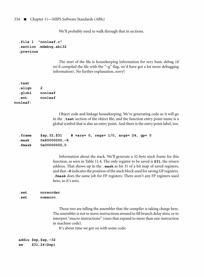
334 Chapter 11—MIPS Software Standards (ABIs)
We’ll probably need to walk through that in sections.
.file 1 "nonleaf.c"
.section .mdebug.abi32
.previous
The start of the file is housekeeping information for very basic debug (ifwe’d compiled the file with the “–g” flag, we’d have got a lot more debugginginformation). No further explanation, sorry!
.text
.align 2
.globl nonleaf
.ent nonleafnonleaf:
Object code and linkage housekeeping. We’re generating code so it will goin the .text section of the object file, and the function entry point name is aglobal symbol that is also an entry point. And there is the entry point label, too.
.frame $sp,32,$31 # vars= 0, regs= 1/0, args= 24, gp= 0
.mask 0x80000000,-8
.fmask 0x00000000,0
Information about the stack. We’ll generate a 32-byte stack frame for thisfunction, as seen in Table 11.4. The only register to be saved is $31, the returnaddress. That shows up in the .mask as bit 31 of a bit map of saved registers,and that -8 indicates the position of the stack block used for saving GP registers..fmask does the same job for FP registers: There aren’t any FP registers usedhere, so it’s zero.
.set noreorder
.set nomacro
Those two are telling the assembler that the compiler is taking charge here.The assembler is not to move instructions around to fill branch delay slots, or tointerpret “macro instructions” (ones that expand to more than one instructionin machine code).
It’s about time we got on with some code:
addiu $sp,$sp,-32sw $31,24($sp)

11.2 Argument Passing and Stack Conventions for MIPS ABIs 335
Adjust the stack pointer and save the return address from the call tononleaf().
move $2,$4 # remember ’a’ for lateraddiu $3,$sp,48sw $3,16($sp) # put &e in argument slotmove $4,$7 # first argument is ’d’jal nestedmove $7,$2 # in delay slot, third argument is ’a’
Adjust the arguments and call nested().
lw $31,24($sp)j $31addiu $sp,$sp,32
Retrieve the return address and return. Restore the stack pointer in the delayslot.
.set macro
.set reorder
.end nonleaf
.ident "GCC: (GNU) 3.4.4 mipssde-6.03.01-20051114"
Re-enable all the assembly things you turned off, and include a string toidentify the compiler build.
Frame Pointers for More Complex Stack Requirements
In the stack frames described above, the compiler has been able to manage thestack with just one reserved register, sp. Those of you who are familiar withother architectures will know that they often use two stack maintenance regis-ters: a stack pointer (sp) to mark the stack low-water point and a frame pointerto point to the data structures created by the function prologue. However, solong as the compiler can allocate all the stack space needed by the function inthe function prologue code, it should be able to decrement sp in the prologueand leave it pointing to a constant stack offset for the life of the function. If so,everything on the local stack frame is at a compile-time-known offset from sp,and no frame pointer is needed. But sometimes you want to mess with the stackpointer at run time: Figure 11.9 shows how MIPS allocates a frame pointer tocope with this need.
What leads to an unpredictable stack pointer? In some languages, and evenin some extensions to C, dynamic variables can be created whose size varies atrun time. And many C compilers can allocate stack space on demand through the

336 Chapter 11—MIPS Software Standards (ABIs)
four 32–bit argument slots
more arguments as required
this function’sstack frame
space for building argumentsfor nested calls
FP register save area
GPR save area
local stack variablesand temporaries
sp while running
called function frame
calling function frame
higher addresses
lower addresses
fp while running
saved hereold value of fp/s8
FIGURE 11.9 Stack frame using separate frame pointer register.
useful built-in function alloca().14 In this case the function prologue grabsanother register, s8 (which has a regular alias of fp), and sets it to the incomingvalue of sp.
Since fp (in its other guise as s8) is one of the saved registers, the pro-logue must also save its old value, which is done just as if we were using s8as a subroutine variable. In a function compiled with a frame pointer, all localstack frame references are made via fp, so if the compiler needs to lowersp to make space for variables of runtime-computed size, it can go rightahead.
14. Actually, some implementations of alloca() don’t just make space on the local stack, andsome are pure library functions (which means that you never need go without alloca() forportability reasons). But compilers that implement alloca() using stack space make code thatgoes faster.

11.2 Argument Passing and Stack Conventions for MIPS ABIs 337
Note that if the function has a nested call that uses so many arguments thatit needs to pass data on the stack, that will be done with relation to sp.
One ingenious feature of this trick is that neither the caller of a frame pointerfunction, nor anything called by it, sees it as anything special. Functions it callsare obliged to preserve the value of fp because it’s a callee-saved register; andthe callee-visible part of the stack frame looks like it should.
Assembly buffs may enjoy the observation that when you create space withalloca(), the address returned is actually a bit higher than sp, since the com-piler has still reserved space for the largest argument structure required by anyfunction call.
Some tools also employ an fp-based stack frame when the size of the localvariables grows so large that some stack frame objects are too far from sp tobe accessed in a single MIPS load/store instruction (with its ±32-KB offsetlimit).
11.2.10 Variable Number of Arguments and stdargs
If you need to build a new function that takes a variable number of arguments,use your toolkit’s stdarg.hmacro package (compulsory for ANSI compatibil-ity). The macro package delivers the macros—or possibly functions—va start(), va end(), and va arg(). To see how they’re used, look at howthe one package implements printf():
int printf(const char *format,... )
{
va_list arg;
int n;
va_start(arg, format);
n = vfprintf(stdout, format, arg);
va_end(arg);
return n;
}
Once we’ve called va start(), we can extract any argument we like. Sosomewhere in the middle of the code that implements the format conversionsfor printf(), you’ll see the following code used to pick up the next argument,supposing it to be a double-precision floating-point type:
...
d = va_arg(ap, double);
...
Never try to build an assembly function that takes a variable number ofarguments—it isn’t worth the portability hassle.

This Page Intentionally Left Blank

Chapter
12Debugging MIPSDesigns—Debug andProfiling Features
When you build a low-cost, low-power embedded device or consumergizmo, it makes sense to squeeze out every feature that doesn’t contribute
to the final application.Or does it?In marketing terms, the way to make money out of these kinds of devices
is to be there first: As the devices become familiar, prices drop rapidly (as hashappened with DVD players, for example). Product lifetimes are short, so devel-opment timescales must be compressed.
There’s a tension here: A cut-to-the-bone hardware system is a hostile basefor development and test. The economics of SoC chips offers a way out. MostSoCs can accommodate a few percent more transistors used for predefined func-tions with no impact on production cost, because the transistor count is limitedby the difficulty of designing circuits and making reasonably sure the chip willwork first time. If the suppliers of SoC components can include developmentaids without passing on much risk to the SoC builder, everyone might win.
So modern MIPS CPUs come with a certain amount of hardware aimedto help developers. Different builders will resolve the competing requirementsdifferently, so—unfortunately for developers and development tool creators—these features are optional and may not be present on your system. But it’s adefinite trend in the last few years to include more of them.
Developers benefit from three different kinds of information about theirsystem, which can be reasonably divided into “debug,” “trace,” and “profile”information.
Debug—The Exact State of the System
To correct your logical errors about how the system should work, it’s very help-ful to be able to dig down and see exactly what is happening, sometimes at thelowest level (instruction by instruction).
339

340 Chapter 12—Debugging MIPS Designs—Debug and Profiling Features
This is the job of a software debugger. To be usable in a complex system, thedebugger needs access to your software source, as well as binary, and must beable to correlate the two. Correlating debug events with source code is a largeproblem we shall ignore here, except to point out that such a debugger can’treside entirely in an embedded system under test, so the debugger needs somekind of host-target connection. At the CPU level, a debugger needs access to theprogram’s memory and in-CPU state, as well as the ability to control executionby arranging traps to debugger software to happen at appropriate points.
MIPS specifications define an on-CPU debug help unit under the name ofEJTAG, described below. But MIPS CPUs also retain pre-EJTAG features, whichlinger because they’re more familiar and easier for some kinds of debug softwareto use, and we’ll mention them too.
Trace—What Just Happened?
To make sense of where the system is, it’s useful to have some kind of overviewabout how it progressed (for example) from “correct” to wrong behavior. Thewhole system state is unmanageably huge, and it’s difficult to know which statewill be important until afterward. But for a CPU, it’s certainly interesting tolook into the instructions it recently executed.
When the CPU is running as fast as billions of instructions per second, it’sa challenge to save enough of that information to cover enough time at enoughlevel of detail, and to get it off-chip fast enough to avoid either stopping theCPU or losing some trace information.
The system used in MIPS CPUs is called PDtrace and is hooked onto theEJTAG debug block.
Profile—Statistical Information about Behavior over a Periodof Time
If debuggers are provided because programmers can’t hold every possibledetailed implication of their software in their heads, profilers are there becauseit’s even more difficult to visualize the behavior of whole subsystems. The mod-ular programming practices that make it possible to build a correct system insu-late the programmer from knowledge of exactly what the CPU has to do tocarry out tasks—but for a system of any complexity, that means you’ve only thevaguest idea whether pressing a button will lead to a satisfactory response or anunsettling wait.
A software tool that provides statistical information about the large-scaletiming and behavior of a system is called a profiler. And profilers work by instru-menting the system, counting events over a particular time.
The EJTAG system includes an option called “PC sampling,” which pro-vides some useful information; but MIPS CPUs also have a number of

12.1 The “EJTAG” On-chip Debug Unit 341
performance counters that are controlled by on-target software. The countersand their controls are provided as CP0 registers and described further below.
When a developer runs a system for debug, trace, or profiling, the hardwarethat provides the low-level information may itself change the behavior of thesystem. That isn’t helpful: It’s preferable if development assistance is, as far aspossible, nonintrusive.
We said previously that transistors on your SoC devoted to developmentaids are extremely cheap and can be a bargain. What’s harder to provide at lowcost is the connection to your development system, which carries the informa-tion back for analysis.
In older systems you typically linked the target and host with an extra serialport or some other piece of system I/O. But more often, it involved a trickynegotiation with the target system software to share the use of a connector anddevice that have some role in the final system.
That’s intrusive: We’d prefer a separate debug connection. Ideally (to reducethe impact on the system design, and to create a standard that will make thetools easier to build), it should come directly from the CPU. But the SoC withthe CPU in it is usually at the heart of the system: Transistors may be cheap, butextra pins are costly.
But here we get lucky; someone else’s problem prompts a solution. Elec-tronic systems are soldered together, and the soldering process has a signif-icant defect rate. Modern electronic boards are automatically tested beforebeing used in products, and a few pins on complex devices are reserved forthat testing. The overwhelmingly chosen test connection standard is JTAG,so MIPS chose to connect the development subsystem by recycling the JTAGpins, which are otherwise unused at run time. That’s why the debug unit iscalled EJTAG.
However, the debug hardware is still useful to a more traditional debugger—one running on the target system and communicating using conventionaldevices of some kind. A debugger that is deeply enmeshed with a high-leveloperating system (for example) is likely to run substantially on the target. Seesection 12.1.13 for some notes on what has to be done for an on-target debuggerto use the debug unit.
12.1 The “EJTAG” On-chip Debug Unit
The EJTAG unit is a loosely integrated collection of in-CPU resources used tobuild debug and trace tools. As we said above, EJTAG finds pins for a nonin-trusive host connection (and gets its name) by recycling the JTAG pins alreadyincluded in every SoC for chip test.1
1. Though it can be quite useful to provide EJTAG with independent-of-hardware-test pins, if youcan afford it.

342 Chapter 12—Debugging MIPS Designs—Debug and Profiling Features
Such a debug unit requires:
Physical communications with the host—usually via some kind of probedevice connected to the debug host by some general-purpose network orwire. The probe is attached to the SoC’s JTAG pins.
The ability for the host/probe to “remote-control” the CPU. That’s doneby directing the CPU to execute code from a magic dmseg memory region,where CPU reads and writes are serviced by the probe. dmseg is part ofthe special memory window dseg, which opens up in debug mode, asdescribed in section 12.1.6.
Although the probe is wonderful for providing debug resources to a min-imal system, the EJTAG resources are quite usable by a pure-softwaredebugger running on the local CPU. We’ll come back to that later.
A just-for-debug exception. In MIPS EJTAG, this is a special super-exception marked by a special debug mode flag, so you can use an EJTAGdebugger to debug the whole system, even its own regular exceptionhandlers. See section 12.1.4.
A number of EJTAG breakpoints, hardware monitors that can be inde-pendently programmed to match addresses and even data.2 When theCPU fetches an instruction or reads/writes a location, the fetch or load/store address and data are compared with any active breakpoints, causinga debug exception on a match.
There can be a lot of breakpoint control registers, and that would bedifficult to fit into the CP0 register set, so they are memory-mapped intodmseg (the subregion used for EJTAG registers is called drseg).
You can also get a debug exception from a debug breakpoint instruc-tion sdbbp, an external signal DINT, or when the EJTAG probe wigglesa control bit it knows about.3
For profiling rather than debugging, you may have the facility to instructthe EJTAG unit to take periodic snapshots of the address of the currentlyexecuting instruction (PC sampling) and make those samples availableto the EJTAG probe, as described in section 12.1.12.
Powerful debug facilities can be built on these foundations.
2. Software engineers habitually use “breakpoint” to mean a debug-support instruction, andit’s often been more helpful to call the hardware monitors “watchpoints.” But all EJTAGdocumentation calls them breakpoints, so we’ll do the same.
3. Or as a rueful colleague notes, if you inadvertently bump the probe wihile debugging asystem.

12.1 The “EJTAG” On-chip Debug Unit 343
12.1.1 EJTAG History
Back in the stone age of microprocessors (before 1980) fine-grain debug couldbe available from an in-circuit emulator (ICE). An ICE was a plug-in replace-ment for your CPU with a large and proprietary cable leading to a rack full ofelectronics. The ICE executed instructions just like a CPU, but could be stoppedand interrogated.
The ICE approach worked because microprocessors were expensive andfragile, so it was often worth attaching them through a chip socket rather thansoldering them in—just as PC processors these days are so expensive that itmakes sense not to solder them to the motherboard.
It was always difficult to get the complex circuitry of the ICE to run as fastas the simpler CPU chip, and as microprocessors got faster that got worse. ICEboxes started off expensive and got ever more so: Once they cost tens of thou-sands of dollars, lots of teams found ways of debugging systems without them.As the 1980s progressed, that undermined the market for ICE boxes.
So the ICE manufacturers needed something like EJTAG. With an on-chipdebug unit, the critical paths (which might have made the CPU slower) werelocal, so the system could run at full speed. The probe you needed to make theconnection and the complex host software that ran it were the sort of things theyknew how to make. That was good, but they ran into a problem: They either hadto sell the tiny probe and software for $10,000, or change their business modelto sell more units at lower prices. Technological change is easy, but institutionalchange is not; for the most part, the ICE manufacturers tried to keep their pricesup and were bypassed.
It was LSI Logic that first incorporated on-chip debug units in their pio-neering system-on-chip MIPS CPUs. With the help of some ICE manufactur-ers, they developed the EJTAG specification much as it is now. But these daysprobes cost less than $1,000 and attach to the software debugger of your choice.
12.1.2 How the Probe Controls the CPU
The probe gets control when the CPU fetches an instruction from the dmsegregion. It sounds like you have to wait for the CPU’s software to volunteer forthis, but in fact:
In response to your debugger start-up your probe will use its JTAG con-nection to set an internal flag, which moves the debug exception entrypoint to 0xFF20.0200—in dmseg.
The probe can cause a debug breakpoint directly or by setting up a hard-ware breakpoint and waiting for the software to trip it.
Your probe can send an EJTAGBOOT command (more about commandsin the next section) and then, after the next CPU reset, the CPU will readinstructionsfromdmseg.Infact,acollectionoffeaturesallowsyoutoreboottheCPUandtakecompletecontrol,evendownloadingnewsoftwareviatheJTAGlink.

344 Chapter 12—Debugging MIPS Designs—Debug and Profiling Features
Once the probe is feeding the CPU with instructions, it can get the CPU todo anything. In particular, it can send it an instruction sequence that will readdata (whether from a CPU register or from memory) and write it back to theprobe via dmseg space.
12.1.3 Debug Communications through JTAG
Your host computer connects to the system under test through a small blackbox, the probe. The chip’s JTAG pins give the probe access to special registersinside the CPU.
The JTAG standard was invented by chip-makers to make it easier to testcircuit boards, and most complex chips already find room for the JTAG pins;subverting them for software debug is easier than fighting for new pins. In the1970s (when JTAG was born) every extra transistor was a significant cost. SoJTAG is designed to minimize the complexity of the logic that receives it, whichis basically a shift register.4
There’s a control/data enable input, a data-in line, and a data-out line. Thecontrol register is sent command codes, most of which just select between dif-ferent data registers. JTAG command codes are called “instructions” but areoften used interchangeably with the names of the data registers—a recipe forconfusion when you’re talking to software engineers.
But the net effect of this very simple hardware is that JTAG provides a wayto read and/or write one of a number of registers internal to the EJTAG unit.The EJTAG unit provides a number of instructions the probe can use to dealwith the CPU, and they’re summarized in Table 12.1.
12.1.4 Debug Mode
Debug mode is a special CPU state, much like exception mode (but more so).The CPU goes into debug mode when it takes any debug exception—whichcan be caused by an sddbp instruction, a hit on an EJTAG breakpoint register,from the external “debug interrupt” signal DINT, or single-stepping (the latter ispeculiar and described briefly below). Debug mode state is visible and control-lable through the CP0 register bit Debug(DM)—there’s more on EJTAG’s CP0registers in section 12.1.7. Debug mode (like exception mode) implicitly dis-ables all normal interrupts. The address map changes in debug mode to give youaccess to the dseg region, described below. Quite a lot of exceptions just won’thappen in debug mode; those that do run peculiarly—see the next section.
4. For those who don’t know, a shift register is a 1-bit-wide store accessed serially. As a bit is clockedin, all other bits are moved up one position to make space for it. In hardware, shift registers areoften also wired in parallel (that is, the state of all the bits is reflected on a collection of wires).

12.1 The “EJTAG” On-chip Debug Unit 345
TABLE 12.1 JTAG Instructions for the EJTAG Unit
JTAG “instruction” Description
IDCODE Reads out the MIPS CPU and revision—not veryinteresting for software, not described further here.
ImpCode Reads bitfield showing which EJTAG options areimplemented.
EJTAG ADDRESSEJTAG DATA
(Read/write) together, allow the probe to provideor accept data in response to instruction fetchesand data reads/writes in the magic dmseg regiondescribed in section 12.1.6.
EJTAG CONTROL Package of flags and control fields for the probe toread and write.
EJTAGBOOTNORMALBOOT
The EJTAGBOOT instruction causes the next CPUreset to reboot from the probe; it’s controlled byEJTAG CONTROL bits called ProbEn, ProbTrap,and EjtagBrk, but you’ll need to read a moredetailed manual to find out more.The NORMALBOOT instruction reverts to the normalCPU bootstrap.
FASTDATA Special access used to accelerate multiword datatransfers with probe. The probe reads/writes the33-bit register formed of EJTAG CONTROL(PrAcc)with EJTAG DATA.
TCBCONTROLATCBCONTROLBTCBADDRESS
Access registers used to control “PDtrace”instruction trace output, if available. Seesection 12.3, but these JTAG-accessible registers arenot detailed.
A CPU with a suitable probe attached can be set up so the debug exceptionentry point is in the dmseg region, running instructions provided by the probeitself. With no probe attached, the debug exception entry point is in the ROM(for an overview of all MIPS exception entry points, see Table 5.1.)
Exceptions in Debug Mode
A software debugger is likely to be coded to avoid causing exceptions (it will testaddresses in software, for example, rather than risk address or TLB exceptions).So it’s reasonable that in debug mode, many conditions that would normally

346 Chapter 12—Debugging MIPS Designs—Debug and Profiling Features
cause an exception are ignored: interrupts, debug exceptions (other than thatcaused by executing sdbbp), and many others.
But a few exceptions occurring in debug mode are turned into nested debugexceptions—a facility that is probably mostly valuable to debuggers using theEJTAG probe.
On such a nested debug exception the CPU jumps to the debug exceptionentry point, remaining in debug mode. The Debug(DExcCode) field recordsthe cause of the nested exception, and DEPC records the debug-mode-coderestart address. This will not be survivable for the debugger unless it saved acopy of the original DEPC soon after entering debug mode, but it probably didthat! To return from a nested debug exception, you don’t use deret (whichwould inappropriately take you out of debug mode); you grab the address outof DEPC and use a jr instruction.
12.1.5 Single-Stepping
When the single-step bit Debug(SSt) is set and control returns from debugmode with a deret, the instruction selected by DERET will be executed in non-debug context;5 then a debug exception will be taken on the very next instruc-tion to be fetched in sequence.
Since one instruction is run in normal mode, it can lead to a nondebugexception; in that case the “very next instruction in sequence” will be the firstinstruction of the exception handler, and you’ll get a single-step debug excep-tion whose DEPC points at the exception handler.
12.1.6 The dseg Memory Decode Region
EJTAG needs to use memory space both to accommodate its numerous break-point management registers (too many for CP0) and for its probe-mapped com-munication space. This memory space pops into existence near the top of theCPU’s virtual address map when the CPU is in debug mode, as shown inTable 12.2.
In the table you can see that:
dseg: Is the whole debug-mode-only memory area, which appears over-laying part of the upper kernel-accessible mapped area (kseg2) when theCPU is in debug mode. It’s possible for debug-mode software to readthe kseg2-mapped locations “underneath” by setting Debug(LSNM)—but a debug-friendly OS should probably avoid using this corner of thememory map for other purposes.
5. If DERET points to a branch instruction, both the branch and branch-delay instruction will beexecuted normally.

12.1 The “EJTAG” On-chip Debug Unit 347
TABLE 12.2 EJTAG Debug Memory Region Map(dseg)
Virtual address Region/subregions Location/register Virtual address
0xC000.0000 0xE000.0000
0xFF1F.FFFF 0xFF1F.FFFF
0xFF20.0000 0xFF20.00000xFF20.000F 0xFF20.000F
fastdata
0xFF20.0010 0xFF20.0010
0xFF20.0200 debug entry 0xFF20.0200
0xFF2F.FFFF 0xFF2F.FFFF
dmseg
0xFF30.0000 DCR register 0xFF30.0000
0xFF30.1000 IBS register 0xFF30.1000
I-breakpoint #1 regs0xFF30.1100 IBA1 0xFF30.11000xFF30.1108 IBM1 0xFF30.11080xFF30.1110 IBASID1 0xFF30.11100xFF30.1118 IBC1 0xFF30.1118
I-breakpoint #2 regs0xFF30.1200 IBA2 0xFF30.12000xFF30.1208 IBM2 0xFF30.12080xFF30.1210 IBASID2 0xFF30.12100xFF30.1218 IBC2 0xFF30.1218
same for next two...
0xFF30.2000 DBS register 0xFF30.2000
D-breakpoint #1 regs0xFF30.2100 DBA1 0xFF30.21000xFF30.2108 DBM1 0xFF30.21080xFF30.2110 DBASID1 0xFF30.21100xFF30.2118 DBC1 0xFF30.21180xFF30.2120 DBV1 0xFF30.21200xFF30.2124 DBVHi1 0xFF30.2124
D-breakpoint #2 regs0xFF30.2200 DBA2 0xFF30.22000xFF30.2208 DBM2 0xFF30.22080xFF30.2210 DBASID2 0xFF30.22100xFF30.2218 DBC2 0xFF30.22180xFF30.2220 DBV2 0xFF30.22200xFF30.2224 DBVHi2 0xFF30.2224
0xFF30.2228 0xFF30.22280xFF3F.FFFF 0xFF3F.FFFF
drseg
dseg
kseg2
0xFF40.0000 0xFF40.0000
0xFFFF.FFFF 0xFFFF.FFFF

348 Chapter 12—Debugging MIPS Designs—Debug and Profiling Features
dmseg: Is the memory region where reads and writes are implementedby the probe. But if no active probe is plugged in, or if DCR(PE) is clear,then accesses here cause reads and writes to be handled like regular kseg2accesses.
drseg: Is where the debug unit’s main register banks are accessed. Accessesto drseg don’t go off CPU. Registers in “drseg” are word-wide, and shouldbe accessed only with word-wide (32-bit) loads and stores.
fastdata: Is a corner of dmseg where probe-mapped reads and writes usea more JTAG-efficient block-mode probe protocol, reducing the amountof JTAG traffic and allowing for faster data transfer. There are no detailsabout how it’s done in this book.
debug entry: Is the debug exception entry point. Because it lies in dmseg,the debug code can be implemented wholly in probe memory, allowingyou to debug a system that has no physical memory reserved for debug.
If there’s no probe-supplied debug exception handler—a condition noti-fied by the probe itself using the EJTAG CONTROL(ProbTrap) bit—thedebugger entry point will be at 0xBFC0.0480 (near the other uncached-space exception entry points).
12.1.7 EJTAG CP0 Registers, Particularly Debug
In normal circumstances (specifically, when not in debug mode), the onlysoftware-visible part of the debug unit is its set of three CP0 registers:
Debug has configuration and control bits and is detailed below.
DEPC keeps the restart address from the last debug exception (automat-ically used by the deret instruction).
DSAVE is a CP0 register that is just 32 bits of read/write space. It’s avail-able for a debug exception handler that needs to save the value of a firstgeneral-purpose register, so that it can use that register as an address baseto save all the others.
Debug is the most complicated and interesting. It has so many fields definedthat we’ve taken them in three groups: debug exception cause bits in Figure 12.1,information about regular exceptions that are pending (they want to happenbut can’t because you’re in debug mode) in Figure 12.2, and everything else.The “everything else” category includes the most important fields, as shown inFigure 12.3.
The fields in Figure 12.3 (the most important fields) are:
DBD: Tells you that the debug exception happened in a branch delayslot. Then DEPC points to the branch instruction, which is usuallythe right place to restart.

12.1 The “EJTAG” On-chip Debug Unit 349
31 20 19 18 17 6 5 4 3 2 1 0
Debug DDBSImpr DDBLImpr DINT DIB DDBS DDBL DBp DSS
FIGURE 12.1 Exception cause bits in the debug register.
DM: Debug mode—set on debug exception from user mode, clearedby deret. Not writable here.
NoDCR: Read-only—0 if the dseg region is implemented. It’s not clearwhat kind of EJTAG unit you’d have if this was 1.
LSNM: Set this to 1 if you want dseg to disappear, even in debug mode, soyou can access the memory locations it otherwise overlays. Thismakes most of the EJTAG unit’s control system unavailable, sowill probably only be done around a particular load/store.
Doze: Before the debug exception, CPU was in some kind of reducedpower mode.
Halt: Before the debug exception, the CPU was stopped—probablyasleep after a wait instruction.
CountDM: Set to 1 if, and only if, the Count register continues to run in debugmode. Sometimes this may be writable, so you get to choose: Oth-erwise this is a read-only bit that tells you what your CPU does.
IEXI: Set to 1 to defer imprecise exceptions. Set by default on entry todebug mode, cleared on exit, but writable. The deferred exceptionwill come back when and if this bit is cleared: Until then you cansee that it happened by looking at the pending bits shown inFigure 12.2.
EJTAGver: Read-only—tells you which revision of the specification thisimplementation conforms to. Known legal values are:
0 Version 2.0 and earlier
1 Version 2.5
2 Version 2.6
3 Version 3.1
DExcCode: Cause of any nondebug exception you just handled from withindebug mode—following first entry to debug mode, this field isundefined. The value will be one of those defined for Cause(ExcCode) and is listed in Table 3.2.
NoSSt: Read-only—reads 1 if single-step is not implemented. Single-stepis usually available, so this usually reads zero.
SSt: Set this flag to 1 to enable single-step.

350 Chapter 12—Debugging MIPS Designs—Debug and Profiling Features
31 25 24 23 22 21 20 0
Debug IBusEP MCheckP CacheEP DBusEP
FIGURE 12.2 Debug register—exception-pending flags.
31 30 29 28 27 26 25 24 21 20 19 18 17 15 14 10 9 8 7 6 5 0
DBD DM NoDCR LSNM Doze Halt CountDM pending IEXI cause EJTAGver DExcCode NoSSt SSt OffLine 0 cause
FIGURE 12.3 Fields in the EJTAG debug register.
OffLine: Often not implemented in single-threaded CPUs, in which case itjust reads zero.
If implemented, you can set it to 1 to stop the CPU (or the CPUthread in a multithreading CPU) from running instructionsexcept in debug mode. This is intended to allow a debugger toshut down some processors/threads in a multiprocessor/multi-threading system, while still leaving those processors/threads torun in debug mode. The condition can only be cleared in debugmode, so if you do a deret with it set, nothing else will happenuntil and unless you get an externally initiated debug interrupt.
The fields in Figure 12.1 are:
DDBSImpr,DDBLImpr: Imprecise store/load breakpoint, respectively—seesection 12.1.11. DEPC probably points to an instruction some timelater in sequence than the store/load that triggered the breakpoint.The debugger or user (or both) have to cope as best they can.
DINT: Debug interrupt caused by pulse on EJTAG pin.
DIB: We hit an instruction breakpoint.
DDBS: We hit a precise store breakpoint.
DDBL: We hit a precise load breakpoint.
DBp: We hit any sort of debug breakpoint (often found together with oneof the above).
DSS: This was a single-step exception.
The “pending” flags (Figure 12.2) record exception conditions caused byinstructions run in debug mode but that have not happened yet because theyare imprecise and Debug(IEXI) is set. The exceptions remain pending and the
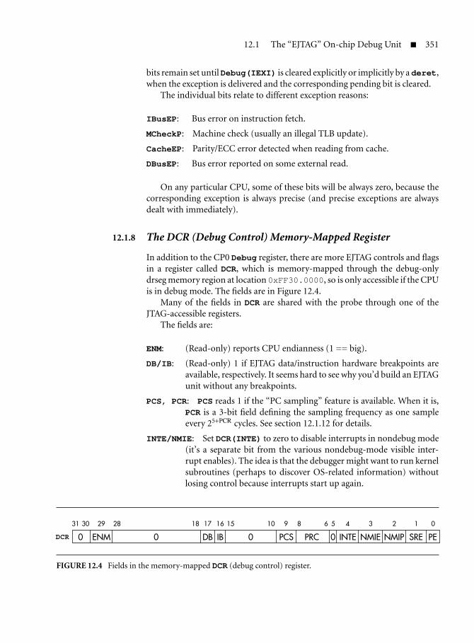
12.1 The “EJTAG” On-chip Debug Unit 351
bits remain set untilDebug(IEXI) is cleared explicitly or implicitly by a deret,when the exception is delivered and the corresponding pending bit is cleared.
The individual bits relate to different exception reasons:
IBusEP: Bus error on instruction fetch.
MCheckP: Machine check (usually an illegal TLB update).
CacheEP: Parity/ECC error detected when reading from cache.
DBusEP: Bus error reported on some external read.
On any particular CPU, some of these bits will be always zero, because thecorresponding exception is always precise (and precise exceptions are alwaysdealt with immediately).
12.1.8 The DCR (Debug Control) Memory-Mapped Register
In addition to the CP0 Debug register, there are more EJTAG controls and flagsin a register called DCR, which is memory-mapped through the debug-onlydrseg memory region at location 0xFF30.0000, so is only accessible if the CPUis in debug mode. The fields are in Figure 12.4.
Many of the fields in DCR are shared with the probe through one of theJTAG-accessible registers.
The fields are:
ENM: (Read-only) reports CPU endianness (1 == big).
DB/IB: (Read-only) 1 if EJTAG data/instruction hardware breakpoints areavailable, respectively. It seems hard to see why you’d build an EJTAGunit without any breakpoints.
PCS, PCR: PCS reads 1 if the “PC sampling” feature is available. When it is,PCR is a 3-bit field defining the sampling frequency as one sampleevery 25+PCR cycles. See section 12.1.12 for details.
INTE/NMIE: Set DCR(INTE) to zero to disable interrupts in nondebug mode(it’s a separate bit from the various nondebug-mode visible inter-rupt enables). The idea is that the debugger might want to run kernelsubroutines (perhaps to discover OS-related information) withoutlosing control because interrupts start up again.
31 30 29 28 18 17 16 15 10 9 8 6 5 4 3 2 1 0
DCR 0 ENM 0 DB IB 0 PCS PRC 0 INTE NMIE NMIP SRE PE
FIGURE 12.4 Fields in the memory-mapped DCR (debug control) register.

352 Chapter 12—Debugging MIPS Designs—Debug and Profiling Features
DCR(NMIE) Masks nonmaskable interrupt in nondebug mode(a nice paradox).
Both the DCR(INTE,NMIE) bits are “1” from reset.
NMIP: (Read-only) tells you that a nonmaskable interrupt is pending, andwill happen when you leave debug mode (and according to DCR(NMIE) as above).
SRE: If implemented, write this zero to prevent a soft-reset.
PE: (Read-only) software-readable version of the probe-controlled enablebit. When set, debug exceptions are redirected to probe-controlleddmseg memory locations.
12.1.9 EJTAG Breakpoint Hardware
EJTAG breakpoints have hardware that monitors instruction fetch, load, andstore accesses from the CPU. If you set a breakpoint, then an access that matchesit for address (and possibly matches data, too, if so specified) will cause a debugexception.
Instruction and data breakpoints are separate. The EJTAG specification per-mits a unit to be built with no breakpoint hardware (though that wouldn’t bemuch use), but it seems common to have between two and six of them. Thebreakpoints:
Work only on virtual addresses, not physical addresses. However, you canrestrict the breakpoint to a single address space by specifying an ASIDvalue to match. Where the operating system is using multiple addressspaces, the debugger will have to work with the OS to make that useful.
Use a bitwise address mask to permit a degree of fuzzy matching.
Breakpoint hits can be made conditional on the data value read or write.But data-sensitive tests may lead to an exception that is imprecise—by thetime the data is available for matching, it’s too late to prevent subsequentinstructions from having some effect. See section 5.1 if you want to knowmore about precise and imprecise exceptions.
There are one overall I-side and one D-side control registers, mapped intothe drseg region, accessible only when in debug mode at the addresses shownin Table 12.2. They’re called IBS and DBS. They are as shown in Figure 12.5.
31 30 29 28 27 24 23 12 0
DBS/IBS 0 NoSVM NoLVM BCN 0 BS1-0ASIDsup
FIGURE 12.5 Fields in the IBS/DBS (EJTAG breakpoint status) registers.

12.1 The “EJTAG” On-chip Debug Unit 353
The fields in Figure 12.5 are:
ASIDsup: Is 1 if the breakpoints can use ASID matching to distinguishaddresses from different address spaces. It’s hard to imagine anymodern debug unit lacking that facility.
NoSVM,NoLVM: Are 1 if you can’t qualify a breakpoint by the data value onstores/load, respectively. Only valid in the DBS register.
BCN: The number of hardware breakpoints available. There are separateI- and D-side breakpoints.
BS1-0: Bitfields showing breakpoints that have been matched. Debug soft-ware has to clear down a bit after a breakpoint is detected. The size ofthe field depends on the number of breakpoints provided on eitherthe I- or D-side.
Then, each EJTAG hardware breakpoint (“n” is 0–3 to select a particularbreakpoint) is set up through four to six separate registers:
IBCn, DBCn: Breakpoint control register shown in Figure 12.6.
IBAn, DBAn: Breakpoint address.
IBAMm, DBAMn: Bitwise mask for breakpoint address comparison. A “1” inthe mask marks an address bit that will be excluded from comparison,so set this register to zero for exact matching.
Ingeniously, IBAMm(0) corresponds to the slightly bogus instructionaddress bit zero, used to track whether the CPU is runningMIPS16 instructions, and allows you to determine that an instruc-tion breakpoint may happen only in MIPS16 (or non-MIPS16) mode.
IBASIDn, DBASIDn: Specifies an 8-bit ASID, which may be comparedagainst the current EntryHi(ASID) field to filter breakpointsso that they only happen to a program in the right address space(typically corresponding to one Linux process, for example). TheASID check can be enabled or disabled using IBCn(ASIDuse) orDBCn (ASIDuse), respectively—see Figure 12.6 and its notes.
The higher 24 bits of each of these registers are always zero.
31 24 23 22 14 13 12 11 4 3 2 1 0
DBCn/IBCn 0 BAI7-0 NoSB NoLB BLM7-0 0 TE 0 BEASIDuse
FIGURE 12.6 Fields in the hardware breakpoint control registers (IBCn,DBCn.)

354 Chapter 12—Debugging MIPS Designs—Debug and Profiling Features
DBVn, DBVHin: The value to be matched on load/store breakpoints. DBCHindefines bits 31–64 to be matched for 64-bit load/stores. A JTAG hard-ware breakpoint for a real 64-bit CPU would have 64-bit DBVn reg-isters, so wouldn’t need DBVHin—they’re provided because some32-bit CPUs implement 64-bit load or store for a double-precisioncoprocessor, perhaps a floating-point unit.
Note that you can disable data matching (to get an address-onlydata breakpoint) by setting the value byte-lane comparison maskDBCn (BLM) to all 1s.
So now let’s look at the control registers in Figure 12.6.The fields are:
ASIDuse: Set 1 to compare the ASID as well as the address.
The BAI7-0, NoSB, NoLB, and BLM7-0 fields are applicable only to D-side(DBCn) breakpoints:
BAI7-0: Byte (lane) access ignore—which sounds mysterious. But this isreally an address filter.
When you set a data breakpoint, you probably want to break on anyaccess to the data of interest. You don’t usually want to make thebreak conditional on whether the access is done with a load byte,load word, or even load-word-left: But the obvious way of setting upthe address match for a breakpoint has that effect.
To make sure you catch any access to a location, you can use theaddress mask to disable subdoubleword address matching and thenuse DBCn(BAI) to mark the bytes of interest inside the doubleword:well, except that zero bits mark the bytes of interest, and 1 bits markthe bytes to ignore (hence the mnemonic).
The DBCn(BAI) bits are numbered by the byte-lane within the32- or 64-bit data bus; so be careful, the relationship between thebyte address of a datum and its byte lane is endianness-sensitive.
NoSB, NoLB: Set 0 to enable6 breakpoint on store/load, respectively.
BLM7-0: A per-byte mask for data comparison. A zero bit means compare thisbyte, a 1 bit means to ignore its value. Set this field all-1s to disablethe data match.
The remaining fields are applicable to both I- and D-side breakpoints:
TE: Set 1 to use as trigger for PDtrace instruction tracing, as described insection 12.3.
6. “1-to-enable” would feel more logical. The advantage of using 0-to-enable here is that the zerovalue means you will break on either read or write, which is a better default than “never breakat all.”

12.1 The “EJTAG” On-chip Debug Unit 355
BE: Set 1 to activate breakpoint. This fields resets to zero to avoid spuri-ous breakpoints caused by random register settings: Don’t forget toset it!
12.1.10 Understanding Breakpoint Conditions
There are a lot of different fields and settings that are involved in determiningwhen a hardware breakpoint detects its condition and causes an exception.
In all cases, there will be no break if you’re in debug mode already . . . butthen, for a break to happen, all the following must be true:
1. The breakpoint control register enable bit IBAn(BE)/DBAn(BE) is set.
2. The address generated by the program for instruction fetch, load, or storematches those bits of the breakpoint’s address register IBAn/DBAn forwhich the corresponding address-mask register bits in IBAn/DBAn arezero.
3. Either the IBCn(ASIDuse)/DBCn(ASIDuse) is zero (so we don’t carewhich address space we’re matching against) or the address-space IDof the running program, EntryHi(ASID), is equal to the value inIBASIDn/DBASIDn.
That’s all for instruction breakpoints, but for data-side breakpoints youneed to distinguish loads and stores and can distinguish accesses by subdou-bleword address too:
4. It’s a load and DBCn(NoLB) is zero, or it’s a store and DBCn(NoSB) iszero.
5. The load or the store touches at least one byte within doubleword forwhich the corresponding DBCn(BAI) bit is zero.
If you didn’t want to compare the load/store value, then you would setDBCn(BLM) to all-ones, and you’re done. But if you also want to consider thevalue, then you have data compare conditions:
6. The data loaded or stored, as it would appear on the system bus, matchesthe 64-bit contents of DBVHin, with DBVn in each of those 8-bit groupsfor which the corresponding bit in DBCn(BLM) is zero.
That’s it. It’s quite complicated, but logical.
356 Chapter 12—Debugging MIPS Designs—Debug and Profiling Features
12.1.11 Imprecise Debug Breaks
Instruction breakpoints, and data breakpoints filtering only on address condi-tions, break with DEPC pointing to the matching instruction. More accurately,such exceptions are “precise exceptions,” in the sense discussed in section 5.1.
Most exceptions in MIPS architecture CPUs are precise. But many MIPSCPUs optimize loads and stores by permitting the CPU to run on at least untilit needs to use the data from a load, so data breakpoints that filter on the datavalue are imprecise. The debug exception will happen to whichever instruction(typically later in the instruction stream) is running when the hardware detectsthe match. The debugging software must cope as best it can.
12.1.12 PC Sampling with EJTAG
A valuable trick available with recent revisions of the EJTAG specification andprobes, PC sampling provides a nonintrusive way to collect statistical informa-tion about the activity of a running system. You can find out whether your CPUoffers this facility by looking at the appropriate bit in DCR(PCS).
PC sampling hardware snapshots the current PC periodically and stores thatvalue where it can be retrieved by a debug probe. It’s then up to software toconstruct a histogram of samples over a period of time, which (statistically)allows a programmer to see where the CPU has spent most cycles. Not only isthis useful, but it’s also familiar: Systems have used intrusive interrupt-based PCsampling for many years, so there are tools (GNU/Linux gprof, for example)that can readily interpret this sort of data.
When PC sampling is configured into your CPU, it runs continuously. Itdoesn’t even stop when the CPU is hanging on a wait instruction (time spentwaiting is still time you might want to measure). On a typical implementation,you might choose to sample as often as once per 32 cycles or as rarely as onceper 4,096 cycles. Since it runs continuously, it’s a good thing that from reset thesampling period defaults to its maximum.
At every sampling point, the address of the instruction completing in thatcycle (or if none completes, the address of the next instruction to complete)is deposited in a JTAG-accessible register. Sampling rate is controlled by a fieldin DCR.
The hardware stores not only 32 bits of the instruction address, but also thethen-current ASID (so you can interpret the virtual PC) and an always written1 “new” bit, which a probe can use to avoid double-counting the same sample.
12.1.13 Using EJTAG without a Probe
The EJTAG unit can be used by a conventional debugger, which runs entirelyon the target system, and, in particular, it can be used to build debug facilitiesinside an OS kernel. But because it was invented primarily to be used via a probe,there are a few issues to work around:

12.1 The “EJTAG” On-chip Debug Unit 357
Handling debug exceptions: Without a probe plugged in and enabled, thedebug exception entry point is in the ROM area of the uncached kseg1region, at 0xBFC0.0480 (if you need to check for the presence of anenabled probe you can read DCR(PE)). You’ll need to put code at thatentry point that will transfer control into your debug exception handler,which may well be built into your OS kernel.
Calling into debug mode inside the kernel: You can’t just switch on debugmode: It’s available only through a debug exception. But you need tobe in debug mode to see the dmseg memory region, and thus to accessthings like breakpoint control registers. So for your software-only debug-ger, you will need a way of invoking debugger support routines in debugmode.
That requires a debug-exception version of a “system call” using a plantedsdbbp instruction. The debug exception handler will need to distinguishthose debugger system calls from other debug exceptions—most likely bylooking at the return address in DEPC. Debugger system call argumentscan be in general-purpose registers.
Similarly, you can’t just switch off debug mode—to get out of debugmode you need to excecute a deret.
In some cases you’ll probably want to execute most of the debugger inordinary kernel mode: So after a brief excursion into debug mode follow-ing a breakpoint match or debug instruction, the debug-mode softwarecan patch up the normal CP0 registers to simulate a more conventionalexception.
Virtual-address-only breakpoints: Note that (unlike the non-EJTAGCP0 “watchpoints”) all EJTAG breakpoints operate on virtual addresses,optionally qualified by the address space ID (ASID).
Handling debug breaks from exception mode or other “illegal” places:This looks like quite a problem when you first meet it. Debug break-points are exceptions, but because they’re “super-exceptions” they don’tplay by the rules of the rest of the kernel. But it’s really the same prob-lem as that discussed previously. It’s likely that a local debugger programusing EJTAG will mostly not run in debug-exception mode. So the debugexception handler will run in exception mode while it saves state, thenstore the return address somewhere safe and use a faked-up deret todrop into normal high-privilege (kernel) mode.
Sometimes, though, a debug exception entry point can be from some-where dangerous—most obviously, from code already running in nor-mal exception mode. The debugger receiving such an exception has totread carefully, and probably can’t just invoke ordinary kernel-moderoutines. Debugger authors need to figure out how far they want to goin allowing debug through exception.

358 Chapter 12—Debugging MIPS Designs—Debug and Profiling Features
12.2 Pre-EJTAG Debug Support—Break Instruction andCPO Watchpoints
The MIPS architecture existed without the EJTAG debug unit for quite a while,so it has more conventional debug facilities. Those include the break instruc-tion, which simply causes an exception while having lots of uninterpreted bitsthat can be given significance to debug software.
But many CPUs also implement up to four hardware watchpoints, controlledby a handful of CP0 registers. Each watchpoint specifies a virtual address thatmay be checked against each instruction-fetch, load, or store operation, and cancause an exception if the load/store address matches.
Not all debuggers make use of the hardware watchpoints; some may ignorethem altogether, and other debuggers use EJTAG facilities.
As compared with EJTAG breakpoints, the watchpoints don’t have fuzzyaddress matching; they aren’t ever data-sensitive; and CP0 watchpoints maywork on both I- and D-side (there are flags to control which any particularwatchpoint is sensitive to). And of course they cause just a normal exceptionwhen tripped, so may not be used to debug through exception handlers.
A watchpoint condition can match when the CPU is already in exceptionstate (when SR(EXL)—or an equivalent bit for error or debug exceptions—is already set). It would cause unhelpful chaos to take the exception at thispoint, so it’s deferred until later. The fact that the exception wanted to hap-pen is recorded in the Cause(WP) bit, and a watchpoint exception will happenafter the CPU returns to normal operation.
The watchpoint registers are shown in Figure 12.7.Watchpoint addresses are maintained only to the nearest doubleword (eight
bytes), so only address bits 31–3 need be matched. On 64-bit CPUs, WatchLogrows to 64 bits to be able to define a complete virtual address.
The other register fields are as follows:
WatchLo(I,R,W): Enables the watchpoint check—on instruction fetches ifWatchLo(I) = 1, on loads if WatchLo(R) = 1, or on stores ifWatchLo(W) = 1. Any combination of those bits is legal.
63 32 31 30 29 24 23 16 15 12 11 3 2 1 0
WatchLo (64-bit CPUs only) VAddr I R W
WatchHi M G 0 ASID 0 Mask I R W
FIGURE 12.7 Layout of the WatchLo and WatchHi registers.

12.3 PDtrace 359
WatchHi(M): Read-only continuation bit—if this reads 1, then there is atleast one more pair of watch registers available.
WatchHi(G): Global—set this bit 1 to match addresses regardless of the cur-rent ASID setting, see below.
WatchHi(ASID): Set this field (with WatchHi(G) zero) to match onlyaccesses made in this particular address space. Operating systemsusing the MIPS TLB maintain their address space in EntryHi(ASID), as described in Chapter 6.
WatchHi(Mask): Any “1” bit set in this field makes the corresponding bitof WatchLo(VAddr) a don’t-care, allowing you to trap accesses toan aligned power of 2 region of memory of any size from 8 to 2,048bytes.
WatchHi(I,R,W): You read these fields after a watch exception to find outwhether the exception was triggered by an I-fetch, read, or write,respectively. Software must clear these fields to make them usefulagain, and these bits are implemented as “write-one-to-clear”—thatis, you clear WatchHi(R) by writing a value to WatchHi, which hasa 1 in bit position 1. That’s done so that you can conveniently clearany of the bits you’ve seen by reading WatchHi and then writing thesame value back again.
12.3 PDtrace
PDtrace is an add-on to the EJTAG debug unit (described earlier in this chapter)that can keep track of program execution for later reconstruction. The execu-tion trace may be kept in an on-chip memory or played out in real time to aprobe, using slightly exotic high-speed signaling techniques.
The earliest trace facilities record only the execution address (the PC), butPDtrace systems may also allow you to keep track of load/store addresses andeven data values.
You don’t need very much data to trace execution. The analysis program isassumed to have a copy of the system’s complete binary, so when execution issequential you only need know how far the CPU got through a sequence; whena conditional branch is met, you only need to know whether the condition wasmet or not. The trace needs to record a full address, though, on an instructionlike jump-register.
Tracing to an on-chip memory is simple and fast; but practical on-chip tracebuffers are very small, so you can only record a short period of program runtime.
When you trace to a probe, there is likely to be a lot of trace memory (tensor hundreds of MBytes). But it requires a few pins on the package to connect

360 Chapter 12—Debugging MIPS Designs—Debug and Profiling Features
the trace data lines. When trace data is generated too fast for the link (which islikely to happen), you either have to slow the CPU until the link catches up ordiscard some of the trace.
EJTAG breakpoints are reused to provide fine-grain control for trace,switching the flow on and off dynamically when you hit particular breakpointconditions.
PDtrace is almost exclusively of interest to probe suppliers and as such isn’tdocumented further here. Manuals are available from MIPS Technologies Inc.(www.mips.com.).
12.4 Performance Counters
Performance counters are there to let software and hardware engineers find outmore about what the system is doing for tuning (and occasionally for debug).Each counter increments on a selected one of a number of events that yourparticular CPU chooses to instrument.
Modern CPUs typically have a couple of performance counters. Mostcan count some common useful things: elapsed cycles, instructions completed,cache misses, and so on. Bear in mind that CPU designs are difficult to buildand validate, and that with “peripheral” functions like performance countingthe events offered are likely to be those that are easy to count. What’s easy tocount is not always exactly what seems natural to a software engineer, so alwaystreat the event description with care and skepticism. Before you really believewhat something is counting, it’s sensible to experiment with how the counterbehaves in controlled conditions.
Each 32-bit counter is accompanied by a control register, which will be asshown in Figure 12.8, where:
M: A continuation bit; if it reads 1, then there’s another performancecounter control/count pair after this one.
W: Reads 1 if your counter register is 64 bits. It probably won’t be!
Event: Determines which event to count—the list will depend entirely onyour CPU, and you’ll need to read that manual.
31 30 29 11 10 5
M W 0 Event IE U S K EXL
4 3 2 1 0
FIGURE 12.8 Layout of the PerfCtl register.

12.4 Performance Counters 361
IE: Set to cause an interrupt when the counter “overflows” into its bit 31.This can be used to implement an extended count but is more oftenused (by presetting the counter appropriately) to notify software aftera certain number of events have happened.
U, S, K, EXL: Count events in User mode, Supervisor mode, Kernel mode,and Exception mode (i.e., when SR(EXL) is set), respectively. Youcan set any combination of these bits.

This Page Intentionally Left Blank

Chapter
13 GNU/Linux from EightMiles High
Why should a book about computer architecture devote several chapters toa particular operating system?
Well, this is what a CPU is for. A CPU “architecture” is the description ofwhat a useful CPU does, and a useful CPU runs programs under the control ofan operating system. Although many operating systems run on MIPS, the greatthing about Linux is that it’s public. Anyone can download the source code, soanyone can see how it works.
Any operating system is just a bunch of programs. Ingenious programs,and—perhaps more than most software—built on a set of ideas that have beenrefined and figured out over the years. An operating system is supposed to beparticularly reliable (doesn’t crash) and secure (doesn’t let some program dothings the OS hasn’t been told to let it do).
Correct usage sees “Linux” as the name of the operating system kerneloriginally written by Linus Torvalds, a kernel whose subsequent history is, well,history. Most of the (much larger) rest of the system came from projects organ-ized under the “GNU” banner of the Free Software Foundation. Everybodysometimes forgets and calls the whole thing “Linux.”
Both sides of this process emerged as a reaction to the seminal work on theUNIX operating system developed by Bell Laboratories in the 1970s. Probablybecause Bell saw it as of no commercial value, it distributed the software widelyto academic institutions under terms that were then unprecedently “open.” Butit wasn’t “open source”—many programmers worked on UNIX at university,only to find that their contributions were either lost or were now owned by BellLabs (and their many successors). Frustration with this process eventually drovepeople to write “really free” replacements.
The last key part was the kernel. Kernels are quite difficult programs, butthe delay was cultural: OS kernels were seen as something for academic groups,and those groups wanted to go beyond UNIX, not to recreate it. The post-UNIX
363

364 Chapter 13—GNU/Linux from Eight Miles High
fashion was for a small, modular operating system built of clearly separatedcomponents, but no OS built on that basis ever found a significant user base.1
Linux won out because it was a much more pragmatic project. Linus andhis fellow developers wanted something that worked (on x86 desktops, in thefirst instance). When the Linux kernel was in competition with offshoots ofthe finally free BSD4.4 system, BSD protagonists insisted with some justifica-tion on their superior engineering. But the Linux community had arrived at anunderstanding of a far more “open” development style. Linux evolved quickly.Sometimes, it evolved quickly because Linux people were perfectly happy toadapt BSD code. It wasn’t long before Linux triumphed, and the engineeringgot better, too.
13.1 Components
To get to grips with any artifact you need to attach some good working meaningto the terms used by its experts, and you are particularly likely to be confused byterms you already know, but with not quite the same meaning. The UNIX/Linuxheritage is long enough that there are lots of magic words:
Thread: The best general definition of “thread” I know is “a set of com-puter instructions being run in the order specified by the programmer.”
The Linux kernel has an explicit notion of a thread (for each threadthere’s a struct thread struct). It’s almost the same thing, but bythe terms of my definition a low-level interrupt handler (for example) isa distinct thread that happens to have borrowed the environment of theinterrupted thread to run with. Both definitions are valuable, and we’llsay “Linux thread” when necessary.
Linux loves threads (there are currently 134 on the desktop machine I’mtyping this on). Most of those threads correspond to an active applica-tion program—but there are quite a few special-purpose threads that runonly in the kernel, and some applications have multiple threads.
One of the kernel’s basic jobs is scheduling—picking which Linux threadto run next. See the bullet on the scheduler, below.
File: A named chunk of data. In GNU/Linux, most of the interactions aprogram makes with the world beyond its process are done by readingand writing files. Files can just be things you write data to and get it backlater. But there are also special files that lead to device drivers: Read one
1. Some claim that Windows/NT—and therefore most modern versions of Microsoft Windows—has a microkernel. That may be true, but it certainly lost any claims to be small or modular onits way to world domination.

13.1 Components 365
of those and the data comes from a keyboard, write another and yourdata is interpreted as digital audio and sent out to a loudspeaker. TheLinux kernel likes to avoid too many new system calls, so special /procfiles are also used to allow applications to get information about thekernel.
User mode and system calls: Linux applications run in user mode, thelower-privilege state of MIPS CPUs. In user mode, the software can’tdirectly access the parts of the address space where the kernel lives, and allthe locations it can address are mapped to pages the kernel has agreed tolet the application play with. In user mode, you can’t run the coprocessor-zero CPU control instructions.
GNU/Linux application code that runs in user mode is frequentlyreferred to as userland.
To obtain any service from the kernel (most often, to read or write a file)the application makes a system call. A system call is a deliberately plantedexception, interpreted by the kernel’s exception handler. The exceptionswitches to high-privilege mode.
Through the system call, Linux application threads run quite happily inthe kernel in high-privilege mode (but of course they’re running trustedcode there). When it’s done, the return from exception code involvesan eret, which makes sure that the change back to user mode and thereturn to user mode code are done simultaneously.
Interrupt context: Linux tries not to disable interrupts too much. WhenLinux is running, at any moment there’s an active thread on a CPU:2 Soan interrupt borrows what appears to be the context of that thread untilit finishes its business and returns. Code called from an interrupt han-dler is in interrupt context, and there are many things such code shouldnot do. It can’t do anything that might have to wait for some other soft-ware activity, for example. If your keyboard input routine is going to logall keystrokes to a file,3 then you can’t do that by calling the file outputroutine from the interrupt handler.
There are decent ways to do that: You can get the keyboard interrupt toarrange to wake some Linux thread that obtains and logs the input, forexample.
Interrupt service routine (ISR): The lowest-level interrupt code in thedevice driver is generally called an ISR. In Linux you’re encouraged tokeep this code short: If there’s lots of work to do, you can consider usingsome kind of “bottom half,” as described in the next chapter.
2. Even if the kernel is waiting in a power-down mode, there’s a thread that is executing the waitinstruction.
3. Perhaps not a good idea from a security point of view, but still . . .

366 Chapter 13—GNU/Linux from Eight Miles High
The scheduler: A kernel subroutine. The OS maintains a list of threadsthat are ready to run (they’re not blocked on an incomplete I/O transfer,for example), and that list is in priority order. The priority is dynamic,and is recalculated periodically—mostly to ensure that long-runningcomputations don’t hog the CPU and prevent it from responding toevents. Applications can lower their own priority to volunteer for a lifein the background but can’t usually raise it.
After any interrupt is handled, the scheduler will be called. If the sched-uler finds another thread is more worthy of running, it parks the currentthread and runs the winner.
Older Linux kernels were not preemptive: once a thread was running inthe kernel it was allowed to run until it either volunteered for rescheduling(by waiting on something) or until control was just about to pass backinto userland—only then would the kernel contemplate a thread switch.
A nonpreemtive kernel is easier to program. Your kernel code sequencemight have to worry about interrupt handlers running unexpectedlywhile it was in flight, but you knew it could never be unexpectedly caughthalfway through something by some other mainstream kernel code. Butit led to excessive delays and inadequate responsiveness.
The luxurious freedom from interference from parallel threads is lostwhen you have an SMP kernel (where two CPUs are simultaneouslythreading the same kernel). To make the SMP kernel work properly, hun-dreds of possible interactions need to be tracked down and protectedwith appropriate locks. The SMP locks are (in almost all cases) exactlywhere you need them to be to permit the scheduler to stop a runningkernel thread and run another: That’s called kernel preemption.
It’s now an important kernel programming discipline to recognize codesequences where preemption must be temporarily inhibited. The macrosused to mark the start and end of that code have definitions that changeaccording to kernel configuration to work correctly on uniprocessor orSMP systems.
Memory map/address space: The map of memory locations available to aparticular Linux thread. The address space of a thread is defined througha mm struct, pointed to by the thread.
For Linux OS ported to the MIPS architecture (hereinafter, “Linux/MIPS”) on a 32-bit processor, the high half of the address space(addresses with bit 31 set) can be read and written only in kernel-privilegemode. The kernel code/data is normally in the corner of this, knownas kseg0, which means the kernel itself does not depend on addressestranslated through the TLB.
The user part of the address space is mapped differently for eachapplication—only threads that collaborate in an explicitly multithreadedapplication share the user address space (i.e., they point to the samemm struct). But all Linux threads share the same kernel map.

13.1 Components 367
A thread running a conventional single-threaded application runs in anaddress space that is distinct from all other threads and is exactly whatolder UNIX-like systems called a “process.”
At any given time, much of an application’s address space may not infact be mapped, or even not represented by any data present in physi-cal memory at all. An attempt to access that will cause a TLB exception,which will be handled by the OS, which will load any missing data andset up an appropriate mapping before it returns to the application. Thatis, of course, virtual memory.
Thread group: The collection of threads within the same memory map iscalled a thread group. Where a group has two or more members, thosethreads are cooperating to run the same program. The thread group isanother good approximation in Linux to what is called a “process” in oldUNIX systems.
High memory: Physical memory above 512 MB (whether real read/writememory or memory-mapped I/O locations) is not directly accessiblethrough the kseg0 (cached) or kseg1 (uncached) windows. On a 32-bitCPU physical addresses above the low 512 MB are “high memory” inthe Linux sense and can only be accessed through TLB mappings. Witha MIPS CPU, you can create a few permanent mappings by defining“wired” TLB entries, protected from replacement. But Linux tries toavoid using resources that will quickly run out, so mainstream kernelcode avoids wired entries completely. For Linux/MIPS, high-memorymappings are maintained dynamically by TLB entries created ondemand.
Libraries and applications: Long ago, applications running on UNIX-likesystems were monolithic pieces of code, which were loaded as required.You built them by compiling some source code and gluing in somelibrary functions—prebuilt binaries provided with your toolchain.
But there are two things wrong with that. One is that the library codeis often bigger than the application that attaches to it, bloating all theprograms. The other is that if a supplier fixes a bug in a library function,you don’t get full benefit from the fix until every software maintainerrebuilds his or her application.
Instead, the application is built without the library functions. The namesof the missing libraries are built into the application, so the loader canfind the required libraries and stitch them in when the application isloaded. So long as the library continues to provide identical functions,everything should be fine (there’s a library version–tracking system toallow libraries to evolve functionally, too, but that’s beyond our scope).
That carries a penalty. When you link a program at load time out ofpieces (each of which may get separately updated), the exact addressof the components is unpredictable at build time. You can’t predict in

368 Chapter 13—GNU/Linux from Eight Miles High
advance which locations will be available for loading a particular library.The runtime loader can do no better than to load each library in the nextspace available, so even the starting address for a library is unpredictable.A library binary has to be position-independent code or PIC—it must runcorrectly wherever its code and data are positioned in virtual addressspace.
We’ll discuss PIC code and the construction of application memoryspaces in Chapter 16.
13.2 Layering in the Kernel
From one point of view, the kernel is a set of subroutines called from excep-tion handlers. The raw post-exception “exception mode” environment on aMIPS CPU is all-powerful and very low-overhead but tricky to program. Sowith each entry to the kernel you get something like a foreshortened bootstrapprocess, as each “layer” constructs the environment necessary for the next one.Moreover, as you exit from the kernel you pass through the same layers again,in reverse order, passing briefly through exception mode again before the finaleret which returns you to userland.
Different environments in the kernel are built by more or less elaborate soft-ware which makes up for the limitations of the exception handler environment.Let’s list a few starting at the bottom, as the kernel is entered:
13.2.1 MIPS CPU in Exception Mode
Immediately after taking an exception, the CPU has SR(EXL) set—it’s in excep-tion mode. Exception mode forces the CPU into kernel-privilege mode and dis-ables interrupts, regardless of the setting of other SR bits. Moreover, the CPUcannot take a nested exception in exception mode except in a very peculiar way.4
The first few instructions of an exception handler usually save the values ofthe CPU’s general-purpose registers, whose values are likely to be important tothe software that was running before the exception. They’re saved on the kernelstack of the process that was running when the interrupt hit. It’s in the natureof MIPS that the store operations that save the register require you to use at leastone general-purpose register first, which is why the registers called k0 and k1are reserved for the use of exception handlers.
The handler also saves the values of some key CP0 registers: SR will bechanged in the next section of the exception handler, but the whole at-exceptionvalue should be kept intact for when we return. Once that’s done, we’re ready toleave exception mode by changing SR, though we are going to leave interruptsdisabled.
4. There are some cunning tricks in MIPS history that exploit the peculiar behavior of an exceptionfrom exception mode—but Linux doesn’t use any of them.

13.2 Layering in the Kernel 369
A CISC CPU like an x86 has no equivalent of exception mode; thework done in MIPS exception mode is done by hardware (really by invisiblemicrocode). An x86 arrives at an interrupt or trap handler with registersalready saved.
The software run in MIPS exception mode can be seen as producing avirtual machine that looks after saving the interrupted user program’s stateimmediately after an exception and then restores it while preparing for theeret, which will take us back again. Programmers need to be very careful whatthey do in exception mode. Exceptions are largely beyond the control of thesoftware locks that make the kernel thread-safe, so exception code may onlyinteract very carefully with the rest of the kernel.
In the particular case of the exception used to implement a system call,it’s not really necessary to save GP registers at all (so long as the exceptionhandler doesn’t overwrite the s0–s8 “saved” registers, that is). In a systemcall or any noninterrupt exception, you can call straight out to code runningin thread context.
Some particularly simple exception handlers never leave exception mode.Such code doesn’t even have to save the registers (it just avoids using mostof them). An example is the “TLB refill” exception handler described insection 14.4.8.
It’s also possible—though currently unusual—to have an interrupt handlerthat runs briefly at exception level, does its minimal business, and returns. Butsuch an interrupt handler has no real visibility at the OS level, and at some pointwill have to cause a Linux-recognized interrupt to get higher-level softwareworking on its data.
13.2.2 MIPS CPU with Some or All Interrupts Off
As we’ll see in the next chapter, an interrupt routine exits exception mode butcontinues to run with at least some interrupts disabled.
Running with all interrupts disabled is a costly but effective way of getting asingle CPU to be nonpreemptive (the longest time software spends with inter-rupts disabled determines your worst-case interrupt latency, and every devicedriver with a real-time constraint must budget for it). And of course it doesn’tprevent re-entrance where there’s a second CPU at work.
The simplest, shortest kind of ISR may opt to run to completion withoutever re-enabling interrupts—Linux can support this and calls it a fast inter-rupt handler. You get that behavior by setting the flag SA INTERRUPT whenregistering the ISR. But most run for a while with higher-priority interruptsenabled.
Potentially, you can get a stack of interrupts interrupting interrupts. Infiniterecursion (and stack overflow and an inevitable crash) can’t happen becauseLinux makes sure you can stack up at most one entry at each distinct interruptlevel. The amount of data saved at each level must be small enough that the
370 Chapter 13—GNU/Linux from Eight Miles High
maximum stack of interrupt save information will not overfill a thread’s kernelstack.
13.2.3 Interrupt Context
After an interrupt, even after the interrupt handler has re-enabled most inter-rupts and built a full C environment, interrupt code is still limited becauseit’s borrowing the state (and kernel stack) of whichever thread happened tobe interrupted.
Servicing an interrupt is someone’s business, certainly, but it has no system-atic relationship with the thread that is executing when the interrupt happens.An interrupt borrows the kernel stack of its victim thread and runs parasiti-cally on that thread’s environment. The software is in interrupt context, and toprevent unreasonable disruption, interrupt-context code is restricted in what itcan do.
One vital job done by the kernel is the scheduler, which determines whichthread the OS should run next. The scheduler is a subroutine, called by a thread;in some cases it’s called by a thread in interrupt context. Once the interrupt-context part of an interrupt handler can get to the point where the hardware’simmediate needs are met, it can (and often does) schedule a thread that willcomplete the interrupt-handling job, this time in thread context.
13.2.4 Executing the Kernel in Thread Context
You can arrive in the kernel in thread context either when an application hasmade a voluntary system call or a forced call for resources on a virtual memoryexception (and the system call or VM exception has emerged from its lowerlayers), or as a result of a reschedule—which is, in turn, always either causedby an interrupt or by another thread voluntarily rescheduling itself because it’swaiting for some event.
System calls are a sort of “subroutine call with security checks.” But a rangeof other exceptions—notably virtual memory maintenance exceptions—arevery much the same, even though the application didn’t know this particularsystem call was necessary until it got the exception.
Not every thread is an application thread. Special threads with no attachedapplication can be used to schedule work in the kernel in process context fordevice management and other kernel functions.
Thread context is the “normal” state of the kernel, and much effort is spentmaking sure that most kernel execution time is spent in this mode. An inter-rupt handler’s “bottom half ” code, which is scheduled into a work queue (seesection 14.1), is in thread context, for example.

Chapter
14 How Hardware andSoftware Work Together
Let me tell you a story . . .Well, in fact let me tell you several stories illustrating how the MIPS hard-
ware provides the low-level features that prop up the Linux kernel.
The life and times of an interrupt: What happens when some piece ofhardware signals the CPU that it needs attention? Interrupts can causechaos when an interrupt-scheduled piece of code interrupts another codehalfway through some larger operation, so that leads on to a section onthreads, critical regions, and atomicity.
What happens on a system call: After a userland application program callsa kernel subroutine, what happens and how is that kept secure?
How addresses get translated in Linux/MIPS: A fairly long story of virtualmemory and how the MIPS hardware serves the Linux memory map.
14.1 The Life and Times of an Interrupt
It all starts when something happens in the real world: Maybe you tapped a keyon the keyboard.
The device controller hardware picks up the data and activates an interruptsignal. That wends its way—probably via various pieces of hardware outsidethe CPU, which are all different and not interesting right now—until it showsup as the activation of one of the CPU’s interrupt signals, most often one ofInt0-5*.
The CPU hardware polls those inputs on every clock cycle. The Linux kernelsometimes disables interrupts, but not often; most often, the CPU is receptive.The CPU responds by taking an interrupt exception the next time it’s ready tofetch an instruction.
371

372 Chapter 14—How Hardware and Software Work Together
It’s sometimes difficult to get across just how fast this happens. A 500-MHzMIPS CPU presented with an interrupt will fetch the first instruction of theexception handler (if in cache) within 3 to 4 clocks: That’s 8 nanoseconds. Sea-soned low-level programmers know that you can’t depend on an 8-ns interruptlatency in any system, so we’ll discuss below what gets in the way.
As the CPU fetches instructions from the exception entry point, it also flipson the exception state bit SR(EXL), which will make it insensitive to furtherinterrupts and puts it in kernel-privilege mode. It will go to the general excep-tion entry point, at 0x8000.0180.1
The general exception handler inspects the Cause register and in particu-lar the Cause(ExcCode) field: That has a zero value, showing that this wasan interrupt exception. The Cause(IP7-2) field shows which interrupt inputlines are active, and SR(IM7-2) shows which of these are currently sensitized.There ought to be at least one active, enabled interrupt; the software calculatesa number corresponding to the number of the active interrupt input that willbecome Linux’s irq number.2
Before calling out into something more like generic code, the main excep-tion handler saves all the integer register values3—they belong to the threadthat was just interrupted and they will need to be restored before that thread isallowed to continue, somewhere in the system’s future. The values are saved onthe kernel stack of the thread that was running when the interrupt happened,and the stack pointer is set accordingly. Some key CP0 register values are savedtoo; those include SR, EPC, and Cause.
With the SR(EXL) bit set, we’re not really ready to call routines in the mainkernel. In this state we can’t take another exception,4 so we have to be carefulto steer clear of any mapped addresses, for example.
Now that we have saved registers and established a stack we can changeSR, clearing SR(EXL) but also clearing SR(IE) to avoid taking a secondinterrupt—after all, the interrupt signal we responded to is still active.
Now we’re ready to call out to do IRQ(). It’s a machine-dependent rou-tine but written in C, with a fairly well standardized flow. do IRQ() is passed astructure full of register values as a parameter. Its job is to selectively disable thisinterrupt in particular and acknowledge any interrupt management hardwarethat needs a confirmation that the interrupt has been serviced.
1. Of course, it can’t be that simple; some MIPS CPUs now provide a dedicated interrupt-exceptionentry point, and some will even go to a different entry point according to which interrupt signalwas asserted. But we’ll keep it simple—many OSs still do.
2. In many cases, the exception handler may consult system-dependent external registers to refinethe information about the interrupt number.
3. Some MIPS CPUs can avoid this overhead for very low level interrupt handlers using shadowregisters, as described in section 5.8.6.
4. This is not quite inevitable. The MIPS architecture has some carefully designed corners thatmake it possible to nest exceptions in carefully controlled conditions. But Linux doesn’t usethem.

14.1 The Life and Times of an Interrupt 373
Assuming there is a device ISR (interrupt service routine) registered on thisirq number, do IRQ() calls on to handle IRQ event(). It’s undesirable torun for long with all interrupts disabled; some other device out there may needfast response to its interrupt. But we’re now into an area where it all dependson the nature of the device whose interrupt we’re handling. If this handler isknown to be very short and efficient (SA INTERRUPT set), we can just go aheadand run it with all interrupts disabled; if it’s going to take longer, then we’llre-enable interrupts in general—do IRQ() has disabled the particular inter-rupt we’re handling.
Multiple interrupt handlers can be registered for this one irq number; if so,they’re called in turn.
Once the interrupt handlers are finished, handle IRQ event() disablesinterrupts again and returns (that’s what do IRQ() expects). After some moreopportunity for machine-dependent tidying up, that calls ret from intr()
to unwind the interrupt exception.Before finally returning from the interrupt, we check whether something
that happened in an ISR means that we should call the scheduler. Linux has aglobal flag, needs resched, for this purpose; the code is not quite so simpleas that because rescheduling from a thread interrupted in kernel mode (kernelpreemption) may cause trouble. In fact, if the interrupted thread was execut-ing with kernel privilege—as shown by the saved value of SR(KSU)—we won’treschedule if the global preemt count is nonzero.
If the system doesn’t schedule another thread, we just carry on and returnfrom the interrupt. We restore all the saved register values. In particular, werestore the postexception value of SR to take us back into exception mode, andwe restore EPC, which holds the restart location. Then we just run a MIPS eret.
If the system does schedule another thread, then our interrupted thread isparked exactly as it is, teetering on the edge of returning from the interrupt.When our interrupt-victim thread is selected to run again, it will burst out,back to whatever it was doing when interrupted.
Some device drivers just grab a little data from the device and send it up tothe next level; others may do quite a lot of processing at interrupt time. But ISRsshould not run for too long in interrupt context. Even after we’ve re-enabledother interrupts, the driver has unconditionally seized the attention of the CPUwithout the OS scheduler getting to apply its policies. Where there’s more thana few tens of instructions’ worth of work to do in the ISR, it would be betterto defer that interrupt processing until the scheduler can decide whether theremay be something more vital to do.
Linux traditionally splits the ISR into a “top half,” run at interrupt time,and a “bottom half,” deferred until after a rescheduling opportunity.5 Modern
5. The name could be confusing. Linux used to have a subsystem called “bottom half ” and withfunctions whose names started “bh,” but that’s obsolete and was finally omitted from the 2.6kernel. But we still use “bottom half ” as a generic term for work moved out of the interrupthandler.

374 Chapter 14—How Hardware and Software Work Together
Linux kernels have a system called softirq, which can arrange to run one of 32functions; a couple of very demanding devices have their own softirq bottomhalves, but most share a more flexible system called tasklets, built on top ofsoftirqs.
Both of these are implemented in machine-independent code and are waysto arrange that a secondary interrupt handler will run soon after the real ISRreturns.
A tasklet is ultimately called from the interrupt handler and can’t do any-thing that might cause the unrelated interrupt-victim thread to sleep. Taskletcode must not do anything that might need waiting for. But there’s always morethan one way to do it. An ISR can also put extra driver tasks on a work queue.The work queue is serviced by a regular kernel thread, and work queue functionscan do anything, even operations that might make the thread sleep.
Since this is all machine-independent, we won’t dwell on the details here;it’s described well in Love, 2004.
14.1.1 High-Performance Interrupt Handling and Linux
Compared with a lightweight OS, there’s a fair amount of extra overhead ina Linux ISR. Linux unconditionally saves all registers and makes several lev-els of function calls (for example, isolating interrupt controller handling indo IRQ()). It’s possible to do useful work in a MIPS interrupt handler thatnever leaves exception mode (that is, it keeps SR(EXL) set)—but that’s notdirectly supported by conventional Linux. It’s possible to build a MIPS OS thatis careful never to disable all interrupts for more than a handful of instructions,but Linux relies on disabling all interrupts at the CPU to avoid interrupts atuncomfortable places.
There are several efforts out there to make Linux more responsive to inter-rupts. While reducing the worst-case interrupt latency—the time it takes fromthe hardware interrupt being asserted to the ISR being entered—is important,it’s not the whole job. To be responsive, the system also has to be prompt aboutscheduling the thread that is concerned with the input or output.
One project (the “low-latency patches” project) is evolutionary, aiming toimprove average performance by a patient and diligent process of refiningkernel locking/preemption control. Some of the low-latency work is in themainstream 2.6+ Linux kernel.
Other projects (various kinds of “real-time” Linux) are revolutionary,commonly jacking up the Linux OS so that it doesn’t see real interrupts at all.Interrupts are handled underneath by a sort of RTOS, of which the whole Linuxkernel is but one thread. When Linux disables interrupts, it doesn’t really dis-able hardware interrupts; it just prevents Linux ISRs from being scheduled bythe RTOS layer.
It’s worth noting that these two approaches are complementary—there’s noreason not to pursue both.

14.2 Threads, Critical Regions, and Atomicity 375
14.2 Threads, Critical Regions, and Atomicity
A thread in Linux has to be aware that the data it’s manipulating may also begetting attention from other, concurrent, activity. One of the main difficultiesencountered in implementing a multitasking OS is finding and protecting allsuch sequences. The concurrent activity can come from:
Code run by another CPU: In a real multiprocessor system
Code run in interrupt context: That is, code run on this same CPU as aresult of an interrupt
Code run by another thread that preempts this one: More subtle, this iscode run by some other kernel thread which (no doubt as a result ofsome interrupt) got scheduled over ours
The problem arises when a sequence of operations on data will be self-consistent when completed, but transiently creates some inconsistent statethat other software cannot safely interpret or operate on. What software wantsis the ability to mark a data transformation as atomic: Any outside view shouldeither see the whole change made, or none of it. Linux provides a small rangeof simple atomic operations: Those operations can be specially implementedfor a particular architecture, if the architecture offers some particularly neatway of doing them. But to make complex operations atomic, Linux uses locks.6
A lock is a ticket to operate on a particular chunk of data, and so long as allsoftware accessing the data cooperates, only one thread will get to work on it atonce. Any contending accessor will be held when they try to acquire the lock forthe data.
The piece of code that does the want-to-be atomic sequence of operationson the data is called a critical region. So what we’ll do is to get anyone wantingto access contended data to do something like this:
acquire_lock(contended_data_marker)
/* do your stuff in the critical region */
release_lock(contended_data_marker)
Every time this code is called, there’s some time spent in those acquire andrelease operations, however they are implemented. When contention actuallyhappens, the thread arriving at the acquire point and finding the lock currentlyunavailable must be held up, and the other thread arriving at the release mustsomehow pass the message on that it’s now OK to continue.
6. A lock is a particularly simple form of what is called a semaphore in the more general case—butit probably helps to start with Linux’s simpler and more minimal definition.

376 Chapter 14—How Hardware and Software Work Together
When the contender is known to be running on a separate CPU and thecritical region consists of a handful of instructions, it may make most senseto get the temporarily frustrated acquirer to spin in a loop watching for thecondition to clear. That’s a spinlock, and Linux provides them for SMP.
When the contender could be a separate thread on the same CPU, you can’tspin (while the waiting thread spins, the thread holding the lock could not berescheduled, never gets to finish and release the lock, so we’re all deadlocked for-ever). So you need a more heavyweight lock, where a thread that fails to acquirethe lock marks itself as not currently runnable and calls the OS scheduler. More-over, the release lock() routine must arrange that any other thread wait-ing for the lock is told it can have another go. The code that suspends andwakes Linux threads is not CPU dependent. But the code that tests the lockstate and sets the lock in the common uncontended case depends on an atomictest-and-set operation, whose implementation is done with special MIPS tricks,described below.
Where the contender might be in interrupt context (called, ultimately, fromthe interrupt entry point and borrowing the context of some randomly choseninterrupted thread to do so), Linux depends on disabling the relevant interruptduring the critical region. And since it’s difficult to mask just one interrupt,that often means disabling all interrupts around the critical region. As men-tioned previously, code called in interrupt context is expected to be disciplinedand avoid doing things that will cause trouble. In fact, interrupt handlers areexpected to have only simple, stylized interactions with the rest of the kernel.
What does the MIPS architecture bring to help implement simple atomicoperations and locks?
14.2.1 MIPS architecture and atomic operations
MIPS has the load-linked/store-conditional pair. You use them to implementan arbitrary read-modify-write sequence on a variable (just read using ll andwrite using sc). The sequence is not atomic, in itself. But the store will do noth-ing unless it is certain that the sequence did run atomically, and sc returns avalue the software can test. If the test shows the sc failed, the software can retrythe RMW sequence until it finally does succeed.
These instructions were invented primarily for multiprocessor systems, asan alternative to a guaranteed-atomic RMW operation. They’re a good choicethere, because they avoid the overhead of a system-wide atomic transaction,which can stop every memory access in a large multiprocessor to make surenone of those accesses touch the data of interest.
The implementation is fairly simple. ll sets a per-CPU link bit and (formultiprocessor or hardware multithreading) records the load address so theCPU can monitor accesses to it. scwill succeed—doing the store and returninga “1” value—only if the link bit is still set. The CPU must clear the link bit if

14.2 Threads, Critical Regions, and Atomicity 377
it detects that the variable is (or may have been) updated by some unrelatedsoftware. In a multiprocessor system, the external-access detection is imple-mented by the snooping logic that keeps the caches coherent. But within a singleCPU, the link is broken by any exception.7
Linux’s atomic inc(&mycount) uses the instructions to do an atomicincrement of any integer variable:
atomic_inc:ll v0, 0(a0) # a0 has pointer to ’mycount’addu v0, 1sc v0, 0(a0)beq v0, zero, atomic_incnopjr ranop
If you emerge from this routine, you emerge having added 1 to mycount ina sequence that—it is guaranteed—was not interfered with by any SMP part-ner CPU, a local interrupt allowing other software to run, or another threadrunning on a hardware-multithreaded machine. It is possible for the routineto spin for a period of time if it is continually frustrated by external writes orinterrupts, but—because the sequence between the ll andsc is very short—it’sextraordinarily unlikely to have to try as many as three times.
You can probably see from the above that the ll/sc test is not suitable foruse on very complicated operations, where the load and store are far apart. Ifyou wait long enough, all links are broken.
14.2.2 Linux Spinlocks
Spinlocks use an atomic test-and-set operation to implement the simplest,cheapest locking primitive that protects multiple CPUs from each other. It’san exercise for the reader to track down how ll/sc can be used to construct anefficient spinlock.
Unlike the atomic operations themselves, spinlocks are quite useless onuniprocessor (that is, single-threaded uniprocessor) systems.
Historically, Linux kernels were built to be SMP-safe before kernel preemp-tion was permitted. “Kernel preemption” is when an interrupt causes a threadrunning in the kernel to be descheduled and another one run. It’s quite possibleto build a Linux system in which a thread in the kernel runs either until its time-slice expires, it sleeps voluntarily (waiting some event), or it attempts to return
7. In most implementations, the link bit is in fact cleared by the eret instruction, which is essentialto return from the exception.

378 Chapter 14—How Hardware and Software Work Together
to user mode. In fact, standard Linux kernels before 2.6 did that and were stillmore responsive than a contemporary Windows system with a background taskrunning. But kernel preemption is better still, if you can make it workproperly.
Along the road to the 2.6 release of the kernel, George Anzinger observedthat almost all the critical regions that need software protection from kernelpreemption also needed protection from SMP concurrency, so these regionsare already delimited by spinlock operations. Spinlocks are macros, so theycan be disabled (and will compile away to nothing) for a uniprocessor system.When a 2.6+ kernel is built with the CONFIG PREEMPT configuration defined,the spinlock operations gain the side effect of disabling preemption betweentheir acquire and release.
Well, that was nearly it. “Almost all” is a dangerous phrase. Just occasion-ally, a piece of data manipulation is inherently SMP-safe (most obviously whenit addresses per-CPU data) so it doesn’t need spinlocks, but it does need defenseagainst preemption, since other kernel code on the same CPU is accessingthe same data. Making the 2.6 kernel reliable with kernel preemption stillrequired a fair amount of patient combing through code and even more patientdebugging.
14.3 What Happens on a System Call
A system call is “just” a subroutine implemented by the kernel for a user-spaceprogram. Some system calls just return information known in the kernel butnot outside (the accurate time of day, for example).
But there are two reasons why it’s more difficult than that. The first has todo with security—the kernel is supposed to be robust in the face of faulty ormalicious application code.
The second reason has to do with stability. The Linux kernel should be ableto run applications built for it, but should also be able to run any applicationbuilt for the same or a compatible architecture at any time in the past. A sys-tem call, once defined, may only be removed after a lot of argument, work, andwaiting.
But back to security. Since the system call will run in kernel mode, the entryto kernel mode must be controlled. For the MIPS architecture that’s done witha software-triggered exception from the syscall instruction, which arrives inthe kernel exception handler with a distinctive code (8 or “Sys”) in the CPU’sCause(ExcCode) register field. The lowest-level exception handler will con-sult that field to decide what to do next and will switch into the kernel’s systemcall handler.
That’s just a single entry point: The application sets a numeric argumentto select which of several hundred different syscall functions should be called.Syscall values are architecture-specific: The MIPS system call number for a func-tion may not be the same as the x86 number for the same function.

14.3 What Happens on a System Call 379
System call arguments are passed in registers, as far as possible. It’s goodto avoid unnecessary copies between user- and kernel-space. In the 32-bitMIPS system:
The syscall number is put in v0.
Arguments are passed as required by the “o32” ABI. Most of the time,that means that up to four arguments are passed in the registers a0–a3; but there are corner cases where something else happens, and it’s allexplained in section 11.2.1.8
Although the kernel uses something like o32 to define how arguments arepassed into system calls, that does not mean that userland programs areobliged to use o32. Good programming practice requires that userlandcalls to the OS should always pass through the C runtime library or itsequivalent, so that the system call interface need only be maintained inone place. The library can translate from any ABI to the o32-like syscallstandard, and that’s done when running 32-bit software on 64-bit MIPSLinux.
The return value of the syscall is usually in v0. But the pipe(2) systemcall returns an array of two 32-bit file descriptors, and it uses v0 andv1—perhaps one day another system call will do the same.9
All system calls that can ever fail return a summary status (0 for good,nonzero for bad) in a3.
In keeping with the calling conventions, the syscall preserves the valuesof those registers that o32 defines as surviving function calls.
Making sure the kernel implementation of a system call is safe involves ahealthy dose of paranoia. Array indexes, pointers, and buffer lengths must bechecked. Not all application programs are permitted to do everything, and thecode for a system call must check the caller’s “capabilities” when required (mostof the time, a process running for the root super-user can do anything).
The kernel code running a system call is in process context—the least restric-tive context for kernel code. System call code can do things that may require thethread to sleep while some I/O event happens, or can access virtual memorythat may need to be paged in.
When copying data in and out, you’re dependent on pointers provided bythe application, and they may be garbage. If we use a bad pointer, we’ll get anexception, which could crash the kernel—not acceptable.
So copying inputs from user space or outputs to user space can be donesafely with functions copy to user()/copy from user(), provided for that
8. Many of the darkest corners of argument passing don’t affect the kernel, because it doesn’t dealin floating-point values or pass or return structures by value.
9. I hear a chorus of “Over our dead bodies!” from the kernel maintainers.
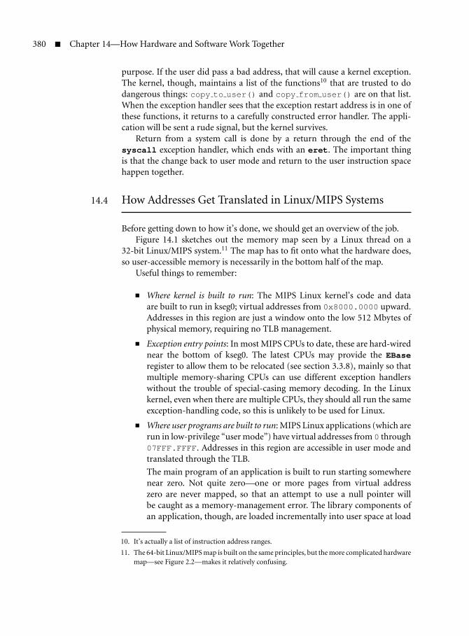
380 Chapter 14—How Hardware and Software Work Together
purpose. If the user did pass a bad address, that will cause a kernel exception.The kernel, though, maintains a list of the functions10 that are trusted to dodangerous things: copy to user() and copy from user() are on that list.When the exception handler sees that the exception restart address is in one ofthese functions, it returns to a carefully constructed error handler. The appli-cation will be sent a rude signal, but the kernel survives.
Return from a system call is done by a return through the end of thesyscall exception handler, which ends with an eret. The important thingis that the change back to user mode and return to the user instruction spacehappen together.
14.4 How Addresses Get Translated in Linux/MIPS Systems
Before getting down to how it’s done, we should get an overview of the job.Figure 14.1 sketches out the memory map seen by a Linux thread on a
32-bit Linux/MIPS system.11 The map has to fit onto what the hardware does,so user-accessible memory is necessarily in the bottom half of the map.
Useful things to remember:
Where kernel is built to run: The MIPS Linux kernel’s code and dataare built to run in kseg0; virtual addresses from 0x8000.0000 upward.Addresses in this region are just a window onto the low 512 Mbytes ofphysical memory, requiring no TLB management.
Exception entry points: In most MIPS CPUs to date, these are hard-wirednear the bottom of kseg0. The latest CPUs may provide the EBaseregister to allow them to be relocated (see section 3.3.8), mainly so thatmultiple memory-sharing CPUs can use different exception handlerswithout the trouble of special-casing memory decoding. In the Linuxkernel, even when there are multiple CPUs, they should all run the sameexception-handling code, so this is unlikely to be used for Linux.
Where user programs are built to run: MIPS Linux applications (which arerun in low-privilege “user mode”) have virtual addresses from 0 through07FFF.FFFF. Addresses in this region are accessible in user mode andtranslated through the TLB.
The main program of an application is built to run starting somewherenear zero. Not quite zero—one or more pages from virtual addresszero are never mapped, so that an attempt to use a null pointer willbe caught as a memory-management error. The library components ofan application, though, are loaded incrementally into user space at load
10. It’s actually a list of instruction address ranges.
11. The 64-bit Linux/MIPS map is built on the same principles, but the more complicated hardwaremap—see Figure 2.2—makes it relatively confusing.
14.4 How Addresses Get Translated in Linux/MIPS Systems 381
kuseg
Linux kernel code and data
Kernel modules
Dynamically mapped kerneldata
Mapping for phys addrabove 512 Mbytes
Main program code and data
Dynamic library code/data
What Linux uses it for Virtual address
0x0000.0000
0x7FFF.FFFF
0x8000.0000
0xA000.0000
0xC000.0000
0xFFFF.FFFF
exception entry points
Boot ROM
I/O registers (if below512-MB physical)
Program heap (growing up)
Direct view of memory to 512 MB
User stack (growing down)
sharedby allthreads
as seenby this thread grouponly
kseg2kernel
mapped
kseg1kernel
uncached
kseg0kernel
cachedunmapped
Hardwarecategories
FIGURE 14.1 Memory map for a Linux thread.
time or even later. That’s possible because a library component is built tobe position-independent (see Chapter 16) and is adjusted to fit the placethat the loader finds for it.
User stack and heap: An application’s stack is initially set to the top ofuser-accessible memory (about 2 GB up in virtual space) and grows down.The OS detects accesses to not-yet-mapped memory near the lowest stackentries it has allocated and automatically maps more pages to let the stackgrow.
Meanwhile, new shared libraries or explicit user data allocated withmalloc() and its descendants are growing up from the bottom of theuser space. So long as the sum of all these remains less than 2 GB, all iswell: This restriction is rarely onerous in any but the biggest servers.
Physical memory up to 512 MB: Can be accessed cached through kseg0and uncached through kseg1. Historically, the Linux kernel assumed ithad direct access to all the physical memory of the machine. For smaller

382 Chapter 14—How Hardware and Software Work Together
MIPS systems that use 512 MB or less of physical memory range, that’strue; in this case, all memory is directly accessible (cached) in kseg0 and(uncached) in kseg1.
Physical memory over 512 MB is “high memory”: Now, 512 MB is nolonger enough, even for embedded systems. Linux has an architecture-independent concept of high memory—physical memory that requiresspecial, architecture-dependent handling, and for a 32-bit Linux/MIPSsystem physical memory above 512 MB is high memory. When we needto access it, we’ll create appropriate translation entries and have themcopied into the TLB on demand.
Early MIPS CPUs sought applications in UNIX workstations and servers,so the MIPS memory-management hardware was conceived as the minimumhardware that could hope to provide memory management for BSD UNIX. TheBSD UNIX system was the first UNIX OS to provide real paged virtual memoryon the DEC VAX minicomputer. The VAX was in many ways the model forthe 32-bit paged-translation virtual-memory architectures that have dominatedcomputing ever since; perhaps it’s not surprising that there are some echoes ofthe VAX memory-management organization in MIPS. But this is a RISC, andthe MIPS hardware does much less. In particular, many problems that the VAX(or an x86) solves with microcode are left to software by the MIPS system.
In this chapter, we’ll start close to where MIPS started, with the require-ments of a basic UNIX-like OS and its virtual memory system; but this time theOS is Linux.
We’ll show how the essence of the MIPS hardware is a reasonable responseto that requirement. For real nuts and bolts details, refer to Chapter 6.
14.4.1 What’s Memory Translation For?
Memory translation hardware (while we’re being general we’ll call it MMU formemory management unit) serves several distinct purposes:12
Hiding and protection: User-privilege programs can only access datawhose program address is in the kuseg memory region (lower programaddresses). Such a program can only get at the memory regions that theOS allows.
Moreover, each page can be individually specified as writable or writeprotected; the OS can even stop a program from accidentally overwritingits code.
Allocating contiguous memory to programs: With the MMU, the OS canbuild contiguous program space out of physically scattered pages of
12. Given just how much the MMU contributes, it’s remarkable that a fairly workable minimalLinux system (ucLinux) can be built without it—but that’s another story.

14.4 How Addresses Get Translated in Linux/MIPS Systems 383
memory, allowing us to allocate memory from a simple pool of fixed-sizepages.
Extending the address range: Some CPUs can’t directly access their fullpotential physical memory range. MIPS32 CPUs, despite their genuine32-bit architecture, arrange their address map so that the unmappedaddress space windows kseg0 and kseg1 (which don’t depend on theMMU tables to translate addresses) are windows onto the first 512 MB ofphysical memory. If you need a memory map that extends further, youmust go through the MMU.
Making the memory map suit your program: With the MMU, your pro-gram can use the addresses that suit it. In a big OS, there may be manycopies of the same program running, and it’s much easier for them all tobe using the same program addresses.
Demand paging: Programs can run as if all the memory resources theyneeded were already allocated, but the OS can actually give them out onlyas needed. A program accessing an unallocated memory region will getan exception that the OS can process; the OS then loads appropriate datainto memory and lets the program continue.
In theory (and sometimes in computer science textbooks), it says thatdemand paging is useful because it allows you to run a larger programthan will fit into physical memory. This is true, if you’ve got a lot of timeto spare, but in reality if a program really needs to use more memorythan is available it will keep displacing bits of itself from memory andwill run very, very slowly.
But demand paging is still very useful, because large programs are filledwith vast hinterlands of code that won’t get run, at least on this execution.Perhaps your program has built-in support for a data format you’re notusing today; perhaps it has extensive error handling, but those errors arerare. In a demand-paged system, the chunks of the program that aren’tused need never be read in. And it will start up fast, which will please animpatient user.
Relocation: The addresses of program entry points and predeclared dataare fixed at program compile/build time—though this is much less truefor position-independent code, used for all Linux’s shared libraries andmost applications. The MMU allows the program to be run anywhere inphysical memory.
The essence of the Linux memory manager’s job is to provide each programwith its own memory space.
Well, really Linux has separate concepts: Threads are what is scheduled,and address spaces (memory maps) are the protection units. Many threadsin a thread group can share one address space. The memory translation sys-tem is obviously interested in address spaces and not in threads. Linux’s

384 Chapter 14—How Hardware and Software Work Together
implementation is that all threads are equal, and all threads have memory-management data structures. Threads that run in the same address space, infact, share most of those data structures.
But for now it will be simpler if we just consider one thread per addressspace, and we can use the older word “process” for them both.
If the memory management job is done properly, the fate of each processis independent of the others (the OS protects itself too): A process can crashor misbehave without bringing down the whole system. This is obviously auseful attribute for a university departmental computer running student pro-grams, but even the most rigorous commercial environment needs to supportexperimental or prototype software alongside the tried and tested.
The MMU is not just for big, full virtual memory systems; even smallembedded programs benefit from relocation and more efficient memory allo-cation. Any system in which you may want to run different programs at differ-ent times will find it easier if it can map the program’s idea of addresses ontowhatever physical address space is readily available.
Multitasking and separation between various tasks’ address spaces used tobe only for big computers, then migrated into personal computers and smallservers, and are increasingly common in the vanishingly small computers ofconsumer devices.
However, few non-Linux embedded OSs use separate address spaces. Thisis probably not so much because this would not be useful, but is due to thelack of consistent features on embedded CPUs and their available operatingsystems. And perhaps because once you add separate address spaces to yoursystem you’re too close to reinventing Linux to make sense!
This is an unexpected bonanza for the MIPS architecture. The minimalismthat was so necessary to make the workstation CPU simple in 1986 is a greatasset to the embedded systems of the early 21st century. Even small applica-tions, beset by rapidly expanding code size, need to use all known tricks to man-age software complexity; and the flexible software-based approach pioneered byMIPS is likely to deliver whatever is needed. A few years ago it was hard to con-vince CPU vendors addressing the embedded market that the MMU was worthincluding; now (in 2006) Linux is everywhere.
14.4.2 Basic Process Layout and Protection
From the OS’s point of view, the low part of memory (kuseg) is a safe “sandbox”in which the user program can play all it wants. If the program goes wild andtrashes all its own data, that’s no worry to anyone else.
From the application’s point of view, this area is free for use in buildingarbitrarily complicated private data structures and to get on with the job.
Inside the user area, within the program’s sandbox, the OS provides morestack to the program on demand (implicitly, as the stack grows down). It willalso provide a system call to make more data available, starting from the highest

14.4 How Addresses Get Translated in Linux/MIPS Systems 385
predeclared data addresses and growing up—systems people call this a heap.The heap feeds library functions, such as malloc(), that provide your programwith chunks of extra memory.
Stack and heap are supplied in chunks small enough to be reasonably thriftywith system memory but big enough to avoid too many system calls or excep-tions. However, on every system call or exception, the OS has a chance to policethe application’s memory consumption. An OS can enforce limits that makesure the application doesn’t get so large a share of memory as to threaten othervital activities.
A Linux thread keeps its identity inside the OS kernel, and when it runs inprocess context in the kernel (as in a system call) it’s really just calling a carefulsubroutine.
The operating system’s own code and data are of course not accessible touser space programs. On some systems, this is done by putting them in a com-pletely separate address space; on MIPS, the OS shares the same address space,and when the CPU is running at the user-program privilege level, access to theseaddresses is illegal and will trigger an exception.
Note that while each process’s user space maps to its own private real stor-age, the privileged space is shared. The OS code and resources are seen at thesame address by all processes—an OS kernel is a multithreaded but single-address-space system inside—but each process’s user space addresses access itsown separate space. Kernel routines running in process context are trusted tocooperate safely, but the application need not be trusted at all.
We mentioned that the stack is initialized to the highest permissible useraddresses: That’s done so we can support programs that use a great deal ofmemory. The resulting wide spread of addresses in use (with a huge hole inbetween) is one characteristic of this address map with which any translationscheme must cope.
Linux maps application code as read-only to the application, so that codecan be safely shared by threads in different address spaces—after all, it’s com-mon to have many processes running the same application.
Many systems share not just whole applications but chunks of applicationsaccessed through library calls (shared libraries). Linux does that through sharedlibraries, but we’ll pick up that story later.
14.4.3 Mapping Process Addresses to Real Memory
Which mechanisms are needed to support this model?We want to be able to run multiple copies of the same application, and
they’d better use different underlying copies of the data. So during programexecution, application addresses are mapped to physical addresses according toa scheme fixed by the OS when the program is loaded.
Although it would be possible for the OS to rush around patching all theaddress translation information whenever we switched contexts from oneprocess to another, it would be very inefficient. Instead, we award each active

386 Chapter 14—How Hardware and Software Work Together
thread’s memory map an 8-bit number called the address space ID or ASID.When the hardware finds a translation entry for the address, it looks for atranslation entry that matches the current ASID as well as the address,13 so thehardware can hold translations for different spaces without getting them mixedup. Now all the software needs to do when scheduling a thread in a differentaddress space is to load a new ASID into EntryHi(ASID).
The mapping facility also allows the OS to discriminate between differentparts of the user address space. Some parts of the application space (typicallycode) can be mapped read-only, and some parts can be left unmapped andaccesses trapped, meaning that a program that runs amok is likely to be stoppedearlier.
The kernel part of the process’s address space is shared by all processes. Thekernel is built to run at particular addresses, so it mostly doesn’t need a flexiblemapping scheme and can take advantage of the kseg0 region, leaving mem-ory mapping resources for application use. Some dynamically generated kernelareas are conveniently built from mapped memory (for example, memory usedto hold kernel loadable modules for device drivers and so on is mapped).
14.4.4 Paged Mapping Preferred
Many exotic schemes have been tried for mapping addresses. Until the mid-1980sor so, the industry kept thinking there must be a better solution than fixed-size pages. Fixed-size pages have nothing to do with the needs or behavior ofapplication programs, after all, and no top-down analysis will ever invent them.
But if the hardware gives programs what they want (chunks of memory inwhichever size is wanted at that moment), available memory rapidly becomesfragmented into awkward-sized pieces. When we finally make contact withaliens, their wheelbarrows will have round wheels and their computers willprobably use fixed-size pages.
So all practical systems map memory in pages—fixed-size chunks of mem-ory. Pages are always a power of 2 bytes big. Small pages might take toomuch management (big tables of translations, many translations needed for aprogram); big pages may be inefficient, since quite a lot of small objects endup occupying a whole page. A total of 4 KB is the overwhelmingly popularcompromise for Linux.14
With 4-KB pages, a program/virtual address can be simply partitioned thus:
Virtual page number (VPN) Address within page
nn 12 11 0
13. Actually, we’ll see that some translation entries can be ASID-independent or “global.”
14. The MIPS hardware would be quite happy with bigger pages: 16 KB is the next directly sup-ported size and is probably a better trade-off for many modern systems. But the page size ispervasive, with tentacles into the way programs are built; so we almost all still use 4 KB.

14.4 How Addresses Get Translated in Linux/MIPS Systems 387
The address-within-page bits don’t need to be translated, so the memorymanagement hardware only has to cope with translating the high-orderaddresses (traditionally called virtual page number or VPN), into the high-order bits of a physical address (a physical frame number, or PFN—nobodycan remember why it’s not PPN).
14.4.5 What We Really Want
The mapping mechanism must allow a program to use a particular addresswithin its own process/address space and translate that efficiently into a realphysical address to access memory.
A good way to do this would be to have a table (the page table) containing anentry for each page in the whole virtual address space, with that entry contain-ing the correct physical address. This is clearly a fairly large data structure andis going to have to be stored in main memory. But there are two big problems.
The first is that we now need two references to memory to do any loador store, and that’s obviously hopeless for performance. You may foresee theanswer to this: We can use a high-speed cache memory to store translationentries and go to the memory-resident table only when we miss in the cache.Since each cache entry covers 4 KB of memory space, it’s plausible that we canget a satisfactorily low miss rate out of a reasonably small cache. (At the timethis scheme was invented, memory caches were rare and were sometimes alsocalled “lookaside buffers,” so the memory translation cache became a transla-tion lookaside buffer or TLB; the acronym survives.)
The second problem is the size of the page table; for a 32-bit applicationaddress space split into 4-KB pages, there are a million entries, which will takeat least 4 MB of memory. We really need to find some way to make the tablesmaller, or there’ll be no memory left to run the programs.
We’ll defer any discussion of the solution for this, beyond observing thatfew real programs use anything like the 4 Gbytes addressable with 32 bits. Moremodest programs have huge holes in their program address space, and if wecan invent some scheme that avoids storing all the “nothing here” translationentries corresponding to the holes, then things are likely to get better.
We’ve now arrived, in essence, at the memory translation system DECfigured out for its VAX minicomputer, which has been extremely influentialin most subsequent architectures. It’s summarized in Figure 14.2.
The sequence in which the hardware works is something like this:
A virtual address is split into two, with the least significant bits (usually12 bits) passing through untranslated—so translation is always done inpages (usually 4 KB).
The more significant bits, or VPN, are concatenated with the currentlyrunning thread’s ASID to form a unique page address.

388 Chapter 14—How Hardware and Software Work Together
ASID VPN Addresswithin page
ASID VPN/Mask PFN Flags PFN Flags
Addresswithin pagePFN
Process No. Program (virtual) address
Refill asrequired
Physical address
TLB Page Table
FIGURE 14.2 Desirable memory translation system.
We look in the TLB (translation cache) to see if we have a translationentry for the page. If we do, it gives us the high-order physical addressbits and we’ve got the address to use.
The TLB is a special-purpose store and can match addresses in varioususeful ways. It may have a global flag bit that tells it to ignore the valueof ASID for some entries, so that these TLB entries can be used to mapsome range of virtual addresses for every thread.
Similarly, the VPN may be stored with some mask bits that cause someparts of the VPN to be excluded from the match, allowing the TLB entryto map a larger range of virtual addresses.
Both of these features are available in MIPS MMUs (there’s no variable-size pages in some very old MIPS CPUs, though).
There are usually extra bits (flags) stored with the PFN that are used tocontrol which kind of access is allowed—most obviously, to permit reads

14.4 How Addresses Get Translated in Linux/MIPS Systems 389
but not writes. We’ll discuss the MIPS architecture’s flags in the nextsection.
If there’s no matching entry in the TLB, the system must locate or buildan appropriate entry (using main-memory-resident page table informa-tion) and load it into the TLB and then run the translation process again.
In the VAX minicomputer, this process was controlled by microcode andseemed to the programmer to be completely automatic. If you build theright format of page table in memory and point the hardware at it, allmemory translation just works.
14.4.6 Origins of the MIPS Design
The MIPS designers wanted to figure out a way to offer the same facilities asthe VAX with as little hardware as possible. The microcoded TLB refill wasnot acceptable, so they took the brave step of consigning this part of the jobto software.
That means that apart from a register to hold the current ASID, the MMUhardware is simply a high-speed, fixed-size table of translations. System soft-ware can (and usually does) use the hardware as a cache of entries from somekind of comprehensive memory-resident page table, so it makes sense to callthe hardware table a TLB. But there’s nothing in the TLB hardware to make ita cache, except this: When presented with an address it can’t translate, the TLBtriggers a special exception (TLB refill) to invoke the software routine. Somecare is taken with the details of the TLB design, the associated control registers,and the refill exception to help the software to be efficient.
The MIPS TLB has always been implemented on chip. The memory transla-tion step is required even for cached references, so it’s very much on the criticalpath of the machine. That meant it had to be small, particularly in the earlydays, so it makes up for its small size by being clever.
It’s basically a genuine associative memory. Each entry in an associativememory consists of a key field and a data field; you present the key and the hard-ware returns the data of any entry the key matches. Associative memories arewonderful, but they are expensive in hardware. MIPS TLBs have had between32 and 64 entries; a store of this size is manageable as a silicon design.
All contemporary CPUs use a TLB in which each entry is doubled up to maptwo consecutive VPNs to independently specified physical pages. The pairedentries double the amount of memory that can be mapped by the TLB withonly a little extra logic, without requiring any large-scale rethinking of TLBmanagement.
You will see the TLB referred to as being fully associative; this emphasizesthat all keys are really compared with the input value in parallel.15
15. The common 32-entry paired TLB would be correctly, if pedantically, described as a 32-wayset-associative store, with two entries per set.

390 Chapter 14—How Hardware and Software Work Together
PageMaskASID GVPN2 FlagsPFN PFN
output (pair of physical pages) input (8 K of virtual space)
CDVFlags
CDV
FIGURE 14.3 TLB entry fields.
The TLB entry is shown schematically in Figure 14.3. For the moment,we’ll assume that pages are 4 Kbytes in size. The TLB’s key—the input value—consists of three fields:
VPN2: The page number is just the high-order bits of the virtual address—the bits left when you take out the 12 low bits that address thebyte within page. The “2” in VPN2 emphasizes that each virtual entrymaps 8 Kbytes because of the doubled output field. Bit 12 of the vir-tual address selects either the first or the second physical-side entry ofthe pair.
PageMask: Controls how much of the virtual address is compared withthe VPN and how much is passed through to the physical address; amatch on fewer bits maps a larger region. A “1” bit causes the corre-sponding address bit to be ignored. Some MIPS CPUs can be set up tomap as much as 16 MB with a single entry. The most significant ignoredbit is used to select the even or odd entry.
ASID: Marks the translation as belonging to a particular address space,so this entry will only be matched if the thread presenting the addresshas EntryHi(ASID) set equal to this value.
The G bit, if set, disables the ASID match, making the translation entryapply to all address spaces (so this part of the address map is sharedbetween all spaces). The ASID is 8 bits: The OS-aware reader will appreci-ate that even 256 is too small an upper limit for the number of simultane-ously active processes on a big UNIX system. However, it’s a reasonablelimit so long as “active” in this context is given the special meaning of“may have translation entries in the TLB.” OS software has to recycleASIDs where necessary, which will involve purging the TLB of transla-tion entries for any processes being downgraded from active. It’s a dirtybusiness, but so is quite a lot of what OSs have to do; and 256 entriesshould be enough to make sure it doesn’t have to be done so often as toconstitute a performance problem.
For programming purposes, it’s easiest if the G bit is kept in the ker-nel’s page tables with the output-side fields. But when you’re translating,it belongs to the input side. On MIPS32/64 CPUs, the two output-sidevalues are AND-ed together to produce the value that is used, but the

14.4 How Addresses Get Translated in Linux/MIPS Systems 391
realistic outcome is that you must make sure the G bit is set the same inboth halves.
The TLB’s output side gives you the physical frame number and a small butsufficient bunch of flags:
Physical frame number (PFN): This is the physical address with the lowbits cut off (the low 12 bits if this is representing a 4-Kbyte page).
Write control bit (D): Set 1 to allow stores to this page to happen. The “D”comes from this being called the dirty bit; see the next sectionfor why.
Valid bit (V): If this is 0, the entry is unusable. This seems pretty pointless:Why have a record loaded into the TLB if you don’t want the translationto work? There are two reasons. The first is that the entry translates apair of virtual pages, and maybe only one of them ought to be there. Theother is that the software routine that refills the TLB is optimized forspeed and doesn’t want to check for special cases. When some furtherprocessing is needed before a program can use a page referred to by thememory-held table, the memory-held entry can be left marked invalid.After TLB refill, this will cause a different kind of trap, invoking specialprocessing without having to put a test in every software refill event.
Cache control (C): This 3-bit field’s primary purpose is to distinguishcacheable (3) from uncached (2) regions.
But that leaves six other values, used for two somewhat incompatiblepurposes: In shared-memory multiprocessor systems, different valuesare used to hint whether the memory is shared (when hardware willhave to work hard to keep any cached data consistent across the wholemachine). In “embedded” CPUs, different values select different localcache management strategies: write-through versus write-back, for exam-ple. See your CPU manual.
Translating an address is now simple, and we can amplify the descriptionabove:
CPU generates a program address: This might be an instruction fetch, aload, or store—and it’s one with an address that does not lie in the specialunmapped regions of the MIPS address space.
The low 13 bits are separated off, and the resulting VPN2, together withthe current ASID (EntryHi(ASID)), is looked up in the TLB. The matchis affected by the thePageMask and byGfields of the various TLB entries.
TLB matches key: If there’s no matching entry, we’ll take a TLB refillexception. But where there is a match, that entry is selected. Bit 12 ofthe virtual address selects which physical-side half we’ll use.

392 Chapter 14—How Hardware and Software Work Together
The PFN from the TLB is glued to the low-order bits of the programaddress to form a complete physical address.
Valid? The V and D bits are consulted. If it isn’t valid, or a store is beingattempted with D unset, the CPU takes an exception. As with all transla-tion traps, the BadVAddr register will be filled with the offendingprogram address; as with any TLB exception, the TLB EntryHi registerwill be preloaded with the VPN of the offending address.
The BadVPN2 fields of the convenience registers Context (and XCon-text on 64-bit CPUs) will be preloaded (in part, as advertised) withthe appropriate bits of the virtual address we failed to translate duringa TLB refill exception. But the specification is less definite about howthose address fields behave in other exceptions. It’s probably a good ideato stick to BadVAddr in other exceptions.
Cached? If the C bit is set, the CPU looks in the cache for a copy of thephysical location’s data; if it isn’t there, it will be fetched from memoryand a copy left in the cache. Where the C bit is clear, the CPU neitherlooks in nor refills the cache.
Of course, the number of entries in the TLB permits you to translate only arelatively small number of program addresses—a few hundred KB worth. Thisis far from enough for most systems. The TLB is almost always going to be usedas a software-maintained cache for a much larger set of translations.
When a program address lookup in the TLB fails, a TLB refill trap is taken.16
System software has the following job:
It figures out whether there is a correct translation; if not, the trap willinvoke the software that handles address errors.
If there is a correct translation, it constructs a TLB entry that will imple-ment it.
If the TLB is already full (and it almost always is full in running systems),the software selects an entry that can be discarded.
The software writes the new entry into the TLB.
See section 14.4.8 for how this is done in Linux.
14.4.7 Keeping Track of Modified Pages (Simulating “Dirty” Bits)
An operating system that provides a page for an application program to useoften wants to keep track of whether that page has been modified since the OSlast obtained it (perhaps from disk or network) or saved a copy of it.
16. Should this be called a “TLB miss” (which is what just happened) or a “TLB refill” (whichis what we’re going to do to sort it out)? I’m afraid we probably use both terms in MIPSdocumentation.

14.4 How Addresses Get Translated in Linux/MIPS Systems 393
Unmodified (“clean”) pages may be quietly discarded, since they can easily berecovered from a file system if they’re ever needed again.
In OS parlance the modified pages are called “dirty,” and the OS must takecare of them until the application program exits or the dirty page is cleaned bybeing saved away to backing store. To help out with this process, it is commonfor CISC CPUs to maintain a bit in the memory-resident page table indicatingthat a write operation to the page has occurred. The MIPS CPU does not sup-port this feature, even in the TLB entries. The D bit of the page table (found inthe EntryLo register) is a write-enable and of course is used to flag read-onlypages.
So here’s the trick:
When a writable page is first loaded into memory, you mark its page tableentry with D clear (leaving it read-only).
When any write is attempted to the page, a trap will result; system soft-ware will recognize this as a legitimate write but will use the event toset a “modified” bit in the memory resident tables—which, since it’s inthe EntryLo(D) position, permits future writes to be done without anexception.
You will also want to set the D bit in the TLB entry so that the write canproceed (but since TLB entries are randomly and unpredictably replaced,this would be useless as a way of remembering the modified state).
14.4.8 How the Kernel Services a TLB Refill Exception
MIPS’s TLB refill exception has always had its own unique entry point (at leastas long as the CPU wasn’t already in exception mode; in Linux, that would bea fatal error, and isn’t considered further).
When the exception routine is called, the hardware has set up EntryHi(VPN2) to the page number of the location we just couldn’t translate: EntryHiis set exactly to what is required to create a new TLB entry to map the offendingaddress.
The hardware has also set up a bunch of other address-related fields, butwe’re not going to use any of them.
In particular, we’re not going to use the convenient “MIPS standard” wayof using Context to find the relevant page table entry, which was describedin section 6.2.4. The MIPS standard way requires that a (notionally very long)linear page table is constructed in kseg2 (it won’t really take up excessive space,because kseg2 is mapped and the vast empty spaces of the table would never bemapped to real memory). But Linux really does not like to have the unique-to-thread-group kernel mappings that would require.
Instead, Linux’s TLB refill page tables are organized as a three-level hierar-chy of tables (called “global,” “middle,” and just “PTE”). But cunning use of Cmacros allows the middle level to disappear completely without changing the

394 Chapter 14—How Hardware and Software Work Together
PTEsPGD
Virtual address
in–page addr
TLB entry data (pair of pages)0111231 13
VPN2 flagsV D C
flagsV D C
PFNs/wonly
s/wonly
EntryLo0 bits EntryLo1 bits
2221
PFN
FIGURE 14.4 Linux two-level page table (32-bit MIPS design).
code—a two-level structure is enough for 32-bit MIPS.17 So you can find thedata for any TLB entry you want—if it exists at all—by following the links, asshown in Figure 14.4.
This structure is reasonably economical of kernel memory: A largish Linuxprogram with a 50-MB virtual address space has about 12-K 4-KB pages, eachneeding four bytes of PTE: That makes 48 KB or 12 pages. That’s anunderestimate, because the address space components have holes in them, buta reasonable-size thread group’s mapping needs take only 15 or so pages. Ker-nel (kseg2) mappings take more, but they’re common to all memory maps, sothere is only one set of PTEs for kernel mappings.
Most 32-bit CPUs are restricted to a 32-bit physical address, too: Wherethat’s so, there are six unused high-order bits in the EntryLo0-1 registers.Linux recycles those to remember some software state about the page tableentries.
This does mean that the TLB refill handler for this 32-bit needs to do twoindex calculations and three loads. It’s certainly longer than the tiny instruction
17. However, all three are required for the extended virtual memory space available with 64-bitMIPS.

14.4 How Addresses Get Translated in Linux/MIPS Systems 395
sequence of the original magic MIPS scheme (where the index calculation isdone by magic by the way the Context register works, and the only loads arefrom the final page table), but it’s not bad.
You may have noticed that this description is very particular to a certainsort of MIPS CPU. Do all Linux systems have a unique kernel? Well, no: Butin the current Linux/MIPS kernel certain critical routines—including the TLBmiss exception handler—are binaries generated by table-driven kernel softwareduring start-up and tailored to the requirements of this particular CPU.
Here, for example, is the TLB miss handler autogenerated for a system basedon a 32-bit MIPS 24-K core:
tlb_refill:# (1) get base of PGD into k1lui k1, %hi(pgd_current)
# get miss virtual address (VA)mfc0 k0, c0_badvaddr # (2) moved up to save a cyclelw k1, %lo(pgd_current)(k1)srl k0, k0, 24sll k0, k0, 2 # (3) shift and mask VA for PGD indexaddu k1, k1, k0 # got a pointer to the correct PGD entry
# get VA again, this time from Context registermfc0 k0, c0_context # (4) moved up to save a cyclelw k1, 0(k1) # OK, read the PTE pointer
srl k0, k0, 0x1 # (5) Context register designed for 2x64-bit,# entry, ours are half that size
andi k0, k0, 0xff8 # (6) mask out higher VPN bits etc
addu k1, k1, k0 # pointer to VPE entry
# load the TLB entrieslw k0, 0(k1) # (7) will lose a cycle herelw k1, 4(k1)
srl k0, k0, 0x6 # (8) shift-out software-only bitsmtc0 k0, c0_entrylo0srl k1, k1, 0x6 # same for other halfmtc0 k1, c0_entrylo1
ehb # (9) wait for CP0 values to be readytlbwr # (10) write into TLB (somewhere)eret # (11) back to user

396 Chapter 14—How Hardware and Software Work Together
Notes on the TLB Refill Code
(1) In an exception handler, the software convention allows us to use tworegisters (k0-1) with impunity. All other general-purpose registers arestill holding application data, and we can’t touch them.
(2, 4, 5) The code is made a little harder to read by the places where one sequencehas been interleaved with the next. That’s done for efficiency: A 24-KCPU load requires the register base to be ready one clock early, so if youcompute the base in the previous instruction you’ll get a one-clock stall.At (2) and (4) we found a nondependent instruction to interleave, but at(5) there isn’t one.
(3) As you can see from Figure 14.4, we want to use the top bits of the virtualaddress with the missing translation (which is in BadVaddr) to index thePGD. Since the PGD has pointers (four bytes) in each entry, we need toshift the index value by two to get a byte offset. You can’t just do a shift-right by 22 bits, because you might generate a nonword-aligned pointer,which is illegal for a MIPS load-word.
(4) See (2, 4, 5).
(5) With only two registers to play with, we can’t keep the original virtualaddress. So now we get it again, but this time from the Context register,which has the low bits of the “VPN2” field we need. For a 64-bit CPU—where we’d need to keep two 64-bit entries to fill the EntryLo0-1 pair—it’s just right, with the VPN2 number shifted up by four positions toindex a table of 16-byte entries. But Linux/MIPS for MIPS32 has eight-byte entries in the PTE table; so we shift it right one place.
(6) The high bits of Context are unwanted, so we mask them out. Evenabove the page number, they’re not always zero: SMP Linux systems usethe Context(PTEBase) field, which consists of plain read/write bits, tostore a CPU ID.
(7) See (2, 4, 5).
(8) On systems like this with 32-bit physical addresses, the EntryLo registeronly has 26 meaningful bits. Linux uses the other six for software flags,which we shift away.
(9) This execution hazard barrier ensures that the instructions followingit are delayed until the writes to the CP0 EntryLo0-1 registers arecomplete. In many CPUs, the write to the CP0 register from the mtc0instruction happens in a late pipeline stage.
(10) tlbwrwrites the complete TLB entry to a “random” place in the TLB. Infact, it gets the index from Random, which just counts continually roundTLB entries, but the timing of TLB misses is random enough that thisworks well.

14.4 How Addresses Get Translated in Linux/MIPS Systems 397
Note that the TLB contents comprise four CP0 registers: We’ve justloadedEntryLo0-1,EntryHiwas set up automatically by the TLB missexception hardware, and PageMask is maintained by Linux/MIPS at aconstant value meaning 4-KB pages.
(11) eret takes us back to the instruction that suffered the TLB miss, and itshould do better this time. Note that eret is also a CP0 hazard barrier,and it won’t allow the returned-to user instruction to be fetched untilthe tlbwr is complete.
14.4.9 Care and Maintenance of the TLB
The MIPS TLB is “just” a collection of translation entries. Entries get into itpurely by the refill handler’s action. Most entries get overwritten in the sameway, of course. But sometimes the kernel needs to change a page table entry,and then it’s important to invalidate any copy in the TLB.
For a single entry, we can look up the TLB entry using the virtual address +ASID of the original entry, doing a tlbp: If the matching entry is there, we canoverwrite that page’s entry with an invalid one.
Sometimes, though, you need to do surgery on a larger scale. The ASIDmechanism allows the TLB to hold entries for 256 different memory maps, buta Linux system will commonly run more than 256 processes between start-upand shutdown. So there are times when a whole batch of translations must berescinded, because the ASID is going to be recycled for a new process and theold entries would be damagingly wrong.
There’s no elegant way of doing that. You just have to iterate through all theTLB entries (index values go in the Index register), read each entry out intothe usual registers, check the ASID value retrieved into EntryHi(ASID), andinvalidate any that match the victim ASID value.
14.4.10 Memory Translation and 64-Bit Pointers
When the MIPS architecture was invented, 32-bit CPUs had been around fora while, and the largest programs’ data sets were already moving up toward100 MB—the address space had only 6 bits or so to spare.18 There was thereforeevery reason to be reasonably careful with the 32-bit space and not to reduceit by profligate fragmentation; this is why application programs (running withuser privilege) keep 31 bits’ worth of addressing for themselves.
When the MIPS III instruction set introduced 64-bit registers in 1991, itwas leading the industry and, as we discussed in section 2.7, MIPS was proba-bly four to six years ahead of real pressure on a 32-bit address boundary. Thedoubling of register size only had to yield a few bits of extra address space to
18. Historically, application program demand for memory space seems to have grown at about34 bit per year.

398 Chapter 14—How Hardware and Software Work Together
be remarkably future-proof; it’s been more important to be cautious about thepotentially exploding size of OS data structures than to make efficient use of alladdress space.
The limitations to the practical address space resulting from the basic 64-bitmemory map are not going to be reached for a while; they theoretically permitthe mapped user and other spaces to grow to 61 bits without any reorganization.But so far, a 40-bit user virtual space has been ample. Most other 64-bit Linuxsystems have 8-Kbyte pages, but that would be annoying for MIPS. The MIPSTLB can map either 4 Kbyte or 16 Kbyte in a single entry, but not 8 Kbyte, so64-bit MIPS kernels use 4-Kbyte pages, with 16-Kbyte pages a desirable optionin some brave future.
If you take a look back at Figure 14.4 and imagine a set of intermediate(PMD) tables between the PGD and PTEs, you can comfortably resolve a40-bit virtual address in a three-level table. We’ll leave details to those enthusi-astic enough to read the source code.

Chapter
15 MIPS Specific Issues inthe Linux Kernel
Much of the Linux kernel is written in portable C, and a great deal of itis portable to a clean architecture like MIPS with no further trouble.
We looked in the last chapter at the obvious machine-dependent code aroundexceptions and memory management. This chapter is looking at other placeswhere MIPS-specific code is needed.
The first two sections deal with cases where most MIPS CPUs have tradedoff programming convenience for hardware simplicity: first, that MIPS cachesoften require software management and, second, that the MIPS CP0 (CPU con-trol) operations sometimes require explicit care with pipeline effects. We’ll takea quick look at what you need to know about MIPS for a multiprocessor (SMP)Linux system. And the last section is a glimpse at the use of heroic assemblycode to speed up a heavily used kernel routine.
15.1 Explicit Cache Management
In the x86 CPUs, where Linux was born and grew up, the caches are mostlyinvisible, with hardware keeping everything just as if you were talking directlyto memory.
Not so MIPS systems, where many MIPS cores have caches with no extra“coherence” hardware of any kind. Linux systems must deal with troubles inseveral areas.
15.1.1 DMA Device Accesses
DMA controllers write memory (leaving cache contents out-of-date) or read it(perhaps missing cached data not yet written back). On some systems—particularly x86 PCs—the DMA controllers find some way to tell the hardwarecache controller about their transfers, and the cache controller automatically
399

400 Chapter 15—MIPS-Specific Issues in the Linux Kernel
invalidates or writes back cache contents as required to make the whole processtransparent, just as though the CPU was reading and writing raw memory. Sucha system is called “I/O-cache coherent” or more often just “I/O coherent.”
Few MIPS systems are I/O-cache coherent. In most cases, a DMA transferwill take place without any notification to the cache logic, and the device driversoftware must manage the caches to make sure that no stale data in cache ormemory is used.
Linux has a DMA API that exports routines to device drivers thatmanage DMA data flow (many of the routines become null in an I/O coher-ent system). You can read about it in the documentation provided with theLinux kernel sources, which includes Documentation/DMA-API.txt. In fact,if you’re writing or porting a device driver, you should read that.
When a driver asks to allocate a buffer, it can choose:
“Consistent” memory: Linux guarantees that “consistent” memory is I/Ocoherent, possibly at some cost to performance. On a MIPS CPU thisis likely to be uncached, and the cost to performance is considerable.But consistent buffers are the best way to handle small memory-residentcontrol structures for complex device controllers.
Using nonconsistent memory for buffers: Since consistent memory will beuncached for many MIPS systems, it can lead to very poor performanceto use it for large DMA buffers.
So for most regular DMA, the API offers calls with names like dma
map xx(). They provide buffers suitable for DMA, but the buffers won’tbe I/O coherent unless the system makes univeral coherence cheap.
The kernel memory allocator makes sure the buffer is in a memory regionthat DMA can reach, segregates different buffers so they don’t share thesame cache lines, and provides you with an address in a form usable bythe DMA controller.
Since this is not coherent, there are calls that operate on the buffer and dothe necessary cache invalidation or write-back operations before or afterDMA: They are called dma sync xx(), and the API includes instruc-tions on when and how to call these functions.
For genuinely coherent hardware, the “sync” functions are null.
The language of the API documentation is unfortunate here. There is alittle-used extension to the API whose function names contain the word“noncoherent,” but you should not use it unless your system is reallystrange. A regular MIPS system, even though it is not I/O coherent, canand should work fine with drivers using the standard API.
This is all moderately straightforward by OS standards. But many driverdevelopers are working on machines that manage this in hardware, where the“sync” functions are just stubs. If they forget to call the right sync function at

15.1 Explicit Cache Management 401
the right moment, their software will work: It will work until you port it toa MIPS machine requiring explicit cache management. So be cautious whentaking driver code from elsewhere. The need to make porting more trouble-free is the most persuasive argument for adding some level of hardware cachemanagement in future CPUs.
If you’re interested in peeking into the Linux implementation to see howthe cache synchronization functions are built from MIPS instructions, use sec-tion 4.6 as a reference.
15.1.2 Writing Instructions for Later Execution
A program that writes instructions for itself can leave the instructions in theD-cache but not in memory, or can leave stale data in the I-cache where theinstructions ought to be.
This is not a kernel-specific problem: In fact, it’s more likely to be met inapplications such as the “just-in-time” translators used to speed up languageinterpreters. It’s beyond the scope of this book to discuss how you might fix thisportably, but any fix for MIPS will be built on the synci instruction. That’sthe ideal: synci was only defined in 2003 with the second revision of theMIPS32/64 specifications, and many CPUs without the instruction are stillin use. On such CPUs there must be a special system call to do the necessaryD-cache write-back and I-cache invalidation using privileged cache instruc-tions. You can find out the details of how synci works in section 8.5.11.
15.1.3 Cache/Memory Mapping Problems
Virtual caches (real ones with virtual index and tagging) seem a wonderful freeride, since the whole cache search process can start earlier and run in parallelwith page-based address translation.
A plain virtual cache must be emptied out whenever there’s a memory mapchange, which is intolerable unless the cache is very small. But if you use theASID to extend the virtual address, entries from different processes are disam-biguated.
OS programmers know why virtual caches are a bad idea: The trouble withvirtual caches is that the data in the cache can survive a change to the pagetables. In general, the virtual cache ought to be checked after any mapping isrescinded. That’s costly, so OS engineers try to minimize updates, miss somecorner case, and end up with bugs.
In a heroic attempt to make Linux work successfully even with virtual caches,the kernel provides a set of rules and function calls that should be provided aspart of the port to an architecture with troublesome caches. They’re the func-tions with names starting flush cache xxx() described in the kernel doc-umentation Documentation/cachetlb.txt. I don’t like the word “flush”to describe cache operations: It’s been used to mean too many things. So note
402 Chapter 15—MIPS-Specific Issues in the Linux Kernel
carefully that in the Linux kernel a “cache flush” is something you do to get rid ofcache entries that relate to obsolete memory mappings. In a system where allcaches are physically indexed and tagged, none of these calls needs to do anything.
Fortunately, virtual D-caches are rare on MIPS CPUs. Some recent CPUshave virtual I-caches: Implement the “flush” functions as described in the doc-umentation and you should be all right. But L1 caches with physical tags butvirtual indexes are common on MIPS CPUs. They solve the problems describedin this section, but they lead to a different problem called a “cache alias”—read on.
15.1.4 Cache Aliases
We’re now getting to something more pernicious. MIPS CPU designers wereamong the first to realize that the benefits of using the virtual address to indextheir cache could be combined with the benefit of using the physical address totag it. This can lead to cache aliases—for more explanation, see section 4.12.
The R4000 CPU was the first to use virtually indexed caches. As originallyconceived, the CPU always came with an L2 cache (the cache memory was off-chip, but the L2 controller is included with the CPU), and it used the L2 cache todetect L1-cache aliases. If you loaded an alias to a line that was already presentin the L1, the CPU generated an exception, which could be used to clean up.
But the temptation to produce a smaller, cheaper R4000 variant by omit-ting the L2 cache memory chips and the pins that wired them up proved toostrong. Contemporary UNIX systems had a fairly stylized way of using virtualmemory, which meant that you could control memory allocation to avoid everloading an alias. In retrospect we can see that generating aliases is a bug, andthe careful memory management was a workaround for it. But it worked, andpeople forgot, and it became a feature.
There are basically two ways to deal with cache aliases.The first is to try to ensure that whenever a page is shared, all the virtual
references to it have the same “page color” (that means that the references maybe different, but the difference between them is a multiple of the cache set size).Any data visible twice in same-color pages will be stored at the same cache indexand handled correctly. It’s possible to ensure that all user-space mappings of apage are of the same color—more on this in section 10.3.4.
But unlike the old BSD systems, Linux provides features where correct pagecoloring is impossible. Those will be cases where you have both a user-spaceand kernel mapping to the same page (in many cases, on a MIPS kernel, thekernel “mapping” will be a kseg0 address). So the MIPS port has special codeto detect those cases and clean out any old alias mappings.
The Cache/TLB documentation (that’sDocumentation/cachetlb.txt,as mentioned in the section above) makes a heroic attempt to deal with cachealiases as “just another symptom” of virtual caches in general. It provides somenotes on how to configure the kernel to do what it can on page coloring andhow to handle kernel/user-space aliases.

15.3 Multiprocessor Systems and Coherent Caches 403
The work of fixing around cache aliases is never finished. As the years gopast, Linux is expected to offer more exciting facilities. Programmers struggleto fix the places where aliases can break legitimate code, but as new facilities areadded to the OS, it breaks again. I think the CPU designers are now recognizingthat relying on software workarounds for aliases creates maintenance problems:Increasingly, new CPUs have at least the D-cache alias-free.
MIPS was a very influential architecture, so some of its competitors faith-fully copied its mistakes;1 as a result, cache aliases are found in other architec-tures too.
15.2 CP0 Pipeline Hazards
As we’ve seen in some of the examples above, CP0 operations which are depend-ent on some CP0 register value need to be done carefully: The pipeline is notalways hidden for these OS-only operations. The OS is where all the CP0 oper-ations happen, of course.
On a modern CPU (compliant to Release 2 of the MIPS32/MIPS64 speci-fications), hazard barrier instructions (eret, jalr.hb, and jr.hb) are avail-able, as described in section 3.4.
On older CPUs, only entry into exception and theeret instruction are guar-anteed to act as CP0 hazard barriers. So where you’re writing a code sequencewhere something depends on the correct completion of a CP0 operation, youmay need to pad the code with a calculated number of no-op instructions (yourCPU may like you to use the ssnop rather than a plain old nop—read themanual).
The CPU manual for an older CPU should describe the (CPU-specific)maximum duration of any hazard and let you calculate how many instructiontimes might pass before you are safe.
15.3 Multiprocessor Systems and Coherent Caches
In the 1990s, MIPS CPUs were used by SGI and others to build cache-coherentmultiprocessor systems. SGI were not exactly pioneers in this area, but the MIPSR4000 was one of the first microprocessors designed from the outset to fit intosuch a system, and SGI’s large MIPS multiprocessor server/supercomputers werevery successful products.
However, little about this technology is really specific to MIPS, so we’ll bebrief.
The kind of multiprocessor system we’re describing here is one in which allthe CPUs share the same memory and, at least for the main read/write memory,
1. If imitation is the sincerest form of flattery, imitation of an architecture’s mistakes must betantamount to hero-worship.

404 Chapter 15—MIPS-Specific Issues in the Linux Kernel
the same physical address space—that’s an “SMP” system (for SymmetricMultiProcessing—it’s “symmetric” because all CPUs have the same relationshipwith memory and work as peers).
The preferred OS structure for SMP systems is one where the CPUs coop-erate to run the same Linux kernel. Such a Linux kernel is an explicitly par-allel program, adapted to be executed by multiple CPUs simultaneously. TheSMP version of the scheduler finds the best next job for any CPU that callsit, effectively sharing out threads between the pool of available CPUs. That’s abig upgrade for an OS kernel that started life on x86 desktops, but the prob-lems posed by multiple CPUs running in parallel are similar to those posed bymultitasking a single CPU.
Back to the hardware. That memory may be built as one giant lump sharedby all CPUs, or distributed so that a CPU is “closer” to some memory regionsthan others. But all multiprocessor systems have the problem that the sharedmemory has lower performance than a private one: Its total bandwidth is dividedbetween the CPUs, but—usually more important—the logic that regulates shar-ing puts delays into the connection and increases memory latency. Performancewould be appalling without large, fast CPU caches.
The trouble with the caches is that while the CPUs execute independentlya lot of the time, they rely on shared memory to coordinate and communicatewith each other. Ideally, the CPU’s individual caches should be invisible: Everyload and store should have exactly the same outcome as if the CPUs were directlysharing memory (but faster)—such caches are called “coherent.” But with sim-ple caches (as featured on many MIPS CPUs), that doesn’t happen—CPUs witha cached copy of data won’t see any change in memory made by some otherCPU, and CPUs may update their cached copy of data without writing back tomemory and giving other CPUs a chance to see it.
What you need is a cache that keeps a copy of memory data in the usual way,but which automatically recognizes when some other CPU wants to access thesame data, and deals with the situation (most of the time, by quietly invalidatingthe local copy). Since relatively few references are to shared code, this can be veryefficient.
It took a while to figure out how to do it. But the system that emerged issomething like this: Memory sharing is managed in units that correspond tocache lines (typically 32 bytes). Each cache line may be copied in any numberof the caches so long as they’re reading the data; but a cache line that one CPUis writing is the exclusive property of one cache.
In turn, that’s implemented within each CPU cache by maintaining a well-defined state for each resident cache line. The bus protocol is organized by spec-ifying a state machine for each cached line, with state transitions caused bylocal CPU reads and writes, and by messages sent between the caches. Coher-ent systems can be classified by enumerating the permitted states, leading toterms like MESI, MOSI, and MOESI (from states called modified, owned, exclu-sive, shared, and invalid). Generally, simpler protocols lead to more expensivesharing.

15.3 Multiprocessor Systems and Coherent Caches 405
The first practical systems used a single broadcast bus connecting all cachesand main memory, which had the advantage that all participants could see alltransactions (simultaneously, and all in the same order—which turns out tomake things much simpler). Much of the intercache communication could beachieved by letting the caches “snoop” on cache-memory refill and write-backoperations. That’s why coherent caches are sometimes called “snoopy caches.”
Single-bus systems don’t scale well either to more CPUs or to very high fre-quencies. Modern systems use more complex networks of cache-to-cache andcache-to-memory connections; that means you can’t rely on snooping and haveno one place in the system where you can figure out in which order differentrequests happened. Much more complicated . . .
At the time of writing in 2006, this technology is migrating to the small-est systems, where multiple processors on a system-on-chip (SoC) share mem-ory. Chip-level multiprocessing (CMP) is more attractive than you might think,because it increases compute power without very high clock rates. The onlyknown practical design and test methods for SoC don’t deliver very highfrequencies—and, in any case, a 3-GHz processor taking 70 W of electric powerand dissipating it as heat is hardly practical in a consumer device. It’s hard tobuild anything on an SoC that behaves like a single snoopable bus. In con-temporary (2006) SoCs the state of the art is a small cluster of CPUs, whosemutual coherency is maintained by a piece of logic that couples those CPUsquite tightly together, implementing a single ordering point. Future SoCs mayuse more loosely coupled networks of CPUs, which will need more complicatedcache coherency protocols.
It was difficult to get cache-coherent SMP hardware to work, and then towork efficiently. Those struggles produced a fair amount of folklore about howto do things well, and it’s worth getting an introduction to it before you workwith a robust multi-CPU application like the Linux kernel. Here are some head-line issues:
Selecting pages that don’t need coherent management: Cache coherencylooks after itself, but performance will be better if the OS can tell thehardware about pages that are not shared and don’t need coherence man-agement. Read-only pages need no management—they come frommemory, and caches may make as many copies of them as required. Nopage is entirely read-only, of course: Data had to be written sometimeand somewhere. But in Linux, instruction pages come close enough to beworth special handling. The kernel’s own instructions were safely writ-ten before anything was cached, so they’re OK. Application instructionpages are generally read in from a file, and at that point all caches musthave any copies invalidated; but after that they’re OK too.
Quite a lot of data is perthread. Process stack is always perthread, andfor single-threaded applications, so is all the user-space data. Unfortu-nately, while there’s only one CPU interested in a single-threaded proc-ess at any point in time, an application can migrate from CPU to CPU

406 Chapter 15—MIPS-Specific Issues in the Linux Kernel
when it’s rescheduled (and if you want a multiprocessor system to workwell, you need few constraints on migration). It’s a matter of judgmentwhether the benefit of more relaxed coherency management on knownsingle-threaded data pages is worthwhile, even though you’ll need to dosome error-prone, manual cache-cleaning when a thread migrates.
Atomicity, critical regions, and multiprocessor locks: SMP systems in whichmultiple CPUs run the same code and negotiate shared data structuresdon’t work without some attention to making data reads and updatesatomic in the sense found in section 14.2.
The MIPS architecture’s ll/sc (load-linked/store-conditional) instruc-tions are its primitive building blocks for atomicity and locks and weredesigned to scale well to large multiprocessors.
Uncertain memory ordering and memory barriers: In a cache-coherentmultiprocessor, when any CPU writes a memory location, another CPUreading that location will (sometime a bit later) see it updated. But onceyou get away from the systems built round a single common bus, it’s hardto make sure even that reads and writes stay in the same relative order.Most of the time that doesn’t matter—the threads running on the dif-ferent CPUs have to cope with the fact that they don’t know much abouthow other threads are progressing. But software using shared memoryto communicate between threads is always vulnerable.
This problem was discussed in section 10.4, which describes the role ofthe MIPS sync instruction as a memory barrier.
sync has another life. In many CPUs it has additional or stronger CPU-family-specific semantics such as “all data has cleared the system inter-face,” or “wait until all my load and store queues are empty.” Read yourCPU manual to find out.
15.4 Demon Tweaks for a Critical Routine
It’s worth looking quickly at some optimized Linux code to get a feel for howfar it’s worth taking architecture- or CPU-specific tuning.
The clear page() routine is heavily used in the Linux kernel. Pages filledwith zero are directly required for the “uninitialized” portion of applicationdata spaces, and it’s also used as a way of cleaning ex-application pages to avoidaccidental leakage of data from one application to another (which would violatethe security policy).
This implementation ofclear page()uses several ideas. It unrolls loops—each iteration of the loop clears a whole cache line (in this case, that’s 32 bytes,eight words).
It also uses the MIPS-specific pref operation to avoid waiting on cachetraffic. If prefetch really does need to read data from memory, that’s going to

15.4 Demon Tweaks for a Critical Routine 407
take a long time compared with the CPU execution rate: So we’ll prefetch a longway ahead. In this case, “a long way” is 512 bytes, 16 cache lines.
But if the CPU can understand it, the prefetch hint is the specialized“prefetch for store” version, which makes a cache entry for a line without actu-ally reading any data in (it relies on the programmer’s promise to overwrite thewhole cache line)—see section 8.5.8.
Here’s the function with added commentary. Bear in mind that PAGE SIZE
is usually 4,096.
#define PREF_AHEAD 512
clear_page:# the first loop (main_loop) stops short so as not to prefetch off# end of pageaddiu a2, a0, PAGE_SIZE - PREF_AHEAD
main_loop:# the prefetch. Bring in cache line, but with luck we won’t read# memory. But if all this CPU offers is a simple prefetch, that# should work too.pref Pref_PrepareForStore, PREF_AHEAD(a0)
# now we’re going to do eight storessw zero, 0(a0)sw zero, 4(a0)sw zero, 8(a0)sw zero, 12(a0)addiu a0, a0, 32 # some CPUs choke on too many writes at
# full-speed, so increment the loop pointer# in the middle to give it a break.
sw zero, -16(a0)sw zero, -12(a0)sw zero, -8(a0)bne a2, a0, main_loopsw zero, -4(a0) # last store in the branch delay slot
# the second (end) loop does the rest, and has no prefetch which# would overrun.
addiu a2, a0, PREF_AHEADend_loop:sw zero, 0(a0)sw zero, 4(a0)sw zero, 8(a0)

408 Chapter 15—MIPS-Specific Issues in the Linux Kernel
sw zero, 12(a0)addiu a0, a0, 32sw zero, -16(a0)sw zero, -12(a0)sw zero,-8(a0)bne a2, a0, end_loopsw zero, -4(a0)
jr ranop

Chapter
16 Linux Application Code,PIC, and Libraries
AGNU/Linux thread running an application is reasonably called a program.Most such applications are bolted together out of previously independent
parts at load time, a process that depends on a rather radical sort of position-independent code (the PIC of our title). Before we start on it, note that nothingin the Linux kernel obliges you to compile and build userland program binariesin any particular way: The kernel makes very few assumptions about what isgoing on in user-space.
GNU/Linux programs typically include large quantities of independentlycompiled library code, which is shared between multiple processes (runningthe same or different programs). There are great advantages in having the appli-cation “main program” link to the libraries dynamically when the program isrun, rather than building library code into an independent monolithic binarywhen you compile it: To take just two of many arguments, dynamic linkinggreatly reduces the size of program binaries both on disk and in memory, andit means you can fix bugs in libraries just by supplying a new library.
Programs and libraries on disk reside in object files, which contain theprecompiled binary, initialized data, and some management information(including symbol tables and relocation records) that will be required to joinup the program and its libraries.
There’s a sketch of the virtual memory image of a typical application inFigure 16.1.
The program consists of multiple quasi-independent link units1—one forthe main program and one for each library it uses.
1. There’s no consensus on what to call one of the individual binaries making up a dynamicallylinked program. What we’ve called a “link unit” has been called a dynamic shared object (DSO),an object, or a module. But that’s nothing to do with a C++ object; and the word “module” isalready used to mean what is built in one go by the compiler. So in this section I’m going to usethe neutral phrase “link unit” to remind you that such a binary is the final thing produced atlink time. The library link unit files are usually marked with a “.so” suffix.
409

410 Chapter 16—Linux Application Code, PIC, and Libraries
code
data
GOT
Link
Uni
t
code
data
GOT
Link
Uni
t
code
data
GOT
Link
Uni
t
stack
initialized data
initialized data
initialized data
FIGURE 16.1 Linux program memory image.
Each link unit is loaded into a number of chunks of memory (segments),many of which have initial data provided by chunks of the object file (sections).But some chunks of memory—notably, those that hold the stack—are createdby the loader.
In Linux, program code is shared (page by page) between all active pro-grams that incorporate the same link unit. Among the sharers may be programswith quite different memory maps; the memory image of the code itself mustwork regardless of where the code is located in virtual memory. That is, the codemust be position-independent code or PIC. It’s not uncommon to describe codeas “position-independent” just because the branch and call instructions are allPC-relative: But Linux PIC code is radically position-independent, because itsdata may be anywhere, too. All code and data references must go on workingregardless of where the link unit’s segments end up in memory.

16.1 How Link Units Get into a Program 411
Consequently, when one link unit’s code calls a function or refers to a pieceof data in another link unit, the function or data address (today’s actual value)has to be computed by the running program. That’s where the GOT (globaloffset table) comes in.
Each piece of code has a GOT, defined in the object file. By the time thedynamic loader has done its work, the GOT contains a pointer2 to each externalfunction or data structure referred to by any part of the link unit’s code. Theobject file of the link unit has no knowledge about these external addresses:It has a symbol table and tracks GOT entries by a mapping between symbols andindexes. So you’ll quite often read that the GOT has an entry for each “externalsymbol”—which is true, but can be confusing when you’re staring at a loadedbinary. The dynamic loader reads the object files of both link units, allocatesboth link units some memory space, then matches symbols to find the rightexternal addresses to put in the GOT.
We just said that the kernel didn’t care how applications were built, and infact the dynamic loader is not part of the kernel. It is itself a Linux link unit,and the main program refers to it pretty much like any other shared library.PIC library-sharing applications start up by running the dynamic loader, whichthen patches together the rest of the VM image before calling back to the appli-cation’s main().
16.1 How Link Units Get into a Program
There are three ways to glue a new link unit into a program:
Brought in when the program is loaded: Each link unit, starting with themain program (the executable), includes a list of other link units that areto be loaded into virtual memory before main() is called. Thatdoesn’t mean the programs are actually read into memory, or even thatvirtual memory mappings set up: This is still a virtual memory OS, andmuch of the program code or data won’t appear until it’s referenced.
Loaded on first reference to subroutine: The dynamic loader defers loadingsome link units (“lazy binding”), provided the link unit is a pure librarywhose interface consists entirely of function calls and with no externallyvisible data.
The loader does that by setting GOT entries relating to a lazily bound linkunit so they call back to a function in the dynamic loader—afunction whose job is to load the missing link unit, fix up the GOT, andthen return control (carefully) to the newly loaded link unit’s function.
2. That’s potentially an oversimplification. You might put anything in the GOT, so long as it permitsthe link unit’s code to call external functions or refer to data.

412 Chapter 16—Linux Application Code, PIC, and Libraries
Link units that are candidates for lazy binding are identified in theobject file.
Loaded explicitly: The dlopen() routine finds a library link unit andglues it into the program, building a data structure that includespointers to the functions the new program will export.
Such a link unit is working very much like a C++ object (the functionpointers are reminiscent of C++ methods)—that’s why link units aresometimes called dynamic shared objects.
Most of the time, it doesn’t matter in which order you load the various linkunits: It will change the memory layout, but each link unit will work whereverit ends up.
But it’s possible to build programs where the same symbol is provided bydifferent link units.3 When that happens, the link unit that loaded first “wins”and provides the variable.
16.2 Global Offset Table (GOT) Organization
The program build process (I refer to compilation and build-time linking)defines at least one GOT for each link unit, though it’s perfectly legal for thereto be more than one.4 Each function can find its GOT, because it’s at a knownoffset from the function entry point (remember, a link unit really is broughtinto memory as one rigid piece, so internal offsets are as the compiler madethem).
Each entry in the GOT is—effectively—an absolute pointer to a piece ofdata or function entry point5 defined (implicitly or explicitly) as external byany function in the link unit using this particular GOT. GOT entries depend onthe layout of link units within the program’s address space and are computedby the dynamic loader as link units are loaded.
Because the binary image of the code (and read-only data) of a link unitis really shared in an OS like Linux, we can’t do any address-map dependentfixups on the code when loading it. But GOTs are part of the data, and eachprogram has its own copy. The pointers in the GOT may be different for eachprogram that uses the shared link unit.
3. Sometimes this might just be an error causing the load to fail, but some symbols are specifi-cally marked as permitting multiple definitions (“first definition loaded wins”) with some safetyrestrictions.
4. The use of multiple GOTs—one per C module, usually—is the preferred way to deal with largelink units that overflow the 128-KB GOT size (if the GOT grows bigger than this, compilers andassemblers have to generate longer code sequences to retrieve pointers from the GOT).
5. In some limited circumstances the compiler might “know” the offset between two data items:In that case, it can make do with one GOT entry for the two items.

16.2 Global Offset Table (GOT) Organization 413
GOT accesses are frequent, so in PIC code the compiler/linker synthesizecode that keeps the gp register pointing to each function’s GOT. The regis-ter gp is a good choice for the table base, since this use is analogous to theGP-relative data idea that led to gp being reserved. Old-fashioned GP-relativedata is inherently incompatible with PIC, so there’s no great conflict.
The GOT pointer must be computed and loaded into gp at the beginningof each function. That’s slightly tricky—this is PIC code, so we don’t know atcompile time where the GOT will be. But the GOT is part of the same linkunit, so the offset from the function’s own entry point to the GOT is known atcompile time.
It makes this computation easier if a remote function “knows” that it’s beencalled by address, since it then has a register that already contains the addressof the function, and that saves effort in computing the pointer to its own GOT.The Linux/MIPS convention is that all PIC calls use t9 to hold the address ofthe called function.
Then a function prologue can compute GP in a single step (not necessarilya single instruction, though):
entrypoint:addu gp, t9, GOT - entrypoint
Code using a GOT entry to access data in a different link unit knows only theslot of the GOT where it should find the pointer: The GOT slots are allocatedwhen the link unit is linked together, but the pointer stored in the GOT is notfixed until the other link unit is loaded at program load time. So the compilermust generate code that does a double-indirect, loading a pointer to the externaldata:
load:lw t1, gp(MYSYMBOL_INDEX)lw t1, (t1)
store:lw t1, gp(MYSYMBOL_INDEX)sw t2, (t1)
call:lw t9, gp(MYFUNCTION_INDEX)jalr t9
PIC code runs slower than code using fixed addresses, but the benefits ofshared libraries are important enough to make this a price well worth paying.We mentioned a couple at the beginning of the chapter, but only to get you

414 Chapter 16—Linux Application Code, PIC, and Libraries
motivated. The advantages are typical of those resulting from any form of latebinding. A more full list might include:
Smaller binaries: As above, your system binaries don’t need to each carrya copy of the C library. Large and complex libraries often dwarf simpleapplications.
Fix a library and you’ve fixed all dependent applications: Some of the mostcomplex code in the system is in the libraries, so it’s good to have thesame update cycle as for individual binaries, even though individualsystems may have different sets of applications installed.
Creates new options in providing legacy interfaces: When you want toobsolete some library or kernel function, you can provide a compatibilitylibrary to reimplement it using the new features.
Library layer insulates applications from kernels: This allows applicationsand kernels to evolve separately.
In the end, dynamic library code is a somewhat higher-level developmentenvironment than is offered by statically linked C/C++.
There is a downside, apart from the execution overhead of doing allexternal calls and data references through the GOT. With dynamic loading,applications and libraries are entangled in complex webs of dependencies:It makes installing new software tricky, and removing existing software froma system even trickier. A robust library search and version-labeling system isessential. Earlier Windows systems notoriously suffered “DLL hell,” where dif-feren applications had incompatible requirements of the same library.
Modern systems (Windows and Linux alike) seem to have constructeddependency database systems that keep track of dependencies robustly. Dynam-ically linked code is here to stay, and the memory economy means it is importantto any embedded system with a significant amount of application software.

Appendix
A MIPS Multithreading
Multithreading hardware was 2004–2005’s “Next Big Thing” in computers.Not so in 2006: Virtualization looks like this year’s NBT, a crown it last
held around 1975–1980. The crest of the multithreading hype wave has gonepast, and multithreading still looks pretty important.
So let’s attempt to define what it is, and then why it’s useful. We’ll use “mul-tithreading” without the hyphen, and use the abbreviation “MT” to refer to theMIPS32/64 architecture extension (the MT ASE).
A.1 What Is Multithreading?
Athreadisasequenceof instructionsexecutedintheorder theprogrammerintended.That seems a bit simple, really, though it leaves a “thread” as a thing that
is probably pretty tangled (there are muddied paths following the call tree ofsubroutines and loops within loops). But when a conventional CPU takes aninterrupt, that isn’t the same thread (at least, not until and unless the inter-rupt handler returns). And what operating systems variously call “processes,”“tasks,” or “jobs” are all separate threads.
You only need to define a thread when you intend to have more than one(otherwise it’s just the program the CPU is running). It’s easy to see why youmight want more than one thread on a timeshared computer where differentusers were impatient to get their programs run.
Sometimes you want a computer to run a single program, but one that mustreconcile competing needs to respond. Some problems are inherently concur-rent. You can (in theory) write an explicit program using some kind of multiwayselect call to wait for one of a number of events, figure out the event, and call theappropriate subroutine. Or maybe you can invent a concurrent programminglanguage.
415

416 Appendix A—MIPS Multithreading
But explicitly concurrent programs are very hard to write, and noconcurrent language ever took off. In the 1970s, research into practical waysto design, write, and test programs that dealt with concurrent events arrived ata conclusion. Researchers homed in on the idea of using multiple simple threadsthat influence each other only through simple, stylized interfaces.
Furious internecine wars were fought over whether those interfaces shouldbe based on message passing or something simpler like semaphores: The warshave long since been abandoned, and everybody won. Modern OSs contain avariety of communication mechanisms, though different programming com-munities seem to favor different subsets.
The word thread emerged as a term distinct from “process” in order to freethe thread from other baggage: UNIX processes each had their own addressspace, but threads were things that might share an address space. The POSIXstandard 1003.1 (known as “PThreads”) proposed a rich cross-OS program-ming interface for threads that explicitly share code and data, and PThreadshas been substantially accepted by a wide range of modern operating systems.
Which Resources Do You Need to Run Two Threads at Once?
Two complete CPUs will do it, of course. But that seems a lot: What’s the min-imum you need?
You can get a good clue about this by looking at the information kept abouteach thread by a multithreading OS (on a conventional CPU). Look at a threadwhen it’s not running, and you’ll find a PC (the address the thread will executefrom when it next starts up) and saved values of all the programmer-visible reg-isters. For user-privilege programs on MIPS, that’s the general-purpose regis-ters and the hi/lo accumulator of the multiplier. The OS will need to keep somekind of identifier as to which thread is running, as well as a flag to say whetherit’s currently holding kernel privilege (as it will be when executing a system call).A MIPS OS maintaining multiple address spaces will need the ASID value too,because it’s used by the hardware when translating addresses.
That’s about it: PC, general-purpose registers, thread ID, kernel mode, ASID.An OS calls this the thread context, and at a minimum each thread must haveits own copy of those registers and fields.
There’s another angle you can take. If you want someone to buy your mul-tithreading hardware, it helps if your hardware can run existing software. Dual-processor x86 PC hardware (particularly the closely related x86 small-serverhardware) has been around for a few years, and Microsoft Windows, Linux,and other UNIX OSs already know how to exploit that hardware. So whenIntel introduced multithreading in its “Hyperthreading” CPUs, it augmentedthe hardware so that a system with one multithreading CPU would run soft-ware built for a dual-CPU system, unchanged. To do the same thing for MIPS,you’d need to provide separate copies of every register to each “virtualprocessor.”

A.3 How to Do Multithreading for MIPS 417
That’s two different approaches to multithreading. Which should MIPSadopt? Before we come to that, let’s take a belated look at why it’s worthdoing at all.
A.2 Why Is MT Useful?
Conventional CPUs in 2005–2006 are hitting the “memory wall.” The timetaken to run an instruction has gone down much faster than the time takento access memory. How much faster? Intel’s 32-bit x86 CPUs have gone fromrunning at 16 MHz in 1985 to about 3 GHz in 2005—200 times faster in 20years. During that time memory access time has dropped too, but by rather lessthan a factor of four, from about 180 ns in 1985 to 50 ns now.1
Roughly speaking, that means a memory read that stopped a CPU for fourcycles in 1985 now stops it for 150 cycles. Vast improvements in caching andclever CPU designs that run as far as possible ahead of the returning data havecovered up the problem, but the scope for further improvement is limited. It’snormal for a CPU to spend well over half its time idle, waiting for data frommemory.
Embedded systems don’t run at anything like 3 GHz, but they have simplercaches and CPU designs. Contemporary embedded systems, too, tend to haveCPUs that are stalled out 50 percentage of the time.
There’s another reason why multithreading hardware might be useful forembedded systems. If you have some very demanding I/O service requirement, athread dedicated to that requirement can respond instantly. You can “park” thethread reading some value from the I/O system, and as soon as the data is readyit will leap back to life. There’s no interrupt overhead and—more importantly—potentially no OS overhead. Who says the I/O thread must run the standard OScode?
So multithreading might be a good thing. How do we do it? And is it a goodbargain? As usual for embedded systems the biggest cost factors are silicon areaand power consumption.
A.3 How to Do Multithreading for MIPS
RISC CPUs like to leave the software in charge, rather than moving policydecisions into hardware. RISC principles favor flexible and general-purposesolutions. That motivates a number of features of MIPS MT:
Expose thread registers to each other: This gives the OS total control overmultithreading. mftr and mttr are privileged instructions (“move
1. Memory bandwidth has risen at a much higher rate, but “Money can buy bandwidth. Latencyrequires bribing God.”—in this case, technology stands in for money.

418 Appendix A—MIPS Multithreading
from/to thread register”) that allow OS software to get at the registersof a different TC. They’re the basis of all cross-thread initialization andmaintenance.
Start up single-threaded: This respects the principle of least surprise forbootstrap software. OS or bootstrap software can wake more threadswhen it feels ready.
Provide both sorts of multithreading: Both minimal-overhead threadengines and complete “virtual CPUs” can be mixed and matched. Thebasic MT feature is the minimal thread engine, known as a TC (inspiredby “thread context”). If we stopped there, everything in the CPU beyondthe immediate thread context would be shared.
Instead, we permit MT CPUs to replicate everything required to make aMIPS32/64-compliant CPU. One of these CPU-like sets of registers andother resources is called a VPE: One or more TCs affiliate to the VPE andshare its registers and resources, and the TC(s) in the VPE make a “virtualprocessing element,” which leads to the acronym. A CPU can implementmore than one VPE to produce something that looks (to software) likemultiple CPUs.
MIPS Technologies’ first MT product, the 34-K CPU, can have up to fiveTCs distributed at will between two VPEs.
Many things can be shared between the VPEs while leaving themsoftware-equivalent to a MIPS32 CPU, of course: This is not a real dualCPU, it only looks like one. The caches, main pipeline, control logic,arithmetic/logic units, and system interface are all shared. The TLB caneither be hard-partitioned between the VPEs, or shared (the shared-TLBversion involves some localized changes to the OS).
Each instruction being run by a machine has a TC number, which selectsits particular context. Whenever the instruction accesses some state—reads orwrites a general-purpose register, for example—it uses its TC number to extendthe register-number field, which is already defined inside the instruction. Aninstruction sees a different set of registers depending on the TC number: It’svery simple, and it just works.
MIPS MT is not quite that simple, because of the TC/VPE trick mentionedabove. So this instruction might be for TC #5 (it uses general-purpose registersfrom the fifth bank) or VPE #1 (it gets CP0 registers from the first bank). Again,this should just work. What’s more complicated, of course, is to get those CPUresources working, which can’t simply be reduced to registers. But that’s notarchitecture, it’s implementation; you’ll have to read CPU manuals for that stuff.
The MT specification doesn’t require it, but effective MT CPUs need to beable to change threads very quickly, or time lost in thread changes will eat awayat the potential throughput gain. Other things being equal, it will usually be bestto mix threads on as fine grain as is possible: In a single-issue CPU, that means

A.3 How to Do Multithreading for MIPS 419
issuing an instruction from a different thread in each clock period so long asmore than one thread is ready.
New CP0 Registers for MT
They come in three groups: those provided for each TC, those provided for eachVPE, and a couple that exist per-CPU. The latter are registers that provide aninventory of the CPU’s resources (how many TCs? how many VPEs? and so on)and allow you to share them out; they are not described further here.
The per-TC registers include:
TCHalt: A 1-bit register, write 1 to halt the target. With a target TChalted, its state is stable and it’s safe to write its registers.
TCRestart: The thread “PC”—when the thread is halted, this is theaddress of the first instruction it will run when it next runs. When nothalted, it may not make much sense.
TCStatus: Per-TC “legacy” fields—kernel/user status, ASID, andinstruction set options flags (such as the one that enables floating point).
There’s also a flag to indicate that the instruction the thread stoppedbefore is in a branch delay slot (in which case TCRestart points at thepreceding branch).
TCBind: Contains the ID of the VPE to which this TC is affiliated (writ-able in a 34-K family CPU), and a read-only ID for this TC.
TCContext: A pure software read/write register, typically used to storean OS-specific thread ID.
The per-VPE register VPEControl is for control fields you might reason-ably change during the running of an OS, while VPEConf0-1 have configura-tion fields you’d most likely set once and then leave alone.
Exceptions and Interrupts
An exception in a single-threaded MIPS architecture CPU is usually quitedisruptive in the pipeline and is commonly implemented by discarding a lot ofexecution state (pipelines get flushed and instructions discarded). An exceptionon a MIPS MT machine happens within a thread context—and other threads (atleast those on separate VPEs) expect to continue undisturbed. So you’d expectthere to be some difficulties when we redefine exceptions on a multithreadingmachine.
Bear in mind that an OS is a program (a set of threads, in fact). It’s likelynot to matter which TC happens to execute some part of it. As we observed atthe beginning of this appendix, each exception handler is a thread in its own

420 Appendix A—MIPS Multithreading
right. So to run an exception handler, we need to borrow a TC to interrupt itsthread and run this one instead.
There are two types of exceptions. Interrupts are asynchronous—theyhappen for reasons unconnected with any particular instruction. But most otherexceptions are synchronous—they’re associated with a particular instruction.That’s what we’ll look at first.
Synchronous exception handlers are run by the TC whose instruction causedthe exception. The TC immediately ceases work on its normal thread and startsfetching instructions from the appropriate exception handler.
The MIPS MT ASE requires that once a TC enters exception state, all theother TCs within the same VPE are suspended. None of the other TC’s instru-ctions may be executed until the the exception handler leaves exception mode:that is, until SR(EXL) is cleared either by the eret at the end of the exceptionhandler or as a result of the exception handler branching off to some less restric-tively coded part of the OS. It’s already good practice for exception handlers tominimize the amount of time spent in exception mode, and most OS code doesthat.
But if your application needs to maximize concurrency, you shouldconsider minimizing exceptions—you may be able to use a thread blocked onan ITC access or yield condition instead. And, of course, arrange that excep-tion handlers (as soon as they can) save the state necessary that they can dropback out of exception mode.
MIPS MT and Interrupts
In the MIPS architecture, interrupt management is by CP0 registers (inparticular, Cause and SR). Those registers are replicated per-VPE, not per-TC,so interrupt masking and steering are managed per-VPE. Even the interruptsignal wiring into the core is per-VPE.
Each interrupt input may be connected to just one VPE or to all of them,so which VPE receives an interrupt comes down to how the system is wiredup, but possibly also to the software configuration. If you connect and unmaskan interrupt on multiple VPEs, any number of them may take the interruptexception—you probably don’t want that to happen, so either don’t connect ordon’t enable some of them.
The interrupt exception may be taken by any available TC associated withthe VPE.
The MIPS architecture already provides multiple ways to refuse aninterrupt exception. An interrupt to any thread from this VPE can be preventedby exception mode, a global interrupt-enable flag (which may be zero), and per-interrupt mask bits: that’s SR(EXL), SR(IE), and SR(IM)—and that list is notexhaustive.
The MIPS MT specification adds yet another reason not to take an interrupt.You can now set a new per-TC CP0 register field TCStatus(IXMT) (interruptexempt), which will prevent the particular TC from being used for an interruptexception.
A.4 MT in Action 421
Thread Priority Hints
Some application developers express interest in being able to steer the provisionof CPU bandwidth to one thread rather than another. The MIPS MT specifica-tion provides for this, though it doesn’t say how it should be done. A schedulingpolicy manager (often PM) is a piece of logic outside the CPU, customizable fora particular application, that generates a 2-bit priority for each TC. Inside thecore, a runnable higher-priority TC will always be preferred over a runnablelower-priority one.
It’s too early to comment on how successful developers will be at using thisscheme.
User-Privilege Dynamic Thread Creation—the Fork Instruction
An interesting but commercially unexplored application of multithreadinghardware is to provide another way of discovering and exploiting parallelismin sequential algorithms. For example, a loop might be optimized by havingtwo threads running its odd- and even-numbered iterations, respectively.
If that’s to be done under the aegis of a protected OS, this requires a veryefficient mechanism for firing off a new thread on demand. MIPS MT’s forkinstruction provides such a mechanism.
So fork d,s,t is a user-privileged instruction. If all is well, it starts athread on a ready-to-fork TC, which starts execution at the instruction pointedto by s. The child thread’s d receives the value from the parent’s t.
The OS enables this by maintaining a pool of ready-to-fork but otherwiseidle TCs (they’re distinguished by a flag bit TCStatus(DA)). After the newthread has done its work in the application, it terminates and returns the TC tothe pool using a yield $0 instruction.2
fork is a forward-looking feature: At the time of writing, no OS yet sup-ports such a pool of TCs. It’s there so that the MIPS MT architecture can be wellplaced as multithreading ideas spread.
A.4 MT in Action
It’s early days yet, but what are people doing with multithreading and, particu-larly, with MIPS MT?
Broadly speaking, there are two different kinds of systems being exploredand/or developed. One seeks to use modified standard SMP OS code (perhapsquite lightly modified) to provide something well suited to provide multithread-ing efficiency to a relatively conventional multiple-thread workload; the otherseeks to build “underneath” the OS to provide a low-level, ultra-responsive“real-time” environment for novel applications.
2. yield fed with a nonzero value from its source register operand has a quite distinct application.

422 Appendix A—MIPS Multithreading
SMP Linux
It’s possible to port an SMP Linux to an MT CPU with two or more TCs in therole of the SMP system’s CPUs. If you’ve got an application that already usesthe Linux implementation of the PThreads threading API (it’s called NPTL),then you can just drop that application onto such a Linux and have it exploitmultithreading.
SMP systems need locks and semaphores that work between the CPUs, andfor MIPS systems, those are built using the load-linked/store-conditionalinstruction pair (ll/sc, described in section 8.5.2). So this wouldn’t workunless the MT CPU preserved the ll/sc semantics between TCs: It does. The34-K family hardware does that by keeping track of an address used by an llissued by any TC, and breaking the link if any other TC’s store modifies anaddress sharing the same doubleword. The link bit is also broken if some man-agement software takes over the TC and reschedules it by writing its TCRestartregister.
It’s very easy to do the SMP port if the TCs are in separate VPEs, because aTC alone in a VPE, by design, looks like a separate CPU. But MIPS Technologieshas also demonstrated it using TCs in the same VPE. There are some difficultieshere but they appear not to cause much loss of performance.
It’s important to note, though, that only some applications benefit directly.You need an application that uses the Linux environment, exploits threading,and where for significant periods of time there are not only two threads running,but two threads that divide up the CPU’s efforts fairly evenly between them.
Highly Responsive Programming with MT
Another approach being taken by MT pioneers is to use dedicated TCs toprovide close-to-hardware intelligence, whose response time can be independ-ent of whatever might be going on in the OS running on another TC in theother VPE. Such a system promises the best of both worlds: a convenient pro-gramming environment for the high-level code, but instant response to eventsthat make the hardware simpler at the low end.
Low-end code on such a system is much in need of efficient synchroniza-tion mechanisms. Even an I/O read is snail-paced compared with the executionspeed of a microprocessor. MIPS MT defines two mechanisms: yield-on-signaland gating storage.
The yield instruction, as hinted above, has a double life. When it’s notdoing the opposite of fork to provide user-privilege thread termination, itprovides a way to cause a thread to wait for a hardware event, defined as theassertion of an external signal sampled into the CPU.
The 34-K CPU can sample any of 15 external signals. A yield instructionwaits until one of any selection of them is asserted, based on an input argumentregister whose value is interpreted as a 15-bit vector: A “1” bit makes it sensitive

A.4 MT in Action 423
to the correspondingly numbered input signal. A low-level thread waiting on ayield instruction starts instantly when one of its signals is asserted.
But you might want a synchronization mechanism that also transfers dataand is useful between software threads. In that case, the gating storage interfacehelps. MIPS MT defines gating storage as a special physical address region whereboth load and store instructions become blocking. A thread that reads or writesa gating storage location blocks on that load or store until data is successfullytransferred. Moreover, an incomplete operation can be terminated (causing anywaiting thread to receive an exception).
The gating storage interface is suitable for hardware interfaces where a high-speed data flow may be interrupted by error or end-of-block conditions.
The 34-K CPU design is licensed together with a gating storage system calledITC (for interthread communication memory): It provides software-to-software communication using “empty/full” storage or short FIFOs. For moreinformation, look at the CPU manuals from MIPS Technologies.

This Page Intentionally Left Blank

Appendix
BOther OptionalExtensions to the MIPSInstruction Set
B.1 MIPS16 and MIPS16e ASEs
MIPS16 is an optional instruction set extension that can reduce the size ofbinary programs by 30 percent to 40 percent. MIPS16e is the name for the
slightly enhanced version of the original MIPS16 instruction set used on CPUsthat already conform to MIPS32/64. MIPS16 is targeted at applications wherecode size is a major concern—which mostly means very low cost systems. Whileit will only be used in certain implementations, it is a multivendor standard:MIPS Technologies, LSI, NEC, and Philips have all produced CPUs that supportMIPS16.
We said back in section 1.2 that what makes MIPS binaries larger than thosefor other architectures is not that MIPS instructions do less work, but that theyare larger—each is four bytes in size, in contrast to a typical average of aboutthree bytes for some CISC architectures.
MIPS16 adds a mode in which the CPU decodes fixed-size 16-bit instruc-tions. Most MIPS16 instructions expand to one regular MIPS32/64 instruction,so it’s clear that this will be a rather restricted subset of instructions. The trickis to make the subset sufficient to encode enough of the program efficiently tomake a substantial impact on the overall program size.
Of course, 16-bit instructions don’t make this a 16-bit instruction set;MIPS16 CPUs are real MIPS CPUs with either 32- or 64-bit registers andoperations that work on the whole of those registers.
MIPS16 is far from a complete instruction set—there’s neither CPU con-trol nor floating-point instructions, for example.1 But that’s OK, because every
1. MIPS did not invent the idea of providing an alternate half-size version of just part of theinstruction set; Advanced RISC Machine’s Thumb version of its ARM CPU was out first.
425
426 Appendix B—Other Optional Extensions to the MIPS Instruction Set
MIPS16 CPU must also run a complete MIPS ISA. You can run a mixture ofMIPS16 and regular MIPS code; every function call or jump-register instructioncan change the mode.
In MIPS16 it’s convenient and effective to encode the mode as the leastsignificant bit of an instruction address. MIPS16 instructions have to be evenbyte aligned, so bit 0 has no role as part of the instruction pointer; instead, everyjump to an odd address starts MIPS16 execution, and every jump to an evenaddress returns to regular MIPS. The target address of the MIPS subroutine-call instruction jal is always word aligned, so a new instruction, jalx, hidesthe mode change in the instruction.
To crush the instruction to half size we allocate only 3 bits to choose a reg-ister for most instructions, allowing free access to only eight general-purposeregisters; also, the 16-bit constant field found in many MIPS instructions getssqueezed, often to 5 bits. Many MIPS16 instructions only specify two registers,not three; in addition, there are some special encodings described in the nextsection.
B.1.1 Special Encodings and Instructions in the MIPS16 ASE
MIPS16 has two particular weaknesses that will add size back to the program;the 5-bit immediate field is inadequate to build constants, and there’s notenough address range on load/store operations. Three new kinds of instructionsand one extra convention help out.
extend is a special MIPS16 instruction consisting of a 5-bit code and an11-bit field, which is concatenated with the immediate field in the followinginstruction to allow an instruction pair to encode a 16-bit immediate. It appearsas an instruction prefix in assembly language.
Loading constants takes extra instructions even in regular MIPS and wouldbe a huge burden in MIPS16; it’s quicker to put the constants into memoryand load them. MIPS16 adds support for loads relative to the instruction’s ownlocation (PC-relative loads), allowing constants to be embedded in the codesegment (typically, just before the start of a function). These are the onlyMIPS16 instructions that don’t correspond exactly to a normal MIPSinstruction—MIPS has no PC-relative data operations.
Many MIPS load/stores are directed at the stack frame, and $29/sp is prob-ably the most popular base register. MIPS16 defines a group of instructionsthat implicitly use sp, allowing us to encode a function’s stack frame referenceswithout needing a separate register field.
MIPS load instructions always generate a full 32-bit address. Since load-word instructions are only valid for an address that is a multiple of four, the twoleast significant bits are wasted. MIPS16 loads are scaled: The address offset isshifted left according to the size of the object being loaded/stored, increasingthe address range available from the instruction.

B.1 MIPS16 and MIPS16e ASEs 427
As an additional escape mechanism, MIPS16 defines instructions that allowit to do an arbitrary move between one of the eight MIPS16-accessible registersand any of the 32 MIPS general registers.
B.1.2 The MIPS16 ASE Evaluated
MIPS16 is not a suitable language for assembly coding, and we’re not going todocument it here. It’s intended for compilers. Most programs compiled withMIPS16 seem to shrink to 60 percent to 70 percent of their MIPS size, whichis more compact than 32-bit CISC architectures, similar to ARM’s Thumb andreasonably competitive with pure 16-bit CPUs.
There’s no such thing as a free lunch, however; a MIPS16 program willprobably compile into 40 percent to 50 percent more instructions than would berequired for MIPS. That means that running a program through the CPU corewill take 40 percent to 50 percent more clock cycles. However, low-end CPUsare usually largely memory limited, not core limited, and the smaller MIPS16program requires less bandwidth to fetch and will promote lower cache missrates. Where the caches are small and program memory is narrow, MIPS16 willclose the gap on and possibly overhaul regular MIPS code.
Because of the performance loss, MIPS16 code is not attractive in comput-ers with large memory resources and wide buses. That’s why it’s an optionalextension.
At the upper end of its range, MIPS16 will find itself in competition withsoftware compression techniques. A regular MIPS program compressed intoROM storage with a general-purpose file compression algorithm will be smallerthan the unencoded MIPS16 equivalent and a little larger than the compressedMIPS16 equivalent;2 if your system has enough volatile memory to be able touse ROM as a file system and to decompress code into RAM for execution,software decompression of a full ISA will most likely give you better overallperformance.
There’s also a clear trend toward writing systems that make extensive useof code written in a byte-coded interpreted language (Java or its successors)for the bulk of code that is not time critical. That kind of intermediate code isvery small, much more efficient than any machine binary; if only the interpreterand a few performance-critical routines are left in the native machine ISA, atighter instruction set encoding will only affect a small part of the program.Of course, interpreters (particularly for Java) may themselves be quite large,but the inexorable increase in application complexity should soon cause that todwindle in importance.
I expect to see MIPS16 continuing in use in a small range of power-, size-,and cost-constrained systems. It was worth inventing and is worth maintaining,because some of these systems are likely to be produced in huge volumes.
2. Tighter encodings have less redundancy for a compression algorithm to exploit.

428 Appendix B—Other Optional Extensions to the MIPS Instruction Set
B.2 The MIPS DSP ASE
The MIPS DSP ASE aims to overcome the perceived deficiencies of conven-tional instruction sets when confronted by multimedia applications. Jobs likeencoding/decoding audio for soft modem or streaming applications or image/video compression/decompression use mathematically based algorithms thatwere once seen as the preserve of special-purpose digital signal processors. Atthe computational level, multimedia tasks like this often involve the repeatedapplication of the same operation to large vectors or arrays of data.
Inside a register-based machine, one good way to accelerate vector opera-tions is to pack multiple data items into a single machine register and performa register-to-register instruction that does the same job on each field of eachof its registers. This is a very explicit form of parallel processing called SIMD(for “single instruction, multiple data”). The DSP ASE includes quad-byte andpaired-half SIMD operations.
It’s not just about vectors, and the DSP ASE has a bundle of otherfeatures:
Fixed-point fractional data types: It is not yet economical (in terms ofeither chip size or power budget) to use floating-point calculations inthese contexts. DSP applications use fixed-point fractions. Such a frac-tion is just a signed integer but interpreted as the value of that integerdivided by some power of 2. A 32-bit fractional format where the implicitdivisor is 216 (65,536) would be referred to as a Q15.16 format; that’sbecause there are 16 bits devoted to fractional precision and 15 bits tothe whole number range (the highest bit does duty as a sign bit and isn’tcounted).
With this notation, Q31.0 is a conventional signed integer, and Q0.31 is afraction representing numbers between−1 and 1 (well, nearly 1). It turnsout that Q0.31 is the most popular 32-bit format for DSP applications,since it won’t overflow when multiplied (except in the corner case where−1 × −1 leads to the just-too-large value 1). Q0.31 is often abbreviatedto Q31.
The DSP ASE provides support for Q31 and Q15 (signed 16-bit)fractions.
Saturating arithmetic: It’s not practicable to build in overflow checks toDSP algorithms—they need to be too fast. Clever algorithms may bebuilt to be overflow-proof; but not all can be. Often the least worst thingto do when a calculation overflows is to make the result the most pos-itive or most negative representable value. Arithmetic that does this iscalled saturating—and quite a lot of operations in the DSP ASE saturate(in many cases there are saturating and nonsaturating versions of whatis otherwise the same instruction).

B.3 The MDMX ASE 429
Multiplying fractions: If you multiply two Q31 fractions by reusing afull-precision integer multiplier, then you’ll get a 64-bit result, whichconsists of a Q62 result with (in the very highest bit) a second copy ofthe sign bit. This is a bit peculiar, so it’s more useful if you always doa left-shift-by-1 on this value, producing a Q63 format (a more naturalway to use 64 bits). Q15 multiply operations that generate a Q31 valuehave to do the shift-left too.
Rounding: Some fractional operations implicitly discard less significantbits. But you get a better approximation if you bump the result by onewhen the discarded bits represent more than a half of the value of a 1 inthe new LS position. That’s what the DSP ASE means by rounding.
Multiply-accumulate sequences with choice of four accumulators: (Withfixed-point types, sometimes saturating).
Modern MIPS32 CPUs like MIPS Technologies’ 24-K CPU already havequite a slick integer multiply-accumulate operation, but it’s not so effi-cient when used for fractional and saturating operations.
The sequences are made more usable by having four 64-bit result/accumulator registers, ac0-3. The old MIPS multiply-divide unit hasjust one, accessible as the hi/lo registers. The new ac0 is just the oldhi/lo, with a new name.
The DSP instruction set is nothing like the regular and orthogonal MIPS32instruction set. It’s a collection of special-case instructions, in many cases aimedat the known hot-spots of important algorithms.
For a summary of the instructions see the programmer’s manuals for the34-K or 24-K CPUs, published by MIPS Technologies.
B.3 The MDMX ASE
MDMX is a much older attempt than the DSP ASE at providing DSP-like SIMDmedia operations within a MIPS instruction set. MDMX was developed andpromoted by SGI and announced in 1997.
There are substantial differences of approach. MDMX chose to handlemedia data in the 64-bit registers of the floating-point unit, while the DSPASE uses the general-purpose registers and much of it is built as an extensionto the integer multiply unit. MDMX’s choice is probably better for ultimateperformance and programming convenience, but it costs more silicon.
The introduction of the DSP ASE provides another reason to doubt thatMDMX will achieve significant use in real applications, so we won’t describe itfurther here. If there’s ever a third edition of this book, perhaps this is a mistakewe’ll have to correct.

This Page Intentionally Left Blank

MIPS Glossary
$f0–$f31 registers: The 32 general-purpose 32-bit floating-point registers.In MIPS I (32-bit) CPUs, only even-numbered registers can be used for arith-metic (the odd-numbered registers hold the low-order bits of 64-bit, double-precision numbers).
$n register: One of the CPU’s 32 general-purpose registers.
a0–a3 register: Aliases for CPU registers $4–$7, conventionally used for pass-ing the first four words of the arguments to a function.
ABI (application binary interface): A particular standard for building pro-gram binaries that in turn is supposed to guarantee correct execution on a con-forming environment. MIPS32 CPUs generally use a standard known as o32,while for 64-bit operation there’s a choice of n32 and n64. Many embeddedsystems rely on only a small subset of the whole ABI.
accumulator: A register specially designated to capture the result of repeatedadd/subtract operations. In the MIPS architecture, the multiply unit resultregisters hi/lo form an accumulator.
address regions: Refers to the division of the MIPS program address spaceinto regions called kuseg, kseg0, kseg1, and kseg2. See under individual regionnames.
address space: The whole range of addresses as seen by the application pro-gram. Programs running under a protected OS have their addresses checkedfor validity and translated. Since such an OS can run many applications con-currently, there are many address spaces.
Alchemy Semiconductor: A 1999 start-up company seeded by key Strong-ARM designers leaving DEC, with a mission to make low-power, medium-performance, highly integrated MIPS microprocessors. Their success waspredicated on an explosion in “pocket computers,” which didn’t really happen.
431

432 MIPS Glossary
In 2002 Alchemy became part of AMD and in 2006 part of Raza. The AU1xxxproduct line is still available for embedded applications.
Algorithmics: The U.K. company, specializing in MIPS technology and tools,of which I am a partner.
alignment: Positioning of data in a memory with respect to byte-addressboundaries. Data items are called naturally aligned if they start on an addressthat is zero modulo their own size. MIPS CPUs require that their machine-supported data objects are naturally aligned; hence, words (four bytes) must beon four-byte boundaries, and a floating-point double datum must be on aneight-byte boundary.
alloca: C library function returning a memory area that will be implicitly freedon return from the function from which the call is made.
Alpha: The range of RISC CPUs made by Digital Semiconductor; it is the near-est relative to MIPS.
ALU (arithmetic/logic unit): A term applied to the part of the CPU that doescomputational functions.
AMD: A long-standing microelectronics company prominent around 2004 forbuilding better x86 CPUs than Intel. They’re in here because they have a MIPSembedded CPU line, acquired as part of Alchemy Semiconductor (see above).
analyzer: See logic analyzer.
Apache group (SVR4.2): An industry group of suppliers of MIPS-architectureUNIX systems that cooperated on a standard version of the UNIX SystemV Release 4.2 operating system and the MIPS ABI standard.
API (application program interface): A procedural interface to some softwarefunction, typically presented as standardized C/C++ function calls. It’s a greatidea, usually spoiled by the fact that capturing useful behavior behind cleaninterfaces is a very difficult art.
architecture: See instruction set architecture.
archive: Alternative name for an object code library.
argument: In C terminology, a value passed to a function. Often called a param-eter in other languages. C arguments are parameters passed by value, if thathelps.
ARM: The U.K.-based company that licenses microprocessor cores to the ARMarchitecture. The ARM architecture is almost RISC, though its initial designtrade-offs favored circuit simplicity over pipeline convenience. However, its verysimplicity helped ARM (the company) to be the first viable supplier of 32-bitsynthesizable core CPUs.
ASCII: Used very loosely for the character encoding used by the C language.

MIPS Glossary 433
ASE: An application-specific extension to the MIPS architecture. These areoptional extensions defined in add-ons to the MIPS32/64 base architecture. Thepresence of an ASE is marked by a flag defined in MIPS32/64, usually a field inone of the Config CP0 registers.
ASIC (application-specific integrated circuit): A chip specially designed oradapted for use in a particular circuit.
ASIC-core CPU: See core CPU.
ASID: The address space ID maintained in the CPU register EntryHi. Usedto select a particular set of address translations: Only those translations whoseown ASID field matches the current value will produce valid physical addresses.
assembler, assembly code: Assembler code (sometimes called assembly codeor assembly language) is the human-writable form of a computer’s machineinstructions. The assembler is the program that reads assembly language andtranslates it to an executable program, probably through an interim object code.
associative store: A memory that can be looked up by presenting part of thestored data. It requires a separate comparator for each data field, so large asso-ciative stores use up prodigious amounts of logic. The MIPS TLB, if fitted, usesa fully associative memory with between 32 and 64 entries.
associativity: See cache, set-associativity.
asynchronous logic: An asynchronous circuit is one that is not organizedaround the transitions of one or a few clock signals. See synchronous logic.
ATMizer: A component made by LSI Logic for ATM network interfacing; itthat has an internal MIPS CPU as just one component inside.
atomic, atomically, atomicity: In computer science jargon, a group of opera-tions is atomic when either all of them happen or none of them do.
backtrace: See stack backtrace.
BadVAddr register: CPU control register that holds the value of an addressthat just caused a trap for some reason (misaligned, inaccessible, TLB miss, etc.).
barrier, hazard: See hazard barrier.
barrier, memory: See entry on the sync instruction.
BAT: An (almost obsolete) option for reusing program memory regions in aMIPS CPU that has no memory-mapping hardware (TLB).
bcopy: C library function to copy the contents of a chunk of memory.
benchmark: A program that can be run on many different computers, with aview to finding something about their relative performance. Benchmarks haveevolved from fragments of code intended to measure the speed of some very

434 MIPS Glossary
specific task to large suites, which should give some guidance as to the speed atwhich a system handles common applications.
Berkeley UNIX: See BSD UNIX.
BEV (boot exception vectors): A bit in the CPU status register that causes trapsto go through a pair of alternate vectors located in uncached (kseg1) mem-ory. The locations are close to the reset-time start point so that they can bothconveniently be mapped to the same read-only memory.
bias: See floating-point bias.
BiCMOS: A particular technology for building chips, mixing dense and coolCMOS transistors for internal logic with faster and electrically quieter bipolartransistors for interface. It was in vogue for CPUs in the late 1980s, but nobodyused it with any great success.
big-endian: Describes an architecture where the most significant part of amultibyte integer is stored at the lowest byte address; see section 10.2.
bitfield: A part of a word that is interpreted as a collection of individual bits.
block size: See cache line size.
blocking: An operation that stops execution until it completes, the opposite ofnonblocking.
bootstrap: A program or program fragment that is responsible for starting upfrom a condition where the state of the CPU or system is uncertain.
branch: In the MIPS instruction set, a PC-relative jump.
branch and link: A PC-relative subroutine call.
branch delay slot: The position in the memory-stored instruction sequenceimmediately following a jump/branch instruction. The instruction in thebranch delay slot is always executed before the instruction that is the target ofthe branch. It is sometimes necessary to fill the branch delay slot with a nopinstruction.
branch optimization: The process (carried out by the compiler, assembler, orprogrammer) of adjusting the memory sequence of instructions so as to makethe best use of branch delay slots.
branch penalty: Many CPUs pause momentarily after taking a branch, becausethey have fetched instructions beyond the branch into their pipeline and mustbacktrack and refill the pipeline. This delay (in clock cycles) is called the branchpenalty. It’s zero on short-pipeline MIPS chips, but the two-clock-cycle branchpenalty on the long-pipeline R4000 was a significant factor in reducing itsefficiency.

MIPS Glossary 435
branch prediction: A CPU implementation technique where simple logicworking at the front end of the pipeline identifies branch instructions andguesses the branch target. The fetch stages of the pipeline then follow the guess,rather than always prefetching sequentially. The CPU needs some mechanismto back out of the guess when it turns out to be wrong.
It turns out that branch prediction works very well, for an acceptable levelof complexity, and it’s employed in all but the simplest 32-bit CPUs.
BrCond3-0: CPU inputs that are directly tested by the coprocessor conditionalbranch instructions.
breakpoint: When debugging a program, a breakpoint is an instruction posi-tion where the debugger will take a trap and return control to the user. Imple-mented by pasting a break instruction into the instruction sequence under test.
Broadcom Corporation: A prominent manufacturer of chips for computernetworking, mentioned here because own it and produces the SB12xx range of64-bit MIPS CPUs, typically integrated with many useful networking interfaces.The SB-12xx designs originated with SiByte, see below.
BSD UNIX: The Berkeley Software Distribution was a variant of the UNIXoperating system originally on the DEC VAX minicomputer. BSD was the firstvariant of UNIX to feature a full 32-bit virtual memory kernel and was the basisfor Sun’s original OS. After a protracted argument, BSD version 4.4 was releasedas open source (but the argument went on long enough to spark the develop-ment of Linux as a successor kernel). It’s most modern direct descendant isApple’s OS X.
BSS: In a compiled C program, the chunk of memory that holds variablesdeclared but not explicitly initialized. Corresponds to a segment of object code.Nobody seems to be able to remember what BSS ever stood for.
Most C compilation systems use the “.bss” name for the data area to whichglobal variables are assigned that have not been explicitly initialized.
burst read cycles: MIPS CPUs (except for some very early parts) refill theircaches by fetching more than one word at a time from memory (four words iscommon) in a burst read cycle.
byte: An 8-bit datum.
byte order: Used to emphasize the ordering of items in memory by byte address.This seems obvious, but it can get confusing when considering the constituentparts of words and halfwords.
byte-swap: The action of reversing the order of the constituent bytes withina word. This may be required when adapting data acquired from a machine ofdifferent endianness.
C preprocessor: The program cpp, typically run as the first pass of the C com-piler. cpp is responsible for textual substitutions and omissions. It processes

436 MIPS Glossary
comments and the useful directives that start with a “#”, like #define,#include, and #ifdef. Despite its association with C, it is a general-purposemacro language, which can be, and often is, used with other languages. In thisbook, its important non-C application is to preprocess assembly language pro-grams.
C++: A compiled language retaining much of the syntax and appearance of C,but offering a range of object-oriented extensions.
cache: A small auxiliary memory, located close to the CPU, that holds copiesof some data recently read from memory. MIPS caches are covered extensivelyin Chapter 4.
cache, direct-mapped: A direct-mapped cache has, for any particular loca-tion in memory, only one slot where it can store the contents of that location.Direct-mapped caches are particularly liable to become inefficient if a programhappens to make frequent use of two variables in different parts of memorythat happen to require the same cache slot; however, direct-mapped caches aresimple, so they can run at high clock rates. Perhaps more importantly, a direct-mapped cache requires many less wires to connect its controller and storage,which makes direct-mapped caches a natural choice for an off-chip cache.
Direct-mapped caches are now rarely encountered in even the simplestCPUs.
cache, duplicate tags: In cache-coherent multiprocessors, the bus interfacecontroller must often look at the CPU’s cache—specifically, at the cache tags—to check whether a particular bus transaction should interact with the data cur-rently in the cache. Such accesses are costly, either in delays to the CPU if thebus interface time-slices the tags with the CPU or in hardware and interlocks ifthe tags are dual ported. It’s often cheaper to keep a second copy of the cacheinformation the bus interface is interested in, updated in parallel with the maincache—the events that cause either to change are bus-visible anyway. The dupli-cate tags don’t need to be perfect to be useful; if they allow the bus interface toavoid accessing the CPU’s tags in a high proportion of cases, they’ll still makethe system more efficient.
cache, physical-addressed: A cache that is accessed entirely by using physical(translated) addresses. Early MIPS CPU caches, and all MIPS L2 caches, are likethis.
cache, set-associative: A cache that has more than one place in the cache wheredata from a particular memory location may be stored. You’ll commonly seetwo-way set-associative caches, which means there are two cache slots availablefor any particular memory data. In effect, there are two caches, searched simul-taneously, so the system can cope with a situation where two frequently accesseditems are sitting at the same cache index.
A set-associative cache requires wider buses than a direct-mapped cache andcannot run quite as fast. Early RISCs used direct-mapped caches to save pins

MIPS Glossary 437
on the external cache. Although the wide buses are not much of a problem foron-chip caches, some early integrated CPUs still had direct-mapped caches toboost the clock frequency. These days, set-associative on-chip caches are usuallypreferred for their lower miss rate.
cache, snooping: In a cache, snooping is the action of monitoring the busactivity of some other device (another CPU or DMA master) to look forreferences to data that are held in the cache. Originally, the term “snooping”was used for caches that could intervene, offering their own version of the datawhere it was more up-to-date than the memory data that would otherwise beobtained by the other master; the word has come to be used for any cache thatmonitors bus traffic.
cache, split: A cache that has separate caches for instruction fetches and fordata references.
cache, write-back: A D-cache in which CPU write data is kept in the cachebut not (for the time being) sent to main memory. The cache line is marked as“dirty.” The data is written back to main memory either when that line in thecache is needed for data from some other location or when the line is deliber-ately targeted by a write-back operation.
cache, write-through: A D-cache in which every write operation is madesimultaneously to the cache (if the access hits a cached location) and to mem-ory. The advantage is that the cache never contains data that is not already inmemory, so cache lines can be freely discarded.
Usually, the data bound for memory can be stored in a write buffer while thememory system’s (relatively slow) write cycle runs, so the CPU does not haveto wait for the memory write to finish.
Write-through caches work very well as long as the memory cycles fastenough to absorb writes at something a little higher than the CPU’s averagewrite rate. That’s rare in modern systems.
cache aliases: In a virtual-memory OS, you can sometimes have the same datamapped at different locations. This can happen with data shared between twotasks’ distinct address spaces or with data for which there is a separate applica-tion and kernel view.
Now, many MIPS CPUs use program (virtual) addresses to index thecache—it saves time to be able to start the cache search in parallel with translat-ing the address. But if different program addresses can access the same data, wecould end up with the same data in the cache at two locations—a cache alias. Ifwe then start writing the locations, that’s going to go horribly wrong.
Cache aliases turn out to be avoidable. The paged address translation usedin MIPS CPUs means that at least 12 low-order addresses are unchanged bytranslation, and it turns out that you only use about 15 low-order address bitsto index the biggest likely cache. Kernel software needs to be careful, when

438 MIPS Glossary
generating multiple different addresses for a page, that the pages are allocatedto program addresses where bits 12–15 are the same.
cache coherency: The name for that state of grace where the contents of yourcache will always deliver precisely what your program and the rest of the systemhas stored into the cache/memory combination. Many complex techniques andhardware tricks are deployed in the search for coherency; older MIPS CPUs for“servers” (like R4000SC or R10000) have clever features in the cache for this. Butsuch technology is not much used outside the world of large server computers,as yet.
cache flush: A somewhat ambiguous term; it is worth avoiding. It is never quiteclear whether it means write-back, invalidate, or both.
cache hit: What happens when you look in the cache and find what you werelooking for.
cache index: The cache index is the part of the address that is used to select thecache location in each set.
cache invalidation: Marks a line of cache data as no longer to be used. There’salways some kind of valid bit in the control bits of the cache line for this purpose.It is an essential part of initialization for a MIPS CPU.
cache line size: Each cache slot can hold one or more words of data, and thechunk of data marked with a single address tag is called a line. Big lines save tagspace and can make for more efficient refill, but big lines waste space by loadingmore data you don’t need.
The best line size tends to increase as you get further from the CPU and forbig cache miss penalties. MIPS I CPUs always had one-word data cache lines,but later CPUs tend to favor four or eight words.
cache miss: What happens when you look in the cache and don’t find whatyou are looking for.
cache miss penalty: The time the CPU spends stalled when it misses in thecache, which depends on the system’s memory response time.
cache profiling: Measuring the cache traffic generated when a particularprogram runs, with a view to rearranging the program in memory to mini-mize the number of cache misses. It is not clear how practicable this is, exceptfor very small programs or sections of program.
cache refill: The memory read that is used to obtain a cache line of data after acache miss. This is first read into the cache, and the CPU then restarts execution,this time hitting in the cache.
cache set: One chunk of a set-associative cache.
cache simulator: A software tool used for cache profiling.

MIPS Glossary 439
cache tag: The information held with the cache line that identifies the mainmemory location of the data.
cache write-back: The process that takes the contents of a cache line and copiesthem back into the appropriate block of main memory. It’s usually performedconditionally, because cache lines have a “dirty” flag, which remembers whenthey’ve been written since being fetched from memory.
cacheable: Used of an address region or a page defined by the memory trans-lation system.
CacheErr register: CPU control (coprocessor 0) register in R4000 CPUs anddescendants, full of information for analyzing and fixing cache parity/ECCerrors.
cacheop: The MIPS architecture provides a multipurpose cache instructionused to initialize and manipulate cache contents.
callee: In a function call, the function that is called.
caller: In a function call, the function where the call instruction is found andwhere control returns afterward.
Cause register: CPU control register that, following a trap, tells you which kindof trap it was. Cause also shows you which external interrupt signals are active.
Cavium Networks: Cavium’s network-specialized computer chips, launchedin 2006, are called Octeon. Each chip contain multiple MIPS64 CPUs.
ceiling: A floating-point-to-integer conversion, rounded to the nearest integerthat is as least as positive. Implemented by the MIPS instruction ceil.
char: C name for a small quantity used to hold character codes. In MIPS CPUs(and practically always, nowadays) this is a single byte.
CISC: An acronym used to refer to non-RISC architectures. In this book, wemean architectures like the DEC VAX, Motorola 680x0, and Intel x86 (32-bitversion). All these instruction sets were invented before the great RISC discov-ery, and all are much harder than a RISC CPU to execute fast.
clock cycle: The period of the CPU’s clock signal. For a RISC CPU, this is therate at which successive pipeline stages run.
CMOS: The transistor technology used to make all practical MIPS CPUs.CMOS chips are denser and use less power per transistor than any other kind,so they are favored for leading-edge integration. With CPUs, the ability to puta lot of circuitry into a small space has proven to be the key performance factor,so all fast CPUs are now CMOS.
coherency: See cache coherency.

440 MIPS Glossary
Compare register: CPU control register provided on CPUs for implementinga timer. Some very old MIPS CPUs did not provide this, but probably not anyyou’ll ever meet.
Config register: CPU control register for configuring basic CPU behavior,standardized on MIPS32/64 CPUs. It has been somewhat standardized sinceMIPS III.
console: The putative I/O channel on which messages can be sent for the userand user input can be read.
const: C data declaration attribute, implying that the data is read-only. It willoften then be packed together with the instructions.
Context register: CPU control register seen only on CPU types with a TLB.Provides a fast way to process TLB misses on systems using a certain arrange-ment of page tables.
context switch: The job of changing the software environment from one taskto another in a multitasking OS.
coprocessor: Some part of the CPU, or some other closely coupled machinepart, that executes some particular set of reserved instruction encodings. Thisis a MIPS architecture concept that has succeeded in separating optional orimplementation-dependent parts of the instruction set and thus reducing thechanges to the mainstream instruction set. It’s been fairly successful, but thenomenclature has caused a lot of confusion.
coprocessor condition: Every coprocessor subset of special instructions in theMIPS architecture gets a single bit for communicating status to the integer CPU,tested by a bcxt/bcxf instruction. See Chapter 3.
coprocessor conditional branches: The MIPS architecture’s coprocessors canprovide one or more condition bits, and all coprocessors get branches such asbc1t label that branch according to the sense of the condition.
coprocessor 0: The (rather fuzzily defined) bits of CPU function that are con-nected with the privileged control instructions for memory mapping, exceptionhandling, and suchlike.
core CPU: A microprocessor designed to be built in as one component of anASIC, making what is sometimes called a “system on a chip.” MIPS CPUs areincreasingly being used as cores.
CorExtend ASE: An instruction set extension, optional on some of MIPS Tech-nologies’ CPU cores, that makes it relatively easy for chip designers to add anduse new, application-specific, computational instructions.
Count register: Continuously running timer register, available in R4000-likeCPUs and some earlier ones.

MIPS Glossary 441
cpp: The C preprocessor program.
CPU core: See core CPU.
CSE (common subexpression elimination): Perhaps the single mostimportant optimization step for an optimizing compiler, this requires logic todetect when the compiler is repeating a computation it already carried out withthe same data. Then it can consider storing the first result and reusing it. It’sparticularly important because other compiler transformations can lead toreplicating calculations, and it’s much simpler to tidy up with CSE than to buildsomewhat-similar logic into other optimizations.
cycle: Clock cycle.
D-cache: Data cache (MIPS CPUs always have separate instruction and datacaches).
D-TLB: Some MIPS processors have tiny separate translation caches fed fromthe main TLB to avoid a resource conflict when translating both instruction anddata addresses. Most MIPS CPUs have an I-side I-TLB, many faster CPUs alsohave the D-TLB. Its operation is invisible to software, other than an occasionalextra clock spent fetching main TLB entries.
data dependencies: The relationship between an instruction that produces avalue in a register and a subsequent instruction that wants to use that value.
data path swapper: See byte-swap.
data/instruction cache coherency: The job of keeping the I-cache and D-cachecoherent. No MIPS CPU does this for you; it is vital to invalidate I-cache loca-tions whenever you write or modify an instruction stream. See cache coherency.
debug mode: A special CPU state, much like exception mode, associated withthe Debug(DM) register bit. You get into debug mode through a debug excep-tion, and exit it when the debugger program runs a deret. See section 12.1.4.
debug probe: A small box of electronics that connects both to your software-development host computer and to your CPU’s EJTAG unit and allows you todebug software on a target system. Such a debugger requires no resources builtinto the target beyond the EJTAG unit and interface, so it can be used on themost stripped-down embedded device.
debugger: A software tool for controlling and interrogating a runningprogram.
DEC: Digital Equipment Corporation, the most successful manufacturer ofminicomputers through the 1980s. Their PDP-11 and VAX computers ins-pired UNIX. They had a short but significant involvement with MIPS CPUsfrom 1989.

442 MIPS Glossary
DECstation: DEC’s trade name for the MIPS-architecture workstations theyproduced between 1989 and 1993.
delayed branches: See branch delay slot.
delayed loads: See load delay slot.
demand paging: A process by which a program is loaded incrementally. Itrelies on an OS and underlying hardware that can implement virtual memory—references to thus-far-unloaded parts of the program are caught by the OS,which reads in the relevant data, maps it so that the program will see it in theright place, and then returns to the program, re-executing the reference thatfailed. It’s called paging because the unit of memory translation and loading isa fixed-size block called a page.
denormalized: A floating-point number is denormalized when it is holding avalue too small to be represented with the usual precision. The way the IEEE 754standard is defined means that it is quite hard for hardware to cope directly withdenormalized representations, so MIPS CPUs always trap when presented withthem or asked to compute them.
dereferencing: A fancy term for following a pointer and obtaining the memorydata it points at.
diagnostics: Short for “diagnostic tests,” referring to software written not toget a job down, but to try to cause, detect, and diagnose problems in the com-puter and attached hardware. Many features are added to highly integratedchips to provide handles for diagnostic software.
direct mapped: See cache, direct-mapped.
directive: One of the terms used for the pieces of an assembly program thatdon’t generate machine instructions but that tell the assembler what to do—forexample, .globl. They’re also called pseudo-ops.
dirty: In a virtual memory system, this describes the state of a page of mem-ory that has been written to since it was last fetched from or written back tosecondary storage. Dirty pages must not be lost.
disassembler: A program that takes a binary instruction sequence in memoryand produces a readable listing in assembly mnemonics.
displacement: A value used in an address calculation by being added to some“base” address. In the common MIPS case, almost every load/store addressis formed from a base address in a register and a 16-bit signed displacementencoded into the instruction.
DMA (direct memory access): An external device transferring data to or frommemory without CPU intervention.

MIPS Glossary 443
double: C and assembly language name for a double-precision (64-bit)floating-point number.
doubleword: The preferred term for a 64-bit data item (not used for floating-point) in MIPS architecture descriptions.
download: The act of transferring data from host to target (in case of doubt,host tends to mean the machine to which the user is connected).
DRAM: Used sloppily to refer to large memory systems (which are usually builtfrom DRAM components). Sometimes used less sloppily to discuss the typicalattributes of memories built from DRAMs.
dseg, drseg, dmseg: Virtual memory regions (overlapping what would other-wise be part of kseg2), which are accessible only in debug mode and are used tomap EJTAG debug unit resources for debugger code.
DSP (digital signal processor): A particular style of microprocessor aimed atapplications that process a stream of data, each data item representing somekind of sampled value ultimately derived from an analog-to-digital converter.DSPs focus on speed at certain popular analog algorithms: They stress multiply-accumulate performance. Compared with a general-purpose processor, theyoften lack precision, easy programming in high-level language, and the facil-ities to build basic OS facilities. But the definition of DSP is not much morefirm than that of RISC.
DSP ASE: An extension to the MIPS32/64 architecture that adds a large num-ber of instructions to help multimedia applications; many of its new operationsare SIMD, saturating, and/or are some kind of multiply-accumulate.
duplicate tags: See cache, duplicate tags.
dword: The MIPS assembly name for a 64-bit integer datum, or doubleword.
dynamic linking: A term for the process by which an application finds andbinds to a subroutine library at run time, immortalized by Microsoft as DLLs.Most Linux/MIPS systems are based on dynamic linking for user-space appli-cations.
dynamic variables: An old-fashioned programmer’s term for variables (likethose defined inside C functions) that are really or notionally kept on the stack.
ECC (error-correcting code): Stored data is accompanied by check bits thatare not only effective in diagnosing corruption but permit errors (supposed toaffect only a small number of bits) to be rectified. Some MIPS CPUs use an ECCthat adds 8 check bits to each 64-bit doubleword for data both in the caches andon the memory bus (and probably in memory too, though that’s a system designdecision).
ECL (emitter-coupled logic): An electrical standard for deciding whether asignal represents a one or a zero. ECL allows faster transitions and less noise

444 MIPS Glossary
susceptibility than the more common standard TTL, but with a penalty in higherpower consumption. It’s now pretty much obsolete. The name describes thetransistor implementation originally used in this sort of chip.
EIC (external interrupt controller) mode: A distinct way of signalinginterrupts to a MIPS CPU available as an option in MIPS32/64. It provides forup to 63 immediately distinguishable interrupts (very useful for embedded sys-tems, which often have very large numbers of interrupt sources), but at the costof requiring the system designer to hardwire interrupt priority. See IPL, and formore details see section 5.8.5.
EJTAG: A specification for an on-core debug unit for MIPS32/64 CPUs, usableby software but even more usable with a debug probe connected through theJTAG (test interface) pins. See section 12.1.
ELF (executable and linking format): An object code format defined for UNIXstandardization and mandated by the MIPS ABI standard.
emacs: The Swiss Army knife of text editors and the essential tool for realprogrammers, emacs (frighteningly) runs the Lisp program of your choice everytime you hit a key. It is indescribably customizable, so with any job you do youget small and valuable contributions from numerous people who went beforeyou. This book was written with it.
embedded: Describes a computer system that is part of a larger object that isnot (primarily) seen as a computer. That could be anything from a video gamesbox to a glass furnace controller.
emulator: See in-circuit emulator; software instruction emulators.
endianness: Whether a machine is big-endian or little-endian. See Chapter 10.
endif: (#endif) The end of a piece of code conditionally included by the magicof cpp. See also #ifdef.
EntryHi/EntryLo register: CPU control registers implemented only in CPUswith a TLB. Used to stage data to and from TLB entries.
EPC (exception program counter) register: CPU control register telling youwhere to restart the CPU after an exception.
epilogue: See function epilogue.
EPROM (erasable programmable read-only memory): The device most com-monly used to provide read-only code for system bootstrap; used sloppily hereto mean the location of that read-only code.
errno: The name of the global variable used for reporting I/O errors in mostC libraries.
ErrorEPC register: R4x00 and later CPUs detect cache errors, and, to allowthem to do so even if the CPU is halfway through some critical (but regular)

MIPS Glossary 445
exception handler, the cache-error system has its own separate register forremembering where to return to. See section 4.9.3.
ExcCode: The bitfield in the Cause register that contains a code showing whattype of exception just occurred.
exception: In the MIPS architecture, an exception is any interrupt or trap thatcauses control to be diverted to one of the two trap entry points.
exception, IEEE: See floating-point (IEEE) exception. Alas, this is a differentanimal from a MIPS exception.
exception vector, exception entry point: The (virtual) memory address wherethe CPU hardware starts executing after an exception. “Exception vector” isa misuse, really, derived from architectures where entry points are software-redefinable through a memory-resident table. In MIPS CPUs, the exceptionhandler entry points may only be changed—all at once—by altering a singlebase address in the EBase register.
exception victim: On an exception, the victim is the first instruction insequence not to be run (yet) as a result of the exception. For exceptions thatare caused by the CPU’s own activity, the victim is also the instruction that ledto the exception. It’s also normally the point to which control returns after theexception; but this is not always the case, because of the effect of branch delays.
exceptional value: A floating-point value outside the normal range ofrepresentation (an infinity, NaN for invalid value, and so on). Any calculationproducing such a value could have led to an IEEE 754 exception, if software haddecided to enable the exception.
executable: Describes a file of object code that is ready to run.
exponent: Part of a floating-point number. See Chapter 7.
extended floating point: Not provided by the MIPS hardware, this usuallyrefers to a floating-point format that uses more than 64 bits of storage (80 bitsis popular).
extern: C data attribute for a variable that is defined in another module.
FastMath: See entry for Intrinsity.
fault, faulting: See page fault.
FCC (floating-point unit condition code): MIPS I through MIPS III CPUshave only one; higher-numbered ISAs have eight.
FCSR register: The floating-point control/status register, see Chapter 7.
FIFO (first-in, first-out): A queue that temporarily holds data, in which theitems have to come out in the same order they went in.

446 MIPS Glossary
fixup: In object code, this is the action of a linker/locator program when itadjusts addresses in the instruction or data segments to match the location atwhich the program will eventually execute.
flag: Used here (and often in computer books) to mean a single-bit field in acontrol register.
floating-point bias: An offset added to the exponent of a floating-point num-ber held in IEEE format to make sure that the exponent is positive for all legit-imate values.
floating-point condition code/flag: A single bit set by FP compareinstructions, which are communicated back to the main part of the CPU andtested by bc1t and bc1f instructions.
floating-point emulation trap: A trap taken by the CPU when it cannot imple-ment a floating-point (coprocessor 1) operation. A software trap handler canbe built that mimics the action of the FPU and returns control, so that appli-cation software need not know whether FPU hardware is installed or not. Thesoftware routine is likely to be 50–300 times slower.
floating-point (IEEE) exception: The IEEE 754 standard for floating-pointcomputation considers the possibility that the result can be “exceptional”—acatch-all term for various kinds of results that some users may not be happywith. The standard requires that conforming CPUs allow each type of excep-tion to be caught—and then it gets confusing, because the MIPS mechanismfor catching events in general is also called exception.
floating-point unit (FPU): The name for the part of the MIPS CPU that doesfloating-point math. Historically, it was a separate chip.
foo: The ubiquitous name for a junk or worthless file.
FORTRAN: Early computer language favored for scientific and numerical uses,where its reasonable portability outweighed its appalling flaws.
FP: Floating point.
fp (frame pointer) register: A CPU general-purpose register ($30) sometimesused conventionally to mark the base address of a stack frame.
fpcond: Another name for the FP condition bit (also known as coprocessor 1condition bit).
FPU: Floating-point unit.
fraction, fractional part: Part of a floating-point value. (Also called the man-tissa.) See Chapter 7.
frame, framesize: See stack frame.
MIPS Glossary 447
Free Software Foundation: The Lone Rangers of free software, FSF is the(loose) organization that keeps the copyright of GNU software.
fully associative: See associative store.
function: The C language name for a subroutine, which we use through mostof this book.
function epilogue: In assembly code, the stereotyped sequence of instructionsand directives found at the end of a function and concerned with returningcontrol to the caller.
function inlining: An optimization offered by advanced compilers, where afunction call is replaced by an interpolated copy of the complete instructionsequence of the called function. In many architectures this is a big win (forvery small functions) because it eliminates the function-call overhead. In theMIPS architecture the function-call overhead is negligible, but inlining is stillsometimes valuable because it allows the optimizer to work on the function incontext.
function prologue: In assembly language, a stereotyped set of instructions anddirectives that start a function, saving registers and setting up the stack frame.
gcc: The usual name for the GNU C compiler.
gdb: The GNU debugger, partner to GNU C.
global: Old-fashioned programmer’s name for a data item whose name isknown and whose value may be accessed across a whole program. Sloppilyextended to any named data item that is awarded its own storage location—andthat should properly be called static.
global pointer: The MIPS gp register, used in some MIPS programs to provideefficient access to those C data items defined as static or extern that live ata fixed program address. See section 2.2.1.
globl: Assembly declaration attribute for data items or code entry points thatare to be visible from outside the module.
GNU: The name of the Free Software Foundation’s project to provide freelyredistributable versions for all the components of a UNIX-like OS (with thepossible exception of the kernel itself).
GNU C compiler: Free product of an extraordinary interaction betweenmaverick programmer and Free Software Foundation leading light RichardStallman and a diverse collection of volunteers from all over the world. GNUC is the best compiler for MIPS targets unless you’re using a Silicon Graphicsworkstation.

448 MIPS Glossary
GOT (global offset table): An essential part of the dynamic linking mechanismused by Linux/MIPS and originally developed under the name MIPS/ABI. Seesection 16.2.
gp register: CPU register $28, often used as a pointer to program data. Pro-gram data that can be linked within ±32 K of the pointer value can be loadedwith a single instruction. Not all toolchains, nor all runtime environments,support this.
halfword: MIPS architecture name for a 16-bit data type.
hazard: Also called pipeline hazard. A hazard occurs where an instructionsequence may be unreliable, because the effect of a producer instruction mayin fact not apply reliably to a consumer instruction that is later in programsequence (typically because the producer’s effect appears late in the pipeline).
It’s only a hazard when the CPU architecture does not insist that the hard-ware make the effect invisible: It’s possible to define an architecture with nohazards, at the cost of implementation complexity and (perhaps) loss of per-formance. In the very oldest MIPS CPUs, there was one hazard visible in user-privilege programs: An attempt to use data in the instruction immediatelyfollowing the load might fail. Modern MIPS CPUs have no hazards in user-privilege code.
But even new CPUs have hazards associated with CPU control, and thoseare discussed in section 3.4.
hazard barrier: An instruction that, when placed between the producer andconsumer of a hazard, ensures that the consumer sees the producer’s effect fullyformed.
heap: Program data space allocated at run time.
Heinrich, Joe: Esteemed author of the definitive MIPS User’s Manual, fromwhich almost all official MIPS ISA manuals are derived.
Hennessy, John: MIPS’s intellectual father and founding parent, ProfessorHennessy led the original MIPS research project at Stanford University.
hi, lo: the result registers of the MIPS integer multiply unit. Taken togetherthey act as an accumulator for integer multiply-accumulate operations.
hit: See cache hit.
I-cache: Instruction cache (MIPS CPUs always have separate instruction anddata caches). The I-cache is called upon when the CPU reads instructions.
ICE: See entry for in-circuit emulator.
ICU: Interrupt control unit.
idempotent: A mathematician’s term for an operation that has the same effectwhen done twice as done once (and hence also the same effect when done nine

MIPS Glossary 449
times or 99). Stirring your coffee is an idempotent operation, but adding sugarisn’t.
When a pipelined CPU takes an exception, and subsequently returns to theinterrupted task, it’s difficult to make sure that everything gets done exactlyonce; if you can make some of the operations idempotent, the system can sur-vive a spuriously duplicated operation. All MIPS branch instructions, for exam-ple, are idempotent.
IDT: Integrated Device Technology, Inc., pioneers of MIPS CPUs for embed-ded applications through the 1980s and 1990s. IDT continues to thrive, butCPUs are no longer such a significant part of its business.
IEEE: An acronym for the U.S. Institute of Electrical and Electronics Engi-neers. This professional body has done a lot to promulgate standards in com-puting. Its work is often more practicable, sensible, and constructive than thatof other standards bodies.
IEEE 754 floating-point standard: An industry standard for the representa-tion of arithmetic values. This standard mandates the precise behavior of agroup of basic functions, providing a stable base for the development of portablenumeric algorithms.
ifdef, ifndef: #ifdef and #endif bracket conditionally compiled code inthe C language. This feature is actually affected by the C preprocessor and so canbe used in other languages, too.
immediate: In instruction set descriptions, an immediate value is a constantthat is embedded in the code sequence. In assembly language, it is any constantvalue.
implementation: Used in opposition to “architecture.” In this book, it mostoften means we’re talking about how something is done in some particularCPU.
in-circuit emulator (ICE): Originally, this meant a device that replaced a CPUchip with a module that, as well as being able to exactly imitate the behav-ior of the CPU, provides some means to control execution and examine CPUinternals. Microprocessor ICE units are inevitably based on a version of themicroprocessor chip (often a higher-speed grade).
It is often possible to do development without an ICE—and they are expen-sive and can prove troublesome.
But these days the acronym is sometimes reused for a debug probe (seeabove), which provides similar facilities in a different way.
index, cache: See cache index.
index register: CPU control register used to define which TLB entry’s con-tents will be read into or written from EntryHi/EntryLo.

450 MIPS Glossary
Indy: A relatively low-cost family of workstations made by SGI (Silicon Graph-ics Inc.) through the 1990s using R4000, R4600, and R5000 64-bit MIPS CPUs.
inexact: Describes a floating-point calculation that has lost precision. Notethat this happens very frequently on the most everyday calculations; for exam-ple, the number 1
3 has no exact representation. IEEE 754 compliance requiresthat MIPS CPUs can trap on an inexact result, but nobody ever turns thattrap on.
infinity: A floating-point data value standing in for any value too big (or toonegative) to represent. IEEE 754 defines how computations with positive andnegative versions of infinity should behave.
inline, inlined, inlining: See function inlining.
instruction scheduling: The process of moving instructions around to exploitthe CPU’s pipelining for maximum performance. On a simple pipelined MIPSCPU, that usually comes down to making the best use of delay slots. This is doneby the compiler and (sometimes) by the assembler.
instruction set architecture (ISA): The functional description of the CPU,which defines exactly what it does with any legitimate instruction stream (butdoes not have to define how it is implemented). MIPS32/64 is the main ISAdescribed described in this book.
instruction synthesis by assembly: The MIPS instruction set omits many use-ful and familiar operations (such as an instruction to load a constant outside therange ±32 K). Most assemblers for the MIPS architecture will accept instruc-tions (sometimes called macro instructions) that they implement with a shortsequence of machine instructions.
int: The C name for an integer data type. The language doesn’t define howmany bits are used to implement an int, and this freedom is intended to allowcompilers to choose something that is efficient on the target machine.
interlock: A hardware feature where the execution of one instruction is delayeduntil something is ready. There are few interlocks in the MIPS architecture.
interrupt: An external signal that can cause an exception (if not masked).
interrupt mask: A bit-per-interrupt mask, held in the CPU status register, thatdetermines which interrupt inputs are allowed to cause an interrupt at any giventime.
interrupt priority: See IPL.
interruptible: Generally used of a piece of program where an interrupt canbe tolerated (and where the programmer has therefore allowed interrupts tooccur).

MIPS Glossary 451
Intrinsity Semiconductor: Intrinsity announced, built, and demonstrated theFastMath MIPS32 CPU (with an attached array coprocessor) at up to 2 GHz—making it the fastest MIPS CPU to date. However, the company was probablyfocused more on silicon design methodology than on MIPS CPUs as such.
invalidation: See cache invalidation.
IPL (interrupt priority level): In many architectures, the interrupt inputs havebuilt-in priority; an interrupt will not take effect during the execution of aninterrupt handler at equal or higher priority. Historically, MIPS hardware didnone of this, leaving priority to the software.
But MIPS32 CPUs using the EIC optional interrupt system communicateand implement interrupt priority in hardware. See section 5.8.5.
Irix: The operating system (based on UNIX System V) on the Silicon Graphicsworkstations/servers.
ISA: Instruction set architecture.
ISR (interrupt service routine): Another name for the software invoked by aninterrupt exception.
issue, instruction: When talking about computer implementations, issue isthe point at which some CPU resources get used to begin doing the operationsassociated with some instruction.
I-TLB: A tiny hardware table duplicating information from the TLB that isused for translating instruction addresses without having to fight the hardwarethat is translating data addresses. It was called the “micro-TLB” or “uTLB” inearly MIPS CPUs. It is not visible to software, unless you’re counting time socarefully that you notice the one-clock pause in execution when an I-fetch hasto access the main TLB.
JPEG: A standard for compressing image data.
JTAG: A standard for connecting electronic components to implement testfunctions. The JTAG signals are intended to be daisy-chained through all theactive components in a design, allowing one single point of access for every-thing. That never quite happened, because small single-function chips don’tusually support JTAG; but it remains an indispensable part of production test-ing of circuit boards.
More relevantly to this book, the JTAG signals provide a workable way ofconnecting an EJTAG on-chip debug unit to a debug probe.
jump and link (jal) instruction: MIPS instruction set name for a function call,which puts the return address (the link) into ra.
k0 and k1 registers: Two general-purpose registers that are reserved, by con-vention, for the use of trap handlers. It is difficult to contrive a trap handler thatdoes not trash at least one register.

452 MIPS Glossary
kernel: The smallest separately compiled unit of an operating system that con-tains task scheduling functions. Some OSs (like Linux) are monolithic, with bigkernels that do a lot; some are modular, with small kernels surrounded by helpertasks.
kernel privilege: For a protected CPU, a state where it’s allowed to do any-thing. That’s usually how it boots up; and in small systems or simple operatingsystems, that’s how it stays.
Kernighan, Brian: Coauthor (with Denis Ritchie) of the C ProgrammingHandbook, and generally held responsible for systematizing the C language. Noprogrammer should ever read another book about C.
kludge: An engineer’s derogatory expression for a quick-and-dirty fix.
kseg0, kseg1: The unmapped address spaces (actually, they are mapped in thesense that the resulting physical addresses are in the low 512 MB). kseg0 is forcached references and kseg1 for uncached references. Standalone programs, orprograms using simple OSs, are likely to run wholly in kseg0/kseg1.
KSU, KU: The kernel/user privilege field in the status register (described insection 3.3.)
kuseg: The low half of the MIPS program address space, which is accessible byprograms running with user privileges and always translated (in CPUs equippedwith a TLB). See Figure 2.1.
L1, L2, L3 cache: Alternative names for primary, secondary, and tertiary caches,respectively.
latency: The delay attributable to some unit or other. Memory read latency isthe time taken for memory to deliver some data and is generally a much moreimportant (and more neglected) parameter than bandwidth.
leaf function: A function that itself contains no other function call. This kindof function can return directly to the ra register and typically uses no stackspace.
level sensitive: An attribute of a signal (particularly an interrupt signal). MIPSinterrupt inputs are level sensitive; they will cause an interrupt any time theyare active and unmasked.
library: See object code library.
line size: See cache line size.
linker, link-loader: A program that joins together separately compiled objectcode modules, resolving external references.
Linux: Properly this is the name of the OS kernel of the “GNU/Linux” oper-ating system. More in Chapter 13.

MIPS Glossary 453
little-endian: An architecture where the least significant part of a multibyteinteger is stored at the lowest byte address; see section 10.2.
ll, load-linked: MIPS32/64’s load-linked, store-conditional instruction pairprovides an efficient way of building atomic operations and other OS buildingblocks for both multiprocessor and uniprocessor systems. See section 8.5.5.
LLAddr register: A CPU control (coprocessor 0) register in R4000 and laterCPUs, with no discernible software use outside diagnostics. It holds an addressfrom a previous load-linked (ll) instruction.
lo, hi registers: Dedicated output registers of the integer multiply/divide unit.These registers are interlocked—an attempt to copy data from them into ageneral-purpose register will be stalled until the multiply/divide can complete.
load delay slot: In the very first commercial MIPS CPUs, the load delay wasnot just a penalty, it was a rule: The hardware did not interlock the load value,and it was software’s responsibility never to use load data in the immediatelyfollowing instruction.
The instruction position just after a load was called the load delay slot byanalogy with the branch delay slot (the latter, though, is and has always beenpart of the architecture).
The compiler, assembler, or programmer may move code around to try tomake best use of load delay slots, but in the old CPUs sometimes you just hadto put a no-op there.
load/store architecture: Describes an ISA like MIPS, where memory data canbe accessed only by explicit load and store instructions. Many other architec-tures define instructions (e.g., a stack push, or arithmetic on a memory variable)that implicitly access memory.
load-to-use penalty, load delay: In most MIPS CPUs, it’s impossible toprovide load data early enough that it can be used without delay by the nextinstruction in sequence (even on a cache hit, there’s typically at least a one-instruction pause if you try to do that).
The delay in CPU cycles that results from using a loaded value immediatelyis called the load-to-use delay. Folklore suggests that a load-to-use delay of onecycle is relatively harmless, two is troublesome, and more than two is probablya mistake.
loader: A program that takes an object code module and assigns fixed programaddresses to instructions and data in order to make an executable file.
local variable: A named data item accessible only within the module currentlybeing compiled/assembled.
locality of reference: The tendency of programs to focus a large number ofmemory references on a small subset of memory locations (at least in the shortterm). It’s what makes caches useful.

454 MIPS Glossary
logic analyzer: A piece of test equipment that simultaneously monitors thelogic level (i.e., as 1 or 0) of many signals. It is often used to keep a list of theaddresses of accesses made by a microprocessor.
long: C’s extra-precision integer; for programs compatible with 32-bit MIPSCPUs, it is 32 bits in size, just like an int. For 64-bit MIPS programs it maywell be 64 bits, but it will generally be the same length as a pointer.
loop unrolling: An optimization used by advanced compilers. Program loopsare compiled to code that can implement several iterations of the loop withoutbranching out of line. This can be particularly advantageous on implementa-tions (rare for MIPS) where a long pipeline and instruction prefetching maketaking branches relatively costly. Even on the MIPS architecture, however, loopunrolling can help. By intermingling code from different loop iterations, youcan improve instruction scheduling.
LRU (least recently used): The optimal replacement algorithm to use whenmaintaining a cache is to recycle the space of the least recently used entry. Main-taining LRU state is complex for large sets, though, so strict LRU is rarely usedfor sets of more than four items.
LS: Least significant.
LSI: LSI Logic Corporation, which makes MIPS CPUs—these days, mostly asASIC core components to be integrated by their customers into systems on achip.
macro: A “word” in a computer language that will be replaced by some pre-defined textual substitution before compilation/assembly. More specifically, it’ssomething defined in a C preprocessor #define statement.
madd: See multiply-add.
mainframe: An old name for a large and expensive computer, rich in storage,used for data-intensive applications.
mantissa: Part of the representation of a floating-point number. (Also calledfraction or fractional part.) See Chapter 7.
mapped: Term used to describe a range of addresses generated by a programthat will be translated in some nontrivial way before appearing as physicaladdresses.
mask: A bitfield used to select part of a data structure with a bitwise logical“and” operation.
MDMX ASE: An extension to MIPS32/64 (originally older than those).MDMX uses the FP registers to represent small arrays of integers (of length 8or 16 bits) and provides arithmetic- and graphics-oriented operations that dothe same thing simultaneously to all the integers in the array. It’s somewhat likex86’s MMX extension.

MIPS Glossary 455
This kind of operation is thought to be useful for accelerating common tasksin audio and video processing (multimedia). But these days, you’re probablymore likely to see the DSP ASE, which supports the same kind of applicationsbut uses GP registers.
memcpy(): A function from the standard C library for copying blocks of data.
memory barrier: See sync entry.
micro-TLB, uTLB: Old name for the I-TLB.
microcode: Many CPUs consist of a low-level core (the microengine)programmed with a wide, obscure machine language (microcode). Instructionsfrom the official ISA are implemented by microcode subroutines.
During the 1970s, microcode was the favored way of managing the complex-ity of a CPU design. As better design tools were developed in the 1980s, partic-ularly better circuit simulators, it became possible to go back to implementingISA operations directly in hardware. But many CPUs (particularly CISCs) stilluse microcode for complicated or obscure instructions.
minicomputer: A computer “the size of an icebox,” from the 1970s or 1980s.Such computers could be sold at relatively low prices in the 1970s, within thebudget of individual university departments or small businesses. First UNIXand then the whole open source movement started on minicomputers, partic-ularly DEC’s PDP-11.
MiniRISC: An LSI Logic trade name for a series of MIPS CPU cores optimizedfor small size.
Minix: A small and simple OS that retains some of UNIX’s features, writtenby Andrew Tannenbaum. It’s been most influential as an OS that can be taughtin introductory OS courses. Notably, Linux was written by Linus Torvalds outof frustration at Minix’s limited ambition.
MIPS: In See MIPS Run, we use this as the name of the architecture. MIPS is aregistered trademark in the U.S. and other countries for architectures, synthe-sizeable cores, hardware and software created by MIPS Technologies, Inc.
MIPS/ABI: The latest standard for MIPS applications, supported by all UNIXsystem vendors using the MIPS architecture in big-endian form.
MIPS Computer Systems, Inc.: The organization that initially commercializedand promoted the MIPS architecture. Sometimes sloppily used to include itssuccessor, the MIPS Technologies group within Silicon Graphics.
MIPS silicon vendor: Any company that has built and sold MIPS CPUs orcomponents containing MIPS CPUs of somewhat original design (that is,excluding those who have only incorporated someone else’s core CPU). Theroll call includes LSI Logic, IDT, Performance Semiconductor, NEC, Siemens,Toshiba, NKK, Philips, QED, Sony, SGI, PMC-Sierra, SiByte/Broadcom,

456 MIPS Glossary
Alchemy/AMD, Cavium, and Raza. No other CPU architecture could producea list of anything like this length.
MIPS System VR3, RISC/OS: These are all ways of referring to the same basicoperating system, a derivative of UNIX System V Release 3. These ports are alsoone of the roots of Irix.
MIPS Technologies, Inc.: The MIPS CPU core company, authors of the MIPS32and MIPS64 architectures, and guardian of all versions of the MIPS architecturefrom 1999 to date. MIPS Technologies was formed by a demerger of SGI’s MIPSCPU operation.
After a brief flirtation with high-end “hard core” MIPS64 designs, MIPSTechnologies has focused on a range of synthesizable core designs. These coresare now found in a wide range of embedded systems.
MIPS UMIPS 4.3BSD: MIPS Computers’ first operating system, a port ofBerkeley’s BSD4.3 version of UNIX. It’s historically important, since some MIPSarchitecture features are oriented specifically to BSD’s requirements.
MIPSEB, MIPSEL: These are the words you use to request big-endian andlittle-endian output (respectively) from most MIPS compiler toolchains.
misaligned: Unaligned.
MMU (memory-management unit): The only memory-management hard-ware provided in the MIPS architecture is the TLB, which can translate programaddresses from any of up to 64 pages into physical addresses.
MS: Most significant.
multiply-add, multiply-accumulate: A single instruction that multiplies twonumbers together and then performs an addition sum. It’s a multiply-accumulate if there is a dedicated (perhaps oversized) accumulator for thevalue, and a multiply-add if the final result can be put in a general-purposeregister.
Such instructions are often a powerful and effective way of encoding numer-ical algorithms, particularly for floating point. Not all pre-MIPS32 CPUs imple-ment integer multiply-accumulate; those that do are mostly compatible withMIPS32/64’s definition.
MIPS32/64 CPUs with floating-point hardware have a full set of floating-point multiply-add instructions.
The DSP ASE adds some specialized multiply-accumulate instructions.
multiprocessor: A system with multiple processing elements; in practice we’lluse it only as a synonym for SMP.
multitasking: Describes an OS that supports multiple threads of control. Atthe most mundane level, a thread is characterized by a stack and a next-instruction address, so there needs to be some scheduler in the OS that pickswhich task to run next and makes sure that all tasks make progress.

MIPS Glossary 457
multithreading hardware: A CPU that can run instructions from multiplethreads in hardware (simultaneously, or at least thoroughly overlapped in thepipeline). The MIPS32/64 MT ASE specifies a way of doing this for MIPS andis described in Appendix A.
NaN (not a number): A special floating-point value defined by IEEE 754 as thevalue to be returned from operations presented with illegal operands.
naturally aligned: A datum of length n is naturally aligned if its base addressis zero mod n. A word is naturally aligned if it is on a four-byte boundary; ahalfword is naturally aligned if it is on a two-byte boundary; see also alignment.
NEC: The electronics giant was a leading supplier of MIPS CPU chips in the1990s.
nested exception/interrupt: What happens when you get a MIPS exceptionwhile still executing the exception handler from the last one. This is sometimesOK.
NKK: The semiconductor division of a large Japanese trading company, NKKproduced some MIPS CPUs (mostly as a second source for IDT) during theearly 1990s.
NMI (nonmaskable interrupt): Available (both as an input signal and as anevent) on R4000 and subsequent components. On MIPS CPUs, it’s not quiteclear whether it’s a nonmaskable interrupt or a very soft reset; there’s no realdifference.
noat, nomacro, noreorder: Assembly language controls, which provide theprogrammer with a way of disabling some more complicated things the assem-bler does and that are not always welcome (the corresponding names withoutthe “no” switch the features back on again).
.set noat prevents the assembler from translating assembly code intobinary sequences relying on the at/$1 register.
.set nomacro prevents the assembler from translating a single assemblystatement into more than one instruction.
.set noreorder prevents the assembler from juggling the code sequenceto move useful instructions into the branch delay slot.
nonblocking: An operation that you might expect to stop execution until itcompletes, but that somehow avoids doing so. So a nonblocking load is onewhere the CPU runs on past the load instruction, with the load data retrievedin the background. The load data is destined to return to a register, and accessto that register for future instructions is interlocked, so the program will blockon the first use of the loaded data, unless it’s already arrived by then.
nonleaf function: A function that somewhere calls another function. Nor-mally, the compiler will translate them with a function prologue, which saves

458 MIPS Glossary
the return address (and possibly other register values) on a stack, and a functionepilogue, which restores these values.
nonvolatile memory: Applied to any memory technology that retains datawith the system power off.
nop, no-op: No operation. On MIPS nop is actually an alias for sllv zero,zero,zero, which doesn’t have much effect; its binary code is all zeros.
normalize: The action of converting a floating-point value to the normalizedform by shifting the mantissa and modifying the exponent. The IEEE standardfor all except very small numbers is a normalized representation.
nullified: Applied to an instruction that, although it has been issued and willcontinue through the pipeline, will not be allowed to have any effect—its write-back is suppressed and it’s not allowed to cause an exception. Where theinstruction is one that “never should have been executed” (perhaps it was aresult of incorrect speculation), this is sometimes referred to as a “pipelinebubble.”
In general, instructions never have any irrevocable effect until late in thepipeline, usually somewhere around where load data from a cache hit shouldarrive. In early simple-pipeline CPUs, instructions are only nullified when theyfollow an instruction that gets an exception. Later CPUs use the trick morewidely—for example, to implement the “likely” variants of branch instructions.
NVRAM: Nonvolatile RAM, used rather generically to refer to any writablestorage that is preserved while the system is powered down.
objdump: Typical name for a utility program that decodes and prints infor-mation from an object file.
object code: A special file format containing compiled program source anddata in a form that can be quickly and easily converted to executable format.
object code library: A file holding several (separately compiled) modules ofobject code, together with an index showing which public function or variablenames are exported by each module. The system linker can accept libraries aswell as simple object modules, and will link only those modules from the librarythat are required to satisfy external references from the supplied modules.
octal: Base 8 notation for binary numbers, traditionally written with a leadingzero. In fact, an integer written with a leading zero will most likely be interpretedas octal by the assembler.
OOO, out-of-order: An implementation technique for CPUs. OOO CPUsfetch instructions in order, but instruction execution proceeds (so long as crit-ical queues don’t fill up) in data-flow order, as operands become available. Toprovide the correct, sequential, semantics such CPUs must ensure that com-pleted instructions retire in order and that all side effects of any instructions inflight can be undone.

MIPS Glossary 459
That sounds very complicated, but data-flow order allows many moreinstructions to be executed in parallel, and the resulting performance gains areso high that this technique is universally used by very high end CPUs. OOOimplementations for the embedded or synthesizable core CPU space have nothappened yet, but it seems inevitable that they will. The MIPS architecture’sclean register-to-register organization and lack of condition codes make OOOa little easier.
op-code: The field of the binary representation of an instruction that is con-stant for a given instruction mnemonic, excluding register selectors, embeddedconstants, and so on.
operand: A value used by an operation.
optimizer: The part of a compiler that transforms one correct representationof a program into a different equivalent representation that (it is to be hoped)is either smaller or likely to run faster.
OS: Operating system.
overflow: When the result of an operation is too big to be represented in theoutput format.
padding: Spaces left in memory data structures and representations that arecaused by the compiler’s need to align data to the boundaries the hardwareprefers.
page: A chunk of memory, usually some power-of-two bytes in size and nat-urally aligned, that is the unit of memory handled by the address translationsystem. Most MIPS operating systems deal in 4-KB fixed-size pages, but thehardware is sometimes capable of mixing translations with a number of differ-ent page sizes.
page color: The color of a page is the value of 1 to 4 low bits of the virtualpage address. In a virtually indexed, physically tagged cache (common in MIPSCPUs) data with the same physical address but whose virtual addresses havedifferent colors will use different cache locations, producing a cache alias.
However, aliases can be avoided if all mappings to the same physical addresshave the same color. In many of the most common situations in which you havemultiple mappings, it is fairly natural for the OS to maintain the same pagecolor. Unfortunately, in some more obscure situations, it’s more difficult.
page fault: An OS term meaning an event where a program accesses a locationin a page for which there is no valid physical page translation assigned; in suchan OS a page fault is resolved by fetching the appropriate contents, allocatingphysical memory, setting up the translation, and restarting the program at theoffending instruction.

460 MIPS Glossary
page table: A typical OS’s TLB miss exception handler keeps a large number ofpage translations (more or less in ready-to-use TLB entry format) indexed bythe high-order bits of the virtual address. Such a structure is called a page table.
paged: A memory management system (such as MIPS) where fixed-size pages(in MIPS they are 4 KB in size) are mapped; high bits are translated while thelow bits (11 bits for MIPS) are passed through unchanged.
PageMask register: Register used in the MIPS memory management system;see Chapter 6.
parameter: When talking about subroutines, some programmers talk aboutpassing parameters to subroutines and some (following the C programmingmanual) talk about passing arguments to functions. They’re talking about thesame thing.
parity: The simplest error check. A redundant “check bit” is added to a byte orother data item and set so that the total number of 1 bits (including the paritybit) is made odd (odd parity) or even (even parity).
partial-word, partial-doubleword: A piece of data less than a whole word ordoubleword, but one that the hardware can transfer as a unit. In some MIPSCPUs this can be between one and seven bytes.
Patterson, David: From the MIPS point of view, he is Professor Hennessy’ssidekick and coauthor (see Hennessy and Patterson). Outside the MIPS field,David Patterson is probably just as famous, having led the Berkeley RISC projectfrom which the SPARC descended.
PC (program counter): Shorthand for the address of the instruction currentlybeing executed by a CPU.
PC relative: An instruction is PC relative if it uses an address that is encodedas an offset from the instruction’s own location. PC-relative branches withinmodules are convenient, because they need no fixing when the entire module isshifted in memory; this is a step toward PIC (full position-independent code).
PCI: I/O bus invented for PCs about 1993 and now a universal way of gluingI/O controllers to computers.
PDP-11: The world’s favorite minicomputer in the 1970s, made by DEC. Itwas vastly influential, because good design decisions and superb documenta-tion made it the best thing for programmers to play with. In particular, KenThompson played with it and made UNIX, and history.
PDtrace: An extension of the EJTAG debug unit that can collect trace informa-tion, a sequence of addresses in a compressed form that allows external softwareto reconstruct the whole execution path of a program. It’s a challenge to storea reasonable amount of trace information in real time. See section 12.3.

MIPS Glossary 461
peephole optimization: A form of optimization that recognizes particular pat-terns of instruction sequence and replaces them with shorter, simpler patterns.Peephole optimizations are not terribly important for RISCs, but they are veryimportant to CISCs, where they provide the principal mechanism by whichcompilers can exploit complex instructions.
PFN (physical frame number): The high-order part of the physical address,which is the output of the paged MMU.
Philips: The diverse European electronic giant has designed and made its ownMIPS cores and continues to use MIPS cores.
physical address: The address that appears on the outer pins of your CPU andthat is passed on to main memory and the I/O system. Not the same as theprogram address (virtual address).
physical cache: Short for “cache that is physically indexed and physicallytagged,” meaning that the physical (translated) address is used for both thesefunctions.
PIC: See position-independent code.
pipeline: The critical architectural feature by which several instructions makeprogress in parallel; see section 1.1.
pipeline concealment by assembly: MIPS assembly language does not usu-ally require the programmer to take account of the pipeline, even though themachine language does. The assembler moves code around or inserts nops toprevent unwanted behavior.
pipeline hazard: See hazard.
pipeline stall: See stall.
pipestage: Specifically, one of the (often five) phases of the MIPS pipeline.More generally, in any pipelined design a pipestage is the logic that affects aninstruction between any two clock-edge boundaries.
pixie, pixprof: Historically influential profiling tools provided with early MIPSUNIX systems. Used to measure and present the instruction-by-instructionbehavior of programs at high speed. Pixie works by translating the original pro-gram binary into a version that includes metering instructions that count thenumber of times each basic block is executed (a basic block is a section of codedelimited by branches and/or branch targets).
pixprof takes the huge indigestible array of counts produced by a pixie runand munches them down into useful statistics. One day, perhaps, these tools orsimilar ones will be available with other toolkits.
PlayStation: Sony’s 1995 games machine, driven by a 32-bit MIPS microproc-essor.

462 MIPS Glossary
PMC-Sierra: PMC-Sierra is a broad-range networking device company. Itacquired MIPS CPU specialists QED in 2000 and have since built a numberof MIPS products. The QED-derived line of high-performance custom CPUscontinued to the dual-64-bit R9000X2 CPU, and further products use CPUcores from MIPS Technologies.
porting/portability/portable: Adapting a program designed to work on onecomputer to work on another. A readily ported program is portable, and youcan rate programs according to their portability.
position-independent code (PIC): Code that can execute correctly regardlessof where it is positioned in program address space—notably, this is required byLinux/MIPS applications. See Chapter 16.
A weaker form of PIC can be produced by simply making sure all referencesare PC relative.
POSIX: An IEEE standard for the programming interface provided by acompliant operating system. The whole standard is somewhat cumbersome,but some subsets (such as the multithreading standard POSIX 1003, known asPThreads) have become de facto standards.
PostScript: A computing language as well as a digital way of representing aprinted page. A truly brilliant idea, originally from Xerox Parc, which failed totake over the world mostly because Adobe Systems, Inc., thought it would makemore money by keeping it out of the mass market.
pragma: The C compiler #pragma directive is used to select compiler optionsfrom within the source code. It’s blessed by the ANSI C standard, but it is uglyand inflexible: GCC tends to evolve so that useful options become languageextensions.
precise exception: Following an exception, all instructions earlier in instruc-tion sequence than the instruction referenced by EPC are completed, whereasall instructions later in instruction sequence appear never to have happened.The MIPS architecture offers precise exceptions.
precision: (Of a data type), the number of bits available for data representa-tion.
preemption: Preemption is when you stop what you’re doing because some-thing more important has come up. In a computer system, the ultimate causeof “something important coming up” must be an interrupt, so a preemptiveOS is one that permits a full reschedule on any interrupt. Old versions of Linux(but none since 2.6) were not preemptive: If an interrupt happened while codewas running in the kernel, no consequent reschedule would be done until theinterrupted code paused voluntarily or returned voluntarily to user mode.
prefetch: An operation that initiates a fetch of the addressed data into a cache,but without delaying the running program. If the programmer can arrange to

MIPS Glossary 463
do prefetches some way in advance of when the data is really loaded,performance may be considerably improved.
preprocessor: See C preprocessor.
PRId register: CPU control register (read-only) that tells you the type andrevision number of your CPU. You shouldn’t rely on it for much.
primary (L1) cache: In a system with more than one level of cache, this is thecache closest to the CPU.
privilege level: CPUs capable of running a secure OS must be able to operateat two different privilege levels. All known MIPS OSs use just two: kernel anduser. (The supervisor-privilege level is universally ignored.)
User-privilege programs are not allowed to interfere with each other or withthe privileged kernel programs; the privileged programs have just got to workproperly.
privilege violation: A program trying to do what it’s not allowed to, which willcause an exception. The OS must then decide which punishment to mete out.
probe, debug: See debug probe.
process: A UNIX word for the chunk of computation that corresponds to aword on the command line or a single application; it combines a thread of con-trol, a program binary to run, and its own address space in which it can runsafely.
profiling: Running a program with some kind of instrumentation to deriveinformation about its resource usage and running. That instrumentation canbe pure software, obtained by a periodic interrupt with software assistance, orpure hardware (as in PDtrace, see above).
program address: The software engineer’s view of addresses, as generated bythe program. Also known as virtual address.
prologue: See function prologue.
PROM (programmable read-only memory): Used sloppily to mean any read-only program memory. Originally it meant those that are programmable aftermanufacture, but hard-programmed (“mask”) ROMs are now rare in systemsof a size that might use MIPS CPUs.
protected OS: An operating system that runs tasks at a low privilege level,where they can be prevented from doing destructive things.
PTE: A page table entry. On MIPS that’s the software-maintained data used toconstruct an entry for the hardware TLB.
PTEBase: Part of the MIPS Context or XContext registers and typicallyloaded with a pointer to an in-memory page table of translations ready to beloaded into the TLB.

464 MIPS Glossary
PThreads: See POSIX.
QED: Quantum Effect Devices, Inc., the most prolific MIPS CPU design groupof the 1990s.
quad-precision (128-bit) floating point: Not supported by MIPS hardware,but defined in the n64 ABI and implemented in software by some compilers. InC, this is called a long double.
R2000, R3000: The first commercial MIPS CPUs, packaged to use externalstatic RAMs as L1 cache.
ra register: CPU register $31, conventionally used for the return address fromsubroutines. This use is supported by the ISA, in that it is used by the jalinstruction (whose 26-bit target address field leaves it no room to specify whichregister should receive the return address value).
RAM (random access memory): Computer memory that can be both read andwritten. See ROM.
Random register: A CPU control register present only if there is a TLB. It incre-ments continually and autonomously and is used for pseudorandom replace-ment of TLB entries.
Raza Microelectronics, Inc.: A relative newcomer to MIPS companies, Razamakes the XLR family of multithreaded, multicore MIPS64 CPUs for near-network applications, which are probably the highest throughput MIPS devicescurrently available. Definitely worth watching!
read priority: Because of the write buffer, the CPU package may simultane-ously want to do a read and a (delayed) write. It is possible, and can boost per-formance, to do the read first. If the CPU is always waiting for the read data,the condition is called read priority. But it causes coherency problems when thelocation being read is affected by a pending write, so few MIPS CPUs tried it(LSI’s LR33000 was an exception).
register renaming: A technique for implementing high-performance comput-ers that permits instructions to be executed out of their normal sequence with-out this sequence being visible to the programmer. Used (heroically) in theMIPS R10000.
relocatable object module: A chunk of object code that still contains thenecessary information and records for a program to be able to find and alterall the offsets and hidden addresses that tie the module to a particular locationin memory.
relocation: The process of patching binary object code to make it runnable ata different location in memory.
renormalization: After a floating-point calculation, the number is probablyno longer normalized. Renormalization is the process of making it so again.

MIPS Glossary 465
reset: Used in this book for the event that happens when you activate the Resetinput to the CPU; this happens at power-on or system reinitialization.
RISC (reduced instruction set computer): Generic term used in this book fora class of CPU architectures designed for easy pipelining. They were introducedin the second half of the 1980s.
RMW (read-modify-write): A frequently encountered sequence of actions ona storage location of any kind. A common fault in any system with multiplethreads occurs when an RMW sequence is interrupted between the read andwrite, so the interrupted thread may use an out-of-date value and overwrite aninterrupting thread’s value. That is, an RMW sequence often needs to be atomic.
ROM (read-only memory): A storage device that can’t be written. (More oftenthese days, it means it can’t be written in normal operation—there’s often someoffline or exceptional means by which it can be reprogrammed.)
rounding mode: Defines the exact behavior of floating-point operations. Con-figurable through the floating-point status/control register (see Chapter 7).
RTOS (real-time operating system): A much-abused acronym. Effectively,every OS simpler than Linux is described as an RTOS. A simple OS really builtto help a system work to deadlines is probably called a “hard real-time” OS thesedays.
s0–s9 registers: A collection of CPU general-purpose registers ($16–$23 and$30) conventionally used for variables of function scope. They must be savedby any function that modifies them.
sandbox: A safely fenced off set of resources (disk, filespace, memory, CPUtime) within which untrusted programs can be safely run. One of the Internet’sbest pieces of jargon.
SandCraft Inc.: A MIPS CPU design house, founded in 1996, that worked onfull-custom CPU designs. It was formed partly by a core of engineers whoworked on the R4300 project at SGI. SandCraft worked on CPUs includ-ing NEC’s Vr54xx family. SandCraft was acquired in 2003 by Raza Micro-electronics.
saturating arithmetic: Operations where overflow is handled by generatingthe nearest representable value when the unlimited-precision result is outsidethe range of the result format. For signed operations, the truncated result willbe either the most positive or most negative representable number, while forunsigned operations, a result that would be negative is replaced by zero.
For calculations that might overflow, but it’s impractical to code a softwarecheck, this is a much less bad option than the “natural” wrap-around.
sc, store conditional: see load-linked.

466 MIPS Glossary
scalar: A simple variable (as distinct from an array or data structure). By anal-ogy, a CPU that operates on single chunks of data at a time is called scalar. Thisterm was originally used to distinguish such a CPU from a vector processor,which can operate on a whole chunk at a time.
scheduler: In a multitasking system, the scheduler is the program that decideswhich task to run next.
SDE-MIPS: The Algorithmics toolkit for developing programs for MIPStargets, built around GNU C.
SDRAM, DDR DRAM (synchronous DRAM): Bulk memory chips withvarious kinds of high-bandwidth data interface based on serial data transmis-sion along data wires.
secondary (L2) cache: In a system with more than one level of cache, this isthe cache second closest to the CPU.
section: The name for the chunks used to separate the code, various kinds ofdata, debug information, and so on from a program and to carry themthrough the object code. Eventually, you get to decide where in memory eachsection ends up.
segment: See kseg0, kseg1.
segmentation: An obsolete approach to memory translation and protection,where program addresses are modified by being added to a base address. It wasused in the x86, but it hasn’t been needed since the 386.
semaphore: A powerful organizing concept for designing robustly cooperatingmultitasking or multiprocessing systems; see section 5.8.4.
.set, assembly language controls: See noat, etc.
set, cache: See cache set.
set-associative: See cache, set-associative.
SGI (Silicon Graphics, Inc.): Dominant supplier of MIPS-powered comput-ers and guardians of the MIPS architecture during the 1990s. The company isinsolvent at the time of writing.
short: In C, the name for an integer data type at least as big as a char and nolarger than an int. In 32- and 64-bit architectures, a short seems always to bea 16-bit integer.
SiByte: A CPU design company that created a 64-bit MIPS CPU in the late1990s. It was acquired by Broadcom, which still uses the SB-12xx CPUs.
signal: A kind of primitive interrupt that is fed to regular programs in a UNIX-like OS. Improved in Berkeley UNIX and codified by the POSIX working group

MIPS Glossary 467
to represent a reasonably clean and simple way of communicating simple eventsin a multitasking system.
silicon vendor: In the MIPS world, one of the companies making and sellingMIPS CPUs.
SIMD (single instruction multiple data): SIMD instructions repeat the sameoperation on multiple data items. Modern SIMD instructions typically obtaintheir multiple operands as “slices” of one wide register.
SmartMIPS ASE: An instruction set extension aimed at “smart cards”—verylow-power CPUs whose biggest task is encryption/decryption. It adds a smallnumber of computational instructions and some memory-management tweaksto provide more fine-grain protection for these security-orientatedapplications.
SMP (symmetric multiprocessing): The most successful form of large-scalemulti-CPU system, in which a number of CPUs effectively sharing memory(typically through coherent caches) run the same OS kernel. Linux/MIPS readilyruns on suitable SMP system hardware.
snooping, snoopy: See cache, snooping.
SoC (system on a chip): A complex component built out of multiplesubsystems. Increasingly, that may be multiple subsystems licensed from dif-ferent components.
soft reset: In digital electronics, reset is that ubiquitous signal asserted to geteverything back to a starting condition. For a CPU, it represents an instant rollof the karmic wheel—death and rebirth in a few milliseconds. Sometimes you’drather reset your CPU in a way that allows it to remember something of its pastlife—that’s a “soft reset.” See section 5.9.
software instruction emulators: A program that emulates the operation of aCPU/memory system. It can be used to check out software too low level to becompatible with a debugger.
software interrupts: Interrupts invoked by setting bits in the Cause register;the software interrupt typically happens only when those bits are unmasked.See section 5.8.
Sony: Consumer electronics company that used MIPS chips in its PlayStations.
source-level debugger: A debugger that interprets current program state interms of the source program (instruction lines, variable names, data structures).Source-level debuggers need access to source code, so when working withembedded system software, the debugger must run on the host and obtains itsinformation about the program state from a simple debug monitor running onthe target.

468 MIPS Glossary
sp register/stack pointer: CPU register $29, used by convention as a stackpointer.
SPARC: Sun Microsystems’ RISC CPU architecture. Derived fairly directlyfrom the University of California at Berkeley RISC project, whereas MIPS cameout of Stanford University. Stanford (on the San Francisco peninsula) isprivate and somewhat conservative; Berkeley (across the bay) is public andradical. There’s a lot of social history in microprocessor design.
sparse address space: Some OS tactics (notably, using an object’s address as along-term handle) work only if you have a much larger address space than youreally need, so you can afford to spread things out thinly and allocate space reck-lessly as a sparse address space. No sparse-address OS has been commerciallysuccessful yet.
speculative execution: A CPU implementation technique in which the CPUexecutes instructions before it really knows it should (most commonly, while it’sstill figuring out whether or not a conditional branch should have happened).Used in high-end MIPS CPUs from R10000 on and increasingly in higher-endembedded CPUs.
spinlock: A form of low-level semaphore for use by an SMP system. Its char-acteristic is that a thread that is blocked on the semaphore just goes into abusy loop checking the lock variable. That makes sense when a lock is typicallyacquired for only a small number of cycles.
SR (Status) register: CPU status register, one of the privileged control regis-ters. Contains control bits for any modes the CPU respects. See section 3.3 fordetails.
stack: The last-in, first-out data structure used to record the execution state ofCPUs that are running the most interesting languages.
stack argument structure: A conceptual data structure used in section 11.2.1to explain how arguments are passed to functions according to the MIPS con-vention.
stack backtrace: A debugger function that interprets the state of the programstack to show the nest of function calls that has got to the current position.Depends wholly on strict stack usage conventions, which assembly programsmust notate with standard directives.
stack frame: The piece of stack used by a particular function.
stack underrun: An error that occurs when you try to pop more off a stackthan was ever put on it.
stale data: Term used for data lying about that has been superseded by a morerecent write. It could be data in memory where a CPU’s cached copy has beenupdated but has not yet been written back; it could be data in a cache where the

MIPS Glossary 469
memory contents have been replaced by a DMA device and the cache has notyet been invalidated. Using stale data is a bug.
stall: Condition in which the pipeline is frozen (no instruction state isadvanced) while the CPU waits for some resource to do its thing.
standalone software: Software operating without the benefit of any kind ofoperating system or standard runtime environment.
Stanford: The San Francisco–area university where the MIPS academic projectwas run by Professor Hennessy and from where the MIPS company was born.
static variable: C terminology for a data item that has a compile-time fixedplace in memory.
Status register: Another name for the SR register, see above.
stdarg: ANSI-approved C macro package that hides the implementation-dependent details of how to provide for functions with a variable number ofarguments or arguments whose type can only be determined at run time (orboth).
strcmp: C library function that compares two (null-terminated) strings.
strcpy: C library function that copies a (null-terminated) string.
supercomputer: Colloquially, a computer built for performance on numeri-cal, compute-intensive applications, essentially without regard for cost. That’soften achieved with relatively exotic architecture features such as vector floating-point instructions.
superpipelined CPU: If pipelining is a good thing, perhaps it can be madebetter by cranking up the clock rate and breaking down individual executionstages into smaller pieces, each of which can fit into the shrunken clock cycle—that’s superpipelining.
The MIPS R4000 CPU was slightly superpipelined, breaking each of theI-fetch and D-cache access stages into two and removing half clock cycles toget an eight-stage pipeline. However, the longer pipeline leads to increases inthe branch penalty (which can be mitigated by branch prediction) and the load-to-use penalty.
The R4000 established that over a wide range of RISC-like architectures, youshouldn’t really use more than five pipeline stages unless you include branchprediction and tackle the load-to-use penalty in some way.
superscalar: A CPU implementation that can issue more than one instructionat the same time. The ideal is that enough pipeline stages should be duplicatedto allow a significant number of instructions to execute alongside each other,giving you “two for the price of one.”
It turns out that, until you embrace the complexity of an OOO organization,superscalar CPUs offer very modest performance gains on compiled code. They

470 MIPS Glossary
may do better with code sequences carefully tailored to the implementation byheroic programming.
But some classes of instructions (floating point, for example) are rathercheap to issue and run in parallel, so the trick is cost effective. It has, however,been more popular than it has deserved.
supervisor-privilege level: Intermediate privilege level between kernel anduser. It’s optional in MIPS32/64, implemented on many MIPS CPUs, but hasnever been used. See section 3.3.1.
swapper: See byte-swapper.
sync, memory synchronization barrier: An instruction that allows a pro-grammer to indicate where the order of reads and writes in a program reallymatters. Any read or write preceding the sync instruction in program ordermust be carried out before any read or write following the sync.
synchronous logic: Means logic organized as “combinatorial” (pure logic)stages interposed between successive registers, where each register stores infor-mation on the transitions of a regular global clock signal. The compilers thatcan turn Verilog code into working chip logic are, for most purposes, restrictedto Verilog code that maps onto synchronous logic, and that’s how all knownsynthesizable CPUs work.
The reliable synthesis of working asynchronous logic is a frustratinglydifficult goal, which could produce big gains in performance versus powerconsumption.
synthesized instructions: See instruction synthesis by assembly.
syscall (system call): An instruction that exists to produce an exception.The exception acts as a secure subroutine call into the kernel. The syscallinstruction has a spare field, uninterpreted by the hardware, that software canuse to encode different system call types. However, Linux doesn’t use it—itprefers to distinguish system calls using a value passed in a GP register.
t0–t9 register/temporaries: CPU registers $8–$15 and $24–$25, conven-tionally used as temporaries; any function can use these registers. The downsideis that the values can’t be guaranteed to survive any function call.
TagHi, TagLo registers: CP0 registers in MIPS32/64; they are staging postsfor cache tag contents. See section 4.9.
TC: In a MIPS MT (multithreading) CPU, a TC is the hardware componentthat runs a thread. It has a PC and a set of GP registers.
temporary register: See t0.
tertiary (L3) cache: A third level of cache between L2 and memory.
thrashing: Collapse of a heuristic optimization characterized by a repeatedcycle of failure. “Cache thrashing” is a specific case in which two locations in

MIPS Glossary 471
frequent use by a program compete for the same cache storage, repeatedly dis-placing each other and making the cache ineffective. Much software effort hasbeen expended in vain trying to construct code that is less susceptible to cachethrashing, but the problem more or less disappears with set-associative caches.
thread: A thread is a part of a program that runs in the sequence theprogrammer intended. It’s the primitive component of a software multitaskingOS, a multiprocessor system, or multithreading CPU hardware.
timer: As a facility for CPUs, a constant-rate counter with some mechanismto cause an interrupt when the counter reaches some specified value.
TLB (translation lookaside buffer): The associative store that translates pro-gram to physical page numbers. When the TLB doesn’t contain the translationentry you need, the CPU takes an exception, and it is up to system software toload an appropriate entry before returning to re-execute the faulting reference.See Chapter 6.
TLB, wired entries: The first few TLB entries may be defended from the usualrandom replacement policy of the TLB refill handler: Just set the wired registerabove zero and the random register will never take a value the same or lowerthan wired. Very old MIPS CPUs lack the wired register and always reservedeight entries.
TLB invalid exception: The exception taken when a TLB entry matches theaddress but is marked as not valid.
TLB miss: The exception taken when no TLB entry matches the programaddress. Most TLB miss exceptions use a unique, dedicated exception entrypoint. This was done because this is by far the most common trap in a hard-working operating system, and it saves time to avoid the code that must workout which kind of trap has occurred.
Very old MIPS CPUs used the dedicated exception entry only for TLB missesfrom user mode: MIPS32/64 CPUs use it for TLB misses other than misses fromexception mode (a rare but useful special case).
TLB modified exception: The exception taken when a TLB entry matches astore address, but the entry is not flagged as writable.
TLB probe,tlbp: An instruction used to submit a program address to the TLBto discover whether it would be translated by any existing entry.
TLB refill: The process of adding a new entry to the TLB following a miss.
toolchain, toolkit: The complete set of tools required to produce runnableprograms starting from source code (compiler, assembler, linker, librarian, etc.).
Toshiba: Japanese chip maker and MIPS licensee. Toshiba has not been promi-nent as a supplier of CPU components for general sale, but is notable for the

472 MIPS Glossary
“Emotion Engine” heart of the Sony PlayStation 2: That’s a 64-bit floating-point vector processor, which wouldn’t have disgraced a 1980 supercomputer.
translated address or address region: A MIPS program (virtual) address thatis destined to be translated through the TLB (or to cause an error). This includesthe kuseg region, where all user-privilege software must run, as well as themapped kernel-privilege region kseg2. The 64-bit CPUs have more translatedregions.
translation lookaside buffer: See TLB.
trap: An exception caused by some internal event affecting a particular instruc-tion.
trunc: The floating-point instruction trunc rounds a floating-point numberto the next integer toward zero.
TTL: An acronym for transistor-transistor logic, this is a signaling conventionthat enables you to decide whether an electrical signal represents 1, 0, or some-thing in between and undefined. TTL is based on the habits of some early 5Vlogic families. TTL signaling has commonly been used in all microprocessorsystems at least up to the late 1990s; its most likely replacement is a slight mod-ification to fit in with 3.3V power supplies.
two-way set-associative: See cache, set-associative.
UART (universal asynchronous receiver/transmitter): A serial port con-troller.
Ultrix: DEC’s trade name for their BSD-family operating system running onMIPS-based DECstation computers. Ultrix ran in the DEC-friendly little-endian mode, making it binary incompatible with contemporary MIPS work-stations and servers.
UMIPS: See MIPS UMIPS 4.3BSD.
unaligned access exception: Trap caused by a memory reference (load/storeword or halfword) at a misaligned address.
unaligned data: Data stored in memory but not guaranteed to be on the properalignment boundary. Unaligned data can only be accessed reliably by specialcode sequences, see section 8.5.1.
uncacheable: Memory areas where CPU reads and writes never search throughor affect the cache. True of the region kseg1 or translated address regions wherethe TLB entry is flagged as uncached.
uncached: A CPU read/write that doesn’t search through or write to the cache.
underflow: What happens when a floating-point operation should produce aresult that is too small to represent properly. See also denormalized.

MIPS Glossary 473
unified cache: A cache that is searched and updated for all CPU accesses, bothinstruction fetches and data references. Essentially all MIPS CPUs use separateprimary I- and D-caches, but most L2 and L3 caches are unified.
unimplemented instruction exception: Exception taken when the CPU doesnot recognize the instruction code; it is also used when it cannot successfullycomplete a floating-point instruction and wants the software emulator to takeover.
union: A C declaration of an item of data that is going to have alternativeinterpretations with different data types. If you store data of one type and readit back as the other type, the result is highly unportable, in an interesting sortof way.
uniprocessor: A CPU that doesn’t share its memory with another.
UNIX-like: A system something of the manner of real UNIX, but without anyimplication as to copyright or formal standardization. Includes Linux, OSs fromthe various OpenBSD and FreeBSD groups, and commercial OSs like Sun’sSolaris or SGI’s Irix.
unmapped, untranslated: Refers to the kseg0, kseg1 address spaces.
unrolled loop: A loop in a program, transformed by arranging that (most ofthe time) the work of more than one iteration of the loop is done betweenjumps. It can often make programs go faster; it’s sometimes done automaticallyby clever compilers.
user space: The space of user-privilege-accessible addresses (kuseg).
userland: Linux name for the parts of the system that are outside the ker-nel: libraries and basic application. The userland for the GNU/Linux OS comesmostly from the GNU project.
user-privilege level: The lowest privilege state for a MIPS CPU, where only theregular instruction set is usable and program addresses must stay inside kuseg.An operating system can prevent user-privilege programs from interfering witheach other or the OS.
utlbmiss exception: A TLB miss from user mode. On old MIPS CPUs, the ded-icated TLB miss exception entry point was only used for exceptions from usermode.
v0–v1 registers: CPU registers $2–$3, conventionally used to hold valuesbeing returned by functions.
varargs: An old but now deprecated version of stdarg.
VAX: DEC’s groundbreaking 32-bit minicomputer architecture, definitely nota RISC. The first minicomputer to support virtual memory (hence the “V”).

474 MIPS Glossary
vector, vector processor: A processor that has instructions that perform thesame operation on a whole collection of data at a time, mostly floating-pointoperations. This is an example of parallel processing characterized as singleinstruction, multiple data (SIMD); it was the first kind of parallel processingto be useful. Number-crunching supercomputers depend on vector processingfor their speed.
vectorizable: A program source that is amenable to automatic loop optimiza-tion to exploit vector or other SIMD operations is called vectorizable. In prac-tice, programs usually need to be fairly carefully written to allow that kind ofoptimization.
Verilog: A programming language used to describe logic designs for simu-lation or “synthesis” to real hardware. Most practical modern reusable logicdesigns are written in Verilog.
virtual address: See program address.
virtual memory (VM): A way of running an application without actually giv-ing it all the memory it thinks it needs, but in such a way that it doesn’t knowthe difference. You do this by arranging that an attempt to access somethingthat isn’t really there causes the operating system to be called in. The OS findsthe required memory (be it code or data), changes the mapping so theapplication will find it, and then restarts the application at the instruction thatled to the bad access. Bigger OSs (UNIX-like or modern Windows) always usevirtual memory.
VMS: The operating system DEC developed for the VAX minicomputer.
void: A data type used to tidy up C programs, indicating that no value isavailable.
volatile: An attribute of declared data in either C or assembly. A volatile vari-able is one that may not simply behave like memory (i.e., does not simply returnthe value last stored in it). In the absence of this attribute, optimizers mayassume that it is unnecessary to reread a value; and if the variable representsa memory-mapped I/O location you are polling, this will be a mistake.
VPE: In MIPS MT (multithreading), a VPE contains one or more TCs (whichrun the programs) and provides a complete set of CP0 registers and the otherresources that make up what looks like a complete MIPS32/64-compatible CPU.
VPN (virtual page number): The part of a program (virtual) address that getstranslated. The low-order bits of the program address (which is the addresswithin a page, usually a 4-KB page) pass unchanged through to the physicaladdress.
VxWorks: A real-time OS kernel used in embedded applications, written andsold by Wind River Systems, Inc.

MIPS Glossary 475
WatchHi, WatchLo register: Coprocessor 0 registers that implement a datawatchpoint, available in some R4000-style CPUs.
watchpoint: A debugger feature that will cause the running program to be sus-pended and control passed back to the user whenever an access is made to thespecified address. NEC’s Vr4300 CPU has one of these.
wbflush: A standard name for a routine/macro that ensures that any queuedexternal write cycles have left the CPU.
Whitechapel: A briefly flowering UK-based UNIX workstation company thatshipped the first MIPS desktop computers in 1987.
workstation: Used here to mean a desktop computer running a UNIX-like OS.
wraparound: Some memory systems (including the MIPS cache when iso-lated) have a property that accesses beyond the memory array size; they simplywrap around and start accessing the memory again at the beginning.
write buffer: A FIFO store that keeps both the address and data of a CPU writecycle (usually up to four of each). The CPU can continue execution while thewrites are carried out as fast as the memory system will manage. A write bufferis particularly effective when used with a write-through cache.
write-back cache: See cache, write-back.
write-through cache: See cache, write-through.
XContext register: Coprocessor 0 register associated with the TLB (memorymanagement hardware). Provides a fast way to process TLB misses on systemsusing a certain arrangement of page tables for 64-bit-addressed virtual memoryregions.
zero register: CPU register $0, which is very special: Regardless of what iswritten to it, it always returns the value zero.

This Page Intentionally Left Blank

References
Books and Articles
Cohen, D. “On Holy Wars and a Plea for Peace.” USC/ISI IEN 137, April 1,1980. To find this paper online look up “endianness” in Wikipedia(www.wikipedia.org).
Heinrich, J. MIPS R4000 User’s Manual. Englewood Cliffs, NJ: PrenticeHall, 1993.
The bible of the MIPS III architecture; lots of details, though this canmake it difficult to locate information. It also takes a rather strict view incovering only those areas that are truly general to the MIPS architecture,omitting anything implementation-specific. At the time of this writing,the book is available for download as a PDF document (see the list ofonline resources below).
Hennessy, J., and D. Patterson. Computer Architecture: A Quantitative App-roach. 3rd edition. San Francisco: Morgan Kaufmann, 2002.
Outside the MIPS-specific field, this is the only book worth having onmodern computer architecture. Its sole defect is its size, but in this caseit’s worth it. Older editions still do a fine job of presenting the essentialconcepts, and used copies are likely to be available at reasonable prices;but if you can justify the cost of the third edition, you’ll find the updateswell worthwhile. Before you buy, check for availability of subsequenteditions.
Kernighan, B., and D. Richie. The C Programming Language. 2nd edition.Englewood Cliffs, NJ: Prentice Hall, 1988.
This is the book to have if you want to learn more about C. You shouldprobably get the updated ANSI edition now, although regrettably it issomewhat fatter.
477

478 References
Love, R. Linux Kernel Development. Carmel, IN: Sams Publishing, 2003.
A well-written and modestly sized high-level guide to the Linux kernel,readable both with and without the source code. It’s good at explainingwhy things are done as they are.
Rosenberg, J. How Debuggers Work: Algorithms, Data Structures, and Architec-ture. New York; John Wiley & Sons, 1996.
Unless you’re developing debug tools, you probably won’t need to under-stand them to the level covered in this book; all the same, it can help youto become a more effective user of the tools you have.
Sweazey, P., and A. J. Smith. “A Class of Compatible Cache-Consistency Pro-tocols and Their Support by the IEEE Future Bus.” Proceedings of the 13thInternational Symposium on Computer Architecture, 1986.
Tanenbaum, A., and A. S. Woodhull. Operating Systems Design and Implemen-tation. 3rd edition. Englewood Cliffs, NJ: Prentice Hall, 2006.
This book is useful as an introduction to operating systems. The Minixoperating system described in the book is also of historical significance,having provided (in an earlier version) the initial impetus for the creationof Linux.
Online Resources
The URLs noted below have all been checked and confirmed to be valid as thisbook goes to press, but as with any printed information about the Web, they’relikely to change. If you’re unable to access a URL, use your favorite search engineto find out whether it may have moved and also to check for new sources ofinformation about MIPS and Linux that may have appeared since this bookwent to press.
The MIPS architecture has been around for quite a long time, and you mayfind other useful reading by looking around the Web.
Advanced Micro Devices (AMD): The Web site at www.amd.com has infor-mation about the Au1000 through Au1550 MIPS processors, originallydesigned by Alchemy Semiconductor before they were acquired by AMD.Search Google for alchemy site:amd.com to find the right page.
Broadcom Corporation: The Web site at www.broadcom.com has informationabout the BCM series MIPS processors designed by SiByte before theywere bought out by Broadcom. Search Google for ‘‘communicationsprocessors’’ site:broadcom.com to locate the relevant pages.

References 479
GNU C compiler has a home page at gcc.gnu.org. Online manuals forcurrent and older versions are available at gcc.gnu.org/onlinedocs.
Linux MIPS port: The group responsible for this maintains a homepage atwww.linux-mips.org. This Web site always offers the most up-to-date source code for the MIPS port of the Linux kernel; furthermore,there’s helpful supporting information about porting and building thekernel. The Web site can also help you find out more about processors,systems, toolchains, and so forth, and has sections containing historicaland background information.
MIPS Technologies: The guardians of the MIPS architecture make their livingfrom licensing core CPUs and are on the Web at www.mips.com. You’llfind numerous links to other companies involved in MIPS.
PMC-Sierra Inc.: The Web site at www.pmc-sierra.com has informationabout PMC-Sierra’s MIPS devices, including many of the processordesigns originally created by QED Inc., which was subsequently acquiredby PMC-Sierra.
The Linux Devices Web site: This is at www.linuxdevices.com and offersa range of news and information about the use of Linux in embeddedsystems.
The Linux Kernel Archives: These are at www.kernel.org. You can alwaysdownload the source code for the latest version of the Linux kernel here(this Web site serves all architectures for which ports exist). Recent ver-sions are usually preserved here too, and you may find this helpful if thelatest version hasn’t yet been ported to your hardware.

This Page Intentionally Left Blank

Index
ABIs, 311–37argument passing, 319–37defined, 311n32, 312n64, 311–12o32, 311stack conventions, 319–37
Abs instruction, 189, 254Abs.s instruction, 211Add instruction, 189, 253Addresses
inconvenient physicalranges, 148
physical, 47process, mapping, 385–86program, 47, 49range, extending, 383user-privilege, 110
Addressing, 24–25gp-relative, 273–74modes, 39, 271–74simple systems, 49
Address space, 47–5064-bit, 110memory map, 366–67program, 48–49
Address translation, 147Addr.ps instruction, 211Add.s instruction, 211Addu instruction, 189Advanced Computing Envi-
ronment (ACE), 12–13Advanced Micro Devices
(AMD), 19
Alchemy Semiconductor,18–19
Alignmentarray types and, 315bitfields, 318data, 280loads/stores, 25requirements, 313
Alnv.ps instruction, 211ALU (arithmetic/logic unit), 6And instruction, 189, 254Application Binary Interfaces.
See ABIsApplications, starting, 128Application-Specific Integrated
Circuits (ASICs), 11Argument passing
for ABIs, 319–37floating-point argument,
323registers for, 321–22structures, 323–24three non-FP operands, 323variable number of
arguments, 324–25Arguments
system calls, 379variable number of, 337
ASIDs, 390–91using, 143value, changing, 144
Assemblers, 263Assembly language
MIPS, 33
reading, 263–77syntax overview, 268–69synthesized instructions
in, 42–43
BadVAddr register, 67Bal instruction, 189, 259Bc0 instruction, 190, 259Bc2f instruction, 190Bc2t instruction, 190Bclany instruction, 190, 211Bclf instruction, 190, 211, 260Bclt instruction, 190, 211Beq instruction, 190, 260Beql instruction, 190Beqz instruction, 190Beqzl instruction, 190Bge instruction, 190Bgel instruction, 190Bgeu instruction, 191Bgezal instruction, 191, 260Bgezall instruction, 191, 260Bgez instruction, 191Bgezl instruction, 191Bgt instruction, 191Bgtu instruction, 191Bgtz instruction, 191Bgtzl instruction, 191BiCMOS CPUs, 10Bi-endian software, 293–95Big-endian
bitfields, 316consistent view, 282
481

482 Index
Big-endian (continued)CPU, wiring to little-endian
bus, 290inconsistent view, 284typical picture, 286See also Endianness
B instruction, 189Bitfields, 315–18
alignment rules, 318big-endian viewpoint, 316little-endian viewpoint, 317
Bitwise logical instructions,254
Ble instruction, 191Bleu instruction, 191Blez instruction, 191Blezl instruction, 191Blt instruction, 191Bltu instruction, 191Bltzal instruction, 192, 260Bltzall instruction, 192, 260Bltz instruction, 191Bltzl instruction, 192Bne instruction, 192Bnel instruction, 192Bnez instruction, 192Bnezl instruction, 192BogoMIPS, 127Bootstrapping, 113Bootstrap sequences, 127–28Branches, 259–60
condition, 25conditional move
instructions and, 225delayed, 27, 27–28, 51–52
Branch instructions, 129Branch-likely, 225–26Break instruction, 192, 260Breakpoints, 260
conditions, 355control registers, 353data, 352EJTAG hardware, 352–55hits, 352instruction, 352virtual-address-only, 357
Byte-addressed, 25Byte gathering, 304Byte lane
defined, 289swapper, 291–92
Byte layout, 285
C, data types in memory, 314C, unaligned data from, 318–19C, writing in, 281, 305–10
moving from 16-bit into,309
negative pointers, 308–9signed versus unsigned
characters, 309stack-dependence
programming, 309–10Cabs instruction, 211Cache aliases, 102–4, 402–3
avoiding, 104defined, 102fixing around, 403illustrated, 103page coloring and, 301
CacheErr register, 95Cache instruction, 91–92, 261
defined, 192Fill, 91HitInvalidate, 90HitWritebackInvali-
date, 90IndexInvalidate, 90IndexStoreTag, 91, 92, 96operations available with, 93
Cache management, 79–80,85–88
DMA data and, 298–99explicit, 280, 399–403in hardware, 87for instruction writers, 232primitive operations, 90–91shared memory systems, 88write-through data and, 300writing instructions and,
299–300Cache misses, 5
causes, 100–101per instruction, 98reducing number of, 98–99refill penalty, 98
Cachesaddress-type operation, 91
CISC architecture, 5coherent, 86, 403–6configurations, 88–89control, 53data, 5data flow, 297D-caches, 6, 402defined, 4direct-mapped, 81efficiency, 98–100efficiency, reorganizing
software for, 100–102evolution, 89function, 79functioning, 80–83hit-type operation, 91index-type operation,
91–92initialization routines,
96–97initializing, 91, 92–94instruction, 5L1, 88, 89L2, 88, 89, 90L3, 88line size choice, 85memory region,
invalidating/writing back, 97physically addressed, 84–85pipelines and, 4–5problems, 401–2programming, 90–97refill penalty, 98, 99set-associative, 82, 101size, 95, 127split, 85stale data in, 297unified, 85virtually addressed, 84–85visible, trouble, 296–301write-back, 83–84write-through, 83
Cache store, 80Cache tags, 4, 80
address bits, 94priority, 96
Cause register, 64–65, 116defined, 64

Index 483
ExcCode, 65, 66–67,113, 158
fields, 64–65IV, 117TLB misses and, 146See also CPU control
registersCeil instruction, 174, 211Cfc instruction, 192, 260Cfcl instruction, 211Chip-level multiprocessing
(CMP), 405C instruction, 211CISC (Complex Instruction Set
Computing), 7, 23–28Clock rate, 127
CPU, 127raising, 9
Clo instruction, 192Clz instruction, 192CMOS chips, 10Coherent caches, 86
defined, 86multiprocessor systems and,
403–6See also Caches
Compare register, 68, 116Conditional branches, 25Conditional branch
instructions, 171–72Conditional move instructions,
224–25branches and, 225defined, 224paired-single test, 176
Condition codes, 24Config registers, 69–73
Config1-2, 71Config3, 72defined, 69fields, 70–73MT, 127See also CPU control
registersConfigurable I/O controllers,
292Context register, 133, 144
BadVAddr, 139defined, 138
fields, 139as pointer, 142PTEBase, 139
Conversion operations, 170–71cause, 170to integer with explicit
rounding, 171paired-single, 175
Count, 68CP0, 53–78
functions, 260–61hazards, 75–78jobs, 53–54operation effects, 75pipeline hazards, 403registers for multithreading,
419as system control
coprocessor, 54CPU control instructions,
55–58components, 57–58problems, 52
CPU control registers, 59–75BadVAddr, 67Cause, 64–65Compare, 68Config, 69–73Context, 133, 138–39, 144EBase, 73EntryHi, 133, 134, 135EntryLo, 133, 136EPC, 65Index, 133, 137–38IntCtl, 73–74LLAddr, 75memory management, 133PageMask, 133, 135, 136PRId, 68–69Random, 127, 133, 138SR, 60–64SRSCtl, 74–75XContext, 133, 138, 140
CPUsarchitecture, 363cache configurations for,
88–89clock rate, 127configuration, 53
in exception mode, 368–69with interrupts off, 369–70multithread, 100probe control, 343–44probing, 126–27recognizing, 126–27write-back caches, 83–84write-through caches, 83
Critical regions, 116defined, 375with interrupts enabled,
121–23Ctc instruction, 192Cvt instruction, 212–13
Dabs instruction, 192, 254Daddi instruction, 192Dadd instruction, 192Daddiu instruction, 192Daddu instruction, 193Data caches, 5Data types, 39–41
C integer, 312integer, 39–40memory requirements,
313sizes, 312–13
D-cache, 6, 402Dclo instruction, 193Dclz instruction, 193DCR register, 351–52
defined, 351fields, 351–52
Ddivd instruction, 256Ddiv instruction, 193, 255Ddivu instruction, 193, 255Debug
breaks, imprecise, 356communications through
JTAG, 344entry, 348exceptions, 342exceptions, handling, 357function, 339–40
Debug mode, 344–46calling into, 357defined, 344exceptions, 345–46normal interrupts and, 344

484 Index
Debug register, 348–51defined, 348exception cause bits, 349fields, 348–50
Delayed branches, 27–28Demand paging, 383DEPC register, 348Deret instruction, 193Device drivers, 373Dext instruction, 193Dextm instruction, 194Dextu instruction, 194Di instruction, 194, 218Dins instruction, 194Dinsm instruction, 194Dinsu instruction, 194Direct-mapped caches, 81Direct memory access
(DMA), 86controllers, 296, 399descriptor arrays, 299device accesses, 399–401into memory, 86Linux API, 400
Divide mnemonics, 187Div instruction, 194, 255Divo instruction, 256Div.s instruction, 213Divu instruction, 194, 195, 255Dla instruction, 195, 253Dli instruction, 195, 253Dmadd16 instruction, 195, 256Dmfc instruction, 195Dmfcl instruction, 213Dmseg memory area, 348Dmtc instruction, 195Dmul instruction, 195, 256Dmulo instruction, 195, 256Dmulou instruction, 196, 256Dmult instruction, 196, 256Dmultu instruction, 196, 256Dneg instruction, 196, 254Dnegu instruction, 196, 254Double precision format, 156Drem instruction, 196, 256Dremu instruction, 196, 256Dret instruction, 196, 260Drol instruction, 196, 197, 254Dror instruction, 197, 254
Drseg memory area, 348DSAVE register, 348Dsbh instruction, 197Dseg memory area, 346Dshd instruction, 197Dsll instruction, 197, 254Dsllv instruction, 197, 254DSP, 32Dsra instruction, 197, 254Dsrl instruction, 198, 254Dsub instruction, 198, 253Dsubu instruction, 198, 253
EBase register, 73, 111Ehb instruction, 198EIC
interrupts, 123mode, 123
Ei instruction, 198EJTAG
breakpoint hardware,352–55
breakpoints, 342CP0 registers, 348–51debug entry, 348debug unit, 341debug unit requirements,
342defined, 341dmseg, 348drseg, 348dseg, 346fastdata, 348history, 343JTAG instructions for, 345PC sampling, 340–41, 356without probe, 356
EJTAG_ADDRESS instruction, 345EJTAGBOOT instruction, 343, 345EJTAG_DATA instruction, 345Emulation
FP, 181instructions, 128–29
Enabling, on demand, 180–81Endianness, 280
configurable connection,290–92
defined, 281foreign data and, 295–96
hardware and, 287–92inconsistent buses, 289–90independent code, 295memory layout and, 313–14“native,” 287problems, false cures, 292program portability and,
285–86software and, 284–86
EntryHi register, 133, 134, 135ASID, 140, 143fields, 134higher-order bits, 135MIPS64 version, 134
EntryLo register, 133, 136bit fields, 144fields, 136
EPC register, 65EPIC (explicitly parallel
instruction computing), 7Eret instruction, 198, 260Error-correcting code (ECC),
94, 95Errors
data, 111hardware-detect, 106program, 106
Exception frames, 115Exception handling, 109–13
basics, 113–14bootstrapping, 113debug, 357dispatching exceptions, 113exception mode and, 369minimal, 26registers, 58–59
Exception mode, 368–69Exceptions
debug, 342in debug mode, 345–46dispatching, 113entry points, 111, 112, 380from exception mode, 144floating-point, 161in instruction sequence,
107–8just-for-debug, 342memory translation, 105multithreading, 419–20

Index 485
nesting, 114–15nonprecise, 108–9occurrence, 109paired-single, 174precise, 107–9processing, 114processing environment,
113–14recycling mechanisms, 124returning from, 59, 114routines, 115TLB miss, 146vectors, 109–13
Exception vectors, 109–13Explicit cache management,
280, 399–403cache aliases, 402–3cache/memory mapping
problems, 401–2DMA device accesses,
399–401instructions for later
execution, 401See also Cache management
Exponentsbiased, 154reserved values, 155–56
Extendable stacks, 148External events, 105Ext instruction, 198, 217
Fastdata, 348FASTDATA instruction, 345Fast interrupt handler, 369FCCR register, 161FCSR register, 161, 162, 171FENR register, 161FEXR register, 161FIR register, 161
defined, 165fields, 165–66summary, 161See also Floating-point
registersFirst-in first-out (FIFO), 83Fixed priorities, 119Floating point
compiled-in, 181
computer-held numbers,152
control, 161–65data formats, 156–57description, 151–52double precision, 156emulation, 181exceptions, 161hardware, 165IEEE 754 standard, 152–54implicit constants, 275–76instruction categories,
166–67instructions, 166–73,
210–16interrupts, 161multiple, condition bits,
228multiply-add instructions,
227–28paired-single instructions,
173–78single precision, 156support, 151–81trap handler, 159use, 151
Floating-pointcomputations, 52
Floating-point data, inmemory, 41
Floating-point numbers,storage, 154–57
Floating-point registers,159–60
conventional names, 160FCCR, 161FCSR, 161, 162, 171FENR, 161FEXR, 161FIR, 161, 165–66implementation, 165–66loads, 179move between, 168moving between general-
purpose registers, 179odd-numbered, 168rounding modes, 164summary, 161usage conventions, 160
uses, 160See also Registers
Floor instruction, 174, 213Foreign data, endianness and,
295–96Fork instruction, 421Frame pointers, 335–37Functions
leaf, 331library, 367nonleaf, 331–35returning values from, 325
General-purpose registersbehavior, 34moves between FP registers
and, 179uses of, 35See also Registers
Global pointers, 273GNU C compiler, 317, 333
defined, 305wrapping assembly code
with, 305–7GNU/Linux, 363–70
components, 364files, 364–65high memory, 367interrupt context, 365ISR, 365libraries and applications,
367–68memory map/address
space, 366–67programs, 409scheduler, 366system calls, 365thread group, 367threads, 364user mode, 365
GOT (global offset table),411
accesses, 413entries, 412organization, 412–14pointer, 413
Gp-relative addressing,273–74

486 Index
Hardwarebreakpoint, 352–55byte-swaps, 292emulating, 148endianness and, 287–92FP, 165
Hazards, 179barrier instructions, 76–77,
231CP0, 75–78between CP0 instructions,
77–78instruction, 77user, 77
Heap, 277, 385maintenance, 277user, 381
Highly integrated multiproces-sor devices, 19
IDCODE instruction, 345IEEE 754 standard, 152–54
areas, 153–54compliance, 158defined, 152–53implementation, 158–59options, 153See also Floating point
IF (instruction fetch), 6ImpCode instruction, 345In-circuit emulator (ICE), 343Index register, 133, 137–38
automatic setting, 138defined, 137
Initializationcache, 91, 92–94, 96–97on demand, 180–81stack and heap, 277
Ins instruction, 198, 217Instruction caches, 5Instruction encodings, 233–51
machine instructions,235–51
simple implementationand, 251
table fields, 233–34table notes, 251
Instructions, 26832-bit, 23, 271
64-bit, 271alphabetical list, 189–209bitwise logical, 254branch, 129computational, 269–71conditional branch, 171–73conditional move, 224–25with constants, 270–71conversion operations,
170–71CPU control, 55–58emulating, 128–29exceptions, 107–8floating-point, 166–73,
210–16general rules, 269–71hazard barrier, 231hazards, 76, 77immediate versions, 186integer multiply-
accumulate, 256–57inventory, 188–209jump, 25for later execution, 401load/store, 167–68, 257–58MIPS, constraints, 23–24MIPS64, 47move between registers,
168–69multiply-add operations, 170multiply/divide, 255–56nullified, 108synthesized, 42–43table conventions, 188–89test, 171–73three-operand, 23–24, 169timing for speed, 179–80timing requirements, 179unary (sign-changing), 170unsigned, 40writing, 86See also specific instructions
IntCtl register, 73–74Integer data types, 39–40, 282Integer multiply, 38–39
instruction, 225, 226–27unit, 38–39
Integer multiply-accumulateinstructions, 256–57
Integrated embedded 32-bitCPUs, 21
Integrated embedded 64-bitCPUs, 21
Interlocks, 180Interrupt handlers
multiple, 373tasklet called from, 374
Interrupt handlinghigh-performance, 374minimal, 26shadow register, 124with vectored interrupts,
124Interrupt priorities, 118–20
fixed, 119implementing, 116, 118–20
Interrupt resources, 116–18Interrupts, 59, 111, 115–24,
371–74bits, 117context, 365, 370debug mode and, 344defined, 116disabling, 116EIC, 123floating-point, 161hardware, 106high-IPL, 118inputs, 117latency, 123life and times, 371–74multithreading, 420nonmaskable (NMI), 111off, 369–70servicing, 370vectored, 110, 123
Interrupt service routine(ISR), 365
I/O device registers, 299
Jal instruction, 199, 259Jalr instruction, 199, 259J instruction, 198JTAG
debug communicationthrough, 344
instructions for EJTAGunit, 345
Index 487
Jump instructions, 25Jumps, 259Just-for-debug exception, 342
Kernel, 363–64executing in thread context,
370implementation, 379issues, 399–408layering, 368–70privileges, 49–50TLB refill exception, 393–97
L1 caches, 88, 89L2 caches, 88, 89
on memory bus, 90physical indexing/tagging,
102L3 caches, 88Labels, 184, 268La instruction, 199, 253, 272Lb instruction, 199, 257Lbu instruction, 199, 257Ldc instruction, 199Ldcl instruction, 199, 213Ld instruction, 199L.d instruction, 213Ld instruction, 257L.d instruction, 258Ldl instruction, 199, 219,
220, 221Ldr instruction, 199, 219,
220, 221Ldxcl instruction, 199, 258Leaf functions, 331Least significant (LS) bits, 282Lh instruction, 200, 258Lhu instruction, 200, 258Libraries, 367–68
fixing, 414layer, 414
Li.d instruction, 213Li instruction, 200, 253Link units
defined, 409in programs, 411–12
Li.s instruction, 213Little-endian
bitfields, 317
bus, 287, 290consistent view, 283picture, 286See also Endianness
LLAddr register, 75, 223Ll instruction, 200, 223, 258Load delay, 28, 52
hiding, 43shot, 28
Load-linked/store-conditional,223–24
Loads/storesalignment, 25architecture, 6instructions, 257–58left, 221–22right, 222–23unaligned, 40–41
LSI Logic, 15L.s instruction, 213, 258Lui instruction, 200, 253Luxcl instruction, 213Lwcl instruction, 214Lw instruction, 200, 258Lwl instruction, 200, 219Lwr instruction, 219Lwt instruction, 200Lwu instruction, 200, 258Lwxcl instruction, 200,
214, 258
Macros, 266–67Madd16 instruction, 201, 256Madd instruction, 201, 227Madd.s instruction, 214Maddu instruction, 201Mad instruction, 200, 227, 256Madu instruction, 200, 256Mantissa, 155MDMX, 31–32, 429Memory
access ordering/reordering,280, 301–5
barriers, 406barriers for loads/stores,
229–30burst bandwidth, 99C data types in, 314consistent, 400
contiguous, allocating,382–83
data layout/alignment, 280data types in, 39–41DMA into, 86floating-point data in, 41high, 367layout, 274–76layout of structure, 315Linux program usage, 410nonconsistent, 400physical, 381–82references, 24resources for exception
routine, 148stale data in, 297–98
Memory managementcontrol registers, 133in simpler OS, 149unit control, 53
Memory map, 4864-bit view, 50, 51illustrated, 48I/O registers, 307–8Linux thread, 381problems, 401–2program suitability, 383
Memory translation, 382–8464-bit pointers and, 397–98exceptions, 105
Mfc instruction, 201, 260Mfcl instruction, 214Mfhc instruction, 201Mfhcl instruction, 214Mfhi instruction, 201, 255, 256Mflo instruction, 201, 255, 256MIPS
assemblers, 263assembly language, 33caches, 5chips, 8–22CPUs. See MIPS processorsdefined, 2design origins, 389–92for embedded systems,
13–14first CPU cores, 11–12five-stage pipeline, 5–7

488 Index
MIPS (continued)instruction constraints,
23–24memory map, 48multithreading, 415–23processor control, 53–78software standards, 311–37
MIPS-3D extension, 174,176–78
MIPS16, 425–26as complete instruction set,
425–26defined, 425encodings and instructions,
426–27evaluated, 427
MIPS16e, 31, 425MIPS32, 30, 45, 46MIPS32/64
Release 2, added privilegedinstructions, 218
Release 2, added regularinstructions, 216
specifications, 216MIPS64, 30, 45, 46–47
FPUs, 45instructions, 47
MIPS I, 30MIPS II, 30, 44MIPS III, 30, 44MIPS IV, 30MIPS V, 30MIPS architecture, 29–52
64-bit addressing, 46atomic operations and,
376–77CISC architecture
comparison, 23–28growth, 43ISA, 29versions, 30
MIPS Computer Systems Inc., 1MIPS DSP ASE, 428–29
defined, 428features, 428–29instruction set, 429
MIPS processors2 GHz, 20categories, 21
in consumer electronics, 15low-power, 17–18milestones, 22modern times, 17–20in network routers/laser
printers, 15–17R2000, 8R3000, 8–9R4000, 12R5000, 15–16R6000, 9–11R10000, 14RM5200, 16RM7000, 16–17Vr4300, 15
MIPS Technologies, 20MMU (memory management
unit), 382–84Mnemonics
divide, 187non-u, 186–87u, 186–87
Modified pages, 392–93Most significant (MS) bit, 282Move instruction, 201, 252Movf instruction, 201, 252Movf.s instruction, 214Movn instruction, 201, 253Movn.s instruction, 214Mov.s instruction, 214Movt instruction, 201, 252Movt.s instruction, 214Movz instruction, 201, 225, 253Movz.s instruction, 214Msub instruction, 202Msub.s instruction, 214Msubu instruction, 202MT, 32Mtc instruction, 202Mtcl instruction, 214Mthc instruction, 202Mthcl instruction, 214Mthi instruction, 202, 256Mtlo instruction, 202, 256Mul instruction, 202, 256Mulo instruction, 202, 256Mulou instruction, 202, 256Mulr.ps instruction, 214Mul.s instruction, 214
Mult instruction, 203, 256Multiply-add operations, 170,
226–27floating-point, 227–28forms, 170FP performance, 170
Multiprocessor systemschip-level, 405coherent caches and, 403–6locks, 406
Multitasking, 384Multithreading, 100, 415–23
CP0 registers for, 419defined, 415exceptions, 419–20features, 417–18highly responsive
programming with,422–23
interrupts, 420resource requirement,
416–17SMP Linux, 422specification, 418, 420thread priority hints, 421user-privilege dynamic
thread creation, 421uses, 417using, 417–21
Multu instruction, 203, 256
N32defined, 312FP register usage, 328organization, 326register-use standards,
326–29See also ABIs
N64defined, 311–12FP register usage, 328organization, 326register-use standards,
326–29See also ABIs
Negative pointers, 308–9Neg instruction, 203, 254Neg.s instruction, 214Negu instruction, 203, 254

Index 489
Nested scheduling, 119Nesting exceptions, 114–15Nintendo64, 15Nmadd.s instruction, 214Nmsub.s instruction, 214Nonleaf functions, 331–35
calls, 337defined, 331
Nonmaskable interrupts(NMIs), 111
Nonprecise exceptions, 108–9Nop instruction, 76, 203,
226, 252Nor instruction, 203NORMALBOOT instruction, 345Normalization, 152
defined, 152IEEE mantissa and, 155
Not instruction, 203Nudge instruction, 203
O32defined, 311stack argument structure,
320–21See also ABIs
Object files, 409Ordering, 301–5
architectures, 303strong, 303write buffers and, 304
Ori instruction, 203, 272Or instruction, 203
Page coloring, 301Page mapped preferred, 386–87PageMask register, 133, 135,
136arbitrary bit patterns, 136fields, 134in TLB field setup, 135
Pagesfilled with zero, 406modified, 392–93selection not needing
coherent management,405–6
Page tablesaccess helpers, 138–40
hardware-friendly, 143–47memory-held, 142
Paging, demand, 383Paired-integer value
conversion, 178Paired-single FP instructions,
173–78conditional move, 176conversion operations, 175defined, 173exceptions, 174
Paired-single value conversion,178
Parity bit, 94PC sampling, 340–41, 342
defined, 340with EJTAG, 356
PDtrace, 359–60defined, 340, 359probe suppliers and, 360tracing, 359–60
Performance counters, 360–61PFN (page frame number), 131Physical addresses, 47Pipelines, 2–5
branch delays and, 27caching and, 4–5CP0 hazards, 403defined, 2effective, 4inefficiency, 3–4load delays and, 28MIPS five-stage, 5–7in RISC microprocessors, 3visibility, 50–52
Pipeliningsoftware, 228visible, 180
PipestagesALU, 6defined, 5IF, 6MEM, 6RD, 6WB, 6
Pll.ps instruction, 215Plu.ps instruction, 215Pointers
64-bit, 397–98
frame, 335–37global, 273GOT, 413negative, 308–9stack, 335types, 313
Position-independent code(PIC), 368, 410
Precise exceptions, 107–8,107–9
causes, 107–8defined, 107See also Exceptions
Precision architecture, 10Prefetch, 228–29Pref instruction, 203, 228–29,
258Prefx instruction, 215, 258PRId register, 68–69
defined, 68field, 68Imp, 126Rev, 126See also CPU control
registersProbe
control, 343–44EJTAG without, 356–57feeding with CPU with
instructions, 344tracing to, 359–60
Processesaddresses, mapping, 385–86layout and protection,
384–85Profiling, 342Program addresses, 47, 49Pul.ps instruction, 215Puu.ps instruction, 215
Quantum Effect Design(QED), 13–14, 16
R2u instruction, 203R2000 processor, 8R3000 processor, 8–9, 63R4000 processor, 12, 63R5000 processor, 15–16R6000 processor, 9–11

490 Index
R10000 processor, 14Radd instruction, 203Random register, 127, 133
defined, 138maintaining, 143
Rdhwr instruction, 127, 203,217, 232–33, 261
Rdpgpr instruction, 203, 218RD (read registers), 6Reads
overtaking writes, 304two-way communication,
302Real-time OS (RTOS), 149Reciprocal calculations, 177–78Recip.s instruction, 215Recycling mechanisms, 124Refill
mechanism, 143–47occurrence, 142–43TLB, 392TLB, code, 396–97TLB exception, kernel
service, 393–97Registers, 24, 34–38
after power-up, 58BadVAddr, 67behavior, 34CacheErr, 95Cause, 64–65, 116, 117Compare, 68, 116Config, 69–73Context, 133, 144conventional names, 35–38CPU control, 59–75data types in, 39–41DCR, 351–52Debug, 348–51DEPC, 348DSAVE, 348EBase, 73, 111EntryHi, 133, 134, 135EntryLo, 133, 136EPC, 65exception-handling, 58–59FCCR, 161FCSR, 161, 162, 171FENR, 161FEXR, 161
FIR, 161floating-point, 35, 41,
159–60general-purpose, 34, 35, 179Index, 133, 137–38IntCtl, 73–74integer multiply unit and,
38–39I/O device, 299LLAddr, 75memory-mapped I/O,
307–8names, 184PageMask, 133, 135, 136passing arguments with,
321–22PRId, 68–69Random, 127, 133, 138shadow, 74, 124SR, 60–64SRSCtl, 74–75status, 125TagLo, 96TCRestart, 422TLB/MMU, 132–40uses, 35use standards, 326–29WatchHi, 358, 359WatchLo, 358Wired, 138, 143XContext, 133, 138,
138–39, 140zero, 148
Relocation, 383Rem instruction, 204, 256Remu instruction, 204, 256Reset, 124Rfe instruction, 204, 261RISC (Reduced Instruction Set
Computing), 7CPUs, 6, 10defined, 1–2
RM5200 processor, 16RM7000 processor, 16–17Rmul instruction, 204Rol instruction, 204, 254ROMable programs, 274, 275Ror instruction, 204, 254Rotr instruction, 204
Rotrv instruction, 204Round instruction, 174Round.l instruction, 215Round.w instruction, 215Rsqrt.s instruction, 215Rsub instruction, 204
SandCraft, 17Sb instruction, 204, 258Scd instruction, 204Scheduler, 366Scheduling, nested, 119Sc instruction, 204, 223, 224Sdbbp instruction, 205, 260Sdc instruction, 205Sdcl instruction, 216Sddbp instruction, 344Sd instruction, 205S.d instruction, 215Sd instruction, 258S.d instruction, 258Sdl instruction, 205Sdr instruction, 205Sdxcl instruction, 205, 216,
258Seb instruction, 205, 217Seh instruction, 205, 217Self-modifying code, 299–300Semaphores, 116, 121–23
defined, 121values, 121
Seq instruction, 205, 255Server processors, 21Set-associative caches
defined, 82four-way, 101illustrated, 82two-way, 82
.set directives, 267–68Sge instruction, 205Sgeu instruction, 205Sgt instruction, 205Sgtu instruction, 205Shadow registers, 124Sh instruction, 205, 258SiByte, 18Silicon Graphics, Inc. (SGI), 13
MIPS acquisition, 13R10000, 14

Index 491
Single precision format, 156Single-stepping, 346Sle instruction, 206Sleu instruction, 206Sll instruction, 206, 254Slti instruction, 206Slt instruction, 206, 254Sltiu instruction, 206Sltu instruction, 206SmartMIPS, 32Sne instruction, 206Soft float, 181Software
bi-endian, 293–95endianness and, 284–86MIPS standards, 311–37pipelining, 228porting to use new
instructions, 231porting with MIPS
architecture, 279–310Sony PlayStation, 15Special symbols, 277Spinlocks, 376, 377–78Sqrt.s instruction, 216Square-root calculations, 177Sra instruction, 206, 254Srl instruction, 206, 254SR register, 60–64
atomic changes, 120–21atomicity, 120–21BEV, 111, 125defined, 60EXL, 114, 116, 118, 358fields, 60–64FS, 180IE, 115, 116, 118, 218IM, 116KSU, 118KX, 146SX, 146UX, 146See also CPU control
registersSRSCtl register, 74–75
defined, 74fields, 74–75
S.s instruction, 216, 258Ssnop instruction, 76, 207
Stack, 277, 385ABI conventions, 319–37argument structure in o32,
320–21frame, 329, 330, 336, 337information about, 334layout, 332maintenance, 277pointer, 335programming dependence,
309–10user, 381
Stale data, 297–98in cache, 297in memory, 297–98
Standby instruction, 207, 261Stdargs, 337Stores, unaligned, 40–41Sub instruction, 207Subroutine calls, 259Sub.s instruction, 216Subu instruction, 207Suspend instruction, 207, 261Suxcl instruction, 216Swc instruction, 207Swcl instruction, 216Sw instruction, 207, 258Swl instruction, 207Swr instruction, 207Swxcl instruction, 207, 216,
258Synci instruction, 92, 207,
217, 232, 261Sync instruction, 207, 230, 261Synthesized instructions, 42–43Syscall instruction, 121, 207,
260System calls, 106, 365, 370
arguments, 379defined, 378
System-on-a-chip (SoC), 12, 21
TagLo register, 96TCBADDRESS instruction, 345TCBCONTROLA instruction, 345TCBCONTROLB instruction, 345TCRestart register, 422Teq instruction, 207, 260Test instructions, 173
Tge instruction, 207, 260Tgeu instruction, 208Thrashing, 101
avoiding, 102losses, 101
Threads, 375defined, 364groups, 367memory map, 381
Three-operand arithmeticoperations, 169
TLBaddress translation, 147applications, 148care/maintenance, 397chip implementation, 389control instructions, 140–41defined, 131, 388entries, 131, 132, 141–42entries, fields, 390entries, selecting, 137–38everyday use, 147–48hardware, 131–32key fields, 134–36misses, 116miss exception, 146miss handling, 145–46output fields, 136–37output side, 391programming, 141–43refill, 392refill code, 396–97refill exceptions, kernel
service, 393–97refill handler, 394registers, 132–40
Tlbp instruction, 141, 208, 261Tlbr instruction, 141, 208, 261Tlbwi instruction, 208, 261Tlbwr instruction, 141, 208,
261Tlt instruction, 208Tltiu instruction, 208Tltu instruction, 208Tne instruction, 208Translation lookaside buffer.
See TLBTrap and emulate, 181Traps, 106, 260

492 Index
Trunc instruction, 174Trunc.l instruction, 216Trunc.w instruction, 216
U2r instruction, 208Udi instruction, 208Uld instruction, 208, 258Ulh instruction, 209, 258Ulhu instruction, 209, 258Ulw instruction, 209, 258Unaligned transfers, 43Unary (sign-changing)
operations, 170Uncached data, 300Usd instruction, 209, 258User hazards, 77Ush instruction, 209, 258Usw instruction, 209, 258
Vectored interrupts, 123defined, 110interrupt handler with, 124
See also InterruptsVisible pipelining, 180VLIW (very long instruction
word), 7VPN (virtual page number),
131Vr4300 processor, 15Vx Works, 149
Wait instruction, 209WatchHi register, 358, 359WatchLo register, 358Wbflush(), 304–5WB (write back), 6Wired register, 138, 143Wiring
endianness configurableconnection, 290–92
endianness-inconsistentbuses, 289–90
Write-back caches, 83–84defined, 84
L1, 89See also Caches
Write buffersdefined, 83implementation, 305ordering and, 304
Write-through caches, 83Wrpgpr instruction, 209, 218Wsbh instruction, 209, 217
XContext register, 133BadVPN2, 139defined, 138field boundaries and, 138as pointer, 142PTEBase, 140R, 140
Xor instruction, 209
Yield instruction, 422–23
Zero register, 148, 255