SEDIMENTARY FACIES ASSOCIATIONS OF THE LOWER
254
SEDIMENTARY FACIES ASSOCIATIONS OF THE LOWER REACHES OF THE ZAYANDEH RIVER AND THE GAVKHONI PLAYA LAKE BASIN (ESFAHAN PROVINCE, IRAN) Dissertation zur Erlangung des Grades eines Doktors der Naturwissenschaften vorgelegt von Hamid Reza Pakzad, M.Sc. aus Esfahan, Iran genehmigt von der Mathematisch-Naturwissenschaftlichen Fakultät der Technischen Universität Clausthal Tag der mündlichen Prüfung: 11.07.2003
-
Upload
khangminh22 -
Category
Documents
-
view
1 -
download
0
Transcript of SEDIMENTARY FACIES ASSOCIATIONS OF THE LOWER

SEDIMENTARY FACIES ASSOCIATIONS OF THE LOWER
REACHES OF THE ZAYANDEH RIVER AND THE GAVKHONI
PLAYA LAKE BASIN (ESFAHAN PROVINCE, IRAN)
Dissertation
zur Erlangung des Grades eines Doktors der Naturwissenschaften
vorgelegt von Hamid Reza Pakzad, M.Sc.
aus Esfahan, Iran
genehmigt von der Mathematisch-Naturwissenschaftlichen Fakultät
der Technischen Universität Clausthal
Tag der mündlichen Prüfung: 11.07.2003

Referent: Prof. Dr. H. Kulke
Korreferent: Prof. Dr. C. Brauckmann Korreferent: Prof. Dr. H.J. Gursky Dekan: Prof. Dr. D. Mayer Die Arbeit wurde an der Abteilung für Erdölgeologie des Institutes für Geologie und Paläontologie der TU Clausthal angefertigt.

ACKNOWLEDGMENTS
I would like to express my gratitude to my supervisors Prof. Dr. H. Kulke for
introduction to genetic sedimentologic field studies, improvement of the text, his valuable
guidance, support and in solving many of my problems and Prof. Dr. C. Brauckmann for
paleantology studies, and correction of the thesis. The writer also wishes to thank Dr. A.
Hamedani, my Iranian supervisor for his help in field, his support and encouragement.
Special thanks are given to Dr. F. Fayazi from the Teacher Training University of
Tehran, Dr. R. Ajaloeian from the Esfahan University and Dr. N. Arzani from the Piam-e-
Nor University for help in field studies, valuable comments, review and correction of my
thesis. I am also grateful to Dr. A. Amini from the Teheran University for his assistance in
field studies, and benefit discussion with him. Thanks to Dr. H. Safaei and Mr. A. Seif for
satellite images processing, Dr. H. V. Moghaddam for paleontology studies and Mr. A.
Afsharzadeh for his help in biology studies from the Esfahan University.
I would like to thank Dr. C. D. Sattler (XRD analyses and helping to determine clay
minerals), for his support in solving many of my problems and also Dr. H. M. Schulz for his
guidance and encouragement during the time that I was at the University of Clausthal. I wish
to thank the technical staff of the Institute of Geology and Palaeontology of the Clausthal
University for their help during laboratory works, particularly Mr. A. Schulz (for
pretreatment of XRD analysis), Mr. F. Sandhagen (for SEM).
Thanks also to all undergraduate students in the Geology Department of the Esfahan
University especially Mr. A. Soltani and Mr. M. Makizadeh who helped me in field
measurements. I am much indepted the staff of the Research Center of Nasoz-e-Azar of
Esfahan (thin section and SEM) and Atomic Energy Organization of Iran (XRD). I wish to
thank Mr. M. Haghighipor in the Chemical Department of the Esfahan University for helping
me to do chemical analyses of water samples. I would like to thank the Ministry of Culture
and Higher Education and the University of Esfahan for financial supports.
Final word of thanks goes to my wife and my children for their patience and encouragement during this study.
III

ABSTRACT The study area, located in an intramontane basin to the southeast of Esfahan,
comprises aeolian, playa lake and alluvial/fluvial sedimentary environments. The playa lake
is permanently fed by the Zayandeh river. The basin is well developed parallel to the Zagros
orogenic belt in central Iran.
The aeolian sand field consists of two main sand forms: sand dune and sand sheet.
High groundwater table, salinity, mud drapes, gravel lag deposits and vegetation are factors,
which inhibit dune development, limit the migration of sand and promote the formation of
sand sheets. Lithology/mineralogy composition of aeolian sands indicates that they are
mostly derived from water-laid sediments of the Zayandeh river.
The playa lake includes six major sub-facies: sand flat, sand beach, mud flat, saline
mud flat, salt pan and an etreme shallow delta, indicating sedimentation from shallow
fresh/brackish water perennial lake to an ephemeral saline lake. Chemical analysis of water
suggests that evolution of water is from Na+, (Mg++), Cl-, (SO4--) to Na+, Mg++, Cl-. Mineral
assemblage comprise halite, carnallite, bischofite, and tachyhydrite in the centre of the salt
pan.
The alluvial fan deposits can be divided into four facies associations:1. Debris-flow-
dominated alluvial fan. 2. Stream-flow-dominated alluvial fan. 3. Lake 4. Overbank. These
facies emphasizes a periodic deposition in a semi-arid setting with dominance of low energy
conditions.
Regarding the facies it is supposed that climatic changes played an important role in
sedimentation. During periods of increased run off and raising water table in the playa lake,
sedimentation of alluvial and lacustrine deposits occurred. During periods of reduced run-off
and falling water table, the salt pan formed and wind erosion of alluvial deposits resulted in
formation of the aeolian sand field.
IV

V
KURZFASSUNG Das Untersuchungsgebiet liegt in einem reifen intramontanen Becken, das sich im
Zentral-Iran südöstlich von Esfahan parallel zum Zagros-Gebirge erstreckt. Die Sedimen-
tation umfasst äolische und alluvial/fluviatile Ablagerungsräume mit einer Playa im
Beckentiefsten, die durch den Zayandeh-Fluss saisonal überflutet wird.
Im äolischen Ablagerungsmilieu sind Sanddünen und Schichtsande vorherrschend.
Hoher Grundwasserstand, Salinität, Ton- und Kieslagen sowie Pflanzenbewuchs sind die
Faktoren, die eine Dünenentwicklung verhindern bzw. deren Migration hemmen, dafür aber
die Bildung von Schichtsanden fördern. Die lithologisch-mineralogische Zusammensetzung
der äolischen Sande zeigt, dass diese aus dem fluviatilen Umfeld des Zayandeh stammen.
Die Sedimente der Playa umfassen insgesamt sechs Subfazies im Bereich eines
permanenten flachen Süßwasser/Brackwasser-Sees bis hin zu einem ephemeralen Salzsee:
Sandwatt, Sandstrand, Schlickebene, Salztonebene, Salzpfanne und ein extrem flaches Delta.
Chemische Analysen der Wässer zeigen Ionen-Assoziationen von Na+, (Mg++), Cl-, (SO4--) zu
Na+, Mg++, Cl- an, aus denen Halit, Carnallit, Bischofit und Tachyhydrit im Zentrum der
Salzpfanne ausgefällt werden.
Die Sedimente der alluvialen Schwemmfächer können vier Faziesbereichen zugeordnet
werden: 1. Schlammstrom-dominierte Schwemmfächer. 2. Fluviatil-dominierte Schwemm-
fächer. 3. Lakustrine Bereiche. 4. Überflutungsebene. Diese Fazies zeigen ein periodisches,
niedrig energetisches Ablagerungsmilieu unter semi-ariden Bedingungen an.
Es wird angenommen, dass Klimaänderungen einen wichtigen Einfluss auf die
Sedimentation ausgeübt haben. In Zeiten erhöhter Niederschläge bzw. steigendem Wasser-
spiegel im Bereich der Playa dominierten alluviale Schwemmfächer bzw. lakustrine
Ablagerungen. Trockenperioden hingegen führten zur Ausbildung einer Salzpfanne, und
durch Winderosion der alluvialen Schwemmfächer bildeten sich äolische Sandfelder.

CONTENTS Page No.
Acknowledgements III
Abstract / Zusammenfassung IV / V
Contents VI
List of Figures X
List of Tables XVI
Chapter 1. Introduction 1
1.1 Objectives of the study 1
1.2 Previous researches 2
1.3 Methodology 2
1.4 Outline of the thesis 4
Chapter 2. Geographical, geological and agricultural background 5
2.1 Location and topography 5
2.2 Tectonic setting 5
2.3 Lithostratigraphy of the Gavkhoni playa lake drainage basin 9
2.4 Climate 12
2.5 Drainage 17
2.6 Groundwater 19
2.7 Aquatic plants and algae in the Zayandeh river 20
2.8 Vegetation 23
2.9 Ancient irrigation system 25
2.10 Quality of soil and water 26
Chapter 3. The Varzaneh aeolian sand field 28
3.1 Introduction 28
3.2 Methodology 30
3.3.Aeolian sand forms 30
3.3.1 Sand dunes 30
3.3.1.1 Active sand dunes 32
3.3.1.2 Sand drift hummocks 34
3.3.1.3 Stabilized sand dunes (dikakas) 36
VI

3.3.2 Sand sheets 37
3.3.2.1 Sabkha sand sheet 37
3.3.2.2 Overbank sand sheet 39
3.3.2.3 Interdune areas 40
3.4 Aeolian sand dynamics 42
3.4.1 Introduction 42
3.4.2 Active sand dunes 42
3.4.3 Active sand sheets 49
3.4.4 Stabilized sand dunes 51
3.4.5 Inactive sand sheets 51
3.5 Mineralogical/lithological composition 52
3.5.1 Introduction 52
3.5.2 Lithic grains 52
3.5.3 Mineral grains 60
3.6 Texture 66
3.6.1 Introduction 66
3.6.2 Grain size 67
3.6.3 Roundness 72
3.7 Provenance 74
3.7.1 Introduction 74
3.7.2 Source rocks 75
3.7.3 Transportation and deposition processes 75
3.8 Summary and conclusions 79
Chapter 4. Sedimentology of the Gavkhoni playa lake
and the Zayandeh river delta 82
4.1 Introduction 82
4.2 Methodology 83
4.3 Depositional environments and facies 83
4.3.1 Introduction 83
4.3.2 Alluvial fans 87
4.3.3 Sand dunes 87 4.3.4 Interdune areas 87
4.3.5 Sand flats (salt pans) 91
VII

4.3.6 Sand beaches 96 4.3.7 Mud flat and saline mud flat 98
4.3.8 Salt pan 103
4.3.9 The Zayandeh river delta 113
4.4 History and evolution of the lower reaches of the playa lake study basin 116
4.5 Geochemistry of brine in relation to the deposits of the Gavkhoni playa lake 119
drainage basin
4.6 Evolution of brine in the Gavkhoni playa lake 132
4.7 Summary and conclusions 135
Chapter 5. Sedimentology of alluvial fans and the Zayandeh river deposits 139
5.1 Introduction 139
5.2 Methodology 139
5.3 Setting and geomorphology 141
5.4 Depositional environments and facies 144
5.4.1 Introduction 144
5.4.2 Gravel/conglomerate deposits 144
5.4.2.1 Matrix-supported gravel deposits 144
5.4.2.2 Clast-supported gravel /conglomerate deposits 147
5.4.3 Sand/sandstone deposits 153
5.4.3.1 Mud-supported sand deposits 153
5.4.3.2 Clast-supported sand/sandstone deposits 155
5.4.4 Mud deposits 160
5.4.4.1 Massive red mud 160
5.4.4.2 Massive yellow mud 162
5.4.4.3 Laminated khaki-colored mud 163
5.5 Facies associations 166
5.5.1 Facies association I: Debris flow dominated alluvial fan 166
5.5.2 Facies association II: Stream flow dominated alluvial fan 166
5.5.3 Facies association III: Lake/lacustrine 168
5.5.4 Facies Association IV: Overbank 168
5.6 Summary and conclusions 169
VIII

Chapter 6. Summary and conclusions 171
References 175
Appendixes 181
Appendix A: Chemical analysis 181
A1: Procedure of chemical analysis of brines 181
A2: Procedure of carbonate content determination 182
Appendix B: XRD analysis 182
B1: Procedure of clay minerals analysis 182
B2: Procedure of XRD analysis for determination of evaporite minerals 183
B3: Symbols used in XRD analysis sheets, station No, size fraction, 184
lithology, facies and semi-quantitative determination of clay and evaporite
minerals
B4: XRD analysis sheets 184
Appendix C: Procedure of separating heavy minerals 209
Appendix D: Thin section-making process of unconsolidated sediments 209
Appendix E: Procedure of installation of sampling traps 209
Appendix F: Lithostratigraphic-sedimentologic sections of alluvial deposits 210
F1: Legend to lithostratigraphic-sedimentologic sections 210
F2: Stratigraphic sections sheets 210
IX

List of Figures (Page numbers in brackets)
Fig. 2.1 False color-Landsat TM image showing approximate situation of the study area and
the major geological features of the lower reach of the Zayandeh river drainage basin (6).
Fig. 2.2 Schematic representation stages of sedimentary development of the intermontane
basin of the Gavkhoni playa lake (8).
Fig. 2.3 Simplified geological map of the Gavkhoni playa lake drainage basin showing
deposits exposed in the study area (11).
Fig. 2.4 Distribution of world dry lands (12).
Fig. 2.5 Wind roses for monthly, seasonally and annually average in the study area from the
Varzaneh observation station (16).
Fig. 2.6 Drainage basin of the Gavkhoni playa lake (17).
Fig. 2.7 Morphology of the Zayandeh river in a part of the study reach from aerial photograph
(19).
Fig. 2.8 Photograph showing aquatic plants (Nasturtium officinalis) in the Dimeh spring,
about 22 km southeast of Kuhrang (21).
Fig. 2.9 Photograph showing filamentous algae (Cladophora sp.) near the Zayandeh river
dam (21).
Fig. 2.10 Photograph indicating algae assemblage in a dry period near the Varzaneh bridge
(about 75 km southeast of Esfahan) (23).
Fig. 2.11 Photograph showing Salicornia sp. and Phragmites sp. found in the Zayandeh river
delta (24).
Fig. 2.12 Photograph showing Seidlitzia rosmarinus and Phragmites sp. in the west of the
aeolian sands along the Zayandeh river (24).
Fig. 2.13 Photograph showing artificial channels which direct water from the Zayandeh river
to the farmlands of Ejieh (26).
Fig. 3.1 False color-Landsat image of the Varzaneh aeolian sand field and its periphery
depositional environments (29).
Fig. 3.2 Simplified map showing approximate locations of sampling, major representative
author’s sand traps and stick marks in the study area (31).
X

Fig. 3.3 Field photograph showing complex sand dunes (32). Fig. 3.4 Field photograph showing barchanoid and star dune (33).
Fig. 3.5 Field photograph showing linear dune with development of minor star dunes (34).
Fig. 3.6 Field photograph showing sand drift hummocks (35).
Fig. 3.7 Close-up view of a dikaka, fixed by Tamarisk sp. roots (36).
Fig. 3.8 Cross-stratification of a dikaka, cut by the Varzaneh–Jarghoieh road (37). Fig. 3.9 Field photograph showing puffy salt encrustation on the surface of the sabkha sand
sheet in the east of the sand dune field (38).
Fig. 3.10 Field photograph showing the surface of the overbank sand sheet with small bushes
and mud layer on the surface (39).
Fig. 3.11 Photograph of a trench showing aqueous climbing-rippled fine-grained sand
interbedded with aeolian sands and mud layers in the overbank sand sheet (40).
Fig. 3.12 Field photograph showing an interdune area (41).
Fig. 3.13 Graph showing gradual movement of a giant sand dune in its foot (43).
Fig. 3.14 Field photograph showing mass movement of aeolian sand as avalanche on the lee
side of a giant dune (44).
Fig. 3.15 Changes in morphology of an arm of a dune (45).
Fig. 3.16 Field photograph showing a sampling trap (46).
Fig. 3.17 Aeolian sand volume collected in four major sampling traps around the sand dunes
(46).
Fig. 3.18 Photograph showing aeolian deflation and sedimentation over an interdune (49).
Fig. 3.19 Variation of groundwater table in the interdune and the sabkha sand sheets (50).
Fig. 3.20 Distribution of the various types of grains in the representative samples of aeolian
sands and alluvial sediments in the study area (55).
Fig. 3.21 Distribution of igneous and sedimentary lithic grains in the western and the eastern
parts of the Varzaneh sand dunes and alluvial sediments from the north to the south of the
study area (56).
Fig. 3.22 Variations of frequency percentage of carbonate lithic grains in the western, the
eastern parts of the Varzaneh sand dunes and in alluvial sediments from the north to the south
of the study area (58).
Fig. 3.23 Distribution of metamorphic lithic grains in the representative samples of alluvial
sediments (59).
Fig. 3.24 Distribution of quartz and feldspar grains in the representative sand dune samples
(61 ).
XI

Fig. 3.25 Distribution of total heavy mineral grains in the representative samples of alluvial
and aeolian sand fraction sediments (62).
Fig. 3.26 Photomicrographs (crossed nicols) of the representative aeolian and alluvial sand
samples (63).
Fig. 3.27 Histograms and frequency curves of the grain size distribution of the representative
samples from sand dunes (68).
Fig. 3.28 Histogram and frequency curve of grain size distribution of the representative
sample from the overbank sand sheet (69).
Fig. 3.29 Histograms and frequency curves of the grain size distribution of the representative
samples from the sabkha sand sheet and interdune sediments (70).
Fig. 3.30 Comparison between grain size frequency curves of representative samples from the
main types of aeolian sediments in the Varzaneh aeolian sand field (71).
Fig. 3.31 SEM (scanning electron microscope) photomicrograph showing the textural
properties of the dune sand samples (73).
Fig. 3.32 False color-Landsat TM image showing main provenance of the aeolian sands in the
study area (77).
Fig. 3.33 An erosional wadi bench representing a source of clastics for the Varzaneh aeolian
sands in the west of the sand dunes (78).
Fig. 4.1 Simplified map showing approximate location of pits, trenches and sampling
localities in the study area (84).
Fig. 4.2 False color-Landsat TM image showing the lowermost Zayandeh river, its lacustrine
delta and evaporitic sub-environments in the Gavkhoni playa lake (85).
Fig. 4.3 Summary of physical environments of evaporite deposition and the main resulting
sedimentary facies (86).
Fig. 4.4 Modern evaporite depositional environments in continental and coastal sabkha
settings (86).
Fig. 4.5 Thin section photomicrograph showing lenticular gypsum crystals and halite cement
from surface layer of an interdune in the Varzaneh aeolian sand field (88).
Fig. 4.6 Field photograph showing individual small sand dunes covered by gypsiferous marl
on the sand flat (92).
Fig. 4.7 Field photograph showing puffy salt blisters on the sand flat (92).
Fig. 4.8 Field photograph showing individual small tufa hills (93).
Fig. 4.9 Close-up view of photograph No. 4.8 showing hard tufa sediment. (93)
XII

Fig. 4.10 Field photograph showing acicular gypsum interbedded with aeolian sand layers in
the margin of sand dunes (94).
Fig. 4.11 Close-up view of Fig. 4.8 showing rippled-gypsum layers (95).
Fig. 4.12 Field photograph showing sand beach ridge in the east of the Zayandeh river delta
(96).
Fig. 4.13 Mineralogical composition of the sand fraction of the sand beach ridges (97).
Fig. 4.14 Fluctuation of groundwater table in the saline mudflat and the mud flat (99).
Fig. 4.15 Field photograph showing small mud cracks on the mud flat (99).
Fig. 4.16 Field photograph showing hard terrain with small holes in the saline mud flat (100).
Fig. 4.17 Mineralogical composition of sand fraction in the lowermost lithology of the saline
mud flat in location No. 3 (102).
Fig. 4.18 Field photograph showing polygonal halite crusts, pressure ridges and spongy
efflorescences at the surface of cracks at the western border of the Gavkhoni playa lake (104).
Fig. 4.19 Pop-corn or cauliflower efflorescence formed on the salt pan (105).
Fig. 4.20 Detail of well-developed pressure ridges near the Jarghoieh salt mine (106).
Fig. 4.21 Fluctuation of groundwater table measured in a trench in the salt pan (106).
Fig. 4.22 Close-up view of halite crystals from the salt pan (107).
Fig. 4.23 Distribution of the various types of lithics and mineral grains of the sand sub-facies
in the study area (108).
Fig. 4.24 A summary of the basic elements of the saline salt pan cycle from intermontane
saline (109)
Fig. 4.25 Field photograph showing raft crystals of halite floating on the top of a brine pool
within the salt pan (110).
Fig. 4.26 Possible genesis of the hopper crystals within mud sediments during four stages in a
salt pan (112).
Fig. 4.27 False color-Landsat TM image showing delta and distributary channels of the
Zayandeh river (114).
Fig. 4.28 False color-Landsat TM image showing location of hypotethic cross section (A-A/)
from the northwest to the southeast of the study area (118).
Fig. 4.29 Hypotethic model of sedimentary infill of the Gavkhoni playa (119).
Fig. 4.30 Content of sodium in the Zayandeh river water and the groundwater of the study
area (121).
Fig. 4.31 Content of magnesium in the Zayandeh river water and the groundwater of the
study area (122).
XIII

Fig. 4.32 Content of potassium in the Zayandeh river water and the groundwater of the study
area (123).
Fig. 4.33 Content of calcium in the Zayandeh river water and the groundwater of the study
area (124).
Fig. 4.34 Content of strontium in the Zayandeh river water and the groundwater of the study
area (125).
Fig. 4.35 Content of chloride in the Zayandeh river water and the groundwater of the study
area (126).
Fig. 4.36 Content of sulfate in the Zayandeh river water and the groundwater of the study
area (127).
Fig. 4.37 Content of bicarbonate in the Zayandeh river water and the groundwater of the
study area (128).
Fig. 4.38 Content of nitrate in the Zayandeh river water and the groundwater of the study area
(129).
Fig. 4.39 Content of total dissolved solids (TDS) in the Zayandeh river water and the
groundwater of the study area (131).
Fig. 4.40 Histograms showing the main cations and anions of the concentrated water in the
Howz-e-Soltan salt lake, the Bristol Dry Lake, and the Great Salt Lake in comparison with
the Gavkhoni playa lake (134).
Fig. 5.1 False color-Landsat TM image showing the situation of the Zayandeh river and
alluvial fan deposits in the study area (140).
Fig. 5.2 Simplified topographic map of the lower reaches of the drainage basin of the
Zayandeh river and the location of studied sections in the study area (142).
Fig. 5.3 Field photograph showing facies massive to crudely stratified-matrix-supported
gravel (Gms) developed in the southern alluvial fan group (146).
Fig. 5.4 Sketch and photograph showing representative sample of massive to crudely
stratified conglomerate facies (Gm) (149).
Fig. 5.5 Sketch and photograph showing example of facies planar cross-stratified
conglomerate (Gp) (151).
Fig. 5.6 Sketch and photograph illustrating of facies trough cross-stratified conglomerate (Gt)
(152).
Fig. 5.7 Sketch and photograph showing example of facies muddy sand (Sms) (154).
Fig. 5.8 Sketch and photograph showing example of facies massive sand (Sm) (156).
XIV

Fig. 5.9 Sketch and photograph showing facies trough cross-stratified sandstone (St) (158).
Fig. 5.10 Sketch and photograph showing example of facies planar cross-stratified
sand/sandstone (Sp) (159).
Fig. 5.11 Sketch and photograph showing example of facies massive red mud (Fm) (161).
Fig. 5.12 Sketch and photograph illustrating an example of facies massive yellow mud (Fsc)
(163).
Fig. 5.13 Sketch and photograph representative of facies laminated khaki mud (Fl) (164).
Fig. 5.14 Field photograph indicating borrows and root traces in the facies Fl (165).
XV

XVI
List of Tables (Page numbers in brackets)
Table 2.1 Major content of ions (meq/l) in the Zayandeh river water (27).
Table 3.1 Location of measurements of groundwater table, major representative author’s sand
traps and stick marks in the study area. (42)
Table 3.2 Frequency percentage of lithic and mineral grains of aeolian and alluvial sediments
in 31 main representative samples in the study area (53).
Table 3.3 Facies and location of representative studied samples of aeolian and alluvial
sediments in the study area (54).
Table 3.4 Average carbonate content of the representative sand samples of two depositional
facies (alluvial, and aeolian) in the study area (57).
Table 3.5 Frequency percentage of the main types of heavy minerals (fine to very fine sand
fractions) in the representative samples from the alluvial and the aeolian sediments (62).
Table 3.6 Statistical size grain size parameters of the main types of aeolian sand samples and
their sampling position in the Varzaneh aeolian sand field (67).
Table 4.1 Facies and sampling locations in the Gavkhoni playa lake and the Zayandeh river
(89).
Table 4.2 Chemical analyses of the Zayandeh river water and the groundwater of the study
area. (120).
Table 4.3 Comparison of the main cations and anions of the concentrated water in the Howz-
e-Soltan salt lake, Bristol Dry Lake, and Great Salt Lake with the Gavkhoni playa lake (133).
Table 5.1 Geological situation, depth, and location of study sections in the study area. (143).
Table 5.2 Average size of the ten largest and maximum size of clasts in the alluvial sediments
(145).
Table 5.3 Major facies of alluvial fans and the Zayandeh river deposits, their brief description
and depositional sub-environments in the study area (167).

Chapter 1 Introduction
1.1 Objectives of the study
Many investigations have been done on intermontane basins during the last few
decades. A certain volume of evaporite productions in the world derives from these basins.
Number of oil (gas) reservoirs and some groundwater resources have been found in this type
of basins. Therefore, intramontane basins, especially playa lakes, have been a very interesting
subject from the viewpoint of sedimentology of evaporites and economic for geologists for
several decades .
Despite economic importance of playa lakes, there are few sedimentological or
geochemical data and therefore no systematic investigation on such depositional
environments. A knowledge of the sedimentary processes, mineralogy, and post depositional
alterations of the sediment is essential, not only to assess the present and future potential of
the economic resources but also to evaluate the short-term changes and long-term evolution of
the depositional system. A study of evaporite mineralogy and its relation to basin lithology,
hydrochemistry, and brine evolution promotes our knowledge on terrestrial-evaporite
sequences. Because of the closed nature of the studied playa lake, its sediments represent a
sensitive indicator of any changes in hydrologic budget within the drainage basin. Thus,
stratigraphic record in this playa lake should be a good reflection of past climatic fluctuation.
Because of these reasons and my private interest, the topic has been chosen. The main
objectives of this study are:
1.To study aeolian sand forms, the provenance of aeolian sands and to identify factors, which
control the migration and development of aeolian sands and sand dunes.
2.To describe the nature of interactions between aeolian, fluvial and playa lake environments.
3.To study the sub-environments of the Gavkhoni playa lake and the geochemistry of its
brine. 4.To investigate sedimentology of the Zayandeh river and their development.
5. To investigate development, distribution, and stratigraphic sequence of alluvial fans.
1

1.2 Previous researches
Previous researches have mostly been focused on general geology, geography and
pedology in a range of environments in the studied area. Aeolian sands and the Gavkhoni
playa lake deposits were studied in general. On the other hand, detailed investigation of the
sediments has not been done.
Krinsley (1970) studied the playa lakes of Iran, and carried out a general assessment of
the Gavkhoni playa lake. The clay minerals of the Zayandeh river flood plain and the saline
soils of the Gavkhoni playa lake were studied (Khademi, 1985; Foroghi, 1983; Honarjo,
1982). Nabian et al., (1991) published the first detailed report about potash in the brine of the
Gavkhoni playa lake. Ramesht (1992) studied the Zayandeh river terraces and their effect on
the special landscape of Esfahan. Tabatabaei (1996) gave the first preliminary description of
the aeolian sands. He studied the source of the Varzaneh aeolian sands regarding grain size
variations.
1.3 Methodology
In order to achieve the objectives, field and laboratory works were carried out in several
stages during about four years to get required data. Using Landsat TM image, and topographic
maps (1: 250 000 scale with 100 m counter interval) the slope of alluvial fans were measured,
geomorphology of the area was studied, and location of sampling were determined. Thirty
four vertical sections including trenches, pits and profiles cut by streams and ghanat
(underground channel with a lot of wells, which drain and conduct groundwater onto ground
surface) were utilized to study vertical and lateral activity and stratigraphy of sedimentary
environments. Color variation, geometry of facies, sedimentary structures, and the nature of
boundary of facies were studied. Lithostratigraphic-sedimentological sections were drawn
based on vertical distribution of facies. Several photographs were taken from sedimentary
structures and remarkable sedimentological features.
Based on facies variation, a total of 150 samples (each 1 to 3 kg), were collected in the
study area. Among these, are 50 samples from sand dune, 15 samples from sand sheet, 50
samples from lacustrine/overbank and 35 samples from coarse-grained alluvial/fluvial
2

deposits. Grain size of about 150 samples was analyzed by sieving (dry and wet) at 0.5 phi
intervals and hydrometer and pipette methods from gravel to mud were applied. Based on
grain size data histogram and cumulative curves were drawn and statistical size parameters
(mean, standard deviation, kurtosis and skewness) were subsequently calculated using the
moment method. The long axis of ten largest particles of 35 samples also was measured. The
roundness of 100 samples (sand and gravel size) was chiefly examined by binocular,
polarizing microscope and macroscopically by visual estimation. SEM was utilized where it
was felt necessary.
To measure the rate of movement of active sand dunes, stick marks with about 100 m
interval were established at the foot of a few dunes. Variations of a crest line of these dunes
were investigated by taking photograph during different seasons. Gradient of the lee sides and
stoss sides of few arms of star dunes was measured. For determination of grain size of wind-
blown material and deflated sand volume, several sampling traps were installed in suitable
places around the active sand dunes (see Appendix E for procedure of installation).
For determination of mineralogical/lithological composition and finally of provenance
of aeolian sands and alluvial/fluvial deposits: 1-About 60 representative samples (sand
fraction) were selected for analysis of heavy minerals from N-S of sand dunes (Appendix C).
2-Carbonate content of about 40 samples (sand fraction) was undertaken using a chemistry
method (Appendix A2). 3-Thin sections of about 90 samples, were prepared (0-1,1-2 and 2-3
phi fractions) (Appendix D). 4-Lithic grains (gravel fraction) composition of about 20
samples was studied.
Clay size fraction of 22 samples was separated by the means of sedimentation method.
X-ray diffraction analyses were undertaken for the detection of different clay minerals
(Appendix B1). Ten samples were taken to determine evaporitic minerals in salt pan using X-
ray diffraction (Appendix B2).
For palaeontology studies, approximately 100 disaggregated samples (sand and mud
fractions) were washed through a 0.062 mm sieve. Dried residues were separated through
sieves at half-phi intervals from 0.5 mm to 0.063 mm and then shells were picked by
binocular microscope.
3

For investigation of sedimentology and stratigraphy of sub-environments and
geochemistry of the Gavkhoni playa lake brine, fourteen trenches (up to 2.5 m deep, 2 m long,
and 0.5 m wide) and pits (up to 1 m deep) were dug and two sedimentological logs (up to 30
m deep) provided by the Geology Survey of Iran were utilized. Variations of groundwater
table were measured in all facies of the Gavkhoni playa lake.
In order to determine the type of water and also the evolution of brines, water samples
were taken from Zayandeh river and groundwater (Zayandeh river, salt pan, saline mud flat
and interdunes) during both in dry and moist seasons. The brines were analyzed by atomic
absorption spectrometer (Ca++, Mg++, Sr++, Na+, K+, Cl-), spectrophotometer (NO3-) and
titration (SO4--, HCO3
-) (Appendix A1).
1.4. Outline of the thesis
This thesis is divided into 6 chapters. Chapter 1 describes few subjects of the study
including previous researches, methodology and the outline of the thesis. Description of
geology, geography, agriculture follows in chapter 2 in general. Chapter 3 presents the
morphology of the various types of sand forms (linar/seif, star, barchan, barchanoid, dikaka,
and sand drift hummocks and sand sheets) and their dynamics. This part also will explain
mineralogical composition, textural characteristics, and the source of the aeolian sands.
Chapter 4 suggests the types of the sub-environments and facies of the Gavkhoni playa lake,
including sand beach, sand flat, mud flat, saline mud flat, salt pan and also delta and brine
evolution in the playa lake. Development and distribution of alluvial fans and the Zayandeh
river, their morphology, development and stratigraphy will be described in Chapter 5. Chapter
6 contains the summary of the results and conclusions are presented at the end of Chapters 2,
3, 4, and 5.
4

Chapter 2 Geographical, geological & agricultural background
2.1 Location & topography
The study area is located in central Iran to the southeast of Esfahan city. It is
surrounded by mountains, which are mainly composed of Eocene volcanic rocks in the east
and the northeast, and Jurassic and Cretaceous sedimentary rocks to the south and the west.
Surface elevation range with a maximum height of about 3330 m above the sea level in the
northern mountains and a minimum of 1474 m in the Gavkhoni playa lake. The most
important large-scale landscapes of this area are the Gavkhoni playa lake, the Varzaneh
aeolian sand field, the Zayandeh river and alluvial fans (Fig. 2.1).
The Gavkhoni playa lake is a closed drainage basin and approximately occurs at the
end of the study are, eastward of the aeolian sand field, with an area of about 550 km2. The
Zayandeh river, which is a permanent river about 400 km long, originates from the Zardkuh
mountain (at the beginning of the Zayandeh river basin) in the west and enters to the
Gavkhoni playa lake in the east. The Varzaneh aeolian sand field is located to the west of the
playa lake and covers an area of approximately 140 km2, trending N/S. Maximum elevation
of the aeolian sand dunes is about 130 m. Coarse-grained alluvial fan deposits, derived from
the surrounding mountains, cover most of the study area, especially to the north and the
northeast.
2.2 Tectonic setting
The Iranian Plateau (Central Iran, Urumieh Dokhtar magmatic and Sanandaj-Sirjan
zones) lies between the Alburz and the Zagros zones (Krinsley, 1970). The northern part of
the Sanandaj-Sirjan zone contains a series of depressions that are well developed parallel to
the southwestern boundary of the Urumieh Dokhtar magmatic assemblage and the
northeastern margin of the Zagros orogenic belt. The study area, as an intramontain basin, is
one of these depressions (Alavi, 1994).
5

Fig.
2.1
Fal
se c
olor
-Lan
dsat
TM
imag
e sh
owin
g ap
prox
imat
e si
tuat
ion
of th
e st
udy
area
(ind
icat
ed b
y bl
ack
lines
)
and
the
maj
or g
eolo
gica
l fea
ture
s of t
he lo
wer
reac
h of
the
Zaya
ndeh
rive
r dra
inag
e ba
sin.
6

Geological evidence suggests that during Paleozoic, Iran (Sanandaj-Sirjan, Central
Iran and Alborz zones) formed the northern part of the continental platform of Arabia as a
part of Gondwana land (Stoecklin, 1968b in Berberian, 1983). It was detached from Arabia
along the main Zagros thrust line in the Late Paleozoic time or possibly the Early Triassic
with formation of a new oceanic trough (Alpine ocean) between them, following extensional
tectonics and rifting (Fig. 2.2 A).
Due to the Late Jurassic compressional movements, as a result of continuing
subduction of the oceanic crust underneath the Sanandaj-Sirjan zone, the whole region
underwent folding, faulting, magmatism and uplifting before deposition of the lower
Cretaceous sediments. In the Late Cretaceous time, the whole Sanandaj-Sirjan zone
underwent strong orogenic movement and magmatism. These conditions were a result of
continuing subduction of oceanic crust underwent Iran. During this time the first depression
parallel to the northeast of the Sanandaj-Sirjan zone formed and Cretaceous deposits folded
weakly (Figs. 2.2 B & C).
Following the Late Cretaceous orogenic movement, immense volumes of lava were
extruded during Eocene time and the Urumieh-Dokhtar magmatic zone was formed. This
resulted in graben and/or half graben basins (e.g. Gavkhoni depression) during Eocene in
response to crustal spreading along the northeastern part of the Sanandaj-Sirjan zone (Fig. 2.2
D).
In Neogene time, this graben and/or half graben basin was filled mostly by molasse–
type erosional sediments. These sediments were folded and faulted during Oligocene and
subsequently during the Late Plio-Pleistocene phase of the Alpine orogeny.
Recent coarse-grained alluvial fan deposits derived from the surrounding mountains,
playa, aeolian sands and deposits covered the central deepest part of the depression in
Quaternary time (Fig. 2.2 E). The Middle Miocene beds provided a source of salt for saline
playa lake. The sedimentary infill of the basin consists of approximately 6 km of a Cenozoic
and Quaternary deposits (NIOC, 1975; Berberian, 1983).
7

A
B
C
D
E
3 2 1
4
8
5
6
9
8
7
Fig. 2.2 Schematic hypothetic representation stages of sedimentary development of the
intramontane basin of the Gavkhoni playa lake (modified from NIOC, 1975; Berberian, 1983;
Tabatabaei & Makoui, 1994).
1. Oceanic crust. 2. Basement and platform cover (Infracambrian to Triassic). 3. Middle
Triassic deposits. 4. Rhetain-Liassic deposits. 5. Baremian-Aptian deposits. 6. Eocene
submarine volcanism. 7. Evaporite–clastic deposits (Oligocene). 8. High Zagros deposits. 9.
Playa lake, alluvial and aeolian sands deposits (Miocene to Quaternary)

2.3 Lithostratigraphy of the Gavkhoni playa lake drainage basin
Lithology of the drainage basin can be divided into the three types of deposits: 1-
Sedimentary rocks 2-Igneous rocks 3-Metamorphic rocks. Sedimentary rocks outcrop mostly
in the west, the southwest and the northwest. Igneous rocks (mainly volcanic) outcrop in the
east and the southwest. Metamorphic rocks extend mostly in the northwest of the playa lake.
It is described the lithology of the basin from Precambrian to Quaternary as follow (Fig. 2.3).
Precambrian:
Schist, gneiss, metamorphosed volcanics, dolomitic limestone, amphibolite, marble,
quartzite, phyllite.
Cambrian-Silurian:
Salt and pyritic marls with intercalation of sandstone, shale with intercalation of limestone.
Silurian- early Devonian:
Sandstone, dolomite with volcanics at the base.
Devonian:
Limestone, dolomitic limestone.
Devonian-Carboniferous:
Limestone, sandstone, quartzite.
Permian:
Limestone, dolomitic limestone, limestone locally bearing coaly shale, sandstone, dolomite,
shale, sandstone, conglomerate.
Permo-Triassic:
Marly reddish limestone, limestone.
Lower-middle Triassic:
Vermicular limestone and oolitic limestone, yellow dolomite, marl, dolomite, dolomitic
siliceous limestone, shale, sandstone.
Late Triassic:
Shale, sandstone, limestone, massive dolomite, dolomitic limestone, red sandstone,
conglomerate with volcanic intercalation (locally).
Early Jurassic:
Shale, sandstone, conglomerate, limestone, radiolarite limestone, andesitic volcanic,
argillaceous dolomitic limestone, sandy dolomite, argillaceous dolomite, tuff, sandy
limestone, black shale, limestone with chert layers, granite, granodiorite.
9

Early Cretaceous:
Limestone, shale, sandstone, conglomerate, yellow dolomite, sandy dolomite, gray limestone,
argillaceous marl, black shale with limestone, gray shale, reef limestone, argillaceous
limestone, marl, sandy limestone, calcareous shale.
Late Cretaceous:
Shaly limestone, sandy limestone, marl, shale, glauconitic sandy limestone, marly limestone,
dolomite, dolomitized limestone, limestone, calcareous shale.
Eocene:
Basaltic andesite, andesitic basalt, latite, dasite tuff, brecia ignimbrite, andesite, rhyolitic tuff,
rhyodacite , basal conglomerate, conglomerate with sandy tuff, sandstone with intercalations
of volcanic, siltstone with evaporitic intercalation, dolomitic limestone, limestone,
radiolarite.
Eocene-Oligocene:
Dolerite.
Oligocene:
Rhyolitic lava, red conglomerate, sandstone, marl with andesitic basalt.
Oligocene-Miocene:
Limestone, basal conglomerate, marly limestone, sandy limestone, marl, acidic dike, rhyolitic
pyromeride, gypsiferous marl.
Miocene:
Conglomerate sandstone.
Miocene-Pliocene:
Sandy limestone, conglomerate, sandstone, sandy marl, gypsiferous marl, marl with sandy
limestone, agglomerate, granodiorite, andesite.
Pliocene-Pleistocene:
Conglomerate, sandstone, diorite, granite, granodiorite, trachy dacite, trachy andesite.
Pleistocene-Holocene
Clay pan, mud flat, sand dune, recent alluvial, river deposits, travertine, gypsiferous marl,
marl.
10

Fig.
2.3
Sim
plifi
ed g
eolo
gica
l map
of t
he G
avkh
oni p
laya
lake
dra
inag
e ba
sin,
sho
win
g de
posi
ts e
xpos
ed in
the
stud
y ar
ea
(mod
ified
from
NIO
C, s
heet
4 (1
978)
and
shee
ts 2
and
5 (1
977)
).
11

2.4 Climate
Generally, the study area is located in the intertropical convergence zone, which
approximately comprises one third of the world. This zone is classified into three sub-zones
of extremely arid (4%), arid (15%) and semi arid (14.5%) climate (Nickling, 1994) (Fig.
2.4).
Fig. 2.4 Distribution of world dry lands; the study area (No. 16) includes an arid region (after
Nickling, 1994 in Pye, 1994).
In the Varzaneh station, temperature varies between –17oC in winter and +42oC in
summer. Average low temperature is 1.8oC in January and average high temperature is 39oC
in July. Mean temperature is 9.30oC in spring and 20oC in autumn. The mean temperature is
about 24oC during the hot season (June to September), and 5.5oC during the cold season
(January to March) with annually 16oC. Average maximum humidity is 54%, minimum 27%
with an annual average of 40.5%. Evaporation is very high, especially in summer, but
variable within different seasons. Average evaporation rate is about 3265 mm/y (averaged
over 10 years, unpublished data, Iranian Water Organization, 1999).
Moist winds bring considerable precipitation during winter to the northern slopes of
the Alborz mountains, which effectively prevent the movements of moisture to the south.
12

Similarly, the Zagros mountains act as barrier to the moisture of the westerly winds. Rainfall
is quickly reduced southwards and the eastwards. The air from the southeastern monsoon,
after having passed through India, reaches Baluchistan and Iran almost completely dry. It is
stable and dry when it descends from the Makran mountains. Therefore, the interior area lies
within a vast rain shadow, and becomes increasingly arid from the west to the east and from
the north to the south. For this reason, the study area, located in this region, has a desert
climate (Krinsley, 1970). Annual mean precipitation exceeds 600 mm in the northwest corner
of the Zayandeh river drainage basin (Kuhrang 3974 m elevation), but decreases up to 80 mm
in Varzaneh. Maximum and minimum annual rainfall recorded there is between 153 and 32
mm. Average rainfall occurs 48 % in winter, 29% in spring, 2% in summer and 21% in
autumn in the Varzaneh station (averaged over 25 years unpublished data, Iranian Water
Organization, 1999).
Data from the Varzaneh station supported by observations in the field suggest that the
westerly winds are dominant throughout the year (mainly 9 months). Wind frequency
increases from January onwards and reaches maximum in March. It decreases from April to
November and again increases in December. The dominant westerly and the northwesterly
winds blow in May, southwesterly ones in March and April, the southeasterly and the easterly
ones in June and July, and the northeasterly ones in July. Minimum mean wind speed is
about 1.2 m/s in November and maximum 3.1 m/s in February and March. Minimum mean
wind speed is recorded in autumn (October-November). Maximum wind speed across the
area is about 28 m/s blowing during March, and April. The frequency of dominant wind
direction varies between 12% (November) to 24.6% (March and May). The frequency of
wind in March and April is higher than in the other months. The maximum frequency of calm
wind is in November (71.7%) and autumn (68%). The minimum frequency of calm wind is in
April (about 38.7%) and spring (42%) (over 36 years, unpublished data, Iranian Meteorology
Organization, 1999) (Fig. 2.5).
13

14

15
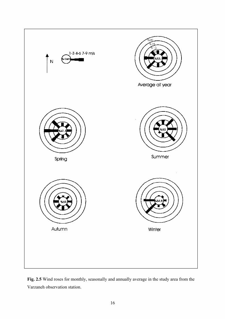
Fig. 2.5 Wind roses for monthly, seasonally and annually average in the study area from the
Varzaneh observation station.
16

2.5 Drainage
The Gavkhoni playa lake drainage basin, which is about 39000 km2 in area, is fed by
the Zayandeh river, two ephemeral rivers and several small streams (Fig. 2.6).
Fig. 2.6 Drainage basin of the Gavkhoni playa lake: 1. Kuhrang (3974 m elevation),
Zayandeh river dam, 3. Esfahan city, 4. Ejieh, 5. Varzaneh, 6. Jarghoieh (Khara), 7. Nikabad,
8. Gavkhoni playa lake, Z. Zayandeh river, R. Rahimi river, D. Zardcheshmeh river
(modified from unpublished report, Iranian Agricultural Administration, 1998).
17
The Zayandeh river activity forms a major part of sedimentation processes in the
southeast of Esfahan sedimentary basin. It is the largest river (about 350 km long) in the
center of Iran. It originates from the central part of the High Zagros mountains. Its headwater
is in the Zardkuh mountain (3974 m elevation) and it terminates the Gavkhoni playa lake
(1474 m elevation). The drainage basin includes the eastern part of the High Zagros zone, and
most of the western part of the Sanandaj-Sirjan zone.
The Zayandeh river attains a peak discharge of 149 m3/sec in spring. The flow of this
river declines to discharge of 1 m3/sec and annual mean discharge of 7.97 m3/sec in the late
fall (gauged in the Varzaneh station over 25 years, unpublished data, Iranian Water
Organization, 1999). Floodwater is usually derived from quick snowmelt in Zardkuh (about
350 km west of Gavkhoni) and/or short periods of high precipitation in the drainage basin
(unpublished report, agricultural administration, 1998). The Zayandeh river dam, constructed
approximately 300 km northwest of Gavkhoni in 1971, has reduced the peak of spring flows.
The Zayandeh river transports a low suspended sediment load in the lower reaches, because
of drainage basin lithology (extensive deposits of carbonate, igneous, and metamorphic
rocks) and the Zayandeh river dam.
The lower reaches of the Zayandeh river, according to aerial photographs and Landsat
imagery, appears to be mainly meandering. Most bends are simple symmetrical, but the more
sinuous ones are simple symmetrical and compound-asymmetrical (Fig. 2.7). The average
slope of this river from the dam to the Gavkhoni playa lake is approximately 2 m/ 1 km but in
the study reach (from about 50 km Esfahan to the Gavkhoni playa lake) is 0.3 m/ 1km along
the Zayandeh river thalweg.
Other streams including Rahimi, Zardcheshmeh ephemeral rivers and small streams
with steep gradient flow down into the western, the southern and the eastern part of the playa
lake only in flood periods (see Fig. 2.6 for their position). Totally, 181 million m3 water is
discharged into the Gavkhoni playa lake on average annually. About 178 million m3 belongs
to the Zayandeh river and 3 million m3 to the ephemeral streams (10 years average,
unpublished data, Iranian Water Organization, 1999).
18

2 Km Fig. 2.7 Morphology of the Zayandeh river in a part of the study reach (from Varzaneh
(indicated by circle) to about 11 km northwest) from aerial photograph.
2.6 Groundwater
Groundwater occurs by infiltration of streams in the upper fans or results from direct
precipitation on alluvial fan surface. Most of the study area is composed of almost
impervious to semi-previous marls and clays of Quaternary age underlying the alluvial
deposits. These sediments impede recharge of water coming from mountains to aquifers.
Recharge of the groundwater is high at the fan heads, which are composed of the coarsest and
most permeable material. The main aquifer in the Gavkhoni playa lake basin consist of
alluvial sediments with a locally thickness of 80 m (Krinsley, 1970). These coarse sediments,
interbedded with fine-grained sediments (e.g. marl), are observed up to depth of 200 m (about
50 km northwest of Varzaneh) (unpublished data, Iranian Water Organization). The natural
recharge of the alluvial aquifers in the basin depends mainly on run-off from the mountains,
which flow onto the alluvial fans.
Except the Zayandeh river water, no run-off water usually reaches the playa, which is
the local base level. The aquifers in the subsurface of the alluvial fans are phreatic, but
towards the center of the basin artesian conditions develop as a result of upward confining
clay layers. Evaporation through the capillary zone from the phreatic aquifer results in
saturation of the water in respect to certain salts and precipitation of evaporite minerals.
19

2.7 Aquatic plants and algae in the Zayandeh river
The Zayandeh river provides an important part of industrial, and agricultural water of
Esfahan city. Mainly in the past two decades, because of pollution sources around the
Zayandeh river, the quality of water has decreased. In the past five years, because of low
precipitation and a high water consumption for irrigation purposes in the Zayandeh river
drainage basin, the water discharge has been reduced in the lower reaches of the Zayandeh
river during summer and autumn and the ion content and organic material of the water have
been increased. For this reason aquatic plants and algae, which are subjected to
environmental conditions, have been affected.
From the beginning of the Zayandeh river to about 60 km southeast of Kuhrang
(Zayandeh river dam) because of few villages and scarcity of farming lands, water pollution
and concentration of ions is low. In this reach, aquatic plants (such as Nasturtium officinalis
and Ranunculus equalities) are observed but because of gravelly bed they don’t find in
abundance (Fig. 2.8). Epilithic diatoms cover the surface of cobbles and pebbles. Filamentous
algae such as Batrachospermum sp., Cladophora sp. and Vaucheria sp. are present but the
variation of algae species is low (Fig. 2.9). During decrease of water quality in late summer
and early autumn algae species do not change remarkable.
From the dam to 45 km east of it, water flow velocity is high and river valley is
narrow and deep. In this reach of the river, because of increase of villages, population and
farming lands pollution increases. In spring, diatoms grow over rocks and sometimes
Vaucheria sp. is observed. In summer and early autumn, because of evaporation and water
consumption for agriculture, river water is decreased, filamentous algae especially
Cladophora sp. grows over bedrocks. Where the velocity of water is low (near bank), benthic
algae such as Chara sp. and Nitella sp. and aquatic plants grow on the river ground and
sometimes cyanobacteria (Nostoc sp.) are observed.
20

Fig. 2.8 Photograph showing aquatic plants (Nasturtium officinalis) in the Dimeh spring,
about 22 km southeast of Kuhrang (see Fig. 2.5 for its position).
Fig. 2.9 Photograph showing filamentous algae (Cladophora sp.) near the Zayandeh river
dam (see Fig. 2.5 for its position).
21

From 45 km east of the dam to Esfahan, due to entrance of the wastewater from a
steel plant and polyacreal plant into the Zayandeh river and abundant water consumption,
pollution of water increases. Therefore, cyanobacteria such as Nostoc sp., Lyngbya sp. and
Oscillatoria sp., diatoms such as Navicula sp., Cymbella sp. and Synedra sp. and filamentous
green algae (Spirogyra sp. and Cladophora sp.) and aquatic plants (Typha sp. and
Ceratophyllum sp.) are observed on pebbles especially in dry periods.
From Esfahan to the east, caused by the increase of phosphorous, nitrates and organic
material, diatoms such as Cymbella sp. and Synedra sp. and Gomphonema sp. increase and
filamentous algae (Cladophora sp.) and red algae (Bangia atropurpurea) are observed on
pebbles where flow velocity is high. Downstream of the wastewater refinery plant, because of
entrance of abundant raw organic and chemical material (i.e. phosphorous and nitrate) into
the Zayandeh river, pollution is very high. These environmental conditions are favorable for
growth of filamentous algae (Cladophora sp., Oedogonium sp. and Stigeoclonium sp.),
cyanobacteria such as Lyngbya sp., Oscillatoria sp. in abundance and few unicellular algae
such as Euglena sp. and Phacus sp..
From 20 km to 50 km east of Esfahan during wet seasons cyanobacteria (Lyngbya sp.
and Oscillatoria sp.) and filamentous algae (Cladophora sp.) which are pollution indicators
and aquatic plants (Ceratophyllum sp. and Typha sp.) are observed during upper flow regime.
In this part of the river, because of self-cleaning capacity of the water, pollution decreases to
some extent. When the river is almost dry (during dry periods) aquatic plants and algae are
not present (S. Afsharzadeh, pers. com., 2000).
From 50 km to 90 km east of Esfahan, cyanobacteria (Lyngbya sp., Oscillatoria sp.
Phormidium, sp.) and diatoms (Navicula sp., Gyrosigma sp. and Cymbella sp.) are observed
during wet periods. Aquatic plant (Lemna minor), flagellates such as Euglena sp., Phacus sp.
and Chlamydomonas sp. grow in abundance during dry periods .
From 100 km east of Esfahan to the Gavkhoni playa lake where water pollution is
high cyanobacteria such as Lyngbya sp. and Oscillatoria sp. and flagellates such as Euglena
sp. are observed. In the Zayandeh river delta district, diatoms such as Navicula sp.,
Gyrosigma sp. and Cymbella sp., cyanobacteria such as Lyngbya sp., Oscillatoria sp. and
22

Flagellates such as Euglena sp. are found (Fig. 2.10). In saline local holes halophytic algae
such as Dunaliella salina and D.parva grow (S. Afsharzadeh, pers. com., 2000).
Fig. 2.10 Photograph indicating algae assemblage in a dry period (autumn 1999) near Ejieh
bridge (about 75 km southeast of Esfahan). View is to the east (see Fig. 2.5 for its position).
2.8 Vegetation
The various kinds of plants, controlled by moisture, salinity and soil texture, cover
locally and sparsely the study area. The plants such as Salicornia sp. and Phragmites sp.
grow along the distributary channels of the Zayandeh river delta. In winter, Salicornia sp. in
red and in summer in green color is also observed (Fig. 2.11). At the margins of the river,
Salicornia sp., Typha sp. and farther Tamarix sp. are present. Tamarix sp. is found sparsely
with Phragmites sp. where the ground water table is high. In efflorescent lands, in the west
of the sand dunes, (from Jarghoieh to Varzaneh) where soil is wet, Seidlitzia rosmarinus and
also halophytes such as Salsola turcomanica are present between Phragmites sp. (Fig. 2.12)
(H. Loghman, pers. com., 1999).
23

Fig. 2.11 Photograph showing Salicornia sp. (s) and Phragmites sp. (f) found in the
Zayandeh river delta (late summer 1999). View is to the northwest.
Fig. 2.12 Photograph showing Seidlitzia rosmarinus (s) and Phragmites sp. (f) in the west of
the aeolian sands along the Zayandeh river (autumn 1999). View is to the east.
24
Erosive winds and particularly low precipitation are two factors, which have
prevented growth of plants in the aeolian sand field. Generally, the aeolian sand field is bare
and without vegetation, except in pits and holes of sand dunes where wind is less effective
and soil humidity is enhanced. In these places, two types of plants including Stipagrostis
karelinii and Calligonum turkestanicum are found. For biologic stabilization of the aeolian
sands in Khara and Varzaneh, Haloxylon ammodendron, Atriplex lentiformis and Atriplex
canecens have been planted (H, Loghman, pers. com.1999). Gravelly areas (mountain slopes
and alluvial fans) are almost bare, and usually except Anabasis sp. no plant grow (S.
Afsharzadeh, pers. com., 2000).
2.9 Ancient irrigation system
Five small dams were constructed over the Zayandeh river to lift water level and
direct it into farmlands by some artificial channels (Fig. 2.13). They are Marvan 35 km, Goli
50 km, Jendich 64 km, Shanzdedeh 84 km, and Shakhkenar 110 km east of Esfahan city. The
first four are 300-800 years old and the second one was constructed about 70 years ago.
In addition to the irrigation channels fed by the above dams, farmlands which are far
from the river and where no shallow aquifers exist, very large number of subterranean
passages (called ghanat or karez) make the subterranean water usable for local peoples. Each
qhanat includes some wells and an underground channel, which drains and conducts
groundwater onto ground surface and farmlands. The largest one is 4 km long and the deepest
well (main well) is about 40 m. Qhanats water is usually brackish and is usable only for
farming. The age of qhanats is not documented.
25

Fig. 2.13 Photograph showing artificial channels which direct water from the Zayandeh river
to the Ejieh farmlands (about 75 km southeast of Esfahan) (see Fig. 2.5 for its position). View
is to the northwest. Photograph provided by H. Kulke.
2.10 Quality of soil and water
The provenance of soil can be divided into three categories in the study area
including: 1-Fine–grained sediments deposited in a lake basin. The soil resulted from these
sediments is usually saline and consist of abundant clay and silt. 2- Sediments deposited
along the Zayandeh river (from the beginning to the Gavkhoni playa lake) which are a result
of inundation by the Zayandeh river (see grain size analyses of loamy silty sandy soils at
Ejieh in Kulke, 1996). From the Zayandeh river toward the north and the south of the study
area, these sediments gradually change to the gypsiferous debris flow deposits (particularly to
the west). Soil produced from the Zayandeh river sediments consist of a mixture of sand, silt
and clay and is of high quality for farming, but in some places, especially from Ejieh to
Gavkhoni, because of evaporation, salinity and incorrect irrigation, it is brackish to saline. 3-
Alluvial fan deposits, originated mainly from igneous rock debris to the east and northeast
and carbonate rock debris to the west and southwest, are mostly products of debris flows.
26

The soil originated from these sediments is coarse-grained and usually contains some
gypsum. Because of these properties, this type of soil is usually rather unfavorable for
farming.
Ion
Station No
Na+ Mg++ Ca++ SO4-- Cl- HCO3
-
1 0.42 1.8 3.3 0.5 0.4 4.5
2 0.48 0.8 2.38 0.68 0.35 2.8
3 0.9 1 2.48 0.68 0.42 3
4 1.40 1.3 2.85 1.38 1.3 3.2
5 2.1 1.75 3.8 1.8 1.6 3.8
6 87 28.7 12.5 19.8 1.2 4.4
Table 2.1 Major content of ions (meq/l) in the Zayandeh river water from the Gavkhoni playa
lake to the northwest: 1: 350 km, 2: 270 km, 3: 220 km, 4: 175 km, 5: 125 km, 6: 28 km (data
after Iranian Water Organization, 1999).
The quality of water is high at the beginning of the Zayandeh river but, because of
entrance of industrial domestic waste water and saline water drainage, pollution gradually
increases from the west to east, so that between Varzaneh and the Gavkhoni playa lake, water
is unusable for agriculture (Table 2.1). From Esfahan to about 70 km east of Esfahan, the
Zayandeh river discharge is usually high, shallow groundwater is fed by the river and also the
river drain waste water of the area as a natural drainage. In this reach, because of leaching of
inorganic and organic material and their entrance into the river, pollution of the water
increases. Despite of these conditions the water is fresh (ground and surface water) and
relatively usable for farming. The Zayandeh river water and groundwater is brackish to saline
from Ejieh to the Gavkhoni playa lake and is unfavorable for agriculture, except for growing
resistant plants where drainage is high enough. In this region, irrigation should vary in
accordance with soil type. On the other hand, correct management of irrigation and favorable
drainage are important parameters in this area (unpublished data, Iranian Water Organization,
1999).
27

Chapter 3 The Varzaneh aeolian sand field
3.1 Introduction
The Varzaneh aeolian sand field is located in the southeast of Esfahan, between
32o,00-32o,23/N and 52o,40/-52o,47/E with an area of approximately 140 km2. Its trend is the
north-south with about 45 km long and maximum width of about 11 km in the north.
Development of aeolian sands decreases from the north to the south. The Gavkhoni playa
lake extends with an area of about 550 km2 to the east of this field. The Zayandeh river,
which is a permanent river, runs the north of this area and enters finally into the Gavkhoni
playa lake. Coarse-grained alluvial deposits border the aeolian sand field in the west, and the
south (Fig. 3.1). The land surface is of low relief with a maximum height of 1607 m (north of
aeolian sand dunes) and a minimum of 1474 m (Gavkhoni playa lake) above sea level.
Distribution of vegetation is variable from the north to the south of the aeolian sand field and
mostly is concentrated along the Zayandeh river in the north (see Chapter 2.8 for details).
Varzaneh has a dry and hot climate with annual precipitation and evaporation average of
about 80 and 3265 mm respectively. The annual average temperature ranges between +42oC
(July) and –17oC (January). Wind blows from all directions but westerly winds dominate
throughout the year (see Chapter 2 for details).
This chapter will represent the various types of aeolian sand forms and their dynamics in
the Varzaneh aeolian sand field. It also will describe the mineralogical composition, textural
characteristics, and analyze the provenance of the aeolian sands.
28
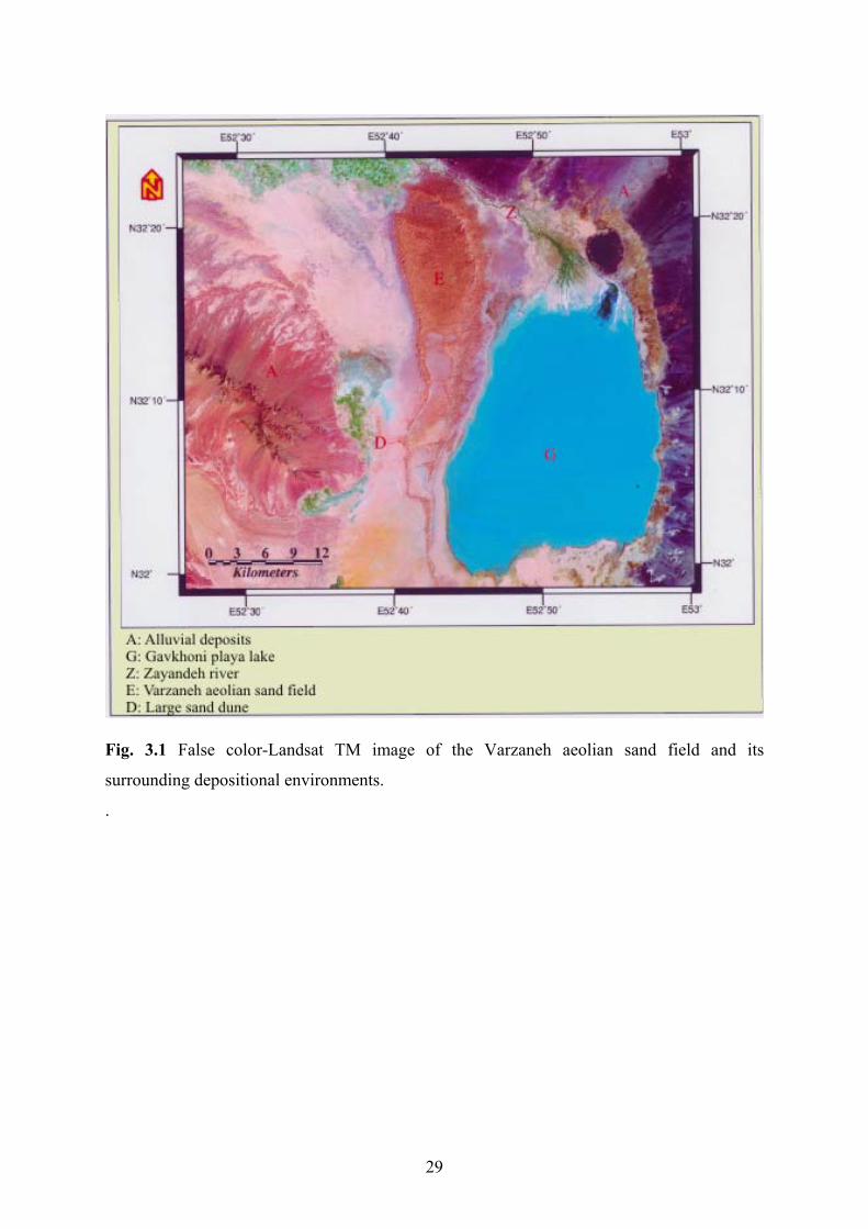
Fig. 3.1 False color-Landsat TM image of the Varzaneh aeolian sand field and its
surrounding depositional environments.
.
29
3.2 Methodology
In order to obtaining data on the rate of the migration of aeolian sand forms and aeolian
sands and also to differentiate various types of sand forms, some field and laboratory
experiments were conducted. For determination of mineralogical composition, textural
properties, the provenance of the aeolian sands and palaeontology studies, about 60 samples
of aeolian sand and alluvial sediments were analyzed (see Chapter 1 and Appendixes A, C &
D for details).
3.3 Aeolian sand forms
Based on different mode of occurrence and morphology, the Varzaneh aeolian sand
field consists of three types sand forms: sand dune, sand sheet and sand drift hummock. The
sand dunes usually occur in groups and also as individuals and are subdivided into four types
of linear/seif barchanoid, star and dikaka. The sand sheets consist of sabkha, overbank and
interdune (Fig. 3.2).
3.3.1 Sand dunes
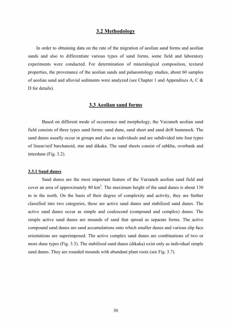
Sand dunes are the most important feature of the Varzaneh aeolian sand field and
cover an area of approximately 80 km2. The maximum height of the sand dunes is about 130
m in the north. On the basis of their degree of complexity and activity, they are further
classified into two categories, these are active sand dunes and stabilized sand dunes. The
active sand dunes occur as simple and coalescend (compound and complex) dunes. The
simple active sand dunes are mounds of sand that spread as separate forms. The active
compound sand dunes are sand accumulations onto which smaller dunes and various slip face
orientations are superimposed. The active complex sand dunes are combinations of two or
more dune types (Fig. 3.3). The stabilized sand dunes (dikaka) exist only as individual simple
sand dunes. They are rounded mounds with abundant plant roots (see Fig. 3.7).
30
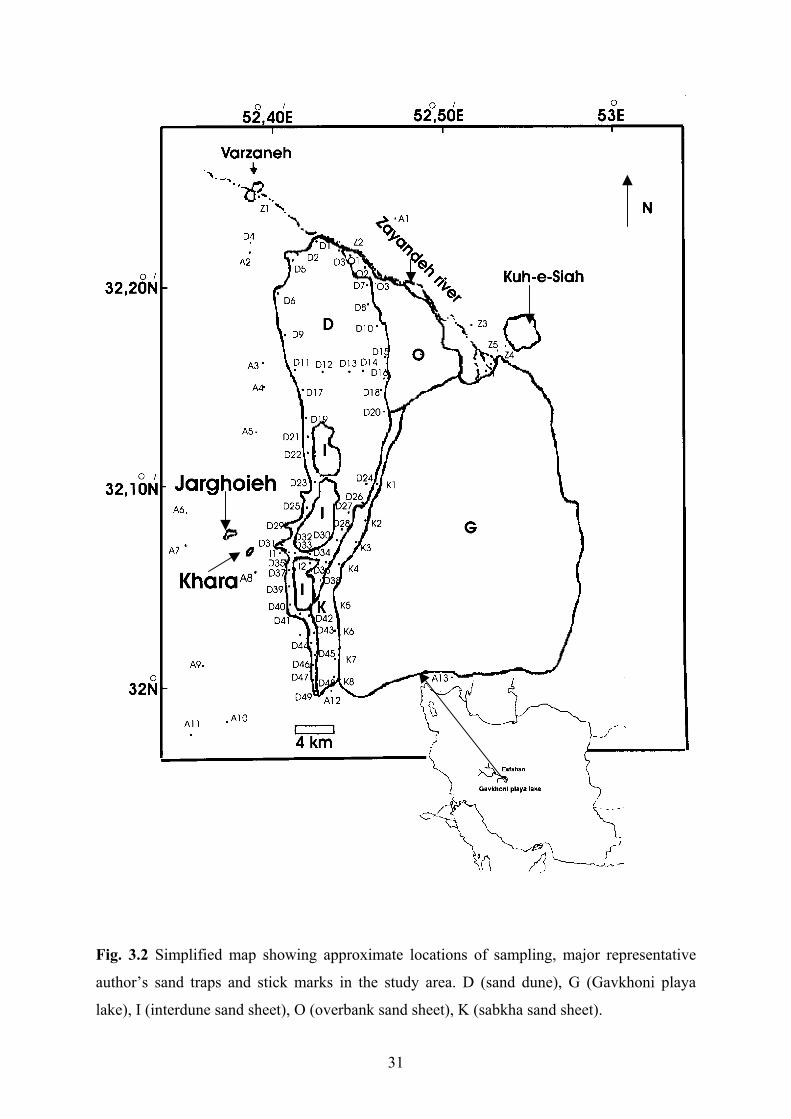
Fig. 3.2 Simplified map showing approximate locations of sampling, major representative
author’s sand traps and stick marks in the study area. D (sand dune), G (Gavkhoni playa
lake), I (interdune sand sheet), O (overbank sand sheet), K (sabkha sand sheet).
31

Fig. 3.3 Field photograph showing complex sand dunes. Barchanoid ridge pattern (akle/) (B)
and star dune (S). The height of star dune is about 10 m. View is to the west.
3.3.1.1 Active sand dunes
Active sand dunes are the most important and common features among the sand dunes
in the study area. They can be grouped on the basis of morphology into three main types of
barchanoid, linear/seif, and star dunes.
Barchanoids
Barchanoids are the simplest crescentic and most common transverse sand dunes in
the Varzaneh sand dunes. Barchanoid ridges are visible as a coalescence of simple barchans
with wavy ridges. Each barchanoid shows a slip face between two arms. In some cases one of
the arms become extended. The crest line of barchanoides moves somewhat according to
wind direction, but in general they maintain their form. Studied barchanoid dunes along the
road of the salt mine of Jarghoieh and in the north of the sand dunes are usually between 5 to
10 m high and 30 to 50 m wide (Figs. 3.3 & 3.4).
32

Fig. 3.4 Field photograph showing barchanoid dunes (A). The slip faces are to the east. The
height of the main dune is about 80 m. View is to the northwest.
Linear/seif dunes
Linear/seif dunes (simple longitudinal dunes) are mostly visible as straight crests
(linear dune) and are common large features of sand dunes in the study area. They usually are
asymmetrical in cross section and tend to bifurcate in the upwind direction. The end of each
dune is mostly to the south. At present most linear dunes are undergoing modification to star
dunes. They are 150 to 200 m long and up to 10 m high in the studied locations (west border
of the Gavkhoni playa lake) (Fig. 3.5).
Star dunes
Star dunes are characterized by a pyramidal morphology, with usually three or four
arms radiating from a central peak in the Varzaneh sand dunes. Some small star dunes are
superimposed over the linear dunes (Figs. 3.3 & 3.5). Each arm also possesses a well-
developed slip face, which is active at different times (see Fig. 3.15). The arms are developed
either sharp-crested or rounded. The height of the star dunes ranges from a few meters to up
to about 130 m (in the north of the sand dune field).
33

Fig. 3.5 Field photograph showing, linear dune (A) with development of minor star dunes
(B). The linear dunes are developed southwards. The main star dune is about 10 m high.
View is to the west.
3.3.1.2 Sand drift hummocks
Sand drift hummocks are temporary sand accumulations, tongue–shaped bodies,
which form in the lee of the small bushes over the sand field especially in the north (near the
Zayandeh river) (Fig. 3.6).
Interpretation
The barchan and barchanoid dunes, which develop in transverse unimodal wind
regimes, suggest dominant wind direction (cf. El-Sayed, 1999) (see Fig 2.5 for dominant
wind direction in the study area). They migrate by avalanching of sand on slip face (Reineck
& Singh, 1980). They respond to essentially unidirectional winds and form more or less
perpendicularly to dominant wind and at right angles to resultant sand drift direction
(Nickling, 1994). They indicate compound barchanoid ridges with increased sand supply or
more variable winds (cf. Thomas, 1989; Nickling, 1994).
34

Fig. 3.6 Field photograph indicating sand drift hummocks with small ripple marks. Dominant
wind direction is toward the right hand side of the photograph (toward northwest).
Linear/seif dunes develop parallel or sub-parallel to the dominant wind or resultant of
two wind directions (Einsele, 1992). Their bedforms arise under conditions of bi-directional
or dispersed unimodal winds of variable strength (Galloway & Hobday, 1996). Wind velocity
is generally higher for forming them (Reineck & Singh, 1980). Linear/seif dunes indicate a
bimodal to wide unimodal formative wind regimes (Thomas, 1989). They are produced in the
vector of two converging wind directions blowing from two quarters, about 900 apart. Some
of them appear to develop by the extension of other dune types as a result of a change in wind
direction or sand supply. Another rather popular explanation for the origin of seif/linear
dunes advocates the presence of helical or roller vortices that develop in the atmosphere with
horizontal axes parallel to wind direction (Nickling, 1994).
During Pleistocene glaciation, because of stronger wind, seif dunes were formed in
abundance in many arid places of the world (Reineck & Singh, 1980). They change into
other sand dune forms such as the star dunes, because of wind directions and velocities are
not strong enough to maintain them (cf. Reineck & Singh, 1980). It is probable that an
unimodal northerly paleo-wind direction was responsible for the development of the
linear/seif dunes in the aeolian sand field. The star dunes are formed as a result of wind
35

blowing from several directions (cf. McKee, 1966; Galloway & Hobday, 1996). The degree
of activity of star dunes depends on velocity and direction of wind. According to variation of
wind direction the slip face changes. They, superimposing the ridges, are developed in a later
stage and are formed due to multi-modal wind regimes (El-Sayed, 1999)
Four main factors control the formation of the sand drift hummocks in the aeolian
sand field. They are wind, sand grain size, vegetation and sand humidity. As a result, they
spread more abundantly where moisture is enough and vegetation is sparse. Such conditions
are found especially in the north of the sand dunes.
3.3.1.3 Stabilized sand dunes (dikaka)
Some individual great and small dikakas extend from Varzaneh to the Gavkhoni playa
lake along the southern bank of the Zayandeh river (Fig. 3.7). They form rounded mounds of
sand without well-developed steep slip face. The height of some dikakas reaches up to 8 m.
In some dikakas, plant growth destroyed the earlier-formed dune bedding but in some cases
original bedding is still clearly visible (Fig. 3.8).
Fig. 3.7 Close-up view of a dikaka fixed by Tamarix sp. roots. The Varzaneh aeolian sand
field is located in the background of photograph. Photograph provided by H. Kulke.
36

Fig. 3.8 Cross-stratification of a dikaka cut by the Varzaneh–Jarghoieh road.
Interpretation The stabilization of aeolian sands and formation of dikaka is mainly achieved by
desert plants, which possess deep penetrating root systems such as Tamarix sp.. The presence
of enough water (non-saline water) maintains the plant growth (Reineck & Singh, 1980).
3.3.2 Sand sheets
Sand sheets are featureless sand plains, more and less flat, and usually devoid of
dunes. They cover about 50 km2 of the Varzaneh aeolian sand field. They occur to the east
and within the interior of the sand dunes. According to situation and behavior, they can be
grouped into three categories: sabkha sand sheet, overbank sand sheet and interdune sand
sheet (see Fig. 3.2).
3.3.2.1 Sabkha sand sheet
Sabkha sand sheet is the most important type of the sand sheets in the aeolian sand
field. It covers about 15 km2 of the east of the sand dunes (see Fig. 3.2). A well developed
polygonally horizontally sand layer cemented by halite covers the sabkha sand sheet a few
centimeters thick. The thickness of this layer transitionally is increased towards the Gavkhoni
37

playa lake. During the drier months its surface is relatively hard and marked by a puffy, salty
surface (Fig. 3.9). The lower sand sheet grades eastwards into the Gavkhoni salt pan. In the
sabkha sand sheet, a few inactive individual small sand dunes, covered with gypsiferous
muddy sediments are observed. The height of these dunes is about up to 2 m (see Fig. 4.6).
Relatively hard ripple marks, cemented by gypsum and halite also occur locally in the east
end of the sand sheet.
Interpretation
High groundwater table, periodic flooding and cementation by evaporites are the most
important factors, which inhibit the development of sand dunes and occurrence of the sabkha
sand sheet in the study area (cf. Langford, 1989). During major floods, muddy sediments
were deposited over the sabkha sand sheet and gypsum minerals were formed in dry periods
by evaporation. Intermittent wet and dry periods caused the formation of hardened ripple
marks as a result of wind action and then cementation by evaporite minerals, especially
halite.
Fig. 3.9 Field photograph showing puffy salt encrustations on the surface of the sabkha sand
sheet in the east of the sand dune field. View is to the northwest.
38

3.3.2.2 Overbank sand sheet
A large overbank sand sheet is situated in the northern margin of the aeolian sand
dunes along the Zayandeh river. It covers about 20 km2 the northeast of the sand dune field.
The overbank sand sheet is relatively flat and vegetated (Fig. 3.10). Plants, up to 2 m tall,
occur along the Zayandeh river, whereas far from the river it consists of small bushes. The
surface of the sand sheet is mostly covered by small gravels and sand-sized grains but a mud
layer is also observed in some localities. Some observation trenches revealed interbedding of
wind and water–laid deposits. Water–laid deposits consist of desiccated mud and fine to
coarse-grained sand and gravel deposits. Fine sand layers exhibit climbing aqueous ripples.
Wind-laid deposits consist of interbedded fine aeolian sand with coarse aeolian sand lag
deposits (Fig. 3.11).
Fig. 3.10 Field photograph showing the surface of the overbank sand sheet with small bushes
and mud layer on the surface (winter 1997). Sand dunes are in the background of photograph.
View is to the southwest.
39

Fig. 3.11 Field photograph of a trench showing aqueous climbing-rippled fine-grained sand
(A) interbedded with aeolian sands (B) and mud layers (C) in the overbank sand sheet.
Interpretation
The climbing aqueous ripples of medium to fine sand have been deposited by
migration of small current ripples during strong sandy bed load transport (cf. Olsen, 1989).
The mud layers result from stagnant water on the top of the overbank sand sheet. The
stratigraphic sequence, the properties of sediments and their positions show that
sedimentation occurred in an overbank or low gradient flood plain environment during
waning flood (cf. Miall, 1992). Alternation of mud layers and aeolian sands result from
fluvial-aeolian interaction.
3.3.2.3 Interdune areas Interdunes are flat areas located between the sand dunes. They include dry, wet and
evaporitic varieties and cover about 15 km2 of the middle part of the sand dunes (see Fig.
3.2). A khaki-colored and well-sorted aeolian sand layer covers the interdune surfaces in
most localities. This layer ranges in thickness from a few up to 100 cm (Fig. 3.12). In some
localities a thin polygonal soft salt-sand layer, up to a few millimeters thick, covers the
surface of the interdune surface. Trenches in two individual interdune areas indicate an
40
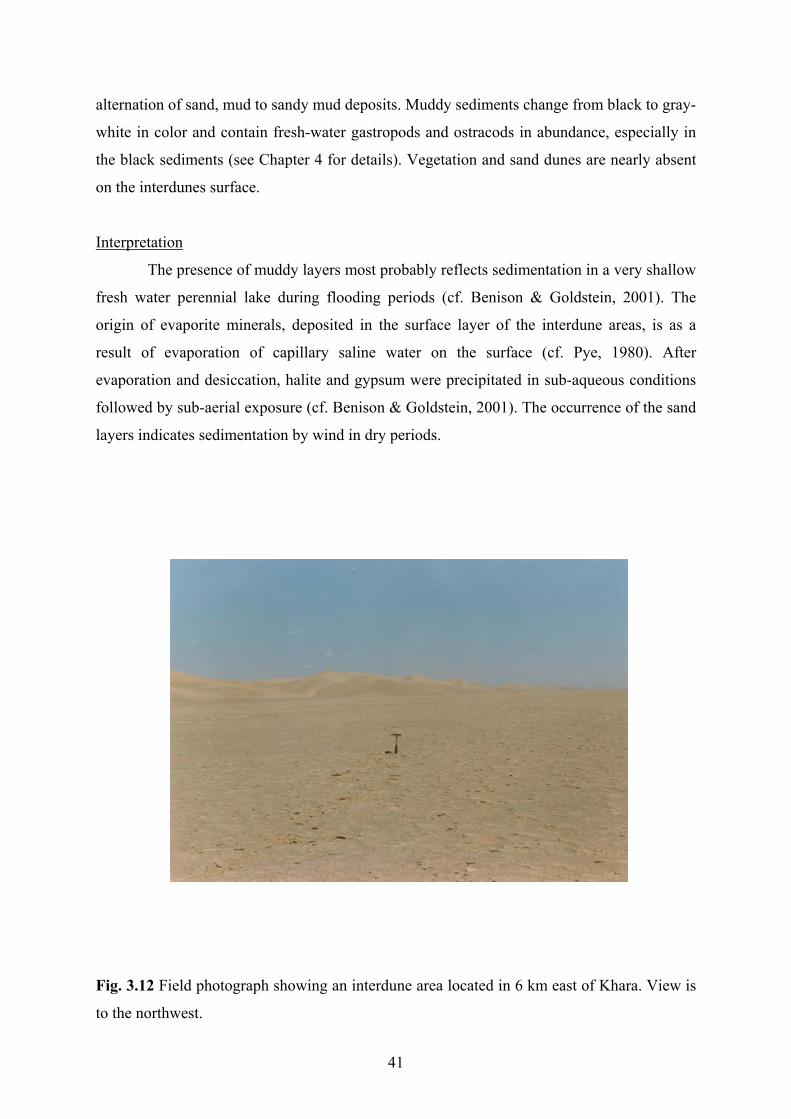
alternation of sand, mud to sandy mud deposits. Muddy sediments change from black to gray-
white in color and contain fresh-water gastropods and ostracods in abundance, especially in
the black sediments (see Chapter 4 for details). Vegetation and sand dunes are nearly absent
on the interdunes surface.
Interpretation
The presence of muddy layers most probably reflects sedimentation in a very shallow
fresh water perennial lake during flooding periods (cf. Benison & Goldstein, 2001). The
origin of evaporite minerals, deposited in the surface layer of the interdune areas, is as a
result of evaporation of capillary saline water on the surface (cf. Pye, 1980). After
evaporation and desiccation, halite and gypsum were precipitated in sub-aqueous conditions
followed by sub-aerial exposure (cf. Benison & Goldstein, 2001). The occurrence of the sand
layers indicates sedimentation by wind in dry periods.
Fig. 3.12 Field photograph showing an interdune area located in 6 km east of Khara. View is
to the northwest.
41

3.4 Aeolian sand dynamics
3.4.1 Introduction
In this study, dynamics and geomorphological development of the Varzaneh aeolian
sand field, including sand dunes and sand sheets, are analyzed. It is attempted to assess the
factors that act to maintain or move these features. Regarding dynamics, the aeolian sand
field of Varzaneh can be categorized into two groups. The first group represents mobile sand
accumulation, including active sand dunes and active sand sheets. The second group
represents immobile ones, consisting of stabilized sand dunes and inactive sand sheets.
3.4.2 Active sand dunes
A large part of the Varzaneh aeolian sand field (about 130 km2) consists of the active
sand dunes. They are the most important landform of the study area (Fig. 3.1& 3.2). Active
sand dunes are either coalscencing or individual. They consist of star, barchan, barchanoid,
and linear/seif dunes. Measurements of the movement of a giant sand dune during about two
years (1997-1999), presented in Fig. 3.13 (A & B) and Table 3.1, indicate that: 1-The sand
dune is approximately fixed and the rate of migration is not remarkable (about few
centimeter). 2-Maximum migration of the sand dune is in late winter, early spring and early
autumn (see Chapter 2.4 for wind direction in the study area). 3-The rate of the movement of
the sand dune is not exactly in accordance with wind direction and frequency.
Sample No Facies Location
A1 Gravel plain 32o,23/,02//N 52o,47/,41//E
A4 Gravel plain 32o,15/,10//N 52o,39/,45//E
A8 Gravel plain 32o,06/,42//N 52o,37/,49//E
D33 Sand dune 32o,07/,00//N 52o,41/,03//E
I2 Interdune 32o,06/,26//N 52o,41/,57//E
K4 Sand sheet 32o,06/,04//N 52o,43/,39//E
Table 3.1 Location of measurements of groundwater table, major representative author’s
sand traps and stick marks in the study area.
42

The measurements of the gradient of the eastern and the western lee sides and stoss
sides of some sand dunes (about 5 km Khara toward salt mine) indicates values between a
maximum 40o on the upper parts and a minimum 15o on the lower parts. Where the slope
angle of slip face is exceeded, the mass movement (avalanching) of the sands takes place.
Avalanching of the aeolian sands occurs as tongue–shaped layers on the slip face of the sand
dunes (Fig. 3.14).
0
50
100
150
200
250
11 1 3 5 7 9 11 1 3 5 7 9
Month (1997-1999)
Mov
emen
t (c
m)
S
N
A
-50
0
50
100
150
200
250
300
11 1 3 5 7 9 11 1 3 5 7 9
Month (1997-1999)
Mov
emen
t (cm
)
S N
B
Fig. 3.13 Graph showing gradual movement of a giant sand dune in its foot in location No.
D33 (about 5 km east of Khara toward salt mine in two locations (A & B) with interval of
about 120 m) during more than two years (1997-1999). The height of sand dune is about 90
m (see Figs. 3.2, 3.15 and Table 3.1 for position of sites and dune morphology). S (south), N
(north).
43

Investigation by taking photographs on a crest line of a sand dune with trends N-S
shows that erosion and deposition occur and movement to the west and the east were
recorde
Fig. 3.14 Field photograph showing mass movement of aeolian sand as avalanche on the lee
side of a giant dune (about 5 km east of Khara).
in the sampling traps (Fig. 3.16 & 3.17)
dicates that: 1- Wind-blown sand volume or migration of sand is maximum in spring and
minimu
d according to variations of wind directions (Fig. 3.15 A & B). Despite of migration
of the crest line and the foot of the sand dune it has been approximately fixed during three
years.
The amount of aeolian sands collected
in
m in autumn. 2- Sand content is maximum in the sampling trap No. I2 (installed in an
interdune) and minimum in the sampling trap No. A8 (installed in the western alluvial fan, a
few hundred meters from the sand dunes) (see Fig 3.2 and Table 3.1 for their positions). 3-
The grain size accumulated in the sampling traps varies from sand to fine gravel size.
44

ig. 3.15 Changes in morphology of an arm of a sand dune (about 5 km Khara, location No.
33): July 1998 (A). March 1999 (B). (see Fig. 3.2 and Table 3.1 for position of the dune).
Photograph A and B is from the same sand dune. View is to the northwest. ?= no measured
A
B
F
D
45

Fig. 3.16
nd Table 3.1for position of sand traps). Notice gravel lag on the top of alluvial sediments
sulted from wind erosion. Barometer for scale is 7 cm.
Fig. 3.2. and Table 3.1for position
f sampling traps).
Continue
Field photograph showing a sampling trap installed in location No. A4 (see Fig. 3.2.
a
re
Fig. 3.17 Aeolian sand volume (in cm3) collected in four major sampling traps No. A1, A4,
A8, I2) around the sand dunes during about one year (see
o
0200400600800
100012001400
1 2 3 4 5 6 7 8 9 10 11 12
Month (1997-1998)
Aeo
lian
sand
vol
ume
(Cm
3)
?
Location No. A1
46

Location No. A4
0
50
100
150
200
250
1 2 3 4 5 6 7 8 9 10 11 12
Month (1997-1998)
Aeo
lian
sand
vol
ume
(cm
3)
?
Continue
Location No. A8
0
10
20
30
40
50
12 1 2 3 4 5 6 7 8 9 10 11
Month(1997-1998)
Aeol
ian
sand
vol
ume
(cm
3)
47
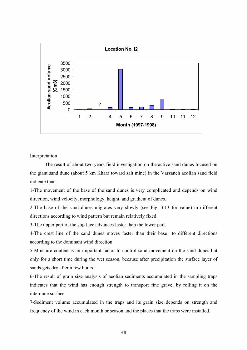
Interpretation
Location No. I2
0500
100015002000250030003500
1 2 4 5 6 7 8 9 10 11 12
Month (1997-1998)
Aeol
ian
sand
vol
ume
(Cm
3)
?
The result of about two years field investigation on the active sand dunes focused on
the giant sand dune (about 5 km Khara toward salt mine) in the Varzaneh aeolian sand field
indicate that:
1-The movement of the base of the sand dunes is very complicated and depends on wind
direction, wind velocity, morphology, height, and gradient of dunes.
2-The base of the sand dunes migrates very slowly (see Fig. 3.13 for value) in different
directions according to wind pattern but remain relatively fixed.
3-The upper part of the slip face advances faster than the lower part.
4-The crest line of the sand dunes moves faster than their base to different directions
according to the dominant wind direction.
5-Moisture content is an important factor to control sand movement on the sand dunes but
only for a short time during the wet season, because after precipitation the surface layer of
few hours.
-The result of grain size analysis of aeolian sediments accumulated in the sampling traps
dicates that the wind has enough strength to transport fine gravel by rolling it on the
terdune surface.
-Sediment volume accumulated in the traps and its grain size depends on strength and
equency of the wind in each month or season and the places that the traps were installed.
sands gets dry after a
6
in
in
7
fr
48

8-At present, for the range of wind velocity in the study area and also regarding to grain size
accumulated in the sampling traps, the wind mainly transports the grain size ranging from 0.1
to 0.3 mm.
9-Sand-sized grains move from active dunes to different directions before they are trapped
within wet interdune areas or by vegetation.
3.4.3 Active sand sheets
Active sand sheets or dry interdunes are located between active sand dunes (Figs. 3.1
& 3.2). They are the sites of erosion and deposition and to some extent the areas of
equilibrium between sedimentation and deflation. The land surface of the interdunes is
usually dry and soft and mostly consists of fine-grained sand (Fig. 3.18) (see Chapter 3. for
details).
Fig. 3.18 Field photograph showing aeolian deflation and sedimentation over an interdune
(7 km from Khara toward the Jarghoieh salt mine). View is to the northwest.
49
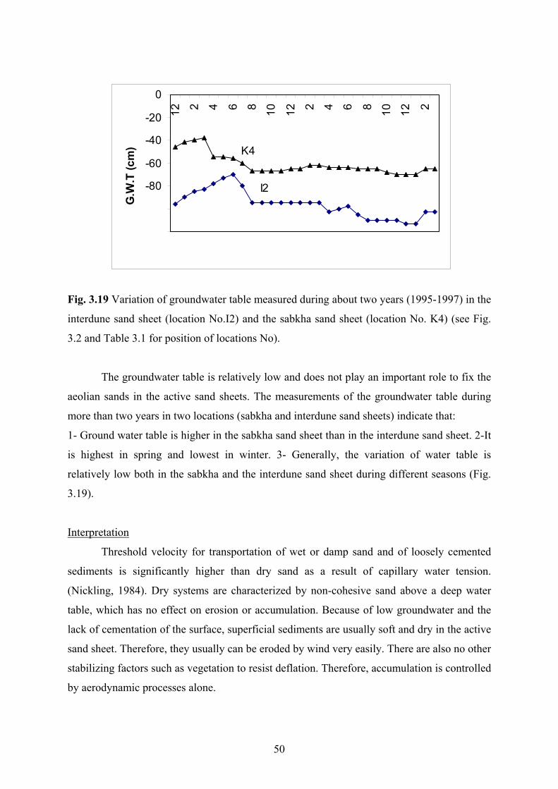
-120
-100
Month (1995-1997)
.T (c -60
-40
-20 12 2 4 6 8 10 12 2 4 6 8 10 12 2
I2
0
m) K4
G.W -80
Fig. 3.19 Variation of groundwater table measured during about two years (1995-1997) in the
terdune sand sheet (location No.I2) and the sabkha sand sheet (location No. K4) (see Fig.
.2 and Table 3.1 for position of locations No).
The groundwater table is relatively low and does not play an important role to fix the
eolian sands in the active sand sheets. The measurements of the groundwater table during
ore than two years in two locations (sabkha and interdune sand sheets) indicate that:
- Ground water table is higher in the sabkha sand sheet than in the interdune sand sheet. 2-It
highest in spring and lowest in winter. 3- Generally, the variation of water table is
elatively low both in the sabkha and the interdune sand sheet during different seasons (Fig.
.19).
nterpretation
in
3
a
m
1
is
r
3
I
Threshold velocity for transportation of wet or damp sand and of loosely cemented
ediments is significantly higher than dry sand as a result of capillary water tension.
Nickling, 1984). Dry systems are characterized by non-cohesive sand above a deep water
e
dry in the active
and sheet. Therefore, they usually can be eroded by wind very easily. There are also no other
tabilizing factors such as vegetation to resist deflation. Therefore, accumulation is controlled
y aero ynamic processes alone.
s
(
table, which has no effect on erosion or accumulation. Because of low groundwater and th
lack of cementation of the surface, superficial sediments are usually soft and
s
s
b d
50

3.4.4 Stabilized sand dunes
Stabilized sand dunes are present as rounded individual sand ridges in the Varzaneh
aeolian sand field (see Fig. 3.7). They develop where non-saline water table is high and
inundation by the Zayandeh river takes place. Plants, which develop long roots, e. g.
Tamarisks sp., stabilize the aeolian sand and form these features.
Interpretation
Two dominant factors control the formation of stabilized sand dunes in the Varzaneh
sand dune field. These are moisture (non-saline or very poorly saline water) and vegetation.
3.4.5 Inactive sand sheets
Inactive sand sheets consist of the sabkha sand sheet, the overbank sand sheet and wet
cm) and water is sucked to the surface by
apillarity. Therefore, moisture content and salinity is high in comparison with the other sand
sheets.
depth.
tation
or saline interdunes. They mostly extend to the east and the northeast of the study area (see
Figs. 3.1 & 3.2 for their positions). The sabkha sand sheet spread where the depth of ground
water table is low and (usually less than 80
c
The lower sabkha sand sheet is at or near water table ( Fig. 3.19). The overbank sand
sheet is located where the Zayandeh river occasionally floods its overbank areas. The depth
of groundwater table is low in the overbank sand sheet and reaches up to about 3 m in
The inactive interdunes are formed where the water table is relatively high and the surface
sand layer is absent or thin.
Interpre
The inactive sand sheets may form in response to a range of factors such as a high
iodic or episodic flooding, slight surface cementation or coalescence of sand,
effects
lopment, limit the migration of sand and promote the
ormation of sabkha sand sheet (Kocurek & Nielson, 1986).
water table, per
of vegetation, limited availability of sand, and coarse-grained sand size, (Kocurek &
Nielson 1986; Fryberger et al., 1988).
A wet surface system involves grain cohesion where the water table or its capillary
fringe attains the surface (Galloway & Hobday, 1996). Aeolian deposition and erosion are
controlled by a combination of aerodynamic processes and moisture content of soil and
consequently wet-interdune deposits resist deflation. High groundwater table and salinity are
factors, which inhibit dune deve
f
51

In the study area, the sabkha sand sheet and wet interdunes developed as a result of
the coalescence of sand by salt and moisture (see Fig. 3.9). Surface evaporation caused the
formation of brines and finally the precipitation of evaporites minerals such as halite and
gypsum.
abilizing systems include occurrence of mud drapes or gravel lag deposits and
vegetat
ineralogical/lithological composition
Other st
ion. Frequent flooding, following formation of intermittent fine and coarse-grained
sediments, caused formation of the overbank sand sheets marginal to the sand dune field.
3.5 M
3.5.1 Introduction
The mineralogical/lithological composition of aeolian sands is a powerful indicator
for determination of provenance of the components, but also for recognition of the tectonic
setting of the source area, weathering and paleo climate history (Pettijohn et al., 1987). Since
the provenance determination is a main objective of this chapter, detailed description of this
aspect is necessary. The aeolian sands of the Varzaneh area are composed of lithic grains
(mostly sedimentary and igneous) and mineral grains. In this part of the study, the
quantitative and qualitative properties of the observed grains are described.
3.5.2 Lithic grains
are the most abundant grains in the studied samples and usually decrease in
ig. 3.20.
Lithics
frequency according to decrease in grain size. Three main types of lithics (igneous,
sedimentary and metamorphic grains) are found in the studied sand grains (see Fig. 3.26).
The average frequency percentage of the lithic grains and mineral grains in the representative
samples are presented in Table 3.2 and F
52

Sample No
A1 A2 A3 A5 A6 A7 A9 A10 A11 A13 D1 D3
Lithology I 39 50 72 52 10 11 3 4 16 41.5 55 44.5 S 39 32 18 37 70 74 95 93 72 51 30 39.7 M 11 5 2 4 0 1 0 0 0 0 3.5 3 Q 8 9.5 6 3 15 10 2 1.5 11 7 10 11 F 3 3.5 2 1 5 4 0 1.5 1 0.5 1.5 0.8 G 0 0 0 0 0 0 0 0 0 0 0 0
Sample No D7 D11 D13 D15 D16 D21 D27 D28 D30 D32 D35 D43 Lithology I 64 26 38 58.5 54 31 40 45 31 27 23 27 S 22.5 63 45 21 30 59 48.5 31 36 55 69 68 M 0.5 1.5 1.5 2.5 0 2 0.5 4 0.5 2 1 1 Q 1 5 6 4 2 8 13.5 15 15 7 9 15 11 1F 1 1.5 2 3 1 1 1 5 0.8 1 1 0 G 0 0 0 0 0 0 1 0 0.7 1 0 0
Sample No
Lithology
D44 D46 I1 K1 K2 Z1 Z5
I 28 31 29 33 23 36 54 S 59 57 60 59.5 63 37 32 M 1.5 0 1.5 0.5 1.5 25 5
F 2.5 1.5 2 1.5 0.8 1 1 G 0 0 0.5 0.5 1.5 0 0
Q 9 10 7 5 9 1 8
able 3.2 Frequency percentage of lithic and mineral grains of alluvial and aeolian sediments
ive samples in the study area. Alluvial sediments (samples No. A and Z)
and ae
T
in the 31 representat
olian sands (samples No. D, I and K) (see Fig. 3.2 and Table 3.3 for position of
samples No). Igneous lithic (I), sedimentary lithic (S), metamorphic lithic (M), quartz (Q),
feldspar (F), and gypsum (G). The gypsum grains (crystals) are formed in–situ, they generally
were transported.
53

Sam
No
s Location Sample Facies Location ple Facie
No
,23/,0 2°,47/ //E D21 A lian ,13/,0 2°,42/,12
,21/,2 2°,3 //E D2 lian ,10/,3 2°,4
,16/,55 2°,3 //E D24 lian ,10/,4 2°,44/
,15/,10 2°,3 //E D2 lian ,09/,20 2°,44/,1
,13/,0 2°,4 //E D2 lian ,08/,5 2°,4
A1 Alluvium 32° 2//N 5 ,41 eo 32° 3//N 5 //E
A2 Alluvium 32° 9//N 5 8/,35 3 Aeo 32° 2//N 5 2/,26//E
A3 Alluvium 32° //N 5 9/,41 Aeo 32° 0//N 5 ,02//E
A4 Alluvium 32° //N 5 9/,45 7 Aeo 32° //N 5 3//E
A5 Alluvium 32° 9//N 5 0/,39 8 Aeo 32° 4//N 5 4/,10//E
A6 Alluvium 32°,09/,25//N 52°,38/,38//E D30 Aeolian 32°,08/,03//N 52°,43/,55//E
A7 Alluvium N 2 o ° 5 //E 32°,07/,25// 52°,38/,5 //E D31 Ae lian 32 ,07/,31//N 2°,40/,33
31 ,55 ,2/ 2°,30/,5 //E D35 Ae lian ,06 ,5/ 2°,41/
31°,53 ,50/ 2°,30 ,0/ //E D3 A lian 32°,06 ,0/ 2°,4 /
,59 ,2/ 52°,43/ //E D4 lian ,04 ,4/ 2°,4
,01 ,02/ 2°,5 / //E D4 lian 32°,04 ,0/ 1°,4
,21 ,5/ 2°,4 //E D4 32°,03 ,4/ 2°,4/ // /
A8 Alluvium 32°,06/,42//N 52°,37/,49//E D32 Aeolian 32°,07/,11//N 52°,41/,00//E
A9 Alluvium 32°,01/,17//N 52°,34/,41//E D33 Aeolian 32°,07/,00//N 52°,41/,03//E
A10 Alluvium ° 8//N 5 5 o 32° 0//N 5 ,05//E
A11 Alluvium //N 5 3 7 eo 6//N 5 0 ,59//E
A12 Alluvium 31° 6//N ,22 0 Aeo 32° 1//N 5 1/,03//E
A13 Alluvium 32° //N 5 1 ,49 1 Aeo 6//N 5 1/,24//E
D1 Aeolian 32° 9//N 5 1/,33 2 Aeolian 8//N 5 2/,27//E
D2 Aeolian 32°,21 ,05//N 52°,41/,13 E D43 Aeolian 32°,03 ,06//N 52°,42/,28//E
D3 Aeolian 32°,21/,26//N 52°,43/,28//E D44 Aeolian 32°,02/,23//N 52°,42/,11//E
D6 Aeolian ° N 5 ,32 Aeolian 32°,01/,03//N 52°,42/,15//E 32 ,19/,16// 2°,40/ //E D46
,18/,3 2°,45 //E D49
,17/,2 2°,40/,5 //E I1
32°,17/ 2°,45/ //E K1
,16/,1 2°,4 //E K2
32°,16/,1 2°,43/ //E K4
,16/ 2°,45/ //E K6
D7 Aeolian 32°,19/,57//N 52°,44/,59//E D47 Aeolian 32°,00/,21//N 52°,42/,14//E
D8 Aeolian 32° 1//N 5 /,26 Aeolian 31°,59/,08//N 52°,42/,51//E
D9 Aeolian 32° 6//N 5 7 Aeolian 32°,06/,40//N 52°,41/,49//E
D10 Aeolian ,46//N 5 ,53 Aeolian 32°,10/,32//N 52°,46/,44//E
D11 Aeolian 32° 8//N 5 1/,40 Aeolian 32o,09/,25//N 52°,45/,50//E
D13 Aeolian 6//N 5 ,47 Aeolian 32°,06/,04//N 52°,43/,39//E
D15 Aeolian 32° ,52//N 5 ,41 Aeolian 32o,03/,10//N 52°,43/,22//E
D16 Aeolian 31°,16/,19//N 52°,45/,37//E Z1 Alluvium 32°,24/,53//N 52°,39/,35//E
D17 Aeolian 32°,16 ,19 N 51°,41 ,41 E Z2 Alluvium 32 ,21 ,45 N 52°,45 ,55 E / // / // o / // / //
D18 Aeolian 32°,16/,14//N 52°,45/,31//E Z3 Alluvium 32°,18/,29//N 52°,51/,51//E
D19 Aeolian 32°,14/,01//N 52°,42/,08//E Z4 Alluvium 32o,17/,51//N 52°,53/,15//E
D20 Aeolian 32°,13 ,59 N 52°,45 ,10 E Z5 Alluvium 32°,17 ,47 N 52°,52 ,56 E / // / // / // / //
Table 3.3 Facies and location of the representative studied samples of the aeolian and alluvial
sediments in the study area.
54

Fig. 3.20 Di on iou gra in th senta les
san (No D I) ial (No A) in the study area. Igneous lithic (IR),
sedimentary lithic (SR), m orphic lithic (MR), quartz (Q), feldspar (F) (see Fig. 3.2 and
Tab 3 for on o No h), outh)
Igneous lithic grains
stributi of the var s types of ins e repre tive samp of aeolian
ds , K & and alluv sediments
etam
le 3. positi f samples ). N (nort S (s .
Igneous lithics consist of acite, and e, a tuff, di e, granite, icrogranit
b grains i e studied ples. Th
0
20
40
80
Z1 D1 D3 1 K1 K 30 D35 D 13 A10
Sam e No
IR
MRQF
60
100
D2 2 D I1 46 A
pl
Wt %
SR
N S
d esit cidic orit m e
and a subordinate amount of andesite-basalt and asalt n th sam e
average frequency percentage of the igneous lithics is about 37% in the aeolian sands (Table
om the north to the south. Exceptionally, the
of the volcanic lithics is identic to lithology of volcanic rocks
xposed in the north and the northeast of the Varzaneh aeolian sand field.
3.2). Their content decreases in frequency fr
amount of igneous lithic increases slightly at the end southern part of the aeolian sand field
(Fig. 3.21). The composition
e
55

0102030405060708090
100
D1 D19 D21 D32 D35 D40 D44 Sample No
Wt
% IRSR
A
N S
0
60
8090
100
D7 D10 D16 D27 D43 D49Sample NO
SR
B
N S
1020304050
70
Wt % IR
010
60
Z1 A2 A5 A9 A10 A13Sample No
SR
20304050
708090
100
Wt % IR
C
N S
Fig. 3.21 Distribution of igneous and sedimentary lithic grains in the western (A), the eastern
(B) parts of the Varzaneh sand dunes and (C) in alluvial sediments from the north to the south
of the study area. Igneous lithic (IR) and sedimentary lithic (SR) (see Fig. 3.2 and Table 3.4
for position of samples No). N (north), S (south).
56

Sedimentary lithic grains
Sedimentary lithics mostly consist of carbonates and few sandstones, siltstones, shales
and chert grains. The average frequency percentage of the sedimentary lithic grains
determined by counting under polarizing microscope is about 52% (approximately 49%
carbonate and 3% non-carbonate in the aeolian sand samples). The carbonate content of
representative samples determined by chemical analysis ranges in turn from about 17% and
79% in aeolian and alluvial samples (Table 3.2 & Fig. 3.22).
Sample No Facies % Carbonate Sample No Facies % Carbonate
A1 Alluvium 25 D24 Aeolian 55 A3 Alluvium 22 D27 Aeolian 55 A5 Alluvium 38 D28 Aeolian 58 A9 Alluvium 78 D30 Aeolian 58 A10 Alluvium 79 D31 Aeolian 62 A12 Alluvium 49 D35 Aeolian 64 A13 Alluvium 47 D41 Aeolian 25 D2 Aeolian 38 D42 Aeolian 54 D6 Aeolian 39 D43 Aeolian 56 D7 Aeolian 17 D44 Aeolian 67 D8 Aeolian 23 D47 Aeolian 52 D9 Aeolian 45 D49 Aeolian 51 D16 Aeolian 32 I1 Aeolian 50 D17 Aeolian 57 K5 Aeolian 43 D18 Aeolian 34 K6 Aeolian 41 D19 Aeolian 49 Z1 Alluvium 25 D21 Aeolian 48 Z3 Alluvium 23 D23 Aeolian 60 Z5 Alluvium 22
Table 3.4 Average carbonate content of the representative sand samples of the two facies
(alluvial and aeolian sands) in the study area (see Fig. 3.2 and Table 3.3 for position of
samples No).
The Carbonate lithic grains occur as micrit, sparite, biogenic (biosparite and
biomicrite) and crystalline carbonate. Biogenic grains are composed of microfaunal shells,
mostly foraminifera (Orbitolina, Orbitoides, Heterastegina, miliolids and ostracods), algae
(red and green) and shell fragments of macrofauna include rudists, fresh water gastropods
ainly Bithynia phialensis) and ostracods. Orbitolina belongs to Aptian, Orbitoides to
rs. com., 2000).
(m
Campanian–Mastertian, algae and rudists mostly Aptian to Maastrichtian, Heterastegina to
Oligo-Miocene, gastropods and ostracods to Quaternary. According to palaeontological
studies, the carbonate grains come mostly from Cretaceous rocks, and subordinate amounts
from Tertiary rocks (Oligomiocene) (H, Vaziri, pe
57

Fig. 3.22 Variations of frequency percentage of carbonate lithic grains in the western (A), the
eastern (B) parts of the Varzaneh sand dunes and (C) alluvial sediments from the north to the
south of the study area (see Fig. 3.2 for position of samples No). N (north), S (south).
100
80
D2 D9 D19 D23 34 D3 4 DSam o
Car
bona
te W
t %
A
N S
0
20
40
60
D 5 D4 47ple N
80
100
S
Continue
0
20
40
D8 D16 D24 D27 D42 D48Sample No
N
B
60
Car
bona
te W
.t %
58

ntary lithics
istribution of metamorphic lithic grains in the representative samples of alluvial
sediments (No. A) and aeolian sands (No. D) (see Fig. 3.2 and Table 3.3 for position of
samples No). N (north), S (south).
In contrast to the igneous lithics, the relative frequency of sedime
(carbonates) increases from the north to the south of the aeolian sand field, expect that they
decrease slightly at the end of the southern part of the sand dunes (see Figs. 3.21 & 3.22).
0
20
40
Z1 A2 A5 A9 A10 A13
Sample No
Car
bona
te W
t %80
100
N S
C
60
0
2
4
6
8
10
12
A1 D1 A2 D21 D44 D43 A9 A10Sample No
Met
ham
orph
ic W
t %
N S
Fig 3.23 D
59
Metamorphic lithic grains
Metamorphic lithics mostly consist of schist (chlorite, muscovite, biotite, and quartz
schist), and subordinate amount of quartzite, gneiss, amphibolite schist, actinolite schist,
phylite, and metagranite grains. The average frequency percentage of the metamorphic
lithics is about 1.5% (Table 3.2) in the aeolian sands. The percentage of these grains
decreases from the north to the south within the aeolian sands (Fig. 3.23).
3.5.3 Mineral grains
Quartz
Quartz grains are the most common mineral type in the sand size fraction (0-1, 1-2, 2-
3 phi fractions) of the aeolian sands, ranging from 2% to up to 15% with an average of 10 %
(see Table 3.2 & Fig. 3.24). They usually increase in frequency with decrease in grain size
nd therefore, are more abundant in the fine-grained sand fraction, in contrast to igneous and
sedime
Feldspar
a
ntary lithics. Quartz grains frequency is rather irregular in the sand dunes from the
north to the south (Fig. 3.24).
Feldspar grains are the third common mineral type in the sand size fraction of the
aeolian sands. They are milky white to buff in color. Average frequency of the feldspar grains
is about 1.5% (see Table 3.2 & Fig. 3.24). Distribution of the feldspar grains is irregular in
the sand dunes similar that of quartz grains (Fig. 3.24). They are represented mainly by
plagioclase (albite to oligoclase and andesine) with subordinate amounts of potash feldspar
(microcline and orthose). The occurring major types of the feldspar grains are similar to that
the intermediate and acidic volcanic igneous rocks, exposed in the northeast of the study area.
60

0
4
14
D1 D19 D21 D35 D41 D44 D7 D11 D16 D27 D43 D49
F6
8
1012
16
Wt% Q
N S
2
Sample No
Fig. 3.24 Distribution of quartz and feldspar grains in the representative sand dune samples
(see Fig. 3.2 and Table 3.3 for position of samples No). N (north), S (south).
Heavy minerals
Heavy mineral grains are the second common minerals in the fine and very fine sand
f the aeolian and alluvial sediments in the study area. The average frequency
percent
and celestine are also observed in traces.
Opaque minerals comprise almost one third of the heavy mineral fraction. Hematite is
the mo mon opaque heavy mineral and its distribution is not regular from the north to
the south of the aeolian sands. Garnet and pyroxene are the most abundant non-opaque heavy
minerals both in fine and very fine sand.
These minerals are more frequent in the very fine sands and decrease in frequency from
the north to the south of the aeolian sands.
fractions o
age of the heavy minerals ranges from 2 % to 3% in the fine to very fine sand
fractions of the aeolian sands. Overall, the percentage of the heavy minerals decreases from
the north to the south of the Varzaneh aeolian sand field (Fig. 3.25 & Table 3.5).
The occurring heavy minerals are mainly garnet, pyroxene, hematite, and,
subordinately amphibole, epidote, limonite, zircon, rutile and magnetite. Mica, apatite,
scheelite, pyrite (oxidized), barite, sphene, ilmenite, jarosite, glauconite, chlorite, leucoxene
st com
61
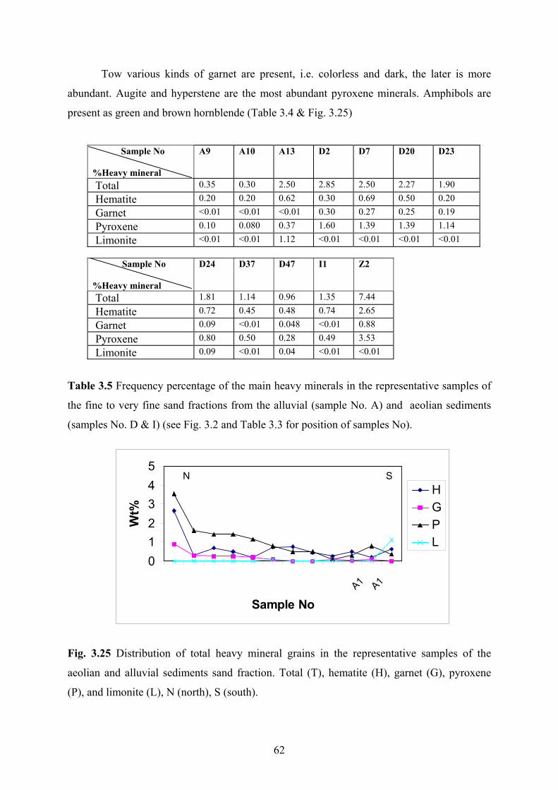
Tow various kinds of garnet are present, i.e. colorless and dark, the later is more
abundant. Augite and hyperstene are the most abundant pyroxene minerals. Amphibols are
present as green and brown hornblende (Table 3.4 & Fig. 3.25)
A9 A10 A13 D2 D7 D20 D23 Sample No %Heavy mineral Total 0.35 0.30 2.50 2.85 2.50 2.27 1.90 Hematite 0.20 0.20 0.62 0.30 0.69 0.50 0.20
Garnet <0.01 <0.01 <0.01 0.30 0.27 0.25 0.19 Pyroxene 0.10 0.080 0.37 1.60 1.39 1.39 1.14
Limonite <0.01 <0.01 1.12 <0.01 <0.01 <0.01 <0.01
D24 D37 D47 I1 Z2 Sample No %Heavy mineral Total 1.81 1.14 0.96 1.35 7.44
0.72 0.45 0.48 0.74 2.65 Hematite Garnet 0.09 <0.01 0.048 <0.01 0.88
Pyroxene 0.80 0.50 0.28 0.49 3.53 Limonite 0.09 <0.01 0.04 <0.01 <0.01
Fig. 3.25 Distribution of total heavy mineral grains in the representative samples of the
aeolia
Table 3.5 Frequency percentage of the main heavy minerals in the representative samples of
the fine to very fine sand fractions from the alluvial (sample No. A) and aeolian sediments
(samples No. D & I) (see Fig. 3.2 and Table 3.3 for position of samples No).
Z2 D2 D7D20 D23 D24 I1
D37 A9D47 0 3
0
5
A1 A1
Sample No
HGPL1
234
Wt%
N S
n and alluvial sediments sand fraction. Total (T), hematite (H), garnet (G), pyroxene
(P), and limonite (L), N (north), S (south).
62

Fig. 3.
fossil (f), granite (g), tuff (t),
carbonate (c), quartz (q), biosparite (s), mudstone (m), metagranite (mt), siltstone (si),
sandstone (sa), schist (sc) (see Table 3.3 for position of samples No).
D4
26 Photomicrographs (crossed nicols) of the representative aeolian and alluvial sand
samples. Magnification of D49, D34, A7, A1, Z3 is x23 and Z1 is x63. Aeolian (D), debris-
flow deposits (A) and stream-flow deposits (Z). Biomicrite (b),
D34
9
63

64
A7
A1

Z1
Z3
65

Interpretation
Mineralogical composition of the lithic grains and optical properties of mineral grains
dicate that the aeolian sands are derived from igneous and sedimentary as main sources and
etamorphic rocks as minor source.
The igneous lithics are mostly composed of volcanic and to a minor extent of plutonic
rains. They chiefly belong to Tertiary highlands, located to the north and the northeast of the
udy area. The major origin of the sedimentary lithic grains (mainly carbonates) is from
dimentary rocks exposed in the west and the southwest of the study area. These rocks
elong to Cretaceous and Jurassic outcrops. The main origin of the metamorphic lithic grains
from the mountain ranges located in the northwestern and the western part of the drainage
asin of the Zayandeh river.
Textures and fabrics of the feldspar grains suggest that they are derived mostly from
ndesitic and granitic rocks. Andesitic rocks mainly outcrop in the northeast of the aeolian
nds but granitic rocks are found at several locations of the drainage basin as small intrusive
odies. Garnet grains mainly are attributed to contact metamorphic rocks and pyroxenes,
mphiboles, and epidotes to intermediate igneous rocks exposed in the north and the
northwest of the study area. The source of zircon and rutile grains mostly could be attributed
the acidic igneous rocks outcropping in the southwest of the aeolian sands. The origin of
e crystalline carbonate grains is intergranular cement from Quaternary open framework
onglomeratic deposits that are exposed in the southern part of the study area.
These grains were transported and deposited mostly by the Zayandeh river to the
orth, and the two ephemeral streams to the south and the west margins of the aeolian sand
eld.
3.6 Texture
in
m
g
st
se
b
is
b
a
sa
b
a
to
th
c
n
fi
.6.1 Introduction3
In this study, general characteristics of grains such as sorting, size, roundness and
rface texture of the various types of the aeolian sand forms (sand dunes and sand sheets)
ere determined. The study mainly concentrates on the grain size distribution of these two
facies. Using the half-phi interval histograms and the simple frequency curves, the average
su
w
66

grain size distribution of these sediments have been studied. Statistical parameters of grain
3.6.2. G
size (mean, standard deviation, skewness and kurtosis) were examined. In addition,
roundness variations of grains from alluvial and aeolian deposits were investigated to some
extent.
rain size
Sand dunes
Sand dunes including the active and the stabilized sand dunes (dikaka) are
characterized by a narrow range of grain size in which medium and fine sand fraction (mostly
fine sand) form about 90% of their average grain size spectrum. The dune sands are
moderately to very well sorted. The size ranges from +1 to about +5 phi (0.5 to 0.031 mm)
with an average mean grain size of 2.20 phi (0.22 mm).
SampleNo
Facies Mean size Sorting Skewness Kurtosis Location
D3 Active sand dune 2 0.43 0.21 4 32o,21/,26//N 52o,43/,28//N o / // o / //
D9 Active sand dune 2.19 0.31 0.37 6.89 32o,17/,26//N 52o,40/,57//N
D16 Active sand dune 2.39 0.33 1.14 7.49 32o,16/,19//N 52o,45/,37//N D22 Active sand dune 2.20 0.64 -0.16 4.03 32 ,12 ,18 N 52 ,42 ,00 N o / // o / //
D24 Active sand dune 2.40 0.80 -1.89 7.96 32o,10/,40//N 52o,44/,02//N D30 Active sand dune 2.30 0.48 -0.05 4.25 32o,08/,03//N 52o,43/,55//N D31 Active sand dune 2.37 0.60 -0.25 3.25 32o,07/,31//N 52o,40/,33//N D32 Active sand dune 2.08 0.38 0.37 4.60 32o,07/,11//N 52o,41/,00//N D33 Active sand dune 2.32 0.49 -0.01 4.03 32o,07/,00//N 52o,41/,03//N D34 Active sand dune 1.81 0.76 -0.06 1.78 32o,06/,30//N 52o,42/,28//N
o / // o / //
D41 Active sand dune 2.22 0.62 -0.45 3.70 32o,04/,06//N o / //
D8 Active sand dune 2.43 0.31 2 9.05 32 ,18 ,31 N 52 ,45 ,26 N
D11 Active sand dune 2.01 0.36 1.25 5.64 32o,16/,18//N 52o,41/,40//N
D35 Active sand dune 2.16 0.6 -0.72 4.69 32 ,06 ,50 N 52 ,41 ,05 N 52o,41/,24//N
D43 Active sand dune 2.20 0.64 -0.16 2.5 32 ,03 ,06 N 52o,42/,28//N D49 Active sand dune 2.23 0.58 -0.79 5.62 31o,59/,08//N 52o,42/,51//N I1 o / // o / //Interdune 2.36 0.59 -0.49 3.83 32 ,07 ,09 N 52 ,40 ,30 N
Interdune 2.06 0.60 -0.47 4.50 32o,06/,26//N 52o,41/,57//N O1 Overbank sand sheet 1.81 1.09 -1.23 3.8 32°,21 ,39 N 52°,45 ,13 N / // / //
O2 Overbank sand sheet 1.92 1.04 -1.30 3.25 32°,20/,56//N 52°,46/,05//N O3 Overbank sand sheet 1.67 1.29 -1.40 4.40 32o,20/,32//N 52o,46/,35//N K1
I2
Sabkha sand sheet 2.23 0.59 -0.72 4.5 32o,10/,32//N 52o,46/,44//N K2 Sabkha sand sheet 2.05 0.78 -0.68 3.33 32o,09/,25//N 52o,45/,50//N K4 Sabkha sand sheet 2.23 0.62 -0.45 3.79 32o,06/,04//N 52o,43/,39//N K5 Sabkha sand sheet 2.06 4.11 32o,04/,53//N 52o,43/,15//N 0.86 -1.01
0.71 -0.532 K6 Sabkha sand sheet 2.36 3.87 32o,03/,10//N 52o,43/,22//N Sd Stabilized sand dune 2.19 0.82 -0.16 1.29 32o,21/,52//N 52o,38/,45//N
Table 3.6 Statistical grain size parameters of the main types of aeolian sand samples and their
positions in the Varzaneh aeolian sand field.
67

These deposits are generally finer than the overbank sand, sabkha and interdune sand
sheets.
The dune sands are from strongly positively skewed (+1.25) to strongly negatively
skewed (-0.1.89). Their kurtosis ranges between 1.78 and 9.05 (very leptokortic to extremely
ptokortic) (Table 3. 6 & Fig. 3.27).
of grain size distribution of the representative
samples from sand dunes (samples No. D33 and D41) (see Fig. 3.2 and Table 3.6 for position
of samples No).
le
Sample No. D33 (sand dune)
20
-2 -1 0 1 2 3 4 >4Phimm 4 2 1 0.5 0.25 0.125 0.062
0
406080
100
Wt%
S ple N 41 nd dune)
0-2 -1 3 4 2 0.1
am o. D (Sa
204060%
80100
0 1 2 4 >Phi
Wt
mm 1 0.5 0.25 25 0.062
Fig. 3.27 Histograms and frequency curves
68

69
Overbank sand sheet
Overbank sand sheet deposits have a wide range of grain size and are poorly sorted.
They ra
ewness. Their kurtosis ranges between 3.8 to 4.83
(extremely leptokortic) (Table 3.6 & Fig 3.28).
Fig. 3.28 Histogram and frequency curve of grain size distribution of the representative
sample from the overbank sand sheet (see Fig. 3.2 and Table 3.6 for position of sample No).
Sabkha sand sheet and interdune
nge between -3 and about +5 phi (8 and 0.031 mm) with an average mean of 1.8 (0.29
mm) phi in size. The granule size fraction comprises about 3 % of grain size distribution on
average and has strongly coarse sk
Sample No.o3 (overbank sand sheet)
020406080
100
-2 -1 0 1 2 3 4 >4Phi
Wt%
mm 4 2 1 0.5 0.25 0.125 0.062
Both sabkha sand sheet and interdune sand sheet deposits have approximately a
similar grain size distribution, in which medium and fine sand fractions form about 82% of
grain size on average. However, fine sand is the most frequent size fraction both in the
interdune sand sheet and the sabkha sand sheet deposits (Fig. 3.29). Sabkha sand sheet
deposits range in size between -2 and about +5 phi (4 and 0.031 mm) with an average mean
ze of 2.16 phi (0.23 mm). They mostly are moderately sorted but relatively better sorted
an overbank sand deposits. This sub-facies has fine skewness (+0.23) to very coarse
ewness (-1.06) and mainly is coarse skewed. Interdune deposits range in size between –1
si
th
sk
phi and about +5 phi (2 and about 0.031 mm) with an average mean size of 2.1 phi (0.235
mm). They are usually moderately well sorted to moderately sorted. These deposits are very

coarse skewed and their kurtosis range between 3.26 to 4.97 (generally extremely leptokortic)
3.2 and Table 3.6 for position of samples No).
(Table 3.6 & Fig. 3.29).
Sample No. I1 (interdune)
100
020406080
-2 -1 0 1 2 3 4 >Phi
Wt%
mm 4 2 1 0.5 0.25 0.125 0.062
Sample No. K 4 (sabkha sand sheet)
0
80 100
-2 -1 0 1 2 3 4 >
Wt
2 1 0.5 0.25 0.125 0.062
20 40 60 %
Phi mm 4
Fig. 3.29 Histograms and frequency curves of the grain size distribution of the representative
samples from the sabkha sand sheet and interdune sediments (samples No. K4, I1) (see Fig.
70

Sample No
01020304050
-2 -1 0 1 2 3 4 >4Phi
Wt%
I1D33D41O3K4
mm 4 2 0.5 0.25 0.125 0.0621
Fig. 3.30 Comparison between grain size frequency curves of representative samples from
the main types of aeolian sediments in the Varzaneh sand field (see Fig. 3.2 and Table 3.5 for
facies and position of samples No).
Interpretation
The capacity of wind to transport solid particles of a density similar to that of quartz
(2.65 gr/cm3) is mostly limited to fine and medium sand (0.125 to 0.5 mm). Strong storms
(20-30 m/s) can slowly move pebbles by creep and sand size particles very fast. Hence wind
is very effective in producing and accumulating well-sorted sands (Einsele, 1992). Excellent
sorting, low content of silt and clay and sometimes the good roundness of quartz grains are
the most important properties of mature aeolian sands (Reineck & Singh, 1980). An
important factor that controls the sorting of the sand grains on the Varzaneh aeolian sands is
the grain size distribution of source sediments (cf. Livingstone et al., 1999).
Data presented here show no systematic variation of the grain–size parameters
kewness, and kurtosis) dune sands except that there is a gradual decrease in average grain
ze from the lower plinths toward the crest of the sand dunes. Interdune, overbank sand sheet
d sabkha sand sheet sediments are moderately to poorly sorted and mostly coarse skewed
f the distribution). Bimodality of the overbank
(s
si
an
(tails to the left) (Fig. 3.30). Dune sands range between very well sorted to moderately sorted
and very fine (tails to the right) to very coarse skewed. Their kurtosis is generally extremely
leptokortic (or good sorting in the central part o
71

sand sheet deposits is as a result of both water and wind processes. They include the
Zayandeh river (gravel and sand fractions) and aeolian sand sediments (sand fraction).
Unimodality of the sediments (especially the dune sands) reflect wind activity in erosion and
deposition of aeolian sands.
3.6.3 Roundness
Investigation of the various types of sand (aeolian and alluvial) shown in Fig. 3.31
represent that: 1-The quartz grains of the aeolian sands have a roundness class that varies
from angular to sub-angular depending on size fraction and feldspar grains are mostly sub-
angular. 2-The carbonate lithic grains of aeolian sands are rounded to well-rounded, igneous
lithics sub-angular to rounded and metamorphic lithic grains angular to rounded. 3-The
roundness of fluvial lithic grains is approximately similar to aeolian sand grains whereas that
f debris flow carbonate lithics is angular to sub-angular. 3-The grain surface of aeolian
Interpretation
a more effective rounding medium than water. Aeolian sand grains are
genera
become rounded faster than those transported in aqueous media (e.g. El-Sayed, 1999). Thus,
environments (Khalaf & Gharib, 1985).
o
sands displays no frosting and no small pits caused by grain impacts in the Varzaneh aeolian
sand field. The roundness depends on size, composition and degree of maturity.
Wind is
lly more rounded because air-transported grains are intensively subjected to pitting and
wind-blown sand grains may achieve a high degree of roundness. The effectiveness of wind
action as an abrasion agent is not the only factor in rounding of sand grains in desert
72

A
N
Continue
Fig. 3.31 SEM (scanning electron microscope) photomic
properties of the dune sand samples. Sample from the north
sample from the southern part of the sand dune field (B),
aeolian sands (C). Quartz (Q), carbonate lithic grain (C), non
73
C
1mm
rogra
ern p
indivi
-carbo
B
c
1 mm
phs showing the textural
art of sand dune field (A),
dual quartz grain from the
nate lithic grain (N).

The Varzaneh aeolian sands are mostly derived
ver and the two ephemeral streams (see Chapter 2.5 f
diments were transported from a few to tens of kilomet
undness than do the aeolian sands. As a result, the sou
e major factor controlling the roundness characteristic
terdunes. Hence the aeolian sands chiefly inherited th
uvial sediments (cf. Khalaf, 1989; cf. Sagga, 1993)
3.7 Provenance
C
ri
se
ro
th
in
fl
.7.1 Introduction 3
The term provenance, in general, refers to a loca
are derived from, and the nature of source rocks (Bate
studies, however, it is used in a wider sense including
production and composition of sediments. These are chi
74
Q
300µm
from the sediments of the Zayandeh
or position of rivers). These alluvial
ers. The fluvial sands show a similar
rce of sediments is considered to be
s of the aeolian sediments and their
e roundness characteristics from the
their
tion of origin, where the sediments
s & Jackson, 1980). In provenance
all the factors, which influence the
efly the nature of source rocks,

position relative to deposition site and the pathways by which sediments are transferred from
source to depositional basin (Pettijohn et al., 1987). In this study two important factors which
d transportation and
3.7.2 Source rocks
control the properties of aeolian sands including source rock an
sedimentation processes are described.
ll aeolian and alluvial sediments accumulated on the Varzaneh aeolian sand field
were originated from rocks exposed in the Gavkhoni playa lake drainage basin. They can be
divided into three types of rocks: Sedimentary, igneous and metamorphic (see Chapter 2 for
details). The sedimentary rocks spread mostly in the west, the southwest and the northwest of
the Gavkhoni playa lake. They consist of chemical and biochemical rocks (mainly limestone,
and dolomite) and detrital rocks (siltstone, sandstone, and conglomerate). The igneous rocks
(mainly volcanic) outcrop in the east and northeast of the playa lake. They mainly contain
andesite, dacite, granite and granodiorite. The metamorphic rocks extend mostly in the
northw logies of these
metamo phibolite.
3.7.3 T
A
est of the upper reaches of the drainage basin. The main litho
rphic rocks are schist, gneiss and am
ransportation and deposition processes
The two main factors, water and wind, control transportation and sedimentation of the
aeolian sands in the study area. The Zayandeh river, the largest interior river in Iran, and the
two ephemeral rivers (see Chapter 2.5 for position of rivers) transport loose sediments within
the study area. The fluvial sediments of the Zayandeh river mostly are concentrated in the
northern part of the sand dune field (Fig. 3.32). These river sediments mainly range from
coarse-grained sand to fine gravel in size. The average grain size of these sediments is
considerably coarser than that of t he sands are mainly composed of
bundant lithic grains i.e. igneous, sedimentary, and metamorphic and mineral grains
including mostly quartz and heavy minerals (see Chapter 3.3 for details). The two ephemeral
streams have chiefly deposited their bed load on the western and the southern margins of the
aeolian
he aeolian sands. T
a
sand field (Fig. 3.1). These materials mostly consist of coarse–grained sand to gravel.
The main composition of these grains is sedimentary lithics (especially carbonates). Non-
carbonate sedimentary lithic grains (such as shale and sandstone), other lithic grains and
mineral grains form these sediments respectively (see Chapter 3.3 for details). These streams
75

provided an adequate volume of loose sand–size particles for the aeolian sand field especially
in favorable climate periods. These sediments (deposited from the Zayandeh river and the
two ephemeral streams) are easily erodible and widely exposed so as to be accessible to
aeolian erosion (Fig. 3.33).
ind has been very important to distribute sediments on the Varzaneh
aeolian sand field. Wind has the potential for transporting large amounts of sand (i.e. particles
60-200
The role of w
0 micron in diameter) (Greeley et al., 1996). At present, the westerly and the
southwesterly winds are dominant during winter and spring in frequency. Wind blows more
often from the north and northwest during summer. Wind speed sometimes reaches 30 m/s in
winter. Sandstorms blow primarily from the southwest to the northeast (see Chapter 2 for
details of wind direction and velocity). The development of the linear/seif dunes (from the
north to the south) indicates that paleo-winds were not exactly similar to present wind
directions and at least a dominant northerly wind existed.
76

Fig.
3.3
2 Fa
lse
colo
r-La
ndsa
t TM
imag
e sh
owin
g m
ain
prov
enan
ce o
f the
aeo
lian
sand
s (ar
row
s) in
the
stud
y ar
ea.
77

ig. 3.33 An erosional wadi bench representing a source of alluvial clastics for the Varzaneh
eolian sands in the west of the sand dunes. The sand dunes are the background o
hotograph.
terpretation
F
f
l
e
s
e
)
s
l
a
p
In
Based on the mineralogical composition of the aeolian sands and the alluvia
diments, the major supply of the sediments in the Varzaneh aeolian sand field is th
ayandeh river sediments, concentrated northward of the aeolian sands. A minor supply i
om sediments deposited by the two ephemeral streams in the south and the southwest of th
nd dunes. According to mineralogical studies, the first major provenance of the Varzaneh
eolian sand field (about 50%) is from sedimentary rocks, the second major one (about 40%
from igneous rocks.
It is most probably that during interglacial periods, strong winds removed sand grain
from the alluvium and concentrated them in the sand dune field. Variations of mineralogica
omposition from the north to the south of the sand dunes, general form of the Varzaneh sand
unes and linear dunes suggests that a large part of the sediments probably was transported
om north to south by the strong northerly winds. Since the sand dune field is close enough
to the supply of sand, relatively unstable heavy minerals such as epidote still are preserved in
se
Z
fr
sa
a
is
c
d
fr
78

the aeolian sands. At present, according to wind direction and wind speed, sediments move to
ll directions (mostly to the east) but it is not enough strength to move them in large
quantities.
Many continental aeolian sand fields have developed during the late Quaternary
orld wide. They result from variations in climatology, vegetation cover, intensity of aeolian
rocesses and the supply of sand (Madole, 1994 in Winspear & Pye, 1995). It is relevant also
r our case that an adequate supply of loose sand with suitable size, wind capable of moving
e sand and sufficient time must be available until large dunes will form. It is supposed that
e sediment supply to the study area was mainly generated during the latest Pleistocene and
arliest Holocene during humid periods of enhanced discharge by the streams.
3.8 Summary and conclusions
a
w
p
fo
th
th
e
ease from the north to the south in width, volume and height. It consists of two
ain sand forms: sand dunes and sand sheets.
(2) The sand dunes consist of linear/seif, barchanoid, star, and dikaka forms. The
linear/seif dunes developed by wide unimodal to bimodal wind regimes. The star dunes could
be initiated and developed from modification of other type dunes by multidirectional winds.
The barchanoid dunes result from the latest dominant wind direction. The stabilized sand
dunes (dikakas) result from enough moisture and plant roots to fix them. The morphological
elements of the aeolian sand dunes indicate which paleo-winds were chiefly responsible for
the overall morphology of the sand dunes and the seif dunes, and neo winds cause the
barchanoids and star dunes. Therefore, according to paleo-wind direction sands mostly
moved from the north to the south and neo-winds redistribute it to a certain extent toward all
directions. The sand sheets occur to the east and within the interior of the sand dunes.
According to situation and behavior, they can be grouped into three categories: sabkha,
overbank and interdune (dry and wet) sand sheet.
(3) From consideration of dynamic behavior, the Varzaneh aeolian sand field consists
of two groups. The first group represents mobile sand accumulation, including active sand
(1) The Varzaneh aeolian sand field extends the western part of the Gavkhoni playa
lake and decr
m
79

dunes i.e. barchanoids, star and seif dunes and active sand sheets i.e. dry interdune areas. The
second group is characterized by immobile ones consisting of stabilized sand dunes (dikaka)
and inactive sand sheets (sabkha and overbank sand sheets). The active sand dunes move
according to wind directions but annual resultant migration rate is low or they are nearly
fixed. T
(4) The Zayandeh river plays a more important role than other streams in relation to
the source of the aeolian sands. The amount of the igneous and the metamorphic lithic grains
of the Zayandeh river incre deh river delta. Therefore,
e northern part of the aeolian sands, due to its proximity to the main source of the sand
grains
abundant carbonate lithic grains. Abnormal
increase of igneous lithic grains at the southern end of the sand dunes is attributed to the
souther
) The textural properties (roundness and surface texture) of the aeolian sediments
are app
he movement rate of grains gradually decrease from the sand dunes toward alluvial
environments, because of relative fixation by moisture and decrease in strength of wind.
Deflation occurs both on sand dunes and on interdune areas, but sabkha sand sheets and
overbank sand sheets are mostly deposition sites. Therefore, main distribution and
concentration pattern of the aeolian sands probably mostly took place by strong paleo-winds
in this area.
ases from Varzaneh toward the Zayan
th
possesses more igneous and metamorphic lithic grains. The aeolian sands in the
southern part of the sand dunes are mostly composed of carbonate lithic grains, because the
southwestern and southern streams consist of
n streams. The percentage variation of quartz and feldspar is not irregular similar to
other particles. This property is attributed to disintegration of lithics especially the igneous
lithics due to their mechanical instability. The amount of the heavy minerals also increases
from the north to the south similar to igneous lithic grains, because they are mostly derived
from the Zayandeh river. The mineralogical composition of sands in the sand dunes and the
interdune areas is approximately similar, because the dune sands are the sources of the
interdune sands, whereas mineralogical composition of sands in the overbank and the sabkha
sand sheets change from the north to the south, because they are derived from dune sands and
the fluvial sediments. The first major source of the aeolian sands belongs to sedimentary
rocks located in the south, the southwest and the northwest and the second major one
originates from igneous rocks exposed in the east and the northeast of the aeolian sands.
(5
roximately the same as in the source sediments, because they are close to area of
deflation and inherit them. Therefore, wind processes did not play an important role to
80

change the primary properties of grains. The interdune aeolian sands are better sorted than the
sabkha and overbank sand sheet sands. The interdune and sabkha sands are unimodal and the
overbank sands are bimodal in most localities. The sorting of sand dunes and interdune
sediments is better than that of other aeolian sediments. Sorting of the aeolian sands increase
from base to crest of the sand dunes.
(6) The presence of the extensive sand field with an area about 130 km2 and 45 km in
length indicates that a large amount of sediments were deposited and deflated during
favorable climate conditions that lasted for a long period in this area. It is believed that
present conditions could not form this sand field. It is considered that after the latest glacial
period heavy rains and melting glaciers simultaneously caused strong erosion in the
Zayandeh river drainage basin and much transportation of clastic to the area. These sediments
were mostly deposited where aeolian sands spread at present.
81

Chapter 4 Sedimentology of the Gavkhoni playa lake and
the Zayandeh river delta
4.1 Introduction
The study area is located between N 32o,00-32o, 23/ and E 52o,43/-52o,49/ and covers
about 550 km2. The surface of the playa lake is about 1474 m above sea level. This end lake
is typical for many permanent lacustrine to saline lake basins within closed drainage basins in
central Iran. Water enters to this basin via the permanent Zayandeh river, an ephemeral river,
some small steams, ground water discharge and direct precipitation. The playa lake receives
most of the water from the Zayandeh river in the north. The ephemeral river enters to the
south of the lake and sometimes floods inundate these parts of the playa lake (see Chapter 2.5
for position of rivers). In normal years, surface water and groundwater contribution and
evaporation are the largest components of hydrologic budget. For these reasons, sediments
may be a sensitive indicator of any changes in the hydrological budget in this playa lake.
Alluvial fan deposits cover the north, the south and the east rim of the playa lake.
These deposits, which extend from the mountains to the margins of the playa lake, derive
mainly from alteration and erosion of igneous rocks. The Varzaneh aeolian sand field marks
the western boundary of this playa lake. The northern shore of the lake is wetter than in other
areas and is covered with abundant bushes (Figs. 4.1 & 4.2).
The study area has an arid climate. The weather is cold in winter and temperature
decreases to about –17oC but in mid summer it is hot and rises to about +42oC. Evaporation
exceeds precipitation and inflow. Extensive evaporation begins in May and continues till
September (see Chapter 2.4 for details).
In this chapter, we will discuss the types of the sedimentary environments and facies
including alluvial fan, sand flat, mud flat, saline mud flat, salt pan and delta and also
geochemistry of brine and its evolution.
82

4.2 Methodology
For investigation of sedimentology, stratigraphy of depositional environments and the
geochemistry of brine, sixteen trenches and pits were dug in the study area (Fig. 4.1).
Sedimentological logs for eighth sections were drawn ( see appendix F for lithostratigrafic-
sedimentologic sections). Variation of groundwater table was measured and nine water
samples (surface and groundwater) were analyzed. Evaporite minerals of ten representative
samples from the salt pan using X-ray diffraction were detected. For determination of
mineralogical composition (sand to mud fractions), paleontology studies, and the provenance
of the sediments, twenty samples of sand-sized fraction and seven clay-sized fraction were
analyzed. Several photographs were taken from sedimentary structures and remarkable
sedimentological features (see Chapter 1 and Appendixes for details of methodology).
4.3 Depositional environments and facies
4.3.1 Introduction
Seven major facies can be easily recognized in this playa lake basin. They can be
defined on the basis of texture, mineralogy, and evaporite to clastic ratio. Although the facies
are distinct and can be mapped, their boundaries are usually graditional. They include,
alluvial fan, aeolian sand field (sand dunes, interdunes, sand flats), sand beaches, mud flats,
saline mud flats, a large salt pan and finally delta (Figs. 4.1 & 4.2). The variety of the playa
lake environments and the main facies, textures and structures of the main evaporite minerals
are shown in Fig. 4.3 and also compared with a coastal sabkha setting in Fig. 4.4.
83

Fig. 4.1 Simplified map showing approximate location of pits, trenches and sampling
localities in the study area. Sd (sand dune), Sp (salt pan), I (interdune), Ss (sand flat), Ms
(mud flat/saline mud flat), Z (Zayandeh river), D (delta).
84

Fig. 4.2 False color-Landsat TM image showing the lowermost Zayandeh river, its lacustrine
delta and evaporitic sub-environments in the Gavkhoni playa lake.
85

Fig. 4.3 Summary of physical environments of evaporite deposition and the main resulting
sedimentary facies (after Kendall 1992, modified from Schreiber et al., 1973).
*
Fig. 4.4 Modern evaporite depositional environments in continental and coastal sabkha
settings (after Kendall, 1992). *Gavkhoni playa lake is of that type.
86

4.3.2 Alluvial fans
Alluvial fan facies occurs at the base of the slopes bordering the playa lake. It grades
laterally into the Varzaneh aeolian sand field to the west, and mud flat, narrow sand beach
and sand flat to the north and east, and narrow sand flat, and wide mud flat to the south of the
Gavkhoni playa lake. It consists of a mixture of coarse and fine clastic material that is derived
from the adjacent mountains. These clastics were transported downslope by channelized flow
in the upper part and dominantly by sheet flow in the lower part of the fan. Debris flows
account for significant movement of sediments. The mineralogical composition of the alluvial
fans in the east is dominated by igneous lithic grains, approximately similar to the northeast
and the north. However, in the south and the west is mainly composed of sedimentary lithic
grains (see Chapter 3 for details). Gypsum crystals are commonly found as sparsely
distributed cement in the alluvial fans, especially in the western ones. They are concentrated
in the surface layer and mostly are developed as fibrous and acicular to lenticular crystals.
Calcite is another chemical mineral, which is present as fine–crystalline cement in this facies.
Regarding development, sedimentation processes, and mineralogy, the alluvial fans will be
described in detail in Chapter 5.
4.3.3 Sand dunes
Sand dunes border the Gavkhoni playa lake to the west. They grade laterally into the
sand flat toward the east and alluvial fans toward the west (Fig. 4.2). The mineralogical
composition of the sand grains comprises, decreasing in abundance, lithic grains
(sedimentary, igneous and metamorphic lithics) and mineral grains (quartz, heavy mineral,
and feldspar). Halite and gypsum crystals are also present as minor constituents. The
morphology, migration, mineralogy and the source of the aeolian sands are described in detail
in Chapter 3.
4.3.4 Interdune areas
Few small and large interdune areas are located between the sand dunes (Fig. 4.2).
These are flat areas, where vegetation and sand dunes are nearly absent. Their surface layer
consists of a very thin sand layer, weakly cemented by fine salt crystals in some localities.
This layer is usually dry, soft and polygonally structured. Morphology and other
characteristics of the interdune areas are also described in detail in Chapter 3.
87

Based on digged trenches, six facies were determined in this facies. They are aeolian
sand, grey to black sandy mud, off-white sandy mud, greenish sandy mud, brown mud and
sand (see Appendix F for stratigraphic logs).
H G
Fig. 4.5 Thin section photomicrograph showing lenticular gypsum crystals (G) and halite
cement (H) from surface layer of an interdune in the Varzaneh aeolian sand field (short rim of
micrograph: 0.7 mm). Photomicrograph provided by H. Kulke.
Aeolian sand
Thin-bedded fine to medium sands, tabular-shaped in geometry and with a sharp base
boundary are located at the top of the interdune areas. This lithology ranges from a few to up
to about 50 cm in thickness. The mineralogical composition of this sub-facies is similar to
that of the sand dunes, i.e. lithic grains (sedimentary, igneous, and metamorphic) and mineral
grains (quartz, feldspar and heavy mineral grains). However, it contains more gypsum and
halite crystals than do the sand dunes (see Chapter 3 for mineralogical composition). Tiny
halite crystals occur either as interbedded or chaotic admixture and lenticular gypsum crystals
have crystallized between sand grains (Fig. 4.5).
88

Sample No Facies Location
B1 Sand beach 32°,16/,48//N 52°,54/,14//E
B2 Sand beach 32o,10/,25//N 52o,57/,03//E
Dz1 Delta 32°,17/,12//N 52°,53/,45//E
Dz5 Delta 31°,17/,11//N 52°,53/,12//E
I1 interdune 32°,07/,09//N 52°,40/,30//E
I2 Interdune 32°,06/,26//N 52o,41/,57//E
K Sand sheet 32°,06/,04//N 52°,43/,39//E
M1 Saline mud flat 32°,19/,10//N 52°,51/,53//E
M2 Saline mud flat 32°,18/,09//N 52°,53/,07//E
M3 Saline mud flat 32°,10/,48//N 52°,57/,56//E
R1 River 32°,16/,55//N 52°,53/,24//E
R2 River 32o,22/,54//N 52o,45/,51//E
S1 Salt pan 32o,05/,40//N 52o,45/,30//E
S2 Salt pan 32o,05/,49//N 52o,46/,57//E
S3 Salt pan 32o,06/,24//N 52o,48/,13//E
S4 Salt pan 32o,01/,33//N 52o,52/,44//E
S5 Salt pan 32o,01/,13//N 52o,48/,09//E
Table 4.1 Facies and sampling locations in the Gavkhoni playa lake and the Zayandeh river.
Grey to black sandy mud
Massive grey to black sandy mud directly underlies aeolian sands in the section No.
I1 (see Fig. 4.1. and Table 4.1 for its position) and is up to 30 cm thick. It is of mixture of
fine sand and black mud. The common characteristic of this sub-facies is the presence of
ostracod and gastropod shells in abundance and massive bedding. In some places, gypsum
crystals are scattered on the surface, where aeolian sands are absent or thin. The
mineralogical composition of the sand grains is approximately similar to the of the aeolian
sands. Clay minerals of this sub-facies consist of smectite, illite, kaolinite, and chlorite
(Appendix B4, sheet No.17).
89

Off-white sandy mud
Massive off-white sandy mud with graditional borders occurs in two layers, divided
by brown mud, in the section No. I1 (see Fig. 4.1. and Table 4.1 for its position). Its thickness
reaches up to about 125 cm. Mineralogical composition and grain size of this sub-facies are
similar to the top aeolian sand layers of this vertical section. Clay minerals and sedimentary
structures are almost the same as in the dark sandy mud. There are abundant gastropod and
ostracod shells in this lithotype.
Greenish sandy mud
Massive greenish fine to medium sandy mud with graditional base and top boundary
occurs in two layers, divided by brown mud facies, in the section No. I2 (see Fig. 4.1 and
Table 4.1 for its position) and is up to about 35 cm thick. The mineralogical composition of
the sand grains is approximately similar to the aeolian sands. There are abundant ostracod
and a few gastropod shells. Clay minerals determined in the mud fraction consist of smectite,
illite, kaolinite, and chlorite (Appendix B4, sheet No. 19).
Brown mud
Brown to red mud with lenticular geometry occurs in the sections No. I1 and I2. The
thickness of this sub-facies reaches up to 9 cm. It consists of few gastropod shells. Clay to silt
ratio is high in this very fine-grained sediment. Grain size occasionally changes to sandy mud
in some places. Clay minerals of this sub-facies comprise illite, kaolinite, chlorite, and
smectite (Appendix B4, sheet No. 18).
Sand
Massive sandy mud with sharp top boundary forms the lowermost sub-facies in the
sections No. I1 and I2 (see Fig. 4.1. and Table 4.1 for their position). It consists of mostly
fine to medium sand and its mineralogical composition is similar to the uppermost layers of
the aeolian sands. It contains a few gastropod and ostracod shells.
Interpretation
The properties of the sediments, black to brown color, mixture of sand and mud,
presence of gypsum and halite crystals and gastropod and ostracod shells indicate which
90

sediments were deposited in different conditions in a shallow fresh water-brackish perennial
to temporary lake and finally saline lake to sub-aerially (cf. Reineck & Singh, 1980, Benison
& Goldstein, 2001). Lack of plant remains probably reflects poorly or not vegetated, semi-
arid to arid conditions, high salinity of pore water and frequent flooding. Association of the
sediments with gypsum in the greenish sandy mud probably reflects the evaporation of
sulfate and calcium-rich pore water by capillary ascendance. A part of the gypsum crystals
scattered between the aeolian sands might be derived from neighboring saline mud flats as
aeolian detritus. The presence of the aeolian sands on the top of the sections keeps moisture
and hinders the formation of skeletal halite at the surface. The source of the clay minerals
determined in each sub-facies is most probably the same, because quantitative and qualitative
characteristics of them are approximately similar. The aeolian sand layers result from wind
activity in dry conditions. The sands mixed with mud are being transported by wind from the
sand dunes. The fine halite crystals between aeolian sands are as a result of evaporation of
brine pore water in dry periods.
4.3.5 Sand flats
Sand flats encircles the playa lake. The studied sand flat (western sand flat) extends as
a wide area (about 50 km2) in the east of the sand dunes and grades laterally to the salt pan
towards the east (see Figs. 4.1 and 4.2). Mineralogical composition and texture of this part
are described in chapter 3 in detail. A few small sand dunes covered by gypsiferous marl and
a porous carbonate debris blanket occur in this facies (Fig. 4.6). A soft, low-relief thin
efflorescence of salt crust covers its surface (Fig. 4.7). This salt crust includes a higher
proportion of underlying sediment and adhesive aeolian sand and often exhibits an irregular
network of puffy salt blisters. A few carbonate mounds (tufa) are found in the west of the
sand dunes (2 km south of Khara) (Figs. 4.8 and 4.9).
91

Fig. 4.6 Field photograph indicating inactivated, subrecent individual small sand
dunes, capped by gypsiferous marl, on the sand flat (8.5 km east of Khara).
The elevation of hills is about 2 m. View is to the northwest.
Fig. 4.7 Field photograph showing puffy salt blisters on the sand flat, 10 km east of Khara.
Geological hammer for scale is 30 cm long.
92

Fig. 4.8 Field photograph showing individual small tufa hills, 3 km south of Khara. Sand
dunes are in the upper right part of photograph. The elevation of hills is about 2 m.
Geological hammer for scale is 30 cm long. View is to the northeast.
Fig. 4.9 Close-up view of photograph No. 4.8 showing hard tufa sediment.
93

The two types of gypsum occur in this sub-facies, acicular and zig-zag. Acicular
gypsum is usually present as wavy layers, interbedded with aeolian sand layers along the
western side of the sand dunes in some localities (Figs. 4.10 & 4.11). The gypsum layers are
soft and friable, not more than a few centimeters thick. The zig-zag gypsum crystals are
found dispersed in the marl sediments and have destroyed lamination of the sediment.
Fig. 4.10 Field photograph showing thin layers of gypsum as acicular, interbedded with the
aeolian sand layers in the margin of sand dunes, 8.5 km east of Khara, 1 km north of salt
mine road. Geological hammer for scale is 30 cm long. View is to the northwest.
94
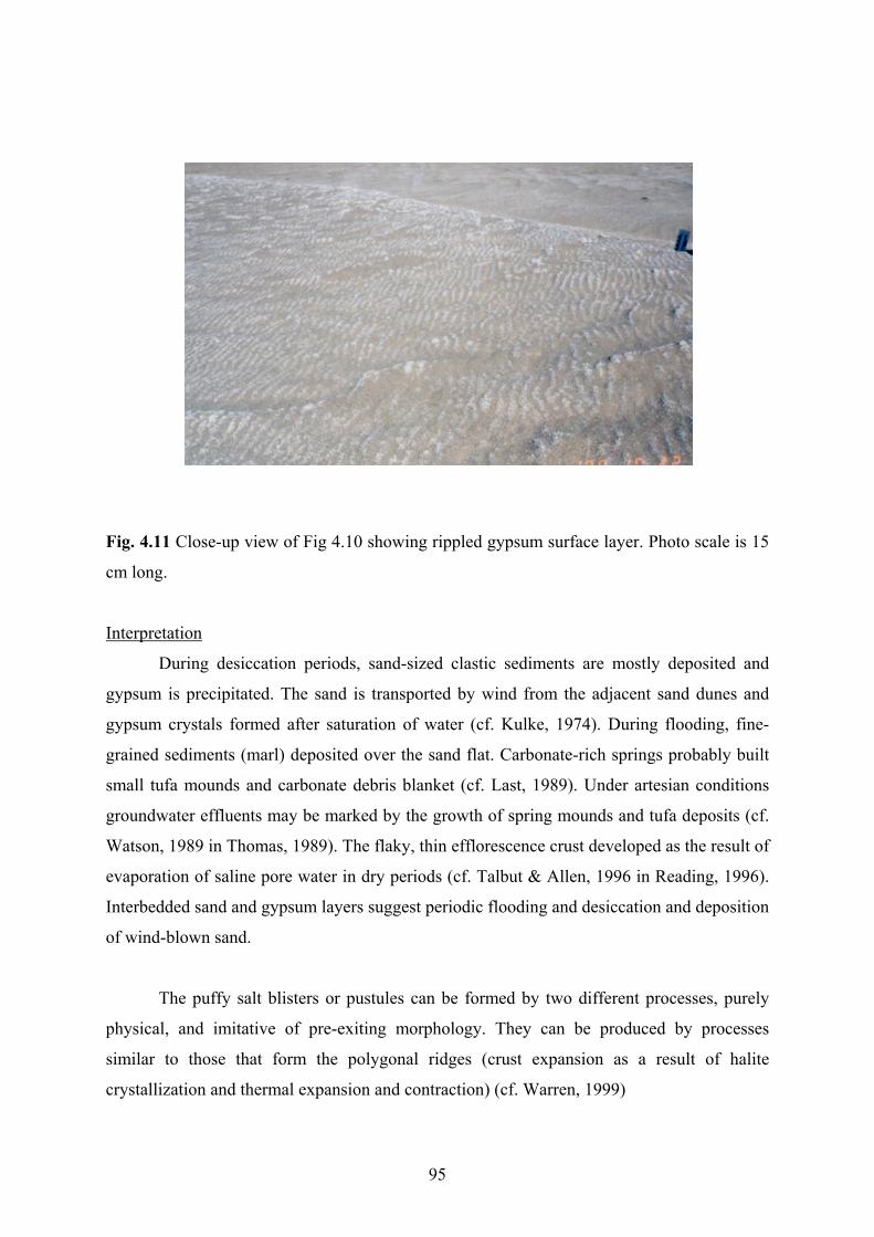
Fig. 4.11 Close-up view of Fig 4.10 showing rippled gypsum surface layer. Photo scale is 15
cm long.
Interpretation
During desiccation periods, sand-sized clastic sediments are mostly deposited and
gypsum is precipitated. The sand is transported by wind from the adjacent sand dunes and
gypsum crystals formed after saturation of water (cf. Kulke, 1974). During flooding, fine-
grained sediments (marl) deposited over the sand flat. Carbonate-rich springs probably built
small tufa mounds and carbonate debris blanket (cf. Last, 1989). Under artesian conditions
groundwater effluents may be marked by the growth of spring mounds and tufa deposits (cf.
Watson, 1989 in Thomas, 1989). The flaky, thin efflorescence crust developed as the result of
evaporation of saline pore water in dry periods (cf. Talbut & Allen, 1996 in Reading, 1996).
Interbedded sand and gypsum layers suggest periodic flooding and desiccation and deposition
of wind-blown sand.
The puffy salt blisters or pustules can be formed by two different processes, purely
physical, and imitative of pre-exiting morphology. They can be produced by processes
similar to those that form the polygonal ridges (crust expansion as a result of halite
crystallization and thermal expansion and contraction) (cf. Warren, 1999)
95

4.3.6 Sand beaches
Distinct and continuos sand beach ridges occur in the east of the Zayandeh river and
the Gavkhoni playa lake as a long narrow zone (Fig 4.12).
Fig. 4.12 Field photograph showing sand beach ridge in the east of the Zayandeh river delta
(see Fig. 4.1 and Table 4.1 for their position). View is to the south.
96

They are composed of igneous, sedimentary, and metamorphic lithic grains, quartz
and feldspar mineral grains. The average percentage of the igneous lithic grains (in sand
fraction) is approximately 90 % in the east and 35% igneous, 53% sedimentary, and 4%
metamorphic lithic grains, 6.5% quartz and 1.5 % feldspar mineral grains in the northeast
(Fig. 4.13). According to the study of two pits, two lithologies were observed including
gravelly sand and sand. It also contains a considerable amount of gastropod shells in the
northeast of the delta (location No. B1)
ig. 4.13 Mineralogical composition of the sand fraction of the sand beach ridges from
ravelly sand
B1
I S M Q F
B2
F
location No. B1 and location No. B2 (see Fig. 4.1 and Table 4.1 for their positions). Igneous
(I), sedimentary (S), metamorphic (M) lithic grains, quartz (Q) and feldspar (F) mineral
grains.
G
ology occurs on the top of the two studied vertical sections in the sand beach
ridges.
and
This lith
The grain size ranges from fine gravel to fine sand (mostly very coarse to coarse sand
fractions) and mostly consists of igneous lithic grains in gravel size. Discoidal gypsum
crystals are found with a few millimeters in diameter on the surface layer.
S
This sub-facies underlies graditionally the gravelly sand in the section No. B1 (see
Fig. 4.1 and Table 4.1 for its position). The main grain size is fine to medium sand and
97

mineralogical composition is approximately similar to the gravelly sand, except that it
consists of more sedimentary lithic grains.
Interpretation
The sand beach ridges usually form where the gradient of distal alluvial fan is
relatively high and small streams transport coarse-grained sediments to the playa lake. They
are formed by wave activity during playa lake level highstand. Distinct differences in mineral
composition between the northeastern and the eastern sand beaches are related to the source
of the sediments. The former originate from igneous, sedimentary and metamorphic rocks but
the later mostly derive from igneous rocks. The gypsum crystals are most probably washed
out from the mud flat.
4.3.7 Mud flat and saline mud flat
This sub-facies encircles the lake, except in the western part. The northern mud flat is
wide, where the Zayandeh river flows into the playa lake (see Figs. 4.2 & 4.27). They are
deposited mainly by sheet floods and then altered by wetting and drying. Groundwater table
measurements during more than two years indicates that fluctuations are not considerable
(maximum 53 cm in the section No. M1 and 41 cm in the section No. M2) (Fig. 4.14) (see
Fig. 4.1 and Table 4.1 for their position).
It is characterized by polygonal mud cracks, plant roots and root casts and is not
saturated by brine. The polygonal desiccation is fairly common and cracks measure up to a
few centimeters across (Fig. 4.15). Calcite is found as consolidated fine mud and is dominant
in the southern and the northern mud flat, where ephemeral Rahimi river and the permanent
Zayandeh river enter the playa lake (see Chapter 2 for their positions). The mud flats are sites
of sedimentation of silt and clay.
Saline mud flats occur between the dominant clastic environment (dry mudflat) and
the evaporite-dominated environment (salt pan). In contrast to the mud flat, all depositional
sedimentary structures have been destroyed in the saline mud flat. It is characterized by
precipitation and preservation of evaporite minerals within the detrital sediments, including
chiefly chaotic mixtures of mud, halite and gypsum.
98

Month (1995-1997)-300
-250
-200
-150
-100
-50
0
4 6 8 10 12 2 4 6 8 10 12 2 4
G.W
.T(c
m)
M1
M2
Fig. 4.14 Fluctuation of groundwater table (in cm below surface) in the saline mud flat/mud
flat measured during two years (1995-97). Locations No. M1 and No. M2 (see Fig. 4.2 and
Table 4.1 for their position).
Fig. 4.15 Field photograph showing small mud cracks on the mud flat, southwest of Kuh-e-
Siah, near section No. Dz1 (see Fig. 4.1 and Table 4.1 for its position). Camera cap for scale
is 6 cm in diameter.
99
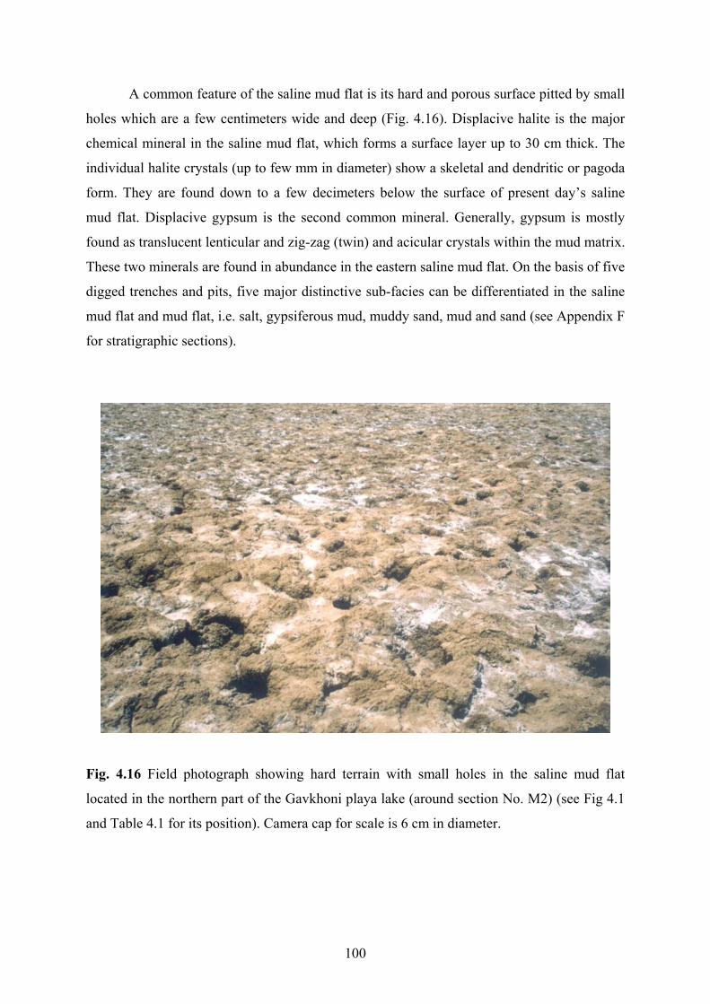
A common feature of the saline mud flat is its hard and porous surface pitted by small
holes which are a few centimeters wide and deep (Fig. 4.16). Displacive halite is the major
chemical mineral in the saline mud flat, which forms a surface layer up to 30 cm thick. The
individual halite crystals (up to few mm in diameter) show a skeletal and dendritic or pagoda
form. They are found down to a few decimeters below the surface of present day’s saline
mud flat. Displacive gypsum is the second common mineral. Generally, gypsum is mostly
found as translucent lenticular and zig-zag (twin) and acicular crystals within the mud matrix.
These two minerals are found in abundance in the eastern saline mud flat. On the basis of five
digged trenches and pits, five major distinctive sub-facies can be differentiated in the saline
mud flat and mud flat, i.e. salt, gypsiferous mud, muddy sand, mud and sand (see Appendix F
for stratigraphic sections).
Fig. 4.16 Field photograph showing hard terrain with small holes in the saline mud flat
located in the northern part of the Gavkhoni playa lake (around section No. M2) (see Fig 4.1
and Table 4.1 for its position). Camera cap for scale is 6 cm in diameter.
100

Salt
This lithology is the uppermost one in the saline mud flat. It mostly consists of
skeletal salt in the lower part and a mixture of salt and mud in the upper part (about 10 cm).
Its thickness reaches up to 30 cm and is dry, hard and porous in dry seasons. The major clay
minerals in mud fraction consist of illite, kaolinite, chlorite and minor smectite (Appendix
B4, sheet No. 20).
Gypsiferous mud
Massive gypsiferous mud is mainly developed in the eastern saline mud flat (see Figs.
4.1 & 4.2 for position of saline mud layer). When the groundwater table is high (a few
centimeters in depth) its surface is usually moist and soft whereas in dry periods the surface is
dry and hard. A large number of discoidal gypsum crystals (up to 3 cm in diameter) are
scattered in the sediment.
Muddy sand
Massive muddy sand occurs in the section No. M1 (see Fig. 4.1 and Table 4.1 for its
position) and is divided in an upper and a lower part. It consists of mostly fine sand-sized
fraction. Its mineralogical composition, comprises, decreasing in abundance, igneous,
sedimentary and metamorphic lithic grains, quartz and feldspar mineral grains (Fig. 4.17).
Abundant gastropod and ostracod shells are present in this lithotype.
Mud
This lithology is exposed in the section No. M2 (see Fig. 4.1 and Table 4.1 for its
position). There is no evidence of the presence of bedding and plant remains in this lithology.
Clay minerals of this sub-facies consist of illite, smectite, chlorite, and kaolinite (Appendix
B4, sheet No. 21).
Sand
Massive fine to medium sand forms the lowermost lithology in the section No. M1
(see Fig. 4.1 and Table 4.1 for their position). Its mineralogical composition is similar to the
muddy sand (Fig. 4.17). There are a large number of gastropod and ostracod shells similar to
muddy sand in this lithotype. It also occurs as lenticular thin layers between mud layers.
101
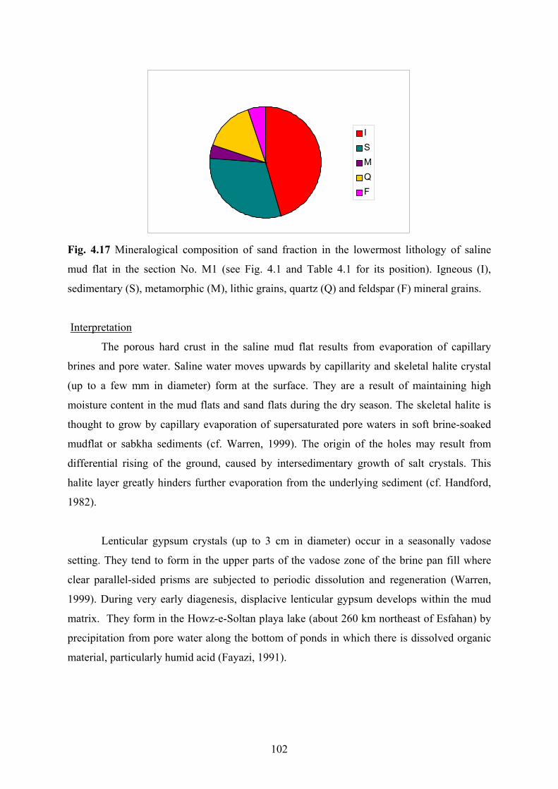
ISMQF
Fig. 4.17 Mineralogical composition of sand fraction in the lowermost lithology of saline
mud flat in the section No. M1 (see Fig. 4.1 and Table 4.1 for its position). Igneous (I),
sedimentary (S), metamorphic (M), lithic grains, quartz (Q) and feldspar (F) mineral grains.
Interpretation
The porous hard crust in the saline mud flat results from evaporation of capillary
brines and pore water. Saline water moves upwards by capillarity and skeletal halite crystal
(up to a few mm in diameter) form at the surface. They are a result of maintaining high
moisture content in the mud flats and sand flats during the dry season. The skeletal halite is
thought to grow by capillary evaporation of supersaturated pore waters in soft brine-soaked
mudflat or sabkha sediments (cf. Warren, 1999). The origin of the holes may result from
differential rising of the ground, caused by intersedimentary growth of salt crystals. This
halite layer greatly hinders further evaporation from the underlying sediment (cf. Handford,
1982).
Lenticular gypsum crystals (up to 3 cm in diameter) occur in a seasonally vadose
setting. They tend to form in the upper parts of the vadose zone of the brine pan fill where
clear parallel-sided prisms are subjected to periodic dissolution and regeneration (Warren,
1999). During very early diagenesis, displacive lenticular gypsum develops within the mud
matrix. They form in the Howz-e-Soltan playa lake (about 260 km northeast of Esfahan) by
precipitation from pore water along the bottom of ponds in which there is dissolved organic
material, particularly humid acid (Fayazi, 1991).
102

The scattered sand-sized sediments admixtured within some muddy layers might be
interpreted as contemporaneous deposition of mud and sand by a flow with insignificant
change in velocities (cf. Amini, 1997). The muddy sediments of this sequence reflect rapid
deposition on a lower flood plain during wet, shortly after sheet floods (cf. Benison &
Goldstein, 2001). The presence of the sand layers most probably represents deposition in the
bottom of small and shallow distributary channels during upper flow regime periods.
4.3.8 Salt flat (Salt pan)
Sediments deposited in the Gavkhoni playa lake change laterally from dominantly
siliciclastic (sand flat and mud flat) to dominantly evaporitic facies (salt pan). The later
covers the center of the Gavkhoni playa lake as a crust that crystallized in highly saline ponds
by efflorescence. It is located in the lowest area of the Gavkhoni closed basin and occupies
most of the playa surface. The salt pan in turns grades outward to the mudflat or immediately
to the sand flat. It is surrounded by a saline-soaked mudflat to the east and saline sand flat to
the west.
The two drilled cores, up to 30 m (sections No. S4 & S5) provided by Nabian et al.
(1991) and three shallow pits dug (see Fig. 4.1 and Table. 4.1 for their positions), record
evaporitic and siliciclastic lithologies. These lithologies range from a few centimeters to up to
12 m thick. They include salt, black mud, sand, gypsiferous marl, and yellow/brown mud (see
Appendix F for stratigraphic logs). Among these lithofacies only the first three ones are
described in detail, because there is no sufficient data about the other facies.
Salt
This sub-facies covers the center of the playa lake as a crust, ranging from a few
centimeters in thickness in the north to up to 150 cm in the south. Its color is usually clear
and white, but black, pink and green colors also occur in some places. The surface layer
consists of a mixture of mostly halite and a few sand-sized grains. The average value of the
detrital sediments around the salt mine is about 3%. The most common sedimentological
feature of this lithology is a polygonal halite crust (Fig. 4.18). The individual polygons
usually measure up to 100 cm across. Efflorescent halite ridges popcorns (cauliflower) and
hairy efflorescent surface halites are other features on the salt pan (Figs. 4.19 & 4.20). The
popcorns commonly form nodular aggregates up to few cm across. The hairy efflorescent
103

surface halite is typically finely crystalline and has a very porous texture. Some of them also
have delicate needle-like hairs of halite covering their surface.
The polygonal crust can be grouped into two categories; high relief (a few decimeters
high) and low relief (a few centimeters high). The former is modified by efflorescence and
occurs mostly in the southern area where the water table is high and the salt pan is susceptible
to flooding after sporadic heavy rainfall. The two types of high-relief thick salt crusts have
been distinguished, polygonal crusts and blocky crusts. The former is a pattern of ridges that
are polygonal on their surface. The later is high-relief polygonal, thick, and saucer-shaped
slabs of salt and possesses a rough blocky morphology. The small stalactites of halite are
common on the undersides of the overhanging slab edges in the central part of the salt pan
(1.5 km from western border of the Gavkhoni playa lake, around the Jarghoieh salt mine).
The low relief salt crust is the most widespread crust type with regular and flat surface.
Fig. 4.18 Field photograph showing polygonal halite crusts, pressure ridges and spongy
efflorescences at the surface of cracks, about 1.5 km from the western border of the playa
lake. Form of polygons is disturbed by nearby gravel road to salt mine. Photograph, taken on
17.11.95, provided by H. Kulke. The Varzaneh aeolian sand field is in the background of
photograph. View is to the northwest.
104

They exhibit a polygonal ridge pattern, but the polygons generally have smaller
diameters than high-relief polygonals. This feature is usually widespread in the northern part
of the salt pan.
Fig. 4.19 Pop-corn or cauliflower efflorescence formed on the salt pan, 1.5 km from the
western border of the Gavkhoni playa lake, northern part of the Jarghoieh salt mine road. A
pressure ridge in its early stage of development runs across the picture. Photograph, taken on
17.11.95, provided by H. Kulke. The small knife for scale is 8 cm long.
There are thin layers of dark mud interbedded with crystalline halite layers. The
thickest mud layer is observed on the southern margin of the salt pan in close proximity to a
major detrital sediment source. In contrast, the crystalline halite layers without intermittent
mud layers are observed in the central portion of the salt pan.
Brine–saturated clastic sediments underlay the salt crust. The brine level (groundwater)
slightly fluctuates during dry and wet seasons, ranging between –20 to +5 centimeters (Fig.
4.21).
105

Fig. 4.20 Detail of well-developed pressure ridges near the Jarghoieh salt mine. Photograph,
taken on 24.4.99, provided by H. Kulke. Geological hammer for scale is 30 cm long.
-25
-20
-15
-10
-5
0
5
12 2 4 6 8 10 12 2 4 6 8 10 12 2
Month (1995-1997)
G.W
.T (c
m)
Fig. 4.21 Fluctuation of groundwater table measured in a trench (location No. S1) in the salt
pan during more than two years (1995-97) (see Fig. 4.1 and Table 4.1 for its position).
106

Fig. 4.22 Close-up view of halite crystals from the salt crust in west-central part of salt pan.
Standard scale is in cm in the left.
The voids of the salt crust and the clastic layers are filled with halite crystals and/or
by saturated brine. The main evaporite mineral determined by XRD in the salt pan is halite,
but other minerals including carnallite (MgCl2.KCl.6H2O), bischofite (MgCl2.6H2O) and
tachyhydrite (CaCl2.2MgCl2.12H2O) are also present locally as minor according to XRD
evidence (Appendix B4, sheets No. 23 & 24). Halite crystallizes in hopper, cubic and massive
form. The size of halite crystals reaches up to 2 cm (Fig. 4.22).
Black mud
Black mud underlies the salt crust in the section No. S1-S3. It also is observed as
interlayering in the uppermost lithology (salt) in drilled cores in the sections No. S4 and S5
with up to 5 cm in thickness (see Fig. 4.1 and Table 4.1 for their position). Its thickness
reaches up to a few centimeters in the playa lake center. The ratio of clay to silt is high (about
80% clay fraction). Clay minerals of this facies (in section No. S1) consist of illite, kaolinite,
chlorite, and smectite (Appendix B3, sheet No. 22). Halite as hoppers and cubes and gypsum
as acicular and discoidal crystals are scattered throughout the grey mud. The size of halite
and gypsum crystals is up to 2 cm. A few gastropod and ostracod shells are present in the
sediments.
107

Sand
nstratified well-sorted fine to medium sands underlay the above mentioned lithology
in the section No. S1-S3 and occur in the drilled cores No. S4 and S5 (see Fig. 4.1 and Table
4.1 for their position). The sand grains are mostly composed of sedimentary, igneous lithic
and feldspar and quartz grains (Fig. 4.23). Halite hopper and discoidal gypsum crystals are
scattered between the sand grains. It also contains a few gastropod and ostracod shells.
Sample No 7
ISQF
Fig. 4.23 Distribution of the various types of lithics and mineral grains of the sand sub-facies
in the section No. S1 in the salt pan (see Fig. 4.1 and Table 4.1 for its position). Igneous (I),
sedimentary (S), metamorphic (M) lithic grains, quartz (Q) and feldspar (F) mineral grains.
Greenish gypsiferous marl
Greenish gypsiferous marl directly overlies brown mud in the drilled core No. S4 (see
Fig. 4.1 and Table 4.1 for its position). The thickness of this sub-facies is about 2 m.
Yellow to brown mud
This lithology is recognizable in the drill cores No. S4 and S5 and is divided in an
upper and a lower part in drilled core No. S1 (see Fig. 4.1 and Table 4.1 for their positions).
The upper one underlies immediately gypsiferous marl and the lower one is the lowermost
lithology in these cores. This sub-facies ranges from 4 to more than 12 m in thickness.
108

Interpretation
The formation of the salt pan is as a result of three stages: flooding, evaporation and
desiccation (Fig. 4.24). After flooding, when the shallow ephemeral lake becomes
concentrated by evaporation, the formation of salt pan starts (cf. Lowenstein & Hardie, 1985,
Benison & Goldstein 2001). In the NaCl-rich system of this lake, continuous evaporation
concentrates the brines until they get saturated with halite. Crystallization starts at the brine
surface as small plates and hopper crystals, which sink to the bottom. The individual floating
crystals are cemented together where they touch to form rafts (Fig. 4.25).
Fig. 4.24 A summary of the basic elements of the saline salt pan cycle from intramontane/
playa) (after Lowenstein & Hardie, 1985).
109

When surface tension is disturbed, the crystals fall to the bottom, forming an
accumulation of individual halite crystals and broken rafts on the brine pool floor (cf.
Hovorka, 1987, Handford, 1982) (Fig. 4.25). These serve as nuclei for further growth and
widespread syntaxial overgrowth that takes place on the lake floor, ultimately resulting in the
development of salt crystals and surface salt crust (cf. Lowenstein & Hardie 1985) (Fig.
4.26). In most cases, rapid evaporation does not allow halite to form as a cubic crystal at the
surface of the salt crust, although in other environments hopper-shaped crystals generally
record rapid growth rate (Fayazi, 1991).
Fig. 4.25 Field photograph showing raft crystals of halite floating on the top of a brine pool
within the salt pan. Length of pen is 15 cm. Photograph, taken on 24.4.1999, provided by H.
Kulke.
When the salt surface is exposed, the halite layers become buckled, break into a
polygonal crust, and tepee structures are formed. The buckling was caused by a net volume
increase due to expansion during crystallization. The continued growth of the halite crystals
just beneath the dry surface of the pan causes the lateral expansion of the surface crust, and
leads to disruption of the crust into large polygons rimmed, by pressure ridges that override
each other like tectonic thrusts (see Fig. 4.20) (cf. Lugli et al., 1999). Pumping of subsurface
110

brine and subsequent evaporation along the cracks between the polygons leads to
precipitation of a spongy efflorescent halite (cf. Lowenstein & Hardie, 1985).
The polygonal pattern might be understood as a result of fracturing by volume
reduction caused by either thermal contraction or desiccation (cf. Warren, 1999). The high-
relief polygonal salt crusts were allowed to develop uninterruptedly for a number of years and
eventually produced a high–relief blocky surface (cf. Eugster & Hardie, 1978).
The hairy efflorescent surface halite leaned in a downwind direction, suggest that its
formation is related to the desiccating action of the wind. The wind assists in the process by
drawing out surface films of brine from the crust, so forming small protuberances of
efflorescent halite. Brine is continually blown to the end of the hair-like projections where it
evaporates, precipitating halite and so lengthening the hairs (cf. Warren, 1999).
During spring, minor meteoric floodwaters (rainstorm runoff and snow meltwater)
cover the saline pan and form a temporary shallow brackish lake. The depth of this lake is
usually no more than a few tens of centimeters. The occurrence of minor flooding is much
more common on saline pans than major flooding, and can create a temporarily
undersaturated the saline lake without deposition of a detrital mud layer in the lake center.
Repetition of such flooding can result in a sequence of partly dissolved halite crusts without
detrital mud drapes in between. During a major storm flooding stage when muddy
floodwaters inundate the pan, mud layers presumably are deposited in the shallow ephemeral
lake. This results the formation of alternating layers of halite and mud. The presence of the
hopper halite within the mud matrix results from fluctuations of brine during the wet and dry
period (Figs. 4.24 & 4.26) (cf. Lowenstein & Hardie 1985; Handford, 1982)
Pink to light red color of the halite is due to impregnation by traces of iron oxides
between the halite crystals (cf. Hovorka, 1987). The presence of microorganisms such as the
flagellate Dunaliella salina can result in a striking pink coloration (cf. Watson, 1989 in
Thomas, 1989). The black to greenish color of halite especially in the surface layer results
from impurities of fine-grained detrital sediments.
111
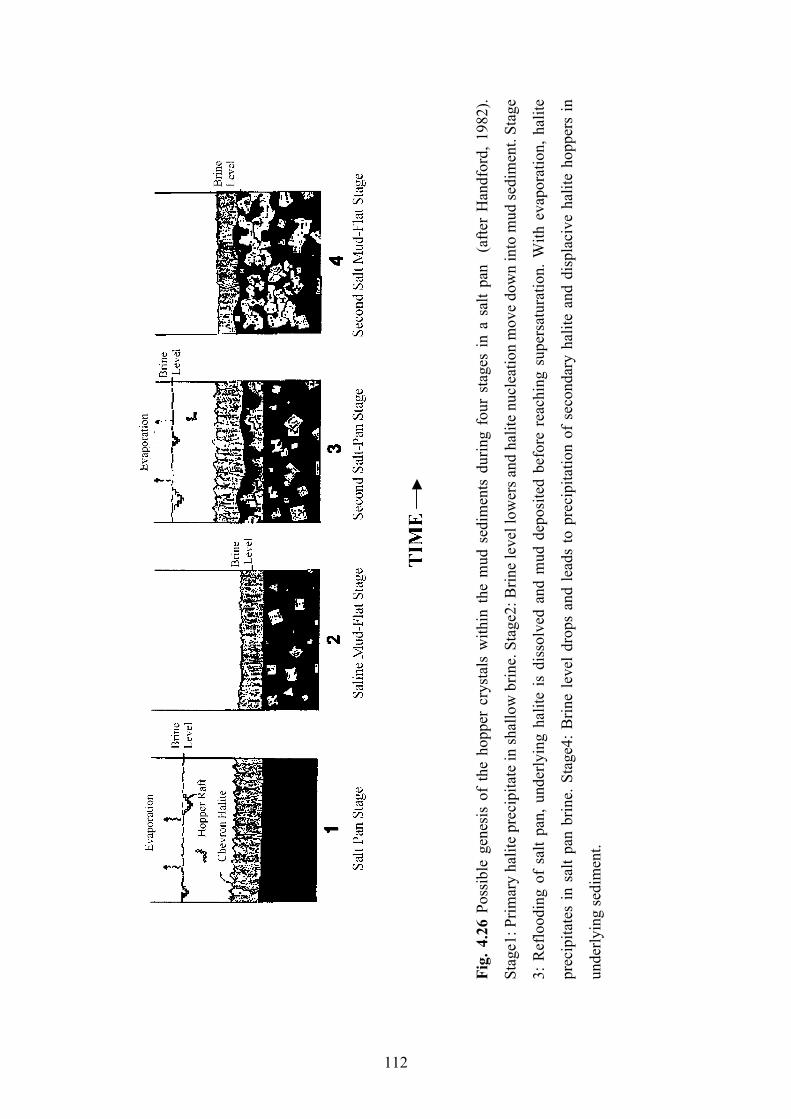
Fig.
4.2
6 Po
ssib
le g
enes
is o
f th
e ho
pper
cry
stal
s w
ithin
the
mud
sed
imen
ts d
urin
g fo
ur s
tage
s in
a s
alt p
an
(afte
r H
andf
ord,
198
2).
Stag
e1: P
rimar
y ha
lite
prec
ipita
te in
shal
low
brin
e. S
tage
2: B
rine
leve
l low
ers a
nd h
alite
nuc
leat
ion
mov
e do
wn
into
mud
sedi
men
t. St
age
3: R
eflo
odin
g of
sal
t pan
, und
erly
ing
halit
e is
dis
solv
ed a
nd m
ud d
epos
ited
befo
re r
each
ing
supe
rsat
urat
ion.
With
eva
pora
tion,
hal
ite
prec
ipita
tes
in s
alt p
an b
rine.
Sta
ge4:
Brin
e le
vel d
rops
and
lead
s to
pre
cipi
tatio
n of
sec
onda
ry h
alite
and
dis
plac
ive
halit
e ho
pper
s in
unde
rlyin
g se
dim
ent.
112

Clay–sized sediments are transported in two ways: 1-Clay in fresh water is suspended
and can be transported over wide areas before it flocculates and slowly fall to the bottom.
Floodwaters move only clay-sized material out from the shoreline; silt is deposited in deltas
near the shore. 2-Aeolian dust storms are an alternative mechanism for transporting silt and
clay sized material for long distances (Hovorka, 1987).
The fine to medium sand sediment intermixtured with salt crystals is derived from
aeolian sands in the west of the playa lake. The sand–sized intercalations (e.g. in section No.
S4) in the salt pan sediments capped by mud most likely reflect a rapid deposition of sand
during thunderstorms in a shallow temporary lake or also directly as bottom load from the
Zayandeh river delta. The upward change in turn from sand, black mud into the salt unit
marks the transition from a sand flat, mud-dominated playa to a salt pan.
The yellow to brown mud is probably deposited in a shallow fresh water-brackish
perennial lake or flood sheets in a semi-arid to arid climate (cf. Talbut & Allen, 1996 in
Reading, 1996; Benison & Goldstein, 2001). The lack of plant roots in the mud flat reflects
that the playa lake was poorly or not vegetated. This is indicative of high salinity of the pore
water and frequent flooding.
4.3.9 The Zayandeh river delta
This deltaic environment occupies about 30 km2 of end reach of the Zayandeh river. It
gradually grades into the poorly saline lake in the south, the sand flat in the west and the sand
beach ridge and the mud flat to the east of the lake (Fig. 4.27). This is an extremely shallow
delta since the playa lake, into which it progrades, is a very flat and shallow geomorphic
feature. Some shallow distributary channels cut up the delta into separate small islands and
drain water into the Gavkhoni playa. In the immediate proximity of these channels, small
ridges (point bar and levee) similar to flood plain of river banks were formed. In the
development of the delta, individual branches gradually become shallower. In wet seasons
vegetation develop in the small islands and distributary channels banks of the delta (see
Chapter 2.7 & 2.8). The sediments are made up of alternating of sandy and muddy facies in
studied trenches and have different origin and composition (see Table 4.1 for position of
trenches).
113
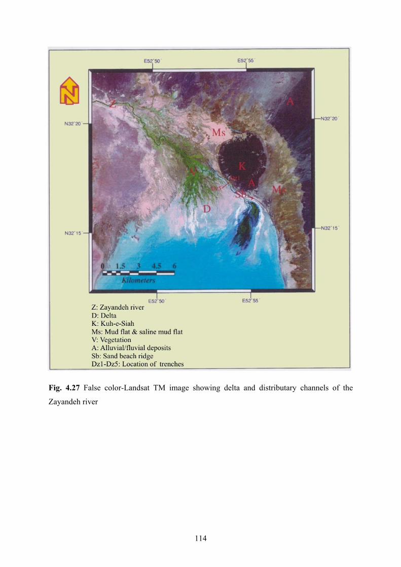
Fig. 4.27 False color-Landsat TM image showing delta and distributary channels of the
Zayandeh river
114

They are gray to black mud, yellow to brown mud and sand. Lithology and
sedimentary structures of the sections Dz1-Dz5 (see Fig. 4.1 and Table 4.1 for position of
trenches) is approximately the same. Therefore, the stratigraphic sections of Dz1 and Dz5
were drawn (see Appendix F).
Grey to black mud
Gray to black massive mud, interbedded with lenticular thin sand layers, forms the
uppermost lithology with sharp boundary at base in the Zayandeh river delta. Its thickness
reaches up to a few centimeters. This sub-facies contains abundant vegetation, root traces,
plant roots and gastropod and ostracod shells. They are found as a homogenous mixture of
clay and silt with a high degree of bioturbation. The surface layer shows extensive mud
cracks and algal mats (see Fig. 4.15).
Yellow to brown mud
Massive brown to yellow mud underlies the grey to black mud in the five studied
vertical sections with graditional boundary at the base and top. It contains a high ratio of clay
to silt. The thickness of this lithology reaches up to 85 cm. Clay minerals of this sub-facies
are composed of kaolinite, illite, chlorite, and smectite (Appendix B4, sheets No. 15 & 16).
Sand
Massive fine to medium sand forms the lowermost layers in the section No. Dz5 with
graditional top and base boundary. Its mineralogical composition is 45% igneous, 31%
sedimentary, and 4% metamorphic lithic grains, 14% quartz and 6 % feldspar mineral grains,
approximately similar to the lowermost layers in the section No. M1 (see Fig. 4.1 and Table
4.1 for its position) in saline mud flat (see Fig. 4.17). It also contains a large number of
gastropod and ostracod shells.
Interpretation
The presence of the sand represents deposition in the bottom of the distributary
channels during periods of stronger flow, while silt and clay are well developed on the upper
parts of the point bars, swamp and levees during floods. Change of sediments both in
horizontal and vertical directions is as a result of frequent shifting and migration of the
channel branches. The most important factor for development of this delta is that the
Zayandeh river ends in a shallow standing body of water.
115

Organic matter is well preserved in the greenish to black mud layer because reducing
conditions occur almost immediately below the surface in this poorly drained environment.
The brown mud is probably deposited in a shallow fresh water–brackish perennial lake or
flood sheets in a semi–arid to arid climate (cf. Talbut & Allen, 1996 in Reading 1996;
Benison & Goldstein, 2001). The lack of plant roots in the brown mud facies reflects that this
depositional environment was poorly or not vegetated. The above mentioned high degree of
bioturbation of mud sediments is caused by plant roots.
4.4 History and evolution of the lower reaches of the playa lake study basin
A developed system of flood-plain terraces, a rather deep morphology of valleys in
the Zayandeh river and other streams (especially in the southwest of the study area), exposure
of lacustrine sediments (marl) marginal to sedimentary mountains (about 100 m above the
base level of the study area), cyclic sedimentation of gravel and marl in the proximal of the
alluvial fans (see Chapter 5 for details) and sand and mud in the Gavkhoni playa lake indicate
a repeated rise and drop of water level of the Gavkhoni playa lake in the Quaternary period.
This is most probably a result of three main factors: Neotectonic movements of the High
Zagros belt (southeast of the study area), subsidence of the base level of erosion (Gavkhoni
playa lake) and climatic changes in the drainage basin of the Zayandeh river.
The folded and thrusted High Zagros belt, trending NNE-SSW, results from tectonic
pressure, continental convergence and collision. Horizontal and vertical movements in this
belt is estimated at 3.5 to 4.7 cm and more than 2 mm respectively in each year in Quaternary
(Haghipour, 1983). Uplifting in the upper reaches of the rivers (specially the Zayandeh river)
is connected with an increase of gradient of the longitudinal profile in the upstream reaches,
resulted in increased intensity of bed erosion and deep incision of river valleys.
The Gavkhoni playa lake formed in a supposed graben and/or half graben system in
response to crustal spreading along the northeastern part of the Sanandaj-Sirjan zone. This
system is a result of orogenic movements and caused volcanic eruptions at the end of
Cretaceous and early Eocene, and faulting which took place after the volcanism (see Chapter
2 for details). Subsidence of this base level of erosion (Gavkhoni playa lake) is most probably
116

due to continuing tectonic activity in Quaternary period. This probably is a major factor
which is responsible for accumulation and erosion (lateral and vertical) in the drainage basin.
Changing climatic conditions took place in the Quaternary period when the vast areas
of the northern hemisphere were frequently covered with thick glaciers, melting of glaciers
increased the amount of water in the rivers and activated their work (Yakushova, 1986). It is
supposed that this phenomenon played the most important role in relation to changing water
level in the lower reaches of the study area, rise and fall in denudation and spatial distribution
of Quaternary deposits in the Zayandeh river drainage basin.
To interpret the history and evolution of the lake, it may be insufficient to present a
model only based on a few digged trenches. However, combined with investigation of two
drill cores (up to 30 m deep) and geological cross sections (provided by NIOC), deep wells
(provided by Iranian Water Organization) (see Chapters 2 & 5 for details), the late
Quaternary to recent sedimentation episodes can be described to some extent in this basin.
Based on these field data, a depositional model for the Gavkhoni playa lake is suggested in
Figs 4. 28 & 4.29.
The material, filling the playa basin, results from a complex interplay of evaporation,
precipitation, quantity and chemistry of groundwater inflow and surface runoff, and drainage
basin characteristics, e.g. clastic input. The stratigraphic sequence generally indicates
considerable differences in depositional and hydrological conditions and changes in water
chemistry in the Gavkhoni playa lake both in time and geographic position. The deposition of
intermittent sand and mud (sand flat and mud flat facies) suggest that the basin was
influenced repeatedly by periods of wet and dry climate. During long wet periods it has been
a shallow permanent lake possibly without considerable change in water table, resulting in
deposition of fine-grained sediments in the basin. The sand-grained deposits most likely
derived from aeolian sands during dry periods at the margin of the sand dunes, but also
directly as bottom load from the Zayandeh river delta. With increasing aridity, the middle
part of the lake gradually became shallower, resulting in a saline lake and the salt pan. The
salt pan is a product of the latest dry period in this playa lake. The lack of a salt crust in
studied depth, except the surface layer, implies that hypersaline conditions probably have
existed only in the latest sedimentation period in the recent centuries in the Gavkhoni playa
lake.
117

Fig. 4.28 False color-Landsat TM image showing location of hypotethic cross-section (A-A/)
from northwest to southeast of the study area.
118
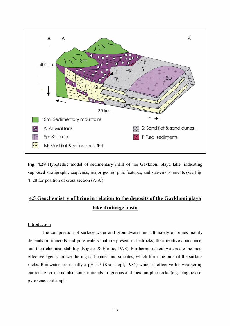
Fig. 4.29 Hypotethic model of sedimentary infill of the Gavkhoni playa lake, indicating
supposed stratigraphic sequence, major geomorphic features, and sub-environments (see Fig.
4. 28 for position of cross section (A-A/).
4.5 Geochemistry of brine in relation to the deposits of the Gavkhoni playa
lake drainage basin
Introduction
The composition of surface water and groundwater and ultimately of brines mainly
depends on minerals and pore waters that are present in bedrocks, their relative abundance,
and their chemical stability (Eugster & Hardie, 1978). Furthermore, acid waters are the most
effective agents for weathering carbonates and silicates, which form the bulk of the surface
rocks. Rainwater has usually a pH 5.7 (Krauskopf, 1985) which is effective for weathering
carbonate rocks and also some minerals in igneous and metamorphic rocks (e.g. plagioclase,
pyroxene, and amph
119

ibole). Chemical analysis of many salt lake environments has shown that they have a
wide range of compositions. In many salt lakes Na+ is the most abundant cation, but anion
concentrations are variable (Fayazi, 1991).
The lithology of the Gavkhoni playa lake drainage basin consists of igneous,
sedimentary and metamorphic rocks. Among these rocks, carbonate rocks are dominant and
igneous rocks, especially andesite, are the second major rocks (see Chapter 2.3 for details).
1 Sample No R1 R2 I1 I2 K M1 M2 S1 S4
Location Zayandeh river Zayandeh river 4.5 km east of 7 km east of 8.5 km east 23 km east of 28 km east of 10.5 km east southwest of
Ion ppm (Varzaneh) (Kuh-e-Siah) Khara Khara of Khara Varzaneh Varzaneh of Khara the playa lake
K+ 78 97.5 507 1560 1950 371 936 2944 3570 Ca++ 160 200 1520 1400 1800 2200 3800 1740 280 HCO3- 414 244 146.4 73.2 73.2 195.2 73.2 512.4 500 Cl- 2095 4118 31240 143420 177500 21868 105080 183890 199254 Na+ 1012 2576 57040 87200 103040 20240 52716 85100 90600 SO4-- 1512 1411 19289 13254 21950 22051 4444 9436 13280 Mg++ 360 624 2088 7200 10080 1800 6600 19152 25691 NO3- 4 5 14 5 32.5 157 307 48 n.d Sr++ 9 9 100 62 4.9 56 292 74 n.d TDS 10900 9900 110200 295100 403700 108700 192700 359000 n.d
2 Sample No R1 R2 I1 I2 K M1 M2 S1 S4
Location Zayandeh river Zayandeh river 4.5 km east of 7 km east of 8.5 km east 23 km east of 28 km east of 10.5 km east southwest of
Ion ppm (Varzaneh) (Kuh-e-Siah) Khara Khara of Khara Varzaneh Varzaneh of Khara the playa lake
K+ 109 105 741 1638 1716 858 936 2457 n.d Ca++ 200 260 860 1400 1600 2680 3480 1500 440 HCO3- 293 390 220 317 122 244 122 366 450 Cl- 6461 6106 88040 156910 178920 65320 101530 187440 199365 Na+ 3933 3542 58420 93840 96600 36800 51520 91080 86600 SO4-- 1162 2323 17731 15872 14882 17824 5040 12864 14000 Mg++ 384 702 3036 6868 9360 3084 6360 18120 24900 NO3- 3.5 1 17 6 25.5 227 476 43 n.d SR++ 9 9 68 16.4 14.5 26.3 254 5.3 n.d TDS 20500 19000 105200 302600 323800 91200 186500 392600 n.d
Table 4.2 Chemical analyses of the Zayandeh river water (R1 & R2) and the groundwater (
I1, I2, K, M1, M, S1 & S2) of the study area taken during wet season (early spring, 1) and dry
season (late summer, 2) in 1996. River (R), interdune(I), sand flat (K), saline mud flat ( M)
and salt pan (S) (see Fig. 4.1 and Table 4.1 for their positions). n.d= not detected.
For determination of the type of the Gavkhoni playa lake brine, the major cations and
anions, i.e. sodium, magnesium, calcium, potassium, sulfate, chloride, bicarbonate, nitrate,
120
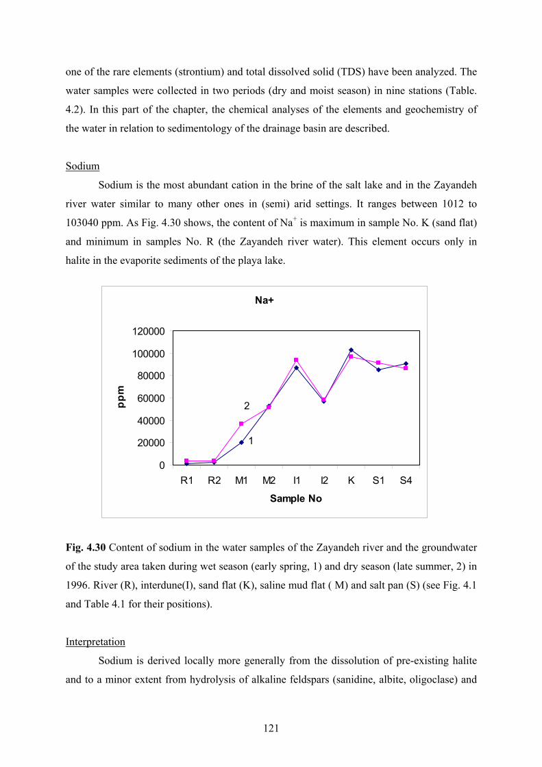
one of the rare elements (strontium) and total dissolved solid (TDS) have been analyzed. The
water samples were collected in two periods (dry and moist season) in nine stations (Table.
4.2). In this part of the chapter, the chemical analyses of the elements and geochemistry of
the water in relation to sedimentology of the drainage basin are described.
Sodium
Sodium is the most abundant cation in the brine of the salt lake and in the Zayandeh
river water similar to many other ones in (semi) arid settings. It ranges between 1012 to
103040 ppm. As Fig. 4.30 shows, the content of Na+ is maximum in sample No. K (sand flat)
and minimum in samples No. R (the Zayandeh river water). This element occurs only in
halite in the evaporite sediments of the playa lake.
Na+
0
20000
40000
60000
80000
100000
120000
R1 R2 M1 M2 I1 I2 K S1 S4
Sample No
ppm
1
2
Fig. 4.30 Content of sodium in the water samples of the Zayandeh river and the groundwater
of the study area taken during wet season (early spring, 1) and dry season (late summer, 2) in
1996. River (R), interdune(I), sand flat (K), saline mud flat ( M) and salt pan (S) (see Fig. 4.1
and Table 4.1 for their positions).
Interpretation
Sodium is derived locally more generally from the dissolution of pre-existing halite
and to a minor extent from hydrolysis of alkaline feldspars (sanidine, albite, oligoclase) and
121

possibly also of analcim. Halite mostly occurs in pore water of the modern marl deposits
surrounding the playa lake. A major amount of Na also stems from the leaching of saline pore
waters in sedimentary rocks during their erosion.
Magnesium
The magnesium content of the surface and the groundwater ranges between 360 to
25691 ppm. It increases usually toward the center and the south of the lake (Fig. 4.31). This
element occurs locally in small amounts in saline minerals, i.e. carnallite (MgCl2.KCl.6H2O),
tachyhydrite (CaCl2.2MgCl2.12H2O) and bischofite (MgCl2.6H2O) in the playa lake.
Interpretation
Magnesium comes chiefly from chemical weathering of dolomite and also of Mg
silicates such as amphibole, biotite, and chlorite, present in the igneous and metamorphic
rocks. Locally basic rocks are a major source of magnesium (Eugster & Hardie, 1978).
Mg++
0
5000
10000
15000
20000
25000
30000
R1 R2 M1 M2 I1 I2 K S1 S4
Sample No
ppm
1
2
Fig. 4.31 Content of magnesium in the water samples of the Zayandeh river and the
groundwater of the study area taken during wet season (early spring, 1) and dry season (late
summer, 2) in 1996. River (R), interdune(I), sand flat (K), saline mud flat ( M) and salt pan
(S) (see Fig. 4.1 and Table 4.1 for their positions).
122

Dolomitic rocks are mostly found in the Permian sequence exposed in the upper
reaches of the drainage basin to the west, and at the base of Cretaceous carbonate rocks in the
southwest. Altered Mg silicates minerals are found mainly in the metamorphic rocks (schist,
metagranite and gneiss) exposed in the upper reaches of the drainage basin in the northwest
and the volcanic rocks (mainly andesite) northeast and east of the playa lake (see Chapter 2.3
for lithology of the drainage basin).
Potassium
The content of potassium in the surface and groundwater samples is low in
comparison with Na+ and Mg++ (Table 4.2). It ranges from 78 in the north to 3570 ppm in the
south of the playa lake (Fig. 4.32). It must be noted that during the precipitation of sodium
salts in sediments, the relative amount of potassium gradually increases. Carnallite
(MgCl2.KCl.6H2O) is the only potassium mineral in the salt pan.
K+
05001000150020002500300035004000
R1 R2 M1 M2 I1 I2 K S1 S4
Sample No
ppm
1
2
Fig. 4.32 Content of potassium in the water samples of the Zayandeh river and the
groundwater of the study area taken during wet season (early spring, 1) and dry season (late
summer, 2) in 1996. River (R), interdune(I), sand flat (K), saline mud flat ( M) and salt pan
(S) (see Fig. 4.1 and Table 4.1 for their positions).
123

Interpretation
Potassium comes mostly from weathering of the alkaline silicate minerals (e.g.
feldspar), muscovite and biotite, which occur in the igneous, metamorphic, and sedimentary
rocks similar to sodium (Eugster & Hardie, 1978).
Alkaline feldspars are found in the igneous rocks located in the east and the northeast
of the lake and metamorphic rocks outcropping in the upper reaches of the drainage basin in
the northwest (see Chapter 2.3 for lithology of the drainage basin).
Calcium
The content of calcium ranges from 160 in the surface water (Zayandeh river) and to
3800 ppm in the groundwater (Fig. 4.33). In contrast to Na+, K+ and Mg++. It gradually
increases from the south to the north and from the center to the west of the playa lake. It
occurs in two minerals, gypsum, and tachyhydrite (CaCl2.2MgCl2.12H2O) determined in the
evaporite sediments of the salt pan.
Ca++
05001000150020002500300035004000
R1 R2 M1 M2 I1 I2 K S1 S4
Sample No
ppm
1
2
Fig. 4.33 Content of calcium in the water samples of the Zayandeh river and the groundwater
of the study area taken during wet season (early spring, 1) and dry season (late summer, 2) in
1996. River (R), interdune(I), sand flat (K), saline mud flat ( M) and salt pan (S) (see Fig. 4.1
and Table 4.1 for their positions).
124

Interpretation
Calcium comes mainly from dissolution of calcite, dolomite, gypsum, and anhydrite
as well as to a minor extent from hydrolysis of silicates, such as plagioclase (andesin and
Labrador), and amphibole (hornblende).
Limestone and gypsum are abundant in the sedimentary rocks surrounding the study
area. The former is exposed mainly in the south and the southwest of the playa lake and as
well as in other parts of the drainage basin as locally. The later is found in the recent
sediment especially alluvial fans and also in the Tertiary deposits (Qom Formation).
Petrographic studies of the igneous and metamorphic rocks exposed in the northeast and the
east shows the presence of altered plagioclase, garnet, and amphibole.
Strontium
The content of strontium is very low in comparison to other elements analyzed in the
surface water and the groundwater of the Gavkhoni playa lake. Its concentration ranges
between about 5 to 292 ppm in the brines (Fig. 4.34).
Sr++
0
50
100
150
200
250
300
350
R1 R2 M1 M2 I1 K S1 S4
Sample No
ppm
1
2
Fig. 4.34 Content of strontium in the water samples of the Zayandeh river and the
groundwater of the study area taken during wet season (early spring, 1) and dry season (late
summer, 2) in 1996. River (R), interdune(I), sand flat (K), saline mud flat ( M) and salt pan
(S) (see Fig. 4.1 and Table 4.1 for their positions).
125

The highest values of strontium are found in the north of the playa lake, whereas the
minimum values occur in the west and in the Zayandeh river water.
Interpretation
Strontium mostly comes from gypsum, present in the recent alluvium and the Tertiary
gypsiferous marl (Qom Formation) sediments, but also from limestones.
Chloride
Chloride is the major anion in the Zayandeh river water and the Gavkhoni playa lake
brine. It ranges from 4118 to 199365 ppm (Fig. 4.35). The content of chloride increases from
the north to the south and its concentration and distribution nearly corresponds with sodium
in the playa lake. It occurs in halite (NaCl), carnallite (MgCl2.KCl.6H2O), tachyhydrite
(CaCl2.2MgCl2.12H2O) and bischofite (MgCl2.6H2O), minerals that could be determined in
the evaporite sediments of the salt pan.
Cl-
0
50000
100000
150000
200000
250000
R1 R2 M1 M2 I1 I2 K S1 S4
Sample No
ppm
1
2
Fig. 4.35 Content of chloride in the water samples of the Zayandeh river and the groundwater
of the study area taken during wet season (early spring, 1) and dry season (late summer, 2) in
1996. River (R), interdune(I), sand flat (K), saline mud flat ( M) and salt pan (S) (see Fig. 4.1
and Table 4.1 for their positions).
126
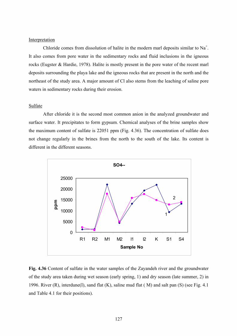
Interpretation
Chloride comes from dissolution of halite in the modern marl deposits similar to Na+.
It also comes from pore water in the sedimentary rocks and fluid inclusions in the igneous
rocks (Eugster & Hardie, 1978). Halite is mostly present in the pore water of the recent marl
deposits surrounding the playa lake and the igneous rocks that are present in the north and the
northeast of the study area. A major amount of Cl also stems from the leaching of saline pore
waters in sedimentary rocks during their erosion.
Sulfate
After chloride it is the second most common anion in the analyzed groundwater and
surface water. It precipitates to form gypsum. Chemical analyses of the brine samples show
the maximum content of sulfate is 22051 ppm (Fig. 4.36). The concentration of sulfate does
not change regularly in the brines from the north to the south of the lake. Its content is
different in the different seasons.
SO4--
0
5000
10000
15000
20000
25000
R1 R2 M1 M2 I1 I2 K S1 S4
Sample No
ppm
1
2
Fig. 4.36 Content of sulfate in the water samples of the Zayandeh river and the groundwater
of the study area taken during wet season (early spring, 1) and dry season (late summer, 2) in
1996. River (R), interdune(I), sand flat (K), saline mud flat ( M) and salt pan (S) (see Fig. 4.1
and Table 4.1 for their positions).
127

Interpretation
Sulfate comes predominantly from dissolution of gypsum and oxidation of sulfides.
Gypsum occurs in the Tertiary Qom Formation and the recent alluvial fans. The former is
locally exposed in the southwest and the northeast and the later extends around the playa
lake. Another source of sulfates is produced by oxidation process of pyrite present in the
Cretaceous carbonate and the Jurassic shale rocks.
Bicarbonate
Bicarbonate is the less abundant anion after nitrate measured in the Zayandeh river
water and the groundwater of the playa lake. Its content ranges from 73 to 450 ppm (Fig.
4.37). The bicarbonate content is highest in the north and the west of the playa lake. It stems
mostly from dissolution of carbonate. According to different seasons and locations, the
content of bicarbonate changes similar to that of sulfate.
HCO3-
0
100
200
300
400
500
600
R1 R2 M1 M2 I1 I2 K S1 S4
Sample No
ppm
11
2
Fig. 4.37 Content of bicarbonate in the water samples of the Zayandeh river and the
groundwater of the study area taken during wet season (early spring, 1) and dry season (late
summer, 2) in 1996. River (R), interdune(I), sand flat (K), saline mud flat ( M) and salt pan
(S) (see Fig. 4.1 and Table 4.1 for their positions).
128

Interpretation
Bicarbonate comes from dissolution of limestone and dolomite, and also from
rainwater. Limestone waters are characterized by high HCO3-. Dolomite waters are similar to
limestone water. Waters in contact with marl also have high HCO3-. The weathering of
igneous (acidic and basic) and metamorphic rocks produces waters rich in HCO3- (Eugster &
Hardie, 1978). These rocks are mostly present in the drainage basin in the south and the
southwestern of the study area (see Chapter 2.3 for lithology of the drainage basin).
Nitrate
Nitrate is the less frequent anion measured in the Zayandeh river water and the brines
of the groundwater in the playa lake. It’s content ranges less than 1 ppm to up to 476 ppm
(Fig. 4.38). The nitrate content is highest in the groundwater of samples No. M1 and M2 in
the north of the playa lake and lowest in the Zayandeh river water. The value of nitrate
increases usually in wet season.
NO3-
0
100
200
300
400
500
R1 R2 M1 M2 I1 K S1 S4
Sample No
ppm
1
2
Fig. 4.38 Content of nitrate in the water samples of the Zayandeh river and the groundwater
of the study area taken during wet season (early spring, 1) and dry season (late summer, 2) in
1996. River (R), interdune(I), sand flat (K), saline mud flat ( M) and salt pan (S) (see Fig. 4.1
and Table 4.1 for their positions).
129

Interpretation
Half of the nitrogen supplied to cultivated fields is from fertilizer, followed in
descending rank by root residue, biological nitrogen fixation, and rainfall (Jensen, 1986).
Eroded soil, the burning of fossil fuel, and decaying organic matter can contribute to airborne
nitrogen (Jensen, 1986). The cyanobacteria fix nitrogen on the surface of moist soils, in or
near, ephemeral lakes and playas or in soils of areas that are moistened by frequent and heavy
winter fogs (Warren, 1999). Nitrogen is also found in sedimentary deposits, e.g. organic
materials in lignite and bituminous coal, clay and caliche soils, and marine shales. It is
returned to the earth as nitrate precipitation. Nitrate as soluble, moves quickly through soils,
and often indicates potential biological contamination (Jensen, 1986). A high content of
n the groundwater of the Gavkhoni playa lake is most probably from the leaching of
of nitrogen is inorganic material, e.g. carbonaceous rocks, shales, and marls. Carbonaceous
cks are found in Jurassic sediments in most of drainage basin. Jurassic marine shales are
ase of the Cretaceous carbonate rocks in the southwest of the study area. Clays
are mo
role of inorganic material in relation to the content of nitrogen is low, because of minor
Total dissolved solid (TDS)
nitrogen i
organic material, fertilizers and industrial waste waters. These materials enter to the
Zayandeh river and groundwater from farmlands and industrial plants. Another minor source
ro
present at the b
stly present in recent marl deposits surrounding the playa lake. It is supposed that the
contribution of organic material-bearing sediments in the drainage basin.
The content of total dissolved solid (TDS) of the analyzed waters (surface water and
groundwater) ranges from 99000 to 403700 ppm. The lowest values are found in the
Zayandeh river and the highest in the center of the saline lake (Fig. 4.39).
130

Fig. 4.39
season (late sum ud flat ( M)
Content of total dissolved solid (TDS) in the water samples of the Zayandeh river
and the groundwater of the study area taken during wet season (early spring, 1) and dry
mer, 2) in 1996. River (R), interdune(I), sand flat (K), saline m
and salt pan (S) (see Fig. 4.1 and Table 4.1 for their positions).
050000100000150000
R1 R2 M1 M2 I1 K S1 S4
Sample No
TDS
200000
400000450000
250000300000350000
ppm
1
2
131

4.6 Evolution of brine in the Gavkhoni playa lake
As figure 4.33 shows, the percentage of Ca++ decreases toward the center of the playa
lake after precipitation of gypsum and carbonate at the margin of the playa lake (alluvial fan,
saline mud flat and mud flat). The evolution of saline waters in seawater (to some extent
comparable with saline water of non-marine environments) starts with early precipitation of
alkaline earth carbonate at 2 times of concentration of the seawater. After carbonate, gypsum
starts to precipi ly 3.5 times of
concentration of the seawater. Calcium thus is removed from brines at an early stage of
concen
ical analyses show (Table 4.2) magnesium content is relatively high in the
brines of the Gavkhoni playa lake and increases in relative concentration after precipitation of
gypsum
e of the Gavkhoni playa lake is very poor in K+ because of its deficiency in
the source rocks and also absorption onto active surfaces of clay minerals in the early phases
of brin
he brine is also relatively poor in bicarbonate, carbonate and sulfate, so that
evapori
tate when the concentration of the brine reaches approximate
tration.
At the end of dry period, when the brine is concentrated many folds (to equivalent of
more than ten times that of seawater) halite is precipitated, covering mostly the center of the
playa lake and forming the salt pan. At this stage a large portion of Na+ and Cl- is extracted
from the brine.
As chem
. Where evaporation is very strong, it is used to form carnallite (MgCl2.KCl.6H2O)
and then bischofite (MgCl2.6H2O) (Appendix B4, sheets No., 23 & 24).
The brin
e concentration. Therefore, potassium sulfates/chlorides which precipitate from
supersaline waters at concentrations more than 70-90 times that of the original seawater can
not form in Gavkhoni (cf. Fayazi, 1991; Warren, 1999).
T
tic carbonate and sulfate minerals such as glauberite (CaSO4.Na2SO4), trona
(Na2CO3.2H2O), nahcolite (NaHCO3), mirabilite (Na2SO4.10 H2O) and thenardite (Na2SO4)
can not form in the Gavkhoni playa lake (cf. Fayazi, 1991).
132

The chemical analyses of dilute water (surface water) taken from the Zayandeh river
in the
waters reveal that they have a
hemistry dominated by Na+, (Mg++), Cl-, (SO4--) type. The chemistry of the groundwaters in
the cen
two locations (Varzaneh and delta samples No. R1, R2) and the groundwater from,
interdune, sand flat and saline mud flat (e.g. samples No. I1, K, M1) exhibit a chemistry
dominated by Na-Cl type (cf. Bryant et al., 1994). Based on Eugster & Hardie, 1978’s
terminology, major cations and anions from the surface
c
ter and the south of the salt pan (e.g. samples No. S1 & S4) indicate Na+, (Mg++), Cl-
to Na+, Mg++, Cl- types (see Fig 4.1 and Table 4.1for position of samples No).
The main cations and anions in the concentrate water of the Bristol Dry Lake, the Great Salt
Lake in the USA and the Howz-e-Soltan salt lake in the center of Iran compared with the
Gavkhoni playa lake shows that Mg++ and K+ values are higher and Ca++, Na+ and SO4-- is
lower in the Gavkhoni playa lake than in the other lakes (Table 4.3 & Fig. 4.40).
Location
Ion
Great Salt
lake
Bristol Dry
Lake
Howz-e-Soltan
lake
Gavkhoni playa
lake
Ca++ 300 43296 46260 117
++
2
Mg 7190 1061 13776 32090
Na+ 80800 57365 275608 57129
K+ 4230 3294 2224 5063
4
arison of th of the concentrated water (in ppm
Howz- an salt lake (cente Ir of
SO -- 156300 223 5000 13239
Cl- 138000 172933 443400 203595
Table 4.3 Comp e main cations and anions ) in
the e-Solt ran), the Bristol Dry Lake, and the Great Salt Lake
(USA) (after Fayazi, 1991) with the Gavkhoni playa lake (Sample No. S4) (see Fig. 4. 1 and
Table 4.1 for its position).
133

PL (based on data of Table 4.2)
Fig. 4.40 Histograms showing the main cations and anions of the concentrated water in the
Howz-e-Soltan salt lake, HSL (center of Iran), the Bristol Dry Lake (BDL), and the Great
Salt Lake, GSL (USA) (after Fayazi, 1991) in comparison with the Gavkhoni playa lake,
Ions
0
100000
200000
300000
400000
GSL BDL HSL GPL
Location
PPM
CaMgNaCl
500000
G
134

4.7 Summary and conclusions
The Gavkhoni playa lake is typical for many permanent lacustrine to saline lake
basins within closed drainage basins in central Iran. Seven major facies can be easily
recognized in this playa la n sand field (sand dune,
interdune, sand flat), sand beach, mud flat, saline mud flat salt pan and delta.
The alluvial fan facies is one of the remarkable sedimentological features in the study
area. Regarding distribution, lithology, stratigraphy and development it is described in details
in Chapter 5.
The sand dunes border the playa lake to the west and grade laterally into the sand flat.
The morphology, migration, mineralogy and the source of the aeolian sand dunes were
described in detail in Chapter 3.
The interdune areas are located between the sand dunes and are covered mostly by a
dry and soft aeolian sand layer. Based on digged trenches, six sub-facies, i.e. aeolian sand,
grey to black sandy mud, white sandy mud, greenish sandy mud, brown mud and sand were
determined in this environment. The properties of the sediments indicate deposition in a
closed basin with a shallow-brackish water perennial lake to sub-aerial conditions, and semi
arid to arid climate with wind activity.
The sand flat surrounds the playa lake. In the studied sand flat (western sand flat)
gypsiferous marl mound, porous tufa, puffy surface and efflorescent salt crust are common
features. The properties of the western sand flat suggest periodic flooding, evaporation, and
desiccation in this area affected by dry climate.
The sand beach ridges occur as a long narrow band to the east of the salt pan and the
Zayandeh river delta. They formed by wave action during wet seasons when the lake level
stands high.
ke. They include alluvial fan, aeolia
135
According to study of two pits, two sub-facies were observed in this facies including
gravelly sand and sand.
The mud flat and saline mud flat encircle the playa lake, except in the western part.
The mud flat is characterized by polygonal mud cracks, plant roots, root casts and is not
saturate
f detrital sediments in the mud flat indicate periodic rather high and
low flow velocities. A common feature in the saline mud flat is its hard and porous surface
pitted b
e salt pan are polygonal halite crusts, efflorescent halite ridges and popcorns
(cauliflower). Halite occurs in hoppers, cubic crystals and massive form. The size of the
halite c
d by brine. It is deposited mainly by sheet floods and then altered by wetting and
drying. The properties o
y small holes with a few centimeters wide and deep, resulting from evaporation of
capillary brines and rapid and differential rising of the sediment surface. The evaporite
minerals (halite and gypsum) scattered in the sediments develop during lower water level as
the result of evaporation of brine pore water in dry periods. Based on digged trenches, five
sub-facies were recognized in the mud flat and saline mud flat: salt, gypsiferous mud, sandy
mud, mud, and sand. The properties of these lithologies indicate that sedimentation occurred
in variable conditions of chemical composition, environment and climate. They formed in
fresh water to brackish perennial lake and ephemeral saline lake in semi-arid to arid
conditions.
The salt pan covers the major part of the center of the playa lake as a hard crust. The
thickness of this crust ranges from a few centimeters to the north and up to 150 cm to the
south. The salt pan is as a result of flooding, evaporation and desiccation. The most common
features of th
rystals reaches up to 2 cm in diameter. Stratigraphic sequence, based on drilled cores
to the depth of up to 30 m and digged trenches, shows sedimentation of mud–sized,
interbedded with sand-sized sediments. These properties suggest that the basin was
influenced repeatedly by wet and dry periods. During the floods it was a shallow fresh water
to brackish permanent lake with changing level of water table, resulting in deposition of fine-
grained sediments in this basin during flooding.
136

The sand-grained deposits are most likely derived from the aeolian sands during dry
periods at the margin of the sand dunes, but also directly as bottom load from the Zayandeh
river delta. With increasing aridity, the middle part of the playa lake gradually became
shallower and finally the ephemeral saline lake and the salt pan developed.
lack mud, yellow
and sand. The presence of the sand sub-facies represents deposition in the
bottom
ya
lake and ultimately produced a Na+, (Mg++), Cl- and Na+, Mg++, Cl- brine type. This type of
the brin
honi playa lake) is most probably
due to continuing tectonic activity in Quaternary period.
The Zayandeh river delta occupies about 30 km2 of the lower reach of the Zayandeh
river. It gradually grades into the poorly saline lake in the south, the sand flat in the west and
the sand beach ridge and the mud flat to the east. Based on studied trenches with depths
reaching 150 cm three main sub-facies were determined. They are grey to b
to brown mud
of distributary channels during periods of rather high flow velocity, while silt and
clay are well developed on the upper parts of point bars, swamp and levees during floods.
The chemical analyses of dilute water (surface water) and the major cations and
anions reveal that it has a chemistry dominated by Na+, (Mg++), Cl-, (SO4--) type reflecting of
the nature of the catchment lithology. The evolution of the brines show that they are
progressively depleted from carbonate and sulfate from the margins to the center of the pla
e is approximately similar to many other playas worldwide in (semi)-arid regions.
After complete desiccation, the mineral assemblage comprises mainly halite but other
minerals including gypsum (CaSO4, 2H2O), carnallite (MgCl2.KCl.6H2O), tachyhydrite
(CaCl2.2MgCl2.12H2O) and bischofite (MgCl2.6H2O) are also determined as minor
constituents in the central and the south of the saline pan. There is no relic of glauberite
(CaSO4.Na2SO4), trona (Na2CO3.2H2O) in the sediments.
The Gavkhoni playa lake formed in a supposed graben and/or half graben system
along the northeastern part of the Sanandaj-Sirjan zone. This system is a result of volcanic
eruptions at the end of Cretaceous and Early Eocene, and faulting which took place after the
volcanism. Subsidence of this base level of erosion (Gavk
137

138
in the Quaternary period played
another important role in relation to changing of water level in the lower reaches of the basin
(Gavkhoni playa lake), rise and fall in denudation and spatial distribution of Quaternary
deposits.
It is supposed that, changing climatic conditions

Chapter 5 Sedimentology of alluvial fan and the Zayandeh river deposits
5.1 Introduction
The study area is bordered by sedimentary mountains to the south, west and northwest,
and igneous mountains to the east and the north. The sedimentary mountains rise as much as
1110 m in the south, the igneous mountains 1860 and 974 m to the northeast and the east
respectively above the Gavkhoni playa lake level. The most active depositional environment
in this basin is the Zayandeh river (Fig. 5.1). Sedimentation occur under the hottest and driest
conditions found in the Esfahan province, with annual rainfall averaging 80 mm, annual
potential evaporation of 3265 mm, and with summer temperature reaching + 42oC (see
Chapter 2.4 for details).
The purpose of this study is to present sedimentology, development and
morphostratigraphy of the Zayandeh river (channel and overbank) and modern alluvial fan
deposits in the southeast of Esfahan. Sedimentology of the Zayandeh river delta was
described in Chapter 4.
5.2 Methodology
Twenty-two vertical sections were selected to study stratigraphic sequence and
development of the Zayandeh river and alluvial fan deposits (see Fig. 5.2 and Table 5.1for
position and sections No). Sedimentological logs for twenty sections were drawn ( see
appendix F for lithostratigrafic-sedimentologic sections). Some photographs were provided
from each facies and their sketches were drawn. For determination of mineralogical
composition (gravel to mud), textural properties of grains, sedimentary structure, the
provenance of the alluvial sediments and paleontology studies, about 60 samples were
analyzed (see Chapter 1 and Appendixes for detailed methodology and stratigraphic sections).
139

Fig.
5.1
Fal
se c
olor
-Lan
dsat
TM
imag
e sh
owin
g th
e si
tuat
ion
of th
e Za
yand
eh ri
ver a
nd a
lluvi
al fa
n de
posi
ts in
the
stud
y ar
ea.
140

5.3 Setting and geomorphology
The major sedimentological features of the study area include lacustrine/overbank,
alluvial fan and the Zayandeh river deposits. Lacustrine/overbank sediments (mainly yellow
mud), deposited during probably Quaternary period, are overlain by recent coarse-grained
sediments. These deposits sometimes form cut-banks of the Zayandeh river up to 10 m in
height. In the most of the study area, the Zayandeh river flows between well-defined steep
banks, with channel width of 50 m on average and in its distal end (Zayandeh river delta) it is
divided in many narrow channels (3-5 wide). The flood plain of the Zayandeh river is narrow
at the beginning of the study area and wide to the end, bordered by overbank and alluvial fan
sediments. The major channel averages about 3 m in depth below the level of adjacent levees.
Minor channels reaches up to 50 cm in depth in the delta. The river carries a sediment load
ranging from fine gravel through sand grains. Small gullies originating from alluvial fans
dissect the floodplain to join the main channel, especially in the delta reach of the Zayandeh
river.
The alluvial fan deposits, regarding lithology, can be classified into two parts, igneous
and sedimentary. The igneous alluvial fan deposits occur mostly in the north of the Zayandeh
river and the east of the Gavkhoni playa lake. The sedimentary alluvial fan deposits mostly
extend in the south of the Zayandeh river (Fig. 5.1).
The northern fans are relatively extensive, with an area of 2000 km2, an average radial
length of 20 km and an average width of the laterally coalescing fans of 95 km. The apex
elevation is about 2100 m, and the toe elevation is about 1500 m above the sea level. The
alluvial fan sediments are derived from a catchment area, underlain mostly by Eocene igneous
rocks, that are approximately 110 km long, 6–15 km wide, 1100 km2 in area and maximum
elevation of 3330 m. These laterally coalescing fans are drained by several shallow,
ephemeral, small streams, averaging few decimeter in depth. The proximal sector has an
average slope of 4.14% medial 1.38% and the distal 0.3%.
141

G1
G4
G7
G8
G14G18
G20
G16G12
G15
G9
G5
G10G11
G6
G2
G13G19
G22G17
G21
G3
NEE
E
E
NN
N
N
Z: Zayandeh river
G: Gavkhoni playa lake
S: Varzaneh sand dunes
Mainly igneous mountains and alluvial fans
Mainly sedimentary mountains and alluvial fans
Town
Section site
Contour line
Road
Geographical coordinates
Elevation
O
O
O O
O
O
O
O
O
O
O
OO
O
O
O
O
O
O
OO
O
-----+
3330
20 km
1474
1600
+
++
Z
-
-
-
---
- -
-
-----
--
-
-
----
-
-
-
-
------
--
- -- -- -
-
---
HASANABAD
PAYKAN
VARZANEH
RAMESHEH
HARAND
EJIEH
SAGZI KUHPAYEH TODESHK
ESFAHAN
S
G
+
Fig. 5.2 Simplified topographic map of the lower reaches of the drainage basin of the
Zayandeh river and the location of stratigraphic sections in the study area.
142

Section No
Geological situation Depth (cm)
Location Main lithology
G1 Stream cut 430 32o,27/,05//N 52°,50/,35//E gravel G2 Ghanat well 420 32o,40/,40//N 52°,16/,15//E Sandstone/sand G3 Stream cut 220 32°,41/,54//N 52°,07/,49//E Conglomerate/gravel G4 Irrigation channel 610 32o,23/,01//N 52°,47/,41//E Mud G5 Trench 500 32o,31/,58//N 52o,27/,37//E Gravel/conglomerate G6 Irrigation channel 380 32o,34/,31//N 52°,16/,42//E Conglomerate/gravel G7 Zayandeh river cut 390 32°,21/,45//N 52°,47/,55//E Sand, coglomerate G8 Zayandeh river cut 410 32°,22/,41//N 52°,46/,56//E Sand, coglomerate G9 Zayandeh river cut 130 32°,29/,44//N 52°,25/,24//E Conglomerate, sandstone G10 Zayandeh river cut 205 32°,30/,34//N 52°,24/,39//E Mud G11 Irrigation channel 125 32o,31/,11//N 52°,21/,04//E Conglomerate/gravel G12 Zayandeh river cut 310 32°,27/,10//N 52°,29/,10//E Mud, conglomerate/gravel G13 Zayandeh river cut 630 32°,26/,44//N 52°,23/,02//E Conglomerate/ G14 Trench 340 32o,13/,09//N 52°,40/,29//E gravel G15 Stream cut 650 32o,24/,34//N 52°,20/,56//E Conglomerate, mud G16 Stream cut 630 32°,23/,25//N 52°,09/,19//E Conglomerate, mud G17 Trench 210 32o,32/,08//N 52°,35/,52//E Gravel G18 Trench 160 32o,14/,50//N 52o,25/,05//E Gravel G19 Ghanat well 315 32°,22/,30//N 52°,06/,45//E Gravel, mud G20 Stream cut 400 32°,19/,54//N 52°,08/,41//E Gravel, mud G21 Stream cut 410 32°,01/,02//N 52°,51/,49//E Mud G22 Stream cut 620 32o,12/,20//N 52°,07/,06//E Conglomerate, mud
Table 5.1 Geological situation, depht, and location of studied sections in the study area.
The southern alluvial fan group is somewhat smaller than the northern one and covers
an area of about 1500 km2, it has an average radial length of 20 km and an average width of
75 km. The apex elevation is 1900 m, and the toe elevation is about 1500 m above sea level. It
contains few relatively deeply incised channels, providing nearly continuous good quality
exposures of several meters to several decimeters in height. These channels cross-cut the
older proximal and medial fan deposits. The fan sediments are derived from a catchment,
which is approximately 75 km long, 50 km wide, 3750 km2 in area and maximum elevation of
2584 m. A surficial fine fraction, derived from mudflow, covers the toe of the fans. The
catchment area consists mostly of Cretaceous carbonate rocks. The proximal sector has a
average slope of 10.5% and the medial 2.6% and the distal 0.4% (Fig. 5.2).
The Varzaneh aeolian sand field, which cover the toe of the fan, consist of well sorted
fine to medium to fine- grained sand (see Chapter 3 for details). The aeolian sand deposits are
derived from the alluvial fans that interfinger with the debris-flow deposits in the distal part of
the fans.
143

5.4 Depositional environments and facies
5.4.1. Introduction
The measured vertical sections can be grouped into four major depositional facies
associations (see Appendix F for stratigraphic logs). They are debris-flow-dominated alluvial
fan, stream-flow-dominated alluvial fan, lake and overbank. Based on Folk (1974) and Tucker
(1991),s terminology, deposits can be divided into three main groups including
gravel/conglomerates, sand/sandstone and mud. According to Miall ( 1985) in Miall 1992,s
terminology eleven sedimentary facies are identified in this study area. They are unstratified
matrix-supported gravel (Gms), massive to crudely stratified clast-supported
gravel/conglomerate (Gm), planar cross-stratified, clast-supported gravel/conglomerate (Gp),
trough cross–stratified, clast-supported gravel/conglomerate (Gt), massive sand/sandstone
(Sm), massive mud-supported sand (muddy sand) (Sms), trough cross-stratified
sand/sandstone (St), planar cross-stratified sand/sandstone (Sp), massive red mud (Fm),
massive yellow mud (Fsc), laminated-khaki mud (Fl). The main characteristics of each facies
are briefly described and interpreted as follows (see Table 5.3).
5.4.2 Gravel/conglomerate deposits
According to texture and induration these deposits can be divided into matrix-
supported gravel and clast-supported gravel/conglomerate deposits.
5.4.2.1 Matrix-supported gravel deposits
These deposits include igneous and sedimentary lithology and consist of only one facies
namely unstratified matrix-supported gravel (Gms). This facies is observed in five sections
(No. G4, G5, G17, G18, G19) in the study area (see Fig. 5.2 and Table 5.1for position of
sections No).
Unstratified matrix-supported gravel (facies Gms)
Facies Gms is characterized by unstratified, matrix-supported gravel, locally clast-
supported, a disorganized nature of grains, typically ungraded, chaotic pebble fabric and
broad lenticular geometry (Fig. 5.3). The deposits are cohesive and non-cohesive, depending
on the amount of fine-grained sediments. This facies extends both in the southern and the
northern part of the Zayandeh river but wider distribution is in the northern part. It is sharply
144

underlain by muddy deposits throughout the study area. Its maximum thickness recorded in
six sections is about 4 m.
The clasts are typically angular to sub-angular and vary in shape from bladed to
equant. The deposits consist of dominantly brown, yellow to purple limestone, green to olive
sandstone and shale in the southern alluvial and violet andesite, white tuff and black andesite-
basalt in the northern alluvial fan.
The grain size analysis of five representative samples from the studied sections shows
that all samples have poor sorting and contain the full range of grain classes from clay to fine
cobble. The granule, pebble and fine cobble sizes together make up 31-58%, sand 40-50%
mud 5-18%. Average size of ten largest and maximum size of clasts was measured in sections
No. G1, G5, G17, G18, G19 (Table. 5.2)( see Fig. 5.2 and Table 5.1 for position of sections
No).
Section No A B Section No A B
G2 20 45 G13 36 180 G3 71 118 G14 10 20 G4 90 140 G15 35 110 G5 49 100 G16 130 260 G6 20 40 G17 29 35 G7 20 40 G18 19 40 G9 36 180 G19 30 37 G11 52 77 G21 42 52 G12 20 40 G22 75 118
Table 5.2 Average size (in mm) of the ten largest (A) and maximum size (B) of clasts in the
study alluvial sediments.
A high degree of desert varnish is mostly observed on the surface of sandstone and
igneous lithics. Both normal and inverse grading of coarse clasts are observed locally. The
winnowing of fine-grained sediments from the exposed debris flows is present in some
localities. A lustrous appearance often characterizes rock fragments. Bubble sand structure is
a common feature in the upper layer of this facies, if recently deposited. It shows a spongy
structure in the sand sediments. Upper part of this facies (from depth of 20 to 100 cm)
contains abundant fibrous displacive gypsum especially in the southern alluvial fans. In some
places the gypsum content reaches up to 30%.
145

The framework clasts consist of abundant igneous particles in the northern part and
sedimentary clastic in the southern part. The sediments consist of about 90-95% carbonate
lithic grains in sections No. G17, G18, G19 in the gravel fraction and 75-80% sedimentary
(mostly carbonate), 7%-10% igneous and 1% metamorphic lithic grains, 5%-13% quartz, and
1-4% feldspar mineral grains in the sand fraction. Composition of grains both in gravel and
sand fractions is about 95% igneous lithics in the sections No. G1 and G5 (see Fig. 5.2 and
Table 5.1 for position of sections No).
Fig. 5.3 Field photograph (section No. G18) showing massive to crudely stratified-matrix-
supported gravel facies (Gms) developed in the southern alluvial fan group (see Fig. 5.2 and
Table 5.1 for position of sections).
Interpretation
Matrix-supported, unsorted, muddy, sandy, cobble to pebble-sized gravel and to a
certain extent inversely graded textures are suggestive of a debris flow origin (Pierson, 1980;
Blair & McPherson, 1999; Blair, 1999). Such facies is generally regarded as a product of
cohesive debris flow (cf. Deck et al., 1996). The presence of the intervening layers of clast-
supported fabric indicate reworking by stream-flood flows (cf. Ryang & Chough, 1997).
Inverse graded bedding indicates that dispersive pressure operated (Lowe, 1988). Debris flow
deposits are restricted to the proximal fan, or mixed with water-laid deposits in the medial fan
and are dominant throughout the stratigraphic sequence of the fans. The winnowing of fines
146

from the exposed debris flows probably resulted from the washing of the surficial deposits by
runoff that commonly follows debris flow deposition or by overland flow generated by heavy
rainfall. Wind may also account for partial winnowing of fine fraction of these deposits (Blair
& McPherson, 1992). Bubble structure, which is very unstable and, therefore, generally only
exists immediately after depositions, is produced from the entrapment of air bubbles (Reineck
& Singh, 1980). Dominance of debris flow deposits indicates semi-arid paleo-climate (Blair
& McPherson, 1995).
Abundant angular siliciclastic particles in the northern debris-flow deposits indicate that
sediments were derived largely from a drainage network of the igneous rocks. Abundant
angular carbonate lithics in the southern debris-flow deposits suggest that sediments were
originated largely from a drainage network of the sedimentary rocks exposed along the
southern part of the basin.
Phreatic desert gypsum precipitates from evaporation of ground water where water
table is within 1 to 2 m of the land surface (Kulke, 1974, Watson, 1989 in Thomas, 1989).
Acicular and fibrous gypsum crystals form probably as a result of migration of Ca++ and SO4--
rich water to surface by capillarity and precipitation after saturation. Most probably the origin
of these ions is in the pore waters of the marl that underlie the matrix–supported deposits.
5.4.2.2 Clast-supported gravel /conglomerate deposits
These deposits are observed in eighteen vertical studied sections. The size of average
ten largest and maximum size of clasts in these sections were measured (Fig. 5.2) ( see Table
5.1 for position of sections No).
Clast–supported gravel/conglomerate deposits consist of about 80-95% carbonate and
20-15% siliciclastic lithic grains in the sections No. G9, G13, G15, G16, G22 and of about
95% igneous lithic grains in the sections No. A2, A3, A5,. Lithology in the sections No. G6,
G7, G11, G12, G14 include carbonate, siliciclastic, igneous and metamorphic lithic grains in
order of decreasing frequency. The sections No. G4 and G21 consist of 50% igneous and 50%
sedimentary lithic grains.
Based on texture and sedimentary structure these deposits can be divided into three
facies including massive to crudely stratified clast-supported gravel/conglomerate (facies
147

Gm), planar cross-stratified, clast supported gravel/conglomerate (facies Gp), and trough
cross–stratified, clast–supported gravel/conglomerate (facies Gt).
Massive to crudely stratified, clast-supported gravel/conglomerate (facies Gm)
It is represented by massive to crudely stratified sandy gravel to conglomerate, mostly
pebble-sized framework clasts, normal grading, wide variation in texture and grain
composition. This facies consist of a few decimeters to few meters of gravel/sandy
conglomerate to openwork gravel/conglomerate (Fig. 5.4). Its geometry mostly is broad
lenticular, wedge–shaped and channel-shaped with erosional base and sheet-like in some
places in the northern alluvial fan. The lower boundary surface is erosive, locally scoured
(such as gutter casts, rarely also flute cast) mainly undulatory, slightly inclined in the southern
alluvial fan (5th order boundary surface of Miall, 1988). Mud rip-up clasts, ranging from few
to few ten centimeters are common in the conglomeratic deposits. The open framework
deposits are indurated by intergranular calcite cement in some places. In the southern alluvial
fan, the framework grains include mainly cabonate lithics in composition and rounded to well
rounded in shape whereas in the northern alluvial fan, they mostly consist of igneous lithics
and angular to sub-rounded in shape.
Interpretation
Clast-supported gravels and conglomerates record bedload deposition from stream
flows. Openwork fabric and textural segregation of gravel and sand indicates deposition in
gravel-bed streams during waning floods (Collinson, 1996 in Reading, 1996).
Such a facies originates from high energy flow, transporting and accumulating coarse
bedload and keeping sand and finer material in suspension (cf. Reineck & Singh, 1980). The
remaining pore space between the gravel is usually infiltered later by sand when the velocity
has increased (cf. Rhee & Chough, 1993).
Gravel is transported only if the current reaches a certain critical velocity (around 1m/s)
and in slower currents it may occur as lag deposits. They are deposited by steep gradients,
high width/depth ratio and low sinuosity braided rivers. The erosional base, cut and fill
structures, discontinuous lenticular geometry and the nature of boundary surfaces are
suggestive of deposition in a stream channel of alluvial fan (c.f. e.g. Reineck & Singh, 1980)
148

or as longitudinal bars (cf. e.g. Einsele, 1992). Sheet like geometry is indicative of unconfined
ephemeral flows (Ryang & Chough, 1997).
Fig. 5.4 Sketch and photograph (section No. G22) showing representative sample of massive
to crudely stratified gravel/conglomerate facies (Gm). Laminated khaki mud (Fl), Massive
sand/sandstone (Sm) (see Fig. 5.2 and Table 5.1 for position of section No).
Sheet flooding (unchannelized flow) and stream flooding (broad, poorly channelized)
flows within ephemeral channels following intense thunderstorms. Sharp bases, distinct lower
boundaries, poor sorting and limited extent of the beds are suggestive of erosion, short
distance transportation, and deposition by ephemeral flows rather than perennial flow (Bridge,
1984) in semi-arid regions or steep slopes on proximal fans (Postma, 1983) or in distributary
149

channels of the proximal zone of alluvial fans (Salder & Kelly, 1993). Abundance of mud rip-
up clasts might be related to strong erosion of the underlying mud layers or to failure of
channel banks during flood events.
Position of the lithofacies within the successions and its occurrence on the top of mud
sediments and its characteristics represent deposition in shallow channels which were
periodically active in distributary channels of alluvial fans (cf. Kelly & Olsen, 1993).
Presence of this facies is an indicator of at least occasional periods with strong rains during
deposition by a longer episodic, periodic or even a perennial discharge (cf. Amini, 1997).
Planar cross-stratified, clast-supported gravel/conglomerate (Facies Gp)
This facies is marked by planar cross-stratified, clast–supported sandy gravel
/conglomerate, mostly granule to pebble framework clasts and a wide range variation in
texture (Fig. 5.5). The size of the ten largest clasts is similar to facies Gm, except for gravels
deposited by the Zayandeh river, occurring in outcrops along this river. Mud rip-up clasts are
observed along the Zayandeh river with decimeter down to few centimeters in size. The
thickness of the facies recorded at six sections (No. G1, G5, 7, G13, G15, G16) ranges from
60 to 160 cm (see Fig. 5.2 and Table 5.1 for position of sections). The external geometry is
usually lenticular, wedge-shaped with a scoured erosional base. In some places, set boundary
is undulatory with a convex top. Individual forests are parallel and in some localities laterally
tangential. The foresets are sometimes graded and show changes in grain size along the sets.
The slope of these foresets ranges from 25o to 40o.
Interpretation
This facies was deposited under high-energy flow conditions similar to the facies Gm
(cf. e.g. Ryang & Chough, 1997). Tabular cross-bedding, in which the foresets are graded and
show changes in grain-size along the set, probably reflect stage fluctuations over the crest of
the bar which possess active slip faces (Collinson, 1996 in Reading, 1996) in braided streams.
Local high-angle dipping planar cross-bedding is related to migration of high bars with steep
slip faces (Reineck & Singh, 1980).
Some authors represent mid-channel or channel-confluence bars, formed in deep sectors
of a channel (Steel & Thompson, 1983) while others compare this feature with the large
bedforms developed on the flanks of bedrock valleys as a result of catastrophic floods (Talbut
150

& Allen, 1996 in Reading, 1996).This facies is interpreted as result of migration of
longitudinal and lingoid bar (Einsele, 1992) in ephemeral rivers in semi-arid regions (Miall,
1992).
Fig. 5.5 Sketch and photograph (section No. G16) showing an example of facies planar cross-
stratified conglomerate (Gp) overlain by crudely stratified to massive conglomerate (Gm) (see
Fig. 5.2 and Table 5.1 for position of section No)
Situation, lithology and overlaying lower part of fining–up sequence of point bars of the
Zayandeh river suggest that this facies is ,in some places, a product of a meandering river.
(Reineck & Singh, 1980).
151
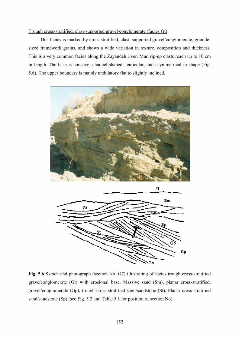
Trough cross-stratified, clast-supported gravel/conglomerate (facies Gt)
This facies is marked by cross-stratified, clast–supported gravel/conglomerate, granule-
sized framework grains, and shows a wide variation in texture, composition and thickness.
This is a very common facies along the Zayandeh river. Mud rip-up clasts reach up to 10 cm
in length. The base is concave, channel-shaped, lenticular, and asymmetrical in shape (Fig.
5.6). The upper boundary is mainly undulatory flat to slightly inclined.
Fig. 5.6 Sketch and photograph (section No. G7) illustrating of facies trough cross-stratified
grave/conglomerate (Gt) with erosional base. Massive sand (Sm), planar cross-stratified,
gravel/conglomerate (Gp), trough cross-stratified sand/sandstone (St), Planar cross-stratified
sand/sandstone (Sp) (see Fig. 5.2 and Table 5.1 for position of section No).
152
Maximum thickness of this facies placed in the central part is about 50 cm. Horizontal
bedding with thickness of a few centimeters and normal graded bedding is observed in some
localities. The slope of isolated layers ranges from slightly inclined to up to 20o. The ten
largest clasts of gravel/granules along the Zayandeh river is between 2 to 6 mm recorded in
three sections (No. G7, G8, G9) (see Fig. 5.2 and Table 5.1for position of sections No).
Interpretation
This facies is deposited during high-energy flow conditions (e.g. Reineck & Singh,
1980; Ryang & Chough, 1997) similar to the facies Gm and Gp. Channel cross-beds may be
produced in the filling-up of small alluvial or erosional channels (e.g. Reineck & Singh,
1980). Similar restricted (narrow) channel conglomerates occur in proximal parts of
distributary alluvial systems (Postma, 1983). Flat-bedded gravels form by vertical accretion
on longitudinal bars (Rust, 1984). In some localities along the Zayandeh river, this facies may
result from the activity of a meandering river and it was deposited at the base of its point bar.
An erosional scoured base and presence of mud rip-up clasts mainly in the lower part are
indicative of scouring and subsequent filling in coarse-grained meandering or in braided
rivers.
5.4.3 Sand/sandstone deposits
According to texture and induration they can be divided into mud-supported sand and
clast-supported sand/sandstone deposits.
5.4.3.1 Mud-supported sand deposits
These deposits can be classified into two groups: igneous and sedimentary lithology and
consist of only one facies namely unstratified mud-supported sand (facies Gms). This facies is
observed in two sections (No. G1, G5) in the study area (see Fig. 5.2 and Table 5.1 for
position of sections No) .
Massive mud-supported sand (facies Sms)
This facies can be compared with facies Gms in Miall (1977 & 1992) terminology. It is
characterized by khaki to yellow massive muddy very fine to coarse sand (matrix-support
sand), alternating with gravelly muddy sand and rich in calcrete nodules in some localities. It
shows a lenticular, wedge-shaped geometry and an erosional upper boundary (Fig. 5.7). This
153

unit is observed only in the northern alluvial fan group and changes laterally and vertically
into the facies Gms in most localities. It consists of approximately 95% igneous lithics in
composition. Maximum thickness of this facies recorded in two sections (No. G1, G5 is about
150 cm (see Fig. 5.2 and Table 5.1 for position of sections No).
Fig. 5.7 Sketch and photograph (section No. G5) showing example of facies muddy sand
(Sms). Planar cross-stratified conglomerate (Gp), Unstratified matrix-supported gravel (Gms)
(see Fig. 5.2 and Table 5.1 for position of section No).
154

Interpretation
Matrix-supported, unsorted gravelly sand bodies might suggest deposition from visco-
plastic sand flows. It is generally considered to be intermediate between debris flow and
normal stream flows and was termed hyper-concentrated flood flow. Such flood flows have
been related to sand-sized debris flows that take up water as they move down stream (Smith,
1986) or developed by adding sediments to fast flowing stream flows (Turner & Monro,
1987). Well-developed calcrete nodules indicate long subaerial exposure under semi-aridic
climate before deposition of the following unit (c.f. Kulke, 1974).
5.4.3.2 Clast-supported sand/sandstone deposits
These deposits are observed in the seven vertical studied sections (No. G7, G8, G9,
G12, G13, G15, G22) in the study area (see Fig. 5.2 and Table 5.1 for position of. It consists
of 35-63% sedimentary lithic (mostly carbonate), 19-45% igneous lithic, 3-7% metamorphic
lithic grains, 7-13% quartz and about 1% feldspar mineral grains in the sections (No. G9,
G13, G15). Lithology in the sections (No. G7, G8, G12), include 16-20% sedimentary lithic
(siliciclastic and carbonate), 50-70% igneous and 10-15%metamorphic lithic grains 2-13%
quartz and about 1% feldspar mineral grains in order of decreasing frequency. Section A21
consist of 55%, sedimentary lithic (mostly carbonate), 40% igneous lithic, 5% quartz (see Fig.
5.2 and Table 5.1 for position of sections).
Based on texture and sedimentary structure these deposits can be divided into three
facies including massive sand/sandstone (facies Sm), trough cross-stratified sandstone (facies
St), and planar cross-stratified sand/sandstone (facies Sp).
Massive sand/sandstone (facies Sm)
This facies found in sections No. G9 and G13, is represented by structuresless, mature
sand/sandstone with slight gravel admixture in some localities and abundant gastropod and
ostracod shells. It is mostly broad lenticular, tabular, locally wedge shaped, and shows flat
boundaries. Contact with underlying and overlaying units is usually graditional and relatively
flat. Its maximum thickness recorded in the two studied sections (No. G7, G12) is about 50
cm (Fig. 5.8). The facies usually occurs on the top of a channel shaped conglomerate with
mud rip-up clast along the Zayandeh river (see Fig. 5.2 and Table 5.1 for position of sections
No).
155

Interpretation
Mature massive sand bodies are attributed to rapid deposition from suspension during
floods (Collinson, 1996 in Reading, 1996). Gravel size clasts have been supported by
combined effects of fluid turbulence and matrix (sand) buoyancy (Rhee & Cough, 1993)
Fig. 5.8 Sketch and photograph (section No. G12) showing example of facies massive sand
(Sm). Facies massive red mud (Fm), massive to crudely stratified gravel (Gm), planar cross-
bedded gravel (Gp), laminated khaki mud (Fl) (see Fig. 5.2 and Table 5.1 for position of
section No).
156

Trough cross-stratified sand/sandstone (facies St)
This facies, observed in sections (No. G9 and G13) is marked by trough cross-bedding,
fine to coarse-grained, khaki sand/sandstone. Its geometry is mainly lenticular, wedge and
channel–shaped, concave downward, and asymmetrical. It is mainly underlain by crudely
stratified to massive conglomerate and shows a lower and upper sharp boundary (Fig. 5.9). In
some places, this facies is underlain by muddy deposits (facies Fsc). Individual laminations
range from few to a few tens of millimeters in thickness. Lateral accretion of sets locally is
observed. The facies shows high variation in thickness and its maximum thickness reaches up
to 60 cm in the central part. It laterally passes into gravelly sandstone and massive to crudely
stratified conglomerate. The gradients of laminations change from slightly inclined to up to
300 and dip direction is also variable from the west to the east. At the base of some set
laminations, lag gravel is present.
Interpretation
The main characteristics of the facies: erosional base, lateral accretion, channel-shaped
and lenticular geometry is indicative of deposition in a channel and/or at subaqueous channel
dunes under lower regime (Miall, 1992) in ephemeral rivers in a semi arid region (Parkash et
al, 1983). It can be interpreted as a result of scouring channels in high flood stage and
subsequent filling in waning stages (Miall, 1992). Lateral changes from sandstone to gravelly
sandstone and conglomerate indicates changes in velocity, variable dip direction of cross
bedding and vertical and lateral variation of the facies probably result from high variability of
discharge and/or rapid shifting of the channels, characteristic of ephemeral braided rivers
(Amini, 1997). Occurrence of the facies on the top of lag type gravel and facies Gm most
likely suggest its development as a result of migration of three-dimensional dunes in channels
under the conditions of the upper part of the lower flow regime (Hjellbakk, 1997). Local lag
type deposits within the unit can be considered as deposition in minor channels cut in the
sediments due to change in discharge values or shifting in channel position, typical of
periodically active channels (Amini, 1997)
157

Fig. 5.9 Sketch and photograph (section No. G9) showing facies trough cross-stratified
sandstone (St). Gt (trough cross-stratified conglomerate), Gm (Massive to crudely stratified
conglomerate), Fsc (massive yellow mud). Hammer length is 30 cm (see Fig. 5.2 and Table
5.1 for position of section No).
158
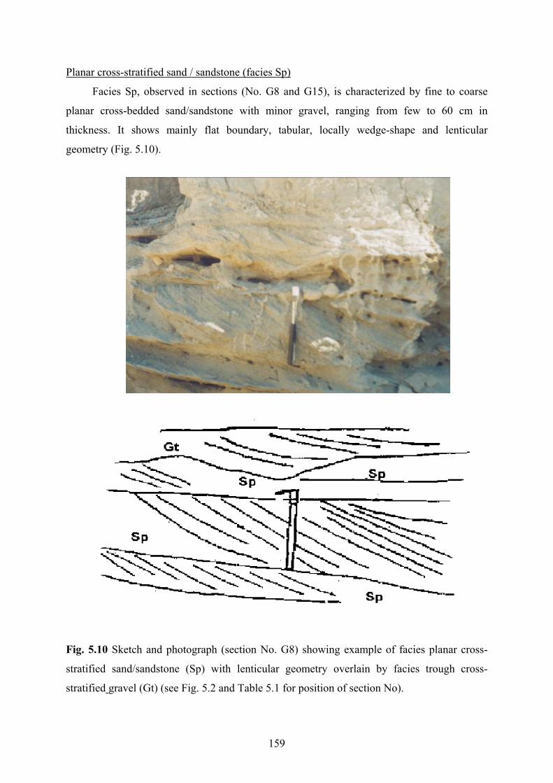
Planar cross-stratified sand / sandstone (facies Sp)
Facies Sp, observed in sections (No. G8 and G15), is characterized by fine to coarse
planar cross-bedded sand/sandstone with minor gravel, ranging from few to 60 cm in
thickness. It shows mainly flat boundary, tabular, locally wedge-shape and lenticular
geometry (Fig. 5.10).
Fig. 5.10 Sketch and photograph (section No. G8) showing example of facies planar cross-
stratified sand/sandstone (Sp) with lenticular geometry overlain by facies trough cross-
stratified gravel (Gt) (see Fig. 5.2 and Table 5.1 for position of section No).
159

Foresets are parallel to slightly tangential locally, with slopes of 15o-40o. The maximum
set thickness is up to 40 cm. Large amounts of mud rip up clasts with up to 4 cm in diameter
are observed at the top of this facies in some localities. Contact with underlying and
overlaying units is usually sharp. It changes upward to channel–fill conglomerate and massive
sand respectively in most localities.
Interpretation
The sedimentary structures and grain size of this facies indicate formation by processes
operating in the lower to middle part of the lower flow regime, either deposition in areas on
the floodplain, or deposition during periods of low water level or waning flow in channels (cf.
Hjellbakk, 1997). Planar stratification, grain size (fine to coarse sand and minor gravel), large
amounts of mud rip-up clasts and the position of the facies are also indicative of deposition by
sand waves or transverse bars of lingoids (cf. Abdullative, 1989). Smaller tabular sets suggest
that sets are produced by straight–crested subaqueous dunes and, less commonly, scour bars
and chute bars. (McCabe, 1977). They result from migration of simple foreset bars and sand
waves (Miall, 1992), bar top deposits (Amini, 1997), and dunes with straight crest (Wizevich,
1992). Some sets ( up to 30 cm ) were probably formed by large transverse or lingoid bars,
which may have been bank attached, or of mid-channel origin (cf. McCabe, 1977)
5.4.4 Mud deposits
Mud deposits indicate a wide range of variation in thickness, sedimentary structure
color and narrow composition in the studied sections. They are dominated by massive to
laminated types of yellow, khaki and red in color. They are interbedded with sandy and
gravelly layers in some places. Based on color, texture, geometry and sedimentary structure
three major facies including massive red mud (facies Fm), massive yellow mud (facies Fsc),
and laminated khaki mud (facies Fl) were determined in the study area.
5.4.4.1 Massive red mud (Facies Fm)
This facies is represented by a red to purple mud, well-developed calcrete nodules and
relatively high clay/silt ratio. It ranges from 50 to 200 cm in thickness in three found sections
(No. G4, G5, G12) and is overlain by facies Fl in the Zayandeh river cut bank (Fig. 5.11). It is
only observed in the northern part and along the Zayandeh river. The external geometry is
mainly broad tabular with graditional boundary. The average carbonate is about 15% and
160

average clay-sized content is %60 in three sections. The clay minerals consist of smectite,
illite, chlorite, and kaolinite (Appendix B4, sheets No. 2 & 3).
Fig. 5.11 Sketches and photograph (section No. G4) showing example of facies massive red
mud (Fm) overlain by facies (Gm) at top with an erosional boundary (see Fig. 5.2 for position
of stratigraphic section No). Gm (Massive to crudely stratified gravel ), Fsc (massive yellow
mud), Fm (facies massive red mud) (see Fig. 5.2 and Table 5.1 for position of sections).
Interpretation
The major characteristics of this facies may indicate rapid settling of suspended grains
(silt and clay fractions) below water level in pond or lake, oxidizing condition during and
after deposition (cf. Ryang & Chough, 1997). The relatively minor content of carbonate, color
and the type of the clay minerals indicate that the provenance of these sediments is most
probably from deeply weathered igneous rocks located in the northeast of the area. Lack of
161

plant remains probably reflect non-development of shallow lacustrine and back swamp
environments in wet climate (Shanley & McCabe 1993) and indicative of a semi-arid and
ephemeral conditions of deposition. Well-developed calcrete nodules indicate long subaerial
exposure before deposition of the following unit in origin (Hjellbakk, 1997). In semi-arid
zone most of the calcretes are pedogenic in origin (Kulke, 1974). Calcretes develop by
crystallization of calcium carbonate from ascending ground water. This facies could also be
deposited on the distal part of the northern alluvial fan.
5.4.4.2 Massive yellow mud (facies Fsc)
This facies is characterized by mainly massive, locally laminated, yellow to green mud,
interbedded with sand layers up to a few centimeters thick in some places (Fig. 5.12). Its
thickness ranges from 150 to 700 cm in the studied sections (No. G2, G4, G6, G9, G10, G13,
G14, G15, G16, G17, G19) (see Fig. 5.2 and Table 5.1for position of sections). It is mostly
broad lenticular, and of wedge-shaped geometry. In most localities it contains few gastropod
and ostracod shells. The average carbonate content ranges between 14% (section No. G2) to
40% (section No. G13). The clay minerals consist of smectite, illite, kaolinite, chlorite and
rectorite? (Appendix B4, sheets No. 1, 4, 6,7, 8, 9, 10, 11, 12,).
Interpretation
The sediments of this facies formed in a sub-aqueous lacustrine environment when a
possibly small-scale lake was formed or base level rose toward the basin margin (cf. Ryang &
Chough, 1997). The dominant sedimentary process was settling from suspension,
accompanied by periodic input of current-transported sands. Interlayering of thin-laminated
fine sand may be as a result of vertical accretion in channels especially where the deposits
display a channel-shaped geometry (Amini, 1997). Lack of bedding results from rapid
deposition by flood. Homogenization by bioturbation can almost be excluded due to color,
indicating absence of organic matter.
162

Fig. 5.12 Sketch and photograph (section No. G13) illustrating an example of facies massive
yellow mud (Fsc) overlain by facies massive to crudely stratified gravel (Gm) along an
erosional scoured base(see Fig. 5.2 and Table 5.1 for position of section No).
5.4.4.3 Laminated khaki (cream) mud (facies Fl)
This facies is represented by mostly well-laminated to locally massive khaki-colored
mud, often with a blocky fracture pattern and interbedded by gravel and sand layers in some
studied sections (Fig. 5.13). It is located in the fining-up sequence of the study area. The
external geometry is mainly wedge-shaped, channel-shaped, irregular flat top and base and
163

sheet–like in some places. Horizontal and vertical burrows and root traces are relatively
abundant in the upper part of this facies (Fig. 5.14). It ranges between 50 to 150 cm in
thickness in six the studied sections (No. G7, G8, G12, G20, G21, G22) (see Fig. 5.2 and
Table 5.1 for position of sections No).
Fig. 5.13 Sketch and photograph (section No. G20) representative of facies laminated khaki
mud (Fl), interbedded with facies massive to crudely stratified gravel (Gm), located at the
bank of an ephemeral river in the southern alluvial fan (see Fig. 5.2 and Table 5.1 for position
of section No).
164

The average carbonate content ranges between 15% (section No. G12) to 37% (section
No. G21). The clay minerals consist of smectite, illite, kaolinite, and chlorite (Appendix B4,
sheets No. 14, 13, 5).
Fig. 5.14 Field photograph indicating borrows and/or root traces in the facies Fl.
Interpretation
General characteristics of the facies (Fl) and its position in the fining-up sequence
shows that it was deposited in low energy conditions in overbank or low gradient flood plain
environments during varying flood stages (cf. Miall 1977; Hjellbakk, 1997). Such facies were
deposited either on the floodplain or in abandoned channels such as ox-bow lakes (Hjellbakk,
1997). Sand layers, interbedded with mud layers, may reflect subsequent flooding and new
channeling into these fine-grained deposits (Bridge, 1984). Relatively thick layers of massive
mud probably represent deposition by sheet flooding during major flood events (Collinson,
1996 in Reading, 1996).
165

5.5 Facies associations
Based on the studied vertical sections, four major facies associations can be suggested.
They are debris-flow-dominated alluvial fan, stream-flow-dominated alluvial fan, lake and
overbank, representing four depositional environments (Table 5.3)
5.5.1 Facies association I: Debris-flow-dominated alluvial fan
This facies association, the most common sedimentary facies in the study area, is
characterized by matrix-supported gravel (facies Gms) and muddy sand or matrix supported
sand (facies Sms). The former extends both in the northern and the southern alluvial fans and
the later is found only in the northern alluvial fans. Regarding lithology, the matrix-supported
gravel can be divided into two groups, including igneous and sedimentary lithic grains but the
facies Sms includes only igneous lithic grains. They are generally a product of cohesive debris
flows. Debris flow sediments are restricted to the proximal fan, or mixed with water-laid
deposits in the medial fan and indicate deposition in semi-arid (paleo-)climate conditions.
5.5.2 Facies association II: Stream-flow-dominated alluvial fan
It consists of five facies including massive to crudely stratified (facies Gm), planar
cross-stratified (facies Gp), trough cross-stratified (facies Gt) clast supported
gravel/conglomerate, and, trough cross-stratified (facies St), planar cross-stratified (facies Sp)
sand/sandstone. The first three facies (Gm, Gp, Gt) are mostly deposited under high energy
flow, steep gradients in ephemeral braided or meandering rivers of alluvial fan environment in
semi-arid region. Sandy conglomerates can be interpreted as a result of scouring channels in
high flood stage and subsequent filling in waning stages of rivers. The second two facies (St,
Sp) are attributed to deposition in a channel and/or at sub-aqueous channel dunes under lower
to middle parts of lower flow regime in ephemeral rivers in a semi-arid region.
166

Asso. facies
Facies Description Interpretation, depositional environment
I Gms Pebble/cobble sized, matrix-supported, unstratified gravel with broad lenticular shape.
Deposition by cohesive mass debris flow with slight fluctuation in flow stage in proximal fan.
I Sms Massive muddy sand, rich in calcrete nodules, lenticular shaped.
Deposition in proximal alluvial fan by very fine-grained debris flow.
II Gm Pebble/cobble sized, clast-supported, massive to crudely stratified, wedge-shaped gravel/conglomerate.
Deposition in shallow channel with periodic activity. Result of rapid deposition in ephemeral system in semi-arid region on rather steep slopes.
II Gp Pebble/cobble sized, clast-supported, planar cross-bedded, lenticular to wedge-shaped gravel/conglomerate.
Deposition in high energy flow in deep sectors of a channel.
II Gt Pebble/cobble sized, clast-supported, trough cross- bedded, lenticular channel-shaped gravel/conglomerate.
Filling up of small alluvial or erosional channel. Indicative scouring and subsequent sedimentation in braided or meandering river.
II Sp Planar cross-bedded, lenticular, wedge-shaped sand/sandstone
Deposition by lingoid or transverse bars. A product of small scale, straight crested dunes, scour bars, chute bars.
II St Trough cross-bedded, wedge-shaped sand/sandstone. A product of three-dimensional dunes migrating in channel under the lower flow regimes.
III Fm Massive, calcrete-rich red mud. Rapid settling of suspended grains below water table in short-lived pond or lake. Sheet floods on distal flood plains.
III Fsc Massive yellow mud, broad lenticular, wedge-shaped geometry.
Formation in lacustrine environment.
IV Sm Massive sand/sandstone, broad lenticular, tabular in shape, graditional boundary.
Rapid deposition during floods.
IV Fl Laminated khaki mud, channel-shaped, irregular flat top and base.
Deposition in low energy conditions in overbank or low gradient flood plain environment.
Table 5.3 Major facies of alluvial fans and the Zayandeh river deposits, their brief description
and depositional sub-environments in the study area.
167

5.5.3 Facies association III: Lake/lacustrine
This facies association includes two facies of yellow to light green (facies Fsc) and red
mud (facies Fm). The former is commonly characterized by massive or to some extent
stratified mud with lenses of sand. It is observed throughout the study area from the north to
the south. The later is mostly developed in the northern alluvial fans. It is characterized by
massive mud and well-developed calcrete nodules. The properties of the two facies, e.g.
interlayering of thin-laminated fine sand, lack of root traces, broad lenticular geometry,
thickness, most probably indicate rapid settling of suspended grains in local pond or lake in
semi-arid and ephemeral conditions. Lenticular sand layers may be a result of vertical
accretion in channels. Lack of bedding results either from rapid deposition or less probable of
homogenization by bioturbation. The presence of calcrete nodules suggests long-term
subaerial exposure before deposition of the following units.
5.5.4 Facies association IV: Overbank
Facies association overbank consist of two facies: Laminated khaki mud, interbedded
with sand and gravel layers (facies Fl), and matrix-free massive sand (facies Sm). They
extend along the Zayandeh river and main ephemeral streams in the southern alluvial fans.
Some properties such as texture, fining-up sequence, external geometry (e.g. wedge-shaped,
channel-shaped), burrows and root traces and interlayering of sand and gravel most probably
reflect flooding and new channeling in overbank system. Matrix-free massive sand bodies are
attributed to rapid deposition from suspension during floods.
168

5.6 Summary and conclusions
The major sedimentological environments of the study area consist of alluvial fans, the
Zayandeh river deposits, a large dune field and the Gavkhoni playa lake. The alluvial fan
deposits, regarding lithology, can be classified into two parts, igneous and sedimentary. The
igneous alluvial fan deposits occur in the north of the Zayandeh river and the east of the
Gavkhoni playa lake. The sedimentary alluvial fan deposits mostly extend in the south of the
Zayandeh river (Fig. 5.1).
Based on the study of twenty one vertical sections in the lower reaches of the
sedimentary basin of the Zayandeh river drainage basin in the southeast of Esfahan four
association of facies, i.e. debris-flow-dominated alluvial fan, stream flow dominated alluvial
fan, lake and overbank and eleven major facies were differentiated.
Facies association (I) includes two facies: matrix–supported gravel (facies Gms) and
massive muddy sand (facies Sms). The former is characterized by unstratified, matrix-
supported gravel and extends both in the southern, and the northern alluvial fans. The later is
characterized by massive muddy sand (matrix-support sand) with abundant calcrete nodules
and only occurs on the northern alluvial fans. They were deposited on the proximal fan, or
with water-laid deposits in the medial fan as a result of cohesive debris respectively sand
flows.
Facies association (II) includes five facies: unstratified to crudely stratified (facies
Gm), planar cross-bedded (facies Gp), through cross-bedded (facies Gt), and clast-supported
gravel/conglomerate, trough cross-bedded (facies St), and planar cross-bedded (facies Sp)
sand/sandstone. The first three facies are represented by gravel to conglomerate, mostly
pebble-sized framework grains, local normal grading, variable texture and grain composition.
They originate from high-energy flow, transport and accumulation as coarse bedload and
keeping sand and finer material in suspension. The remaining pore space between the gravel
is usually infiltered later by sand when the velocity has decreased. Facies Gm is deposited in a
stream channel on an alluvial fan. Facies Gp formed in deep sectors of mid-channel bars or
bedforms developed on the flanks of bedrock valleys as a result of catastrophic floods. Facies
Gt might represent the filling of small alluvial or erosional channels. The second two facies
169
are characterized by sand/sandstone to gravelly sand/sandstone bodies with a relatively wide
variation in thickness, texture, grain composition, matrix content and cement. Facies St is a
product of migration of three-dimensional subaqueous dunes on channel floors. Facies Sp
suggests deposition by sand waves or transverse bars might be deposited in scour bars, chute
bars, sand waves, transverse bars or straight crested subaqueous dunes.
Facies association (III) includes two facies: red to purple massive mud (facies Fm) and
yellow to greenish mud, interlayering with sand layers (facies Fsc). The properties of these
two facies are supposed to result from deposition from suspension of silt and clay-sized
particles in a sub-aqueous lacustrine environment when a lake was formed or base level of the
Gavkhoni playa lake rose toward the basin margin and deposition of sand –sized material
may reflect subsequent flooding and new channeling into these fine-grained deposits.
Facies association (IV) includes two facies. These are massive sand/sandstone (facies
Sm) and laminated khaki mud (facies Fl). Facies Sm is attributed to rapid deposition from
suspension of sand-sized material during floods in a probable overbank situation. Facies Fl
was deposited either on low gradient flood plain or on overbank of meandering rivers.
The sharp boundary between mud and debris-flow or stream-flow indicates that the
alluvial system developed progressively from margin to the center. The quantitative summary
of these facies emphasizes a periodic deposition in a semi-arid setting and ephemeral rainy
conditions of deposition with dominance of low energy. Fluctuation in rainfall caused
periodic change of the base level, which are reflected both in lacustrine deposits and in the
deposits produced by the alluvial systems, particularly in the distal fan.
170

Chapter 6 Summary and conclusions
6.1 Introduction
The main sedimentary environments of the studied area (lower reaches of the
Gavkhoni playa lake drainage basin) include the Varzaneh aeolian sand field, the Gavkhoni
playa lake, and alluvial fans. In this chapter, the main significant aspects, results of these
three major components of the study and the evolution of the studied basin, which have been
described and discussed in foregoing chapters, are outlined separately.
6.2 Evolution of the study basin
In this intramontane basin, sedimentation has occurred in a supposed graben or half-
graben system. This structural basin is a result of orogenic movements, volcanic eruptions at
the end of Cretaceous and Early Eocene, and faulting which took place after the volcanism in
some central parts of Iran, and also in the study area. Controlling mechanisms in fluctuation
of water level reflected in sedimentation of alluvial fans (particularly in the distal fan) and
lacustrine sediments are most likely a result of combination of three main factors. These are:
neotectonic movements of the High Zagros belt, subsidence of the base level of erosion
(Gavkhoni playa lake) and climatic changes in the drainage basin of the Zayandeh river.
6.3 Aeolian sand field
1) The Varzaneh aeolian sand field consists of two main sand forms, sand dunes and
sand sheets. The sand dunes comprise linear (seif), barchanoid, star, sand drift and dikaka
dune forms. The sand sheets can be grouped into three types: sabkha, overbank and interdune.
2) In the term of dynamic behavior, the sand dunes and sand sheets can be divided into
two groups, mobile and immobile. The mobile sand dunes move according to wind directions,
but the rate of resultant migration is low annually or they are almost fixed. Deflation occurs
over the sand dunes and the dry interdunes but sabkha and overbank sand sheets are immobile
on most sites. The rate of movement of sand grains gradually decreases from the sand dunes
towards alluvial fan and the playa lake environments, because of relative fixation of these
sediments by stabilizing factors such as moisture and vegetation. The overall form of the
aeolian sand field and the various forms of sand dunes indicate that ancient winds were
chiefly responsible for the linear/seif and modern winds for the barchanoid and star dune
171

forms. Therefore, according to ancient wind direction, sand dunes mostly moved from the
north to the south and to recent winds towards all directions.
3) Mineralogical investigations indicate that the main provenance of the aeolian sands
is from sedimentary rocks extended in the south, the southwest and the northwest and also
from igneous rocks exposed in the east and the northeast of the aeolian sand field. The
metamorphic rocks, exposed mostly at the upper reaches of the drainage basin, are a minor
source. The concentration place of the aeolian sands, mineralogical composition, textural
properties, and dominant wind direction indicate that the water laid sediments of the
Zayandeh river, widespread to the north of the aeolian sands, are the main supply of the
aeolian sands.
4) The morphology of the aeolian sand grains (i.e. roundness and sphericity) indicates
that they are similar to the Zayandeh river sediments. This results that wind processes did not
play an important role in changing the primary form of the grains in this case.
5) Immobile sand sheets deposits (i.e. sabkha sand sheet) are less well-sorted than the
active sand dunes (i.e. star dune) and active sand sheets (i.e. dry interdune). This mainly
results from the fact that the mobile sand deposits became better sorted by wind deflation
processes than the immobile sand deposits. Interdune, overbank sand sheet and sabkha sand
sheet sediments are mostly coarse skewed and dune sands range between very fine to very
coarse skewed because this statistical parameter depends on variety of factors such as the
nature of source, availability of fine fractions, wind regime and mechanism of deposition. All
aeolian facies have the highest kurtosis index and are mainly very leptokortic, indicating high
sorting of their center of size populations.
6) The presence of the extensive sand field with an area of about 130 km2 (45 km long
and maximum of 11 km wide) indicates that a large amount of sediments were deposited and
deflated under favorable climate conditions for a long period of time. It is believed that
present conditions are not favorable to form this sand field. It is supposed that after the latest
glacial period, heavy rains and melting glaciers simultaneously caused severe erosion in the
Zayandeh river drainage basin followed by transportation and deposition of great amounts of
fluvial sediments close to the recent aeolian sand accumulation. Deflation of the fluvial
sediments, affected by strong winds in dry periods, has formed this aeolian sand field.
6.4 Gavkhoni playa lake
1) The Gavkhoni playa lake comprises six main facies of sand flat, sand beach, mud
flat, saline mud flat, salt pan and delta.
172

2) The sand flat covers mostly the west of the playa lake. The remarkable
characteristics of this facies are gypsiferous marl mounds, porous tufa, gypsum layers, puffy
surface and efflorescent salt crusts. These properties suggest that sedimentation occurred
under periodic flooding and desiccation conditions.
3) The long narrow sand beach ridges that extend to the east and the north of the playa
lake, were formed mostly by wave action during flood periods by reworking sand from the
Zayandeh delta.
4) Saline mud flats and mud flats surround the playa lake, except in the western part.
The most common characteristic of the saline mud flat is a hard surface pitted by small holes
with a few centimeters wide and deep and displacive gypsum and halite crystals, resulting
from evaporation of capillary brines and rapid and differential rising of the sedimentary
surface. The mud flat is characterized by polygonal mud cracks, plant roots and root casts. It
is deposited mainly by sheet floods and then altered almost syndepositionally by wetting and
drying. Based on digged trenches in the mud flat and saline mud flat, five units of salt,
gypsiferous mud, muddy sand, massive mud, and sand were recognized.
5) The salt pan covers the most central part of the playa lake as an efflorescent crust.
The thickness of the salt crust varies from a few centimeters to the north and up to one meter
to the south. The most common features of the salt pan are polygonal halite crusts,
efflorescent cauliflower and halite pressure ridge. The lithostratigraphic sequence, up to 30 m
deep in drill holes in the salt pan, shows intermittent sedimentation of mud–sized and sand-
sized sediments followed by a salt crust on the surface. The formation of the salt pan is as a
result of three stages: flooding, evaporation and desiccation.
6) The Zayandeh river delta occupies about 30 km2 of the end reach of the Zayandeh
river. Its sediments are made up of alternating sandy and muddy facies in studied trenches.
Based on five digged trenches, three main sub-facies were determined in the delta. They are
gray to black mud, yellow to brown mud and sand. Change of sediments both in horizontal
and vertical directions is as a result of frequent shifting and migration of the channel
branches. The most important factor for the development of this shallow, fast prograding delta
is a large supply of sediments by the Zayandeh river.
7) The chemical analyses of the dilute water (surface water) and the amount of major
cations and anions indicate a brine type of Na+, (Mg++), Cl-, (SO4--). The evolution of
concentrated waters (groundwater) show that brines are progressively depleted from
carbonate and sulfate from margins to the center. This ultimately produced the Na+, (Mg++),
Cl- and Na+, Mg++, Cl- brine type. The later is comparable to the composition of many saline
173

174
playa brines. After complete desiccation, the mineral assemblage comprises halite, bischofite,
carnallite, and tachyhydrite in the central and the south of the salt pan. There is no relic of
sylvite, thenardite, glauberite, and trona in this facies, because of insufficient bicarbonate,
sulfate and potassium ions.
8) Stratigraphic sequence in the playa lake suggest that sedimentation occurred under
variable conditions regarding chemical, compositional, hydrologic environment and climate.
They were formed in a fresh to saline water in a semi-arid to arid climate with rather strong
wind activity. During the flash floods the playa was a shallow fresh water to brackish
perennial lake with resulting deposition of fine-grained sediments. During the latest dry
period the middle part of the lake gradually became shallower and more restricted and the salt
crust formed. Sand-grained deposits were derived from aeolian sands in most sites during dry
periods.
6.5 Alluvial fans
1) Based on facies analysis of studied sections 4 facies associations including, debris-
flow-dominated alluvial fan (I), stream-flow dominated alluvial fan (II), lake/lacustrine (III)
and overbank (IV) were recognized.
2) Facies association (I) is dominated by gypsiferous matrix-supported conglomerate/
gravel. This facies association is restricted to the proximal fan, or mixed with water-laid
deposits in the medial fan, resulting from cohesive debris flows.
3) Facies association (II) mainly consists of clast-supported conglomerate/gravel
originated from high-energy flow, transported and accumulating in erosional channels,
channel bars in braided (or meandering) rivers.
4) Facies association (III) is dominated by yellow mud indicating deposition from
suspension in a lacustrine environment.
5) Facies association (IV) includes mud-dominated sediments alternating with gravel
and sand lenticles. They are attributed to rapid deposition on overbank environments during
floods.
6) Sharp boundary between the facies association (III) and the facies association (II)
most probably is as a result of a strong variation of local climatic conditions especially in the
south of the study area.

REFERENCES Abdullative, O.M., 1989, Channel fill and sheet flood facies sequences in the ephemeral terminal River Gash, Kassala, Sudan. Sedimentary Geology. v. 63: 171-184. Alavi, M., 1994, Tectonics of the Zagros orogenic belt of Iran: new data and interpretations. Tectonophysics. v. 229: 211-238. Amini, A., 1997, Provenance and depositional environment of the Upper Red Formation, Central Zone, Iran. Unpublished Ph.D. thesis. University of Manchester.
Bates, R.L. and Jackson, J.A., 1980, Glossary of Geology. 2nd ed, American Geological Institute, Virginia, 751 pp. Benison, K.C., & Goldstein, R.H., 2001, Evaporites and siliciclastics of the Permian Nippewalla Group of Kansas USA: a case for non-marine deposition in saline lakes and saline pans. Sedimentology. v. 48: 165-188 Berberian, M., 1983, Continental deformation in the Iranian plateau, Geological Survey of Iran, Report No. 52. 625 pp. Blair, T.C., & McPherson, J.G., 1992, The Trollheim alluvial fan and facies model revisited. Geological Society of America Bulletin. v. 104: 762-769. Blair, T.C., & McPherson, J.G., 1995, Quaternary alluvial fans in southwestern Crete: sedimentation processes and geomorphic evolution. Sedimentology. v. 42: 531-549. Blair, T.C., 1999, Sedimentology of the debris-flow-dominated Warm Spring Canyon alluvial fan, Death Valley, California. Sedimentology. v. 46: 941-965. Blair, T.C., & McPherson., J.G., 1999, Grain size and textural classification of coarse sedimentary particles. Journal of Sedimentary Research. v. 69: 6-19.
Bridge, J.S., 1984, Large-scale facies sequences in alluvial overbank environments. Journal of Sedimentary Petrology. v. 54. 583-588. Bryant, G.B., Sellwood, B.w., Millington, A.C., & Drake, N.A., 1994, Marine- like potash evaporite formation on a continental playa: case study from Chott el Djerid, southern Tunisia. Sedimentary Geology. v. 90: 269-291. Carver, R.E., 1971, Procedure in Sedimentary Petrology. John & Wiley, 663 pp.
Collinson, J.D., 1996, Alluvial Sediments. In: Reading, H.G. (ed.) Sedimentary Environments and Facies. 3rd ed., Blackwell, Oxford, 37-82 pp. Deck, T., Hein, F.J., & Trotter, R., 1996, Granite wash alluvial fans, fan deltas and tidal environments, northwestern Alberta: implication for controls on distribution of Devonian clastic wedges associated with the Peace River Arch. Bulletin of Canadian Petroleum Geology. v. 44(3): 541-565.
175
Einsele, G., 1992, Sedimentology of Basins: Evolution, Facies and Sediment Budget. Springer–Verlag, 628 pp. El-Sayed, M.I., 1999, Sedimetological characteristics and morphology of the aeolian sand dunes in the eastern part of the UAE: a case study from Ar Rub, Al Khali. Sedimentary Geology. v. 123: 219- 238. Eugster, H.O., & Hardie, L A., 1978, Saline Lake. In: Lerman, A., (ed): Lakes: Chemistry, Geology, Physics. New York, Springer-Verlag, pp. 237-293. Fayazi, F., 1991, Sedimentological studies in the Qom area, Central Iran. Unpublished Ph.D. thesis. University of East Anglia, England.
Folk, R.L., 1974, Petrology of Sedimentary Rocks. Hemphill, Austin, 182 pp. Foroghi, H., 1983, Genesis of saline soils and role of topography and source material on their formation around the Gavkhoni playa lake. Unpublished. Ms thesis. Technical University of Esfahan, Iran. Fryberger, S. G et al., 1988, Stokes surfaces and the effects of near surface groundwater table on aeolian deposition. Sedimentary geology. v. 55: 21-41. Galloway, W.E., & Hobday, D.K., 1996, Terrigenous clastic depositional systems: An Application to Fossil Fuel and Groundwater Resources. Springer-Verlag. 489 pp. Greeley, R, Blumbery, D.G, & Williams, S.T., 1996, Field measurement of the flux and speed of wind-blown sand. Sedimentology. v. 43: 41-52. Haghipour, A., 1983, Geological and seismological of the Hana region (Semirom), unpublished report, Iranian Water Organization. Handford, R.H., 1982, Sedimentology and evaporite genesis in a Holocene continental-sabkha playa basin, Bristol Dry Lake. California, Sedimentology. v. 29: 239-253. Hardy, R., & Tucker, M., 1988, X-ray powder diffraction of sediments. In: Tucker, M., (ed): Techniques in Sedimentology. Blackwell, pp. 191-228. Hjellbakk, A., 1997, Facies and fluvial architecture of a high energy braided river: the Upper Proterozoic Seglodden Member, Varanger Peninsula, northern Norway. Sedimentary Geology. v. 114: 131-161. Honarjo, N., 1982, They study of evolution and variation of clay minerals in the Zayandeh river terraces soils. Unpublished. Ms thesis. Technical University of Esfahan, Iran. Hovorka, S., 1987, Depositional environment of marine-dominated bedded halite, Permian San Andres Formation, Texas. Sedimentology, v. 34: 1029-1054. Jensen, R., 1986, Threats to ground water quality. Texas Water Resources Institute, v. 12, No. 1.
176
Kelly, S.B. and Olsen, H., 1993, Terminal fans-a review with reference to Devonian examples. Sedimentary Geology. v. 85, 339-374. Kendall, A.C., 1992, Evaporites. In: Walker, R.G., & James, N.P., (eds): Facies Models: Response to See Level Change. Geological Association of Canada. pp. 375-409. Khademi, H., 1985, The study of evolution and recognition of clay minerals in Rodasht region soils. Unpublished. Ms thesis. Technical University of Esfahan, Iran. Khalaf, F., 1989, Textural characteristics and genesis of the aeolian sediments in the kuwaiti desert. Sedimentology. v. 36: 253-271. Khalaf, F.I., & Gharib, I.M., 1985, Roundness parameters of quartz grains of recent aeolian sand deposits in Kuwait. Sedimentary Geology. v. 45: 147-158 Kocurek, G., & Nielson, J., 1986, Conditions favorable for the formation of warm-climate aeolian sand sheets. Sedimentology. v. 33: 795-816. Krauskopf, K.B., 1985, Introduction to Geochemistry. McGraw-Hill, London, 613 pp. Krinsley, D.B., 1970, A geomorphological and paleoclimatological study of the playa of Iran. U. S. Government Printing Office, Washington, D. C. 20, 402 pp. Kulke, H., 1974, Zur Geologie und Mineralogie der Kalk-und Gipskrusten Algeriens. Geol. Rundschau. v. 63(3): 970-998 Kulke, H., 1996, Large pigeon towers in the Province of Esfahan (Iran). Trialog, Karstruhe. v. 4 30-35 Langford, R.R,. 1989, Fluvial-aeolian interactions: Part1, modern systems. Sedimentology. v. 36: 1023-1035. Last, W.M., 1989, Sedimentology of a saline playa in the northern Great Plains, Canada. Sedimentology. v. 36: 109-123. Lewis, D.W., 1983, Practical Sedimentology, Van Nostrand Reinhold Company, 229 pp. Lindholm, R.C., 1987, A Practical Approach to Sedimentology. Allen & Unwin. London. 278 pp. Livingstone, I., Bullard, J.E., Wiggs, G.F.S., & Thomas, D.S.G., 1999, Grain–size variation on dunes in the southwest of Kalahari, Southern Africa. Journal of Sedimentary Research. v. 69: 546-552. Lowe, D.R., 1988, Suspended-load fallout rate as an independent variable in the analysis of current structures. Sedimentology. v. 35: 765-776. Lowenstein, T.K., and Hardie, L.A., 1985, Criteria for the recognition of salt pan evaporites. Sedimentology. v. 32: 627-644.
177

Lugli, S., Schreiber, B.C., & Triberti, B., 1999, Giant polygonals in the Realmonte Mine (Agrigento, Sicily): evidence for the desiccation of a Messinian halite basin. Journal of Sedimentary Research. v. 69 (3): 764-771. Madole, R.F., 1994, Stratigraphic evidence of desertification in the west-central Great Plains within the past 1000 year. Geology. v. 22: 483-486. Mange, M.A., & Maurer, H.F.W., 1992, Heavy Minerals in Color. Chapman & Hall. 147 pp. McCabe, P.J., 1977, Deep distributary channels and giant bedforms in the Upper Carboniferous of the Central Pennies northern England. Sedimentology. v. 24: 271-290. McKee, E.D., 1966, Structures of dunes at White Sands National Monument, New Mexico (and a comparison with structures of dunes from other selected areas). Sedimentology. v.7: 1-69. Miall, A.D., 1977, A review of the braided river depositional environment: Earth Science Reviews. v. 13: 1-62.
Miall, A.D., 1985, Architectural-element analysis: a new method of facies analysis applied to fluvial deposits. Earth Science Reviews. v. 22: 261-308.
Miall, A.D., 1988, Architectural elements and bounding surfaces in fluvial deposits: anatomy of the Kayenta Formation (Lower Jurassic), southeast Colorado. Sedimentary Geology. v. 55: 233-262. Miall, A.D., 1992. Alluvial deposits. In: Walker, R.G., & James, N.P., (eds): Facies Models: Response to Sea Level Change. Geological Association of Canada, Toronto, pp. 119-142. Nabian, A., et al 1991, Exploration project of potash in the Gavkhoni playa lake brine. Geological Survey of Iran, unpublished report. pp. 33. National Iranian Oil Company (NIOC), 1975, Geological Cross Sections of South-Central Iran, scale 1: 500 000. National Iranian Oil Company (NIOC), 1977, Geological map of Iran, sheets No. 2 and 5, scale 1:1 000 000. National Iranian Oil Company (NIOC), 1978, Geological map of Iran, sheet No. 4, scale 1:1 000 000. Nickling, W.G., 1984, The stabilizing role of bonding agents on the entertainment of sediment by wind. Sedimentology. v. 31:111-117. Nickling, W. G., 1994, Aeolian Sediment Transport and Deposition. In: Pye, K. (ed): Sediment Transport and Depositional Processes. Blackwell, pp. 293-350.
Olsen, H., 1989, Sandstone-body structures and ephemeral stream processes in the Dinosaur Canyon Member, Moenave Formation (Lower Jurassic), Utah, USA. Sedimentary Geology. v. 61: 207-221.
178
Parkash, B., Awasthi, A.K., and Gohain, K., 1983, Lithofacies of the Mrkanda terminal fan, Kurukshetra district, Haryana, India. In: Collinson, J.D. and Lewin, J. (eds) Modern and ancient fluvial systems. International Association of Sedimentology, Special Publication, No. 6, 337-344. Pettijohn, F.G., Potter, P.E., & Siever, R., 1987, Sand and Sandstone, 3rd ed, Springer-Verlag, New York, 553 pp. Pierson, T.C., 1980, Erosion and deposition by debris flows at Mt.Thomas, North Canterbury, New Zealand. Sedimentology. v. 5: 227-247.
Postma, G., 1983, Water escape structures in the context of a depositional model of a mass flow dominated conglomeratic fan-delta (Abrioja Formation, Pliocene, Almeria Basin, SE Spain). Sedimentology. v. 30: 91-103. Pye, K., 1980, Beach salcrete and aeolian sand transport: evidence from North Queensland. Journal of Sedimentary Petrology. v. 50: 257-261 Ramesht, M., 1992, The study of Zayandeh river terraces and their effect on special landscape of Esfahan. Unpublished. Ph.D. thesis. University of Shahid Beheshti, Iran. Reineck, H.E., and Singh., I.B., 1980, Depositional Sedimentary Environments. Springer-Verlag, Berlin, 551pp.
Rhee, C.W. & Chough, S.K., 1993, The Cretaceous Pyonghae sequence, southeast Korea: terminal fan facies. Palaeogeography, Palaeoclimatology, Palaeoecology, v. 105. 139-156. Rust, B.R., 1984, Proximal braid plain deposits in the Middle Devonian Malbaie Formation of Eastern Gaspe , Quebec, Canada. Sedimentology. v. 31: 675-695. Ryang, W. H., & Chough, S.K., 1997, Sequential development of alluvial/lacustrin system: southern Eumusung Basin (Cretaceous), Korea. Journal of Sedimentary Research. v. 67(2): 274-285. Sagga, A.M.S., 1993, Roundness of sand grains of longitudinal dunes in Saudi Arabia. Sedimentary Geology. v. 87: 63-68.
Salder, S.P. and Kelly, S.B., 1993, Fluvial processes and cyclicity in terminal fan deposits: an example from the Late Devonian of southwest Ireland. Sedimentary Geology. v. 85: 375-386. Schreiber, B.C., Friedman, G.M., Desima, A & Schreiber, E., 1973, Depositional environments of Upper Miocene (Messinian) evaporite deposits of the Sisilian basin. Sedimentology. v. 23: 729-760.
Shanley, K.W. and McCabe, P.J., 1993, Predicting facies architecture through sequence stratigraphy-an example from the Kaiparowits Plateau, Utah. Geology. v. 19: 742-745. Smith, G.A,. 1986, Coarse-grained non-marine volcaniclastic sediment: terminology and depositional process. Bulletin Geological Society of America. v. 97: 1-10.
179

Steel, R.J., & Thompson, D.B., 1983, Structures and textures in Triassic braided stream conglomerates (Bunter Pebble Beds) in the Sherwood Sandstone Group, North Staffordshire, England. Sedimentology. v. 30: 341-367. Stoecklin, J., 1968b, Structural history and tectonics of Iran; a review. America Association of Petroleum Geology Bulletin. v. 52(7), 1229-1285. Tabatabaei, J., 1996, The study of the source of aeolian sands in the Varzaneh region, Unpublished. Ms thesis. Azad University, Iran. Tabatabaei, N., & Makoui., T.N., 1994, The structural map of the Nikabad area (east of Esfahan). National Iranian Oil Company (NIOC), scale 1:500,000, Tehran. Talbot, M.R., & Allen, P.A., 1996, Lakes. In: Reading, H.G., (ed.) Sedimentary Environment and Facies, 3rd ed, Blackwell, Oxford, pp. 83-124. Thomas, D.S.G., 1989, Arid zone geomorphology. Belhaven Press, London, 327 pp. Trewin, N., 1988, Use of the Scanning Electron Microscope in Sedimentology. In: tucker, M., (ed): Techniques in Sedimentology. Blackwell, pp. 229-273
Tucker, M 1991, Sedimentary Petrology: An Introduction to the Origin of Sedimentary Rocks. Blackwell, 260 pp. Turner, B.R., & Monro, M., 1987, Channel formation and migration by mass flow processes in the Lower Carboniferous fluviatile Fell Sandstone Group, northeast England. Sedimentology. v. 34: 1107-1122. Vogel, A.T., 1971, A Text Book of Quantitative Inorganic Analysis Including Instrumental Analysis, Longman 1216 pp. Warren, J., 1999, Evaporites: Their Evolution and Economics, Blackwell, pp. 438. Watson, A., 1989, Desert Crusts and Rock Varnish. In: Thomas, D.S.G., (ed): Arid Zone Geomorphology. Belhaven Press, London, pp.25-55. Winspear, N. R., & Pye, K., 1995, Sand supply to the Algodones dunefield, south-eastern California, USA. Sedimentology. v. 42: 875-891.
Wizevich, M.C., 1992, Sedimentology of Pennsylvanian quartzose sandstone of the Lee Formation, central Appalachian: fluvial inter-pretation based on lateral profile analysis. Sedimentary Geology. v. 78, 1-47. Yakushova, A.F., 1986, Geology with the elements of geomorphology. Mir, Moscow, 400 pp.
180

Appendixes Appendix A: Chemical analysis
A1: Procedure of chemical analysis of brines conducted in Chemistry Department of Esfahan
University:
1. For determination of Na+, Ca++, Mg++, K+, by AAS (atomic absorption
spectrophotometer), 20 ml of representative sub-samples was taken from each water
sample, for some cations high concentration 10, 100, 1000 and 2000 times dilutions were
used.
2. For determination of Sr++, 20 ml of main solution was transferred to a 25 ml volumetric
flask, and 1 ml nitric acid (10%) added. Then 1. 25 ml sodium base solution was added
and the solution diluted to 25 ml for AAS measurement of Sr++.
3. For determination of Cl-, 5 ml of main solution was transferred into 250 ml of volumetric
flask and 20 ml of standard Ag solution added, plus 1 ml concentric nitric acid. The
solution was diluted to 250 ml, mixed and allowed to stand overnight in darkness. The
precipitate was then separated by centrifuging, and the solution diluted 10 times in order
to measure excess Ag by AAS.
4. For determination of sulfate, 25 ml of main solution was transferred into a 250 ml beaker
(plus two empty beakers for blanks). In each beaker 100 ml of 10% HCl, was added,
covered and then beaker were boiled for one hour. They were then filtered (using 542
filter paper) into 400 ml conical beakers, together with 20 ml hot water washing four
times. The solutions were neutralized with 50% (v/v) ammonium hydroxide solution
using a methyl red indicator. 1 ml concentrate hydrochloride acid, was then added, and
solution diluted to 200 ml with water. 25 ml potassium sulfate solution (2g/l) was then
added, the solution was boiled, then 10 ml barium chloride solution (10%) was added and
boiling kept for half an hour. The precipitate was filtered using 542 paper, and washed
with hot water until the washing was chloride-free. The filter paper was ignited with the
precipitate in silica crucibles at 8000C for 15 minutes. It was then allowed to cool in a
desiccator, and then weighed. Later the precipitate was removed and the crucible
weighed.
5. For determination of bicarbonate, a portion of the cold brine was slowly titrated with
standard 0.1 N- hydrochloric acid, using phenolphthalein. This (M ml) corresponds to half
the carbonate (CO3-- +H+ = HCO3
-). Another sample of equal volume was then titrated
181

with the same standard acid using methyl orange as indicator. The volume of acid used (m
ml) corresponds to carbonate = bicarbonate. Hence 2=carbonate, and m-2M= bicarbonate.
6. For determination of NO3-, standard solutions of potassium nitrate (0.01-0.5 ppm) were
transferred into backers . 2 ml of sodium salisilate (C8H5O3Na2) was added into each
beaker and were dried in water boil. The residues were heated at 100oC for two hours.
After cooling, 2 ml concentric sulfuric acid was added into the solutions and to be
allowed to stand for 10 min. Then 15 ml alkaline tartarate (C4H4O6KNa.4H2O) was added
into the solutions and dilute them to 100 ml. These processes were also treated for water
sub-samples and then absorption value was measured by spectrophotometer (Vogel,
1971).
A2: Procedure of carbonate content determination: 1. Approximately 5 gr samples was transferred to a pre-weighed tall-form 250 ml beaker, and
covered with watch glass.
2. 5ml of 0.1 N HCl was added into 10 ml of distilled water and stirred to promote reaction.
After initial reaction ceased, additional 2 ml 0.1 N HCl was added and continued until no
further reaction was observed or until the solution will be showed strongly acidic with pH
indicator paper.
3. Excess acid was decanted and sample carefully washed in distilled water until all CaCl2
being removed.
4. Remaining sample was heated to 110oC before transferring to desiccator to be dryness and
cool 5. Weight loss was weighed and calculated.
5. Results may be calculated and reported as follow (Carver, 1971).
%CaCO3=100 × weight loss/ initial dry weight of samples
Appendix B: XRD analysis
B1: Procedure of clay minerals analysis:
Carbonate was removed by buffered sodium acetate (Lewis, 1983) and clay-sized fraction
extracted by pipette, at the required depth of the measuring cylinder (Hardy &Tucker, 1988 in
Tucker, 1988).
182

For identification of clay minerals involved making oriented samples, standard
pretreatment of ethylene glycol, air drying at 60oC, chloride acid (6N) and heating at 550oC.
For this reason, suction onto ceramic disc under a vacuum and also sedimentation of
suspension onto a slide method was used for the preparation of oriented clay samples. The
oriented slides were introduced into desiccator containing half a pint (0.25 liter) of ethylene
glycol, and then placing the desiccator in an oven at 60oC for about 4 hours. Further treatment
involved heating the samples at 550oC in a furnace. Another treatment was resolving the
samples by HCl (6N at 60oC for 16h) (Hardy & Tucker, 1988 in Tucker, 1988). After the
samples were air-dried, they were prepared for XRD analysis as an oriented mount. X-ray
diffraction was accomplished using copper radiation and Phillips pw automated
diffractometer.
The semi–quantitative estimates of the relative amounts of clay minerals were calculated.
The absolute peak area under the characteristic lattice spacing (d-spacing) of the identified
minerals was used as a measure of the relative abundance of minerals in bulk samples (Hardy
& Tucker, 1988 in Tucker, 1988).
B2: Procedure of XRD analysis for determination of evaporite minerals:
In this method samples were crushed with electrical machine to prepare powder mixed with
water and was mounted on a glass slide. The analyses were worked out with a philips X-ray
diffraction unit using Ge filter, Cu K radiation.
183

B3: Symbols used in XRD analysis sheets, sheet No., section No., size fraction, lithology,
facies and semi- quantitative of clay and evaporite minerals types (in turn of decreasing in
abundance) determined in the study area.
k kaolinite ca calcite H heat t tachyhydrite
i illite g gypsum N air dried cr carnallite
ch chlorite h halite G ethylene glycol
s smectite b bischofite HCl chloride acid
Sheet No.
Section No.
Clay & evaporite mineral types
Lithology Size Sedimentary environment & facies
Location
1 Dz1 Sm, I, K, Cl Brown mud <6 Delta, mud flat 32°,17/,12//N 52°,53/,45//E 2 Dz5 I, K, Cl, Sm Brown mud <6 Delta, mud flat 32°,17/,11//N 52°,53/,12//E 3 G2 Sm, I, Cl, K Yellow mud <2 Lake/lacustrine, mud flat 32°,40/,40//N 52°,16/,15//E 4 G4 Sm, I, K, Cl Red mud <2 Lake/lacustrine, mud flat 32°,23/,01//N 52°,47/,41//E 5 G5 Sm, I, Cl, K Red mud <2 Lake/lacustrine, mud flat 32°,31/,58//N 52°,27/,37//E 6 G6 Sm, I, Cl, K Yellow mud <2 Lake/lacustrine, mud flat 32°,34/,31//N 52°,16/,42//E 7 G7 I, Sm, Cl, K Khaki mud <6 Lake (Overbank), mud flat 32°,21/,45//N 52°,47/,55//E 8 G9 Sm, I, K, Cl Yellow mud <2 Lake/lacustrine, mud flat 32°,29/,44//N 52°,25/,24//E 9 G10 I, Sm, Cl, K Yellow mud <2 Lake/lacustrine, mud flat 32°,30/,34//N 52°,24/,39//E 10 G13 Sm, I, K, Cl Yellow mud <6 Lake/lacustrine, mud flat 32°,26/,44//N 52°,23/,02//E 11 G14 Sm, I, K, Cl Yellow mud <2 Lake/lacustrine, mud flat 32°,01/,13//N 52°,48/,09//E 12 G15 I, K, Cl, Sm Yellow mud <6 Lake/lacustrine, mud flat 32°,24/,40//N 52°,20/,53//E 13 G16 I, Sm, Cl, K Yellow mud <2 Lake/lacustrine, mud flat 32°,23/,25//N 52°,09/,19//E 14 G19 Sm, I, K, Cl Yellow mud <2 Lake/lacustrine, mud flat 32°,13/,09//N 52°,40/,29//E 15 G21 Sm, I, K, Cl Khaki mud <2 Overbank, mud flat 32°,01/,02//N 52°,51/,49//E 16 G22 I, Sm, Cl, K Khaki mud <2 Overbank, mud flat 32°,12/,20//N 52°,07/,06//E 17 I1-1 Sm, I, K, Cl Black sandy mud <6 Lake, mud flat 32°,07/,09//N 52°,40/,30//E 18 I1-2 I, K, Cl, Sm Brown mud <2 Interdune, mud flat 32°,07/,09//N 52°,40/,30//E 19 I2 I, Sm, K, Cl White sandy mud <6 Interdune, mud flat 32o,06/,26//N 52o,41/,57//E 20 M2-1 I, K, Cl, Sm Khaki mud-salt <6 Flood plain, saline mud flat 32°,18/,09//N 52°,53/,07//E 21 M2-2 Sm, I, K, Cl Khaki mud <2 Flood plain, mud flat 32o,18/,09//N 52o,53/,07//E 22 S1 I, K, Cl, Sm Black mud <6 Salt lake, saline mud flat 32o,05/,40//N 52o,45/,30//E 23 S3 b, cr, t, h, ca, g White salt Powder Salt pan 32°,06/,24//N 52°,48/,13//E 24 S4 h, b White salt Powder Salt pan 32°,01/,33//N 52°,52/,44//E
B4: XRD analysis sheets (No. 1-24)
184

185

186

187
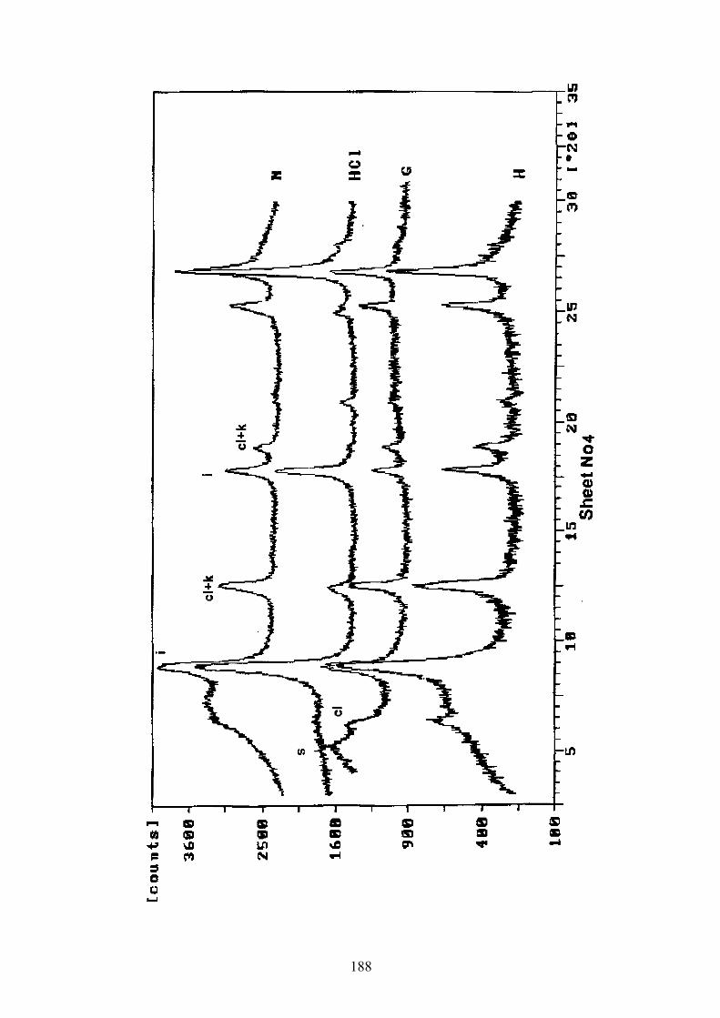
188

189

190

191

192

193

194

195
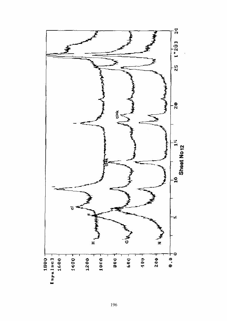
196
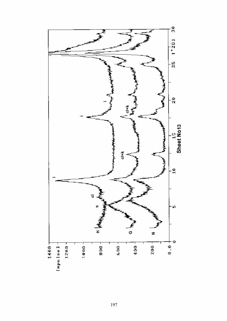
197

198

199

200

201

202

203

204

205

206

207

208

Appendix C: Procedure of separating heavy minerals
Fine and very fine sand fractions (0.125-0.062 mm ) of samples were selected by dry-
sieving method. Heavy minerals of these fractions were separated using special apparatus and
standard bromoform method. The magnetic fractions were removed by hand magnet and
electromagnetic method. The magnetic fractions determined by reflected polarizing
microscope and X-ray diffraction where was necessary. After this stage enough light heavy
mineral grains were obtained to be made one slide for each sample. A glass microscope slide
was heated on a hot plate and was melted enough entellan to be covered the slide. The sample
was poured on the slide and the grains were spread using a wire probe. A flame (match or
Bunsen burner) applied briefly to the surface of the entellan will be destroyed any bubble. A
cover glass was put on the slide and an eraser end of a pencil was used to position the cover
glass and remove any bubbles. The relative frequency percentage of heavy minerals was then
determined by counting at least 100 grains in each mount using by transmitted light binocular
and polarizing microscope (Lewis, 1984; Lindholm , 1987; Mange & Maurer, 1992).
Appendix D: Thin Section–making process of unconsolidated sediments:
Two hundred ml of resin (Araldite) for 10 samples (a total of about 200 thin sections
were prepared for this study) were mixed with a level teaspoon of waxoline blue dye and
placed in an oven at 60oC and gently stirred at 5 min intervals until the dye was dissolved (30
min approx.). Twenty ml of hardener was added and well mixed for 1 min. The resin was
then immediately poured into the 10 labeled moulds and the samples dropped in (don’t put
the samples in first as a flat based samples may not be wetted or may adhere to grease). The
mould plus samples was put in the desiccator and the vacuum was applied. Then the moulds
were removed and allowed to be hardened for 24 hours at room temperature. Finally the
impregnated samples were released from the moulds and were cut in suitable sections for
examination by polarizing microscope (Trewin, 1988).
Appendix E: Procedure of installation of sampling traps:
Sediment collector traps were established in very slightly elevated places. At least
two, optimum three, 10 l buckets were buried. The opening of the trap was favorably covered
by a net (e.g. curtain meshwork, to prevent aeolian erosion and unwanted trapping of larger
animals). The rim of the traps should be slightly above the sediment surface. Sediments,
deposited in the traps, were removed every month by a kind of blade.
209

Appendix F: Lithostratigraphic- Sedimentologic sections of alluvial deposits
F1: Legend to stratigraphic sections
LITHOLOGY
Muddy sandy gravel
Sandy conglomerate/Gravel
Gravelly sandstone/Sand
Sandstone/Sand
Muddy sandstone/Sand
Mud/marl
Sandy mud
SEDIMENTARY STRUCTURE
NODULES & QUALIFIERS
TRACE FOSSIL
ABBREVATIONS
FOSSIL
FC
CB
I
II
III
IV
Trough cross bedding
Fining-up
Corsening -up
Erosional surface
Climbing ripples
Mud flakes
Mud rip up clasts
Planar cross bedding
Reverse bedding
Normal bedding
Gastropod
Ostracod
Root trace
Calcrete
Gypsum crystal
Facies association I
Facies association IV
Facies association II
Facies association III
Cross bedding
Flute cast
(Fining upward)
Salt
Halite crystal
F2: Stratigraphic sections sheets (No. 1-28)
210

MUD SAND
clay csvfs
silt fs pebb
leco
bble
gran
ule
Facies ssoc Col
or
30
Massive mud interbedded with lenticular sand layers, frequent plants,root traces and plant roots, a few gypsum crystals and sharp boundary at base. A product of deposition in shallow distributary channels and upper parts of point bars in the Zayandeh river delta.
Massive mud, high ratio of clay to silt.Deposition on the upper parts of point bars, swamps and levees of the Zayandeh river delta.
Grey to black
LOCATION: 32 ,17 ,12 N 52 ,53 ,45 ENAME: Kuh-e-Siah ( 3o km east of Varzaneh) SHEET 1 OF 28
0 / // 0 / //CTION NO: Dz1GEOLOGICAL SITUATION: Trench
CALE 1:15
SE S
211

MUD SANDcl
ay csvfs
silt fs pebb
leco
bble
gran
ule
Facies ssoc Col
or
30
150
Massive mud interbedded with lenticular sand layers, frequent plants, root traces and plant roots, a few gypsum crystals, sharp boundary at base.Deposition in shallow distributary channels and upper parts of levees in the Zayandeh river delta
Massive mud, high ratio of clay to silt. A product of rapid deposition in a shallow fresh water-brackish lake or flood sheets.
Khaki
Intermittent of sand and brown mud layers, graditional boundary at base and top. Deposition on the various parts of the Zayandeh river delta.
Yellow to brown
Massive fine to medium sand with gastropod and ostracod shells. Deposition in the bottom of small shallow distributary channels during upper flow regime periods.
Grey to black
CTION NO: Dz5EOLOGICAL SITUATION: TrenchCALE 1:15
LOCATION: 32 ,17 ,11 N 52 ,53 ,12 ENAME: Kuh-e-Siah ( 30 km east of Varzaneh) SHEET 2 OF 28
0 / // 0 / //SE G S
212

MUD SAND
clay csvfs
silt fs pebb
leco
bble
gran
ule
PAL
EO-
CU
RR
EN
T
Facies ssoc
Faci
es a
ssoc
Col
or
100
200
300
400
Unstratified-matrix-supported gravel, with abundantfibrous gypsum crystals. A product of cohesive debis- flow deposited in mid alluvial fan.
Planar cross-bedded sandy gravel with normal graded bedding. A result of migration of mid-channel bars in high energy conditions .
64 50
60 55
52 45
Red toyellow
Red
Red
Red
320
270
CB
CB
I
II
II
I
Grain-size mm
Max
Ave
LOCATION: 32 ,27 ,05 N 52 ,50 ,35 ENAME: Siahkuh (15 km northeast of Ejieh)SHEET 3 OF 28
0 / // 0 / //
213

MUD SAND
clay csvfs
silt fs pebb
leco
bble
gran
ule
PALE
O-
CU
RR
EN
T
Facies ssoc
Faci
es a
ssoc
Col
or
100
200
300
400
Massive to crudely stratified gravelly sandstone/sand, lenticular, tabular shaped geometry, sharp lower boundary gypsum crystals at top.A product of bed load deposition in high energy conditions and sedimentation of subsequent suspended sand material in low energy flow.
Yellow
Clear
II
III
Grain-size mm
Max
Ave
45 20
CTION NO: G2EOLOGICAL SITUATION: Qnat wellCALE 1:30
LOCATION: 32 ,40 ,40 N 52 ,16 ,15 ENAME:Ghehi (16 km northeast of Ejieh) SHEET 4 OF 28
0 / // 0 / //SE G S
214

MUD SAND
clay csvfs
silt fs pebb
leco
bble
gran
ule
PAL
EO-
CU
RR
EN
T
Facies ssoc
Faci
es a
ssoc
Col
or
100
200
Unstratified-sandy conglomerate/gravel with abundant gypsum crystals, normal graded bedding structure, broad lenticular sheet like geometry with erosional base. Deposition from high energy flow , transporting and accumulating coarse bed load and keeping sand material in suspension.
118 71Clear
Yellow
II
III
Grain-size mm
Max
Ave
LOCATION: 32 ,41 ,54 N 52 ,07 ,49 ENAME: Segzi (15 km north of Shahkaram) SHEET 5 OF 28
0 / // 0 / //SECTION NO: G3GEOLOGICAL SITUATION: Stream cut SCALE: 1:30
215

MUD SAND
clay csvfs
silt fs pebb
leco
bble
gran
ule
PALE
O-
CU
RR
EN
T
Facies ssoc
Faci
es a
ssoc
Col
or
100
200
300
400
500
600
Unstratified-sandy conglomerate/gravel with a few andesite, limestone cobble, broad to lenticular geometry.
Massive mud with root traces.
Massive mud with root traces.
Massive mud. Rapid settling of suspended grains below water level in a lake.
140 90Red
Yellow
Dark red
Yellow
Light red
II
IIIM
ax
Grain-size mm
Ave
SECTION NO: G4GEOLOGICAL SITUATION: Irrigation channelSCALE: 1:30
LOCATION: 32 ,23 ,01 N 52 ,47 ,41 ENAME: Siahkuh (13.5 km southeast of Varzaneh) SHEET 6 OF 28
0 / // 0 / //
Deposition from high energy flow , transporting and accumulating coarse bed load and keeping sand material in suspension.
Massive mud. Rapid settling of suspended grains below water level in a lake.
216

MUD SAND
clay csvfs
silt fs pebb
leco
bble
gran
ule
PAL
EO-
CU
RR
EN
T
Facies ssoc
Faci
es a
ssoc
Col
or
100
200
300
400
500
Red
Red
Red massive, matrix- supported gravel, locally reverse bedding. A product of cohesive debris flow deposited in alluvial fan.
Planar cross-bedded, channel-shaped, erosional base, lenticular geometry, normal graded, cross bedded sandy -conglomerate/gravel.A result of migration of mid-channel bars in high energy conditions.
Massive muddy sandstone with abundant calcrete nodules.Wide lenticular, wedge-shaped geometry.Deposition from visco-plastic sand flows in alluvial fan.
Red toYellow
Red
I
II
I
III
100 49
100 49
CB
CB
50
45
Grain-size mm
Max
Ave
.
LOCATION: 32 ,31 ,58 N 52 ,27 ,37 ENAME: Harand (12.5 km northeast of Ejieh) SHEET 7 OF 28
0 / // 0 / //SECTION NO: G5GEOLOGICAL SITUATION: TrenchSCALE 1:30
217

MUD SAND
clay csvfs
silt
fs pebb
leco
bble
gran
ule
PALE
O-
CU
RR
EN
T
Facies ssoc
Faci
es a
ssoc
Col
or
100
200
300
Crudely stratified sandy conglomerate/gravel, normal bedding, wedge shaped geometry, erosional base. Deposition of bed load material in high energy flow and keeping sand grains in suspension.
40 20Clear
Yellow
II
III
Grain-size mm
Grain-size mm
Max
Ave
CTION NO: G6EOLOGICAL SITUATION: Irrigation channelCALE: 1:30
LOCATION: 32 ,34 ,31 N 52 ,16 ,42 ENAME: Serian (10 km northeast of Shahkaram) SHEET 8 OF 28
0 / // 0 / //SE G S
218
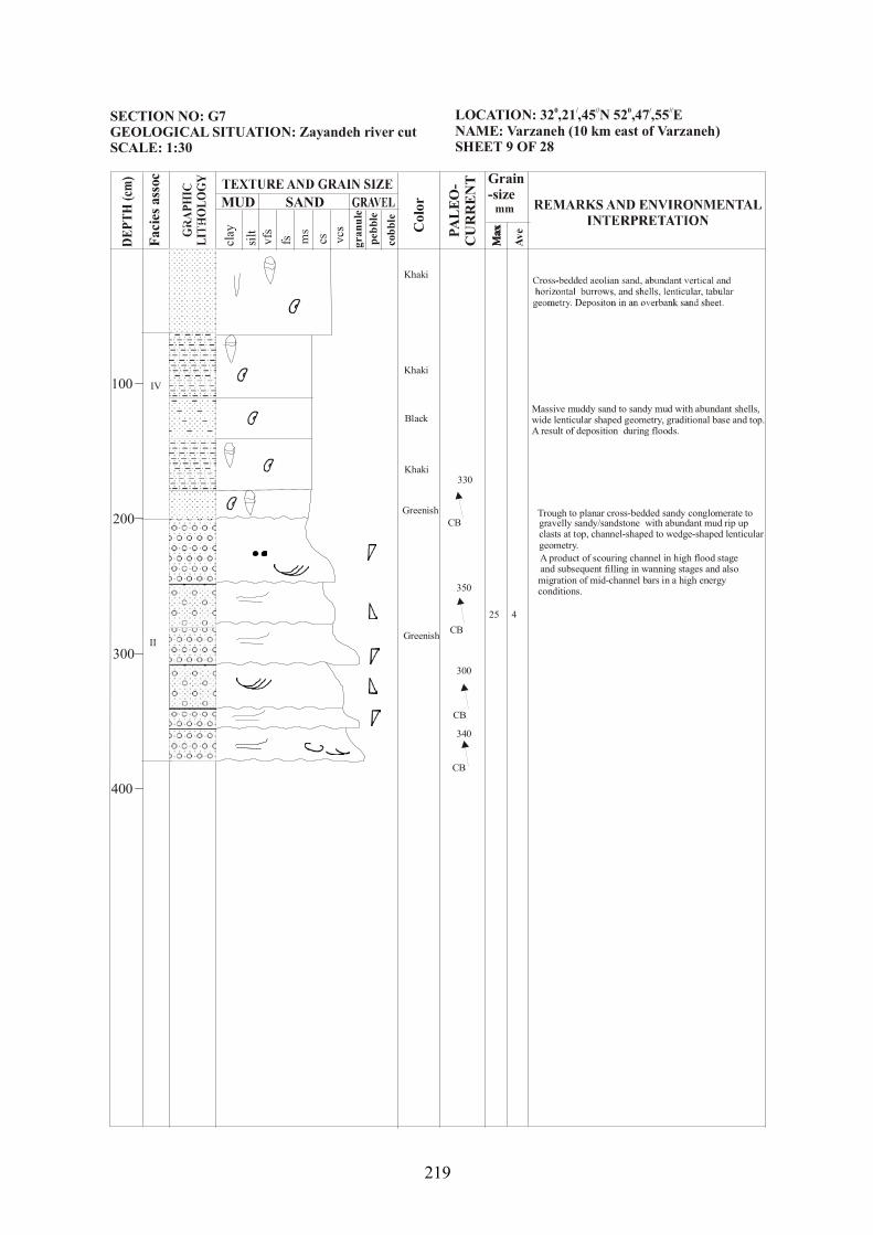
MUD SAND
clay csvfs
silt fs pebb
leco
bble
gran
ule
PAL
EO-
CU
RR
EN
T
Facies ssoc
Faci
es a
ssoc
Col
or
0
200
300
0
Massive muddy sand to sandy mud with abundant shells, geometry, graditional base and top.
A result of deposition during floods.wide lenticular shaped
Trough to planar cross-bedded sandy conglomerate to gravelly sandy/sandstone with abundant mud rip up clasts at top, channel-shaped to wedge-shaped lenticular geometry.
Khaki
Khaki
Khaki
Black
Greenish
Greenish
25 4
IV
II
CB
CB
CB
CB
340
300
350
330
Grain-size mm
Max
Max
Max
Ave
A product of scouring channel in high flood stageand subsequent filling in wanning stages and also migration of mid-channel bars in a high energy conditions.
LOCATION: 32 ,21 ,45 N 52 ,47 ,55 ENAME: Varzaneh (10 km east of Varzaneh) SHEET 9 OF 28
0 / // 0 / //CTION NO: G7OLOGICAL SITUATION: Zayandeh river cut
CALE: 1:30
SE GE S
10
40
219

MUD SAND
clay csvfs
silt fs pebb
leco
bble
gran
ule
PALE
O-
CU
RR
EN
T
Facies ssoc
Faci
es a
ssoc
Col
or
100
Trough cross-bedded asymmetrical, channel-shaped, concave base sandy conglomerate.A product of scoring an subsequent filling of bed load sediments in a channel.
Massive sandy conglomerate with abundant mud rip up clasts, wedge-shaped lenticular geometry.
Massive yellow mud.
Clear
Yellow
100 30II
III
Ave
Max
Grain-size mm
SECTION NO: G9GEOLOGICAL SITUATION: Zayandeh river cut SCALE: 1:30
LOCATION: 32 ,29 ,44 N 52 ,25 ,24 ENAME: Ejieh (2 km east of Ejieh) SHEET 10 OF 28
0 / // 0 / //
Bed load deposition from high energy stream flow,
220
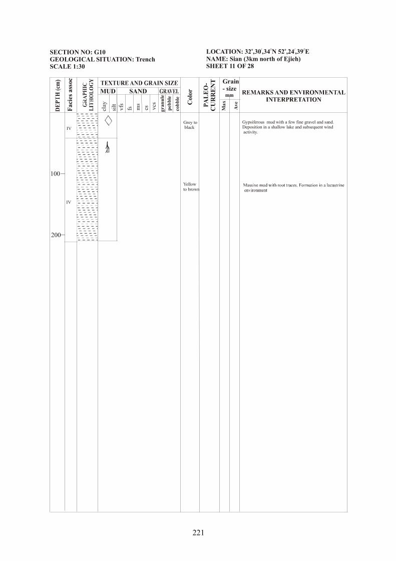
MUD SAND
clay csvfs
silt fs pebb
leco
bble
gran
ule
PALE
O-
CU
RR
EN
T
Facies ssoc
Faci
es a
ssoc
Col
or
100
200
Gypsiferous mud with a few fine gravel and sand.Deposition in a shallow lake and subsequent wind activity.
Grey to black
Yellowto brown
IV
IV
Max
Ave
Grain- size mm
LOCATION: 32 ,30 ,34 N 52 ,24 ,39 ENAME: Sian (3km north of Ejieh) SHEET 11 OF 28
o / // o / //SECTION NO: G10GEOLOGICAL SITUATION: TrenchSCALE 1:30
221

MUD SAND
clay csvfs
silt fs pebb
leco
bble
gran
ule
PAL
EO-
CU
RR
EN
T
Facies ssoc
Faci
es a
ssoc
Col
or
100
,
Mud without any bedding. Deposition in a lacustrine sedimentary environment.
77 52Clear
Yellow
II
III
Grain-size mm
Max
Ave
CTION NO: G11EOLOGICAL SITUATION: Irrigation channelCALE 1:30
LOCATION: 32 ,31 ,11 N 52 ,21 ,04 ENAME: Gishi (7.5 km northwest of Ejieh) SHEET 12 OF 28
0 / // 0 / //SE G S
222

MUD SANDcl
ay csvfs
silt
fs pebb
leco
bble
gran
ule
PALE
O-
CU
RR
EN
T
Facies ssoc
Faci
es a
ssoc
Col
or
200
300
Laminated sandy mud to mud with abundant burrowing root traces, gastropod and ostracod shells.
Massive sand/sandstone with abundant gastropod andostracod shells. Broad lenticular, tabular geometry and normal graded bedding. Rapid deposition from suspension during floods.
Trough sandy conglomerate/gravel, channel shaped geometry, erosional scoured base. A product of scouring and filling in coarse-grained meandering or in braided river.
Planar cross-bedded sandy conglomerate/gravel, normal graded bedding with abundant mud rip-up clasts.It is resulted from migration of mid-channel bars.
40 20
Khaki
Dark
Red
Greenish
Greenish
GreenishCB
45
IV
II
Broad lenticular, tabular geometry, graditional border with upper and lower layers.Deposition in a river overbank environment.
Max
Ave
Massive mud with broad lenticular geometry, abundant root traces and gastropod and ostracod shells.A result of settling of suspended grains below water level of a lake.
LOCATION: 32 ,27 ,10 N 52 ,29 ,10 ENAME: Farfan (7.5 km east of Ejieh) SHEET 13 OF 28
0 / // 0 / //CTION NO: G12OLOGICAL SITUATION: Zayandeh river cut
CALE 1:30
SE GE S 100
223

MUD SAND
clay csvfs
silt fs pebb
leC
obbl
e
gran
ule
PAL
EO-
CU
RR
EN
T
Facies ssoc
Faci
es a
ssoc
Col
or
100
200
300
400
500
600
Massive sandy conglomerate with a few mud rip up clasts in the lower part, graded bedding structure, channel shaped geometry.Bed load deposition from stream flow originated from high energy flow, transporting and accumulating coarse bed load and keeping sand material in suspension.
Trough cross-bedded sandstone with granules, lenticular wedge shaped geometryA result of scouring channel and subsequent filling in wanning stages.
Strongly erosional scoured based massive sandy conglomerate.Deposition under high energy conditions in braided river.
Massive mud to sandy mud with a few gastropod shells and abundant root traces, lenticular geometry.Deposition in a lacustrine environment accompanied period input of current transported sands.
Massive sandstone/ sand with slightly mud, lenticular wedge geometry, graditional base and top. Rapid deposition from suspension during floods.
shapedGreenish
Yellow
Clear
180 36
II
III
III
FC
55
Grain-size mm
Max
Ave
Yellow
.
.
.
SECTION NO: G13GEOLOGICAL SITUATION: Zayandeh river cutSCALE: 1:30
LOCATION: 32 ,26 ,44 N 52 ,23 ,02 ENAME: Ejieh bridge SHEET 14 OF 28
0 / // 0 / //
224

MUD SAND
clay csvfs
silt fs pebb
leco
bble
gran
ule
PAL
EO-
CU
RR
EN
T
Facies ssoc
Faci
es a
ssoc
Col
or
200
300
Massive sandy gravel with erosional base, normal graded bedding is common structure.Bed load deposition under high energy conditions and keeping sand material in suspension.
Massive mud with occasional root traces.A product of deposition of suspended material in a lacustrine environment.
20 10Clear
Yellow
II
III
Grain-size mm
Max
Ave
LOCATION: 32 ,13 ,09 N 52 ,40 ,29 ENAME: Dastgerd (7.5 km northwest of Hasanabad) SHEET 15 OF 28
0 / // 0 / //CTION NO: G14OLOGICAL SITUATION: Trench
CALE 1: 30
SE GE S
100
225

MUD SAND
clay csvfs
silt
fs pebb
leco
bble
gran
ule
PALE
O-
CU
RR
EN
T
Facies ssoc
Faci
es a
ssoc
Col
or
100
200
300
400
500
600
Crudely stratified to planar cross-bedded sandy conglomerate and sandstone, strongly erosional scoured base, wedge shaped, lenticular to channel shaped, concave based, asymmetrical geometry.It is originated from migration mid channel bars and also deposition of coarse bed loads in a braided riverchannels.
110 35Clear
Yellow
II
III
FC
CB
CB
CB
45
65
60
60
Grain-size mm
Max
Ave
CTION NO: G15EOLOGICAL SITUATION: Stream cut CALE 1:30
LOCATION: 32 ,24 ,34 N 52 ,20 ,56 ENAME: Ejieh (5 km south of Ejieh)SHEET 16 OF 28
0 / // 0 / //SE G S
226

MUD SANDcl
ay csvfs
silt fs pebb
leco
bble
gran
ule
PAL
EO-
CU
RR
EN
T
Facies ssoc
Faci
es a
ssoc
Col
orTrough to planar cross-bedded sandy conglomerate, channel shaped, lenticular geometry, strongly erosional-base with flute cast, asymmetrical shape, concave up and base.A product of scouring and filling to migration of mid-channel bars in coarse-grained meandering or in braided river.
Massive mud with abundant root traces. No bedding is evident. A result of sedimentation in a lacustrine environment.
260 130
Clear
Yellow
CB
FC
II
III
50
320
Grain-size mm
Max
Ave
LOCATION: 32 ,23 ,25 N 52 ,09 ,19 ENAME: SHEET 17 OF 28
0 / // 0 / //ECTION NO: G16EOLOGICAL SITUATION: Stream cutCALE 1:30
)S G S
100
200
300
400
500
600
227

MUD SAND
clay csvfs
silt fs pebb
leco
bble
gran
ule
PAL
EO-
CU
RR
EN
T
Facies ssoc
Faci
es a
ssoc
Col
or
200
300
Unstratified, matrix supported gravel, locally reverse graded bedding, wedge- shaped, broad lenticular geometry.A product of cohesive debris flow deposited in proximal alluvial fan environment.
Red
Red
35 29I
Max
Grain-size mm
Ave
CTION NO: G17EOLOGICAL SITUATION: Trench
E 1:30
LOCATION: 32 ,32 ,08 N 52 ,35 ,52 ENAME: Kamalabad (2.5 km northwest of Hasanabad) SHEET 18 OF 28
0 / // 0 / //SE G SCAL
100
228

MUD SAND
clay csvfs
silt fs pebb
leco
bble
gran
ule
PAL
EO-
CU
RR
EN
T
Facies ssoc
Faci
es a
ssoc
Col
or
0
Unstratified muddy sandy gravel with inverse gradedbedding in some places. A result of cohesive debris flow deposited in proximal alluvial fan.
40 19Red
I
Grain-size mm
Max
Ave
LOCATION: 32 ,14 ,50 N 52 ,25 ,05 ENAME: SHEET 19 OF 28
0 / // 0 / //ECTION NO: G18EOLOGICAL SITUATION: TrenchCALE 1:30
Heydarabad (17.5 km northwest of Hasanabad)S GS 10
229

MUD SAND
clay csvfs
silt fs pebb
leco
bble
gran
ule
PAL
EO-
CU
RR
EN
T
Facies ssoc
Faci
es a
ssoc
Col
or
0
0
Unstratified matrix supported gravel, reverse graded bedding locally, broad lenticular to sheet like geometry.A product of visco-plastic debris flow deposited in proximal alluvial fan.
Mssive mud with root traces. Formation an a lake environment
37 30Red
Yellow
I
Grain-size mm
Max Av
e
CTION NO: G19EOLOGICAL SITUATION: Qnat wellCALE 1:30
LOCATION: 32 ,22 ,30 N 52 ,06 ,45 ENAME: Ganjabad (8 km northwest of Yangabad) SHEET 20 OF 28
0 / // 0 / //SE G S
100
20
30
230

MUD SAND
clay csvfs
silt fs pebb
leco
bble
gran
ule
PALE
O-
CU
RR
EN
T
Facies ssoc
Faci
es a
ssoc
Col
or
100
200
300
400
500
Massive sandy conglomerate/gravel, broad lenticular geometry with erosional base.Bed load deposition from stream flow under high energy conditions, transporting and accumulating coarse bed loadand keeping sand material in suspension.
Laminated mud to sandy mud with a few ostracod shells,
Laminated mud to sandy mud with a few ostracod shells.Deposition in a river overbank environment.
Laminated mud with occasional ostracod shells lenticular geometry.A product of deposition in a river overbank environment.
lenticular geometry. Deposition in a river overbank.
Sandy conglomerate/gravel, lenticular, wedge- shaped geometry. Deposition of bed load material in high energy condition and keeping sand grains in suspension in a braided to meandering river.
Sandy conglomerate/gravel, lenticular, wedge shaped geometry.Lenticular, wedge shaped geometry, base.Deposition in channel under high energy flow and subsequent filling of sand material in suspension.
erosional
52 42
50 38
Khaki
Khaki
Khaki
Clear
Clear
II
IV
IV
IV
II
II
Grain-size mm
Max Av
e
Clear
LOCATION: 32 ,01 ,02 N 52 ,51 ,49 ENAME: Salt mine ( 25 km southeast of Hasanabad) SHEET 21 OF 28
0 / // 0 / //CTION NO: G21EOLOGICAL SITUATION: Stream cutCALE 1:30
SE G S
231

MUD SAND
clay csvfs
silt fs pebb
leco
bble
gran
ule
PAL
EO-
CU
RR
EN
T
Facies ssoc
Faci
es a
ssoc
Col
or
100
200
300
400
500
600
Unstratified sandy conglomerate with broad lenticular, tabular geometry and erosional base Extensive erosional scoured base with gutter and flute- casts. Deposition under high to low energy condition in a braided or meandering river
Mud with abundant trace fossil and root traces, lenticular, wedge shaped geometry, sharp base and top.A product of deposition in a river overbank environment.
Massive gravelly sandstone with granules, lenticular, wedge- shaped geometry, undulous erosional top andbase. A product of bed load deposition under high energy flow and subsequent sedimentation of suspended sand material in a steam channel.
Massive mud with trace fossil and root traces. Rapid deposition in a river overbank environment.
Mud , no bedding is evident. Deposition in a river overbank.
118 80
100 75
Clear
Clear
Clear
Khaki
Khaki
Khaki
II
II
II
IV
IV
IV
FC
80
CB
CB
CB
60
45
50
.
Grain-size mm
Max
Ave
SECTION NO: G22GEOLOGICAL SITUATION: Stream cutSCALE 1:30
LOCATION: 32 ,12 ,20 N 52 ,07 ,06 ENAME: Peykan (10 km southwest of Yangabad) SHEET 22 OF 28
0 / // 0 / //
232

MUD SAND
clay csvfs
silt fs pebb
leco
bble
gran
ule
Facies ssoc Col
or
30
150
Thin bedded fine to medium sand with fine halite crystals, tabular shaped geometry.Deposition in an interdune sub-environment by wind activity.
Massive sandy mud, abundant gastropod and ostracod shells, lenticular gypsum crystals in some places.A product of deposition in a shallow restricted freshwater-brackish lake in reduction conditions.
Massive sandy mud, a few gastropod and ostracod shells. It is deposited in a fresh water -brackish lake with wind activity.
Massive sandy mud, abundant gastropod and ostracod shells. Formation in a shallow fresh water-brackish lake and wind activity.
Brown mud with lenticular geometry. A result of deposition in a fresh water-brackish lake.
Khaki
Grey to black
Off-white
Brown to red
Off-white
LOCATION: 32 ,07 ,09 N 52 ,40 ,30 ENAME: Khara (5 km southeast of hasanabad) SHEET 23 OF 28
0 / // 0 / //CTION NO: I1EOLOGICAL SITUATION: TrenchCALE1:15
SE G S
233

MUD SAND
clay csvfs
silt fs pebb
leco
bble
gran
ule
Facies ssoc Col
or
30
150
Thin bedded fine to medium nd fine halite crystals, tabular shaped geometry.
Deposited in an interdune sub-environment.
sandy mud, a few gastropod and ostracod shells a
Fine to medium massive sandy mud, a few gastropod and ostracod shells.A result of rapid deposition in a shallow restricted lake.
Massive sandy mud, a few gastropod and ostracod shells A product of deposition in a fresh water -brackish lake with wind activity..
Brown mud with lenticular geometry. Deposition i na shallow fresh water- brackish lake.
Massive sandy mud without gastropod and ostracod shells.
Brown to red
Greenish
Greenish
Khaki
Khaki
CTION NO: I2EOLOGICAL SITUATION: TrenchCALE1:15
LOCATION: 32 ,06 ,26 N 52 ,41 ,57 ENAME: Khara (7 km east of Hasanabad) SHEET 24 OF 28
0 / // 0 / //SE G S
234

MUD SAND
clay csvfs
silt fs pebb
leco
bble
gran
ule
Facies ssoc Col
or
30
150
Skeletal salt with minor mud, hard and porous surface.Originated from migration of water to surface by capillarity and precipitation after saturation in flood plain.
Massive muddy sand with abundant gastropod and ostracode shells.A product of rapid deposition in flood sheets and shallow distributary channels.
Massive muddy sand, graditional boundary at base and top . Deposition in flood plain and shallow distributary channels.
Massive fine to medium sand with abundant gastropod and ostracod shells. A rapid deposition during thunderstorms in a shallow temporary lake or also directly as bottom load from the Zayandeh river.
Massive mud, graditional boundary at base and top. Rapid depositionof suspended load in flood plain
Khaki
Khaki
Khaki
Khaki
Khaki
LOCATION: 32 ,19 ,10 N 52 , 51 , 53 ENAME: Shakhkenar (23 km east of Varzaneh) SHEET 25 OF 28
0 / // 0 / //CTION NO: M1EOLOGICAL SITUATION: TrenchCALE 1:15
SE G S
235

MUD SAND
clay csvfs
silt fs pebb
leco
bble
gran
ule
Facies ssoc Col
or
30
Skeletal salt with minor mud, hard and porous surface, a few ostracod shells, gypsiferous mud in the eastern saline mud flat. A product of migration of water by capillarity and subsequent saturationin flood plain environment.
Massive mud. Rapid deposition in flood sheet in a semi-arid to arid climate.
Khaki
Khaki
ION NO: M2EOLOGICAL SITUATION: TrenchALE 1:15
LOCATION: 32 ,18 ,09 N 52 ,53 ,07 ENAME: Kuh-e-Siah (28 km east of Varzaneh) SHEET 26 OF 28
0 / // 0 / //SECT G SC
236

MUD SAND
clay csvfs
silt fs pebb
leco
bble
gran
ule
Facies ssoc Col
or
30
Unstratified fine to medium sand with ostracod and gastropod shells and gypsum crystals. Most likely rapid deposition during thunderstorms in a shallow temporary lake.
White, red,green
Black
Khaki
LOCATION: 32 ,06 ,24 N 52 ,48 ,13 ENAME: Salt mine SHEET 27 OF 28
0 / // 0 / //CTION NO: S3EOLOGICAL SITUATION: TrenchCALE 1:15
SE G S
237
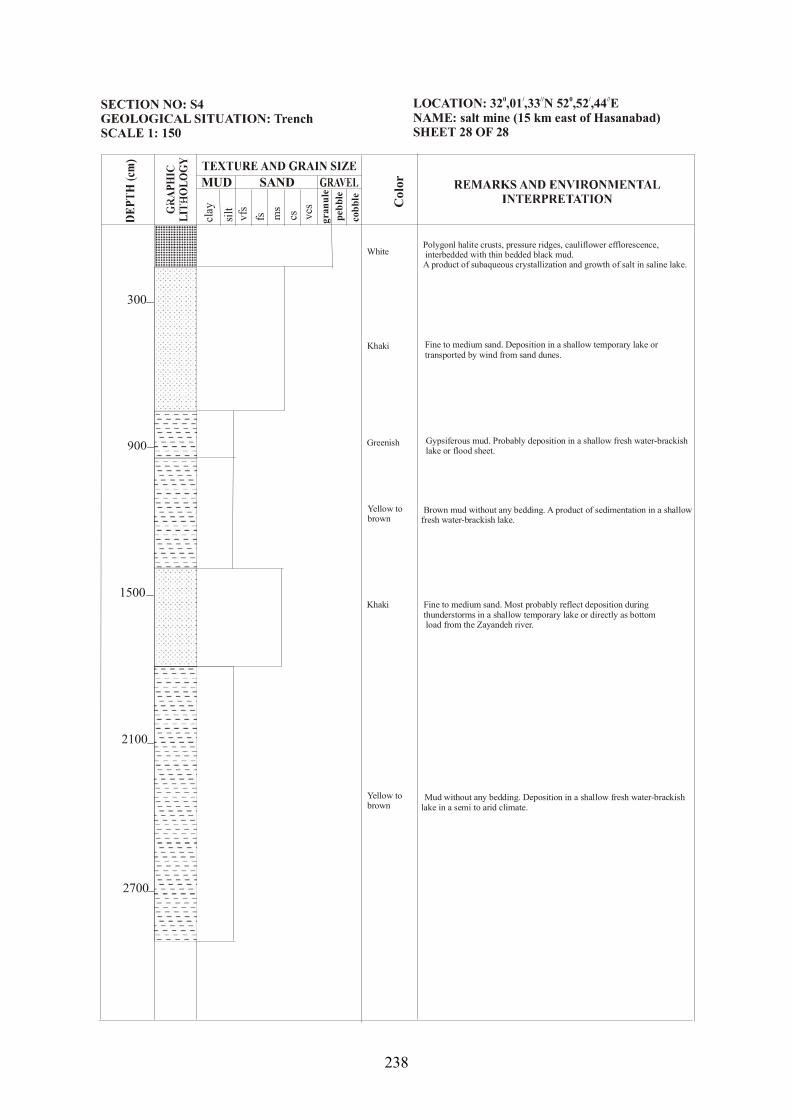
MUD SAND
clay csvfs
silt fs pebb
leco
bble
gran
ule
Facies ssoc Col
or
300
2100
1500
2700
Polygonl halite crusts, pressure ridges, cauliflower efflorescence, interbedded with thin bedded black mud. A product of subaqueous crystallization and growth of salt in saline lake.
Fine to medium sand. Deposition in a shallow temporary lake or transported by wind from sand dunes.
Gypsiferous mud. Probably deposition in a shallow fresh water-brackish lake or flood sheet.
Brown mud without any bedding. A product of sedimentation in a shallow fresh water-brackish lake.
Fine to medium sand. Most probably reflect deposition during thunderstorms in a shallow temporary lake or directly as bottom load from the Zayandeh river.
Mud without any bedding. Deposition in a shallow fresh water-brackish lake in a semi to arid climate.
White
Greenish
Khaki
Yellow to brown
Yellow to brown
Khaki
LOCATION: 32 ,01 ,33 N 52 ,52 ,44 ENAME: salt mine (15 km east of Hasanabad)SHEET 28 OF 28
0 / // 0 / //
238