Secure communication by chaotic synchronization: Robustness under noisy conditions
10
Nonlinear Analysis: Real World Applications 8 (2007) 1003 – 1012 www.elsevier.com/locate/na Secure communication by chaotic synchronization: Robustness under noisy conditions Amalia N. Miliou a , ∗ , Ioannis P. Antoniades a , Stavros G. Stavrinides b , Antonios N. Anagnostopoulos b a Department of Informatics, Aristotle University of Thessaloniki, GR-54124, Thessaloniki, Greece b Physics Department, Aristotle University of Thessaloniki, GR-54124, Thessaloniki, Greece Received 28 March 2006; accepted 3 May 2006 Abstract In this work we present a thorough investigation of the effect of noise (internal or external) on the synchronization of a drive- response configuration system (unidirectional coupling between two identical systems). Moreover, since in every practical imple- mentation of a communication system, the transmitter and receiver circuits (although identical) operate under slightly different conditions it is essential to consider the case of the mismatch between the parameters of the transmitter and the receiver. In our work we consider the non-autonomous second order non-linear oscillator system presented by G. Mycolaitis et al. in Proceed- ings of Seventh International Workshop on Nonlinear Dynamics of Electronic Systems [Globally synchronizable non-autonomous chaotic oscillator, Denmark, July 1999, pp. 277–280], which is particularly suitable for digital communications. Binary information is encoded by combining square pulses of two different frequencies selected so that the system is always in the chaotic regime independent of the encoded message. 2006 Elsevier Ltd. All rights reserved. Keywords: Chaos; Non-linear circuits; Synchronization; Communication system security 1. Introduction Computer networks are inherently insecure for Internet communication. Data transmission is not safe unless it is assured that the packets will never pass through a router or a computer, over which there is no control.Traditionally, software techniques were used for data encoding. However, the ever-increasing computer power threatens Internet communication security. The simplicity of chaos generators, the rich structure of chaotic signals and the fact that chaotic signals can be synchronized caused a significant interest in possible utilization of chaos for secure Internet communications [3,6,9]. The use of synchronized chaotic systems for communications usually relies on the robustness of the synchronization within the transmitter and receiver pair [6,13,11,2,10,8,4,5]. However, if the communication channel is imperfect and/or there is internal noise at the electronic circuitry the distorted signal at the receiver input might cause considerable synchronization mismatch between the transmitter–receiver pair [12,7,14,1,15]. ∗ Corresponding author. Tel.: +30 2310 998407; fax: +30 2310 998419. E-mail address: [email protected] (A.N. Miliou). 1468-1218/$ - see front matter 2006 Elsevier Ltd. All rights reserved. doi:10.1016/j.nonrwa.2006.05.004
Transcript of Secure communication by chaotic synchronization: Robustness under noisy conditions

Nonlinear Analysis: Real World Applications 8 (2007) 1003–1012www.elsevier.com/locate/na
Secure communication by chaotic synchronization: Robustnessunder noisy conditions
Amalia N. Milioua,∗, Ioannis P. Antoniadesa, Stavros G. Stavrinidesb,Antonios N. Anagnostopoulosb
aDepartment of Informatics, Aristotle University of Thessaloniki, GR-54124, Thessaloniki, GreecebPhysics Department, Aristotle University of Thessaloniki, GR-54124, Thessaloniki, Greece
Received 28 March 2006; accepted 3 May 2006
Abstract
In this work we present a thorough investigation of the effect of noise (internal or external) on the synchronization of a drive-response configuration system (unidirectional coupling between two identical systems). Moreover, since in every practical imple-mentation of a communication system, the transmitter and receiver circuits (although identical) operate under slightly differentconditions it is essential to consider the case of the mismatch between the parameters of the transmitter and the receiver. In ourwork we consider the non-autonomous second order non-linear oscillator system presented by G. Mycolaitis et al. in Proceed-ings of Seventh International Workshop on Nonlinear Dynamics of Electronic Systems [Globally synchronizable non-autonomouschaotic oscillator, Denmark, July 1999, pp. 277–280], which is particularly suitable for digital communications. Binary informationis encoded by combining square pulses of two different frequencies selected so that the system is always in the chaotic regimeindependent of the encoded message.� 2006 Elsevier Ltd. All rights reserved.
Keywords: Chaos; Non-linear circuits; Synchronization; Communication system security
1. Introduction
Computer networks are inherently insecure for Internet communication. Data transmission is not safe unless it isassured that the packets will never pass through a router or a computer, over which there is no control. Traditionally,software techniques were used for data encoding. However, the ever-increasing computer power threatens Internetcommunication security.
The simplicity of chaos generators, the rich structure of chaotic signals and the fact that chaotic signals can besynchronized caused a significant interest in possible utilization of chaos for secure Internet communications [3,6,9].
The use of synchronized chaotic systems for communications usually relies on the robustness of the synchronizationwithin the transmitter and receiver pair [6,13,11,2,10,8,4,5]. However, if the communication channel is imperfect and/orthere is internal noise at the electronic circuitry the distorted signal at the receiver input might cause considerablesynchronization mismatch between the transmitter–receiver pair [12,7,14,1,15].
∗ Corresponding author. Tel.: +30 2310 998407; fax: +30 2310 998419.E-mail address: [email protected] (A.N. Miliou).
1468-1218/$ - see front matter � 2006 Elsevier Ltd. All rights reserved.doi:10.1016/j.nonrwa.2006.05.004

1004 A.N. Miliou et al. / Nonlinear Analysis: Real World Applications 8 (2007) 1003–1012
In this paper, we consider the dynamical system first presented in [9] and we investigate the synchronization of thesystem under noisy channel conditions as well as the case where different noise levels are added in the transmitter andthe receiver (internal noise) due to electronics. Moreover, since in every practical implementation of a communicationsystem, the transmitter and receiver electronic elements may be slightly different or operate under slightly differentconditions, it is essential to consider the case of the mismatch between the parameters of the transmitter and receiver.The paper is organized as follows: the circuit’s description and the synchronization properties are presented in Section2. The simulation results obtained are shown in Section 3. Finally, concluding remarks and discussion are givenin Section 4.
2. Circuit description and synchronization properties
The transmitter and the receiver are identical circuits similar to those in [9]. The circuits include an integrator-basedsecond order RC resonance loop, a comparator H (the circuit’s non-linear element), an exclusive OR gate, with an inputM for the external source and a buffer to avoid overloading of the XOR gate. M(t) can be a sequence of square pulsesof period T = 2�/� or a more complex signal if one wants to encode an arbitrary message, for example.
The transmitter–receiver system is shown in Fig. 1. The principle of operation is demonstrated below. Here thechaotic pulses U∗(t) ∝ F(y1, t) drive both the resonance loop of the transmitter and the resonance loop of the receiver.
F
F
H
UO
U2+
-
HH
H
F
XOR
XOR
Transmitter
Receiver
R R
R
C
RS
R
U1
M
R2U*
R*
+
-
U2
UO
RS
+
-
C
C
RSR
U1
RS
C
+
-R
R
-
+
R*
R
M
R2+
-
M
+
-
+
-
Fig. 1. Schematic diagram of the transmitter–receiver system.

A.N. Miliou et al. / Nonlinear Analysis: Real World Applications 8 (2007) 1003–1012 1005
t (RC)-1
Fig. 2. Synchronization with the application of external noise (channel).
The transmitter–receiver system is governed by the following set of equations:
x1 = aF(y1, t) − bx1 + y1,
y1 = −x1 − by1,
F(y1, t) = H(y1) ⊕ M(t),
x2 = aF(y1, t) − bx2 + y2,
y2 = −x2 − by2. (1)
The subscripts ‘1’ and ‘2’ at the state variables specify the transmitter and the receiver, respectively.Note the same driving term F(y1, t) in the equations for the transmitter and the receiver. The following substitutions
have been used in the previous system of equations since the parameters are usually written in a dimensionless form:
x = U1
U0, y = U2
U0, t = t
RC,
� = U∗ · R
U0 · R∗ , b = R
Rs
,
� = �MRC. (2)
The shifted heaviside function H(y) = H(−y − 1) has the following values: H(−y > 1) = 1 and H(−y�1) = 0,while the symbol ⊕ denotes the exclusive OR operation and M(t) denotes the signal carrying the message.
For zero external drive M to the XOR gate the circuit exhibits damped oscillations. For all reasonable (x20 + y2
0 < 1)
initial conditions, the corresponding amplitudes of the variables x and y converge exponentially (∝ e−bt ) to a stable

1006 A.N. Miliou et al. / Nonlinear Analysis: Real World Applications 8 (2007) 1003–1012
A (internal)=0.0001
A (internal)=0.0005
A (internal)=0.001
A (internal)=0.01
A (internal)=0.1
t (RC)-1
Fig. 3. Synchronization with the application of internal noise (electronics).
steady state. However, due to the comparator H, for a non-zero drive M the circuit becomes a periodically forced secondorder non-autonomous non-linear oscillator, exhibiting chaos [3,6].
Introducing in (1) the error variables �x = x2 − x1 and, �y = y2 − y1 we obtain the equations governing the errordynamics:
�x = b�x + �y, �y = −�x − b�y. (3)
The solution of (3) shows the exponential decrease of the errors for all possible initial errors �x0 and �y0:
�x = a exp(−bt) cos(t + �), �y = a exp(−bt) sin(t + �), (4)
where a =√
�x20 + �y2
0 and � = arctan(�y0/�x0).Thus, the synchronization is globally asymptotically stable. This requirement leads to the conclusion that for �x → 0
and �y → 0, the corresponding state variables, are robustly synchronized (x2 → x1 and y2 → y1). Consequently,the non-linear functions behave in a synchronous way H(y2) → H(y1) as well. This result suggests an extremelysimple technique of recovering the signal M(t) at the receiver end. The received signal F(y1, t) ∝ U∗(t) is applied tothe XOR unit of the receiver. Due to the sum mod 2 property, the signal M(t) can be recovered from the chaotic oneF(y1, t) without any errors, according to
F(y1, t) ⊕ H(y2) = H(y1) ⊕ M(t) ⊕ H(y2)
→ H(y1) ⊕ M(t) ⊕ H(y1) = M(t). (5)

A.N. Miliou et al. / Nonlinear Analysis: Real World Applications 8 (2007) 1003–1012 1007
t (RC)-1
1.0
0.8
0.6
0.2
0.4
0.0
1.0
0.8
0.6
0.2
0.4
0.0
1.0
0.8
0.6
0.2
0.4
0.0
1.0
0.8
0.6
0.2
0.4
0.0
1.0
0.8
0.6
0.2
0.4
0.0
MH
(y 1
)F
(y 1
,t)H
(y 2
)M
(de
code
d)
150 200 250 300 350
(a)
(b)
(c)
(d)
(e)
Fig. 4. The effect of internal noise on the received (decoded) signal Md(t) for a message ‘1111 . . . 1111’.
3. Simulation results
Eqs. (1) have been numerically integrated. Chaotic oscillations are observed at different frequency windows, i.e.between �=0.7–0.8 and 1.05–1.16 and �=2.65. The damping parameter b should not be too large and in our simulationb = 0.02.
Figs. 2 and 3 depict the synchronization with the application of external and internal noise, respectively. The externalnoise is applied on the communication channel and in our simulation is represented by white noise added on F(y1, t),where frequencies greater than RC were cutoff. The internal noise is due to the electronics circuitry and is again appliedboth on the transmitter and the receiver (added on x1, y1 and x2, y2 variables). Once again frequencies higher than RCare cutoff.

1008 A.N. Miliou et al. / Nonlinear Analysis: Real World Applications 8 (2007) 1003–1012
t (RC)-1
1.0
0.8
0.6
0.2
0.4
0.0
1.0
0.8
0.6
0.2
0.4
0.0
1.0
0.8
0.6
0.2
0.4
0.0
1.0
0.8
0.6
0.2
0.4
0.0
1.0
0.8
0.6
0.2
0.4
0.0
MH
(y 1
)F
(y 1
,t)H
(y 2
)M
(de
code
d)
150 200 250 300 350
(a)
(b)
(c)
(d)
(e)
Fig. 5. The effect of internal noise on the received (decoded) signal Md(t) for a message ‘1010 . . . 1010’.
Different noise amplitudes A, have been utilized ranging from 0.01% to 50% of the mean signal amplitude. As thenoise amplitude A is increased, the synchronization of the system continuously deteriorates and is practically destroyedin both cases (external and internal noise) above a certain noise level.
The artificial noise added at the simulation was produced as follows: a pseudorandom number generator produces anarray of random numbers in the interval [0, 1]. The random numbers are equal to the total number of simulation steps.Then the Fourier transform of this series is obtained by standard procedures and amplitudes for frequencies larger thana particular cutoff value are zeroed. The inverse Fourier transform is taken in order to produce the noise series to beused in the subsequent simulation. In our simulation we cutoff frequencies larger than the characteristic frequency ofthe system RC. By this ‘noise filtering’ procedure we avoid the dependence of the generated noise on the simulationstep. Noise was added at every simulation step to the signal F(y1, t) coming out of the transmitter (external noise) or

A.N. Miliou et al. / Nonlinear Analysis: Real World Applications 8 (2007) 1003–1012 1009
MH
(y 1
)F
(y 1
,t )
H (
y 2)
M (
deco
ded)
t (RC)-1
1.0
0.8
0.6
0.4
0.2
0.0
1.0
0.8
0.6
0.4
0.2
0.0
1.0
0.8
0.6
0.4
0.2
0.0
1.0
0.8
0.6
0.4
0.2
0.0
1.0
0.8
0.6
0.4
0.2
0.0
150 200 250 300 350
(a)
(b)
(c)
(d)
(e)
Fig. 6. The effect of internal noise on the received (decoded) signal Md(t) for a message ‘10110011101000101101’.
to each of the dynamic variables x1, y1 and x2, y2 of the transmitter and receiver in respect (internal noise). In the lattercase, four different noise series were used one for each dynamic variable.
In order to load a specific binary message to transmitted signal (F (y1, t)) several options exist on how to constructthe signal M(t). However, since for security reasons the system must operate in the chaotic regime which stronglydepends on the driving signal M(t), the encoding scheme must be such that this requirement is met for all possiblemessages. Therefore, we attempted two different encoding schemes: in scheme A ‘1’ and ‘0’ were represented each bya square pulse of a single period duration, the same frequency but with opposite phases, while in scheme B ‘1’ and ‘0’were represented by square pulses of single period duration, the same phase but two distinct frequencies.
In both scheme we tried three types of messages: (i) a sequence of several ‘1’, (ii) an alternating sequence of ‘1’ and‘0’ and (iii) a random binary string. The messages were loaded on the signal M(t) starting at t > tsynch, where tsynch was
1010 A.N. Miliou et al. / Nonlinear Analysis: Real World Applications 8 (2007) 1003–1012
100000
10000
1000
100
10
1
0.1
0.1
0.01
0.01 0.1
0.01
internalexternal
internalexternal
sqrt
(<
Δy2
>/Δ
y2 in
itial
)
1E-3
1E-3A (noise amplitude)
MD
Fig. 7. The effect of noise on the square mean mismatch of the y parameters and MD.
the characteristic time for the synchronization to be achieved. For times t outside the time window where the messagewas loaded, M(t) was effectively ‘padded’ with zeros (essentially a periodic train of square pulses).
In realizing scheme A it was very difficult to produce chaotic output of the system for all types of messages that wetried. The reason was that encoding a ‘0’ and ‘1’ by a pulse of opposite phase leads, in certain combinations of ‘0’ and‘1’, to an effective change in the frequency of the signal M(t) so that the system was carried outside of the chaoticregime. For example, if one was encoding a message of alternating ‘0’ and ‘1’ (101010101 . . .) using a frequency value� = 1.1 for each pulse (which lies in the chaotic regime), the signal M(t) became a periodic sequence of pulses withhalf the frequency (� = 0.55), which did not give chaotic output.
In scheme B, for the two frequencies encoding ‘0’ and ‘1’, respectively, we picked two values each of which lies inthe chaotic regime and they were as far apart as possible. Such values were �1 = 0.75 and �2 = 1.15. We found thatfor all messages tried the output was firmly chaotic.
Figs. 4–6 represent the encoding and decoding procedure for the three types of messages tried and for internalnoise amplitude of 5%. In all cases a 20 bit message was used: ‘1111 . . . 111’ (Fig. 4), ‘1010 . . . 1010’ (Fig. 5) and‘10110011101000101101’ (Fig. 6). In each figure the first one from the top is the signal M(t) carrying the messagewhich is XORed with H(y1) (Figs. 4b, 5b, 6b) to give the transmitted signal F(y1, t) (Figs. 4c, 5c, 6c) which is XORedwith H(y2) (Figs. 4d, 5d, 6d) in order to produce the decoded signal M(decoded) (Figs. 4e, 5e, 6e). We see that internal

A.N. Miliou et al. / Nonlinear Analysis: Real World Applications 8 (2007) 1003–1012 1011
0.5
0.4
0.3
0.2
0.1
0.0
0.03
0.02
0.01
0.00
0.00 0.05 0.10 0.15 0.20 0.25 0.30 0.35 0.40
sqrt
(<
Δy2 >
)/Δy
initi
al
b=0.02b=0.0199
b=0.02b=0.0199
Δα
MD
Fig. 8. Sensitivity of the system to parameters � and b.
noise although it partly distorts the decoded signal does not affect the bit error rate because the correct bits can berecognized and restored by a suitable decision algorithm.
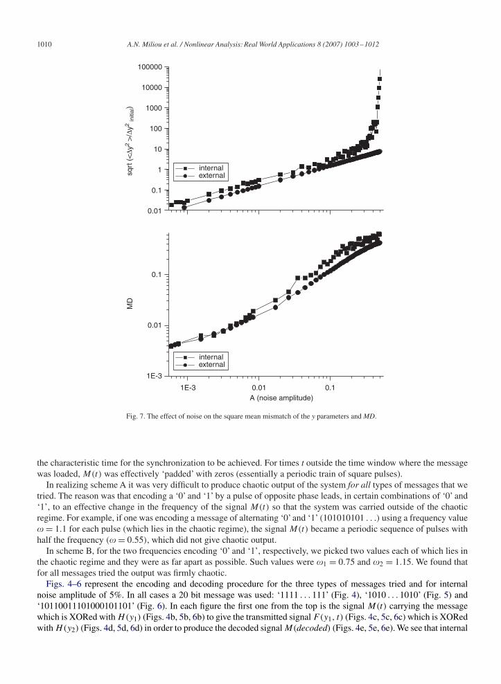
Fig. 7 demonstrates the square mean mismatch√〈�y2〉 over the initial �y =y2 −y1 (=0.3) and the mean difference
[MD = (1/t)∫ t
0 (M(t) − Md(t)) dt] between signals M(t) and Md(t) in the time interval of the simulation versus thenoise amplitude, for external and internal noise. The signal M(t) in this case was simply a periodic sequence of squarepulses of frequency � = 1.1. As expected, both system synchronization and MD (message mismatch) become worst asnoise amplitude increases and internal noise is affecting the system’s synchronization more than external noise of thesame amplitude level.
Finally, Fig. 8 illustrates the sensitivity of the system to the parameters � and b. These parameters depend onresistors used in both circuits and naturally may take different values between transmitter and receiver. For � = 2.65and b = 0.02 at the transmitter circuit, using a slightly different value of b (b = 0.0199) at the receiver circuit doesnot have any effect on the MD or the square mean mismatch of the y parameters regardless of the difference between� parameters of the transmitter and the receiver. The system is also robust in terms of deviations (��) of the valuesof the parameter � between the transmitter and receiver; a deviation in the order of �� = 0.35 causes an MD ofonly about 3%.

1012 A.N. Miliou et al. / Nonlinear Analysis: Real World Applications 8 (2007) 1003–1012
4. Conclusion
We have studied the influence of the external (channel) and the internal (electronics) noise on the synchronization ofthe transmitter–receiver pair presented in [9] by numerical simulation of the equations governing the system. The resultshave shown the robustness of the system although internal noise has more influence than external on the synchronizationfor the same levels of noise amplitudes. The robustness is even more pronounced if one considers the actual bit errorrates that can be very low even at high noise amplitudes due to the particular encoding schemes that can be employed.
Furthermore, synchronization occurs, even if the parameters of the drive and response system are mismatched,meaning that the system is robust regarding the employed parameters.
Concluding our study, we could state that there is no doubt that the robustness to noise is very advantageous for thesynchronization of the system and its realization with off the shelf electronics.
In terms of the security of communication, however, the robustness to the mismatch of the system parameters wouldbe destructive since an enemy in possession of the same device could in principle ‘tune in’ the transmitted signal byadjusting the parameters a and b so that he approximately matches the transmitter’s values.
In order to improve security, one would require either a much higher sensitivity of synchronization to systemparameters (which would decrease robustness) or a system with a much higher dimensionality in order to increase thenumber of degrees of freedom an enemy would have to scan in order to synchronize. Implementing systems that wouldbe both robust and also present higher sensitivity could result from a straightforward extension of the very simplesystem presented in this work.
Acknowledgements
This work was supported by the PYTHAGORAS II project of the Greek Ministry of National Education and ReligiousAffairs and NATO ICS.EAP.CLG 981947.
References
[1] T.L. Carroll, Noise-resistant chaotic synchronization, Phys. Rev. E 64 (015201) (2001) 1–4.[2] T.L. Carroll, L.M. Pecora, Synchronizing nonautonomous chaotic circuits, IEEE Trans. Circuits Syst. II 40 (10) (1993) 646–650.[3] G. Chen, Control and synchronization of chaotic systems (online). Available: 〈ftp.egr.uh.edu/pub/TeX/chaos.tex〉.[4] K.M. Cuomo, A.V. Oppenheim, Circuit implementation of synchronized chaos with applications to communications, Phys. Rev. Lett. 71 (1)
(1993) 65–68.[5] G. Kolumban, M.P. Kennedy, L.O. Chua, The role of synchronization in digital communications using chaos—part I: fundamentals of digital
communications, IEEE Trans. Circuits Syst. I 44 (10) (1997) 927–936.[6] G. Kolumban, M.P. Kennedy, L.O. Chua, The role of synchronization in digital communications using chaos—part II: chaotic modulation and
chaotic synchronization, IEEE Trans. Circuits Syst. I 45 (11) (1998) 1129–1140.[7] M.N. Lorenzo, V. Perez-Munuzuri, V. Perez-Villar, Noise performance of a synchronization scheme through compound chaotic signal, Int. J.
Bifurcation Chaos 10 (12) (2000) 2863–2870.[8] M. Murali, M. Lakshmanan, Drive-response scenario of chaos synchronization in identical nonlinear systems, Phys. Rev. E 49 (5) (1994)
4882–4885.[9] G. Mycolaitis, A. Tamaševicious, A. Cenys, A. Namajunas, K. Navionis, A.N. Anagnostopoulos, Globally synchronizable non-autonomous
chaotic oscillator, in: Proceedings of Seventh International Workshop on Nonlinear Dynamics of Electronic Systems, Denmark, July 1999, pp.277–280.
[10] L.M. Pecora, T.L. Carroll, Synchronization in chaotic systems, Phys. Rev. Lett. 64 (8) (1990) 821–823.[11] A. Pikovsky, M. Rosenblum, J. Kurths, Synchronization: a Universal Concept in Nonlinear Sciences, first paperback ed., The Cambridge
Nonlinear Science Series, vol. 12, Cambridge University Press, Cambridge, 2003.[12] E. Sanchez, M.A. Matias, V. Perez-Munuzuri, Analysis of synchronization of chaotic systems by noise: an experimental study, Phys. Rev. E 56
(4) (1997) 4068–4071.[13] A. Tamaševicious, A. Cenys, G. Mycolaitis, A. Namajunas, Synchronizing hyperchaos in infinite-dimensional dynamical systems, J. Chaos
Solitons Fractals 9 (8) (1998) 1403–1408.[14] M. Wang, Z. Hou, H. Xin, Internal noise-enhanced phase synchronization of coupled chemical chaotic oscillators, J. Phys. A 38 (1) (2005)
145–152.[15] X. Yang, T.X. Wu, D.L. Jaggard, Synchronization recovery of chaotic wave through an imperfect channel, IEEE Antennas Wireless Propag.
Lett. 1 (2002) 154–156.