
Eco-friendly electric outboard motor - FLOVER Trolling Motor
Upload
khangminh22Category
view
0download
0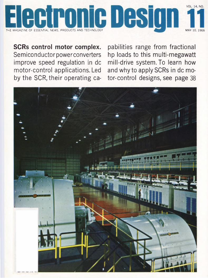
THE MAGAZINE OF ESSENTIAL NEWS. PRODUCTS AND TECHNOLOGY MAY 10, 1966
SCRs control motor complex. Semiconductor powerconverters improve speed regulation in de motor-control applications. Led by the SCR, their operating ca
pabilities range from fractional hp loads to this multi-megawatt mill-drive system. To learn how and why to apply SCRs in de motor-control designs, see page 38
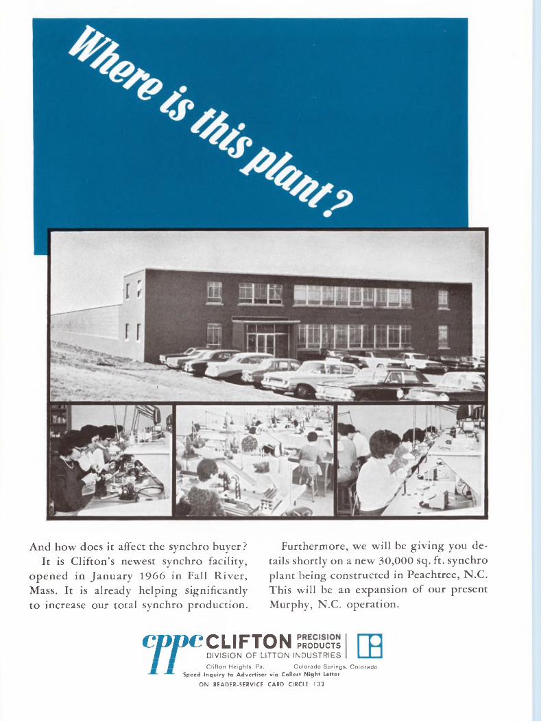
And how does it affect the synchro buyer?It is Clifton’s newest synchro facility,
opened in January 1966 in Fall River, Mass. It is already helping significantly to increase our total synchro production.
Furthermore, we will be giving you details shortly on a new 30,000 sq. ft. synchro plant being constructed in Peachtree, N.C. This will be an expansion of our present Murphy, N.C. operation.
CppcCLIFTON PRODUCTS S f DIVISION OF LITTON INDUSTRIESK U Clifton Heights, Pa. Colorado Springs, Colorado
Speed Inquiry to Advertiser via Collect Night Letter
ON READER-SERVICE CARD CIRCLE 132
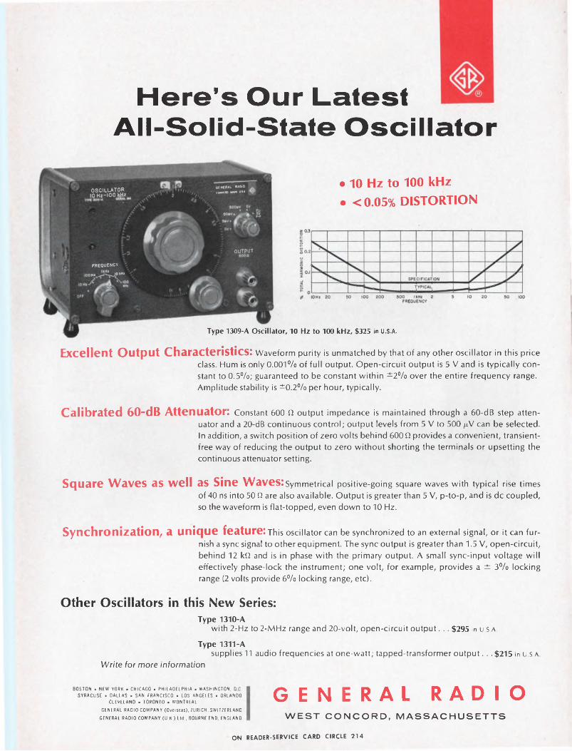
Here’s Our LatestAll-Solid-State Oscillator
OSCILLATOR 10 Hz-100 kriz
QEHERAL RADIOCOWCOW HM* «•*
• 10 Hz to 100 kHz• <0.05% DISTORTION
OUTPUT
FREQUENCY
Hi JjiLjOkHx
Type 1309-A Oscillator, 10 Hz to 100 kHz, $325 in U.S.A.
Excellent Output Characteristics: Waveform purity is unmatched by that of any other oscillator in this price class. Hum is only 0.001% of full output. Open-circuit output is 5 V and is typically constant to 0.5%; guaranteed to be constant within ±2% over the entire frequency range. Amplitude stability is ±0.2% per hour, typically.
Calibrated 60-dB Attenuator: Constant 600 £2 output impedance is maintained through a 60-dB step attenuator and a 20-dB continuous control; output levels from 5 V to 500 /A/ can be selected. In addition, a switch position of zero volts behind 600 Q provides a convenient, transient- free way of reducing the output to zero without shorting the terminals or upsetting the continuous attenuator setting.
Square Waves as well as Sine Waves: Symmetrical positive-going square waves with typical rise times of 40 ns into 50 Q are also available. Output is greater than 5 V, p-to-p, and is de coupled, so the waveform is flat-topped, even down to 10 Hz.
Synchronization, a unique feature: This oscillator can be synchronized to an external signal, or it can furnish a sync signal to other equipment. The sync output is greater than 1.5 V, open-circuit, behind 12 kQ and is in phase with the primary output. A small sync-input voltage will effectively phase-lock the instrument; one volt, for example, provides a ± 3% locking range (2 volts provide 6% locking range, etc).
Other Oscillators in this New Series:Type 1310-A
with 2-Hz to 2-MHz range and 20-volt, open-circuit output. .. $295 in U.S.A.
Type 1311-Asupplies 11 audio frequencies at one-watt; tapped-transformer output... $215 in U.S.A.
Write for more information
BOSTON . NEW YORK • CHICAGO . PHILADELPHIA • WASHINGTON. DC.
SYRACUSE • DALLAS • SAN FRANCISCO . LOS ANGELES • ORLANDO
CLEVELAND • TORONTO • MONTREAL
GENERAL RADIO COMPANY (Overseas), ZURICH. SWITZERLAND
GENERAL RADIO COMPANY (U.K.) Ltd., BOURNE END, ENGLAND
GENERAL RADIOWEST CONCORD, MASSACHUSETTS
ON READER-SERVICE CARD CIRCLE 214
a ssèDIGITAL computer cm Oe°omNbHIGH-LEVEL multiplexer8^HIGH reliability NASa^tX^TITAN II VIBRATION analys*^'^^^
TELEMETRY systems •Fl JNCTIONAL D_^ MiSSiL^ ::g0RPEDCOR-
I ELCivil.. ... _ FUNCTIONAL digital MULJUi-i. COMPUTED CONTROLLED MISSILE
Nike multiplexing Tape-to-tape oon^c
ROCKET Bl NADY-TO ■ BCD°py NASA RF
PR°PE»
DATA^à^
Engineers: If your field is analog/digital data systems or component design, a career opportunity awaits you at REDCOR.Write to Personnel Director.
complete systems compatibility...
IREDCORP.O. BOX 1031 / CANOGA PARK, CALIFORNIA 91304 PHONE: (AREA CODE 213) 348-5892 / TWX: 213-348-2573
Speed Inquiry to Advertiser via Collect Night Letter
ON READER-SERVICE CARD CIRCLE 2
2 Electronic Design
NEWS
13 News Report17 Industry standards picture confused
The electronic industry voices both praise and criticism for the National Bureau of Standards and the job it is doing.
21 Fewer dramatics, more uses for lasersSpeakers at Quantum Electronics Conference predict practical applications and innovations rather than startling breakthroughs.
26 Saw cuts IC wafers without touching.26 Unique lab customizes computer systems.26 Phono cartridge uses strain.gauge.28 Jet engines power satellite ground station.:28 3-D television is still a long way off.31 Washington Report33 Letters35 Editorial: Making the proper first impression. . .
TECHNOLOGY38 Device-hunting for motor speed control? The source will show when, where and
why the SCR usually outlaps competing units.48 A guide to crystal selection, this table can help to acquaint you better with the
wide variety of crystals on the market.54 Design a transformerless chopper with “off-the-shelf” integrated circuits. Small
size and low cost are the main advantages.60 A silent stepping relay? Yes, it’s possible with the use of a combination of reed
relays and Silicon-controlled rectifiers.64 Ideas for Design73 NASA Tech Briefs
PRODUCTS78 Test Equipment: Volt/ratiometer features accuracy and stability.88 Components: Solar cells charge operational amplifier.98 Power Equipment106 Materials110 Microwaves114 Production Equipment117 Semiconductors
Departments118 Design Aids120 New Literature126 Advertisers’ Index128 Designer’s Datebook
ELECTRONIC DESIGN is published bi weekly by Hayden Publishing Company, Inc., 850 Third Avenue, New York, N. Y„10022. James S. Mulholland, Jr., President. Printed at Poole Bros., Inc., Chicago, III., Controlled-circulation postage
paid at Chicago, III., and New York, N. Y. Copyright © 1966, Hayden Publishing Company, Inc. 61,114 copies this issue
May 10, 1966
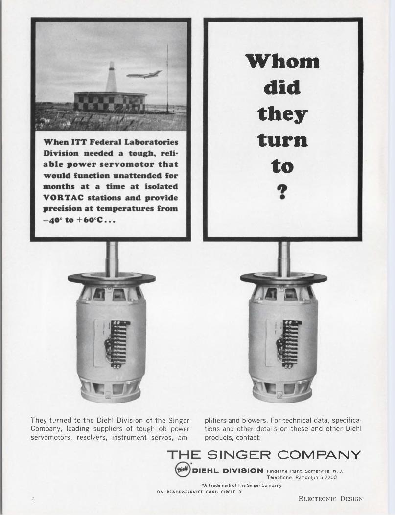
Whom did they turn
to
They turned to the Diehl Division of the Singer Company, leading suppliers of tough-job power servomotors, resolvers, instrument servos, am-
plifiers and blowers. For technical data, specifications and other details on these and other Diehl products, contact:
SINGER COMPANYDIEHL DIVISION Finderne Plant, Somerville, N. J.
Telephone: Randolph 5-2200*A Trademark of The Singer Company
ON READER-SERVICE CARD CIRCLE 3
4 Electronic Design
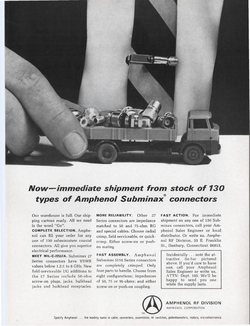
Now—immediate shipment from stock of 130 types of Amphenol Subminax connectors
Our warehouse is full. Our shipping cartons ready. All we need is the word “Go”.COMPLETE SELECTION. Amphenol can fill your order for any one of 130 suhminiature coaxial connectors. All give you superior electrical performance.MEET MIL-C-22557A. Subminax 27 Series connectors have VSWR values below 1.2:1 to 6 GHz. New field-serviceable UG additions to the 27 Series include 50-ohm screw-on plugs, jacks, bulkhead jacks and bulkhead receptacles.
MORE RELIABILITY. Other 27 Series connectors are impedance matched to 50 and 75-ohm RG and special cables. Choose radial crimp, field serviceable, or quickcrimp. Either screw-on or push- on mating.
FAST ASSEMBLY. Amphenol Subminax 5116 Series connectors are completely crimped. Only four parts to handle. Choose from eight configurations; impedances of 50, 75 or 95-ohms; and either screw-on or push-on coupling.
FAST ACTION. For immediate shipment on any one of 130 Subminax connectors, call your Amphenol Sales Engineer or local distributor. Or write us. Amphenol RF Division,. 33 E. Franklin St, Danbury, Connecticut 06813.
Incidentally . . . note the attractive tie-bar pictured above. If you’d care to have one, call your Amphenol Sales Engineer or write us, ATTN: Dept. 103. We’ll be happy to send you one while the supply lasts.
AMPHENOL RF DIVISIONAMPHENOL CORPORATION
Specify Amphenol ... the leading name in cable, connectors, assemblies, rf switches, potentiometers, motors, microelectronics
TEAR UP YOUR FAIRCHILD DU
PRICE LIST
We did. We’ve dropped our prices on all DTjiL integrated circuits. By 38 to 42% on most units. By 20 to 25% on others. Both on our industrial circuits and on our mil spec units. And the reductions apply to all price breaks up to 999 units. (Our 1000-up prices are already unbeatable.)
Call a Fairchild Distributor, or contact us for details.
May 10, 1966 5
FAIRCHILDSEMICONDUCTOR
FAIRCHILD SEMICONDUCTOR/A Division of Fairchild Camera and Instrument Corporation ■ 313 Fairchild Drive. Mountain View, California (415) 962-5011 ■ TWX: 910-379-6435
ON READER-SERVICE CARD CIRCLE 4
Wouldn’t it be nice if there were some way you could get immediate delivery on Heinemann circuit breakers ?
We have good news for you. There are now 27 ways to get immediate delivery:
AUTHORIZED HEINEMANN STOCKING DISTRIBUTORS
AlabamaElectro-Tech, Inc.Huntsville(205) 539-1250
ArizonaKierulff Electronics CorporationPhoenix(602) 273-7331
CaliforniaWesco ElectronicsPasadena(213) 795-9161
FloridaParts Service CorporationOrlando(305) 293-5730
GeorgiaElectro-Tech, Inc.Hapeville(404) 758-7205
KansasPrecision Electronic Devices, Inc.Kansas City(913) AD 6-4343
KentuckyE & H Electric Supply CompanyLouisville(502) 587-0991Marine Electric Company, Inc.Louisville(502) 587-6511
LouisianaHall-Mark Electronics Corporation New Orleans(504) 242-7581MarylandD & H Distributing Co., Inc. Baltimore(301) 727-5100MassachusettsApparatus Service Company Allston (617) 782-7440Electrical Supply Corporation Cambridge(617) 491-3300T. F. Cushing, Inc.Springfield(413) 788-7341
New JerseyAlpha Electronic Services Pennsauken(609) NO 2-1310Federated Purchaser, Inc.Springfield(201) DR 6-8900New YorkFederal Electronics Inc.Vestal(607) PI 8-8211Schweber ElectronicsWestbury, Long Island (516) ED 4-7474North CarolinaElectro-Tech, Inc.Charlotte (704) 333-0326
OhioThe Midwest Equipment Company Cincinnati(513) 821-1687
PennsylvaniaWest Chester Electric Supply Co.West Chester(215) 696-7500
T exasWarren Electric CompanyBeaumont(713) TE 3-9405Nelson Electric Supply CompanyDallas(214) Rl 1-6341Hall-Mark Electronics CorporationGarland(214) 276-8531Hall-Mark Electronics CorporationHouston(713) 781-0011Warren Electric CompanyHouston(713) CA 5-0971Messner Electric Supply Company Longvie v(214) PLaza 3-4484The Perry Shankle CompanySan Antonio(512) CA 3-1801
HEINEMANN ELECTRIC COMPANY Trenton, New Jersey 086023402
Speed Inquiry to Advertiser via Collect Night LetterON READER-SERVICE CARD CIRCLE 5
7< ON READER-SERVICE CARD CIRCLE 215
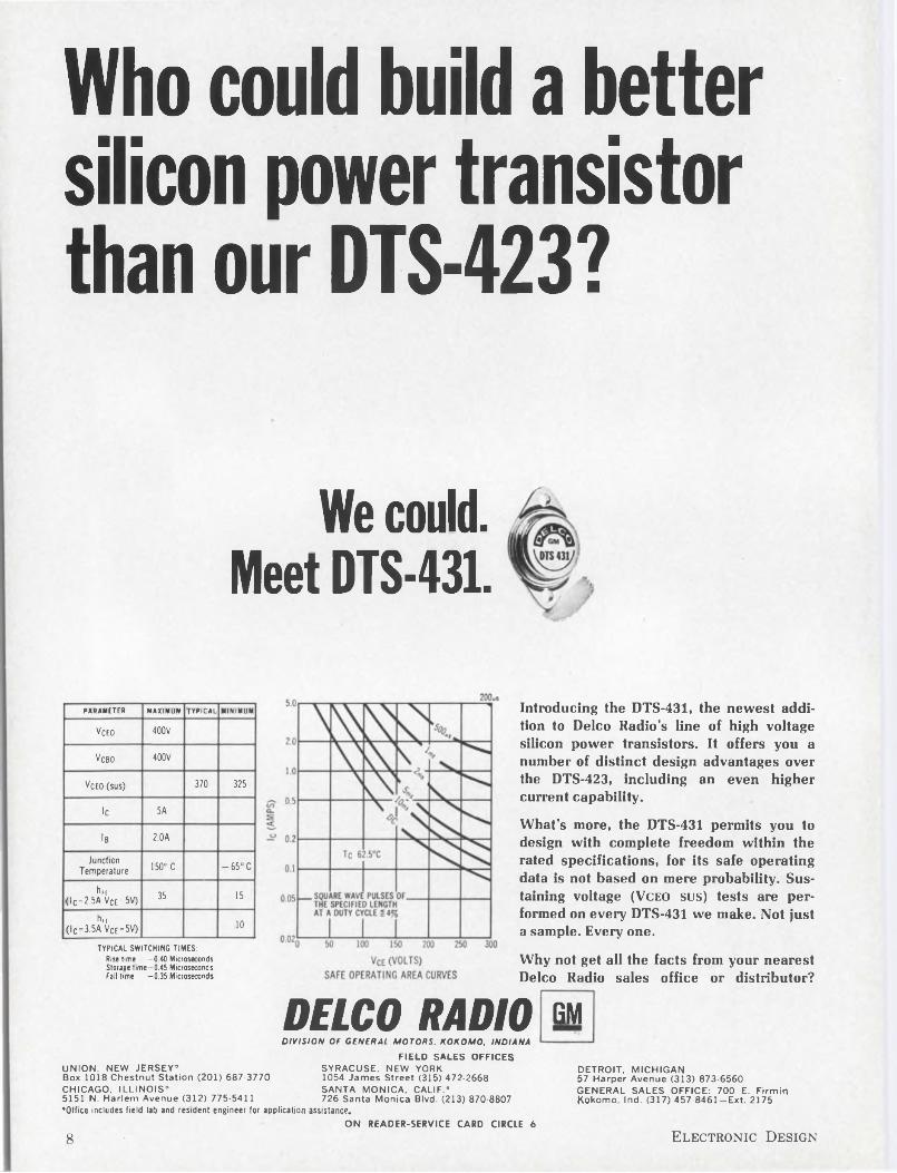
Who could build a better silicon power transistor than our DTS-423?
We could. Meet DTS-431.
PARAMETER MAXIMUM TYPICAL MINIMUM
Veto 400V
Vcbo 400V
Veto(sus) 370 325
lc 5A
Ib 2.0A
Junction Temperature 150° C - 65° C
hfE (lC=2.5A VCe=5V) 35 15
hrr (lc-3.5A Vce-5V) 10
TYPICAL SWITCHING TIMES:Rise time —0.40 MicrosecondsStorage time—0.45 MicrosecondsFall time —0.35 Microseconds
Introducing the DTS-431, the newest addition to Delco Radio’s line of high voltage silicon power transistors. It offers you a number of distinct design advantages over the DTS-423, including an even higher current capability.What’s more, the DTS-431 permits you to design with complete freedom within the rated specifications, for its safe operating data is not based on mere probability. Sustaining voltage (Vceo SUS) tests are performed on every DTS-431 we make. Not just a sample. Every one.
Why not get all the facts from your nearest Delco Radio sales office or distributor?
DELCO RADIODIVISION OF GENERAL MOTORS. KOKOMO, INDIANA
GMUNION, NEW JERSEY’Box 1018 Chestnut Station (201) 687-3770CHICAGO. ILLINOIS’5151 N. Harlem Avenue (312) 775-5411’Office includes field lab and resident engineer for application assistance.
FIELD SALES OFFICES SYRACUSE, NEW YORK1054 James Street (315) 472-2668SANTA MONICA, CALIF.*726 Santa Monica Blvd. (213) 870-8807
DETROIT, MICHIGAN57 Harper Avenue (313) 873-6560 GENERAL SALES OFFICE: 700 E. Firmin Kokomo, Ind. (317) 457-8461-Ext. 2175
ON READER-SERVICE CARD CIRCLE 6
8 Electronic Design
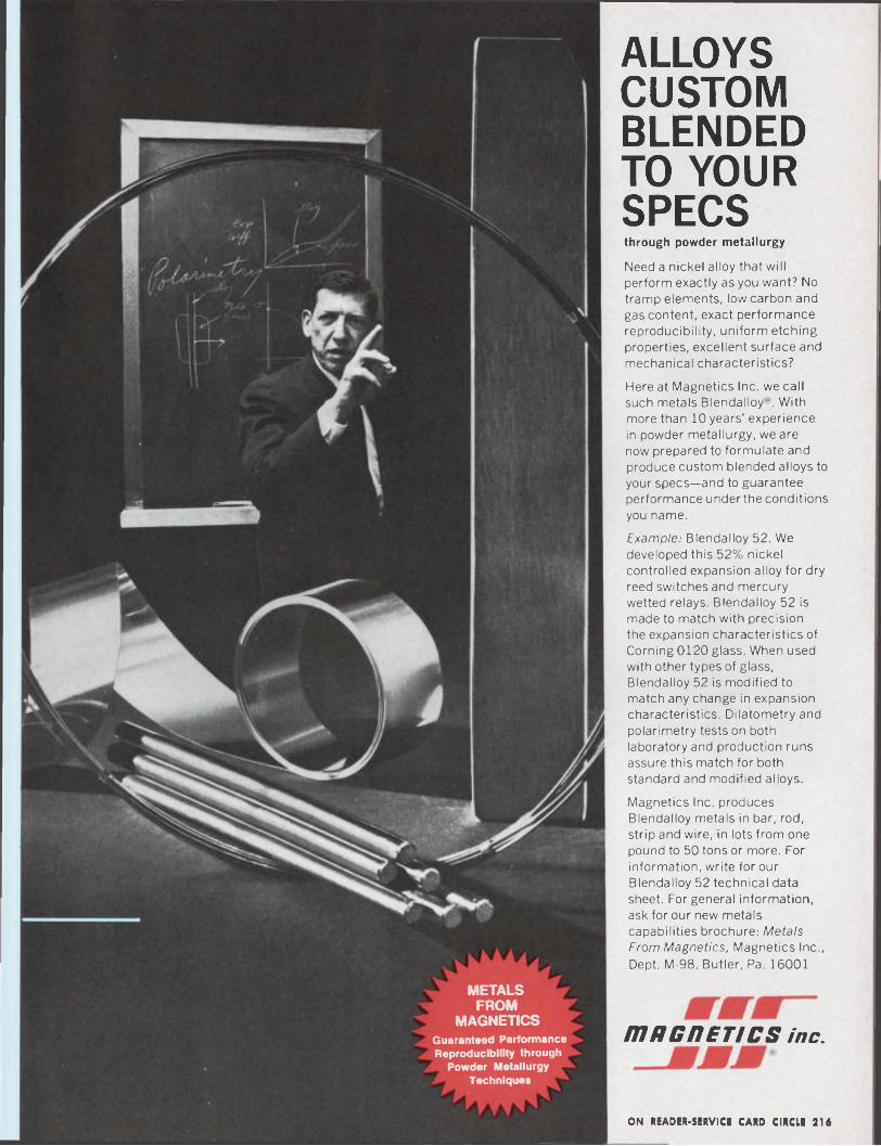
ALLOYS CUSTOM BLENDED TO YOUR SPECS through powder metallurgy
Need a nickel alloy that will perform exactly as you want? No tramp elements, low carbon and gas content, exact performance reproducibility, uniform etching properties, excellent surface and mechanical characteristics?
Here at Magnetics Inc. we call such metals Blendalloy". With more than 10 years' experience in powder metallurgy, we are now prepared to formulate and produce custom blended alloys to your specs—and to guarantee performance underthe conditions you name.
Example: Blendalloy 52. We developed this 52% nickel controlled expansion alloy for dry reed switches and mercury wetted relays. Blendalloy 52 is made to match with precision the expansion characteristics of Corning 0120 glass. When used with other types of glass, Blendalloy 52 is modified to match any change in expansion characteristics. Dilatometry and polarimetry tests on both laboratory and production runs assure this match for both standard and modified alloys.
Magnetics Inc. produces Blendalloy metals in bar, rod, strip and wire, in lots from one pound to 50 tons or more. For information, write for our Blendalloy 52 technical data sheet. For general information, ask for our new metals capabilities brochure: Metals From Magnetics, Magnetics Inc, Dept. M-98, Butler, Pa. 16001
METALS FROM
MAGNETICSGuaranteed Performance Reproducibility through
Powder MetallurgyTechniques
mncnET/cs inc.
ON READER-SERVICE CARD CIRCLE 216
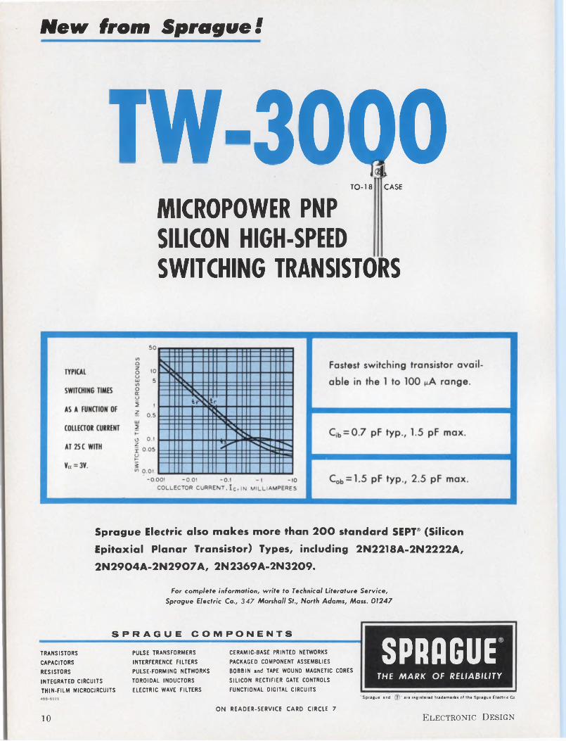
New from Sprague!
TW-3000CASETO-18
MICROPOWER PNP SILICON HIGH-SPEEDSWITCHING TRANSISTORS
Sprague Electric also makes more than 200 standard SEPT® (Silicon
Epitaxial Planar Transistor) Types, including 2N2218A-2N2222A,
2N2904A-2N2907A, 2N2369A-2N3209.
For complete information, write to Technical Literature Service, Sprague Electric Co., 347 Marshall St., North Adams, Mass. 01247
SPRAGUE COMPONENTS
TRANSISTORS
CAPACITORS
RESISTORS
INTEGRATED CIRCUITS
THIN-FILM MICROCIRCUITS
PULSE TRANSFORMERS
INTERFERENCE FILTERS
PULSE-FORMING NETWORKS
TOROIDAL INDUCTORS
ELECTRIC WAVE FILTERS
CERAMIC BASE PRINTED NETWORKS
PACKAGED COMPONENT ASSEMBLIES
BOBBIN and TAPE WOUND MAGNETIC CORES
SILICON RECTIFIER GATE CONTROLS
FUNCTIONAL DIGITAL CIRCUITS
SPRAGUETHE MARK OF RELIABILITY
Sprague' and '(2)' are registered trademarks of the Sprague Electric Co.
ON READER-SERVICE CARD CIRCLE 7
10 Electronic Design
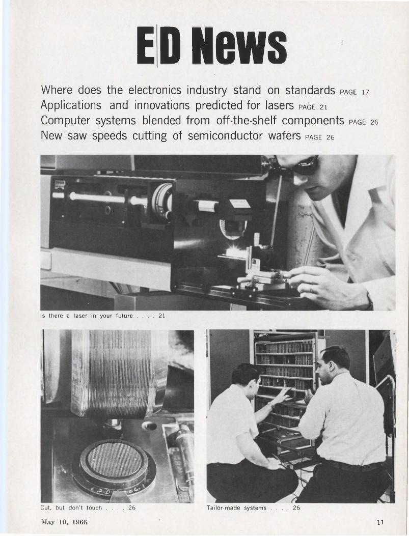
Where does the electronics industry stand on standards page 17
Applications and innovations predicted for lasers page 21
Computer systems blended from off-the-shelf components page 26
New saw speeds cutting of semiconductor wafers page 26
ED News
Is there a laser in your future .... 21
Cut, but don’t touch .... 26 Tailor-made systems .... 26
May 10, 1966. 11
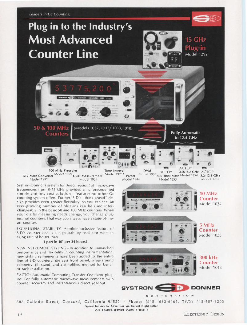
Leaders in Cc Counting
Counter Line
COUNTER IQ37
(Models 1037,1017/1038,1018)
Plug in to the Industry's
Most Advanced 15 GHz Plug-in Model 1292
50 & 100 MHz Counters Fully Automatic
to 12.4 GHz
ACTO* ACTO*8.2-12.4 GHzModel 1255
ACTO*2.96 8.2 GHz100 MHz Prescaler Time Interval DVM
512 MHz ConverterModel 1979 Dual Measurement Model 1926A Preset Model 1936Model 1291 Model 1924 Model 1944
500-3000 MHz Model 1254Model 1253
Systron-Donner's system for direct readout of microwave frequencies from 0-15 GHz provides an unprecedented simple and low cost solution — features no other Gc counting system offers. Further, S-D's "think ahead" design provides even greater flexibility. As you can see, an ever-growing number of plug-ins can be used interchangeably in the basic 50 and 100 MHz counters. When your digital measuring needs change, you change plugins, not counters. That way you always have a state-of-the- art-counter.
EXCEPTIONAL STABILITY—Another exclusive feature of S-D's counter line is a high stability oscillator with an aging rate of better than
1 part in 109 per 24 hours!NEW INSTRUMENT STYLING—In addition to unmatched performance and flexibility in counting instrumentation, new styling refinements have been added to the entire line of S-D counters: die cast front panel, wrap-around cabinetry, tilt stand, and a simplified method for bench or rack installation.
*ACTO: Automatic Computing Transfer Oscillator plugins. For fully automatic microwave measurements with counter accuracy and instantaneous direct readout.
SYSTRONCORPORATION
10 MHz CounterModel 1034
5 MHz Counter Model 1033
300 kHz Counter Model 1013
DONNER
888 Galindo Street, Concord, California 94520 ’ Phone: (415) 682-6161, TWX: 415-687-3200Speed Inquiry to Advertiser via Collect Night Letter
ON READER-SERVICE CARD CIRCLE 8
12 Electronic Design
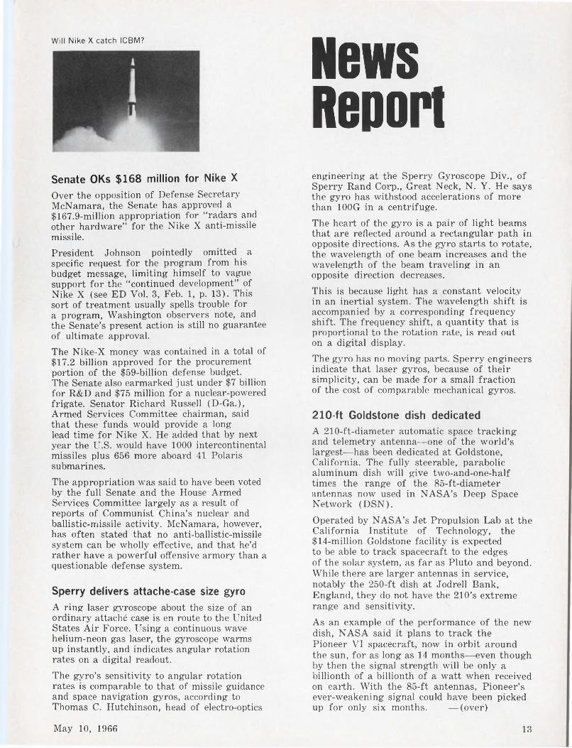
Will Nike X catch ICBM? News Report
Senate OKs $168 million for Nike X
Over the opposition of Defense Secretary McNamara, the Senate has approved a $167.9-million appropriation for “radars and other hardware” for the Nike X anti-missile missile.President Johnson pointedly omitted a specific request for the program from his budget message, limiting himself to vague support for the “continued development” of Nike X (see ED Vol. 3, Feb. 1, p. 13). This sort of treatment usually spells trouble for a program, Washington observers note, and the Senate’s present action is still no guarantee of ultimate approval.The Nike-X money was contained in a total of $17.2 billion approved for the procurement portion of the $59-billion defense budget.The Senate also earmarked just under $7 billion for R&D and $75 million for a nuclear-powered frigate. Senator Richard Russell (D-Ga.), Armed Services Committee chairman, said that these funds would provide a long lead time for Nike X. He added that by next year the U.S. would have 1000 intercontinental missiles plus 656 more aboard 41 Polaris submarines.The appropriation was said to have been voted by the full Senate and the House Armed Services Committee largely as a result of reports of Communist China’s nuclear and ballistic-missile activity. McNamara, however, has often stated that no anti-ballistic-missile system can be wholly effective, and that he’d rather have a powerful offensive armory than a questionable defense system.
Sperry delivers attache-case size gyro
A ring laser gyroscope about the size of an ordinary attaché case is en route to the United States Air Force. Using a continuous wave helium-neon gas laser, the gyroscope warms up instantly, and indicates angular rotation rates on a digital readout.
The gyro’s sensitivity to angular rotationrates is comparable to that of missile guidanceand space navigation gyros, according toThomas C. Hutchinson, head of electro-optics
engineering at the Sperry Gyroscope Div., of Sperry Rand Corp., Great Neck, N. Y. He says the gyro has withstood accelerations of more than 100G in a centrifuge.The heart of the gyro is a pair of light beams that are reflected around a rectangular path in opposite directions. As the gyro starts to rotate, the wavelength of one beam increases and the wavelength of the beam traveling in an opposite direction decreases.
This is because light has a constant velocity in an inertial system. The wavelength shift is accompanied by a corresponding frequency shift. The frequency shift, a quantity that is proportional to the rotation rate, is read out on a digital display.The gyro has no moving parts. Sperry engineers indicate that laser gyros, because of their simplicity, can be made for a small fraction of the cost of comparable mechanical gyros.
210-ft Goldstone dish dedicatedA 210-ft-diameter automatic space tracking and telemetry antenna—one of the world’s largest—has been dedicated at Goldstone, California. The fully steerable, parabolic aluminum dish will give two-and-one-half times the range of the 85-ft-diameter antennas now used in NASA’s Deep Space Network (DSN).
Operated by NASA’s Jet Propulsion Lab at the California Institute of Technology, the $14-million Goldstone facility is expected to be able to track spacecraft to the edges of the solar system, as far as Pluto and beyond. While there are larger antennas in service, notably the 250-ft dish at Jodrell Bank, England, they do not have the 210’s extreme range and sensitivity.
As an example of the performance of the new dish, NASA said it plans to track the Pioneer VI spacecraft, now in orbit around the sun, for as long as 14 months—even though by then the signal strength will be only a billionth of a billionth of a watt when received on earth. With the 85-ft antennas, Pioneer’s ever-weakening signal could have been picked up for only six months. —(over)
May 10, 1966 13
News Report CONTINUED
“Experiment,” will be carried by the 104 stations of the National Educational Television Network.
The new science show will be hosted by Don Herbert, who for 14 years made “Mr. Wizard” famous explaining science to children. Now Herbert will turn his talents to the grown-ups.
Like other DSN facilities operating at S-band (2110-2120 MHz transmitting and 2290-2300 MHz receiving), the 210-ft dish incorporates a Cassegrainian cone feed mounted at the center of the reflector.Signals collected in the main dish bounce up and hit a sub-reflector which focuses the signal into the feed horn of the Cassegrainian cone where there is a maser amplifier. The deep-space signal is usually maser-amplified about 40,000 times before it is fed into the rest of the receiver system for further amplification.NASA is planning to build additional antennas the size of the Goldstone facility at other DSN sites around the world.
Semiconductor sales rose sharply last year
Last year was a banner year for semiconductor manufacturers, with factory sales up 20 per cent over the 1964 figures. Another 19-per-cent increase is expected this this year, according to Electronic Industries Association estimates.Germanium transistors led the field in total numbers sold with over 333 million units worth $166.5 million. In dollar value, silicon transistors were top, with 272 million units sold for over $213 million. Sales of FETs were over 610,000 units, a whopping 265-per- cent increase over 1964. IC sales were up 93 per cent over 1964 for a total of $79 million.
SECAM “oui” PAL “nyet"French and Russian endorsement of the SE CAM-3 color-television system has scuttled hope for a compatible Pan-European system. On agreeing to SECAM-3, the Soviets shelved their proposals to adapt the SECAM system in such a way as would have made it a variation of the German PAL system. To date all other major European countries have indicated preference for the amplitude-modulated PAL system. The French-Soviet action spells trouble for international exchange of programs. It also complicates the manufacture of TV sets for the European market.
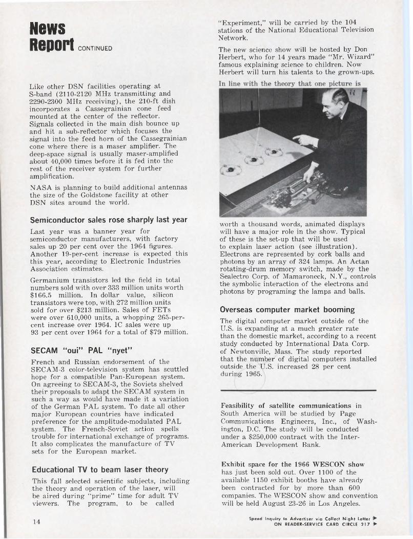
Educational TV to beam laser theoryThis fall selected scientific subjects, includingthe theory and operation of the laser, willbe aired during “prime” time for adult TVviewers. The program, to be called
worth a thousand words, animated displays will have a major role in the show. Typical of these is the set-up that will be used to explain laser action (see illustration). Electrons are represented by cork balls and photons by an array of 324 lamps. An Actan rotating-drum memory switch, made by the Sealectro Corp, of Mamaroneck, N.Y., controls the symbolic interaction of the electrons and photons by programing the lamps and balls.
Overseas computer market boomingThe digital computer market outside of the U.S. is expanding at a much greater rate than the domestic market, according to a recent study conducted by International Data Corp, of Newtonville, Mass. The study reported that the number of digital computers installed outside the U.S. increased 28 per cent during 1965.
Feasibility of satellite communications in South America will be studied by Page Communications Engineers, Inc., of Washington, D.C. The study will be conducted under a $250,000 contract with the InterAmerican Development Bank.
Exhibit space for the 1966 WESCON show has just been sold out. Over 1100 of the available 1150 exhibit booths have already been contracted for by more than 600 companies. The WESCON show and convention will be held August 23-26 in Los Angeles.
Speed Inquiry to Advertiser via Collect Night LetterON READER-SERVICE CARD CIRCLE 217 >14
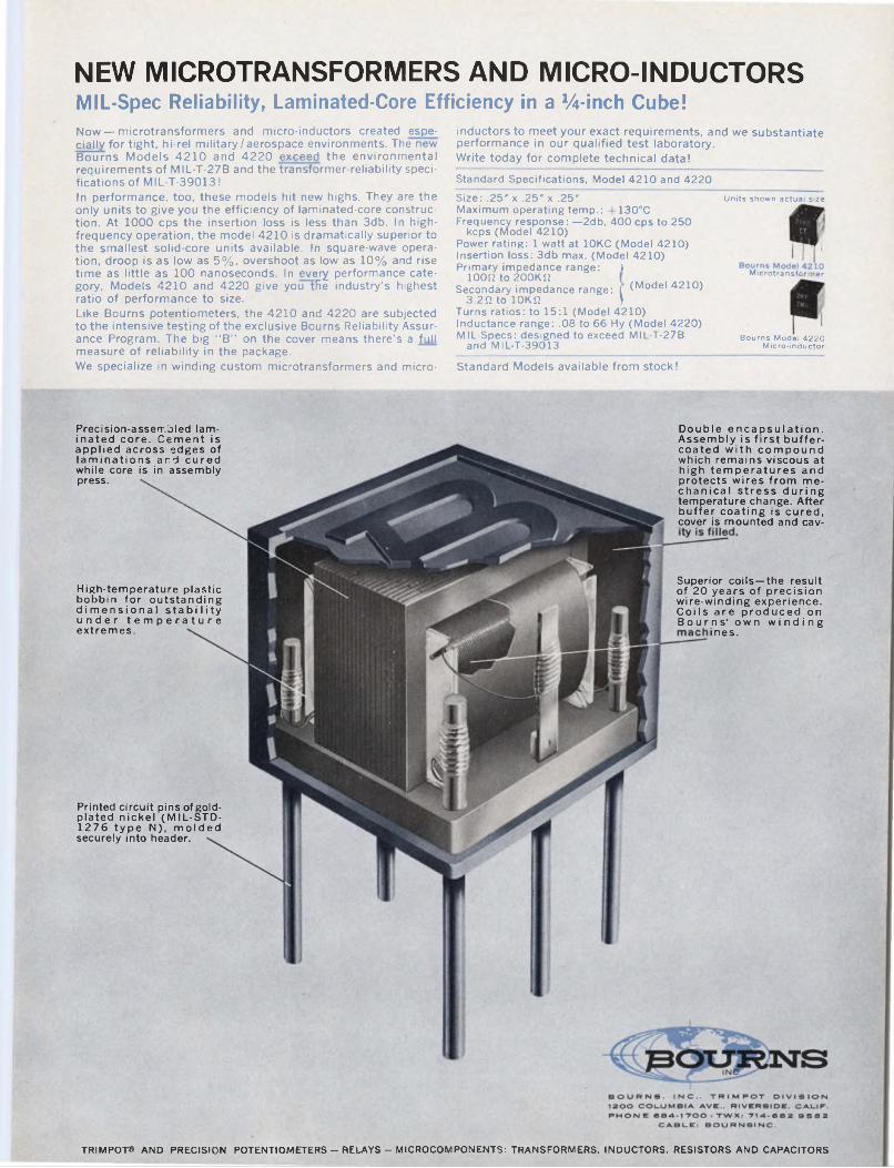
NEW MICROTRANSFORMERS AND MICRO-INDUCTORSMIL-Spec Reliability, Laminated-Core Efficiency in a %-inch Cube!Now—microtransformers and micro-inductors created especially for tight, hi-rel military/aerospace environments. The new Bourns Models 4210 and 4220 exceed the environmental requirements of MIL-T-27B and the transformer-reliability specifications of MIL-T-39013!In performance, too, these models hit new highs. They are the only units to give you the efficiency of laminated-core construction. At 1000 cps the insertion loss is less than 3db. In high- frequency operation, the model 4210 is dramatically superior to the smallest solid-core units available. In square-wave operation, droop is as low as 5%, overshoot as low as 10% and rise time as little as 100 nanoseconds. In every performance category, Models 4210 and 4220 give you the industry's highest ratio of performance to size.Like Bourns potentiometers, the 4210 and 4220 are subjected to the intensive testing of the exclusive Bourns Reliability Assurance Program. The big “B” on the cover means there’s a full measure of reliability in the package.We specialize in winding custom microtransformers and micro
inductors to meet your exact requirements, and we substantiate performance in our qualified test laboratory.Write today for complete technical data!Standard Specifications, Model 4210 and 4220Size: .25" x .25" x .25"Maximum operating temp.: +130°CFrequency response: —2db, 400 cps to 250
keps (Model 4210)Power rating: 1 watt at 10KC (Model 4210)Insertion loss: 3db max. (Model 4210)Primary impedance range: )
100(2 to 2OOK(2Secondary impedance range: ( (Model 4210)
3.2(1 to lOKil )Turns ratios: to 15:1 (Model 4210)Inductance range: .08 to 66 Hy (Model 4220)MIL-Specs: designed to exceed MIL-T-27B
and MIL-T-39013
Units shown actual size
Microtransformer
Bourns Model 4220 Micro-inductor
Standard Models available from stock!
Precision-assembled laminated core. Cement is applied across edges of laminations and cured while core is in assembly press.
Double encapsulation. Assembly is first buffer- coated with compound which remains viscous at high temperatures and protects wires from mechanical stress during temperature change. After buffer coating is cured, cover is mounted and cav-
High-temperature plastic bobbin for outstanding dimensional stability under temperature extremes.
Printed circuit pins of gold- plated nickel (MIL-STD- 1276 type N), molded securely into header.
Superior coils—the result of 20 years of precision wire-winding experience. Coils are produced on Bourns’ own winding
ines.
TRIMPOT» AND PRECISION POTENTIOMETERS - RELAYS - MICROCOMPONENTS: TRANSFORMERS. INDUCTORS. RESISTORS AND CAPACITORS
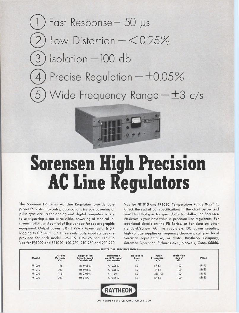
(T) Fast Response —50 jis
CZ) Low Distortion — <0.25%
3) Isolation —100 db
Sorensen High Precision AC Line Regulators
The Sorensen FR Series AC Line Regulators provide pure power for critical circuitry; applications include powering of pulse-type circuits for analog and digital computers where false triggering is not permissible, powering of medical instrumentation, and control of line voltage for spectrographic equipment. Output power is 0 - 1 kVA • Power factor is 0.7 lagging to 0.7 leading • Three switchable input ranges are provided for each model—95-115, 105-125 and 115-135 Vac for FR1000 and FR1020; 190-230, 210-250 and 230-270
Vac for FRI010 and FRI030. Temperature Range 0-55° C. Check the rest of our specifications in the chart below and you'll find that spec for spec, dollar for dollar, the Sorensen FR Series is your best value in precision line regulators. For additional details on the FR Series, or for data on other standard/custom AC line regulators, DC power supplies, high voltage supplies or frequency changers, call your local Sorensen representative, or write: Raytheon Company, Sorensen Operation, Richards Ave., Norwalk, Conn. 06856.
ELECTRICAL SPECIFICATIONS
ModelOutput Voltage
Vac
Regulation Line & Load Combined
Distortion w/10% Input
Harmonics
Response Time
A*
Input Frequency
c/s
Isolation In/Out
dbPrice
FR1000 115 ± 0.05% < 0.25% 50 57-63 100 $1425
FR1010 230 ± 0.05% < 0.25% 50 47-53 100 $1650
FRI020 115 ± 0.05% < 1-0% 50 380-420 100 $1525
FRI030 230 ± 0.5% < 0.25% 50 57-63 100 $1650
ON READER-SERVICE CARD CIRCLE 200
NEWS
Crisis in standards: new survey pinpoints needsNBS services falling short of industry needs; diagnosis-acute budgetary malnutrition
Peer Fossen Robert Haavind West Coast Editor Managing Editor
First the “missile gap,” now the “standards gap.”
The latter refers to the subject of a new survey being reported today (May 10) at a meeting of the National Conference of Standards Laboratories (NCSL) in Gaithersburg, Md. This survey pinpoints areas where industry needs basic standards or calibrations services; but can’t get them. The survey was conducted by an NCSL committee headed by Charles Johnson of Boeing Co., Seattle, who is making the report.
According to Johnson, the most critical areas of need revealed by the survey of 118 member-laboratories were:
■ High-frequency attenuation.■ Spectral transmission.■ Vacuum measurements and
leak-rate measurements under vacuum conditions.
■ High-frequency reflection coefficient.
■ Impulse spectral density.A majority of the requests for
new standards, according to Johnson, come from NASA or from manufacturers in space work. Very few
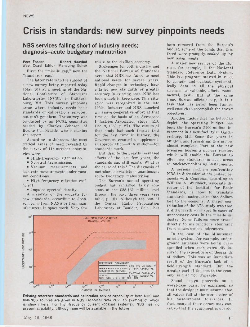
HIGH-FREQUENCY CURRENT (COAXIAL SYSTEM)
CALIBRATION SERVICE
REFERENCE STANDARDS — ■ ■■ EXISTING CAPABILITY
------------------------------------- 5 yEar OBJECTIVE
10° IO-10 IO-0 IO-6 IO*4 IO-2 10° IO2 IO4
CURRENT IN AMPERES
Existing reference standards and calibration service capability of both NBS and non-NBS sources are given in NBS Technical Note 262, an example of which is shown here. For high-frequency current (coaxial systems), NBS has no present capability, although one will be available in the future
relate to the civilian economy.Spokesmen for both industry and
the National Bureau of Standards agree that NBS has failed to meet national needs for several years. Rapid changes in technology have entailed new standards or greater accuracy in existing ones. NBS has been unable to keep pace. This situation was recognized in the late 1950s. Industry and NBS launched a massive cooperative effort at that time on the basis of an Aerospace Industries Association study (ED, Dec. 9, 1959, p. 27). The results of that study had such impact that for the first time in history, the Government granted a supplemental appropriation—$1.5 million—for standards work.
But, despite the greatly increased efforts of the last few years, the standards gap still exists. What is the cause of this ? The diagnosis of metrology specialists is unanimous: acute budgetary malnutrition.
The Bureau’s annual operating budget has remained fairly constant at the $28-$31 million level through the past three years (see table, p. 18). Although the cost of the Central Radio Propagation Laboratory at Boulder, Colo., has
-------------------------------------- EXISTING CAPABILITY ------------------------------------ 5 YEAR OBJECTIVE NON-NBS STATE OF THE ART
been removed from the Bureau’s budget, some of the funds that this freed were promptly soaked up by new assignments.
A major new service of the Bureau, for example, is the National Standard Reference Data System. This is a program, started in 1963, to compile and evaluate systematically data in all the physical sciences—a valuable, albeit monumental, task! But at the same time, Bureau officials say, it is a task that has never been funded well enough to accomplish the stated objectives.
Another factor that has helped to deplete the operating budget has been the Bureau’s $100-million investment in a new facility in Gaithersburg, Md. Some five years in building and furnishing, this is now almost complete. Part of the new premises houses a nuclear reactor, which will enable the Bureau to offer new standards in such areas as nuclear-monitoring instruments.
A serious problem confronting NBS in discussion of its budget requests with Congress, according to William A. Wildhack, associate director of the Institute for Basic Standards, is how to translate standards inadequacies into dollars lost to the economy. A major contribution of the AIA study was that it did unearth some specific cases of unnecessary costs in the missile industry. Some failures were traced directly to malfunctions stemming from measurement tolerances.
In the case of the Minuteman missile system, for example, underground antennas were being overspecified when each extra dB incurred the expenditure of thousands of dollars. This was an immediate result of the Bureau’s lack of a field-strength standard. But the greater part of the cost to the economy is just not traceable.
Sound design proceeds on a worst-case basis, he explained, so that the designer must assume that all values fall at the worst edge of his measurement tolerances. In fact, many of these errors may cancel, so that the equipment is overde
May 10, 1966 17
NEWS(standards, continued) signed at the outset. Then an inspector is assigned to test the equipment. Again, he tests on the basis that all values are falling at the worst side of the measurement tolerance band. So, the equipment is overtested. Finally, in the field, the user wants to take no chances, so he operates the system at the lower edge of its rating tolerances.
Thus, because of inaccuracies in standards, the equipment costs and weighs more than it should and performs below its potential.
NBS tied to Commerce DeptMany in industry ascribe the Bu
reau’s difficulties in part to the fact that it is part of the Commerce Department. Its activities are just as essential to space or military programs as many elements of the NASA and DOD budgets, they say, yet they receive closer scrutiny.
“NBS can’t say, ‘Without this we can’t beat the Russians to the moon’ like NASA can,” one industry spokesman said, “Although, in fact, something of the sort may be true.”
One instance that clearly points up this situation was cited by Charles White, publicity chairman of NCSL and a standards manager at Avco Corp., Wilmington, Mass. West Coast companies were spending millions of dollars making repeated thrust measurements for rocket engines. Because the tests were not very accurate, they had to be duplicated again and again, in order to develop a reasonable degree of repeatability. Finally NBS received authorization to build a million-pound standard dead-weight tester at a cost of $1.5 million— about as much as four inaccurate
NBS operating budget, 1963-1967
Fiscal year
Budget request (millions of $)
Funds granted (millions of $)
1963 30.8 28.3
1964 33.2 28.7
1965 35.8 30.8
1966 31.7* 28.7
1967 31.9**
* Adjusted to take into account the removal of the Central Radio Propagation Laboratory at Boulder from NBS.** Budget now under consideration; CRPL again excluded.
tests would have cost.The practice of giving NBS an
nual allocations, instead of longterm contracts, is another vexing question, according to Bruno Wein- schel, president of Weinschel Engineering Co., Gaithersburg, Md. NBS gets military or Advanced Research Projects Agency funds on a year-to-year basis.
“The Bureau cannot attract additional top level men on such a basis. They need five-year funding so that they can plan properly,” Weinschel said.
He and other metrologists hope that the new NCSL survey will provide the nudge needed to improve the Bureau’s financing.
Most trimming of the NBS budget in the past few years has been done by the House Appropriations Committee. The Subcommittee on State, Justice and Commerce, headed by Rep. John J. Rooney (D- N.Y.) has handled the hearings. The Senate has been more liberal in its treatment, and the final budgets shown in the table were reached generally through House-Senate compromises.
Complaints form pattern
All these factors do not satisfy industry critics. A sampling of opinion at instrument companies and standards laboratories around the country elicited the following comments :
■ “NBS is not calibrating certain instruments we can build. As a result, we are stymied in our development of better instruments.”
■ “The Bureau does not have the capability to measure instruments to the precision we require.”
■ “There aren’t enough skilled people at the Bureau. NBS can not
attract the new, young blood needed for creative, imaginative, dynamic leadership.”
■ “The Bureau is too much concerned with routine low-level calibration. It competes with, and takes business away from, commercial calibration laboratories. It should direct its activities, instead, toward defining and researching tomorrow’s standards, so they can be available when needed.”
A definite pattern emerged from ED’s survey of the standards field. The loudest and most bitter complaints emanated from instrument manufacturers. The reasons for their strong feelings are fairly obvious : more instruments with higher accuracy claims mean more sales.
In one specific case an instrument maker says he can produce an ac in-
. strument with errors within 0.01% over a wide frequency range. Yet the best certification he can get from NBS is 0.01% up to 20 kHz and 0.05% from there to 1 MHz.
A member of the Bureau’s Instrument Calibration Group at Boulder replied to this, explaining NBS’ policy on such standards.
“Sure we would like to have better accuracy. But we here at NBS have found absolutely no need for accuracies better than this (what is now available) anywhere in the field. Now, just because one company makes an instrument that has a certain stability, is not a good enough reason to sink a lot of good taxpayer’s money into something that will give him better accuracy than is needed by everyone else.” If there were a demand for greater accuracies, he added, the Bureau would definitely try to improve its service.New developments in works
One particular complaint brought to light two new developments, which the Bureau will be announcing shortly. An instrument maker charged that NBS had stymied his development of a low-frequency (up to 100 kHz) differential voltmeter, with specifications of about 0.05%. He said that he felt he could improve on this, but with the Bureau limited to about 0.01% he did not consider that there was enough margin.
It was revealed that the Bureau has developed a ratio transformer, actually a high-frequency inductance
18 Electronic Design
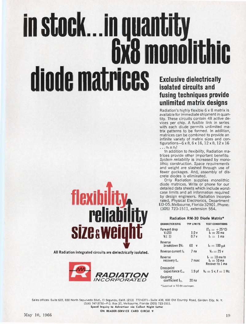
In stock...In quantity 6x1 monolithicdiode matrices
flexibility.reliability
sizesweiqhtAll Radiation integrated circuits are dielectrically isolated.
Exclusive dielectrically isolated circuits and fusing techniques provide unlimited matrix designsRadiation’s highly flexible 6x8 matrix is available for immediate shipment in quantity. These circuits contain 48 active devices per chip. A fusible link in series with each diode permits unlimited matrix patterns to be formed. In addition, matrices can be combined to provide an infinite variety of matrix sizes and configurations—6 x 8, 6 x 16, 12 x 8, 12 x 16 ... m x n2!
In addition to flexibility, Radiation matrices provide other important benefits: System reliability is increased by monolithic construction. Space requirements and weight are slashed through use of fewer packages. And, assembly of discrete diodes is eliminated.
Only Radiation supplies monolithic diode matrices. Write or phone for our detailed data sheets which include worstcase limits and all information required by design engineers. Radiation Incorporated, Physical Electronics, Department ED-05,Melbourne, Florida 32901. Phone: (305) 723-1511, extension 554.
RADIATIONINCORPORATED
Radiation RM-30 Diode Matrix*CHARACTERISTIC TYP LIMITS TEST CONDITIONS
Forward drop (Ta = +25’0Vf(20) 1.0 V If = 20 maVf( 1) 0.7 v k = 1 ma
Reversebreakdown BVR 60 v k = 100 p.a
Reverse current k 7 na Vr = 25v
Reverse If = 10 ma torecovery tr 7 nsec k = 10 ma
Crosspoint capacitance Ccp 1.9 pf
Recover to 1 ma
V« = 5v,f = lMc
Coupling coefficient lei 20 na
"Supplied in TO-84 packages.
Sales offices: Suite 622, 650 North Sepulveda Blvd, El Segundo, Calif. (213) 772-6371—Suite 438, 600 Old Country Road, Garden City, N. Y. (516) 747-3730-P.0. Box 37, Melbourne, Florida (305) 723-1511.
Speed Inquiry to Advertiser via Collect Night LetterON READER-SERVICE CARD CIRCLE 9
May 10, 1966 19
NEWS
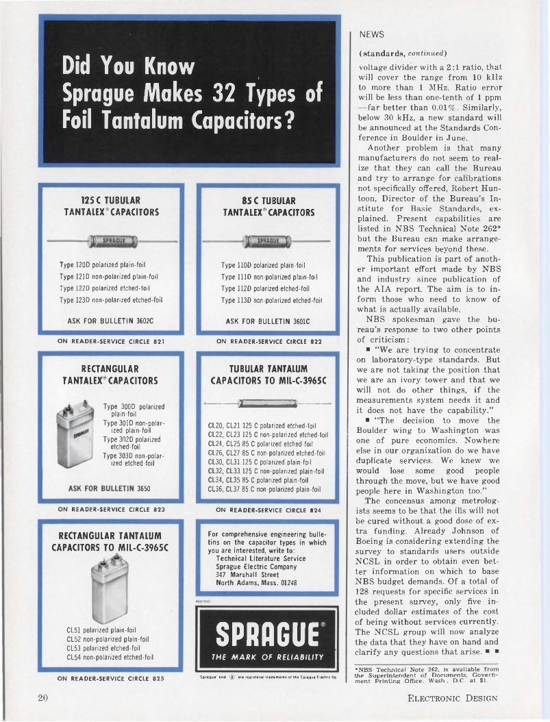
Did You Know I
Sprague Makes 32 Types of Foil Tantalum Capacitors?
125C TUBULAR TANTALEX®CAPACITORS
85 C TUBULAR TANTALEX® CAPACITORS
Type 120D polarized plain-foil
Type 121D non-polarized plain-foil
Type 122D polarized etched-foil
Type 1230 non-polarized etched-foil
ASK FOR BULLETIN 3602C
Type 110D polarized plain-foil
Type HID non-polarized plain-foil
Type 112D polarized etched-foil
Type 113D non-polarized etched-foil
ASK FOR BULLETIN 3601C
ON READER-SERVICE CIRCLE 821 ON READER-SERVICE CIRCLE 822
RECTANGULAR TANTALEX' CAPACITORS
Type 300D polarized plain-foil
Type 301D non-polarized plain-foil
Type 302D polarized etched-foil
Type 303D non-polarized etched-foil
3650
TUBULAR TANTALUM CAPACITORS TO MIL-C-3965C
---- £=»----CL20, CL21 125 C polarized etched-foil CL22, CL23 125 C non-polarized etched-foilCL24, CL25 85 C polarized etched-foilCL26, CL27 85 C non-polarized etched-foilCL30, CL31 125 C polarized plain-foilCL32, CL33 125 C non-polarized plain-foil CL34, CL35 85 C polarized plain-foilCL36, CL37 85 C non-polarized plain-foil
ON READER-SERVICE CIRCLE 823 ON READER-SERVICE CIRCLE 824
RECTANGULAR TANTALUM CAPACITORS TO MIL-C-3965C
For comprehensive engineering bulletins on the capacitor types in which you are interested, write to:
Technical Literature Service Sprague Electric Company 347 Marshall Street North Adams, Mass. 01248
CL51 polarized plain-foilCL52 non-polarized plain-foilCL53 polarized etched-foilCL54 non-polarized etched-foil
SPRAGUETHE MARK OF RELIABILITY
ON READER-SERVICE CIRCLE 825 ' Sprague' and ' (2)’ are registered trademarks of the Sprague Electric Co.
(standards, continued)voltage divider with a 2:1 ratio, that will cover the range from 10 kHz to more than 1 MHz. Ratio error will be less than one-tenth of 1 ppm —far better than 0.01%. Similarly, below 30 kHz, a new standard will be announced at the Standards Conference in Boulder in June.
Another problem is that many manufacturers do not seem to realize that they can call the Bureau and try to arrange for calibrations not specifically offered, Robert Hun- toon, Director of the Bureau’s Institute for Basic Standards, explained. Present capabilities are listed in NBS Technical Note 262* but the Bureau can make arrangements for services beyond these.
This publication is part of another important effort made by NBS and industry since publication of the AIA report. The aim is to inform those who need to know of what is actually available.
NBS spokesman gave the bureau’s response to two other points of criticism:
■ “We are trying to concentrate on laboratory-type standards. But we are not taking the position that we are an ivory tower and that we will not do other things, if the measurements system needs it and it does not have the capability.”
■ “The decision to move the Boulder wing to Washington was one of pure economics. Nowhere else in our organization do we have duplicate services. We knew we would lose some good people through the move, but we have good people here in Washington too.”
The concensus among metrologists seems to be that the ills will not be cured without a good dose of extra funding. Already Johnson of Boeing is considering extending the survey to standards users outside NCSL in order to obtain even better information on which to base NBS budget demands. Of a total of 128 requests for specific services in the present survey, only five included dollar estimates of the cost of being without services currently. The NCSL group will now analyze the data that they have on hand and clarify any questions that arise. ■ ■
*NBS Technical Note 262, is available from the Superintendent of Documents, Government Printing Office, Wash., D.C. at $1.
20 Electronic Design
NEWS
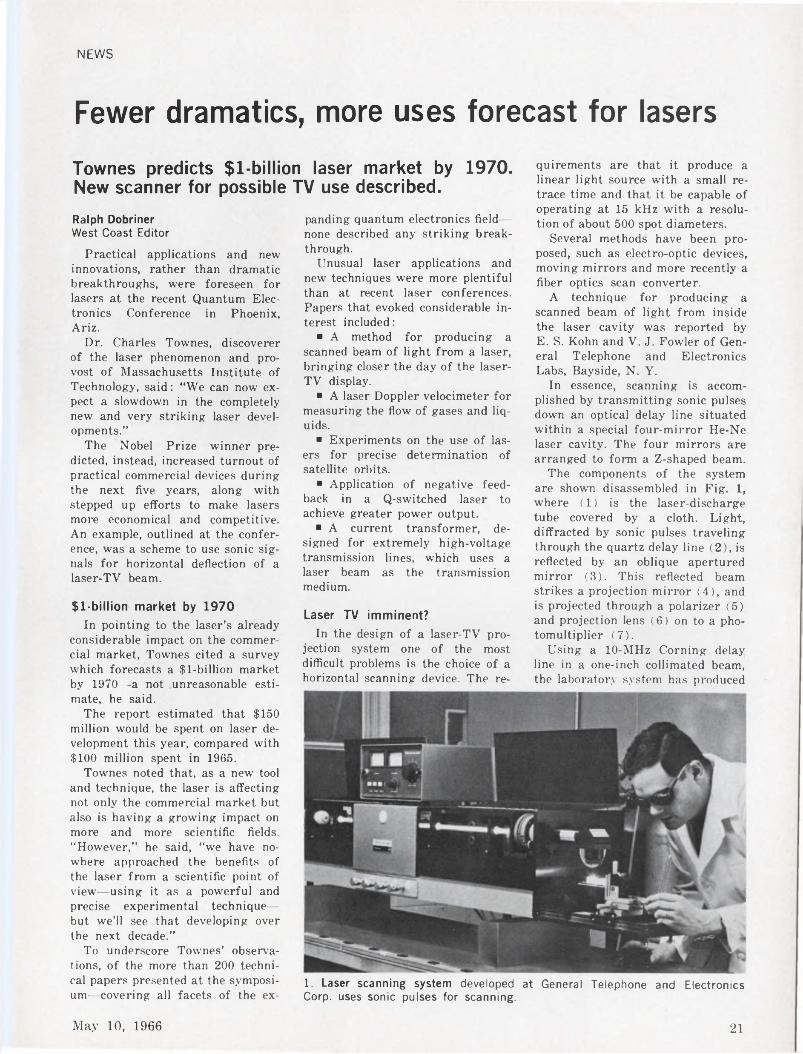
Fewer dramatics, more uses forecast for lasers
Townes predicts $l-billion laser market by 1970. New scanner for possible TV use described.
Ralph DobrinerWest Coast Editor
Practical applications and new innovations, rather than dramatic breakthroughs, were foreseen for lasers at the recent Quantum Electronics Conference in Phoenix, Ariz.
Dr. Charles Townes, discoverer of the laser phenomenon and provost of Massachusetts Institute of Technology, said: “We can now expect a slowdown in the completely new and very striking laser developments.”
The Nobel Prize winner predicted, instead, increased turnout of practical commercial devices during the next five years, along with stepped up efforts to make lasers more economical and competitive. An example, outlined at the conference, was a scheme to use sonic signals for horizontal deflection of a laser-TV beam.
$l-billion market by 1970In pointing to the laser’s already
considerable impact on the commercial market, Townes cited a survey which forecasts a $l-billion market by 1970—a not unreasonable estimate, he said.
The report estimated that $150 million would be spent on laser development this year, compared with $100 million spent in 1965.
Townes noted that, as a new tool and technique, the laser is affecting not only the commercial market but also is having a growing impact on more and more scientific fields. “However,” he said, “we have nowhere approached the benefits of the laser from a scientific point of view—using it as a powerful and precise experimental technique— but we’ll see that developing over the next decade.”
To underscore Townes’ observations, of the more than 200 technical papers presented at the symposium—covering all facets of the ex
panding quantum electronics field— none described any striking breakthrough.
Unusual laser applications and new techniques were more plentiful than at recent laser conferences. Papers that evoked considerable interest included:
■ A method for producing a scanned beam of light from a laser, bringing closer the day of the laser- TV display.
■ A laser Doppler velocimeter for measuring the flow of gases and liquids.
■ Experiments on the use of lasers for precise determination of satellite orbits.
■ Application of negative feedback in a Q-switched laser to achieve greater power output.
■ A current transformer, designed for extremely high-voltage transmission lines, which uses a laser beam as the transmission medium.
Laser TV imminent?In the design of a laser-TV pro
jection system one of the most difficult problems is the choice of a horizontal scanning device. The re
1. Laser scanning system developed at General Telephone and Electronics Corp, uses sonic pulses for scanning.
quirements are that it produce a linear light source with a small retrace time and that it be capable of operating at 15 kHz with a resolution of about 500 spot diameters.
Several methods have been proposed, such as electro-optic devices, moving mirrors and more recently a fiber optics scan converter.
A technique for producing a scanned beam of light from inside the laser cavity was reported by E. S. Kohn and V. J. Fowler of General Telephone and Electronics Labs, Bayside, N. Y.
In essence, scanning is accomplished by transmitting sonic pulses down an optical delay line situated within a special four-mirror He-Ne laser cavity. The four mirrors are arranged to form a Z-shaped beam.
The components of the system are shown disassembled in Fig. 1, where (1) is the laser-discharge tube covered by a cloth. Light, diffracted by sonic pulses traveling through the quartz delay line (2), is reflected by an oblique apertured mirror (3). This reflected beam strikes a projection mirror (4), and is projected through a polarizer (5) and projection lens (6) on to a photomultiplier (7).
Using a 10-MHz Corning delay line in a one-inch collimated beam, the laboratory system has produced
May 10, 1966 21
NEWS
(laser, continued)about 15 resolvable spot positions so far. The peak power in the scanning beam was 4 mW.
According to the scientists, the speed and linearity of the swept beam obtained from this system makes it very attractive for use as the horizontal scanner in a TV display. In this application, cylindrical optics would be used to collapse the moving line of light to form a scanning spot. The spot could then be scanned in the vertical direction by an electro-optic or vibrating mirror deflector.
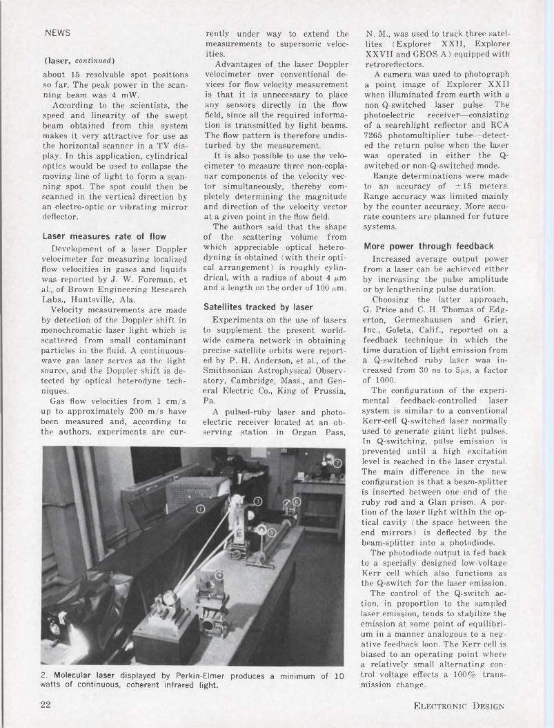
Laser measures rate of flowDevelopment of a laser Doppler
velocimeter for measuring localized flow velocities in gases and liquids was reported by J. W. Foreman, et al, of Brown Engineering Research Labs, Huntsville, Ala.
Velocity measurements are made by detection of the Doppler shift in monochromatic laser light which is scattered from small contaminant particles in the fluid. A continuous- wave gas laser serves as the light source, and the Doppler shift is detected by optical heterodyne techniques.
Gas flow velocities from 1 cm/s up to approximately 200 m/s have been measured and, according to the authors, experiments are cur
2. Molecular laser displayed by Perkin-Elmer produces a minimum of 10 watts of continuous, coherent infrared light.
rently under way to extend the measurements to supersonic velocities.
Advantages of the laser Doppler velocimeter over conventional devices for flow velocity measurement is that it is unnecessary to place any sensors directly in the flow field, since all the required information is transmitted by light beams. The flow pattern is therefore undisturbed by the measurement.
It is also possible to use the velocimeter to measure three non-copla- nar components of the velocity vector simultaneously, thereby completely determining the magnitude and direction of the velocity vector at a given point in the flow field.
The authors said that the shape of the scattering volume from which appreciable optical heterodyning is obtained (with their optical arrangement) is roughly cylindrical, with a radius of about 4 pm and a length on the order of 100 pm.
Satellites tracked by laserExperiments on the use of lasers
to supplement the present worldwide camera network in obtaining precise satellite orbits were reported by P. H. Anderson, et al, of the Smithsonian Astrophysical Observatory, Cambridge, Mass, and General Electric Co, King of Prussia, Pa.
A pulsed-ruby laser and photoelectric receiver located at an observing station in Organ Pass,
N. M, was used to track three satellites (Explorer XXII, Explorer XXVII and GEOS A) equipped with retroreflectors.
A camera was used to photograph a point image of Explorer XXII when illuminated from earth with a non-Q-switched laser pulse. The photoelectric receiver—consisting of a searchlight reflector and RCA 7265 photomultiplier tube—detected the return pulse when the laser was operated in either the Q- switched or non-Q-switched mode.
Range determinations were made to an accuracy of ±15 meters. Range accuracy was limited mainly by the counter accuracy. More accurate counters are planned for future systems.
More power through feedbackIncreased average output power
from a laser can be achieved either by increasing the pulse amplitude or by lengthening pulse duration.
Choosing the latter approach, G. Price and C. H. Thomas of Edgerton, Germeshausen and Grier, Inc, Goleta, Calif, reported on a feedback technique in which the time duration of light emission from a Q-switched ruby laser was increased from 30 ns to 5/j.s, a factor of 1000.
The configuration of the experimental feedback-controlled laser system is similar to a conventional Kerr-cell Q-switched laser normally used to generate giant light pulses. In Q-switching, pulse emission is prevented until a high excitation level is reached in the laser crystal. The main difference in the new configuration is that a beam-splitter is inserted between one end of the ruby rod and a Gian prism. A portion of the laser light within the optical cavity (the space between the end mirrors) is deflected by the beam-splitter into a photodiode.
The photodiode output is fed back to a specially designed low-voltage Kerr cell which also functions as the Q-switch for the laser emission.
The control of the Q-switch action, in proportion to the sampled laser emission, tends to stabilize the emission at some point of equilibrium in a manner analogous to a negative feedback loon. The Kerr cell is biased to an operating point where a relatively small alternating control voltage effects a 100% transmission change.
22 Electronic Design
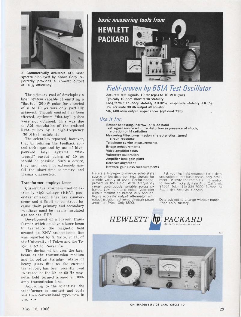
3. Commercially available CO2 laser system displayed by Korad Corp, reportedly provides a 75-watt output at 10% efficiency.
The primary goal of developing a laser system capable of emitting a “flat-top” 20-kW pulse for a period of 5 to 10 /xs was only partially achieved. Though control has been effected, optimum “flat-top” pulses were not obtained. This was due to AM modulation of the emitted light pulses by a high-frequency (30 MHz) instability.
The scientists reported, however, that by refining the feedback control technique and by use of high- powered laser systems, “flattopped” output pulses of 10 /xs should be possible. Such a device, they said, would be extremely useful for short-time telemetry and plasma diagnostics.
Transformer employs laserCurrent transformers used on ex
tremely high voltage (EHV) power-transmission lines are cumbersome and difficult to construct because their primary and secondary windings must be heavily insulated against the EHV.
Development of a current transformer which employs a laser beam to transduce the magnetic field around an EHV transmission line was reported by S. Saito, et al., of the University of Tokyo and the Tokyo Electric Power Co.
The device, which uses the laser beam as the transmission medium and an optical Faraday rotator of heavy glass flint as the current transducer, has been recently used to transduce the 50- or 60-Hz magnetic field formed around a 1000- amp transmission line.
According to the scientists, the transformer is compact and costs less than conventional types now in use. ■ ■
basic measuring tools from
HEWLETT Elay PACKARD '
Field-proven hp 651 A Test OscillatorAccurate test signals, 10 Hz (cps) to 10 MHz (me)Typically 10 ppm short-term stabilityLong-term frequency stability ±0.02%, amplitude stability ±0.1% 1% accurate 90 db output attenuator 50-, 600-ohm output impedances (optional 75f>)
Use it for:Response testing, narrow- or wide-bandTest signal source with low distortion in presence of shock,
vibration or hf radiationMeasuring filter transmission characteristics, tuned
circuit responseTelephone carrier measurementsBridge measurementsVideo amplifier testsVoltmeter calibrationAmplifier loop gain plotsReceiver alignmentNetwork gain/loss measurements
Here's a high-performance solid-state source of low-distortion test signals for a wide variety of uses. Performance- proved in the field. Wide frequency range, continuously variable across six bands. Low hum and noise. Voltmeter output monitor calibrated in v and db, highly accurate output attenuator with output isolation achieved through power amplifier. Price: Only $590.
HEWLETT Jip PACKARDAn extra measure of quality
905
Ask your hp field engineer for a demonstration of this basic measuring instrument. Or write for complete information to Hewlett-Packard, Palo Alto, California 94304, Tel. (415) 326-7000; Europe: 54 Route des Acacias, Geneva.
Data subject to change without notice. Price f.o.b. factory. "
ON READER-SERVICE CARD CIRCLE 10
May 10, 1966 23
□ESIBIXIER’SP. R. MALLORY & CO. INC., INDIANAPOLIS, INDIANA 46206
Molded Zener Diodes give high reliability at low prices
New Hermetic Seal Tantalum Capacitors— Style CL55 of MIL-C-3965CThe new Mallory Type TL wet slug tantalum capacitor is a compact rectangular package designed for ability to withstand extreme environmental conditions. It has glass- to-metal terminal seals in a hermetic sealed outer case. Microfarad-volt ratings per unit volume are exceptionally high for this class of construction.
The Mallory Type ZA zeners are molded units which give performance and reliability equal to that required by military specifications —at about half the price of hermetically sealed zeners.One reason for this unusual quality is that Mallory uses the same silicon cell in the Type ZA as in the zener diodes we make for military requirements. Another is the unique Mallory production technique, in which complete classification, screening and
Wire-Wound Controls with special Temperature CoefficientsWhen exceptional stability of resistance is needed over the normal operating temperature range, Mallory can supply custom-made wire-wound controls with special values of temperature coefficient. Selected types of resistance wire are used for the winding.The minimum TC available is 20 parts per million per degree C . . . also stated as .002% or ±.00002 ohm/ohm/°C. All styles of Mallory wire-wound controls—2, 3, 4, 5, 7 and 121^ watts—can be supplied with special TC. CIRCLE 241 ON READER SERVICE CARD
pre-testing can be done on silicon cells before packaging. And finally, there’s the economy of the molded case—moisture-proof, electrically cold, and so compact that high- density circuit packages are readily accommodated.The 1-watt Type ZA and 3-watt Type ZAC are available in zener ratings from 6.8 to 200 volts. Hermetically sealed and high wattage ratings are also available.CIRCLE 240 ON READER SERVICE CARD
The TL offers the superior performance which is characteristic of Mallory wet slug capacitors. It has exceptional stability of capacitance and power factor, both over a broad temperature range from —55°C to +125°C, and throughout extended operating life and shelf tests. DC leakage is low; maximum values at top mfd-volt ratings are in the order of 10 microamps, with actual test values typically around 1 to 2 microamps.
Ratings available: 2400 mfd, 15 volts to 180 mfd, 150 volts. Temperature rating: —55°C to +125°C. The TL is designed to meet performance criteria of style CL55, per MIL-C-3965CandMIL-C-3965/21B.CIRCLE 242 ON READER SERVICE CARD
24 Electronic Design
FILE MallorYANNIVERSARY
No voltage de-rating needed on MTP wet slug tantalum capacitorsMany designers add their own "safety factor” by specifying a considerably higher voltage rating than actually needed for surge or steady state conditions in the circuit. With Mallory MTP miniature wet slug tantalum capacitors, you don’t need to de-rate. And you can often save space and money by not de-rating. How come ? In the first place, we’ve already built in a generous safety factor in the stated rating on the capacitor. And second, we’ve found out by tests that operating at reduced voltage neither improves nor impairs performance of the MTP. We have extensive data in a recent engineering report, which we’ll be glad to send on request.As an example of the size savings possible, a 33 mfd, 60 volt MTP measures .225" in diameter by .775" long. But the same 33 mfd at 50 volts fits into the next smaller case size: .145" in diameter by .590" long. And the cost is about 13% lower. The MTP, incidentally, has the most capacity per unit size of any tantalum capacitor—up to 178,000 mfd-volts/cubic inch, or about five times what you can get in any solid electrolyte type. And it’s made in the same high-reliability facility as similar Mallory capacitors for Minuteman II.CIRCLE 243 ON READER SERVICE CARD
High capacity ceramic capacitors save space in transistor circuits
Whenever you need a lot of microfarads in a small space at transistor circuit voltages, use Magnacap® disc ceramic capacitors. Made by Radio Materials Company, a division of Mallory, Magnacaps are particularly applicable to by-pass and coupling in low impedance transistor circuits.
Because they maintain their impedance characteristics well into the radio frequency range, they are especially useful as emitter bypasses. They fill the range of capacitance values between standard
RMC Discap® Capacitors and Mallory aluminum or tantalum electrolytics.Insulation resistance is amply high to assure excellent operation in battery powered equipment. Magnacaps have outstanding stability of capacitance from —55°C to +85°C. They have a proven record of reliability, and are economically priced. 3, 12, 16 and 25 volt ratings are available. Maximum capacities: 2.2 mfd ® 3 volts; 1.0 mfd @ 12 volts; .22 mfd ® 16 volts and 25 volts.CIRCLE 245 ON READER SERVICE CARD
May 10, 1966 25
NEWS
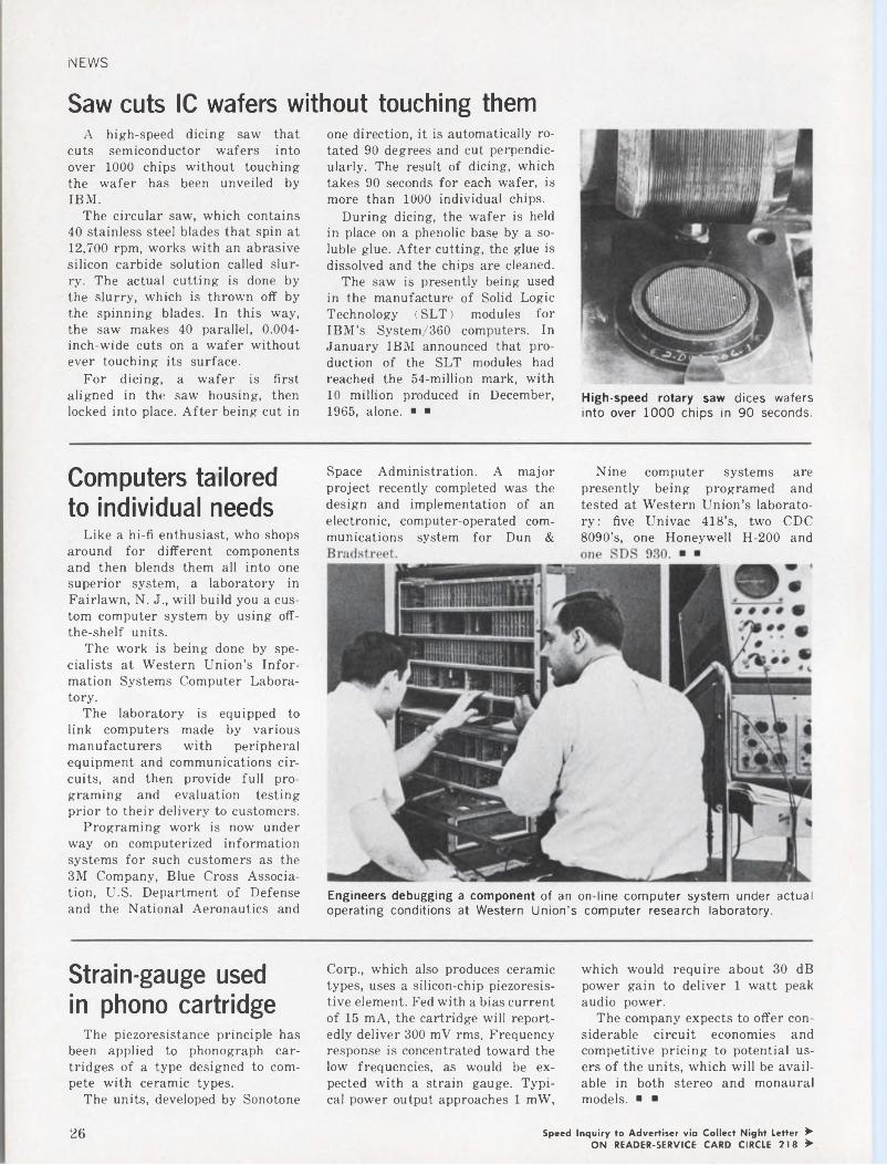
Saw cuts IC wafers without touching themA high-speed dicing saw that
cuts semiconductor wafers into over 1000 chips without touching the wafer has been unveiled by IBM.
The circular saw, which contains 40 stainless steel blades that spin at 12,700 rpm, works with an abrasive silicon carbide solution called slurry. The actual cutting is done by the slurry, which is thrown off by the spinning blades. In this way, the saw makes 40 parallel, 0.004- inch-wide cuts on a wafer without ever touching its surface.
For dicing, a wafer is first aligned in the saw housing, then locked into place. After being cut in
one direction, it is automatically rotated 90 degrees and cut perpendicularly. The result of dicing, which takes 90 seconds for each wafer, is more than 1000 individual chips.
During dicing, the wafer is held in place on a phenolic base by a soluble glue. After cutting, the glue is dissolved and the chips are cleaned.
The saw is presently being used in the manufacture of Solid Logic Technology (SLT) modules for IBM’s System/360 computers. In January IBM announced that production of the SLT modules had reached the 54-million mark, with 10 million produced in December, 1965, alone. ■ ■
High-speed rotary saw dices wafers into over 1000 chips in 90 seconds.
Computers tailored to individual needs
Like a hi-fi enthusiast, who shops around for different components and then blends them all into one superior system, a laboratory in Fairlawn, N. J., will build you a custom computer system by using off- the-shelf units.
The work is being done by specialists at Western Union’s Information Systems Computer Laboratory.
The laboratory is equipped to link computers made by various manufacturers with peripheral equipment and communications circuits, and then provide full programing and evaluation testing prior to their delivery to customers.
Programing work is now under way on computerized information systems for such customers as the 3M Company, Blue Cross Association, U.S. Department of Defense and the National Aeronautics and
Space Administration. A major project recently completed was the design and implementation of anelectronic, computer-operated communications system for Dun &
ry: five Univac 418’s, two CDC 8090’s, one Honeywell H-200 and
Engineers debugging a component of an on line computer system under actual operating conditions at Western Union’s computer research laboratory.
Nine computer systems are presently being programed and tested at Western Union’s laborato-
Strain-gauge used in phono cartridge
The piezoresistance principle has been applied to phonograph cartridges of a type designed to compete with ceramic types.
The units, developed by Sonotone
Corp., which also produces ceramic types, uses a silicon-chip piezoresistive element. Fed with a bias current of 15 mA, the cartridge will reportedly deliver 300 mV rms. Frequency response is concentrated toward the low frequencies, as would be expected with a strain gauge. Typical power output approaches 1 mW,
which would require about 30 dB power gain to deliver 1 watt peak audio power.
The company expects to offer considerable circuit economies andcompetitive pricing to potential users of the units, which will be available in both stereo and monauralmodels. ■ ■
Speed Inquiry to Advertiser via Collect Night Letter ►ON READER-SERVICE CARD CIRCLE 218 >
26
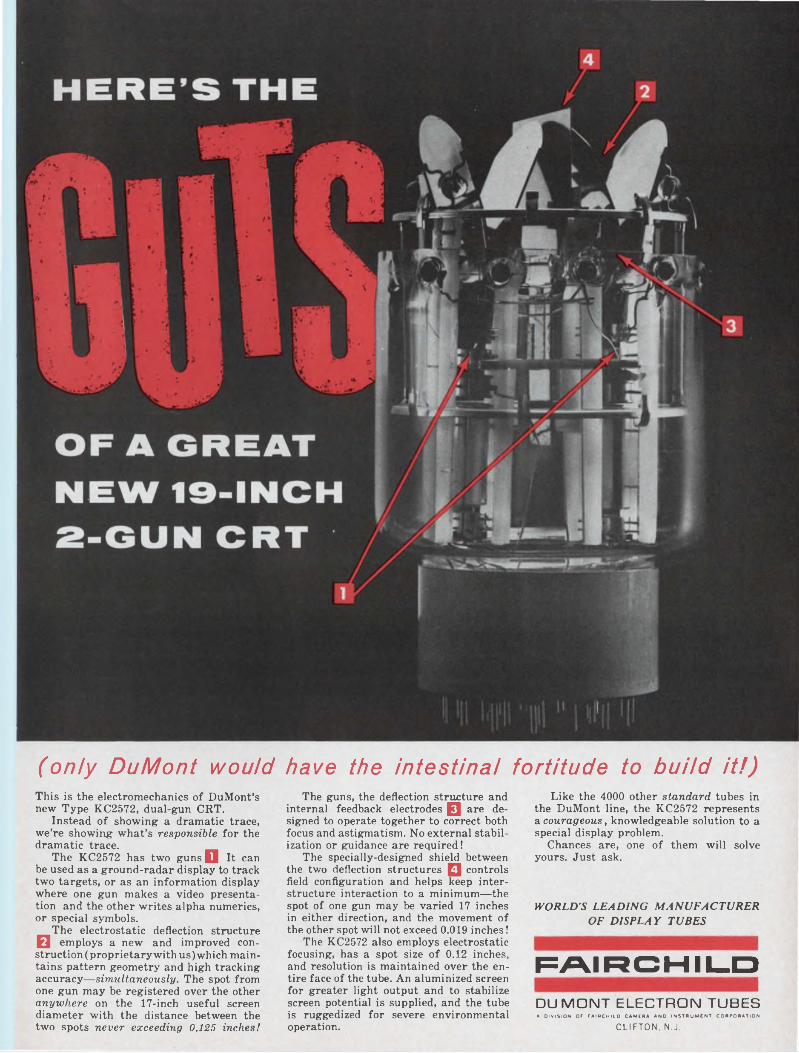
(only DuMont would have the intestinal fortitude to build it!)This is the electromechanics of DuMont’s new Type KC2572, dual-gun CRT.
Instead of showing a dramatic trace, we’re showing what’s responsible for the dramatic trace.
The KC2572 has two guns fl It can be used as a ground-radar display to track two targets, or as an information display where one gun makes a video presentation and the other writes alpha numerics, or special symbols.
The electrostatic deflection structure Q employs a new and improved construction (proprietary with us) which maintains pattern geometry and high tracking accuracy—simultaneously. The spot from one gun may be registered over the other anywhere on the 17-inch useful screen diameter with the distance between the two spots never exceeding 0.125 inches!
The guns, the deflection structure and internal feedback electrodes fl are designed to operate together to correct both focus and astigmatism. No external stabilization or guidance are required!
The specially-designed shield between the two deflection structures fl controls field configuration and helps keep interstructure interaction to a minimum—the spot of one gun may be varied 17 inches in either direction, and the movement of the other spot will not exceed 0.019 inches!
The KC2572 also employs electrostatic focusing, has a spot size of 0.12 inches, and resolution is maintained over the entire face of the tube. An aluminized screen for greater light output and to stabilize screen potential is supplied, and the tube is ruggedized for severe environmental operation.
Like the 4000 other standard tubes in the DuMont line, the KC2572 represents a courageous, knowledgeable solution to a special display problem.
Chances are, one of them will solve yours. Just ask.
WORLD’S LEADING MANUFACTURER OF DISPLAY TUBES
FAIRCHILDDUMONT ELECTRON TUBESA DIVISION OF FAIRCHILD CAMERA AND INSTRUMENT CORPORATION
CLIFTON, N.J.
NEWS
Jets power portable ground stationGas-turbine jet engines will pow
er a transportable U.S.-built ground station for communications satellites to be erected in Australia, where 50-Hz power is preferred to 60 Hz. Sylvania Electronic Systems was responsible for development of the station, which will be shipped “down-under” in mid-May. It will be the principal western terminal for NASA’s Application Technology Satellite (ATS) program.
Jet engines are very sensitive to changes in load and, therefore, are excellent regulators, according to Tully Gibbon, ATS site supervisor.
Sylvania was directly responsible for the antenna and feed, the tracking receiver, the master control console, and the integration and testing of the complete station. “We have become night owls—most of the tests must be done at night to avoid interruption,” said Windsor D. Wright, senior engineering spe
cialist responsible for program management and performance evaluation.
The preamplifier was subcontracted to Airborne Instruments Laboratory. NASA supplied the transmitters.
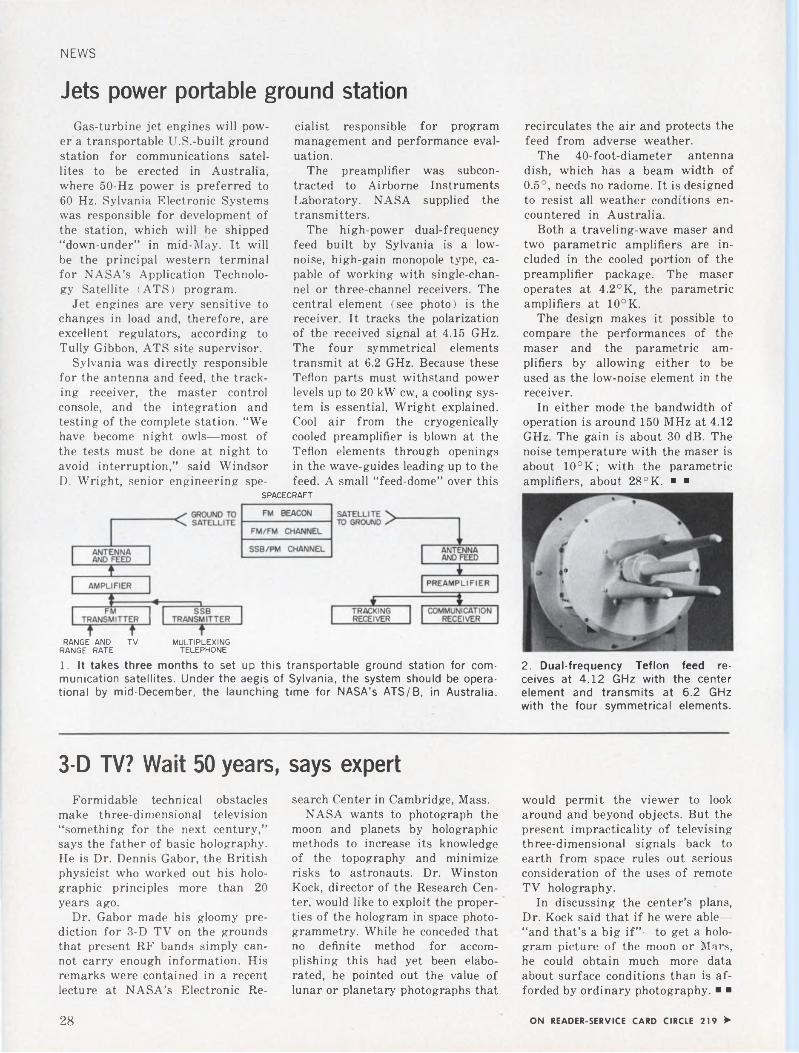
The high-power dual-frequency feed built by Sylvania is a low- noise, high-gain monopole type, capable of working with single-channel or three-channel receivers. The central element (see photo) is the receiver. It tracks the polarization of the received signal at 4.15 GHz. The four symmetrical elements transmit at 6.2 GHz. Because these Teflon parts must withstand power levels up to 20 kW cw, a cooling system is essential, Wright explained. Cool air from the cryogenically cooled preamplifier is blown at the Teflon elements through openings in the wave-guides leading up to the feed. A small “feed-dome” over this
recirculates the air and protects the feed from adverse weather.
The 40-foot-diameter antenna dish, which has a beam width of 0.5°, needs no radome. It is designed to resist all weather conditions encountered in Australia.
Both a traveling-wave maser and two parametric amplifiers are included in the cooled portion of the preamplifier package. The maser operates at 4.2°K, the parametric amplifiers at 10°K.
The design makes it possible to compare the performances of the maser and the parametric amplifiers by allowing either to be used as the low-noise element in the receiver.
In either mode the bandwidth of operation is around 150 MHz at 4.12 GHz. The gain is about 30 dB. The noise temperature with the maser is about 10°K; with the parametric amplifiers, about 28 °K. ■ ■
SPACECRAFT
RANGE AND TV MULTIPLEXINGRANGE RATE TELEPHONE
1. It takes three months to set up this transportable ground station for communication satellites. Under the aegis of Sylvania, the system should be operational by mid-December, the launching time for NASA’s ATS/B, in Australia.
2. Dual-frequency Teflon feed receives at 4.12 GHz with the center element and transmits at 6.2 GHz with the four symmetrical elements.
3-D TV? Wait 50 years, says expertFormidable technical obstacles
make three-dimensional television “something for the next century,” says the father of basic holography. He is Dr. Dennis Gabor, the British physicist who worked out his holographic principles more than 20 years ago.
Dr. Gabor made his gloomy prediction for 3-D TV on the grounds that present RF bands simply cannot carry enough information. His remarks were contained in a recent lecture at NASA’s Electronic Re
search Center in Cambridge, Mass.NASA wants to photograph the
moon and planets by holographic methods to increase its knowledge of the topography and minimize risks to astronauts. Dr. Winston Kock, director of the Research Center, would like to exploit the properties of the hologram in space photogrammetry. While he conceded that no definite method for accomplishing this had yet been elaborated, he pointed out the value of lunar or planetary photographs that
would permit the viewer to look around and beyond objects. But the present impracticality of televising three-dimensional signals back to earth from space rules out serious consideration of the uses of remote TV holography.
In discussing the center’s plans, Dr. Kock said that if he were able— “and that’s a big if”—to get a hologram picture of the moon or Mars, he could obtain much more data about surface conditions than is afforded by ordinary photography. ■ ■
28 ON READER-SERVICE CARD CIRCLE 219 >
CALIBRA1
ZERO
LOCK
GMN
TRIM
GAIN
10 30
wo<300
SANBORN 8875A DIFFERENTIAL AMPLIFIER
VLRHILR
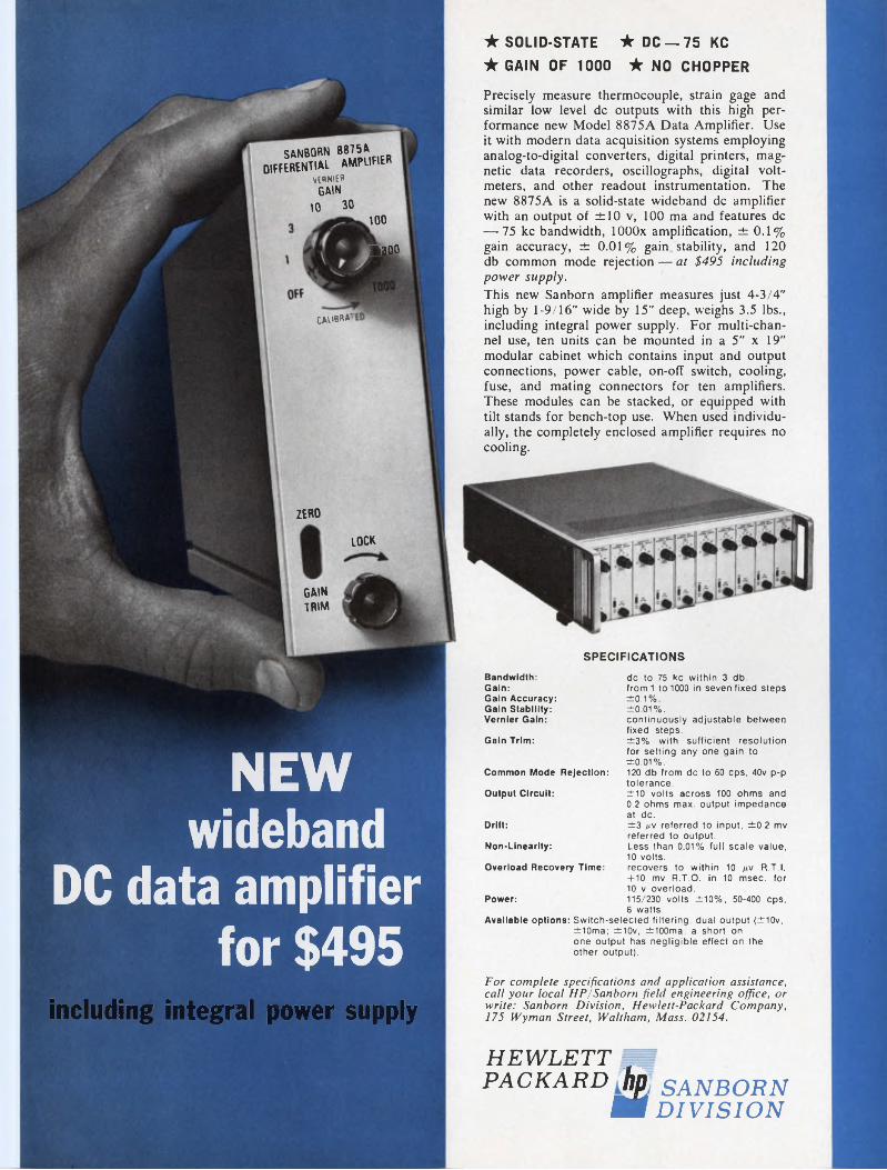
NEW wideband
DC data amplifier for $495
★ SOLID-STATE ★DC —75KC★ GAIN OF 1000 ★ NO CHOPPER
Precisely measure thermocouple, strain gage and similar low level de outputs with this high performance new Model 8875A Data Amplifier. Use it with modern data acquisition systems employing analog-to-digital converters, digital printers, magnetic data recorders, oscillographs, digital voltmeters, and other readout instrumentation. The new 8875A is a solid-state wideband de amplifier with an output of ±10 v, 100 ma and features de — 75 kc bandwidth, lOOOx amplification, ±0.1% gain accuracy, ± 0.01% gain stability, and 120 db common mode rejection — at $495 including power supply.This new Sanborn amplifier measures just 4-3/4" high by 1-9/16" wide by 15" deep, weighs 3.5 lbs., including integral power supply. For multi-channel use, ten units can be mounted in a 5" x 19" modular cabinet which contains input and output connections, power cable, on-off switch, cooling, fuse, and mating connectors for ten amplifiers. These modules can be stacked, or equipped with tilt stands for bench-top use. When used individually, the completely enclosed amplifier requires no cooling.
SPECIFICATIONSBandwidth:Gain:Gain Accuracy:Gain Stability:Vernier Gain:
Gain Trim:
Common Mode Rejection:
Output Circuit:
Drift:
Non-Linearity:
Overload Recovery Time:
Power:
de to 75 kc within 3 db.from! to 1000 in seven fixed steps ±0.1%.±0.01%.continuously adjustable between fixed steps.±3% with sufficient resolution for setting any one gain to ±0.01%.120 db from de to 60 cps. 40v p-p tolerance.±10 volts across 100 ohms and 0.2 ohms max. output impedance at de.±3 nv referred to input, ±0.2 mv referred to output.Less than 0.01% full scale value, 10 volts.recovers to within 10 tiv R.T.I. +10 mv R.T.O. in 10 msec, for 10 v overload.115/230 volts ±10%, 50-400 cps, 6 watts.
Available options: Switch-selected filtering, dual output (±10v, ±10ma; ±10v, ±100ma; a short on one output has negligible effect on the other output).
including integral power supply■
For complete specifications and application assistance, call your local HP/Sanborn field engineering office, or write: Sanborn Division, Hewlett-Packard Company, 175 Wyman Street, Waltham, Mass. 02154.
HEWLETTPACKARD hp SANBORN
ÊK DIVISION
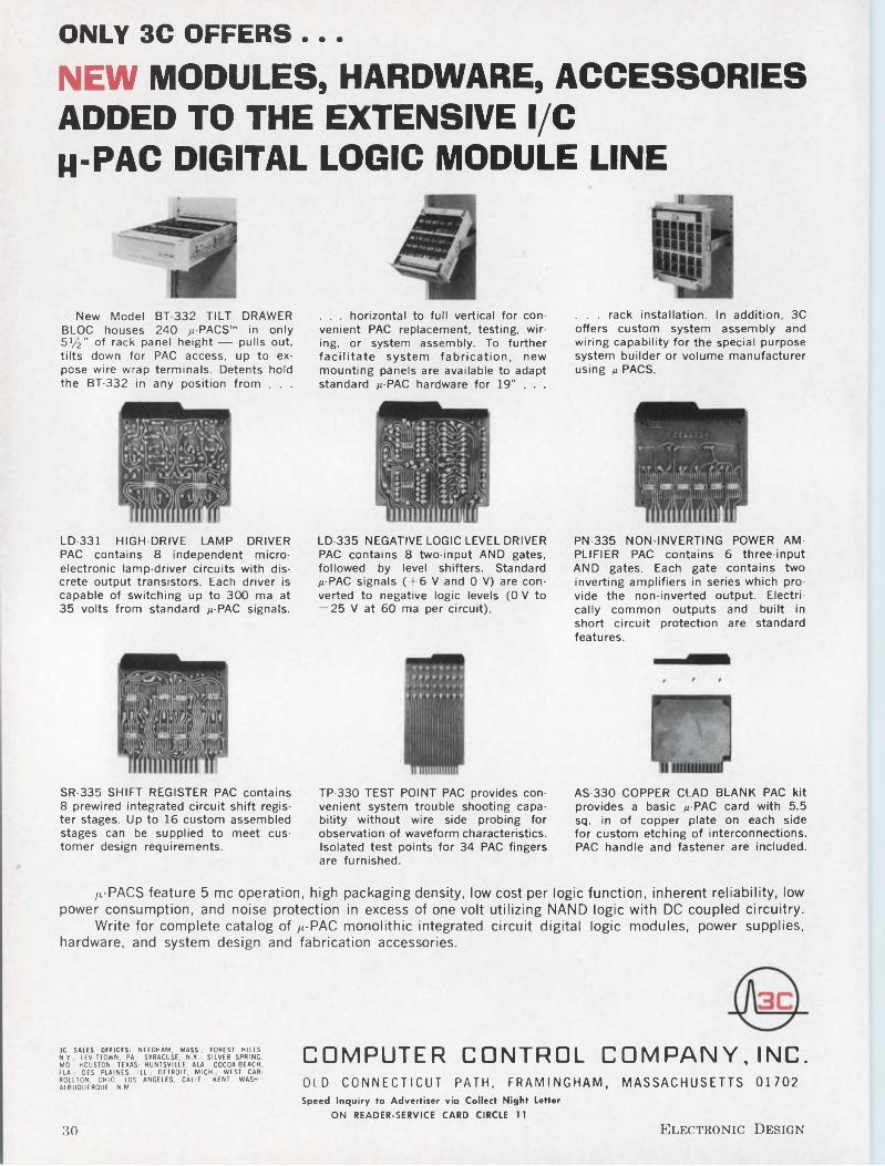
ONLY 3C OFFERS ...NEW MODULES, HARDWARE, ACCESSORIES ADDED TO THE EXTENSIVE l/C h-pac DIGITAL LOGIC MODULE LINE
New Model BT-332 TILT DRAWER BLOC houses 240 /z-PACS,m in only BVz" of rack panel height — pulls out, tilts down for PAC access, up to expose wire wrap terminals. Detents hold the BT-332 in any position from . . .
. . . horizontal to full vertical for convenient PAC replacement, testing, wiring, or system assembly. To further facilitate system fabrication, new mounting panels are available to adapt standard /z-PAC hardware for 19" . . .
. . . rack installation. In addition, 3C offers custom system assembly and wiring capability for the special purpose system builder or volume manufacturer using /z-PACS.
LD-331 HIGH-DRIVE LAMP DRIVER PAC contains 8 Independent microelectronic lamp-driver circuits with discrete output transistors. Each driver is capable of switching up to 300 ma at 35 volts from standard /z-PAC signals.
LD-335 NEGATIVE LOGIC LEVEL DRIVER PAC contains 8 two-input AND gates, followed by level shifters. Standard /z-PAC signals (+6 V and 0 V) are converted to negative logic levels (0 V to — 25 V at 60 ma per circuit).
PN-335 NON-INVERTING POWER AMPLIFIER PAC contains 6 three-input AND gates. Each gate contains two inverting amplifiers in series which provide the non-inverted output. Electrically common outputs and built in short circuit protection are standard features.
SR-335 SHIFT REGISTER PAC contains 8 prewired integrated circuit shift register stages. Up to 16 custom assembled stages can be supplied to meet customer design requirements.
TP-330 TEST POINT PAC provides convenient system trouble shooting capability without wire side probing for observation of waveform characteristics. Isolated test points for 34 PAC fingers are furnished.
AS-330 COPPER CLAD BLANK PAC kit provides a basic /z-PAC card with 5.5 sq. in of copper plate on each side for custom etching of interconnections. PAC handle and fastener are included.
/x-PACS feature 5 me operation, high packaging density, low cost per logic function, inherent reliability, low power consumption, and noise protection in excess of one volt utilizing NAND logic with DC coupled circuitry.
Write for complete catalog of /x-PAC monolithic integrated circuit digital logic modules, power supplies, hardware, and system design and fabrication accessories.
3C SALES OFFICES: NEEDHAM, MASS.; FOREST HILLS. N.Y.; LEVITTOWN. PA.; SYRACUSE, N.Y.; SILVER SPRING. MD.; HOUSTON, TEXAS; HUNTSVILLE, ALA.; COCOA BEACH. FLA ; DES PLAINES. ILL.; DETROIT. MICH.; WEST CAR ROLLTON, OHIO; LOS ANGELES. CALIF.; KENT. WASH.; ALBUQUERQUE, N.M.
COMPUTER CONTROL COMPANY, INC.OLD CONNECTICUT PATH, FRAMINGHAM, MASSACHUSETTS 01702 Speed Inquiry to Advertiser via Collect Night Letter
ON READER-SERVICE CARD CIRCLE 11
30 Electronic Design
WashingtonReport S. DAVID PURSGLOVE,
WASHNGTION EDITOR
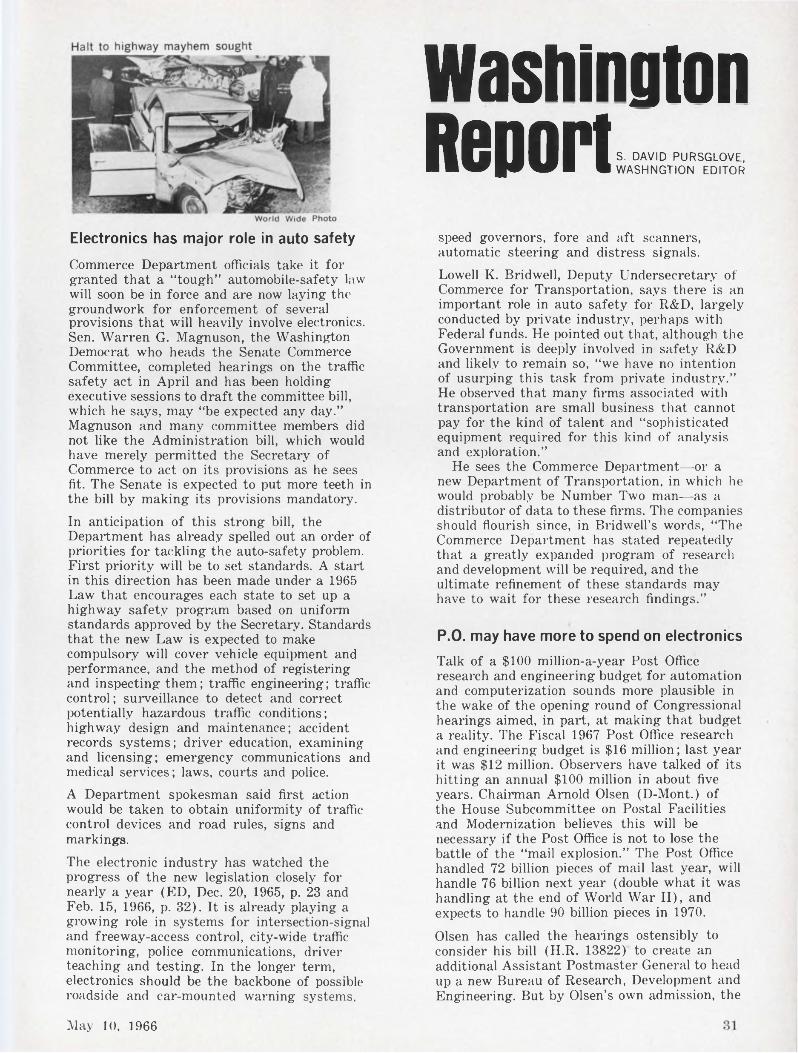
Electronics has major role in auto safety
Commerce Department officials take it for granted that a “tough” automobile-safety law will soon be in force and are now laying the groundwork for enforcement of several provisions that will heavily involve electronics. Sen. Warren G. Magnuson, the Washington Democrat who heads the Senate Commerce Committee, completed hearings on the traffic safety act in April and has been holding executive sessions to draft the committee bill, which he says, may “be expected any day.” Magnuson and many committee members did not like the Administration bill, which would have merely permitted the Secretary of Commerce to act on its provisions as he sees fit. The Senate is expected to put more teeth in the bill by making its provisions mandatory.
In anticipation of this strong bill, the Department has already spelled out an order of priorities for tackling the auto-safety problem. First priority will be to set standards. A start in this direction has been made under a 1965 Law that encourages each state to set up a highway safety program based on uniform standards approved by the Secretary. Standards that the new Law is expected to make compulsory will cover vehicle equipment and performance, and the method of registering and inspecting them ; traffic engineering ; traffic control; surveillance to detect and correct potentially hazardous traffic conditions; highway design and maintenance; accident records systems; driver education, examining and licensing; emergency communications and medical services; laws, courts and police.
A Department spokesman said first action would be taken to obtain uniformity of traffic control devices and road rules, signs and markings.
The electronic industry has watched the progress of the new legislation closely for nearly a year (ED, Dec. 20, 1965, p. 23 and Feb. 15, 1966, p. 32). It is already playing a growing role in systems for intersection-signal and freeway-access control, city-wide traffic monitoring, police communications, driver teaching and testing. In the longer term, electronics should be the backbone of possible roadside and car-mounted warning systems.
speed governors, fore and aft scanners, automatic steering and distress signals.
Lowell K. Bridwell, Deputy Undersecretary of Commerce for Transportation, says there is an important role in auto safety for R&D, largely conducted by private industry, perhaps with Federal funds. He pointed out that, although the Government is deeply involved in safety R&D and likely to remain so, “we have no intention of usurping this task from private industry.” He observed that many firms associated with transportation are small business that cannot pay for the kind of talent and “sophisticated equipment required for this kind of analysis and exploration.”
He sees the Commerce Department—or a new Department of Transportation, in which he would probably be Number Two man—as a distributor of data to these firms. The companies should flourish since, in Bridwell’s words, “The Commerce Department has stated repeatedly that a greatly expanded program of research and development will be required, and the ultimate refinement of these standards may have to wait for these research findings.”
P.O. may have more to spend on electronics
Talk of a $100 million-a-year Post Office research and engineering budget for automation and computerization sounds more plausible in the wake of the opening round of Congressional hearings aimed, in part, at making that budget a reality. The Fiscal 1967 Post Office research and engineering budget is $16 million; last year it was $12 million. Observers have talked of its hitting an annual $100 million in about five years. Chairman Arnold Olsen (D-Mont.) of the House Subcommittee on Postal Facilities and Modernization believes this will be necessary if the Post Office is not to lose the battle of the “mail explosion.” The Post Office handled 72 billion pieces of mail last year, will handle 76 billion next year (double what it was handling at the end of World War II), and expects to handle 90 billion pieces in 1970.
Olsen has called the hearings ostensibly to consider his bill (H.R. 13822) to create an additional Assistant Postmaster General to head up a new Bureau of Research, Development and Engineering. But by Olsen’s own admission, the
May 10. 1966
WashingtonReport CONTINUED
hearings are primarily, in fact, a review of what the P.O. has done—and has not done—in R&D and engineering. Olsen and most other Congressmen with authority over Postal operations have been trying to have the P.O. request more money to beef up its largely electronic R&D efforts. The new Postmaster General, Lawrence F. O’Brien, has been receptive to Olsen’s ideas and has privately indicated that “some old-fashioned skulls around this place” might be knocked together to make them more cooperative.
Olsen has pointed out that the Agriculture Department research allocation of $224.9 million is 3.2 per cent of the Department’s total $6.99-billion budget, that R&D at the Commerce Department amounts to 6.4 per cent of its budget, that the Office of Economic Opportunity plans to devote 3.2 per cent of its budget to R&D, and that Pentagon R&D is 11.5 per cent of the total Defense-Department budget. The Post Office R&D budget of $16.1 million is less than 1/3 of one percent of the total P.O. budget. Should the P.O. increase its R&D budget to a sum comparable to that of other departments, it would be well over $100 million.
Most of such a budget would go into electronics, if past and present spending can be taken as a guide. It would pay for a gigantic centralized computer system, ZIP-code readers, letter sorters, stamp readers, a yet-to-be-designed automatic parcel-sorting and facing system, electronic address directory system’ (for which P.O. has just requested proposals from R&D firms), systems for mating electronic presorters with electronic cancelers, electronic mail-counting devices, and a new informationcataloging, storage and retrieval system for research and engineering data used in the proposed new Assistant PMG’s department.
Sun sets on desalting
With the comment, “there is little opportunity to apply solar energy in the U.S.,” a Government spokesman announced that the Office of Saline Water will phase out its solar power programs. “We are not disenchanted with solar devices or with the concept of solar distillation,” he said, “it’s just that we have completed our R&D programs on solar-still designs and don’t see in the offing any good ideas that look like they would improve on present designs.”
OSW has received many ideas for using solar energy for water desalination, but usually they involve investing even more capital to
better utilize the heat. OSW’s attitude is that they do not pay off for the few Btus’ increase they achieve. But ‘“we have not closed the door on solar ideas,” the spokesman said. OSW would give a sympathetic hearing to “a really new idea with potential for major improvement.” However, there would have to be “substantial” saving over present costs.
Unsolicited research proposals from small R&D firms do get consideration by the Air Force. The Air Force reports that its Systems Command accepted and funded at a cost of $18.5 million almost 27 per cent of the 1189 technical proposals deemed worthy of technical evaluation that were received during the second half of 1965. AFSC states: “Many new firms, particularly small ones who would never have an opportunity to prove their worth otherwise, are able to establish their capabilities and qualifications through unsolicited proposals.” An Air Force spokesman points out: “We don’t care about the size of a firm; it’s the competence of its people that interests us.”
Comprehensive study of the If component of the Fleet Broadcast System is being carried out for the Navy by Deco Electronics, Washington, D. C. At the same time, Deco will conduct a Navy investigation of propagation of extremely low-frequency waves.
Navy is seeking improved radar safety goggles to protect the wearer’s eyes from microwave radiation in the 3-to-10-GHz spectrum. Negotiations with a company that has experience in the field are believed under way.
A new air-droppable electronic homing and command device is being sought by the Air Force Aeronautical Systems Division. It will have to be a highly portable receiver-decoder weighing less than 25 pounds and completely self-contained. Contract negotiations are said to be in progress.
Army Electronic Proving Ground is preparing a “Human Factors Checklist and Guidebook” for use by test engineers in planning engineering and service tests.
Army Engineers at Ft. Belvoir, Va, have asked selected R&D firms to carry out exploratory design study on electron optical systems that are either transparent or reflective, or both. The goal is to turn up completely new concepts in electron optics.
32 Electronic Design
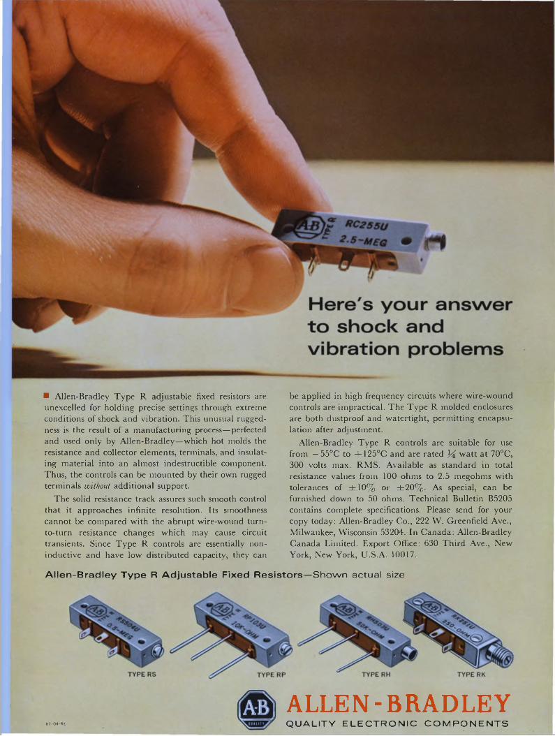
■ Allen-Bradley Type R adjustable fixed resistors are unexcelled for holding precise settings through extreme conditions of shock and vibration. This unusual ruggedness is the result of a manufacturing process—perfected and used only by Allen-Bradley—which hot molds the resistance and collector elements, terminals, and insulating material into an almost indestructible component. Thus, the controls can be mounted by their own rugged terminals without additional support.
The solid resistance track assures such smooth control that it approaches infinite resolution. Its smoothness cannot be compared with the abrupt wire-wound turn- to-turn resistance changes which may cause circuit transients. Since Type R controls are essentially non- inductive and have low distributed capacity, they can
be applied in high frequency circuits where wire-wound controls are impractical. The Type R molded enclosures are both dustproof and watertight, permitting encapsulation after adjustment.
Allen-Bradley Type R controls are suitable for use from — 55°C to +125°C and are rated J4 watt at 70°C, 300 volts max. RMS. Available as standard in total resistance values from 100 ohms to 2.5 megohms with tolerances of ±10% or ±20%. As special, can be furnished down to 50 ohms. Technical Bulletin B5205 contains complete specifications. Please send for your copy today: Allen-Bradley Co., 222 W. Greenfield Ave., Milwaukee, Wisconsin 53204. In Canada: Allen-Bradley Canada Limited. Export Office: 630 Third Ave., New York, New York, U.S.A. 10017.
Allen-Bradley Type R Adjustable Fixed Resistors—Shown actual size
ALLEN-BRADLEYQUALITY ELECTRONIC COMPONENTS61-04-6E
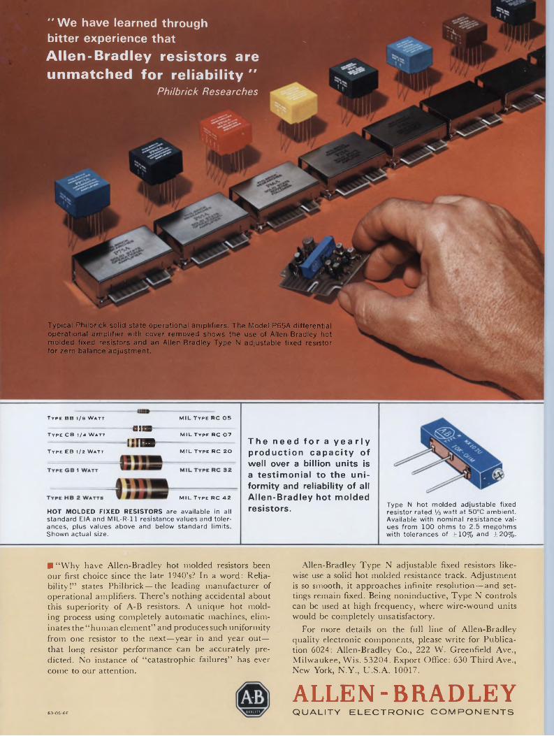
I
“ 'Ne have learned through bitter experience that
Allen-Bradley resistors are unmatched for reliability "
Philbrick Researches
Typical Philbrick solid state operational amplifiers. The Model P65A differential operational amplifier with cover removed shows the use of Allen-Bradley hot molded fixed resistors and an Allen-Bradley Type N adjustable fixed resistor for zero balance adjustment.
Type BB i/e Watt MIL TYPE RC 05
UJISType CB 1/4 Watt _______ MILType RC 07
î'!!SType EB 1/2 Watt MILType RC 20
1
MIL Type RC 42
HOT MOLDED FIXED RESISTORS are available in all standard EIA and MIL-R-11 resistance valuesand tolerances, plus values above and below standard limits. Shown actual size.
The need for a yearly production capacity of well over a billion units is a testimonial to the uniformity and reliability of all Allen-Bradley hot molded resistors. Type N hot molded adjustable fixed
resistor rated '/a watt at 50°C ambient. Available with nominal resistance values from 100 ohms to 2.5 megohms with tolerances of ±10% and ±20%.
■ “Why have Allen-Bradley hot molded resistors been our first choice since the late 1940’s? In a word: Reliability!” states Philbrick — the leading manufacturer of operational amplifiers. There’s nothing accidental about this superiority of A-B resistors. A unique hot molding process using completely automatic machines, eliminates the “human element” and produces such uniformity from one resistor to the next—year in and year out— that long resistor performance can be accurately predicted. No instance of “catastrophic failures” has ever come to our attention.
Allen-Bradley Type N adjustable fixed resistors likewise use a solid hot molded resistance track. Adjustment is so smooth, it approaches infinite resolution—and settings remain fixed. Being noninductive, Type N controls can be used at high frequency, where wire-wound units would be completely unsatisfactory.
For more details on the full line of Allen-Bradley quality electronic components, please write for Publication 6024: Allen-Bradley Co., 222 W. Greenfield Ave., Milwaukee, Wis. 53204. Export Office: 630 Third Ave., New York, N.Y., U.S.A. 10017.
ALLEN-BRADLEYQUALITY ELECTRONIC COMPONENTS63-05-6E
LETTERS
Holiday death tolls are not exaggeratedSir:
A recent letter from one of your readers [John Darrow, ED 5, March 1, p. 32] questioned the National Safety Council’s “sincerity” in our “misleading emphasis of the danger of holiday driving.” To prove his case, the reader unfortunately made the same statistical error made by so many others: He divided total traffic deaths for the year by 365 to arrive at a per-day figure, then multiplied this by the number of days in the holiday weekend and discovered the result to be not too different from the number of persons killed in traffic accidents over the holiday period.
Here is why such reasoning is wrong. The only deaths included in the holiday figures supplied to the Council by the Associated Press and United Press International are those of persons who have accidents and die during the holiday period. Thus, the 575 persons who died over the last Labor Day weekend, for example, were in accidents that occurred during those 78 hours, and they died during those 78 hours. The actual number of deaths caused by traffic accidents during that holiday weekend amounts to about 765. Almost 200 of these deaths occurred after the weekend was over, in some cases considerably later. This 765 figure is the only one that can validly be compared with the figure obtained in the manner of your letter writer. The 575 figure can be compared only with the number of persons who might have died during those 78 hours if it hadn’t been a holiday period; our estimate of that was 440.
It is interesting to note that the Associated Press runs an actual count of traffic deaths a weekend or so before such a holiday period to determine a “normal” figure; their figure on this runs amazingly close to our statisticians’ estimate of what might be expected during such a non-holiday period. In our contacts with the media during the holiday period, we try to stress the difference between the “immediate”
deaths during the period and the “complete” total to result from accidents during the period, but we are at the media’s mercy in trying to get our message across, of course.
Wayne Willie Asst. Director, Public Information National Safety Council Chicago
Received signal cannot be foundSir:
The Feburary 15th issue of Electronic Design carries a brief note and nomograph on p. 84 under the title, “Find the received signal.” After a very careful reading of this article by R. A. Hunting and E. J. Salley, I have come to the conclusion that the reader will have to search for a mighty long time to “find the received signal.”
Either the blue pencil of an editor cut some essential information or the authors ignored things like transmitting antenna form, efficiency, gain, polarization, seasonal and diurnal variation in the ionosphere, the possibility of skip distance, height of the reflection coefficient, ground wave, etc.
In short, this attempt to boil volumes of information on propagation theory and data down to one page is of dubious value and may mislead engineers by giving them incorrect field strength values.
G. H. Keitel Acting ChairmanDept, of Electrical Engineering San Jose State CollegeSan Jose, Calif.
Accuracy is our policyOn page U142 of ED 6, Mar. 15, 1966, Radio Frequency Lab’s thermometer bridge is incorrectly shown as Julie Research Lab’s potentiometer, and Julie’s pot as RFL’s bridge.
Scientific Data Systems points out that in ED 8, Apr. 12, 1966, p. 18, the Sigma 7 computer is erroneously stated to have an 8-bit word size. It in fact has a 32-bit word size.
what gives? less than 1/1000 of an inch!
That’s why our line of Palomar Accelerometers is your best choice for military and aerospace applications.
Fast response, accuracy and reliability are key features.
The heart of the Palomar Accelerometer is a tiny jewel-pivot pendulum captured in a magnetic field. So sensitive that the smallest hint of a change in velocity causes it to send out a corrective signal; maximum pendulum movement is less than 1/1000 of an inch.
United Control Corporation offers an entire family of these closed-loop, servoed acceleration transducers. Choose from types to measure either angular or linear acceleration...analog or digital output...fluid or electronically damped.
For the solution to your acceleration measurement problem for instrumentation or control, call or write UCC. “Control” is our middle name.
UNITED CONTROLAerospace Division
UNITED CONTROL CORP REDMOND, WN. 98052PHONE: (2061 885-3711 TWX: (2061 999-1874
ON READER-SERVICE CARD CIRCLE 12
< ON READER-SERVICE CARD CIRCLE 236 33
Less than .01% T.C. from O°C to 4- 125°CTRW—acknowledged leader in film capacitors—continues its leadership with advanced polycarbonate types providing mica-like stability through 125°C.
This is a complete new line of low-TC devices designed for no-drift performance at elevated temperatures.
TRW polycarbonates are offered in a variety of styles to meet all design needs for operation from -55°C to 125°C.
■ WIDE-RANGE TEMPERATURE STABILITY—< 1 % capacitance change from 0°C to 125°C (positive or negative TC available).■ long stable life—less than .1% drift after 10,000 hours.■ close tolerance—available in capacity tolerances to ±.5%.■ small size—up to 90% less volume than paper dielectrics.■ quick delivery—widely used styles available from stock.■ mil-c-19978 and mil-C-27287 performance and ruggedness.For full information phone, wire or write: 112 West First Street. Ogallala, Nebraska. Phone: 308-284-3611. TWX: 910-620-0321'
TR IVCAPACITORSON READER-SERVICE CARD CIRCLE 13
34 Electronic Design
ED EDITORIAL'Co-PublishersJames S. Mulholland, Jr.Robert E. Ahrensdorf
Editorial DirectorEdward E. Grazda
EditorHoward Bierman
Managing EditorRobert C. Haavind
Technical EditorsJoseph J. CasazzaRene ColenMaria DekanyRichard Harnar Mark B. Leeds Neil Sclater
News EditorsFrank EganRoger K. Field
West Coast EditorsRalph DobrinerPeer Fossen
Copy EditorPeter Beales
New Products EditorsDavid Surgan
Washington EditorS. David Pursglove
Editorial ProductionDollie S. Viebig Anne T. Lombardi
Art DirectorClifford M. Gardiner
Art AssistantWilliam Kelly
Technical IllustratorsLewis D. HillLeonard P. Levenson Cheh Nam Low
Production ManagerThomas V. Sedita
Asst. Production ManagerHelen De Polo
Production AssistantsCarl MerkinBernard Wolinsky
Circulation ManagerNancy L. Merritt
Reader ServiceDiane Pellechi
Making the proper first impression ...Cap-and-gown time is approaching at engineering college
campuses throughout the country, and industry recruiters are now in the last throes of their preparations. Professional interviewers are busily arranging trip schedules, and agencies are putting last-minute touches to company brochures and personnel managers are setting up plant tours for interested students. Competition for outstanding ’66 graduates is keen.
The company that hopes to attract its share of talent is wise to make a sound first impression. How? Recruitment specialists in recently published advice* say use the company brochure and follow these steps:
1. Resist the urge to go all-out on an elaborate brochure. Presentations combining brevity and simplicity are preferable.
2. Be up-to-date. Use descriptions of current job openings. If company statistics or product innovations are presented, ensure they are recent.
3. Clearly state educational requirements for each position, opportunities for advancement, and minimum standards expected of a new employee.
4. Outline basic salary structure; specific salary figures are unnecessary. Include, however, salary review procedure and approximate salary ranges after set service periods.
5. Detail what the new employee will be doing, indicating when he can expect to assume a superior position.
6. Describe the major points of the company’s training program.
7. If jobs are offered in different areas of the country, include brief descriptions of the cultural and leisure opportunities as well as educational and residential information.
8. Define company policy on relocation and travel, especially when transfers during the first few years are to be expected.
9. List key fringe benefits, including medical and health coverage, policy on graduate-level courses, disability plan, etc.
10. Tell the candidate how to make arrangements for an interview. Once the candidate becomes interested in your company, don’t force him to write for an application blank. Include the necessary forms and indicate clearly the name, address and telephone number of the personnel contact.
A sure way to be ineffective, according to the recruitment experts, is to concentrate on the following:
1. A series of ethereal illustrations, depicting a modern plant nestled serenely in a valley, with just a few overstated captions.
2. A flowing account of a proud company’s rise from obscurity to prominence.
3. A passionate promise by a company president of a glowing future for new employees, devoid of details on how really to succeed.
4. A number of detailed balance sheets starkly charting a company’s financial pattern and growth.
In short, recruitment advisers regard the ’66 graduate as sophisticated, intensely concerned with long-range career plans. He’s asking how hard he’ll have to work to achieve a particular goal, not where to find a soft job. As one university placement direct put it: “You can’t get away with giving him a glittering generality and a snow job.”
Howard Bierman
•“College Recruiting,” Business Management, Dec., 1965, p. 50.
May 10, 1966 35
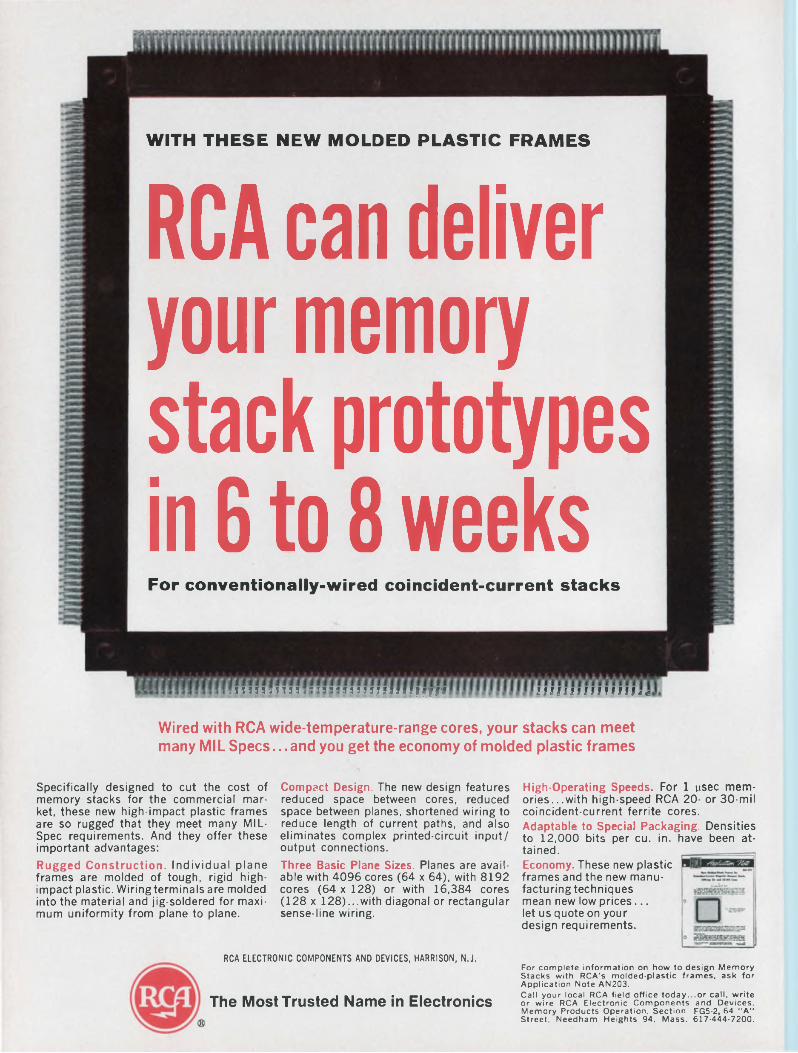
WITH THESE NEW MOLDED PLASTIC FRAMES
RCA can deliver your memory stack prototypes in 6 to 8 weeksFor conventionally-wired coincident-current stacks
? UUIbUMb" ” ” * MUIIIIU It 1W I IIMlltfl IUUI«*
Wired with RCA wide-temperature-range cores, your stacks can meet many MIL Specs. ..and you get the economy of molded plastic frames
Specifically designed to cut the cost of memory stacks for the commercial market, these new high-impact plastic frames are so rugged that they meet many MILSpec requirements. And they offer these important advantages:Rugged Construction. Individual plane frames are molded of tough, rigid highimpact plastic. Wiring terminals are molded into the material and jig-soldered for maximum uniformity from plane to plane.
Compact Design. The new design features reduced space between cores, reduced space between planes, shortened wiring to reduce length of current paths, and also eliminates complex printed-circuit input/ output connections.Three Basic Plane Sizes. Planes are available with 4096 cores (64 x 64), with 8192 cores (64 x 128) or with 16,384 cores (128 x 128)...with diagonal or rectangular sense-line wiring.
High-Operating Speeds. For 1 psec memories.. .with high-speed RCA 20- or 30-mil coincident-current ferrite cores.Adaptable to Special Packaging. Densities to 12,000 bits per cu. in. have been attained.Economy. These new plastic frames and the new manufacturing techniques mean new low prices... let us quote on your design requirements.
RCA ELECTRONIC COMPONENTS AND DEVICES, HARRISON, N.J.
The Most Trusted Name in Electronics
For complete information on how to design Memory Stacks with RCA’s molded-plastic frames, ask for Application Note AN203.Call your local RCA field office today...or call, write or wire RCA Electronic Components and Devices, Memory Products Operation, Section FG5-2, 64 “A” Street, Needham Heights 94, Mass. 617-444-7200.
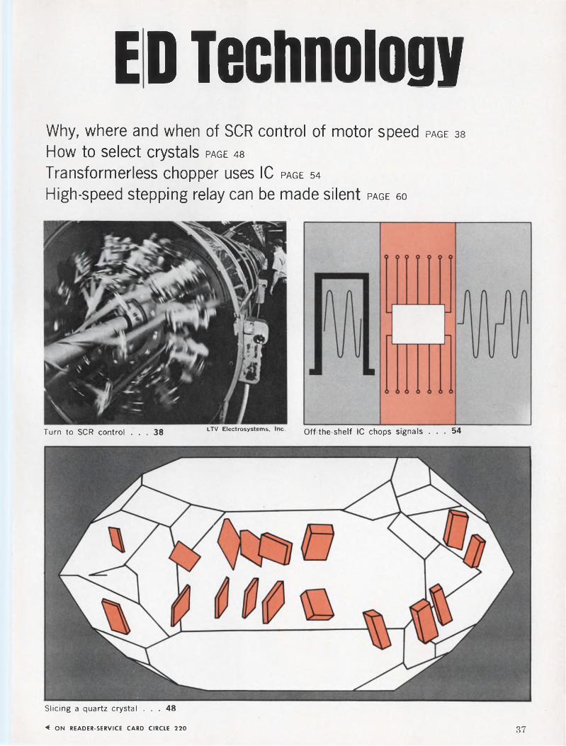
ED TechnologyWhy, where and when of SCR control of motor speed PAGE 38
How to select crystals page 48
Transformerless chopper uses IC page 54
High-speed stepping relay can be made silent page 60
Turn to SCR control ... 38 LTV Electrosystems' ,nc- Off-the-shelf IC chops signals ... 54
Slicing a quartz crystal ... 48
< ON READER-SERVICE CARD CIRCLE 220 37
Device-hunting for motor speed control?Look to the source as a guide—it shows when, where and why the SCR usually outlaps competing units.
An increasing number of motor speed-control systems now rely on a semiconductor power switch or regulator to govern the drive power furnished to the load. In a number of cases the engineer must choose between the SCR and power-transistor devices for this role. Not many designers realize, however, that the nature of the power source will usually dictate which semiconductor is best to use.
When this is taken into consideration, the SCR qualifies as a near-universal device for dc-motor speed control. Of course, such traditional factors as cost, complexity, size, speed of commutation and efficiency must also be considered. But even with all of these criteria, the SCR invariably fills the bill, regardless of the type of motor—series, shunt, compound or permanent-magnet—involved.
This SCR dominance is due to these properties:■ Unlike the transistor, it naturally accommo
dates ac power sources. It can also be used with de supplies, requiring a minimum of commutating circuitry in those applications.
■ It has both higher and broader power-handling capabilities, extending from fractional horsepower loads to hundreds of kilowatts.
■ It now has excellent speed and conducting characteristics. Some can switch at rates of 25,000 Hz, and its forward voltage drop is nearly as small—1 V typically—as that of the transistor. (Transistors are faster switches; but their power-handling capability is lower than the SCRs.)
■ It possesses a built-in latching action that ensures high power gain and automatic commutation at zero current conditions.
Let’s see how these attributes are put to work. By examining the salient characteristics of the major de motors, we will develop the design criteria for speed regulation peculiar to each. Then, using the power source as our litmus, we will analyze a number of typical SCR speed-control systems.
A look at three dc-motor types
De motors take three general forms: series, shunt and compound wound. Fig. 1 shows the field-armature relationships and torque speed curves for these three types. In general, the torque, speed and power relationships of de machines apply and are given by
John C. Hey, Applications Engineer, General Electric Co., Auburn, N. Y.
T = Ky*Ia, (1)
s=^(VIN-IaRa), (2)
and hp = KTs. (3)In Eqs. 1 to 3, T is the motor torque, * is the
flux per pole, Ia is the armature current, s the motor speed and the input voltage. Ra is the armature resistance, Kx and K2 are motor constants, K is a dimensional constant equal to 1/5250 and hp is the output horsepower.
Note from the speed relationship (Eq. 2) that there are two parameters that can be varied to change motor speed. These are the input voltage and the field flux. As input voltage is decreased, speed decreases. Conversely, as flux is decreased (field weakening), speed increases. Note that the resistive voltage drop in the armature is ignored here, inasmuch as it is small compared with Vm.
With a shunt motor one usually has both the armature and the field available for control purposes. By holding the field voltage constant and varying the armature input voltage, we obtain speed variation while delivering essentially constant torque to the load. This type of control is especially desirable in such applications as machine tools and conveyer drives. If the field excitation is varied, torque is increased as speed decreases, and essentially constant horsepower is delivered to the load. Although field control is not
Don't get your wires crossed. Author Hey hooks up his SCR motor speed control unit for a test run.
38 Electronic Design
1. The speed of any de motor is controlled by regulating either its input voltage or its field flux. Shown are the simplified armature-field relationships and the associated torque-speed curves for series (a), shunt (b) and compound (c) motor types.
as widely employed as armature control, the former’s constant hp output is ideal for such applications as winder drives or fan controls.
In a series-wound machine, armature current and field current are the same. Observe that field flux is proportional to field current. We thus have a slightly, more complicated situation than with the shunt motor, because of this interdependence of armature and field. Since the field must carry the armature current, its impedance must be very small. As such, most of the input voltage is applied to the armature. This dependency is expressed by
T a (4)
Torque may turn tables
For a constant torque load, the speed of the machine varies in proportion to the input voltage. As torque requirements increase, additional input voltage is required to maintain a given speed, and even more voltage is needed to increase the speed.
Torque may also, by itself, determine the application. One important characteristic of the series-wound de motor is its high-starting torque. Torque, being proportional to field flux and armature current, is therefore proportional to the square of armature current (neglecting saturation effects). The high-starting current provides comparably high-starting torque, which makes this machine ideal for vehicle drives, including railway service, and crane and hoist drives. The universal motor, which is a small form of the series motor, has found wide application in small
2. A varying voltage is used to effect a change in motor speed. If the power source is de, it must be chopped, and duty cycle levels establish the amount of power furnished to the load (a). If the source is ac (b), phase-control is used to govern the amount of load power.
shop and portable hand tools because of its torque property.
The compound motor has both a series and a shunt field. It exhibits characteristics that lie between the extremes defined by the series and shunt motors. The speed of a compound motor is varied either by field or armature control, as is the case with the shunt motor. Although the series motor has the highest starting torque of the de motor family, its no-load speed can climb to dangerous levels. The compound motor is thus used to give higher starting torque than the shunt motor, while providing a safe, finite, no-load speed.
Another type of de motor that is gaining in popularity is the permanent-magnet (PM). Its characteristics are somewhat similar to the shuntwound motor. The PM motor, however, is more efficient, because external field excitation is not required. Only armature control (for speed regulation) is possible, and therefore constant-torque applications are a natural for the PM motor.
So far we have considered ways to vary the input voltage to the machine to change its speed. Let’s see now how solid-state components achieve this function.
Power switch needed for chopping
An adjustable de voltage can be produced efficiently by chopping the source voltage at variable duty cycles. This delivers a varyinig average de voltage to the load. The chopping is done either directly from a de source (by means of a chopper) or from an ac source (by employing phase control) as illustrated in Fig. 2.
May 10, 1966 39
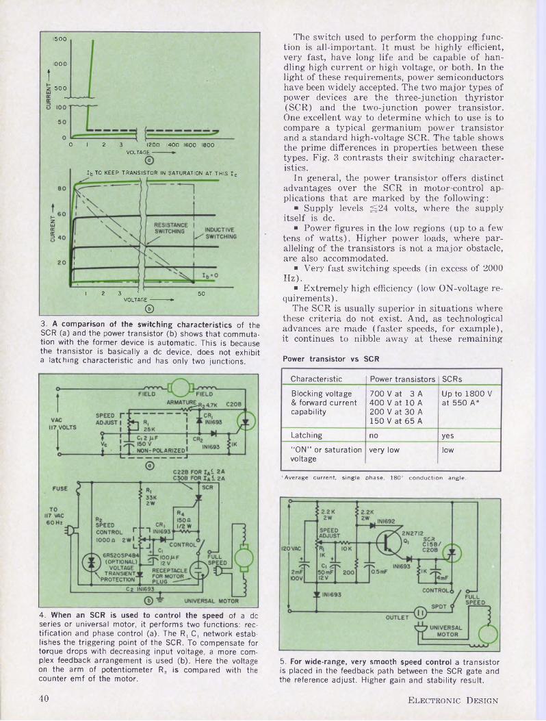
1500
1000î
z 500
0 12 3 1200 1400 1600 1800VOLTAGE -
lb TO KEEP TRANSISTOR IN SATURATION AT THIS Ic
I 2 3 < 50VOLTAGE------------ ►
©
The switch used to perform the chopping function is all-important. It must be highly efficient, very fast, have long life and be capable of handling high current or high voltage, or both. In the light of these requirements, power semiconductors have been widely accepted. The two major types of power devices are the three-junction thyristor (SCR) and the two-junction power transistor. One excellent way to determine which to use is to compare a typical germanium power transistor and a standard high-voltage SCR. The table shows the prime differences in properties between these types. Fig. 3 contrasts their switching characteristics.
In general, the power transistor offers distinct advantages over the SCR in motor-control applications that are marked by the following:
■ Supply levels ^24 volts, where the supply itself is de.
■ Power figures in the low regions (up to a few tens of watts). Higher power loads, where paralleling of the transistors is not a major obstacle, are also accommodated.
■ Very fast switching speeds (in excess of 2000 Hz).
■ Extremely high efficiency (low ON-voltage requirements).
The SCR is usually superior in situations where these criteria do not exist. And, as technological advances are made (faster speeds, for example), it continues to nibble away at these remaining
3. A comparison of the switching characteristics of the SCR (a) and the power transistor (b) shows that commutation with the former device is automatic. This is because the transistor is basically a de device, does not exhibit a latching characteristic and has only two junctions.
4. When an SCR is used to control the speed of a de series or universal motor, it performs two functions: rectification and phase control (a). The Rj C, network establishes the triggering point of the SCR. To compensate for torque drops with decreasing input voltage, a more complex feedback arrangement is used (b). Here the voltage on the arm of potentiometer R2 is compared with the counter emf of the motor.
Power transistor vs SCR
Characteristic Power transistors SCRs
Blocking voltage & forward current capability
700 V at 3 A 400 V at 10 A200 V at 30 A 150 V at 65 A
Up to 1800 V at 550 A*
Latching no yes
"ON” or saturation voltage
very low low
"■Average current, single phase, 180° conduction angle.
5. For wide-range, very smooth speed control a transistor is placed in the feedback path between the SCR gate and the reference adjust. Higher gain and stability result.
40 Electronic Design
bastions of transistor supremacy.Note also that because of its nonlatching prop
erty, the power transistor is basically a de device. Commutation is accomplished in a de circuit by simply removing its base drive. On the other hand, the latching characteristic of the SCR makes it basically an ac switch, where the commutation is automatic whenever current through the SCR tries to reverse.
This is not to imply that de operation of SCR’s is impractical. On the contrary, de applications are many and are growing. They include inverters, choppers, pulse modulators and de static switches.
Observe that the SCR has higher voltage and current capabilities, while the transistor has a lower forward drop in the ON state and is slightly faster. In an ac circuit the transistor loses its forward-drop advantage, inasmuch as a diode must be added in series with its collector to provide for a reverse-blocking capability. In effect, three junctions are required here. The SCR has all the necessary junctions, and each is optimized for the job at hand.
The basic differences in properties point to source voltage as the prime consideration in device selection.
Phase control used for ac sources
Fig. 4a shows the simplest of approaches to the
6. With shunt motors, speed control is effected by using the motor voltage to drive the SCR’s phase-shift network. Shown are half-wave (a) and full-wave (b) control.
speed control of a dc-series, or universal, motor. The SCR here provides two functions: It changes ac to de (half-wave) and then varies the resulting de voltage to the motor by means of phase control. The RiCr phase-shift circuit varies the point in the positive half cycle at which the SCR triggers.
As we have already seen, the series motor loses torque as the input voltage is decreased. This can be a serious handicap in such applications as hand tools, where low speed and high torque are required. A circuit that automatically adjusts the input voltage to the motor so as to compensate for the load-induced speed reduction appears in Fig. 4b. During positive half cycles of supply voltage, a reference voltage is established on the arm of potentiometer R,. This voltage is then compared with the counter emf of the motor through the gate of the SCR. When the potentiometer voltage rises above the counter emf, current flows through CRi into the gate of the SCR. This triggers the SCR and thus applies the remainder of that half cycle of supply voltage to the motor.
If load is applied to the motor, its speed tends to decrease, and this decreases the counter emf proportionally. The reference voltage then causes current to flow into the SCR gate earlier in the cycle. The SCR triggers sooner than before, and additional voltage is applied to the armature to compensate for the increased load and to maintain the preset speed.
The particular speed at which the motor operates is selected by R,. With this arrangement, stable operation is provided over a speed range of approximately 10 to 1. Stability at very low speeds can be improved by reducing the value of Ci at the expense of feedback gain. Note that there will be some variation in the effectiveness of speed control from one motor to another, depending upon the magnitude of the residual field for each motor.
Before we consider the control needs of more complex motors, observe the over-all simplicity of the circuits in the dc-series motor (Figs. 4a and 4b). This is one reason why SCR universal-motor controls are widely used, even in applications where low cost is paramount, such as hand tools.
For more elaborate motor speed-control needs, higher performance is achieved by a “plush” version of the dc-series, or universal, motor speed control (Fig. 5). The principle of operation is the same as previously described, except that a transistor is used to provide current gain from the reference voltage to the SCR gate circuitry. The superior feedback characteristic of this circuit yields smooth operation, with feedback providing stability throughout the range, including the very low speed portion.
Drive shifted for shunt motors
Speed control of shunt motors is accomplished in a manner similar to that employed with the series motor. Fig. 6 illustrates a simple approach for both half-wave and full-wave control. In both cases the voltage across the motor, as determined
May 10, 1966 41
7. For large de shunt motors, use a polyphase supply for speed control. More power is required than is usually available from single-phase sources (a), where four SCRs are needed. Only three SCRs, three diodes and a coasting
rectifier are needed (b) with a three-phase source. A three- phase regenerative system employing twelve SCRs (c) has the advantage of dual behavior—that is, it acts as a motor-generator set.
by speed and load, is used as the driving function for the R,C, phase-shift network.
If the motor speed tends to slow down, the SCR voltage is higher (there is less back emf), causing earlier breakover of D4. This in turn triggers SCRi earlier in the cycle, thus bringing the motor back to speed. Conversely, if the motor tries to speed up due to a lighter load, the SCR is made to trigger later in the cycle. In the half-wave case, Ci is discharged via the field winding because of the conduction of D3 during negative half cycles. In the full wave case the phase-shift network is reset via Ra and D, at the end of each half cycle.
For larger de shunt motors it is desirable to operate from a polyphase supply, because the power available from a single-phase source is usually limited. Fig. 7a shows a de motor driven from a three-phase supply by way of a full-wave bridge. A coasting rectifier is required across^ the load to free-wheel the inductive load current during the SCR OFF periods.
Instead of using a coasting diode, one may use an inverting bridge—that is, a bridge capable of returning the inductive load energy to the ac source. This is a particularly useful approach for fast field-control situations. For a single-phase, full-controlled bridge, four SCRs are used, and for three-phase operations, six rectifierss are required (Fig. 7b). Assume (in Fig. 7a) that the input line one is positive with respect to line two. At some delay angle (after one has gone positive), SCR, and SCR2 are triggered, and power is delivered to the load. As the source voltage is
reversed, inductive load current is free-wheeled back to the source, until the load current goes to zero or until SCR3 and SCR4 are triggered.
There are two distinct modes of operation: continuous and noncontinuous, as applied to the flow of load current. A high-inertia load may draw discontinuous current as the motor starts, go to continuous current operation at rated speed and rated torque, and then return to a discontinuous current flow when the motor is idle. Each case must be evaluated separately, inasmuch as voltage, current and dynamic stresses to the SCRs are different.
By using two full-control bridges, one can build a regenerative system. This type returns power to the source over periods that are larger than a portion of a cycle, as was the case with a single, full-controlled bridge. A typical application for this type of system (Fig. 7c) is an elevator drive, where power is delivered to a de machine to lift the cab. Then, as the cab descends, the machine becomes a generator, delivering energy back to the supply.
Voltage determines choice of SCR
Let’s see how to choose an SCR for a typical motor-control application. Assume we have a controlled bridge feeding an inductive load with a free-wheeling rectifier arrangement (Fig. 8a). E is both the peak repetitive forward and reverse voltage encountered by the power semiconductors in this circuit. For inputs of 120, 240 and 480 volts
42 Electronic Design
% RATED RECURRENT PEAK VOLTAGE ©
8. In a typical speed-control system (a), some provision must be made for protecting the SCR against voltage peaks and transients. Capacitor surge suppresors (b) and thyrector selenium suppressors (c) are commonly used.
rms, the peak values are 170,.340 and 680, respectively. With a 10% high-line situation, the peaks become 187, 374 and 750 volts. Stiff power sources can deliver energetic transient voltages. For these reasons, some form of voltage suppression is desirable. .
This is particularly true in high-power systems, where the investment in power semiconductors and the probability of high-energy transients warrant voltage protection. Even though the SCR’s ability to withstand surges of current and voltage is superior to that of power transistors, the investment is worth the insurance against costly down time. Of the numerous devices available for this protection, the cheapest and most widely used combination is the simple capacitor and the selenium surge suppressor. Capacitors are effective against low-energy transients, where the energy-storage capability is sufficient to limit the voltage to the capability of the power semiconductor.
Fig. 8b shows a typical capacitive voltage suppressor. It is obvious that an additional voltage capability is required of the power semiconductor, above that demanded by the recurrent peak of the input voltage. The selenium surge suppressor differs from the capacitive approach in that it dissipates transient energy (as opposed to storing it). The selenium suppressor is applied directly across the ac input (Fig. 8c). A typical volt-ampere characteristics for a Thyrector surge suppressor appears in Fig. 8d.
Note that the voltage across the Thyrector must
The former stores excess energy; the latter device dissipates it. The thyrector volt-ampere characteristic (d) is used to establish its blocking role. Note that it must conduct heavily to suppress excess energy levels effectively.
go to 1.75—two times the rated blocking voltage— before the Thyrector is in heavy conduction. Voltage clamping is needed to handle the transient energy. In designing high-power semiconductors into equipment, the designer must predict the maximum transient energy available, so the suppressor can accommodate that energy without danger of semiconductor damage or malfunction. He then chooses his surge suppressor so that voltage is limited to the transient, or peak, voltage rating of the semiconductors while that maximum energy is either stored or displayed.
Surge-current protection is handled in a similar fashion. The time-current capability of the semiconductor (i2t) is coordinated with that of a fuse, so that the fuse is limiting. The maximum average current per semiconductor in the circuit of Fig. 8a is IA/2 at all conduction angles.1
De sources require extra commutation
Referring to Fig. 2 again, we recall that when a motor is controlled from a de source (by chopping the voltage with a rapid-acting switch that uses an SCR as the power device), some form of auxiliary commutation is required. In the simplest of SCR choppers, the turn-on action of the SCR resonates a series LC circuit (connected across the SCR) as shown in Fig. 9a. The time required to charge the capacitor is the duration of power delivery, via the SCR, to the load.
As the capacitor voltage begins to ring back, the discharge current extinguishes the SCR. The
May 10, 1966 43
(in addition to the FM action of the other SCR), a smoother commutation results. This obviates stalled armature or plugged motor conditions.
9. With de power sources, SCR chopping is used to fre- quency-modulate the power supplied to the armature (a). When an extra SCR is used for pulse width modulation (b)
10. Reduction of the capacitor used in the chopper circuit is achieved by using an autotransformer. Here the capacitor is charged to higher voltages (than in Fig. 9b), to handle the same amount of joules (1 /2 CV2).
capacitor further discharges into the load, until its voltage equals that of the supply. SCRs not only require reverse voltage for commutation, but they also require that this voltage be applied for a minimum period of time: the turn-off time. In the circuit the length of time that the capacitor retains its reverse voltage is dependent upon how quickly the load allows it to discharge. In other words, the circuit turn-off time (that presented to the SCR) is dependent upon load impedance. It is for this reason that an SCR chopper must be designed for the condition of lowest load impedance, or, more appropriately, highest load current.
In the case of motor loads this corresponds to a stalled armature condition, or, even worse, plugging. For the configuration in Fig. 9a, when the circuit is operating into a stalled motor, the turnoff time is 0.7 RSaC, where RSA is the motor-stalled armature resistance. This circuit provides a constant pulsewidth to the load, and modulation is obtained by altering the triggering frequency of the SCR. ‘
Fig. 9b outlines an approach whereby the addition of an auxiliary SCR provides pulsewidth modulation in addition to frequency modulation. As the main SCR is triggered, the commutating capacitor rings up to twice the supply voltage via L and D,. The diode prevents the capacitor from discharging. When SCR2 is triggered, reverse voltage is applied to SCR,, and commutation proceeds as previously described.
Turn-off time is a cost factor
We see that for a given load circuit, turn-off time is dependent on the capacitance of the commutating capacitor. Obviously the shorter the turn-off time required by the SCR, the smaller the commutating capacitor need be. Since the total of microfarads can be roughly equated to the total of dollars spent for capacitors, SCR manufacturers have made great efforts to provide devices with short turn-off times. To date, 10 p.s is the practical lower limit on this parameter.
Motors rely on SCRs. Banks of SCR power converterscontrol giant GE motors in this mill-drive system. Morethan 15,000 kW is being handled here (BethlehemSteel’s Burns Harbor [Ind.] plant).
44 Electronic Design
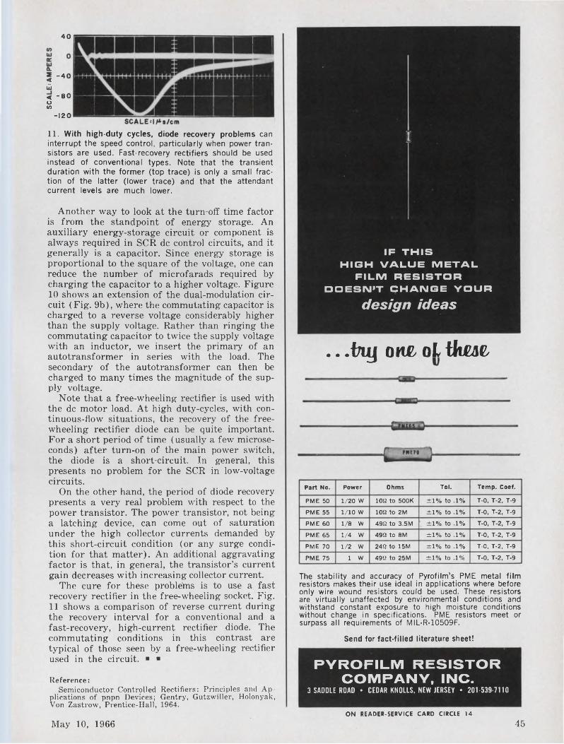
40
a.< "40 ü< -80 O co
-120
11. With high-duty cycles, diode recovery problems can interrupt the speed control, particularly when power transistors are used. Fast-recovery rectifiers should be used instead of conventional types. Note that the transient duration with the former (top trace) is only a small fraction of the latter (lower trace) and that the attendantcurrent levels are much lower.
Another way to look at the turn-off time factor is from the standpoint of energy storage. An auxiliary energy-storage circuit or component is always required in SCR de control circuits, and it generally is a capacitor. Since energy storage is proportional to the square of the voltage, one can reduce the number of microfarads required by charging the capacitor to a higher voltage. Figure 10 shows an extension of the dual-modulation circuit (Fig. 9b), where the commutating capacitor is charged to a reverse voltage considerably higher than the supply voltage. Rather than ringing the commutating capacitor to twice the supply voltage with an inductor, we insert the primary of an autotransformer in series with the load. The secondary of the autotransformer can then be charged to many times the magnitude of the supply voltage.
Note that a free-wheeling rectifier is used with the de motor load. At high duty-cycles, with continuous-flow situations, the recovery of the freewheeling rectifier diode can be quite important. For a short period of time (usually a few microseconds) after turn-on of the main power switch, the diode is a short-circuit. In general, this presents no problem for the SCR in low-voltage circuits.
On the other hand, the period of diode recovery presents a very real problem with respect to the power transistor. The power transistor, not being a latching device, can come out of saturation under the high collector currents demanded by this short-circuit condition (or any surge condition for that matter). An additional aggravating factor is that, in general, the transistor’s current gain decreases with increasing collector current.
The cure for these problems is to use a fast recovery rectifier in the free-wheeling socket. Fig. 11 shows a comparison of reverse current during the recovery interval for a conventional and a fast-recovery, high-current rectifier diode. The commutating conditions in this contrast are typical of those seen by a free-wheeling rectifier used in the circuit. ■ ■
Reference:Semiconductor Controlled
plications of pnpn Devices; Von Zastrow, Prentice-Hall,
Rectifiers: Principles and Ap- Gentry, Gutzwiller, Holonyak, 1964.
IF THIS HIGH VALUE METAL
FILM RESISTOR DOESN’T CHANGE YOUR
design ideas
.. .Hy ohl oL tkm
The stability and accuracy of Pyrofilm’s PME metal film resistors makes their use ideal in applications where before only wire wound resistors could be used. These resistors are virtually unaffected by environmental conditions and withstand constant exposure to high moisture conditions without change in specifications. PME resistors meet or surpass all requirements of MIL-R-10509F.
Part No. Power Ohms Toi. Temp. Coef.
PME 50 1/20 W 102 to 500K ±1% to .1% T-0, T-2, T-9
PME 55 1/10 w 102 to 2M ±1% to .1% T-0, T-2, T-9
PME 60 1/8 W 490 to 3.5M . ±1% to .1% T-0, T-2, T-9
PME 65 1/4 W 499 to 8M ±1% to .1% T-0, T-2, T-9
PME 70 1/2 W 242 to 15M ±1% to .1% T-0, T-2, T-9
PME 75 1 w 492 to 25M ±1% to .1% T-0, T-2, T-9
Send for fact-filled literature sheet!
PYROFIL.M RESISTOR COMPANY, INC.
3 SADDLE ROAD • CEDAR KNOLLS, NEW JERSEY • 201-539 7110
ON READER-SERVICE CARD CIRCLE 14
May 10, 1966 45
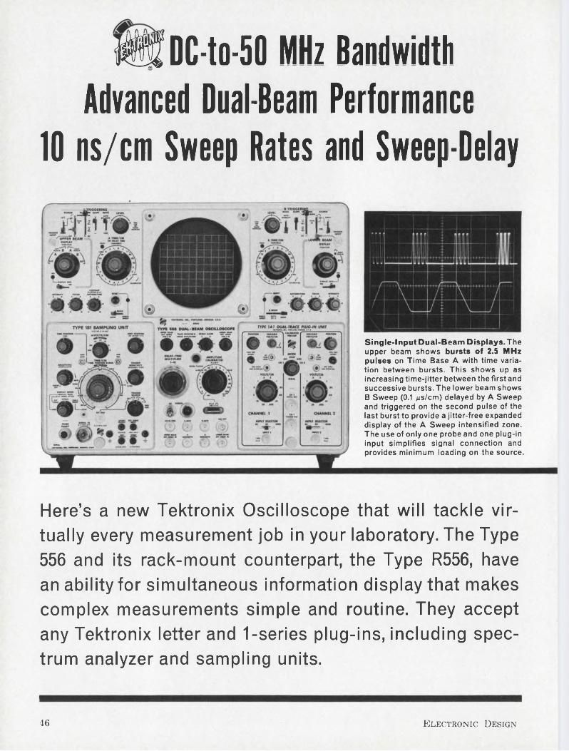
W DC-to-50 MHz Bandwidth Advanced Dual-Beam Performance
10 ns/cm Sweep Rates and Sweep-Delay
Single-Input Dual-Beam Displays. The upper beam shows bursts of 2.5 MHz pulses on Time Base A with time variation between bursts. This shows up as increasing time-jitter between the first and successive bursts. The lower beam shows B Sweep (0.1 gs/cm) delayed by A Sweep and triggered on the second pulse of the last burst to provide a jitter-free expanded display of the A Sweep intensified zone. The use of only one probe and one plug-in input simplifies signal connection and provides minimum loading on the source.
Here’s a new Tektronix Oscilloscope that will tackle virtually every measurement job in your laboratory. The Type 556 and its rack-mount counterpart, the Type R556, have an ability for simultaneous information display that makes complex measurements simple and routine. They accept any Tektronix letter and 1-series plug-ins, including spectrum analyzer and sampling units.
46 Electronic Design
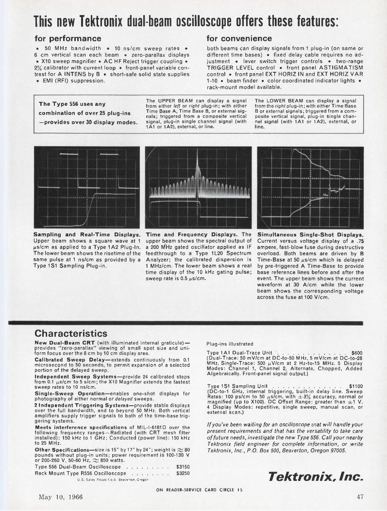
This new Tektronix dual-beam oscilloscope offers these features:for performance• 50 MHz bandwidth • 10 ns/cm sweep rates •
6 cm vertical scan each beam • zero-parallax displays• X10 sweep magnifier • AC HF Reject trigger coupling •
2% calibrator with current loop • front-panel variable contrast for A INTENS by B • short-safe solid state supplies• EMI (RFI) suppression.
for convenienceboth beams can display signals from 1 plug-in (on same or different time bases) • fixed delay cable requires no adjustment • lever switch trigger controls • two-range TRIGGER LEVEL control • front panel ASTIGMATISM control • front panel EXT HORIZ IN and EXT HORIZ VAR 1-10 • beam finder • color coordinated indicator lights • rack-mount model available.
The Type 556 uses any
combination of over 25 plug-ins
—provides over 30 display modes.
The UPPER BEAM can display a signal from either left or right plug-in; with either Time Base A, Time Base B, or external signals; triggered from a composite vertical signal, plug-in single channel signal (with 1A1 or 1A2), external, or line.
The LOWER BEAM can display a signal from the right plug-in; with either Time Base B or external signals; triggered from a composite vertical signal, plug-in single channel signal (with 1A1 or 1A2), external, or line.
Sampling and Real-Time Displays. Upper beam shows a square wave at 1 gs/cm as applied to a Type 1A2 Plug-In. The lower beam shows the risetime of the same pulse at 1 ns/cm as provided by a Type1S1 Sampling Plug-in.
Time and Frequency Displays. The upper beam shows the spectral output of a 200 MHz gated oscillator applied as IF feedthrough to a Type 1L20 Spectrum Analyzer; the calibrated dispersion is 1 MHz/cm. The lower beam shows a real time display of the 10 kHz gating pulse; sweep rate is 0.5 jus/cm.
Simultaneous Single-Shot Displays. Current versus voltage display of a .75 ampere, fast-blow fuse during destructive overload. Both beams are driven by B Time-Base at 50 gs/cm which is delayed by pre-triggered A Time-Base to provide base reference lines before and after the event. The upper beam shows the current waveform at 30 A/cm while the lower beam shows the corresponding voltage across the fuse at 100 V/cm.
CharacteristicsNew Dual-Beam CRT (with illuminated internal graticule) — provides "zero-parallax” viewing of small spot size and uniform focus over the 8 cm by 10 cm display area.Calibrated Sweep Delay—extends continuously from 0.1 microsecond to 50 seconds, to permit expansion of a selected portion of the delayed sweep.Independent Sweep Systems—provide 24 calibrated steps from 0.1 /zs/cm to 5 s/cm; the X10 Magnifier extends the fastest sweep rates to 10 ns/cm.Single-Sweep Operation—enables one-shot displays for photography of either normal or delayed sweeps.2 Independent Triggering Systems—provide stable displays over the full bandwidth, and to beyond 50 MHz. Both vertical amplifiers supply trigger signals to both of the time-base triggering systems.Meets interference specifications of MIL-I-6181 D over the following frequency ranges —Radiated (with CRT mesh filter installed): 150 kHz to 1 GHz; Conducted (power line): 150 kHz to 25 MHz.Other Specifications—size is 15" by 17" by 24"; weight is 80pounds without plug-in units; power requirement is 100-130 V
Plug-ins illustrated
Type1A1 Dual-Trace Unit....................................................... $600(Dual-Trace: 50 mV/cm at DC-to-50 MHz, 5 mV/cm at DC-to-28 MHz. Single-Trace: 500 pNIcm at 2 Hz-to-15 MHz. 5 Display Modes: Channel 1, Channel 2, Alternate, Chopped, Added Algebraically. Front-panel signal output.)
Type1S1 Sampling Unit................................................... $1100(DC-to-1 GHz, internal triggering, built-in delay line. Sweep Rates: 100 ps/cm to 50 /xs/cm, with ±3% accuracy, normal or magnified (up to X100). DC Offset Range: greater than ±1 V. 4 Display Modes: repetitive, single sweep, manual scan, or external scan.)
If you've been waiting for an oscilloscope mat will handle your present requirements and that has the versatility to take care of future needs, investigate the new Type 556. Call your nearby Tektronix field engineer for complete information, or write Tektronix, Inc., P.O. Box 500, Beaverton, Oregon 97005.
or 200-260 V, 50-60 Hz, ~ 850 watts.Type 556 Dual-Beam Oscilloscope............................... $3150Rack Mount Type R556 Oscilloscope........................... $3250
U.S. Sales Prices f.o.b. Beaverton, Oregon Tektronix, Inc.ON READER-SERVICE CARD CIRCLE 15
May 10, 1966 47
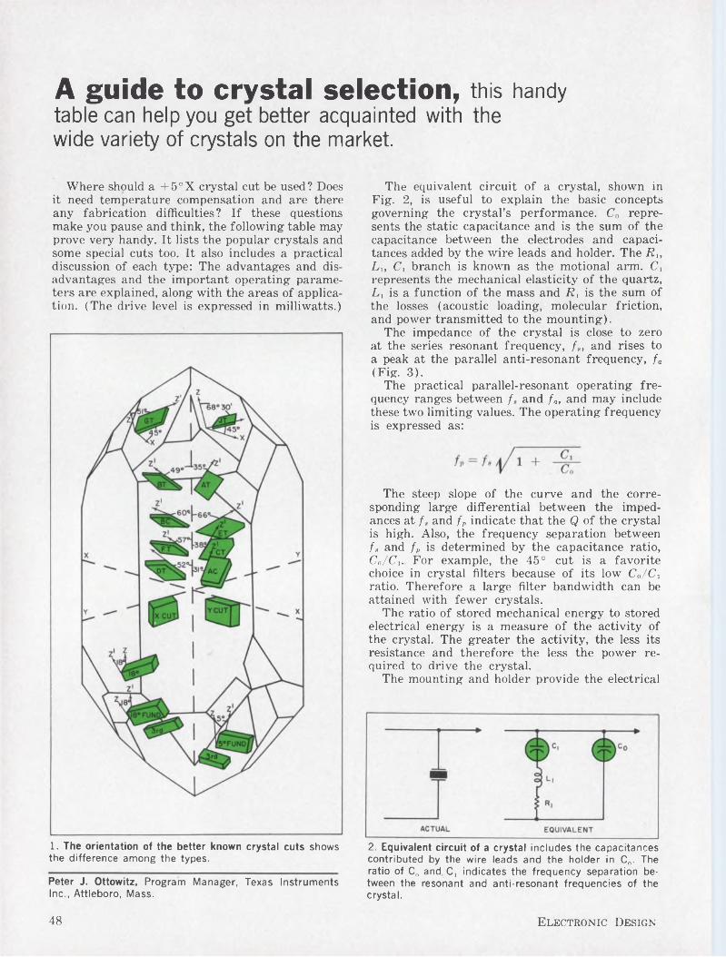
A guide to crystal selection, this handy table can help you get better acquainted with the wide variety of crystals on the market.
Where should a +5°X crystal cut be used? Does it need temperature compensation and are there any fabrication difficulties? If these questions make you pause and think, the following table may prove very handy. It lists the popular crystals and some special cuts too. It also includes a practical discussion of each type: The advantages and disadvantages and the important operating parameters are explained, along with the areas of application. (The drive level is expressed in milliwatts.)
1. The orientation of the better known crystal cuts shows the difference among the types.
The equivalent circuit of a crystal, shown in Fig. 2, is useful to explain the basic concepts governing the crystal’s performance. Co represents the static capacitance and is the sum of the capacitance between the electrodes and capacitances added by the wire leads and holder. The Rt, L„ Ci branch is known as the motional arm. C, represents the mechanical elasticity of the quartz, L, is a function of the mass and R, is the sum of the losses (acoustic loading, molecular friction, and power transmitted to the mounting).
The impedance of the crystal is close to zero at the series resonant frequency, fs, and rises to a peak at the parallel anti-resonant frequency, fa (Fig. 3).
The practical parallel-resonant operating frequency ranges between f„ and fa, and may include these two limiting values. The operating frequency is expressed as:
The steep slope of the curve and the corresponding large differential between the impedances at f, and fp indicate that the Q of the crystal is high. Also, the frequency separation between f„ and f„ is determined by the capacitance ratio, Cn/Cj. For example, the 45° cut is a favorite choice in crystal filters because of its low Co/Ci ratio. Therefore a large filter bandwidth can be attained with fewer crystals.
The ratio of stored mechanical energy to stored electrical energy is a measure of the activity of the crystal. The greater the activity, the less its resistance and therefore the less the power required to drive the crystal.
The mounting and holder provide the electrical
2. Equivalent circuit of a crystal includes the capacitances contributed by the wire leads and the holder in C„. The ratio of C„ and C, indicates the frequency separation between the resonant and anti-resonant frequencies of the crystal.
Peter J. Ottowitz, Program Manager, Texas Instruments Inc., Attleboro, Mass.
48 Electronic Design
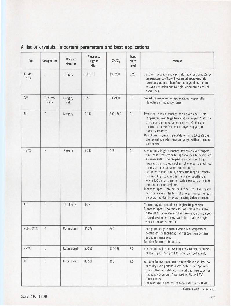
A list of crystals, important parameters and best applications.
Cut Designation Mode of vibration
Frequency range in
kHzCq/Ci
Max. drive level
Remarks
Duplex 5°X
J Length, 0.800-10 190-250 0.20 Used in frequency and oscillator applications. Zerotemperature coefficient occurs at approximately room temperature; therefore the crystal is limited to oven operation and to rigid temperature-control conditions.
XY Custommade
Length, width
3-50 600-900 0.1 Suited for oven-control applications, especially in its optimum frequency range.
NT N Length, 4-150 800-1500 0.1 Preferred in low-frequency oscillators and filters. It operates over large temperature ranges. Stability of ±5 ppm can be obtained over ±5°C, if oven- controlled in the frequency range. Rugged, if properly mounted.
Can obtain frequency stability within ±0.0025% over the normal room-temperature range, without temperature control.
+5°X H Flexure 5-140 225 0.1 A relatively large frequency deviation over temperature range restricts filter applications to controlled environments. Low temperature coefficient and large ratio of stored mechanical energy to electrical energy are the characteristic features.
Used in wideband filters, below the range of practical size E plates, and in transistor oscillators, where LC circuits are not stable enough, or where there is a space problem.
Disadvantages: Fabrication difficulties. The crystal must be made in the form of a long, thin bar to fit in a special holder, to avoid jumping between modes.
BT B Thickness 1-75 Thicker crystal possible at higher frequencies. Disadvantages: Too thick for low frequency. Also,
difficult to fabricate and has zero-temperature coefficient over only a very small temperature range. Not as active as the AT.
-18-1/2°X F Extensional 50-250 200 — Used principally in filters where low temperature coefficient is sacrificed for freedom from certain spurious responses.
Suitable for multi-electrodes.+5°X E Extensional 50-250 130-160 2.0 Mostly applicable in low-frequency filters, because
of low Cq/Cj and good temperature coefficient.
DT D Face shear 80-500 450 2.0 Suitable for oven and non-oven applications. Its low capacity ratio permits many useful filter applications. Used as calibrator crystal and time base for frequency counters. Also used in FM and TV transmitters.
Disadvantage: Does not perform well over 500 kHz.(Continued on p 50)
May 10, 1966 49
Crystal list (cont.)
Cut Designation Mode of vibration
Frequency range in
kHzC(/Cl
Max. drive level
Remarks
MT M Extensional 50-250 250 2.0 Its low temperature coefficient makes it useful for oscillator control and for filters where low Cq/Cj ratio is required along with low inductance and good temperature coefficient. However, this crystal is seldom used, because more compact units have replaced it.
GT G Extensional 85-400 375 0.1 Has the greatest stability yet attained within a cut. Does not vary more than 1 part per million over a range of 100°C.
Offers a low temperature coefficient over a wide frequency range, by coupling any desired mode with another of nearly equal amplitude at a frequency equal to 0.86 times its natural frequency.
Used in frequency standards and when stabili.ty without temperature control or low impedance is essential.
Disadvantages: Most expensive of all types, because of painstaking labor required to obtain exact orientation in dimension.
CT C Face shear 300-1100 350-400 2.0 Provides a zero temperature coefficient in the shear mode for low frequencies.
Widely used in low-frequency oscillators and filters and does not require constant temperature control over normal operating conditions. Useful in filters because of low Cq/Cj ratio. Popular in oscillators because of its low series resistance, especially above 400 kHz.
Disadvantages: Large face dimensions make it difficult to fabricate for the very low frequencies.
X Custommade
Extensional 350-20,000 - - Mechanically stable and an economic type of cut. Disadvantages: Large temperature coefficient, with
the tendency to jump from one mode to another.
SL Custommade
Face shear, coupled to flexure
300-800 450 — Electrical characteristics similar to DT, but it is larger, has better Q and uniformity of characteristics above 300 kHz. Its various characteristics make it desirable for some filter applications.
Y Y Thickness, shear
500-20,000 — — Most active. Ratio of stored mechanical to electrical energy is large. Is strong mechanically.
Disadvantages: Large temperature coefficient and poor frequency spectrum.
AT A Thickness 550-20,000fundamental
10,000-60,000(3rd overtone)
100,000(5th overtone)
10-100,000 1.0-8.0 Excellent temperature and frequency characteristics. Its overtones are used in cases where the frequency should not change with oscillator reactance variations.
Designs provide suitable capabilities for satisfying 70-80% of all crystal requirements. Preferred for high-frequency oscillator-control wherever wide variation of temperature is encountered. Because of small size, it can be readily mounted to meet stringent vibration specifications.
Disadvantage: Difficult to fabricate for optimum operation without coupling between modes.
50 Electronic Design
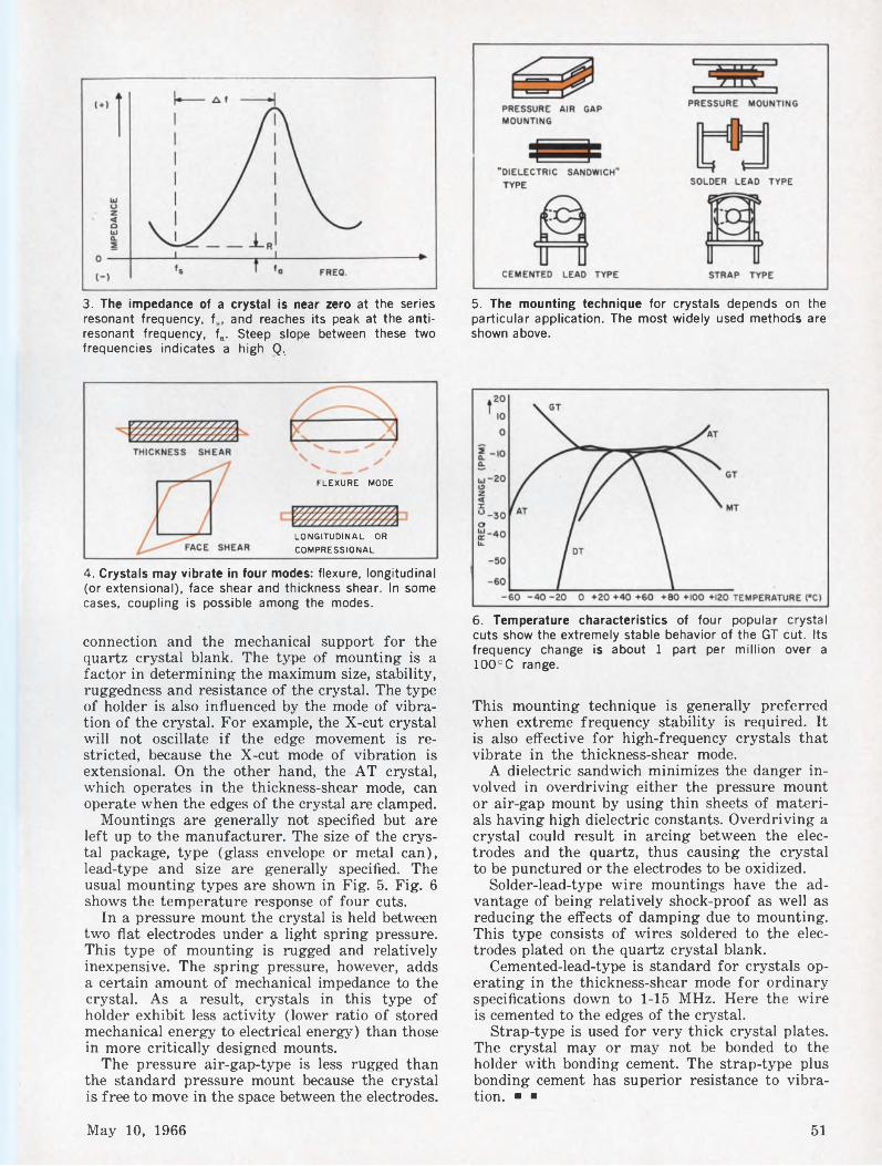
3. The impedance of a crystal is near zero at the series resonant frequency, fs, and reaches its peak at the antiresonant frequency, fa. Steep slope between these two frequencies indicates a high Q,
5. The mounting technique for crystals depends on the particular application. The most widely used methods are shown above.
FLEXURE MODE
LONGITUDINAL OR COMPRESSIONAL
4. Crystals may vibrate in four modes: flexure, longitudinal (or extensional), face shear and thickness shear. In some cases, coupling is possible among the modes.
connection and the mechanical support for the quartz crystal blank. The type of mounting is a factor in determining the maximum size, stability, ruggedness and resistance of the crystal. The type of holder is also influenced by the mode of vibration of the crystal. For example, the X-cut crystal will not oscillate if the edge movement is restricted, because the X-cut mode of vibration is extensional. On the other hand, the AT crystal, which operates in the thickness-shear mode, can operate when the edges of the crystal are clamped.
Mountings are generally not specified but are left up to the manufacturer. The size of the crystal package, type (glass envelope or metal can), lead-type and size are generally specified. The usual mounting types are shown in Fig. 5. Fig. 6 shows the temperature response of four cuts.
In a pressure mount the crystal is held between two flat electrodes under a light spring pressure. This type of mounting is rugged and relatively inexpensive. The spring pressure, however, adds a certain amount of mechanical impedance to the crystal. As a result, crystals in this type of holder exhibit less activity (lower ratio of stored mechanical energy to electrical energy) than those in more critically designed mounts.
The pressure air-gap-type is less rugged than the standard pressure mount because the crystal is free to move in the space between the electrodes.
6. Temperature characteristics of four popular crystal cuts show the extremely stable behavior of the GT cut. Its frequency change is about 1 part per million over a 100°C range.
This mounting technique is generally preferred when extreme frequency stability is required. It is also effective for high-frequency crystals that vibrate in the thickness-shear mode.
A dielectric sandwich minimizes the danger involved in overdriving either the pressure mount or air-gap mount by using thin sheets of materials having high dielectric constants. Overdriving a crystal could result in arcing between the electrodes and the quartz, thus causing the crystal to be punctured or the electrodes to be oxidized.
Solder-lead-type wire mountings have the advantage of being relatively shock-proof as well as reducing the effects of damping due to mounting. This type consists of wires soldered to the electrodes plated on the quartz crystal blank.
Cemented-lead-type is standard for crystals operating in the thickness-shear mode for ordinary specifications down to 1-15 MHz. Here the wire is cemented to the edges of the crystal.
Strap-type is used for very thick crystal plates. The crystal may or may not be bonded to the holder with bonding cement. The strap-type plus bonding cement has superior resistance to vibration. ■ ■
May 10, 1966 51
Planar is a patented Fairchild process.FAIRCHILD SEMICONDUCTOR/A Division of Fairchild Camera and Instrument Corporation ■ 313 Fairchild Drive, Mountain View, California (415) 962-5011 ■ TWX: 910-379-6435
52 Electronic Design
Fairchild is in the power business with more than 25 transistors, diodes, and SCR’s, in nine package configurations. These are newly-designed devices, for efficient circuits. They feature integrated nickel-chromium resistors and epitaxial construction where appropriate, and something else: Planar processing that keeps out most of the impurities and keeps in all of the reliability. But Planar processing also means higher yields. And that means that Fairchild power costs less. You can learn to live with that, can’t you? We can.
POWER FAIRCHILDSEMICONDUCTOR
ON READER-SERVICE CARD CIRCLE 16
May 10, 1966 53
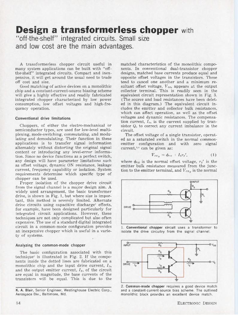
Design a transformerless chopper with “off-the-shelf” integrated circuits. Small size and low cost are the main advantages.
A transformerless chopper circuit useful in many system applications can be built with “off- the-shelf” integrated circuits. Compact and inexpensive, it will get around the usual need to trade off cost and size.
Good matching of active devices on a monolithic chip and a constant-current-source biasing scheme will give a highly effective and readily fabricated integrated chopper characterized by low power consumption, low offset voltages and high-frequency operation.
Conventional drive limitations
Choppers, of either the electro-mechanical or semiconductor types, are used for low-level multiplexing, mode-switching, commutating, and modulating and demodulating. Their function in these applications is to transfer signal information alternately without distorting the original signal content or introducing any level-error information. Since no device functions as a perfect switch, any design will have parameter limitations such as offset voltage, dynamic ON resistance, leakage current, frequency capability or isolation. System requirements determine which specific type of chopper can be used.
Proper isolation of the chopper drive circuit from the signal channel is a major design aim. A widely used arrangement, the basic transformer drive, is shown in Fig. 1, but where size is important, this method is severely limited. Alternate drive circuits using capacitive discharge1 effects, for example, have been designed particularly for integrated circuit applications. However, these techniques are not only complicated but also often expensive. The use of a standard digital integrated circuit in a common-mode configuration provides an inexpensive chopper which is useful in a variety of systems.
Analyzing the common-mode chopper
The basic configuration associated with this technique2 is illustrated in Fig. 2. If the components inside the dotted lines are fabricated on a monolithic chip and the input drive current, ID, and the output emitter current, IE, of the circuit are equal in magnitude, the base currents of the transistors will be equal. This is due to the
K. A. Blair, Senior Engineer, Westinghouse Electric Corp., Aerospace Div., Baltimore, Md.
matched characteristics of the monolithic components. In conventional dual-transistor chopper designs, matched base currents produce equal and opposite offset voltages in the transistors. These tend to cancel one another and a minimum resultant offset voltage, FOs, appears at the output collector terminal. This is readily seen in the equivalent circuit representation shown in Fig. 3. (The source and load resistances have been deleted in this diagram.) The equivalent circuit includes the emitter and collector bulk resistances, which can affect operation, as well as the offset voltages and dynamic resistances. The compensation current, Io, is the current supplied by transistor Q. to correct any current imbalance in the circuit.
The offset voltage of a single transistor, operated as a saturated switch in the normal commonemitter configuration and with zero signal current,3-4 can be given as:
Fcba = d)CE + I lrE, (1)where is the normal offset voltage, rE is the emitter bulk resistance measured from the junction to the emitter terminal, and VCEn is the normal
1. Conventional chopper circuit uses a transformer to isolate the drive circuitry from the signal channel.
2. Common-mode chopper requires a good device match and a constant-current-source bias scheme. The outlined monolithic block provides an excellent device match.
54 Electronic Design
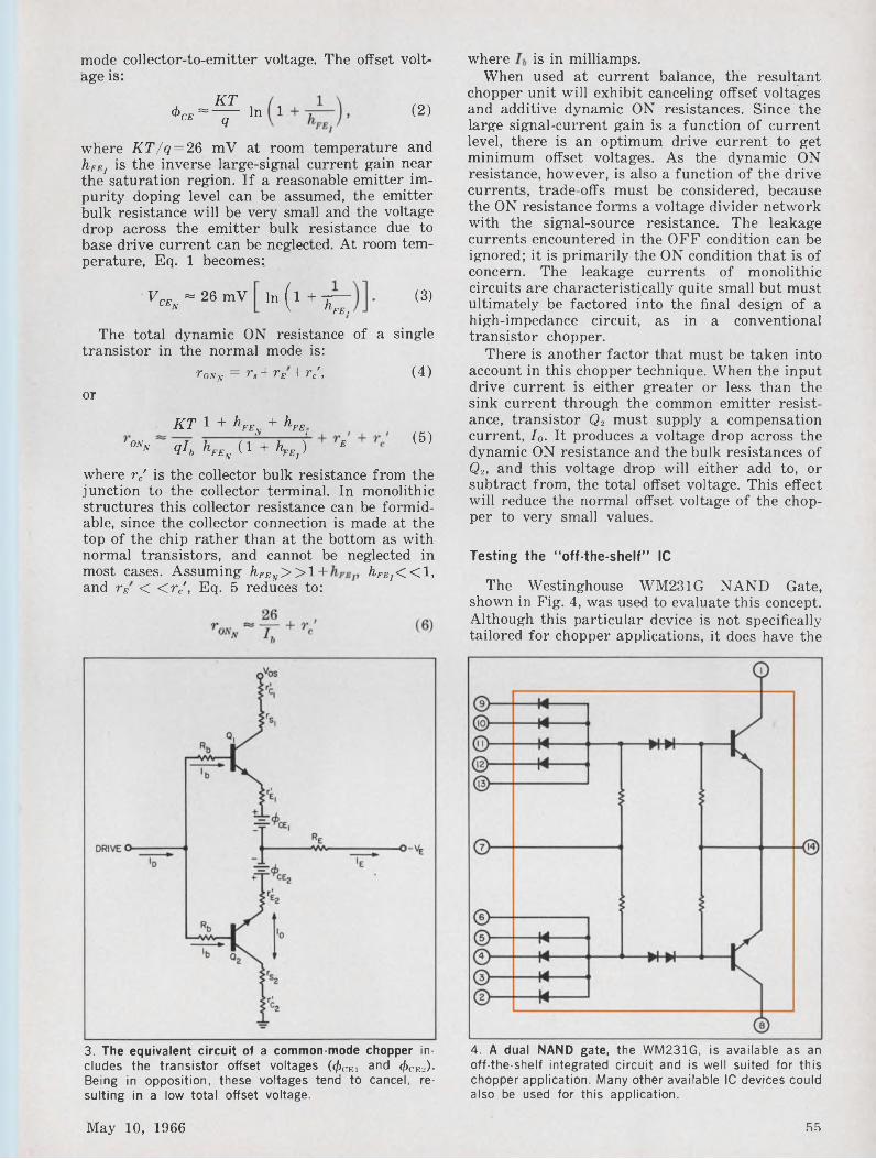
mode collector-to-emitter voltage. The offset voltage is:
^CEKT
=----- Inq1 (2)
where KT/q = 26 mV at room temperature and hFEl is the inverse large-signal current gain near the saturation region. If a reasonable emitter impurity doping level can be assumed, the emitter bulk resistance will be very small and the voltage drop across the emitter bulk resistance due to base drive current can be neglected. At room temperature, Eq. 1 becomes;
VrF «26 mV cen ln i1 + T—' rbFE.
The total dynamic ON resistance of transistor in the normal mode is:
tOnn = ra + rE+rc',
a
or
KT 1 + hFEN + hFEionn qlh hFE (1 + ^ ) E 1 U r K n “ ß j
(3)
single
(4)
(5)
where rc' is the collector bulk resistance from the junction to the collector terminal. In monolithic structures this collector resistance can be formidable, since the collector connection is made at the top of the chip rather than at the bottom as with normal transistors, and cannot be neglected in most cases. Assuming /¿™v> >1 + hFEl<<l, and rE < <r/, Eq. 5 reduces to:
where is in milliamps.When used at current balance, the resultant
chopper unit will exhibit canceling offset voltages and additive dynamic ON resistances. Since the large signal-current gain is a function of current level, there is an optimum drive current to get minimum offset voltages. As the dynamic ON resistance, however, is also a function of the drive currents, trade-offs must be considered, because the ON resistance forms a voltage divider network with the signal-source resistance. The leakage currents encountered in the OFF condition can be ignored; it is primarily the ON condition that is of concern. The leakage currents of monolithic circuits are characteristically quite small but must ultimately be factored into the final design of a high-impedance circuit, as in a conventional transistor chopper.
There is another factor that must be taken into account in this chopper technique. When the input drive current is either greater or less than the sink current through the common emitter resistance, transistor Q2 must supply a compensation current, Io. It produces a voltage drop across the dynamic ON resistance and the bulk resistances of Q2, and this voltage drop will either add to, or subtract from, the total offset voltage. This effect will reduce the normal offset voltage of the chopper to very small values.
Testing the “off-the-shelf” IC
The Westinghouse WM231G NAND Gate, shown in Fig. 4, was used to evaluate this concept. Although this particular device is not specifically tailored for chopper applications, it does have the
3. The equivalent circuit of a common-mode chopper includes the transistor offset voltages (^cei and </>CE2). Being in opposition, these voltages tend to cancel, resulting in a low total offset voltage.
4. A dual NAND gate, the WM231G, is available as an off-the-shelf integrated circuit and is well suited for this chopper application. Many other available IC devices could also be used for this application.
May 10, 1966 55
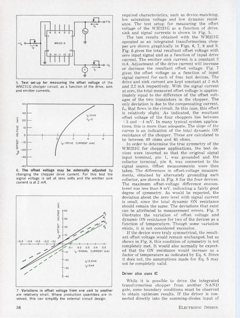
5. Test set-up for measuring the offset voltage of the WM231G chopper circuit, as a function of the drive, sink and emitter currents.
changing the chopper drive current. For this test thesignal voltage is set at zero volts and the emitter sink current is at 2 mA.
7. Variations in offset voltage from one unit to another are relatively small. Where production quantities are involved, this can simplify the external circuit design.
required characteristics, such as device-matching, low saturation voltage and low dynamic resistance. The test setup for measuring the offset voltage of the WM231G as a function of drive, sink and signal currents is shown in Fig. 5.
The test results obtained with the WM231G operated as an integrated transformerless chopper are shown graphically in Figs. 6, 7, 8 and 9. Fig. 6 gives the total resultant offset voltage with zero input signal and as a function of input drive current. The emitter sink current is a constant 2 mA. Adjustment of the drive current will increase or decrease the resultant offset voltage. Fig. 7 gives the offset voltage as a function of input signal current for each of foui test devices. The drive and sink current are kept constant at 2 mA and 2.2 mA respectively. With the signal current at zero, the total measured offset voltage is approximately equal to the difference of the offset voltages of the two transistors in the chopper. The only deviation is due to the compensating current, Io, that flows in the circuit. In this case, this effect is relatively slight. As indicated, the resultant offset voltage of the four choppers lies between + 3 and —4 mV. In many typical system applications, this is more than adequate. The slope of the curves is an indication of the total dynamic ON resistance of the chopper. These are calculated to be between 49 ohms and 65 ohms.
In order to determine the true symmetry of the WM231G for chopper applications, the test devices were inverted so that the original signal input terminal, pin 1, was grounded and the collector terminal, pin 8, was connected to the signal source. Offset measurements were then taken. The differences in offset-voltage measurements, obtained by alternately grounding each collector, are shown in Fig. 8 for the four devices. The maximum offset-voltage difference encountered was less than 8 mV, indicating a fairly good degree of symmetry. As would be expected, the deviation about the zero level with signal current is small, since the total dynamic ON resistance should remain the same. The deviations that exist can be attributed to measurement errors. Fig. 9 illustrates the variation of offset voltage and dynamic ON resistance for two of the devices as a function of temperature. Though some variation exists, it is not considered excessive.
If the device were truly symmetrical, the resultant offset voltage would remain unchanged, but as shown in Fig. 8, this condition of symmetry is not completely met. It would also normally be expected that the ON resistance would increase as a factor of temperature as indicated by Eq. 6. Since it does not, the assumptions made for Eq. 5 may not be completely valid.
Driver also uses IC
While it is possible to drive the integrated transformerless chopper from another NAND gate, some boundary conditions must be observed to obtain optimum results. If the driver is connected directly into the summing-diodes input of
56 Electronic Design
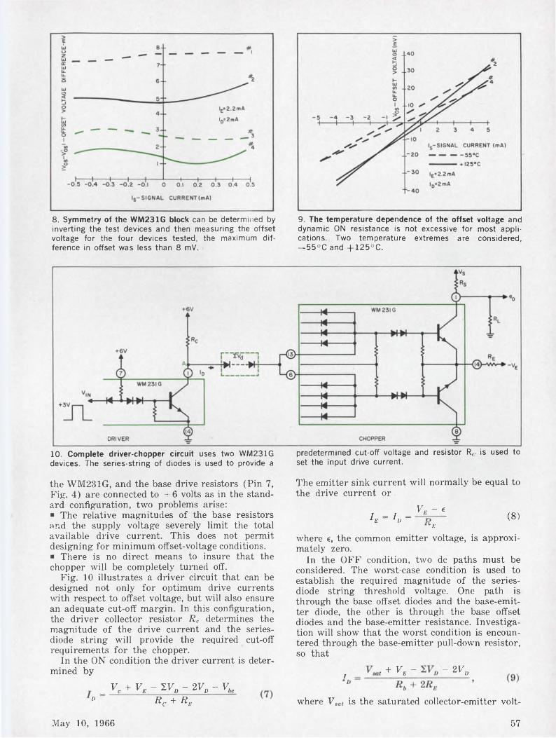
8. Symmetry of the WM231G block can be determined by inverting the test devices and then measuring the offset voltage for the four devices tested, the maximum difference in offset was less than 8 mV.
9. The temperature dependence of the offset voltage and dynamic ON resistance is not excessive for most applications. Two temperature extremes are considered, —55°C and +125°C.
10. Complete driver-chopper circuit uses two WM231G devices. The series-string of diodes is used to provide a
predetermined cut-off voltage and resistor R,. is used to set the input drive current.
the WM231G, and the base drive resistors (Pin 7, Fig. 4) are connected to +6 volts as in the standard configuration, two problems arise:■ The relative magnitudes of the base resistors and the supply voltage severely limit the total available drive current. This does not permit designing for minimum offset-voltage conditions.■ There is no direct means to insure that the chopper will be completely turned off.
Fig. 10 illustrates a driver circuit that can be designed not only for optimum drive currents with respect to offset voltage, but will also ensure an adequate cut-off margin. In this configuration, the driver collector resistor R„ determines the magnitude of the drive current and the seriesdiode string will provide the required cut-off requirements for the chopper.
In the ON condition the driver current is determined by
= VC + VB- WD - 2VP - VbeD Rc + Re
The emitter sink current will normally be equal to the drive current or
V - eIE = ID = <8)
^Bwhere e, the common emitter voltage, is approximately zero.
In the OFF condition, two de paths must be considered. The worst-case condition is used to establish the required magnitude of the seriesdiode string threshold voltage. One path is through the base offset diodes and the base-emitter diode, the other is through the base offset diodes and the base-emitter resistance. Investigation will show that the worst condition is encountered through the base-emitter pull-down resistor, so that
, + V, - - 2Va
where Vsat is the saturated collector-emitter volt-
May 10, 1966 57
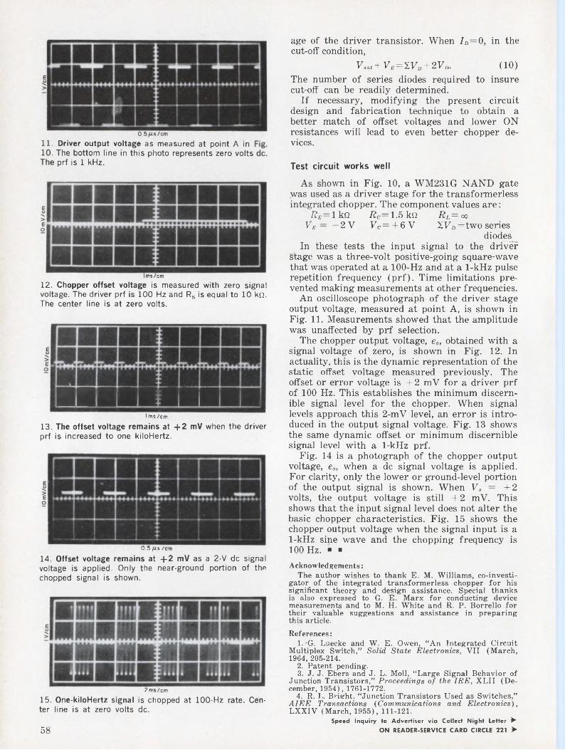
. Driver output voltage as measured at point A in
. The bottom line in this photo represents zero volts e prf is 1 kHz.
I ms/cm
12. Chopper offset voltage is measured with zero signal voltage. The driver prf is 100 Hz and Rs is equal to 10 kQ. The center line is at zero volts.
■■■■■■■■■■I ms /cm
13. The offset voltage remains at 4-2 mV when the driver prf is increased to one kiloHertz.
0.5 /zs /cm
14. Offset voltage remains at 4-2 mV as a 2-V de signal voltage is applied. Only the near-ground portion of the chopped signal is shown.
age of the driver transistor. When ID—0, in the cut-off condition,
Vaat + VE=1VD + 2VD. (10)The number of series diodes required to insure cut-off can be readily determined.
If necessary, modifying the present circuit design and fabrication technique to obtain a better match of offset voltages and lower ON resistances will lead to even better chopper devices.
Test circuit works well
As shown in Fig. 10, a WM231G NAND gate was used as a driver stage for the transformerless integrated chopper. The component values are:
Re 1 kQ Rc~ 1.5 kQ Re= ooVE — — 2V VC= + 6V WD= two series
diodesIn these tests the input signal to the driver
stage was a three-volt positive-going square-wave that was operated at a 100-Hz and at a 1-kHz pulse repetition frequency (prf). Time limitations prevented making measurements at other frequencies.
An oscilloscope photograph of the driver stage output voltage, measured at point A, is shown in Fig. 11. Measurements showed that the amplitude was unaffected by prf selection.
The chopper output voltage, e0, obtained with a signal voltage of zero, is shown in Fig. 12. In actuality, this is the dynamic representation of the static offset voltage measured previously. The offset or error voltage is + 2 mV for a driver prf of 100 Hz. This establishes the minimum discernible signal level for the chopper. When signal levels approach this 2-mV level, an error is introduced in the output signal voltage. Fig. 13 shows the same dynamic offset or minimum discernible signal level with a 1-kHz prf.
Fig. 14 is a photograph of the chopper output voltage, e0, when a de signal. voltage is applied. For clarity, only the lower or ground-level portion of the output signal is shown. When Vs — +2 volts, the output voltage is still +2 mV. This shows that the input signal level does not alter the basic chopper characteristics. Fig. 15 shows the chopper output voltage when the signal input is a 1-kHz sine wave and the chopping frequency is 100 Hz. ■ ■Acknowledgements:
The author wishes to thank E. M. Williams, co-investi- gator of the integrated transformerless chopper for his significant theory and design assistance. Special thanks is also expressed to G. E. Marx for conducting device measurements and to M. H. White and R. P. Borrello for their valuable suggestions and assistance in preparing this article.References:
1. G. Luecke and W. E. Owen, “An Integrated Circuit Multiplex Switch,” Solid State Electronics, VII (March, 1964, 205-214.
2. Patent pending.3. J. J. Ebers and J. L. Moll, “Large Signal Behavior of
Junction Transistors,” Proceedings of the IRE, XLII (December, 1954), 1761-1772.
4. R. L. Bright. “Junction Transistors Used as Switches,” AIEE Transactions (Communications and Electronics), LXXIV (March, 1955), 111-121.
Speed Inquiry to Advertiser via Collect Night Letter ► ON READER-SERVICE CARD CIRCLE 221 >
2ms/cm
15. One-kiloHertz signal is chopped at 100-Hz rate. Center line is at zero volts de.
58
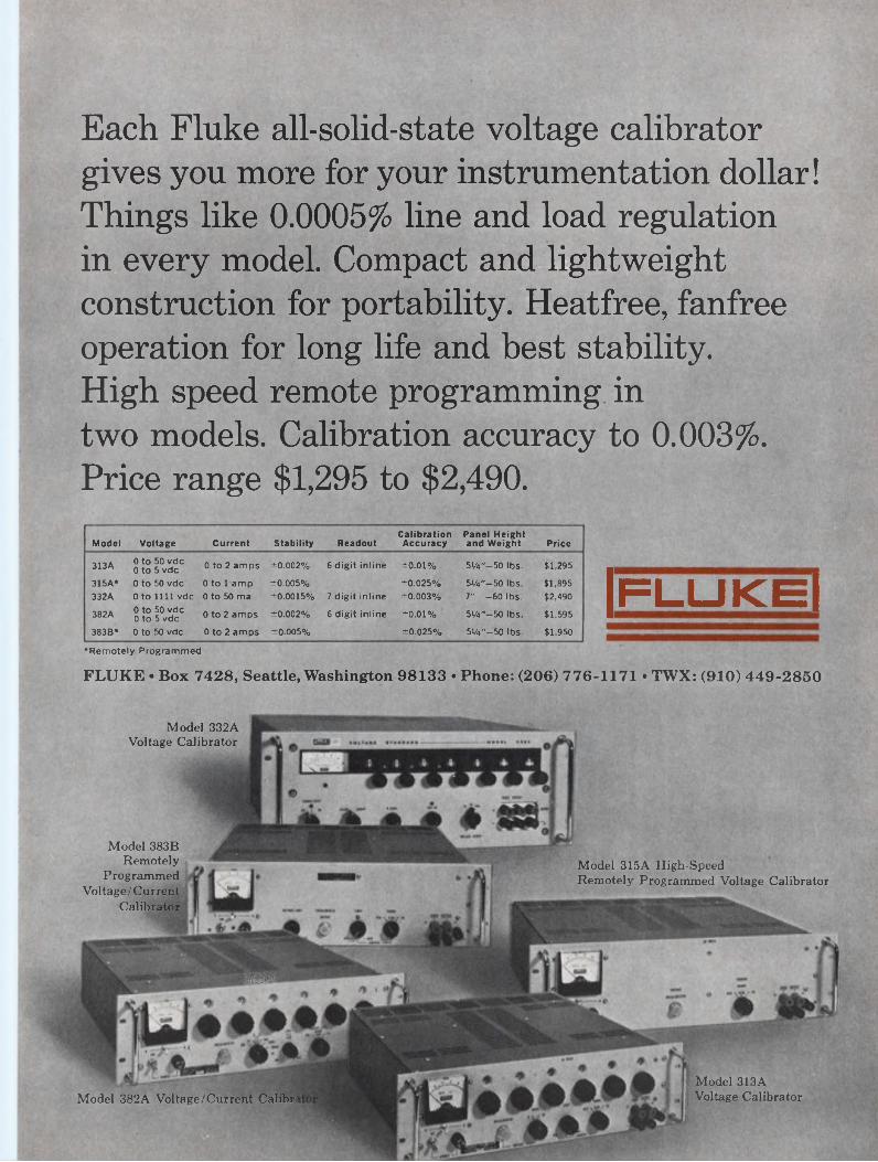
Each Fluke all-solid-state voltage calibrator gives you more for your instrumentation dollar! Things like 0.0005% line and load regulation in every model. Compact and lightweight construction for portability. Heatfree, fanfree operation for long life and best stability.High speed remote programming in two models. Calibration accuracy to 0.003%. Price range $1,295 to $2,490.
‘Remotely Programmed
Model Voltage Current Stability ReadoutCalibration Accuracy
Panel Height and Weight Price
313A 0 to 50 vdc 0 to 5 vdc 0 to 2 amps ±0.002% 6 digit inline ±0.01% 5%"-50 lbs. $1,295
315A* 0 to 50 vdc 0 to 1 amp ±0.005% ±0.025% 5V«"-50 lbs. $1,895332A 0 to 1111 vdc 0 to 50 ma ±0.0015% 7 digit inline ±0.003% 7" -60 lbs. $2,490
382A 0 to 50 vdc 0 to 5 vdc 0 to 2 amps ±0.002% 6 digit inline ±0.01% 5MT-50 lbs. $1,595
383B* 0 to 50 vdc 0 to 2 amps ±0.005% ±0.025% 5%"—50 lbs. $1,950
|fluke|FLUKE • Box 7428, Seattle, Washington 98133 • Phone: (206) 776-1171 • TWX: (910) 449-2850
MM
Model 382A Voltage/Current Calibri
Model 315A High-SpeedRemotely Programmed Voltage Calibrator
Model 313AVoltage Calibrator
Model 332AVoltage Calibrator
Model 383B Remotely
Programmed Voltage/Current
Calibrator
A silent stepping relay? Yes, it s possible with the use of a combination of reed relays and Silicon-controlled rectifiers.
A silent, high-speed stepping relay that is inexpensive and yet reliable may sound like a tall order. But it’s possible to design one by combining miniature magnetic reed relays and silicon-con- trolled-rectifier (SCR) actuating circuitry.
Such a unit is often an excellent compromise between relatively slow and noisy mechanical stepping relays and very-high-speed electronic switches.
Reed relays have many advantages.
The development and production of a wide variety of magnetic reed relays in the last few years has resulted in a whole new family of switching circuitry, with these advantages:
■ Silent operation.■ Low power, typically 100 mw.■ Hermetically sealed contacts.■ Fast actuating time, typically 0.5 to 1 msec.■ Extremely long life expectancy.■ Uniformly low contact resistance.■ Low open-circuit capacity.■ High open-circuit resistance.The basic magnetic reed switch consists of a pair
of thin cantilever strips sealed inside of a short glass tube. These cantilever strips (or reeds) are mounted in such a way that the free ends overlap each other slightly and maintain a normally-open spacing of several thousandths of an inch or more. The reed elements are made from a magnetic material; hence, when the reed is aligned with a sufficiently strong magnetic field, the electromagnetic force across the gap causes the reed elements to move together. The normal manner of energizing the magnetic reed switch is to place one or more of these units inside a solenoid coil.
Stepping circuit uses reed-relay stages.
The use of magnetic reed switches in a highspeed stepping-relay circuit is shown in Fig. 1. This particular circuit is designed to sample both X and Y coordinate signals for direct oscilloscope plotting. However, the basic principle is suitable for a wide variety of applications.
The stepping relay circuit is composed of N
Hays Penfield, Engineer, Concord, Mass.
number of magnetic reed relay stages. Each stage consists of a coil, three magnetic reed units and an SCR energizing circuit. In the normal circuit operating mode, the sequencing, or stepping, of the switches is controlled by a positive triggerinput to the SCR gate circuit. For each stage, the connection to the gate circuit is made through one of the normally-open reed contacts (c) of the preceding stage. Hence, the positive trigger-pulse will be applied only to the gate of the stage immediately following the stage that is energized. The negative anode-to-cathode pulse required to turn the SCRs off is obtained by capacitance coupling between adjacent SCR anodes.
Gate triggering to the initial stage may be switched from either an external input (Single Scan) or from the reed contact of the final stage (Recycle). When the initial stage receives its gate trigger externally, the stepping switch will sequence from position 1 through position N, and hold position N closed until the next gate trigger. When the initial stage is triggered from the final stage, the stepping switch will continually recycle from position 1 through position N. The X and Y signal samples are taken through normally-open reed contacts (a and b) in each stage. RESET and MANUAL START buttons are provided to permit external control of the stepping switch.
Receiver sampling represents typical use
Fig. 2 illustrates the use of the reed stepping switch to sample the output of a 10-channel receiver system. The channels are equally spaced in frequency, with the spacing equal to the channel bandwidth. In this case the X samples are the detected channel output level, and the Y samples are equal de voltage increments. Hence, the oscilloscope display is a plot of the received spectrum. It should be noted that the stepping action is make-before-break, so intermediate points are visible between the 10 main points on the plot.
Typical waveforms on the gate and anode of successive stages in the stepping switch are shown in Fig. 3. Note the negative spikes that appear on the anode voltage as a result of the capacitive coupling between adjacent anodes. It is this negative spike that provides the convenient turnoff action in the SCR. ■ ■
60 Electronic Design
1. Stepping-relay circuit consists of N number of identical reed-relay stages. The circuit steps in sequence when a
positive trigger-input is applied. The first stage can be triggered either externally or from the last stage.
2. Typical application of the stepping-relay circuit is demonstrated by this arrangement for sampling the output of a multi-channel receiver.
3. SCR waveforms for all stages are identical, except that those of each succeeding stage are displaced in time by the interval between trigger pulses.
May 10, 1966 61
for integrated circuits...
uncased Cera I a m* close tolerance capacitors
The CERALAM capacitor is a rugged, monolithic block of ceramic dielectric and metallic plate laminated into an extremely dense unit. Because of their unique structure they can be supplied unencapsulated, ready to solder into the circuitry, saving appreciably on volume.
The high ratio of capacity-to-volume achieved in CERALAM capacitors allows unusually small sizes suited to hybrid circuitry. They are also suitable because their unique construction permits an unlimited selection of geometric configuration to facilitate packaging in the hybrid circuit. CERALAMs also offer a wide range of dielectric properties: body NPO's of 0 to ±30ppm TC for high stability; for no
measurable aging effect; temperature compensating dielectrics, intermediate stability dielectrics; and high dielectric constant ceramics which yield very high capacity-to-volume ratios.
Some capacitors are just stumbling blocks in the way of hybrid circuit design. Replace them with CERALAM “blocks.” Write us. We’ll be happy to help.
Hl-OkDIVISION
AERO VOXCORPORATION OLEAN, N.Y.
Selected commercial and military Hi-Q products are available off-the-shelf from Authorized Aero.vox Distributors.ON READER-SERVICE CARD CIRCLE 17
62 Electronic Design
MOTOROLA takes the high
cost out of
A new Motorola % million dollar computerized test facility, called MATECt now provides fully automatic temperature compensated zener diode testing at all temperature measuring points from —55°C to +150°C ... at twice the speed of antiquated hand-classification methods... with a 75% reduction in human handling!As a result. Motorola now offers more thoroughly tested and evaluated reference diodes, deliverd faster than ever before, at new lower prices .. . and a new 1-24, 25-99 quantity “pricebreak” schedule which provides even more advantageous prices for small-quantity users.
TC ZENER DIODE (M)testing !
... prices reduced up to 54%*
•EXAMPLE: Type 1N829A was $36.55, in 1-99 quantities ... is now only $16.85 in 25-99 quantities . . . 54% reduction . . . (extensive price reductions have also been made on the 1N821-27, 1N3154-57, IN935-39, 1N941-45 series ... their ‘A’ and *B’, USN and MEG-A-LIFE 1, 2 and 3 versions)!
Sound too good to be true ? Try us! Order one of the hard-to- get TC Zener Diode types you’ve had problems with in the past. Your Motorola Franchised Distributor carries an indepth stock backed by extensive factory “shelf-inventories” and fast-action production capabilities.Get the whole story ... NOW! For complete new pricing information write Motorola Semiconductor Products Inc., Box 955, Phoenix, Arizona 85001.
........ ............D0-7 (glass diode)
1N821 series1N935 series1N941 series
1N3154 series
MOTOROLA
fTHE MOTOROLA "MATEC” COMPUTERIZED AUTOMATIC TESTING AND CLASSIFICATION SYSTEM . . . eliminates "human-error” . . . measurements repeatable within less than 0.5%. Each of the 12 temperature chambers is automatically cycled by its own control system. Equipment can test over 50,000 units/week. Complete "readout” data classifies device types by EIA number according to exact voltage readings to 6 digits (nominal voltages : 6.2, 6.4, 8.4, 8.5, 9.0, 9.1, 9.3.and 11.7 volts) for each testing temperature . .. —55, 0, 4-25, 4-75, 4-100 and 4-150°C; provides date-code, lot-number, oven and device locations, as well as voltage changes over complete operating temperature range.
Speed Inquiry to Advertiser via Collect Night LetterON READER-SERVICE CARD CIRCLE 18
May 10, 1966 63
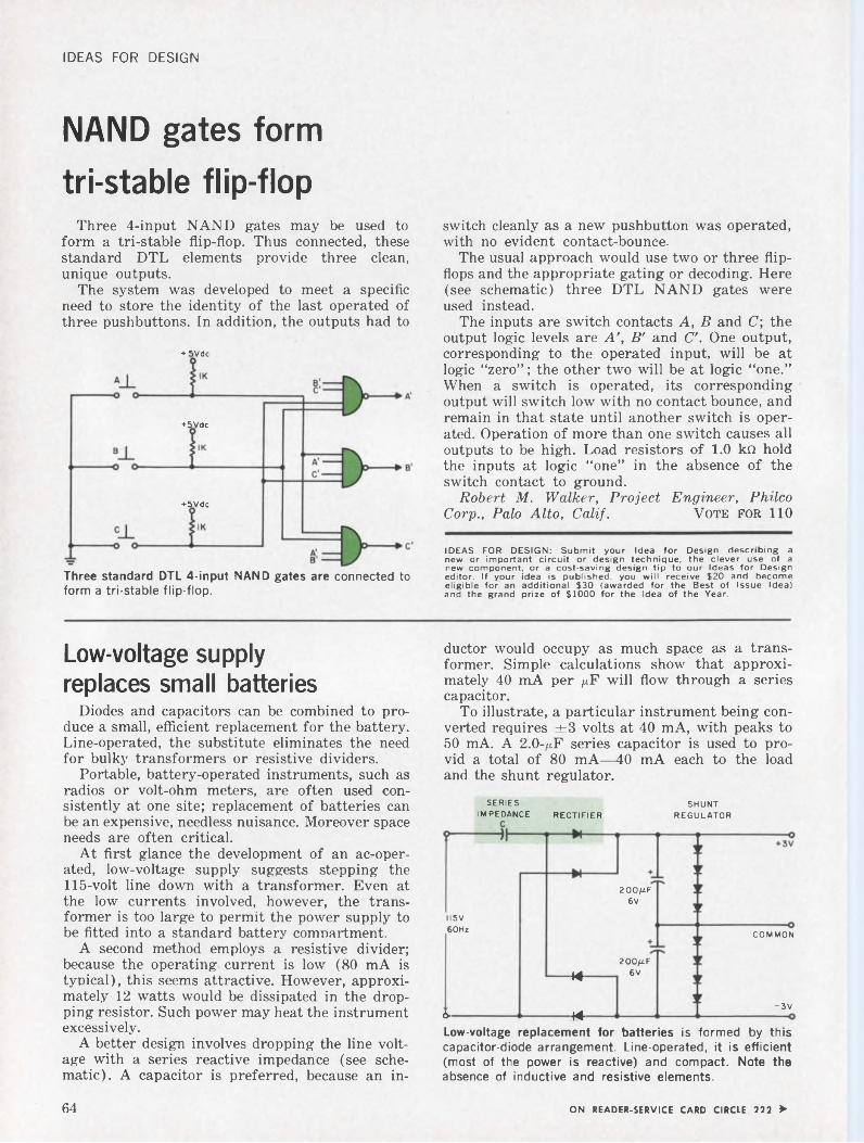
IDEAS FOR DESIGN
NAND gates form tri-stable flip-flop
Three 4-input NAND gates may be used to form a tri-stable flip-flop. Thus connected, these standard DTL elements provide three clean, unique outputs.
The system was developed to meet a specific need to store the identity of the last operated of three pushbuttons. In addition, the outputs had to
+ 5Vdc
+5Vdc
+5Vdc
Three standard DTL 4-input NAND gates are connected to form a tri-stable flip-flop.
switch cleanly as a new pushbutton was operated, with no evident contact-bounce.
The usual approach would use two or three flipflops and the appropriate gating or decoding. Here (see schematic) three DTL NAND gates were used instead.
The inputs are switch contacts A, B and C; the output logic levels are A', B' and C. One output, corresponding to the operated input, will be at logic “zero”; the other two will be at logic “one.” When a switch is operated, its corresponding output will switch low with no contact bounce, and remain in that state until another switch is operated. Operation of more than one switch causes all outputs to be high. Load resistors of 1.0 kil hold the inputs at logic “one” in the absence of the switch contact to ground.
Robert M. Walker, Project Engineer, Philco Corp., Palo Alto, Calif. Vote for 110
IDEAS FOR DESIGN: Submit your Idea for Design describing a new or important circuit or design technique, the clever use of a new component, or a cost-saving design tip to our Ideas for Design editor. If your idea is published, you will receive $20 and become eligible for an additional $30 (awarded for the Best of Issue Idea) and the grand prize of $1000 for the Idea of the Year.
Low-voltage supply replaces small batteries
Diodes and capacitors can be combined to produce a small, efficient replacement for the battery. Line-operated, the substitute eliminates the need for bulky transformers or resistive dividers.
Portable, battery-operated instruments, such as radios or volt-ohm meters, are often used consistently at one site; replacement of batteries can be an expensive, needless nuisance. Moreover space needs are often critical.
At first glance the development of an ac-operated, low-voltage supply suggests stepping the 115-volt line down with a transformer. Even at the low currents involved, however, the transformer is too large to permit the power supply to be fitted into a standard battery compartment.
A second method employs a resistive divider; because the operating current is low (80 mA is typical), this seems attractive. However, approximately 12 watts would be dissipated in the dropping resistor. Such power may heat the instrument excessively.
A better design involves dropping the line voltage with a series reactive impedance (see schematic). A capacitor is preferred, because an in
ductor would occupy as much space as a transformer. Simple calculations show that approximately 40 mA per /iF will flow through a series capacitor.
To illustrate, a particular instrument being converted requires ±3 volts at 40 mA, with peaks to 50 mA. A 2.0-^F series capacitor is used to provid a total of 80 mA—40 mA each to the load and the shunt regulator.
RECTIFIERSERIES
IMPEDANCESHUNT
REGULATOR
COMMON
44
-3V44ò-
II5V 60Hz
200/zF 6V
Low-voltage replacement for batteries is formed by this capacitor-diode arrangement. Line-operated, it is efficient (most of the power is reactive) and compact. Note the absence of inductive and resistive elements.
2OO/ZF 6V
64 ON READER-SERVICE CARD CIRCLE 222 >
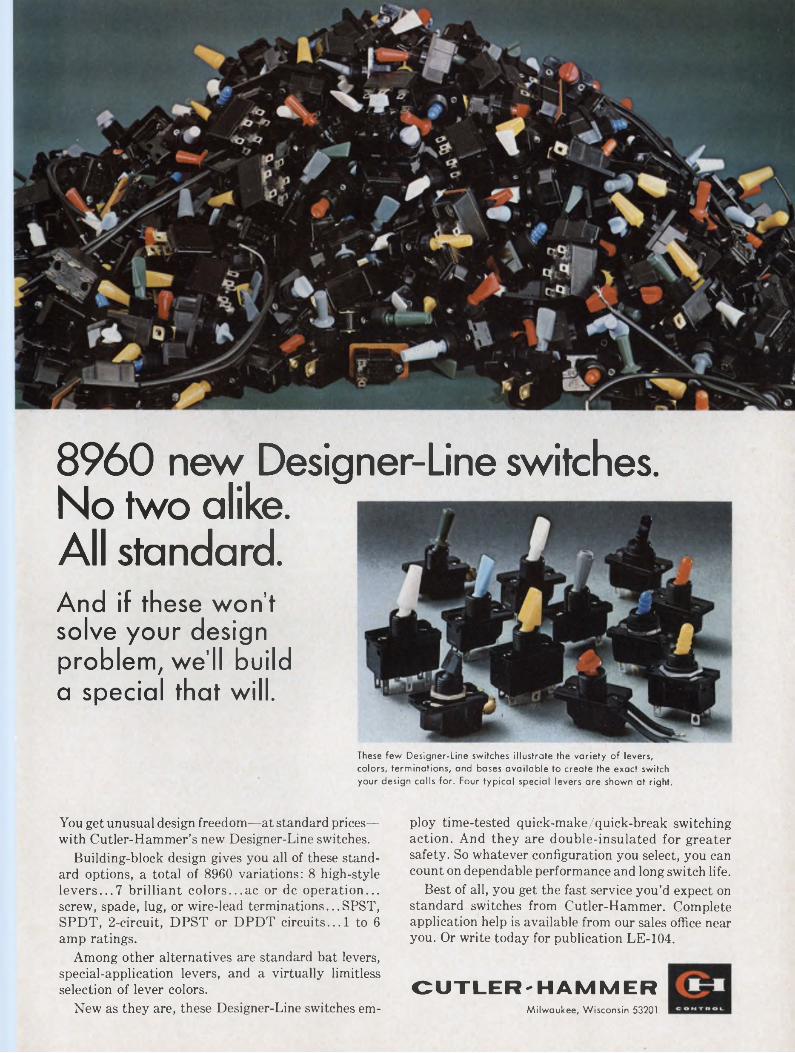
8960 new Designer-Line switches. No two alike. All standard.And if these won’t solve your design problem, we’ll build a special that will.
These few Designer-Line switches illustrate the variety of levers, colors, terminations, and bases available to create the exact switch your design calls for. Four typical special levers are shown at right.
You get unusual design freedom—at standard prices— with Cutler-Hammer’s new Designer-Line switches.
Building-block design gives you all of these standard options, a total of 8960 variations: 8 high-style levers...7 brilliant colors...ac or de operation... screw, spade, lug, or wire-lead terminations... SPST, SPDT, 2-circuit, DPST or DPDT circuits... 1 to 6 amp ratings.
Among other alternatives are standard bat levers, special-application levers, and a virtually limitless selection of lever colors.
New as they are, these Designer-Line switches em-
ploy time-tested quick-make/quick-break switching action. And they are double-insulated for greater safety. So whatever configuration you select, you can count on dependable performance and long switch life.
Best of all, you get the fast service you’d expect on standard switches from Cutler-Hammer. Complete application help is available from our sales office near you. Or write today for publication LE-104.
CUTLER'HAMMERMilwaukee, Wisconsin 53201
IDEAS FOR DESIGNThe shunt regulator consists of eight forward
conducting silicon diodes in series. Zener diodes could be used but would give poorer regulation at this low voltage (3 volts). Virtually any type of silicon signal diode may be used in both the regulator and the bridge rectifier. The ac voltage into the bridge is only 7.6 volts. A full-wave rectifier is necessary here, because a bi-directional current flows through the capacitor.
The low-voltage power supply fits on to a 2-by 3-inch plastic card, easily meeting the small space needs of the battery compartment. As most of the power is reactive, the circuit is very efficient.
Howard F. Stearns, Principal Engineer, Fairchild Hiller Corporation, Rockville, Md.
Vote for 111
Low-frequency astable circuit uses three inexpensive relays
One ordinary relay and two thermal-delay relays may be combined to create an inexpensive, low-frequency astable system. Total timing periods of six minutes or higher may thus be achieved.
In the circuit, K, is a conventional relay and K2 and K, are the thermal types (see schematic). The thermal-delay relays establish the duration of the ON and OFF cycles.
Power is initially applied to the filament of K2. After a time interval determined by the thermal characteristic of K, has elapsed, its NO contacts close and energize relay K,. Power to K2 is broken by A,, but power to the coil of K, is maintained through the NC contact of K, and the NO contact of A,. At the same time, power is applied to the filament of K3.
After a time interval determined by the thermal characteristic of K, has occurred, the NC contacts of K3 will open and cause A, to deenergize. The system is now in its original state. The filaments should be permitted to cool off before the start of a new cycle.
G. Richwell, Staff Engineer, Reflective Electronics, Stamford, Conn.
Vote for 112
Low-frequency astable circuit is formed by three relays. K, determine the ON cycle and K3 establishes the OFF period. Duration T is variable between four seconds and six minutes.
Flip-flop reset circuit requires no diodes
Digital systems often require a means to reset their flip-flop stages manually. A simple and direct method of achieving this uses one spdt switch and no extra diodes.
In the normal operating mode (see schematic) resistor R2 is connected through the NC position
Resetting of flip-flop is easily achieved by an spdt switch connected to two power sources. This function does not require switching diodes.
of the reset switch to bias voltage — V B. When the switch is momentarily depressed, R. is connected to the + Vc source. This applies a positive bias to transistor Q2 and resets the flip-flop.
By connecting the bias resistor of each flip-flop to the reset switch, any number of flip-flops can be reset. Moreover, with this method there is no problem of cross-coupling other than that which is normally present on the voltage-bias lines.
John T. Hannon Jr., Project Engineer, Metric Systems Corp., Fort Walton Beach, Fla.
Vote for 113
Output circuit increases noise immunity of ICs
A simple transistor-diode output configuration, coupled to standard DTL and TTL integrated circuits, increases the noise immunity of the microcircuit logic elements. This emitter-follower output stage requires little power and raises the fan-out figure.
Some low-priced ICs (dual, two-input gates, J-K Ain-flop, etc.) exhibit poorer noise immunity than their more expensive counterparts. Noise immunity can often be increased to ±2.0 volts, and the fan-out raised to 20 or more, by the addition of a discrete component output circuit (see schematic “a”).
66 ON READER-SERVICE CARD CIRCLE 223 >
Our ferrite division can make that many toroids in a month. In sizes as small as 80 mils, with high temperature stability, inductance values within ± 5%, and in a wide range of ferrite materials to meet practically any pulsing speed. For example: for microsecond switching we can offer our Ferramic® 0-5, 0-6, and T-1 ferrites and for nanosecond switching there’s our Ferramic Hand Q-1 materials.
This materials capability plus our pro
duction capacity have made us the world's largest supplier of ferrite toroids for pulse transformers. But toroids are only a part of our business. In total we have eleven standard ferrite materials right now and will soon introduce a twelfth one. A brand new flat temperature-coefficient ferrite that will make circuit design news. We are equally big in other ferrites for digital applications such as square-loop (memory core) ferrites,
recording head ferrites, and multiaperture devices.
So whether you want 2 samples, an order of 10 million, or catalogs and technical literature, you can get immediate action by writing Mr. Ken Talbot, Manager of Sales, Indiana General Corporation, Electronics Division/Ferrites, Keasbey, New Jersey.
INDIANA GENERAL F3
Ten million pulse transformer cores
© ’«46 INDIANA GCNfRAl CORPORATION
IDEAS FOR DESIGN
Noise immunity is increased when an emitter-follower diode output stage is connected to an integrated circuit (a). Suitable for DTL, TTL and other logic elements, they are used with buffer-gates when connected to flip-flops (b).
The base-to-emitter diode voltage drop of Q, and the voltage drop across D. and D. cause the output to swing from +2.5 volts to —2.0 volts, instead of the usual swing from +3.5 to ground. When the output is at —2.0 volts, the input transistor in the next stage is back-biased by two volts, thus giving it two volts of noise rejection. When the output is at +2.5 volts, the input threshold of the next stage is exceeded by nearly +2.0 volts, thus providing two volts of noise rejection here.
The low output impedance of the emitter-follower also helps to improve noise immunity. To boot, the fan-out of the gate is increased to 20 or more because of its current gain.
The flip-flop output voltage swing is not as large as the gate output voltage swing, because there are internal feedback connections in the flipflop. For this reason, the flip-flop must be buffered with gates (schematic “b”). Propagation delay tests were made to ensure that these circuits would work in a system with a 2-MHz clock and a fan-out of 20. Eight gates with emitter followers were connected in series, and each emitter-follower was loaded with 500 pF to ground. In parallel with the 500 pF were 27 ohms in series with a diode. The resistor-diode combination represented approximately 20 gate input loads. The total delay through the eight circuits was 400 ns.
Four flip-flops buffered with gates and emitterfollowers were then connected as a binary counter. When each emitter-follower was loaded, total delay through all four elements was also 400 ns. With the lesser capacitive loading typical of actual use, the circuits will be even faster.
The technique of making the output swing negative of the ground reference to increase noise immunity is not limited to a particular logic form. For example, it may be used with DTL or TTL. In line with today’s microelectronic trends, the
emitter-follower could be placed on the same integrated circuit chip as the gate or the flip-flop.
Gary Babcock, Design Engineer, U.S. Naval Ordnance Test Station, China Lake, Calif.
Vote for 114
Package electronic modules with shrinkable tubing
Plastic tubing that shrinks when heated has an unusual application in the packaging of entire electronic assemblies. The round package in the photograph consisted of three circular printed- circuit assemblies, each potted in epoxy. To hold the three assemblies together, tubing slightly larger in diameter than the modules’ 5.9 inches was used and shrunk in place.
Since the tubing shrinks to 50% of its original diameter, it folds itself over the ends and provides a very tight, secure package that resists vibration, tensile and shear stresses very well. The other
Shrinkable tubing encapsulates modules of various sizes, providing insulation and environmental protection, and even binding the modules together.
package shows that the technique can be used with other than circular packages, even though the original shape of the tubing is circular.
In addition to providing a simple, effective means of binding the modules together, the material’s dielectric properties are used to advantage in insulating the package.
Plastic materials that shrink when heated are extensively used for “spaghetti,” cabling jackets, splice insulators, etc. Less familiar to electronic designers is the larger diameter and thicker tubing of the same material that is primarily used in industrial applications, such as the weather-proofing of pipeline weld joints. This material is usually supplied with a coating of tar, but can be purchased untarred in varying diameters (to 18 in.).
Gilbert C. Willems, Research Engineer, U.S. Army Missile Command, Redstone Arsenal, Ala.
Vote for 115
IFD Winner for Feb. 1, 1966Dan R. Cole, Skil Corp., Chicago, Ill.
His idea, “Iron mightier than pen for polaroid data marking,” has been voted the $50 Most Valuable of Issue Award.Cast Your Vote for the Best Idea in this Issue.
68 ON READER-SERVICE CARD CIRCLE 224 >
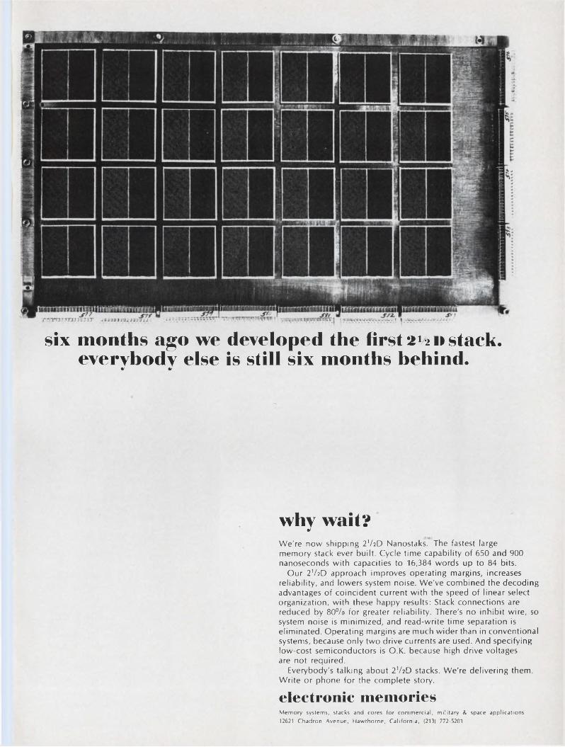
six months ago we developed the first 2^d stack, everybody else is still six months behind.
why wait?We're now shipping 2V2D Nanostaks. The fastest large memory stack ever built. Cycle time capability of 650 and 900 nanoseconds with capacities to 16,384 words up to 84 bits.
Our 2V2D approach improves operating margins, increases reliability, and lowers system noise. We've combined the decoding advantages of coincident current with the speed of linear select organization, with these happy results: Stack connections are reduced by 80% for greater reliability. There's no inhibit wire, so system noise is minimized, and read-write time separation is eliminated. Operating margins are much wider than in conventional systems, because only two drive currents are used. And specifying low-cost semiconductors is O.K. because high drive voltages are not required.
Everybody's talking about 2V2D stacks. We're delivering them. Write or phone for the complete story.
electronic memoriesMemory systems, stacks and cores for commercial, military & space applications 12621 Chadron Avenue, Hawthorne, California, (213) 772-5201
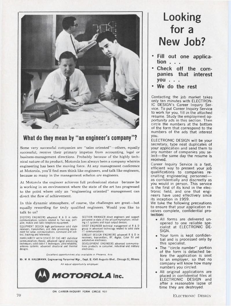
What do they mean by “an engineer’s company”?Some very successful companies are “sales oriented”—others, equally successful, receive their primary impetus from accounting, legal or business-management directions. Probably because of the highly technical nature of its product, Motorola has always been a company wherein engineering has been the moving force. At any management conference at Motorola, you’ll find men think like engineers, and talk like engineers, because so many in the management echelon are engineers.
At Motorola the engineer achieves full professional status—because he is working in an environment where the state of the art has progressed to the point where only an “engineering oriented” management can direct the flow of achievement.
In this dynamic atmosphere, of course, the challenges are great—but equally rewarding for truly qualified engineers. Would you like to talk to us?SYSTEMS ENGINEERS advanced R & D in radio communications systems related to Two-way, portable, mobile and radio-telephone equipment.
EQUIPMENT DESIGN high performance solid state receivers, transmitters, and data processing equipment for radar, communications, command and control, tracking and telemetry.
FAMILIARITY WITH STATE-OF-THE-ART statistical communications theory, advanced signal processing techniques, solid state r.f. techniques, ultra-reliability, antenna systems, advanced structural and thermal designs.
Excellent opportunities also available in Phoenix. Ariz.Mr. W. H. HAUSMANN, Engineering Personnel Mgr., Dept. B, 4545 Augusta Blvd., Chicago 51, Illinois
An equal opportunity employer.
MOTOROLA Inc.
SECTION MANAGER direct engineers and support personnel in state-of-the-art communications, including r.f. systems and input-output devices.CHIEF ENGINEER technical management of R & D group in advanced technology related to solid state r.f. communications.CIRCUIT DESIGN ENGINEERS advanced R & D in receivers, transmitters, RF, digital, Color TV and automotive electronics.DEVELOPMENT ENGINEERS advanced communications products in consumer, industrial and military electronics.
Looking for a
New Job?• Fill out one applica
tion . . .• Check off the com
panies that interest you . . .
• We do the rest
Contacting the job market takes only ten minutes with ELECTRONIC DESIGN’S Career Inquiry Service. To put Career Inquiry Service to work for you, fill in the attached resume. Study the employment opportunity ads in this section. Then circle the numbers at the bottom of the form that correspond to the numbers of the ads that interest you.ELECTRONIC DESIGN will be your secretary, type neat duplicates of your application and send them to any number of companies you select—the same day the resume is received.Career Inquiry Service is a fast, efficient way to present your job qualifications to companies recruiting engineering personnel— as confidentially and discreetly as you would in person. This service is the first of its kind in the electronic field, and one that engineers have used effectively since its inception in 1959.We take the following precautions to ensure that your application receives complete, confidential protection:
• All forms are delivered unopened to one reliable specialist at ELECTRONIC DESIGN.
• Your form is kept confidential and is processed only by this specialist.
• The "circle number” portion of the form is detached before the application is sent to an employer, so that no company will know how many numbers you circled.
• All original applications areplaced in confidential files atELECTRONIC DESIGN andafter a reasonable lapse oftime they are destroyed.
ON CAREER-INQUIRY FORM CIRCLE 901
70 Electronic Design
CAREER INQUIRY SERVICE USE BEF0RE UNE 211966ELECTRONIC DESIGN May 10, 1966
After completing, staple, fold and mail career form to Electronic Design, 850 Third Avenue, NewYork, N. Y. Our Reader Service Department will forward copies to the companies you select below.
(Please print with a soft pencil or type.)
Name Telephone
Home Address City Zone State
Date of Birth Place of Birth Citizenship
Position Desired_______ _____ _ _________________________________________________________________ —
Educational HistoryCollege Dates Degree Major Honors
Recent Special Training__________________________________________________________________________
Employment HistoryCompany City and State Dates Title Engineering Specialty
Outstanding Engineering and Administrative Experience
Professional Societies _____________________________________________________________________ _ _____ _
Published Articles________________________________________________________________________________
Minimum Salary Requirements (Optional)___________________________________________________________Use section below instead of Reader Service Card. Do not write personal data below this line. This section will be detached before processing.
Circle Career Inquiry numbers of companies that interest you900 901 902 903 904 905 906 907 908 909 910 911 912 913 914 915 916 917 918 919 920 921 922 923 924
926 926 927 928 929 930 931 932 933 934 935 936 937 938 939 940 941 942 943 944 945 946 947 948 949
DIGITAL LOGIC DESIGN
ELECTRICAL DESIGN ENGINEER - SENIOR Design experience including schematic diagram presentation, electrical/electronic components, design installation and related circuit design and analysis for automatic checkout equipment.ELECTRICAL DESIGN ENGINEER Design experience including preparation of schematics and wiring diagrams. Able to work from checkout parameter criteria and evolve checkout equipment circuitry utilizing current state-of-the-art components for electrical checkout equipment design.ELECTRICAL DESIGN ENGINEER - JUNIOR Prefer recent college graduates with industrial design experience involving solid state circuitry and/or logistic presentation to assist in the design of automatic electrical checkout equipment.BS in E.E. or Physics required for all of the above positions.Write: K. R. Kiddoo, Professional Placement Manager, Lockheed Missiles & Space Company, P.O. Box 504, Sunnyvale, California. An Equal Opportunity Employer.
LOCKHEEDMISSILES & SPACE COMPANYA GROUP DIVISION OF LOCKHEED AIRCRAFT CORPORATION
ON CAREER-INQUIRY FORM CIRCLE 902Fold here, staple and Mail.
FIRST CLASS Permit No. 725 New York, N.Y.
BUSINESS REPLY MAILNo Postage Stamp Necessary if Mailed in the United States
POSTAGE WILL BE PAID BY
ELECTRONIC DESIGNREADER SERVICE850 THIRD AVENUENEW YORK, NEW YORK 10022
72 Electronic Design
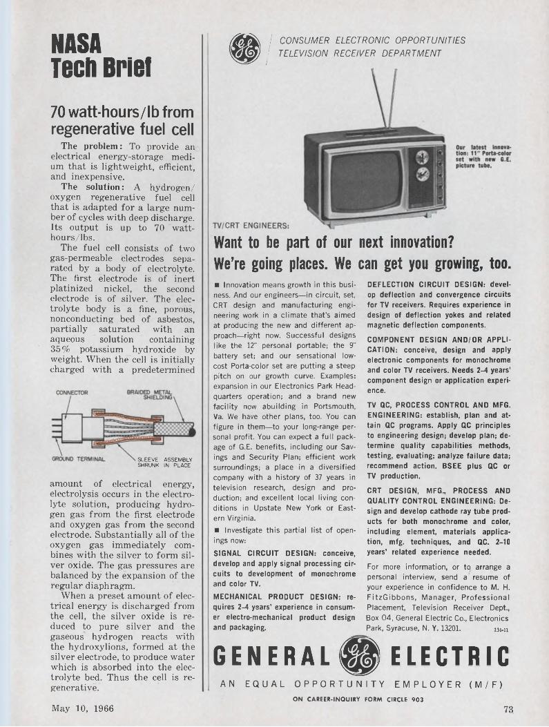
NASA Tech Briel
70 watt-hours/lb from regenerative fuel cell
The problem: To provide an electrical energy-storage medium that is lightweight, efficient, and inexpensive.
The solution: A hydrogen/ oxygen regenerative fuel cell that is adapted for a large number of cycles with deep discharge. Its output is up to 70 watt- hours/lbs.
The fuel cell consists of two gas-permeable electrodes separated by a body of electrolyte. The first electrode is of inert platinized nickel, the second electrode is of silver. The electrolyte body is a fine, porous, nonconducting bed of asbestos, partially saturated with an aqueous solution containing 35% potassium hydroxide by weight. When the cell is initially charged with a predetermined
SLEEVE ASSEMBLY SHRUNK IN PLACE
amount of electrical energy, electrolysis occurs in the electrolyte solution, producing hydrogen gas from the first electrode and oxygen gas from the second electrode. Substantially all of the oxygen gas immediately combines with the silver to form silver oxide. The gas pressures are balanced by the expansion of the regular diaphragm.
When a preset amount of electrical energy is discharged from the cell, the silver oxide is reduced to pure silver and the gaseous hydrogen reacts with the hydroxylions, formed at the silver electrode, to produce water which is absorbed into the electrolyte bed. Thus the cell is regenerative.
®/ CONSUMER ELECTRONIC OPPORTUNITIES / TELEVISION RECEIVER DEPARTMENT
I
Want to be part of our next innovation?We’re going places. We can get you growing, too.■ Innovation means growth in this business. And our engineers—in circuit, set, CRT design and manufacturing engineering work in a climate that's aimed at producing the new and different approach-right now. Successful designs like the 12" personal portable; the 9" battery set; and our sensational lowcost Porta-color set are putting a steep pitch on our growth curve. Examples: expansion in our Electronics Park Headquarters operation; and a brand new facility now abuilding in Portsmouth, Va. We have other plans, too. You can figure in them—to your long-range personal profit. You can expect a full package of G.E. benefits, including our Savings and Security Plan; efficient work surroundings; a place in a diversified company with a history of 37 years in television research, design and production; and excellent local living conditions in Upstate New York or Eastern Virginia.■ Investigate this partial list of openings now:SIGNAL CIRCUIT DESIGN: conceive, develop and apply signal processing circuits to development of monochrome and color TV.
MECHANICAL PRODUCT DESIGN: requires 2-4 years’ experience in consumer electro-mechanical product design and packaging.
GENERAL® ELECTRICAN EQUAL OPPORTUNITY EMPLOYER (M/F)
DEFLECTION CIRCUIT DESIGN: develop deflection and convergence circuits for TV receivers. Requires experience in design of deflection yokes and related magnetic deflection components.
COMPONENT DESIGN AND/OR APPLICATION: conceive, design and apply electronic components for monochrome and color TV receivers. Needs 2-4 years' component design or application experience.
TV QC, PROCESS CONTROL AND MFG. ENGINEERING: establish, plan and attain QC programs. Apply QC principles to engineering design; develop plan; determine quality capabilities methods, testing, evaluating; analyze failure data; recommend action. BSEE plus QC or TV production.
CRT DESIGN, MFG., PROCESS AND QUALITY CONTROL ENGINEERING: Design and develop cathode ray tube products for both monochrome and color, including element, materials application, mfg. techniques, and QC. 2-10 years’ related experience needed.
For more information, or to arrange a personal interview, send a resume of your experience in confidence to M. H. FitzGibbons, Manager, Professional Placement, Television Receiver Dept., Box 04, General Electric Co., Electronics Park, Syracuse, N. Y. 13201. 231-11
ON CAREER-INQUIRY FORM CIRCLE 903
May 10, 1966 73
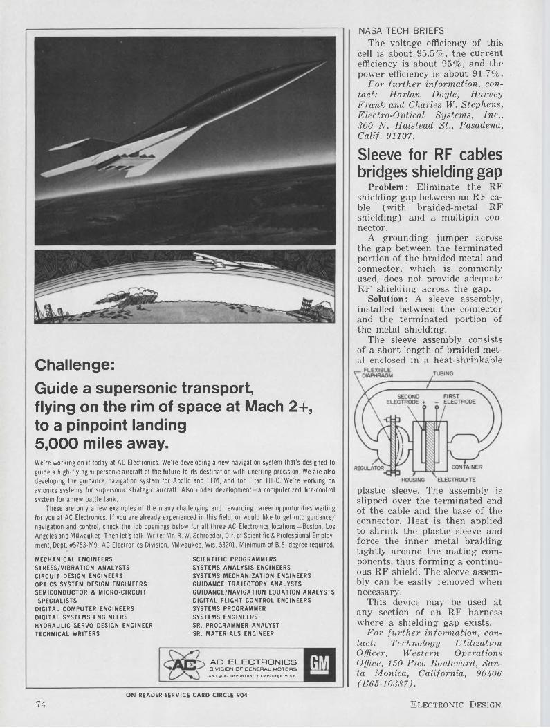
Challenge:Guide a supersonic transport,flying on the rim of space at Mach 2+, to a pinpoint landing5,000 miles away.We're working on it today at AC Electronics. We’re developing a new navigation system that’s designed to guide a high-flying supersonic aircraft of the future to its destination with unerring precision. We are also developing the guidance/navigation system for Apollo and LEM, and for Titan lll-C. We’re working on avionics systems for supersonic strategic aircraft. Also under development—a computerized fire-control
system for a new battle tank.These are only a few examples of the many challenging and rewarding career opportunities waiting
for you at AC Electronics. If you are already experienced in this field, or would like to get into guidance/ navigation and control, check the job openings below fur all three AC Electronics locations—Boston, Los Angeles and Milwaukee. Then let’s talk. Write: Mr. R. W. Schroeder, Dir. of Scientific & Professional Employment, Dept. #5753-M9, AC Electronics Division, Milwaukee, Wis. 53201. Minimum of B.S. degree required.
MECHANICAL ENGINEERS STRESS/VIBRATION ANALYSTS CIRCUIT DESIGN ENGINEERS OPTICS SYSTEM DESIGN ENGINEERS SEMICONDUCTOR & MICRO-CIRCUIT SPECIALISTS
DIGITAL COMPUTER ENGINEERS DIGITAL SYSTEMS ENGINEERS HYDRAULIC SERVO DESIGN ENGINEER TECHNICAL WRITERS
SCIENTIFIC PROGRAMMERS SYSTEMS ANALYSIS ENGINEERS SYSTEMS MECHANIZATION ENGINEERS GUIDANCE TRAJECTORY ANALYSTS GUIDANCE/NAVIGATION EQUATION ANALYSTS DIGITAL FLIGHT CONTROL ENGINEERS SYSTEMS PROGRAMMER SYSTEMS ENGINEERS SR. PROGRAMMER ANALYST SR. MATERIALS ENGINEER
NASA TECH BRIEFSThe voltage efficiency of this
cell is about 95.5%, the current efficiency is about 95%, and the power efficiency is about 91.7%.
For further information, contact: Harlan Doyle, Harvey Frank and Charles W. Stephens, Electro-Optical Systems, Inc., 300 N. Halstead St., Pasadena, Calif. 91107.
Sleeve for RF cables bridges shielding gap
Problem: Eliminate the RF shielding gap between an RF cable (with braided-metal RF shielding) and a multipin connector.
A grounding jumper across the gap between the terminated portion of the braided metal and connector, which is commonly used, does not provide adequate RF shielding across the gap.
Solution: A sleeve assembly, installed between the connector and the terminated portion of the metal shielding.
The sleeve assembly consists of a short length of braided metal enclosed in a heat-shrinkable
plastic sleeve. The assembly is slipped over the terminated end of the cable and the base of the connector. Heat is then applied to shrink the plastic sleeve and force the inner metal braiding tightly around the mating components, thus forming a continuous RF shield. The sleeve assembly can be easily removed when necessary.
This device may be used at any section of an RF harness where a shielding gap exists.
For further information, contact: Technology UtilizationOfficer, Western OperationsOffice, 150 Pico Boulevard, Santa Monica, California, 90406(B65-10387).
AC ELECTRONICSDIVISION OF GENERAL MOTORS
AN EQUAL OPPORTUNITY EMPLOYER M & F
GMON READER-SERVICE CARD CIRCLE 904
74 Electronic Design
DEVELOPING THE SYSTEMS TO CHECK OUT APOLLO IS SOMETHING LIKE BEING A DOCTOR’S DOCTOR.
When the mission is to work on the frontiers of reliability, integration and checkout for the NASA Apollo program, your work comes under the scrutiny of some of the most astute professional people in the nation. It takes a good man to thrive in a working environment this stringent.The high-speed automated systems we're developing for Apollo will simulate entire equipments before they're built, put partial systems through their paces and measure their performance against rigorous acceptance criteria, and check out every possible operational aspect of the astronaut’s spacecraft before the mission begins. Additional checkout tasks include the electrical support equipment for the Saturn launch vehicle, and special equipment to check out the systems and facilities in the launch area.So if you're good enough to be an engineer’s engineer, you shouldn’t be working on a lesser program than Apollo. And you shouldn’t settle for a less responsible post than one of these:
Systems Engineers BS Engineering or Physics Daytona Beach, Fla.
Instrumentation Systems Sales Engineers BSEE/ME/MS/MBA Daytona Beach, Fla.
Thermal Systems Analysis Engineers BS/MS ME/AE Houston, Texas
Reliability End-Item Engineers BSEE/ME Houston, Texas
Spacecraft Parts, Materials & Processes Engineers BSEE/ME Houston, Texas
Structural Systems Engineers BSAE/ME/CE Houston, Texas
Advanced Systems Engineers BSEE/MSEE/Physics Huntsville, Ala.
Configuration/lnterface Management Manager BS Business Administration Huntsville, Ala.
Systems Management Documentation Specialists BS Business Administration Huntsville, Ala.
Logistics Status & Control Engineers BSME/EE Kennedy Space Center, Fla.
Metallurgical Engineers BSME/Metallurgical Engineering Kennedy Space Center, Fla.
Decommutation Engineers/Specialists BSEEKennedy Space Center, Fla. Bethpage, N.Y./Downey, Calif. Houston, Texas
Please write in full confidence, including salary requirements, to: Mr. D. M. Hill, Professional Placement, Room 1142-T, Apollo Support Dept., General Electric Company, P.O. Box 2500, Daytona Beach, Fla. 32015.
An equal opportunity employer, (M & F).
APOLLO SUPPORT DEPARTMENTMISSILE & SPACE DIVISION
GENERAL^ ELECTRIC
ON CAREER-INQUIRY FORM CIRCLE 905
May 10, 1966 75
Space Research
Electrical/Electronic EngineersThe Boeing Aerospace Group’s deep involvement in the nation's most important missile and space programs is providing challenging openings for graduate electrical/electronic engineers and scientists. (See list in righthand column.) Assignments, which vary with each Aerospace Group facility, are at Cape Kennedy, Fla.; Huntsville, Ala.; New Orleans, La.; Seattle, Wash., and Vandenberg AFB, Calif.
Minimum requirements are a B.S. degree in an engineering or science discipline, plus applicable experience. Salaries are commensurate with your experience and education background. Travel and moving allowances are paid to newly hired personnel. Boeing is an equal opportunity employer.
Send your resume today to the employment manager at the installation(s) you prefer: Mr. L. S. Bonsteel, Boeing Atlantic Test Center, P.O. Box 1698-EDB, Cocoa Beach, Fla.; Mr. John Hall, Boeing Launch Systems Branch, P.O. Box 1680-EDB, Huntsville, Ala.; Mr. L. Wendell Hays, Boeing Launch Systems Branch, P.O. Box 29100-EDB, New Orleans, La. 70129; or Mr. Robert Laurie, The Boeing Company, P.O. Box 3822-EDB, Seattle, Wash. 98124.
BOfJWC
Circuit Design • Reliability Communications • Instrumentation • Scientific Computer Programming • Digital Computer Development • Guidance and Control • Microminiaturization • Test • Spares Maintenance • Telemetry • Laboratory Test • Manufacturing Development • Component Evaluation • Data Processing and Display • Equipment Installation • Power Systems • Radar • Computer Systems Analysis • Antennas • Navigation • Electronic Countermeasures • Electronic Packaging • Infrared • Quality Control
Divisions: Missile & Information Systems • Space • Commercial Airplane • Supersonic Transport • Wichita • Vertol • Also, Boeing Scientific Research Laboratories
76 Electronic Design
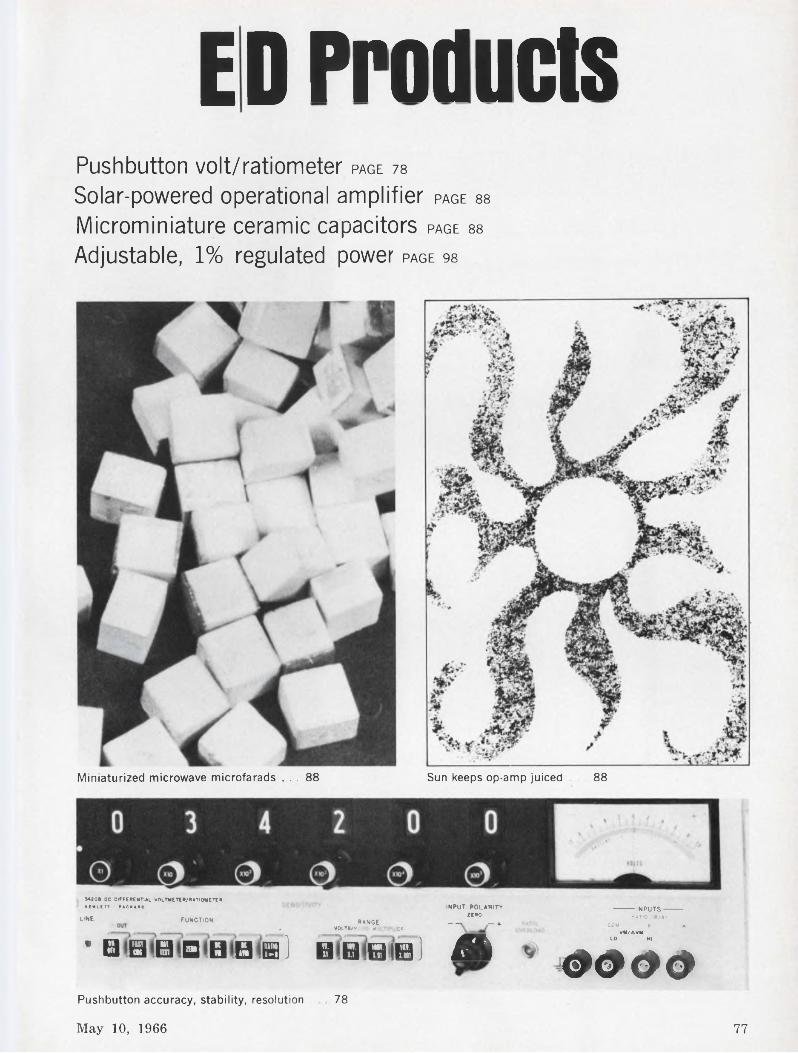
ED ProductsPushbutton volt/ratiometer page 78
Solar-powered operational amplifier page 88
Microminiature ceramic capacitors page 88
Adjustable, 1% regulated power page 98
Miniaturized microwave microfarads ... 88 Sun keeps op-amp juiced ... 88
MOOD OC DIFFERENTIAL VOLTMETER?RATIOMETER .
-------- INPUTS RATIO 18/A J
COM------------- 6 aVM/AVM
LO HI
0000MtWLtTT PACKARD INPUT POLARITY
. - ZEROUNE FUNCTION RANGE ------ , - +, VOLTS/ “*• Mu ER
’ H 0 B D B B H ] H Q a ® ) A
May 10, 1966 77
Pushbutton accuracy, stability, resolution . 78
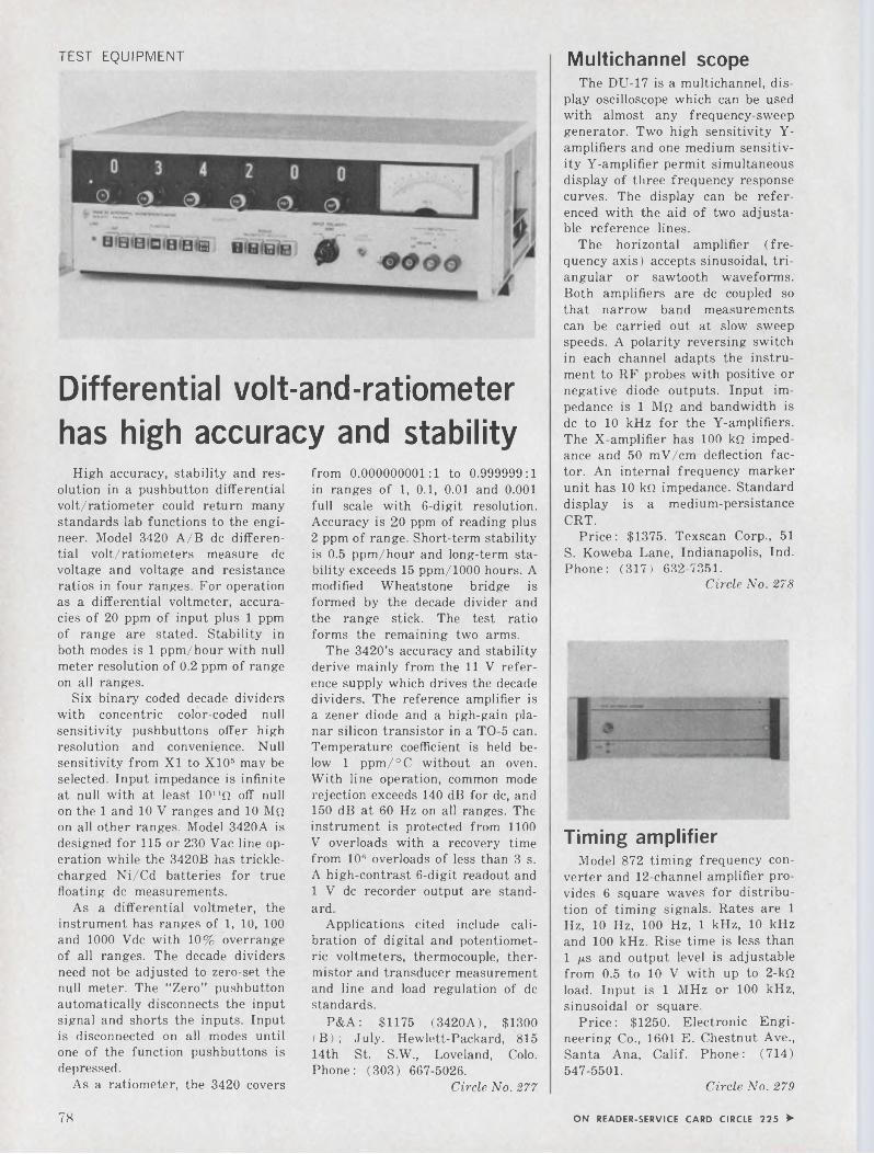
TEST EQUIPMENT
Differential volt-and-ratiometer has high accuracy and stability
High accuracy, stability and resolution in a pushbutton differential volt/ratiometer could return many standards lab functions to the engineer. Model 3420 A/B de differential volt/ratiometers measure de voltage and voltage and resistance ratios in four ranges. For operation as a differential voltmeter, accuracies of 20 ppm of input plus 1 ppm of range are stated. Stability in both modes is 1 ppm/hour with null meter resolution of 0.2 ppm of range on all ranges.
Six binary coded decade dividers with concentric color-coded null sensitivity pushbuttons offer high resolution and convenience. Null sensitivity from XI to X105 may be selected. Input impedance is infinite at null with at least lO11^ off null on the 1 and 10 V ranges and 10 Mq on all other ranges. Model 3420A is designed for 115 or 230 Vac line operation while the 3420B has trickle- charged Ni/Cd batteries for true floating de measurements.
As a differential voltmeter, the instrument has ranges of 1, 10, 100 and 1000 Vdc with 10% overrange of all ranges. The decade dividers need not be adjusted to zero-set the null meter. The “Zero” pushbutton automatically disconnects the input signal and shorts the inputs. Input is disconnected on all modes until one of the function pushbuttons is depressed.
As a ratiometer, the 3420 covers
from 0.000000001:1 to 0.999999:1 in ranges of 1, 0.1, 0.01 and 0.001 full scale with 6-digit resolution. Accuracy is 20 ppm of reading plus 2 ppm of range. Short-term stability is 0.5 ppm/hour and long-term stability exceeds 15 ppm/1000 hours. A modified Wheatstone bridge is formed by the decade divider and the range stick. The test ratio forms the remaining two arms.
The 3420’s accuracy and stability derive mainly from the 11 V reference supply which drives the decade dividers. The reference amplifier is a zener diode and a high-gain planar silicon transistor in a TO-5 can. Temperature coefficient is held below 1 ppm/°C without an oven. With line operation, common mode rejection exceeds 140 dB for de, and 150 dB at 60 Hz on all ranges. The instrument is protected from 1100 V overloads with a recovery time from 10" overloads of less than 3 s. A high-contrast 6-digit readout and 1 V de recorder output are standard.
Applications cited include calibration of digital and potentiometric voltmeters, thermocouple, thermistor and transducer measurement and line and load regulation of de standards.
P&A: $1175 (3420A), $1300 (B) ; July. Hewlett-Packard, 815 14th St. S.W., Loveland, Colo. Phone: (303) 667-5026.
Circle No. 277
Multichannel scopeThe DU-17 is a multichannel, dis
play oscilloscope which can be used with almost any frequency-sweep generator. Two high sensitivity Y- amplifiers and one medium sensitivity Y-amplifier permit simultaneous display of three frequency response curves. The display can be referenced with the aid of two adjustable reference lines.
The horizontal amplifier (frequency axis) accepts sinusoidal, triangular or sawtooth waveforms. Both amplifiers are de coupled so that narrow band measurements can be carried out at slow sweep speeds. A polarity reversing switch in each channel adapts the instrument to RF probes with positive or negative diode outputs. Input impedance is 1 Mq and bandwidth is de to 10 kHz for the Y-amplifiers. The X-amplifier has 100 kQ impedance and 50 mV/cm deflection factor. An internal frequency marker unit has 10 kQ impedance. Standard display is a medium-persistance CRT.
Price: $1375. Texscan Corp., 51 S. Koweba Lane, Indianapolis, Ind. Phone: (317) 632-7351.
Circle No. 278
Timing amplifierModel 872 timing frequency con
verter and 12-channel amplifier provides 6 square waves for distribution of timing signals. Rates are 1 Hz, 10 Hz, 100 Hz, 1 kHz, 10 kHz and 100 kHz. Rise time is less than 1 ps and output level is adjustable from 0.5 to 10 V with up to 2-kQ load. Input is 1 MHz or 100 kHz, sinusoidal or square.
Price: $1250. Electronic Engineering Co., 1601 E. Chestnut Ave., Santa Ana, Calif. Phone: (714) 547-5501.
Circle No. 279
ON READER-SERVICE CARD CIRCLE 225 >78
RCA-40234RCA-40395
RCA-40396 (NPN)
RCA-40396 (PNP)
take this RCA4-transistor
1-watt kitPUT IT IN THIS TRANSFORMERLESSCOMPLEMENTARY SYMMETRY CIRCUIT■ . ' ' ~ -• Xu? ’ ■ - - - <X'?u' ■ . ■
PACKAGE IT...
I
RCA-403964
RCA-40395 û 4...'
RCA-403964 NPN
TYPE
AND YOU’VE GOT A LOW-COST PHONOGRAPHWITH TOP-OF-THE-LINE PERFORMAN CWith this matched complement of four RCA audio transistors in the circuit above, you can build a 3-stage, 1-watt AC-operated audio amplifier that has many "top-of-the-line” features for a “bottom- of-the-line" production cost.
The complementary symmetry push-pull output stage uses an RCA-40396—a matched pair of PNP/NPN transistors—eliminating the need for output and driver transformers.
At 0.5 watt output, total harmonic distortion, hum and noise combined do not exceed 2% (10% at one watt).
Frequency response of the amplifier for a constant-voltage input (with tone control in “flat" position) is substantially flat from 180 to 20,000 c/s. And the tone control both "boosts” and "cuts”.
The 12.6-volt ac input for the power supply is easily obtained from an auxiliary winding on the phonograph motor.
The circuit offers an automatically compensated loudness control without use of a tapped potentiometer. This provides automatic base boost, minimized midrange distortion.... yet saves costs in both parts and labor.
Tight control of the driver and output transistor characteristics provides excellent thermal stability and eliminates need fora bias-adjustment potentiometer intypical circuits.
For more information, write for RCA Technical Bulletin ICE-326 (1-66); it contains performance curves, applications data, and specifications for both the transistors and a typical circuit. Write to: RCA Commercial Engineering, Sec. EG5-2, Harrison, N.J. Or call your RCA Field Representative.
AVAILABLE THROUGH YOUR RCA DISTRIBUTOR
RCA ELECTRONIC COMPONENTS AND DEVICES
The Most Trusted Name in Electronics
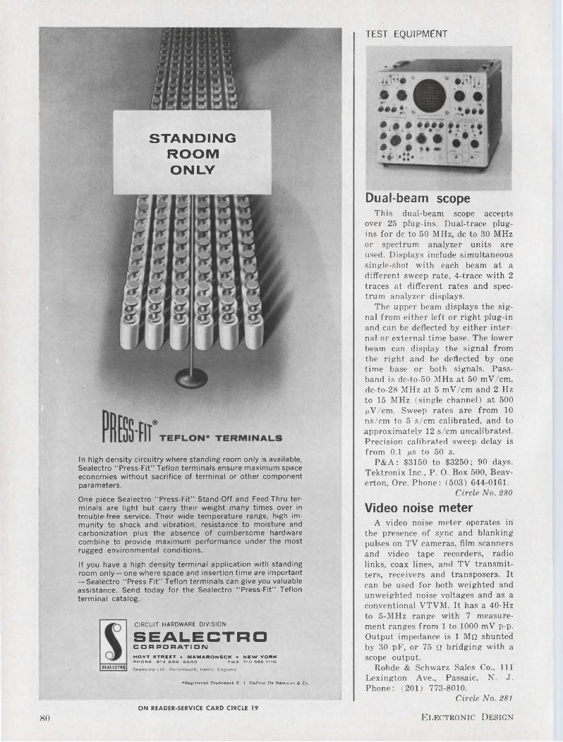
TEST EQUIPMENT
STANDING ROOM ONLY
In high density circuitry where standing room only is available, Sealectro “Press-Fit” Teflon terminals ensure maximum space economies without sacrifice of terminal or other component parameters.
One piece Sealectro “Press-Fit” Stand-Off and Feed-Thru terminals are light but carry their weight many times over in trouble-free service. Their wide temperature range, high immunity to shock and vibration, resistance to moisture and carbonization plus the absence of cumbersome hardware combine to provide maximum performance under the most rugged environmental conditions.
If you have a high density terminal application with standing room only—one where space and insertion time are important — Sealectro "Press-Fit” Teflon terminals can give you valuable assistance. Send today for the Sealectro “Press-Fit” Teflon terminal catalog.
SEALECTRO
CIRCUIT HARDWARE DIVISION
SEALECTROCORPORATI ONHOYT STREET • MAMARONECK • NEW YORK PHONE: 91 4 698-5600 TWX ; 710-566-1110
Sealectro Ltd.. Portsmouth. Hants. England
♦Registered Trademark E. 1. DuPont De Nemours & Co.
Dual-beam scopeThis dual-beam scope accepts
over 25 plug-ins. Dual-trace plugins for de to 50 MHz, de to 30 MHz or spectrum analyzer units are used. Displays include simultaneous single-shot with each beam at a different sweep rate, 4-trace with 2 traces at different rates and spectrum analyzer displays.
The upper beam displays the signal from either left or right plug-in and can be deflected by either internal or external time base. The lower beam can display the signal from the right and be deflected by one time base or both signals. Passband is dc-to-50 MHz at 50 mV/cm, dc-to-28 MHz at 5 mV/cm and 2 Hz to 15 MHz (single channel) at 500 ^V/cm. Sweep rates are from 10 ns/cm to 5 s/cm calibrated, and to approximately 12 s/cm uncalibrated. Precision calibrated sweep delay is from 0.1 p.s to 50 s.
P&A: $3150 to $3250; 90 days. Tektronix Inc., P. O. Box 500, Beaverton, Ore. Phone: (503) 644-0161.
Circle No. 280
Video noise meterA video noise meter operates in
the presence of sync and blanking pulses on TV cameras, film scanners and video tape recorders, radio links, coax lines, and TV transmitters, receivers and transposers. It can be used for both weighted and unweighted noise voltages and as a conventional VTVM. It has a 40-Hz to 5-MHz range with 7 measurement ranges from 1 to 1000 mV p-p. Output impedance is 1 Mq shunted by 30 pF, or 75 Q bridging with a scope output.
Rohde & Schwarz Sales Co., Ill Lexington Ave., Passaic, N. J. Phone: (201) 773-8010.
Circle No. 281
Electronic DesignON READER-SERVICE CARD CIRCLE 19
80
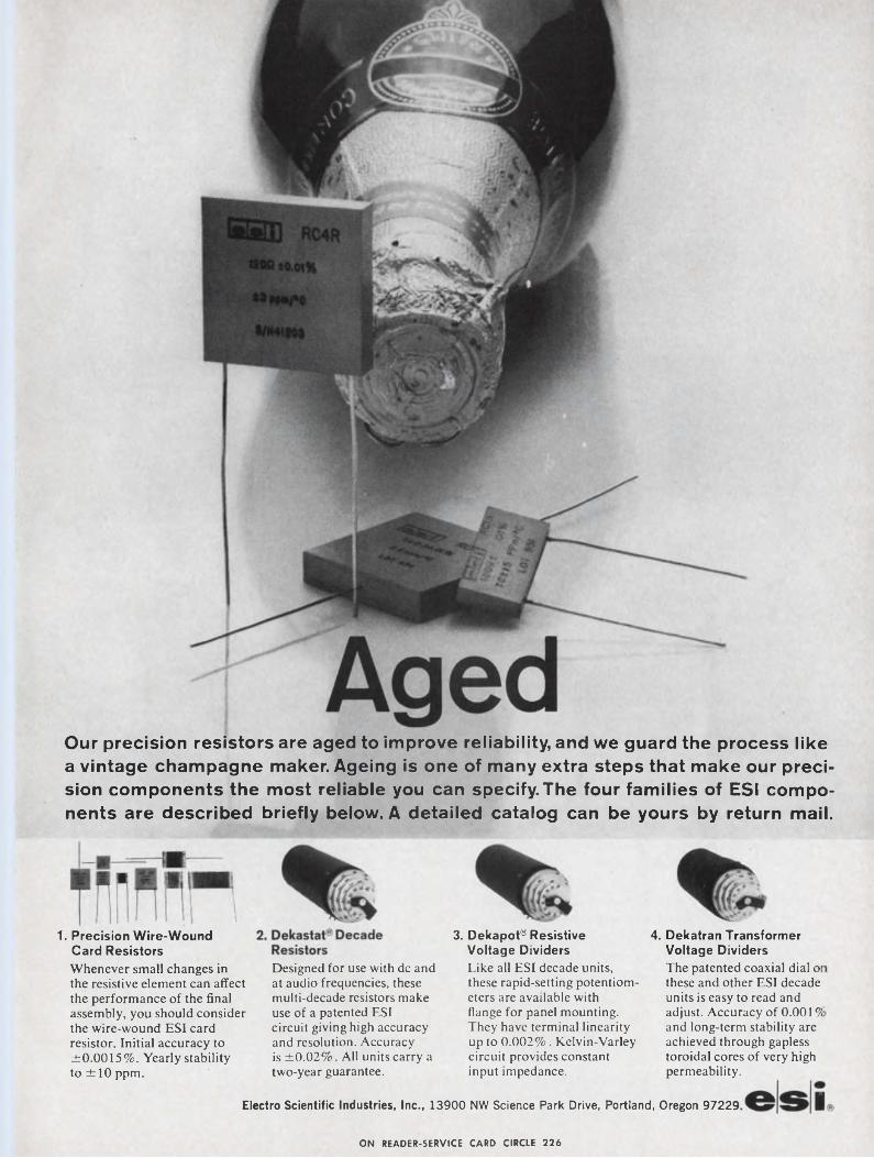
Our precision resistors are aged to improve reliability, and we guard the process like a vintage champagne maker. Ageing is one of many extra steps that make our precision components the most reliable you can specify.The four families of ESI components are described briefly below. A detailed catalog can be yours by return mail.
1. Precision Wire-Wound Card ResistorsWhenever small changes in the resistive element can affect the performance of the final assembly, you should consider the wire-wound ESI card resistor. Initial accuracy to ±0.0015%. Yearly stability to ±10 ppm.
Designed for use with de and at audio frequencies, these multi-decade resistors make use of a patented ESI circuit giving high accuracy and resolution. Accuracy is ±0.02%. All units carry a two-year guarantee.
3. Dekapot® Resistive Voltage Dividers Like all ESI decade units, these rapid-setting potentiometers are available with flange for panel mounting. They have terminal linearity up to 0.002%. Kelvin-Varley circuit provides constant input impedance.
4. Dekatran Transformer Voltage DividersThe patented coaxial dial oi these and other ESI decade units is easy to read and adjust. Accuracy of 0.00191 and long-term stability are achieved through gapless toroidal cores of very high permeability.
Electro Scientific Industries, Inc., 13900 NW Science Park Drive, Portland, Oregon 97229
ON READER-SERVICE CARD CIRCLE 226
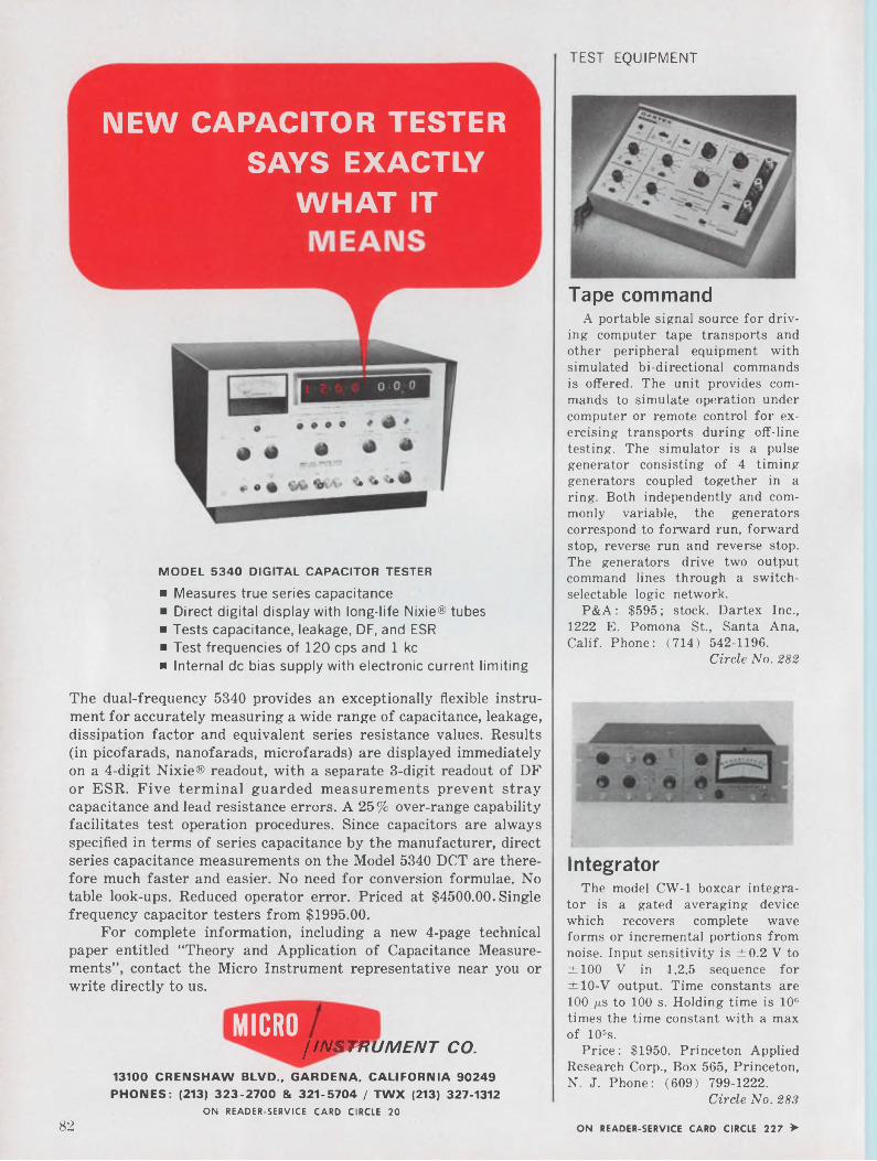
TEST EQUIPMENT
Tape command
NEW CAPACITOR TESTERSAYS EXACTLY
WHAT IT
A portable signal source for driving computer tape transports and other peripheral equipment with simulated bi-directional commands is offered. The unit provides commands to simulate operation under computer or remote control for exercising transports during off-line testing. The simulator is a pulse generator consisting of 4 timing generators coupled together in a ring. Both independently and commonly variable, the generators correspond to forward run, forward stop, reverse run and reverse stop. The generators drive two output command lines through a switch- selectable logic network.
P&A : $595 ; stock. Dartex Inc., 1222 E. Pomona St., Santa Ana, Calif. Phone: (714) 542-1196.
Circle No. 282
MODEL 5340 DIGITAL CAPACITOR TESTER
■ Measures true series capacitance■ Direct digital display with long-life Nixie® tubes ■ Tests capacitance, leakage, DF, and ESR ■ Test frequencies of 120 cps and 1 kc■ Internal de bias supply with electronic current limiting
The dual-frequency 5340 provides an exceptionally flexible instrument for accurately measuring a wide range of capacitance, leakage, dissipation factor and equivalent series resistance values. Results (in picofarads, nanofarads, microfarads) are displayed immediately on a 4-digit Nixie® readout, with a separate 3-digit readout of DF or ESR. Five terminal guarded measurements prevent stray capacitance and lead resistance errors. A 25% over-range capability facilitates test operation procedures. Since capacitors are always specified in terms of series capacitance by the manufacturer, direct series capacitance measurements on the Model 5340 DCT are therefore much faster and easier. No need for conversion formulae. No table look-ups. Reduced operator error. Priced at $4500.00. Single frequency capacitor testers from $1995.00.
For complete information, including a new 4-page technical paper entitled “Theory and Application of Capacitance Measurements”, contact the Micro Instrument representative near you or write directly to us.
MICRO/INSTRUMENT CO.
13100 CRENSHAW BLVD., GARDENA, CALIFORNIA 90249 PHONES: (213) 323-2700 & 321-5704 / TWX (213) 327-1312
ON READER-SERVICE CARD CIRCLE 20
IntegratorThe model CW-1 boxcar integra
tor is a gated averaging device which recovers complete wave forms or incremental portions from noise. Input sensitivity is ±0.2 V to ±100 V in 1,2,5 sequence for ±10-V output. Time constants are 100 ps to 100 s. Holding time is 106 times the time constant with a max of 105s.
Price: $1950. Princeton Applied Research Corp., Box 565, Princeton, N. J. Phone: (609) 799-1222.
Circle No. 283
82 ON READER-SERVICE CARD CIRCLE 227 ►
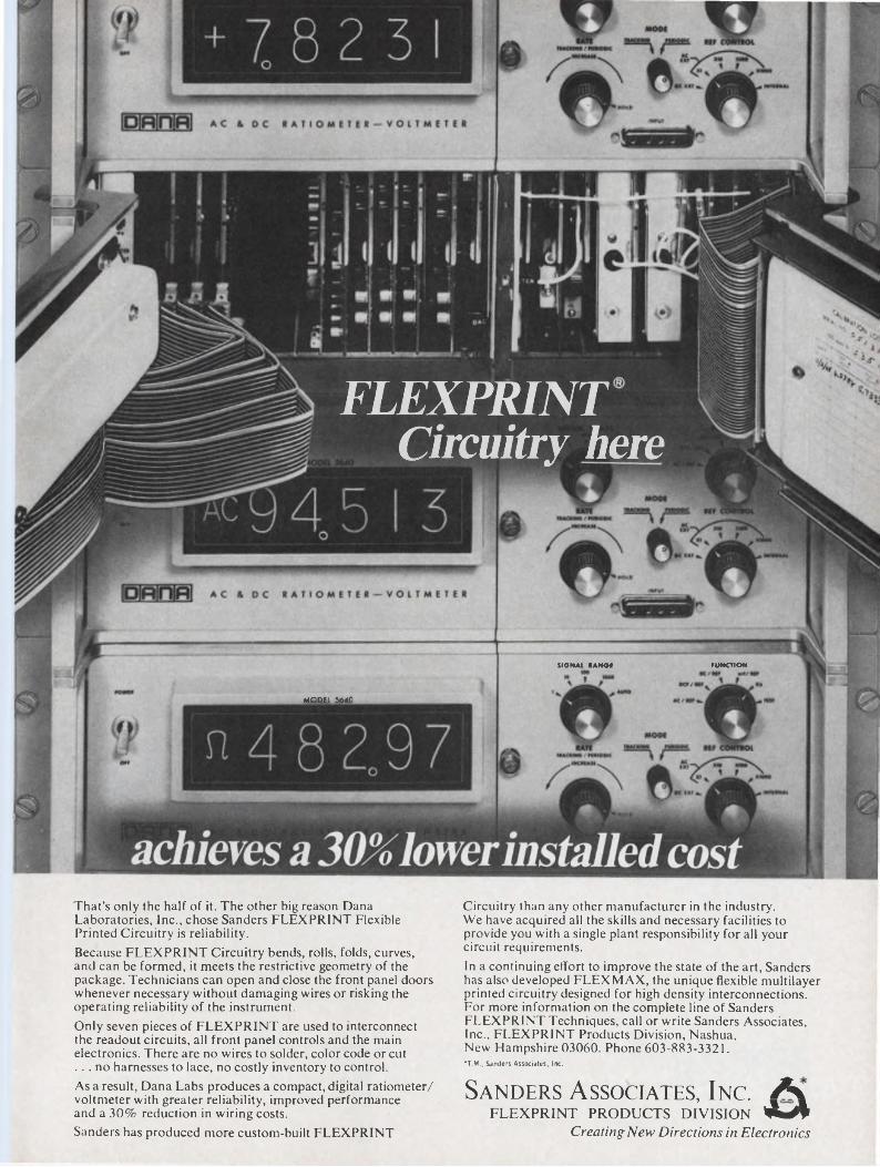
FUNCTIONSIGNAL RANQf
MODEL 5640
FLEXPRINT Circuitry here
That’s only the half of it. The other big reason Dana Laboratories, Inc., chose Sanders FLEXPRINT Flexible Printed Circuitry is reliability.Because FLEXPRINT Circuitry bends, rolls, folds, curves, and can be formed, it meets the restrictive geometry of the package. Technicians can open and close the front panel doors whenever necessary without damaging wires or risking the operating reliability of the instrument.Only seven pieces of FLEXPRINT are used to interconnect the readout circuits, all front panel controls and the main electronics. There are no wires to solder, color code or cut ... no harnesses to lace, no costly inventory to control.As a result, Dana Labs produces a compact, digital ratiometer/ voltmeter with greater reliability, improved performance and a 30% reduction in wiring costs.Sanders has produced more custom-built FLEXPRINT
Circuitry than any other manufacturer in the industry. We have acquired all the skills and necessary facilities to provide you with a single plant responsibility for all your circuit requirements.In a continuing effort to improve the state of the art, Sanders has also developed FLEXMAX, the unique flexible multilayer printed circuitry designed for high density interconnections. For more information on the complete line of Sanders FLEXPRINT Techniques, call or write Sanders Associates, Inc., FLEXPRINT Products Division, Nashua, New Hampshire 03060. Phone 603-883-3321.•T.M., Sanders Associates, Inc.
Sanders Associates, Inc. AlFLEXPRINT PRODUCTS DIVISION AwA
Creating New Directions in Electronics
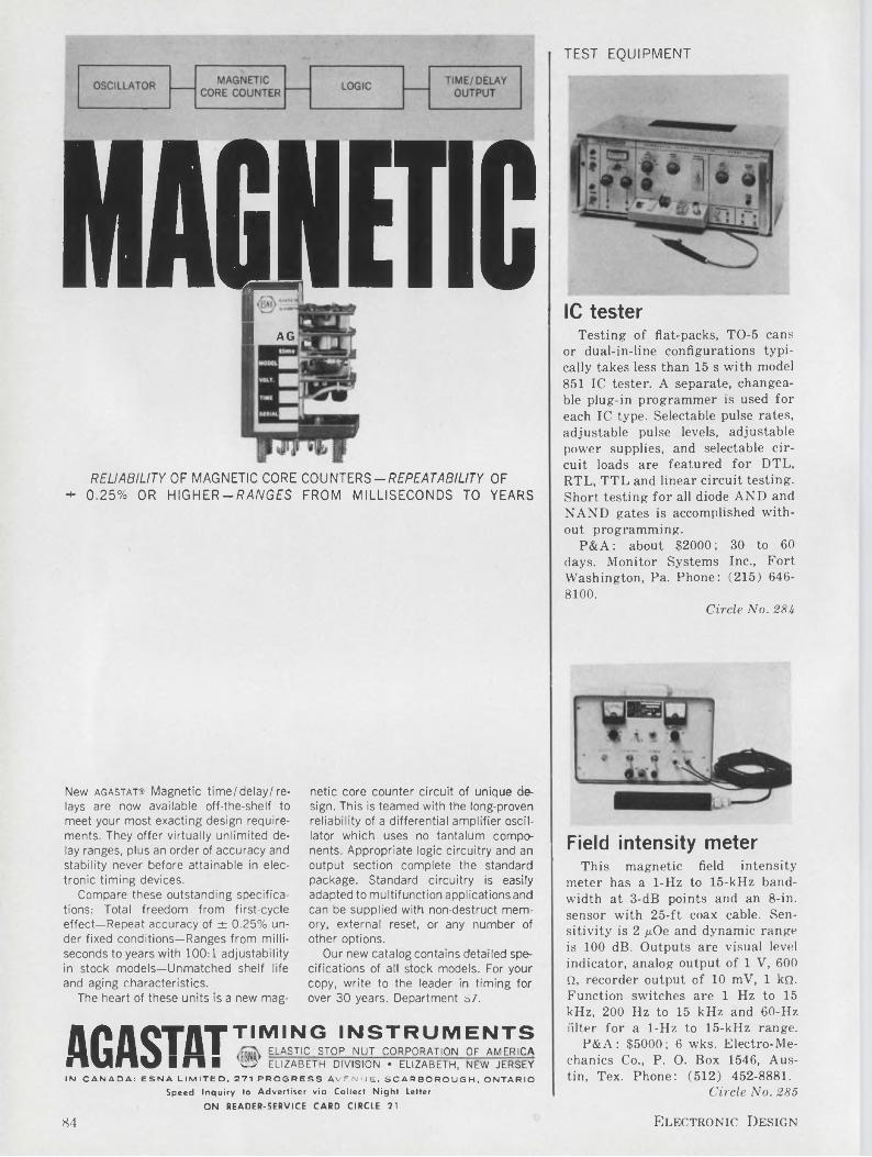
TEST EQUIPMENT
MAGNETICH AG
IC tester
RELIABILITY OF MAGNETIC CORE COUNTERS-REPEATABILITY OF * 0.25% OR HIGHER —R4/VGES FROM MILLISECONDS TO YEARS
Testing- of fiat-packs, TO-5 cans or dual-in-line configurations typically takes less than 15 s with model 851 IC tester. A separate, changeable plug-in programmer is used for each IC type. Selectable pulse rates, adjustable pulse levels, adjustable power supplies, and selectable circuit loads are featured for DTL, RTL, TTL and linear circuit testing. Short testing for all diode AND and NAND gates is accomplished without programming.
P&A: about $2000; 30 to 60 days. Monitor Systems Inc., Fort Washington, Pa. Phone: (215) 6468100.
Circle No. 284
New agastat® Magnetic time/delay/relays are now available off-the-shelf to meet your most exacting design requirements. They offer virtually unlimited delay ranges, plus an order of accuracy and stability never before attainable in electronic timing devices.
Compare these outstanding specifications: Total freedom from first-cycle effect—Repeat accuracy of ± 0.25% under fixed conditions—Ranges from milliseconds to years with 100:1 adjustability in stock models—Unmatched shelf life and aging characteristics.
The heart of these units is a new mag
AO AOTAT TIM,NG instrumentsI1I«U A I 11 I ELASTIC STOP NUT CORPORATION OF AMERICA fTVnV I O ■ ® ELIZABETH division • Elizabeth, new jersey IN CANADA: ESNA LIMITED. 271 PROGRESS AVENUE, SCARBOROUGH, ONTARIO
Speed Inquiry to Advertiser via Collect Night Letter
ON READER-SERVICE CARD CIRCLE 21
netic core counter circuit of unique design. This is teamed with the long-proven reliability of a differential amplifier oscillator which uses no tantalum components. Appropriate logic circuitry and an output section complete the standard package. Standard circuitry is easily adapted to multifunction applicationsand can be supplied with non-destruct memory, external reset, or any number of other options.
Our new catalog contains detailed specifications of all stock models. For your copy, write to the leader in timing for over 30 years. Department S7.
Field intensity meterThis magnetic field intensity
meter has a 1-Hz to 15-kHz bandwidth at 3-dB points and an 8-in. sensor with 25-ft coax cable. Sensitivity is 2 p.Oe and dynamic range is 100 dB. Outputs are visual level indicator, analog output of 1 V, 600 Q, recorder output of 10 mV, 1 kQ. Function switches are 1 Hz to 15 kHz, 200 Hz to 15 kHz and 60-Hz filter for a 1-Hz to 15-kHz range.
P&A: $5000; 6 wks. Electro-Mechanics Co., P. O. Box 1546, Austin, Tex. Phone: (512) 452-8881.
Circle No. 285
84 Electronic Design
test under actual load conditions. . . the ultimate test for integrated circuits, transistors,
diodes, thin films, logic cards or modules. The Model 553 Dynamic Test System performs both static (de) and dynamic
tests from de to 50 megacycles on multi-lead devices in a single socket! Variable word-length mnemonic machine language
simplifies programming . . . operators can be trained in a few hours. Unique program modification eliminates repetitive
instructions, speeds additions and deletions to save up to two-thirds in programming time.
Let us tell you more about the 553.
Texas Instruments INCORPORATED
APPARATUS DIVISIONP. O. BOX 66027 HOUSTON, TEXAS 77006 TIB RUE du RHONE GENEVA, SWITZERLAND
ON READER-SERVICE CARD CIRCLE 22
May 10, 1966 85
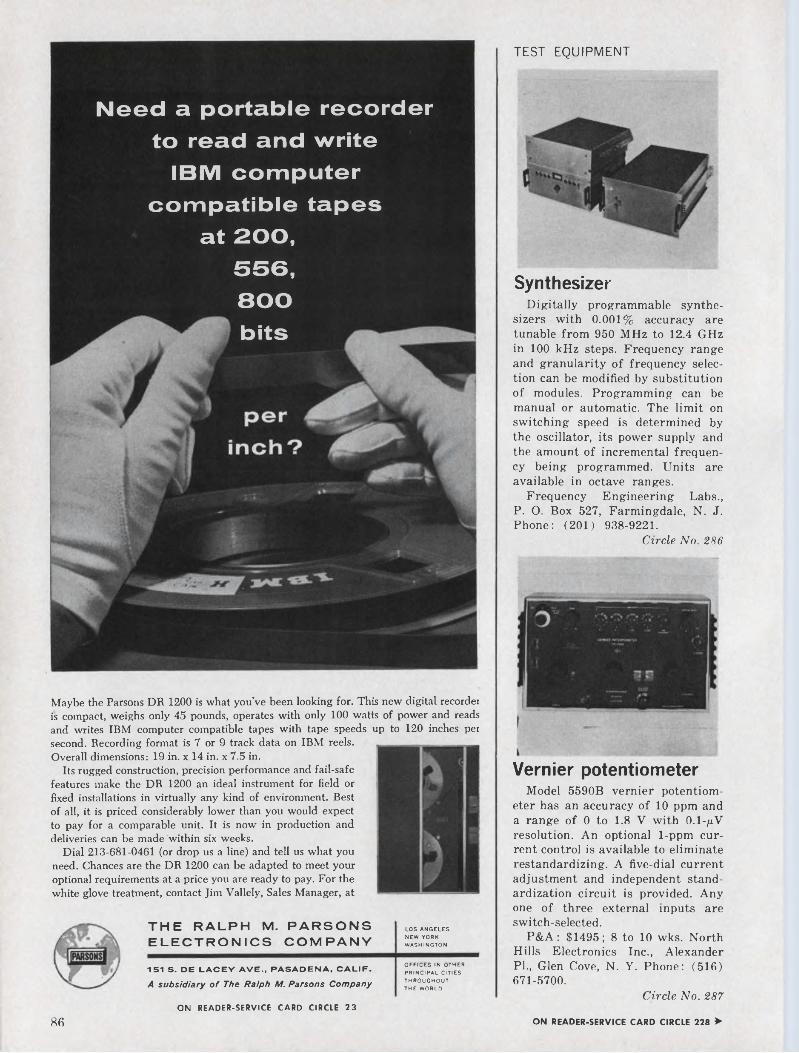
TEST EQUIPMENT
Need a portable recorder to read and write
IBM computer compatible tapes
at 200, 556, 800
' bits
Maybe the Parsons DR 1200 is what you’ve been looking for. This new digital recorder is compact, weighs only 45 pounds, operates with only 100 watts of power and reads and writes IBM computer compatible tapes with tape speeds up to 120 inches persecond. Recording format is 7 or 9 track data on IBM reels. Overall dimensions: 19 in. x 14 in. x 7.5 in.
Its rugged construction, precision performance and fail-safe features make the DR 1200 an ideal instrument for field or fixed installations in virtually any kind of environment. Best of all, it is priced considerably lower than you would expect to pay for a comparable unit. It is now in production and deliveries can be made within six weeks.
Dial 213-681-0461 (or drop us a line) and tell us what you need. Chances are the DR 1200 can be adapted to meet your optional requirements at a price you are ready to pay. For the white glove treatment, contact Jim Vallely, Sales Manager, at
LOS ANGELES NEW YORK WASHINGTON
THE RALPH M. PARSONS ELECTRONICS COMPANY
151 S. DE LACEY AVE., PASADENA, CALIF.A subsidiary of The Ralph M. Parsons Company
OFFICES IN OTHER PRINCIPAL CITIES THROUGHOUT THE WORLD
SynthesizerDigitally programmable synthe
sizers with 0.001% accuracy are tunable from 950 MHz to 12.4 GHz in 100 kHz steps. Frequency range and granularity of frequency selection can be modified by substitution of modules. Programming can be manual or automatic. The limit on switching speed is determined by the oscillator, its power supply and the amount of incremental frequency being programmed. Units are available in octave ranges.
Frequency Engineering Labs., P. O. Box 527, Farmingdale, N. J. Phone: (201) 938-9221.
Circle No. 286
Vernier potentiometerModel 5590B vernier potentiom
eter has an accuracy of 10 ppm and a range of 0 to 1.8 V with O.I-/1V resolution. An optional 1-ppm current control is available to eliminate restandardizing. A five-dial current adjustment and independent standardization circuit is provided. Any one of three external inputs are switch-selected.
P&A : $1495 ; 8 to 10 wks. North Hills Electronics Inc., Alexander Pl., Glen Cove, N. Y. Phone: (516) 671-5700.
Circle No. 287ON READER-SERVICE CARD CIRCLE 23
86 ON READER-SERVICE CARD CIRCLE 228 >
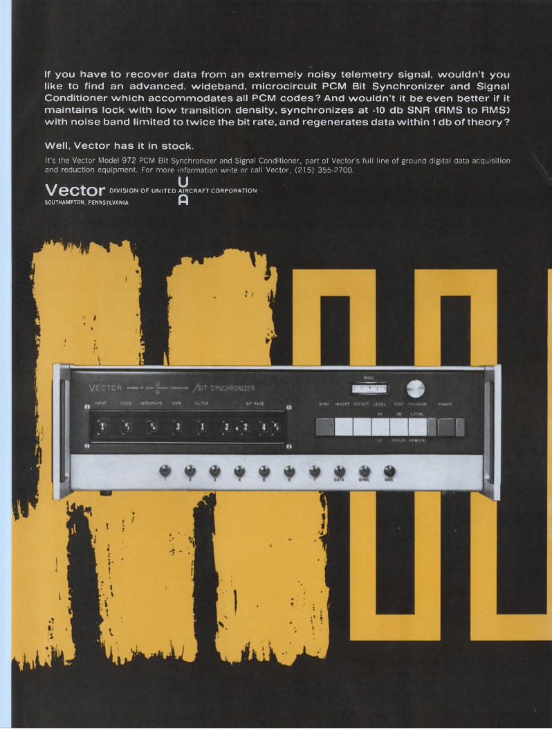
If you have to recover data from an extremely noisy telemetry signal, wouldn’t you like to find an advanced, wideband, microcircuit PCM Bit Synchronizer and Signal Conditioner which accommodates all PCM codes? And wouldn’t it be even better if it maintains lock with low transition density, synchronizes at -10 db SNR (RMS to RMS) with noise band limited to twice the bit rate, and regenerates data within 1 db of theory ?
Well, Vector has it in stock.It’s the Vector Model 972 PCM Bit Synchronizer and Signal Conditioner, part of Vector's full line of ground digital data acquisition and reduction equipment. For more information write or call Vector, (215) 355-2700.
Vector DIVISION OF UNITED McRAFT CORPORATION
SOUTHAMPTON, PENNSYLVANIA O
COMPONENTS
Solar power keeps amplifier operating around the clock
Another dimension has been added to operational amplifier design and packaging: Ambient light powers the self-contained model 982. Internal energy storage is sufficient for around-the-clock operation after an eight-hour exposure to visible or near-infrared radiation. An internal cut-off eliminates the risk of overcharging or undercharging when stored energy falls below a pre-set level or when the nickel/cadmium battery voltage is below 7.5 volts.
The FET input provides a differential input impedance of 1 Gq and a common-mode input impedance of 3 Gfi. Output voltage is
Charging circuitry prevents the batteries from overcharging and maintains charging currents under low ambient light levels.
±7.5 V max at 10 mA. Unity gain frequency is 300 kHz min and the amplifier has 6 dB/octave slope from knee to unity gain. Open loop gain is typically 50,000 (30,000 min). Input noise is 4 pV p-p.
The amplifier is available with a kit of feedback components. It will be possible to use the model 982 as a differential or single-ended amplifier having 2 MQ input impedance with X10 gain, as an integrator or as a differentiator. The manufacturers’ “logarithmic element,” which behaves as a bipolar semiconductor junction, makes it possible for the 982 to be used as a logarithmic and anti-logarithmic amplifier, a half-wave ideal rectifier or an approximate sine-wave oscillator. The array of banana jacks on 3/4-in. centers eases the task of changing functions.
Originally intended as a lab or classroom tool, the amplifier’s complete isolation is bringing it into the field as an analog building block or portable function module. The differential input and output suggest uses in breadboarding computation systems.
P&A: 197 (complete kit), $143 (amplifier); stock to 30 days. Optical Electronics Inc., P.O. Box 11140, Tucson, Ariz. Phone: (602) 6243605.
Circle No. 288
Ceramic capacitors offer 1 in a 0.001-in? case
Deposition of uniform, pore-free ceramic dielectric sections less than 10~3-in. thick results in packaging densities of 1000 juF/in.3 and 100 (itF/in.3 for the ATC-300 and -200 series of ceramic capacitors. Thus, the -300 series can offer 1 /xF in a 0.1 x 0.1 x 0.1-in.3 case.
The monolithic ceramic capacitors have been used in tests at 1 GHz, and the manufacturer projects a self-resonant frequency over 10 GHz. Insulation resistance of the two series is 10 and 100 Gq respectively and both feature a negligible series resistance. The ATC-200 exhibits a temperature coefficient of ±2% from 25 to 125° while the -300 reaches capacity peak at 25°C. Working voltage is 50 V and capacity-voltage rating is claimed to exceed non-polarized tantalum in volumtric efficiency. Dissipation factor at 1 kHz is 2.5% max.
The cubes are terminated with standard radial-tinned copper wire or are provided as pellets with solderable pads. They are offered in ranges of 0.001 to 0.1 (-200)and 0.1 to 1 /xF (-300). Tolerances are 5, 10 and 20% and 10 and 20% guaranteed minimum respectively. Ranges of 0.1 to 1000 pF, and Qs greater than 5000 are available.
P&A: $1 to $5; stock to 4 wks. American Technical Ceramics, P. O. Box 141, Hell Gate Station, New York. Phone (212) 256-9330.
Circle No. 289
88 Electronic Design
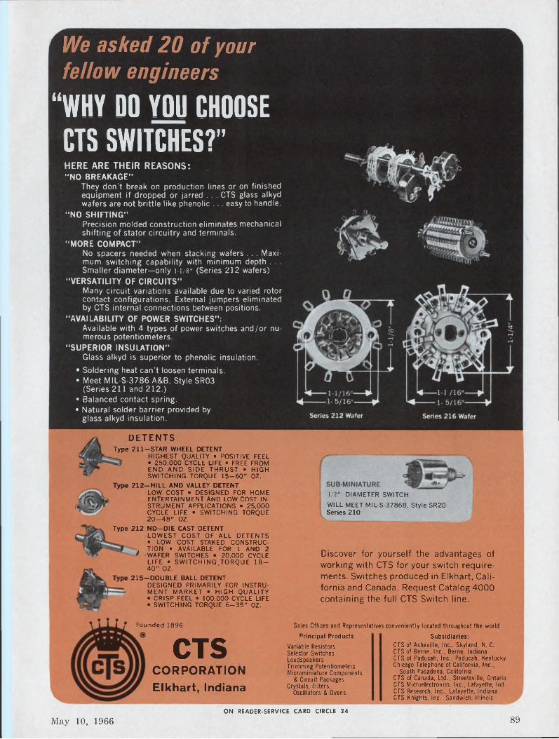
'We asked 20 of your fellow engineers
“WHY DO YOU CHOOSECTS SWITCHES?"HERE ARE THEIR REASONS:“NO BREAKAGE”
They don’t break on production lines or on finished equipment if dropped or jarred . . . CTS glass alkyd wafers are not brittle like phenolic . . . easy to handle.
"NO SHIFTING"Precision molded construction eliminates mechanical shifting of stator circuitry and terminals.
“MORE COMPACT"No spacers needed when stacking wafers . . . Maximum switching capability with minimum depth . . . Smaller diameter—only 1-1/8' (Series 212 wafers)
"VERSATILITY OF CIRCUITS”Many circuit variations available due to varied rotor contact configurations. External jumpers eliminated by CTS internal connections between positions.
"AVAILABILITY OF POWER SWITCHES”:Available with 4 types of power switches and/or numerous potentiometers.
"SUPERIOR INSULATION”Glass alkyd is superior to phenolic insulation.
• Soldering heat can’t loosen terminals.• Meet MIL-S-3786 A&B, Style SR03
(Series 211 and 212.)• Balanced contact spring.• Natural solder barrier provided by
glass alkyd insulation.
DETENTSType 211-STAR WHEEL DETENT
HIGHEST QUALITY • POSITIVE FEEL • 250,000 CYCLE LIFE • FREE FROM END AND SIDE THRUST • HIGH SWITCHING TORQUE 15-60" OZ.
212—HILL AND VALLEY DETENTLOW COST • DESIGNED FOR HOME ENTERTAINMENT AND LOW COST INSTRUMENT APPLICATIONS • 25,000 CYCLE LIFE • SWITCHING TORQUE 20-48" OZ.
1/2’ DIAMETER SWITCHWILL MEET MIL-S-3786B, Style SR20Series 210
Type 212 ND-DIE CAST DETENTLOWEST COST OF ALL DETENTS• LOW COST STAKED CONSTRUC-
. TION • AVAILABLE FOR 1 AND 2 * WAFER SWITCHES • 20,000 CYCLE
LIFE • SWITCHING TORQUE 18- 40" OZ.
215—DOUBLE BALL DETENTDESIGNED PRIMARILY FOR INSTRUMENT MARKET • HIGH QUALITY • CRISP FEEL • 100,000 CYCLE LIFE • SWITCHING TORQUE 6-35" OZ.
Discover for yourself the advantages of working with CTS for your switch requirements. Switches produced in Elkhart, California and Canada. Request Catalog 4000 containing the full CTS Switch line.
Founded 1896
CTSCORPORATIONElkhart, Indiana
Principal ProductsVariable ResistorsSelector SwitchesLoudspeakersTrimming PotentiometersMicrominiature Components
& Circuit Packages Crystals, Filters,
Oscillators & Ovens
Sales Offices and Representatives conveniently located throughout the world
Subsidiaries:CTS of Asheville, Inc., Skyland, N. C.CTS of Berne, Inc., Berne, IndianaCTS of Paducah, Inc., Paducah, KentuckyChicago Telephone of California, Inc.,
South Pasadena, CaliforniaCTS of Canada, Ltd., Streetsville, Ontario CTS Microelectronics, Inc., Lafayette, Ind. CTS Research, Inc., Lafayette, Indiana CTS Knights, Inc., Sandwich, Illinois
ON READER-SERVICE CARD CIRCLE 24
May 10, 1966 89
COMPONENTS
When the specs say...“Meet Requirements of
MIL Standard 202B”You can depend on us!
The above photograph shows Circuit Breakers at Wood Electric being tested for temperature and humidity requirements of MIL Standard 202B. Units undergo temperature changes from 14 to 160° F during a 10 day cycle while relative humidity is held constant at 50%. Test chamber is controlled within ±2° F and ±2% humidity.
There are other specs and other tests, lots of them, buf they all have one purpose in common—to assure the most reliable performance in the industry. If it's by Wood Electric — you can depend on it!
Choose from a wide variety of proven commercial and military Circuit Breakers to meet the specific needs of your application-Thermal types with time delays from 0.5 to 90 seconds and Magnetic types with temperature-stable trip points from instantaneous to 10 seconds. Models are available with ratings from Vz to 50 amps ... AC or DC .. . single pole, two pole and three pole.
Write for Circuit Breaker Catalog CB-10-65
WOOD ELECTRIC244 Broad St. Lynn, Massachusetts (617) 598-5313
ON READER-SERVICE CARD CIRCLE 25
Power dividerA circular, eight-way power divid
er for 200 to 400 MHz use replaces seven transmission line hybrids. The 8U-50-1 power divider provides isolation of 30 dB min with even power distribution. Amplitude balance is 0.2 dB max and vswr is 1.3 max. The 2-1/4-in. diameter units have 50-Q BNC, TNC or type N connectors.
P&A : $425 ; stock. Adams-Russell Co. Inc., 280 Bear Hill Rd., Waltham, Mass. Phone: (617) 899- 3145.
Circle No. 290
Magnetic switchA totally enclosed, dust, water
and explosion-proof magnetic pushbutton switch is capable of switching high current loads with virtually no arcing. Life span of 10“ operations is claimed with resistive loads of 25 A, 120 Vac, or 25 A, 30 Vdc or inductive loads of 15 A, 120 Vac at an ambient range of -60 to 300°F.
P&A: $4.29 to $8.00; 30 days. Gardiner Corp., P.O. Box 375, David City, Neb. Phone: (402) 367- 3400.
Circle No. 291
90 Electronic Design
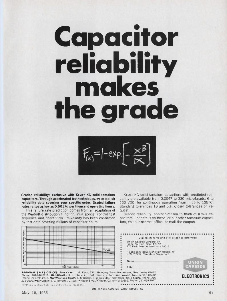
Capacitor reliability
makes the grade
Graded reliability: exclusive with Kemet KG solid tantalum capacitors. Through accelerated test techniques, we establish reliability data covering your specific order. Graded failure rates range as low as 0.001 % per thousand operating hours.
This failure rate prediction comes from an adaptation of the Weibull distribution function, in a special control test sequence and chart form. Its validity has been confirmed by test data covering billions of capacitor hours.
Kemet KG solid tantalum capacitors with predicted reliability are available from 0.0047 to 330 microfarads, 6 to 100 VDC, for continuous operation from —55 to 125°C. Standard tolerances 10 and 5%. Closer tolerances on request.
Graded reliability: another reason to think of Kemet capacitors. For details on these, or our other tantalum capacitors, call our nearest office, or mail the coupon.
Clip, fill in name and title, attach to letterheadUnion Carbide CorporationLinde Division, Dept. ED-52270 Park Avenue, New York 10017
Please send details on High-Reliability KEMET Solid Tantalum Capacitors
Name
Title.
UNION CARBIDE
REGIONAL SALES OFFICES. East Coast: J. G. Egan, 1341 Hamburg Turnpike, Wayne, New Jersey 07472. Phone: 201-696-2710. Mid-Atlantic: R. H. Robecki, 1341 Hamburg Turnpike, Wayne, New Jersey 07472. Phone: 201-696-2710. Mid-West and South: K. S. CoIlart, P. 0. Box 6087, Cleveland, Ohio 44101. Phone: 216221-0600. West Coast: B. G. Bryant, 701 East Whittier Blvd., Whittier, California 90605. Phone: 213-698-8077.Kemet is a registered trade mark of Union Carbide Corporation. •••••••••••••••••
ELECTRONICS
ON READER-SERVICE CARD CIRCLE 26
May 10, 1966 91
COMPONENTS
Why is this MKTRMiniature O.E.M. Relay
so remarkable?
Read these specs and find out.Size Low profile. 1-3/16 x 1-3/8 x 1-3/8
A real space saver.Sensitivity Down to 60 milliwatts per pole D.C.
Ideal for plate circuits.Contact Ratings 5 amperes and 10 amperes
(AC & DC).Contact Selections Fine silver (gold flashed) Silver
Cadmium Oxide (gold flashed) Gold diffused (for low level switching).
PoleConfigurations Available in 1, 2 and 3 pole double throw combinations.
Covers Plastic dust covers made of Styrene, Butyrate or Polycarbonate. Clear, Translucent and Opaque in a variety of colors (no extra charge). Hermetically sealed.
Indicator Spotlights available to indicate coil normally open or normally closed.
Terminals Solder lug, Plug-in, Printed Circuit and .110 Snap-on.
Sockets True 10 amp construction socket. Can be used in printed circuit boards.Solder terminals which accept .110 Snap-on terminals standard.
Mountings Available with side or base studs for chassis mounting.
Applications General purpose. Medium power. Practically unlimited.
U. L. File No. E36213For a prototype (specify coil and contact requirements) and for more information ask for our Bulletin No. 16.
LINE ELECTRIC COMPANYDivision of Industrial Timer Corporation 205 River Street, Orange, New Jersey In Canada: Sperry Gyroscope Ottawa Ltd. Ont.
DemodulatorModel 351 synchronous demodula
tor has a gain of 20 dB, an output dynamic range of ±10 Vdc, and will accommodate chopper frequencies from 4 to 100 Hz (10 kHz with phase control bypassed). A calibrated locking control provides 0 to 360° continuous phase adjustment. Phase setting is frequency-independent so that no fine tuning is required. The unit has a post-detection filter time constant control ranging from 0.015 to 5 s.
Ithaco Inc., 415 Taughannock Blvd., Ithaca, N. Y. Phone: (607) 272-7640.
Circle No. 292
Zener voltage referenceThe model 1200 temperature-
compensated zener voltage references operate from 30 to 60 Vac, 50 to 500 Hz or 40 Vdc. Output is 12 Vdc from 0.1 to 15 mA. Long term stability is better than 0.003% per year. Noise is less than 50 pV p-p. Temperature coefficient of the 1- in.3 unit is 0.0002%/°C.
P&A: $40 to $60; stock. NorfaxCorp., 1152 Morena Blvd., San Diego, Calif. Phone: (714) 276-3200.
Circle No. 293
|INERELAYS
ON READER-SERVICE CARD CIRCLE 27
92 Electronic Design
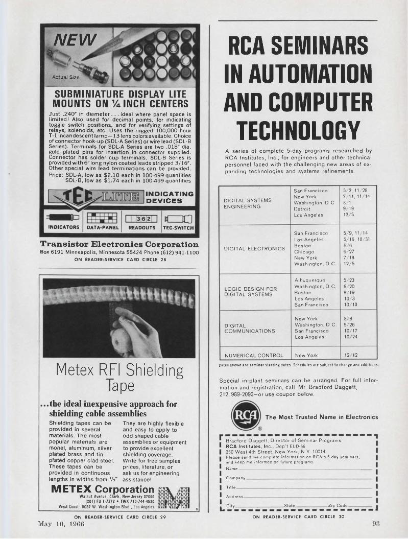
NEW
Actual Size
INDICATORS DATA* PAN EL READOUTS TEC-SWITCH
INDICATING DEVICES
SUBMINIATURE DISPLAY LITE MOUNTS ON %INCH CENTERS
Just .240" in diameter... ideal where panel space is limited! Also used for decimal points, for indicating toggle switch positions, and for verifying settings of relays, solenoids, etc. Uses the rugged 100,000 hour T-l incandescent lamp—13 lens colors available. Choice of connector hook-up (SDL-A Series) or wire lead (SDL-B Series). Terminals for SDL-A Series are two .018" dia. gold plated pins for insertion in connector supplied. Connector has solder cup terminals. SDL-B Series is provided with 6" long nylon coated leads stripped 3/16". Other special wire lead terminations can be provided. Price: SDL-A, low as $2.10 each in 100-499 quantities
SDL-B, low as $1.74 each in 100-499 quantities
Transistor Electronics CorporationBox 6191 Minneapolis, Minnesota 55424 Phone (612)941-1100
ON READER-SERVICE CARD CIRCLE 28
RCA SEMINARS IN AUTOMATION AND COMPUTER
TECHNOLOGYA series of complete 5-day programs researched by RCA Institutes, Inc., for engineers and other technical personnel faced with the challenging new areas of expanding technologies and systems refinements.
Dates shown are seminar starting dates. Schedules are subject to change and additions.
DIGITAL SYSTEMS ENGINEERING
San Francisco New York Washington, D.C. Detroit Los Angeles
5/2, 11/287/11, 11/148/19/1912/5
DIGITAL ELECTRONICS
San Francisco Los Angeles Boston Chicago New York Washington, D.C.
5/9, 11/145/16, 10/316/66/277/1812/5
LOGIC DESIGN FOR DIGITAL SYSTEMS
AlbuquerqueWashington, D.C.BostonLos AngelesSan Francisco
5/236/209/1910/310/10
DIGITALCOMMUNICATIONS
New York Washington, D.C. San Francisco Los Angeles
8/8 9/2610/17 10/24
NUMERICAL CONTROL New York 12/12
Metex RFI Shielding Tape Special in-plant seminars can be arranged. For full infor
mation and registration, call Mr. Bradford Daggett, 212, 989-2093—or use coupon below.
the ideal inexpensive approach for shielding cable assembliesShielding tapes can be provided in several materials. The most popular materials are monel, aluminum, silver plated brass and tin plated copper clad steel. These tapes can be provided in continuous lengths in widths from 'A".
They are highly flexible and easy to apply to odd shaped cable assemblies or equipment to provide excellent shielding coverage. Write for free samples, prices, literature, or ask us for engineering assistance!
METEX Corporation mWalnut Avenue, Clark, New Jersey 07066 VWI
(201) FU 1-7272 • TWX 710-744-4530
The Most Trusted Name in Electronics
Bradford Daggett, Director of Seminar ProgramsRCA Institutes, Inc., Dep t ELD-56350 West 4th Street, New York, N.Y. 10014Please send me complete information on RCA’s 5-day seminars, and keep me informed on future programs.Name______________________________________________
Company.
Title.
Address
City. State. Zip Code.
ON READER-SERVICE CARD CIRCLE 29
May 10, 1966
West Coast: 5057 W. Washington Blvd., Los Angeles khi xíü/finiON READER-SERVICE CARD CIRCLE 30
COMPONENTS
Operational amplifierA new chopper-stabilized opera
tional amplifier has an output of ±150 V peak at 5 mA or ±100 V peak at 50 mA. The amplifier uses compensated FET chopper circuitry with internal drive for 2 pV/°C drift. Zero offset voltage adjustment is built in. Open loop de gain is 107 and gain-bandwidth product is 0.5 MHz.
P&A: $165 (1 to 9); stock. Zel- tex Inc., 1000 Chalomar Rd., Concord, Calif. Phone: (415) 686- 6660.
Circle No. 294
1-mW relaySeries 8 relay has an aluminum
dust cover with octal plug-in base and features 1 mW sensitivity.
Designed for de operation, it is available for close differential requirements (high release) in which the difference between operate and release values may be as high as 80%. Coil resistance ranges from 100 mil to 27 Mq. Contacts are rated from low level to 2 A resistive at 28 Vdc or 115 Vac.
Price: $3.75. General Automatic Corp., 7 Sherman Ave., Jersey City, N. J. Phone: (201) 653-8970.
Circle No. 295
Tantalum capacitorsA new type of tantalum capaci
tor uses a neutral electrolyte to eliminate damage by acid leakage. The type WF capacitors meet MIL- C-3965 but do not use sintered slugs in their manufacture. Voltage ratings are up to 300 Vdc at 85°C and to 200 Vdc at 125°C. Capacitance ranges are from 0.1 to 560 /tF. Standard capacitance tolerance is ±20% with others available.
Transistor Electronics Inc., West Rd., Bennington, Vt. Phone: (802) 442-5473.
Circle No. 296
DARD TRANSFORMERS
POWER
'ILTERS CHOKES PLATE TRANSISTOR
....... ..... .STancOR STANCOR STANDARD
FILAMENTTRANSFORMERSOver 75,000 in stock ranging from 100 to 10,000 of over 100 types.
Specification Ranges
• Primary Voltage 115-230 volts 50/60 cycle and 400 cycles
• Secondary Voltage 2.5 to 25.2 volts
• Secondary Current 0.6 to 51 amperes
USE STANCOR STANDARDS*AND BE ASSURED OF . . .
Immediate Availability: Sold by Industrial Electronic Distributors in major marketing areas — AT OEM PRICES IN ANY QUANTITY.
Highest Quality: Millions of standard transformers, time-tested and field-proven for over 35 years.
Competitive Prices: Mass production facilities — to supply its extensive distributor organization — enable Stancor to manufacture at lowest costs.
Stock In Depth: Over 300,000 transformers stocked in our warehouses strategically located throughout the country.
Service Replacement: Available from over 1 ,< Industrial and Service Parts Electronic Distributors located in over 500 cities.
* Write for 1966 catalog and information on variations from standard transformers.
CONTROL ISOLATION FILAMENT AUDIO
3501 W. Addison Street • Chicago, Illinois 6OS1SON READER-SERVICE CARD CIRCLE 31
94 Electronic Design
HELIPOT CUTS THE SIZE
OF ITS 10-TURN POT
but there’s not a spec of differenceIt’s true... Helipot actually cut the length of its %" diameter 10-turn in half. No hocus pocus. The new Model 7266 is %" long... the shortest 10-turn %" diameter precision potentiometer you can buy. Yet its precision performance is unscathed, and the wirewound resistance element is actually longer than that of its predecessor. It is a precision pot in every respect. Resolution is better, the total resistance range is still 10 ohms to 125K, with ±0.2% linearity as good as ever.How much was the price raised ? Not a penny — it’s priced at $10 for 1 —9 pieces and well below $8 in quantity. (And you get two for the size of one.) Complete product information is available now from your local Helipot sales office.
INSTRUMENTS, INC.
HELIPOT DIVISIONFULLERTON, CALIFORNIA • 92634
INTERNATIONAL SUBSIDIARIES: GENEVA; MUNICH; GLENROTHES, SCOTLAND; TOKYO; PARIS; CAPETOWN; LONDON
Speed Inquiry to Advertiser via Collect Night LetterON READER-SERVICE CARD CIRCLE 32
Beckman
May 10, 1966 95
COMPONENTS
Need a small 1, 5 or 10 me crystal oscillator for use in synthesizers, timing systems, counters, communication systems, time-code generators, tape systems, or some other small black box?
Think TRACOR9
Voltage sensing switch
OSCILLATOR
* • idui HB
fREOUENCt
iwrShown half actual size
TFA 766
Volume 19.1 in.3That’s about the size of it.For further information: TRACOR, Inc.General Sales Office 6500 Tracor Lane Austin, Texas 78721 Phone: 512-926-2800
SULZER DIVISION
Potentiometers
REPRESENTATIVES IN PRINCIPAL CITIES
We are looking for EE’s, ME’s and Physicists for design consultation or systems development in ASW and undersea problems—experience in penetrations aids—design studies, tests, analysis and reports on electronic and mechanical systems. Your reply strictly confidential.
Micromin 7-A switch
Models VS1/2 are miniature sensing switches featuring low hysteresis. The units combine silicon transistors and 1% metal film resistors in a welded cordwood assembly. With an input impedance of 8 Mq, a 0.1-/zA input is required to switch up to 150 mA of output current. The switching level is factory set within ±1%.
P&A: $12 to $18; stock to 2 wks. Electronic Modules Inc., 2560 E. Foothill Blvd., Pasadena, Calif. Phone: (213) 795-4231.
Circle No. 297
Hermetically sealed 0.045-in.3 snap-action switches, series 10AT2, feature current capacity to 7 A resistive at 28 Vdc for 25,000 life cycles.
The 1-gram switch has shock resistance of 200 G and vibration resistance of 65 G. The switch has an ambient temperature range of — 85°F to +275°F and conforms to MIL-S-8805B.
Texas Instruments, 34 Forest St., Attleboro, Mass. Phone: (617) 222-2800.
Circle No. 298
The DJA series time delay module is designed to be wired in series with the 300 to 800 Q coil winding of an electromechanical relay, thus converting it into a time de- lay/on operate relay. Factory adjustable time delays are available from 100 ms to 15 s. Voltage range is 24 to 32 Vdc.
P&A: $29.85; 4 wks. Parko Electronics Co. Inc., 1320 E. Wakeham Ave., Santa Ana, Calif. Phone: (714) 547-0184.
Circle No. 299
Model 3460 single-turn pots guarantee a 2-x-lO0 revolution rotational life. Linearity is ±0.5% and power is 4 W at 40°C. The mandrel-wound element is welded directly to the gold-plated solderlug terminals. The bushing-mounted pbt is available in one, two or three gangs with resistances from 100 to 50,000 Q.
Amphenol Corp., 120 S. Main St., Janesville, Wis. Phone: (608) 754-6616.
Circle No. 300
ON READER-SERVICE CARD CIRCLE 33
96 Electronic Design
MultiplierModel 903 multiplier accepts two
signals and multiplies them with an accuracy of ±0.5% over —40 to 110°C. Operation is in all four quadrants with input signals from de to 100 kHz. Input impedance of the 0.4-in.3 unit is 1 Mo. Power required is 6 ±0.02 Vdc at 5 mA.
Spacelabs Inc., 15521 Lanark St., Van Nuys, Calif. Phone: (213) 781- 0881.
Circle No. 301
Low-pass filtersA series of 1-in.3 3-pole, active
elliptic low-pass filters is designated LN301. Typical output noise with input shorted is 10 gV rms and insertion loss is 2 dB ±0.5 dB. Power supply is ±12 Vdc±5% regulation at ±15 mA max. Max output linear range is ±0.5 V peak. Operating temperature of the filters is 0 to 70°C.
EG&G Inc., 170 Brookline Ave., Boston. Phone: (617) 267-9700.
Circle No. 302
Telemetry preamplifierA wide dynamic range preamp
for updating IRIG telemetry receivers covers 215 to 265 MHz and delivers up to 200 mV ( + 23 dBm) into 50 0. A “Power Guard” circuit withstands 2 W cw incident RF power without harm to the preamp. All circuitry is encapsulated and the 10-oz enclosure uses type N connectors. Noise figure of the silicon-transistorized device is 6 dB max, 5 dB typical, gain is 29 ±1 dB and vswr is 2.0 max, 1.5 typical. Input power requirements are 22 to 28 Vdc at 150 mA via coax center conductor or separate feedthrough.
Avantek Inc., 3001 Copper Rd., Santa Clara, Calif. Phone: (408) 739-6170.
Circle No. 303
Build reliabilityinto every connection with GARDNER-DENVER (OÂÆedDTUip'tools
Reliability is an inherent characteristic of solderless wrapped connections made with Gardner-Denver "Wire-Wrap”® tools.It does not depend on the skill and judgment of the operator ... or on complex quality control procedures.Proof: More than 37 billion such wrapped connections have been made , . . without a reported electrical failure.Why? "Wire-Wrap” tools are simple to use. Connections are permanently tight . . . withstand severe temperature changes, atmospheric corrosion and vibration.
Send for Bulletins 14-1, 14-3, and 14-5 onGardner-Denver "Wire-Wrap” tools. Air- or electric-powered models.
oSEE WHAT AIR IS DOING NOW...SEE
@7GARDNER - DENVERGardner-Denver Company, Quincy, Illinois
ON READER-SERVICE CARD CIRCLE 34
May 10, 1966 97
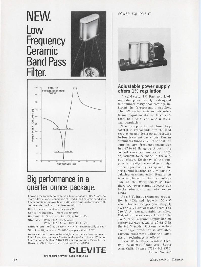
POWER EQUIPMENTNEW.Low Frequency Ceramic Band Pass Filter.
Big performance in a quarter ounce package.Looking for something better in a low frequency filter? Look no more. Clevite's new generation of fixed-tuned ceramic band pass filters combine narrow bandwidths and high performance with surprisingly small size and low weight.
Check the specs and see for yourself:Center Frequency — from 9kc to 50kcBandwidth (% fo) - @ 3db-1%; @ 20db-13%Stability — Within 0.2% fo? 5 years
Within 0.2% from —40°C to +85°CDimensions—HC-6/U case %"x%"x.34" (hermetically sealed)Shock — 20g any axis 20-2000 cps per mil std. 202B.
As we said, look no more for a high performance, low frequency filter. This new one from Clevite is the perfect choice. Write for free Technical Bulletin 94023. Clevite Corporation, Piezoelectric Division, 232 Forbes Road, Bedford, Ohio 44014.
CLEVITE
Adjustable power supply offers 1% regulation
A solid-state, 1% line- and load- regulated power supply is designed to eliminate many shortcomings inherent in ferroresonant supplies. The LX series satisfies microelectronic requirements for large currents at 4 to 5 Vdc with a ±1% load regulation.
The incorporation of closed loop control is responsible for the load regulation and for a 50 /xs response to line transient variations. Design eliminates tuned circuits so that the supplies are frequency-insensitive in a 47 to 63 Hz range. A pot in the control circuitry enables a ±3% adjustment to be made in the output voltage. Efficiency of the supplies is greatly increased as no significant pre-loading is required. Under partial loading, only minor circulating currents exist. Regulation is accomplished on the high voltage side of the transformer so that there are lower magnetic losses due to the reduction in magnetic components.
At 6.3 V, input frequency regulation is ±2% and ripple is 150 mV rms. Thirteen ranges (including 4, 4.5 and 5 V) are available from 4 to 240 V. All are adjustable to ±3%. Output amperes range from 15 to 0.5 A. The 14-pound supply has an energy storage capacity of 5.6 J in the 6.3 V model. Optional crowbar overvoltage protection is available. Custom equipment using the same design techniques is offered.
P&A: $125; stock. Wanlass Electric Co., 2189 S. Grand Ave., SantaAna, Calif. Phone: (714) 546-8990.
Circle No. 355ON READER-SERVICE CARD CIRCLE 35
98 Electronic Design
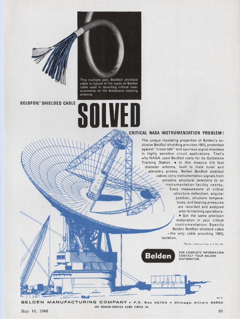
BELDFOIL*SHIELDED CABLE SOLVED
’Belden Trademark Reg. U.S. Pat. Off.
FOR COMPLETE INFORMATION CONTACT YOUR BELDEN DISTRIBUTOR.Belden
CRITICAL NASA INSTRUMENTATION PROBLEM!The unique insulating properties of Belden’s exclusive Beldfoil shielding provides 100% protection against “cross-talk" and spurious signal impulses in highly sensitive circuit applications. That’s why NASA used Beldfoil cable for its Goldstone Tracking Station. ■ In this massive 210 foot
diameter antenna, built to track lunar and planetary probes, Belden Beldfoil shielded
cables carry instrumentation signals from sensitive structural detectors to an
instrumentation facility nearby. Every measurement of critical
structure deflection, angular position, structure temperatures, and bearing pressures are recorded and analyzed prior to tracking operations. ■ Get the same precision
analyzation in your critical instrumentation. Specify
Belden Beldfoil shielded cable —the only cable providing 100%
isolation.
May 10, 1966 99
BELDEN MANUFACTURING COMPANY • P.O. Box 5O7OA • Chicago, Illinois 60680ON READER-SERVICE CARD CIRCLE 36
POWER EQUIPMENT
MAKE THE BIG DIFFERENCEBETWEEN A YOKE SPECIALISTAND A YOKE SUPPLIER
Service... Engineering...
Syntronic Yoke Specialists have more yoke knowledge and provide more engineering assistance than anyone else in the field.The most extensive line of deflection yokes available is offered by Syntronic ... in production quantities or custom designed to special requirements. See the BIG Difference for yourself the next time you specify a yoke.
Oneof our newer types. 1" Vidicon Yoke for TV cameras.
SyTltî OlllC INSTRUMENTS, INC.100 Industrial Road, Addison, Illinois Phone 312, 543-6444
Look to the Leader
PERMACOR
ON READER-SERVICE CARD CIRCLE 37
9540 Tulley Ave., Oak Lawn, III. Phone: 312-GArden 2-3353
SCR switching supplyDesigned for life testing diodes
and rectifiers, the model 652 power supply provides up to 150 A in alternate half sine-wave pulses in each of two balanced outputs followed by alternate half sine-wave pulses of peak inverse voltage. Forward current and reverse voltage are adjustable over their entire range.
Forward voltage of about 12 V peak is delivered to the load at each half of the output. Forward current outputs are balanced to 1%. Standard supplies are available with 200, 400, 600, 800 or 1000 V max peak reverse ratings. Normal reverse conduction angle exceeds 170°. Peak reverse current is 250 mA. Two front-panel mounted blowers cool the SCR heat sinks. Input is 208 or 230 Vac.
Aerotronic Assoc., Inc., Contoocook, N. H. Phone: (603) 746-3141.
Circle No. 304
For Every ElectronicPowdered
IRON CORE Need!...As the world’s largest producer of iron cores, Permacor has the capability and facilities to supply any requirement er meet any specification you may have.
Write for Complete Information
PERMACOR®A Division of Radio Cores, Inc.
High current supplyThe XR series of high current,
fast recovery power supplies is fully protected against overloads and shorts. Typically, the 24- to 32-Vdc models are available at ratings up to 100 A.
Twelve models are available with voltage range from 5 to 35 Vdc, currents up to 100 A with recovery time of 50 ps max.
Price: $525 to $1714. DeltronInc., Wissahickon Ave., NorthWales, Pa. Phone: (215) 699-9261.
Circle No. 305ON READER-SERVICE CARD CIRCLE 38
100 Electronic Design
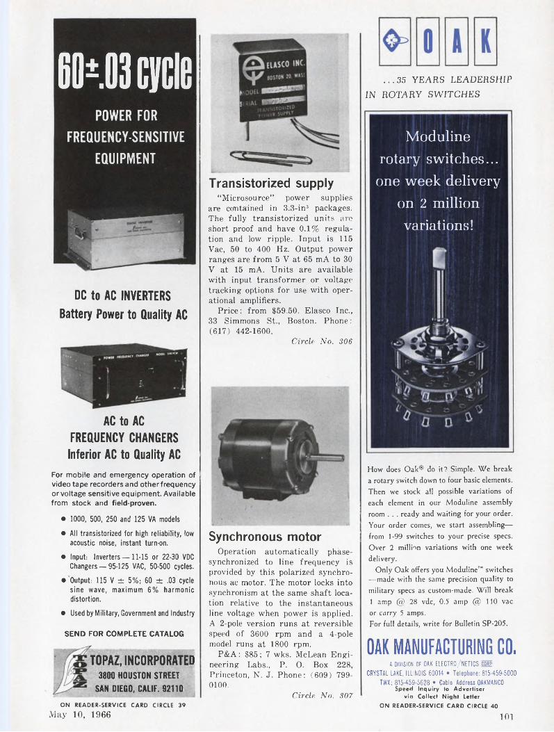
60±.os cyclePOWER FOR
FREQUENCY-SENSITIVEEQUIPMENT
DC to AC INVERTERS Battery Power to Quality AC
AC to AC FREQUENCY CHANGERS
Inferior AC to Quality ACFor mobile and emergency operation of videotape recordersand otherfrequency or voltage sensitive equipment. Available from stock and field-proven.
• 1000, 500, 250 and 125 VA models
• All transistorized for high reliability, low
acoustic noise, instant turn-on.
• Input: Inverters —11-15 or 22-30 VDC
Changers —95-125 VAC, 50-500 cycles.
• Output: 115 V ± 5%; 60 ± .03 cycle
sine wave, maximum 6% harmonic
distortion.
• Used by Military, Government and Industry
SEND FOR COMPLETE CATALOG
TOPAZ, INCORPORATED 3800 HOUSTON STREET
SAN DIEGO, CALIF. 92110
Transistorized supply“Microsource” power supplies
are contained in 3.3-in3 packages. The fully transistorized units are short proof and have 0.1% regulation and low ripple. Input is 115 Vac, 50 to 400 Hz. Output power ranges are from 5 V at 65 mA to 30 V at 15 mA. Units are available with input transformer or voltage tracking options for use with operational amplifiers.
Price: from $59.50. Elasco Inc., 33 Simmons St., Boston. Phone: (617) 442-1600.
Circle No. 306
Synchronous motorOperation automatically phase-
synchronized to line frequency is provided by this polarized synchronous ac motor. The motor locks into synchronism at the same shaft location relative to the instantaneous line voltage when power is applied. A 2-pole version runs at reversible speed of 3600 rpm and a 4-pole model runs at 1800 rpm.
P&A: $85; 7 wks. McLean Engineering Labs., P. O. Box 228, Princeton, N. J. Phone: (609) 7990100.
Circle No. 307
...35 YEARS LEADERSHIPIN ROTARY SWITCHES
Moduline rotary switches... one week delivery
on 2 million variations!
How does Oak® do it? Simple. We break a rotary switch down to four basic elements. Then we stock all possible variations of each element in our Moduline assembly room . . . ready and waiting for your order. Your order comes, we start assembling— from 1-99 switches to your precise specs. Over 2 million variations with one week delivery.
Only Oak offers you Moduline™ switches •—made with the same precision quality to military specs as custom-made. Will break 1 amp @ 28 vdc, 0.5 amp @ 110 vac or carry 5 amps.For full details, write for Bulletin SP-205.
OAK MANUFACTURING CO.A DIVISION OF OAK ELECTRO/NETICS corp
CRYSTAL LAKE, ILLINOIS 60014 • Telephone: 815-459-5000
TWX: 815-459-5628 • Cable Address OAKMANCOSpeed Inquiry to Advertiser
via Collect Night Letter
ON READER-SERVICE CARD CIRCLE 40
101ON READER-SERVICE CARD CIRCLE 39
May 10, 1966
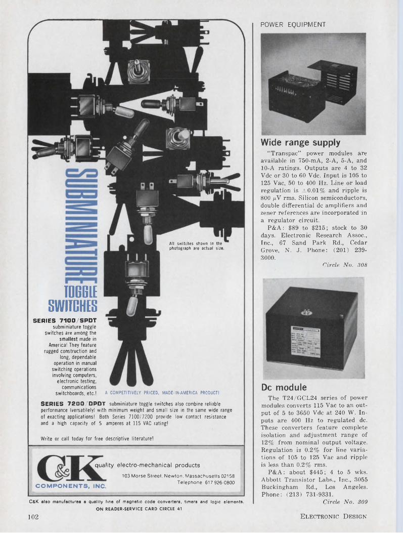
POWER EQUIPMENT
All switches shown In the photograph are actual size.
TOGGLE SWITCHES
SERIES 7200/DPDT subminiature toggle switches also combine reliable performance (versatilely) with minimum weight and small size in the same wide range of exacting applications! Both Series 7100/7200 provide low contact resistance and a high capacity of 5 amperes at 115 VAC rating!
Write or call today for free descriptive literature!
SERIES 7100/SPDTsubminiature toggle
switches are among the smallest made in
America! They feature rugged construction and
long, dependable operation in manual
switching operations involving computers,
electronic testing, communications
switchboards, etc.! A COMPETITIVELY PRICED, MADE-IN-AMERICA PRODUCT!
quality electro-mechanical products
COMPONENTS, INC.
103 Morse Street. Newton. Massachusetts 02158 Telephone: 617 926-0800
C&K also manufactures a quality line of magnetic code converters, timers and logic elements.ON READER-SERVICE CARD CIRCLE 41
Wide range supply“Transpac” power modules are
available in 750-mA, 2-A, 5-A, and 10-A ratings. Outputs are 4 to 32 Vdc or 30 to 60 Vdc. Input is 105 to 125 Vac, 50 to 400 Hz. Line or load regulation is ±0.01% and ripple is 800 pV rms. Silicon semiconductors, double differential de amplifiers and zener references are incorporated in a regulator circuit.
P&A: $89 to $215; stock to 30 days. Electronic Research Assoc., Inc., 67 Sand Park Rd., Cedar Grove, N. J. Phone: (201) 2393000.
Circle No. 308
De moduleThe T24/GCL24 series of power
modules converts 115 Vac to an output of 5 to 3650 Vdc at 240 W. Inputs are 400 Hz to regulated de. These converters feature complete isolation and adjustment range of 12% from nominal output voltage. Regulation is 0.2% for line variations of 105 to 125 Vac and ripple is less than 0.2% rms.
P&A: about $445; 4 to 5 wks. Abbott Transistor Labs., Inc., 3055 Buckingham Rd., Los Angeles. Phone: (213) 731-9331.
Circle No. 309
102 Electronic Design
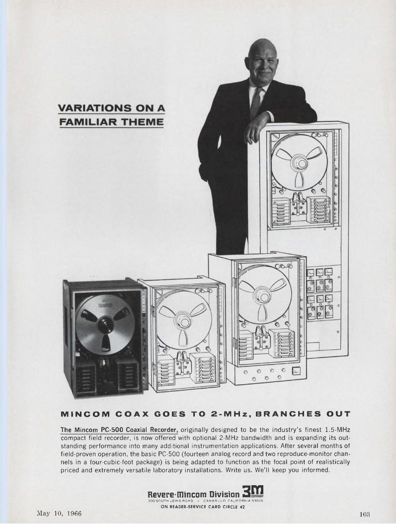
MINCOM COAX GOES TO 2-MHz, BRANCHES OUT
The Mincom PC-500 Coaxial Recorder, originally designed to be the industry's finest 1.5-MHz compact field recorder, is now offered with optional 2-MHz bandwidth and is expanding its outstanding performance into many additional instrumentation applications. After several months of field-proven operation, the basic PC-500 (fourteen analog record and two reproduce-monitor channels in a four-cubic-foot package) is being adapted to function as the focal point of realistically priced and extremely versatile laboratory installations. Write us. We’ll keep you informed.
Revere-mincom Division 3m300 SOUTH LEWIS ROAD • CAMARILLO. CALIFORNIA 93010
ON READER-SERVICE CARD CIRCLE 42
May 10, 1966 103
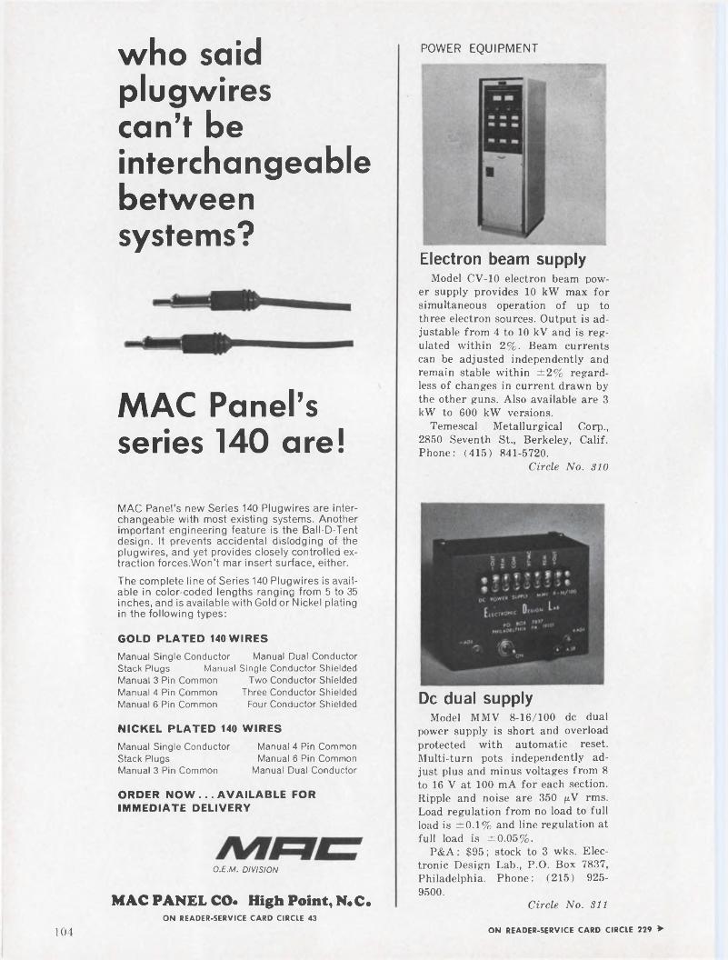
POWER EQUIPMENTwho said plugwires can’t be interchangeable between systems?
MAC Panel’s series 140 are!
Electron beam supplyModel CV-10 electron beam pow
er supply provides 10 kW max for simultaneous operation of up to three electron sources. Output is adjustable from 4 to 10 kV and is regulated within 2%. Beam currents can be adjusted independently and remain stable within ±2% regardless of changes in current drawn by the other guns. Also available are 3 kW to 600 kW versions.
Temescal Metallurgical Corp., 2850 Seventh St., Berkeley, Calif. Phone: (415) 841-5720.
Circle No. 310
MAC Panel's new Series 140 Plugwires are interchangeable with most existing systems. Another important engineering feature is the Ball-D-Tent design. It prevents accidental dislodging of the plugwires, and yet provides closely controlled extraction forces.Won't mar insert surface, either.The complete line of Series 140 Plugwires is available in color-coded lengths ranging from 5 to 35 inches, and is available with Gold or Nickel plating in the following types:
GOLD PLATED 140 WIRES
Manual Single Conductor Manual Dual ConductorStack Plugs ManualManual 3 Pin CommonManual 4 Pin CommonManual 6 Pin Common
NICKEL PLATED 140
Manual Single ConductorStack PlugsManual 3 Pin Common
Single Conductor ShieldedTwo Conductor Shielded
Three Conductor ShieldedFour Conductor Shielded
WIRES
Manual 4 Pin CommonManual 6 Pin Common
Manual Dual Conductor
ORDER NOW ... AVAILABLE FOR IMMEDIATE DELIVERY
O.E.M. DIVISION
MAC PANEL CO. High Point, N.C.ON READER-SERVICE CARD CIRCLE 43
De dual supplyModel MMV 8-16/100 de dual
power supply is short and overload protected with automatic reset. Multi-turn pots independently adjust plus and minus voltages from 8 to 16 V at 100 mA for each section. Ripple and noise are 350 pN rms. Load regulation from no load to full load is ±0.1% and line regulation at full load is ±0.05%.
P&A: $95; stock to 3 wks. Electronic Design Lab., P.O. Box 7837, Philadelphia. Phone: (215) 925- 9500.
Circle No. 311
104 ON READER-SERVICE CARD CIRCLE 229 ►
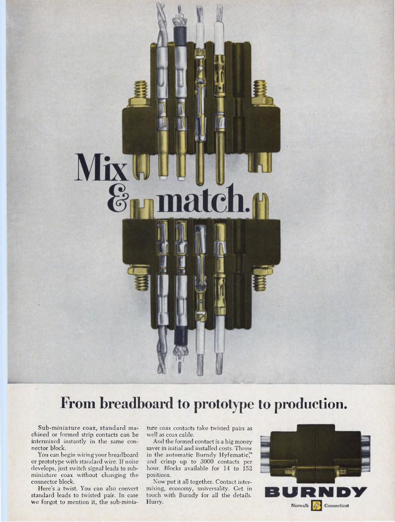
From breadboard to prototype to production.Sub-miniature coax, standard ma
chined or formed strip contacts can be intermixed instantly in the same connector block.
You can begin wiring your breadboard or prototype with standard wire. If noise develops, just switch signal leads to subminiature coax without changing the connector block.
Here’s a twist. You can also convert standard leads to twisted pair. In case we forgot to mention it, the sub-minia
ture coax contacts take twisted pairs as well as coax cable.
And the formed contact is a big money saver in initial and installed costs. Throw in the automatic Burndy Hyfematic7 and crimp up to 3000 contacts per hour. Blocks available for 14 to 152 positions.
Now put it all together. Contact intermixing, economy, universality. Get in touch with Burndy for all the details. Hurry.
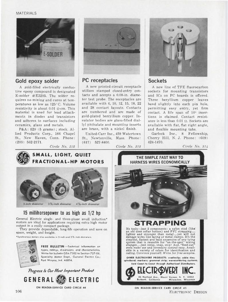
MATERIALS
Gold epoxy solderA gold-filled electrically conduc
tive epoxy compound is designated E-solder #E3205. The solder requires no mixing and cures at temperatures as low as 125°C. Volume resistivity is about 0.01 Q-cm. This material is used for lead attachments in diodes and transistors and adheres to surfaces including ceramics, glass and metals.
P&A: $20 (5 grams) ; stock. Allied Products Corp., 166 Chapel St., New Haven, Conn. Phone: (203) 562-2171.
Circle No. 312
PC receptaclesA new printed-circuit receptacle
utilizes stamped closed-entry contacts and accepts a 0.08-in. diameter test probe. The receptacles are available with 6, 10, 12, 15, 18, 22 and 28 contact layouts. Contacts are numbered and are made of gold-plated berryilium copper. Insulator bodies are glass-filled diallyl phthalate and mounting inserts are brass, with a nickel finish.
United-Carr Inc., 459 Watertown St., Newtonville, Mass. Phone: (617) 527-8400.
Circle No. 313
SocketsA new line of TFE fluorocarbon
sockets for mounting transistors and ICs on PC boards is offered. Three beryllium copper leaves bend slightly into each pin hole, permitting easy entry, yet firm contact. A life span of 105 insertions is claimed. Contact resistance is less than 0.01 Q. Sockets are available with flat, flat right angle, and flexible mounting tabs.
Garlock Inc., 8 Fellowship, Cherry Hill, N. J. Phone: (609) 424-1470.
Circle No. 314
SMALL, LIGHT, QUIET FRACTIONAL-HP MOTORS
THE SIMPLE FAST WAY TO HARNESS WIRES ECONOMICALLY
15 millihorsepower to as high as 1/2 hp FGeneral Electric single- and three-phase small induction* motors are ideal for applications requiring extra-high motor output in a really compact package.
They provide dependable, long-life operation and save on space, weight, and freight.♦Synchronous motors also available in 3-inch and 3% -inch diameters.
FREE BULLETIN—Technical information on types, ratings, dimensions, and characteristics. Write for bulletin GEA-7300 to Section 727-06; Specialty Motor Dept., General Electric Co.; Fort Wayne, Ind. 46804.
Progress fs Our Most- Important- Product
STRAPPINGNo tools—just 2 components: a nylon stud (like' an old time collar button) and PVC strapping... lighter and stronger than metal...yet will not damage wires like lacing or metal clamps. It’s the simplest, fastest and least expensive of any tying system that is reusable for “on-the-spot” wiring changes...just strap, snap, snip! And, “feed-out” reels make use and inventory control easy. Available in a variety of colors for identification and coding. Convince yourself. Write for free samples.OTHER ELECTROVERT PRODUCTS: cradledip; cable ties;
spiroband; markers; grommet strip; wavesoldering systems.Sold Coast-to-Coast through Authorised Distributors.
& ELECIP^VEPT INC.86 Hartford Ave., Mount Vernon, N. Y. 10553
^F Burbank, California Milwaukee, WisconsinGENERAL^ ELECTRICON READER-SERVICE CARD CIRCLE 44
106ON READER-SERVICE CARD CIRCLE 45
Electronic Design
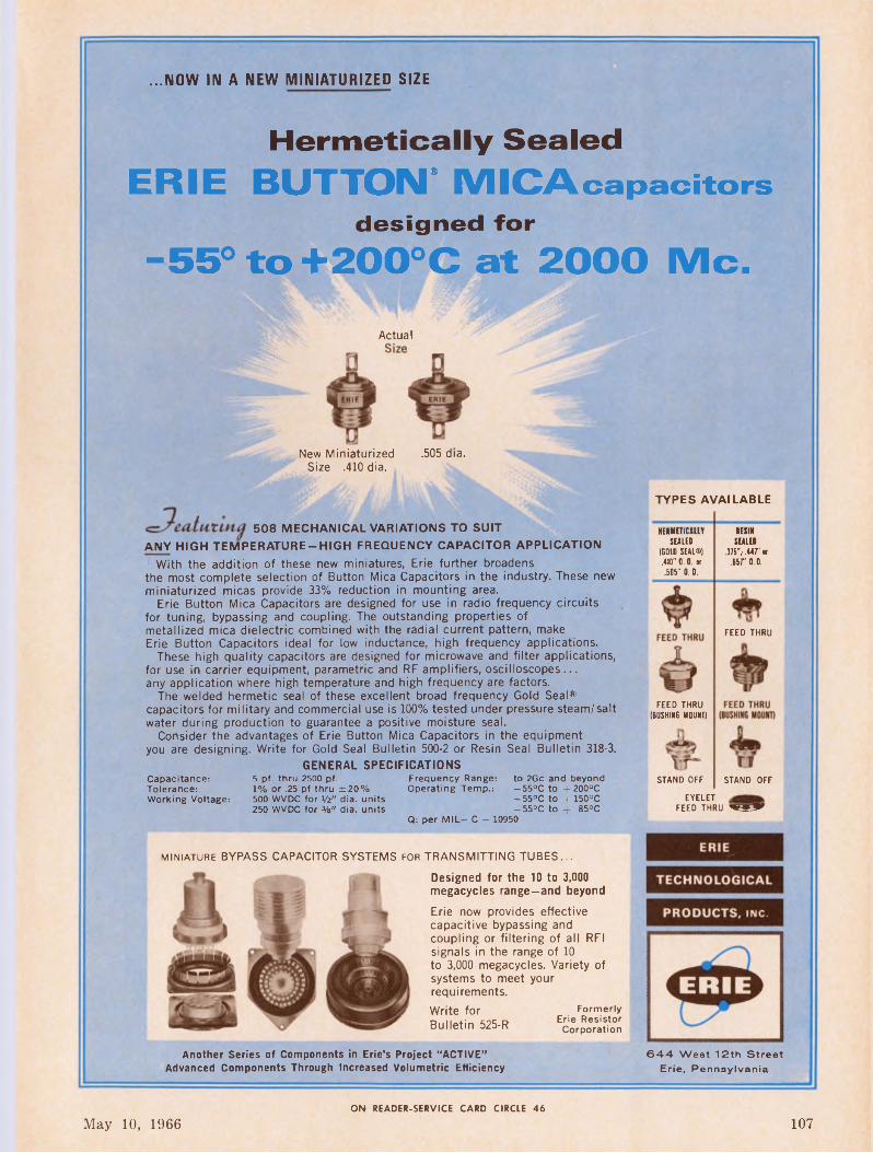
...NOW IN A NEW MINIATURIZED SIZE
Hermetically SealedERIE BUTTON* MICAcapacitors
designed for
-55° to +200°C at 2000 Me.
Actual
New Miniaturized .505 dia.Size .410 dia.
TYPES AVAILABLE
508 MECHANICAL VARIATIONS TO SUITANY HIGH TEMPERATURE-HIGH FREQUENCY CAPACITOR APPLICATION
With the addition of these new miniatures, Erie further broadens the most complete selection of Button Mica Capacitors in the industry. These new miniaturized micas provide 33% reduction in mounting area.
Erie Button Mica Capacitors are designed for use in radio frequency circuits for tuning, bypassing and coupling. The outstanding properties of metallized mica dielectric combined with the radial current pattern, make Erie Button Capacitors ideal for low inductance, high frequency applications.
These high quality capacitors are designed for microwave and filter applications, for use in carrier equipment, parametric and RF amplifiers, oscilloscopes... any application where high temperature and high frequency are factors.
The welded hermetic seal of these excellent broad frequency Gold Seal® capacitors for military and commercial use is 100% tested under pressure steam/salt water during production to guarantee a positive moisture seal.
Consider the advantages of Erie Button Mica Capacitors in the equipment you are designing. Write for Gold Seal Bulletin 500-2 or Resin Seal Bulletin 318-3.
GENERAL SPECIFICATIONS
HERMETICALLY SEALED
(GOLD SEAL®) .410" 0.0. « .505" 0. D.
FEED THRU (BUSHING MOUNT)
STAND OFFCapacitance: Tolerance: Working Voltage:
5 pf. thru 2500 pf.1% or .25 pf thru ±20%500 WVDC for Va" dia. units250 WVDC for %" dia. units
Frequency Range: to 2Gc and beyond Operating Temp.: — 55°C to + 200°C
—55°C to +150°C—55°C to + 85°C
Q: per MIL- C - 10950
MINIATURE BYPASS CAPACITOR SYSTEMS FOR TRANSMITTING TUBES...
Designed for the 10 to 3,000 megacycles range-and beyond
Erie now provides effective capacitive bypassing and coupling or filtering of all RFI signals in the range of 10 to 3,000 megacycles. Variety of systems to meet your requirements.Write for Bulletin 525-R
FormerlyErie Resistor Corporation
Another Series of Components in Erie's Project “ACTIVE” Advanced Components Through Increased Volumetric Efficiency
RESIN SEALED
.STS"? .44T« .657" O.D.
FEED THRU
STAND OFF
EYELETFEED THRU WæW
644 West 12th Street Erie, Pennsylvania
ON READER-SERVICE CARD CIRCLE 46
May 10, 1966 107
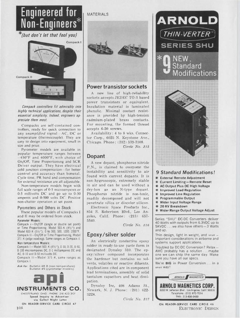
MATERIALSEngineered for Non-Engineers*
*1*
(but don't let that fool you)
Compack controllers fit admirably into highly techoical applications, despite their essentia! simplicity. Indeed, engineers appreciate them most.
Compacks are self-contained controllers, ready for quick connection to any unamplified signal—AC, DC or temperature (thermocouple). They are easy to design into equipment, small in size and price.
Pyrometer models are available in popular temperature ranges between —450°F and 4000°F, with choice of On/Off, Time Proportioning and SCR Driver output. They have electrical cold junction compensation—for better control and accuracy than bimetal. Cycle time, PR band and compensation for external resistance are all adjustable.
Non-temperature models begin with full scale ranges of 0-5 microamperes or 0-5 millivolts DC and go up to 0-50 amperes and 0-500 volts DC. Positive non-chatter operation at set point.
Pyrometers and Others in StockThese popular models of Compacks I
and II may be ordered from stock.Pyrometer Models:Compack I—On/Off (single or double set point) or Time Proportioning, Model 503-K (4'/2") and Model 603-K (5/2"): 0 to 300 , 500, 1000, 2000°F.Compack 11 —On/Off or Time Proportioning, Model 371-K (edge-reading). Same ranges as Compack I.
Non-temperature Models:Compack l-Model 503-K (4'/2"), 0-10, 0-20, 0-50, 0-100 microamperes DC, 0-1 milliamperes DC and AC, 0-10 and 0-50 millivolts DC.Compack II —Model 371-K, same ranges as Compack I.
Ask for: Bulletin 48-B (non-temperature)Bulletin 49 (pyrometer models)
aptINSTRUMENTS CO.
CHESTERLAND OHIO ■ PHONE 216-423-3131Speed Inquiry to Advertiser
via Collect Night Letter
ON READER-SERVICE CARD CIRCLE 47
Power transistor socketsA new line of high-reliability
sockets accepts JEDEC TO-3 based power transistors or equivalent. Insulation material is laminated phenolic. Minimal contact resistance is provided by high-tension cadmium-plated brass contacts. For mounting, the formed thread accepts 6-20 screws.
Availability: 4 to 8 wks. Connector Corp., 6025 N. Keystone Ave., Chicago. Phone: (312) 539-3108.
Circle No. 315
DopantA new dopant, phosphorus nitride
P3N5, is claimed to overcome the instability and sensitivity to air found with current dopants. It is non-hygroscopic, extremely stable in air and can be used without a dry-box as an N-type dopant. Phosphorus nitride is non-toxic, readily decomposed and will not penetrate silica or discolor silicon.
Electronic Space Products Inc., 854 S. Robertson Blvd., Los Angeles, Calif. Phone: (213) 6575540.
Circle No. 316
Epoxy/silver solderAn electrically conductive epoxy
solder in ready-to-use paste form is designated Dynaloy 310. The ep- oxy/silver compound incorporates the hardener but contains no solvents, volatiles or reactive diluents. Applications cited are in component lead terminations, assembly of solid tantalum capacitors and heat dissipation.
Dynaloy Inc, 408 Adams St., Newark, N. J. Phone: (201) 6223228.
Circle No. 317
ARNOLDTHIN-VERTERJ
SERIES SHU
NEW.M Standard v Modifications
9 Standard Modifications!* External Remote Adjustment* Current Limiting—Remote Reset* AC Output Plus DC High Voltage46 Improved Load Regulation* Improved Line Regulation* Programmable Output* Wider Input Voltage Range* 20 KV Breakdown* Wider Range Output Voltage Adjust
Series “SHU” DC-DC Converters deliver 40 Watts with outputs from 6.3VDC up to 5KVDC ... we also have others —3 Watts and up.Thin design, light in weight, and small - important considerations in airborne and systems support applications.Troubled by DC-DC Conversion? Relax— AMC probably has a solution ... maybe one we can ship the same day. Make sure you have all our specs.We're BIG in Power Conversion ... in a smaii way!
ARNOLD MAGNETICS CORP.6050 W. Jefferson Blvd., Los Angeles, Calif. 90016
Telephone: (213) 870-7014TWX: 213-836-0430
ON READER-SERVICE CARD CIRCLE 48
108 Electronic Design
What is really important when evaluating crystal frequency standards?
How much can you find out from aging-rate data?
Two reports will be of special help if you want to know the fine points in evaluating a crystal frequency standard.
One is "Selection of a Frequency Standard”, Application Report 1266.
The other is a National Bureau of Standards report on a specific oscillator of this type.
Both are yours via the reader-service card in this magazine — or for faster response write directly to:
TRACOR, Inc.General Sales Offices 6500 Tracor Lane Austin, Texas 78721
Phone: 512-926-2800
SULZER DIVISION
REPRESENTATIVES IN PRINCIPAL CITIES
Resistance alloyA 55% Cu/45% Ni alloy for re
sistor applications has a temperature coefficient controllable between —24 and —75 ppm/°C over a range of —18 to +100°C with a tolerance of ±i2.5 ppm/°C. Nominal resistivity of 53 /xQ-cm varies depending on the temperature coefficient.
Resistvar I is available in foil form in thickness from 0.0001-in., and widths from 0.03- to 4-in. Standard thickness tolerance from 0.0001 to 0.001 in. is +5%. Tensile strength is 70,000 to 90,000 psi and thermal emf against copper is 42 MV/°C.
Hamilton Watch Company, Lancaster, Pa. Phone: (717) 394-7161.
Circle No. 318
Silicone insulationDeterioration, hardening, and
cracking of materials such as polyethylene, PVC and TVE are not considerations with this S-2254 silicone rubber. This flame-retardant insulation for high voltage wires remains pliable and useful after extended exposure to 500° F and withstands corona. The heat stability of the unit permits assembly prior to any baking or dipping operations.
Dow Corning Corp., U. S. H'way. 10, Midland, Mich. Phone: (517) 636-8507.
Circle No. 319
Dross eliminator“Electro-Nox” is an anti-oxidant
solder pot cover for electronic soldering. Formulated for use on PC wave-soldering machines and other solder pots at approximately 500 to 600°F, the material eliminates oxidized dross on solder pots.
Instead of inhibiting oxidation by acting as a solder/air barrier it dissipates dross by chemical action. Removal is not necessary, as it is a non-corrosive, non-oily, non-greasy and non-waxy dry material which melts on the pot and contains no salts or acids.
Urban Chemical Co., 3005 W. Franklin Blvd., Chicago, Ill. Phone: (312) 722-3060.
Circle No. 320
AMCO gives you "instant delivery” of instrument enclosures... from your own stockroom!
Why wait for the enclosures you need for test equipment, prototypes or even production orders?
That’s the real advantage of the versatile new Amco lightweight aluminum system. With a minimum supply of Amco %-inch extrusions and corner castings maintained on an inplant basis, you can put together enclosure frames for almost any purpose in a matter of minutes—and— at minimum cost.
Assembly is simplicity itself. And the variety of integral tubing flanges permits complete freedom for panel and equipment mounting.
Complete details on request.
IN STEP WITH THE FUTURE . . .
7333 W. Ainslie StreetChicago, Illinois 60656ON READER-SERVICE CARD CIRCLE 49
ON READER-SERVICE CARD CIRCLE 230 ►
MICROWAVES
... All you want is my PROBLEM?
Right. . . just the problem! We’re loaded with solutions to high temperature wiring problems. Quite likely one of them matches your problem exactly. So save yourself the trouble we've already had ... put your wiring problem up to us the minute you spot it! If we don’t have the right answer on tap, we’ll find one. You can take our word for it . . . because we’ve been insulation specialists for 44 years.
HIGH TEMPERATURE WIRE AND CABLE
A wide variety of standard leadwire constructions, insulated with Teflon (TFE and FEP) or silicone rubber, are available for applications up to 1000 V. and 200°C. FLEXLEAD can also be supplied in many special wire and cable constructions to meet your specific requirements. These may combine insulations (Teflon, silicone rubber, fiberglass, nylon- shielding, fillers, liners, and jacket materials), and provide single, twisted pair or multiple conductors . . . for any temperature from —90°C to 260°C. The line also includes both standard and special RG/U coaxial cables, fused twisted pair, and MB bondable Teflon wire. Ask for a FLEXLEAD Selector. Write. ..
L.FRANKNorristown, Pa.
& SONS215-272-8960
Power monitorThree or more RF mounts
covering 7 to 12.4 GHz can be used with the model 30-540-3 microwave power meter for systems power monitoring. Any or all of the three sources could be located up to 1,000 ft from the meter. The 30 mW full scale reading has an accuracy greater than 5%. Vswr is less than 1.5 and the output varies less than 5% over a 0 to 85°C ambient range.
A spring-loaded screwdriver-adjusted switch, the “operational check,” indicates system performance without the use of waveguide switches or recalibration. Calibration power at 50 to 1000 Hz line frequency is less than 100 mW.
P&A: $245; 30 days. MSI Electronics Inc., 116-06 Myrtle Ave., Richmond Hill, N. Y. Phone: (212) 441-4620.
Circle No. 321
Reflectometer bridgeThe model 3073 reflectometer
bridge covers 7 to 12.4 GHz and is designed to effectively balance out reflections of the reference measurement channels. Directivity of the bridge is greater than 30 dB.
Input power is fed into a hybrid junction and splits into two signal paths equal in amplitude but 90° out of phase. The signals are then fed into a matched pair of coax directional couplers which are connected in a reverse position. Equal sample signals then appear at the inputs of a second hybrid junction. At the detected output these signals are 180° out-of-phase and cancel. The in-phase components appear at the second output and are terminated.
P&A: $12,000; 8 to 12 wks. Narda Microwave Corp., Plainview,N. Y. Phone: (516) 433-9000.
Circle No. 322INSULATING TUBINGS & SLEEVINGS . HIGH TEMPERATURE WIRE & CABLE
ON READER-SERVICE CARD CIRCLE 50
110 Electronic Design
Mounting, connecting and
maintenance are easier
Terminals Through-Chassis Terminals Above Chassis Octal Style Plug Socket for Std. Terminals
with OHMITE GPR relays...
Exclusive Enclosed 4-Pole Unenclosed 4-Pole Exclusive Enclosed Latching Unenclosed Latching
5&l0-amp contacts... catalog 700RHEOSTATS • POWER RESISTORS • PRECISION RESISTORS • VARIABLE TRANSFORMERS • RELAYS TAP SWITCHES • TANTALUM CAPACITORS • SEMICONDUCTOR DEVICES • R.F. CHOKES
MANUFACTURING COMPANY3643 Howard Street • Skokie, Illinois 60076 Phone: (312) ORchard 5-2600OHMITE
ON READER-SERVICE CARD CIRCLE 51
May 10, 1966 111
MICROWAVESBRAA/SO/V
DPDT 1/6 SIZE
RELAYj
Meets Requirements of MIL-R-5757/19
NEW FROM BRANSONThis small 1/6 crystal can size DPDT relay, Type JR, handles low level up to 1 full ampere . . . withstands high shock and vibration . . . meets MIL-R-5757/19. Coil and header styles available to meet all applications!
OTHER BRANSON PRODUCTS
TIME DELAY RELAYS
SOLID STATE TIME DELAY RELAY
6 POLE CRYSTAL CAN RELAY
4PDT HALF CRYSTAL CAN RELAYS
VANDERHOOF AVENUE DENVILLE, NEW JERSEY
(201) 625-0600
TWTThe TWC14 is a pulse-position
modulation focused TWT operating at 10 W over 5.8 to 8.2 GHz. The tube operates in a periodic permanent magnet mount which incorporates RF input, output waveguide connections and convection cooler. It is secured within the mount with a fitting which provides for plug-in replaceability. A 10,000-hour guarantee is offered.
M-0 Valve Co. Ltd., Brook Green Works, London, England. Phone: RIVerside 3431.
Circle No. 323
SwitchesStripline-insert switches which
eliminate the need for connectors are offered in X, L, S, C and Ku band models. Typical for an X- band spst are an insertion loss of 1.3 dB max, an isolation greater than 30 dB, a switching speed less than 50 ns and vswr less than 1.1. Isolation on the order of 60 dB can be obtained with higher insertion loss.
Micro State, 152 Floral Ave., Murray Hill, N. J. Phone: (201) 464-3000.
Circle No. 324
Why the Treasury has 2 prices for
$500 Savings BondsIt’s really for your convenience.
One of the $500 Bonds shown above is a Series E Bond. The growing type. You pay $375 for it and collect your interest when you cash it in for $500 at maturity. It’s designed for people who want their savings to accumulate.
The other $500 Bond is a Series H. It costs $500 to begin with, and you collect your interest by check twice a year. It’s designed for people who want their Bonds to give them an income. Retired people, for instance.
Both bonds do the same job of helping your country, too, by building the financial strength Uncle Sam needs to manage his affairs and safeguard our rights.
Whichever suits your needs better—Series E or Series H— buy some Bonds soon. They’re good for your future.
Help yourself as you help your country
BUY U.S. SAVINGS BONDS
©This advertising is donated by The Advertising Council
and this magazine.
ON READER-SERVICE CARD CIRCLE 52
112 Electronic Design
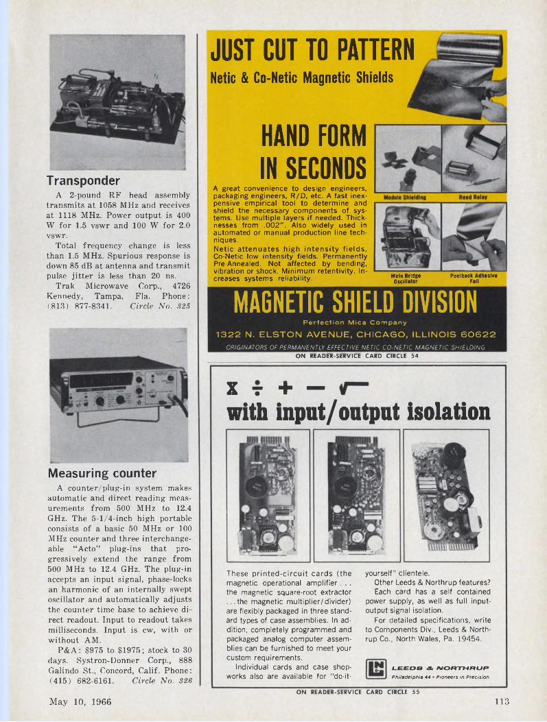
TransponderA 2-pound RF head assembly
transmits at 1058 MHz and receives at 1118 MHz. Power output is 400 W for 1.5 vswr and 100 W for 2.0 vswr.
Total frequency change is less than 1.5 MHz. Spurious response is down 85 dB at antenna and transmit pulse jitter is less than 20 ns.
Trak Microwave Corp., 4726 Kennedy, Tampa, Fla. Phone : (813) 877-8341. Circle No. 325
Measuring counterA counter/plug-in system makes
automatic and direct reading measurements from 500 MHz to 12.4 GHz. The 5-1/4-inch high portable consists of a basic 50 MHz or 100 MHz counter and three interchangeable “Acto” plug-ins that progressively extend the range from 500 MHz to 12.4 GHz. The plug-in accepts an input signal, phase-locks an harmonic of an internally swept oscillator and automatically adjusts the counter time base to achieve direct readout. Input to readout takes milliseconds. Input is cw, with or without AM.
P&A: $975 to $1975; stock to 30 days. Systron-Donner Corp., 888 Galindo St., Concord, Calif. Phone: (415) 682-6161. Circle No. 326
JUST CUT TO PATTERNNetic & Co-Netic Magnetic Shields
HAND FORMIN SECONDS
A great convenience to design engineers, packaging engineers, R/D, etc. A fast inexpensive empirical tool to determine and shield the necessary components of systems. Use multiple layers if needed. Thicknesses from .002". Also widely used in automated or manual production line techniques.Netic attenuates high intensity fields, Co-Netic low intensity fields. Permanently Pre-Annealed. Not affected by bending, vibration or shock. Minimum retentivity. Increases systems reliability.
MAGNETIC SHIELD DIVISIONPerfection Mica Company
1322 N. ELSTON AVENUE, CHICAGO, ILLINOIS 60622ORIGINATORS OF PERMANENTLY EFFECTIVE NETIC CO-NETIC MAGNETIC SHIELDING
ON READER-SERVICE CARD CIRCLE 54
X T + —with input/output isolation
These printed-circuit cards (the magnetic operational amplifier. . . the magnetic square-root extractor ...the magnetic multiplier/divider) are flexibly packaged in three standard types of case assemblies. In addition, completely programmed and packaged analog computer assemblies can be furnished to meet your custom requirements.
Individual cards and case shopworks also are available for "do-it-
Wein Bridge Peelback AdhesiveOscillator Foil
yourself" clientele.Other Leeds & Northrup features?Each card has a self contained
power supply, as well as full inputoutput signal isolation.
For detailed specifications, write to Components Div., Leeds & Northrup Co., North Wales, Pa. 19454.
LEEDS dk IVORTHRUPPhiladelphia 44 • Pioneers in Precision
ON READER-SERVICE CARD CIRCLE 55
May 10, 1966 113
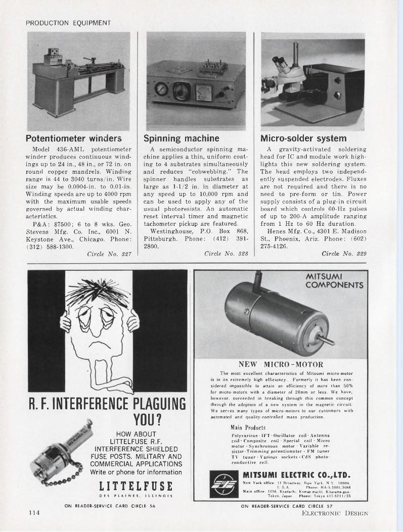
PRODUCTION EQUIPMENT
Potentiometer windersModel 436-AML potentiometer
winder produces continuous windings up to 24 in., 48 in., or 72 in. on round copper mandrels. Winding range is 44 to 3040 turns/in. Wire size may be 0.0004-in. to 0.01-in. Winding speeds are up to 4000 rpm with the maximum usable speeds governed by actual winding characteristics.
P&A: $7500; 6 to 8 wks. Geo. Stevens Mfg. Co. Inc., 6001 N. Keystone Ave., Chicago. Phone: (312) 588-1300.
Circle No. 327
Spinning machineA semiconductor spinning ma
chine applies a thin, uniform coating to 4 substrates simultaneously and reduces “cobwebbing.” The spinner handles substrates as large as 1-1/2 in. in diameter at any speed up to 10,000 rpm and can be used to apply any of the usual photoresists. An automatic reset interval timer and magnetic tachometer pickup are featured.
Westinghouse, P.O. Box 868, Pittsburgh. Phone: (412) 3912800.
Circle No. 328
Micro-solder systemA gravity-activated soldering
head for IC and module work highlights this new soldering system. The head employs two independently suspended electrodes. Fluxes are not required and there is no need to pre-form or tin. Power supply consists of a plug-in circuit board which controls 60-Hz pulses of up to 200-A amplitude ranging from 1 Hz to 60 Hz duration.
Henes Mfg. Co., 4301 E. Madison St., Phoenix, Ariz. Phone: (602) 275-4126.
Circle No. 329
NEW MICRO-MOTORThe most excellent characteristics of Mitsumi micro-motor
is in its extremely high efficiency. Formerly it has been considered impossible to attain an efficiency of more than 50% for micro-motors with a diameter of 20mm or less. We have, however, succeeded in breaking through this common concept through the adoption of a new system in the magnetic circuit. We serves many types of micro-motors to our customers with automated and quality-controlled mass production.
R. F. INTERFERENCE PLAGUINGYOU?
HOW ABOUT LITTELFUSE R.F.
INTERFERENCE SHIELDED FUSE POSTS. MILITARY AND COMMERCIAL APPLICATIONS Write or phone for information
Main ProductsPolyvaricon • IFT • Oscillator coil • Antenna coil • Composite coil • Special coil • Micro motor - Synchronous motor • Variable resistor-Trimming potentiometer • FM tuner TV tuner • Various sockets-CdS photoconductive cell.
LITTELFUSEDES PLAINES, ILLINOIS
MITSUMI ELECTRIC CO.,LTD.New York office: 11 Broadway, New York. N.Y. 10004,
U.S.A. Phone: HA-5-3085.3086Main office: 1056, Koadachi, Komae-machi, Kitatama-gun,
Tokyo, Japan. Phone: Tokyo 41 5-6211/23
ON READER-SERVICE CARD CIRCLE 56 ON READER-SERVICE CARD CIRCLE 57
114 Electronic Design
A new miniature sensitive relay from RBM CONTROLS IT WILL BE COPIED BUT NEVER EQUALED
Reason—RBM CONTROLS has more production ENGINEERING SPECIFICATIONS
and quality control experience and has built more sensitive miniature relays than any other manufacturer in the industry.
The new miniature Type 64 is an isolated contact relay for maximum sensitive applications where reliability, rugged construction and low cost are of major importance. This low level circuit switching relay is designed for compact areas and may be stack assembled in close proximity to each other. A protective nylon cover eliminates physical contaminance or mishandling. A variety of mounting brackets are available making this relay the most versatile in the industry.
Serving Major Markets Since 1921RBM
CONTROLS
RBM CONTROLS□¡vision Essex Wire Corporation Logansport, Indiana
CONTACTSRatings: 28V DC or 115 V AC 1 Amp (Non-inductive)Form: SPNO, SPNC, SPDTType: Cross-Bar
COIL RATINGSMaximum—1 WattMinimum—.050 WattResistance—10,000 Ohms Max.
TERMINALSContact: To Mount To Printed Circuit Board
APPROXIMATE DIMENSIONS (Overall Including Brackets and Mountings)
Printed Circuit L 1-3/16" xW 3/4" x H 1-3/8"Bottom L 1-3/16" x W 3/4" x H 1-9/16"Top L 1-11/16" X W 3/4" x H 1-15/32"Parallelogram L 1-3/16" x W 1-7/16" x H 1-15/32"
MOUNTINGSPrinted Circuit BoardBottomTop—Parallelogram ReplacementTop Mounting Also Available
RBMSTANDARD CONTROLS
ARE AVAILABLE FROM YOUR ELECTRONIC PARTS DISTRIBUTORS
Speed Inquiry to Advertiser via Collect Night LetterON READER-SERVICE CARD CIRCLE 58
May 10, 1966 115
PRODUCTION EQUIPMENT Here is aDUAL OUTPUT
RMSUPPLIES
Dual output power supplies are housed in one case 3-5/16" x 4-5/32" x 4-11/16" high. Identical or different output voltages from 1.5 to 75 are available in 1 volt increments for each of the DC outputs. The graph below furnishes maximum current corresponding to output voltage. Select the two outputs needed and telephone Acopian for all the details — plus guaranteed 3-day shipment after receipt of your order.
75
60
a 5012£ 40 ä5 30 S1 20
10
—
1—
—100 200 300 400 500
OUTPUT CURRENT (MA.)
TYPICAL SPECIFICATIONS Input Voltage: 105 to 125 VAC Line Regulation: ±0.5 to ±0.05%
(depending on model)Load Regulation: ±1.0 to ±0.05%
(depending on model)Ripple: 5 to 1 mv (depending on model)No additional external heat sinking required.Write for Acopian’s 16-page catalog and price list to: Acopian Corp., Easton, Penna., or call collect (215) 258-5441.
ON READER-SERVICE CARD CIRCLE 59
Ultrasonic solderingA series of soldering pots uses
ultrasonically agitated solder and eliminates flux. The pots typically draw 100 W with a peak output of 200 W at 18.5 kHz. Power can be controlled from 0 to 100% and is applied through a solid nickel magnetostrictive transducer brazed to the bottom of the pot. Temperatures can be maintained to 700 °E with bimetallic or variac control.
Blackstone Ultrasonics Inc., 103 Horton Ave., Sheffield, Pa. Phone: (814) 968-3222. Circle No. 330
Resistor firing furnaceThe “IQ” series of resistor firing
furnaces is designed for volume production of thick film resistors and conductors. On a “continuous load” basis, firing capacity is 3000 1/4-in.2 pieces/hour. A combination hearth and thermocouple system detects an alumina substrate 1/2 x 1/2 x 1/32-in. on the belt and produces equal results for any load between one substrate and full belt loading. Temperature uniformity is ±1°C across an 8-in. belt. Furnaces are available with 4, 5 or 8 zones operating from 200 to 1100°C. A radiant dryer is available as an option.
BTU Engineering Corp., Bear Hill, Waltham, Mass. Phone: (617) 894-6050.
Circle No. 331
general purpose
Designed to provide telephone type reliability at clapper type relay prices.the 88 is built better—
1. Hinge-pin armature bearings with oversize bearing surfaces—the construction used in fine telephone type relays.
2. Glass insulation for great dielectric strength unaffected by humidity.
3. Nylon bobbins with rugged coil terminal inserts eliminate shorts.
4. Built-in contact wipe to maintain low contact resistance through long life.
5. Heavy duty 10-ampere contacts.Both types illustrated above are stocked for immediate delivery with SPDT, DPDT and 3PDT 10-ampere contacts for popular AC and DC coil voltages.
Compareat our expense
Send NOW for a free MAGNECRAFT 88 Stock Relay on your company letterhead. Specify: 1) open type or plugin-mounted with crackproof plastic cover; 2) SPDT, DPDT or 3PDT; 3) voltage, AC or DC. Our representative will deliver the Relay to you free of charge to inspect, test and use as you see fit.For more information about better relays circle the reader service card number for Catalog 165. This 50- page catalog contains complete circuit-designing data on general purpose and telephone type, mercury-wetted and dry reed, time delay and coaxial relays.
MAGNECRAFTELECTRIC CO.
5575 N. Lynch, Chicago, 111. 60630Phone 312-282-5500
ON READER-SERVICE CARD CIRCLE 60
116 Electronic Design
SEMICONDUCTORS
WIRE & SUPPLY the source that
is geared for
SPECIALS
ON READER-SERVICE CARD CIRCLE 61
May 10, 1966
No matter what your needs are in wire
or cable... the chances are that Columbia has it ... IN STOCK and IN QUANTITY! We have built our reputation by being "specialists" in "specials" for industry, science and the military. You name it and Columbia has it ... or the knowledge skill, and facilities for producing it in very short order. Columbia wire and cable is both UL and CSA listed. For both experimental and production runs,
| specify Columbia and you'll save both money and time.
Write for Catalog 111 today and learn how completely Columbia "wires you in" to greater profit possibilities.
- WIRE & SUPPLY CO 2850 IRVING PARK ROAD
I_____ CHICAGO 18, ILLINOIS
Epoxy FETsThree new types of epoxy field
effect transistors meet all requirements of MIL-S-19500. Typical values for transconductance are 2000 to 3000 g.mhos. Drain-to-gate capacitance is 2.0 pF and pinch-off voltage is 4.0 to 10 V.
Teledyne Inc., Amelco Semiconductor Div., P.O. Box 1030, Mountain View, Calif. Phone: (415) 9689241.
Circle No. 332
SCRsA new “BCD” series of minia
ture silicon controlled rectifiers offers a forward current rating of 100 mA. Peak inverse voltages range from 8000 to 50,000 V. Units have 3/8-in. diameter and a typical 10 kV unit is 1-1/8-in. long.
Price: about $3.90 (100). Electronic Devices Inc., 21 Gray Oaks Ave., Yonkers, N. Y. Phone: (914) 965-4400.
Circle No. 333
Switching diodesDiffused silicon high-voltage di
odes TID40 through TID44 feature mesa wafer construction. Voltages up to 250 V are handled with currents to 200 mA at 1 V.
Prices: TID40-44: about $2.30 (1-99), about $1.75 (100-999) Texas Instruments, 13500 N. Central Expwy, Dallas. Phone: (214) 2353111.
Circle No. 334
HOW DOES DECITRAK DIFFER FROM OTHER SHAFT ENCODERS?
Really Low Cost
Extraordinary Life
Drives Printers
Choice of 523 Solid-State Accessories
Rapid Delivery
Available in 2-Digit to 6-Digit Versions
DECITRAK systems will transform an electrical signal or shaft rotation into a remotely-located digital display and printout.DECITRAK systems have provision for precisely interfacing with most digital computers. In addition, DECITRAK systems offer digital outputs for alarms, sequencing, and motor control.
FREE!NEW
ENGINEERING CATALOG
Details Hundreds of Encoding Systems
INSTRUMENT CORPORATION SADDLE BROOK, NEW JERSEY
201-487-3508
ON READER-SERVICE CARD CIRCLE 62
117
ULTRADEX AUTOMATIC INDEXING TABLES ACCURATE WITHIN % SECOND OF ARC
24" ULTRADEX with visual read-out remote control console for automatic indexing.
Designed for programming directly into any machine for completely automatic production where extreme accuracy in radial indexing is required.
ULTRADEX 12" and 24" diameter tables are available in models to index to any full, half, or quarter degree. Horizontal or vertical tables available. All-electric lifting mechanism, or electro-pneumatic for heavier loads.
350 FAIR STREET DETROIT, MICHIGAN 48220
ON READER-SERVICE CARD CIRCLE 63
FOCUS COILS DRIVERSYOKES
YOKEDRIVERS
The standard CELCO X-Y Amplifiers •— 1.5, 3 or 6 amperes — in conjunction with CELCO low impedance yokes, produce the finest CRT displays — a the lowest cost. Let us help define your system requirements and formulate the optimum driver-
yoke combination for your display. Save your engineering, design and technician breadboarding time. For your new de sign or to up-grade your present system, use CELCO X-Y Deflection Drivers and Yokes.Write'for our Amplifier Brochure
nyineeriny oCaboralorieA Company
TEL. 201-327-1123 MAHWAH, N. J. TWX 201-327-1435
Design Aids
SCR slide ruleAn SCR selector and calculator
features a cross-reference of JEDEC and house numbers covering 4.7 to 235 A rms and peak forward and reverse voltages from 25 to 1300 V. Scales include output voltage as a function of firing pulse angle or phase retard for single- through 12-phase circuits. Critical dv/dt test circuit and scales relate time constant values to dv/dt as a function of peak forward blocking voltage of 1500 V. Design constants for single- through 12-phase rectifier circuits are given.
Available for $1.00 from International Rectifier, 233 Kansas St., El Segundo, Calif. Phone: (213) 678-6281.
Thermocouple tablesA 40-page booklet of standard
reference tables for thermocouples is offered. Thermocouples covered include: Iron/constantan, chro- mel/alumel, platinum 10% rhodi- um/platinum, platinum 13% rho- dium/platinum, copper/constantan and chromel/constantan. A thermocouple resistance table is also featured. West Instrument Corp.
Circle No. 335
Photoconductive cellsA designer’s guide to choosing
Cd and CdSe bulk-effect photoconductive cells is offered. The 16- page manual covers photocell theory, design, and properties from an applications viewpoint.
Included in the manual are sections on photocell theory, spectral and color temperature response, sensitivity, temperature coefficients, response speed, light history effects and maximum voltage. A discussion of photometry with a nomograph completes the two-color reference manual. Clairex Corp.
Circle No. 336ON READER-SERVICE CARD CIRCLE 64
118 Electronic Design
Home...
for quick change artistsCircuit changes, replacements or repairs ... all are performed faster with the AMP-TAB* Printed Circuit Connector without ever taking it off the board!New twin and quad type AMP-TAB Connectors come in your choice of three contact spacings—.100, .125, and .156 inches. They’re all one-piece, hand-inserted connectors designed for optimum flexibility and production economy.The dual housing accepts two tab terminals per position, commoning top and bottom paths of the board. The quad type accepts four tab terminals per position; two common to the top, and two to the bottom, without commoning the board. Our reliable "F" crimp provides maximum conductivity, high tensile strength, and built-in wire insulation support.
Lowest installed costs are assured, because . . .• Tab terminals are automachine crimpable, hand
insertable and rear extractable• Sleeving is eliminated by the anti-flashover egg
crating design• Front and rear cavity identification aids circuit wiring• Two hand crimping tools cover the entire wire range
(#18-26 AWG)
Additional features include:
• Standard AMP gold-over-nickel plating on phosphor bronze
• Positive mechanical retention of tabs
• Diallyl phthalate (MIL-M-14F, Type SDG-F) or general-purpose phenolic housings
• Meet applicable performance requirements of MIL- C-21097
Available with 10, 15, 18, 22, 30, 31, 41 and 43 contact positions
Get all the facts on this star performer of the printed circuit, today. Ask for Data Sheet No. 946.
♦Trademark of AMP Incorporated
AMPI NCO RPORATEDHarrisburg, Pennsylvania
A-MP* products and engineering assistance are available through subsidiary companies in:Australia • Canada • England • France • Holland • Italy • Japan • Mexico • Spain • West Germany
Speed Inquiry to Advertiser via Collect Night Letter
ON READER-SERVICE CARD CIRCLE 65
May 10, 1966 119
PHASE COMPARATOR RECEIVER
HAVING
frequency PROBLEMS?
GET IN TUNE
WITH THE h 60KC (Ì
r
Low Cost • Easy to Operate • AccurateThe Model SR-60 is the first low
cost VLF Phase Comparison Receiver designed to permit phase comparison measurements between a local oscillator and the National Bureau of Standards transmitted 60 Kc/s from WWVB, Fort Collins, Colorado. The receiver is a straight-forward Tuned Radio Frequency receiver and can be used in any location in the United States with highly satisfactory results.
The SR-60 permits accuracy measurements to parts in 10'° with relative short measurements. Phase difference is displayed on a front panel meter or on a strip chart when more precise measurements are made over a long period of time.
Antenna input through a specially designed antenna coupler is made from the rear chassis. The antenna coupler allows the use of a high impedance antenna. Provisions are made to tune the coupler for any antenna. Connections are also available for scope monitoring the incoming signal (output of RF Amplifiers) the multiplied RF carrier signal and the multiplied (or divided) local oscillator signal. ,
PRICE: $850.00Write, wire or phone for
complete catalog information.Specialists in Frequency Management
SPECIFICPRODUCTS xJAP.O. BOX 42521051 COSTANSO STREET WOODLAND HILLS, CALIFORNIA AREA CODE: 213 340-3131
< SIE OUR SPECIFICATIONS IN
VSE&FMICROFILM CATALOG
New LiteratureControlled rectifier
“The Controlled Rectifier,” Vol. I, defines the properties, characteristics and values of the controlled rectifier as a power control device. The material presented is based on those device characteristics which can be observed and measured, avoiding the introduction of theory or analytical concepts which cannot be supported. Structure and operation, static, dynamic, gate and thermal characteristics, cooling methods and testing are among the topics covered.
Available for $2.50 from International Rectifier, 233 Kansas St., El Segundo, Calif. Phone: (213) 678-6281.
Coax circulatorsA new catalog describes a line of
high-power coaxial circulators. Standard and special models from uhf to X-band are covered. Coaxial circulators are used as duplexers or isolators in radar systems. Raytheon Co.
Circle No. 337
Frequency standardsA 6-page brochure, “Selection of
a Frequency Standard” is offered. The bulletin is a comprehensive report on the factors to be considered in selecting a frequency standard, and tells how to evaluate aging rates in determining anticipated performance. Tracor, Inc.
Circle No. 338
Magnetrons“Voltage Tunable Magnetrons” is
a 20-page handbook describing hf continuous-wave oscillators that operate in the microwave region. Theory, basic operation and power supply requirements for three major groups of VTMs are given.
Parameters such as tuning characteristics, power output, and operating frequency are detailed and illustrated. General Electric, Electronic Components Div.
Circle No. 339
SHADED-POLE Model 6500
PAMOTORAxial Fans
• Free air delivery in excess of 300 cfm at 3000 rpm
• Over 20,000 operational hours without maintenance
• Outstanding performance at moderate cost (under $30.00 for single units)
• Only 2" deep• 110 v or 220 v operation• Stocked for immediate
delivery
Write for technical data on the Model 6500 and other PAMOTOR axial fans to:
PAMOJOR, INC.312 SEVENTH STREET • SAN FRANCISCO, CALIF.
ON READER-SERVICE CARD CIRCLE 66
120ON READER-SERVICE CARD CIRCLE 67
Electronic Design
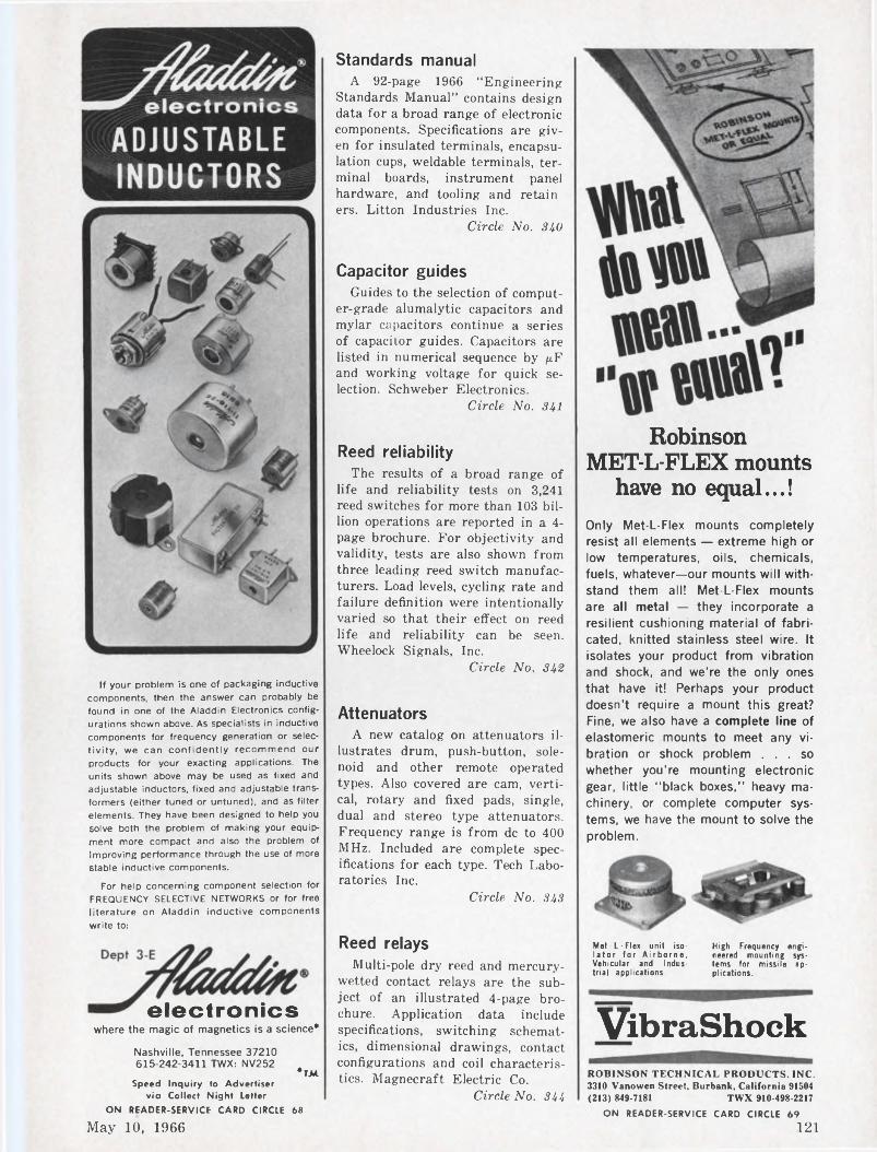
If your problem is one of packaging inductive components, then the answer can probably be found in one of the Aladdin Electronics configurations shown above. As specialists in inductive components for frequency generation or selectivity, we can confidently recommend our products for your exacting applications. The units shown above may be used as fixed and adjustable inductors, fixed and adjustable transformers (either tuned or untuned), and as filter elements. They have been designed to help you solve both the problem of making your equipment more compact and also the problem of Improving performance through the use of more Stable inductive components.
For help concerning component selection for FREQUENCY SELECTIVE NETWORKS or for free literature on Aladdin inductive components write to:
electronicswhere the magic of magnetics is a science*
Standards manualA 92-page 1966 “Engineering
Standards Manual” contains design data for a broad range of electronic components. Specifications are given for insulated terminals, encapsulation cups, weldable terminals, terminal boards, instrument panel hardware, and tooling and retain ers. Litton Industries Inc.
Circle No. 340
Capacitor guidesGuides to the selection of comput
er-grade alumalytic capacitors and mylar capacitors continue a series of capacitor guides. Capacitors are listed in numerical sequence by juF and working voltage for quick selection. Schweber Electronics.
Circle No. 341
Reed reliabilityThe results of a broad range of
life and reliability tests on 3,241 reed switches for more than 103 billion operations are reported in a 4- page brochure. For objectivity and validity, tests are also shown from three leading reed switch manufacturers. Load levels, cycling rate and failure definition were intentionally varied so that their effect on reed life and reliability can be seen. Wheelock Signals, Inc.
Circle No. 342
AttenuatorsA new catalog on attenuators il
lustrates drum, push-button, solenoid and other remote operated types. Also covered are cam, vertical, rotary and fixed pads, single, dual and stereo type attenuators. Frequency range is from de to 400 MHz. Included are complete specifications for each type. Tech Laboratories Inc.
Circle No. 343
Reed relaysMulti-pole dry reed and mercury-
wetted contact relays are the subject of an illustrated 4-page brochure. Application data include specifications, switching schematics, dimensional drawings, contact configurations and coil characteristics. Magnecraft Electric Co.
Circle No. 344
Robinson MET-L-FLEX mounts
have no equal...!Only Met-L-Flex mounts completely resist all elements — extreme high or low temperatures, oils, chemicals, fuels, whatever—our mounts will withstand them all! Met-L-Flex mounts are all metal — they incorporate a resilient cushioning material of fabricated, knitted stainless steel wire. It isolates your product from vibration and shock, and we're the only ones that have it! Perhaps your product doesn’t require a mount this great? Fine, we also have a complete line of elastomeric mounts to meet any vibration or shock problem ... so whether you’re mounting electronic gear, little “black boxes,” heavy machinery, or complete computer systems, we have the mount to solve the problem.
Met-L-Flex unit isolator for Airborne, Vehicular and Industrial applications.
High Frequency engineered mounting systems for missile applications.
VibraShockROBINSON TECHNICAL PRODUCTS. INC.3310 Vanowen Street, Burbank, California 91504(213) 849-7181 TWX 910-498-2217
Nashville, Tennessee 37210615-242-3411 TWX: NV252
*TJ4Speed Inquiry to Advertiser
vic Collect Night Letter
ON READER-SERVICE CARD CIRCLE 68 ON READER-SERVICE CARD CIRCLE 69
121May 10, 1966
NEW LITERATURE
SiliconesA 24-page reference guide to sili
cones is geared to materials selection for aerospace electronics. Bulletin CDS-716 contains sections on properties, product forms and functions. potting, encapsulating and sealing compounds, dielectric coolants and insulating compounds. Special features include a MIL-spec guide and product selector chart. General Electric, Silicone Products Dept.
Circle No. 345
Operational amplifiersCatalog 66A completely covers 33
de operational amplifiers, universal electronic rack housing and plug-in modules. All specifications are presented in a single chart showing model number and 39 performance specifications. Dimensions, diagrams, mounting configurations and complete pin designations for standard packages are shown for systems amplifiers on printed-circuit board and encapsulated models. Computer Dynamics, Inc.
Circle No. 346
Integrating DVMsA pair of 2-color brochures pro
vide information on the features, operating principles and specification of all-electronic, 5-digit integrating DVMs. Hughes Aircraft Co., Vacuum Tube Products Div.
Circle No. 347
Trimmer capacitorsThis catalog features a new line
of metallized glass miniature trimmer capacitors. Also included are specifications on a full line of precision trimmer capacitors and inductors. LRC Electronics Inc.
Circle No. 348
Mercury ballast guideA buyer’s guide to mercury lamp
ballasts is offered. The two-color, 12-page bulletin MV-200 describes and depicts a line of constant-wattage and mercury vapor ballasts for indoor and outdoor service. The illustrated brochure includes specifications, charts and technical data on mercury ballasts as well as mounting accessories. Sola Basic Industries.
Circle No. 349
Analog computer guideA comprehensive comparative
study of 81 performance and operational characteristics of six leading desk-mounted analog computers is offered in the form of a buyer’s guide. Subjects covered include performance, operator convenience and analog and hybrid capacity and capability. Computer Products Inc.
Circle No. 350.
Magnetic tapeA sample length of magnetic tape
with five suggested ways to “torture it” is attached to this 4-page folder. Standard reel sizes, roll lengths and test standards are also given. U.S. Magnetic Tape Co.
Circle No. 351
Investment castingA 44-page brochure details the
basic steps in investment casting. Applications, a designing guide and a wide range of ferrous and nonferrous alloy specifications are featured. Arwood Corp.
Circle No. 352
Quality and economy in servo motors and motor-tachs depend on the manufacturer's
experience
...and CEDAR has it!When it comes to sizes 8, 10 and 11 servo motors and motor-tachometers both with and without gear heads, Cedar is the leader, currently building at a higher rate than any other manufacturer in the country.
Because Cedar’s volume is big and production techniques have been perfected and standardized, you are assured of the most economical price available. At the same time, the reliability testing and quality assurance programs built up on these units through years of experience guarantee you the finest quality and dependability.
When you need a servo motor or motor-tach, remember that the most advanced designs built with the most modern production techniques come from Cedar. Write or call us for complete information. You’ll be glad you did.
CONTROL DATACORPORATION
200 WATT DC SERVO AMPLIFIER
22V @
FOR DC MOTORS
AND TORQUERS
★ Current feedback★ Three signal inputs★ Small size—2% W x 6 Lx 4 H★ Gain —50 amp./volt★ Signal inputs DC isolated
from 28VDC pwr.Servo Amplifiers I Static Inverters I Power Supplies
WESÎAMPSANTA MONICA, CALIFORNIA • 213+393-0401
ON READER-SERVICE CARD CIRCLE 71
Electronic Design
CEDARENGINEERING DIVISION
5806 W. 36th St., Minneapolis, Minn. 55416 Phone (612) 929-1681ON READER-SERVICE CARD CIRCLE 70
122
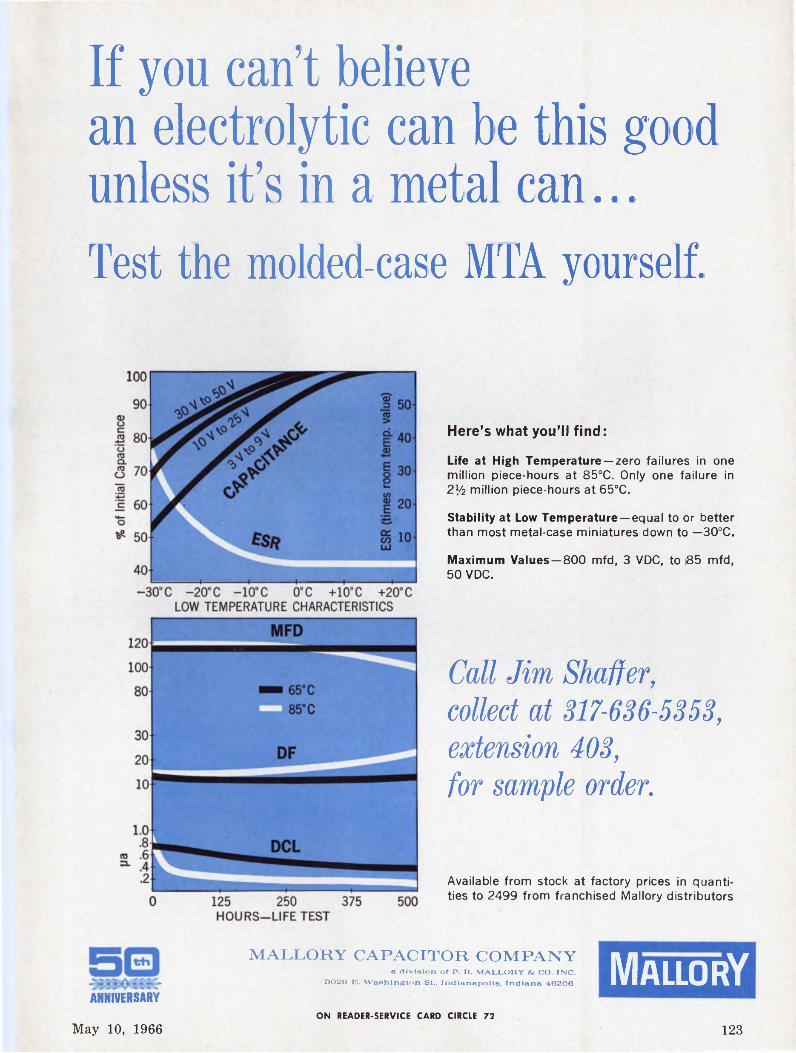
If you can’t believe an electrolytic can be this good unless it’s in a metal can...Test the molded-case MTA yourself.
Here’s what you’ll find:
Life at High Temperature —zero failures in one million piece-hours at 85°C. Only one failure in 21/2 million piece-hours at 65°C.
Stability at Low Temperature —equal to or better than most metal-case miniatures down to —30°C.
Maximum Values —800 mfd, 3 VDC, to 185 mfd, 50 VDC.
Call Jim Shaffer, collect at 317-636-5353, extension 403, for sample order.
Available from stock at factory prices in quantities to 2499 from franchised Mallory distributors
MALLORY CAPACITOR COMPANYa division of P. R. MALLORY & CO. INC.
3029 E. Washington St., Indianapolis, Indiana 46206: MallorYANNIVERSARY
ON READER-SERVICE CARD CIRCLE 72
May 10, 1966 123
NEW LITERATURE Design Data fromRectifiers and zeners
A 32-page catalog covers a line of zener, rectifier and other diodes. Full information on high surge zeners, fast recovery rectifiers and radiation-tolerant rectifiers is included. A section on application data details mounting and derating, recovery time and forward and reverse surge ratings. Unitrode Corp.
Circle No. 353
Gyro instrumentsA 6-page gyro test instrumenta
tion catalog is offered. Included in the catalog are typical test configurations. Inland Controls.
Circle No. 354
Reprints AvailableThe following reprints are avail
able free and in limited quantities. To obtain single copies, circle the number of the article you want on the Reader-Service Card.
High Volume, Low Cost: Designers Challenge (No. 740)
Harmonic Generators (No. 741)Hall Effect Multiplier Simplifies
Polar Displays (No. 742)
Subscription PolicyElectronic Design is circulated
free of charge to qualified design engineers in the U.S., Western free Europe and England. To establish your qualifications, send Electronic Design the following information on your company’s letterhead: Your name, engineering title, description of your design duties and a list of your company’s major products. The letter must be signed by you personally.
Subscription rates for nonqualified subscribers—$25.00 per year in U.S.A., $35.00 in all other countries. Single copy, $1.50.
Change of AddressAn address change for a subscriber requires a restatement of his qualifications. To expedite the change, and to avoid missing any issues, send along a label from a backcopy.
Microfilm copies of all 1961, 1962, 1963 and 1964 issues of Electronic Design are available through University Microfilms, Inc., 313 N. First Street, Ann Arbor, Mich.
Relay Price and Product Bulletin
MILWAUKEE RELAYS, INC.
SU* IK IS
This new illustrated, two-color, 12-page bulletin provides descriptions and complete pricing information for general purpose, power, plug-in, antenna switching, hermetically sealed, and magnetic latching relays, as well as clapper mechanisms and a continuous or intermittent buzzer. A color key easily identifies models immediately available from distributors' stock.
Milwaukee Relays, Inc.606 E. Pioneer Road
Cedarburg, Wis. 53012 171
Low-Impedance Crystal AccelermeterBulletin 259865 contains description and specifications on revolutionary Model 812A Piezotron, a low cost quartz transducer for precision measurement of vibration, shock and acceleration. Used with any single-wire shielded cable, the instrument eliminates the cable noise, attentuation, and insulation resistance usually associated with conventional piezoelectric systems. Generating a high amplitude, low impedance output signal, the Piezotron can be connected directly to a meter, scope, or recorder.
Kistler Instrument Corporation8969 Sheridan Drive
Clarence, N. Y. 14031 173
New Continuous Plating Saves 40% !• • X» New continuous reel-to-reel precious metal plating
(gold, silver. Rhodium, etc.) on strip reduces materials cost up to 40%. Provides extremely accurate depositing to specifications, allows selection of plated area (i.e.: 20 microinches one side, 100 microinches on opposite side).Process also permits plating of pre-die cut integrated circuits for semi-conductors, etc., and allows forming after plating.
Burton Research Laboratories, Inc.Division of
Burton Silverplating Co. 175124 Electronic Design
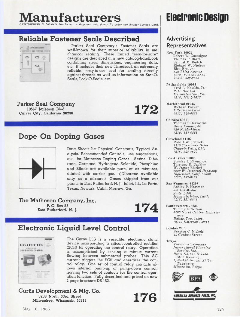
ManufacturersAdvertisements of booklets, brochures, catalogs and data sheets. To order use Reader-Service Card.
Electronic Design
Reliable Fastener Seals DescribedParker Seal Company's Fastener Seals are
well-known for their superior reliability in mechanical sealing. These famed "seal-for-sure" designs are described in a new catalog-handbook containing sizes, dimensions, engineering data, etc. It includes their new Thredseal, an extremely reliable, easy-to-use seal for sealing directly against threads as well as information on Stat-O- Seals, Lock-O-Seals, etc.
Parker Seal Company10567 Jefferson Blvd.
Culver City, California 90230 172
Dope On Doping GasesData Sheets list Physical Constants, Typical Analysis, Recommended Controls, use suggestions, etc., for Matheson Doping Gases. Arsine, Diborane, Germane, Hydrogene Selenide, Phosphine and Silane are available pure, or as mixtures, diluted with carrier gas. (Diborane available only as a mixture.) Gases shipped from our plants in East Rutherford, N. J., Joliet, Ill., La Porte, Texas, Newark, Calif., Morrow, Ga.
The Matheson Company, Inc.P. O. Box 85
East Rutherford, N. J. 174Electronic Liquid Level Control
The Curtis LLS is a versatile, electronic static device incorporating a Silicon-controlled rectifier (SCR) for operating the control relay. Operation is accomplished by sensing a minute current flowing between submerged probes. This AC current triggers the SCR and energizes the control relay. One set of control relay contacts allows internal pump-up or pump-down control, leaving two sets of contacts for the control operation function. Fully described and priced on new 2-page brochure DS-162.
Curtis Development & Mfg. Co.3236 North 33rd Street
Milwaukee, Wisconsin 53216 176
Advertising RepresentativesNew York 10022
Robert W. Gascoigne Thomas P. Barth Samuel M. Deitch Richard W. Nielson Rick Brough 850 Third Avenue (212) PLaza 1-5530 TWX: 867-7866
Philadelphia 19066 Fred L. Mowlds, Jr. P. O. Box 206 Merion Station, Pa. (215) MO 4-1073
Marblehead 01945Richard Parker 7 Redstone Lane (617) 742-0252
Chicago 60611Thomas P. Kavooras Berry Conner, Jr. 720 N. Michigan (312) 337-0588
Cleveland 44107Robert W. Patrick 8410 Treetower Drive Chagrin Falls, Ohio (216) 247-7670
Los Angeles 90005 Stanley I. Ehrenclou Terrence D. Buckley W. James Bischof 2930 W. Imperial Highway Inglewood, Calif. 90303 (213) 757-0183
San Francisco 94306 Ashley P. Hartman 541 Del Medio Suite #301 Mountain View, Calif. (415) 327-6536
Southwestern 75235 Tommy L. Wilson 6200 North Central Express
wayDallas, Tex. 75206 (214) EM er son 1-2311
London W. 1Brayton C. Nichols 44 Conduit Street
TokyoYoshihiro TakemuraInternational Planning
Service, Inc.Room No. 512 Nikkoh
Mita Building1, Nishidaimachi, Shiba-
TakanawaMinato-ku, Tokyo
BPA
AMERICAN BUSINESS PRESS, INC.
May 10, 1966 125
1 NANOSECOND LIGHT PULSE GENERATOR
ENL MODEL 450 NANOSOURCE LIGHT PULSE GENERATOR• One-nanosecond rise time• Selectable light-pulse width• For use in determining rise time of PM tubes and
solid-state (p-n or PiN) detectors• For measurement of minority carrier lifetime in
semiconductors• Spectrum typical of high pressure Hg arc, rich in
UV, visible, and IRFor further information, write or call:
ELECTRO-NUCLEAR LABORATORIES, INC.115 Independence Drive, Menlo Park, Calif. 94025; (415) 322-8451
ON READER-SERVICE CARD CIRCLE 74
ENL TYPE 626 SILICON OPTICAL DETECTOR features:• High quantum efficiency and/or D*• Fast response or fast rise time• High reliability• Hermetically sealed TO-18 package with lens• Ideal for card and tape readers, encoders,
fusing, and ranging• High production — large stock item• Unit price, 626A, $9.95; for 626B, $24.95
For further information, write to:
Advertisers’ Index
NIGHT LETTER PROGRAM*PARTICIPANTS IN
Advertiser PageAA Industries, Inc................................................................................................. 118
♦AMP Incorporated .........................................................................................119API Instruments Co............................................................................................... 108Acopian Corporation ...........................................................................................116Aero vox Corporation ............................................................................ 62
♦Agastat Timing Instruments, Elastic Stop Nut Corporation ofAmerica ............................................................................................................... 84
♦Aladdin Electronics, A Div. of Aladdin Industries, Inc........................121Allen-Bradley Co...............................................................................................32A-BAmco Engineering Co............................................................................................ 109Amphenol Corporation, RF Division ...................................................... 6Arnold Magnetics Corporation ........................................................................108
♦Beckman Instruments, Inc., Helipot Division ......................................... 95Belden Manufacturing Company .................................................................. 99
♦Bourns, Inc.............................................................................................................. 15Branson Corp........................................................................................................... 112Burndy Corporation ...........................................................................................105Burton Research Industries Inc......................................................................124
C & K Components Inc........................................................................................ 102CTS Corporation .................................................................................................. 89Cedar Engineering Division, Data Control Corporation .................... 122CELCO Constantine Engineering Laboratories Co.................................118
♦Clevite Corporation, Piezoelectric Division .............................................. 98♦Clifton Precision Products, Division of Litton Industries ...Cover IIColumbia Wire & Supply Co............................................................................. 117
♦Computer Control Company, Inc.................................................................. 30Curtis Development and Mfg. Co................................................................... 125Cutler-Hammer, Inc............................................................................................... 65
♦Dale Electronics. Inc................................................................................Cover inDelco Radio, Division of General Motors Corporation ...................... 8
ESI/Electro Scientific Industries ................................................................ 81Electro Nuclear Laboratories ..........................................................................126Electronic Engineering Company ................................................................. 127Electronic Marketing Division, Essex Wire Corporation ................. 94
♦Electronic Memories, Inc.................................................................................... 69Electro vert, Inc........................................................................................................ 106Erie Technological Products, Inc................................................................... 107
Fairchild Du Mont Laboratories, Electronic Tube Division ........... 27Fairchild Semiconductor,
A Division Fairchild Camera and Instrument Corporation 5, 52, 53♦Fluke Mfg. Co., Inc., John ............................................................................... 59
Gardner-Denver Company ............................................................................. 97General Electric Company, Specialty Control Department ............. 106General Radio Company ................................................................................... 1
♦Heinemann Electric Company ....................................................................... 7Hewlett Packard .............................................................................................23, 29
Indiana General Corporation ......................................................................... 67♦Industrial Timer Corporation ....................................................................... 92
Kistler Instrument Corporation ................................................................... 124
Leeds & Northrup Company ............................................................................113Littelfuse ..................................................................................................................114
Mac Panel Company ........................................................................................... 104Magnecraft Electric Co.........................................................................................116
•Magnetics, Inc........................................................................................................... 9
ELECTRO-NUCLEAR LABORATORIES, INC.115 Independence Drive, Menlo Park, Calif. 94025; (415) 322-8451
ON READER-SERVICE CARD CIRCLE 73
126 Electronic Design
COMBINEDMULTIPLEXER
RHDfl/D CONVERTER
Advertiser Page•Mallory & Co., Inc., P. R..........................................................................24, 25Mallory Capacitor Company ........................................................................123Markel & Sons, L. Frank ................................................................................ 110Matheson Company, Inc................................................................................... 125Merrimac Research & Development, Inc............................................... 128Metex Electronics, A Division of Ferrodynamics Corporation .... 93Micro Instrument Company ......................................................................... 82Mitsumi Electric Co., Inc.................................................................................. 114
•Motorola Semiconductor Products, Inc.................................................... 63
• Oak Manufacturing Co................................................................................. 101Ohmite Manufacturing Company ...............................................................Ill
Pamotor, Inc.............................................................................................................120Parker Seal Company .......................................................................................125Parsons Electronics Company, The Ralph .............................................. 86Perfection Mica Company .............................................................................. 113Pyrofilm Resistor Co., Inc................................................................................. 45
♦ RBM Controls Division ............................................................................. 115• Radiation, Incorporated ............................................................................ 19Radio Cores, Inc..................................................................................................... 100Radio Corporation of America Institutes Inc............................................ 93Radio Corporation of America, Semiconductor & Materials
■ QC 7Q TX7• Redcor Corporation ..................................................................................... 2Revere-Mincom Division, 3M Company ...................................................103Robinsorf Technical Products Inc................................................................121
Sanders Associates, Inc...................................................................................... 83Sealectro Corporation ...................................................................................... 80
• Singer Company, The, Diehl Division ............................................. 4Sorensen Operation, Raytheon Company .............................................. 16Specific Products ................................................................................................. 120Sprague Electric Company .......................................................................10, 20Syntronic Instruments, Inc................................................................................100
• Systron-Donner Corporation .................................................................... 12
TRW Capacitors ................................................................................................. 34Tektronix, Inc., Oscilloscopes ................................................................ 46, 47Texas Instruments Incorporated ................................................................. 85Theta Instrument Corporation ......................................................................117Topaz Transformer Products, Inc................................................................. 101Tracor, Inc........................................................................................................ 96, 109Transistor Electronics Corp.............................................................................. 93
• Union Carbide Corporation, Linde Division .................................... 91United Control Corporation ................. 33
Vector Division of United Aircraft ............................................................ 87
Westamp, Inc............................................................................................................122Wood Electric Corporation ........................................................................... 90
Regional Advertising
• Arnold Engineering Company, The .....................................................96A• Brush Instrument Division of Clevite ................................................. 96C• JFD Electronics Corporation .................................................................. 96D• Leach Corporation ........................................................................................96B
Career Advertising
AC Electronics ..................................................................................................... 74Boeing Company, The ...................................................................................... 76General Electric Television Receiver Dept............................................... 73General Electric Company, Apollo Support Division ..................... 75Lockheed Missiles and Space ....................................................................... 72Motorola, Inc........................................................................................................... 72
EECO 762From 5lo ioo analog inputs
Dgtou-hll binary or 4 BCD +sign Bated dismai ol output lor aw input channel
lip ip 44,000 conversions per second F.E.T. suiiiches-too megohm input impedance
Optional simultaneous binary and BCD nuipuis too nanosecnnd aperture on sample end hold
Only 7 inches of panel height
Up to 100
analog inputs
Digital data in parallel or serial form
EECO 762...less than $4,000
lor most modelsElectronic Engineering Company
of California1601 East Chestnut Avenue (Box 58)
Santa Ana, California 92702Phone: Kimberly 7-5501 (714) ’TWX: 714-531-5711
ON READER-SERVICE CARD CIRCLE 75
May 10, 1966 127
Designer’s Datebook
6 713 1420 2127 28
UNES M T W T F S
2 3 46 7 8 9 10 11
12 13 14 IS 16 17 1819 20 21 22 23 2426 27 28 29 30
■ SSB Modulators■ Image Reject Mixers ■ Phase Comparators
Using lumped-element components to achieve lower frequency equivalents of classic microwave devices, quadrature (90°) hybrids are offered for applications from arbitrary low frequencies to beyond 1000 Me. Bandwidths range from 10% to a complete octave. Standard-size units are offered with conventional coaxial connectors; microminiature versions with solder pin connectors. From $125 in small quantities.
Microminiature Hybrid
For application notes and complete catalog information, write:
MERRIMAC RESEARCH & DEVELOPMENT, INC,517 Lyons Ave., Irvington,, NJ. 07111 • (201) ESsex 1-1616
COMPONENTS FOR LOW, I.F. L MICROWAVE FREQUENCIES ■ Hybrids ■ Hybrid I Magic Tees ■ Power Dividers ■ Resolvers ■ Directional Couplers ■ Phase Shifters ■ Attenuators ■ Phase Measuring Systems ■ Reflectometer Systems
May 10-121966 National Telemetering Conference (Boston, Mass.) Sponsors: AIAA, IEEE, ISA; Paul Barr, Raytheon Co., Norwood, Mass.
May 11-12Seminar on Photographic Systems for Engineers (San Francisco) Sponsor: Society of Photographic Scientists and Engineers; Suite 204, 1330 Massachusetts Ave.N.W., Washington, D. C.
May 14Seventh Annua) West Coast Reliability Symposium (Los Angeles) Sponsor: Society for Quality Control ; S. Goldklang, TRW Systems, One Space Park, Redondo Beach, Calif.
May 16-189th National ISA Power Instrumentation Symposium (Detroit Mich.) Sponsor: ISA; Robert R Donaldson, Hagan Controls Corp., 5757 Trumbull Ave., Detroit, Mich.
May 16-191966 International Microwave Symposium (Palo Alto, Calif.) Sponsor: IEEE, G-MTT ; Marvin Waldman, Waldman Assocs., 1094 W. Evelyn Ave., Sunnyvale, Calif.
May 16-194th National ISA Biomedical Sciences Instrumentation Symposium (Anaheim, Calif.) Sponsor: John F. Bishop, Dana Labs., Inc., Irvine, Calif.
May 23-2512th Annual Meeting of the American Astronautical Society (Anaheim, Calif. ; Dr. Donald B. Duncan, Philco Corp., Newport Beach, Calif.
June 7-920th Annual Convention of the Armed Forces Communications and Electronics Association (Wash., D. C.) Sponsor: AFCEA;W. J. Baird, 1725 Eye St., N.W., Washington 6, D.C.
ON READER-SERVICE CARD CIRCLE 76
128 Electronic Design
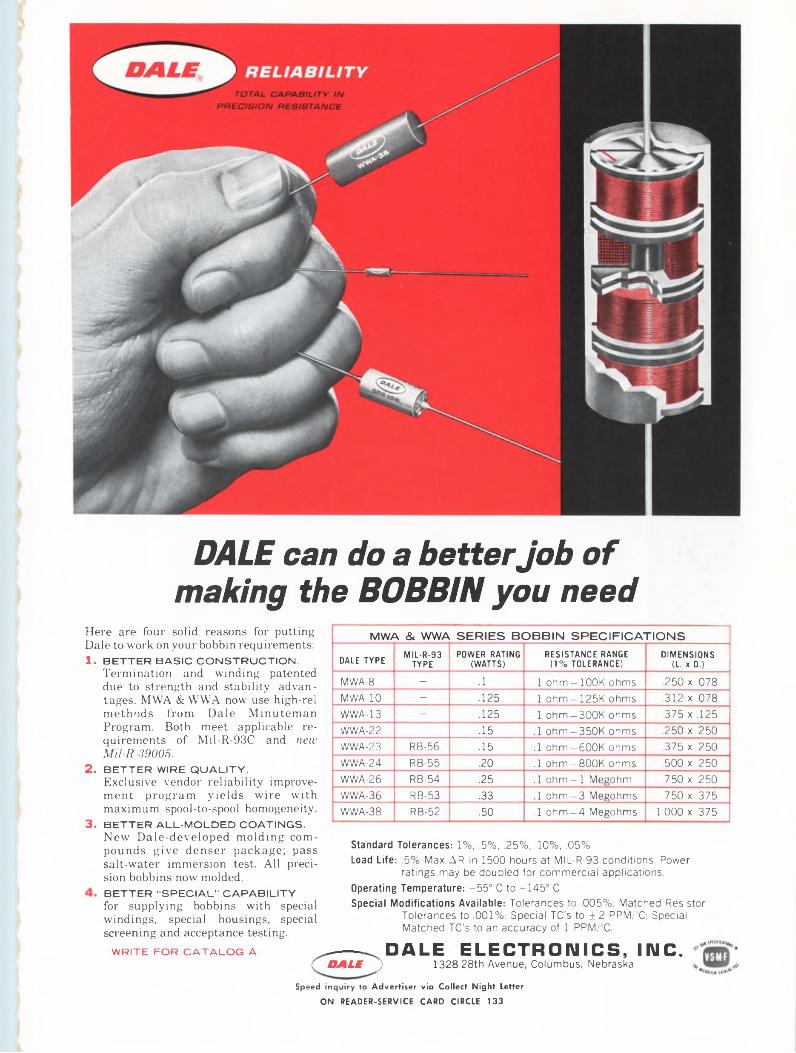
DALE can do a better Job of making the BOBBIN you need
Here are four solid reasons for putting Dale to work on your bobbin requirements: 1. BETTER BASIC CONSTRUCTION.
Termination and winding patented due to strength and stability advantages. MWA & WWA now use high-rel methods from Dale Minuteman Program. Both meet applicable requirements of Mil-R-93C and new Mil-R-39005.
2. BETTER WIRE QUALITY.Exclusive vendor reliability improvement program yields wire with maximum spool-to-spool homogeneity.
3. BETTER ALL-MOLDED COATINGS.New Dale-developed molding compounds give denser package; pass salt-water immersion test. All precision bobbins now molded.BETTER “SPECIAL" CAPABILITYfor supplying bobbins with special windings, special housings, special screening and acceptance testing.
MWA & WWA SERIES BOBBIN SPECIFICATIONS
DALE TYPEMIL-R-93
TYPEPOWER RATING
(WATTS)RESISTANCE RANGE
(1% TOLERANCE)DIMENSIONS
(L. X D.)
MWA-8 - .1 1 ohm — 100K ohms .250 x .078MWA-10 — .125 1 ohm- 125K ohms .312 x .078WWA-13 - .125 1 ohm-3OOK ohms .375 x .125WWA-22 — .15 .1 ohm —350K ohms .250 x .250WWA-23 RB-56 .15 .1 ohm —600K ohms .375 x .250WWA-24 RB-55 .20 .1 ohm-800K ohms .500 x .250WWA-26 RB-54 .25 .1 ohm —1 Megohm .750 x .250WWA-36 RB-53 .33 .1 ohm-3 Megohms .750 x .375WWA-38 RB-52 .50 .1 ohm—4 Megohms 1.000 x .375
Standard Tolerances: 1%, .5%, .25%, .10%, .05%Load Life: .5% Max. AR in 1500 hours at MIL-R-93 conditions. Power
ratings may be doubled for commercial applications.Operating Temperature: -55° C to +145° CSpecial Modifications Available: Tolerances to .005%; Matched Resistor
Tolerances to .001%; Special TC’s to + 2 PPM/°C; Special Matched TC’s to an accuracy of 1 PPM/°C.
WRITE FOR CATALOG A ------ DALE ELECTRONICS, INC.DALE ; 1328 28th Avenue, Columbus, Nebraska
Speed inquiry to Advertiser via Collect Night Letter
ON READER-SERVICE CARD CIRCLE 133
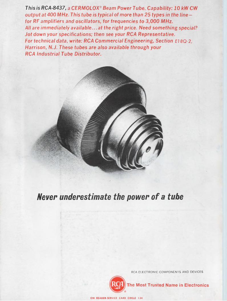
This is RCA-8437, a CERMOLOX® Beam Power Tube. Capability: 10 kW CW output at 400 MHz. This tube is typical of more than 25 types in the line- for RF amplifiers and oscillators, for frequencies to 3,000 MHz.All are immediately available...at the right price. Need something special? Jot down your specifications; then see your RCA Representative.For technical data, write: RCA Commercial Engineering, Section E18Q-2, Harrison, N.J. These tubes are also available through your RCA Industrial Tube Distributor.
Never underestimate the power of a tube
RCA ELECTRONIC COMPONENTS AND DEVICES
The Most Trusted Name in Electronics
ON READER-SERVICE CARD CIRCLE 134
Copyright © 2022 FDOKUMEN