Cold white light generation from hafnium oxide films activated with Ce3+, Tb3+, and Mn2+ ions
Upload
faculdadefbCategory
view
3download
0
INSTITUTE OF PHYSICS PUBLISHING JOURNAL OF PHYSICS: CONDENSED MATTER
J. Phys.: Condens. Matter 15 (2003) 2091–2102 PII: S0953-8984(03)58989-5
Scintillation properties of Lu2Si2O7:Ce3+, a fast andefficient scintillator crystal
L Pidol1,2, A Kahn-Harari1, B Viana1, B Ferrand3, P Dorenbos4,J T M de Haas4, C W E van Eijk4 and E Virey2
1 Ecole Nationale Superieure de Chimie de Paris (ENSCP), Laboratoire de Chimie Appliquee del’Etat Solide, UMR-CNRS 7574, 11 rue Pierre et Marie Curie, 75231 Paris Cedex 05, France2 Saint Gobain Cristaux et Detecteurs, 104 route de Larchant, 77140 Saint Pierre les Nemours,France3 LETI/DOPT/STCO/Laboratoire Cristallogenese Appliquee—CEA Grenoble, 17 rue desMartyrs, 38054 Grenoble Cedex 09, France4 Interfaculty Reactor Institute, Delft University of Technology, Mekelweg 15, 2629 JB Delft,The Netherlands
E-mail: [email protected]
Received 31 January 2003Published 17 March 2003Online at stacks.iop.org/JPhysCM/15/2091
AbstractCerium doped lutetium pyrosilicate Lu2Si2O7:Ce3+ (LPS), a new inorganicscintillator, displays particularly promising performance. This material canbe readily pulled from the melt. A high light output (average value:26 300 ph MeV−1), a relatively good energy resolution (9%) and a fast decaytime (38 ns) without afterglow make this new scintillator very attractive, inparticular for medical imaging. Optical characterizations and scintillationproperties of LPS:Ce large single crystals are presented, including timingproperties and study of the scintillation yields as a function of incident energy.
1. Introduction
Scintillator crystals are used to detect gamma rays or x-rays in many applications likecomputerized tomography (CT), positron emission tomography (PET), nuclear and particlephysics experiments or geophysical exploration. A scintillator crystal converts a fraction ofthe energy deposited by the incident gamma ray or x-ray into a burst of visible or ultravioletphotons which is then converted into an electrical signal by a photomultiplier tube (PMT) or aphotodiode optically coupled to the crystal. The ideal scintillator should have high density andhigh effective atomic number for a high stopping power of gamma rays, a high scintillationlight yield (LY) for measuring the gamma ray energy accurately and a short decay time for highcount-rate capability [1]. A number of cerium doped oxide based scintillators have recentlybeen developed, like GSO (Gd2SiO5:Ce) [2], LSO (Lu2SiO5:Ce) [3], LuAP (LuAlO3:Ce) [4, 5]and LYSO (Lu2(1−x)Y2x SiO5:Ce) [6, 7]. These materials tend to exhibit the desired qualities
0953-8984/03/122091+12$30.00 © 2003 IOP Publishing Ltd Printed in the UK 2091

2092 L Pidol et al
Table 1. Physical and scintillation properties of several scintillators.
BGO GSO:Ce LSO:Ce LuAP:Ce LPS:CeBi4Ge3O12 Gd2SiO5 Lu2SiO5 LuAlO3 Lu2Si2O7
Melting point (◦C) 1050 1950 2100 1960 1900Density (g cm−3) 7.13 6.7 7.4 8.34 6.23Effective atomic number 75 59 66 65 64Attenuation length for a
511 keV photon (cm) 1.12 1.38 1.14 1.05 1.38Refractive index 2.15 1.89 1.81 1.94 1.74LY (photons MeV−1) 8200 8500 25 000 11 300 26 300Emission wavelength (nm) 480 430 420 365 385Decay times 300 ns 56 ns, 40 ns, 18 ns 38 ns
600 ns >2000 sTime resolution (ps) 1000 700 160 160 253
for gamma detection scintillators: a high density, a scintillation decay time shorter than 100 nsand a light output exceeding that of BGO (Bi4Ge3O12), which is still commonly used forgamma detection.
In this paper, we have characterized the scintillation properties of cerium doped lutetiumpyrosilicate, Lu2Si2O7 (LPS:Ce), a new material which is suitable for applications such as PETor oil well logging. Following the first successful studies with LPS:Ce crystals prepared bythe floating zone melting technique [1, 8], optically clear Czochralski grown LPS boules weregrown with desired properties for gamma-ray detection [9]. The main properties are gatheredin table 1, together with properties of some other already studied scintillators.
2. Experimental details
LPS crystals were grown from the melt (1900 ◦C) by a vertical pulling method (Czochralskiprocess) using an iridium crucible. A LPS crystal was used as a seed. Both undoped LPS(Lu2Si2O7) and Ce doped LPS (Lu2(1−x)Ce2x Si2O7) were grown, with a cerium concentrationin the melt ranging from 0.25 to 0.5%. Samples of about 1 cm3 were cut and polished forscintillation measurements (table 2).
Optical absorption experiments were done using a CARY 5 Varian spectrophotometer.Emission measurements and decay time profiles under UV excitation were performed with theexcitation wavelength coming from the third harmonic of a YAG:Nd laser (λexc = 355 nm).The light was analysed with a UV enhanced ICCD (Princeton) detector. Optical spectra wererecorded at temperatures ranging from 10 to 300 K with a CTI-Cryogenics refrigeration system.Between 300 and 600 K, we used a home-made heating device. The temperature accuracy was±2 K.
X-ray excited optical luminescence spectra were recorded using an x-ray tube with a Cuanode, operating at 35 kV and 25 mA, at temperatures ranging from 200 to 400 K. The emissionwas dispersed with an ARC VM504 monochromator (blazed at 300 nm, 1200 grooves mm−1)and measured with an EMI 9462 PMT. The data were corrected for the wavelength dependenceof the PMT quantum efficiency and for the monochromator response.
Scintillation decay time spectra, under 137Cs 662 keV γ -ray excitation, were recordedwith two Philips XP2020Q PMTs using standard start–stop techniques as described in [10].
To evaluate the possible afterglow, crystals were first heated for several minutes at 672 Kand then exposed to x-ray irradiation for 50 s (Cu anode,35 kV and 25 mA). Next,a HamamatsuR943-02 PMT was used to measure the emission intensity for several hours after this exposureand results were normalized per milligram of material.
Scintillation properties of Lu2Si2O7:Ce3+ 2093
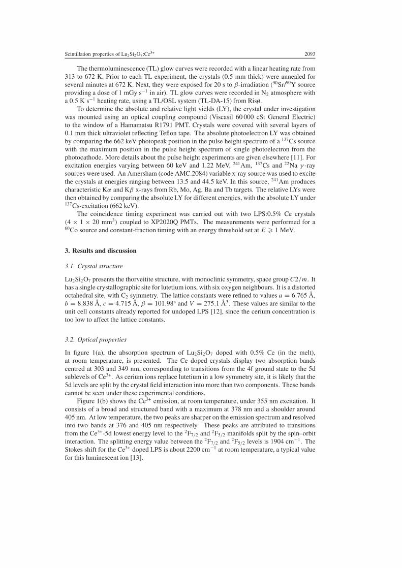
The thermoluminescence (TL) glow curves were recorded with a linear heating rate from313 to 672 K. Prior to each TL experiment, the crystals (0.5 mm thick) were annealed forseveral minutes at 672 K. Next, they were exposed for 20 s to β-irradiation (90Sr/90Y sourceproviding a dose of 1 mGy s−1 in air). TL glow curves were recorded in N2 atmosphere witha 0.5 K s−1 heating rate, using a TL/OSL system (TL-DA-15) from Risø.
To determine the absolute and relative light yields (LY), the crystal under investigationwas mounted using an optical coupling compound (Viscasil 60 000 cSt General Electric)to the window of a Hamamatsu R1791 PMT. Crystals were covered with several layers of0.1 mm thick ultraviolet reflecting Teflon tape. The absolute photoelectron LY was obtainedby comparing the 662 keV photopeak position in the pulse height spectrum of a 137Cs sourcewith the maximum position in the pulse height spectrum of single photoelectron from thephotocathode. More details about the pulse height experiments are given elsewhere [11]. Forexcitation energies varying between 60 keV and 1.22 MeV, 241Am, 137Cs and 22Na γ -raysources were used. An Amersham (code AMC.2084) variable x-ray source was used to excitethe crystals at energies ranging between 13.5 and 44.5 keV. In this source, 241Am producescharacteristic Kα and Kβ x-rays from Rb, Mo, Ag, Ba and Tb targets. The relative LYs werethen obtained by comparing the absolute LY for different energies, with the absolute LY under137Cs-excitation (662 keV).
The coincidence timing experiment was carried out with two LPS:0.5% Ce crystals(4 × 1 × 20 mm3) coupled to XP2020Q PMTs. The measurements were performed for a60Co source and constant-fraction timing with an energy threshold set at E � 1 MeV.
3. Results and discussion
3.1. Crystal structure
Lu2Si2O7 presents the thorveitite structure, with monoclinic symmetry, space group C2/m. Ithas a single crystallographic site for lutetium ions, with six oxygen neighbours. It is a distortedoctahedral site, with C2 symmetry. The lattice constants were refined to values a = 6.765 Å,b = 8.838 Å, c = 4.715 Å, β = 101.98◦ and V = 275.1 Å3. These values are similar to theunit cell constants already reported for undoped LPS [12], since the cerium concentration istoo low to affect the lattice constants.
3.2. Optical properties
In figure 1(a), the absorption spectrum of Lu2Si2O7 doped with 0.5% Ce (in the melt),at room temperature, is presented. The Ce doped crystals display two absorption bandscentred at 303 and 349 nm, corresponding to transitions from the 4f ground state to the 5dsublevels of Ce3+. As cerium ions replace lutetium in a low symmetry site, it is likely that the5d levels are split by the crystal field interaction into more than two components. These bandscannot be seen under these experimental conditions.
Figure 1(b) shows the Ce3+ emission, at room temperature, under 355 nm excitation. Itconsists of a broad and structured band with a maximum at 378 nm and a shoulder around405 nm. At low temperature, the two peaks are sharper on the emission spectrum and resolvedinto two bands at 376 and 405 nm respectively. These peaks are attributed to transitionsfrom the Ce3+-5d lowest energy level to the 2F7/2 and 2F5/2 manifolds split by the spin–orbitinteraction. The splitting energy value between the 2F7/2 and 2F5/2 levels is 1904 cm−1. TheStokes shift for the Ce3+ doped LPS is about 2200 cm−1 at room temperature, a typical valuefor this luminescent ion [13].

2094 L Pidol et al
250 300 350 400 450 5000.0
0.2
0.4
0.6
0.8
1.0
*
(b)
(a)O
ptic
al d
ensi
ty
Wavelength (nm)
Figure 1. Optical characteristics of the Lu2Si2O7:0.5% Ce crystal (1 mm thick) at roomtemperature: (a) absorption spectrum; (b) emission spectrum under a 355 nm excitation wavelength.Bands are indicated by arrows. The small peak marked by a star is an artifact due to the laserexcitation.
Compared to UV excitation, x-ray induced emission at room temperature, gives a verysimilar result (figure 2). Whatever the excitation, only one type of Ce3+ emission is observed.It is linked to the fact that the lutetium pyrosilicate structure offers a single site for Ce3+.
Under x-ray excitation, we have measured the emission intensity as function of temperaturefor LPS:0.5% Ce. The luminescence efficiency remains very high when the temperatureincreases. It even increases when the temperature varies between 200 and 400 K as presentedin figure 3. This could allow the LPS:Ce scintillation detectors to be used under relatively hightemperature conditions.
3.3. Decay time under UV and gamma irradiation
Figure 4 shows the decay time spectra of LPS:Ce under UV excitation (λexc = 355 nm) andgamma ray excitation (137Cs source, 662 keV). The solid curves fit the data with a singleexponential. The deduced decay times are similar, 37 and 38 ns respectively, under UV andgamma excitation. When LPS:Ce crystals are excited by UV radiation, the Ce3+ luminescentcentres are directly excited and then the experimental lifetimes are very short,due to the allowed5d14f0 → 5d04f1 transition. When LPS crystals are excited with higher energy photons suchas gamma rays or x-rays, the scintillation process in LPS:Ce can be divided into two parts:
(1) the creation of electron–hole pairs and the energy transfer to the luminescent Ce3+ centresand
(2) the radiative emission of the excited luminescent centres.
Since the observed decay constant under gamma-ray excitation is close to that obtainedunder UV excitation, the energy transfer to the luminescent centres should be faster than 1 ns,at room temperature.
Figure 5 presents the temperature dependence of the decay time under UV excitation.The rollover point of the decay time is close to 440 K. Two distinct trends are observed.

Scintillation properties of Lu2Si2O7:Ce3+ 2095
200 250 300 350 400 450 500 550 600
Wavelength (nm)
Inte
nsit
y (a
.u.)
Figure 2. X-ray induced emission spectra for Lu2Si2O7:0.5% Ce crystals at room temperature(1 mm thick). The signal near 200 nm, marked with an arrow, is an experimental artifact.
200 240 280 320 360 4000.0
0.2
0.4
0.6
0.8
1.0
Lum
ines
cenc
e ef
fici
ency
Temperature (K)
Figure 3. Luminescence efficiency under x-ray excitation of Ce3+ in LPS:0.5% Ce (1 mm thick)as a function of temperature. For each temperature, the emission intensity, determined as the totalarea under the spectral curve of emission, was normalized to the intensity at 400 K. The curve is aguide to the eye.
First, below 440 K, the decay time slightly increases with temperature. Second, beyond440 K, when the temperature increases, the experimental lifetime strongly decreases. Suchtemperature dependence of the measured fluorescence lifetimes has already been reported forcerium doped:YAlO3, Y3Al5O12, CaF2 and YLiF4 compounds [14]. The total decay rate isgiven by
τ−1exp = τ−1
R + τ−1N R (1)

2096 L Pidol et al
0 50 150 200
Cou
nts
Time (ns)
under -ray excitation = 38 ns
= 37 nsunder UV-excitation
100
Figure 4. Decay curves of Ce3+ in LPS:0.25% Ce crystal (3.9×8.2×30 mm3) at room temperatureunder UV excitation, λexc = 355 nm and λem = 385 nm (◦), and gamma excitation, with a 137Cssource (�). The solid curves fit the data with a single exponential.
50 100 150 200 250 300 350 400 450 500 550 600
16
20
24
28
32
36
40
Dec
ay t
ime
(ns)
Temperature (K)
Figure 5. Decay times (λexc = 355 nm and λem = 385 nm) of Ce3+ in LPS:0.5% Ce (1 mm thick)as function of temperature.
where τexp is the experimental fluorescence lifetime of the 5d–4f transition and τR and τN R arethe contributions from radiative and non-radiative processes, respectively. At low temperatures,radiative transitions dominate and a slow linear increase of τR could be explained by a photontrapping effect. At higher temperatures, the rapid decrease of the decay time values means thatnon-radiative de-excitation predominates and should be correlated to a strong quenching of theluminescence efficiency. To confirm that, a study of luminescence efficiency for temperatureover 400 K is still necessary. The non-radiative decay rate WN R (=τ−1
N R) is calculated fromequation (1) for temperatures higher than 440 K. Figure 6 illustrates the temperature variation

Scintillation properties of Lu2Si2O7:Ce3+ 2097
1.6 1.7 1.8 1.9 2.0 2.1 2.2 2.3
106
107
1000 /T(K –1)
WN
R(s
–1)
Figure 6. Non-radiative decay rate for Ce3+:LPS as a function of inverse temperature. The solidline fits the data with the Arrhenius equation, �E = 0.66±0.01 eV and τt = 80±20 fs. The non-radiative probability is obtained by subtraction of the radiative contribution linearly extrapolatedfor temperature above 440 K.
of the deduced non-radiative relaxation rate. The fit was done assuming that WN R varies withtemperature, following an Arrhenius law:
WN R = τ−1t exp
(− �E
kB T
)(2)
where kB is the Boltzmann constant, the activation energy �E is 0.66 ± 0.1 eV andτt = 80 ± 20 ps corresponds to the thermal decay. If we assume, as in [14], that quenchingof Ce3+ luminescence is caused by autoionization of the 5d electron to the conduction band,then �E ∼ 5400 cm−1 should be related to the energy bandgap between the bottom of theconduction band and the position of the lowest 5d level.
3.4. Afterglow and thermoluminescence
A key parameter for scintillation applications is the afterglow phenomenon. Comparisonbetween afterglow in LSO:Ce and LPS:Ce behaviour is presented in figure 7, using long timerecorded luminescence. A previous study on the here-employed LSO sample is describedin [15] and [16]. Whereas LSO:Ce presents an exponentially decaying afterglow [15, 17],the LPS:Ce crystal does not show any afterglow in that time range, as observed in figure 7.Actually, for LSO:Ce, after 200 s, the residual intensity induced by the x-ray exposure is about0.2% of the initial intensity and this intensity is still decreasing after several minutes, pointingout the strong afterglow, well known in the lutetium oxyorthosilicate material. In the case ofLPS:Ce, this residual intensity is less than 0.01% after 200 s. Then, it remains at this constantrate, due only to the background intrinsic intensity of 176Lu isotopes in the compound.
TL experiments confirm these observations. Figure 8 shows the thermoluminesence glowcurves for LPS:0.25% Ce and LSO:0.2% Ce crystals. This latter sample (LSO6-4) has alreadybeen studied in [15] and [16]. After exposure to β-irradiation for 20 s, several peaks areobserved when the temperature increases. Our attention is focused on the peak observed just

2098 L Pidol et al
0 500 1000 1500 2000
LSO: Ce
LPS: Ce
coun
ts/m
g
Time (s)
Figure 7. Afterglow luminescence of LPS:0.25% Ce and LSO:0.2% Ce at room temperature. Thecrystals were exposed for 50 s to an x-ray beam (λCu, 35 kV and 25 mA). (The LSO sample isnamed LSO7-11 in references [15, 16].)
Table 2. LYs and energy resolutions of several Lu2Si2O7:Ce crystals under γ -ray excitation (137Cssource 662 keV). Shaping time, 10 µs; LY estimated standard deviation, 10%. Dimensions of thesix-sided polished samples are mentioned; cerium concentration corresponds to the initial melt.
EnergyCerium rate Dimensions LY resolution
Samples in the melt (mm3) (ph MeV−1) (%)
1 LPS:0.5% Ce 3.9 × 8.2 × 26.4 23 310 11.42 LPS:0.5% Ce 9.5 × 9 × 10 25 700 9.53 LPS:0.25% Ce 3.9 × 8.3 × 20.5 28 960 11.94 LPS:0.25% Ce 3.9 × 8.2 × 30 24 800 10.85 LPS:0.5% Ce 5 × 1.95 × 31.1 28 720 10.1
above room temperature (337 and 346 K for LPS and LSO, respectively), which is closely linkedto the afterglow phenomenon. For the LPS:Ce crystal, the very low intensity of this peak is ingood agreement with the absence of afterglow. In contrast, for the LSO crystal, this peak is veryintense, confirming the observed strong afterglow (figure 7). Some authors [18] report that theposition of this glow peak depends on the crystallographic structure of oxyorthosilicates. ForGd2SiO5, with P21/c crystal symmetry, the maximum in the TL curve is observed 50 K higherthan for Lu2SiO5, with C2/c crystal symmetry. The authors suggest that the crystal structureof these silicates plays an important role in trap creation, which is probably associated withthe host metal–ion–ligand configuration. So, major differences between the crystallographicstructures, C2/c—two sites for the rare-earth ion in LSO—and C2/m—one site for the rareearth in LPS, could explain the different behaviours in terms of trap creation and therefore inthe afterglow phenomenon.
3.5. Light yields, energy resolution and non-proportionality
Table 2 compiles the LY values and the energy resolution of several LPS:Ce crystals. Theaverage LY is about 26 300 ph MeV−1, with a dispersion about ±3000 ph MeV−1. LPS:Ce

Scintillation properties of Lu2Si2O7:Ce3+ 2099
300 350 400 450 500 550 600 650 7000
2000
4000
6000
8000
10000
12000
14000
LPS:Ce LSO:Ce
300 310 320 330 340 350 360 370
LPS:CeZoom× 10
coun
ts/m
g
Temperature (K)
Figure 8. TL glow curves of LPS:0.25% Ce and LSO:0.2% Ce crystals (0.5 mm thick), recorded ata heating rate β = 0.5 K s−1, after exposure for 20 s to β-irradiation (90Sr/90Y source, 1 mGy s−1).In the inset, the first peak is scaled by a factor of ten for LPS.
crystals present one of the best LYs obtained with a cerium doped oxide based scintillator. Thetheoretical maximum LY, in photons MeV−1, can be described by the following equation [19]:
LY = 106SQ
β Egap(3)
where Egap is the energy gap between valence and conduction bands (about 6.95 eV forLPS), β Egap indicates the average energy required to produce one thermalized electron–holepair (Ee−h), β ≈ 2–3. S is the energy transfer efficiency to the luminescent centre (Ce3+)
and Q is the corresponding quantum efficiency, i.e. the efficiency for photon emission oncethe luminescent centre is excited. By using S = 1 and Q = 1, the theoretical maximumLY would be about 57 000 ph MeV−1 (for β = 2.5). The difference between theoreticaland experimental light outputs could then be linked either to defects present in the material,that could trap electrons or holes created during the process, or to a direct electron–holerecombination process. Several peaks observed around 470 and 600 K in the TL curve (figure 8)confirm the existence of traps in the material. The energy resolution at 662 keV, given by thefull width at half maximum (FWHM) of the photopeak, is in the range 9–12%.
Figure 9 shows the pulse height spectrum of an LPS:0.5% Ce crystal excited by a 137Cssource. Also shown in the same picture is the intrinsic background activity from the crystalitself. This background, measured without excitation, arises from the beta decay of the 176Luisotope, which represents 2.6% of natural Lu abundance. The intrinsic background activity ofLPS:Ce is 219 counts s−1 cm−3, which is somewhat less than for LSO:Ce or LuAP:Ce (318and 323 counts s−1 cm−3 respectively [20]).
To go further into the analysis, the variation of the scintillation response as a function ofthe incident energy was investigated. Figure 10 shows non-proportional scintillation responsecurves of three different LPS:Ce polished crystals. For each sample, the light output isapproximately divided by two when incident energy decreases from 1 MeV to 14 keV. Onecan notice a discontinuity around 60 keV where the slope decreases: it could correspond tothe K absorption edge at 63.3 keV of lutetium ions. It appears so far that all silicate materials,

2100 L Pidol et al
200 400 600 800 1000
10.1%coun
ts
28 720 ph/MeV
Energy (keV)
Figure 9. Pulse height spectrum recorded with LPS:0.5% Ce (sample 5) under γ -ray excitation,137Cs source of 662 keV (solid curve). Pulse height spectrum corresponding to the background,recorded with LPS:0.5% Ce without radioactive source (dashed curve). Shaping time: 10 µs, LYestimated standard deviation: 10%.
10 100 10000.4
0.6
0.8
1.0
1.2
LPS:0.5%Ce (1) LPS:0.5%Ce (2) LPS:0.25%Ce (3)
Energy (keV)
Rel
ativ
e lig
ht y
ield
Figure 10. Scintillation LYs for different LPS:Ce crystals, at room temperature, as a function ofexcitation energy, normalized to the LY at 662 keV excitation. The numbers in brackets refer tothe samples of table 2. Shaping time, 3 µs; LY estimated standard deviation, 10%.
like LSO, YSO, GSO or LGSO [21–23], exhibit large non-proportionality in the light output.This suggests that the non-proportionality in the scintillation response could be characteristicof silicate scintillators.
The non-proportional response of the scintillator influences the ultimate energy resolution.The fundamental limit to the energy resolution is primarily determined by the Poisson statisticsin the number of photons detected by the PMT. The fundamental limit for energy resolution

Scintillation properties of Lu2Si2O7:Ce3+ 2101
-2000 -1500 -1000 -500 0 500 1000 1500 20001
10
100
Time (ps)
coun
ts
FWHM=358 ps
Figure 11. Coincidence timing spectrum obtained with two six-sided polished LPS:0.5% Cecrystals (4 × 1 × 20 mm3) coupled to XP2020Q PMTs. The measurements were performed for a60Co source with an energy threshold set at E � 1 MeV.
(FWHM) is given by:
R = 2.35
√1 + υ(M)
Nphe(4)
where υ(M) is the variance in the photomultiplier gain, usually about 0.1, and Nphe is thenumber of photoelectrons detected by the PMT. For LPS: Ce crystals, this fundamental limit isaround 4% at 662 keV. The experimental values for the energy resolution are in the range9–12% (table 2). Additional contributions are mentioned in the literature, such as non-proportionality in the response of the material, inhomogeneities in the crystal, non-uniformityin the light collection efficiency and non-uniformity in the photocathode performance [22, 24].For LPS:Ce, the strong non-proportionality response could partially explain these relativelyhigh experimental energy resolution values. Furthermore, the crystalline quality of LPS:Cesamples could be further improved, as some defects are still present in the crystals. Theseinhomogeneities could, in some way, affect the energy resolution.
4. Coincidence timing
The coincidence timing spectrum of LPS:Ce crystals is depicted in figure 11. The measuredvalue (FWHM) is 358 ps, which corresponds to a time resolution of 253 ps. By comparison,LSO [25, 26] and LuAP [27] crystals have better time resolutions than LPS (about 160 ps),whereas those of GSO [28] and BGO [29] are worse (700 and 1000 ps respectively). As thetime resolution value depends on the crystal size and shape [26], the relatively high valueobtained for the LPS:Ce crystal could be explained by a non-optimized crystal shape.
5. Conclusion
In the search for new heavy scintillators, we have characterized the lutetium pyrosilicatematerial doped with the Ce3+ ion (Lu2Si2O7:Ce3+ or LPS:Ce), of which large sized crystals

2102 L Pidol et al
were obtained from the melt by the Czochralski process. The outstanding features of theLPS:Ce crystals are a short decay time of 38 ns, without long components or afterglow, ahigh LY (about 26 300 ph MeV−1) and an easy crystal growth with a moderately high meltingpoint (1900 ◦C), by comparison with other materials. This makes this material an attractivenew scintillator for detection of hard gamma rays and it could be used in PET or in boreholelogging applications. Better energy resolution is expected by improving the crystalline quality.
Acknowledgments
This research was supported by Saint Gobain Crystals and Detectors, by French–Dutch VanGogh exchanges and by the French Office of Industry (convention No 014906108).
References
[1] van Eijk C W E 2001 Nucl. Instrum. Methods A 460 1[2] Takagi K and Fukazawa T 1983 Appl. Phys. Lett. 42 43[3] Melcher C L and Schweitzer J S 1992 Nucl. Instrum. Methods A 314 212[4] Moses W W, Derenzo S E, Fyodorov A, Korzhik M, Gektin A, Minkov B and Aslanov V 1995 IEEE Trans.
Nucl. Sci. 42 275[5] Lempicki A, Randles M H, Wisniewski D, Balcerzyk M, Brecher C and Wojtowicz A J 1995 IEEE Trans. Nucl.
Sci. 42 280[6] Cooke D W, McClellan K J, Bennett B L, Roper J M, Whittaker M T and Muenchausen R E 2000 J. Appl. Phys.
88 7360[7] Kimble T, Chou M and Chai B H T 2002 Proc. IEEE Nuclear Science Symp. Conf. at press[8] Pauwels D, Lemasson N, Viana B, Kahn-Harari A, van Loef E V D, Dorenbos P and van Eijk C W E 2000 IEEE
Trans. Nucl. Sci. 47 1787[9] Pauwels D, Viana B, Kahn-Harari A, Dorenbos P and van Eijk C W E 2002 US Patent Specification 6437336
[10] Moses W W 1993 Nucl. Instrum. Methods A 336 253[11] Dorenbos P, de Haas J T M, Visser R, van Eijk C W E and Hollander R W 1993 IEEE Trans. Nucl. Sci. 40 424[12] Bretheau-Raynal F, Lance M and Charpin P 1981 J. Appl. Crystallogr. 14 349[13] Dorenbos P 2000 J. Lumin. 91 155[14] Lyu L J and Hamilton D S 1991 J. Lumin. 48/49 251[15] Dorenbos P, van Eijk C W E, Bos A J J and Melcher C L 1994 J. Phys.: Condens. Matter 6 4167[16] Dorenbos P, van Eijk C W E, Bos A J J and Melcher C L 1994 J. Lumin. 60/61 979[17] Rogers J G and Batty C J 2000 IEEE Trans. Nucl. Sci. 47 438[18] Cooke D W, Bennett B L, McClellan K J, Roper J M and Whittaker M T 2001 J. Lumin. 92 83[19] Rodnyi P A, Dorenbos P and van Eijk C W E 1995 Phys. Status Solidi b 187 15[20] van’t Spijker J C 1999 Thesis University of Technology Delft[21] Dorenbos P, de Haas J T M, van Eijk C W E, Melcher C L and Schweitzer J S 1994 IEEE Trans. Nucl. Sci. 41
735[22] Dorenbos P, de Haas J T M and van Eijk C W E 1995 IEEE Trans. Nucl. Sci. 42 2190[23] Balcerzyk M, Moszynski M, Kapusta M, Wolski D, Pawelke J and Melcher C L 2000 IEEE Trans. Nucl. Sci.
47 1319[24] Dorenbos P 2002 Nucl. Instrum. Methods A 486 208[25] Ludziejewski T, Moszynska K, Moszynski M, Wolski D, Klamra W, Norlin L O, Devitsin E and Kozlov V 1995
IEEE Trans. Nucl. Sci. 42 328[26] Moses W W and Derenzo S E 1999 IEEE Trans. Nucl. Sci. 46 474[27] Moszynski M, Wolski D, Ludziejewski T, Kapusta M, Lempicki A, Brecher C, Wisniewski D and Wojtowicz A
J 1997 Nucl. Instrum. Methods A 385 123[28] Moszynski M, Ludziejewski T, Wolski D, Klamra W and Avdejchikov V V 1996 Nucl. Instrum. Methods A 372
51[29] Moszynski M, Gresset C, Vacher J and Odru R 1981 Nucl. Instrum. Methods 188 403
Copyright © 2022 FDOKUMEN