Scientific and Computational Challenges in Coupled Plasma ...
12
Contrib. Plasma Phys. 54, No. 4-6, 329 – 340 (2014) / DOI 10.1002/ctpp.201410014 Scientific and Computational Challenges in Coupled Plasma Edge/Plasma-Material Interactions for Fusion Tokamaks ∗ J. N. Brooks 1∗∗ , A. Hassanein 1 , A. Koniges 2 , P.S. Krstic 3 , T. D. Rognlien 4 , T. Sizyuk 1 , V. Sizyuk 1 , and D. P. Stotler 5 1 Purdue University, West Lafayette IN, USA 2 Lawrence Berkeley National Laboratory, Berkeley CA, USA 3 University of Tennessee, Knoxville TN, USA 4 Lawrence Livermore National Laboratory, Livermore CA, USA 5 Princeton Plasma Physics Laboratory, Princeton NJ, USA Received 28 October 2013, revised 20 January 2014, accepted 20 January 2014 Published online 12 June 2014 Key words Fusion plasma/material interaction modelling, plasma simulation/supercomputing. Plasma/material interactions is a critical scientific issue for fusion power, with major potential limitations on plasma core and edge operating parameters. Gaining understanding and predictive capability in this area will require simultaneously addressing complex and diverse physics occurring over a wide range of lengths (angstroms to meters) and times (femtoseconds to days). This requires further development and validation of detailed physics models and computational strategies at each of these scales. The overriding numerical need is for petascale real-time coupling between 3-D material response/evolution/trapping codes, plasma edge/SOL codes, and impurity transport codes. We discuss selected science and modeling/computational challenges in this area and our ideas for achieving these goals; this from the standpoint of our existing simulation codes. c ⃝ 2014 WILEY-VCH Verlag GmbH & Co. KGaA, Weinheim 1 Introduction Plasma/material interactions significantly affects existing magnetic fusion devices and will critically impact the design, performance, and economic feasibility of DEMO and future commercial fusion tokamak reactors. Key issues are lifetime of plasma facing components (PFC’s) due to steady state sputter erosion; erosion/damage by plasma transients; surface ultrastructure and mixed-material evolution; plasma contamination by eroded material; tritium codeposition in redeposited material; and plasma operating limits due to these factors. A REDEP/WBC code-package analysis, for example, shows that a beryllium first wall is probably acceptable for the low duty- factor ITER but would not extrapolate post-ITER, due to high sputter erosion and T/Be codeposition [1]. A HEIGHTS code-package analysis shows that the ITER outer tungsten divertor may not even survive a single full-power disruption, or tolerate so-called giant ELM’s [2]. However, these and other studies have pointed the way to acceptable operation, e.g. with plasma regimes having moderate ELM activity only, high-Z wall and divertor surfaces with appropriate plasma edge parameters, and possibly liquid metal divertor surfaces. In general, solutions appear definitely possible but we need major scientific and engineering understanding and predictive capability. It is an unusual and unsatisfactory situation that such a critical issue has not been far more resolved for a major engineering project such as ITER, as well as for post-ITER devices. The need for such resolution has also been identified in several fusion community evaluations, including the US RENEW workshop [3] and Extreme-Scale Computing Workshop [4], and in the journal literature, e.g. [5]. In this paper we discuss selected scientific issues and challenges in modeling plasma/surface interactions in the context of our respective codes for plasma edge/scrape-of layer (SOL) solutions, surface material response to the steady-state and transient plasma, and resulting plasma and material evolution. For each code we briefly summarize the covered science and computational methods, modeling challenges, and possible responses. We ∗ Work supported by US Department of Energy ∗∗ Corresponding author. E-mail: [email protected] c ⃝ 2014 WILEY-VCH Verlag GmbH & Co. KGaA, Weinheim
-
Upload
khangminh22 -
Category
Documents
-
view
2 -
download
0
Transcript of Scientific and Computational Challenges in Coupled Plasma ...

Contrib. Plasma Phys. 54, No. 4-6, 329 – 340 (2014) / DOI 10.1002/ctpp.201410014
Scientific and Computational Challenges in Coupled PlasmaEdge/Plasma-Material Interactions for Fusion Tokamaks∗
J. N. Brooks1∗∗, A. Hassanein1, A. Koniges2, P. S. Krstic3, T. D. Rognlien4, T. Sizyuk1,V. Sizyuk1, and D. P. Stotler5
1 Purdue University, West Lafayette IN, USA2 Lawrence Berkeley National Laboratory, Berkeley CA, USA3 University of Tennessee, Knoxville TN, USA4 Lawrence Livermore National Laboratory, Livermore CA, USA5 Princeton Plasma Physics Laboratory, Princeton NJ, USA
Received 28 October 2013, revised 20 January 2014, accepted 20 January 2014Published online 12 June 2014
Key words Fusion plasma/material interaction modelling, plasma simulation/supercomputing.
Plasma/material interactions is a critical scientific issue for fusion power, with major potential limitationson plasma core and edge operating parameters. Gaining understanding and predictive capability in this areawill require simultaneously addressing complex and diverse physics occurring over a wide range of lengths(angstroms to meters) and times (femtoseconds to days). This requires further development and validation ofdetailed physics models and computational strategies at each of these scales. The overriding numerical needis for petascale real-time coupling between 3-D material response/evolution/trapping codes, plasma edge/SOLcodes, and impurity transport codes. We discuss selected science and modeling/computational challenges inthis area and our ideas for achieving these goals; this from the standpoint of our existing simulation codes.
c⃝ 2014 WILEY-VCH Verlag GmbH & Co. KGaA, Weinheim
1 Introduction
Plasma/material interactions significantly affects existing magnetic fusion devices and will critically impact thedesign, performance, and economic feasibility of DEMO and future commercial fusion tokamak reactors. Keyissues are lifetime of plasma facing components (PFC’s) due to steady state sputter erosion; erosion/damage byplasma transients; surface ultrastructure and mixed-material evolution; plasma contamination by eroded material;tritium codeposition in redeposited material; and plasma operating limits due to these factors. A REDEP/WBCcode-package analysis, for example, shows that a beryllium first wall is probably acceptable for the low duty-factor ITER but would not extrapolate post-ITER, due to high sputter erosion and T/Be codeposition [1]. AHEIGHTS code-package analysis shows that the ITER outer tungsten divertor may not even survive a singlefull-power disruption, or tolerate so-called giant ELM’s [2]. However, these and other studies have pointedthe way to acceptable operation, e.g. with plasma regimes having moderate ELM activity only, high-Z wall anddivertor surfaces with appropriate plasma edge parameters, and possibly liquid metal divertor surfaces. In general,solutions appear definitely possible but we need major scientific and engineering understanding and predictivecapability. It is an unusual and unsatisfactory situation that such a critical issue has not been far more resolvedfor a major engineering project such as ITER, as well as for post-ITER devices. The need for such resolutionhas also been identified in several fusion community evaluations, including the US RENEW workshop [3] andExtreme-Scale Computing Workshop [4], and in the journal literature, e.g. [5].
In this paper we discuss selected scientific issues and challenges in modeling plasma/surface interactions inthe context of our respective codes for plasma edge/scrape-of layer (SOL) solutions, surface material responseto the steady-state and transient plasma, and resulting plasma and material evolution. For each code we brieflysummarize the covered science and computational methods, modeling challenges, and possible responses. We
∗ Work supported by US Department of Energy∗∗ Corresponding author. E-mail: [email protected]
c⃝ 2014 WILEY-VCH Verlag GmbH & Co. KGaA, Weinheim

330 J.N. Brooks et al.: Scientific and computational challenges . . .
then discuss some overall coupling, computation, and validation strategies. While we naturally focus on our owncodes we believe that many of the issues and proposed solutions can apply to a number of simulation tools usedin the world fusion community.
2 Plasma/material interaction science and prediction requirementsThe general science requirements are for rigorous self-consistent modelling of the complex array of interactingprocesses that include plasma edge and SOL parameters with ion, atom, and molecule fluxes to/from the ma-terial surfaces, tokamak-type oblique incidence sheaths, single and mixed-material surface evolution/chemistryand sputtering in response to the normal plasma, emitted impurity transport, and finally and critically the PFCresponse to ELM’s, disruptions, and other high-power plasma transients. Time/distance scales vary by some 10-18 orders of magnitude, from femtoseconds/angstroms to picoseconds/microns (e.g., atomic collisions, radiativetransitions, sputtering) to centimetres/microseconds-meters/seconds ( redeposition, tritium migration, turbulence,plasma transport, plasma transient event/response) and finally through days/meters (surface equilibration). Fulltime-dependent simulations, in 3-D reactor configurations, are ultimately needed.
Required information includes:
• Net erosion of plasma facing components (first wall, divertor target, etc.)
• Tritium codeposition in sputtered/redeposited material, D-T retention and recycling in irradiated material
• Plasma contamination from sputtered and plasma-transient (ELM’s, disruptions, VDE’s, runaway electrons)released and transported material
• Dynamic surface evolution in mixed-material environments, including microstructure changes, irradiationeffects, surface chemistry, helium irradiation, bubble and dust formation
• Lifetime prediction of overall PFC materials and nearby components
• Identification of acceptable and unacceptable plasma core/edge solutions
• PFC design optimization and innovation to prolong lifetimes
3 Science areas and simulation tools3.1 Erosion/redeposition during normal-plasma operation
REDEP/WBC Code PackageThis code package, e.g. [6,7], computes sputtering and other atom/ion emission (evaporation, etc.) from plasmafacing materials, near-surface impurity transport and redeposition, plasma contamination, and tritium codepo-sition. The level of description is 3-D, fully kinetic (3-V), sub-gyro-orbit motion of an emitted particle in agiven background D-T plasma. The package contains hundreds of sub-models/data-inputs for surface geom-etry, magnetic and electric fields, plasma parameters, impinging D, T, He, B, O, etc. ion and neutral fluxes,sputtering coefficients and sputtered velocity distributions, atomic and molecular processes (electron and protonimpact ionization, recombination, charge exchange, and misc. processes), carbon chemical sputtering and hy-drocarbon transport, material and temperature-dependent tritium codeposition rates, dual-structure tokamak typesheath parameters via BPHI-3D code [8], and related phenomena. Self-sputtering from redeposited impurity par-ticles is self-consistently modeled; this is critical for determining maximum acceptable plasma edge temperature.REDEP/WBC has been used to study plasma material interactions in all major US tokamaks (TFTR, C-MOD,DIII-D, NSTX), world tokamaks (e.g. JET), planned devices (INTOR, ITER), and misc. applications (mirrormachines, lab devices, diagnostic mirrors, non-fusion plasma applications). The code package interfaces withother codes, including UEDGE, DEGAS, ITMC-DYN–these codes to be discussed–but currently on an off-linebasis.
REDEP/WBC uses a wide variety of numerical techniques with a focus on Monte Carlo. Individual emittedatom/ion motion is solved via Newton’s law, with Lorentz force and charge-changing and velocity-changingcollisions. The latter is computed via Fokker-Plank treatment and using a rigorous extended Braginski method
c⃝ 2014 WILEY-VCH Verlag GmbH & Co. KGaA, Weinheim www.cpp-journal.org
Contrib. Plasma Phys. 54, No. 4-6 (2014) / www.cpp-journal.org 331
for arbitrary-mass impurity ion collisions with plasma ions/electrons, and using a test particle colliding partnermethod for impurity atom collisions with the background plasma ions/neutrals. The collision terms depend onbackground plasma electron and ion temperatures and temperature gradients, ion and electron densities, and fluidvelocity and velocity gradient. So-called thermal forces and viscosity terms are included. Bohm (anomalous)diffusion is also modeled. Other numerical techniques are employed as needed (e.g. PIC for sheath sub-package).
REDEP/WBC plasma/material interactions analysis of present devices has generally shown good code/dataagreement. For future devices REDEP/WBC studies have been most useful in defining broad trends, however,there are present limitations in satisfying the major need for a full, precise, predictive capability. One example is astudy of ITER first wall sputtering erosion with the critical plasma physics phenomenon of edge/SOL convective(“blob”) transport [1]. This analysis used UEDGE and DEGAS-2 calculated plasma edge/SOL parameters, withfull-kinetic sputtered impurity transport, and TRIM-SP sputter computations. Convective plasma transport ispredicted to result in much higher particle fluxes to the wall and consequently ∼20-40 times higher wall sputteringthan for radial diffusion-only physics. Figure 1 shows sample calculated trajectories for wall-sputtered beryllium.In spite of high sputter yields, the net erosion rate (∼0.3 nm/s), plasma contamination, and T/Be codeposition (∼2gT/400-s shot) for the reference beryllium coated wall appear to be acceptable for ITER–with low (∼3%) dutyfactor–but are high enough that ongoing analysis with continuing improved models and code coupling is clearlyneeded. Another key prediction is a significant wall-to-divertor beryllium transport; the implications of this onBe/W divertor mixed-material formation and performance have been examined, but need much more detailedassessment.
Fig. 1 REDEP/WBC code package full-kinetic transport calculations of beryllium, uniformly sputtered from ITER outer firstwall. Transport shown in poloidal flux coordinates; computation region from outer midplane to core plasma, divertor, andbaffle region. From Ref. [1] analysis.
While this analysis is encouraging for ITER, there are major uncertainties due to the need for auto-coupledself-consistent codes and improved material response modeling. Coupling is needed, in addition to establish-ing consistency between interacting systems, for better statistics for spatially-resolved charge exchange neutralflux/energy impingement on the first wall, time-dependent convection effects, and spatially-resolved first wallerosion and resulting T/Be deposition. In any event, REDEP analysis shows that low-Z material (Be, C) will notbe acceptable surface materials for post-ITER devices due to high erosion and tritium codeposition. We also noteuncertainties/differences in predicted erosion for a tungsten first wall, e.g. between studies [1] and [9], apparentlymostly due to edge plasma solution differences including charge exchange D-T energy spectrum predictions.
An uncertainty for any first wall plasma-response modeling is the sheath potential (if any) and structure at thefirst wall. In contrast to the divertor, the magnetic field geometry can vary greatly at the wall including regionsof being purely tangential. Although some models exist for these cases, a full 3-D wall sheath theory/model is
www.cpp-journal.org c⃝ 2014 WILEY-VCH Verlag GmbH & Co. KGaA, Weinheim

332 J.N. Brooks et al.: Scientific and computational challenges . . .
needed along with supporting experiments. Also needed is evaluation of multiple plasma solution dependence ofPFC response, and conversely, the plasma edge dependence/iteration on/with sputtered impurity transport.
Regarding divertor erosion/redeposition, some advancements are likewise needed, for high-confidence pre-dictive capability, particularly for high-Z materials and high edge density plasmas. Here, the net erosion rateis of order 1% of the gross rate (i.e. ∼99% redeposition), thus requiring high-fidelity low variance analysis.Among the scientific challenges for ITER etc. are detailed evaluation of tungsten ultrastructure (nm-µm scale“tendrils”) formation and response, due to simultaneous D, T, He impingement, and mixed-material Be/W for-mation/response.
Erosion/redeposition calculations were made for the National Spherical Torus (NSTX) outer liquid lithiumdivertor (LLD), with low D recycling, and with anticipated high heating power plasma shots [10]. The goalwas to determine the basic compatibility of an LLD with NSTX (or similar device) high heating power op-eration, from the standpoint of Li evaporation, sputter erosion, and core plasma contamination. The resultsare encouraging showing significant D+ sputtering but non-runaway self-sputtering, acceptable net erosion rate(∼5 nm/s), and acceptable edge and core plasma contamination (∼10% edge, ∼0.1-1% core Li/D). However,liquid lithium is a very complex material involving ion (∼66%) and atom (∼34%) sputtering, Li+ ion reflection,surface chemistry/mixing/trapping with D, C and redeposited Li, and related issues. A key challenge is to predictD retention/recycling for a lithium surface that is evolving with surface impurities and “slag” during plasma op-eration. This will require a major increase in employed computing speed, with coupled codes, and with advancedmodels from both binary-collision and molecular dynamics material response codes. Likewise, a self-consistentassessment of the effect of emitted Li on the near-surface plasma is needed.
Also analyzed for NSTX was a molybdenum divertor surface, subject to D, Li, and C impingement [11]. Thiswas done via REDEP/ITMC analysis, using a SOLPS fluid code and EIRENE Monte Carlo neutrals code plasmasolution [12] with outer strike point located on the inner Mo divertor, and with high-recycling boundary condition.Figure 2 shows the computed time dependence of the sputtering yield of Mo and the deposited C and Li, at thestrike point, over the 1 s discharge time. Initially, the surface is pure Mo and then continues to be enriched in Cand Li. This results in a decrease in Mo sputtering yield and an increase in the sputtering yield of C and Li. Asteady state surface concentration of Mo, C, and Li is not yet reached at the end of the discharge.
A next obvious but major step would be fully coupled, self-consistent, computations of material evolution fromthe ITMC-DYN code with REDEP/WBC calculations of sputtered impurity transport, and for the entire divertorsurface. In particular, we require future computation capability for all divertor points, with full time-dependentself-consistent point-to-point coupling, and with a wide range of plasma conditions corresponding to anticipatedoperational windows. A desirable simulation would typically involve ∼100 spatial points @ 10,000 sputteredparticle histories per point, totaling ∼106 histories for one plasma time interval. For order of 1000 time intervalsand 10 plasma conditions (e.g. with variable D recycling coefficient, plasma heating power, and magnetic fieldtopology) an NSTX (or like device) material assessment would involve some 1010 particle histories. Also, im-proved numerical treatment of sputtered particle distributions is required, using on line coupling with ITMC andCMD-DFTB or similar codes. The need is thus for fully coupled codes, using ∼105 cores.
3.2 Composite/mixed-material response and surface evolution
3.2.1 ITMC-DYN kinetic Monte Carlo code
This code [13, 14] computes surface atom sputtering and interaction within evolving textured surfaces, hydrogenisotope retention and release, diffusion and effect on bubble formation, chemical erosion in the presence ofimpurities, and atom segregation to near-surface layers. Dynamic tracking of surface evolution in nano/microlayers, with modeling of relevant duration times (several hours) and time-dependent update of target compositionis performed. The code is Monte Carlo, using the binary collision cascade approximation (BCC) for the selectionof the struck atom from a compound and for modeling of the atomic collision processes. The capability is fora target with multiple layers, materials, and thicknesses. ITMC-DYN updates the composition of target layersat each time step. Motion of ions and atoms in the target is modeled using pseudo particles with interval andparticle flux weighting. The dynamic part of the ITMC-DYN code was benchmarked against recent experimentaldata from the deposition of low energy ions of C and Fe on Si substrate [14].
Diffusion process inclusion is very important in simulating realistic fusion reactor conditions where targetmaterials operate at high temperatures and the diffusion of the incident particles can significantly influence the
c⃝ 2014 WILEY-VCH Verlag GmbH & Co. KGaA, Weinheim www.cpp-journal.org

Contrib. Plasma Phys. 54, No. 4-6 (2014) / www.cpp-journal.org 333
material surface composition and hence plasma-material interactions and the overall performance of the fusionreactor. ITMC-DYN calculates the diffusion coefficients in multi-component materials depending on the targetcomposition. Also computed is the very important issue of release of the helium and hydrogen isotope implantedgases from the target material. In particular, tritium retention and inventory in plasma facing components ismodeled, and affects both safety and plasma performance, and also affects sputtering of the target material (viaa dilution effect by the hydrogen isotopes). Output from ITMC-DYN has been used in REDEP/WBC, but on anoff-line basis, necessitating simplifications and not permitting efficient self-consistent time-dependent materialevolution calculations.
a) b)
Fig. 2 NSTX molybdenum divertor analysis: a) time dependence of divertor sputtering at strike-point due to D, 1% Li, and1% C impingement and Mo self-sputtering; b) depth distribution of the deposited C and Li in the Mo substrate, at strikepoint, after 1 s. Initial surface (pure Mo) is changed substantially after only one second. REDEP/ITMC-DYN analysis. FromRef. [11].
Required model improvements include detailed description of D-T interaction with materials and compoundsand corresponding integrated modelling of hydrogen isotopes trapping, diffusion, agglomeration, recombinationand desorption. Further benchmarking, e.g., of H-isotopes retention with experimental results in the US andGermany, is also in order.
3.2.2 CMD and QCMD advanced molecular dynamics (MD) codes
Molecular dynamics is a computationally intensive technique most applicable for collective effects modeling,low energy impingement (non-BCC regime), and/or complex chemical effects. MD simulation serves as a goodcomplement to kinetic type codes such as ITMC. The classical (CMD) and quantum-classical (QCMD) codes[15,16] compute PFC material response, e.g. for Li using polar Li-C-O-H-Mo mixed material quantum-classicalmolecular dynamics, with full inclusion of the relevant chemistry, and covering the range of sub-eV to keV impactD+ ions. It is found via these codes that the surface oxygen plays a key role in trapping hydrogen and reducingerosion, for a lithiated carbon surface [16].
For tungsten, the codes simulate radiation damage to obtain vacancies, displacements, interstitials, and otherdamage induced by high-fluence, high-energy particle impacts. We start from well-ordered, crystalline surfaces,then follow the surface evolution and damage produced by the cumulative plasma particle irradiation. The shorttime and length scales, where atomic collisions and chemical reactions take place in the PFC materials, aredescribed using an MD formulation employing complex classical and quantum density-functional tight-binding(DFTB) many-body potentials. The latter formulation is an approximation to Density Functional Theory (DFT)and is significantly faster than first-principles methods, but still much slower than classical MD that utilizespredefined bond order potentials.
Figure 3 shows example QCMD calculations–using the self-consistent charge density functional tight binding(SCC-DFTB) theory quantum component–of the retention and sputtering yields upon bombardment with 5 eV Datoms, on pure carbon, and various C, Li, D, and O containing material matrices: Matrix A: 100% carbon; MatrixB: 80% carbon; 20% lithium; Matrix C: 60% carbon, 20% lithium, 20% oxygen; Matrix D: 52% carbon, 16%lithium, 16% oxygen, 16% deuterium; and Matrix E: 80% carbon, 20% oxygen.
www.cpp-journal.org c⃝ 2014 WILEY-VCH Verlag GmbH & Co. KGaA, Weinheim

334 J.N. Brooks et al.: Scientific and computational challenges . . .
Particle impact on a material surface is a stochastic process, requiring many thousands of trajectories in orderto obtain reliable yields of the investigated processes and parameters in MD. For example, 30,000 CPU hourhours are needed for 5000 trajectories (cores) on the Kraken computer at the National Institute of ComputationalSciences of University of Tennessee, with 500 fs long (quantum-classical) evolution of a computation cell con-taining a thousand mixed-material atoms bombarded by single-energy deuterium projectiles of a few eV. Thisapproach is well suited for current super-computing capabilities. Treatment of diffusion and transport effectsin this approach can rely on the kinetic Monte Carlo solution of a Liouville type master transport equation (a6-dimensional 2nd order partial differential equation).
Fig. 3 QCMD MD example analysis. From Ref. [16] results.
We have developed, in collaboration with K. Morokuma and S. Moeda of Kyoto University and of S. Irle ofNagoya University, SCC-FTB parameterizations for all the plasma-facing materials of current interest, includingthe W-H-He-Re-O system as well as LI-C-O-H-Mo, permitting immediate calculation of the relevant processessuch as T-retention and sputtering. The classical potentials for W-Be-C-H-He system are available as well, thoughnot experimentally validated.
A large portion of molecular dynamics simulations can be performed with the SCC-DFTB theory for electrons.An important element for future progress for fusion materials analysis is the gradual orientation toward quantummechanics for the description of electronic dynamics. Most plasma particles impinging on the tokamak surfacesare ions, generally in excited electronic states, transferring their energy and charge along the collision cascade inthe solid not only to the atomic but also to the electronic degrees of freedom, causing excitations, charge transfer,ionizations, and chemical reactions. The electronic processes are not described within the current classical MDapproaches and need to be addressed through appropriate quantum mechanical methods. A key challenge is toinclude, self-consistently, two new features in transition to the quantum dynamics: interatomic potentials andcharges, in the SCC-DFTB framework.
In our previous calculations of hydrocarbons [17] we have used our classical molecular dynamics (CMD)code on up to 26,000 processors, each treating independently the evolution of one random impact event, for5-30 ps. Such level of statistics is essential for the meaningful calculation of small yields and requires a largenumber of processors in a simple parallelization approach, with almost perfect scaling. Similar statistics isneeded also for DFTB calculations, however the time needed per trajectory is about a factor 1,000 longer for thesame size of the simulation cell, which requires reduction of the simulation cell by an order of magnitude. Inaddition, Self-Consistent Charge calculations, required for calculations of lithium-based mixed materials increasethe processing time by about a factor of 3 in comparison to non-polarized DFTB calculations.
3.3 Fluid/kinetic edge plasma parameters
UEDGE-BOUT codesThese codes [18,19] are used for computing edge and near-surface plasma conditions and ion/energy fluxes to thesurface materials, and resulting effects on the plasma from emitted impurities. UEDGE [18] is a multispecies,
c⃝ 2014 WILEY-VCH Verlag GmbH & Co. KGaA, Weinheim www.cpp-journal.org

Contrib. Plasma Phys. 54, No. 4-6 (2014) / www.cpp-journal.org 335
2D (toroidally axisymmetric) transport code that evolves edge and scrape-off-layer main-fuel ions (D-T), helium,electrons, sputtered impurities, and neutrals. Time-dependent transport equations are solved for the density ofspecies including neutrals from surfaces, their parallel velocity along the magnetic field, separate electron and iontemperatures, and the electrostatic potential. Velocities across the magnetic field are computed from classical driftmotion, an anomalous diffusion/convection model, and charge-exchange and neutral-neutral collisions. Realistictoroidal tokamak geometry is used with a body-fitting mesh to conform to divertor material surfaces that can beextended to include adjacent surfaces. A finite-volume discretization of the equations is used to ensure accurateparticle number density conservation, which is very important for high-recycling divertor surfaces where the netpumping is a very small faction of the recycling particle flux. A fully implicit Newton-Krylov algorithm is usedto advance the solution in time. Particle and energy fluxes are computed to all material surfaces, including theenergy released when ion and electrons recombine near the material surface. Additionally, UEDGE computes thesurface energy flux from line radiation arising from impurities within the edge plasma region.
Wall/near-wall inputs to UEDGE include continuum-model material thermal profiles and transport, ionizedhydrogen & Monte Carlo impurities, and dust near the plasma-surface sheath. The WBC code has providedimpurity input to UEDGE–e.g. Li with order of 10% Li/D in the SOL, as discussed above for the NSTX tokamakLiquid Lithium Divertor. Such high impurity levels can significantly influence the plasma solution thus requiringplasma-code and erosion/redeposition-code iteration. Sputtered impurity species densities also have high spatialgradients; this can compromise plasma solver efficiency and robustness.
BOUT++ (with its predecessor, BOUT, developed by X.Q. Xu) is a 3D turbulence code [19] for computingintermittent edge/scrape-off-layer short wavelength instabilities leading to plasma “blob” transport and, mostrecently, also MHD instabilities yielding ELMs; these and associated processes determining the SOL heat-fluxwidth and thus plasma fluxes to material surfaces. The code evolves turbulence from profiles of the main-fuelspecies and electrons provided by experiments or, e.g., UEDGE, and is being upgraded to include neutrals.Time-dependent equations are solved for ions and electron density, their parallel velocities along and across themagnetic field, separate electron and ion temperatures, and the electrostatic and magnetic vector potentials. Afinite-different discretization of the equations is used, and a Newton-Krylov algorithm is applied to solve thesystem. While the equation set is similar to the transport model in UEDGE, inclusion of toroidal variationsallows simulation of a number to low-frequency (well below the ion cyclotron frequency) drift instabilities. Suchinstabilities typically lead to nonlinearly generated 3D filaments that are believed to be a central element oflocalized particle and heat fluxes to material surfaces.
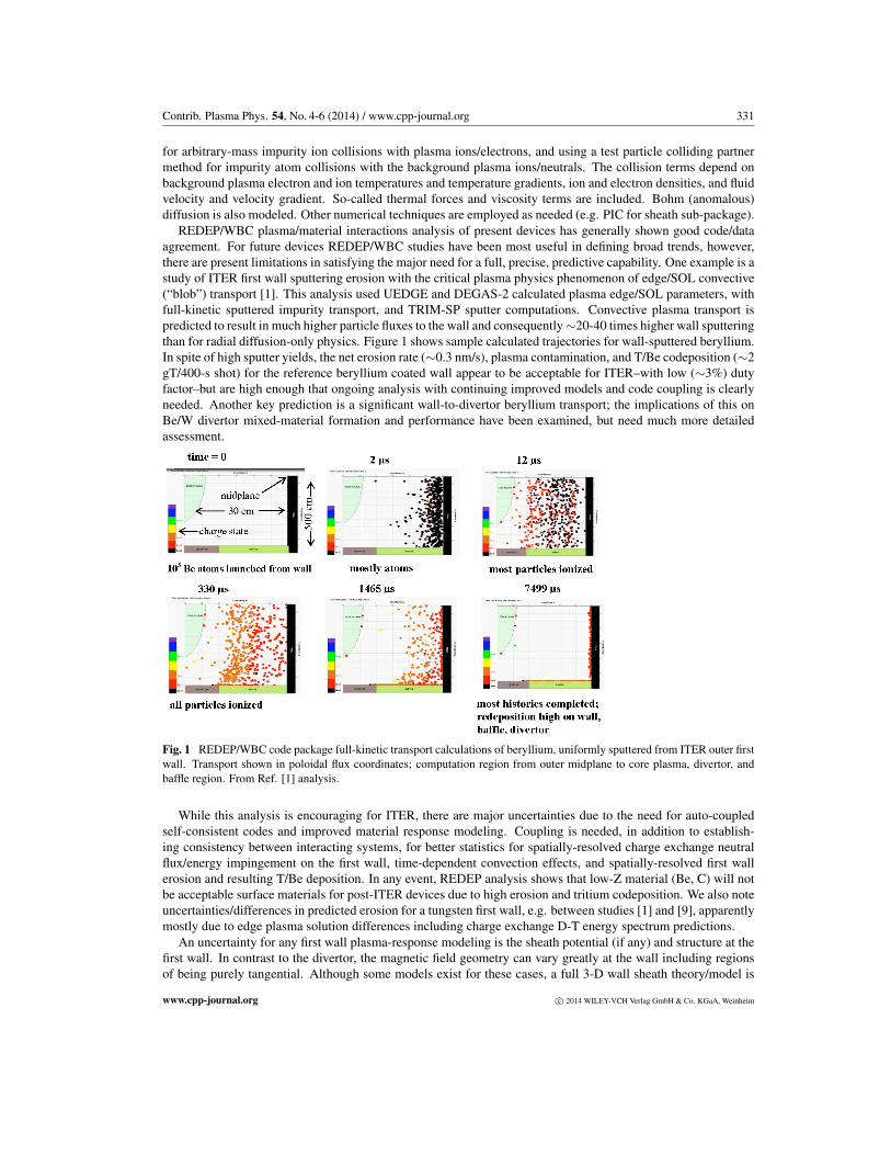
The need to obtain a consistent model of SOL plasma profiles to predict particle and heat flux profiles to PFCsprovides an example of coupling models. Because 3D BOUT++/BOUT simulates the detailed turbulence timescale, it can be inefficient to evolve the plasma profiles over the long time required for recycling to establish asteady state SOL plasma. Consequently, an algorithm has been developed to couple the turbulence fluxes fromBOUT to the 2D UEDGE transport code and in return, use the resultant modified plasma profiles within BOUTto evolve a new turbulent state. This iterative procedure has been shown to converge after about 10 iterations [20]using a procedure known as relaxed-iterative coupling. It is important to note that here it is the radial turbulentfluxes that are coupled, rather than diffusive transport coefficients that can be inferred from the turbulence. Theresulting plasma fluxes to the main chamber wall are shown in Fig. 4, where inclusion of the coupled turbulentfluxes shows the potentially strong fluxes to the main chamber (though the heat fluxes in this low-power DIII-Dexample are still modest). More recently, a more advanced model of the impact of plot propagation on radial heatflux has been developed [21]. Increased utilization of such coupled models, or more direct 3D simulations withneutrals and profile evolution, would substantially improve the realism of plasma fluxes to materials.
There are significant numerical challenges for these and similar plasma codes. In general, the accuracy ofthe discretization schemes should be improved. BOUT++ is finite-difference; this can cause important long-timeparticle conservation issues if used for transport. There are issues regarding accurate radial derivatives in stronglysheared magnetic fields, and with fluctuation levels ∼100% in the far SOL. Transport codes are typically only1st or at most 2nd order; 1st order upwinding is often used for robustness. Turbulence codes have made moreprogress in using higher order schemes, though they are sometimes of mixed order. The codes would benefitfrom consistent high-order discretization.
www.cpp-journal.org c⃝ 2014 WILEY-VCH Verlag GmbH & Co. KGaA, Weinheim
336 J.N. Brooks et al.: Scientific and computational challenges . . .
Fig. 4 Plasma fluxes to the DIII-D main-chamber wall showingcomparison of simulations with ad-hoc constant radial diffusivi-ties and those coupled to the 3D BOUT turbulence code for low-power conditions [20]. The strongly increased wall fluxes withcoupling illustrate the importance of modelling self-consistent tur-bulent plasma transport.
3.4 Neutral transport in the plasma
DEGAS-2 codeThis is a time-dependent 3-D code that uses a Monte Carlo technique to solve the Boltzmann equation for thevelocity space distribution function of the neutral species [22]. Collisional processes (dissociation, ionization,charge exchange, etc.) with specified (usually Maxwellian) background plasma are treated in full kinetic detail,via a differential scattering cross section. Nonlinear neutral-neutral scattering is simulated with an approximate,BGK technique. The most important source terms are those due to plasma-material interactions, e.g. backscatter-ing/reflection and desorption. Again, the use of the Monte Carlo algorithm allows these processes to be describedkinetically and in arbitrary detail. Since the simulated neutral particle histories are independent, the Monte Carloalgorithm parallelizes naturally. Consequently, DEGAS-2 was designed from the outset to run on parallel ma-chines, including the use of a specialized random number generator that provides reproducible results in suchenvironments.
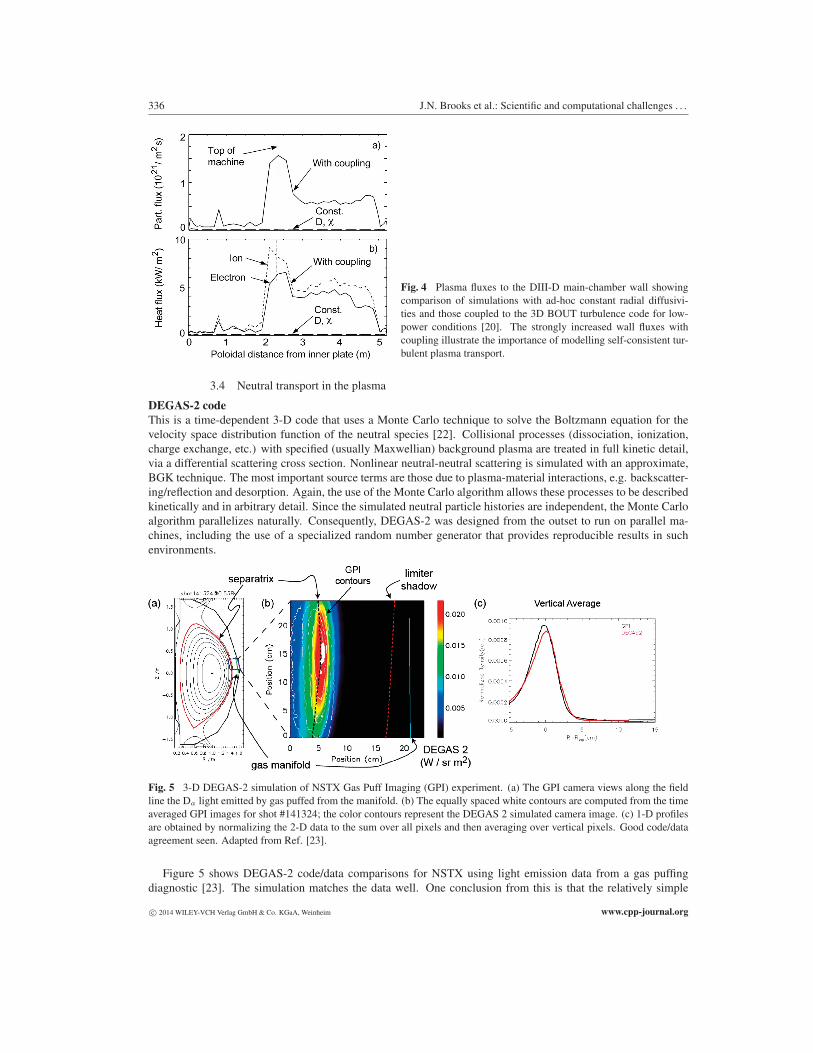
Fig. 5 3-D DEGAS-2 simulation of NSTX Gas Puff Imaging (GPI) experiment. (a) The GPI camera views along the fieldline the Da light emitted by gas puffed from the manifold. (b) The equally spaced white contours are computed from the timeaveraged GPI images for shot #141324; the color contours represent the DEGAS 2 simulated camera image. (c) 1-D profilesare obtained by normalizing the 2-D data to the sum over all pixels and then averaging over vertical pixels. Good code/dataagreement seen. Adapted from Ref. [23].
Figure 5 shows DEGAS-2 code/data comparisons for NSTX using light emission data from a gas puffingdiagnostic [23]. The simulation matches the data well. One conclusion from this is that the relatively simple
c⃝ 2014 WILEY-VCH Verlag GmbH & Co. KGaA, Weinheim www.cpp-journal.org

Contrib. Plasma Phys. 54, No. 4-6 (2014) / www.cpp-journal.org 337
atomic physics model used to describe the D2 molecules, ignoring the effects of excited states, is adequate forsimulating the relatively high-temperature, low density plasmas found in the main chamber of NSTX.
DEGAS-2 has previously been coupled to UEDGE in an iterative fashion to obtain consistent plasma-neutralsolutions and has also been used in conjunction with the REDEP/WBC package. Key features of DEGAS-2 areits flexibility and kinetic characterization of the neutral species. One algorithmic improvement that needs to beaddressed is the inclusion of REDEP/ITMC/MD-computed sputtering as a new source term. Plans also exist toextend the code to effectively utilize hundreds of thousands of processors.
3.5 TRANSIENT RESPONSE
3.5.1 HEIGHTS Code Package
.HEIGHTS (High Energy Interaction with General Heterogeneous Target Systems), e.g. [24, 25], is considered
the world’s leading tool for comprehensive simulation of plasma surface interaction and bulk response during var-ious transient events. HEIGHTS computes detailed vaporization loss, melt layer formation and splashing erosion,secondary damage to nearby plasma facing components (PFC), and eroded material transport and contaminationin the SOL and bulk plasma.
It is vital to fusion development that PFC material erosion and plasma contamination during transients bevery well simulated. Edge localized modes (ELM’s), for example, appear to be an unavoidable part of highperformance plasma operation, but there is a wide spectrum of ELM frequency, energy content, and power loadingthat may obtain, and the acceptable operating parameter window must be identified. Transient plasma materialerosion is an extremely complex self-consistent problem where the exposed local areas are coupled through MHDand radiation transport processes. Our simulations show the potential for significant damage to PFC surfaces inITER-like devices, during giant ELMs, disruptions, runaway electrons, and other transients, both directly from thedisrupting core plasma flux, and as a result of the divertor material evolution and secondary plasma radiation flux.Figure 6 shows a typical HEIGHTS computation of a fusion reactor PFC response; the predicted energy/powerflux and carbon erosion under impact of plasma particles during a disruption event in the region near a carbondivertor module in ITER.
The most significant erosion and plasma contamination problems in tokamaks are macroscopic melt splashesand MHD–related losses from metallic divertor plates and wall materials into the core plasma [26]. We imple-mented the volume of fluid model to predict the flow of plasma and liquid tungsten as two immiscible fluids ofdifferent densities. The plasma-liquid tungsten fluids are separated by a sharp interface under the effects of grav-ity and surface tension. We predicted the phenomena of continuous liquid tungsten ligaments, their elongation bythe plasma flow and development of long, thin threads that eventually can break into liquid droplets [27]. The lossof molten tungsten in the form of continuous long ligaments was clearly observed during melt splashes in recentTEXTOR experiments [27], confirming this phenomenon. Further refinement of melt layer behavior models isneeded in areas of viscosity effects, temperature-dependence of surface tension, melt-solid adhesion forces, heatand mass exchange, and melt crater finite size effects.
HEIGHTS analysis [28] for the ITER W divertor shows that tungsten will start to melt for giant ELMs ofenergy QELM >7-8% of plasma energy Q0, released at the midplane. The surface temperature will exceed themelting temperature and a melt layer thickness of 100 µm is developed for giant ELMs (QELM ∼10% Q0) de-posited in 1 ms-duration. A key HEIGHTS result, however, is that carbon has similar ELM and other transientconcerns as tungsten. Also, radiation from the resulting vapour cloud for either material can damage nearbycomponents. We have identified acceptable and unacceptable ELM parameter windows for ITER [28, 29]. Forthe unacceptable giant ELM of !10% deposited core plasma energy in 0.1 ms on the divertor (energy density> 3 MJ/m2), the erosion is high for carbon (0.2 µm/ELM). For tungsten there is less vaporization erosion thancarbon but significant melting. For longer deposition times (∼1 ms) and/or lower ELM energy the surface re-sponse for all materials is much better.
HEIGHTS can interface with the above mentioned codes for pre-transient plasma edge/SOL parameters. TheHEIGHTS simulation package itself includes five main integrated modules: Monte Carlo block of disruptingplasma particles interaction with solid and plasma facing materials; MHD block of plasma evolution taking intoaccount magnetic field diffusion; heat conduction and vaporization block for tokamak plasma facing components;heat conduction block for vapor and plasma; and Monte Carlo radiation transport. The radiation transport block is
www.cpp-journal.org c⃝ 2014 WILEY-VCH Verlag GmbH & Co. KGaA, Weinheim

338 J.N. Brooks et al.: Scientific and computational challenges . . .
based on optical data calculated by the HEIGHTS atomic physics package. Current HEIGHTS high performancenumerical methods and code parallelization is based on the message passing interface (MPI). Parallel algorithmsof hydrodynamics, magnetic diffusion and thermal conduction blocks use approximately equal domain partitionaccording to the number of processors available, employing utilities for optimum domain decomposition.
Fig. 6 Time integrated energy deposition, energy flux evolution(color background) and divertor erosion (black curve) during 0.1ms giant ELM, for ITER carbon outer divertor, strike point at x=0.HEIGHTS code package analysis. From Ref. [2].
Fig. 7 ITER SOL zones for 16 processorHEIGHTS PFC transient response modeling.
We recently developed an unstructured adaptive mesh computational approach, and reconstructed all inte-grated physical and numerical processes of the HEIGHTS package. A scheme using five spatial scales spanning6 orders of magnitude (m to µm) is used for accurate simulation of the entire SOL plasma transient response.Fig. 7 shows an example mesh setup. This approach aids in calculating the fully integrated material transientresponse in a reasonable time on multiprocessor computers. In general, HEIGHTS can simulate the plasma evo-lution and surface erosion dynamics in divertor and nearby areas following a plasma transient, using one weekof a typical (16-32 processor) computer cluster. However, a full simulation, of the whole reactor concept, wouldtake months, depending on the event duration. Therefore, we need a major expansion to order of 105 cores.
3.5.2 ALE-AMR code
This open-source code [30,31] complements the HEIGHTS package to implement critical 3D effects in plasma-wall interactions. By combining Arbitrary Lagrangian-Eulerian (ALE) hydrodynamics with Adaptive Mesh Re-finement (AMR), the code is able to accurately calculate 3-D bulk deposition effects as well as resolve small-scalestructures in the solid material, e.g. void generation, and molten material/droplets formation. Calculating the re-sponse to dynamic loading requires anisotropic material strength models with material time history, and modelsfor void generation, which are available in the code. A molten layer can be created on plasma facing componentsfollowing dynamic loading, and surface tension plays a critical role in the evolution of this layer. Imbalances invapor pressure leading to Rayleigh-Taylor instabilities can affect droplet formation. In addition, droplets behavioris affected by Marangoni stresses associated with temperature dependent surface tension. Currently, there are twomodels for surface tension implemented in the ALE-AMR code. The first is based on the advective Cahn-Hilliardequations, which allow for droplet breakup in divergent velocity fields without the need for imposed perturba-tions. The second is based on the Korteweg representation that couples the surface tension effects into the stresstensor.
The application of the ALE-AMR code, which was developed for inertial confinement experiments, to mag-netic fusion devices, can leverage a large effort in material response to dynamic loading. It provides a goodtechnique to strengthen and advance the capabilities afforded by the HEIGHTS package. Combining ALE hy-drodynamics with AMR can allow us to accurately calculate critical phenomena such as volume ablation, materialresponse including void generation, and surface droplet formation and splashing.
c⃝ 2014 WILEY-VCH Verlag GmbH & Co. KGaA, Weinheim www.cpp-journal.org

Contrib. Plasma Phys. 54, No. 4-6 (2014) / www.cpp-journal.org 339
3.6 Other codes
We believe that many of the strategies outlined here could apply to a number of other codes, from the extensiveset used in the fusion community. Such codes include those for overall plasma solutions, e.g. B2/EIRENE [32],impurity transport, e.g., ERO [33], and various codes for surface response, dust issues, and so forth, such as notedin Ref. [5].
4 Common needs and computational issues
The above codes/packages individually consider localized reactor plasma and material science areas. The fullpicture of the plasma/material response in the entire reactor configuration with various involved physics “talkingto each other” can be achieved by integration of these (or alternative) codes into two self-consistent main codepackages, for steady state and transient response respectively. Because individual codes have their own variousextensive physics, and different algorithms and methods for parallel calculations, the challenge is to employ com-putational strategies with advanced algorithms and optimization methods to address the coupling of these codesover extremely broad physical phenomena length and time scales, viz. angstroms to meters and femtoseconds(e.g., for individual particle trapping/reflection) to hours/days (e.g. for surface micro-structure changes), and withhighly disparate code execution times.
The overriding numerical goal is for petascale real-time coupling between material response/evolution/trappingcodes, near-surface plasma codes, and impurity transport codes, and with specific needs such as common incor-poration of PFC CAD geometry, and 3-D plasma and B field mesh generation/use. Use of ∼105 cores is neededand would enable major increase in predictive capability. Advanced numerical tools and solution methods in anintegrated parallel environment need to be used to efficiently couple these codes/packages, to ensure high ac-curacy and minimize execution time. This should include implementation of unstructured meshes for the entirePFC surfaces with extra surface refinements to account for details of surface evolution and erosion processes atthe micro and nano scale levels.
Full implementation of this goal would likely take on the order of 5 years, obviously depending on the effortlevel. However, significant progress can be made in a staged program. The best initial means for coupling thesecodes is probably a loosely coupled model. Here, the run time environment is used to address the control andstart-up of jobs in the parallel environment, and exchange of data is primarily through file communication. Later,one can consider using a more tightly coupled framework for coupling at the distributed shared memory (DSM)level. Capabilities to be exploited include end-to-end performance optimization, single-node performance, in-terprocessor communication, load balancing and I/O and performance portability for new systems, includingheterogeneous processors and new memory hierarchies.
Most of the codes above mentioned have been in use for a decade or more, consequently certain fundamen-tal code verifications has been completed. Nonetheless, additional verification tests of individual codes andintegrated code packages would be needed, against reference solutions where available, and/or to develop test so-lutions as needed, to improve confidence in the codes and to provide a starting point for subsequent error analysisand uncertainty quantification (UQ).
Some codes have similar capabilities, but target disparate length and time scales. Where those scales overlap,the two codes can be compared, with one essentially serving as a “reference” solution for the other. A cross-code comparison can essentially broaden the parameter space covered by a verification effort. An example isthe accelerated molecular dynamics techniques that can provide effectively first principles material responsesimulation capabilities at microsecond to millisecond time scales. An obvious opportunity for verifying such acode, given adequate resources, is to perform a brute-force run of the fundamental MD code to a much longertime scale than it is typically run and to compare with the result of the accelerated MD technique.
5 Conclusions
Plasma material interactions is the single most critical engineering issue for fusion tokamak development. Wehave described some key science/modeling issues and computational challenges for predictive simulation ofthe self-consistent plasma edge/SOL and plasma facing component response. For the most part, the requiredcomputer codes/packages, supercomputers, and numerical techniques already exist. There are some significant
www.cpp-journal.org c⃝ 2014 WILEY-VCH Verlag GmbH & Co. KGaA, Weinheim

340 J.N. Brooks et al.: Scientific and computational challenges . . .
science/model gaps, however, such as in the areas of the first wall sheath, tungsten ultrastructure, mixed-materialsurface properties/response, melted material properties, lithium issues, interatomic potentials for MD codes, andedge plasma turbulence. Theory/modeling advancements in these areas should of course complement a vigorousexperimental program.
We suggest that petascale computing with current parallel processing techniques is a reasonable and practicalapproach to the predictive simulation challenge. A logical division is for a normal plasma response coupled“super-package”, anchored by erosion/redeposition simulation, and incorporating surface response and detailededge/SOL plasma solutions; and secondly, a transient response super-package with similar inputs. Such coupledcodes/packages would use verification/validation and UQ efforts as roughly outlined here.
References[1] J.N. Brooks, J.P. Allain, and T.D. Rognlien, Physics of Plasmas 13, 122502 (2006).[2] V. Sizyuk and A. Hassanein, Nuclear Fusion 50, 115004 (2010).[3] US DOE/OFES, “Report of the Research Needs Workshop (ReNeW)”, Bethesda MD, ( 2009).[4] J.N. Brooks et al., “Plasma-Material Interaction Science Challenges Panel Report”, in “Scientific Grand Chal-
lenges; Fusion Energy Sciences and the Role of Computation at the Extreme Scale”, DOE Workshop(2009), Pacific Northwest Laboratory Report PNNL-19404; http://science.energy.gov/ ∼/media/ascr/pdf/program-documents/docs/Fusion report.pdf.
[5] G. Federici et al., Nuclear Fusion 41, 1967 (2001).[6] J.N. Brooks, Physics of Fluids 8, 1858 (1990).[7] J.N. Brooks, Fusion Eng. Des. 60, 515 (2002).[8] J.N. Brooks and D. Naujoks, Physics of Plasmas 7, 2565 (2000).[9] V. Kotov et al., Physica Scripta T138, 014020 (2009).
[10] J.P. Allain and J.N. Brooks, Nuclear Fusion 51, 023002 (2011).[11] J.N. Brooks et al., Fusion Eng. Des. 87, 1737 (2011).[12] J. Canik, (ORNL), pers. comm., (2010).[13] A. Hassanein, Fusion Technol. 8, 1735 (1985).[14] T. Sizyuk, A. Hassanein, J. Nucl. Mater. 404, 60 (2010).[15] P.S. Krstic, R. J. Harrison, and B. Sumpter, Physica Scripta T124, 101 (2006).[16] P.S. Krstic et al., Phys. Rev. Lett. 110, 105001 (2003).[17] P.S. Krstic, C.O. Reinhold, and S.J. Stuart, J. Applied Physics 104, 10), 103308 (2008).[18] T.D. Rognlien and M. E. Rensink, Fusion Eng. Des. 60, 497 (2002).[19] B.D. Dudson et al., Comp. Phys. Comm. 180, 1467 (2009).[20] T.D. Rognlien, M.V. Umansky et al., J. Nucl. Mater. 337-339, 327 (2005).[21] A.Yu. Pigarov, S.I. Krasheninnikov, and T.D. Rognlien, Phys. Plasmas 1, 072516 (2012).[22] D.P. Stotler et al., J. Nucl. Mater. 290-293, 812 (2001).[23] B. Cao et al., Fusion Sci. Tech. 64, 29 (2013).[24] A. Hassanein, Fusion Eng. Des. 60, 527 (2002).[25] V. Sizyuk, A. Hassanein, Nuclear Fusion 53, 073023 (2013).[26] A. Hassanein et al., J. Nucl. Mater. 241, 288 (1997).[27] G. Miloshevsky, A. Hassanein, Nuclear Fusion 50, 115005 (2010).[28] A. Hassanein, T. Sizyuk, I. Konkashbaev, J. Nucl. Mater. 390-391, 772 (2009).[29] J.N. Brooks et al., Nuclear Fusion 49, 035007 (2009).[30] A.E. Koniges et al., Journal of Physics: Conference Series 244, 032019 (2010).[31] D.C. Eder, A.C. Fisher, A.E. Koniges, and N.D. Masters, Nuclear Fusion 53, 113037 (2013).[32] H. Verbeek et al., Nuclear Fusion 38, 1789 (1998).[33] D. Naujoks et al., Nuclear Fusion 33, 581 (1993).
c⃝ 2014 WILEY-VCH Verlag GmbH & Co. KGaA, Weinheim www.cpp-journal.org