
SCIENTIFIC PROGRAMME - EUROSIS
122
SCIENTIFIC PROGRAMME
-
Upload
khangminh22 -
Category
Documents
-
view
4 -
download
0
Transcript of SCIENTIFIC PROGRAMME - EUROSIS

SCIENTIFIC PROGRAMME


GAMES DESIGN AND
DEVELOPMENT


A REVIEW OF 3-D ACCELERATOR TECHNOLOGY FOR GAMES
NATHAN CHIA, RICHARD CANT, DAVID AL-DABASS
Department of Computing and Mathematics
The Nottingham Trent University Nottingham NG1 4BU.
Email: richard.cant/[email protected]
KEYWORDS OpenGL, DirectX, anti-aliasing, animation graphics. ABSTRACT In this paper we attempt to review the current technology of 3 -D accelerators for animating graphics used in games and visual simulation systems, together with associated techniques and software architectures. Topics covered include OpenGl, DirectX, anti-aliasing, motion blur and depth of field. A summary of work in progress is give in the conclusions section. INTRODUCTION Ever since 3dfx released their first Voodoo card (the first 3D hardware accelerator for the consumer market), it had always been a 5 horse race between the top video card makers: nVidia, 3dfx, ATI, Matrox and S3. It was a race to see who can hit the highest screen resolution and who can draw the most polygons in a period of time. It was rarely about making the real-time renders closer to real-life. 3dfx came out with a simplified version of the accumulative buffer to gain more speed from the available version. It was named the ‘T-buffer’ and it was introduced as the solution for drawing effects like motion blur, depth-of-field and multi-sampling anti-aliasing in real-time. Now that 3dfx has faded away and nVidia is bringing out with their own version of multi-sampling anti-aliasing named ‘Quincunx AA’, it seems everyone had forgotten about the things that the T-buffer had put out to do. In this paper we will first review the development of 3-D graphics technology and the current state of the art. We will then discuss some effects that remain to be incorporated in 3-D rendering systems. The problems facing 3D accelerators today are mainly spatial aliasing, depthless rendering, temporal aliased animation and images looking 'too perfect'. One might question the motive for this by asking isn’t it better to have sharper, perfect renders rather than distorting them? However, including these effects will give a greater feel of realism
and improve game play by modifying the difficulty of task. Hopefully these effects can be included in ways that exploit the features of current hardware such as texture mapping support. This will give software and game makers more freedom to create 3D renders with their very own style in them. The consumers will benefit from this greatly as more real-time graphics is pushed towards reality. THE HISTORY OF COMPUTER GRAPHICS Computer Graphics first started in 1945 when one of the earliest electronic computers, the ENIAC (Electronic Numerical Intergrator And Computer), was built at the University of Pennsylvania’s Moore School of Engineers. By the 1950s, they were powerful enough to deal with computer graphics. To handle the task of drawing lines, special vector display devices were designed to be interfaced to the computer. Vector display can produce wire-frame images (Figure 1), which needed only a minimal amount of storage. As computer memory is extremely expensive in those days, it was only capable of drawing a list of segments. As the 60s grew nearer, General Motors and IBM jointly designed the DAC-1 (Design Augmented by Computer). It allowed the user to enter geometric specification of a wire-frame object and view it from different angles (Figure 2).
Figure 1 Vector Display
Figure 2 Wire-frame Object
In the 1960s, Digital Equipment Corporation (DEC) produced the PDP-1 computer. MIT bought one of the machines and a group of its students created the first video game – Spacewars. The game was so popular

that it took up more than half the usage time on the PDP-1 and it was used as a benchmark for newer computers. Despite it’s popularity, it was never copyrighted because very few people could afford the hardware that runs it, and the concept had been copied numerous times. In the 1960s, another MIT student, Ivan Sutherland, built the first head mounted display. The device was capable of displaying two separate wire-frame images, one for each eye. The two images were generated from slightly different angles of view that corresponds to the position of the eye. This technique created the stereoscopic effect of depth (Figure 3). In 1967, General Electric (founded by Sutherland and Dave Evans from the University of Utah) developed the first real-time flight simulator for NASA.
Figure 3 Ivan Sutherland’s head mounted display
image There had been a great increase in speed and quantities and decrease in price for computers in the 70s, which rendered the raster display devices practical. Raster display devices represents images as a regular mosaic of dots, known as pixels, each with different colour and shade. Solid object generation is also possible. (In 1977, a 512-by-512 display acquired by the National Institute of Health, in USA, cost US$65000. A similar one today can be bought for less than $50.) In 1971, Henri Gouraud proposed an algorithm to interpolate a polygon’s colour to produce a continuous matte object as opposed to flat surfaced ones (Figure 4). Later, in the University of Utah, Phong Bui-Toung proposed a method similar to Gouraud’s. It aimed to model shiny surfaces approximated by polygons (Figure 5). In 1974, Ed Catmull (who went on to lead the graphics division of Lucasfilm) proposed texturing mapping, Z-buffering hidden surface removal, and modelling with curved surfaces. These techniques are now commonly available in all 3D accelerator cards. Zbuffer is the area of the graphics memory used to store the Z or depth information about rendered objects. The Z-buffer value of a pixel is used to determine if it is behind or in front of another pixel. Z calculations prevent background objects from overwriting foreground objects in the frame buffer. Two years later, Jim Blinn developed environmental reflection mapping and bump mapping which adds details to a 3D model without adding more polygons
(Figure 6). A modern processor, which does the real-time environmental bump mapping very well, is the G400 series from Matrox. Real-time reflection mapping is claimed to be available in the hardware of nVidia’s NV15,- it is just the hardware’s ability to take snapshots quickly from the scene so that they can be used as reflective textures.
Figure 4 Sphere drawn with and without Gouraud
Shading
Figure 5 Gouraud Shading and Phong Shading Bump mapping is a shading technique using multiple textures and lighting effects to simulate wrinkled or bumped surfaces. Bump mapping is useful because it gives a 3D surface the appearance of roughness and other surface detail, such as dimples on a golf ball, without increasing the geometric complexity. Some common types of bump mapping are Emboss Bump Mapping, Dot3 Bump Mapping, Environment Mapped Bump Mapping (EMBM) and True, Reflective Bump Mapping. Dot3 bump mapping is the most effective technique of the three. In 1982, Silicon Graphics (founded by Jim Clark) produced computers with built-in capabilities for graphics. Since then, computer graphics started to appear in movies. The first was in Disney’s Tron, which used approximately 30 minutes of computer graphics. Lucasfilm and its famous Industrial Light and Magic division (later, part of it was branched off as Pixar) progressed from the projection of the Death Star in Return of the Jedi to the sophisticated animation of Jurrasic Park. 3D graphics also started to take off in the gaming industry on the IBM-PC in 1991. In 1991, John Carmack, Adrian Carmack and John Romero founded id Software and released Wolfenstein 3D (Figure 7). Although the game used a much simplified texture mapping and projection techniques, and “bill-boarding” was used heavily, it considerably raised the expectations for 3D graphics in computer games. This

placed id Software on the map and its now developing the sequel to the classic.
Figure 6 Phong Shading, Environmental Reflection
Mapping and Bump Mapping Bill-boarding is to have the quadrilateral polygon drawn base its orientation on the view direction. As the view changes, the orientation of the polygon changes. Bill-boarding, combined with alpha texturing and animation, can be used to represent many phenomena that do not have solid surfaces. Smoke, fire, explosions, vapor trails, and clouds are just a few of the objects that can be represented by these techniques. But for id’s case, bill-boarding is used to pre-draw or pre-render the characters in its game into a texture and is more effective for the computer at that time to draw just one polygon for each character rather than rendering them in real-time.
Figure 7 id Software’s Wolfenstein 3D
Most recently, graphic cards with 3D algorithms built into the hardware became affordable for the personal computers. Quality real-time 3D graphics that used to be only possible on specialized workstations is now possible on the normal PC (Figure 8).
Figure 8 id Software’s sequel to Wolfenstein 3D
The remaining top players are nVidia and ATi. 3dfx was bought over by nVidia and Matrox is now focussing on the ‘office’ market. Recently, however, 3DPower is formed by the ex-employees of 3dfx and headed by former CTO Scott Sellers. The 3dfx ex-employees
secretly gathered without the knowledge of 3dfx or nVidia and their new product will be based specifically on 3dfx’s previous Rampage graphics chipset. With this huge variety of graphics card to program for, developers will soon find that the situation is becoming more and more chaotic. Every PC user owns a different graphics card and new hardware keeps popping day after day. Here’s where API comes into the picture. The APIs available now are OpenGL and DirectX. CURRENT APIS, BENEFITS AND LIMITATIONS OpenGL The definition of OpenGL was a software interface to graphics hardware. Better describing it would be a 3D graphics and modelling library that is extremely portable and fast. The greatest strength of OpenGL compared to a ray tracer is speed. Ray tracing is also known as the screen-to-world method. The idea of ray tracing is quite different to OpenGL world-to-screen method, which is projection of a 3D scene to a two-dimensional buffer. In ray tracing, for every pixel on the screen, a ray is cast into the representation of the virtual world until it intersects with some surface. The colour of that surface in the intersection point is what is supposed to be seen at that pixel on the screen. It is a new industry standard that had gained enormous support over a few years. It originated from IRIS GL from Silicon Graphics. It is the company’s 3D programming API for the IRIS graphics workstations. These machines had specialized hardware optimised for the displaying of sophisticated real-time graphics. The IRIS hardware does hardware matrix transformations, hardware depth buffering, and other features. OpenGL was born when Silicon Graphics got stuck trying to port IRIS GL to other hardware platforms. OpenGL is in fact an improvement in IRIS GL’s portability. It has the same capabilities of IRIS GL but is “OPEN” for adaptability to any hardware platforms and operating systems. OpenGL is more like a C runtime library rather then an application itself and it is intended to be used with specialized hardware that is designed to draw and manipulate 3D graphics. Because of its efficiency, OpenGL is used in a large number of areas, like CAD, architectural, modelling and animations. And with hardware accelerators and faster processors becoming essentials, 3D graphics will soon be a typical building block for any consumer and business applications. A good example of such is
Quattro Pro, one of the pioneers to utilise 3D to power its 3D charting of the old 2D spreadsheets. OpenGL would add a lot of pleasant appearance to products because appearance does matter. To ensure that a particular hardware is OpenGL compatible, it must undergo OpenGL conformance tests. These are a set of tests designed to ensure full implementation and production of reasonably acceptable 3D renders.
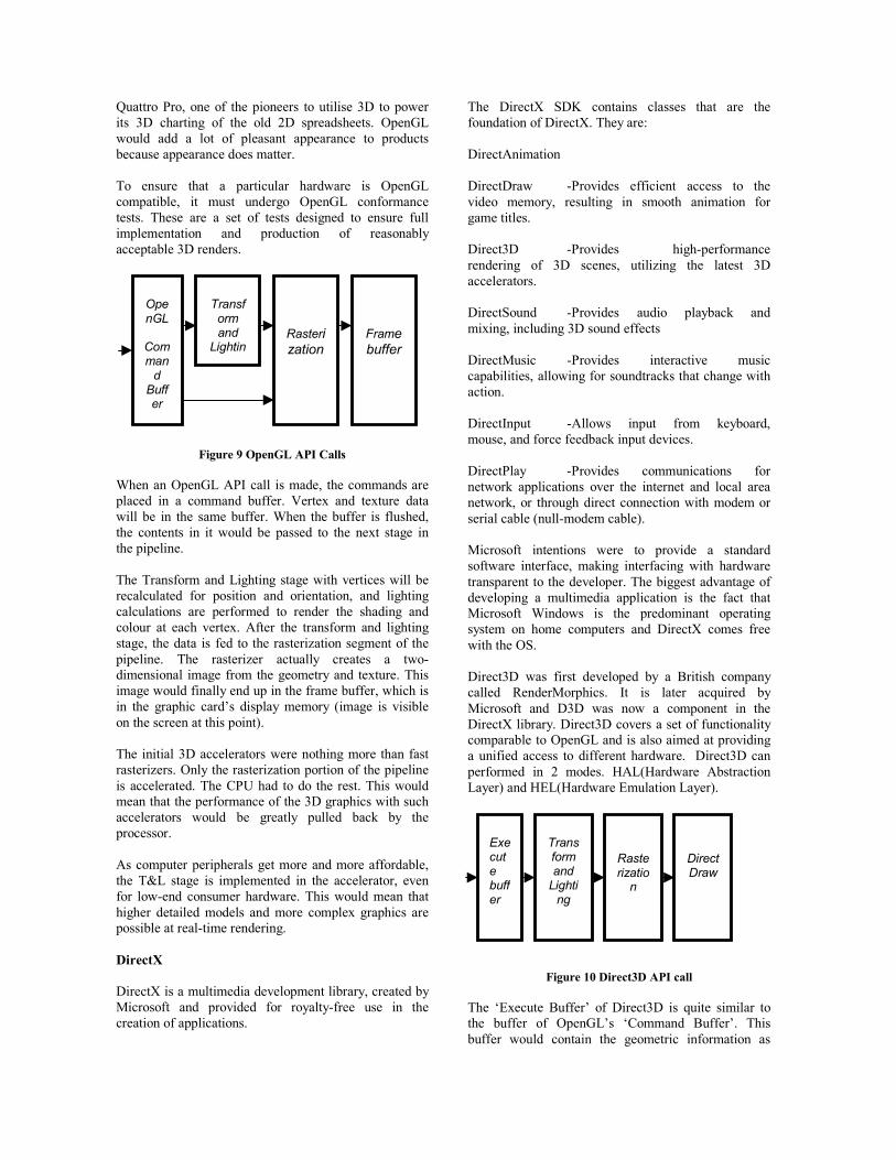
Figure 9 OpenGL API Calls When an OpenGL API call is made, the commands are placed in a command buffer. Vertex and texture data will be in the same buffer. When the buffer is flushed, the contents in it would be passed to the next stage in the pipeline. The Transform and Lighting stage with vertices will be recalculated for position and orientation, and lighting calculations are performed to render the shading and colour at each vertex. After the transform and lighting stage, the data is fed to the rasterization segment of the pipeline. The rasterizer actually creates a two-dimensional image from the geometry and texture. This image would finally end up in the frame buffer, which is in the graphic card’s display memory (image is visible on the screen at this point). The initial 3D accelerators were nothing more than fast rasterizers. Only the rasterization portion of the pipeline is accelerated. The CPU had to do the rest. This would mean that the performance of the 3D graphics with such accelerators would be greatly pulled back by the processor. As computer peripherals get more and more affordable, the T&L stage is implemented in the accelerator, even for low-end consumer hardware. This would mean that higher detailed models and more complex graphics are possible at real-time rendering. DirectX DirectX is a multimedia development library, created by Microsoft and provided for royalty-free use in the creation of applications.
The DirectX SDK contains classes that are the foundation of DirectX. They are: DirectAnimation DirectDraw -Provides efficient access to the video memory, resulting in smooth animation for game titles. Direct3D -Provides high-performance rendering of 3D scenes, utilizing the latest 3D accelerators. DirectSound -Provides audio playback and mixing, including 3D sound effects DirectMusic -Provides interactive music capabilities, allowing for soundtracks that change with action. DirectInput -Allows input from keyboard, mouse, and force feedback input devices. DirectPlay -Provides communications for network applications over the internet and local area network, or through direct connection with modem or serial cable (null-modem cable). Microsoft intentions were to provide a standard software interface, making interfacing with hardware transparent to the developer. The biggest advantage of developing a multimedia application is the fact that Microsoft Windows is the predominant operating system on home computers and DirectX comes free with the OS. Direct3D was first developed by a British company called RenderMorphics. It is later acquired by Microsoft and D3D was now a component in the DirectX library. Direct3D covers a set of functionality comparable to OpenGL and is also aimed at providing a unified access to different hardware. Direct3D can performed in 2 modes. HAL(Hardware Abstraction Layer) and HEL(Hardware Emulation Layer).
Figure 10 Direct3D API call The ‘Execute Buffer’ of Direct3D is quite similar to the buffer of OpenGL’s ‘Command Buffer’. This buffer would contain the geometric information as
OpenGL
Comman
d Buffer
Rasterization
Transform and
Lightin
Frame buffer
Execute buffer
Rasterizatio
n
Transform and
Lighting
DirectDraw

well as commands to be performed. Unlike OpenGL, the execute buffers are quite cumbersome to work with. Multiple data structures must be allocated, locked, filled up in order to construct them. The final module, 'DirectDraw', actually handles the access of the frame-buffer. Another disadvantage of Direct3D is that it only supports triangles. OpenGL supports polygonal objects as long as all the points are convex and no intersection is occurred. CURRENT TECHNIQUES Anti-aliasing One of the biggest faults of raster graphics to all PC users which needs no introduction is aliasing. Because we are so used to perceive images in an “infinite” resolution, it would be quite impossible to try to achieve that with higher and higher screen resolutions. No matter how high the resolution goes, the eyes will still tell the mind that the staircase edges are still evident when observed closely. It is the same reason why a 320x240 MPEG1 video might looks more pleasing than a 1024x768 real-time 3D render. That is why anti-aliasing plays such an important part in producing a realistic image. Also due to the impracticality of building an infinite resolution display, another shortcoming of raster graphics is under-sampling. This effect gets more visible when textured objects are drawn smaller or further away. For example, visualise a checkers board in the middle of the screen. It moves further away in the 3D scene. One would expect that as it gets further, the white and black would blur into a shade of grey. It doesn’t (Left image of figure 11). In fact, the viewer would witness a shimmering effect at some point. The pixels alternate between black and white.
Figure 11 Checkered Texture without filtering (Left) and
with filtering (Right) This aliasing found in Figure 11 can be reduced by the use of bilinear filtering and MIP maps. The essential idea of MIP mapping is to pre-compute the texture at different levels of detail (Figure 12), and then to use smaller textures for polygons further away from the viewer. Bilinear filtering is used for textures that are magnified to smooth out the jaggies. This could be improved further by bilinearly blending neighbouring levels of MIP maps to generate more levels of detail. This is known as trilinear filtering. Although this will
not truly eliminate aliasing, the shimmering effect mentioned earlier would be eliminated.
Figure 12 Generating smaller images
Another method of removing aliasing is to make use of the accumulative buffer of the hardware accelerator. This can be quite time consuming and hence cannot be used in real-time animation. It is, however, relatively easy to implement. The technique is to jitter the image one-half a pixel in several directions, to blur the edges of an image but not the solid areas. Only four jitters is necessary to produce a remarkably smooth image but even four jitters will require the whole scene to be rendered 4 times. Another anti-aliasing technique which most hardware accelerator implements is super-sampling. Super-sampling anti-aliasing draws the scene in a much larger buffer than the screen resolution and scales it down to fit the screen. The filtering procedure will take a group of pixels from the original image and compute the weighted sum of their intensities. The result from this sum will be placed into a filtered image bitmap. This will then be placed onto the frame buffer to show the antialiased image. This however requires a significant amount of video memory and bandwidth. (Bandwidth is still the main limitations of most hardware accelerators. Most accelerators could be perceived as large buckets with tiny bottlenecks.) Another technique, which the latest Geforce 3 card from nVidia is using for anti-aliasing, is multisampling. nVidia patented it and calls it HRAA (High Resolution Anti-aliasing) or Quincunx anti-aliasing. nVidia claims that it provides performance that rivals a 4X super-sampling anti-alising render with the performance hit slightly more than a 2X super-sampling anti-aliasing render. This technique uses a “reconstruction filter” that uses data from the neighbouring pixels to compute the final pixel colour. nVidia will no longer be "blowing up" the 800x600 screen to 1600x1200 and then shrinking it back down in hardware to do their anti-aliasing in their new Quincunx mode. Quin·cunx (kwin'kungks) - It is an arrangement of five objects, with one at each corner of a rectangle or square and one at the center (like the side ‘5’ of a dice). This is a reference to the way they

sample the pixels that are used to fill in the jaggies. It pulls information from the pixels surrounding a pixel in order to smooth out the lines that are not perfectly vertical or horizontal. This means that a significant amount of bandwidth and memory usage can be greatly reduced. Motion Blur The deficiency of motion blur is also a form of aliasing known as temporal aliasing (the previous form aliasing could be called spatial aliasing). The human eyes are fast enough only for 25-30 frames per second, and less in darker scenes. But the human eye is capable for blurring several consecutive frames that are flipped too quickly. That is why real-time 3D animations that moves at 24 frames per second looks less convincing than in the movies which moves at the same rate. Temporal aliasing can also be seen in some videos of moving carts in cowboy movies where the spokes of turning wheels suddenly appear to be going the opposite direction when it is not. It happens when the sampling rate of the camera gets lower than rate of movement of the spoke moving to the position of the next one. In 3D graphics, without motion-blurring, the result would be even worse than in the movies. Motion blurring would add a blur trail to hint to us the direction where the spoke is moving towards and gives an illusion of a more fluid animation. Depth Of Field The human eye is able to focus on a particular object and the rest of the “extras” in our scene will be defocused. We can often see how this effect is used to allow even a still image to be more dramatic in the movies. How photographers with their award masterpiece capture the essence of an object by using depth of field.
Figure 13 Elsa 3D
Revelator Figure 14 Left and Right
Images on Alternate Lines The effect of ‘Depth of Field’ can be achieved by the use of some affordable 3D glasses (Figure 13). The glasses has to be in sync with the refresh rate of the monitor. By altering the display drivers so that what the left eye sees will go on the odd lines of the screen and
what the right eye sees to the even lines (Figure 14). The left side of the glasses will turn opaque when the even lines are drawn and will turn transparent when the odd lines are drawn. The right side does the exact opposite. Disadvantages are that the vertical resolution will be reduced by half and it will often cause discomfort to the person viewing when the view of that person is not positioned right in the centre from the centre of the monitor. The illusion of depth of field can also be achieved by using (once again) the accumulative buffer. The idea is to do multiple renders with the source of the view-port offset slightly around the original position (Figure 15). The target of the view-port will remain at the position of the focus distance. Once again, the use of the accumulative buffer might be too time-consuming for most hardware accelerators.
Figure 15 DOF effect with Accumulative Buffer
CONCLUSIONS AND WORK IN PROGRESS A review of current state of the technology in computer graphics and 3-D accelerators for games was given. A brief history of graphics was outlined which focused on OpenGL and DirectX. A review of current techniques was described which included anti-aliasing, motion blur and depth of field. Current work addresses the following problems: Lack of a customizable graphics engine: to demonstrate and implement the algorithms, reasonably believable 3D scenes and models are required to be constructed. There is also a need for better texture management for the graphics engine to be more flexible and easier to use. Textures are also used within the model importer, so, the texture library must be intelligent enough to prevent duplicate loadings of the same texture and yet keep this invisible from the programmer. A model importer that supports multiple textures and can support deformation for character animation is needed too.

Spatial aliasing: due to the nature of raster displays, aliasing artifacts are introduced into a real-time scene. The brute force method of super-sampling antialiasing adopted by current graphics card seems to do the job quite well but has a big performance hit. The hardware filters are also not customizable by the programmer. Depthless renders: current hardware has the ability of fogging which reduces the depth confusion in an image. But the existence of fogging in a small area, like a room, will make a scene look artificial. There is a need for another mechanism, like depth-of-field, that would reduce that confusion without the use of fog. It should imitate the depth-of-field witnessed in real-life photography. Temporal aliasing: Because of this effect in real-time computer graphics, graphics cards need to render at very high frame-rates to create the illusion of fluid motion. Multi-pass techniques consumes much processing time and hence power. REFERENCES
1. Richard S. Wright, Jr and Micheal Sweet, "OpenGL Super Bible", 2nd Edition, By Waite Group Press.
2. Robert Dunlop with Dale Shepherd and Mark Martin, "DirectX7 (Teach Yourself … in 24 hours)",SAMS.
3. Sergei Savchenko, "3D Graphics Programming", SAMS.
4. Rod Stephens, "Visual Basic Graphics Programming", Wiley
5. NVIDIA's Developer Relations Site, (SDKs, technical papers, demos) http://www.nvidia.com/developer.
6. Neon Helium Productions, (Tutorials, base code, AVI loader), http://nehe.gamedev.net.
7. Code Guru, http://www.codeguru.com. 8. Emeran, R., Mongomery, S. & Werfall, J.,
(2000) Pixel perfect - graphics card review, Personal Computer World, Oct. 2000, 195-213.
9. Montgomery, S. (2001) Graphics Cards, PCW, Sept. 187-199.
10. Emeran, R. et al (2001) Graphics galore (graphics card group test), PCW, Sept 161-181.
11. Wen et al (2000) Creating Animated Behavioural Game Characters based on Environmental Effects, Proc GAME-ON 2000 Int Conf, pp76-80.

KEYWORDS Motion Design, Human Interface, Software Architecture, Game Toolkit, Component ware. ABSTRACT For 3D game creation, character design is a very important factor but very hard work. Especially its motion design is very laborious work. We have to spend much time to design character's motions. So this paper proposes new motion editing environment for 3D game character design. The proposed motion editing environment is based on a key-frame animation technology. In conventional tools for key-frame animation, each key-pose is defined and displayed separately on a computer screen so that users can not recognize its complete motion until they see its animation by applying a defined motion to a character. The proposed motion editing environment displays all sequential key-poses at the same time on a computer screen. Then by seeing those key-poses users can recognize a complete motion those key-poses mean and can edit each key-pose interactively and easily by comparison with its adjoining poses. Furthermore, the proposed motion editing environment is realized as composition of several software components so that users can make its copy and transfer the copy to other computers through Internet. As a result, users can create motions only by reusing and modifying the motions already defined by other users. 1. INTRODUCTION Advances in recent computer hardware technology have made possible 3D rendering images in real-time. However, it is still difficult for end-users to develop 3D graphics software. For this reason, Okada and Tanaka developed a 3D prototype system called IntelligentBox(Okada and Tanaka 1995). IntelligentBox is a component based construction system. Its application fields include various kinds, e.g., animation creation (Okada and Tanaka, 1999), collaborative virtual environment construction (Okada and Tanaka, 1998), education system development (Okada and Itoh, 2001) and so on. IntelligentBox also has aspects as an interactive 3D game development system (Okada et. al., 2000). For 3D game creation as well as 3D animation creation, 3D shape design and motion design are the most laborious works. Traditional motion design is based on
key-frame animation. A motion is represented as a sequence of a number of poses those are automatically generated by interpolation of several key-poses, which are poses used as keys of key-frame animation. Each key-pose is defined by specifying the joints angles of a character. In conventional tools for key-frame animation, each key-pose is defined and displayed separately on a computer screen so that users can not recognize its complete motion until they see its animation by applying a defined motion to a character. So this paper proposes new motion editing environment for 3D game character design. The proposed motion editing environment is also based on a key-frame animation technology. However, the proposed motion editing environment displays all sequential key-poses at the same time on a computer screen. Then by seeing those key-poses users can recognize a complete motion those key-poses mean and can edit each key-pose interactively and easily by comparison with its adjoining poses. We have already developed such motion editing environment using IntelligentBox. As mentioned above, IntelligentBox is a component based development tool that provides functional components called boxes. The proposed motion editing environment is developed as a composite box, which includes user-defined motion information itself. Therefore, users can exchange their edited motions each other through Internet by copy-and-transfer operations, and create motions only by modifying the motions already defined by other users. [Related Work] There are many researches on motion generation for computer animation. (Witkin and Kass, 1988) proposed concept of spacetime constraints. After that, many research papers based on spacetime constraints were published. IK(Inverse Kinematics) is one of the popular methods for efficient motion generation. The motion path functionality is also a popular technique to intuitively define movement of a character's center of mass. Furthermore, the use of motion capture data has been becoming common. Many animation creation software products have been made so far. Most of them provide a traditional key-frame animation function, IK and a motion path function. Those products include 3D Studio MaxTM, LightWaveTM and so on. IK is a powerful tool but it is not always available for arbitrary motion definition. Then key-frame animation is
COMPONENT BASED MOTION EDITING ENVIRONMENT
FOR 3D GAME CHARACTER DESIGN
Yoshihiro Okada Graduate School of Information Science and Electrical Engineering,
Kyushu University 6-1 Kasuga-Koen, Kasuga Fukuoka 816-8580, Japan
E-mail: [email protected]

still used in many cases. Life FormsTM provides a graphical timeline display functionality of key-poses. Users can understand a motion by seeing the graphical timeline of its key-poses. However, it does not include movement information of a character's center of mass. In our motion editing environment, users can edit each key-pose of a character, which includes the movement of its center of mass besides its joints angles. Most products also support the use of motion capture data. However, most of the motion capture data are human motions. For animation creation of animals and other characters except human-like figures, users have to define their motions based on key-frame animation. Therefore, our motion editing environment is significant since there are few researches on efficient and intuitive interface for motion design based on key-frame animation. Gleicher proposed a motion editing based on spacetime constraints (Gleicher, 1997). Lee proposed an interactive motion editing method for human-like figures (Lee and Shin, 1999). Both of their systems provide an interactive and graphical interface for motion editing. Those are very intuitive interfaces. However, their systems are dedicated to generate motions. Our system is an integrated system so that the user can create 3D game characters in the one integrated environment. The remainder of this paper is organized as follows. Section 2 explains essential mechanisms of IntelligentBox and shows its simple composite box example. Section 3 explains the motion editing environment and its realization mechanisms. Section 4 shows motion definition examples. Finally section 5 concludes this paper. 2. ESSENTIAL MECHANISMS OF INTELLIGENTBOX IntelligentBox employs the following essential mechanisms inherited from IntelligentPad (Tanaka 1996), which is a 2D synthetic media system since IntelligentBox is an extension of IntelligentPad to 3D graphics applications. 2.1 Model-View-Controller (MVC) Structure As shown in Figure 1, each box consists of two objects, a model and a display object. This structure is called an MD (Model-Display object) structure. Strictly speaking, a display object consists of two objects, a view and a controller. Therefore, this structure is called an MVC structure. A model holds state values of a box. They are stored in variables called slots. A view defines how the box appears on a computer screen. A controller defines how the box reacts to user operations. Figure 1 also shows messages between a display object and a model. This is an example of a RotationBox. A RotationBox has a slot named ‘ratio’ that holds a double precision number, which means a rotation angle. This value is normalized between zero and one. One means one rotation. Through direct manipulations on a box, its associated slot value changes. Furthermore, its visual image simultaneously changes according to the slot value change. So a box reacts to a user's manipulations according to its function.
2.2 Message-Sending Protocol for Slot Connections Figure 2 illustrates a data linkage concept among boxes. As shown in the figure, each box has multiple slots. Each slot can be connected to one of the slots of an other box. This connection is called a slot connection. The slot connection is carried out by some messages when there is a parent-child relationship between two boxes. There are three standard messages, i.e., a set message, a gimme message and an update message. These messages have the following formats: (1) Parent box set <slotname> <value>. (2) Parent box gimme <slotname>. (3) Child box update. A <value> in a format (1) represents any value, and a <slotname> in formats (1) and (2) represents a user-selected slot of the parent box that receives these two messages. A set message writes a child box slot value into its parent box slot. A gimme message reads a parent box slot value and sets it into its child box slot. Update messages are issued from a parent box to all of its child boxes to tell them that the parent box slot value has changed. In this way, these three messages connect a child box slot and its parent box slot, and combine their two functions. 2.3 A Simple Example of Composite Boxes Figure 3 shows a simple composite box example. Figure 4 illustrates its message flow and data flow. In this example, the motor is a counter box having a cylindrical shape. Its model has a slot with a double precision number value that is increased automatically by a timer process. The toggle button attached to the motor works as a switch that changes the state of the timer process. Pushing the toggle button activates the timer process and hence the motor. The slot value of the motor begins to increase automatically, and
Figure 1. An MD structure of a box and itsinternal messages.
Figure 2. Standard messages between boxes.

hence the motor begins to rotate. Then according to the data flow shown in the figure, the toothed wheel 1 and toothed wheel 2 come to rotate since both are RotationBoxes. Consequently, the toothed wheel 2 makes the shaft with the two wheels rotate. 3. COMPONENT BASED MOTION EDITING ENVIRONMENT 3.1 Component structure of a human-like model and its one pose data Figure 5 shows components of a human-like model. This model is consisted of 17 joints. Each joint is a 3DRotationBox. The bottom box is an ArrayBox that stores xyz-angle data of the all joints. Therefore, this ArrayBox keeps one pose data. So this composite box illustrated in the figure is used as a unit for editing one pose.
3.2 Editing of multiple key-poses Figure 6 shows multiple key-poses those mean a walking motion. This motion is consisted of five key-poses. As you see the figure and easily understand that the motion is a walking motion, the figure means an intuitive motion editing environment we propose in this paper. Figure 7(left) shows another motion. This is a jump motion consisting of six different poses. As for a walking motion, the character's center of mass moves gradually in one direction. So it is not difficult to specify each pose by directly dragging the joints on a computer screen. However as for a jump motion, the character's center of mass moves up and then down again. So it is difficult to specify each pose by directly dragging the joints on a computer screen since some poses are occluded. In this case, it is possible to disappear other poses except the one pose that the user is currently modifying. As you see, there is a ContainerBox below each pose. A ContainerBox controls visibility of its descendant boxes. If a user clicks a mouse button on a ContainerBox, its descendant boxes become invisible, and the user clicks again then its descendant boxes become visible. By interactively controlling their visibility, users can edit a pose with showing only one corresponding character as shown in Figure 7(right). 3.3 Mechanism of motion generation Figure 8 shows data flow and component structure for concatenated motion generation. The upper part of the figure is component structure for one motion generation. There is an InterpolationBox. The InterpolationBox
Figure 4. Message and data flow between boxes.
Figure 3. A composite box example.
Figure 7. Editing of a jump motion(left) and its one pose(right). Figure 6. Editing of a walk motion.
Figure 5. Component structure of a human-like model.

generates a motion as a complete sequence of poses generated by interpolation among several key-poses. The motion is stored in a slot of an ArrayBox. Furthermore the lower part of the figure is component structure for concatenation of several motions. There is a MotionConcatenationBox. The MotionConcatenationBox generates one motion as a sequence of several motions. Figure 9 shows an example model to generate a concatenated motion from two different motions. One motion is a walking motion and the other is a jump motion. In this figure, the walk motion is assigned a value of zero as its ID number and the jump motion is assigned a value of one. After the user specifies a sequence of ID number values like ( 0, 1, 1, 0 ), the MotionConcatenationBox generates one concatenated motion. That motion acts in the order of a walk, a jump, a jump and a walk. As shown
in Figure 10, two sequential motions are concatenated smoothly by a linear combination of last n frames of the first motion and first n frames of the second motion. Strictly speaking, concatenation process generates a smooth motion, i.e., the first motion fades out and the second motion simultaneously fades in. 3.4 Motion capture data support As shown in Figure 11, IntelligentBox has provided a particular box called a MotionBox This box reads a motion capture data file and generates a motion as a sequence of several poses. Currently this box supports a BioVision Inc. BVH file format. In the figure, there is another box called a MotionToKeyBox under the MotionBox. This box automatically extracts multiple poses, which would become key-poses, from one motion data generated by the MotionBox. Figure 12 show a screen image of key-poses extraction. This figure is concerning a kick motion. Its motion capture data file includes 150 frames ( 150 poses ) and the MotionToKeyBox extracted eight frames ( eight poses ) as key-poses from 150 frames. We checked that the key-poses generate almost the same motion as its original motion of the motion capture data file by their interpolation. As shown in Figure 11, after once several poses are extracted as key-poses, the user edits those poses and then creates new motion. 4. OTHER MOTION EXAMPLES This section describes another motion editing example.
Figure 10. Smooth concatenation of twosequential motions.
Figure 9. Example model of concatenated motiongeneration from two different motions.
Figure 12. Key-poses extracted from a kick motion file.
Figure 8. Data flow of concatenated motion generation. Figure 11. Data flow to generate one new motion from motion capture data.

Figure 13 shows four screen images of each different pose of a triceratops. This example uses an FFDControlBox to deform a triceratops shape model according to the shape of its skeleton model. Similarly to Figure 5, outside cubic (wire-frame) boxes are all 3DRotationBoxes those work as bones of the skeleton model. The skeleton model is consisted of 17 bones, i.e., 17 joints. Users can define each pose by dragging 3DRotationBoxes interactively on a computer screen. In this way, using our motion editing environment, users can design any character motions in an intuitive manner as well as design of human-like model motions. 5. CONCLUDING REMARKS This paper proposed an intuitive motion editing environment in which users can edit a character motion by means of directly defining its multiple key-poses. In the proposed intuitive motion editing environment, all sequential key-poses are displayed as the corresponding CG character's poses on a computer screen simultaneously. Therefore users can see those poses and then rapidly understand the motion that those key-poses mean. We have already developed such a motion editing environment using IntelligentBox and described its realization mechanisms in this paper. Furthermore the proposed motion editing environment is realized as a composition of software components. It includes user-defined motion information. So, it is possible to make its copy and transfer the copy to other computer through Internet. As a result, users can exchange their defined motions each other through Internet. In the future works, we have to clarify availability of our proposed motion editing environment by evaluation of its efficiency. Currently we have been developing a motion database and a shape model database for easier creation of 3D animation. Our final goal is to build an interactive animation system by which even end-users, especially non-expert users, can create 3D animation rapidly and easily. We will present their new findings as soon as possible. AKNOWLEDGEMENT This work is partially supported by research fund of Ministry of Education, Culture, Sports, Science and
Technology of Japan, and the Telecommunications Advancement Foundation (TAF) of Japan. REFERENCES Gleicher, M., 1997 : Motion editing with spacetime constraints, Proc. of SIGGRAPH'97, pp. 139-148.
Lee, J. and Shin, S.-Y. , 1999 : A hierarchical approach to interactive motion editing for human-like figures, Proc. of SIGGRAPH'99, pp. 39-48.
Okada, Y. and Tanaka, Y., 1995 : IntelligentBox: A Constructive Visual Software Development System for Interactive 3D Graphic Applications, Proc. of Computer Animation ’'95, IEEE Computer Society Press, pp. 114-125.
Okada, Y. and Tanaka, Y., 1998 : Collaborative Environments in IntelligentBox for Distributed 3D Graphic Applications, The Visual Computer (CGS special issue), Vol. 14, No. 4, pp. 140-152.
Okada, Y. and Tanaka, Y., 1999 : IntelligentBox: Its Aspect as an Interactive Animation System, Proc. of SCI'99/ISAS'99, Vol.2, pp. 198-201.
Okada, Y. and Itoh, E., 2001 : Aspects of IntelligentBox as an Internet-Supported Tutoring System, Proc. of SAINT2001 Workshops, IEEE Computer Society Press, pp. 27-32.
Okada, Y., Itoh, E. and Hirokawa, S., 2000 : IntelligentBox: Its Aspects as a Rapid Construction System for Interactive 3D Games, Proc. of First International Conference on Intelligent Games and Simulation, SCS Publication, pp. 22-26.
Tanaka, Y., 1996 : Meme Media and a World Wide Meme Pool, Proc. of ACM Multimedia ’96, pp. 175-186.
Witkin, A. and Kass, K., 1988 : Spacetime constraints, Proc. of SIGGRAPH'88, pp. 159-168.
Life FormsTM , http://www.credo-interactive.com/products/lifeforms/lf_3-9_studio.html
Figure 13. Motion editing example of a triceratops model.

STRATEGO EXPERT SYSTEM SHELL
Casper Treijtel and Leon Rothkrantz Faculty of Information Technology and Systems
Delft University of Technology Mekelweg 4 2628 CD Delft University of Technology
E-mail: [email protected]
KEYWORDS Games, A.I., Multi-agent, Expert systems, Stratego
ABSTRACT The field of multi-agent systems is an active area of
research. One of the possible applications of a multi-agent system is the use of distributed techniques for problem solving. Instead of approaching the problem from a central point of view, a multi-agent system can impose a new mode of reasoning by breaking the problem down in a totally different way.
In this paper we investigate a distributed approach to playing Stratego. Computational agents that each have their own field of perception, evaluation and behavior represent the individual pieces of the Stratego army.
A first prototype of a framework has been developed that consists of a simulation environment for the agents and an implementation of the agent’s evaluation function. The agents have a rule engine that generates behavior that is a resultant of the environment in which they live.
INTRODUCTION This paper describes a first attempt to play the Stratego
game with multiple agents. The Stratego game is a board game where two players battle each other with their armies of pieces. The object of the game is to capture the enemy flag, by moving pieces towards the enemy and trying to capture the enemy pieces. An interesting property of the game is that the information the players have is incomplete, because the identity of the opponent's pieces is concealed until exposed by battles between pieces.
Our motivations for using the multiple agent approach are as follows. When we consider a human society from a central point of view we see that it is a very complex system. A possible attempt to understand the complex behavior of a human society is to consider it as a system that is made up of individuals that have their own characteristics, behavior patterns and interactions with each other. It is the sum of all the local actions and interactions that constitutes the overall behavior of the society. This investigation is an attempt to support this hypothesis by considering the Stratego game. Specifically we want to investigate whether a distributed way of playing this game will provide us with a means to break down the complexity of playing it.
Our work is based on ideas of multiple agents as described by J. Ferber (Ferber 1999) and intelligent agents
as developed by P.Maes (Maes 1995) and L.Steels (Steels 1997).
DESIGN In designing the agents we want to make use of the fact
that each piece in the Stratego army has a certain dedicated role. These roles originate from their specific ranks and the rules of the Stratego game. All pieces have secondary goals as well of which possibly the most important one is to stay alive. We propose to define some degrees of freedom in our model of the agent that will allow us to experiment with different types of agents in the Stratego army. Specifically we define for each agent:
• The agent's perception range. Depending on the
agent's role in the army the perception will be a diamond of range one to five, or an n x n square of fields. Important pieces will have wider perceptions.
• The agent's ‘reactive’ behavior. For every agent we define four elementary behaviors that are executed following a reaction in various situations. These behaviors are attack, flee, random walk, and stay and do nothing.
• The agent's ‘cognitive’ abilities, for example evaluate situation, compute optimal next move, form hypotheses, and make plans.
In our design emotion is modeled as follows. Emotions
are related to parameter settings regarding the agent's perception and behavior. For example, if an agent gets upset, afraid or stressed we shrink his field of perception (tunnel view). And if the agent is angry we increase the possibility to attack (McCauley 1998; Scheutz 2000).
We designed two levels of communication among agents. One is communication by means of a blackboard that can be written to and read from by every agent. The blackboard is a container of all information of the board situation that is available. This way all agents can rely on the fact that their field of perception is in accordance with the current board-situation. The blackboard contains strictly information about the board status.
Additionally the agents can use an asynchronous message-passing structure. Agents can send and receive messages to each other containing information about the Stratego battlefield. The communication structure allows sending messages to all other agents, sending messages to agents of a certain rank or sending messages to specific agents. The content of messages can either be known facts, hypotheses or requests.

Because only one piece can move at a time, a mechanism was designed that decides which agent is allowed to move. The decision rule was based on scores, where each agent evaluates its current situation and assigns scores to preferences of moving. A higher score will indicate a stronger desire to move and the agent with the highest score will be allowed to move.
ARCHITECTURE OF THE STRATEGO AGENT For our Stratego agent we defined a three-layered
architecture, with a sensor, evaluation and effector layer. These layers relate sensor inputs to actuator outputs. The actual relation between percepts and actions takes place in the evaluation layer. There are various possibilities for filling in the evaluation layer. We discuss the traditional and the behavior-based approach designed by R. Brooks (Brooks 1986).
The traditional approaches to model cognitive systems are based upon a strict functional decomposition of modules. These approaches result in so-called sense-model-plan-act frameworks. The cognitive system contains a number of modules that are built on top of each other, each performing a dedicated function as a part of the system.
One characteristic of these types of frameworks is that every module has a specific function that uses input from the module before it. When applied to the Stratego agent, the traditional framework takes the form as indicated in Figure 1. The three layers, (sensors, evaluation and effectors) are influenced by the motivational and emotional states that the agent undergoes.
The behavior-based approach has the advantage that new modules with new behaviors can be added to the system quite easily. Also, the architecture allows for a combination of modules that may be based on each other or that may be conflicting among each other. It is imaginable that some goals of Stratego agents may very well be conflicting. The architecture of the behavior-based approach seems to be very appropriate for our notion of the Stratego agent, in the sense that for each goal we are able to add a separate behavior module. The three layers are influenced by the motivational and emotional states that the agent undergoes.
As is the case in the subsumption architecture, these modules operate in a considerable autonomous way. The modules shown in Figure 2 are some behaviors that apply to a piece in a Stratego environment. Depending on the situation at hand, one of the behaviors has the overhand and dictates the overall behavior of the agent.
KNOWLEDGE OF THE AGENTS Since the agents represent pieces of the Stratego army, we
want them to express behavior that can be seen as ‘rational’ from their point of view. In other words, we want them to express behavior that will make the agents successful in achieving their goals. Our approach is based on a rule-set that explicitly defines what to do for a number of situations.
For each of the Stratego agents we have defined a set of rules that specify the behavior, according to the current situation of the agent. We call these rule-sets preference rules, since they indicate preferences to exhibit behavior rather than performing explicit actions. The use of preferences instead of actions in the rules arises from the desire to allow separate behaviors to be activated simultaneously.
We will give some examples of preference rules of the set of 29 preference rules for the “minor”-agent:
Rule 1: This rule will fire the preference “attack” when the following conditions are met:
• Enemy bombs captured • I have moved • My rank revealed • Enemy with unknown rank present at distance 1
Rule 13: This rule will force the preference “flee” when the following conditions are met:
• I have moved • My rank revealed • NOT enemy bombs captured • Enemy with unknown rank present at distance 1
Figure 1: Traditional approach to modeling an Stratego
agent based on a functional composition of modules in the evaluation layer.
Figure 2: Behavior-based model of the Stratego agent with separate behavior modules in the evaluation layer.

Rule 22: This rule will fire the preference “stay” when the following conditions are met:
• NOT I have moved • NOT my rank revealed • NOT enemy bombs captured • Enemy with higher rank present at distance 1
Rule 27: This rule will fire the preference “attack” if an only if an enemy bomb has been spotted at distance 1.
Upon each move, all agents evaluate their situation and
express their desire to act or not. Because of the fact that only one agent can and has to move at a time, one agent has to be selected. This is done according to a weighted function that takes into account all desires of agents. The agent’s rule engine has been implemented using the notion of separate behavior patterns that conform to the behavior-based model (Figure 2). The agent’s behavior can be explained as being a resultant of all separate behaviors. The agents show emergent behavior that is caused by the sum of all separate behaviors.
A great advantage of this type of emergent behavior is that the agent comes somewhat closer to our notion of an autonomous system. The agent’s perception, goals, motivations, etc. all influence the agent’s actions. This means that we can define different types of rules for the agent that may harmonize or conflict with each other.
Figure 3: The environment in which the agent playing Stratego
lives
IMPLEMENTATION In this section we will describe an implementation for a
prototype called Stratesys, as an acronym of the words Stratego expert system shell. The implementation has been done using the object-oriented programming language Java2. In the current version of the Stratesys we have implemented an agent type that is based on production systems. For the communication among agents and the
agent rule-engine we have used the JavaSpaces Technology and an expert system shell called Jess, respectively.
The simulation According to Russel & Norvig (Russel et all. 1995), an
agent is anything that can be viewed as perceiving its environment through sensors and acting upon that environment through effectors (see Figure 3). All agents have the three layers sensors, evaluation and effectors. See Figure 4 for a schematic view of the agent. Here we can see each layer containing the agent’s internals. It also shows the objects it is related to in its environment.
Figure 4: Schematic view of the agent's implementation
The Agent Player functions as a representative of the Stratego army formed by agents. It is responsible for creating all agents upon start-up, initializing them and positioning them on the Stratego board. Also, the Agent Player is responsible for maintaining information on the Blackboard (Cavazza 2000). This is an object that continuously reflects the actual situation on the Stratego board, the way the Agent Player sees it. In other words the Agent Player keeps positions of all pieces and where possible fills in missing information concerning enemy ranks.
The Agent Space is the agent's interface to communicate with its fellow agents (a JavaSpace-service). It is read from by the Hearing object and sent to by the Talk effector. The View object provides the agents with visual perception. It is actually an accurate copy of a small part of the Blackboard. It continuously checks for recent changes on the Blackboard, and updates itself whenever necessary.
The Stratego Space is the communication medium for the Client and the Server. The agent's lifecycle can be viewed as a number of states and transitions. The most important state in the cycle is the Evaluate state. Here, the Rete algorithm is applied using the percepts that have been received. If the Evaluation leads to an action, it will cause a transition to the Sleep state. In the Move state a piece can do an actual move. From the Move state there are two possible transitions to other states. When a move to an empty square was done the agent perceives some changes in

its environment and evaluates them. The other possibility is a battle with an enemy piece. In the Battle state the agent either wins and notifies all fellow agents of the capture, or the agent looses and notifies its death.
The Client-Server model Since we wanted to be able to play human versus human
games, we have created two programs that implement a Client-Server model. The Client is the main Stratesys program. The Server runs in the background, continuously listening for Clients to connect. See Figure 5 for a schematic view of the Client and the Server.
The communication between the Clients en the Server has been implemented by a Java Space-service called ‘Stratego Service Space’. Using the space the Clients and the Server can exchange information by reading from and writing messages to the space.
Figure 5: The Client-Server model
The Client is the main Stratesys program. At startup, a window is positioned on the screen with an empty Stratego board. The possible ways of playing the game are a human player playing against an agent army and two human players playing against each other.
At startup, the players will be registered with the Server. The human playing Stratego can position his army by clicking on the squares of the board. A pop-up menu will appear that will allow the player to choose a piece. When all pieces have been positioned, the players can begin to move their pieces. By using mouse-clicks on the squares of the board the human player can select pieces to move. For clarity concerning the situation on board we have chosen to implement the use of animation for each moving piece. When a correct move has been requested the board draws an animation of the moving piece from the initial position to its destination.
Depending on the type of game that is played, one or two Player objects will be created. Only in the human versus human mode will the Client create a one Player object. Naturally this implicates the necessity of another Client in the network. In the other modes of operation, only one Client is used which runs both Player objects. The Player object has both references to its own Pieces and to Enemy Pieces. The Enemy Pieces are actually only ‘dummy’ Pieces that are a visual representation of the actual enemy pieces.
From the Player object to the Server and back are messages to register the player with the board. Messages from Player to Pieces concern position and move messages. The same applies to the messages sent from the Pieces to the Server and back. The Enemy Pieces however only receive messages from the Server and relay them to the Player object. This is because of the fact that these objects are only visual representations, as mentioned before.
Our implementation of the Server can accept two players wanting to play Stratego. These players can reside in one Client program or two. The latter case is only for human versus human games. After the game is over, the Server will wait for new requests for playing. The Client-Server communication consists of four phases. These are registration, positioning pieces, moving pieces and notifying a game over. For each of the phases we have defined specific messages, which we call, tickets.
Tickets are sent as requests and received as answers to that request. The idea behind the concept of a ticket is that a ticket gives a piece the right to position itself somewhere or move to a certain square.
Upon starting the game, the Client creates one or two Player objects, depending on the type of game that is played. The Players send a Registration Ticket to the Server to register. After sending the ticket, they will receive an answer with information about the registration (successful or not).
When two players have registered to the Server, they can position their pieces. For each piece to be positioned a Position Ticket is created and sent to the Server. The Server checks to see if the requested positions are valid, and send the tickets back with this information.
EXAMPLE OF A TEST RUN In this section we will consider two situations where the
sergeant is in the environment as indicated in Figure 6. The sergeant sees an enemy piece with unknown rank (north square) and an enemy scout (northeast square). We will consider the case where the sergeant has already moved and its rank is known. The JESS output gives:
f-51 (enemy-known north east) f-52 (enemy-unknown north) f-54 (flee) f-54 (update scores 0,–200,50,200,50) f-55 (attack) f-56 (update-scores 0,50,-50,-50,50)
Let us consider the computation of the scores (see Figure 7) in case that the sergeant has a desire to attack:
Score for staying: 0 Score for moving forward: -200 Score for moving left: 50 Score for moving backward: 200 Score for moving right: 50
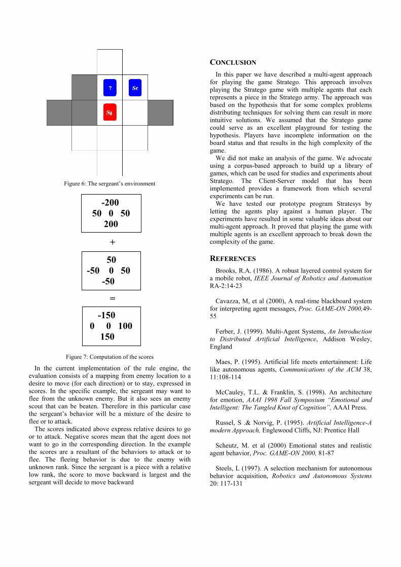
Figure 6: The sergeant’s environment
+
=
Figure 7: Computation of the scores
In the current implementation of the rule engine, the evaluation consists of a mapping from enemy location to a desire to move (for each direction) or to stay, expressed in scores. In the specific example, the sergeant may want to flee from the unknown enemy. But it also sees an enemy scout that can be beaten. Therefore in this particular case the sergeant’s behavior will be a mixture of the desire to flee or to attack.
The scores indicated above express relative desires to go or to attack. Negative scores mean that the agent does not want to go in the corresponding direction. In the example the scores are a resultant of the behaviors to attack or to flee. The fleeing behavior is due to the enemy with unknown rank. Since the sergeant is a piece with a relative low rank, the score to move backward is largest and the sergeant will decide to move backward
CONCLUSION In this paper we have described a multi-agent approach
for playing the game Stratego. This approach involves playing the Stratego game with multiple agents that each represents a piece in the Stratego army. The approach was based on the hypothesis that for some complex problems distributing techniques for solving them can result in more intuitive solutions. We assumed that the Stratego game could serve as an excellent playground for testing the hypothesis. Players have incomplete information on the board status and that results in the high complexity of the game.
We did not make an analysis of the game. We advocate using a corpus-based approach to build up a library of games, which can be used for studies and experiments about Stratego. The Client-Server model that has been implemented provides a framework from which several experiments can be run.
We have tested our prototype program Stratesys by letting the agents play against a human player. The experiments have resulted in some valuable ideas about our multi-agent approach. It proved that playing the game with multiple agents is an excellent approach to break down the complexity of the game.
REFERENCES Brooks, R.A. (1986). A robust layered control system for
a mobile robot, IEEE Journal of Robotics and Automation RA-2:14-23
Cavazza, M, et al (2000), A real-time blackboard system
for interpreting agent messages, Proc. GAME-ON 2000,49-55
Ferber, J. (1999). Multi-Agent Systems, An Introduction
to Distributed Artificial Intelligence, Addison Wesley, England
Maes, P. (1995). Artificial life meets entertainment: Life
like autonomous agents, Communications of the ACM 38, 11:108-114
McCauley, T.L. & Franklin, S. (1998). An architecture
for emotion, AAAI 1998 Fall Symposium “Emotional and Intelligent: The Tangled Knot of Cognition”, AAAI Press.
Russel, S .& Norvig, P. (1995). Artificial Intelligence-A
modern Approach, Englewood Cliffs, NJ: Prentice Hall Scheutz, M. et al (2000) Emotional states and realistic
agent behavior, Proc. GAME-ON 2000, 81-87 Steels, L (1997). A selection mechanism for autonomous
behavior acquisition, Robotics and Autonomous Systems 20: 117-131
-200 50 0 50 200
50 -50 0 50
-50
-150 0 0 100
150

DIRECTIONS FOR FUTURE GAMES DEVELOPMENT
Michael J. Allen, Hussam Suliman, Zhigang Wen, Norman E. Gough and Qasim H. Mehdi
Multimedia and Intelligent Systems Technology Research Group School of Computing and Information Technology, University of Wolverhampton,
35 – 49 Lichfield Street, Wolverhampton, WV1 1EQ, United Kingdom
email: [email protected]
KEYWORDS Eye Tracking Technology, Artificial Intelligence, Computer Animation.
ABSTRACT In this paper artificial intelligence (AI), eye tracking technology and computer graphics for character animation are reviewed and current developments examined. In each case the review is followed by a discussion on how these developments may affect the games industry in the future. Game AI and traditional AI methods are investigated as well as the drawbacks of using the traditional approaches in game development. The graphics section examines four of the current methods available for character animation - articulated body animation, single mesh skinning and the N-patch method - and discusses the advantages and disadvantages of each one. The process and evolution of eye movement research is undertaken in the final section which concludes with a list of potential applications for the technology within the Games arena.
INTRODUCTION In this work, the fields of Artificial Intelligence (AI), computer graphics for computer animation and eye tracking technology are investigated. The aim of the paper is to review how these technologies are currently being used, inside and outside of the games industry, and to highlight where they could be used in the future.
AI is now an established discipline. It enables an electronic system to act intelligently by exhibiting characteristics usually associated with human or animal behaviour. A number of sub-fields have evolved, such as soft-computing, intelligent computational control and intelligent planning, and several other research areas have become synonymous with AI, e.g. machine vision, natural language processing and mobile robotics. Other areas, such as pattern recognition and path planning, may also use AI techniques although alternative non-AI techniques also exist. In Section 2 the use of AI in games is discussed. Game AI is discussed alongside traditional AI techniques and the section concludes with a
discussion on computational efficiency and how this affects the use of AI in game production.
With the advance in both computer hardware and software, real time multimedia software applications such as computer games can exhibit much more attractive character animation to the users compared to earlier applications. Furthermore, advances in animation control methods enable the characters to be more intelligent in responding to their environment and the user interaction. Section 3 of this paper starts with the most commonly used character animation method such as rigid-body animation in 3D-computer games, and then describes the single mesh animation method along with the more advanced or recently proposed methods such as mesh skinning and N-patch. The advantages and disadvantages of these methods will also be discussed.
Eye tracking is an emerging technology in which a feature of the eye is tracked to determine where the user is looking. Eye tracking has been used in a number of studies that have analysed where a subject looks when driving, reading, playing fast action sports and interfacing with a computer. Compression techniques, such as the content-based functionalities of MPEG-4 and foreground - background, encode Regions Of Interest (ROI) within an image with more bits to improve the perceptual quality of the encoded image. The ROI are those areas where the user/operator’s eye tends to fixate. Section 4 begins with a review of the research undertaken into eye tracking to date and concludes with a list of potential application areas where this research could, and is, being applied in the area of games.
AI IN COMPUTER GAMES
Game AI
There are no generally-accepted guidelines for what methods are included under games AI, but the broad definition given by Wright & Marshall (2000) ‘Game AI is the high-level control code that determines the behaviour of game agents’ is widely accepted. Strictly speaking, many games merely create the illusion of intelligence. Games do not need to process every possible object at every frame in order to create an illusion of

believability. Wright & Marshall (2000) go on to observe that 'virtual worlds built for entertainment purposes need to concentrate on presenting a believable world to the player and need not concentrate on presenting an accurate simulation of the real world'. Furthermore, games AI does not necessarily imply that any traditional soft computing tools such as neural networks are being employed. Hence purists often refer to games AI as "cheating" (Smith, 2000). However, for the purpose of this research, we will adopt a less rigorous definition of AI as one that creates believability in the sense that games characters appear to be interacting intelligently with one another and their environment.
The most common and popular AI technologies (Woodcock 1999, 2000) for Non Player Characters (NPCs) specification are based on Finite state machines (FSMs) (Gough et al, 2000, Hein 1996, Funge 1999, Hopcroft & Ullman 1979) that are machine-like representations of rule based systems. Hence all reflex or reactive agents that react to a rule of the form if condition then action can be implemented by FSMs. They are characterised as having sets of distinct internal states that respond to a sensory input transit to a new state and release an output. FSMs are used in layered or hierarchical structures (Woodcock 1999,2000, Funge 1999) for implementing and customising behaviour. Computer games such as ID software’s Quake I, II and III use FSM modelled systems. The Valve software team (Valve 2001) used a ‘schedule driven’ (event driven) FSM for their award winning game Half-Life (GameAI 2000). Unreal and Unreal Tournament, for example, demonstrates the complexity of behaviours available using FSMs. The AI makes extensive use of FSMs to control the behaviour of the player's opponents to an amazingly realistic degree. For example, the monsters appear to exhibit considerable intelligence, as they run away, hide when wounded, call for reinforcements, and even trick the player into ambushes. In addition, group movements exhibited through the use of a flocking algorithm add considerably to the realism, such as the method of Reynolds (1987) used in The Lion King. All of these effects were achieved by the developers through the implementation of layering FSMs, which were built on top of an extensible scripting system called UnrealScript.
Path finding and planning methods for agent navigation are also extensively used in games. The basic problem is to find a route through a network of possible locations in the presence of constraints, such as take the shortest distance, avoid ambush, minimise the number of locations visited, etc. There are many well-known search algorithms used in path finding such as breadth-first, bi-directional breadth-first, Dijkstra’s algorithm, depth-first and A∗ (Pearl 1984, Russell & Norvig 1995). They share some common features and especially the strategies by which they find paths. One of the most popular
algorithms for finding shortest distance paths in games, A∗, is a heuristic search that ranks a node by an estimate of the best route that goes through that node. It combines the tracking of past path lengths with the heuristic of breadth-first search (Hart et al 1968,1972, Russell & Norvig 1995).
Path finding in practice also requires obstacle avoidance. However, games involving 2D and 3D virtual environments often avoid this problem by using networks with pre-stored nodes through which NPCs must travel, thus ignoring the existence of obstacles altogether. In a more complicated scheme, the space can be presented as a uniform grid, through which NPCs freely travel in any direction but this requires the development and implementation of complex obstacle avoidance systems for NPCs to ‘sense’ the obstacles. For example, influence maps or field methods (Boas 1983) consider objects such as locations or obstacles as field sources that exert influence on distant points.
Game companies are now focusing on extending these techniques for specific games (such as path finding in 3D space). Path finding tools are also beginning to take account of environmental terrain. Terrain analysis is a more difficult than simple path finding in that the game AI must take into consideration geographic features but it has been used successfully, particularly in military games scenarios (Smith 2000).
One of the most interesting topics that has attracted game developers recently is the development of AI software development kits (SDKs). Academics and developers alike have found them to be powerful tools for both game development and AI research. There are many AI SDKs available to the game developers but most of them are intended for use in industrial or business applications. DirectIA is an agent based toolkit that uses state machines to specify behaviour. Also using state machine modelling is GSM Suite, a set of programs for using FSMs in a graphical fashion. The suite consists of programs that edit, compile, and print state machines (Game AI Page 2001).
Artificial Intelligence Tools
Traditional artificial intelligence has been exemplified by a set of methods commonly referred to as soft computing tools. These include expert systems, fuzzy logic, artificial neural networks (ANNs), evolutionary algorithms, and probabilistic reasoning (McCarthy 1987, Nilsson 2001, Russell & Norvig 1995). Many hybrid methods have also emerged from these basic methods, such as distributed AI, which is logic based AI.
Logical AI involves representing knowledge as sentences in logic (McCarthy 1958, 1987, Poole et al 1998, Russell and Norvig 1995). It is used to develop computer programs that represent what they know about the world

primarily by logical formulas and decide what to do primarily by logical reasoning, i.e. applying inferences to statements to draw conclusions. The proponents of the symbolic AI approach to intelligence use logic based systems for building intelligence into agents. Many AI systems represent facts by a limited subset of logic, e.g. logic programming restricts its representation to Horn Clauses (Nilsson 2001, Russell & Norvig 1996), databases often use only ground formulas and hardware design usually involves only Propositional Logic (Nilsson 2001, Russell & Norvig 1995). Theses restrictions are almost all justified by considerations of computational efficiency.
The goal-based agent architecture used in Quake II games is an example of a rule-based production system. Based on the SOAR model of Van Lent & Laird (1999) it uses an arbitration method to decide what action to take when the percept matches more than one rule.
Fuzzy logic (Zadeh 1965, Dubois & Prade 1980) is one of the main components of AI. In a narrow sense it is a branch of multi-valued logic, which provides approximate reasoning in logical operations. It has found applications in control systems, business and computer games. Fuzzy logic developed by Lotfi Zadeh is based on a concept known as fuzzy sets (Zadeh 1965), introduced to handle uncertainty and linguistic variables. The development of fuzzy logic has led to many successful implementations of fuzzy systems. A fuzzy inferencing system (FIS) uses the fuzzy sets in a rule-based system to make decisions or draw conclusions. These rules are then combined using rule composition and firm conclusions are drawn through defuzzification. Fuzzy State Machines (FzSMs) (Dubois & Prade 1984) are machine-like representations of rule based systems that have fuzzified states for more modelling power.
Connectionism is a style of modelling based on networks of interconnected simple processing devices. Connectionist systems, also referred to as Neural Networks or Artificial Neural Networks (ANNs) (Bishop 1995, Hertz et al. 1991, Russell & Norvig 1995). ANNs appeal to many AI researchers due to the analogy to the structure of the human brain and the basic building block, the neuron. The earliest work in neural computing goes back to the 1940s when McCulloch and Pitts introduced the first model. In the 1950s, Rosenblatt's work resulted in a two-layer network, the perceptron (Minski & Papert 1969, Hertz et al 1991), which are capable of learning certain classifications by adjusting connection weights. Recent work includes Boltzmann machines, Hopfield nets, Radial Basis Function networks, competitive learning models, and Adaptive Resonance Theory models (Bishop 1995, Hertz et al. 1991). ANNs are strongly implicated as robust methods for detecting and classifying patterns in data. Few of the top 100 games claim to use ANNs. Battle Cruiser:3000AD developed by
Derek Smart (GAMEAI Page 2000) claimed to be the first commercial game to feature ANNs for route finding and goal-oriented design but it used fuzzy logic where the networks were considered to be inadequate. Watson (1996) used a neuro-fuzzy ANN with back propagation to control a space ship on interstellar missions. An example of a computer game using an ANN has been produced and is described in Medhi et al (2000).
Evolutionary or Genetic algorithms (GAs) (Griffiths et al, 1997) are optimisation techniques that are inspired by how animals evolved over time. The idea centres on the principle of survival of the fittest whereby members of a species compete over limited resources. The environment poses a test which can favour particular elements of a species over time. The surviving genes present the codification of the solution to the optimisation problem expressed in a fitness function. These optimisation techniques have received comparatively little attention in games dues to the vast computational costs. However there is potential to evolve agents in artificial life (A-life) communities. One game that claims to have used GAs is Creatures from Cyberlife (Grand et al 1997). GAs have also been used to evolve, controllers for characters and for changing the characters body shapes (Taylor, 2000).
Computational Efficiency
‘The fastest computation is the one you don’t have to compute’
John Carmack (ID software)
Clearly, any increased complexity of game AI can only be achieved at a price. Firstly, it brings increased computational overheads. Furthermore, the emergent behaviours may be so complex that they interfere with game play and may have to be curtailed. For example, the A-life techniques used to control NPCs in the online game Ultima Online were so rich that they had to be compromised in the interests of gameplay (Woodcock, 1999).
Game developers inevitably take short cuts to minimise the computational load. For example, the FPS game Unreal Tournament demonstrates realistic bot AI that can compete strongly with the best of players yet is also fun to play against. It intentionally makes mistakes and does not always act optimally. However, it does not incorporate any AI in a strict sense. Although, developers are now looking towards more sophisticated ways of incorporating AI in the traditional sense, they are unlikely to accept them if they involve excessive computational overheads.
In the early days of the gaming industry, tight and often unreadable code was common place. The demand for sophistication in agents and more complex virtual environments, means that recent game designs tend to be well-structured showing an integrated system of
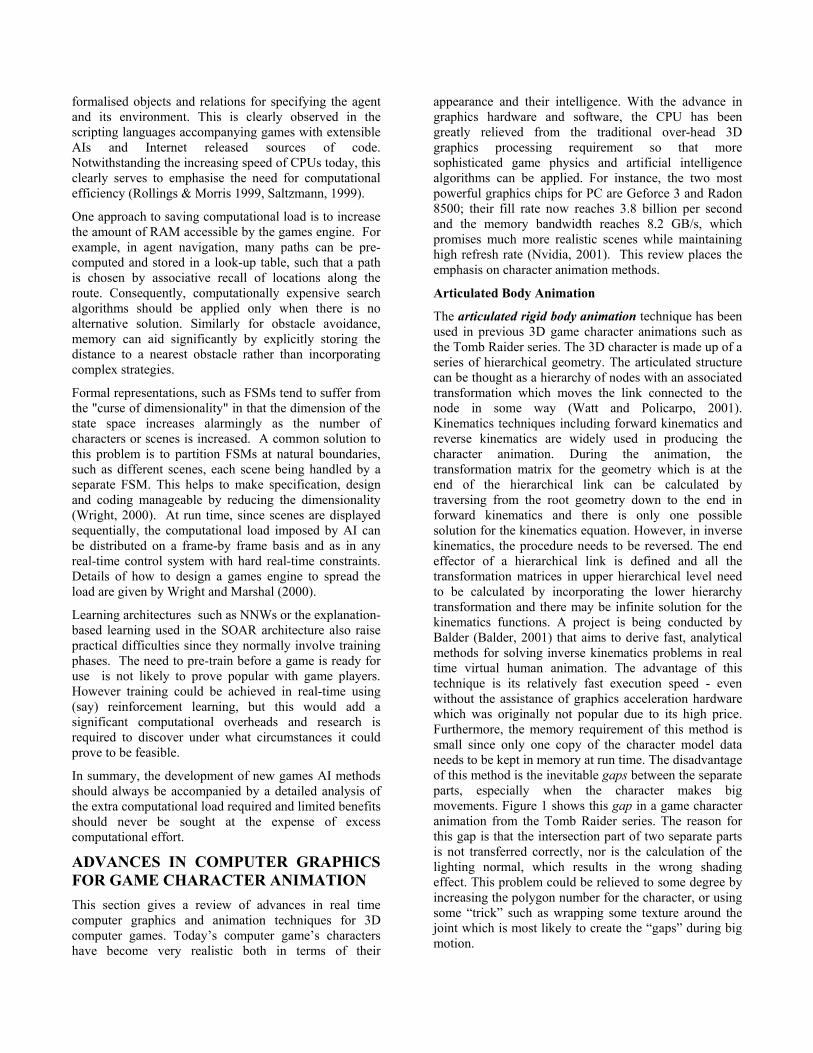
formalised objects and relations for specifying the agent and its environment. This is clearly observed in the scripting languages accompanying games with extensible AIs and Internet released sources of code. Notwithstanding the increasing speed of CPUs today, this clearly serves to emphasise the need for computational efficiency (Rollings & Morris 1999, Saltzmann, 1999).
One approach to saving computational load is to increase the amount of RAM accessible by the games engine. For example, in agent navigation, many paths can be pre-computed and stored in a look-up table, such that a path is chosen by associative recall of locations along the route. Consequently, computationally expensive search algorithms should be applied only when there is no alternative solution. Similarly for obstacle avoidance, memory can aid significantly by explicitly storing the distance to a nearest obstacle rather than incorporating complex strategies.
Formal representations, such as FSMs tend to suffer from the "curse of dimensionality" in that the dimension of the state space increases alarmingly as the number of characters or scenes is increased. A common solution to this problem is to partition FSMs at natural boundaries, such as different scenes, each scene being handled by a separate FSM. This helps to make specification, design and coding manageable by reducing the dimensionality (Wright, 2000). At run time, since scenes are displayed sequentially, the computational load imposed by AI can be distributed on a frame-by frame basis and as in any real-time control system with hard real-time constraints. Details of how to design a games engine to spread the load are given by Wright and Marshal (2000).
Learning architectures such as NNWs or the explanation-based learning used in the SOAR architecture also raise practical difficulties since they normally involve training phases. The need to pre-train before a game is ready for use is not likely to prove popular with game players. However training could be achieved in real-time using (say) reinforcement learning, but this would add a significant computational overheads and research is required to discover under what circumstances it could prove to be feasible.
In summary, the development of new games AI methods should always be accompanied by a detailed analysis of the extra computational load required and limited benefits should never be sought at the expense of excess computational effort.
ADVANCES IN COMPUTER GRAPHICS FOR GAME CHARACTER ANIMATION This section gives a review of advances in real time computer graphics and animation techniques for 3D computer games. Today’s computer game’s characters have become very realistic both in terms of their
appearance and their intelligence. With the advance in graphics hardware and software, the CPU has been greatly relieved from the traditional over-head 3D graphics processing requirement so that more sophisticated game physics and artificial intelligence algorithms can be applied. For instance, the two most powerful graphics chips for PC are Geforce 3 and Radon 8500; their fill rate now reaches 3.8 billion per second and the memory bandwidth reaches 8.2 GB/s, which promises much more realistic scenes while maintaining high refresh rate (Nvidia, 2001). This review places the emphasis on character animation methods.
Articulated Body Animation
The articulated rigid body animation technique has been used in previous 3D game character animations such as the Tomb Raider series. The 3D character is made up of a series of hierarchical geometry. The articulated structure can be thought as a hierarchy of nodes with an associated transformation which moves the link connected to the node in some way (Watt and Policarpo, 2001). Kinematics techniques including forward kinematics and reverse kinematics are widely used in producing the character animation. During the animation, the transformation matrix for the geometry which is at the end of the hierarchical link can be calculated by traversing from the root geometry down to the end in forward kinematics and there is only one possible solution for the kinematics equation. However, in inverse kinematics, the procedure needs to be reversed. The end effector of a hierarchical link is defined and all the transformation matrices in upper hierarchical level need to be calculated by incorporating the lower hierarchy transformation and there may be infinite solution for the kinematics functions. A project is being conducted by Balder (Balder, 2001) that aims to derive fast, analytical methods for solving inverse kinematics problems in real time virtual human animation. The advantage of this technique is its relatively fast execution speed - even without the assistance of graphics acceleration hardware which was originally not popular due to its high price. Furthermore, the memory requirement of this method is small since only one copy of the character model data needs to be kept in memory at run time. The disadvantage of this method is the inevitable gaps between the separate parts, especially when the character makes big movements. Figure 1 shows this gap in a game character animation from the Tomb Raider series. The reason for this gap is that the intersection part of two separate parts is not transferred correctly, nor is the calculation of the lighting normal, which results in the wrong shading effect. This problem could be relieved to some degree by increasing the polygon number for the character, or using some “trick” such as wrapping some texture around the joint which is most likely to create the “gaps” during big motion.
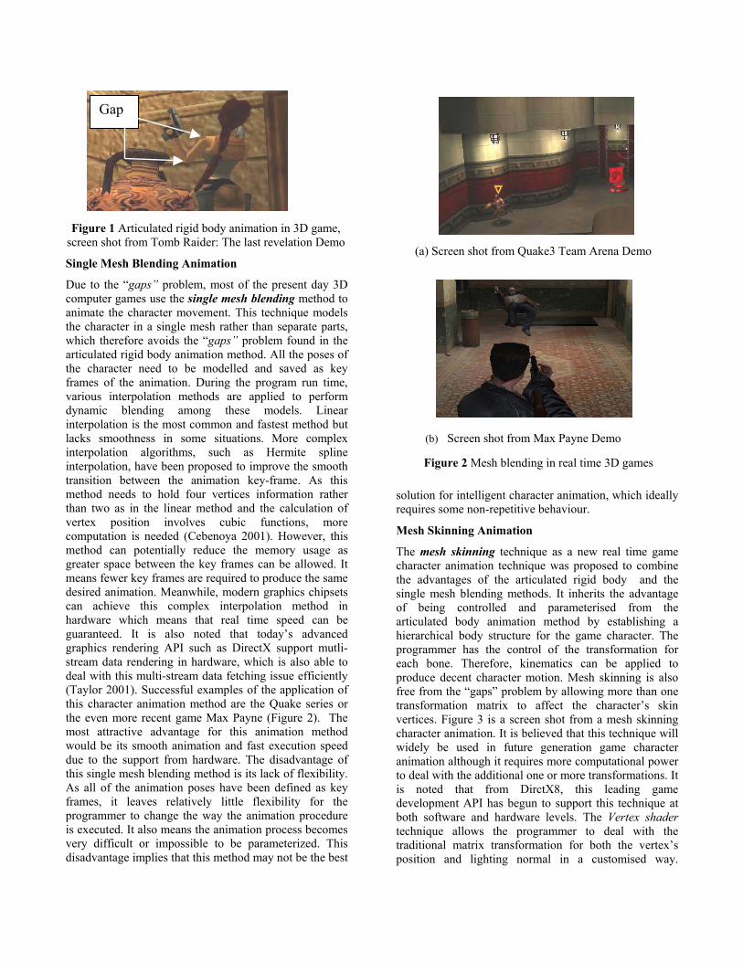
Gap
Single Mesh Blending Animation
Due to the “gaps” problem, most of the present day 3D computer games use the single mesh blending method to animate the character movement. This technique models the character in a single mesh rather than separate parts, which therefore avoids the “gaps” problem found in the articulated rigid body animation method. All the poses of the character need to be modelled and saved as key frames of the animation. During the program run time, various interpolation methods are applied to perform dynamic blending among these models. Linear interpolation is the most common and fastest method but lacks smoothness in some situations. More complex interpolation algorithms, such as Hermite spline interpolation, have been proposed to improve the smooth transition between the animation key-frame. As this method needs to hold four vertices information rather than two as in the linear method and the calculation of vertex position involves cubic functions, more computation is needed (Cebenoya 2001). However, this method can potentially reduce the memory usage as greater space between the key frames can be allowed. It means fewer key frames are required to produce the same desired animation. Meanwhile, modern graphics chipsets can achieve this complex interpolation method in hardware which means that real time speed can be guaranteed. It is also noted that today’s advanced graphics rendering API such as DirectX support mutli-stream data rendering in hardware, which is also able to deal with this multi-stream data fetching issue efficiently (Taylor 2001). Successful examples of the application of this character animation method are the Quake series or the even more recent game Max Payne (Figure 2). The most attractive advantage for this animation method would be its smooth animation and fast execution speed due to the support from hardware. The disadvantage of this single mesh blending method is its lack of flexibility. As all of the animation poses have been defined as key frames, it leaves relatively little flexibility for the programmer to change the way the animation procedure is executed. It also means the animation process becomes very difficult or impossible to be parameterized. This disadvantage implies that this method may not be the best
solution for intelligent character animation, which ideally requires some non-repetitive behaviour.
Figure 1 Articulated rigid body animation in 3D game, screen shot from Tomb Raider: The last revelation Demo
(a) Screen shot from Quake3 Team Arena Demo
(b) Screen shot from Max Payne Demo
Figure 2 Mesh blending in real time 3D games
Mesh Skinning Animation
The mesh skinning technique as a new real time game character animation technique was proposed to combine the advantages of the articulated rigid body and the single mesh blending methods. It inherits the advantage of being controlled and parameterised from the articulated body animation method by establishing a hierarchical body structure for the game character. The programmer has the control of the transformation for each bone. Therefore, kinematics can be applied to produce decent character motion. Mesh skinning is also free from the “gaps” problem by allowing more than one transformation matrix to affect the character’s skin vertices. Figure 3 is a screen shot from a mesh skinning character animation. It is believed that this technique will widely be used in future generation game character animation although it requires more computational power to deal with the additional one or more transformations. It is noted that from DirctX8, this leading game development API has begun to support this technique at both software and hardware levels. The Vertex shader technique allows the programmer to deal with the traditional matrix transformation for both the vertex’s position and lighting normal in a customised way.
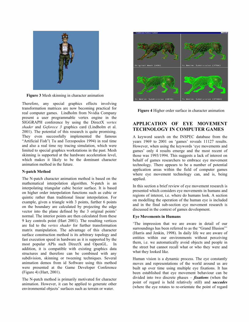
Figure 4 Higher order surface in character animation
Figure 3 Mesh skinning in character animation
Therefore, any special graphics effects involving transformation matrices are now becoming practical for real computer games. Lindholm from Nvidia Company present a user programmable vertex engine in the SIGGRAPH conference by using the DirectX vertex shader and Geforece 3 graphics card (Lindholm et al. 2001). The potential of this research is quite promising. They even successfully implemented the famous “Artificial Fish”( Tu and Terzopoulos 1994) in real time and also a real time ray tracing simulation, which were limited to special graphics workstations in the past. Mesh skinning is supported at the hardware acceleration level, which makes it likely to be the dominant character animation method in the future.
N-patch Method
The N-patch character animation method is based on the mathematical interpolation algorithm. N-patch is an interpolating triangular cubic bezier surface. It is based on higher order interpolation functions such as cubic or quintic rather than traditional linear interpolation. For example, given a triangle with 3 points, further 6 points on the boundary are calculated by projecting the edge vector into the plane defined by the 3 original points’ normal. The interior points are then calculated from these 9 key controls point (Hart 2001). The resulting vertices are fed to the vertex shader for further transformation matrix manipulation. The advantage of this character surface construction method is its arbitrary topology and fast execution speed in hardware as it is supported by the most popular APIs such DirectX and OpenGL. In addition, it is compatible with existing graphics data structures and therefore can be combined with any subdivision, skinning or tweening techniques. Several animation demos from id Software using this method were presented at the Game Developer Conference (Figure 4) (Hart, 2001).
The N-patch method is primarily motivated for character animation. However, it can be applied to generate other environmental objects’ surfaces such as terrain or water.
APPLICATION OF EYE MOVEMENT TECHNOLOGY IN COMPUTER GAMES A keyword search on the INSPEC database from the years 1969 to 2001 on ‘games’ reveals 11127 results. However, when using the keywords ‘eye movements and games’ only 4 results emerge and the most recent of those was 1993/1994. This suggests a lack of interest on behalf of games researchers to embrace eye movement technology. There appears to be a number of potential application areas within the field of computer games where eye movement technology can, and is, being applied.
In this section a brief review of eye movement research is presented which considers eye movements in humans and regions of interest, i.e. where do humans look. A section on modelling the operation of the human eye is included and in the final sub-section eye movement research is discussed in the context of games development.
Eye Movements in Humans
‘The impression that we are aware in detail of our surroundings has been referred to as the “Grand Illusion”’ (Harris and Jenkin, 1998). In daily life we are aware of entities within our environments without perceiving them, i.e. we automatically avoid objects and people in the street but cannot recall what or who they were and what they looked like.
Human vision is a dynamic process. The eye constantly moves and representations of the world around us are built up over time using multiple eye fixations. It has been established that eye movement behaviour can be divided into two discrete phases – fixations (when the point of regard is held relatively still) and saccades (where the eye rotates to re-orientate the point of regard

from one position to another) (Hendersen and Hollingworth, 1998). The fovea is an area at the centre of the retina where our ability to define fine detail and colour information is best. Consequently, the eye moves to focus regions of interest (ROI) within the scene onto the fovea.
Humans actively seek information. When humans see and understand they actively look (Aloimonos et al, 1987). In their review, Hendersen and Hollingworth (1998) cite a number of studies (Buswell, 1935; Yarbus, 1967; Antes, 1974; Mackworth and Morandi, 1978; Hendersen et al, 1999) that suggest that during scene viewing the fixation points are non-random with more fixations directed towards the more informative regions –ROI. In each case the eye movements were recorded when the viewer was presented with static images, e.g. colour paintings and black or line drawings.
Norton and Stark (1971) coined the term scanpath to describe the sequence of fixations used by a particular viewer when viewing a particular pattern. As with the studies listed above, this work was also conducted with static images back-projected on to a screen. The study examined how viewers examined new (previously unseen) patterns during a ‘learning phase’ and then how they recognized the same patterns during a ‘recognition phase’. The result of the experimental work showed that when recognizing a pattern the viewer enacted an appropriate scanpath in 65% of the cases. The authors regarded this as a strong result and suggested that the presence of scanpaths is indicative of how patterns are remembered and they provide evidence that high-level processing is used for visual perception and eye movement control (Top-down control).
Stark et al (2001) present a review of current scanpath theory for top-down visual perception. This review includes a general explanation of early and current scanpath theory gathered from experiments with static images and when looking at dynamic scenes. A detailed description of their experimental work is given – which includes work monitoring eye movements during the viewing of animated scenes - and the presentation concludes with a report on the implementation of a top-down computer vision model.
However, top-down control is not the only control mechanism. Low level signals highlight areas of potential importance, e.g. our peripheral vision is particularly sensitive to movement, and can influence eye movement control (Bottom-up vision). When modelling the human model Stark et al (2001) refer to the problem of how to match bottom up confirmatory signals from the peripheral field with detailed information that is extracted from the fovea.
Regions of Interest
The eye moves to focus regions of interest on to the fovea, but what makes one region more interesting than another? Hendersen and Hollingworth (1998) discuss semantic informativeness - the meaning of a region - and visual informativeness - discontinuities in colour, depth, luminance and/or texture. The scanpath theory indicates that the use of semantic information is used extensively in pattern recognition. The eyes follows a scanpath to gather salient features about the scene to match against the viewer’s cognitive model. The scanpath is controlled by high level processing within the central nervous system which in turn draws upon memory. However, Stark et al (2001) identify task setting as an important factor that can induce the viewer to modify the scanpath. Hendersen and Hollingworth (1998) also identify task setting as a factor that can influence eye movement patterns and also include factors of viewing time and image content.
In computer games the player has to analyze data from a dynamic scene in real time. Often, as events on the screen become more intense, the real time window becomes smaller and the deadlines more important, i.e. the viewing time is decreased. It has been established that the human model combines visual data and experience (expert knowledge) to anticipate future events in order to reduce reaction times. In fast action sports, experts use visual information, such as the body movements of a competitor, to predict their subsequent actions and to gain an advantage. The expert is able to distinguish between the irrelevant and relevant information and to recognize these cues early in the sequence of events (Paull and Glencross, 1997). This also applies to experienced and novice drivers. An examination by Chapman and Underwood (1998) identified that, when viewing a scene novice drivers, in general, fixated longer than experienced drivers and it was argued that this related to the additional time that is required by novice drivers to process visual data from the scene. The study also revealed that different visual scene (rural and urban scenes) also invoked different observation behaviour (influence of image content).
Modelling Eye Movements
If a model of eye movement behaviour can be constructed, even a simple model to identify the density of fixations in different parts of a scene, it could be used to identify the ROI in different game scenarios. The model would have to take into account the factors listed above the influence the eye movements, e.g. task setting, viewing time and image content, and whether the player is a novice or expert. A knowledge of where the game player is looking could facilitate the design process, i.e. more attention could be paid to ROI and less to those of

lesser interest, and for playing interactive on-line games where multi-resolution meshes are employed.
Hendersen et al (1999) describe a model of eye movement control in scene viewing. The control method uses a saliency map to determine the subsequent fixation point. The saliency map contains a set of weights that are initially assigned based on the saliency of a region based on a parse of the entire scene. It is suggested that these initial saliency metrics are assigned by low-level stimulus factors such as luminance, contrast, colour, etc, i.e. visual information as opposed to semantic information. The attention is turned to the region with the highest weight. Over time as the information within the regions of the map are processed and become meaningful elements the saliency weights are modified to reflect the semantic importance of the regions. Consequently, the basis for each weight gradually moves from being visually based to semantically based.
The present authors (Allen et al, 1999) describe a method for efficiently scanning image frames using a method inspired by the operation of the eye. A schematic breakdown of this system is shown in Figure 5. As with the method described above this process assigns weights to regions of the scene. However, a Fuzzy Inference System is used to assign the weights (possibility values) based on historical data relating to the proximity of the region to other ROI; the attention paid to it in the past; the success of the system in locating known objects; and the position of regions that are known to be constantly important. These possibilities are stored in a saccade map. The regions to be examined during a particular scan are chosen using a weighted roulette wheel, i.e. those with the highest weights have more chance of being selected. The 3D plot in Figure 6 shows the attention paid to different areas of a dynamic scene over 60 frames. The frames contained one static object and a mobile object. It can be seen that more attention was paid to those regions containing the objects. In the form described, this method is not intended to model the movements of the eye. However, the behaviour of the fuzzy system could be retuned to handle new input data and resemble more closely the operation of the eye.
Eye Movement Technology and Computer Games
A study was undertaken at the University of Hawaii (Crosby and Chin, 1997) that utilized eye-tracking technology to identify whether embedded information is more difficult to interpret than unembedded information when using multi-user interfaces. This study identified where users of a user interface in emergency conditions. A similar approach could adopted for examining the eye movement behaviour of game players who will also be interacting with a video image whilst under pressure.
In most game scenarios the game area is dynamic, particularly so in action games. A number of methods for capturing eye-movements whilst viewing dynamic scenes have now been developed and used in experimental projects (Stark et al, 2001; Land, 1998). If the eye-movements of players could be modelled then it would give an insight into how expert and novice game players gather information when playing particular games and this may provide useful data on how the game could be improved.
062.0176.0532.0987.0067.0154.0543.0532.0052.0167.0143.0123.0054.0032.0034.0012.0
Image frame or scene sub
divided into sub-regions
Historical data mapped using a fuzzy inference system to establish the saliency of each sub-
region.
Saccade map of possibility values establishing how salient a region is
from 0 to 1
Weighted roulette wheel selects n
regions using the possibilities in the
saccade map
(4,1) Scanpath is a string of n sub-
regions that are to be examined
(1,3)
(3,2)
(2,4)
Figure 5 Construction of a scanpath from a saccade map

Interactive on-line computer gaming is an area where eye tracking technology can be employed to maximize the quality perceived by a subject viewing on-screen graphics at interactive frame rates. The level of accuracy in a transmitted image sequence can be sacrificed to improve speed. O’Sullivan et al (2000) discusses the technique of Interactive Perception of Multi-resolution Meshes (IPoMM) which is an interest-dependent strategy where the most interesting part of the scene is retained at a higher resolution for as long as possible. The region of interest is determined using eye movement technology.
As the intelligence of NPCs improves, expert knowledge of where to look at the player-character, say during a football match, would add to the realism of the character. Like the player character the NPC would have to learn to use visual cues to gain an advantage over his/her opponent.
Research has been undertaken to ascertain how professional racing drivers view the track when they are racing. These eye movements could be compared with those of an experienced player to assess whether a particular racing game was realistic. The game could be improved by including more visual cues on the lines of those incorporated at the real tracks.
The apparatus required for tracking eye movements has been relatively expensive and cumbersome to wear. As a consequence, it is currently most valuable to disabled people and researchers. However, Canon have developed a miniaturized eye-tracker and included it as a means of directing the automatic focusing system on two of their cameras. The EagleEye project (Gips and Olivieri, 1996) demonstrated how eye movement apparatus could be used by disabled people in place of a mouse. If the price of eye tracking instruments falls then the scope of their use in virtual reality will increase. Game playing could be
made available to the disabled and these controllers could be used as an additional form of on screen control.
Figure 6 Attention shown to sub-regions of the frames in a sequence containing a static object and a mobile object
CONCLUSIONS In this paper, various techniques that might be used in games development have been examined and reviewed. The area of graphics is well known to the games industry and the field of AI is attracting more interest. Eye tracking technology is possibly less well known but may have much to offer in improving games in the future.
Section 2 discussed AI in computer games and introduced the Game AI methods commonly used by the games industry. This was followed by a section considering games that use traditional soft computing methods and went on to discuss computational efficiency. In summary, the development of new games AI methods should always be accompanied by a detailed analysis of the extra computational load required and limited benefits should never be sought at the expense of excess computational effort.
Four different approaches to graphic animation were presented – the articulated body animation, single mesh skinning and the N-patch method. Although the articulated body animation approach is used in numerous adventure games, the single mesh skinning technique is currently the most common method. However, although not widely used at present, we suspect that the N-patch method will become more popular in the future.
Eye tracking is a technology that is currently expensive but, as the technology improves, the cost of the hardware will go down and make it more accessible to a wider range of applications including games. Currently, the technology can be used to develop more effective displays, i.e. for on-line gaming where data transmission rates may be low, and in the future with added control for the player who will be able to utilize eye movement to control aspects of the game. The technology will also open up computer gaming to people with disabilities.
REFERENCES Allen M. J., Q. Mehdi, I. J. Griffiths, N. Gough, I. M.
Coulson. 1999. “Object location in colour images using fuzzy-tuned scanpaths and neural networks.” Proc. 19th SGES Int. Conf. Knowledge Based Systems and Applied Artificial Intelligence, Cambridge, UK, pp 302-314.
Aloimonos J. Y, I. Weiss and A. Bandyopadhyay. 1987. “Active Vision.” Int. Jour. Of Computer Vision, pp 333-356.
Antes, J. R. 1974. “The time course of picture viewing.” Journal of Experimental Psychology, 103, 62 – 70.
Balder N. 2001 “Real-Time Inverse Kinematics for Human Animation”
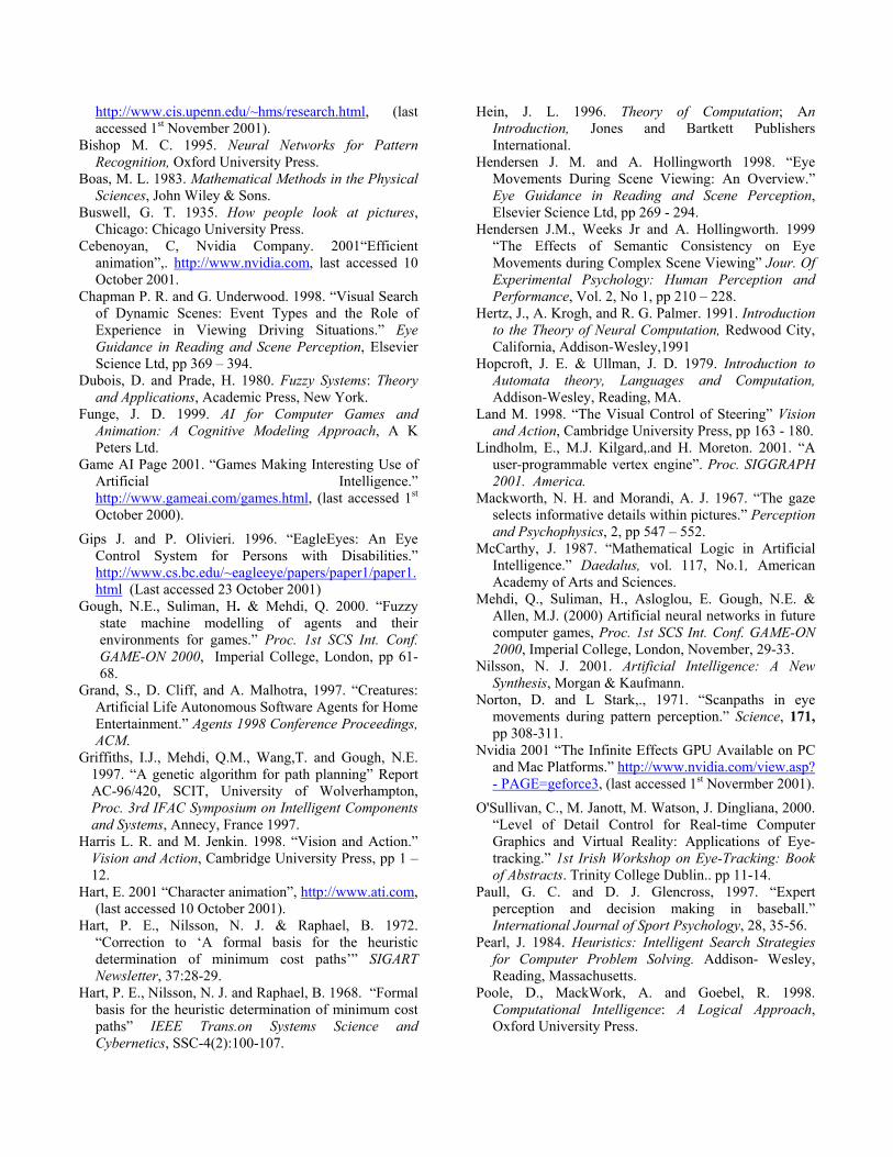
http://www.cis.upenn.edu/~hms/research.html, (last accessed 1st November 2001).
Bishop M. C. 1995. Neural Networks for Pattern Recognition, Oxford University Press.
Boas, M. L. 1983. Mathematical Methods in the Physical Sciences, John Wiley & Sons.
Buswell, G. T. 1935. How people look at pictures, Chicago: Chicago University Press.
Cebenoyan, C, Nvidia Company. 2001“Efficient animation”,. http://www.nvidia.com, last accessed 10 October 2001.
Chapman P. R. and G. Underwood. 1998. “Visual Search of Dynamic Scenes: Event Types and the Role of Experience in Viewing Driving Situations.” Eye Guidance in Reading and Scene Perception, Elsevier Science Ltd, pp 369 – 394.
Dubois, D. and Prade, H. 1980. Fuzzy Systems: Theory and Applications, Academic Press, New York.
Funge, J. D. 1999. AI for Computer Games and Animation: A Cognitive Modeling Approach, A K Peters Ltd.
Game AI Page 2001. “Games Making Interesting Use of Artificial Intelligence.” http://www.gameai.com/games.html, (last accessed 1st October 2000).
Gips J. and P. Olivieri. 1996. “EagleEyes: An Eye Control System for Persons with Disabilities.” http://www.cs.bc.edu/~eagleeye/papers/paper1/paper1.html (Last accessed 23 October 2001)
Gough, N.E., Suliman, H. & Mehdi, Q. 2000. “Fuzzy state machine modelling of agents and their environments for games.” Proc. 1st SCS Int. Conf. GAME-ON 2000, Imperial College, London, pp 61-68.
Grand, S., D. Cliff, and A. Malhotra, 1997. “Creatures: Artificial Life Autonomous Software Agents for Home Entertainment.” Agents 1998 Conference Proceedings, ACM.
Griffiths, I.J., Mehdi, Q.M., Wang,T. and Gough, N.E. 1997. “A genetic algorithm for path planning” Report AC-96/420, SCIT, University of Wolverhampton, Proc. 3rd IFAC Symposium on Intelligent Components and Systems, Annecy, France 1997.
Harris L. R. and M. Jenkin. 1998. “Vision and Action.” Vision and Action, Cambridge University Press, pp 1 – 12.
Hart, E. 2001 “Character animation”, http://www.ati.com, (last accessed 10 October 2001).
Hart, P. E., Nilsson, N. J. & Raphael, B. 1972. “Correction to ‘A formal basis for the heuristic determination of minimum cost paths’” SIGART Newsletter, 37:28-29.
Hart, P. E., Nilsson, N. J. and Raphael, B. 1968. “Formal basis for the heuristic determination of minimum cost paths” IEEE Trans.on Systems Science and Cybernetics, SSC-4(2):100-107.
Hein, J. L. 1996. Theory of Computation; An Introduction, Jones and Bartkett Publishers International.
Hendersen J. M. and A. Hollingworth 1998. “Eye Movements During Scene Viewing: An Overview.” Eye Guidance in Reading and Scene Perception, Elsevier Science Ltd, pp 269 - 294.
Hendersen J.M., Weeks Jr and A. Hollingworth. 1999 “The Effects of Semantic Consistency on Eye Movements during Complex Scene Viewing” Jour. Of Experimental Psychology: Human Perception and Performance, Vol. 2, No 1, pp 210 – 228.
Hertz, J., A. Krogh, and R. G. Palmer. 1991. Introduction to the Theory of Neural Computation, Redwood City, California, Addison-Wesley,1991
Hopcroft, J. E. & Ullman, J. D. 1979. Introduction to Automata theory, Languages and Computation, Addison-Wesley, Reading, MA.
Land M. 1998. “The Visual Control of Steering” Vision and Action, Cambridge University Press, pp 163 - 180.
Lindholm, E., M.J. Kilgard,.and H. Moreton. 2001. “A user-programmable vertex engine”. Proc. SIGGRAPH 2001. America.
Mackworth, N. H. and Morandi, A. J. 1967. “The gaze selects informative details within pictures.” Perception and Psychophysics, 2, pp 547 – 552.
McCarthy, J. 1987. “Mathematical Logic in Artificial Intelligence.” Daedalus, vol. 117, No.1, American Academy of Arts and Sciences.
Mehdi, Q., Suliman, H., Asloglou, E. Gough, N.E. & Allen, M.J. (2000) Artificial neural networks in future computer games, Proc. 1st SCS Int. Conf. GAME-ON 2000, Imperial College, London, November, 29-33.
Nilsson, N. J. 2001. Artificial Intelligence: A New Synthesis, Morgan & Kaufmann.
Norton, D. and L Stark,., 1971. “Scanpaths in eye movements during pattern perception.” Science, 171, pp 308-311.
Nvidia 2001 “The Infinite Effects GPU Available on PC and Mac Platforms.” http://www.nvidia.com/view.asp? - PAGE=geforce3, (last accessed 1st Novermber 2001).
O'Sullivan, C., M. Janott, M. Watson, J. Dingliana, 2000. “Level of Detail Control for Real-time Computer Graphics and Virtual Reality: Applications of Eye-tracking.” 1st Irish Workshop on Eye-Tracking: Book of Abstracts. Trinity College Dublin.. pp 11-14.
Paull, G. C. and D. J. Glencross, 1997. “Expert perception and decision making in baseball.” International Journal of Sport Psychology, 28, 35-56.
Pearl, J. 1984. Heuristics: Intelligent Search Strategies for Computer Problem Solving. Addison- Wesley, Reading, Massachusetts.
Poole, D., MackWork, A. and Goebel, R. 1998. Computational Intelligence: A Logical Approach, Oxford University Press.

Reynolds, C.W. 1987. “Flocks, herds, and schools: a distributed behavioural model.” Computer Graphics, 21 (4), 25-34.
Rollings, A. and D. Morris, 1999. Game Architecture and Design, Coriolis Group Books.
Russell S. & Norvig P. 1995. Artificial Intelligence A Modern Approach, Prentice Hall Inc.
Saltzmann, M. 1999. Game Design, McMillan Digital Publishing, Indianapolis, USA.
Smith, R. 2000 “ModelBenders LLC, The double helix: simulation and gaming, Keynote Lecture, GAME-ON 2000 1st Int. Conf. On Intelligent Games and Simulation, London, pp
Stark L. W., C. M. Privitera, H. Yang, M. Azzariti, Y. F. Ho, T. Blackmon, C. Dimitri, 2001. “Representation of human vision in the brain: How does human perception recognize images”, Jour. Of Electronic Imaging, 10(1) 123 – 151.
Taylor, P. 2001. “Tweening 3-ways, or Using Vertex Shaders”, http://www.msdn.microsoft.com/library/enus/dndrive/html/directx04162001, (last accessed 10 October 2001).
Tu X. and D. Terzopoulos 1994 “Artificial fishes: physics, locomotion, perception, behaviour”, Proc. SIGGRAPH’94 (Orlando, FL USA, July24-29, 1994), pp.43-50.
Valve (2001), www.valvesoftware.com/square.htm, last accessed 8th November 2001.
Van Lent, M. & Laird, J. 1999. “Developing an artificial intelligence engine, Computer Games Developer Conf. May.
Watson, M. 1996. AI Agents in Virtual Reality Worlds: Programming Intelligent VR in C++, John Wiley & Sons.
Watt A. and F. Policarpo 2001 “3D games real-time rendering and software technology”, Addison Wesley.
Woodcock, S. 2000. “Game AI: The State of the industry, part two”, Gamasutra, http://www.gamasutra.com/features/20001108/laird_01.htm (last accessed March 2001).
Wright, I. (2000) Sony Computer Entertainment Europe, personal communication.
Wright, I. and J. Marshall, 2000. “Egocentric AI processing for computer entertainment: A real-time process manager for games.” Proc. 1st SCS Int. Conf. GAME-ON 2000, Imperial College, London, November,, pp 34-41.
Yarbus, A. L. 1967. Eye Movements and Vision, New York: Plenum Press.
Zadeh, L. 1965. “Fuzzy Sets”, Information and Control 8:338-353.

MODELLING INTELLIGENT CHARACTERS


LOGIC DEVELOPMENT FOR REASONING ANDCOGNITIVE NPCS
H. Suliman Q. H. Mehdi N. E. Gough
Multimedia and Intelligent Systems Technology (MIST) Research GroupSchool of Computing and Information Technology
University of Wolverhampton, UK, WV1 [email protected]
KEYWORDS: NPC, Logic, Reasoning, CognitiveAgent, Knowledge Base, Ontology, Memory, Attention.
ABSTRACT
This paper begins by reviewing logic systems and thendiscusses some of the important issues relating toreasoning Non-player Characters (NPCs) in conjunctionwith believable and cognitive behaviour for computergames. A KB system that relies heavily on substitutionrules for the specification of a logical agent isintroduced and is used as a first step in the research ofknowledge representations for game AI. Additionalfeatures for incorporating common sense reasoning andfeatures of human cognition such as attention memoryare also presented. Examples and discussion areincluded to demonstrate some of the applications of thesystem and future directions of the research.
INTRODUCTION
Non-player characters (NPCs) or game agents can bemade to show more cognitive behaviour by being ableto reason about their environment and other NPCs. Thisadds to their believability and enhances game play andthe immersion of the game. Creating scenes orsituations for a game that bring out the intelligence inthe NPC is not only the responsibility of the AI expertbut also the writer’s and the game’s ‘level’ designers.The AI experts in a software team should provide theapparatus (i.e. behavioural rules, AI engine, Logicengine, etc) by which the NPC is able to make newinferences as well as the ontology or vocabulary ofrelations that describe the environment and thesituation. The AI expert formalises the domain andintegrates the degree of intelligence recommended forthe game scenario. In that respect the NPC must be ableto store and process facts about its world, i.e. it mustpossess a Knowledge Base System (KBS) (Ringland &Duce 1988, Russell & Norvig 1995), which has a storedset of representations of facts ‘sentences’ about theworld. The vocabulary used for creating thesesentences, and hence describing the agent and itsenvironment is called an Ontology (Gruber 1993,Russell & Norvig 1995). A conceptualisation of thevirtual world is a simplification and an abstraction ofthis virtual world by identifying some comprehensibleconcepts. An ontology, according to Gruber (1993) is‘an explicit specification of a conceptualisation’. Whenthe domain knowledge is specified in a declarativeformalism, the set of objects that can be represented is
referred to as the universe of discourse. This set ofobjects, along with the relations between them, arerepresented in the vocabulary with which a KB systemrepresents its knowledge. Determining what followsfrom the KB is called inference and it is any process ormode of reasoning used to produce a conclusion from aset of premises. Hence inference is used to produce aproof to verify formally the validity of some assertion,in the form of a statement. An inference system iscomplete if it can find a proof for any sentence that isentailed by the knowledge base. A proof is a sequenceof sound steps (successive steps that are implied bypreceding ones) that are used to verify formally thevalidity of some assertion, in the form of a statement.Conventional and common reasoning systems employFirst Order Logic (FOL) (Russell & Norvig 1995) alsoknown as Classical Logic which has an ontology of aset of constant objects together with a set of relationsthat are used to relate these objects. Sentencesformulated in first order logic are boolean statements,i.e. are assertively TRUE or FALSE and so make use ofboolean connectives as well as additional connectives,the universal quantifier and existential quantifier.
The KB system presented in this work is a hybridsystem, similar in capabilities to Semantic Networksand Frame type systems (Minsky 1975, Ringland &Duce 1988) in the representation of knowledge yetmore similar computationally to more conventionalFOL systems in their use of sentence parsing andsubstitutions. Overall this paper discusses some of theimportant issues relating to reasoning agents and inconjunction with cognitive behaviour. Additionalfeatures for more ‘common sense’ and ‘cognitive’behaviour are also included. These include attention(Norman 1976, Ashcraft 1998) and a simplified form ofhuman memory (Baddley 1999, Ashcraft 1998).
LOGIC REASONING SYSTEMS
Logic programming languages (Ringland & Duce 1988,Russell & Norvig 1995) such as LIFE, ISABELLE,OTTER and the very popular PROLOG, are high levelprogramming languages used for theorem proving andproblem solving, and are often used for reasoning inmathematical or scientific problems. The majority ofthese languages use resolution (Hein 1996, Russell &Norvig 1995) for theorem proving in a FOLrepresentation and use the backward-chainingalgorithm for searching a proof. Resolution can exploita proof by contradiction strategy known as refutation
which is very commonly used. Resolution is a powerfulinference procedure that mechanises theorem provingby repeated application of a single rule. To useresolution, sentences in the KB must be expressed indisjunctive or conjunctive clausal form (a conjunctionor disjunction series of literals respectively). Whenusing backward-chaining, proving a query begins asearch for substitutions that satisfy the query, i.e. workbackwards starting with a query sentence. Othersystems such as CLIPS and the well known SOAR(Rosenbloom 1993) rely on production statements (if-then or implications ⇒) for representing facts andmostly used forward-chaining (Russell & Norvig 1995)for searching solutions. With forward-chaining thestarting point for proof are the sentences in the KB.The implication statements are used to trigger actionson all aspects of the KB, such as control, updating anddeletion. SOAR has been developed as a generalcognitive architecture capable of representing and usingdifferent forms of knowledge, i.e. procedural,declarative or episodic presentations of knowledge.Frame systems, semantic networks and subsumptionnetworks (Ringland & Duce 1987) draw strongly oninheritance as a system for representing mostlydeclarative knowledge. The idea of a frame has beenused to represent declarative knowledge and has beenencapsulated in a series of frame oriented knowledgerepresentation languages. Examples include KL-ONE(Roberts & Goldstein 1997), KRYPTON (Brachman etal 1985) and THEO (Mitchell et al 1989).
EXTENDING CLASSICAL LOGICS
The agent’s knowledge is often comprised of materialimplications expressions of the form P⇒Qi (whichreads if P is true then Qi must also be true) for all i.Such sentences known as Horn sentences (Hein 1996,Russell & Norvig 1995) are powerful representations ofknowledge. The implication P⇒Qi for some i, statesthat whenever P is true so must Qi be true, if P is falsethe state of Qi being true or false does not contradict thestatement. Hence P⇒ Qi is identical to saying that Qicannot be false when P is true, i.e. ¬(P∧¬Qi). Howeverthe power of the operator ⇒ is not expressive enough,especially when P stands to represent a complexconcept, one that is understood through experience andnot defined. For example, consider the expressionloves(John, Jessy)⇒ Kindto(John, Jessy), saying that ifJohn loves Jessy then he is also kind to her. In additionto statements loves(John, Jessy)⇒cares(John, Jessy),Loves(John, Jessy)⇒Likes(John, Jessy), etc, in totalthese amount to an expression of the form P ⇒ Q1∧Q2∧… ∧QN. Unfortunately the antecedent P of ‘⇒’ cannotbe true while any of the consequents Qi is false. Forexample, if John is not kind to Jessy, i.e. ¬Kindto(John,Jessy) then he does not love her, which is notnecessarily true. What we actually wish to say is that ifmost of the Qi are true then P is true. For example, wecan write,
P = (ΣN ,i=1Qi >n) 1≤n≤N
At extreme values, n=1 is equivalent to P = ∨iQi adisjunction series, and when n = N is equivalent to P =∧iQi a conjunction series. We have more flexibilitybeing able to choose intermediate values of n. This alsobrings us closer to artificial neural networks (Mehdi etal 2000, Bishop 1995) as this expression resembles ofthe firing condition for a McCulloch-Pitts neuronmodel. This directly exposes the limitation of the classiclogics or FOLs that use boolean and quantifieroperators and do not extend their functionality. Fuzzylogic for example, extends the capability of logicbecause its propositional variables have a truth valuefrom the closed interval [0,1], where as propositionalvariables in classical logics have truth values limited to1 or 0 (True or False). For the P case, P = (ΣN ,i=1Qi)/N,1≤n≤N, dividing by N to normalise P into a range [0,1],P can be interpreted as the average of the Qi, so this alsoproposes a probabilistic interpretation.
In a different but related direction, modal logic(Hintikka 1962, Kripke 1963, Chellas 1980) can offeran alternative for extending classical logic’s apparatus.Modal logic is a non-monotonic, first order, booleanlogic that employs formal arguments that involve thenotions of necessity ‘ ’ and possibility ‘◊’ in additionto the apparatus of FOL, i.e. the boolean connectivesand existential quantifiers. Modal logic was invented byJaako Hintikka in 1962 and was originally based on theconcept of strict implication to allow stricter use of ⇒when it comes to adding expression. The modal strictimplication is written as P⇒Q ≡ ¬(P∧¬Q) whichreads it is necessary that P implies Q. Saul Kripke(1963) presented modal logic added with possible-worlds semantics. A world is conceived as ‘possible’for the agent using a modal logic if this world isconsistent with its present knowledge. In other wordsthese worlds summarise the possible directions ofmonotonic change to the KB. Consider atomicsentences P, Q, R, S, … , let Worlds(P) be the set ofworlds for which P is true and is a subset of the set ofall possible worlds W and similarly let Worlds(Q),Worlds(R), … etc represent the possible worlds for therespective atomic sentences. Note that the agent’sknowledge involves relating these atomic sentences inprobably complex ways, i.e. a KB, roughly speaking, isa collection of logical constraints. Hence, intuitivelygiving truth values to some will impose restrictions onother atomic sentences whose truth values are unknown,and so makes it possible to cause tighter restrictions onthe possible truth value of some sentences than others.Hence by using a simple example it is easy to see that ifWorld(P)∩World(Q) = ∅ (the empty set) andWorld(P)∪World(Q) = W then P and Q cannot be bothtrue as there is no world for which they can be bothtrue, and this is regardless of truth values of R, S, T, …etc leading us to infer that P = ¬Q. Hence theexpression ¬(P∧¬Q) would translate to saying that Pand ¬Q cannot be both true in any one world. HenceJohn loves Jessy does not necessarily imply he is kindto her. That is ◊(loves(John, Jessy)∧¬Kindto(John,Jessy)). However despite the seductive use of the

operators of ◊ and , this does not seem to offer a greatsimplification or more expressive power than relatingthe premise P and consequent Q with the threshold
technique P = (ΣN ,i=1Qi >n) mentioned earlier. Themodal logic system known as S5 is the most widelyused system among the Sn modal systems preciselybecause it is the simplest due to two strong axioms orschemas ◊A→ ◊A, A→A (Chellas 1980) which donot hold in every system of modal logic.
The above points are also related to the handling ofdefault reasoning problems in semantic network,subsumption networks and Frame type systems throughthe use of inheritance with exceptions. In these systemsa relation such as loves is an instance of cares can be setby default, unless other information states otherwise.Monotinicity is the property of a KB system by whichnew statements can be added without invalidatingpreviously valid sentences. So in a monotonic logiccares is implied by loves or it is not. Logics with thisproperty are referred to as monotonic logics. Thiscontrasts with non monotonic logics which allow theKB to treat a proposition as being true until evidence isprovided to infer otherwise. Most conventionalreasoning systems such as FOL form monotonic KBsystems.
KBSs FOR GAME AI PROGRAMMING
Creating a KB System for a Game’s AI
Creating a KB in an object oriented language such asC++, which is widely used for writing computer games,sounds interesting and promises speed, but compilersonly allow programs to be structurally fixed aftercompile time. This is not suitable as a KB system sharessome similarities to creating a programming language,albeit a restricted and possibly very high level one. Amore common form of KB is one comprised of a stringof words and an inference process that involves themanipulation and substitution of words for others. Thisprocess known as unification (Robinson 1992, Russell& Norvig 1995) makes the proving process efficient butseemingly mechanical. Though this is the style of manyKB systems, unfortunately it does not sit well with theway game engines are commonly designed - as classobjects each with their own member variables andmethods (Horrowitz et al 1995, Dewhurst & Stark1989). These methods and variables are fixed asmachine code after compilation. Otherwise they areinterpreted which requires the production of a table,called a Jump Table to detect the scripted instruction.For example, consider a gate object, an instance of theDoor class with method open() for which the sourcecode portion gate.open() has the effect of openingthe gate in the games virtual environment. Thisinstruction presented as a string ‘open door’ forexample, will have to be interpreted, i.e. parsed for thewords ‘open’ and ‘gate’ and linked to the appropriatefunction or method specified in the jump table. Henceaddresses to instructions corresponding to many
combinations of object ‘dot’ member variable ormethod have to be included in the table, thus creating alarge interpretive overhead. Fortunately, most sentenceswould be descriptive in nature and do not containinstructions, so it is feasible to use an interpreted orpartly interpreted language at the end of the day. This isalso favourable for games that feature a extensible AIbecause the game engine source itself is secret or toocomplex for the players to successfully modify.
Extensible AIs
It is quite common for computer games today to comewith a scripting language that allows game fans toexpand the game such as scenery or NPC AI. Forexample, UnrealScript for the first person shooter gameUNREAL (Epic MegaGames 2001) is one of many AIscripting languages that enables the player to modifyaspects of NPC AI. UnrealScript is similar to C++ andJava in syntax and is interpreted quite similarly to theJava virtual machine. The UnrealScript files are codedto function similarly to dynamic link library (DLL) filesin that they refer to other unreal components when readby Unreal. Another example, is COG language createdfor the 3D action-adventure game Jedi Knight: Darkforces 2 on the PC (Huebner 1997). COG also has asyntax very similar to the C language but with lesskeywords and constructs such as aspects of thelanguage dealing with function declarations and switchstatements because they were significantly morecomplex to parse and execute than the rest of thelanguage. The COG library provides about a hundreddifferent functions to the author, ranging fromenvironment manipulation commands to informationqueries. These functions are used to control the gameenvironment while using the language syntax to providecontrol for branching and looping.
A very useful resource is the catalogue of freecompilers website (Catalog of free Compilers andInterpreters 2001) that can be linked with a developer’sapplication. In particular the sections concerning logicprogramming and natural languages are useful in thispaper’s context. The majority of these languages areprovided free being the products of government oruniversity research projects, or usually because of notshowing strong commercial application.
A SUBSTITUTION-PARSER KB
A prototype system is being developed to enable thespecification of a logical agent that relies onsubstitutions and string pattern matching for alteringand inferring of knowledge in a KBS. A KB sentence isexpressed as a string of words ‘w1 w2 w3 … ’ whichcan be variables or conjoined variables, all joined with asingle space to indicate the ending or beginning ofanother word. The KB itself contains a single longseries of sentences stored as a string ‘K1,K2`,K3``, …’ ofstrings Kn separated by a comma ‘,’ to indicate the endor beginning of one sentence. Kn corresponds to the nthKB sentences. Particular words are reserved for specialroles, some are concerned with representing knowledge

and others are syntax related. Most of them invoke theKBS to perform some particular task when encounteredwhile parsing and can have many aliases. For example,‘are’, ‘is-a’, ‘implies’, ‘means’, ‘the’ can be used inplace of ‘a’ which is used to express instances of classesas a binary relation. Below are some of these reservedwords alongside their aliases and function.
Reserved words Function‘is’,’equals’, … equivalence/implication
‘a’, ‘is-a’,‘implies’,‘means’, … inheritance /existence/ implication‘all’, ‘every’, … entire class reference /universal‘and’, ‘&’, … Conjunction
‘or’, ‘either’, … Disjunction‘not’, ‘a false’, … Negation
‘,’ Sentence separator‘⋅’, ‘-’, ‘ ’, Word separators
‘#’ Sentence reference
These words are also stated in order of precedencebecause some might vary in the way the parserinterprets them as we shall see later. A sentence such as‘man a human’ expresses that man is an instance-of orinherits the features of the class human. Then a sentence‘Jessica loves a man’ will naturally allow thesubstitution of ‘human’ for ‘man’ to give ‘Jessica lovesa human’. Hence a sentence ‘x a y’ can be read as xcan-be-replaced-by y. However the statement ‘Jessicaloves man’ will then be construed as Jessica loves allmen, the substitution for human would give ‘Jessicaloves human’ saying that Jessica loves all humans,which is incorrect! hence the substitution must beconditional on adjacent words. If K is a sentence inwords x,y,z, … , the following substitution rules orschemas would allow only for the correct changesinvolving the ‘a’ character,
Changes Substitution Rule New SentenceC1. K(‘x’), ‘x a y’, x≠y K(‘a-y’)C2. K(‘a x’), ‘x a y’, x≠y K(‘a-y’)C3. K(‘y’), ‘x a y’, x≠y K(‘x’)C4. K(‘x’) K(‘a-x’)C5. K(‘a a’) K(‘a’)
where the symbol ‘ ’ means is substituted for. Note C5is necessary if we only use C1 and abandon C2. C1 isthe inference step modus ponens in substitution form.The ‘is’ word is used to indicate equality and can berephrased in terms of ‘a’, for example, ‘man is male’ isequivalent to ‘man a male’ and ‘male a man’ occurringseparately. Hence,
C6. K(‘x is y’) K(‘x a y’)C7. K(‘x is y’) K(‘y a x’)
These substitutions are used extensively to generatenew sentences or cause the modification of existingones as part of steps in a proof process or justgenerating new sentences. The role of the ‘-’ wordseparator appearing in C1, C2 and C4 forms a word ofseries of words joined by it, as explained in more detailin the following sections.
Phrase Substitution
Sentences or statements can be referred to collectivelyor as a phrase or Frame, for example
‘mike likes woman implies mike’
can literally mean mike likes all women. We may wishto give a phrase meaning, so we can add,
‘mike-likes-woman implies mike-a-heterosexual’
The collective meaning is given preference orprecedence over the literal meaning in making proofs. If‘mike-a-heterosexual’ is not contained in the KB, hencethe phrase does not exist and so the literal meaning isused by default. If a sentence K(‘x-y’) where ‘x-y’occurs only there and in no other sentence then ‘x-y’does not exist as a phrase or sub phrase, so it can bereplaced by ‘x y’. This generalises to sentences withmore words. The parser interprets two words as a singleword if the word separators used is not the single space‘ ’. Overall this system thus far is similar to what areknown as slot-filler or Frame type of systems (Minsky1975, Ringland & Duce 1989) in structure becausesentences such as ‘x-y-z- …’ conjoins many conceptsinto a single one.
Representational Power
The system is intended to simplify the substitutionprocess by using only binary relations (such as loves in‘x loves y’ relating the pair x and y) and overlayingstatements which has similarities in the way humans usenatural language. Overlaying statements is done withoutbringing ambiguity to meaning, thus economising theusage and hence search when employing inference. Forexample, ‘Jack owns a dog named Rover’ is writtensimply as,
‘Jack owns Rover a dog’ ≡ ∃x owns(Jack, x)∧Dog(x)
The statement expressed in FOL representation iscontrasted on the right. The string ‘Jack owns Rover adog’ contains both ‘Jack owns Rover’ and ‘Rover adog’ which refer to two independent facts. Ambiguousor incorrect statements can be expressed if one is notcareful, for example ‘all who love Jessica are tall’would be incorrectly expressed as
‘tall loves Jessica’ ≡ ∀x tall(x)∧loves(x, Jessica)
because ‘tall’ can be substituted with all instances of tallaccording to rule R1, giving rise to the meaning that allthat is tall loves Jessica, which is not correct. Thecorrect sentence is
‘loves-Jessica is-a tall’ ≡ ∀x loves(x, Jessica) ⇒ tall(x)
Notice that ‘love’ and ‘Jessica’ are joined by ‘-’ else theparser will extract ‘Jessica is-a tall’ and erroneouslyinfer that Jessica is tall. The correct expression aboveallows the occurrence of John in ‘John love Jane’ to bereplaced with ‘John is-a tall’, hence inferring that Johnis a tall person. Further complicating, to say all wholove Jane are tall men can be done in two ways,

‘love-Jane is-a tall’‘love-Jane is-a man’
or by creating a phrase tall-man,
‘tall-man is-a tall’‘tall-man is-a man’
The additional word separator dot ‘⋅’ is used fordistributive operations. Consider ‘not-P-and-Q’, thissentence defaults to ‘not P or Q’, i.e. ¬P∨Q whenreduced to its literal meaning by removing the dashes ‘-’. However ‘not⋅P-and-Q’ is understood as ¬(P∨Q)because ‘⋅’ is given precedence over ‘-’ in removal toproduce a new sentence,
C8. K(‘⋅’, ‘-’) K(‘⋅’,‘ ’) K(‘ ’,‘ ’)
The characters ‘⋅’ and ‘-’ used for forming phrases orframes from individual words are preferred overbrackets because the length of a string does not have tochange with substitutions. The characters ‘.’ and ‘-’replace the space between words and hence strings donot have to be pushed to make more space, copied orform linked lists to other strings, which is an incrediblymore efficient syntax.
Complex Specification of Patterns
Wildcards ‘∗’ can be used within sentences inspecifying more complex patterns or schemas. The rulesCn mentioned above are enforced independently of thesentences in the KB. However as they are simple theycan be removed and relegated into sentences with in theKB, but the KB would then be more than a knowledgerepresentation system. ‘∗’ can be used in expressions tocreate pattern rules for example,
‘not-∗ a ∗-a-false’ ≡ ∀P ¬P⇒ false(P)
which puts a request that upon encountering any wordpreceded with the word ‘not’ it is permissible to makethe substitution with ‘a-false’ on the right. Thisfollowing rule has the power of removing redundancyin using ‘a’ twice.
‘∗-a-∗ a ∗’
To distinguish between several free variables in anexpression, the recurrences of ‘∗’ would be used todemonstrate this, for example
∗-below-∗∗ is ∗∗-above-∗ ≡ ∀x,y below(x,y)⇔above(x,y)
Sentences can be also referenced as wholes using ‘#’. Asentence Kn has a corresponding number n in the KB asthe nth sentence, which can be used in referring to it.For example, ‘#2 a False’ refers to the 2nd KB sentenceas being false.
Expressing Propositional Statements
Boolean connectives are used in relating propositiontype objects. However a proposition cannot be directlytermed in this system. As it stands no statement in thesystem can contradict another, precisely because thenegation of a statement is not possible by makingstatements purely about inheritance. Truth and False
statements can be phrased using ‘a’ (or ‘is-a’ or one ofits aliases) as set objects, e.g. ‘x a false’ or ‘x a true’however the fact ‘true’ are ‘false’ disjoint sets cannot beexpressed. So the parser did need added capability tohandle statements (predominantly about inheritance) aspropositions. The ‘not’ word is used to refer tonegation.
‘not-∗’ ↔ ‘∗-a-false’
The most important complete inference procedure isresolution.
(P∨Q)∧(¬Q∨S) → (P∨S) P,Q and S propositions
Precisely employed as a reduction schema, wherever ina sentence, a word x and its negation lie in the samesentence. The implementation is more complex than canbe expressed as one of the schemas Cn.
A point in relation to existence statements, considerthe expression ‘John owns a dog’ then given that rover,bulldog, snoopy, … are all dogs mentioned in the KBthen they are possible candidates, as well as those notspecified in the KB as common sense dictates.
C9 K(‘a F’),x a F, y a F, … → 'K(‘x’) or K(‘x’) or … K(‘F’)’
Notice that ‘or F’ occurs as a possible substitution forone of the disjuncts as an alternative if none of theexisting ones are appropriate. Substituting withexamples amounts to exploring statements, which canbe useful when the inference process examines a fewcandidates random choices and does not enumerate allthe possibilities for substitution which may be the casein proving theorems.
KB Queries
Resolving queries or proving statements amounts tousing substitutions and string matching or linkingmultiple string matches to build a proof. This was easilyimplemented using forward and backward chainingalgorithms which each can be invoked as separatefunctions. Searching for statements relevant to a querybegin with more recent sentences and works its waybackwards. Without invoking any functions, by defaultan incomplete sentence added to the KB can beinterpreted as a query. Hence when an agent usesincomplete information it may store an incompletesentence thus querying itself.
Data Replication and Object Oriented Programmingfor Performance Enhancement
Additional arrays or tables can be created for pointingwithin KB sentences locations for more direct access tostatements within sentences. So in addition to stringsentences other locations can retain copies of thesimplest or ‘atomic’ sentences made in the KB orpointers to positions in the KB sentences. A methodmore common in relational databases is tree-basedindexing or table-based indexing (Russell & Norvig1995) where data is rearranged in tables such thatsearches are made more efficient. For example, considerthe binary predicate ‘loves’ which relates pairs of

names such as ‘John’ and ‘Jessica’ in ‘loves(John,Jessica)’. A two column table can be used to store allpairs of names related by Love. A query on who Johnloves would be helped if the table was sorted accordingto who loves, so that all those rows that show fields ofwho John loves are adjacent. Similarly the table can besorted according to who is loved. Instead of replicatingthe table for all permutations of the arguments of therelations an array of pointers can be stored to show thesorted order of the rows for a given argument.
In computer memory strings are just similar to anyother array. As a series of locations of fixed byte sizesthey could hold memory addresses as well characters ornumbers. In this sense a string could be replaced by anarray of pointers (Horowitz et al 1995, Dewhurst & Stark1989) to objects where more information can beseparately stored, for example member variables ofaddresses can point elsewhere in the KB for more directreference to other related objects. For example, in C++we can create a class object called logic object (typeLogicObject) of which the KB will contain sentencesas arrays of pointers to these objects,
class LogicObject {
char *Name;LogicObject *SubsetOf;LogicObject *SupersetOf;LogicObject **Associates;
Public :// … };
A KB sentence would be an array of pointers toinstances of these objects,
LogicObject **aKBSentence;
The member variable SubsetOf points to all the objectsto which the instance is a member. The SupersetOfmember variable is the set of elements to which theinstance of the class is a superset. For example, ‘man’in ‘man a human’ would correspond to some instance ofLogicObject for which its member variable wouldpoint to the logic object of ‘human’, i.e.
LogicObject *man;
LogicObject *human;
man->SubsetOf = human;
The member variable Associates points to sentences thatcontain the occurrence of the logic object. It can beupdated every time the parser encounters the logicobject.
ADDING COGNITIVE PERFORMANCE
Intelligence, Believability and Knowledge
It is well known that human intelligence is both afunction of the state of knowledge and the problems towhich it can be applied. Intuitively, having moreknowledge on a problem reduces the amount of timeand effort to solve it. On the other hand, believability ofan NPC that aims to mimic a human can be definedbroadly as a domain dependent intelligence, i.e.intelligence observed with in a specific virtual worldinstance. Within this world the NPC is able to perform
as well as any human or the character it represents.Hence the believability of an NPC can depend greatlyon possessing the correct expertise and knowledgeassociated with the character it portrays. Aconsiderable effort in creating some of this knowledgewould be undertaken by the game designers whencreating an ontology for the game world. A welldesigned ontology eases the creation of a AI scriptinglanguage so as to provide an extensible AI with a game.Consider as an example, a thief/Guard situation wherean NPC plays the character of a Guard who isresponsible for securing some premises. The playerplays the role of the thief or intruder whose task is torob the premises. The first impression leads us tobelieve that the guard’s behaviour can be predominantlyscripted because the possible circumstances that canoccur in this limited universe are very small and so canbe enumerated. For example, a guard can be attributedan internal state which determines his level ofsuspicion. Create a fuzzy variable Suspicion∈[0,1],where at the extreme level of suspicion, i.e.Suspicion=1, the NPC will be certain of the presence ofan intruder in or around the premises and will then goabout trying to apprehend the intruder, raise the alarm,call for help, … etc. In the KB system introducedearlier, the fuzzy value can be accessed by creating aspecialised function or table that will return the fuzzyvalue for a string name corresponding to the variable.That is, it is interpreted, alternatively the fuzzy value isstored in an appropriate member variable of acorresponding object instance of LogicObjectmentioned earlier, with an additional member variablefor storing the fuzzy value.
Believability demands the guards pick up on changesin the environment they inhabit because the guards liveabout the premises as well as guard it. So they moveabout in patrols most of the time, perhaps with the oddirregularity added to the pattern. Sometimes visits to thelatrine, a chat with another guard or just sleep in arotational basis. This translates to being familiar witheach other’s habits and the layout of their environment.For example, an open door would be consideredsuspicious if the guard could not determine who openedit or if it is normally shut most of the time. Henceguards must be able to remember and predict themovements of each other so that they can makeinferences, e.g. ‘ … I here a noise behind me, but theGuards are inside, it must be an intruder!!’ andgenerally learn if the inferences produced wrongconclusions, ‘… oops!, it was just a rat’. It is alsonecessary that guards remember the layout of theirenvironment, for example if some boxes were movedthe guards must recognise the change and reason aboutthese changes, such as ‘ … these boxes were not likethis before, and a cat or rat is too small to move theseboxes. It must then be an intruder!!!’. In summary, theNPC must show expertise; and be able to remember itsenvironment and past occurrences and use thisknowledge in conjunction with its expertise to infer newfacts.

Managing Memory and NPC Attention
As the NPC roams about its virtual environment, acognitive behaviour implies that the NPC must beinquiring regularly on the states of some of theseobjects. These objects can be said to have attracted theNPC’s ‘attention’ and must be messaged to the NPC,i.e. the NPC’s attention mechanism or managementsystem will be event driven so that it does not have tocontinuously monitor all objects in its environment todetect these changes. For example, consider thepossibility that a box placed near a guards patrol routewas moved in the guard/thief example mentionedabove. The box reports this change to the agent whenthe conditions are correct or qualified (Funge 1999,Russell & Norvig 1995). The NPC then consults itsmemory of the boxes and determines if the changes areindeed significant. If the changes are significant thenthe NPC’s suspicion is increased. In addition, it is notnecessary for the agent to receive all details associatedwith a single object that is not relevant to its situation,hence a context may have to be defined in relation to anobject’s details. In resemblance to humans the agentwould also inquire on an object from time to time andnot just wait for a message. If changes are not detectedthen the memory of the object does not need to bealtered. Hence not only should the NPC’s visual processalarms to objects detected in its visual field but it shouldalso suggest objects to look at according its personalinterests and preferences. Consider again the guardNPC of the earlier guard/thief example: objects that canbe inquired upon or worth inquiring on form a set,called Objs, for example,
Objs = { Door, Boxes, Alarm, Cat, Rat, Guard1 , Guard2, …}
These objects are precisely those which can suffer astate change. Doors can be opened or closed, boxes canbe moved, guards can roam about and the alarm buttoncan be triggered or switched off. The states of aboveobjects can only be determined when they lie in theNPC’s field of view. The exception is the alarm button,whose state can be deduced by the fact it is heard or not.So the NPC’s attention mechanism would cycle itsattention through different objects over many frames.Generally, if RM(X) is defined as the rate of monitoringan object X, and X can grab the agent’s attention, thenits rate of monitoring should increase. Hence, RM canbe interpreted as a probability and the NPC’s attentionmechanism creates a sequence of references to objectssuch that the periodicity of each reference reflects theRM of the object. RM must therefore obey thenormalisation expression,
ΣX in NPC Visual Field RM(X) = 1 or Audible Range
n object X should message a change to the agent whenthe condition of access is fulfilled or qualified, such asbeing in the NPC’s visual or audible range. The objectitself may redirect the agent’s attention to some otherobject. For example, an open door should direct theagent’s attention to who opened the door as part of the
ability to make inferences. A missing box shouldredirect the agent’s attention to who moved the box,where is it now, and why was it moved. The where, whoand why are important in giving momentum to theNPC’s thought processing.
NPC and Human Memory
As the NPC gathers information about objects in itssurrounding environment it retains copies of the statesof these objects. Typically, most of the objects the agentwill encounter in its environment can be modelled asFinite State Machines (FSMs) (Gough et al 2000, Hein1996). Doors, levers, elevators, guns, etc are examplesof FSMs in that they have distinct internal states thatcharacterise their behaviour. For example, a gun can bein a firing or idle state, a door can be shut or open, etc.Copying static data is unnecessary as the NPC’smemory can just ‘point’ to it. However state changingor dynamic objects have to be copied into its memory.Based on human memory research (Baddley 1999,Ashcraft 1998), a cognitive agent should be providedwith believable behaviour that includes forgetfulnessand an efficient management of stored knowledge. Inhuman memory, redundant information is constantlybeing discarded and the memory is contracted withoutseriously affecting overall cognitive ability. This can besimply implemented when data degrades with passingtime but is reinforced with usage and recall. In areasoning NPC the data stored takes the form ofsentences in a some logic. Simple exponential decaymethods (Brown 1958, Nelson 1985, Ashcraft 1998)can be used to apply this on atomic sentences of a KB.Memory is also hierarchical in its representation(Suliman et al 2000). Memory ‘items’ are coded featurerepresentations of concepts which reflect relationshipsthat bind these objects. Less prominent features tend todecay than more prominent ones. In an inheritancehierarchy, concepts further up the hierarchy would beconsidered more prominent or general features. Forexample if
‘bachelor is-a male’ ≡ ∀x bachelor(x)⇒ male(x)
it should be easier to forget that John is a bachelor thanhe is a male. In terms of the KB system introducedearlier a query sentence can be added to the KB and bydefault, a incomplete sentence added to the KB can beinterpreted as a query. The KBS searches normallybegin with most recent sentences first and go backwardsin time. When the answer to a query or the KBS’sattempt is available it can be added at the bottom as anew sentence which refers to the query and answer as asentence. For example, if the query was logged as the10th sentence in the KB and the system’s attempt waslogged as the 11th sentence, then the 12th KB sentencewould be, ‘#10 is-a #11’ instructing the KBS to replacea new query with #11 if it looks exactly like thesentence #10.
CONCLUSIONThis paper has highlighted some of the most importantissues in improving NPC intelligence and how thesebroadly tie with expertise, cognitive behaviour andreasoning. The KB system presented has the expressivepower of FOL in declarative representations and takesadvantage largely of the substitution orientedrepresentation to make inferences. Further work isneeded to improve the performance of the KB systemand especially with regard to guiding the inferenceprocess. Inference was done purely by pattern matchingand using the forward or backward chaining algorithms.The language is extremely flexible overall and providesa very good basis for creating a KB system. There aremany more interesting aspects of these topics that canbe indulged upon and already a lot of what wasdeveloped provides a strong mechanism for expressingand manipulating knowledge. It was also not theintention of the authors to build a theorem provingsystem because they are intended for more formalapplications but rather to investigate those aspects moreconcerned with game design.
REFERENCES
Ashcraft M. H. (1998). Fundamentals of Cognition, Addison–Wesley Educational Publishers Inc.
Baddley A. D. (1999). Essentials of Human Memory,Psychology Press Ltd.
Bishop M. C. (1995), Neural Networks for PatternRecognition, Oxford University Press.
Brachman, R. J., Gilbert, V. P. and Levesque, H. J. (1985).‘An essential hybrid reasoning system:Knowledge and symbollevel accounts of KRYPTON’. In Proceedings IJCAI-85.
Brown, J. A. (1958). ‘Some tests of the decay theory ofimmediate memory’. Quarterly Journal of ExperimentalPsychology, 62, 375-385.
Catalog of free Compilers (2001), www.idiom,com/free-compilers/ , last accessed 1st November 2001.
Chellas, B. F. (1980), Modal Logic: An Introduction,Cambridge University Press.
Dewhurst, S.C. and Stark, K. T. (1989), Programming inC++, Prentice Hall Inc.
Epic MegaGames Inc (2001), unreal.epicgames.com, lastaccessed 1st November 2001.
Funge, D. (1999), AI for Games and Animation: A CognitiveModelling Approach, A K Peters Ltd.
Gough, N.E., Suliman, H. & Mehdi, Q. (2000), ‘Fuzzy statemachine modelling of agents and their environments forgames’, Proc. 1st SCS Int. Conf. GAME-ON 2000, ImperialCollege, London, pp 61-68.
Gruber, T. R. (1993), 'A translation approach to portableontologies'. Knowledge Acquisition, 5(2):199-220, 1993.
Hein, J. L. (1996), Theory of Computation; An Introduction,Jones and Bartkett Publishers International.
Heubner, R. (1997), ‘Adding languages to game engines’,Game Developer Magazine September 1997 issue.
Hintikka, J. (1962), Knowledge and Belief. Cornell UniversityPress, Ithaca, New York.
Hopcroft, J. E. and J. D. Ullman (1979), Introduction toAutomata theory, Languages and Computation, Addison-Wesley, Reading, MA.
Horowitz, E., Sahni, S. and Mehta, D. (1995), Fundamentalsof Data Structures in C++, Computer Science Press, NewYork.
Kripke, S. (1963), ‘Semantical considerations on modallogic’. Acta Philosophica Fennica, 16:83-94.
Mehdi, Q., Suliman, H., Asloglou, E. Gough, N.E. & Allen,M.J. (2000) Artificial neural networks in future computergames, Proc. 1st SCS Int. Conf. GAME-ON 2000, ImperialCollege, London, November, 29-33.
Minsky, M. (1975). ‘A framework for representingknowledge’. In The Psychology of Computer Vision, ed. P.Winston. McGraw-Hill, New York.
Mitchell, T. M., Allen, J., Chalasini, J., Cheng, O., Etzioni, M.Ringuette and Schlimmer, J. (1989). ‘Theo: A framework forself improving systems’. In Architectures for Intelligence, ed.K. VanLehn. Hillsdale, NJ., Erlbaum.
Nelson, T. O. (1985). ‘Ebbinghaus’s contribution to themeasurement of retention: Savings during relearning’.Journal of Experimental Psychology: Learning, Memory, andCognition, 11, 472-479.
Norman, D. A. (1976). Memory and attention: Anintroduction to human information processing’ 2nd ed. NewYork, Wiley.
Ringland G. A. and Duce D. (1988), Approaches toKnowledge Representation - An Introduction, Taunton,Somerset: Research Studies Press.
Roberts, R. B. and Goldstein, I. P. (1977). The FRL Manual.Tech. Rep. MIT Artificial Intelligence Laboratory.
Robinson, J. A. (1992), ‘Logic and logic programming’,Communications of the ACM, March 1992, vol.35, no.3.
Rosenbloom, P. S., Laird, J. E., Newell, A. & McCarl, R.(1991). ‘A preliminary analysis of the Soar architecture as abasis for general intelligence’. Artificial Intelligence,47,289-325.
Russell S. and Norvig P. (1995), Artificial Intelligence aModern Approach, Prentice Hall Inc.
Suliman, H., Mehdi, Q. and Gough, N. (2001), ‘Spatialcognitive maps in agent navigation and path planning’,Proceeding of the ISCA 10th Int. Conf., Arlington, VirginiaUSA, 27-31.
Technomagi Design Links (2001), www.technomagi.com/links/design.html, last accessed 1st November 2001.
Hussam Suliman is a PhD researcher at theuniversity of Wolverhampton researchingon AI with applications to computer games.He first graduated in BSc Physics and MScphysics in Control Systems from ImperialCollege London in 1997 before joiningWolfson College to study GraduateMathematics (PartIII) for 1 yr atCambridge University in 1998. Afterwardshe briefly worked as a software engineer
trainee with Saudi Airlines before joining Wolverhampton inOctober 1999. Please visit his personal web page (foreverunder construction) at www.wlv.ac.uk/~in6543 for moreinformation.

© SCS
BEHAVIOURAL INTERACTION OF CHARACTERSFOR VIRTUAL STORYTELLING
Fred Charles, Steven J. Mead and Marc CavazzaSchool of Computing and Mathematics
University of TeessideMiddlesbrough, TS1 3BA,
United KingdomE-mail: {f.charles, steven.j.mead, m.o.cavazza}@tees.ac.uk
KEYWORDSInteractive Storytelling, Synthetic Characters, AI-basedAnimation, Computer Games.
ABSTRACT
In this paper we describe a fully implemented prototype forinteractive storytelling using the Unreal™ engine. Wedescribe the important mechanisms involved in the variabilityof plot instantiations, within a scenario of sitcom genre. Wealso provide an evaluation of the concepts of how thedynamic interactions between agents and/or the userinfluence the generation of story, with first results ofexamples
INTRODUCTION
In this paper, we present results from a first version of afully-implemented storytelling prototype, which illustrate thegeneration of variants of a generic storyline. These variantsresult from the interaction of autonomous characters with oneanother, with environment resources or from userintervention.The development of artificial actors and AI-based animationnaturally leads to envision future interactive storytellingsystems. A typical interactive storytelling system would bebased on autonomous virtual actors that generate the plotthrough their real-time interaction. Besides, the user shouldbe allowed to interfere with the ongoing action, therebyaltering the plot as it unfolds.Many interactive storytelling models have been proposed:user-centred plot resolution (Sgouros et al. 1996), character-based approaches (Young 2000) (Mateas 2000), anytimeinteraction (Nakatsu and Tosa 1999) and the need fornarrative formalisms (Szilas 1999). Previous work hasidentified relevant dimensions and key problems for theimplementation of interactive storytelling, among which: thestatus of the user, the level of explicit narrativerepresentation and narrative control, the modes of userintervention, the relations between characters and plot, etc.Some of these problems derive from the inherent tensionbetween interaction and narrative (Young 2000) (Mateas2000). Interactive systems demand user involvement butoften at the expense of a real storyline; on the other hand, astrong narrative dimension is traditionally conceived with auser as spectator rather than being actively involved. Oursolution to this problem consists in limiting the user
involvement in the story, though interaction should beallowed at anytime. This is achieved by driving the plot withautonomous characters’ behaviours, and allowing the user tointerfere with the characters’ plans. The user can interacteither by physical intervention on the set or by passinginformation to the actors (e.g., through speech input).In the next sections, we will introduce the important conceptsof character-centred storytelling as well as a brief descriptionof our implementation. Results of variants in story generationare illustrated with an example.
CHARACTER-BASED STORYTELLING
The storyline for our prototype is based on a simple sitcom-like scenario, where the main character “Ross” wants toinvite the female character “Rachel” out on a date. Thisscenario tests a narrative element (i.e. “Will he succeed?”) aswell as situational elements (the actual episodes of thisoverall plan that can have dramatic significance, e.g., how hewill manage to talk to her in private if she is busy, etc.). Oursystem is driven by characters’ behaviours. These actually“compile” narrative content into characters’ behaviours, bydefining a superset of all
Figure 1: HTN Representation for Character Behaviour
possible behaviours, represented by a plan for each character.Dynamic choice of an actual course of action within thissuperset is the basis for plot instantiation (Young 2000). Inthat sense, this addresses the causality/choice duality

© SCS
described by Raskin (Raskin 1998) in storytelling, thoughthis choice takes place within the limits of the formalism usedto represent possible behaviours, which is a plan-basedformalism (Young 2000). This can be illustrated byconsidering the overall plan for the character Ross (seeFigure 1).In order to invite Rachel, he must for instance acquireinformation on her preferences, find a way to talk to her, andfinally formulate his request (or having someone acting onhis behalf, etc.). These goals can be broken into manydifferent sub-goals, corresponding to various courses ofaction, each having a specific narrative significance.The initial storyline should actually determine not only themain character's plan, but those of other characters as well.The problem of dependencies between characters’ roles hasactually been described within modern narratology, thoughnot to a formal level. Narrative functions can be refined intobipolar relations between a couple of actors, emphasising theasymmetry in their roles (Barthes 1966). We have adoptedthis framework to define the respective behaviours of our twoleading characters. We started with the overall narrativeproperties imposed by the story genre (sitcoms). In terms ofbehaviour definition, this amounts to defining an “active”plan for the Ross character (oriented towards invitingRachel) and a generic pattern of behaviour for Rachel (herday-to-day activities).
AI-BASED CHARACTERS' BEHAVIOUR
Individual agent behaviours are produced by solving the setof sub-plans described in the preceding section, which arerepresented by Hierarchical Task Networks (HTN), such asthe one of Figure 1. Using formal properties of these plans, itis possible to generate solution plans by searching directlythe AND/OR graph of the HTN with an algorithm such asAO* (Tsuneto 1997) (Pearl 1984). In our system (Cavazza2000), this is done with a “real-time” variant of AO*, whichinterleaves planning and execution and supports re-planningthat is required when a character’s plan is altered throughinteraction with another virtual actor or the user. Theterminal actions (e.g. reaching a location, using an object,interacting with other actors) forming the plan are actuallyplayed in the graphic environment through theircorresponding animations. The dramatisation of these actionsconstitutes the story as seen by the user.The “virtual sitcom” prototype described in this paper hasbeen developed using the Unreal™ game engine. TheUnreal™ environment provides most of the user interactionfeatures required to support user intervention in the plot, suchas navigating about and interacting with objects within thevirtual set and its use has been previously reported inprototyping interactive storytelling (Young 2000). Thesystem has been fully implemented as a set of template C++classes, which can be used as native functions from withinUnrealScript™, Unreal™’s scripting language.
USER INTERVENTION
The user watches the story as a spectator. At this stage he canfollow the story from any character’s perspective or navigateon the virtual set while the action is in progress. From his
understanding of the current action, he can choose whether tointerfere or not with the characters’ goals. Characters’ actionsare dramatised through the timing of appropriate animations.Because the actors are playing a role rather than improvising,their actions are always narratively meaningful. Hence, if acharacter moves towards a given object, it is likely to bearsignificance for the story and can be the target for userintervention. For instance, if the user sees Ross movingtowards Rachel’s diary, he can choose to steal or hide thatdiary (see Figures 2 and 3).
Figure 2: Re-planning on Action Failure
Figure 3: Dramatisation of Action Failure
The user can intervene by either acting on physical objectson-stage that bear narrative relevance (and are often obvious,such as keys, letters, gifts, weapons, etc.). These objectsbeing resources for actions, they will force the character intore-planning or action repair, which, being dramatised as well,will create a new course for the plot. The other mode ofinteraction consists in influencing actors using speechrecognition. This form of influence will become the main onein further developments of the system and will include:
1. providing information needed by the actors tocomplete their plans (e.g. Rachel’s preferred gifts)(see Figure 4)
2. giving doctrine advice that influences thepersonality of an actor (i.e. recommending afriendly behaviour towards certain characters)
3. trying to alter the mood of a character4. getting actors to perform certain actions that have
narrative consequences, such as moving to a certainlocation that increases the probability of meetingother characters
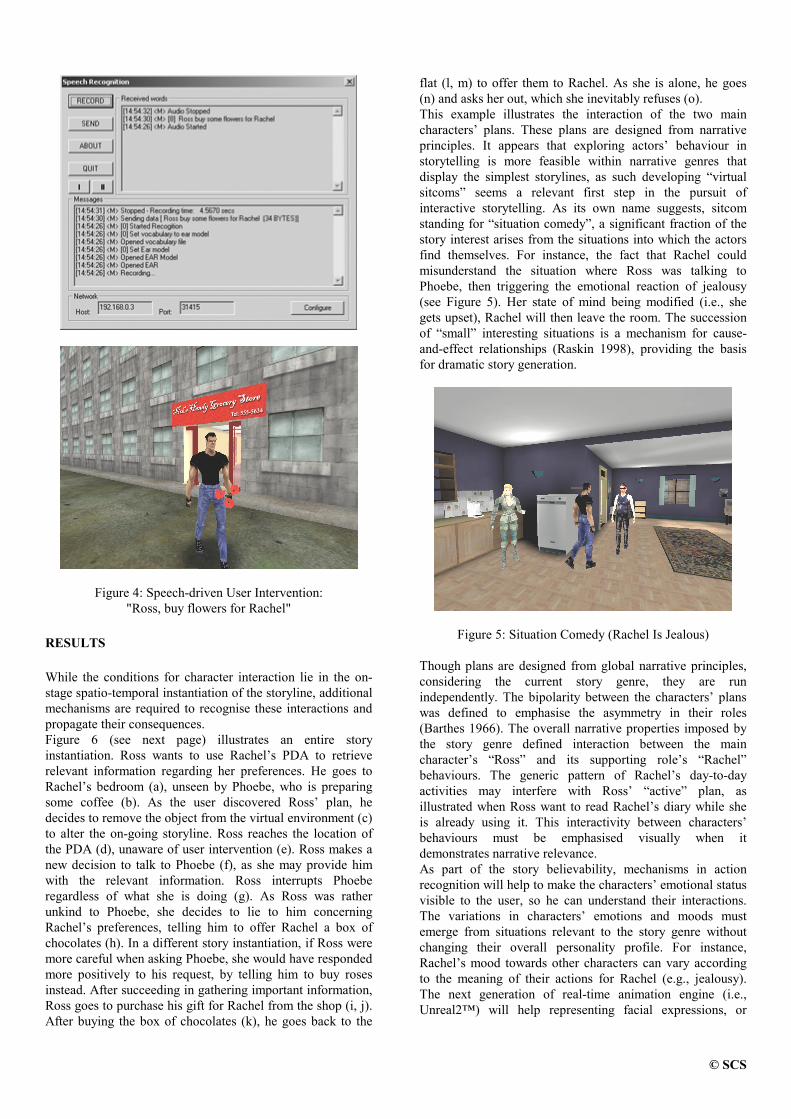
© SCS
Figure 4: Speech-driven User Intervention:"Ross, buy flowers for Rachel"
RESULTS
While the conditions for character interaction lie in the on-stage spatio-temporal instantiation of the storyline, additionalmechanisms are required to recognise these interactions andpropagate their consequences.Figure 6 (see next page) illustrates an entire storyinstantiation. Ross wants to use Rachel’s PDA to retrieverelevant information regarding her preferences. He goes toRachel’s bedroom (a), unseen by Phoebe, who is preparingsome coffee (b). As the user discovered Ross’ plan, hedecides to remove the object from the virtual environment (c)to alter the on-going storyline. Ross reaches the location ofthe PDA (d), unaware of user intervention (e). Ross makes anew decision to talk to Phoebe (f), as she may provide himwith the relevant information. Ross interrupts Phoeberegardless of what she is doing (g). As Ross was ratherunkind to Phoebe, she decides to lie to him concerningRachel’s preferences, telling him to offer Rachel a box ofchocolates (h). In a different story instantiation, if Ross weremore careful when asking Phoebe, she would have respondedmore positively to his request, by telling him to buy rosesinstead. After succeeding in gathering important information,Ross goes to purchase his gift for Rachel from the shop (i, j).After buying the box of chocolates (k), he goes back to the
flat (l, m) to offer them to Rachel. As she is alone, he goes(n) and asks her out, which she inevitably refuses (o).This example illustrates the interaction of the two maincharacters’ plans. These plans are designed from narrativeprinciples. It appears that exploring actors’ behaviour instorytelling is more feasible within narrative genres thatdisplay the simplest storylines, as such developing “virtualsitcoms” seems a relevant first step in the pursuit ofinteractive storytelling. As its own name suggests, sitcomstanding for “situation comedy”, a significant fraction of thestory interest arises from the situations into which the actorsfind themselves. For instance, the fact that Rachel couldmisunderstand the situation where Ross was talking toPhoebe, then triggering the emotional reaction of jealousy(see Figure 5). Her state of mind being modified (i.e., shegets upset), Rachel will then leave the room. The successionof “small” interesting situations is a mechanism for cause-and-effect relationships (Raskin 1998), providing the basisfor dramatic story generation.
Figure 5: Situation Comedy (Rachel Is Jealous)
Though plans are designed from global narrative principles,considering the current story genre, they are runindependently. The bipolarity between the characters’ planswas defined to emphasise the asymmetry in their roles(Barthes 1966). The overall narrative properties imposed bythe story genre defined interaction between the maincharacter’s “Ross” and its supporting role’s “Rachel”behaviours. The generic pattern of Rachel’s day-to-dayactivities may interfere with Ross’ “active” plan, asillustrated when Ross want to read Rachel’s diary while sheis already using it. This interactivity between characters’behaviours must be emphasised visually when itdemonstrates narrative relevance.As part of the story believability, mechanisms in actionrecognition will help to make the characters’ emotional statusvisible to the user, so he can understand their interactions.The variations in characters’ emotions and moods mustemerge from situations relevant to the story genre withoutchanging their overall personality profile. For instance,Rachel’s mood towards other characters can vary accordingto the meaning of their actions for Rachel (e.g., jealousy).The next generation of real-time animation engine (i.e.,Unreal2™) will help representing facial expressions, or

© SCS
a b c
d e f
g h i
j k l
m n o
Figure 6: Example of a Story Instantiation
detailed non-verbal behaviour (e.g., body postures) toimprove the dramatisation of events through physicalcharacterisation.Above the planning and interleaving of actions, explicitsituated mechanisms for reactive behaviours (Geib 1994) areneeded in order to deal with specific situations (e.g., Rosssuddenly meets Rachel on his way). This implies high-levelaction recognition of interactions between characters’behaviours. If a narratively meaningful (considering the storygenre) situation arises, the mechanism would act on the
character’s current plan by ordering a re-planning of itsaction.
CONCLUSION
We have shown that, although actor's behaviours aredeterministic, the interaction between actors couldconsiderably contribute towards story variability. This degreeof unpredictability conditions the generation of dramatic

© SCS
situations. The character-centred approach has the advantageof being modular and extendable to many actors.Further work is to be dedicated to developing more complexstorylines within differing genres, scaling up using multipleplans for each actor to increase characters' interactions andnarrative function recognition.
REFERENCESBarthes, R. 1966. “Introduction à l’Analyse Structurale des Récits”
(in French), Communications, 8, pp. 1-27.Cavazza, M., F.Charles and S.J. Mead. 2001. “Characters in Search
of an Author: AI-based Virtual Storytelling”. First InternationalConference on Virtual Storytelling, Avignon, France.
Geib C., “The Intentional Planning System: ItPlans”. Proceedingsof the 2nd Artificial Intelligence Planning Conference, AIPS-94, 1994, pp. 55-64.
Mateas, M.. 2000. “A Neo-Aristotelian Theory of InteractiveDrama”, AA,AI Spring Symposium in Artificial Intelligenceand Interactive Entertainment, AAAI Press.
Nakatsu R. and N. Tosa. 1999. “Interactive Movies”. In: B. Furht(Ed), Handbook of Internet and Multimedia – Systems andapplications, CRC Press and IEEE Press.
Pearl, J., 1984. “Heuristics: Intelligent Search Strategies forComputer Problem Solving”. Reading (Massachusetts),Addison-Wesley.
Raskin, R. 1998. “Five Parameters for Story Design in the ShortFiction Film”, P.O.V., n. 5.
Sgouros, N.M., G. Papakonstantinou and P. Tsanakas. 1996. “AFramework for Plot Control in Interactive Story Systems”.Proceedings AAAI’96, AAAI Press, Portland.
Szilas, N. 1999. “Interactive Drama on Computer: Beyond LinearNarrative”, AAAI Fall Symposium on Narrative Intelligence,Technical Report FS-99-01, AAAI Press.
Tsuneto, R., D. Nau and J. Hendler. 1997. “Plan-RefinementStrategies and Search-Space Size”, Proceedings of theEuropean Conference on Planning, pp. 414-426.
Young, R.M. 2000. “Creating Interactive Narrative Structures: ThePotential for AI Approaches”. AAAI Spring Symposium inArtificial Intelligence and Interactive Entertainment, AAAIPress, 2000.

���������������� ��� ������������������������ �����������"!#�
$&% '�% ()%�*,+.-�/0+1*3254625-7+.-9878�4;:5%<8=4>%@?<% $&% '�%&ACB.D6E=FG46+3-�D6HI9+�JLK=MNDPOQB3RTSU-�RVB�4XW�+.DXYZB3-�[\2]J;E=-=B3MZB3^�O_+.-98�`GO�:aDX25W�:
bc2>MdReDgfh-=YZ*32>46:XYdDPOQB.Ri[T2>J;E9-=B3MZB3^�O'"2>F32>MNjk25^l9m9n3o�n3prqkbsbc2>MdReD]m&[tE=2vuc2LDXE92546MZ+3-98=:
w"xcy{z}|�~{���� +.W2>:>m=�hS�m&�h4XDXYN�&JLY�+.M�(�MZ+1O�254]mG�cK�DXB�W�+,DX2]874XB�K�DX2g�9-98=YN-=^&%
�Q� ����~ �_� �
SU-�DXE=Y�:"�9+3�&2>4"DXE=2���K&+.F32�SaSXS"�h4625-9+���B.D�Y�:"�=462>:X25-rDX2]8�%[tE=2���B.D7YZ:7+.-�YN-rDX2>MNMZYZ^325-rD�+.4XDXYN�&JLY�+.M��=MZ+1O�254{25W�K9MZ+.DXYZ-=^�+EGK=W�+.-7�=MZ+1O�254tYZ-QD6E=2v^�+3W�2�2>-r*GYZ4XB�-=W25-rDtB.R\D6E=2��94;:PDC��254X�:aB�-�:aE9BrB3Da��25W�K=����Ii(k`=�v^r+.W2{��K9+3F32_SXSaS��h4625-&+=%"/�YNDXEDXE=2Q��K9+3F32SaSXS��c4X2>-9+7�&B3D�25*32>4XO�B3-=2�J5+3-�2>-, PB,O"DXE92�^�+.W2+.-98¡�=4;+3JLDXY�JL2tjCYdD6E=B3K=D@DXE=2t-=2>2>8¡RVB34@B3DXE=2>4@�&2>B3�=MZ23%)[tE=2t�&B3DYZ:�+.-0+.4XDXYN�&JLY�+.M@�=M�+1O32>4�DXE9+.D�¢aMZYN*�2>:6£7YN-9:XY�8�2DXE=2_J5B3W�=K�D6254]m:aY�8�2¡�rO�:XYZ8�2¡jCYdD6E"DXE92¡^r+.W2��=46B3^�46+3W7%h[tE92���B.D�B�-=MZO7+3����&2]+.4;:tMNYZF32v+�EGK=W�+.-7�=M�+1O3254tYZ-9:XYZ8�2�D6E=2v^�+3W2L��j¤B�4XM�8�%)¥hB,jt�25*�254DXE92�YN-�^r+.W2��&2>E9+1*GYNB�4�B.R�DXE=2"��B.D7:aE=B�K=M�8���2"E9+3468DXB78�YZ:aDXYZ-=^�K=YZ:XE�RV46B3W¦D6E=2��&2>E9+1*GYNB�4cB.R¤ErK9W+3-��=M�+1O32>46:>%�[TB:aE9B,j§EGK=W�+.-���MZYNF�27��25E&+1*rYZB34_+0jCY�8�2"4;+.-=^�2�B.RgDX2>J;E9-=YZ¨rK=2]:+.-98�JLB�WW�B�-�:a2>-9:a2":XB3MZK�DXYZB3-&:�+.462{K9:X2>8�RVB�4DXE=2"��B.DQ�cS�%[tE=2{��K9+3F32�SaSaS��h4625-&+{��B.D�Y�:�D6E=2�94;:PD�J5B3WW254;JLY�+.MZMNO�8�25�*32>MNB��&2]87+34aD6Yd��JLY�+.M��=M�+1O32>4tDXE9+.DhK9:a2]:tRVK=MZMNO�+.K=DXB3W�+.DX2>87�9+.DXE+.-98{46B3K�D62��9-98�YZ-=^DXE94XB�K=^3E�+.46�=YNDX4;+.46OJ5B3W�=MZ2L©�ª3b«��B3MZOG^.�B3-9+3McjkB346MZ89:5mCjCYNDXE=B�K�D7DXE=2�-=252]8�RVB34{DXE=2��&B3D{D6B�+�J5¨rK=YZ4X2FG-=B,jCMN2]8�^32+.��B3K=D�4XB�K�DXYZ-=^"+.-98�-9+1*GYZ^�+.DXYZB3-�8=K=4XYZ-=^�^�+3W2L��=M�+1O3%tuhB_EGK=W�+.-"YZ-rDX2>4X*�25-rDXYZB3-�Y�:h462>¨rK=YZ4X2]8QD6B_�=46B,*GYZ8�2gD6E=2�&B3DTjCYNDXE�+.MZM3D6E=2¤YZ-�RVB�4XW�+,D6YNB�-v-=252]8�2>8�DXB�-9+1*GYN^r+,DX2)D6E=46B3K=^�E�m+.-98�K9-98�254;:aD6+.-&8{-925js^�+3W�2�25-G*GYN46B3-=W2>-�D;:5%t[tE=2���B.D�K9:a2]:+�*�B3MZK=W2��¬+.462>+r���&+3:X2>8�4625�94X2]:a2>-�D;+,D6YNB�-�B.R�DXE=2�ª�b¦^�+.W225-G*GYN46B3-9W�2>-rD>m9jCE9YZJ;E�:X2546*32]:h+3:�+��9+3J;Fr���&B�-=2�RVB34cDXE=2¡�&B3D> :JLB�^3-=YNDXYZ*32�jkB346M�8�W�B�8�2>M�%®[TB3^325DXE=2>4QjCYNDXE�+�E=YZ^3E���254XRVB34X�W�+.-9J52c�9+.DXE��9-&8�YN-9^�:XB3MZK�DXYZB3-D6E=Y�:kJ5B3^�-=YdD6YN*�2hWB�8�25M¯W�+.F�2>:DXE=2v��B.Dc¨rK=YNDX2v462>:XB3K946J52c2L°_J5YN2>-�D]%
±L²"��~_|��7³ � ��±>|�²
��K9+.F�2SaSaS��c4X2>-9+���25MZB3-=^r:�DXB"D6E=2_^�25-=462�B.RkDXE=2Q�94;:PD���254X�:aB�-�:aE9BrB3Da��25W´K=��^�+3W2>:Q��I)(¤`=�L%T�µ�9MZ+1O�254�*GYZ25jh:vRV46B3W¶+�94;:PD"��254;:aB�-#��254;:a��2>JLDXYZ*32�+.-&8�WB,*32]:�+.46B3K=-98�YN-«+�462>+.MN�DXYZW2{ª3b§*GYN4XDXK9+3M�jkB346MZ8�%�[tE92_WB�:aD�YNW��B34XD6+3-�D�D6+3:XF�:�+34X2:PD;+1OGYN-=^�+.MZYN*�2�+3-98�25MZYZW�YZ-9+.DXYZ-=^¡B��=��B3-=2>-�D;:kjCYdD6E=YN-QDXE=Y�:t*GYN4X�DXK9+3McjkB346MZ8�%s[tE92>:X2�B3�=��B3-925-rD6:{+.462"B.DXE9254Q��25B��=MZ23mC2>¨rK9+3MYN-�:PD64X2>-=^.D6E�+.-98�+3�=YZMNYNDXYZ2>:>m<JLB�-=-=2>JLDX2]8�DXB�D6E=2{:6+.W2{^�+.W2DXE=46B3K9^3E�+_-92LDPjkB346F{B�4cD6E=2�SU-rDX2>4X-92LD>%�[tE=2��=M�+1O3254;:CE9+1*�2�+jCYZ8=2�4;+.-=^�2<B.R9jk2>+3�&B�-9:>m]YNDX2>W�:T+3-98���B,j¤2>4a��K=�9:T+1*,+.YZMZ+3�=MN2<DXB+.Y�8vYZ-�DXE92��9+.DaDXMZ2>:>%)[tE=2�^r+.W2�E9+�:T+�:a25DTB3R&8�YN·�2>4X2>-�Di*GYN4XDXK9+3M25-G*GYN46B3-9W�2>-rD6:CJ5+3MNMZ2>87MZ25*�25M�:CB34CW�+.�&:5m�D6E9+,DgJLB3-rD;+.YZ-746BGB3W�:+.-98�E9+3MNMZjt+1OG:>%�[tE=2��&+,DaD6MN2]:�YZ-�DXE=2"^r+.W2�D6+3F32"�=M�+3J527YZ-
DXE=2]:a2hW�+3�9:@W�K&J;E�MNYZF32C^�MZ+�8�YZ+.DXB�46:i�9^�ErD�YN-_+3-�+.4625-9+9%T(<M�+1Or�254;:CJ5+.-":6JLB�4X2���B3YZ-�D;:C�GO_D;+.FGYN-9^�B�K�DhB.D6E=254c�=MZ+1O�254;:5%)/�E=2>-FrYZMZMN2]8�m�+_�=MZ+1O�254C462>:X�9+1jC-9:h+.DcB3-92�B.R)DXE92¡8�2]:aYZ^3-9+.DX2]8�MNB�J5+.�DXYZB3-9:�B3-�DXE=2�W�+.��+3-98�J>+.-�J5B3-rDXYZ-GK=2�D6BQ�&^3ErD>%���K9+3F32�SXSaS�h4625-9+�+.M�:aB�E9+�:C:a2>*3254;+.M&DX2]+.WµB�4XYZ25-rD62>8{^�+.W25�¸�=M�+1OWBG8=2>:>%SU-�-9B346W+3M@DX2]+.W����=MZ+1O�DXE=2>4X2_+34X2�DPjkB�DX2>+3W�:vjCYdD6E��=M�+1O3254;:DXE9+.Dh�9^3ErDc2]+3J;E�B.D6E=254]%t[tE=2vDX2]+.W}jCYdD6E"DXE92�E=YZ^3E=2]:PD�+�J5J5K��W�K=M�+,D62>8�:XJ5B34623m�B3R)+3MNM��9MZ+1O�254;:¤B�-7DXE9+.DhDX2]+.W�m=jCYZ-9:5%¤[tE=25462YZ:7+.M�:aB�+�qk+.�=DXK=462�[tE=20IiMZ+3^��¸qk[CI@�_DX2>+3W¹�9+3:X2>8�^r+.W2W�B�8�2�%��h^r+.YZ-0DXE=2>4X2Q+34X2_DPj¤B"D62>+3W:�jCYdD6E��=M�+1O32>46:>%7º¤+3J;EDX2>+3W®E9+3:k+��9+�:a2�:PD64XK9JLDXK=462cYZ-_D6E=2c^r+.W2cjkB346M�8B34�W�+3��%@�» +.^{YZ:��&Br:aYNDXYZB3-92>8�YZ-�:XK9J;E�+{�9+�:a2�%g�¼DX2]+.W�:6JLB3462>:c�&B�YN-rD;:�rO�J5+3��DXK=46YZ-=^�DXE=2 » +.^vB3R&D6E=2hB3�9�&Br:aYZ-=^�DX2]+.W½+.-98�=46YZ-=^3YZ-=^YdDh�9+�J;F�DXB�D6E=25YZ4hB,jC- » +.^�YN-7D6E=25YZ4hB,jC-7�9+3:X23%[tE=2k��K9+3F32@SaSXS��h4625-9+h�&B3DTY�:\:XK=�=��B�:X2>8gDXBg+3JLD\MNYZF32¤+CEGK=W�+.-�=MZ+1O�254@YZ-DXE=2c*rYZ4XDXK9+3M9jkB346MZ8¡B.R¯DXE92h^�+3W�2�%i��:�:XK9J;E�DXE=2��&B3D:aE=B�K=M�8��&2¤E9+.4;8�DXBc8�Y�:aDXYZ-=^3K=Y�:XEvRV4XB�W#+CEGK=W�+3-v�=MZ+1O�254�YZ-�DXE92^�+.W2�%@SU-7B�468=254kDXB_+�J�DCMNYZF32�+�EGK=W�+.-��=M�+1O32>4kDXE=2v��B.Dc8�BG2]:-=B.DcB�-=MZO{-=2>2>8�D6B_K=-98=254;:PD;+.-987D6E=2�46K=MZ2>:hB3R@DXE=2�^�+.W2�+3-98E=B,j�D6E=2v^�+3W�2vjkB346F�:5%@[tE=2v��B.Dc+3MZ:XB-=252]8=:C�9+�:aY�J�+.�=YZMZYdD6YN2]:MNYZF32h-&+1*rYZ^�+.DXYZ-=^vD6E=4XB�K=^3ED6E=2c^r+.W2h2>-r*GYZ4XB�-=W25-rD6:>m3�9YZJ;FGYZ-=^K=��YdD625W�:k+.-98E9+3-98�MZYN-9^�j¤2]+.��B3-9:>%T[tE92c��B.D�E9+�:@D6B��&2�+.�=MZ2DXBg�=MZ+1O�D6E=2¤DX2>+3W¾�9+�:a2]8v^�+3W�2¤DPOG�&2]:)+.-98�E9+3:TDXBgB3��254;+,D62¤YZ-DX2>+3W�:5%)SU-QB�468=254¤DXB�B3��254;+,DX2�YN-�+vD62>+3W7m�jCYNDXE{�&B3DXE7EGK=W�+.-�=MZ+1O�254;:�+.-98�B.D6E=254��&B3D6:>m�DXE92_�&B3D�-=252]8=:�D6B�JLB3WW¡K=-=Y�J5+,D62jCYdD6E�B.DXE9254��9MZ+1O�254;:5%7[tE=2_��B.D�MZYN*�2>:�YN-9:XY�8�2�DXE92QJLB�W��9K�DX2>4-=2L©GD�DXB�DXE=27^�+3W2{�=46B3^�46+3W�+3-98�B�-=MZO�+.�=��2>+346:+3:�+�ErK=�W+3-��=M�+1O3254�YN-�D6E=2Q^r+.W23%�[tE92Q:X+3W2��V^r+.W2]��4XK=MZ2>:�DXE9+.D+.�=�=MZO7DXB7EGK=W�+.-��9MZ+1O�254;:hYZ-�DXE92¡^r+.W23m�+.M�:XBQ+.�=�9MNO�D6B_DXE92�&B3D>%�[tE=2���B.D�8=Br2]:tE=B,jk25*32>4t-=B.DCK9:X2�DXE=2�:6+.W2�YZ-=�=K�D�+3-98B3K�D6�=K�DC8�25*GY�JL2>:t+�:�EGK=W�+.-{�=M�+1O3254;:>%\SU-9:aDX2]+38_B3R�DXE92�B�K�DX�=K=D8�25*GY�JL2>:tEGK=W�+3-Q�=M�+1O32>46:kK9:X23m�MZYNF�2gDXE=2vJLB�W�=K�DX2>4> :tWB3-=YNDXB�4+.-987:aB�K=-987J5+3468�mGD6E=2��&B3Dh4X2]JL2>YN*�2>:kYN-=RVB346W+.DXYZB3-7+.��B3K�DtDXE92*rYZ4XDXK9+3M@j¤B�4XM�8�8=YN462>JLDXMZO"RV4XB�W¿DXE92�^�+.W2�=46B3^�46+3W�+3:v+�:a25DB.Rt*1+34XY�+.�9MN2]:5%�[tE=2���B.D�+3MZ:XB78=Br2]:v-=B3D�K9:a2�D6E=2_JLB�W�WB�-=MNOK9:a2]80YN-9�=K�D�8=25*GYZJ52>:�MNYZF32�D6E=2QF�25OG��B�+.4;8�+.-980WB3K&:a2�%�[tE=2�&B3D{:a2>-98=:_+�:X2>¨rK=2>-9JL2"B3R�+�J�D6YNB�-9:�B34�YZ-rDX2>-�D6YNB�-9:_8�YZ462>J�D6MNODXB_D6E=2�^r+.W2��=46B3^�46+3W�%h[tE=2>:X2¡+�J�DXYZB3-&:hE=B,jk25*�254]m&+.462�*�2546O:aYZWYNM�+.4vD6B�DXE=2{+3J�D6YNB�-9:�+"EGK=W�+3-��9MZ+1O�254�J5+3-�YN-9�=K�D�K9:XYZ-=^DXE=2JLB�W��9K�DX2>4> :gYN-=�9K�D�8�25*GY�JL2>:>%�[tE=2��&B3DgK&:a2]:�FG-=B,jCMZ2>8=^32DXE9+.D¡E9+�:���252>-��=46B,*GYZ8�2]80YN-�+38�*,+.-&JL2{+3-98�FG-=B,jCMZ2>8�^�2Q+3JL�¨�K9YN462>8{8�K=46YN-=^^r+.W2L���=M�+1O�D6BJ5B3-9:aDX46K9JLDt:XK9J;E�:a2]¨�K925-9J52>:kB.R+3J�D6YNB�-9:>%[\Bv��2c+.�9MN2CD6BvK=-98�2>46:aD6+3-98�+.-&8¡462>+�:aB�-�+.��B3K�D@D6E=2h25-G*GYZ4XB�-��W�2>-rD�D6E=2��&B3D�-=252]8=:+�J5B3^�-=YdD6YN*�2QWB�8�25MCB3RcD6E=2�j¤B�4XM�8�YNDMNYZ*32]:�YN-�%{[tE=YZ:�JLB3^�-=YNDXYZ*32WBG8=25M<�=M�+1O�:v+.-�YNW��B34XD6+3-�D�46B3MZ2

YN-�E=B,j§DXE=2"��B.D���254;JL25YZ*32]:�+.-98�K=-98=254;:PD;+.-98=:�D6E=2�*GYN4XDXK9+3Mj¤B�4XM�8�%�SU-��9+34aD6YZJ5K=M�+.4]m\D6E=2Q��B.DJ5+.-9-=B.D�-9B.DXY�JL27+3:X�&2]J�D;:�B.RDXE=2jkB346MZ8"DXE9+.Dv+34X2�-=B3Dg4625�=462>:X25-rD62>8�jCYNDXE9YN-�YdD;:vJLB�^3-=YNDXYZ*32WBG8=25M¸%iSU-�YND> :�:XYZW��9MN2]:PD<RVB�4XWÀDXE9YZ:¤JLB3^�-=YNDXYZ*32CWB�8�25M�J5+.-��2+¡:X2LDtB.RT*1+34XY�+.�9MN2]:<D6E9+,DC4625�=462>:X25-rD�D6E=2vJLK=464625-rDk:aD6+.DX2gB.R�D6E=2j¤B�4XM�8�%�[tE=Y�:v:aD6+,D62¡B3R�D6E=2¡jkB346M�8�YZ-9JLMZK98�2]:gDXE=2��&Br:aYNDXYZB3-�B.RDXE=2��&B3D>mr�&Br:aYNDXYZB3-QB.R�25-=2>WYN2]:¤+3-98YdD625W�:>m�D6E=2cjk2>+3�&B�-9:)D6E=2�&B3D�E9+�:�^�+.DXE=2>4X2]8�2LD6J3%�[\B"��2{+3�=MZ2�DXB�-&+1*rYZ^�+.DX2�DXE94XB�K=^3EDXE=2�*GYZ4aD6K9+.M@jkB346M�8�+3-98��&-98�JL2>4aD;+.YZ-�MZB�J5+,D6YNB�-9:gYN-�D6E=2_*GYN4X�DXK9+3M&jkB346M�8�DXE=2g�&B3Dk-9252>89:¤+v4625�94X2]:a2>-�D;+,D6YNB�-�B.R�DXE92�MZ25*�25M�B34W�+.�{DXE=2v��B.DhY�:h:XYdD6K9+,D62>8{YN-�%I=B�4¡+.K=DXB3-9B3WB3K9:��&2>E9+1*GYNB�4vDXE92{��B.D+.M�:aB�-9252>89:vDXB�W�+.YZ-��D6+3YN-"+.-�25©G�9MNY�JLYNDh4X2>�=462>:X25-rD6+.DXYZB3-7B.R)E=B,j�D6E=2v*GYN4XDXK&+.M�jkB346MZ8J;E9+.-9^32>:>%\[tE=Y�:TFr-9B,jCMN2]8�^32¤YZ:T4X25RV25464X2]8gDXB�+3:i8�B3W�+3YN-�FG-=B,jCMN�2>8�^�23m,+.-&8�YZ:T4X2]¨rK=YN462>8gD6Bh462>+3:XB3-v+3�&B�K�D\D6E=2�25·�2]J�D6:TB.R98=Yd·¯254X�25-rDC:a2]¨�K925-9J52>:kB.RT+�J�D6YNB�-9:5%@[tE=2g462>+3:XB3-9YN-=^�YZ:t-=2]JL2]:X:6+.46O�RVB�4DXE=2g��B.DtYN-{B34;8�254�DXB:a2>MN2]J�Dk+�J�D6YNB�-9:5m�DXE&+,DC+.462cK9:X2LRVK=M¯jCYNDXE=YZ-DXE=2�^�+3W�2�+.-98�+3MNMZB,j}DXE=2��&B3DQDXB�+3J;E=YZ25*�2�JL2>4aD;+.YZ-�^3B�+3MZ:>%¥hK=W�+3-7�9MZ+1O�254;:tB.ReDX2>-7DXE=YZ-=F7YN-rDXK9YdD6YN*�25MZO7+3�&B�K�DCDXE=2v25·�2]J�D;:B.R<+3JLDXYZB3-9:c+.-98�W�+.F�2�+MNB3DcB.R@YZW�=MNY�JLYNDgJ5B3WWB3-":X25-9:X2�+3:a�:aK9W��=DXYZB3-9:>%<���&B3Dc8�BG2>:kB.R@JLB�K=46:X2g-=B.DCE9+1*�2cD6E=YZ:CJ5B3WWB3-:a2>-9:X2��GO�8=2LR¬+.K9MdD]%_�ÁJL254XD6+3YN-�MZ25*32>[email protected]�B3W�+.YZ-�Fr-9B,jCMN2]8�^32+.-987JLB�WW�B�-7:X25-&:a2�jCYZMNM�E&+1*32gDXB��2v�=K=YZMdDhYZ-rDXBDXE92v�&B3D>%[tE=2c��B.DC8�BG2>:k-=B3D¤B�-=MNO-=2>2>8Q�9+3:XYZJcFG-=B,jCMN2]8�^32�YN-{+38�*,+.-&JL2DXB{�&2�+.�=MZ2vDXB{B3��254;+,D62�YN-�DXE=2�*GYN4XDXK9+3M\jkB346MZ8�m=DXE92¡��B.D�+.M�:aBE9+3:hDXB�+3J>¨�K9YN462�FG-=B,jCMZ2>8�^�2�jCE=YZMN2¡�=MZ+1OGYZ-=^�D6E=2¡^r+.W23%g[tE=2JLK=464625-rD�:PD;+,D62cB.R¯D6E=2cjkB346MZ8Y�:<B�-=2hB3R�DXE=2g:aYZW�=MN2]:PD¤FrYZ-98=:¤B.RFG-=B,jCMN2]8�^32�DXE=2��B.DvJ5+.-�+3J>¨�K9YN4623%v[tE=Y�:gFr-9B,jCMN2]8�^32�+3J5¨rK=YN�:aYNDXYZB3-�Y�:¡4X25RV25464X2]8�D6B�+3:¡:a2>-9:XYN-=^&%��c:XYZ8=2_RV46B3W�Fr-9B,jCMN2]8�^32+.��B3K�D�DXE927J5K=4X4625-rD�:PD;+,D62{B3RhDXE=27jkB346MZ80D6E=2��&B3DJ>+.-�+.M�:aB+3J>¨�K9YN462tFr-9B,jCMN2]8�^32C+.��B3K=D@DXE=2c8=Or-&+.WYZJ>:)B.R¯DXE92Cj¤B�4XM�8�m,D6E=28�B3W�+3YN-�Fr-9B,jCMN2]8�^32�%�[tE=2���B.D_JLB�K=MZ8�+3J>¨rK=YN4627Fr-9B,jCMN2]8�^32+.��B3K�D�E=B,j§DXE=2"jkB346M�8���25E9+1*�2>:>m¤+.-&8�E=B,jÂB.D6E=254�2>-�D6YdD6YN2]:MNYZF32cB.DXE9254��9MZ+1O�254;:@jCYdD6E=YZ-_DXE92cjkB346MZ8��25E9+1*�23%)[tE=Y�:�FGYZ-98�B.RFG-=B,jCMN2]8�^32�+3J>¨rK=YZ:XYNDXYZB3-7YZ:CJ>+.MZMN2]8QMZ2>+34X-=YZ-=^�+.-&8QY�:tR¬+.4CWB�4X2JLB�W��9MN25©cDXE&+.-�:X25-9:XYZ-=^9%iÃcReD625-vMZ2>+34X-=YZ-=^C462>¨rK=YZ4X2]:¯DXE92�462>JLB�^.�-=YNDXYZB3-�B.R��&+,DaD62546-9:<YZ-Q+vM�+.46^32h+3WB3K=-rD�B3R¯B��9:X2546*1+.DXYZB3-9:�+.-9825*,+.MZK9+.DXYZB3-9:)B3R�D6E=2h25·�2]J�D6:<B.R�JL2>4aD;+.YZ-�:X2>¨rK=2>-9JL2]:@B.R�+3JLDXYZB3-9:>%fc:XK9+.MZMZO�W�Br:PD]m=YNRT-=B3DC+3MNM�8=B3W�+.YZ-{FG-=B,jCMZ2>8=^32�+���B.DCK9:X2>:tY�:�=46B,*rY�8�2]8_YZ-�+�8�*,+.-9J523%
��Ä"xv|�~gy
q¤4X2]+,D6YN-=^0+��&B3DRVB34_+.-�I)(¤`�^�+3W�2�Y�:�+.-�2L©GDX2>-9:XYN*�2QD;+3:XFjCE=Y�J;EÅ462>¨rK=YZ4X2]:�25©G��254XDXY�:X2¼RV46B3W�W�+.-GO¿8�YN·�2>4X2>-rDs+34X2]+3:jCYdD6E=YZ-�DXE92Q�92>MZ8�B.R�+34aD6Yd��JLY�+.MkYN-rDX2>MNMZYZ^325-&JL2����hSa�Lm<+.-98�+.M�:aB+.462>+�:<-=B3Dt8�YZ462>J�D6MNO�+�:X:XB�JLY�+,DX2]8�jCYNDXE{�cS�%=`GB3W2gB.R�DXE92gJ5B3W��WB3-=MZOK9:a2]8�W2LD6E=B�8=:¤+3-98D62>J;E=-=Y�¨rK=2>:k+.462c8�2]:XJ54XYZ��2>8�E=2>4X2�%
ÆcÇ�È]É�Ê)ËTÌiͬËiÎ
Ã�-=2�B.R�D6E=204X2]¨rK=YN4625W2>-�D;:_RVB�4�+.K�D6B3-=B�WB3K9:{�&2>E9+1*GYNB�4{YZ-I)(¤`{^�+3W�2]:CY�:tDXE=2�+.�=YZMZYdDPOQDXB�-9+1*GYZ^�+,D62�DXE=46B3K9^3E7DXE=2�^�+.W2j¤B�4XM�8�YZ-�+�MNYNRV2L��MNYZF327W�+.-=-9254]%0b�2LD62546WYN-=YZ-=^�E=B,j®DXB�-9+1*r�YN^r+,D62�DXE=46B3K9^3E�+�W�+.��Y�:�+3-�YZ-�D625462>:aDXYZ-=^"�=46B3�=MZ25W�%�'�+3-GO8�YN·�2>4X2>-�Dv+.�9�=4XBr+3J;E=2]:hD6B7:XB3MZ*GYN-9^_DXE9YZ:��=46B3�9MN2>W¿E9+1*32¡�&2>25-�=462>:X25-rDX2]8�%CÏ@2546O7:XYZW��9MN2��hS) PK9:aD�MZ2LD;:�+���B.Dgjk+3MNFQRVB346jk+3468
IiYZ^3K=462Ð3Ñ<'�+3H52�jCYdD6E�jk+1OG��B3YZ-�D;:k4X2>�=4X2]:a2>-rDX2>8Q�GO{8�B3D6:
K=-rDXYZMT:XB3W2LD6E=YN-9^�YZ:CE9YdD]%¤�kDhD6E9+,Dc��B3YZ-rDCDXE=2��&B3DhDXK=46-9:h+3-98JLB3-rD6YN-GK=2]:�jt+.MZFGYN-=^�RVB346jk+3468�%0[tE=2>4X27+.462{+.M�:XB�WB3462QJLB�W���=MN25©7�&+,DXE��9-98�YZ-=^{+3MN^�B346YdD6E=W�:tDXE&+,D�K&:a2�E925K=46YZ:aDXY�J5:hDXB��&-984XB�K�DX2]:cD6E=46B3K=^�E"DXE=22>-r*GYZ4XB�-=W25-rD>%¡�½:X��2>JLY�+.M)4625�=462>:X25-rD;+,�DXYZB3-�B.R<D6E=225-G*GYN46B3-=W2>-�D�B34�W�+.��YZ:�B3ReDX2>-�K9:X2>8�RVB34gD6E=2>:X2W�B�4X2�J5B3W�=MZ2L©�+3MN^�B346YdD6E=W�:5%_Ã�-=2B.R¤DXE=2�WB�:aD�JLB�W�WB�-=MNOK9:a2]8�4625�94X2]:a2>-�D;+,D6YNB�-9:�Y�:�+�jk+1OG��B3YZ-�D�:XOG:aDX2>WÒ�¬IiYZ^3K=4620Ð]�L%`GK9J;E_+vjt+1OG�&B�YN-rD�:XOG:aDX2>W¼Y�:�+�J5B3MZMN2]J�D6YNB�-�B.R��&B�YN-rD;:<B34�MNB�J5+.�DXYZB3-9:�Vjt+1OG�&B�YN-rD;:6�cjCYdD6E�8�YN462>JLDXYZB3-9+3M)MNYZ-=F�:g�&25DPj¤2>25-�DXE=2>W7%[tE=2�jk+1OG��B3YZ-rD6:�4625�=462>:X25-rDgDXE=2_�9MZ+�JL2>:�jCE925462DXE=2���B.D�J>+.-^3BQ+3-98�DXE92�MZYN-=F�:��&25DPj¤2>25-�D6E=25W¿4625�=462>:X25-rDCD6E=2¡�&+,DXE&:CDXE92�&B3D�J5+3-0RVB3MZMNB,j®YZ-�B34;8�2>4�DXB�2>+3:XYZMNO�DX4;+1*32>M<RV46B3W�B3-=2_jt+1Or��&B�YN-rD�DXB0+.-=B3DXE=2>4>%�fc:XK9+3MNMZO�DXE=2�MZYN-=F�:¡4X2>�=462>:X25-rD�:aDX4;+.YZ^3ErDMNYZ-=2�8�YZ462>J�D6YNB�-9+.MC�&+,DXE&:5%¾q¤4X2]+,D6YN-=^�+3-�2L°_JLYZ25-rDQjt+1OG�&B�YN-rD:aO�:aDX25W¦RVB�4g+7:X�&2]JLYN�&J�2>-G*rYZ46B3-=W25-rD�YZ:�+3-�YZ-�D625462>:aDXYZ-=^{+3-98B.ReDX2>-�J5B3W�=MZ2L©�D6+�:aF¯%��Â�&B3D�J5B3K=M�8�J54X2]+,D62_DXE92{jt+1OG�&B�YN-rD:aO�:aDX25W½8�K=46YN-9^�^�+3W�25�¸�9MZ+1O�+3-98�8�46B3�jk+1OG��B3YZ-rD6:<+�:@YdD¤jk+3-��8�254;:iDXE=46B3K9^3E¡DXE=2h2>-G*rYZ46B3-=W25-rD]%T[tE=2C��B.D<jCYZMNM9E9+1*32C+gE9+.4;8DXYZW�2�4X2]+3J;E=YZ-=^CWB�:aD\�=M�+3J52>:�YZ-vDXE92<25-G*GYN46B3-9W�2>-rD�K=-rDXYZM�YND\E9+�:jk+3-98�25462>8"DXE=46B3K=^�E�WB�:aD�B.R<D6E=2¡^r+.W2�j¤B�4XM�8�%�fc:XYZ-=^QD6E=Y�:W�25DXE=B�87D6E=2���B.DcB3ReDX2>-"-=25*�254C�9-&8=:hB�K�DcE=B,j#DXB_^�BDXBQJ5254X�D6+.YZ-�E9+.4;8�D6B�4X2]+3J;E��=MZ+�JL2]:5%[tE=2�jt+1Or��B3YZ-rD�:XO�:PD625WÅJ5B3K=M�8+.M�:aB��&2�JL462>+.DX2]8�YZ-#+38=*1+3-9JL2���2LRVB3462�DXE=20��B.D"25-rDX2>46:QDXE92^�+.W2�%7(�MZ+�JLYZ-=^"jk+1OG��B3YZ-rD6:�D6E=4XB�K=^3E9B3K�DvD6E=2Q2>-r*GYZ4XB�-=W25-rD+.-98�MNYZ-=FGYN-9^_DXE925W�Y�:cB3ReDX2>-�+QDXYZW�2JLB�-9:XK=WYN-=^QD6+�:aF�D6BQ��2JLB3W�=MZ2LD62>8��GO_D6E=2�MZ25*�25M\8=2>:XYN^�-=254]%t`�B3W2�+.MZ^3B�4XYNDXE9W:tE&+1*32�&2>25-"8�25*�25MZB3��2>8QDXB_+3YZ8{YN-"J54X2]+,DXYZ-=^+jk+1OG��B3YZ-rDt:XO�:PD625W§YZ-+38�*,+.-&JL23m&�=K�DgK9:aK&+.MZMNO7EGK=W�+.-�YZ-rDX2546*32>-rDXYZB3-�YZ:c4X2]¨rK=YN462>87D6BB3��D6YNWYZH52�DXE92�:aO�:aDX25W�%/�E=25-7+�^3BGB�8jt+1Or��B3YZ-rD¤:XOG:aDX2>W®YZ:k+1*,+.YZMZ+3�=MN2hDXB¡DXE=2��&B3D>m�+jCE=B3MZ2@46+3-=^32@B3R=8�Yd·¯254625-rD��9+.DXE9:TJ5+3-v�&2�J>+.M�JLK=M�+,D62>8�%Tfc:XK9+.MZMNOB3-=MZOhD6E=2�:XE=B34XDX2]:PD��9+.DXE9:�DXB,jt+.4;8=:�:a��2>J5Yd��J@^3Br+.M�:�+.462@K9:a2]8g�rO+���B.D>%@¥cB,j¤2>*3254¤8�Yd·¯254625-rDkFrYZ-98=:¤B.R��&+,DXE&:¤J>+.-_��2cK9:X2LRVK9M�+�:j¤2>MNM¸%@I=B34kYZ-9:PD;+.-9J52��&+,DXE&:�D6E9+,DtMZ2>+38_DXB,jt+.4;8=:�+¡^3Br+.M¸m�jCE9YNMZ2+1*3B3Y�8�YZ-=^�J5254XD6+3YN-�+.462>+�:�B3RcDXE927jkB346M�8�+,DD6E=2�:X+3W2QD6YNW23%`G25*�254;+.M�+3MN^�B346YdD6E=W�:T+34X2k+1*,+.YZMZ+3�=MN2<DXB�J5+.M�JLK9MZ+.DX2<D6E=2C:aE9B34XDX2>:aD�9+,D6E"�&25DPj¤2>25-�+_:XB3K946J52vMNB�J5+.DXYZB3-�+3-98"+_8�2]:PD6YN-9+.DXYZB3-�%�[tE=2W�Br:PDcJ5B3WWB3-=MZO_K9:X2>8�+3MN^�B346YdD6E=W�:C+.462�IiMZB,O�8� :>m=b�Y PF�:aDX4;+= :+.-98��gÓ��¬�¼�C:aD6+34;�¡Ô ª,Õ�%�[tE=2>:X2¡+3MN^�B346YdD6E=W�:cjk25462¡8�2]:aYZ^3-92>8YN-�D6E=2�J5B3-rDX25©GD�B.R�^�46+3�=E9:<+3-98�^34;+.�9E¡D6E=25B�4XO�%)`�YN-9J52�+vjt+1Or��&B�YN-rD�:XO�:PD625W¶Y�:�*�2546O�:XYNWYZMZ+34�D6B�+�8=YN462>JLDX2>8�^34;+.�=E0D6E=2>:X2+.MZ^3B346YNDXE=W�:7J5+.-#+.M�:aB��&20K9:X2>8�DXB�J5+.M�JLK9MZ+.DX2��&+,DXE&:7+3MNB�-=^B3-=2�B34kW�B�4X2gjt+1Or��B3YZ-rD6:>%i[T4;+1*325MZYZ-=^�+.MZB3-=^�+��&+,DXE\m�D6E=2��&B3DW�YZ^3ErD:PD6YNMZMt25-9J5B3K=-rDX2>4¡:XW�+.MZM¤B�4¡M�+.46^32>4�B3�9:aD6+�JLMZ2>:>%��Â�&B3D
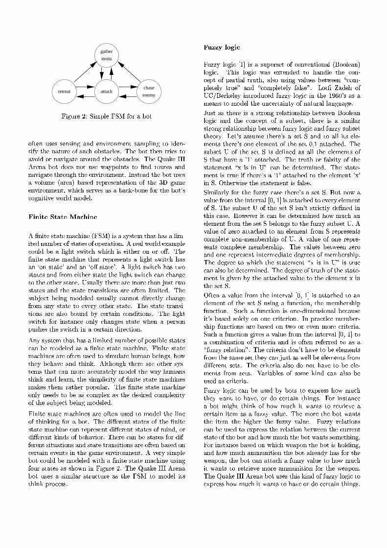
retreat attackenemy
chase
items
gather
IiYN^�K=4X2�n=Ñ@`�YNW�=MZ2�I@`�'´RVB34h+��B.D
B.ReD625-�K9:a2]::a2>-9:aYZ-=^0+.-98�25-G*GYN46B3-9W�2>-rD:6+.W�=MZYN-9^�D6B�Y�8�2>-��DXYNRVOQD6E=2�-&+,DXK94X2vB3R@:XK9J;E�B3�&:PD;+3JLMZ2>:>%t[tE=2���B.DhD6E=25-�D64XYZ2>:hDXB+1*3B�YZ87B34�-9+1*GYN^r+,D62�+.46B3K=-&87DXE=2¡B3�9:aD6+�JLMZ2>:>%c[tE=2���K9+3F32�SXSaS�h4625-9+���B.DQ8�BG2]:-=B.D_K9:X2"jt+1Or��B3YZ-rD6:¡DXB0�&-98�4XB�K�DX2]:�+.-98-9+1*GYN^r+,D62¤D6E=46B3K=^�E¡D6E=2h2>-r*GYZ4XB�-=W25-rD>%TSU-9:aDX2>+�8¡DXE=2h��B.D¤K9:a2]:+�*�B3MZK=W2��¬+.462>+r���&+3:X2>8�4625�94X2]:a2>-�D;+,D6YNB�-�B.R�DXE=2�ª�b¦^�+.W225-G*GYN46B3-9W�2>-rD>m9jCE9YZJ;E�:X2546*32]:h+3:�+��9+3J;Fr���&B�-=2�RVB34cDXE=2¡�&B3D> :JLB�^3-=YNDXYZ*32gj¤B�4XM�8{W�B�8�2>M�%
ÖCͬËiÍVÈ]×���È]Ç�È>×�ؼÇ=Ù1ÉTÍ�ËT×
���9-=YNDX2h:aD6+,D62tW+�J;E=YZ-=2v�¬I@`�'��iY�:@+�:aO�:aDX25W¾DXE9+.D)E&+3:@+gMNYZW��YdD62>8v-GK=W¡�&2>4\B3R9:PD;+,DX2]:�B3RGB��&2>46+.DXYZB3-�%T��462>+.M�j¤B�4XM�8g2L©=+.W�=MZ2JLB�K=MZ80��2{+�MNYZ^3ErD¡:XjCYdD;J;E�jCE=Y�J;E�YZ:¡25YNDXE9254�B�-�B34¡B.·)%�[tE=2�9-=YNDX27:PD;+,DX2{W�+3J;E=YZ-=2_D6E9+,D�4X2>�=462>:X25-rD6:�+�MNYZ^3ErD¡:XjCYND6J;E�E9+�:+.-�Ú B3-�:PD;+,DX2��+3-98�+3-�Ú B.·�:PD;+,DX2�N%��ÀMNYZ^3ErDg:XjCYND6J;E�E&+3:cDPj¤B:PD;+,D62>:k+.-98_RV4XB�WÁ25YNDXE=2>4t:aD6+.DX2cDXE=2�MZYN^�E�Dt:ajCYND6J;E7J5+3-{J;E9+3-=^32DXB�D6E=2cB3DXE=2>4�:PD;+,D623%)fc:XK9+.MZMNO¡DXE925462h+.462CW�B�4X2tD6E9+.-� PK&:PD¤DPj¤B:PD;+,D62>:v+.-&8�D6E=2�:PD;+,DX2D646+3-9:XYdD6YNB�-9:�+.462¡B3ReDX25-0MZYNWYNDX2]8�%_[tE=2:aK9�� P2>JLD_�&2>YN-=^0WB�8�25MZ2>8�K9:XK9+3MNMZO�J5+3-=-=B3DQ8�YN462>JLDXMZO�J;E9+3-=^32RV4XB�W´+3-rO�:PD;+,D62�DXB"2>*32546O�B3DXE=2>4�:aD6+,D623%�[tE=2Q:aD6+.DX2�D646+3-9:aYN�DXYZB3-9:+34X27+.M�:aB��&B�K=-98��rO�J5254XD6+3YN-�JLB3-&8�YdD6YNB�-9:>%�[tE=27MNYZ^3ErD:ajCYND6J;E�RVB�4�YN-9:aD6+3-9JL2"B�-=MZO�J;E9+3-=^32]:�:PD;+,DX2�jCE=2>-�+��&2>46:XB3-�=K9:XE=2>:kD6E=2�:XjCYdD;J;E7YZ-"+JL254XD6+3YN-�8�YZ4X2]J�D6YNB�-�%�h-GO¡:XO�:PD625W¼DXE9+.D<E9+3:@+�MZYNWYNDX2]8-rK9W���254<B3R&��B�:6:aYZ�=MZ2h:PD;+,DX2]:J5+3-���2W�B�8�2>MN2]8�+�:v+_�&-=YdD62_:PD;+,D62�W�+�J;E=YN-923%ITYZ-=YNDX2_:aD6+.DX2W�+3J;E=YZ-=2>:¤+.462hB.ReD625-{K9:a2]8DXB�:aYZW�K9MZ+.DX2cEGK=W�+3-_�&2>YN-9^�:>m�E=B,jDXE=2>O���25E&+1*32�+.-98�D6E=YZ-=F¯%7�cMdD6E=B3K=^�E0DXE=2>4X2_+34X2�B3DXE=2>4�:XOG:a�DX2>W:gD6E9+,D�J>+.-�WB�4X2+3J>JLK=4;+,D625MZO7WB�8�2>M)DXE=2jt+1O7EGK=W�+3-9:DXE=YZ-=F�+3-98�MN2]+.46-�m¯DXE=2�:XYNW�=MZY�JLYNDPO�B.R<�&-=YdD62_:PD;+,D62¡W�+3J;E9YN-=2]:W�+.F32]:vD6E=25WÛ4;+,D6E=254���B3�=K=M�+.4]%0[tE=2Q�&-=YdD62":PD;+,DX2{W�+3J;E=YZ-=2B3-=MZO"-=2>2>8=:gD6B{��2�+3:�JLB�W��9MN25©�+3:�DXE=2�8�2]:aYZ462>8�J5B3W�=MZ2L©�YNDPOB.RTDXE=2�:XK=�� P2]J�Dh��25YZ-=^�WBG8=25MZ2>8�%IiYN-=YNDX2_:aD6+.DX2W�+3J;E=YZ-=2]:v+.462�B3ReDX2>-�K&:a2]8�D6B"W�B�8�2>M@DXE92�MNYZ-=2B.R<D6E=YZ-=FGYN-=^7RVB�4�+7��B.D]%¡[tE=2�8�YN·�2>4X2>-rD�:aD6+.DX2>:�B3R<DXE92¡�&-=YdD62:PD;+,D62gW�+�J;E=YN-92�J5+.-74625�=462>:X25-rDC8�Yd·¯254625-rDc:aD6+.DX2>:hB.RTWYZ-98�m&B348�YN·�2>4X2>-�DhFGYZ-98=:CB3Ri��25E&+1*rYZB34]%@[tE=25462�J5+3-{��2�:aD6+.DX2>:kRVB�4h8�YNRe�RV254625-rD@:aYNDXK9+.DXYZB3-9:)+3-98�:aD6+.DX2¤DX4;+.-9:XYdD6YNB�-9:i+.462¤B3ReDX25-¡�9+3:X2>8�B3-JL2>4aD;+.YZ-72>*32>-�D;:tYN-�D6E=2�^r+.W2v25-G*GYN46B3-9W�2>-rD>%��«*�2546O{:XYNW�=MZ2�&B3DcJLB�K=MZ87��2�WB�8�25MZ2>87jCYNDXE�+��9-=YNDX2�:aD6+.DX2vW�+3J;E9YN-=2vK&:aYZ-=^RVB3K=4�:PD;+,DX2]:h+3:�:aE9B,jC-7YZ-�IiYN^�K=462�n�%t[tE=2¡��K9+.F�2vSaSXSt�c4X2>-9+�&B3D_K9:X2>:�+0:aYZWYNM�+.4�:aDX46K9J�D6K=462�+�:�DXE=2�I@`�'ÜD6B�WB�8�2>MhYdD;:DXE=YZ-=F{�=4XB�J52>:6:5%
Ö\ÝiÞ3Þ.ß�à¬á�Î�ͬÙ
I=K=H>H5O�MNB�^3Y�J"ÔdÐ5Õ¤Y�:�+�:XK=�&2>46:X2LD¡B.RCJLB3-G*�25-rDXYZB3-9+3Mh�¬âkBGB3MZ2>+3-&�MNB�^3Y�J.%�[tE=Y�:�MZB3^�YZJ�jk+�:�2L©GD625-98�2]8®DXBÀE9+.-&8�MN2�DXE=2sJLB�-��JL25�=D¡B.RC�9+34aD6YZ+3M<D64XK�D6E�m<+.M�:XB"K9:aYZ-=^�*,+3MNK=2]:���2LDPjk252>-¾¢XJ5B3W���=MN25DX2>MNO�D64XK=2]£�+3-98¢XJLB�W�=MN25DX2>MNO�R¬+.M�:X2>£=%Â?�B.DX�«ã¯+�8�25E#B.RfgqCä,âk2>4XF�25MZ25O�YZ-rDX46BG8=K9JL2]8�RVK9H5H5O�MZB3^3Y�J�YN-0D6E=2�Ð]å3o3æ9 :�+�:�+W�2]+.-9:kD6BW�B�8�2>M�DXE92vK=-9JL2>4aD;+.YZ-rDPO_B.Ri-9+,D6K=46+3M�MZ+3-=^3K&+.^32�%$3K9:aD�+3:gD6E=25462�YZ:v+�:aDX46B3-=^�4625M�+,D6YNB�-9:aE9YN���&25DPj¤2>25-�âkBrB�MN2]+.-MNB�^3Y�J�+3-98�DXE=2�J5B3-9J525��D"B.R�+�:aK9�9:a25D>m�D6E=254620YZ:"+�:XYNWYZMZ+34:PD64XB�-=^�4625M�+,D6YNB�-9:XE=YN����2LDPjk2525-¡RVK=H>H5O�MZB3^�YZJt+3-98�RVK9H5H5O�:aK9�9:a25DDXE=2>B346O3%_?�25D> :�+3:6:XK=W2DXE=2>4X2� :v+":X2LD¡`�+.-&8�D6B�+.MZM<YND6:v2>MN25�W�2>-rD6:cDXE=2>4X2� :cB3-=2�2>MN2>W25-rD�B3R@DXE=2�:a25D�æ=mZÐ�+,DXD6+�J;E=2>8�%�[tE=2:aK=�&:a25D�fµB3RCDXE=27:a25D`0Y�:�8=2L�9-=2]8�+3:�+.MZM<D6E=2Q2>MN2>W25-rD6:¡B.R`"D6E9+,D�E9+1*�2�+�ZÐ3�+.DaD6+�J;E=2>8�%�[tE=2�D64XK�D6E0B34gR¬+.M�:aYNDPO�B3R�DXE92:PD;+,DX2>W25-rD�¢a©�YZ:�YZ-�fc£�J5+3-���278=2LDX2>4XWYZ-=2>8�%�[tE=27:aD6+.DX25�W�2>-rD�Y�:cD64XK92�YNR<DXE=2>4X2� :g+�ZÐ3¯+,DXD6+�J;E=2>87D6BQD6E=2�2>MN2>W�2>-rD� ©�YN-�`¯%�ÃcD6E=2546jCY�:a2�DXE=2�:aD6+.DX2>W�2>-rDhYZ:kR¬+3MZ:X23%`GYNWYZMZ+34XMZO�RVB34�D6E=2�RVK=H5H>O�J>+3:X2�D6E=254623 :�+7:X2LD�`¯%�âkK�D�-9B,j¼+*1+3MNK92<RV46B3W#DXE=2¤YN-rDX2>4X*,+3M�Ô æ=mGÐLÕrYZ:i+,DXD6+�J;E=2>8gD6Bc25*�2546O�2>MN2>W25-rDB.R¤`¯%�[tE=2:aK9�9:a25D�f¼B.R<D6E=2:a25Dv`�Y�:X-� Dv:aDX46YZJLDXMZO�8�2L�9-92>8�YZ-DXE=Y�:�J5+3:X23%�¥cB,j¤2>*32>4cYNDvJ>+.-��&28�2LD62546WYN-=2]8�E9B,j«W�K9J;E�+.-25MZ25W25-rD�RV46B3WÀDXE92g:X2LDk`��&2>MNB�-=^�:�DXBvD6E=2hRVK9H5H5O�:XK=�9:X2LDtf�%G�*1+3MNK92�B.R¤H52546B{+.DaD;+3J;E=2]8�DXB7+.-�2>MN2>W�2>-rD�RV46B3W�`"4625�94X2]:a2>-�D;:JLB3W�=MZ2LD62Q-=B�-���W�2>W���254;:aE9YN��B3Rcf�%)�µ*,+.MZK=2QB3RhB3-=2Q4X2>�=4X25�:a2>-�D;:¡J5B3W�=MZ2LD62{W25W¡�&2>46:XE=YZ��%�[tE=27*,+.MZK=2>:¡�&25DPj¤2>25-�H52546B+.-987B3-92v4X2>�=4X2]:a2>-rDhYN-rDX2>4XW2]8�YZ+.DX2�8�2>^346252]:tB.R@W25W���254;:XE=YN�\%[tE=2_8�25^�4X2>2�D6B"jCE=Y�J;E�D6E=2_:PD;+,D625W25-rD�¢P©�YZ:�YZ-�fc£7YZ:vDX46K=2J5+.-�+3MZ:XBh��2k8=2LDX2>4XWYZ-=2>8�%T[tE=2k8�25^�4X2>2<B.R�D64XK�D6E�B.R�D6E=2¤:aD6+.DX25�W�2>-rDtY�:t^3YZ*32>-Q�GO�D6E=2�+,DXD6+3J;E92>8_*,+3MNK=2gD6B¡D6E=2�25MZ25W25-rDC©QYZ-DXE=2�:X2LDc`¯%ÃcReDX25-�+_*,+.MZK=2�RV4XB�WÂD6E=2�YN-rDX2>4X*,+3MkÔ æ=m)ÐLÕ)Y�:g+.DaD;+3J;E=2]8�DXB7+.-25MZ25W25-rDvB.RkDXE=2�:X2LD¡`�K9:XYN-=^"+{RVK=-9JLDXYZB3-�m\DXE=2�W2>W���254;:aE=YZ�RVK=-9J�D6YNB�-�%�`�K9J;E�+�RVK9-9J�D6YNB�-�YZ:�B�-=2L�U8�YZW25-9:XYNB�-9+.Mt��2>J>+.K9:X2YdD] :��9+�:a2]8�:XB3MZ25MZO"B3-�B3-=2JL46YdD62546YNB�-�%�SU-��=4;+3J�D6YZJ52¡W2>W���254X�:aE=YZ��RVK=-9JLDXYZB3-9:¡+.462��&+3:X2>8�B3-�DPjkB"B34v25*�25-0WB3462_JL46YdD62546YZ+9%`GK9J;E"+�RVK=-9JLDXYZB3-�^3YZ*32]:C+*1+3MNK92�RV4XB�WÁDXE=2�YN-rDX2>4X*,+3M<Ô æ9m�ÐLÕ�D6B+�JLB�W��=YZ-9+.DXYZB3-�B.RgJL46YdD62546YZ+�+3-98�Y�:�B3ReDX2>-�462LRV2546462>8�DXB0+3:¡+¢PRVK=H>H5O�4X2>MZ+.DXYZB3-9£9%i[tE=2gJL46YdD62546YZ+v8=B3-� D¤E9+1*�2CDXB¡�&2�25MZ25W25-rD;:RV4XB�WsDXE=2h:6+.W2t:a25DiD6E=25O¡J5+.-c PK9:aD�+3:ij¤2>MNMG��2t25MZ25W25-rD6:iRV46B3W8�Yd·¯254625-rD�:X2LD;:5%7[tE=2_JL46YdD62546YZ+"+3MZ:XB"8�B"-=B3D�E9+1*32�DXB"��2_2>MN25�W�2>-rD6:RV46B3W¹:a25D6:>%�Ï<+34XY�+.�=MZ2>:_B.Rv:aB�W�2"FGYZ-98�J5+3-�+.M�:aB0��2K9:a2]8{+�:CJL46YdD62546YZ+9%I=K=H>H5O�MNB�^3Y�J�J5+.-���2QK&:a2]80�rO��&B3D6:�DXB�25©��=4X2]:X:�E=B,jÀW¡K9J;EDXE=2>O�jt+.-rD�D6B�E9+1*�23miB34�8�B�J5254XD6+.YZ-0DXE9YN-=^r:5%�I=B�4�YZ-9:PD;+.-9J52+"�&B3D�WYZ^3ErD�D6E=YZ-=F0B.RhE=B,j®W�K&J;E�YdDjt+.-rD6:�DXB�462LD64XYZ25*�2_+JL254XD6+3YN-"YNDX2>W�+3:�+RVK=H5H>O�*1+3MNK923%�[tE92�WB3462vDXE92¡��B.Dgjk+3-�D;:DXE=2�YdD625W¹DXE92�E=YZ^3E=2>4_D6E=2�RVK9H5H5O�*,+.MZK=2�%ÀI=K9H5H5O�4625M�+,D6YNB�-9:J5+.-{�&2�K9:X2>8_DXB2L©��=462>:6:�DXE=2�4625M�+,DXYZB3-Q�&25DPj¤2>25-{DXE=2vJLK94X4625-rD:PD;+,DX2kB.R&DXE=2t��B.D<+.-&8�E=B,j�W¡K9J;E¡DXE=2t��B.D@jk+3-rD6:i:aB�W�25DXE=YZ-=^&%I=B34kYZ-9:PD;+.-9J52��&+3:X2>8�B�-QjCE=Y�J;EQjk2>+3�&B�-�DXE=2g��B.DtYZ:kE=B�MZ8�YZ-=^&m+.-98�E=B,j�W�K&J;E�+.WW�K=-9YdD6YNB�-�DXE=2���B.Dg+.MZ4X2]+38�O{E9+3:tRVB�4CDXE92j¤2]+.��B3-�m9DXE=2���B.DgJ5+.-�+.DaD;+3J;E�+�RVK=H>H5O�*,+.MZK=2vDXBQE=B,j#W¡K9J;EYdD�jt+.-rD;:�DXB�462LD64XYZ25*�2�WB3462_+.WW�K=-9YdD6YNB�-0RVB34vD6E=2Qjk2>+3�&B�-�%[tE=2g��K9+3F32tSaSXS)�c4X2>-9+���B.D�K9:X2>:@DXE=Y�:<FGYZ-98B.R�RVK=H5H>O¡MZB3^�YZJkD6B2L©��=462>:6:<E=B,j�W�K&J;E_YdDkjk+3-rD6:@D6B�E9+1*�2hB34k8�B¡J5254XD6+3YN-D6E=YN-9^�:>%

l3ç¬è [\2]+.WµMZ2>+�8�254h�cSª3é;ê '"Y�:6J.%<�hS �hStuh25DPj¤B�4XF q¤B3WW�+.-98=:n.ë3ê I9K=H5H>O q¤E9+.4;+3JLDX2>4 � B�+3MZ: u�+1*rYZ^�+.DXYZB3- q¤E9+,D;:Ð]ì�ç �h462>+�hjt+.4625-=2]:X:C`GO�:aDX2>W ât+�:aY�J��cJ�D6YNB�-9:
IiYZ^3K=462vª=Ñ@?\+1O�25462>8Q+346J;E9YdD62>J�D6K=462
xcí�î¤×�ï1È�ð>ß�ð5È]×rñ
�h-�25©G��254XDQ:XOG:aDX2>W�:�Ô n,Õ�Y�:_+�:XOG:aDX2>WòD6E9+,D7:PD6B3462>:EGK=W�+.-2L©���254XDXY�:a2�m&^r+.YZ-=2>8{RV46B3W}DX4;+.YZ-=YZ-=^Q+.-&8�2L©��&2>4XYZ25-&JL23%c`�K9J;E�+:aO�:aDX2>WÂE9+�:hD6E=46252�YZW�&B�4aD;+.-rDg+�:a��2>JLD6:>%c[tE=2�FG-=B,jCMZ2>8�^�2�B.RR¬+3JLD6:>mGDXE=2�FG-=B,jCMZ2>8�^�2�B3RT4625M�+,DXYZB3-&:¤��2LDPjk252>-_D6E=2�R¬+3JLD6:>m=+.-98+7E=25K=46Y�:PD6YZJB�4g25°_JLYZ25-rD�W2LDXE9BG8�RVB�4�:PD6B34;+.^32+.-&8�+�J5¨rK=Y�:aYN�DXYZB3-"B3RTD6E=YZ:cYN-=RVB346W+.DXYZB3-�%t[tE=2�J5B3-9:aDX46K9JLDXYZB3-�B.R@+.-"25©G��254XD:aO�:aDX2>WÛYZ:�J>+.MZMN2]8�FG-=B,jCMZ2>8=^32725-=^�YN-=2>2546YN-9^9%��¦Fr-9B,jCMN2]8�^3225-=^�YN-925254@25©GDX4;+3J�D;:)DXE92hFG-=B,jCMN2]8�^32v�¬�=4XB�J52>8�K=462>:>m3:aDX4;+,D625^3YZ2>:>mYN-=RVB346W+.DXYZB3-7�9MNDX2>46:>m9JLB�WW�B�-�25*32>-rD6:>m=2LD;J.%ó�_B�K�DhB.R@EGK=W�+.-2L©���254XD6:+.-98�DX4;+.-&:PRVB�4XW�:�DXE=Y�:FG-=B,jCMN2]8�^32{YN-rD6B�+3-�25©G��254XD:aO�:aDX2>W7%µ[tE92�F�25O�Y�:X:XK=2�YN-#2L©��&2>4aD�:XO�:PD625W�:QY�:{DXE=20jt+1OFG-=B,jCMN2]8�^32Y�:�:aDXB3462>8�YZ-�mi+3-98�2L©GDX4;+3JLDX2]8�RV46B3WÅDXE=2_FG-=B,jCMN�2>8�^�2��&+3:X23%@?�B�^3Y�Jc:XOG:aDX2>W�:¤�94XB,*GY�8�2���B,jk254XRVK=M�DXBGB3M�:¤DXB�4X2>���4X2]:a2>-rD¡+.-98�YN-�RV2>4¡FG-=B,jCMZ2>8=^32_YZ-�+.-�2L©��&2>4aD:aO�:aDX2>W7%�(<46B.�8�K9JLDXYZB3-�4XK=MZ2>:�B�4�4XK=MZ2L���9+�:a2]8�:XOG:aDX2>W�:v+.462�D6E=25462LRVB�4X2�B.ReD625-K9:X2>8�D6BQYZW��9MN2>W�2>-rD�+3-�2L©���254XDg:XOG:aDX2>W�%�(<46B�8�K9JLDXYZB3-"46K=MN2]:B346YN^�YN-&+,DX2�RV46B3W¿D6E=2_SPIÀ�P%]%L%6��[C¥�º�uµ:aDX46K9JLDXK=4623mTjCE=YZJ;E0Y�:FG-=B,jC-�RV46B3W«D646+�8�YNDXYZB3-9+3M��=4XB�J52>8�K=4;+.MGM�+.-=^�K9+.^�2>:>%\[tE=2t46K=MN2]:JLB�-9:aY�:aDgB3R¤+{J5B3-98=YdD6YNB�-�:XYZ8�2"�VDXE=2�+.-rD62>JL2]8�25-rD��c+3-98�+3-�+�J��DXYZB3-�:XY�8�2��VDXE=27JLB3-&:a2]¨�K925-rD;�LÑ�SPI®��JLB3-&8�YdD6YNB�-&��[C¥�º�u´�¬+3JL�DXYZB3-&�L%@[tE=2hJLB�-98�YNDXYZB3-�Y�:<+vMZB3^3Y�J5+3M�2L©��=462>:6:aYZB3-�B.R¯R¬+�J�D6:@RV4XB�WDXE=2�FG-=B,jCMZ2>8�^�2Q�9+�:a2�%�[tE=2�+3J�D6YNB�-�2>YdD6E=254�JL462>+.DX2]:¡B�-=27B34WB3462C-=25j�R¬+3JLD6:>m34625WB,*32]:iR¬+3JLD6:<B�4)DX46YN^�^32>46:@J5254XD6+.YZ-25*�25-rD6:>%[tE=2�8�YN·�2>4X2>-9JL2"YZ-�46K=MN25�¸�&+3:X2>8��=4XB�^34;+.WWYN-9^�+�:B3�=��B�:X2>8DXB0JLB�-r*�25-rDXYZB3-&+.Mk�=4XB�^34;+.WWYN-9^�MNYZ2>:YZ-�DXE=27R¬+3JLD¡D6E9+,DD6E=2:PD;+,D625W25-rD6:cYN-�JLB3-G*�25-rDXYZB3-9+3M��=46B3^�46+3W�WYZ-=^�M�+.-=^�K9+.^�2>:h+34X22L©�2>J5K�DX2]8QYZ-�+¡�94X2]8�2L�9-92>8{B34;8�254]%@ACK=MZ2L���9+3:X2>8{:aO�:aDX25W�:tK9:X2+.-�YN-�RV2>4X2>-9JL2�2>-=^3YZ-=23m¤jCE=Y�J;E�8�25DX2>4XWYZ-=2>:¡DXE92746K=MZ2>:�D6B���2�9462>8"�9+�:a2]8�B�-"DXE=2JLK94X4625-rDcR¬+�J�D;:5%�SU-�D6E=Y�:�jt+1O�-=25j¾R¬+3J�D;:J5+3-�J;E9+.-=^�2gDXE=2�JLB3K946:X2vB.R)DXE92��=46B3^�46+3W§+3:CYND��94XB�JL2>2>8=:CDXB�9462�B3DXE=2>4k46K=MZ2>:>mrDXE9+.DC+34X2�-=B.Dt-=2]JL2>:6:6+.46YNMZO�:PD6B3462>8QJ5B3-9:X2>J5K��DXYZ*32>MNO�D6B��=4625*GYNB�K9:XMNO�9462>8{46K=MN2]:5%�h-�2L©���254XDQ:aO�:aDX2>WòJ5+3-���2"K9:X2>8�DXB0YZW�=MN2>W25-rD_DXE92"4X2]+,�:aB�-=YZ-=^"B.Rc+"��B.D]%�[tE=2Q25©��&2>4aD6YZ:X2�RV46B3W�ErK9W+3-��=M�+1O3254;:vY�:2L©GDX4;+3JLDX2]8�+.-&8�:aDXB�4X2]8�YZ-0+{FG-=B,jCMZ2>8�^�2¡�9+�:a2�%�(�4XB�8�K&J�DXYZB3-4XK9MN2]:CJ5+.-���2vK9:X2>8{DXB_J54X2]+,DX2�-=2>j�R¬+�J�D;:CB34CYZ-=YNDXY�+,DX2�J5254XD6+3YN-+3JLDXYZB3-9:>%�I9B34�YZ-9:aD6+.-&JL27DXE=2"��B.DQJ5B3K=M�8�K9:a27D6E=2�RVB3MZMNB,jCYZ-=^�=46BG8=K9J�D6YNB�-�4XK=MZ23Ñ�SPIÀDXE=2���B.D7YZ:_�9^3ErD6YN-=^��cucbÅDXE92��&B3DYZ:�MNB,jÀB3-0E=2>+3MdD6E��cucbµDXE=2���B.D�8=Br2]:v-=B3D�E9+1*32�+7�&B,jk254X�RVK=M�jk2>+3�&B�-7[C¥�º�us462LDX462>+.DtRV4XB�WÁDXE=2��&^3ErD>%<[tE=2�J5B3-9J525��D;:¢aMZB,j�B3-E=2]+.MNDXE9£�+3-98�¢X8�BG2>:)-9B.D<E9+1*�2k+���B,j¤2>4aRVK9M�j¤2]+.��B3-9£+.462�-=B3D�J5MN2]+.4�R¬+3JLD6:gYN-�DXE=Y�:g2L©=+.W�=MZ23%�I9K=H5H>O"MNB�^3Y�J�J>+.-���2K9:X2>8gDXB�^3YZ*32<+hJ5MN2]+.4TW�2]+.-=YZ-=^CD6Bc:XK9J;E�JLB�-9JL2>��D6:>%\��*1+3MNK92�B.RDX46K�DXE7J5+3-_�&2�+,DXD6+�J;E=2>8D6B�D6E=2�:PD;+,DX2>W25-rD¡¢XMNB,j�B�-_E=2>+3MdD6E9£�9+3:X2>8B�-DXE=2g+.WB3K9-�D¤B.R�E=2>+3MdD6E�DXE92c��B.D�E9+�:5%)SU-D6E=2�:6+.W2
jk+1O�+�*,+.MZK=2�B3RgD64XK=DXE�J>+.-���2�+,DXD6+�J;E=2>8�D6B�DXE=2�JLB�-9JL2>��D¢PDXE92{��B.D_8�BG2>:-9B.DE9+1*32�+���B,jk254XRVK=Mtj¤2]+.��B3-9£��9+3:X2>8�B3-DXE=2�jk2>+3�&B�-9:�+.-980+.WW¡K=-=YNDXYZB3-�DXE=2���B.D�Y�:vJ5+34X46OGYN-9^9%fc:a�YN-=^�+�RVK=H5H>O�4625M�+,D6YNB�-�miYdD�YZ:¡+.M�:aB"��B�:6:aYZ�=MZ2�DXB�JLB�W��=YZ-=2DXE92JLB3-&JL25�=D6:v¢XMNB,j�B3-E=2>+3MdD6E9£v+.-&8�¢68�BG2>:)-=B3D�E9+1*�2t+g��B,j¤2>4aRVK9Mj¤2]+.��B3-9£�YN-rD6B�DXE=2C-=2>j�J5B3-9J525��D�¢aDXE=2t��B.D<Y�:@-=B.D)�=D<2>-=B3K9^3EDXB��9^�E�D;£=%�[tE=2_25©�+3W�=MN2��94XB�8�K9JLDXYZB3-046K=MN2{JLB3K9MZ8�DXE925-���24X2>�=MZ+�JL2]8��GO¯Ñ{SPI¾DXE=2���B.D�YZ:YZ-�+��&^3ErD_�cucb¿DXE=2"��B.D�Y�:-=B.D@�=Dk25-=B�K=^3E�D6B��9^3ErD�[C¥cº¤u�462LDX462>+.D@RV4XB�W¾D6E=2C�9^�E�D]%i�c-YN-�RV2>4X2>-9JL2�25-9^3YZ-=2�B3R¤:aB�W2¡FGYZ-98�J>+.-���2K9:a2]8�YZ-�J5B3W��9YN-9+.�DXYZB3-jCYdD6E�=4XB�8�K&J�DXYZB3-46K=MZ2>:@+3:)YZ-�DXE=2C25©=+.W�=MZ2>:>%i¥cB,j¤2>*3254]m:aK9J;E��=46B�8�K9J�D6YNB�-4XK=MZ2>:@+34X2C+3MZ:XB�B3ReDX2>-� PK&:PD�MZY�:PD62>8�YN-�:X25*�254;+.M�=4XB�J52>8�K=462>:>%�[tE=2Q��K9+3F32�SaSXS��h4625-&+{��B.DvK9:X2>:g�=46B�8�K9JLDXYZB3-4XK=MZ2>:TD6Bg25©��=MNY�JLYNDXMZO�4625�=462>:X25-rD@JL2>4aD;+.YZ-�FG-=B,jCMZ2>8�^�2k+3-98�W�+3F32JL254XD6+3YN-�8�2]JLY�:aYZB3-9:>%
� ~ � Ä"±L��x � ��³{~{x
ô�Ç�ß&×rï,×rÌ�Ç�ï,Ù]ÉiÍVÈ]×GÙ.È>ÝTï,×
[tE=2Q��K9+.F�2¡SXSaS��h4625-9+{�&B3D�YZ:��9K=YNM�8�K=�0YN-0:a2>*32>46+3MiM�+1O32>46:>%[tE=2g+1jt+.4625-92>:6:<B.Ri8�2>J5YZ:XYNB�-9:¤DXE=2g��B.DCW�+.F32]:�jCE9YNMZ2��=MZ+1OGYZ-=^DXE=2�^r+.W2"YZ-9JL462>+�:a2]:�jCYdD6E�E=YZ^3E=2>4QM�+1O3254;:>%#[tE=2�8=2>JLY�:XYNB�-9:RV4XB�WõE=YZ^3E9254_M�+1O32>46:_+34X2"25©�2>JLK=DX2>8�D6E=46B3K=^�E�MNB,jk254_M�+1O32>46:>%[tE=2vMZ+1O�25462>8_:aDX46K9JLDXK=462�B.RiDXE=2v��B.DhY�:C:aE9B,jC-{YZ-"ITYZ^3K94X2vª=%[tE=2�Ð1ì�çMZ+1O�254QY�:{�9+3:XYZJ>+.MZMNO�DXE92�YZ-=�=K�D"+.-98�B3K�D6�=K�D�MZ+1O�254RVB34CD6E=2���B.D]%t[tE92��h462>+��cjk+34X2>-=2>:6:h`GO�:PD625W}YZ:hDXE=2¡:aO�:aDX25WDXE9+.D<�=4XB,*GY�8�2>:TD6E=2C�&B3D�jCYNDXE�+.MZMGDXE=2cYN-�RVB�4XW�+.DXYZB3-+.��B3K�D)DXE92JLK=464X2>-rDC:aD6+.DX2vB3RTD6E=2vj¤B�4XM�8�%@SU-�RVB�4XW�+.DXYZB3-"+.��B3K�DCD6E=2�:aD6+,D62B.R=D6E=2tj¤B�4XM�8vY�:T462>J525YZ*32]8�+3:i+�:X2LD)B.R&*1+34XY�+.�9MN2]:T8�YZ462>J�D6MNO�RV46B3WDXE=2¤^�+.W2¤�=4XB�^34;+.W�%�I=B�4\R¬+�:PD)+.-98�2>+3:XOv+3J>JL2>:6:\+3-98vK9:6+.^�23m1+MNB3DTB.R�RVB�4XW�+.DaDXYZ-=^g+.-98v�94X25�¸�=46B�JL2]:X:XYN-9^CYZ:T�&2>4aRVB�4XW2]8vB3-vD6E=Y�:YN-�RVB�4XW�+.DXYZB3-�%sº<*�2546O�D6E=YZ-=^�DXE=2���B.D�:a2>-9:X2>:�^�Br2]:DXE94XB�K=^3EDXE=2��h462>+_�cjk+34X2>-=2>:6:c`GO�:aDX25W�%g[tE=2��9+�:aY�J�+�J�DXYZB3-&:c+.462�DXE92B3K�D6�=K�DTB3R�DXE=2¤�&B3D>%i[tE=2�B�K�DX�=K=DTY�:�RVB�4XW�+,DXDX2]8�YN-�+hjk+1O�DXE9+.DJLB3-=RVB346W:<DXB¡DXE=2g�9+346+3W�25DX2>46:�B.R�D6E=2�^r+.W23%)[tE=2gB3K�D6�=K�DtB.RDXE=27�&B3D�YZ:¡DXE92{�=M�+1O32>4�YZ-=�=K�DRVB�4¡D6E=27^�+.W2�m<W�K9J;E�MNYZF327+ErK9W+3-{�9MZ+1O�254tK9:X2>:C+F32>OG�&Br+.4;8Q+.-&8{+�WB3K9:X23%[tE=2cn.ë3êCMZ+1O�254@�=46B,*GYZ8�2]:TDXE=2hYZ-rDX2>MNMZYN^�25-9J52kDXE9+.D�YZ:<B.ReDX2>-�:aK=�=�JLB3-&:XJ5YNB�K9:kDXBQ:XFGYNMZMZ2>87EGK=W�+.-"�=M�+1O32>46:>%�[tE=Y�:hM�+1O32>4hJLB3-rD;+.YZ-9:�hStRVB34g^3Br+.M\:X25MZ2>JLDXYZB3-�%g[tE=Y�:��cSc+.MZMNB,jh:CDXE=2��&B3DcD6B{J;E=BGB�:X2DXE=2��&2]:PDv^�B�+.MTDXB7�=K=4;:XK=2�RV46B3W�+QjCE=B3MZ2�46+3-=^32¡B.R���B�:6:aYZ�=MZ2^3B�+3MZ:>%�[tE92{��B.D�K9:a2]:¡RVK=H5H>O�MZB3^�YZJ_DXB�8�2>J5YZ8�27jCE=Y�J;E�^3Br+.M�:YdDjk+3-rD6:�DXB0+3J;E=YZ25*�23%0[tE=YZ:�RVK=H>H5O�MZB3^3Y�J_Y�:+.M�:aB�:PD6B3462>8�YZ-DXE=2¡n3ë3ê�M�+1O32>4>%�[tE925462vYZ:h+3MZ:XB_�hS¤DXBQ-9+1*GYN^r+,DX2gD6E=4XB�K=^3E{DXE92^�+.W2k25-G*GYN46B3-9W�2>-rDTD6B,jk+3468=:i+�:a��2>J5Yd��J¤^�B�+3M�%i[\B���2t+3�=MZ2¤D6BJLB3WW¡K=-=Y�J5+,D62�jCYdD6E�B.D6E=254��9MZ+1O�254;:cD6E=Y�:�M�+1O3254�+3MZ:XB"E9+�:��hS

Client codeproviding the IOfunctionality forhuman players
Server
Client
Renderer
Game Bot AI (3 & 4 layer)rd th
ndBot AI (1 & 2 layer)st
Player input
Sound
3D image
Client Game
networking
ITYZ^3K94X2�l9Ñ)SU-rDX2>^34;+,D6YNB�-{B3RT��B.Dc�hSkjCYNDXE7DXE=2v^r+.W2�25-=^�YN-923%
DXB¡YN-rDX2>4X�94X25DkJ;E9+.D¤W2>:6:X+3^32]:)RV4XB�W®B.DXE9254;:¤+3-98DXB�JLB�-9:PD64XK&J�DJ;E9+,D�W2]:X:6+.^�2>:�8�YZ462>J�D62>8�+.D�B.DXE9254��9MZ+1O�254;:5%7ITYZ-9+3MNMZO�D6E=25462YZ:c+�WBG8=K=MN2�DXB_:aDXB3462�+.-&8�4X25DX46YN2>*32��=46B3��254XDXYZ2>:CB3R@8=Yd·¯254625-rD�&B3D<J;E9+.4;+3JLDX254;:>%\º�+�J;E���B.D<J;E9+.4;+3JLDX2>4TE9+�:)+g:X2LD@B3R&*,+.46YZ+3�=MZ2>:DXE9+.Dh4X2>�=462>:X25-rD¤D6E=2�J;E9+346+�J�DX2>4XY�:aDXY�J5:¤B.RiDXE=2v��B.D]%[tE=2�ª�é6ê�MZ+1O�254hY�:c+QWYd©GDXK94X2�B3R<�=46BG8=K9J�D6YNB�-"4XK=MZ2>:¡�VYNRe��D6E=25-=�25M�:a21��+3-98Q+3-Q�hS¤-=2LDPjkB346F�jCYdD6E7:X�&2]JLY�+.M�-=B�8�2>:¤RVB�4t8=Yd·¯254625-rD:aYNDXK&+,DXYZB3-&:<+.-98�:aD6+.DX2]:@B.R�WYN-&8�%@[tE=YZ:<-=2LDPjkB346F�Y�:@*32>4XO�:aYZW��YNM�+.4D6B�+�:PD;+,D627W�+�J;E=YN-923%��cMNMcDXE=2"E=YZ^3E9254X�¸MZ25*�25MtDXE9YN-=FGYZ-=^+.-98�4X2]+3:XB3-=YZ-=^D6+3F32]:c�=M�+3J52�YZ-�D6E=YZ:�M�+1O3254]%�[tE9YZ:�MZ+1O�254g+.M�:aBJLB�-�D;+.YZ-9:i+�J5B3WW�+.-98�W�B�8�K9MN2kjCE=Y�J;E�+3MNMZB,jh:�D6E=2t�&B3DiD6B�K9-��8�254;:aD6+.-&8{B�468=254;:C+.-98�JLB�WW+3-98=:tRV46B3WÂB.D6E=254h�9MZ+1O�254;:tB34h+DX2]+.W§MZ2>+�8�254]%<[tE=2vWY�:XJ525MZMZ+3-=25B�K9:C�hStWB�8�K=MZ2�JLB3-rD;+.YZ-9:C�hSDXB_:XK=�=��B34XDh�&2>E9+1*GYNB�4hK9:X2>87YZ-�m&+3-98"8�2>J5YZ:XYZB3-9:tW�+38=2�YN-7D6E=2�hSC-=25DPj¤B�4XF¯%g[tE=YZ:gYZ-9JLMZK98�2]:��cSCRVB34cDXE=2¡�9^�E�D6YN-9^Q��25E9+1*GYZB34B.R=D6E=2k�&B3D@+3-98��cS�DXBg-9+1*GYZ^�+,D62¤+34XB�K=-98vB��9:PD;+3J5MN2]:T+3-98�:XB3MZ*32:aW�+3MNM��=K9H5H5MZ2>:tYZ-7DXE=2v^r+.W2�25-G*GYN46B3-9W�2>-rD>%[tE=2vl3ç¬è�MZ+1O�254tYZ:CDXE=2�¢X�=4;+.YZ-9£�B3RTD6E=2vD62>+.WÂMN2]+38�2>4CB34hJ5B3W��W�+.-98�J525-rDX2>4>%gSU-�+_DX2]+.W¦^�+3W�2¡B3-=2¡B.R@D6E=2¡��B.D;:cY�:�8�2>:XYZ^.�-9+,D62>8{DXBQ�&2vD6E=2�DX2]+.W}MN2]+38�2>4c+.-&8{E&+3:tD6E=YZ:c2L©GDX4;+�¢a�=4;+.YZ-9£K9:X2>8�D6B�JLB3WW�+.-&8�DX2]+.WW�+,D62>:>%Â[tE=Y�:�+.MZMNB,jh:{DXE92�D62>+3WMN2]+38�2>4�DXB"B�4X^r+.-=YZH52¡DXE=2D62>+3W´+.-&8�+�J5J5B3W�=MZYZ:XE�D;+3:XF�:�YN-�+DX2]+.W�%[tE=2_JLB�8�2�B3RtDXE=2�^r+.W2�25-=^�YN-923m\YZ-9J5MNK98=YN-=^�DXE=2_��B.D��cS�m\Y�::PD64XK&J�DXK94X2]8{+�:C:aE=B,jC-7YZ-{D6E=2v�=MZB�J;FQ8�Y�+.^34;+.W���IiYN^�K=4X2�lG��%[tE=2�¢ � +3W2>£�WBG8=K=MN2�:a25D6:D6E=2"4XK9MN2]:RVB34�D6E=2"^�+3W2�+.-988�Y�J�D6+.DX2]:{E9B,j¿DXE=20^r+.W2�jkB346F�:5%µ[tE=2�¢6`�2546*3254;£�WB�8�K=MZ2�=46B,*rY�8�2]:CDXE92�RVK=-9JLDXYZB3-9+3MNYNDPO7RVB34g�=M�+1O3254;:tD6B{JLB�-=-=2]J�DcD6B_D6E=2^�+3W�2�%#[tE=2�¢;q¤MZYN2>-�D;£=m¢;q¤MZYZ25-rD � +.W2>£�+3-98®¢XAh25-98�2>4X2>46£WBG8=K=MN2]:CD6B3^325DXE=2>4h�=46B,*GYZ8�2�D6E=2�SU-9�=K�D�ä�Ã�K�DX�9K�D��¬SXÃ��kRVK=-9JL�DXYZB3-9+3MNYNDPO�RVB340+�EGK=W�+.-¼�=MZ+1O�254]%ò[tE=2½¢;q¤MZYN2>-rD6£�WB�8�K=MZ24X2]JLB�468=:<YN-=�9K�D�RV46B3W½DXE92cYZ-=�=K�Dt8�25*GY�JL2>:k+.-&8�:a2>-98=:¤YdD¤DXBvD6E=2:a2>4X*�254]%T[tE=Y�:kWBG8=K=MN2g+.M�:aB�RVB346jk+34689:@YN-=RVB346W+.DXYZB3-�RV46B3W½D6E=2:a2>4X*�254�+3�&B�K�D�D6E=2c^r+.W23mG+.-&8�jCE9+,DkYZ:�*GYZ:XYN�9MN2cDXB�D6E=2c�9MZ+1O�254DXBCD6E=2�¢�q¤MNYZ25-rD � +3W2>£CWB�8�K=MZ23%i[tE=2�¢�q¤MNYZ25-rD � +3W�2]£CWB�8G�K=MZ2�YZ-�D62546�=462LD6:cDXE9YZ:�YN-=RVB346W+.DXYZB3-�+3-98�:X25-989:hD6E=2�-=2]JL2]:X:6+.46O
8=+,D;+7DXB�DXE92�¢XAC2>-98�2>4X2>46£7jCE=Y�J;E0�=4XB,*GY�8�2>:�+"ª3bÁYZW�+.^32D6BDXE=2��=M�+1O32>4>%@[tE=2�¢;q¤MZYZ25-rD � +.W2>£¡WBG8=K=MN2�+3MZ:XB:a2>-98=:t�9+�J;FYN-�RVB�4XW�+.DXYZB3-Q+3�&B�K�Dh:aB�K=-98=:�DXB¡DXE=2�¢�q¤MNYZ25-rD6£9mGjCE=YZJ;E{W�+.F32]:DXE=2Q:XB3K9-98=:�+3K98�YZ�=MZ2�DXB"D6E=2_�=M�+1O32>4>%7SU-�IiYN^�K=462�l"DXE=2{�&B3D�hSCY�:�:XE=B,jC-"YZ-"DPj¤BQ�9+.4XD6:>Ñ�D6E=2�MNB,jk254CDPjkB_M�+1O32>46:h+3-987DXE92K=�=��2547DPj¤B�MZ+1O�254;:5%½[tE=2#¢ � +.W2>£�W�B�8�K9MN2��=46B,*rY�8�2]:�DXE92�h462>+�hjt+.4625-=2]:X:h`�OG:aDX2>W§jCYNDXE�+3MNM�D6E=2vYZ-�RVB346W�+,DXYZB3-"+3�&B�K�DDXE=2:PD;+,D62�B.R@D6E=2�^�+.W2¡j¤B�4XM�8�%�[tE9YZ:gYZ-�RVB346W�+,DXYZB3-�JLB3-&:aY�:PD;:W+3YN-9MNO�B.Rt25-rDXYNDPO�8=+.D6+9%_[tE=2��&Br:aYNDXYZB3-\m\DPOG��23mT+3�=��2>+.4;+.-&JL22LD6J3%�B.R�25-rDXYNDXYZ2>:YZ-�D6E=2�^�+.W27+.462{JLB�WW�K=-=Y�J5+.DX2]8�DXB�DXE92�h462>+Q�cjk+34X2>-=2>:6:�`�OG:aDX2>W�%�[tE=2¡��B.D�YZ-=�=K�D]m\+Q:X2>¨rK=2>-9JL2�B.R�9+3:XYZJc+3J�D6YNB�-9:@B�4<YN-rD625-rDXYZB3-9:>mr^325-9254;+,DX2]8��rO¡DXE92c��B.D>mrY�:�:X25-rD8�YN462>JLDXMZO�DXBD6E=2"¢ � +3W2>£¡W�B�8�K9MN2�%[tE=2{jCE9B3MZ2Q^�+3W2QDPOG�=Y�J5+3MNMZO04XK=-&:¡YZ-�:XW�+.MZM�D6YNW2":aDX25�&:¡B�4RV46+3W�2]:5m�jCE=YZJ;E�Y�:4X25RV25464X2]8�DXB�+�:�D6YNW25�¸�9+�:a2]8�:XYNW¡K=M�+,DXYZB3-\%º�+3J;E¡RV4;+.W2tDXE=2hDXYZW�2�+.-98¡DXE92hjCE=B3MZ2C^�+3W2Cj¤B�4XM�8¡+�8�*,+.-9J52+�MNYNDaD6MN2{�=YdD]%�[tE=2_��B.D] :�¢a�=4;+.YZ-9£�+.M�:aB"B��&2>46+.DX2]:vYN-�RV46+3W�2]:�=K�D-=B.D�-=2]JL2>:6:6+.46YNMZO�:XOG-9J;E=46B3-=YZH52]8�jCYNDXE�D6E=27^�+.W2�%�[tE=2�&B3D> :�¢a�=4;+.YZ-9£+.MZjt+1OG:tB��&2>46+.DX2]:C+,D�Ð]æ�¥cH3%tº<*�2546O�DX2>-�D6E"B.R+C:a2]JLB3-&8cD6E=2<��B.D\J;E=2]J;F�:�K=��B3-vYND6:�:aD6+.DXK9:�+3-98v:XYdD6K9+,D6YNB�-�+3-988�2>J5YZ8�2]:¯RVB34�DXE=2<��2>:aDT+�J�DXYZB3-&:¯DXBh��2)D6+3F32>-�%T[tE=2@��B.DTK9:a2]:¯DXE92YN-�RVB�4XW�+.DXYZB3-"+1*,+.YZMZ+3�=MN2�RV46B3WÂDXE92��h462>+��cjk+34X2>-=2>:6:c`GO�:aDX25WDXBv:PD;+1O�K=��DXBv8=+.DX2C+.��B3K=D<YdD;:@:PD;+,DXK&:<+.-98�DXE92C25-G*GYN46B3-=W2>-�D]%
� ±�ËT×rÈ;ö�á&ï]÷
[tE=2�J525-rDX4;+.M¤¢a�=4;+.YZ-9£vB3R�DXE=2��&B3D¤Y�:¤+�-=2LDPjkB346F¡jCYNDXE{:a��2>J5YZ+3M-=B�8�2>:�RVB�4�8�YN·�2>4X2>-�D�:XYNDXK9+.DXYZB3-9:�+3-9808�YN·�2>4X2>-�D�^�B�+3MZ:>%_[tE=Y�:� +.W2¡�cSh-=2LDPjkB346F�4X2]:aY�8�2]:c+,DgDXE92�ª�é6ê¡M�+1O3254�B.R@D6E=2�:PD64XK9JL�DXK=462Q:XE=B,jC-0YN-�IiYZ^3K=462Qª=%"�cMNM�DXE=2{B.DXE9254��cS�:aK=�=��:XO�:PD625W�:+.462�K&:a2]8�RV46B3W´B34vjCYNDXE=YZ-�DXE=Y�:v-=25DPj¤B�4XF¯%�[tE=Y�:"¢a�=4;+.YZ-9£{B.RDXE=2h��B.D¤YZ:�*32546O�W¡K9J;E�MZYNF�2h+��9-=YNDX2c:aD6+.DX2hW�+�J;E=YN-92hWBG8=25MZ2>8+3:i+c-=25DPj¤B�4XF�B3R9-=B�8�2>:ijCYNDXEJLB�-98�YNDXYZB3-9+3M�MZYN-9FG:i��2LDPjk252>-�DXE92-=B�8�2>:>%{[tE=2Q�&B3D¡J5+3-�B�-=MZO���2Q+,D�B�-=2_-=B�8�2_+.D�+.-GO�D6YNW23%º<*32>4XO�D6E=YN-9F�RV4;+.W27DXE=2���B.D_^3BG2]:�D6E=46B3K=^�E�D6E=YZ:-92LDPjkB346FK=-rDXYZM<DXE92_-=B�8�2_��2>:aD¡:XK=YdD;+.�=MZ2RVB34�DXE=2_��B.D] :¡JLK=464625-rD�:aYNDXK=�+,DXYZB3-0Y�:vRVB�K=-98�%"[tE=2>4X2�Y�:�+3MNjt+1O�:�2L©=+3JLDXMZO�B3-92_-=B�8�2���2>:aD:aK=YND6+3�=MZ2¡RVB�4gDXE=2_J5K=4X4625-rDv:aYNDXK&+,DXYZB3-\m\+.-98�DXE92���B.D�J;E9+3-=^32]:-=B�8�2>:�K=-rDXYZM&YND��9-&8=:<D6E=Y�:¤:X�&2]JLYN�&Jh-9BG8=23%@º�+�J;E�-9BG8=2cjCYNDXE=YZ-DXE=2�-92LDPjkB346F�YZ:QB3��D6YNWYZH52>8�RVB�4Q+�:a��2>J5Yd��J�46+3-=^32�B.R�^3Br+.M�:B34�:XK=����^3B�+3MZ:>%�[tE=2�-=25DPj¤B�4XF�+3MZ:XB�E9+3:�-9BG8=2>:vjCE=Y�J;E�+.MZMNB,jDXE=2g�&B3DtDXB8�B��=462>:6:XYN-=^�D6+�:aF�:¤jCE=YNMZ2�^3B�YN-=^�RVB34C+�MZB3-9^�DX2>4XW^3B�+3M�%¤º�+3J;E7-=B�8�2vE9+�:h+�=46B�JL2>8=K=4X2�jCYNDXE"�=46B�8�K9JLDXYZB3-�4XK9MN2]:�VYNRe��D6E=25-��t25M�:X2]�tRVB�4hD6E=2¡462>+�:aB�-=YZ-=^_+.-98"8=2>JLY�:XYNB�-�W�+.FGYN-9^_B.RDXE=2���B.D]%7`GK9J;E�+��=46B�JL2]8�K=462+3MZ:XB�YNW�=MZ25W2>-�D;:vD6E=2_JLB�-98�YN�DXYZB3-9+3M� PK9W��&:�D6B¡B3DXE=2>4t-=B�8�2>:¤DXB�W�+.F�2�:XK=4X2�DXE92���2>:aDC-=B�8�2YZ:kRVB�K=-98{RVB34C2]+3J;E�:aYNDXK9+.DXYZB3-�%ITYZ^3K94X2�ø�:aE9B,jh:@DXE92�-=25DPj¤B�4XF¡K9:X2>8_�GO�DXE92c��B.D>%@[tE=2g��B1©G2]:jCYdD6E�+�-9+.W2t4625�=462>:X25-rD\D6E=2t-=B�8�2>:>%)[tE=2k+34X46B,jh:\:XE=B,j�RV46B3WjCE=YZJ;E�-=B�8�2{DXB�jCE=YZJ;E�-=B�8�2{DXE=27�&B3DJ>+.-� PK=W��YZ-�B�468�2>4DXB��&-98�D6E=2���2>:aD7-9BG8=2�RVB34{DXE92�JLK94X4625-rD{:XYdD6K9+,D6YNB�-�%®[tE=2Ú 462>:X�9+1jC-�r-=B�8�2�YZ:tK&:a2]8QjCE=2>-QD6E=2��&B3DCYZ:C8�2]+38�m�+3-98Q-9252>89:DXB"462>:X�9+1jC-�:aB�W�2>jCE=25462YN-0D6E=2Q^r+.W225-G*GYN46B3-9W�2>-rD>%�[tE=2Ú :aD6+3-98�@-=B�8�2�Y�:K9:a2]8�jCE925-�DXE=2���B.D_Y�:�:PD;+.-98=YN-=^0:aDXYZMNMCD6BJ;E9+,D�jCYNDXE�B.D6E=254��=M�+1O32>46:>%�I=K=4XDXE=2>4XWB�4X27DXE925462�+34X27D6E=4X2>2Ú :X252>F�¯-=B�8�2]:gjCE=YZJ;E�DXE=2��B.DvK9:X2>:gjCE=2>-�YNDvYZ:g-=B3D��9^�ErDXYZ-=^jCYdD6E�+.-GO�B��=��B3-=2>-�D;:5%¾[tE92���B.D{J>+.-��=K=4;:XK=2�MZB3-=^�D62546W�m

Seek Long TermGoal
Seek Short TermGoal
Seek ActivateEntity
Stand Respawn
Battle Fight Battle Chase Battle RetreatBattle Short Term
Goal
IiYZ^3K=462�ø�Ñ � +3W�2v�cS¤-=25DPj¤B�4XF¯%
+.-98�:XE=B34XDc^�B�+.M�:tYZ-�DXE=2]:a2�-9BG8=2>:>%t[tE925462vYZ:�+.M�:aB�+�-=B�8�2�DXB+3JLDXYZ*1+.DX2C�=K=DaDXB�-9:<+3-98¡DX46YN^�^3254;:iDXBvB��&2>-�8�BGB34;:5m.�&+.4;:)2LD6J3%TYZ-DXE=2�^r+.W2�25-G*GYZ4XB�-=W25-rD>%_/�E925-�DXE=2Q�&B3D�YZ:��&^3ErDXYZ-=^"jCYNDXE+.-_2>-=25W¡OB3-=2�B.R�D6E=2�Ú �9+.DaDXMZ23G-=B�8�2]:�Y�:kK9:X2>8�%@[tE=2��&B3DkE9+�:+v-=B�8�2cDXBv�9^�ErDk8�YZ4X2]J�D6MNO�jCYdD6E�DXE92c25-925W�O�mrJ;E&+3:X2c+.-�2>-=25W¡ODXE9+.D�DX46YN2]:�DXB�46K=-�+1jk+1O�m�462LDX462>+.D¡RV46B3Wù+��9^3ErD�jCE=25-�D6E=2�&B3D�8�BG2>:@-9B.D@RV252>M=�=D<2>-=B3K9^3E�mr+.-98+g-=B�8�2CD6B�+3J;E=YZ25*�2k:XE=B34XDDX2>4XW�^3Br+.M�:�8�K=46YN-9^�+C�9+.DaD6MN2�m]MZYZF32��9YZJ;FGYZ-=^hK=��+h-=2>+34X�GOcYNDX2>W�%
� ï,×GÇ � ö�Ç�ï,×GËT×Gð]ðQ��ß�ð>È>×Gñ
[tE=2h�h462>+v�cjk+34X2>-=2>:6:<`GO�:aDX25W¦�¬����`=�<YZ:<DXE=2cjCE=B3MZ2h:aO�:aDX2>WK9:X2>8�D6BQ�=46B,*GYZ8�2�D6E=2��&B3D�jCYNDXE�+3MNMTDXE=2¡YN-=RVB346W+.DXYZB3-�+3�&B�K�DDXE=2{JLK=464X2>-rDv:aD6+.DX2_B3R¤D6E=2_jkB346MZ8�%{[tE=Y�:vYZ-9JLMZK98�2]:�YZ-�RVB346W�+,�DXYZB3-_+3�&B�K�D¤-9+1*GYZ^�+.DXYZB3-�m�4XB�K�DXYZ-=^�+3-98�+.M�:aB�B.DXE9254�2>-rDXYNDXYZ2>:<YZ-DXE=2�^r+.W23%@�hMZM¯DXE92gYZ-�RVB�4XW�+,D6YNB�-QY�:¤RVB346W+.DaD62>87+.-98Q�=4X2>�=46B.�JL2]:X:X2>8�RVB34�R¬+3:aD_+.-98�2>+3:XO�+3J>JL2]:X:�+.-98�K9:6+.^�2Q�GO0DXE=2���B.D]%[tE=2�E=2]+.4XDcB.R�����`�Y�:c+Q:a��2>J5YZ+3Miª�b¾4625�=462>:X25-rD6+.DXYZB3-�B.R)D6E=2^�+3W�2jkB346MZ8�%�cMNM�YN-�RVB�4XW�+.DXYZB3-��=4XB,*GY�8�2>8�DXB�D6E=2��&B3D�YZ:�YZ-:aB�W2�jk+1O74625M�+,DX2]8�DXB{B34�MNYZ-=F32]8"jCYNDXE�D6E=Y�:gª�b¼4625�94X2]:a2>-�D;+,�DXYZB3-�%�¥cB,j¤2>*32>4hDXE9YZ:g4625�=462>:X25-rD6+.DXYZB3-"Y�:g�=4XYZW�+.46YNMZO�K9:X2>8"RVB�44XB�K�DXYZ-=^�+.-&8Q-9+1*GYZ^�+.DXYZB3-�%�µjt+1OG�&B�YN-rD�:XO�:PD625W¶Y�:¡J5B3WWB3-=MZO�K&:a2]8�RVB34¡4XB�K�DXYZ-=^�+.-98-9+1*GYN^r+,D6YNB�-��=K=46�&Br:a2]:�YN-�ª3b¦2>-r*GYZ4XB�-=W25-rD6:>%�I9B34-9+1*GYN^r+,�DXYZB3-��=K=46�&Br:a2]:�D6E=2{MZYZ-=F�:¡��2LDPjk252>-�D6E=2{jt+1OG�&B�YN-rD;:�E9+1*�2{+:a��2>J5Yd��J_�=46B3��254XDPO¯Ñ¡B�-=2QJ5+3-�2>+�:aYZMNO�DX4;+1*32>M<RV46B3W�B3-=2Qjk+1Or��&B�YN-rD�DXB{+3-=B.D6E=254gYNR<DXE=2>O"+.462�MNYZ-=F�2>8�%gSU-�B3DXE=2>4cjkB34;8=:CD6E=2-9+1*GYN^r+,D6YNB�-�JLB�W�=MN25©�YdDPO�DXB�4X2]+3J;E�B3-=2�jt+1OG�&B�YN-rD�RV46B3WÅ+3-��B.D6E=254i+.MZB3-=^g+CMNYZ-=FvY�:\WYZ-=YZW+3M�m1RVB�4TYZ-9:aD6+3-9JL2�DXE=2¤-9+1*GYN^r+,DXYZB3-+.MZB3-=^¡+�:PD646+3YN^�ErD�MNYZ-=2�%)����`_E9+3:¤+�:XYNWYZMZ+34��=46B3��254XDPO�+�:@D6E=2
jk+1OG��B3YZ-�D�:aO�:aDX25W�%��c��`�K9:X2>:�ª3bÂ�&B�K=-98�2]8�EGK=MNM�:>m<J5+.MZMZ2>8+.462>+3:>m.jCYNDXEQ+�:a��2>J5Yd�&Jh�=4XB��&2>4aDPO¯Ñ\DXE=2�-9+1*GYN^r+,DXYZB3-�J5B3W�=MZ2L©G�YdDPORVB�4¤D646+1*�25MZYN-9^vRV4XB�Wµ+.-GO�462>+3J;E&+.�=MZ2h��B3YZ-�DtYZ-7+3-{+.462>+9m3D6B+.-GO�B.D6E=254C462>+�J;E9+.�=MZ2g�&B�YN-rDCYN-7D6E=2�:X+3W2g+34X2]+=mGYZ:tWYZ-=YZW+3M�%SU-���K9+3F32hSXSaS¤�c4X2>-9+vD6E=Y�:¤W2]+.-9:k+���B.DCJ5+3-_WB,*32��&25DPj¤2>25-+.-GO�:aK9J;EQDPj¤B¡�&B�YN-rD;:¤�GO� PK9:aDtjk+3MNFGYZ-=^�B�4k:XjCYNWWYZ-=^�+3MNB�-=^+g:aDX4;+.YZ^3ErD@MZYN-=2�%@[tE=2CW�+.��B34@^�+3W2k2>-G*rYZ46B3-=W25-rD@E9+�:)DXB���2:aK=�¯8�YZ*GYZ8�2]8�YZ-rDXB�+.462>+�:cjCYNDXE�DXE=Y�:��=46B3��254XDPO3%�'�B�:aD�J5B3-G*325©B3��25-�:X�9+3J52>:CB�4hEGK=MNM�:hE&+1*32�DXE92��=46B3��254XDPOQ462>¨rK=YZ4X2]8QRVB�4CDXE92+.462>+3:tB3R)����`¯%�âkYN-9+34XO7`G�9+3J52�(@+.4XDXYNDXYZB3-=YZ-=^"�¬âC`�(k�tY�:CK9:X2>8DXB":aK9��8�YZ*GYZ8=2DXE=2�W�+.�0YZ-rDXB7DXE=2]:a2_J5B3-G*325©�EGK=MNM�:vB�4�+.462>+3:>%¥�%=I=K&J;E9:5m&ã)%=ú�2>8�2>W7m=+3-987â�%=u�+1OGMNB�4��94;:aDtYZ-rDX46B�8�K9JL2]8QâkYN�-9+.46O¡`G�9+�JL2h(@+34aD6YdD6YNB�-=YN-9^�RVB�4<^34;+.�9E=YZJ>:i4X2>-98�2546YZ-=^v�=K=46�&Br:a2]:Ô l3Õ¸%{/�YdD6E��=YZ-9+.46O�:X�9+3J52��9+.4XDXYNDXYZB3-=YZ-=^�+7D64X2>2_:PD64XK9JLDXK=462�Y�:JL462>+,D62>8�mr+�:XB.�UJ5+.MZMZ2>8âC`�(�DX46252�%)[tE9YZ:¤ât`=(0DX46252hY�:�+��=YN-&+.46ODX462523m�jCE=Y�J;E�4X2>�=4X2]:a2>-rD6:iDXE92h25-rDXYZ462h:a�9+�JL2�m�+.-�2>-rDXYZ4X2CW�+.��YZ-DXE=2<^r+.W23%Tº�+3J;E�-=B�8�2�YN-�D6E=2@DX46252@4625�94X2]:a2>-�D;:�+hJLB�-G*32L©g:aK=�=�:a�9+�JL2k+.-98�:PD6B3462>:i+c�9MZ+3-=23m,jCE=Y�J;E¡:X�=MZYdD;:iDXE=2t:X�9+3J52�D6E=2t-=B�8�24X2>�=4X2]:a2>-rD6:hYZ-�DPj¤B{E9+.MZ*32]:5%v�À-=B�8�2�+3MZ:XB{:aDXB�4X2]:c462LRV2>4X2>-9JL2]:DXB�DPj¤B�B.DXE9254�-=B�8�2>:>m<jCE=Y�J;E�4625�=462>:X25-rD�2]+3J;E�E&+.MNRP%�[tE=2>:X2DPj¤B-=B�8�2]:h+.462vB.ReD625-"J5+3MNMZ2>8�J;E=YZMZ8=4X2>-7B�4hJ;E=YZMZ87-=B�8�2]:5%k[tE=2�=MZ+3-=2>:hB.RiDXE=2���B3MZOG^3B�-9:CK9:X2>8{RVB34hDXE=2�jkB346M�8{^�25B�W�25DX46OQ+.462K9:a2]8�+3:g:X�=MNYNDaD6254;:�+.DcD6E=2¡-9BG8=2>:�B.R@DXE92�D64X2>23%�¥hB,jk25*32>4CDXE92j¤B�4XM�8¡+3-98�DXE=2]:a2C��B3MZOG^3B3-&:i+34X2t25©G�&+.-98�2]8¡�946:aD>%)[tE=2t*GYZ:XK9+3M�=MZ+1O�254�WB�8�2>M�Y�:�-=B3D¡K9:X2>8�D6B�JLB�MNMZYZ8=2_jCYdD6E�DXE92_j¤B�4XM�80^325�B3W2LD64XO�m9YZ-9:PD62>+�8QD6E=2��9MZ+1O�254C462>:XYZ8�2]:CYZ-�+.-�+,©�Y�+.M���B3K9-98�YZ-=^�&B1©�m<jCE=Y�J;E�Y�:�K9:X2>8�RVB�4�J5B3MZMNY�:XYNB�-�8�25DX2>JLDXYZB3-�%�[tE92{�=M�+1O32>4W�B,*�25W25-rD�Y�:¡MNYZWYdD62>8��GO�DXE92{JLB�MNMZY�:aYZB3-9:�B.RCD6E=2{��B3K9-98�YZ-=^�&B1©�jCYNDXE_D6E=2�j¤B�4XM�8^32>B3W2LD64XO�mr+3-98�D6E=2gB346YN^�YN-_B3R�DXE=Y�:k�&B1©E9+3:D6E=2�:6+.W2�RV46252>8=B3WòYZ-�WB,*32>W�2>-rD�+�:DXE92��&B1©�YdD;:a2>MdRP%

[tE=25462LRVB�4X2{YdD_:XK�°_JL2]:�D6B0B3-=MZO�FG-=B,jÁjCE=25462{DXE=2�B346YZ^3YZ-�B.RDXE=Y�:v��B3K=-&8�YN-9^7��B1©�J>+.-0�&2�jCYNDXE9YN-�DXE92�^�+.W2jkB346MZ8�%I=B�4DXE=Y�:i4X2]+3:XB3-�D6E=2t�&B�K=-98�YZ-=^g�&B1©vY�:i8=2>JL462>+�:a2]8�DXBg+c��B3YZ-rD>m1D6E=2�&B1©{B346YN^�YN-�m�+3-98{DXE=2v��B3MZOG^3B3-&:¤B3RTD6E=2vjkB346MZ8Q^325B�W2LDX46OQ+34X22L©��9+3-98�2>8�mGDXB�W+3F32�K=�{RVB34tB3-9MNOQJ5B3MZMNY�8�YZ-=^�jCYdD6E{D6E=2�B346YN^�YN-B.RTDXE=2v��B1©QYZ-9:PD62>+�8{B3R\D6E=2v�&B�K=-98�YZ-=^���B1©QYND6:X25MNRP%[tE=2c+34X2]+3:@JL462>+.DX2]8¡jCYNDXE��9YN-9+34XO�:a�&+3JL2C�&+.4XDXYNDXYZB3-=YZ-=^�8�B�-9B.D-=2>J52>:6:X+34XYZMZOcE9+1*�2@W�YZ-=YZW�+.M3-&+1*rYZ^�+.DXYZB3-vJLB�W�=MN25©�YdDPOg�&25DPj¤2>25-+.-GO�DPjkB4X2]+3J;E9+3�=MN2g��B3YZ-�D;:CjCYNDXE=YZ-�DXE=2�:6+.W2�+34X2]+=%)SU-�J5+�:a2+���B.DCJ5+3-Qjt+.MZF:XB3W2>jCE=25462hYZ-{+�JLB3-G*�2L©�+.462>+�D6E=25462�WYZ^3ErD+.M�:aB���2�B�-=2�B�4cWB3462v^�+3�9:hYZ-�DXE=2 » BGB34�YN-�D6E=2¡:6+.W2�+34X2]+=%[tE=2��&B3DQJLB�K=MZ8�R¬+.MZMhYZ-rDXB�:aK&J;E�^r+.�9:�+3-98�-9B.D_��2�+.�=MZ27DXB^325D�B3K=D>%��h462>+3:cjCYdD6E���B.D6E�+_^r+.��YZ-"DXE92 » BGB�4�+.-&8"�=M�+3JL2]:jCE=25462hD6E=2g�&B3DtJ>+.-Qjt+.MZF¯m�jCYZMZM�E&+1*32hD6B���2v:aK=�¯8�YZ*GYZ8�2]8_YZ-rDXBW�K=MNDXYZ�=MZ27+34X2]+3:>%�/�E=2>-=25*�254:aK9J;E�+.-�+34X2]+�YZ:¡RVB3K9-98�m@YND�Y�::a�9MNYNDvjCYdD6E�+{*32>4aD6YZJ>+.Mi�=MZ+3-=2�DXE=46B3K9^3E�+3-�2]8�^32�B.R<D6E=2^�+3��%[tE=2¡âC`�(�DX46252¡YZ:gWB�8�YN�92>8�+3J5J5B34;8�YZ-=^3MZO_D6B7:aDXB�4X2�DXE=2�-=25j:aK9�9:a�&+3JL2]:¤J54X2]+,D62>8��GO_:X�=MNYNDaD6YN-9^�D6E=2v:aK=�&:a�9+�JL2�4X2>�=4X2]:a2>-rDX2>8�GO�DXE=2�+34X2]+=%[tE=2h+.�9YNMZYdDPO�DXBv2>+�:aYZMZOv-9+1*GYN^r+,DX2tjCYNDXE=YZ-�+.462>+�:TY�:@-=B3D@25-=B�K=^3EDXB{DX4;+1*32>M\D6E=4XB�K=^3E�DXE=2�jCE=B�MN2�W�+.��%¡`�B�J>+.MZMN2]8�462>+�J;E9+.�=YZMZYd�DXYZ2>:�+34X2�J>+.M�JLK=M�+,D62>8��&25DPj¤2>25-�+.462>+�:5%_[tE92>:X2�4X2]+3J;E9+3�=YNMZYNDXYZ2>:+.462�MZYZ-=F�:t�&25DPj¤2>25-�+.462>+3:¤D6E9+,Dc:XE=B,j�E=B,j�DXE=2���B.DcJ>+.-72>+3:a�YNMZO�DX4;+1*32>M�RV46B3W¿B�-=2¡+34X2]+�DXB�+.-9B.DXE9254]%�[TB{J>+.M�JLK=M�+,D62�D6E=2>:X24X2]+3J;E9+3�=YZMNYNDXYZ2>:)WB3462t2>+�:aYZMNO�DXE=2�ât`=(�DX46252CjCE=Y�J;E4X2>�=4X2]:a2>-rD6:DXE=2v^r+.W2gj¤B�4XM�8QY�:kDX4;+.-&:PRVB�4XW2>8QYN-rD6B+3-=B.D6E=254C4625�94X2]:a2>-�D;+,�DXYZB3-�%cSU-�DXE=Y�:c-925j«4625�=462>:X25-rD6+.DXYZB3-7DXE92¡+.462>+�:h+.462v��B3K=-98=2>8�GO¡R¬+�JL2]:5%@[tE=2]:a2�R¬+3J52>:k+.462c��B3MZOr^�B3-9:<DXE9+.Dk2>YdD6E=254t4625�=462>:X25-rD:aB�MNY�8�jk+3MNM�:�B�4_MN2]+38�D6B�B.D6E=254Q+34X2]+3:>%#AC2]+3J;E9+3�=YZMNYNDXYZ2>:_J>+.-2>+�:aYZMNO¡�&2cRVB3K=-&8�DXE=46B3K=^�E_:aK&J;ER¬+3JL2]:@D6E9+,D�MZ2>+�8�DXB�+�81 a+3J525-rD+.462>+�:5%i¥hB,jk25*32>4�WB3462�JLB3W�=MZ2L©�462>+�J;E9+.�=YZMZYdD6YN2]:¤J>+.-Q+3MZ:XB���2J5+3MZJ5K=MZ+.DX2]8¡K&:aYZ-=^vD6E=2CR¬+3J52h4625�=462>:X25-rD6+.DXYZB3-�B.R¯DXE92c+.462>+�:5m,RVB�4YN-&:PD;+.-9J52{+Q PK=W��RV46B3WûB3-92{+.462>+"DXB0+.-=B3DXE=2>4¡jCE=Y�J;E�^�BG2>:DXE=46B3K9^3E7W�K=MNDXYZ�=MZ2�+.462>+3:>%fc:XYN-9^{D6E=2�462>+3J;E&+.�=YZMNYNDXYZ2>:�D6E=2��&B3D�J5+.-0-=B,j¼-=B.D�B�-=MNO�2>+3:a�YNMZO7DX4;+1*32>M\jCYNDXE=YZ-�+34X2]+3:>m9�=K�Dv+.M�:XB_�&25DPj¤2>25-�+.462>+3:>%cACB�K�DX2]:J5+3-�+.M�:XBQ��2J>+.M�JLK=M�+,D62>8"��2LDPjk252>-�+34X2]+3:cK9:aYZ-=^{DXE=2462>+�J;E9+,��=YZMdD6YN2]:5%@[tE=2>4X2h+34X2c:X25*�254;+.M=+3MN^�B346YdD6E=W�:@4X2]+38�YZMZO¡+1*,+.YZMZ+3�=MZ2tDXBJ5+3MZJ5K=MZ+.DX246B3K�D62>:v+.-&8�D646+1*�25M)D6YNW2>:�YN-�+7^34;+.�9E�%Q¥hB,jk25*�254DXE=2���K9+3F32hSXSaS¤�c4X2>-9+���B.DtK9:X2>:k+¡:X��2>JLY�+.M�W�K9MdD6Yd��MN2>*32>M�46B3K=Da�YN-9^�+3MN^�B346YdD6E=W�DXB0J5+.M�JLK9MZ+.DX2_D646+1*�25M¤DXYZW2>:��&25DPj¤2>25-�+.462>+3:>%I=B�4�DXE=Y�:Q+3MN^�B346YdD6E=WÛD6E=2�+34X2]+3:�+.462"^346B3K9�&2]8�YZ-rDXB�:X25*�254;+.MJLMZK9:aDX254;:>%¡[tE=2�DX4;+1*32>M\D6YNW2]:v+.462�J>+.M�JLK=M�+,D62>8�+,DgDPj¤B7MN2>*32>MZ:>ÑjCYdD6E=YZ-�J5MNK&:PD6254;:_+.-98���2LDPjk2525-�J5MNK9:aDX2>46:>%�[tE=2"W¡K=MdD6Yd��MZ25*32>M4XB�K�DXYZ-=^�+.MZ^3B346YNDXE=WÛJ>+.-�J>+.M�JLK=M�+,D62QD6E=2":X+3W2_DX4;+1*32>M�D6YNW2]:+3:<DXE=2gJLB3WWB3-9MNO�K9:X2>8�+.MZ^3B�4XYNDXE9W:�MNYZF32�ITMZB,O�8� :�+.-&8�bcY PFr�:PD646+9 :�Ô ª,Õ�m=�=K�DhK&:a2]:C:aYZ^3-=YN�&J>+.-rDXMZO_MZ2>:6:t4X2]:aB�K=46J52>:>%
� á&ÈÙ]ÉiÇ�ï,Ç=Ù3È>×rï,ð
�§EGK=W�+3-��=M�+1O3254J5+3-��=M�+1O�DXE=27^�+3W�2{jCYdD6E�B�-=2{B�4¡WB�4X2+.4XDXYN�&JLY�+.Mg�=M�+1O32>46:>%µ[\B�W�+.F�2�D6E=20^�+.W2�W�B�4X2�25-. PB,O�+.�9MN2+.-980WB�4X2_*�254;:X+.DXYZMN2�miDXE=2>4X2_Y�:�+"jCE=B3MZ2_4;+.-=^�2_B.Rc8=Yd·¯254625-rD�&B3D_J;E9+.4;+3JLDX254;:�DXE9+.D�9MZ+1O�D6E=2�^�+3W�27YZ-�D6E=25YZ4�B,jC-�:aDPOGMN2�m+.-98_�=4XB,*GY�8�2c8�YN·¯254625-rDkJ;E9+3MNMZ25-9^32>:<RVB34¤DXE=2gEGK=W�+.-_�9MZ+1O�254]% �J;E9+.4;+3JLDX2>4�J5B3-9:XY�:PD;:�B.RC+"J5+.462LRVK9MNMZO�:X25MZ2>JLDX2>80:X2LD�B3RtJ;E9+346+�J��DX2>4XY�:PD6YZJ>:kDXE9+.Dh+.462g+3�=�=MZYZJ>+.�=MZ2�YN-{DXE=2v^r+.W23%@[tE=2]:a2vJ;E9+346+�J��
DX2546Y�:PD6YZJ>:v+.462�:aDXB�4X2]8�YZ-�D6E=2_J;E9+.4;+3JLDX2>4�WB�8�K=MZ2YN-�DXE92�n.-98MZ+1O�254tB.RTDXE=2�:aDX46K9J�D6K=462��IiYN^�K=4X2�ªr��%[tE=2�W�B�4X2gJ;E9+.4;+3JLDX2>4XY�:PD6YZJ>:<D6E9+,DhJ>+.-Q��2vJ;E9+.-9^32>8Q�&2>4CJ;E9+.4X�+3J�D6254]miDXE=2{W�B�4X2Q*3254;:6+,DXYZMZ2DXE=27J;E9+.4;+3JLDX254¡J5+.-���23%�S�D�J>+.-W+3F32�DXE92�J;E9+.4;+3JLDX254;:7MN2]:X:��=4X2]8�Y�J�D6+3�=MZ23%�¥hB,jk25*�254":XB3W2J;E9+.4;+3JLDX2546Y�:PD6YZJ>:CYN-rD6254;+3J�D�jCYdD6E�2>+�J;E"B.D6E=254gB34�25*32>-�JLB�-rDX4;+,�8�YZJLD"2>+3J;E#B.D6E=254]%ÂSU-rD6254;+3J�D6YNB�-#J>+.-=-=B3D�+3MNjt+1O�:Q2]+3:XYNMZO���2+1*3B3Y�8�2]8�% I9B34@YZ-9:aD6+.-&JL2hD6E=25462c+34X2cJ;E&+.4;+3J�D62546YZ:aDXY�J5:)4625�94X2]:a2>-�DX�YN-=^�DXE=2QDX25-&8�25-9J5O�D6B_ PK=W��+3-98�DXE92_DX2>-98�2>-9JLO�DXB�JL46B3K9J;E4X2]:a��2>JLDXYZ*325MZO��VWB�:aDXMZOvYZ-��9^�E�D;:�D6Bg+1*�B3Y�8v�=46B. P2]J�DXYZMZ2>:;��%T¥cB,jt�25*32>4\+t��B.DiJ>+.-=-9B.D� PK=W��+3-98vJL46B3K9J;E�+,D\DXE=2k:X+3W�2)D6YNW2�%�DXE92YN-rDX2>46+�J�D6YNB�-�YZ:+1*3B�YZ8=2>80�GO�J;E=BGB�:XYN-=^�J;E9+.4;+3JLDX2546Y�:PD6YZJ>:vjCYdD6EJLMZ2>+.4t��B3K=-&8=+.46YN2]:C+.-987jCYNDXE=B�K�DhB,*32>4XM�+.�\%[tE=2{J;E9+346+�J�D62546YZ:aDXY�J5:�+34X2{+.M�:aB�-9B346W+3MNYZH52]8�%�[tE92Q4;+.-=^�2_B.RDXE=2"*,+.MZK=2"B3R�+0J;E9+346+�J�DX2>4XY�:aDXY�J{+3-98�YdD;:�YN- » K=25-&JL2"B3-�E=B,jDXE=2<��B.Di�&2>E9+1*32]:¯jCYdD6E=YZ-vDXE=2�^�+.W2�m]:XE=B3K9MZ8�W�+.F�2<:a2>-9:X23% [tE=2J;E9+.4;+3JLDX2546Y�:PD6YZJ>:g+34X2�+34X2_+3MZ:XB�-=B346W�+.MZYNH>2>8�4X2>MZ+.DXYZ*32�DXB�2]+3J;EB.DXE9254]%�I=B34�YZ-9:aD6+3-9JL2�YNR�D6E=25462"YZ:�+3-�+.YZWò+3J>JLK=4;+3J5O�J;E9+.4X�+3J�D62546YZ:aDXY�JQRVB342>+�J;E�B.R�DPj¤B�jk2>+.��B3-&:5m@D6E=25-�DXE927*,+3MNK=2]:B.RDXE=2]:a2�J;E&+.4;+3J�D62546YZ:aDXY�J5:�:XE=B�K=MZ8�E&+1*32iDXE=2k:X+3W2@2L·¯2>J�DTRVB34���B.D6Ej¤2]+.��B3-9:>%/�E=25-�+v:X2LD<B.R�J;E9+346+�J�DX2>4XY�:aDXY�J5:iYZ:�:a2>MN2]J�DX2]8�B3-=2C:XE=B3K=M�8�F32>25�YN-vWYZ-98�DXE&+,D\D6E=2<��254;JL2>��DXYZB3-�B3R�ErK9W+3-v�=M�+1O3254;:¯Y�:�DXE92�WB�:aDYNW��B34XD6+.-rD)DXE9YN-=^&%)/�E=25-EGK=W�+.-��=M�+1O3254;:TDXE=YZ-=F�+.��B3K�D@E=B,j+{��B.D��9MZ+1O�:gDXE92�^�+.W2Y�:�W�B�4X2YZW�&B�4aD;+.-rDvDXE9+3-�E9B,j¾DXE92�&B3D<4X2]+.MZMNOv�=M�+1O�:iDXE=2C^r+.W23%@Ã�-=2h+3:iD6B�W+3F32C:XK=4X2kD6E=2CK9:X2>8J;E9+.4;+3JLDX2546Y�:PD6YZJ>:�462>+3MNMZO_8�BW�+.F32v+�8�YN·�2>4X2>-9JL2�D6E9+,DhJ5+3-7+3-98jCYNMZMC�&2�-=B3DXY�JL2]8��GO�EGK=W�+.-��=MZ+1O�254;:q¤K94X4625-rDXMZO0YN-���K9+3F32SaSaSi�h4625-9+9m1DXE=2>4X2C+34X2Cn3øcJ;E9+.4;+3JLDX2546Y�:PD6YZJ>:\YZW�=MN2>W25-rDX2]8¡:XK9J;E+3:v-9+3W23m\^�25-98=254]mT+.^�^3462>:6:aYZB3-\m�+.MZ254XDX-=2]:X:>m= PK=W��254]m)jk+3MNF�254+,DaD;+3J;Fv:XFrYZMZM�m3+3YNW¾+�J5J5K=46+�JLO�m]jk2>+3�&B�-�jk25YZ^3ErD6:>m YdD625W«jk25YZ^3ErD6:>mJ;E9+,D;:t2LD6J3%'"B�:aD�J;E&+.4;+3J�D62546YZ:aDXY�J5:cE9+1*32¡*,+.MZK=2>:�YZ-�D6E=246+3-=^327Ô æ9mNÐ5ÕC��:a2>2ITYZ^3K94X2�or��%#[tE92�J;E9+.4;+3JLDX2546Y�:PD6YZJ>:�¢Xj¤2]+.��B3-�j¤2>YN^�ErD6:6£�+3-98¢aYNDX25Wüjk25YZ^3ErD6:6£�+.462�4X25RV254625-9J52>:�D6B�DXE=2�MNB�J5+.DXYZB3-9:�jCE=25462RVK=H5H>O#MZB3^�YZJ�Y�:�:aDXB�4X2]8�RVB34�:XYNDXK9+.DXYZB3-¼8�2>�&2>-98�2>-�D�j¤2]+.��B3-�=4X25RV254625-9J52>:_+3-98�YNDX2>Wù^�B�+3Mc:a2>MN2]J�D6YNB�-�4X2]:a��2>JLDXYZ*32>MNO�%¾[tE=2J;E9+.4;+3JLDX2546Y�:PD6YZJÁ¢6J;E9+,D;:X£¼YZ:�+À4X25RV254625-9J52�D6B¼D6E=2#MZB�J5+.DXYZB3-jCE=25462�DXE=2¡YN-&8�YN*GY�8�K9+3M\��B.D�J;E9+.DaD6254cY�:h:aDXB�4X2]8�%C'"B�:aDhB.R)DXE92+.��B,*32¡J;E&+.4;+3J�D62546YZ:aDXY�J5:�+.462�4625M�+,D62>8�D6BQD6E=2��9^3ErDXYZ-=^7�&2>E9+1*r�YNB�4¤B3R�DXE=2���B.D]%<[tE=2���B.DCY�:kB.ReDX2>-{:X252>-{8�K=46YZ-=^��&^3ErD6:>%@�c:t+4X2]:aK=MNDcD6E=2�8�YN·�2>4X2>-9JL2]:cYZ-���25E9+1*GYZB34g�&25DPj¤2>25-�8�Yd·¯254625-rD��&B3DJ;E9+.4;+3JLDX254;:TYZ:iWB�:aD@-=B.D6YZJ52>+.�9MN2tjCE=2>-�D6E=2t�&B3D6:@+.462¤�9^3ErDXYZ-=^&%
� |_² � ô�³"��±>|_²
[tE=2���K9+.F�2�SaSXS7�c4X2>-9+��&B3D�Y�:�+�R¬+.YZ4XMZO�^3BGB�8�B��=�&B�-=25-rD]%[tE=2c��B.DtYZ:t+3MZ:XB�25-rD6254XD6+.YZ-=YZ-=^¡+3-98_¨rK=YNDX2�:aK9YdD;+.�=MZ2hRVB�4¤�=4;+3JL�DXY�JL2�+3-987DX4;+.YZ-=YZ-=^��=K=46�&Br:a2]:5%k[tE=2���B.DcY�:c+3�=MZ2vDXB�-9+1*GYZ^�+.DX2DXE=46B3K=^�E�DXE=2¡25-G*GYN46B3-9W�2>-rDcYN-�+�MZYdRV25�¸MZYNF�2�W�+.-9-=254]m�+3-987DXE92�&B3DCJ>+.-7�=Y�J;F�K=�{YNDX2>W�:h+.-98QE9+.-&8�MN2�jk2>+3�&B�-9:T PK9:PDhMZYZF32gErK=�W+3-��=M�+1O3254;:>%#[tE=2���B.D7+.M�:aB�:XE=B,jh:�YZ-rDX25462>:aDXYZ-=^0�9^�ErDXYZ-=^�&2>E9+1*GYNB�4CjCYdD6E�D6+3JLDXY�J5+3M�WB,*32>:>%<[tE=2���B.DcJ>+.-"J;E9+�:a2�B3�9�&B3�-=25-rD6:CDXE9+.DCDX46O�DXB�2]:XJ>+.��2�RV46B3WÂ+��9^3ErD>m=+3-98{DXE=2v��B.DhYND6:X25MNRJ5+.-{DX46O�D6B�4X25DX462>+,DtYNR)YNDhY�:t-=B.DCRV2>25MZYN-=^��=Dh2>-=B3K9^3E{DXB�9^�E�D]%[tE=2{��K9+.F�2¡SXSaSv�h4625-&+{��B.D�J>+.-�:XE=B,j¼4625M�+,D6YN*�25MZO�JLB3W�=MZ2L©�&2>E9+1*GYNB�4cjCYNDXE�+{4;+,DXE9254�:XYZW��9MN2�WBG8=25MiRVB34gYdD] :g462>+�:aB�-=YN-9^9%
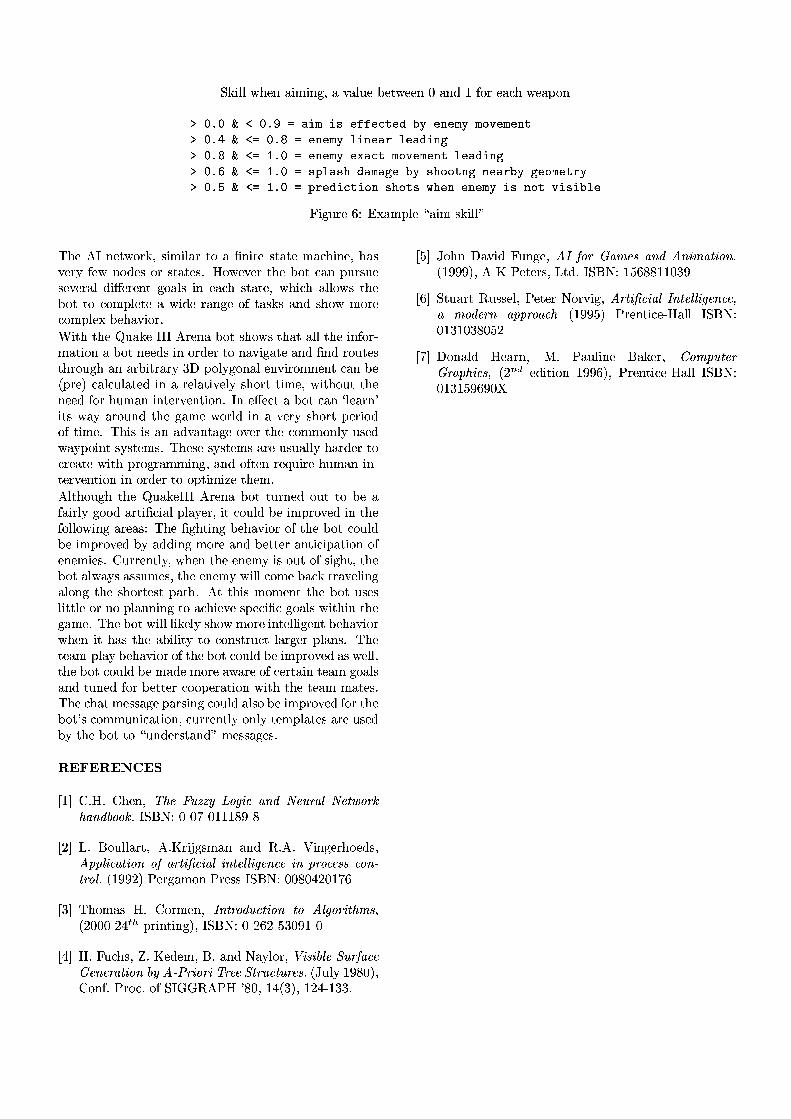
`�FrYZMZM�jCE=25-"+.YZWYN-9^9m=+�*,+.MZK=2v�&25DPj¤2>25-"æ+.-98�ÐgRVB34C2]+3J;E7j¤2]+.��B3-
ý�þ<ÿaþ�����þ�ÿ������ ����������������������������� ���!�#"�$%� �&�'���ý�þ<ÿ)(������#þ�ÿ�*������� �+�-,%.������/-,������#.��0ý�þ<ÿ�*������21\ÿaþ������� �+�3��4%�������&"�$�� �&������,������#5��0ý�þ<ÿ�6������21\ÿaþ��7� 8+,����.93��� �&��0�������� 9�"�"�����0�������/�����0%��" �#����/��ý�þ<ÿ�:������21\ÿaþ���8�/%���#����&'"��-� 9�"��+�<;�9���������.�+�7����%"���$&���.��,��
IiYZ^3K=462vo=Ñ@º@©=+.W�=MZ2�¢X+3YNW§:XFGYNMZM�£
[tE=2_�hSg-=25DPj¤B�4XF¯m\:XYNWYZMZ+34�DXB�+{�9-=YNDX2{:PD;+,DX2W�+3J;E9YN-=2�m\E9+�:*32>4XO�RV2>jÀ-=B�8�2]:�B34v:aD6+,D62>:>%�¥hB,jk25*32>4cD6E=2���B.D�J5+3-��=K946:XK=2:a2>*32>46+3Mt8=Yd·¯254625-rDQ^�B�+.M�:YZ-�2]+3J;E�:aD6+,D623mtjCE=Y�J;E�+.MZMNB,jh:�D6E=2�&B3D�DXB�JLB3W�=MZ2LD62Q+"jCY�8�2_4;+.-=^�2B.RtD6+�:aF�:�+3-980:aE9B,j½WB�4X2JLB�W��9MN25©Q�&2>E9+1*GYNB�4>%/�YdD6E7DXE=2¡��K9+3F32�SaSXSk�c4X2>-9+��&B3Dc:aE9B,jh:�D6E9+,Dc+3MNM¯D6E=2vYZ-�RVB34X�W�+,DXYZB3-7+���B.Dt-=252]8=:kYN-{B34;8�254¤DXB�-9+1*GYZ^�+,D62c+.-&8��9-98{46B3K�D62>:DXE=46B3K9^3E�+.-�+.46�=YdD646+34XO�ª�b«�&B�MNOG^�B3-9+3M�2>-G*rYZ46B3-=W25-rDCJ5+3-{��2�V�=462]��J5+3MZJ5K=M�+,DX2]8�YZ-�+Q4X2>MZ+.DXYZ*32>MNO":XE=B34XD�D6YNW2�m�jCYdD6E=B3K=D�D6E=2-=252]8_RVB�4CEGK=W�+.-7YN-rDX2>4X*�25-rDXYZB3-\%iSU-�25·�2]J�Dc+��&B3DhJ5+.-�Ú MN2]+.46-�YdD;:�jt+1O�+.46B3K9-98�DXE=2_^r+.W2�jkB346MZ8�YZ-�+�*32546O�:XE=B�4aD���2546YNB�8B.R@D6YNW23%v[tE=Y�:�YZ:g+.-�+�8�*,+.-rD6+3^32�B,*�254CD6E=2JLB3WWB3-9MNO�K9:X2>8jk+1OG��B3YZ-rDt:XO�:PD625W�:5%<[tE92>:X2�:aO�:aDX25W�:C+34X2�K9:XK9+.MZMZO_E9+.4;8�2>4tDXBJL462>+.DX2�jCYNDXE��94XB�^34;+.WWYN-=^&m9+.-&8"B.ReD625-�462>¨rK=YZ4X2�ErK9W+3-�YZ-��DX2>4X*�25-rDXYZB3-{YN-�B34;8�2>4¤D6B�B3��D6YNWYZH52�D6E=25W�%�hMNDXE=B�K=^3E�DXE=2���K9+3F32>SaSaS��c4X2>-9+��&B3D¡D6K=4X-92>8�B�K�DDXB��&2�+R¬+.YZ4XMZO_^�BrB�8{+.4XDXYN�&JLY�+.M��=M�+1O32>4>mGYNDcJLB�K=MZ8{��2vYNW�=46B,*32]8_YZ-QD6E=2RVB3MZMNB,jCYZ-=^_+34X2]+3:>Ñk[tE=2��9^3ErD6YN-=^Q�&2>E9+1*GYNB�4hB.R@D6E=2���B.D�JLB3K9MZ8�&2vYZW�=46B,*32>8{�GO{+�8=8�YZ-=^W�B�4X2v+3-987�&25DaDX2>4c+.-rD6YZJ5YN�9+.DXYZB3-�B.R25-=2>WYN2]:5%�q¤K=464X2>-rDXMZO3mGjCE=25-QDXE=2g25-925W�O�Y�:kB3K�DtB.Ri:aYZ^3ErD>mrD6E=2�&B3D¤+.MZjt+1OG:@+�:X:XK=W2>:>m,D6E=2h25-925W�O�jCYZMNM9J5B3W2h�9+�J;FvDX4;+1*32>MNYZ-=^+.MZB3-=^7D6E=2_:aE9B34XDX2>:aDv�9+,D6E�%Q�kDvD6E=YZ:�WB3W25-rDvDXE92��&B3D�K9:a2]:MNYNDaD6MN2�B�4k-9B¡�=M�+.-9-=YN-9^�D6B+�J;E=YZ25*32g:a��2>J5Yd��J�^�B�+3MZ:¤jCYdD6E=YZ-QD6E=2^�+3W�2�%T[tE=2¤�&B3DijCYZMZMrMZYZF325MZO�:XE=B,j�WB3462<YN-rD625MZMNYZ^32>-�D)��25E9+1*GYZB34jCE=25-0YND�E9+�:�DXE=2{+.�=YZMNYNDPO�D6B�JLB�-9:PD64XK&J�D�M�+.46^3254v�9MZ+3-9:5%7[tE=2DX2]+.W��¸�9MZ+1Og�&2>E9+1*GYNB�4�B.R�D6E=2���B.D@JLB�K=M�8v�&2¤YNW�=46B,*32]8v+3:\j¤2>MNM¸%DXE=2C��B.DkJLB3K9MZ8���2hW�+38�2CWB3462C+1jk+34X2kB.R�JL2>4aD;+.YZ-�DX2>+3W¼^�B�+.M�:+.-98{D6K=-=2>8"RVB34h��2LDXDX254gJLBGB3��254;+,D6YNB�-�jCYdD6E�DXE=2vD62>+3WÂW�+,D62>:>%[tE=2tJ;E9+,DiW�2]:X:6+.^�2<�9+346:XYN-9^�JLB�K=M�8�+.M�:XBh�&2tYZW�=4XB,*�2>8gRVB�4\D6E=2�&B3D> :¤J5B3WW�K9-=YZJ>+,D6YNB�-�m�J5K=4X4625-rD6MNO�B3-=MZO¡DX25W�=M�+,D62>:k+.462hK9:X2>8�GO�DXE=2v��B.DCD6B0¢aK=-98=254;:PD;+.-98=£�W2>:6:6+.^32]:5%
~QxgÖCx�~{x�² � xv�
ÔdÐ5Õ¡q�% ¥�%�q¤E=25-�m>=&?%@BADC�EFEHG<IKJML'NPORQ'S#TRUV@ C�WMQ�XYUZ@H[]\^J'W`_?%Q�S&T�aFJ.J5_�b�Sa`�âtu�Ñ9æ.��æ�c]�Uæ=Ð3Ð�Ð>p�å,�Up
Ô n,Õ�?<%�âkB3K9MNM�+.4XD>m_��% ú�46Y P^r:aW�+3-½+3-98®Av% ��%�Ï�YN-=^�2546E=BG2>8=:>mdfe�e XgNPOFQ�[hNPJ�S�JjikQ�Wl[hN mfOHNPQ�XnNoS�[)@ XoXpNpL�@HS#OF@qNoS e W`J.OM@ rFrqOFJ�S�s[]W`J'XtbT�PÐ>å�å�n���()2>4X^r+.WB3-Q(�4X2]:X:tSa`=âku�Ñ=æ3æ�p3æ.lGn.æ9Ð c,o
Ô ª.Õ�[tE=B3W�+3:�¥�%{q¤B�4XW2>-�m>ulS+[]W`J.T�C�OH[hNPJ�Sv[wJ d X L�J�WlNo[x?�yVr�m��n.æ�æ3æn,l�ç¬è��=4XYZ-rDXYZ-=^r�Lm�Sa`�âtu�Ñ9æ.�Un3o�n,�Uø3ª3æ3å9ÐL�Uæ
Ô l3Õ�¥�%9I9K9J;E9:>m&ãi%=ú�2>8�2>W�m=â�%&+.-987uc+1OGMZB34]mnzKN{rlNPa Xt@}|+C�Wxi Q�OF@~ @HS#@HW`Q'[]NPJ'S�a G d s]�nWlNPJ'WlN�=%W`@F@f|+[hWlC�OH[]C�W`@ rHbr�¬$�K=MNO�Ð>å�p3ær��mq¤B3-�RP%9(�4XB�J3%rB3R@`�S �v� Ah�c(¤¥® p�æ=m�Ð5l��¬ªr��m�Ð]n.l.�;Ð>ª�ª=%
Ô ø,Õv$�B3E9-�bg+1*rY�8�I9K=-=^�23m d u�i J'W ~ Q'y�@ r�Q'S#T d S+Noy�Q'[]NPJ'S#b�aÐ>å�å3å��Lm��«úÀ()25DX254;:>mG?�D68�%9Sa`�âtu�Ñ�Ð1ø.o3p�p=Ð�Ð>æ3ª�å
Ô o.Õ�`GDXK9+34aD¡AhK9:X:X25M¸mT()25DX2>4�uhB�4X*GYZ^9m d Wl[hN mfOHNPQ�X�ulS+[w@HXoXgNpL�@ S&OM@ �Q�y�J.T�@HWlS�Q e�e W`J.Q�OF? �aÐ>å�å�ø3�½(�4X2>-�D6YZJ52L�U¥c+3MNM�Sa`�âtu�Ñæ9Ð>ª9Ð>æ3ª�p3ærø3n
Ô c1Õvb�B3-&+.M�8 ¥c2>+.46-�m¹'�%µ(@+.K9MNYZ-=2 ât+.F32>4>m���J'y e C�[w@HW~ W`Q e ?�NPOlr�m_��n ë3ê 2>8=YdD6YNB�-ÀÐ]å3å3or��mc(�4X2>-rDXY�JL2L�U¥c+3MNM�Sa`�âtu�Ñæ9Ð>ª9Ð]ø.å�o3å�æ'�

MESH SKINNING TECHNIQUE FOR INTELLIGENT ANIMATED CHARACTERS IN
COMPUTER GAME
Z. Wen, Q.H.Mehdi, and N.E.GoughSchool of Computing and Information Technology
University of Wolverhampton, 35-49 Lichfield StreetWolverhampton, WV1 1EQ, United Kingdom
E-Mail: [email protected]
KEYWORDS:
Mesh skinning, transformation pipeline, DirectX 8,intelligent animated character, transformation matrix,vertex shader.
ABSTRACT
The mesh skinning technique has several distinctadvantages compared to the traditional computer gameanimation techniques such as key framing and articulatedrigid body animation. It can produce realistic and smoothcharacter animation in real time by allowing more thanone transformation matrix to affect the vertices that formthe “skin” of the character. With advances in bothhardware and software, it has now become more practicalto implement this technique in PCs in real time. The paperfirstly gives a brief review of traditional animationmethods in computer games. It then introduces theskinning mesh technique and proposes a method toincorporate this technique into procedures for intelligentcharacter animation. The paper also introduces theimplementation of mesh skinning using DirectX 8. Theresult of this work could be applied to 3D simulationinvolving realistic character animation.
INTRODUCTION
Computer animated characters play an important role ininteractive entertainment products such as computergames. Due to the limited computational power of PCsand real time performance, efficient character animation isone of the main concerns for computer game design andimplementation. Various methods such as hierarchicalarticulated rigid body animation and simple meshblending animation have been applied to produce realtime character animation.
The hierarchical articulated body animation method uses ahierarchical set of interconnected mesh pieces that formthe body of a character (Anderson 2001). A simpleexample of this technique would be a head connected tothe torso, the torso to the upper arm, the upper arm to thelower arm, and so forth. During the rendering, the finaltransformation matrix is calculated in such a way that it
makes a recursive function call to all the matrices that siton the higher hierarchy in forward kinematics or lowerhierarchy in reverse kinematics. For instance, in the aboveexample, the animation matrix for the lower arm isaffected by the matrices of upper arm. For the 3Dhierarchic articulated object, the flexibility is its mainbenefits. Various transformations that comprise acharacter’s motion can be produced using an animationpackage, and then any interpolation techniques fromsimple linear interpolation to complex hermite splineinterpolation can be applied to generate in-betweenframes in order to produce smooth animation (Cebenoyan2001). Furthermore, inverse kinematics also can be usedto produce realistic character movement. Since the vertexinformation for the model including position, texture co-ordinate and transformation matrix needs to be stored onlyonce during program runtime, the memory usage wouldbe small. However, the memory capacity constraint is nolonger a significant problem to the game designer due to arapid reduction in the cost. Another advantage of thistechnique is that it is simple to implement and it can beexecuted relatively quickly in software, which was clearlyan important prerequisite for early real time 3D computergames (Freidlin 2001). One of the drawbacks to thismethod is the result of an unpleasant folding effect whencharacter’s limb is rotated too far about a joint. Inpractice, when the game character makes some largemovement, an ugly gap will appear between the separateparts of bodies. Furthermore, it would be very difficult toachieve smooth shading across the boundaries of theseparate mesh pieces because of the anomalousperturbation of the vertex normal surrounding a joint. Thisproblem therefore forces game designer to devise tricks tocover the problem. For example, a cloth accessory likebelt or long sleeve is applied around the joints that aremost likely to cause the problem.
A mesh blending skinning method was introduced toimplement smooth character animation. Rather thanbreaking a character into separate body parts, the meshblending method produces a character in a single meshobject, generates multiple slightly different copies of thecharacter model and produce real time animation byblending these different models using variousinterpolation methods. The main advantage of this methodis the result of smooth animation with no gaps or self-penetration part in the character model during runtime.

Although mesh blending can be executed very fast duringruntime by using a special multi-stream data renderingtechnique provided by today advanced APIs such asDirectX, the disadvantages of this method still remain amajor issue. This is because the animator needs to modelall of the possible poses of the character in advance andstore them in a huge system database for use in runtime.The problem is that after the animator has modelled theposes, it leave nearly no flexibility to the game designer togenerate various animations based on user interaction andchanges of game environments. The animation processbecomes difficult to parameterise. This problem impliesthat it is not easy for the movements of character to reflectchanges in its run time environment, which is animportant aspect of character’s believability.
In the light of the preceding discussion, a more suitablemethod is needed and a way of applying this method tointelligent animated character needs to be investigated.
MESH SKINNING IN INTELLIGENTCHARACTER ANIMATION
Introduction to mesh skinning
Mesh skinning animation was introduced in order tocombine both advantages from articulated body animationand single mesh blending animation, namely flexibilityand smoothness (Lander 2001a; Lander 2001b; Weber2001). Generally speaking, the mesh skinning techniqueachieves this effect by allowing more than onetransformation matrix to affect a vertex’s final positionand lighting normal. The mathematical equations thatdescribe this method are as follows (Domine 2001). Forthe position of a vertex,
The normal needs to be transformed by the inversetranspose of the matrix used to transform geometry inorder to achieve the correct effect for back-face cullingand shading (Moller and Haines 1999).
The mesh skinning technique allows a mesh to bedeformed based on an underlying hierarchicaltransformation matrix set. This animation method mimicsthe way in which the skin is deformed by a skeleton inreality. The animator has the control of the transformationmatrices that comprise the character’s skeleton rather thanthe direct skin vertex and associates each skin vertex withmore than one transformation matrix. In this way, themesh skinning method can enable the application to createunique animation sequences based on user interaction andrun-time game environments instead of interpolating fromper-set poses. Furthermore, skeleton animation is easilyparameterised, which makes it a superior choice forintelligent character animation. This is because once theanimation procedure can be parameterised such that theanimation procedure’s parameters are able to changeduring program run-time according to the character’sinternal and external stimuli, the character will be capableof performing various movements based on environmentalstimuli and internal states. The following section depictsthe animation architecture that reflects the above method.
The animation architecture
The animation architecture is based on that proposed in(Mehdi et al. 2001) and enhances the behavioural andgraphics part so as to adapt to the mesh skinning method.The character perceives its environment from several datachannels named virtual sensor (Thalmann 1995;Thalmann 1996). The sensorial information is then passedto the perception component to form its own “image” forthe world. The reason for this stage is that the intelligentcharacter’s beliefs are distinct from the actual states of theworld (Burke et al. 2001). For instance, an object may belocated at co-ordinates (20, 20, 0), but the character onlyknows where the object is relative to its head. Therefore,the character cannot be allowed access to the worldmodel. Furthermore, not all perceived information shouldbe passed through this component to reach the internalstates of character. This perception component will alsoact as a “information filter”. The actions will then beselected via a Fuzzy Finite State Machine (FzFSM). Themost important enhancement is the graphics componentand the links between the graphics component andbehavioural component. The system architecture isoutlined in Figure 1. Compared to the Pat-Nets proposedby the Balder (Granieri et al. 1995), this architecture ismore suitable to be implemented in PC platform. The Pat-Nets is an inter-connected network that contains threekinds of nodes, namely control, perceptual andbehaviours. As the system is intended for the multi-agentanimation, a network processes each behaviour node. Inthis way, the system needs to be run in a multi-processorsystem. In reality, normal PCs would not have more thanone processor available in their system. Therefore, thegeneric implementation method proposed by Thalmann(1996) is more suitable. As shown in Figure 1, thesensorial information comes from the external gameenvironments. Different data channels can detect different
vMwVn
iiifinal ∑= ∑ =
iiw 1
v is the vertex positionn is the number of matrices
iw is the associated weightiM is the transformation matrix
Where:
(1)
∑ =i
iw 1∑ −=N
iiifinal nMwN
T1
n is the vertex normalN is the number of matrices
iw is the associated weightT
iM 1− is the inverse transpose oftransformation matrix
Where:
(2)
For the lighting normal of a vertex,
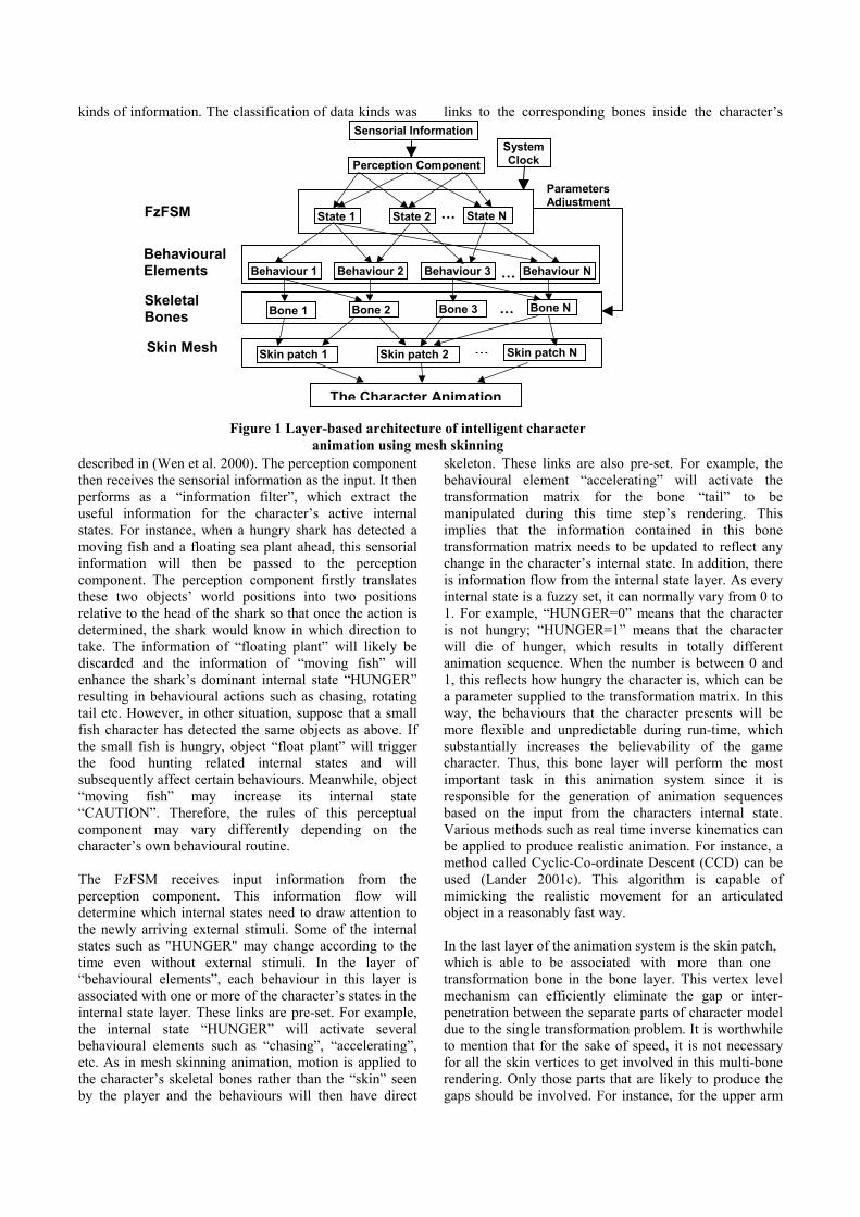
Perception Component
Sensorial Information
State 1 State 2 State N
Behaviour 1 Behaviour 2 Behaviour 3 Behaviour N
…
…
Bone 1 Bone 2 Bone 3 Bone N…
Skin patch 1 Skin patch 2 Skin patch N…
FzFSM
BehaviouralElements
SkeletalBones
Skin Mesh
ParametersAdjustment
Figure 1 Layer-based architecture of intelligent characteranimation using mesh skinning
SystemClock
The Character Animation
kinds of information. The classification of data kinds was
described in (Wen et al. 2000). The perception componentthen receives the sensorial information as the input. It thenperforms as a “information filter”, which extract theuseful information for the character’s active internalstates. For instance, when a hungry shark has detected amoving fish and a floating sea plant ahead, this sensorialinformation will then be passed to the perceptioncomponent. The perception component firstly translatesthese two objects’ world positions into two positionsrelative to the head of the shark so that once the action isdetermined, the shark would know in which direction totake. The information of “floating plant” will likely bediscarded and the information of “moving fish” willenhance the shark’s dominant internal state “HUNGER”resulting in behavioural actions such as chasing, rotatingtail etc. However, in other situation, suppose that a smallfish character has detected the same objects as above. Ifthe small fish is hungry, object “float plant” will triggerthe food hunting related internal states and willsubsequently affect certain behaviours. Meanwhile, object“moving fish” may increase its internal state“CAUTION”. Therefore, the rules of this perceptualcomponent may vary differently depending on thecharacter’s own behavioural routine.
The FzFSM receives input information from theperception component. This information flow willdetermine which internal states need to draw attention tothe newly arriving external stimuli. Some of the internalstates such as "HUNGER" may change according to thetime even without external stimuli. In the layer of“behavioural elements”, each behaviour in this layer isassociated with one or more of the character’s states in theinternal state layer. These links are pre-set. For example,the internal state “HUNGER” will activate severalbehavioural elements such as “chasing”, “accelerating”,etc. As in mesh skinning animation, motion is applied tothe character’s skeletal bones rather than the “skin” seenby the player and the behaviours will then have direct
links to the corresponding bones inside the character’s
skeleton. These links are also pre-set. For example, thebehavioural element “accelerating” will activate thetransformation matrix for the bone “tail” to bemanipulated during this time step’s rendering. Thisimplies that the information contained in this bonetransformation matrix needs to be updated to reflect anychange in the character’s internal state. In addition, thereis information flow from the internal state layer. As everyinternal state is a fuzzy set, it can normally vary from 0 to1. For example, “HUNGER=0” means that the characteris not hungry; “HUNGER=1” means that the characterwill die of hunger, which results in totally differentanimation sequence. When the number is between 0 and1, this reflects how hungry the character is, which can bea parameter supplied to the transformation matrix. In thisway, the behaviours that the character presents will bemore flexible and unpredictable during run-time, whichsubstantially increases the believability of the gamecharacter. Thus, this bone layer will perform the mostimportant task in this animation system since it isresponsible for the generation of animation sequencesbased on the input from the characters internal state.Various methods such as real time inverse kinematics canbe applied to produce realistic animation. For instance, amethod called Cyclic-Co-ordinate Descent (CCD) can beused (Lander 2001c). This algorithm is capable ofmimicking the realistic movement for an articulatedobject in a reasonably fast way.
In the last layer of the animation system is the skin patch,which is able to be associated with more than onetransformation bone in the bone layer. This vertex levelmechanism can efficiently eliminate the gap or inter-penetration between the separate parts of character modeldue to the single transformation problem. It is worthwhileto mention that for the sake of speed, it is not necessaryfor all the skin vertices to get involved in this multi-bonerendering. Only those parts that are likely to produce thegaps should be involved. For instance, for the upper arm
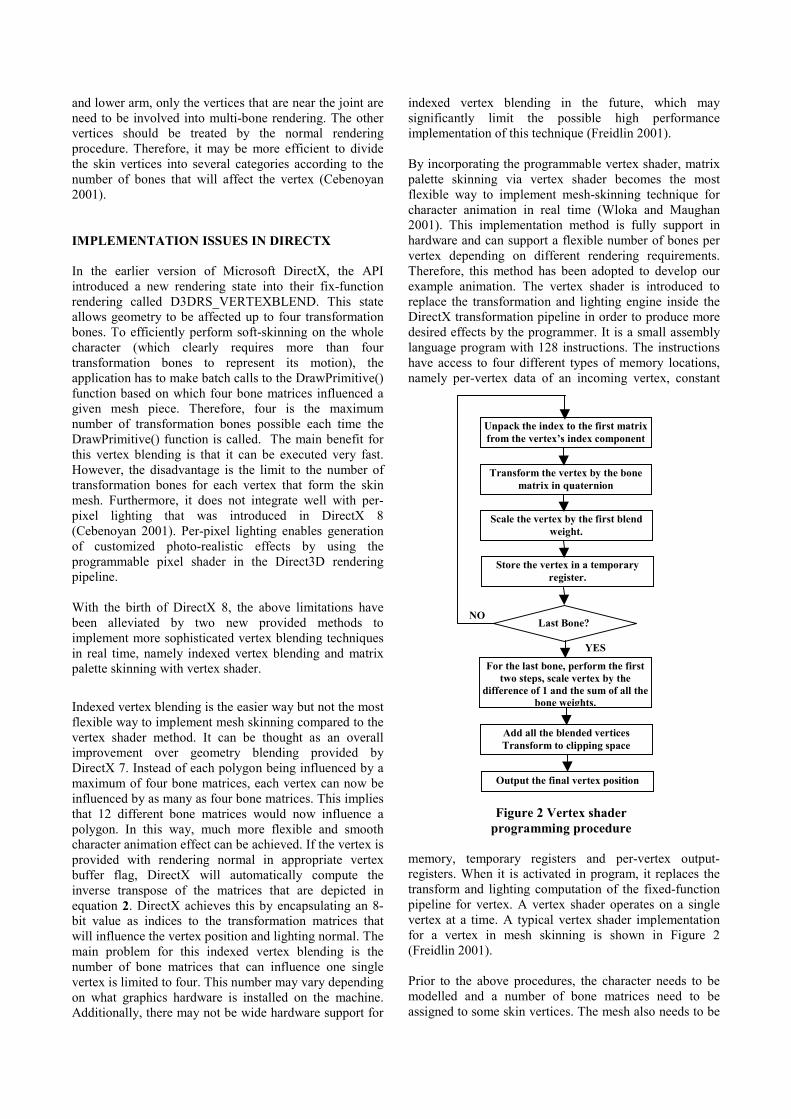
and lower arm, only the vertices that are near the joint areneed to be involved into multi-bone rendering. The othervertices should be treated by the normal renderingprocedure. Therefore, it may be more efficient to dividethe skin vertices into several categories according to thenumber of bones that will affect the vertex (Cebenoyan2001).
IMPLEMENTATION ISSUES IN DIRECTX
In the earlier version of Microsoft DirectX, the APIintroduced a new rendering state into their fix-functionrendering called D3DRS_VERTEXBLEND. This stateallows geometry to be affected up to four transformationbones. To efficiently perform soft-skinning on the wholecharacter (which clearly requires more than fourtransformation bones to represent its motion), theapplication has to make batch calls to the DrawPrimitive()function based on which four bone matrices influenced agiven mesh piece. Therefore, four is the maximumnumber of transformation bones possible each time theDrawPrimitive() function is called. The main benefit forthis vertex blending is that it can be executed very fast.However, the disadvantage is the limit to the number oftransformation bones for each vertex that form the skinmesh. Furthermore, it does not integrate well with per-pixel lighting that was introduced in DirectX 8(Cebenoyan 2001). Per-pixel lighting enables generationof customized photo-realistic effects by using theprogrammable pixel shader in the Direct3D renderingpipeline.
With the birth of DirectX 8, the above limitations havebeen alleviated by two new provided methods toimplement more sophisticated vertex blending techniquesin real time, namely indexed vertex blending and matrixpalette skinning with vertex shader.
Indexed vertex blending is the easier way but not the mostflexible way to implement mesh skinning compared to thevertex shader method. It can be thought as an overallimprovement over geometry blending provided byDirectX 7. Instead of each polygon being influenced by amaximum of four bone matrices, each vertex can now beinfluenced by as many as four bone matrices. This impliesthat 12 different bone matrices would now influence apolygon. In this way, much more flexible and smoothcharacter animation effect can be achieved. If the vertex isprovided with rendering normal in appropriate vertexbuffer flag, DirectX will automatically compute theinverse transpose of the matrices that are depicted inequation 2. DirectX achieves this by encapsulating an 8-bit value as indices to the transformation matrices thatwill influence the vertex position and lighting normal. Themain problem for this indexed vertex blending is thenumber of bone matrices that can influence one singlevertex is limited to four. This number may vary dependingon what graphics hardware is installed on the machine.Additionally, there may not be wide hardware support for
indexed vertex blending in the future, which maysignificantly limit the possible high performanceimplementation of this technique (Freidlin 2001).
By incorporating the programmable vertex shader, matrixpalette skinning via vertex shader becomes the mostflexible way to implement mesh-skinning technique forcharacter animation in real time (Wloka and Maughan2001). This implementation method is fully support inhardware and can support a flexible number of bones pervertex depending on different rendering requirements.Therefore, this method has been adopted to develop ourexample animation. The vertex shader is introduced toreplace the transformation and lighting engine inside theDirectX transformation pipeline in order to produce moredesired effects by the programmer. It is a small assemblylanguage program with 128 instructions. The instructionshave access to four different types of memory locations,namely per-vertex data of an incoming vertex, constant
memory, temporary registers and per-vertex output-registers. When it is activated in program, it replaces thetransform and lighting computation of the fixed-functionpipeline for vertex. A vertex shader operates on a singlevertex at a time. A typical vertex shader implementationfor a vertex in mesh skinning is shown in Figure 2(Freidlin 2001).
Prior to the above procedures, the character needs to bemodelled and a number of bone matrices need to beassigned to some skin vertices. The mesh also needs to be
Unpack the index to the first matrixfrom the vertex’s index component
Transform the vertex by the bonematrix in quaternion
Scale the vertex by the first blendweight.
Store the vertex in a temporaryregister.
Last Bone?NO
For the last bone, perform the firsttwo steps, scale vertex by the
difference of 1 and the sum of all thebone weights.
YES
Add all the blended verticesTransform to clipping space
Output the final vertex position
Figure 2 Vertex shaderprogramming procedure

translated via the functionConvertToIndexedBlendedMesh() in order to beinfluenced by certain transformation bones.
EXAMPLE ANIMATION
This section describes an example animation using themethod outlined in above section. The character has
around 19 bones and it is designed to be able to exhibit itsbehaviours based on the run-time of the gameenvironment and its internal states in real time. In thisexample, the character has two internal states, namelyCAUTION and HAPPY and several behavioural elementssuch as “walking”, “standing”, “looking around” and“running”. Figure 3a shows the character model, whichhas been developed in 3D Studio Max. In Figure 3b thecharacter is walking around with HAPPY and CAUTIONbeing kept in at intermediate level. The character inFigure 3c is walking and looking around with caution dueto noise/sound being detected. The level of CAUTIONhas gone up in this situation. Figure 3d shows that afterthe CAUTION level has been reached a high level, thecharacter is starting to run away while looking around.
CONCLUSIONS AND FUTURE WORK
The paper has proposed a methodology on how to applymesh-skinning technique to realistically animate anintelligent game character in virtual environments. Thismethod has been shown to be an efficient way to generatereal time intelligent game character animation. The gamecharacter is capable of performing various movements
based on run time game environment, user interaction andits own internal states. Future work will concern efficientuse of the vertex shader to produce more complicatedcharacter’s motion in real time.
REFERENCE
Anderson, E. F. 2001. “ Real-time character animation forcomputer game”. http://www.pope-mp.org.uk/projects/tentacle, last accessed 01/09/2001.
Burke, R.; Isla, D.; Downie, M.; Ivanov, Y. and Blumberg, B.2001 “ Creature smarts: the art and architecture of a virtualbrain.”http://www.gdconf.com/archives/proceedings/2001/burke/BurkeR.htm, Last accessed 01/09/2001.
Cebenoyan, C. 2001.“Efficient Animation”. http:// partners.nvidia.com/ Marketing/ Developer/
DevRel.nsf/ TechnicalPresentationsFrame? OpenPage lastaccessed 01/09/2001.
Domine, S. 2001 “Mesh Skinning”. http:// partners.nvidia.com/Marketing/Developer/DevRel.nsf/TechnicalPresentationsFrame?OpenPage, last accessed 01/09/2001.
Freidlin, B. 2001“DirectX8: Enhancing real-time characteranimation with matrix palette skinning and vertex shaders”.
http://msdn.microsoft.com/ msdnmag/ issues/01/06/Matrix/print.asp, last accessed 01/09/2001.
Granieri, J. P.; Becket, W.; Reich, D.; Crabtree, J. and Badler,N.I. 1995. “Behavioral control for real-time simulatedhuman agents.” Proceedings of the 1995 symposium onInteractive 3D graphics (NewYork, USA, April), ACMPress New York, NY, 173 – 180.
Lander, J. 2001a “Skin them bones: game programming for theweb generation”.http:// www. darwin3d.com/ gamedev.htm,last accessed 01/09/2001.
Lander, J 2001b “Slashing through real-time characteranimation”. http://www.darwin3d.com / gamedev.htm, lastaccessed 01/09/2001
Lander, J. 2001c “Oh my god I inverted kine: inverse kinematicsfor real-time games.” http:// www.darwin3d.com/gamedev.htm, last accessed 01/09/2001.
Mehdi, Q.; Wen, Z. and Gough, N.E. 2001 “Visualisationsystem for agent behaviours in virtual environments”. Proc.10th International conference of Intelligent System,(Arlington, Virginia USA, June 13-15, 2001), pp 47-50.
Moller, T. and Haines, E. 1999. Real-time rendering. A KPeters Natick, Massachusetts.
Thalmann, D. 1996. “Physical, Behavioural, and Sensor-basedAnimation”, In Proc. Graphicon96 (St Petersburg, Russia)214-221.
Thalmann, D. 1995. “Virtual Sensors: A key Tools For theArtificial Life of Virtual Actors”. In Proc. PacificGraphics’95 (Singapore) 22-40.
Weber, J. 2001 “ Run-time skin deformation”http://www.intel.com/eBusiness/business/digitalmedia/wp012209_sum.htm, last accessed 01/09/2001.
Wloka, M. and Maughan, C. 2001 “Vertex shader introduction”.http://partners.nvidia.com/Marketing/Developer/DevRel.nsf/WhitepapersFrame?OpenPage, last accessed 01/09/2001.
Wen, Z.; Mehdi, Q, Gough, N.E and Allen, M.J. 2000. “Creating animated behavioural game characters based onenvironmental effects”, Proc. Game On 2000, InternationalConference on Intelligent Games and Simulation (London,UK November 11-12,2000), pp. 76-80.
Figure 3 Screen shots from the example animation(a) Establish the model in 3D studio Max(b) Character is walking(c) Character is walking and looking around with
caution(d) Character is running away and looking around
with scare
(a) (b)
(c) (d)

ALGORITHMS FOR GAMES SIMULATION AND AGENT
PATH PLANNING


© SCS
REAL-TIME EDGE FOLLOW: A NEW PARADIGM TO REAL-TIME PATH SEARCH
Cagatay Undeger
Modeling and Simulation Section Defense Technologies Enginering Inc.
35. Sok. No.28 Balgat 06520 Ankara,
Turkey E-mail: [email protected]
Faruk Polat Department of Computer Engineering
Middle East Technical University 06531 Ankara,
Turkey E-mail: [email protected]
Ziya Ipekkan Scientific Decision Support Center
Turkish General Staff (TGS) Bakanliklar
06100 Ankara, Turkey
E-mail: [email protected]
KEYWORDS Computer-generated forces, real-time path search, maze problems. ABSTRACT Path searching and mission planning are challenging problems in many domains such as war games, robotics, military mission planning, computer-generated forces, etc. The objective of this study is to develop a real-time path-planning algorithm to accomplish specified missions on large landscapes. For that purpose, a real-time goal-directed path search algorithm, Real-Time Edge Follow (RTEF), which can work on fully known, partial known or completely unknown maze environments, is developed. RTEF aims to find a path from a staring point to a static or dynamic target point in real-time. The basic idea behind the RTEF is to let the agent eliminate closed directions (the directions that cannot reach the target point) by analyzing obstacle edges in order to decide on which way to go (open directions). For instance, if the agent has a chance to realize that moving to north and east won’t let him reach the goal state (although the target is at north-east), then he will prefer going to south or west. RTEF finds out these open and closed directions, so decreasing the number of choices the agent has and significantly shortening the path. The method is tested on large mazes and compared with Real-Time A*. We observed that RTEF always performs much better than RTA* when solution quality is considered and usually better when total time spent to reach the goal state is considered (especially on complicated mazes). RTEF frequently gives high solution quality, which is in most cases near to optimal solution, and never needs to return to a previously visited cell while on the way. INTRODUCTION Multi agent systems can be used to model computer-generated environments where intelligent agents react suitably to various events. Many of the applications in this context need realistic environment generation, efficient search algorithms and heuristics suitable for real-time simulations. Multi agent systems are integrated into these simulations for supporting automatic and semi-automatic
human and group behaviors to complete a given mission. Planning a mission usually means to plan a sequence of actions that lead to the goal-state. The problem of path planning can be described as finding a sequence of state transitions from some initial state (starting point) to a goal state (target point), or finding out that no such sequence exists. Path-planning algorithms can be off-line or on-line. Off-line path planning algorithms like A* [Russell and Norving 1994] find the whole solution before starting execution. They plan paths in advance and usually find optimal solutions. Their efficiency is not considered to be crucial and the agent just follows the generated path. Although this is a good solution for a static environment, it is completely infeasible for dynamic environments, because if the environment or the cost function changes, the remaining path may need to be re-planned, which is not efficient for real-time applications. Real-time path planning algorithms such as Real-Time A* (RTA*), Learning Real-Time A* (LRTA*) [Knight 1993; Korf 1090], Moving Target Search [Ishida and Korf 1995], Bi-directional Real-Time Search [Ishida 1996], Real-Time Horizontal A* [Undeger 2001], D* [Stentz 1994], Focused D* [Stentz 1995] are on-line and offer more efficient solutions. Some of them produce optimal solutions for dynamic changes such as D* and Focused D*, and some only bring efficiency but not optimality such as Real-Time A*. In this paper, we have proposed a real-time path search algorithm, “Real-Time Edge Follow” (RTEF), which provides both efficiency and solution quality on maze environments. The algorithm is capable of searching a path in real-time to reach a static or dynamic target on a fully known, a partial known or a completely unknown mazes. It can also be used in real-life applications uncluding robotics. RTEF is tested on randomly generated mazes and large terrain data, and compared with RTA*. The results showed that RTEF performed better in both solution quality and execution time. In Section 2, a survey of related work on path planning is given. Our real-time path search algorithm, Real-Time Edge Follow is described in detail in Section 3. The

© SCS
performance analysis of RTEF is given in Section 4. Finally, the conclusion is given in Section 5. RELATED WORK Multi-agent systems are used in many domains such as robotics, computer generated forces, games, training, RoboCup soccer and their simulators. In robotics [LaValle and Kuffner 1999] and RoboCup soccer [Jensen and Veloso 1998], intelligent planning aims to find out ways for interacting with the physical world, which makes the problem hard to solve. In contrast, intelligent planning for computer generated forces and games [Pew and Mavor 1998; Undeger et al. 2000; Undeger 2001; Baxter and Horn 1999; Gelenbe 1998; DeLoura 2000] aim to generate behaviors similar to the real world in virtual environments. Simulating real world actions in a virtual environment is basically used to test some conditions that are not possible or hard to generate in the real world. For example, intelligent agents that behave much like real world entities are frequently used for pilot trainings in flight simulators [Jones et al. 1993, 1994]. In such simulators, realistic modeling of agent behaviors is very important for the realism of training. In multi agent simulations, evaluating the environment information, learning and reacting in time is essential. Erol Gelenbe proposed modeling computer-generated forces with learning stochastic finite-state machines whose state transitions are controlled by state and signal dependent random neural networks [Gelenbe 1998]. In Knuffner’s approach [Kuffner and Latombe 1999], rendering off-screen from the character’s point of view and real-time path planning is used. His path-planning module aims to find a collision free path between a starting and ending point over the 3D terrain using the information gathered from vision based perceptions. In the study of Knuffner, the terrain is divided into embedded graph cells, which have vertical, horizontal and diagonal costs of walking through. Then, the suitable path is found using Dijkstra’s algorithm, which is actually an optimal off-line path-planning algorithm integrated into a real-time application. Using an off-line path-planning algorithm in a real-time application is not suitable for large terrains. By the help of some guidance such as admissible heuristics can increase efficiency of off-line path planning algorithms. A* [Russell and Norving 1994] is one of best-known efficient path planning algorithms, which is guided by a heuristic function. A* always finds the optimal solution and uses linear distances between points for the heuristic function. Optimal path planning algorithms cannot be used for large and dynamic landscapes because of its complexity. To avoid this drawback, some partial path update algorithms are also proposed such as D* [Stentz 1994] and focused D* [Stentz 1995]. These algorithms plan an off-line path, let the agent follow the path, and if any new environment information is gathered, they partially re-plan the existing solution. But some times, a small change in the environment may cause to re-plan almost a complete path, which may take a long process time.
A number of algorithms exist for supporting real-time simulations such as Real-time A* (RTA*) and Learning Real-Time A* (LRTA*) [Knight 1993; Korf 1990]. RTA* uses a greedy search strategy and a heuristic together to guide the search. It guarantees to find a solution if one exists, but the solution may not be optimal. In this paper, we have proposed a new Real-Time path search algorithm for maze environments. There are also some path-planning algorithms that use random search techniques such as genetic algorithms, random tree generators. In [Sugihara and Smith 1997], an adaptive path-planning algorithm based on genetic approach is proposed. In this study, they assumed that a valid path that is not optimal is initially found and they refine this given path by genetic algorithm. Considering this concept, our previously developed off-line path-planning algorithm, Linear Search Path Finder [Undeger 2001] seems to be applicable to this case successfully. In the study of LaValla and Knuffner [LaValle and Kuffner 1999], a randomized planning technique based on a version of random tree generation called rapidly exploring random tree is presented. They generated two random trees starting from the goal and the target points, and try to catch an intersection among the points of distinct trees to find a path. REAL-TIME EDGE FOLLOW RTEF is developed for maze-type problems and aims to find a path from a staring point to a target point in real-time. The basic idea behind the RTEF is to let the agent eliminate closed directions (the directions that cannot reach the target point) in order to decide on which way to go, (open directions). For instance, if the agent has a chance to realize that moving to north and east won’t let him reach the goal state, than he will prefer going to south or west. RTEF finds out these open and closed directions, so decreasing the number of choices the agent has. The environment is assumed to be a grid world with obstacles, where the cells having obstacles are marked with a non-zero value and the rest is filed with zero. Initially, the agent is at a starting point and the goal is to reach a static or dynamic target. At each move, RTEF algorithm is executed to eliminate closed directions from the current cell in order to select the next move from a set of open directions. The cost of moving to the next cell + the distance to the target is used for the heuristic function to select one of the open alternatives. After doing the move, the previous cell is marked as an obstacle; so loops are prevented. The set of previously marked cells are called the history of the agent. In exploration mode with an unknown maze, the history has to be cleared when a newly discovered obstacle blocks the way that was open before. The algorithm is constructed on the idea that every obstacle has a boundary, which is actually formed from a set of connected edges shaping the object. The obstacles are

© SCS
defined as a set of merged cells in a grid world. RTEF splits the moving directions from each other by a set of rays sent away from the agent, and analyze each region to discover whether it is closed or open. Moving Directions and Sent-Rays RTEF accepts the possible moving directions as north, south, east and west. Although there are many interval values of these directions, a set of basic directions is chosen to partition the area for the sake of efficiency. The idea is not to find an exact direction, but to choose a general direction having a left and right angle limit. The algorithm splits the visual environment into four regions by sending 4 rays away from the agent. The rays are sent
along 4 diagonal directions (the angle between two adjacent rays is 90 degree). The rays go away from the agent until hitting an obstacle and hence split the area into 4 different regions. Some of these regions are on the way to the target point and some are not. This is illustrated in Figure 1. Each ray hits the boundary of one of the obstacles. The cells on the way of a ray are followed until a blocked cell is detected. The boundary of the grid world is also marked as blocked in order to prevent infinitely going rays. The first ray is assumed to be on the northwest diagonal. This is illustrated in Figure 2. A ray is assumed to hit an obstacle, when any cell on the way is marked as blocked.
Figure 1: Sending rays until hitting an obstacle to split the basic directions
Figure 2: Rays, Directions and hitting: Rays and directions are numbered from 0 to 3 in clockwise direction on the left. The figure on the right shows the cells on the way of 4 rays.
Following Edges Four rays split the area around the agent into 4 regions. Some of these limited regions are closed and target point is inaccessible from any point located inside these regions. If all are closed, that means the target is inaccessible from the current state or location. To detect which ones are closed, the boundaries of obstacles that the rays hit must be analyzed. The edges on the boundaries are followed and if
edges are followed clockwise or counter-clockwise directions starting from a hit-point, we always return to the same point. By following edges and returning to the same starting point on the boundary, a polygonal area is formed (the boundary of the obstacle is detected). We call this polygonal area an “island”. There are two kinds of islands: outwards facing and inwards facing, which are shown in Figure 3. If the target is inside an outwards facing island or
North d.
South d.
East d. West d.
The agent
An obstacle
A hit-point
Target
The best direction that
could be chosen from 3 open alternatives (west, east,
south) Moving directions
Rays
Legend
90 degree
North d.
South d.
East d. West d.

© SCS
outside an inwards facing island, that means the target is inaccessible from the current location.
Figure 3: Island types: outwards facing (top), inwards facing (bottom)
If we reach the hit-point of another ray while following edges (only the first one reached is considered), we have an additional polygonal area (the two rays are also included) called “hit-point-island”. This polygonal area is illustrated in Figure 4.
Figure 4: Two rays hitting the same obstacle at two different points
A hit-point-island borders one or more moving directions. If the target point is not inside the hit-point-island, it means that all the directions that are bordered by the hit-point-island are closed. Otherwise all the directions that are not bordered by the hit-point-island are closed. This is illustrated in Figure 5.
Figure 5: Analyzing hit-point islands and eliminating
moving directions
The edge following algorithm works on grid worlds and it is the most time consuming part of RTEF. There are two edge follow directions. One follows the edges from the left side of the hit-point and one follows from the right side. If we follow edges from the left, we have to choose the next edge, which is connected to the left side of the current edge and similar process is done for the right side. This is depicted in Figure 6.
Figure 6: Edge detection: The figure illustrate next possible
states when starting from south side of a cell. The possibilities are tested from smaller angles to larger angles. After finding the island and the hit-point-island, the target must be checked if it is located inside these polygonal areas or not. Implementing an inside test is not so complicated. For testing whether the coordinate (tx,ty) is inside a polygon P or not, we just need to count the number of edges in P that are on the left side of ty and intersecting the horizontal line passing on ty. If the edge count is an odd number, the point is inside the polygon else it is not. Detecting Closed/Open Regions To detect closed and open regions, “edge following process” and “inside polygon tests” are used together. To follow edges from only one direction is enough for the detection, but one direction has to be chosen and used for all the rays. The C-like pseudo code for left side edge following is shown in Figure 7. When open and closed directions are detected, one of the open directions is chosen and one-step move is performed. The simplest heuristic is the cost of moving to the next cell + the distance of next cell to the target. The direction, which minimizes the cost, is selected for the next move. Although the algorithm finds only the open directions, there is a high possibility of getting into loops, especially when there is more than one open direction at a time. For example, assume that the agent is at the same y coordinate as the target is, and there is one choice “moving north”. So, the agent moves north. Consider the next state has two open regions: north and south. South is the previous cell. If the agent selects the south, it is obvious that it will go into a loop. The agent selects the south, because being at the same y coordinate as the target is, has less cost than being at two cells up from the y coordinate of the target (the distance to the target is shorter). This is only one of many possibilities. The simplest solution to avoid the loops is to mark the previous point as an obstacle. So the agent never has a chance to visit the same point again.
An outwards facing
An inwards facing island
A hit-point island
The first ray The second ray
Target
All the directions that are bordered by the hit-point-island are closed
Target
All the directions that are not bordered by the hit-point-island are closed

© SCS
For each ray-sent Find hit-point of the ray; Follow the edges from left side of the hit-point; Find out the island and hit-point-island; if (an hit-point-island is found) {
if (targetx,targety) is inside the hit-point-island) {
if ((targetx,targety) is inside the island) {
if ((agentx,agenty) is not inside the island)
close all the directions; // the target is inaccessible;
} else close the directions that are not bounded by hit-point-island.
} else close the directions that are bounded by hit-point-island.
} else {
if ((the island is outwards facing and (targetx,targety) is inside the hit-point-island) or (the island is inwards facing and (targetx,targety) is not inside the hit-point-island))
close all the directions; // the target is inaccessible;
} Figure 7: The C-like pseudo code for detecting closed and
open regions Exploring and Adaptation to Dynamic Environments If the maze is not given in advance or just a part of the maze is known, the agent has to explore and learn the environment in real-time. The algorithm is applicable for real-time exploration. It will immediately adapt itself to the new condition, but there can be a problem because of marking the cells traveled with obstacle. Because the agent assumes that the rest of the way is opened, so it marks the previous cells as obstacle, but when it explores the area and notices that the region is closed, it may be stuck in a completely closed region. All we need to do is to clear the history when all the directions are closed. In real life, the targets, the obstacles and the threats usually have a dynamic nature. For RTEF having a dynamic environment is not a big problem in fact. The algorithm can also be adapted to a change in the cost function rapidly. The only problem that may occur is blocking. For example, while the target is moving, it may enter to a previously blocked region, but if the target is blocked, the agent rapidly detects that all the directions are closed and the history is cleared. One disadvantage of clearing history is forgetting previous experience and returning back to same regions again. While marking traveled cells as obstacles, one good thing is also done. The noise (small obstacles) on the maze is cleared by connecting them with history lines. So clearing the history causes noise to increase again.
Complexity of RTEF The worst case complexity of RTEF for each move is O(w x h), where w is the width of maze and h is the height of maze. But almost never we have this complexity. In general, it is much more smaller than this. The efficiency of a move can be explained with total number of edges followed. Other operations are very efficient compared to edge following process. The observed worst-case frame rates for different sized mazes are shown in Table 1. As seen, the seconds per move increases almost proportional to the number of cells.
Table 1: Worst-case performances on sample mazes: Sec/M = seconds per move, M/sec = moves per second,
Increase = Increase compared to previous column
100x100 200x200 400x400 800x800 1600x1600
Sec/m 0.005 0.024 0.110 0.462 1.935
M/sec 200.000 41.666 9.090 2.164 0.516
Increase - 4.800 4.583 4.200 4.188
PERFORMANCE ANALYSIS The test environment is implemented in Borland Delphi programming language under Windows platform. The tests are run on an Intel Celeron-466 with 128 MB memory. Both RTEF and RTA* (described in subsection “Real-Time A*”) are implemented. We observed that the solution quality of RTEF is always better than RTA* in both simple and complicated mazes. The efficiency (seconds per move) of RTEF is satisfactory in most cases, but not better than RTA*. The efficiency of RTEF depends on the environment complexity, while the efficiency of RTA* is nearly constant. Three different versions of RTEF algorithm are realized and tested using randomly generated mazes, and compared to RTA*. The first RTEF algorithm knows the entire maze in advance, so has a chance of better planning. The second and third ones don’t know the maze. The agents can see the neighboring cells to a certain depth. They completely see a square region with size d x d, where d is twice of their visual depth plus one. For example, if the observation depth is 5, the agent knows a square of 11x11 cells (5 left, 5 right, 5 up and 5 down). The agent can build the map with real data in time. Real-Time A* (RTA*) RTA*, which RTEF is compared to, is a greedy search algorithm that uses heuristics to direct the search. It evaluates the costs of the neighbor voxels at the current position and jumps to the voxel having minimum cost. While jumping to the next voxel, the algorithm writes 1 plus the cost of the second best neighbor to the previous voxel. This is illustrated in Figure 8.

© SCS
5 8 3
1 7
9 6 7
The best
The second best
5 8 3
1 7
9 6 7
4
The second best + 1
Figure 8: State transition of Real-Time A* The algorithm is effective and complete for maze environments, but if the terrain is large and there are many semi-closed regions having large open areas inside, the agent may be stuck in the regions for a long time, because the search strategy is too local, only the neighbor voxels are evaluated. In addition RTA* uses much memory than RTEF, because it needs an additional array to store cost updates. And RTA is also not applicable to dynamic environments in practice. Test Results of RTEF The mazes with size 100x100 and 500x500 are randomly generated. The agents and the targets are positioned on upper-left, lower-right or upper-central, lower- central side of the mazes. Total time passed, average moves/sec and the number of moves to reach the target point are used to evaluate the results. We evaluated the efficiency and solution quality of RTEF. The average values of test results are shown in Table 2 and 3. As seen from the results, RTEF always gives better solution quality than RTA* on the average. The difference significantly increases if complicated mazes are used. The RTEF again has a good solution quality when unknown mazes are explored. The best solution quality over RTA* is 995.741 times better than RTA* on the average. The worst solution quality of RTEF is again better than RTA*, which is 1.010 times better than RTA*. The average moves/sec (moves per seconds) of RTA* is 2395 (almost constant), where average moves/sec of RTEF is 371 (varies from 29 moves/sec to 991 moves/sec). This moves/sec is much more smaller than RTA*, but acceptable for soft real-time systems. In robotics, doing unneeded physical actions is much more time consuming than thinking and doing good actions, so the moves/sec is not a disadvantage at all. In real world, the time to walk to the next state will usually take more time than thinking phase, and the next move can be calculated while walking to the next state. If we examine total time spent to reach the goal state, an interesting result is observed. In very simple mazes the efficiency ratio of RTA* is better than solution quality ratio of RTEF. But in simple mazes, they go head to head. And after simple mazes, the solution quality and efficiency generally seems to be better than RTA* and after average mazes, the RTEF is better both in efficiency and solution quality. Some sample snapshots are shown in Figure 9, 10.
CONCLUSION In this paper, we have studied the concept of computer-generated forces in order to construct a real-time simulation system. We have generated complicated landscapes similar to real ones and tried to solve real-time path planning problem for mission planning purposes. A test environment is generated and a set of scenarios is performed to evaluate performance of developed algorithm. We observed that RTEF performs better than RTA* in most cases. The algorithm is also applicable to robotics and real-time observation, and it frequently gives high solution quality, which is in most cases near to optimal solution. By introducing new heuristics, the solution quality can be increased, but these methods may reduce the efficiency of the algorithm. For example, some evaluation methods can be applied using edge follow information. As a result of our observations, we state that the real-time path planning techniques can be improved by increasing the visual search depth, which helps a lot to escape earlier from the local semi-closed regions. But we have also noticed that there is much to do for better intelligent search strategies. More human-like evaluation techniques are needed to go one step forward.
Figure 9: A Maze with 5 cell corridors: RTA* performs 226772 moves in 102.034 seconds (top), RTEF performs
1664 moves in 46.474 seconds (bottom). Black regions are traveled cells. RTA* may travel a cell more than once.

© SCS
Figure 10: A Simple Maze (left): RTA* performs 2163 moves in 0.890 seconds (top-left), RTEF performs 1325 moves in 2.840 seconds (bottom-left). A Complicated Maze (Middle): RTA* performs 6157 moves in 27.024 seconds (top-middle),
RTEF performs 1487 moves in 13.680 seconds (bottom-middle). A Very Complicated Maze (right): RTA* performs 76387 moves in 34.105 seconds (top-right), RTEF performs 1670 moves in 20.870 seconds (bottom-right).
Table 2: Test results (mazes filled with randomly distributed noise)
Average of Simple Mazes:
500x500 cells Time in Seconds
Average Moves/Sec
Number of Moves
Efficiency of RTEF, RTA* Time / Time
S. Quality of RTEF, RTA* Moves / Moves
RTA* 1.665 2408 3950 1.000 1.000 RTEF (maze is fully known) 2.850 449 1282 0.584 3.081 RTEF (observation depth 5) 3.490 507 1771 0.477 2.230 RTEF (observation depth 10) 3.889 389 1513 0.428 2.610
Average of Average Mazes: 500x500 cells
Time in Seconds
Average Moves/Sec
Number of Moves
Efficiency of RTEF, RTA* Time / Time
S. Quality of RTEF, RTA* Moves / Moves
RTA* 4.058 2367 9718 1.000 1.000 RTEF (maze is fully known) 4.695 218 1026 0.864 9.471 RTEF (observation depth 5) 2.653 660 1753 1.529 5.543 RTEF (observation depth 10) 3.018 404 1221 1.344 7.959
Average of Complicated Mazes: 500x500 cells
Time in Seconds
Average Moves/Sec
Number of Moves
Efficiency of RTEF, RTA* Time / Time
S. Quality of RTEF, RTA* Moves / Moves
RTA* 57.685 2468 94365 1.000 1.000 RTEF (maze is fully known) 19.138 74 1428 3.014 66.081 RTEF (observation depth 5) 29.094 285 8317 1.982 11.346 RTEF (observation depth 10) 18.802 300 5652 3.068 16.695
Average of Very Complicated Mazes: 500x500 cells
Time in Seconds
Average Moves/Sec
Number of Moves
Efficiency of RTEF, RTA* Time / Time
S. Quality of RTEF, RTA* Moves / Moves
RTA* 58.766 2415 142089 1.000 1.000 RTEF (maze is fully known) 21.932 62 1373 2.679 103.487 RTEF (observation depth 5) 21.897 422 9245 2.683 15.369 RTEF (observation depth 10) 21.960 369 8123 2.676 17.492

© SCS
Table 3: Test results (5 and 1 cell corridors with sizes 500x500 and 100x100)
Average of mazes with 5 cell corridors: 500x500 cells
Time in Seconds
Average Moves/Sec
Number of Moves
Efficiency of RTEF, RTA* Time / Time
S. Quality of RTEF, RTA* Moves / Moves
RTA* 843.917 2495 2176692 1.000 1.000 RTEF (maze is fully known) 73.257 29 2186 11.519 995.741 RTEF (observation depth 5) 581.190 122 71377 1.452 30.495 RTEF (observation depth 10) 167.415 119 19983 5.040 108.927
Average of mazes with 1 cell
corridors: 100x100 cells
Time in Seconds
Average Moves/Sec
Number of Moves
Efficiency of RTEF, RTA* Time / Time
S. Quality of RTEF, RTA* Moves / Moves
RTA* 3.861 2434 9201 1.000 1.000 RTEF (maze is fully known) 2.801 117 329 1.378 27.966 RTEF (observation depth 5) 2.808 434 1220 1.375 7.541 RTEF (observation depth 10) 2.385 295 704 1.618 13.069
REFERENCES
Baxter, J.W. and Horn, G.S. 1999. “A Model for Co-Ordination and Co-Operation Between CGF Agents.” In Proceedings of 8th conference on Computer Gererated Forces and Behavioral Representation, Orlando, Florida, 101-111.
DeLoura, M.A. 2000. Game Programming Gems. Charles River Media.
Gelenbe, E. 1999. “Modelling CGF with Learning Stochastic Finite-State Machines.” In Proceedings of 8th conference on Computer Gererated Forces and Behavioral Representation, Orlando, Florida, 113-115.
Ishida, T. and Korf, R.E. 1995. “A Moving Terget Search: A Real-Time Search for Changing Goals.” IEEE Trans Pattern Analysis and Machine Intelligence, Vol.17, No.6, 97-109.
Ishida, T. 1996. “Real-Time Bidirectional Search: Coordinated Problem Solving in Uncertain Situations.” IEEE Trans Pattern Analysis and Machine Intelligence, Vol.18, No.6.
Jensen, R.M. and Veloso, M.M. 1998. “Interleaving Deliberative and Reactive Planning in Dynamic Multi-Agent Domains.” In Proceedings of the AAAI Fall Symposium on Integrated Planning for Autonomous Agent Architectures, AAAI Press.
Jones, R.M., Tambe, M., Laird, J.E. and Rosenbloom, P.S. 1993. “Intelligent Automated Agents for Flight Training Simulator.” In Proceedings of 3th conference on Computer Gererated Forces and Behavioral Representation, Orlando, Florida, 33-42.
Jones, R.M., Laird, J.E., Tambe, M. and Rosenbloom, P.S. 1994. “Generating Behavior in Response to Interacting Goals.” In Proceedings of 4th conference on Computer Gererated Forces and Behavioral Representation, Orlando, Florida.
Knight, K. 1993. “Are Many Reactive Agents Better Than A Few Deliberative Ones?” In Proceedings of The International Joint Conference on Artificial Intelligence, 432-437.
Kuffner, J.J. and Latombe, J.C. 1999. “Fast Synthetic Vision, Memory, and Learning Models for Virtual Humans.” In Proceedings of Computer Animation, IEEE, 118-127.
Korf, R.E. 1990. “Real-Time Heuristic Search.” Artificial Intelligence, Vol.42, No.2-3, 189-211.
LaValle, S.M. and Kuffner, J.J. 1999. “Randomized Kinodynamic Planning.” In Proceedings of IEEE International Conference on Robotics and Automation, ICRA'99, Detroit, MI.
Pew, R.W. and Mavor, A.S. 1998. Modeling Human and Organizational Behavior: Application to Military Simulations, National Academy Press.
Russell, S. and Norving, P. 1994. Artificial Intelligence: a Modern Approach, Prentice Hall.
Stentz, A. 1994. “Optimal and Efficient Path Planning for Partially-Known Environments.” In Proceedings of the IEEE International Conference on Robotics and Automation, ICRA '94, Vol.4, 3310–3317.
Stentz A. 1995. “The Focussed D* Algorithm for Real-Time Replanning.” In Proceedings of the International Joint Conference on Artificial Intelligence, IJCAI’95.
Sugihara K. and Smith, J.K. 1997. “Genetic Algorithms for Adaptive Planning of Path and Trajectory of a Mobile Robot in 2D Terrains.” Technical Report, number ICS-TR-97-04, University of Hawaii, Department of Information and Computer Sciences.
Undeger, C., Isler, V. and Ipekkan, Z. 2000. “An Intelligent Action Algorithm for Virtual Human Agents.” In Proceedings of the 9th Conference on Computer Generated Forces and Behavioral Representation, Orlando, Florida, 25-33.
Undeger, C. 2001. Real-Time Mission Planning For Virtual Human Agents. M.S. Thesis in Computer Engineering Department of Middle East Technical University, Ankara, Turkey.
AUTHOR BIOGRAPHY CAGATAY UNDEGER received his B.Sc. degree from Kocaeli
University, Turkey in 1998 and went to the Department of Computer Engineering, Middle East Technical University, where he has worked as a research assistant and obtained his M.S. degree in 2001. He is currently doing his Ph.D. in the same university and studing on Modeling and Simulation within Defense Technologies Engineering Inc.
FARUK POLAT is an associate professor in the Department of
Computer Engineering of Middle East Technical University, Ankara, Turkey. He received his B.Sc. in computer engineering from the Middle East Technical University, Ankara, in 1987 and his M.S. and Ph.D. degrees in computer engineering and information science from Bilkent University, Ankara, in 1989 and 1993 respectively. He conducted research as a visiting NATO science scholar at Computer Science Department of University of Minnesota, Minneapolis in 1992-93. His research interests include artificial intelligence, multi-agent systems and object oriented data models.
ZIYA IPEKKAN has been serving as an operations research
analyst at TGS for more than twelve years. Lt.Col.Ziya øSHNNDQ LV FXUUHQWO\ WKH OHDGHU IRU )RUFH 6WUXFWXUH $QDO\VHVTeam at the position since August 2000. He is responsible for conduct of studies and analysis of joint concepts, the warfighting capabilities and plans, and force structures.

Figure 1. Unreal’s scene.
USING GAMES ENGINES TO IMPLEMENT INTELLIGENT VIRTUAL ENVIRONMENTS
Carlos Calderon and Marc Cavazza University of Teesside, TS1 3BA Middlesbrough, United Kingdom,
[email protected], [email protected]
KEYWORDS Games Engines, IVE, and problem solving mechanisms. ABSTRACT
In this paper we present an Intelligent Virtual Environment (IVE) obtained by incorporating a problem solving mechanism (AI technique) into a Virtual Environment. In particular, in this paper, we will discuss the implementation of the interaction with the problem solving mechanism by using the following metaphor: the visual space provided by the Virtual Environment is seen as the search space. INTRODUCTION The emerging area of Intelligent Virtual Environments explores the integration of Artificial Intelligence techniques into Virtual Reality systems. One particular research topic is to couple interactive AI systems (scheduling, planning, etc.) to virtual environments where the VE serves as an interface to the interactive planning system. Because the nature of the tasks to be solved are mainly spatial, Visualisation Engines, in general, and Games Engines in particular are well suited to serve as interface to the planning and/or problem solving mechanisms. That is, by incorporating AI techniques into 3d real-time interactive graphics technologies, we could, for instance, add a problem-solving component to the virtual environment. This would be beneficial for industrial applications where task scheduling or interactive design is relevant. The objective of this paper is to present an interactive prototype in which we have linked a Virtual Environment (VE) to a constraint solving mechanis m (solver). In our example application is possible to directly manipulate the objects from the virtual environment to create an input configuration for the planning system. This new input configuration is analysed by the problem solving mechanism and then, displayed in the Virtual Environment. The next section briefly introduces the technologies used to create an Intelligent Virtual Environment for our example application. The third section describes how the problem solving mechanism has been incorporated into the Game Engine. Finally, the paper concludes with a brief discussion about the different implemented types of interactivity, further work lines of work and some conclusions.
TECHNOLOGY BASELINE Interactive Visualization Engine We decided to use the Unreal Virtual Machine for three main technical reasons: extensibility, an extremely powerful rendering engine and cutting-edge networking capabilities. Unreal has also been successfully used in non-gaming applications [1] and research projects [2]. Rendering engine and subsystems.
The Unreal rendering engine has the most complete lighting conditions support of all the games engines. A variety of effects: such as surfaces with shadowing, realistic wavy water, animated materials, etc (see figure 1) have been used to add realism to the virtual scene. Unreal also supports digital sound system (software Dolby Surround encoding for full 360-degrees). Real world sounds , e.g water splashing, have been incorporated to the virtual scene to add realism to the exploration of the virtual environment. Problem Solving Techniques Our approach is based on a combination of Constraint Logic Programming over Finite Domains (CLP(FD)) and 3D real-time interactive technology. Our choice of CLP(FD) as a software technology was made based on a series of factors: expressivity, the combination of search and incremental constraint solving capabilities, the short development time while exhibiting an efficiency comparable to imperative languages, and the fact that CLP(FD) is fast enough to react in “real-time” to the user’s input configuration

In our concept architecture examples we have used GNU Prolog as a programming environment, which contains an efficient constraint solver over FD. GNU Prolog offers two different propagation techniques to solve arithmetic constraints: full arc -consistency and partial arc-consistency. This coupled with the use of labeling constraints help us to discover inconsistency as soon as possible, thus avoiding futile search through inconsistent alternatives. Hence, efficient and very fast constraint solvers can be programmed. INTELLIGENT VIRTUAL ENVIRONMENT This section explains how we have made the constraint solver work jointly with the visualization engine to create an Intelligent Virtual Environment in which the virtual environment serves as an interface to the planning system. The starting point is to formulate the problem in terms of constraints (using GNU Prolog). Then the next step is to link our constraint solver with the visualization engine (Unreal Virtual Machine). The next sub-section explains in more detail how the constraint solver has been implemented. Constraint Solver Problem To experiment we have developed a test application in which the task is to allocate a Coke machine in a bank hall. This task can be seen as an example of a spatial/resource allocation problem. This can be represented as a Constraint Satisfaction Problem (CSP), which, consequently, can be easily formalised in CLP (FD). There are numerous design issues, especially in the context of building design, that can be easily transformed into constraints such as health and safety regulations, urban and planning regulations, etc. The Constraints imposed on the Coke machines are the following: a) sources of heat (i.e. radiators) should stay a minimum distance away from the machines, b) the coke machines can only be placed at a maximum distance away from a socket (power point) c) the machines must not obstruct ventilation ducts, d) the coke machines must stay clear from exits and thoroughfares e) the minimum distance to a wall is 25 cm f) finally, the allocation of coke machines must take into account the existing furniture and decoration in the hall. Representation of the Search Space There are at least three options to choose from to represent the spatial search space: rectangular or hexagonal discretisation, actual polygonal floor and polygonal floor representation. There is no obvious choice, each representation has its trade-offs. This decision has great implications in terms of speed to solve the CSP problem and flexibility to accurately represent a constraint satisfaction problem. In this prototype we have opted for a Rectangular or
Hexagonal Grid: A uniform rectangular or hexagonal grid is overlaid onto the world. The size o f each grid space is related to the smallest character. The pros of this approach are: obstacles and characters can be easily marked in the grid; it works well for our 3D world, in our example application the working (spatial search) space is a flat 3D world that is, the z coordinate is constant; save computations on the z coordinate. c When we translate our CSP problem to a rectangular grid, we are simplifying the 3D space into more familiar 2D terms. The idea is to solve the problem in a pseudo 3D environment (where the Z coordinate is constant) while providing a full 3D representation to the user. To do this, we use a rectangular grid as a mesh to transform the 3D space into a more manageable search space. We have experimented with different grid size but as far as the search space goes, the maximum number of cells or the finest possible mesh is implementation dependent. This is due to the fact that in GNU Prolog FD variables can only take values in their domains. There are two internal representations for an FD variable: interval and sparse representation. The initial representation for a FD variable is always internal representation and is switched to a sparse when a “hole” appears in the domain (i.e due to an inequality constraint). So to avoid unexpected surprises we have used the following predicate: fd_set_vector_max(512) that sets the environment variable VECTORMAX to the greatest value that any FD variable can take. This means that in our example application the finest possible mesh has a cell size of 37mm by 37 mm in real units, That is, in the real world. Problem expressed in CLP(FD) We can easily transform our initial task into a CSP problem. That is, a problem where one is given: a finite set of variables, a function which map each variable to a finite domain, and a finite set of constraints. In our case, the set of variable is (X,Y) where X and Y represent the coke machine’s x and y coordinates in our search space. We map these variables to a finite domain by using the following predicate: fd_domain(Vars,1,36). Finally, we have to impose our constraints. We have regarded the constraints d and f as fixed
/*distance to a wall, in this case 25cm*/ walldistance(X,Y) :- X=2,! ; Y=2,! ; X=35.
/*max distance to, i.e, a plug*/ /*In this case the Manhattan distance is 3 units*/maxdistance(X,Y) :- D is 3, (Xc is 2, Yc is 1, distance(X,Xc,Dc1), distance(Y,Yc,Dc2), Dc1+Dc2#=<D)). Figure 2. Examples of constraints

topological constraints and we have implemented them as facts in the database. Alternatively, we could have implemented them as atomic constraints such as Y#=<10 what could have been more efficient but for simplicity we chose not to. The constraints a and c have been regarded as
conjunctive. The formulation of this type of constraints (conjunctive) is straight forward. See figure 3 where Xo and Yo are the position of the source of heat in the search space. Finally, b is regarded as a disjunctive constraint. The formulation of this type of constraints is also simple. See figure 2 where Xc and Yc represent the location of the socket in the search space. We have used the Manhattan distance as distance criterion. It is worth noticed that the incremental constraint solving capabilities makes very easy to implement more conjunctive constraints. We just need to add a new constraint but with a different Xi and Yi and the solver takes care of the rest (see figure 3). Figure 4 shows a graphical representation of a fraction of the search space and the constraints implemented in it. System Architecture Concept Architecture Example The system is constructed of a number of modules
-LinkServer This module handles the communication of Unreal with the GNU Prolog solver and it has been implemented using the Berkley socket interface. In short, the aim of this subsystem is to provide a means of inter-process communication that allows bi-directional messages between two processes regardless of whether those processes reside on the same machine or different machines. In our current implementation, the solver is located in a remote location and the communication protocol used to send information across the network is TCP/IP (Transfer Control Protocol and Internet Protocol).
-Interaction Modules (ITModules)
A series of Unreal modules have been scripted in order to create a satisfactory and appropriate player’s interaction with the world. These modules provide the system with a customized player pawn which has embedded the following functionality: the ability to locate the sought object and Grabbing/Dropping objects at will by just pressing the appropriate key. Figure 5 shows a player exploring the
/*Where X0 and Yo is a ventilation duct*/ /*The criterion to used to calculate the distance is: */ /*The Manhattan distance*/ mindistV0(X,Y) :- D is 1, X0 is 1, Y0 is 1, distance(X,X0,D1), distance(Y,Y0,D2), D1+D2#>D. /*A new constraint can be added just by changing */ /*te location of the ventilation duct, Xi Yi*/ mindistVi(X,Y) :- D is 1, Xi is 1, Yi is 1, distance(X,X0,D1), distance(Y,Y0,D2), D1+D2#>D.
Figure 3. Incremental Constraints
Figure 5. Player explores virtual scene.
Legend:
Plug
Radiator
Duct
Thoroughfares
Figure 4. Fraction of the search space with constraints.
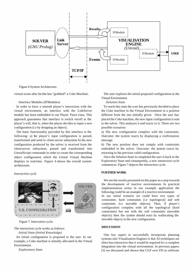
virtual scene after he/she has “grabbed” a Coke Machine.
-Interface Modules (IFModules) In order to have a smooth player’s interaction with the virtual environment, an interface with the LinkServer module has been embedded in our Player Pawn class. This approach guarantees that interface is switch on/off at the player’s will, that is, when the player decides to input a new configuration (i.e by dropping an object). The basic functionality provided by this interface is the following: a) the player’s input configuration is parsed, transformed and send to client-server subsystem b) the new configuration produced by the solver is received from the client-server subsystem, parsed and transformed into UnrealScript commands in order to create the corresponding object configuration which the Unreal Virtual Machine displays in real-time. Figure 6 shows the overall system architecture. Interaction cycle
The interaction cycle works as follows: -Initial State (Initial Knowledge)
An initial configuration is proposed to the user. In our example, a Coke machine is initially allocated in the Virtual Environment.
-Exploratory State
The user explores the initial proposed configuration in the Virtual Environment.
-Solution State To reach this state the u ser has previously decided to place the Coke machine in the Virtual Environment in a position different from the one initially given. Once the user has placed the Coke machine, the new input configuration is sent to the solver. This analyzes it and reacts to it. There are two possible scenarios: a) The new configuration complies with the constraints. Outcome: the system reacts by displaying a confirmation message. b) The new position does not comply with constraints embedded in the solver. Outcome: the system reacts by returning to the previous valid configuration. Once the Solution State is completed the user is back to the Exploratory State and consequently, a new interaction cycle commences. Figure 7 depicts the interaction cycle. FURTHER WORK We see the results presented on this paper as a step towards the development of reactive environments In practical implementation terms in our example application the following could be an example of a reactive environment: In our initial scenario we could have two types of constraints: hard constraints (i.e topological) and soft constraints (i.e movable objects). Thus, if player’s configuration complies with all the topological (hard constraints) but not with the soft constraints (movable objects) then the system should react by reallocating the movable objects in the new configuration. DISCUSSION One key aspect to successfully incorporate planning systems into Visualisation Engines is that AI techniques are often less interactive that it would be required for a complete integration into the virtual environment. In previous papers [3] we discussed and shown that CLP over FD as software
Figure 7. Intercation cycle.
SOLVER (GNU Prolog)
VISUALISATION ENGINE
(Unreal)
IFModule
IFModule
Results
ITModule
Link Server
USER
Events
TCP/IP
Figure 6 System Architecture.

technology it is fast enough to react in “real-time” to user’s input configuration. Furthermore, the results shown in table1 underpinned the idea that although constraint programming in itself is not a reactive technique it can be used to emulate reactivity because it can produce a solution quickly enough.
Table1. Solution times.
To find: First Solution(ms)
To find: All Solutions (ms)
User-time 0 [10-40] System-time 0 [0-10]
Cpu-time 0 [10-30] Real-time [0-2] [61-63]
Average time in milliseconds over 10 trials
Another key point in order to implement a real-time system is that the sampling rate of object manipulation in the virtual environment must be compatible with the result production granularity of the problem-solving algorithm. In our case, the implementation of a real-time reactive environment will depend not only on using the adequate technology to implement the constraint solver but also on the overall system architecture. Unfortunately, at this point in time, we do not have enough experimental data to back up this particular point. However, our empirical estimation is that the current implementation produces a satisfactory result in terms of the compatibility of the object manipulation in the virtual environment with the overall result production granularity.
CONCLUSIONS In this paper we have presented an interactive system in which the virtual environment acts as an interface to the interactive planning system. Because the nature of the tasks to be solved takes place in a 3 dimensional space, Visualisation Engines are suitable tools to serve as an interface to the planning and/or problem solving mechanisms. We have shown that the inclusion of an AI layer adds a problem-solving component to the Virtual Environment. This could also be seen as having a VE where objects have associated behaviours. ACKNOWLEDGEMENTS Many thanks to Mr Steve James Mead. for his technical assistance regarding C programming and system architecture. Many thanks to Mr H. Robert Berry, Jr for his technical assistance regarding UnrealScript.
REFERENCES [1] De Leon, Victor. (1999), VRND:NOTRE-DAME CATHEDRAL: A Globally Accessible Multi-User Real-Time Virtual Reconstruction, the 5th International Conference on Virtual System and MultiMedia 1999 (VSMM’99):Next Generation Virtual Reality “Milestones for a New Virtual Milennium”.Dundee, Scotland, UK, 1-3 September, 1999. [2] Young, Micheal. (2001), An Overview of the Mimesis Architecture: Integrating Intelligent Narrative Control into an Existing Gaming Environment. In The Working Notes of the AAAI Spring Symposium on Artificial Intelligence and Interactive Entertainment, Stanford, CA, March 2001. [3] Calderon, C and Cavazza, M. (2001), Intelligent Virtual Environments to Interactively Solve Spatial Configuration Tasks. Proceedings of the Seventh International Conference on Virtual System and Multimedia. Berkeley, USA, 25-27 Oct 2001

© SCS
Co-ordination of Multi-agent Path Planning usingthe Synchronous Near-Admissibility A* (SNA*) Algorithm
M.Shafie Abd LatiffIan Palmer Marc Cavazza
Electronic Imaging and Media Communication School of Computing and MathematicsUniversity of Bradford University of Teesside
Bradford BD7 1DP Middlesbrough, TS1 3BAUnited Kingdom United Kingdom
E-mail: [email protected] Email : [email protected] : [email protected]
KEYWORDSMulti-agent co-ordination, path planning, games theory
ABSTRACT
This paper discusses a solution to generate multiple pathsusing a single algorithm. The paths will disperse amongdifferent available roués and reconvene back at the samedestination. The solution is unique in terms of co-ordinationamong agents. Co-ordinated path planning for multi-agentsis based on collective behaviour. Admissibility, as a mainproperty of the A* algorithm, provides the basis toincorporate a collective behaviour in path planning. Weintroduce a new extension of A* called Synchronous Near-Admissible A* or SNA* that produces alternative paths thatdepart from the shortest path solution.
INTRODUCTION
Co-ordination of agents not only refers to interactionbetween agents where the goal of each agent’s action is toinduce change in the other agents (Pinhanes, 1999) but italso includes the sharing of information to work together asa group of agents. For example, in crowd simulation andthe movement of groups of artificial animals, informationabout separation distance is important to ensure that agentswill not collide with other agents. Most research into multi-agent movement focuses on how to move the crowd togetherwithout inter-agent collisions and avoiding obstacles. Thecrowd is intended to move from the same location to thesame destination. If there are several alternative paths or anumber of obstacles providing several paths to thedestination, human nature is to choose a different pathrather than the same congested path. This is especiallyevident for crowds in emergency conditions.There are many real-world applications in which thisproblem arises, as can be illustrated by a practical example.In many modern computer games, the player’s avatar isoften confronted with several Non-Player Characters(NPCs). A measure of how “intelligent” these NPCs are isoften how well they co-ordinate their attacks on the player,including the path planning phase. In particular, it is easyfor the human player to confront opponents lined in a row,all following the same path towards his avatar. A betterapproach consists of using the player's position as a goal,
while approaching him from different directions.(AbdLatiff, 2000).
The design of virtual buildings or dealing with the problemof space layout planning (Medjdoub and Yannou, 2001) isincomplete, generally only fulfilling the dimensional andtopological constraints. The approval of building design alsoincludes the safety of the people occupied inside thebuilding. The location of emergency exits is vital and theseshould be arranged in such locations so that alternativepaths are provided and the people could vacate the buildingin the quickest possible time. The important aspect ofsecurity in building design has also been expressed in(Atlas, 1989).
CURRENT WORK
There are requirements in many applications to co-ordinatethe movement of a population of artificial actors. Forexample, in crowd simulation (Thalmann et. al., 2000),battlefield planning (Brock et. al., 1992), flocking behaviour(Reynolds, 1987) etc. Thalmann et. al. (2000) haveemphasised the concept of ‘Level of Autonomy’ and haveimplemented this concept in crowd behaviour. In this thelevel of co-ordination among the agents is classified intothree levels. On the first level, ‘guided crowd’ behaviour isdefined explicitly by the user. Schweiss (1999) uses a rule-based behaviour system to control them. Programmedcrowds are a second level where the behaviour isprogrammed in a scripting language. On the third levelautonomous crowds are specified by rules or other complexmethods. Farenc et. al. (2000) present a crowd managementmethod as an architecture for simulating crowds.
Brock et. al. (1992) employ the concept of a group leader inco-ordination and control of multiple autonomous vehiclesfor soldiers in a training simulation. A flocking algorithm isidentified among the early solutions in co-ordinating themovement of a group of animated characters. This wasintroduced by Reynolds in 1987 to simulate the movementof birds in a park. It is described as ‘boid’ procedures byParker (1999) and has been referred to by many researchersin their animation of multi-agents movement simulation.For instance (Bedau, 1992), (Noser, 1996), (Tu, 1996),(Brogan, 1997), etc.

© SCS
Algorithms that simply co-ordinate agents around a groupleader without actually sharing a common goal are facedwith a certain number of limitations. For instance, flockingalgorithms are vulnerable to local phenomena in the virtualworld: if one actor splits from the group it might not be ableto reconvene on the basis of the flocking algorithm only,especially if the terrain contains obstacles. Morespecifically it is difficult with flocking algorithms to usedevise strategies for multiple path planning that enable co-ordinated agents to follow different routes to the samedestination (AbdLatiff and Cavazza, 2000). Separate pathsare created for each agent using linear interpolation asimplemented in crowd behaviour and do not actually involvea proper path planning process. The movement is based onguided crowd behaviour from one interest point (IP) toanother IP and collision detection with obstacles is includedin a separate module for each agent. Schooling behaviouralso does not include path planning and the actions arecontrolled by a separate behaviour routine, for instanceavoiding static-obstacles, avoiding fishes, leaving the group,schooling etc.
RESEARCH PROBLEM
There are two aspects to the problem of co-ordination ofgroups of actors: to search the minimal path from source todestination and to co-ordinate the group of actors whichshare the same destination or goal. Most of the research onmulti-agents movement focuses on how to move the crowdtogether, without collisions between each other and avoidingobstacles. Most of the solutions to path movement formulti-agents are not based on a path planning algorithmsand there is no co-ordination between agents in pathgeneration.
Most of the research on path planning or shortest pathalgorithms is exclusively meant for an individual agent or asingle animated character. Every single character in avirtual environment has to find its own path in order tomove from one location to another.
To find the path for a group of actors originating from thesame place towards the same destination results in all actorsfollowing the same path. This is shown in Figure 1 wherethree actors find their own paths using a normal A*algorithm, directing from the left middle room to the rightroom. There are a few obstacles for them to avoid. Theresult shows that every actor generates more or less thesame path to the destination.
METHODOLOGY
Bandi & Cavazza (1999) explained that the path planningalgorithm must satisfy some optimality criteria. Theseoptimality criteria include not only the shortest distance butalso include application-dependent data that relate to theVirtual Environment semantic. An example of application-dependent data is that the path taken should approach acertain object.
Figure 1: Three agents follow one after another usingnormal A*
We introduce collective behaviour as application-dependentknowledge incorporated in a secondary heuristic of the A*algorithm. One of the collective behaviours is maximumdispersion. With this behaviour, every agent will takedifferent path from the same start location to the samedestination, if such a path exists.
One major property of the A* algorithm is admissibility. Inother words A* will be guaranteed to find an optimalsolution if the path exists (Nilsson, 1980)( Pearl,1995)(Luger, 1993). The optimal solution in this case is theshortest distance between the starting point and thedestination.
Barr and Feigenbaum (1981) have suggested relaxing theadmissibility condition, thus trading optimality of thesolution for computation speed. In addition to the OPENlist of expanded nodes, Pearl (1995) has defined a FOCALlist as:
where n' is a node in the OPEN list and f(n') is its cost. InA* the node with the lowest cost is selected for the nextexpansion. In A*ε algorithm, however, the criterion isaltered. All the nodes with cost less than or equal to (1 + ε)times the minimum cost in OPEN are considered. This setof nodes is termed FOCAL. A*ε has been introduced as atrade-of between admissibility/optimality and computationalefficiency (Bandi and Cavazza, 1999).
The property of admissibility is used to enhance thecapabilities of A* algorithm to serve this purpose. Everyagent will generate his own path with a different size ofFOCAL. This generation is implemented synchronously.Epsilon-admissibility is only guaranteed when the size ofFOCAL is small. Practically, the bigger the size of FOCALthe longer the path that exceeds the optimal path. This willgive a measure of how much the algorithm departs fromadmissibility. To reflect the fact that this implementationmight depart from admissibility, we will use the term near-admissible rather than ε-admissible. Hence we called thisalgorithm Synchronous Near-admissible A*, or SNA*.
})'(min)1()(:{'
nfnfnFOCALOPENn ∈
+≤= ε

© SCS
Primary and secondary heuristic
In A*, the best node from OPEN list is selected as the nextnode to be expanded. The evaluation function f (n) = g (n) +h (n) is the main function used to determine the order ofOPEN list.
Generally, Euclidean distance or Manhattan distance is usedas the main geometrical heuristic function, h (n). This iscalled the primary heuristic and is concerned with thedistance between the current node and the destination node.The path generated using only the primary heuristic willresolve the shortest path between start and final node. Thispath is not concerned with the properties of the environmentor any other constraints such as dynamic configuration asdescribed by Bandi and Cavazza (1999).
As there are requirements to incorporate application-relatedknowledge or application-dependent data into pathplanning, a secondary heuristic is introduced. We are usingthis secondary heuristic to incorporate the behaviour ofmulti-agents and this behaviour is called the collectivebehaviour. For the second heuristic, the expanded node is nolonger the best node in OPEN list, but a node from FOCALlist will be used instead. The best or selected nodes inFOCAL are induced with the application-dependentknowledge or collective behaviour.
While these heuristics can have a geometrical translation(e.g. in term of heading vector) they also dependdynamically on the shape of the path planned for the agent.Using a secondary heuristic, an alternative to theaggregation of multiple heuristics as described in Pearl(1985) can also be seen. It has however the advantage ofmaintaining a hierarchy between the primary heuristic andthe secondary heuristic. This is especially relevant in pathplanning, where the primary heuristic is distance based(AbdLatiff & Cavazza, 2000).
Synchronous Near-admissible A* (SNA*)
The algorithm of SNA* is given by the pseudocode below:procedure SNA_star;begin
get_BEHAVIOUR(focal_A, focal_B, focal_C)call A_star(xa, xb, xc)get_DIRECTION_for_Agent1(s1, d0)get_DIRECTION_for_Agent2(s2, d0)get_DIRECTION_for_Agent3(s3, d0)
endend_of_procedure;
get_BEHAVIOUR() is the main function used to set thecollective behaviour between agents. Maximum dispersionis a collective behaviour defined as :xn = max(max_dist(x1 , x2 ), max_dist(x1 , x3 ),..,max_dist(x1 , xm ))
where xn is the next expansion node, for m agents. Figure 2shows the result for three agents taking different routes to
the same destination using SNA* algorithm with maximumdispersion behaviour.
Figure 2. The result of using SNA* algorithm for maximumdispersion behaviour for three agents
RESULT
There are four criteria that control the delineation of pathsgenerated in SNA*, i.e. obstacle density, obstacledistribution, the constrained environment and the FOCALsize. A high density of obstacles will cause the alternativepaths to a destination to be difficult to find, whereas a lowdensity of obstacles will not generate any alternative paths.The Virtual Environment that we have used is limited to anopen environment where the obstacles are individuallylocated. In this condition the alternative paths areguaranteed to exist and the implementation of SNA*algorithm is assured.
The position of obstacles is another factor that determinesthe layout of paths, especially the first obstacle encounteredby the agents. Early obstacles will make the path generateddisjoint and early dispersion will normally determine thepattern of the remaining path. At least one obstacle has tobe located in such a position so that any two agents will splitfrom each other. This is shown in Figure 3, where A, B, Cand D are obstacles to be avoided.
In a constrained environment, the possibility of agentsdispersing at an early stage will effect the dispersion ofremaining path. It appears that agents starting from a moreopen environment have more opportunity for earlydispersion and subsequently more dispersion in the rest ofthe path generated. This is shown in Figure 4 where A is ina room and B is at the door.
All the limitations for the maximum dispersion due to thedensity, disposition and the closed environment, can beimproved with the size of the FOCAL set. The ability todisperse is more when there are more options to select in thenext expansion. So with the increase of FOCAL size eitherthe ability to disperse is increased or the dispersion patternbecomes greater. Moreover the percentage should be limitedto maintain the property of admissibility. With this propertythe alternative paths are semantically logical for the agent tofollow. Although a higher percentage does not significantlyeffect the processing speed, the path generated will be to farfrom optimal.

© SCS
Figure 4: Open environment has more opportunity for early dispersion
Figure 5 shows the effect of increasing FOCAL size on theprevious experiment. In Figure 5(i), the previous experimentis as shown in Figure 3 with 20% of FOCAL size and thenincreased to 30%. Agent_A and Agent_C have departed8.8% and 14.3% from its admissibility respectively.Agent_B is assumed to take the shortest path to destination.Figure 5(ii) shows the effect of increasing FOCAL size from20% (from Figure 4) to 50%. Admissibility comparison istaken from 0%, 30%, 40% and 50% of FOCAL size. Thefigure shows that the dispersion for multi-agents paths inthe constrained environment can be improved by increasingthe FOCAL size.
CONCLUSION AND FURTHER WORK
This paper discusses the co-ordination of path planning formulti-agents using the Synchronous Near-admissible A*(SNA*) algorithm. SNA* uses maximum dispersion as thecollective behaviour for the co-ordination of multi-agents inpath planning. This differs from existing solutions likeflocking algorithms, crowd simulation and school
behaviour. SNA* provides a path planning solution as wellas co-ordination among agents. The path generated usingSNA* has direct influence with the admissibility property.The density of obstacles in certain environments willprovide alternative paths that do not differ from theoptimum path from the start to the destination. Howeverwith a higher percentage of FOCAL size, the path generatedis able to depart from the admissibility property and pathdispersion becomes high. It should be noted that the numberof alternative paths does not have to match the number ofagents. Splitting a large group of agents into three smallergroups taking different routes can be sufficient for manyapplications.
There is certainly an upper bound on the number ofalternative paths that can be found in a given environment.This would depend on the obstacle density and layout aswell as the size set of the FOCAL list. However, as thenumber of alternative paths increases, some might departtoo much from optimality (AbdLatiff & Cavazza, 2000).
A
B
A
A
Figure 3: The early obstacle would act as a “splitters”
A
BC
A
BCD

© SCS
Figure 5: i. Increasing 30% from 20% (Figure 3)ii. Increasing 50% from 20% (Figure 4).
REFERENCES
Abd Latiff, M.S. and Cavazza, M., 2000. Synchronous PathPlanning for Multi-Agent Co-ordination. Proceedings of theVSMM 2000 Conference. Gifu, Japan.
Atlas, R. 1989. Building Design Can Provide Defensible Space.Access Control, September. [Online]. Available from:http://www.cpted-security.com/builddes.html. [accessed July 6,2001].
Bandi, S. and Cavazza, M., 1999. Integrating World Semanticsinto Path Planning Heuristics for Virtual Agents. Proceedingsof VA'99. Salford, UK.
Barr, A. and Feigenbaum, E.A., 1981. The Handbook of ArtificialIntelligence, vol. 1. William Kaufmann.
Bedau, M.A, 1992. Philosophical aspects of artificial life. InToward a Practice of Autonomous Systems: Proceedings of theFirst European Conference on Artificial Life, pages 494--503,Paris, France, 1992
Brock, D.L., Montana, D.J. & Ceranowicz, A.Z., 1992.Coordination and Control of Multiple Autonomous Verhicles.Proceedings of the IEEE Conference on Robotic andAutomation. Nice, France.
Brogan, D.C., Metoyer, R.A., and Hodgins, J.K. 1997.Dynamically simulated characters in virtual environments.SIGGRAPH'97 Visual Proc.. pp. 216.
Farenc, N., Musse, S.R., Schweiss, E., Kallmann, M., Aune, O.,Boulic, R. and Thalmann, D., 2000. A Paradigm forControlling Virtual Humans in Urban EnvironmentSimulations. Applied Artificial Intelligence. 14, 1, pp. 93-124.
Luger, G.F. & Stubblefield, W.A., 1993. Artificial Inteligence –Structures and strategies for complex problem solving, TheBenjamin/Cumming Publishers.
Medjdoub, B. and Yannou , B., 2001. Separating topology andgeometry in space planning. Computer-Aided Design. Vol.32.No.1. pp 39-61.
Nilsson, N.J., 1980. Principles of Artificial Intelligence. TiogaPublishing Company.
Noser, H., Pandzic, I.S., Capin, T.K., Magnenat-Thalmann, N., &Thalmann, D. 1996. Playing Games through the Virtual LifeNetwork. ALIFE V, Oral Presentations, May 16-18, Nara,Japan, 114-121
Parker, C. (1999). Boids Pseudocode. [Online] Available fromhttp://www.cse.unsw.edu.au/~conradp/boids/pseudocode.html[Accessed on September 15, 2000]
Pearl, J., 1985. Heuristics. Intelligent Search Strategies forComputer Problem Solving. Addison-Wesley.
Pinhanez, C.S., 1999. Representation and Recognition of Action inInteractive Spaces. PhD Thesis. MIT
Reynolds, C.W., 1987. Flocks, Herds, and Schools: A DistributedBehavioral Model. Computer Graphics, 21(4), July 1987, pp.25-34.
Reynolds, C.W., 1999. Steering Behaviors for AutonomousCharacters. In Conference Proceedings of the 1999 GameDevelopers Conference, Miller Freeman Game Group, SanFrancisco, California, pp 763-782.
Schweiss, E. , Musse, S.R., Garat. F., Thalmann, D., 1999, AnArchitecture to Guide Crowds Using a Rule-Based BehaviourSystem, Proc. Agents 99.
Thalmann, D., Musse, S.R, Kallmann, M., 2000. From IndividualHuman Agents to Crowds. , INFORMATIK/INFORMATIQUE, No1, 2000
Tu, X., 1996. Artificial Animatl for Computer Animation:Biomechanic, Locomotion, Perception and Behaviour. PhD.Thesis. University of Toronto.
Admissibility Comparison
38
40
42
44
46
48
50
Agent_A Agent_B Agent_C
Agents
Pat
h L
eng
th
30%
20%
A
B
Admissibility Comparison
0
10
20
30
40
50
60
70
agent_A 44.87 45.69 54.02 57.79
agent_B 44.28 45.92 45.92 45.1
agent_C 44.28 44.28 44.28 58.97
0% 30% 40% 50%
i
ii

A NEW COMPUTATIONAL APPROACH TO THE GAME OF GO
JULIAN CHURCHILL, RICHARD CANT, DAVID AL-DABASS
Department of Computing and Mathematics
The Nottingham Trent University Nottingham NG1 4BU.
Email: richard.cant/[email protected]
KEYWORDS Computer Go, Neural Networks, Alpha beta search algorithms. ABSTRACT This paper investigates the application of neural network techniques to the creation of a program that can play the game of Go with some degree of success. The combination of soft AI, such as neural networks, and hard AI methods, such as alpha-beta pruned minimax game tree searching, is attempted to assess the usefulness of blending these two different types of artificial intelligence and to investigate how the methods can be combined successfully. INTRODUCTION Go is an oriental game that is very popular in China, Japan and Korea in particular, but which has a very large following all around the world [Chikun 97]. It is a relatively simple game, the complexity of which emerges as you become familiar with the ideas presented. A comparison with Chess is often made [Burmeister et al 95], as these are both board-based games of zero-chance. The rules are simpler in Go, however the board is larger and due to the unrestrictive nature the rules tend to, there are many more moves available for the Go player to consider. The game is played on a board, which has a grid of 19x19 intersections. Two players, black and white, take turns to place a single stone on any unoccupied intersection, with the aim of surrounding as much territory as possible. A player can pass at any turn instead of placing a stone. Capturing the opponent’s stones is also used to increase a player’s score but is usually a secondary concern compared to securing territory. A stone is captured when the last of its liberties is removed. A liberty is an empty intersection directly next to the stone. Liberties are shared amongst connected stones. Diagonals are ignored when looking at connectivity between points in Go. With this in mind suicide is not allowed unless it is to capture some opponent’s stones in which case the suiciding stone remains uncaptured and is left on the board. The end of the game is usually reached by mutual agreement between the players, when they both pass consecutively. The remaining stones on the board are considered as to whether they would survive further or not. If they are decided to be effectively dead then those points count for the opposing player. The territory is then totalled up and the winner declared.
CURRENT RESEARCH Neural Networks: To implement a neural network on a computer a model of neurological activity as described above is used. This usually takes the form of two or more layers of connection weight values. These are changed during training using some specific mathematical rules until the network outputs the correct values for the input pattern. A function for calculating the output of a neuron given a set of input values also needs to be specified. This function is referred to as the activation function, since it determines whether a neuron ‘activates’, that is whether it generates an output signal or not and also determines the strength of the signal based on a set of parameters. This is frequently a simple summing function of the weights multiplied by the input signal along the associated weight. Figure 1 shows a small but typical multilayer network of the form 3-2-3, 3 input neurons, 2 hidden neurons, and 3 output neurons. Note weights of connections only apply between neurons, so the intial values being fed into the input layer do not have to multiplied by a connection weight. The same applies for the output neurons final output of values. Also note that each neuron is connected to every other neuron in adjoining layers. This is not always done in neural networks, but shall be so for the networks developed in this project.
Figure 1 - Small Multilayer Neural Network
A particularly interesting and relevant aspect of neural network techniques is that the neural net developed will usually learn general trends in the relationships between input and output patterns, often these are things that people may not consciously notice themselves. This means the net will frequently be able to handle input that it has not been trained on and will hopefully give useful output. For new classes of input the net may have to

be trained further, but at least this shows that neural nets are flexible, can adapt to changing circumstances and learn from new experience even when installed in its application environment. State Of The Art: The computer Go programming community is relatively small compared to computer Chess but interest in the topic is building now that computer chess has reached such a high level of success, the AI community are looking for a new holy grail. The central hub of this community can be found at the computer Go mailing list [Computer Go Mailing List 01], where many of the best Go programmers gather to thrash out new ideas, protocols and discuss recent tournaments. Many Faces Of Go: Many Faces Of Go uses many traditional or hard AI techniques the most important of which are alpha-beta search, pattern matching and rule based expert systems. The main principle is to supply the program with as much knowledge, about how to play Go and what makes a good move, as possible. The alpha-beta search algorithm is used in conjunction with a complex evaluation function to investigate moves where necessary. NeuroGo: One program that has been developed using neural network techniques is called NeuroGo [Enzenberger 96]. It achieved some amount of success against Many Faces Of Go set to a medium level. Many Faces is currently ranked one of the best in the world. The training target was determined by the Temporal Difference learning algorithm [Schraudolph et al. 94], which has been used with great success in a backgammon neural network program called TD-Gammon [Tesauro 94]. NeuroGo is really a crossover program, which does lean heavily towards soft AI techniques of machine learning, but also incorporates expert knowledge, which must ultimately come from human experience. A NEW APPROACH The use of a NN for selecting possible moves should be fast and also allows the opportunity to expand the NNs knowledge in an automated fashion. This is part of the strength of NNs, even when the NN is actually in use it is still possible to teach it where it went wrong and show it how to correct it’s behaviour by supplying it with the correct stimuli/reaction combination. Combination Of Hard And Soft AI Techniques: By attempting to use neural networks with game tree search this project is bringing together hard and soft AI techniques and trying to meld them in a useful and productive fashion. The main purpose behind this is to take the best features of each component and combine them to produce something that performs better than either of the two components separately. In the case of game tree search the advantage of using it comes from its ability to look ahead into the probable results of playing a particular move. The disadvantage is that it can be very resource intensive and inefficient. For example without additional help a standard game tree search may spend as much time looking at what may be obviously bad moves to us, as it does looking at what may be obviously good moves. It has no knowledge, no sense of what makes a good or bad move. Application To Standard Game Tree Search: The terminal nodes in a game tree are assigned a score based upon some
static analysis of the board position at that node and the scores from all the terminal nodes are filtered up the tree toward the root node. Using a technique known as Minimax [Owsnicki-Klewe 99], the best move, the one that maximises the players score can be found, however there are still many problems with this approach. For instance the terminal node board scoring method must be fairly accurate else the minimax values will be irrelevant, and for many games the computational power required to generate a game tree large enough to produce a conclusive result is enormous. For example a game of chess could have around 40
Figure 2 - A Partial Game Tree for Tic-Tac-Toe moves and at each turn there maybe 10 legal moves available giving 1040 nodes. For Go it is much more complex due to the 19x19 board and very few restrictions on moves. With around 220 moves per game and an average of about 180 different moves to play each turn it has been estimated that the size of this particular search space is around 10170 [Allis et al. 91]. So an exhaustive search is completely out of the question, even a relatively shallow game tree search, 6 ply, could easily be beyond the resources of the host computer. SOFTWARE/HARDWARE DEVELOPMENT System Specification: A generic neural network program was developed to create and train neural nets. The generic application was expanded and applied to Go, in such a way as to be able to create and train a neural network to suggest plausible moves, using the current board position as input for the network. A user interface was provided for both the neural network module and the Go playing part of the overall system. A graphical interface is useful for displaying board positions and for showing what moves the system maybe considering. Board Representation: A few definitions first: a string is a connected line of stones (north, south east, west only, no diagonals), a liberty is an empty point next to the string and can be thought of as breathing space for that particular string. According to the rules if a string has no liberties all the stones in the string are captured and removed from the board. The board is represented by a special ‘Board’ object that contains a two dimensional array, one value for each point on the board; 0 for empty, 1 for white and 2 for black. An array of ‘GoString’ objects is also stored that represent each string of stones currently on the board containing details such as which points belong to it, the colour of the string and the number of liberties the string has. This information is updated incrementally; everytime a stone is added or removed from the board. Other arrays are present to represent special markers that may be of use to show the neural networks responses at various points.

Graphical User Interface: A simple but functional GUI must be a part of this project since Go is a visual game and it would be very difficult to judge the performance of the neural network. The GUI would ideally allow a human to play a game of Go against the program thus enabling those people with some knowledge of the game to test it’s weaknesses and strengths. Also the user should be able to view the program playing against another program and to observe the neural networks responses during a game or whilst playing through an expert game so that the success of the program can be evaluated. As can be seen from the screenshot below the interface provides menus to access all of the available functions of the program. A toolbar is present with for greyed out buttons. These currently allow the user to step forward or backwards through moves in an SGF game, to indicate a pass move during a game of Go and to abort the current action by using the round button at the end. A log window is provided to output text messages to the user. From this image the board can also be seen, with coordinate system along the edges. When necessary the user can select points on the board, for instance during a game to specify a move. Design Issues: The initial architecture prposed was a 3-layer network consisting of 25 neurons for the input layer, 10 for the hidden layer and 1 for the output layer. The 25 neurons of the input layer would map directly onto a 5 by 5 section of a Go board. The idea was to train a network so that all the legal moves possible in a particular board position could be fed into the network one at a time, incorporating a 5 by 5 area of board around the potential move and that the neural net would output a plausibility value for the given move. The move with the highest plausibility would then be chosen, or better still, several of the highest plausible moves would be taken and fed into an alpha-beta minimax search to investigate the moves impact on the future of the game. The back propagation algorithm [Callan 99] for training chosen, mostly because of it’s general applicability to a wide range of problems and also it would be simple to implement and use. Training data was acquired as a collection of professional tournament games in SGF format from the Internet [Van Der Steen 01]. A training database generator then dissected these files into input/output pairs that could be fed directly into the neural network training algorithm. For each move the board position was analysed to produce several input/output training pairs. For every legal move in the board position an input matrix was generated that represented an n-by-n area centred on the move. It was determined whether the move was played up to 6 moves in the future and if so an output value was associated with it that started at 1.0 for the move occurring next turn, down to 0.2 for it occurring 6 moves in the future. If the move did not occur within 6 moves it was relegated to a set of unlikely moves and an output of 0 was connected to it. At the end 6 unlikely moves were randomly chosen and stored in the database with the 6 likely moves to balance the networks training. Figure 4 shows the game walkthrough test in progress, which allows the user to play through a game of Go that has been stored in SGF format. The program itself makes suggestions and comparisons are made between the program and the actual moves made. This test is most useful is professional quality
SGF games are used. The green circle shows the most recent move, the blue circles highlight the programs top ten suggested moves and each point on the board has a small coloured square. This indicates the plausibility score given to a move at that point in the current situation by the neural network. The redder the square the lower the score and the high end goes to blue. Lots of log information is also outputted in the window on the right, showing the actual scores associated with the best and the worst suggested moves. Also the rank of the actual move is outputted, in this case being 52nd out of 314 legal moves. IMPLEMENTATION Smart Game Format files can be read and interpreted allowing training databases to be compiled from SGF files. However SGF files cannot be saved and only the main line of play can be read, not any saved alternative lines of play. Many testing functions have been written to maintain consistency throughout development of the program and to allow progress to be measured. The code to create and maintain GoString information has been written and stores which stones belong to each string, what
Figure 3 - NeuralGo GUI
Figure 4 - Game walkthrough in progress
colour the string is and how many liberties the string has. This greatly increases the speed when detecting and removing captured groups and could provide useful information for additional tactically oriented modules. A graphic board display
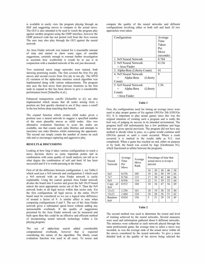
is available to easily view the program playing through an SGF and suggesting moves to compare to the actual move. The GUI is also intended to be used to watch the program play against another program using the GMP interface, however the GMP protocol code has not ported well from the Java version The user may also play through the GUI against the neural network. An Area Finder network was trained for a reasonable amount of time and started to show some signs of sensible suggestions, certainly enough to warrant further investigation to ascertain how worthwhile it would be to use it in conjunction with a standard network of the sort just discussed. Two restricted move range networks were trained, both showing promising results. The first covered the first five ply moves and second covers from five ply to ten ply. The MTD (f) variation of the alpha-beta minimax search algorithm was implemented along with various enhancements. The program also uses the best move from previous iterations as the first node to expand as this has been shown to give a considerable performance boost [Schaeffer et al.]. Enhanced transposition cutoffs [Schaeffer et al.] are also implemented which means that all nodes arising from a position are first quickly checked to see if they cause a cutoff in the tree before deep searching that branch. The expand function which creates child nodes given a position uses a neural network to suggest a specified number of the most plausible moves as child nodes. Also two alternative evaluation functions to score the nodes are available, one that counts each sides liberties and attempts to maximise one sides liberties whilst minimising the opponents. The second one simply counts the number of stones on each side and so encourages capturing and aggressive play. RESULTS & DISCUSSIONS Looking at how long it takes various configurations to reach a move decision shows us some important points and in combination with some quality of result analysis can tell us to what degree the combination of soft and hard AI has been successful and if it is worth pursuing in the future. First of all the difference between configuration 1, see Table-2 which used just a 9x9 network and configuration 2 which used a 9x9 network with an Area Finder network is easily explainable. Using the coarser grained Area Finder network divides the board into 9 sectors and given the full 19x19 board selects the most appropriate sector out of the 9. Then the 9x9 network looks at all legal moves within that sector only. For the first configuration all legal moves in the entire 19x19 board must be considered so we see a logical time difference of around a factor of 9. A similar affect is seen when comparing configurations 4 and 5. The use of the Area Finder network gives a substantial speed boost without adding any unreasonable overheads. If the quality of suggestions presented by the Area Finder network can be measured and built upon then this could be an effective and efficient method of incorporating neural network technology within a Go playing program. The use of alpha-beta search added considerable computational overheads, however that is expected considering the nature of the algorithm. The liberty count evaluation function was used in all cases. To assess and
compare the quality of the neural networks and different configurations involving either or both soft and hard AI two approaches were taken.
Configuration Average Time Taken Per Move (seconds)
1. 9x9 Neural Network 0.784 2. 9x9 Neural Network + Area Finder
0.136
3. Alpha-Beta (Liberty Count) 41 4. 9x9 Neural Network + Alpha-Beta (Liberty Count)
9
5. 9x9 Neural Network + Alpha-Beta (Liberty Count) +Area Finder
1.56
Table 1
First, the configurations used for timing an average move were used to play proper games of Go against GNUGo 26b [GNUGo 01]. It is important to play actual games since this was the original intention of creating such a program and is really the best way of judging its success in its intended environment. The program itself still unfortunately has a few problems and bugs that were given special provision. The program did not have any method to decide when to pass, so a game would continue until GNUGo passed or until a crash occurred. Where a crash occurred it is marked in the results table as N.C. (not completed). When a game has reached an end, either on purpose or by fault, the board was scored by Jago [Grothmann 01], which functioned as arbiter between the programs.
Percentage of time that actual move is in top n percent
Neural Network
Average Time Per Move
Average Move Rank
10 20 30 40 50 5x5 0.576 105 19 36 50 59 65 7x7 0.736 115 17 30 42 60 66 9x9 0.936 114 12 31 39 53 64 Copy of 9x9
0.912 104 18 34 47 56 69
11x11 1.256 161 10 19 30 35 44 13x13 1.664 124 18 28 36 51 62 Random 9x9
0.824 156 5 21 29 35 45
Table 2
The second method was used to determine the extent and level of training achieved by the neural networks. Several measures were used and information gathered about 6 different networks. The statistics were collected as each network played through the same professional game; the average time to select a move was recorded, as was the average rank of the actual move within all the moves considered by the neural networks. To give a more detailed look at the quality of the moves being selected the
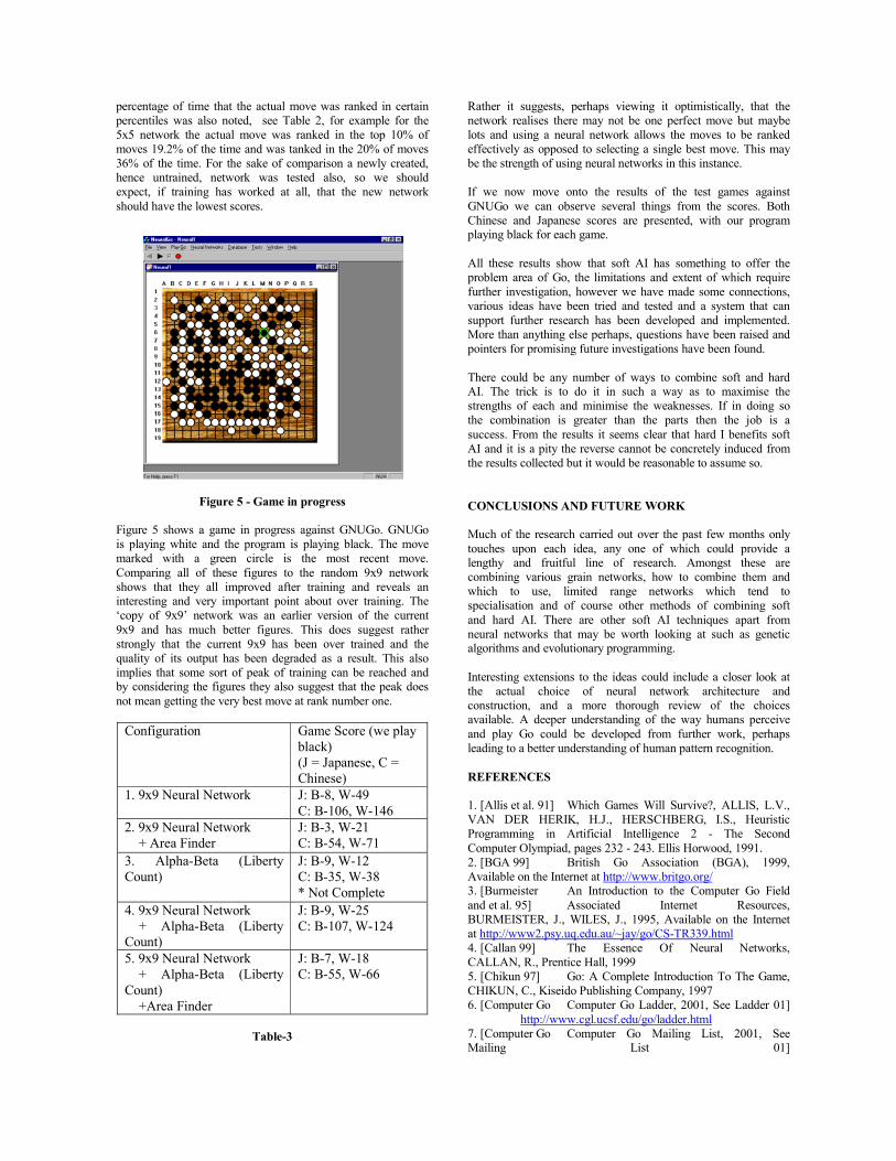
percentage of time that the actual move was ranked in certain percentiles was also noted, see Table 2, for example for the 5x5 network the actual move was ranked in the top 10% of moves 19.2% of the time and was tanked in the 20% of moves 36% of the time. For the sake of comparison a newly created, hence untrained, network was tested also, so we should expect, if training has worked at all, that the new network should have the lowest scores.
Figure 5 - Game in progress
Figure 5 shows a game in progress against GNUGo. GNUGo is playing white and the program is playing black. The move marked with a green circle is the most recent move. Comparing all of these figures to the random 9x9 network shows that they all improved after training and reveals an interesting and very important point about over training. The ‘copy of 9x9’ network was an earlier version of the current 9x9 and has much better figures. This does suggest rather strongly that the current 9x9 has been over trained and the quality of its output has been degraded as a result. This also implies that some sort of peak of training can be reached and by considering the figures they also suggest that the peak does not mean getting the very best move at rank number one.
Configuration Game Score (we play black) (J = Japanese, C = Chinese)
1. 9x9 Neural Network J: B-8, W-49 C: B-106, W-146
2. 9x9 Neural Network + Area Finder
J: B-3, W-21 C: B-54, W-71
3. Alpha-Beta (Liberty Count)
J: B-9, W-12 C: B-35, W-38 * Not Complete
4. 9x9 Neural Network + Alpha-Beta (Liberty Count)
J: B-9, W-25 C: B-107, W-124
5. 9x9 Neural Network + Alpha-Beta (Liberty Count) +Area Finder
J: B-7, W-18 C: B-55, W-66
Table-3
Rather it suggests, perhaps viewing it optimistically, that the network realises there may not be one perfect move but maybe lots and using a neural network allows the moves to be ranked effectively as opposed to selecting a single best move. This may be the strength of using neural networks in this instance. If we now move onto the results of the test games against GNUGo we can observe several things from the scores. Both Chinese and Japanese scores are presented, with our program playing black for each game. All these results show that soft AI has something to offer the problem area of Go, the limitations and extent of which require further investigation, however we have made some connections, various ideas have been tried and tested and a system that can support further research has been developed and implemented. More than anything else perhaps, questions have been raised and pointers for promising future investigations have been found. There could be any number of ways to combine soft and hard AI. The trick is to do it in such a way as to maximise the strengths of each and minimise the weaknesses. If in doing so the combination is greater than the parts then the job is a success. From the results it seems clear that hard I benefits soft AI and it is a pity the reverse cannot be concretely induced from the results collected but it would be reasonable to assume so. CONCLUSIONS AND FUTURE WORK Much of the research carried out over the past few months only touches upon each idea, any one of which could provide a lengthy and fruitful line of research. Amongst these are combining various grain networks, how to combine them and which to use, limited range networks which tend to specialisation and of course other methods of combining soft and hard AI. There are other soft AI techniques apart from neural networks that may be worth looking at such as genetic algorithms and evolutionary programming. Interesting extensions to the ideas could include a closer look at the actual choice of neural network architecture and construction, and a more thorough review of the choices available. A deeper understanding of the way humans perceive and play Go could be developed from further work, perhaps leading to a better understanding of human pattern recognition. REFERENCES 1. [Allis et al. 91] Which Games Will Survive?, ALLIS, L.V., VAN DER HERIK, H.J., HERSCHBERG, I.S., Heuristic Programming in Artificial Intelligence 2 - The Second Computer Olympiad, pages 232 - 243. Ellis Horwood, 1991. 2. [BGA 99] British Go Association (BGA), 1999, Available on the Internet at http://www.britgo.org/ 3. [Burmeister An Introduction to the Computer Go Field and et al. 95] Associated Internet Resources, BURMEISTER, J., WILES, J., 1995, Available on the Internet at http://www2.psy.uq.edu.au/~jay/go/CS-TR339.html 4. [Callan 99] The Essence Of Neural Networks, CALLAN, R., Prentice Hall, 1999 5. [Chikun 97] Go: A Complete Introduction To The Game, CHIKUN, C., Kiseido Publishing Company, 1997 6. [Computer Go Computer Go Ladder, 2001, See Ladder 01] http://www.cgl.ucsf.edu/go/ladder.html 7. [Computer Go Computer Go Mailing List, 2001, See Mailing List 01]

http://www.cs.uoregon.edu/~richard/computer-go/index.html 8. [Enzenberger 96] The Integration of a Priori of Knowledge into a Go Playing Neural Network, ENZENBERGER, M., 1996, Available on the Internet at http://www.uni-muenchen.de 9. [Fotland 93] Knowledge Representation In The Many Faces Of Go, FOTLAND, D., 1993. 10. [GNUGo 01] GNU Go latest version can be found at http://freedom.sarang.net/software/gnugo/beta.html 11. [Grothmann 01] Jago, GROTHMANN, R., Available on the Internet at http://mathsrv.ku-eichstaett.de/MGF/homes/grothmann 12. [GTP 01] Go Text Protocol information can be found 2/3 down the page at http://freedom.sarang.net/software/gnugo/beta.html 13. [Hollosi 99] SGF User Guide, HOLLOSI, A., 1999, Available on the Internet at http://www.red-bean.com/sgf/user_guide/index.html 14. [Huima 99] A Group-Theoretic Hash Function, HUIMA, A., 1999, Available on the Internet at http://people.ssh.fi/huima/compgo/zobrist/index.html 15. [Muller 97] Playing It Safe: Recognizing Secure Territories in Computer Go by Using Static Rules and Search, MULLER, M., 1997, Available on the Internet at http://www.cs.ualberta.ca/~mmueller/publications.html 16. [Plaat 97] MTD(f), A Minimax Algorithm Faster than NegaScout, PLAAT, A., 1997, Available on the Internet at http://www.cs.vu.nl/~aske/mtdf.html 17. [Owsnicki-Klewe Search Algorithms, OWSNICKI-KLEWE, B., 1999] Available on the Internet at http://www.informatik.fh-hamburg.de/~owsnicki/search.html 18. [Tesauro 94] TD-Gammon, a self-teaching backgammon program, achieves master level play, TESAURO, G., Neural Computation, Vol. 6, No.2, 1994. 19. [Schaeffer et al.] New Advances In Alpha-Beta Searching, SCHAEFFER, J., PLAAT, A. 20. [Schraudolph Temporal Difference Learning of Position Evaluation in the et al. 94] Game of Go, SCHRAUDOLPH, N., DAYAN, P., SEJNOWSKI, T., Neural Information Processing Systems 6, Morgan Kaufmann, 1994, Available on the Internet at ftp://bsdserver.ucsf.edu/Go/comp/td-go.ps.Z 21. [Van Der Steen 01] Go Game Gallery, VAN DER STEEN, J., 2001, Available on the Internet at http://www.cwi.nl/~jansteen/go/index.html. 22. [Wilcox et al.] The Standard Go Modem Protocol – Revision 1.0, WILCOX, B., Available on the Internet at http://www.britgo.org/

A LEARNING ARCHITECTURE FOR THE GAME OF GO
A.B. Meijer and H. KoppelaarDelft University of Technology. Faculty ITS. Section Mediamatics.
Mekelweg 4, P.O.Box 356, 2600 AJ, Delft, The Netherlands.{a.b.meijer, h.koppelaar}@its.tudelft.nl
ABSTRACT
In this paper, a three-component architecture of alearning environment for Go is sketched, which can beapplied to any two-player, deterministic, full informa-tion, partizan, combinatorial game. The architecturecalled HUGO has natural and human-like reasoningcomponents. Its most abstract component deals withthe selection of subgames of Go. The second componentis concerned with initiative. The notion of gote nosente (a move that loses initiative but creates newlines of play that will hold initiative) is formalized. Inthe third component, game values are computed witha new kind of ®-¯ algorithm based on fuzzy, partialordering. Our approach leaves some valuable controlparameters and o¤ers ways to apply further machinelearning techniques.
KEYWORDS Combinatorial Games, Uncertainty,Initiative, Fuzzy Partial Ordering, Game of Go
INTRODUCTION
Two-player, deterministic, complete, information, parti-zan, combinatorial games form a family of games whichhas received a lot of attention from the AI communityover the last decennia. Altough much progress has beenmade, resulting in some well-playing chess programs forexample, almost all modern programs for these gameslack (well-formalized) human-like behavior in generaland the notion of initiative in particular. This need notresult in a poor performance, rather it depends on thedomain. We hypothesize that the notion of initiativeis mandatory for writing a good program for the mostnotorious of combinatorial games: Go. It’s folklore isfull of terminology concerning initiative and profession-als play the game at an abstract level of initiative, farbeyond considering just move sequences, as in the com-monly used ®-¯ algorithm (or any other minimax-based
search algorithm). Furthermore, the ®-¯ algorithm isbased on some absolute scalar-valued evaluation func-tion, whereas humans can be said to use an orderingfunction to compare two board situations directly withone another. For example, a professional Go playercould reason that one position is slightly better thananother when his walls look a bit thicker (=stronger).
Figure 1: An endgame situation in 9£9 Go.
This paper is organized as follows. In the next two sec-tions we will give a short introduction to the game ofGo and combinatorial game theory. Then, we formalizethese two human-like concepts that arise in the learn-ing environment of Go and embed them in an architec-ture called HUGO. The following three sections furtherexplain the three components of HUGO. The …rst com-ponent deals with the selection of subgames of Go, thesecond with initiative and the third with the compu-tation of game values. We end with some concludingremarks and future work. Go terminology is written in
small caps.
THE GAME OF GO
Go is an ancient game, originated in China about 4000years ago. It has in‡uenced oriental warfare, whichshows o¤ in the shape of the Great Walls of China and,very recently in Afghanistan, in the preference for semi-…xed frontlines between the opposing factions, whichonly change hands if there is a broad momentum infavour of one of the sides. Compare this with Go, wheretwo players have to embark territory by alternately plac-ing a stone on a grid, gradually building strongholds andeventually walls that completely surround one’s terri-tory. Strongholds will only be given up if the opponenthas created enough in‡uence (Go term for momentum)to walk over it.The rules of Go are very simple in principle (but in …-nesse they can vary a lot over di¤erent rule sets like theChinese, Japanese or mathematical Go rules). The cap-turing rule is the most important, stating that a stringof stones gets captured if all of its neighboring intersec-tions are occupied by enemy stones. This rule impliesthat the two x ’s in …gure 1 are suicide, which implies inturn that the white group that surrounds them cannotbe captured (Go terminology: the group lives). Thewhite group can only be captured if White would co-operate foolishly and plays on one of the x ’s himself.Black is then allowed to play the “temporary suicide”of the other x, because this would capture the entirewhite group and the suicide is resolved.The goal of the game is to make living groups that sur-round more territory than your opponent.If in the game of …gure 1 Black were to play, he wouldhave two good options. The …rst is to play at d, killingthe white group since it has become impossible forWhite to construct two suicide points (eyes) like thetwo x ’s. The second option is to save his own group inthe bottom right by playing at a. This would result intwo black strings, each having one eye. The strings canalways be connected with White b, Black c or vice versa.The resulting group lives with two eyes. The best of thetwo is a, since there are more stones in this group.
COMBINATORIAL GAME THEORY
This section is a very short introduction to Combi-natorial Game Theory, loosely following (Cazenave,1996). It is a mathematical theory for games and num-bers, developed by J.H. Conway (Conway, 1976) andadapted to many games by Berlekamp, Conway and Guy(Berlekamp et alii, 1982).
De…nition 1 A combinatorial game G = fF jOg iscomposed of two sets F and O of combinatorial games.Every combinatorial game is constructed this way.
In games, F should be seen as the set of options (boardpositions) that player Friend can reach with one legalmove. O can be looked at as the options for playerOpponent. F can have two possible values, W (win forFriend) or L (loss for Friend, so win for Opponent). IfFriend has a legal move that ensures a win for the wholegame, then the value of F is W. This gives four possibleoutcomes for a combinatorial game: WW, WL, LL andLW (We will use both WW and WjW as abbreviatednotations for {WjW}). The left half of a game value isthe maximum result that Friend can obtain, the righthalf is Opponent’s best result.WW denotes a game that is won by Friend, irrespectiveof who moves …rst (both player can at best move thegame to W = win for Friend). A Go example is thewhite group in the bottom left of …gure 1, which livesunconditionally.WL is an unsettled game, it is won by the player whomoves …rst. An example is the life status of the whitegroup in the upper right corner. If White moves …rsthe can play at d, resulting in a living shape (its terri-tory contains two eyes, intersections that are suicide forBlack).LL is a lost game for Friend, so a sure win for Opponent,even if Friend moves …rst. Trying to kill the black groupin the upper left corner is a lost game for White (givencorrect counterplay from Black)LW is a somewhat strange equilibrium situation wherethe player who moves …rst will lose the game. An ex-ample of this situation is known as seki. The triangledstones in …gure 1 form a seki: either player who wantsto capture the opponent string of triangled stones andplays at one of the two shared intersections will imme-diately be captured himself.To evaluate a subgame, we de…ne
V alue(W ) = 1; V alue(L) = ¡1:
In order to evaluate the global position, each subgameis assigned a numerical importance. A (linear) combina-tion of the value of the subgames yields an indication ofthe balance of power. The precise nature of combinationis a task for component 1.Now it is possible to de…ne the value of a move:
V alue (move) = V alue (F ) ¡ V alue (O) :
V alue(move) is the value of the move that achieves stateF and thus prevents Opponent from achieving state O.The value of a seki needs special attention, since usu-ally there will be no play inside a seki (the value for sucha move is -2 times the numerical importance). Its valuedepends on the rules. In Chinese counting one countsone point for all the stones that live in a seki but nopoint for territory, which is natural since no player con-trols the in-between territory.Another commonly used term for game value is temper-ature, which corresponds to the size of the largest play.

As the game progresses, the temperature tends to drop.Local temperature corresponds to the size of the largestplay in a region of the board. Ambient temperature isthe temperature of the game besides the local region.In theory, the value of a game has only two values, W orL. However, it is often intractable to compute the pre-cise game value. Cazenave therefore extended Conway’stheory to uncertain outcomes (Cazenave 1996). He in-troduced a variable U, denoting an uncertain game valuewith range [-1, 1]. If halfway a game the position is con-sidered roughly equal for both players, then it makessense to assign this uncertain position the value 0.U can be seen as a control parameter along the risky-safe axis, since one is free to de…ne the value of U. Alow value for U would result in conservative play, a highvalue models a form of risky play.
THE HUGO ARCHITECTURE
As stated in the introduction, it is our aim to modelhuman concepts that exist in the folklore of Go. Wehave identi…ed three components that are inadmissablein our approach. The …rst component is to select rel-evant subgames and their numerical importances. Thesecond is an initiative engine and the third computesgame values. We have called the resulting architectureHUGO (human Go), see …gure 2.HUGO’s input is a board position and some constraints,for example a time or memory limit. This input goes tocomponent 1, which outputs a collection of games. Thisis the input of the initiative engine, which calls the thirdcomponent to calculate the value of every single game.Knowing all the game values, the initiative engine triesto …nd a move that both scores some points and holdsinitiative.
COMPONENT 1: CHOICE OF SUBGAMES
The task of this component is to select a collection ofwell-de…ned subgames (or simply: games) of Go whichform the basis for further computation. A good choiceof games should have a high discriminative ability: theplayer that wins most of the important games shouldalso win the whole game and vice versa. The problem ofsuch an approach is that the subgames are not indepen-dent and thus the value of the whole game is not simplythe sum of the value of the subgames (Berlekamp et alii1982). However, advanced human Go players constantlyuse a variety of games, such as life or death, connectionof stones, territory and more. They do this as a meansto obtain overview in a chaotic board situation and theresult is some sort of a mental model of the state ofthe game. For each separate game, they can quite eas-ily …nd the (sub-)optimal move. The di¢cult part isto take the interactions among games into considerationand to …nd the optimal move for the whole game. Play-
Board position, time constraint
move
Component 1: Selection of subgames
Ensure high discriminative abilities
Component 2:Initiative Engine
1. For all subgames:determine desiredwidth of game values
2. Select overall bestmove
Component 3:Compute Game Value
a-ß search based onfuzzy partial ordering
{G1, G2, … , GN}
Gn, width
Value(Gn)
Figure 2: The HUGO architecture
ing Go at this abstract level means …nding con‡ictinginteractions all the time and then resolving or exploitingthem.A good collection of games to start with are (1) lifeand death for strings of stones and (2) connection ofstrings (the fundamental importance of these games fol-lows from the importance of the capturing rule). Thesetwo families of games govern tactical play, but are alsoinadmissable in strategic play.One can think of many more games and there is indeed alot of work to be done, before this can all be automated.However, one could also leave this task to an expert. In-troducing more families of games would enhance moresophisticated play, but at the cost of a higher computa-tional e¤ort.One further sophistication is to de…ne connections be-tween groups (clusters of strings that are highly inter-connected) instead of strings of stones. A clusteringalgorithm would be valuable for this task.
COMPONENT 2: INITIATIVE ENGINE
Given a collection of well-de…ned subgames from com-ponent 1, the task of the initiative engine is to …nd themove that yields the most points, preferably while hold-

ing initiative. When one has the initiative, one dictatesthe course of the game and one can choose to accumulatesmall gains from di¤erent subgames.The …rst step of this component is to compute the valueof each game. A sophisticated game value should notonly reveal the player how will win a particular gamewith which move, but should also tell what are threat-ening moves in the game. A simple approach to meetthis criterium is to compute the game value for the twocases that each player once moves …rst and once movessecond (this is more or less common practice in the moresophisticated current Go programs). If one wishes tomodel threats, s/he must also compute game values fortwo cases where each player gets to play twice beforethe opponent may respond.Let us call the number of plays by one player before theopponent answers the width of a game value. One possi-ble outcome for a game value with width two is WLjLL.This is the situation that Friend can move to an un-settled situation (WL) which he can win if he gets thechance to play a second move (only when Opponent ig-nores the …rst move), whereas Opponent can move to awon game (LL) if he does answer. Cazenave already de-rived that this type of game has a threat for Friend only(Cazenave 1996). In fact, the general representation ofa one-sided threat is WUUU for Friend and UUUL forOpponent. WUUL is a two-sided threat.If Friend wishes to play kiku (play to hold initiative)he can choose to play a series of threatening moves. Al-though Opponent simply can answer all the threats andwin in all the threatened games, this line of play canbe advantageous to Friend because a move generallyplays in more than one game at the time (multipurposemoves). If a move is a threat in two games at the sametime, it will be di¢cult (if possible at all) for Opponentto …nd a move that resolves both threats at the sametime. The simplest line of follow up play is to answerthe most important threat, but then Friend can win theother game.Sometimes there is such a big move that one does notcare about holding initiative but just grabs the pointsassociated with the move (for example killing a largegroup). In general, this should be done when the localtemperature is hotter than the ambient temperature.Such moves usually end in gote (loss of initiative) andthe resulting game is cold (not much to gain left foreither side). In general, gote play lowers the local tem-perature, while sente play raises it.Ryo-sente (two-sided sente) arises when a move is atwo-sided threat. If it arises in important games it isusually played immediately.Despite losing initiative, gote moves can develop newinitiative. If a move is gote in one game but creates newsente moves in another game, then this move is calledgote no sente (gote with sente potential). For ex-ample, WLLLjLLLL is a lost game for Friend, but he canchange the game to a (lost) game where he does have a
threat (WLLL), whereas Opponent can move to a gamewhich he has won and leaves no threat (LLLL). So, anexample of a gote no sente move is one that is gotein one game and moves another game from WLLLjLLLLto WLLL. Gote no sente moves can only be foundif one considers the possible outcomes if a player movesthree times in a row before his opponent starts to answer(width = 3). None of the current Go programs describedin literature does this. Cazenave uses game values up towidth 2 (but gave a formalization for greater width).Computing up to width K is twice the cost of computingup to width K-1. Therefore, one has to know when to doso. This task should be dealt with by component 2. Onegood possibility is iteratively widening based on gamevalue feedback from component 3, since it is known from(Berlekamp et alii, 1982) that one best makes moves inhot (unsettled) games. So these are the games whosevalue one would like to know most precise.All the current commercial programs lack a well-de…nednotion of initiative and their advantage in playingstrength can be expected to shrink relative to programsbased on scienti…c research, which do implement Com-binatorial Game Theory.
COMPONENT 3: COMPUTING GAME VAL-UES
The task of this component is to compute the game-theoretic value of a particular game. Once determinedto what width an outcome has to be calculated, one ac-tually has to calculate the value of the game and themove(s) that accomplishes this value. In fact, in orderto do so, one has to calculate the value for all the movesand select the best one. However, at this point it hasn’tyet been determined in which game is to be played. Itis better not to remember just the best move but all(good) options, because this leaves the possibility opento detect multipurpose moves. Such a move might besuboptimal in all the games it plays in, but can be su-perior in the combined game compared to any of theoptimal moves in the separate games. Furthermore, re-membering all good options can o¤er a means to preventunnecessary recalculations. Imagine you would only re-member the best option (and also only the best reply)and your opponent plays in a later stadium a subopti-mal move in the nearby region, threatening the resultof your best move. You then would need to re-evaluatethis move, whereas you wouldn’t need to, had you re-membered opponent’s suboptimal moves too.So the task in this component is to calculate the value ofa game, given some width. An ®-¯ algorithm (or otherforms of minimax search) can be used to do this, but thisrequires some sort of scalar-valued evaluation functionto compare two board positions. This indirect compari-son has several drawbacks, including the horizon e¤ect.Quiescence search has been invented to circumvent this
problem, but does not solve all the problems. This andother disadvantages of using absolute evaluation func-tions are well described in (Müller 2000).Müller concludes that in many cases partial orderingis better than absolute evaluation. This makes sense,since it is more natural and even in ®-¯ search absoluteevaluation is used for partial ordering in the end.We hypothesize that ®-¯ search in its current form can-not handle the multidisciplinary and strategic nature ofGo.Müller’s alternative was a method that combines par-tial order evaluation with minimax search, called Par-tial Order Bounding. In this method one categorizes allthe possible states into a success set or a failure set.Minimax search is performed to determine which moveguarantees that any leaf node of this move’s subtree be-longs to the success set. Leaf nodes are evaluated justby checking whether or not it falls into the success set,so the minimax values are boolean.In contrast to this, our approach does not directly usea success set, rather we bring partial ordering right intothe ®-¯ algorithm itself, so we use no boolean-valuedevaluation function. To be more precise, we will usefuzzy partial ordering of vector states. Obviously, thisgeneralization is not possible without considering allconsequences of introducing fuzzyness and partial or-dering at the same time.In short, fuzzyness can be dealt with by putting statesthat are approximately equal into one cluster. If onewatches out that intra-cluster distances remain (far) big-ger than inter-cluster distances, it is possible to orderclusters just as if one were ordering single board situa-tions.The partial ordering function compares the game valueof two (clusters of) feature vectors a and b and outputsan ordering such as a  b (a is preferred over b), a ÂÂb (a is by far preferred over b) a ¼ b (about equal),a » b (a and b are incomparable), combinations ofthese like a % b (a is preferred over or approximatelyequal to b) and negations. Notice that incomparableis di¤erent from approximate equality. Two states thathave approximately the same value are incomparable ifone is far hotter (more unstable) than the other.A traditional ®-¯ algorithm (without speed enhance-ments) remembers during search just the values ® and¯. In comparison, our generalized algorithm has to re-mind a partially ordered tree of fuzzy clusters of alreadyevaluated options. We believe that the considerable ex-tra amount of work (…rm theory plus implementation)is worthwhile, since it o¤ers a natural (=human) lookat Go. For example, it enables an ordering between twomoves based on the achievements relative to some sharedparent state, which is really di¤erent (and probably eas-ier) than any scalar-valued board evaluation technique.The details of this approach will be discussed in a forth-coming paper, due to shortage of space here. One issuethat will be discussed in great detail and with math-
ematical rigour is omitted here, namely the fact thatgame values are looked at as scalars in the above dis-cussion, whereas they are more like an interval [O,F],where O is an underbound for the real value (the bestresult for Opponent) and F is an upperbound (Friendbest result). The real value is determined as soon asone of the two players chooses to play in that game. Ofcourse, the discussion of this section still holds for smallgame value intervals (cold games).
CONCLUSIONS AND FUTURE WORK
This paper sketched a human-like learning architecturefor the game of Go, called HUGO, but it uses no gamespeci…c knowledge, so it should be possible to apply itto any two-player, full information, deterministic, com-binatorial game. HUGO has three major components.The …rst component deals with the de…nition and choiceof subgames. The second component is concerned withinitiative. In the third component, game values are com-puted with a generalized ®-¯ algorithm based on fuzzy,partial ordering.The notion of gote no sente (a move that loses ini-tiative but creates new lines of play that will hold ini-tiative) is formalized for the …rst time.There are some points where one can apply further ma-chine learning techniques, for instance a clustering al-gorithm in the extended ®-¯ algorithm. Furthermore,each component has some valuable control parameters.The iterative widening in component 2 and possible iter-ative deepening in component 3 could further enhancereal-time behaviour. The value of uncertainty can beused to control the style of play along a safe-risky axis.Currently, work is carried out to mathematically for-malize and implement the ®-¯ algorithm based on fuzzypartial ordering, having combinatorial game values withuncertainty as output.
REFERENCES
Berlekamp, E.; J.H. Conway; and R.K. Guy. 1982. WinningWays (for your mathematical plays). Academic Press,New York.
Cazenave T. 1996. Systeme d’Apprentissage par Auto-Observation. Application au Jeu de Go. PhD thesis,Université Pierre et Marie Curie, Paris.
Conway J.H. 1976. On Numbers and Games. AcademicPress, New York.
Müller M. 2000. “Partial Order Bounding: A new Approachto Evaluation in Game Tree Search.” Technical Re-port of ETL, TR-00-10. To appear in a special issue onheuristic search of the Arti…cial Intelligence Journal.


GAMES PLATFORMS

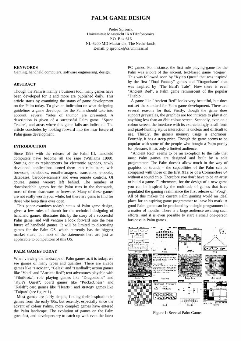
PALM GAME DESIGN
Pieter Spronck Universiteit Maastricht IKAT/Infonomics
P.O. Box 616 NL-6200 MD Maastricht, The Netherlands
E-mail: [email protected]
KEYWORDS Gaming, handheld computers, software engineering, design.
ABSTRACT
Though the Palm is mainly a business tool, many games have been developed for it and more are published daily. This article starts by examining the status of game development on the Palm today. To give an indication on what designing guidelines a game developer for the Palm should take into account, several "rules of thumb" are presented. A description is given of a successful Palm game, "Space Trader", and areas where this game fails are indicated. The article concludes by looking forward into the near future of Palm game development.
INTRODUCTION
Since 1998 with the release of the Palm III, handheld computers have become all the rage (Williams 1999). Starting out as replacements for electronic agendas, newly developed applications turned them into calculators, web browsers, notebooks, email-managers, translators, e-books, databases, barcode-scanners and even remote controls. Of course, games weren't left behind. The number of downloadable games for the Palm runs in the thousands, most of them shareware or freeware. Many of these games are not really worth your while, but there are gems to find for those who keep their eyes open. This paper examines today's status of Palm game design, gives a few rules of thumb for the technical designing of handheld games, illustrates this by the story of a successful Palm game, and will venture a look forward into the near future of handheld games. It will be limited to discussing games for the Palm OS, which currently has the biggest market share, but most of the statements here are just as applicable to competitors of this OS.
PALM GAMES TODAY
When viewing the landscape of Palm games as it is today, we see games of many types and qualities. There are arcade games like "PacMan", "Galax" and "Hardball"; action games like "Void" and "Ancient Red"; text adventures playable with "PilotFrotz"; role playing games like "Dragonbane" and "Kyle's Quest"; board games like "PocketChess" and "Kalah"; card games like "Hearts"; and strategy games like "Taipan" (see figure 1). Most games are fairly simple, finding their inspiration in games from the early '80s, but recently, especially since the advent of colour Palms, more complex games have entered the Palm landscape. The evolution of games on the Palm goes fast, and developers try to catch up with even the latest
PC games. For instance, the first role playing game for the Palm was a port of the ancient, text-based game "Rogue". This was followed soon by "Kyle's Quest" that was inspired by the first "Final Fantasy" games and "Dragonbane" that was inspired by "The Bard's Tale". Now there is even "Ancient Red", a Palm game reminiscent of the popular "Diablo". A game like "Ancient Red" looks very beautiful, but does not set the standard for Palm game development. There are several reasons for that. Firstly, though the game does support greyscales, the graphics are too intricate to play it on anything less than an 8bit colour screen. Secondly, even on a colour screen, the interface with its excruciatingly small fonts and pixel-hunting stylus interaction is unclear and difficult to use. Thirdly, the game's memory usage is enormous. Fourthly, it has a steep price. Though the game seems to be popular with some of the people who bought a Palm purely for pleasure, it has only a limited audience. "Ancient Red" seems to be an exception to the rule that most Palm games are designed and built by a sole programmer. The Palm doesn't allow much in the way of graphics or sounds – the capabilities of the Palm can be compared with those of the first XTs or of a Commodore 64 without a sound chip. Therefore you don't have to be an artist to build a game. Furthermore, for the design of a new game you can be inspired by the multitude of games that have populated the gaming realm since the first release of "Pong". All of this makes the current Palm gaming world an ideal place for an aspiring game programmer to leave his mark. A good Palm game can be produced by a single programmer in a matter of months. There is a large audience awaiting such efforts, and it is even possible to start a small one-person business in Palm games.
Figure 1: Several Palm Games
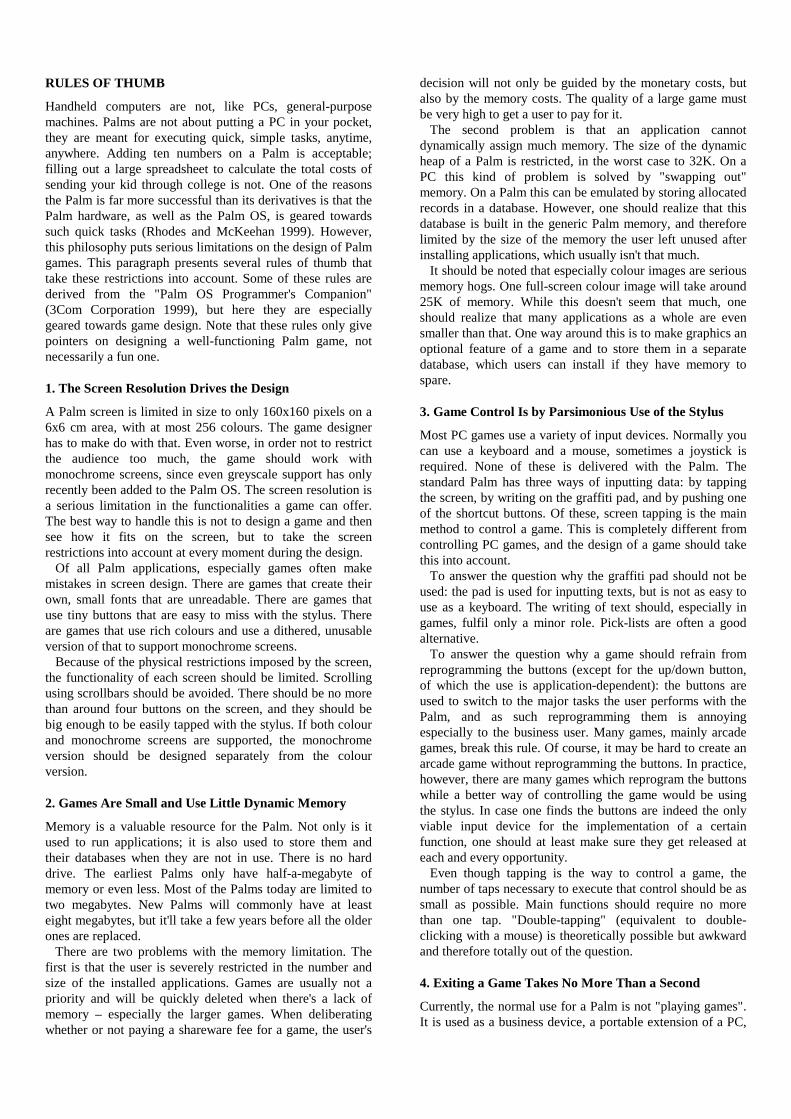
RULES OF THUMB
Handheld computers are not, like PCs, general-purpose machines. Palms are not about putting a PC in your pocket, they are meant for executing quick, simple tasks, anytime, anywhere. Adding ten numbers on a Palm is acceptable; filling out a large spreadsheet to calculate the total costs of sending your kid through college is not. One of the reasons the Palm is far more successful than its derivatives is that the Palm hardware, as well as the Palm OS, is geared towards such quick tasks (Rhodes and McKeehan 1999). However, this philosophy puts serious limitations on the design of Palm games. This paragraph presents several rules of thumb that take these restrictions into account. Some of these rules are derived from the "Palm OS Programmer's Companion" (3Com Corporation 1999), but here they are especially geared towards game design. Note that these rules only give pointers on designing a well-functioning Palm game, not necessarily a fun one.
1. The Screen Resolution Drives the Design
A Palm screen is limited in size to only 160x160 pixels on a 6x6 cm area, with at most 256 colours. The game designer has to make do with that. Even worse, in order not to restrict the audience too much, the game should work with monochrome screens, since even greyscale support has only recently been added to the Palm OS. The screen resolution is a serious limitation in the functionalities a game can offer. The best way to handle this is not to design a game and then see how it fits on the screen, but to take the screen restrictions into account at every moment during the design. Of all Palm applications, especially games often make mistakes in screen design. There are games that create their own, small fonts that are unreadable. There are games that use tiny buttons that are easy to miss with the stylus. There are games that use rich colours and use a dithered, unusable version of that to support monochrome screens. Because of the physical restrictions imposed by the screen, the functionality of each screen should be limited. Scrolling using scrollbars should be avoided. There should be no more than around four buttons on the screen, and they should be big enough to be easily tapped with the stylus. If both colour and monochrome screens are supported, the monochrome version should be designed separately from the colour version.
2. Games Are Small and Use Little Dynamic Memory
Memory is a valuable resource for the Palm. Not only is it used to run applications; it is also used to store them and their databases when they are not in use. There is no hard drive. The earliest Palms only have half-a-megabyte of memory or even less. Most of the Palms today are limited to two megabytes. New Palms will commonly have at least eight megabytes, but it'll take a few years before all the older ones are replaced. There are two problems with the memory limitation. The first is that the user is severely restricted in the number and size of the installed applications. Games are usually not a priority and will be quickly deleted when there's a lack of memory – especially the larger games. When deliberating whether or not paying a shareware fee for a game, the user's
decision will not only be guided by the monetary costs, but also by the memory costs. The quality of a large game must be very high to get a user to pay for it. The second problem is that an application cannot dynamically assign much memory. The size of the dynamic heap of a Palm is restricted, in the worst case to 32K. On a PC this kind of problem is solved by "swapping out" memory. On a Palm this can be emulated by storing allocated records in a database. However, one should realize that this database is built in the generic Palm memory, and therefore limited by the size of the memory the user left unused after installing applications, which usually isn't that much. It should be noted that especially colour images are serious memory hogs. One full-screen colour image will take around 25K of memory. While this doesn't seem that much, one should realize that many applications as a whole are even smaller than that. One way around this is to make graphics an optional feature of a game and to store them in a separate database, which users can install if they have memory to spare.
3. Game Control Is by Parsimonious Use of the Stylus
Most PC games use a variety of input devices. Normally you can use a keyboard and a mouse, sometimes a joystick is required. None of these is delivered with the Palm. The standard Palm has three ways of inputting data: by tapping the screen, by writing on the graffiti pad, and by pushing one of the shortcut buttons. Of these, screen tapping is the main method to control a game. This is completely different from controlling PC games, and the design of a game should take this into account. To answer the question why the graffiti pad should not be used: the pad is used for inputting texts, but is not as easy to use as a keyboard. The writing of text should, especially in games, fulfil only a minor role. Pick-lists are often a good alternative. To answer the question why a game should refrain from reprogramming the buttons (except for the up/down button, of which the use is application-dependent): the buttons are used to switch to the major tasks the user performs with the Palm, and as such reprogramming them is annoying especially to the business user. Many games, mainly arcade games, break this rule. Of course, it may be hard to create an arcade game without reprogramming the buttons. In practice, however, there are many games which reprogram the buttons while a better way of controlling the game would be using the stylus. In case one finds the buttons are indeed the only viable input device for the implementation of a certain function, one should at least make sure they get released at each and every opportunity. Even though tapping is the way to control a game, the number of taps necessary to execute that control should be as small as possible. Main functions should require no more than one tap. "Double-tapping" (equivalent to double-clicking with a mouse) is theoretically possible but awkward and therefore totally out of the question.
4. Exiting a Game Takes No More Than a Second
Currently, the normal use for a Palm is not "playing games". It is used as a business device, a portable extension of a PC,
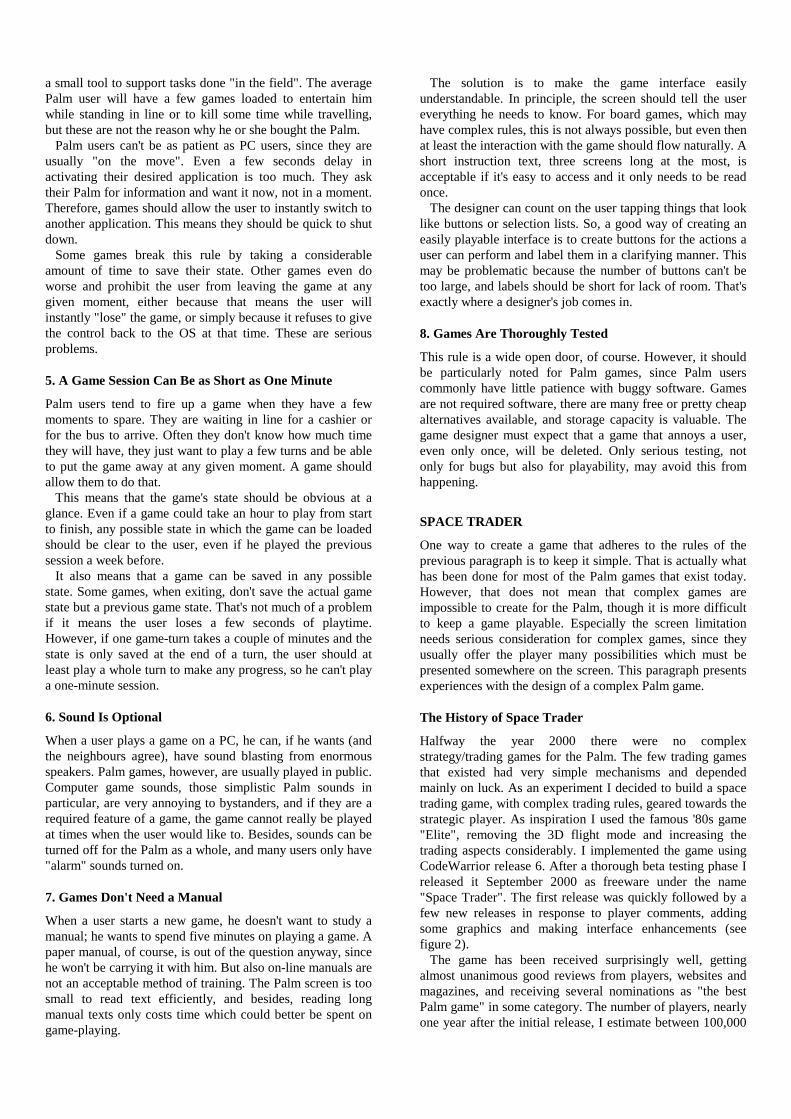
a small tool to support tasks done "in the field". The average Palm user will have a few games loaded to entertain him while standing in line or to kill some time while travelling, but these are not the reason why he or she bought the Palm. Palm users can't be as patient as PC users, since they are usually "on the move". Even a few seconds delay in activating their desired application is too much. They ask their Palm for information and want it now, not in a moment. Therefore, games should allow the user to instantly switch to another application. This means they should be quick to shut down. Some games break this rule by taking a considerable amount of time to save their state. Other games even do worse and prohibit the user from leaving the game at any given moment, either because that means the user will instantly "lose" the game, or simply because it refuses to give the control back to the OS at that time. These are serious problems.
5. A Game Session Can Be as Short as One Minute
Palm users tend to fire up a game when they have a few moments to spare. They are waiting in line for a cashier or for the bus to arrive. Often they don't know how much time they will have, they just want to play a few turns and be able to put the game away at any given moment. A game should allow them to do that. This means that the game's state should be obvious at a glance. Even if a game could take an hour to play from start to finish, any possible state in which the game can be loaded should be clear to the user, even if he played the previous session a week before. It also means that a game can be saved in any possible state. Some games, when exiting, don't save the actual game state but a previous game state. That's not much of a problem if it means the user loses a few seconds of playtime. However, if one game-turn takes a couple of minutes and the state is only saved at the end of a turn, the user should at least play a whole turn to make any progress, so he can't play a one-minute session.
6. Sound Is Optional
When a user plays a game on a PC, he can, if he wants (and the neighbours agree), have sound blasting from enormous speakers. Palm games, however, are usually played in public. Computer game sounds, those simplistic Palm sounds in particular, are very annoying to bystanders, and if they are a required feature of a game, the game cannot really be played at times when the user would like to. Besides, sounds can be turned off for the Palm as a whole, and many users only have "alarm" sounds turned on.
7. Games Don't Need a Manual
When a user starts a new game, he doesn't want to study a manual; he wants to spend five minutes on playing a game. A paper manual, of course, is out of the question anyway, since he won't be carrying it with him. But also on-line manuals are not an acceptable method of training. The Palm screen is too small to read text efficiently, and besides, reading long manual texts only costs time which could better be spent on game-playing.
The solution is to make the game interface easily understandable. In principle, the screen should tell the user everything he needs to know. For board games, which may have complex rules, this is not always possible, but even then at least the interaction with the game should flow naturally. A short instruction text, three screens long at the most, is acceptable if it's easy to access and it only needs to be read once. The designer can count on the user tapping things that look like buttons or selection lists. So, a good way of creating an easily playable interface is to create buttons for the actions a user can perform and label them in a clarifying manner. This may be problematic because the number of buttons can't be too large, and labels should be short for lack of room. That's exactly where a designer's job comes in.
8. Games Are Thoroughly Tested
This rule is a wide open door, of course. However, it should be particularly noted for Palm games, since Palm users commonly have little patience with buggy software. Games are not required software, there are many free or pretty cheap alternatives available, and storage capacity is valuable. The game designer must expect that a game that annoys a user, even only once, will be deleted. Only serious testing, not only for bugs but also for playability, may avoid this from happening.
SPACE TRADER
One way to create a game that adheres to the rules of the previous paragraph is to keep it simple. That is actually what has been done for most of the Palm games that exist today. However, that does not mean that complex games are impossible to create for the Palm, though it is more difficult to keep a game playable. Especially the screen limitation needs serious consideration for complex games, since they usually offer the player many possibilities which must be presented somewhere on the screen. This paragraph presents experiences with the design of a complex Palm game.
The History of Space Trader
Halfway the year 2000 there were no complex strategy/trading games for the Palm. The few trading games that existed had very simple mechanisms and depended mainly on luck. As an experiment I decided to build a space trading game, with complex trading rules, geared towards the strategic player. As inspiration I used the famous '80s game "Elite", removing the 3D flight mode and increasing the trading aspects considerably. I implemented the game using CodeWarrior release 6. After a thorough beta testing phase I released it September 2000 as freeware under the name "Space Trader". The first release was quickly followed by a few new releases in response to player comments, adding some graphics and making interface enhancements (see figure 2). The game has been received surprisingly well, getting almost unanimous good reviews from players, websites and magazines, and receiving several nominations as "the best Palm game" in some category. The number of players, nearly one year after the initial release, I estimate between 100,000
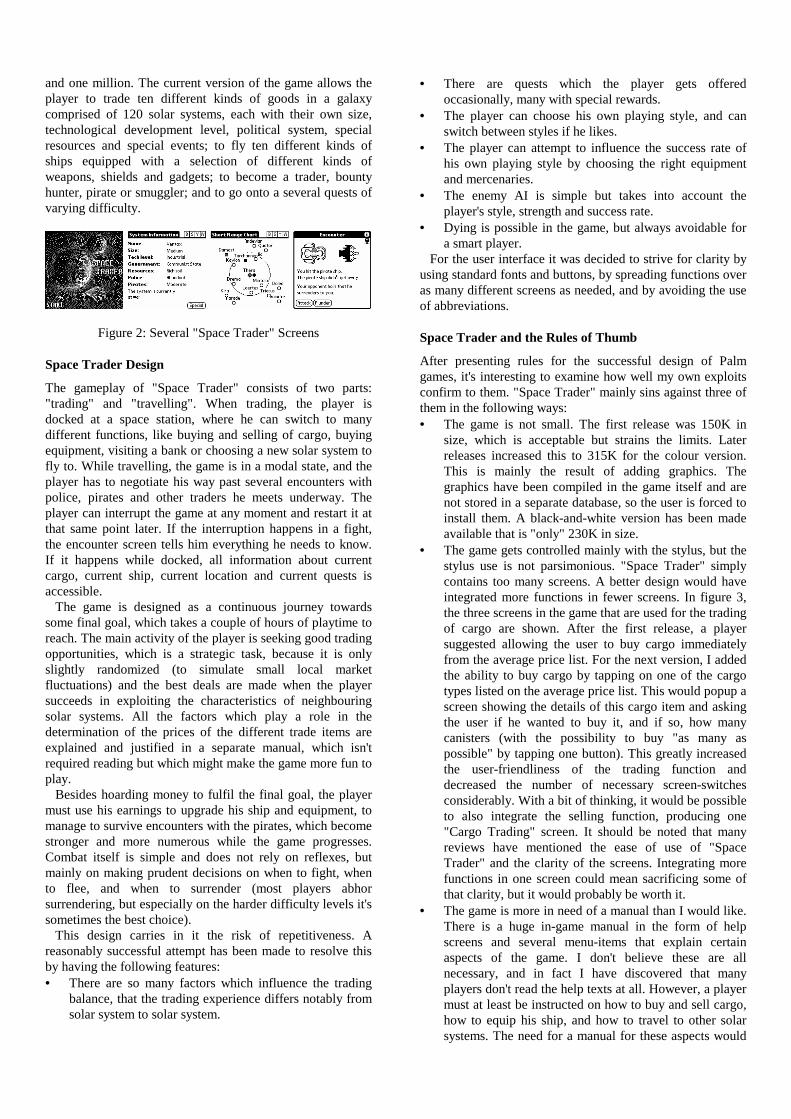
and one million. The current version of the game allows the player to trade ten different kinds of goods in a galaxy comprised of 120 solar systems, each with their own size, technological development level, political system, special resources and special events; to fly ten different kinds of ships equipped with a selection of different kinds of weapons, shields and gadgets; to become a trader, bounty hunter, pirate or smuggler; and to go onto a several quests of varying difficulty.
Figure 2: Several "Space Trader" Screens
Space Trader Design
The gameplay of "Space Trader" consists of two parts: "trading" and "travelling". When trading, the player is docked at a space station, where he can switch to many different functions, like buying and selling of cargo, buying equipment, visiting a bank or choosing a new solar system to fly to. While travelling, the game is in a modal state, and the player has to negotiate his way past several encounters with police, pirates and other traders he meets underway. The player can interrupt the game at any moment and restart it at that same point later. If the interruption happens in a fight, the encounter screen tells him everything he needs to know. If it happens while docked, all information about current cargo, current ship, current location and current quests is accessible. The game is designed as a continuous journey towards some final goal, which takes a couple of hours of playtime to reach. The main activity of the player is seeking good trading opportunities, which is a strategic task, because it is only slightly randomized (to simulate small local market fluctuations) and the best deals are made when the player succeeds in exploiting the characteristics of neighbouring solar systems. All the factors which play a role in the determination of the prices of the different trade items are explained and justified in a separate manual, which isn't required reading but which might make the game more fun to play. Besides hoarding money to fulfil the final goal, the player must use his earnings to upgrade his ship and equipment, to manage to survive encounters with the pirates, which become stronger and more numerous while the game progresses. Combat itself is simple and does not rely on reflexes, but mainly on making prudent decisions on when to fight, when to flee, and when to surrender (most players abhor surrendering, but especially on the harder difficulty levels it's sometimes the best choice). This design carries in it the risk of repetitiveness. A reasonably successful attempt has been made to resolve this by having the following features: • There are so many factors which influence the trading
balance, that the trading experience differs notably from solar system to solar system.
• There are quests which the player gets offered occasionally, many with special rewards.
• The player can choose his own playing style, and can switch between styles if he likes.
• The player can attempt to influence the success rate of his own playing style by choosing the right equipment and mercenaries.
• The enemy AI is simple but takes into account the player's style, strength and success rate.
• Dying is possible in the game, but always avoidable for a smart player.
For the user interface it was decided to strive for clarity by using standard fonts and buttons, by spreading functions over as many different screens as needed, and by avoiding the use of abbreviations.
Space Trader and the Rules of Thumb
After presenting rules for the successful design of Palm games, it's interesting to examine how well my own exploits confirm to them. "Space Trader" mainly sins against three of them in the following ways: • The game is not small. The first release was 150K in
size, which is acceptable but strains the limits. Later releases increased this to 315K for the colour version. This is mainly the result of adding graphics. The graphics have been compiled in the game itself and are not stored in a separate database, so the user is forced to install them. A black-and-white version has been made available that is "only" 230K in size.
• The game gets controlled mainly with the stylus, but the stylus use is not parsimonious. "Space Trader" simply contains too many screens. A better design would have integrated more functions in fewer screens. In figure 3, the three screens in the game that are used for the trading of cargo are shown. After the first release, a player suggested allowing the user to buy cargo immediately from the average price list. For the next version, I added the ability to buy cargo by tapping on one of the cargo types listed on the average price list. This would popup a screen showing the details of this cargo item and asking the user if he wanted to buy it, and if so, how many canisters (with the possibility to buy "as many as possible" by tapping one button). This greatly increased the user-friendliness of the trading function and decreased the number of necessary screen-switches considerably. With a bit of thinking, it would be possible to also integrate the selling function, producing one "Cargo Trading" screen. It should be noted that many reviews have mentioned the ease of use of "Space Trader" and the clarity of the screens. Integrating more functions in one screen could mean sacrificing some of that clarity, but it would probably be worth it.
• The game is more in need of a manual than I would like. There is a huge in-game manual in the form of help screens and several menu-items that explain certain aspects of the game. I don't believe these are all necessary, and in fact I have discovered that many players don't read the help texts at all. However, a player must at least be instructed on how to buy and sell cargo, how to equip his ship, and how to travel to other solar systems. The need for a manual for these aspects would
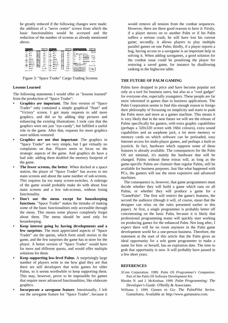
be greatly reduced if the following changes were made: the addition of a "nerve centre" screen from which the basic functionalities would be accessed and the reduction of the number of screens as already mentioned above.
Figure 3: "Space Trader" Cargo Trading Screens
Lessons Learned
The following statements I would offer as "lessons learned" from the production of "Space Trader": • Graphics are important. The first version of "Space
Trader" only contained a simple graphical "Start" and "Victory" screen. I got many requests to add more graphics, and did so by adding ship pictures and enhancing the existing illustrations. I took care that the graphics were not just "eye-candy", but fulfilled a useful role in the game. After that, requests for more graphics were seldom ventured.
• Graphics are not that important. The graphics in "Space Trader" are very simple, but I get virtually no complaints on that. Players seem to focus on the strategic aspects of the game. And graphics do have a bad side: adding them doubled the memory footprint of the game.
• The fewer screens, the better. When docked at a space station, the player of "Space Trader" has access to ten main screens and about the same number of sub-screens. This requires far too many screen-switches. A redesign of the game would probably make do with about four main screens and a few sub-screens, without losing functionality.
• Don't use the menu except for housekeeping functions. "Space Trader" makes the mistake of making some of the basic functionalities only accessible through the menu. This means some players completely forget about them. The menu should be used only for housekeeping.
• Keep interest going by having developments and a few surprises. The most appreciated aspects of "Space Trader" are the quests, which form small stories in the game, and the few surprises the game has in store for the player. A better version of "Space Trader" would have far more and different quests, and would offer multiple solutions for them.
• Keep supporting low-level Palms. A surprisingly large number of players write to me how glad they are that there are still developers that write games for older Palms, so it seems worthwhile to keep supporting them. This may, however, prove to be impossible for games that require more advanced functionalities, like elaborate graphics.
• Incorporate a savegame feature. Intentionally, I left out the savegame feature for "Space Trader", because it
would remove all tension from the combat sequences. However, there are three good reasons to have it: Firstly, if a player moves on to another Palm or if his Palm suffers a serious crash, he will have lost his current game; secondly, it allows players to play multiple parallel games on one Palm; thirdly, if a player reports a bug, having access to a savegame is an important help in solving it. When adding savegames, a good solution for the combat issue could be penalizing the player for restoring a saved game, for instance by disallowing ranking in the highscore table.
THE FUTURE OF PALM GAMING
Palms have dropped in price and have become popular not only as a tool for business users, but also as a "cool gadget" for everyone else, especially youngsters. These people are far more interested in games than in business applications. The Palm Corporation seems to find this enough reason to forego their philosophy of focussing on simplicity and starts to push the Palm more and more as a games machine. This means it is very likely that in the near future we will see the release of Palms specifically for gamers, with extra graphic capabilities (perhaps a 320x320 screen with 16bit colours), extra sound capabilities and an earphone jack, a lot more memory or memory cards on which software can be preloaded, easy Internet access for multi-player games, and perhaps a built-in joystick. In fact, hardware which supports some of these features is already available. The consequences for the Palm OS are minimal, it's mainly the hardware that will be changed. Palms without these extras will, as long as the game-specific Palms are clumsier than regular Palms, still be available for business purposes. Just like what happened with PCs, the gamers will use the most expensive and advanced machines. The consequence is, however, that game programmers must decide whether they will build a game which runs on all Palms, or whether they will produce a game for a "GamePalm". The first will restrict the game's features, the second the audience (though it will, of course, mean that the designer can relax on the rules presented earlier in this paper). At first, a single programmer is probably better off concentrating on the basic Palm, because it is likely that professional programming teams will quickly start working on producing games for the enhanced Palm. Not long after, I expect there will be no room anymore in the Palm game development world for a one-person business. Therefore, the statement at the start of this article that the Palm gives an ideal opportunity for a sole game programmer to make a name for him- or herself, has an expiration date. The time to grab that opportunity is now. It will probably have passed in a few short years.
REFERENCES 3Com Corporation. 1999. Palm OS Programmer's Companion.
Part of the Palm OS Software Development Kit. Rhodes N. and J. McKeehan. 1999. Palm Programming: The
Developer's Guide. O'Reilly & Associates. Williams J. 1999. Games to Go: The PalmPilot Series.
GamaSutra. Available at: http://www.gamasutra.com.

DISTRIBUTED AUDIO-VIDEO SHARING
BY COPY-AND-TRANSFER OPERATIONFOR NETWORK 3D GAMES
Hirotatsu Sakamoto Yoshihiro Okada Eisuke Itoh Masafumi YamashitaGraduate School of Information Science and Electrical Engineering, Kyushu University
6-10-1 Hakozaki, Higashi-ku, Fukuoka, 812-8581, JapanPhone: +81-92-642-3872, Fax: +81-92-583-7632
[email protected] [email protected] [email protected] [email protected]
KEYWORDS
Network 3D games, Audio-video communication,Copy-and-transfer, Component ware, Distributedvirtual environments
ABSTRACT
This paper treats distributed audio-video shar-ing mechanisms for the development of network 3Dgames. Especially the authors propose the conceptof the copy-and-transfer operation. This concept isthat making a copy of a visible, manually opera-ble software component and transferring it to an-other computer enable users to share it. If a fa-cility that manages audio or video data is realizedas such a component, even end-users can easily andrapidly build audio-video communication environ-ments through the copy-and-transfer operation. Thispaper explains realization mechanisms of the copy-and-transfer operation and describes its availabilityby showing network 3D game examples.
1 INTRODUCTION
Advances of computer hardware technologiesmake it possible to create 3D images in real-time,so that 3D graphics software has become in greatdemand. For this reason, we have been studying3D graphics software development systems and us-ing IntelligentBox [Okada and Tanaka 1995] as ourresearch system. IntelligentBox is a component ware,which provides various software components as visi-ble, manually operable 3D objects called boxes. In-telligentBox also provides a dynamic data linkagemechanism called slot-connection that enables usersto construct 3D graphics applications by combin-ing existing boxes through direct manipulations ona computer screen. Okada et al. described thatIntelligentBox is available for the development ofinteractive 3D games and also network 3D games
[Okada et al. 2000]. For network 3D games, face-to-face communication by audio/video media enablesplayers to feel their enemy’s emotion and it enhancesenjoy-ability during playing a game. Especially forgroup battle games, audio-video communication isnecessary to effectively and strategically play games.
Then this paper treates a distributed audio-videosharing mechanism. Especially we describe a newconcept of the copy-and-transfer operation. Thiscopy-and-transfer operation is similar to the copy-and-paste/cut-and-paste operations, which are stan-dard GUI operations based on using a mouse-device.With the copy-and-transfer operation, even end-userscome to easily and rapidly build audio-video com-munication environments. IntelligentBox provided avideo managing facility as a VideoBox. However thisversion of VideoBox was not available through net-work. So we improved it in order to support videocommunication via network [Sakamoto et al. 2001].We have also been developing boxes to manage au-dio media through network. Furthermore a par-ticular box called RoomBox exists for providing ashared 3D space [Okada and Tanaka 1998]. Usingthese boxes, i.e., RoomBox, VideoBox and audio man-aging boxes, which support audio-video communica-tion, only through copy-and-transfer operations, itwill be possible to build network 3D games. In thispaper, we clarify availability of this copy-and-transferoperation by discussing development costs and per-formances with showing possible, practical applica-tion examples.
Related works
Our research purpose is to establish software ar-chitecture that makes it easier to develop 3D graph-ics applications. Related works are 3D softoware de-velopment systems including DIVE [Hagsand 1998],MASSIVE [Greenhalgh and Benford 1995], MERL[Anderson et al. 1995][Barrus et al. 1996], dVS[Ghee 1995], MR Toolkit [Shaw et al. 1993]. DIVE

Copy
Transfer
Information sharing
: visible, manually operatable object
network
virtual environment A virtual environment B
Figure 1: The concept of copy-and-transfer.
is a virtual reality construction toolkit system. Ithas network communication facilities by audio andtext media. MASSIVE is a remote conference sys-tem based on sharing a 3D virtual space. It has atext-to-audio communication facility, but not a videocommunication facility. MERL is a development sys-tem for collaborative virtual environments. It allowsus to communicate by audio and text media. dVS isa commercial product as a virtual reality construc-tion toolkit. It allows us to develop distributed col-laborative applications, but does not provide audio-video communication facilities. MR Toolkit is a vir-tual reality construction toolkit system at a librarylevel. Although these are very powerful systems, it isnot easy to use their essential mechanisms when de-veloping distributed 3D graphics applications. Ourresearch system IntelligentBox provides various 3Dsoftware components represented as visible, manuallyoperable, and reusable objects. Furthermore the In-telligentBox system provides a dynamic data linkagemechanism. These features make it easier even forend-users to develop 3D graphics applications includ-ing network 3D games. This is the main differencebetween IntelligentBox and the others.
The remainder of this paper is organized as fol-lows: Section 2 describes the copy-and-transfer con-cept. Section 3 explains essential mechanisms ofIntelligentBox and RoomBox. In section 4, we ex-plain audio-video data sharing mechanisms. Section5 discusses development costs and performances withshowing possible, practical 3D game examples. Fi-nally, we conclude this paper in section 6.
2 COPY-AND-TRANSFER
Object-oriented programming becomes very com-mon because of its reusability of software componetsand its availability of bottom-up programming man-ner. However, conventional object-oriented program-
Figure 2: An MD structure of a box and its internalmessages.
Figure 3: Standard messages between boxes.
ming is not enough for end-users, who do not haveany programming knowledge, since it requests usersto write text-based programs. We think that softwarecomponents should be represented as visible, man-ually operable objects because such software com-ponents allow even end-users to develop softwareonly by combining them interactively on a computerscreen. Furthermore, for such visible, manually op-erable components, it is possible to execute the copy-and-transfer operation as shown in Figure 1. In thisfigure, the user using the left computer can make acopy of a certain component, and transfer it to theright computer. This operation is done only withmanual operation using a mouse-device on a com-puter screen. If the copy and its original softwarecomponent keep the same states, two users usingeach computer can share the same data as its states.Therefore the copy-and-transfer operation of audio-video managing components allows users to shareaudio-video data via network.
3 ESSENTIAL MECHANISMS OF INTEL-LIGENTBOX
The following essential mechanisms are inheritedfrom IntelligentPad [Tanaka 1996], which is a 2Dsynthetic media system, to IntelligentBox, since In-telligentBox is an extension of IntelligentPad to 3Dgraphics applications.

Figure 4: Message flow between two RoomBoxes for network collaboration.
3.1 Basic structure of box
As shown in Figure 2, each box consists of twoobjects, a model and a display object. This structureis called an MD (Model-Display object) structure. Amodel holds state values of a box. They are storedin variables called slots. A display object defines howthe box appears on a computer screen and defineshow the box reacts to user operations.
Figure 2 is an example of a RotationBox. A Ro-tationBox holds a rotation angle as its slot value.Through direct manipulations on the box, this slotvalue changes( 1© 2©). Furthermore, its visual imagesimultaneously changes according to the slot valuechange( 3© 4©). Then the box reacts to the user ma-nipulations according to its function( 5©).
3.2 Message-sending protocol for slot con-nections
Figure 3 illustrates a data linkage concept betweenboxes. Each box has multiple slots. Its one slot canbe connected to one of the slots of other boxes. Thisconnection is called a slot connection. The slot con-nection is carried out by three messages.
A set message( 1©) writes a child box slot value intoits parent box slot. A gimme message( 2©) reads aparent box slot value and sets it into its child boxslot. An update message( 3©) is issued from a parentbox to all of its child boxes to tell them that the parentbox slot value has changed. In this way, these threemessages connect a child box slot and its parent boxslot, and combine their two functionalities.
3.3 A shared-copy and a distributed model-sharing
The MD structure allows more than one box toshare the same common model. This mechanism iscalled model-sharing and the operation that gener-ates a copy of a display object sharing a commonmodel is called shared-copy. A box generated by theshared-copy operation shares all slot values. After oneof model-shared boxes is transferred to another com-puter via network, a new corresponding box is gen-erated in that computer and the box has the sameslot values and keep them always by messages vianetwork to conserve consistency of slot values. Thismeans distributed model-sharing.
3.4 RoomBox for collaborative virtual envi-ronments
This section briefly describes an idea of a shared3D space and a functionality of a RoomBox. Asshown in Figure 4, the RoomBox has a slot named‘event’ which holds a current user-operation eventoperated on its descendant boxes. Some specific user-operation events generated in a RoomBox are alwaysstored in this slot until the next event is generated.As mentioned above, IntelligentBox provides a dis-tributed model-sharing mechanism. By this mecha-nism, multiple RoomBoxes can share user-operationevents with each other. Here, descendant boxes ofa RoomBox are treated as collaborative operable 3Dobjects.
In Figure 4, there are two RoomBox models exist-ing separately on a different computer. These modelsare kept in the same state by messages passed via net-work. This linkage is built easily and rapidly by mak-ing a shared-copy of a RoomBox on one computer andby transferring it to the other computer. When a user

slot connection
MovieBox
VideoBox
SoundBox
MicBox
movie file
video camera device
sound file
mic device
ScreenBox
ScreenBox
SpeakerBox
SpeakerBox
:Model of Box :frame slot in Model
Figure 5: Boxes managing audio-video data and their pairs.
operates one box in the RoomBox on the computer A,his operation event is sent to the RoomBox model andsubsequently set in its event slot. Furthermore, thisevent is sent to the other RoomBox model existing onthe computer B by a message. After these processesare completed, the operation event is applied to thecorresponding box on the computer B. In this way, byusing distributed RoomBoxes, user-operation eventsare shared among several computers.
4 DISTRIBUTED AUDIO-VIDEO SHAR-ING MECHANISMS
As previously mentioned, using RoomBoxes, itis possible to build collaborative virtual environ-ments easily and rapidly. As well if boxes that man-age audio-video data exist, it is possible to buildaudio-video communication environments easily andrapidly by their copy-and-transfer operations. Thenwe designed and implemented six boxes managingaudio-video data as follows. Actually four boxes areused for audio-video communication, i.e., the pair ofVideoBox and ScreenBox for video communication,and the pair of MicBox and SpeakerBox for audiocommunication.
1. MovieBox reads movie data from a movie file.2. VideoBox gets movie data from a video camera
device.3. ScreenBox displays movie data onto its surface
as texture images.4. SoundBox reads audio data from a sound file.5. MicBox gets audio data from a mic device.6. SpeakerBox outputs audio data to a speaker de-
vice.
Figure 5 illustrates the usage of the six boxes.We can implement audio-video facilities as just onesoftware component like Microsoft MediaPlayerTM .However we designed them as six components se-paretely because of the following. We think thatsoftware components should be as simple as possi-ble and should have the same metaphor as existingthings in the real world. Such software componentsare very easier for end-users to deal with and havehigh reusability.
4.1 Boxes managing video data
MovieBox, VideoBox, and ScreenBox managevideo data. MovieBox and VideoBox are used forreading video data, and ScreenBox are used for dis-playing video data. The texture-mapping techniqueis used to display a binary 2D image in a 3D virtualspace. Strictly speaking, a texture image is mappedon the surface of a 3D object, i.e., a box. Theseboxes have a ‘frame’ slot in its model. A textureimage is loaded and stored in this slot. Periodicalupdates of the slot content allow us to see an anima-tion. MovieBox and VideoBox also have a ‘TRIG-GER’ slot. Whenever ‘TRIGGER’ is accessed, thenext frame will be loaded. Actually a TimerBoxis used to access the ‘TRIGGER’ periodically by aslot-connection. A TimerBox holds a timer value,which periodically increases every user-specified in-terval time, in its ‘time’ slot. Then this box is usedas a timer to notify MovieBox and VideoBox of itstiming to get new frame of video data.
Figure 6 and Figure 7 illustrate distributed videodata shaing mechanisms using VideoBox and Screen-Box. Figure 6 is the case without using RoomBox.

Computer A Computer B
slot connection
VideoBox A
ScreenBox A ScreenBox A’
ScreenBox B’
slot connection
ScreenBox B
VideoBox B
Figure 6: Distributed video data sharing mechanismswithout RoomBox.
Computer A Computer B
slot connection
slot connectionVideoBox A
ScreenBox A
ScreenBox B’
VideoBox B’
slot connection
slot connectionVideoBox A’
ScreenBox A’
ScreenBox B
VideoBox B
event event
Figure 7: Distributed video data sharing mechanismswith RoomBox.
We can build this structure by means of the copy-and-transfer operation of ScreenBox. This is the simplestway to share audio-video data between two comput-ers. For network 3D games, we have to build collab-orative virtual environments using RoomBoxes.
Figure 7 is the case with using RoomBox. Wecan also build this structure by means of the copy-and-transfer operation of RoomBox, which contains acomposite box of VideoBox and ScreenBox. Actuallya RoomBox contains its child boxes, which are collab-orative operable 3D objects. In this way, even end-users can build collaborative virtual environments in-cluding audio-video communication for network 3Dgames.
4.2 Boxes managing audio data
SoundBox, MicBox, and SpeakerBox manage au-dio data. SoundBox and MicBox are used for readingaudio data, and SpeakerBox for playing audio data.These boxes have the common structure for manag-ing audio-data. Actually these boxes have a dedi-cated buffer called ”audio buffer,” a ‘frame’ slot, andan ‘always’ slot. The audio buffer is used for storingtemporal audio data sent from an audio device orread from an audio file. A part of the audio buffer ismapped to a ‘frame’ slot. The size of this slot is fixed.
The timing of updating this slot value is controlledby an ‘always’ slot, which has a boolean value. If an‘always’ slot value is true, the update timing is asyn-chronous. Strictly speaking, in the case of SoundBoxand MicBox, audio data sent from a source is oncewritten to audio buffer and its part is sent to a ‘frame’slot asynchronously. In the case of SpeakerBox, audiodata stored in its ‘frame’ slot is written to a part ofan audio buffer asynchronously and is sent to speakerdevice. Actually a ToggleSwitchBox is used to changethe ‘always’ slot value since a ToggleSwitchBox has aboolean value in its ‘State’ slot and it can be used asa switch.
5 DISCUSSION
This section discusses possible, a practical appli-cation example, their development costs and perfor-mances.
5.1 A practical application example
Figure 8 shows two screen images of a networkgame, which is a tank battle game actually we havealready developed. In this example, there are twoplayers each using a different computer. The left fig-ure is a screen image of one computer and the rightfigure is that of the other one. As for the left fig-ure, the upper right small view is a camera view ofa CameraBox attached to the tank controlled by thiscomputer’s player. Each player can control his owntank with looking at the each camera view. Fur-thermore the two upper left small images are twoplayers faces displayed using VideoBoxes. As thisexample case, face-to-face communication is impor-tant for enhancement of enjoy-ability during playinga game. Especially for a group battle game, audio-video communication is necessary to effectively andstrategically play a game. Then our proposed copy-and-transfer operation is significant since it allowseven end-users to construct network 3D games.
5.2 Development costs
We give an outline of the simplest way to cre-ate an application with video communication usingVideoBox, RoomBox and TimerBox:
1. Compose a composite box from a TimerBox anda VideoBox.
2. Connect the ‘time’ slot of the TimerBox andthe ‘TRIGGER’ slot of the VideoBox by a slot-connection through a menu selection.
3. Define the composite box as a descendant of aRoomBox.
4. Make a copy of the RoomBox and transfer it toanother computer.

Figure 8: A distributed tank battle game.
In this way, construction process for video commu-nication, based on the copy-and-transfer operation, isvery simple and easy for even end-users. This pro-cess is done immediately only through mouse-deviceoperations.
As mentioned in the paper[Okada et al. 2000],using IntelligentBox, it is possible to build 3Dgames without writing any text-based programs onlythrough direct manipulations on a computer screen.The network game example without audio-videocommunication presented in this paper was also de-veloped in several hours only through direct manip-ulations on a computer screen.
5.3 Performances
We experimented to evaluate the performance ofvideo communication. So we executed a copy-and-transfer operation to each VideoBox on two comput-ers and created video communication environment.The environment we experimented is as follows:
• computer A
– CPU: Pentium III 800MHz– Memory: 256MB– Network: 100Base-TX– OS: Windows 98– Graphics Card: Geforce
• computer B
– CPU: Pentium III 450MHz– Memory: 256MB– Network: 100Base-TX– OS: Windows NT– Graphics Card: Cobalt
Parameters are as follows:
• uni-direction or bi-direction
• frame rate(frame/sec)• resolution(the numbers of vertical pixel × the
numbers of horizontal pixel)• color depth(byte/pixel)
Table 1 shows frame rates in some cases. For in-stance, the left lower values, i.e., 2.5 and 0.2, meanthe frame rate of computer A to computer B andthe frame rate of computer B to computer A respec-tively in the case that communication is bi-direction,frame resolustion is 128×128 pixels, and color depthis four byte/pixel. The frame rates of computer A tocomputer B are larger than the frame rates of com-puter B to computer A because of the difference ofCPU peformances of computer A and computer B.In any case, the table does not show performancesenough for practical use since we didn’t use any datacompression technique nor particular communicationprotocol. So communication performce can be im-proved if these techniques are used. These are left asa future work.
6 CONCLUDING REMARKS
This paper presented distributed audio-video shar-ing mechanisms for the development of network 3Dgames. Especially the new concept, i.e., the copy-and-transfer operation, was proposed and its realiza-tion mechanisms were explained. If a software com-ponent is represented as a visible, manually operableobject, the copy-and-transfer operation on such anobject becomes possible. Then if a facility that man-ages audio-video data is realized as such a visible,manually operable object, even end-users can easilyand rapidly build audio-video communication envi-ronments through the copy-and-transfer operation.This paper clarified the availability of the copy-and-transfer operation by discussing development costsand performances of applications with showing net-work game examples.

128 x 1284
128 x 1281
64 x 644
64 x 641
A -> B
B -> A
B -> A
uni-direct
bi-direct
B
Astand-alone
18.0 18.0 18.0 18.0
6.6 6.6 6.1 6.1
resolution (pixel)depth (byte/pixel)
frame rate (frame/sec)
A -> B
0.3 0.9 0.9 3.4
0.80.2 3.10.9
17.0 2.5 18.010.3
2.6 18.1 10.3 18.1
Table 1: Frame rate of VideoBox.
ACKNOWLEDGEMENTS
We would like to thank all members of our labo-ratory for their advices and suggestions. This workis partially supported by foundation for Fusion OfScience and Technology(FOST) of Japan.
References
[Anderson et al. 1995] Anderson, B., D., Barrus, W.J., et al., 1995. ”Building Multiuser InteractiveMultimedia Environments at MERL.” IEEEMultimedia, Vol 2, No. 4, 77-82.
[Barrus et al. 1996] Barrus, W., J., Waters, C.,R. and Anderson, B., D., 1996. ”Locals andBeacons: Efficient and Precise Support ForLarge Multi-User Virtual Environments.” Proc.of IEEE Virtual Reality Annual Int. Symp.(VRAIS-96).
[Greenhalgh and Benford 1995] Greenhalgh, C. andBenford, S., 1995. ”MASSIVE: A Collabora-tive Virtual Environment for Teleconferencing.”ACM Transations on Computer-Human Inter-action, Vol. 2, No. 3, 239-261.
[Hagsand 1998] Hagsand, O., 1996. ”InteractiveMultiuser VEs in the DIVE System.” IEEEMultimedia, Vol. 3, No. 1, 30-39.
[Okada et al. 2000] Okada, Y., Itoh, E. and Hi-rokawa, S., 2000. ”IntelligentBox: Its Aspects asa Rapid Construction System for Interactive 3DGames.” Proc. of First International Conferenceon Intelligent Games and Simulation (GAME-ON2000), SCS Publication, 22-26.
[Okada and Tanaka 1998] Okada, Y. and Tanaka,Y., 1998. ”Collaborative Environments in Intel-ligentBox for Distributed 3D Graphics Applica-tions.” The Visual Computer (CGS special is-sue), Vol. 14, No. 4, 140-152.
[Okada and Tanaka 1995] Okada, Y. and Tanaka,Y., 1995. ”IntelligentBox:A Constructive Visual
Software Development System for Interactive3D Graphic Applications.” Proc. of ComputerAnimation ’95, IEEE Computer Society Press,114-125.
[Sakamoto et al. 2001] Sakamoto, H., Okada, Y.,Shimokawa, T. and Ushijima, K., 2001. ”Com-ponent Based Video Communication Tool forCollaborative Virtual Environment.” Proc. of15th International Conference on InformationNetworking, 375-380.
[Shaw et al. 1993] Shaw, D., Green, M., Liang, J.and Sun, Y., 1993. ”Decoupled Simulation inVirtual Reality with the MR Toolkit.” ACMTrans. on Information Systems, Vol. 11, No. 3,287-317.
[Ghee 1995] Ghee, S., 1995. ”dVS – a DistributedVR System Infrastructure.” In SIGGRAPH ’95CourseNotes.
[Tanaka 1996] Tanaka, Y., 1996. ”Meme Media anda World Wide Meme Pool.” Proc. of ACM Mul-timedia’96, 175-186.

© SCS
CONTENT-BASED RECKONING FOR INTERNET GAMES
Jörg R. J. Schirra Department of Computer Science
Otto von Guericke University Universitätsplatz 2
D 39 106, Magdeburg, Germany E-mail: [email protected]
KEYWORDS Dead reckoning, behaviour encoding & decoding, ABSTRACT Event concepts, which structure our understanding of agents’ behaviours as well as and our verbal descriptions, can reduce the amount of messages in network games if they are em-ployed in a content-based extension of dead reckoning for anticipating and communicating the game states among cli-ents. An example case is described by adapting to the new task the necessary recognition and reconstruction routines for such “semantic” event concepts from prior work in an AI pro-ject dealing with the linking of natural language generation and computer vision. Beside reducing communication, analys-ing the players in terms of high-level concepts also opens a preview of dealing with dissociations on a more general level. NETWORK GAMES AND DISSOCIATION Messages can pass through the internet only with a certain speed leading often to a significant latency between the time of sending and the time of receiving. This is particularly dis-turbing in settings with a high amount of interaction as in computer games, when players all around the earth may try enjoying a common game with each others, and long dis-tances are coupled with temporally highly demanding ex-changes. If, for example, the updating of the players’ posi-tions in a shooter game is delayed, there is a severe danger that the game dissociates, i.e., that the actions of the players no longer belong to one unique context of interaction. There-fore, handling dissociation is one of the crucial technical questions when building internet-based games. So far, several methods have been proposed to deal with the danger of disso-ciation. Reducing the amount of information that has to be sent through the net is a basis for most of them, as the reduc-tion of necessary bandwidth also lessens the temporal pres-sure on the communication channel. Often, a multitude of local game contexts are used that are essentially autonomous and may deviate from each other to a certain degree. Only major differences need explicit synchro-nization. One of the most successful methods in this frame-work is Dead Reckoning (or more generally: “predictive con-tracts”, Mellon and West 1995): essentially, the movements of all player characters are locally extrapolated by every partici-pant. Deviations between the predictions of the movements of the “local character” and the “real” positions determined by
the player trigger corresponding messages to the others – but only if they exceed a certain threshold. The receivers react by smooth correction movements of the corresponding characters in their respective game contexts. So far, the threshold of al-lowed deviation depends merely on geometric information, and it is always the same no matter what kind of behaviour in which context is considered.
CONTENT-BASED RECKONING This paper examines the idea of using descriptions as in natu-ral language for anticipating and communicating the game states between clients instead of geometric information alone. Our verbal descriptions of actions in games are usually struc-tured in events that belong mainly to an intermediate level of complexity: they are richer than pure geometry, and less global than strategic notions. Therefore, they cover relatively large segments of time. They also define context-sensitive thresholds for tolerable deviations only dependent on rele-vance. While the usual dead reckoning is easily performed on the description of the game states as already given – basically the coordinates and velocity vectors of the characters – dead reckoning based on high-level descriptions depends crucially on routines for encoding and decoding the behaviour of game characters into concepts underlying our own descriptions of what is going on: e.g., “running along some channel toward a trap door” in a role playing game, or “playing a double-pass with a team-mate in front of the opposing team’s penalty area” in an online soccer game. Such routines are described in the next section, based on research in a classical sub-field of AI: natural language systems. Predictive contracts allow local game clients to act rather in-dependently from each other by calculating the players’ prob-able behaviours, instead of using their real input. Correspond-ingly, in our approach “semantic” concepts of actions are de-coded into concrete spatio-temporal instances of that behav-iour, predicting the players’ activities. At the same time, every game client analyses the actual behaviour of “its” player by encoding his/her concrete movements into the high-level con-cepts, and compares them with its own predictions. The rele-vant distinctions are determined indicating necessary correc-tions of the simulations. This revised architecture is intro-duced in the second section. The paper ends with a sketch of the approach’s open ques-tions and its potential to stimulate future research.

© SCS
Behaviour Recognition and Reconstruction in VITRA To define in an operational manner what we mean in this con-text by “content” is the first step toward content-based reck-oning. Essentially, we need procedures for encoding behav-iour given by means of coordinates and velocity vectors into relevant concepts, and also for decoding them back. Fortu-nately, an existing implementation of the operational seman-tics of spatio-temporal verbs and prepositions from a natural language system is close enough to the multiplayer game set-ting that it can immediately be adapted for a soccer game without many changes. In the project VITRA (VIsual TRAns-lator), we have studied the connection of natural language generation and computer vision in the scenario of a radio sports report (Herzog and Wazinski 1994). The domain is soccer games. Aiming at a continuous processing from video input to a fluid report in German, many approaches of low and high level computer vision had to be coordinated in VITRA with components for utterance planning, syntax gen-eration, and pragmatic anticipations of the listeners’ under-standing. Since a “life report” setting was chosen, temporal restrictions also played an important role. After calculating from the video signal the 3D-positions, forms, and types of “objects” (players and ball), an idealized representation is sufficient for the higher levels of behaviour recognition: the centres of gravity of the players in the 2D-plane of the soccer field in a bird’s eye view (Schirra et al. 1987). Encoding the game states is based on the relative posi-tions of the players and the ball with respect to each others and to the geometric and functional parts of the soccer field. Such static spatial relations, which can be articulated by means of locative prepositions like “in” or “to the right of”, can efficiently be detected by mathematical applicability func-tions based on simple geometric concepts and part-whole rela-tions. Applying such a function onto an idealized geometric game state (as given by object recognition) leads to a fuzzy applicability value in [0.0 .. 1.0] (Schirra 1993). In Figure 1, such a function is graphically represented (unmarked position ≡ applicability value 0.0; black ≡ 1.0).
More complex events (including simple and interactive be-haviours as well as intentional acts) have been defined as temporal sequences of sets of such static spatial relations (plus part-whole relations like team membership), forming Finite State Machines (FSM), the states of which correspond to points in time, the transitions to the flow of time. They can immediately be used for parsing the input data into corre-
sponding events. More precisely, we employed an augmented version of FSM: each state transition is marked twice (cf. Fig. 2): (a) with a condition, i.e., a conjunction of static spatial relations (or sub-events, see below) that have to hold at the time this transition is active, and (b) one of the following types: start, proceed, succeed, stop. The later classes deter-mine phases of recognition: the moment of first assumption; an ongoing recognition without final confirmation (i.e., event not completed, completion can still fail); an ongoing con-firmed recognition of durative events (e.g. “running”); and the final moment of successful recognition (first moment after the event). In order to simplify definitions, these recognition phases can be used for referring to sub-events in state transi-tions, too (in Fig. 2, the start phase of the “pass” event refers to the stop phase of an event “ball-possession”, i.e., one player is losing contact with the ball). The actual recognition of geometric events (e.g. “ball rolling toward something/somebody”) or intentional acts (e.g. “scor-ing” or “attacking”) is controlled in an object-oriented manner by means of “type demons” associated to each event type de-fined: if the conditions of its start phase apply to a sufficient degree (≥ 0.8) in the input of that moment, an event instance is created that tries to reach its stop phase through a couple of proceed (and perhaps succeed) loops. At every time step, a transition with fulfilled conditions must be made, or the rec-ognition fails. While the instance is active, an event of that type is recognized as being seemingly happening – an assumption that might fail if the FSM does not reach a succeed or stop phase. Nevertheless, the assumption can already be communicated – covering a relatively long look-ahead on the probable development of the game in the future. The utterance has to be explicitly corrected only if the event recognition fails (Herzog 1992). Most aspects of VITRA’s language generation are not in the focus of attention here; it may suffice to mention that all event instances that are still active or successfully completed at that time are taken into consideration for generating the next utter-ance. They are dynamically ordered into a speech plan deter-mined by criteria of the event types’ relevance and the in-stances’ topicality. The event concepts are linked in the lexi-con to deep-case frames for verbs: the verbalization is finally created around that core (André et al. 1988). Although it may on first view seem unexpected in the context of VITRA, we have also demonstrated that the very same data structures used for encoding – FSM and applicability func-tions – can efficiently be used for decoding corresponding verbal descriptions, i.e., for reconstructing the geometric scene. This problem was investigated in the context of listener modelling: How will a listener understand the utterance under planning? Such anticipations are useful in order to deal with several problems of linguistic pragmatics in language genera-tion. In a nutshell: A corresponding “mental image” is con-structed as the listeners’ presumed understanding and com-
Figure 1: 2D-Typicality Distribution for “in front of” and Three Approximation Paths
:START
AND (
STOP (Ball-Possession (p1, b) t), between (b, p1, p2))
START (Move-free (b), t),
AND (START (Ball-Possession (p2, b) t), STOP (Move-free (b), t))
PROCEED (Move-free (b), t)
:PROCEED
:STOP Figure 2: Augmented Finite State Machine for event type
“player p1 passes ball b to player p2”
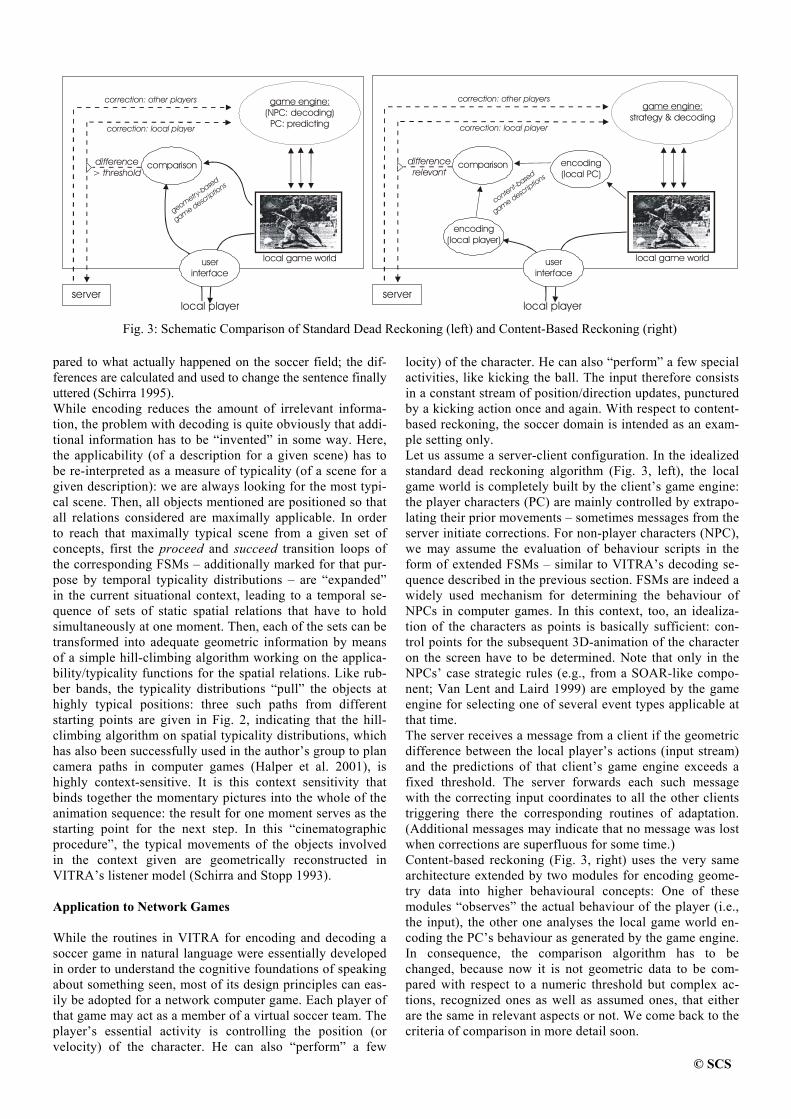
© SCS
pared to what actually happened on the soccer field; the dif-ferences are calculated and used to change the sentence finally uttered (Schirra 1995). While encoding reduces the amount of irrelevant informa-tion, the problem with decoding is quite obviously that addi-tional information has to be “invented” in some way. Here, the applicability (of a description for a given scene) has to be re-interpreted as a measure of typicality (of a scene for a given description): we are always looking for the most typi-cal scene. Then, all objects mentioned are positioned so that all relations considered are maximally applicable. In order to reach that maximally typical scene from a given set of concepts, first the proceed and succeed transition loops of the corresponding FSMs – additionally marked for that pur-pose by temporal typicality distributions – are “expanded” in the current situational context, leading to a temporal se-quence of sets of static spatial relations that have to hold simultaneously at one moment. Then, each of the sets can be transformed into adequate geometric information by means of a simple hill-climbing algorithm working on the applica-bility/typicality functions for the spatial relations. Like rub-ber bands, the typicality distributions “pull” the objects at highly typical positions: three such paths from different starting points are given in Fig. 2, indicating that the hill-climbing algorithm on spatial typicality distributions, which has also been successfully used in the author’s group to plan camera paths in computer games (Halper et al. 2001), is highly context-sensitive. It is this context sensitivity that binds together the momentary pictures into the whole of the animation sequence: the result for one moment serves as the starting point for the next step. In this “cinematographic procedure”, the typical movements of the objects involved in the context given are geometrically reconstructed in VITRA’s listener model (Schirra and Stopp 1993). Application to Network Games While the routines in VITRA for encoding and decoding a soccer game in natural language were essentially developed in order to understand the cognitive foundations of speaking about something seen, most of its design principles can eas-ily be adopted for a network computer game. Each player of that game may act as a member of a virtual soccer team. The player’s essential activity is controlling the position (or velocity) of the character. He can also “perform” a few
locity) of the character. He can also “perform” a few special activities, like kicking the ball. The input therefore consists in a constant stream of position/direction updates, punctured by a kicking action once and again. With respect to content-based reckoning, the soccer domain is intended as an exam-ple setting only. Let us assume a server-client configuration. In the idealized standard dead reckoning algorithm (Fig. 3, left), the local game world is completely built by the client’s game engine: the player characters (PC) are mainly controlled by extrapo-lating their prior movements – sometimes messages from the server initiate corrections. For non-player characters (NPC), we may assume the evaluation of behaviour scripts in the form of extended FSMs – similar to VITRA’s decoding se-quence described in the previous section. FSMs are indeed a widely used mechanism for determining the behaviour of NPCs in computer games. In this context, too, an idealiza-tion of the characters as points is basically sufficient: con-trol points for the subsequent 3D-animation of the character on the screen have to be determined. Note that only in the NPCs’ case strategic rules (e.g., from a SOAR-like compo-nent; Van Lent and Laird 1999) are employed by the game engine for selecting one of several event types applicable at that time. The server receives a message from a client if the geometric difference between the local player’s actions (input stream) and the predictions of that client’s game engine exceeds a fixed threshold. The server forwards each such message with the correcting input coordinates to all the other clients triggering there the corresponding routines of adaptation. (Additional messages may indicate that no message was lost when corrections are superfluous for some time.) Content-based reckoning (Fig. 3, right) uses the very same architecture extended by two modules for encoding geome-try data into higher behavioural concepts: One of these modules “observes” the actual behaviour of the player (i.e., the input), the other one analyses the local game world en-coding the PC’s behaviour as generated by the game engine. In consequence, the comparison algorithm has to be changed, because now it is not geometric data to be com-pared with respect to a numeric threshold but complex ac-tions, recognized ones as well as assumed ones, that either are the same in relevant aspects or not. We come back to the criteria of comparison in more detail soon.
local player
correction: other players
correction: local player
comparison
userinterface
local game world
(NPC: )PC: predicting
game engine:decoding
server
geometry-based
game descriptio
ns
difference> threshold
local game world
encoding(local PC)
local player
correction: other players
correction: local playerstrategy & decoding
game engine:
comparison
encoding(local player)
userinterface
server
content-based
game descriptio
ns
differencerelevant
Fig. 3: Schematic Comparison of Standard Dead Reckoning (left) and Content-Based Reckoning (right)
© SCS
Instead of numeric positions and velocity values, the correc-tion messages now carry the information of actions taking place as in verbal descriptions. Of course, in the game set-ting, the event concepts do not have to be really verbalized in any natural language with all its peculiarities and redun-dancies. The event type’s name, a mark for the current phase of the event recognition, some optional spatial rela-tions indicating important location and direction parameters of that event instance, and a time stamp suffice for a mes-sage. The game engine is modified in order to understand these messages. In general, the PCs’ positions are now derived by means of decoding event concepts as described in the previ-ous section, i.e., just like the NPCs’ behaviours. On an in-termediate level between the strategic overview and the concrete animation of the character, the gradient-based search for maximal typicality concretises behavioural con-cepts chosen by strategic rules in the current context delivering control parameters for the 3D-animations to be presented on the screen. However, this autonomous selection of actions may be overwritten by the concepts in correction messages – bringing in the real actions of the players. The correction itself is anchored in the current game state by the very same decoding procedures that unfold any behaviour of characters. Note that the geometric difference to be corrected cannot be extreme (or it would have been corrected earlier). The context-sensitivity of the cinematographic procedure therefore leads to smooth transitions even if the underlying concept is changed. It is crucial here that events can be used in correction mes-sages even if they are not yet completed, i.e., if they are merely assumed: events, the beginnings of which have been recognized in the players’ movements (but not in the corre-sponding character’s behaviour). Assume that the start phase of an event – e.g., of type “scoring”, i.e. ball starts moving away from the player toward the opposing goal – was found in the player’s activities but not in the local game with the PC’s reckoned behaviour. Consequently, a correc-tion message informs the game engines about this event, which then replaces the one currently active for that PC. Time stamps and phase markers in the messages allow the game engines to position the correct parts of the expanded events at the right temporal frames. A combination with “time warp” techniques looks promising in order to simplify the integration of the events at the right time. Following (Mauve 2000), a network soccer game with its limited number of characters is a plausible application for a “time warp” addition to standard dead reckoning. It may work well with content-based reckoning, too. For virtual environments with more characters, however, “time warping” becomes too expensive. As only the start phase has really happened so far in our ex-ample, most of the activity covered by that concept still be-longs to the future at communication time. If the “scoring” action is finished as predicted (and communicated to the other clients) no further message needs to be sent for the rest of that time. Thus, the general frequency of messages is reduced as we have intended. The crucial component is the comparison, filtering out rele-vant from irrelevant differences of behaviour. In principle we have to decide whether the two descriptions of behaviour con-structed by the two encoding components are literally the same or not. In fact, in the original sports report setting, a
similar comparison was performed in order to determine 13 kinds of difference between the listeners’ anticipated under-standing (the re-analysed mental image) and the real events (as seen by the reporter; Blocher and Schirra 1995). For con-tent-based reckoning, only two cases have to be distinguished: (a) no instance of the event type covering the real behaviour is predicted, (b) two corresponding instances of the same event type occur, though with different parameters (mainly, a place or direction slot is filled with different spatial relations or the phase is wrong). In both cases the observed event must be communicated to the game engines. In the second case, a marker has to be added indicating that a corresponding in-stance with divergent parameters is already active and has to be adapted, not replaced. A third case seems interesting, too: no instance of a predicted event type is recognized in the real behaviour (case (a) inverted). However, this case is not rele-vant since it always co-occurs with a difference of type (a): then, as a consequence of the correction message, all active events of that PC are replaced. The player’s input may indeed differ to a greater or smaller degree from the positions generated by decoding the active concept: Only if the input cannot be “parsed” any longer into the same concept, a correction message is generated. Thus, depending on the concepts and the phases of the events, the tolerance allowed can be quite different – a few small steps only (e.g., if a lot of spatial relations restrict simultaneously the PC’s position), or several long paces (if few relations are given or the PC is away from anything that could act as a ref-erence object at that moment). Some Problems So far, an example architecture for content-based reckoning has been presented on the basis of procedures adapted from a project in cognitive science for recognizing and reconstruct-ing events (i.e., behaviours in the game). Of course, a lot of questions remain open. For example: more complex event concepts lead not only to the positive effect of longer look-ahead times but also to higher chances of wrong recognition and more effort for recognizing. Therefore, determining for different game genres the right tactical level of detail and ab-straction of the concepts is a particularly crucial task for fur-ther empirical research in this framework. Content-based reckoning trades off less communication load for more local effort for encoding/decoding. These routines, however, become easily quite complicated – a standard prob-lem in AI. While VITRA’s routines for encoding and decod-ing at least performed approximately “in real time”, other types of games with more characters or/and more difficult behaviours may become problematic. If the additional com-ponents could be transformed into “anytime” versions (Zilber-stein 1996), thus leading even under temporal pressure to at least acceptable results, a dynamic adaptation to the resources available at that time (and for that client) offers an interesting solution. Typicality approximation with hill climbing has al-ready “anytime” property. Encoding can also be transformed – though not easily (Wahlster et al. 1998). However, there remains another, more principal problem with this approach that has to be considered in greater detail: the variations in-herent to the results of anytime algorithms may contradict the ultimate prerequisite of dead reckoning (using the same pre-dictive algorithm).
© SCS
AN OUTLOOK ON FUTURE RESEARCH The most promising perspective of content-based reckoning opens if we consider again the main reason to set it up origi-nally: the danger of dissociation, which so far is reduced but not banned. Encoding game states into semantic concepts that cover longer time intervals allows us at least to recognize ear-lier the danger of dissociation. So far, we have used the server only to forward the correction messages. It can also maintain its own local copy of the game world predicting the behaviour of all PCs (no encoding of a player or comparison necessary here). Then, with a decoding of the concepts presently active that is faster than real (game) time, the server is able to antici-pate the probable development of the game for some time ahead. Some of those game states may evoke strategic rules activating critical interactions of two players with particularly high latencies (it is easy to keep track of the current average latency to each client). For example, in the soccer domain, two characters of opposing teams may run toward each other from some distance – one having the ball, the other perform-ing the beginning of an attack event. The server recognizes that the game is likely to dissociate when the attack concept is realized much further (because this initiates critical types of interaction beyond the potential of the current latencies), and may therefore initiate resource-sensitive countermeasures – if available. In the Germanic world of legends, Wotan appoints the Val-kyries to influence with minimal “perceptibility” for the par-ticipants the fights between human heroes, and to decide the encounters as he demands – based on his general plan and the earlier “performances” of the heroes. The legendary schema, which we name “the Wotan Principle”, suggests an idea of how to keep together a dissociating game without too much loss of “gameplay”: when it recognizes a probable dissocia-tion, the server (acting as Wotan) decides how the sensitive interaction is going to happen, though only on a very general, coarse scale (essentially: the results). To this purpose the server can, for example, script a sequence of the semantic concepts described above. The decision could depend on some general game principles or, in a rather futuristic version, on players’ personal profiles derived automatically from ear-lier encounters. It is left to the clients (acting as “Valkyries”) by merging the script with the players’ reactions to set up the events accordingly, giving the local player some room for her/his own activities (i.e., remaining relatively imperceptible) nevertheless binding him or her into the general schema har-monized a priori with the other players in focus. Of course, the concrete sequence of events may be realised in quite a different way for each of the players involved in a dissociat-ing scene. But the overall results are unique and allow all players (“surviving” – in a shooter game) to continue after the dissociation in a non-dissociated game with relatively similar memories of that encounter. The effects of this hidden author-ity on the “gameplay” feeling are yet unknown and form a major focus of interest in our future research on content-based reckoning.
* * * Whilst most computer games are said to be provided with an internal AI, few results from Artificial Intelligence research on visual event recognition, natural language generation, and
user modelling of the past twenty years have had a noticeable influence on the development of computer games so far. The transfer described in this paper is an attempt to improve this situation. In particular, insights in the cognitive aspects of defining motion verbs and spatial relations may hopefully play a more prominent role in computer games in the future. REFERENCES André, E.; G. Herzog; and T. Rist. 1988. “On the Simultaneous
Interpretation of Real World Image Sequences and their Natural Language Description: The System SOCCER.” In Proceedings of the 8th European Conference on Artificial Intelligence 1988 (Munich). Pittman, London, 449-454.
Blocher, A. and J. R. J. Schirra. 1995. “Optional deep case filling and focus control with mental images: ANTLIMA-KOREF.” In Proceedings of the International Joint Conference on Artificial Intelligence 1995 (Montreal, August 20–25). 417–423.
Halper, N.; R. Helbing; and Th. Strothotte. 2001. “A Camera Engine for Computer Games: Managing the Trade-Off Between Con-straint Satisfaction and Frame Coherence.” In Computer Graph-ics Forum: Proceedings of Eurographics 2001. Manchester, 2001. To appear.
Herzog, G. 1992. “Utilizing Interval-Based Event Representations for Incremental High-Level Scene Analysis.” In Proceedings of the 4th International Workshop on Semantics of Time, Space, and Movement and Spatio-Temporal Reasoning 1992 (Château de Bonas, France), M. Aurnague (ed.), IRIT, Toulouse, 425–435,
Herzog, G. and P. Wazinski. 1994. “VIsual TRAnslator: Linking Perceptions and Natural Language Descriptions.” Artificial Intel-ligence Review 8 (2/3), 175–187.
Mauve, M. 2000. “How to Keep a Dead Man from Shooting.” In Proceedings of the 7th International Workshop on Interactive Distributed Multimedia Systems and Telecommunication Ser-vices (IDMS) 2000, Enschede, The Netherlands, 199–204.
Mellon, L. and D. West. 1995. “Architectural Optimizations to Advanced Distributed Simulation.” In Proceedings of the 1995 Winter Simulation Conference. Ch. Alexopoulos (ed.). IEEE, Piscataway, N.J., 634–641.
Schirra, J. R. J. 1993. “A Contribution to Reference Semantics of Spatial Prepositions: The Visualization Problem and its Solution in VITRA.” In The Semantics of Prepositions - From Mental Processing to Natural Language Processing 1993, C. Zelinsky-Wibbelt (Ed.). Mouton de Gruyter, Berlin, 471–515.
Schirra, J. R. J. 1995. “Understanding Radio Broadcasts On Soccer: The Concept ‘Mental Image’ and Its Use in Spatial Reasoning.” In Bilder im Geiste: Zur kognitiven und erkenntnistheoretischen Funktion piktorialer Repräsentationen. K. Sachs-Hombach (Ed.). Rodopi, Amsterdam, 1995, 107–136.
Schirra, J. R. J.; G. Bosch; C.K. Sung; and G. Zimmermann. 1987. “From Image Sequences to Natural Language: A First Step to-wards Automatic Perception and Description of Motion.” Ap-plied Artificial Intelligence 1(3), 287–305.
Schirra, J. R. J. and E. Stopp. 1993. “ANTLIMA – A Listener Model with Mental Images.” In Proceedings of the International Joint Conference on Artificial Intelligence 1993 (Chambéry, France, Aug. 29 – Sep. 3). 175–180.
Van Lent, M. and J. Laird. 1999. “Developing an Artificial Intelli-gence Engine.” In Proceedings of the Game Developers Confer-ence 1999 (San Jose, Ca., Mar. 16–18). 577–588.
Wahlster, W.; A. Blocher; J. Baus; E. Stopp; and H. Speiser. 1998. „Ressourcenadaptierende Objektlokalisation: Sprachliche Raum-beschreibung unter Zeitdruck.“ Kognitionswissenschaft 7(3), 111–117.
Zilberstein, S. 1996. „Using Anytime Algorithms in Intelligent Sy-stems.“ AI Magazine Fall 1996, 73–83.


LATE PAPER

NEW ANTI-ALIASING AND DEPTH OF FIELD TECHNIQUES FOR GAMES
RICHARD CANT, NATHAN CHIA, DAVID AL-DABASS
Department of Computing and Mathematics
The Nottingham Trent University Nottingham NG1 4BU.
Email: richard.cant/[email protected] KEYWORDS
Computer Graphics, Anti-aliasing, super-sampling, depth of field, focus, Open GL. ABSTRACT We describe software techniques that will enable Open GL capable graphics cards to implement antialiasing and depth of field effects in software. The methods allow any hardware facilities that are available on the graphics card to be used to improve performance but do not require hardware support in order to work. INTRODUCTION Sophisticated graphical and optical effects have in the past been the preserve of pre-rendered animation sequences taking hours or even days to calculate. In other cases these effects were incorporated in real time systems but only in very expensive military simulators, Potmesil and Chakravarty 1981, Cant and Sherlock 1987, Montrym et al, 1997. Since that time high end graphics workstations have also incorporated these techniques, e.g. Silicon Graphics. However recent advances in technology suggest that some of these effects should now be considered for real time implementation even on relatively low cost systems, such as PCs and games consoles. In this paper we will explore the possibilities of implementing some of these features by making use of existing facilities in hardware 3-D accelerators via OpenGL. ANTI-ALIASING For the implementation of anti-aliasing, this paper will attempts to replicate nVidia’s quincunx anti-aliasing (which is built into the hardware of an expensive GeForce 3 card) Figure 1, by using the existing hardware calls of common 3D accelerators. nVidia’s quincunx does the filtering at the stage where the buffer is rasterized to the screen. The 3D-scene is rendered normally, but the Pixel Shader is storing each pixel twice, Figure-2, in two different locations of the frame buffer. This does not cost more rendering power
than the rendering without AA, but requires twice the memory bandwidth of the pixel write operation at the end of the pixel rendering process.
Figure 1: Quincunx Anti-aliasing By the time the last pixel of the frame has been rendered, the HRAA-engine of GeForce3 virtually shifts the one sample buffer half a pixel in x and y direction (Figure 3).
Figure 2: Storing pixels twice
Figure 3

This has the effect that each pixel of the 'first' sample is surrounded by four pixels of the second sample that are 1/SQR(2) pixels away from it in diagonal direction. The HRAA-engine filters over those five pixels to create the anti-aliased pixel. The weights of the pixels are shown in Figure 4.
Figure 4: Weights of the quincunx pixels Figure 5 is a comparison of quality between the anti-aliasing results. These images were captured by www.tomshardware.com for an article on the GeForce 3 video card. The image was taken from a frame in Quake III: Arena. (Nowadays, Quake III: Arena is used more often as a benchmarking tool than a game.) It is quite clear that the quality of quincunx filtering is quite close to that of the 4x super-sampling anti-aliasing.
No anti-aliasing 2x anti-aliasing
Quincunx anti-aliasing 4x anti-aliasing
Figure 5: Comparison of anti-aliasing quality Coming up with a similar technique with the available hardware is quite intuitional. By examining figure 2.3 and 2.4 a little bit closer, one can deduce that the quincunx sample can be reduced to the 2x2 sample in figure 6.
Figure 6 The top-left pixel and the centre pixel are virtually the same pixel in the case of a quincunx sample. The implemented algorithm simply captures the entire back buffer and draws it back to the same position {offset(0,0)} with 0.625 of the original value, blend with alpha value of 0.125 for three other images at offset(0,1), offset(1,0) and offset(1,1). This would be equivalent of averaging the 2x2 sample with the new weights in Figure 6:
R= 0.625*offsetR(0,0) + 0.125*[offsetR(1,0) + offsetR(0,1) + offsetR(1,1)]
G= 0.625*offsetG(0,0) + 0.125*[offsetG(1,0) + offsetG(0,1) + offsetG(1,1)]
B= 0.625*offsetB(0,0) + 0.125*[offsetB(1,0) + offsetB(0,1) + offsetB(1,1)]
The algorithm can be summed up in the following diagram:
Draw Scene in back buffer
Read buffer
Draw 0.625 of original value on back buffer
Set blending at 0.125
Blend 0.125 of original value on back buffer at offset(1,0)
Blend 0.125 of original value on back buffer at offset(0,1)
Blend 0.125 of original value on back buffer at offset(1,1)
Swap buffer
MIP MAPPING DEPTH OF FIELD MIP mapping is a popular technique intended to reduce aliasing. The essence of the technique is to pre-compute the texture at different levels of detail, Figure 7, and to use smaller textures for polygons further away from the viewer. It aims to improve graphics performance by
1 2
1 8
1 8
1 8
1 8
12
18
18
18
18
1 8
1 8
1 8
5 8

generating and storing multiple versions of the original texture image. The graphics processor chooses a different MIP map based on how large the object is on the screen, so that low-detail textures can be used on objects that contain only a few pixels and high-detail textures can be used on larger objects where the user will actually see the difference. This technique saves memory bandwidth and enhances performance. The acronym MIP stands for Multum In Parvo (Latin for 'much in small')
Figure 7: A 320x240 image reduced to 160x120, 80x60,
40x30 and so on… The 3D hardware bilinear hardware kicks in when the smaller images are enlarged and as it attempts to fill in the missing pixels, an image that is more blurred will be generated (Figure 8). This algorithm will attempt to abuse this aspect of the MIP mapping hardware of a modern 3D accelerator to generate the blurred portions in an image with depth-of-field.
Figure 8: Enlarging a scaled down image Since MIP mapping is such a standard technique, it would be safe to assume that all hardware accelerators, even the pioneering 3dfx Voodoo card, will be able to do it without much effort at all. The scene can either be rendered on the back buffer or the memory buffer before requesting the hardware to generate the MIP maps. If the hardware does not natively allow rendering to a buffer other than the back buffer, rendering can be done on the back buffer first and the memory block will have to be copied by hand. And similarly, if MIP-map generation is not supported in hardware, it can also be read by hand and averaged with neighbouring pixels when scaling down.
“MIP-map Pixel Value” = [ pixel(1,1) + pixel(1,2) + pixel(2,1) + pixel(1,2) ] >>2
(where ‘>>’ refers to shifting the bits to the right)
MIP mapping DOF algorithm
Render Scene onto back buffer and Z-buffer. { : }
Capture Scene from back buffer { for (y=0;y<height;y++){ for (x=0;x<width;x++){ image(x,y)=backbuffer(x,y) } } }
Generate MIPMAPs { int level=0 Repeat until image is 1x1 {
scale image to ( WIDTH 2level
by
HEIGHT 2level ) Use as LOD ‘level’ image Increment ‘level’ by 1 } }
Draw DOF image back onto back buffer { for (y=0;y<height;y++) { for (x=0;x<width;x++) { backbuffer(x,y)=MIPMAP[ Z-value for pixel(x,y)](x,y) //MIPMAP[float i](int t,int s) // where ‘i’ is a choice of which // level of mipmap to use } } }

Since the next level of detail is always a quarter of the current level, the averaging isn’t as taxing as it sounds. Each destination MIP map pixel is just the average of the four corresponding source pixels, arranged in a 2x2 square. MIP mapping and bilinear sampling can be merged to form tri-linear sampling where two neighbouring levels of detail from the texture are averaged to generate an in-between image. This will effectively allow the blurring of an image to be varied without the use of a filtering kernel and therefore speeding up the process of generating depth-of-field because multiple different degree of blurring will be needed for every single render. It may be handy to be able to do a full screen blur with ease but this is an extreme effect and may not be much use when it comes to rendering a 3D scene other than doing transitions. It is, however, more desirable to be able to blur out some objects and leave the others sharp. Depth-of-field effects is can now be possible where only objects in the extreme distance or foreground are blurred, image focussing, in real-time. Depth-of-field would give a very impressive photo-realistic look to a rendered image (as shown with the cartoon image in Figure 9).
Figure 9: An image after MIP mapping depth of
field
The next step in the algorithm is to decide which portion of the image would use what level of blurring. This will have to be done when the image is being rasterized onto the back buffer. The decision for each pixel will be made based on the Z-buffer value at the same position.
By definition depth of field is the total distance, on either side of the point of focus, which , when viewed from an appropriate distance, appears sharp in the final image. The interest of this algorithm is to move real-time graphics away from their usual artificial look which is caused by shaded triangles projected in a 2 dimensional space. The cartoon image is intentionally chosen as an example because like all or most real-time 3D computer graphics, everything appears to be in the foreground and without the perspective drawn into the cartoon, the confusion may be even greater. Notice how the depth of field increase the realism as well as reducing the confusion between the background and foreground image which plagued the left image of Figure 9. This forces the viewer's eye to concentrate on the more important, non-blurred characters. Since the backbone of the major part of the algorithm relies on the 3D hardware, the whole process could be automated into the hardware itself. This would provide easy access to the depth-of-field or blurring effect with just an API call. As with all great things, there is a down side to this algorithm. One of the deficiencies of this technique is the effect which appears like an aura around a focused object. The appearance of this effect is not at all bad as it creates a “Vaseline lens” effect (Figure 10) on an image and brings it closer to photo-realism.
Figure 10: Photo of Xena, the cat, without and with the “Vaseline lens” effect
The other effect that is not pleasant appears when the focused object is in the background. Due to the cut-off of the Z-buffer when the foreground is blurred, instead of fuzzing out the foreground, a distinct line can be seen where the foreground edge meets the background. So while the effect obtained when focusing the foreground and blurring the background adds realism to an image, the effect when focusing the background and blurring the foreground is less forgiving. This renders this technique only effective when doing depth of field of the former.

A possible solution to stop this effect is to blur out the Z buffer when doing this method of depth-of-field so that no sharp edges would be present, and hence will give a smoother transition from the foreground object to the background object. Another possible but less appealing solution would be to render the foreground objects (objects before the focal point) onto individual memory buffers. These images will then be used as sprites, drawn on the position where the object will be if drawn in 3D. Do multi-pass blending jitters with
Offsets = (focal_point – object_distance_from_focal_point) * constant with the sprites to create the fuzzy edged objects that are at the foreground. For the mentioned MIP mapping DOF implementation to work effectively, one would need to get to the metal of the hardware. For the purpose of this project, a simplified version of the algorithm, which could produce a similar result on existing 3D accelerators, was implemented.
Figure 11: Original screenshot image from the
game Airblade.
Figure 12: Images with different LOD layered
and scaled to appear as the same size and position to the viewer
MIP mapping DOF algorithm (second implementation)
Render Scene onto back buffer and Z-buffer. { .
. }
Capture Scene from back buffer { for (y=0;y<height;y++) { for (x=0;x<width;x++) { image(x,y)=backbuffer(x,y)
} } }
Generate MIPMAPs { int level=0 Repeat until image is 1x1 {
scale image to (
WIDTH 2level
by HEIGHT 2level )
Use as LOD ‘level’ image, Increment ‘level’ by 1 }
}
Draw DOF image back onto back buffer {
On Depth Testing but do not write changes to depth buffer
Let Z be the depth where objects are to be sharpest
Draw LOD[3] at Z-3*offset Draw LOD[2] at Z-2*offset Draw LOD[1] at Z-1*offset Draw LOD[0] at Z Draw LOD[1] at Z+1*offset Draw LOD[2] at Z+1*offset Draw LOD[3] at Z+1*offset
}

While the first implementation assumes an infinite amount of LODs in the image, this implementation will reduce that to a finite amount of LODs. As before, a scene like the one in Figure 11 will be rendered, MIP maps generated. These maps will be layered and scaled in such a way that they will all appear the same size and position to the viewer (Figure 12). These images will be effectively be billboards cutting through the depth of the scene based on the existing Z-buffer values. By positioning the desired LOD on appropriate position along the Z-axis, the Z-buffer mechanism will automatically cut out the unwanted portions of a layer that might block the layers at the back.
Figure 13: Simplified Z-buffer of the image.
Figure 14: MIP mapping depth-of-field in effect. In figure 13, the darker portions are objects that are further away and the brighter portions are objects nearer to the front. Figure 14 is drawn by drawing the LOD images in the way illustrated in figure 12 using the Z buffer values in figure 13.
As can be seen from Figure 14, although the levels of LODs have been reduced to a finite amount, the technique can still deliver a convincing effect of depth-of-field. The effects that are found in the previous implementation will still exist in this implementation, however the ‘foreground blurring edge’ effect will not be visible in Figure 14 because the focused character is in the foreground. CONCLUSIONS AND FUTURE WORK Techniques were proposed and implemented to perform anti-aliasing and depth of field processing using features of OpenGL and current 3-D accelerators. Surprisingly impressive images have been obtained in spite of the fact that these facilities are not supported 'natively' by the equipment in use. Future work will include refinements of these algorithms, exploration of the possibilities for direct implementation in future hardware and investigation of other effects such as motion blur, sun glare and film grain. REFERENCES 1. M. Potmesil and I Chakravarty, "A Lens and Aperture Camera Model for Synthetic Image Generation", in Proceedings of ACM-SIGGRAPH 81, Dallas, Texas, August 3-7 1981, pp297-305, Vol. 15, No.3. 2. Richard S. Wright, Jr and Micheal Sweet, " OpenGL Super Bible", 2nd Edition, Waite Group Press. 3. Cant, R.J. and P.E. Sherlock. 1987, "CIG System for Periscope Observer Training", in Proceedings of the 9th Inter-Service/Industry Training Systems Conference, 311-314. 4. J. Montrym, D Baum, D Dignam, and C Migdal, "InfinitReality: A Real-Time Graphics System", in Proceedings of ACM SIGGRAPH'97, pp 293-301, August 1997. 5. S Nishimura, and T Kunii, "VC-1: A Scalable Graphics Computer with Virtual Local Frame Buffers", in Proceedings of ACM SIGGRAPH'96, pp 365-372, August 1996. 6. Sergei Savchenko, "3D Graphics Programming", SAMS. 7. Rod Stephens, "Visual Basic Graphics Programming", Wiley.

AUTHOR LISTING
Al-Dabass D. ............................. 5/81/114 Allen M.J. .................................. 22 Calderon C................................. 71 Cant R........................................ 5/81/114 Cavazza M................................. 43/71/76 Charles F. .................................. 43 Chia N. ...................................... 5/114 Churchill J. ................................ 81 Gelenbe E. ................................. XVII Gough N.E................................. 22/35/56 Hussain K. ................................. XVII Hussam H.S. .............................. 35 Ipekkan Z................................... 63 Itoh E. ........................................ 100 Kaptan V. .................................. XVII Koppelaar H. ............................. 87 Mead S.J. ................................... 43 Mehdi Q.H................................. 22/35/56
Meijer A.B. ................................87 Okada Y. ....................................12/100 Palmer I. .....................................76 Polat F. .......................................63 Rothkrantz L.J.M. ......................17/48 Sakamoto H................................100 Schirra J.R.J. ..............................107 Shafie Abd Latiff M...................76 Spronck P. ..................................95 Suliman H. .................................22 Treijtel C. ...................................17 Undeger C. .................................63 van Waveren J.M.P. ...................48 Wen Z.........................................22/56 Yamashita M. .............................100