Scenario-Driven Approach for Business Process Modeling
20
Int. J. Business Process Integration and Management, Vol. 6, No. 1, 2012 77 Copyright © 2012 Inderscience Enterprises Ltd. Scenario-driven approach for business process development A. Ruokonen*, T. Kokko and T. Systä Department of Software Systems, Tampere University of Technology, P.O. Box 553, FI-33101 Tampere, Finland E-mail: [email protected] E-mail: [email protected] E-mail: [email protected] *Corresponding author Abstract: The development of services-based systems starts from defining business requirements to be implemented as high-level business processes. In this paper, we describe a scenario-driven approach for developing business processes specified as WS-BPEL descriptions. We aim for simplicity in the business level notation and leverage example-like modelling principles in order to enable process sketching. The first step in our approach is to identify the essential functional requirements for business processes. The requirements are modelled as simple scenarios, each of them defining a sample run through the process, i.e., required behaviour that the underlying service-based system should allow. The scenarios, specifying sent and received messages among the services, are synthesised into a state machine. The state machine is transformed into an initial process model given in UML activity model notation. To enable mapping into WS-BPEL code, the transformation exploit domain-specific rules, i.e., our target model consists of a subset of UML with WS-BPEL specific constraints and stereotypes. The initial process model can be further refined to enable generation of executable WS-BPEL descriptions. We apply the approach on two cases, a simple process for managing loan requests and an industry case study from a logistics provider are presented. Keywords: business process; scenario synthesis; WS-BPEL; UML. Reference to this paper should be made as follows: Ruokonen, A., Kokko, T. and Systä, T. (2012) ‘Scenario-driven approach for business process development’, Int. J. Business Process Integration and Management, Vol. 6, No. 1, pp.77–96. Biographical notes: A. Ruokonen holds an MSc in Software Engineering. She is a Researcher in Tampere University of Technology, Department of Software Systems. She is currently finishing her PhD thesis on development of service-based systems. T. Kokko is a postgraduate student at Tampere University of Technology, Department of Software Systems. His current research interests include utilisation of service-oriented architecture, event driven architecture and model driven software development in context of enterprise architecture to realise business agility and flexibility. T. Systä is a Professor at Tampere University of Technology, Department of Software Systems. Her current research interests include software maintenance and analysis, software architectures, model-driven software development, and development and management of service-oriented systems. 1 Introduction Service-based systems combine and coordinate separate tasks to accomplish a certain business goal. On business terms, there is a business need that can be fulfilled by performing multiple interrelated activities. On technical terms, there are multiple computer systems that need to exchange information with each other in appropriate manner. Typically business requirements are defined by different people than those who are managing the computer systems. Therefore, there needs to be a dialog between business people and IT-oriented people. The quality of this dialog has an important impact on achieved results. Misunderstandings in the dialog can cause wrong behaviour in execution, which can then reduce the value of the whole business activity. To avoid a mismatch between the system and its operating environment needs is one of the challenges in software engineering. As a proposed solution, requirement-driven development aim at reducing a gap between the system requirements and the system being developed (Jaelson et al., 2001). In requirements capture, the core idea is that system
Transcript of Scenario-Driven Approach for Business Process Modeling

Int. J. Business Process Integration and Management, Vol. 6, No. 1, 2012 77
Copyright © 2012 Inderscience Enterprises Ltd.
Scenario-driven approach for business process development
A. Ruokonen*, T. Kokko and T. Systä Department of Software Systems, Tampere University of Technology, P.O. Box 553, FI-33101 Tampere, Finland E-mail: [email protected] E-mail: [email protected] E-mail: [email protected] *Corresponding author
Abstract: The development of services-based systems starts from defining business requirements to be implemented as high-level business processes. In this paper, we describe a scenario-driven approach for developing business processes specified as WS-BPEL descriptions. We aim for simplicity in the business level notation and leverage example-like modelling principles in order to enable process sketching. The first step in our approach is to identify the essential functional requirements for business processes. The requirements are modelled as simple scenarios, each of them defining a sample run through the process, i.e., required behaviour that the underlying service-based system should allow. The scenarios, specifying sent and received messages among the services, are synthesised into a state machine. The state machine is transformed into an initial process model given in UML activity model notation. To enable mapping into WS-BPEL code, the transformation exploit domain-specific rules, i.e., our target model consists of a subset of UML with WS-BPEL specific constraints and stereotypes. The initial process model can be further refined to enable generation of executable WS-BPEL descriptions. We apply the approach on two cases, a simple process for managing loan requests and an industry case study from a logistics provider are presented.
Keywords: business process; scenario synthesis; WS-BPEL; UML.
Reference to this paper should be made as follows: Ruokonen, A., Kokko, T. and Systä, T. (2012) ‘Scenario-driven approach for business process development’, Int. J. Business Process Integration and Management, Vol. 6, No. 1, pp.77–96.
Biographical notes: A. Ruokonen holds an MSc in Software Engineering. She is a Researcher in Tampere University of Technology, Department of Software Systems. She is currently finishing her PhD thesis on development of service-based systems.
T. Kokko is a postgraduate student at Tampere University of Technology, Department of Software Systems. His current research interests include utilisation of service-oriented architecture, event driven architecture and model driven software development in context of enterprise architecture to realise business agility and flexibility.
T. Systä is a Professor at Tampere University of Technology, Department of Software Systems. Her current research interests include software maintenance and analysis, software architectures, model-driven software development, and development and management of service-oriented systems.
1 Introduction
Service-based systems combine and coordinate separate tasks to accomplish a certain business goal. On business terms, there is a business need that can be fulfilled by performing multiple interrelated activities. On technical terms, there are multiple computer systems that need to exchange information with each other in appropriate manner.
Typically business requirements are defined by different people than those who are managing the computer systems.
Therefore, there needs to be a dialog between business people and IT-oriented people. The quality of this dialog has an important impact on achieved results. Misunderstandings in the dialog can cause wrong behaviour in execution, which can then reduce the value of the whole business activity. To avoid a mismatch between the system and its operating environment needs is one of the challenges in software engineering. As a proposed solution, requirement-driven development aim at reducing a gap between the system requirements and the system being developed (Jaelson et al., 2001). In requirements capture, the core idea is that system

78 A. Ruokonen et al.
requirements should be presented in some structured but still understandable way, for example, as use cases (Rumbaugh, 1994).
Business goals change over time, which in practice requires changes in the functionality of the underlying system. The system flexibility could be improved by enhancing the aforementioned dialog by enabling non-IT people to describe business goals in a way that easily allows their transformation and refinement into technical process descriptions, i.e., business processes. A business process defines a workflow of service activities which constitute a meaningful business task or a transaction.
One of the main promises of service-oriented architecture (SOA) is that it bridges business and information technology (IT) oriented views, i.e., that business process designs can comfortably be transformed into service orchestrations expressed, e.g., as executable WS-BPEL processes. Various model transformation approaches and tools have been proposed for that purpose (Kalnins et al., 2004; Kalnins and Vitolins, 2006; BPMI, 2004; ETTK, 2006; Lohmann et al., 2007). These approaches almost solely assume the business process designs to be expressed in some workflow or business process language, such as business process modelling notation (BPMN) or unified modelling language (UML) activity diagrams. The transformations presented follow the main idea of model-driven architecture (MDA); the BPMN or UML activity diagrams present high-level platform-independent business processes that are then transformed into platform-specific (in this case process execution language specific) service orchestrations.
While aforementioned approaches prove that transformability from UML activity diagram or BPMN to WS-BPEL exists, they do not consider the issues relevant from the business process modeller’s point of view, e.g., whether BPMN or UML would be appropriate notations for process modelling and what is the desired abstraction level. Depending on a tool vendor’s product, the level of required details at the business process modelling level varies. In some cases, these business-level models are not sufficient and expressive enough to be used for code generation, but they are used rather as a requirements document given to the system developers. To acknowledge these two issues, we aim at keeping business level modelling as simple as possible, at the level of use cases. Instead, we propose that technical details are added by IT-oriented people. By providing automatic model transformations, we ensure the business requirements are propagated into the service orchestrations.
Customer and other system requirements are often specified as use cases, which present the desired behaviour of the system to be build. In addition to textual descriptions and use case diagrams, use cases are often refined by scenarios. A scenario presents a simple interaction between objects, i.e., sequence of sent and received messages. In our approach, these requirements are used to derive an initial business process model to be refined with technical details.
We rather aim at a business feature oriented modelling approach instead of an implementation-oriented one.
In this paper we propose a scenario-driven approach to business process development. The first step in our approach is to define functional business requirements. This step is assumed to be performed by business process modeller. This implies that no technical details should be required from these process models. The modelling should emphasise requirements capture rather than specification of full-fetched process models, i.e., the modeller should be allowed to model desired/required behaviours, without being forced to specify the complete process behaviour. The business process modeller can sketch required behavioural sequences the process should satisfy using a notation that is simple to use and understand. These sequences are then synthesised into a state machine that summarises these example behaviours. The synthesis is iterative and more requirements can be added to refine the model. The state machine is translated into a process model skeleton given as a UML activity diagram. We use the model as a target for automatically detecting and creating WS-BPEL specific structures (i.e., patterns). The refined model can be used as a source for a transformation tool that produces WS-BPEL descriptions.
In this paper, we describe algorithms and a tool called Sketch built to support the scenario-driven approach targeted for business processes development. Sketch synthesises functional requirements into a state machine. Furthermore, we have defined mappings from a state machine into a WS-BPEL flavoured activity diagram. From the state machine Sketch produces an activity model which enables transformation into WS-BPEL description. The main contribution of the paper is to provide an approach and tool chain from functional business requirements, given as simple message-based interactions, into a WS-BPEL compatible model. By providing this tool chain, we can reduce the gap between business and IT views. In addition, with automated model transformations the overhead for providing several models for different views, e.g., requirements, business, and execution, can be avoided. To illustrate the approach and its usefulness, we present a simple Loan approval example and an industry case study carried out for a logistics service provider. The approach presented in this paper has been further developed based on our earlier work (Ruokonen et al., 2009). In addition, this paper includes developed algorithms, description of the developed tool, and an industry case study.
The rest of the paper is organised as follows. In Section 2, we describe our scenario-driven approach in detail. In Section 3.1, we use illustrate the scenario-driven process development in practice. Our implementation is described in Section 4. In Section 5, we discus related work and topics. In Section 6, we discuss limits of our approach. Finally, in Section 7 we conclude the paper.

Scenario-driven approach for business process development 79
2 Scenario-driven approach for business process modelling
In this section, we introduce a scenario-driven approach for business process development. The approach starts from sketching simple functional requirements for business processes with scenarios of example behaviours. In our approach, we assume the scenarios to be given graphically as UML sequence diagrams, without control structures. That is, we do not expect the business requirement modeller to define more complicated technical details, such as different types of control structures, at this point.
Each scenario presents one possible execution path. They are synthesised into a merged process view illustrated as a UML state machine. The synthesis algorithm concludes the control structures, e.g., branching and merging of flows. The synthesised state machine is transformed into a process skeleton, defined as UML activity model. Furthermore, the created process skeleton is automatically refined with WS-BPEL specific elements, stereotypes, and structural patterns. However, refinement still requires adding some technical details manually. Finally, a model transformation tool can be used for generating executable WS-BPEL descriptions. In the following subsections, the approach with its transformation steps is described in detail.
2.1 Adjusting services for scenario-based modelling
In the context our scenario-driven process, we do not consider service design and realisation, instead we assume that existing services are used. For sketching the scenarios, the process designer needs to know and identify the services she wants to orchestrate. In addition, she needs to know the service providers and operations to be called. In order to make scenarios easy and understandable to compose, the services themselves should offer straightforward interfaces. The goal is that interaction patterns with each service are as simple as possible. For example, in order to send information from one service to another, as few messages as possible should be used instead of dividing information into many correlated messages.
Reducing the number of interactions will simplify the models and make the system more reliable by removing places where messaging may go wrong. For example, in cases such as loan requests, the initial loan request message should contain all information required for processing and message exchange pattern should not be designed so that the requester needs to first request a session or an applicant number, then use this to initiate an application process, and after that send more details. This is not a requirement specific to our approach, but rather a guideline for service-based systems in general.
This approach is targeted for traditional method-based service interaction. Use of resource or data oriented services, might not be a good starting point for the approach. We will discuss these limitations more in Section 6.
Our recommendation is to model each use case as an individual scenario. Before approaching to the next step, we
assume that the identified services, i.e., their interfaces, are described as a UML class diagram. In addition, a design of simple service interfaces is assumed.
2.2 Scenario-based modelling
Our approach aims at providing as intuitive starting point for process modelling as possible. The underlying idea is that the business process modeller sketches simple example sequences that illustrate the required behaviours of the business process to be implemented as a web service orchestration. The set of scenarios does not need to (but it can) illustrate all possible execution runs through the process. For instance, scenarios describing exceptional behaviour, such as error handling, may be omitted. Such information can be defined later in the process refinement step, and more importantly, by IT people.
There are two types of exceptional behaviour: functional and non-functional. As an example of functional exception, if a certain hotel reservation system is out of order, a different hotel chain could be tried. A business process modeller should model these functional operations. However, as an example of non-functional behaviour, if a hotel reservation service is busy, but available after a small period of time, the system should automatically generate a proper way to handle the exception by waiting and retrying. In this approach, we only consider functional requirements.
As a result of scenario-based modelling, we assume one sequence diagram consisting of a number of interactions. An interaction is a simple scenario with no UML control structures. Each scenario presents a realisation of one use case.
For instance, Figure 1 presents one possible scenario constructed for a LoanManager process, which administers customers’ loan requests.
Figure 1 An input trace (see online version for colours)
2.3 Process synthesis
After the set of scenarios has been constructed, they are transformed into a merged view that summarises the

80 A. Ruokonen et al.
behaviours of individual services participating the scenarios. This is done with state machine synthesis. We have implemented a simple graph-based synthesis algorithm, but other synthesis algorithm could be used as well.
For example, a scenario in Figure 1 defines a sequence of (send_message, receive_message) message pairs. If either of the messages is missing, it is defined as NULL. VOID presents the end of the scenario.
LoanManager's message sequence is the following:
(NULL, requestLoan<1000)(checkRisk, checkRisk _ high)(approve, approve _ yes)(requestLoan _ yes, VOID)
send message is a message sent by the LoanManager process and receive message is a message received by the LoanManager process. The message pairs define one possible interaction trace. In the LoanManager's message sequence, the other participating services, Customer, RiskAssessment, and Approver, are collapsed into one representative group.
To construct the overall conversation between the process and the participating services, all the scenarios are synthesised into a state machine. When composing a state machine each sent message (e.g., service call) is mapped to an action performed in a state and each received message (e.g., respond to a service call) is mapped to an event that causes a state transition (i.e., fires a transition). In Figure 3, the aforementioned trace can be seen as a one execution path through the state machine, from the initial state to a final state. The other possible execution paths results from the other input scenarios.
A common problem in automatic state machine synthesisers is ‘overgeneralisation’, i.e., the synthesis algorithms generalise information given in scenarios so that the resulting state machine accepts more paths through the modelled system than is represented in the scenarios. In process modelling, overgeneralisation means that the final process instance accepts additional behaviours to those process requirements expressed as scenarios. Our synthesis algorithm does not tackle with issue of overgeneralisation. However, there are synthesisers which can avoid overgeneralisation, e.g., through interactive synthesis as implemented in minimally adequate synthesiser (MAS) (Makinen and Systä, 2000).
In some cases, the input scenarios can be conflicting. Typically, this results a non-deterministic state machine. Some synthesis algorithms, however, e.g., the algorithm used in MAS, generate deterministic state machines only. This is achieved by splitting states and thus separating two conflicting paths, if necessary. In the worst cases this may yield to disconnected state machines. However, a conflict might be an accidental error or it might present a deterministic choice, i.e., the conditional statements cannot be expressed by the simple scenarios. Thus, our synthesis algorithm accepts a non-deterministic state machine as a result at this point.
2.4 Process skeleton
In the next step, the state diagram is converted into a WS-BPEL flavoured activity model, which presents a skeleton of the process model. A proposal for a UML Profile for WS-BPEL (Amsden et al., 2004) provides guidelines how to map UML activity model and WS-BPEL constructs. In this paper, we use the term WS-BPEL profile to express a subset of UML with WS-BPEL specific constraints and stereotypes. By following these rules the resulting UML model supports mapping into WS-BPEL code.
The basic transformation rules include the following. A state action in a state diagram results an invoke activity in an activity model, meaning the process invokes an external service. A state transition in a state diagram means that the process receives a message. Thus, it results a receive activity in an activity model.
In addition to these basic principles, WS-BPEL profile allows only one incoming and one outgoing control flow for each activity. There are alternatives ways to translate parallel state transitions into a WS-BPEL model. Basically, parallel flows are handled by detecting WS-BPEL specific structures (so called patterns), such as decision, flow fork, flow merge, and loop structures.
Mapping rules from state machine to WS-BPEL flavoured activity model are given in Table 1. The first column presents a state machine construct, the second column presents a corresponding activity diagram construct, and the third column presents a possible stereotype in activity diagram.
Table 1 Mappings form a state machine to a WS-BPEL flavoured activity diagram
State machine Activity diagram Stereotype
A state transition A call behaviour action Receive A state action A call behaviour action Invoke A start state A start node - A final state A flow final node - Several deterministic outgoing transition
A fork node -
Several non-deterministic outgoing transition
A decision node -
Several incoming transitions
A join node -
A loop A structured activity with nested substructure
While
The transformation can be run in two different ways. The first option is just to translate the state machine into a workflow model, consisting of a start node, invoke and receive activities connected by control flows, and ending in a final node. However, the simple mapping from state machines to activity models does not usually result in an adequate activity model in respect to desired process model. The second option is to automatically try to detect and create WS-BPEL specific structures to end-up with a more

Scenario-driven approach for business process development 81
specific WS-BPEL model as a result of the transformation (e.g., parallel control flows are not allowed by the WS-BPEL profile). In this approach, we apply the latter approach aiming at WS-BPEL flavoured activity model. Detection of WS-BPEL specific structures, including handling of parallel transitions, is discussed in Section 4.
2.5 Process refinement
To minimise manual work we have applied domain-specific rules (i.e., WS-BPEL profile) to create the WS-BPEL flavoured process model skeleton. However, to end-up with a detailed executable model, the process refinement step still requires manual activities.
Non-deterministic branching in the state machine is handled by creating a decision node in the activity model. However, the branching conditions are not assumed to be found from the simple scenarios. Thus, the user must specify these conditions for making the decision for selecting a correct branch.
Need for flow synchronisation in case of fork and join nodes cannot be concluded from the state machine and also remains manual task. By default, we just assume a flow splitting and merging without a need for synchronisation.
As mentioned, business process modeller may not want or be able to design all exceptional executions and error handling mechanisms. They should, however, be taken into account in the process refinement step, which is assumed to be taken care of by IT-oriented persons.
2.6 Generation of executable processes
In our earlier work, we have developed a tool to generate WSDL and WS-BPEL descriptions from UML-based models (Pajunen and Ruokonen, 2007). To enable WS-BPEL generation, in addition to the process model, also static information, such as information on the participating services, must be provided. Thus, we use stereotyped UML activity and class models. In our approach, class roles in scenarios are translated into partner links. In WS-BPEL processes, partners must be defined as WSDLs in separate files. To create the WSDLs, the interfaces can be concluded from the class definitions in the static part of the sequence diagram.
There are several existing approaches to generate WS-BPEL code from graphical models like BPMN and UML activity models (Kalnins et al., 2004; Kalnins and Vitolins, 2006; BPMI, 2004; ETTK, 2006; Lohmann et al., 2007). In this paper, we are not going into details in such mappings.
2.7 Summary
Table 2 summarises the phases of scenario-driven development approach.
In practice, in our approach a state machine representation is an intermediate deliverable towards an activity model. However, is some cases state-based model might be more desired and transformation into activity model can be omitted.
Table 2 Phases of the scenario-driven approach
Process phases Input Output Execution
Adjusting services Service descriptions
Class diagram
Manual
Scenario-based modelling
Class diagram
Sequence diagram
Manual
Process synthesis Sequence diagram
State machine
Automatic
Process skeleton State machine
Activity diagram
Automatic
Process refinement Activity diagram
Activity diagram
Manual
Generation of executable WS-BPEL
Activity and class diagram
WS-BPEL Automatic
3 Case studies
To illustrate and evaluate the scenario-driven approach, we apply it on two different examples. The first example, loan approval process, is a simple WS-BPEL process utilising pure operation-centric web services. The second example is to define a process for an industry project called speech guidance system. It also illustrates creation of loops and handling of non-deterministic transitions.
3.1 Loan approval process
3.1.1 Scenario synthesis
We use a simple loan approval service as an example. This is a classical process example, also presented in WS-BPEL specification (Andrews et al., 2003). Customers of the service send their loan requests, including personal information and the amount being requested, to loan approval service. By using this information, the loan service runs a simple process, which returns either a ‘loan request approved’ or a ‘loan request rejected’ message. The approval decision can be reached in two different ways, depending on the amount requested and the risk associated with the customer. If the customer requests a small loan (less than 1,000) and her personal risk is evaluated as low, the request is approved with no further evaluation. Second, if the customer asks for a big loan (more than 1,000) or her personal risk is evaluated as high, the request needs to be handled by external approver. The external approver decides, if the loan is granted or not. The customer will receive a return message according to the decision.

82 A. Ruokonen et al.
Figure 2 Loan approval scenarios (see online version for colours)
Traditional process modelling approaches, using e.g., UML2 activity diagrams or BPMN, aim at understanding and capturing the overall process flow. Here, on the contrary to traditional approaches, we assume the developer defines a set of simple scenarios defining possible traces of the process flow. A complete set of scenarios, defining the
process requirements, is presented in Figure 2. The scenarios are next synthesised into a state machine. The resulting state diagram is presented in Figure 3. It contains control structures learned from the scenarios during the state machine synthesis.
Scenario-driven approach for business process development 83
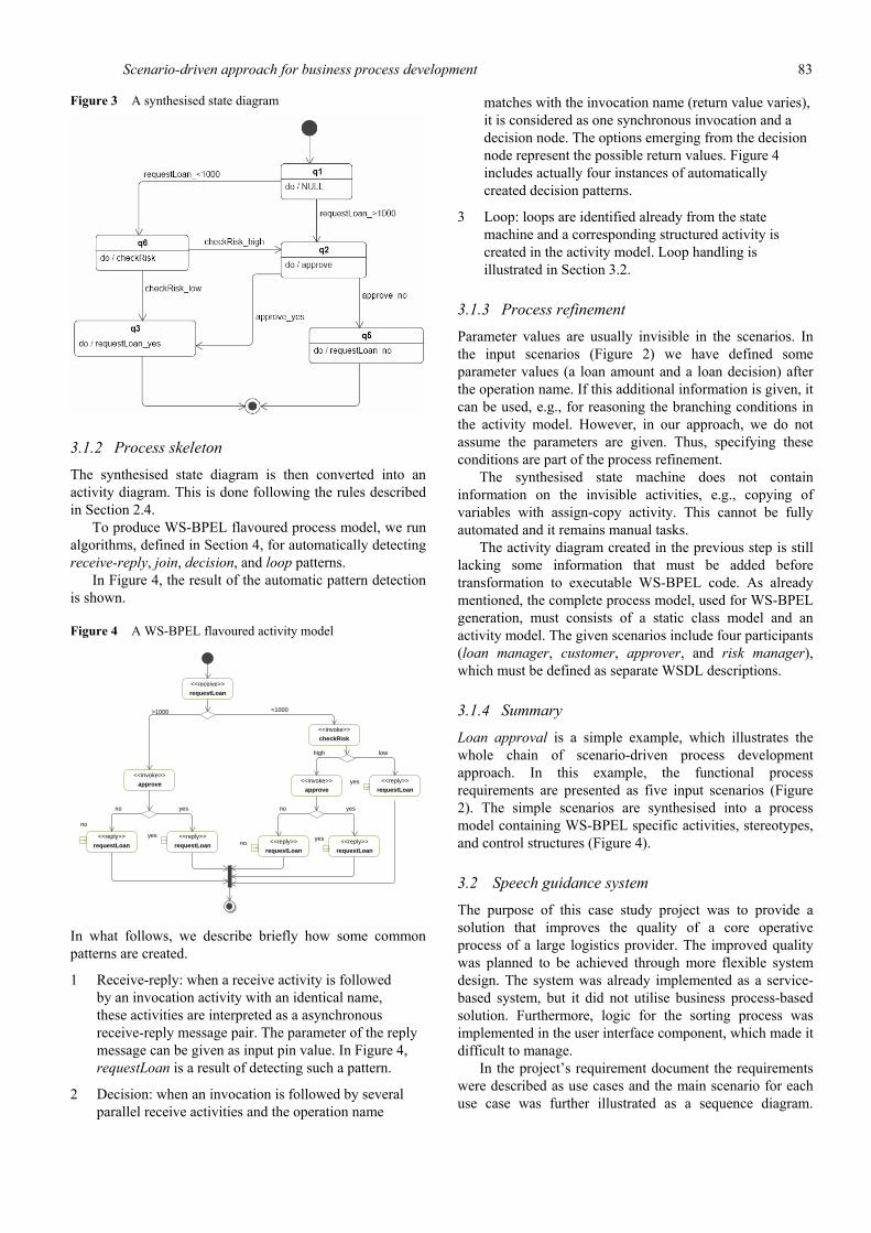
Figure 3 A synthesised state diagram
3.1.2 Process skeleton
The synthesised state diagram is then converted into an activity diagram. This is done following the rules described in Section 2.4.
To produce WS-BPEL flavoured process model, we run algorithms, defined in Section 4, for automatically detecting receive-reply, join, decision, and loop patterns.
In Figure 4, the result of the automatic pattern detection is shown.
Figure 4 A WS-BPEL flavoured activity model
<<reply>>
requestLoanno
<<reply>>
requestLoan
no
<<receive>>
requestLoan
<<invoke>>
approve
<<reply>>
requestLoan
yes<<reply>>
requestLoan
yes
<<invoke>>
checkRisk
<<reply>>
requestLoanyes<<invoke>>
approve
<1000>1000
low
yesno yesno
high
In what follows, we describe briefly how some common patterns are created.
1 Receive-reply: when a receive activity is followed by an invocation activity with an identical name, these activities are interpreted as a asynchronous receive-reply message pair. The parameter of the reply message can be given as input pin value. In Figure 4, requestLoan is a result of detecting such a pattern.
2 Decision: when an invocation is followed by several parallel receive activities and the operation name
matches with the invocation name (return value varies), it is considered as one synchronous invocation and a decision node. The options emerging from the decision node represent the possible return values. Figure 4 includes actually four instances of automatically created decision patterns.
3 Loop: loops are identified already from the state machine and a corresponding structured activity is created in the activity model. Loop handling is illustrated in Section 3.2.
3.1.3 Process refinement
Parameter values are usually invisible in the scenarios. In the input scenarios (Figure 2) we have defined some parameter values (a loan amount and a loan decision) after the operation name. If this additional information is given, it can be used, e.g., for reasoning the branching conditions in the activity model. However, in our approach, we do not assume the parameters are given. Thus, specifying these conditions are part of the process refinement.
The synthesised state machine does not contain information on the invisible activities, e.g., copying of variables with assign-copy activity. This cannot be fully automated and it remains manual tasks.
The activity diagram created in the previous step is still lacking some information that must be added before transformation to executable WS-BPEL code. As already mentioned, the complete process model, used for WS-BPEL generation, must consists of a static class model and an activity model. The given scenarios include four participants (loan manager, customer, approver, and risk manager), which must be defined as separate WSDL descriptions.
3.1.4 Summary
Loan approval is a simple example, which illustrates the whole chain of scenario-driven process development approach. In this example, the functional process requirements are presented as five input scenarios (Figure 2). The simple scenarios are synthesised into a process model containing WS-BPEL specific activities, stereotypes, and control structures (Figure 4).
3.2 Speech guidance system
The purpose of this case study project was to provide a solution that improves the quality of a core operative process of a large logistics provider. The improved quality was planned to be achieved through more flexible system design. The system was already implemented as a service-based system, but it did not utilise business process-based solution. Furthermore, logic for the sorting process was implemented in the user interface component, which made it difficult to manage.
In the project’s requirement document the requirements were described as use cases and the main scenario for each use case was further illustrated as a sequence diagram.

84 A. Ruokonen et al.
However, the description of the sorting process was spread in several documents and interrelations between the use cases were a bit unclear.
To improve the system maintainability and to provide a starting point for migration into WS-BPEL process engine environment, we agreed to apply the scenario-driven approach.
3.2.1 Gathering system requirements
Speech guidance system requirement document defines the main use cases for the sorting process. In the documentation, each use case is defined as a textual description including the main scenario given as sequence diagram like notation. As a perquisite for the sorting tasks the user has to be logged in the work place. After each sorting task the user can log out the work place or start a new sorting task.
The main use cases, which are essential to the sorting process, are described in the following listing.
• Use cases for speech guidance system 1 uc006: logout the sorting point 2 uc007: login the sorting point 3 uc011: move a sorting item to a container 4 uc014: report exception 5 uc015: remove a sorting item from a container 6 uc018: close a container 7 uc019: print a container label 8 uc020: print a container label set 9 uc021: combine two container units.
We have modelled the uses cases as usage scenarios. Use cases uc011, uc014, uc015, and uc018–uc021 are the main sorting tasks, which form the sorting process. Use case uc007 is a precondition to all the other use cases and a sorting process must end with loging out of the sorting point, i.e., uc006. Thus, these pre and post conditions must be referenced in each sorting task scenario.
Speech guidance system has connections to the following external systems: sorting item tracking system (iTR), container label printing system (CLPS), sorting machine, and sorting point data storage. In addition, the user represents one of the system participants.
As an example, ‘print a container label’ use case (uc019) is illustrated as a sequence diagram in Figure 5. The user first inputs the container position, type, and identifier. The speech guidance system invokes CLPS for printing. It receives a status code from CLPS and informs iTR. Finally, speech guidance system sends the user ‘end of printing’ message and the user can continue towards new tasks.
Figure 5 Print a container label (uc019) as a scenario (see online version for colours)
3.2.2 Scenario synthesis
Next, the use cases are synthesised into a state machine. The resulting state machine is presented in Figure 6. The state machine is non-deterministic, as it has one nondeterministic branching point. From setPosition return there are several automatic transitions that end up in different states. In addition, the state machine contains one loop.

Scenario-driven approach for business process development 85
Figure 6 Sorting process state machine
Academic Version for Teaching OnlyCommercial Development is strictly Prohibited
setContainerLabelSet_returndo /
setContainerLabelSet_return
setContainerLabel_returndo /
setContainerLabel_return
setExceptionCode_returndo /
setExceptionCode_return
reportException_returndo /
reportException_return
setContainertype_returndo /
setContainertype_return
removeContainer_returndo /
removeContainer_return
setSortingItemID_returndo /
setSortingItemID_return
setSortingItemDetailsdo /
setSortingItemDetails
setContainerID_returndo /
setContainerID_return
startNewtask_returndo /
startNewtask_return
readBarCode_returndo /
readBarCode_return
setUnitReady_returndo /
setUnitReady_return
setPositiondo /
setPosition_return
printContainerLabeldo /
printContainerLabel
connect_returndo /
connect_return
linkToContainerdo /
linkToContainer
valReqistrationdo /
valReqistration
klkEvantdo /
klkEvent
logout_returndo /
logout_return
login_returndo /
login_return
katEventdo /
katEvent
endTaskdo /
endTask
startNewTask
setContainerLabelSet
removeContainer_return
setUnitReady
setContainerLabel
katEvent_return linkToContainer_return
setSortingItemID
setContainerID
setSortingPoint
connect
setPosition
setPosition
setPosition
logout
setContainerID
setPosition
setSortingItemDetails_return
setContainerID
klkEvent_return
setContainerType
valReqistration_return
printContainerLabel_return
logout
reportException
login
startNewTask
setSortingItemID
setExceptionCode
readBarCode
3.2.3 Process skeleton
In the activity model, loops are presented as structured activities. Before transforming the state machine into an activity diagram possible loops are detected and detached form the state machine. The state machine contains one loop starting from a state startNewTask_return and ending in a state endTask. The corresponding process model generated from the state machine is presented in Figure 7.
The process model has several fork nodes, which present deterministic branching points, i.e., fork node is
used to splitting the control flow into alternative branches. The process model contains join nodes, which present a merging point for several flows. Again, in our example the join node does not imply synchronisation between the coming branches. In addition, the process model contains one decision node, which is a result of non-deterministic branching point (setPosition_return in the state machine). Defining the evaluation criteria for the choices remains manual task, as they cannot be concluded from the state machine.

86 A. Ruokonen et al.
Figure 7 Sorting process process model
<<structured>>
loop
<<invoke>>
setSortingItemDetails
<<reply>>
setContainerLabelSet
<<receive>>
setContainerLabelSet
<<invoke>>
printContainerLabel
<<receive>>
printContainerLabel
<<receive>>
removeContainer <<receive>>
setContainerLabel
<<reply>>
removeContainer <<reply>>
setContainerLabel
<<reply>>
setPosition
<<receive>>
setContainertype
<<reply>>
setContainerType
<<reply>>
setSortingItemID
<<receive>>
setSortingItemID
<<reply>>
reportExeption
<<reply>>
readBarCode
<<reply>>
connect
<<receive>>
startNewTask
<<receive>>
reportException
<<receive>>
connect
<<receive>>
unitReady
<<receive>>
readBarCode
<<receive>>
linkToContainer
<<receive>>
setPosition
<<receive>>
setContainerID
<<invoke>>
klkEvent
<<receive>>
klkEvent
<<invoke>>
endTask
<<receive>>
setSortingPoint
<<invoke>>
katEvent
<<receive>>
katEvent
<<invoke>>
valReqistration
<<receive>>
valReqistration
<<reply>>
setContainerID
<<reply>>
setExceptionCode
<<receive>>
setExceptionCode
<<reply>>
unitReady
<<reply>>
startNewtask
<<receive>>
logout
<<reply>>
logout
<<receive>>
logout
<<receive>>
login
<<reply>>
login
According to the interviews with the system provider, the resulting process model seems useful in the following ways:
1 it gives the missing definition for the overall sorting process
2 it can be use a model for guiding maintenance and development
3 it seems a good starting point for WS-BPEL process-based implementation.
3.2.4 Summary
Speech guidance system case study is an industry case study for a logistics provider. We applied the scenario-driven approach to improve the maintainability of the existing system and to provide a starting point for process-based implementation. The process-based solution was seen as a solution for enabling separation of the process logic from the UI. The results were evaluated by interviewing the system developers and project managers.

Scenario-driven approach for business process development 87
We discovered that the vendor’s and our approaches have some similarities. As in our approach, the vendor had started their design process from the use cases and sequence diagrams, which they called dialogs. However, it required unnecessary manual work to update parallel diagrams. In addition, the vendor did not model connections between the use cases. Moreover, the diagrams were used only as a specification document for the system developers. Thus, they had problems to discover the overlaps and dependencies between the different use cases, which caused big architectural challenges to the system design and implementation.
According to the system provider, the provided process model (Figure 7) seemed useful in migration into a process-based implementation providing an initial process model of the system logic. In addition, the development team are able to easily form a big picture of the overlaps and dependencies and the critical services during a maintenance effort.
4 Implementation
We have implemented a tool called Sketch, which supports the scenario-driven approach defined in Section 2. Sketch is implemented as an eclipse plug-in using an EMF-based UML2 implementation (Eclipse, 2005). The input model for sketch is a UML sequence model and the outputs are UML state and activity models. The input model is constructed from a set of simple UML interactions. An interaction defines a scenario presenting a functional system requirement. Interactions are synthesised into a state machine. Furthermore, the state machine is transformed into a WS-BPEL specific activity model, which allows mapping into WS-BPEL code.
The main algorithms of our graph-based implementation are presented in what follows.
4.1 Scenario synthesis
A scenario is presented as an interaction consisting of participating objects (e.g., a process and external services) and messages sent and received between these objects (presenting service calls). Objects are shown as vertical lines called lifelines and messages as horizontal arrows extending from a sender object to a receiver object. The process object is marked with a stereotype process and the other objects present the participating services. The synthesised state machine is constructed for the process object and it presents the process’ viewpoint in the overall communication.
The synthesis, assumes that the service operations have a unique names. If needed, overlapping operation names can be handled by relabelling. A scenario is read and stored as a sequence of message pairs. Each message pair consists of a send and receive message (send message, receive message), as illustrated in Figure 8. In addition to the message names, each message pair has a link to the following message pair.
In Figure 8, a corresponding (initial) state machine is shown. In the figure, the state machine states are created based on three message pairs sd pair1, sd pair2, and sd pair3. If a send or receive message is empty, the missing send message or receive message is replaced with a null message. In the state machine, a null transition presents an automatic transition and a null state action means that no message is received. If the send message is null, it means that no state action is made.
Figure 8 Transforming a scenario into a state machine (see online version for colours)

88 A. Ruokonen et al.
The synthesis algorithm implemented in sketch is iterative; a first scenario produces an initial state machine, which is extended to accept the other scenarios one by one. The state machine is refined while synthesising other scenarios into the current state machine. The algorithm tries to map each message sequence to the current state machine always starting from an initial state of the current state machine. If the state machine already contains a transition corresponding to a received message, no extension to the current state machine is made and the execution continues from the next received message. If the received message is not defined by the current state machine, a new state transition is created in the state machine. The next sent message determines weather the new transition ends up in an existing state machine state (if such a corresponding state exists) or in a new state. In addition, each scenario produces a final transition to the final state. As the result, deterministic or non-deterministic state machine is created. Non-determinism is removed later while transforming the state machine into an activity model.
The scenario synthesis is implemented as two main algorithms. runIncrementalSynthesis is used to collect and iterate all the sequence diagrams. integrateInTheStateMachine is the actual synthesis algorithm. It extends the current state machine to accept a sequence diagram. The main ideas for these algorithms are given in Algorithms 1 and 2. The following markings on sequence diagrams are used to describe the algorithms:
Markings for a sequence diagram • SD is a set of sequence diagrams sdi • a sequence diagram sdi consists of an ordered list
of send and receive message pairs mpj • for mpj, a send message is mpj .send and a receive
message is mpj .rec • mpj has exactly one follower pair mpj .next, except
for final pair mpj, which has no follower • sdi has exactly one initial message pair mp0 and
one final message pair mpf.
For state machines, the following markings are used in the algorithm descriptions:
Markings for a state machine • sm is a state machine, which consists of a set of
stages si • a state si has zero to many incoming and outgoing
transitions, si.Tout being the set of si’s outgoing transitions and si.Tin being the set of si’s incoming transitions
• each transition tk has a source state tk.source and a target state tk.target
• sm has exactly one initial state s0 and one final state sf
• sf has no outgoing transitions and s0 has no incoming transitions.
Algorithm 1 runIncrementalSynthesis(SD)
input: SD: a set of sequence diagrams output: resulting state machine sm sm is an empty State Machine forall sdi in SD do
integrateInTheStateMachine(sdi, sm) return sm
Algorithm 2 integrateInTheStateMachine(sdi, sm)
input: sdi: a sequence diagram, sm: a current state machine //Start from the first message pair in sdi mpj := sdi.mp0 //Start the simulation from the initial sm state sourceSMState := sm.getInitialState() if sourceSMState == null then //Create an initial state sourceSMState := sm.createInitialState()
nextSendMessage := mpj.send //Find or create the first state. targetSMState := sm.findStateByStateAction(nextSendMessage) //If no such a state exists, new state is created if targetSMState == null then targetSMState := sm.createNewState(nextSendMessage) sourceSMState.createNewTransition( targetSMState, null) sourceSMState := targetSMState
//Continue from the next send message. nextSendMessage := mpj.next.send while true do nextReceiveMessage := mpj .rec if mpj is final then //End of message sequence is found. targetSMState := sm.getFinalState() if targetSMState == null then //Create a final state targetSMState := sm.newFinalState()
//Create a final transition, if it does not exists. if sourceSMState.getTransition(targetSMState, nextReceiveMessage) == null then sourceSMState.createNewTransition (targetSMState, nextReceiveMessage)
return
//Find a next state machine state. targetSMState :=
Scenario-driven approach for business process development 89
sm.findStateByStateAction(nextSendMessage) //If no such a state exists, new state is created if targetSMState == null then targetSMState := sm.createNewState(nextSendMessage)
//Create a transition, if it does not exists. if sourceSMState.getTransition(targetSMState, nextReceiveMessage) == null then sourceSMState.createNewTransition( targetSMState, nextReceiveMessage)
//Continue from the next message pair. mpj := mpj.next if mpj is not _nal then nextSendMessage := mpj.next.send
//Continue simulation from the next state machine state. sourceSMState := targetSMState
Sketch aims at a minimal state machine with respect to the number of states. This means in practice that state merges are made whenever possible. That is, states with equal state actions are merged. Sometimes also yielding to overgeneralisations. In our application context, i.e., process modelling, we do not see overgeneralisation to be a major concern. In addition, the synthesised model is not to be considered as a final result ready for execution, but it most often needs be further refined.
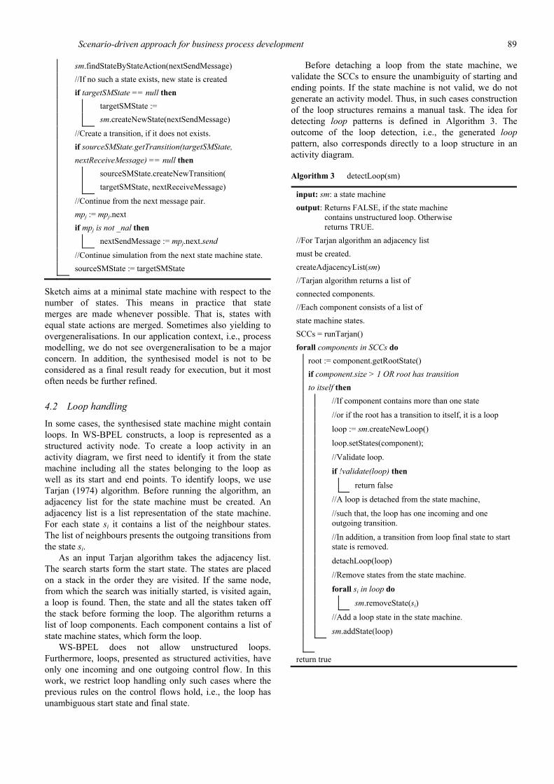
4.2 Loop handling
In some cases, the synthesised state machine might contain loops. In WS-BPEL constructs, a loop is represented as a structured activity node. To create a loop activity in an activity diagram, we first need to identify it from the state machine including all the states belonging to the loop as well as its start and end points. To identify loops, we use Tarjan (1974) algorithm. Before running the algorithm, an adjacency list for the state machine must be created. An adjacency list is a list representation of the state machine. For each state si it contains a list of the neighbour states. The list of neighbours presents the outgoing transitions from the state si.
As an input Tarjan algorithm takes the adjacency list. The search starts form the start state. The states are placed on a stack in the order they are visited. If the same node, from which the search was initially started, is visited again, a loop is found. Then, the state and all the states taken off the stack before forming the loop. The algorithm returns a list of loop components. Each component contains a list of state machine states, which form the loop.
WS-BPEL does not allow unstructured loops. Furthermore, loops, presented as structured activities, have only one incoming and one outgoing control flow. In this work, we restrict loop handling only such cases where the previous rules on the control flows hold, i.e., the loop has unambiguous start state and final state.
Before detaching a loop from the state machine, we validate the SCCs to ensure the unambiguity of starting and ending points. If the state machine is not valid, we do not generate an activity model. Thus, in such cases construction of the loop structures remains a manual task. The idea for detecting loop patterns is defined in Algorithm 3. The outcome of the loop detection, i.e., the generated loop pattern, also corresponds directly to a loop structure in an activity diagram.
Algorithm 3 detectLoop(sm)
input: sm: a state machine output: Returns FALSE, if the state machine
contains unstructured loop. Otherwise returns TRUE.
//For Tarjan algorithm an adjacency list must be created. createAdjacencyList(sm) //Tarjan algorithm returns a list of connected components. //Each component consists of a list of state machine states. SCCs = runTarjan() forall components in SCCs do
root := component.getRootState() if component.size > 1 OR root has transition to itself then
//If component contains more than one state
//or if the root has a transition to itself, it is a loop
loop := sm.createNewLoop()
loop.setStates(component);
//Validate loop.
if !validate(loop) then
return false
//A loop is detached from the state machine,
//such that, the loop has one incoming and one outgoing transition.
//In addition, a transition from loop final state to start state is removed.
detachLoop(loop)
//Remove states from the state machine.
forall si in loop do
sm.removeState(si)
//Add a loop state in the state machine.
sm.addState(loop)
return true

90 A. Ruokonen et al.
Loop validation is defined in Algorithm validate 4. It detects the loop start and loop end states. If either of them is ambiguous, it returns false. Algorithm 5 is used to detach the loop from the state machine. It utilises detachOutgoingTransitionsFromLoopEnd and detachIncomingTransitionsFromLoopStart algorithms to detach incoming and outgoing transitions from loop start and end states. In addition, it uses removeInternalTransitions to remove final transitions form loop end state to loop start state.
Algorithm 4 validate(loop)
input: loop: a loop output: If loop start and loop end states are
unambiguous, returns TRUE. Otherwise returns FALSE.
forall si in SCCList do forall transitions tj in si.Tout do if tj.target not in SCCList then exitStates.add(si)
forall transitions tk in si.Tin do if tk.source not in SCCList then inStates.add(si)
if exitStates:size != 1 then loopEnd = null return false else loopEnd = exitStates:getF irst()
if inStates:size != 1 then loopStart = null return false else loopStart = inStates:getF irst()
return true
Algorithm 5 detachLoop(loop)
input: loop: a loop component detachIncomingTransitionsFromLoopStart(loop) detachOutgoingTransitionsFromLoopEnd(loop) removeInternalTransitions(loop)
Before transforming the state machine into an activity diagram, all the loops in the state machine are removed and replaced by composite states, which contains all the states belonging to the loop including one initial and one final state.
4.3 State machine to activity diagram
In our implementation, the state machine representation is an intermediate deliverable towards an activity model.
Sketch further translates the synthesised state diagram into a UML activity diagram representation.
We have implemented a transformation form a state machine to an activity model in such a way that the resulting activity model enables further mapping into WS-BPEL code. In other words, we exploit domain-specific rules defined in the WS-BPEL profile. The main restriction addressed by the WS-BPEL profile is that each activity has at most one incoming and one outgoing control flow. First, we make a transformation into a workflow-flavoured activity model. Second, we run automatic pattern detection to identify and create WS-BPEL specific structures to construct a WS-BPEL flavoured activity model.
The following markings are used for defining the algorithms for activity diagrams:
Markings for an activity diagram • a is an activity model, which consists of a set of
activities ai • an activity ai has zero to many outgoing transitions,
ai.Tout being the set of outgoing transitions for an activity ai and Tout.size the number transitions in Tout
• an activity ai has zero to many incoming transitions, ai.Tin being the set of incoming transitions for an activity ai and Tin.size the number transitions in Tin
• each transition tk has exactly one source activity tk.source and exactly one target activity tk.target
• ai can be a structured activity, which contains zero to many other activities and exactly one initial activity node ai0 and one activity final node aif
• a has exactly one initial activity node a0 and one activity final node af
• af has zero outgoing transitions and a0 has zero incoming transitions.
Algorithm 6 detachIncomingTransitionsFromLoopStart(loop)
input: loop: a loop component //Create loop initial state sloopInitial := createLoopInitialState() //Remove incoming transitions forall transitions tk in loopStart.Tin do If tk.source not in SCCList then loopStart.removeIncomingTransitionEnd(tk) loop.addIncomingTransitionEnd(tk) if tk.source == loopEnd then // Remove final transition from source final to start state tk.source.removeTransitionEnd(tk)
sm.createTransition(sloopInitial,loopStart)

Scenario-driven approach for business process development 91
Algorithm 7 detachOutgoingTransitionsFromLoopEnd(loop)
input: loop: a loop component //Create loop final state sloopF inal := createLoopFinalState() //Remove ougoing transitions forall transitions tk in loopEnd.Tout do if tk.target not in SCCList then loopEnd.removeIncomingTransitionEnd(tk) loop.addOutgoingTransitionEnd(tk) sm.removeTransition(tk)
sm.createTransition(loopEnd,sloopF inal,)
Algorithm 8 removeInternalTransitions(loop)
input: loop: a loop component forall transitions tk in loopStart.Tin do if tk.source in SCCList then //Remove final transition from source state tk.source.removeTransition(tk);
handleState is an algorithm (Algorithm 9), which is used to recursively create an activity model from a state machine representation. Activities are created as a child either for the activity model or for a structured activity. The transformation begins from an initial state of the state machine (s0) with an empty activity model (a). Also, a parent structured activity node (astructured) is null. For each state and transition in the state machine, a corresponding activity and a control flow is created. Automatic transitions (null) and null state actions are ignored in the transformation and they do not produce new elements in the activity model.
As defined in Algorithm 10, handleStateTransition is used to create a receive activity for each state transition. For the transition target an activity node is again created and thus createActivityNode is called to create a corresponding activity node.
4.4 Pattern detection
In this paper, we only consider fully automated pattern detection. Given algorithms include detection for decision, join, invoke-reply, and loop structural workflow patterns. These can be concluded from the information already given in the scenarios, and not requiring additional knowledge for example from the user. Algorithms are recursive such that they are called also for each structured activity node (i.e., loop). In the following sections, algorithms for pattern detection from the activity model are described. They require that loop patterns are already detected and removed from the state machine as described in Section 4.3.
Algorithm 9 createActivityNode(a,astructured,apredecessor, si)
input: a: an activity model, astructured: a parent structured activity node (a loop),apredecessor: a previous activity node, si: a state machine state anew = null
if si is InitialState then //Create a final activity node if astructured is null then anew := a.newFinalNode() else anew := astructured.newFinalNode()
else if si is FinalState then
//Create an initial activity node
if astructured is null then anew := a.newStartNode() else anew := astructured.newStartNode()
else if si is loop then //Create a loop node anew := newLoopNode(astructured,si) if astructured is null then anew := a.newStructuredActivityNode() else anew := a.newStructuredActivityNode()
createActivityNode(anew, null, si.getLoopStartState()) else if si.getStateAction() != null then //If the state action is not null, create an invoke activity node. if astructured is null then anew := a.newInvokeActivityNode(si) else anew := astructured.newInvokeActivityNode(si)
//Create a control flow if apredecessor not null and anew not null then a.newControlFlow(astructured,apredecessor, anew) else //If no activity was created, continue from the previous activity. anew = apredecessor //If there are outgoing transitions, continue to create activities forall transitions in tk si.T do handleTransition(astructured,anew, tk)
92 A. Ruokonen et al.
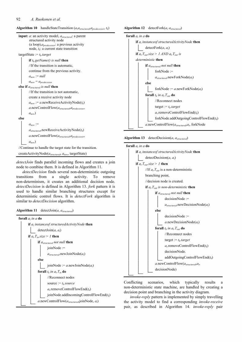
Algorithm 10 handleStateTransition (a,astructured,apredecessor, tk)
input: a: an activity model, astructured: a parent structured activity node (a loop),apredecessor: a previous activity node, tk: a current state transition
targetState := tk.target if tk.getName() is null then //If the transition is automatic, continue from the previous activity. anew := null anew = apredecessor else if astructured is null then //If the transition is not automatic, create a receive activity node anew := a.newReceiveActivityNode(tk) a.newControlFlow(astructured,apredecessor, anew) else anew := astructured.newReceiveActivityNode(tk) a.newControlFlow(astructured,apredecessor, anew)
//Continue to handle the target state for the transition. createActivityNode(astructured, anew, targetState)
detectJoin finds parallel incoming flows and creates a join node to combine them. It is defined in Algorithm 11.
detectDecision finds several non-deterministic outgoing transitions from a single activity. To remove non-determinism, it creates an additional decision node. detectDecision is defined in Algorithm 13. fork pattern it is used to handle similar branching structures except for deterministic control flows. It is detectFork algorithm is similar to detectDecision algorithm.
Algorithm 11 detectJoin(a, astructured)
forall ai in a do if ai instanceof structuredActivityNode then detectJoin(a, ai)
if ai.Tin.size > 1 then if astructured not null then joinNode := astructured.newJoinNode(ai) else joinNode := a.newJoinNode(ai)
forall tk in ai.Tin do //Reconnect nodes source := tk.source ai.removeControlFlowEnd(tk) joinNode.addIncomingControlFlowEnd(tk)
a.newControlFlow(astructured,joinNode, ai)
Algorithm 12 detectFork(a, astructured)
forall ai in a do if ai instanceof structuredActivityNode then detectFork(a, ai)
if ai.Tout.size > 1 AND ai.Tout is deterministic then if astructured not null then forkNode := astructured.newForkNode(ai) else forkNode := a.newForkNode(ai)
forall tk in ai.Tout do //Reconnect nodes target := tk.target ai.removeControlFlowEnd(tk) forkNode.addOutgoingControlFlowEnd(tk)
a.newControlFlow(astructured,ai, forkNode
Algorithm 13 detectDecision(a, astructured)
forall ai in a do if ai instanceof structuredActivityNode then detectDecision(a, ai)
if ai.Tout.size > 1 then //If ai.Tout is a non-deterministic branching point, //decision node is created. if ai.Tout is non-deterministic then if astructured not null then decisionNode := astructured.newDecisionNode(ai) else decisionNode := a.newDecisionNode(ai)
forall tk in ai.Tout do //Reconnect nodes target := tk.target ai.removeControlFlowEnd(tk) decisionNode. addOutgoingControlFlowEnd(tk)
a.newControlFlow(astructured,ai, decisionNode)
Conflicting scenarios, which typically results a non-deterministic state machine, are handled by creating a decision point and branching in the activity diagram.
invoke-reply pattern is implemented by simply travelling the activity model to find a corresponding invoke-receive pair, as described in Algorithm 14. invoke-reply pair
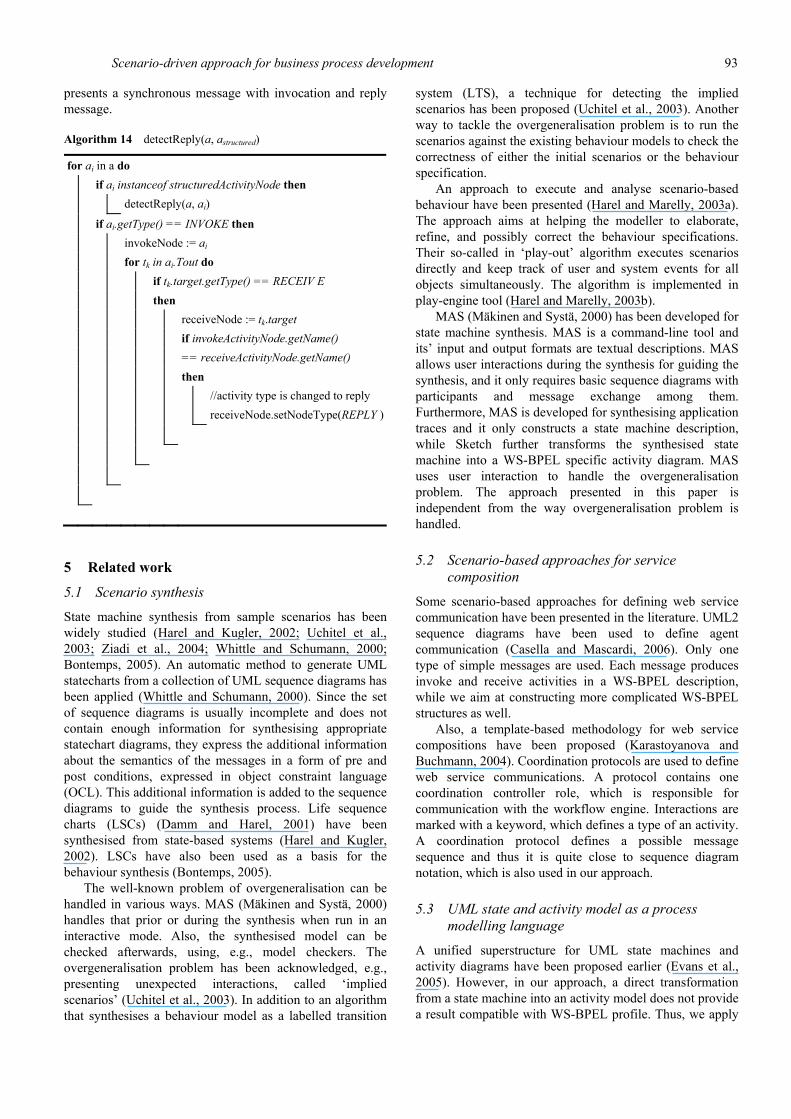
Scenario-driven approach for business process development 93
presents a synchronous message with invocation and reply message.
Algorithm 14 detectReply(a, astructured)
for ai in a do if ai instanceof structuredActivityNode then detectReply(a, ai)
if ai.getType() == INVOKE then invokeNode := ai for tk in ai.Tout do if tk.target.getType() == RECEIV E then receiveNode := tk.target if invokeActivityNode.getName() == receiveActivityNode.getName() then //activity type is changed to reply receiveNode.setNodeType(REPLY )
5 Related work
5.1 Scenario synthesis
State machine synthesis from sample scenarios has been widely studied (Harel and Kugler, 2002; Uchitel et al., 2003; Ziadi et al., 2004; Whittle and Schumann, 2000; Bontemps, 2005). An automatic method to generate UML statecharts from a collection of UML sequence diagrams has been applied (Whittle and Schumann, 2000). Since the set of sequence diagrams is usually incomplete and does not contain enough information for synthesising appropriate statechart diagrams, they express the additional information about the semantics of the messages in a form of pre and post conditions, expressed in object constraint language (OCL). This additional information is added to the sequence diagrams to guide the synthesis process. Life sequence charts (LSCs) (Damm and Harel, 2001) have been synthesised from state-based systems (Harel and Kugler, 2002). LSCs have also been used as a basis for the behaviour synthesis (Bontemps, 2005).
The well-known problem of overgeneralisation can be handled in various ways. MAS (Mäkinen and Systä, 2000) handles that prior or during the synthesis when run in an interactive mode. Also, the synthesised model can be checked afterwards, using, e.g., model checkers. The overgeneralisation problem has been acknowledged, e.g., presenting unexpected interactions, called ‘implied scenarios’ (Uchitel et al., 2003). In addition to an algorithm that synthesises a behaviour model as a labelled transition
system (LTS), a technique for detecting the implied scenarios has been proposed (Uchitel et al., 2003). Another way to tackle the overgeneralisation problem is to run the scenarios against the existing behaviour models to check the correctness of either the initial scenarios or the behaviour specification.
An approach to execute and analyse scenario-based behaviour have been presented (Harel and Marelly, 2003a). The approach aims at helping the modeller to elaborate, refine, and possibly correct the behaviour specifications. Their so-called in ‘play-out’ algorithm executes scenarios directly and keep track of user and system events for all objects simultaneously. The algorithm is implemented in play-engine tool (Harel and Marelly, 2003b).
MAS (Mäkinen and Systä, 2000) has been developed for state machine synthesis. MAS is a command-line tool and its’ input and output formats are textual descriptions. MAS allows user interactions during the synthesis for guiding the synthesis, and it only requires basic sequence diagrams with participants and message exchange among them. Furthermore, MAS is developed for synthesising application traces and it only constructs a state machine description, while Sketch further transforms the synthesised state machine into a WS-BPEL specific activity diagram. MAS uses user interaction to handle the overgeneralisation problem. The approach presented in this paper is independent from the way overgeneralisation problem is handled.
5.2 Scenario-based approaches for service composition
Some scenario-based approaches for defining web service communication have been presented in the literature. UML2 sequence diagrams have been used to define agent communication (Casella and Mascardi, 2006). Only one type of simple messages are used. Each message produces invoke and receive activities in a WS-BPEL description, while we aim at constructing more complicated WS-BPEL structures as well.
Also, a template-based methodology for web service compositions have been proposed (Karastoyanova and Buchmann, 2004). Coordination protocols are used to define web service communications. A protocol contains one coordination controller role, which is responsible for communication with the workflow engine. Interactions are marked with a keyword, which defines a type of an activity. A coordination protocol defines a possible message sequence and thus it is quite close to sequence diagram notation, which is also used in our approach.
5.3 UML state and activity model as a process modelling language
A unified superstructure for UML state machines and activity diagrams have been proposed earlier (Evans et al., 2005). However, in our approach, a direct transformation from a state machine into an activity model does not provide a result compatible with WS-BPEL profile. Thus, we apply
94 A. Ruokonen et al.
a domain-specific mapping, meaning that the resulting activity diagram is created according to WS-BPEL profile rules and it is customised with WS-BPEL specific stereotypes and structures.
In some approaches, state machines have been used for modelling business processes, including transformation into WS-BPEL. Especially, state-oriented approaches have proven to be successful for modelling high level human-driven workflows (Shi et al., 2008). However, UML activity diagram notation provides many of the workflow modelling constructs and is closer to BPMN. It is often used for process modelling by IT professionals.
5.4 Process and decision mining
Business process mining aims at the automatic construction of process models (van der Aalst et al., 2007; van der Aalst, 2006). In process mining, the process behaviour is discovered based on the observed event log. The event log, i.e., trace, defines the possible execution paths, which are merged into a state presentation. The process mining has similar motivation as our approach and similar techniques are used.
In scenario mining, invisible tasks, which belong to process model but cannot be found from the process log, must be usually constructed manually. Similarly, in our approach, for example, assign copy activities for copying of process variables and evaluation criteria for decision nodes need to be created manually.
Decision mining aims at automatically detecting decision points, i.e., how data dependencies affect the process flow. Decision mining approaches are usually applied to initial process model, which might be a result of applying some process mining algorithm. In case of Sketch, synthesised workflow model can be used as a target for decision mining.
Affect of the values of data attributes on the process routing have been studied (Rozinat and van der Aalst, 2006). In the study, decision points are turned into a learning problem and machine learning techniques, like decision tree, have been applied for Petri net-based models. Similar techniques have been applied also for restructuring WS-BPEL descriptions into more structured and readable form (van der Aalst and Lassen, 2008). Process restructuring can be useful for process redocumentation.
Process and decision mining techniques have also been applied for conformance checking as described (Rozinat and van der Aalst, 2008). The approach aims at finding inconsistencies between the event log and the corresponding process model.
5.5 WS-BPEL generation from graph-based models
Several transformation approaches to generate WS-BPEL code from graphical models like BPMN and UML activity models exist (Kalnins et al., 2004; Kalnins and Vitolins, 2006; BPMI, 2004; ETTK, 2006; Lohmann et al., 2007). For example, in our earlier work, we have developed a tool
to generate WS-BPEL descriptions from UML activity models (Pajunen and Ruokonen, 2007). In this approach, we define a subset of UML with WS-BPEL specific stereotypes and constraints, called a WS-BPEL profile. Models that confirm to the WS-BPEL profile can be used as a source for transformation into WS-BPEL.
However, there is a slight mismatch between graph-oriented BPMNs and XML-based block-oriented WS-BPEL. WS-BPEL uses two ways of modelling: a structured block style and a graph-based flow concept. Nevertheless, graph-style in WS-BPEL is essentially restricted and it does not allow arbitrary cycles, which are usually supported in graph-based modelling notations. With a human designer unsupported structures can be avoided, for example, by using a limited subset of the modelling language and proper tool support. However, for example automatic process mining and synthesis approaches sometimes result unstructured models, which do not allow direct mapping into WS-BPEL descriptions.
The issue of handling unstructured models have been studied earlier. SQPR-tree decomposition techniques have been applied for translating BPMN models to WS-BPEL code (Banuelos, 2009). A tree-based calculation approach for eliminating unstructured loops have been presented (Sandberg, 2003). Tree-based calculation produces several distinct parallel branches in the process model. As a drawback, some information might get lost or the result is not very intuitive. Especially, if some manual process refinement is needed, readable process models are highly valued. Thus, in our approach, we do not further transform unstructured state machines into a process model.
6 Discussion
The underlying goal of our approach is to provide a simple method, meaning easy to use and understand, for business processes modelling. The simple functional requirements are captured as scenarios, which are automatically synthesised into an initial process model. However, the scenarios are not meant to capture all the system requirement such as non-functional and detailed technical requirements. Thus, the resulting WS-BPEL specific process model is not expected to be a final model. Instead, it usually requires some manual further refinement, possibly taken care of by IT-oriented persons.
We have presented the Sketch tool, which is our implementation of the approach. We have also presented the implemented algorithms. Our tool, as well as the algorithms, assumes use of UML models, i.e., the input is a UML sequence model capturing a set of scenarios. The Sketch tool supports automatic detection on simple WS-BPEL specific structures, i.e., patterns. In some cases, automatic pattern detection is simply not enough and additional information is needed. For example, there might be alternative patterns to be applied or more complicated structures need to be created, for example different type of flow branching, handling of parallel flows, and flow synchronisation. However, since we only can detect simple

Scenario-driven approach for business process development 95
structures, the more advanced features must be specified manually in process refinement phase if needed.
The approach is targeted for business processes which utilise operation-centric web services. It has limited applicability with resource-oriented and data-centric services. In addition to case studies presented in this paper, we have conducted a case study on modelling a shopping cart functionality. The shopping cart process utilised several low level entity services each providing standard operations like save, add, and remove. However, due to use of low level data-centric services the resulting state machine contained several overlapping loops and lots of state merges was done. For such low level and/or data-oriented services, scenario-driven approach might not be an intuitive starting point. That is, the synthesis is likely to produce unstructured models, which do not enable direct mapping into WS-BPEL. In addition, complicated loop structures typically produce overgeneralisation and loss of information. In our implementation, such models are not further transformed into an initial process model before manually removing unstructured loops.
7 Conclusions
In this paper, we have proposed a scenario-driven approach to develop business processes realised as WS-BPEL-based web service orchestrations. To provide an easy to use and intuitive method, usable also for non-IT people, the approach starts from sketching the functional process requirements as scenarios described with just a sequence of sent and received messages among the services. After the key scenarios are sketched, they are synthesised into a state machine. The state machine is further translated into a WS-BPEL flavoured activity model, i.e., a process model skeleton, which enables mapping into a WS-BPEL description. The process skeleton can be refined by adding some details needed to generate executable WS-BPEL code. The approach promotes requirement propagation from functional requirements into executable business processes. This is essential when aiming at bridging business and IT views.
We have developed a tool called Sketch, which realises the proposed approach. In this paper, we have defined the implemented algorithms for state machine synthesis, activity diagram transformation, and detection of WS-BPEL specific structures. We have discussed applicability and limitations of the approach. As applications of the approach, we have presented two cases, development of a simple loan manager process and an industry case study from a logistics provider.
References Amsden, J., Gardner, T., Griffin, C. and Iyengar, S. (2004) Draft
UML 1.4 Profile for Automated Business Processes with a Mapping to BPEL 1.0. Version 1.1, IBM.
Andrews, T., Curbera, F., Dholakia, H., Goland, Y., Klein, J., Leymann, F., Liu, K., Roller, D., Smith, D., Thatte, S., Trickovic, I. and Weerawarana, S. (2003) Business Process Execution Language for Web Services Version 1.1, IBM.
Banuelos, L.G. (2009) ‘Translating BPMN models to BPEL code’, in Proc. of Graph-Based Tool Contest – Solutions to Case Studies (raBaTs 2009).
Bontemps, Y. (2005) ‘Relating inter-agent and intra-agent specifications (the case of live sequence charts)’, PhD thesis.
Business Process Modeling Language (BPMI) (2004) Available at http://www.bpmi.org/ (accessed on December 2011).
Casella, G. and Mascardi, V. (2006) ‘From AUML to WS-BPEL’, available at http://www.disi.unige.it/person/MascardiV/Download/ DISI-TR-06-01.pdf (accessed on December 2011).
Damm, W. and Harel, D. (2001) ‘LSCs: breathing life into message sequence charts’, Formal Methods in System Design, Vol. 19, No. 1, pp.45–80.
Eclipse (2005) Available at http://www.eclipse.org (accessed on December 2011).
Emerging Technologies Toolkit (ETTK) (2006) ‘alphaWorks’, Available at http://www.alphaworks.ibm.com/, IBM (accessed on December 2011).
Evans, A., Sammut, P., Willans, J.S., Moore, A. and Rama, G.M. (2005) ‘A unified superstructure for UML’, JOT, Vol. 4, No. 1, pp.165–182.
Harel, D. and Kugler, H. (2002) ‘Synthesizing state-based object systems from LSC specifications’, IJFCS, Vol. 13, No. 1, pp.5–51.
Harel, D. and Marelly, R. (2003a) ‘Specifying and executing behavioral requirements: the play-in/play-out approach’, SoSyM, Vol. 2, No. 2, pp.82–107.
Harel, D. and Marelly, R. (2003b) Come, Let's Play: Scenario-Based Programming Using LSCs and the Play-Engine, Springer-Verlag New York, Inc., Secaucus, NJ, USA.
Jaelson, C., Kolp, M. and Mylopouluos, J. (2001) ‘A requirements-driven development methodology’, in Proc. of the 13th International Conference on Advanced Information Systems Engineering (CAiSE '01), Springer-Verlag, 3-540-42215-3, pp.108–123.
Kalnins, A. and Vitolins, V. (2006) ‘Use of UML and model transformations for workflow process definitions’, in Proc. of Baltic DBIS '06, pp.3–14.
Kalnins, A., Barzdins, J. and Celms, E. (2004) ‘Model transformation language MOLA’, in U. Amann, M. Aksit and A. Rensink (Eds.): MDAFA, Vol. 3599 of LNCS, pp.62–76, Springer.
Karastoyanova, D. and Buchmann, A. (2004) ‘A methodology for development and execution of web service-based business processes’, in Proc. of 1st Australian Workshop on Engineering Service-Oriented Systems, Melbourne.
Lohmann, C., Greenyer, J., Jiang, J. and Syst, T. (2007) ‘Applying triple graph grammars for pattern-based workflow model transformations’, in Proc. of TOOLS 2007, JOT.
Mäkinen, E. and Systä, T. (2000) ‘Implementing minimally adequate synthesizer’, Report A-2000-9.
Mäkinen, E. and Systä, T. (2000) ‘Minimally adequate teacher designs software’, Report A-2000-7.

96 A. Ruokonen et al.
Pajunen, L. and Ruokonen, A. (2007) ‘Modeling and generating mobile business processes’, in IEEE 7th International Conference on Web Services (ICWS 2007), IEEE, Salt Lake City, Utah, USA, pp.920–927.
Rozinat, A. and van der Aalst, W.M.P. (2006) ‘Decision mining in proM’, Lecture Notes in Computer Science: Business Process Management, Vol. 4102, pp.420–425, LNCS.
Rozinat, A. and van der Aalst, W.M.P. (2008) ‘Conformance checking of processes based on monitoring real behavior’, Inf. Syst., Vol. 33, No. 1, pp.64–95.
Rumbaugh, C. (1994) ‘Getting started: using use cases to capture requirements’, JOOP, Vol. 7, No. 5, pp.8–12.
Ruokonen, A., Pajunen, L. and Systä, T. (2009) ‘Scenario-driven approach for business process modeling’, in IEEE 7th International Conference on Web Services (ICWS 2009), IEEE, Los Angeles, CA, USA.
Sandberg, C. (2003) ‘Elimination of unstructured loops in flow analysis’, in WCET 2003 Workshop.
Shi, W., Wu, J., Zhou, S., Zhang, L., Yin, Y. and Wu, Z. (2008) ‘Facilitating the flexible modeling of human-driven workflow in BPEL’, in Proc. of AINAW '08, IEEE, Gino-wan, Okinawa, Japan, pp.1615–1624.
Tarjan, R.E. (1974) ‘Testing flow graph reducibility’, Journal of Computer and System Sciences, Vol. 9, No. 3, pp.355–365.
Uchitel, S., Kramer, J. and Magee, J. (2003) ‘Synthesis of behavioral models from scenarios’, IEEE Trans. Softw. Eng., Vol. 29, No. 2, pp.99–115.
van der Aalst, W.M.P. (2006) ‘06291 workshop report: Process mining, monitoring processes and services’, in Leymann, F., Reisig, W., Thatte, S.R. and van der Aalst, W.M.P. (Eds.): The Role of Business Processes in Service Oriented Architectures, in Dagstuhl Seminar Proceedings, number 06291, Internationales Begegnungsund Forschungszentrum fuer Informatik (IBFI), Schloss Dagstuhl, Germany.
van der Aalst, W.M.P. and Lassen, K.B. (2008) ‘Translating unstructured workflow processes to readable BPEL: theory and implementation’, Inf. Softw. Technol., Vol. 50, No. 3, pp.131–159.
van der Aalst, W.M.P., Reijers, H.A., Weijters, A.J., van Dongen, B.F., Alves de Medeiros, A.K., Song, M. and Verbeek, H.M.W. (2007) ‘Business process mining: an industrial application’, Inf. Syst., Vol. 32, No. 5, pp.713–732.
Whittle, J. and Schumann, J. (2000) ‘Generating statechart designs from scenarios’, in Proc. of International Conference on Software Engineering (ICSE'00), ACM Press, pp.314–323.
Ziadi, T., Hélouët, L. and Jézéquel, J-M. (2004) ‘Revisiting statechart synthesis with an algebraic approach’, in Proc. of International Conference on Software Engineering (ICSE '04), pp.242–251.