Towards a pattern-based framework for goal-driven business process modeling
9
Towards a Pattern-Based Framework for Goal-Driven Business Process Modeling Saeed Ahmadi Behnam, Daniel Amyot, Gunter Mussbacher University of Ottawa 800 King Edward Avenue, Ottawa, Ontario, Canada [email protected], {damyot | gunterm}@site.uottawa.ca Abstract—In organizations, a gap commonly exists between busi- ness goals and business processes. While several approaches pro- vide modeling solutions in each of these two areas, their relation- ships are often not defined well enough to be used in the software development process. This paper aims to better fill this gap through the introduction of a pattern-based framework that helps construct business processes from organization goals while maintaining traceability relationships between the two. How to extract patterns, which are composed of goal templates, process templates, and their relationships, is briefly presented. The framework, which includes a collection of patterns for a particu- lar domain, is formalized as a profile of the User Requirements Notation, a standard modeling language that supports goals, sce- narios, and links between them. A method for the use of such framework is defined and then illustrated through a case study involving an adverse event management system that targets the improvement of patient safety in healthcare organizations. Keywords—Business Processes; Goal Modeling; Healthcare; Patterns; User Requirements Notation. I. INTRODUCTION Business goals drive the definition of requirements for dif- ferent business processes. In this paper, we consider a business goal as a desired situation for one or more stakeholders. A problem exists if the current situation diverges too much from the desired situation. During problem solving, stakeholders evaluate the importance of their problems and thus prioritize their business goals. A business process can be seen as a se- quence of activities that satisfy the goals by decreasing the dis- tance between the current situation and the stakeholder’s de- sired situation. For example in a particular hospital, having less than a certain number of adverse events (i.e., bad outcomes) is a high-level goal of the clinical department, while minimizing cost is a goal of the finance department. The problem is hence to cost-effectively decrease the current number of adverse events to less than a tolerable number. Business processes im- plemented in the hospital are in turn responsible for making this happen. The value of software applications supporting these processes is based on how well the business goals are satisfied. However, organizations often have difficulties in properly identifying their goals and linking them to their busi- ness processes. There are additional challenges in going from descriptions of automatable business processes to their imple- mentation as software applications. Two gaps representing these difficulties of transforming business goals to business processes and then to software applications are identified in Figure 1. This figure also shows the conventional roles typi- cally associated with the artifacts discussed so far (business analyst for business goals, business process analyst for business processes, and developer for software applications). Modeling can help formalize and document such artifacts. For example, just to name a few possibilities: • Goal models can be described with the i* frame- work [1] or with the Goal-oriented Requirement Lan- guage (GRL) [2]. • Processes can be modeled with the Business Process Modeling Notation (BPMN) [3] or with Use Case Maps (UCM) [2]. • Software can be modeled with the Unified Modeling Language (UML) [4]. Figure 1. Gaps between different levels of the software development process The gap between business processes and software applica- tions has received much attention over the past decade, and dedicated technologies such as the Web Service Business Proc- ess Execution Language (WSBPEL) [5] have emerged. Also, the Object Management Group’s Model-Driven Architecture (MDA) [6], a well-known incarnation of the Model-Driven Engineering (MDE) transformation approach [7], can help formalize and automate the generation of software from busi- ness process models. However, the gap between business goals and business processes has received far less attention. Yet, not addressing this gap leads to problems typically identified by senior executives [8], such as: • Information Technology (IT) investments are unrelated to business strategies. • Payoff from IT investments is inadequate. • There is too much "technology for technology's sake." Consequently, many software development projects yield disappointing results or are simply canceled because software applications and business processes are not aligned properly with business goals [9]. Modeling business goals and processes separately is not sufficient to bridge this gap; alignment of goals and processes
-
Upload
independent -
Category
Documents
-
view
0 -
download
0
Transcript of Towards a pattern-based framework for goal-driven business process modeling

Towards a Pattern-Based Framework for Goal-Driven Business Process Modeling
Saeed Ahmadi Behnam, Daniel Amyot, Gunter Mussbacher University of Ottawa
800 King Edward Avenue, Ottawa, Ontario, Canada [email protected], {damyot | gunterm}@site.uottawa.ca
Abstract—In organizations, a gap commonly exists between busi-ness goals and business processes. While several approaches pro-vide modeling solutions in each of these two areas, their relation-ships are often not defined well enough to be used in the software development process. This paper aims to better fill this gap through the introduction of a pattern-based framework that helps construct business processes from organization goals while maintaining traceability relationships between the two. How to extract patterns, which are composed of goal templates, process templates, and their relationships, is briefly presented. The framework, which includes a collection of patterns for a particu-lar domain, is formalized as a profile of the User Requirements Notation, a standard modeling language that supports goals, sce-narios, and links between them. A method for the use of such framework is defined and then illustrated through a case study involving an adverse event management system that targets the improvement of patient safety in healthcare organizations.
Keywords—Business Processes; Goal Modeling; Healthcare; Patterns; User Requirements Notation.
I. INTRODUCTION Business goals drive the definition of requirements for dif-
ferent business processes. In this paper, we consider a business goal as a desired situation for one or more stakeholders. A problem exists if the current situation diverges too much from the desired situation. During problem solving, stakeholders evaluate the importance of their problems and thus prioritize their business goals. A business process can be seen as a se-quence of activities that satisfy the goals by decreasing the dis-tance between the current situation and the stakeholder’s de-sired situation. For example in a particular hospital, having less than a certain number of adverse events (i.e., bad outcomes) is a high-level goal of the clinical department, while minimizing cost is a goal of the finance department. The problem is hence to cost-effectively decrease the current number of adverse events to less than a tolerable number. Business processes im-plemented in the hospital are in turn responsible for making this happen. The value of software applications supporting these processes is based on how well the business goals are satisfied. However, organizations often have difficulties in properly identifying their goals and linking them to their busi-ness processes. There are additional challenges in going from descriptions of automatable business processes to their imple-mentation as software applications. Two gaps representing these difficulties of transforming business goals to business processes and then to software applications are identified in Figure 1. This figure also shows the conventional roles typi-cally associated with the artifacts discussed so far (business analyst for business goals, business process analyst for business processes, and developer for software applications).
Modeling can help formalize and document such artifacts. For example, just to name a few possibilities:
• Goal models can be described with the i* frame-work [1] or with the Goal-oriented Requirement Lan-guage (GRL) [2].
• Processes can be modeled with the Business Process Modeling Notation (BPMN) [3] or with Use Case Maps (UCM) [2].
• Software can be modeled with the Unified Modeling Language (UML) [4].
Figure 1. Gaps between different levels of the software
development process
The gap between business processes and software applica-tions has received much attention over the past decade, and dedicated technologies such as the Web Service Business Proc-ess Execution Language (WSBPEL) [5] have emerged. Also, the Object Management Group’s Model-Driven Architecture (MDA) [6], a well-known incarnation of the Model-Driven Engineering (MDE) transformation approach [7], can help formalize and automate the generation of software from busi-ness process models. However, the gap between business goals and business processes has received far less attention. Yet, not addressing this gap leads to problems typically identified by senior executives [8], such as:
• Information Technology (IT) investments are unrelated to business strategies.
• Payoff from IT investments is inadequate. • There is too much "technology for technology's sake." Consequently, many software development projects yield
disappointing results or are simply canceled because software applications and business processes are not aligned properly with business goals [9].
Modeling business goals and processes separately is not sufficient to bridge this gap; alignment of goals and processes

as well as traceability must also be taken into account. In addi-tion, defining such models is challenging, especially when done from scratch. Reusing domain expertise captured in the form of patterns can often help address this issue. For instance, design patterns have been quite successful in the construction of soft-ware applications [10]. However, patterns that span business goals and processes are far less common.
This paper introduces a new method to help business ana-lysts bridge the gap between business goals and processes (Figure 1). This method is goal-driven because one of its inputs is a partial business goal model where only some of the high-level goals need to be identified. The main output of the method is a more complete goal model combined with a busi-ness process that is aligned with the identified goals, as well as additional traceability links between the two views. This ap-proach complies with the spirit of MDE while including goal models in the chain of transformations. Another input of our method, which is the key enabler for transforming business goals into business processes, is a pattern-based framework that specifies typical refinements of goals in terms of processes for a particular domain (e.g., healthcare). In addition, the frame-work helps assess the impact of strategic alternatives for achieving the high-level goals. The method and the framework build on the User Requirements Notation (URN) [2][11], an international standard that already combines goal and scenario modeling into a single language.
The paper is organized as follows. Section II presents back-ground information on URN and patterns. Then, section III describes how patterns in our framework can be extracted for a given domain, with an illustrative example where the main goal is patient safety in a healthcare organization. Section IV pre-sents how the framework is formalized with the help of URN. Section V gives an overview of the proposed method, illustrat-ing the application of the framework in the context of a specific organization with a case study focusing on the development of an Adverse Event Management System (AEMS) for a hospital. Sections VI and VII follow with a discussion, our conclusions, and future work.
II. BACKGROUND ON URN AND PATTERNS
A. User Requirements Notation The User Requirements Notation (URN) is a standard of the
International Telecommunication Union intended for the elici-tation, analysis, specification, and validation of requirements using a combination of goal-oriented and scenario-based mod-eling [2]. URN allows software and requirements engineers to discover and specify requirements for a proposed system or an evolving system, and analyze such requirements for correctness and completeness. Although the main application domain for URN is reactive and telecommunications systems, it has also been applied successfully to the modeling and analysis of busi-ness goals and processes [12].
URN contains two complementary graphical modeling lan-guages, namely GRL and UCM. The Goal-oriented Require-ment Language (GRL) enables the modeling of stakeholders, business goals, non-functional requirements (NFRs), alterna-tives, and rationales. Modeling goals and NFRs of stakeholders with GRL makes it possible to understand the problem that ought to be solved. GRL enables business analysts and IT ar-chitects to model strategic goals and concerns using various
types of intentional elements and relationships, as well as their stakeholders called actors ( ). Core intentional elements in-clude goals ( ), softgoals ( ) for qualities and non-functional requirements, and tasks ( ) for activities and al-ternative solutions. Intentional elements can also be linked by AND/OR decompositions, dependencies, and contributions. Various qualitative positive and negative contribution levels exist as well as quantitative contribution levels on a [-100, 100] scale. Correlations are similar to contributions but depict side-effects rather than desired impact.
For example, the left side of Figure 2 depicts a GRL model that describes the main goal Increase Patient Safety for an Ad-verse Event Management System (AEMS) in a hospital. In-crease Patient Safety may be realized by its four sub-goals Collect Data, Generate Informative Outcome Information, Make Safety Decision, and Adopt Decision as shown by the contribu-tion links (solid lines) while having side-effects on two other high-level softgoals Increase Quality of Care in Long Term and Decrease Costs as shown by the correlations (dashed lines). In addition, some of the sub-goals require Deploy Advanced Infra-structure to be achieved as indicated by the dependencies (i.e., an advanced infrastructure must be available for making and adopting safety decision). Quantitative contribution levels are defined for the contributions and correlations.
GRL evaluation strategies enable modelers to assign initial satisfaction values to some of the intentional elements (usually alternatives at the bottom of a goal graph) and propagate this information to the other elements through the decomposition, dependency, and contribution links [13]. In addition, impor-tance values are usually defined for high-level goals of stake-holders in a quantitative range of [0, 100] or with qualitative labels such as High, Medium, Low, or None. This ultimately helps assess the impact of alternative solutions on high-level goals of the involved stakeholders. Such models are also useful for evaluating trade-offs and documenting decision rationales.
The Use Case Map (UCM) notation is a visual process modeling language for specifying causal scenarios and option-ally binding their responsibilities ( ) to an underlying struc-ture of components ( ). Responsibilities represent activities performed in a process whereas components represent actors, systems, and system parts. UCMs support most of the concepts used in common workflow modeling notations including start points ( ), end points (|) as well as alternative and concurrent flows. Stubs ( ) are containers for sub-maps and may be used to organize a complex model in a hierarchical structure as shown on the right side of Figure 2. This example illustrates two high-level UCM business processes for accomplishing Increase Patient Safety. Stubs describe the major steps in the business process (i.e., Collecting Data, Generating Informative Outcome Information, Making Safety Decision, and Adopting Decision) and an OR-fork and an OR-join denote a loop. The bottom right UCM in Figure 3 makes use of an AND-fork and an AND-join to model concurrency.
Furthermore, URN allows typed links to be established be-tween modeling elements (e.g., goal and scenario model ele-ments). These links are called URN links. URN also supports the annotation of any model element with metadata, which are name-value pairs. For example, Increase Patient Safety in the GRL model in Figure 2 is stereotyped as the main goal with the «main» metadata tag. URN links and metadata, together with

Making SafetyDecision
AdoptingDecision
Business Process Template
CollectingData
Generating InformativeOutcome Information
Business Process Template
the possibility of adding constraints in UML’s Object Con-straint Language (OCL), enable URN to be profiled to a par-ticular application domain in a lightweight fashion [14].
jUCMNav is an open source URN tool for the creation, analysis, and management of URN models [15]. It allows for the qualitative, quantitative, or hybrid evaluation of GRL mod-els according to strategies. jUCMNav is an Eclipse plug-in that also supports extensions to URN for modeling key perform-ance indicators in the context of business process analysis and monitoring and performance management [16]. It also supports
the verification of user-defined OCL constraints to enforce compliance to URN profiles [14].
B. Patterns Patterns have been proposed to categorize knowledge of re-
curring problems and give advice on possible solutions to those problems [9][17]. Patterns provide an abstract description of a problem and a solution for that problem along with a descrip-tion of the context of use and the forces at play. Forces typi-cally discuss the reasons for using the suggested solution for the given problem in the given context. A pattern is a reusable
Increase Quality ofCare in Long Term
«external» Decrease Costs«external»
Deploy Advanced Infrastructure
«external»
Goal Template
Increase Patient Safety «main»
1st Strategy: A
GenerateInformative Outcome
Information
CollectData
Make SafetyDecision
AdoptDecision
CollectingData
Generating InformativeOutcome Information
A
A
A
B
B
B
B
B
50
5050
50
2nd Strategy: B
25 25
75
75
-25-25
Making SafetyDecision
AdoptingDecision
Business Process TemplateBusiness Process Template
CollectingData
Generating InformativeOutcome Information
Business Process TemplateBusiness Process Template
Increase Quality ofCare in Long Term
«external»
Increase Quality ofCare in Long Term
«external» Decrease Costs«external»
Decrease Costs«external»
Deploy Advanced Infrastructure
«external»
Deploy Advanced Infrastructure
«external»
Goal Template
Increase Patient Safety «main»
Increase Patient Safety «main»
1st Strategy: A1st Strategy: A
GenerateInformative Outcome
Information
GenerateInformative Outcome
Information
CollectData
CollectData
Make SafetyDecision
Make SafetyDecision
AdoptDecision
AdoptDecision
CollectingData
AA
Generating InformativeOutcome Information
AA
AA
BB
BB BB
BB BB
50
5050
50
2nd Strategy: B2nd Strategy: B
25 25
75
75
-25-25
Figure 2. Increase Patient Safety Pattern
Business Process Template
Increase Quality ofCare in Long Term
«external»
Goal Template
Collect Data«main»
Collect Outcome Data
CollectingOutcome Data
Business Process TemplateC
C
E
E D ECollect
Process Data
CollectingProcess Data
Business Process TemplateD
CollectingOutcome Data
CollectingProcess Data
1st Strategy: C 2nd Strategy: D 3rd Strategy: E
50 50
25 75
Business Process TemplateBusiness Process Template
Increase Quality ofCare in Long Term
«external»
Increase Quality ofCare in Long Term
«external»
Goal Template
Collect Data«main»
Collect Data«main»
Collect Outcome Data
Collect Outcome Data
CollectingOutcome Data
Business Process TemplateC
CollectingOutcome Data
Business Process TemplateCC
CC
EE
EE DD EECollect
Process DataCollect
Process Data
CollectingProcess Data
D Business Process Template
CollectingProcess Data
DD Business Process Template
CollectingOutcome Data
CollectingProcess Data
1st Strategy: C1st Strategy: C 2nd Strategy: D2nd Strategy: D 3rd Strategy: E3rd Strategy: E
50 50
25 75
Figure 3. Collect Data Pattern

model that describes a need and solves a problem which may occur at different levels of abstraction and in different domains (e.g., in the area of software engineering with design pat-terns [9] or in the area of conceptual modeling with analysis patterns [18]).
Patterns have been described with URN [19] by formalizing a) the description of forces with GRL’s intentional elements as well as contribution and correlation links and b) the solution with UCM models that provide a more detailed description of the behavior and structure of the solution suggested by the pat-tern. This paper applies and extends the basic framework in [19] to business process modeling and illustrates the ex-tended framework in the context of health information systems.
III. ESTABLISHING THE FRAMEWORK In the context of this paper, we define a framework as a set
of customizable models consisting of a set of problems and solutions in the form of patterns. A pattern in our proposed framework contains a goal template, business strategies, busi-ness process templates, and realization links between business goals and business processes that loosely couple goals in the goal template with model elements in the business process templates.
Based on interviews with stakeholders, business analysts elicit goals and create a hierarchical goal model for the stake-holders. In such a hierarchy, higher-level goals show more ab-stract and more intentional goals. They are consequently satis-fied by less abstract and more operational goals, thus shaping and designing the required business processes along the way. The lowest-level goals typically represent concrete choices available to an organization.
In many situations, goals may be satisfied in different ways and to different degrees. Each of these ways represents a strat-egy that shapes the business differently. A business strategy is thus a collection of decisions that selects a particular set of choices. Real problems may lead to complex goal models with many goals at different levels of abstraction. In such cases, not all goals may be satisfied and various alternative strategies may have to be evaluated to find the best solution for a given or-ganization. Business process models usually define the behav-ior and structure of these solutions in more detail.
An analysis of goal and business process models for or-ganizations in a particular application domain reveals the pat-terns in our framework. For example in the framework for AEMS, different goal and process models were created for various departments in a healthcare organization at different levels of abstraction. Goal templates capture recurring excerpts of goal graphs thus identifying common problems faced by organizations, potential solution choices, as well as the forces that have to be considered for these problems. Furthermore, goal templates also identify the strategies used to address the identified problem by selecting from the set of possible solu-tions. A business process template then captures the behavioral and structural details of the strategy, thus documenting com-mon solutions to the identified problem in more depth. Trace-ability links between the potential solutions in the goal models and the business process templates are also established. These are called realization links.
For example, Figure 2 shows that the contributions of Col-lect Data, Generate Informative Outcome Information, Make
Safety Decision, and Adopt Decision to the realization of In-crease Patient Safety and all side-effects as well as dependen-cies are considered as a goal template. Increase Patient Safety is an abstract, recurring requirement in different hospital de-partments and in other healthcare institutes. Increase Patient Safety is modeled with the help of GRL.
Two strategies have been defined in Figure 2. The first strategy (A) includes only the sub-goals Collect Data and Gen-erate Informative Outcome Information and is described in more detail by the top business process template on the right side. The business process template shows that collecting data oc-curs before generating information. The second strategy (B) includes also the two other sub-goals Make Safety Decision and Adopt Decision and adds these activities to its business process template (bottom right). UCM models represent these two strategies as business process templates. All GRL and UCM models together constitute the Increase Patient Safety pattern.
The satisfaction of the four sub-goals of Increase Patient Safety can in turn be described in a next layer of more detailed goals. Next layers may also be considered as goal templates. Figure 3 presents such a goal template for a next layer. The Collect Data goal requires two sub-goals of its own (Collect Outcome Data and Collect Process Data) and defines three strategies (C, D, and E).
In addition, realization links are established between the goals in the goal template and the stubs in the business process templates. Increase Patient Safety is linked to both business process templates (i.e., both UCM maps in Figure 2), Collect Data is linked to the Collecting Data stubs in both business process templates in Figure 2 as well as the three business process templates in Figure 3, Generate Informative Outcome Information to both Generate Informative Information Outcome stubs, and so on.
The framework we built for improving patient safety re-quires up to ten layers of goals templates to reach a satisfactory level of detail. Note that in any goal template, tasks may be used to indicate that this particular intentional element does not need to be refined any further. Tasks may still be part of a strategy but they have realization links to responsibilities and components in the business process templates rather than stubs.
The objective of the analysis of existing goal models is to locate and capture best practice models as abstract goal tem-plates that represent reusable goals in the domain. Goal tem-plates emphasize what must happen in order for stakeholder requirements to be realized. This results in a catalog of goal templates, i.e., a collection of goal templates for a particular application domain. Business analysts along with stakeholders may use this catalog as a starting point to select appropriate solutions for given requirements. Goal templates may be from different levels of abstraction. They may be extended and im-proved over time as more knowledge is gained, and the sug-gested framework encourages this practice.
Similarly, the objective of the analysis of the solutions iden-tified in existing goal and business process models is to capture best practice models as business process templates. Business process templates are abstract business process models that emphasize goal achievement but leave the concrete implemen-tation of processes to later steps [20]. Goal and business proc-ess templates are two sides of the same coin (i.e., of a pattern). On one side, goal templates represent the requirements and

address the problems that are important to stakeholders. On the other side, business process templates represent recurring ways of doing business that fulfill those particular goals. In other words, goals need business processes to be realized, and busi-ness processes are justified by goals.
Since the set of business process templates in a pattern re-flect the various strategies that could be applied to address the problem captured by the goal template, individual elements of the business process templates may overlap, be shared, or slightly altered. Hence, the set may be viewed as a family of business process templates similar to families of software products that provide solutions to problems that are common to the family [21]. In a family of business process templates, each family member provides a business process template that is one possible way of fulfilling a goal shared by all members of the family. Although each member addresses the common goal, there are variations among the members of the family which may lead to differences in the quality of achieving the common goal and the conditions associated with a member.
IV. FORMALIZING THE FRAMEWORK WITH URN The framework concepts are formalized as a profile of
URN, as shown in the metamodel of Figure 4, where the names between parentheses refer to corresponding metaclasses from the URN metamodel [2]. In URN, a concern is a model ele-ment that groups other model elements, including other con-cerns. URN metadata is used to associate stereotypes to model elements in a URN model that are part of this framework, as specified in Figure 4 (e.g., a concern may be stereotyped as a «pattern»).
Strategy (EvaluationStrategy)
Framework (Concern)
BusinessStrategy (Concern)
1
1
1
1
GoalTemplate (GRLGraph)
Pattern (Concern)
0..*
1
0..*
1
11
11
1..*
1
1..*
1
BusinessProcessTemplate (UCMmap)
1
1
1
1
Intention (IntentionalElementRef)
0..*
0..*
0..*
0..*
0..1
0..1
patternDef
0..1
0..1
ProcessElement (PathNode)
1..*
10..1
0..*0..*
0..1 realization
1..*
1
Figure 4. Framework metamodel
A framework contains patterns, each of which includes one goal template and at least one business strategy. Each goal template is essentially a GRL graph/diagram, and hence in-cludes intentions (e.g., goals, tasks, and softgoals), and their relationships. The goal intentions contributing to the main goal of such a template (which is tagged «main») can themselves be
refined by other patterns, and this patternDef relationship is supported with a URN link in the profile. Some softgoal inten-tions can be tagged «external» when they represent the target of side-effects or dependencies. Task intentions capture primitive activities that are no longer refined by other patterns.
Business strategies contain two main parts: a strategy (i.e., a regular GRL evaluation strategy) and a corresponding busi-ness process template (i.e., a UCM map describing the process that specifies among other things the ordering of the goals se-lected by the strategy). In addition, goals and tasks in the goal template can be realized by process elements (e.g., stubs and responsibilities) in the business process template. Such realiza-tion links, discussed in the previous section, are also supported with URN links. Further realization links between goals and business process templates are derived from existing associa-tions (from Intention to BusinessProcessTemplate via pat-ternDef). Additional OCL constraints, not discussed in this paper, are specified to enforce well-formedness rules as well as the stricter association multiplicities found in the framework metamodel [14].
The benefits of casting this framework as a URN profile is that resulting models are expressed in a standard language, and familiar goal and scenario languages, together with existing analysis algorithms (e.g., GRL propagation [13]) are reused as is. In addition, jUCMNav provides tool support for editing such models (with well-formedness checking through OCL con-straints) and analyzing them.
V. APPLYING THE FRAMEWORK This section presents a method for applying frameworks as
defined in the previous section, together with a case study based on an Adverse Event Management System (AEMS).
A. Method Overview The pattern-based framework is a key element of our goal-
driven business process modeling method. The inputs of our method are:
I1. An initial business organization model (in GRL) capturing the high-level goals of the organization, including their importance to the main actor;
I2. An instance of the framework for a particular domain. I3. An evaluation strategy describing the as-is situation in the
organization.
The output of this method is a URN model comprised of:
O1. A GRL model that refines the original business model by adding the selected goals from the framework;
O2. A UCM model describing the selected business process; O3. URN links describing how goals are realized by process
elements.
The transformation of the inputs into the outputs is done ac-cording to the following steps:
S1. MainGoal:Goal = «main» goal of the framework S2. InitBP:UCMmap = a simple process that contains only one
stub (TargetStub:Stub) S3. ToRefine:List = {(Main Goal, TargetStub)} S4. Match the target goal in the business organization model
with MainGoal (add a GRL contribution of weight 100 from the latter to the former).

S5. Match «external» goals in the framework that capture side-effects with relevant goals in the business organization model (create GRL contributions from the former to the latter).
S6. Match «external» goals in the framework that are targets of dependencies with relevant intentional elements in the business organization model (create GRL contributions from the latter to the former).
S7. While ToRefine is not empty S7.1. Extract the next element of ToRefine as (NextGoal,
NextStub) S7.2. In the pattern where NextGoal is refined, evaluate all
strategies (merged with the as-is organization strat-egy) and select the “best” one (i.e., which leads to the highest satisfaction of the main actor in the busi-ness organization model) as Strat:Strategy
S7.3. Add NextGoal, the intentions selected in Strat, and their links to the business organization model.
S7.4. Add the business process template (BPT:UCMmap) from Strat’s parent business strategy as a plug-in to NextStub
S7.5. Create realization URN links from NextGoal to its realization process element and also to BPT. Fur-thermore, add realization URN links from the inten-tions selected in Strat to the corresponding process elements in BPT.
S7.6. For each intention initialized in Strat, if it is a goal (and not a task), then add that goal and its realization stub as a new record to ToRefine.
The loop in step 0 is fully automatable, although this has
not yet been implemented. Hence, the transformation in the following case study was done manually.
B. Case Study: Adverse Event Management System The framework for the Adverse Event Management System
(AEMS) domain, which targets the improvement of patient safety, has been defined based on AEMS models for several
-25-2575
50
Making SafetyDecision
AdoptingDecision
Business Process Template
Deploy Advanced Infrastructure
«external»
Goal Template
GenerateInformative Outcome
Information
CollectData
Make SafetyDecision
AdoptDecision
CollectingData
Generating InformativeOutcome Information
«realization link»
Organizational Goal Model
HealthcareInstitute
A
Increase Patient Safety (100)
Increase Quality of Care (100)
DecreaseCosts (25)
Support Research on Adverse Events (20)
Increase Quality ofCare in Long Term
«external» Decrease Costs«external»
Implement Advanced Infrastructure
100 100 100100
Increase Patient Safety «main»
50
50
50
25 25 75
-75
Simple Process
98
98
98
98
100*
100*
60*
60
60
60
-30
-75
40*
75
-25-2575
50
Making SafetyDecision
AdoptingDecision
Business Process TemplateBusiness Process Template
Deploy Advanced Infrastructure
«external»
Deploy Advanced Infrastructure
«external»
Goal Template Simple ProcessSimple Process
GenerateInformative Outcome
Information
GenerateInformative Outcome
Information
CollectData
CollectData
Make SafetyDecision
Make SafetyDecision
AdoptDecision
AdoptDecision
CollectingData
Generating InformativeOutcome Information
«realization link»
Organizational Goal Model
HealthcareInstitute
A
HealthcareInstitute
A
Increase Patient Safety (100)
Increase Patient Safety (100)
Increase Quality of Care (100)
Increase Quality of Care (100)
DecreaseCosts (25)DecreaseCosts (25)
Support Research on Adverse Events (20)
Support Research on Adverse Events (20)
Increase Quality ofCare in Long Term
«external»
Increase Quality ofCare in Long Term
«external» Decrease Costs«external»
Decrease Costs«external»
Implement Advanced Infrastructure
Implement Advanced Infrastructure
100 100 100100
Increase Patient Safety «main»
Increase Patient Safety «main»
50
50
50
25 25 75
-75
98
98
98
98
100*
100*
60*
60
60
60
-30
-75
40*
75
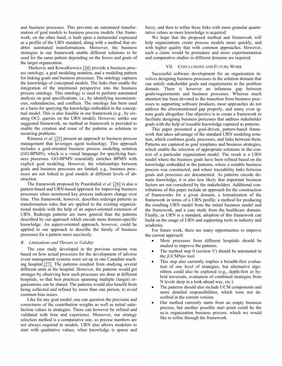
Figure 5. Highest-Level Output of Method for Healthcare Institute A

departments of a teaching hospital. A typical URN model con-sists of more than 100 diagrams and requires up to ten goal layers. 32 patterns have been extracted from the AEMS models and made available in the framework together with 79 strate-gies and business process templates. For the case study, this framework is used as one of the initial inputs to our method described in section V.A (step I2).
While Figure 5 mainly states the final output of the method for the highest-level goal in the AEMS framework (Increase Patient Safety), it also illustrates the other required inputs. The bottom half of the figure shows the initial organizational model (step I1). The main stakeholder of the organizational model is the Healthcare Institute A. The main goal Increase Patient Safety and three high-level softgoals are identified for the stakeholder as well as one task that represents already existing infrastructure of the Healthcare Institute A. The three softgoals cover quality, cost, and research concerns. Note that the task negatively impacts the cost concern.
Furthermore, Figure 5 depicts the current evaluation strat-egy of the organization, describing the as-is situation (step I3). Importance values are added to some of the intentional ele-ments in the organizational goal model (e.g., the importance of Increase Patient Safety to its containing actor is deemed to be 100 while the importance of Decrease Cost is 25). The current strategy also sets the satisfaction level of the task to 60, indicat-ing that although some advanced infrastructure is available, there is still room for improvement. A star (*) next to a satis-faction value indicates that the value is initialized by an evalua-tion strategy and not computed.
The whole Figure 5 represents the output of our method: a refined GRL model of the organization (step O1) with a model of the chosen business process (step O2) and realization links between them (step O3). The following paragraphs describe how we arrived at the final output.
The first three steps of our method initialize the main goal of the framework as Increase Patient Safety (step S1) and then initialize the InitBP and ToRefine variables (steps S2 and S3). The next three steps establish the links between the initial or-ganizational goal model and the goal template of the pattern. Therefore, a contribution with weight 100 is added from the Increase Patient Safety goal in the pattern to the Increase Pa-tient Safety goal of the organization (step S4), two contribu-tions with weight 100 are added from the quality/cost softgoals in the pattern to the quality/cost softgoals of the organizational model (step S5), and finally a contribution with weight 100 is added from the task in the organizational model to the softgoal with the dependencies in the pattern (step S6). Not all inten-tional elements from the organization goal model need to be linked to an element of the framework (e.g., Support Research on Adverse Events is not addressed by the current framework).
At this point, the ToRefine list contains the Increase Patient Safety goal and a simple process with one stub, which are ex-tracted to NextGoal and NextStub in step S7.1. The next step, S7.2, applies all strategies to find the best solution. In this case, there are two strategies defined for the pattern as shown in Fig-ure 2. Figure 5 shows the result of the second strategy (B) be-cause it yields the better result than the first strategy (A), given that the organizational goal model places more value on quality than on cost and already has some advanced infrastructure available. For example, the results are 98 vs. 98 for the main
goal Increase Patient Safety, 50 vs. 98 for Increase Quality of Care, -45 vs. -75 for Decrease Cost, and 59 vs. 75 for the main stakeholder for strategy A vs. B, respectively. A different healthcare institute with more focus on cost than quality and no advanced infrastructure available would see the first strategy (A) win over the second strategy (B). Note how the satisfaction values of the goals Make Safety Decision and Adopt Decision are not the same as the satisfaction values of Collect Data and Generate Informative Outcome Information as defined by the second strategy (B), because the dependencies restrict the satis-faction values of Make Safety Decision and Adopt Decision to lower values (in a dependency, the depender cannot be more satisfied than the dependee).
Step S7.3 then adds the goals and links of the pattern to the organizational goal model, while step S7.4 adds the business process template related to the chosen strategy as a plug-in to the stub of the simple process (indicated by the long-dash-dot-dotted line in Figure 5). Finally, step S7.5 establishes realiza-tion links between the main goal and the business process tem-plate (shown in Figure 5) as well as the sub-goals of the pattern and the stubs of the business process template (not shown in Figure 5 for reasons of simplicity).
The last step of the loop (step S7.6) then adds all four sub-goals and linked stubs to the ToRefine list to be evaluated in the next iterations of the loop. This is done because all sub-goals are required by the chosen strategy. In the next iteration, the three strategies of the Collect Data goal as shown in Figure 3 are assessed, and so on until business process templates have been chosen for all goals. The result in Figure 5 assumes that the third strategy (E) is chosen for the Collect Data pattern.
VI. DISCUSSION
A. Related Work Lapouchnian et al. [22] present a requirement-driven ap-
proach to address the problems caused by the gap between goals and business processes. The authors provide annotations that enrich goal models to capture information about business processes and ordering. Such enriched goal models are trans-formed semi-automatically to generate executable business processes in BPEL. The executable model can be configured at runtime based on stakeholders’ goals. By preserving the vari-ability in the executable business process, stakeholders can change the behavior of the application by changing their high-level goals. However, combining goal models and business processes in such a way makes the models specific to the or-ganization, which hurts reusability. In our approach, we pro-vide a framework that keeps goal models and business process models separate while the traceability links between these models are created and preserved in the patterns. The suggested patterns make it possible to reuse solutions in contexts where goals and the forces at play are compatible. Keeping goal tem-plates and business process templates separate also increases their maintainability when there is need to change any of them.
Bubenko et al. [23] propose Enterprise Knowledge Patterns (EKP), a systematic approach for documenting, analyzing, and capturing patterns. EKP contains patterns that are described with interrelated models such as goal, business process, and concepts models. These models are used to describe reusable solutions for enterprise problems. However, this approach does not provide a formal semantics for links between goal models
and business processes. This prevents an automated transfor-mation of goal models to business process models. Our frame-work, on the other hand, is built upon a metamodel expressed as a profile of the URN standard, along with a method that en-ables automated transformations. Moreover, the business strategies in our framework enable different solutions to be used for the same pattern depending on the forces and goals of the target organization.
Markovic and Kowalkiewicz [24] provide a business proc-ess ontology, a goal modeling notation, and a modeling pattern for linking goals and business processes. The ontology captures the knowledge of conceptual models. The links then enable the integration of the intentional perspective into the business process ontology. This ontology is used to perform automated analysis on goal specifications, i.e., by identifying inconsisten-cies, redundancies, and conflicts. The ontology has been used as a basis for querying the knowledge embedded in the concep-tual model. This is also feasible in our framework (e.g., by cre-ating OCL queries on the URN model). However, unlike our suggested framework, no method or framework is provided to enable the creation and reuse of the patterns as solutions to recurring problems.
Rimassa et al. [25] present an approach to business process management that leverages agent technology. This approach includes a goal-oriented business process modeling notation (GO-BPMN), which is a visual language for specifying busi-ness processes. GO-BPMN essentially enriches BPMN with explicit goal modeling. However, the relationships between goals and business processes are limited, e.g., business proc-esses are not linked to goal models at different levels of ab-straction
The framework proposed by Pourshahid et al. [26] is also a pattern-based and URN-based approach for improving business processes when monitored key process indicators change over time. This framework, however, describes redesign patterns as transformation rules that are applied to the existing organiza-tional models with the help of an aspect-oriented extension of URN. Redesign patterns are more general than the patterns described by our approach which encode more domain-specific knowledge. An aspect-oriented approach, however, could be applied to our approach to describe the family of business processes for a pattern more succinctly.
B. Limitations and Threats to Validity The case study developed in the previous sections was
based on how actual processes for the development of adverse event management systems were set up in one Canadian teach-ing hospital [27]. The patterns resulted from studying several different units at the hospital. However, the patterns would get stronger by observing how such processes are done at different hospitals, so that best practices spanning multiple (larger) or-ganizations can be shared. The patterns would also benefit from being collected and refined by more than one person, to avoid common bias issues.
Like for any goal model, one can question the precision and correctness of the contribution weights as well as initial satis-faction values in strategies. These can however be refined and validated with time and experience. Moreover, our strategy selection method is a comparative one, so precise numbers are not always required in models. URN also allows modelers to start with qualitative values, when knowledge is sparse and
fuzzy, and then to refine these links with more granular quanti-tative values as more knowledge is acquired.
We hope that the proposed method and framework will help organizations create process models more quickly, and with higher quality that with common approaches. However, such a claim would be premature and more experimentation and comparative studies in different domains are required.
VII. CONCLUSIONS AND FUTURE WORK Successful software development for an organization in-
volves designing business processes in the solution domain that can satisfy stakeholder goals and requirements in the problem domain. There is however an infamous gap between goals/requirements and business processes. Whereas much attention has been devoted to the transition from business proc-esses to supporting software products, most approaches do not address the aforementioned gap properly, and many even ig-nore goals altogether. Our objective is to create a framework to facilitate designing business processes that address stakeholder goals with the help of reusable knowledge captured as patterns.
This paper presented a goal-driven, pattern-based frame-work that takes advantage of the standard URN modeling nota-tion, which combines goals, processes, and links between them. Patterns are captured as goal templates and business strategies, which enable the selection of appropriate solutions in the con-text of a particular organization model. The result is a URN model where the business goals have been refined based on the knowledge embedded in the patterns, where a suitable business process was constructed, and where traceability links between goals and processes are documented. As patterns encode do-main knowledge, it is also less likely that important business factors are not considered by the stakeholders. Additional con-tributions of this paper include an approach for the construction of frameworks for a given domain, a formalization of the framework in terms of a URN profile, a method for producing the resulting URN model from the initial business model and the framework, and a case study from the healthcare domain. Finally, as URN is a standard, adoption of this framework can build on the usage of URN and supporting tools in industry and academia.
For future work, there are many opportunities to improve the current approach:
• More processes from different hospitals should be studied to improve the patterns.
• The method step 0 (section V) should be automated in the jUCMNav tool.
• This step also currently implies a breadth-first evalua-tion of one level of strategies, but alternative algo-rithms could also be explored (e.g., depth-first or hy-brid traversals, evaluation of combined strategies from N levels deep in a look-ahead way, etc.).
• The patterns should also include UCM components and more detailed responsibilities, which were not de-scribed in the current version.
• Our method currently starts from an empty business process, but another possible start point could be the as-is organization business process, which we would like to refine through the framework.

• The best use of indicators [16] in the goal templates, which could be used for process monitoring, also re-mains to be explored.
• In addition, instead of having only one sub-process (plug-in map) selected per stub and resolving every-thing at design time, many sub-processes may be kept in dynamic stubs (which allows for many sub-processes) and resolved at run-time according to the current context of the organization as monitored by the indicators.
• Finally, linking this work to the new Business Process Definition Metamodel (BPDM) [28] from OMG might enable moving these ideas outside of the URN world into other modeling notations.
ACKNOWLEDGMENT This research was supported by NSERC’s Postgraduate
Scholarships program and the NSERC/CIHR Collaborative Health Research Program (Canada).
REFERENCES [1] i* Wiki, http://istar.rwth-aachen.de/tiki-index.php, Dec. 2009. [2] ITU-T – International Telecommunications Union, Recommendation
Z.151 (11/08) User Requirements Notation (URN) – Language definition. Geneva, Switzerland, Nov. 2008
[3] Object Management Group, BPMN 1.2 Specification, formal/2009-01-03, January 2009.
[4] Object Management Group, UML 2.2 Specification, formal/2009-02-04, February 2009.
[5] OASIS, Web Services Business Process Execution Language (WSBPEL), version 2.0, April 2007.
[6] D.S. Frankel, Model Driven Architecture: Applying MDA to Enterprise Computing, Wiley, 2003.
[7] D.C. Schmidt, “Model-Driven Engineering”. IEEE Computer 39 (2), February 2006.
[8] M. Bensaou and M. Earl, “The right mind-set for managing information technology”, Harvard Business Review, vol. 76, 1998, pp. 118–129.
[9] T. Hoffman, “Study: 85% of IT departments fail to meet biz needs”, Computer World, vol. 11, Oct. 1999.
[10] E. Gamma, R. Helm, R. Johnson, and J. Vlissides, Design Patterns: Elements of Reusable Object-Oriented Software, Addison-Wesley Professional , 1994.
[11] URN Wiki, http://www.usecasemaps.org/, Dec. 2009. [12] M. Weiss and D. Amyot, “Business process modeling with URN,” Inter-
national Journal of E-Business Research, vol. 1, 2005, pp. 63–90. [13] D. Amyot, S. Ghanavati, J. Horkoff, G. Mussbacher, L. Peyton, and E.
Yu, “Evaluating Goal Models within the Goal-oriented Requirement
Language”. To appear in: International Journal of Intelligent Systems, 2009.
[14] D. Amyot, J. Horkoff, D. Gross, and G. Mussbacher, “A Lightweight GRL Profile for i* Modeling”, 3rd Intl. Workshop on Requirements, Intentions and Goals in Conceptual Modeling (RIGiM), ER Workshops 2009. LNCS, vol. 5833, Springer, pp. 254-264.
[15] jUCMNav, http://jucmnav.softwareengineering.ca/jucmnav/, Dec. 2009. [16] A. Pourshahid, P. Chen, D. Amyot, A.J. Forster, S. Ghanavati, L. Pey-
ton, and M. Weiss, “Business Process Management with the User Requirements Notation”. Electronic Commerce Research, 9(4), Springer, December 2009, pp.269-316.
[17] Y. Yu, H. Kaiya, H. Washizaki, Y. Xiong, and Z. Hu, “Enforcing a security pattern in stakeholder goal models”, Proceedings of the 4th ACM Workshop on Quality of Protection, 2008, pp. 9–14.
[18] M. Fowler, Analysis Patterns: Reusable Object Models, Addison-Wesley, 2000.
[19] G. Mussbacher, D. Amyot, and M. Weiss, “Formalizing Patterns with the User Requirements Notation,” Design patterns formalization tech-niques, IGI Global, 2007, pp. 302-322.
[20] D. de Francisco, I. Markovic, J. Martinez, H. Munoz, and N. Perez, “Methodological Extensions for Semantic Business Process Modeling”, Proc. 10th Intl. Conf. on Enterprise Information Systems (ICEIS), Bar-celona, Spain, 2008, pp. 410–415.
[21] D.L. Parnas, “On the design and development of program families”, IEEE Trans. Software Eng., vol. 2, 1976, pp. 1–9.
[22] A. Lapouchnian, Y. Yu, and J. Mylopoulos, “Requirements-Driven Design and Configuration Management of Business Processes”, 5th Intl. Conf on Business Process Management (BPM 2007). LNCS 4714, Springer, 2007, pp. 246-261.
[23] J.A. Bubenko Jr, A. Persson, and J. Stirna, “User Guide of the Knowl-edge Management Approach Using Enterprise Knowledge Patterns”, de-liverable D3, IST Programme project HyperKnowledge–Hypermedia and Pattern Based Knowledge Management for Smart Organisations, Stockholm, Sweden, 2001.
[24] I. Markovic and M. Kowalkiewicz, “Linking Business Goals to Process Models in Semantic Business Process Modeling,” Proc. 12th Intl. IEEE Enterprise Distributed Object Computing Conference - Volume 00, IEEE Computer Society, 2008, pp. 332-338.
[25] G. Rimassa and B. Burmeister, “Achieving Business Process Agility in Engineering Change Management with Agent Technology”, Dagli Oggetti agli Agenti. 8th AI*IA/TABOO Joint Workshop “From Objects to Agents”, Genova, Italy, 2007, pp. 1–7.
[26] A. Pourshahid, G. Mussbacher, D. Amyot, and M. Weiss, “An Aspect-Oriented Framework for Business Process Improvement”, 4th Intl. MCeTech Conf. on eTechnologies, Ottawa, Canada. E-Technologies: Innovation in an Open World, Springer, LNBIP 26, pp. 290–305.
[27] S.A. Behnam, D. Amyot, A.J. Forster, L. Peyton, and A. Shamsaei, “Goal-Driven Development of a Patient Surveillance Application for Improving Patient Safety”, E-Technologies: Innovation in an Open World. LNPIB 26, Springer, 2009, pp. 65-76.
[28] Object Management Group, Business Process Definition MetaModel (BPDM), version 1.0, formal/2008-11-03, November 2008.