S1 Ch07 Technologies Review
46
The Saigon CTT Chapter 7 (Cont.) Layer 2 - Technologies
Transcript of S1 Ch07 Technologies Review

The
Saig
on C
TT
Chapter 7 (Cont.)
Layer 2 - Technologies

The
Saig
on C
TT
Topic
1. Basics of Token Ring2. Basics of Fiber Distributed Data Interface (FDDI3. Ethernet and IEEE 802.34. Layer 2 Devices5. Effects of Layer 2 Devices on Data Flow6. Basic Ethernet 10BASE-T Troubleshooting7. Summary

The
Saig
on C
TT
History of Ethernet
• 1960’s– CSMA/CD developed at the University of Hawaii
• 1970’s– First experimental Ethernet system at Xerox
PARC• 1980’s
– IEEE 802.3 released– Digital Equipment, Intel, and Xerox jointly
develop & release Ethernet Version 2.0• DIX standard• Substantially compatible with IEEE 802.3

The
Saig
on C
TT
History of Ethernet
• Today, the term Ethernet is often used to refer to all Carrier Sense Multiple Access/Collision Detection (CSMA/CD) LAN’s that generally conform to Ethernet specifications, including IEEE 802.3.

The
Saig
on C
TT
CSMA/CD MAC• Stations can access the network at any time• Stations listen to the network before
transmitting and while transmitting• If no signal on the wire, the station sends• If two stations send at the same time, a
collision occurs– Both transmissions are damaged– Both stations must retransmit– Backoff algorithms determine when each station
can retransmit

The
Saig
on C
TT
Broadcast Networks• All stations see all transmissions• Each station must examine each frame to
determine if they are the destination– If yes, the frame is passed to upper layers for
processing• Ethernet & IEEE 802.3 are both broadcast
networks

The
Saig
on C
TT
Comparing Ethernet and IEEE 802.3
• Ethernet provides services to all of OSI Layer 1 & 2• IEEE 802.3 specifies the physical layer and the MAC
sub layer of the data link layer.– Does not define a Logical Link Control sublayer protocol
• Both are implemented through hardware, typically an NIC card

The
Saig
on C
TT
Ethernet Family Tree
Category 5 UTP100m802.3ab1000BaseTShielded copper25m802.3z1000BaseCxSingle-mode or multimode fiber3000m802.3z1000BaseLxMultimode fiber220-550m802.3z1000BaseSxSingle-mode fiber10,000m802.3u100BaseFxMultimode fiber400/2000 m802.3u100BaseFxCategory 3, 4, or 5 UTP100 m802.3u100BaseT2Category 3 UTP100 m 802.3u100BaseT4Category 5 UTP100 m802.3u100BaseTxFiber2000 m802.310BaseFLCategory 3, 4, or 5 UTP100 m802.310BaseT50-Ohm thin coaxial cable185 m802.310Base250-Ohm thick coaxial cable500m802.310Base5
Cable TypeMaximum Cable Length
MAC Sublayer
SpecificationStandard

The
Saig
on C
TT
Ethernet and IEEE 802.3 framingformat
Ethernet-II( DIX 2.0)
FCSDataTypeSource AddressDest. AddressPreamble
446-15002667+1
Start Frame
Delimiter
1
IEEE 802.3
FCS802.2
Header & Data
Length
Source Address
Dest. AddressPreamble
464-15002667

The
Saig
on C
TT
Preamble Field
• Preamble– Alternating patterns of 1s and 0s, ended by 2 bits 11– Tells receiving stations whether frame is Ethernet or
IEEE 802.3• Preamble + SOF(10101011) =Ethernet frame
Start Frame Delimiter
1
IEEE 802.3
FCS802.2 Header & Data
Length
Source Address
Dest. AddressPreamble
464-15002667

The
Saig
on C
TT
Start of Frame
Start
DelimiterFrame
1
IEEE 802.3
FCS802.2 Header & Data
Length
Source Address
Dest. AddressPreamble
464-15002667
• Start of Frame– SOF– IEEE 802.3 only– Delimiter byte ends with 2 consecutive 1 bits
• Synchronize the frame-reception, ready to receive
– Explicitly specified in Ethernet

The
Saig
on C
TT
Address
Start Frame Delimiter
1
IEEE 802.3
FCS802.2 Header & Data
Length
Source Address
Dest. AddressPreamble
464-15002667
• Destination and source addresses– 1st 3 bytes are vendor-specific
• Specified by IEE– Last 3 bytes are specified by vendor
• Ethernet or IEEE 802.3 vendor– Source address is always unicast– Destination can be unicast, multicast, or broadcast

The
Saig
on C
TT
Type/Length
Start Frame Delimiter
1
IEEE 802.3
FCS802.2 Header & Data
Length
Source Address
Dest. AddressPreamble
464-15002667
• Type (Ethernetype)– Ethernet only– Specifies the upper-layer protocol to receive the data
• Length– IEEE 802.3 only– Number of bytes of data field

The
Saig
on C
TT
Data - EthernetEthernet-II( DIX 2.0)
FCSDataTypeSource AddressDest. AddressPreamble
446-15002667+1
• Data—Ethernet– At least 46 bytes of data– Padding bytes inserted as needed

The
Saig
on C
TT
Data IEEE 802.3
Start Frame Delimiter
1
IEEE 802.3
FCS802.2 Header & Data
Length
Source Address
Dest. AddressPreamble
464-15002667
• Data—IEEE 802.3– Upper-layer protocol destination is defined within the
data portion of the frame (DSAP, SSAP, Control)– At least 64 bytes– Padding bytes inserted as needed
The
Saig
on C
TT
FCSEthernet-II( DIX 2.0)
FCSDataTypeSource AddressDest. AddressPreamble
446-15002667+1
• Frame Check Sequence– 4 byte CRC value

The
Saig
on C
TT
Ethernet MAC

The
Saig
on C
TT
Ethernet MAC• Connectionless network architecture
– Source device is not notified of successful delivery of data packet
– “Best-effort” delivery system

The
Saig
on C
TT
Signaling• Most common varieties use Manchester
encoding• Newer, faster varieties use more complex
encoding schemes

The
Saig
on C
TT
Half Duplex Ethernet Design
• 10Base-T Transceivers– Built on to NIC– Use 4 wires– 1 pair transmits– 1 pair receives

The
Saig
on C
TT
10Base-T Media & Topologies
• Why 10Base-T?– Commonly installed– Basic configuration– Not always applicable

The
Saig
on C
TT
Star Topology
• Media runs from a central hub out to each device
• Central point of control• All communication is via the hub

The
Saig
on C
TT
Hubs• Receive data on one port, broadcast it to
all other ports• Active or passive
– Active• Connection and regeneration• Extends networking distances• Sometimes called concentrators
– Passive• Connection only

The
Saig
on C
TT
Advantages of star topology• Easy to design and install• Ease of maintenance
– Only area of concentration is at the hub– Layout is easy to modify and troubleshoot
• Easy to add workstations• Limited network effect if a device or cable
goes down– Increased reliability

The
Saig
on C
TT
Disadvantages of star topology• Lots of media needed
– Increases setup costs• Hub represents single point of failure

The
Saig
on C
TT
Horizontal Cabling (TIA/EIA 568A)
Work Station(Patch Cable)
HorizontalCable Run
Cross-Connect Jumpers(Patch Cable)
3m 90m 6m+ + = 99m

The
Saig
on C
TT
Network Area
• Cable length limitations limit the size of a star topology network
• Sneakernet outside the 200m x 200 area

The
Saig
on C
TT
Extending the network
• Repeaters regenerate and retime signals• Attenuation is “repaired”• Cable length specification “restarts”

The
Saig
on C
TT
Layer 2 Devices
• NICS• Bridge• Switch

The
Saig
on C
TT
NICs• Provides ports for network connection• Communicate with network via serial
connection• Communication with computer through
parallel connection• Resources required:
– IRQ, I/O address, …

The
Saig
on C
TT
Selection Factors for NICs
• Type of network– Ethernet, Token Ring, FDDI
• Type of media– Twisted pair, coax, fiber
• Type of system bus– PCI, ISA

The
Saig
on C
TT
NIC Operations• Layer 1 & Layer 2 device• Primarily Layer 2
– Communicates with upper layers in the computer• Logical Link Control (LLC)
– Has MAC address burned in– Encapsulates data into frames– Provides access to the media
• Also Layer 1– Creates signals and interfaces with the media– On-board transceiver

The
Saig
on C
TT
Effects of Layer 2 Devices• Two primary reasons for segmenting a
LAN:– Isolate traffic between segments– Achieve more bandwidth per user by
creating smaller collision domains• Use Bridge & Switch to solve

The
Saig
on C
TT
Bridges• Connects two network segments
– Can connect different layer 2 protocols• Ethernet, Token Ring, FDDI
• Makes intelligent decisions about traffic– Reduces unnecessary traffic– Minimizes collisions– Filters traffic based on MAC address
• Maintains address tables• Rarely implemented today
– Conceptually important

The
Saig
on C
TT
Address Table built

The
Saig
on C
TT
Bridge Operations• Broadcasts and multicast frames are forwarded
by a bridge cause Broadcast Storm• Transparent bridges perform switching of frames
using Layer 2 headers and Layer 2 logic and are Layer 3 protocol-independent.
• Store-and-forward switch method. Additional latency
• The transparent bridge must perform processing on the frame, which also can increase latency
Note Source-route bridging use by Token ring

The
Saig
on C
TT
Switching

The
Saig
on C
TT
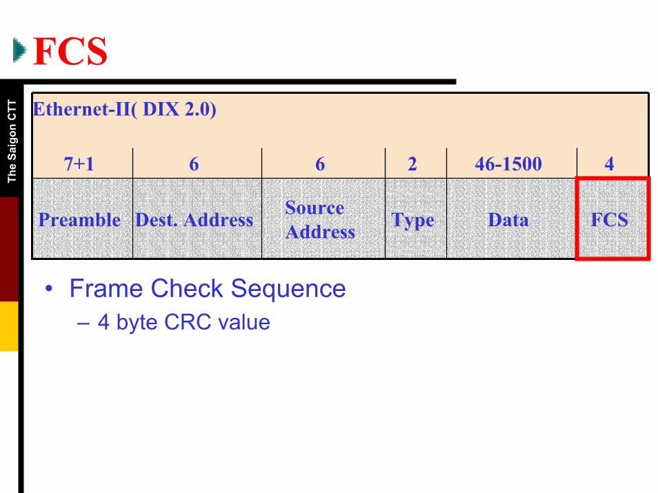
Switching OperationMicro-segmentation
– Each switch port acts as a micro bridge (Layer 2 device)
– Multiple traffic paths within the switch–Virtual circuits–Temporarily exist - only when needed
– Each data frame has a dedicated path• No collisions• Increases bandwidth availability
–Each host gets full bandwidth

The
Saig
on C
TT
Advantages of Switches• Much faster than bridges
– Hardware based, not software– Switch method:
• Store-and-forward• Cut-through• FragmentFree
• Support new uses– e.g. virtual LANs
• Reduce collision domains

The
Saig
on C
TT
Advantages of Switches• Allows many users to communicate in parallel
– Creates virtual circuits– Creates dedicated segments
• Collision free • Maximizes bandwidth
• Cost effective– Can simply replace hubs in same cable
infrastructure• Minimal disruption
• Flexible network management– Software based configuration
The
Saig
on C
TT
Collision Domain

The
Saig
on C
TT
Broadcast Domains

The
Saig
on C
TT
Router• The Router is a layer 3 (Network) device,
but operates at layers 1-3.– Routers create the highest level of
segmentation because of their ability to make exact determinations of where to send the data packet.
– Because routers perform more functions than bridges, they operate with a higher rate of latency.

The
Saig
on C
TTIdentify Broadcast Domains andCollision Domains
The
Saig
on C
TT
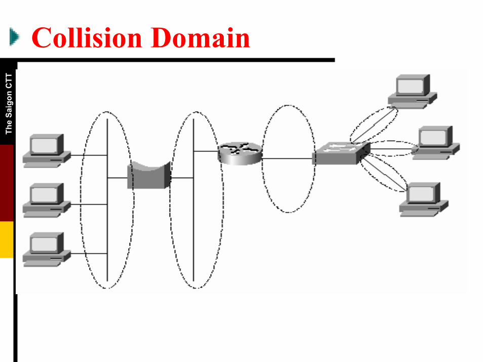
Troubleshooting

The
Saig
on C
TT
Labs• 7.6.2 You will use the help menu, and the
process of experimentation, to learn the basics of navigating within the Network environment.
• 7.6.3 You will learn about the problems/symptoms that the NI program can detect.
• 7.6.4 Use Protocol Inspector software to examine some simple network utilization and frame statistics, in order to make more real the concept of frame flow as the heartbeat of the LAN