Review of Technologies for DC Grids - Power Conversion ...
23
Review of Technologies for DC Grids - Power Conversion, Flow Control and Protection Grain Philip Adam 1 , Til Kristian Vrana 2 , Rui Li 1 , Peng Li 3 , Graeme Burt 1 and Stephen Finney 4 1 University of Strathclyde, Department of Electronics and Electrical Engineering, Glasgow, UK 2 SINTEF Energi, Norway 3 University of Aberdeen, School of Engineering, Aberdeen, UK 4 University of Edinburgh, School of Engineering, Edinburgh, UK Abstract: This article reviews dc transmission technologies for future power grids. The article emphasizes the attributes that each technology offers in terms of enhance controllability and stability, resiliency to ac and dc faults, and encourage increased exploitations of renewable energy resources (RERs) for electricity generation. Discussions of ac/dc and dc/dc converters reveal that the self-commutated dc transmission technologies are critical for better utilization of large RERs which tend to be dispersed over wide geographical areas, and offer needed controllability for operation of centralized and decentralized power grids. It is concluded that the series power flow controllers have potential to restrict the expensive isolated dc/dc converters to few applications, in which the prevention of dc fault propagation is paramount. Cheaper non-isolated dc/dc converters offer dc voltage tapping and matching and power regulation but they are unable to prevent pole-shifting during pole-to-ground dc fault. To date hybrid dc circuit breakers target dc fault isolation times ranging from 3ms to 5ms; while the resonance-based dc circuit breakers with forced current zeros target dc fault clearance times from 8ms to 12.5ms. 1. INTRODUCTION Renewable power generation has increased substantially in all major developed and developing countries, presenting significant challenges to grid operators at generation, transmission and distribution levels. Some of these challenges can be summarised as follows [1-6] • Wide spread uses of HVDC links and wind generators with fully rated back-to-back converters deprive ac grids from the contribution of the generators’ rotating inertias to damping of low frequency power oscillations following major ac network disturbances. • Intermittent nature of renewable energy resources exacerbates the problems of power balance and poor utilization of the ac lines due to undesirable power flow in ac power systems with high penetration of renewable power generation. • Operation of power electronic based solar and wind generators, which are less sensitive to frequency variation (±2.5Hz) alongside the frequency sensitive large conventional synchronous generators, render most existing protection philosophies inadequate. This is because the stability margins of the latter dictate the overall stability of the entire power system, leading to unnecessary loss of generation or tripping of conventional power plants due to loss of synchronism. Some of these challenges could be addressed with well-designed smart grids that employ both ac and dc transmission systems with state-of-arts control and communication systems, where the vast energy stored in the dc lines and converters’ cell capacitors of the asynchronous connections could be manipulated to mitigate the effect of renewable energy resources variability on power quality, and improve transient stability by splitting large ac power systems into several independent asynchronous ac protection zones in order to prevent ac fault propagation throughout the system [4, 5, 7]. In this manner, conventional synchronous and doubly fed induction generators can contribute to power oscillation damping (POD) in their respective zone alongside the synthetic inertia from the capacitors of asynchronous links. The trend of data driven power consumption at lower distribution systems of smart grids (380~415V) may require agile generation and transmission system infrastructures which are able to cope with rapid change in power demand, mainly driven by electricity prices, consumer behaviour, and other autonomous smart devices for demand side management [8-11]. To avoid poor utilization of the generation and transmission infrastructures in data driven smart grids, fast and secure communication systems capable of dealing with large data and a number of high level controllers will be required to optimize the power flow at the transmission level. This flow optimisation can be done with: • converter terminals of the HVDC interconnectors • embedded HVDC links within some of the ac protection zones • flexible ac transmission system (FACTS) devices • high-voltage dc-dc converters, which manage the power flow in meshed parts of the dc infrastructure Instead of the present large centralized power grids, centralized operation of large smart grids that spread over wide areas such as Europe, USA, China and India are necessary for better utilization of the diversity of
-
Upload
khangminh22 -
Category
Documents
-
view
0 -
download
0
Transcript of Review of Technologies for DC Grids - Power Conversion ...

Review of Technologies for DC Grids - Power Conversion, Flow Control and Protection
Grain Philip Adam1, Til Kristian Vrana2, Rui Li1, Peng Li3, Graeme Burt1 and Stephen Finney4 1University of Strathclyde, Department of Electronics and Electrical Engineering, Glasgow, UK 2SINTEF Energi, Norway 3University of Aberdeen, School of Engineering, Aberdeen, UK 4University of Edinburgh, School of Engineering, Edinburgh, UK Abstract: This article reviews dc transmission technologies for future power grids. The article
emphasizes the attributes that each technology offers in terms of enhance controllability and stability, resiliency to ac and dc faults, and encourage increased exploitations of renewable energy resources (RERs) for electricity generation. Discussions of ac/dc and dc/dc converters reveal that the self-commutated dc transmission technologies are critical for better utilization of large RERs which tend to be dispersed over wide geographical areas, and offer needed controllability for operation of centralized and decentralized power grids. It is concluded that the series power flow controllers have potential to restrict the expensive isolated dc/dc converters to few applications, in which the prevention of dc fault propagation is paramount. Cheaper non-isolated dc/dc converters offer dc voltage tapping and matching and power regulation but they are unable to prevent pole-shifting during pole-to-ground dc fault. To date hybrid dc circuit breakers target dc fault isolation times ranging from 3ms to 5ms; while the resonance-based dc circuit breakers with forced current zeros target dc fault clearance times from 8ms to 12.5ms.
1. INTRODUCTION
Renewable power generation has increased substantially in all major developed and developing countries, presenting significant challenges to grid operators at generation, transmission and distribution levels. Some of these challenges can be summarised as follows [1-6] • Wide spread uses of HVDC links and wind
generators with fully rated back-to-back converters deprive ac grids from the contribution of the generators’ rotating inertias to damping of low frequency power oscillations following major ac network disturbances.
• Intermittent nature of renewable energy resources exacerbates the problems of power balance and poor utilization of the ac lines due to undesirable power flow in ac power systems with high penetration of renewable power generation.
• Operation of power electronic based solar and wind generators, which are less sensitive to frequency variation (±2.5Hz) alongside the frequency sensitive large conventional synchronous generators, render most existing protection philosophies inadequate. This is because the stability margins of the latter dictate the overall stability of the entire power system, leading to unnecessary loss of generation or tripping of conventional power plants due to loss of synchronism.
Some of these challenges could be addressed with well-designed smart grids that employ both ac and dc transmission systems with state-of-arts control and communication systems, where the vast energy stored in the dc lines and converters’ cell capacitors of the
asynchronous connections could be manipulated to mitigate the effect of renewable energy resources variability on power quality, and improve transient stability by splitting large ac power systems into several independent asynchronous ac protection zones in order to prevent ac fault propagation throughout the system [4, 5, 7]. In this manner, conventional synchronous and doubly fed induction generators can contribute to power oscillation damping (POD) in their respective zone alongside the synthetic inertia from the capacitors of asynchronous links. The trend of data driven power consumption at lower distribution systems of smart grids (380~415V) may require agile generation and transmission system infrastructures which are able to cope with rapid change in power demand, mainly driven by electricity prices, consumer behaviour, and other autonomous smart devices for demand side management [8-11]. To avoid poor utilization of the generation and transmission infrastructures in data driven smart grids, fast and secure communication systems capable of dealing with large data and a number of high level controllers will be required to optimize the power flow at the transmission level. This flow optimisation can be done with: • converter terminals of the HVDC interconnectors • embedded HVDC links within some of the ac
protection zones • flexible ac transmission system (FACTS) devices • high-voltage dc-dc converters, which manage the
power flow in meshed parts of the dc infrastructure Instead of the present large centralized power grids,
centralized operation of large smart grids that spread over wide areas such as Europe, USA, China and India are necessary for better utilization of the diversity of
renewable energy resources across different regions; thus, leading to provision of cheap, reliable and sustainable power throughout all four seasons of the year. In this manner, power plant types which are operated with fixed output power such as nuclear and other fossil fuel based plants could be reduced [10, 12-17]. In contrast, the planned transition of smart grids from centralised to decentralised operation could be executed during major network faults or outages of the critical power corridors, with no or minimum loss of power supply, provided the said ac protection zones are designed to be self-contained (each must be able to satisfy the grid code as an independent ac network). In being able to operate in centralised and decentralised modes, smart grids have potential to avoid the problem of total system blackout.
The multi-terminal HVDC transmission network concept is attractive to many transmission system operators, and for future smart grids because of the following reasons: • real power can be exchanged over a wide
geographical area at reduced transmission power loss
• increased control flexibility over power flow (magnitude and direction) using a reduced number of converters and dc cables (hence, offers cost-effective solution)
• dc line conductor cross-section areas are fully utilized for carrying real power (no parasitic current or reactive current)
• dc line loadability is not limited by its surge impedance loading (SIL) as in equivalent ac lines, and dc lines are magnetic field neutral (less harmful to nearby wildlife and sea creatures)
However, because of low resistance and rapidly diminishing effect of the line inductance during a dc short circuit fault, the speed of dc fault propagation is much faster than an ac fault. Also, because the dc fault current increases rapidly within the first 3ms of the fault initiation, the dc short circuit fault has to be interrupted within an ac sub-fundamental cycle to avoid irreparable damage to expensive and vulnerable part of the dc network, such as power converters. Recently, significant effort has been invested in the development of new types of power converters that do not increase the fault level in the dc network and can survive dc faults for extended periods (several milliseconds without the risk of damage). This has been done in an attempt to relax dc circuit breakers requirements (in terms of let-through current, current breaking capacity, and operating speed). Although some of the emerged converters and dc circuit breakers are designed to cope with the high demands of dc faults, most of these circuit breakers require a number of sizable extra dc inductors to be incorporated into the dc-link or converter control modification to slow down the rate of rise of the dc fault current at the dc-link of each converter and rate of fall of the dc-link voltage or actively control the fault current [1, 3, 10, 18, 19]. Research is needed into protection aspects related to fault detection and
discrimination and in coordination between ac and dc side protection to avoid catastrophic outcomes of miss-operation.
This discussion shows that besides complex control and communication systems, line and self-commutated FACTS devices and HVDC transmission systems and high-voltage dc-dc converters are all critical in achieving the increased control flexibility expected from smart grids. Besides increased controllability, smart grids provide platforms to facilitate a cheap way to integrate many renewable power plants into power grids, without the need for energy storage systems, benefiting from the diversity of renewable energy resources in different regions. Therefore, this paper presents a comprehensive review of the transmission system technologies for smart grids, with particular focus on components of dc transmission systems. Although a qualitative discussion is used as the main tool to articulate the attributes and limitations of different components or solutions in general and from a smart grid prospective, quantitative substantiation is used in a limited number of cases.
2. MODULAR MULTILEVEL AC-DC
CONVERTERS
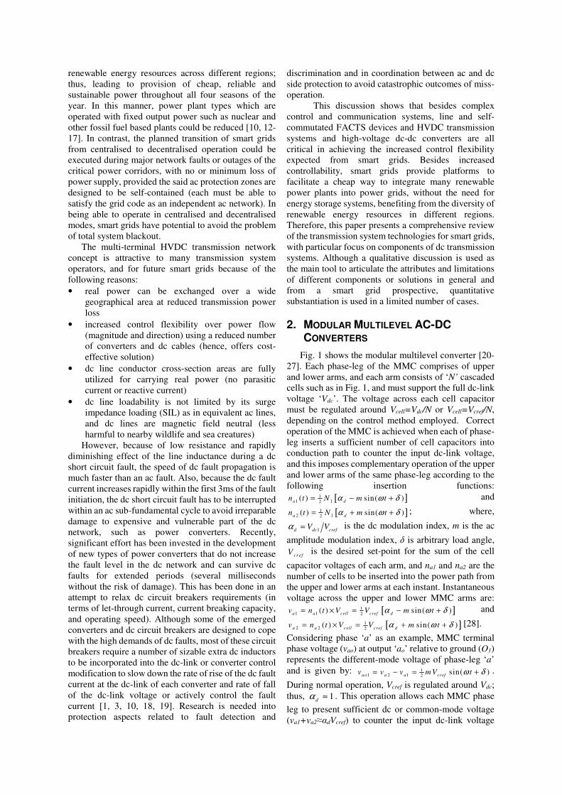
Fig. 1 shows the modular multilevel converter [20-27]. Each phase-leg of the MMC comprises of upper and lower arms, and each arm consists of ‘N’ cascaded
cells such as in Fig. 1, and must support the full dc-link voltage ‘Vdc’. The voltage across each cell capacitor must be regulated around Vcell=Vdc/N or Vcell=Vcref/N, depending on the control method employed. Correct operation of the MMC is achieved when each of phase-leg inserts a sufficient number of cell capacitors into conduction path to counter the input dc-link voltage, and this imposes complementary operation of the upper and lower arms of the same phase-leg according to the following insertion functions:
[ ]11 12( ) sin( )a dn t N m tα ω δ= − + and
[ ]12 12( ) sin( )a dn t N m tα ω δ= + + ; where,
1d dc crefV Vα = is the dc modulation index, m is the ac
amplitude modulation index, δ is arbitrary load angle,
crefV is the desired set-point for the sum of the cell
capacitor voltages of each arm, and na1 and na2 are the number of cells to be inserted into the power path from the upper and lower arms at each instant. Instantaneous voltage across the upper and lower MMC arms are:
[ ]11 1 2( ) sin( )a a cell cref dv n t V V m tα ω δ= × = − + and
[ ]12 2 2( ) sin( )a a cell cref dv n t V V m tα ω δ= × = + + [28].
Considering phase ‘a’ as an example, MMC terminal phase voltage (vao) at output ‘ao’ relative to ground (O1) represents the different-mode voltage of phase-leg ‘a’ and is given by: 1
1 2 1 2 sin( )ao a a crefv v v m V tω δ= − = + .
During normal operation, Vcref is regulated around Vdc; thus, 1
dα ≈ . This operation allows each MMC phase
leg to present sufficient dc or common-mode voltage (va1+va2≈αdVcref) to counter the input dc-link voltage

(Vdc1), while maintaining a small voltage mismatch between the two voltages to allow the dc current flow; thus, power exchange between the ac and dc sides. The arm inductor Ld in Fig. 1 limits the inrush current due to mismatch between common-mode voltage and input dc-link voltage. This operation means the MMC is the only VSC where the upper and lower arms of the same phase leg conduct simultaneously; with arms containing continuous ac and dc currents. The fundamental components of the arm currents are used to exchange active power between the converter and ac sides, while the dc components of the arm currents provide power transfer from the converter to the dc side [29]. When ia1 and ia2 are phase ‘a’ upper and lower arm currents as defined in Fig. 1, phase ‘a’ output current (iao) represents the differential-mode current (iao=ia1-
ia2). The current component that circulates between the upper and lower arm of phase ‘a’, without reaching the output circuit, is denoted as common-mode current ‘icom’ and is given by: icom=½(ia1+ia2). Without dedicated active or passive countermeasure, the MMC arm or common-mode currents may contain some parasitic components such as 2nd order harmonic current that could increase semiconductor losses and cell capacitor voltage ripple. The main attributes and drawbacks of MMCs are [20-27]: • The MMC generates sinusoidal output voltages,
with near zero harmonics and extremely low voltage stresses (dv/dt) on the interfacing transformer; thus, ac filters and phase interfacing reactors are not needed.
• Beside the known attributes of conventional voltage source converters, the circuit structure of the MMC permits the power rated and dc operating voltage of VSC-HVDC links to be increased to a level comparable to that of conventional of LCC-HVDC links; and internal fault management, which is necessary for continued operation during cell failure (cell capacitors or switching devices). Moreover, the use of distributed cell capacitors in MMCs reduces the first peak (or transient component) of the let-though currents that may flow in the dc circuit breaker before its opening; thus, allowing dc circuit breaker design requirements to be relaxed.
However, the large footprint of the MMC due to the use of a large number of cell capacitors, represents a major drawback from the scenery point of view and costs of right-of-way. The ratings for MMCs have reached 1000 MW and 525 kV [30].
The properties of the MMC highly depend on the internal structure of the utilised cells. The following subsections give an overview on the most prominent proposed cell types.
Fig. 1: Schematic diagrams of the generic MMC
2.1 Half-bridge cell MMC (HB-MMC)
Fig. 2 (a) shows a half-bridge cell [23, 25, 26]. The HB-MMC offers low semiconductor losses, which is in line with the decarbonisation efforts of transmission networks; but is subject to the same constraints of conventional VSCs such as operation with unipolar dc-link voltage and vulnerability to dc faults. All existing MMC-type HVDC links currently operational are HB-MMCs.
2.2 Full-bridge cell MMC (FB-MMC)
Fig. 2 (b) shows a full-bridge cell. Although the FB-MMC has high semiconductor losses, it offers dc fault reverse blocking capability; and operation with variable and bipolar dc-link voltage, including zero dc voltage, while retaining full control over active and reactive power exchange between converter ac and dc sides [31-33]. This feature means the FB-MMC handles dc faults without the need to block the converter, while full control over the ac current in-feed from the ac side is retained. Additionally, bipolar dc voltage operation allows the FB-MMC to operate in a generic dc grid, side by side to line commutated converters (as the FB-MMC can change power flow direction with the change of dc current or dc voltage polarities). These attributes are expected to be invaluable in the delivery of increased control flexibility needed in smart grids.
FB-MMC technology has been proposed for a HVDC link with overhead lines in Germany: the ULTRANET project (±380 kV, 2 GW) [34]. The main reason for applying full-bridge technology was better fault handling ability, since the project uses overhead lines, where the likelihoods of DC faults are much higher compared to its counterpart with cables.
2.3 Doubled clamped cell MMC (DCL-MMC)
Fig. 2 (c) shows a three-level double clamped cell. Each cell of the DCL-MMC is equivalent to two HB cells as it uses two capacitors and generates three viable voltage levels (2Vc, Vc and 0) provided the cell capacitor (C1 and C2) voltages are maintained such that Vc1≈Vc2≈Vc (this is contrary to that explained in [35]). But each double clamped cell in

Fig. 2(c) inserts three semiconductor switching devices in conduction path, instead of two switches with equivalent HB cells but offers dc fault reverse voltage blocking capability, lacked in the HB-MMC. The main weakness of the DCL-MMC that uses the DCL cell is inability to generate a negative voltage level for both polarities of arm current, which restricts its operation to unipolar dc-link voltages. Thus, making it unable to facilitate operation with reduced dc-link voltage, unlike the MC-MMC.
2.4 Five-level cross-connected cell MMC (5LCC-MMC)
Fig. 2 (d) shows a symmetrical five-level cross-connected cell that can generate voltage levels 2Vc, Vc, 0, -Vc and -2Vc, provided the cell capacitor voltages are regulated such that Vc1≈Vc2≈Vc[35]. The five-level cross-connected cell in Fig. 2 (d) is equivalent to two symmetrical full-bridge cells (four devices in conduction path, generate the same voltage levels); thus, its loss performance and control range and flexibility is expected to be similar to that of the FB-MMC, including operation with positive and negative dc-link voltages.
2.5 Flying capacitor cell MMC (FC-MMC)
Fig. 2 (e) shows a half-bridge flying capacitor unipolar cell, where each cell generates three voltage levels 0, Vc and 2Vc [35]. This flying capacitor cell is equivalent to two half-bridges, where both insert two switches in the conduction path, but uses two capacitors rated at different voltages (2Vc and Vc), compared to Vc in the equivalent HB cells. Therefore, the FC-MMC is expected to be subject to the same control range limitations as the HB-MMC and unipolar dc-link voltage operation and lack of dc reverse blocking. Capacitors with different rated voltages compromises power circuit modularity, thus is less attractive in terms of cell manufacture and maintenance. Although the FC cell can be configured as a symmetrical bipolar cell, similar to FB and five-level cross-connected cells described previously, this possibility is unattractive due to large number of cell capacitors required.
2.6 Active neutral-point clamped unipolar cell MMC (ANPC-MMC)
Fig. 2 (f) displays the modular multilevel converter that uses an active neutral-point-clamped unipolar cell to generate three voltage levels per cell (0, Vc and 2Vc) [35]. Operationally, the control range of an ANPC-MMC is limited to unipolar positive dc-link voltages as with the HB-MMC, where power reversal is only achieved by changing the polarity of the dc-link current, and it is unable to block dc faults or decouple cell capacitor regulation from the dc-link voltage (Vdc) over a wide range; especially, when Vdc falls below the peak of the line-to-line voltage the interfacing transformer imposes at the converter terminals. Because of the lack of redundant switch states at cell level, which restricts the selection of the upper capacitor (C1), cell capacitor voltages of the ANPC-
MMC may exhibit larger capacitor voltage ripple than HB-MMC and FC-MMC of similar rating and energy content. Although all the devices of the ANPC structure have the same voltage rating, two more IGBTs S5 and S6 are required, resulting in higher capital cost. Hence, they are not preferable in the practical application, compared with the HB cells.
2.7 Mixed cells MMC (MC-MMC)
It is possible to employ a combination of different cells within an MMC, with Fig. 2 (g) depicts an example of mixed cell. A lot of combinations are theoretically possible, but most commonly referred to is a combination of half- and full-bridge cells in order to reduce semiconductor losses to less than that of the FB-MMC[35, 36], while retaining some of control flexibility of the FB-MMC such as: a) Resiliency to dc network faults, including dc fault
reverse blocking capability and controlled operation with reduced and zero dc-link voltage.
b) Bipolar dc-link voltage operation can be achieved over a limited range, determined by the ratio γ=NFB/NHB; where NFB= Nγ/(γ+1), NHB=N/(γ+1), N is the total number of cells per arm (N=NFB+NHB), and NFB and NHB are the number of full and half bridge cells per arm. This feature is necessary for arc extinction following a dc fault.
c) The tributes and flexibilities in a) and b) show that the mixed cell MMC could be used to deliver customised features for a given level of semiconductor losses.
Theoretically, the MC-MMC operates using a similar principle as the FB and HB MMC and adheres to the same insertion functions described in section 2. However, its operation limits, including bipolar dc voltage operation are determined by the ratio ‘γ’ that defines the control range for ‘αd’. For example, when γ=1, NFB=NHB=½N, which implies that the control range for dc modulation index ‘αd’ is:0≤αd≤1; thus, each MC-MMC arm is able to synthesize any voltage level between Vdc0 and -½Vdc0. Within this envelope, each MC-MMC arm can generated the necessary negative voltage to enable operation with any dc-link voltage from rated positive dc voltage (Vdco) to Vdc=0, without jeopardizing the converter ability to synthesize the rated ac voltage. The combination of half and full bridge cells as depicted in Fig. 2 (g) generates two positive voltage levels (2Vc and Vc) and one negative voltage (-Vc) and zero; therefore, it belongs to family of asymmetric cells (or simply refer to as asymmetric cell).
2.8 Single-clamped cell MMC (SC-MMC)
The single-clamped cell shown in Fig. 2 (h) [37] provides small negative voltage sufficiently for blocking a dc fault, exploiting additional clamp diode D1 which is connected to the mid-point of the dc capacitors C1 and C2 and middle IGBT. Compared to FB cells, the single-clamped cell requires reduced number of IGBTs, thus, leading to relatively lower capital cost. It is worth stressing that only half of the
cell capacitor voltage per cell is utilized to block dc faults, and the unidirectional conduction of clamping diode D1 makes the single-clamped cell unable to generate negative voltage when the MMC under active control, resulting in restricted control range and flexibility
2.9 Other cell topologies
Besides the aforementioned cells, more unipolar, asymmetric and symmetric bipolar cells can be found in [37, 38]
.
(a)
(b)
(c)
(d)
(e)
(f)
(g)
(h)
Fig. 2: Examples of MMC cells. (a) Half-bridge cell (b) Full-bridge cell (c) Three-level double clamped cell (d) Symmetrical bipolar five-level cross-connected cell (e) Three-level unipolar flying capacitor cell (f) Three-level unipolar ANPC cell (g) Hybrid or mixed cell (h) Single clamped cell
3. SPECIAL MULTILEVEL AC-DC
CONVERTERS
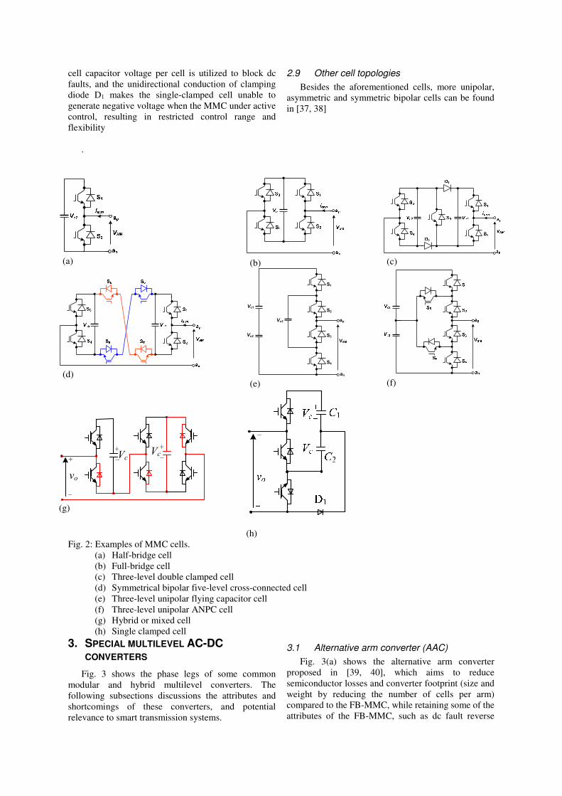
Fig. 3 shows the phase legs of some common modular and hybrid multilevel converters. The following subsections discussions the attributes and shortcomings of these converters, and potential relevance to smart transmission systems.
3.1 Alternative arm converter (AAC)
Fig. 3(a) shows the alternative arm converter proposed in [39, 40], which aims to reduce semiconductor losses and converter footprint (size and weight by reducing the number of cells per arm) compared to the FB-MMC, while retaining some of the attributes of the FB-MMC, such as dc fault reverse
S1
S2
S3
S4
ap
an
VSM
Vc1
Vc2
Vc3
vo
+
–
+
–Vc
+
–Vc

voltage blocking ability and reduced dc-link voltage operation. However, in retaining these attributes, the FB cells in each arm of the AAC must be able to block a dc voltage greater than ½Vdc, as originally envisaged ( 1
21
NFB
cj dc
j
v V=
> ). Unlike MMC type converters with
concurrent conduction in the upper and lower arms of the same phase leg, each arm of the AAC conducts for 180o with the director switch in each arm used to commutate currents between arms and ensure that each arm is able to block the full dc-link voltage (Vdc). With the aid of a brief overlap period at the ‘0’ voltage level, where both upper and lower arms of the AAC conduct simultaneously, the director switch of each arm is used to facilitate current commutation between the upper and lower arms. Thus, seamless current commutation is achievable for a limited range of power factors, and beyond which large inrush current occurs in the AAC arms. Its input dc-link capacitors may increase the peak of dc fault current transient component [41].
In an effort to address the aforementioned problems and ensure satisfactory operation over full modulation index linear range and all power factors, extended overlap operation of AAC was proposed [42].
In summary, this discussion shows that the AAC is inferior to MC-MMC in terms of performance, flexibility and control.
3.2 Hybrid cascaded two-level converter (HC2LC)
Fig. 3 (b) presents the hybrid cascaded two-level converter which uses a two-level converter as the main power stage that manipulates the phase and magnitude of fundamental voltage of the switched voltage (VTo) to control the converter output active and reactive powers[43]. The ac-side cascaded FB chain link of each phase operates as a series active power filter (wave shaping circuit) to inject the necessary voltage harmonics (VFB) to cancel the inherent harmonics in the switched output voltage of the two-level converter stage (VTo), thus a pure sinusoidal output voltage (vao) is generated at output pole ‘ao’ relative to dc-link mid-point ‘o’. If the orthogonality relationship between vFB and iao is maintained, the linear range for modulation index control of the HC2LC can be extended to 1.27 without compromise to cell capacitor voltage balancing. This means the P-Q envelope of the HC2LC will be larger than all MMC type converters. In the case of reactive power applications, the modulation index control range can be extended further, to 2. The HC2LC is expected to be smaller than all MMC type converters as the number of cell capacitors required per phase, is a quarter that of the HB and FB MMC. The main shortcomings of the HC2LC are[44]: • DC fault reverse blocking capability if achieved at
the expense of high semiconductor losses as the number of devices in the conduction path, carrying full load current, is higher that the AAC and MC-MMC.
• Its input dc-link capacitors contribute substantial discharge current into a dc fault, and this increases the current stresses on the dc switchgear connected to its positive and negative dc poles.
• Ensuring synchronization between the switching of the two-level converter and the chain link is challenging, and it may expose the converter transformer to high-voltage spikes of ±2Vdc in the worst-case, and with period corresponding to miss-synchronization period. These spikes tend to introduce low-order harmonics into the baseband and need filtering using ac tuned filters.
• Its operation is limited to positive dc-link voltages, and reduced dc voltage operation is possible should the number of FB cells in the chain link be increased to be able to synthesize the nominal terminal ac voltage when the dc-link is suppressed to zero; thus, operating as a typical cascaded multilevel converter.
3.3 Hybrid cascaded modular multilevel converter (HC-MMC)
Fig. 3 (c) displays one-phase-leg of a hybrid converter that employs a HB-MMC in the main stage (instead of a two-level converter as in the HC2LC described in subsection 3.2) to control the fundamental voltage and power exchange between the converter ac and dc sides [45]. The operation of the ac-side FB chain link of each phase leg is as explained for the HC2LC. The low dv/dt of the staircase multilevel voltage waveform ‘VTo’ at its terminal means switching synchronization to the FB chain link involves a maximum voltage error of one cell capacitor voltage. The HB-MMC in the main stage allows the FB chain links of the HC-MMC to be used as ac circuit breakers, while the cell capacitors of the HB-MMC facilitate controlled recharge of the dc-link following dc fault clearance [45]. The HC-MMC has a large footprint, high semiconductor losses, and high cost due to its larger semiconductor area and large number of capacitors.
3.4 Line commutated converter with ac-side cascaded full-bridge chain link (LCC-ACFBCL)
Fig. 3 (d) shows a phase-leg of a line commutating converter that uses cascaded FB cells in its ac side as a series active power filter to ensure that the LCC stage receives a distortion free (or pure sinusoidal) commutation voltage, independent of the system operating condition at the point of common coupling[46]. Thus LCC commutation failure is avoided [46], and the entire LCC reactive power needs can be provided by manipulating the magnitude of the commutation voltage (vTo) relative to the magnitude of the grid voltage (vao) at the point of common coupling. A limited number of tuned ac filters are needed to attenuate the characteristic harmonic currents injected by the LCC stage. The main attributes and limitations of the LCC-FBCL are:

• Lower semiconductor loss than hybrid counterparts such as the HC2LC and HC-MMC.
• Increased the power handling of LCC type HVDC links, without extra equipment dedicated for provision of reactive power support.
• LCC limitations related to power flow direction and reversal remain.
3.5 Hybrid converter with half-bridge cells across the dc-link
Fig. 3 (e) shows a three-phase hybrid converter with three limbs of cascaded half-bridge cells connected across the dc link (one limb per phase)[47]. Each limb comprises of N half-bridge cells, supports ½Vdc (where Vdc is the dc link voltage) and presents a rectified dc voltage (Vd1=½Vdc|sin(ωt+θ)|) at the input dc terminals of the high-voltage full-bridge cell of each phase that synthesises an output ac voltage such as (va1) to be imposed on each isolated winding of the interfacing transformer (thus, switching devices of the high-voltage full-bridge cell must be rated for ½Vdc). At each instant, ‘2N’ half-bridge cells are selected from the ‘3N’ available cells in the three limbs of the three-phase converter to be used to synthesize rectified dc voltages Vd1, Vd2 and Vd3 to be presented at dc terminals of the high-voltage full-bridge cell of each phase-leg. The high-voltage full-bridge cell connected to output circuit of each phase-leg exploits its bi-polar switching capability to generate positive and negative halves of the output phase voltages (such as va1 for phase a) from the rectified dc voltages (such as Vd1 for phase ‘a’) being presented by the cascaded half-bridge cells of the three limbs. To avoid uncontrolled inrush current, the half-bridge cells to be inserted into the power path at each instant must be selected all three limbs and must be sufficient to match the input dc link voltage (Vdc), i.e., Vd1+Vd2+Vd3≈Vdc. Thus, a large dc inductor (Ldc) is needed in the dc link in order to supress any potential inrush current that may arise due to any voltage mismatch between (Vd1+Vd2+Vd3) and the input dc link voltage (Vdc). This constraint makes the hybrid converter in Fig. 3 (e) unable to generate an ac voltage with variability magnitude, and this is the main weakness of this hybrid converter.
3.6 Other hybrid multilevel converters
The authors in [48, 49] proposed a controlled transition bridge (CTB) converter that avoids high dv/dt and excessive switching losses of the conventional two-level converter by employing FB chain-links rated for half of the dc voltage (Vdc) and trapezoidal type modulation to facilitate stepped transitions of the output voltage between two extrema of +½Vdc and -½Vdc, with each voltage step is defined by the voltage of one cell capacitor of the FB chain-link. The director switches of CTB converter experience slow and gradual build-up of the voltage and switch at zero voltage; director switches do not require stringent series connection of IGBTs and incur zero switching losses. But trapezoidal modulation imposes limited control range and high ac side filtering.
Extensive discussions of sinusoidal operation of CTB proposed in [50, 51] show that it generates high quality multilevel ac voltage as MMCs, and requires large dc side filtering which increases dc fault level.
Reference [52] has proposed a hybrid multilevel converter that represents a modified version of an AAC, but with the node between the director swicth (SD1or, SD2) and cascaded half or full bridge chain-link of each arm is clamped to ground (O) through additional director swicth (SC1 or SC2), see Fig. 3 (f). The chain-links of upper and arms of each phase leg are utilized to shape the output ac voltage (vao), with the director switches operate alternately every half fundamental cycle. It has been claimed in [52] that the proposed converter requires fewer cells and reduced energy storage requirement over full power factor range. As in an AAC, its director switches operate at zero voltage switching, hence, leading to reduced switching losses. However, the director switches of the proposed converter must be designed to withstand voltage stresses amount to half of the rated DC voltage; thus, a large number of series-connected IGBTs are required.
In [53]an improved alternate arm converter (IAAC) was presented, in which the director switches of each phase leg are realized by flying capacitor cell. The proposed IAAC addresses the problem of current commutation between the arms and eliminate the dependency on power factor and modulation depth, and no sizable input capacitors or inductors are required for filtering as in conventional AAC.
In [54, 55]a compact mixed cell modular multilevel converter (CMC-MMC) which is created by realizing the director switch in each arm of conventional AAC by high-voltage half-bridge cell is proposed. The proposed CMC-MMC offers all the attributes of conventional MC-MMC described earlier.
Recently, an hybrid converter based on active forced commutated bridge (AFC-B) is proposed for UHVDC transmission systems with rated powers and voltages up to 3000MW and 800kV per converter[55, 56]. The proposed hybrid converter requires large ac and dc side filtering, and apart from that it offers many of the features of the FB-MMC at reduced semiconductor losses, thanks to the use of symmetrical thyristors in the main conduction paths. Moreover, it employs the FB chain-links in its limbs to actively commutate the current between the upper and lower arms of the same phase-leg; with no risk of commutation failure. The proposed converter can block dc fault, operate with positive and negative dc voltages, reverse active power with change of polarity of dc current or voltage polarity, generate leading and lagging reactive powers and resilient to both ac and dc faults.
Reference [57] presented a novel hybrid converter with alternate common arm and director switches that resembles a further Improvement to the AFC-B converter in [55, 56]. The presented converter uses thyristors in alternate arms that operate as director switches, and FB chain-link in common arm and in the

upper and lower arms similar to that of the conventional FB-MMC. In this way, it nearly doubles the current capability of each arm, hence, the power rating, while
retaining the power quality of the ac and dc sides as that of the MMCs.
(a)
(b)
(c)
(d) (e) (f)
Fig. 3: Examples of converter (leg) topologies for HVDC transmission systems (a) Phase-leg of alternative arm converter (b) Hybrid cascaded two-level converter (c) Hybrid cascaded modular multilevel converter (d) Hybrid converter with LCC and ac-side cascaded FB cells (e) Hybrid converter with half-bridge cells across the dc-link (f) Hybrid multilevel converter with cells connected to AC terminal (HMC-AC)
4. DC-DC CONVERTERS
Fig 4. shows examples of dc-dc converter topologies with potential to be applied in large-scale HVDC transmission networks to perform voltage matching or tapping, and can act as flexible dc controllers to regulate power in highly meshed dc networks [58].
4.1 Front-to-front dc-dc converter topology
The front-to-front (F2F) dc-dc converter is described in [59-61]. The converter terminals VSC1 and VSC2 can employ any of the converter topologies summarised in Fig. 1 and Fig. 3, with one converter acts as reference that defines the ac voltage and frequency in the internal ac-link, and other converter controls dc
N
N
N
Ldc
co
bo
ao
vco
vbo
vao
Vdc
Vd1va1
Vd2
Vd3

power or dc voltage. Although high-frequency square waveform voltage operation of VSC1 and VSC2 has been adopted in low and medium voltage applications for many years [59-64], sinusoidal or trapezoidal (quasi-two-level) voltage waveform in the ac-link with fundamental frequency ranging from 200Hz to 500Hz is likely to be adopted in HVDC applications, with dc operating voltages up to 800kV [58, 65, 66].
Besides dc voltage matching, power regulation and dc voltage regulation, the F2F dc-dc converter decouples the dc systems as it can block dc fault propagation from the faulty system to the healthy system. Therefore, the F2F dc-dc converter is suitable for splitting large dc networks into several protection zones to contain the impact of dc fault within a well-defined zone. The main shortcomings of the F2F dc-dc converter are: • Both converter terminals must be fully rated (1 per
unit); thus, its semiconductor losses resemble that of the two-terminal HVDC link.
• Its dc voltage matching range is limited by the current stresses in the converter switches of the low-voltage side.
The isolated front-to-front dc-dc converter is shown in Fig 4(a). The provided galvanic isolation is necessary for connection of dc system with a separate dc ground.
The F2F converter can also be realised without isolation. In this case, the transformer is replaced by a simple inductor. Although a non-isolated F2F dc-dc converter in HVDC applications can reduce costs, there are major drawbacks of not having isolation. The implication of under-modulation in the non-isolated F2F dc-dc converter is that the switching devices of its high-voltage converter are subjected to the same ac currents as that of the low-voltage converter, which are higher than its isolated counterpart. Thus, high semiconductor losses are incurred in the high-voltage side.
4.2 Multi-pole multi-module front-to-front dc-dc converter topology
Fig. 4(b) shows a configuration that employs series-input and series output to connect a symmetrical mono-pole dc system to a symmetrical multi-pole dc system, with each sub-converter in Fig. 4 (a) realized with modular type converters, or two-level or NPC converters, with each rated at a higher dc voltage and power than in traditional medium-voltage applications. With the multipole side being limited to tri-pole, the voltage stresses on the upper and lower transformers in the ac-link could be limited to slightly higher than that of conventional bipolar HVDC link[67].
4.3 Partially isolated dc-dc converter topology
Fig. 4(c) shows schematic diagram of an efficient partially isolated dc-dc converter that can be used for voltage matching and tapping in dc systems with a common dc ground [68, 69]. The total dc power at the high-voltage dc terminal (Pdc1) transfers to the low-voltage dc terminal (Pdc2), without the need for the switching devices of any of the sub-converters to be
rated for full power. The power flow between the two dc terminals of dc-dc converter topology in Fig. 4 (b) is explained, assuming the power flow is from the high to low voltage dc terminals as follows: • The total dc power Pdc2 splits into ac power Pac and
dc power Pdc12. • Pac represents the component transferred through
the ac side and it determines the magnitudes of ac and dc currents in the arms of VSC1 and VSC2 for a given transformer voltage ratio. This component can be approximated by: Pac≈(Vdc1-
Vdc2)Idc1≈Pdc1(n-1)/n, where n=Vdc1/Vdc2. • Pdc12 represents the power component transferred
directly to the low-voltage dc terminal using dc components of the arm currents, without passing through the switching devices of VSC2; and can be approximated by: Pdc12≈Idc1Vdc2≈Pdc1/n.
In this manner, the switching devices of VSC1 and VSC2 must be rated to handle the current stresses corresponding to ac power of Pdc1(n-1)/n, and dc operating voltage of Vdc1(n-1)/n and Vdc1/n respectively.
4.4 Non-isolated MMC-based dc-dc converter
The converter in Fig. 4(d) is formed by series connection of two MMCs (HB or mixed cells type); however, the mixed cells approach is preferred because it blocks dc fault propagation from the faulty side to the healthy side, due its FB dc fault blocking capability [60]. Although this dc-dc converter does not use an isolation transformer, the coupling inductor being employed in the positive and negative poles of the low-voltage dc terminal must be insulated to withstand the high dc voltage stress corresponding to the dc-link voltage of the low-voltage dc terminal, Vdcl. Additional weakness of this topology is that the fundamental ac component being used to exchange power between converter arms needs to be filtered using large passive filters (Lf and Cf). Based on this discussion, this non-isolated dc-dc converter topology is inferior to the partially isolated topology, as described in the previous section.
4.5 Full-bridge-based Non-isolated hybrid cascaded two-level dc-dc converter
Fig. 4(e) shows a full-bridge-based non-isolated hybrid cascaded two-level dc-dc converter, where the dc-link of the two-level converter stage represents the high-voltage side (Vdc2>Vdc1)[70]. The submodules of each limb at the low-voltage side must be of the full-bridge type so that it can inject the necessary bipolar ac voltage waveform to cancel some of the generated voltage by the two-level converter stage. In this way, a ripple-free fully-controlled dc voltage with magnitude Vdc1 will be generated at the low-voltage dc terminal. This means the series connected switching devices of the two-level converter stage must be rated for high-voltage side voltage (Vdc2). Inhibiting the gating signals is sufficient to prevent dc fault propagation from one side to the other, independent of the fault location (dc short circuit). Lack of isolated dc ground may require

system shutdown during a pole-to-ground dc fault to prevent exposure of the healthy pole to excessive dc voltage stresses. In this topology, the number of semiconductor devices in the conduction path (thus, conversion loss) is the same as in F2F dc-dc two-level converter, but its overall losses and semiconductor area remain lower than F2F dc-dc converter topologies.
4.6 Half-bridge-based non-isolated hybrid cascaded two-level dc-dc converter
Fig. 4(f) shows a half-bridge-based non-isolated hybrid cascaded two-level dc-dc converter, where the
dc-link of the two-level converter stage represents the low-voltage dc terminal (Vdc1>Vdc2), and cascaded HB cells are used (instead of the FB cells) as each limb only needs to inject a unipolar voltage waveform to boost the output dc voltage[70]. In this scenario, the chain link of each limb must be able to support the full dc voltage of the high-voltage side.
(a) (b)
(c)
(d)
(e)
(f)
Fig. 4: Other examples of dc-dc converter topologies (a) Front-to front dc-dc converter (b) Isolated front-to-front dc-dc converter with one side connected to multi-pole dc system (c) Partially isolated dc-dc converter (d) Non-isolated MMC based dc-dc converter
FB
FB
FB
FB
Vdc1
Vdc2
Ld
Ld
Ld
FB FBFB
FB FBFB
FB FBFB
0
vao
vFBa
Vdc1
Vdc2
Ld
Ld
Ld
HB HBHB
HB HBHB
HB HBHB
0
vao
vFBa

(e) Non-isolated hybrid cascaded two-level dc-dc converter (f) Half-bridge-based non-isolated hybrid cascaded two-level dc-dc converter
5. SERIES-TYPE DC FLOW CONTROLLING
DEVICES
Besides dc fault ride-through challenges highlighted in previous sections, full utilization of dc lines in meshed multi-terminal HVDC transmission networks that contain a number of floating dc nodes is extremely important for efficient operation of dc grid. However, control of the dc power flows on the individual dc lines that form a mesh is technically challenging [71] as the current split between parallel paths is solely determined by the Ohm and Kirchoff laws. Unlike in an ac system, a dc system does not have a phase angle or reactive power, giving less degree of freedom to control the power flow. To realise better utilization of dc cables in a meshed multi-terminal high-voltage direct current (MT-HVDC) network, the dc equivalent of the FACTS devices, such as power shifters, are beneficial to optimize the power flow within the dc network.
This task can be performed by incorporating appropriate dc/dc converters or interline series type current controlling devices [72, 73]. Although series type power controlling devices appear effective and cost effective, their ability to survive dc short circuit faults are yet to be demonstrated. Apart from isolating transformers, all the power electronic parts are fractionally rated. In addition to dc-dc converter discussed in section (e), some of the proposed methods for power flow control in MT-HVDC networks are discussed briefly in the following subsections
5.1 Controlled Series Resistor
Fig. 5(a) show a dc power controller that uses a series switched resistor to regulate the power flow between two dc nodes by manipulating the dc voltage drop of the line that connects these dc nodes[72]. Although this solution seems to be simple and effective, it has a limited control range.
5.2 Series Current Flow Controllers
Amongst several series current flow controllers proposed in [72, 74-77], Fig. 5(b) and (c) show examples of series connected bi-directional dc current or power flow controllers capable of controlling power flow in individual dc lines by inserting small positive or negative dc voltage in series with a given dc line, depending on the power flow direction [72, 75-77]. These power flow controllers incur low on-state losses as they present small number of semiconductor devices in conduction path. Extensive studies performed in [72,
75-77] show these series controllers are able to operate satisfactorily over wide range of operating conditions and can survive dc faults.
5.3 Series Voltage Injection
The solution in Fig. 5(d) can control dc power in a given dc line from zero to the rated power and in a reverse direction due to its ability to inject positive or negative dc voltage in series with the line [72]. This device is equivalent to a unified power flow controller in an ac system.
(a) (b)
Vdcp
Vdcn
Rd
Rd
Vdc0
Idcn
Idcp
+ -
- +
ΔVp
ΔVn

(c)
(d)
Fig. 5: Examples of examples fractionally rated dc series power flow controllers for meshed multi-terminal HVDC network:
(a) Resistive unidirectional dc series power flow controller. (b) Inter-bus bidirectional dc power flow controller (c) Inter-bus bidirectional dc series power flow controller with reduced switching devices (d) dc voltage injection dc series power flow controllers.
The current absence of a cost-effective high-voltage
dc circuit breaker (DCCB) is the main missing element prevent bringing dc grids in line with ac counterpart. Its absence denies the ability to isolate the faulty dc part while allowing the remaining healthy parts of the dc grid to operate normally. Being able to continuously exchange power is paramount from a supply reliability and security point of view. Although the technology for solid-state dc circuit breakers has existed since the 1990s and is improving, they incur excessive semiconductor losses and cost [78-84]. Fig. 6 and Fig. 7 summarise some of the main dc circuit breakers being suggested for dc fault current interruption in multi-terminal dc networks, targeting different fault clearance times.
5.4 Hybrid DC Circuit Breakers
Fig. 6(a) and (b) show types ‘1’ and ‘2’ hybrid dc circuit breakers that exploit a voltage injection method to force the fault current to zero, where the injected dc voltage must be larger and oppose that being presented by the faulty line [84, 85]. During normal operation, the main conduction path for the dc current is through a low-voltage rated semiconductor switch known as a load commutation switch (LCS) and low-resistance mechanical ultra-fast disconnector (UFD) with Sulphur Hexafluoride (SF6) as insulation media and a 2ms opening time. The mechanical UFD must be designed to support the prospective dc voltage when opened. When the dc fault is detected in the type ‘1’ DCCB, the LCS is turned off to initiate commutation of the dc fault
current from the principle conduction path to the main circuit breaker (MCB), which is a typical high-voltage semiconductor switch, capable of carrying high current for short period (<10ms) [86, 87]. After the entire dc fault current is commutated to the MCB, the mechanical UFD is opened at near zero current and voltage, and during this period the fault current continues to flow in the MCB, and then, the MCB is opened to interrupt the dc fault current. More details on Fig. 6(a) are presented in [84].
The type ‘2’ DCCB in Fig. 6(b) turns off LCS when a dc fault is detected and triggers the switching delay branches in a progressive manner in order to commutate the fault current from the main conduction path to the arming branch. The current in each switching delay branch drops to zero when its capacitor charges to the blocking voltage across the LCS. After the entire fault current is transferred to the arming branch and all thyristors of the switching delay branches are off and carry zero current, the mechanical UFD is turned off. This is followed by gating-off the composite thyristor of the arming branch to interrupt the fault current to force the surge arrester across the arming branch to absorb the entire inductive energy of the faulty line and to force the fault current to zero [85]. The hybrid dc circuit breakers in Fig. 6(a) and (b) are intended for faster current interruption, ranging from 3ms to 5ms.
The hybrid DCCB in Fig. 6(c) and (d) [83, 88] have similar on-state losses and operating speed as the counterparts in Fig. 6 (a) and (b).
=
=
=
~
=
=
=
~

(a)
(b)
(c)
(d)
Fig. 6: Some hybrid dc circuit breakers being proposed for use for dc fault isolation in dc grids
(a) Type 1 hybrid dc circuit breaker (b) Type 2 hybrid circuit breaker (c) Type 3 hybrid dc circuit breaker (d) Type 4 hybrid dc circuit breaker
5.5 Resonant DC Circuit Breakers
Fig. 7 (a) shows a forced current zero resonance dc circuit breaker that uses a pre-charge capacitor to initiate resonance with the aim of creating a speedy current zero when the negative peak of the resonant current component larger than the dc component of the fault current [81]. In [81], this approach interrupts a dc fault current up to 21kA, within 8ms to 10ms.
Fig. 7 (b) and (c) show other versions of low-loss active resonance based dc circuit breakers [80]. The versions of the active resonance DCCBs displayed in Fig. 7 (b) and (c) are expected to have similar performance (on-state loss, current breaking capability and operating speed) as that presented in Fig. 7 (a), where the options in Fig. 7 (a) and (b) permit easy incorporation of additional resonance branches that facilitate execution of several successive fault clearance attempts.
Besides relatively slow resonant DC circuit breakers discussed above, reference [89] presented a
cost effective fast acting resonant based hybrid DC circuit breakers that uses vacuum AC circuit breaker technology in parallel with resonance branch that uses half-bridge or full-bridge cells to initiate high frequency resonance, see Fig. 7 (d). Each resonance branch consists of HB or FB cell in series with inductor and capacitor, and when the fault is detected the HB or FB cell will be switched at 10kHz to impose bipolar square waveform voltage in each resonance branch, causing high frequency bipolar oscillating current with increasing magnitude to be superimposed on the DC fault current. Operation of HB or FB cell at each resonance branch at 10kHz permits creation of multiple current zeros within 1ms (recall that the current zeros are created when the negative peaks of the oscillating current equal or exceed the magnitude of the actual DC fault current). In this manner, the DC circuit breaker in [89] is able to interrupt DC faults within sub-milliseconds, provided that the protection systems responsible for fault discrimination is able to operate with such speed.

(a)
(b)
(c)
(d)
Fig. 7: Some resonant dc circuit breakers being proposed for use for dc fault isolation in dc grids (a) Forced current zero resonance circuit breaker (type 1) (b) Forced current zero resonance circuit breaker (type 2) (c) Forced current zero resonance circuit breaker (type 3) (d) Forced current zero resonance DC circuit breaker (type 4)
6. DISCUSSIONS
Based on critical review of the open literature, the main findings of this work are highlighted as follows: 1) Modular multilevel converters: It is established
that the MMCs with asymmetrical and symmetrical bipolar cells can block and control dc fault current, and remain controllable for a wide range of dc voltages, and these features are useful for pole restraining during pole-to-ground dc fault. Therefore, MC-MMC as a representative of the MMCs with asymmetric bipolar cells offers all flexibilities needed for efficient, reliable and fault-tolerant operation of VSC based dc grids. Nonetheless, extra control range offered by the MMCs with symmetrical bipolar cells such as the FB-MMC are well-suited for generic dc grids that employ both VSCs and LCCs (thanks to the ability to operate with positive and negative dc voltages, and reverse power flow direction by change of dc current or voltage polarities).
2) Hybrid multilevel converters: Section 1 establishes that the AFC-B converter and hybrid converter with alternate common arm and director switches in [55-57] offer most of the features of the FB-MMC at much lower semiconductor losses. The former increases the power capability at reduced semiconductor losses but requires
substantial ac and dc filtering. Whilst the latter increases the power capability with no filtering requirements at ac and dc sides, thanks to additional current path provided by the thyristor based director switches which conduct alternately, i.e., upper director switch conducts for half fundamental cycle with the upper arm of the FB-MMC and vice versa. The latter hybrid converter resolves the current commutation problem of the conventional AAC and its variants [39, 40, 42, 53, 54, 57, 90]. These hybrid converters are well-suited for generic and large dc grids, , where the LCCs are expected to operate alongside VSCs. On other hand, hybrid converters in [53, 54] are viable alternative to conventional AAC and MC-MMC and most of the MMCs with asymmetric bipolar cells, particularly in applications with confined space as they offer all features of MC-MMC with arguably reduced footprint and power circuit and control complexity.
3) DC-DC converters: Isolated F2F dc-dc converters offer many desirable features for reliable operation of dc grids such as prevention of dc fault propagation and pole shifting in the healthy side during pole-to-pole and pole-to-ground dc faults respectively, and dc voltage matching and power control (it worth stressing that these features are essential for partial selective dc
Rg
Lr Cr
T1
T2
T3 T4
CB

grid protection strategies that employ the zoning concept). However, high capital cost and semiconductor losses may hinder their acceptance as economic solution. Non-isolated F2F dc-dc converters are unable to prevent pole-shifting during pole-to-ground dc fault and suffer from high losses and poor utilization of the semiconductor of the high-voltage converter, therefore, not viable for dc grids. Partially isolated dc-dc converter in [68, 69, 91] is attractive economically as it permits the transformer in its ac link and sub-converters to be fractionally rated. Its multi-port version that generates multiple and independent dc and ac voltages is attractive for complex hub that facilitates dc and ac voltage tapping and matching and power control, with bespoke ability to precisely define the route of the power flow from a given input to a given output[91, 92]. The non-isolated MMC and hybrid cascaded two-level dc-dc converters in [70, 93] offer cost-effective solution for dc voltage matching between two dc systems with common ground.
4) Series current flow controllers: Fractionally rated bidirectional interline current or power flow controllers in [72, 74-77, 94] offer low cost solutions for controlling and rerouting dc currents or dc powers within the dc grids away from the bottlenecks and over-loaded dc cables; thus, these devices are expected to play major roles in large dc grids that include floating dc nodes.
5) DC circuit breakers: Section Error! Reference
source not found. reviews a number of basic dc circuit breaker technologies, covering fault
isolation time-scales ranging from 2ms to 15ms. It is found that although the hybrid dc circuit breakers offer faster fault clearance times (2ms to 5ms) which is critical for continued operation of dc grids, their large semiconductor areas make them expensive and vulnerable to rapid rise of fault current, particularly, in large dc grids that operate at dc voltages above 640kV and contain a number of long dc cables. Resonance based mechanical dc circuit breakers offer slower fault clearance time (up to 15ms) and require large dc inductances to be installed strategically across the dc grid to slowdown the rate of rise of fault currents and fault propagation through the dc grid. Nevertheless, mechanical dc circuit breakers remain practically attractive because of their relatively low cost and small semiconductor areas, primarily, in the resonant branch. Active resonance dc circuit breaker with reduced semiconductor area proposed in [89] offers the best overall trade-offs between performance (fault clearance times in order of 3ms to 5ms) and cost. However, an economic mechanism for sustaining the dc voltage of the fractionally rated VSC that responsible for initiation of high frequency resonant as soon as dc fault is detected remains to be solved. The concept of multiline dc circuit breaker proposed in [95, 96] represents an economic way to protect multiple dc cables connected to a single dc node using one current breaking branch. In this way, the overall cost of the dc grid protection can be reduced substantially.
In summary, Table 6-1 to Table 6-5 provide high-level summary of the main aspects discussed earlier.
Table 6-1: High-level comparison MMCs the employ unipolar cells, and asymmetric and symmetric bipolar cells [42, 50, 54, 97-109], where P and Q stand for active and reactive powers, Vdc is the dc voltage, and Vdc0
stands for rated dc voltage.
MMC with unipolar cells MMC with asymmetric bipolar
cells
MMC with symmetric bipolar cells
DC fault blocking No Yes Yes Control of fault current
No, therefore, necessitates the use of fast acting dc circuit breakers plus large dc inductors to quickly isolate dc faults and prevent over-stressing of the converters’ semiconductor switches.
Yes, therefore, a range of options available, ranging from relatively cheap mechanical dc circuit breakers to simple ultra-fast dc switches could be combined with fault current capability of the MMCs with asymmetric bipolar cells to isolate dc faults.
Yes, therefore, a range of options available, ranging from relatively cheap mechanical dc circuit breakers to simple ultra-fast dc switches could be combined with fault current capability of the MMCs with symmetric bipolar cells to isolate dc faults.
Active and reactive power
a) Independent control of P and Q, with maximum capacitive Q is limited by dc voltage limit and inductive Q by current limit.
b) P reversal is achieved by change direction of Idc, while Vdc remains positive.
c) Losses control over P and Q when the Vdc falls below line-to-line voltage at converter ac side
a) Independent control of P and Q, with maximum capacitive Q is limited by dc voltage limit and inductive Q by current limit.
b) P reversal is achieved by change direction of Idc, while Vdc polarity remains positive.
c) Retains control over P and Q for wide range of positive dc voltage, 0≤Vdc≤Vdc0; where Vdc0 is the rated dc voltage.
a) Independent control of P and Q, with maximum capacitive Q is limited by dc voltage limit and inductive Q but current limit. However, maximum capacitive reactive power can be extended if over-modulation capability is exploited.
b) P reversal can be achieved by change the polarities of Idc or Vdc .
c) Retains control over P and Q for very wide range of dc voltage, -Vdc0≤Vdc≤Vdc0.

DC voltage polarity and range
Remain controllable for narrow range of positive dc voltages which are greater than the peak of the line-to-line voltages the interfacing transformers impose at MMCs ac terminals. Therefore, MMCs with unipolar cells only applicable to VSC based dc grids.
Remain controllable for wide range of positive dc voltages, 0≤Vdc≤Vdc0. Therefore, MMCs with asymmetric bipolar cells applicable to VSC dc grids, and hybrid dc grids with combinations of VSCs and LCCs provided that unidirectional power flows are contemplated in all LCC terminals.
Remain controllable for very wide range of positive and negative dc voltages, -Vdc0≤Vdc≤ Vdc0. This feature permits operation in generic dc grids alongside LCCs, without compromising bidirectional power flow at LCC terminals.
Internal fault management
Yes, and realized by bypassing of faulty cells; hence, simpler cell structures such as HB are preferred for ease of identification of the faulty cells.
Yes, and realized by bypassing of faulty cells; hence, simpler cell structures such as HB and FB are preferred for ease of identification of faulty cells.
Yes, and it is realized by bypassing of faulty cells; hence, simpler cell structures such as FB are preferred for ease of identification of faulty cells. Five-level cross-connected cell is an alternative for FB cell that delivers MMC with similar features as FB-MMC, but its complex structure increases the complexity of internal fault management.
Over-modulation No, even though the MMCs with unipolar cells include redundant cells to facilitate continued operation during internal faults, these cells remain unusable for extension of modulation index linear beyond 1.155; this limit is due to single polarity of the voltages that the unipolar cells generate.
Yes, should the MMCs with asymmetric bipolar cells include redundant cells to facilitate continued operation during internal faults, and these cells could be used to extend modulation index linear range beyond 1.155; thus, the maximum achievable ac voltage, exploiting limited bipolar capability of the asymmetric bipolar cells.
Yes, should the MMCs with asymmetric bipolar cells include redundant cells to facilitate continued operation during internal faults, and these cells could be used to extend modulation index linear range beyond 1.155; thus, the magnitude of the maximum achievable ac voltage, exploiting full bipolar capability of the symmetric bipolar cells.
Semiconductor losses low medium high
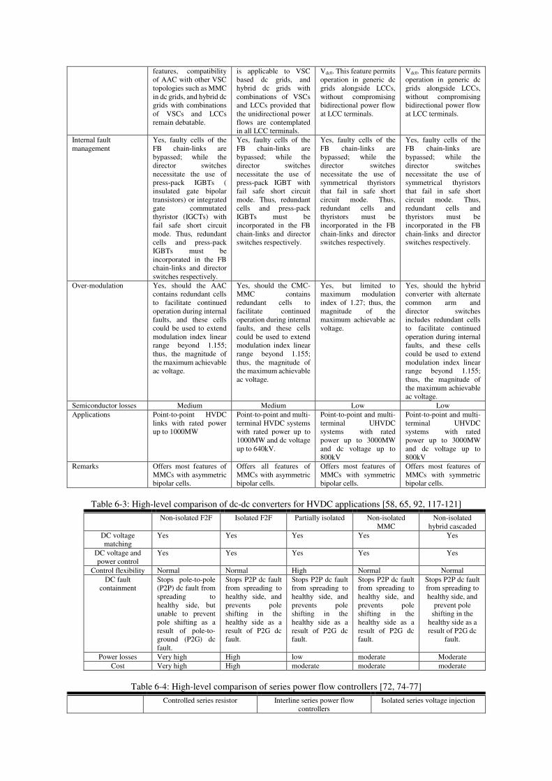
Table 6-2: High-level comparison selected hybrid converters (A≡ AAC, B≡ CMC-MMC, C≡ AFC-B converter, and D≡
hybrid converter with alternate common arm and director switches)[42, 54, 55, 57, 110-116]
A B C D
DC fault blocking Yes, Yes Yes Yes Resiliency to ac faults Resilient to symmetrical
ac fault, but unsatisfactory performances during severe unbalanced ac grids and asymmetrical ac faults.
Yes, resilient to symmetrical and asymmetrical ac faults.
Yes, resilient to symmetrical and asymmetrical ac faults.
Yes, resilient to symmetrical and asymmetrical ac faults.
control of fault current Yes, therefore, a range of options available, ranging from relatively cheap and slow mechanical dc circuit breakers to simple ultra-fast dc switches could be used to ride-through dc faults.
Yes, therefore, a range of options available, ranging from relatively cheap and slow mechanical dc circuit breakers to simple ultra-fast dc switches could be used to ride-through dc faults.
Yes, therefore, a range of options available, ranging from relatively cheap and slow mechanical dc circuit breakers to simple ultra-fast dc switches could be used to ride-through dc.
Yes, therefore, a range of options available, ranging from relatively cheap and slow mechanical dc circuit breakers to simple ultra-fast dc switches could be used to ride-through dc faults, including fault clearance.
Active and reactive power control
a) Independent control of P and Q, but with very limited reactive power.
b) P reversal is achieved by change polarity of Idc, while Vdc polarity remains positive.
c) Retains control over P and Q for wide range of positive dc voltage, 0≤Vdc≤Vdc0.
a) Independent control of P and Q
b) P reversal is achieved by change polarity of Idc, while Vdc polarity remains positive.
c) Retains control over P and Q for wide range of positive dc voltage, 0≤Vdc≤Vdc0
a) Independent control of P and Q.
b) P reversal is achieved by change of polarities of Idc or Vdc.
c) Retains control over P and Q for very wide range of positive and negative dc voltages, -Vdc0≤Vdc≤Vdc0.
a) Independent control of P and Q.
b) P reversal is achieved by change of polarities of Idc or Vdc.
c) Retains control over P and Q for very wide range of positive and negative dc voltages, -Vdc0≤Vdc≤Vdc0.
DC voltage polarity and control range
Remain controllable for wide range of positive dc voltages, 0≤Vdc≤Vdc0. Despite the above
Remain controllable for wide range of positive dc voltages, 0≤Vdc≤Vdc0. Therefore, CMC-MMC
Remain controllable for very wide range of positive and negative dc voltages, -Vdc0≤Vdc≤
Remain controllable for very wide range of positive and negative dc voltages, -Vdc0≤Vdc≤
features, compatibility of AAC with other VSC topologies such as MMC in dc grids, and hybrid dc grids with combinations of VSCs and LCCs remain debatable.
is applicable to VSC based dc grids, and hybrid dc grids with combinations of VSCs and LCCs provided that the unidirectional power flows are contemplated in all LCC terminals.
Vdc0. This feature permits operation in generic dc grids alongside LCCs, without compromising bidirectional power flow at LCC terminals.
Vdc0. This feature permits operation in generic dc grids alongside LCCs, without compromising bidirectional power flow at LCC terminals.
Internal fault management
Yes, faulty cells of the FB chain-links are bypassed; while the director switches necessitate the use of press-pack IGBTs ( insulated gate bipolar transistors) or integrated gate commutated thyristor (IGCTs) with fail safe short circuit mode. Thus, redundant cells and press-pack IGBTs must be incorporated in the FB chain-links and director switches respectively.
Yes, faulty cells of the FB chain-links are bypassed; while the director switches necessitate the use of press-pack IGBT with fail safe short circuit mode. Thus, redundant cells and press-pack IGBTs must be incorporated in the FB chain-links and director switches respectively.
Yes, faulty cells of the FB chain-links are bypassed; while the director switches necessitate the use of symmetrical thyristors that fail in safe short circuit mode. Thus, redundant cells and thyristors must be incorporated in the FB chain-links and director switches respectively.
Yes, faulty cells of the FB chain-links are bypassed; while the director switches necessitate the use of symmetrical thyristors that fail in safe short circuit mode. Thus, redundant cells and thyristors must be incorporated in the FB chain-links and director switches respectively.
Over-modulation Yes, should the AAC contains redundant cells to facilitate continued operation during internal faults, and these cells could be used to extend modulation index linear range beyond 1.155; thus, the magnitude of the maximum achievable ac voltage.
Yes, should the CMC-MMC contains redundant cells to facilitate continued operation during internal faults, and these cells could be used to extend modulation index linear range beyond 1.155; thus, the magnitude of the maximum achievable ac voltage.
Yes, but limited to maximum modulation index of 1.27; thus, the magnitude of the maximum achievable ac voltage.
Yes, should the hybrid converter with alternate common arm and director switches includes redundant cells to facilitate continued operation during internal faults, and these cells could be used to extend modulation index linear range beyond 1.155; thus, the magnitude of the maximum achievable ac voltage.
Semiconductor losses Medium Medium Low Low Applications Point-to-point HVDC
links with rated power up to 1000MW
Point-to-point and multi-terminal HVDC systems with rated power up to 1000MW and dc voltage up to 640kV.
Point-to-point and multi-terminal UHVDC systems with rated power up to 3000MW and dc voltage up to 800kV
Point-to-point and multi-terminal UHVDC systems with rated power up to 3000MW and dc voltage up to 800kV
Remarks Offers most features of MMCs with asymmetric bipolar cells.
Offers all features of MMCs with asymmetric bipolar cells.
Offers most features of MMCs with symmetric bipolar cells.
Offers most features of MMCs with symmetric bipolar cells.
Table 6-3: High-level comparison of dc-dc converters for HVDC applications [58, 65, 92, 117-121]
Non-isolated F2F Isolated F2F Partially isolated Non-isolated MMC
Non-isolated hybrid cascaded
DC voltage matching
Yes Yes Yes Yes Yes
DC voltage and power control
Yes Yes Yes Yes Yes
Control flexibility Normal Normal High Normal Normal DC fault
containment Stops pole-to-pole (P2P) dc fault from spreading to healthy side, but unable to prevent pole shifting as a result of pole-to-ground (P2G) dc fault.
Stops P2P dc fault from spreading to healthy side, and prevents pole shifting in the healthy side as a result of P2G dc fault.
Stops P2P dc fault from spreading to healthy side, and prevents pole shifting in the healthy side as a result of P2G dc fault.
Stops P2P dc fault from spreading to healthy side, and prevents pole shifting in the healthy side as a result of P2G dc fault.
Stops P2P dc fault from spreading to healthy side, and
prevent pole shifting in the
healthy side as a result of P2G dc
fault.
Power losses Very high High low moderate Moderate Cost Very high High moderate moderate moderate
Table 6-4: High-level comparison of series power flow controllers [72, 74-77]
Controlled series resistor Interline series power flow controllers
Isolated series voltage injection

Control range Control dc line power flow in one direction
Control dc line power flow in both directions
Control dc line power flow in both directions
Power losses low low Relatively high Complexity (circuit and control)
low Low, thanks to low-voltage rated IGBTs and capacitors
Relatively high (two back-to-back converters and isolation transformers)
Vulnerability to dc faults
Manageable Manageable Manageable
Cost low High moderate
Table 6-5: High-level comparison of low loss dc circuit breakers [18, 75, 83, 89, 95, 96, 122-137]
Hybrid dc circuit breakers Resonance based dc circuit breakers Target operating speeds 3ms to 5ms 8ms to 15ms, except type 4 dc circuit
breaker in Fig. 7(d) Cost High, because of their large
semiconductor areas Relatively low, because of their relatively low semiconductor areas.
Current breaking capacity Relatively low (semiconductor switches of the breaking branch restrict its current breaking capability); therefore, relatively large dc inductors are needed to slow the rate of rise of dc fault currents.
High; but, large dc inductors are needed to slow the rate of rise of dc fault currents and extend the fault clearance time, without posing risk to semiconductor switches of the converters.
Footprint Large, mostly dominated by semiconductor devices
Relative small due to small semiconductor areas
7. CONCLUSIONS
Recognizing its limitations, LCC-HVDC links could act as backbones for highly complex power grids, so that they can operate with nearly constant power, meaning that the required power balancing and frequency control function could be performed by VSC-HVDC links, some of the generators and other FACTS devices.
HB-MMCs and its variants are expected to dominate HVDC parts of future smart grids due to their high efficiency and fault tolerant circuit structure, which can facilitate continued operation during internal faults (cell failures) and resiliency to ac network faults. This is enabled by recent progress in the dc circuit breakers developments (summarised in Section 7). There are a number of established and successful methods available that allow the HB-MMC and its variants to survive a dc fault for extended periods prior to opening of the dc circuit such as diversion of part or the entire fault current to thyristors or mechanical switch. However, successful isolation of the faulty part, while ensuring uninterrupted power exchange through the healthy parts of the HVDC network, relies on the incorporation of large dc inductances in order to prevent rapid collapse of the dc voltage in the healthy parts; thus, slowing down the dc fault propagation within the dc network.
FB-MMCs and its inferior derivatives (from a control aspect) offer a solution for less critical power corridors in future power grids, where the entire dc network which is affected by a dc short circuit fault could be allowed to briefly stop operation. During this, dc fault clearance can be done using fast disconnectors or ac circuit breakers, and the system could afterwards
be reenergised quickly from the ac grids or stored energy in the converters’ cell capacitors in a controlled manner. In such a scenario, the dc fault current could be extinguished rapidly by a brief period of negative polarity dc voltage injection. Additionally, these converters can prevent exposure of the healthy pole to twice the rated dc voltage during a pole-to-ground dc fault (pole restraining); thus, facilitating continued operation during a pole-to-ground dc fault. These power converter groups could be designed for a customized level of fault tolerant operation against semiconductor losses.
DC-DC converters are essential for proper operation of highly meshed MT-HVDC networks (power flow optimization, dc voltage matching and segmentation of large MT-HVDC networks into several protection zones). F2F dc-dc converters offer all these features but at a high level of losses and cost as both its converters and transformer have to be rated for 1pu power. Non-isolated or partially isolated auto dc transformers offers dc voltage matching and power flow optimization at reduced semiconductor loss and cost. But they compromise the dc fault protection offered by the F2F topology. This means, cost effective dc auto-transformers could be used in less critical power corridors of smart grids.
Series type power flow controllers such as in Fig. 5 offer the possibility for optimizing dc power flow in highly meshed MT-HVDC networks without excessive power loss and the high cost of dc-transformers (dc-dc converters).

8. ACKNOWLEDGEMENT
This work is part of contribution of University of Strathclyde and SINTEF Energi to European Energy Research Alliance (EERA), sub-programme 5, Review of Transmission Technologies for Smart Grids.
9. REFERENCES
[1] L. Xiaolin, Y. Zhichang, F. Jiao, W. Yizhen, L. Tao, and Z. Zhe, "Nanao multi-terminal VSC-HVDC project for integrating large-scale wind generation," in PES General
Meeting | Conference & Exposition, 2014 IEEE, National Harbor, MD, US, 2014, pp. 1-5.
[2] W. Wang, M. Barnes and O. Marjanovic, "The impact of control design on dynamic behaviour of multi-terminal VSC-HVDC (MTDC) system under AC grid fault conditions," in 7th IET International Conference on
Power Electronics, Machines and Drives (PEMD 2014), 2014, pp. 1-6.
[3] S. P. Le Blond, Q. Deng and M. Burgin, "High frequency protection scheme for multi-terminal HVDC overhead lines," in Developments in Power System Protection
(DPSP 2014), 12th IET International Conference on, Copenhagen, Denmark, 2014, pp. 1-5.
[4] M. Hadjikypris and V. Terzija, "Active power modulation assisting controller scheme implemented on a VSC-HVDC link establishing effective damping of low frequency power oscillations," in Energy Conference
(ENERGYCON), 2014 IEEE International, Cavtat, Croatia, 2014, pp. 295-302.
[5] S. Paul, M. S. Rabbani, R. K. Kundu and S. M. R. Zaman, "A review of smart technology (Smart Grid) and its features," in Non Conventional Energy (ICONCE), 2014
1st International Conference on, Kalyani, India, 2014, pp. 200-203.
[6] L. Wang and M. S. Thi, "Comparisons of Damping Controllers for Stability Enhancement of an Offshore Wind Farm Fed to an OMIB System Through an LCC-HVDC Link," Power Systems, IEEE Transactions on, vol. 28, pp. 1870-1878, 2013.
[7] L. Wang, Q. S. Vo and A. V. Prokhorov, "Comparative stability analysis of a DFIG-based offshore wind farm fed to a multi-machine power system through an LCC-HVDC link and an HVAC line," in 2016 IEEE/PES Transmission
and Distribution Conference and Exposition (T&D), Dallas, TX, USA, 2016, pp. 1-6.
[8] M. Erol-Kantarci and H. T. Mouftah, "Energy-Efficient Information and Communication Infrastructures in the Smart Grid: A Survey on Interactions and Open Issues," IEEE Communications Surveys & Tutorials, vol. 17, pp. 179-197, 2015.
[9] G. Rietveld, J. P. Braun, R. Martin, P. Wright, W. Heins, N. Ell, P. Clarkson, and N. Zisky, "Measurement Infrastructure to Support the Reliable Operation of Smart Electrical Grids," IEEE Transactions on Instrumentation
and Measurement, vol. 64, pp. 1355-1363, 2015. [10] E. V. Martinez and J. A. D. L. O. Serna, "Smart grids Part
1: Instrumentation challenges," IEEE Instrumentation &
Measurement Magazine, vol. 18, pp. 6-9, 2015. [11] E. Veldman and R. A. Verzijlbergh, "Distribution Grid
Impacts of Smart Electric Vehicle Charging From Different Perspectives," IEEE Transactions on Smart
Grid, vol. 6, pp. 333-342, 2015. [12] T. C. Chiu, Y. Y. Shih, A. C. Pang and C. W. Pai,
"Optimized Day-Ahead Pricing with Renewable Energy Demand-Side Management for Smart Grids," IEEE
Internet of Things Journal, vol. PP, pp. 1-1, 2016. [13] S. Xu, Y. Qian and R. Q. Hu, "On Reliability of Smart
Grid Neighborhood Area Networks," IEEE Access, vol. 3, pp. 2352-2365, 2015.
[14] A. Picciariello, K. Alvehag, S. L, x00F and der, "Impact of Network Regulation on the Incentive for DG Integration for the DSO: Opportunities for a Transition
Toward a Smart Grid," IEEE Transactions on Smart Grid,
vol. 6, pp. 1730-1739, 2015. [15] A. Cassidy, M. Strube and A. Nehorai, "A Framework for
Exploring Social Network and Personality-Based Predictors of Smart Grid Diffusion," IEEE Transactions
on Smart Grid, vol. 6, pp. 1314-1322, 2015. [16] L. Hernandez, C. Baladron, J. M. Aguiar, B. Carro, A. J.
Sanchez-Esguevillas, J. Lloret, and J. Massana, "A Survey on Electric Power Demand Forecasting: Future Trends in Smart Grids, Microgrids and Smart Buildings," IEEE
Communications Surveys & Tutorials, vol. 16, pp. 1460-1495, 2014.
[17] Z. Ziadi, S. Taira, M. Oshiro and T. Funabashi, "Optimal Power Scheduling for Smart Grids Considering Controllable Loads and High Penetration of Photovoltaic Generation," IEEE Transactions on Smart Grid, vol. 5, pp. 2350-2359, 2014.
[18] G. P. Adam;, R. Li;, D. Holliday;, S. Finney;, L. Xu;, B. W. Williams;, R. Uda;, K. Kuroda;, R. Yamamoto;, and H. Ito, "Continued Operation of Multi-Terminal HVDC Networks Based on Modular Multilevel Converters," presented at the Cigre Symposium 2015, Lund, 2015.
[19] P. McNamara, R. R. Negenborn, B. De Schutter and G. Lightbody, "Optimal Coordination of a Multiple HVDC Link System Using Centralized and Distributed Control," Control Systems Technology, IEEE Transactions on, vol. 21, pp. 302-314, 2013.
[20] S. Allebrod, R. Hamerski and R. Marquardt, "New transformerless, scalable Modular Multilevel Converters for HVDC-transmission," in Power Electronics
Specialists Conference, 2008. PESC 2008. IEEE, 2008, pp. 174-179.
[21] M. Balzani, A. Reatti and G. Salvadori, "Design, Assembly and Testing of Modular Multilevel Converter with Multicarrier PWM Method," in Research in
Microelectronics and Electronics 2006, Ph. D., Otranto, Italy, 2006, pp. 57-60.
[22] H. M. Pirouz, M. T. Bina and K. Kanzi, "A New Approach to the Modulation and DC-Link Balancing Strategy of Modular Multilevel AC/AC Converters," in Power
Electronics and Drives Systems, 2005. PEDS 2005.
International Conference on, Kuala Lumpur, Malaysia, 2005, pp. 1503-1507.
[23] M. Glinka and R. Marquardt, "A new AC/AC multilevel converter family," Industrial Electronics, IEEE
Transactions on, vol. 52, pp. 662-669, 2005. [24] M. Glinka, "Prototype of multiphase modular-multilevel-
converter with 2 MW power rating and 17-level-output-voltage," in Power Electronics Specialists Conference,
2004. PESC 04. 2004 IEEE 35th Annual, Aachen, Germany, 2004, pp. 2572-2576 Vol.4.
[25] A. Lesnicar and R. Marquardt, "An innovative modular multilevel converter topology suitable for a wide power range," in Power Tech Conference Proceedings, 2003
IEEE Bologna, Bologna, Italy, 2003, pp. 1-6. [26] M. Glinka and R. Marquardt, "A new AC/AC-multilevel
converter family applied to a single-phase converter," in Power Electronics and Drive Systems, 2003. PEDS 2003.
The Fifth International Conference on, 2003, pp. 16-23 Vol.1.
[27] B. Jacobson, P. Karlsson, G.Asplund, L.Harnnart and a. T. Jonsson, "VSC-HVDC Transmission with Cascaded Two-level Converters," presented at the CIGRE 2010, 2010.
[28] G. Adam and I. Davidson, "Robust and Generic Control of Full-Bridge Modular Multilevel Converter High-Voltage DC Transmission Systems," Power Delivery,
IEEE Transactions on, vol. PP, pp. 1-1, 2015. [29] G. P. Adam and B. W. Williams, "Half and Full-Bridge
Modular Multilevel Converter Models forSimulations of Full-Scale HVDC Links and Multi-terminal DC grids," Emerging and Selected Topics in Power Electronics,
IEEE Journal of, vol. PP, pp. 1-1, 2014.

[30] T. K. Vrana, "Review of HVDC Component Ratings: XLPE Cables and VSC Converters," IEEE EnergyCon,
Leuven, Belgium, 2016. [31] G. P. Adam, "Improved control strategy of full-bridge
modular multilevel converter," in Electrical Power and
Energy Conference (EPEC), 2015 IEEE, 2015, pp. 326-331.
[32] G. P. Adam and I. E. Davidson, "Robust and Generic Control of Full-Bridge Modular Multilevel Converter High-Voltage DC Transmission Systems," IEEE
Transactions on Power Delivery, vol. 30, pp. 2468-2476, 2015.
[33] C. Chao, G. P. Adam, S. Finney, J. Fletcher and B. Williams, "H-bridge modular multi-level converter: control strategy for improved DC fault ride-through capability without converter blocking," Power
Electronics, IET, vol. 8, pp. 1996-2008, 2015. [34] SIEMENS, "The energy transition in Germany - Siemens
supplies converters for grid expansion to Amprion and TransnetBW," Siemens Presentation 2016.
[35] A. Nami, L. Jiaqi, F. Dijkhuizen and G. D. Demetriades, "Modular Multilevel Converters for HVDC Applications: Review on Converter Cells and Functionalities," IEEE
Transactions on Power Electronics, vol. 30, pp. 18-36, 2015.
[36] Z. Rong, X. Lie, Y. Liangzhong and B. W. Williams, "Design and Operation of a Hybrid Modular Multilevel Converter," IEEE Transactions on Power Electronics,
vol. 30, pp. 1137-1146, 2015. [37] G. Konstantinou, J. Zhang, S. Ceballos, J. Pou and V. G.
Agelidis, "Comparison and evaluation of sub-module configurations in modular multilevel converters," in 2015
IEEE 11th International Conference on Power
Electronics and Drive Systems, Sydney, NSW, Australia, 2015, pp. 958-963.
[38] A. Nami, J. Liang, F. Dijkhuizen and G. D. Demetriades, "Modular Multilevel Converters for HVDC Applications: Review on Converter Cells and Functionalities," IEEE
Transactions on Power Electronics, vol. 30, pp. 18-36, 2015.
[39] M. M. C. Merlin, T. C. Green, P. D. Mitcheson, D. R. Trainer†, D. R. Critchley†, and R. W. Crookes†, "A New Hybrid Multi-Level Voltage-Source Converter with DC Fault Blocking Capability," in IET ACDC2010, London,UK, 2010.
[40] T. Luth, M. M. C. Merlin, T. C. Green, F. Hassan and C. D. Barker, "High-Frequency Operation of a DC/AC/DC System for HVDC Applications," Power Electronics,
IEEE Transactions on, vol. 29, pp. 4107-4115, 2014. [41] H. R. Wickramasinghe, G. Konstantinou, Z. Li and J. Pou,
"Alternate Arm Converters-Based HVDC Model Compatible With the CIGRE B4 DC Grid Test System," IEEE Transactions on Power Delivery, vol. 34, pp. 149-159, 2019.
[42] S. Liu, M. Saeedifard and X. Wang, "Zero-Current Switching Control of the Alternate Arm HVdc Converter Station With an Extended Overlap Period," IEEE
Transactions on Industrial Electronics, vol. 66, pp. 2355-2365, 2019.
[43] G. P. Adam, S. J. Finney, B. W. Williams, D. R. Trainer, C. D. M. Oates, and D. R. Critchley, "Network fault tolerant voltage-source-converters for high-voltage applications," in AC and DC Power Transmission, 2010.
ACDC. 9th IET International Conference on, 2010, pp. 1-5.
[44] Y. Zhang, G. Adam, S. Finney and B. Williams, "Improved pulse-width modulation and capacitor voltage-balancing strategy for a scalable hybrid cascaded multilevel converter," IET Power Electronics, vol. 6, pp. 783-797, 2013.
[45] R. Li, G. P. Adam, D. Holliday, J. E. Fletcher and B. W. Williams, "Hybrid Cascaded Modular Multilevel Converter With DC Fault Ride-Through Capability for the HVDC Transmission System," IEEE Transactions on
Power Delivery, vol. 30, pp. 1853-1862, 2015.
[46] Y. Xue, X. P. Zhang and C. Yang, "Elimination of Commutation Failures of LCC HVDC System with Controllable Capacitors," IEEE Transactions on Power
Systems, vol. 31, pp. 3289-3299, 2016. [47] R. Feldman, M. Tomasini, J. C. Clare, P. Wheeler, D. R.
Trainer, and R. S. Whitehouse, "A hybrid voltage source converter arrangement for HVDC power transmission and reactive power compensation," in Power Electronics,
Machines and Drives (PEMD 2010), 5th IET
International Conference on, 2010, pp. 1-6. [48] C. Oates and K. Dyke, "The controlled transition bridge,"
in Power Electronics and Applications (EPE'15 ECCE-
Europe), 2015 17th European Conference on, Geneva, Switzerland, 2015, pp. 1-10.
[49] C. Oates, K. Dyke and D. Trainer, "The use of trapezoid waveforms within converters for HVDC," in 2014 16th
European Conference on Power Electronics and
Applications, 2014, pp. 1-10. [50] G. Adam, F. Alsokhiry, I. Abdelsalam, K. Ahmed and Y.
Al-Turki, "Controlled transition bridge converter: Operating principle, control and application in HVDC transmission systems," Electric Power Systems Research,
ELSEVIER, vol. 163,, pp. 98-109, 2018. [51] P. Li, G. P. Adam, D. Holliday and B. Williams,
"Controlled Transition Full-Bridge Hybrid Multilevel Converter With Chain-Links of Full-Bridge Cells," IEEE
Transactions on Power Electronics, vol. 32, pp. 23-38, 2017.
[52] J. Yang, Z. He, J. Ke and M. Xie, "A New Hybrid Multilevel DC–AC Converter With Reduced Energy Storage Requirement and Power Losses for HVDC Applications," IEEE Transactions on Power Electronics,
vol. 34, pp. 2082-2096, 2019. [53] D. Vozikis, G. Adam, D. Holliday and S. Finney, "An
Improved Alternate Arm Converter for HVDC Applications," in IECON 2018 - 44th Annual Conference
of the IEEE Industrial Electronics Society, Washington, DC, USA, 2018, pp. 3921-3925.
[54] G. P. Adam, R. Li, L. Xu and I. Abdelsalam, "Compact mixed cell modular multilevel converter," in 2018 IEEE
International Conference on Industrial Technology
(ICIT), 2018, pp. 646-651. [55] P. Li, G. P. Adam, S. J. Finney and D. Holliday,
"Operation Analysis of Thyristor-Based Front-to-Front Active-Forced-Commutated Bridge DC Transformer in LCC and VSC Hybrid HVDC Networks," IEEE Journal
of Emerging and Selected Topics in Power Electronics,
vol. 5, pp. 1657-1669, 2017. [56] P. Li, S. J. Finney and D. Holliday, "Active-Forced-
Commutated Bridge Using Hybrid Devices for High Efficiency Voltage Source Converters," IEEE
Transactions on Power Electronics, vol. 32, pp. 2485-2489, 2017.
[57] P. Bakas, K. Ilves, L. Harnefors, S. Norrga and H. Nee, "Hybrid Converter With Alternate Common Arm and Director Thyristors for High-Power Capability," in 2018
20th European Conference on Power Electronics and
Applications (EPE'18 ECCE Europe), 2018, pp. P.1-P.10. [58] G. P. Adam, I. A. Gowaid, S. J. Finney, D. Holliday and
B. W. Williams, "Review of dc-dc converters for multi-terminal HVDC transmission networks," IET Power
Electronics, vol. 9, pp. 281-296, 2016. [59] R. W. A. A. De Doncker, D. M. Divan and M. H.
Kheraluwala, "A three-phase soft-switched high-power-density DC/DC converter for high-power applications," Industry Applications, IEEE Transactions on, vol. 27, pp. 63-73, 1991.
[60] S. P. Engel, M. Stieneker, N. Soltau, S. Rabiee, H. Stagge, and R. W. De Doncker, "Comparison of the Modular Multilevel DC Converter and the Dual-Active Bridge Converter for Power Conversion in HVDC and MVDC Grids," Power Electronics, IEEE Transactions on, vol. 30, pp. 124-137, 2015.
[61] N. Soltau, H. Stagge, R. W. D. Doncker and O. Apeldoorn, "Development and demonstration of a
medium-voltage high-power DC-DC converter for DC distribution systems," in 2014 IEEE 5th International
Symposium on Power Electronics for Distributed
Generation Systems (PEDG), Galway, Ireland, 2014, pp. 1-8.
[62] N. Soltau, S. P. Engel, H. Stagge and R. W. De Doncker, "Compensation of asymmetric transformers in high-power DC-DC converters," in ECCE Asia Downunder
(ECCE Asia), 2013 IEEE, 2013, pp. 1084-1090. [63] R. L. Steigerwald, R. W. D. Doncker and M. H.
Kheraluwala, "A comparison of high power DC-to-DC soft-switched converter topologies," in Industry
Applications Society Annual Meeting, 1994., Conference
Record of the 1994 IEEE, Denver, CO, USA, 1994, pp. 1090-1096 vol.2.
[64] R. W. D. Doncker, O. Demirci, S. Arthur and V. A. Temple, "Characteristics of GTOs and high voltage MCTs in high power soft-switching converters," in Industry
Applications Society Annual Meeting, 1991., Conference
Record of the 1991 IEEE, Dearborn, MI, USA, 1991, pp. 1539-1545 vol.2.
[65] I. A. Gowaid, G. P. Adam, A. M. Massoud, S. Ahmed, D. Holliday, and B. W. Williams, "Quasi Two-Level Operation of Modular Multilevel Converter for Use in a High-Power DC Transformer With DC Fault Isolation Capability," Power Electronics, IEEE Transactions on,
vol. 30, pp. 108-123, 2015. [66] I. A. Gowaid, G. P. Adam, B. W. Williams, A. M.
Massoud and S. Ahmed, "The transition arm multilevel converter – A concept for medium and high voltage DC-DC transformers," in 2015 IEEE International
Conference on Industrial Technology (ICIT), Seville, Spain, 2015, pp. 3099-3104.
[67] G. P. Adam and B. W. Williams, "Multi-pole voltage source converter HVDC transmission systems," IET
Generation, Transmission & Distribution, vol. 10, pp. 496-507, 2016.
[68] A. Schön and M. Bakran, "A new HVDC-DC converter with inherent fault clearing capability," in 2013 15th
European Conference on Power Electronics and
Applications (EPE), Lille, France, 2013, pp. 1-10. [69] A. Schön and M. Bakran, "High power HVDC-DC
converters for the interconnection of HVDC lines with different line topologies," in 2014 International Power
Electronics Conference (IPEC-Hiroshima 2014 - ECCE
ASIA), Hiroshima, Japan, 2014, pp. 3255-3262. [70] Y. Jie, H. Zhiyuan, P. Hui and T. Guangfu, "The Hybrid-
Cascaded DC-DC Converters Suitable for HVdc Applications," Power Electronics, IEEE Transactions on,
vol. 30, pp. 5358-5363, 2015. [71] T. K. Vrana, K. Bell, P. E. Sørensen and T. Hennig,
"Definition and Classification of Terms for HVDC Networks," CIGRE Science & Engineering, vol. 3, 2015.
[72] H. Y. Diab, M. I. Marei and S. B. Tennakoon, "Operation and control of an insulated gate bipolar transistor-based current controlling device for power flow applications in multi-terminal high-voltage direct current grids," IET
Power Electronics, vol. 9, pp. 305-315, 2016. [73] J. Sau-Bassols, E. Prieto-Araujo, O. Gomis-Bellmunt and
F. Hassan, "Selective Operation of Distributed Current Flow Controller Devices for Meshed HVDC Grids," IEEE
Transactions on Power Delivery, pp. 1-1, 2018. [74] S. Balasubramaniam, C. E. Ugalde-Loo, J. Liang, T.
Joseph, R. King, and A. Adamczyk, "Experimental Validation of Dual H-Bridge Current Flow Controllers for Meshed HVdc Grids," IEEE Transactions on Power
Delivery, vol. 33, pp. 381-392, 2018. [75] O. Cwikowski, J. Sau-Bassols, B. Chang, E. Prieto-
Araujo, M. Barnes, O. Gomis-Bellmunt, and R. Shuttleworth, "Integrated HVDC Circuit Breakers With Current Flow Control Capability," IEEE Transactions on
Power Delivery, vol. 33, pp. 371-380, 2018. [76] J. Sau-Bassols, E. Prieto-Araujo and O. Gomis-Bellmunt,
"Modelling and Control of an Interline Current Flow
Controller for Meshed HVDC Grids," IEEE Transactions
on Power Delivery, vol. 32, pp. 11-22, 2017. [77] F. Hassan, R. King, R. Whitehouse and C. Barker,
"Double modulation control (DMC) for dual full bridge current flow controller (2FB-CFC)," in 2015 17th
European Conference on Power Electronics and
Applications (EPE'15 ECCE-Europe), 2015, pp. 1-9. [78] O. Cwikowski, B. Chang, M. Barnes, R. Shuttleworth and
A. Beddard, "Fault Current Testing Envelopes for VSC HVDC Circuit Breakers," in AC and DC Power
Transmission, 11th IET International Conference on, 2015, pp. 1-8.
[79] R. P. P. Smeets, A. Yanushkevich, N. A. Belda and R. Scharrenberg, "Design of test-circuits for HVDC circuit breakers," in Electric Power Equipment ??? Switching
Technology (ICEPE-ST), 2015 3rd International
Conference on, 2015, pp. 229-234. [80] B. C. Kim, Y. H. Chung, H. D. Hwang and H. S. Mok,
"Development of HVDC circuit breaker with fast interruption speed," in 2015 9th International Conference
on Power Electronics and ECCE Asia (ICPE-ECCE
Asia), Seoul, South Korea, 2015, pp. 2844-2848. [81] K. Tahata, S. E. Oukaili, K. Kamei, D. Yoshida, Y. Kono,
R. Yamamoto, and H. Ito, "HVDC circuit breakers for HVDC grid applications," in 11th IET International
Conference on AC and DC Power Transmission, 2015, pp. 1-9.
[82] G. Chaffey and T. C. Green, "Directional current breaking capacity requirements for HVDC circuit breakers," in 2015 IEEE Energy Conversion Congress and Exposition
(ECCE), Montreal, QC, Canada, 2015, pp. 5371-5377. [83] R. Sander, M. Suriyah and T. Leibfried, "A Novel
Current-Injection Based Design for HVDC Circuit Breakers," in PCIM Europe 2015; International
Exhibition and Conference for Power Electronics,
Intelligent Motion, Renewable Energy and Energy
Management; Proceedings of, 2015, pp. 1-7. [84] J. Häfner and B. Jacobson, "Proactive Hybrid HVDC
Breakers - A key innovation for reliable HVDC grids," presented at the Cigre 2011, The Electric Power System of the Future-Integrating Supergrids and Microgrids International Symposium, BOLOGNA, 2011.
[85] C. C. Davidson, R. S. Whitehouse, C. D. Barker, J.-P. Dupraz and W. Grieshaber, "A new ultra-fast HVDC Circuit breaker for meshed DC networks," presented at the IET Conference Proceedings, Birmingham, UK.
[86] O. Cwikowski, H. R. Wickramasinghe, G. Konstantinou, J. Pou, M. Barnes, and R. Shuttleworth, "Modular Multilevel Converter DC Fault Protection," IEEE
Transactions on Power Delivery, vol. 33, pp. 291-300, 2018.
[87] S. Wang, C. Li, O. D. Adeuyi, G. Li, C. E. Ugalde-Loo, and J. Liang, "Coordination of MMCs With Hybrid DC Circuit Breakers for HVDC Grid Protection," IEEE
Transactions on Power Delivery, vol. 34, pp. 11-22, 2019. [88] G. Tang, Z. He, H. Pang, X. Huang and X. p. Zhang,
"Basic topology and key devices of the five-terminal DC grid," CSEE Journal of Power and Energy Systems, vol. 1, pp. 22-35, 2015.
[89] L. Ängquist, S. Norrga and T. Modéer, "A new dc breaker with reduced need for semiconductors," in 2016 18th
European Conference on Power Electronics and
Applications (EPE'16 ECCE Europe), Karlsruhe, Germany, 2016, pp. 1-9.
[90] E. M. Farr, R. Feldman, J. C. Clare, A. J. Watson and P. W. Wheeler, "The Alternate Arm Converter (AAC) — “Short-Overlap” Mode Operation—Analysis and Design Parameter Selection," IEEE Transactions on Power
Electronics, vol. PP, pp. 1-1, 2017. [91] F. Alsokhiry, Y. Al-Turki, I. Abdelsalam, G. P. Adam and
K. H. Ahmed, "Multi-port converter for medium and high voltage applications," presented at the 7th IEEE International Conference on Renewable Energy Research and Applications ( ICRERA2018), Paris, France, 2018.

[92] G. P. Adam, I. Abdelsalam, L. Xu, J. Fletcher, G. Burt, and B. Williams, "Multi-tasking dc–dc and dc–ac converters for dc voltage tapping and power control in highly meshed multi-terminal HVDC networks," IET
Power Electronics, vol. 10, pp. 2217-2228, 2017. [93] X. Zhang, X. Xiang, T. C. Green and X. Yang, "Operation
and Performance of Resonant Modular Multilevel Converter With Flexible Step Ratio," IEEE Transactions
on Industrial Electronics, vol. 64, pp. 6276-6286, 2017. [94] C. D. Barker and R. S. Whitehouse, "A current flow
controller for use in HVDC grids," in AC and DC Power
Transmission (ACDC 2012), 10th IET International
Conference on, Birmingham, UK, 2012, pp. 1-5. [95] E. Kontos, T. Schultz, L. Mackay, L. M. Ramirez-
Elizondo, C. M. Franck, and P. Bauer, "Multiline Breaker for HVdc Applications," IEEE Transactions on Power
Delivery, vol. 33, pp. 1469-1478, 2018. [96] A. Jehle, D. Peftitsis and J. Biela, "Unidirectional hybrid
circuit breaker topologies for multi-line nodes in HVDC grids," in 2016 18th European Conference on Power
Electronics and Applications (EPE'16 ECCE Europe), 2016, pp. 1-10.
[97] D. Guo, M. H. Rahman, G. P. Adam, L. Xu, A. Emhemed, G. Burt, and Y. Audichya, "Interoperability of Different Voltage Source Converter Topologies in HVDC Grids," presented at the 15th IET International Conference on AC and DC Power Transmssion Systems, Coventry, UK, 2019.
[98] D. Vozikis, G. Adam, D. Holliday and S. Finney, "An Improved Alternate Arm Converter for HVDC applications," presented at the IEEE 44th Annual Conference of the IEEE Industrial Electronics S ( IECON 2018), Washington DC, USA, 2018.
[99] G. P. Adam, I. Abdelsalam, J. E. Fletcher, G. M. Burt, D. Holliday, and S. J. Finney, "New Efficient Submodule for a Modular Multilevel Converter in Multiterminal HVDC Networks," IEEE Transactions on Power Electronics,
vol. 32, pp. 4258-4278, 2017. [100] J. Freytes, G. Bergna, J. A. Suul, S. D’Arco, F. Gruson, F.
Colas, H. Saad, and X. Guillaud, "Improving Small-Signal Stability of an MMC With CCSC by Control of the Internally Stored Energy," IEEE Transactions on Power
Delivery, vol. 33, pp. 429-439, 2018. [101] D. Xu, M. Han and A. M. Gole, "Propagation of AC
Background Harmonics in MMC HVdc Multiterminal Systems Due to Resonances and Mitigation Measures," IEEE Transactions on Power Delivery, vol. 33, pp. 229-238, 2018.
[102] K. Shinoda, A. Benchaib, J. Dai and X. Guillaud, "Virtual Capacitor Control: Mitigation of DC Voltage Fluctuations in MMC-Based HVdc Systems," IEEE Transactions on
Power Delivery, vol. 33, pp. 455-465, 2018. [103] O. Cwikowski, A. Wood, A. Miller, M. Barnes and R.
Shuttleworth, "Operating DC Circuit Breakers With MMC," IEEE Transactions on Power Delivery, vol. 33, pp. 260-270, 2018.
[104] P. Tünnerhoff, P. Ruffing and A. Schnettler, "Comprehensive Fault Type Discrimination Concept for Bipolar Full-Bridge-Based MMC HVDC Systems with Dedicated Metallic Return," IEEE Transactions on Power
Delivery, vol. 33, pp. 330-339, 2018. [105] H. R. Wickramasinghe, G. Konstantinou, J. Pou and V. G.
Agelidis, "Interactions Between Indirect DC-Voltage Estimation and Circulating Current Controllers of MMC-Based HVDC Transmission Systems," IEEE Transactions
on Power Systems, vol. 33, pp. 829-838, 2018. [106] J. Hu, M. Xiang, L. Lin, M. Lu, J. Zhu, and Z. He,
"Improved Design and Control of FBSM MMC With Boosted AC Voltage and Reduced DC Capacitance," IEEE Transactions on Industrial Electronics, vol. 65, pp. 1919-1930, 2018.
[107] L. Luo, Y. Zhang, L. Jia and N. Yang, "A Novel Method Based on Self-Power Supply Control for Balancing Capacitor Static Voltage in MMC," IEEE Transactions on
Power Electronics, vol. 33, pp. 1038-1049, 2018.
[108] J. Wang, H. Ma and Z. Bai, "A Submodule Fault Ride-Through Strategy for Modular Multilevel Converters With Nearest Level Modulation," IEEE Transactions on
Power Electronics, vol. 33, pp. 1597-1608, 2018. [109] Z. Kong, X. Huang, Z. Wang, J. Xiong and K. Zhang,
"Active Power Decoupling for Submodules of a Modular Multilevel Converter," IEEE Transactions on Power
Electronics, vol. 33, pp. 125-136, 2018. [110] D. Soto-Sánchez, M. Hernández, I. Andrade and R. Peña,
"Control of an asymmetric alternate arm converter for HVDC," in 2017 CHILEAN Conference on Electrical,
Electronics Engineering, Information and
Communication Technologies (CHILECON), 2017, pp. 1-6.
[111] H. R. Wickramasinghe, G. Konstantinou, J. Pou, R. Picas, S. Ceballos, and V. G. Agelidis, "Comparison of bipolar sub-modules for the alternate arm converter," in IECON
2016 - 42nd Annual Conference of the IEEE Industrial
Electronics Society, 2016, pp. 6482-6487. [112] H. R. Wickramasinghe, G. Konstantinou, J. Pou and V. G.
Agelidis, "Asymmetric overlap and hysteresis current control of zero-current switched alternate arm converter," in IECON 2016 - 42nd Annual Conference of the IEEE
Industrial Electronics Society, 2016, pp. 2526-2531. [113] S. Heinig, K. Ilves, S. Norrga and H. P. Nee, "On energy
storage requirements in alternate arm converters and modular multilevel converters," in 2016 18th European
Conference on Power Electronics and Applications
(EPE'16 ECCE Europe), Karlsruhe, Germany, 2016, pp. 1-10.
[114] C. Zhao, Y. Xu, J. Xu and P. Zhao, "Optimal redundancy configuration method of wave-shaping circuits and director switches in hybrid multi-level converters," in 12th IET International Conference on AC and DC Power
Transmission (ACDC 2016), Beijing, China, 2016, pp. 1-8.
[115] F. J. Moreno, M. M. C. Merlin, D. R. Trainer, T. C. Green and K. J. Dyke, "Zero phase sequence voltage injection for the alternate arm converter," in AC and DC Power
Transmission, 11th IET International Conference on, Birmingham, UK, 2015, pp. 1-6.
[116] B. Fan, K. Wang, Y. Li, L. Xu and Z. Zheng, "Module-capacitor voltage fluctuation optimization control for an alternate arm converter," in 2015 IEEE Energy
Conversion Congress and Exposition (ECCE), Montreal, QC, Canada, 2015, pp. 3326-3330.
[117] I. A. Gowaid, G. P. Adam, A. M. Massoud, S. Ahmed and B. W. Williams, "Hybrid and Modular Multilevel Converter Designs for Isolated HVDC–DC Converters," IEEE Journal of Emerging and Selected Topics in Power
Electronics, vol. 6, pp. 188-202, 2018. [118] P. Li, G. P. Adam, S. J. Finney and D. Holliday,
"Operation Analysis of Thyristor Based Front-to-Front Active-Forced-Commutated Bridge DC Transformer in LCC and VSC Hybrid HVDC Networks," IEEE Journal
of Emerging and Selected Topics in Power Electronics,
vol. PP, pp. 1-1, 2017. [119] Q. Ren, C. Sun and F. Xiao, "A Modular Multilevel
DC–DC Converter Topology With a Wide Range of Output Voltage," IEEE Transactions on Power
Electronics, vol. 32, pp. 6018-6030, 2017. [120] S. Dey, D. Samajdar, T. Bhattacharya and D. Chatterjee,
"A modular DC-DC converter topology for HVDC applications," in IECON 2017 - 43rd Annual Conference
of the IEEE Industrial Electronics Society, 2017, pp. 595-600.
[121] Z. Xing, X. Ruan, H. You, X. Yang, D. Yao, and C. Yuan, "Soft-Switching Operation of Isolated Modular DC—DC Converters for Application in HVDC Grids," IEEE
Transactions on Power Electronics, vol. 31, pp. 2753-2766, 2016.
[122] S. Wang, C. Li, O. D. Adeuyi, G. Li, C. E. U. Loo, and J. Liang, "Coordination of MMCs with Hybrid DC Circuit Breakers for HVDC Grid Protection," IEEE Transactions
on Power Delivery, pp. 1-1, 2018.

[123] N. A. Belda and R. P. P. Smeets, "Test circuits for HVDC circuit breakers," in 2017 IEEE Manchester PowerTech, 2017, pp. 1-1.
[124] L. Feng, R. Gou, X. Yang, F. Wang, F. Zhuo, and S. Shi, "A 320kV hybrid HVDC circuit breaker based on thyristors forced current zero technique," in 2017 IEEE
Applied Power Electronics Conference and Exposition
(APEC), 2017, pp. 384-390. [125] R. Majumder, S. Auddy, B. Berggren, G. Velotto, P.
Barupati, and T. U. Jonsson, "An Alternative Method to Build DC Switchyard With Hybrid DC Breaker for DC Grid," IEEE Transactions on Power Delivery, vol. 32, pp. 713-722, 2017.
[126] E. Kontos, T. Schultz, L. Mackay, L. Ramirez-Elizondo, C. M. Franck, and P. Bauer, "Multi-Line Breaker for HVDC Applications," IEEE Transactions on Power
Delivery, vol. PP, pp. 1-1, 2017. [127] C. MacIver, K. R. W. Bell and D. P. Nedi, "A Reliability
Evaluation of Offshore HVDC Grid Configuration Options," IEEE Transactions on Power Delivery, vol. 31, pp. 810-819, 2016.
[128] D. D, xf, ring, D. Ergin, W. K, xfc, rflinger, J. Dorn, F. Schettler, and E. Spahic, "System integration aspects of DC circuit breakers," IET Power Electronics, vol. 9, pp. 219-227, 2016.
[129] S. Fu, Y. Xu, L. Chen, X. Chen, M. Liu, L. Zhang, Y. Gao, and S. Liu, "The status and prospects of VSC-HVDC reliability research," in 2016 China International
Conference on Electricity Distribution (CICED), Xi'an, China, 2016, pp. 1-6.
[130] E. Kontos and P. Bauer, "Reactor design for DC fault ride-through in MMC-based multi-terminal HVDC grids," in 2016 IEEE 2nd Annual Southern Power Electronics
Conference (SPEC), Auckland, New Zealand, 2016, pp. 1-6.
[131] K. Tahata, R. Uda, K. Kuroda, K. Kikuchi, R. Yamamoto, H. Ito, F. Page, G. P. Adam, L. Xu, S. J. Finney, B. W. Williams, and D. Holliday, "Mitigation on requirement of DCCB by DC reactor for multi-terminal HVDC operation," in 12th IET International Conference on AC
and DC Power Transmission (ACDC 2016), Beijing, China, 2016, pp. 1-6.
[132] M. H. Rahman, L. Xu and Y. Liangzhong, "DC fault protection strategy considering DC network partition," in 2016 IEEE Power and Energy Society General Meeting
(PESGM), 2016, pp. 1-5. [133] M. Hajian, L. Zhang and D. Jovcic, "DC Transmission
Grid With Low-Speed Protection Using Mechanical DC Circuit Breakers," IEEE Transactions on Power Delivery,
vol. 30, pp. 1383-1391, 2015. [134] K. Tahata, S. Tokoyoda, K. Kikuchi, M. Miyashita, K.
Kamei, D. Yoshida, Y. Kono, R. Yamamoto, and H. Ito, "Investigation of suppression effect of short-circuit current and voltage drop in multi-terminal HVDC by DC reactor," in Electric Power Equipment ??? Switching
Technology (ICEPE-ST), 2015 3rd International
Conference on, 2015, pp. 240-245. [135] W. Wen, Y. Huang, M. Al-Dweikat, Z. Zhang, T. Cheng,
S. Gao, and W. Liu, "Research on Operating Mechanism for Ultra-Fast 40.5-kV Vacuum Switches," IEEE
Transactions on Power Delivery, vol. 30, pp. 2553-2560, 2015.
[136] A. Hassanpoor, J. Hafner and B. Jacobson, "Technical assessment of load commutation switch in hybrid HVDC breaker," in Power Electronics Conference (IPEC-
Hiroshima 2014 - ECCE-ASIA), 2014 International, Hiroshima, Japan, 2014, pp. 3667-3673.
[137] E. Kontos, S. Rodrigues, R. T. Pinto and P. Bauer, "Optimization of limiting reactors design for DC fault protection of multi-terminal HVDC networks," in 2014
IEEE Energy Conversion Congress and Exposition
(ECCE), Pittsburgh, PA, USA, 2014, pp. 5347-5354.