
Application of the DC-Ripple Reinjection Concept to Forced-Commutated Conversion
16
QUT Digital Repository: http://eprints.qut.edu.au/ Liu, Y.H. and Arrillaga, J. and Watson, N.R. and Perera, Lasantha B. (2006) Application of the DC-ripple reinjection concept to forced-commutated conversion. International Journal of Emerging Electric Power Systems, 5(2). © Copyright 2006 Berkeley Electronic Press
-
Upload
independent -
Category
Documents
-
view
3 -
download
0
Transcript of Application of the DC-Ripple Reinjection Concept to Forced-Commutated Conversion

QUT Digital Repository: http://eprints.qut.edu.au/
Liu, Y.H. and Arrillaga, J. and Watson, N.R. and Perera, Lasantha B. (2006) Application of the DC-ripple reinjection concept to forced-commutated conversion. International Journal of Emerging Electric Power Systems, 5(2).
© Copyright 2006 Berkeley Electronic Press

International Journal of EmergingElectric Power Systems
Volume5, Issue2 2006 Article 5
Application of the DC-Ripple ReinjectionConcept to Forced-Commutated Conversion
Liu Yonghe∗ Jos Arrillaga†
Neville R. Watson‡ Lasantha B. Perera∗∗
∗Inner Mongolia University of Technology (China), [email protected]†University of Canterbury, [email protected]‡University of Canterbury, [email protected]
∗∗University of Canterbury, [email protected]
Copyright c©2006 The Berkeley Electronic Press. All rights reserved.

Application of the DC-Ripple ReinjectionConcept to Forced-Commutated Conversion∗
Liu Yonghe, Jos Arrillaga, Neville R. Watson, and Lasantha B. Perera
Abstract
A dc-ripple reinjection concept, described in the literature with reference to the line-commutatedcurrent source converter, is applied in this paper to the self-commutated current source converter.This is achieved by means of a reinjection converter fed, via a single-phase transformer, from thetriple frequency ripple signal. It is shown that the three-phase bridge can be made to operate ef-fectively at any multiple of the six-pulse number and, thus, presents an effective alternative to theuse of ac and dc side filters.
KEYWORDS: ac/dc conversion, harmonics, commutation
∗The authors wish to acknowledge the early contributions made to this topic by J.F.Baird andM.Villablanca at The University of Canterbury, New Zealand.

I. INTRODUCTION he dc-ripple reinjection concept was introduced a quarter of a century ago [1][2] to increase the pulse number of the line-commutated three-phase bridge converter. The scope of multi-pulse conversion is wider than that of multi-level conversion [3-7], which, as the name
indicates, is exclusively concerned with the generation of a stepped ac output waveform. The multi-pulse concept goes further in that it provides a corresponding increase in the dc output ripple frequency (which defines the pulse number); this is an important advantage in dc transmission, as it eliminates the need for dc side filters as well.
In the original contribution the reinjection current pulses were derived from the dc current by means of a single phase auxiliary circuit consisting of a feedback thyristor converter and a feedback transformer; thus, no external energy source was required. The feedback thyristors were naturally commutated by the voltage ripple of the common anode and common cathode terminals to produce a pulsed reinjection current at three times the ac system frequency; therefore the reinjection pulses were naturally synchronized in frequency and position with the main bridge current pulses and can be controlled to operate, both, under rectification and inversion.
Despite its relative simplicity, the dc ripple reinjection scheme was not considered cost competitive with the use of filters due to the need to provide substantial reactive power compensation for the operation of the line-commutated conversion process. With the development of forced commutated converters of large power rating the problem of reactive power compensation does not arise and the dc-ripple reinjection concept becomes more attractive. Therefore the use of the dc-ripple reinjection concept is extended in this paper to the current source self-commutated converter configuration.
II. ORIGINAL REINJECTION CONCEPT The ripple frequency of the rectified (or inverted) dc voltage is six times the fundamental. However, with respect to the star point of the converter transformer, each dc pole has a non-sinusoidal ripple voltage of period T/3, i.e. a triple frequency voltage. This voltage has the same phase relationship on each dc pole, (i.e. it is a common mode dc ripple voltage) and is used as the source for the injection signal. The simplest reinjection scheme uses a rectangular current waveform; this current is fed back from the dc current source by means of the reinjection circuit shown in Fig. 1. In this configuration the common mode ripple voltage is rectified via two single- phase transformers T1 and T2 (the feedback transformers) with reverse connected secondaries. This arrangement provides the common mode dc ripple voltage for the feedback converter. The circuit also includes two blocking capacitors.
T
1
Yonghe et al.: DC-Ripple Reinjection Concept to Forced-Commution Conversion
Published by The Berkeley Electronic Press, 2006

1: N
C
C
1T
2T
1: N
Fig. 1 Bridge rectifier with ripple reinjection On the dc side, the output of the feedback converter is connected in series with the dc output of the main bridge and this has the effect of doubling the dc voltage pulse number. The effect of the reinjection circuit on the ac side is illustrated in Figure 2; Figure 2(a) shows the phase current (ii) and the feedback converter current (i); if the feedback converter switches are fired 300 after the corresponding switches in the main converter then the waveforms illustrated in Figure 2(b) result. The addition of (iii) and (iv) produces the modified output current (v) of Figure 2(c), which is exactly the same as the current waveform of a conventional twelve-pulse configuration. Therefore the reinjection circuit transforms the six-pulse converter bridge into a twelve-pulse converter, which, can operate in the rectifier and inverter modes in any of the four quadrants, i.e. as a generator or absorber of reactive power. When the main converter operates as a rectifier the feedback converter also acts as a rectifier. There will be an increase of fundamental current (as described in the next Section), but the related incremental energy is dissipated in the load or transferred to the other system (in the case of a dc link). When the main converter operates as an inverter the feedback converter also operates as an inverter and takes power from the dc side to provide the feedback current. Thus it should be apparent that the proposed reinjection scheme has no need for an external source of energy and that operates very efficiently. As the reinjection frequency is always locked to the supply frequency there is no need for synchronization.
A. Derivation of the feedback ratio The ideal current waveforms of Figure 2, used above to explain the reinjection principle, are perfectly adequate to analyze the harmonic content of the force-commutated scheme, because in this case there is no commutation overlap. The current waveform of Fig. 2 (iii) is an odd function with half-wave symmetry and the general Fourier term is given by the expression
2
0
4 ( )sin( )na f x nx dxπ
π= ∫
2
International Journal of Emerging Electric Power Systems, Vol. 5 [2006], Iss. 2, Art. 5
http://www.bepress.com/ijeeps/vol5/iss2/art5

where
( ) 0 06
f x x π= = →
( ) 16 3
f x FB x π π= − = →
( ) 13 2
f x FB x π π= + = →
and FB is the ratio of feedback current to the direct current (see Fig 3).
( ) ( ) ( ) [ ] ( ) [ ]
3 2
6 3
3 2
6 3
4 1 sin( ) 1 sin( )
1 14 cos( ) cos( )
na FB nx dx FB nx dx
FB FBnx nx
n n
π π
π π
π π
π π
π
π
= − + +
⎧ ⎫− += − + −⎨ ⎬
⎩ ⎭
∫ ∫ where n=1,3,5,7,..
(i)
(ii)
a
Time
Time
Time
(iii) (iv)
(v)b
c
2FB
1 Phase
Fig. 2 Synthesis of the 12-pulse current
(i) Triple-frequency injected waveform (ii) Rectifier current before modification (iii) Modified phase current, rectifier winding (iv) Second phase displaced 120° (v) Resultant phase current on delta primary
3
Yonghe et al.: DC-Ripple Reinjection Concept to Forced-Commution Conversion
Published by The Berkeley Electronic Press, 2006

Take n=1
( ) ( )14 1 3 11 1 0
2 2 2
4 3 3 12 2
a FB FB
FB
π
π
⎧ ⎫⎛ ⎞−⎪ ⎪⎛ ⎞= − + + + +⎜ ⎟⎨ ⎬⎜ ⎟⎜ ⎟ ⎝ ⎠⎪ ⎪⎝ ⎠⎩ ⎭⎧ ⎫⎛ ⎞−⎪ ⎪= + +⎜ ⎟⎨ ⎬⎜ ⎟⎪ ⎪⎝ ⎠⎩ ⎭
Take n=5
( ) ( )54 1 3 11 1 0
5 2 2 2
4 3 3 15 2 2
a FB FB
FB
π
π
⎧ ⎫⎛ ⎞−⎪ ⎪⎛ ⎞= − − + + +⎜ ⎟⎨ ⎬⎜ ⎟⎜ ⎟ ⎝ ⎠⎪ ⎪⎝ ⎠⎩ ⎭⎧ ⎫⎛ ⎞−⎪ ⎪= + +⎜ ⎟⎨ ⎬⎜ ⎟⎪ ⎪⎝ ⎠⎩ ⎭
In general it can be shown that for n=1,11,13,23,25..
4 3 3 12 2na FB
nπ⎧ ⎫⎛ ⎞−⎪ ⎪= + +⎜ ⎟⎨ ⎬⎜ ⎟⎪ ⎪⎝ ⎠⎩ ⎭
and that for n=5,7,17,19,..
4 3 3 12 2na FB
nπ
⎧ ⎫⎛ ⎞−⎪ ⎪= + +⎜ ⎟⎨ ⎬⎜ ⎟⎪ ⎪⎝ ⎠⎩ ⎭
These are put to zero when
3 312 2
FB⎛ ⎞
+ =⎜ ⎟⎜ ⎟⎝ ⎠
i.e.
3 0.46412 3
FB = =+
The percentage increase of fundamental and 12-pulse harmonics is
( )1 3 2
100 7.183 2
FB−
× = %
The a.c. input power is therefore increased by 7.18 % for rectifier operation. It can be shown that the a.c. output power is correspondingly reduced for inverter operation.
4
International Journal of Emerging Electric Power Systems, Vol. 5 [2006], Iss. 2, Art. 5
http://www.bepress.com/ijeeps/vol5/iss2/art5

6dπ
+ 3dπ
+23
dπ+
56
dπ+
(1+FB)
(1-FB) 1
2FB
Fig. 3 Current waveform in the main diodes
dashed line – unmodified current equal to 1 per unit solid line – modified current waveform
III. EXTENSION OF THE REINJECTION CONCEPT TO PULSE MULTIPLICATION The previous section has shown that the six-pulse bridge can be effectively made to operate as a 12-pulse configuration by reinjecting the dc current in the form of triple frequency pulses. A rigorous optimization analysis [3] shows that the triple frequency injection current needed for complete harmonic elimination is a quasi-triangular non-linear waveform. A close approximation to the ideal is the symmetrical triangular wave, shown in Figures 4(a) and (b); the effect of this reinjection current on the converter output waveform and its spectrum are shown in Figures 4(e) and (f) respectively. However, the derivation of a triangular wave is not a practical proposition. A more practical solution is the use of a stepped current reinjection, which can be derived from the dc side by the controlled multi-tap reinjection transformer configuration shown in Figure 5. In Figure 5 the dc current circulates through the feedback switches, the two feedback transformers, smoothing reactor Lm and dc voltage source dE . With a sufficiently large inductance, the dc current will remain constant. Because the feedback transformer winding current direction can be changed by the switching actions of the reinjection switches, a winding divided into 2m portions with 2 1m + taps can
be used to generate m-levels of the reinjection current; the addition of two optional switches 0pjS
and 0njS provides an extra level, such that no reinjection current passes by the feedback
transformer windings. Thus the reinjection circuit in Fig. 5 can generate ( 1)m+ level currents
BPI and BNI .
The ( 1)m+ level main bridge output currents, BPI and BNI , are formed by the switching combinations shown in Tables 1 and 2.
5
Yonghe et al.: DC-Ripple Reinjection Concept to Forced-Commution Conversion
Published by The Berkeley Electronic Press, 2006
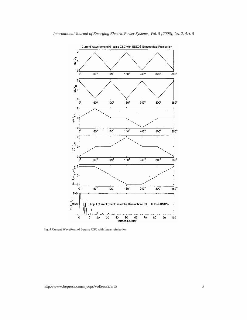
Fig. 4 Current Waveform of 6-pulse CSC with linear reinjection
6
International Journal of Emerging Electric Power Systems, Vol. 5 [2006], Iss. 2, Art. 5
http://www.bepress.com/ijeeps/vol5/iss2/art5

iBp
iaY
Sy1 Sy3 Sy5
Sy4 Sy6 Sy2
ijp
ijn
Ia Ib Ic
Np
Np
N1
Nm/2
N1
idc
Lm
Spj1
Snjm
Snj0
Spj0
Spjm/2
Snjm/2+1
Spjm/2+1
Snjm/2
Spjm
Snj1
Vdc
VdcD
VdcD
Cj
Cj
iBn
Spj2
Snjm-1
Spjm-1
Snj2
Nm/2
Ed
Fig. 5 Multi-pulse topological structure
7
Yonghe et al.: DC-Ripple Reinjection Concept to Forced-Commution Conversion
Published by The Berkeley Electronic Press, 2006

TABLE I SWITCHING COMBINATIONS AND MULTI-LEVEL REINJECTION CURRENT (POSITIVE POLE) ON state switches BPI
Winding Combinations (P-group)
jpI
1pjS and
1njS LmI
1 1 2 2S mN N N N= + + +L
1S
dcP
N IN
2pjS
and 2njS (L mI −
2 2 3 2S mN N N N= + + +L
2S
dcP
N IN
M M M M
2mpj
S
and
2mnj
S
( 2L mI
2 2S m mN N= 2S mdc
P
NI
N
0pjS
and 0njS dcI 0 0SN = 0
( 1)2mpj
S+
and
( 1)2mnj
S+
2LmI
2 2S m mN N= 2S md
P
NI
N−
M M M M
( 1)pj mS −
and
( 1)nj mS −
2LI 2 2 3 2S mN N N N= + + +L
2S
dcP
N IN−
pjmS
and
njmS
1LI 1 2 2 1S mN N N N= + + +L
1S
dcP
N IN−
Tables 1 and 2 give the corresponding relationships between the (m+1) levels of currents BPI
and BNI , the required feedback switches in ON-state, the windings connections of the feedback
transformers and the currents jpI and jnI used to shape the dc output currents BPI and BNI .
The winding connections of the feedback transformers in Figure 5 ensures that np jpI I= − and
the main bridge output currents are formed by dcI , jpI and jnI , i.e. BP dc jpI I I= + and
BN dc jn dc jpI I I I I= + = − . Because jpI and jnI are determined by the turns ratio of the
8
International Journal of Emerging Electric Power Systems, Vol. 5 [2006], Iss. 2, Art. 5
http://www.bepress.com/ijeeps/vol5/iss2/art5

feedback transformers, the main bridge output currents BPI and BNI can be shaped into the required multi-level forms from constant d.c. by selecting the appropriate winding ratio. The required current waveforms BPI and BNI , are synchronized with the firing control of the main bridge switches, therefore by supplying the required reinjection current waveforms the converter output current waveforms are also shaped into the expected waveforms
TABLE II SWITCHING COMBINATIONS AND MULTI-LEVEL REINJECTION CURRENT (NEGATIVE POLE)
ON state switches NPI Winding Combinations
(P-group) jnI
1pjS and
1njS 1LI 1 2 2 1S mN N N N= + + +L
1S
dcP
N IN−
2pjS and
2njS 2LI 2 2 3 2S mN N N N= + + +L
2S
dcP
N IN−
M M M M
2mpj
S and
2mnj
S
2LmI
2 2S m mN N= 2S md
P
NI
N−
0pjS and
0njS dcI 0 0SN = 0
( 1)2mpj
S+
and
( 1)2mnj
S+
( 2L mI +
2 2S m mN N= 2S m
dcP
NI
N
M M M M
( 1)pj mS −
and
( 1)nj mS −
( 1)L mI −
2 2 3 2S mN N N N= + + +L
2S
dcP
N IN
pjmS and
njmS LmI 1 1 2 2S mN N N N= + + +L
1S
dcP
N IN
In the original, line-commutated, scheme this doubles the number of (feedback) commutations
(i.e. from three to six per cycle); it also halves the ripple voltage used for the commutations which, in turn, increases the commutation overlap and reduces the effectiveness of the reinjection process. This is not a problem in the force-commutated alternative, where the commutations do not depend on the voltage level and, therefore, the double bridge reinjection scheme should make
9
Yonghe et al.: DC-Ripple Reinjection Concept to Forced-Commution Conversion
Published by The Berkeley Electronic Press, 2006

the concept even more attractive for high voltage applications.
A. Analysis and simulation of the current waveforms An optimization process [3] has been used to determine the width and height of the current step that minimize the harmonic current. Also a sufficient zero current width interval is allowed to ensure that the main valves switch under a zero current condition.
If the heights are denote by Hi (i=1,2,…m), from 0 to π/6, the optimization process gives: 3 (2 1)1 3.4641 sin sin sin
6 2 6 6iiH m m
m mπ π π−⎛ ⎞ ⎛ ⎞= + −⎜ ⎟ ⎜ ⎟
⎝ ⎠ ⎝ ⎠ (1)
The resulting fundamental component of the output current has the expression
2 2 dcA1m
n
I6 3I = 1+2m sin tan6 2 6 k
mm mπ π
π⎛ ⎞⎛ ⎞ ⎛ ⎞−⎜ ⎟⎜ ⎟ ⎜ ⎟⎜ ⎟⎝ ⎠ ⎝ ⎠⎝ ⎠
(2)
where kn is the turns ratio of the converter transformer. and the output current’s rms value is
2 2dcAm(rms)
n
I 3I = 2 1+2m sin tank 6 2 6
mm mπ π⎛ ⎞ ⎛ ⎞−⎜ ⎟ ⎜ ⎟
⎝ ⎠ ⎝ ⎠ (3)
Finally, the total harmonic distortion of the output current is
2 2( ) 1
2
2 2
2 1
139 1 2 sin tan
6 2 6
IAm Am rms A mTHD I I
m mm m
ππ π
= −
= −⎛ ⎞⎛ ⎞ ⎛ ⎞+ −⎜ ⎟⎜ ⎟ ⎜ ⎟
⎝ ⎠ ⎝ ⎠⎝ ⎠
(4)
The relationship between the reinjection level number and the THD is shown in Table 3.
Table III - THD versus reinjection level number Level m
3 4 5 6 7 8 9 10
THD (%)
10.05 8.29 7.05 6.28 5.76 5.40 5.14 4.95
The Table shows that the harmonic content reduction slows down when the level number is greater than eight and therefore there is no need to use high level numbers. A scaled down model was used in [1] to verify the basic reinjection waveforms of the line commutated converter. However, the relatively large value of the magnetizing current of the model transformer made it difficult to verify the output current of a practical scheme. Instead, the waveforms of the present self-commutated converter have been derived by means of PSCAD/EMTDC simulation. The test system used for the simulation is based on the circuit of Figure 5 with m=5. The converter system rated at 50 MVA /100kV is directly connected to a balanced three phase voltage source with a small series impedance of (0.1+j0.1) Ω. Nominal leakage reactance of the interface transformer is set to 10%. The reinjection transformers turns ratio are set to its optimum value,
10
International Journal of Emerging Electric Power Systems, Vol. 5 [2006], Iss. 2, Art. 5
http://www.bepress.com/ijeeps/vol5/iss2/art5

(Ns1/Np=0.3901, Ns2/Np=0.3944) to obtain minimum harmonic distortion. The load branch inductance is set to 5H and the dc voltage source to 0V and 1 Ω. Finally the converter system is closed loop controlled to supply 50 MVAr of leading reactive power. The two half-bridges are supplied with the optimized multi-step reinjection waveforms (shown in Figures 6(a) and (b) for m=5). These currents are used to shape the main bridges output current
BPI and BNI . The resulting currents in the primary (delta connected) phases A & B of the interface transformer are shown in Fig. 6 (c) & (d) respectively and the total output phase current and its spectrum in Figures 6(e) and (f). The simulation results for the voltages on the dc side of the converter are shown in Figure 7, where diagram (c) clearly illustrates the pulse multiplication effect achieved by the multi-stepped reinjection scheme, i.e. for the 5-level reinjection scheme the number of pulses per cycle of the fundamental frequency are 30.
0 60 120 180 240 300 360−0.5
0
0.5
(a).
I jp (
kA)
o o o o o o o
0 60 120 180 240 300 360−0.5
0
0.5
(b).
I jn (
kA)
o o o o o o o
0 60 120 180 240 300 360−0.5
0
0.5
(c).
I ∆ a (
kA)
o o o o o o o
0 60 120 180 240 300 360−0.5
0
0.5
(d).
I ∆ b (
kA)
o o o o o o o
0 60 120 180 240 300 360−0.5
0
0.5
(e).
I A (
kA)
o o o o o o o
0 10 20 30 40 50 60 70 80 90 1000
0.02
0.04
(f).
I An/I A
1
Harmonic Order
Spectrum of output Current
Fig. 6 Simulated Current Waveforms of 5-level reinjection CSC
11
Yonghe et al.: DC-Ripple Reinjection Concept to Forced-Commution Conversion
Published by The Berkeley Electronic Press, 2006

0 60 120 180 240 300 360
−100
0
100(a
). V
p (kV
)
o o o o o o o
0 60 120 180 240 300 360
−100
0
100
(b).
Vn (
kV)
o o o o o o o
0 60 120 180 240 300 360−50
0
50
(c).
Vdc
(kV
)
o o o o o o o Fig. 7 Simulated Voltage Waveforms of 5-level reinjection CSC
IV. DISCUSSION AND CONCLUSIONS Besides the extra components required, the reinjection scheme imposes some increases in the ratings of the main converter as indicated in Section 2.2 for the pulse-doubling scheme. The higher ratings and additional components have to be weighed against the need for substantial ac and dc filters in the conventional configuration. It is not possible to make a straight forward economic comparison between the conventional and reinjection schemes for a variety of reasons. Prominent among them are the variety and high cost of the passive filters (of up to 10% of the total cost of the converter plant); the large capacitance of the lower order tuned filters, which is often a source of parallel third harmonic resonance with the system impedance; the conventional twelve-pulse, and even the higher pulse configurations suffer from six-pulse related harmonic distortion; the unequal power sharing between the bridges in the case of the parallel configuration, which often requires overrating the individual bridges by up to 25%, etc. In contrast, the reinjection technique transforms the conventional self-commutated six-pulse current source converter waveforms into consistent multi-step ac current and multi-pulse dc voltage waveforms. This applies equally to rectifier and inverter operation and to variable frequency supplies. The power conversion efficiency is high as the rectified harmonic power is reinjected into the dc system. Multi-level linear symmetrical reinjection combines together the benefits of harmonic reinjection, multi-level conversion and soft switching. Based on linearity and equal increments this configuration can be built up by the same type of components, which is a significant advantage in high power applications.
V. ACKNOWLEDGMENT The authors wish to acknowledge the early contributions made to this topic by J.F.Baird and
M.Villablanca at The University of Canterbury, New Zealand.
12
International Journal of Emerging Electric Power Systems, Vol. 5 [2006], Iss. 2, Art. 5
http://www.bepress.com/ijeeps/vol5/iss2/art5

VI. REFERENCES [1] J.F. Baird and J. Arrillaga (1979) “Improvements in and relating to static convertors”, N.Z. patent application 190713,
1979. [2] J.F. Baird and J. Arrillaga (1980), “Harmonic reduction in dc-ripple reinjection”, Proc. IEE, Vol. 127, No. 5, Part C,
249-303. [3] Y.H. Liu, J. Arrillaga and N.R. Watson (2002), “Multi-level voltage source conversion by voltage reinjection at six
times the fundamental frequency”, Proc. IEE Power Applications, Vol. 149, No. 3, 201-207. [4] Y.H.Liu (2004), “Multi-level voltage and current reinjection ac-dc conversion”, Ph D thesis, University of
Canterbury, New Zealand. [5] I. Takahashi A. Nabae and H. Akagi, “A new neutral-point-clamped PWM inverter”, IEEE Trans. on Industry
Application, Vol. 17, No. 5, pp. 518--523, 1981. [6] N.S. Choi, J.G. Cho and G.H. Cho, “A General Circuit Topology of Multilevel Inverter”, IEEE Power Electronics
Specialist Conference, MIT, USA, Vol. PESC 91 Record, pp. 96--103, 1991. [7] T.A. Meynard and H. Foch, “Multi-level conversion: high voltage choppers and voltage-source inverters”, 23rd
Annual Power Electronics Specialists Conference, PESC'92, Vol. 1, pp. 397--403, July 1992. [8] Y.S. Lai and F.Z. Peng, “Multilevel converters-a new breed of power converters", IEEE Trans. on Industry
Applications, Vol. 32, No. 3, pp. 509-517, May/Jun. 1996. [9] X. Yuan and et al., “Fundamentals of a New Diode Clamping Multilevel Inverter”, IEEE Trans. on Power
Electronics, Vol. 15, No. 4, pp. 711--718, July, 2000.
VII. BIOGRAPHIES
Jos Arrillaga received a BE degree in Spain and the MSc, PhD, and DSc in Manchester, where he led the power systems group of UMIST between 1970-74. He has been a Professor at the University of Canterbury since 1975. He is a Fellow of the IEE, of the IEEE, and of the Royal Society of New Zealand.
Neville Watson received his BE (Hons) and PhD degrees in Electrical and Electronic Engineering from the University
of Canterbury (New Zealand), where he is an Associate Professor. His interests include steady-state and dynamic analysis of ac/dc power systems.
Yonghe Liu received an M.E. in automation from The Chinese Science Academy and a Ph..D. from the University of
Canterbury (New Zealand). He is a Professor at the Inner Mongolia University of Technology, China. L. Bernard Perera received his B.Sc.(Eng) degree in Electrical Engineering from the University of Moratuwa, Sri
Lanka in 2000. Since 2003 he has been working on a Ph.D. at the University of Canterbury (New Zealand).
13
Yonghe et al.: DC-Ripple Reinjection Concept to Forced-Commution Conversion
Published by The Berkeley Electronic Press, 2006