Σ-7S SERVOPACK with - FT/EX Specification for Three-Point ...
187
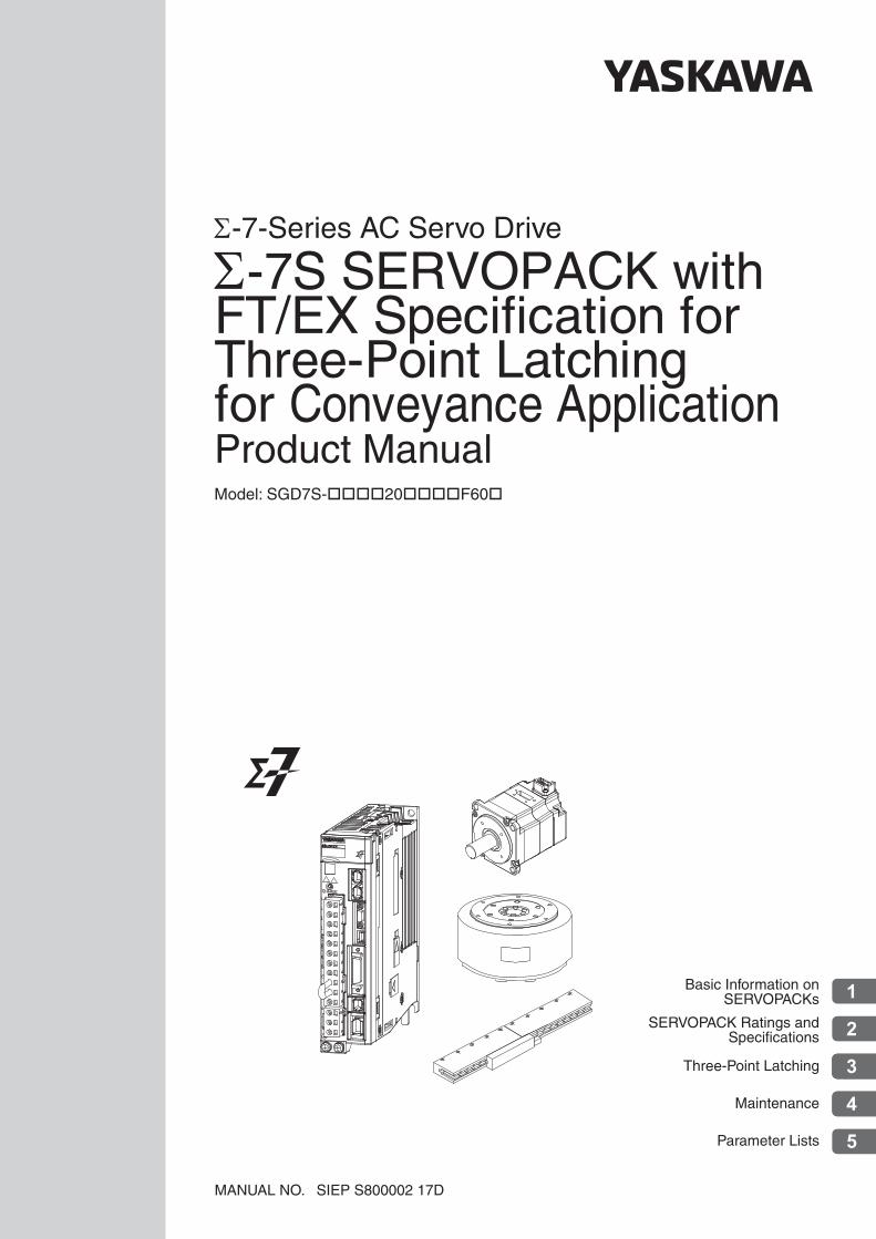
Model: SGD7S-20F60 -7-Series AC Servo Drive MANUAL NO. SIEP S800002 17D -7S SERVOPACK with FT/EX Specification for Three-Point Latching for Conveyance Application Three-Point Latching Maintenance Parameter Lists Basic Information on SERVOPACKs SERVOPACK Ratings and Specifications 1 2 3 4 5 Product Manual
-
Upload
khangminh22 -
Category
Documents
-
view
1 -
download
0
Transcript of Σ-7S SERVOPACK with - FT/EX Specification for Three-Point ...
Model: SGD7S-20F60
-7-Series AC Servo Drive
MANUAL NO. SIEP S800002 17D
-7S SERVOPACK with FT/EX Specification for Three-Point Latching for Conveyance Application
Three-Point Latching
Maintenance
Parameter Lists
Basic Information on SERVOPACKs
SERVOPACK Ratings andSpecifications
1
2
3
4
5
Product Manual

Copyright © 2016 YASKAWA ELECTRIC CORPORATION
All rights reserved. No part of this publication may be reproduced, stored in a retrieval system, or transmitted, in any form, or by any means, mechanical, elec-tronic, photocopying, recording, or otherwise, without the prior written permission of Yaskawa. No patent liability is assumed with respect to the use of the informa-tion contained herein. Moreover, because Yaskawa is constantly striving to improve its high-quality products, the information contained in this manual is sub-ject to change without notice. Every precaution has been taken in the preparation of this manual. Nevertheless, Yaskawa assumes no responsibility for errors or omissions. Neither is any liability assumed for damages resulting from the use of the information contained in this publication.
iii
About this Manual
This manual describes three-point latching for conveyance applications for Σ-7-Series AC Servo Drive Σ-7S SERVOPACKs.Read and understand this manual to ensure correct usage of the Σ-7-Series AC Servo Drives.
Keep this manual in a safe place so that it can be referred to whenever necessary.
Outline of Manual
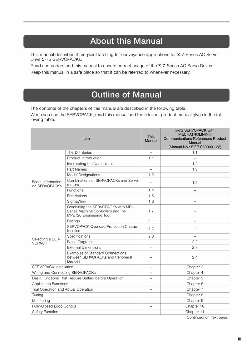
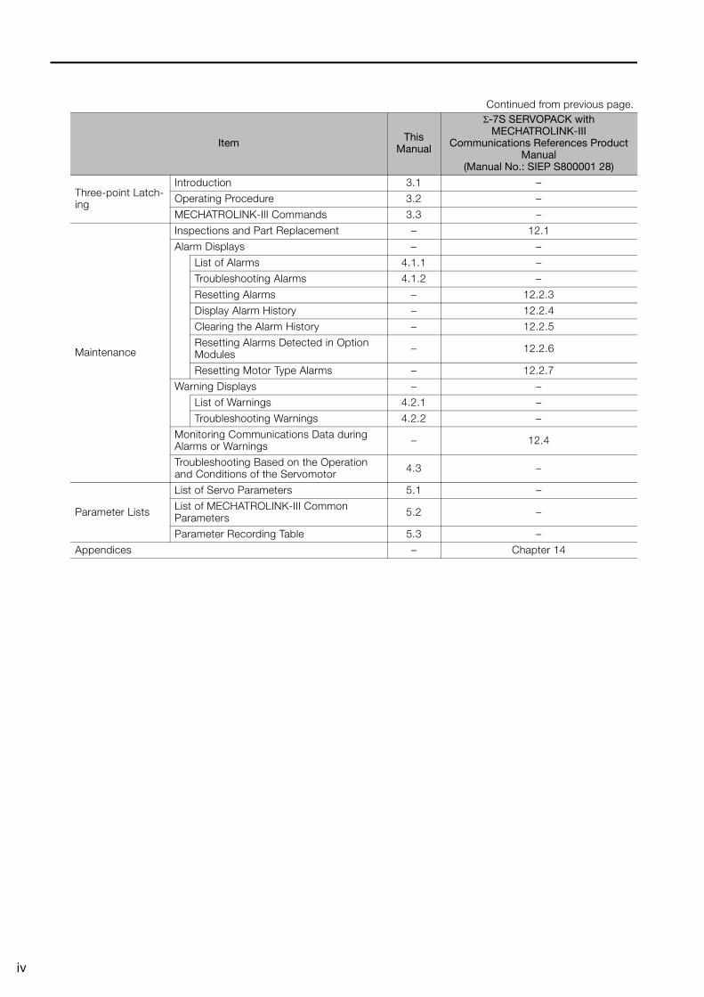
The contents of the chapters of this manual are described in the following table.When you use the SERVOPACK, read this manual and the relevant product manual given in the fol-lowing table.
Item This Manual
Σ-7S SERVOPACK with MECHATROLINK-III
Communications References Product Manual
(Manual No.: SIEP S800001 28)
Basic Information on SERVOPACKs
The Σ-7 Series – 1.1
Product Introduction 1.1 –
Interpreting the Nameplates – 1.2
Part Names – 1.3
Model Designations 1.2 –
Combinations of SERVOPACKs and Servo-motors – 1.5
Functions 1.4 –
Restrictions 1.5 –
SigmaWin+ 1.6 –
Combining the SERVOPACKs with MP-Series Machine Controllers and the MPE720 Engineering Tool
1.7 –
Selecting a SER-VOPACK
Ratings 2.1 –
SERVOPACK Overload Protection Charac-teristics 2.2 –
Specifications 2.3 –
Block Diagrams – 2.2
External Dimensions – 2.3
Examples of Standard Connections between SERVOPACKs and Peripheral Devices
– 2.4
SERVOPACK Installation – Chapter 3
Wiring and Connecting SERVOPACKs – Chapter 4
Basic Functions That Require Setting before Operation – Chapter 5
Application Functions – Chapter 6
Trial Operation and Actual Operation – Chapter 7
Tuning – Chapter 8
Monitoring – Chapter 9
Fully-Closed Loop Control – Chapter 10
Safety Function – Chapter 11
Continued on next page.
iv
Three-point Latch-ing
Introduction 3.1 –
Operating Procedure 3.2 –
MECHATROLINK-III Commands 3.3 –
Maintenance
Inspections and Part Replacement – 12.1
Alarm Displays – –
List of Alarms 4.1.1 –
Troubleshooting Alarms 4.1.2 –
Resetting Alarms – 12.2.3
Display Alarm History – 12.2.4
Clearing the Alarm History – 12.2.5
Resetting Alarms Detected in Option Modules – 12.2.6
Resetting Motor Type Alarms – 12.2.7
Warning Displays – –
List of Warnings 4.2.1 –
Troubleshooting Warnings 4.2.2 –
Monitoring Communications Data during Alarms or Warnings – 12.4
Troubleshooting Based on the Operation and Conditions of the Servomotor 4.3 –
Parameter Lists
List of Servo Parameters 5.1 –
List of MECHATROLINK-III Common Parameters 5.2 –
Parameter Recording Table 5.3 –
Appendices – Chapter 14
Continued from previous page.
Item This Manual
Σ-7S SERVOPACK with MECHATROLINK-III
Communications References Product Manual
(Manual No.: SIEP S800001 28)
v
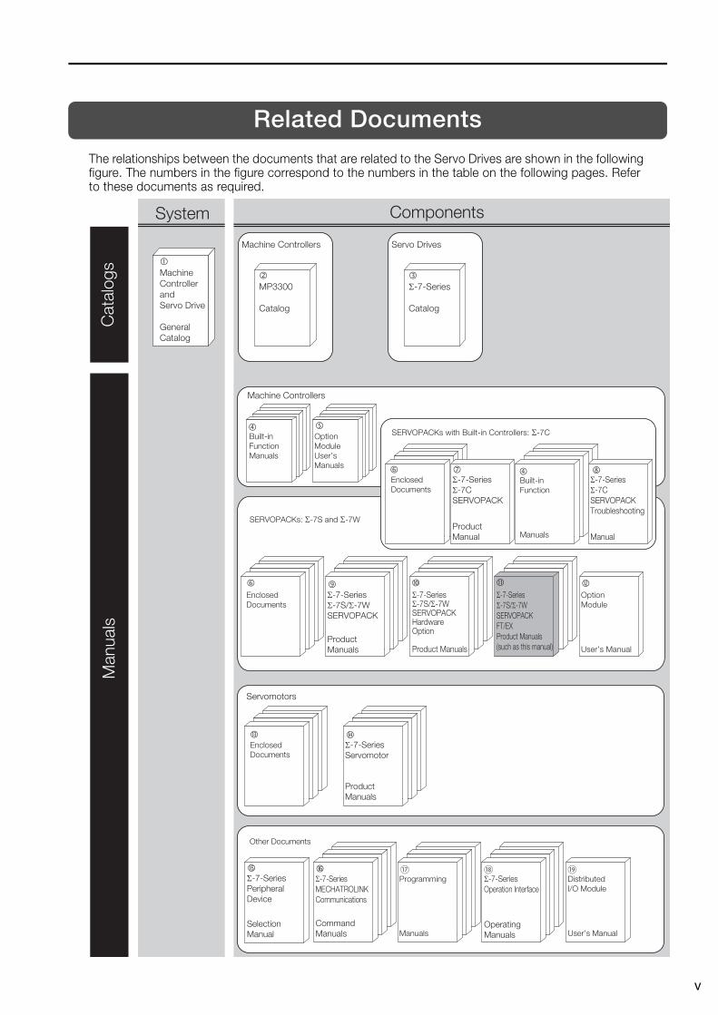
Related Documents
The relationships between the documents that are related to the Servo Drives are shown in the following figure. The numbers in the figure correspond to the numbers in the table on the following pages. Refer to these documents as required.
System Components
� Machine Controller and Servo Drive
General Catalog
� MP3300
Catalog
� Σ-7-Series
Catalog
Machine Controllers Servo Drives
Man
uals
Cat
alog
s
SERVOPACKs: Σ-7S and Σ-7W
Built-in Function Manuals
Option Module User’s Manuals
Enclosed Documents
Σ-7-Series Σ-7S/Σ-7W SERVOPACK
Product Manuals
Σ-7-Series Σ-7S/Σ-7W SERVOPACK Hardware Option Product Manuals
Option Module
User’s Manual
Other Documents
Σ-7-Series MECHATROLINK Communications
Command Manuals
Programming
Manuals
Σ-7-Series Operation Interface
OperatingManuals
Distributed I/O Module
User’s Manual
Enclosed Documents
Σ-7-Series Servomotor
Product Manuals
SERVOPACKs with Built-in Controllers: Σ-7C
Enclosed Documents
Σ-7-Series Σ-7C SERVOPACK
Product Manual
Built-in Function
Manuals
Σ-7-Series Σ-7C SERVOPACK Troubleshooting
Manual
Σ-7-Series Peripheral Device
Selection Manual
Σ-7-Series Σ-7S/Σ-7W SERVOPACK FT/EX Product Manuals (such as this manual)
Machine Controllers
�
Servomotors
�
�
�
�
�
vi
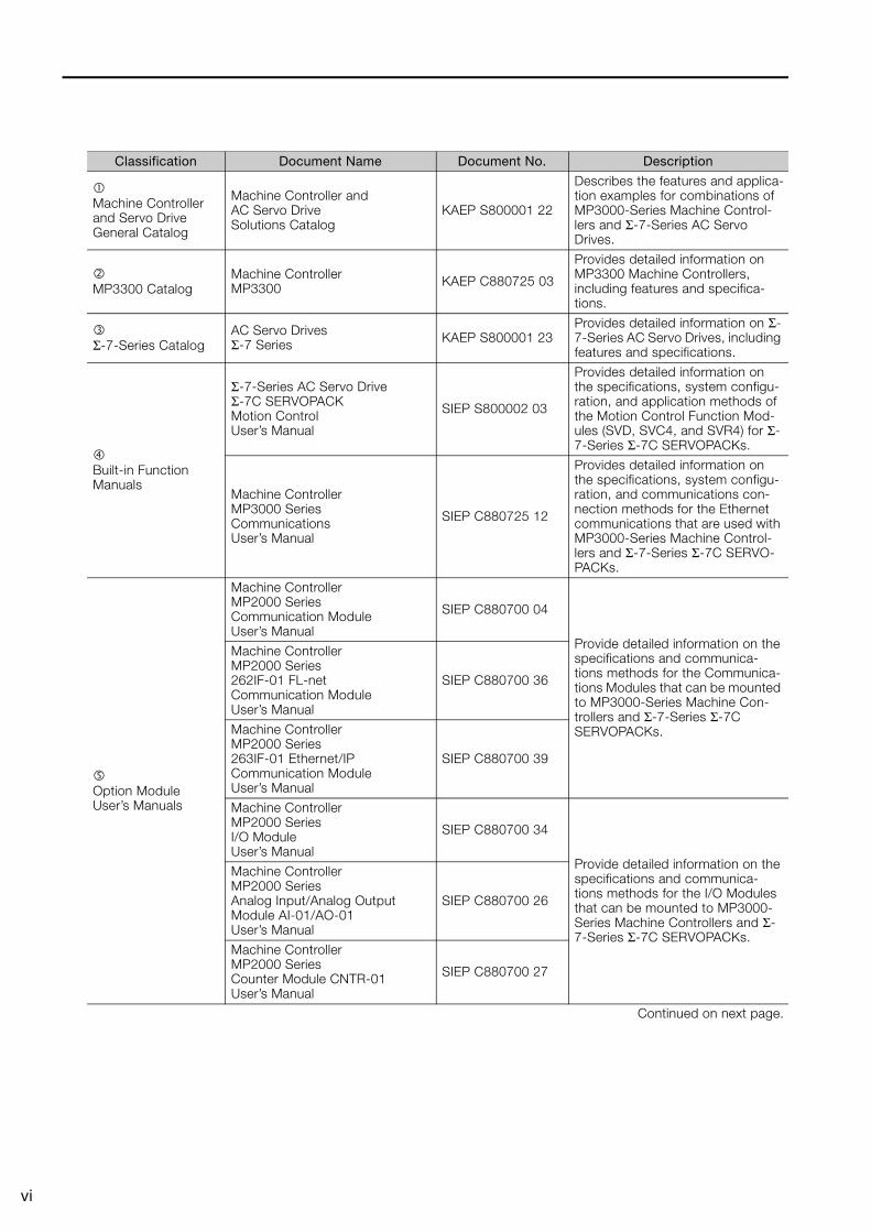
Classification Document Name Document No. Description
Machine Controller and Servo Drive General Catalog
Machine Controller and AC Servo Drive Solutions Catalog
KAEP S800001 22
Describes the features and applica-tion examples for combinations of MP3000-Series Machine Control-lers and Σ-7-Series AC Servo Drives.
MP3300 Catalog
Machine ControllerMP3300 KAEP C880725 03
Provides detailed information on MP3300 Machine Controllers, including features and specifica-tions.
Σ-7-Series Catalog
AC Servo DrivesΣ-7 Series KAEP S800001 23
Provides detailed information on Σ-7-Series AC Servo Drives, including features and specifications.
Built-in Function Manuals
Σ-7-Series AC Servo Drive Σ-7C SERVOPACK Motion Control User’s Manual
SIEP S800002 03
Provides detailed information on the specifications, system configu-ration, and application methods of the Motion Control Function Mod-ules (SVD, SVC4, and SVR4) for Σ-7-Series Σ-7C SERVOPACKs.
Machine Controller MP3000 Series Communications User’s Manual
SIEP C880725 12
Provides detailed information on the specifications, system configu-ration, and communications con-nection methods for the Ethernet communications that are used with MP3000-Series Machine Control-lers and Σ-7-Series Σ-7C SERVO-PACKs.
Option Module User’s Manuals
Machine Controller MP2000 Series Communication Module User’s Manual
SIEP C880700 04
Provide detailed information on the specifications and communica-tions methods for the Communica-tions Modules that can be mounted to MP3000-Series Machine Con-trollers and Σ-7-Series Σ-7C SERVOPACKs.
Machine Controller MP2000 Series 262IF-01 FL-net Communication Module User’s Manual
SIEP C880700 36
Machine Controller MP2000 Series 263IF-01 Ethernet/IP Communication Module User’s Manual
SIEP C880700 39
Machine Controller MP2000 Series I/O Module User’s Manual
SIEP C880700 34
Provide detailed information on the specifications and communica-tions methods for the I/O Modules that can be mounted to MP3000-Series Machine Controllers and Σ-7-Series Σ-7C SERVOPACKs.
Machine Controller MP2000 Series Analog Input/Analog Output Module AI-01/AO-01 User’s Manual
SIEP C880700 26
Machine Controller MP2000 Series Counter Module CNTR-01 User’s Manual
SIEP C880700 27
Continued on next page.
vii
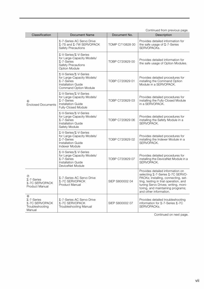
Enclosed Documents
Σ-7-Series AC Servo Drive Σ-7S and Σ-7W SERVOPACK Safety Precautions
TOMP C710828 00Provides detailed information for the safe usage of Σ-7-Series SERVOPACKs.
Σ-V-Series/Σ-V-Seriesfor Large-Capacity Models/Σ-7-Series Safety PrecautionsOption Module
TOBP C720829 00 Provides detailed information for the safe usage of Option Modules.
Σ-V-Series/Σ-V-Seriesfor Large-Capacity Models/Σ-7-Series Installation GuideCommand Option Module
TOBP C720829 01Provides detailed procedures for installing the Command Option Module in a SERVOPACK.
Σ-V-Series/Σ-V-Series for Large-Capacity Models/Σ-7-Series Installation Guide Fully-Closed Module
TOBP C720829 03Provides detailed procedures for installing the Fully-Closed Module in a SERVOPACK.
Σ-V-Series/Σ-V-Series for Large-Capacity Models/Σ-7-Series Installation Guide Safety Module
TOBP C720829 06Provides detailed procedures for installing the Safety Module in a SERVOPACK.
Σ-V-Series/Σ-V-Series for Large-Capacity Models/Σ-7-Series Installation Guide Indexer Module
TOBP C720829 02Provides detailed procedures for installing the Indexer Module in a SERVOPACK.
Σ-V-Series/Σ-V-Series for Large-Capacity Models/Σ-7-Series Installation Guide DeviceNet Module
TOBP C720829 07Provides detailed procedures for installing the DeviceNet Module in a SERVOPACK.
Σ-7-Series Σ-7C SERVOPACKProduct Manual
Σ-7-Series AC Servo Drive Σ-7C SERVOPACK Product Manual
SIEP S800002 04
Provides detailed information on selecting Σ-7-Series Σ-7C SERVO-PACKs; installing, connecting, set-ting, testing in trial operation, and tuning Servo Drives; writing, moni-toring, and maintaining programs; and other information.
Σ-7-Series Σ-7C SERVOPACK Troubleshooting Manual
Σ-7-Series AC Servo Drive Σ-7C SERVOPACK Troubleshooting Manual
SIEP S800002 07Provides detailed troubleshooting information for Σ-7-Series Σ-7C SERVOPACKs.
Continued on next page.
Continued from previous page.
Classification Document Name Document No. Description

viii
Σ-7-Series Σ-7S/Σ-7W SERVOPACK Product Manuals
Σ-7-Series AC Servo Drive Σ-7S SERVOPACK with MECHATROLINK-III Communications References Product Manual
SIEP S800001 28
Provide detailed information onselecting Σ-7-Series Σ-7S andΣ-7W SERVOPACKs; installing,connecting, setting, testing in trialoperation, tuning, monitoring, andmaintaining Servo Drives; andother information.
Σ-7-Series AC Servo Drive Σ-7S SERVOPACK with MECHATROLINK-II Communications References Product Manual
SIEP S800001 27
Σ-7-Series AC Servo Drive Σ-7S SERVOPACK with Analog Voltage/Pulse Train References Product Manual
SIEP S800001 26
Σ-7-Series AC Servo DriveΣ-7S SERVOPACK Command Option Attachable Type with INDEXER ModuleProduct Manual
SIEP S800001 64
Σ-7-Series AC Servo DriveΣ-7S SERVOPACK Command Option Attachable Type with DeviceNet ModuleProduct Manual
SIEP S800001 70
Σ-7-Series AC Servo Drive Σ-7W SERVOPACK with MECHATROLINK-III Communications References Product Manual
SIEP S800001 29
Σ-7-Series Σ-7S/Σ-7W SERVOPACK with Hardware Option Specification Product Manuals
Σ-7-Series AC Servo Drive Σ-7S/Σ-7W SERVOPACK with Hardware Option Specifications Dynamic Brake Product Manual
SIEP S800001 73
Provide detailed information on Hardware Options for Σ-7-Series SERVOPACKS.Σ-7-Series AC Servo Drive
Σ-7W/Σ-7C SERVOPACK with Hardware Option Specifications HWBB Function Product Manual
SIEP S800001 72
Continued on next page.
Continued from previous page.
Classification Document Name Document No. Description
ix
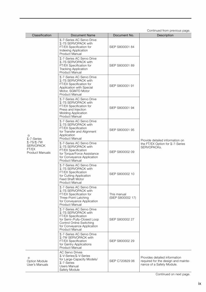
Σ-7-Series Σ-7S/Σ-7W SERVOPACK FT/EX Product Manuals
Σ-7-Series AC Servo DriveΣ-7S SERVOPACK with FT/EX Specification for Indexing Application Product Manual
SIEP S800001 84
Provide detailed information on the FT/EX Option for Σ-7-Series SERVOPACKs.
Σ-7-Series AC Servo DriveΣ-7S SERVOPACK with FT/EX Specification for Tracking Application Product Manual
SIEP S800001 89
Σ-7-Series AC Servo DriveΣ-7S SERVOPACK withFT/EX Specification for Application with Special Motor, SGM7D MotorProduct Manual
SIEP S800001 91
Σ-7-Series AC Servo DriveΣ-7S SERVOPACK with FT/EX Specification for Press and InjectionMolding ApplicationProduct Manual
SIEP S800001 94
Σ-7-Series AC Servo DriveΣ-7S SERVOPACK withFT/EX Specificationfor Transfer and AlignmentApplicationProduct Manual
SIEP S800001 95
Σ-7-Series AC Servo DriveΣ-7S SERVOPACK withFT/EX Specificationfor Torque/Force Assistancefor Conveyance ApplicationProduct Manual
SIEP S800002 09
Σ-7-Series AC Servo DriveΣ-7S SERVOPACK withFT/EX Specificationfor Cutting ApplicationFeed Shaft MotorProduct Manual
SIEP S800002 10
Σ-7-Series AC Servo DriveΣ-7S SERVOPACK with FT/EX Specification for Three-Point Latching for Conveyance Application Product Manual
This manual (SIEP S800002 17)
Σ-7-Series AC Servo DriveΣ-7S SERVOPACK withFT/EX Specificationfor Semi-/Fully-Closed LoopControl Online Switchingfor Conveyance ApplicationProduct Manual
SIEP S800002 27
Σ-7-Series AC Servo DriveΣ-7W SERVOPACK withFT/EX Specificationfor Gantry ApplicationsProduct Manual
SIEP S800002 29
Option Module User’s Manuals
AC Servo DrivesΣ-V-Series/Σ-V-Seriesfor Large-Capacity Models/Σ-7-Series Users ManualSafety Module
SIEP C720829 06Provides detailed information required for the design and mainte-nance of a Safety Module.
Continued on next page.
Continued from previous page.
Classification Document Name Document No. Description
x
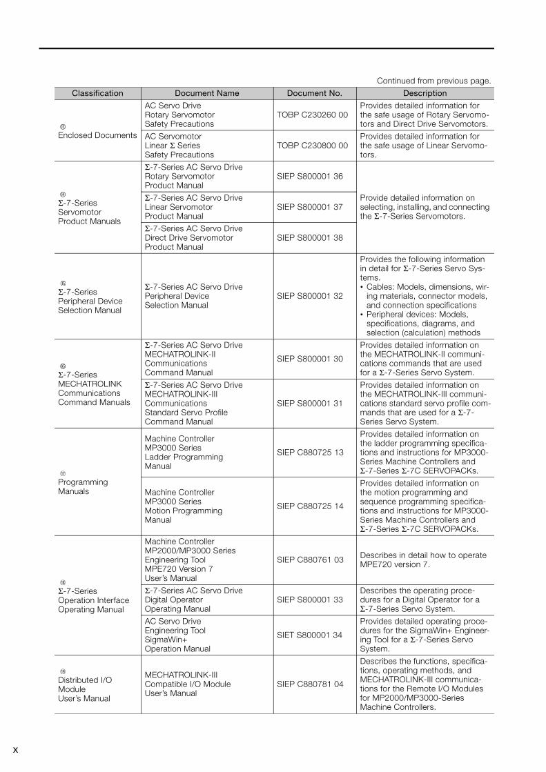
Enclosed Documents
AC Servo Drive Rotary Servomotor Safety Precautions
TOBP C230260 00Provides detailed information for the safe usage of Rotary Servomo-tors and Direct Drive Servomotors.
AC Servomotor Linear Σ Series Safety Precautions
TOBP C230800 00Provides detailed information for the safe usage of Linear Servomo-tors.
Σ-7-Series Servomotor Product Manuals
Σ-7-Series AC Servo Drive Rotary Servomotor Product Manual
SIEP S800001 36
Provide detailed information on selecting, installing, and connecting the Σ-7-Series Servomotors.
Σ-7-Series AC Servo Drive Linear Servomotor Product Manual
SIEP S800001 37
Σ-7-Series AC Servo Drive Direct Drive Servomotor Product Manual
SIEP S800001 38
Σ-7-Series Peripheral Device Selection Manual
Σ-7-Series AC Servo Drive Peripheral Device Selection Manual
SIEP S800001 32
Provides the following information in detail for Σ-7-Series Servo Sys-tems.• Cables: Models, dimensions, wir-
ing materials, connector models, and connection specifications
• Peripheral devices: Models, specifications, diagrams, and selection (calculation) methods
Σ-7-Series MECHATROLINK Communications Command Manuals
Σ-7-Series AC Servo Drive MECHATROLINK-II Communications Command Manual
SIEP S800001 30
Provides detailed information on the MECHATROLINK-II communi-cations commands that are used for a Σ-7-Series Servo System.
Σ-7-Series AC Servo Drive MECHATROLINK-III Communications Standard Servo Profile Command Manual
SIEP S800001 31
Provides detailed information on the MECHATROLINK-III communi-cations standard servo profile com-mands that are used for a Σ-7-Series Servo System.
Programming Manuals
Machine Controller MP3000 Series Ladder Programming Manual
SIEP C880725 13
Provides detailed information on the ladder programming specifica-tions and instructions for MP3000-Series Machine Controllers and Σ-7-Series Σ-7C SERVOPACKs.
Machine Controller MP3000 Series Motion Programming Manual
SIEP C880725 14
Provides detailed information on the motion programming and sequence programming specifica-tions and instructions for MP3000-Series Machine Controllers and Σ-7-Series Σ-7C SERVOPACKs.
Σ-7-Series Operation Interface Operating Manual
Machine Controller MP2000/MP3000 Series Engineering Tool MPE720 Version 7 User’s Manual
SIEP C880761 03 Describes in detail how to operate MPE720 version 7.
Σ-7-Series AC Servo Drive Digital Operator Operating Manual
SIEP S800001 33Describes the operating proce-dures for a Digital Operator for a Σ-7-Series Servo System.
AC Servo Drive Engineering Tool SigmaWin+ Operation Manual
SIET S800001 34
Provides detailed operating proce-dures for the SigmaWin+ Engineer-ing Tool for a Σ-7-Series Servo System.
Distributed I/O Module User’s Manual
MECHATROLINK-III Compatible I/O Module User’s Manual
SIEP C880781 04
Describes the functions, specifica-tions, operating methods, and MECHATROLINK-III communica-tions for the Remote I/O Modules for MP2000/MP3000-Series Machine Controllers.
Continued from previous page.
Classification Document Name Document No. Description
xi
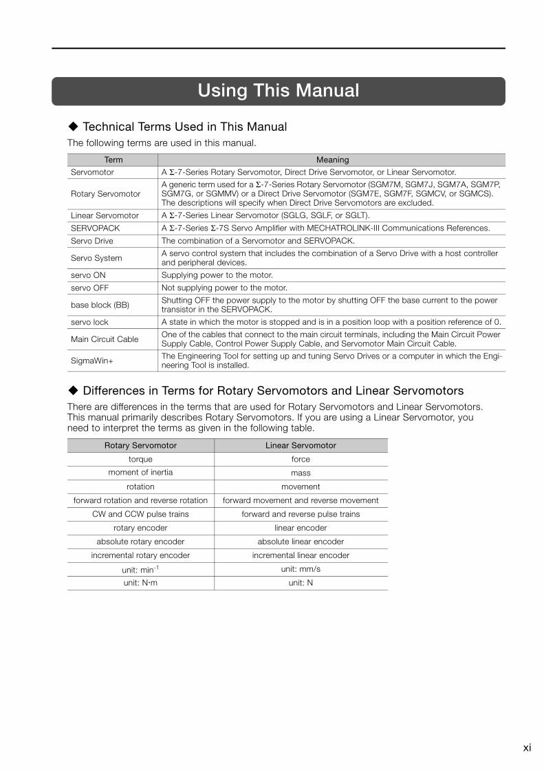
Using This Manual
Technical Terms Used in This ManualThe following terms are used in this manual.
Differences in Terms for Rotary Servomotors and Linear ServomotorsThere are differences in the terms that are used for Rotary Servomotors and Linear Servomotors. This manual primarily describes Rotary Servomotors. If you are using a Linear Servomotor, you need to interpret the terms as given in the following table.
Term Meaning
Servomotor A Σ-7-Series Rotary Servomotor, Direct Drive Servomotor, or Linear Servomotor.
Rotary ServomotorA generic term used for a Σ-7-Series Rotary Servomotor (SGM7M, SGM7J, SGM7A, SGM7P, SGM7G, or SGMMV) or a Direct Drive Servomotor (SGM7E, SGM7F, SGMCV, or SGMCS).The descriptions will specify when Direct Drive Servomotors are excluded.
Linear Servomotor A Σ-7-Series Linear Servomotor (SGLG, SGLF, or SGLT).
SERVOPACK A Σ-7-Series Σ-7S Servo Amplifier with MECHATROLINK-III Communications References.
Servo Drive The combination of a Servomotor and SERVOPACK.
Servo System A servo control system that includes the combination of a Servo Drive with a host controller and peripheral devices.
servo ON Supplying power to the motor.
servo OFF Not supplying power to the motor.
base block (BB) Shutting OFF the power supply to the motor by shutting OFF the base current to the power transistor in the SERVOPACK.
servo lock A state in which the motor is stopped and is in a position loop with a position reference of 0.
Main Circuit Cable One of the cables that connect to the main circuit terminals, including the Main Circuit Power Supply Cable, Control Power Supply Cable, and Servomotor Main Circuit Cable.
SigmaWin+ The Engineering Tool for setting up and tuning Servo Drives or a computer in which the Engi-neering Tool is installed.
Rotary Servomotor Linear Servomotor
torque force
moment of inertia mass
rotation movement
forward rotation and reverse rotation forward movement and reverse movement
CW and CCW pulse trains forward and reverse pulse trains
rotary encoder linear encoder
absolute rotary encoder absolute linear encoder
incremental rotary encoder incremental linear encoder
unit: min-1 unit: mm/s
unit: Nm unit: N
xii
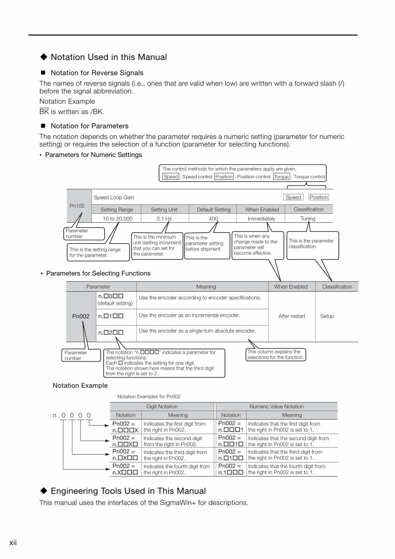
Notation Used in this Manual
Notation for Reverse Signals
The names of reverse signals (i.e., ones that are valid when low) are written with a forward slash (/) before the signal abbreviation.Notation Example
BK is written as /BK.
Notation for Parameters
The notation depends on whether the parameter requires a numeric setting (parameter for numeric setting) or requires the selection of a function (parameter for selecting functions).
• Parameters for Numeric Settings
Notation Example
Engineering Tools Used in This ManualThis manual uses the interfaces of the SigmaWin+ for descriptions.
Pn100
Speed Loop Gain
Setting Range
10 to 20,000 0.1 Hz 400 Immediately
Setting Unit Default Setting When Enabled Classification
Tuning
(default setting)Use the encoder according to encoder specifications.
Use the encoder as an incremental encoder.
Use the encoder as a single-turn absolute encoder.
This is the setting range for the parameter.
Parameter number
This column explains the selections for the function.
Position Torque
The control methods for which the parameters apply are given.
Speed : Speed control : Position control : Torque control
This is the parameter setting before shipment.
This is when any change made to the parameter will become effective.
This is the parameter classification.
This is the minimum unit (setting increment) that you can set for the parameter.
PositionSpeed
Parameter Meaning When Enabled Classification
Pn002
n.�0��
After restart Setupn.�1��
n.�2��
Parameter number
The notation “n.����” indicates a parameter for selecting functions.Each � indicates the setting for one digit.The notation shown here means that the third digit from the right is set to 2.
• Parameters for Selecting Functions
Notation Examples for Pn002
Pn002 = n.���X
Indicates the first digit from the right in Pn002.
Pn002 = n.���1
Indicates that the first digit from the right in Pn002 is set to 1.
Pn002 = n.��X�
Indicates the second digit from the right in Pn002.
Pn002 = n.��1�
Indicates that the second digit from the right in Pn002 is set to 1.
Pn002 =n.�X��
Indicates the third digit from the right in Pn002.
Pn002 = n.�1��
Indicates that the third digit from the right in Pn002 is set to 1.
Pn002 =n.X���
Indicates the fourth digit from the right in Pn002.
Pn002 = n.1���
Indicates that the fourth digit from the right in Pn002 is set to 1.
n . 0 0 0 0 Notation
Digit Notation Numeric Value Notation
Meaning Notation Meaning
xiii
Trademarks• MECHATROLINK is a trademark of the MECHATROLINK Members Association.• QR code is a trademark of Denso Wave Inc.• Other product names and company names are the trademarks or registered trademarks of the
respective company. “TM” and the ® mark do not appear with product or company names in this manual.
Visual AidsThe following aids are used to indicate certain types of information for easier reference.
Indicates precautions or restrictions that must be observed.Also indicates alarm displays and other precautions that will not result in machine damage.
Indicates definitions of difficult terms or terms that have not been previously explained in this manual.
Important
Term
Indicates operating or setting examples.Example
Indicates supplemental information to deepen understanding or useful information.Information
xiv
Safety Precautions
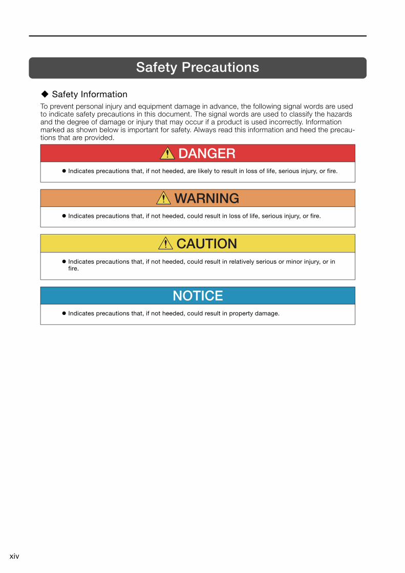
Safety InformationTo prevent personal injury and equipment damage in advance, the following signal words are used to indicate safety precautions in this document. The signal words are used to classify the hazards and the degree of damage or injury that may occur if a product is used incorrectly. Information marked as shown below is important for safety. Always read this information and heed the precau-tions that are provided.
DANGER Indicates precautions that, if not heeded, are likely to result in loss of life, serious injury, or fire.
WARNING Indicates precautions that, if not heeded, could result in loss of life, serious injury, or fire.
CAUTION
Indicates precautions that, if not heeded, could result in relatively serious or minor injury, or in fire.
NOTICE Indicates precautions that, if not heeded, could result in property damage.
xv
Safety Precautions That Must Always Be Observed
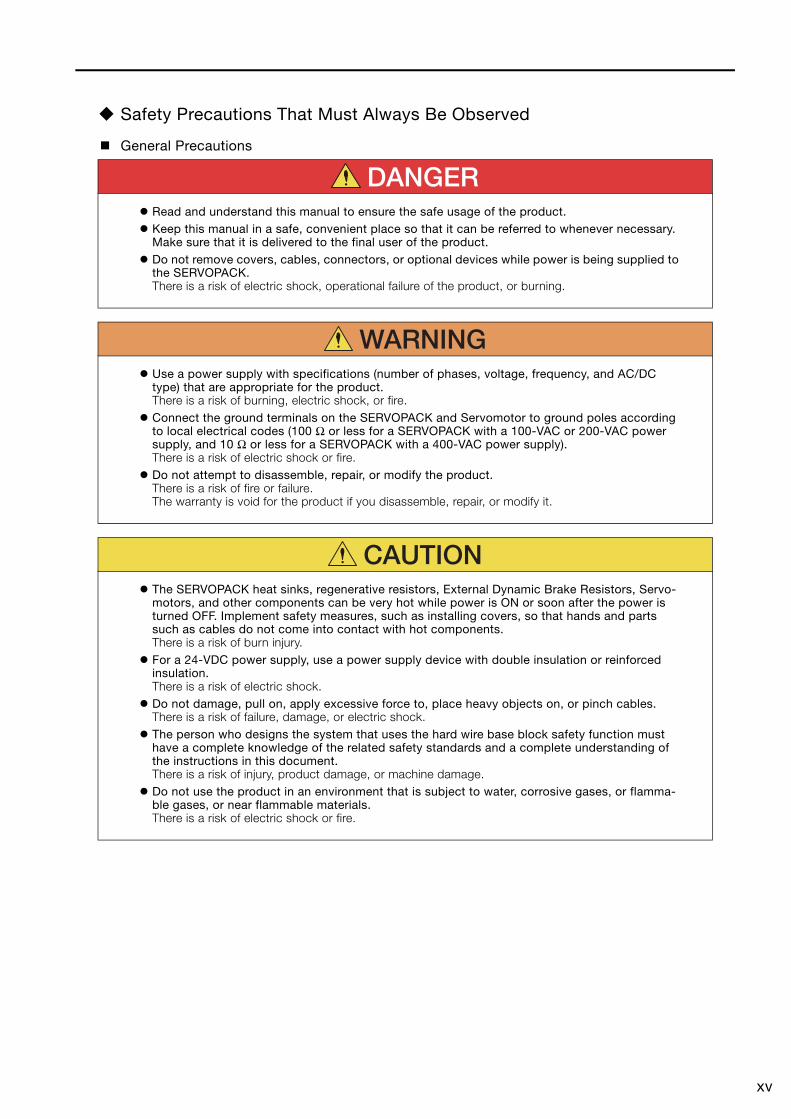
General Precautions
DANGER Read and understand this manual to ensure the safe usage of the product. Keep this manual in a safe, convenient place so that it can be referred to whenever necessary.
Make sure that it is delivered to the final user of the product. Do not remove covers, cables, connectors, or optional devices while power is being supplied to
the SERVOPACK.There is a risk of electric shock, operational failure of the product, or burning.
WARNING Use a power supply with specifications (number of phases, voltage, frequency, and AC/DC
type) that are appropriate for the product.There is a risk of burning, electric shock, or fire.
Connect the ground terminals on the SERVOPACK and Servomotor to ground poles according to local electrical codes (100 Ω or less for a SERVOPACK with a 100-VAC or 200-VAC power supply, and 10 Ω or less for a SERVOPACK with a 400-VAC power supply).There is a risk of electric shock or fire.
Do not attempt to disassemble, repair, or modify the product.There is a risk of fire or failure.The warranty is void for the product if you disassemble, repair, or modify it.
CAUTION The SERVOPACK heat sinks, regenerative resistors, External Dynamic Brake Resistors, Servo-
motors, and other components can be very hot while power is ON or soon after the power is turned OFF. Implement safety measures, such as installing covers, so that hands and parts such as cables do not come into contact with hot components.There is a risk of burn injury.
For a 24-VDC power supply, use a power supply device with double insulation or reinforced insulation.There is a risk of electric shock.
Do not damage, pull on, apply excessive force to, place heavy objects on, or pinch cables.There is a risk of failure, damage, or electric shock.
The person who designs the system that uses the hard wire base block safety function must have a complete knowledge of the related safety standards and a complete understanding of the instructions in this document.There is a risk of injury, product damage, or machine damage.
Do not use the product in an environment that is subject to water, corrosive gases, or flamma-ble gases, or near flammable materials.There is a risk of electric shock or fire.
xvi
Storage Precautions
Transportation Precautions
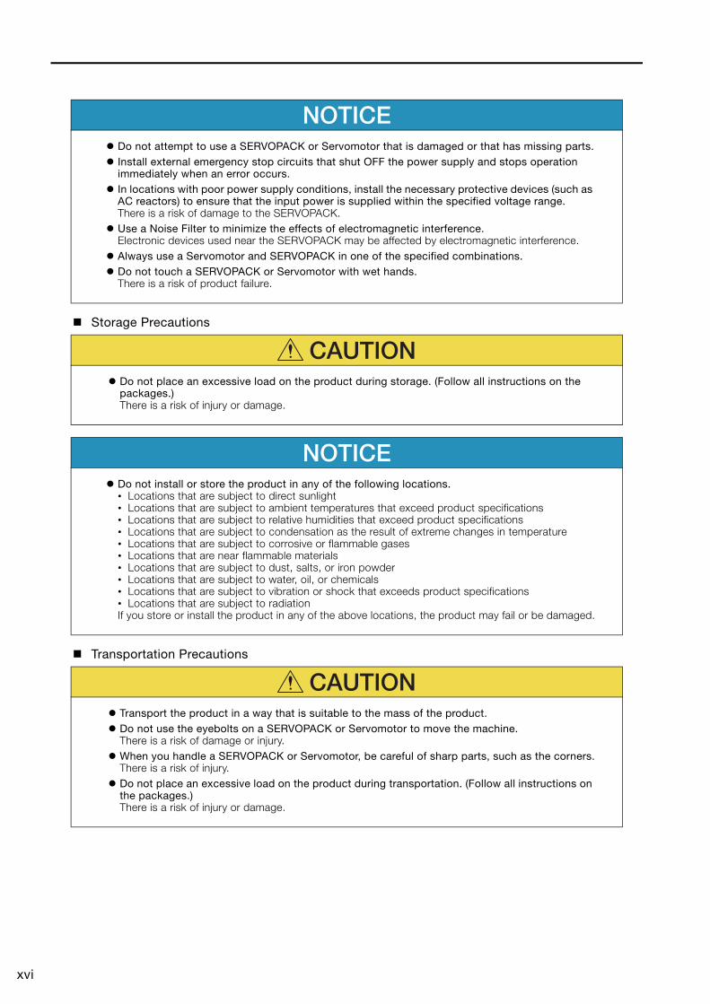
NOTICE Do not attempt to use a SERVOPACK or Servomotor that is damaged or that has missing parts. Install external emergency stop circuits that shut OFF the power supply and stops operation
immediately when an error occurs. In locations with poor power supply conditions, install the necessary protective devices (such as
AC reactors) to ensure that the input power is supplied within the specified voltage range.There is a risk of damage to the SERVOPACK.
Use a Noise Filter to minimize the effects of electromagnetic interference.Electronic devices used near the SERVOPACK may be affected by electromagnetic interference.
Always use a Servomotor and SERVOPACK in one of the specified combinations. Do not touch a SERVOPACK or Servomotor with wet hands.
There is a risk of product failure.
CAUTION Do not place an excessive load on the product during storage. (Follow all instructions on the
packages.)There is a risk of injury or damage.
NOTICE Do not install or store the product in any of the following locations.
• Locations that are subject to direct sunlight• Locations that are subject to ambient temperatures that exceed product specifications• Locations that are subject to relative humidities that exceed product specifications• Locations that are subject to condensation as the result of extreme changes in temperature• Locations that are subject to corrosive or flammable gases• Locations that are near flammable materials• Locations that are subject to dust, salts, or iron powder• Locations that are subject to water, oil, or chemicals• Locations that are subject to vibration or shock that exceeds product specifications• Locations that are subject to radiationIf you store or install the product in any of the above locations, the product may fail or be damaged.
CAUTION Transport the product in a way that is suitable to the mass of the product. Do not use the eyebolts on a SERVOPACK or Servomotor to move the machine.
There is a risk of damage or injury. When you handle a SERVOPACK or Servomotor, be careful of sharp parts, such as the corners.
There is a risk of injury. Do not place an excessive load on the product during transportation. (Follow all instructions on
the packages.)There is a risk of injury or damage.
xvii
Installation Precautions
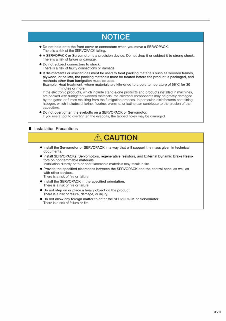
NOTICE Do not hold onto the front cover or connectors when you move a SERVOPACK.
There is a risk of the SERVOPACK falling. A SERVOPACK or Servomotor is a precision device. Do not drop it or subject it to strong shock.
There is a risk of failure or damage. Do not subject connectors to shock.
There is a risk of faulty connections or damage. If disinfectants or insecticides must be used to treat packing materials such as wooden frames,
plywood, or pallets, the packing materials must be treated before the product is packaged, and methods other than fumigation must be used.Example: Heat treatment, where materials are kiln-dried to a core temperature of 56°C for 30
minutes or more.If the electronic products, which include stand-alone products and products installed in machines, are packed with fumigated wooden materials, the electrical components may be greatly damaged by the gases or fumes resulting from the fumigation process. In particular, disinfectants containing halogen, which includes chlorine, fluorine, bromine, or iodine can contribute to the erosion of the capacitors.
Do not overtighten the eyebolts on a SERVOPACK or Servomotor.If you use a tool to overtighten the eyebolts, the tapped holes may be damaged.
CAUTION Install the Servomotor or SERVOPACK in a way that will support the mass given in technical
documents. Install SERVOPACKs, Servomotors, regenerative resistors, and External Dynamic Brake Resis-
tors on nonflammable materials.Installation directly onto or near flammable materials may result in fire.
Provide the specified clearances between the SERVOPACK and the control panel as well as with other devices.There is a risk of fire or failure.
Install the SERVOPACK in the specified orientation.There is a risk of fire or failure.
Do not step on or place a heavy object on the product.There is a risk of failure, damage, or injury.
Do not allow any foreign matter to enter the SERVOPACK or Servomotor.There is a risk of failure or fire.
xviii
Wiring Precautions
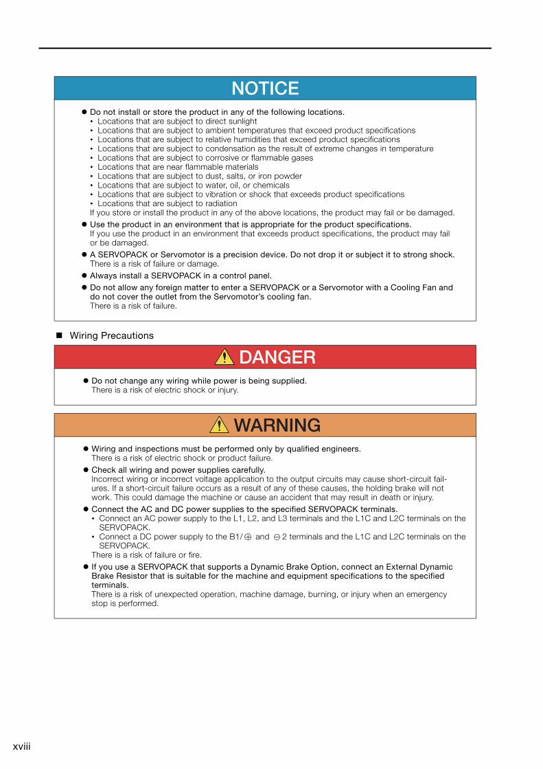
NOTICE Do not install or store the product in any of the following locations.
• Locations that are subject to direct sunlight• Locations that are subject to ambient temperatures that exceed product specifications• Locations that are subject to relative humidities that exceed product specifications• Locations that are subject to condensation as the result of extreme changes in temperature• Locations that are subject to corrosive or flammable gases• Locations that are near flammable materials• Locations that are subject to dust, salts, or iron powder• Locations that are subject to water, oil, or chemicals• Locations that are subject to vibration or shock that exceeds product specifications• Locations that are subject to radiationIf you store or install the product in any of the above locations, the product may fail or be damaged.
Use the product in an environment that is appropriate for the product specifications.If you use the product in an environment that exceeds product specifications, the product may fail or be damaged.
A SERVOPACK or Servomotor is a precision device. Do not drop it or subject it to strong shock.There is a risk of failure or damage.
Always install a SERVOPACK in a control panel. Do not allow any foreign matter to enter a SERVOPACK or a Servomotor with a Cooling Fan and
do not cover the outlet from the Servomotor’s cooling fan.There is a risk of failure.
DANGER Do not change any wiring while power is being supplied.
There is a risk of electric shock or injury.
WARNING Wiring and inspections must be performed only by qualified engineers.
There is a risk of electric shock or product failure. Check all wiring and power supplies carefully.
Incorrect wiring or incorrect voltage application to the output circuits may cause short-circuit fail-ures. If a short-circuit failure occurs as a result of any of these causes, the holding brake will not work. This could damage the machine or cause an accident that may result in death or injury.
Connect the AC and DC power supplies to the specified SERVOPACK terminals.• Connect an AC power supply to the L1, L2, and L3 terminals and the L1C and L2C terminals on the
SERVOPACK.• Connect a DC power supply to the B1/ and 2 terminals and the L1C and L2C terminals on the
SERVOPACK.There is a risk of failure or fire.
If you use a SERVOPACK that supports a Dynamic Brake Option, connect an External Dynamic Brake Resistor that is suitable for the machine and equipment specifications to the specified terminals.There is a risk of unexpected operation, machine damage, burning, or injury when an emergency stop is performed.
xix
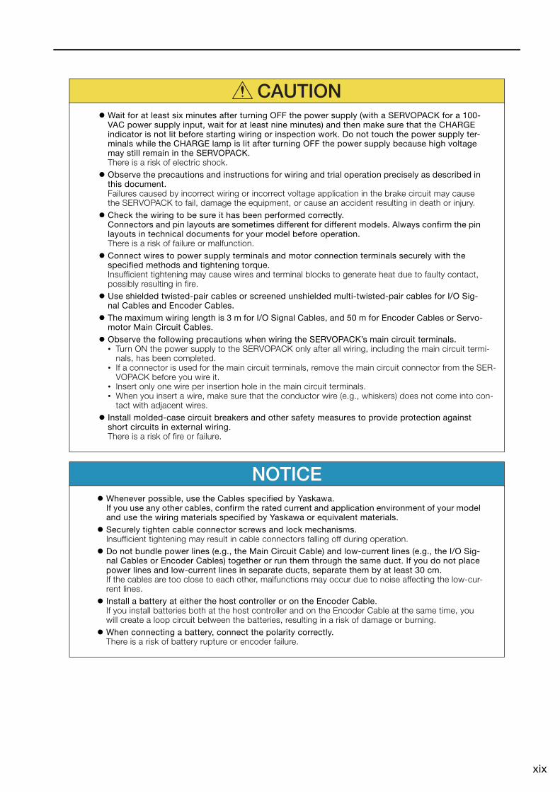
CAUTION Wait for at least six minutes after turning OFF the power supply (with a SERVOPACK for a 100-
VAC power supply input, wait for at least nine minutes) and then make sure that the CHARGE indicator is not lit before starting wiring or inspection work. Do not touch the power supply ter-minals while the CHARGE lamp is lit after turning OFF the power supply because high voltage may still remain in the SERVOPACK.There is a risk of electric shock.
Observe the precautions and instructions for wiring and trial operation precisely as described in this document.Failures caused by incorrect wiring or incorrect voltage application in the brake circuit may cause the SERVOPACK to fail, damage the equipment, or cause an accident resulting in death or injury.
Check the wiring to be sure it has been performed correctly.Connectors and pin layouts are sometimes different for different models. Always confirm the pin layouts in technical documents for your model before operation.There is a risk of failure or malfunction.
Connect wires to power supply terminals and motor connection terminals securely with the specified methods and tightening torque.Insufficient tightening may cause wires and terminal blocks to generate heat due to faulty contact, possibly resulting in fire.
Use shielded twisted-pair cables or screened unshielded multi-twisted-pair cables for I/O Sig-nal Cables and Encoder Cables.
The maximum wiring length is 3 m for I/O Signal Cables, and 50 m for Encoder Cables or Servo-motor Main Circuit Cables.
Observe the following precautions when wiring the SERVOPACK’s main circuit terminals.• Turn ON the power supply to the SERVOPACK only after all wiring, including the main circuit termi-
nals, has been completed.• If a connector is used for the main circuit terminals, remove the main circuit connector from the SER-
VOPACK before you wire it.• Insert only one wire per insertion hole in the main circuit terminals.• When you insert a wire, make sure that the conductor wire (e.g., whiskers) does not come into con-
tact with adjacent wires. Install molded-case circuit breakers and other safety measures to provide protection against
short circuits in external wiring.There is a risk of fire or failure.
NOTICE Whenever possible, use the Cables specified by Yaskawa.
If you use any other cables, confirm the rated current and application environment of your model and use the wiring materials specified by Yaskawa or equivalent materials.
Securely tighten cable connector screws and lock mechanisms.Insufficient tightening may result in cable connectors falling off during operation.
Do not bundle power lines (e.g., the Main Circuit Cable) and low-current lines (e.g., the I/O Sig-nal Cables or Encoder Cables) together or run them through the same duct. If you do not place power lines and low-current lines in separate ducts, separate them by at least 30 cm.If the cables are too close to each other, malfunctions may occur due to noise affecting the low-cur-rent lines.
Install a battery at either the host controller or on the Encoder Cable.If you install batteries both at the host controller and on the Encoder Cable at the same time, you will create a loop circuit between the batteries, resulting in a risk of damage or burning.
When connecting a battery, connect the polarity correctly.There is a risk of battery rupture or encoder failure.
xx
Operation Precautions
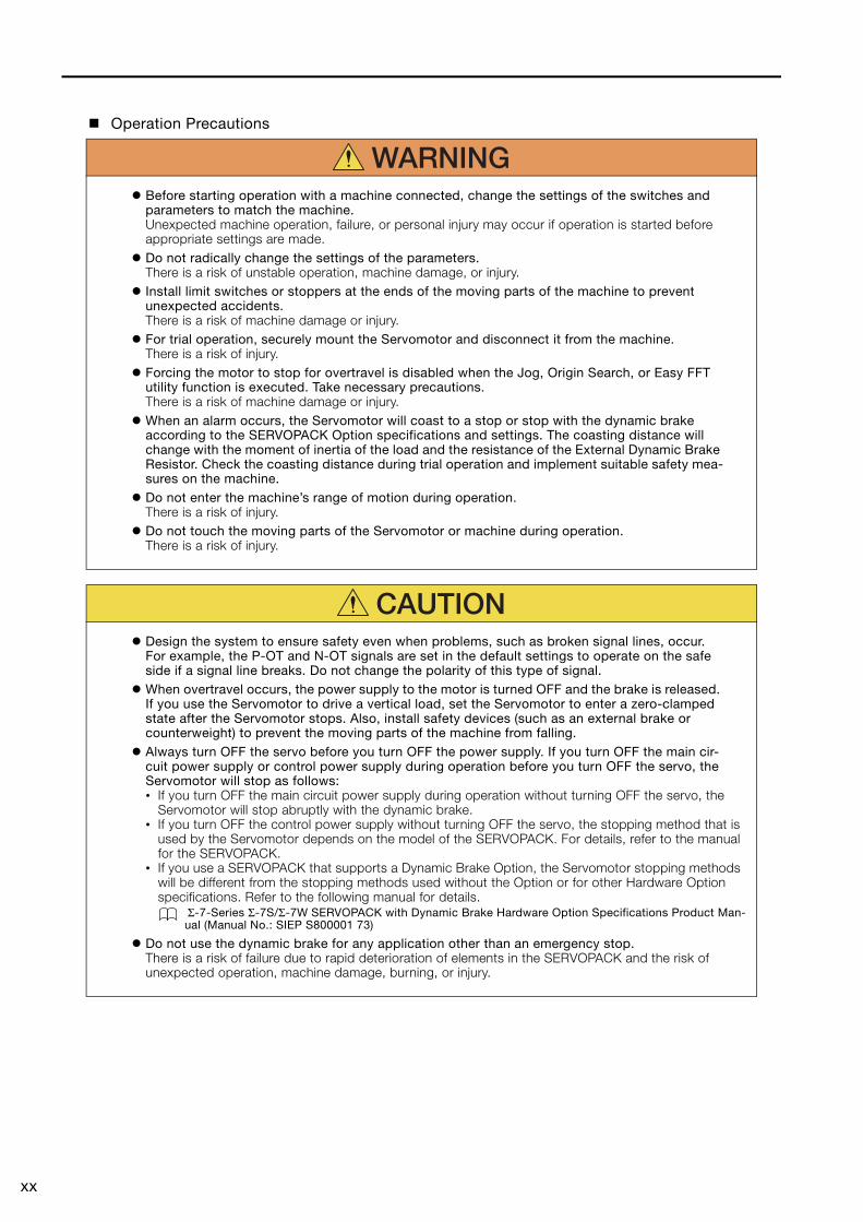
WARNING Before starting operation with a machine connected, change the settings of the switches and
parameters to match the machine.Unexpected machine operation, failure, or personal injury may occur if operation is started before appropriate settings are made.
Do not radically change the settings of the parameters.There is a risk of unstable operation, machine damage, or injury.
Install limit switches or stoppers at the ends of the moving parts of the machine to prevent unexpected accidents.There is a risk of machine damage or injury.
For trial operation, securely mount the Servomotor and disconnect it from the machine.There is a risk of injury.
Forcing the motor to stop for overtravel is disabled when the Jog, Origin Search, or Easy FFT utility function is executed. Take necessary precautions.There is a risk of machine damage or injury.
When an alarm occurs, the Servomotor will coast to a stop or stop with the dynamic brake according to the SERVOPACK Option specifications and settings. The coasting distance will change with the moment of inertia of the load and the resistance of the External Dynamic Brake Resistor. Check the coasting distance during trial operation and implement suitable safety mea-sures on the machine.
Do not enter the machine’s range of motion during operation.There is a risk of injury.
Do not touch the moving parts of the Servomotor or machine during operation.There is a risk of injury.
CAUTION Design the system to ensure safety even when problems, such as broken signal lines, occur.
For example, the P-OT and N-OT signals are set in the default settings to operate on the safe side if a signal line breaks. Do not change the polarity of this type of signal.
When overtravel occurs, the power supply to the motor is turned OFF and the brake is released. If you use the Servomotor to drive a vertical load, set the Servomotor to enter a zero-clamped state after the Servomotor stops. Also, install safety devices (such as an external brake or counterweight) to prevent the moving parts of the machine from falling.
Always turn OFF the servo before you turn OFF the power supply. If you turn OFF the main cir-cuit power supply or control power supply during operation before you turn OFF the servo, the Servomotor will stop as follows:• If you turn OFF the main circuit power supply during operation without turning OFF the servo, the
Servomotor will stop abruptly with the dynamic brake.• If you turn OFF the control power supply without turning OFF the servo, the stopping method that is
used by the Servomotor depends on the model of the SERVOPACK. For details, refer to the manual for the SERVOPACK.
• If you use a SERVOPACK that supports a Dynamic Brake Option, the Servomotor stopping methods will be different from the stopping methods used without the Option or for other Hardware Option specifications. Refer to the following manual for details.
Σ-7-Series Σ-7S/Σ-7W SERVOPACK with Dynamic Brake Hardware Option Specifications Product Man-ual (Manual No.: SIEP S800001 73)
Do not use the dynamic brake for any application other than an emergency stop.There is a risk of failure due to rapid deterioration of elements in the SERVOPACK and the risk of unexpected operation, machine damage, burning, or injury.
xxi
Maintenance and Inspection Precautions
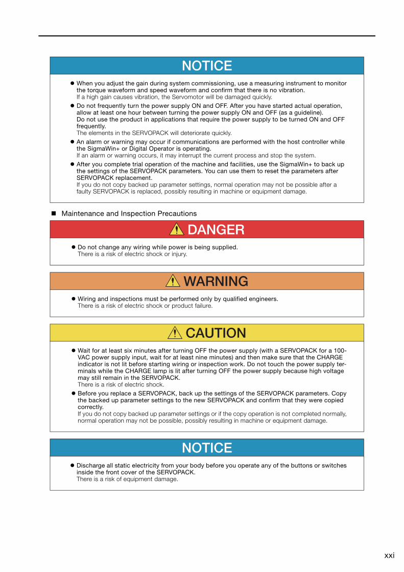
NOTICE When you adjust the gain during system commissioning, use a measuring instrument to monitor
the torque waveform and speed waveform and confirm that there is no vibration.If a high gain causes vibration, the Servomotor will be damaged quickly.
Do not frequently turn the power supply ON and OFF. After you have started actual operation, allow at least one hour between turning the power supply ON and OFF (as a guideline).Do not use the product in applications that require the power supply to be turned ON and OFF frequently.The elements in the SERVOPACK will deteriorate quickly.
An alarm or warning may occur if communications are performed with the host controller while the SigmaWin+ or Digital Operator is operating.If an alarm or warning occurs, it may interrupt the current process and stop the system.
After you complete trial operation of the machine and facilities, use the SigmaWin+ to back up the settings of the SERVOPACK parameters. You can use them to reset the parameters after SERVOPACK replacement.If you do not copy backed up parameter settings, normal operation may not be possible after a faulty SERVOPACK is replaced, possibly resulting in machine or equipment damage.
DANGER Do not change any wiring while power is being supplied.
There is a risk of electric shock or injury.
WARNING Wiring and inspections must be performed only by qualified engineers.
There is a risk of electric shock or product failure.
CAUTION Wait for at least six minutes after turning OFF the power supply (with a SERVOPACK for a 100-
VAC power supply input, wait for at least nine minutes) and then make sure that the CHARGE indicator is not lit before starting wiring or inspection work. Do not touch the power supply ter-minals while the CHARGE lamp is lit after turning OFF the power supply because high voltage may still remain in the SERVOPACK.There is a risk of electric shock.
Before you replace a SERVOPACK, back up the settings of the SERVOPACK parameters. Copy the backed up parameter settings to the new SERVOPACK and confirm that they were copied correctly.If you do not copy backed up parameter settings or if the copy operation is not completed normally, normal operation may not be possible, possibly resulting in machine or equipment damage.
NOTICE Discharge all static electricity from your body before you operate any of the buttons or switches
inside the front cover of the SERVOPACK.There is a risk of equipment damage.
xxii
Troubleshooting Precautions
Disposal Precautions
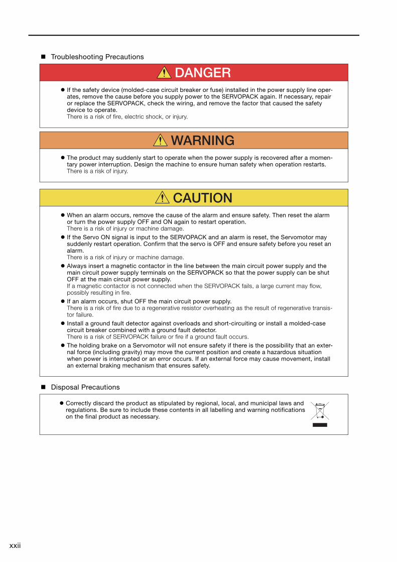
DANGER If the safety device (molded-case circuit breaker or fuse) installed in the power supply line oper-
ates, remove the cause before you supply power to the SERVOPACK again. If necessary, repair or replace the SERVOPACK, check the wiring, and remove the factor that caused the safety device to operate.There is a risk of fire, electric shock, or injury.
WARNING The product may suddenly start to operate when the power supply is recovered after a momen-
tary power interruption. Design the machine to ensure human safety when operation restarts.There is a risk of injury.
CAUTION When an alarm occurs, remove the cause of the alarm and ensure safety. Then reset the alarm
or turn the power supply OFF and ON again to restart operation.There is a risk of injury or machine damage.
If the Servo ON signal is input to the SERVOPACK and an alarm is reset, the Servomotor may suddenly restart operation. Confirm that the servo is OFF and ensure safety before you reset an alarm.There is a risk of injury or machine damage.
Always insert a magnetic contactor in the line between the main circuit power supply and the main circuit power supply terminals on the SERVOPACK so that the power supply can be shut OFF at the main circuit power supply.If a magnetic contactor is not connected when the SERVOPACK fails, a large current may flow, possibly resulting in fire.
If an alarm occurs, shut OFF the main circuit power supply.There is a risk of fire due to a regenerative resistor overheating as the result of regenerative transis-tor failure.
Install a ground fault detector against overloads and short-circuiting or install a molded-case circuit breaker combined with a ground fault detector.There is a risk of SERVOPACK failure or fire if a ground fault occurs.
The holding brake on a Servomotor will not ensure safety if there is the possibility that an exter-nal force (including gravity) may move the current position and create a hazardous situation when power is interrupted or an error occurs. If an external force may cause movement, install an external braking mechanism that ensures safety.
Correctly discard the product as stipulated by regional, local, and municipal laws and regulations. Be sure to include these contents in all labelling and warning notifications on the final product as necessary.
xxiii
General Precautions
Figures provided in this document are typical examples or conceptual representations. There may be differences between them and actual wiring, circuits, and products.
The products shown in illustrations in this document are sometimes shown without covers or protective guards. Always replace all covers and protective guards before you use the product.
If you need a new copy of this document because it has been lost or damaged, contact your nearest Yaskawa representative or one of the offices listed on the back of this document.
This document is subject to change without notice for product improvements, specifications changes, and improvements to the manual itself.We will update the document number of the document and issue revisions when changes are made.
Any and all quality guarantees provided by Yaskawa are null and void if the customer modifies the product in any way. Yaskawa disavows any responsibility for damages or losses that are caused by modified products.
xxiv
Warranty
Details of Warranty
Warranty Period
The warranty period for a product that was purchased (hereinafter called the “delivered product”) is one year from the time of delivery to the location specified by the customer or 18 months from the time of shipment from the Yaskawa factory, whichever is sooner.
Warranty Scope
Yaskawa shall replace or repair a defective product free of charge if a defect attributable to Yaskawa occurs during the above warranty period.This warranty does not cover defects caused by the delivered product reaching the end of its ser-vice life and replacement of parts that require replacement or that have a limited service life.This warranty does not cover failures that result from any of the following causes.• Improper handling, abuse, or use in unsuitable conditions or in environments not described in
product catalogs or manuals, or in any separately agreed-upon specifications • Causes not attributable to the delivered product itself • Modifications or repairs not performed by Yaskawa• Use of the delivered product in a manner in which it was not originally intended• Causes that were not foreseeable with the scientific and technological understanding at the time
of shipment from Yaskawa• Events for which Yaskawa is not responsible, such as natural or human-made disasters
Limitations of Liability• Yaskawa shall in no event be responsible for any damage or loss of opportunity to the customer
that arises due to failure of the delivered product.• Yaskawa shall not be responsible for any programs (including parameter settings) or the results of
program execution of the programs provided by the user or by a third party for use with program-mable Yaskawa products.
• The information described in product catalogs or manuals is provided for the purpose of the cus-tomer purchasing the appropriate product for the intended application. The use thereof does not guarantee that there are no infringements of intellectual property rights or other proprietary rights of Yaskawa or third parties, nor does it construe a license.
• Yaskawa shall not be responsible for any damage arising from infringements of intellectual prop-erty rights or other proprietary rights of third parties as a result of using the information described in catalogs or manuals.
xxv
Suitability for Use• It is the customer’s responsibility to confirm conformity with any standards, codes, or regulations
that apply if the Yaskawa product is used in combination with any other products.• The customer must confirm that the Yaskawa product is suitable for the systems, machines, and
equipment used by the customer.• Consult with Yaskawa to determine whether use in the following applications is acceptable. If use
in the application is acceptable, use the product with extra allowance in ratings and specifica-tions, and provide safety measures to minimize hazards in the event of failure.
•Outdoor use, use involving potential chemical contamination or electrical interference, or use in conditions or environments not described in product catalogs or manuals
•Nuclear energy control systems, combustion systems, railroad systems, aviation systems, vehicle systems, medical equipment, amusement machines, and installations subject to sep-arate industry or government regulations
•Systems, machines, and equipment that may present a risk to life or property•Systems that require a high degree of reliability, such as systems that supply gas, water, or
electricity, or systems that operate continuously 24 hours a day•Other systems that require a similar high degree of safety
• Never use the product for an application involving serious risk to life or property without first ensuring that the system is designed to secure the required level of safety with risk warnings and redundancy, and that the Yaskawa product is properly rated and installed.
• The circuit examples and other application examples described in product catalogs and manuals are for reference. Check the functionality and safety of the actual devices and equipment to be used before using the product.
• Read and understand all use prohibitions and precautions, and operate the Yaskawa product correctly to prevent accidental harm to third parties.
Specifications ChangeThe names, specifications, appearance, and accessories of products in product catalogs and manuals may be changed at any time based on improvements and other reasons. The next edi-tions of the revised catalogs or manuals will be published with updated code numbers. Consult with your Yaskawa representative to confirm the actual specifications before purchasing a product.

xxvi
Compliance with UL Standards, EU Directives, and Other Safety Standards
Certification marks for the standards for which the product has been certified by certification bodies are shown on nameplate. Products that do not have the marks are not certified for the standards.
North American Safety Standards (UL)
* Only products with derating specifications are in compliance with the UL Standards. Estimates are available for those prod-ucts. Contact your Yaskawa representative for details.
Product Model North American Safety Standards (UL File No.)
SERVOPACKs SGD7S UL 61800-5-1 (E147823)CSA C22.2 No.274
Rotary Servomotors
• SGM7M• SGM7A• SGM7J• SGM7P• SGM7G• SGMMV
UL 1004-1UL 1004-6(E165827)
Direct Drive Servomotors
• SGM7E• SGM7F-A,
-B, -C, and -D (Small-Capacity Servomotors with Cores)
• SGMCV• SGMCS-B,
-C, -D, and -E (Small-Capacity, Coreless Servomotors)
UL 1004-1UL 1004-6(E165827)
Linear Servomotors
• SGLGW*• SGLFW*• SGLFW2• SGLTW*
UL 1004-1UL 1004-6(E165827)
xxvii
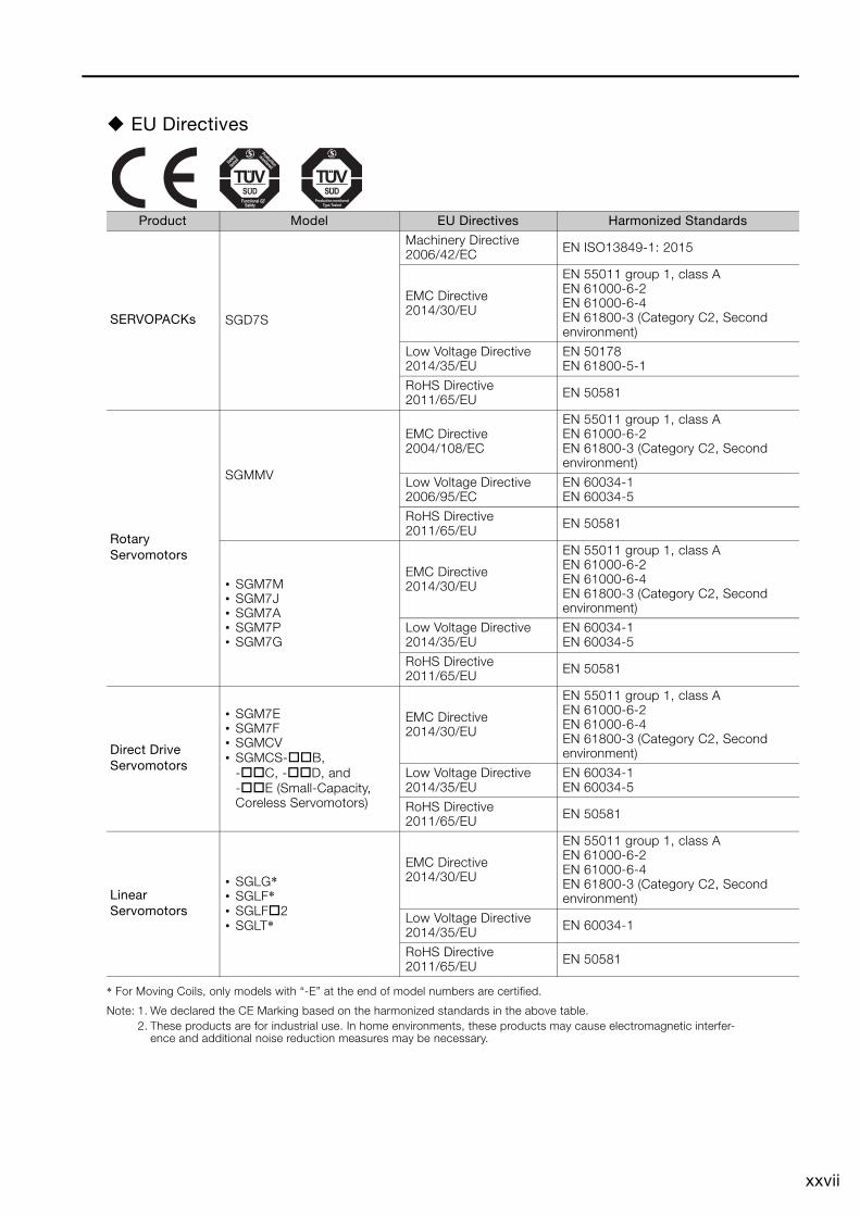
EU Directives
* For Moving Coils, only models with “-E” at the end of model numbers are certified.
Note: 1. We declared the CE Marking based on the harmonized standards in the above table.2. These products are for industrial use. In home environments, these products may cause electromagnetic interfer-
ence and additional noise reduction measures may be necessary.
Product Model EU Directives Harmonized Standards
SERVOPACKs SGD7S
Machinery Directive2006/42/EC EN ISO13849-1: 2015
EMC Directive2014/30/EU
EN 55011 group 1, class AEN 61000-6-2EN 61000-6-4EN 61800-3 (Category C2, Second environment)
Low Voltage Directive2014/35/EU
EN 50178EN 61800-5-1
RoHS Directive2011/65/EU EN 50581
Rotary Servomotors
SGMMV
EMC Directive2004/108/EC
EN 55011 group 1, class AEN 61000-6-2EN 61800-3 (Category C2, Second environment)
Low Voltage Directive2006/95/EC
EN 60034-1EN 60034-5
RoHS Directive2011/65/EU EN 50581
• SGM7M• SGM7J• SGM7A• SGM7P• SGM7G
EMC Directive2014/30/EU
EN 55011 group 1, class AEN 61000-6-2EN 61000-6-4EN 61800-3 (Category C2, Second environment)
Low Voltage Directive2014/35/EU
EN 60034-1EN 60034-5
RoHS Directive2011/65/EU EN 50581
Direct Drive Servomotors
• SGM7E• SGM7F• SGMCV• SGMCS-B,
-C, -D, and -E (Small-Capacity, Coreless Servomotors)
EMC Directive2014/30/EU
EN 55011 group 1, class AEN 61000-6-2EN 61000-6-4EN 61800-3 (Category C2, Second environment)
Low Voltage Directive2014/35/EU
EN 60034-1EN 60034-5
RoHS Directive2011/65/EU EN 50581
Linear Servomotors
• SGLG*• SGLF*• SGLF2• SGLT*
EMC Directive2014/30/EU
EN 55011 group 1, class AEN 61000-6-2EN 61000-6-4EN 61800-3 (Category C2, Second environment)
Low Voltage Directive2014/35/EU EN 60034-1
RoHS Directive2011/65/EU EN 50581
xxviii
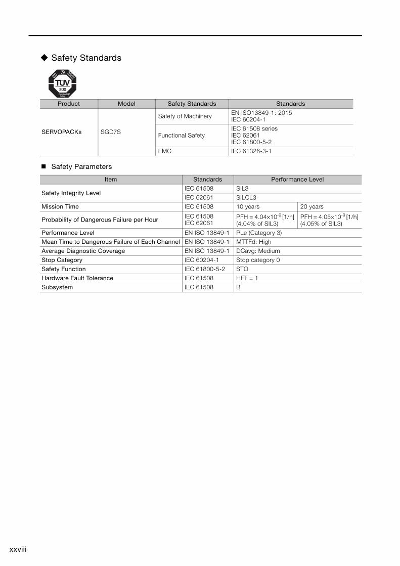
Safety Standards
Safety Parameters
Product Model Safety Standards Standards
SERVOPACKs SGD7S
Safety of Machinery EN ISO13849-1: 2015IEC 60204-1
Functional SafetyIEC 61508 seriesIEC 62061IEC 61800-5-2
EMC IEC 61326-3-1
Item Standards Performance Level
Safety Integrity LevelIEC 61508 SIL3
IEC 62061 SILCL3
Mission Time IEC 61508 10 years 20 years
Probability of Dangerous Failure per Hour IEC 61508IEC 62061
PFH = 4.04×10⁻⁹ [1/h] (4.04% of SIL3)
PFH = 4.05×10⁻⁹ [1/h] (4.05% of SIL3)
Performance Level EN ISO 13849-1 PLe (Category 3)
Mean Time to Dangerous Failure of Each Channel EN ISO 13849-1 MTTFd: High
Average Diagnostic Coverage EN ISO 13849-1 DCavg: Medium
Stop Category IEC 60204-1 Stop category 0
Safety Function IEC 61800-5-2 STO
Hardware Fault Tolerance IEC 61508 HFT = 1
Subsystem IEC 61508 B
xxix
ContentsAbout this Manual. . . . . . . . . . . . . . . . . . . . . . . . . . . . . . . . . . . . . . . . . . . . . . . . . iiiOutline of Manual . . . . . . . . . . . . . . . . . . . . . . . . . . . . . . . . . . . . . . . . . . . . . . . . . iiiRelated Documents . . . . . . . . . . . . . . . . . . . . . . . . . . . . . . . . . . . . . . . . . . . . . . . vUsing This Manual . . . . . . . . . . . . . . . . . . . . . . . . . . . . . . . . . . . . . . . . . . . . . . . .xiSafety Precautions . . . . . . . . . . . . . . . . . . . . . . . . . . . . . . . . . . . . . . . . . . . . . . . xivWarranty . . . . . . . . . . . . . . . . . . . . . . . . . . . . . . . . . . . . . . . . . . . . . . . . . . . . . . xxivCompliance with UL Standards, EU Directives, and Other Safety Standards . . xxvi
Basic Information on SERVOPACKs1
1.1 Product Introduction . . . . . . . . . . . . . . . . . . . . . . . . . . . . . . . . . 1-2
1.2 Model Designations . . . . . . . . . . . . . . . . . . . . . . . . . . . . . . . . . . 1-31.2.1 Interpreting SERVOPACK Model Numbers . . . . . . . . . . . . . . . . . . . . . . . . . 1-31.2.2 Interpreting Servomotor Model Numbers. . . . . . . . . . . . . . . . . . . . . . . . . . . 1-3
1.3 Combinations of SERVOPACKs and Servomotors . . . . . . . . . . . 1-4
1.4 Functions . . . . . . . . . . . . . . . . . . . . . . . . . . . . . . . . . . . . . . . . . . 1-5
1.5 Restrictions . . . . . . . . . . . . . . . . . . . . . . . . . . . . . . . . . . . . . . . . 1-81.5.1 Function Application Restrictions . . . . . . . . . . . . . . . . . . . . . . . . . . . . . . . . 1-81.5.2 Restrictions on Specifications . . . . . . . . . . . . . . . . . . . . . . . . . . . . . . . . . . . 1-8
1.6 SigmaWin+ . . . . . . . . . . . . . . . . . . . . . . . . . . . . . . . . . . . . . . . . . 1-9
1.7 Combining the SERVOPACKs with MP-Series Machine Controllers and the MPE720 Engineering Tool . . 1-10
SERVOPACK Ratings and Specifications2
2.1 Ratings . . . . . . . . . . . . . . . . . . . . . . . . . . . . . . . . . . . . . . . . . . . . 2-2
2.2 SERVOPACK Overload Protection Characteristics . . . . . . . . . . 2-5
2.3 Specifications. . . . . . . . . . . . . . . . . . . . . . . . . . . . . . . . . . . . . . . 2-6
Three-Point Latching3
3.1 Introduction . . . . . . . . . . . . . . . . . . . . . . . . . . . . . . . . . . . . . . . . 3-2
3.2 Operating Procedure . . . . . . . . . . . . . . . . . . . . . . . . . . . . . . . . . 3-33.2.1 Monitoring Latched Position Data . . . . . . . . . . . . . . . . . . . . . . . . . . . . . . . . 3-33.2.2 Setting the Latching Allowable Area . . . . . . . . . . . . . . . . . . . . . . . . . . . . . . 3-63.2.3 Latching Position Data with Three-Point Latching . . . . . . . . . . . . . . . . . . . . 3-63.2.4 Operation Example . . . . . . . . . . . . . . . . . . . . . . . . . . . . . . . . . . . . . . . . . . . 3-7
xxx
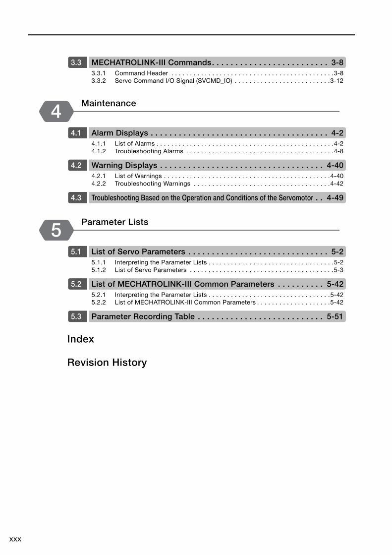
3.3 MECHATROLINK-III Commands. . . . . . . . . . . . . . . . . . . . . . . . . 3-83.3.1 Command Header . . . . . . . . . . . . . . . . . . . . . . . . . . . . . . . . . . . . . . . . . . . .3-83.3.2 Servo Command I/O Signal (SVCMD_IO) . . . . . . . . . . . . . . . . . . . . . . . . . .3-12
Maintenance4
4.1 Alarm Displays . . . . . . . . . . . . . . . . . . . . . . . . . . . . . . . . . . . . . . 4-24.1.1 List of Alarms . . . . . . . . . . . . . . . . . . . . . . . . . . . . . . . . . . . . . . . . . . . . . . . .4-24.1.2 Troubleshooting Alarms . . . . . . . . . . . . . . . . . . . . . . . . . . . . . . . . . . . . . . . .4-8
4.2 Warning Displays . . . . . . . . . . . . . . . . . . . . . . . . . . . . . . . . . . . 4-404.2.1 List of Warnings . . . . . . . . . . . . . . . . . . . . . . . . . . . . . . . . . . . . . . . . . . . . .4-404.2.2 Troubleshooting Warnings . . . . . . . . . . . . . . . . . . . . . . . . . . . . . . . . . . . . .4-42
4.3 Troubleshooting Based on the Operation and Conditions of the Servomotor . . 4-49
Parameter Lists5
5.1 List of Servo Parameters . . . . . . . . . . . . . . . . . . . . . . . . . . . . . . 5-25.1.1 Interpreting the Parameter Lists . . . . . . . . . . . . . . . . . . . . . . . . . . . . . . . . . .5-25.1.2 List of Servo Parameters . . . . . . . . . . . . . . . . . . . . . . . . . . . . . . . . . . . . . . .5-3
5.2 List of MECHATROLINK-III Common Parameters . . . . . . . . . . 5-425.2.1 Interpreting the Parameter Lists . . . . . . . . . . . . . . . . . . . . . . . . . . . . . . . . .5-425.2.2 List of MECHATROLINK-III Common Parameters . . . . . . . . . . . . . . . . . . . .5-42
5.3 Parameter Recording Table . . . . . . . . . . . . . . . . . . . . . . . . . . . 5-51
Index
Revision History
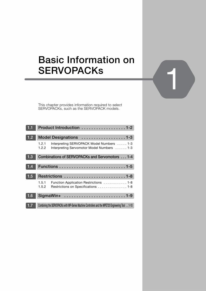
This chapter provides information required to select SERVOPACKs, such as the SERVOPACK models.
1.1 Product Introduction . . . . . . . . . . . . . . . . . . 1-2
1.2 Model Designations . . . . . . . . . . . . . . . . . . 1-31.2.1 Interpreting SERVOPACK Model Numbers . . . . . 1-31.2.2 Interpreting Servomotor Model Numbers . . . . . . 1-3
1.3 Combinations of SERVOPACKs and Servomotors . . . 1-4
1.4 Functions . . . . . . . . . . . . . . . . . . . . . . . . . . . 1-5
1.5 Restrictions . . . . . . . . . . . . . . . . . . . . . . . . . 1-81.5.1 Function Application Restrictions . . . . . . . . . . . . 1-81.5.2 Restrictions on Specifications . . . . . . . . . . . . . . . 1-8
1.6 SigmaWin+ . . . . . . . . . . . . . . . . . . . . . . . . . 1-9
1.7 Combining the SERVOPACKs with MP-Series Machine Controllers and the MPE720 Engineering Tool . . 1-10
Basic Information on SERVOPACKs 1

1.1 Product Introduction
1-2
1.1 Product Introduction
The FT60 SERVOPACKs provide built-in three-point latching that is suitable for the following applications.• Applications that require correction of the angle of a conveyed workpiece• Applications that require coordination of the arrival times of workpieces conveyed on different
lines
1.2 Model Designations
1.2.1 Interpreting SERVOPACK Model Numbers
1-3
1
Bas
ic In
form
atio
n on
SE
RV
OPA
CKs
1.2 Model Designations
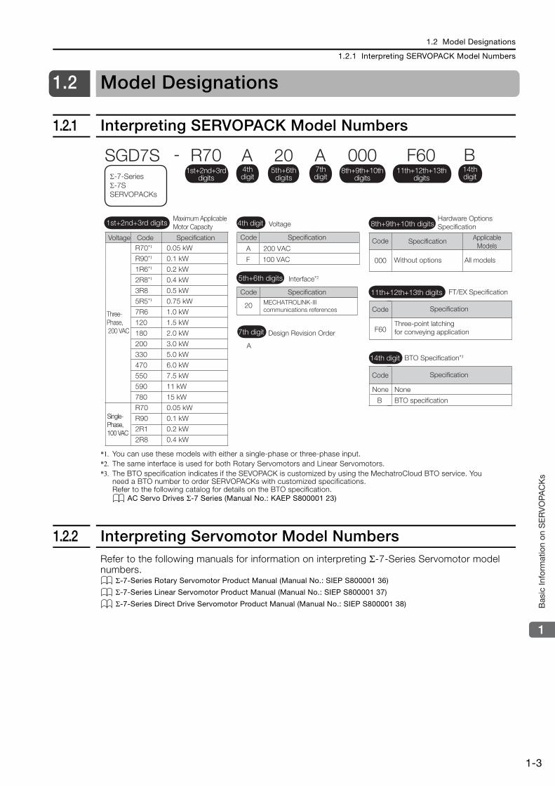
1.2.1 Interpreting SERVOPACK Model Numbers
*1. You can use these models with either a single-phase or three-phase input.*2. The same interface is used for both Rotary Servomotors and Linear Servomotors.*3. The BTO specification indicates if the SEVOPACK is customized by using the MechatroCloud BTO service. You
need a BTO number to order SERVOPACKs with customized specifications.Refer to the following catalog for details on the BTO specification.
AC Servo Drives Σ-7 Series (Manual No.: KAEP S800001 23)
1.2.2 Interpreting Servomotor Model NumbersRefer to the following manuals for information on interpreting Σ-7-Series Servomotor model numbers.
Σ-7-Series Rotary Servomotor Product Manual (Manual No.: SIEP S800001 36)
Σ-7-Series Linear Servomotor Product Manual (Manual No.: SIEP S800001 37)
Σ-7-Series Direct Drive Servomotor Product Manual (Manual No.: SIEP S800001 38)
F60Three-point latching for conveying application
000
SpecificationCode
FT/EX Specification
None
B
None
BTO specification
SpecificationCode
BTO Specification*3
MECHATROLINK-IIIcommunications references
20
A 200 VAC
SGD7S - R70 A 20 A 000
A
Maximum Applicable Motor Capacity Voltage
Interface*2
Code
Code
Specification
Specification
Design Revision Order
Hardware Options Specification
Three-Phase, 200 VAC
1st+2nd+3rd digits 4th digit
5th+6th digits
7th digit
8th+9th+10th digits
Σ-7-Series Σ-7S SERVOPACKs
4th digit
1st+2nd+3rd digits
5th+6th digits
8th+9th+10th digits
7th digit
R70*1
R90*1
1R6*1
2R8*1
3R8
5R5*1
7R6
120
180
200
330
470
550
590
780
R70
R90
2R1
2R8
0.05 kW
0.1 kW
0.2 kW
0.4 kW
0.5 kW
0.75 kW
1.0 kW
1.5 kW
2.0 kW
3.0 kW
5.0 kW
6.0 kW
7.5 kW
11 kW
15 kW
0.05 kW
0.1 kW
0.2 kW
0.4 kW
Voltage Code Specification
Without options All models
Code Specification Applicable Models
F60 B11th+12th+13th
digits14th digit
11th+12th+13th digits
14th digit
F 100 VAC
Single-Phase, 100 VAC

1.3 Combinations of SERVOPACKs and Servomotors
1-4
1.3 Combinations of SERVOPACKs and Servomotors
Refer to the following manuals for information on combinations with Σ-7-Series Servomotors. Σ-7-Series Rotary Servomotor Product Manual (Manual No.: SIEP S800001 36)
Σ-7-Series Linear Servomotor Product Manual (Manual No.: SIEP S800001 37)
Σ-7-Series Direct Drive Servomotor Product Manual (Manual No.: SIEP S800001 38)
1.4 Functions
1-5
1
Bas
ic In
form
atio
n on
SE
RV
OPA
CKs
1.4 Functions
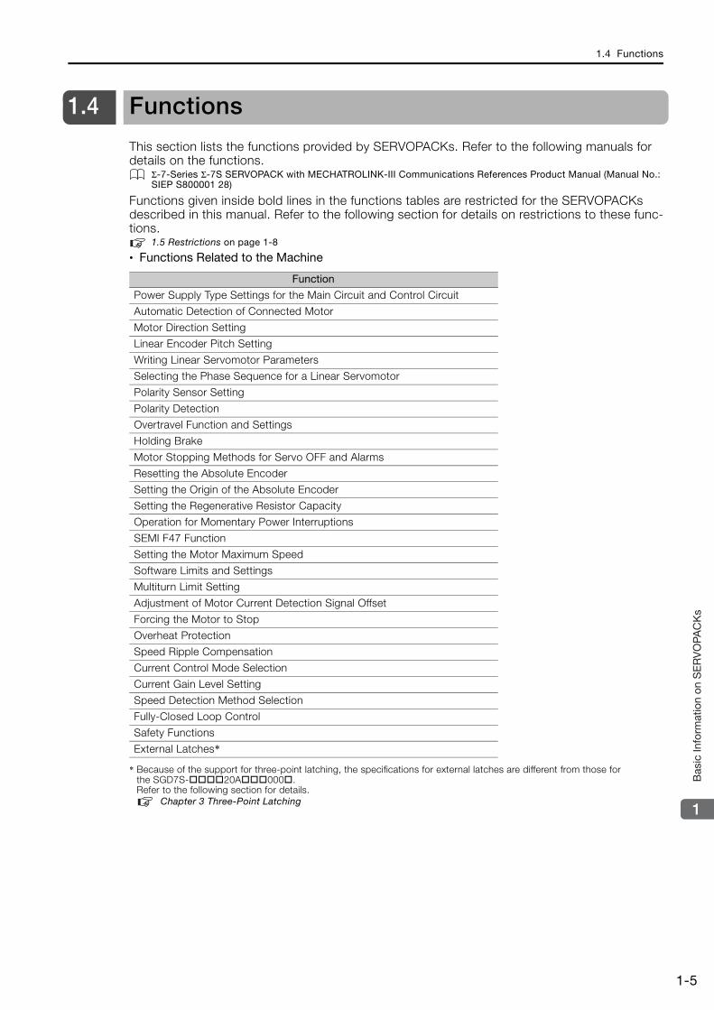
This section lists the functions provided by SERVOPACKs. Refer to the following manuals for details on the functions.
Σ-7-Series Σ-7S SERVOPACK with MECHATROLINK-III Communications References Product Manual (Manual No.: SIEP S800001 28)
Functions given inside bold lines in the functions tables are restricted for the SERVOPACKs described in this manual. Refer to the following section for details on restrictions to these func-tions.
1.5 Restrictions on page 1-8
• Functions Related to the Machine
* Because of the support for three-point latching, the specifications for external latches are different from those for the SGD7S-20A000.Refer to the following section for details.
Chapter 3 Three-Point Latching
Function
Power Supply Type Settings for the Main Circuit and Control Circuit
Automatic Detection of Connected Motor
Motor Direction Setting
Linear Encoder Pitch Setting
Writing Linear Servomotor Parameters
Selecting the Phase Sequence for a Linear Servomotor
Polarity Sensor Setting
Polarity Detection
Overtravel Function and Settings
Holding Brake
Motor Stopping Methods for Servo OFF and Alarms
Resetting the Absolute Encoder
Setting the Origin of the Absolute Encoder
Setting the Regenerative Resistor Capacity
Operation for Momentary Power Interruptions
SEMI F47 Function
Setting the Motor Maximum Speed
Software Limits and Settings
Multiturn Limit Setting
Adjustment of Motor Current Detection Signal Offset
Forcing the Motor to Stop
Overheat Protection
Speed Ripple Compensation
Current Control Mode Selection
Current Gain Level Setting
Speed Detection Method Selection
Fully-Closed Loop Control
Safety Functions
External Latches*
1.4 Functions
1-6
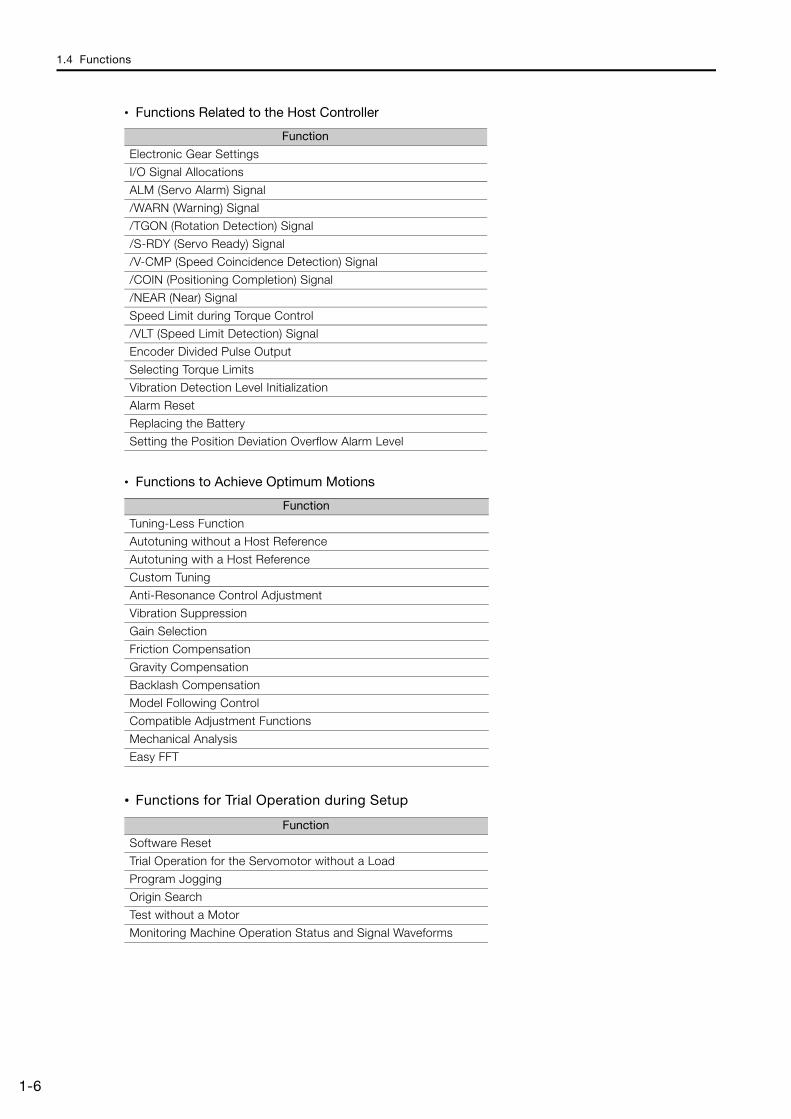
• Functions Related to the Host Controller
• Functions to Achieve Optimum Motions
• Functions for Trial Operation during Setup
Function
Electronic Gear Settings
I/O Signal Allocations
ALM (Servo Alarm) Signal
/WARN (Warning) Signal
/TGON (Rotation Detection) Signal
/S-RDY (Servo Ready) Signal
/V-CMP (Speed Coincidence Detection) Signal
/COIN (Positioning Completion) Signal
/NEAR (Near) Signal
Speed Limit during Torque Control
/VLT (Speed Limit Detection) Signal
Encoder Divided Pulse Output
Selecting Torque Limits
Vibration Detection Level Initialization
Alarm Reset
Replacing the Battery
Setting the Position Deviation Overflow Alarm Level
Function
Tuning-Less Function
Autotuning without a Host Reference
Autotuning with a Host Reference
Custom Tuning
Anti-Resonance Control Adjustment
Vibration Suppression
Gain Selection
Friction Compensation
Gravity Compensation
Backlash Compensation
Model Following Control
Compatible Adjustment Functions
Mechanical Analysis
Easy FFT
Function
Software Reset
Trial Operation for the Servomotor without a Load
Program Jogging
Origin Search
Test without a Motor
Monitoring Machine Operation Status and Signal Waveforms
1.4 Functions
1-7
1
Bas
ic In
form
atio
n on
SE
RV
OPA
CKs
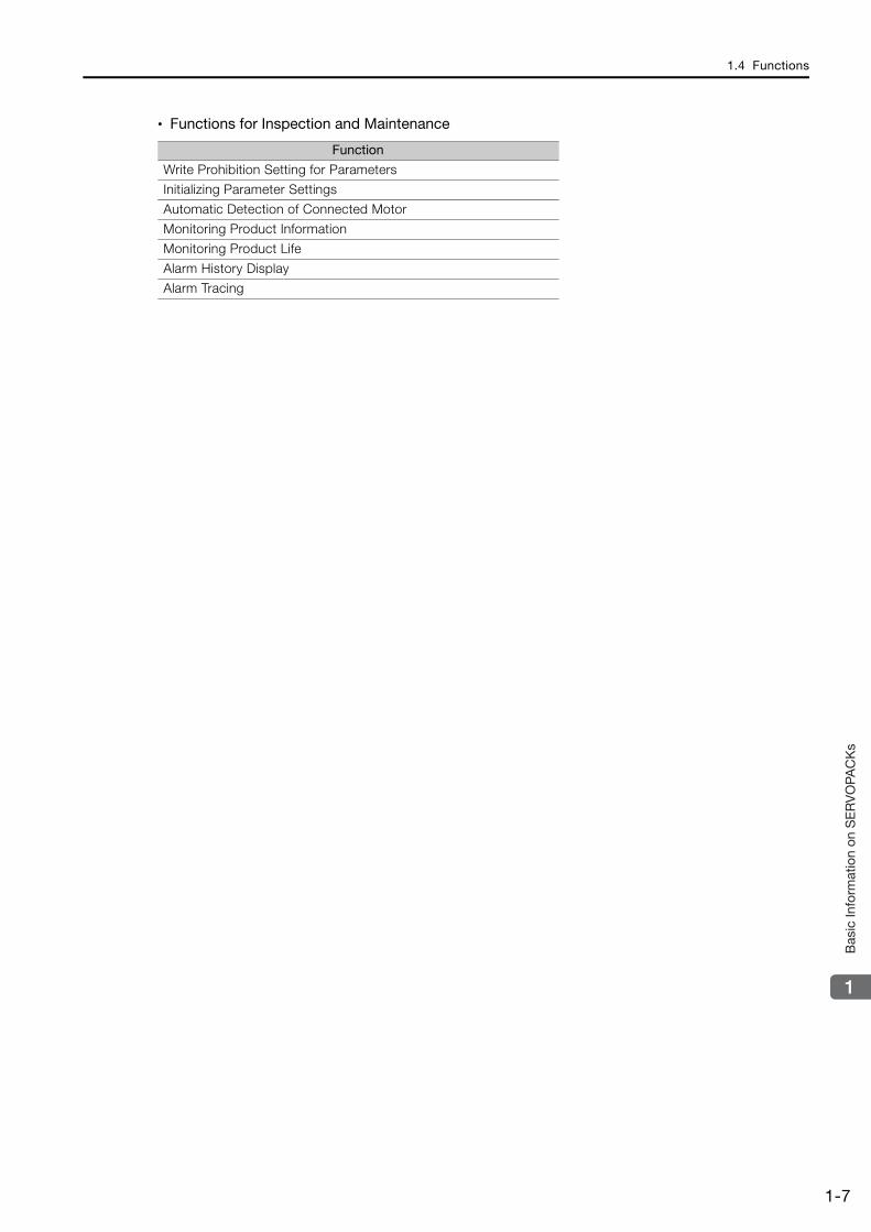
• Functions for Inspection and Maintenance
Function
Write Prohibition Setting for Parameters
Initializing Parameter Settings
Automatic Detection of Connected Motor
Monitoring Product Information
Monitoring Product Life
Alarm History Display
Alarm Tracing

1.5 Restrictions
1.5.1 Function Application Restrictions
1-8
1.5 Restrictions
This section describes restrictions that apply when using the SERVOPACKs described in this manual.
1.5.1 Function Application RestrictionsThere are no functional restrictions when you use the SERVOPACKs described in this manual.
1.5.2 Restrictions on SpecificationsThere are no restrictions on specifications when you use the SERVOPACKs described in this manual.
1.6 SigmaWin+
1-9
1
Bas
ic In
form
atio
n on
SE
RV
OPA
CKs
1.6 SigmaWin+
If you use SigmaWin+ with the SERVOPACKs described in this manual, use SigmaWin+ version 7. It is not necessary to add a model information file.

1.7 Combining the SERVOPACKs with MP-Series Machine Controllers and the MPE720 Engineering Tool
1-10
1.7 Combining the SERVOPACKs with MP-Series Machine Controllers and the MPE720 Engineering Tool
If you combine the SERVOPACK with an MP-Series Machine Controller or the MPE720 Engi-neering Tool, it will be recognized as a SERVOPACK with standard specifications. To use the parameters that have been added or changed for the SERVOPACKs described in this manual, use the SigmaWin+.
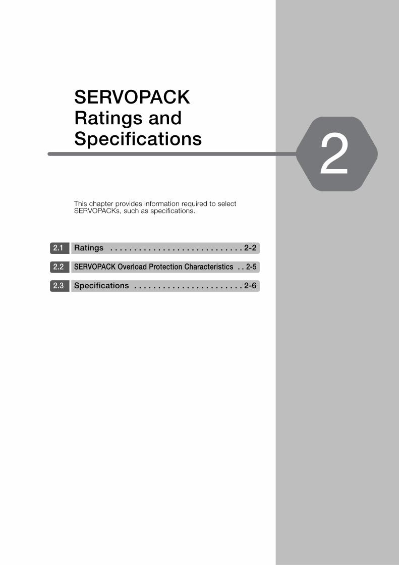
This chapter provides information required to select SERVOPACKs, such as specifications.
2.1 Ratings . . . . . . . . . . . . . . . . . . . . . . . . . . . . 2-2
2.2 SERVOPACK Overload Protection Characteristics . . 2-5
2.3 Specifications . . . . . . . . . . . . . . . . . . . . . . . 2-6
SERVOPACK Ratings and Specifications 2
2.1 Ratings
2-2
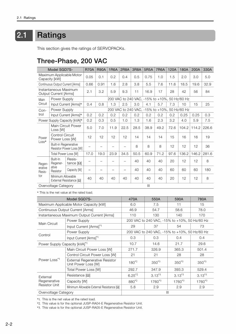
2.1 Ratings
This section gives the ratings of SERVOPACKs.
Three-Phase, 200 VAC
* This is the net value at the rated load.
*1. This is the net value at the rated load.*2. This value is for the optional JUSP-RA04-E Regenerative Resistor Unit.*3. This value is for the optional JUSP-RA05-E Regenerative Resistor Unit.
Model SGD7S- R70A R90A 1R6A 2R8A 3R8A 5R5A 7R6A 120A 180A 200A 330A
Maximum Applicable Motor Capacity [kW] 0.05 0.1 0.2 0.4 0.5 0.75 1.0 1.5 2.0 3.0 5.0
Continuous Output Current [Arms] 0.66 0.91 1.6 2.8 3.8 5.5 7.6 11.6 18.5 19.6 32.9
Instantaneous Maximum Output Current [Arms] 2.1 3.2 5.9 9.3 11 16.9 17 28 42 56 84
Main Circuit
Power Supply 200 VAC to 240 VAC, -15% to +10%, 50 Hz/60 Hz
Input Current [Arms]* 0.4 0.8 1.3 2.5 3.0 4.1 5.7 7.3 10 15 25
Con-trol
Power Supply 200 VAC to 240 VAC, -15% to +10%, 50 Hz/60 Hz
Input Current [Arms]* 0.2 0.2 0.2 0.2 0.2 0.2 0.2 0.2 0.25 0.25 0.3
Power Supply Capacity [kVA]* 0.2 0.3 0.5 1.0 1.3 1.6 2.3 3.2 4.0 5.9 7.5
Power Loss*
Main Circuit Power Loss [W] 5.0 7.0 11.9 22.5 28.5 38.9 49.2 72.6 104.2 114.2 226.6
Control Circuit Power Loss [W] 12 12 12 12 14 14 14 15 16 16 19
Built-in Regenerative Resistor Power Loss [W] − − − − 8 8 8 12 12 12 36
Total Power Loss [W] 17.0 19.0 23.9 34.5 50.5 60.9 71.2 97.6 136.2 146.2 281.6
Regen-erative Resis-tor
Built-In Regener-ative Resistor
Resis-tance [Ω] − − − − 40 40 40 20 12 12 8
Capacity [W] − − − − 40 40 40 60 60 60 180
Minimum Allowable External Resistance [Ω] 40 40 40 40 40 40 40 20 12 12 8
Overvoltage Category III
Model SGD7S- 470A 550A 590A 780A
Maximum Applicable Motor Capacity [kW] 6.0 7.5 11 15
Continuous Output Current [Arms] 46.9 54.7 58.6 78.0
Instantaneous Maximum Output Current [Arms] 110 130 140 170
Main CircuitPower Supply 200 VAC to 240 VAC, -15% to +10%, 50 Hz/60 Hz
Input Current [Arms]*1 29 37 54 73
ControlPower Supply 200 VAC to 240 VAC, -15% to +10%, 50 Hz/60 Hz
Input Current [Arms]*1 0.3 0.3 0.4 0.4
Power Supply Capacity [kVA]*1 10.7 14.6 21.7 29.6
Power Loss*1
Main Circuit Power Loss [W] 271.7 326.9 365.3 501.4
Control Circuit Power Loss [W] 21 21 28 28
External Regenerative Resistor Unit Power Loss [W] 180*2 350*3 350*3 350*3
Total Power Loss [W] 292.7 347.9 393.3 529.4
External Regenerative Resistor Unit
Resistance [Ω] 6.25*2 3.13*3 3.13*3 3.13*3
Capacity [W] 880*2 1760*3 1760*3 1760*3
Minimum Allowable External Resistance [Ω] 5.8 2.9 2.9 2.9
Overvoltage Category III
2.1 Ratings
2-3
2
SE
RV
OPA
CK
Rat
ings
and
Sp
ecifi
catio
ns
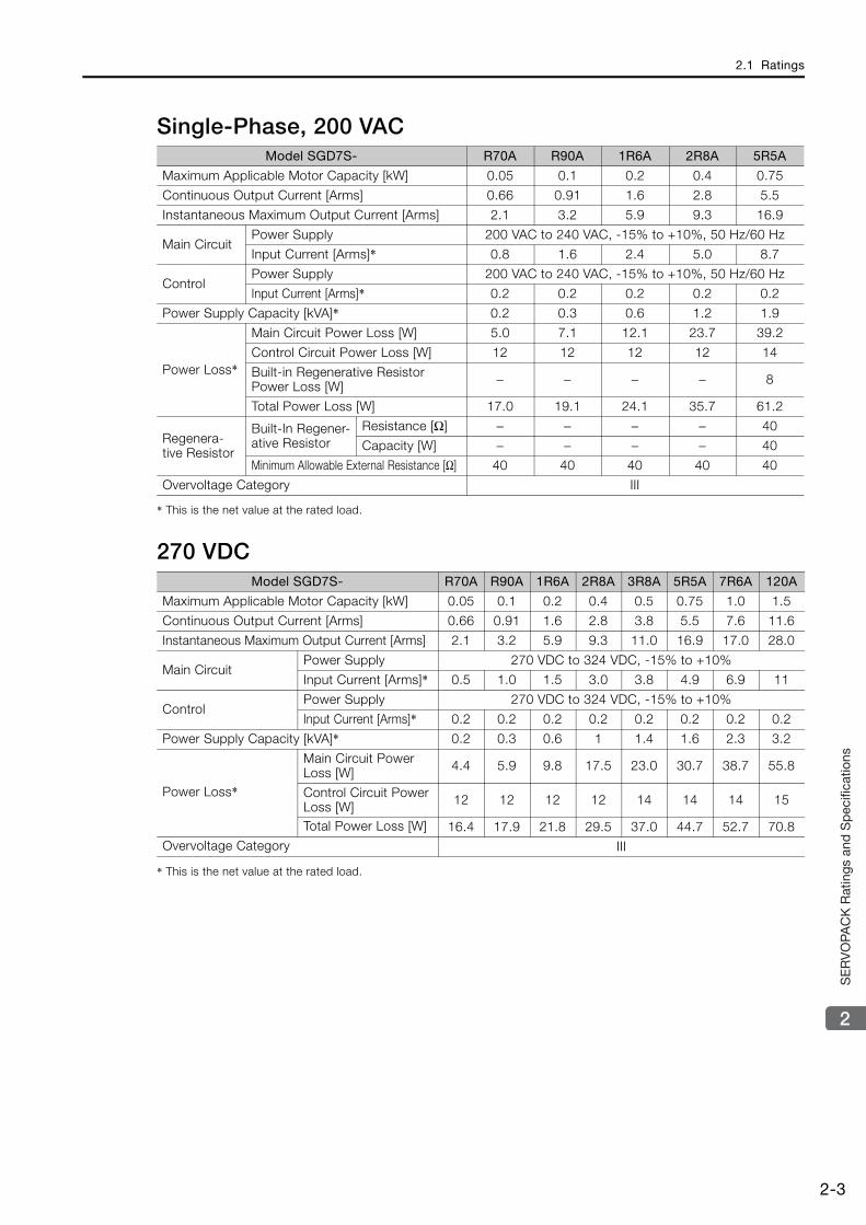
Single-Phase, 200 VAC
* This is the net value at the rated load.
270 VDC
* This is the net value at the rated load.
Model SGD7S- R70A R90A 1R6A 2R8A 5R5A
Maximum Applicable Motor Capacity [kW] 0.05 0.1 0.2 0.4 0.75
Continuous Output Current [Arms] 0.66 0.91 1.6 2.8 5.5
Instantaneous Maximum Output Current [Arms] 2.1 3.2 5.9 9.3 16.9
Main CircuitPower Supply 200 VAC to 240 VAC, -15% to +10%, 50 Hz/60 Hz
Input Current [Arms]* 0.8 1.6 2.4 5.0 8.7
ControlPower Supply 200 VAC to 240 VAC, -15% to +10%, 50 Hz/60 Hz
Input Current [Arms]* 0.2 0.2 0.2 0.2 0.2
Power Supply Capacity [kVA]* 0.2 0.3 0.6 1.2 1.9
Power Loss*
Main Circuit Power Loss [W] 5.0 7.1 12.1 23.7 39.2
Control Circuit Power Loss [W] 12 12 12 12 14
Built-in Regenerative Resistor Power Loss [W] − − − − 8
Total Power Loss [W] 17.0 19.1 24.1 35.7 61.2
Regenera-tive Resistor
Built-In Regener-ative Resistor
Resistance [Ω] − − − − 40
Capacity [W] − − − − 40
Minimum Allowable External Resistance [Ω] 40 40 40 40 40
Overvoltage Category III
Model SGD7S- R70A R90A 1R6A 2R8A 3R8A 5R5A 7R6A 120A
Maximum Applicable Motor Capacity [kW] 0.05 0.1 0.2 0.4 0.5 0.75 1.0 1.5
Continuous Output Current [Arms] 0.66 0.91 1.6 2.8 3.8 5.5 7.6 11.6
Instantaneous Maximum Output Current [Arms] 2.1 3.2 5.9 9.3 11.0 16.9 17.0 28.0
Main CircuitPower Supply 270 VDC to 324 VDC, -15% to +10%
Input Current [Arms]* 0.5 1.0 1.5 3.0 3.8 4.9 6.9 11
ControlPower Supply 270 VDC to 324 VDC, -15% to +10%
Input Current [Arms]* 0.2 0.2 0.2 0.2 0.2 0.2 0.2 0.2
Power Supply Capacity [kVA]* 0.2 0.3 0.6 1 1.4 1.6 2.3 3.2
Power Loss*
Main Circuit Power Loss [W] 4.4 5.9 9.8 17.5 23.0 30.7 38.7 55.8
Control Circuit Power Loss [W] 12 12 12 12 14 14 14 15
Total Power Loss [W] 16.4 17.9 21.8 29.5 37.0 44.7 52.7 70.8Overvoltage Category III

2.1 Ratings
2-4
* This is the net value at the rated load.
Single-Phase, 100 VAC
* This is the net value at the rated load.
Model SGD7S- 180A 200A 330A 470A 550A 590A 780A
Maximum Applicable Motor Capacity [kW] 2.0 3.0 5.0 6.0 7.5 11.0 15.0
Continuous Output Current [Arms] 18.5 19.6 32.9 46.9 54.7 58.6 78.0
Instantaneous Maximum Output Current [Arms] 42.0 56.0 84.0 110 130 140 170
Main CircuitPower Supply 270 VDC to 324 VDC, -15% to +10%
Input Current [Arms]* 14 20 34 36 48 68 92
ControlPower Supply 270 VDC to 324 VDC, -15% to +10%
Input Current [Arms]* 0.25 0.25 0.3 0.3 0.3 0.4 0.4
Power Supply Capacity [kVA]* 4.0 5.9 7.5 10.7 14.6 21.7 29.6
Power Loss*
Main Circuit Power Loss [W] 82.7 83.5 146.2 211.6 255.3 243.6 343.4
Control Circuit Power Loss [W] 16 16 19 21 21 28 28
Total Power Loss [W] 98.7 99.5 165.2 232.6 276.3 271.6 371.4Overvoltage Category III
Model SGD7S- R70F R90F 2R1F 2R8F
Maximum Applicable Motor Capacity [kW] 0.05 0.1 0.2 0.4
Continuous Output Current [Arms] 0.66 0.91 2.1 2.8
Instantaneous Maximum Output Current [Arms] 2.1 3.2 6.5 9.3
Main CircuitPower Supply 100 VAC to 120 VAC, -15% to +10%, 50 Hz/60 Hz
Input Current [Arms]* 1.5 2.5 5 10
ControlPower Supply 100 VAC to 120 VAC, -15% to +10%, 50 Hz/60 Hz
Input Current [Arms]* 0.38 0.38 0.38 0.38
Power Supply Capacity [kVA]* 0.2 0.3 0.6 1.4
Power Loss*
Main Circuit Power Loss [W] 5.3 7.8 14.2 26.2
Control Circuit Power Loss [W] 12 12 12 12
Total Power Loss [W] 17.3 19.8 26.2 38.2
Regenerative Resistor Minimum Allowable Resistance [Ω] 40 40 40 40
Overvoltage Category III
2.2 SERVOPACK Overload Protection Characteristics
2-5
2
SE
RV
OPA
CK
Rat
ings
and
Sp
ecifi
catio
ns
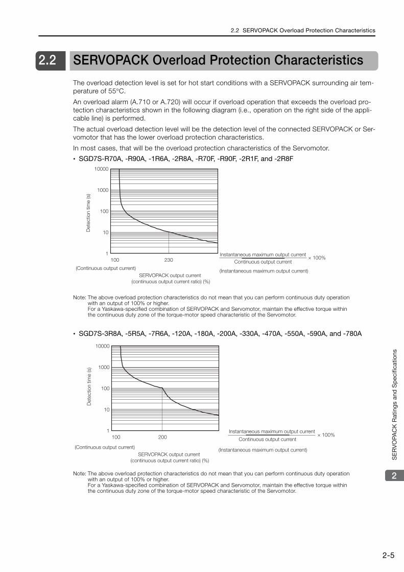
2.2 SERVOPACK Overload Protection Characteristics
The overload detection level is set for hot start conditions with a SERVOPACK surrounding air tem-perature of 55°C.
An overload alarm (A.710 or A.720) will occur if overload operation that exceeds the overload pro-tection characteristics shown in the following diagram (i.e., operation on the right side of the appli-cable line) is performed.
The actual overload detection level will be the detection level of the connected SERVOPACK or Ser-vomotor that has the lower overload protection characteristics.
In most cases, that will be the overload protection characteristics of the Servomotor.
• SGD7S-R70A, -R90A, -1R6A, -2R8A, -R70F, -R90F, -2R1F, and -2R8F
Note: The above overload protection characteristics do not mean that you can perform continuous duty operation with an output of 100% or higher.For a Yaskawa-specified combination of SERVOPACK and Servomotor, maintain the effective torque within the continuous duty zone of the torque-motor speed characteristic of the Servomotor.
• SGD7S-3R8A, -5R5A, -7R6A, -120A, -180A, -200A, -330A, -470A, -550A, -590A, and -780A
Note: The above overload protection characteristics do not mean that you can perform continuous duty operation with an output of 100% or higher.For a Yaskawa-specified combination of SERVOPACK and Servomotor, maintain the effective torque within the continuous duty zone of the torque-motor speed characteristic of the Servomotor.
SERVOPACK output current (continuous output current ratio) (%)
Instantaneous maximum output current
(Instantaneous maximum output current)
Continuous output current× 100%100 230
10000
1000
100
10
1
Det
ectio
n tim
e (s
)
(Continuous output current)
× 100%100 200
10000
1000
100
10
1
SERVOPACK output current (continuous output current ratio) (%)
Instantaneous maximum output current
(Instantaneous maximum output current)
Continuous output current
Det
ectio
n tim
e (s
)
(Continuous output current)

2.3 Specifications
2-6
2.3 Specifications
This section gives the general specifications of SERVOPACKs.
Item Specification
Control Method IGBT-based PWM control, sine wave current drive
Feedback
With Rotary Servomotor
Serial encoder: 17 bits (absolute encoder)20 bits or 24 bits (incremental encoder/absolute encoder)22 bits (absolute encoder)
With Linear Servomotor
• Absolute linear encoder(The signal resolution depends on the absolute linear encoder.)
• Incremental linear encoder(The signal resolution depends on the incremental linear encoder or Serial Converter Unit.)
Environ-mental Conditions
Surrounding Air Tem-perature*1
-5°C to 55°C (With derating, usage is possible between 55°C and 60°C.) Refer to the following manual for derating specifications.
Σ-7-Series Σ-7S SERVOPACK with MECHATROLINK-III Communications References Product Manual (Manual No.: SIEP S800001 28)
Storage Temperature -20°C to 85°C
Surrounding Air Humidity 95% relative humidity max. (with no freezing or condensation)
Storage Humidity 95% relative humidity max. (with no freezing or condensation)
Vibration Resistance 4.9 m/s2
Shock Resistance 19.6 m/s2
Degree of Protection
Pollution Degree
2• Must be no corrosive or flammable gases.• Must be no exposure to water, oil, or chemicals. • Must be no dust, salts, or iron dust.
Altitude*1
1,000 m max. (With derating, usage is possible between 1,000 m and 2,000 m.) Refer to the following manual for derating specifications.
Σ-7-Series Σ-7S SERVOPACK with MECHATROLINK-III Communications References Product Manual (Manual No.: SIEP S800001 28)
Others Do not use the SERVOPACK in the following locations: Locations sub-ject to static electricity noise, strong electromagnetic/magnetic fields, or radioactivity
Applicable Standards Refer to the following section for details.
Compliance with UL Standards, EU Directives, and Other Safety Stan-dards on page xxvi
Mounting Base-mounted
Perfor-mance
Speed Control Range 1:5000 (At the rated torque, the lower limit of the speed control range must not cause the Servomotor to stop.)
Coefficient of Speed Fluctuation*2
±0.01% of rated speed max. (for a load fluctuation of 0% to 100%)
0% of rated speed max. (for a load fluctuation of ±10%)
±0.1% of rated speed max. (for a temperature fluctuation of 25°C ±25°C)
Torque Control Preci-sion (Repeatability) ±1%
Soft Start Time Setting 0 s to 10 s (Can be set separately for acceleration and deceleration.)
Continued on next page.
Degree SERVOPACK Model: SGD7S-
IP20R70A, R90A, 1R6A, 2R8A, 3R8A, 5R5A, 7R6A, 120A, R70F, R90F, 2R1F, 2R8F
IP10 180A, 200A, 330A, 470A, 550A, 590A, 780A
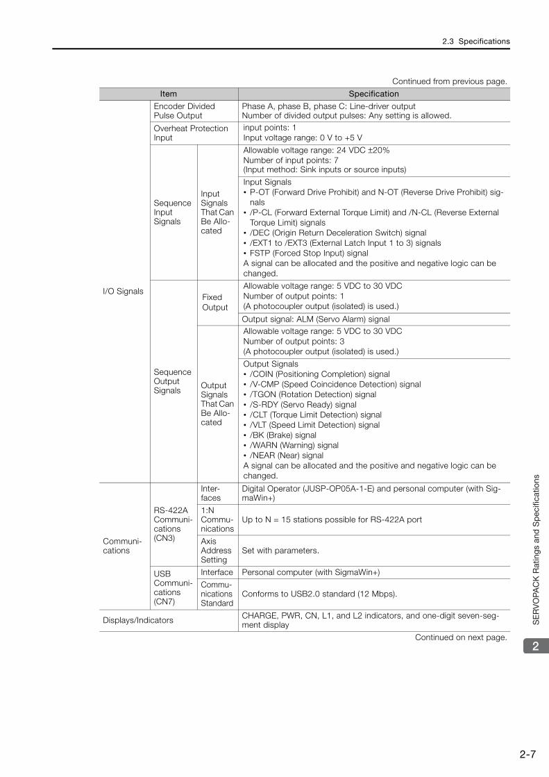
2.3 Specifications
2-7
2
SE
RV
OPA
CK
Rat
ings
and
Sp
ecifi
catio
ns
I/O Signals
Encoder Divided Pulse Output
Phase A, phase B, phase C: Line-driver output Number of divided output pulses: Any setting is allowed.
Overheat Protection Input
input points: 1 Input voltage range: 0 V to +5 V
Sequence Input Signals
Input Signals That Can Be Allo-cated
Allowable voltage range: 24 VDC ±20%Number of input points: 7(Input method: Sink inputs or source inputs)
Input Signals• P-OT (Forward Drive Prohibit) and N-OT (Reverse Drive Prohibit) sig-
nals• /P-CL (Forward External Torque Limit) and /N-CL (Reverse External
Torque Limit) signals• /DEC (Origin Return Deceleration Switch) signal• /EXT1 to /EXT3 (External Latch Input 1 to 3) signals• FSTP (Forced Stop Input) signalA signal can be allocated and the positive and negative logic can be changed.
Sequence Output Signals
Fixed Output
Allowable voltage range: 5 VDC to 30 VDC Number of output points: 1(A photocoupler output (isolated) is used.)
Output signal: ALM (Servo Alarm) signal
Output Signals That Can Be Allo-cated
Allowable voltage range: 5 VDC to 30 VDCNumber of output points: 3(A photocoupler output (isolated) is used.)
Output Signals• /COIN (Positioning Completion) signal• /V-CMP (Speed Coincidence Detection) signal• /TGON (Rotation Detection) signal• /S-RDY (Servo Ready) signal• /CLT (Torque Limit Detection) signal• /VLT (Speed Limit Detection) signal• /BK (Brake) signal• /WARN (Warning) signal• /NEAR (Near) signalA signal can be allocated and the positive and negative logic can be changed.
Communi-cations
RS-422A Communi-cations (CN3)
Inter-faces
Digital Operator (JUSP-OP05A-1-E) and personal computer (with Sig-maWin+)
1:N Commu-nications
Up to N = 15 stations possible for RS-422A port
Axis Address Setting
Set with parameters.
USB Communi-cations(CN7)
Interface Personal computer (with SigmaWin+)
Commu-nications Standard
Conforms to USB2.0 standard (12 Mbps).
Displays/Indicators CHARGE, PWR, CN, L1, and L2 indicators, and one-digit seven-seg-ment display
Continued on next page.
Continued from previous page.
Item Specification
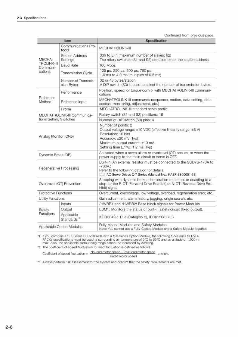
2.3 Specifications
2-8
*1. If you combine a Σ-7-Series SERVOPACK with a Σ-V-Series Option Module, the following Σ-V-Series SERVO-PACKs specifications must be used: a surrounding air temperature of 0°C to 55°C and an altitude of 1,000 m max. Also, the applicable surrounding range cannot be increased by derating.
*2. The coefficient of speed fluctuation for load fluctuation is defined as follows:
*3. Always perform risk assessment for the system and confirm that the safety requirements are met.
MECHA-TROLINK-III Communi-cations
Communications Pro-tocol MECHATROLINK-III
Station Address Settings
03h to EFh (maximum number of slaves: 62) The rotary switches (S1 and S2) are used to set the station address.
Baud Rate 100 Mbps
Transmission Cycle 125 μs, 250 μs, 500 μs, 750 μs, 1.0 ms to 4.0 ms (multiples of 0.5 ms)
Number of Transmis-sion Bytes
32 or 48 bytes/stationA DIP switch (S3) is used to select the number of transmission bytes.
Reference Method
Performance Position, speed, or torque control with MECHATROLINK-III communi-cations
Reference Input MECHATROLINK-III commands (sequence, motion, data setting, data access, monitoring, adjustment, etc.)
Profile MECHATROLINK-III standard servo profile
MECHATROLINK-III Communica-tions Setting Switches
Rotary switch (S1 and S2) positions: 16
Number of DIP switch (S3) pins: 4
Analog Monitor (CN5)
Number of points: 2Output voltage range: ±10 VDC (effective linearity range: ±8 V)Resolution: 16 bitsAccuracy: ±20 mV (Typ)Maximum output current: ±10 mASettling time (±1%): 1.2 ms (Typ)
Dynamic Brake (DB) Activated when a servo alarm or overtravel (OT) occurs, or when the power supply to the main circuit or servo is OFF.
Regenerative Processing
Built-in (An external resistor must be connected to the SGD7S-470A to -780A.)Refer to the following catalog for details.
AC Servo Drives Σ-7 Series (Manual No.: KAEP S800001 23)
Overtravel (OT) Prevention Stopping with dynamic brake, deceleration to a stop, or coasting to a stop for the P-OT (Forward Drive Prohibit) or N-OT (Reverse Drive Pro-hibit) signal
Protective Functions Overcurrent, overvoltage, low voltage, overload, regeneration error, etc.
Utility Functions Gain adjustment, alarm history, jogging, origin search, etc.
Safety Functions
Inputs /HWBB1 and /HWBB2: Base block signals for Power Modules
Output EDM1: Monitors the status of built-in safety circuit (fixed output).
Applicable Standards*3 ISO13849-1 PLe (Category 3), IEC61508 SIL3
Applicable Option Modules Fully-closed Modules and Safety ModulesNote: You cannot use a Fully-Closed Module and a Safety Module together.
Continued from previous page.
Item Specification
× 100%Coefficient of speed fluctuation = No-load motor speed - Total-load motor speedRated motor speed
This chapter describes three-point latching.
3.1 Introduction . . . . . . . . . . . . . . . . . . . . . . . . . 3-2
3.2 Operating Procedure . . . . . . . . . . . . . . . . . . 3-33.2.1 Monitoring Latched Position Data . . . . . . . . . . . . 3-33.2.2 Setting the Latching Allowable Area . . . . . . . . . . 3-63.2.3 Latching Position Data with Three-Point
Latching . . . . . . . . . . . . . . . . . . . . . . . . . . . . . . . 3-63.2.4 Operation Example . . . . . . . . . . . . . . . . . . . . . . . 3-7
3.3 MECHATROLINK-III Commands . . . . . . . . . 3-83.3.1 Command Header . . . . . . . . . . . . . . . . . . . . . . . . 3-83.3.2 Servo Command I/O Signal (SVCMD_IO) . . . . . 3-12
Three-Point Latching 3
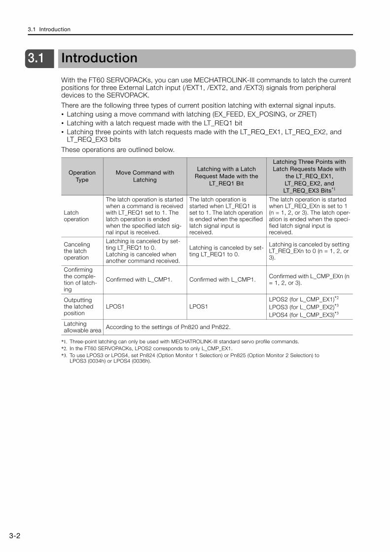
3.1 Introduction
3-2
3.1 Introduction
With the FT60 SERVOPACKs, you can use MECHATROLINK-III commands to latch the current positions for three External Latch input (/EXT1, /EXT2, and /EXT3) signals from peripheral devices to the SERVOPACK.
There are the following three types of current position latching with external signal inputs.• Latching using a move command with latching (EX_FEED, EX_POSING, or ZRET)• Latching with a latch request made with the LT_REQ1 bit• Latching three points with latch requests made with the LT_REQ_EX1, LT_REQ_EX2, and
LT_REQ_EX3 bits
These operations are outlined below.
*1. Three-point latching can only be used with MECHATROLINK-III standard servo profile commands.*2. In the FT60 SERVOPACKs, LPOS2 corresponds to only L_CMP_EX1.*3. To use LPOS3 or LPOS4, set Pn824 (Option Monitor 1 Selection) or Pn825 (Option Monitor 2 Selection) to
LPOS3 (0034h) or LPOS4 (0036h).
Operation Type
Move Command with Latching
Latching with a Latch Request Made with the
LT_REQ1 Bit
Latching Three Points with Latch Requests Made with
the LT_REQ_EX1, LT_REQ_EX2, and LT_REQ_EX3 Bits*1
Latch operation
The latch operation is started when a command is received with LT_REQ1 set to 1. The latch operation is ended when the specified latch sig-nal input is received.
The latch operation is started when LT_REQ1 is set to 1. The latch operation is ended when the specified latch signal input is received.
The latch operation is started when LT_REQ_EXn is set to 1 (n = 1, 2, or 3). The latch oper-ation is ended when the speci-fied latch signal input is received.
Canceling the latch operation
Latching is canceled by set-ting LT_REQ1 to 0.Latching is canceled when another command received.
Latching is canceled by set-ting LT_REQ1 to 0.
Latching is canceled by setting LT_REQ_EXn to 0 (n = 1, 2, or 3).
Confirming the comple-tion of latch-ing
Confirmed with L_CMP1. Confirmed with L_CMP1. Confirmed with L_CMP_EXn (n = 1, 2, or 3).
Outputting the latched position
LPOS1 LPOS1LPOS2 (for L_CMP_EX1)*2
LPOS3 (for L_CMP_EX2)*3
LPOS4 (for L_CMP_EX3)*3
Latching allowable area According to the settings of Pn820 and Pn822.
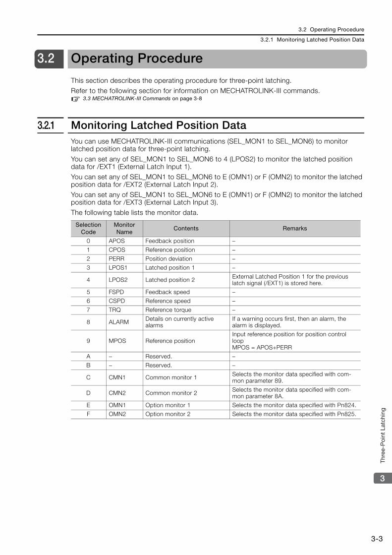
3.2 Operating Procedure
3.2.1 Monitoring Latched Position Data
3-3
3
Thre
e-P
oint
Lat
chin
g
3.2 Operating Procedure
This section describes the operating procedure for three-point latching.Refer to the following section for information on MECHATROLINK-III commands.
3.3 MECHATROLINK-III Commands on page 3-8
3.2.1 Monitoring Latched Position DataYou can use MECHATROLINK-III communications (SEL_MON1 to SEL_MON6) to monitor latched position data for three-point latching.You can set any of SEL_MON1 to SEL_MON6 to 4 (LPOS2) to monitor the latched position data for /EXT1 (External Latch Input 1).You can set any of SEL_MON1 to SEL_MON6 to E (OMN1) or F (OMN2) to monitor the latched position data for /EXT2 (External Latch Input 2).You can set any of SEL_MON1 to SEL_MON6 to E (OMN1) or F (OMN2) to monitor the latched position data for /EXT3 (External Latch Input 3).
The following table lists the monitor data.
Selection Code
Monitor Name
Contents Remarks
0 APOS Feedback position –
1 CPOS Reference position –
2 PERR Position deviation –
3 LPOS1 Latched position 1 –
4 LPOS2 Latched position 2 External Latched Position 1 for the previous latch signal (/EXT1) is stored here.
5 FSPD Feedback speed –
6 CSPD Reference speed –
7 TRQ Reference torque –
8 ALARM Details on currently active alarms
If a warning occurs first, then an alarm, the alarm is displayed.
9 MPOS Reference positionInput reference position for position control loopMPOS = APOS+PERR
A − Reserved. –
B − Reserved. –
C CMN1 Common monitor 1 Selects the monitor data specified with com-mon parameter 89.
D CMN2 Common monitor 2 Selects the monitor data specified with com-mon parameter 8A.
E OMN1 Option monitor 1 Selects the monitor data specified with Pn824.
F OMN2 Option monitor 2 Selects the monitor data specified with Pn825.
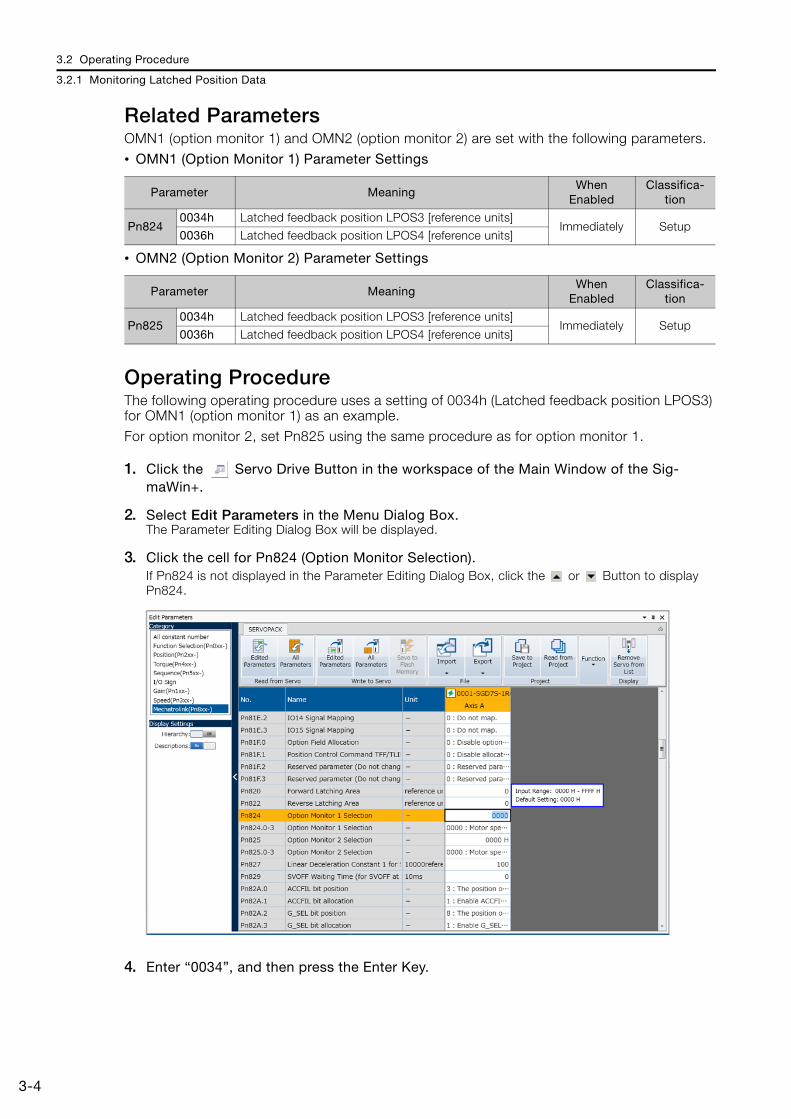
3.2 Operating Procedure
3.2.1 Monitoring Latched Position Data
3-4
Related ParametersOMN1 (option monitor 1) and OMN2 (option monitor 2) are set with the following parameters.• OMN1 (Option Monitor 1) Parameter Settings
• OMN2 (Option Monitor 2) Parameter Settings
Operating ProcedureThe following operating procedure uses a setting of 0034h (Latched feedback position LPOS3) for OMN1 (option monitor 1) as an example.For option monitor 2, set Pn825 using the same procedure as for option monitor 1.
1. Click the Servo Drive Button in the workspace of the Main Window of the Sig-maWin+.
2. Select Edit Parameters in the Menu Dialog Box.The Parameter Editing Dialog Box will be displayed.
3. Click the cell for Pn824 (Option Monitor Selection).If Pn824 is not displayed in the Parameter Editing Dialog Box, click the or Button to display Pn824.
4. Enter “0034”, and then press the Enter Key.
Parameter MeaningWhen
EnabledClassifica-
tion
Pn8240034h Latched feedback position LPOS3 [reference units]
Immediately Setup0036h Latched feedback position LPOS4 [reference units]
Parameter MeaningWhen
EnabledClassifica-
tion
Pn8250034h Latched feedback position LPOS3 [reference units]
Immediately Setup0036h Latched feedback position LPOS4 [reference units]
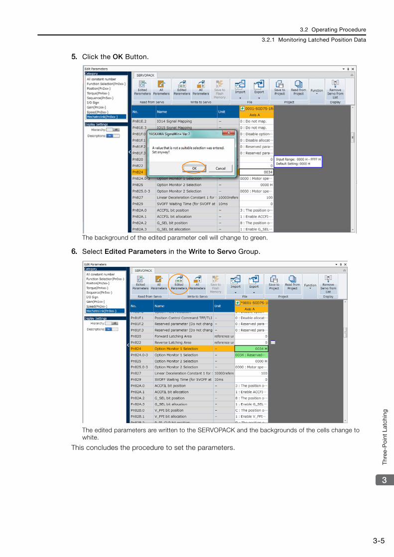
3.2 Operating Procedure
3.2.1 Monitoring Latched Position Data
3-5
3
Thre
e-P
oint
Lat
chin
g
5. Click the OK Button.
The background of the edited parameter cell will change to green.
6. Select Edited Parameters in the Write to Servo Group.
The edited parameters are written to the SERVOPACK and the backgrounds of the cells change to white.
This concludes the procedure to set the parameters.
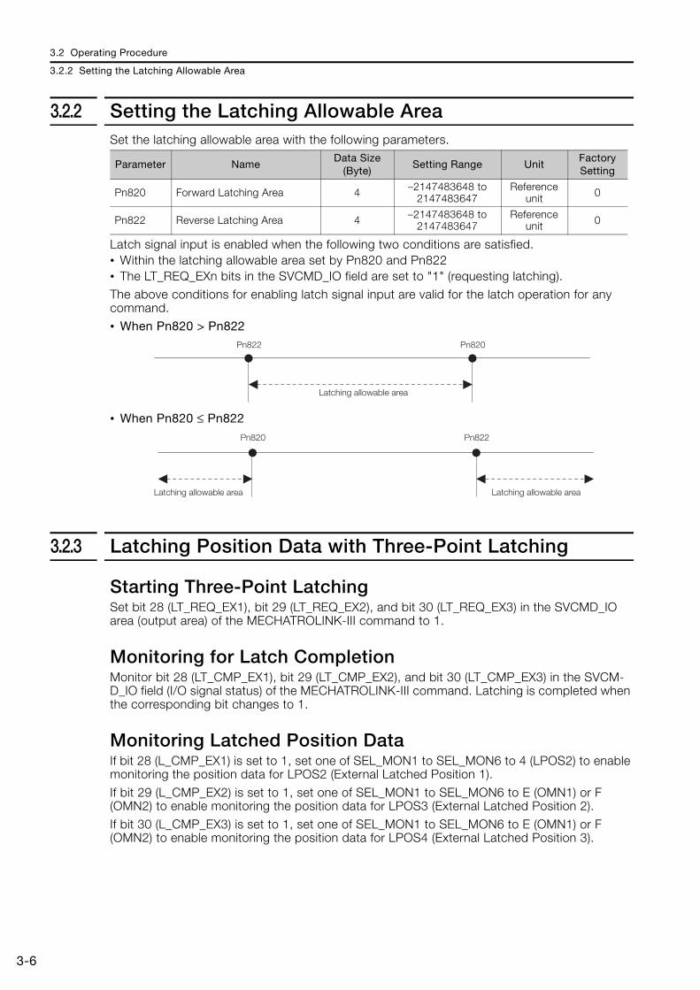
3.2 Operating Procedure
3.2.2 Setting the Latching Allowable Area
3-6
3.2.2 Setting the Latching Allowable AreaSet the latching allowable area with the following parameters.
Latch signal input is enabled when the following two conditions are satisfied.• Within the latching allowable area set by Pn820 and Pn822• The LT_REQ_EXn bits in the SVCMD_IO field are set to "1" (requesting latching).The above conditions for enabling latch signal input are valid for the latch operation for any command.• When Pn820 > Pn822
• When Pn820 ≤ Pn822
3.2.3 Latching Position Data with Three-Point Latching
Starting Three-Point LatchingSet bit 28 (LT_REQ_EX1), bit 29 (LT_REQ_EX2), and bit 30 (LT_REQ_EX3) in the SVCMD_IO area (output area) of the MECHATROLINK-III command to 1.
Monitoring for Latch CompletionMonitor bit 28 (LT_CMP_EX1), bit 29 (LT_CMP_EX2), and bit 30 (LT_CMP_EX3) in the SVCM-D_IO field (I/O signal status) of the MECHATROLINK-III command. Latching is completed when the corresponding bit changes to 1.
Monitoring Latched Position DataIf bit 28 (L_CMP_EX1) is set to 1, set one of SEL_MON1 to SEL_MON6 to 4 (LPOS2) to enable monitoring the position data for LPOS2 (External Latched Position 1).
If bit 29 (L_CMP_EX2) is set to 1, set one of SEL_MON1 to SEL_MON6 to E (OMN1) or F (OMN2) to enable monitoring the position data for LPOS3 (External Latched Position 2).
If bit 30 (L_CMP_EX3) is set to 1, set one of SEL_MON1 to SEL_MON6 to E (OMN1) or F (OMN2) to enable monitoring the position data for LPOS4 (External Latched Position 3).
Parameter NameData Size
(Byte)Setting Range Unit
Factory Setting
Pn820 Forward Latching Area 4 –2147483648 to 2147483647
Reference unit 0
Pn822 Reverse Latching Area 4 –2147483648 to 2147483647
Reference unit 0
Pn822 Pn820
Latching allowable area
Pn820 Pn822
Latching allowable area Latching allowable area
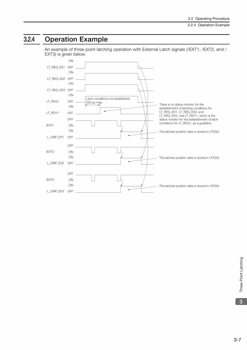
3.2 Operating Procedure
3.2.4 Operation Example
3-7
3
Thre
e-P
oint
Lat
chin
g
3.2.4 Operation ExampleAn example of three-point latching operation with External Latch signals (/EXT1, /EXT2, and /EXT3) is given below.
ON
OFFLT_REQ_EX1
ON
OFFLT_REQ_EX2
ON
OFFLT_REQ_EX3
ON
OFFLT_REQ1
ON
OFFLT_RDY1
ON
OFFL_CMP_EX1
OFF
ON/EXT2
ON
OFFL_CMP_EX2
OFF
ON/EXT3
ON
OFFL_CMP_EX3
OFF
ON/EXT1
Latch conditions not established: 250 μs max.
The latched position data is stored in LPOS2.
The latched position data is stored in LPOS3.
The latched position data is stored in LPOS4.
There is no status monitor for the establishment of latching conditions for LT_REQ_EX1, LT_REQ_EX2, and LT_REQ_EX3. Use LT_RDY1, which is the status monitor for the establishment of latch conditions for LT_REQ1, as a guideline.

3.3 MECHATROLINK-III Commands
3.3.1 Command Header
3-8
3.3 MECHATROLINK-III Commands
Refer to the following manual for information on MECHATROLINK commands other than the command header (servo command controls (SVCMD_CTRL), servo command status (SVCM-D_STAT), and servo command I/O signals (SVCMD_IO)).
Σ-7-Series MECHATROLINK-III Communications Standard Servo Profile Command Manual (Manual No.: SIEP S800001 31)
3.3.1 Command Header
Servo Command Control (SVCMD_CTRL)Byte 4 to byte 7 of the command format are specified as the SVCMD_CTRL field.The control bit specifies a motion command for a slave station.The SVCMD_CTRL field contains auxiliary data for the specified command and the control bits have no meaning with commands other than the command that specified the data.
Note that the designation in this field is valid even when a CMD_ALM has occurred.The SVCMD_CTRL field is specified as shown below by the communication specification.
SVCMD_CTRL Field
Details of Control BitsThe following table shows the details of the control bits.
bit 7 bit 6 bit 5 bit 4 bit 3 bit 2 bit 1 bit 0
Reserved (0) ACCFIL STOP_MODE CMD_CANCEL
CMD_PAUSE
bit 15 bit 14 bit 13 bit 12 bit 11 bit 10 bit 9 bit 8
Reserved (0) LT_SEL1 Reserved (0) LT_REQ1
bit 23 bit 22 bit 21 bit 20 bit 19 bit 18 bit 17 bit 16
SEL_MON2 SEL_MON1
bit 31 bit 30 bit 29 bit 28 bit 27 bit 26 bit 25 bit 24
Reserved (0) SEL_MON3
Bit Name Description Value Setting Enabled Timing
0CMD_PAUSE Pause of Move
Command
0 NoneLevel
1 Move command pause command
Pauses execution of the POSING, FEED, EX_FEED, EX_POSING, ZRET and VELCTRL com-mands according to STOP_MODE.
1CMD_CANCEL Cancellation of
Move Command
0 NoneLevel
1 Cancellation of move command
Cancels execution of the POSING, FEED, EX_FEED, EX_POSING, ZRET and VELCTRL com-mands according to STOP_MODE.
2, 3STOP_MODE Selection of Stop
Mode
0 Stop after deceleration
Level1 Immediate stop
2 Reserved
3 Reserved
Selects the stop mode for CMD_PAUSE and CMD_CANCEL.
Continued on next page.
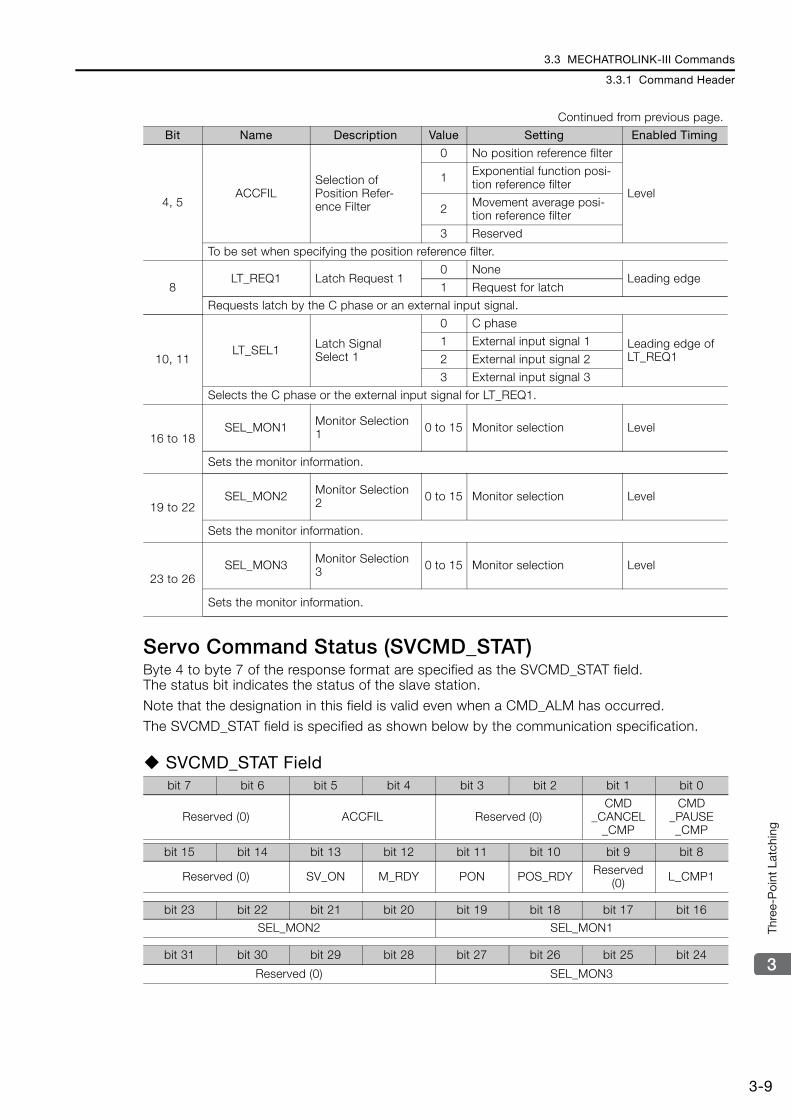
3.3 MECHATROLINK-III Commands
3.3.1 Command Header
3-9
3
Thre
e-P
oint
Lat
chin
g
Servo Command Status (SVCMD_STAT)Byte 4 to byte 7 of the response format are specified as the SVCMD_STAT field.The status bit indicates the status of the slave station.
Note that the designation in this field is valid even when a CMD_ALM has occurred.The SVCMD_STAT field is specified as shown below by the communication specification.
SVCMD_STAT Field
4, 5ACCFIL
Selection of Position Refer-ence Filter
0 No position reference filter
Level1 Exponential function posi-
tion reference filter
2 Movement average posi-tion reference filter
3 Reserved
To be set when specifying the position reference filter.
8LT_REQ1 Latch Request 1
0 NoneLeading edge
1 Request for latch
Requests latch by the C phase or an external input signal.
10, 11LT_SEL1 Latch Signal
Select 1
0 C phase
Leading edge of LT_REQ1
1 External input signal 1
2 External input signal 2
3 External input signal 3
Selects the C phase or the external input signal for LT_REQ1.
16 to 18SEL_MON1 Monitor Selection
1 0 to 15 Monitor selection Level
Sets the monitor information.
19 to 22SEL_MON2 Monitor Selection
2 0 to 15 Monitor selection Level
Sets the monitor information.
23 to 26SEL_MON3 Monitor Selection
3 0 to 15 Monitor selection Level
Sets the monitor information.
bit 7 bit 6 bit 5 bit 4 bit 3 bit 2 bit 1 bit 0
Reserved (0) ACCFIL Reserved (0)CMD
_CANCEL_CMP
CMD_PAUSE_CMP
bit 15 bit 14 bit 13 bit 12 bit 11 bit 10 bit 9 bit 8
Reserved (0) SV_ON M_RDY PON POS_RDY Reserved (0) L_CMP1
bit 23 bit 22 bit 21 bit 20 bit 19 bit 18 bit 17 bit 16
SEL_MON2 SEL_MON1
bit 31 bit 30 bit 29 bit 28 bit 27 bit 26 bit 25 bit 24
Reserved (0) SEL_MON3
Continued from previous page.
Bit Name Description Value Setting Enabled Timing
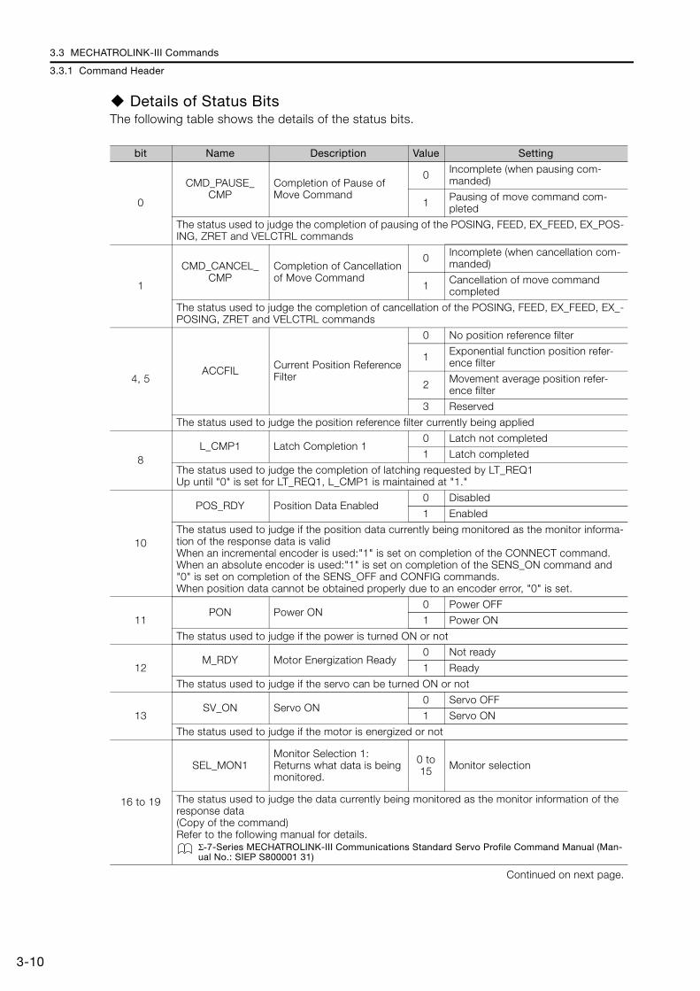
3.3 MECHATROLINK-III Commands
3.3.1 Command Header
3-10
Details of Status BitsThe following table shows the details of the status bits.
bit Name Description Value Setting
0
CMD_PAUSE_CMP
Completion of Pause of Move Command
0 Incomplete (when pausing com-manded)
1 Pausing of move command com-pleted
The status used to judge the completion of pausing of the POSING, FEED, EX_FEED, EX_POS-ING, ZRET and VELCTRL commands
1
CMD_CANCEL_CMP
Completion of Cancellation of Move Command
0 Incomplete (when cancellation com-manded)
1 Cancellation of move command completed
The status used to judge the completion of cancellation of the POSING, FEED, EX_FEED, EX_-POSING, ZRET and VELCTRL commands
4, 5ACCFIL Current Position Reference
Filter
0 No position reference filter
1 Exponential function position refer-ence filter
2 Movement average position refer-ence filter
3 Reserved
The status used to judge the position reference filter currently being applied
8L_CMP1 Latch Completion 1
0 Latch not completed
1 Latch completed
The status used to judge the completion of latching requested by LT_REQ1Up until "0" is set for LT_REQ1, L_CMP1 is maintained at "1."
10
POS_RDY Position Data Enabled0 Disabled
1 Enabled
The status used to judge if the position data currently being monitored as the monitor informa-tion of the response data is validWhen an incremental encoder is used:"1" is set on completion of the CONNECT command.When an absolute encoder is used:"1" is set on completion of the SENS_ON command and "0" is set on completion of the SENS_OFF and CONFIG commands.When position data cannot be obtained properly due to an encoder error, "0" is set.
11PON Power ON
0 Power OFF
1 Power ON
The status used to judge if the power is turned ON or not
12M_RDY Motor Energization Ready
0 Not ready
1 Ready
The status used to judge if the servo can be turned ON or not
13SV_ON Servo ON
0 Servo OFF
1 Servo ON
The status used to judge if the motor is energized or not
16 to 19
SEL_MON1Monitor Selection 1: Returns what data is being monitored.
0 to 15 Monitor selection
The status used to judge the data currently being monitored as the monitor information of the response data(Copy of the command)Refer to the following manual for details.
Σ-7-Series MECHATROLINK-III Communications Standard Servo Profile Command Manual (Man-ual No.: SIEP S800001 31)
Continued on next page.

3.3 MECHATROLINK-III Commands
3.3.1 Command Header
3-11
3
Thre
e-P
oint
Lat
chin
g
Supplementary Information on Latch OperationLatch operation is enabled on the leading edge of LT_REQ1. If a command is changed after the latch operation has been enabled, the latch operation is performed as described in the follow-ing table.(The values of LT_SEL1 are examples.)
20 to 23
SEL_MON2Monitor Selection 2: Returns what data is being monitored.
0 to 15 Monitor selection
The status used to judge the data currently being monitored as the monitor information of the response data(Copy of the command)Refer to the following manual for details.
Σ-7-Series MECHATROLINK-III Communications Standard Servo Profile Command Manual (Man-ual No.: SIEP S800001 31)
24 to 27
SEL_MON3Monitor Selection 3: Returns what data is being monitored.
0 to 15 Monitor selection
The status used to judge the data currently being monitored as the monitor information of the response data(Copy of the command)Refer to the following manual for details.
Σ-7-Series MECHATROLINK-III Communications Standard Servo Profile Command Manual (Man-ual No.: SIEP S800001 31)
Command before Switching
Command after Switching
Latch Operation
Command without latch-ing
LT_SEL1 = 1LT_REQ1 = 1
Common commands Continues the latch request before switching.
Command with latchingLT_SEL1 = 1LT_REQ1 = 1
Common commands Interrupts operation as a command with latching.
Command without latch-ing
LT_SEL1 = 1LT_REQ1 = 1
Command without latching
LT_SEL1 = 1LT_REQ1 = 1
Continues the latch request before switching.
Command without latch-ing
LT_SEL1 = 1LT_REQ1 = 1
Command without latching
LT_SEL1 = 2LT_REQ1 = 1
Continues the latch request before switching.
Command without latch-ing
LT_SEL1 = 1LT_REQ1 = 1
Command with latchingLT_SEL1 = 1LT_REQ1 = 1
Switches to a latch request for the command after switching.The Servo Drive requests latching again (internal pro-cessing).If L_CMP1 changes to 1 before the command is changed, set L_CMP1 to 0 when you change the com-mand.
Command with latchingLT_SEL1 = 1LT_REQ1 = 1
Command without latching
LT_SEL1 = 1LT_REQ1 = 1
Switches to a latch request for the command after switching.The Servo Drive requests latching again (internal pro-cessing).If L_CMP1 changes to 1 before the command is changed, set L_CMP1 to 0 when you change the com-mand.
Continued on next page.
Continued from previous page.
bit Name Description Value Setting
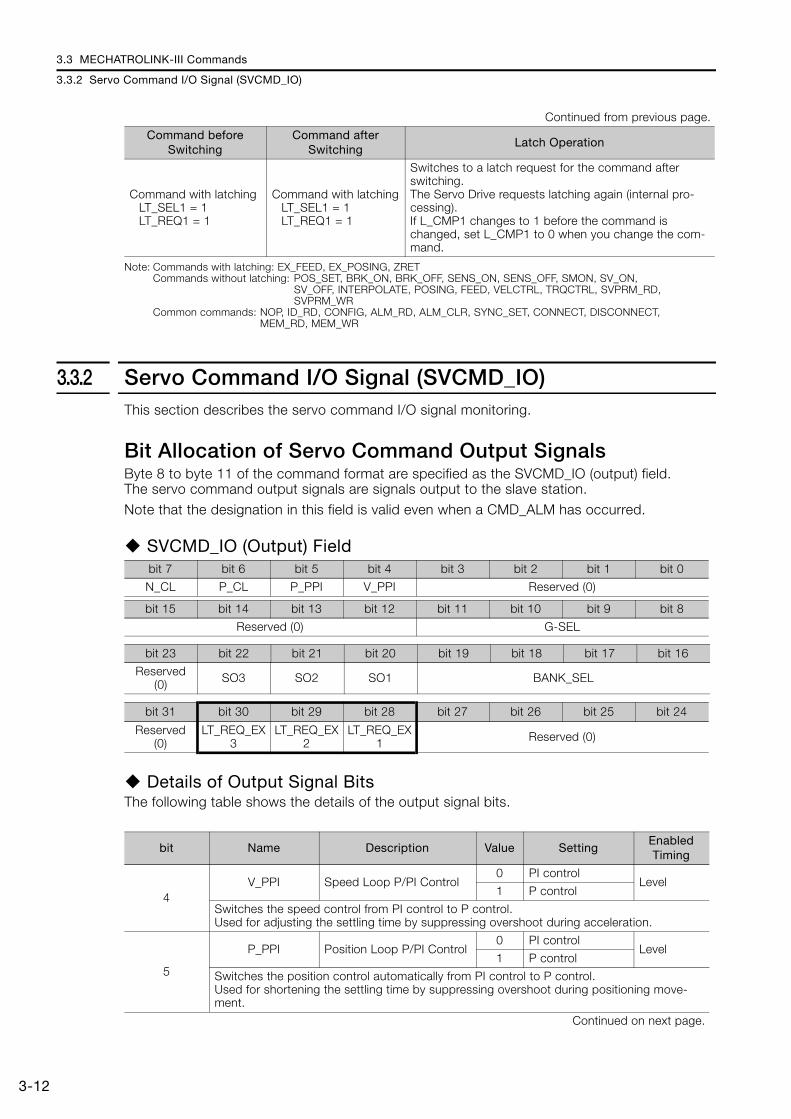
3.3 MECHATROLINK-III Commands
3.3.2 Servo Command I/O Signal (SVCMD_IO)
3-12
Note: Commands with latching: EX_FEED, EX_POSING, ZRETCommands without latching: POS_SET, BRK_ON, BRK_OFF, SENS_ON, SENS_OFF, SMON, SV_ON,
SV_OFF, INTERPOLATE, POSING, FEED, VELCTRL, TRQCTRL, SVPRM_RD, SVPRM_WR
Common commands: NOP, ID_RD, CONFIG, ALM_RD, ALM_CLR, SYNC_SET, CONNECT, DISCONNECT, MEM_RD, MEM_WR
3.3.2 Servo Command I/O Signal (SVCMD_IO)This section describes the servo command I/O signal monitoring.
Bit Allocation of Servo Command Output SignalsByte 8 to byte 11 of the command format are specified as the SVCMD_IO (output) field.The servo command output signals are signals output to the slave station.Note that the designation in this field is valid even when a CMD_ALM has occurred.
SVCMD_IO (Output) Field
Details of Output Signal BitsThe following table shows the details of the output signal bits.
Command with latchingLT_SEL1 = 1LT_REQ1 = 1
Command with latchingLT_SEL1 = 1LT_REQ1 = 1
Switches to a latch request for the command after switching.The Servo Drive requests latching again (internal pro-cessing).If L_CMP1 changes to 1 before the command is changed, set L_CMP1 to 0 when you change the com-mand.
Continued from previous page.
Command before Switching
Command after Switching
Latch Operation
bit 7 bit 6 bit 5 bit 4 bit 3 bit 2 bit 1 bit 0
N_CL P_CL P_PPI V_PPI Reserved (0)
bit 15 bit 14 bit 13 bit 12 bit 11 bit 10 bit 9 bit 8
Reserved (0) G-SEL
bit 23 bit 22 bit 21 bit 20 bit 19 bit 18 bit 17 bit 16
Reserved (0) SO3 SO2 SO1 BANK_SEL
bit 31 bit 30 bit 29 bit 28 bit 27 bit 26 bit 25 bit 24
Reserved (0)
LT_REQ_EX3
LT_REQ_EX2
LT_REQ_EX1 Reserved (0)
bit Name Description Value SettingEnabled Timing
4V_PPI Speed Loop P/PI Control
0 PI controlLevel
1 P control
Switches the speed control from PI control to P control.Used for adjusting the settling time by suppressing overshoot during acceleration.
5
P_PPI Position Loop P/PI Control0 PI control
Level1 P control
Switches the position control automatically from PI control to P control.Used for shortening the settling time by suppressing overshoot during positioning move-ment.
Continued on next page.
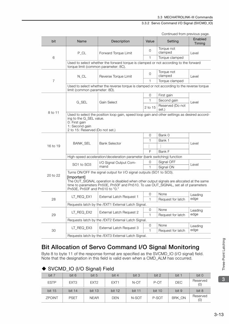
3.3 MECHATROLINK-III Commands
3.3.2 Servo Command I/O Signal (SVCMD_IO)
3-13
3
Thre
e-P
oint
Lat
chin
g
Bit Allocation of Servo Command I/O Signal MonitoringByte 8 to byte 11 of the response format are specified as the SVCMD_IO (I/O signal) field.Note that the designation in this field is valid even when a CMD_ALM has occurred.
SVCMD_IO (I/O Signal) Field
6P_CL Forward Torque Limit
0 Torque not clamped Level
1 Torque clamped
Used to select whether the forward torque is clamped or not according to the forward torque limit (common parameter: 8C).
7N_CL Reverse Torque Limit
0 Torque not clamped Level
1 Torque clamped
Used to select whether the reverse torque is clamped or not according to the reverse torque limit (common parameter: 8D).
8 to 11
G_SEL Gain Select
0 First gain
Level1 Second gain
2 to 15 Reserved (Do not set.)
Used to select the position loop gain, speed loop gain and other settings as desired accord-ing to the G_SEL value.0: First gain1: Second gain2 to 15: Reserved (Do not set.)
16 to 19BANK_SEL Bank Selector
0 Bank 0
Level1 Bank 1
F Bank F
High-speed acceleration/deceleration parameter (bank switching) function
20 to 22
SO1 to SO3 I/O Signal Output Com-mand
0 Signal OFFLevel
1 Signal ON
Turns ON/OFF the signal output for I/O signal outputs (SO1 to SO3).[Important]The OUT_SIGNAL operation is disabled when other output signals are allocated at the same time to parameters Pn50E, Pn50F and Pn510. To use OUT_SIGNAL, set all of parameters Pn50E, Pn50F and Pn510 to "0."
28LT_REQ_EX1 External Latch Request 1
0 None Leading edge1 Request for latch
Requests latch by the /EXT1 External Latch Signal.
29LT_REQ_EX2 External Latch Request 2
0 None Leading edge1 Request for latch
Requests latch by the /EXT2 External Latch Signal.
30LT_REQ_EX3 External Latch Request 3
0 None Leading edge1 Request for latch
Requests latch by the /EXT3 External Latch Signal.
bit 7 bit 6 bit 5 bit 4 bit 3 bit 2 bit 1 bit 0
ESTP EXT3 EXT2 EXT1 N-OT P-OT DEC Reserved (0)
bit 15 bit 14 bit 13 bit 12 bit 11 bit 10 bit 9 bit 8
ZPOINT PSET NEAR DEN N-SOT P-SOT BRK_ON Reserved (0)
Continued from previous page.
bit Name Description Value SettingEnabled Timing
… …
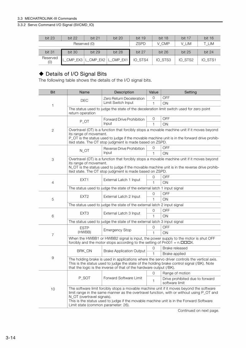
3.3 MECHATROLINK-III Commands
3.3.2 Servo Command I/O Signal (SVCMD_IO)
3-14
Details of I/O Signal BitsThe following table shows the details of the I/O signal bits.
bit 23 bit 22 bit 21 bit 20 bit 19 bit 18 bit 17 bit 16
Reserved (0) ZSPD V_CMP V_LIM T_LIM
bit 31 bit 30 bit 29 bit 28 bit 27 bit 26 bit 25 bit 24
Reserved (0) L_CMP_EX3 L_CMP_EX2 L_CMP_EX1 IO_STS4 IO_STS3 IO_STS2 IO_STS1
Bit Name Description Value Setting
1DEC Zero Return Deceleration
Limit Switch Input0 OFF
1 ON
The status used to judge the state of the deceleration limit switch used for zero point return operation
2
P_OT Forward Drive Prohibition Input
0 OFF
1 ON
Overtravel (OT) is a function that forcibly stops a movable machine unit if it moves beyond its range of movement.P_OT is the status used to judge if the movable machine unit is in the forward drive prohib-ited state. The OT stop judgment is made based on ZSPD.
3
N_OT Reverse Drive Prohibition Input
0 OFF
1 ON
Overtravel (OT) is a function that forcibly stops a movable machine unit if it moves beyond its range of movement.N_OT is the status used to judge if the movable machine unit is in the reverse drive prohib-ited state. The OT stop judgment is made based on ZSPD.
4EXT1 External Latch 1 Input
0 OFF
1 ON
The status used to judge the state of the external latch 1 input signal
5EXT2 External Latch 2 Input
0 OFF
1 ON
The status used to judge the state of the external latch 2 input signal
6EXT3 External Latch 3 Input
0 OFF
1 ON
The status used to judge the state of the external latch 3 input signal
7
ESTP(HWBB) Emergency Stop
0 OFF
1 ON
When the HWBB1 or HWBB2 signal is input, the power supply to the motor is shut OFF forcibly and the motor stops according to the setting of Pn001 = n.X.
9
BRK_ON Brake Application Output0 Brake released
1 Brake applied
The holding brake is used in applications where the servo driver controls the vertical axis.This is the status used to judge the state of the holding brake control signal (/BK). Note that the logic is the inverse of that of the hardware output (/BK).
10
P_SOT Forward Software Limit0 Range of motion
1 Drive prohibited due to forward software limit
The software limit forcibly stops a movable machine unit if it moves beyond the software limit range in the same manner as the overtravel function, with or without using P_OT and N_OT (overtravel signals). This is the status used to judge if the movable machine unit is in the Forward Software Limit state (common parameter: 26).
Continued on next page.

3.3 MECHATROLINK-III Commands
3.3.2 Servo Command I/O Signal (SVCMD_IO)
3-15
3
Thre
e-P
oint
Lat
chin
g
11
N_SOT Reverse Software Limit0 Range of motion
1 Drive prohibited due to reverse software limit
The software limit forcibly stops a movable machine unit if it moves beyond the software limit range in the same manner as the overtravel function, with or without using P_OT and N_OT (overtravel signals). This is the status used to judge if the movable machine unit is in the Reverse Software Limit state (common parameter: 28).
12DEN Distribution Completed
(Position Control Mode)0 During distribution
1 Distribution completed
The status used to judge if the position reference from the servo drive has been completedThis bit is valid only in the position control mode.
13
NEAR Near Position(Position Control Mode)
0 Outside the near-position range
1 Within the near-position range
The status used to judge if the current position is within the range of the NEAR Signal Width (common parameter: 67)This bit is valid only in position control mode.
14
PSET Positioning Completed(Position Control Mode)
0 Outside the positioning comple-tion range
1 Within the positioning completion range
The status used to judge if the current position is within the range of the Positioning Com-pleted Width (common parameter: 66)This bit is valid only in the position control mode.Refer to the following manual for details.
Σ-7-Series MECHATROLINK-III Communications Standard Servo Profile Command Manual (Manual No.: SIEP S800001 31)
15ZPOINT Zero Point
0 Outside the zero point position range
1 Within the zero point position range
The status used to judge if the current position is within the range of the Origin Detection Range (common parameter: 8B)
16T_LIM Torque Limit
0 Not in the torque limited state
1 In the torque limited state
The status used to judge if the torque is clamped at the Forward Toque Limit or the Reverse Toque (force) Limit
17
V_LIM Speed Limit(Torque Control Mode)
0 Speed limit not detected
1 Speed limit detected
The status used to judge if the speed is clamped at the limit value specified in the com-mand or parameterThis bit is valid only in the torque control mode.
18
V_CMP Speed Match(Speed Control Mode)
0 Speed not matched
1 Speed match
The status used to judge if the speed is within the Speed Match Signal Detection Range (common parameter: 8F)This bit is valid only in the speed control mode.
19ZSPD Zero Speed
0 Zero speed not detected
1 Zero speed detected
The status used to judge if the current speed is within the Zero Speed Detection Range (common parameter: 8E)
24 to 27
IO_STS1 to IO_STS8 I/O Signal Monitor
0 Signal OFF
1 Signal ON
The status used to indicate the I/O signal state of CN1Allocate the input signals using parameters Pn860 to Pn866, Pn868, and Pn869.
Continued on next page.
Continued from previous page.
Bit Name Description Value Setting

3.3 MECHATROLINK-III Commands
3.3.2 Servo Command I/O Signal (SVCMD_IO)
3-16
28L_CMP_EX1 External Latch Comple-
tion 10 Latch not completed
1 Latch completed
The status used to judge if latching for LT_REQ_EX1 has been completedL_CMP_EX1 will remain at 1 until LT_REQ_EX1 changes to 0.
29L_CMP_EX2 External Latch Comple-
tion 20 Latch not completed
1 Latch completed
The status used to judge if latching for LT_REQ_EX2 has been completedL_CMP_EX2 will remain at 1 until LT_REQ_EX2 changes to 0.
30L_CMP_EX3 External Latch Comple-
tion 30 Latch not completed
1 Latch completed
The status used to judge if latching for LT_REQ_EX3 has been completedL_CMP_EX3 will remain at 1 until LT_REQ_EX3 changes to 0.
Continued from previous page.
Bit Name Description Value Setting
This chapter provides information on the meaning of, causes of, and corrections for alarms and warnings.
4.1 Alarm Displays . . . . . . . . . . . . . . . . . . . . . . 4-24.1.1 List of Alarms . . . . . . . . . . . . . . . . . . . . . . . . . . . 4-24.1.2 Troubleshooting Alarms . . . . . . . . . . . . . . . . . . . . 4-8
4.2 Warning Displays . . . . . . . . . . . . . . . . . . . . 4-404.2.1 List of Warnings . . . . . . . . . . . . . . . . . . . . . . . . 4-404.2.2 Troubleshooting Warnings . . . . . . . . . . . . . . . . . 4-42
4.3 Troubleshooting Based on the Operation and Conditions of the Servomotor . . 4-49
Maintenance 4
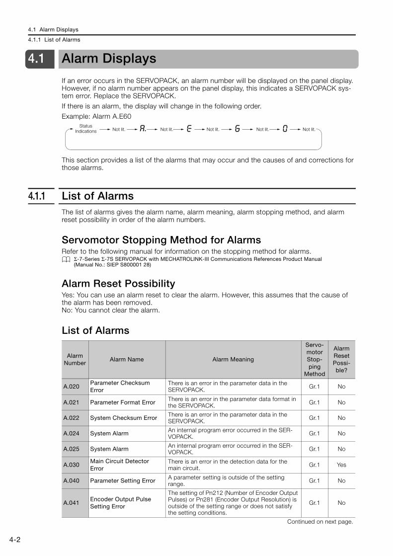
4.1 Alarm Displays
4.1.1 List of Alarms
4-2
4.1 Alarm Displays
If an error occurs in the SERVOPACK, an alarm number will be displayed on the panel display. However, if no alarm number appears on the panel display, this indicates a SERVOPACK sys-tem error. Replace the SERVOPACK.
If there is an alarm, the display will change in the following order.Example: Alarm A.E60
This section provides a list of the alarms that may occur and the causes of and corrections for those alarms.
4.1.1 List of AlarmsThe list of alarms gives the alarm name, alarm meaning, alarm stopping method, and alarm reset possibility in order of the alarm numbers.
Servomotor Stopping Method for AlarmsRefer to the following manual for information on the stopping method for alarms.
Σ-7-Series Σ-7S SERVOPACK with MECHATROLINK-III Communications References Product Manual (Manual No.: SIEP S800001 28)
Alarm Reset PossibilityYes: You can use an alarm reset to clear the alarm. However, this assumes that the cause of the alarm has been removed.No: You cannot clear the alarm.
List of Alarms
Status Indications Not lit. Not lit. Not lit. Not lit. Not lit.
Alarm Number
Alarm Name Alarm Meaning
Servo-motor Stop-ping
Method
Alarm Reset Possi-ble?
A.020Parameter Checksum Error
There is an error in the parameter data in the SERVOPACK. Gr.1 No
A.021 Parameter Format Error There is an error in the parameter data format in the SERVOPACK. Gr.1 No
A.022 System Checksum Error There is an error in the parameter data in the SERVOPACK. Gr.1 No
A.024 System Alarm An internal program error occurred in the SER-VOPACK. Gr.1 No
A.025 System Alarm An internal program error occurred in the SER-VOPACK. Gr.1 No
A.030Main Circuit Detector Error
There is an error in the detection data for the main circuit. Gr.1 Yes
A.040 Parameter Setting Error A parameter setting is outside of the setting range. Gr.1 No
A.041Encoder Output Pulse Setting Error
The setting of Pn212 (Number of Encoder Output Pulses) or Pn281 (Encoder Output Resolution) is outside of the setting range or does not satisfy the setting conditions.
Gr.1 No
Continued on next page.

4.1 Alarm Displays
4.1.1 List of Alarms
4-3
4
Mai
nten
ance
A.042Parameter Combination Error
The combination of some parameters exceeds the setting range. Gr.1 No
A.044Semi-Closed/Fully-Closed Loop Control Parameter Setting Error
The settings of the Option Module and Pn002 = n.X (External Encoder Usage) do not match.
Gr.1 No
A.04A Parameter Setting Error 2 There is an error in the bank members or bank data settings. Gr.1 No
A.050 Combination Error The capacities of the SERVOPACK and Servomo-tor do not match. Gr.1 Yes
A.051Unsupported Device Alarm
An unsupported device was connected. Gr.1 No
A.070Motor Type Change Detected
The connected motor is a different type of motor from the previously connected motor. Gr.1 No
A.080Linear Encoder Pitch Setting Error
The setting of Pn282 (Linear Encoder Scale Pitch) has not been changed from the default setting. Gr.1 No
A.0b0Invalid Servo ON Com-mand Alarm
The SV_ON (Servo ON) command was sent from the host controller after a utility function that turns ON the Servomotor was executed.
Gr.1 Yes
A.100 Overcurrent Detected An overcurrent flowed through the power transis-tor or the heat sink overheated. Gr.1 No
A.101Motor Overcurrent Detected
The current to the motor exceeded the allowable current. Gr.1 No
A.300 Regeneration Error There is an error related to regeneration. Gr.1 Yes
A.320 Regenerative Overload A regenerative overload occurred. Gr.2 Yes
A.330Main Circuit Power Supply Wiring Error
• The AC power supply input setting or DC power supply input setting is not correct.
• The power supply wiring is not correct.Gr.1 Yes
A.400 Overvoltage The main circuit DC voltage is too high. Gr.1 Yes
A.410 Undervoltage The main circuit DC voltage is too low. Gr.2 Yes
A.510 Overspeed The motor exceeded the maximum speed. Gr.1 Yes
A.511Encoder Output Pulse Overspeed
• The pulse output speed for the setting of Pn212 (Number of Encoder Output Pulses) was exceeded. (This applies to Rotary Servomo-tors.)
• The motor speed upper limit for the setting of Pn281 (Encoder Output Resolution) was exceeded. (This applies to Linear Servomotors.)
Gr.1 Yes
A.520 Vibration Alarm Abnormal oscillation was detected in the motor speed. Gr.1 Yes
A.521 Autotuning Alarm Vibration was detected during autotuning for the tuning-less function. Gr.1 Yes
A.550Maximum Speed Setting Error
The setting of Pn385 (Maximum Motor Speed) is greater than the maximum motor speed. Gr.1 Yes
A.710 Instantaneous OverloadThe Servomotor was operating for several sec-onds to several tens of seconds under a torque that largely exceeded the rating.
Gr.2 Yes
A.720 Continuous Overload The Servomotor was operating continuously under a torque that exceeded the rating. Gr.1 Yes
A.730Dynamic Brake Overload
When the dynamic brake was applied, the rota-tional or linear kinetic energy exceeded the capacity of the dynamic brake resistor.
Gr.1 YesA.731
A.740Inrush Current Limiting Resistor Overload
The main circuit power supply was frequently turned ON and OFF. Gr.1 Yes
Continued on next page.
Continued from previous page.
Alarm Number
Alarm Name Alarm Meaning
Servo-motor Stop-ping
Method
Alarm Reset Possi-ble?

4.1 Alarm Displays
4.1.1 List of Alarms
4-4
A.7A1Internal Temperature Error 1 (Control Board Tempera-ture Error)
The surrounding temperature of the control PCB is abnormal. Gr.2 Yes
A.7A2Internal Temperature Error 2 (Power Board Tempera-ture Error)
The surrounding temperature of the power PCB is abnormal. Gr.2 Yes
A.7A3Internal Temperature Sen-sor Error
An error occurred in the temperature sensor cir-cuit. Gr.2 No
A.7AbSERVOPACK Built-in Fan Stopped
The fan inside the SERVOPACK stopped. Gr.1 Yes
A.810 Encoder Backup Alarm The power supplies to the encoder all failed and the position data was lost. Gr.1 No
A.820 Encoder Checksum Alarm There is an error in the checksum results for encoder memory. Gr.1 No
A.830 Encoder Battery AlarmThe battery voltage was lower than the specified level after the control power supply was turned ON.
Gr.1 Yes
A.840 Encoder Data Alarm There is an internal data error in the encoder. Gr.1 No
A.850 Encoder Overspeed The encoder was operating at high speed when the power was turned ON. Gr.1 No
A.860 Encoder Overheated The internal temperature of encoder is too high. Gr.1 No
A.861 Motor Overheated The internal temperature of motor is too high. Gr.1 No
A.862 Overheat AlarmThe input voltage (temperature) for the overheat protection input (TH) signal exceeded the setting of Pn61B (Overheat Alarm Level).
Gr.1 Yes
A.890 Encoder Scale Error A failure occurred in the linear encoder. Gr.1 No
A.891 Encoder Module Error An error occurred in the linear encoder. Gr.1 No
A.8A0 External Encoder Error An error occurred in the external encoder. Gr.1 Yes
A.8A1External Encoder Module Error
An error occurred in the Serial Converter Unit. Gr.1 Yes
A.8A2External Incremental Encoder Sensor Error
An error occurred in the external encoder. Gr.1 Yes
A.8A3External Absolute Encoder Position Error
An error occurred in the position data of the external encoder. Gr.1 Yes
A.8A5External Encoder Over-speed
An overspeed error occurred in the external encoder. Gr.1 Yes
A.8A6External Encoder Over-heated
An overheating error occurred in the external encoder. Gr.1 Yes
A.b33 Current Detection Error 3 An error occurred in the current detection circuit. Gr.1 No
A.b6AMECHATROLINK Commu-nications ASIC Error 1
ASIC error 1 occurred in MECHATROLINK com-munications. Gr.1 No
A.b6bMECHATROLINK Commu-nications ASIC Error 2
ASIC error 2 occurred in MECHATROLINK com-munications. Gr.2 No
A.bF0 System Alarm 0 Internal program error 0 occurred in the SERVO-PACK. Gr.1 No
A.bF1 System Alarm 1 Internal program error 1 occurred in the SERVO-PACK. Gr.1 No
A.bF2 System Alarm 2 Internal program error 2 occurred in the SERVO-PACK. Gr.1 No
A.bF3 System Alarm 3 Internal program error 3 occurred in the SERVO-PACK. Gr.1 No
Continued on next page.
Continued from previous page.
Alarm Number
Alarm Name Alarm Meaning
Servo-motor Stop-ping
Method
Alarm Reset Possi-ble?
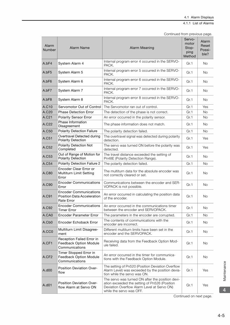
4.1 Alarm Displays
4.1.1 List of Alarms
4-5
4
Mai
nten
ance
A.bF4 System Alarm 4 Internal program error 4 occurred in the SERVO-PACK. Gr.1 No
A.bF5 System Alarm 5 Internal program error 5 occurred in the SERVO-PACK. Gr.1 No
A.bF6 System Alarm 6 Internal program error 6 occurred in the SERVO-PACK. Gr.1 No
A.bF7 System Alarm 7 Internal program error 7 occurred in the SERVO-PACK. Gr.1 No
A.bF8 System Alarm 8 Internal program error 8 occurred in the SERVO-PACK. Gr.1 No
A.C10 Servomotor Out of Control The Servomotor ran out of control. Gr.1 Yes
A.C20 Phase Detection Error The detection of the phase is not correct. Gr.1 No
A.C21 Polarity Sensor Error An error occurred in the polarity sensor. Gr.1 No
A.C22Phase Information Disagreement The phase information does not match. Gr.1 No
A.C50 Polarity Detection Failure The polarity detection failed. Gr.1 No
A.C51Overtravel Detected during Polarity Detection
The overtravel signal was detected during polarity detection. Gr.1 Yes
A.C52Polarity Detection Not Completed
The servo was turned ON before the polarity was detected. Gr.1 Yes
A.C53Out of Range of Motion for Polarity Detection
The travel distance exceeded the setting of Pn48E (Polarity Detection Range). Gr.1 No
A.C54 Polarity Detection Failure 2 The polarity detection failed. Gr.1 No
A.C80Encoder Clear Error or Multiturn Limit Setting Error
The multiturn data for the absolute encoder was not correctly cleared or set. Gr.1 No
A.C90Encoder Communications Error
Communications between the encoder and SER-VOPACK is not possible. Gr.1 No
A.C91Encoder Communications Position Data Acceleration Rate Error
An error occurred in calculating the position data of the encoder. Gr.1 No
A.C92Encoder Communications Timer Error
An error occurred in the communications timer between the encoder and SERVOPACK. Gr.1 No
A.CA0 Encoder Parameter Error The parameters in the encoder are corrupted. Gr.1 No
A.Cb0 Encoder Echoback Error The contents of communications with the encoder are incorrect. Gr.1 No
A.CC0Multiturn Limit Disagree-ment
Different multiturn limits have been set in the encoder and the SERVOPACK. Gr.1 No
A.CF1Reception Failed Error in Feedback Option Module Communications
Receiving data from the Feedback Option Mod-ule failed. Gr.1 No
A.CF2Timer Stopped Error in Feedback Option Module Communications
An error occurred in the timer for communica-tions with the Feedback Option Module. Gr.1 No
A.d00Position Deviation Over-flow
The setting of Pn520 (Position Deviation Overflow Alarm Level) was exceeded by the position devia-tion while the servo was ON.
Gr.1 Yes
A.d01Position Deviation Over-flow Alarm at Servo ON
The servo was turned ON after the position devi-ation exceeded the setting of Pn526 (Position Deviation Overflow Alarm Level at Servo ON) while the servo was OFF.
Gr.1 Yes
Continued on next page.
Continued from previous page.
Alarm Number
Alarm Name Alarm Meaning
Servo-motor Stop-ping
Method
Alarm Reset Possi-ble?
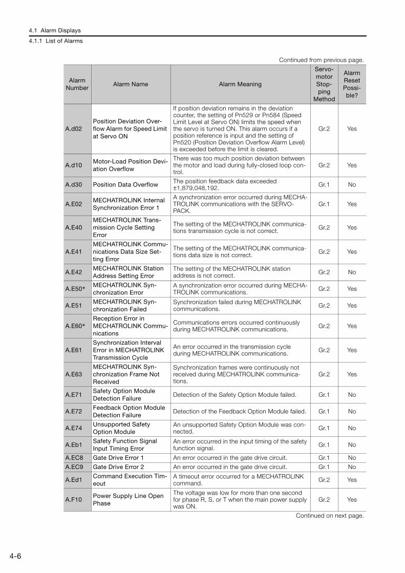
4.1 Alarm Displays
4.1.1 List of Alarms
4-6
A.d02Position Deviation Over-flow Alarm for Speed Limit at Servo ON
If position deviation remains in the deviation counter, the setting of Pn529 or Pn584 (Speed Limit Level at Servo ON) limits the speed when the servo is turned ON. This alarm occurs if a position reference is input and the setting of Pn520 (Position Deviation Overflow Alarm Level) is exceeded before the limit is cleared.
Gr.2 Yes
A.d10Motor-Load Position Devi-ation Overflow
There was too much position deviation between the motor and load during fully-closed loop con-trol.
Gr.2 Yes
A.d30 Position Data Overflow The position feedback data exceeded ±1,879,048,192. Gr.1 No
A.E02MECHATROLINK Internal Synchronization Error 1
A synchronization error occurred during MECHA-TROLINK communications with the SERVO-PACK.
Gr.1 Yes
A.E40MECHATROLINK Trans-mission Cycle Setting Error
The setting of the MECHATROLINK communica-tions transmission cycle is not correct. Gr.2 Yes
A.E41MECHATROLINK Commu-nications Data Size Set-ting Error
The setting of the MECHATROLINK communica-tions data size is not correct. Gr.2 Yes
A.E42MECHATROLINK Station Address Setting Error
The setting of the MECHATROLINK station address is not correct. Gr.2 No
A.E50* MECHATROLINK Syn-chronization Error
A synchronization error occurred during MECHA-TROLINK communications. Gr.2 Yes
A.E51MECHATROLINK Syn-chronization Failed
Synchronization failed during MECHATROLINK communications. Gr.2 Yes
A.E60*Reception Error in MECHATROLINK Commu-nications
Communications errors occurred continuously during MECHATROLINK communications. Gr.2 Yes
A.E61Synchronization Interval Error in MECHATROLINK Transmission Cycle
An error occurred in the transmission cycle during MECHATROLINK communications. Gr.2 Yes
A.E63MECHATROLINK Syn-chronization Frame Not Received
Synchronization frames were continuously not received during MECHATROLINK communica-tions.
Gr.2 Yes
A.E71Safety Option Module Detection Failure
Detection of the Safety Option Module failed. Gr.1 No
A.E72Feedback Option Module Detection Failure
Detection of the Feedback Option Module failed. Gr.1 No
A.E74Unsupported Safety Option Module
An unsupported Safety Option Module was con-nected. Gr.1 No
A.Eb1Safety Function Signal Input Timing Error
An error occurred in the input timing of the safety function signal. Gr.1 No
A.EC8 Gate Drive Error 1 An error occurred in the gate drive circuit. Gr.1 No
A.EC9 Gate Drive Error 2 An error occurred in the gate drive circuit. Gr.1 No
A.Ed1Command Execution Tim-eout
A timeout error occurred for a MECHATROLINK command. Gr.2 Yes
A.F10Power Supply Line Open Phase
The voltage was low for more than one second for phase R, S, or T when the main power supply was ON.
Gr.2 Yes
Continued on next page.
Continued from previous page.
Alarm Number
Alarm Name Alarm Meaning
Servo-motor Stop-ping
Method
Alarm Reset Possi-ble?

4.1 Alarm Displays
4.1.1 List of Alarms
4-7
4
Mai
nten
ance
* These alarms are not stored in the alarm history. They are only displayed on the panel display.
Note: The A.Eb0, A.Eb2 to A.Eb9, and A.EC0 to A.EC2 alarms can occur when a Safety Module is connected. Refer to the following manual for details.
AC Servo Drive Σ-V-Series/Σ-V-Series for Large-Capacity Models/Σ-7-Series User’s Manual Safety Module (Manual No.: SIEP C720829 06)
FL-1*
System Alarm An internal program error occurred in the SER-VOPACK. – No
FL-2* FL-3* FL-4* FL-5* FL-6*
CPF00Digital Operator Commu-nications Error 1 Communications were not possible between the
Digital Operator (model: JUSP-OP05A-1-E) and the SERVOPACK (e.g., a CPU error occurred).
– NoCPF01
Digital Operator Commu-nications Error 2
Continued from previous page.
Alarm Number
Alarm Name Alarm Meaning
Servo-motor Stop-ping
Method
Alarm Reset Possi-ble?
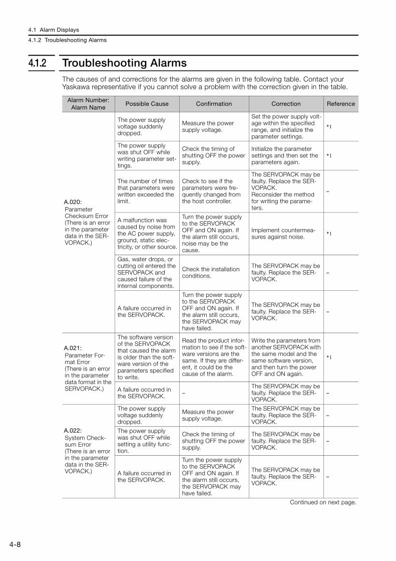
4.1 Alarm Displays
4.1.2 Troubleshooting Alarms
4-8
4.1.2 Troubleshooting AlarmsThe causes of and corrections for the alarms are given in the following table. Contact your Yaskawa representative if you cannot solve a problem with the correction given in the table.
Alarm Number: Alarm Name
Possible Cause Confirmation Correction Reference
A.020: Parameter Checksum Error (There is an error in the parameter data in the SER-VOPACK.)
The power supply voltage suddenly dropped.
Measure the power supply voltage.
Set the power supply volt-age within the specified range, and initialize the parameter settings.
*1
The power supply was shut OFF while writing parameter set-tings.
Check the timing of shutting OFF the power supply.
Initialize the parameter settings and then set the parameters again.
*1
The number of times that parameters were written exceeded the limit.
Check to see if the parameters were fre-quently changed from the host controller.
The SERVOPACK may be faulty. Replace the SER-VOPACK.Reconsider the method for writing the parame-ters.
–
A malfunction was caused by noise from the AC power supply, ground, static elec-tricity, or other source.
Turn the power supply to the SERVOPACK OFF and ON again. If the alarm still occurs, noise may be the cause.
Implement countermea-sures against noise. *1
Gas, water drops, or cutting oil entered the SERVOPACK and caused failure of the internal components.
Check the installation conditions.
The SERVOPACK may be faulty. Replace the SER-VOPACK.
–
A failure occurred in the SERVOPACK.
Turn the power supply to the SERVOPACK OFF and ON again. If the alarm still occurs, the SERVOPACK may have failed.
The SERVOPACK may be faulty. Replace the SER-VOPACK.
–
A.021: Parameter For-mat Error (There is an error in the parameter data format in the SERVOPACK.)
The software version of the SERVOPACK that caused the alarm is older than the soft-ware version of the parameters specified to write.
Read the product infor-mation to see if the soft-ware versions are the same. If they are differ-ent, it could be the cause of the alarm.
Write the parameters from another SERVOPACK with the same model and the same software version, and then turn the power OFF and ON again.
*1
A failure occurred in the SERVOPACK. –
The SERVOPACK may be faulty. Replace the SER-VOPACK.
–
A.022: System Check-sum Error (There is an error in the parameter data in the SER-VOPACK.)
The power supply voltage suddenly dropped.
Measure the power supply voltage.
The SERVOPACK may be faulty. Replace the SER-VOPACK.
–
The power supply was shut OFF while setting a utility func-tion.
Check the timing of shutting OFF the power supply.
The SERVOPACK may be faulty. Replace the SER-VOPACK.
–
A failure occurred in the SERVOPACK.
Turn the power supply to the SERVOPACK OFF and ON again. If the alarm still occurs, the SERVOPACK may have failed.
The SERVOPACK may be faulty. Replace the SER-VOPACK.
–
Continued on next page.
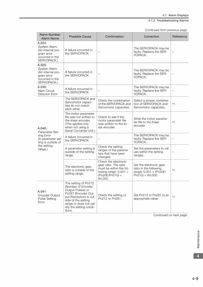
4.1 Alarm Displays
4.1.2 Troubleshooting Alarms
4-9
4
Mai
nten
ance
A.024: System Alarm (An internal pro-gram error occurred in the SERVOPACK.)
A failure occurred in the SERVOPACK. –
The SERVOPACK may be faulty. Replace the SER-VOPACK.
–
A.025: System Alarm (An internal pro-gram error occurred in the SERVOPACK.)
A failure occurred in the SERVOPACK. –
The SERVOPACK may be faulty. Replace the SER-VOPACK.
–
A.030: Main Circuit Detector Error
A failure occurred in the SERVOPACK. –
The SERVOPACK may be faulty. Replace the SER-VOPACK.
–
A.040: Parameter Set-ting Error (A parameter set-ting is outside of the setting range.)
The SERVOPACK and Servomotor capaci-ties do not match each other.
Check the combination of the SERVOPACK and Servomotor capacities.
Select a proper combina-tion of SERVOPACK and Servomotor capacities.
*1
The motor parameter file was not written to the linear encoder. (This applies only when not using a Serial Converter Unit.)
Check to see if the motor parameter file was written to the lin-ear encoder.
Write the motor parame-ter file to the linear encoder.
*1
A failure occurred in the SERVOPACK. –
The SERVOPACK may be faulty. Replace the SER-VOPACK.
–
A parameter setting is outside of the setting range.
Check the setting ranges of the parame-ters that have been changed.
Set the parameters to val-ues within the setting ranges.
–
The electronic gear ratio is outside of the setting range.
Check the electronic gear ratio. The ratio must be within the fol-lowing range: 0.001 < (Pn20E/Pn210) < 64,000.
Set the electronic gear ratio in the following range: 0.001 < (Pn20E/Pn210) < 64,000.
*1
A.041: Encoder Output Pulse Setting Error
The setting of Pn212 (Number of Encoder Output Pulses) or Pn281 (Encoder Out-put Resolution) is out-side of the setting range or does not sat-isfy the setting condi-tions.
Check the setting of Pn212 or Pn281.
Set Pn212 or Pn281 to an appropriate value. *1
Continued on next page.
Continued from previous page.
Alarm Number: Alarm Name
Possible Cause Confirmation Correction Reference

4.1 Alarm Displays
4.1.2 Troubleshooting Alarms
4-10
A.042: Parameter Com-bination Error
The speed of program jogging went below the setting range when the electronic gear ratio (Pn20E/Pn210) or the Servo-motor was changed.
Check to see if the detection conditions*2 are satisfied.
Decrease the setting of the electronic gear ratio (Pn20E/Pn210).
*1
The speed of program jogging went below the setting range when Pn533 or Pn585 (Program Jogging Movement Speed) was changed.
Check to see if the detection conditions*2 are satisfied.
Increase the setting of Pn533 or Pn585. *1
The movement speed of advanced autotun-ing went below the setting range when the electronic gear ratio (Pn20E/ Pn210) or the Servomotor was changed.
Check to see if the detection conditions*3 are satisfied.
Decrease the setting of the electronic gear ratio (Pn20E/Pn210).
*1
A.044: Semi-Closed/Fully-Closed Loop Control Parameter Setting Error
The setting of the Fully-closed Module does not match the setting of Pn002 = n.X (External Encoder Usage).
Check the setting of Pn002 = n.X.
Make sure that the setting of the Fully-closed Mod-ule agrees with the setting of Pn002 = n.X.
*1
A.04A: Parameter Set-ting Error 2
For 4-byte parameter bank members, there are two consecutive members with nothing registered.
–Change the number of bytes for bank members to an appropriate value.
–
The total amount of bank data exceeds 64 (Pn900 × Pn901 > 64).
– Reduce the total amount of bank data to 64 or less. –
A.050: Combination Error (The capacities of the SERVOPACK and Servomotor do not match.)
The SERVOPACK and Servomotor capaci-ties do not match each other.
Confirm that the follow-ing condition is met:1/4 ≤ (Servomotor capacity/SERVOPACK capacity) ≤ 4
Select a proper combina-tion of the SERVOPACK and Servomotor capaci-ties.
*1
A failure occurred in the encoder.
Replace the encoder and check to see if the alarm still occurs.
Replace the Servomotor or encoder. –
A failure occurred in the SERVOPACK. –
The SERVOPACK may be faulty. Replace the SER-VOPACK.
–
A.051: Unsupported Device Alarm
The motor parameter file was not written to the linear encoder. (This applies only when not using a Serial Converter Unit.)
Check to see if the motor parameter file was written to the lin-ear encoder.
Write the motor parame-ter file to the linear encoder.
*1
An unsupported Serial Converter Unit or encoder (e.g., an external encoder) is connected to the SERVOPACK.
Check the product combination specifica-tions.
Change to a correct com-bination of models. –
Continued on next page.
Continued from previous page.
Alarm Number: Alarm Name
Possible Cause Confirmation Correction Reference
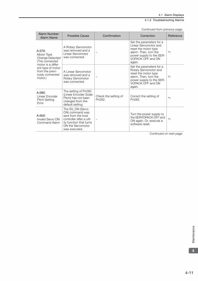
4.1 Alarm Displays
4.1.2 Troubleshooting Alarms
4-11
4
Mai
nten
ance
A.070: Motor Type Change Detected (The connected motor is a differ-ent type of motor from the previ-ously connected motor.)
A Rotary Servomotor was removed and a Linear Servomotor was connected.
–
Set the parameters for a Linear Servomotor and reset the motor type alarm. Then, turn the power supply to the SER-VOPACK OFF and ON again.
*1
A Linear Servomotor was removed and a Rotary Servomotor was connected.
–
Set the parameters for a Rotary Servomotor and reset the motor type alarm. Then, turn the power supply to the SER-VOPACK OFF and ON again.
*1
A.080: Linear Encoder Pitch Setting Error
The setting of Pn282 (Linear Encoder Scale Pitch) has not been changed from the default setting.
Check the setting of Pn282.
Correct the setting of Pn282. *1
A.0b0: Invalid Servo ON Command Alarm
The SV_ON (Servo ON) command was sent from the host controller after a util-ity function that turns ON the Servomotor was executed.
–
Turn the power supply to the SERVOPACK OFF and ON again. Or, execute a software reset.
*1
Continued on next page.
Continued from previous page.
Alarm Number: Alarm Name
Possible Cause Confirmation Correction Reference
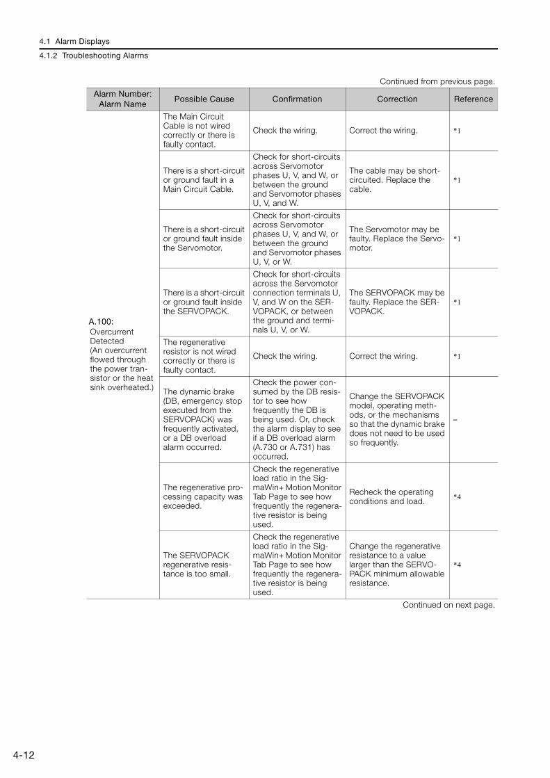
4.1 Alarm Displays
4.1.2 Troubleshooting Alarms
4-12
A.100: Overcurrent Detected (An overcurrent flowed through the power tran-sistor or the heat sink overheated.)
The Main Circuit Cable is not wired correctly or there is faulty contact.
Check the wiring. Correct the wiring. *1
There is a short-circuit or ground fault in a Main Circuit Cable.
Check for short-circuits across Servomotor phases U, V, and W, or between the ground and Servomotor phases U, V, and W.
The cable may be short-circuited. Replace the cable.
*1
There is a short-circuit or ground fault inside the Servomotor.
Check for short-circuits across Servomotor phases U, V, and W, or between the ground and Servomotor phases U, V, or W.
The Servomotor may be faulty. Replace the Servo-motor.
*1
There is a short-circuit or ground fault inside the SERVOPACK.
Check for short-circuits across the Servomotor connection terminals U, V, and W on the SER-VOPACK, or between the ground and termi-nals U, V, or W.
The SERVOPACK may be faulty. Replace the SER-VOPACK.
*1
The regenerative resistor is not wired correctly or there is faulty contact.
Check the wiring. Correct the wiring. *1
The dynamic brake (DB, emergency stop executed from the SERVOPACK) was frequently activated, or a DB overload alarm occurred.
Check the power con-sumed by the DB resis-tor to see how frequently the DB is being used. Or, check the alarm display to see if a DB overload alarm (A.730 or A.731) has occurred.
Change the SERVOPACK model, operating meth-ods, or the mechanisms so that the dynamic brake does not need to be used so frequently.
–
The regenerative pro-cessing capacity was exceeded.
Check the regenerative load ratio in the Sig-maWin+ Motion Monitor Tab Page to see how frequently the regenera-tive resistor is being used.
Recheck the operating conditions and load. *4
The SERVOPACK regenerative resis-tance is too small.
Check the regenerative load ratio in the Sig-maWin+ Motion Monitor Tab Page to see how frequently the regenera-tive resistor is being used.
Change the regenerative resistance to a value larger than the SERVO-PACK minimum allowable resistance.
*4
Continued on next page.
Continued from previous page.
Alarm Number: Alarm Name
Possible Cause Confirmation Correction Reference
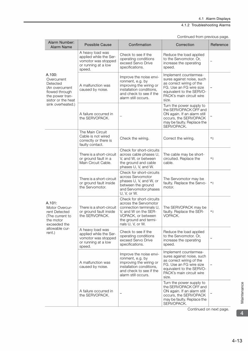
4.1 Alarm Displays
4.1.2 Troubleshooting Alarms
4-13
4
Mai
nten
ance
A.100: Overcurrent Detected (An overcurrent flowed through the power tran-sistor or the heat sink overheated.)
A heavy load was applied while the Ser-vomotor was stopped or running at a low speed.
Check to see if the operating conditions exceed Servo Drive specifications.
Reduce the load applied to the Servomotor. Or, increase the operating speed.
–
A malfunction was caused by noise.
Improve the noise envi-ronment, e.g. by improving the wiring or installation conditions, and check to see if the alarm still occurs.
Implement countermea-sures against noise, such as correct wiring of the FG. Use an FG wire size equivalent to the SERVO-PACK’s main circuit wire size.
–
A failure occurred in the SERVOPACK. –
Turn the power supply to the SERVOPACK OFF and ON again. If an alarm still occurs, the SERVOPACK may be faulty. Replace the SERVOPACK.
–
A.101: Motor Overcur-rent Detected (The current to the motor exceeded the allowable cur-rent.)
The Main Circuit Cable is not wired correctly or there is faulty contact.
Check the wiring. Correct the wiring. *1
There is a short-circuit or ground fault in a Main Circuit Cable.
Check for short-circuits across cable phases U, V, and W, or between the ground and cable phases U, V, and W.
The cable may be short-circuited. Replace the cable.
*1
There is a short-circuit or ground fault inside the Servomotor.
Check for short-circuits across Servomotor phases U, V, and W, or between the ground and Servomotor phases U, V, or W.
The Servomotor may be faulty. Replace the Servo-motor.
*1
There is a short-circuit or ground fault inside the SERVOPACK.
Check for short-circuits across the Servomotor connection terminals U, V, and W on the SER-VOPACK, or between the ground and termi-nals U, V, or W.
The SERVOPACK may be faulty. Replace the SER-VOPACK.
*1
A heavy load was applied while the Ser-vomotor was stopped or running at a low speed.
Check to see if the operating conditions exceed Servo Drive specifications.
Reduce the load applied to the Servomotor. Or, increase the operating speed.
–
A malfunction was caused by noise.
Improve the noise envi-ronment, e.g. by improving the wiring or installation conditions, and check to see if the alarm still occurs.
Implement countermea-sures against noise, such as correct wiring of the FG. Use an FG wire size equivalent to the SERVO-PACK’s main circuit wire size.
–
A failure occurred in the SERVOPACK. –
Turn the power supply to the SERVOPACK OFF and ON again. If an alarm still occurs, the SERVOPACK may be faulty. Replace the SERVOPACK.
–
Continued on next page.
Continued from previous page.
Alarm Number: Alarm Name
Possible Cause Confirmation Correction Reference

4.1 Alarm Displays
4.1.2 Troubleshooting Alarms
4-14
A.300: Regeneration Error
When using the built-in regenerative resis-tor, the jumper between the regener-ative resistor terminals (B2 and B3) was removed from one of the following SERVO-PACKs: SGD7S-3R8A, -5R5A, -7R6A, -120A, -180A, -200A, or -330A.
Check to see if the jumper is connected between power supply terminals B2 and B3.*5
Correctly connect a jumper. *1
The External Regener-ative Resistor or Regenerative Resis-tor Unit is not wired correctly, or was removed or discon-nected.
Check the wiring of the External Regenerative Resistor or Regenera-tive Resistor Unit.*5
Correct the wiring of the External Regenerative Resistor or Regenerative Resistor Unit.
*1
Pn600 (Regenerative Resistor Capacity) is not set to 0 and an External Regenerative Resistor is not con-nected to one of the following SERVO-PACKs: SGD7S-R70A, -R90A,-1R6A, -2R8A, -R70F, -R90F, -2R1F, or -2R8F.
Check to see if an External Regenerative Resistor is connected and check the setting of Pn600.
Connect an External Regenerative Resistor, or set Pn600 (Regenerative Resistor Capacity) to 0 (setting unit: ×10 W) if no Regenerative Resistor is required.
*1
An External Regener-ative Resistor is not connected to one of the following SERVO-PACKs: SGD7S-470A, -550A, -590A, or -780A.
Check to see if an External Regenerative Resistor or a Regenera-tive Resistor Unit is con-nected and check the setting of Pn600.
Connect an External Regenerative Resistor and set Pn600 to an appropri-ate value, or connect a Regenerative Resistor Unit and set Pn600 to 0.
*1
A failure occurred in the SERVOPACK. –
While the main circuit power supply is OFF, turn the control power supply to the SERVOPACK OFF and ON again. If the alarm still occurs, the SERVO-PACK may be faulty. Replace the SERVO-PACK.
–
Continued on next page.
Continued from previous page.
Alarm Number: Alarm Name
Possible Cause Confirmation Correction Reference
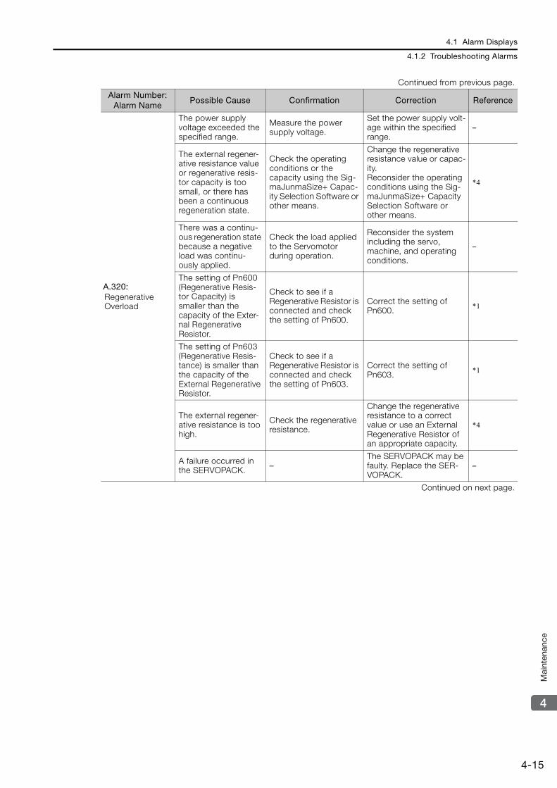
4.1 Alarm Displays
4.1.2 Troubleshooting Alarms
4-15
4
Mai
nten
ance
A.320: Regenerative Overload
The power supply voltage exceeded the specified range.
Measure the power supply voltage.
Set the power supply volt-age within the specified range.
–
The external regener-ative resistance value or regenerative resis-tor capacity is too small, or there has been a continuous regeneration state.
Check the operating conditions or the capacity using the Sig-maJunmaSize+ Capac-ity Selection Software or other means.
Change the regenerative resistance value or capac-ity.Reconsider the operating conditions using the Sig-maJunmaSize+ Capacity Selection Software or other means.
*4
There was a continu-ous regeneration state because a negative load was continu-ously applied.
Check the load applied to the Servomotor during operation.
Reconsider the system including the servo, machine, and operating conditions.
–
The setting of Pn600 (Regenerative Resis-tor Capacity) is smaller than the capacity of the Exter-nal Regenerative Resistor.
Check to see if a Regenerative Resistor is connected and check the setting of Pn600.
Correct the setting of Pn600. *1
The setting of Pn603 (Regenerative Resis-tance) is smaller than the capacity of the External Regenerative Resistor.
Check to see if a Regenerative Resistor is connected and check the setting of Pn603.
Correct the setting of Pn603. *1
The external regener-ative resistance is too high.
Check the regenerative resistance.
Change the regenerative resistance to a correct value or use an External Regenerative Resistor of an appropriate capacity.
*4
A failure occurred in the SERVOPACK. –
The SERVOPACK may be faulty. Replace the SER-VOPACK.
–
Continued on next page.
Continued from previous page.
Alarm Number: Alarm Name
Possible Cause Confirmation Correction Reference
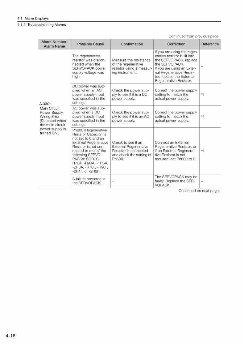
4.1 Alarm Displays
4.1.2 Troubleshooting Alarms
4-16
A.330: Main Circuit Power Supply Wiring Error (Detected when the main circuit power supply is turned ON.)
The regenerative resistor was discon-nected when the SERVOPACK power supply voltage was high.
Measure the resistance of the regenerative resistor using a measur-ing instrument.
If you are using the regen-erative resistor built into the SERVOPACK, replace the SERVOPACK.If you are using an Exter-nal Regenerative Resis-tor, replace the External Regenerative Resistor.
–
DC power was sup-plied when an AC power supply input was specified in the settings.
Check the power sup-ply to see if it is a DC power supply.
Correct the power supply setting to match the actual power supply.
*1
AC power was sup-plied when a DC power supply input was specified in the settings.
Check the power sup-ply to see if it is an AC power supply.
Correct the power supply setting to match the actual power supply.
*1
Pn600 (Regenerative Resistor Capacity) is not set to 0 and an External Regenerative Resistor is not con-nected to one of the following SERVO-PACKs: SGD7S-R70A, -R90A, -1R6A, -2R8A, -R70F, -R90F, -2R1F, or -2R8F.
Check to see if an External Regenerative Resistor is connected and check the setting of Pn600.
Connect an External Regenerative Resistor, or if an External Regenera-tive Resistor is not required, set Pn600 to 0.
*1
A failure occurred in the SERVOPACK. –
The SERVOPACK may be faulty. Replace the SER-VOPACK.
–
Continued on next page.
Continued from previous page.
Alarm Number: Alarm Name
Possible Cause Confirmation Correction Reference

4.1 Alarm Displays
4.1.2 Troubleshooting Alarms
4-17
4
Mai
nten
ance
A.400: Overvoltage (Detected in the main circuit power supply section of the SERVOPACK.)
The power supply voltage exceeded the specified range.
Measure the power supply voltage.
Set the AC/DC power supply voltage within the specified range.
–
The power supply is not stable or was influenced by a light-ning surge.
Measure the power supply voltage.
Improve the power sup-ply conditions, install a surge absorber, and then turn the power supply OFF and ON again. If an alarm still occurs, the SERVOPACK may be faulty. Replace the SER-VOPACK.
–
The voltage for AC power supply was too high during accelera-tion or deceleration.
Check the power sup-ply voltage and the speed and torque during operation.
Set the AC power supply voltage within the speci-fied range.
–
The external regener-ative resistance is too high for the operating conditions.
Check the operating conditions and the regenerative resistance.
Select a regenerative resistance value that is appropriate for the oper-ating conditions and load.
*4
The moment of inertia ratio or mass ratio exceeded the allow-able value.
Check to see if the moment of inertia ratio or mass ratio is within the allowable range.
Increase the deceleration time, or reduce the load. –
A failure occurred in the SERVOPACK. –
While the main circuit power supply is OFF, turn the control power supply to the SERVOPACK OFF and ON again. If an alarm still occurs, the SERVO-PACK may be faulty. Replace the SERVO-PACK.
–
A.410: Undervoltage (Detected in the main circuit power supply section of the SERVOPACK.)
The power supply voltage went below the specified range.
Measure the power supply voltage.
Set the power supply volt-age within the specified range.
–
The power supply voltage dropped during operation.
Measure the power supply voltage.
Increase the power supply capacity. –
A momentary power interruption occurred.
Measure the power supply voltage.
If you have changed the setting of Pn509 (Momen-tary Power Interruption Hold Time), decrease the setting.
*1
The SERVOPACK fuse is blown out. –
Replace the SERVO-PACK and connect a reactor to the DC reactor terminals ( 1 and 2) on the SERVOPACK.
–
A failure occurred in the SERVOPACK. –
The SERVOPACK may be faulty. Replace the SER-VOPACK.
–
Continued on next page.
Continued from previous page.
Alarm Number: Alarm Name
Possible Cause Confirmation Correction Reference

4.1 Alarm Displays
4.1.2 Troubleshooting Alarms
4-18
A.510: Overspeed (The motor exceeded the maximum speed.)
The order of phases U, V, and W in the motor wiring is not correct.
Check the wiring of the Servomotor.
Make sure that the Servo-motor is correctly wired. –
A reference value that exceeded the over-speed detection level was input.
Check the input refer-ence.
Reduce the reference value. Or, adjust the gain.
−
The motor exceeded the maximum speed.
Check the waveform of the motor speed.
Reduce the speed refer-ence input gain and adjust the servo gain. Or, reconsider the operating conditions.
A failure occurred in the SERVOPACK. –
The SERVOPACK may be faulty. Replace the SER-VOPACK.
–
A.511: Encoder Output Pulse Overspeed
The encoder output pulse frequency exceeded the limit.
Check the encoder out-put pulse setting.
Decrease the setting of Pn212 (Number of Encoder Output Pulses) or Pn281 (Encoder Out-put Resolution).
*1
The encoder output pulse frequency exceeded the limit because the motor speed was too high.
Check the encoder out-put pulse setting and the motor speed.
Reduce the motor speed. –
A.520: Vibration Alarm
Abnormal oscillation was detected in the motor speed.
Check for abnormal motor noise, and check the speed and torque waveforms during oper-ation.
Reduce the motor speed. Or, reduce the setting of Pn100 (Speed Loop Gain).
*1
The setting of Pn103 (Moment of Inertia Ratio) is greater than the actual moment of inertia or was greatly changed.
Check the moment of inertia ratio or mass ratio.
Set Pn103 (Moment of Inertia Ratio) to an appro-priate value.
*1
The vibration detec-tion level (Pn312 or Pn384) is not suitable.
Check that the vibra-tion detection level (Pn312 or Pn384) is suitable.
Set a suitable vibration detection level (Pn312 or Pn384).
*1
A.521: Autotuning Alarm (Vibration was detected while executing the custom tuning, Easy FFT, or the tuning-less func-tion.)
The Servomotor vibrated considerably while performing the tuning-less function.
Check the waveform of the motor speed.
Reduce the load so that the moment of inertia ratio is within the allowable value. Or increase the load level or reduce the rigidity level in the tuning-less level settings.
*1
The Servomotor vibrated considerably while performing cus-tom tuning or Easy FFT.
Check the waveform of the motor speed.
Check the operating pro-cedure of corresponding function and implement corrections.
*1
A.550: Maximum Speed Setting Error
The setting of Pn385 (Maximum Motor Speed) is greater than the maximum speed.
Check the setting of Pn385, and the upper limits of the maximum motor speed setting and the encoder output resolution setting.
Set Pn385 to a value that does not exceed the max-imum motor speed.
*1
Continued on next page.
Continued from previous page.
Alarm Number: Alarm Name
Possible Cause Confirmation Correction Reference
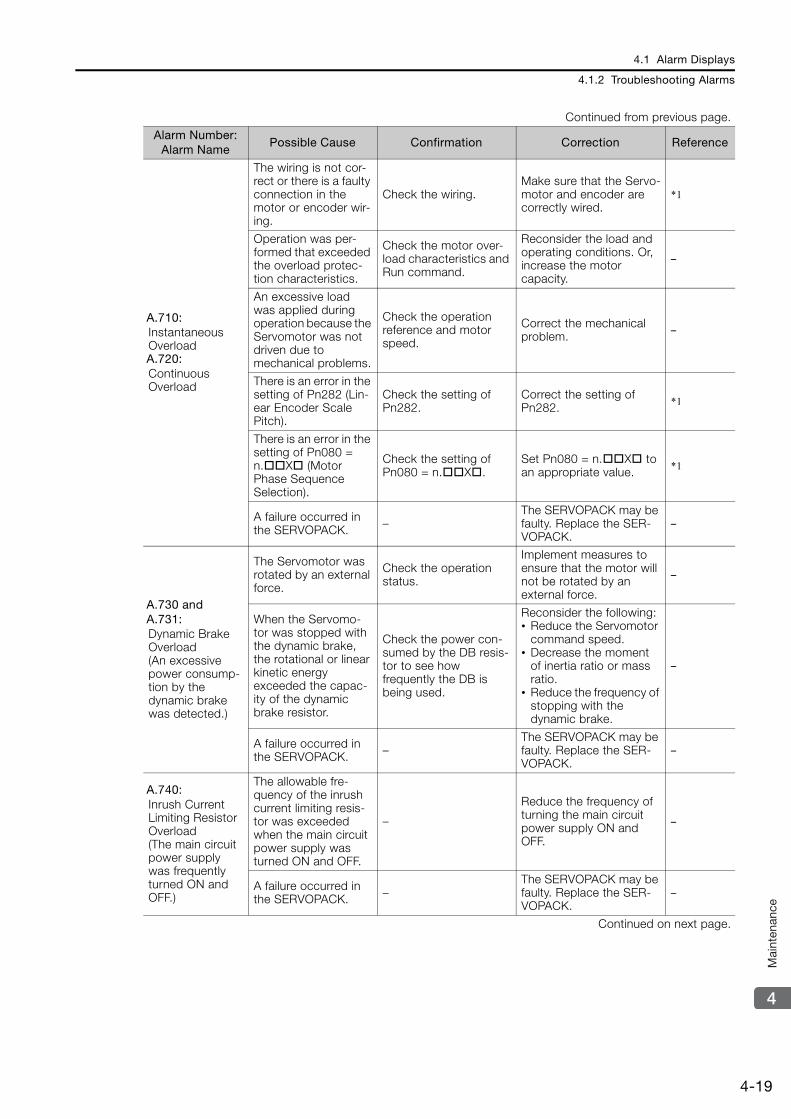
4.1 Alarm Displays
4.1.2 Troubleshooting Alarms
4-19
4
Mai
nten
ance
A.710: Instantaneous OverloadA.720: Continuous Overload
The wiring is not cor-rect or there is a faulty connection in the motor or encoder wir-ing.
Check the wiring.Make sure that the Servo-motor and encoder are correctly wired.
*1
Operation was per-formed that exceeded the overload protec-tion characteristics.
Check the motor over-load characteristics and Run command.
Reconsider the load and operating conditions. Or, increase the motor capacity.
–
An excessive load was applied during operation because the Servomotor was not driven due to mechanical problems.
Check the operation reference and motor speed.
Correct the mechanical problem. –
There is an error in the setting of Pn282 (Lin-ear Encoder Scale Pitch).
Check the setting of Pn282.
Correct the setting of Pn282. *1
There is an error in the setting of Pn080 = n.X (Motor Phase Sequence Selection).
Check the setting of Pn080 = n.X.
Set Pn080 = n.X to an appropriate value. *1
A failure occurred in the SERVOPACK. –
The SERVOPACK may be faulty. Replace the SER-VOPACK.
–
A.730 and A.731:Dynamic Brake Overload (An excessive power consump-tion by the dynamic brake was detected.)
The Servomotor was rotated by an external force.
Check the operation status.
Implement measures to ensure that the motor will not be rotated by an external force.
–
When the Servomo-tor was stopped with the dynamic brake, the rotational or linear kinetic energy exceeded the capac-ity of the dynamic brake resistor.
Check the power con-sumed by the DB resis-tor to see how frequently the DB is being used.
Reconsider the following:• Reduce the Servomotor
command speed.• Decrease the moment
of inertia ratio or mass ratio.
• Reduce the frequency of stopping with the dynamic brake.
–
A failure occurred in the SERVOPACK. –
The SERVOPACK may be faulty. Replace the SER-VOPACK.
–
A.740: Inrush Current Limiting Resistor Overload (The main circuit power supply was frequently turned ON and OFF.)
The allowable fre-quency of the inrush current limiting resis-tor was exceeded when the main circuit power supply was turned ON and OFF.
–
Reduce the frequency of turning the main circuit power supply ON and OFF.
–
A failure occurred in the SERVOPACK. –
The SERVOPACK may be faulty. Replace the SER-VOPACK.
–
Continued on next page.
Continued from previous page.
Alarm Number: Alarm Name
Possible Cause Confirmation Correction Reference
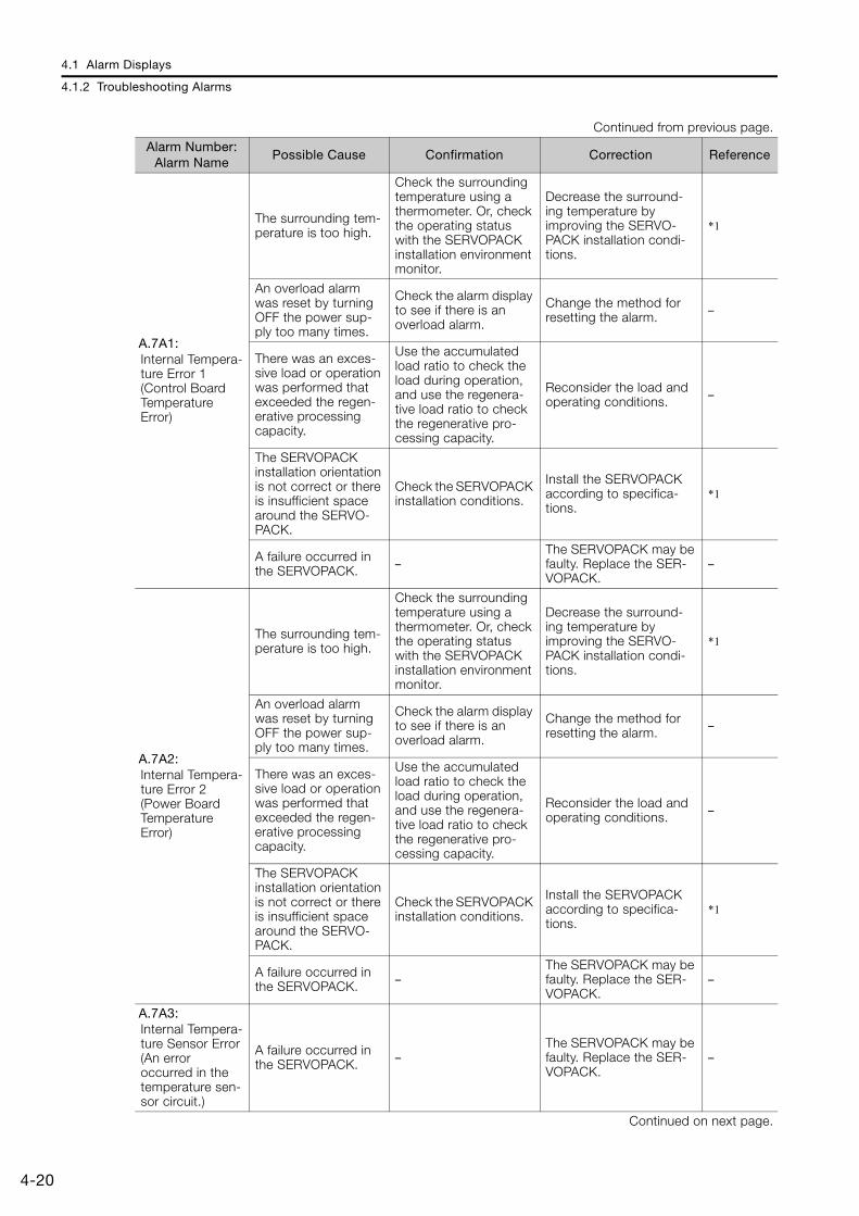
4.1 Alarm Displays
4.1.2 Troubleshooting Alarms
4-20
A.7A1: Internal Tempera-ture Error 1 (Control Board Temperature Error)
The surrounding tem-perature is too high.
Check the surrounding temperature using a thermometer. Or, check the operating status with the SERVOPACK installation environment monitor.
Decrease the surround-ing temperature by improving the SERVO-PACK installation condi-tions.
*1
An overload alarm was reset by turning OFF the power sup-ply too many times.
Check the alarm display to see if there is an overload alarm.
Change the method for resetting the alarm. –
There was an exces-sive load or operation was performed that exceeded the regen-erative processing capacity.
Use the accumulated load ratio to check the load during operation, and use the regenera-tive load ratio to check the regenerative pro-cessing capacity.
Reconsider the load and operating conditions. –
The SERVOPACK installation orientation is not correct or there is insufficient space around the SERVO-PACK.
Check the SERVOPACK installation conditions.
Install the SERVOPACK according to specifica-tions.
*1
A failure occurred in the SERVOPACK. –
The SERVOPACK may be faulty. Replace the SER-VOPACK.
–
A.7A2: Internal Tempera-ture Error 2 (Power Board Temperature Error)
The surrounding tem-perature is too high.
Check the surrounding temperature using a thermometer. Or, check the operating status with the SERVOPACK installation environment monitor.
Decrease the surround-ing temperature by improving the SERVO-PACK installation condi-tions.
*1
An overload alarm was reset by turning OFF the power sup-ply too many times.
Check the alarm display to see if there is an overload alarm.
Change the method for resetting the alarm. –
There was an exces-sive load or operation was performed that exceeded the regen-erative processing capacity.
Use the accumulated load ratio to check the load during operation, and use the regenera-tive load ratio to check the regenerative pro-cessing capacity.
Reconsider the load and operating conditions. –
The SERVOPACK installation orientation is not correct or there is insufficient space around the SERVO-PACK.
Check the SERVOPACK installation conditions.
Install the SERVOPACK according to specifica-tions.
*1
A failure occurred in the SERVOPACK. –
The SERVOPACK may be faulty. Replace the SER-VOPACK.
–
A.7A3:Internal Tempera-ture Sensor Error (An error occurred in the temperature sen-sor circuit.)
A failure occurred in the SERVOPACK. –
The SERVOPACK may be faulty. Replace the SER-VOPACK.
–
Continued on next page.
Continued from previous page.
Alarm Number: Alarm Name
Possible Cause Confirmation Correction Reference
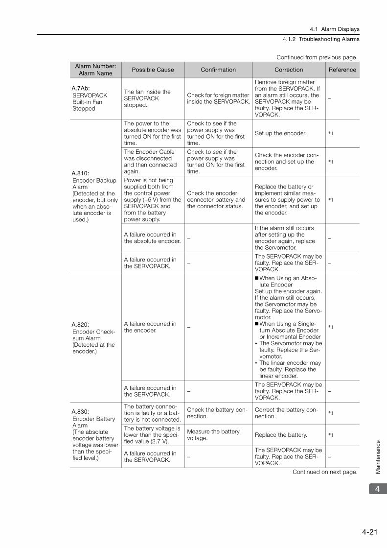
4.1 Alarm Displays
4.1.2 Troubleshooting Alarms
4-21
4
Mai
nten
ance
A.7Ab: SERVOPACK Built-in Fan Stopped
The fan inside the SERVOPACK stopped.
Check for foreign matter inside the SERVOPACK.
Remove foreign matter from the SERVOPACK. If an alarm still occurs, the SERVOPACK may be faulty. Replace the SER-VOPACK.
–
A.810: Encoder Backup Alarm (Detected at the encoder, but only when an abso-lute encoder is used.)
The power to the absolute encoder was turned ON for the first time.
Check to see if the power supply was turned ON for the first time.
Set up the encoder. *1
The Encoder Cable was disconnected and then connected again.
Check to see if the power supply was turned ON for the first time.
Check the encoder con-nection and set up the encoder.
*1
Power is not being supplied both from the control power supply (+5 V) from the SERVOPACK and from the battery power supply.
Check the encoder connector battery and the connector status.
Replace the battery or implement similar mea-sures to supply power to the encoder, and set up the encoder.
*1
A failure occurred in the absolute encoder. –
If the alarm still occurs after setting up the encoder again, replace the Servomotor.
–
A failure occurred in the SERVOPACK. –
The SERVOPACK may be faulty. Replace the SER-VOPACK.
–
A.820: Encoder Check-sum Alarm (Detected at the encoder.)
A failure occurred in the encoder. –
When Using an Abso-lute Encoder
Set up the encoder again. If the alarm still occurs, the Servomotor may be faulty. Replace the Servo-motor.When Using a Single-
turn Absolute Encoder or Incremental Encoder
• The Servomotor may be faulty. Replace the Ser-vomotor.
• The linear encoder may be faulty. Replace the linear encoder.
*1
A failure occurred in the SERVOPACK. –
The SERVOPACK may be faulty. Replace the SER-VOPACK.
–
A.830: Encoder Battery Alarm (The absolute encoder battery voltage was lower than the speci-fied level.)
The battery connec-tion is faulty or a bat-tery is not connected.
Check the battery con-nection.
Correct the battery con-nection. *1
The battery voltage is lower than the speci-fied value (2.7 V).
Measure the battery voltage. Replace the battery. *1
A failure occurred in the SERVOPACK. –
The SERVOPACK may be faulty. Replace the SER-VOPACK.
–
Continued on next page.
Continued from previous page.
Alarm Number: Alarm Name
Possible Cause Confirmation Correction Reference

4.1 Alarm Displays
4.1.2 Troubleshooting Alarms
4-22
A.840: Encoder Data Alarm (Detected at the encoder.)
The encoder malfunc-tioned. –
Turn the power supply to the SERVOPACK OFF and ON again. If an alarm still occurs, the Servomotor or linear encoder may be faulty. Replace the Servo-motor or linear encoder.
–
An error occurred in reading data from the linear encoder.
–
The linear encoder is not mounted within an appro-priate tolerance. Correct the mounting of the linear encoder.
–
Excessive speed occurred in the linear encoder.
–
Control the motor speed within the range specified by the linear encoder manufacturer and then turn ON the control power supply.
–
The encoder malfunc-tioned due to noise. –
Correct the wiring around the encoder by separating the Encoder Cable from the Servomotor Main Cir-cuit Cable or by ground-ing the encoder.
–
The polarity sensor is not wired correctly.
Check the wiring of the polarity sensor.
Correct the wiring of the polarity sensor. –
The polarity sensor failed. – Replace the polarity sen-
sor. –
A.850: Encoder Over-speed (Detected at the encoder when the control power supply is turned ON.)
Rotary Servomotor: The Servomotor speed was 200 min-1 or higher when the control power supply was turned ON.
Check the motor speed when the power supply is turned ON.
Reduce the Servomotor speed to a value less than 200 min-1, and turn ON the control power supply.
–
Linear Servomotor: The Servomotor exceeded the speci-fied speed when the control power supply was turned ON.
Check the motor speed when the power supply is turned ON.
Control the motor speed within the range specified by the linear encoder manufacturer and then turn ON the control power supply.
–
A failure occurred in the encoder. –
Turn the power supply to the SERVOPACK OFF and ON again. If an alarm still occurs, the Servomotor or linear encoder may be faulty. Replace the Servo-motor or linear encoder.
–
A failure occurred in the SERVOPACK. –
Turn the power supply to the SERVOPACK OFF and ON again. If an alarm still occurs, the SERVOPACK may be faulty. Replace the SERVOPACK.
–
Continued on next page.
Continued from previous page.
Alarm Number: Alarm Name
Possible Cause Confirmation Correction Reference
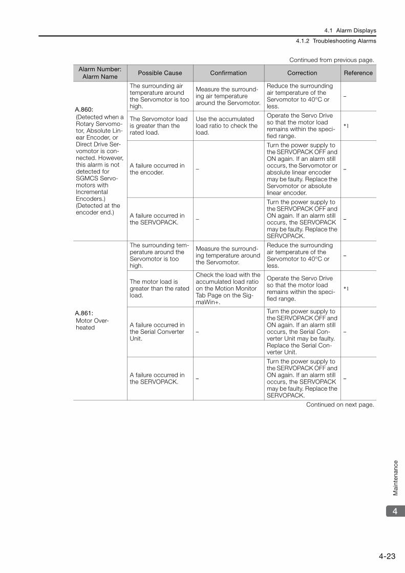
4.1 Alarm Displays
4.1.2 Troubleshooting Alarms
4-23
4
Mai
nten
ance
A.860: (Detected when a Rotary Servomo-tor, Absolute Lin-ear Encoder, or Direct Drive Ser-vomotor is con-nected. However, this alarm is not detected for SGMCS Servo-motors with Incremental Encoders.) (Detected at the encoder end.)
The surrounding air temperature around the Servomotor is too high.
Measure the surround-ing air temperature around the Servomotor.
Reduce the surrounding air temperature of the Servomotor to 40°C or less.
–
The Servomotor load is greater than the rated load.
Use the accumulated load ratio to check the load.
Operate the Servo Drive so that the motor load remains within the speci-fied range.
*1
A failure occurred in the encoder. –
Turn the power supply to the SERVOPACK OFF and ON again. If an alarm still occurs, the Servomotor or absolute linear encoder may be faulty. Replace the Servomotor or absolute linear encoder.
–
A failure occurred in the SERVOPACK. –
Turn the power supply to the SERVOPACK OFF and ON again. If an alarm still occurs, the SERVOPACK may be faulty. Replace the SERVOPACK.
–
A.861: Motor Over-heated
The surrounding tem-perature around the Servomotor is too high.
Measure the surround-ing temperature around the Servomotor.
Reduce the surrounding air temperature of the Servomotor to 40°C or less.
–
The motor load is greater than the rated load.
Check the load with the accumulated load ratio on the Motion Monitor Tab Page on the Sig-maWin+.
Operate the Servo Drive so that the motor load remains within the speci-fied range.
*1
A failure occurred in the Serial Converter Unit.
–
Turn the power supply to the SERVOPACK OFF and ON again. If an alarm still occurs, the Serial Con-verter Unit may be faulty. Replace the Serial Con-verter Unit.
–
A failure occurred in the SERVOPACK. –
Turn the power supply to the SERVOPACK OFF and ON again. If an alarm still occurs, the SERVOPACK may be faulty. Replace the SERVOPACK.
–
Continued on next page.
Continued from previous page.
Alarm Number: Alarm Name
Possible Cause Confirmation Correction Reference
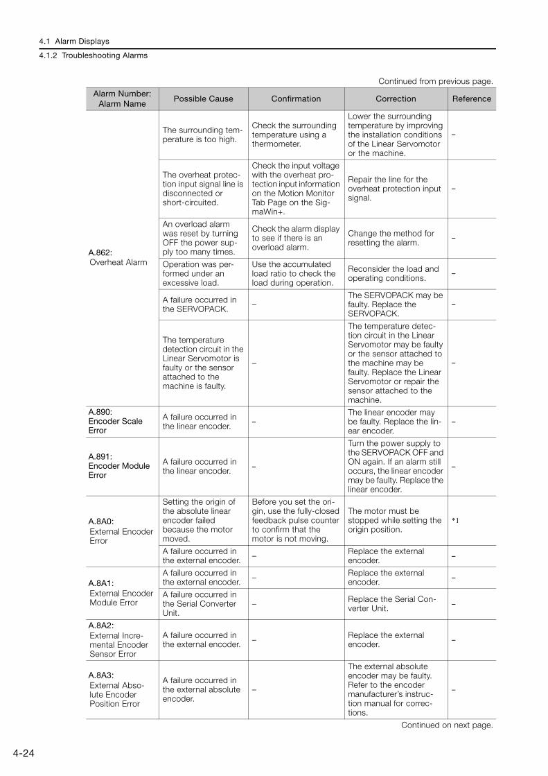
4.1 Alarm Displays
4.1.2 Troubleshooting Alarms
4-24
A.862: Overheat Alarm
The surrounding tem-perature is too high.
Check the surrounding temperature using a thermometer.
Lower the surrounding temperature by improving the installation conditions of the Linear Servomotor or the machine.
–
The overheat protec-tion input signal line is disconnected or short-circuited.
Check the input voltage with the overheat pro-tection input information on the Motion Monitor Tab Page on the Sig-maWin+.
Repair the line for the overheat protection input signal.
–
An overload alarm was reset by turning OFF the power sup-ply too many times.
Check the alarm display to see if there is an overload alarm.
Change the method for resetting the alarm.
–
Operation was per-formed under an excessive load.
Use the accumulated load ratio to check the load during operation.
Reconsider the load and operating conditions.
–
A failure occurred in the SERVOPACK. –
The SERVOPACK may be faulty. Replace the SERVOPACK.
–
The temperature detection circuit in the Linear Servomotor is faulty or the sensor attached to the machine is faulty.
–
The temperature detec-tion circuit in the Linear Servomotor may be faulty or the sensor attached to the machine may be faulty. Replace the Linear Servomotor or repair the sensor attached to the machine.
–
A.890: Encoder Scale Error
A failure occurred in the linear encoder. –
The linear encoder may be faulty. Replace the lin-ear encoder.
–
A.891: Encoder Module Error
A failure occurred in the linear encoder. –
Turn the power supply to the SERVOPACK OFF and ON again. If an alarm still occurs, the linear encoder may be faulty. Replace the linear encoder.
–
A.8A0: External Encoder Error
Setting the origin of the absolute linear encoder failed because the motor moved.
Before you set the ori-gin, use the fully-closed feedback pulse counter to confirm that the motor is not moving.
The motor must be stopped while setting the origin position.
*1
A failure occurred in the external encoder. – Replace the external
encoder. –
A.8A1: External Encoder Module Error
A failure occurred in the external encoder. – Replace the external
encoder. –
A failure occurred in the Serial Converter Unit.
– Replace the Serial Con-verter Unit. –
A.8A2: External Incre-mental Encoder Sensor Error
A failure occurred in the external encoder. – Replace the external
encoder. –
A.8A3: External Abso-lute Encoder Position Error
A failure occurred in the external absolute encoder.
–
The external absolute encoder may be faulty. Refer to the encoder manufacturer’s instruc-tion manual for correc-tions.
–
Continued on next page.
Continued from previous page.
Alarm Number: Alarm Name
Possible Cause Confirmation Correction Reference
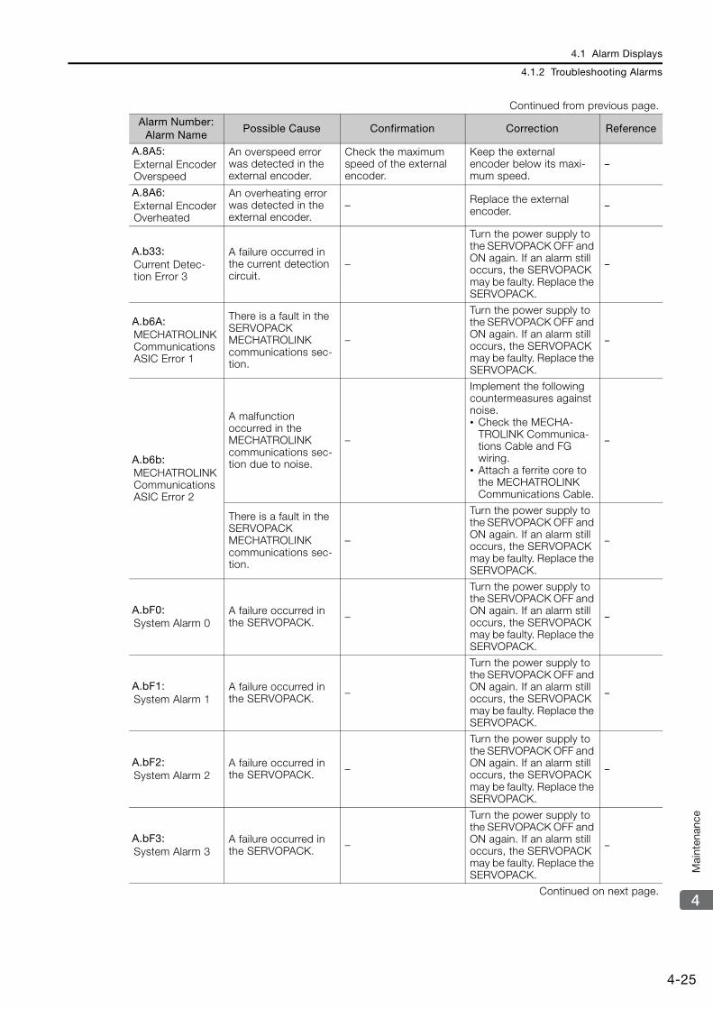
4.1 Alarm Displays
4.1.2 Troubleshooting Alarms
4-25
4
Mai
nten
ance
A.8A5: External Encoder Overspeed
An overspeed error was detected in the external encoder.
Check the maximum speed of the external encoder.
Keep the external encoder below its maxi-mum speed.
–
A.8A6: External Encoder Overheated
An overheating error was detected in the external encoder.
– Replace the external encoder. –
A.b33: Current Detec-tion Error 3
A failure occurred in the current detection circuit.
–
Turn the power supply to the SERVOPACK OFF and ON again. If an alarm still occurs, the SERVOPACK may be faulty. Replace the SERVOPACK.
–
A.b6A: MECHATROLINK Communications ASIC Error 1
There is a fault in the SERVOPACK MECHATROLINK communications sec-tion.
–
Turn the power supply to the SERVOPACK OFF and ON again. If an alarm still occurs, the SERVOPACK may be faulty. Replace the SERVOPACK.
–
A.b6b: MECHATROLINK Communications ASIC Error 2
A malfunction occurred in the MECHATROLINK communications sec-tion due to noise.
–
Implement the following countermeasures against noise.• Check the MECHA-
TROLINK Communica-tions Cable and FG wiring.
• Attach a ferrite core to the MECHATROLINK Communications Cable.
–
There is a fault in the SERVOPACK MECHATROLINK communications sec-tion.
–
Turn the power supply to the SERVOPACK OFF and ON again. If an alarm still occurs, the SERVOPACK may be faulty. Replace the SERVOPACK.
–
A.bF0: System Alarm 0
A failure occurred in the SERVOPACK. –
Turn the power supply to the SERVOPACK OFF and ON again. If an alarm still occurs, the SERVOPACK may be faulty. Replace the SERVOPACK.
–
A.bF1: System Alarm 1
A failure occurred in the SERVOPACK. –
Turn the power supply to the SERVOPACK OFF and ON again. If an alarm still occurs, the SERVOPACK may be faulty. Replace the SERVOPACK.
–
A.bF2: System Alarm 2
A failure occurred in the SERVOPACK. –
Turn the power supply to the SERVOPACK OFF and ON again. If an alarm still occurs, the SERVOPACK may be faulty. Replace the SERVOPACK.
–
A.bF3: System Alarm 3
A failure occurred in the SERVOPACK. –
Turn the power supply to the SERVOPACK OFF and ON again. If an alarm still occurs, the SERVOPACK may be faulty. Replace the SERVOPACK.
–
Continued on next page.
Continued from previous page.
Alarm Number: Alarm Name
Possible Cause Confirmation Correction Reference

4.1 Alarm Displays
4.1.2 Troubleshooting Alarms
4-26
A.bF4: System Alarm 4
A failure occurred in the SERVOPACK. –
Turn the power supply to the SERVOPACK OFF and ON again. If an alarm still occurs, the SERVOPACK may be faulty. Replace the SERVOPACK.
–
A.bF5: System Alarm 5
A failure occurred in the SERVOPACK. –
Turn the power supply to the SERVOPACK OFF and ON again. If an alarm still occurs, the SERVOPACK may be faulty. Replace the SERVOPACK.
–
A.bF6: System Alarm 6
A failure occurred in the SERVOPACK. –
Turn the power supply to the SERVOPACK OFF and ON again. If an alarm still occurs, the SERVOPACK may be faulty. Replace the SERVOPACK.
–
A.bF7: System Alarm 7
A failure occurred in the SERVOPACK. –
Turn the power supply to the SERVOPACK OFF and ON again. If an alarm still occurs, the SERVOPACK may be faulty. Replace the SERVOPACK.
–
A.bF8: System Alarm 8
A failure occurred in the SERVOPACK. –
Turn the power supply to the SERVOPACK OFF and ON again. If an alarm still occurs, the SERVOPACK may be faulty. Replace the SERVOPACK.
–
A.C10: Servomotor Out of Control (Detected when the servo is turned ON.)
The order of phases U, V, and W in the motor wiring is not correct.
Check the Servomotor wiring.
Make sure that the Servo-motor is correctly wired. –
There is an error in the setting of Pn080 = n.X (Motor Phase Sequence Selection).
Check the setting of Pn080 = n.X.
Set Pn080 = n.X to an appropriate value. *1
A failure occurred in the encoder. –
If the motor wiring is cor-rect and an alarm still occurs after turning the power supply OFF and ON again, the Servomotor or linear encoder may be faulty. Replace the Servo-motor or linear encoder.
–
A failure occurred in the SERVOPACK. –
Turn the power supply to the SERVOPACK OFF and ON again. If an alarm still occurs, the SERVOPACK may be faulty. Replace the SERVOPACK.
–
Continued on next page.
Continued from previous page.
Alarm Number: Alarm Name
Possible Cause Confirmation Correction Reference
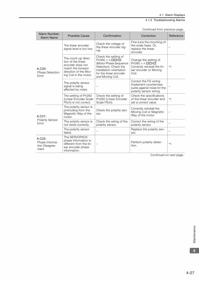
4.1 Alarm Displays
4.1.2 Troubleshooting Alarms
4-27
4
Mai
nten
ance
A.C20: Phase Detection Error
The linear encoder signal level is too low.
Check the voltage of the linear encoder sig-nal.
Fine-tune the mounting of the scale head. Or, replace the linear encoder.
–
The count-up direc-tion of the linear encoder does not match the forward direction of the Mov-ing Coil in the motor.
Check the setting of Pn080 = n.X (Motor Phase Sequence Selection). Check the installation orientation for the linear encoder and Moving Coil.
Change the setting of Pn080 = n.X.Correctly reinstall the lin-ear encoder or Moving Coil.
*1
The polarity sensor signal is being affected by noise.
–
Correct the FG wiring. Implement countermea-sures against noise for the polarity sensor wiring.
–
The setting of Pn282 (Linear Encoder Scale Pitch) is not correct.
Check the setting of Pn282 (Linear Encoder Scale Pitch).
Check the specifications of the linear encoder and set a correct value.
*1
A.C21: Polarity Sensor Error
The polarity sensor is protruding from the Magnetic Way of the motor.
Check the polarity sen-sor.
Correctly reinstall the Moving Coil or Magnetic Way of the motor.
–
The polarity sensor is not wired correctly.
Check the wiring of the polarity sensor.
Correct the wiring of the polarity sensor. –
The polarity sensor failed. – Replace the polarity sen-
sor. –
A.C22: Phase Informa-tion Disagree-ment
The SERVOPACK phase information is different from the lin-ear encoder phase information.
– Perform polarity detec-tion. *1
Continued on next page.
Continued from previous page.
Alarm Number: Alarm Name
Possible Cause Confirmation Correction Reference
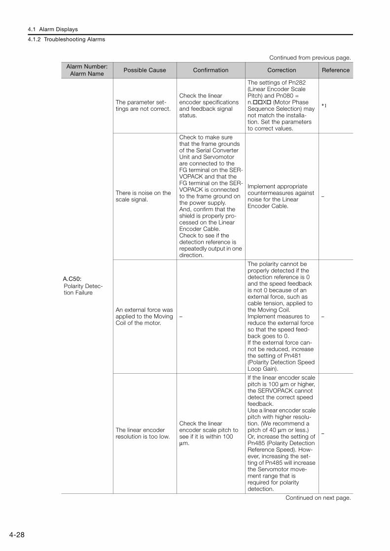
4.1 Alarm Displays
4.1.2 Troubleshooting Alarms
4-28
A.C50: Polarity Detec-tion Failure
The parameter set-tings are not correct.
Check the linear encoder specifications and feedback signal status.
The settings of Pn282 (Linear Encoder Scale Pitch) and Pn080 = n.X (Motor Phase Sequence Selection) may not match the installa-tion. Set the parameters to correct values.
*1
There is noise on the scale signal.
Check to make sure that the frame grounds of the Serial Converter Unit and Servomotor are connected to the FG terminal on the SER-VOPACK and that the FG terminal on the SER-VOPACK is connected to the frame ground on the power supply.And, confirm that the shield is properly pro-cessed on the Linear Encoder Cable.Check to see if the detection reference is repeatedly output in one direction.
Implement appropriate countermeasures against noise for the Linear Encoder Cable.
–
An external force was applied to the Moving Coil of the motor.
–
The polarity cannot be properly detected if the detection reference is 0 and the speed feedback is not 0 because of an external force, such as cable tension, applied to the Moving Coil.Implement measures to reduce the external force so that the speed feed-back goes to 0.If the external force can-not be reduced, increase the setting of Pn481 (Polarity Detection Speed Loop Gain).
–
The linear encoder resolution is too low.
Check the linear encoder scale pitch to see if it is within 100 μm.
If the linear encoder scale pitch is 100 μm or higher, the SERVOPACK cannot detect the correct speed feedback.Use a linear encoder scale pitch with higher resolu-tion. (We recommend a pitch of 40 μm or less.) Or, increase the setting of Pn485 (Polarity Detection Reference Speed). How-ever, increasing the set-ting of Pn485 will increase the Servomotor move-ment range that is required for polarity detection.
–
Continued on next page.
Continued from previous page.
Alarm Number: Alarm Name
Possible Cause Confirmation Correction Reference

4.1 Alarm Displays
4.1.2 Troubleshooting Alarms
4-29
4
Mai
nten
ance
A.C51: Overtravel Detected during Polarity Detection
The overtravel signal was detected during polarity detection.
Check the overtravel position.
Wire the overtravel sig-nals. Execute polarity detection at a position where an overtravel sig-nal would not be detected.
*1
A.C52: Polarity Detec-tion Not Com-pleted
The servo was turned ON when using an absolute linear encoder, Pn587 was set to n.0 (Do not detect polarity), and the polarity had not been detected.
–
When using an absolute linear encoder, set Pn587 to n.1 (Detect polar-ity).
–
A.C53: Out of Range of Motion for Polar-ity Detection
The travel distance exceeded the setting of Pn48E (Polarity Detection Range) in the middle of detec-tion.
–
Increase the setting of Pn48E (Polarity Detection Range). Or, increase the setting of Pn481 (Polarity Detection Speed Loop Gain).
–
A.C54: Polarity Detec-tion Failure 2
An external force was applied to the Servo-motor.
–
Increase the setting of Pn495 (Polarity Detection Confirmation Force Refer-ence).Increase the setting of Pn498 (Polarity Detection Allowable Error Range). Increasing the allowable error will also increase the motor temperature.
–
A.C80: Encoder Clear Error or Multiturn Limit Setting Error
A failure occurred in the encoder. –
Turn the power supply to the SERVOPACK OFF and ON again. If an alarm still occurs, the Servomotor or linear encoder may be faulty. Replace the Servo-motor or linear encoder.
–
A failure occurred in the SERVOPACK. –
Turn the power supply to the SERVOPACK OFF and ON again. If an alarm still occurs, the SERVOPACK may be faulty. Replace the SERVOPACK.
–
Continued on next page.
Continued from previous page.
Alarm Number: Alarm Name
Possible Cause Confirmation Correction Reference
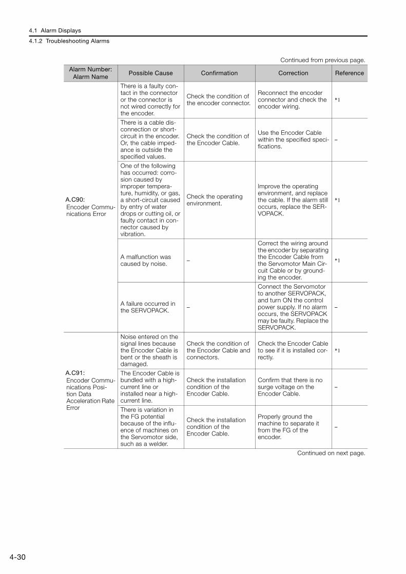
4.1 Alarm Displays
4.1.2 Troubleshooting Alarms
4-30
A.C90: Encoder Commu-nications Error
There is a faulty con-tact in the connector or the connector is not wired correctly for the encoder.
Check the condition of the encoder connector.
Reconnect the encoder connector and check the encoder wiring.
*1
There is a cable dis-connection or short-circuit in the encoder. Or, the cable imped-ance is outside the specified values.
Check the condition of the Encoder Cable.
Use the Encoder Cable within the specified speci-fications.
–
One of the following has occurred: corro-sion caused by improper tempera-ture, humidity, or gas, a short-circuit caused by entry of water drops or cutting oil, or faulty contact in con-nector caused by vibration.
Check the operating environment.
Improve the operating environment, and replace the cable. If the alarm still occurs, replace the SER-VOPACK.
*1
A malfunction was caused by noise. –
Correct the wiring around the encoder by separating the Encoder Cable from the Servomotor Main Cir-cuit Cable or by ground-ing the encoder.
*1
A failure occurred in the SERVOPACK. –
Connect the Servomotor to another SERVOPACK, and turn ON the control power supply. If no alarm occurs, the SERVOPACK may be faulty. Replace the SERVOPACK.
–
A.C91: Encoder Commu-nications Posi-tion Data Acceleration Rate Error
Noise entered on the signal lines because the Encoder Cable is bent or the sheath is damaged.
Check the condition of the Encoder Cable and connectors.
Check the Encoder Cable to see if it is installed cor-rectly.
*1
The Encoder Cable is bundled with a high-current line or installed near a high-current line.
Check the installation condition of the Encoder Cable.
Confirm that there is no surge voltage on the Encoder Cable.
–
There is variation in the FG potential because of the influ-ence of machines on the Servomotor side, such as a welder.
Check the installation condition of the Encoder Cable.
Properly ground the machine to separate it from the FG of the encoder.
–
Continued on next page.
Continued from previous page.
Alarm Number: Alarm Name
Possible Cause Confirmation Correction Reference
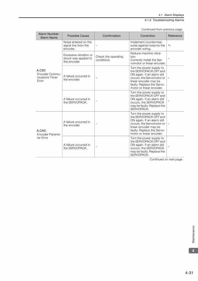
4.1 Alarm Displays
4.1.2 Troubleshooting Alarms
4-31
4
Mai
nten
ance
A.C92: Encoder Commu-nications Timer Error
Noise entered on the signal line from the encoder.
–Implement countermea-sures against noise for the encoder wiring.
*1
Excessive vibration or shock was applied to the encoder.
Check the operating conditions.
Reduce machine vibra-tion.Correctly install the Ser-vomotor or linear encoder.
–
A failure occurred in the encoder. –
Turn the power supply to the SERVOPACK OFF and ON again. If an alarm still occurs, the Servomotor or linear encoder may be faulty. Replace the Servo-motor or linear encoder.
–
A failure occurred in the SERVOPACK. –
Turn the power supply to the SERVOPACK OFF and ON again. If an alarm still occurs, the SERVOPACK may be faulty. Replace the SERVOPACK.
–
A.CA0: Encoder Parame-ter Error
A failure occurred in the encoder. –
Turn the power supply to the SERVOPACK OFF and ON again. If an alarm still occurs, the Servomotor or linear encoder may be faulty. Replace the Servo-motor or linear encoder.
–
A failure occurred in the SERVOPACK. –
Turn the power supply to the SERVOPACK OFF and ON again. If an alarm still occurs, the SERVOPACK may be faulty. Replace the SERVOPACK.
–
Continued on next page.
Continued from previous page.
Alarm Number: Alarm Name
Possible Cause Confirmation Correction Reference
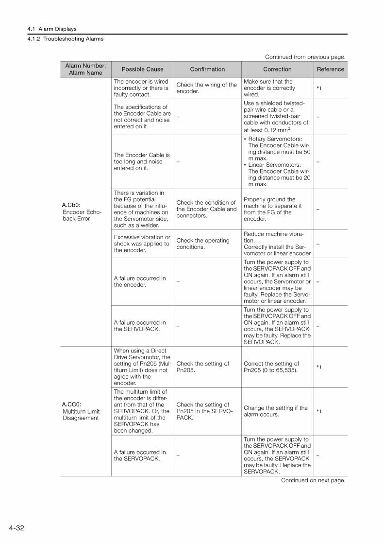
4.1 Alarm Displays
4.1.2 Troubleshooting Alarms
4-32
A.Cb0: Encoder Echo-back Error
The encoder is wired incorrectly or there is faulty contact.
Check the wiring of the encoder.
Make sure that the encoder is correctly wired.
*1
The specifications of the Encoder Cable are not correct and noise entered on it.
–
Use a shielded twisted-pair wire cable or a screened twisted-pair cable with conductors of at least 0.12 mm2.
–
The Encoder Cable is too long and noise entered on it.
–
• Rotary Servomotors: The Encoder Cable wir-ing distance must be 50 m max.
• Linear Servomotors: The Encoder Cable wir-ing distance must be 20 m max.
–
There is variation in the FG potential because of the influ-ence of machines on the Servomotor side, such as a welder.
Check the condition of the Encoder Cable and connectors.
Properly ground the machine to separate it from the FG of the encoder.
–
Excessive vibration or shock was applied to the encoder.
Check the operating conditions.
Reduce machine vibra-tion.Correctly install the Ser-vomotor or linear encoder.
–
A failure occurred in the encoder. –
Turn the power supply to the SERVOPACK OFF and ON again. If an alarm still occurs, the Servomotor or linear encoder may be faulty. Replace the Servo-motor or linear encoder.
–
A failure occurred in the SERVOPACK. –
Turn the power supply to the SERVOPACK OFF and ON again. If an alarm still occurs, the SERVOPACK may be faulty. Replace the SERVOPACK.
–
A.CC0: Multiturn Limit Disagreement
When using a Direct Drive Servomotor, the setting of Pn205 (Mul-titurn Limit) does not agree with the encoder.
Check the setting of Pn205.
Correct the setting of Pn205 (0 to 65,535). *1
The multiturn limit of the encoder is differ-ent from that of the SERVOPACK. Or, the multiturn limit of the SERVOPACK has been changed.
Check the setting of Pn205 in the SERVO-PACK.
Change the setting if the alarm occurs. *1
A failure occurred in the SERVOPACK. –
Turn the power supply to the SERVOPACK OFF and ON again. If an alarm still occurs, the SERVOPACK may be faulty. Replace the SERVOPACK.
–
Continued on next page.
Continued from previous page.
Alarm Number: Alarm Name
Possible Cause Confirmation Correction Reference
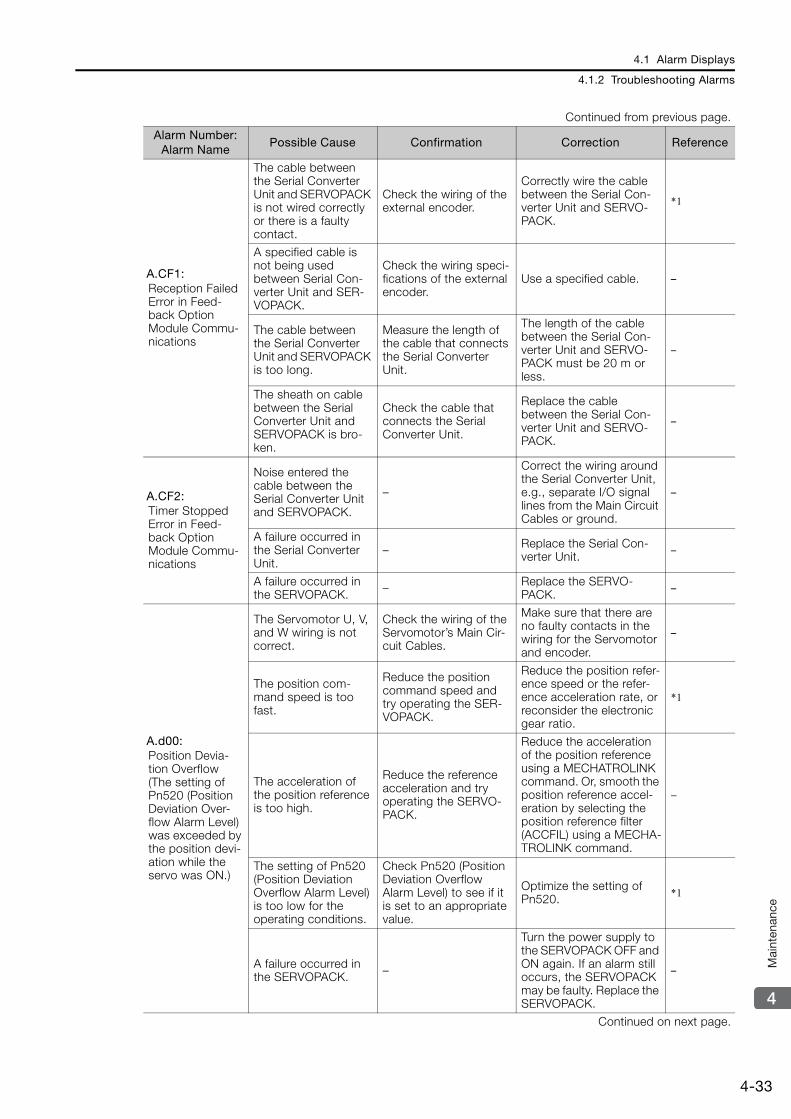
4.1 Alarm Displays
4.1.2 Troubleshooting Alarms
4-33
4
Mai
nten
ance
A.CF1: Reception Failed Error in Feed-back Option Module Commu-nications
The cable between the Serial Converter Unit and SERVOPACK is not wired correctly or there is a faulty contact.
Check the wiring of the external encoder.
Correctly wire the cable between the Serial Con-verter Unit and SERVO-PACK.
*1
A specified cable is not being used between Serial Con-verter Unit and SER-VOPACK.
Check the wiring speci-fications of the external encoder.
Use a specified cable. –
The cable between the Serial Converter Unit and SERVOPACK is too long.
Measure the length of the cable that connects the Serial Converter Unit.
The length of the cable between the Serial Con-verter Unit and SERVO-PACK must be 20 m or less.
–
The sheath on cable between the Serial Converter Unit and SERVOPACK is bro-ken.
Check the cable that connects the Serial Converter Unit.
Replace the cable between the Serial Con-verter Unit and SERVO-PACK.
–
A.CF2: Timer Stopped Error in Feed-back Option Module Commu-nications
Noise entered the cable between the Serial Converter Unit and SERVOPACK.
–
Correct the wiring around the Serial Converter Unit, e.g., separate I/O signal lines from the Main Circuit Cables or ground.
–
A failure occurred in the Serial Converter Unit.
– Replace the Serial Con-verter Unit. –
A failure occurred in the SERVOPACK. – Replace the SERVO-
PACK. –
A.d00: Position Devia-tion Overflow (The setting of Pn520 (Position Deviation Over-flow Alarm Level) was exceeded by the position devi-ation while the servo was ON.)
The Servomotor U, V, and W wiring is not correct.
Check the wiring of the Servomotor’s Main Cir-cuit Cables.
Make sure that there are no faulty contacts in the wiring for the Servomotor and encoder.
–
The position com-mand speed is too fast.
Reduce the position command speed and try operating the SER-VOPACK.
Reduce the position refer-ence speed or the refer-ence acceleration rate, or reconsider the electronic gear ratio.
*1
The acceleration of the position reference is too high.
Reduce the reference acceleration and try operating the SERVO-PACK.
Reduce the acceleration of the position reference using a MECHATROLINK command. Or, smooth the position reference accel-eration by selecting the position reference filter (ACCFIL) using a MECHA-TROLINK command.
−
The setting of Pn520 (Position Deviation Overflow Alarm Level) is too low for the operating conditions.
Check Pn520 (Position Deviation Overflow Alarm Level) to see if it is set to an appropriate value.
Optimize the setting of Pn520. *1
A failure occurred in the SERVOPACK. –
Turn the power supply to the SERVOPACK OFF and ON again. If an alarm still occurs, the SERVOPACK may be faulty. Replace the SERVOPACK.
–
Continued on next page.
Continued from previous page.
Alarm Number: Alarm Name
Possible Cause Confirmation Correction Reference
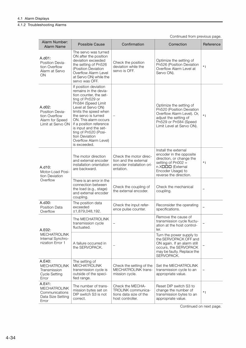
4.1 Alarm Displays
4.1.2 Troubleshooting Alarms
4-34
A.d01: Position Devia-tion Overflow Alarm at Servo ON
The servo was turned ON after the position deviation exceeded the setting of Pn526 (Position Deviation Overflow Alarm Level at Servo ON) while the servo was OFF.
Check the position deviation while the servo is OFF.
Optimize the setting of Pn526 (Position Deviation Overflow Alarm Level at Servo ON).
*1
A.d02: Position Devia-tion Overflow Alarm for Speed Limit at Servo ON
If position deviation remains in the devia-tion counter, the set-ting of Pn529 or Pn584 (Speed Limit Level at Servo ON) limits the speed when the servo is turned ON. This alarm occurs if a position reference is input and the set-ting of Pn520 (Posi-tion Deviation Overflow Alarm Level) is exceeded.
–
Optimize the setting of Pn520 (Position Deviation Overflow Alarm Level). Or, adjust the setting of Pn529 or Pn584 (Speed Limit Level at Servo ON).
*1
A.d10: Motor-Load Posi-tion Deviation Overflow
The motor direction and external encoder installation orientation are backward.
Check the motor direc-tion and the external encoder installation ori-entation.
Install the external encoder in the opposite direction, or change the setting of Pn002 = n.X (External Encoder Usage) to reverse the direction.
*1
There is an error in the connection between the load (e.g., stage) and external encoder coupling.
Check the coupling of the external encoder.
Check the mechanical coupling. –
A.d30: Position Data Overflow
The position data exceeded ±1,879,048,192.
Check the input refer-ence pulse counter.
Reconsider the operating specifications. –
A.E02: MECHATROLINK Internal Synchro-nization Error 1
The MECHATROLINK transmission cycle fluctuated.
–
Remove the cause of transmission cycle fluctu-ation at the host control-ler.
–
A failure occurred in the SERVOPACK. –
Turn the power supply to the SERVOPACK OFF and ON again. If an alarm still occurs, the SERVOPACK may be faulty. Replace the SERVOPACK.
–
A.E40: MECHATROLINK Transmission Cycle Setting Error
The setting of MECHATROLINK transmission cycle is outside of the speci-fied range.
Check the setting of the MECHATROLINK trans-mission cycle.
Set the MECHATROLINK transmission cycle to an appropriate value.
–
A.E41: MECHATROLINK Communications Data Size Setting Error
The number of trans-mission bytes set on DIP switch S3 is not correct.
Check the MECHA-TROLINK communica-tions data size of the host controller.
Reset DIP switch S3 to change the number of transmission bytes to an appropriate value.
*1
Continued on next page.
Continued from previous page.
Alarm Number: Alarm Name
Possible Cause Confirmation Correction Reference
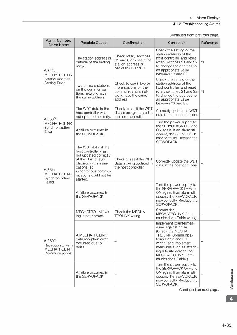
4.1 Alarm Displays
4.1.2 Troubleshooting Alarms
4-35
4
Mai
nten
ance
A.E42: MECHATROLINK Station Address Setting Error
The station address is outside of the setting range.
Check rotary switches S1 and S2 to see if the station address is between 03 and EF.
Check the setting of the station address of the host controller, and reset rotary switches S1 and S2 to change the address to an appropriate value between 03 and EF.
*1
Two or more stations on the communica-tions network have the same address.
Check to see if two or more stations on the communications net-work have the same address.
Check the setting of the station address of the host controller, and reset rotary switches S1 and S2 to change the address to an appropriate value between 03 and EF.
*1
A.E50*4: MECHATROLINK Synchronization Error
The WDT data in the host controller was not updated normally.
Check to see if the WDT data is being updated at the host controller.
Correctly update the WDT data at the host controller. –
A failure occurred in the SERVOPACK. –
Turn the power supply to the SERVOPACK OFF and ON again. If an alarm still occurs, the SERVOPACK may be faulty. Replace the SERVOPACK.
–
A.E51: MECHATROLINK Synchronization Failed
The WDT data at the host controller was not updated correctly at the start of syn-chronous communi-cations, so synchronous commu-nications could not be started.
Check to see if the WDT data is being updated in the host controller.
Correctly update the WDT data at the host controller. –
A failure occurred in the SERVOPACK. –
Turn the power supply to the SERVOPACK OFF and ON again. If an alarm still occurs, the SERVOPACK may be faulty. Replace the SERVOPACK.
–
A.E60*4: Reception Error in MECHATROLINK Communications
MECHATROLINK wir-ing is not correct.
Check the MECHA-TROLINK wiring.
Correct the MECHATROLINK Com-munications Cable wiring.
–
A MECHATROLINK data reception error occurred due to noise.
–
Implement countermea-sures against noise. (Check the MECHA-TROLINK Communica-tions Cable and FG wiring, and implement measures such as attach-ing a ferrite core to the MECHATROLINK Com-munications Cable.)
–
A failure occurred in the SERVOPACK. –
Turn the power supply to the SERVOPACK OFF and ON again. If an alarm still occurs, the SERVOPACK may be faulty. Replace the SERVOPACK.
–
Continued on next page.
Continued from previous page.
Alarm Number: Alarm Name
Possible Cause Confirmation Correction Reference
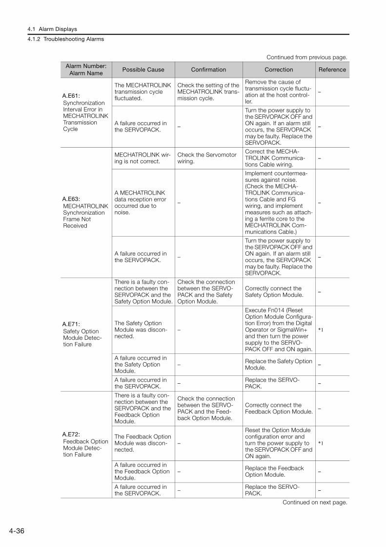
4.1 Alarm Displays
4.1.2 Troubleshooting Alarms
4-36
A.E61: Synchronization Interval Error in MECHATROLINK Transmission Cycle
The MECHATROLINK transmission cycle fluctuated.
Check the setting of the MECHATROLINK trans-mission cycle.
Remove the cause of transmission cycle fluctu-ation at the host control-ler.
–
A failure occurred in the SERVOPACK. –
Turn the power supply to the SERVOPACK OFF and ON again. If an alarm still occurs, the SERVOPACK may be faulty. Replace the SERVOPACK.
–
A.E63: MECHATROLINK Synchronization Frame Not Received
MECHATROLINK wir-ing is not correct.
Check the Servomotor wiring.
Correct the MECHA-TROLINK Communica-tions Cable wiring.
–
A MECHATROLINK data reception error occurred due to noise.
–
Implement countermea-sures against noise. (Check the MECHA-TROLINK Communica-tions Cable and FG wiring, and implement measures such as attach-ing a ferrite core to the MECHATROLINK Com-munications Cable.)
–
A failure occurred in the SERVOPACK. –
Turn the power supply to the SERVOPACK OFF and ON again. If an alarm still occurs, the SERVOPACK may be faulty. Replace the SERVOPACK.
–
A.E71:Safety Option Module Detec-tion Failure
There is a faulty con-nection between the SERVOPACK and the Safety Option Module.
Check the connection between the SERVO-PACK and the Safety Option Module.
Correctly connect the Safety Option Module. –
The Safety Option Module was discon-nected.
–
Execute Fn014 (Reset Option Module Configura-tion Error) from the Digital Operator or SigmaWin+ and then turn the power supply to the SERVO-PACK OFF and ON again.
*1
A failure occurred in the Safety Option Module.
– Replace the Safety Option Module. –
A failure occurred in the SERVOPACK. – Replace the SERVO-
PACK. –
A.E72: Feedback Option Module Detec-tion Failure
There is a faulty con-nection between the SERVOPACK and the Feedback Option Module.
Check the connection between the SERVO-PACK and the Feed-back Option Module.
Correctly connect the Feedback Option Module. –
The Feedback Option Module was discon-nected.
–
Reset the Option Module configuration error and turn the power supply to the SERVOPACK OFF and ON again.
*1
A failure occurred in the Feedback Option Module.
– Replace the Feedback Option Module. –
A failure occurred in the SERVOPACK. – Replace the SERVO-
PACK. –
Continued on next page.
Continued from previous page.
Alarm Number: Alarm Name
Possible Cause Confirmation Correction Reference

4.1 Alarm Displays
4.1.2 Troubleshooting Alarms
4-37
4
Mai
nten
ance
A.E74: Unsupported Safety Option Module
A failure occurred in the Safety Option Module.
– Replace the Safety Option Module. –
An unsupported Safety Option Module was connected.
Refer to the catalog of the connected Safety Option Module.
Connect a compatible Safety Option Module. –
A.Eb1: Safety Function Signal Input Tim-ing Error
The delay between activation of the /HWBB1 and /HWBB2 input sig-nals for the HWBB was ten second or longer.
Measure the time delay between the /HWBB1 and /HWBB2 signals.
The output signal circuits or devices for /HWBB1 and /HWBB2 or the SER-VOPACK input signal cir-cuits may be faulty. Alternatively, the input sig-nal cables may be discon-nected. Check to see if any of these items are faulty or have been dis-connected.
–
A failure occurred in the SERVOPACK. –
Replace the SERVO-PACK. –
A.EC8: Gate Drive Error 1 (An error occurred in the gate drive circuit.) A failure occurred in
the SERVOPACK. –
Turn the power supply to the SERVOPACK OFF and ON again. If an alarm still occurs, the SERVOPACK may be faulty. Replace the SERVOPACK.
–A.EC9: Gate Drive Error 2 (An error occurred in the gate drive circuit.)
A.Ed1: Command Exe-cution Timeout
A timeout error occurred for a MECHATROLINK command.
Check the motor status when the command is executed.
Execute the SV_ON or SENS_ON command only when the motor is not operating.
–
• For fully-closed loop control, check the status of the external encoder when the command is exe-cuted.
• For other types of control, check the status of the linear encoder when the command is exe-cuted.
Execute the SENS_ON command only when an external rotary encoder or linear encoder is con-nected.
–
Continued on next page.
Continued from previous page.
Alarm Number: Alarm Name
Possible Cause Confirmation Correction Reference

4.1 Alarm Displays
4.1.2 Troubleshooting Alarms
4-38
A.F10: Power Supply Line Open Phase (The voltage was low for more than one second for phase R, S, or T when the main power supply was ON.)
The three-phase power supply wiring is not correct.
Check the power sup-ply wiring.
Make sure that the power supply is correctly wired. *1
The three-phase power supply is unbalanced.
Measure the voltage for each phase of the three-phase power sup-ply.
Balance the power sup-ply by changing phases. –
A single-phase power supply was input with-out specifying a sin-gle-phase AC power supply input (Pn00B = n.1).
Check the power sup-ply and the parameter setting.
Match the parameter set-ting to the power supply. *1
A failure occurred in the SERVOPACK. –
Turn the power supply to the SERVOPACK OFF and ON again. If an alarm still occurs, the SERVOPACK may be faulty. Replace the SERVOPACK.
–
FL-1*6: System Alarm
A failure occurred in the SERVOPACK. –
Turn the power supply to the SERVOPACK OFF and ON again. If an alarm still occurs, the SERVOPACK may be faulty. Replace the SERVOPACK.
–
FL-2*6: System Alarm
FL-3*6: System Alarm
FL-4*6: System Alarm
FL-5*6: System Alarm
FL-6*6: System Alarm
CPF00: Digital Operator Communications Error 1
There is a faulty con-nection between the Digital Operator and the SERVOPACK.
Check the connector contact.
Disconnect the connec-tor and insert it again. Or, replace the cable.
–
A malfunction was caused by noise. –
Keep the Digital Operator or the cable away from sources of noise.
–
CPF01: Digital Operator Communications Error 2
A failure occurred in the Digital Operator. –
Disconnect the Digital Operator and then con-nect it again. If an alarm still occurs, the Digital Operator may be faulty. Replace the Digital Oper-ator.
–
A failure occurred in the SERVOPACK. –
Turn the power supply to the SERVOPACK OFF and ON again. If an alarm still occurs, the SERVOPACK may be faulty. Replace the SERVOPACK.
–
Continued from previous page.
Alarm Number: Alarm Name
Possible Cause Confirmation Correction Reference
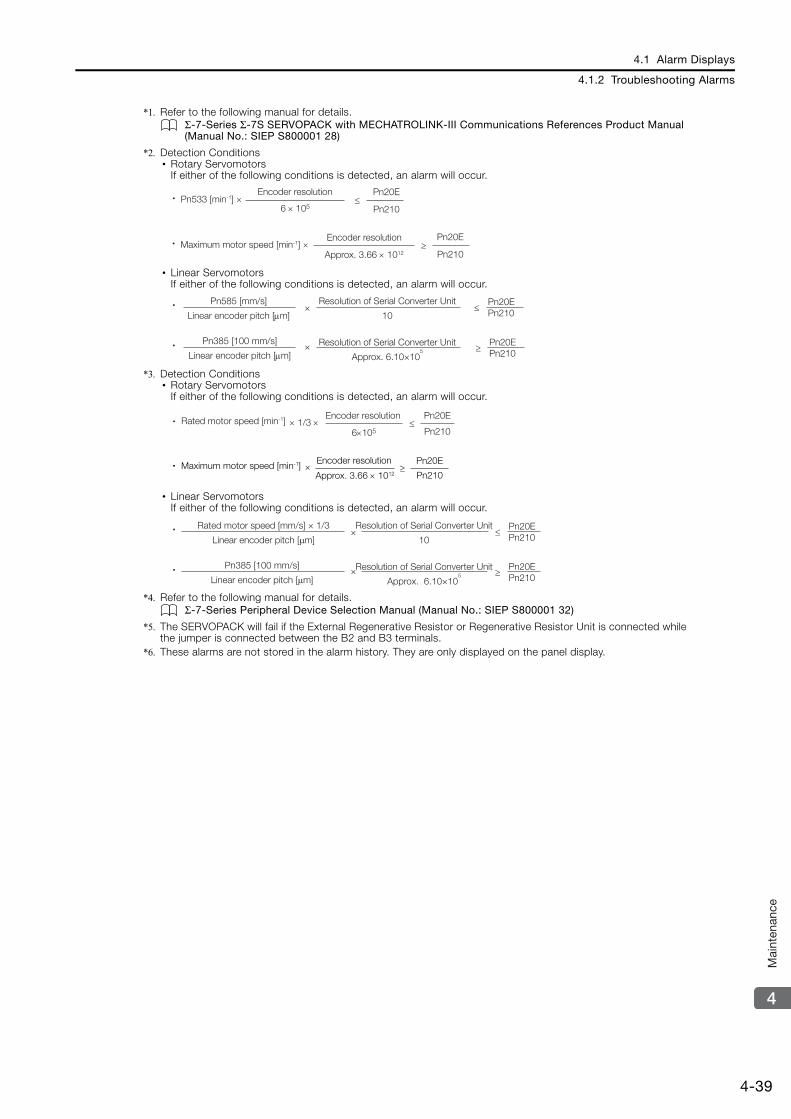
4.1 Alarm Displays
4.1.2 Troubleshooting Alarms
4-39
4
Mai
nten
ance
*1. Refer to the following manual for details.Σ-7-Series Σ-7S SERVOPACK with MECHATROLINK-III Communications References Product Manual (Manual No.: SIEP S800001 28)
*2. Detection Conditions• Rotary Servomotors
If either of the following conditions is detected, an alarm will occur.
• Linear ServomotorsIf either of the following conditions is detected, an alarm will occur.
*3. Detection Conditions• Rotary Servomotors
If either of the following conditions is detected, an alarm will occur.
• Linear ServomotorsIf either of the following conditions is detected, an alarm will occur.
*4. Refer to the following manual for details.Σ-7-Series Peripheral Device Selection Manual (Manual No.: SIEP S800001 32)
*5. The SERVOPACK will fail if the External Regenerative Resistor or Regenerative Resistor Unit is connected while the jumper is connected between the B2 and B3 terminals.
*6. These alarms are not stored in the alarm history. They are only displayed on the panel display.
Pn533 [min-1] 6 105
Pn20E
Pn210
Encoder resolution
Pn20E
Pn210Maximum motor speed [min-1]
Encoder resolution
Approx. 3.66 1012
Pn585 [mm/s]
Linear encoder pitch [m]
Resolution of Serial Converter Unit
10Pn20EPn210×
×Pn385 [100 mm/s]
Linear encoder pitch [m]Pn20EPn210
Resolution of Serial Converter Unit
Approx. 6.10×10⁵
1/3 6105
Pn20E
Pn210Rated motor speed [min-1] Encoder resolution
Pn20E
Pn210Maximum motor speed [min-1] Encoder resolution
Approx. 3.66 1012
Rated motor speed [mm/s] × 1/3
Linear encoder pitch [μm]
Resolution of Serial Converter Unit
10Pn20EPn210≤×
×Pn385 [100 mm/s]
Linear encoder pitch [μm]Pn20EPn210≥
Resolution of Serial Converter Unit
Approx. 6.10×10⁵

4.2 Warning Displays
4.2.1 List of Warnings
4-40
4.2 Warning Displays
If a warning occurs in the SERVOPACK, a warning number will be displayed on the panel dis-play. Warnings are displayed to warn you before an alarm occurs.
4.2.1 List of WarningsThe list of warnings gives the warning name and warning meaning in order of the warning num-bers.
Warning Number
Warning Name Meaning Resetting
A.900Position Deviation Overflow
The position deviation exceeded the percentage set with the following formula: (Pn520 × Pn51E/100)
Required.
A.901Position Deviation Overflow Alarm at Servo ON
The position deviation when the servo was turned ON exceeded the percentage set with the following formula: (Pn526 × Pn528/100)
Required.
A.910 OverloadThis warning occurs before an overload alarm (A.710 or A.720) occurs. If the warning is ignored and operation is continued, an alarm may occur.
Required.
A.911 Vibration
Abnormal vibration was detected during motor opera-tion. The detection level is the same as A.520. Set whether to output an alarm or a warning by setting Pn310 (Vibration Detection Selections).
Required.
A.912
Internal Temperature Warning 1 (Control Board Temperature Error)
The surrounding temperature of the control PCB is abnormal. Required.
A.913
Internal Temperature Warning 2 (Power Board Temperature Error)
The surrounding temperature of the power PCB is abnormal. Required.
A.920 Regenerative OverloadThis warning occurs before an A.320 alarm (Regenera-tive Overload) occurs. If the warning is ignored and operation is continued, an alarm may occur.
Required.
A.921Dynamic Brake Over-load
This warning occurs before an A.731 alarm (Dynamic Brake Overload) occurs. If the warning is ignored and operation is continued, an alarm may occur.
Required.
A.923SERVOPACK Built-in Fan Stopped
The fan inside the SERVOPACK stopped. Required.
A.930Absolute Encoder Bat-tery Error
This warning occurs when the voltage of absolute encoder’s battery is low. Required.
A.93B Overheat WarningThe input voltage (temperature) for the overheat protec-tion input (TH) signal exceeded the setting of Pn61C (Overheat Warning Level).
Required.
A.942Speed Ripple Com-pensation Information Disagreement
The speed ripple compensation information stored in the encoder does not agree with the speed ripple com-pensation information stored in the SERVOPACK.
Required.
A.94A Data Setting Warning 1 (Parameter Number Error)
There is an error in the parameter number for a Data Setting Warning 1 (Parameter Number) command.
Automatically reset.*
A.94bData Setting Warning 2 (Out of Range)
The command data is out of range. Automatically reset.*
A.94CData Setting Warning 3 (Calculation Error)
A calculation error was detected. Automatically reset.*
Continued on next page.
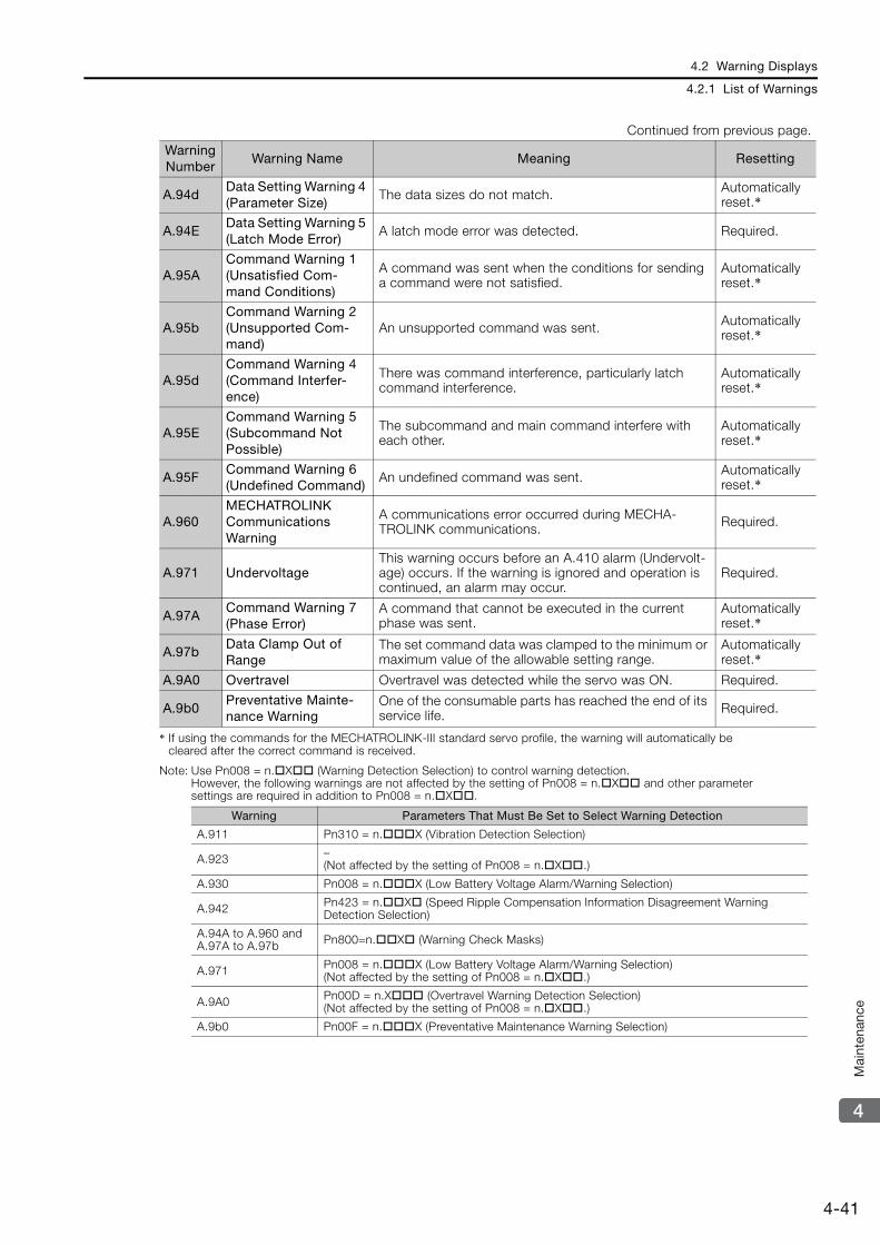
4.2 Warning Displays
4.2.1 List of Warnings
4-41
4
Mai
nten
ance
* If using the commands for the MECHATROLINK-III standard servo profile, the warning will automatically be cleared after the correct command is received.
Note: Use Pn008 = n.X (Warning Detection Selection) to control warning detection.However, the following warnings are not affected by the setting of Pn008 = n.X and other parameter settings are required in addition to Pn008 = n.X.
A.94dData Setting Warning 4 (Parameter Size)
The data sizes do not match. Automatically reset.*
A.94EData Setting Warning 5 (Latch Mode Error)
A latch mode error was detected. Required.
A.95ACommand Warning 1 (Unsatisfied Com-mand Conditions)
A command was sent when the conditions for sending a command were not satisfied.
Automatically reset.*
A.95bCommand Warning 2 (Unsupported Com-mand)
An unsupported command was sent. Automatically reset.*
A.95dCommand Warning 4 (Command Interfer-ence)
There was command interference, particularly latch command interference.
Automatically reset.*
A.95ECommand Warning 5 (Subcommand Not Possible)
The subcommand and main command interfere with each other.
Automatically reset.*
A.95FCommand Warning 6 (Undefined Command)
An undefined command was sent. Automatically reset.*
A.960MECHATROLINK Communications Warning
A communications error occurred during MECHA-TROLINK communications. Required.
A.971 UndervoltageThis warning occurs before an A.410 alarm (Undervolt-age) occurs. If the warning is ignored and operation is continued, an alarm may occur.
Required.
A.97ACommand Warning 7 (Phase Error)
A command that cannot be executed in the current phase was sent.
Automatically reset.*
A.97bData Clamp Out of Range
The set command data was clamped to the minimum or maximum value of the allowable setting range.
Automatically reset.*
A.9A0 Overtravel Overtravel was detected while the servo was ON. Required.
A.9b0Preventative Mainte-nance Warning
One of the consumable parts has reached the end of its service life. Required.
Warning Parameters That Must Be Set to Select Warning Detection
A.911 Pn310 = n.X (Vibration Detection Selection)
A.923 –(Not affected by the setting of Pn008 = n.X.)
A.930 Pn008 = n.X (Low Battery Voltage Alarm/Warning Selection)
A.942 Pn423 = n.X (Speed Ripple Compensation Information Disagreement Warning Detection Selection)
A.94A to A.960 and A.97A to A.97b Pn800=n.X (Warning Check Masks)
A.971 Pn008 = n.X (Low Battery Voltage Alarm/Warning Selection)(Not affected by the setting of Pn008 = n.X.)
A.9A0 Pn00D = n.X (Overtravel Warning Detection Selection)(Not affected by the setting of Pn008 = n.X.)
A.9b0 Pn00F = n.X (Preventative Maintenance Warning Selection)
Continued from previous page.
Warning Number
Warning Name Meaning Resetting
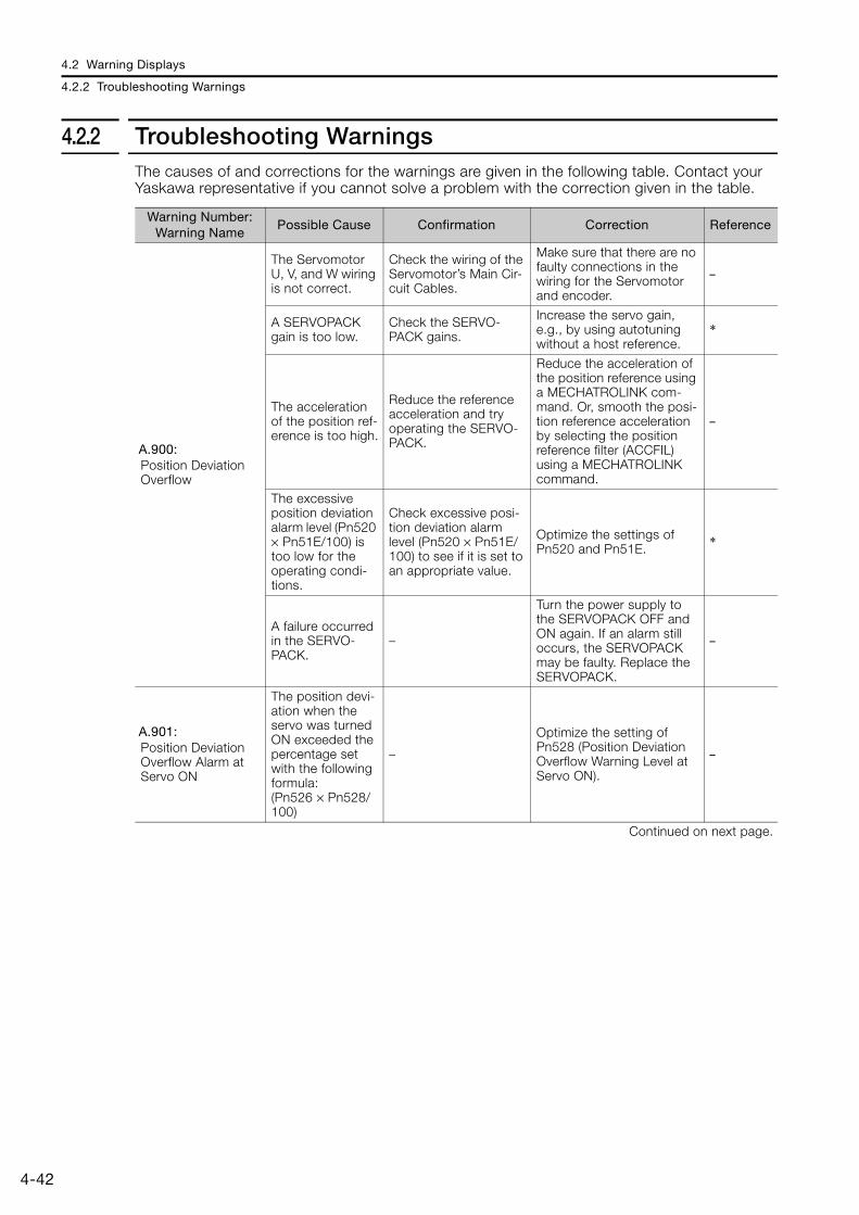
4.2 Warning Displays
4.2.2 Troubleshooting Warnings
4-42
4.2.2 Troubleshooting WarningsThe causes of and corrections for the warnings are given in the following table. Contact your Yaskawa representative if you cannot solve a problem with the correction given in the table.
Warning Number: Warning Name
Possible Cause Confirmation Correction Reference
A.900: Position Deviation Overflow
The Servomotor U, V, and W wiring is not correct.
Check the wiring of the Servomotor’s Main Cir-cuit Cables.
Make sure that there are no faulty connections in the wiring for the Servomotor and encoder.
–
A SERVOPACK gain is too low.
Check the SERVO-PACK gains.
Increase the servo gain, e.g., by using autotuning without a host reference.
*
The acceleration of the position ref-erence is too high.
Reduce the reference acceleration and try operating the SERVO-PACK.
Reduce the acceleration of the position reference using a MECHATROLINK com-mand. Or, smooth the posi-tion reference acceleration by selecting the position reference filter (ACCFIL) using a MECHATROLINK command.
–
The excessive position deviation alarm level (Pn520 × Pn51E/100) is too low for the operating condi-tions.
Check excessive posi-tion deviation alarm level (Pn520 × Pn51E/100) to see if it is set to an appropriate value.
Optimize the settings of Pn520 and Pn51E. *
A failure occurred in the SERVO-PACK.
–
Turn the power supply to the SERVOPACK OFF and ON again. If an alarm still occurs, the SERVOPACK may be faulty. Replace the SERVOPACK.
–
A.901: Position Deviation Overflow Alarm at Servo ON
The position devi-ation when the servo was turned ON exceeded the percentage set with the following formula:(Pn526 × Pn528/100)
–
Optimize the setting of Pn528 (Position Deviation Overflow Warning Level at Servo ON).
–
Continued on next page.

4.2 Warning Displays
4.2.2 Troubleshooting Warnings
4-43
4
Mai
nten
ance
A.910: Overload (warning before an A.710 or A.720 alarm occurs)
The wiring is not correct or there is a faulty connec-tion in the motor or encoder wiring.
Check the wiring.Make sure that the Servo-motor and encoder are cor-rectly wired.
–
Operation was performed that exceeded the overload protec-tion characteris-tics.
Check the motor over-load characteristics and Run command.
Reconsider the load and operating conditions. Or, increase the motor capacity.
–
An excessive load was applied during operation because the Ser-vomotor was not driven because of mechanical prob-lems.
Check the operation reference and motor speed.
Remove the mechanical problem. –
The overload warning level (Pn52B) is not suitable.
Check that the over-load warning level (Pn52B) is suitable.
Set a suitable overload warning level (Pn52B). *
A failure occurred in the SERVO-PACK.
–The SERVOPACK may be faulty. Replace the SERVO-PACK.
–
A.911: Vibration
Abnormal vibra-tion was detected during motor operation.
Check for abnormal motor noise, and check the speed and torque waveforms during operation.
Reduce the motor speed. Or, reduce the servo gain with custom tuning.
*
The setting of Pn103 (Moment of Inertia Ratio) is greater than the actual moment of inertia or was greatly changed.
Check the moment of inertia ratio or mass ratio.
Set Pn103 (Moment of Iner-tia Ratio) to an appropriate value.
*
The vibration detection level (Pn312 or Pn384) is not suitable.
Check that the vibra-tion detection level (Pn312 or Pn384) is suitable.
Set a suitable vibration detection level (Pn312 or Pn384).
*
Continued on next page.
Continued from previous page.
Warning Number: Warning Name
Possible Cause Confirmation Correction Reference
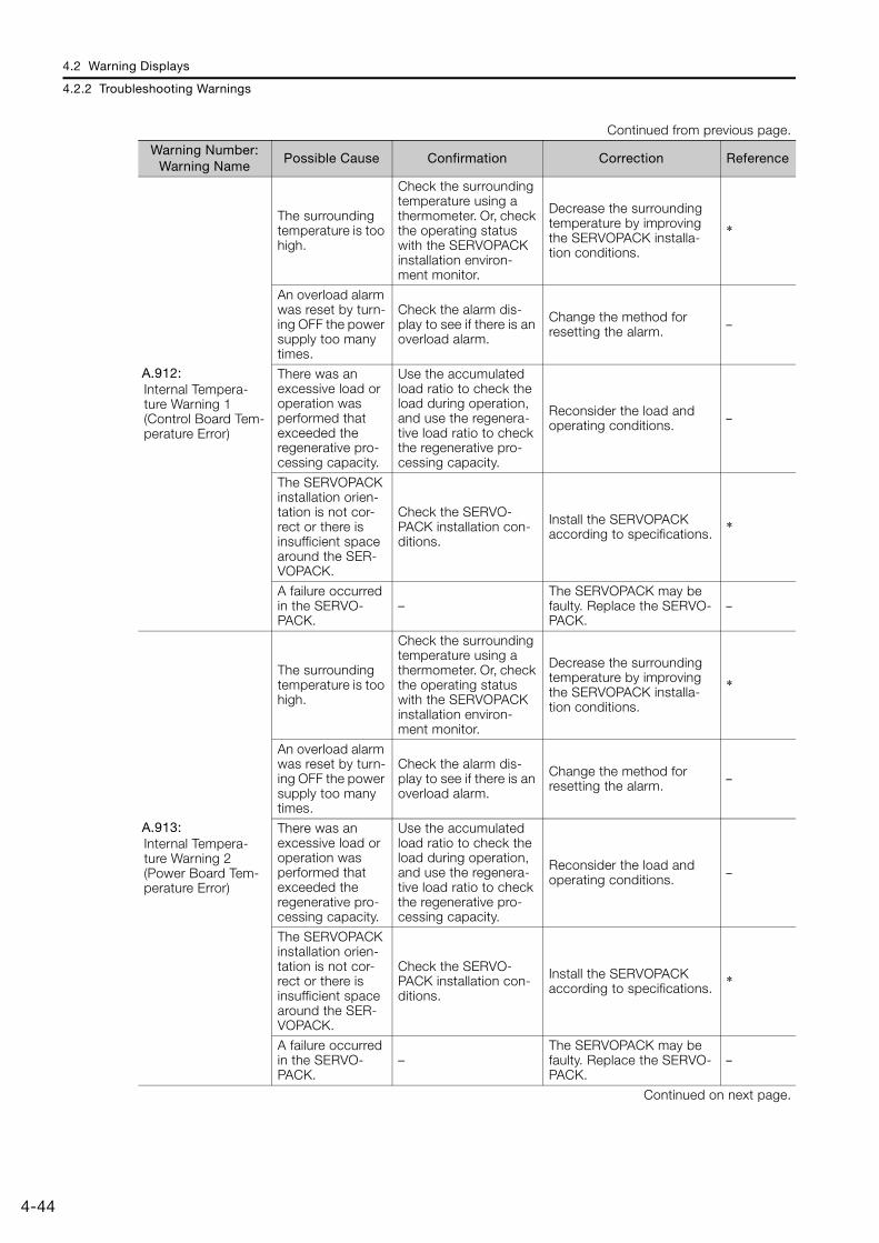
4.2 Warning Displays
4.2.2 Troubleshooting Warnings
4-44
A.912: Internal Tempera-ture Warning 1 (Control Board Tem-perature Error)
The surrounding temperature is too high.
Check the surrounding temperature using a thermometer. Or, check the operating status with the SERVOPACK installation environ-ment monitor.
Decrease the surrounding temperature by improving the SERVOPACK installa-tion conditions.
*
An overload alarm was reset by turn-ing OFF the power supply too many times.
Check the alarm dis-play to see if there is an overload alarm.
Change the method for resetting the alarm. –
There was an excessive load or operation was performed that exceeded the regenerative pro-cessing capacity.
Use the accumulated load ratio to check the load during operation, and use the regenera-tive load ratio to check the regenerative pro-cessing capacity.
Reconsider the load and operating conditions. –
The SERVOPACK installation orien-tation is not cor-rect or there is insufficient space around the SER-VOPACK.
Check the SERVO-PACK installation con-ditions.
Install the SERVOPACK according to specifications. *
A failure occurred in the SERVO-PACK.
–The SERVOPACK may be faulty. Replace the SERVO-PACK.
–
A.913: Internal Tempera-ture Warning 2 (Power Board Tem-perature Error)
The surrounding temperature is too high.
Check the surrounding temperature using a thermometer. Or, check the operating status with the SERVOPACK installation environ-ment monitor.
Decrease the surrounding temperature by improving the SERVOPACK installa-tion conditions.
*
An overload alarm was reset by turn-ing OFF the power supply too many times.
Check the alarm dis-play to see if there is an overload alarm.
Change the method for resetting the alarm. –
There was an excessive load or operation was performed that exceeded the regenerative pro-cessing capacity.
Use the accumulated load ratio to check the load during operation, and use the regenera-tive load ratio to check the regenerative pro-cessing capacity.
Reconsider the load and operating conditions. –
The SERVOPACK installation orien-tation is not cor-rect or there is insufficient space around the SER-VOPACK.
Check the SERVO-PACK installation con-ditions.
Install the SERVOPACK according to specifications. *
A failure occurred in the SERVO-PACK.
–The SERVOPACK may be faulty. Replace the SERVO-PACK.
–
Continued on next page.
Continued from previous page.
Warning Number: Warning Name
Possible Cause Confirmation Correction Reference
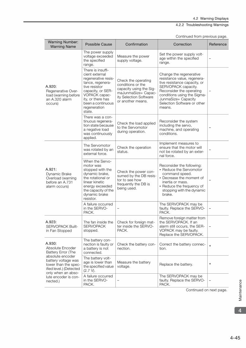
4.2 Warning Displays
4.2.2 Troubleshooting Warnings
4-45
4
Mai
nten
ance
A.920: Regenerative Over-load (warning before an A.320 alarm occurs)
The power supply voltage exceeded the specified range.
Measure the power supply voltage.
Set the power supply volt-age within the specified range.
–
There is insuffi-cient external regenerative resis-tance, regenera-tive resistor capacity, or SER-VOPACK capac-ity, or there has been a continuous regeneration state.
Check the operating conditions or the capacity using the Sig-maJunmaSize+ Capac-ity Selection Software or another means.
Change the regenerative resistance value, regenera-tive resistance capacity, or SERVOPACK capacity. Reconsider the operating conditions using the Sigma-JunmaSize+ Capacity Selection Software or other means.
–
There was a con-tinuous regenera-tion state because a negative load was continuously applied.
Check the load applied to the Servomotor during operation.
Reconsider the system including the servo, machine, and operating conditions.
–
A.921: Dynamic Brake Overload (warning before an A.731 alarm occurs)
The Servomotor was rotated by an external force.
Check the operation status.
Implement measures to ensure that the motor will not be rotated by an exter-nal force.
–
When the Servo-motor was stopped with the dynamic brake, the rotational or linear kinetic energy exceeded the capacity of the dynamic brake resistor.
Check the power con-sumed by the DB resis-tor to see how frequently the DB is being used.
Reconsider the following:• Reduce the Servomotor
command speed.• Decrease the moment of
inertia or mass.• Reduce the frequency of
stopping with the dynamic brake.
–
A failure occurred in the SERVO-PACK.
–The SERVOPACK may be faulty. Replace the SERVO-PACK.
–
A.923: SERVOPACK Built-in Fan Stopped
The fan inside the SERVOPACK stopped.
Check for foreign mat-ter inside the SERVO-PACK.
Remove foreign matter from the SERVOPACK. If an alarm still occurs, the SER-VOPACK may be faulty. Replace the SERVOPACK.
–
A.930: Absolute Encoder Battery Error (The absolute encoder battery voltage was lower than the spec-ified level.) (Detected only when an abso-lute encoder is con-nected.)
The battery con-nection is faulty or a battery is not connected.
Check the battery con-nection.
Correct the battery connec-tion. *
The battery volt-age is lower than the specified value (2.7 V).
Measure the battery voltage. Replace the battery. *
A failure occurred in the SERVO-PACK.
–The SERVOPACK may be faulty. Replace the SERVO-PACK.
–
Continued on next page.
Continued from previous page.
Warning Number: Warning Name
Possible Cause Confirmation Correction Reference
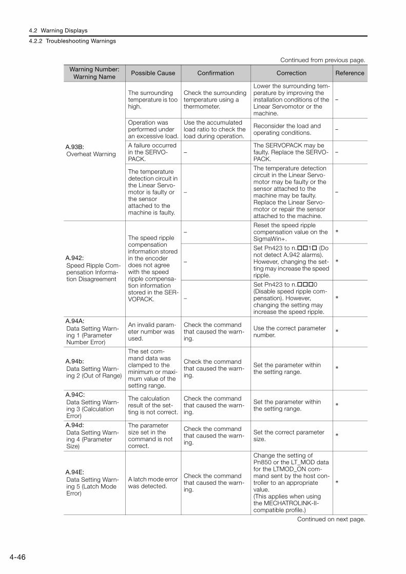
4.2 Warning Displays
4.2.2 Troubleshooting Warnings
4-46
A.93B: Overheat Warning
The surrounding temperature is too high.
Check the surrounding temperature using a thermometer.
Lower the surrounding tem-perature by improving the installation conditions of the Linear Servomotor or the machine.
–
Operation was performed under an excessive load.
Use the accumulated load ratio to check the load during operation.
Reconsider the load and operating conditions.
–
A failure occurred in the SERVO-PACK.
–The SERVOPACK may be faulty. Replace the SERVO-PACK.
–
The temperature detection circuit in the Linear Servo-motor is faulty or the sensor attached to the machine is faulty.
–
The temperature detection circuit in the Linear Servo-motor may be faulty or the sensor attached to the machine may be faulty. Replace the Linear Servo-motor or repair the sensor attached to the machine.
–
A.942: Speed Ripple Com-pensation Informa-tion Disagreement
The speed ripple compensation information stored in the encoder does not agree with the speed ripple compensa-tion information stored in the SER-VOPACK.
–Reset the speed ripple compensation value on the SigmaWin+.
*
–
Set Pn423 to n.1 (Do not detect A.942 alarms). However, changing the set-ting may increase the speed ripple.
*
–
Set Pn423 to n.0 (Disable speed ripple com-pensation). However, changing the setting may increase the speed ripple.
*
A.94A: Data Setting Warn-ing 1 (Parameter Number Error)
An invalid param-eter number was used.
Check the command that caused the warn-ing.
Use the correct parameter number. *
A.94b: Data Setting Warn-ing 2 (Out of Range)
The set com-mand data was clamped to the minimum or maxi-mum value of the setting range.
Check the command that caused the warn-ing.
Set the parameter within the setting range. *
A.94C: Data Setting Warn-ing 3 (Calculation Error)
The calculation result of the set-ting is not correct.
Check the command that caused the warn-ing.
Set the parameter within the setting range. *
A.94d: Data Setting Warn-ing 4 (Parameter Size)
The parameter size set in the command is not correct.
Check the command that caused the warn-ing.
Set the correct parameter size. *
A.94E: Data Setting Warn-ing 5 (Latch Mode Error)
A latch mode error was detected.
Check the command that caused the warn-ing.
Change the setting of Pn850 or the LT_MOD data for the LTMOD_ON com-mand sent by the host con-troller to an appropriate value.(This applies when using the MECHATROLINK-II-compatible profile.)
*
Continued on next page.
Continued from previous page.
Warning Number: Warning Name
Possible Cause Confirmation Correction Reference

4.2 Warning Displays
4.2.2 Troubleshooting Warnings
4-47
4
Mai
nten
ance
A.95A: Command Warning 1 (Unsatisfied Com-mand Conditions)
The command conditions are not satisfied.
Check the command that caused the warn-ing.
Send the command after the command conditions are satisfied.
*
A.95b: Command Warning 2 (Unsupported Command)
An unsupported command was received.
Check the command that caused the warn-ing.
Do not send unsupported commands. *
A.95d: Command Warning 4 (Command Inter-ference)
The command sending condi-tions for latch-related com-mands was not satisfied.
Check the command that caused the warn-ing.
Send the command after the command conditions are satisfied.
*
A.95E: Command Warning 5 (Subcommand Not Possible)
The command sending condi-tions for subcom-mands was not satisfied.
Check the command that caused the warn-ing.
Send the command after the conditions are satisfied. *
A.95F: Command Warning 6 (Undefined Com-mand)
An undefined command was sent.
Check the command that caused the warn-ing.
Do not send undefined commands. *
A.960: MECHATROLINK Communications Warning
The MECHA-TROLINK Com-munications Cable is not wired cor-rectly.
Check the wiring con-ditions.
Correct the MECHA-TROLINK communications cable wiring.
*
A MECHA-TROLINK data reception error occurred due to noise.
Confirm the installation conditions.
Implement the following countermeasures against noise.• Check the MECHA-
TROLINK Communica-tions Cable and FG wiring and implement counter-measures to prevent noise from entering.
• Attach a ferrite core to the MECHATROLINK Com-munications Cable.
–
A failure occurred in the SERVO-PACK.
–The SERVOPACK may be faulty. Replace the SERVO-PACK.
–
Continued on next page.
Continued from previous page.
Warning Number: Warning Name
Possible Cause Confirmation Correction Reference
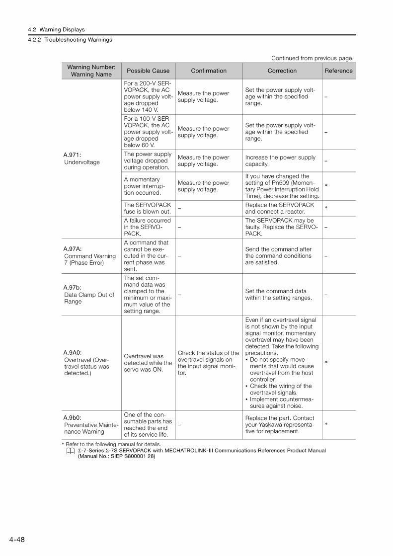
4.2 Warning Displays
4.2.2 Troubleshooting Warnings
4-48
* Refer to the following manual for details.Σ-7-Series Σ-7S SERVOPACK with MECHATROLINK-III Communications References Product Manual (Manual No.: SIEP S800001 28)
A.971: Undervoltage
For a 200-V SER-VOPACK, the AC power supply volt-age dropped below 140 V.
Measure the power supply voltage.
Set the power supply volt-age within the specified range.
–
For a 100-V SER-VOPACK, the AC power supply volt-age dropped below 60 V.
Measure the power supply voltage.
Set the power supply volt-age within the specified range.
–
The power supply voltage dropped during operation.
Measure the power supply voltage.
Increase the power supply capacity. –
A momentary power interrup-tion occurred.
Measure the power supply voltage.
If you have changed the setting of Pn509 (Momen-tary Power Interruption Hold Time), decrease the setting.
*
The SERVOPACK fuse is blown out. – Replace the SERVOPACK
and connect a reactor. *
A failure occurred in the SERVO-PACK.
–The SERVOPACK may be faulty. Replace the SERVO-PACK.
–
A.97A: Command Warning 7 (Phase Error)
A command that cannot be exe-cuted in the cur-rent phase was sent.
–Send the command after the command conditions are satisfied.
–
A.97b: Data Clamp Out of Range
The set com-mand data was clamped to the minimum or maxi-mum value of the setting range.
– Set the command data within the setting ranges. –
A.9A0: Overtravel (Over-travel status was detected.)
Overtravel was detected while the servo was ON.
Check the status of the overtravel signals on the input signal moni-tor.
Even if an overtravel signal is not shown by the input signal monitor, momentary overtravel may have been detected. Take the following precautions.• Do not specify move-
ments that would cause overtravel from the host controller.
• Check the wiring of the overtravel signals.
• Implement countermea-sures against noise.
*
A.9b0: Preventative Mainte-nance Warning
One of the con-sumable parts has reached the end of its service life.
–Replace the part. Contact your Yaskawa representa-tive for replacement.
*
Continued from previous page.
Warning Number: Warning Name
Possible Cause Confirmation Correction Reference
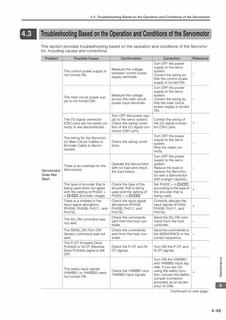
4.3 Troubleshooting Based on the Operation and Conditions of the Servomotor
4-49
4
Mai
nten
ance
4.3 Troubleshooting Based on the Operation and Conditions of the Servomotor
This section provides troubleshooting based on the operation and conditions of the Servomo-tor, including causes and corrections.
Problem Possible Cause Confirmation Correction Reference
Servomotor Does Not Start
The control power supply is not turned ON.
Measure the voltage between control power supply terminals.
Turn OFF the power supply to the servo system.Correct the wiring so that the control power supply is turned ON.
–
The main circuit power sup-ply is not turned ON.
Measure the voltage across the main circuit power input terminals.
Turn OFF the power supply to the servo system.Correct the wiring so that the main circuit power supply is turned ON.
–
The I/O signal connector (CN1) pins are not wired cor-rectly or are disconnected.
Turn OFF the power sup-ply to the servo system.Check the wiring condi-tion of the I/O signal con-nector (CN1) pins.
Correct the wiring of the I/O signal connec-tor (CN1) pins.
*
The wiring for the Servomo-tor Main Circuit Cables or Encoder Cable is discon-nected.
Check the wiring condi-tions.
Turn OFF the power supply to the servo system.Wire the cable cor-rectly.
–
There is an overload on the Servomotor.
Operate the Servomotor with no load and check the load status.
Turn OFF the power supply to the servo system.Reduce the load or replace the Servomo-tor with a Servomotor with a larger capacity.
–
The type of encoder that is being used does not agree with the setting of Pn002 = n.X (Encoder Usage).
Check the type of the encoder that is being used and the setting of Pn002 = n.X.
Set Pn002 = n.X according to the type of the encoder that is being used.
*
There is a mistake in the input signal allocations (Pn50A, Pn50B, Pn511, and Pn516).
Check the input signal allocations (Pn50A, Pn50B, Pn511, and Pn516).
Correctly allocate the input signals (Pn50A, Pn50B, Pn511, and Pn516).
*
The SV_ON command was not sent.
Check the commands sent from the host con-troller.
Send the SV_ON com-mand from the host controller.
–
The SENS_ON (Turn ON Sensor) command was not sent.
Check the commands sent from the host con-troller.
Send the commands to the SERVOPACK in the correct sequence.
–
The P-OT (Forward Drive Prohibit) or N-OT (Reverse Drive Prohibit) signal is still OFF.
Check the P-OT and N-OT signals.
Turn ON the P-OT and N-OT signals. *
The safety input signals (/HWBB1 or /HWBB2) were not turned ON.
Check the /HWBB1 and /HWBB2 input signals.
Turn ON the /HWBB1 and /HWBB2 input sig-nals. If you are not using the safety func-tion, connect the Safety Jumper Connector (provided as an acces-sory) to CN8.
*
Continued on next page.
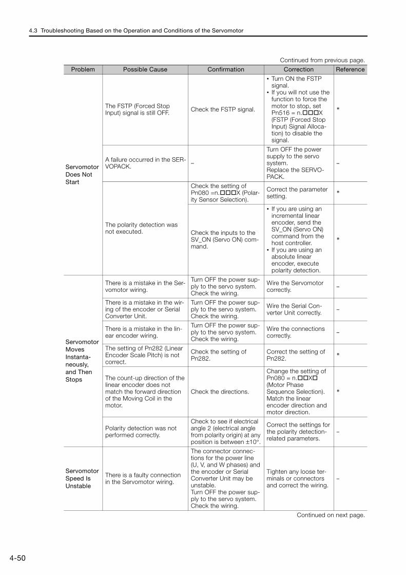
4.3 Troubleshooting Based on the Operation and Conditions of the Servomotor
4-50
Servomotor Does Not Start
The FSTP (Forced Stop Input) signal is still OFF. Check the FSTP signal.
• Turn ON the FSTP signal.
• If you will not use the function to force the motor to stop, set Pn516 = n.X (FSTP (Forced Stop Input) Signal Alloca-tion) to disable the signal.
*
A failure occurred in the SER-VOPACK. –
Turn OFF the power supply to the servo system.Replace the SERVO-PACK.
–
The polarity detection was not executed.
Check the setting of Pn080 =n.X (Polar-ity Sensor Selection).
Correct the parameter setting. *
Check the inputs to the SV_ON (Servo ON) com-mand.
• If you are using an incremental linear encoder, send the SV_ON (Servo ON) command from the host controller.
• If you are using an absolute linear encoder, execute polarity detection.
*
Servomotor Moves Instanta-neously, and Then Stops
There is a mistake in the Ser-vomotor wiring.
Turn OFF the power sup-ply to the servo system.Check the wiring.
Wire the Servomotor correctly. –
There is a mistake in the wir-ing of the encoder or Serial Converter Unit.
Turn OFF the power sup-ply to the servo system.Check the wiring.
Wire the Serial Con-verter Unit correctly. –
There is a mistake in the lin-ear encoder wiring.
Turn OFF the power sup-ply to the servo system.Check the wiring.
Wire the connections correctly. –
The setting of Pn282 (Linear Encoder Scale Pitch) is not correct.
Check the setting of Pn282.
Correct the setting of Pn282. *
The count-up direction of the linear encoder does not match the forward direction of the Moving Coil in the motor.
Check the directions.
Change the setting of Pn080 = n.X (Motor Phase Sequence Selection). Match the linear encoder direction and motor direction.
*
Polarity detection was not performed correctly.
Check to see if electrical angle 2 (electrical angle from polarity origin) at any position is between ±10°.
Correct the settings for the polarity detection-related parameters.
–
Servomotor Speed Is Unstable
There is a faulty connection in the Servomotor wiring.
The connector connec-tions for the power line (U, V, and W phases) and the encoder or Serial Converter Unit may be unstable.Turn OFF the power sup-ply to the servo system.Check the wiring.
Tighten any loose ter-minals or connectors and correct the wiring.
–
Continued on next page.
Continued from previous page.
Problem Possible Cause Confirmation Correction Reference
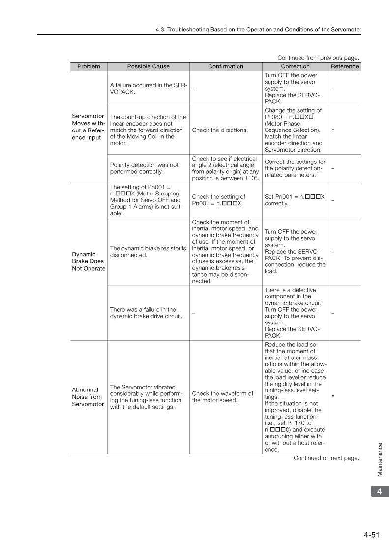
4.3 Troubleshooting Based on the Operation and Conditions of the Servomotor
4-51
4
Mai
nten
ance
Servomotor Moves with-out a Refer-ence Input
A failure occurred in the SER-VOPACK. –
Turn OFF the power supply to the servo system.Replace the SERVO-PACK.
–
The count-up direction of the linear encoder does not match the forward direction of the Moving Coil in the motor.
Check the directions.
Change the setting of Pn080 = n.X (Motor Phase Sequence Selection). Match the linear encoder direction and Servomotor direction.
*
Polarity detection was not performed correctly.
Check to see if electrical angle 2 (electrical angle from polarity origin) at any position is between ±10°.
Correct the settings for the polarity detection-related parameters.
–
Dynamic Brake Does Not Operate
The setting of Pn001 = n.X (Motor Stopping Method for Servo OFF and Group 1 Alarms) is not suit-able.
Check the setting of Pn001 = n.X.
Set Pn001 = n.X correctly. –
The dynamic brake resistor is disconnected.
Check the moment of inertia, motor speed, and dynamic brake frequency of use. If the moment of inertia, motor speed, or dynamic brake frequency of use is excessive, the dynamic brake resis-tance may be discon-nected.
Turn OFF the power supply to the servo system.Replace the SERVO-PACK. To prevent dis-connection, reduce the load.
–
There was a failure in the dynamic brake drive circuit. –
There is a defective component in the dynamic brake circuit.Turn OFF the power supply to the servo system.Replace the SERVO-PACK.
–
Abnormal Noise from Servomotor
The Servomotor vibrated considerably while perform-ing the tuning-less function with the default settings.
Check the waveform of the motor speed.
Reduce the load so that the moment of inertia ratio or mass ratio is within the allow-able value, or increase the load level or reduce the rigidity level in the tuning-less level set-tings.If the situation is not improved, disable the tuning-less function (i.e., set Pn170 to n.0) and execute autotuning either with or without a host refer-ence.
*
Continued on next page.
Continued from previous page.
Problem Possible Cause Confirmation Correction Reference

4.3 Troubleshooting Based on the Operation and Conditions of the Servomotor
4-52
Abnormal Noise from Servomotor
The machine mounting is not secure.
Turn OFF the power sup-ply to the servo system.Check to see if there are any loose mounting screws.
Tighten the mounting screws. –
Turn OFF the power sup-ply to the servo system.Check to see if there is misalignment in the cou-pling.
Align the coupling. –
Turn OFF the power sup-ply to the servo system.Check to see if the cou-pling is balanced.
Balance the coupling. –
The bearings are defective.
Turn OFF the power sup-ply to the servo system.Check for noise and vibration around the bear-ings.
Replace the Servomo-tor. –
There is a vibration source at the driven machine.
Turn OFF the power sup-ply to the servo system.Check for any foreign matter, damage, or defor-mation in the machine’s moving parts.
Consult with the machine manufacturer. –
Noise interference occurred because of incorrect I/O sig-nal cable specifications.
Turn OFF the power sup-ply to the servo system.Check the I/O signal cables to see if they sat-isfy specifications. Use shielded twisted-pair wire cables or screened twisted-pair cables with conductors of at least 0.12 mm2.
Use cables that satisfy the specifications. –
Noise interference occurred because an I/O signal cable is too long.
Turn OFF the power sup-ply to the servo system.Check the lengths of the I/O signal cables.
The I/O signal cables must be no longer than 3 m.
–
Noise interference occurred because of incorrect Encoder Cable specifications.
Turn OFF the power sup-ply to the servo system.Make sure that the rotary or Linear Encoder Cable satisfies the specifica-tions. Use a shielded twisted-pair wire cable or a screened twisted-pair cable with a conductors of at least 0.12 mm2.
Use cables that satisfy the specifications. –
Noise interference occurred because the Encoder Cable is too long.
Turn OFF the power sup-ply to the servo system.Check the length of the Encoder Cable.
• Rotary Servomotors: The Encoder Cable length must be 50 m max.
• Linear Servomotors: Make sure that the Serial Converter Unit cable is no longer than 20 m and that the Linear Encoder Cable and the Sensor Cable are no longer than 15 m each.
–
Continued on next page.
Continued from previous page.
Problem Possible Cause Confirmation Correction Reference

4.3 Troubleshooting Based on the Operation and Conditions of the Servomotor
4-53
4
Mai
nten
ance
Abnormal Noise from Servomotor
Noise interference occurred because the Encoder Cable is damaged.
Turn OFF the power sup-ply to the servo system.Check the Encoder Cable to see if it is pinched or the sheath is damaged.
Replace the Encoder Cable and correct the cable installation envi-ronment.
–
The Encoder Cable was sub-jected to excessive noise interference.
Turn OFF the power sup-ply to the servo system.Check to see if the Encoder Cable is bundled with a high-current line or installed near a high-cur-rent line.
Correct the cable lay-out so that no surge is applied by high-current lines.
–
There is variation in the FG potential because of the influence of machines on the Servomotor side, such as a welder.
Turn OFF the power sup-ply to the servo system.Check to see if the machines are correctly grounded.
Properly ground the machines to separate them from the FG of the encoder.
–
There is a SERVOPACK pulse counting error due to noise.
Check to see if there is noise interference on the signal line from the encoder.
Turn OFF the power supply to the servo system.Implement counter-measures against noise for the encoder wiring.
–
The encoder was subjected to excessive vibration or shock.
Turn OFF the power sup-ply to the servo system.Check to see if vibration from the machine occurred. Check the Ser-vomotor installation (mounting surface preci-sion, securing state, and alignment).Check the linear encoder installation (mounting sur-face precision and secur-ing method).
Reduce machine vibra-tion. Improve the mounting state of the Servomotor or linear encoder.
–
A failure occurred in the encoder. –
Turn OFF the power supply to the servo system.Replace the Servomo-tor.
–
A failure occurred in the Serial Converter Unit. –
Turn OFF the power supply to the servo system.Replace the Serial Con-verter Unit.
–
A failure occurred in the linear encoder. –
Turn OFF the power supply to the servo system.Replace the linear encoder.
–
Continued on next page.
Continued from previous page.
Problem Possible Cause Confirmation Correction Reference
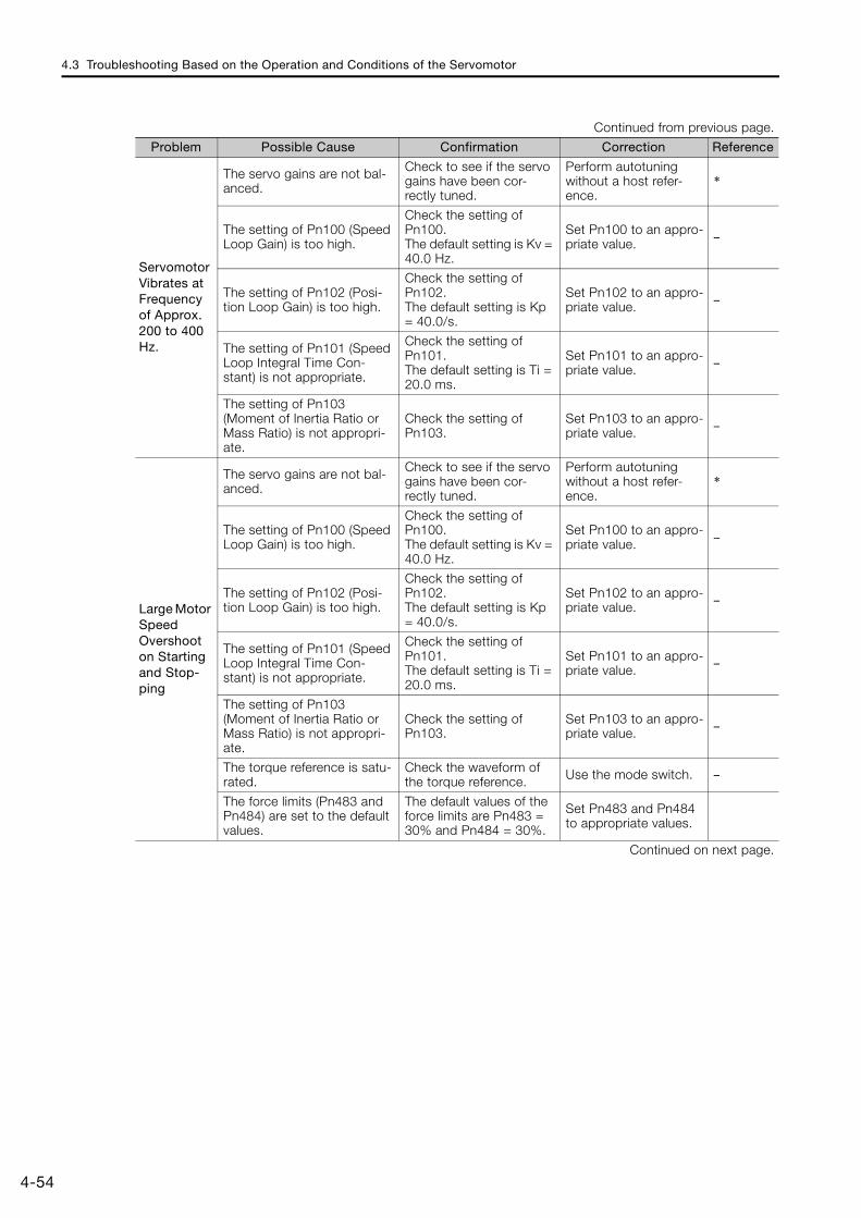
4.3 Troubleshooting Based on the Operation and Conditions of the Servomotor
4-54
Servomotor Vibrates at Frequency of Approx. 200 to 400 Hz.
The servo gains are not bal-anced.
Check to see if the servo gains have been cor-rectly tuned.
Perform autotuning without a host refer-ence.
*
The setting of Pn100 (Speed Loop Gain) is too high.
Check the setting of Pn100.The default setting is Kv = 40.0 Hz.
Set Pn100 to an appro-priate value. –
The setting of Pn102 (Posi-tion Loop Gain) is too high.
Check the setting of Pn102.The default setting is Kp = 40.0/s.
Set Pn102 to an appro-priate value. –
The setting of Pn101 (Speed Loop Integral Time Con-stant) is not appropriate.
Check the setting of Pn101.The default setting is Ti = 20.0 ms.
Set Pn101 to an appro-priate value. –
The setting of Pn103 (Moment of Inertia Ratio or Mass Ratio) is not appropri-ate.
Check the setting of Pn103.
Set Pn103 to an appro-priate value. –
Large Motor Speed Overshoot on Starting and Stop-ping
The servo gains are not bal-anced.
Check to see if the servo gains have been cor-rectly tuned.
Perform autotuning without a host refer-ence.
*
The setting of Pn100 (Speed Loop Gain) is too high.
Check the setting of Pn100.The default setting is Kv = 40.0 Hz.
Set Pn100 to an appro-priate value. –
The setting of Pn102 (Posi-tion Loop Gain) is too high.
Check the setting of Pn102.The default setting is Kp = 40.0/s.
Set Pn102 to an appro-priate value. –
The setting of Pn101 (Speed Loop Integral Time Con-stant) is not appropriate.
Check the setting of Pn101.The default setting is Ti = 20.0 ms.
Set Pn101 to an appro-priate value. –
The setting of Pn103 (Moment of Inertia Ratio or Mass Ratio) is not appropri-ate.
Check the setting of Pn103.
Set Pn103 to an appro-priate value. –
The torque reference is satu-rated.
Check the waveform of the torque reference. Use the mode switch. –
The force limits (Pn483 and Pn484) are set to the default values.
The default values of the force limits are Pn483 = 30% and Pn484 = 30%.
Set Pn483 and Pn484 to appropriate values.
Continued on next page.
Continued from previous page.
Problem Possible Cause Confirmation Correction Reference

4.3 Troubleshooting Based on the Operation and Conditions of the Servomotor
4-55
4
Mai
nten
ance
Absolute Encoder Position Deviation Error (The position that was saved in the host con-troller when the power was turned OFF is dif-ferent from the posi-tion when the power was next turned ON.)
Noise interference occurred because of incorrect Encoder Cable specifications.
Turn OFF the power sup-ply to the servo system.Check the Encoder Cable to see if it satisfies speci-fications.Use a shielded twisted-pair wire cable or a screened twisted-pair cable with conductors of at least 0.12 mm2.
Use cables that satisfy the specifications. –
Noise interference occurred because the Encoder Cable is too long.
Turn OFF the power sup-ply to the servo system.Check the length of the Encoder Cable.
• Rotary Servomotors: The Encoder Cable length must be 50 m max.
• Linear Servomotors: Make sure that the Serial Converter Unit cable is no longer than 20 m and that the Linear Encoder Cable and the Sensor Cable are no longer than 15 m each.
–
Noise interference occurred because the Encoder Cable is damaged.
Turn OFF the power sup-ply to the servo system.Check the Encoder Cable to see if it is pinched or the sheath is damaged.
Replace the Encoder Cable and correct the cable installation envi-ronment.
–
Replace the Encoder Cable and correct the cable instal-lation environment.
Turn OFF the power sup-ply to the servo system.Check to see if the Encoder Cable is bundled with a high-current line or installed near a high-cur-rent line.
Correct the cable lay-out so that no surge is applied by high-current lines.
–
There is variation in the FG potential because of the influence of machines on the Servomotor side, such as a welder.
Turn OFF the power sup-ply to the servo system.Check to see if the machines are correctly grounded.
Properly ground the machines to separate them from the FG of the encoder.
–
There is a SERVOPACK pulse counting error due to noise.
Turn OFF the power sup-ply to the servo system.Check to see if there is noise interference on the I/O signal line from the encoder or Serial Con-verter Unit.
Implement counter-measures against noise for the encoder or Serial Converter Unit wiring.
–
The encoder was subjected to excessive vibration or shock.
Turn OFF the power sup-ply to the servo system.Check to see if vibration from the machine occurred.Check the Servomotor installation (mounting sur-face precision, securing state, and alignment).Check the linear encoder installation (mounting sur-face precision and secur-ing method).
Reduce machine vibra-tion. Or, improve the mounting state of the Servomotor or linear encoder.
–
Continued on next page.
Continued from previous page.
Problem Possible Cause Confirmation Correction Reference
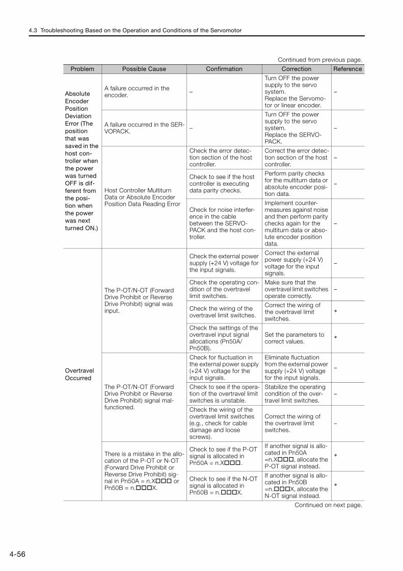
4.3 Troubleshooting Based on the Operation and Conditions of the Servomotor
4-56
Absolute Encoder Position Deviation Error (The position that was saved in the host con-troller when the power was turned OFF is dif-ferent from the posi-tion when the power was next turned ON.)
A failure occurred in the encoder. –
Turn OFF the power supply to the servo system.Replace the Servomo-tor or linear encoder.
–
A failure occurred in the SER-VOPACK. –
Turn OFF the power supply to the servo system.Replace the SERVO-PACK.
–
Host Controller Multiturn Data or Absolute Encoder Position Data Reading Error
Check the error detec-tion section of the host controller.
Correct the error detec-tion section of the host controller.
–
Check to see if the host controller is executing data parity checks.
Perform parity checks for the multiturn data or absolute encoder posi-tion data.
–
Check for noise interfer-ence in the cable between the SERVO-PACK and the host con-troller.
Implement counter-measures against noise and then perform parity checks again for the multiturn data or abso-lute encoder position data.
–
Overtravel Occurred
The P-OT/N-OT (Forward Drive Prohibit or Reverse Drive Prohibit) signal was input.
Check the external power supply (+24 V) voltage for the input signals.
Correct the external power supply (+24 V) voltage for the input signals.
–
Check the operating con-dition of the overtravel limit switches.
Make sure that the overtravel limit switches operate correctly.
–
Check the wiring of the overtravel limit switches.
Correct the wiring of the overtravel limit switches.
*
Check the settings of the overtravel input signal allocations (Pn50A/Pn50B).
Set the parameters to correct values. *
The P-OT/N-OT (Forward Drive Prohibit or Reverse Drive Prohibit) signal mal-functioned.
Check for fluctuation in the external power supply (+24 V) voltage for the input signals.
Eliminate fluctuation from the external power supply (+24 V) voltage for the input signals.
–
Check to see if the opera-tion of the overtravel limit switches is unstable.
Stabilize the operating condition of the over-travel limit switches.
–
Check the wiring of the overtravel limit switches (e.g., check for cable damage and loose screws).
Correct the wiring of the overtravel limit switches.
–
There is a mistake in the allo-cation of the P-OT or N-OT (Forward Drive Prohibit or Reverse Drive Prohibit) sig-nal in Pn50A = n.X or Pn50B = n.X.
Check to see if the P-OT signal is allocated in Pn50A = n.X.
If another signal is allo-cated in Pn50A =n.X, allocate the P-OT signal instead.
*
Check to see if the N-OT signal is allocated in Pn50B = n.X.
If another signal is allo-cated in Pn50B =n.X, allocate the N-OT signal instead.
*
Continued on next page.
Continued from previous page.
Problem Possible Cause Confirmation Correction Reference
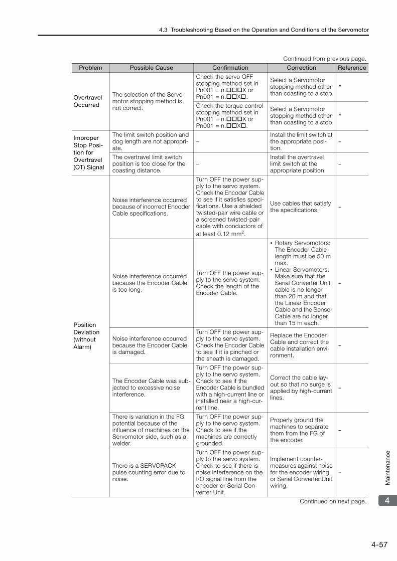
4.3 Troubleshooting Based on the Operation and Conditions of the Servomotor
4-57
4
Mai
nten
ance
Overtravel Occurred
The selection of the Servo-motor stopping method is not correct.
Check the servo OFF stopping method set in Pn001 = n.X or Pn001 = n.X.
Select a Servomotor stopping method other than coasting to a stop.
*
Check the torque control stopping method set in Pn001 = n.X or Pn001 = n.X.
Select a Servomotor stopping method other than coasting to a stop.
*
Improper Stop Posi-tion for Overtravel (OT) Signal
The limit switch position and dog length are not appropri-ate.
–Install the limit switch at the appropriate posi-tion.
–
The overtravel limit switch position is too close for the coasting distance.
–Install the overtravel limit switch at the appropriate position.
–
Position Deviation (without Alarm)
Noise interference occurred because of incorrect Encoder Cable specifications.
Turn OFF the power sup-ply to the servo system.Check the Encoder Cable to see if it satisfies speci-fications. Use a shielded twisted-pair wire cable or a screened twisted-pair cable with conductors of at least 0.12 mm2.
Use cables that satisfy the specifications. –
Noise interference occurred because the Encoder Cable is too long.
Turn OFF the power sup-ply to the servo system.Check the length of the Encoder Cable.
• Rotary Servomotors: The Encoder Cable length must be 50 m max.
• Linear Servomotors: Make sure that the Serial Converter Unit cable is no longer than 20 m and that the Linear Encoder Cable and the Sensor Cable are no longer than 15 m each.
–
Noise interference occurred because the Encoder Cable is damaged.
Turn OFF the power sup-ply to the servo system.Check the Encoder Cable to see if it is pinched or the sheath is damaged.
Replace the Encoder Cable and correct the cable installation envi-ronment.
–
The Encoder Cable was sub-jected to excessive noise interference.
Turn OFF the power sup-ply to the servo system.Check to see if the Encoder Cable is bundled with a high-current line or installed near a high-cur-rent line.
Correct the cable lay-out so that no surge is applied by high-current lines.
–
There is variation in the FG potential because of the influence of machines on the Servomotor side, such as a welder.
Turn OFF the power sup-ply to the servo system.Check to see if the machines are correctly grounded.
Properly ground the machines to separate them from the FG of the encoder.
–
There is a SERVOPACK pulse counting error due to noise.
Turn OFF the power sup-ply to the servo system.Check to see if there is noise interference on the I/O signal line from the encoder or Serial Con-verter Unit.
Implement counter-measures against noise for the encoder wiring or Serial Converter Unit wiring.
–
Continued on next page.
Continued from previous page.
Problem Possible Cause Confirmation Correction Reference
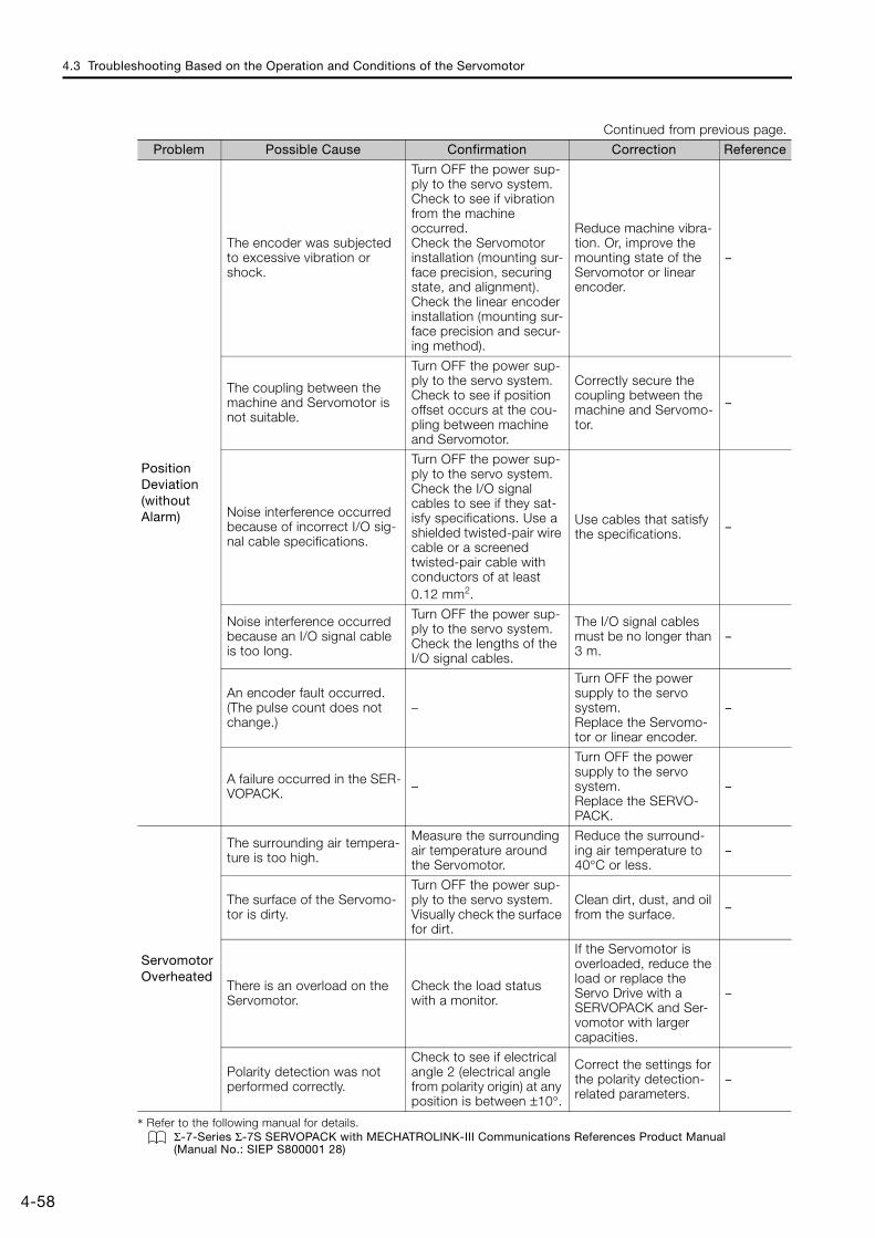
4.3 Troubleshooting Based on the Operation and Conditions of the Servomotor
4-58
* Refer to the following manual for details.Σ-7-Series Σ-7S SERVOPACK with MECHATROLINK-III Communications References Product Manual (Manual No.: SIEP S800001 28)
Position Deviation (without Alarm)
The encoder was subjected to excessive vibration or shock.
Turn OFF the power sup-ply to the servo system.Check to see if vibration from the machine occurred.Check the Servomotor installation (mounting sur-face precision, securing state, and alignment).Check the linear encoder installation (mounting sur-face precision and secur-ing method).
Reduce machine vibra-tion. Or, improve the mounting state of the Servomotor or linear encoder.
–
The coupling between the machine and Servomotor is not suitable.
Turn OFF the power sup-ply to the servo system.Check to see if position offset occurs at the cou-pling between machine and Servomotor.
Correctly secure the coupling between the machine and Servomo-tor.
–
Noise interference occurred because of incorrect I/O sig-nal cable specifications.
Turn OFF the power sup-ply to the servo system.Check the I/O signal cables to see if they sat-isfy specifications. Use a shielded twisted-pair wire cable or a screened twisted-pair cable with conductors of at least 0.12 mm2.
Use cables that satisfy the specifications. –
Noise interference occurred because an I/O signal cable is too long.
Turn OFF the power sup-ply to the servo system.Check the lengths of the I/O signal cables.
The I/O signal cables must be no longer than 3 m.
–
An encoder fault occurred. (The pulse count does not change.)
–
Turn OFF the power supply to the servo system.Replace the Servomo-tor or linear encoder.
–
A failure occurred in the SER-VOPACK. –
Turn OFF the power supply to the servo system.Replace the SERVO-PACK.
–
Servomotor Overheated
The surrounding air tempera-ture is too high.
Measure the surrounding air temperature around the Servomotor.
Reduce the surround-ing air temperature to 40°C or less.
–
The surface of the Servomo-tor is dirty.
Turn OFF the power sup-ply to the servo system.Visually check the surface for dirt.
Clean dirt, dust, and oil from the surface. –
There is an overload on the Servomotor.
Check the load status with a monitor.
If the Servomotor is overloaded, reduce the load or replace the Servo Drive with a SERVOPACK and Ser-vomotor with larger capacities.
–
Polarity detection was not performed correctly.
Check to see if electrical angle 2 (electrical angle from polarity origin) at any position is between ±10°.
Correct the settings for the polarity detection-related parameters.
–
Continued from previous page.
Problem Possible Cause Confirmation Correction Reference
This chapter provides information on the parameters.
5.1 List of Servo Parameters . . . . . . . . . . . . . . . 5-25.1.1 Interpreting the Parameter Lists . . . . . . . . . . . . . 5-25.1.2 List of Servo Parameters . . . . . . . . . . . . . . . . . . . 5-3
5.2 List of MECHATROLINK-III Common Parameters . . 5-425.2.1 Interpreting the Parameter Lists . . . . . . . . . . . . 5-425.2.2 List of MECHATROLINK-III Common
Parameters . . . . . . . . . . . . . . . . . . . . . . . . . . . . 5-42
5.3 Parameter Recording Table . . . . . . . . . . . . 5-51
Parameter Lists 5

5.1 List of Servo Parameters
5.1.1 Interpreting the Parameter Lists
5-2
5.1 List of Servo Parameters
5.1.1 Interpreting the Parameter Lists
Parameter No. S
ize
NameSetting Range
Setting Unit
Default Setting
Applica-ble Motors
When Enabled
Classi-fication
Refer-ence
Pn000
2 Basic Function Selections 0 0000h to 10B1h – 0000h All After restart Setup –
Rotary Servomotor terms are used for parameters that are applicable to all Servomotors. If you are using a Linear Servomotor, you need to interpret the terms accordingly. Refer to the following section for details.
Rotary: The parameter is used for only Rotary Servomotors.Linear: The parameter is used for only Linear Servomotors.
All: The parameter is used for both Rotary Servomotors and Linear Servomotors.The types of motors to which the parameter applies.
Differences in Terms for Rotary Servomotors and Linear Servomotors on page xi
Indicates when a change to the parameter will be effective.“After restart” indicates parameters that will be effective after one of the following is executed.• The power supply is turned OFF
and ON again.• The CONFIG command is sent.• A software reset is executed.
M3
n.X
Rotation Direction SelectionReference
Movement Direction Selection
0Use CCW as the forward direction.
–
Use the direction in which the linear encoder counts up as the for-ward direction.
1Use CW as the forward direction. (Reverse Rotation Mode)
Use the direction in which the linear encoder counts down as the forward direction. (Reverse Movement Mode)
n.X Reserved parameter (Do not change.)
n.X Reserved parameter (Do not change.)
n.X
Rotary/Linear Servomotor Startup Selection When Encoder Is Not Connected Reference
0 When an encoder is not connected, start as SERVOPACK for Rotary Servomotor.
–1 When an encoder is not connected, start as SERVOPACK for Lin-
ear Servomotor.
If there are differences in the parameters for Rotary Servomotor and Linear Servomotor, information is provided for both.
Bottom row: For Linear ServomotorsTop row: For Rotary Servomotors
TuningSetup
There are the following two classifications.
Refer to the following section for details.Σ-7-Series Σ-7S SERVOPACK with MECHATROLINK-III Communications References Product Manual (Manual No.: SIEP S800001 28)
M2M3
Parameters that are valid only for a MECHATROLINK-II-compatible profile.
Symbols are provided when a parameter is valid only for a specific profile.
Parameters that are valid only for a MECHATROLINK-III standard servo profile.
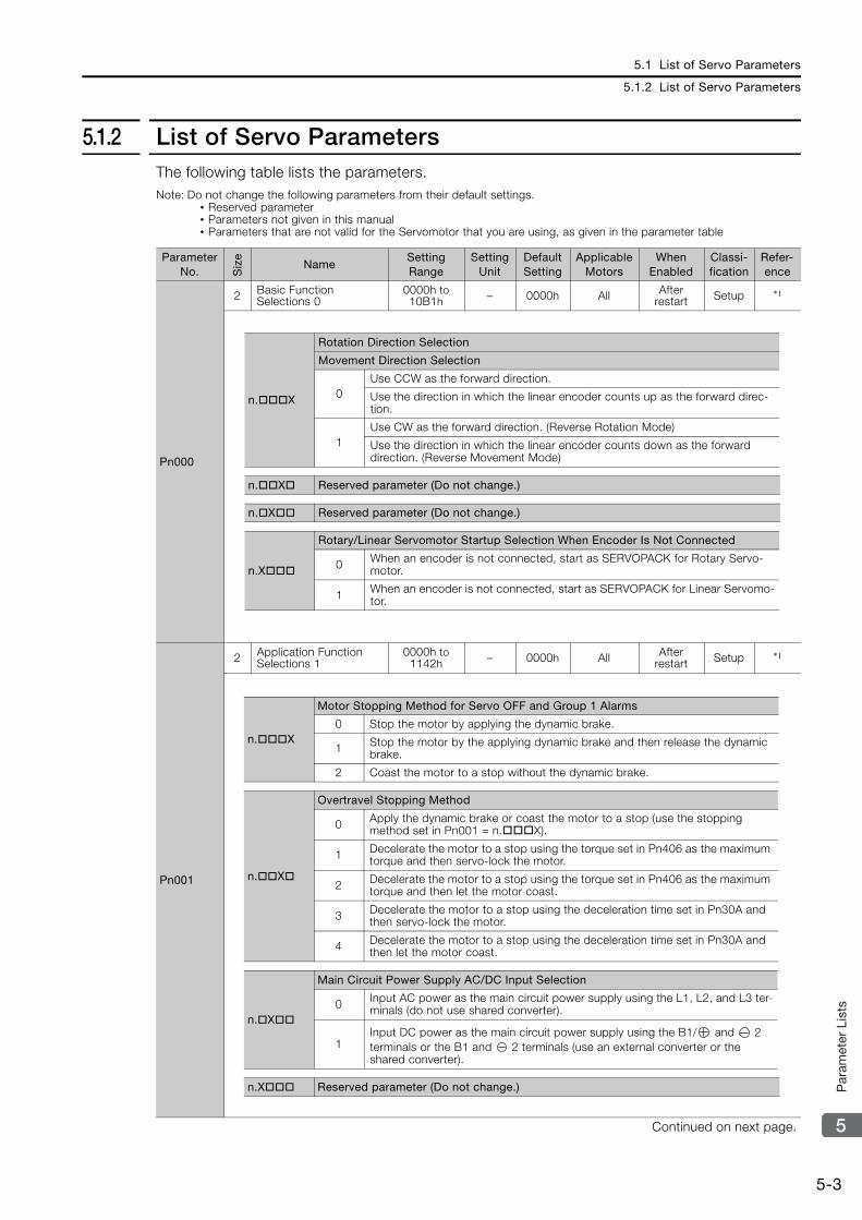
5.1 List of Servo Parameters
5.1.2 List of Servo Parameters
5-3
5
Par
amet
er L
ists
5.1.2 List of Servo ParametersThe following table lists the parameters.Note: Do not change the following parameters from their default settings.
• Reserved parameter• Parameters not given in this manual• Parameters that are not valid for the Servomotor that you are using, as given in the parameter table
Parameter No. S
ize
NameSetting Range
Setting Unit
Default Setting
Applicable Motors
When Enabled
Classi-fication
Refer-ence
Pn000
2 Basic Function Selections 0
0000h to 10B1h – 0000h All After
restart Setup *1
Pn001
2 Application Function Selections 1
0000h to 1142h – 0000h All After
restart Setup *1
Continued on next page.
n.X
Rotation Direction Selection
Movement Direction Selection
0Use CCW as the forward direction.
Use the direction in which the linear encoder counts up as the forward direc-tion.
1Use CW as the forward direction. (Reverse Rotation Mode)
Use the direction in which the linear encoder counts down as the forward direction. (Reverse Movement Mode)
n.X Reserved parameter (Do not change.)
n.X Reserved parameter (Do not change.)
n.X
Rotary/Linear Servomotor Startup Selection When Encoder Is Not Connected
0 When an encoder is not connected, start as SERVOPACK for Rotary Servo-motor.
1 When an encoder is not connected, start as SERVOPACK for Linear Servomo-tor.
n.X
Motor Stopping Method for Servo OFF and Group 1 Alarms
0 Stop the motor by applying the dynamic brake.
1 Stop the motor by the applying dynamic brake and then release the dynamic brake.
2 Coast the motor to a stop without the dynamic brake.
n.X
Overtravel Stopping Method
0 Apply the dynamic brake or coast the motor to a stop (use the stopping method set in Pn001 = n.X).
1 Decelerate the motor to a stop using the torque set in Pn406 as the maximum torque and then servo-lock the motor.
2 Decelerate the motor to a stop using the torque set in Pn406 as the maximum torque and then let the motor coast.
3 Decelerate the motor to a stop using the deceleration time set in Pn30A and then servo-lock the motor.
4 Decelerate the motor to a stop using the deceleration time set in Pn30A and then let the motor coast.
n.X
Main Circuit Power Supply AC/DC Input Selection
0 Input AC power as the main circuit power supply using the L1, L2, and L3 ter-minals (do not use shared converter).
1Input DC power as the main circuit power supply using the B1/ and 2 terminals or the B1 and 2 terminals (use an external converter or the shared converter).
n.X Reserved parameter (Do not change.)
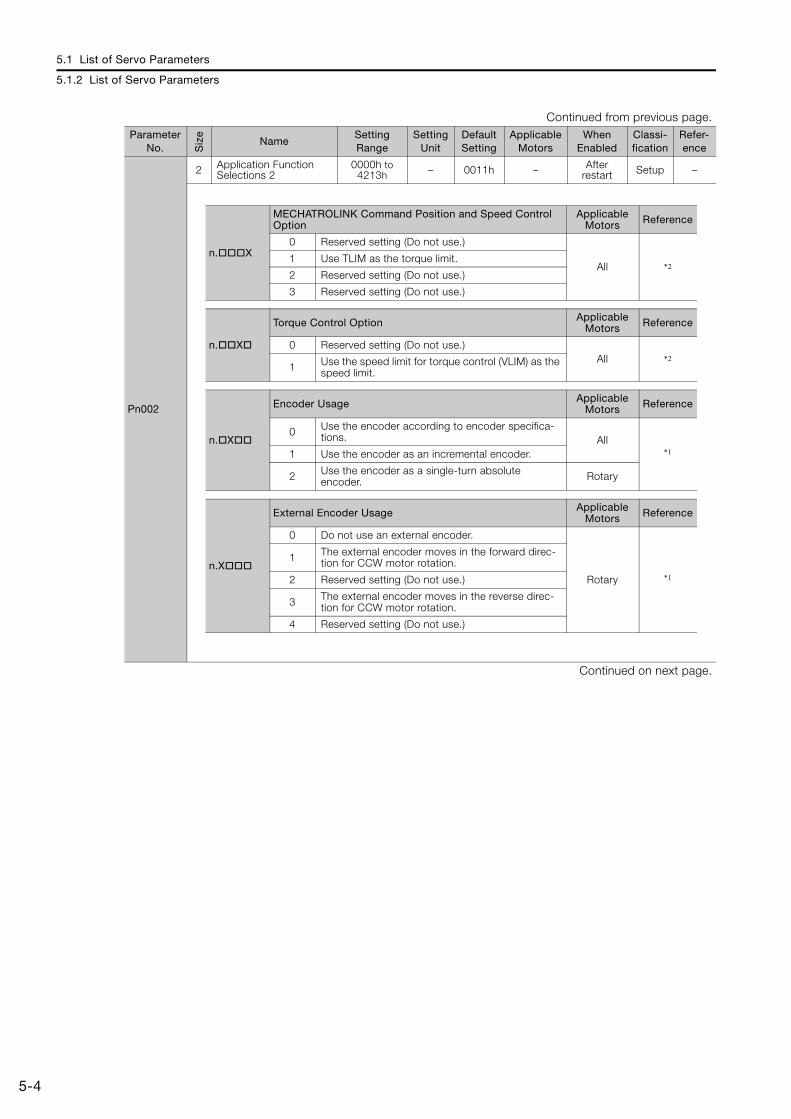
5.1 List of Servo Parameters
5.1.2 List of Servo Parameters
5-4
Pn002
2 Application Function Selections 2
0000h to 4213h – 0011h – After
restart Setup –
Continued on next page.
Continued from previous page.Parameter
No. Siz
e
NameSetting Range
Setting Unit
Default Setting
Applicable Motors
When Enabled
Classi-fication
Refer-ence
n.X
MECHATROLINK Command Position and Speed Control Option
Applicable Motors Reference
0 Reserved setting (Do not use.)
All *21 Use TLIM as the torque limit.
2 Reserved setting (Do not use.)
3 Reserved setting (Do not use.)
n.X
Torque Control Option Applicable Motors Reference
0 Reserved setting (Do not use.)All *2
1 Use the speed limit for torque control (VLIM) as the speed limit.
n.X
Encoder Usage Applicable Motors Reference
0 Use the encoder according to encoder specifica-tions. All
*11 Use the encoder as an incremental encoder.
2 Use the encoder as a single-turn absolute encoder. Rotary
n.X
External Encoder Usage Applicable Motors Reference
0 Do not use an external encoder.
Rotary *1
1 The external encoder moves in the forward direc-tion for CCW motor rotation.
2 Reserved setting (Do not use.)
3 The external encoder moves in the reverse direc-tion for CCW motor rotation.
4 Reserved setting (Do not use.)
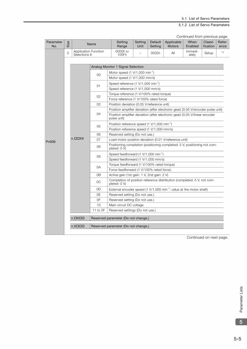
5.1 List of Servo Parameters
5.1.2 List of Servo Parameters
5-5
5
Par
amet
er L
ists
Pn006
2 Application Function Selections 6
0000h to 105Fh – 0002h All Immedi-
ately Setup *1
Continued on next page.
Continued from previous page.Parameter
No. Siz
e
NameSetting Range
Setting Unit
Default Setting
Applicable Motors
When Enabled
Classi-fication
Refer-ence
n.XX
Analog Monitor 1 Signal Selection
00Motor speed (1 V/1,000 min-1)
Motor speed (1 V/1,000 mm/s)
01Speed reference (1 V/1,000 min-1)
Speed reference (1 V/1,000 mm/s)
02Torque reference (1 V/100% rated torque)
Force reference (1 V/100% rated force)
03 Position deviation (0.05 V/reference unit)
04Position amplifier deviation (after electronic gear) (0.05 V/encoder pulse unit)
Position amplifier deviation (after electronic gear) (0.05 V/linear encoder pulse unit)
05Position reference speed (1 V/1,000 min-1)
Position reference speed (1 V/1,000 mm/s)
06 Reserved setting (Do not use.)
07 Load-motor position deviation (0.01 V/reference unit)
08 Positioning completion (positioning completed: 5 V, positioning not com-pleted: 0 V)
09Speed feedforward (1 V/1,000 min-1)
Speed feedforward (1 V/1,000 mm/s)
0ATorque feedforward (1 V/100% rated torque)
Force feedforward (1 V/100% rated force)
0B Active gain (1st gain: 1 V, 2nd gain: 2 V)
0C Completion of position reference distribution (completed: 5 V, not com-pleted: 0 V)
0D External encoder speed (1 V/1,000 min-1: value at the motor shaft)
0E Reserved setting (Do not use.)
0F Reserved setting (Do not use.)
10 Main circuit DC voltage
11 to 5F Reserved settings (Do not use.)
n.X Reserved parameter (Do not change.)
n.X Reserved parameter (Do not change.)
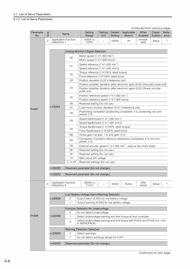
5.1 List of Servo Parameters
5.1.2 List of Servo Parameters
5-6
Pn007
2 Application Function Selections 7
0000h to 105Fh – 0000h All Immedi-
ately Setup *1
Pn008
2 Application Function Selections 8
0000h to 7121h – 4000h Rotary After
restart Setup *1
Continued on next page.
Continued from previous page.Parameter
No. Siz
e
NameSetting Range
Setting Unit
Default Setting
Applicable Motors
When Enabled
Classi-fication
Refer-ence
n.XX
Analog Monitor 2 Signal Selection
00Motor speed (1 V/1,000 min-1)
Motor speed (1 V/1,000 mm/s)
01Speed reference (1 V/1,000 min-1)
Speed reference (1 V/1,000 mm/s)
02Torque reference (1 V/100% rated torque)
Force reference (1 V/100% rated force)
03 Position deviation (0.05 V/reference unit)
04Position amplifier deviation (after electronic gear) (0.05 V/encoder pulse unit)
Position amplifier deviation (after electronic gear) (0.05 V/linear encoder pulse unit)
05Position reference speed (1 V/1,000 min-1)
Position reference speed (1 V/1,000 mm/s)
06 Reserved setting (Do not use.)
07 Load-motor position deviation (0.01 V/reference unit)
08 Positioning completion (positioning completed: 5 V, positioning not com-pleted: 0 V)
09Speed feedforward (1 V/1,000 min-1)
Speed feedforward (1 V/1,000 mm/s)
0ATorque feedforward (1 V/100% rated torque)
Force feedforward (1 V/100% rated force)
0B Active gain (1st gain: 1 V, 2nd gain: 2 V)
0C Completion of position reference distribution (completed: 5 V, not com-pleted: 0 V)
0D External encoder speed (1 V/1,000 min-1: value at the motor shaft)
0E Reserved setting (Do not use.)
0F Reserved setting (Do not use.)
10 Main circuit DC voltage
11 to 5F Reserved settings (Do not use.)
n.X Reserved parameter (Do not change.)
n.X Reserved parameter (Do not change.)
n.X
Low Battery Voltage Alarm/Warning Selection
0 Output alarm (A.830) for low battery voltage.
1 Output warning (A.930) for low battery voltage.
n.X
Function Selection for Undervoltage
0 Do not detect undervoltage.
1 Detect undervoltage warning and limit torque at host controller.
2 Detect undervoltage warning and limit torque with Pn424 and Pn425 (i.e., only in SERVOPACK).
n.X
Warning Detection Selection
0 Detect warnings.
1 Do not detect warnings except for A.971.
n.X Reserved parameter (Do not change.)
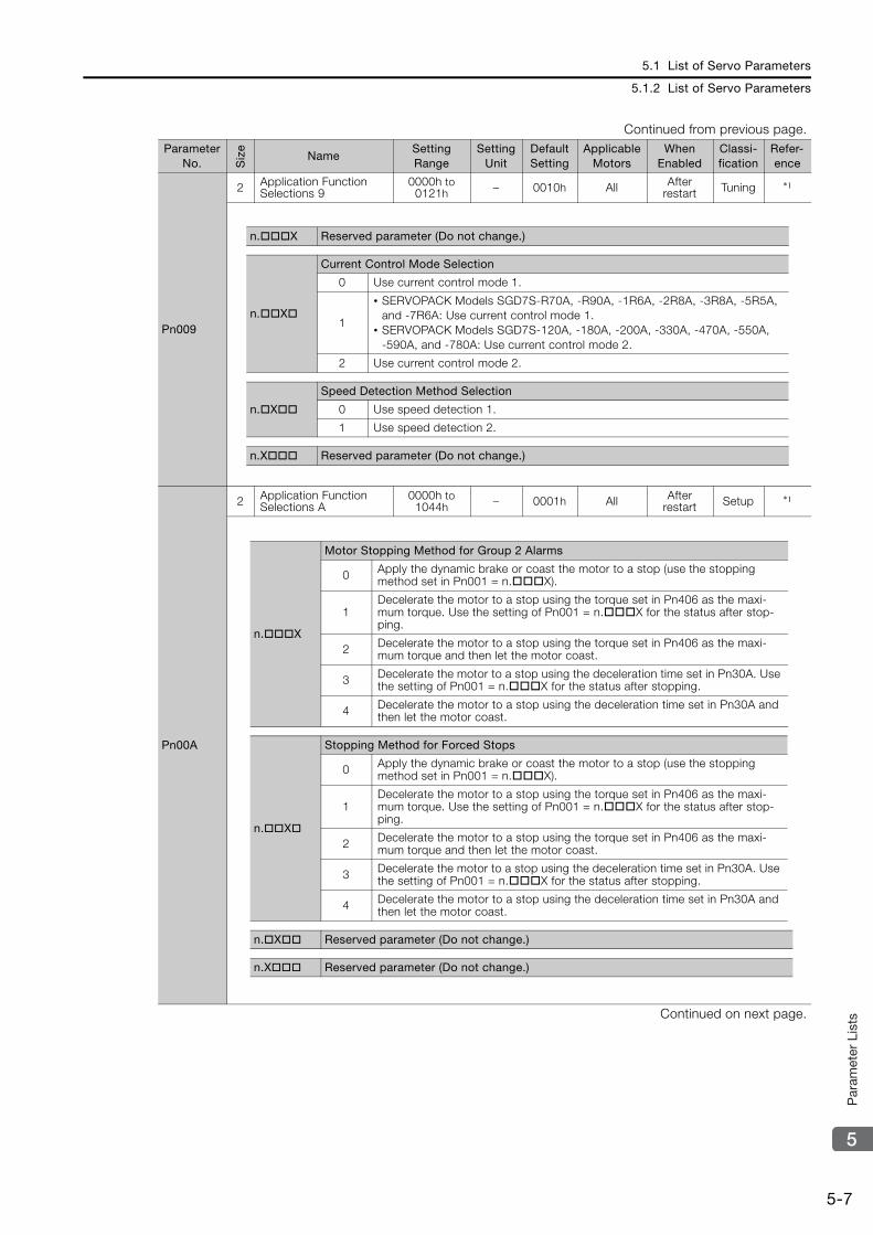
5.1 List of Servo Parameters
5.1.2 List of Servo Parameters
5-7
5
Par
amet
er L
ists
Pn009
2 Application Function Selections 9
0000h to 0121h – 0010h All After
restart Tuning *1
Pn00A
2 Application Function Selections A
0000h to 1044h – 0001h All After
restart Setup *1
Continued on next page.
Continued from previous page.Parameter
No. Siz
e
NameSetting Range
Setting Unit
Default Setting
Applicable Motors
When Enabled
Classi-fication
Refer-ence
n.X Reserved parameter (Do not change.)
n.X
Current Control Mode Selection
0 Use current control mode 1.
1
• SERVOPACK Models SGD7S-R70A, -R90A, -1R6A, -2R8A, -3R8A, -5R5A, and -7R6A: Use current control mode 1.
• SERVOPACK Models SGD7S-120A, -180A, -200A, -330A, -470A, -550A, -590A, and -780A: Use current control mode 2.
2 Use current control mode 2.
n.X
Speed Detection Method Selection
0 Use speed detection 1.
1 Use speed detection 2.
n.X Reserved parameter (Do not change.)
n.X
Motor Stopping Method for Group 2 Alarms
0 Apply the dynamic brake or coast the motor to a stop (use the stopping method set in Pn001 = n.X).
1Decelerate the motor to a stop using the torque set in Pn406 as the maxi-mum torque. Use the setting of Pn001 = n.X for the status after stop-ping.
2 Decelerate the motor to a stop using the torque set in Pn406 as the maxi-mum torque and then let the motor coast.
3 Decelerate the motor to a stop using the deceleration time set in Pn30A. Use the setting of Pn001 = n.X for the status after stopping.
4 Decelerate the motor to a stop using the deceleration time set in Pn30A and then let the motor coast.
n.X
Stopping Method for Forced Stops
0 Apply the dynamic brake or coast the motor to a stop (use the stopping method set in Pn001 = n.X).
1Decelerate the motor to a stop using the torque set in Pn406 as the maxi-mum torque. Use the setting of Pn001 = n.X for the status after stop-ping.
2 Decelerate the motor to a stop using the torque set in Pn406 as the maxi-mum torque and then let the motor coast.
3 Decelerate the motor to a stop using the deceleration time set in Pn30A. Use the setting of Pn001 = n.X for the status after stopping.
4 Decelerate the motor to a stop using the deceleration time set in Pn30A and then let the motor coast.
n.X Reserved parameter (Do not change.)
n.X Reserved parameter (Do not change.)
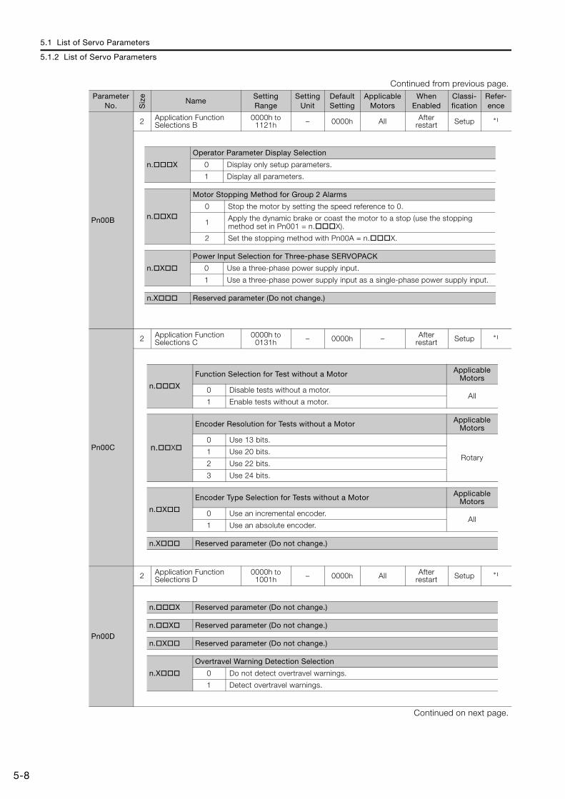
5.1 List of Servo Parameters
5.1.2 List of Servo Parameters
5-8
Pn00B
2 Application Function Selections B
0000h to 1121h – 0000h All After
restart Setup *1
Pn00C
2 Application Function Selections C
0000h to 0131h – 0000h – After
restart Setup *1
Pn00D
2 Application Function Selections D
0000h to 1001h – 0000h All After
restart Setup *1
Continued on next page.
Continued from previous page.Parameter
No. Siz
e
NameSetting Range
Setting Unit
Default Setting
Applicable Motors
When Enabled
Classi-fication
Refer-ence
n.X
Operator Parameter Display Selection
0 Display only setup parameters.
1 Display all parameters.
n.X
Motor Stopping Method for Group 2 Alarms
0 Stop the motor by setting the speed reference to 0.
1 Apply the dynamic brake or coast the motor to a stop (use the stopping method set in Pn001 = n.X).
2 Set the stopping method with Pn00A = n.X.
n.X
Power Input Selection for Three-phase SERVOPACK
0 Use a three-phase power supply input.
1 Use a three-phase power supply input as a single-phase power supply input.
n.X Reserved parameter (Do not change.)
n.X
Function Selection for Test without a Motor Applicable Motors
0 Disable tests without a motor.All
1 Enable tests without a motor.
n.X
Encoder Resolution for Tests without a Motor Applicable Motors
0 Use 13 bits.
Rotary1 Use 20 bits.
2 Use 22 bits.
3 Use 24 bits.
n.X
Encoder Type Selection for Tests without a Motor Applicable Motors
0 Use an incremental encoder.All
1 Use an absolute encoder.
n.X Reserved parameter (Do not change.)
n.X Reserved parameter (Do not change.)
n.X Reserved parameter (Do not change.)
n.X Reserved parameter (Do not change.)
n.X
Overtravel Warning Detection Selection
0 Do not detect overtravel warnings.
1 Detect overtravel warnings.
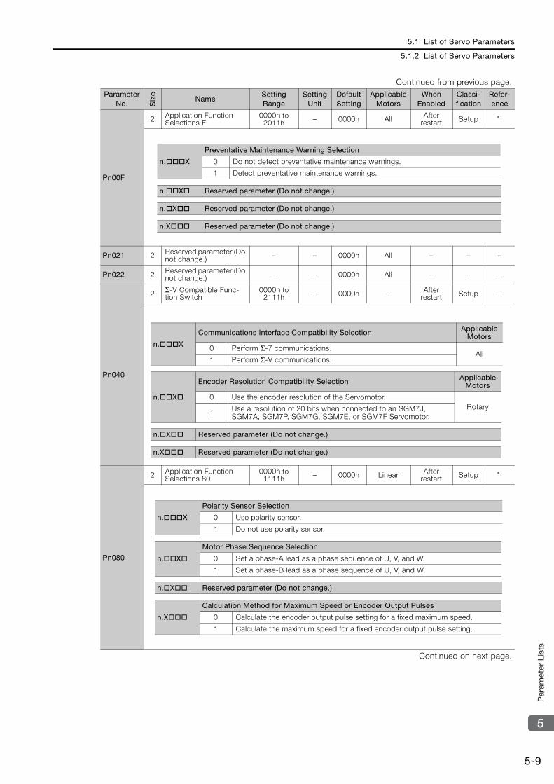
5.1 List of Servo Parameters
5.1.2 List of Servo Parameters
5-9
5
Par
amet
er L
ists
Pn00F
2 Application Function Selections F
0000h to 2011h – 0000h All After
restart Setup *1
Pn021 2 Reserved parameter (Do not change.) – – 0000h All – – –
Pn022 2 Reserved parameter (Do not change.) – – 0000h All – – –
Pn040
2 Σ-V Compatible Func-tion Switch
0000h to 2111h – 0000h – After
restart Setup –
Pn080
2 Application Function Selections 80
0000h to 1111h – 0000h Linear After
restart Setup *1
Continued on next page.
Continued from previous page.Parameter
No. Siz
e
NameSetting Range
Setting Unit
Default Setting
Applicable Motors
When Enabled
Classi-fication
Refer-ence
n.X
Preventative Maintenance Warning Selection
0 Do not detect preventative maintenance warnings.
1 Detect preventative maintenance warnings.
n.X Reserved parameter (Do not change.)
n.X Reserved parameter (Do not change.)
n.X Reserved parameter (Do not change.)
n.X
Communications Interface Compatibility Selection Applicable Motors
0 Perform Σ-7 communications.All
1 Perform Σ-V communications.
n.X
Encoder Resolution Compatibility Selection Applicable Motors
0 Use the encoder resolution of the Servomotor.Rotary
1 Use a resolution of 20 bits when connected to an SGM7J, SGM7A, SGM7P, SGM7G, SGM7E, or SGM7F Servomotor.
n.X Reserved parameter (Do not change.)
n.X Reserved parameter (Do not change.)
n.X
Polarity Sensor Selection
0 Use polarity sensor.
1 Do not use polarity sensor.
n.X
Motor Phase Sequence Selection
0 Set a phase-A lead as a phase sequence of U, V, and W.
1 Set a phase-B lead as a phase sequence of U, V, and W.
n.X Reserved parameter (Do not change.)
n.X
Calculation Method for Maximum Speed or Encoder Output Pulses
0 Calculate the encoder output pulse setting for a fixed maximum speed.
1 Calculate the maximum speed for a fixed encoder output pulse setting.

5.1 List of Servo Parameters
5.1.2 List of Servo Parameters
5-10
Pn081
2 Application Function Selections 81
0000h to 1111h – 0000h All After
restart Setup *1
Pn100 2 Speed Loop Gain 10 to 20,000 0.1 Hz 400 All Immedi-ately Tuning *1
Pn101 2 Speed Loop Integral Time Constant 15 to 51,200 0.01 ms 2000 All Immedi-
ately Tuning *1
Pn102 2 Position Loop Gain 10 to 20,000 0.1/s 400 All Immedi-ately Tuning *1
Pn103 2 Moment of Inertia Ratio 0 to 20,000 1% 100 All Immedi-ately Tuning *1
Pn104 2 Second Speed Loop Gain 10 to 20,000 0.1 Hz 400 All Immedi-
ately Tuning *1
Pn105 2 Second Speed Loop Integral Time Constant 15 to 51,200 0.01 ms 2000 All Immedi-
ately Tuning *1
Pn106 2 Second Position Loop Gain 10 to 20,000 0.1/s 400 All Immedi-
ately Tuning *1
Pn109 2 Feedforward 0 to 100 1% 0 All Immedi-ately Tuning *1
Pn10A 2 Feedforward Filter Time Constant 0 to 6,400 0.01 ms 0 All Immedi-
ately Tuning *1
Pn10B
2 Gain Application Selec-tions
0000h to 5334h – 0000h All – Setup *1
Pn10C 2 Mode Switching Level for Torque Reference 0 to 800 1% 200 All Immedi-
ately Tuning *1
Pn10D 2 Mode Switching Level for Speed Reference 0 to 10,000 1 min-1 0 Rotary Immedi-
ately Tuning *1
Continued on next page.
Continued from previous page.Parameter
No. Siz
e
NameSetting Range
Setting Unit
Default Setting
Applicable Motors
When Enabled
Classi-fication
Refer-ence
n.X
Phase-C Pulse Output Selection
0 Output phase-C pulses only in the forward direction.
1 Output phase-C pulses in both the forward and reverse directions.
n.X Reserved parameter (Do not change.)
n.X Reserved parameter (Do not change.)
n.X Reserved parameter (Do not change.)
n.X
Mode Switching Selection When Enabled
0 Use the internal torque reference as the condition (level setting: Pn10C).
Immedi-ately
1Use the speed reference as the condition (level setting: Pn10D).
Use the speed reference as the condition (level setting: Pn181).
2
Use the acceleration reference as the condition (level setting: Pn10E).
Use the acceleration reference as the condition (level setting: Pn182).
3 Use the position deviation as the condition (level setting: Pn10F).
4 Do not use mode switching.
n.X
Speed Loop Control Method When Enabled
0 PI controlAfter
restart1 I-P control
2 and 3 Reserved settings (Do not use.)
n.X Reserved parameter (Do not change.)
n.X Reserved parameter (Do not change.)
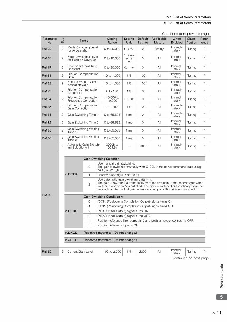
5.1 List of Servo Parameters
5.1.2 List of Servo Parameters
5-11
5
Par
amet
er L
ists
Pn10E 2 Mode Switching Level for Acceleration 0 to 30,000 1 min-1/s 0 Rotary Immedi-
ately Tuning *1
Pn10F 2 Mode Switching Level for Position Deviation 0 to 10,000
1 refer-ence unit
0 All Immedi-ately Tuning *1
Pn11F 2 Position Integral Time Constant 0 to 50,000 0.1 ms 0 All Immedi-
ately Tuning *1
Pn121 2 Friction Compensation Gain 10 to 1,000 1% 100 All Immedi-
ately Tuning *1
Pn122 2 Second Friction Com-pensation Gain 10 to 1,000 1% 100 All Immedi-
ately Tuning *1
Pn123 2 Friction Compensation Coefficient 0 to 100 1% 0 All Immedi-
ately Tuning *1
Pn124 2 Friction Compensation Frequency Correction
-10,000 to 10,000 0.1 Hz 0 All Immedi-
ately Tuning *1
Pn125 2 Friction Compensation Gain Correction 1 to 1,000 1% 100 All Immedi-
ately Tuning *1
Pn131 2 Gain Switching Time 1 0 to 65,535 1 ms 0 All Immedi-ately Tuning *1
Pn132 2 Gain Switching Time 2 0 to 65,535 1 ms 0 All Immedi-ately Tuning *1
Pn135 2 Gain Switching Waiting Time 1 0 to 65,535 1 ms 0 All Immedi-
ately Tuning *1
Pn136 2 Gain Switching Waiting Time 2 0 to 65,535 1 ms 0 All Immedi-
ately Tuning *1
Pn139
2 Automatic Gain Switch-ing Selections 1
0000h to 0052h – 0000h All Immedi-
ately Tuning *1
Pn13D 2 Current Gain Level 100 to 2,000 1% 2000 All Immedi-ately Tuning *1
Continued on next page.
Continued from previous page.Parameter
No. Siz
e
NameSetting Range
Setting Unit
Default Setting
Applicable Motors
When Enabled
Classi-fication
Refer-ence
n.X
Gain Switching Selection
0Use manual gain switching.The gain is switched manually with G-SEL in the servo command output sig-nals (SVCMD_IO).
1 Reserved setting (Do not use.)
2
Use automatic gain switching pattern 1.The gain is switched automatically from the first gain to the second gain when switching condition A is satisfied. The gain is switched automatically from the second gain to the first gain when switching condition A is not satisfied.
n.X
Gain Switching Condition A
0 /COIN (Positioning Completion Output) signal turns ON.
1 /COIN (Positioning Completion Output) signal turns OFF.
2 /NEAR (Near Output) signal turns ON.
3 /NEAR (Near Output) signal turns OFF.
4 Position reference filter output is 0 and position reference input is OFF.
5 Position reference input is ON.
n.X Reserved parameter (Do not change.)
n.X Reserved parameter (Do not change.)

5.1 List of Servo Parameters
5.1.2 List of Servo Parameters
5-12
Pn140
2 Model Following Con-trol-Related Selections
0000h to 1121h – 0100h All Immedi-
ately Tuning *1
Pn141 2 Model Following Con-trol Gain 10 to 20,000 0.1/s 500 All Immedi-
ately Tuning *1
Pn142 2 Model Following Con-trol Gain Correction 500 to 2,000 0.1% 1000 All Immedi-
ately Tuning *1
Pn143 2Model Following Con-trol Bias in the Forward Direction
0 to 10,000 0.1% 1000 All Immedi-ately Tuning *1
Pn144 2Model Following Con-trol Bias in the Reverse Direction
0 to 10,000 0.1% 1000 All Immedi-ately Tuning *1
Pn145 2 Vibration Suppression 1 Frequency A 10 to 2,500 0.1 Hz 500 All Immedi-
ately Tuning *1
Pn146 2 Vibration Suppression 1 Frequency B 10 to 2,500 0.1 Hz 700 All Immedi-
ately Tuning *1
Pn147 2Model Following Con-trol Speed Feedforward Compensation
0 to 10,000 0.1% 1000 All Immedi-ately Tuning *1
Pn148 2 Second Model Following Control Gain 10 to 20,000 0.1/s 500 All Immedi-
ately Tuning *1
Pn149 2 Second Model Following Control Gain Correction 500 to 2,000 0.1% 1000 All Immedi-
ately Tuning *1
Pn14A 2 Vibration Suppression 2 Frequency 10 to 2,000 0.1 Hz 800 All Immedi-
ately Tuning *1
Pn14B 2 Vibration Suppression 2 Correction 10 to 1,000 1% 100 All Immedi-
ately Tuning *1
Continued on next page.
Continued from previous page.Parameter
No. Siz
e
NameSetting Range
Setting Unit
Default Setting
Applicable Motors
When Enabled
Classi-fication
Refer-ence
n.X
Model Following Control Selection
0 Do not use model following control.
1 Use model following control.
n.X
Vibration Suppression Selection
0 Do not perform vibration suppression.
1 Perform vibration suppression for a specific frequency.
2 Perform vibration suppression for two specific frequencies.
n.X
Vibration Suppression Adjustment Selection
0Do not adjust vibration suppression automatically during execution of auto-tuning without a host reference, autotuning with a host reference, and custom tuning.
1Adjust vibration suppression automatically during execution of autotuning without a host reference, autotuning with a host reference, and custom tun-ing.
n.X
Speed Feedforward (VFF)/Torque Feedforward (TFF) Selection
0 Do not use model following control and speed/torque feedforward together.
1 Use model following control and speed/torque feedforward together.
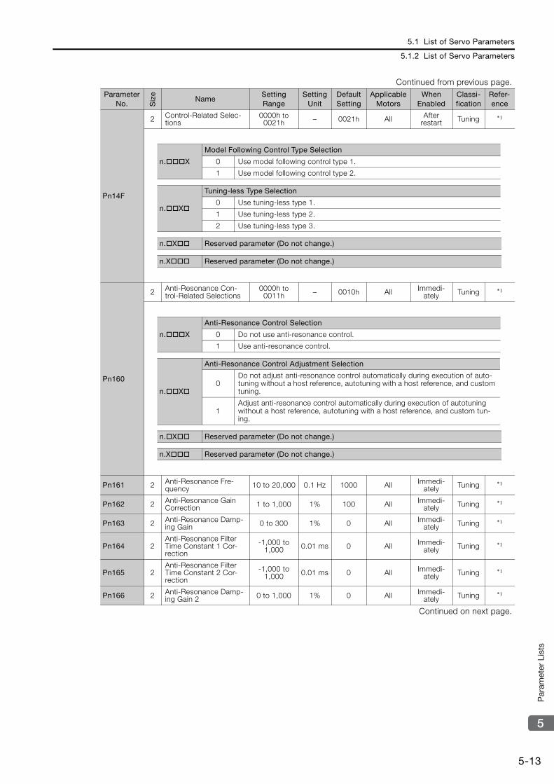
5.1 List of Servo Parameters
5.1.2 List of Servo Parameters
5-13
5
Par
amet
er L
ists
Pn14F
2 Control-Related Selec-tions
0000h to 0021h – 0021h All After
restart Tuning *1
Pn160
2 Anti-Resonance Con-trol-Related Selections
0000h to 0011h – 0010h All Immedi-
ately Tuning *1
Pn161 2 Anti-Resonance Fre-quency 10 to 20,000 0.1 Hz 1000 All Immedi-
ately Tuning *1
Pn162 2 Anti-Resonance Gain Correction 1 to 1,000 1% 100 All Immedi-
ately Tuning *1
Pn163 2 Anti-Resonance Damp-ing Gain 0 to 300 1% 0 All Immedi-
ately Tuning *1
Pn164 2Anti-Resonance Filter Time Constant 1 Cor-rection
-1,000 to 1,000 0.01 ms 0 All Immedi-
ately Tuning *1
Pn165 2Anti-Resonance Filter Time Constant 2 Cor-rection
-1,000 to 1,000 0.01 ms 0 All Immedi-
ately Tuning *1
Pn166 2 Anti-Resonance Damp-ing Gain 2 0 to 1,000 1% 0 All Immedi-
ately Tuning *1
Continued on next page.
Continued from previous page.Parameter
No. Siz
e
NameSetting Range
Setting Unit
Default Setting
Applicable Motors
When Enabled
Classi-fication
Refer-ence
n.X
Model Following Control Type Selection
0 Use model following control type 1.
1 Use model following control type 2.
n.X
Tuning-less Type Selection
0 Use tuning-less type 1.
1 Use tuning-less type 2.
2 Use tuning-less type 3.
n.X Reserved parameter (Do not change.)
n.X Reserved parameter (Do not change.)
n.X
Anti-Resonance Control Selection
0 Do not use anti-resonance control.
1 Use anti-resonance control.
n.X
Anti-Resonance Control Adjustment Selection
0Do not adjust anti-resonance control automatically during execution of auto-tuning without a host reference, autotuning with a host reference, and custom tuning.
1Adjust anti-resonance control automatically during execution of autotuning without a host reference, autotuning with a host reference, and custom tun-ing.
n.X Reserved parameter (Do not change.)
n.X Reserved parameter (Do not change.)

5.1 List of Servo Parameters
5.1.2 List of Servo Parameters
5-14
Pn170
2 Tuning-less Function-Related Selections
0000h to 2711h – 1401h All – Setup *1
Pn181 2 Mode Switching Level for Speed Reference 0 to 10,000 1 mm/s 0 Linear Immedi-
ately Tuning *1
Pn182 2 Mode Switching Level for Acceleration 0 to 30,000 1 mm/s2 0 Linear Immedi-
ately Tuning *1
Pn205 2 Multiturn Limit 0 to 65,535 1 rev 65535 Rotary After restart Setup *1
Pn207
2 Position Control Func-tion Selections
0000h to 2210h – 0010h All After
restart Setup −
Pn20A 4 Number of External Encoder Scale Pitches
4 to 1,048,576
1 scale pitch/revolu-
tion
32768 Rotary After restart Setup *1
Pn20E 4 Electronic Gear Ratio (Numerator)
1 to 1,073,741,824 1 16 All After
restart Setup *1
Pn210 4 Electronic Gear Ratio (Denominator)
1 to 1,073,741,824 1 1 All After
restart Setup *1
Pn212 4 Number of Encoder Output Pulses
16 to 1,073,741,824 1 P/Rev 2048 Rotary After
restart Setup *1
Continued on next page.
Continued from previous page.Parameter
No. Siz
e
NameSetting Range
Setting Unit
Default Setting
Applicable Motors
When Enabled
Classi-fication
Refer-ence
n.X
Tuning-less Selection When Enabled
0 Disable tuning-less function. After restart1 Enable tuning-less function.
n.X
Speed Control Method When Enabled
0 Use for speed control. After restart1 Use for speed control and use host controller for position control.
n.XRigidity Level When
Enabled
0 to 7 Set the rigidity level. Immedi-ately
n.XTuning-less Load Level When
Enabled
0 to 2 Set the load level for the tuning-less function. Immedi-ately
n.X Reserved parameter (Do not change.)
n.X Reserved parameter (Do not change.)
n.X Reserved parameter (Do not change.)
n.X
/COIN (Positioning Completion Output) Signal Output Timing
0 Output when the absolute value of the position deviation is the same or less than the setting of Pn522 (Positioning Completed Width).
1Output when the absolute value of the position error is the same or less than the setting of Pn522 (Positioning Completed Width) and the reference after the position reference filter is 0.
2Output when the absolute value of the position error is the same or less than the setting of Pn522 (Positioning Completed Width) and the reference input is 0.
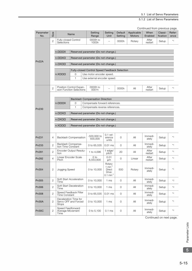
5.1 List of Servo Parameters
5.1.2 List of Servo Parameters
5-15
5
Par
amet
er L
ists
Pn22A
2 Fully-closed Control Selections
0000h to 1003h – 0000h Rotary After
restart Setup *1
Pn230
2 Position Control Expan-sion Function Selections
0000h to 0001h – 0000h All After
restart Setup *1
Pn231 4 Backlash Compensation -500,000 to 500,000
0.1 ref-erence units
0 All Immedi-ately Setup *1
Pn233 2 Backlash Compensa-tion Time Constant 0 to 65,535 0.01 ms 0 All Immedi-
ately Setup *1
Pn281 2 Encoder Output Resolu-tion 1 to 4,096 1 edge/
pitch 20 All After restart Setup *1
Pn282 4 Linear Encoder Scale Pitch
0 to 6,553,600
0.01 μm 0 Linear After
restart Setup *1
Pn304 2 Jogging Speed 0 to 10,000
Rotary: 1 min-1
Direct Drive:
0.1 min-1
500 Rotary Immedi-ately Setup *1
Pn305 2 Soft Start Acceleration Time 0 to 10,000 1 ms 0 All Immedi-
ately Setup *2
Pn306 2 Soft Start Deceleration Time 0 to 10,000 1 ms 0 All Immedi-
ately Setup *2
Pn308 2 Speed Feedback Filter Time Constant 0 to 65,535 0.01 ms 0 All Immedi-
ately Setup *1
Pn30A 2Deceleration Time for Servo OFF and Forced Stops
0 to 10,000 1 ms 0 All Immedi-ately Setup *1
Pn30C 2Speed Feedforward Average Movement Time
0 to 5,100 0.1 ms 0 All Immedi-ately Setup *1
Continued on next page.
Continued from previous page.Parameter
No. Siz
e
NameSetting Range
Setting Unit
Default Setting
Applicable Motors
When Enabled
Classi-fication
Refer-ence
n.X Reserved parameter (Do not change.)
n.X Reserved parameter (Do not change.)
n.X Reserved parameter (Do not change.)
n.X
Fully-closed Control Speed Feedback Selection
0 Use motor encoder speed.
1 Use external encoder speed.
n.X
Backlash Compensation Direction
0 Compensate forward references.
1 Compensate reverse references.
n.X Reserved parameter (Do not change.)
n.X Reserved parameter (Do not change.)
n.X Reserved parameter (Do not change.)

5.1 List of Servo Parameters
5.1.2 List of Servo Parameters
5-16
Pn310
2 Vibration Detection Selections
0000h to 0002h – 0000h All Immedi-
ately Setup *1
Pn311 2 Vibration Detection Sen-sitivity 50 to 500 1% 100 All Immedi-
ately Tuning *1
Pn312 2 Vibration Detection Level 0 to 5,000 1 min-1 50 Rotary Immedi-
ately Tuning *1
Pn316 2 Maximum Motor Speed 0 to 65,535 1 min-1 10000 Rotary After restart Setup *1
Pn324 2 Moment of Inertia Cal-culation Starting Level 0 to 20,000 1% 300 All Immedi-
ately Setup *1
Pn383 2 Jogging Speed 0 to 10,000 1 mm/s 50 Linear Immedi-ately Setup *1
Pn384 2 Vibration Detection Level 0 to 5,000 1 mm/s 10 Linear Immedi-
ately Tuning *1
Pn385 2 Maximum Motor Speed 1 to 100 100 mm/s 50 Linear After
restart Setup *1
Pn401 2First Stage First Torque Reference Filter Time Constant
0 to 65,535 0.01 ms 100 All Immedi-ately Tuning *1
Pn402 2 Forward Torque Limit 0 to 800 1%*3 800 Rotary Immedi-ately Setup *1
Pn403 2 Reverse Torque Limit 0 to 800 1%*3 800 Rotary Immedi-ately Setup *1
Pn404 2 Forward External Torque Limit 0 to 800 1%*3 100 All Immedi-
ately Setup *1
Pn405 2 Reverse External Torque Limit 0 to 800 1%*3 100 All Immedi-
ately Setup *1
Pn406 2 Emergency Stop Torque 0 to 800 1%*3 800 All Immedi-ately Setup *1
Pn407 2 Speed Limit during Torque Control 0 to 10,000 1 min-1 10000 Rotary Immedi-
ately Setup *1
Continued on next page.
Continued from previous page.Parameter
No. Siz
e
NameSetting Range
Setting Unit
Default Setting
Applicable Motors
When Enabled
Classi-fication
Refer-ence
n.X
Vibration Detection Selection
0 Do not detect vibration.
1 Output a warning (A.911) if vibration is detected.
2 Output an alarm (A.520) if vibration is detected.
n.X Reserved parameter (Do not change.)
n.X Reserved parameter (Do not change.)
n.X Reserved parameter (Do not change.)
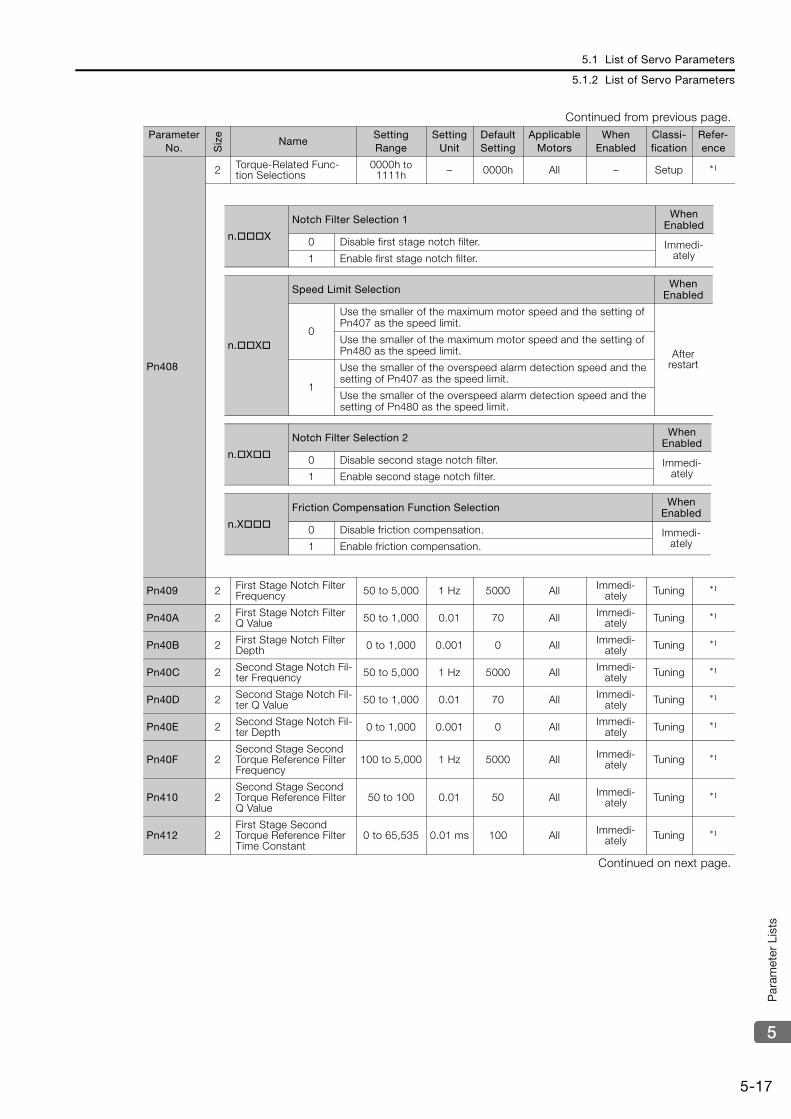
5.1 List of Servo Parameters
5.1.2 List of Servo Parameters
5-17
5
Par
amet
er L
ists
Pn408
2 Torque-Related Func-tion Selections
0000h to 1111h – 0000h All – Setup *1
Pn409 2 First Stage Notch Filter Frequency 50 to 5,000 1 Hz 5000 All Immedi-
ately Tuning *1
Pn40A 2 First Stage Notch Filter Q Value 50 to 1,000 0.01 70 All Immedi-
ately Tuning *1
Pn40B 2 First Stage Notch Filter Depth 0 to 1,000 0.001 0 All Immedi-
ately Tuning *1
Pn40C 2 Second Stage Notch Fil-ter Frequency 50 to 5,000 1 Hz 5000 All Immedi-
ately Tuning *1
Pn40D 2 Second Stage Notch Fil-ter Q Value 50 to 1,000 0.01 70 All Immedi-
ately Tuning *1
Pn40E 2 Second Stage Notch Fil-ter Depth 0 to 1,000 0.001 0 All Immedi-
ately Tuning *1
Pn40F 2Second Stage Second Torque Reference Filter Frequency
100 to 5,000 1 Hz 5000 All Immedi-ately Tuning *1
Pn410 2Second Stage Second Torque Reference Filter Q Value
50 to 100 0.01 50 All Immedi-ately Tuning *1
Pn412 2First Stage Second Torque Reference Filter Time Constant
0 to 65,535 0.01 ms 100 All Immedi-ately Tuning *1
Continued on next page.
Continued from previous page.Parameter
No. Siz
e
NameSetting Range
Setting Unit
Default Setting
Applicable Motors
When Enabled
Classi-fication
Refer-ence
n.X
Notch Filter Selection 1 When Enabled
0 Disable first stage notch filter. Immedi-ately1 Enable first stage notch filter.
n.X
Speed Limit Selection When Enabled
0
Use the smaller of the maximum motor speed and the setting of Pn407 as the speed limit.
After restart
Use the smaller of the maximum motor speed and the setting of Pn480 as the speed limit.
1
Use the smaller of the overspeed alarm detection speed and the setting of Pn407 as the speed limit.
Use the smaller of the overspeed alarm detection speed and the setting of Pn480 as the speed limit.
n.X
Notch Filter Selection 2 When Enabled
0 Disable second stage notch filter. Immedi-ately1 Enable second stage notch filter.
n.X
Friction Compensation Function Selection When Enabled
0 Disable friction compensation. Immedi-ately1 Enable friction compensation.
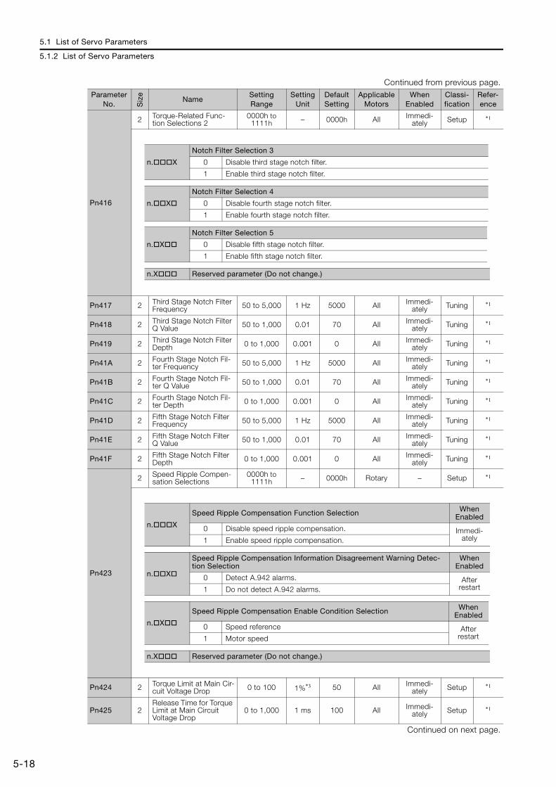
5.1 List of Servo Parameters
5.1.2 List of Servo Parameters
5-18
Pn416
2 Torque-Related Func-tion Selections 2
0000h to 1111h – 0000h All Immedi-
ately Setup *1
Pn417 2 Third Stage Notch Filter Frequency 50 to 5,000 1 Hz 5000 All Immedi-
ately Tuning *1
Pn418 2 Third Stage Notch Filter Q Value 50 to 1,000 0.01 70 All Immedi-
ately Tuning *1
Pn419 2 Third Stage Notch Filter Depth 0 to 1,000 0.001 0 All Immedi-
ately Tuning *1
Pn41A 2 Fourth Stage Notch Fil-ter Frequency 50 to 5,000 1 Hz 5000 All Immedi-
ately Tuning *1
Pn41B 2 Fourth Stage Notch Fil-ter Q Value 50 to 1,000 0.01 70 All Immedi-
ately Tuning *1
Pn41C 2 Fourth Stage Notch Fil-ter Depth 0 to 1,000 0.001 0 All Immedi-
ately Tuning *1
Pn41D 2 Fifth Stage Notch Filter Frequency 50 to 5,000 1 Hz 5000 All Immedi-
ately Tuning *1
Pn41E 2 Fifth Stage Notch Filter Q Value 50 to 1,000 0.01 70 All Immedi-
ately Tuning *1
Pn41F 2 Fifth Stage Notch Filter Depth 0 to 1,000 0.001 0 All Immedi-
ately Tuning *1
Pn423
2 Speed Ripple Compen-sation Selections
0000h to 1111h – 0000h Rotary – Setup *1
Pn424 2 Torque Limit at Main Cir-cuit Voltage Drop 0 to 100 1%*3 50 All Immedi-
ately Setup *1
Pn425 2Release Time for Torque Limit at Main Circuit Voltage Drop
0 to 1,000 1 ms 100 All Immedi-ately Setup *1
Continued on next page.
Continued from previous page.Parameter
No. Siz
e
NameSetting Range
Setting Unit
Default Setting
Applicable Motors
When Enabled
Classi-fication
Refer-ence
n.X
Notch Filter Selection 3
0 Disable third stage notch filter.
1 Enable third stage notch filter.
n.X
Notch Filter Selection 4
0 Disable fourth stage notch filter.
1 Enable fourth stage notch filter.
n.X
Notch Filter Selection 5
0 Disable fifth stage notch filter.
1 Enable fifth stage notch filter.
n.X Reserved parameter (Do not change.)
n.X
Speed Ripple Compensation Function Selection When Enabled
0 Disable speed ripple compensation. Immedi-ately1 Enable speed ripple compensation.
n.X
Speed Ripple Compensation Information Disagreement Warning Detec-tion Selection
When Enabled
0 Detect A.942 alarms. After restart1 Do not detect A.942 alarms.
n.X
Speed Ripple Compensation Enable Condition Selection When Enabled
0 Speed reference After restart1 Motor speed
n.X Reserved parameter (Do not change.)
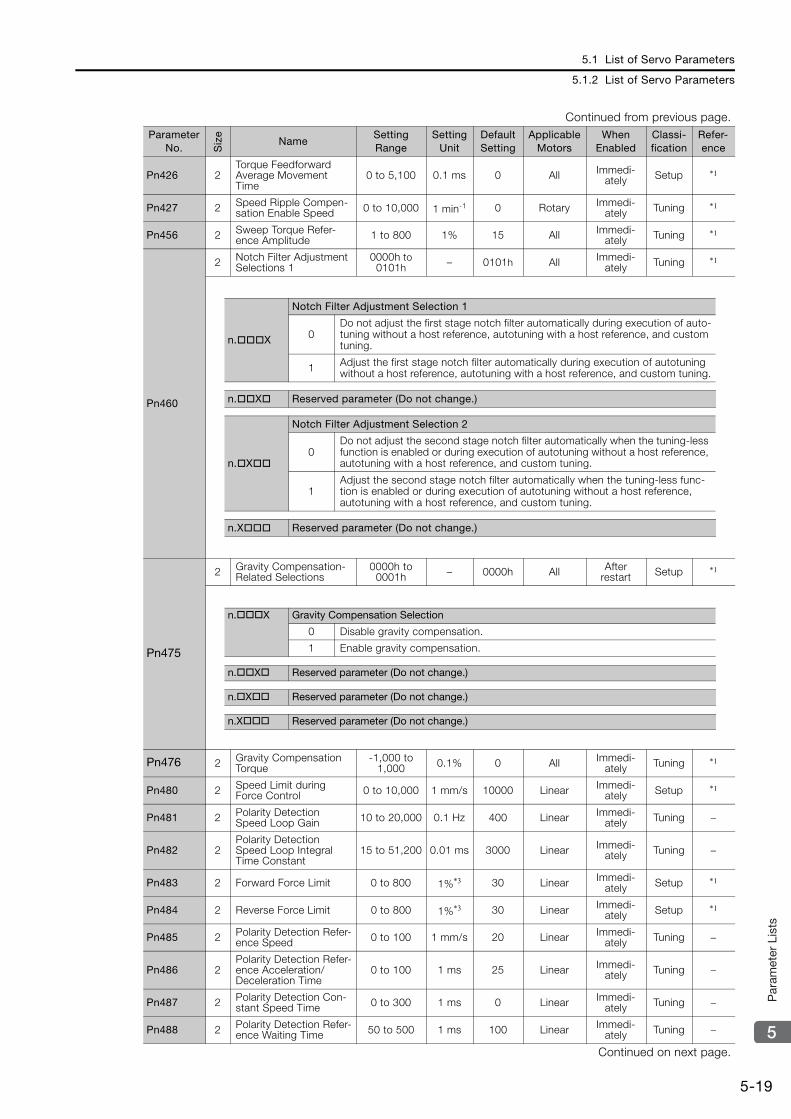
5.1 List of Servo Parameters
5.1.2 List of Servo Parameters
5-19
5
Par
amet
er L
ists
Pn426 2Torque Feedforward Average Movement Time
0 to 5,100 0.1 ms 0 All Immedi-ately Setup *1
Pn427 2 Speed Ripple Compen-sation Enable Speed 0 to 10,000 1 min-1 0 Rotary Immedi-
ately Tuning *1
Pn456 2 Sweep Torque Refer-ence Amplitude 1 to 800 1% 15 All Immedi-
ately Tuning *1
Pn460
2 Notch Filter Adjustment Selections 1
0000h to 0101h – 0101h All Immedi-
ately Tuning *1
Pn475
2 Gravity Compensation-Related Selections
0000h to 0001h – 0000h All After
restart Setup *1
Pn476 2 Gravity Compensation Torque
-1,000 to 1,000 0.1% 0 All Immedi-
ately Tuning *1
Pn480 2 Speed Limit during Force Control 0 to 10,000 1 mm/s 10000 Linear Immedi-
ately Setup *1
Pn481 2 Polarity Detection Speed Loop Gain 10 to 20,000 0.1 Hz 400 Linear Immedi-
ately Tuning −
Pn482 2Polarity Detection Speed Loop Integral Time Constant
15 to 51,200 0.01 ms 3000 Linear Immedi-ately Tuning −
Pn483 2 Forward Force Limit 0 to 800 1%*3 30 Linear Immedi-ately Setup *1
Pn484 2 Reverse Force Limit 0 to 800 1%*3 30 Linear Immedi-ately Setup *1
Pn485 2 Polarity Detection Refer-ence Speed 0 to 100 1 mm/s 20 Linear Immedi-
ately Tuning −
Pn486 2Polarity Detection Refer-ence Acceleration/Deceleration Time
0 to 100 1 ms 25 Linear Immedi-ately Tuning −
Pn487 2 Polarity Detection Con-stant Speed Time 0 to 300 1 ms 0 Linear Immedi-
ately Tuning −
Pn488 2 Polarity Detection Refer-ence Waiting Time 50 to 500 1 ms 100 Linear Immedi-
ately Tuning −
Continued on next page.
Continued from previous page.Parameter
No. Siz
e
NameSetting Range
Setting Unit
Default Setting
Applicable Motors
When Enabled
Classi-fication
Refer-ence
n.X
Notch Filter Adjustment Selection 1
0Do not adjust the first stage notch filter automatically during execution of auto-tuning without a host reference, autotuning with a host reference, and custom tuning.
1 Adjust the first stage notch filter automatically during execution of autotuning without a host reference, autotuning with a host reference, and custom tuning.
n.X Reserved parameter (Do not change.)
n.X
Notch Filter Adjustment Selection 2
0Do not adjust the second stage notch filter automatically when the tuning-less function is enabled or during execution of autotuning without a host reference, autotuning with a host reference, and custom tuning.
1Adjust the second stage notch filter automatically when the tuning-less func-tion is enabled or during execution of autotuning without a host reference, autotuning with a host reference, and custom tuning.
n.X Reserved parameter (Do not change.)
n.X Gravity Compensation Selection
0 Disable gravity compensation.
1 Enable gravity compensation.
n.X Reserved parameter (Do not change.)
n.X Reserved parameter (Do not change.)
n.X Reserved parameter (Do not change.)

5.1 List of Servo Parameters
5.1.2 List of Servo Parameters
5-20
Pn48E 2 Polarity Detection Range 1 to 65,535 1 mm 10 Linear Immedi-
ately Tuning −
Pn490 2 Polarity Detection Load Level 0 to 20,000 1% 100 Linear Immedi-
ately Tuning −
Pn495 2Polarity Detection Con-firmation Force Refer-ence
0 to 200 1% 100 Linear Immedi-ately Tuning −
Pn498 2 Polarity Detection Allow-able Error Range 0 to 30 1 deg 10 Linear Immedi-
ately Tuning −
Pn49F 2 Speed Ripple Compen-sation Enable Speed 0 to 10,000 1 mm/s 0 Linear Immedi-
ately Tuning *1
Pn502 2 Rotation Detection Level 1 to 10,000 1 min-1 20 Rotary Immedi-ately Setup *1
Pn503 2Speed Coincidence Detection Signal Output Width
0 to 100 1 min-1 10 Rotary Immedi-ately Setup *1
Pn506 2 Brake Reference-Servo OFF Delay Time 0 to 50 10 ms 0 All Immedi-
ately Setup *1
Pn507 2 Brake Reference Out-put Speed Level 0 to 10,000 1 min-1 100 Rotary Immedi-
ately Setup *1
Pn508 2 Servo OFF-Brake Com-mand Waiting Time 10 to 100 10 ms 50 All Immedi-
ately Setup *1
Pn509 2 Momentary Power Inter-ruption Hold Time 20 to 50,000 1 ms 20 All Immedi-
ately Setup *1
Pn50A
2 Input Signal Selections 1
0000h to FFF2h – 1881h All After
restart Setup *1
Continued on next page.
Continued from previous page.Parameter
No. Siz
e
NameSetting Range
Setting Unit
Default Setting
Applicable Motors
When Enabled
Classi-fication
Refer-ence
n.X Reserved parameter (Do not change.)
n.X Reserved parameter (Do not change.)
n.X Reserved parameter (Do not change.)
n.X
P-OT (Forward Drive Prohibit) Signal Allocation
0 Enable forward drive when CN1-13 input signal is ON (closed).
1 Enable forward drive when CN1-7 input signal is ON (closed).
2 Enable forward drive when CN1-8 input signal is ON (closed).
3 Enable forward drive when CN1-9 input signal is ON (closed).
4 Enable forward drive when CN1-10 input signal is ON (closed).
5 Enable forward drive when CN1-11 input signal is ON (closed).
6 Enable forward drive when CN1-12 input signal is ON (closed).
7 Set the signal to always prohibit forward drive.
8 Set the signal to always enable forward drive.
9 Enable forward drive when CN1-13 input signal is OFF (open).
A Enable forward drive when CN1-7 input signal is OFF (open).
B Enable forward drive when CN1-8 input signal is OFF (open).
C Enable forward drive when CN1-9 input signal is OFF (open).
D Enable forward drive when CN1-10 input signal is OFF (open).
E Enable forward drive when CN1-11 input signal is OFF (open).
F Enable forward drive when CN1-12 input signal is OFF (open).
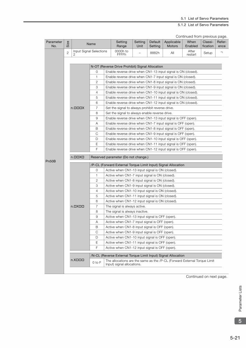
5.1 List of Servo Parameters
5.1.2 List of Servo Parameters
5-21
5
Par
amet
er L
ists
Pn50B
2 Input Signal Selections 2
0000h to FFFFh – 8882h All After
restart Setup *1
Continued on next page.
Continued from previous page.Parameter
No. Siz
e
NameSetting Range
Setting Unit
Default Setting
Applicable Motors
When Enabled
Classi-fication
Refer-ence
n.X
N-OT (Reverse Drive Prohibit) Signal Allocation
0 Enable reverse drive when CN1-13 input signal is ON (closed).
1 Enable reverse drive when CN1-7 input signal is ON (closed).
2 Enable reverse drive when CN1-8 input signal is ON (closed).
3 Enable reverse drive when CN1-9 input signal is ON (closed).
4 Enable reverse drive when CN1-10 input signal is ON (closed).
5 Enable reverse drive when CN1-11 input signal is ON (closed).
6 Enable reverse drive when CN1-12 input signal is ON (closed).
7 Set the signal to always prohibit reverse drive.
8 Set the signal to always enable reverse drive.
9 Enable reverse drive when CN1-13 input signal is OFF (open).
A Enable reverse drive when CN1-7 input signal is OFF (open).
B Enable reverse drive when CN1-8 input signal is OFF (open).
C Enable reverse drive when CN1-9 input signal is OFF (open).
D Enable reverse drive when CN1-10 input signal is OFF (open).
E Enable reverse drive when CN1-11 input signal is OFF (open).
F Enable reverse drive when CN1-12 input signal is OFF (open).
n.X Reserved parameter (Do not change.)
n.X
/P-CL (Forward External Torque Limit Input) Signal Allocation
0 Active when CN1-13 input signal is ON (closed).
1 Active when CN1-7 input signal is ON (closed).
2 Active when CN1-8 input signal is ON (closed).
3 Active when CN1-9 input signal is ON (closed).
4 Active when CN1-10 input signal is ON (closed).
5 Active when CN1-11 input signal is ON (closed).
6 Active when CN1-12 input signal is ON (closed).
7 The signal is always active.
8 The signal is always inactive.
9 Active when CN1-13 input signal is OFF (open).
A Active when CN1-7 input signal is OFF (open).
B Active when CN1-8 input signal is OFF (open).
C Active when CN1-9 input signal is OFF (open).
D Active when CN1-10 input signal is OFF (open).
E Active when CN1-11 input signal is OFF (open).
F Active when CN1-12 input signal is OFF (open).
n.X/N-CL (Reverse External Torque Limit Input) Signal Allocation
0 to F The allocations are the same as the /P-CL (Forward External Torque Limit Input) signal allocations.
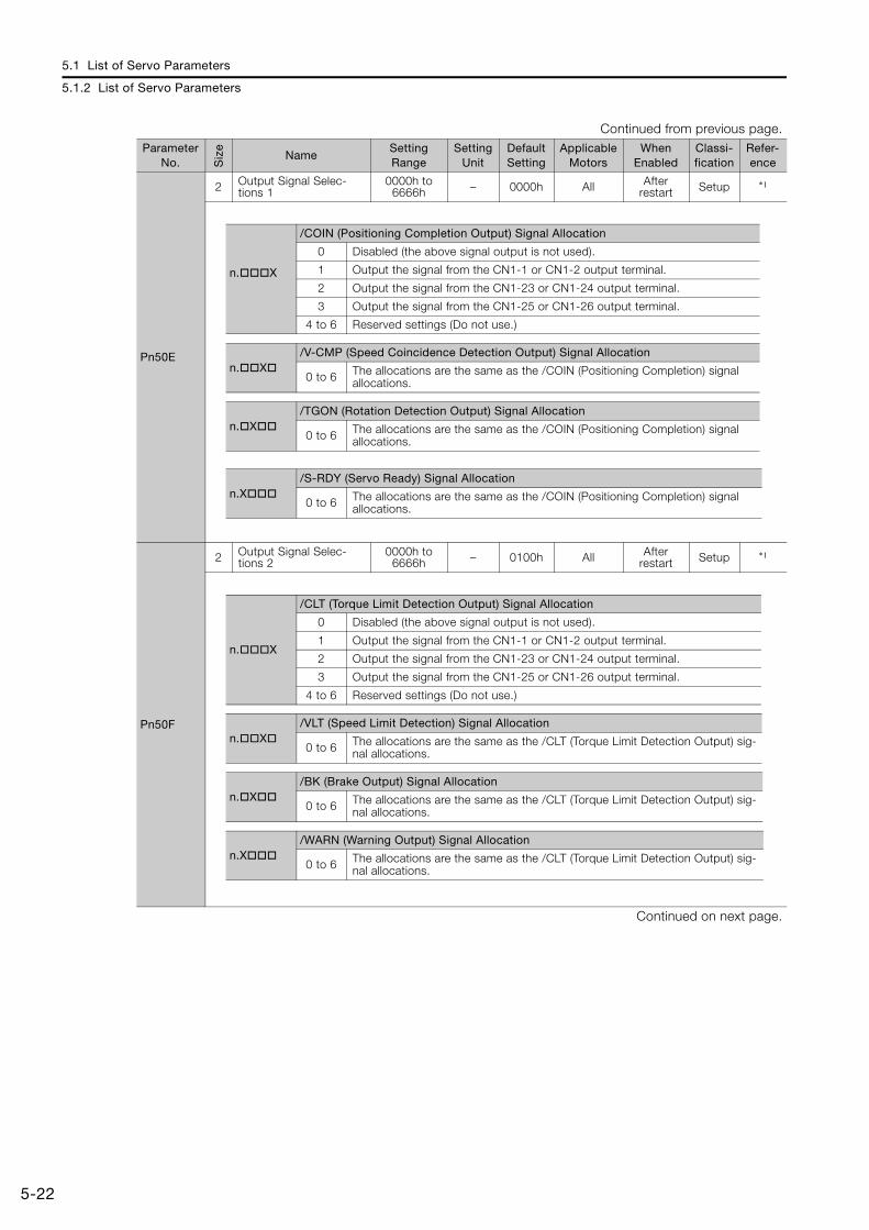
5.1 List of Servo Parameters
5.1.2 List of Servo Parameters
5-22
Pn50E
2 Output Signal Selec-tions 1
0000h to 6666h – 0000h All After
restart Setup *1
Pn50F
2 Output Signal Selec-tions 2
0000h to 6666h – 0100h All After
restart Setup *1
Continued on next page.
Continued from previous page.Parameter
No. Siz
e
NameSetting Range
Setting Unit
Default Setting
Applicable Motors
When Enabled
Classi-fication
Refer-ence
n.X
/COIN (Positioning Completion Output) Signal Allocation
0 Disabled (the above signal output is not used).
1 Output the signal from the CN1-1 or CN1-2 output terminal.
2 Output the signal from the CN1-23 or CN1-24 output terminal.
3 Output the signal from the CN1-25 or CN1-26 output terminal.
4 to 6 Reserved settings (Do not use.)
n.X/V-CMP (Speed Coincidence Detection Output) Signal Allocation
0 to 6 The allocations are the same as the /COIN (Positioning Completion) signal allocations.
n.X/TGON (Rotation Detection Output) Signal Allocation
0 to 6 The allocations are the same as the /COIN (Positioning Completion) signal allocations.
n.X/S-RDY (Servo Ready) Signal Allocation
0 to 6 The allocations are the same as the /COIN (Positioning Completion) signal allocations.
n.X
/CLT (Torque Limit Detection Output) Signal Allocation
0 Disabled (the above signal output is not used).
1 Output the signal from the CN1-1 or CN1-2 output terminal.
2 Output the signal from the CN1-23 or CN1-24 output terminal.
3 Output the signal from the CN1-25 or CN1-26 output terminal.
4 to 6 Reserved settings (Do not use.)
n.X/VLT (Speed Limit Detection) Signal Allocation
0 to 6 The allocations are the same as the /CLT (Torque Limit Detection Output) sig-nal allocations.
n.X/BK (Brake Output) Signal Allocation
0 to 6 The allocations are the same as the /CLT (Torque Limit Detection Output) sig-nal allocations.
n.X/WARN (Warning Output) Signal Allocation
0 to 6 The allocations are the same as the /CLT (Torque Limit Detection Output) sig-nal allocations.
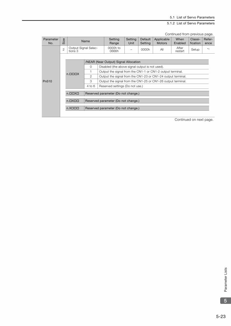
5.1 List of Servo Parameters
5.1.2 List of Servo Parameters
5-23
5
Par
amet
er L
ists
Pn510
2 Output Signal Selec-tions 3
0000h to 0666h – 0000h All After
restart Setup *1
Continued on next page.
Continued from previous page.Parameter
No. Siz
e
NameSetting Range
Setting Unit
Default Setting
Applicable Motors
When Enabled
Classi-fication
Refer-ence
n.X
/NEAR (Near Output) Signal Allocation
0 Disabled (the above signal output is not used).
1 Output the signal from the CN1-1 or CN1-2 output terminal.
2 Output the signal from the CN1-23 or CN1-24 output terminal.
3 Output the signal from the CN1-25 or CN1-26 output terminal.
4 to 6 Reserved settings (Do not use.)
n.X Reserved parameter (Do not change.)
n.X Reserved parameter (Do not change.)
n.X Reserved parameter (Do not change.)

5.1 List of Servo Parameters
5.1.2 List of Servo Parameters
5-24
Pn511
2 Input Signal Selections 5
0000h to FFFFh – 6543h All After
restart Setup *1
Pn512
2 Output Signal Inverse Settings
0000h to 1111h – 0000h All After
restart Setup *1
Continued on next page.
Continued from previous page.Parameter
No. Siz
e
NameSetting Range
Setting Unit
Default Setting
Applicable Motors
When Enabled
Classi-fication
Refer-ence
n.X
/DEC (Origin Return Deceleration Switch Input) Signal Allocation
0 Active when CN1-13 input signal is ON (closed).
1 Active when CN1-7 input signal is ON (closed).
2 Active when CN1-8 input signal is ON (closed).
3 Active when CN1-9 input signal is ON (closed).
4 Active when CN1-10 input signal is ON (closed).
5 Active when CN1-11 input signal is ON (closed).
6 Active when CN1-12 input signal is ON (closed).
7 The signal is always active.
8 The signal is always inactive.
9 Active when CN1-13 input signal is OFF (open).
A Active when CN1-7 input signal is OFF (open).
B Active when CN1-8 input signal is OFF (open).
C Active when CN1-9 input signal is OFF (open).
D Active when CN1-10 input signal is OFF (open).
E Active when CN1-11 input signal is OFF (open).
F Active when CN1-12 input signal is OFF (open).
n.X
/EXT1 (External Latch Input 1) Signal Allocation
0 to 3 The signal is always inactive.
4 Active when CN1-10 input signal is ON (closed).
5 Active when CN1-11 input signal is ON (closed).
6 Active when CN1-12 input signal is ON (closed).
D Active when CN1-10 input signal is OFF (open).
E Active when CN1-11 input signal is OFF (open).
F Active when CN1-12 input signal is OFF (open).
7 to C The signal is always inactive.
n.X/EXT2 (External Latch Input 2) Signal Allocation
0 to F The allocations are the same as the /EXT1 (External Latch Input 1) signal allo-cations.
n.X/EXT3 (External Latch Input 3) Signal Allocation
0 to F The allocations are the same as the /EXT1 (External Latch Input 1) signal allo-cations.
n.X
Output Signal Inversion for CN1-1 and CN1-2 Terminals
0 The signal is not inverted.
1 The signal is inverted.
n.X
Output Signal Inversion for CN1-23 and CN1-24 Terminals
0 The signal is not inverted.
1 The signal is inverted.
n.X
Output Signal Inversion for CN1-25 and CN1-26 Terminals
0 The signal is not inverted.
1 The signal is inverted.
n.X Reserved parameter (Do not change.)
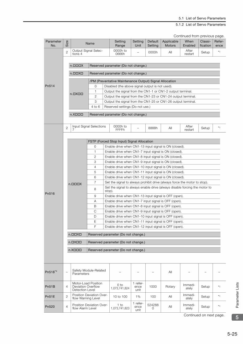
5.1 List of Servo Parameters
5.1.2 List of Servo Parameters
5-25
5
Par
amet
er L
ists
Pn514
2 Output Signal Selec-tions 4
0000h to 0666h – 0000h All After
restart Setup *1
Pn516
2 Input Signal Selections 7
0000h to FFFFh – 8888h All After
restart Setup *1
Pn518*4 – Safety Module-Related Parameters – – – All – – –
Pn51B 4Motor-Load Position Deviation Overflow Detection Level
0 to 1,073,741,824
1 refer-ence unit
1000 Rotary Immedi-ately Setup *1
Pn51E 2 Position Deviation Over-flow Warning Level 10 to 100 1% 100 All Immedi-
ately Setup *1
Pn520 4 Position Deviation Over-flow Alarm Level
1 to 1,073,741,823
1 refer-ence unit
5242880 All Immedi-
ately Setup *1
Continued on next page.
Continued from previous page.Parameter
No. Siz
e
NameSetting Range
Setting Unit
Default Setting
Applicable Motors
When Enabled
Classi-fication
Refer-ence
n.X Reserved parameter (Do not change.)
n.X Reserved parameter (Do not change.)
n.X
/PM (Preventative Maintenance Output) Signal Allocation
0 Disabled (the above signal output is not used).
1 Output the signal from the CN1-1 or CN1-2 output terminal.
2 Output the signal from the CN1-23 or CN1-24 output terminal.
3 Output the signal from the CN1-25 or CN1-26 output terminal.
4 to 6 Reserved settings (Do not use.)
n.X Reserved parameter (Do not change.)
n.X
FSTP (Forced Stop Input) Signal Allocation
0 Enable drive when CN1-13 input signal is ON (closed).
1 Enable drive when CN1-7 input signal is ON (closed).
2 Enable drive when CN1-8 input signal is ON (closed).
3 Enable drive when CN1-9 input signal is ON (closed).
4 Enable drive when CN1-10 input signal is ON (closed).
5 Enable drive when CN1-11 input signal is ON (closed).
6 Enable drive when CN1-12 input signal is ON (closed).
7 Set the signal to always prohibit drive (always force the motor to stop).
8 Set the signal to always enable drive (always disable forcing the motor to stop).
9 Enable drive when CN1-13 input signal is OFF (open).
A Enable drive when CN1-7 input signal is OFF (open).
B Enable drive when CN1-8 input signal is OFF (open).
C Enable drive when CN1-9 input signal is OFF (open).
D Enable drive when CN1-10 input signal is OFF (open).
E Enable drive when CN1-11 input signal is OFF (open).
F Enable drive when CN1-12 input signal is OFF (open).
n.X Reserved parameter (Do not change.)
n.X Reserved parameter (Do not change.)
n.X Reserved parameter (Do not change.)
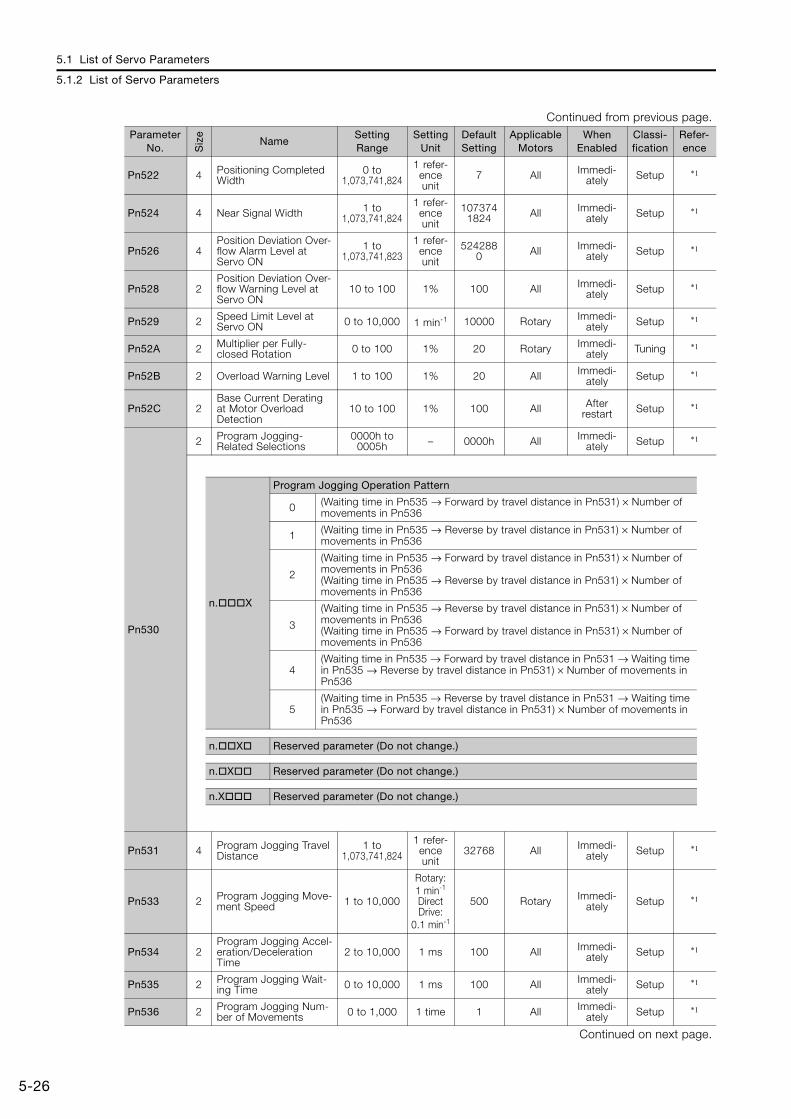
5.1 List of Servo Parameters
5.1.2 List of Servo Parameters
5-26
Pn522 4 Positioning Completed Width
0 to 1,073,741,824
1 refer-ence unit
7 All Immedi-ately Setup *1
Pn524 4 Near Signal Width 1 to 1,073,741,824
1 refer-ence unit
1073741824 All Immedi-
ately Setup *1
Pn526 4Position Deviation Over-flow Alarm Level at Servo ON
1 to 1,073,741,823
1 refer-ence unit
5242880 All Immedi-
ately Setup *1
Pn528 2Position Deviation Over-flow Warning Level at Servo ON
10 to 100 1% 100 All Immedi-ately Setup *1
Pn529 2 Speed Limit Level at Servo ON 0 to 10,000 1 min-1 10000 Rotary Immedi-
ately Setup *1
Pn52A 2 Multiplier per Fully-closed Rotation 0 to 100 1% 20 Rotary Immedi-
ately Tuning *1
Pn52B 2 Overload Warning Level 1 to 100 1% 20 All Immedi-ately Setup *1
Pn52C 2Base Current Derating at Motor Overload Detection
10 to 100 1% 100 All After restart Setup *1
Pn530
2 Program Jogging-Related Selections
0000h to 0005h – 0000h All Immedi-
ately Setup *1
Pn531 4 Program Jogging Travel Distance
1 to 1,073,741,824
1 refer-ence unit
32768 All Immedi-ately Setup *1
Pn533 2 Program Jogging Move-ment Speed 1 to 10,000
Rotary: 1 min-1
Direct Drive:
0.1 min-1
500 Rotary Immedi-ately Setup *1
Pn534 2Program Jogging Accel-eration/Deceleration Time
2 to 10,000 1 ms 100 All Immedi-ately Setup *1
Pn535 2 Program Jogging Wait-ing Time 0 to 10,000 1 ms 100 All Immedi-
ately Setup *1
Pn536 2 Program Jogging Num-ber of Movements 0 to 1,000 1 time 1 All Immedi-
ately Setup *1
Continued on next page.
Continued from previous page.Parameter
No. Siz
e
NameSetting Range
Setting Unit
Default Setting
Applicable Motors
When Enabled
Classi-fication
Refer-ence
n.X
Program Jogging Operation Pattern
0 (Waiting time in Pn535 → Forward by travel distance in Pn531) × Number of movements in Pn536
1 (Waiting time in Pn535 → Reverse by travel distance in Pn531) × Number of movements in Pn536
2
(Waiting time in Pn535 → Forward by travel distance in Pn531) × Number of movements in Pn536(Waiting time in Pn535 → Reverse by travel distance in Pn531) × Number of movements in Pn536
3
(Waiting time in Pn535 → Reverse by travel distance in Pn531) × Number of movements in Pn536(Waiting time in Pn535 → Forward by travel distance in Pn531) × Number of movements in Pn536
4(Waiting time in Pn535 → Forward by travel distance in Pn531 → Waiting time in Pn535 → Reverse by travel distance in Pn531) × Number of movements in Pn536
5(Waiting time in Pn535 → Reverse by travel distance in Pn531 → Waiting time in Pn535 → Forward by travel distance in Pn531) × Number of movements in Pn536
n.X Reserved parameter (Do not change.)
n.X Reserved parameter (Do not change.)
n.X Reserved parameter (Do not change.)

5.1 List of Servo Parameters
5.1.2 List of Servo Parameters
5-27
5
Par
amet
er L
ists
Pn550 2 Analog Monitor 1 Offset Voltage
-10,000 to 10,000 0.1 V 0 All Immedi-
ately Setup *1
Pn551 2 Analog Monitor 2 Offset Voltage
-10,000 to 10,000 0.1 V 0 All Immedi-
ately Setup *1
Pn552 2 Analog Monitor 1 Mag-nification
-10,000 to 10,000 × 0.01 100 All Immedi-
ately Setup *1
Pn553 2 Analog Monitor 2 Mag-nification
-10,000 to 10,000 × 0.01 100 All Immedi-
ately Setup *1
Pn55A 2 Power Consumption Monitor Unit Time 1 to 1,440 1 min 1 All Immedi-
ately Setup −
Pn560 2 Residual Vibration Detection Width 1 to 3,000 0.1% 400 All Immedi-
ately Setup *1
Pn561 2 Overshoot Detection Level 0 to 100 1% 100 All Immedi-
ately Setup *1
Pn581 2 Zero Speed Level 1 to 10,000 1 mm/s 20 Linear Immedi-ately Setup *1
Pn582 2Speed Coincidence Detection Signal Output Width
0 to 100 1 mm/s 10 Linear Immedi-ately Setup *1
Pn583 2 Brake Reference Out-put Speed Level 0 to 10,000 1 mm/s 10 Linear Immedi-
ately Setup *1
Pn584 2 Speed Limit Level at Servo ON 0 to 10,000 1 mm/s 10000 Linear Immedi-
ately Setup *1
Pn585 2 Program Jogging Move-ment Speed 1 to 10,000 1 mm/s 50 Linear Immedi-
ately Setup *1
Pn586 2 Motor Running Cooling Ratio 0 to 100
1%/Max.
speed0 Linear Immedi-
ately Setup −
Pn587
2Polarity Detection Execution Selection for Absolute Linear Encoder
0000h to 0001h – 0000h Linear Immedi-
ately Setup *1
Pn600 2Regenerative Resistor Capacity*5
Depends on model.*6 10 W 0 All Immedi-
ately Setup *1
Pn601 2Dynamic Brake Resistor Allowable Energy Con-sumption
0 to 65,535 10 J 0 All After restart Setup *7
Pn603 2 Regenerative Resis-tance 0 to 65,535 10 mΩ 0 All Immedi-
ately Setup *1
Pn604 2 Dynamic Brake Resis-tance 0 to 65,535 10 mΩ 0 All After
restart Setup *7
Continued on next page.
Continued from previous page.Parameter
No. Siz
e
NameSetting Range
Setting Unit
Default Setting
Applicable Motors
When Enabled
Classi-fication
Refer-ence
n.X
Polarity Detection Selection for Absolute Linear Encoder
0 Do not detect polarity.
1 Detect polarity.
n.X Reserved parameter (Do not change.)
n.X Reserved parameter (Do not change.)
n.X Reserved parameter (Do not change.)
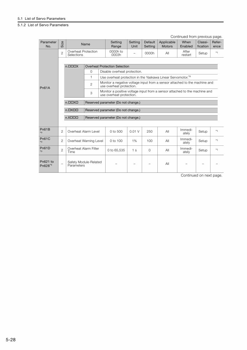
5.1 List of Servo Parameters
5.1.2 List of Servo Parameters
5-28
Pn61A
2 Overheat Protection Selections
0000h to 0003h – 0000h All After
restart Setup *1
Pn61B*9 2 Overheat Alarm Level 0 to 500 0.01 V 250 All Immedi-
ately Setup *1
Pn61C*9 2 Overheat Warning Level 0 to 100 1% 100 All Immedi-
ately Setup *1
Pn61D*9 2 Overheat Alarm Filter
Time 0 to 65,535 1 s 0 All Immedi-ately Setup *1
Pn621 to Pn628*4 – Safety Module-Related
Parameters – – – All – – –
Continued on next page.
Continued from previous page.Parameter
No. Siz
e
NameSetting Range
Setting Unit
Default Setting
Applicable Motors
When Enabled
Classi-fication
Refer-ence
n.X Overheat Protection Selection
0 Disable overheat protection.
1 Use overheat protection in the Yaskawa Linear Servomotor.*8
2 Monitor a negative voltage input from a sensor attached to the machine and use overheat protection.
3 Monitor a positive voltage input from a sensor attached to the machine and use overheat protection.
n.X Reserved parameter (Do not change.)
n.X Reserved parameter (Do not change.)
n.X Reserved parameter (Do not change.)
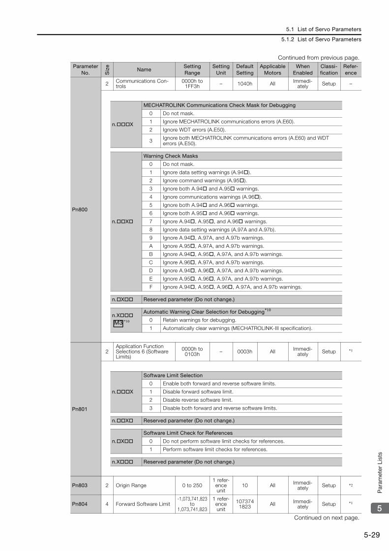
5.1 List of Servo Parameters
5.1.2 List of Servo Parameters
5-29
5
Par
amet
er L
ists
Pn800
2 Communications Con-trols
0000h to 1FF3h – 1040h All Immedi-
ately Setup –
Pn801
2Application Function Selections 6 (Software Limits)
0000h to 0103h – 0003h All Immedi-
ately Setup *1
Pn803 2 Origin Range 0 to 2501 refer-ence unit
10 All Immedi-ately Setup *2
Pn804 4 Forward Software Limit-1,073,741,823
to 1,073,741,823
1 refer-ence unit
1073741823 All Immedi-
ately Setup *1
Continued on next page.
Continued from previous page.Parameter
No. Siz
e
NameSetting Range
Setting Unit
Default Setting
Applicable Motors
When Enabled
Classi-fication
Refer-ence
n.X
MECHATROLINK Communications Check Mask for Debugging
0 Do not mask.
1 Ignore MECHATROLINK communications errors (A.E60).
2 Ignore WDT errors (A.E50).
3 Ignore both MECHATROLINK communications errors (A.E60) and WDT errors (A.E50).
n.X
Warning Check Masks
0 Do not mask.
1 Ignore data setting warnings (A.94).
2 Ignore command warnings (A.95).
3 Ignore both A.94 and A.95 warnings.
4 Ignore communications warnings (A.96).
5 Ignore both A.94 and A.96 warnings.
6 Ignore both A.95 and A.96 warnings.
7 Ignore A.94, A.95, and A.96 warnings.
8 Ignore data setting warnings (A.97A and A.97b).
9 Ignore A.94, A.97A, and A.97b warnings.
A Ignore A.95, A.97A, and A.97b warnings.
B Ignore A.94, A.95, A.97A, and A.97b warnings.
C Ignore A.96, A.97A, and A.97b warnings.
D Ignore A.94, A.96, A.97A, and A.97b warnings.
E Ignore A.95, A.96, A.97A, and A.97b warnings.
F Ignore A.94, A.95, A.96, A.97A, and A.97b warnings.
n.X Reserved parameter (Do not change.)
n.XAutomatic Warning Clear Selection for Debugging*10
0 Retain warnings for debugging.
1 Automatically clear warnings (MECHATROLINK-III specification).M3 *10
n.X
Software Limit Selection
0 Enable both forward and reverse software limits.
1 Disable forward software limit.
2 Disable reverse software limit.
3 Disable both forward and reverse software limits.
n.X Reserved parameter (Do not change.)
n.X
Software Limit Check for References
0 Do not perform software limit checks for references.
1 Perform software limit checks for references.
n.X Reserved parameter (Do not change.)

5.1 List of Servo Parameters
5.1.2 List of Servo Parameters
5-30
Pn806 4 Reverse Software Limit-1,073,741,823
to 1,073,741,823
1 refer-ence unit
-1073741823 All Immedi-
ately Setup *1
Pn808 4 Absolute Encoder Origin Offset
-1,073,741,823 to
1,073,741,823
1 refer-ence unit
0 AllImmedi-ately *11 Setup *1
Pn80A 2 First Stage Linear Accel-eration Constant 1 to 65,535
10,000 refer-ence
units/s2
100 AllImmedi-ately *12 Setup *2
Pn80B 2 Second Stage Linear Acceleration Constant 1 to 65,535
10,000 refer-ence
units/s2
100 AllImmedi-ately *12 Setup *2
Pn80C 2 Acceleration Constant Switching Speed 0 to 65,535
100 ref-erence units/s
0 AllImmedi-ately *12 Setup *2
Pn80D 2 First Stage Linear Deceleration Constant 1 to 65,535
10,000 refer-ence
units/s2
100 AllImmedi-ately *12 Setup *2
Pn80E 2 Second Stage Linear Deceleration Constant 1 to 65,535
10,000 refer-ence
units/s2
100 AllImmedi-ately *12 Setup *2
Pn80F 2 Deceleration Constant Switching Speed 0 to 65,535
100 ref-erence units/s
0 AllImmedi-ately *12 Setup *2
Pn810 2 Exponential Accelera-tion/Deceleration Bias 0 to 65,535
100 ref-erence units/s
0 AllImmedi-ately *13 Setup *2
Pn811 2Exponential Accelera-tion/Deceleration Time Constant
0 to 5,100 0.1 ms 0 AllImmedi-ately *13 Setup *2
Pn812 2 Movement Average Time 0 to 5,100 0.1 ms 0 All
Immedi-ately *13 Setup *2
Pn814 4 External Positioning Final Travel Distance
-1,073,741,823 to
1,073,741,823
1 refer-ence unit
100 All Immedi-ately Setup *2
Pn816
2 Origin Return Mode Set-tings
0000h to 0001h – 0000h All Immedi-
ately Setup *14
Pn817*16 2 Origin Approach Speed
1 0 to 65,535100 ref-erence units/s
50 AllImmedi-ately *12 Setup *2
Pn818*17 2 Origin Approach Speed
2 0 to 65,535100 ref-erence units/s
5 AllImmedi-ately *12 Setup *2
Pn819 4 Final Travel Distance for Origin Return
-1,073,741,823 to
1,073,741,823
1 refer-ence unit
100 All Immedi-ately Setup *2
Continued on next page.
Continued from previous page.Parameter
No. Siz
e
NameSetting Range
Setting Unit
Default Setting
Applicable Motors
When Enabled
Classi-fication
Refer-ence
M2 *15
n.X
Origin Return Direction
0 Return in forward direction.
1 Return in reverse direction.
n.X Reserved parameter (Do not change.)
n.X Reserved parameter (Do not change.)
n.X Reserved parameter (Do not change.)
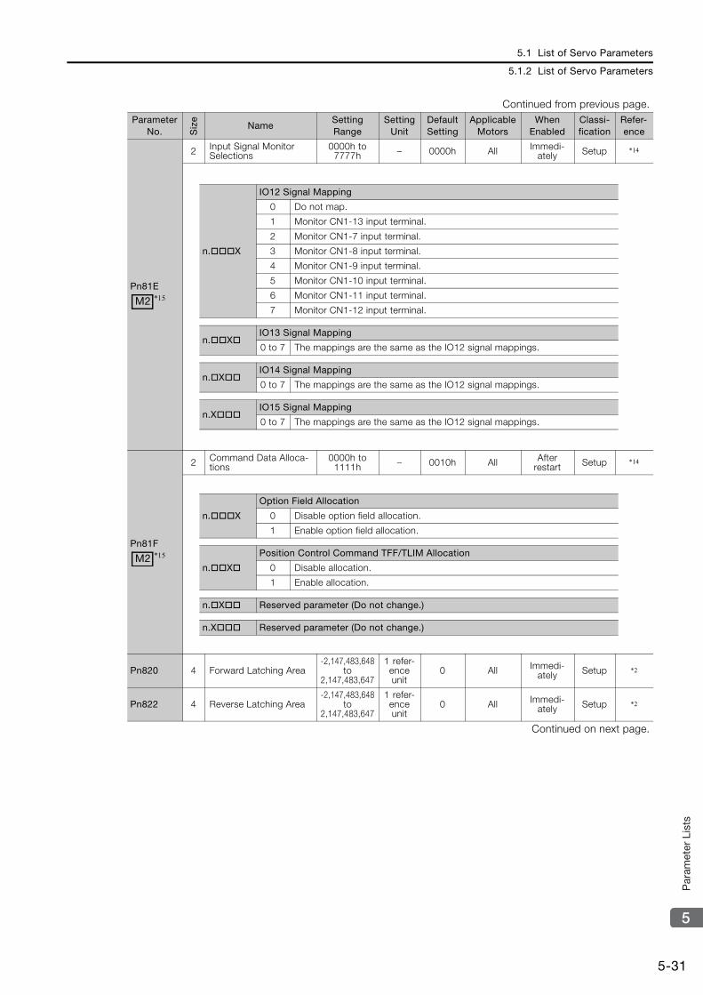
5.1 List of Servo Parameters
5.1.2 List of Servo Parameters
5-31
5
Par
amet
er L
ists
Pn81E
2 Input Signal Monitor Selections
0000h to 7777h – 0000h All Immedi-
ately Setup *14
Pn81F
2 Command Data Alloca-tions
0000h to 1111h – 0010h All After
restart Setup *14
Pn820 4 Forward Latching Area-2,147,483,648
to 2,147,483,647
1 refer-ence unit
0 All Immedi-ately Setup *2
Pn822 4 Reverse Latching Area-2,147,483,648
to 2,147,483,647
1 refer-ence unit
0 All Immedi-ately Setup *2
Continued on next page.
Continued from previous page.Parameter
No. Siz
e
NameSetting Range
Setting Unit
Default Setting
Applicable Motors
When Enabled
Classi-fication
Refer-ence
M2 *15
n.X
IO12 Signal Mapping
0 Do not map.
1 Monitor CN1-13 input terminal.
2 Monitor CN1-7 input terminal.
3 Monitor CN1-8 input terminal.
4 Monitor CN1-9 input terminal.
5 Monitor CN1-10 input terminal.
6 Monitor CN1-11 input terminal.
7 Monitor CN1-12 input terminal.
n.XIO13 Signal Mapping
0 to 7 The mappings are the same as the IO12 signal mappings.
n.XIO14 Signal Mapping
0 to 7 The mappings are the same as the IO12 signal mappings.
n.XIO15 Signal Mapping
0 to 7 The mappings are the same as the IO12 signal mappings.
M2 *15
n.X
Option Field Allocation
0 Disable option field allocation.
1 Enable option field allocation.
n.X
Position Control Command TFF/TLIM Allocation
0 Disable allocation.
1 Enable allocation.
n.X Reserved parameter (Do not change.)
n.X Reserved parameter (Do not change.)
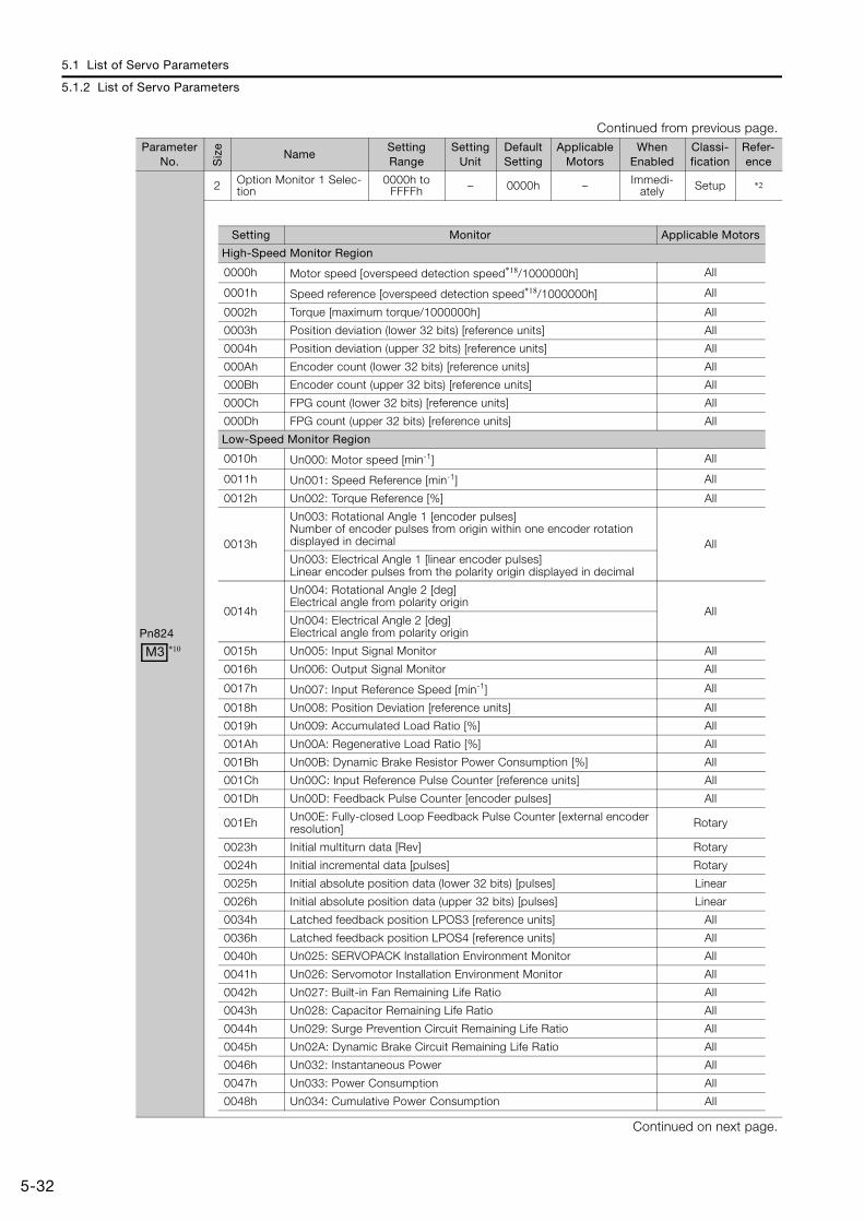
5.1 List of Servo Parameters
5.1.2 List of Servo Parameters
5-32
Pn824
2 Option Monitor 1 Selec-tion
0000h to FFFFh – 0000h – Immedi-
ately Setup *2
Continued on next page.
Continued from previous page.Parameter
No. Siz
e
NameSetting Range
Setting Unit
Default Setting
Applicable Motors
When Enabled
Classi-fication
Refer-ence
M3 *10
Setting Monitor Applicable Motors
High-Speed Monitor Region
0000h Motor speed [overspeed detection speed*18/1000000h] All
0001h Speed reference [overspeed detection speed*18/1000000h] All
0002h Torque [maximum torque/1000000h] All
0003h Position deviation (lower 32 bits) [reference units] All
0004h Position deviation (upper 32 bits) [reference units] All
000Ah Encoder count (lower 32 bits) [reference units] All
000Bh Encoder count (upper 32 bits) [reference units] All
000Ch FPG count (lower 32 bits) [reference units] All
000Dh FPG count (upper 32 bits) [reference units] All
Low-Speed Monitor Region
0010h Un000: Motor speed [min-1] All
0011h Un001: Speed Reference [min-1] All
0012h Un002: Torque Reference [%] All
0013h
Un003: Rotational Angle 1 [encoder pulses]Number of encoder pulses from origin within one encoder rotation displayed in decimal AllUn003: Electrical Angle 1 [linear encoder pulses]Linear encoder pulses from the polarity origin displayed in decimal
0014h
Un004: Rotational Angle 2 [deg]Electrical angle from polarity origin
AllUn004: Electrical Angle 2 [deg]Electrical angle from polarity origin
0015h Un005: Input Signal Monitor All
0016h Un006: Output Signal Monitor All
0017h Un007: Input Reference Speed [min-1] All
0018h Un008: Position Deviation [reference units] All
0019h Un009: Accumulated Load Ratio [%] All
001Ah Un00A: Regenerative Load Ratio [%] All
001Bh Un00B: Dynamic Brake Resistor Power Consumption [%] All
001Ch Un00C: Input Reference Pulse Counter [reference units] All
001Dh Un00D: Feedback Pulse Counter [encoder pulses] All
001Eh Un00E: Fully-closed Loop Feedback Pulse Counter [external encoder resolution] Rotary
0023h Initial multiturn data [Rev] Rotary
0024h Initial incremental data [pulses] Rotary
0025h Initial absolute position data (lower 32 bits) [pulses] Linear
0026h Initial absolute position data (upper 32 bits) [pulses] Linear
0034h Latched feedback position LPOS3 [reference units] All
0036h Latched feedback position LPOS4 [reference units] All
0040h Un025: SERVOPACK Installation Environment Monitor All
0041h Un026: Servomotor Installation Environment Monitor All
0042h Un027: Built-in Fan Remaining Life Ratio All
0043h Un028: Capacitor Remaining Life Ratio All
0044h Un029: Surge Prevention Circuit Remaining Life Ratio All
0045h Un02A: Dynamic Brake Circuit Remaining Life Ratio All
0046h Un032: Instantaneous Power All
0047h Un033: Power Consumption All
0048h Un034: Cumulative Power Consumption All
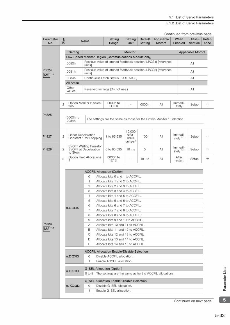
5.1 List of Servo Parameters
5.1.2 List of Servo Parameters
5-33
5
Par
amet
er L
ists
Pn824
Pn825
2 Option Monitor 2 Selec-tion
0000h to FFFFh – 0000h All Immedi-
ately Setup *2
Pn827 2 Linear Deceleration Constant 1 for Stopping 1 to 65,535
10,000 refer-ence
units/s2
100 AllImmedi-ately *12 Setup *2
Pn829 2SVOFF Waiting Time (for SVOFF at Deceleration to Stop)
0 to 65,535 10 ms 0 AllImmedi-ately *12 Setup *2
Pn82A
2 Option Field Allocations 1
0000h to 1E1Eh – 1813h All After
restart Setup *14
Continued on next page.
Continued from previous page.Parameter
No. Siz
e
NameSetting Range
Setting Unit
Default Setting
Applicable Motors
When Enabled
Classi-fication
Refer-ence
M3 *10
Setting Monitor Applicable Motors
Low-Speed Monitor Region (Communications Module only)
0080h Previous value of latched feedback position (LPOS1) [reference units] All
0081h Previous value of latched feedback position (LPOS2) [reference units] All
0084h Continuous Latch Status (EX STATUS) All
All Areas
Other values Reserved settings (Do not use.) All
0000h to 0084h The settings are the same as those for the Option Monitor 1 Selection.
M2 *15
n.X
ACCFIL Allocation (Option)
0 Allocate bits 0 and 1 to ACCFIL.
1 Allocate bits 1 and 2 to ACCFIL.
2 Allocate bits 2 and 3 to ACCFIL.
3 Allocate bits 3 and 4 to ACCFIL.
4 Allocate bits 4 and 5 to ACCFIL.
5 Allocate bits 5 and 6 to ACCFIL.
6 Allocate bits 6 and 7 to ACCFIL.
7 Allocate bits 7 and 8 to ACCFIL.
8 Allocate bits 8 and 9 to ACCFIL.
9 Allocate bits 9 and 10 to ACCFIL.
A Allocate bits 10 and 11 to ACCFIL.
B Allocate bits 11 and 12 to ACCFIL.
C Allocate bits 12 and 13 to ACCFIL.
D Allocate bits 13 and 14 to ACCFIL.
E Allocate bits 14 and 15 to ACCFIL.
n.X
ACCFIL Allocation Enable/Disable Selection
0 Disable ACCFIL allocation.
1 Enable ACCFIL allocation.
n.XG_SEL Allocation (Option)
0 to E The settings are the same as for the ACCFIL allocations.
n. X
G_SEL Allocation Enable/Disable Selection
0 Disable G_SEL allocation.
1 Enable G_SEL allocation.
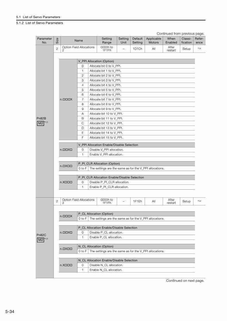
5.1 List of Servo Parameters
5.1.2 List of Servo Parameters
5-34
Pn82B
2 Option Field Allocations 2
0000h to 1F1Fh – 1D1Ch All After
restart Setup *14
Pn82C
2 Option Field Allocations 3
0000h to 1F1Fh – 1F1Eh All After
restart Setup *14
Continued on next page.
Continued from previous page.Parameter
No. Siz
e
NameSetting Range
Setting Unit
Default Setting
Applicable Motors
When Enabled
Classi-fication
Refer-ence
M2 *15
n.X
V_PPI Allocation (Option)
0 Allocate bit 0 to V_PPI.
1 Allocate bit 1 to V_PPI.
2 Allocate bit 2 to V_PPI.
3 Allocate bit 3 to V_PPI.
4 Allocate bit 4 to V_PPI.
5 Allocate bit 5 to V_PPI.
6 Allocate bit 6 to V_PPI.
7 Allocate bit 7 to V_PPI.
8 Allocate bit 8 to V_PPI.
9 Allocate bit 9 to V_PPI.
A Allocate bit 10 to V_PPI.
B Allocate bit 11 to V_PPI.
C Allocate bit 12 to V_PPI.
D Allocate bit 13 to V_PPI.
E Allocate bit 14 to V_PPI.
F Allocate bit 15 to V_PPI.
n.X
V_PPI Allocation Enable/Disable Selection
0 Disable V_PPI allocation.
1 Enable V_PPI allocation.
n.XP_PI_CLR Allocation (Option)
0 to F The settings are the same as for the V_PPI allocations.
n.X
P_PI_CLR Allocation Enable/Disable Selection
0 Disable P_PI_CLR allocation.
1 Enable P_PI_CLR allocation.
M2 *15
n.XP_CL Allocation (Option)
0 to F The settings are the same as for the V_PPI allocations.
n.X
P_CL Allocation Enable/Disable Selection
0 Disable P_CL allocation.
1 Enable P_CL allocation.
n.XN_CL Allocation (Option)
0 to F The settings are the same as for the V_PPI allocations.
n.X
N_CL Allocation Enable/Disable Selection
0 Disable N_CL allocation.
1 Enable N_CL allocation.
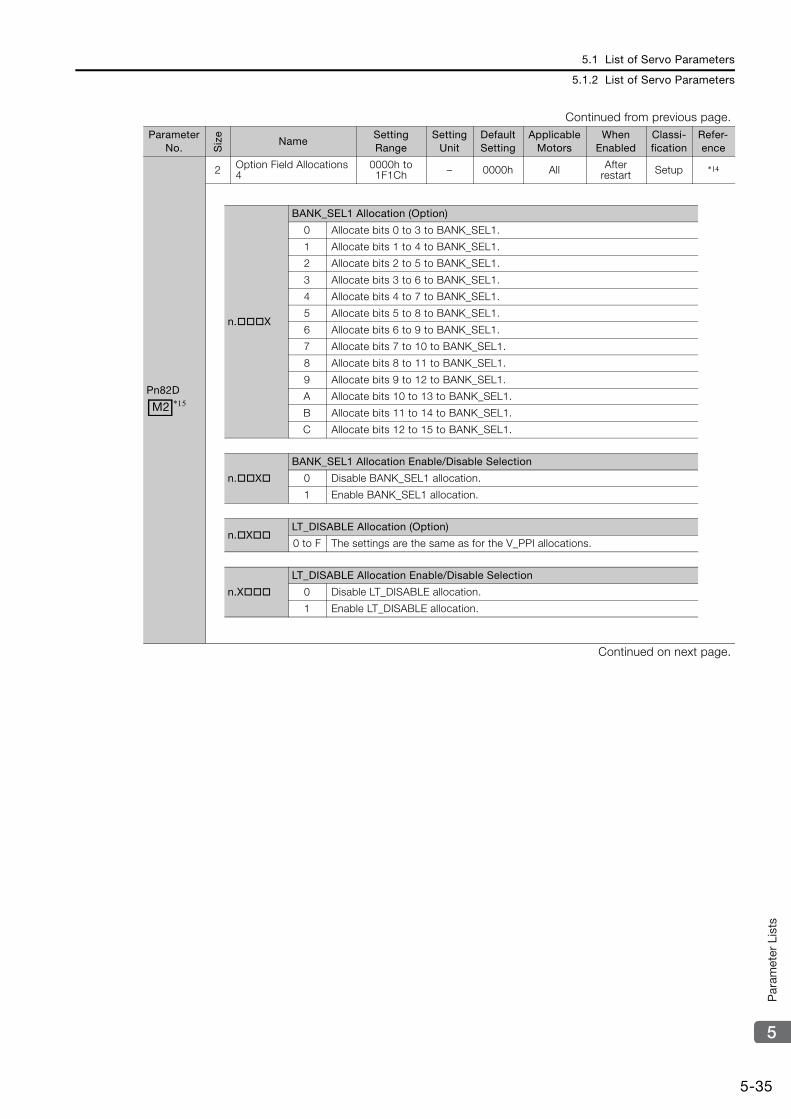
5.1 List of Servo Parameters
5.1.2 List of Servo Parameters
5-35
5
Par
amet
er L
ists
Pn82D
2 Option Field Allocations 4
0000h to 1F1Ch – 0000h All After
restart Setup *14
Continued on next page.
Continued from previous page.Parameter
No. Siz
e
NameSetting Range
Setting Unit
Default Setting
Applicable Motors
When Enabled
Classi-fication
Refer-ence
M2 *15
n.X
BANK_SEL1 Allocation (Option)
0 Allocate bits 0 to 3 to BANK_SEL1.
1 Allocate bits 1 to 4 to BANK_SEL1.
2 Allocate bits 2 to 5 to BANK_SEL1.
3 Allocate bits 3 to 6 to BANK_SEL1.
4 Allocate bits 4 to 7 to BANK_SEL1.
5 Allocate bits 5 to 8 to BANK_SEL1.
6 Allocate bits 6 to 9 to BANK_SEL1.
7 Allocate bits 7 to 10 to BANK_SEL1.
8 Allocate bits 8 to 11 to BANK_SEL1.
9 Allocate bits 9 to 12 to BANK_SEL1.
A Allocate bits 10 to 13 to BANK_SEL1.
B Allocate bits 11 to 14 to BANK_SEL1.
C Allocate bits 12 to 15 to BANK_SEL1.
n.X
BANK_SEL1 Allocation Enable/Disable Selection
0 Disable BANK_SEL1 allocation.
1 Enable BANK_SEL1 allocation.
n.XLT_DISABLE Allocation (Option)
0 to F The settings are the same as for the V_PPI allocations.
n.X
LT_DISABLE Allocation Enable/Disable Selection
0 Disable LT_DISABLE allocation.
1 Enable LT_DISABLE allocation.
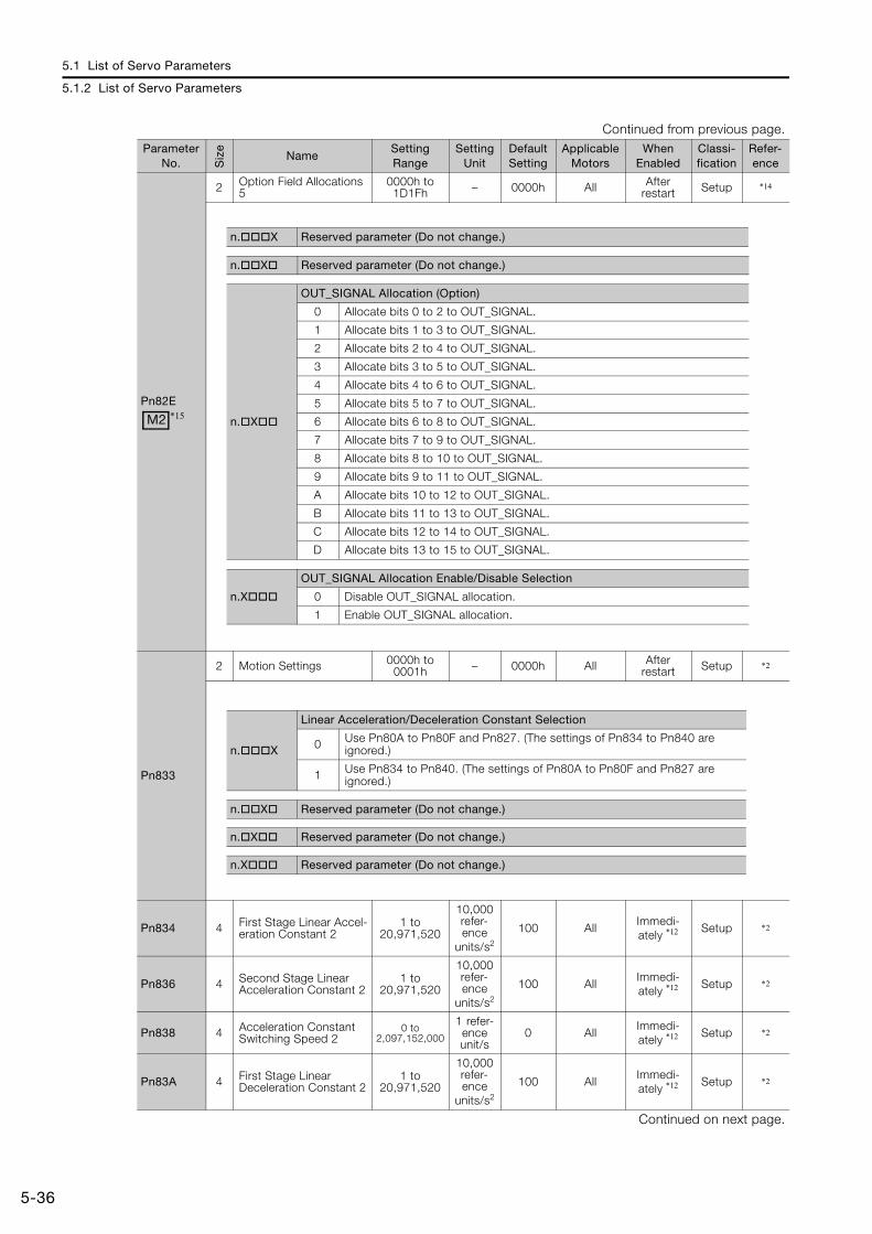
5.1 List of Servo Parameters
5.1.2 List of Servo Parameters
5-36
Pn82E
2 Option Field Allocations 5
0000h to 1D1Fh – 0000h All After
restart Setup *14
Pn833
2 Motion Settings 0000h to 0001h – 0000h All After
restart Setup *2
Pn834 4 First Stage Linear Accel-eration Constant 2
1 to 20,971,520
10,000 refer-ence
units/s2
100 AllImmedi-ately *12 Setup *2
Pn836 4 Second Stage Linear Acceleration Constant 2
1 to 20,971,520
10,000 refer-ence
units/s2
100 AllImmedi-ately *12 Setup *2
Pn838 4 Acceleration Constant Switching Speed 2
0 to 2,097,152,000
1 refer-ence unit/s
0 AllImmedi-ately *12 Setup *2
Pn83A 4 First Stage Linear Deceleration Constant 2
1 to 20,971,520
10,000 refer-ence
units/s2
100 AllImmedi-ately *12 Setup *2
Continued on next page.
Continued from previous page.Parameter
No. Siz
e
NameSetting Range
Setting Unit
Default Setting
Applicable Motors
When Enabled
Classi-fication
Refer-ence
M2 *15
n.X Reserved parameter (Do not change.)
n.X Reserved parameter (Do not change.)
n.X
OUT_SIGNAL Allocation (Option)
0 Allocate bits 0 to 2 to OUT_SIGNAL.
1 Allocate bits 1 to 3 to OUT_SIGNAL.
2 Allocate bits 2 to 4 to OUT_SIGNAL.
3 Allocate bits 3 to 5 to OUT_SIGNAL.
4 Allocate bits 4 to 6 to OUT_SIGNAL.
5 Allocate bits 5 to 7 to OUT_SIGNAL.
6 Allocate bits 6 to 8 to OUT_SIGNAL.
7 Allocate bits 7 to 9 to OUT_SIGNAL.
8 Allocate bits 8 to 10 to OUT_SIGNAL.
9 Allocate bits 9 to 11 to OUT_SIGNAL.
A Allocate bits 10 to 12 to OUT_SIGNAL.
B Allocate bits 11 to 13 to OUT_SIGNAL.
C Allocate bits 12 to 14 to OUT_SIGNAL.
D Allocate bits 13 to 15 to OUT_SIGNAL.
n.X
OUT_SIGNAL Allocation Enable/Disable Selection
0 Disable OUT_SIGNAL allocation.
1 Enable OUT_SIGNAL allocation.
n.X
Linear Acceleration/Deceleration Constant Selection
0 Use Pn80A to Pn80F and Pn827. (The settings of Pn834 to Pn840 are ignored.)
1 Use Pn834 to Pn840. (The settings of Pn80A to Pn80F and Pn827 are ignored.)
n.X Reserved parameter (Do not change.)
n.X Reserved parameter (Do not change.)
n.X Reserved parameter (Do not change.)
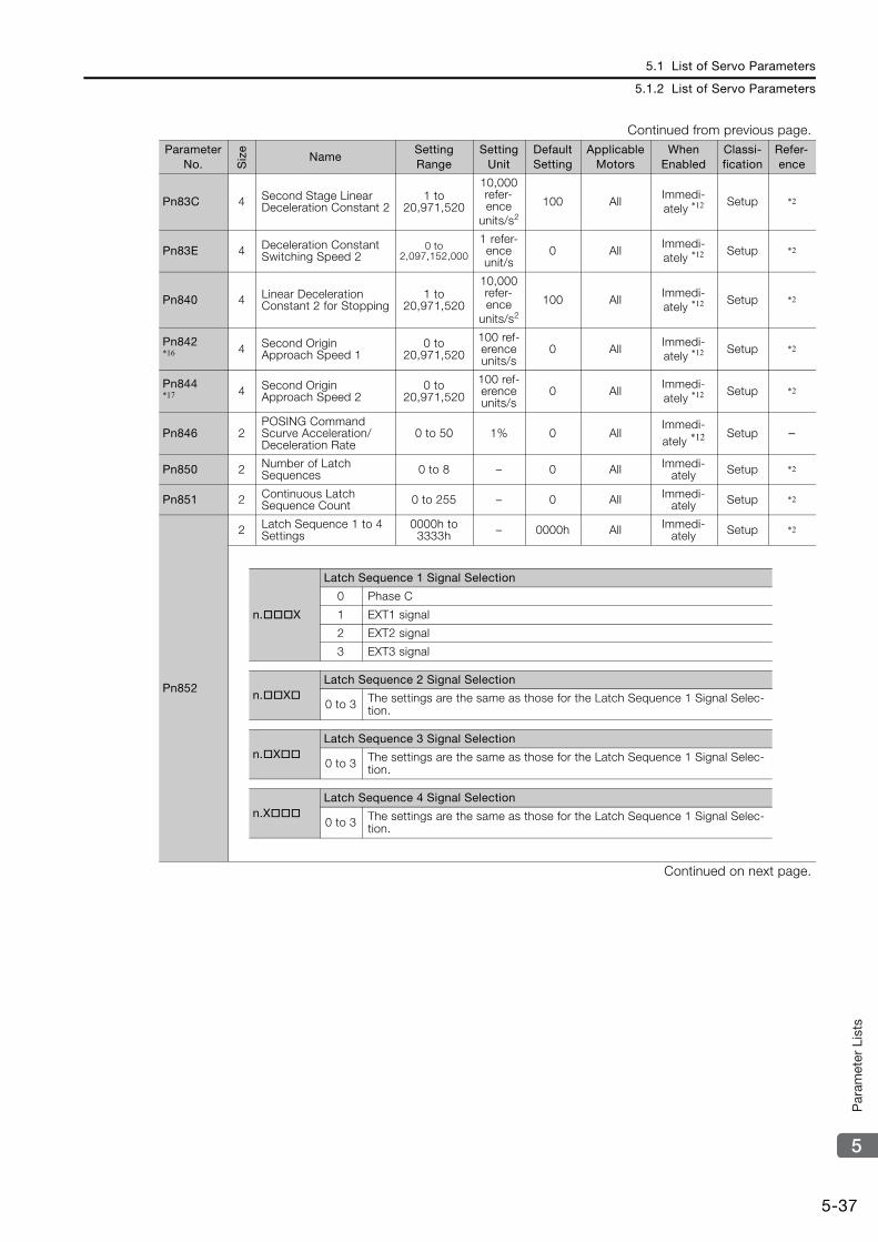
5.1 List of Servo Parameters
5.1.2 List of Servo Parameters
5-37
5
Par
amet
er L
ists
Pn83C 4 Second Stage Linear Deceleration Constant 2
1 to 20,971,520
10,000 refer-ence
units/s2
100 AllImmedi-ately *12 Setup *2
Pn83E 4 Deceleration Constant Switching Speed 2
0 to 2,097,152,000
1 refer-ence unit/s
0 AllImmedi-ately *12 Setup *2
Pn840 4 Linear Deceleration Constant 2 for Stopping
1 to 20,971,520
10,000 refer-ence
units/s2
100 AllImmedi-ately *12 Setup *2
Pn842*16 4 Second Origin
Approach Speed 10 to
20,971,520
100 ref-erence units/s
0 AllImmedi-ately *12 Setup *2
Pn844*17 4 Second Origin
Approach Speed 20 to
20,971,520
100 ref-erence units/s
0 AllImmedi-ately *12 Setup *2
Pn846 2POSING Command Scurve Acceleration/Deceleration Rate
0 to 50 1% 0 AllImmedi-ately *12 Setup –
Pn850 2 Number of Latch Sequences 0 to 8 – 0 All Immedi-
ately Setup *2
Pn851 2 Continuous Latch Sequence Count 0 to 255 – 0 All Immedi-
ately Setup *2
Pn852
2 Latch Sequence 1 to 4 Settings
0000h to 3333h – 0000h All Immedi-
ately Setup *2
Continued on next page.
Continued from previous page.Parameter
No. Siz
e
NameSetting Range
Setting Unit
Default Setting
Applicable Motors
When Enabled
Classi-fication
Refer-ence
n.X
Latch Sequence 1 Signal Selection
0 Phase C
1 EXT1 signal
2 EXT2 signal
3 EXT3 signal
n.XLatch Sequence 2 Signal Selection
0 to 3 The settings are the same as those for the Latch Sequence 1 Signal Selec-tion.
n.XLatch Sequence 3 Signal Selection
0 to 3 The settings are the same as those for the Latch Sequence 1 Signal Selec-tion.
n.XLatch Sequence 4 Signal Selection
0 to 3 The settings are the same as those for the Latch Sequence 1 Signal Selec-tion.
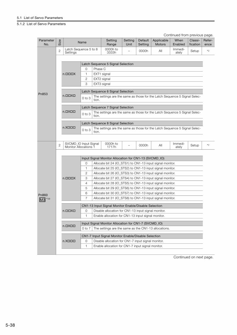
5.1 List of Servo Parameters
5.1.2 List of Servo Parameters
5-38
Pn853
2 Latch Sequence 5 to 8 Settings
0000h to 3333h – 0000h All Immedi-
ately Setup *2
Pn860
2 SVCMD_IO Input Signal Monitor Allocations 1
0000h to 1717h – 0000h All Immedi-
ately Setup *2
Continued on next page.
Continued from previous page.Parameter
No. Siz
e
NameSetting Range
Setting Unit
Default Setting
Applicable Motors
When Enabled
Classi-fication
Refer-ence
n.X
Latch Sequence 5 Signal Selection
0 Phase C
1 EXT1 signal
2 EXT2 signal
3 EXT3 signal
n.XLatch Sequence 6 Signal Selection
0 to 3 The settings are the same as those for the Latch Sequence 5 Signal Selec-tion.
n.XLatch Sequence 7 Signal Selection
0 to 3 The settings are the same as those for the Latch Sequence 5 Signal Selec-tion.
n.XLatch Sequence 8 Signal Selection
0 to 3 The settings are the same as those for the Latch Sequence 5 Signal Selec-tion.
M3 *10
n.X
Input Signal Monitor Allocation for CN1-13 (SVCMD_IO)
0 Allocate bit 24 (IO_STS1) to CN1-13 input signal monitor.
1 Allocate bit 25 (IO_STS2) to CN1-13 input signal monitor.
2 Allocate bit 26 (IO_STS3) to CN1-13 input signal monitor.
3 Allocate bit 27 (IO_STS4) to CN1-13 input signal monitor.
4 Allocate bit 28 (IO_STS5) to CN1-13 input signal monitor.
5 Allocate bit 29 (IO_STS6) to CN1-13 input signal monitor.
6 Allocate bit 30 (IO_STS7) to CN1-13 input signal monitor.
7 Allocate bit 31 (IO_STS8) to CN1-13 input signal monitor.
n.X
CN1-13 Input Signal Monitor Enable/Disable Selection
0 Disable allocation for CN1-13 input signal monitor.
1 Enable allocation for CN1-13 input signal monitor.
n.XInput Signal Monitor Allocation for CN1-7 (SVCMD_IO)
0 to 7 The settings are the same as the CN1-13 allocations.
n.X
CN1-7 Input Signal Monitor Enable/Disable Selection
0 Disable allocation for CN1-7 input signal monitor.
1 Enable allocation for CN1-7 input signal monitor.
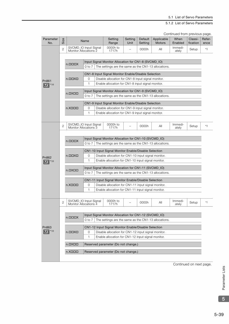
5.1 List of Servo Parameters
5.1.2 List of Servo Parameters
5-39
5
Par
amet
er L
ists
Pn861
2 SVCMD_IO Input Signal Monitor Allocations 2
0000h to 1717h – 0000h All Immedi-
ately Setup *2
Pn862
2 SVCMD_IO Input Signal Monitor Allocations 3
0000h to 1717h – 0000h All Immedi-
ately Setup *2
Pn863
2 SVCMD_IO Input Signal Monitor Allocations 4
0000h to 1717h – 0000h All Immedi-
ately Setup *2
Continued on next page.
Continued from previous page.Parameter
No. Siz
e
NameSetting Range
Setting Unit
Default Setting
Applicable Motors
When Enabled
Classi-fication
Refer-ence
M3 *10
n.XInput Signal Monitor Allocation for CN1-8 (SVCMD_IO)
0 to 7 The settings are the same as the CN1-13 allocations.
n.X
CN1-8 Input Signal Monitor Enable/Disable Selection
0 Disable allocation for CN1-8 input signal monitor.
1 Enable allocation for CN1-8 input signal monitor.
n.XInput Signal Monitor Allocation for CN1-9 (SVCMD_IO)
0 to 7 The settings are the same as the CN1-13 allocations.
n.X
CN1-9 Input Signal Monitor Enable/Disable Selection
0 Disable allocation for CN1-9 input signal monitor.
1 Enable allocation for CN1-9 input signal monitor.
M3 *10
n.XInput Signal Monitor Allocation for CN1-10 (SVCMD_IO)
0 to 7 The settings are the same as the CN1-13 allocations.
n.X
CN1-10 Input Signal Monitor Enable/Disable Selection
0 Disable allocation for CN1-10 input signal monitor.
1 Enable allocation for CN1-10 input signal monitor.
n.XInput Signal Monitor Allocation for CN1-11 (SVCMD_IO)
0 to 7 The settings are the same as the CN1-13 allocations.
n.X
CN1-11 Input Signal Monitor Enable/Disable Selection
0 Disable allocation for CN1-11 input signal monitor.
1 Enable allocation for CN1-11 input signal monitor.
M3 *10
n.XInput Signal Monitor Allocation for CN1-12 (SVCMD_IO)
0 to 7 The settings are the same as the CN1-13 allocations.
n.X
CN1-12 Input Signal Monitor Enable/Disable Selection
0 Disable allocation for CN1-12 input signal monitor.
1 Enable allocation for CN1-12 input signal monitor.
n.X Reserved parameter (Do not change.)
n.X Reserved parameter (Do not change.)
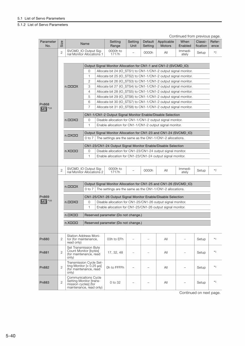
5.1 List of Servo Parameters
5.1.2 List of Servo Parameters
5-40
Pn868
2 SVCMD_IO Output Sig-nal Monitor Allocations 1
0000h to 1717h – 0000h All Immedi-
ately Setup *2
Pn869
2 SVCMD_IO Output Sig-nal Monitor Allocations 2
0000h to 1717h – 0000h All Immedi-
ately Setup *2
Pn880 2Station Address Moni-tor (for maintenance, read only)
03h to EFh – – All – Setup *1
Pn881 2
Set Transmission Byte Count Monitor [bytes] (for maintenance, read only)
17, 32, 48 – – All – Setup *1
Pn882 2
Transmission Cycle Set-ting Monitor [× 0.25 μs] (for maintenance, read only)
0h to FFFFh – – All – Setup *1
Pn883 2
Communications Cycle Setting Monitor [trans-mission cycles] (for maintenance, read only)
0 to 32 – – All – Setup *1
Continued on next page.
Continued from previous page.Parameter
No. Siz
e
NameSetting Range
Setting Unit
Default Setting
Applicable Motors
When Enabled
Classi-fication
Refer-ence
M3 *10
n.X
Output Signal Monitor Allocation for CN1-1 and CN1-2 (SVCMD_IO)
0 Allocate bit 24 (IO_STS1) to CN1-1/CN1-2 output signal monitor.
1 Allocate bit 25 (IO_STS2) to CN1-1/CN1-2 output signal monitor.
2 Allocate bit 26 (IO_STS3) to CN1-1/CN1-2 output signal monitor.
3 Allocate bit 27 (IO_STS4) to CN1-1/CN1-2 output signal monitor.
4 Allocate bit 28 (IO_STS5) to CN1-1/CN1-2 output signal monitor.
5 Allocate bit 29 (IO_STS6) to CN1-1/CN1-2 output signal monitor.
6 Allocate bit 30 (IO_STS7) to CN1-1/CN1-2 output signal monitor.
7 Allocate bit 31 (IO_STS8) to CN1-1/CN1-2 output signal monitor.
n.X
CN1-1/CN1-2 Output Signal Monitor Enable/Disable Selection
0 Disable allocation for CN1-1/CN1-2 output signal monitor.
1 Enable allocation for CN1-1/CN1-2 output signal monitor.
n.XOutput Signal Monitor Allocation for CN1-23 and CN1-24 (SVCMD_IO)
0 to 7 The settings are the same as the CN1-1/CN1-2 allocations.
n.X
CN1-23/CN1-24 Output Signal Monitor Enable/Disable Selection
0 Disable allocation for CN1-23/CN1-24 output signal monitor.
1 Enable allocation for CN1-23/CN1-24 output signal monitor.
M3 *10
n.XOutput Signal Monitor Allocation for CN1-25 and CN1-26 (SVCMD_IO)
0 to 7 The settings are the same as the CN1-1/CN1-2 allocations.
n.X
CN1-25/CN1-26 Output Signal Monitor Enable/Disable Selection
0 Disable allocation for CN1-25/CN1-26 output signal monitor.
1 Enable allocation for CN1-25/CN1-26 output signal monitor.
n.X Reserved parameter (Do not change.)
n.X Reserved parameter (Do not change.)
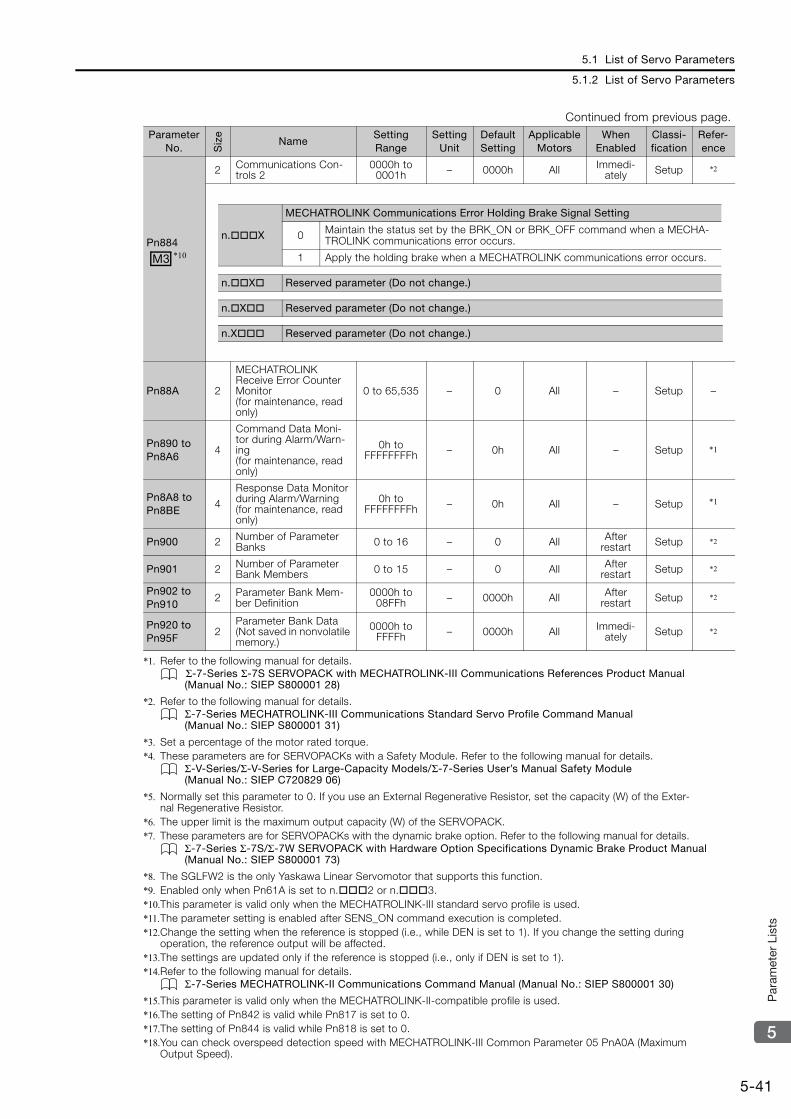
5.1 List of Servo Parameters
5.1.2 List of Servo Parameters
5-41
5
Par
amet
er L
ists
*1. Refer to the following manual for details.Σ-7-Series Σ-7S SERVOPACK with MECHATROLINK-III Communications References Product Manual (Manual No.: SIEP S800001 28)
*2. Refer to the following manual for details.Σ-7-Series MECHATROLINK-III Communications Standard Servo Profile Command Manual (Manual No.: SIEP S800001 31)
*3. Set a percentage of the motor rated torque.*4. These parameters are for SERVOPACKs with a Safety Module. Refer to the following manual for details.
Σ-V-Series/Σ-V-Series for Large-Capacity Models/Σ-7-Series User’s Manual Safety Module (Manual No.: SIEP C720829 06)
*5. Normally set this parameter to 0. If you use an External Regenerative Resistor, set the capacity (W) of the Exter-nal Regenerative Resistor.
*6. The upper limit is the maximum output capacity (W) of the SERVOPACK.*7. These parameters are for SERVOPACKs with the dynamic brake option. Refer to the following manual for details.
Σ-7-Series Σ-7S/Σ-7W SERVOPACK with Hardware Option Specifications Dynamic Brake Product Manual (Manual No.: SIEP S800001 73)
*8. The SGLFW2 is the only Yaskawa Linear Servomotor that supports this function.*9. Enabled only when Pn61A is set to n.2 or n.3.*10.This parameter is valid only when the MECHATROLINK-III standard servo profile is used.*11.The parameter setting is enabled after SENS_ON command execution is completed.*12.Change the setting when the reference is stopped (i.e., while DEN is set to 1). If you change the setting during
operation, the reference output will be affected.*13.The settings are updated only if the reference is stopped (i.e., only if DEN is set to 1).*14.Refer to the following manual for details.
Σ-7-Series MECHATROLINK-II Communications Command Manual (Manual No.: SIEP S800001 30)
*15.This parameter is valid only when the MECHATROLINK-II-compatible profile is used.*16.The setting of Pn842 is valid while Pn817 is set to 0.*17.The setting of Pn844 is valid while Pn818 is set to 0.*18.You can check overspeed detection speed with MECHATROLINK-III Common Parameter 05 PnA0A (Maximum
Output Speed).
Pn884
2 Communications Con-trols 2
0000h to 0001h – 0000h All Immedi-
ately Setup *2
Pn88A 2
MECHATROLINK Receive Error Counter Monitor (for maintenance, read only)
0 to 65,535 – 0 All – Setup –
Pn890 toPn8A6
4
Command Data Moni-tor during Alarm/Warn-ing (for maintenance, read only)
0h to FFFFFFFFh – 0h All – Setup *1
Pn8A8 toPn8BE
4
Response Data Monitor during Alarm/Warning (for maintenance, read only)
0h to FFFFFFFFh – 0h All – Setup *1
Pn900 2 Number of Parameter Banks 0 to 16 – 0 All After
restart Setup *2
Pn901 2 Number of Parameter Bank Members 0 to 15 – 0 All After
restart Setup *2
Pn902 toPn910
2 Parameter Bank Mem-ber Definition
0000h to 08FFh – 0000h All After
restart Setup *2
Pn920 toPn95F
2Parameter Bank Data (Not saved in nonvolatile memory.)
0000h to FFFFh – 0000h All Immedi-
ately Setup *2
Continued from previous page.Parameter
No. Siz
e
NameSetting Range
Setting Unit
Default Setting
Applicable Motors
When Enabled
Classi-fication
Refer-ence
M3 *10
n.X
MECHATROLINK Communications Error Holding Brake Signal Setting
0 Maintain the status set by the BRK_ON or BRK_OFF command when a MECHA-TROLINK communications error occurs.
1 Apply the holding brake when a MECHATROLINK communications error occurs.
n.X Reserved parameter (Do not change.)
n.X Reserved parameter (Do not change.)
n.X Reserved parameter (Do not change.)

5.2 List of MECHATROLINK-III Common Parameters
5.2.1 Interpreting the Parameter Lists
5-42
5.2 List of MECHATROLINK-III Common Parameters
5.2.1 Interpreting the Parameter Lists
5.2.2 List of MECHATROLINK-III Common ParametersThe following table lists the common MECHATROLINK-III parameters. These common parame-ters are used to make settings from the host controller via MECHATROLINK communications. Do not change the settings with the Digital Operator or any other device.
Parameter No.
Size NameSetting Range
Setting Unit [Resolution]
Default Setting
Applicable Motors
When Enabled
Classi-fication
61PnAC2
4 Speed Loop Gain 1,000 to 2,000,000
0.001 Hz[0.1 Hz] 40000 All Immedi-
ately Tuning
All: The parameter is used for both Rotary Servomotors and Linear Servomotors.Rotary: The parameter is used for only Rotary Servomotors.Linear: The parameter is used for only Linear Servomotors.
The types of motors to which the parameter applies.
Rotary Servomotor terms are used for parameters that are applicable to all Servomotors. If you are using a Linear Servomotor, you need to interpret the terms accordingly. Refer to the following section for details.
Differences in Terms for Rotary Servomotors and Linear Servomotors on page xi
Indicates when a change to the parameter will be effective.“After restart” indicates parameters that will be effective after one of the following is executed.• The power supply is turned OFF
and ON again.• The CONFIG command is sent.• A software reset is executed.
You can set the parameter in increments of the setting unit.However, if a unit is given in square brackets, the setting is automatically converted to the resolution given in the square brackets.
Parameter No.
Size Name Setting RangeSetting Unit [Resolution]
Default Setting
Applicable Motors
When Enabled
Classi-fication
01PnA02
4 Encoder Type (read only) 0h or 1h – – All –D
evic
e in
form
atio
n
02PnA04
4 Motor Type (read only) 0h or 1h – – All –
03PnA06
4Semi-closed/Fully-closed Type (read only)
0h or 1h – – All –
04PnA08
4 Rated Speed (read only)
0h to FFFFFFFFh 1 min-1 – All –
Continued on next page.
0000h Absolute encoder
0001h Incremental encoder
0000h Rotary Servomotor
0001h Linear Servomotor
0000h Semi-closed
0001h Fully-closed
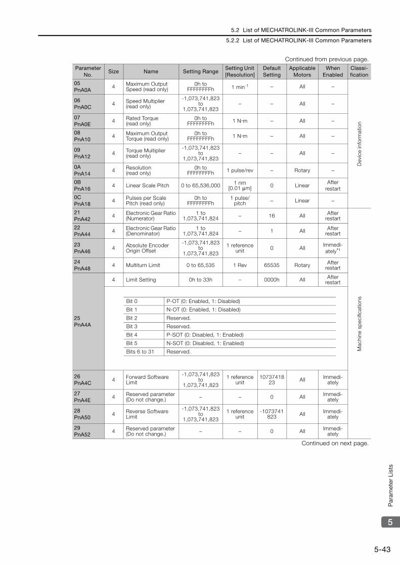
5.2 List of MECHATROLINK-III Common Parameters
5.2.2 List of MECHATROLINK-III Common Parameters
5-43
5
Par
amet
er L
ists
05PnA0A
4 Maximum Output Speed (read only)
0h to FFFFFFFFh 1 min-1 – All –
Dev
ice
info
rmat
ion
06PnA0C
4 Speed Multiplier (read only)
-1,073,741,823 to
1,073,741,823– – All –
07PnA0E
4 Rated Torque (read only)
0h to FFFFFFFFh 1 Nm – All –
08PnA10
4 Maximum Output Torque (read only)
0h to FFFFFFFFh 1 Nm – All –
09PnA12
4 Torque Multiplier (read only)
-1,073,741,823 to
1,073,741,823– – All –
0APnA14
4 Resolution (read only)
0h to FFFFFFFFh 1 pulse/rev – Rotary –
0BPnA16
4 Linear Scale Pitch 0 to 65,536,000 1 nm [0.01 μm] 0 Linear
After restart
0CPnA18
4 Pulses per Scale Pitch (read only)
0h to FFFFFFFFh
1 pulse/pitch – Linear –
21PnA42
4 Electronic Gear Ratio (Numerator)
1 to 1,073,741,824 – 16 All After
restart
Mac
hine
sp
ecifi
catio
ns
22PnA44
4 Electronic Gear Ratio (Denominator)
1 to 1,073,741,824 – 1 All After
restart
23PnA46
4 Absolute Encoder Origin Offset
-1,073,741,823 to
1,073,741,823
1 reference unit 0 All
Immedi-ately*1
24PnA48
4 Multiturn Limit 0 to 65,535 1 Rev 65535 Rotary After restart
25PnA4A
4 Limit Setting 0h to 33h – 0000h All After restart
26PnA4C
4 Forward Software Limit
-1,073,741,823 to
1,073,741,823
1 reference unit
1073741823 All Immedi-
ately
27PnA4E
4 Reserved parameter (Do not change.) – – 0 All Immedi-
ately
28PnA50
4 Reverse Software Limit
-1,073,741,823 to
1,073,741,823
1 reference unit
-1073741823 All Immedi-
ately
29PnA52
4 Reserved parameter (Do not change.) – – 0 All Immedi-
ately
Continued on next page.
Continued from previous page.Parameter
No.Size Name Setting Range
Setting Unit [Resolution]
Default Setting
Applicable Motors
When Enabled
Classi-fication
Bit 0 P-OT (0: Enabled, 1: Disabled)
Bit 1 N-OT (0: Enabled, 1: Disabled)
Bit 2 Reserved.
Bit 3 Reserved.
Bit 4 P-SOT (0: Disabled, 1: Enabled)
Bit 5 N-SOT (0: Disabled, 1: Enabled)
Bits 6 to 31 Reserved.
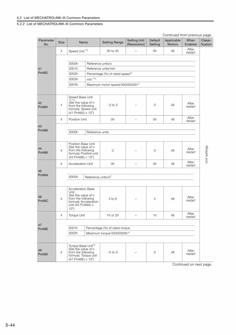
5.2 List of MECHATROLINK-III Common Parameters
5.2.2 List of MECHATROLINK-III Common Parameters
5-44
41PnA82
4 Speed Unit *2 0h to 4h – 0h All After restart
Uni
t se
ttin
gs
42PnA84
4
Speed Base Unit *3, *4(Set the value of n from the following formula: Speed unit (41 PnA82) × 10n)
-3 to 3 – 0 All After restart
43PnA86
4 Position Unit 0h – 0h All After restart
44PnA88
4
Position Base Unit(Set the value of n from the following formula: Position unit (43 PnA86) × 10n)
0 – 0 All After restart
45PnA8A
4 Acceleration Unit 0h – 0h All After restart
46PnA8C
4
Acceleration Base Unit(Set the value of n from the following formula: Acceleration unit (45 PnA8A) × 10n)
4 to 6 – 4 All After restart
47PnA8E
4 Torque Unit 1h or 2h – 1h All After restart
48PnA90
4
Torque Base Unit*5
(Set the value of n from the following formula: Torque unit (47 PnA8E) × 10n)
-5 to 0 – 0 All After restart
Continued on next page.
Continued from previous page.Parameter
No.Size Name Setting Range
Setting Unit [Resolution]
Default Setting
Applicable Motors
When Enabled
Classi-fication
0000h Reference units/s
0001h Reference units/min
0002h Percentage (%) of rated speed*3
0003h min-1*3
0004h Maximum motor speed/40000000h*4
0000h Reference units
0000h Reference units/s2
0001h Percentage (%) of rated torque
0002h Maximum torque/40000000h*5
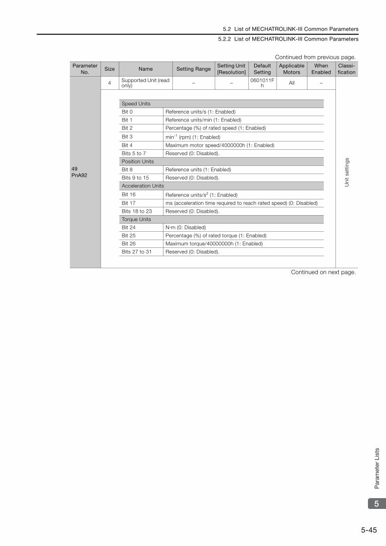
5.2 List of MECHATROLINK-III Common Parameters
5.2.2 List of MECHATROLINK-III Common Parameters
5-45
5
Par
amet
er L
ists
49PnA92
4 Supported Unit (read only) – – 0601011F
h All –
Uni
t se
ttin
gs
Continued on next page.
Continued from previous page.Parameter
No.Size Name Setting Range
Setting Unit [Resolution]
Default Setting
Applicable Motors
When Enabled
Classi-fication
Speed Units
Bit 0 Reference units/s (1: Enabled)
Bit 1 Reference units/min (1: Enabled)
Bit 2 Percentage (%) of rated speed (1: Enabled)
Bit 3 min-1 (rpm) (1: Enabled)
Bit 4 Maximum motor speed/4000000h (1: Enabled)
Bits 5 to 7 Reserved (0: Disabled).
Position Units
Bit 8 Reference units (1: Enabled)
Bits 9 to 15 Reserved (0: Disabled).
Acceleration Units
Bit 16 Reference units/s2 (1: Enabled)
Bit 17 ms (acceleration time required to reach rated speed) (0: Disabled)
Bits 18 to 23 Reserved (0: Disabled).
Torque Units
Bit 24 Nm (0: Disabled)
Bit 25 Percentage (%) of rated torque (1: Enabled)
Bit 26 Maximum torque/40000000h (1: Enabled)
Bits 27 to 31 Reserved (0: Disabled).
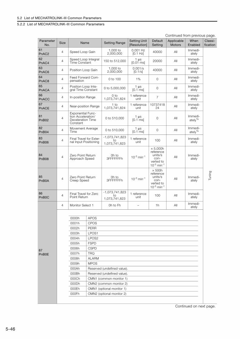
5.2 List of MECHATROLINK-III Common Parameters
5.2.2 List of MECHATROLINK-III Common Parameters
5-46
61PnAC2
4 Speed Loop Gain 1,000 to 2,000,000
0.001 Hz[0.1 Hz] 40000 All Immedi-
ately
Tuni
ng
62PnAC4
4 Speed Loop Integral Time Constant 150 to 512,000 1 μs
[0.01 ms] 20000 All Immedi-ately
63PnAC6
4 Position Loop Gain 1,000 to 2,000,000
0.001/s [0.1/s] 40000 All Immedi-
ately
64PnAC8
4 Feed Forward Com-pensation 0 to 100 1% 0 All Immedi-
ately
65PnACA
4 Position Loop Inte-gral Time Constant 0 to 5,000,000 1 μs
[0.1 ms] 0 All Immedi-ately
66PnACC
4 In-position Range 0 to 1,073,741,824
1 reference unit 7 All Immedi-
ately
67PnACE
4 Near-position Range 1 to 1,073,741,824
1 reference unit
1073741824 All Immedi-
ately
81PnB02
4
Exponential Func-tion Acceleration/Deceleration Time Constant
0 to 510,000 1 μs[0.1 ms] 0 All
Immedi-ately*6
82PnB04
4 Movement Average Time 0 to 510,000 1 μs
[0.1 ms] 0 AllImmedi-ately*6
83PnB06
4 Final Travel for Exter-nal Input Positioning
-1,073,741,823 to
1,073,741,823
1 reference unit 100 All Immedi-
ately
84PnB08
4 Zero Point Return Approach Speed
0h to 3FFFFFFFh 10-3 min-1
× 5,000h reference
units/s con-
verted to 10-3 min-1
All Immedi-ately
85PnB0A
4 Zero Point Return Creep Speed
0h to 3FFFFFFFh 10-3 min-1
× 500h reference
units/s con-
verted to 10-3 min-1
All Immedi-ately
86PnB0C
4 Final Travel for Zero Point Return
-1,073,741,823 to
1,073,741,823
1 reference unit 100 All Immedi-
ately
87PnB0E
4 Monitor Select 1 0h to Fh – 1h All Immedi-ately
Continued on next page.
Continued from previous page.Parameter
No.Size Name Setting Range
Setting Unit [Resolution]
Default Setting
Applicable Motors
When Enabled
Classi-fication
0000h APOS
0001h CPOS
0002h PERR
0003h LPOS1
0004h LPOS2
0005h FSPD
0006h CSPD
0007h TRQ
0008h ALARM
0009h MPOS
000Ah Reserved (undefined value).
000Bh Reserved (undefined value).
000Ch CMN1 (common monitor 1)
000Dh CMN2 (common monitor 2)
000Eh OMN1 (optional monitor 1)
000Fh OMN2 (optional monitor 2)
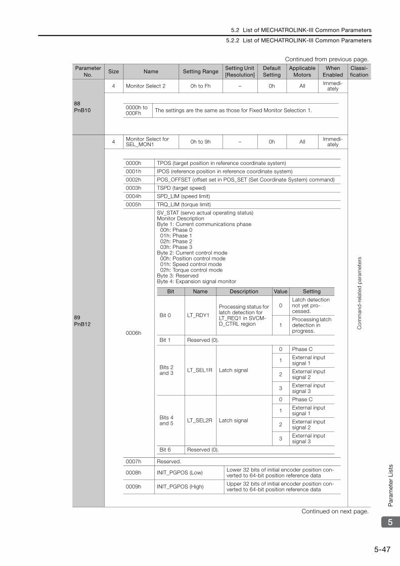
5.2 List of MECHATROLINK-III Common Parameters
5.2.2 List of MECHATROLINK-III Common Parameters
5-47
5
Par
amet
er L
ists
88PnB10
4 Monitor Select 2 0h to Fh – 0h All Immedi-ately
Com
man
d-r
elat
ed p
aram
eter
s
89PnB12
4 Monitor Select for SEL_MON1 0h to 9h – 0h All Immedi-
ately
Continued on next page.
Continued from previous page.Parameter
No.Size Name Setting Range
Setting Unit [Resolution]
Default Setting
Applicable Motors
When Enabled
Classi-fication
0000h to 000Fh The settings are the same as those for Fixed Monitor Selection 1.
0000h TPOS (target position in reference coordinate system)
0001h IPOS (reference position in reference coordinate system)
0002h POS_OFFSET (offset set in POS_SET (Set Coordinate System) command)
0003h TSPD (target speed)
0004h SPD_LIM (speed limit)
0005h TRQ_LIM (torque limit)
0006h
SV_STAT (servo actual operating status)Monitor DescriptionByte 1: Current communications phase 00h: Phase 0 01h: Phase 1 02h: Phase 2 03h: Phase 3Byte 2: Current control mode 00h: Position control mode 01h: Speed control mode 02h: Torque control modeByte 3: ReservedByte 4: Expansion signal monitor
0007h Reserved.
0008h INIT_PGPOS (Low) Lower 32 bits of initial encoder position con-verted to 64-bit position reference data
0009h INIT_PGPOS (High) Upper 32 bits of initial encoder position con-verted to 64-bit position reference data
Bit Name Description Value Setting
Bit 0 LT_RDY1
Processing status for latch detection for LT_REQ1 in SVCM-D_CTRL region
0Latch detection not yet pro-cessed.
1Processing latch detection in progress.
Bit 1 Reserved (0).
Bits 2 and 3 LT_SEL1R Latch signal
0 Phase C
1 External input signal 1
2 External input signal 2
3 External input signal 3
Bits 4 and 5 LT_SEL2R Latch signal
0 Phase C
1 External input signal 1
2 External input signal 2
3 External input signal 3
Bit 6 Reserved (0).
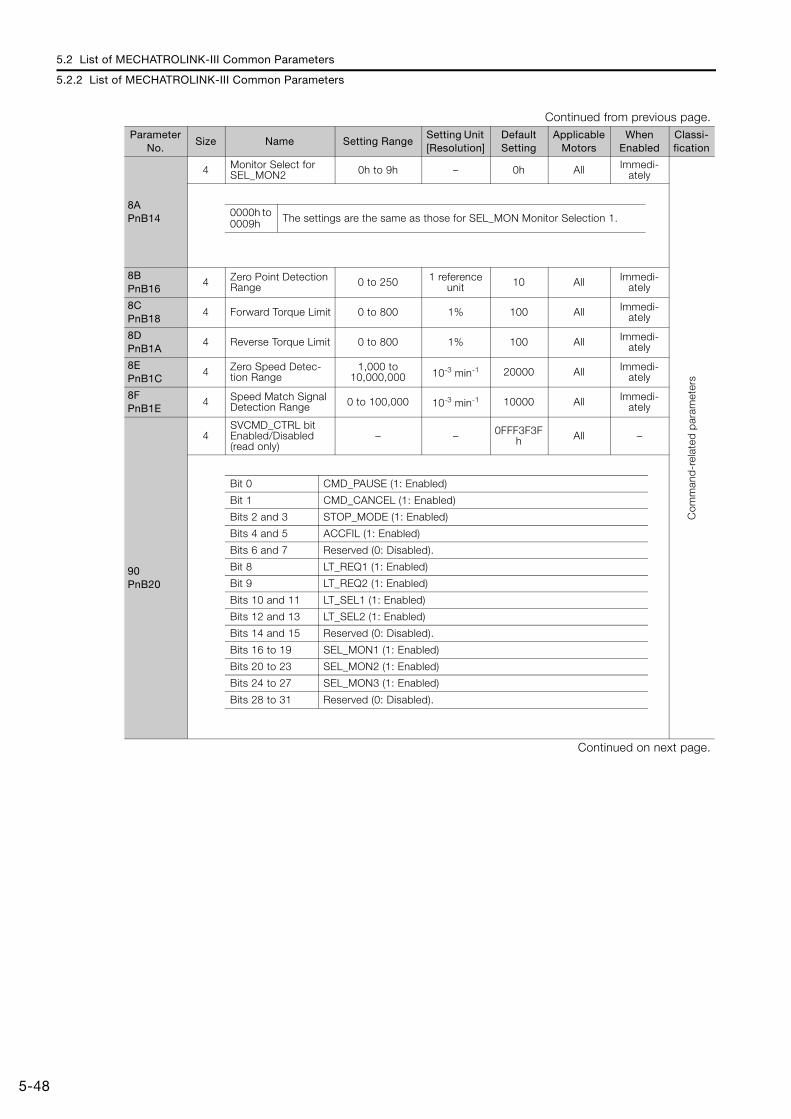
5.2 List of MECHATROLINK-III Common Parameters
5.2.2 List of MECHATROLINK-III Common Parameters
5-48
8APnB14
4 Monitor Select for SEL_MON2 0h to 9h – 0h All Immedi-
ately
Com
man
d-r
elat
ed p
aram
eter
s
8BPnB16
4 Zero Point Detection Range 0 to 250 1 reference
unit 10 All Immedi-ately
8CPnB18
4 Forward Torque Limit 0 to 800 1% 100 All Immedi-ately
8DPnB1A
4 Reverse Torque Limit 0 to 800 1% 100 All Immedi-ately
8EPnB1C
4 Zero Speed Detec-tion Range
1,000 to 10,000,000 10-3 min-1 20000 All Immedi-
ately
8FPnB1E
4 Speed Match Signal Detection Range 0 to 100,000 10-3 min-1 10000 All Immedi-
ately
90PnB20
4SVCMD_CTRL bit Enabled/Disabled (read only)
– – 0FFF3F3Fh All –
Continued on next page.
Continued from previous page.Parameter
No.Size Name Setting Range
Setting Unit [Resolution]
Default Setting
Applicable Motors
When Enabled
Classi-fication
0000h to 0009h The settings are the same as those for SEL_MON Monitor Selection 1.
Bit 0 CMD_PAUSE (1: Enabled)
Bit 1 CMD_CANCEL (1: Enabled)
Bits 2 and 3 STOP_MODE (1: Enabled)
Bits 4 and 5 ACCFIL (1: Enabled)
Bits 6 and 7 Reserved (0: Disabled).
Bit 8 LT_REQ1 (1: Enabled)
Bit 9 LT_REQ2 (1: Enabled)
Bits 10 and 11 LT_SEL1 (1: Enabled)
Bits 12 and 13 LT_SEL2 (1: Enabled)
Bits 14 and 15 Reserved (0: Disabled).
Bits 16 to 19 SEL_MON1 (1: Enabled)
Bits 20 to 23 SEL_MON2 (1: Enabled)
Bits 24 to 27 SEL_MON3 (1: Enabled)
Bits 28 to 31 Reserved (0: Disabled).

5.2 List of MECHATROLINK-III Common Parameters
5.2.2 List of MECHATROLINK-III Common Parameters
5-49
5
Par
amet
er L
ists
91PnB22
4SVCMD_STAT bit Enabled/Disabled (read only)
– 0h 0FFF3F33h All –
Com
man
d-r
elat
ed p
aram
eter
s
92PnB24
4I/O Bit Enabled/Dis-abled (Output) (read only)
– – 007F01F0h All –
Continued on next page.
Continued from previous page.Parameter
No.Size Name Setting Range
Setting Unit [Resolution]
Default Setting
Applicable Motors
When Enabled
Classi-fication
Bit 0 CMD_PAUSE_CMP (1: Enabled)
Bit 1 CMD_CANCEL_CMP (1: Enabled)
Bit 2 and 3 Reserved (0: Disabled).
Bits 4 and 5 ACCFIL (1: Enabled)
Bits 6 and 7 Reserved (0: Disabled).
Bit 8 L_CMP1 (1: Enabled)
Bit 9 L_CMP2 (1: Enabled)
Bit 10 POS_RDY (1: Enabled)
Bit 11 PON (1: Enabled)
Bit 12 M_RDY (1: Enabled)
Bit 13 SV_ON (1: Enabled)
Bits 14 and 15 Reserved (0: Disabled).
Bits 16 to 19 SEL_MON1 (1: Enabled)
Bits 20 to 23 SEL_MON2 (1: Enabled)
Bits 24 to 27 SEL_MON3 (1: Enabled)
Bits 28 to 31 Reserved (0: Disabled).
Bits 0 to 3 Reserved (0: Disabled).
Bit 4 V_PPI (1: Enabled)
Bit 5 P_PPI (1: Enabled)
Bit 6 P_CL (1: Enabled)
Bit 7 N_CL (1: Enabled)
Bit 8 G_SEL (1: Enabled)
Bits 9 to 11 G_SEL (0: Disabled)
Bits 12 to 15 Reserved (0: Disabled).
Bits 16 to 19 BANK_SEL (1: Enabled)
Bits 20 to 22 SO1 to SO3 (1: Enabled)
Bit 23 Reserved (0: Disabled).
Bits 24 to 31 Reserved (0: Disabled).
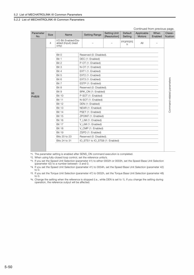
5.2 List of MECHATROLINK-III Common Parameters
5.2.2 List of MECHATROLINK-III Common Parameters
5-50
*1. The parameter setting is enabled after SENS_ON command execution is completed.*2. When using fully-closed loop control, set the reference units/s.*3. If you set the Speed Unit Selection (parameter 41) to either 0002h or 0003h, set the Speed Base Unit Selection
(parameter 42) to a number between -3 and 0.*4. If you set the Speed Unit Selection (parameter 41) to 0004h, set the Speed Base Unit Selection (parameter 42)
to 0.*5. If you set the Torque Unit Selection (parameter 47) to 0002h, set the Torque Base Unit Selection (parameter 48)
to 0.*6. Change the setting when the reference is stopped (i.e., while DEN is set to 1). If you change the setting during
operation, the reference output will be affected.
93PnB26
4I/O Bit Enabled/Dis-abled (Input) (read only)
– – FF0FFEFEh All –
Com
man
d-r
elat
ed p
aram
eter
s
Continued from previous page.Parameter
No.Size Name Setting Range
Setting Unit [Resolution]
Default Setting
Applicable Motors
When Enabled
Classi-fication
Bit 0 Reserved (0: Disabled).
Bit 1 DEC (1: Enabled)
Bit 2 P-OT (1: Enabled)
Bit 3 N-OT (1: Enabled)
Bit 4 EXT1 (1: Enabled)
Bit 5 EXT2 (1: Enabled)
Bit 6 EXT3 (1: Enabled)
Bit 7 ESTP (1: Enabled)
Bit 8 Reserved (0: Disabled).
Bit 9 BRK_ON (1: Enabled)
Bit 10 P-SOT (1: Enabled)
Bit 11 N-SOT (1: Enabled)
Bit 12 DEN (1: Enabled)
Bit 13 NEAR (1: Enabled)
Bit 14 PSET (1: Enabled)
Bit 15 ZPOINT (1: Enabled)
Bit 16 T_LIM (1: Enabled)
Bit 17 V_LIM (1: Enabled)
Bit 18 V_CMP (1: Enabled)
Bit 19 ZSPD (1: Enabled)
Bits 20 to 23 Reserved (0: Disabled).
Bits 24 to 31 IO_STS1 to IO_STS8 (1: Enabled)

5.3 Parameter Recording Table
5-51
5
Par
amet
er L
ists
5.3 Parameter Recording Table
Use the following table to record the settings of the parameters.
Parameter No.
Default Setting NameWhen
Enabled
Pn000 0000h Basic Function Selections 0 After restart
Pn001 0000h Application Function Selec-tions 1 After restart
Pn002 0011h Application Function Selec-tions 2 After restart
Pn006 0002h Application Function Selec-tions 6 Immediately
Pn007 0000h Application Function Selec-tions 7 Immediately
Pn008 4000h Application Function Selec-tions 8 After restart
Pn009 0010h Application Function Selec-tions 9 After restart
Pn00A 0001h Application Function Selec-tions A After restart
Pn00B 0000h Application Function Selec-tions B After restart
Pn00C 0000h Application Function Selec-tions C After restart
Pn00D 0000h Application Function Selec-tions D After restart
Pn00F 0000h Application Function Selec-tions F After restart
Pn021 0000h Reserved parameter −Pn022 0000h Reserved parameter −
Pn040 0000h Σ-V Compatible Function Switch After restart
Pn080 0000h Application Function Selec-tions 80 After restart
Pn081 0000h Application Function Selec-tions 81 After restart
Pn100 400 Speed Loop Gain Immediately
Pn101 2000 Speed Loop Integral Time Constant Immediately
Pn102 400 Position Loop Gain Immediately
Pn103 100 Moment of Inertia Ratio Immediately
Pn104 400 Second Speed Loop Gain Immediately
Pn105 2000 Second Speed Loop Inte-gral Time Constant Immediately
Pn106 400 Second Position Loop Gain Immediately
Pn109 0 Feedforward Immediately
Pn10A 0 Feedforward Filter Time Constant Immediately
Pn10B 0000h Gain Application Selections *1
Pn10C 200 Mode Switching Level for Torque Reference Immediately
Pn10D 0 Mode Switching Level for Speed Reference Immediately
Pn10E 0 Mode Switching Level for Acceleration Immediately
Continued on next page.
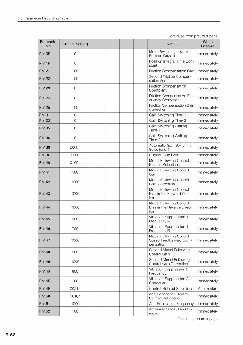
5.3 Parameter Recording Table
5-52
Pn10F 0 Mode Switching Level for Position Deviation Immediately
Pn11F 0 Position Integral Time Con-stant Immediately
Pn121 100 Friction Compensation Gain Immediately
Pn122 100 Second Friction Compen-sation Gain Immediately
Pn123 0 Friction Compensation Coefficient Immediately
Pn124 0 Friction Compensation Fre-quency Correction Immediately
Pn125 100 Friction Compensation Gain Correction Immediately
Pn131 0 Gain Switching Time 1 Immediately
Pn132 0 Gain Switching Time 2 Immediately
Pn135 0 Gain Switching Waiting Time 1 Immediately
Pn136 0 Gain Switching Waiting Time 2 Immediately
Pn139 0000h Automatic Gain Switching Selections 1 Immediately
Pn13D 2000 Current Gain Level Immediately
Pn140 0100h Model Following Control-Related Selections Immediately
Pn141 500 Model Following Control Gain Immediately
Pn142 1000 Model Following Control Gain Correction Immediately
Pn143 1000Model Following Control Bias in the Forward Direc-tion
Immediately
Pn144 1000Model Following Control Bias in the Reverse Direc-tion
Immediately
Pn145 500 Vibration Suppression 1 Frequency A Immediately
Pn146 700 Vibration Suppression 1 Frequency B Immediately
Pn147 1000Model Following Control Speed Feedforward Com-pensation
Immediately
Pn148 500 Second Model Following Control Gain Immediately
Pn149 1000 Second Model FollowingControl Gain Correction Immediately
Pn14A 800 Vibration Suppression 2 Frequency Immediately
Pn14B 100 Vibration Suppression 2 Correction Immediately
Pn14F 0021h Control-Related Selections After restart
Pn160 0010h Anti-Resonance Control-Related Selections Immediately
Pn161 1000 Anti-Resonance Frequency Immediately
Pn162 100 Anti-Resonance Gain Cor-rection Immediately
Continued on next page.
Continued from previous page.
Parameter No.
Default Setting NameWhen
Enabled
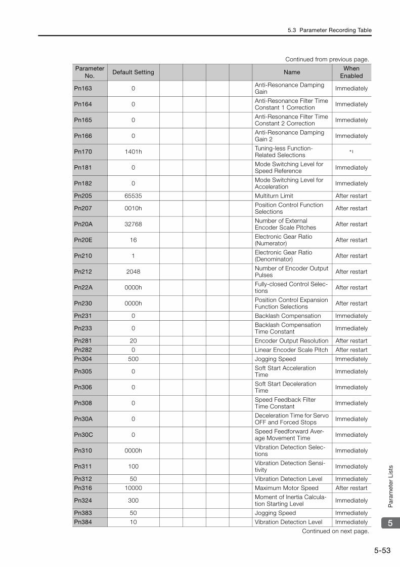
5.3 Parameter Recording Table
5-53
5
Par
amet
er L
ists
Pn163 0 Anti-Resonance Damping Gain Immediately
Pn164 0 Anti-Resonance Filter Time Constant 1 Correction Immediately
Pn165 0 Anti-Resonance Filter Time Constant 2 Correction Immediately
Pn166 0 Anti-Resonance Damping Gain 2 Immediately
Pn170 1401h Tuning-less Function-Related Selections
*1
Pn181 0 Mode Switching Level for Speed Reference Immediately
Pn182 0 Mode Switching Level for Acceleration Immediately
Pn205 65535 Multiturn Limit After restart
Pn207 0010h Position Control Function Selections After restart
Pn20A 32768 Number of ExternalEncoder Scale Pitches After restart
Pn20E 16 Electronic Gear Ratio (Numerator) After restart
Pn210 1 Electronic Gear Ratio (Denominator) After restart
Pn212 2048 Number of Encoder Output Pulses After restart
Pn22A 0000h Fully-closed Control Selec-tions After restart
Pn230 0000h Position Control Expansion Function Selections After restart
Pn231 0 Backlash Compensation Immediately
Pn233 0 Backlash Compensation Time Constant Immediately
Pn281 20 Encoder Output Resolution After restart
Pn282 0 Linear Encoder Scale Pitch After restart
Pn304 500 Jogging Speed Immediately
Pn305 0 Soft Start Acceleration Time Immediately
Pn306 0 Soft Start Deceleration Time Immediately
Pn308 0 Speed Feedback Filter Time Constant Immediately
Pn30A 0 Deceleration Time for Servo OFF and Forced Stops Immediately
Pn30C 0 Speed Feedforward Aver-age Movement Time Immediately
Pn310 0000h Vibration Detection Selec-tions Immediately
Pn311 100 Vibration Detection Sensi-tivity Immediately
Pn312 50 Vibration Detection Level Immediately
Pn316 10000 Maximum Motor Speed After restart
Pn324 300 Moment of Inertia Calcula-tion Starting Level Immediately
Pn383 50 Jogging Speed Immediately
Pn384 10 Vibration Detection Level Immediately
Continued on next page.
Continued from previous page.
Parameter No.
Default Setting NameWhen
Enabled
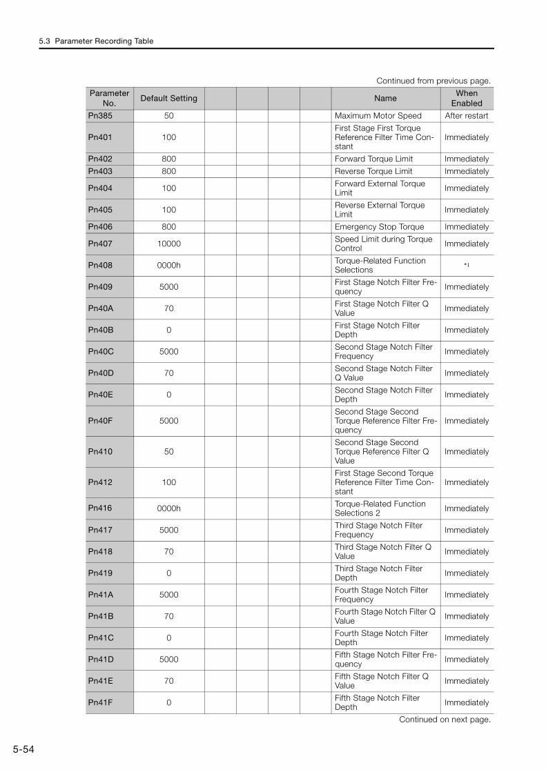
5.3 Parameter Recording Table
5-54
Pn385 50 Maximum Motor Speed After restart
Pn401 100First Stage First Torque Reference Filter Time Con-stant
Immediately
Pn402 800 Forward Torque Limit Immediately
Pn403 800 Reverse Torque Limit Immediately
Pn404 100 Forward External Torque Limit Immediately
Pn405 100 Reverse External Torque Limit Immediately
Pn406 800 Emergency Stop Torque Immediately
Pn407 10000 Speed Limit during Torque Control Immediately
Pn408 0000h Torque-Related Function Selections
*1
Pn409 5000 First Stage Notch Filter Fre-quency Immediately
Pn40A 70 First Stage Notch Filter Q Value Immediately
Pn40B 0 First Stage Notch Filter Depth Immediately
Pn40C 5000 Second Stage Notch Filter Frequency Immediately
Pn40D 70 Second Stage Notch Filter Q Value Immediately
Pn40E 0 Second Stage Notch Filter Depth Immediately
Pn40F 5000Second Stage Second Torque Reference Filter Fre-quency
Immediately
Pn410 50Second Stage Second Torque Reference Filter Q Value
Immediately
Pn412 100First Stage Second Torque Reference Filter Time Con-stant
Immediately
Pn416 0000h Torque-Related Function Selections 2 Immediately
Pn417 5000 Third Stage Notch Filter Frequency Immediately
Pn418 70 Third Stage Notch Filter Q Value Immediately
Pn419 0 Third Stage Notch Filter Depth Immediately
Pn41A 5000 Fourth Stage Notch Filter Frequency Immediately
Pn41B 70 Fourth Stage Notch Filter Q Value Immediately
Pn41C 0 Fourth Stage Notch Filter Depth Immediately
Pn41D 5000 Fifth Stage Notch Filter Fre-quency Immediately
Pn41E 70 Fifth Stage Notch Filter Q Value Immediately
Pn41F 0 Fifth Stage Notch Filter Depth Immediately
Continued on next page.
Continued from previous page.
Parameter No.
Default Setting NameWhen
Enabled
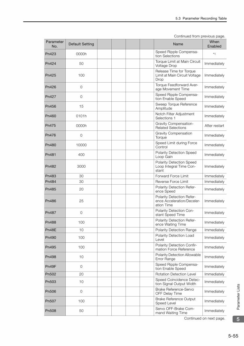
5.3 Parameter Recording Table
5-55
5
Par
amet
er L
ists
Pn423 0000h Speed Ripple Compensa-tion Selections
*1
Pn424 50 Torque Limit at Main Circuit Voltage Drop Immediately
Pn425 100Release Time for Torque Limit at Main Circuit Voltage Drop
Immediately
Pn426 0 Torque Feedforward Aver-age Movement Time Immediately
Pn427 0 Speed Ripple Compensa-tion Enable Speed Immediately
Pn456 15 Sweep Torque Reference Amplitude Immediately
Pn460 0101h Notch Filter Adjustment Selections 1 Immediately
Pn475 0000h Gravity Compensation-Related Selections After restart
Pn476 0 Gravity Compensation Torque Immediately
Pn480 10000 Speed Limit during Force Control Immediately
Pn481 400 Polarity Detection Speed Loop Gain Immediately
Pn482 3000Polarity Detection Speed Loop Integral Time Con-stant
Immediately
Pn483 30 Forward Force Limit Immediately
Pn484 30 Reverse Force Limit Immediately
Pn485 20 Polarity Detection Refer-ence Speed Immediately
Pn486 25Polarity Detection Refer-ence Acceleration/Deceler-ation Time
Immediately
Pn487 0 Polarity Detection Con-stant Speed Time Immediately
Pn488 100 Polarity Detection Refer-ence Waiting Time Immediately
Pn48E 10 Polarity Detection Range Immediately
Pn490 100 Polarity Detection Load Level Immediately
Pn495 100 Polarity Detection Confir-mation Force Reference Immediately
Pn498 10 Polarity Detection Allowable Error Range Immediately
Pn49F 0 Speed Ripple Compensa-tion Enable Speed Immediately
Pn502 20 Rotation Detection Level Immediately
Pn503 10 Speed Coincidence Detec-tion Signal Output Width Immediately
Pn506 0 Brake Reference-Servo OFF Delay Time Immediately
Pn507 100 Brake Reference Output Speed Level Immediately
Pn508 50 Servo OFF-Brake Com-mand Waiting Time Immediately
Continued on next page.
Continued from previous page.
Parameter No.
Default Setting NameWhen
Enabled
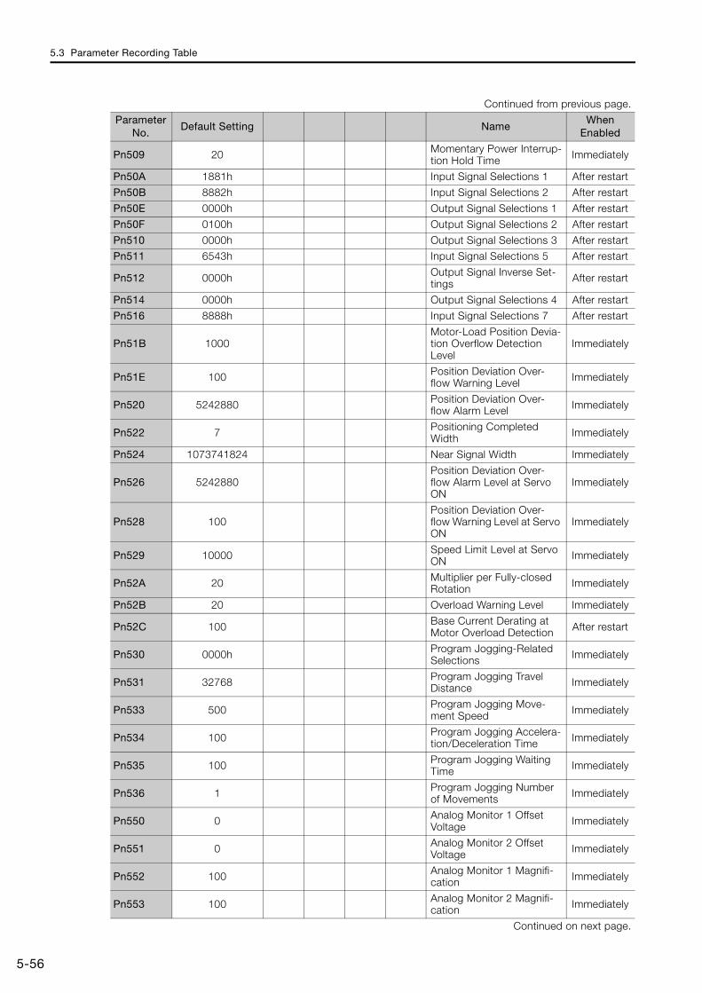
5.3 Parameter Recording Table
5-56
Pn509 20 Momentary Power Interrup-tion Hold Time Immediately
Pn50A 1881h Input Signal Selections 1 After restart
Pn50B 8882h Input Signal Selections 2 After restart
Pn50E 0000h Output Signal Selections 1 After restart
Pn50F 0100h Output Signal Selections 2 After restart
Pn510 0000h Output Signal Selections 3 After restart
Pn511 6543h Input Signal Selections 5 After restart
Pn512 0000h Output Signal Inverse Set-tings After restart
Pn514 0000h Output Signal Selections 4 After restart
Pn516 8888h Input Signal Selections 7 After restart
Pn51B 1000Motor-Load Position Devia-tion Overflow Detection Level
Immediately
Pn51E 100 Position Deviation Over-flow Warning Level Immediately
Pn520 5242880 Position Deviation Over-flow Alarm Level Immediately
Pn522 7 Positioning Completed Width Immediately
Pn524 1073741824 Near Signal Width Immediately
Pn526 5242880Position Deviation Over-flow Alarm Level at Servo ON
Immediately
Pn528 100Position Deviation Over-flow Warning Level at Servo ON
Immediately
Pn529 10000 Speed Limit Level at Servo ON Immediately
Pn52A 20 Multiplier per Fully-closed Rotation Immediately
Pn52B 20 Overload Warning Level Immediately
Pn52C 100 Base Current Derating at Motor Overload Detection After restart
Pn530 0000h Program Jogging-Related Selections Immediately
Pn531 32768 Program Jogging Travel Distance Immediately
Pn533 500 Program Jogging Move-ment Speed Immediately
Pn534 100 Program Jogging Accelera-tion/Deceleration Time Immediately
Pn535 100 Program Jogging Waiting Time Immediately
Pn536 1 Program Jogging Number of Movements Immediately
Pn550 0 Analog Monitor 1 Offset Voltage Immediately
Pn551 0 Analog Monitor 2 Offset Voltage Immediately
Pn552 100 Analog Monitor 1 Magnifi-cation Immediately
Pn553 100 Analog Monitor 2 Magnifi-cation Immediately
Continued on next page.
Continued from previous page.
Parameter No.
Default Setting NameWhen
Enabled
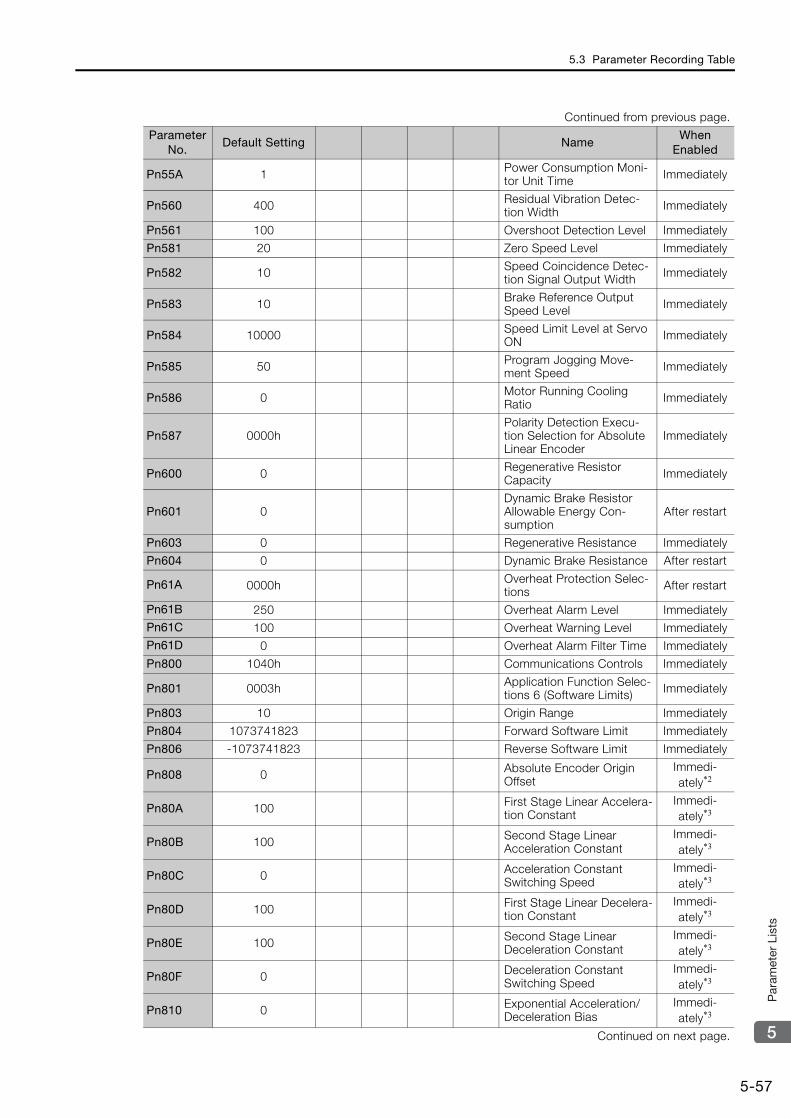
5.3 Parameter Recording Table
5-57
5
Par
amet
er L
ists
Pn55A 1 Power Consumption Moni-tor Unit Time Immediately
Pn560 400 Residual Vibration Detec-tion Width Immediately
Pn561 100 Overshoot Detection Level Immediately
Pn581 20 Zero Speed Level Immediately
Pn582 10 Speed Coincidence Detec-tion Signal Output Width Immediately
Pn583 10 Brake Reference Output Speed Level Immediately
Pn584 10000 Speed Limit Level at Servo ON Immediately
Pn585 50 Program Jogging Move-ment Speed Immediately
Pn586 0 Motor Running Cooling Ratio Immediately
Pn587 0000hPolarity Detection Execu-tion Selection for Absolute Linear Encoder
Immediately
Pn600 0 Regenerative Resistor Capacity Immediately
Pn601 0Dynamic Brake Resistor Allowable Energy Con-sumption
After restart
Pn603 0 Regenerative Resistance Immediately
Pn604 0 Dynamic Brake Resistance After restart
Pn61A 0000h Overheat Protection Selec-tions After restart
Pn61B 250 Overheat Alarm Level ImmediatelyPn61C 100 Overheat Warning Level ImmediatelyPn61D 0 Overheat Alarm Filter Time Immediately
Pn800 1040h Communications Controls Immediately
Pn801 0003h Application Function Selec-tions 6 (Software Limits) Immediately
Pn803 10 Origin Range Immediately
Pn804 1073741823 Forward Software Limit Immediately
Pn806 -1073741823 Reverse Software Limit Immediately
Pn808 0 Absolute Encoder Origin Offset
Immedi-ately*2
Pn80A 100 First Stage Linear Accelera-tion Constant
Immedi-ately*3
Pn80B 100 Second Stage Linear Acceleration Constant
Immedi-ately*3
Pn80C 0 Acceleration Constant Switching Speed
Immedi-ately*3
Pn80D 100 First Stage Linear Decelera-tion Constant
Immedi-ately*3
Pn80E 100 Second Stage Linear Deceleration Constant
Immedi-ately*3
Pn80F 0 Deceleration Constant Switching Speed
Immedi-ately*3
Pn810 0 Exponential Acceleration/Deceleration Bias
Immedi-ately*3
Continued on next page.
Continued from previous page.
Parameter No.
Default Setting NameWhen
Enabled
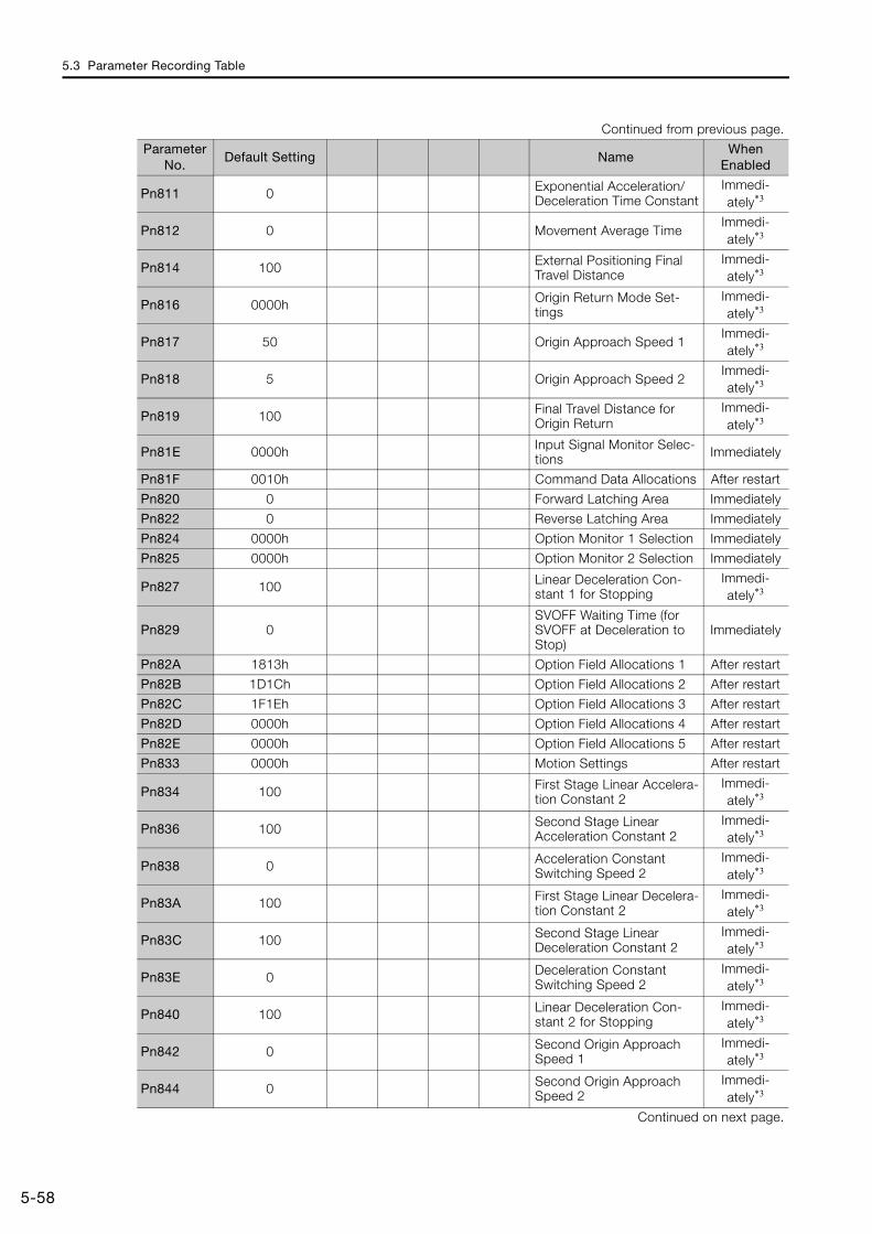
5.3 Parameter Recording Table
5-58
Pn811 0 Exponential Acceleration/Deceleration Time Constant
Immedi-ately*3
Pn812 0 Movement Average TimeImmedi-ately*3
Pn814 100 External Positioning Final Travel Distance
Immedi-ately*3
Pn816 0000h Origin Return Mode Set-tings
Immedi-ately*3
Pn817 50 Origin Approach Speed 1Immedi-ately*3
Pn818 5 Origin Approach Speed 2Immedi-ately*3
Pn819 100 Final Travel Distance for Origin Return
Immedi-ately*3
Pn81E 0000h Input Signal Monitor Selec-tions Immediately
Pn81F 0010h Command Data Allocations After restart
Pn820 0 Forward Latching Area Immediately
Pn822 0 Reverse Latching Area Immediately
Pn824 0000h Option Monitor 1 Selection Immediately
Pn825 0000h Option Monitor 2 Selection Immediately
Pn827 100 Linear Deceleration Con-stant 1 for Stopping
Immedi-ately*3
Pn829 0SVOFF Waiting Time (for SVOFF at Deceleration to Stop)
Immediately
Pn82A 1813h Option Field Allocations 1 After restart
Pn82B 1D1Ch Option Field Allocations 2 After restart
Pn82C 1F1Eh Option Field Allocations 3 After restart
Pn82D 0000h Option Field Allocations 4 After restart
Pn82E 0000h Option Field Allocations 5 After restart
Pn833 0000h Motion Settings After restart
Pn834 100 First Stage Linear Accelera-tion Constant 2
Immedi-ately*3
Pn836 100 Second Stage Linear Acceleration Constant 2
Immedi-ately*3
Pn838 0 Acceleration Constant Switching Speed 2
Immedi-ately*3
Pn83A 100 First Stage Linear Decelera-tion Constant 2
Immedi-ately*3
Pn83C 100 Second Stage Linear Deceleration Constant 2
Immedi-ately*3
Pn83E 0 Deceleration Constant Switching Speed 2
Immedi-ately*3
Pn840 100 Linear Deceleration Con-stant 2 for Stopping
Immedi-ately*3
Pn842 0 Second Origin Approach Speed 1
Immedi-ately*3
Pn844 0 Second Origin Approach Speed 2
Immedi-ately*3
Continued on next page.
Continued from previous page.
Parameter No.
Default Setting NameWhen
Enabled
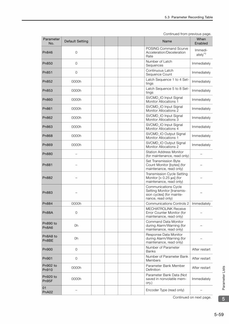
5.3 Parameter Recording Table
5-59
5
Par
amet
er L
ists
Pn846 0POSING Command Scurve Acceleration/Deceleration Rate
Immedi-ately*3
Pn850 0 Number of Latch Sequences Immediately
Pn851 0 Continuous Latch Sequence Count Immediately
Pn852 0000h Latch Sequence 1 to 4 Set-tings Immediately
Pn853 0000h Latch Sequence 5 to 8 Set-tings Immediately
Pn860 0000h SVCMD_IO Input Signal Monitor Allocations 1 Immediately
Pn861 0000h SVCMD_IO Input Signal Monitor Allocations 2 Immediately
Pn862 0000h SVCMD_IO Input Signal Monitor Allocations 3 Immediately
Pn863 0000h SVCMD_IO Input Signal Monitor Allocations 4 Immediately
Pn868 0000h SVCMD_IO Output Signal Monitor Allocations 1 Immediately
Pn869 0000h SVCMD_IO Output Signal Monitor Allocations 2 Immediately
Pn880 – Station Address Monitor (for maintenance, read only) −
Pn881 –Set Transmission Byte Count Monitor [bytes] (for maintenance, read only)
−
Pn882 –Transmission Cycle Setting Monitor [× 0.25 μs] (for maintenance, read only)
−
Pn883 –
Communications Cycle Setting Monitor [transmis-sion cycles] (for mainte-nance, read only)
−
Pn884 0000h Communications Controls 2 Immediately
Pn88A 0MECHATROLINK Receive Error Counter Monitor (for maintenance, read only)
−
Pn890 to Pn8A6
0hCommand Data Monitor during Alarm/Warning (for maintenance, read only)
−
Pn8A8 to Pn8BE
0hResponse Data Monitor during Alarm/Warning (for maintenance, read only)
−
Pn900 0 Number of Parameter Banks After restart
Pn901 0 Number of Parameter Bank Members After restart
Pn902 to Pn910
0000h Parameter Bank Member Definition After restart
Pn920 to Pn95F
0000hParameter Bank Data (Not saved in nonvolatile mem-ory.)
Immediately
01PnA02
− Encoder Type (read only) −
Continued on next page.
Continued from previous page.
Parameter No.
Default Setting NameWhen
Enabled
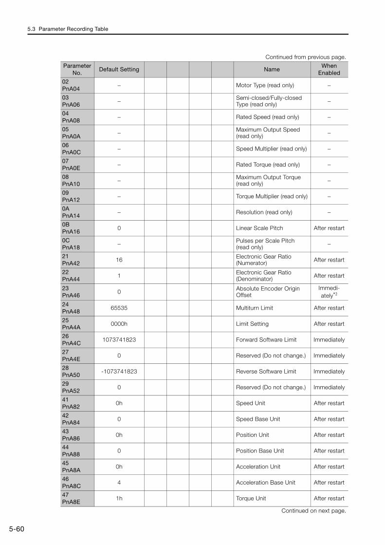
5.3 Parameter Recording Table
5-60
02PnA04
− Motor Type (read only) −
03PnA06
− Semi-closed/Fully-closed Type (read only) −
04PnA08
− Rated Speed (read only) −
05PnA0A
− Maximum Output Speed (read only) −
06PnA0C
− Speed Multiplier (read only) −
07PnA0E
− Rated Torque (read only) −
08PnA10
− Maximum Output Torque (read only) −
09PnA12
− Torque Multiplier (read only) −
0APnA14
− Resolution (read only) −
0BPnA16
0 Linear Scale Pitch After restart
0CPnA18
− Pulses per Scale Pitch (read only) −
21PnA42
16 Electronic Gear Ratio (Numerator) After restart
22PnA44
1 Electronic Gear Ratio (Denominator) After restart
23PnA46
0 Absolute Encoder Origin Offset
Immedi-ately*2
24PnA48
65535 Multiturn Limit After restart
25PnA4A
0000h Limit Setting After restart
26PnA4C
1073741823 Forward Software Limit Immediately
27PnA4E
0 Reserved (Do not change.) Immediately
28PnA50
-1073741823 Reverse Software Limit Immediately
29PnA52
0 Reserved (Do not change.) Immediately
41PnA82
0h Speed Unit After restart
42PnA84
0 Speed Base Unit After restart
43PnA86
0h Position Unit After restart
44PnA88
0 Position Base Unit After restart
45PnA8A
0h Acceleration Unit After restart
46PnA8C
4 Acceleration Base Unit After restart
47PnA8E
1h Torque Unit After restart
Continued on next page.
Continued from previous page.
Parameter No.
Default Setting NameWhen
Enabled
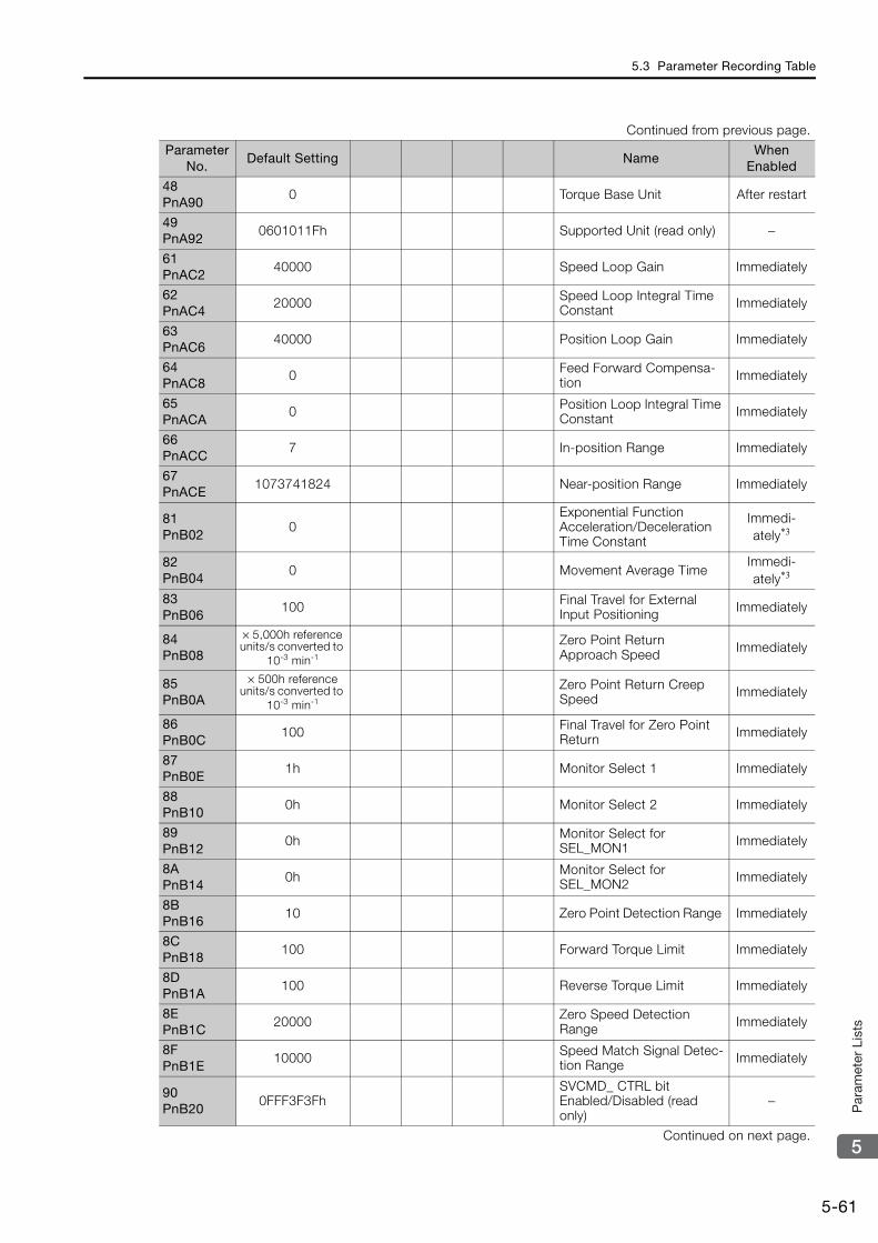
5.3 Parameter Recording Table
5-61
5
Par
amet
er L
ists
48PnA90
0 Torque Base Unit After restart
49PnA92
0601011Fh Supported Unit (read only) −
61PnAC2
40000 Speed Loop Gain Immediately
62PnAC4
20000 Speed Loop Integral Time Constant Immediately
63PnAC6
40000 Position Loop Gain Immediately
64PnAC8
0 Feed Forward Compensa-tion Immediately
65PnACA
0 Position Loop Integral Time Constant Immediately
66PnACC
7 In-position Range Immediately
67PnACE
1073741824 Near-position Range Immediately
81PnB02
0Exponential Function Acceleration/Deceleration Time Constant
Immedi-ately*3
82PnB04
0 Movement Average TimeImmedi-ately*3
83PnB06
100 Final Travel for External Input Positioning Immediately
84PnB08
× 5,000h reference units/s converted to
10-3 min-1
Zero Point Return Approach Speed Immediately
85PnB0A
× 500h reference units/s converted to
10-3 min-1
Zero Point Return Creep Speed Immediately
86PnB0C
100 Final Travel for Zero Point Return Immediately
87PnB0E
1h Monitor Select 1 Immediately
88PnB10
0h Monitor Select 2 Immediately
89PnB12
0h Monitor Select for SEL_MON1 Immediately
8APnB14
0h Monitor Select for SEL_MON2 Immediately
8BPnB16
10 Zero Point Detection Range Immediately
8CPnB18
100 Forward Torque Limit Immediately
8DPnB1A
100 Reverse Torque Limit Immediately
8EPnB1C
20000 Zero Speed Detection Range Immediately
8FPnB1E
10000 Speed Match Signal Detec-tion Range Immediately
90PnB20
0FFF3F3FhSVCMD_ CTRL bit Enabled/Disabled (read only)
−
Continued on next page.
Continued from previous page.
Parameter No.
Default Setting NameWhen
Enabled

5.3 Parameter Recording Table
5-62
*1. The enable timing depends on the digit that is changed. Refer to the following section for details.5.1.2 List of Servo Parameters on page 5-3
5.2 List of MECHATROLINK-III Common Parameters on page 5-42
*2. The parameter setting is enabled after SENS_ON command execution is completed.*3. Change the setting when the reference is stopped (i.e., while DEN is set to 1). If you change the setting during
operation, the reference output will be affected.
91PnB22
0FFF3F33h SVCMD_ STAT bit Enabled/Disabled (read only) −
92PnB24
007F01F0h I/O Bit Enabled/Disabled (Output) (read only) −
93PnB26
FF0FFEFEh I/O Bit Enabled/Disabled (Input) (read only) −
Continued from previous page.
Parameter No.
Default Setting NameWhen
Enabled
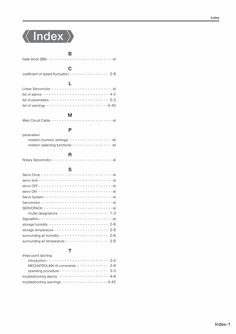
Index
Index-1
IndexB
base block (BB)- - - - - - - - - - - - - - - - - - - - - - - - - -xi
Ccoefficient of speed fluctuation - - - - - - - - - - - - - - - 2-8
LLinear Servomotor - - - - - - - - - - - - - - - - - - - - - - - -xilist of alarms - - - - - - - - - - - - - - - - - - - - - - - - - 4-2
list of parameters - - - - - - - - - - - - - - - - - - - - - - - 5-3list of warnings - - - - - - - - - - - - - - - - - - - - - - - -4-40
MMain Circuit Cable - - - - - - - - - - - - - - - - - - - - - - - -xi
Pparameters
notation (numeric settings) - - - - - - - - - - - - - - - - xiinotation (selecting functions) - - - - - - - - - - - - - - - xii
RRotary Servomotor - - - - - - - - - - - - - - - - - - - - - - - -xi
SServo Drive - - - - - - - - - - - - - - - - - - - - - - - - - - - -xiservo lock - - - - - - - - - - - - - - - - - - - - - - - - - - - - -xiservo OFF - - - - - - - - - - - - - - - - - - - - - - - - - - - - -xi
servo ON - - - - - - - - - - - - - - - - - - - - - - - - - - - - -xiServo System - - - - - - - - - - - - - - - - - - - - - - - - - - -xiServomotor - - - - - - - - - - - - - - - - - - - - - - - - - - - -xi
SERVOPACK - - - - - - - - - - - - - - - - - - - - - - - - - - -ximodel designations - - - - - - - - - - - - - - - - - - - 1-3
SigmaWin+ - - - - - - - - - - - - - - - - - - - - - - - - - - - -xistorage humidity - - - - - - - - - - - - - - - - - - - - - - - 2-6storage temperature - - - - - - - - - - - - - - - - - - - - - 2-6
surrounding air humidity - - - - - - - - - - - - - - - - - - - 2-6surrounding air temperature- - - - - - - - - - - - - - - - - 2-6
Tthree-point latching
introduction - - - - - - - - - - - - - - - - - - - - - - - - 3-2MECHATROLINK-III commands - - - - - - - - - - - - 3-8operating procedure - - - - - - - - - - - - - - - - - - - 3-3
troubleshooting alarms - - - - - - - - - - - - - - - - - - - 4-8
troubleshooting warnings - - - - - - - - - - - - - - - - - -4-42

Revision History-1
Revision History
The date of publication, revision number, and Web revision number of the manual are given on the bottom right of the back cover. Refer to the following example.
Date of Publication
Rev. No.
Web Rev. No.
Section Revised Contents
October 2019 <3> 0 Preface, chapters 2, 4, 5
Partly revised.
Back cover Revision: Address
September 2018 <2> 0 All chapters Partly revised.
2.1 Revision: Built-in regenerative resistor power loss for SGD7S-120A, -180A, -200A
4.1 Deletion: A.F50
Back cover Revision: Address
November 2017 <1> 0 All chapters Partly revised.
Back cover Revision: Address
September 2016 − − − First edition
MANUAL NO. SIEP S800002 17A <0>-0
Published in Japan September 2016
Date of publication
Revision numberWEB revision number
IRUMA BUSINESS CENTER (SOLUTION CENTER)480, Kamifujisawa, Iruma, Saitama, 358-8555, JapanPhone: +81-4-2962-5151 Fax: +81-4-2962-6138http://www.yaskawa.co.jp
YASKAWA AMERICA, INC.2121, Norman Drive South, Waukegan, IL 60085, U.S.A.Phone: +1-800-YASKAWA (927-5292) or +1-847-887-7000 Fax: +1-847-887-7310http://www.yaskawa.com
YASKAWA ELÉTRICO DO BRASIL LTDA.777, Avenida Piraporinha, Diadema, São Paulo, 09950-000, Brasil Phone: +55-11-3585-1100 Fax: +55-11-3585-1187http://www.yaskawa.com.br
YASKAWA EUROPE GmbHHauptstraβe 185, 65760 Eschborn, GermanyPhone: +49-6196-569-300 Fax: +49-6196-569-398http://www.yaskawa.eu.com E-mail: [email protected]
YASKAWA ELECTRIC KOREA CORPORATION35F, Three IFC, 10 Gukjegeumyung-ro, Yeongdeungpo-gu, Seoul, 07326, KoreaPhone: +82-2-784-7844 Fax: +82-2-784-8495http://www.yaskawa.co.kr
YASKAWA ASIA PACIFIC PTE. LTD.30A, Kallang Place, #06-01, 339213, SingaporePhone: +65-6282-3003 Fax: +65-6289-3003http://www.yaskawa.com.sg
YASKAWA ELECTRIC (THAILAND) CO., LTD.59, 1st-5th Floor, Flourish Building, Soi Ratchadapisek 18, Ratchadapisek Road, Huaykwang, Bangkok, 10310, ThailandPhone: +66-2-017-0099 Fax: +66-2-017-0799http://www.yaskawa.co.th
YASKAWA ELECTRIC (CHINA) CO., LTD.22F, Link Square 1, No.222, Hubin Road, Shanghai, 200021, ChinaPhone: +86-21-5385-2200 Fax: +86-21-5385-3299http://www.yaskawa.com.cn
YASKAWA ELECTRIC (CHINA) CO., LTD. BEIJING OFFICERoom 1011, Tower W3 Oriental Plaza, No.1, East Chang An Ave.,Dong Cheng District, Beijing, 100738, ChinaPhone: +86-10-8518-4086 Fax: +86-10-8518-4082
YASKAWA ELECTRIC TAIWAN CORPORATION12F, No. 207, Sec. 3, Beishin Rd., Shindian Dist., New Taipei City 23143, TaiwanPhone: +886-2-8913-1333 Fax: +886-2-8913-1513 or +886-2-8913-1519http://www.yaskawa.com.tw
In the event that the end user of this product is to be the military and said product is to be employed in any weapons systems or the manufacture thereof, the export will fall under the relevant regulations as stipulated in the Foreign Exchange and Foreign Trade Regulations. Therefore, be sure to follow all procedures and submit all relevant documentation according to any and all rules, regulations and laws that may apply.
Specifications are subject to change without notice for ongoing product modifications and improvements.
© 2016 YASKAWA ELECTRIC CORPORATION
Published in Japan October 2019
MANUAL NO. SIEP S800002 17D <3>-0
18-10-15Original instructions
-7-Series AC Servo Drive
-7S SERVOPACK with FT/EX Specification for Three-Point Latching for Conveyance ApplicationProduct Manual