RVTD Operations, Administration & Maintenance Campus ...
88
RVTD Operations, Administration & Maintenance Campus Master Plan Report DRAFT 02.19.2021
-
Upload
khangminh22 -
Category
Documents
-
view
2 -
download
0
Transcript of RVTD Operations, Administration & Maintenance Campus ...
RVTD Operations, Administration & Maintenance Campus Master Plan Report
DRAFT
02.19.2021
PIVOT Architecture 02.19.2021 DRAFT RVTD Master Plan Report
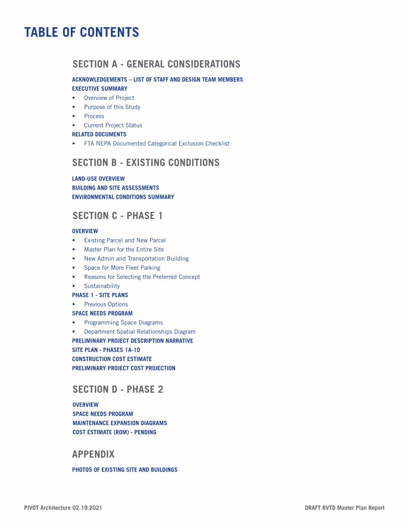
TABLE OF CONTENTS
ACKNOWLEDGEMENTS – LIST OF STAFF AND DESIGN TEAM MEMBERS
EXECUTIVE SUMMARY
• Overview of Project
• Purpose of this Study
• Process
• Current Project Status
RELATED DOCUMENTS
• FTA NEPA Documented Categorical Exclusion Checklist
LAND-USE OVERVIEW
BUILDING AND SITE ASSESSMENTS
ENVIRONMENTAL CONDITIONS SUMMARY
OVERVIEW
• Existing Parcel and New Parcel
• Master Plan for the Entire Site
• New Admin and Transportation Building
• Space for More Fleet Parking
• Reasons for Selecting the Preferred Concept
• Sustainability
PHASE 1 - SITE PLANS
• Previous Options
SPACE NEEDS PROGRAM
• Programming Space Diagrams
• Department Spatial Relationships Diagram
PRELIMINARY PROJECT DESCRIPTION NARRATIVE
SITE PLAN - PHASES 1A-1D
CONSTRUCTION COST ESTIMATE
PRELIMINARY PROJECT COST PROJECTION
OVERVIEW
SPACE NEEDS PROGRAM
MAINTENANCE EXPANSION DIAGRAMS
COST ESTIMATE (ROM) - PENDING
PHOTOS OF EXISTING SITE AND BUILDINGS
SECTION A - GENERAL CONSIDERATIONS
SECTION B - EXISTING CONDITIONS
SECTION C - PHASE 1
SECTION D - PHASE 2
APPENDIX
SECTION A - GENERAL CONSIDERATIONS
SECTION A - GENERAL CONSIDERATIONS
SECTION C - PHASE 1
SECTION D - PHASE 2
PIVOT Architecture 02.19.2021 DRAFT RVTD Master Plan Report
SECTION A - GENERAL CONSIDERATIONS
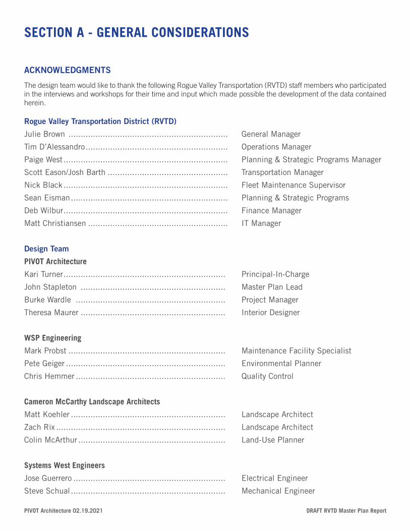
ACKNOWLEDGMENTS
The design team would like to thank the following Rogue Valley Transportation (RVTD) staff members who participated in the interviews and workshops for their time and input which made possible the development of the data contained herein.
Rogue Valley Transportation District (RVTD)
Julie Brown ................................................................. General Manager
Tim D’Alessandro .......................................................... Operations Manager
Paige West ................................................................... Planning & Strategic Programs Manager
Scott Eason/Josh Barth ................................................. Transportation Manager
Nick Black ................................................................... Fleet Maintenance Supervisor
Sean Eisman ................................................................ Planning & Strategic Programs
Deb Wilbur ................................................................... Finance Manager
Matt Christiansen ......................................................... IT Manager
Design Team
PIVOT Architecture
Kari Turner .................................................................. Principal-In-Charge
John Stapleton ........................................................... Master Plan Lead
Burke Wardle ............................................................. Project Manager
Theresa Maurer ........................................................... Interior Designer
WSP Engineering
Mark Probst ................................................................ Maintenance Facility Specialist
Pete Geiger ................................................................. Environmental Planner
Chris Hemmer ............................................................. Quality Control
Cameron McCarthy Landscape Architects
Matt Koehler ............................................................... Landscape Architect
Zach Rix ..................................................................... Landscape Architect
Colin McArthur ............................................................ Land-Use Planner
Systems West Engineers
Jose Guerrero .............................................................. Electrical Engineer
Steve Schual ............................................................... Mechanical Engineer
DRAFT RVTD Master Plan Report PIVOT Architecture 02.19.2021
ZCS Engineers
Josh Modin ................................................................. Civil Engineer
Malia Waters ............................................................... Civil Designer
Sylas Allen .................................................................. Structural Engineer
Matt Smith ................................................................. Structural Engineer
Joey Gipner ................................................................. Structural Designer
Construction Focus
Steve Gunn ................................................................. Lead Cost Estimator
Bjorn Carlson .............................................................. Cost Estimator
Wallace Leake – ES&A ........................................................ Biology
Michael Minor – Michael Minor Associates ..................... Noise Analysis
Kathryn Toepel- Heritage Research Associates ................ Archaeology and History
SECTION A - GENERAL CONSIDERATIONS
PIVOT Architecture 02.19.2021 DRAFT RVTD Master Plan Report
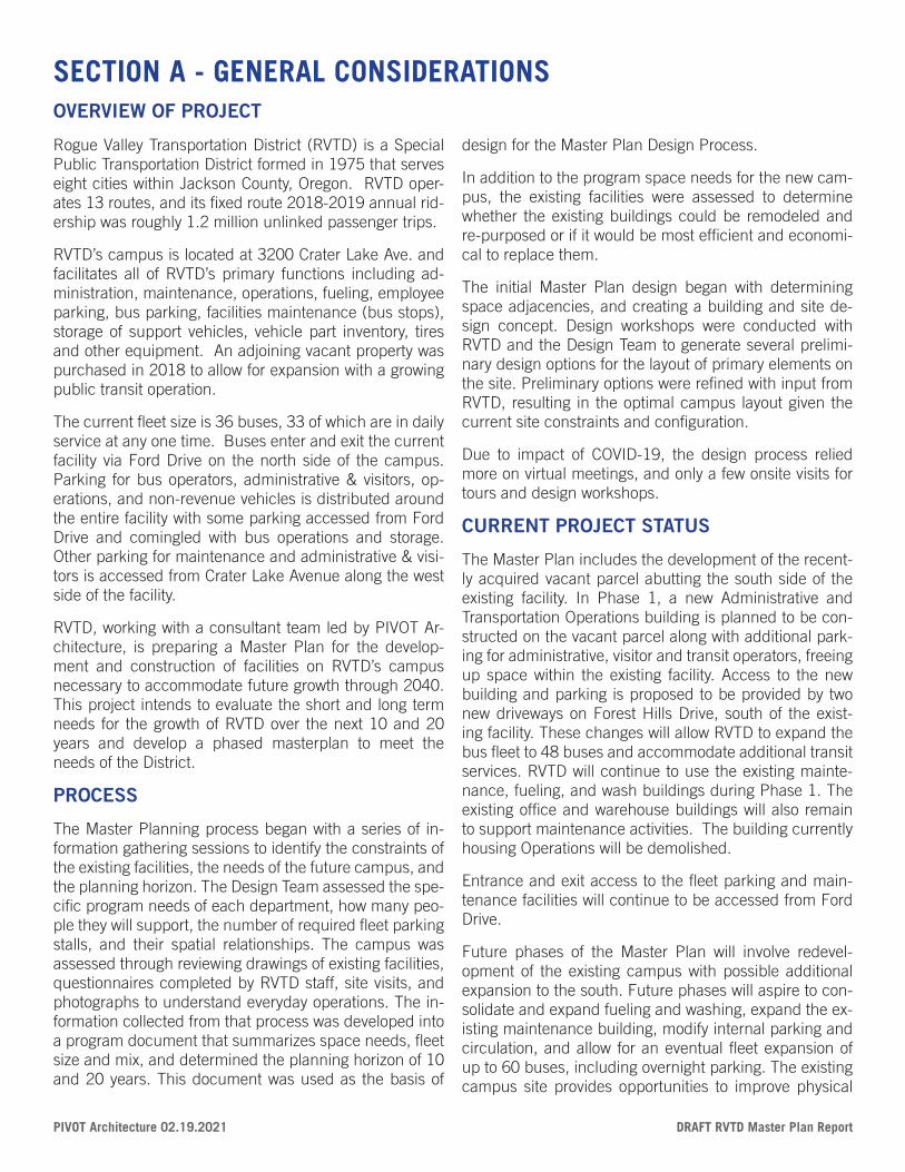
Rogue Valley Transportation District (RVTD) is a Special Public Transportation District formed in 1975 that serves eight cities within Jackson County, Oregon. RVTD oper-ates 13 routes, and its fixed route 2018-2019 annual rid-ership was roughly 1.2 million unlinked passenger trips.
RVTD’s campus is located at 3200 Crater Lake Ave. and facilitates all of RVTD’s primary functions including ad-ministration, maintenance, operations, fueling, employee parking, bus parking, facilities maintenance (bus stops), storage of support vehicles, vehicle part inventory, tires and other equipment. An adjoining vacant property was purchased in 2018 to allow for expansion with a growing public transit operation.
The current fleet size is 36 buses, 33 of which are in daily service at any one time. Buses enter and exit the current facility via Ford Drive on the north side of the campus. Parking for bus operators, administrative & visitors, op-erations, and non-revenue vehicles is distributed around the entire facility with some parking accessed from Ford Drive and comingled with bus operations and storage. Other parking for maintenance and administrative & visi-tors is accessed from Crater Lake Avenue along the west side of the facility.
RVTD, working with a consultant team led by PIVOT Ar-chitecture, is preparing a Master Plan for the develop-ment and construction of facilities on RVTD’s campus necessary to accommodate future growth through 2040. This project intends to evaluate the short and long term needs for the growth of RVTD over the next 10 and 20 years and develop a phased masterplan to meet the needs of the District.
PROCESS
The Master Planning process began with a series of in-formation gathering sessions to identify the constraints of the existing facilities, the needs of the future campus, and the planning horizon. The Design Team assessed the spe-cific program needs of each department, how many peo-ple they will support, the number of required fleet parking stalls, and their spatial relationships. The campus was assessed through reviewing drawings of existing facilities, questionnaires completed by RVTD staff, site visits, and photographs to understand everyday operations. The in-formation collected from that process was developed into a program document that summarizes space needs, fleet size and mix, and determined the planning horizon of 10 and 20 years. This document was used as the basis of
design for the Master Plan Design Process.
In addition to the program space needs for the new cam-pus, the existing facilities were assessed to determine whether the existing buildings could be remodeled and re-purposed or if it would be most efficient and economi-cal to replace them.
The initial Master Plan design began with determining space adjacencies, and creating a building and site de-sign concept. Design workshops were conducted with RVTD and the Design Team to generate several prelimi-nary design options for the layout of primary elements on the site. Preliminary options were refined with input from RVTD, resulting in the optimal campus layout given the current site constraints and configuration.
Due to impact of COVID-19, the design process relied more on virtual meetings, and only a few onsite visits for tours and design workshops.
CURRENT PROJECT STATUS
The Master Plan includes the development of the recent-ly acquired vacant parcel abutting the south side of the existing facility. In Phase 1, a new Administrative and Transportation Operations building is planned to be con-structed on the vacant parcel along with additional park-ing for administrative, visitor and transit operators, freeing up space within the existing facility. Access to the new building and parking is proposed to be provided by two new driveways on Forest Hills Drive, south of the exist-ing facility. These changes will allow RVTD to expand the bus fleet to 48 buses and accommodate additional transit services. RVTD will continue to use the existing mainte-nance, fueling, and wash buildings during Phase 1. The existing office and warehouse buildings will also remain to support maintenance activities. The building currently housing Operations will be demolished.
Entrance and exit access to the fleet parking and main-tenance facilities will continue to be accessed from Ford Drive.
Future phases of the Master Plan will involve redevel-opment of the existing campus with possible additional expansion to the south. Future phases will aspire to con-solidate and expand fueling and washing, expand the ex-isting maintenance building, modify internal parking and circulation, and allow for an eventual fleet expansion of up to 60 buses, including overnight parking. The existing campus site provides opportunities to improve physical
SECTION A - GENERAL CONSIDERATIONSOVERVIEW OF PROJECT
DRAFT RVTD Master Plan Report PIVOT Architecture 02.19.2021
connection to Crater Lake Avenue while also improving visual connection to Crater Lake Highway (HWY 62). This visual connection is critical for RVTD to better connect with the surrounding context and neighborhood. Visibility from HWY 62 will provide RVTD an opportunity to be seen by the Medford community and the transit district’s users.
PROJECT COSTS
A Construction Cost estimate was developed for the Phase 1 scope of work. A detailed Preliminary Project Description that included assumptions about materials and systems for the building and site development was prepared as part of the cost estimating effort. Based on the Construction Cost estimate, a Preliminary Project Cost Projection was developed using a template project esti-mating tool developed by PIVOT. The current project cost is estimated to be between $14-16 million depending on which additional sustainable design strategies RVTD chooses to implement.
RVTD is using the Project Cost projection to apply for grants and other federal funding that could be used for the project.
SECTION A - GENERAL CONSIDERATIONS
DRAFT RVTD Master Plan Report PIVOT Architecture 02.19.2021
SECTION B - EXISTING CONDITIONS
PIVOT Architecture 02.19.2021 DRAFT RVTD Master Plan Report
RVTD MASTER PLAN3200 CRATER LAKE AVE, MEDFORD OR
EXISTING CONDITIONS 12.18.2020
Building Square Footage:(E) Maintenance(E) Transportation(E) Warehouse(E) Admin
10,300 SF1,500 SF4,000 SF5,700 SF
Parking:
(E) Administration & Visitor(E) NRV(E) Driver’s Parking(E) Operations
3810395
92Total
FLEETBUSES X36
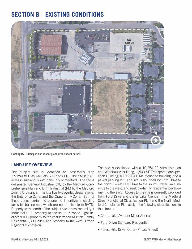
LAND-USE OVERVIEW
The subject site is identified on Assessor’s Map 37-1W-08CC as Tax Lots 500 and 800. The site is 5.62 acres in size and is within the City of Medford. The site is designated General Industrial (GI) by the Medford Com-prehensive Plan and Light Industrial (I-L) by the Medford Zoning Ordinance. The site has two overlay designations, the Enterprise Zone, and the Opportunity Zone. Both of these zones pertain to economic incentives regarding taxes for businesses, which are not applicable to RVTD. Property to the north of the subject site is also zoned Light Industrial (I-L), property to the south is zoned Light In-dustrial (I-L) property to the east is zoned Multiple Family Residential (30 Units), and property to the west is zone Regional Commercial.
The site is developed with a 10,250 SF Administration and Warehouse building, 1,500 SF Transportation/Oper-ation Building, a 10,300 SF Maintenance building, and a paved parking lot. The site is bounded by Ford Drive to the north, Forest Hills Drive to the south, Crater Lake Av-enue to the west, and multiple-family residential develop-ment to the east. Access to the site is currently provided from Ford Drive and Crater Lake Avenue. The Medford Street Functional Classification Plan and the North Med-ford Circulation Plan assign the following classifications to the streets:
• Crater Lake Avenue; Major Arterial
• Ford Drive; Standard Residential
• Forest Hills Drive; Other (Private Street)
SECTION B - EXISTING CONDITIONS
Existing RVTD Campus and recently acquired vacant parcel.
DRAFT RVTD Master Plan Report PIVOT Architecture 02.19.2021
Development standards for Right of Way improvements will be further defined following a pre-application meeting with the City of Medford.
ENVIRONMENTAL CONDITIONS SUMMARY
The RVTD campus is located to the southeast of the Rogue Valley International Medford Airport and just to the east of the Crater Lake Highway (OR 62). Prior to the 1960s, the area was agricultural land, with farmed fields and orchards. Much of the area surrounding the project APE has been converted to commercial and residential developments over the last 60 years. Most of the area of potential effect (APE) is covered by buildings and im-pervious paved or graveled surfaces. The only portion of the APE that remains unpaved is a small (0.4-acre) par-cel along Forest Hills Drive and it is on this south parcel where future developments are planned.
The entire RVTD site, comprised of two tax lots (TL# 371W08CC 500 and 800), totals 5.7-acres. The RVTD facility is zoned Light Industrial. Immediately to the east is Multifamily Residential Planned Unit Development with 20 units per acre. Other zoning in the area includes Re-gional Commercial and Single Family Residential with 4 units per acre south of Delta Waters Road. No property is proposed for acquisition; the two parcels that make up the RVTD campus are under RVTD’s ownership.
The project is within the Midway Basin, which is the north-ern-most drainage basin within the City of Medford. Since 1981, on-site detention for all industrial and commercial development in the basin has been required. Projects that will develop or redevelop more than 2,500 square feet of impervious surfaces (buildings, roads, parking lots, etc.) on a site must manage stormwater runoff in compliance with the Rogue Valley Stormwater Quality Design Manual
Site investigation determined a small wetland – Wetland A (333 square feet) on the western edge of southern parcel. No other wetland or waters are present on site and the wetland was determined to not be connected via surface channel or pipe to a downstream waterway or wetland. The wetland is subject to the jurisdiction with Oregon De-partment of State Lands (DSL) Removal-Fill Law rules. The wetland is likely not jurisdictional US Army Corps of Engineers (USACE) Clean Water Act rules due to a lack of hydrologic connection to downstream waters.
The RVTD facility also has five permitted and active un-derground storage tanks and two decommissioned un-derground storage tanks. The RVTD subject property has
experienced three Leaking Underground Storage Tank (LUST) incidents since 1993. All three incidents have resulted in cleanup actions and have received determi-nations of no further remedial action from Oregon De-partment of Environmental Quality. However residual soil contamination could remain within potential construction areas beneath the footprint of current operations.
The US Census data indicate that the project area is re-flective of the City of Medford as a whole and will not have disproportionately high and adverse impacts on environ-mental justice populations.
A cultural resource inventory of the RVTD’s Crater Lake Avenue Campus to identify potentially eligible historical or archaeological properties that may meet National Reg-ister criteria. As a result of the records review and field inventory, the following findings are made as art of this assessment:
• No evidence of prehistoric or early historic archaeologi-cal materials or deposits was observed during the archae-ological survey.
• No indication of the former Hopkins Canal was observed on the ground in the extreme southeastern corner of the APE where earlier aerial photographs indicate that the ca-nal, now relocated, was previously aligned.
• No historic-era resources in the APE were identified as potentially meeting National Registry of Historical Proper-ties eligibility criteria.
BUILDING AND SITE ASSESSMENT
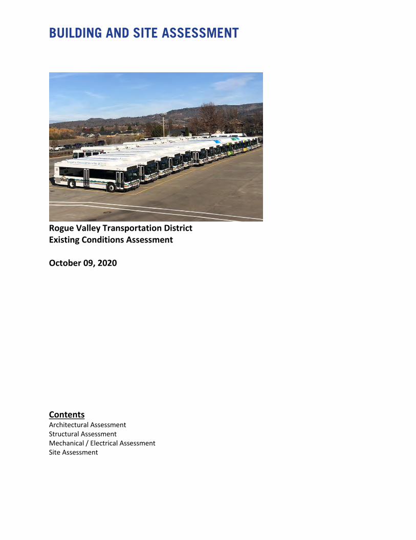
Rogue Valley Transportation District Existing Conditions Assessment October 09, 2020 Contents Architectural Assessment Structural Assessment Mechanical / Electrical Assessment Site Assessment
RVTD Site Assessment 02/12/21
Rogue Valley Transportation District Existing Conditions Assessment October 09, 2020 As part of our work for the Rogue Valley Transportation District, PIVOT Architecture, ZCS, Systems West and Cameron McCarthy have assessed the existing conditions, finishes, and systems of the building. Our assessment is based on 3-4 hour walk-throughs of the building and visual observations of exposed materials and equipment. We were able to look above ceiling tiles but did not open any walls concealed spaces. The Civil, Structural, MEP assessments are included as appendixes to this report.
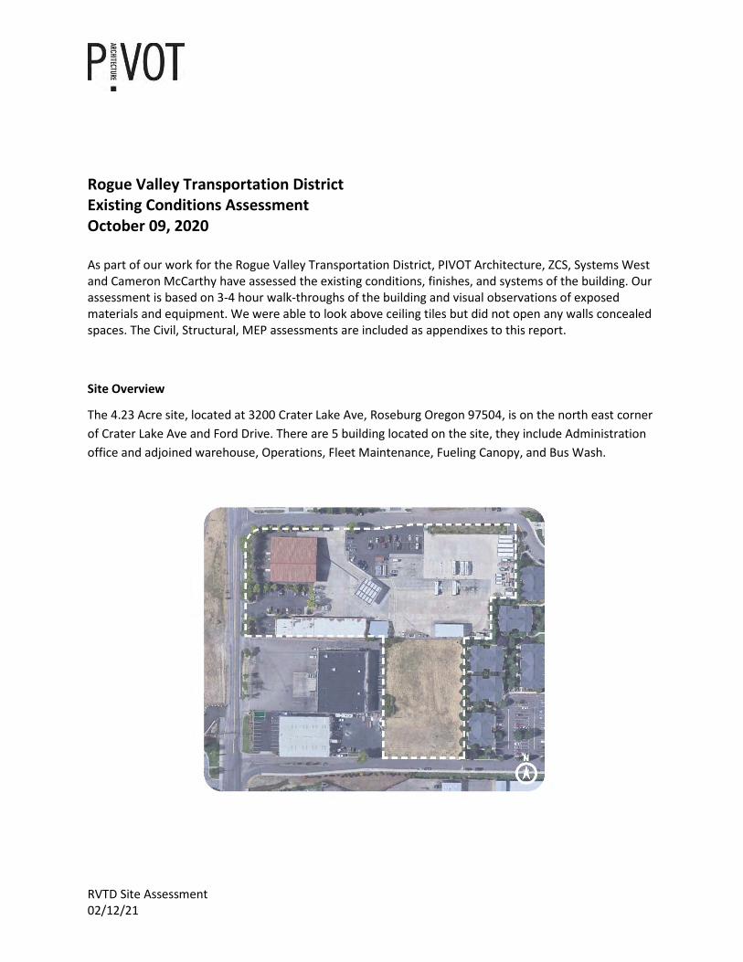
Site Overview
The 4.23 Acre site, located at 3200 Crater Lake Ave, Roseburg Oregon 97504, is on the north east corner of Crater Lake Ave and Ford Drive. There are 5 building located on the site, they include Administration office and adjoined warehouse, Operations, Fleet Maintenance, Fueling Canopy, and Bus Wash.
RVTD Site Assessment 02/12/21
Administration Office & Warehouse
The Main Office & Warehouse building original construction year is unknown but it has received remodels in 1986, 1989, and 2009 and 2020. The remodel in 2009, replaced the roofing system and mechanical systems and the 2020 remodel focused on interior improvements by adding a large board room, new carpet and paint in the office building.
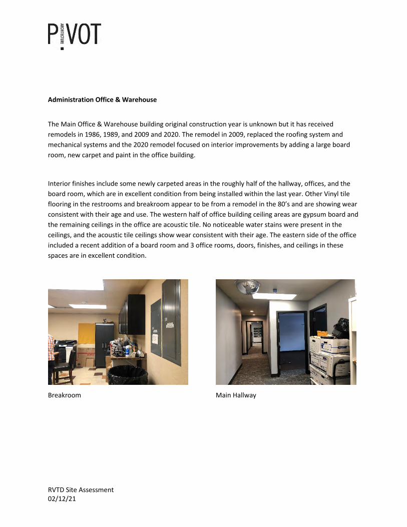
Interior finishes include some newly carpeted areas in the roughly half of the hallway, offices, and the board room, which are in excellent condition from being installed within the last year. Other Vinyl tile flooring in the restrooms and breakroom appear to be from a remodel in the 80’s and are showing wear consistent with their age and use. The western half of office building ceiling areas are gypsum board and the remaining ceilings in the office are acoustic tile. No noticeable water stains were present in the ceilings, and the acoustic tile ceilings show wear consistent with their age. The eastern side of the office included a recent addition of a board room and 3 office rooms, doors, finishes, and ceilings in these spaces are in excellent condition.
Breakroom Main Hallway
RVTD Site Assessment 02/12/21
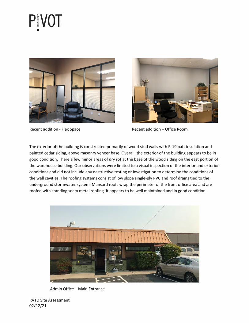
Recent addition - Flex Space Recent addition – Office Room
The exterior of the building is constructed primarily of wood stud walls with R-19 batt insulation and painted cedar siding, above masonry veneer base. Overall, the exterior of the building appears to be in good condition. There a few minor areas of dry rot at the base of the wood siding on the east portion of the warehouse building. Our observations were limited to a visual inspection of the interior and exterior conditions and did not include any destructive testing or investigation to determine the conditions of the wall cavities. The roofing systems consist of low slope single-ply PVC and roof drains tied to the underground stormwater system. Mansard roofs wrap the perimeter of the front office area and are roofed with standing seam metal roofing. It appears to be well maintained and in good condition.
Admin Office – Main Entrance
RVTD Site Assessment 02/12/21
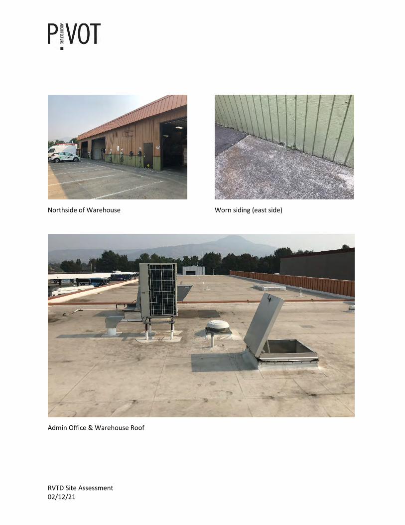
Northside of Warehouse Worn siding (east side)
Admin Office & Warehouse Roof
RVTD Site Assessment 02/12/21
Operations Office
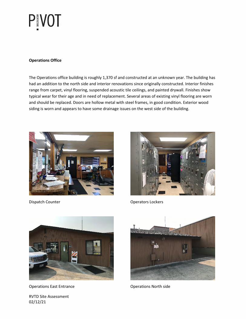
The Operations office building is roughly 1,370 sf and constructed at an unknown year. The building has had an addition to the north side and interior renovations since originally constructed. Interior finishes range from carpet, vinyl flooring, suspended acoustic tile ceilings, and painted drywall. Finishes show typical wear for their age and in need of replacement. Several areas of existing vinyl flooring are worn and should be replaced. Doors are hollow metal with steel frames, in good condition. Exterior wood siding is worn and appears to have some drainage issues on the west side of the building.
Dispatch Counter Operators Lockers
Operations East Entrance Operations North side
RVTD Site Assessment 02/12/21
Fleet Maintenance Building
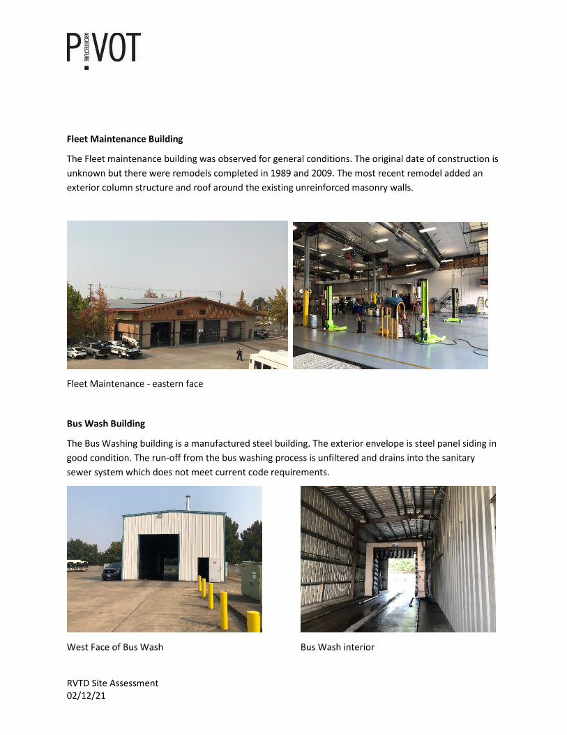
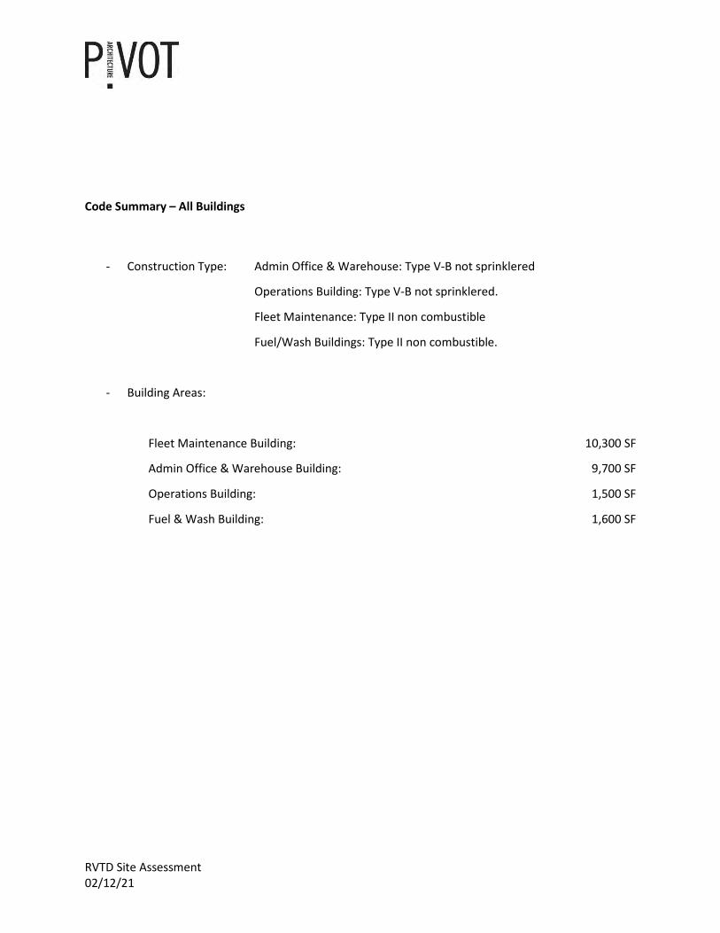
The Fleet maintenance building was observed for general conditions. The original date of construction is unknown but there were remodels completed in 1989 and 2009. The most recent remodel added an exterior column structure and roof around the existing unreinforced masonry walls.
Fleet Maintenance - eastern face
Bus Wash Building
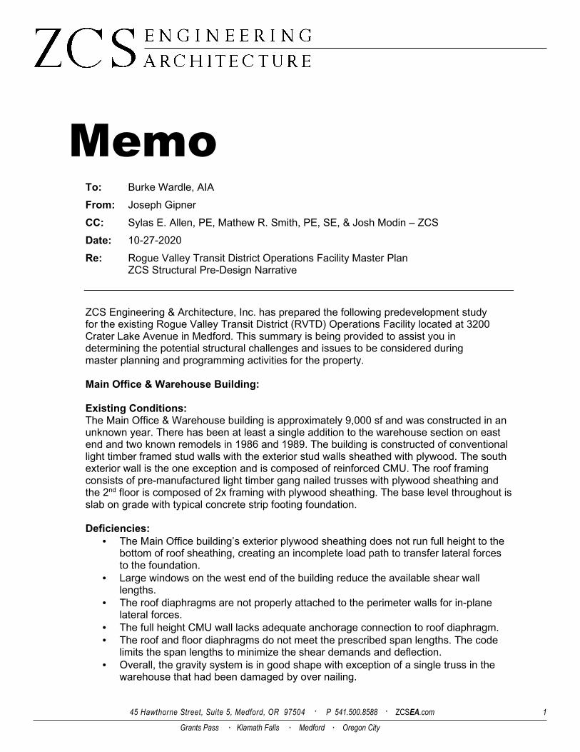
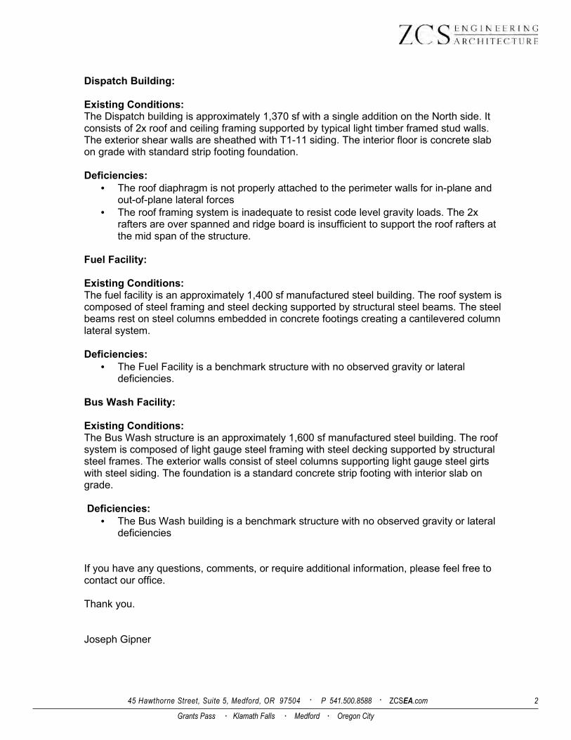
The Bus Washing building is a manufactured steel building. The exterior envelope is steel panel siding in good condition. The run-off from the bus washing process is unfiltered and drains into the sanitary sewer system which does not meet current code requirements.
West Face of Bus Wash Bus Wash interior
RVTD Site Assessment 02/12/21
Code Summary – All Buildings
- Construction Type: Admin Office & Warehouse: Type V-B not sprinklered
Operations Building: Type V-B not sprinklered.
Fleet Maintenance: Type II non combustible
Fuel/Wash Buildings: Type II non combustible.
- Building Areas:
Fleet Maintenance Building: 10,300 SF
Admin Office & Warehouse Building: 9,700 SF
Operations Building: 1,500 SF
Fuel & Wash Building: 1,600 SF
45 Hawthorne Street, Suite 5, Medford, OR 97504 · P 541.500.8588 · ZCSEA.com 1
Grants Pass · Klamath Falls · Medford · Oregon City
Memo To: Burke Wardle, AIA
From: Joseph Gipner
CC: Sylas E. Allen, PE, Mathew R. Smith, PE, SE, & Josh Modin – ZCS
Date: 10-27-2020
Re: Rogue Valley Transit District Operations Facility Master Plan ZCS Structural Pre-Design Narrative
ZCS Engineering & Architecture, Inc. has prepared the following predevelopment study for the existing Rogue Valley Transit District (RVTD) Operations Facility located at 3200 Crater Lake Avenue in Medford. This summary is being provided to assist you in determining the potential structural challenges and issues to be considered during master planning and programming activities for the property. Main Office & Warehouse Building: Existing Conditions: The Main Office & Warehouse building is approximately 9,000 sf and was constructed in an unknown year. There has been at least a single addition to the warehouse section on east end and two known remodels in 1986 and 1989. The building is constructed of conventional light timber framed stud walls with the exterior stud walls sheathed with plywood. The south exterior wall is the one exception and is composed of reinforced CMU. The roof framing consists of pre-manufactured light timber gang nailed trusses with plywood sheathing and the 2nd floor is composed of 2x framing with plywood sheathing. The base level throughout is slab on grade with typical concrete strip footing foundation. Deficiencies:
• The Main Office building’s exterior plywood sheathing does not run full height to the bottom of roof sheathing, creating an incomplete load path to transfer lateral forces to the foundation.
• Large windows on the west end of the building reduce the available shear wall lengths.
• The roof diaphragms are not properly attached to the perimeter walls for in-plane lateral forces.
• The full height CMU wall lacks adequate anchorage connection to roof diaphragm.
• The roof and floor diaphragms do not meet the prescribed span lengths. The code limits the span lengths to minimize the shear demands and deflection.
• Overall, the gravity system is in good shape with exception of a single truss in the warehouse that had been damaged by over nailing.
45 Hawthorne Street, Suite 5, Medford, OR 97504 · P 541.500.8588 · ZCSEA.com 2
Grants Pass · Klamath Falls · Medford · Oregon City
Dispatch Building: Existing Conditions: The Dispatch building is approximately 1,370 sf with a single addition on the North side. It consists of 2x roof and ceiling framing supported by typical light timber framed stud walls. The exterior shear walls are sheathed with T1-11 siding. The interior floor is concrete slab on grade with standard strip footing foundation. Deficiencies:
• The roof diaphragm is not properly attached to the perimeter walls for in-plane and out-of-plane lateral forces
• The roof framing system is inadequate to resist code level gravity loads. The 2x rafters are over spanned and ridge board is insufficient to support the roof rafters at the mid span of the structure.
Fuel Facility: Existing Conditions: The fuel facility is an approximately 1,400 sf manufactured steel building. The roof system is composed of steel framing and steel decking supported by structural steel beams. The steel beams rest on steel columns embedded in concrete footings creating a cantilevered column lateral system. Deficiencies:
• The Fuel Facility is a benchmark structure with no observed gravity or lateral deficiencies.
Bus Wash Facility: Existing Conditions: The Bus Wash structure is an approximately 1,600 sf manufactured steel building. The roof system is composed of light gauge steel framing with steel decking supported by structural steel frames. The exterior walls consist of steel columns supporting light gauge steel girts with steel siding. The foundation is a standard concrete strip footing with interior slab on grade. Deficiencies:
• The Bus Wash building is a benchmark structure with no observed gravity or lateral deficiencies
If you have any questions, comments, or require additional information, please feel free to contact our office. Thank you. Joseph Gipner
W019.06 (2020-10-30) Page 1
RVTD OPERATIONS,
ADMINISTRATION & MAINTENANCE
CAMPUS MEP ASSESSMENT
MEP SYSTEM
CONDITION ASSESSMENT
INTRODUCTION
Systems West Engineers was retained to perform an existing conditions evaluation of mechanical,
electrical, plumbing, and fire protection systems at the Rogue Valley Transit District facility. The
three buildings evaluated were the office and warehouse building, dispatch building, and bus
wash facility. A site visit was performed on October 9, 2020. Plans of the facility showing existing
conditions were obtained and reviewed as part of the evaluation. Documentation showing
existing conditions is limited.
FIRE SUPPRESSION
The office and warehouse, dispatch, and bus wash buildings are not currently equipped with fire
suppression systems. If the building is reused without increasing the floor area or changing
building occupancy, a new system will not be required.
PLUMBING
Following is a description of existing systems, equipment, and notable conditions:
OFFICE AND WAREHOUSE BUILDING
Storm Drainage
Roof drains and sidewall scupper overflows provide storm drainage for flat roof sections.
Sanitary Waste and Vent
Sanitary waste and vent piping is primarily DWV PVC pipe. Sanitary waste throughout the facility
is conventional gravity-drainage type, with sanitary vents extended through the roof. Existing
plans indicate a 4-inch sewer main for the building, which is adequate for expected uses of the
building.
Potable Water Systems
Service size and entrance location to the office building are not known. Available plans show a
¾” domestic cold-water pipe connected to existing piping west of the restrooms. Piping within
the building is type L copper. A backflow prevention device was not observed for the service to
the building. Plumbing fixtures are generally commercial grade, of good quality, and in good
condition.
▪ Water closets are floor mounted tank-type with manual valves.
▪ Lavatory faucets are manual type.
▪ Urinals are automatic flush valve-type.
▪ Stainless steel kitchen sink.
▪ Exterior hose bibbs are standard non-frost proof.
W019.06 (2020-10-30) Page 2
▪ Drinking fountain is a wall mounted type with a bottle filler.
Water Heaters and Recirculation
A 4.5 kW electric water heater with a 40-gallon storage capacity provides hot water to plumbing
fixtures. The hot water system does not have a recirculation system to maintain a constant hot-
water temperature in the supply water piping when fixtures are not in use. This water heater was
installed in 2005 and is near the end of its expected service life.
Natural Gas
A natural gas utility meter is located on the north side of the office building. Current distribution
pressure is not known. The meter and piping are not labeled, and no pressure gauges were noted;
however, given that the buildings are of light commercial use, existing distribution pressure is
expected to be 14 in WC on the customer side of the meter. Gas piping serves packaged rooftop
HVAC equipment furnaces at the office building and the dispatch building. Piping is threaded
black steel painted with small service branches to equipment unpainted.
A second natural gas utility meter is located on the east side of the dispatch building. Current
distribution pressure is not known. The meter and piping are not labeled, and no pressure gauges
were noted; however, given that the buildings are of light commercial use, existing distribution
pressure is expected to be 14 in WC on the customer side of the meter. Gas piping is routed
above grade behind the dispatch building through the east wall of the warehouse and serves the
gas furnace hanging inside the space. Piping is threaded black steel painted with short unpainted
sections.
Notable Conditions:
▪ Plumbing systems appear to be in good to fair condition.
▪ Below-grade sanitary sewer piping type and condition is not known.
▪ Existing domestic water piping service size is adequate for use with flush tank fixtures but
will not be adequate for restroom fixtures with flushometer valves.
▪ Major renovations to the building may require installation of a new backflow preventer
on the building water service.
▪ The warehouse portion of the building does not include any plumbing fixtures. Waste,
vent, and domestic water piping serve the office area only.
▪ Exposed unpainted natural gas piping is showing signs of corrosion.
DISPATCH BUILDING
Storm Drainage
A gutter and downspout system serves the dispatch building. Downspouts discharge on grade
to paved areas without a connection to a storm sewer.
Sanitary Waste and Vent
Sanitary waste and vent piping is primarily DWV PVC pipe. Sanitary waste throughout the facility
is conventional gravity-drainage type, with sanitary vents extended through the roof. Existing
plans indicate a 4-inch sewer main for the building, which is adequate for expected uses of the
building.

W019.06 (2020-10-30) Page 3
Potable Water Systems
Service size and entrance location to the dispatch building are not known. Piping appears to be
type L copper. A backflow prevention device was not observed for the service to the building.
Plumbing fixtures are generally light commercial grade, and in fair to good condition, but some
restroom fixtures may not meet current ADA requirements.
▪ Restroom fixtures are vitreous china.
▪ Lavatories and sinks have manual faucets.
▪ Water closets are floor-mount tank-type.
▪ Urinals are automatic flush valve-type.
▪ Exterior hose bibbs are standard non frost proof.
Water Heaters and Recirculation
A 2-kW electric water heater with a 6-gallon storage capacity provides hot water to plumbing
fixtures. The hot water system does not have a recirculation system to maintain a constant hot
water temperature in supply water piping when fixtures are not in use. This water heater was
installed in 2004 and is near the end of its expected service life.
Natural Gas
Natural gas appears to be connected to the office building gas piping. Gas piping appears to be
routed below grade between buildings and is routed up along the south exterior wall of the
dispatch building. Gas piping serves the furnaces in the dispatch building. Piping is painted,
threaded, black steel.
Notable Conditions:
▪ Plumbing systems appear to be in good to fair condition.
▪ Existing domestic water piping service size is adequate for use with flush tank fixtures but
is not be adequate for restroom fixtures with flushometer valves.
▪ Major renovations to the building may require installation of a new backflow preventer
on the building water service.
BUS WASH BUILDING
Storm Drainage
No storm drainage is provided for the bus wash building.
Sanitary Waste and Vent
Sanitary waste and vent piping is primarily DWV PVC pipe. Sanitary waste throughout the facility
is conventional gravity-drainage type, with sanitary vents extended through the roof. Existing
plans indicate a 4-inch sewer main for the building, which is adequate for expected uses of the
building.
Potable Water Systems
A 2-inch potable water service enters the building at the south side. A reduced-pressure backflow
preventer is provided inside the building at the service entrance location. Piping appears to be
type L copper. Water is supplied to a clothes washer, water heater, emergency eyewash, and hose
bibbs.
W019.06 (2020-10-30) Page 4
Water Heaters and Recirculation
A 4.5 kW electric water heater with a 60-gallon storage capacity provides hot water to a clothes
washer. The hot water system does not have a recirculation system to maintain a constant hot
water temperature in supply water piping when fixtures are not in use. This water heater appears
to be recently installed and in good condition.
Notable Conditions:
▪ Plumbing systems appear to be in good to fair condition.
HEATING, VENTILATING, AND AIR-CONDITIONING
OFFICE AND WAREHOUSE BUILDING
Air Distribution Systems
A variety of heating, cooling, and ventilation equipment serves the building. A summary of air-
distribution systems is included in the table on the following page.
Rooftop Heating and Cooling Units
Two packaged rooftop heating and cooling units serve a variety of spaces throughout the
building. The units generally include a supply fan, natural gas standard-efficiency furnace, and
self-contained direct expansion cooling system. The units are controlled by local electronic
programmable thermostats.
▪ The unit capacity appears to be appropriate for the type and size of facility.
▪ There is no individual temperature control for the office spaces, break room, and
conference room served by these rooftop units.
▪ Rooftop units appear to be in fair condition. The date of manufacture for the two units is
2004 and 2005. According to ASHRAE, the equipment life expectancy for rooftop air
conditioners is 15 years.
▪ The units have R-22 refrigerant. The production and import of R-22 will be discontinued
in 2020. Only reclaimed refrigerant will be available commercially beyond 2020, which will
result in significant price increases. Consideration should be given to replacing the R-22
rooftop units as part of any major addition.
▪ Generally, heating and cooling systems do not conform to current Codes for equipment
efficiency, type of refrigerant, and system control.
Split-System Heating and Cooling Units
A multi-split heat pump system provides cooling and heating to individual office spaces east of
the conference room. The system includes one ducted fan coil unit, three ceiling-mounted
ductless fan coil units, and a roof-mounted, air-cooled condenser unit. The units are controlled
by local electronic programmable thermostats.
▪ Unit capacity appears to be appropriate for the three offices.
▪ This system appears to be in generally good condition. The date of manufacture is 2019.
▪ A break room in the remodeled portion of the building does not appear to include any
heating, cooling, or ventilation system.
W019.06 (2020-10-30) Page 5
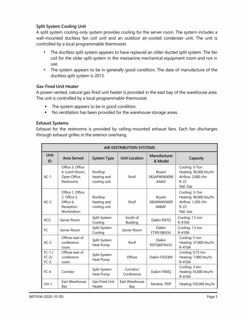
Split System Cooling Unit
A split system cooling-only system provides cooling for the server room. The system includes a
wall-mounted ductless fan coil unit and an outdoor air-cooled condenser unit. The unit is
controlled by a local programmable thermostat.
▪ The ductless split system appears to have replaced an older ducted split system. The fan
coil for the older split system in the mezzanine mechanical equipment room and not in
use.
▪ The system appears to be in generally good condition. The date of manufacture of the
ductless split system is 2013.
Gas-Fired Unit Heater
A power-vented, natural gas-fired unit heater is provided in the east bay of the warehouse area.
The unit is controlled by a local programmable thermostat.
▪ The system appears to be in good condition.
▪ No ventilation has been provided for the warehouse storage areas.
Exhaust Systems
Exhaust for the restrooms is provided by ceiling-mounted exhaust fans. Each fan discharges
through exhaust grilles in the exterior overhang.
AIR DISTRIBUTION SYSTEMS
Unit
ID Area Served System Type Unit Location
Manufacturer
& Model Capacity
AC-1
Office 3, Office
4, Lunch Room,
Open Office,
Restrooms
Rooftop
heating and
cooling unit
Roof
Bryant
582APW060090
AAAG
Cooling: 5-Ton
Heating: 90,000 btu/hr
Airflow: 2,000 cfm
R-22
Nat. Gas
AC-2
Office 1, Office
2, Office 5,
Office 6,
Reception,
Workstation
Rooftop
heating and
cooling unit
Roof
Bryant
582ANW03609
0ABAF
Cooling: 3-Ton
Heating: 90,000 btu/hr
Airflow: 1,200 cfm
R-22
Nat. Gas
ACU Server Room Split-System
Cooling
South of
Building Daikin RXTQ
Cooling: 1.5 ton
R-410A
FC Server Room Split-System
Cooling Server Room
Daikin
FTXN18KVJU
Cooling: 1.5 ton
R-410A
AC-2
Offices east of
conference
room
Split-System
Heat Pump Roof
Daikin
RXTQ60TAVJU
Cooling: 5-ton
Heating: 57,000 btu/hr
R-410A
FC-1 /
FC-2/
FC-3
Offices east of
conference
room
Split-System
Heat Pump Offices Daikin FXZQ09
Cooling: 0.75 ton
Heating: 7,000 btu/hr
R-410A
FC-4 Corridor Split-System
Heat Pump
Corridor/
Conference Daikin FXMQ
Cooling: 3 ton
Heating 33,000 btu/hr
R-410A
UH-1 East Warehouse
Bay
Gas-Fired Unit
Heater
East Warehouse
Bay Modine PDP Heating:150,000 btu/hr
W019.06 (2020-10-30) Page 6
DISPATCH BUILDING
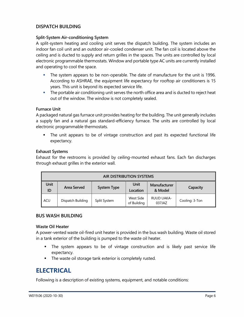
Split-System Air-conditioning System
A split-system heating and cooling unit serves the dispatch building. The system includes an
indoor fan coil unit and an outdoor air-cooled condenser unit. The fan coil is located above the
ceiling and is ducted to supply and return grilles in the spaces. The units are controlled by local
electronic programmable thermostats. Window and portable type AC units are currently installed
and operating to cool the space.
▪ The system appears to be non-operable. The date of manufacture for the unit is 1996.
According to ASHRAE, the equipment life expectancy for rooftop air conditioners is 15
years. This unit is beyond its expected service life.
▪ The portable air conditioning unit serves the north office area and is ducted to reject heat
out of the window. The window is not completely sealed.
Furnace Unit
A packaged natural gas furnace unit provides heating for the building. The unit generally includes
a supply fan and a natural gas standard-efficiency furnace. The units are controlled by local
electronic programmable thermostats.
▪ The unit appears to be of vintage construction and past its expected functional life
expectancy.
Exhaust Systems
Exhaust for the restrooms is provided by ceiling-mounted exhaust fans. Each fan discharges
through exhaust grilles in the exterior wall.
AIR DISTRIBUTION SYSTEMS
Unit
ID Area Served System Type
Unit
Location
Manufacturer
& Model Capacity
ACU Dispatch Building Split System West Side
of Building
RUUD UAKA-
037JAZ Cooling: 3-Ton
BUS WASH BUILDING
Waste Oil Heater
A power-vented waste oil-fired unit heater is provided in the bus wash building. Waste oil stored
in a tank exterior of the building is pumped to the waste oil heater.
▪ The system appears to be of vintage construction and is likely past service life
expectancy.
▪ The waste oil storage tank exterior is completely rusted.
ELECTRICAL
Following is a description of existing systems, equipment, and notable conditions:
W019.06 (2020-10-30) Page 7
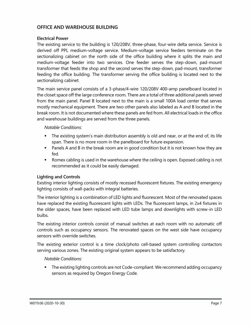
OFFICE AND WAREHOUSE BUILDING
Electrical Power
The existing service to the building is 120/208V, three-phase, four-wire delta service. Service is
derived off PPL medium-voltage service. Medium-voltage service feeders terminate on the
sectionalizing cabinet on the north side of the office building where it splits the main and
medium-voltage feeder into two services. One feeder serves the step-down, pad-mount
transformer that feeds the shop and the second serves the step-down, pad-mount, transformer
feeding the office building. The transformer serving the office building is located next to the
sectionalizing cabinet.
The main service panel consists of a 3-phase/4-wire 120/208V 400-amp panelboard located in
the closet space off the large conference room. There are a total of three additional panels served
from the main panel. Panel B located next to the main is a small 100A load center that serves
mostly mechanical equipment. There are two other panels also labeled as A and B located in the
break room. It is not documented where these panels are fed from. All electrical loads in the office
and warehouse buildings are served from the three panels.
Notable Conditions:
▪ The existing system’s main distribution assembly is old and near, or at the end of, its life
span. There is no more room in the panelboard for future expansion.
▪ Panels A and B in the break room are in good condition but it is not known how they are
fed.
▪ Romex cabling is used in the warehouse where the ceiling is open. Exposed cabling is not
recommended as it could be easily damaged.
Lighting and Controls
Existing interior lighting consists of mostly recessed fluorescent fixtures. The existing emergency
lighting consists of wall-packs with integral batteries.
The interior lighting is a combination of LED lights and fluorescent. Most of the renovated spaces
have replaced the existing fluorescent lights with LEDs. The fluorescent lamps, in 2x4 fixtures in
the older spaces, have been replaced with LED tube lamps and downlights with screw-in LED
bulbs.
The existing interior controls consist of manual switches at each room with no automatic off
controls such as occupancy sensors. The renovated spaces on the west side have occupancy
sensors with override switches.
The existing exterior control is a time clock/photo cell-based system controlling contactors
serving various zones. The existing original system appears to be satisfactory.
Notable Conditions:
▪ The existing lighting controls are not Code-compliant. We recommend adding occupancy
sensors as required by Oregon Energy Code.
W019.06 (2020-10-30) Page 8
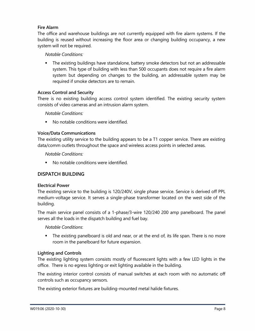
Fire Alarm
The office and warehouse buildings are not currently equipped with fire alarm systems. If the
building is reused without increasing the floor area or changing building occupancy, a new
system will not be required.
Notable Conditions:
▪ The existing buildings have standalone, battery smoke detectors but not an addressable
system. This type of building with less than 500 occupants does not require a fire alarm
system but depending on changes to the building, an addressable system may be
required if smoke detectors are to remain.
Access Control and Security
There is no existing building access control system identified. The existing security system
consists of video cameras and an intrusion alarm system.
Notable Conditions:
▪ No notable conditions were identified.
Voice/Data Communications
The existing utility service to the building appears to be a T1 copper service. There are existing
data/comm outlets throughout the space and wireless access points in selected areas.
Notable Conditions:
▪ No notable conditions were identified.
DISPATCH BUILDING
Electrical Power
The existing service to the building is 120/240V, single phase service. Service is derived off PPL
medium-voltage service. It serves a single-phase transformer located on the west side of the
building.
The main service panel consists of a 1-phase/3-wire 120/240 200 amp panelboard. The panel
serves all the loads in the dispatch building and fuel bay.
Notable Conditions:
▪ The existing panelboard is old and near, or at the end of, its life span. There is no more
room in the panelboard for future expansion.
Lighting and Controls
The existing lighting system consists mostly of fluorescent lights with a few LED lights in the
office. There is no egress lighting or exit lighting available in the building.
The existing interior control consists of manual switches at each room with no automatic off
controls such as occupancy sensors.
The existing exterior fixtures are building-mounted metal halide fixtures.
W019.06 (2020-10-30) Page 9
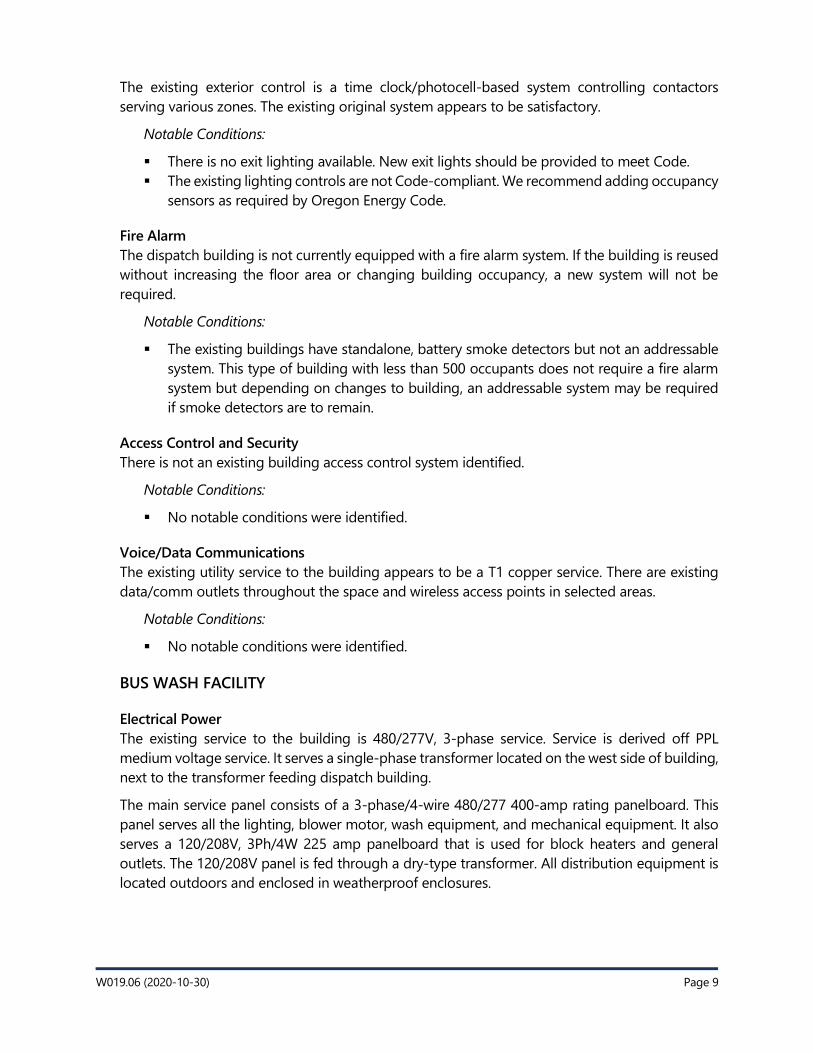
The existing exterior control is a time clock/photocell-based system controlling contactors
serving various zones. The existing original system appears to be satisfactory.
Notable Conditions:
▪ There is no exit lighting available. New exit lights should be provided to meet Code.
▪ The existing lighting controls are not Code-compliant. We recommend adding occupancy
sensors as required by Oregon Energy Code.
Fire Alarm
The dispatch building is not currently equipped with a fire alarm system. If the building is reused
without increasing the floor area or changing building occupancy, a new system will not be
required.
Notable Conditions:
▪ The existing buildings have standalone, battery smoke detectors but not an addressable
system. This type of building with less than 500 occupants does not require a fire alarm
system but depending on changes to building, an addressable system may be required
if smoke detectors are to remain.
Access Control and Security
There is not an existing building access control system identified.
Notable Conditions:
▪ No notable conditions were identified.
Voice/Data Communications
The existing utility service to the building appears to be a T1 copper service. There are existing
data/comm outlets throughout the space and wireless access points in selected areas.
Notable Conditions:
▪ No notable conditions were identified.
BUS WASH FACILITY
Electrical Power
The existing service to the building is 480/277V, 3-phase service. Service is derived off PPL
medium voltage service. It serves a single-phase transformer located on the west side of building,
next to the transformer feeding dispatch building.
The main service panel consists of a 3-phase/4-wire 480/277 400-amp rating panelboard. This
panel serves all the lighting, blower motor, wash equipment, and mechanical equipment. It also
serves a 120/208V, 3Ph/4W 225 amp panelboard that is used for block heaters and general
outlets. The 120/208V panel is fed through a dry-type transformer. All distribution equipment is
located outdoors and enclosed in weatherproof enclosures.
W019.06 (2020-10-30) Page 10
Notable Conditions:
▪ The existing panelboards are in good condition, but the transformer looks to be
weathered and may need replacing.
▪ There is exposed surface-mount PVC conduit from the transformer secondary to the
120/208V panelboard that needs to be replaced.
Lighting and Controls
The existing lighting system consist of high-bay metal halide fixtures. The existing interior control
consists of manual switches. The existing exterior fixtures are building-mounted metal halide
fixtures.
The existing exterior control is a time clock/photocell-based system controlling contactors
serving various zones. The existing original system appears to be satisfactory.
Notable Conditions:
▪ The existing lighting controls are not Code-compliant. We recommend adding occupancy
sensors as required by Oregon Energy Code.
Fire Alarm
The existing building does not have a fire alarm system and does not require one.
Access Control and Security
There is no existing building access control system identified.
Notable Conditions:
▪ No notable conditions were identified.
Voice/Data Communications
The existing building does not have a voice/data communication system.
Notable Conditions:
▪ No notable conditions were identified.

45 Hawthorne Street, Suite 5, Medford, OR 97504 · P 541.500.8588 · ZCSEA.com 1
Grants Pass · Klamath Falls · Medford · Oregon City
MemoTo: Burke Wardle, AIA
From: Malia Waters
CC: Sylas E. Allen, PE & Josh Modin – ZCS
Date: 10-26-2020
Re: Rogue Valley Transit District Operations Facility Master PlanZCS Civil Pre-Design Narrative
ZCS Engineering & Architecture, Inc. has prepared the following predevelopment study for the existing Rogue Valley Transit District (RVTD) Operations Facility located at 3200 Crater Lake Avenue in Medford. This summary is being provided to assist you in determining the potential site challenges and issues to be considered during master planning and programming activities for the property.
Existing ConditionsThe existing site is comprised of one fully developed tax lot (TL 500, 4.28 acres) located at the southeast corner of the intersection of Ford Drive and Crater Lake Avenue and a second undeveloped parcel (TL 800, 1.34 acres) abutting the south property line of TL 500 with frontage along Forest Hills Drive within City of Medford limits (tax map T37S-R01W-S08CC, tax lots 500 and 800). The property is zoned Limited Industrial (I-L) which supports a wide variety of light industrial uses adjacent to commercial and residential zones, including the operations facility, storage, and office buildings currently existing on site. Properties to the north and south of the site are zoned I-L, with multi-family residential (MFR-20) to the west and regional commercial (CR) across Crater Lake Highway to the east; all adjacent properties to tax lots 500 and 800 are fully developed.
The property has a gradual slope from south to north with a large stormwater detention swale located in the northeast corner of tax lot 500. Aside from curb and gutter, there are no frontage improvements on Crater Lake Avenue, Ford Drive, or Forest Hills Drive adjacent to the site; it is anticipated that full frontage improvements along Crater Lake Avenue may be required based on future site programming.
AccessAdequate access to the site is available via Crater Lake Avenue (one driveway), Ford Drive (two driveways), and Forest Hills Drive (one driveway).
Site / Surface PavementThe asphalt parking lot serving the administration building appears to be in good conditions and exhibits signs of routine crack-seal/seal-coat maintenance. No significant cracking or other damage patterns were observed.
45 Hawthorne Street, Suite 5, Medford, OR 97504 · P 541.500.8588 · ZCSEA.com 2
Grants Pass · Klamath Falls · Medford · Oregon City
At this time, no asphalt pavement repair or replacement is recommended. Asphalt pavement west, south, and north of the main operations building appear to be in similar condition. The asphalt paved parking lot along the north property line has recently undergone maintenance/restriping and appears to be in good condition. At this time, no asphalt pavement repair or replacement is recommended across the site.
Vast portions of the site are paved with reinforced vehicular concrete and pavement generally appears to be in good condition. There are several individual concrete panels that show signs of cracking or other damage. In total, it is recommended that roughly 1,000-square feet of reinforced concrete pavement be removed and replaced with new 6” to 8” thick reinforced concrete pavement utilizing the existing underlying base rock and geotextile support fabric.
Areas of pedestrian concrete throughout the site generally appear to be in good condition with allowable slopes meeting current accessibility standards. The existing accessible ramp between the parking lot and front entry of the administration building does not have a top landing/walk-around and therefore does not comply with current accessibility standards; replacement is recommended. No other pedestrian concrete replacement is recommended at this time.
Accessible parking striping within the administration parking lot do not appear to meet dimensional standards and no signage was observed. It is recommended that accessible parking be restriped, and appropriate signage added. By observation, it appears that surface grading within the limits of accessible parking stalls and access aisles are within allowable standards, therefore, no modifications to grading is suggested.
Grading and Drainage (Stormwater Infrastructure) Based on existing pavement and overall topography it appears that the site is graded to provide adequate drainage across the development. Various localized catch basins and trench drains function as intended. No issues with site drainage have been voiced, and therefore changes to on-site storm infrastructure is not recommended.
In general, the following recommendations will help maintain the condition of existing stormwater conveyance networks and detention/treatment facilities. It is recommended the following inspection and maintenance program be performed twice annually, in April and October.
Paved parking and maneuvering areas – prior to cleaning the pipe network, all paved parking and maneuvering areas shall be swept or washed clean.
Area inlets – inspect and clean each inlet grate and sump, clean and repair as needed. Do not allow sediment material to wash downstream from this point.
Stormwater pipe network – inspect conveyance pipes for sediment buildup. If sediment is present, high pressure wash each pipe into adjacent downstream catch basin/control structure, taking care not to allow material to wash downstream. All sediment shall be extracted from structures/pipes and disposed of at an approved location
45 Hawthorne Street, Suite 5, Medford, OR 97504 · P 541.500.8588 · ZCSEA.com 3
Grants Pass · Klamath Falls · Medford · Oregon City
Stormwater detention swale – Inspect and clean swale. Remove any accumulated garbage/debris. Inspect swale for any signs of erosion; repair any found defects. Review condition of plantings; any plantings that are found to be dead or dying shall be replaced. Remove discharge structure grate to wash and vacuum sump. Do not allow sediment material to wash downstream from this point. All sediment to be extracted from structures and disposed of at an approved location. Examine orifice, remove any blockages to allow for proper operation and drainage.
Additionally, review of available wetland and sensitive area mapping shows that there are no mapped wetlands on site. The site is located within City of Medford stormwater management jurisdiction.
Sanitary Sewer Based on available utility mapping and as-built information it appears that sanitary sewer facilities on-site function as intended and do not warrant replacement or upgrade. Sanitary sewer is directed to a pump station located at the northwest corner of the administrative parking lot and discharges to the public system running under Crater Lake Avenue. The site is located within City of Medford sanitary sewer jurisdiction. Fire Water / Domestic Water Based on available utility mapping and as-built information it appears that domestic and fire water facilities on-site function as intended and do not warrant replacement or upgrade. Multiple fire hydrants were observed on and adjacent to the site which appear to provide appropriate coverage to critical infrastructure on-site including the fueling station and natural gas storage. The site is located within Medford Water Commission jurisdiction, with fire protection provided by Medford Fire Department Station #5.
Power / Data and CommunicationsBased on available utility mapping and as-built information it appears that power and data/communications services on-site function as intended and do not warrant replacement or upgrade. Primary power service to the site is accessed from overhead power running along the east side of Crater Lake Avenue; service to the site is buried with a primary transformer located east of the administrative parking lot. Data/communications services (various utility companies) are accessed from buried and overhead lines running along the east side of Crater Lake Avenue. Services to the site are provided by Pacific Power (power); specific data/communications providers will be identified during later planning efforts.
Natural Gas (exclusive of fuel)Based on available utility mapping and as-built information it appears that natural gas services on-site function as intended and do not warrant replacement. A gas meter located near the southeast corner of the dispatch building does not appear to be appropriately supported; recommend replacement of meter supports. Service to the site is provided by Avista Utilities via a regular station located at the northeast corner of the site along the south side of Ford Drive.
Fuel (diesel / natural gas)Based on available utility mapping and as-built information it appears that diesel and natural gas fueling facilities on-site function as intended and do not warrant replacement or upgrade.
45 Hawthorne Street, Suite 5, Medford, OR 97504 · P 541.500.8588 · ZCSEA.com 4
Grants Pass · Klamath Falls · Medford · Oregon City
Diesel fuel is stored in an underground storage tank situated east of the primary operations building and liquid natural gas is stored in three above ground pressurized tanks northeast of the fueling station. Waste oil and chemicals are stored in a series of underground storage tanks located north of the primary operations building.
If you have any questions, comments, or require additional information, please feel free to contact our office.
Thank you.
Page 1 of 3
Memorandum
To: Burke Wardle, PIVOT Architecture
CC: Kari Turner, John Stapleton, Matt Koehler
From: Zach Rix, Cameron McCarthy
Date: October 27, 2020
RVTD Operations, Administration and Maintenance Campus Master Plan
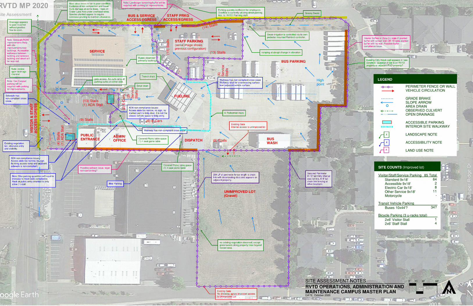
Site Assessment
8. ASTM E2018—15: Walk-Through Survey
8.1. Objective (no content)
8.2. Frequency (no content)
8.3. Photographs
See Attachment CM-2.
8.4. Scope
8.4.1. Site:
See Attachment CM-1.
8.4.1.2. Topography
Generally, the site slopes from southeast to northwest with approximately 7-ft of elevation
change and slopes ranging from <4% to 1% across paved surfaces. The site visually appears
flat, without many abrupt changes in elevation. Some are noted on Attachment CM-1.
The unimproved gravel lot slopes from south to northeast with approximately 7-ft of
elevation change.
8.4.1.3. Storm Water Drainage
A part of the Midway Basin, stormwater is intercepted into storm drains or roadside
channels, ending up in Midway Creek and ultimately the Rogue River. The visitor parking
area mostly drains to a single catch basin with the remainder appearing to drain out to
Crater Lake Avenue’s drainage channel.
The 2009 addition to the bus parking area drains north to a grass water quality swale that
appears to be maintained by regular mowing.
The unimproved gravel lot drains to the northwest corner of the lot where an invert collects
and routes through the current campus to Ford Drive and ultimately to Crater Lake Avenue.
Curb openings at grassy water quality swale have sediment buildup, potentially limiting
stormwater flow to swale.
8.4.1.4. Ingress and Egress
Two-way Access/Egress at Crater Lake Avenue: Provides access to a parking area with visitor
and administrative staff parking.
Two-way Access/Egress at Ford Drive (west): Provides access to secured lot for bus fueling,
maintenance, parking, and other maintenance or RVTD electric vehicle parking. The main lot
connects to the unimproved gravel lot. There is a rolling gate at the southwest corner of lot,
at Forrest Hills Drive, with no driveway apron or improved access for vehicles.
Two-way Access/Egress at Ford Drive (east): Provides access to secured parking lot for
majority of staff parking. Parking Lot has no through access.

Page 2 of 3
Pedestrian access is limited by lack of sidewalk on Crater Lake Avenue and south side of Ford
Drive. No accessible pathway is marked between right-of-way and public building entry
facing Crater Lake Avenue.
Crater Lake Avenue paving ends on other side of fog line, no bicycle accommodations such
as bike lanes, shared use markings, or multiuse sidewalks are present. 35MPH speed sign
indicates an unsafe speed for mixed vehicle/bicycle traffic.
8.4.1.5. Paving, Curbing, and Parking
Asphalt paving onsite appears to have received a recent seal coat. Repaired cracks are visible
in parking lots where seal coat was applied. Some areas of asphalt appear to be heaving
possibly due to adjacent tree roots. Damage due to tree roots has been observed at existing
concrete paving areas and may be indicating poor soil drainage on site.
Curbs at visitor parking area appear in fair condition, however curb height is shallow in some
areas and curb ramps appear non-compliant to ADA guidelines.
No curbs or sidewalks are present at driveway entry from Crater Lake Avenue. Curb and
gutter are existing along parts of Ford Drive, but no sidewalk is present on the south side of
the street.
No curb present at enclosed staff parking area, concrete wheel stops have been installed.
Gutter behind Service building appears to be non-functioning or ponding water prior to
reaching a storm drain.
Vehicle Parking and Bicycle Parking quantities as observed are tallied in the quantities table
on Attachment CM-1.
Bicycle Parking is provided by three covered “U” racks. One rack is oriented to allow only one
space, the other two allow for two spaces each, however only one rack (two spaces) appears
to comply with guidelines for space dimensions and clearance from a building wall.
8.4.1.6. Flatwork
Concrete paving shows signs of failure at bus access driveway apron. Other areas within the
lot interior show spalling possibly due to heavy traffic over areas that were previously
patched.
A doorway to the warehouse building has a grade change between finish grade and finish
floor greater than ¼ inch. This transition may limit access.
8.4.1.7. Landscaping and Appurtenances
At the visitor entry, the parking lot landscape buffer to Crater Lake Avenue is dense and tall,
obscuring the main building entry.
Many of the street/parking lot trees appear to be in fair, poor, or in declining condition.
Possibly poor draining soil, compacted soil, and minimal area for root establishment has
caused stunted growth, and lead to pavement heaving and surface roots.
Some trees and large shrubs have drip rings for irrigation. Other irrigation is not visible
above ground or is non-existent.
Site fencing appears in fair to good condition, with some areas looking recently installed.
Fencing is 6’ to 8’ chain link fence with sections around the perimeter having barbed security
wire along the top.
8.4.1.8. Recreational Facilities
There are two covered picnic areas within the secured lot, one free standing shelter near the
Administration building across from bicycle parking and the other under an attached shed
roof connecting a warehouse structure to the dispatch structure. Each have one picnic table,
seating approximately 4 adults, no accessible features are present.
8.5. Additional Considerations
8.5.3. Additional Issues
8.5.3.5. ADA Requirements
Accessible parking stalls are observed to have non-compliant access aisle width and signage.
Stall width and depth appear within compliant range. Accessible paths from parking stalls to
building entries appear non-compliant due to non-compliant ramp and/or cross slope over
2.08%.
Page 3 of 3
Accessible paths from building entry to public right-of-way is non-existent at visitor
entry/Administration building. Accessible pathways between staff parking area and between
site buildings do not comply with surface contrast and cross slope guidelines. Barriers such
as curbs are noted at one existing pathway location between Service building and
Administration building.
Additional Notes:
There are a few concerns regarding existing non-compliance of Medford Municipal Code. Notes related to
improvements anticipated to bring any existing issues into full compliance are provided on Attachment
CM-1. This is not a land use review and should only be included here for the purposes of understanding
current site conditions.
PIVOT Architecture 02.19.2021 DRAFT RVTD Master Plan Report
SECTION C - PHASE 1
DRAFT RVTD Master Plan Report PIVOT Architecture 02.19.2021
SECTION C - PHASE 1
OVERVIEW
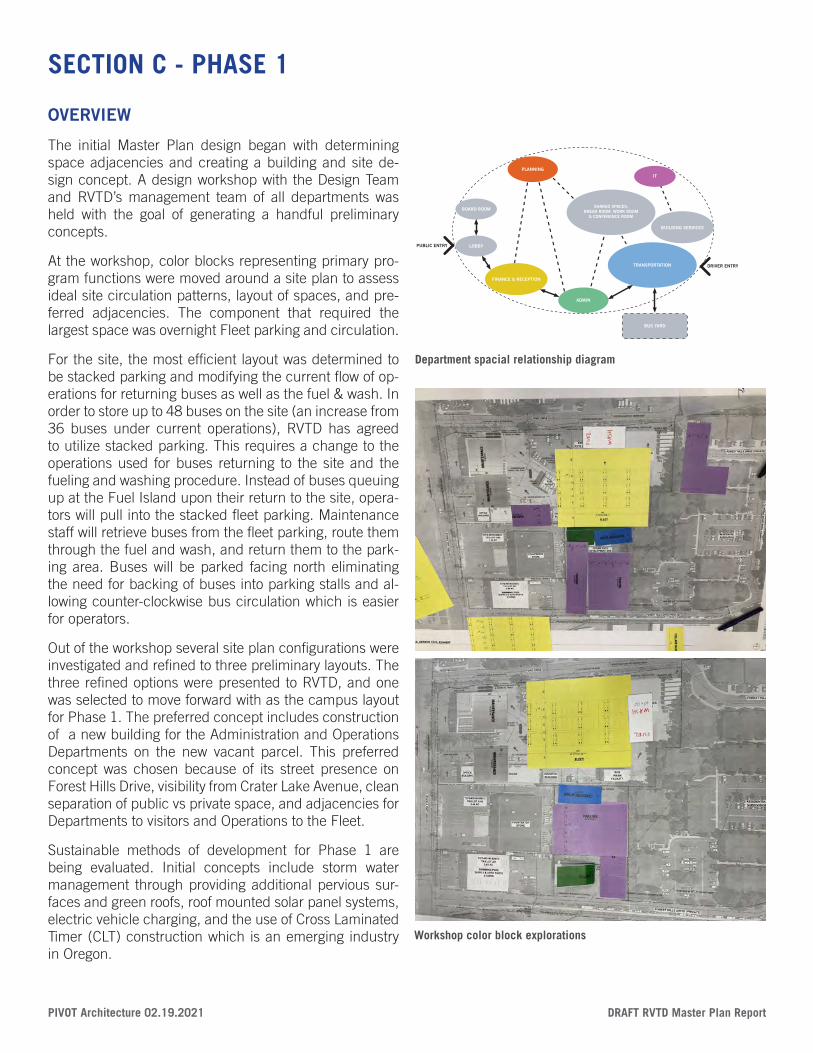
The initial Master Plan design began with determining space adjacencies and creating a building and site de-sign concept. A design workshop with the Design Team and RVTD’s management team of all departments was held with the goal of generating a handful preliminary concepts.
At the workshop, color blocks representing primary pro-gram functions were moved around a site plan to assess ideal site circulation patterns, layout of spaces, and pre-ferred adjacencies. The component that required the largest space was overnight Fleet parking and circulation.
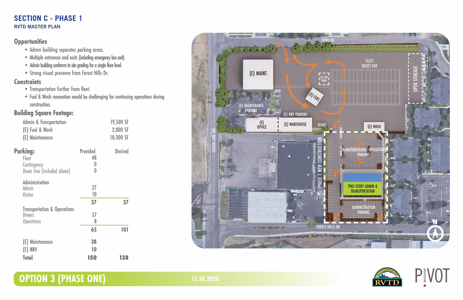
For the site, the most efficient layout was determined to be stacked parking and modifying the current flow of op-erations for returning buses as well as the fuel & wash. In order to store up to 48 buses on the site (an increase from 36 buses under current operations), RVTD has agreed to utilize stacked parking. This requires a change to the operations used for buses returning to the site and the fueling and washing procedure. Instead of buses queuing up at the Fuel Island upon their return to the site, opera-tors will pull into the stacked fleet parking. Maintenance staff will retrieve buses from the fleet parking, route them through the fuel and wash, and return them to the park-ing area. Buses will be parked facing north eliminating the need for backing of buses into parking stalls and al-lowing counter-clockwise bus circulation which is easier for operators.
Out of the workshop several site plan configurations were investigated and refined to three preliminary layouts. The three refined options were presented to RVTD, and one was selected to move forward with as the campus layout for Phase 1. The preferred concept includes construction of a new building for the Administration and Operations Departments on the new vacant parcel. This preferred concept was chosen because of its street presence on Forest Hills Drive, visibility from Crater Lake Avenue, clean separation of public vs private space, and adjacencies for Departments to visitors and Operations to the Fleet.
Sustainable methods of development for Phase 1 are being evaluated. Initial concepts include storm water management through providing additional pervious sur-faces and green roofs, roof mounted solar panel systems, electric vehicle charging, and the use of Cross Laminated Timer (CLT) construction which is an emerging industry in Oregon.
LOBBYPUBLIC ENTRY
BOARD ROOM
FINANCE & RECEPTION
PLANNING
ADMIN
BUILDING SERVICES
DRIVER ENTRY
SHARED SPACES:BREAK ROOM, WORK ROOM
& CONFERENCE ROOM
TRANSPORTATION
IT
BUS YARD
Department spacial relationship diagram
Workshop color block explorations
(E) WASH
FLEETBUSES X48
(E) CNGTANKS
FOREST HILLS DR
CRAT
ER LA
KE AV
E
FORD DR
(E) WAREHOUSE
(E) MAINT.
(E) OFFICE
OPEN
STOR
AGE
TWO-STORY ADMIN &TRANSPORTATION
ADMINISTRATIONPARKING
TRANSPORTATION/ OPERATIONSPARKING
(E) FUEL(E) MAINTENANCE
PARKING(E) NRV PARKING
Opportunities
Constraints
Building Square Footage:Admin & Transportation (E) Fuel & Wash (E) Maintenance
19,500 SF2,000 SF
10,300 SF
Parking:
AdministrationAdminVisitor
Transportation & OperationsDriversOperations
Provided Desired
271037 37
578
65 101
150 138Total
(E) Maintenance(E) NRV
3810
FleetContingencyDown line (Included above)
4800
• Admin building separates parking areas.• Multiple entrances and exits (including emergency bus exit).• Admin building conforms to site grading for a single floor level.• Strong visual presence from Forest Hills Dr.
• Transportation further from fleet.• Fuel & Wash renovation would be challenging for continuing operations during
construction.
12.18.2020OPTION 3 (PHASE ONE)
DEMO
PHAS
E 1 N
EW CO
NSTR
UCTIO
N
SECTION C - PHASE 1RVTD MASTER PLAN
PIVOT Architecture 02.19.2021 DRAFT RVTD Master Plan Report
RVTD MASTER PLAN3200 CRATER LAKE AVE, MEDFORD OR
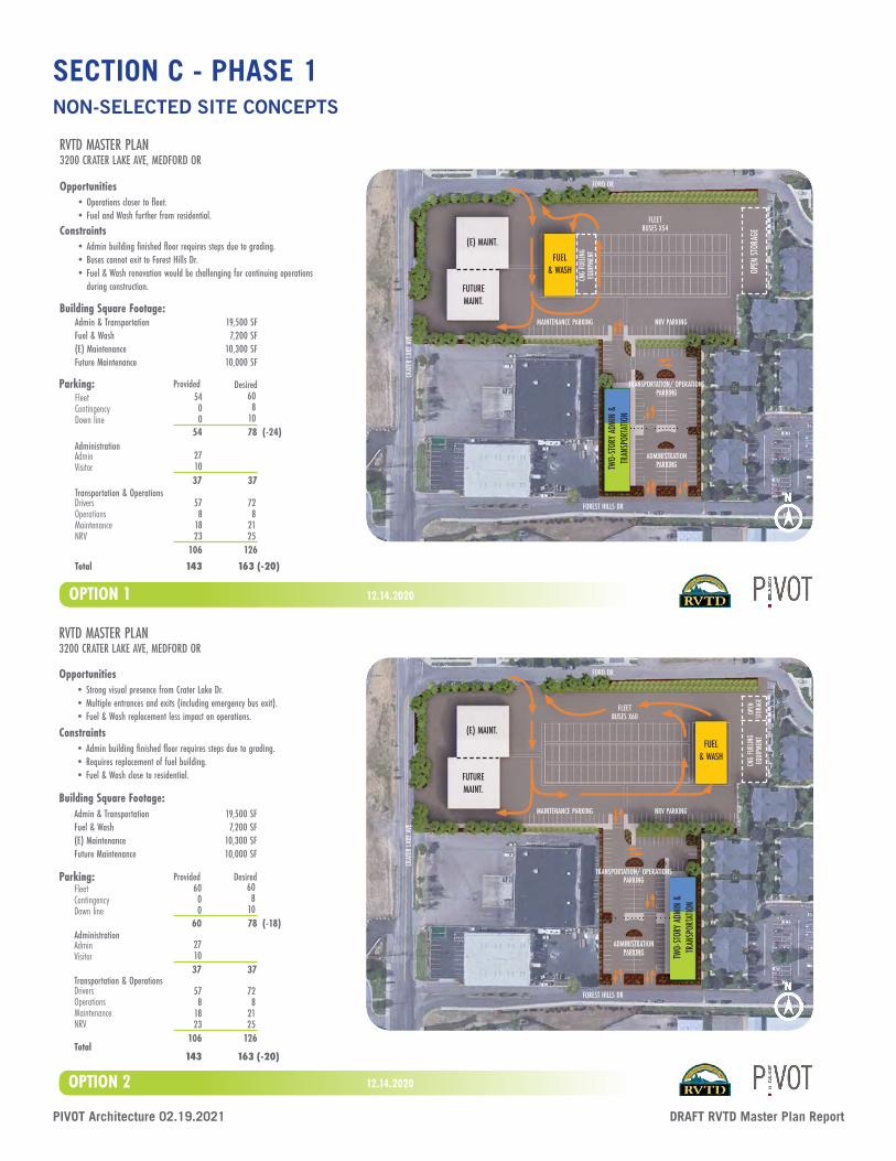
OPTION 1
FUEL& WASH
FLEETBUSES X54
FOREST HILLS DR
CRAT
ER LA
KE AV
E
FORD DR
TRANSPORTATION/ OPERATIONSPARKING
ADMINISTRATIONPARKINGTW
O-ST
ORY A
DMIN
&
TRAN
SPOR
TATIO
N
12.14.2020
MAINTENANCE PARKING NRV PARKING
(E) MAINT.
FUTUREMAINT.
OPEN
STOR
AGE
CNG
FUEL
ING
EQUI
PMEN
T
Opportunities• Operations closer to fleet.• Fuel and Wash further from residential.
Constraints• Admin building finished floor requires steps due to grading.• Buses cannot exit to Forest Hills Dr.• Fuel & Wash renovation would be challenging for continuing operations
during construction.
Building Square Footage:Admin & Transportation Fuel & Wash (E) MaintenanceFuture Maintenance
19,500 SF7,200 SF
10,300 SF10,000 SF
Parking:
AdministrationAdminVisitor
Transportation & OperationsDriversOperations MaintenanceNRV
Provided Desired
271037 37
578
1823
106 126
143 163 (-20)Total
728
2125
FleetContingencyDown line
5400
608
1054 78 (-24)
RVTD MASTER PLAN3200 CRATER LAKE AVE, MEDFORD OR
FLEETBUSES X60
FOREST HILLS DR
CRAT
ER LA
KE AV
E
FORD DR
ADMINISTRATIONPARKING
TRANSPORTATION/ OPERATIONSPARKING
(E) MAINT.
FUTUREMAINT.
FUEL& WASH
MAINTENANCE PARKING NRV PARKING
OPEN
ST
ORAG
E
TWO-
STOR
Y ADM
IN &
TR
ANSP
ORTA
TION
OPTION 2 12.14.2020
CNG
FUEL
ING
EQUI
PMEN
T
Opportunities• Strong visual presence from Crater Lake Dr.• Multiple entrances and exits (including emergency bus exit).• Fuel & Wash replacement less impact on operations.
Constraints• Admin building finished floor requires steps due to grading.• Requires replacement of fuel building.• Fuel & Wash close to residential.
Building Square Footage:Admin & Transportation Fuel & Wash (E) MaintenanceFuture Maintenance
19,500 SF7,200 SF
10,300 SF10,000 SF
Parking:
AdministrationAdminVisitor
Transportation & OperationsDriversOperationsMaintenanceNRV
Provided Desired
271037 37
Total
578
1823
106 126
143 163 (-20)
728
2125
FleetContingencyDown line
6000
608
1060 78 (-18)
NON-SELECTED SITE CONCEPTS
SECTION C - PHASE 1
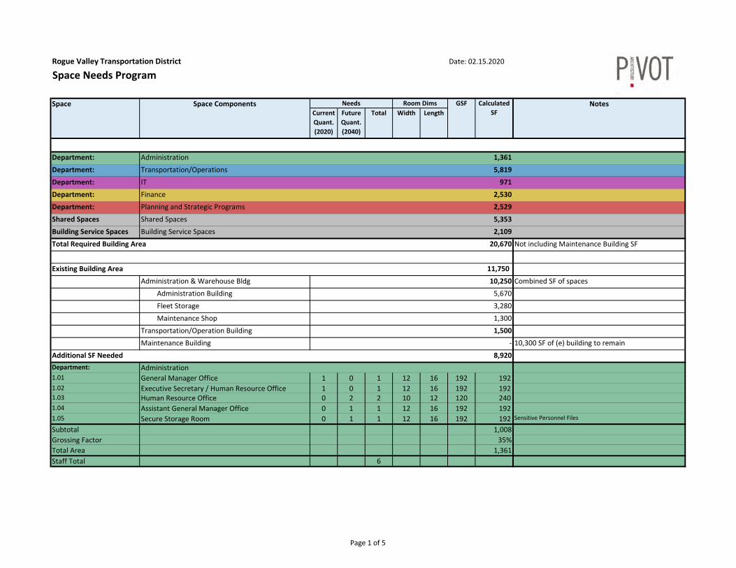
Rogue Valley Transportation District Date: 02.15.2020
Space Needs Program
Current Quant.(2020)
FutureQuant.(2040)
Total Width Length
Department: Administration 1,361
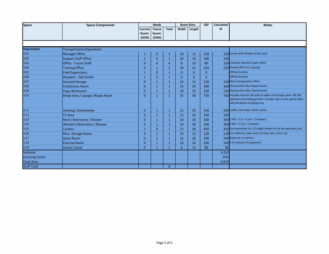
Department: Transportation/Operations 5,819
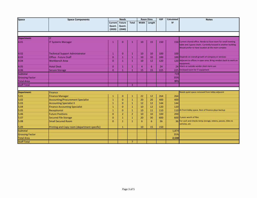
Department: IT 971
Department: Finance 2,530
Department: Planning and Strategic Programs 2,529
Shared Spaces Shared Spaces 5,353
Building Service Spaces Building Service Spaces 2,109
Total Required Building Area 20,670 Not including Maintenance Building SF
Existing Building Area 11,750
Administration & Warehouse Bldg 10,250 Combined SF of spaces
Administration Building 5,670
Fleet Storage 3,280
Maintenance Shop 1,300
Transportation/Operation Building 1,500
Maintenance Building ‐ 10,300 SF of (e) building to remain
Additional SF Needed 8,920 Department: Administration1.01 General Manager Office 1 0 1 12 16 192 192 1.02 Executive Secretary / Human Resource Office 1 0 1 12 16 192 192 1.03 Human Resource Office 0 2 2 10 12 120 240 1.04 Assistant General Manager Office 0 1 1 12 16 192 192 1.05 Secure Storage Room 0 1 1 12 16 192 192 Sensitive Personnel FilesSubtotal 1,008 Grossing Factor 35%Total Area 1,361 Staff Total 6
Space Space Components Needs Room Dims GSF Calculated SF
Notes
Page 1 of 5
Current Quant.(2020)
FutureQuant.(2040)
Total Width LengthSpace Space Components Needs Room Dims GSF Calculated
SFNotes
Department: Transportation/Operations3.01 Manager Office 1 0 1 10 12 120 120 Locate with window to bus yard3.02 Support Staff Office 1 0 1 10 10 100 100 3.03 Office ‐ Future Staff 0 4 4 8 10 80 320 Could be shared or open office 3.04 Training Office 0 1 1 10 22 220 220 Shared office for 2 people3.05 Field Supervisors 1 0 1 0 0 0 ‐ Offsite location3.06 Dispatch ‐ Call Center 1 0 1 0 0 0 ‐ Offsite location3.07 Secured Storage 0 1 1 10 12 120 120 Near transporation office3.08 Conference Room 0 1 1 15 24 360 360 Shared with other Departments
3.09 Copy Workroom 0 1 1 10 15 150 150 Shared with other Departments
3.10 Break Area / Lounge /Ready Room 0 1 1 25 30 750 750 Includes area for 30 seats at tables and lounge space. 80‐100 operators (including growth). Includes sign in area, game table, and cell phone charging area.
3.11 Vending / Kitchenette 0 1 1 12 20 240 240 Coffee, hot water, water cooler.3.12 TV Area 0 1 1 12 20 240 240 3.13 Men's Restrooms / Shower 0 1 1 10 30 300 300 2 WC + 2 U + 3 Lav + 2 showers
3.14 Women's Restrooms / Shower 0 1 1 10 30 300 300 3 WC + 3 Lav + 2 showers
3.15 Lockers 1 0 1 15 30 450 450 Accommodate for 1/2 height lockers for all the operators and
3.16 Misc. Storage Room 0 1 1 10 12 120 120 For uniforms, back stock of coats, hats, shirts, etc
3.17 Quiet Room 0 1 1 12 20 240 240 Space for 4 recliners3.18 Exercise Room 0 1 1 10 20 200 200 2 to 3 pieces of equipment
3.19 Janitor Closet 0 1 1 8 10 80 80 Subtotal 4,310 Grossing Factor 35%Total Area 5,819 Staff Total 8
Page 2 of 5
Current Quant.(2020)
FutureQuant.(2040)
Total Width LengthSpace Space Components Needs Room Dims GSF Calculated
SFNotes
Department: IT4.01 IT Systems Manager 1 0 1 10 15 150 150 Current shared office. Needs to have room for small meeting
table and 2 guest chairs. Currently housed in another building. Would prefer to have location at the main complex
4.02 Technical Support Administrator 1 0 1 10 10 100 100 4.03 Office ‐ Future Staff 0 1 1 10 10 100 100 Depends on overall growth of company or services
4.04 Workbench Area 0 1 1 10 12 120 120 Adjacent to offices in open area. Bring vendors back to work on equipment.
4.05 Hotel Desk 0 1 1 4 6 24 24 Intern or outside vendor short‐term use
4.06 Secure Storage 0 1 1 15 15 225 225 Enclosed room for IT equipment
Subtotal 719 Grossing Factor 35%Total Area 971 Staff Total 3
Department: Finance Needs quiet space removed from lobby adjacent
5.01 Finance Manager 1 0 1 22 12 264 264 5.02 Accounting/Procurement Specialist 1 0 1 20 20 400 400 5.03 Accounting Specialist II 1 0 1 12 12 144 144 5.04 Finance Accounting Specialist 1 0 1 10 12 120 120 5.05 Receptionist 1 0 1 10 11 110 110 At front lobby space. Rest of finance plays backup5.06 Future Positions 0 2 2 10 10 100 200 5.07 Secured File Storage 0 1 1 20 30 600 600 3 years worth of files5.08 Small Secured Room 0 1 1 6 6 36 36 For cash and checks temp storage, tokens, passes, titles to
vehicles, etc5.09 Printing and Copy room (department specific) 1 10 15 150Subtotal 1,874 Grossing Factor 35%Total Area 2,530 Staff Total 7
Page 3 of 5
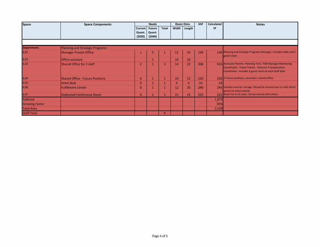
Current Quant.(2020)
FutureQuant.(2040)
Total Width LengthSpace Space Components Needs Room Dims GSF Calculated
SFNotes
Department: Planning and Strategic Programs 6.01 Manager Private Office 1 0 1 12 20 240 240 Planning and Strategic Programs Manager. Includes table and 4
guest chairs6.02 Office assistant 1 10 106.03 Shared Office for 2 staff 2 1 3 14 22 308 924 Associate Planner, Planning Tech, TDM Manager/Marketing
Coordinator, Travel Trainer, Veterans Transportation Coordinator. Includes 2 guest chairs at each staff desk
6.04 Shared Office ‐ Future Positions 0 1 1 10 22 220 220 2 Future positions, assumed 1 shared office
6.05 Hotel desk 0 1 1 4 6 24 24 6.06 Fulfillment Center 0 1 1 12 20 240 240 Includes area for storage. Should be located near or with direct
access to event vehicle6.07 Dedicated Conference Room 0 1 1 15 15 225 225 Room for 6‐15 seats. Can be shared with others
Subtotal 1,873 Grossing Factor 35%Total Area 2,529 Staff Total 9
Page 4 of 5
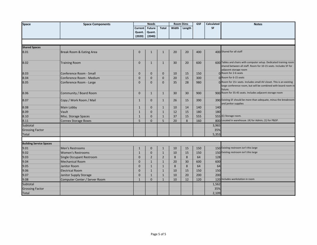
Current Quant.(2020)
FutureQuant.(2040)
Total Width LengthSpace Space Components Needs Room Dims GSF Calculated
SFNotes
Shared Spaces8.01 Break Room & Eating Area 0 1 1 20 20 400 400 Shared for all staff
8.02 Training Room 0 1 1 30 20 600 600 Tables and chairs with computer setup. Dedicated training room shared between all staff. Room for 10‐15 seats. Includes SF for adjacent storage room
8.03 Conference Room ‐ Small 0 0 0 10 15 150 0 Room for 2‐6 seats
8.04 Conference Room ‐ Medium 0 0 0 20 15 300 0 Room for 6‐15 seats
8.05 Conference Room ‐ Large 0 0 0 35 28 980 0 Room for 15+ seats. Includes small AV closet. This is an existing large conference room, but will be combined with board room in future.
8.06 Community / Board Room 0 1 1 30 30 900 900 Room for 35‐45 seats. Includes adjacent storage room
8.07 Copy / Work Room / Mail 1 0 1 26 15 390 390 Existing SF should be more than adequate, minus the breakroom and janitor supplies
8.08 Main Lobby 1 0 1 10 14 140 1408.09 Vault 1 0 1 12 15 180 1808.10 Misc. Storage Spaces 1 0 1 37 15 555 555 (E) Storage room.
8.11 Connex Storage Boxes 5 0 5 20 8 160 800 Located in warehouse. (4) for Admin, (1) for P&SP.
Subtotal 3,965 Grossing Factor 35%Total 5,353
Building Service Spaces9.01 Men's Restrooms 1 0 1 10 15 150 150 Existing restroom isn't this large
9.02 Women's Restrooms 1 0 1 10 15 150 150 Existing restroom isn't this large
9.03 Single Occupant Restroom 0 2 2 8 8 64 1289.04 Mechanical Room 0 1 1 20 30 600 6009.05 Janitor Room 0 1 1 8 8 64 649.06 Electrical Room 0 1 1 10 15 150 1509.07 Janitor Supply Storage 0 1 1 10 20 200 2009.08 Computer Center / Server Room 1 0 1 10 12 120 120 Includes workstation in room
Subtotal 1,562 Grossing Factor 35%Total 2,109
Page 5 of 5
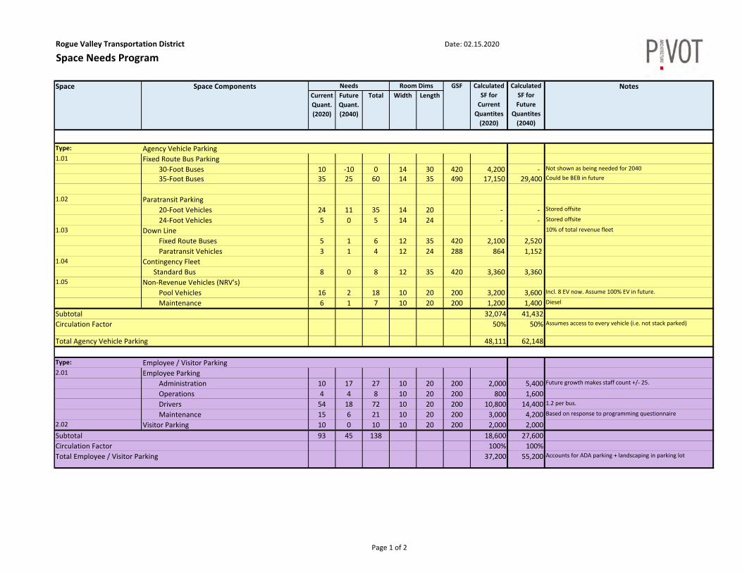
Rogue Valley Transportation District Date: 02.15.2020
Space Needs Program
Current Quant.(2020)
FutureQuant.(2040)
Total Width Length
Type: Agency Vehicle Parking1.01 Fixed Route Bus Parking
30‐Foot Buses 10 ‐10 0 14 30 420 4,200 ‐ Not shown as being needed for 2040 35‐Foot Buses 35 25 60 14 35 490 17,150 29,400 Could be BEB in future
1.02 Paratransit Parking 20‐Foot Vehicles 24 11 35 14 20 ‐ ‐ Stored offsite 24‐Foot Vehicles 5 0 5 14 24 ‐ ‐ Stored offsite
1.03 Down Line 10% of total revenue fleet
Fixed Route Buses 5 1 6 12 35 420 2,100 2,520 Paratransit Vehicles 3 1 4 12 24 288 864 1,152
1.04 Contingency FleetStandard Bus 8 0 8 12 35 420 3,360 3,360
1.05 Non‐Revenue Vehicles (NRV's) Pool Vehicles 16 2 18 10 20 200 3,200 3,600 Incl. 8 EV now. Assume 100% EV in future.
Maintenance 6 1 7 10 20 200 1,200 1,400 DieselSubtotal 32,074 41,432 Circulation Factor 50% 50% Assumes access to every vehicle (i.e. not stack parked)
Total Agency Vehicle Parking 48,111 62,148
Type: Employee / Visitor Parking2.01 Employee Parking
Administration 10 17 27 10 20 200 2,000 5,400 Future growth makes staff count +/‐ 25.
Operations 4 4 8 10 20 200 800 1,600 Drivers 54 18 72 10 20 200 10,800 14,400 1.2 per bus. Maintenance 15 6 21 10 20 200 3,000 4,200 Based on response to programming questionnaire
2.02 Visitor Parking 10 0 10 10 20 200 2,000 2,000 Subtotal 93 45 138 18,600 27,600 Circulation Factor 100% 100%Total Employee / Visitor Parking 37,200 55,200 Accounts for ADA parking + landscaping in parking lot
Space Space Components Needs Room Dims GSF NotesCalculated SF for Current Quantites (2020)
Calculated SF for Future
Quantites (2040)
Page 1 of 2
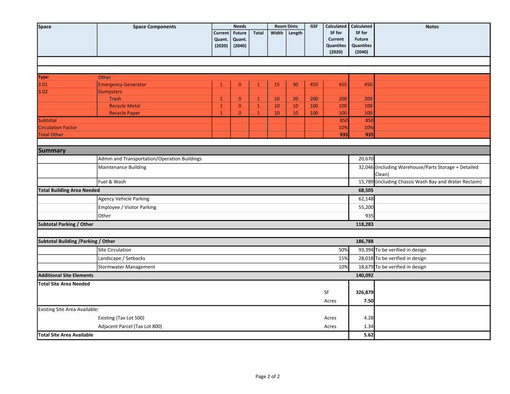
Current Quant.(2020)
FutureQuant.(2040)
Total Width LengthSpace Space Components Needs Room Dims GSF NotesCalculated
SF for Current Quantites (2020)
Calculated SF for Future
Quantites (2040)
Type: Other3.01 Emergency Generator 1 0 1 15 30 450 450 450 3.02 Dumpsters
Trash 1 0 1 10 20 200 200 200 Recycle Metal 1 0 1 10 10 100 100 100 Recycle Paper 1 0 1 10 10 100 100 100
Subtotal 850 850 Circulation Factor 10% 10%Total Other 935 935
SummaryAdmin and Transportation/Operation Buildings 20,670
Maintenance Building 32,046 (including Warehouse/Parts Storage + Detailed Clean)
Fuel & Wash 15,789 (including Chassis Wash Bay and Water Reclaim)
Total Building Area Needed 68,505
Agency Vehicle Parking 62,148
Employee / Visitor Parking 55,200
Other 935
Subtotal Parking / Other 118,283
Subtotal Building /Parking / Other 186,788
Site Circulation 50% 93,394 To be verified in design
Landscape / Setbacks 15% 28,018 To be verified in design
Stormwater Management 10% 18,679 To be verified in design
Additional Site Elements 140,092
Total Site Area Needed
SF 326,879
Acres 7.50
Existing Site Area Available:
Existing (Tax Lot 500) Acres 4.28
Adjacent Parcel (Tax Lot 800) Acres 1.34
Total Site Area Available 5.62
Page 2 of 2
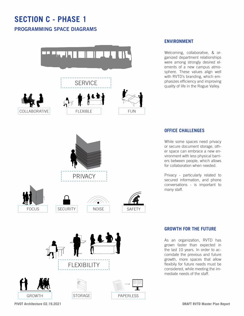
DRAFT RVTD Master Plan Report PIVOT Architecture 02.19.2021
Lorem ipsum dolor sit amet, consectetuer adipiscing elit, sed diam nonummy nibh euismod tincidunt ut laoreet
dolore magna aliquam erat volutpat. Ut wisi enim ad minim veniam, quis Lorem ipsum dolor sit amet, consectetuer
adipiscing elit, sed diam nonummy nibh euismod tincidunt ut laoreet dolore magna aliquam erat volutpat. Ut wisi
enim ad minim veniam, quis nostrud exerci tation ullamcorper suscipit lobortis nisl ut aliquip ex ea commodo
consequat. Duis autem vel eum iriure dolor in hendrerit in vulputate velit esse molestie consequat, vel illum dolore
eu feugiat nulla facilisis at vero eros et accumsan et iusto odio dignissim qui blandit praesent luptatum zzril delenit
augue duis dolore te feugait nulla facilisi.
Lorem ipsum dolor sit amet, cons ectetuer adipiscing elit, sed diam nonummy nibh euismod tincidunt ut laoreet
dolore magna aliquam erat volutpat. Ut wisi enim ad minim veniam, quis nostrud exerci tation ullamcorper suscipit
lobortis nisl ut aliquip ex ea commodo consequat.
Lorem ipsum dolor sit amet, consectetuer adipiscing elit, sed diam nonummy nibh euismod tincidunt ut laoreet
dolore magna aliquam erat volutpat. Ut wisi enim ad minim veniam, quis nostrud exerci tation ullamcorper suscipit
lobortis nisl ut aliquip ex ea commodo consequat. Duis autem vel eum iriure dolor in hendrerit in vulputate velit
esse molestie consequat, vel illum dolore eu feugiat nulla facilisis at vero eros et accumsan et iusto odio dignissim
qui blandit praesent luptatum zzril delenit augue duis dolore te feugait nulla facilisi.
Lorem ipsum dolor sit amet, cons ectetuer adipiscing elit, sed diam nonummy nibh euismod tincidunt ut laoreet
dolore magna aliquam erat volutpat. Ut wisi enim ad minim veniam, quis nostrud exerci tation ullamcorper suscipit
lobortis nisl ut aliquip ex ea commodo consequat.
Lorem ipsum dolor sit amet, consectetuer adipiscing elit, sed diam nonummy nibh euismod tincidunt ut laoreet
dolore magna aliquam erat volutpat. Ut wisi enim ad minim veniam, quis nostrud exerci tation ullamcorper suscipit
lobortis nisl ut aliquip ex ea commodo consequat. Duis autem vel eum iriure dolor in hendrerit in vulputate velit
Lorem ipsum dolor sit amet, consectetuer adipiscing elit, sed diam nonummy nibh euismod tincidunt ut laoreet dolore magna aliquam erat volutpat. Ut wisi enim ad minim veniam, quis nostrud exerci tation ullamcorper suscipit lobortis nisl ut aliquip ex ea commodo consequat. Duis autem vel eum iriure dolor in hendrerit in vulputate velit esse molestie consequat, vel illum dolore eu feugiat nulla facilisis at vero eros et accumsan et iusto odio dignissim qui blandit praesent luptatum zzril delenit augue duis dolore te feugait nulla facilisi.Lorem ipsum dolor sit amet, cons ectetuer adipiscing elit, sed diam nonummy nibh euismod tincidunt ut laoreet dolore magna aliquam erat volutpat. Ut wisi enim ad minim veniam, quis nostrud exerci tation ullamcorper suscipit lobortis nisl ut aliquip ex ea commodo consequat.Lorem ipsum dolor sit amet, consectetuer adipiscing elit, sed diam nonummy nibh euismod tincidunt ut laoreet dolore magna aliquam erat volutpat. Ut wisi enim ad minim veniam, quis nostrud exerci tation ullamcorper suscipit lobortis nisl ut aliquip ex ea commodo consequat. Duis autem vel eum iriure dolor in hendrerit in vulputate velit esse molestie consequat, vel illum dolore eu feugiat nulla facilisis at vero eros et accumsan et iusto odio dignissim qui blandit praesent luptatum zzril delenit augue duis dolore te feugait nulla facilisi.Lorem ipsum dolor sit amet, cons ectetuer adipiscing elit, sed diam nonummy nibh euismod tincidunt ut laoreet dolore magna aliquam erat volutpat. Ut wisi enim ad minim veniam, quis nostrud exerci tation ullamcorper suscipit lobortis nisl ut aliquip ex ea commodo consequat.Lorem ipsum dolor sit amet, consectetuer adipiscing elit, sed diam nonummy nibh euismod tincidunt ut laoreet dolore
Lorem ipsum dolor sit amet, consectetuer adipiscing elit, sed diam nonummy nibh euismod tincidunt ut laoreet dolore magna aliquam erat volutpat. Ut wisi enim ad minim veniam, quis nostrud exerci tation ullamcorper suscipit lobortis nisl ut aliquip ex ea commodo consequat. Duis autem vel eum iriure dolor in hendrerit in vulputate velit esse molestie consequat, vel illum dolore eu feugiat nulla facilisis at vero eros et accumsan et iusto odio dignissim qui blandit praesent luptatum zzril delenit augue duis dolore te feugait nulla facilisi.Lorem ipsum dolor sit amet, cons ectetuer adipiscing elit, sed diam nonummy nibh euismod tincidunt ut laoreet dolore magna aliquam erat volutpat. Ut wisi enim ad minim veniam, quis nostrud exerci tation ullamcorper suscipit lobortis nisl ut aliquip ex ea commodo consequat.Lorem ipsum dolor sit amet, consectetuer adipiscing elit, sed diam nonummy nibh euismod tincidunt ut laoreet dolore magna aliquam erat volutpat. Ut wisi enim ad minim veniam, quis nostrud exerci tation ullamcorper suscipit lobortis nisl ut aliquip ex ea commodo consequat. Duis autem vel eum iriure dolor in hendrerit in vulputate velit esse molestie consequat, vel illum dolore eu feugiat nulla facilisis at vero eros et accumsan et iusto odio dignissim qui blandit praesent luptatum zzril delenit augue duis dolore te feugait nulla facilisi.Lorem ipsum dolor sit amet, cons ectetuer adipiscing elit, sed diam nonummy nibh euismod tincidunt ut laoreet dolore magna aliquam erat volutpat. Ut wisi enim ad minim veniam, quis nostrud exerci tation ullamcorper suscipit lobortis nisl ut aliquip ex ea commodo consequat.Lorem ipsum dolor sit amet, consectetuer adipiscing elit, sed diam nonummy nibh euismod tincidunt ut laoreet dolore magna aliquam erat volutpat. Ut wisi enim ad minim veniam, quis nostrud exerci tation ullamcorper suscipit lobortis nisl ut aliquip ex ea commodo consequat. Duis autem vel eum iriure dolor in hendrerit in vulputate velit esse molestie consequat, vel illum dolore eu feugiat nulla facilisis
SERVICE
COLLABORATIVE FUNFLEXIBLE
FOCUS
PRIVACY
NOISESECURITY SAFETY
PAPERLESSSTORAGE
FLEXIBILITY
GROWTH
Welcoming, collaborative, & or-ganized department relationships were among strongly desired el-ements of a new campus atmo-sphere. These values align well with RVTD’s branding, which em-phasizes efficiency and improving quality of life in the Rogue Valley.
ENVIRONMENT
While some spaces need privacy or secure document storage, oth-er space can embrace a new en-vironment with less physical barri-ers between people, which allows for collaboration when needed.
Privacy - particularly related to secured information, and phone conversations - is important to many staff.
OFFICE CHALLENGES
As an organization, RVTD has grown faster than expected in the last 10 years. In order to ac-comdate the previous and future growth, more spaces that allow flexibily for future needs must be considered, while meeting the im-mediate needs of the staff.
GROWTH FOR THE FUTURE
SECTION C - PHASE 1PROGRAMMING SPACE DIAGRAMS
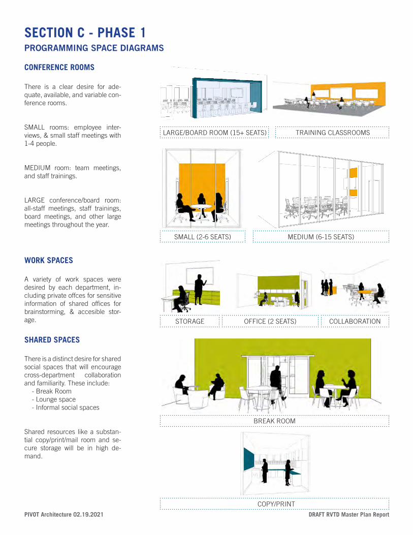
PIVOT Architecture 02.19.2021 DRAFT RVTD Master Plan Report
SMALL (2-6 SEATS) MEDIUM (6-15 SEATS)
LARGE/BOARD ROOM (15+ SEATS) TRAINING CLASSROOMS
OFFICE (2 SEATS)STORAGE COLLABORATION
BREAK ROOM
COPY/PRINT
There is a clear desire for ade-quate, available, and variable con-ference rooms.
SMALL rooms: employee inter-views, & small staff meetings with 1-4 people.
MEDIUM room: team meetings, and staff trainings.
LARGE conference/board room: all-staff meetings, staff trainings, board meetings, and other large meetings throughout the year.
CONFERENCE ROOMS
A variety of work spaces were desired by each department, in-cluding private offces for sensitive information of shared offices for brainstorming, & accesible stor-age.
WORK SPACES
There is a distinct desire for shared social spaces that will encourage cross-department collaboration and familiarity. These include: - Break Room - Lounge space - Informal social spaces
Shared resources like a substan-tial copy/print/mail room and se-cure storage will be in high de-mand.
SHARED SPACES
SECTION C - PHASE 1PROGRAMMING SPACE DIAGRAMS
PRELIMINARY PROJECT DESCRIPTION Project: Rogue Valley Transit District Master Plan (#2017) Date: January 5, 2021
Introduction The following is a preliminary project description of the building materials and systems envisioned for a new Admin & Operations building and associated site development for RVTD, for use in the preparation of early cost estimates. PIVOT Architecture provided the information, in consultation with design team members including ZCS Engineering (Civil and Structural engineering), Systems West Engineers (Mechanical, Plumbing, and Electrical engineering) and Cameron McCarthy (Landscape Architecture). The materials and systems described here represent probable levels of scope, effort, and quality for the project based on our assessment of preliminary goals and prior to more detailed design. The information is organized using CSI Uniformat. Uniformat describes building and site systems (rather than organizations by product as in CSI Masterformat). Assumed Construction start: Q2 2022 Assumed Design-Bid-Build construction contract with BOLI wage rates and other applicable public agency procurement laws
RVTD - PRELIMINARY PROJECT DESCRIPTION 01.05.2021
Page 2 of 15
Information about the site and each of the building structure is provided below based on assumptions developed in the early design stages. The format is loosely based on CSI Uniformat, commonly referred to as the Outline Specifications. Building: Administration and Operations Building Code Summary
- Construction Type: Type V-B, non-separated
- Fire Sprinklered
- Number of Stories: Two stories
- Building Areas:
- Seismic Design Risk Category: Type II for administration & operations building. Type IV for Fuel Station (may be lowered with Risk Management Plan and local jurisdiction approval)
- First floor to second floor height: 14’
- Second floor to exterior wall top plate height: 12’ (assume a pitched roof)
A. Substructure A10. Foundations
1. Concrete 1. 3,500 psi
2. Excavation 1. Over excavate minimum 6” past bottom of footing for minimum 6” of structural fill.
3. Grading 1. Perform grading in the dry summer months
2. Slope subgrade as required to eliminate standing water during earthwork procedures.
4. Fills 1. Material:
2. Compaction: 95 percent of maximum dry density
3. Maximum lifts: 8 inches
5. Strip Footings 1. Dimensions: 36” wide x 15” deep x length of exterior walls
2. Reinforcing:
3. Extent: Provide at all exterior walls
6. Spread Footings 1. Dimensions: 48” square x 24” deep
2. Reinforcing:
3. Extent: Provide at all column locations
7. Slab on Grade 1. Thickness: 6”
2. Reinforcing:
3. Finish: Assume slab will be covered with flooring materials
4. Slope: Slope to drain at rest rooms. Level all other locations

RVTD - PRELIMINARY PROJECT DESCRIPTION 01.05.2021
Page 3 of 15
5. Provide Underslab Vapor Barrier; 15 mil thickness, directly over subgrade.
8. Perimeter foundation drain 1. Slope to drain. Civil to pick-up.
9. Elevator pit 1. Bentonite water-proofing, lighting, access ladder, sump.
B. Shell B10. Superstructure
1. Columns 1. Wideflange or HSS columns at primary grid lines
2. Load Bearing Walls 1. Structure: wood stud between steel columns
2. Sheathing: exterior plywood
3. Floors 1. 1st floor
a. Structure: Concrete slab – see above
2. 2nd floor
a. Structure: Glu-lam beams with open web wood truss purlins
b. Sheathing: T&G plywood
4. Roof: 1. Structure: Glu-lam beams with open web wood truss purlins
2. Sheathing: 2 ½” metal decking, acoustical type – Epic dovetail style. (Or wood T&G decking)
B20. Exterior Closure 1. Walls
1. Structure: Light wood framing
2. Sheathing: Plywood
3. Insulation: R-21 batt insulation at studs, 1 ½” continuous rigid insulation
4. Weather barrier: Liquid applied
5. Flashing: as needed
6. Exterior Finish:
a. Assume brick veneer for 70% of building
b. Assume concealed fastener metal panel system, for 30% of building
7. Interior Finish: 5/8” gypsum board
2. Windows 1. Glazing: Standard high-performance glazing, minimal tinting
2. Frame System: Aluminum storefront
3. Window operation: 50% operable, 50% fixed
3. Doors 1. Door: Aluminum storefront
RVTD - PRELIMINARY PROJECT DESCRIPTION 01.05.2021
Page 4 of 15
2. Door Frame: Aluminum storefront
3. Door Hardware: High-quality commercial hardware
4. Glazing: Full-lite
5. Access Control: Provide at all exterior doors (assume 4)
4. Skylight 1. Assume standard-sized unit skylights with standard commercially rated insulation. Non-
operable.
2. Assume up to 8 unit skylights
5. Sunshade 1. Frame/structure: Aluminum assembly by storefront manufacturer
2. Extent: Windows on south side of building
3. Finish: Matching Aluminum Storefront system
B30. Roofing 1. Roofing: Standing-Seam metal roofing
2. Slope: Assume 2:12 minimum, 5:12 maximum
3. Insulation: Rigid insulation, R-39 above roof structure
4. Drainage: Water directed to perimeter gutters and downspouts
C. Interiors C10. Interior Construction
1. Interior frame partitions: 1. Frame/structure: Light wood framing
2. Acoustical control: Extend walls to structure, and acoustical insulation at all offices, conference rooms, and meeting rooms.
3. Finish: See "Interior Finishes" below.
2. Interior Doors: 1. Door: Wood
2. Door Frame: Hollow Metal
3. Door Hardware: High-quality commercial hardware
4. Glazing: assume half-lite glazing at 50% of interior doors
5. Access Control: none
3. Casework 1. Cabinet: Plastic laminate
2. Counters: Solid surface
4. Interior Specialities – Toilet Rooms 1. Restroom accessories: standard components
2. Toilet partitions: solid phenolic partitions
3. Shower enclosure: tiled enclosures, glass doors (assume 6 showers)
5. Interior Specialties - Misc 1. Fire extinguishers and cabinets: Provide fire extinguisher and cabinet for every 3,000 sf

RVTD - PRELIMINARY PROJECT DESCRIPTION 01.05.2021
Page 5 of 15
2. Marker boards: Provide 4 ft x 12 ft at all conference rooms and meeting rooms
3. Tack boards: Provide 4 ft x 6 ft at all conference rooms and meeting rooms. Provide 4 ft x 12 ft at all Break Rooms and Copy Rooms
C20. Stairways 1. Open Stair(s) – assume 2:
1. Treads: tbd
2. Railings: Steel frame with cable infill
3. Railing Cap: wood
4. Handrail: wood
5. Support: steel stringer
C30. Interior Finishes - tbd 1. Floors
1. Porcelain tile: -- a. Location(s): -
2. Linoleum: -- a. Location(s): -
3. Rubber Tile: - a. Location(s): -
4. Carpet Tile: a. Location(s): -
5. Base: - a. Location(s): -
2. Walls 1. Material: Gypsum board
2. Finish: standard
3. Ceilings 1. Offices and Conference rooms
a. Ceiling material: Acoustic Ceiling
b. Ceiling support: Support ceiling grid from structure; provide seismic support/bracing per building code.
2. Operators report, break rooms: Open to structure with suspended acoustical ceiling clouds
4. Trim 1. Material: Birch 1x base, chair rail, and window sills at conference rooms.
5. Showers 1. Walls: porcelain tile
2. Floor: porcelain tile
D. Services D10. Conveying Systems
1. Elevator – assume 1 elevator, code required size to fit emergency responder gurney and other Code requirements
RVTD - PRELIMINARY PROJECT DESCRIPTION 01.05.2021
Page 6 of 15
1. Operation: -
2. Cab Size: -
3. Finishes: -
D20. Plumbing Systems
1. Sanitary: 1. Material: Cast iron,
All sanitary waste, storm water, and underground vent piping shall be the following:
1. Hubless, cast-iron soil pipe and fittings; CISPI hubless-piping couplings; and coupled joints.
Aboveground, vent piping shall be[ any of] the following:
1. Galvanized-steel pipe, drainage fittings, and threaded joints.
2. Solid-wall ABS pipe, ABS socket fittings, and solvent-cemented joints.
3. Solid-wall PVC pipe, PVC socket fittings, and solvent-cemented joints.
4. Dissimilar Pipe-Material Couplings: Unshielded, Non-pressure transition couplings.
2. Floor Drains: - Finished floor - Josam Series 30000-S coated cast-iron floor drain. Two-piece body with double drainage flange. Invertible non-puncturing flashing collar, weepholes, bottom outlet and adjustable satin Nikaloy 5-inch round strainer. Primer tapping.
Provide floor drains in restrooms and Janitors closet.
3. Water heating 1. Heat Source: Heat Source: - An electric storage tank-type water heater will be provided
to serve restroom lavatories, mop sink and kitchen sink in the new admin building.
2. Capacity: -40 gallon
4. Fixtures: 1. Urinals: Wall-mounted porcelain, waterless.
2. Water Closets: Wall-mounted porcelain
3. Lavatories: Counter supported at break room
4. Janitors Sink: floor mounted stainless steel
5. Hose bibs: 3/4" 1. Location(s)/quantity: - 4 hose bibbs one on each corner of the building.
6. Roof drains 1. J.R. Smith Fig. 1010 coated cast-iron roof drain, large polypropylene locking dome,
underdeck clamp ring, gravel stop, large sump with wide roof flange sump receiver and bottom outlet.
D30. HVAC Systems
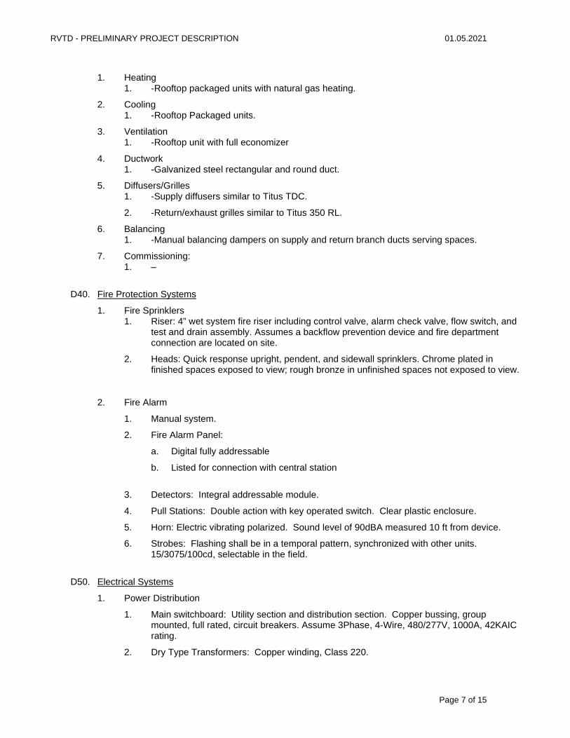
RVTD - PRELIMINARY PROJECT DESCRIPTION 01.05.2021
Page 7 of 15
1. Heating 1. -Rooftop packaged units with natural gas heating.
2. Cooling 1. -Rooftop Packaged units.
3. Ventilation 1. -Rooftop unit with full economizer
4. Ductwork 1. -Galvanized steel rectangular and round duct.
5. Diffusers/Grilles 1. -Supply diffusers similar to Titus TDC.
2. -Return/exhaust grilles similar to Titus 350 RL.
6. Balancing 1. -Manual balancing dampers on supply and return branch ducts serving spaces.
7. Commissioning: 1. –
D40. Fire Protection Systems
1. Fire Sprinklers 1. Riser: 4” wet system fire riser including control valve, alarm check valve, flow switch, and
test and drain assembly. Assumes a backflow prevention device and fire department connection are located on site.
2. Heads: Quick response upright, pendent, and sidewall sprinklers. Chrome plated in finished spaces exposed to view; rough bronze in unfinished spaces not exposed to view.
2. Fire Alarm
1. Manual system.
2. Fire Alarm Panel:
a. Digital fully addressable
b. Listed for connection with central station
3. Detectors: Integral addressable module.
4. Pull Stations: Double action with key operated switch. Clear plastic enclosure.
5. Horn: Electric vibrating polarized. Sound level of 90dBA measured 10 ft from device.
6. Strobes: Flashing shall be in a temporal pattern, synchronized with other units. 15/3075/100cd, selectable in the field.
D50. Electrical Systems
1. Power Distribution
1. Main switchboard: Utility section and distribution section. Copper bussing, group mounted, full rated, circuit breakers. Assume 3Phase, 4-Wire, 480/277V, 1000A, 42KAIC rating.
2. Dry Type Transformers: Copper winding, Class 220.
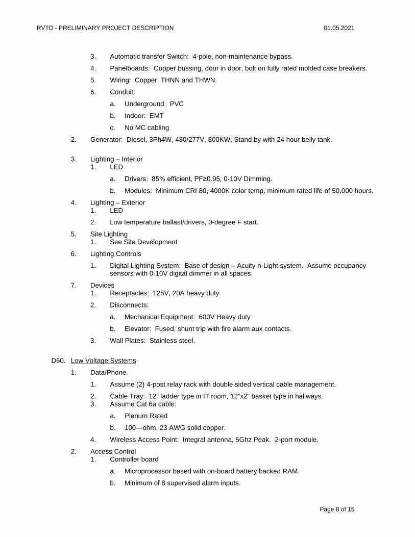
RVTD - PRELIMINARY PROJECT DESCRIPTION 01.05.2021
Page 8 of 15
3. Automatic transfer Switch: 4-pole, non-maintenance bypass.
4. Panelboards: Copper bussing, door in door, bolt on fully rated molded case breakers.
5. Wiring: Copper, THNN and THWN.
6. Conduit:
a. Underground: PVC
b. Indoor: EMT
c. No MC cabling
2. Generator: Diesel, 3Ph4W, 480/277V, 800KW, Stand by with 24 hour belly tank.
3. Lighting – Interior 1. LED
a. Drivers: 85% efficient, PF≥0.95, 0-10V Dimming.
b. Modules: Minimum CRI 80, 4000K color temp, minimum rated life of 50,000 hours.
4. Lighting – Exterior 1. LED
2. Low temperature ballast/drivers, 0-degree F start.
5. Site Lighting 1. See Site Development
6. Lighting Controls
1. Digital Lighting System: Base of design – Acuity n-Light system. Assume occupancy sensors with 0-10V digital dimmer in all spaces.
7. Devices 1. Receptacles: 125V, 20A heavy duty.
2. Disconnects:
a. Mechanical Equipment: 600V Heavy duty
b. Elevator: Fused, shunt trip with fire alarm aux contacts.
3. Wall Plates: Stainless steel.
D60. Low Voltage Systems
1. Data/Phone.
1. Assume (2) 4-post relay rack with double sided vertical cable management.
2. Cable Tray: 12” ladder type in IT room, 12”x2” basket type in hallways. 3. Assume Cat 6a cable:
a. Plenum Rated
b. 100—ohm, 23 AWG solid copper.
4. Wireless Access Point: Integral antenna, 5Ghz Peak. 2-port module.
2. Access Control 1. Controller board
a. Microprocessor based with on-board battery backed RAM.
b. Minimum of 8 supervised alarm inputs.
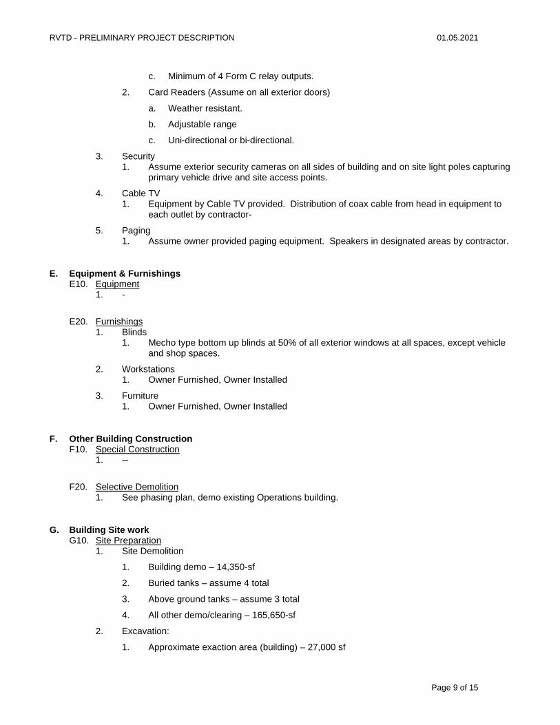
RVTD - PRELIMINARY PROJECT DESCRIPTION 01.05.2021
Page 9 of 15
c. Minimum of 4 Form C relay outputs.
2. Card Readers (Assume on all exterior doors)
a. Weather resistant.
b. Adjustable range
c. Uni-directional or bi-directional.
3. Security 1. Assume exterior security cameras on all sides of building and on site light poles capturing
primary vehicle drive and site access points.
4. Cable TV 1. Equipment by Cable TV provided. Distribution of coax cable from head in equipment to
each outlet by contractor-
5. Paging 1. Assume owner provided paging equipment. Speakers in designated areas by contractor.
E. Equipment & Furnishings E10. Equipment
1. -
E20. Furnishings 1. Blinds
1. Mecho type bottom up blinds at 50% of all exterior windows at all spaces, except vehicle and shop spaces.
2. Workstations 1. Owner Furnished, Owner Installed
3. Furniture 1. Owner Furnished, Owner Installed
F. Other Building Construction F10. Special Construction
1. --
F20. Selective Demolition 1. See phasing plan, demo existing Operations building.
G. Building Site work G10. Site Preparation
1. Site Demolition
1. Building demo – 14,350-sf
2. Buried tanks – assume 4 total
3. Above ground tanks – assume 3 total
4. All other demo/clearing – 165,650-sf
2. Excavation:
1. Approximate exaction area (building) – 27,000 sf
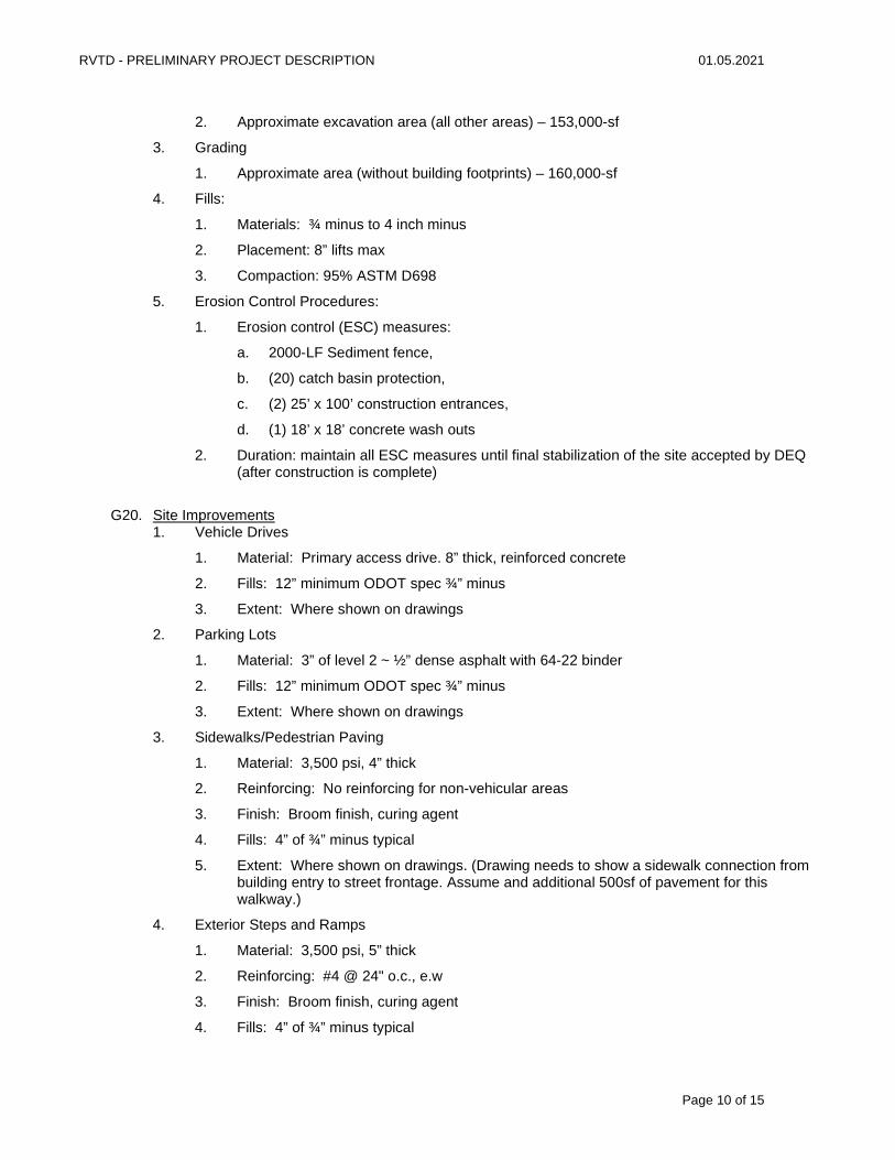
RVTD - PRELIMINARY PROJECT DESCRIPTION 01.05.2021
Page 10 of 15
2. Approximate excavation area (all other areas) – 153,000-sf
3. Grading
1. Approximate area (without building footprints) – 160,000-sf
4. Fills:
1. Materials: ¾ minus to 4 inch minus
2. Placement: 8” lifts max
3. Compaction: 95% ASTM D698
5. Erosion Control Procedures:
1. Erosion control (ESC) measures:
a. 2000-LF Sediment fence,
b. (20) catch basin protection,
c. (2) 25’ x 100’ construction entrances,
d. (1) 18’ x 18’ concrete wash outs
2. Duration: maintain all ESC measures until final stabilization of the site accepted by DEQ (after construction is complete)
G20. Site Improvements 1. Vehicle Drives
1. Material: Primary access drive. 8” thick, reinforced concrete
2. Fills: 12” minimum ODOT spec ¾” minus
3. Extent: Where shown on drawings
2. Parking Lots
1. Material: 3” of level 2 ~ ½” dense asphalt with 64-22 binder
2. Fills: 12” minimum ODOT spec ¾” minus
3. Extent: Where shown on drawings
3. Sidewalks/Pedestrian Paving
1. Material: 3,500 psi, 4” thick
2. Reinforcing: No reinforcing for non-vehicular areas
3. Finish: Broom finish, curing agent
4. Fills: 4” of ¾” minus typical
5. Extent: Where shown on drawings. (Drawing needs to show a sidewalk connection from building entry to street frontage. Assume and additional 500sf of pavement for this walkway.)
4. Exterior Steps and Ramps
1. Material: 3,500 psi, 5” thick
2. Reinforcing: #4 @ 24" o.c., e.w
3. Finish: Broom finish, curing agent
4. Fills: 4” of ¾” minus typical
RVTD - PRELIMINARY PROJECT DESCRIPTION 01.05.2021
Page 11 of 15
5. Extent: Where shown on the drawings
5. Site Markings
1. Painted parking lot striping and markings
G30. Site Development 1. Fences and Gates
1. Gates:
a. Material: same as fence
b. Height: same as fence
c. Operation: Motorized cantilever
d. Quantity: two
2. Fence:
a. Material: Vinyl coated chain link
b. Height: 7 feet
c. Extent: As shown on the drawings
2. Retaining Walls 1. Foundation: 12” deep by 5 ft wide.
2. Materials:
a. Under 4’ – unreinforced stack block walls (8” x 16” units)
b. Over 4’ – reinforced stack block walls or cast-in-place concrete
c. 4,000 psi concrete
3. Thickness: Varies, 6” minimum, 8” typical
4. Reinforcing
a. #4 and/or #5 at 12” – 18” o.c., e.w.
5. Waterproofing: Sheet bentonite waterproofing, protection board, drainage
Retaining wall at stormwater planters will be an 8” pcc wall with reinforcement, 12” height above finish grade of planter soil, curb height at adjacent surfaces, and 18” minimum below grade to top of footing. Planting soil description below
3. Trash Enclosures 1. Foundation: Concrete; 8 inch slab on grade with 16 inch thickened edge.
2. Structure: HSS columns and roof structure with metal roofing. 7'-4" CMU walls on three sides, chain link fence with slats on open end.
a. 8” x 16” units (i.e. 8” thick walls)
3. Size: approximately 10 ft x 12 ft
4. Pavement: 6” thick reinforced concrete with turndown edge
5. Roofing: Standing seam metal, free spanning.
RVTD - PRELIMINARY PROJECT DESCRIPTION 01.05.2021
Page 12 of 15
4. Bike Enclosures – same as trash enclosure 1. Foundation:
2. Structure:
3. Pavement:
4. Roofing:
5. Site Lighting: 1. Pole/fixture: 20 ft high pole mounted LED luminaires
2. Base: 6’ deep, 24” dia. with standard reinforcing base
G40. Site Amenities 1. Site Furnishings
1. Benches: 6 ft metal bench, galvanized and painted (2)
2. Trash Receptacles: 6 ft metal bench, galvanized and painted (2)
2. Bike Racks 1. Style: Single loop, stainless steel
2. Extent/Quantity: Assume 8
3. Exterior Signs 1. Monument Sign: Assume one, CMU base, 4 ft high by 12 ft wide; raised metal letters
(assume 30); base lighting.
2. Directional Sign(s): Assume 24 standard metal signs on 7 ft pole.
4. Flag Poles 1. Height: 30 ft for American flag, and 25 ft for Oregon flag.
2. Foundation: 3 ft by 5 ft by 3 ft
3. Operation: Internal halyard
4. Lighting: Ground lighting
5. Quantity: Two; (1) for American flag, and one for Oregon flag.
G50. Site Utilities 1. Storm Sewer System
1. Piping/Conveyance:
a. ‘HDPE’ pipe, 6” to 18” diameter, 12” typical
b. ‘PVC’ pipe within 5’ of buildings, 6” diameter typical
c. Perforated ‘PVC’ for foundation drains and underlying swales, 6” diameter typical
d. Cleanout risers (6” diameter typical), spaced every 100’ max. along pipe runs and at the upstream end of each pipe
2. Collection:
a. Vehicular areas: 24” square pre-cast concrete catch basins with H-20 load rated grates, equipped with hood & trap

RVTD - PRELIMINARY PROJECT DESCRIPTION 01.05.2021
Page 13 of 15
b. Landscape areas: 18” diameter nyloplast area drains with atrium grates, equipped with hood & trap
c. At fueling station: 4” wide heavy duty trench drain (assume ‘NDS’ duraslope) with heavy duty steel grates
d. Oil/water separator: assume ‘Oldcastle’ pre-cast concrete 1,000 gal, model 576-SA-1000
e. No flow through area drains in system
3. Extent: Where shown on drawings
2. Storm Water management 1. At grade option:
a. Primary treatment/detention: filtration swale/pond, assume 15’ width, assume 100’ length, 2’ depth, 3” topping, 18” amended soil media, 12” round drain rock <4”, unlined
b. Preliminary treatment/conveyance: parking lot bioswales, 8’ wide, 12” deep, 12” amended soil media, 12” round drain rock <4”, unlined
2. Below grade option:
a. ‘Stormtech’ model SC-740 arched chambers, 12” stone encasement, all sides, fully lined, assume treatment with proprietary ‘isolation’ row (assume 2200 sf, 1/3 of which is isolation treatment row)
3. Extent: not shown on drawings, refer to areas listed herein
3. Sanitary Sewer 1. Schedule 40 ‘PVC’ piping; 6” typical
2. Cleanout risers (6” diameter typical), spaced every 100’ max. along pipe runs and at the upstream end of each pipe
3. Manholes – pre-cast 48” diameter concrete manholes at an average depth of 6 to 7 feet, assume 5 total
4. Extent: Where shown on the drawings
4. Domestic Water 1. Piping
a. Schedule 40 pressure rated ‘PVC’ piping; 2” typical for standard services
2. Approved backflow prevention assembly (approved by OHA, MWC, sized to match domestic service)
3. 36” cover, typical (30” minimum)
4. Extent: Where shown on the drawings
5. Fire Suppression Water 1. Hydrants:
a. Mueller ‘Super Centurion’ hydrant or similar (as approved by MWC)
2. Fire suppression supply:
a. Public (assume on-site fire hydrants served by public lines): Class 54 ‘DIP’, assume 8” diameter
b. Private (service between fire vault and building): Class 150 ‘DR-18 C900’ pipe, assume 6” diameter
RVTD - PRELIMINARY PROJECT DESCRIPTION 01.05.2021
Page 14 of 15
3. Extent: Where shown on the drawings
6. Power 1. Schedule 40 ‘PVC’ conduit, 4” diameter typical
2. Extent: Where shown on the drawings
7. Gas 1. ASTM D2513 polyethylene piping, 1” diameter
2. Extent: Where shown on the drawings
8. Phone 1. Schedule 40 ‘PVC’ conduit, 4” diameter typical
2. Extent: Where shown on the drawings
9. Cable
1. Schedule 40 ‘PVC’ conduit, 4” diameter typical
2. Extent: Where shown on the drawings
10. Data/Fiber 1. Schedule 40 ‘PVC’ conduit, 4” diameter typical
2. Extent: Where shown on the drawings
11. Power Generator 1. Per electrical (outside of ZCS scope and knowledge)
G60. Landscaping and Irrigation 1. Soil Prep
1. 18” imported loam at plant beds and stormwater planters, 9” imported loam at lawns. 3” mulch, typical.
2. Imported soil shall be amended on-site with select fertilizer, compost and other organics.
2. Irrigation 1. Supply: 2” BFP in underground vault, stubbed off of potable service to new building or
fire. Master valve and flow sensor downstream of irrigation BFP.
2. Controls: All new irrigation shall be 2-wire with decoders. Controller shall be commercial rated smart technology connected to ethernet and allow for both 2-wire and conventional wire conversion. Assume wall mounted within building. Baseline’s BaseStation 3200 may be used as an example for pricing.
3. Zones: Industrial strength globe valve with electric solenoid powered control and pressure regulating device. Assume 10 zones at new site with 50 zone minimum capacity.
4. Piping: Sch40 mainline and lateral line. Mainline will loop full perimeter of improvement area. Sch40 sleeves under pavement, two at each location.
5. Heads: All heads shall be pop-up on swing riser with stream rotary nozzles or subsurface drip line. Drip lines shall have (1) 4” indicator pop-up micro-spray nozzle per zone. All rotary heads shall be pressure regulating at the body. Stormwater Planters will be rotary heads, other plant bed may be drip irrigation. Drip rings at all new tree plantings (20).
6. Provide allowance for trenching on existing site to connect existing irrigation to remain to the new controller.
3. Planting
RVTD - PRELIMINARY PROJECT DESCRIPTION 01.05.2021
Page 15 of 15
1. Lawn: Hot and cool season blend from Pickseed or Sunmark. Seeded with top dressing or hydroseeded (no top dressing). I think we only have plant bed identified on plan, but good to have in case we add it.
2. Shrubs:
a. Parking Lot Screening and at building: Mix of 24” to 36” tall shrubs, ornamental grasses, and groundcoveres. All hardy to southern Oregon, requiring minimal watering and maintenance. Assume a 24-36” on-center spacing, 1-gallon minimum size.
b. Stormwater Planters: Native grasses, sedges, rushes, and groundcover per local stormwater management manual recommendations and required quantities. Assume a 12” on-center spacing, 1-gallon minimium size.
3. Trees: 2” Caliper or larger deciduous, or 8’ height coniferous. Assume deciduous trees spaced 30-ft on-center along frontage and sideyard lot lines. Assume no trees in stormwater planters or within 10-ft of driveway aprons. Assume each parking lot island or plant bed has at least one tree. Total quantity: 20 trees minimum.
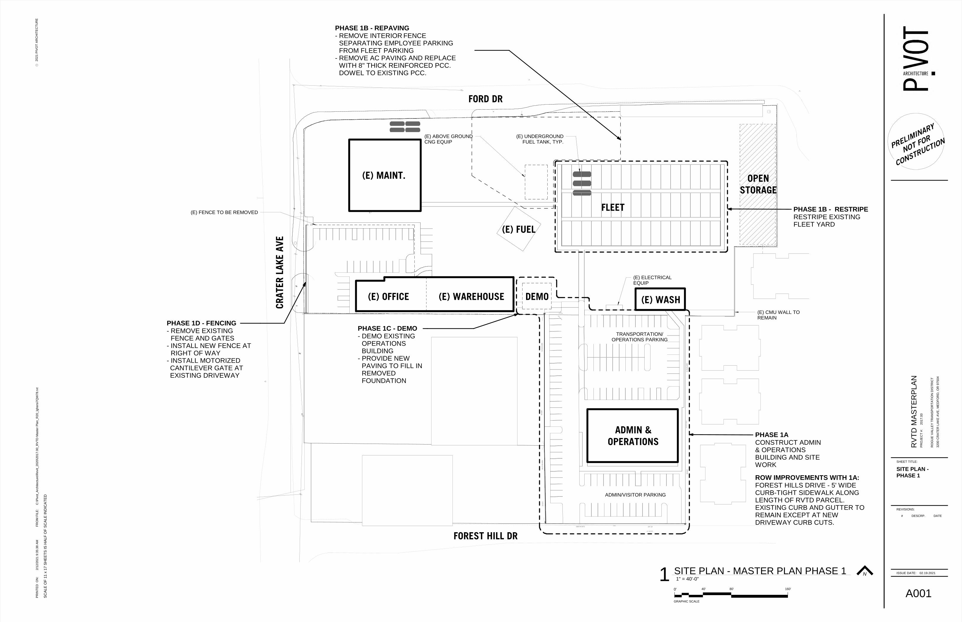
10" WATER
197.10S89°54'34"E
29
4.5
8S
00°0
4'5
1"E
18
5.0
0S
00°0
4'5
1"E
11
0.5
1N
00°5
0' 1
3"W
BL
OC
K W
AL
L
C&G
1340.15 IE
12"CCP
T
TRANSPORTATION/ OPERATIONS PARKING
ADMIN/VISITOR PARKING
(E) FUEL
FLEET
OPEN STORAGE
(E) MAINT.
(E) WAREHOUSE
ADMIN &OPERATIONS
(E) OFFICE (E) WASHDEMO
FOREST HILL DR
CRAT
ER L
AKE
AVE
FORD DR
(E) FENCE TO BE REMOVED
(E) ABOVE GROUND CNG EQUIP
(E) UNDERGROUND FUEL TANK, TYP.
(E) ELECTRICAL EQUIP
PHASE 1ACONSTRUCT ADMIN & OPERATIONS BUILDING AND SITE WORK
(E) CMU WALL TO REMAIN
PHASE 1B - RESTRIPERESTRIPE EXISTING FLEET YARD
PHASE 1C - DEMO - DEMO EXISTING
OPERATIONS BUILDING
- PROVIDE NEW PAVING TO FILL IN REMOVED FOUNDATION
PHASE 1D - FENCING- REMOVE EXISTING
FENCE AND GATES- INSTALL NEW FENCE AT
RIGHT OF WAY- INSTALL MOTORIZED CANTILEVER GATE AT EXISTING DRIVEWAY
PHASE 1B - REPAVING- REMOVE INTERIOR FENCE
SEPARATING EMPLOYEE PARKINGFROM FLEET PARKING
- REMOVE AC PAVING AND REPLACEWITH 8" THICK REINFORCED PCC.DOWEL TO EXISTING PCC.
ROW IMPROVEMENTS WITH 1A:FOREST HILLS DRIVE - 5' WIDE CURB-TIGHT SIDEWALK ALONG LENGTH OF RVTD PARCEL. EXISTING CURB AND GUTTER TO REMAIN EXCEPT AT NEW DRIVEWAY CURB CUTS.
PRELIMINARY
NOT FOR
CONSTRUCTION
REVISIONS:
PR
INT
ED
O
N:
20
21
PIV
OT
AR
CH
ITE
CT
UR
EF
RO
M F
ILE
:C
SC
ALE
OF
11 x
17 S
HE
ET
S IS
HA
LF
OF
SC
ALE
IN
DIC
AT
ED
ISSUE DATE:
SHEET TITLE:
PR
OJE
CT
#:
2/1
2/2
021 9
:35:3
8 A
MC
:\P
ivot_
Arc
hitectu
re\R
evit_2020\2
017.0
0_R
VT
D M
aste
r P
lan_R
20_lg
hers
i7Q
W78.r
vt
A001
02.19.2021
SITE PLAN -PHASE 1
RO
GU
E V
AL
LE
Y T
RA
NS
PO
RT
AT
ION
DIS
TR
ICT
RV
TD
MA
ST
ER
PLA
N
32
00
CR
AT
ER
LA
KE
AV
E,
ME
DF
OR
D,
OR
97
50
4
20
17
.00
N
0' 80' 160'40'
GRAPHIC SCALE
1" = 40'-0"1 SITE PLAN - MASTER PLAN PHASE 1
# DESCRP. DATE
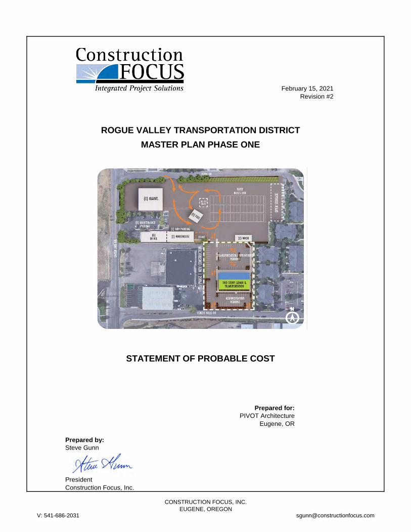
February 15, 2021
Revision #2
ROGUE VALLEY TRANSPORTATION DISTRICT
MASTER PLAN PHASE ONE
STATEMENT OF PROBABLE COST
Prepared for:
PIVOT Architecture
Eugene, OR
Prepared by:
Steve Gunn
President
Construction Focus, Inc.
V: 541-686-2031
CONSTRUCTION FOCUS, INC.
EUGENE, [email protected]
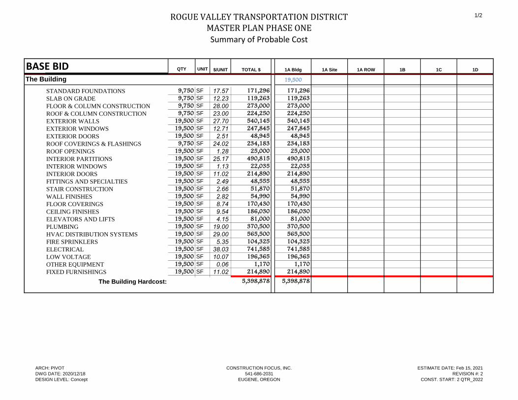
ROGUE VALLEY TRANSPORTATION DISTRICTMASTER PLAN PHASE ONE
Summary of Probable Cost
1/2
BASE BID QTY UNIT $/UNIT TOTAL $ 1A Bldg 1A Site 1A ROW 1B 1C 1D
The Building 19,500 SF 19,500
STANDARD FOUNDATIONS 9,750 SF 17.57 171,296 171,296
SLAB ON GRADE 9,750 SF 12.23 119,263 119,263
FLOOR & COLUMN CONSTRUCTION 9,750 SF 28.00 273,000 273,000
ROOF & COLUMN CONSTRUCTION 9,750 SF 23.00 224,250 224,250
EXTERIOR WALLS 19,500 SF 27.70 540,145 540,145
EXTERIOR WINDOWS 19,500 SF 12.71 247,845 247,845
EXTERIOR DOORS 19,500 SF 2.51 48,945 48,945
ROOF COVERINGS & FLASHINGS 9,750 SF 24.02 234,183 234,183
ROOF OPENINGS 19,500 SF 1.28 25,000 25,000
INTERIOR PARTITIONS 19,500 SF 25.17 490,815 490,815
INTERIOR WINDOWS 19,500 SF 1.13 22,035 22,035
INTERIOR DOORS 19,500 SF 11.02 214,890 214,890
FITTINGS AND SPECIALTIES 19,500 SF 2.49 48,555 48,555
STAIR CONSTRUCTION 19,500 SF 2.66 51,870 51,870
WALL FINISHES 19,500 SF 2.82 54,990 54,990
FLOOR COVERINGS 19,500 SF 8.74 170,430 170,430
CEILING FINISHES 19,500 SF 9.54 186,030 186,030
ELEVATORS AND LIFTS 19,500 SF 4.15 81,000 81,000
PLUMBING 19,500 SF 19.00 370,500 370,500
HVAC DISTRIBUTION SYSTEMS 19,500 SF 29.00 565,500 565,500
FIRE SPRINKLERS 19,500 SF 5.35 104,325 104,325
ELECTRICAL 19,500 SF 38.03 741,585 741,585
LOW VOLTAGE 19,500 SF 10.07 196,365 196,365
OTHER EQUIPMENT 19,500 SF 0.06 1,170 1,170
FIXED FURNISHINGS 19,500 SF 11.02 214,890 214,890
The Building Hardcost: 5,398,878 5,398,878
ARCH: PIVOT
DWG DATE: 2020/12/18
DESIGN LEVEL: Concept
CONSTRUCTION FOCUS, INC.
541-686-2031
EUGENE, OREGON
ESTIMATE DATE: Feb 15, 2021
REVISION #: 2
CONST. START: 2 QTR_2022
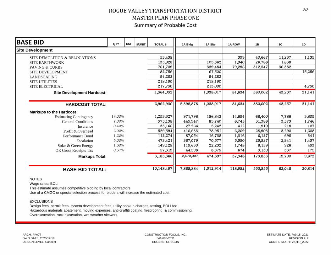
ROGUE VALLEY TRANSPORTATION DISTRICTMASTER PLAN PHASE ONE
Summary of Probable Cost
2/2
BASE BID QTY UNIT $/UNIT TOTAL $ 1A Bldg 1A Site 1A ROW 1B 1C 1D
Site Development
SITE DEMOLITION & RELOCATIONS 53,438 399 40,667 11,237 1,135
SITE EARTHWORK 135,928 105,562 1,940 26,788 1,638
PAVING & CURBS 761,709 339,484 79,296 312,547 30,382
SITE DEVELOPMENT 82,756 67,500 15,256
LANDSCAPING 94,282 94,282
SITE UTILITIES 218,190 218,190
SITE ELECTRICAL 217,750 213,000 4,750
Site Development Hardcost: 1,564,052 1,038,017 81,634 380,002 43,257 21,141
HARDCOST TOTAL: 6,962,930 5,398,878 1,038,017 81,634 380,002 43,257 21,141
Markups to the Hardcost
Estimating Contingency 18.00% 1,253,327 971,798 186,843 14,694 68,400 7,786 3,805
General Conditions 7.00% 575,138 445,947 85,740 6,743 31,388 3,573 1,746
Insurance 0.40% 35,166 27,266 5,242 412 1,919 218 107
Profit & Overhead 6.00% 529,594 410,633 78,951 6,209 28,903 3,290 1,608
Performance Bond 1.20% 112,274 87,054 16,738 1,316 6,127 698 341
Escalation 5.00% 473,421 367,079 70,577 5,550 25,837 2,941 1,437
Solar & Green Energy 1.50% 149,128 115,630 22,232 1,748 8,139 926 453
OR Gross Receipts Tax 0.57% 57,519 44,598 8,575 674 3,139 357 175
Markups Total: 3,185,566 2,470,007 474,897 37,348 173,853 19,790 9,672
BASE BID TOTAL: 10,148,497 7,868,884 1,512,914 118,982 553,855 63,048 30,814
NOTES
Wage rates: BOLI
This estimate assumes competitive bidding by local contractors
Use of a CMGC or special selection process for bidders will increase the estimated cost
EXCLUSIONS
Design fees, permit fees, system development fees, utility hookup charges, testing, BOLI fee.
Hazardous materials abatement, moving expenses, anti-graffiti coating, fireproofing, & commissioning.
Overexcavation, rock excavation, wet weather sitework.
ARCH: PIVOT
DWG DATE: 2020/12/18
DESIGN LEVEL: Concept
CONSTRUCTION FOCUS, INC.
541-686-2031
EUGENE, OREGON
ESTIMATE DATE: Feb 15, 2021
REVISION #: 2
CONST. START: 2 QTR_2022
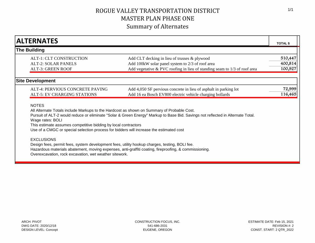
ROGUE VALLEY TRANSPORTATION DISTRICTMASTER PLAN PHASE ONE
Summary of Alternates
1/1
ALTERNATES TOTAL $
The Building
ALT-1: CLT CONSTRUCTION Add CLT decking in lieu of trusses & plywood 510,447
ALT-2: SOLAR PANELS Add 100kW solar panel system to 2/3 of roof area 400,814
ALT-3: GREEN ROOF Add vegetative & PVC roofing in lieu of standing seam to 1/3 of roof area 100,927
Site Development
ALT-4: PERVIOUS CONCRETE PAVING Add 4,050 SF pervious concrete in lieu of asphalt in parking lot 72,999
ALT-5: EV CHARGING STATIONS Add 16 ea Bosch EV800 electric vehicle charging bollards 116,465
NOTES
All Alternate Totals include Markups to the Hardcost as shown on Summary of Probable Cost.
Pursuit of ALT-2 would reduce or eliminate "Solar & Green Energy" Markup to Base Bid. Savings not reflected in Alternate Total.
Wage rates: BOLI
This estimate assumes competitive bidding by local contractors
Use of a CMGC or special selection process for bidders will increase the estimated cost
EXCLUSIONS
Design fees, permit fees, system development fees, utility hookup charges, testing, BOLI fee.
Hazardous materials abatement, moving expenses, anti-graffiti coating, fireproofing, & commissioning.
Overexcavation, rock excavation, wet weather sitework.
ARCH: PIVOT
DWG DATE: 2020/12/18
DESIGN LEVEL: Concept
CONSTRUCTION FOCUS, INC.
541-686-2031
EUGENE, OREGON
ESTIMATE DATE: Feb 15, 2021
REVISION #: 2
CONST. START: 2 QTR_2022
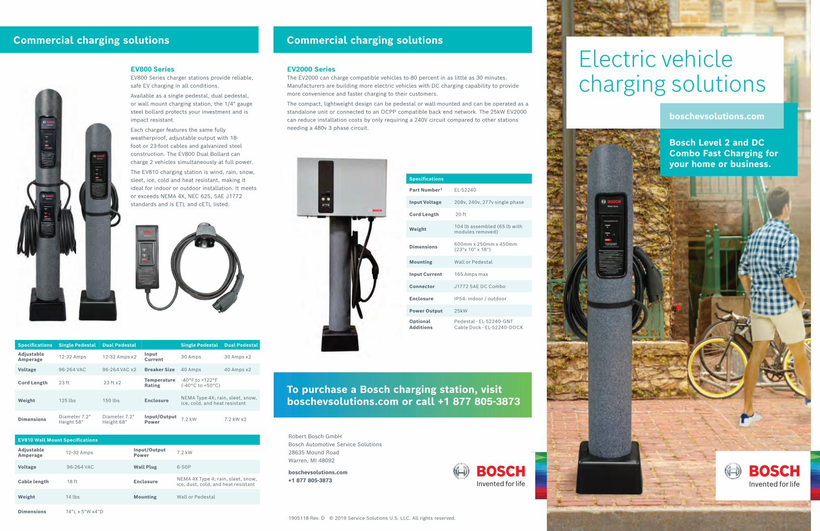
1905118 Rev. D © 2019 Service Solutions U.S. LLC. All rights reserved.
Robert Bosch GmbHBosch Automotive Service Solutions28635 Mound RoadWarren, MI 48092
boschevsolutions.com +1 877 805-3873
To purchase a Bosch charging station, visit boschevsolutions.com or call +1 877 805-3873
Specifications Single Pedestal Dual Pedestal Single Pedestal Dual Pedestal
Adjustable Amperage 12-32 Amps 12-32 Amps x2 Input
Current 30 Amps 30 Amps x2
Voltage 96-264 VAC 96-264 VAC x2 Breaker Size 40 Amps 40 Amps x2
Cord Length 23 ft 23 ft x2 Temperature Rating
-40°F to +122°F (-40°C to +50°C)
Weight 125 lbs 150 lbs Enclosure NEMA Type 4X; rain, sleet, snow, ice, cold, and heat resistant
Dimensions Diameter 7.2" Height 58"
Diameter 7.2" Height 68"
Input/Output Power 7.2 kW 7.2 kW x2
EV2000 Series The EV2000 can charge compatible vehicles to 80 percent in as little as 30 minutes. Manufacturers are building more electric vehicles with DC charging capability to provide more convenience and faster charging to their customers.
The compact, lightweight design can be pedestal or wall-mounted and can be operated as a standalone unit or connected to an OCPP compatible back end network. The 25kW EV2000 can reduce installation costs by only requiring a 240V circuit compared to other stations needing a 480v 3 phase circuit.
Specifications
Part Number1 EL-52240
Input Voltage 208v, 240v, 277v single phase
Cord Length 20 ft
Weight 104 lb assembled (65 lb with modules removed)
Dimensions 600mm x 250mm x 450mm (23"x 10" x 18")
Mounting Wall or Pedestal
Input Current 165 Amps max
Connector J1772 SAE DC Combo
Enclosure IP54: indoor / outdoor
Power Output 25kW
Optional Additions
Pedestal - EL-52240-GNT Cable Dock - EL-52240-DOCK
Commercial charging solutions Commercial charging solutions
Bosch Level 2 and DC Combo Fast Charging for your home or business.
Electric vehicle charging solutions
boschevsolutions.com
EV810 Wall Mount Specifications
Adjustable Amperage 12-32 Amps Input/Output
Power 7.2 kW
Voltage 96-264 VAC Wall Plug 6-50P
Cable length 18 ft Enclosure NEMA 4X Type 4; rain, sleet, snow, ice, dust, cold, and heat resistant
Weight 14 lbs Mounting Wall or Pedestal
Dimensions 14"L x 5"W x4"D
EV800 SeriesEV800 Series charger stations provide reliable, safe EV charging in all conditions.
Available as a single pedestal, dual pedestal, or wall mount charging station, the 1/4" gauge steel bollard protects your investment and is impact resistant.
Each charger features the same fully weatherproof, adjustable output with 18-foot or 23-foot cables and galvanized steel construction. The EV800 Dual Bollard can charge 2 vehicles simultaneously at full power.
The EV810 charging station is wind, rain, snow, sleet, ice, cold and heat resistant, making it ideal for indoor or outdoor installation. It meets or exceeds NEMA 4X, NEC 625, SAE J1772 standards and is ETL and cETL listed.
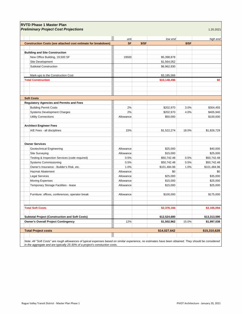
Preliminary Project Cost Projections 1.20.2021
unit low end high end
Construction Costs (see attached cost estimate for breakdown) SF $/SF $/SF
Building and Site ConstructionNew Office Building, 19,500 SF 19500 $5,398,878
Site Development $1,564,052
Subtotal Construction $6,962,930
Mark-ups to the Construction Cost $3,185,566
Total Construction $10,148,496 $0
Soft CostsRegulatory Agencies and Permits and Fees
Building Permit Costs 2% $202,970 3.0% $304,455
Systems Development Charges 2% $202,970 4.0% $405,940
Utility Connections Allowance $50,000 $100,000
Architect Engineer FeesA/E Fees - all disciplines 15% $1,522,274 18.0% $1,826,729
Owner ServicesGeotechnical Engineering Allowance $25,000 $40,000
Site Surveying Allowance $15,000 $25,000
Testing & Inspection Services (code required) 0.5% $50,742.48 0.5% $50,742.48
Systems Commissioning 0.5% $50,742.48 0.5% $50,742.48
Owner's Insurance - Builder's Risk, etc. 1.0% $101,484.96 1.0% $101,484.96
Hazmat Abatement Allowance $0 $0
Legal Services Allowance $25,000 $35,000
Moving Expenses Allowance $15,000 $25,000
Temporary Storage Facilities - lease Allowance $15,000 $25,000
Furniture: offices, conferences, operator break Allowance $100,000 $175,000
Total Soft Costs $2,376,184 $3,165,094
Subtotal Project (Construction and Soft Costs) $12,524,680 $13,313,590Owner's Overall Project Contingency 12% $1,502,962 15.0% $1,997,038
Total Project costs $14,027,642 $15,310,628
RVTD Phase 1 Master Plan
Note: All "Soft Costs" are rough allowances of typical expenses based on similar experience, no estimates have been obtained. They should be considered in the aggregate and are typically 25-30% of a project's constuction costs.
Rogue Valley Transit District ‐ Master Plan Phase 1 PIVOT Architecture ‐ January 20, 2021
SECTION D- PHASE 2
PIVOT Architecture 02.19.2021 DRAFT RVTD Master Plan Report
Additional masterplan studies were explored for phase 2 to address future needs and expansion of the fleet main-tenance spaces. A full evaluation of the fleet maintenance building and operations was not scoped as part of the masterplan study. Instead, a high-level program was de-veloped by WSP to identify the space needs and help evaluate the existing Maintenance and Fuel & Wash op-erations while planning for a future expansion. The con-clusion is that the existing maintenance building will not be able to meet the needs of the district within 10 years. Some aspects of the existing facility are already strained or performing below industry standards.
To test the master plan configuration and the location of the new Administration and Operations building, sever-al layouts were developed to accommodate the 20 year and beyond growth needs for the maintenance shop. This study assumed an idealized layout and size for the maintenance shop, fuel, and wash facilities. The various maintenance options validated the location of Phase 1 building and determined that additional property to the south of the campus would be needed to meet the 2040 program needs of the Fleet Maintenance, Fuel & Wash, and Fleet Parking.
SECTION D - PHASE 2OVERVIEW OF PROJECT
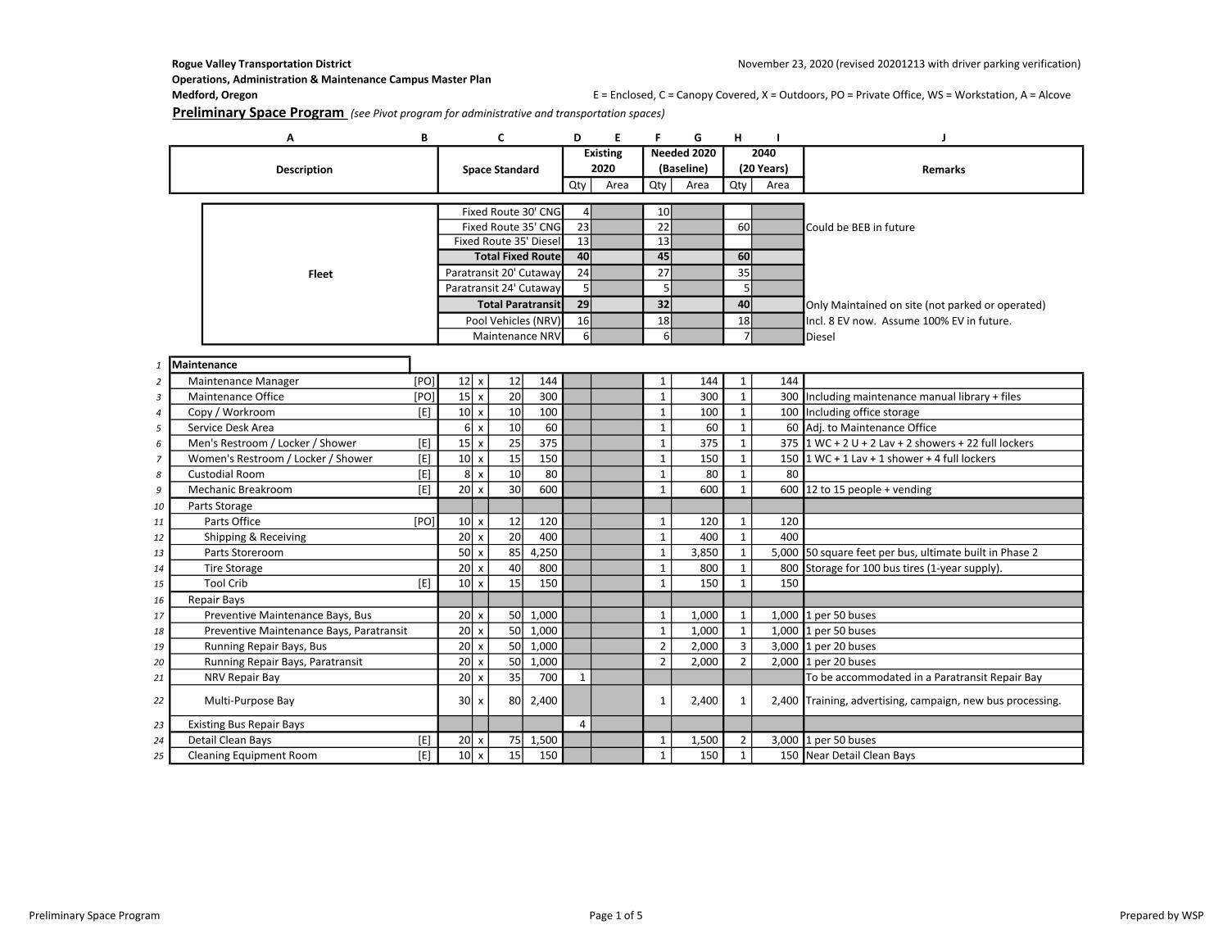
Rogue Valley Transportation District November 23, 2020 (revised 20201213 with driver parking verification)
Operations, Administration & Maintenance Campus Master Plan
Medford, Oregon E = Enclosed, C = Canopy Covered, X = Outdoors, PO = Private Office, WS = Workstation, A = Alcove
Preliminary Space Program (see Pivot program for administrative and transportation spaces)
B D E F G H I J
Qty Area Qty Area Qty Area
4 10
23 22 60 Could be BEB in future13 13
Total Fixed Route 40 45 60
24 27 35
5 5 5
Total Paratransit 29 32 40 Only Maintained on site (not parked or operated)
16 18 18 Incl. 8 EV now. Assume 100% EV in future.
6 6 7 Diesel
1 Maintenance
2 Maintenance Manager [PO] 12 x 12 144 1 144 1 144
3 Maintenance Office [PO] 15 x 20 300 1 300 1 300 Including maintenance manual library + files
4 Copy / Workroom [E] 10 x 10 100 1 100 1 100 Including office storage
5 Service Desk Area 6 x 10 60 1 60 1 60 Adj. to Maintenance Office
6 Men's Restroom / Locker / Shower [E] 15 x 25 375 1 375 1 375 1 WC + 2 U + 2 Lav + 2 showers + 22 full lockers
7 Women's Restroom / Locker / Shower [E] 10 x 15 150 1 150 1 150 1 WC + 1 Lav + 1 shower + 4 full lockers
8 Custodial Room [E] 8 x 10 80 1 80 1 80
9 Mechanic Breakroom [E] 20 x 30 600 1 600 1 600 12 to 15 people + vending
10 Parts Storage
11 Parts Office [PO] 10 x 12 120 1 120 1 120
12 Shipping & Receiving 20 x 20 400 1 400 1 400
13 Parts Storeroom 50 x 85 4,250 1 3,850 1 5,000 50 square feet per bus, ultimate built in Phase 2
14 Tire Storage 20 x 40 800 1 800 1 800 Storage for 100 bus tires (1-year supply).
15 Tool Crib [E] 10 x 15 150 1 150 1 150
16 Repair Bays
17 Preventive Maintenance Bays, Bus 20 x 50 1,000 1 1,000 1 1,000 1 per 50 buses
18 Preventive Maintenance Bays, Paratransit 20 x 50 1,000 1 1,000 1 1,000 1 per 50 buses
19 Running Repair Bays, Bus 20 x 50 1,000 2 2,000 3 3,000 1 per 20 buses
20 Running Repair Bays, Paratransit 20 x 50 1,000 2 2,000 2 2,000 1 per 20 buses
21 NRV Repair Bay 20 x 35 700 1 To be accommodated in a Paratransit Repair Bay
22 Multi-Purpose Bay 30 x 80 2,400 1 2,400 1 2,400 Training, advertising, campaign, new bus processing.
23 Existing Bus Repair Bays 4
24 Detail Clean Bays [E] 20 x 75 1,500 1 1,500 2 3,000 1 per 50 buses
25 Cleaning Equipment Room [E] 10 x 15 150 1 150 1 150 Near Detail Clean Bays
Remarks
Existing
2020
Needed 2020
(Baseline)
Fixed Route 35' CNG
Pool Vehicles (NRV)
Fixed Route 35' Diesel
Paratransit 20' Cutaway
2040
(20 Years)
Fixed Route 30' CNG
Description
A C
Space Standard
Maintenance NRV
Paratransit 24' CutawayFleet
Preliminary Space Program Page 1 of 5 Prepared by WSP

Rogue Valley Transportation District November 23, 2020 (revised 20201213 with driver parking verification)
Operations, Administration & Maintenance Campus Master Plan
Medford, Oregon E = Enclosed, C = Canopy Covered, X = Outdoors, PO = Private Office, WS = Workstation, A = Alcove
Preliminary Space Program (see Pivot program for administrative and transportation spaces)
B D E F G H I J
Qty Area Qty Area Qty Area
4 10
23 22 60 Could be BEB in future13 13
Total Fixed Route 40 45 60
24 27 35
5 5 5
Total Paratransit 29 32 40 Only Maintained on site (not parked or operated)
16 18 18 Incl. 8 EV now. Assume 100% EV in future.
6 6 7 Diesel
Remarks
Existing
2020
Needed 2020
(Baseline)
Fixed Route 35' CNG
Pool Vehicles (NRV)
Fixed Route 35' Diesel
Paratransit 20' Cutaway
2040
(20 Years)
Fixed Route 30' CNG
Description
A C
Space Standard
Maintenance NRV
Paratransit 24' CutawayFleet
26 Electronics / Farebox Repair Shop 10 x 15 150 1 150 1 150
27 Common Work Area / Rebuild Area 20 x 50 1,000 1 1,000 1 1,000
28 Welding Shop 20 x 30 600 1 600 1 600
29 Component Clean See Chassis Wash under Fuel and Wash
30 Handwash / Safety Shower / Used Oil Drop 8 x 12 96 1 96 1 96
31 Floor Scrubber Parking / Dump Area 8 x 10 80 1 80 1 80
32 Portable Equipment Storage 20 x 50 1,000 1 1,000 1 1,000
33 Tool Box Storage 20 x 25 500 1 500 1 500 10 tool boxes
34 Body Repair and Paint Not required
35 Tire Repair
36 Tire Repair Bay Done in Running Repair Bays
37 Tire Shop / Storage 20 x 40 800 See Parts Storeroom. Tire work contracted off-site
38 Building Maintenance
39 Building Maintenance Shop [E] 20 x 50 1,000 1 1,000 1 1,000
40 Building Maintenance Storage [E] 20 x 50 1,000 1 1,000 1 1,000
41 Lube / Compressor Room [E] 15 x 30 450 1 450 1 450 ATF, EC, EO, CG, GO, WO
42 Subtotal 23,055 26,705
43 Circulation Factor 4,611 5,341
44 Total Maintenance 27,666 32,046
45 Existing Maintenance Facility
46 First Floor 9,996
47 Upper Level 1,099 Not ADA accessible
48 Warehouse 5,400
49 Total Maintenance 16,495
20%
Preliminary Space Program Page 2 of 5 Prepared by WSP
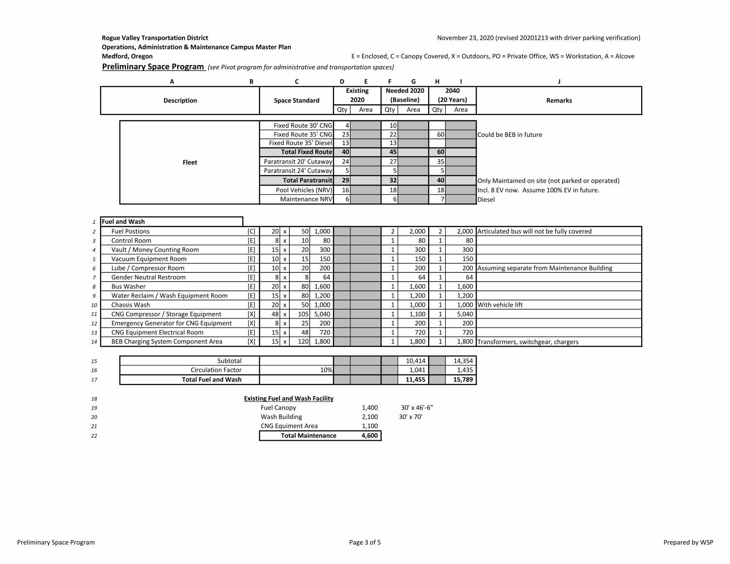
Rogue Valley Transportation District November 23, 2020 (revised 20201213 with driver parking verification)
Operations, Administration & Maintenance Campus Master Plan
Medford, Oregon E = Enclosed, C = Canopy Covered, X = Outdoors, PO = Private Office, WS = Workstation, A = Alcove
Preliminary Space Program (see Pivot program for administrative and transportation spaces)
B D E F G H I J
Qty Area Qty Area Qty Area
4 10
23 22 60 Could be BEB in future13 13
Total Fixed Route 40 45 60
24 27 35
5 5 5
Total Paratransit 29 32 40 Only Maintained on site (not parked or operated)
16 18 18 Incl. 8 EV now. Assume 100% EV in future.
6 6 7 Diesel
Remarks
Existing
2020
Needed 2020
(Baseline)
Fixed Route 35' CNG
Pool Vehicles (NRV)
Fixed Route 35' Diesel
Paratransit 20' Cutaway
2040
(20 Years)
Fixed Route 30' CNG
Description
A C
Space Standard
Maintenance NRV
Paratransit 24' CutawayFleet
1 Fuel and Wash
2 Fuel Postions [C] 20 x 50 1,000 2 2,000 2 2,000 Articulated bus will not be fully covered
3 Control Room [E] 8 x 10 80 1 80 1 80
4 Vault / Money Counting Room [E] 15 x 20 300 1 300 1 300
5 Vacuum Equipment Room [E] 10 x 15 150 1 150 1 150
6 Lube / Compressor Room [E] 10 x 20 200 1 200 1 200 Assuming separate from Maintenance Building
7 Gender Neutral Restroom [E] 8 x 8 64 1 64 1 64
8 Bus Washer [E] 20 x 80 1,600 1 1,600 1 1,600
9 Water Reclaim / Wash Equipment Room [E] 15 x 80 1,200 1 1,200 1 1,200
10 Chassis Wash [E] 20 x 50 1,000 1 1,000 1 1,000 With vehicle lift11 CNG Compressor / Storage Equipment [X] 48 x 105 5,040 1 1,100 1 5,040
12 Emergency Generator for CNG Equipment [X] 8 x 25 200 1 200 1 200
13 CNG Equipment Electrical Room [E] 15 x 48 720 1 720 1 720
14 BEB Charging System Component Area [X] 15 x 120 1,800 1 1,800 1 1,800 Transformers, switchgear, chargers
15 Subtotal 10,414 14,354
16 Circulation Factor 1,041 1,435
17 Total Fuel and Wash 11,455 15,789
18 Existing Fuel and Wash Facility
19 Fuel Canopy 1,400 30' x 46'-6"
20 Wash Building 2,100 30' x 70'
21 CNG Equiment Area 1,100
22 Total Maintenance 4,600
10%
Preliminary Space Program Page 3 of 5 Prepared by WSP

RVTD MASTER PLAN3200 CRATER LAKE AVE, MEDFORD OR
OPTION A1 01.18.2021
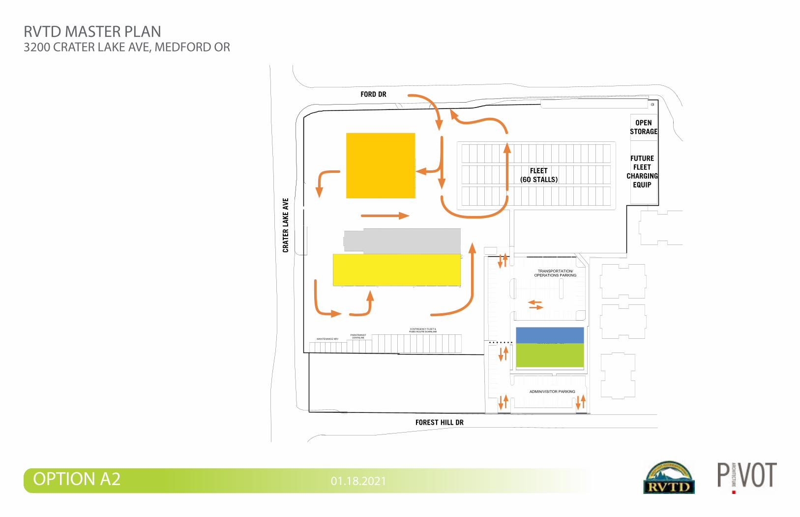
RVTD MASTER PLAN3200 CRATER LAKE AVE, MEDFORD OR
OPTION A2 01.18.2021
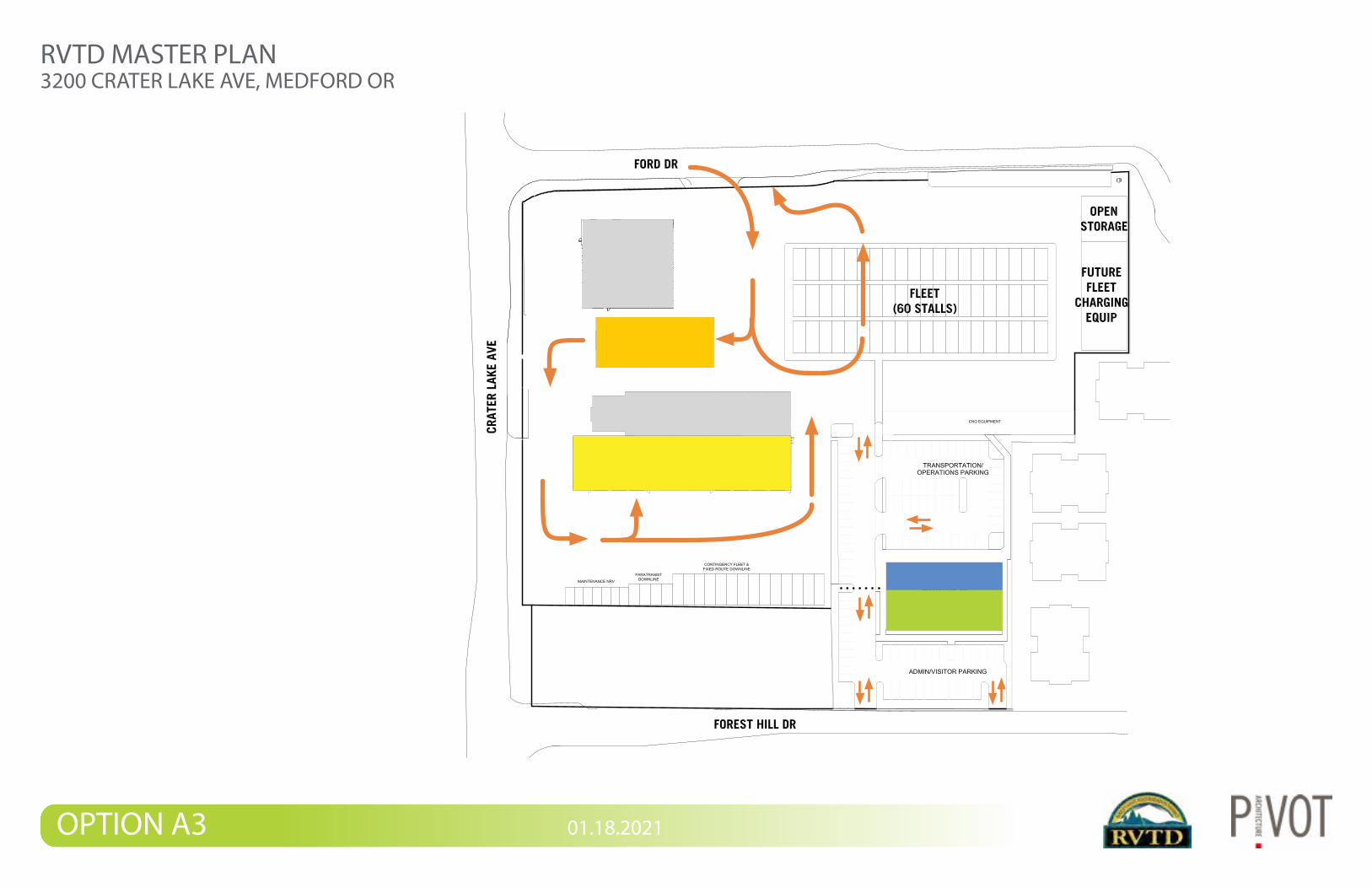
RVTD MASTER PLAN3200 CRATER LAKE AVE, MEDFORD OR
OPTION A3 01.18.2021

RVTD MASTER PLAN3200 CRATER LAKE AVE, MEDFORD OR
OPTION B 01.18.2021
APPENDIX
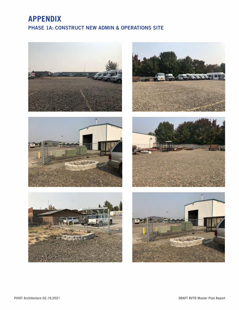
PIVOT Architecture 02.19.2021 DRAFT RVTD Master Plan Report
APPENDIXPHASE 1A: CONSTRUCT NEW ADMIN & OPERATIONS SITE
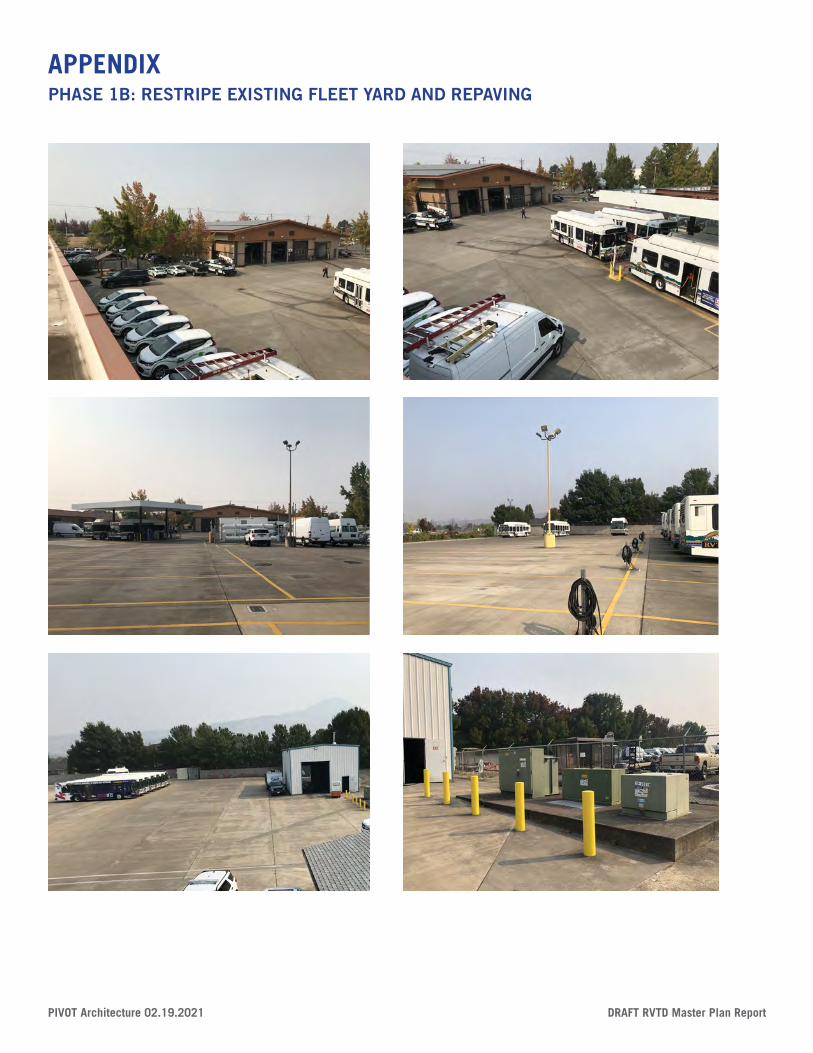
DRAFT RVTD Master Plan Report PIVOT Architecture 02.19.2021
APPENDIXPHASE 1B: RESTRIPE EXISTING FLEET YARD AND REPAVING
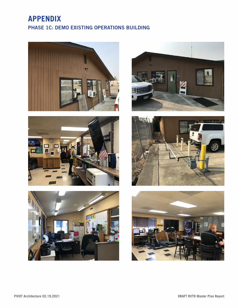
PIVOT Architecture 02.19.2021 DRAFT RVTD Master Plan Report
APPENDIXPHASE 1C: DEMO EXISTING OPERATIONS BUILDING
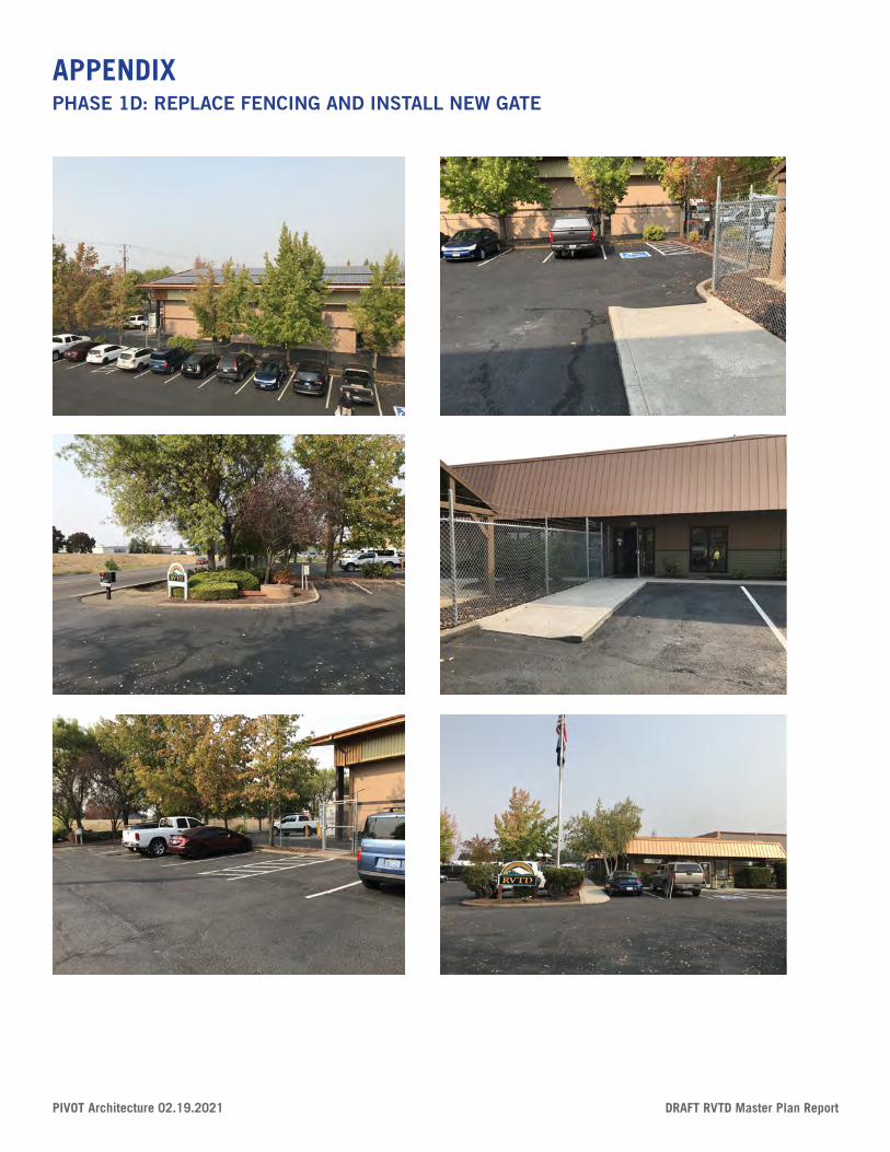
DRAFT RVTD Master Plan Report PIVOT Architecture 02.19.2021
APPENDIXPHASE 1D: REPLACE FENCING AND INSTALL NEW GATE

3 | PIVOT Architecture
PIVOT Architecture44 West Broadway, Suite 300Eugene, OR 97401
t. 541.342.7291
pivotarchitecture.com