
RULE THE MOUNTAIN - Marker
192
1 RULE THE MOUNTAIN We are very pleased to present you with the MARKER Technical Manual 2016/17. It is intended exclusively for our partners and for professionals in the field of ski bindings. The new handbook contains a wealth of insider infor - mation ranging from freeride, touring and novice bindings to pro-style rigs for alpine racing. It also includes a host of insider info, installation instructions, an extensive FAQ and a detailed overview of all MARKER bindings and their ideal uses. For over 60 years MARKER has stood for unbeatable performance and inno - vation. Our 2016/17 program once again delivers powerful and unique products to make the most beautiful sport in the world even safer and more attractive. As a specialized MARKER dealer, you are at the front lines of our interaction with end consumers. MARKER’s pledges of quality and safety would not be seen or heard by the consumers without your conscientious work and pro - fessional recommendations. We'd like to take a moment to thank you for your remarkable efforts. Here’s to a white and successful winter 2016/17 ! The Marker Team PS: The current MARKER Technical Handbook is naturally also available in PDF form for download off the internet: http://extranet.marker.de username: dealer password: sh0ps!
-
Upload
khangminh22 -
Category
Documents
-
view
0 -
download
0
Transcript of RULE THE MOUNTAIN - Marker

1
RULE THE MOUNTAINWe are very pleased to present you with the MARKER Technical Manual2016/17. It is intended exclusively for our partners and for professionals inthe field of ski bindings. The new handbook contains a wealth of insider infor-mation ranging from freeride, touring and novice bindings to pro-style rigs foralpine racing. It also includes a host of insider info, installation instructions,an extensive FAQ and a detailed overview of all MARKER bindings and theirideal uses.For over 60 years MARKER has stood for unbeatable performance and inno-vation.Our 2016/17 program once again delivers powerful and unique productsto make the most beautiful sport in the world even safer and more attractive.As a specialized MARKER dealer, you are at the front lines of our interactionwith end consumers. MARKER’s pledges of quality and safety would not beseen or heard by the consumers without your conscientious work and pro-fessional recommendations. We'd like to take a moment to thank you for yourremarkable efforts.Here’s to a white and successful winter 2016/17 !
The Marker Team
PS: The current MARKER Technical Handbook is naturally also available in PDF form for download off the internet:
http://extranet.marker.deusername: dealer password: sh0ps!
2
45
778
10
101214
1920242830323335
3640444852
5660646870727475767778828486
8890929698
100102
104106108
110
CON
TEN
T
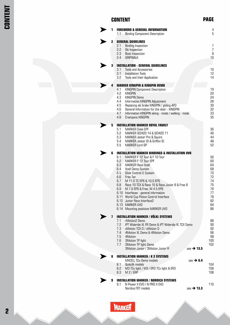
CONTENT
1 FOREWORD & GENERAL INFORMATION 1.1 Binding Component Description
2 GENERAL GUIDELINES 2.1 Binding Inspection 2.2 Ski Inspection 2.3 Boot Inspection 2.4 GRIPWALK
3 INSTALLATION - GENERAL GUIDELINES3.1 Tools and Accessories3.1 Installation Tools3.2 Tools and their Application
4 MARKER KINGPIN & KINGPIN DEMO4.1 KINGPIN Component Description4.2 KINGPIN4.3 KINGPIN Demo4.4 Information KINGPIN Adjustment4.5 Replacing ski brake KINGPIN / gliding AFD4.6 General Information for the skier - KINGPIN4.7 Information KINGPIN skiing - mode / walking - mode4.8 Crampons KINGPIN
5 INSTALLATION MARKER ROYAL FAMILY5.1 MARKER Duke EPF5.2 MARKER SCHIZO 14 & SCHIZO 115.3 MARKER Jester Pro & Squire5.4 MARKER Jester ID & Griffon ID5.5 MARKER Lord SP
6 INSTALLATION MARKER BINDINGS & INSTALLATION UVO6.1 MARKER F 12 Tour & F 10 Tour6.2 MARKER F 12 Tour EPF6.3 MARKER Race Xcell 6.4 Xcell Demo System6.5 Glide Control D System6.6 Free Ten6.7 M 11.0 TC EPS & 10.0 EPS6.8 Race 10 TCX & Race 10 & Race Junior 8 & Free 86.9 M 7.0 EPS & Free; M 4.5 EPS6.10 Interfaces - general information6.11 World Cup Piston Control Interface6.12 Junior Race Interface26.13 MARKER UVO6.14 Mounting positions MARKER UVO
7 INSTALLATION MARKER / VÖLKL SYSTEMS7.1 rMotion2 Demo7.2 iPT Wideride XL FR Demo & iPT Wideride XL TCX Demo7.3 xMotion TCX D / xMotion D7.4 4Motion XL Demo & 4Motion Demo7.5 4Motion7.6 3Motion TP light7.7 3Motion TP light Demo 3Motion Junior / 3Motion Junior R see 13.5
8 INSTALLATION MARKER / K 2 SYSTEMS MXCELL TCx Demo models see 6.48.1 Quikclik models8.2 M3 TCx light / M3 / ER3 TCx light & ER38.3 M 2 / ERP
9 INSTALLATION MARKER / NORDICA SYSTEMS9.1 N Power X EVO / N PRO X EVO Nordica FDT models see 13.3
PAGE

3
114116118120122
124128130131
132132132132132133134135136
138140144146150154156158
162162163164166167168169
170176181
CON
TEN
T
CONTENT
10 INSTALLATION MARKER / BLIZZARD SYSTEMS10.1 XCELL DEMO & TP 11 D MODELS10.2 TCX Demo & TP 10 Demo10.3 IQ TP CM210.4 IQ TP10.4 IQ Junior System
INSTALLATION MARKER / MOVEMENT SYSTEMS FDT TP see 13.3 FDT TLT see 13.3 FREESKI TP 120 / TP 100 see 6.7 12.0 TCX / 10.0 Glide Control D see 6.5
INSTALLATION MARKER / BOGNER - INDIGO SYSTEMS Xcell Demo see 6.4
11 BINDING ADJUSTMENT 11.1 Release Value Selection and Adjustment 11.2 Adjustment screws and scales 11.3 Function test and inspection 11.4 Trouble - shooting 12 SPECIAL CASES 12.1 Competition Bindings 12.2 Monoski 12.3 Adjustment outside of the standards 12.4 Antiquated bindings which do not conform the standard 12.5 Replacing ski brakes 12.6 Replacing ski brakes Inter Pivot, Squire & Tour heels 12.7 Replacing ski brakes Xcell, Race 10 & 8, 11.0 TC heels 12.8 Replacing ski brakes Compact Step - in heels 12.9 Installation DIN - Adapter AT - boot
13 MARKER RENTAL & DEMO MODELS 13.1 General Information and Descriptions 13.2 Installation Marker Jester Demo 13.3 Installation Marker Griffon D & Squire D & FDT models 13.4 Installation 10.0 Fastrak III & 10.0 Fastrak III TP 13.5 Installation Junior Fastrak II 13.6 Installation Junior RTL 13.7 Installation Race Xcell Demo heel plate 13.8 Function Test and Service
14 INFORMATION FOR THE SKIER 14.1 Maintenance 14.2 Warranty 14.3 Service 14.4 Additional Information Marker Tour 14.5 Marker TOUR brakes & safety leash 14.6 Additional Information Marker Duke EPF & Baron EPF 14.7 Crampons 14.8 Crampons
15 APPENDIX 15.1 Screw Chart 15.2 Brake chart 15.3 Marker collection 2016 - 2017
PAGE

4
FOREWORDThis Technical Manual was designed from the user’s point of view. It is clearly structured and easy to apply. The user has usually one product out of the MARKER Collection (binding, accessories, etc.) in front of him which he wants to install:
• The description for the product is easy to locate.
• The user receives complete installation instructions for the specific MARKER product.
• Each important installation step is described with text and an accompanying graphic.
• Important movements, groupings and views are presented.
• The pictures are a combination of photos and minimalized draw-ings.
THIS LAYOUT RESULTS IN THE FOLLOWING ADVANTAGES:
1) The user can actually see his MARKER product with all it’s characteristics rather than imagining it.
2) Each working step, which may be valid only for this specific product, is clearly marked.
3) Detailed views are reduced to the essential in order to eliminate redundant distractions.
REMARK:MARKER, DUKE, BARON, JESTER, GRIFFON, GRIPWALK, KINGPIN, M, BIOMETRIC, BIOTECH, GLIDE, COMSHOCK, PISTON, EPS, SCHIZO, SQUIRE, LORD, XCELL, UVO and FASTRAK are registered MARKER VÖLKL (International) GmbH trademarks and other marks are pend-ing.
GENERAL INFORMATIONAll rights on this Technical Manual are owned by MARKER. Reproduc-tion and reprinting of this manual, in whole or in part are permitted only with approval of MARKER and if the source of the information is specified.We reserve the right to make changes to the ski bindings and their accessories with respect to the information and illustrations contained in the manual. Technical status: 05 - 2016
MARKINGS AND SYMBOLS
Important passages are emphasized in the text and it is essential to take note of them as follows:
CAUTION !Requires measures to be taken during the installation to protect the skier’s safety. IMPORTANT ! Emphasizes what has to be done or refrained from being done in order to avoid damaging the binding or valuable property during the installation process.
REMARK: Recommends action and gives instruction for smooth and quick installation.
REFERENCES:References to other chapters are marked with an arrow, e.g.: 3.2
1.0
ABO
UT T
HIS
MAN
UAL
5
1 2
3
4
6
7
81011
12 a
2021
22
23
DUKE EPF + BARON EPF
12
34
6
7
8
1011
12 a
18
19
JESTER PRO + SQUIRE
17
9
12
3
4 6
7
8
10
11
12 a
RACE XCELL 9
9
12
34
6
7
8
1011
12 a
SCHIZO 14 + SCHIZO 11
24
2526
27
28
9
MARKER TOUR + TOUR EPF
12
34
6
7
8
1011
12 a
1314
15
16
9JESTER ID + GRIFFON ID
1
2
346
7
81011
12 a
18 19
30
9
29
1.1
BIN
DIN
G CO
MPO
NEN
T DE
SCRI
PTIO
N
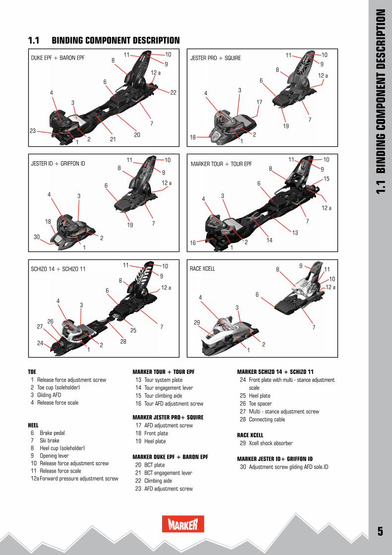
1.1 BINDING COMPONENT DESCRIPTION
TOE 1 Release force adjustment screw 2 Toe cup (soleholder) 3 Gliding AFD 4 Release force scale
HEEL 6 Brake pedal 7 Ski brake 8 Heel cup (soleholder) 9 Opening lever 10 Release force adjustment screw 11 Release force scale 12a Forward pressure adjustment screw
MARKER TOUR + TOUR EPF 13 Tour system plate 14 Tour engagement lever 15 Tour climbing aide 16 Tour AFD adjustment screw
MARKER JESTER PRO+ SQUIRE 17 AFD adjustment screw 18 Front plate 19 Heel plate
MARKER DUKE EPF + BARON EPF 20 BCT plate 21 BCT engagement lever 22 Climbing aide 23 AFD adjustment screw
MARKER SCHIZO 14 + SCHIZO 11 24 Front plate with multi - stance adjustment scale 25 Heel plate 26 Toe spacer 27 Multi - stance adjustment screw 28 Connecting cable
RACE XCELL 29 Xcell shock absorber
MARKER JESTER ID+ GRIFFON ID 30 Adjustment screw gliding AFD sole.ID

6
1
2
34
6
7
8 9
1011
12 a
LORD SP
12
34
6
7
8
10
11
12 a
FREE TEN
1
2
3
4
6
7
8
9
10
11
12 a
RACE 10 + RACE JUNIOR 8
40
1 2 3
4
6
7
8
9
10
11
302931
GLIDE CONTROL D SYSTEM
1
2
34
5
6
7
8
10
11
12 b
JUNIOR EPS
40
32
33 17
35
34
9
9
36
1
2
3
4
6
7
8
9
10
11
12 a
10.0 EPS
40
1.1
BIN
DIN
G CO
MPO
NEN
T DE
SCRI
PTIO
N
TOE 1 Release force adjustment screw 2 Toe cup (soleholder) 3 Gliding AFD 4 Release force scale 5 BIOTECH upward release
HEEL 6 Brake pedal 7 Ski brake 8 Heel cup (soleholder) 9 Opening lever 10 Release force adjustment screw 11 Release force scale 12a Forward pressure adjustment screw 12b Child & Junior forward pressure lever
GLIDE CONTROL D SYSTEM 29 Glide Control D front plate 30 Glide Control D connecting arm 31 Glide Control D heel plate 32 Glide Control D adjustment lever 33 Glide Control D toe spacer
LORD SP 34 Lord SP locking lever 35 Lord SP fixation screw FREE TEN 36 front plate EPS 40 EPS heel plate
KINGPIN & KINGPIN DEMO:see 4.1 on page 19
MARKER bindings conform to the CPSIA Act of 2008, Section 101
For complete information on Section 101 please refer to the CPSC or Marker web sites.
1.1 BINDING COMPONENT DESCRIPTION
7
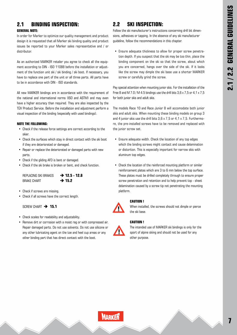
2.1 BINDING INSPECTION:GENERAL NOTE:In order for Marker to optimize our quality management and product design it is requested that all Marker ski binding quality and product issues be reported to your Marker sales representative and / or distributor.
As an authorized MARKER retailer you agree to check all the equip-ment according to DIN - ISO 11088 before the installation or adjust-ment of the function unit ski / ski binding / ski boot. If necessary, you have to replace one part of the unit or all three parts. All parts have to be in accordance with DIN - ISO standards.
All new MARKER bindings are in accordance with the requirement of the national and international norms (ISO and ASTM) and may even have a higher accuracy than required. They are also inspected by the TÜV Product Service. Before the installation and adjustment perform a visual inspection of the binding (especially with used bindings).
NOTE THE FOLLOWING: • Check if the release force settings are correct according to the
skier. • Check the surfaces which stay in direct contact with the ski boot
if they are deteriorated or damaged. • Repair or replace the deteriorated or damaged parts with new
parts. • Check if the gliding AFD is bent or damaged. • Check if the ski brake is broken or bent, and check function.
REPLACING SKI BRAKES 12.5 - 12.8 BRAKE CHART 15.2
• Check if screws are missing. • Check if all screws have the correct length.
SCREW CHART 15.1
• Check scales for readability and adjustability. • Remove dirt or corrosion with a moist rag or with compressed air.
Repair damaged parts. Do not use solvents. Do not use silicone or any other lubricating agent on the toe and heel cup areas or any other binding part that has direct contact with the boot.
2.1
/ 2.2
GEN
ERAL
GUI
DELI
NES
2.2 SKI INSPECTION:Follow the ski manufacturer’s instructions concerning drill bit dimen-sions, adhesives or tapping. In the absence of any ski manufacturer guideline, follow the recommendations in this chapter.
• Ensure adequate thickness to allow for proper screw penetra-tion depth. If you suspect that the ski may be too thin, place the binding component on the ski so that the screw, about which you are concerned, hangs over the side of the ski. If it looks like the screw may dimple the ski base use a shorter MARKER screw or carefully grind the screw.
Pay special attention when mounting junior skis. For the installation of the Free 8 and M 7.0 / M 4.5 bindings use the drill bits 3,6 x 7,5 or 4,1 x 7,5 for both junior skis and adult skis.
The models Race 10 and Race Junior 8 will accomodate both junior skis and adult skis. When mounting these binding models on group 3 and 4 junior skis use the drill bits 3,6 x 7,5 or 4,1 x 7,5. Furthermo-re, the pre-installed screws have to be removed and replaced with the junior screw set.
• Ensure adequate width. Check the location of any top edges which the binding screws might contact and cause delamination or distortion. This is especially important for narrow skis with aluminum top edges.
• Check the location of the reinforced mounting platform or similar reinforcement plates which are 3 to 6 mm below the top surface. These plates must be drilled completely through to ensure proper screw penetration and retention and to help prevent top - sheet delamination caused by a screw tip not penetrating the mounting platform.
CAUTION ! When installed, the screws should not dimple or pierce the ski base.
CAUTION ! The intended use of MARKER ski bindings is only for the sport of alpine skiing and should not be used for any other purpose.
8
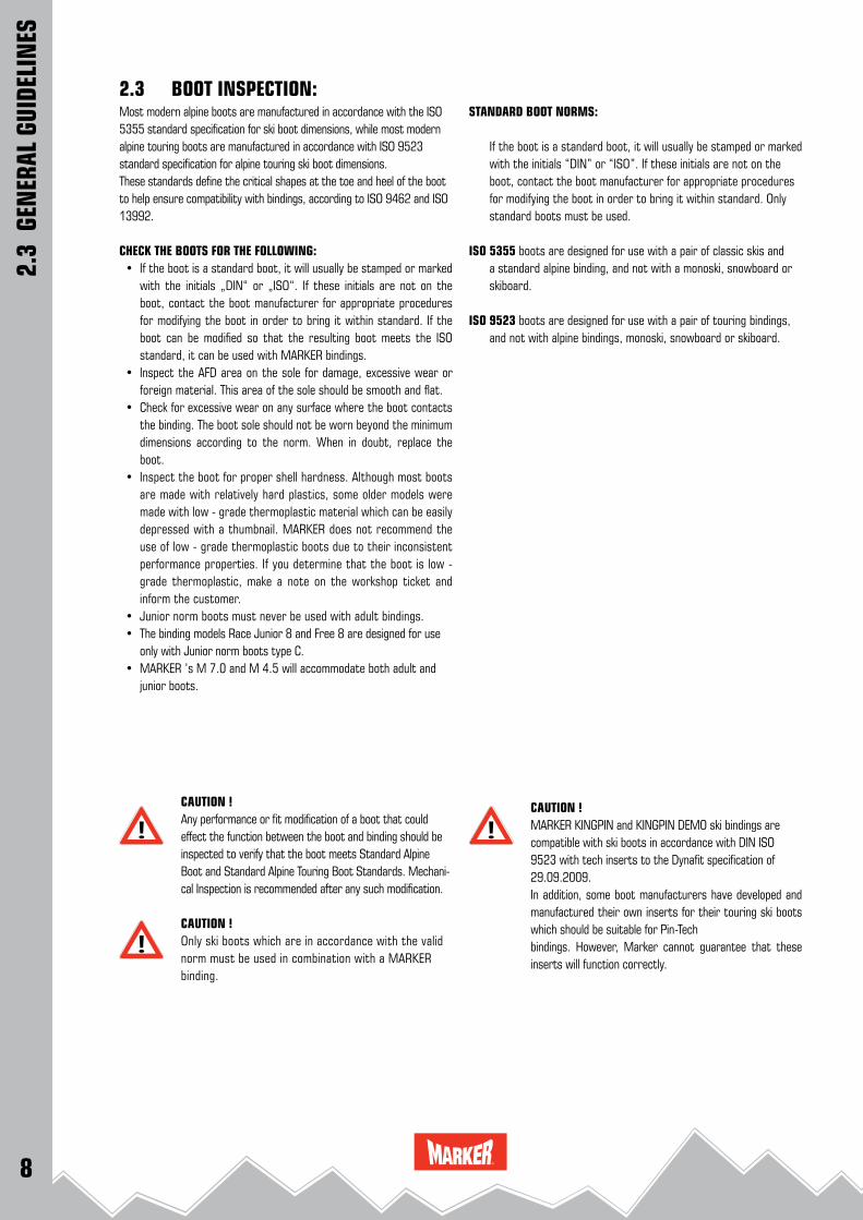
2.3 BOOT INSPECTION:Most modern alpine boots are manufactured in accordance with the ISO 5355 standard specification for ski boot dimensions, while most modern alpine touring boots are manufactured in accordance with ISO 9523 standard specification for alpine touring ski boot dimensions.These standards define the critical shapes at the toe and heel of the boot to help ensure compatibility with bindings, according to ISO 9462 and ISO 13992.
CHECK THE BOOTS FOR THE FOLLOWING: • If the boot is a standard boot, it will usually be stamped or marked
with the initials „DIN“ or „ISO“. If these initials are not on the boot, contact the boot manufacturer for approp riate procedures for modifying the boot in order to bring it within standard. If the boot can be modified so that the resulting boot meets the ISO standard, it can be used with MARKER bindings.
• Inspect the AFD area on the sole for damage, excessive wear or foreign material. This area of the sole should be smooth and flat.
• Check for excessive wear on any surface where the boot contacts the binding. The boot sole should not be worn beyond the minimum dimensions according to the norm. When in doubt, replace the boot.
• Inspect the boot for proper shell hardness. Although most boots are made with relatively hard plastics, some older models were made with low - grade thermoplastic material which can be easily depressed with a thumbnail. MARKER does not recommend the use of low - grade thermoplastic boots due to their inconsistent performance properties. If you determine that the boot is low - grade thermoplastic, make a note on the workshop ticket and inform the customer.
• Junior norm boots must never be used with adult bindings. • The binding models Race Junior 8 and Free 8 are designed for use
only with Junior norm boots type C. • MARKER ’s M 7.0 and M 4.5 will accommodate both adult and
junior boots.
CAUTION ! Any performance or fit modification of a boot that could effect the function between the boot and binding should be inspected to verify that the boot meets Standard Alpine Boot and Standard Alpine Touring Boot Standards. Mechani-cal Inspection is recommended after any such modification.
CAUTION ! Only ski boots which are in accordance with the valid norm must be used in combination with a MARKER binding.
2.3
GEN
ERAL
GUI
DELI
NES
STANDARD BOOT NORMS:
If the boot is a standard boot, it will usually be stamped or marked with the initials “DIN” or “ISO”. If these initials are not on the boot, contact the boot manufacturer for appropriate procedures for modifying the boot in order to bring it within standard. Only standard boots must be used.
ISO 5355 boots are designed for use with a pair of classic skis and a standard alpine binding, and not with a monoski, snowboard or skiboard.
ISO 9523 boots are designed for use with a pair of touring bindings, and not with alpine bindings, monoski, snowboard or skiboard.
CAUTION ! MARKER KINGPIN and KINGPIN DEMO ski bindings are compatible with ski boots in accordance with DIN ISO 9523 with tech inserts to the Dynafit specification of 29.09.2009. In addition, some boot manufacturers have developed and manufactured their own inserts for their touring ski boots which should be suitable for Pin-Techbindings. However, Marker cannot guarantee that these inserts will function correctly.

9
2.3 - 3
30 40
8070 min.
L 2
boot sole length L1
69 ±
2
69 ±
2
30 ± 1
19 ±
15 ±
1
45 °
50 + 1
8 ± 1
4 ± 1
7 ± 1
15 ± 2
L 1 < 300 ≥ 300L 2 100 min. 120 min.
2.3 - 1
25 4050 min.
boot sole length L1
62 ±
2
62 ±
2
27.5 ± 2
16.5
± 1.5
3 ± 1
45 °
45 + 1
8 ± 1
3 ± 1
10
12 ± 2
7 ± 1
L 2
L 1 < 240L 2 80 min. 90 min.
2.3 - 2
2.3
GEN
ERAL
GUI
DELI
NES
Adult boottype A
Junior boottype C
2.3 BOOT INSPECTIONSTANDARD BOOT NORMS:
Standard adult alpine boot according to DIN ISO 5355 (2.3 - 1)
Standard children alpine boot according to DIN ISO 5355 (2.3 - 2)
Standard alpine touring boot according to DIN ISO 9523 (2.3 - 3)
Touring boot
10
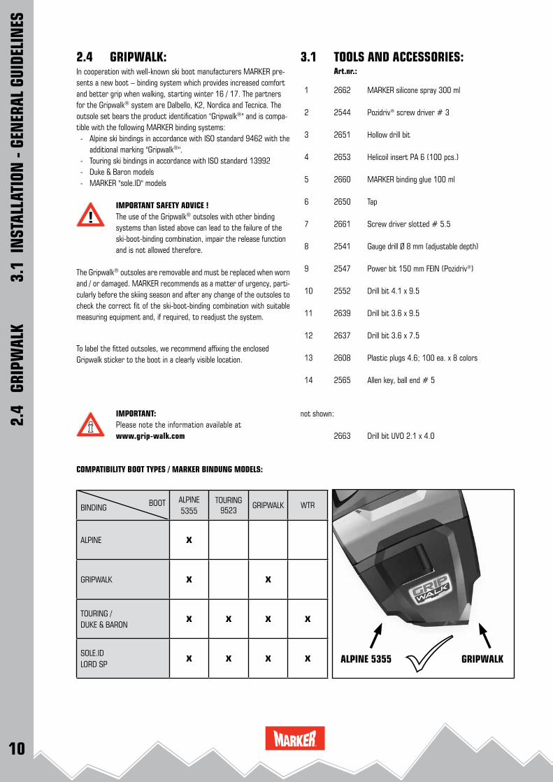
BOOTBINDINGALPINE5355
TOURING9523
GRIPWALK WTR
ALPINE X
GRIPWALK X X
TOURING /DUKE & BARON
X X X X
SOLE.IDLORD SP
X X X X ALPINE 5355 GRIPWALK
2.4 GRIPWALK: Art.nr.:
1 2662 MARKER silicone spray 300 ml
2 2544 Pozidriv® screw driver # 3
3 2651 Hollow drill bit
4 2653 Helicoil insert PA 6 (100 pcs.)
5 2660 MARKER binding glue 100 ml
6 2650 Tap
7 2661 Screw driver slotted # 5.5
8 2541 Gauge drill Ø 8 mm (adjustable depth)
9 2547 Power bit 150 mm FEIN (Pozidriv®)
10 2552 Drill bit 4.1 x 9.5
11 2639 Drill bit 3.6 x 9.5
12 2637 Drill bit 3.6 x 7.5
13 2608 Plastic plugs 4.6; 100 ea. x 8 colors
14 2565 Allen key, ball end # 5
not shown:
2663 Drill bit UVO 2.1 x 4.0
3.1 TOOLS AND ACCESSORIES:
2.4
GRI
PWAL
K
3.1
INST
ALLA
TION
- GE
NER
AL G
UIDE
LIN
ES
In cooperation with well-known ski boot manufacturers MARKER pre-sents a new boot – binding system which provides increased comfort and better grip when walking, starting winter 16 / 17. The partners for the Gripwalk® system are Dalbello, K2, Nordica and Tecnica. The outsole set bears the product identification "Gripwalk®" and is compa-tible with the following MARKER binding systems: - Alpine ski bindings in accordance with ISO standard 9462 with the
additional marking "Gripwalk®". - Touring ski bindings in accordance with ISO standard 13992 - Duke & Baron models - MARKER "sole.ID" models
IMPORTANT SAFETY ADVICE ! The use of the Gripwalk® outsoles with other binding systems than listed above can lead to the failure of the ski-boot-binding combination, impair the release function and is not allowed therefore.
The Gripwalk® outsoles are removable and must be replaced when worn and / or damaged. MARKER recommends as a matter of urgency, parti-cularly before the skiing season and after any change of the outsoles to check the correct fit of the ski-boot-binding combination with suitable measuring equipment and, if required, to readjust the system.
To label the fitted outsoles, we recommend affixing the enclosed Gripwalk sticker to the boot in a clearly visible location.
IMPORTANT:Please note the information available at www.grip-walk.com
COMPATIBILITY BOOT TYPES / MARKER BINDUNG MODELS:

11
1
23
4
5
6
7 8
9
10
11
12
13
14
3.1 TOOLS AND ACCESSORIES:
3.1
INST
ALLA
TION
- GE
NER
AL G
UIDE
LIN
ES
12
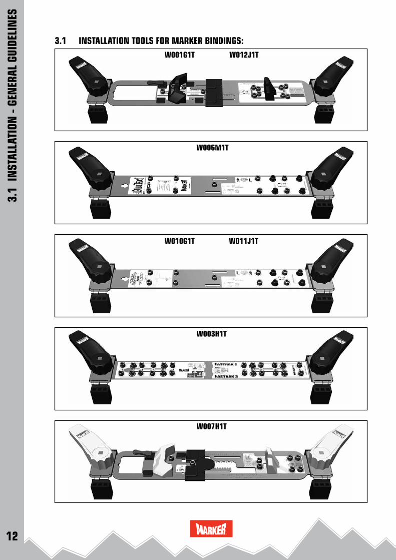
W001G1T W012J1T
W010G1T W011J1T
W003H1T
W006M1T
W007H1T
3.1 INSTALLATION TOOLS FOR MARKER BINDINGS:
3.1
INST
ALLA
TION
- GE
NER
AL G
UIDE
LIN
ES

13
W001G1T (61 - 117 mm) W012J1T (95 - 150 mm) Jester 18 Pro, Jester 16 ID, Griffon 13 ID, Griffon 13, Squire 11,
Schizo 14, Schizo 11, Jester Demo, Lord SP, Race Xcell 24.0, 18.0, 16.0, Race Xcell 12.0, M 11.0 TC EPS, 10.0 EPS, Free Ten, Free 8, Freeski TP 120, Freeski TP 100, Race 10 TCX, Race 10, Race Junior 8
W006M1T (95 - 150 mm) MARKER Duke EPF S & L MARKER Baron EPF S & L MARKER F 12 Tour EPF S & L
W010G1T (61 - 117 mm) W011J1T (95 - 150 mm) MARKER Duke S & L (→ 11 / 12) MARKER Baron S & L (→ 12 / 13) MARKER F 12 Tour S & L MARKER F 10 Tour S & L
W003H1T (61 - 117 mm) Fastrak III Fastrak II, Junior Fastrak II,
W007H1T M 7.0 Free, M 7.0, M 4.5, Junior RTL, Child RTL
3.1 INSTALLATION TOOLS FOR MARKER BINDINGS:
3.1
INST
ALLA
TION
- GE
NER
AL G
UIDE
LIN
ES
14
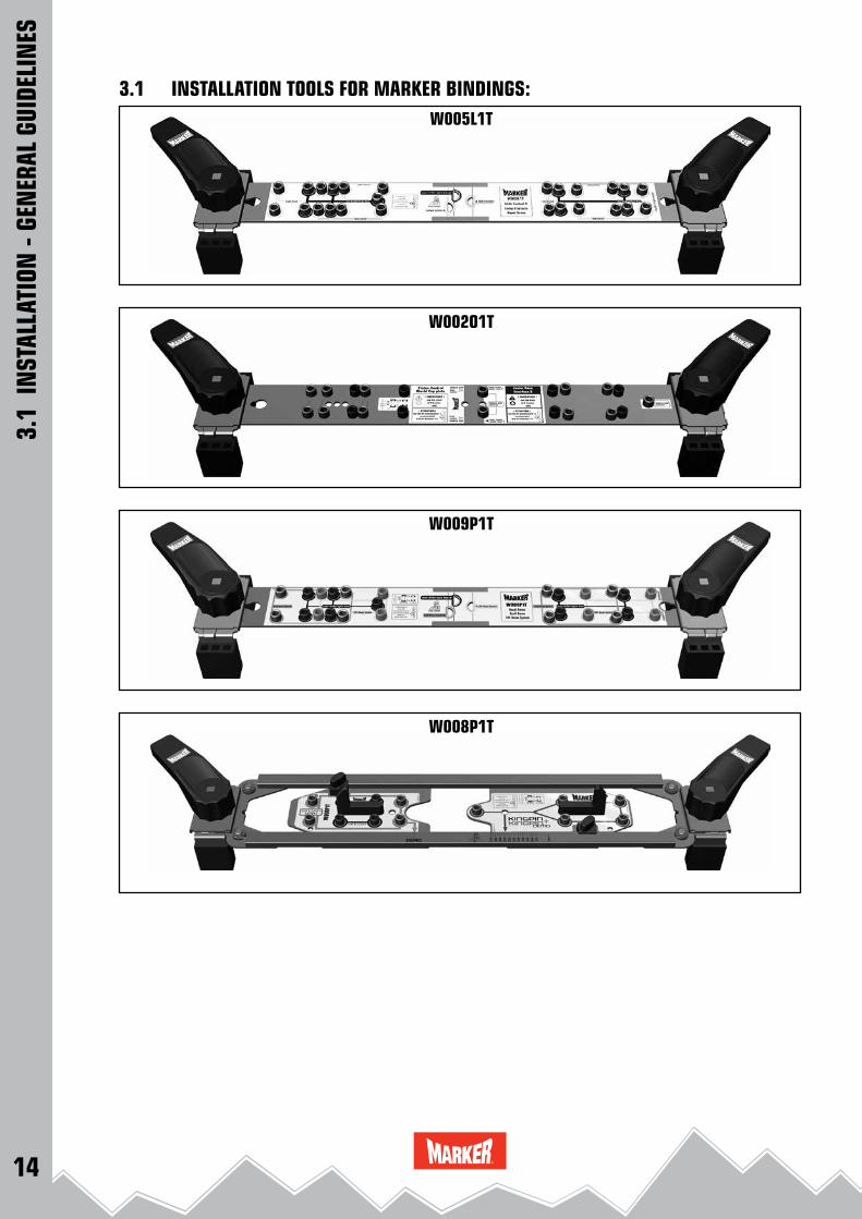
W005L1T
W002O1T
W009P1T
W008P1T
3.1 INSTALLATION TOOLS FOR MARKER BINDINGS:
3.1
INST
ALLA
TION
- GE
NER
AL G
UIDE
LIN
ES

15
W005L1T (61 - 117 mm) Glide Control D System, Comp D System, Jester Demo
W002O1T (61 - 117 mm) World Cup Piston Control, Junior Race Interface 2
W009P1T (61 - 117 mm) W004Q1T (95 - 150 mm) Jester Demo & Xcell Demo & FDT
W008P1T (70 - 126 mm) KINGPIN & KINGPIN Demo
3.1 - 1
3.1 INSTALLATION TOOLS FOR MARKER BINDINGS:
3.1
INST
ALLA
TION
- GE
NER
AL G
UIDE
LIN
ES
REMARK: For wide skis up to 148 mm MARKER offers an adapter kit for
installation tools. (3.1 - 1) (mounting tool adapter wide skis 148 mm; Art. Nr.: W001J1A)
MOUNTING THE TOOL ADAPTER: • Remove the four standard feet and replace them with the
mounting tool adapters as indicated in the picture (3.1 - 2).
FOR BOTH SKI
3.1 - 2 (backview)

16
3.2 - 4
3.2 - 2 3 6 7
3.2 - 3
3.2 - 5
3.2 - 1
1 12 23
54
ADJUSTMENT OF THE BINDING INSTALLATION TOOLS
IMPORTANT !Use only original MARKER installation tools ! Make sure that the installation tool is correctly positioned on the ski for all adjustments !
REMARK: The following installation steps are basic know - how and valid for all MARKER bindings.
ADJUSTING BOOT SOLE LENGTHOPTIMIZED BY USING THE SKI BOOT (3.2 - 1):
• Twist the grips (1) until the clamping jaws (2) are fully extended. Position the installation tool on the ski and lock it by releasing the grips.
• Open the locking lever (3) and place the boot heel against the heel guide (5).
• Slide the toe guide (4) until the boot is firmly against both toe (4) and heel guide (5).
• Close the locking lever (3). • Remove the ski boot.
WITHOUT SKI BOOT (3.2 - 2):
• Ask for the boot sole length or size of the ski boot (marked on the boot or measure it).
• Adjust the gauge of the sole length on scale (6) or (7). • Close the locking lever (3).
DETERMINE THE BINDING PLACEMENT ON THE SKI
IF MID - SOLE MARKS ON THE SKIS ARE USED:
• Place the installation tool on the ski and align the mid - sole mark on the ski with the mid - sole mark on the installation tool
(3.2 - 3).
IF BOOT TOE MARKS ON THE SKIS ARE USED:
• Place the installation tool on the ski and align the toe guide on the tool with the boot toe mark on the ski (3.2 - 4).
IMPORTANT ! Before drilling, check that the installation tool is flush and centered on the ski (3.2 - 5) ! Take particular care with skis that have angled sidewalls, extreme sidecuts or external plates.
3.2 TOOLS AND THEIR APPLICATION:
3.2
INST
ALLA
TION
- GE
NER
AL G
UIDE
LIN
ES

17
3 – 4 U > 4 U
3.2 - 8
3.2 - 9
Ø 3
,6
9,5
9,5
Ø 4
,1Ø
4,1
7,5
Ø 3
,6
7,5
3.2 TOOLS AND THEIR APPLICATION:GENERAL INFORMATION INSTALLATION
DRILLING:
REMARK: Use original MARKER drill bits for an optimal result (3.2 - 7).
• Drill all necessary mounting holes through the drill bushings on the installation tool.
(Details: see installation of the individual bindings)
• After drilling is completed remove the installation tool from the ski.
• Always keep the drill bit vertically aligned with the drill bushings in the installation tool and drill to the countersunk depth. (3.2 - 8)
• Shavings and dust have to be removed from the surface of the ski and all holes.
TAPPING:
REMARK: Holes should only be tapped if recommended by the ski manu-
facturer. Use an original MARKER tap. Use the installation tool for tapping.
• Drill all mounting holes. • Tap through the drill bushings of the installation tool. • Apply slight downward pressure and turn the tap. As soon as the
tap begins to cut, simple turning will thread the hole. Turn the tap three or four revolutions. (3.2 - 9)
IMPORTANT ! Be careful not to tap too deep !
• Back the tap out of the hole. Shavings and dust have to be removed from the surface of the ski and all holes.
3.2 - 7 Drill bits for adult bindings
3.2 - 7 Drill bits for child & junior bindings M 4.5 / M 7.0
3.2
INST
ALLA
TION
- GE
NER
AL G
UIDE
LIN
ES
18
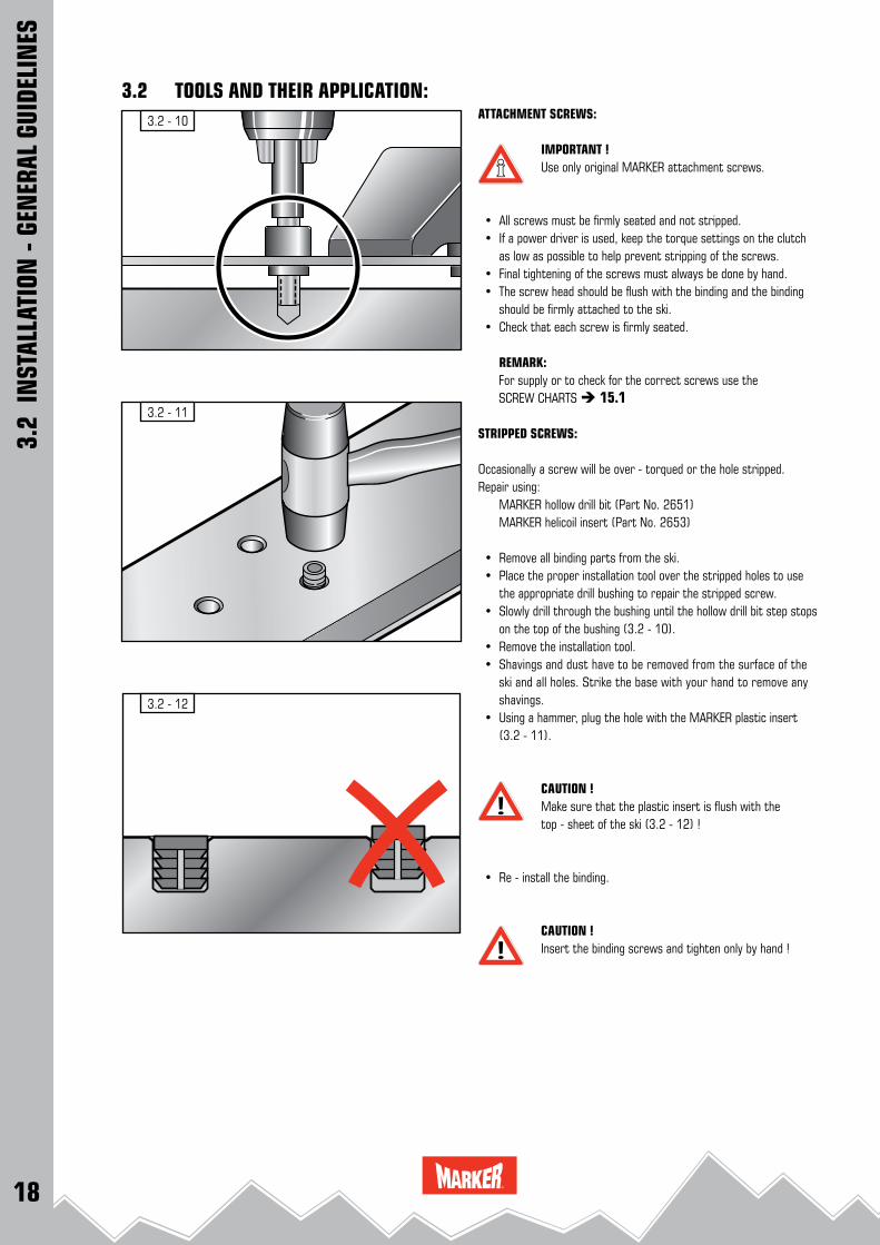
3.2 - 10
3.2 - 11
3.2 - 12
3.2 TOOLS AND THEIR APPLICATION:ATTACHMENT SCREWS:
IMPORTANT ! Use only original MARKER attachment screws.
• All screws must be firmly seated and not stripped. • If a power driver is used, keep the torque settings on the clutch
as low as possible to help prevent stripping of the screws. • Final tightening of the screws must always be done by hand. • The screw head should be flush with the binding and the binding
should be firmly attached to the ski. • Check that each screw is firmly seated.
REMARK: For supply or to check for the correct screws use the SCREW CHARTS 15.1
STRIPPED SCREWS:
Occasionally a screw will be over - torqued or the hole stripped. Repair using: MARKER hollow drill bit (Part No. 2651) MARKER helicoil insert (Part No. 2653)
• Remove all binding parts from the ski. • Place the proper installation tool over the stripped holes to use
the appropriate drill bushing to repair the stripped screw. • Slowly drill through the bushing until the hollow drill bit step stops
on the top of the bushing (3.2 - 10). • Remove the installation tool. • Shavings and dust have to be removed from the surface of the
ski and all holes. Strike the base with your hand to remove any shavings.
• Using a hammer, plug the hole with the MARKER plastic insert (3.2 - 11).
CAUTION !Make sure that the plastic insert is flush with the top - sheet of the ski (3.2 - 12) !
• Re - install the binding.
CAUTION ! Insert the binding screws and tighten only by hand !
3.2
INST
ALLA
TION
- GE
NER
AL G
UIDE
LIN
ES
19
1
2
3
4
5
6
78
9
10
11
12
13
14
15
16
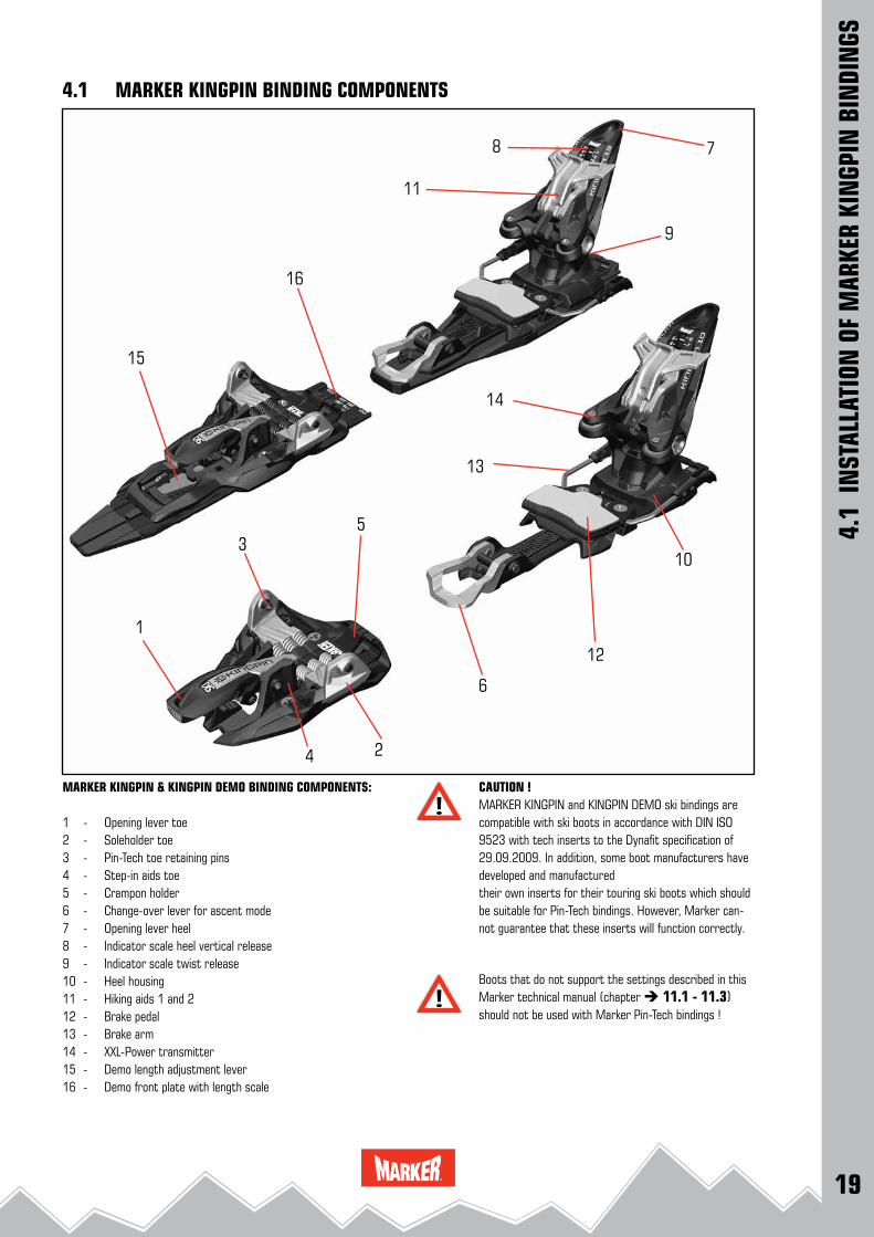
MARKER KINGPIN & KINGPIN DEMO BINDING COMPONENTS:
1 - Opening lever toe2 - Soleholder toe3 - Pin-Tech toe retaining pins4 - Step-in aids toe5 - Crampon holder6 - Change-over lever for ascent mode7 - Opening lever heel 8 - Indicator scale heel vertical release9 - Indicator scale twist release10 - Heel housing11 - Hiking aids 1 and 212 - Brake pedal13 - Brake arm14 - XXL-Power transmitter15 - Demo length adjustment lever16 - Demo front plate with length scale
CAUTION ! MARKER KINGPIN and KINGPIN DEMO ski bindings are compatible with ski boots in accordance with DIN ISO 9523 with tech inserts to the Dynafit specification of 29.09.2009. In addition, some boot manufacturers have developed and manufacturedtheir own inserts for their touring ski boots which should be suitable for Pin-Tech bindings. However, Marker can-not guarantee that these inserts will function correctly.
Boots that do not support the settings described in this Marker technical manual (chapter 11.1 - 11.3) should not be used with Marker Pin-Tech bindings !
4.1 MARKER KINGPIN BINDING COMPONENTS
4.1
INST
ALLA
TION
OF
MAR
KER
KIN
GPIN
BIN
DIN
GS
20
4.2 - 4
4.2 - 3
4.2 - 2
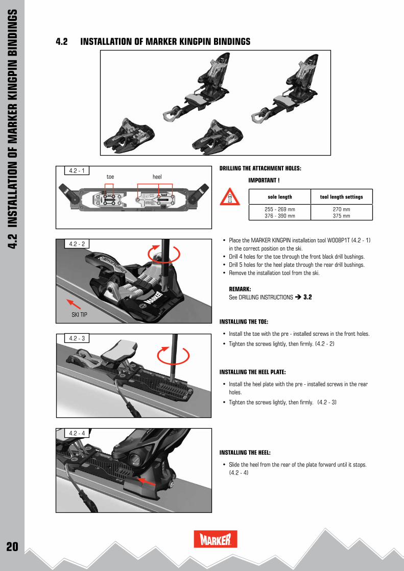
4.2 - 1 DRILLING THE ATTACHMENT HOLES:
IMPORTANT !
• Place the MARKER KINGPIN installation tool W008P1T (4.2 - 1) in the correct position on the ski.
• Drill 4 holes for the toe through the front black drill bushings. • Drill 5 holes for the heel plate through the rear drill bushings. • Remove the installation tool from the ski.
REMARK: See DRILLING INSTRUCTIONS 3.2
INSTALLING THE TOE:
• Install the toe with the pre - installed screws in the front holes.
• Tighten the screws lightly, then firmly. (4.2 - 2)
INSTALLING THE HEEL PLATE:
• Install the heel plate with the pre - installed screws in the rear holes.
• Tighten the screws lightly, then firmly. (4.2 - 3)
INSTALLING THE HEEL:
• Slide the heel from the rear of the plate forward until it stops. (4.2 - 4)
sole length tool length settings
255 - 269 mm376 - 390 mm
270 mm375 mm
toe heel
SKI TIP
4.2
INST
ALLA
TION
OF
MAR
KER
KIN
GPIN
BIN
DIN
GS
4.2 INSTALLATION OF MARKER KINGPIN BINDINGS

21
4.2 - 5
4.2 - 6
4.2 - 7
4.2 - 8
4.2 - 9
180 °
• With strong pressure, screw the heel forward onto the plate by turning the forward pressure adjustment screw. (4.2 - 5)
CAUTION ! Screw the heel onto the heel plate by hand !(4.2 - 6)
• Open the toe by pressing down the toe opening lever. (4.2 - 7)
• Switch the change-over lever 180° forward. (4.2 - 8)
• Open the heel. (4.2 - 9)
4.2
INST
ALLA
TION
OF
MAR
KER
KIN
GPIN
BIN
DIN
GS
4.2 INSTALLATION OF MARKER KINGPIN BINDINGS

22
4.2 - 13
4.2 - 10
4.2 - 11
4.2 - 12
• Position the tip of the ski boot between the Pin-Tech retaining pins on the toe. Then press the tip of the boot down and step into the toe. (4.2 - 10)
• The pins must be locked fully into position in the insert, the toe opening lever has to snap to the "Ski" position. (4.2 - 11)
POSITIONING THE HEEL:
• Place the ski boot into the binding and turn the adjustment screw until the position of the heel is approximately right. (4.2 - 12)
CHECK FORWARD PRESSURE:
• Place the ski boot into the binding and close it.
• Check if the forward pressure adjustment screw is flush with the back of the heel housing. If this adjustment is incorrect, turn the screw until it is flush with the back of the housing. (4.2 - 13 and 4.2 - 14)
4.2
INST
ALLA
TION
OF
MAR
KER
KIN
GPIN
BIN
DIN
GS
4.2 INSTALLATION OF MARKER KINGPIN BINDINGS
23
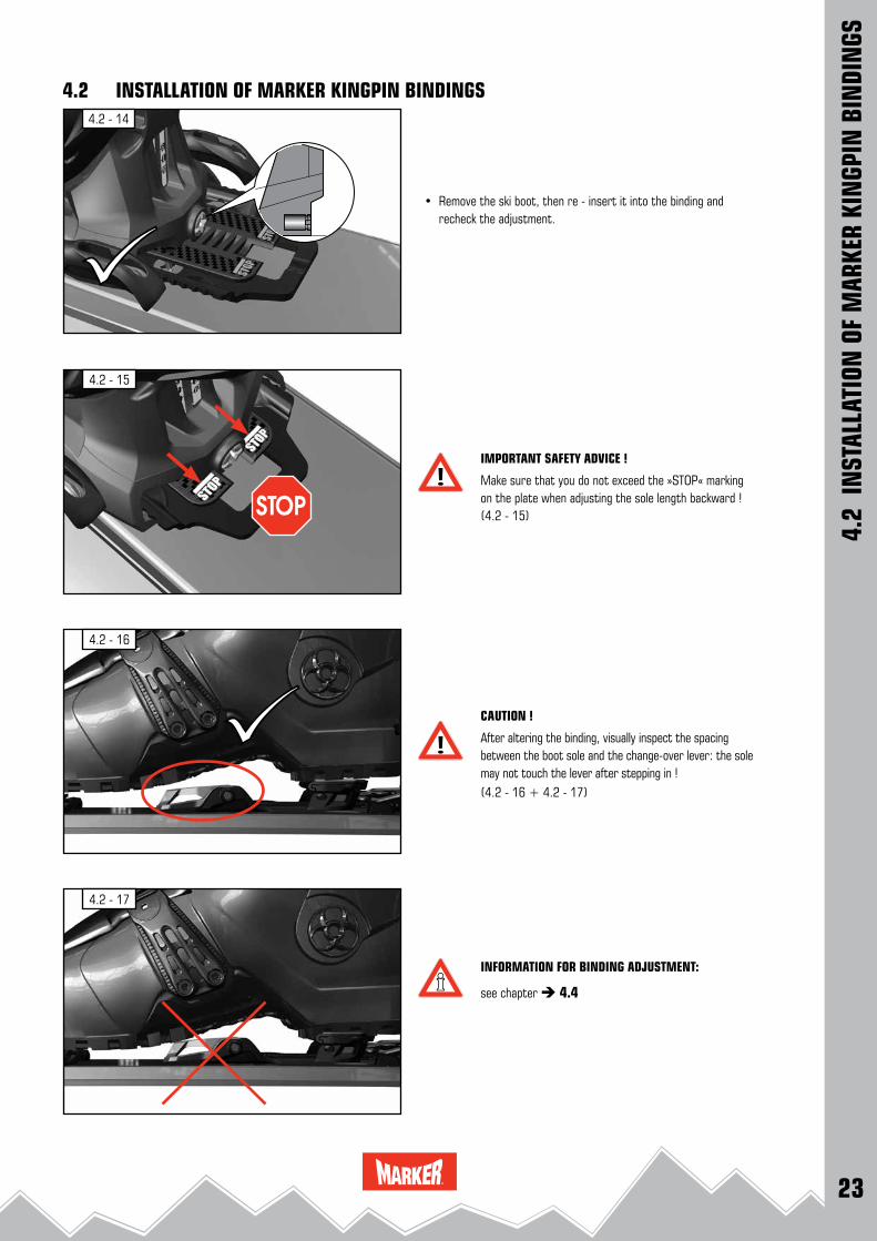
4.2 - 14
4.2 - 15
4.2 - 16
4.2 - 17
• Remove the ski boot, then re - insert it into the binding and recheck the adjustment.
IMPORTANT SAFETY ADVICE !
Make sure that you do not exceed the »STOP« marking on the plate when adjusting the sole length backward ! (4.2 - 15)
CAUTION !
After altering the binding, visually inspect the spacing between the boot sole and the change-over lever: the sole may not touch the lever after stepping in ! (4.2 - 16 + 4.2 - 17)
INFORMATION FOR BINDING ADJUSTMENT:
see chapter 4.4
4.2
INST
ALLA
TION
OF
MAR
KER
KIN
GPIN
BIN
DIN
GS
4.2 INSTALLATION OF MARKER KINGPIN BINDINGS

24
4.3 - 4
4.3 - 3
4.3 - 2
4.3 - 1
A
B C
Ls
DRILLING THE ATTACHMENT HOLES:
• Adjusting the installation tool: the arrow "Demo" on the front drill plate must be aligned with the marking "Demo" on the frame.
• Place the MARKER KINGPIN installation tool W008P1T (4.3 - 1) in the correct position on the ski.
• Drill 4 holes for the toe through the front silver drill bushings. • Drill 5 holes for the heel plate through the rear drill bushings. • Remove the installation tool from the ski.
REMARK: See DRILLING INSTRUCTIONS 3.2
INSTALLING THE TOE PLATE:
• Place the toe plate onto the ski.
• Insert the enclosed screws. Tighten the screws lightly, then firmly. (4.3 - 2)
INSTALLING THE TOE:
• Press down the lever lock and open the lever. Slide the toe with lever open from the front of the plate backward. (4.3 - 3)
• Slide the toe backward to the correct sole length in accordance with the sole length scale. (4.3 - 4)
toe heel
4.3
INST
ALLA
TION
OF
MAR
KER
KIN
GPIN
BIN
DIN
GS
4.3 INSTALLATION OF MARKER KINGPIN DEMO BINDINGS
ski tip

25
4.3 - 5
4.3 - 6
4.3 - 8
4.3 - 10
4.3 - 9
4.3 - 7
180 °
• Close the locking lever. (4.3 - 5)
CAUTION !Ensure that the lever is engaged properly !
INSTALLING THE HEEL PLATE:
• Install the heel plate with the pre - installed screws in the rear holes.
• Tighten the screws lightly, then firmly. (4.3 - 6)
INSTALLING THE HEEL:
• Slide the heel from the rear of the plate forward until it stops. (4.3 - 7)
• With strong pressure, screw the heel forward onto the plate by turning the forward pressure adjustment screw. (4.3 - 8)
CAUTION ! Screw the heel onto the heel plate by hand !
• Open the toe by pressing down the toe opening lever. (4.3 - 9)
• Switch the change-over lever 180° forward. (4.3 - 10)
4.3
INST
ALLA
TION
OF
MAR
KER
KIN
GPIN
BIN
DIN
GS
4.3 INSTALLATION OF MARKER KINGPIN DEMO BINDINGS

26
4.3 - 11
4.3 - 15
4.3 - 12
4.3 - 13
4.3 - 14
• Open the heel. (4.3 - 11)
• Position the tip of the ski boot between the Pin-Tech retaining pins on the toe. Then press the tip of the boot down and step into the toe. (4.3 - 12)
• The pins must be locked fully into position in the insert, the toe opening lever has to snap to the "Ski" position. (4.3 - 13)
POSITIONING THE HEEL:
• Place the ski boot into the binding and turn the adjustment screw until the position of the heel is approximately right. (4.3 - 14)
CHECK FORWARD PRESSURE:
• Place the ski boot into the binding and close it. (4.3 - 15)
4.3
INST
ALLA
TION
OF
MAR
KER
KIN
GPIN
BIN
DIN
GS
4.3 INSTALLATION OF MARKER KINGPIN DEMO BINDINGS

27
4.3 - 20
4.3 - 19
4.3 - 16
4.3 - 17
4.3 - 18
• Correct forward pressure: Check if the forward pressure adjustment screw is flush with the
back of the heel housing. If this adjustment is incorrect, turn the screw until it is flush with the back of the housing. (4.3 - 16 and 4.3 - 17)
• Remove the ski boot, then re - insert it into the binding and recheck the adjustment.
IMPORTANT SAFETY ADVICE !
Make sure that you do not exceed the »STOP« marking on the plate when adjusting the sole length backward ! (4.3 - 18)
CAUTION !
After altering the binding, visually inspect the spacing between the boot sole and the change-over lever: the sole may not touch the lever after stepping in ! (4.3 - 19 and 4.3 - 20)
INFORMATION FOR BINDING ADJUSTMENT:
see chapter 4.4
4.3
INST
ALLA
TION
OF
MAR
KER
KIN
GPIN
BIN
DIN
GS
4.3 INSTALLATION OF MARKER KINGPIN DEMO BINDINGS
28
4.4 - 1
4.4 - 21 2
4.4 - 4 3
4
4.4 - 3
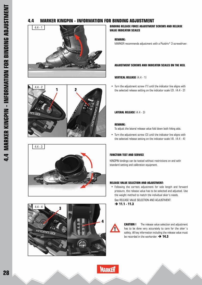
BINDING RELEASE FORCE ADJUSTMENT SCREWS AND RELEASEVALUE INDICATOR SCALES
REMARK: MARKER recommends adjustment with a Pozidriv® 3 screwdriver.
ADJUSTMENT SCREWS AND INDICATOR SCALES ON THE HEEL
VERTICAL RELEASE (4.4 - 1)
• Turn the adjustment screw (1) until the indicator line aligns with the selected release setting on the indicator scale (2). (4.4 - 2)
LATERAL RELEASE (4.4 - 3)
REMARK:To adjust the lateral release value fold down both hiking aids.
• Turn the adjustment screw (3) until the indicator line aligns with the selected release setting on the indicator scale (4). (4.4 - 4)
FUNCTION TEST AND SERVICE
KINGPIN bindings can be tested without restrictions on and with standard setting and calibration equipment.
RELEASE VALUE SELECTION AND ADJUSTMENT: • Following the correct adjustment for sole length and forward
pressure, the release value has to be selected and adjusted. Use the weight method to match the individual skier’s needs.
See RELEASE VALUE SELECTION AND ADJUSTMENT: 11.1 - 11.3
CAUTION ! The release value selection and adjustment has to be done very accurately to care for the skier´s safety. All key information including the release value must be recorded in the workorder. 14.3
4.4
MAR
KER
KIN
GPIN
- IN
FORM
ATIO
N F
OR B
INDI
NG
ADJU
STM
ENT
4.4 MARKER KINGPIN - INFORMATION FOR BINDING ADJUSTMENT
29
4.4 - 5
4.4 - 8
4.4 - 6
4.4 - 7
180 °
7 cm
Laser
04 cm
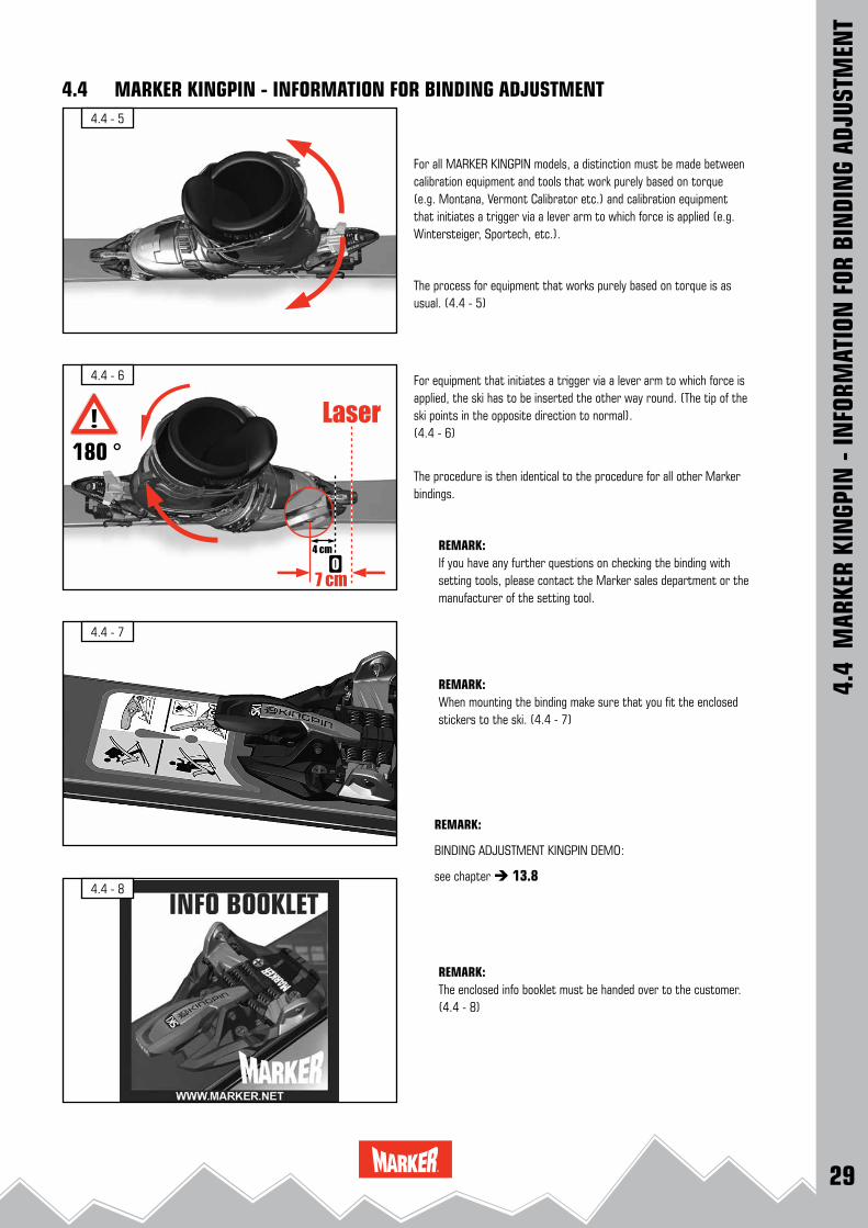
For all MARKER KINGPIN models, a distinction must be made between calibration equipment and tools that work purely based on torque (e.g. Montana, Vermont Calibrator etc.) and calibration equipment that initiates a trigger via a lever arm to which force is applied (e.g. Wintersteiger, Sportech, etc.).
The process for equipment that works purely based on torque is as usual. (4.4 - 5)
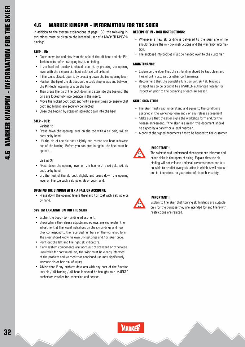
For equipment that initiates a trigger via a lever arm to which force is applied, the ski has to be inserted the other way round. (The tip of the ski points in the opposite direction to normal). (4.4 - 6)
The procedure is then identical to the procedure for all other Marker bindings.
REMARK:If you have any further questions on checking the binding with setting tools, please contact the Marker sales department or the manufacturer of the setting tool.
REMARK:When mounting the binding make sure that you fit the enclosed stickers to the ski. (4.4 - 7)
REMARK:
BINDING ADJUSTMENT KINGPIN DEMO:
see chapter 13.8
REMARK:The enclosed info booklet must be handed over to the customer. (4.4 - 8)
4.4
MAR
KER
KIN
GPIN
- IN
FORM
ATIO
N F
OR B
INDI
NG
ADJU
STM
ENT
4.4 MARKER KINGPIN - INFORMATION FOR BINDING ADJUSTMENT

30
4.5 - 5
4.5 - 4
4.5 - 1
4.5 - 3
4.5 - 2
4.5 - 6
DEMOUNT THE SKI BRAKE:
• Switch the change-over lever 180° forward to the "Ski" position. (4.5 - 1)
• Remove the attachment screws of the ski brake. (4.5 - 2)
• Pull the ski brake slightly forward and upward to remove. (4.5 - 3)
INSTALL THE KINGPIN BRAKE:
• Mount the brake from top to the heel plate. (4.5 - 4)
• Slide the brake backward onto the heel plate. (4.5 - 5 and 4.5 - 6)
4.5
MAR
KER
KIN
GPIN
REP
LACI
NG
BRAK
ES /
GLID
ING
AFD
4.5 MARKER KINGPIN REPLACING BRAKES / INSTALLATION OF GLIDING AFD

31
4.5 - 11
4.5 - 9
4.5 - 7
4.5 - 8
4.5 - 10
4.5 - 12
CAUTION !
Sliding the ski brake backward, make sure that the hooks of the brake base latch beneath the metal base plate and the plastic base plate of the heel on both sides ! (4.5 - 7)
• Install the attachment screws and tighten them by hand. (4.5 - 8)
INSTALLATION OF THE KINGPIN GLIDING AFD:
The brakes of the KINGPIN bindings can be replaced by the AFD gliding platform.
CAUTION !When using the binding MARKER KINGPIN withoutbrake a safety leash must be installed !
• Remove the brake as described under 4.5 - 1, 4.5 - 2 and 4.5 - 3.
• Mount the gliding AFD from top to the heel plate, ensure that the screw points align with the drilled holes. (4.5 - 9)
• Install the attachment screws and tighten them by hand. (4.5 - 10)
IMPORTANT SAFETY ADVICE !The MARKER KINGPIN must be equipped with ski brake and / or safety leash !In case of disregard the ski can speed downhill after arelease and hazard other persons.
REMARK: MARKER offers a special KINGPIN safety leash. (4.5 - 11)
Art. #: L001P1A
ATTACHING THE SAFETY LEASH: • Pass the leash through the hole on the right side of the toe and
secure the leash with a cow-hitch. (4.5 - 12)
4.5 MARKER KINGPIN REPLACING BRAKES / INSTALLATION OF GLIDING AFD
4.5
MAR
KER
KIN
GPIN
REP
LACI
NG
BRAK
ES /
GLID
ING
AFD
32
RECEIPT OF IN - BOX INSTRUCTIONS:
• Whenever a new ski binding is delivered to the skier she or he should receive the in - box instructions and the warranty informa-tion.
• The enclosed info booklet must be handed over to the customer.
MAINTENANCE:
• Explain to the skier that the ski binding should be kept clean and free of dirt, rust, salt or other contaminants.
• Recommend that the complete function unit ski / ski binding / ski boot has to be brought to a MARKER authorized retailer for inspection prior to the beginning of each ski season.
SKIER SIGNATURE
• The skier must read, understand and agree to the conditions specified in the workshop form and / or any release agreement.
• Make sure that the skier signs the workshop form and /or the release agreement. If the skier is a minor, this document should be signed by a parent or a legal guardian.
• A copy of the signed documents has to be handed to the customer.
IMPORTANT ! The skier should understand that there are inherent and other risks in the sport of skiing. Explain that the ski binding will not release under all circumstances nor is it possible to predict every situation in which it will release and is, therefore, no guarantee of his or her safety.
IMPORTANT ! Explain to the skier that touring ski bindings are suitable only for the purpose they are intended for and therewith restrictions are related.
In addition to the system explanations of page 162, the following in-structions must be given to the intended user of a MARKER KINGPIN binding:
STEP - IN: • Clear snow, ice and dirt from the sole of the ski boot and the Pin-
Tech inserts before stepping into the binding. • If the heel sole holder is closed, open it by pressing the opening
lever with the ski pole tip, boot sole, ski tail or hand. • If the toe is closed, open it by pressing down the toe opening lever. • Position the tip of the ski boot on the toe's step-in aids and between
the Pin-Tech retaining pins on the toe. • Then press the tip of the boot down and step into the toe until the
pins are locked fully into position in the insert. • Move the locked boot back and forth several times to ensure that
boot and binding are securely connected. • Close the binding by stepping straight down into the heel.
STEP - OUT: Variant 1: • Press down the opening lever on the toe with a ski pole, ski, ski
boot or by hand. • Lift the tip of the ski boot slightly and rotate the boot sideways
out of the binding. Before you can step in again, the heel must be opened.
Variant 2: • Press down the opening lever on the heel with a ski pole, ski, ski
boot or by hand. • Lift the heel of the ski boot slightly and press down the opening
lever on the toe with a ski pole, ski or your hand.
OPENING THE BINDING AFTER A FALL OR ACCIDENT: • Press down the opening levers (heel and / or toe) with a ski pole or
by hand.
SYSTEM EXPLANATION FOR THE SKIER:
• Explain the boot - to - binding adjustment. • Show where the release adjustment screws are and explain the
adjustment at the visual indicators on the ski bindings and how they correspond to the recorded numbers on the workshop form. The skier should know his own DIN settings and / or skier code.
• Point out the left and the right ski indicators. • If any system components are worn out of standard or otherwise
unsuitable for continued use, the skier must be clearly informed of the problem and warned that continued use may significantly increase his or her risk of injury.
• Advise that if any problem develops with any part of the function unit ski / ski binding / ski boot it should be brought to a MARKER authorized retailer for inspection and service.
4.6
MAR
KER
KIN
GPIN
- IN
FORM
ATIO
N F
OR T
HE S
KIER
4.6 MARKER KINGPIN - INFORMATION FOR THE SKIER

33
4.7 - 1
4.7 - 2
4.7 - 5
4.7 - 7
4.7 - 6
4.7 - 3 4.7 - 4
180 °
III
In addition to the system explanations of page 162, the following in-structions must be given to the intended user of a MARKER KINGPIN binding:
CHANGE - OVER FROM SKIING TO HIKING POSITION: • An adjusting lever between the toe and heel can be used to set two
different positions (skiing - mode / walking - mode).
• There is also another lever at the front end of the toe (C). that can also be used to choose between the positions for descent (SKI) and ascent (WALK). To switch from the descent position to ascent mode in order to walk with the binding, move the adjusting lever (4.7 - 1, 4.7 - 2 and 4.7 - 3) backwards by 180° and pull the toe opening lever upwards (4.7 - 4). The lever noticeably clicks into a catch and should be pushed as far as possible.
• When taking the first step with the binding in walking mode, the brake is automatically applied and the heel clicks, thus getting the hiking aids ready for use. The ski mountaineer is now in the 0° walking position.
USING THE HIKING AID
• In hiking mode, you can use two hiking aids with different angles. (4.7 - 5)
HIKING AID LOW POSITION: • To use this position, fold down hiking aid 1 with the pole disc or
by brushing along the heel opening lever with the tip of the pole. (4.7 - 6)
HIKING AID HIGH POSITION: • To use this position, fold down the hiking aid 2 with the pole disc or
by brushing along the heel opening lever with the tip of the pole . (4.7 - 7)
HIKING AID BASIC POSITION: • Fold the hiking aids back into the starting position individually or
together with the pole disc, or by brushing along the heel opening lever with the tip of the pole.
4.7 MARKER KINGPIN - INFORMATION FOR THE SKIER
4.7
MAR
KER
KIN
GPIN
- IN
FORM
ATIO
N F
OR T
HE S
KIER

34
4.7 - 8
4.7 - 11
4.7 - 9
4.7 - 10
180 °
CHANGING FROM WALKING - MODE TO SKIING - MODE:
• Free the bindings from snow and ice before changing from the walking - mode to the skiing - mode !
• In order to change from the walking - mode (unlocked position) to the skiing - mode (locked position) switch the lever 180° forward . (4.7 - 8, 4.7 - 9 and 4.7 - 10).
REMARK: Because the brake is not active in ascent mode, the lever must be set
to the descent position before the skins are removed from the ski.
CAUTION !For downhill skiing, always make sure that the opening lever toe (at the front end of the toe) is in the flat skiing position. The binding should always be in downhill mode(SKI) when skiing ! (4.7 - 11)
4.7
MAR
KER
KIN
GPIN
- IN
FORM
ATIO
N F
OR T
HE S
KIER
4.7 MARKER KINGPIN - INFORMATION FOR THE SKIER

35
4.8 - 1
4.8 - 2
4.8 - 4
4.8 - 6
4.8 - 5
4.8 - 3
KINGPIN CRAMPONS:
MARKER offers special crampons for the MARKER KINGPIN: (4.8 - 1)
Crampons KINGPIN 90 mm (for ski width 75-90 mm) Art.-Nr. H001P1PCrampons KINGPIN 105 mm (for ski width 90-105 mm) Art.-Nr. H002P1PCrampons KINGPIN 120 mm (for ski width 105-120 mm) Art.-Nr. H003P1P
ATTACHING THE CRAMPONS:
• Insert the crampon with the axis into the recess provided at the toe. Tilt the crampon around 60° to insert. (4.8 - 2 and 4.8 - 3)
• The crampon must noticeably click in place when it is centered. (4.8 - 4)
CAUTION !Using crampons that are too small can damage the ski !
CAUTION !No hiking aid may be used when walking with crampons. The effective action of the crampon in the snow may otherwise be too small.
DETACHING THE CRAMPONS:
• Tilt the crampon around 60°. (4.8 - 5)
• Push against the crampon from the side and pull out. (4.8 - 6)
4.8 MARKER KINGPIN - INFORMATION FOR THE SKIER
4.8
MAR
KER
KIN
GPIN
- IN
FORM
ATIO
N F
OR T
HE S
KIER

36
5.1 - 1
5.1 - 3
5.1 - 5
5.1 - 4
5.1 - 2
5.1
INST
ALLA
TION
OF
MAR
KER
ROYA
L FA
MIL
Y BI
NDI
NGS
5.1 INSTALLATION OF MARKER DUKE EPF & BARON EPF
CAUTION !The hole pattern for the MARKER DUKE / BARON EPF binding deviates from ISO 8364 (lateral hole spacing = 46 mm)Please take care to ensure that you use only the enclo-sed paper drilling jig (5.1 - 1) or the installation tool EPF, W006M1T (5.1 - 2).
This new hole spacing has been agreed with the following ski manufacturers, to ensure screw pull-out resistance values comply with ISO 8364: Völkl, K 2, Nordica, Blizzard, Movement, Line. For other brands of skis, please contact your ski manufacturer directly.
MARKER DUKE / BARON EPF: MARKER DUKE / BARON EPF small: 265 mm - 325 mmMARKER DUKE / BARON EPF large: 305 mm - 365 mm
REMARK:MARKER DUKE / BARON EPF bindings meet DIN ISO 13992 and 9462 and are designed for the following standard boot soles:• Touring ski boots for adults DIN ISO 9523• Alpine ski boots for adults DIN ISO 5355• Touring ski boots for adults DIN ISO 9523 with the additional marking "Gripwalk®"
DRILLING THE ATTACHMENT HOLES: • Place the MARKER EPF installation tool W006M1T (5.1 - 2) in
the correct position on the ski. • Drill 5 holes for the front plate through the front drill bushings. • MARKER DUKE / BARON EPF small: Drill 4 holes for the heel plate through the rear silver drill bushings. • MARKER DUKE / BARON EPF large: Drill 4 holes for the heel plate through the rear black drill bushings. • Remove the installation tool from the ski.
REMARK: See DRILLING INSTRUCTIONS 3.2
INSTALLING THE HEEL PLATE: • Install the heel plate with the 4 pre - installed screws. Tighten the
screws lightly, then firmly (5.1 - 3).
INSTALLING THE TOE: • Open the binding and install the front plate with the 3 pre - in-
stalled screws. Tighten the screws lightly, then firmly (5.1 - 4 and 5.1 - 5).
front plate heel plate small
heel plate large
SKI TIP
37
5.1 - 6
5.1 - 7
5.1 - 9
5.1 - 11
5.1 - 10
5.1 - 8
180 °
180 °
5.1
INST
ALLA
TION
OF
MAR
KER
ROYA
L FA
MIL
Y BI
NDI
NGS
5.1 INSTALLATION OF MARKER DUKE EPF & BARON EPF
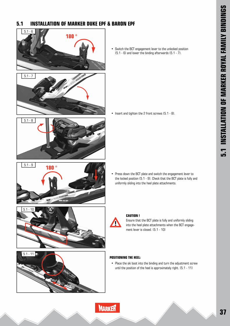
• Switch the BCT engagement lever to the unlocked position (5.1 - 6) and lower the binding afterwards (5.1 - 7).
• Insert and tighten the 2 front screws (5.1 - 8).
• Press down the BCT plate and switch the engagement lever to the locked position (5.1 - 9). Check that the BCT plate is fully and uniformly sliding into the heel plate attachments.
CAUTION ! Ensure that the BCT plate is fully and uniformly sliding into the heel plate attachments when the BCT engage-ment lever is closed. (5.1 - 10)
POSITIONING THE HEEL:
• Place the ski boot into the binding and turn the adjustment screw until the position of the heel is approximately right. (5.1 - 11)
38
5.1 - 12
5.1 - 13
5.1 - 15
5.1 - 17
5.1 - 16
5.1 - 14
5.1
INST
ALLA
TION
OF
MAR
KER
ROYA
L FA
MIL
Y BI
NDI
NGS
5.1 INSTALLATION OF MARKER DUKE EPF & BARON EPFCHECK FORWARD PRESSURE:
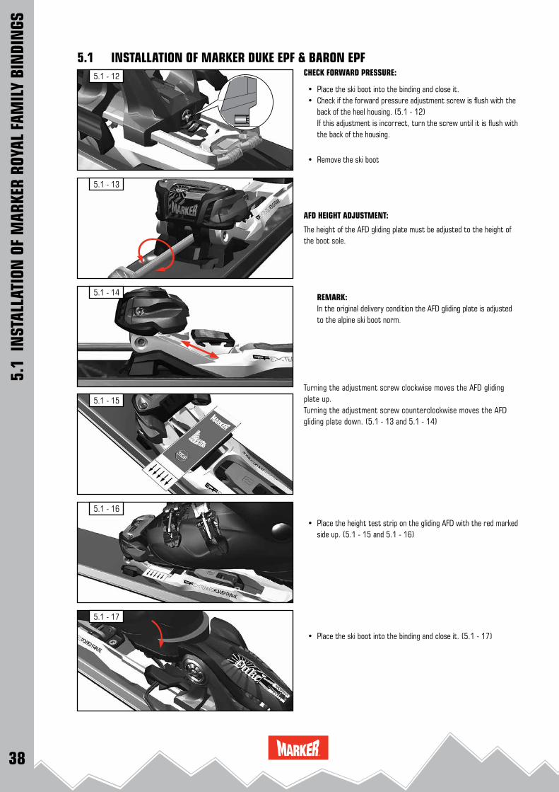
• Place the ski boot into the binding and close it. • Check if the forward pressure adjustment screw is flush with the
back of the heel housing. (5.1 - 12) If this adjustment is incorrect, turn the screw until it is flush with
the back of the housing.
• Remove the ski boot
AFD HEIGHT ADJUSTMENT:
The height of the AFD gliding plate must be adjusted to the height of the boot sole.
REMARK: In the original delivery condition the AFD gliding plate is adjusted to the alpine ski boot norm.
Turning the adjustment screw clockwise moves the AFD gliding plate up.Turning the adjustment screw counterclockwise moves the AFD gliding plate down. (5.1 - 13 and 5.1 - 14)
• Place the height test strip on the gliding AFD with the red marked side up. (5.1 - 15 and 5.1 - 16)
• Place the ski boot into the binding and close it. (5.1 - 17)
39
5.1 - 18
5.1 - 19
5.1 - 21
5.1 - 23
5.1 - 22
5.1 - 20
5.1
INST
ALLA
TION
OF
MAR
KER
ROYA
L FA
MIL
Y BI
NDI
NGS
5.1 INSTALLATION OF MARKER DUKE EPF & BARON EPF
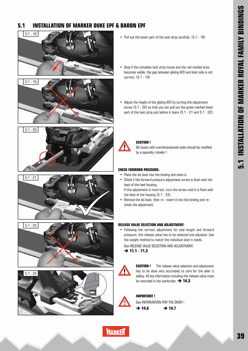
• Pull out the lower part of the test strip carefully. (5.1 - 18)
• Stop if the complete test strip moves and the red marked area becomes visible, the gap between gliding AFD and boot sole is not correct. (5.1 - 19)
• Adjust the height of the gliding AFD by turning the adjustment screw (5.1 - 20) so that you can pull out the green marked lower part of the test strip just before it tears (5.1 - 21 and 5.1 - 22).
CAUTION ! Ski boots with overdimensioned soles should be modified by a specialty retailer !
CHECK FORWARD PRESSURE: • Place the ski boot into the binding and close it. • Check if the forward pressure adjustment screw is flush with the
back of the heel housing. If this adjustment is incorrect, turn the screw until it is flush with
the back of the housing (5.1 - 23). • Remove the ski boot, then re - insert it into the binding and re-
check the adjustment.
RELEASE VALUE SELECTION AND ADJUSTMENT: • Following the correct adjustment for sole length and forward
pressure, the release value has to be selected and adjusted. Use the weight method to match the individual skier’s needs.
See RELEASE VALUE SELECTION AND ADJUSTMENT: 11.1 - 11.3
CAUTION ! The release value selection and adjustment has to be done very accurately to care for the skier´s safety. All key information including the release value must be recorded in the workorder. 14.3
IMPORTANT !
See INFORMATION FOR THE SKIER !
14.6 14.7

40
3
1
2
5
4
5.2 - 2
5.2 - 4 265 - 279280 - 299300 - 319320 - 339340 - 365
265
280
300
320
340
279299
319339
365
5.2 - 15.2 - 1
5.2 - 3
MARKER SCHIZO SYSTEM:1 Toe piece 2 Toe plate with adjustment scale3 Heel plate 4 Connecting cable5 Multi - stance adjustment screw
REMARK: these binding models are designed for use only with Alpine ski boots for adults DIN ISO 5355 type A.
DRILLING THE ATTACHMENT HOLES: See ADJUSTMENT OF THE BINDING INSTALLATION TOOLS. 3.2 IMPORTANT !
• Place the MARKER universal installation tool W001G1T or W012J1T (5.2 - 1) in the correct position on the ski.
• Drill 4 holes for the front plate (toe) through the red marked drill bushings, drill the additional rear hole for the front plate through the rear toe bushing. (5.2 - 1)
• Drill 4 holes for the heel plate (heel) through the red marked drill bushings
• Remove installation tool from the ski.
REMARK: See DRILLING INSTRUCTIONS 3.2
INSTALLING THE TOE PLATE: • Install the MARKER SCHIZO toe plate with the 5 pre - installed
screws in the front holes (5.2 - 2). Tighten the screws lightly, then firmly.
INSTALLING THE HEEL PLATE: • Install the MARKER SCHIZO heel plate with the 4 pre - installed
screws in the rear holes (5.2 - 3). Tighten the screws lightly, then firmly.
INSTALLING THE CONNECTING CABLE : • Determine the sole length and identify the cor-
rect mounting position of the connecting cable on the bottom side of the toe piece. (5.2 - 4)
5.2
INST
ALLA
TION
OF
MAR
KER
ROYA
L FA
MIL
Y BI
NDI
NGS
5.2 INSTALLATION OF MARKER SCHIZO 14 & SCHIZO 11
ski tip
ski tip
toe
heel
sole length tool length setting
< 279 mm 280 mm
41
5.2 - 5 B
5.2 - 9
5.2 - 7 A
5.2 - 5 A
5.2 - 8
5.2 - 6
5.2 - 7 B
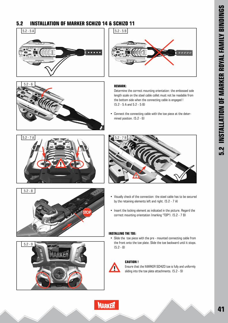
REMARK: Determine the correct mounting orientation: the embossed sole
length scale on the steel cable collet must not be readable from the bottom side when the connecting cable is engaged !
(5.2 - 5 A and 5.2 - 5 B)
• Connect the connecting cable with the toe piece at the deter-mined position. (5.2 - 6)
• Visually check of the connection: the steel cable has to be secured by the retaining elements left and right. (5.2 - 7 A)
• Insert the locking element as indicated in the picture. Regard the correct mounting orientation (marking "TOP"). (5.2 - 7 B)
INSTALLING THE TOE: • Slide the toe piece with the pre - mounted connecting cable from
the front onto the toe plate. Slide the toe backward until it stops. (5.2 - 8)
CAUTION ! Ensure that the MARKER SCHIZO toe is fully and uniformly sliding into the toe plate attachments. (5.2 - 9)
5.2
INST
ALLA
TION
OF
MAR
KER
ROYA
L FA
MIL
Y BI
NDI
NGS
5.2 INSTALLATION OF MARKER SCHIZO 14 & SCHIZO 11
42
5.2 - 10
5.2 - 11
- 30
5.2 - 12
265 - 289290 - 309310 - 329330 - 349350 - 365
5.2 - 13
5.2 - 14
5.2 - 165.2 - 15
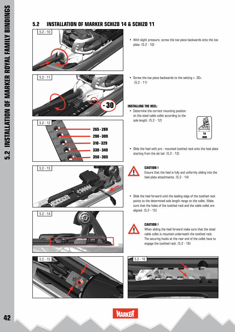
• With slight pressure, screw the toe piece backwards onto the toe plate. (5.2 - 10)
• Screw the toe piece backwards to the setting »- 30«. (5.2 - 11)
INSTALLING THE HEEL: • Determine the correct mounting position on the steel cable collet according to the sole length. (5.2 - 12)
• Slide the heel with pre - mounted toothed rack onto the heel plate starting from the ski tail. (5.2 - 13)
CAUTION ! Ensure that the heel is fully and uniformly sliding into the heel plate attachments. (5.2 - 14)
• Slide the heel forward until the leading edge of the toothed rack points to the determined sole length range on the collet. Make sure that the holes of the toothed rack and the cable collet are aligned. (5.2 - 15)
CAUTION ! When sliding the heel forward make sure that the steel cable collet is mounted underneath the toothed rack. The securing hooks at the rear end of the collet have to engage the toothed rack. (5.2 - 16)
5.2 INSTALLATION OF MARKER SCHIZO 14 & SCHIZO 11
5.2
INST
ALLA
TION
OF
MAR
KER
ROYA
L FA
MIL
Y BI
NDI
NGS

43
5.2 - 18
+ 0 -
5.2 - 19
5.2 - 20
+-
5.2 - 22
=
5.2 - 21 - 30+ 30 + 30 = max.
5.2 - 175.0 ± 0.5 Nm • Position the connecting screw. With downward pressure, tighten
the screw with a torque of 5.0 ± 0.5 Nm. (5.2 - 17)
• Adjust the system to the middle position »= 0« by turning the Multi - stance adjustment screw. (5.2 - 18)
CHECK FORWARD PRESSURE:
• Place the ski boot into the binding and close it. • Check if the forward pressure adjustment screw is flush with the
back of the heel housing. (5.2 - 19). If this adjustment is incorrect, turn the screw until it is flush with
the back of the housing. • Remove the ski boot, then re - insert it into the binding and re-
check the adjustment. RELEASE VALUE SELECTION AND ADJUSTMENT:
• Following the correct adjustment for sole length and forward pressure, the release value has to be selected and adjusted. Use the weight method to match the individual skier’s needs.
See RELEASE VALUE SELECTION AND ADJUSTMENT: 11.1 - 11.3
CAUTION ! The release value selection and adjust-ment has to be done very accurately to care for the skier´s safety. All key information including the release value must be recorded in the workorder. 14.3
INFORMATION FOR THE SKIER:
• The Multi - Stance - Adjustor allows to change the binding positi-on for max. 60 mm. (5.2 - 20 and 5.2 - 21)
With the provided key the customer can easily adjust the positi-on by turning the Multi - stance adjustment screw.
IMPORTANT SECURITY ADVICE !
The customer must be informed that the position mar-kings »+ 30« and »- 30« on the front plate are the end positions ! Position + 30 = max (5.2 - 21) Position - 30 = min.
• Ensure that both bindings are adjusted to the same position on the ski. (5.2 - 22)
5.2 INSTALLATION OF MARKER SCHIZO 14 & SCHIZO 11
5.2
INST
ALLA
TION
OF
MAR
KER
ROYA
L FA
MIL
Y BI
NDI
NGS

44
5.3 - 1
5.3 - 4
5.3 - 3
5.3 - 2
REMARK: these binding models are designed for use only with Alpine ski boots for adults DIN ISO 5355 type A.
DRILLING THE ATTACHMENT HOLES:
See ADJUSTMENT OF THE BINDING INSTALLATION TOOLS. 3.2
• Place the MARKER universal installation tool W001G1T or W012J1T (5.3 - 1) in the correct position on the ski.
• Drill 4 holes for the front plate (toe) through the red marked drill bushings.
• Drill 4 holes for the heel plate (heel) through the red marked drill bushings
• Remove installation tool from the ski.
REMARK: See DRILLING INSTRUCTIONS 3.2
INSTALLING THE HEEL :
• Install the heel plate with the 4 pre - installed screws (5.3 - 2). Tighten the screws lightly, then firmly.
• Slide the heel onto the heel plate, starting from the front. (5.3 - 3)
• Slide the heel back until it stops. (5.3 - 3)
CAUTION ! Ensure that the heel is fully and uniformly sliding onto the heel plate. (5.3 - 4)
5.3
INST
ALLA
TION
OF
MAR
KER
ROYA
L FA
MIL
Y BI
NDI
NGS
5.3 INSTALLATION OF MARKER JESTER PRO & SQUIRE
heel
toe
45
5.3 - 5
5.3 - 7
5.3 - 8
5.3 - 9
5.3 - 6
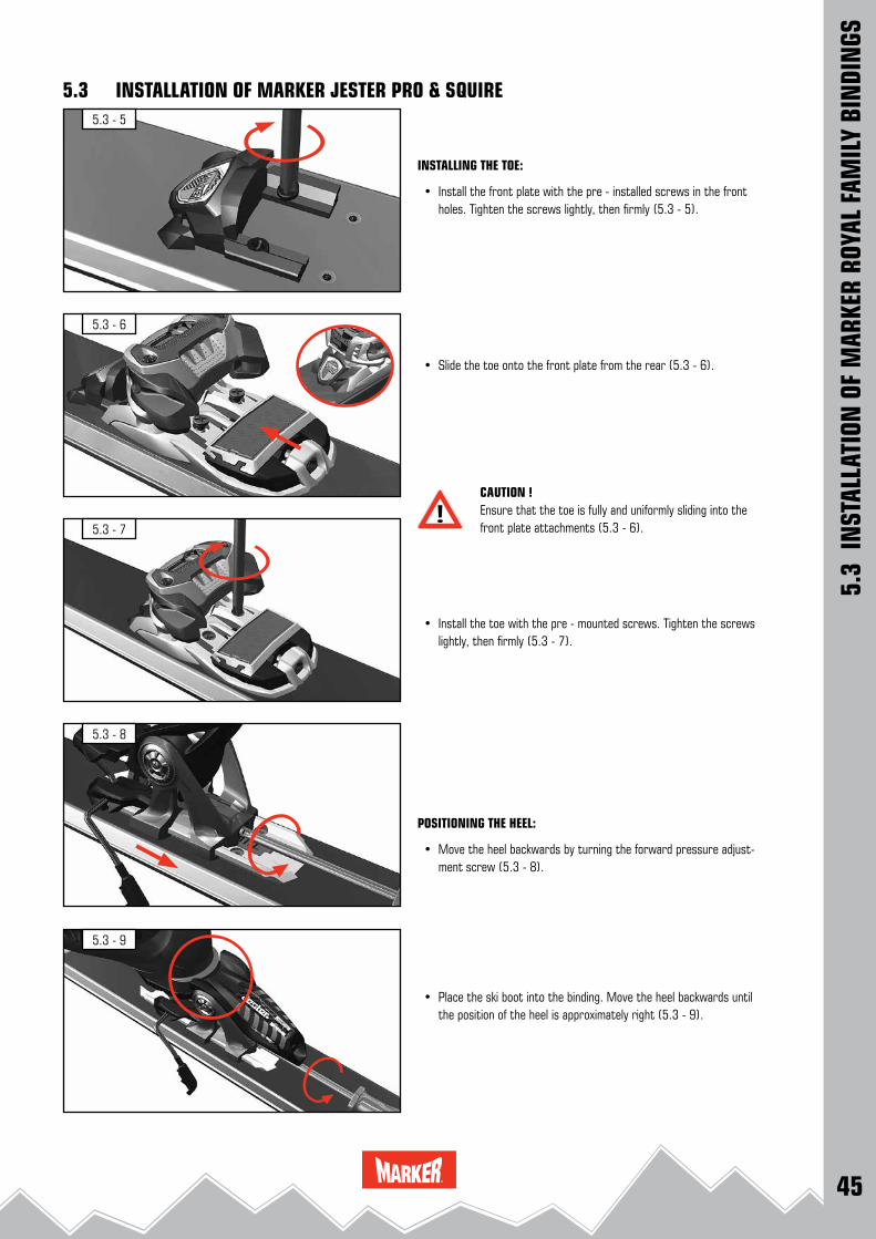
INSTALLING THE TOE:
• Install the front plate with the pre - installed screws in the front holes. Tighten the screws lightly, then firmly (5.3 - 5).
• Slide the toe onto the front plate from the rear (5.3 - 6).
CAUTION ! Ensure that the toe is fully and uniformly sliding into the front plate attachments (5.3 - 6).
• Install the toe with the pre - mounted screws. Tighten the screws lightly, then firmly (5.3 - 7).
POSITIONING THE HEEL:
• Move the heel backwards by turning the forward pressure adjust-ment screw (5.3 - 8).
• Place the ski boot into the binding. Move the heel backwards until the position of the heel is approximately right (5.3 - 9).
5.3
INST
ALLA
TION
OF
MAR
KER
ROYA
L FA
MIL
Y BI
NDI
NGS
5.3 INSTALLATION OF MARKER JESTER PRO & SQUIRE
46
5.3 - 14
5.3 - 13
5.3 - 10
5.3 - 12
5.3 - 11
5.3
INST
ALLA
TION
OF
MAR
KER
ROYA
L FA
MIL
Y BI
NDI
NGS
5.3 INSTALLATION OF MARKER JESTER PRO & SQUIRE
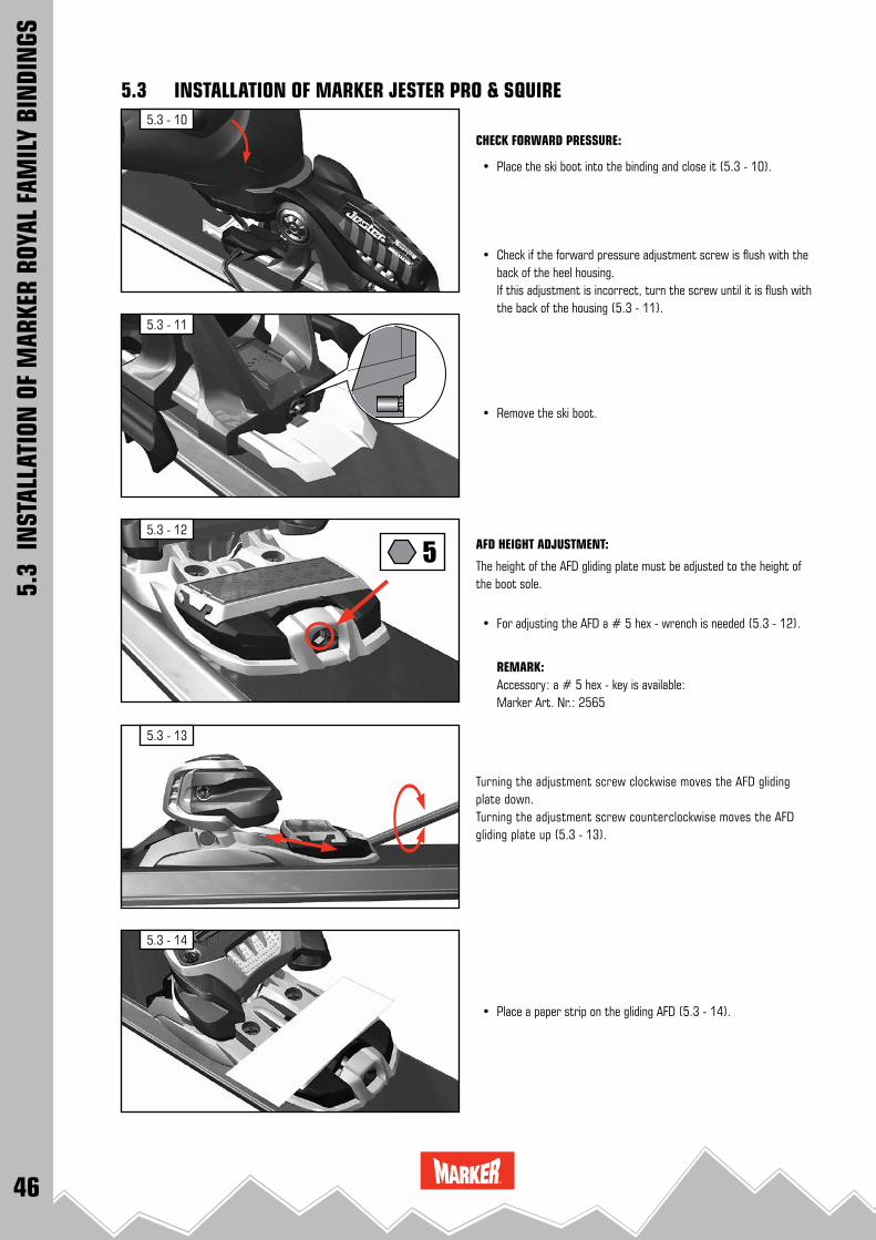
CHECK FORWARD PRESSURE:
• Place the ski boot into the binding and close it (5.3 - 10).
• Check if the forward pressure adjustment screw is flush with the back of the heel housing.
If this adjustment is incorrect, turn the screw until it is flush with the back of the housing (5.3 - 11).
• Remove the ski boot.
AFD HEIGHT ADJUSTMENT:
The height of the AFD gliding plate must be adjusted to the height of the boot sole.
• For adjusting the AFD a # 5 hex - wrench is needed (5.3 - 12).
REMARK: Accessory: a # 5 hex - key is available: Marker Art. Nr.: 2565
Turning the adjustment screw clockwise moves the AFD gliding plate down.Turning the adjustment screw counterclockwise moves the AFD gliding plate up (5.3 - 13).
• Place a paper strip on the gliding AFD (5.3 - 14).
47
5.3 - 16
5.3 - 17
5.3 - 15
5.3 - 19
5.3 - 18
ca. 0.5 mm
5.3
INST
ALLA
TION
OF
MAR
KER
ROYA
L FA
MIL
Y BI
NDI
NGS
5.3 INSTALLATION OF MARKER JESTER PRO & SQUIRE
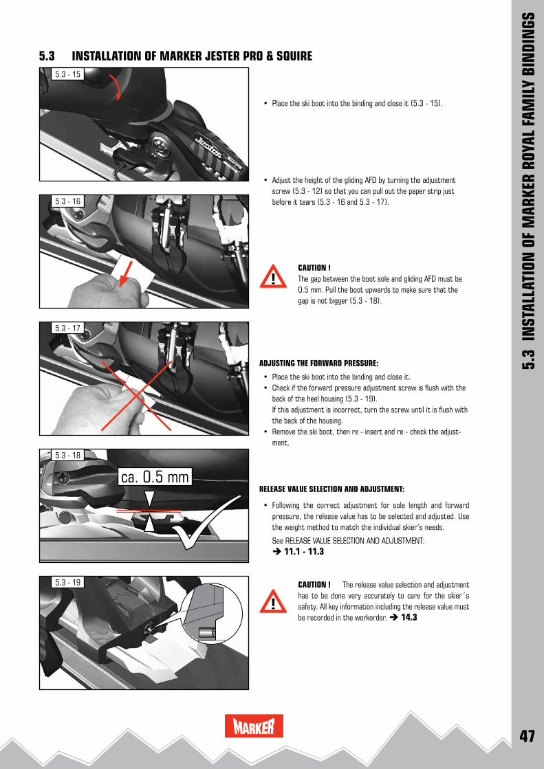
• Place the ski boot into the binding and close it (5.3 - 15).
• Adjust the height of the gliding AFD by turning the adjustment screw (5.3 - 12) so that you can pull out the paper strip just before it tears (5.3 - 16 and 5.3 - 17).
CAUTION ! The gap between the boot sole and gliding AFD must be 0.5 mm. Pull the boot upwards to make sure that the gap is not bigger (5.3 - 18).
ADJUSTING THE FORWARD PRESSURE:
• Place the ski boot into the binding and close it. • Check if the forward pressure adjustment screw is flush with the
back of the heel housing (5.3 - 19). If this adjustment is incorrect, turn the screw until it is flush with
the back of the housing. • Remove the ski boot, then re - insert and re - check the adjust-
ment.
RELEASE VALUE SELECTION AND ADJUSTMENT:
• Following the correct adjustment for sole length and forward pressure, the release value has to be selected and adjusted. Use the weight method to match the individual skier’s needs.
See RELEASE VALUE SELECTION AND ADJUSTMENT: 11.1 - 11.3
CAUTION ! The release value selection and adjustment has to be done very accurately to care for the skier´s safety. All key information including the release value must be recorded in the workorder. 14.3
48
5.4 - 1
5.4 - 4
5.4 - 3
5.4 - 2
5.4
INST
ALLA
TION
OF
MAR
KER
ROYA
L FA
MIL
Y BI
NDI
NGS
5.4 INSTALLATION OF MARKER JESTER 16 ID & GRIFFON 13 ID
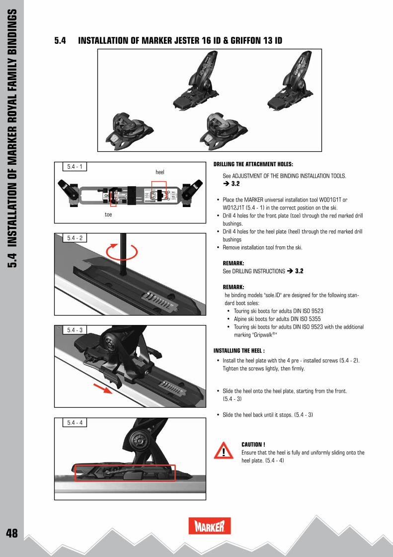
DRILLING THE ATTACHMENT HOLES:
See ADJUSTMENT OF THE BINDING INSTALLATION TOOLS. 3.2
• Place the MARKER universal installation tool W001G1T or W012J1T (5.4 - 1) in the correct position on the ski.
• Drill 4 holes for the front plate (toe) through the red marked drill bushings.
• Drill 4 holes for the heel plate (heel) through the red marked drill bushings
• Remove installation tool from the ski.
REMARK: See DRILLING INSTRUCTIONS 3.2
REMARK:he binding models "sole.ID" are designed for the following stan-dard boot soles:• Touring ski boots for adults DIN ISO 9523• Alpine ski boots for adults DIN ISO 5355• Touring ski boots for adults DIN ISO 9523 with the additional marking "Gripwalk®"
INSTALLING THE HEEL :
• Install the heel plate with the 4 pre - installed screws (5.4 - 2). Tighten the screws lightly, then firmly.
• Slide the heel onto the heel plate, starting from the front. (5.4 - 3)
• Slide the heel back until it stops. (5.4 - 3)
CAUTION ! Ensure that the heel is fully and uniformly sliding onto the heel plate. (5.4 - 4)
heel
toe

49
5.4 - 5
5.4 - 6
5.4 - 8
5.4 - 9
5.4 - 10
max. 4 Nm
5.4 - 7
ISO 5355ALPINE
5.4
INST
ALLA
TION
OF
MAR
KER
ROYA
L FA
MIL
Y BI
NDI
NGS
5.4 INSTALLATION OF MARKER JESTER 16 ID & GRIFFON 13 ID
INSTALLING THE TOE:
• Install the front plate with the pre - installed screws in the front holes. Tighten the screws lightly, then firmly (5.4 - 5).
• Slide the toe onto the front plate from the rear (5.4 - 6).
CAUTION ! Ensure that the toe is fully and uniformly sliding into the front plate attachments and the height adjustment screw is mounted correct to the front plate. (5.4 - 7)
• Install the toe with the enclosed screws. Tighten the screws lightly, then firmly (5.4 - 8).
AFD HEIGHT ADJUSTMENT.
• The height of the AFD gliding plate must be adjusted to the height of the boot sole. (5.4 - 9)
REMARK: In the original delivery condition the AFD gliding plate is adjusted to the alpine ski boot norm.
• When the gliding AFD is adjusted to the rear / upper position, the height conforms to the DIN ISO 5355 (Alpine boots) (5.4 - 10)
50
5.4 - 16
5.4 - 15
5.4 - 11
5.4 - 14
5.4 - 12
5.4 - 13
ISO 9523TOURING
5.4
INST
ALLA
TION
OF
MAR
KER
ROYA
L FA
MIL
Y BI
NDI
NGS
5.4 INSTALLATION OF MARKER JESTER 16 ID & GRIFFON 13 ID
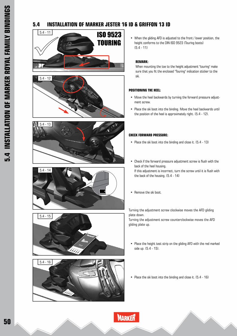
• When the gliding AFD is adjusted to the front / lower position, the height conforms to the DIN ISO 9523 (Touring boots) (5.4 - 11)
REMARK:When mounting the toe to the height adjustment "touring" make sure that you fit the enclosed "Touring" indication sticker to the ski.
POSITIONING THE HEEL:
• Move the heel backwards by turning the forward pressure adjust-ment screw.
• Place the ski boot into the binding. Move the heel backwards until the position of the heel is approximately right. (5.4 - 12).
CHECK FORWARD PRESSURE:
• Place the ski boot into the binding and close it. (5.4 - 13)
• Check if the forward pressure adjustment screw is flush with the back of the heel housing.
If this adjustment is incorrect, turn the screw until it is flush with the back of the housing. (5.4 - 14)
• Remove the ski boot.
Turning the adjustment screw clockwise moves the AFD gliding plate down.Turning the adjustment screw counterclockwise moves the AFD gliding plate up.
• Place the height test strip on the gliding AFD with the red marked side up. (5.4 - 15).
• Place the ski boot into the binding and close it. (5.4 - 16)

51
5.4 - 22
5.4 - 21
5.4 - 17
5.4 - 20
5.4 - 18
5.4 - 19
5.4
INST
ALLA
TION
OF
MAR
KER
ROYA
L FA
MIL
Y BI
NDI
NGS
5.4 INSTALLATION OF MARKER JESTER 16 ID & GRIFFON 13 ID
• Pull out the lower part of the test strip carefully. (5.4 - 17)
• Stop if the complete test strip moves and the red marked area becomes visible, the gap between gliding AFD and boot sole is not correct. (5.4 - 18)
• Adjust the height of the gliding AFD by turning the adjustment screw (5.4 - 19) so that you can pull out the green marked lower part of the test strip just before it tears (5.4 - 20 and 5.4 - 21).
CHECK FORWARD PRESSURE: • Place the ski boot into the binding and close it. • Check if the forward pressure adjustment screw is flush with the
back of the heel housing. If this adjustment is incorrect, turn the screw until it is flush with
the back of the housing (5.4 - 22). • Remove the ski boot, then re - insert it into the binding and re-
check the adjustment.
RELEASE VALUE SELECTION AND ADJUSTMENT: • Following the correct adjustment for sole length and forward
pressure, the release value has to be selected and adjusted. Use the weight method to match the individual skier’s needs.
See RELEASE VALUE SELECTION AND ADJUSTMENT: 11.1 - 11.3
CAUTION ! The release value selection and adjustment has to be done very accurately to care for the skier´s safety. All key information including the release value must be recorded in the workorder. 14.3

52
5.5 - 1
5.5 - 2
5.5 - 4
5.5 - 6
5.5 - 5
5.5 - 3
5.5 - 7
5.5
INST
ALLA
TION
OF
MAR
KER
ROYA
L FA
MIL
Y BI
NDI
NGS
5.5 INSTALLATION OF MARKER LORD SP
DRILLING THE ATTACHMENT HOLES:
See ADJUSTMENT OF THE BINDING INSTALLATION TOOLS. 3.2 • Place the MARKER universal installation tool W001G1T or
W012J1T (5.5 - 1) in the correct position on the ski. • Drill 4 holes for the front plate (toe) through the red marked drill
bushings. • Drill 4 holes for the heel plate (heel) through the red marked drill
bushings • Remove installation tool from the ski.
REMARK: See DRILLING INSTRUCTIONS 3.2
INSTALLING THE HEEL :
• Install the heel plate with the 4 pre - installed screws (5.5 - 2). • Slide the heel onto the heel plate, starting from the front. • Slide the heel back until it stops (5.5 - 3). • Move the heel backwards by turning the forward pressure adjust-
ment screw counterclockwise.
CAUTION ! Ensure that the heel is fully and uniformly sliding onto the heel plate. (5.5 - 4).
INSTALLING THE TOE: • Install the front plate with the 4 pre - installed screws. Tighten the screws lightly, then firmly (5.5 - 5). • Unlock the system by lifting the locking lever. (5.5 - 6)
• Insert the toe from top. (5.5 - 7)
heel
toe
53
5.5 - 8
5.5 - 9
5.5 - 11
5.5 - 13
5.5 - 12
5.5 - 10
5.5
INST
ALLA
TION
OF
MAR
KER
ROYA
L FA
MIL
Y BI
NDI
NGS
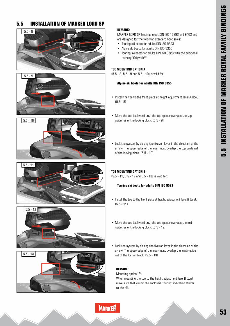
5.5 INSTALLATION OF MARKER LORD SPREMARK:MARKER LORD SP bindings meet DIN ISO 13992 and 9462 and are designed for the following standard boot soles:• Touring ski boots for adults DIN ISO 9523• Alpine ski boots for adults DIN ISO 5355• Touring ski boots for adults DIN ISO 9523 with the additional marking "Gripwalk®"
TOE MOUNTING OPTION A (5.5 - 8, 5.5 - 9 and 5.5 - 10) is valid for:
Alpine ski boots for adults DIN ISO 5355
• Install the toe to the front plate at height adjustment level A (low) (5.5 - 8)
• Move the toe backward until the toe spacer overlaps the top guide rail of the locking block. (5.5 - 9)
• Lock the system by closing the fixation lever in the direction of the arrow. The upper edge of the lever must overlap the top guide rail of the locking block. (5.5 - 10)
TOE MOUNTING OPTION B (5.5 - 11, 5.5 - 12 and 5.5 - 13) is valid for:
Touring ski boots for adults DIN ISO 9523
• Install the toe to the front plate at height adjustment level B (top). (5.5 - 11)
• Move the toe backward until the toe spacer overlaps the mid guide rail of the locking block. (5.5 - 12)
• Lock the system by closing the fixation lever in the direction of the arrow. The upper edge of the lever must overlap the lower guide rail of the locking block. (5.5 - 13)
REMARK:Mounting option "B":When mounting the toe to the height adjustment level B (top) make sure that you fit the enclosed "Touring" indication sticker to the ski.

54
5.5 - 14
5.5 - 16
5.5 - 18
5.5 - 20
5.5 - 19
5.5 - 17
5.5 - 15
3.0 ± 0.2 Nm
5.5
INST
ALLA
TION
OF
MAR
KER
ROYA
L FA
MIL
Y BI
NDI
NGS
5.5 INSTALLATION OF MARKER LORD SP
• Insert the fixation screw (5.5 - 14)
part #: 460200
(For mounting the screw a # 5 hex - wrench is needed)
• Tighten the fixation screw by hand with a torque of 3.0 ± 0.2 Nm. (5.5 - 15)
POSITIONING THE HEEL:
• Place the ski boot into the binding. Move the heel backwards until the position of the heel is approximately correct. (5.5 - 16)
CHECK FORWARD PRESSURE:
• Check if the forward pressure adjustment screw is flush with the back of the heel housing.
If this adjustment is incorrect, turn the screw until it is flush with the back of the housing. (5.5 - 17)
• Remove the ski boot.
AFD HEIGHT ADJUSTMENT:
The height of the AFD gliding plate must be fine adjusted to the height of the boot sole.
• For adjusting the AFD a # 5 hex - wrench is needed. (5.5 - 18)
Turning the adjustment screw clockwise moves the AFD gliding plate down.Turning the adjustment screw counterclockwise moves the AFD gliding plate up (5.5 - 19).
• Place the height test strip on the gliding AFD with the red marked side up. (5.5 - 20)

55
5.5 - 21
5.5 - 22
5.5 - 24
5.5 - 26
5.5 - 25
5.5 - 23
5.5
INST
ALLA
TION
OF
MAR
KER
ROYA
L FA
MIL
Y BI
NDI
NGS
5.5 INSTALLATION OF MARKER LORD SP
• Place the ski boot into the binding and close it. (5.5 - 21)
• Pull out the lower part of the test strip carefully. (5.5 - 22)
• Stop if the complete test strip moves and the red marked area becomes visible, the gap between gliding AFD and boot sole is not correct. (5.5 - 23)
• Adjust the height of the gliding AFD by turning the adjustment screw (5.5 - 18) so that you can pull out the green marked lower part of the test strip just before it tears (5.5 - 24 and 5.5 - 25).
CHECK FORWARD PRESSURE: • Place the ski boot into the binding and close it. • Check if the forward pressure adjustment screw is flush with the
back of the heel housing. If this adjustment is incorrect, turn the screw until it is flush with
the back of the housing (5.5 - 26). • Remove the ski boot, then re - insert it into the binding and re-
check the adjustment.
RELEASE VALUE SELECTION AND ADJUSTMENT: • Following the correct adjustment for sole length and forward
pressure, the release value has to be selected and adjusted. Use the weight method to match the individual skier’s needs.
See RELEASE VALUE SELECTION AND ADJUSTMENT: 11.1 - 11.3
CAUTION ! The release value selection and adjustment has to be done very accurately to care for the skier´s safety. All key information including the release value must be recorded in the workorder. 14.3

56
6.1 - 4
6.1 - 3
6.1 - 2
6.1 - 1
6.1
INST
ALLA
TION
OF
MAR
KER
BIN
DIN
GS
MARKER F 10 TOUR / F 12 TOUR:
MARKER F 10 TOUR + F 12 TOUR small: 265 mm - 325 mmMARKER F 10 TOUR + F 12 TOUR large: 305 mm - 365 mm
DRILLING THE ATTACHMENT HOLES:
• Place the MARKER TOUR installation tool W010G1T or W011J1T (6.1 - 1) in the correct position on the ski.
• Drill 5 holes for the front plate through the front drill bushings. • MARKER TOUR small: Drill 4 holes for the heel plate through the rear silver drill bushings. • MARKER TOUR large: Drill 4 holes for the heel plate through the rear black drill bushings. • Remove the installation tool from the ski.
REMARK: See DRILLING INSTRUCTIONS 3.2
REMARK:MARKER F 10 / F 12 TOUR bindings meet DIN ISO 13992 and 9462 and are designed for the following standard boot soles:• Touring ski boots for adults DIN ISO 9523• Alpine ski boots for adults DIN ISO 5355• Touring ski boots for adults DIN ISO 9523 with the additional marking "Gripwalk®"
INSTALLING THE HEEL PLATE:
• Install the MARKER TOUR heel plate with the 4 pre - installed screws. (6.1 - 2)
INSTALLING THE TOE:
• Open the binding and install the front plate with the 3 pre - installed screws (6.1 - 3 / 6.1 - 4).
6.1 INSTALLATION OF MARKER F 10 TOUR / F 12 TOUR
front plate heel platesmall
heel platelarge
Ski tip

57
6.1 - 5 180 °
6.1 - 6
6.1 - 7
6.1 - 8
180 °
6.1 - 9
6.1
INST
ALLA
TION
OF
MAR
KER
BIN
DIN
GS
6.1 INSTALLATION OF MARKER F 10 TOUR / F 12 TOUR
• Switch the TOUR engagement lever to the unlocked position (6.1 - 5)
• and lower the binding afterwards (6.1 - 6).
• Insert and tighten the 2 front screws (6.1 - 7).
• Press down the TOUR plate and switch the engagement lever to the locked position (6.1 - 8). Check that the TOUR plate is fully and uniformly sliding into the heel plate attachments.
CAUTION ! Ensure that the TOUR plate is fully and uniformly sliding into the heel plate attachments when the engagement lever is closed (6.1 - 9).

58
6.1 - 15
6.1 - 10
6.1 - 16
6.1 - 14
6.1 - 12
6.1 - 11
6.1 - 13
6.1
INST
ALLA
TION
OF
MAR
KER
BIN
DIN
GS
6.1 INSTALLATION OF MARKER F 10 TOUR / F 12 TOURPOSITIONING THE HEEL:
• Place the ski boot into the binding and turn the adjustment screw until the position of the heel is approximately right (6.1 - 10).
CHECK FORWARD PRESSURE:
• Place the ski boot into the binding and close it. • Check if the forward pressure adjustment screw is flush with the
back of the heel housing (6.1 - 11). If this adjustment is incorrect, turn the screw until it is flush with
the back of the housing. • Remove the ski boot
MARKER TOUR AFD HEIGHT ADJUSTMENT:
The height of the AFD gliding plate must be adjusted to the height of the boot sole.
Turning the adjustment screw clockwise moves the AFD gliding plate up.
Turning the adjustment screw counterclockwise moves the AFD gliding plate down (6.1 - 12 / 6.1 - 13).
• Place the height test strip on the gliding AFD with the red marked side up (6.1 - 14 and 6.1 - 15).
• Place the ski boot into the binding and close it (6.1 - 16).

59
6.1 - 17
6.1 - 18
6.1 - 20
6.1 - 22
6.1 - 21
6.1 - 19
6.1
INST
ALLA
TION
OF
MAR
KER
BIN
DIN
GS
6.1 INSTALLATION OF MARKER F 10 TOUR / F 12 TOUR
• Pull out the lower part of the test strip carefully. (6.1 - 17)
• Stop if the complete test strip moves and the red marked area becomes visible, the gap between gliding AFD and boot sole is not correct. (6.1 - 18)
• Adjust the height of the gliding AFD by turning the adjustment screw (6.1 - 19) so that you can pull out the green marked lower part of the test strip just before it tears (6.1 - 20 and 6.1 - 21).
CAUTION ! Ski boots with overdimensioned soles should be modified by a specialty retailer !
CHECK FORWARD PRESSURE: • Place the ski boot into the binding and close it. • Check if the forward pressure adjustment screw is flush with the
back of the heel housing. If this adjustment is incorrect, turn the screw until it is flush with
the back of the housing. (6.1 - 22) • Remove the ski boot, then re - insert it into the binding and re-
check the adjustment.
RELEASE VALUE SELECTION AND ADJUSTMENT: • Following the correct adjustment for sole length and forward
pressure, the release value has to be selected and adjusted. Use the weight method to match the individual skier’s needs.
See RELEASE VALUE SELECTION AND ADJUSTMENT: 11.1 - 11.3
CAUTION ! The release value selection and adjustment has to be done very accurately to care for the skier´s safety. All key information including the release value must be recorded in the workorder. 14.3
IMPORTANT !
See INFORMATION FOR THE SKIER
14.4 14.5 14.7

60
6.2 - 1
6.2 - 3
6.2 - 5
6.2 - 4
6.2 - 2
6.2
INST
ALLA
TION
OF
MAR
KER
BIN
DIN
GS
6.2 INSTALLATION OF MARKER F 12 TOUR EPF
CAUTION !The hole pattern for the MARKER F 12 TOUR EPF binding deviates from ISO 8364 (lateral hole spacing = 46 mm)Please take care to ensure that you use only the enclo-sed paper drilling jig (6.2 - 1) or the installation tool EPF, W006M1T (6.2 - 2).
This new hole spacing has been agreed with the following ski manufacturers, to ensure screw pull-out resistance values comply with ISO 8364: Völkl, K 2, Nordica, Blizzard, Movement, Line. For other brands of skis, please contact your ski manufacturer directly.
MARKER TOUR F 12 EPF: MARKER F 12 Tour EPF small: 265 mm - 325 mmMARKER F 12 Tour EPF large: 305 mm - 365 mm
REMARK:MARKER F 12 Tour EPF bindings meet DIN ISO 13992 and 9462 and are designed for the following standard boot soles:• Touring ski boots for adults DIN ISO 9523• Alpine ski boots for adults DIN ISO 5355• Touring ski boots for adults DIN ISO 9523 with the additional marking "Gripwalk®"
DRILLING THE ATTACHMENT HOLES: • Place the MARKER EPF installation tool W006M1T (6.2 - 2) in
the correct position on the ski. • Drill 5 holes for the front plate through the front drill bushings. • MARKER F 12 Tour EPF small: Drill 4 holes for the heel plate through the rear silver drill bushings. • MARKER F 12 Tour EPF large: Drill 4 holes for the heel plate through the rear black drill bushings. • Remove the installation tool from the ski.
REMARK: See DRILLING INSTRUCTIONS 3.2
INSTALLING THE HEEL PLATE: • Install the heel plate with the 4 pre - installed screws. Tighten the
screws lightly, then firmly (6.2 - 3).
INSTALLING THE TOE: • Open the binding and install the front plate with the 3 pre - in-
stalled screws. Tighten the screws lightly, then firmly (6.2 - 4 and 6.2 - 5).
front plate heel plate small
heel plate large
SKI TIP
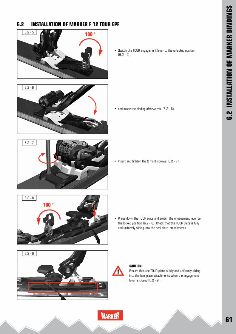
61
6.2 - 5 180 °
6.2 - 6
6.2 - 7
6.2 - 8
180 °
6.2 - 9
6.2
INST
ALLA
TION
OF
MAR
KER
BIN
DIN
GS
6.2 INSTALLATION OF MARKER F 12 TOUR EPF
• Switch the TOUR engagement lever to the unlocked position (6.2 - 5)
• and lower the binding afterwards (6.2 - 6).
• Insert and tighten the 2 front screws (6.2 - 7).
• Press down the TOUR plate and switch the engagement lever to the locked position (6.2 - 8). Check that the TOUR plate is fully and uniformly sliding into the heel plate attachments.
CAUTION ! Ensure that the TOUR plate is fully and uniformly sliding into the heel plate attachments when the engagement lever is closed (6.2 - 9).

62
6.2 - 15
6.2 - 10
6.2 - 16
6.2 - 14
6.2 - 12
6.2 - 11
6.2 - 13
6.2
INST
ALLA
TION
OF
MAR
KER
BIN
DIN
GS
6.2 INSTALLATION OF MARKER F 12 TOUR EPFPOSITIONING THE HEEL:
• Place the ski boot into the binding and turn the adjustment screw until the position of the heel is approximately correct (6.2 - 10).
CHECK FORWARD PRESSURE:
• Place the ski boot into the binding and close it.. • Check if the forward pressure adjustment screw is flush with the
back of the heel housing (6.2 - 11). If this adjustment is incorrect, turn the screw until it is flush with
the back of the housing. • Remove the ski boot
MARKER TOUR AFD HEIGHT ADJUSTMENT:
The height of the AFD gliding plate must be adjusted to the height of the boot sole.
Turning the adjustment screw clockwise moves the AFD gliding plate up.
Turning the adjustment screw counterclockwise moves the AFD gliding plate down (6.2 - 12 / 6.2 - 13).
• Place the height test strip on the gliding AFD with the red marked side up (6.2 - 14 and 6.2 - 15).
• Place the ski boot into the binding and close it (6.2 - 16).
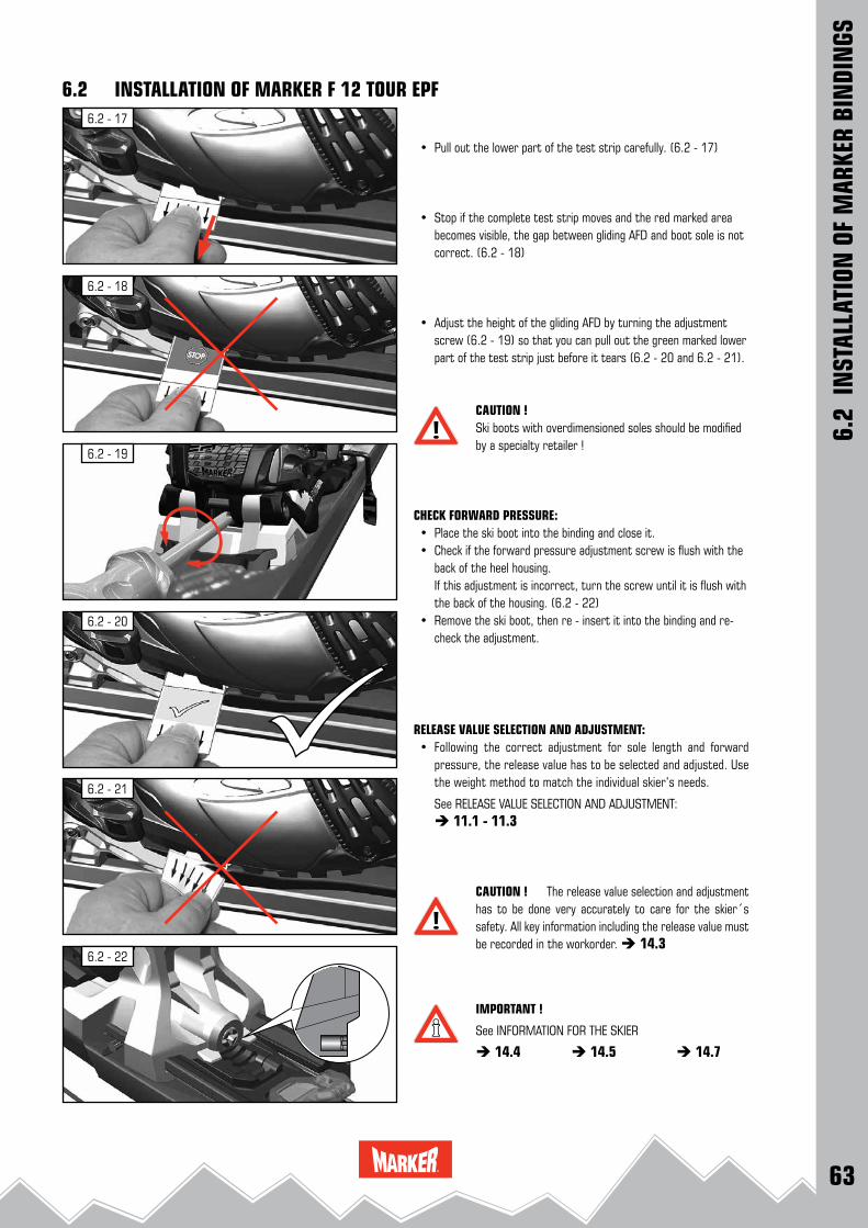
63
6.2 - 17
6.2 - 18
6.2 - 20
6.2 - 22
6.2 - 21
6.2 - 19
6.2
INST
ALLA
TION
OF
MAR
KER
BIN
DIN
GS
6.2 INSTALLATION OF MARKER F 12 TOUR EPF
• Pull out the lower part of the test strip carefully. (6.2 - 17)
• Stop if the complete test strip moves and the red marked area becomes visible, the gap between gliding AFD and boot sole is not correct. (6.2 - 18)
• Adjust the height of the gliding AFD by turning the adjustment screw (6.2 - 19) so that you can pull out the green marked lower part of the test strip just before it tears (6.2 - 20 and 6.2 - 21).
CAUTION ! Ski boots with overdimensioned soles should be modified by a specialty retailer !
CHECK FORWARD PRESSURE: • Place the ski boot into the binding and close it. • Check if the forward pressure adjustment screw is flush with the
back of the heel housing. If this adjustment is incorrect, turn the screw until it is flush with
the back of the housing. (6.2 - 22) • Remove the ski boot, then re - insert it into the binding and re-
check the adjustment.
RELEASE VALUE SELECTION AND ADJUSTMENT: • Following the correct adjustment for sole length and forward
pressure, the release value has to be selected and adjusted. Use the weight method to match the individual skier’s needs.
See RELEASE VALUE SELECTION AND ADJUSTMENT: 11.1 - 11.3
CAUTION ! The release value selection and adjustment has to be done very accurately to care for the skier´s safety. All key information including the release value must be recorded in the workorder. 14.3
IMPORTANT !
See INFORMATION FOR THE SKIER
14.4 14.5 14.7
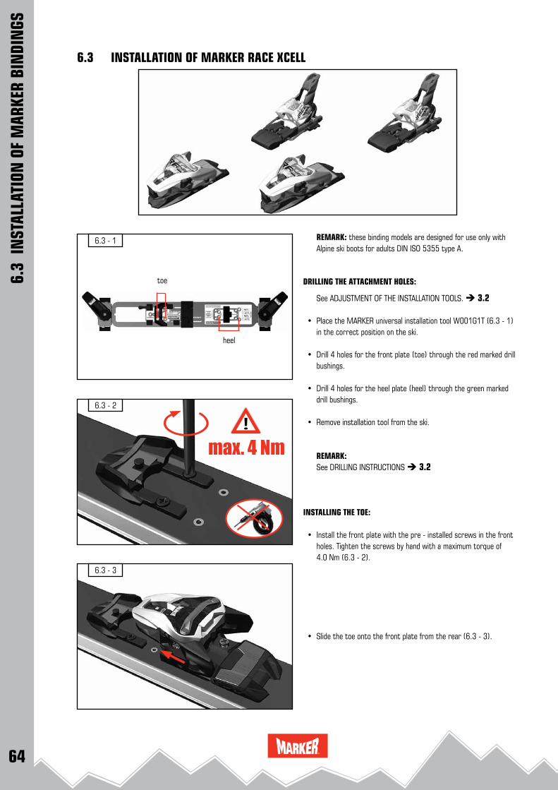
64
6.3 - 1
6.3 - 2
6.3 - 3
max. 4 Nm
6.3
INST
ALLA
TION
OF
MAR
KER
BIN
DIN
GS
6.3 INSTALLATION OF MARKER RACE XCELL
REMARK: these binding models are designed for use only with Alpine ski boots for adults DIN ISO 5355 type A.
DRILLING THE ATTACHMENT HOLES:
See ADJUSTMENT OF THE INSTALLATION TOOLS. 3.2
• Place the MARKER universal installation tool W001G1T (6.3 - 1) in the correct position on the ski.
• Drill 4 holes for the front plate (toe) through the red marked drill bushings.
• Drill 4 holes for the heel plate (heel) through the green marked drill bushings.
• Remove installation tool from the ski.
REMARK: See DRILLING INSTRUCTIONS 3.2
INSTALLING THE TOE:
• Install the front plate with the pre - installed screws in the front holes. Tighten the screws by hand with a maximum torque of 4.0 Nm (6.3 - 2).
• Slide the toe onto the front plate from the rear (6.3 - 3).
heel
toe

65
6.3 - 5
6.3 - 6
6.3 - 7
6.3 - 4
6.3
INST
ALLA
TION
OF
MAR
KER
BIN
DIN
GS
6.3 INSTALLATION OF MARKER RACE XCELL
CAUTION ! Ensure that the toe is fully and uniformly sliding into the front plate attachments (6.3 - 4).
• Install the toe with the pre - mounted screws. Tighten the screws lightly, then firmly (6.3 - 5).
INSTALLING THE HEEL: • Place the heel with the pre - installed screws onto the ski. • With downward pressure, tighten the screws lightly, then firmly.
(6.3 - 6)
CHECK FORWARD PRESSURE:
• Place the ski boot into the binding and close it. • Check if the forward pressure adjustment screw is flush with the
back of the heel housing. (6.3 - 7) If this adjustment is incorrect, turn the screw until it is flush with
the back of the housing. • Remove the ski boot, then re - insert it into the binding and re-
check the adjustment.
CAUTION ! Make sure that you do not exceed the back stop when
adjusting the sole length backward !
RELEASE VALUE SELECTION AND ADJUSTMENT:
• Following the correct adjustment for sole length and forward pressure, the release value has to be selected and adjusted. Use the weight method to match the individual skier’s needs.
See RELEASE VALUE SELECTION AND ADJUSTMENT: 11.1 - 11.3
see COMPETITION BINDINGS: 12.1
CAUTION ! The release value selection and adjustment has to be done very accurately to care for the skier´s safety. All key information including the release value must be recorded in the workorder. 14.3

66
6.4 - 4
6.4 - 2
6.4 - 3
6.4 - 5 6.4 - 6
Ls 260 - 370
6.4 - 1 Xcell Demo System
3.5 + 0.5 Nm
6.4
INST
ALLA
TION
OF
MAR
KER
BIN
DIN
GS
6.4 INSTALLATION OF MARKER XCELL DEMO SYSTEMREMARK: these binding models are designed for use only with Alpine ski boots for adults DIN ISO 5355 type A.
DRILLING THE ATTACHMENT HOLES: • Place the installation tool Xcell Demo System W009P1T (6.4 - 1)
in the correct position on the ski and secure it. • Drill the 4 holes for the front position and 4 holes for the rear
position through the silver marked drill bushings. • Remove the installation tool from the ski.
REMARK: See DRILLING INSTRUCTIONS 3.2
• Tighten the 4 front and the 4 rear screws lightly, then firmly. (6.4 - 2)
IMPORTANT ! For the installation of the Xcell Demo System plate a Torx wrench T 20 is needed.
REMARK:The binding mounting instruction is also valid for the MARKER / K 2 models MXCELL TCx D and the MARKER - BOGNER and MARKER INDIGO models Xcell Demo System.
INSTALLING THE TOE: • Slide the toe piece from the front onto the plate. Slide the toe
backward until it stops. (6.4 - 3)
CAUTION ! Make sure that the toe spacer rails engage both sides of the base plate properly. (6.4 - 3)
• With slight pressure, screw the toe piece backwards onto the plate. (6.4 - 4)
SOLE LENGTH ADJUSTMENT:
• Adjust the toe to the correct sole length in accordance with the sole length scale. (6.4 - 5)
IMPORTANT SAFETY ADVICE !
Make sure that you do not exceed the »STOP« marking on the plate when adjusting the sole length in forward direction ! (6.4 - 6)
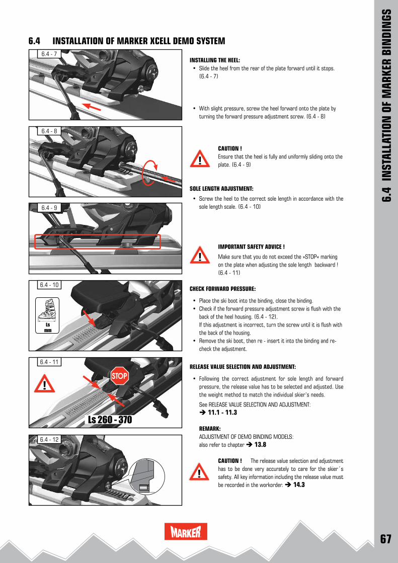
67
6.4 - 8
6.4 - 9
6.4 - 11
6.4 - 12
6.4 - 7
6.4 - 10
Ls 260 - 370
6.4
INST
ALLA
TION
OF
MAR
KER
BIN
DIN
GS
6.4 INSTALLATION OF MARKER XCELL DEMO SYSTEM
INSTALLING THE HEEL: • Slide the heel from the rear of the plate forward until it stops.
(6.4 - 7)
• With slight pressure, screw the heel forward onto the plate by turning the forward pressure adjustment screw. (6.4 - 8)
CAUTION ! Ensure that the heel is fully and uniformly sliding onto the plate. (6.4 - 9)
SOLE LENGTH ADJUSTMENT:
• Screw the heel to the correct sole length in accordance with the sole length scale. (6.4 - 10)
IMPORTANT SAFETY ADVICE !
Make sure that you do not exceed the »STOP« marking on the plate when adjusting the sole length backward ! (6.4 - 11)
CHECK FORWARD PRESSURE:
• Place the ski boot into the binding, close the binding. • Check if the forward pressure adjustment screw is flush with the
back of the heel housing. (6.4 - 12). If this adjustment is incorrect, turn the screw until it is flush with
the back of the housing. • Remove the ski boot, then re - insert it into the binding and re-
check the adjustment.
RELEASE VALUE SELECTION AND ADJUSTMENT:
• Following the correct adjustment for sole length and forward pressure, the release value has to be selected and adjusted. Use the weight method to match the individual skier’s needs.
See RELEASE VALUE SELECTION AND ADJUSTMENT: 11.1 - 11.3
REMARK:ADJUSTMENT OF DEMO BINDING MODELS:also refer to chapter 13.8
CAUTION ! The release value selection and adjustment has to be done very accurately to care for the skier´s safety. All key information including the release value must be recorded in the workorder. 14.3

68
6.5 - 4
6.5 - 3
6.5 - 1
6.5 - 2
Glide Control D
4.0 ± 0.5 Nm
6.5
INST
ALLA
TION
OF
MAR
KER
BIN
DIN
GS
6.5 INSTALLATION OF BINDINGS WITH GLIDE CONTROL DEMO SYSTEM
REMARK: these binding models are designed for use only with Alpine ski boots for adults DIN ISO 5355 type A.
DRILLING THE ATTACHMENT HOLES: • Place the Glide Control D & Comp D System & Royal Demo instal-
lation tool W005L1T (6.5 - 1) onto the ski and align the mid - sole mark »Glide Control D« with the mid - sole mark on the ski.
• Check if the installation tool is positioned correctly on the ski. • Drill 4 holes for the front plate and 4 holes for the heel plate
through the yellow marked drill bushings. • Remove installation tool from the ski.
REMARK: See DRILLING INSTRUCTIONS 3.2
INSTALLATION OF THE GLIDE CONTROL D PLATE:
• Place the Glide Control D plate onto the ski, tighten the front plate screws lightly, then firmly. (6.5 - 2)
• Tighten the heel plate screws lightly, then firmly with a torque of 4.0 ± 0.5 Nm. (6.5 - 3)
REMARK:The binding mounting instruction is also valid for the MARKER - MOVEMENT Glide Control models.
INSTALLING THE TOE:
• Open the locking lever at the toe by pivoting it upward and forward. (6.5 - 4)

69
6.5 - 5
6.5 - 6
6.5 - 7
6.5 - 8
6.5 - 9
6.5
INST
ALLA
TION
OF
MAR
KER
BIN
DIN
GS
6.5 INSTALLATION OF BINDINGS WITH GLIDE CONTROL DEMO SYSTEM
• The red locking block has to be pushed up to the "unlocked"
position. (6.5 - 5)
• Slide the toe from the center of the plate (6.5 - 6) forward
• to the ski tip. (6.5 - 7).
CAUTION !Make sure that the spacer rails engage both sides of the base plate properly. (6.5 - 8)
INSTALLING THE HEEL:
• Pull the connecting arm backwards.(6.5 - 9)
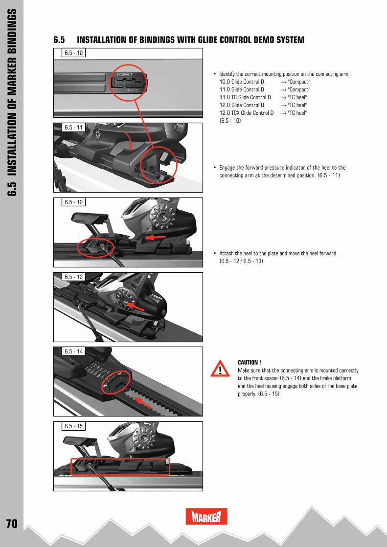
70
6.5 - 10
6.5 - 12
6.5 - 11
6.5 - 13
6.5 - 14
6.5 - 15
6.5
INST
ALLA
TION
OF
MAR
KER
BIN
DIN
GS
6.5 INSTALLATION OF BINDINGS WITH GLIDE CONTROL DEMO SYSTEM
• Identify the correct mounting position on the connecting arm: 10.0 Glide Control D → "Compact"
11.0 Glide Control D → "Compact" 11.0 TC Glide Control D → "TC heel" 12.0 Glide Control D → "TC heel" 12.0 TCX Glide Control D → "TC heel" (6.5 - 10)
• Engage the forward pressure indicator of the heel to the connecting arm at the determined position. (6.5 - 11)
• Attach the heel to the plate and move the heel forward. (6.5 - 12 / 6.5 - 13)
CAUTION !Make sure that the connecting arm is mounted correctly to the front spacer (6.5 - 14) and the brake platform and the heel housing engage both sides of the base plate properly. (6.5 - 15)
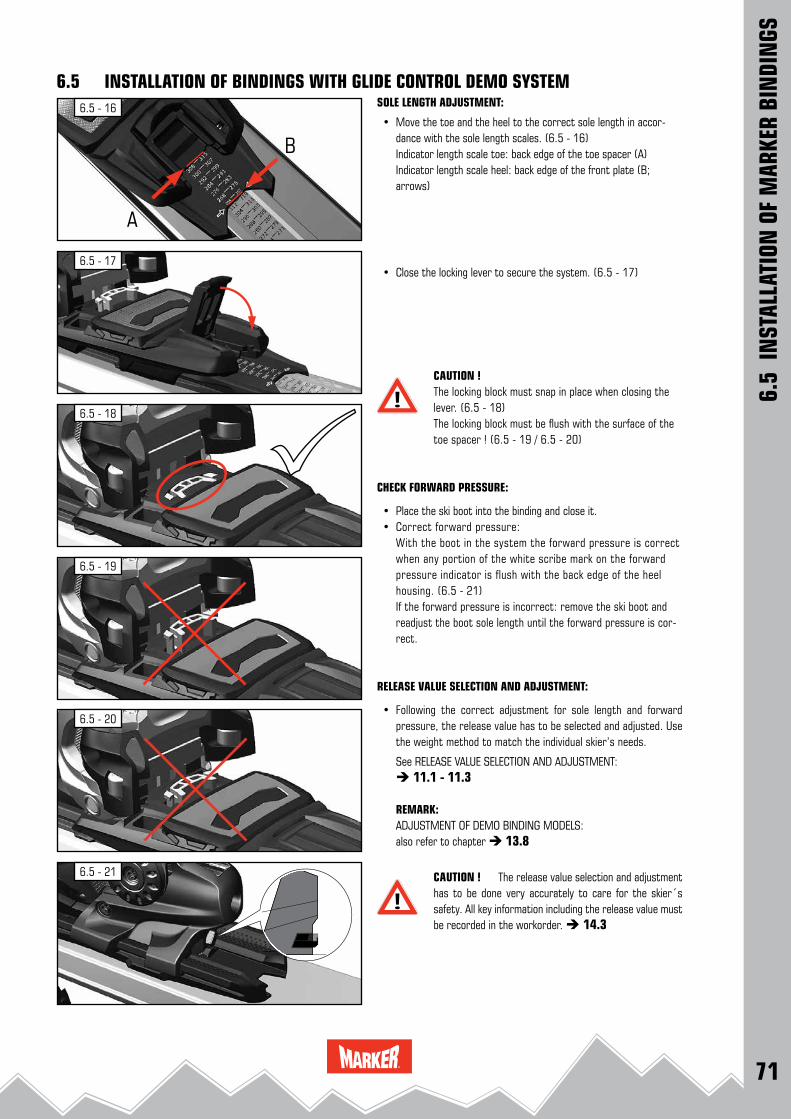
71
6.5 - 17
6.5 - 18
6.5 - 21
6.5 - 19
6.5 - 20
6.5 - 16
A
B
6.5
INST
ALLA
TION
OF
MAR
KER
BIN
DIN
GS
6.5 INSTALLATION OF BINDINGS WITH GLIDE CONTROL DEMO SYSTEMSOLE LENGTH ADJUSTMENT:
• Move the toe and the heel to the correct sole length in accor-dance with the sole length scales. (6.5 - 16)
Indicator length scale toe: back edge of the toe spacer (A) Indicator length scale heel: back edge of the front plate (B;
arrows)
• Close the locking lever to secure the system. (6.5 - 17)
CAUTION !The locking block must snap in place when closing the lever. (6.5 - 18)The locking block must be flush with the surface of the toe spacer ! (6.5 - 19 / 6.5 - 20)
CHECK FORWARD PRESSURE:
• Place the ski boot into the binding and close it. • Correct forward pressure: With the boot in the system the forward pressure is correct
when any portion of the white scribe mark on the forward pressure indicator is flush with the back edge of the heel housing. (6.5 - 21)
If the forward pressure is incorrect: remove the ski boot and readjust the boot sole length until the forward pressure is cor-rect.
RELEASE VALUE SELECTION AND ADJUSTMENT:
• Following the correct adjustment for sole length and forward pressure, the release value has to be selected and adjusted. Use the weight method to match the individual skier’s needs.
See RELEASE VALUE SELECTION AND ADJUSTMENT: 11.1 - 11.3
REMARK:ADJUSTMENT OF DEMO BINDING MODELS:also refer to chapter 13.8
CAUTION ! The release value selection and adjustment has to be done very accurately to care for the skier´s safety. All key information including the release value must be recorded in the workorder. 14.3
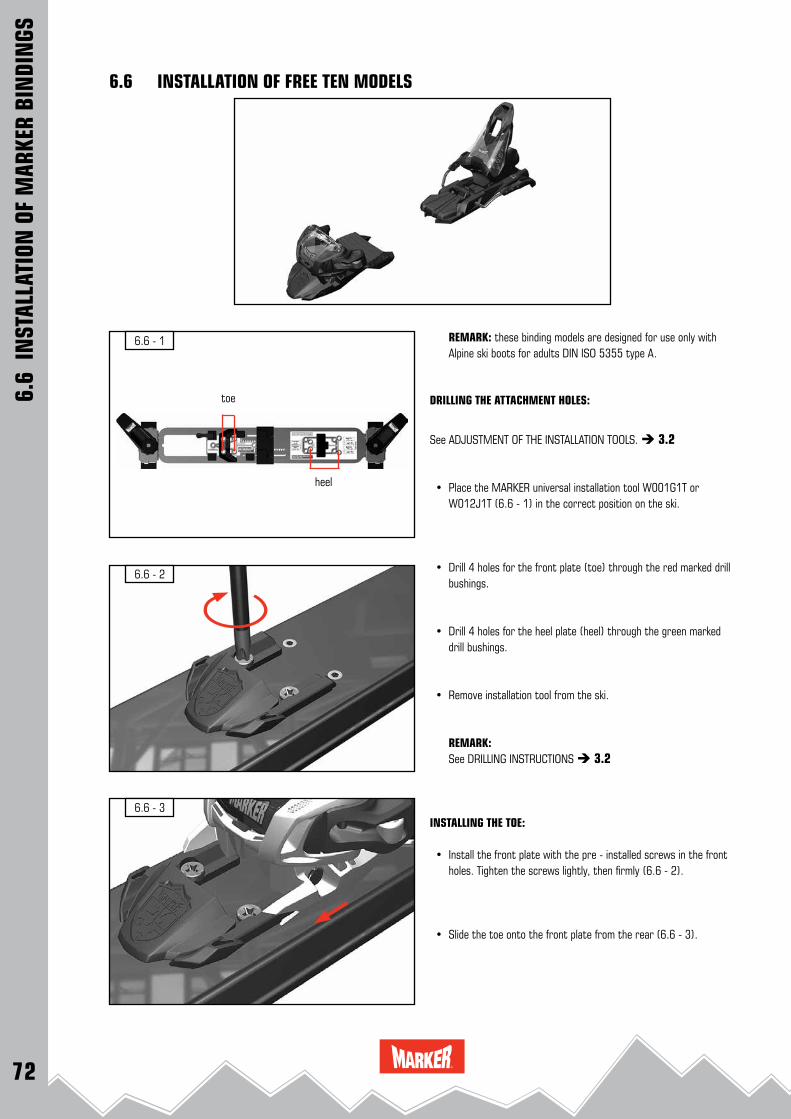
72
6.6 - 1
6.6 - 2
6.6 - 3
6.6 INSTALLATION OF FREE TEN MODELS
6.6
INST
ALLA
TION
OF
MAR
KER
BIN
DIN
GS
REMARK: these binding models are designed for use only with Alpine ski boots for adults DIN ISO 5355 type A.
DRILLING THE ATTACHMENT HOLES:
See ADJUSTMENT OF THE INSTALLATION TOOLS. 3.2
• Place the MARKER universal installation tool W001G1T or W012J1T (6.6 - 1) in the correct position on the ski.
• Drill 4 holes for the front plate (toe) through the red marked drill bushings.
• Drill 4 holes for the heel plate (heel) through the green marked drill bushings.
• Remove installation tool from the ski.
REMARK: See DRILLING INSTRUCTIONS 3.2
INSTALLING THE TOE:
• Install the front plate with the pre - installed screws in the front holes. Tighten the screws lightly, then firmly (6.6 - 2).
• Slide the toe onto the front plate from the rear (6.6 - 3).
heel
toe
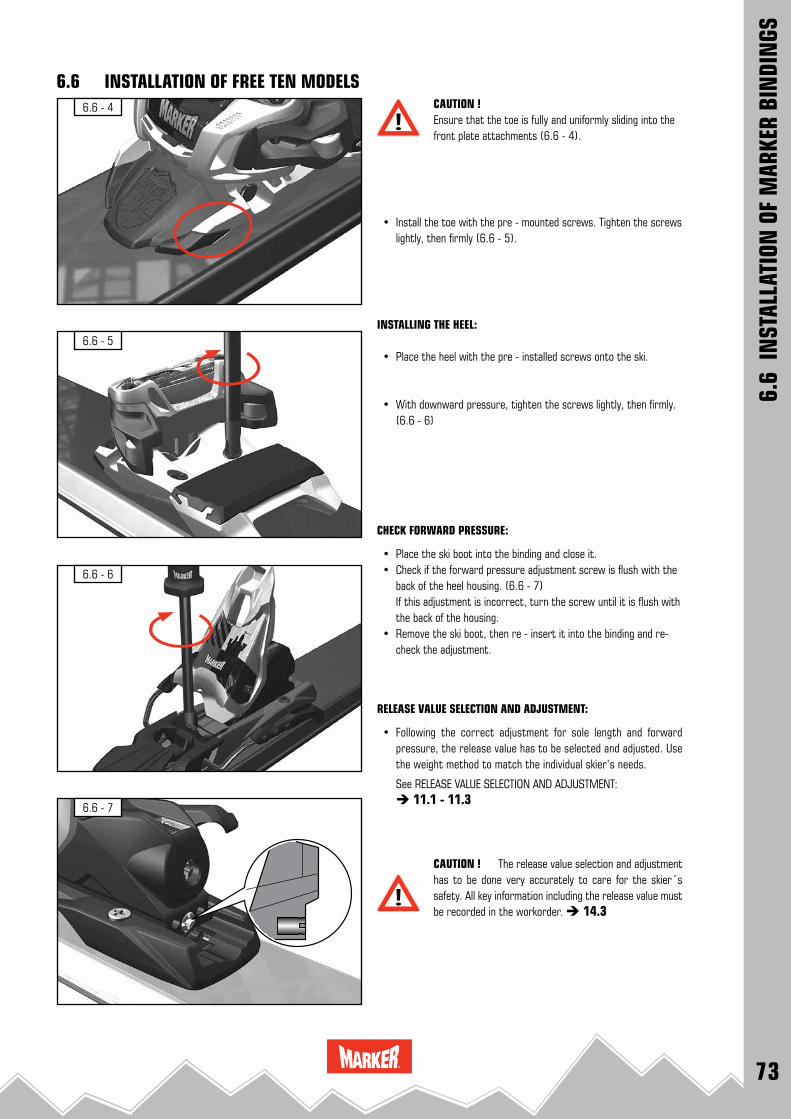
73
6.6 - 5
6.6 - 6
6.6 - 7
6.6 - 4
6.6 INSTALLATION OF FREE TEN MODELS
6.6
INST
ALLA
TION
OF
MAR
KER
BIN
DIN
GS
CAUTION ! Ensure that the toe is fully and uniformly sliding into the front plate attachments (6.6 - 4).
• Install the toe with the pre - mounted screws. Tighten the screws lightly, then firmly (6.6 - 5).
INSTALLING THE HEEL:
• Place the heel with the pre - installed screws onto the ski.
• With downward pressure, tighten the screws lightly, then firmly. (6.6 - 6)
CHECK FORWARD PRESSURE:
• Place the ski boot into the binding and close it. • Check if the forward pressure adjustment screw is flush with the
back of the heel housing. (6.6 - 7) If this adjustment is incorrect, turn the screw until it is flush with
the back of the housing. • Remove the ski boot, then re - insert it into the binding and re-
check the adjustment.
RELEASE VALUE SELECTION AND ADJUSTMENT:
• Following the correct adjustment for sole length and forward pressure, the release value has to be selected and adjusted. Use the weight method to match the individual skier’s needs.
See RELEASE VALUE SELECTION AND ADJUSTMENT: 11.1 - 11.3
CAUTION ! The release value selection and adjustment has to be done very accurately to care for the skier´s safety. All key information including the release value must be recorded in the workorder. 14.3

74
6.7 - 3
6.7 - 2
6.7 - 1
6.7 - 4
6.7
INST
ALLA
TION
OF
MAR
KER
BIN
DIN
GS
6.7 INSTALLATION OF M 11.0 TC EPS & 10.0 EPSREMARK:This mounting instruction is also valid for the MARKER / MOVE-MENT models Freeski TP 100 and Freeski TP 120.
REMARK: these binding models are designed for use only with Alpine ski boots for adults DIN ISO 5355 type A.
DRILLING THE ATTACHMENT HOLES: See ADJUSTMENT OF INSTALLATION TOOLS 3.2
• Place the MARKER universal installation tool W001G1T or W012J1T (6.7 - 1) in the correct position on the ski
• Drill 3 holes for the front plate (toe) through the green marked drill bushings.
• Drill 4 holes for the heel plate (heel) through the green marked drill bushings.
• Remove the installation tool from the ski.
REMARK: see DRILLING INSTRUCTIONS 3.2
INSTALLING THE TOE:
• Place the toe with the pre - installed screws onto the ski. • Tighten the screws lightly, then firmly (6.7 - 2)
INSTALLING THE HEEL:
• Place the heel with the pre - installed screws onto the ski. • Tighten the screws lightly, then firmly (6.7 - 3)
CHECK FORWARD PRESSURE:
• Place the ski boot into the binding and close it. • Check if the forward pressure adjustment screw is flush with the
back of the heel housing. (6.7 - 4) If this adjustment is incorrect, turn the screw until it is flush with
the back of the housing. • Remove the ski boot, then re - insert it into the binding and re-
check the adjustment.
CAUTION ! Make sure that you do not exceed the back stop when
adjusting the sole length backward !
RELEASE VALUE SELECTION AND ADJUSTMENT:
• Following the correct adjustment for sole length and forward pressure, the release value has to be selected and adjusted. Use the weight method to match the individual skier’s needs.
See RELEASE VALUE SELECTION AND ADJUSTMENT: 11.1 - 11.3
CAUTION ! The release value selection and adjustment has to be done very accurately to care for the skier´s safety. All key information including the release value must be recorded in the workorder. 14.3
heel
toe

75
6.8 - 3
6.8 - 2
6.8 - 1
6.8 - 4
6.8
INST
ALLA
TION
OF
MAR
KER
BIN
DIN
GS
6.8 INSTALLATION OF RACE 10 TCX & RACE 10 & RACE JUNIOR 8 & FREE 8 REMARK:
The binding models Race Junior 8 and Free 8 may only be used with junior ski boots DIN ISO 5355 type C.
The binding models Race 10 TCX and Race 10 are designed for use only with Alpine ski boots for adults DIN ISO 5355 type A.
DRILLING THE ATTACHMENT HOLES: See ADJUSTMENT OF INSTALLATION TOOLS 3.2
• Place the MARKER universal installation tool W001G1T (6.8 - 1) in the correct position on the ski
• Drill 3 holes for the front plate (toe) through the green marked drill bushings.
• Drill 4 holes for the heel plate (heel) through the green marked drill bushings.
• Remove the installation tool from the ski.
REMARK: see SKI INSPECTION 2.2 see DRILLING INSTRUCTIONS 3.2
INSTALLING THE TOE: • Place the toe with the pre - installed screws onto the ski. • Tighten the screws lightly, then firmly (6.8 - 2)
INSTALLING THE HEEL: • Place the heel with the pre - installed screws onto the ski. • Tighten the screws lightly, then firmly (6.8 - 3)
CHECK FORWARD PRESSURE: • Place the ski boot into the binding and close it. • Check if the forward pressure adjustment screw is flush with the
back of the heel housing. (6.8 - 4) If this adjustment is incorrect, turn the screw until it is flush with
the back of the housing. • Remove the ski boot, then re - insert it into the binding and re-
check the adjustment..
CAUTION ! Make sure that you do not exceed the back stop when
adjusting the sole length backward !
RELEASE VALUE SELECTION AND ADJUSTMENT:
• Following the correct adjustment for sole length and forward pressure, the release value has to be selected and adjusted. Use the weight method to match the individual skier’s needs.
See RELEASE VALUE SELECTION AND ADJUSTMENT: 11.1 - 11.3
CAUTION ! The release value selection and adjustment has to be done very accurately to care for the skier´s safety. All key information including the release value must be recorded in the workorder. 14.3
heel
toe
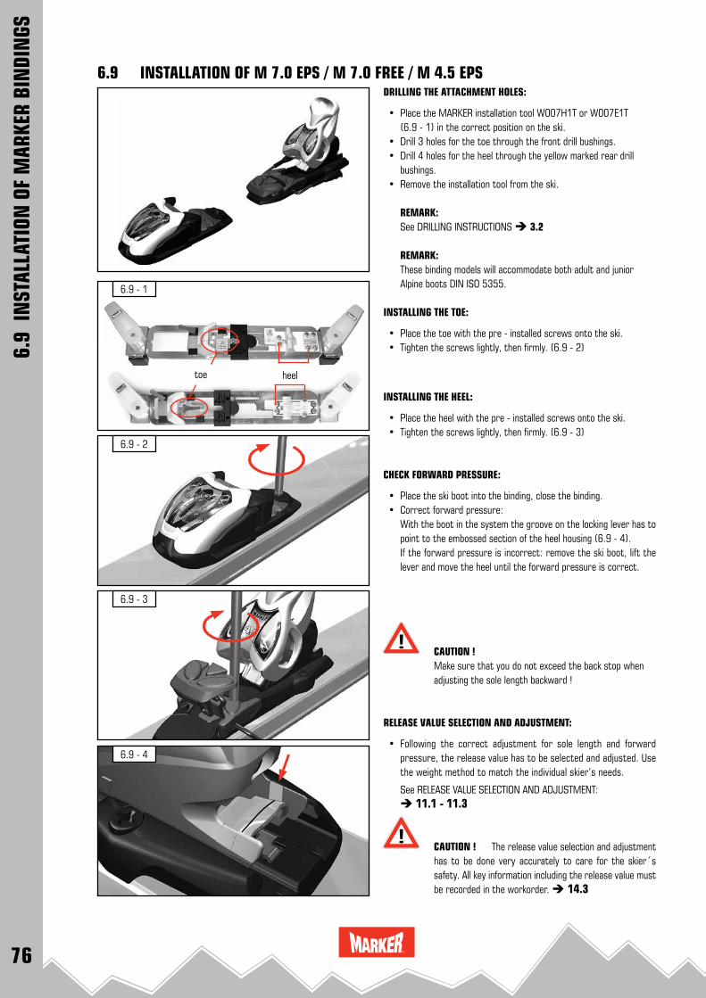
76
6.9 - 1
6.9 - 2
6.9 - 3
6.9 - 4
6.9
INST
ALLA
TION
OF
MAR
KER
BIN
DIN
GS
6.9 INSTALLATION OF M 7.0 EPS / M 7.0 FREE / M 4.5 EPS DRILLING THE ATTACHMENT HOLES:
• Place the MARKER installation tool W007H1T or W007E1T (6.9 - 1) in the correct position on the ski.
• Drill 3 holes for the toe through the front drill bushings. • Drill 4 holes for the heel through the yellow marked rear drill
bushings. • Remove the installation tool from the ski.
REMARK: See DRILLING INSTRUCTIONS 3.2
REMARK: These binding models will accommodate both adult and junior
Alpine boots DIN ISO 5355.
INSTALLING THE TOE:
• Place the toe with the pre - installed screws onto the ski. • Tighten the screws lightly, then firmly. (6.9 - 2)
INSTALLING THE HEEL:
• Place the heel with the pre - installed screws onto the ski. • Tighten the screws lightly, then firmly. (6.9 - 3)
CHECK FORWARD PRESSURE:
• Place the ski boot into the binding, close the binding. • Correct forward pressure: With the boot in the system the groove on the locking lever has to
point to the embossed section of the heel housing (6.9 - 4). If the forward pressure is incorrect: remove the ski boot, lift the
lever and move the heel until the forward pressure is correct.
CAUTION ! Make sure that you do not exceed the back stop when
adjusting the sole length backward !
RELEASE VALUE SELECTION AND ADJUSTMENT:
• Following the correct adjustment for sole length and forward pressure, the release value has to be selected and adjusted. Use the weight method to match the individual skier’s needs.
See RELEASE VALUE SELECTION AND ADJUSTMENT: 11.1 - 11.3
CAUTION ! The release value selection and adjustment has to be done very accurately to care for the skier´s safety. All key information including the release value must be recorded in the workorder. 14.3
heeltoe

77
6.10
IN
STAL
LATI
ON O
F IN
TERF
ACES
6.10 INSTALLATION OF INTERFACES
GENERAL INFORMATION:In connection with shaped skis skiers may wish a higher stand height with lifters or plates.
By installing and using these lifters or plates the risk to the skier may increase and therefore the proper installation is very important.
It is your responsibility as a MARKER certified technician to check the compatibility and the function of the ski, binding, ski brake, plate and boot components.
Assemble them together as a unit and then test the system to verify that it performs as intended. Occasionally check the function of the ski brake.
CAUTION ! MARKER guarantees proper braking function with their ski bindings only if lifters and plates are used that are offered and recommended by MARKER.
REMARK: FIS - regulation for stand heights (ski + plate + binding): Children max. 50 mm Junior (15 years and older) / Adult max. 50 mm
IMPORTANT ! All new MARKER bindings which are delivered together with lifters and plates are checked and confirmed by TÜV and can be installed without any problems.
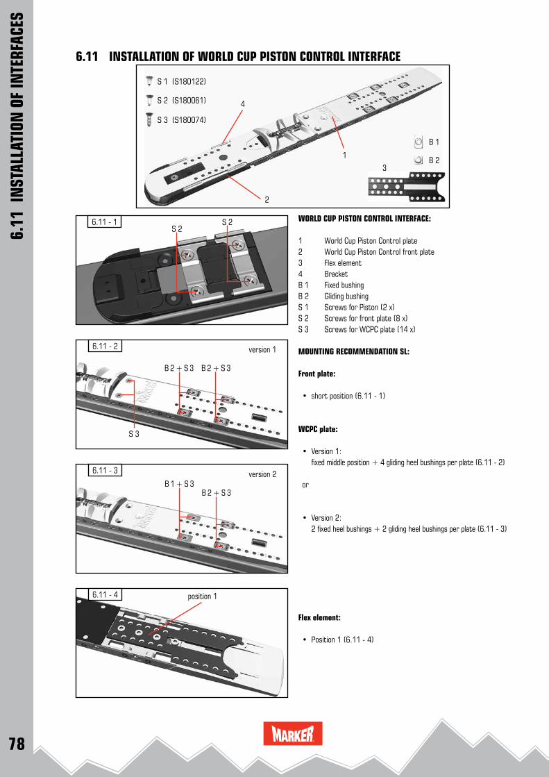
78
6.11 - 1S 2
S 2
6.11 - 2
B 2 + S 3 B 2 + S 3
S 3
6.11 - 3
B 1 + S 3B 2 + S 3
6.11 - 4
1
2
3
4
B 1
B 2
S 1 (S180122)
S 2 (S180061)
S 3 (S180074)
6.11 INSTALLATION OF WORLD CUP PISTON CONTROL INTERFACE
6.11
IN
STAL
LATI
ON O
F IN
TERF
ACES
WORLD CUP PISTON CONTROL INTERFACE:
1 World Cup Piston Control plate2 World Cup Piston Control front plate3 Flex element4 BracketB 1 Fixed bushingB 2 Gliding bushingS 1 Screws for Piston (2 x)S 2 Screws for front plate (8 x)S 3 Screws for WCPC plate (14 x)
MOUNTING RECOMMENDATION SL:
Front plate:
• short position (6.11 - 1)
WCPC plate:
• Version 1: fixed middle position + 4 gliding heel bushings per plate (6.11 - 2)
or
• Version 2: 2 fixed heel bushings + 2 gliding heel bushings per plate (6.11 - 3)
Flex element:
• Position 1 (6.11 - 4)
position 1
version 1
version 2
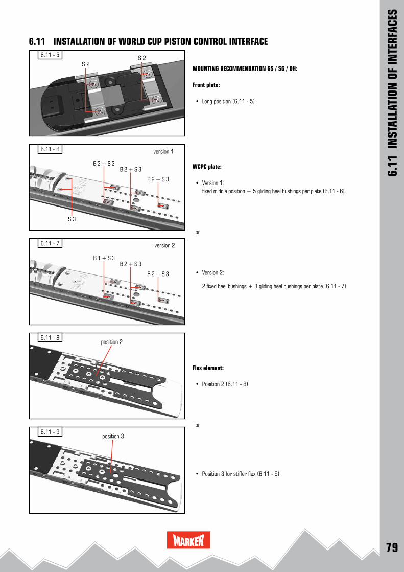
79
6.11 - 5
S 2S 2
6.11 - 6
6.11 - 7
6.11 - 8
6.11 - 9
B 2 + S 3B 2 + S 3
S 3
B 2 + S 3
B 1 + S 3B 2 + S 3
B 2 + S 3
version 1
version 2
position 2
position 3
6.11
IN
STAL
LATI
ON O
F IN
TERF
ACES
MOUNTING RECOMMENDATION GS / SG / DH:
Front plate:
• Long position (6.11 - 5)
WCPC plate:
• Version 1: fixed middle position + 5 gliding heel bushings per plate (6.11 - 6)
or
• Version 2:
2 fixed heel bushings + 3 gliding heel bushings per plate (6.11 - 7)
Flex element:
• Position 2 (6.11 - 8)
or
• Position 3 for stiffer flex (6.11 - 9)
6.11 INSTALLATION OF WORLD CUP PISTON CONTROL INTERFACE

80
6.11 - 11
6.11 - 14
6.11 - 15
6.11 - 12
6.11 - 13
6.11 - 10
WCPC long / short
WCPC optional
WCPC plate
WCPC optional
6.11
IN
STAL
LATI
ON O
F IN
TERF
ACES
6.11 INSTALLATION OF WORLD CUP PISTON CONTROL INTERFACEDRILLING THE ATTACHMENT HOLES:
• Place the World Cup Piston Control installation tool W002O1T or W002H1T (6.11 - 10) in the correct position on the ski.
• Drill 4 holes for the front plate for short or long mounting position. (6.11 - 1 or 6.11 - 5)
• Drill the holes for the chosen mounting version of the WCPC plate (6.11 - 2 or 6.11 - 3 for SL; 6.11 - 6 or 6.11 - 7 for GS / SG / DH)
• Remove installation tool from the ski.
REMARK:See DRILLING INSTRUCTIONS 3.2
INSTALLATION OF THE WORLD CUP PISTON CONTROL FRONT PLATE:
• Install the World Cup Piston Control front plate using the 4 provided screws. (6.11 - 11)
INSTALLATION OF THE WORLD CUP PISTON CONTROL PLATE:
• Insert the Flex element at the chosen position SL or GS / SG / DH (6.11 - 12)
• Insert and slide the World Cup Piston Control plate into installed front plate. (6.11 - 13)
• Connect the World Cup Piston Control plate to the front plate using the front screw. (6.11 - 14)
• Insert the bushings and the screws for the chosen mounting ver-sion, tighten the rear screws in the pre - drilled mounting holes. (6.11 - 15)
BINDING INSTALLATION:
see INSTALLATION OF RACE XCELL BINDINGS 6.3

81
ToeRace XCell
HeelRace XCell
+ 2 mm inline screw inline screw + 2 mm inline screw inline screw+ 4 mm 180171 (5.5 x 14.0) 180154 (5.5 x 20.5) + 4 mm 180074 (5.5 x 17.5) 180182 (5.5 x 28.0)
6.11 - 16
123
6.11 - 17
654 987 10
6.11 - 20
6.11 - 19
6.11 - 18
2
BINDING POSITIONING: (6.11 - 16 / 6.11 - 17) Toe: (6.11 - 16) Heel: (6.11 - 17) 1: 260 mm - 308 mm 4: 262 mm - 278 mm 2: 309 mm - 328 mm 5: 279 mm - 288 mm 3: 329 mm - 362 mm 6: 289 mm - 298 mm 7: 299 mm - 318 mm 8: 319 mm - 338 mm 9: 339 mm - 348 mm 10: 349 mm - 362 mm
Race Xcell models: Mount the two forward toe fixation screws for the front mounting plate 3 sole-length holes forward of the identified sole-length scale. Slide the toe onto the front mounting plate and affix the two rear screws in the correctly identified sole-length holes. (6.11 - 18)
DUCK STANCE OPTION: REMARK: use 4.1 x 9.5 drill bit.
TOE: (6.11 - 19)The duck stance mounting position allows 3 mm lateral positioning of the toe.HEEL: (6.11 - 20)The duck stance mounting position allows 2 mm lateral positioning of the heel.
REMARK:For mounting the World Cup PC Interface 14 mm the enclosed mounting instruction 820223 C is valid. When mounting the binding onto the plate please take note of the advice concerning the correct screw choice !
SCREW CHART FOR SPACERS6.
11 I
NST
ALLA
TION
OF
INTE
RFAC
ES
6.11 INSTALLATION OF WORLD CUP PISTON CONTROL INTERFACE

82
6.12 - 2
6.12 - 4
5.2 - 16.12 - 1
6.12 - 3
Junior Race Interface 26.12
IN
STAL
LATI
ON O
F IN
TERF
ACES
DRILLING THE ATTACHMENT HOLES:
• Place the installation tool for Junior Race Interface 2 W002O1T (6.12 - 1) in the correct position on the ski and secure it.
• Drill the 4 holes for the front position and 4 holes for the rear position of the JUNIOR RACE INTERFACE 2.
• Remove the installation tool from the ski.
REMARK:See DRILLING INSTRUCTIONS 3.2
REMARK:For mounting the Junior Race Interface 2 use of an adhesive is recommended. (Consult the ski manufacturer’s technical data for screw hole adhesive recommendations.) If an adhesive is recom-mended, place a drop in each drilled hole. The screw will coat itself as it passes through the adhesive.
INSTALLATION OF THE JUNIOR RACE INTERFACE 2:
• Tighten the 4 front screws through the marked bore holes. Tighten the screws lightly, then firmly. (6.12 - 2 / 6.12 - 3)
• Tighten the 4 rear screws lightly, then firmly. (6.12 - 4)
IMPORTANT ! For the installation of the JUNIOR RACE INTERFACE 2 a Torx wrench T 20 is needed.
6.12 INSTALLATION OF JUNIOR RACE INTERFACE 2
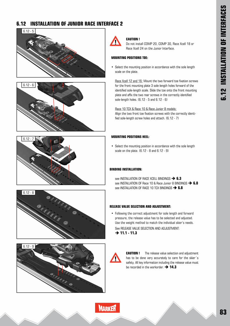
83
6.12 - 9
6.12 - 8
6.12 - 6
6.12 - 5
6.12 - 7
6.12
IN
STAL
LATI
ON O
F IN
TERF
ACES
CAUTION ! Do not install COMP 20, COMP 30, Race Xcell 18 or Race Xcell 24 on the Junior Interface.
MOUNTING POSITIONS TOE:
• Select the mounting position in accordance with the sole length scale on the plate.
Race Xcell 12 and 16: Mount the two forward toe fixation screws for the front mounting plate 3 sole-length holes forward of the identified sole-length scale. Slide the toe onto the front mounting plate and affix the two rear screws in the correctly identified sole-length holes. (6.12 - 5 and 6.12 - 6)
Race 10 TCX & Race 10 & Race Junior 8 models: Align the two front toe fixation screws with the correctly identi-
fied sole-length screw holes and attach. (6.12 - 7)
MOUNTING POSITIONS HEEL:
• Select the mounting position in accordance with the sole length scale on the plate. (6.12 - 8 and 6.12 - 9)
BINDING INSTALLATION:
see INSTALLATION OF RACE XCELL BINDINGS 6.3 see INSTALLATION OF Race 10 & Race Junior 8 BINDINGS 6.8 see INSTALLATION OF RACE 10 TCX BINDINGS 6.8
RELEASE VALUE SELECTION AND ADJUSTMENT:
• Following the correct adjustment for sole length and forward pressure, the release value has to be selected and adjusted. Use the weight method to match the individual skier’s needs.
See RELEASE VALUE SELECTION AND ADJUSTMENT: 11.1 - 11.3
CAUTION ! The release value selection and adjustment has to be done very accurately to care for the skier´s safety. All key information including the release value must be recorded in the workorder. 14.3
6.12 INSTALLATION OF JUNIOR RACE INTERFACE 2

84
6.13 - 2
6.13 - 3
6.5 - 116.13 - 5
6.13 - 1
6.13 - 4
6.13 - 6
6.13 - 7
DRILLING THE ATTACHMENT HOLES:
VERSION A:
(Ski with printing and punch marking for the Marker UVO)
• Drill the 3 mounting holes with the UVO drill bit (2.1 x 4.0) at the punch markings. (6.13 - 1)
VERSION B:
(Ski without marking)
• Determine the UVO mounting position (see chart) with a tape rule. (6.13 - 2) see chart on page 86 / 87
• Mark the mounting position on both sides of the ski. (6.13 - 3 and 6.13 - 4)
• Remove the paper from the mounting jig (6.13 - 5)
• and ensure that the horizontal (middle) line of the jig is aligned with the mounting position marks on the ski. The scale on the mounting jig helps you to center it on the ski. (6.13 - 6)
• Mark the drilling positions by using a hammer and a center punch. (6.13 - 7)
6.13 INSTALLATION OF MARKER UVO
6.13
IN
STAL
LATI
ON O
F M
ARKE
R UV
O

85
6.13 - 8
6.13 - 10 6.13 - 11
6.13 - 14
6.13 - 12
6.13 - 13
6.13 - 9
1.5 Nm
• Remove the mounting jig from the ski. (6.13 - 8)
• Drill the 3 mounting holes with the UVO drill bit (2.1 x 4.0) at the punch markings. (6.13 - 9)
INSTALLATION OF THE MARKER UVO:
• Remove shavings and dust from the drill holes and clean the ski surface. (6.13 - 10)
• For mounting the Marker UVO use of an adhesive is recommen-ded. Place a drop of binding glue in each drilled hole. (6.13 - 11)
• Remove the protection foil from the glued surface on the bottom of the UVO. (6.13 - 12)
• Place the UVO onto the ski. Ensure that all three screw points align with the drilled holes. (6.13 - 13)
• Tighten the 3 screws with a screwdriver. After mounting the UVO store the ski for one to two days at room temperature in a dry room to ensure the hardening of the adhesive. (6.13 - 14)
6.13
IN
STAL
LATI
ON O
F M
ARKE
R UV
O
6.13 INSTALLATION OF MARKER UVO

86
SL
155 / 155 WC 132
2.1 x 4.0157 / 157 WC 136
165 / 165 WC 143
GS
174 R > 21 m 154
2.1 x 4.0
178 R > 23 m 158,7
183 R > 25 m 160
183 R > 30 m 160
188 R > 27,5 m 166,5
188 R > 30 m 166,5
191 R > 35 m 169
196 R > 35 m 175
SG
183 R > 30 m U14 160
2.1 x 4.0188 R > 30 m U 14 166,5
203 R > 30 m U 16 180
6.14 CHART MOUNTING POSITIONS UVO
Ski ski length (cm)
position (cm)(measured from ski tail)
drill bit
6.14
IN
STAL
LATI
ON O
F M
ARKE
R UV
O
Mounting positions UVOCAUTION !The Marker UVO has been tested with specific Völkl ski models only. Mounting and usage with not specific tested and marked as such skis can cause damage of your ski equipment and / or injuries.
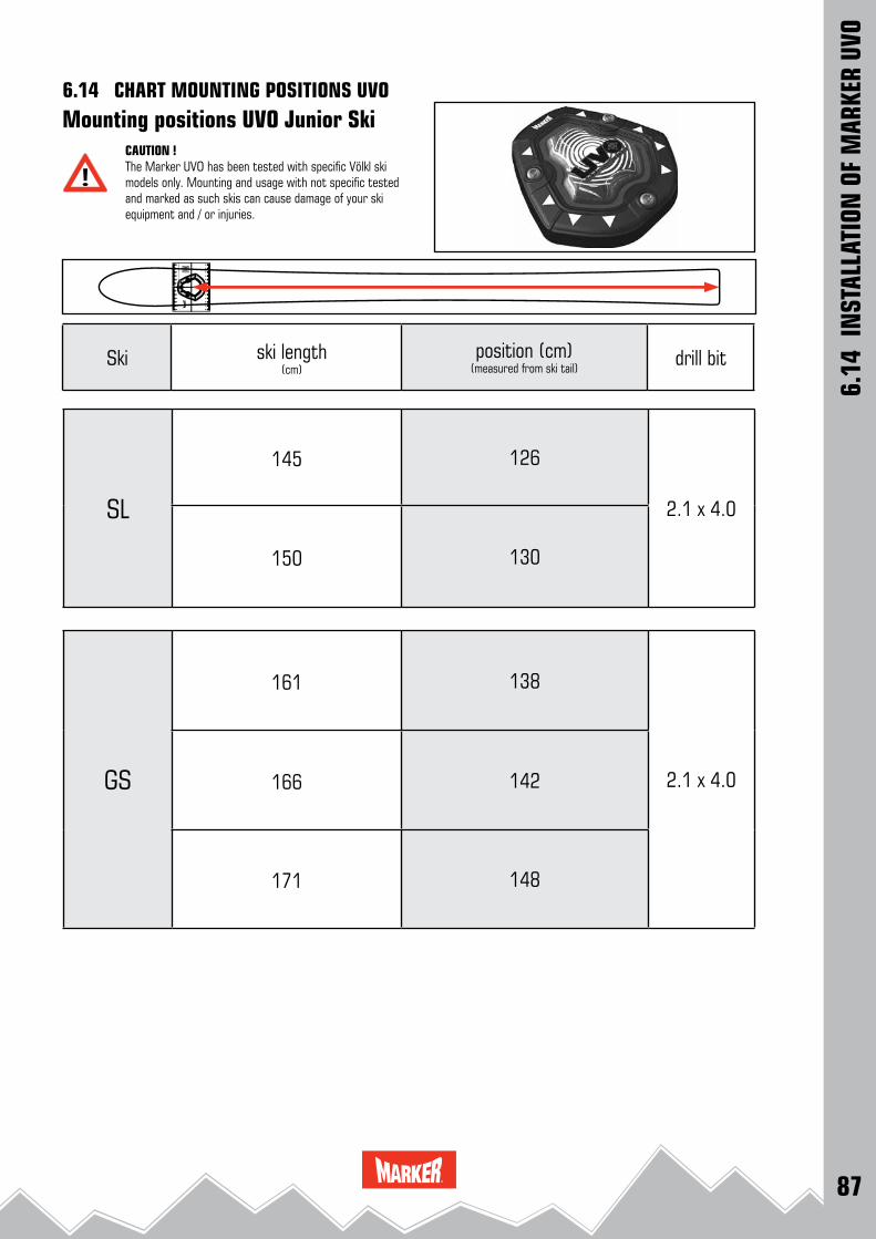
87
SL
145 126
2.1 x 4.0
150 130
GS
161 138
2.1 x 4.0166 142
171 1486.
14 I
NST
ALLA
TION
OF
MAR
KER
UVO
6.14 CHART MOUNTING POSITIONS UVO
Ski ski length (cm)
position (cm)(measured from ski tail)
drill bit
Mounting positions UVO Junior SkiCAUTION !The Marker UVO has been tested with specific Völkl ski models only. Mounting and usage with not specific tested and marked as such skis can cause damage of your ski equipment and / or injuries.
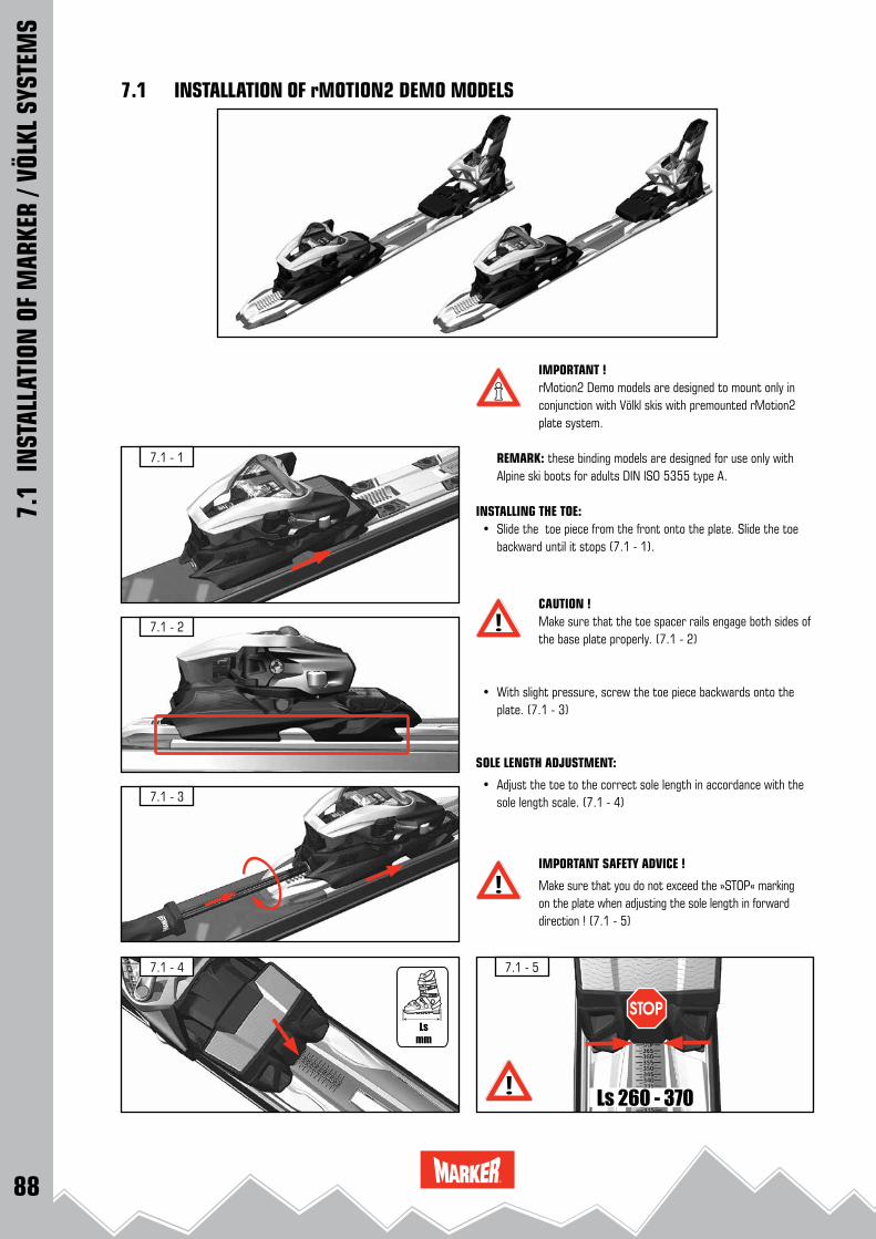
88
7.1 - 3
7.1 - 1
7.1 - 2
7.1 - 4 7.1 - 5
Ls 260 - 370
IMPORTANT ! rMotion2 Demo models are designed to mount only in conjunction with Völkl skis with premounted rMotion2 plate system.
REMARK: these binding models are designed for use only with Alpine ski boots for adults DIN ISO 5355 type A.
INSTALLING THE TOE: • Slide the toe piece from the front onto the plate. Slide the toe
backward until it stops (7.1 - 1).
CAUTION ! Make sure that the toe spacer rails engage both sides of the base plate properly. (7.1 - 2)
• With slight pressure, screw the toe piece backwards onto the plate. (7.1 - 3)
SOLE LENGTH ADJUSTMENT:
• Adjust the toe to the correct sole length in accordance with the sole length scale. (7.1 - 4)
IMPORTANT SAFETY ADVICE !
Make sure that you do not exceed the »STOP« marking on the plate when adjusting the sole length in forward direction ! (7.1 - 5)
7.1
INST
ALLA
TION
OF
MAR
KER
/ VÖL
KL S
YSTE
MS
7.1 INSTALLATION OF rMOTION2 DEMO MODELS

89
7.1 - 7
7.1 - 8
7.1 - 10
7.1 - 11
7.1 - 6
7.1 - 9
Ls 260 - 370
INSTALLING THE HEEL: • Slide the heel from the rear of the plate forward until it stops
(7.1 - 6).
• With slight pressure, screw the heel forward onto the plate by turning the forward pressure adjustment screw (7.1 - 7).
CAUTION ! Ensure that the heel is fully and uniformly sliding onto the plate (7.1 - 8).
SOLE LENGTH ADJUSTMENT:
• Screw the heel to the correct sole length in accordance with the sole length scale (7.1 - 9).
IMPORTANT SAFETY ADVICE !
Make sure that you do not exceed the »STOP« marking on the plate when adjusting the sole length backward ! (7.1 - 10)
CHECK FORWARD PRESSURE:
• Place the ski boot into the binding, close the binding. • Check if the forward pressure adjustment screw is flush with the
back of the heel housing. (7.1 - 11). If this adjustment is incorrect, turn the screw until it is flush with
the back of the housing. • Remove the ski boot, then re - insert it into the binding and re-
check the adjustment.
RELEASE VALUE SELECTION AND ADJUSTMENT:
• Following the correct adjustment for sole length and forward pressure, the release value has to be selected and adjusted. Use the weight method to match the individual skier’s needs.
See RELEASE VALUE SELECTION AND ADJUSTMENT: 11.1 - 11.3
REMARK:ADJUSTMENT OF DEMO BINDING MODELS:also refer to chapter 13.8
CAUTION ! The release value selection and adjustment has to be done very accurately to care for the skier´s safety. All key information including the release value must be recorded in the workorder. 14.3
7.1
INST
ALLA
TION
OF
MAR
KER
/ VÖL
KL S
YSTE
MS
7.1 INSTALLATION OF rMOTION2 DEMO MODELS
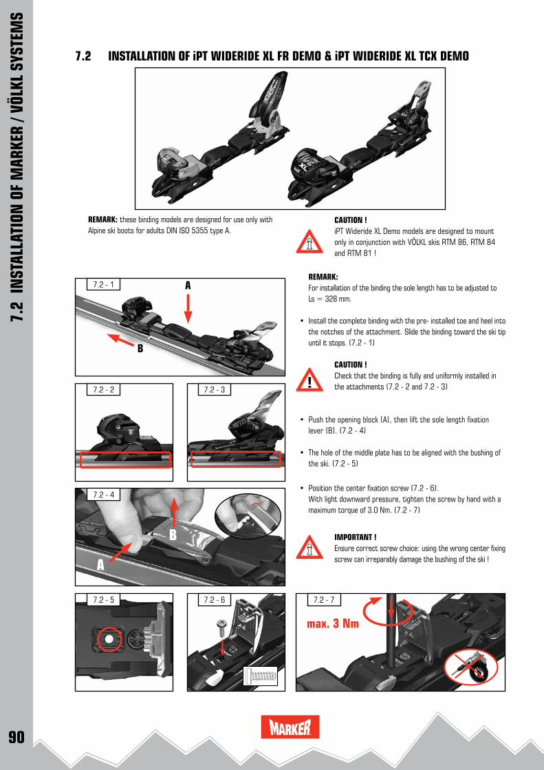
90
7.2 - 5 7.2 - 6
7.2 - 4
7.2 - 2
7.2 - 1
7.2 - 3
7.2 - 7
A
B
max. 3 Nm
A
B
7.2
INST
ALLA
TION
OF
MAR
KER
/ VÖL
KL S
YSTE
MS
7.2 INSTALLATION OF iPT WIDERIDE XL FR DEMO & iPT WIDERIDE XL TCX DEMO
CAUTION ! iPT Wideride XL Demo models are designed to mount only in conjunction with VÖLKL skis RTM 86, RTM 84 and RTM 81 !
REMARK: For installation of the binding the sole length has to be adjusted to
Ls = 328 mm.
• Install the complete binding with the pre- installed toe and heel into the notches of the attachment. Slide the binding toward the ski tip until it stops. (7.2 - 1)
CAUTION !Check that the binding is fully and uniformly installed in the attachments (7.2 - 2 and 7.2 - 3)
• Push the opening block [A], then lift the sole length fixation lever [B]. (7.2 - 4)
• The hole of the middle plate has to be aligned with the bushing of the ski. (7.2 - 5)
• Position the center fixation screw (7.2 - 6). With light downward pressure, tighten the screw by hand with a
maximum torque of 3.0 Nm. (7.2 - 7)
IMPORTANT !Ensure correct screw choice: using the wrong center fixing screw can irreparably damage the bushing of the ski !
REMARK: these binding models are designed for use only with Alpine ski boots for adults DIN ISO 5355 type A.

91
7.2 - 13
7.2 - 10
7.2 - 8
7.2 - 9
7.2 - 11
7.2 - 12
7.2
INST
ALLA
TION
OF
MAR
KER
/ VÖL
KL S
YSTE
MS
7.2 INSTALLATION OF iPT WIDERIDE XL FR DEMO & iPT WIDERIDE XL TCX DEMO
SOLE LENGTH ADJUSTMENT:
• Adjust the sole length either by hand by shifting the binding to the corresponding markings on the scale or by turning the sole length adjustment screw with the appropriate screwdriver. (Use a Pozidriv® 3 screwdriver)
(7.2 - 8 and 7.2 - 9)
• Lock the system by closing the sole length fixation lever. (7.2 - 10)
CAUTION ! The sole length fixation lever must not be pressed down with effort, but is correctly aligned with the locking teeth when it closes easily.
CAUTION ! Visually check locking mechanism: when locking the system the opening lever has to snap into the basic position. (7.2 - 11)The warning symbol on the right side of the opening lever must not be visible ! (7.2 - 12)
CHECK FORWARD PRESSURE:
• Place the ski boot into the binding and close it. • Correct forward pressure: With the boot in the system the forward pressure is correct when
any portion of the white scribe mark on the forward pressure indi-cator is flush with the back edge of the heel housing. (7.2 - 13).
If the forward pressure is incorrect: remove the ski boot and re-adjust the boot sole length until the forward pressure is correct.
RELEASE VALUE SELECTION AND ADJUSTMENT:
• Following the correct adjustment for sole length and forward pressure, the release value has to be selected and adjusted. Use the weight method to match the individual skier’s needs.
See RELEASE VALUE SELECTION AND ADJUSTMENT: 11.1 - 11.3
REMARK:ADJUSTMENT OF DEMO BINDING MODELS:also refer to chapter 13.8
CAUTION ! The release value selection and adjustment has to be done very accurately to care for the skier´s safety. All key information including the release value must be recorded in the workorder. 14.3
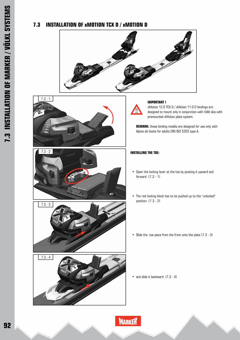
92
7.3 - 3
7.3 - 4
7.3 - 1
7.3 - 2
7.3
INST
ALLA
TION
OF
MAR
KER
/ VÖL
KL S
YSTE
MS
7.3 INSTALLATION OF xMOTION TCX D / xMOTION D
IMPORTANT ! xMotion 12.0 TCX D / xMotion 11.0 D bindings are designed to mount only in conjunction with Völkl skis with premounted xMotion plate system.
REMARK: these binding models are designed for use only with Alpine ski boots for adults DIN ISO 5355 type A.
INSTALLING THE TOE:
• Open the locking lever at the toe by pivoting it upward and forward. (7.3 - 1)
• The red locking block has to be pushed up to the "unlocked"
position. (7.3 - 2)
• Slide the toe piece from the front onto the plate (7.3 - 3)
• and slide it backward. (7.3 - 4)

93
7.3 - 8
7.3 - 9
7.3 - 5
7.3 - 7
7.3 - 6
7.3
INST
ALLA
TION
OF
MAR
KER
/ VÖL
KL S
YSTE
MS
7.3 INSTALLATION OF xMOTION TCX D / xMOTION D
CAUTION !Make sure that the spacer rails engage both sides of the base plate properly. (7.3 - 5)
INSTALLING THE HEEL:
• Pull the connecting arm backwards.(7.3 - 6)
• Identify the correct mounting position on the connecting arm: xMotion 12.0 TCX D → "TC heel"
xMotion 11.0 D → "Compact" (7.3 - 7)
• Engage the forward pressure indicator of the heel to the connecting arm at the determined position. (7.3 - 8)
• Attach the heel to the plate. (7.3 - 9)
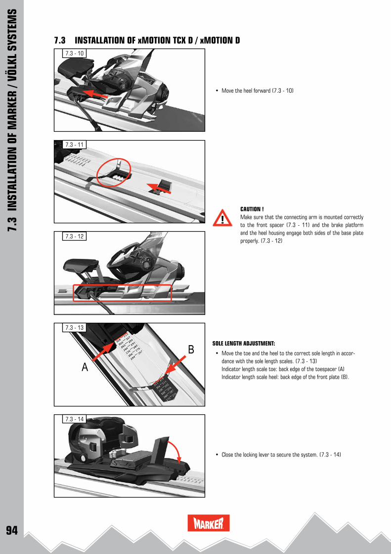
94
7.3 - 13
7.3 - 14
7.3 - 10
7.3 - 11
7.3 - 12
AB
7.3
INST
ALLA
TION
OF
MAR
KER
/ VÖL
KL S
YSTE
MS
7.3 INSTALLATION OF xMOTION TCX D / xMOTION D
• Move the heel forward (7.3 - 10)
CAUTION !Make sure that the connecting arm is mounted correctly to the front spacer (7.3 - 11) and the brake platform and the heel housing engage both sides of the base plate properly. (7.3 - 12)
SOLE LENGTH ADJUSTMENT:
• Move the toe and the heel to the correct sole length in accor-dance with the sole length scales. (7.3 - 13)
Indicator length scale toe: back edge of the toespacer (A) Indicator length scale heel: back edge of the front plate (B).
• Close the locking lever to secure the system. (7.3 - 14)
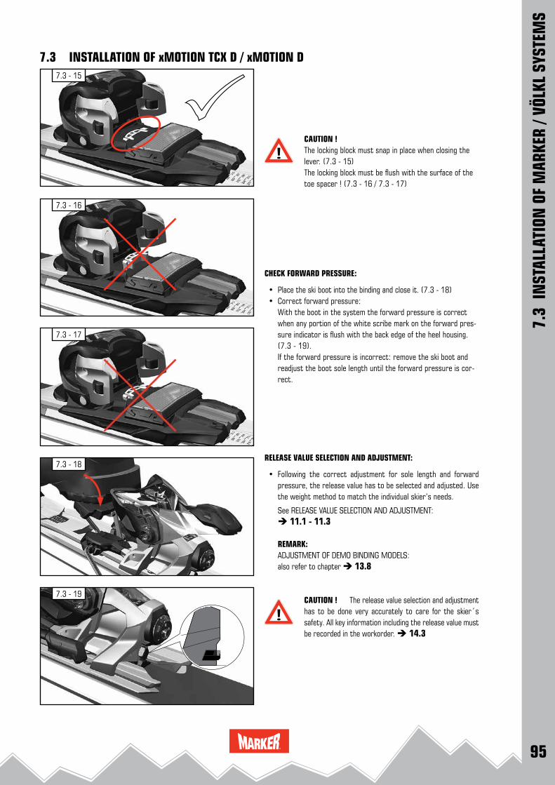
95
7.3 - 18
7.3 - 19
7.3 - 15
7.3 - 17
7.3 - 16
7.3
INST
ALLA
TION
OF
MAR
KER
/ VÖL
KL S
YSTE
MS
7.3 INSTALLATION OF xMOTION TCX D / xMOTION D
CAUTION !The locking block must snap in place when closing the lever. (7.3 - 15)The locking block must be flush with the surface of the toe spacer ! (7.3 - 16 / 7.3 - 17)
CHECK FORWARD PRESSURE:
• Place the ski boot into the binding and close it. (7.3 - 18) • Correct forward pressure: With the boot in the system the forward pressure is correct
when any portion of the white scribe mark on the forward pres-sure indicator is flush with the back edge of the heel housing. (7.3 - 19).
If the forward pressure is incorrect: remove the ski boot and readjust the boot sole length until the forward pressure is cor-rect.
RELEASE VALUE SELECTION AND ADJUSTMENT:
• Following the correct adjustment for sole length and forward pressure, the release value has to be selected and adjusted. Use the weight method to match the individual skier’s needs.
See RELEASE VALUE SELECTION AND ADJUSTMENT: 11.1 - 11.3
REMARK:ADJUSTMENT OF DEMO BINDING MODELS:also refer to chapter 13.8
CAUTION ! The release value selection and adjustment has to be done very accurately to care for the skier´s safety. All key information including the release value must be recorded in the workorder. 14.3

96
7.4 - 5 7.4 - 6
7.4 - 4
7.4 - 2
7.4 - 1
7.4 - 3
A
B
7.4 - 7
max. 3 Nm
7.4
INST
ALLA
TION
OF
MAR
KER
/ VÖL
KL S
YSTE
MS
7.4 INSTALLATION OF 4MOTION XL DEMO & 4MOTION DEMO
IMPORTANT ! 4MOTION XL and 4MOTION Demo bindings are designed to mount only in conjunction with VÖLKL 4MOTION ski models !
• Install the complete binding with the pre- installed toe and heel into the notches of the attachment. Slide the binding toward the ski tip until it stops. (7.4 - 1)
CAUTION !Check that the binding is fully and uniformly installed in the attachments (7.4 - 2 and 7.4 - 3)
• Push the opening block [A], then lift the sole length fixation lever [B]. (7.4 - 4)
• The hole of the middle plate has to be aligned with the bushing of the ski. (7.4 - 5)
• Position the center fixation screw. With light downward pressure, tighten the screw by hand with a
maximum torque of 3.0 Nm. (7.4 - 6 and 7.4 - 7)
IMPORTANT !Ensure correct screw choice: using the wrong center fixing screw can irreparably damage the bushing of the ski !
REMARK: these binding models are designed for use only with Alpine ski boots for adults DIN ISO 5355 type A.

97
7.4 - 13
7.4 - 10
7.4 - 8
7.4 - 9
7.4 - 11
7.4 - 12
7.4
INST
ALLA
TION
OF
MAR
KER
/ VÖL
KL S
YSTE
MS
7.4 INSTALLATION OF 4MOTION XL DEMO & 4MOTION DEMOSOLE LENGTH ADJUSTMENT:
• Adjust the sole length either by hand by shifting the binding to the corresponding markings on the scale or by turning the sole length adjustment screw with the appropriate screwdriver (Use a Pozidriv® 3 screwdriver)
(7.4 - 8 and 7.4 - 9)
REMARK:The sole length scale of the 4Motion 10.0 Demo is equipped with an additional color code. This color code corresponds with the Dalbello 4 - factor rental boot code system.
• Lock the system by closing the sole length fixation lever. (7.4 - 10)
CAUTION ! The sole length fixation lever must not be pressed down with effort, but is correctly aligned with the locking teeth when it closes easily.
CAUTION ! Visually check locking mechanism: when locking the system the opening lever has to snap into the basic position. (7.4 - 11)The warning symbol on the right side of the opening lever must not be visible ! (7.4 - 12)
CHECK FORWARD PRESSURE:
• Place the ski boot into the binding and close it. • Correct forward pressure: With the boot in the system the forward pressure is correct
when any portion of the white scribe mark on the forward pres-sure indicator is flush with the back edge of the heel housing. (7.4 - 13).
If the forward pressure is incorrect: remove the ski boot and readjust the boot sole length until the forward pressure is cor-rect.
RELEASE VALUE SELECTION AND ADJUSTMENT:
• Following the correct adjustment for sole length and forward pressure, the release value has to be selected and adjusted. Use the weight method to match the individual skier’s needs.
See RELEASE VALUE SELECTION AND ADJUSTMENT: 11.1 - 11.3
REMARK:ADJUSTMENT OF DEMO BINDING MODELS:also refer to chapter 13.8
CAUTION ! The release value selection and adjustment has to be done very accurately to care for the skier´s safety. All key information including the release value must be recorded in the workorder. 14.3
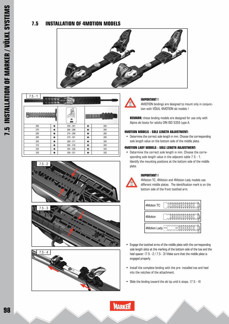
98
7.5 - 3
7.5 - 2
7.5 - 4
260 259 - 281 260270 264 - 286 260280 274 - 296 280290 279 - 301 280
300 289 - 311 300310 294 - 316 300320 304 - 326 320330 309 - 331 320
7.5 - 1
4Motion
4Motion TC
4Motion Lady
IMPORTANT ! 4MOTION bindings are designed to mount only in conjunc-tion with VÖLKL 4MOTION ski models !
REMARK: these binding models are designed for use only with Alpine ski boots for adults DIN ISO 5355 type A.
4MOTION MODELS - SOLE LENGTH ADJUSTMENT: • Determine the correct sole length in mm. Choose the corresponding
sole length value on the bottom side of the middle plate.
4MOTION LADY MODELS - SOLE LENGTH ADJUSTMENT: • Determine the correct sole length in mm. Choose the corre-
sponding sole length value in the adjacent table 7.5 - 1. Identify the mounting positions at the bottom side of the middle
plate. IMPORTANT ! 4Motion TC, 4Motion and 4Motion Lady models use
different middle plates. The identification mark is on the bottom side of the front toothed arm.
• Engage the toothed arms of the middle plate with the corresponding sole length slots at the marking of the bottom side of the toe and the heel spacer. (7.5 - 2 / 7.5 - 3) Make sure that the middle plate is engaged properly.
• Install the complete binding with the pre- installed toe and heel into the notches of the attachment.
• Slide the binding toward the ski tip until it stops. (7.5 - 4)
7.5
INST
ALLA
TION
OF
MAR
KER
/ VÖL
KL S
YSTE
MS
7.5 INSTALLATION OF 4MOTION MODELS
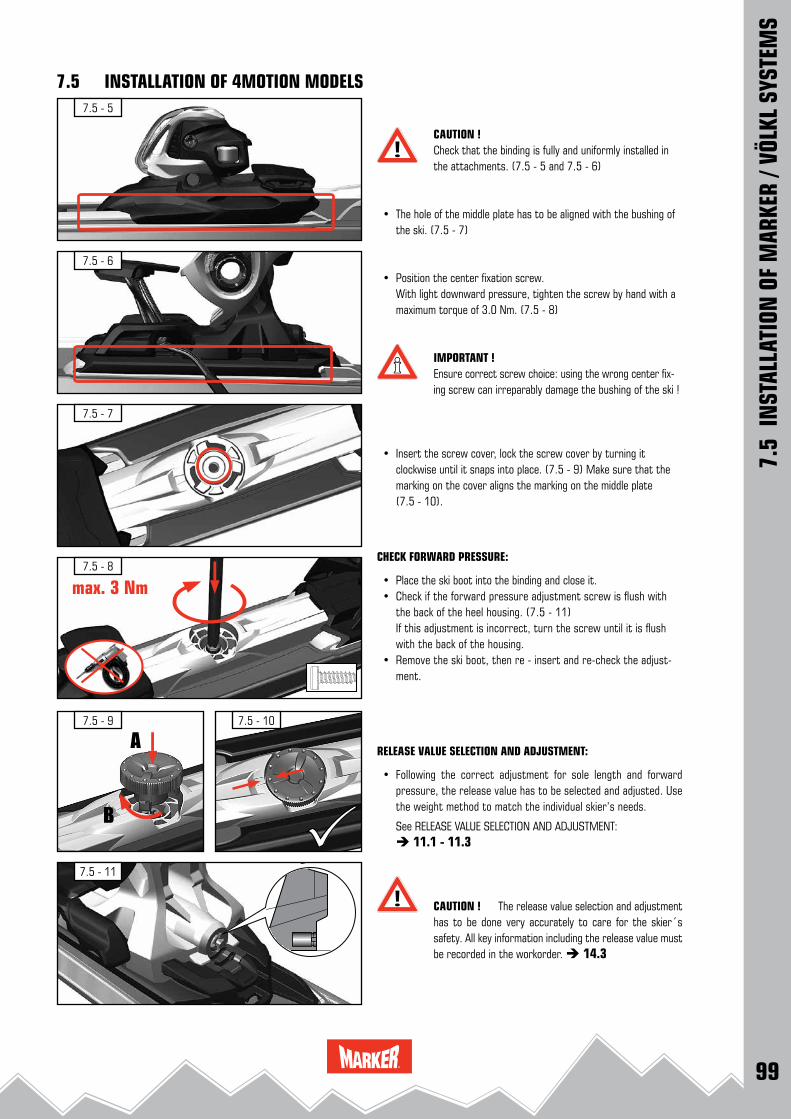
99
7.5 - 8
7.5 - 11
7.5 - 5
7.5 - 6
7.5 - 7
max. 3 Nm
7.5 - 107.5 - 9
A
B
7.5
INST
ALLA
TION
OF
MAR
KER
/ VÖL
KL S
YSTE
MS
7.5 INSTALLATION OF 4MOTION MODELS
CAUTION !Check that the binding is fully and uniformly installed in the attachments. (7.5 - 5 and 7.5 - 6)
• The hole of the middle plate has to be aligned with the bushing of the ski. (7.5 - 7)
• Position the center fixation screw. With light downward pressure, tighten the screw by hand with a
maximum torque of 3.0 Nm. (7.5 - 8)
IMPORTANT !Ensure correct screw choice: using the wrong center fix-ing screw can irreparably damage the bushing of the ski !
• Insert the screw cover, lock the screw cover by turning it clockwise until it snaps into place. (7.5 - 9) Make sure that the marking on the cover aligns the marking on the middle plate (7.5 - 10).
CHECK FORWARD PRESSURE:
• Place the ski boot into the binding and close it. • Check if the forward pressure adjustment screw is flush with
the back of the heel housing. (7.5 - 11) If this adjustment is incorrect, turn the screw until it is flush
with the back of the housing. • Remove the ski boot, then re - insert and re-check the adjust-
ment.
RELEASE VALUE SELECTION AND ADJUSTMENT:
• Following the correct adjustment for sole length and forward pressure, the release value has to be selected and adjusted. Use the weight method to match the individual skier’s needs.
See RELEASE VALUE SELECTION AND ADJUSTMENT: 11.1 - 11.3
CAUTION ! The release value selection and adjustment has to be done very accurately to care for the skier´s safety. All key information including the release value must be recorded in the workorder. 14.3

100
7.6 - 2
7.6 - 1
7.6 - 3
7.6
INST
ALLA
TION
OF
MAR
KER
/ VÖL
KL S
YSTE
MS
7.6 INSTALLATION OF 3MOTION TP LIGHT MODELS
IMPORTANT ! 3MOTION TP light bindings are designed to mount only in conjunction with VÖLKL 3MOTION skis with integrated rails !
REMARK: these binding models are designed for use only with Alpine ski boots for adults DIN ISO 5355 type A.
SOLE LENGTH ADJUSTMENT: • Identify the correct sole length (7.6 - 1).
• Adjust the sole length in accordance with the sole length scale by inserting the front plate with the pre - installed toe in the cor-responding sole length slots on the bottom side of the base plate (7.6 - 2).
CAUTION ! 3MOTION bindings are not compatible with boot soles larger than 370 mm.
3MOTION BINDING INSTALLATION: • Starting from the back of the rails slide the toe forward until the
heel is able to drop into the rear rails. Slide the binding forward until the binding stops (7.6 - 3).

101
7.6 - 7
7.6 - 6
90 °
7.6 - 4
7.6 - 5
7.6 - 8
7.6
INST
ALLA
TION
OF
MAR
KER
/ VÖL
KL S
YSTE
MS
7.6 INSTALLATION OF 3MOTION TP LIGHT MODELS
CAUTION ! Ensure that the rails engage both sides of the base plate of the 3MOTION toe and heel properly.(7.6 - 4 and 7.6 - 5).
3MOTION BINDING FIXATION:
• Lock the eccentric pin by rotating it clockwise 90° (7.6 - 6).
CAUTION ! The pin slot of the eccentric pin must be oriented top right (7.6 - 7).
CHECK FORWARD PRESSURE:
• Place the ski boot into the binding and close it. • Check if the forward pressure adjustment screw is flush with
the back of the heel housing. (7.6 - 8) If this adjustment is incorrect, turn the screw until it is flush
with the back of the housing. • Remove the ski boot, then re - insert and re-check the adjust-
ment.
RELEASE VALUE SELECTION AND ADJUSTMENT:
• Following the correct adjustment for sole length and forward pressure, the release value has to be selected and adjusted. Use the weight method to match the individual skier’s needs.
See RELEASE VALUE SELECTION AND ADJUSTMENT: 11.1 - 11.3
CAUTION ! The release value selection and adjustment has to be done very accurately to care for the skier´s safety. All key information including the release value must be recorded in the workorder. 14.3

102
7.7 - 4
7.7 - 1
7.7 - 2
7.7 - 3
90 °
7.7
INST
ALLA
TION
OF
MAR
KER
/ VÖL
KL S
YSTE
MS
7.7 INSTALLATION OF 3MOTION TP LIGHT DEMO
IMPORTANT ! 3MOTION TP light Demo bindings are designed to mount only in conjunction with VÖLKL 3MOTION skis with integrated rails !
REMARK: these binding models are designed for use only with Alpine ski boots for adults DIN ISO 5355 type A.
3MOTION DEMO BINDING INSTALLATION: • Starting from the back of the rails slide the toe forward until the
heel is able to drop into the rear rails. Slide the binding forward until the binding stops (7.7 - 1).
CAUTION ! Ensure that the rails engage both sides of the base plate of the 3MOTION Demo toe and heel properly.(7.7 - 2 and 7.7 - 3).
3MOTION DEMO BINDING FIXATION:
• Lock the eccentric pin by rotating it clockwise 90° (7.7 - 4).

103
7.7 - 5
7.7 - 7
7.7 - 8
7.7 - 9
7.7 - 10
7.7 - 6
7.7
INST
ALLA
TION
OF
MAR
KER
/ VÖL
KL S
YSTE
MS
7.7 INSTALLATION OF 3MOTION TP LIGHT DEMO
CAUTION ! The pin slot of the eccentric pin must be oriented top right (7.7 - 5).
SOLE LENGTH ADJUSTMENT:
TOE:
• Open the adjustment lever at the toe (7.7 - 6). • Adjust the sole length in accordance with the sole length scale by
moving the toe. (7.7 - 7) • Close the adjustment lever (7.7 - 7). • Check that the boot sole length is adjusted correct. HEEL: • With the heel in the open position, pull up on the length adjust-
ment lever, slide the heel to the correct position (7.7 - 8). • Release the lever to lock the heel. • Check that the boot sole length is adjusted correct. (7.7 - 9).
CAUTION ! Ensure that both adjustment levers are in the locked position !
CHECK FORWARD PRESSURE:
• Place the ski boot into the binding and close it. • Correct forward pressure: With the boot in the system the forward pressure is correct
when the back edge of the steel indicator is within the forward pressure scribe mark on the heel housing. (7.7 - 10).
If the forward pressure is incorrect: remove the ski boot and re-adjust the boot sole length until the forward pressure is correct.
RELEASE VALUE SELECTION AND ADJUSTMENT:
• Following the correct adjustment for sole length and forward pressure, the release value has to be selected and adjusted. Use the weight method to match the individual skier’s needs.
See RELEASE VALUE SELECTION AND ADJUSTMENT: 11.1 - 11.3
REMARK:ADJUSTMENT OF DEMO BINDING MODELS:also refer to chapter 13.8
CAUTION ! The release value selection and adjustment has to be done very accurately to care for the skier´s safety. All key information including the release value must be recorded in the workorder. 14.3
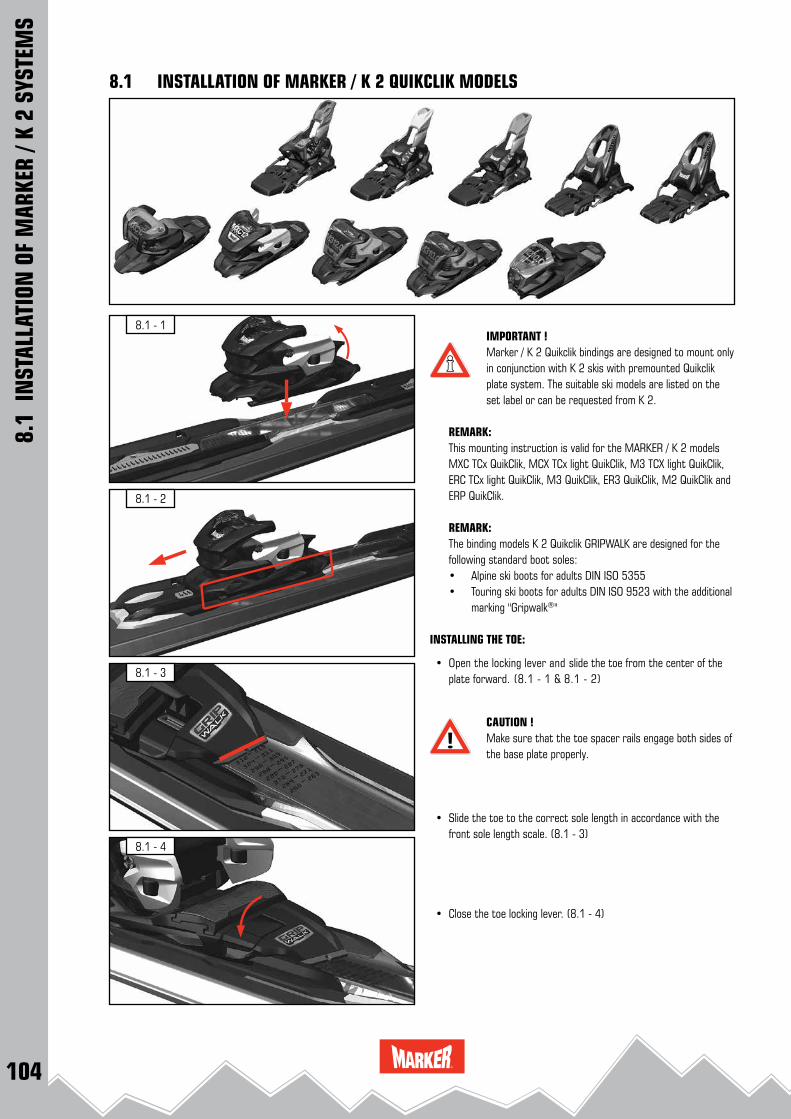
104
8.1 - 3
8.1 - 4
8.1 - 1
8.1 - 2
8.1
INST
ALLA
TION
OF
MAR
KER
/ K 2
SYS
TEM
S
8.1 INSTALLATION OF MARKER / K 2 QUIKCLIK MODELS
IMPORTANT ! Marker / K 2 Quikclik bindings are designed to mount only in conjunction with K 2 skis with premounted Quikclik plate system. The suitable ski models are listed on the set label or can be requested from K 2.
REMARK:This mounting instruction is valid for the MARKER / K 2 models MXC TCx QuikClik, MCX TCx light QuikClik, M3 TCX light QuikClik, ERC TCx light QuikClik, M3 QuikClik, ER3 QuikClik, M2 QuikClik and ERP QuikClik.
REMARK:The binding models K 2 Quikclik GRIPWALK are designed for the following standard boot soles:• Alpine ski boots for adults DIN ISO 5355• Touring ski boots for adults DIN ISO 9523 with the additional marking "Gripwalk®"
INSTALLING THE TOE:
• Open the locking lever and slide the toe from the center of the plate forward. (8.1 - 1 & 8.1 - 2)
CAUTION !Make sure that the toe spacer rails engage both sides of the base plate properly.
• Slide the toe to the correct sole length in accordance with the
front sole length scale. (8.1 - 3)
• Close the toe locking lever. (8.1 - 4)

105
8.1 - 8
8.1 - 9
8.1 - 5
8.1 - 7
8.1 - 6
8.1
INST
ALLA
TION
OF
MAR
KER
/ K 2
SYS
TEM
S
8.1 INSTALLATION OF MARKER / K 2 QUIKCLIK MODELS
INSTALLING THE HEEL:
• Open the heel locking lever and slide the heel onto the plate starting from the rear. (8.1 - 5)
• Slide the heel forward. (8.1 - 6)
CAUTION !Ensure that the rails of the heel engage both sides of the base plate properly.
• Slide the heel to the correct sole length in accordance with the rear sole length scale. (8.1 - 7)
• Close the heel locking lever. (8.1 - 8)
CHECK FORWARD PRESSURE:
• Place the ski boot into the binding, close the binding. • Correct forward pressure: With the boot in the system the forward pressure is correct
when the imprinted line on the forward pressure indicator is visible in the cutout of the heel housing. (8.1 - 9)
If the forward pressure indicator line is not visible: remove the ski boot and readjust the boot sole length until the forward pressure indicator line is visible in the cutout.
RELEASE VALUE SELECTION AND ADJUSTMENT:
• Following the correct adjustment for sole length and forward pressure, the release value has to be selected and adjusted. Use the weight method to match the individual skier’s needs.
See RELEASE VALUE SELECTION AND ADJUSTMENT: 11.1 - 11.3
REMARK:ADJUSTMENT OF DEMO BINDING MODELS:also refer to chapter 13.8
CAUTION ! The release value selection and adjustment has to be done very accurately to care for the skier´s safety. All key information including the release value must be recorded in the workorder. 14.3

106
8.2 - 3
8.2 - 4
8.2 - 1
8.2 - 2
8.2
INST
ALLA
TION
OF
MAR
KER
/ K 2
SYS
TEM
S
8.2 INSTALLATION OF M3 TCx LIGHT / ER3 TCx LIGHT / M3 / ER3 MODELS
IMPORTANT ! M3 TCx light / M3 / ER3 TCx light and ER3 bindings are designed to mount only in conjunction with K 2 M3 / ER3 skis.The suitable ski models are listed on the set label or can be requested from K 2.
REMARK: these binding models are designed for use only with Alpine ski boots for adults DIN ISO 5355 type A.
INSTALLING THE HEEL:
• Slide the heel from the center of the plate backward until it stops. (8.2 - 1)
CAUTION ! Make sure that the spacer rails engage both sides of the base plate properly. (8.2 - 2)
• Move the heel backwards by turning the forward pressure adjust-ment screw. (8.2 - 3)
INSTALLING THE TOE:
• Ensure that the fixation screw tips do not exceed the bottom side of the spacer.
• Slide the toe onto the plate, starting from the front. (8.2 - 4)
CAUTION !Make sure that the spacer rails engage both sides of the base plate properly. (8.2 - 4)

107
8.2 - 8
8.2 - 9
8.2 - 5
8.2 - 7
8.2 - 6 5.0 ± 0.5 Nm
8.2
INST
ALLA
TION
OF
MAR
KER
/ K 2
SYS
TEM
S
8.2 INSTALLATION OF M3 TCx LIGHT / ER3 TCx LIGHT / M3 / ER3 MODELSSOLE LENGTH ADJUSTMENT:
• Slide the toe backward and adjust the sole length in accordance with the sole length scale. The screw hole of the toe spacer has to be aligned with the hole of the plate. (8.2 - 5).
• Tighten the fixing screws by hand with a torque of 5.0 ± 0.5 Nm. (8.2 - 6)
• Screw the heel backward to the correct sole length in accordance with the sole length scale. Indicator: left back edge of the heel housing. (8.2 - 7 / 8.2 - 8)
CHECK FORWARD PRESSURE:
• Place the ski boot into the binding, close the binding. • Check if the forward pressure adjustment screw is flush with the
back of the heel housing. (8.2 - 9). If this adjustment is incorrect, turn the screw until it is flush with
the back of the housing. • Remove the ski boot, then re - insert it into the binding and re-
check the adjustment.
RELEASE VALUE SELECTION AND ADJUSTMENT:
• Following the correct adjustment for sole length and forward pressure, the release value has to be selected and adjusted. Use the weight method to match the individual skier’s needs.
See RELEASE VALUE SELECTION AND ADJUSTMENT: 11.1 - 11.3
CAUTION ! The release value selection and adjustment has to be done very accurately to care for the skier´s safety. All key information including the release value must be recorded in the workorder. 14.3

108
8.3 - 3
8.3 - 4
8.3 - 1
8.3 - 2
8.3
INST
ALLA
TION
OF
MAR
KER
/ K 2
SYS
TEM
S
8.3 INSTALLATION OF M2 / ERP MODELS
IMPORTANT ! M2 / ERP bindings are designed to mount only in conjunc-tion with K 2 M2 / ERP skis.The suitable ski models are listed on the set label or can be requested from K 2.
REMARK:The binding models M2 / ERP GRIPWALK are designed for the following standard boot soles:• Alpine ski boots for adults DIN ISO 5355• Touring ski boots for adults DIN ISO 9523 with the additional marking "Gripwalk®"
INSTALLING THE HEEL:
• Slide the heel from the center of the plate backward until it stops. (8.3 - 1)
CAUTION ! Make sure that the spacer rails engage both sides of the base plate properly. (8.3 - 2)
• Move the heel backwards by turning the forward pressure adjust-ment screw. (8.3 - 3)
INSTALLING THE TOE:
• Ensure that the fixation screw tips do not exceed the bottom side of the spacer.
• Slide the toe onto the plate, starting from the front. (8.3 - 4)
CAUTION !Make sure that the spacer rails engage both sides of the base plate properly. (8.3 - 4)
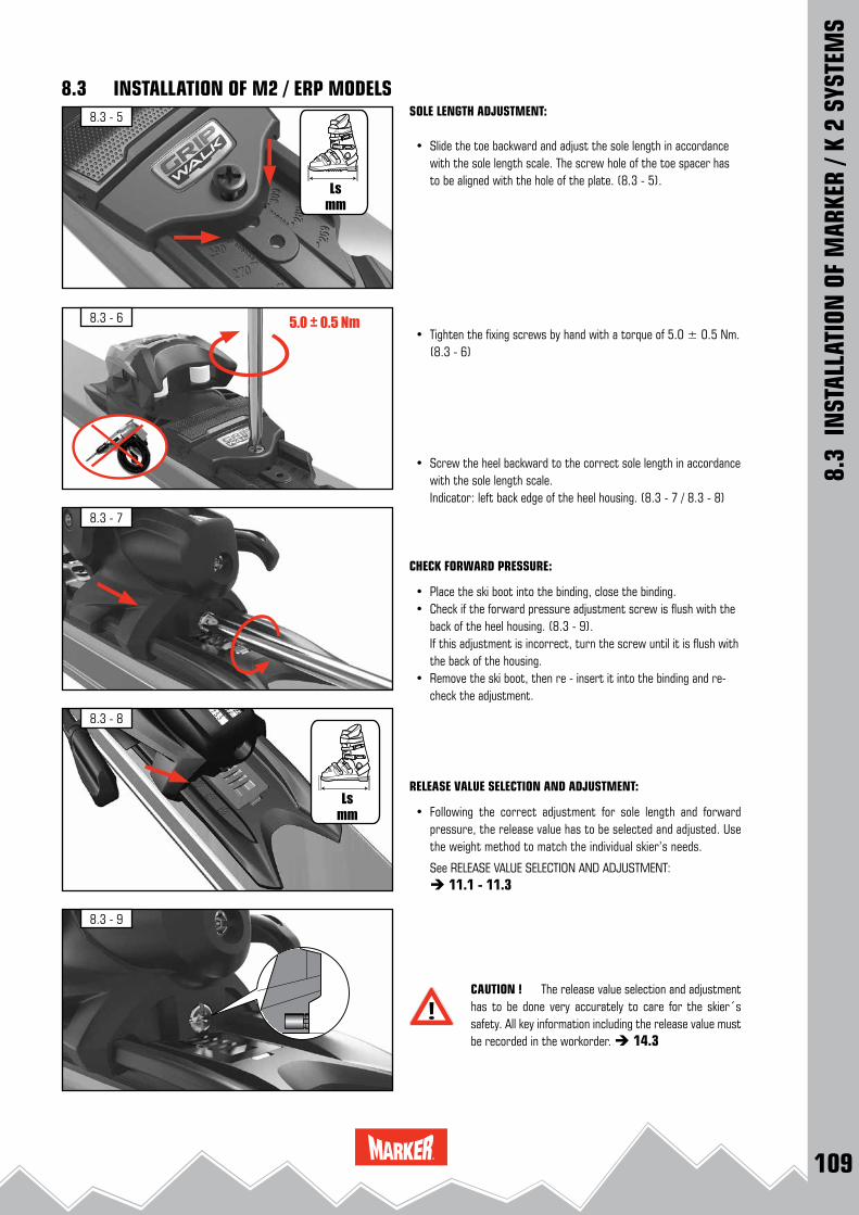
109
8.3 - 8
8.3 - 9
8.3 - 5
8.3 - 7
8.3 - 6 5.0 ± 0.5 Nm
8.3
INST
ALLA
TION
OF
MAR
KER
/ K 2
SYS
TEM
S
8.3 INSTALLATION OF M2 / ERP MODELSSOLE LENGTH ADJUSTMENT:
• Slide the toe backward and adjust the sole length in accordance with the sole length scale. The screw hole of the toe spacer has to be aligned with the hole of the plate. (8.3 - 5).
• Tighten the fixing screws by hand with a torque of 5.0 ± 0.5 Nm. (8.3 - 6)
• Screw the heel backward to the correct sole length in accordance with the sole length scale. Indicator: left back edge of the heel housing. (8.3 - 7 / 8.3 - 8)
CHECK FORWARD PRESSURE:
• Place the ski boot into the binding, close the binding. • Check if the forward pressure adjustment screw is flush with the
back of the heel housing. (8.3 - 9). If this adjustment is incorrect, turn the screw until it is flush with
the back of the housing. • Remove the ski boot, then re - insert it into the binding and re-
check the adjustment.
RELEASE VALUE SELECTION AND ADJUSTMENT:
• Following the correct adjustment for sole length and forward pressure, the release value has to be selected and adjusted. Use the weight method to match the individual skier’s needs.
See RELEASE VALUE SELECTION AND ADJUSTMENT: 11.1 - 11.3
CAUTION ! The release value selection and adjustment has to be done very accurately to care for the skier´s safety. All key information including the release value must be recorded in the workorder. 14.3

110
9.1 - 4
9.1 - 2
9.1 - 1
9.1 - 3
N POWER X EVO N PRO X EVO 22.0 mm
9.1
INST
ALLA
TION
OF
MAR
KER
/ NOR
DICA
SYS
TEM
S
9.1 INSTALLATION OF N POWER X EVO & N PRO X EVO MODELS
IMPORTANT ! Nordica N POWER X EVO and N PRO X EVO models are designed to mount only in conjunction with NORDICA EVO skis.The suitable ski models are listed on the set label or can be requested from Nordica.
REMARK: these binding models are designed for use only with Alpine ski boots for adults DIN ISO 5355 type A.
INSTALLING THE TOE:
• Slide the toe onto the premounted plate, starting from the front. (9.1 - 1)
• Slide the toe backward until the holes of the toespacer are aligned with the holes of the front plate (9.1 - 2).
CAUTION !Ensure that the spacer rails engage both sides of the base plate properly. (9.1 - 3)
• Install the fixing screws. (9.1 - 4)
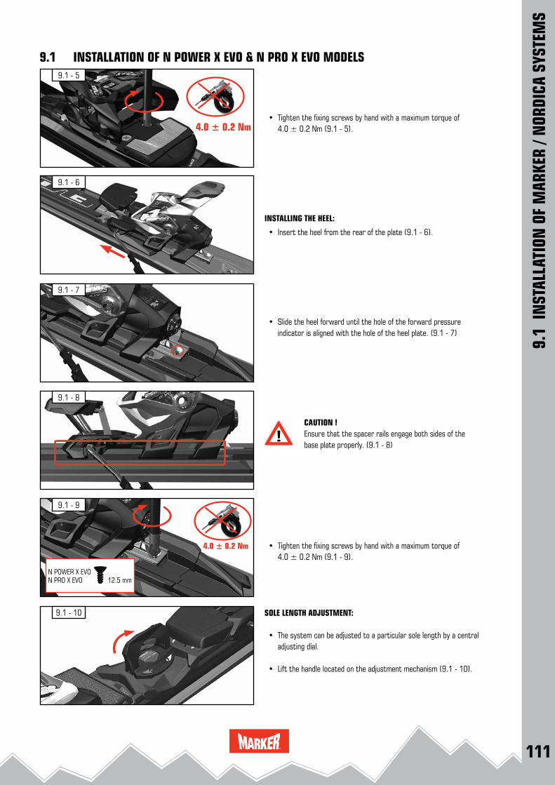
111
9.1 - 8
9.1 - 9
9.1 - 10
9.1 - 7
9.1 - 6
9.1 - 5
4.0 ± 0.2 Nm
4.0 ± 0.2 Nm
N POWER X EVO N PRO X EVO 12.5 mm
9.1
INST
ALLA
TION
OF
MAR
KER
/ NOR
DICA
SYS
TEM
S
9.1 INSTALLATION OF N POWER X EVO & N PRO X EVO MODELS
• Tighten the fixing screws by hand with a maximum torque of 4.0 ± 0.2 Nm (9.1 - 5).
INSTALLING THE HEEL:
• Insert the heel from the rear of the plate (9.1 - 6).
• Slide the heel forward until the hole of the forward pressure indicator is aligned with the hole of the heel plate. (9.1 - 7)
CAUTION !Ensure that the spacer rails engage both sides of the base plate properly. (9.1 - 8)
• Tighten the fixing screws by hand with a maximum torque of 4.0 ± 0.2 Nm (9.1 - 9).
SOLE LENGTH ADJUSTMENT:
• The system can be adjusted to a particular sole length by a central adjusting dial.
• Lift the handle located on the adjustment mechanism (9.1 - 10).
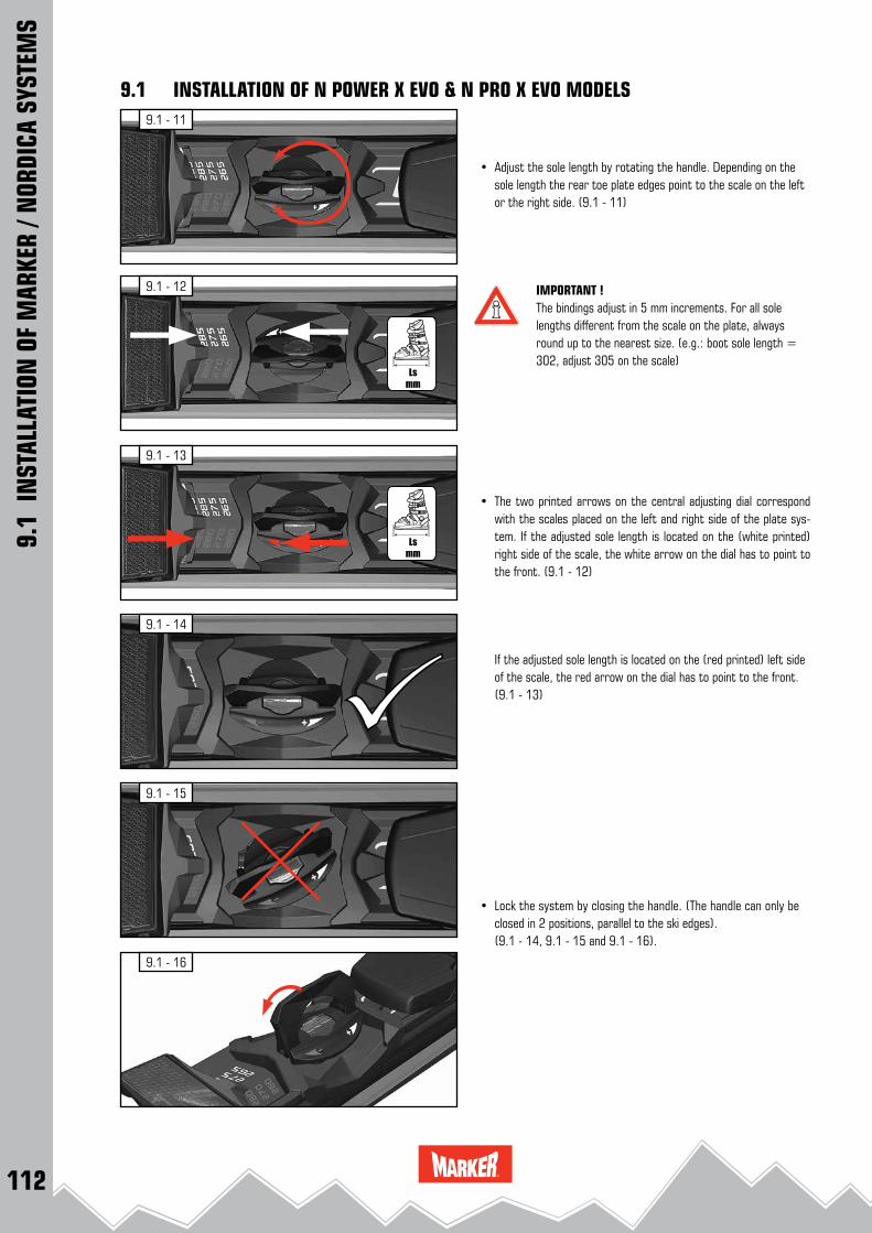
112
9.1 - 14
9.1 - 15
9.1 - 16
9.1 - 13
9.1 - 12
9.1 - 11
9.1
INST
ALLA
TION
OF
MAR
KER
/ NOR
DICA
SYS
TEM
S
9.1 INSTALLATION OF N POWER X EVO & N PRO X EVO MODELS
• Adjust the sole length by rotating the handle. Depending on the sole length the rear toe plate edges point to the scale on the left or the right side. (9.1 - 11)
IMPORTANT ! The bindings adjust in 5 mm increments. For all sole lengths different from the scale on the plate, always round up to the nearest size. (e.g.: boot sole length = 302, adjust 305 on the scale)
• The two printed arrows on the central adjusting dial correspond with the scales placed on the left and right side of the plate sys-tem. If the adjusted sole length is located on the (white printed) right side of the scale, the white arrow on the dial has to point to the front. (9.1 - 12)
If the adjusted sole length is located on the (red printed) left side of the scale, the red arrow on the dial has to point to the front. (9.1 - 13)
• Lock the system by closing the handle. (The handle can only be closed in 2 positions, parallel to the ski edges).
(9.1 - 14, 9.1 - 15 and 9.1 - 16).
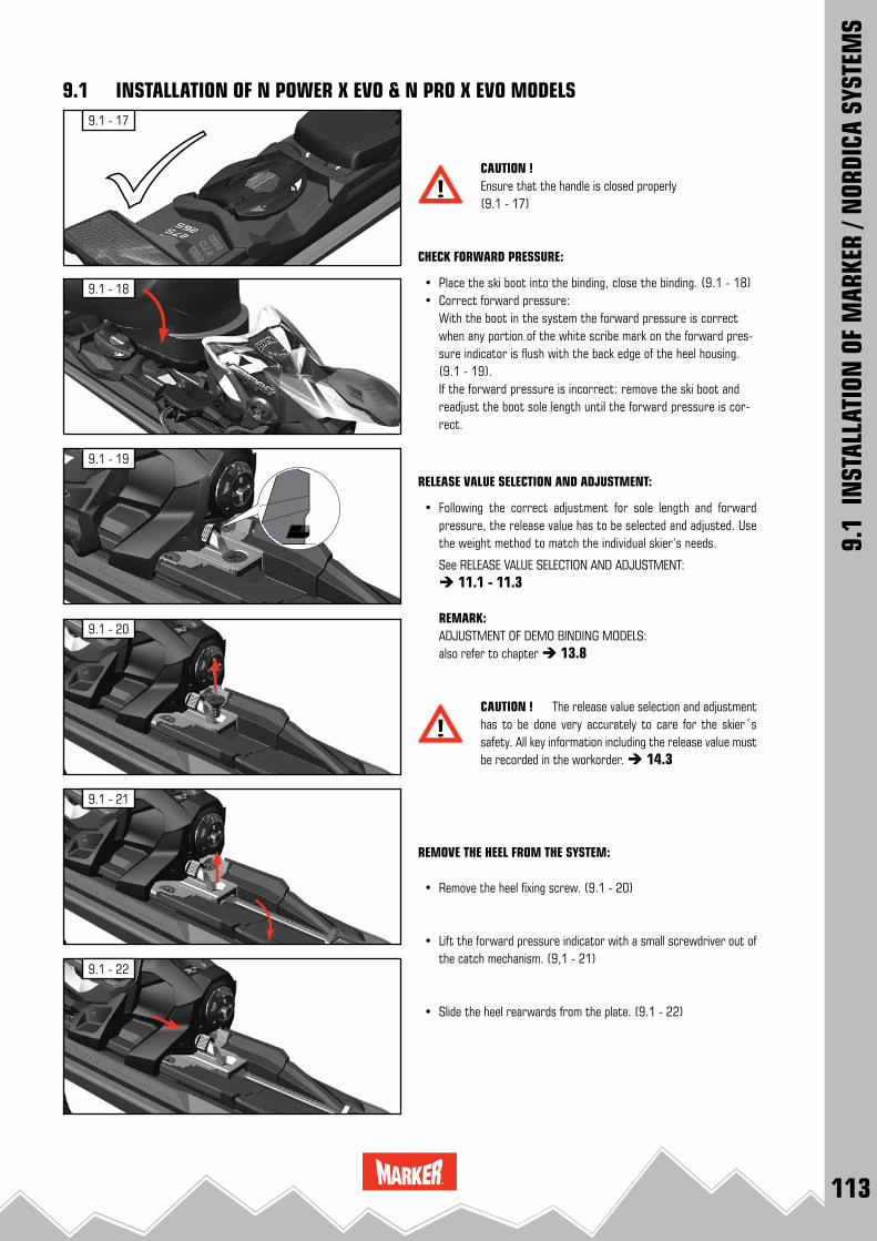
113
9.1 - 22
9.1 - 19
9.1 - 20
9.1 - 21
9.1 - 18
9.1 - 17
9.1
INST
ALLA
TION
OF
MAR
KER
/ NOR
DICA
SYS
TEM
S
9.1 INSTALLATION OF N POWER X EVO & N PRO X EVO MODELS
CAUTION !Ensure that the handle is closed properly (9.1 - 17)
CHECK FORWARD PRESSURE:
• Place the ski boot into the binding, close the binding. (9.1 - 18) • Correct forward pressure: With the boot in the system the forward pressure is correct
when any portion of the white scribe mark on the forward pres-sure indicator is flush with the back edge of the heel housing. (9.1 - 19).
If the forward pressure is incorrect: remove the ski boot and readjust the boot sole length until the forward pressure is cor-rect.
RELEASE VALUE SELECTION AND ADJUSTMENT:
• Following the correct adjustment for sole length and forward pressure, the release value has to be selected and adjusted. Use the weight method to match the individual skier’s needs.
See RELEASE VALUE SELECTION AND ADJUSTMENT: 11.1 - 11.3
REMARK:ADJUSTMENT OF DEMO BINDING MODELS:also refer to chapter 13.8
CAUTION ! The release value selection and adjustment has to be done very accurately to care for the skier´s safety. All key information including the release value must be recorded in the workorder. 14.3
REMOVE THE HEEL FROM THE SYSTEM:
• Remove the heel fixing screw. (9.1 - 20)
• Lift the forward pressure indicator with a small screwdriver out of the catch mechanism. (9,1 - 21)
• Slide the heel rearwards from the plate. (9.1 - 22)
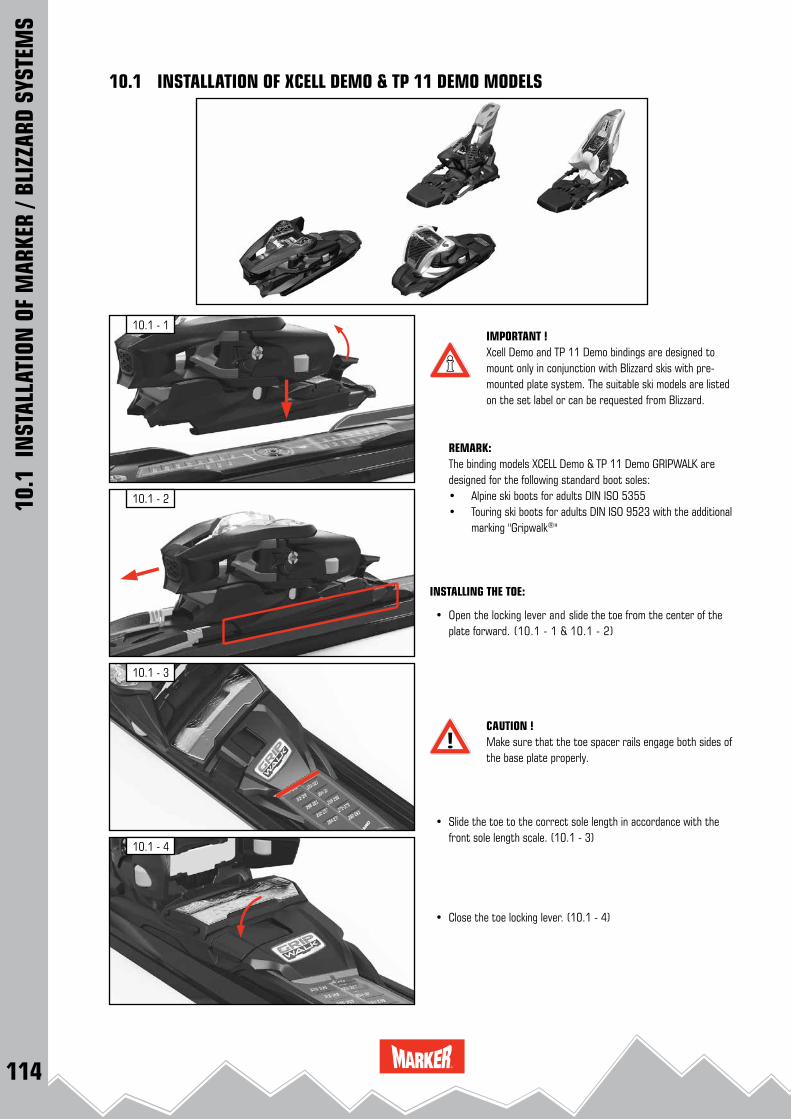
114
10.1 - 3
10.1 - 4
10.1 - 1
10.1 - 210.1
IN
STAL
LATI
ON O
F M
ARKE
R / B
LIZZ
ARD
SYST
EMS
10.1 INSTALLATION OF XCELL DEMO & TP 11 DEMO MODELS
IMPORTANT ! Xcell Demo and TP 11 Demo bindings are designed to mount only in conjunction with Blizzard skis with pre-mounted plate system. The suitable ski models are listed on the set label or can be requested from Blizzard.
REMARK:The binding models XCELL Demo & TP 11 Demo GRIPWALK are designed for the following standard boot soles:• Alpine ski boots for adults DIN ISO 5355• Touring ski boots for adults DIN ISO 9523 with the additional marking "Gripwalk®"
INSTALLING THE TOE:
• Open the locking lever and slide the toe from the center of the plate forward. (10.1 - 1 & 10.1 - 2)
CAUTION !Make sure that the toe spacer rails engage both sides of the base plate properly.
• Slide the toe to the correct sole length in accordance with the
front sole length scale. (10.1 - 3)
• Close the toe locking lever. (10.1 - 4)

115
10.1 - 8
10.1 - 9
10.1 - 7
10.1 - 6
10.1 - 5
10.1
IN
STAL
LATI
ON O
F M
ARKE
R / B
LIZZ
ARD
SYST
EMS
10.1 INSTALLATION OF XCELL DEMO & TP 11 DEMO MODELS
INSTALLING THE HEEL:
• Open the heel locking lever and slide the heel onto the plate starting from the rear. (10.1 - 5)
• Slide the heel forward. (10.1 - 6)
CAUTION !Ensure that the rails of the heel engage both sides of the base plate properly.
• Slide the heel to the correct sole length in accordance with the rear sole length scale. (10.1 - 7)
• Close the heel locking lever. (10.1 - 8)
CHECK FORWARD PRESSURE:
• Place the ski boot into the binding, close the binding. • Correct forward pressure: With the boot in the system the forward pressure is correct
when the imprinted line on the forward pressure indicator is visible in the cutout of the heel housing. (10.1 - 9)
If the forward pressure indicator line is not visible: remove the ski boot and readjust the boot sole length until the forward pressure indicator line is visible in the cutout.
RELEASE VALUE SELECTION AND ADJUSTMENT:
• Following the correct adjustment for sole length and forward pressure, the release value has to be selected and adjusted. Use the weight method to match the individual skier’s needs.
See RELEASE VALUE SELECTION AND ADJUSTMENT: 11.1 - 11.3
REMARK:ADJUSTMENT OF DEMO BINDING MODELS:also refer to chapter 13.8
CAUTION ! The release value selection and adjustment has to be done very accurately to care for the skier´s safety. All key information including the release value must be recorded in the workorder. 14.3

116
10.2 - 3
10.2 - 4
10.2 - 1
10.2 - 210.2
IN
STAL
LATI
ON O
F M
ARKE
R / B
LIZZ
ARD
SYST
EMS
10.2 INSTALLATION OF TCX DEMO & TP 10 DEMO MODELS
IMPORTANT ! TCX Demo and TP 10 Demo bindings are designed to mount only in conjunction with Blizzard skis with pre-mounted plate system. The suitable ski models are listed on the set label or can be requested from Blizzard.
REMARK: these binding models are designed for use only with Alpine ski boots for adults DIN ISO 5355 type A.
INSTALLING THE TOE:
• Open the locking lever and slide the toe from the center of the plate forward. (10.2 - 1 & 10.2 - 2)
CAUTION !Make sure that the toe spacer rails engage both sides of the base plate properly.
• Slide the toe to the correct sole length in accordance with the
front sole length scale. (10.2 - 3)
• Close the toe locking lever. (10.2 - 4)

117
10.2 - 8
10.2 - 9
10.2 - 7
10.2 - 6
10.2 - 5
10.2
IN
STAL
LATI
ON O
F M
ARKE
R / B
LIZZ
ARD
SYST
EMS
10.2 INSTALLATION OF TCX DEMO & TP 10 DEMO MODELS
INSTALLING THE HEEL:
• Open the heel locking lever and slide the heel onto the plate starting from the rear. (10.2 - 5)
• Slide the heel forward. (10.2 - 6)
CAUTION !Ensure that the rails of the heel engage both sides of the base plate properly.
• Slide the heel to the correct sole length in accordance with the rear sole length scale. (10.2 - 7)
• Close the heel locking lever. (10.2 - 8)
CHECK FORWARD PRESSURE:
• Place the ski boot into the binding, close the binding. • Correct forward pressure: With the boot in the system the forward pressure is correct
when the imprinted line on the forward pressure indicator is visible in the cutout of the heel housing. (10.2 - 9)
If the forward pressure indicator line is not visible: remove the ski boot and readjust the boot sole length until the forward pressure indicator line is visible in the cutout.
RELEASE VALUE SELECTION AND ADJUSTMENT:
• Following the correct adjustment for sole length and forward pressure, the release value has to be selected and adjusted. Use the weight method to match the individual skier’s needs.
See RELEASE VALUE SELECTION AND ADJUSTMENT: 11.1 - 11.3
REMARK:ADJUSTMENT OF DEMO BINDING MODELS:also refer to chapter 13.8
CAUTION ! The release value selection and adjustment has to be done very accurately to care for the skier´s safety. All key information including the release value must be recorded in the workorder. 14.3

118
10.3 - 5 10.3 - 6
10.3 - 4
10.3 - 2
10.3 - 1
10.3 - 3
A
B
10.3 - 7
ca. 5 Nm
10.3
IN
STAL
LATI
ON O
F M
ARKE
R / B
LIZZ
ARD
SYST
EMS
10.3 INSTALLATION OF IQ TCX CM2 & IQ TP CM2 MODELS
CAUTION ! Blizzard IQ TCX CM2 & IQ TP CM2 models are designed to mount only in conjunction with Blizzard IQ skis.The suitable ski models are listed on the set label or can be requested from Blizzard.
REMARK: these binding models are designed for use only with Alpine ski boots for adults DIN ISO 5355 type A.
• Slide the complete binding with pre - installed toe and heel onto the IQ interface rail starting from the ski tail. (10.3 - 1)
CAUTION !Ensure that the spacer rails engage the ski rail properly (10.3 - 2 and 10.3 - 3)
• Push the opening block [A], then lift the sole length fixation lever [B]. (10.3 - 4)
• The hole of the middle plate has to be aligned with the bushing of the ski. (10.3 - 5)
• Position the center fixation screw (10.3 - 6). With light downward pressure, tighten the center fixing screw
by hand with a torque of ca. 5.0 Nm. (10.3 - 7)
IMPORTANT !Ensure correct screw choice: using the wrong center fixing screw can irreparably damage the bushing of the ski !

119
10.3 - 13
10.3 - 10
10.3 - 9
10.3 - 11
10.3 - 12
10.3 - 8
10.3
IN
STAL
LATI
ON O
F M
ARKE
R / B
LIZZ
ARD
SYST
EMS
10.3 INSTALLATION OF IQ TCX CM2 & IQ TP CM2 MODELS
SOLE LENGTH ADJUSTMENT:
• Adjust the sole length either by hand by shifting the binding to the corresponding markings on the scale or by turning the sole length adjustment screw with the appropriate screwdriver. (Use a Pozidriv® 3 screwdriver)
(10.3 - 8 and 10.3 - 9)
• Lock the system by closing the sole length fixation lever. (10.3 - 10)
CAUTION ! The sole length fixation lever must not be pressed down with effort, but is correctly aligned with the locking teeth when it closes easily.
CAUTION ! Visually check locking mechanism: when locking the system the opening lever has to snap into the basic position. (10.3 - 11)The warning symbol on the right side of the opening lever must not be visible ! (10.3 - 12)
CHECK FORWARD PRESSURE:
• Place the ski boot into the binding and close it. • Correct forward pressure: With the boot in the system the forward pressure is correct when
any portion of the white scribe mark on the forward pressure indi-cator is flush with the back edge of the heel housing. (10.3 - 13)
If the forward pressure is incorrect: remove the ski boot and re-adjust the boot sole length until the forward pressure is correct.
RELEASE VALUE SELECTION AND ADJUSTMENT:
• Following the correct adjustment for sole length and forward pressure, the release value has to be selected and adjusted. Use the weight method to match the individual skier’s needs.
See RELEASE VALUE SELECTION AND ADJUSTMENT: 11.1 - 11.3
REMARK:ADJUSTMENT OF DEMO BINDING MODELS:also refer to chapter 13.8
CAUTION ! The release value selection and adjustment has to be done very accurately to care for the skier´s safety. All key information including the release value must be recorded in the workorder. 14.3

120
10.4 - 3
10.4 - 2
10.4 - 1 IMPORTANT ! Blizzard IQ TP models are designed to mount only in conjunction with Blizzard IQ skis.The suitable ski models are listed on the set label or can be requested from Blizzard.
REMARK: these binding models are designed for use only with Alpine ski boots for adults DIN ISO 5355 type A.
SOLE LENGTH ADJUSTMENT:
• Determine the correct sole length in mm. Choose the correspond-ing sole length value on the bottom side of the middle plate. (10.4 - 1)
IMPORTANT ! IQ TP bindings adjust in 10 mm increments. For all sole lengths different from the scales on the middle plate always round up or down to the nearest size.
• Engage the front toothed arm of the middle plate with the cor-responding sole length slots at the marking of the bottom side of the toe spacer. (10.4 - 2) Make sure that the middle plate is engaged properly.
• Engage the rear toothed arm of the middle plate with the cor-responding sole length slots at the marking of the bottom side of the heel spacer (10.4 - 3). Make sure that the middle plate is engaged properly.
10.4
IN
STAL
LATI
ON O
F M
ARKE
R / B
LIZZ
ARD
SYST
EMS
10.4 INSTALLATION OF IQ TP MODELS

121
10.4 - 4
10.4 - 7
10.4 - 5
10.4 - 6 ca. 5.0 Nm
INSTALLING THE BINDING:
• Slide the complete binding with pre - installed toe and heel onto the IQ interface rail starting from the ski tail. (10.4 - 4)
CAUTION !Ensure that the spacer rails engage the ski rail properly.
• Slide the binding forward until the hole of the IQ middle plate is aligned with the marking on the ski and the bushing. (10.4 - 5)
• Tighten the center fixing screw by hand with a torque of ca. 5.0 Nm. (10.4 - 6)
CAUTION !Ensure correct screw choice: using the wrong center fixing screw can irreparably damage the bushing of the ski !
CHECK FORWARD PRESSURE: • Place the ski boot into the binding, close the binding. • Check if the forward pressure adjustment screw is flush with the
back of the heel housing. If this adjustment is incorrect, turn the screw until it is flush with the back of the housing (10.4 - 7)
• Remove the ski boot, then re - insert and re-check the adjust-ment.
RELEASE VALUE SELECTION AND ADJUSTMENT:
• Following the correct adjustment for sole length and forward pressure, the release value has to be selected and adjusted. Use the weight method to match the individual skier’s needs.
See RELEASE VALUE SELECTION AND ADJUSTMENT: 11.1 - 11.3
CAUTION ! The release value selection and adjustment has to be done very accurately to care for the skier´s safety. All key information including the release value must be recorded in the workorder. 14.3
10.4
IN
STAL
LATI
ON O
F M
ARKE
R / B
LIZZ
ARD
SYST
EMS
10.4 INSTALLATION OF IQ TP MODELS

122
10.5 - 3
10.5 - 4
10.5 - 1
10.5 - 210.5
IN
STAL
LATI
ON O
F M
ARKE
R / B
LIZZ
ARD
SYST
EMS
10.5 INSTALLATION OF IQ JUNIOR MODELS
IMPORTANT ! Blizzard IQ 4.5 and IQ 7 models are designed to mount only in conjunction with Blizzard IQ Junior skis.The suitable ski models are listed on the set label or can be requested from Blizzard.
IMPORTANT ! IQ Junior binding models are designed for junior boots
with sole lengths from 135 mm to 325 mm.
INSTALLING THE BINDING:
• Determine the ski length. (10.5 - 1)
• Choose the corresponding ski length value on the bottom side of the white middle plate and connect the middle plate with the heel rack at the determined position. (10.5 - 2)
• Slide the premounted heel onto the IQ interface starting from the ski tip. (10.5 - 3)
• Slide the heel backward until the plug on the bottom side of the white middleplate engages the central bore hole of the ski. (10.5 - 4)

123
10.5 - 9
10.5 - 5
10.5 - 8
10.5 - 10
10.5 - 6
10.5 - 7
AB10
.5 I
NST
ALLA
TION
OF
MAR
KER
/ BLI
ZZAR
D SY
STEM
S
10.5 INSTALLATION OF IQ JUNIOR MODELS
• Slide the locking device onto the IQ interface starting from the ski tip and move it backward until the symbol „unlocked“ is visible in the cutout. (10.5 - 5 / 10.5 - 6)
• Determine the sole length in mm. • Slide the toe onto the IQ interface starting from the ski tip. Adjust
to the correct sole length by shifting the toe to the corresponding marking on the scale. (10.5 - 7)
IMPORTANT ! IQ Junior bindings adjust in 4 mm increments. For all sole lengths different from the scale on the plate always round up or down to the nearest size.
• Lock the system by moving the locking device forward until the interlocking snaps into place. (10.5 - 8)
• Install the boot in the binding, lift the forward pressure lever and slide the heel until the position of the heel is correct. (10.5 - 9) Latch the forward pressure lever by locking it down until it is fixed.
CAUTION ! Ensure that the lever is engaged properly !
CHECK FORWARD PRESSURE:
• Place the ski boot into the binding, close the binding. • Correct forward pressure: With the boot in the system the groove on the locking lever has
to point to the embossed section of the heel housing. If the forward pressure is incorrect: remove the ski boot, lift the
lever and move the heel until the forward pressure is correct. (10.5 - 10)
RELEASE VALUE SELECTION AND ADJUSTMENT:
• Following the correct adjustment for sole length and forward pressure, the release value has to be selected and adjusted. Use the weight method to match the individual skier’s needs.
See RELEASE VALUE SELECTION AND ADJUSTMENT: 11.1 - 11.3
CAUTION ! The release value selection and adjustment has to be done very accurately to care for the skier´s safety. All key information including the release value must be recorded in the workorder. 14.3
124
11.1
AD
JUST
MEN
TS
11.1 RELEASE VALUE SELECTION AND ADJUSTMENT
TYPE III SKIERS:
• Ski aggressively. • Normally ski at higher speeds. • Prefer steeper and more challenging terrain. • Favor higher than average release / retention settings. • Skiers who designate themselves Type 3 accept a narrower
margin of release in order to gain a wider margin of retention.
This classification is not recommended for skiers with a weight of 21 kg or less (code A - C). In this case classify the skier to Type 2.
SPECIAL CASES: • Skiers who desire release / retention settings lower than Type I
may designate themselves » I - « Type » I - «: move up the table one skier code.
• Skiers who desire release / retention settings higher than Type III may designate themselves » III + «
Type » III + «: move down the table three skier codes
• Skiers may select skier type designations that are different for twist and forward pressure. In such cases the selection shall be indicated by a slash separating twist and forward lean selections respectively.
CAUTION ! The release value selection and adjustment has to be done very accurately to care for the skier´s safety. As a MARKER certified technician you are required to keep accurate and complete records of all work performed on any MARKER binding. 14.3
DETERMINE THE RELEASE VALUE:
BASIC PROCEDURE:
• First record all essential skier information: • Skiers will classify themselves as skier Type I, II or III. • Determine the exact release value with the tables and examples
on the following pages. • Adjust the relase value at the binding.
SKIER CLASSIFICATION:
The following descriptions should enable skiers to classify themselves and their skier type in accordance with ISO 11088. Keep in mind that the type of skier classification has nothing in com-mon with the skier’s ability. For example, many advanced skiers who have a smooth skiing style may be correctly classified as a Type II skier.
TYPE I SKIERS:
• Ski conservatively. • Prefer slower speeds. • Prefer smooth slopes of gentle to moderate pitch. • Favor lower than average release / retention settings. • Skiers who designate themselves Type I skiers accept a narrower
margin of retention in order to gain a wider margin of release. • Entry - level skiers uncertain of their classification should be clas-
sified as a Type I skier.
TYPE II SKIERS:
• Ski moderately. • Prefer a variety of speeds. • Ski on varied terrain, including „most difficult“. • Are skiers who do not meet the descriptions of either Type I or
Type III.

125
11.1
AD
JUST
MEN
TS
11.1 RELEASE VALUE SELECTION AND ADJUSTMENT
CAUTION ! For the determination of the release values the MARKER adjustment charts of the former seasons are no longer valid. Use the present MARKER adjustment chart given in this manual 11.1 - 1
WEIGHT METHOD:
Determine the release value:Necessary skier information: • Weight • Height • Skier type • Age • Sole length
DETERMINE THE RELEASE VALUE (DIN - SETTING):
The value lines in the MARKER adjustment chart are marked with the letters A – O for a better orientation.
• Find the skier ’s weight in the left hand column and the skier ’s height in the next column. If the skier ’s weight and height are not in the same line, move up the chart one row.
• The chosen line is determined for skier Type I. For skier Type II move down the chart one row, for skier type III move down the chart two rows.
• If the skier is age 50 or over, or younger than 10, move up the chart one row.
• Locate the given release value in the chart at the intersection of the last chosen row and the column with the boot sole length. If the intersection of the appropriate row and column is a blank box, move left or right on the same line of the chart to the nearest number that shows a release value.
• Adjust this release value on both toe and heel.
EXAMPLE:
Skier information: ► Weight: 170 lbs ► Height: 170 cm ► Skier type: III ► Age: 55 ► Sole length: 320 mm
DETERMINE THE RELEASE VALUE (DIN - SETTING):
► Weight and height in row K ►Skier type III: move two rows down = row M ► For skiers age 50 or over, or age 10 or under, move up the chart
one row = row L ► Column sole length 311 - 330 mm ► Result: release value 6

126
11.1
AD
JUST
MEN
TS
11.1 RELEASE VALUE SELECTION AND ADJUSTMENTExamples for initial indicator value Z (presetting), depending on boot sole length.The initial indicator values found in this table are only the starting point in the binding setting process. The initial values may need to be modified in order to archieve the correct measured release values.
WEIGHT
[kg] [lbs]
HEIGHT
[cm][ft´ in´́ ]
RELEASE TORQUE RANGE
RELEASE VALUE
SOLE LENGTH[mm]
MZ
[Nm]
MY
[Nm]
≤230231 - 250
251-270
271-290
291-310
311-330
331-350
≥351
5* 18*
10-13 1) 22-29 A 8 29 0,75 0,75 0,75
14-17 2) 30-38 B 11 40 1,00 0,75 0,75 0,75
18-21 39-47 C 14 52 1,50 1,25 1,25 1,00
22-25 48-56 D 17 64 2,00 1,75 1,50 1,50 1,25
26-30 57-66 E 20 75 2,50 2,25 2,00 1,75 1,50 1,50
31-35 67-78 F 23 87 3,00 2,75 2,50 2,25 2,00 1,75 1,75
36-41 79-91 G 27 102 3,50 3,00 2,75 2,50 2,25 2,00
42-48 92-107
≤148≤4´10´´ H 31 120 3,50 3,00 3,00 2,75 2,50
49-57 108-125
149-1574´11´ -́ 5´1´´ I 37 141 4,50 4,00 3,50 3,50 3,00
58-66 126-147
158-1665´2´ -́ 5´5´´ J 43 165 5,50 5,00 4,50 4,00 3,50 3,00
67-78 148-174
167-1785´6´ -́ 5´10´´ K 50 194 6,50 6,00 5,50 5,00 4,50 4,00
79-94 175-209
179-1945´11´ -́ 6´4´´ L 58 229 7,50 7,00 6,50 6,00 5,50 5,00
≥95 ≥210
≥195≥6´5´´ M 67 271 8,50 8,00 7,00 6,50 6,00
N 78 320 10,00 9,50 8,50 8,00 7,50
O 91 380 11,50 11,00 10,00 9,50 9,00
105 452 12,00 11,00 10,50
121** 520**
137** 588**
11.1 - 1 ADJUSTMENT CHART ACCORDING TO ISO 11088
l139
5
711
14
14
5
11 7
913
* Lowest tolerance limit ** Highest tolerance limit

127
11.1
AD
JUST
MEN
TS
11.1 RELEASE VALUE SELECTION AND ADJUSTMENT
11.1 - 1 ADJUSTMENT CHART ACCORDING TO ISO 11088
The values are given in this table for example purposes and may be written also in fractions.
1) For skiers 13 kg (29 lbs) and under, no further correction is appropriate.
2) For skiers 17 kg (38 lbs) and under, skier Type -1 is inappropriate.
The initial indicator values given in this table are suggested values for the beginning of the procedure.
A re - adjustment could be necessary in order to make the measure MZ and MY values coincide with the selected individual MZ and MY values within the limits stated in this table.

128
1
2
Triple Pivot X
1
2
Race 2 - linkage (TLT2)
Biotech Junior 4 - linkage
1
2
1
2
Xcell
1
2
Triple Pivot Elite 2
1
2
Triple Pivot light
1
2
Triple Pivot Comfort
1
2
Triple Pivot Compact
11.2
AD
JUST
MEN
TS
11.2 RELEASE VALUE SELECTION AND ADJUSTMENTBINDING RELEASE FORCE ADJUSTMENT SCREWS AND RELEASE VALUE INDICATOR SCALES
REMARK: MARKER recommends adjustment with a Pozidriv® 3
screwdriver.
ADJUSTMENT SCREW AND INDICATOR SCALE ON THE TOE
• Turn the adjustment screw (1) until the indicator line aligns with the selected release setting on the appropriate indicator scale.
(2)

129
3
4
3
4
3
4
3
4
Inter Pivot 2
3
4
Hollow linkage
Compact
Compact 2
Compact Junior
Comfort 23
4
3
4
Twincam X / TCX light
3
4
Twincam
11.2
AD
JUST
MEN
TS
11.2 RELEASE VALUE SELECTION AND ADJUSTMENT
ADJUSTMENT SCREW AND INDICATOR SCALE ON THE HEEL
• Turn the adjustment screw (3) until the indicator line aligns with the selected release setting on the appropriate indicator scale. (4)

130
If the measured values are beyond the limits for a new adjustment value C, it is not allowed to correct the adjustment of the binding. Replace ski boot, binding or both.
DELIVERY TO THE CUSTOMER:
IMPORTANT ! After all adjustments are done, deliver the customer the whole system together with a function test report (workshop form). Fix the data as mentioned in chapter 14 »workshop records« beside the result of the measurement.
EXAMPLE 11.3 - 1
11.3
AD
JUST
MEN
TS
11.3 FUNCTION TEST AND INSPECTION
After installation, adjustment and function test have been duly carried out, the binding should be tested with a calibrated testing device for ski bindings.
IMPORTANT ! See the information given by the manufacturer of the ski binding test device.
This function test should verify that the release torque ranges (men-tioned in Nm) are within the limits of the tolerances and should be noted on a workshop form.
RELEASE VALUE TOLERANCE:
A release value tolerance of ± 15 % is valid according to ISO 11088. This equals a value in the MARKER adjustment chart 11.1 - 1 in an area one line up and down of the chosen release value. See example 11.3 - 1, equivalent to B. If the measured value is in this area, the system can receive clearance.
LIMITING VALUE FOR NEW ADJUSTMENTS:
A release value limit of ± 30 % is valid for new adjustments according to ISO 11088. This equals a value in the MARKER adjustment chart 11.1 - 1 in an area two lines up and down of the chosen release value. See example 11.3 - 1, equivalent to C.
IMPORTANT ! If the measured value is in the area for a new adjustment (value C), the system may not be delivered.
• Inspect again the consistency of ski boot and binding and verify the adjustment of the binding.
• Re - test the binding. If the measured value is still in the area for a new adjustment, correct the adjustment of the binding until the measured value is within the release value tolerance (value B).
4 3,50 J 43 165 – C
5 4,50 K 50 194 – B
6 5,50 L 58 229RELEASE VALUE
7 6,50 M 67 271 + B
8,50 8 N 78 320 + C
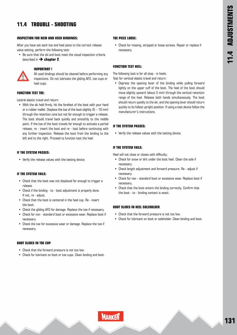
131
11.4
AD
JUST
MEN
TS
11.4 TROUBLE - SHOOTING
TOE PIECE LOOSE:
• Check for missing, stripped or loose screws. Repair or replace if necessary.
FUNCTION TEST HEEL:
The following test is for all step - in heels. Test for vertical elastic travel and return: • Depress the opening lever of the binding while pulling forward
lightly on the upper cuff of the boot. The heel of the boot should move slightly upward (about 5 mm) through the vertical retention range of the heel. Release both hands simultaneously. The boot should return quickly to the ski, and the opening lever should return quickly to its fullest upright position. If using a test device follow the manufacturer’s instructions.
IF THE SYSTEM PASSES:
• Verify the release values with the testing device.
IF THE SYSTEM FAILS:
Heel will not close or closes with difficulty: • Check for snow or dirt under the boot heel. Clean the sole if
necessary. • Check length adjustment and forward pressure. Re - adjust if
necessary. • Check for non - standard boot or excessive wear. Replace boot if
necessary. • Check that the boot enters the binding correctly. Confirm that
the boot - to - binding contact is exact.
BOOT SLIDES IN HEEL SOLEHOLDER:
• Check that the forward pressure is not too low. • Check for lubricant on boot or soleholder. Clean binding and boot.
INSPECTION FOR NEW AND USED BINDINGS:
After you have set each toe and heel piece to the correct release value setting, perform the following test: • Be sure that the ski and boot meet the visual inspection criteria
described in chapter 2.
IMPORTANT ! All used bindings should be cleaned before performing any inspections. Do not lubricate the gliding AFD, toe cups or heel cups.
FUNCTION TEST TOE:
Lateral elastic travel and return: • With the ski held firmly, hit the forefoot of the boot with your hand
or a rubber mallet. Displace the toe of the boot slightly (6 – 10 mm) through the retention zone but not far enough to trigger a release. The boot should travel back quickly and smoothly to the middle point. If the toe of the boot travels far enough to activate a partial release, re - insert the boot and re - test before continuing with any further inspection. Release the boot from the binding to the left and to the right. Proceed to function test the heel.
IF THE SYSTEM PASSES:
• Verify the release values with the testing device.
IF THE SYSTEM FAILS:
• Check that the boot was not displaced far enough to trigger a release.
• Check if the binding - to - boot adjustment is properly done. If not, re - adjust.
• Check that the boot is centered in the heel cup. Re - insert the boot.
• Check the gliding AFD for damage. Replace the toe if necessary. • Check for non - standard boot or excessive wear. Replace boot if
necessary. • Check the toe for excessive wear or damage. Replace the toe if
necessary.
BOOT SLIDES IN TOE CUP:
• Check that the forward pressure is not too low. • Check for lubricant on boot or toe cups. Clean binding and boot.

132
12.1
- 12
.5
SPEC
IAL
CASE
S / R
EPLA
CIN
G SK
I BRA
KES
12.1 - 12.5 SPECIAL CASES / REPLACING SKI BRAKES
12.5 REPLACING SKI BRAKES:
Within the scope of the binding adjustment the ski brakes should be subjected to a visual and functional test.
If the brakes are defective (if the brake arms are damaged, the brake platform or brake pedal are worn) or a wider brake is necessary the pair of brakes should be replaced.
MARKER offers ski brakes with different widths for replacement.
REMARK
To determine the correct brake the width of the ski has to be measured ca. 200 mm behind the mid ski mark.
• Replacing ski brakes see 12.6 - 12.8
• Brake chart see 15.2
12.1 COMPETITION BINDINGS:
For racers MARKER offers special competition ski bindings with higher release values. Please advise your customer that skiers skiing on such bindings are doing so at their own risk and liability.
12.2 MONOSKI:
MARKER ski bindings are designed for the use on a pair of skis. Any other use or the installation on a Monoski will not be covered by MARKER ’s indemnification or warranty.
12.3 ADJUSTMENT OUTSIDE OF THE STANDARDS:
If skiers request a release setting other than that recommended by the MARKER adjustment chart in this manual or not in accordance with the standards, the shop may choose to adjust the system to MARKER’s recommendations and instruct the skiers on how to change the setting themselves, should they wish to. As a service to the skier the shop may wish to adjust the skier’s system in accordance with the skier’s wishes, even when this requested setting would fall outside of the MARKER adjustment chart ’s recommendations. If the shop provides this type of service, the system will only be indemnified if the skier signs a release agreement in which he declares that the adjustment has be done at the skier’s own risk.
12.4 ANTIQUATED BINDINGS WHICH DO NOT CONFORM WITH THE STANDARD:
Shops may choose to work on bindings not indemnified by MARKER at their discretion. If a skier asks the retailer to perform work on antiquated or non - standard MARKER bindings, the system should be inspected according to the procedures described in the appropri-ate chapter of this manual. (Be certain to explain to the skier the advantages of using a current model !) If the system passes the inspections, for the shop’s own legal protection the shop should ask the skier to sign a waiver and release.
IMPORTANT !If the system fails any of these inspections, a notation to this effect must be made on the workshop form and the skier must be warned that continued use of the system is inadvisable and may significantly increase the skier ’s risk of injury.
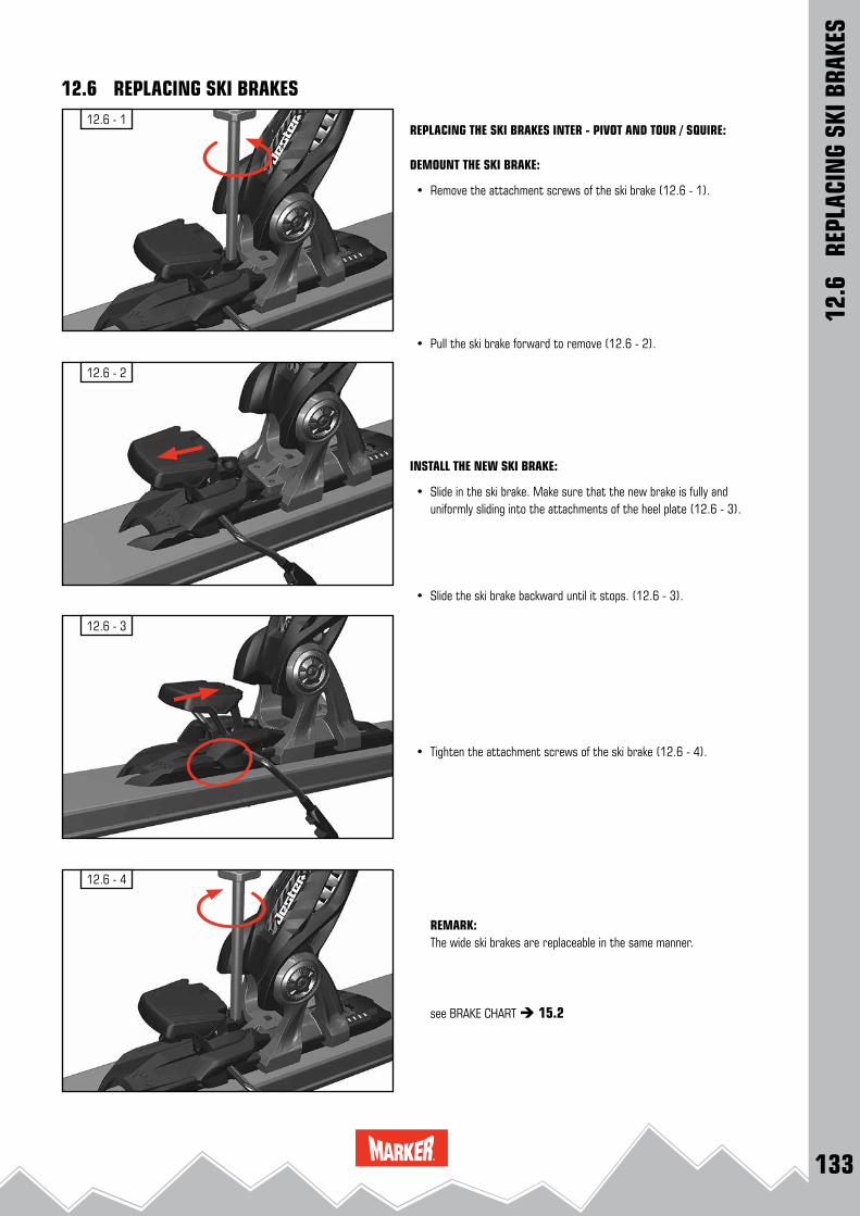
133
12.6 - 3
12.6 - 1
12.6 - 2
12.6 - 4
12.6
RE
PLAC
ING
SKI B
RAKE
S
12.6 REPLACING SKI BRAKES
REPLACING THE SKI BRAKES INTER - PIVOT AND TOUR / SQUIRE:
DEMOUNT THE SKI BRAKE:
• Remove the attachment screws of the ski brake (12.6 - 1).
• Pull the ski brake forward to remove (12.6 - 2).
INSTALL THE NEW SKI BRAKE:
• Slide in the ski brake. Make sure that the new brake is fully and uniformly sliding into the attachments of the heel plate (12.6 - 3).
• Slide the ski brake backward until it stops. (12.6 - 3).
• Tighten the attachment screws of the ski brake (12.6 - 4).
REMARK: The wide ski brakes are replaceable in the same manner.
see BRAKE CHART 15.2
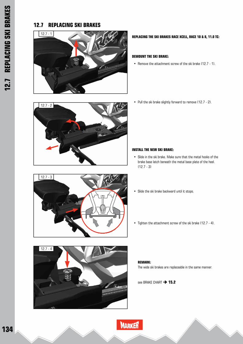
134
12.7 - 3
12.7 - 1
12.7 - 2
12.7 - 4
12.7
RE
PLAC
ING
SKI B
RAKE
S
12.7 REPLACING SKI BRAKES
REPLACING THE SKI BRAKES RACE XCELL, RACE 10 & 8, 11.0 TC:
DEMOUNT THE SKI BRAKE:
• Remove the attachment screw of the ski brake (12.7 - 1).
• Pull the ski brake slightly forward to remove (12.7 - 2).
INSTALL THE NEW SKI BRAKE:
• Slide in the ski brake. Make sure that the metal hooks of the brake base latch beneath the metal base plate of the heel. (12.7 - 3)
• Slide the ski brake backward until it stops.
• Tighten the attachment screw of the ski brake (12.7 - 4).
REMARK: The wide ski brakes are replaceable in the same manner.
see BRAKE CHART 15.2
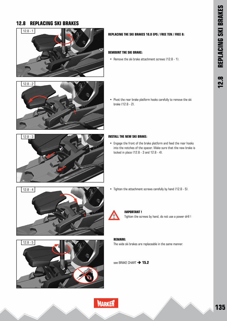
135
12.8 - 4
12.8 - 1
12.8 - 2
12.8 - 3
12.8 - 5
12.8
R
EPLA
CIN
G SK
I BRA
KES
12.8 REPLACING SKI BRAKES
REPLACING THE SKI BRAKES 10.0 EPS / FREE TEN / FREE 8:
DEMOUNT THE SKI BRAKE:
• Remove the ski brake attachment screws (12.8 - 1).
• Pivot the rear brake platform hooks carefully to remove the ski brake (12.8 - 2).
INSTALL THE NEW SKI BRAKE:
• Engage the front of the brake platform and feed the rear hooks into the notches of the spacer. Make sure that the new brake is locked in place (12.8 - 3 and 12.8 - 4).
• Tighten the attachment screws carefully by hand (12.8 - 5).
IMPORTANT !Tighten the screws by hand, do not use a power drill !
REMARK: The wide ski brakes are replaceable in the same manner.
see BRAKE CHART 15.2

136
12.9 - 2
12.9 - 4
12.9 - 3
12.9 - 1DIN - ADAPTER AT BOOT FORDYNAFIT TLT 5 + TLT 6 BOOTS
IMPORTANT !Tools required for assembly: DIN Adapter, Power drill, Drill bit size 2, small slotted screwdriver, Phillips head screwdriver size PH2, Torx screwdriver size 10(12.9 - 1)
• Use the Phillips head screwdriver to unscrew the screw with which the heel insert is fixed in place. (12.9 - 2)
• Then remove the heel insert. This can be gently levered out using a small slotted screwdriver. (12.9 - 3 and 12.9 - 4)
12.9
DI
N A
DAPT
ER A
T BO
OT
12.9 DIN ADAPTER AT BOOT
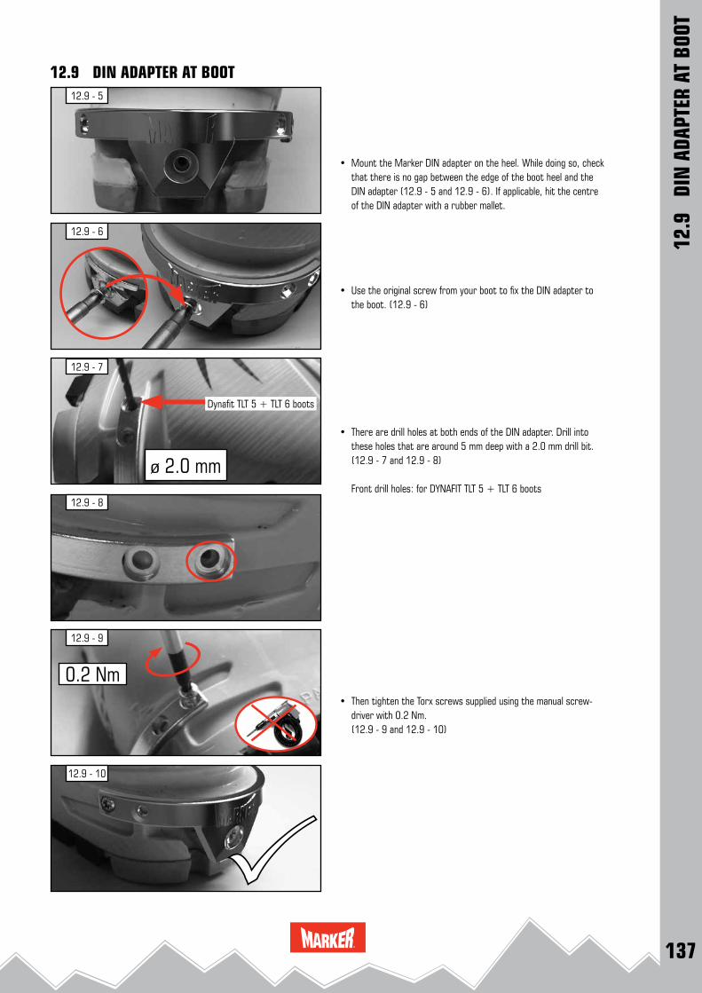
137
12.9 - 5
12.9 - 6
12.9 - 8
12.9 - 10
12.9 - 9
12.9 - 7
ø 2.0 mm
0.2 Nm
Dynafit TLT 5 + TLT 6 boots
• Mount the Marker DIN adapter on the heel. While doing so, check that there is no gap between the edge of the boot heel and the DIN adapter (12.9 - 5 and 12.9 - 6). If applicable, hit the centre of the DIN adapter with a rubber mallet.
• Use the original screw from your boot to fix the DIN adapter to the boot. (12.9 - 6)
• There are drill holes at both ends of the DIN adapter. Drill into these holes that are around 5 mm deep with a 2.0 mm drill bit. (12.9 - 7 and 12.9 - 8)
Front drill holes: for DYNAFIT TLT 5 + TLT 6 boots
• Then tighten the Torx screws supplied using the manual screw-driver with 0.2 Nm.
(12.9 - 9 and 12.9 - 10)
12.9
DI
N A
DAPT
ER A
T BO
OT
12.9 DIN ADAPTER AT BOOT

138
13.1 - 5
13.1 - 1
13.1 - 3
13.1 - 4
13.1 - 2
13.1
M
ARKE
R RE
NTA
L &
DEM
O M
ODEL
S
13.1 GENERAL INFORMATION
DEFINITION OF JESTER DEMO BINDINGS: (13.1 - 1)MARKER Jester Demo have adjustable toes and adjustable heels.
Adjustment range
mm toe heel
Jester Demo 265 - 365 50 mm 50 mm
DEFINITION OF FDT BINDINGS: (13.1 - 2)MARKER FDT have adjustable toes and adjustable heels.
Adjustment range
mm toe heel
Griffon DSquire D
FDT TPX 12FDT TP 11 FDT TP 10FDT TLT 10
260 - 388 64 mm 64 mm
DEFINITION OF FASTRAK III BINDINGS: (13.1 - 3)The Fastrak III System is adjustable by a centralized length adjustment system.
Adjustment range (in 4 mm steps)
mm toe heel
10.0 Fastrak III 266 - 370 104 mm
DEFINITION OF JUNIOR FASTRAK II BINDINGS: (13.1 - 4)Junior Fastrak II bindings have movable toes and movable heels.
Adjustment range (toe: in 5 mm steps, heel in 4 mm steps)
mm toe heel
7.0 Fastrak II 86 50 36
4.5 Fastrak II 86 50 36
DEFINITION JUNIOR RENTAL BINDINGS: (13.1 - 5)Junior Rental (RTL) bindings have fixed toes and movable heels.
Adjustment range (in 4 mm steps)
mm toe heel
M 7.0 RTL 240 - 304 - 64 mm
M 4.5 RTL 200 - 264 - 64 mm

139
13.1 - 8
13.1 - 9
13.1 - 6
13.1 - 7
13.1 - 5
13.1
M
ARKE
R RE
NTA
L &
DEM
O M
ODEL
S
13.1 GENERAL INFORMATION
GENERAL INFORMATION BINDING - TO - BOOT ADJUSTMENT
For the correct binding - to - boot adjustment there are number codes, respectively sole length scales on the MARKER Jester Demo & Griffon D & Squire D, FDT Demo, Fastrak III, Junior Fastrak II, and Junior RTL bindings:
MARKER Jester Demo:Sole length in mm (265 – 365) is marked on the toe - and heel plates. (13.1 - 5)
MARKER Griffon D & Squire D & FDT Demo:Sole length in mm (260 – 388) is marked on the FDT Demo middle plate. (13.1 - 6)
Fastrak III:Sole length in mm (266 - 370) is marked on the Fastrak III middle plate. (13.1 - 7)
Junior Fastrak II:Sole length in mm (245 - 330 mm large; 200 - 285 mm small) is marked on the Junior Fastrak II toe - and heel plates. (13.1 - 8)
M 7.0 / M 4.5 RTL:Number codes are placed on the heel spacers. (13.1 - 9)
M 7.0 RTL Code 54 – 69 240 – 304 mm
M 4.5 RTL Code 44 – 59 200 – 264 mm

140
13.2 - 3
13.2 - 2
13.2 - 1
315 mm
3
1
2
A
B
13.2
M
ARKE
R RE
NTA
L &
DEM
O M
ODEL
S
13.2 INSTALLATION OF MARKER JESTER DEMO
MARKER JESTER DEMO1 Front plate with sole length scale2 Heel plate with sole length scale3 Length adjustment screw
REMARK: these binding models are designed for use only with Alpine ski boots for adults DIN ISO 5355 type A.
DRILLING THE ATTACHMENT HOLES (A): • Place the Jester Demo installation tool W005L1T or W009P1T
(13.2 - 1 A) onto the ski and align the mid - sole mark »Jester Demo« with the mid - sole mark on the ski.
• Check if the installation tool is positioned correctly on the ski. • Drill 5 holes for the front plate and 4 holes for the heel plate
through the black marked drill bushings. • Remove installation tool from the ski.
or
DRILLING THE ATTACHMENT HOLES (B): Adjusting the installation tool W001G1T or W012J1T (13.2 - 1
B) for mounting the MARKER Jester Demo: • Open the locking lever. Move the toe guide until the sole length
315 mm is adjusted. (13.2 - 2) • Close the locking lever. Place the pre - installed installation tool
onto the ski and align the mid - sole mark of the installation tool with the mid - sole mark on the ski.
• Drill 4 holes for the front plate (toe) through the red marked drill bushings, drill the additional rear hole for the front plate through the rear toe bushing. (13.2 - 1)
• Drill 4 holes for the heel plate (heel) through the red marked drill bushings.
• Remove installation tool from the ski.
REMARK: See the DRILLING INSTRUCTIONS 3.2
INSTALLING THE HEEL: • Install the MARKER Jester Demo heel plate with the 4 pre - in-
stalled screws (13.2 - 3). Tighten the screws lightly, then firmly.
heeltoe
ski tip
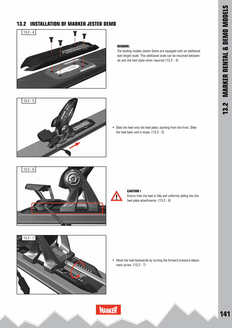
141
13.2 - 5
13.2 - 7
13.2 - 6
13.2 - 4
13.2
M
ARKE
R RE
NTA
L &
DEM
O M
ODEL
S
13.2 INSTALLATION OF MARKER JESTER DEMO
REMARK: The binding models Jester Demo are equipped with an additional sole length scale. This additional scale can be mounted between ski and the heel plate when required.(13.2 - 4)
• Slide the heel onto the heel plate, starting from the front. Slide the heel back until it stops. (13.2 - 5)
CAUTION ! Ensure that the heel is fully and uniformly sliding into the heel plate attachments. (13.2 - 6)
• Move the heel backwards by turning the forward pressure adjust-ment screw. (13.2 - 7)
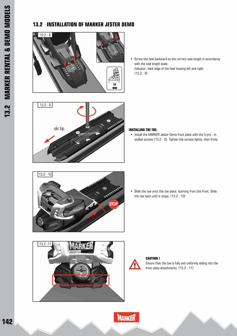
142
13.2 - 10
13.2 -11
13.2 - 9
13.2 - 8
13.2
M
ARKE
R RE
NTA
L &
DEM
O M
ODEL
S
13.2 INSTALLATION OF MARKER JESTER DEMO
• Screw the heel backward to the correct sole length in accordance with the sole length scale. Indicator: back edge of the heel housing left and right. (13.2 - 8)
INSTALLING THE TOE: • Install the MARKER Jester Demo front plate with the 5 pre - in-
stalled screws (13.2 - 9). Tighten the screws lightly, then firmly.
• Slide the toe onto the toe plate, starting from the front. Slide the toe back until it stops. (13.2 - 10)
CAUTION ! Ensure that the toe is fully and uniformly sliding into the front plate attachments. (13.2 - 11)
ski tip

143
13.2 - 15
13.2 -12
13.2 - 13
13.2 - 14
Ls 365 = max13
.2
MAR
KER
REN
TAL
& DE
MO
MOD
ELS
13.2 INSTALLATION OF MARKER JESTER DEMO
• With slight pressure, screw the toe backwards onto the front plate. (13.2 - 12)
• Screw the toe backward to the correct sole length in accordance with the sole length scale. Indicator: back edge of the toespacer left and right (13.2 - 13)
IMPORTANT SAFETY ADVICE !
Make sure that you do not exceed the »STOP« marking on the front plate ! Sole length adjustment 365 = max ! (13.2 - 14)
CHECK FORWARD PRESSURE:
• Place the ski boot into the binding, close the binding. • Check if the forward pressure adjustment screw is flush with the
back of the heel housing. (13.2 - 15). If this adjustment is incorrect, turn the screw until it is flush with
the back of the housing. • Remove the ski boot, then re - insert it into the binding and re-
check the adjustment.
RELEASE VALUE SELECTION AND ADJUSTMENT:
• Following the correct adjustment for sole length and forward pressure, the release value has to be selected and adjusted. Use the weight method to match the individual skier’s needs.
See RELEASE VALUE SELECTION AND ADJUSTMENT: 11.1 - 11.3
REMARK:ADJUSTMENT OF DEMO BINDING MODELS:also refer to chapter 13.8
CAUTION ! The release value selection and adjustment has to be done very accurately to care for the skier´s safety. All key information including the release value must be recorded in the workorder. 14.3
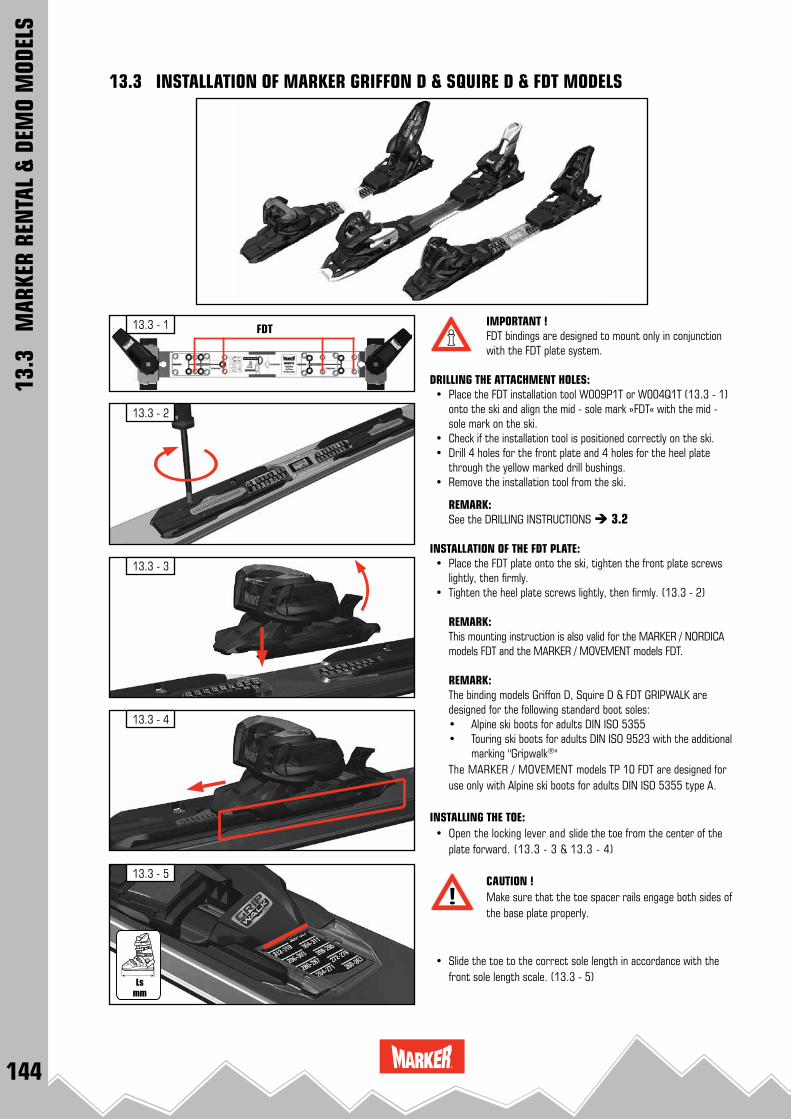
144
13.3 - 4
13.3 - 2
13.3 - 3
13.3 - 5
13.3 - 1 FDTIMPORTANT !FDT bindings are designed to mount only in conjunction with the FDT plate system.
DRILLING THE ATTACHMENT HOLES: • Place the FDT installation tool W009P1T or W004Q1T (13.3 - 1)
onto the ski and align the mid - sole mark »FDT« with the mid - sole mark on the ski.
• Check if the installation tool is positioned correctly on the ski. • Drill 4 holes for the front plate and 4 holes for the heel plate
through the yellow marked drill bushings. • Remove the installation tool from the ski.
REMARK: See the DRILLING INSTRUCTIONS 3.2
INSTALLATION OF THE FDT PLATE: • Place the FDT plate onto the ski, tighten the front plate screws
lightly, then firmly. • Tighten the heel plate screws lightly, then firmly. (13.3 - 2)
REMARK:This mounting instruction is also valid for the MARKER / NORDICA models FDT and the MARKER / MOVEMENT models FDT.
REMARK:The binding models Griffon D, Squire D & FDT GRIPWALK are designed for the following standard boot soles:• Alpine ski boots for adults DIN ISO 5355• Touring ski boots for adults DIN ISO 9523 with the additional marking "Gripwalk®"The MARKER / MOVEMENT models TP 10 FDT are designed for use only with Alpine ski boots for adults DIN ISO 5355 type A.
INSTALLING THE TOE: • Open the locking lever and slide the toe from the center of the
plate forward. (13.3 - 3 & 13.3 - 4)
CAUTION !Make sure that the toe spacer rails engage both sides of the base plate properly.
• Slide the toe to the correct sole length in accordance with the
front sole length scale. (13.3 - 5)
13.3
M
ARKE
R RE
NTA
L &
DEM
O M
ODEL
S
13.3 INSTALLATION OF MARKER GRIFFON D & SQUIRE D & FDT MODELS
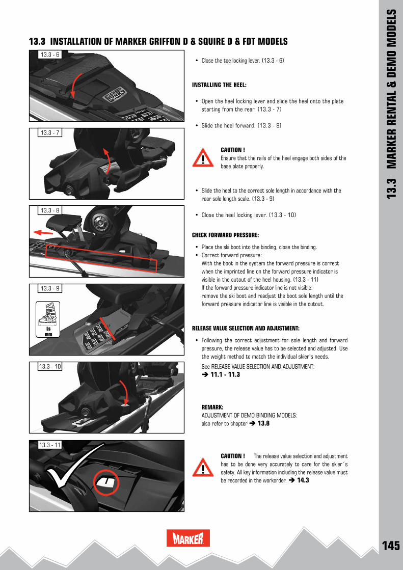
145
13.3 - 7
13.3 - 8
13.3 - 10
13.3 - 11
13.3 - 6
13.3 - 9
• Close the toe locking lever. (13.3 - 6)
INSTALLING THE HEEL:
• Open the heel locking lever and slide the heel onto the plate starting from the rear. (13.3 - 7)
• Slide the heel forward. (13.3 - 8)
CAUTION !Ensure that the rails of the heel engage both sides of the base plate properly.
• Slide the heel to the correct sole length in accordance with the rear sole length scale. (13.3 - 9)
• Close the heel locking lever. (13.3 - 10)
CHECK FORWARD PRESSURE:
• Place the ski boot into the binding, close the binding. • Correct forward pressure: With the boot in the system the forward pressure is correct
when the imprinted line on the forward pressure indicator is visible in the cutout of the heel housing. (13.3 - 11)
If the forward pressure indicator line is not visible: remove the ski boot and readjust the boot sole length until the forward pressure indicator line is visible in the cutout.
RELEASE VALUE SELECTION AND ADJUSTMENT:
• Following the correct adjustment for sole length and forward pressure, the release value has to be selected and adjusted. Use the weight method to match the individual skier’s needs.
See RELEASE VALUE SELECTION AND ADJUSTMENT: 11.1 - 11.3
REMARK:ADJUSTMENT OF DEMO BINDING MODELS:also refer to chapter 13.8
CAUTION ! The release value selection and adjustment has to be done very accurately to care for the skier´s safety. All key information including the release value must be recorded in the workorder. 14.3
13.3
M
ARKE
R RE
NTA
L &
DEM
O M
ODEL
S
13.3 INSTALLATION OF MARKER GRIFFON D & SQUIRE D & FDT MODELS
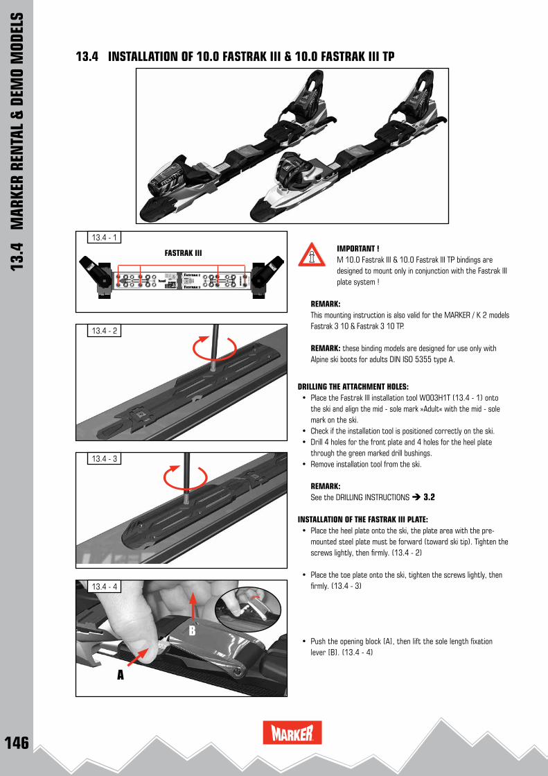
146
13.4 - 1
FASTRAK III
13.4 - 3
13.4 - 2
13.4 - 4
A
B
13.4
M
ARKE
R RE
NTA
L &
DEM
O M
ODEL
S
13.4 INSTALLATION OF 10.0 FASTRAK III & 10.0 FASTRAK III TP
IMPORTANT !M 10.0 Fastrak III & 10.0 Fastrak III TP bindings are designed to mount only in conjunction with the Fastrak III plate system !
REMARK:This mounting instruction is also valid for the MARKER / K 2 models Fastrak 3 10 & Fastrak 3 10 TP.
REMARK: these binding models are designed for use only with Alpine ski boots for adults DIN ISO 5355 type A.
DRILLING THE ATTACHMENT HOLES: • Place the Fastrak III installation tool W003H1T (13.4 - 1) onto
the ski and align the mid - sole mark »Adult« with the mid - sole mark on the ski.
• Check if the installation tool is positioned correctly on the ski. • Drill 4 holes for the front plate and 4 holes for the heel plate
through the green marked drill bushings. • Remove installation tool from the ski. REMARK: See the DRILLING INSTRUCTIONS 3.2
INSTALLATION OF THE FASTRAK III PLATE: • Place the heel plate onto the ski, the plate area with the pre-
mounted steel plate must be forward (toward ski tip). Tighten the screws lightly, then firmly. (13.4 - 2)
• Place the toe plate onto the ski, tighten the screws lightly, then firmly. (13.4 - 3)
• Push the opening block [A], then lift the sole length fixation lever [B]. (13.4 - 4)

147
13.4 - 8
13.4 - 7
13.4 - 5
13.4 - 6
13.4 - 9
A
B
13.4
M
ARKE
R RE
NTA
L &
DEM
O M
ODEL
S
13.4 INSTALLATION OF 10.0 FASTRAK III & 10.0 FASTRAK III TP
• Adjust the system to max. length. (13.4 - 5)
• Lock the system by closing the sole length fixation lever. (13.4 - 6)
• To attach the binding system Fastrak III to the plate, position the toe spacer at the middle section of the plate. (13.4 - 7)
• Slide the system forward. (13.4 - 8)
• Push the opening block [A], then lift the sole length fixation lever [B]. (13.4 - 9)

148
13.4 - 1413.4 - 13
13.4 - 15
13.4 - 16
13.4 - 10
13.4 - 12
13.4 - 11
13.4
M
ARKE
R RE
NTA
L &
DEM
O M
ODEL
S
13.4 INSTALLATION OF 10.0 FASTRAK III & 10.0 FASTRAK III TP
• Make sure that the toe and heel spacer rails engage both sides of the base plate properly (13.4 - 10 and 13.4 - 11)
• Slide the binding system forward until the hole of the middle plate and the hole of the steel plate are aligned. (13.4 - 12)
• Position the center fixation screw. (13.4 - 13)
• With light downward pressure, tighten the screw by hand with a maximum torque of 4.0 ± 0.2 Nm. (13.4 - 14)
SOLE LENGTH ADJUSTMENT • Adjust the sole length either by hand by shifting the binding to
the corresponding markings on the scale or by turning the sole length adjustment screw with the appropriate screwdriver (Use a Pozidriv® 3 screwdriver)
(13.4 - 15)
REMARK:The sole length scale is equipped with an additional color code. (MARKER 10.0 Fastrak III & Fastrak III TP) This color code corresponds with the Dalbello 4 - factor rental boot code system.

149
13.4 - 19
13.4 - 18
13.4 - 17
13.4 - 20
13.4 - 21
A
B
C
13.4
M
ARKE
R RE
NTA
L &
DEM
O M
ODEL
S
13.4 INSTALLATION OF 10.0 FASTRAK III & 10.0 FASTRAK III TP
• Lock the system by closing the sole length fixation lever. (13.4 - 17)
CAUTION ! The sole length fixation lever must not be pressed down with effort, but is correctly aligned with the locking teeth when it closes easily.
CAUTION ! Visually check locking mechanism: when locking the system the opening lever has snap into the basic posi-tion. (13.4 - 18)The warning symbol on the right side of the opening lever must not be visible ! (13.4 - 19)
CHECK FORWARD PRESSURE:
• Place the ski boot into the binding, close the binding. • Correct forward pressure: With the boot in the system the forward pressure is correct
when any portion of the white scribe mark on the forward pres-sure indicator is flush with the back edge of the heel housing. (13.4 - 20).
If the forward pressure is incorrect: remove the ski boot and readjust the boot sole length until the forward pressure is cor-rect.
RELEASE VALUE SELECTION AND ADJUSTMENT:
• Following the correct adjustment for sole length and forward pressure, the release value has to be selected and adjusted. Use the weight method to match the individual skier’s needs.
See RELEASE VALUE SELECTION AND ADJUSTMENT: 11.1 - 11.3
CAUTION ! The release value selection and adjustment has to be done very accurately to care for the skier´s safety. All key information including the release value must be recorded in the workorder. 14.3
REMARK:ADJUSTMENT OF DEMO BINDING MODELS:also refer to chapter 13.8
DISASSEMBLY OF THE SYSTEM:For disassembling the system first adjust the sole length to maximum. Remove the central fixation screw. Lift the middle plate section with a small screwdriver out of the catch mechanism and slide the binding system rearwards from the plate. (13.4 - 21)
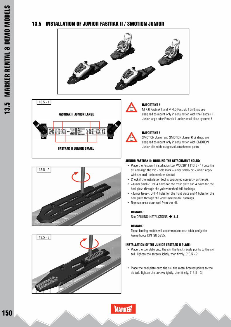
150
13.5 - 3
13.5 - 2
13.5 - 1
FASTRAK II JUNIOR LARGE
FASTRAK II JUNIOR SMALL
13.5
M
ARKE
R RE
NTA
L &
DEM
O M
ODEL
S
13.5 INSTALLATION OF JUNIOR FASTRAK II / 3MOTION JUNIOR
IMPORTANT !M 7.0 Fastrak II and M 4.5 Fastrak II bindings are designed to mount only in conjunction with the Fastrak II Junior large oder Fastrak II Junior small plate systems !
IMPORTANT ! 3MOTION Junior and 3MOTION Junior R bindings are designed to mount only in conjunction with 3MOTION Junior skis with integrated attachment parts !
JUNIOR FASTRAK II: DRILLING THE ATTACHMENT HOLES: • Place the Fastrak II installation tool W003H1T (13.5 - 1) onto the
ski and align the mid - sole mark »Junior small« or »Junior large« with the mid - sole mark on the ski.
• Check if the installation tool is positioned correctly on the ski. • »Junior small«: Drill 4 holes for the front plate and 4 holes for the
heel plate through the yellow marked drill bushings. • »Junior large«: Drill 4 holes for the front plate and 4 holes for the
heel plate through the violet marked drill bushings. • Remove installation tool from the ski. REMARK: See DRILLING INSTRUCTIONS 3.2
REMARK: These binding models will accommodate both adult and junior
Alpine boots DIN ISO 5355.
INSTALLATION OF THE JUNIOR FASTRAK II PLATE: • Place the toe plate onto the ski, the length scale points to the ski
tail. Tighten the screws lightly, then firmly. (13.5 - 2)
• Place the heel plate onto the ski, the metal bracket points to the ski tail. Tighten the screws lightly, then firmly. (13.5 - 3)

151
13.5 - 6
13.5 - 5
13.5 - 4
13.5 - 7
13.5
M
ARKE
R RE
NTA
L &
DEM
O M
ODEL
S
13.5 INSTALLATION OF JUNIOR FASTRAK II / 3MOTION JUNIOR
INSTALLING THE JUNIOR FASTRAK II / 3MOTION JUNIOR TOE:
• Open the toe locking lever by lifting it up and backwards. (13.5 - 4)
• Slide the toe with lever open from the center of the plate for-ward. (13.5 - 5)
CAUTION !Ensure that the rails of the toe engage both sides of the base plate properly. (13.5 - 6)
• Slide the toe forward to the correct sole length in accordance with the sole length scale. (13.5 - 7)
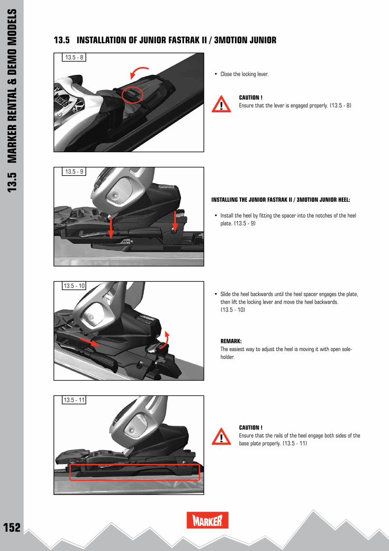
152
13.5 - 11
13.5 - 10
13.5 - 9
13.5 - 8
• Close the locking lever.
CAUTION !Ensure that the lever is engaged properly. (13.5 - 8)
INSTALLING THE JUNIOR FASTRAK II / 3MOTION JUNIOR HEEL:
• Install the heel by fitting the spacer into the notches of the heel plate. (13.5 - 9)
• Slide the heel backwards until the heel spacer engages the plate, then lift the locking lever and move the heel backwards. (13.5 - 10)
REMARK: The easiest way to adjust the heel is moving it with open sole-holder.
CAUTION !Ensure that the rails of the heel engage both sides of the base plate properly. (13.5 - 11)
13.5
M
ARKE
R RE
NTA
L &
DEM
O M
ODEL
S
13.5 INSTALLATION OF JUNIOR FASTRAK II / 3MOTION JUNIOR
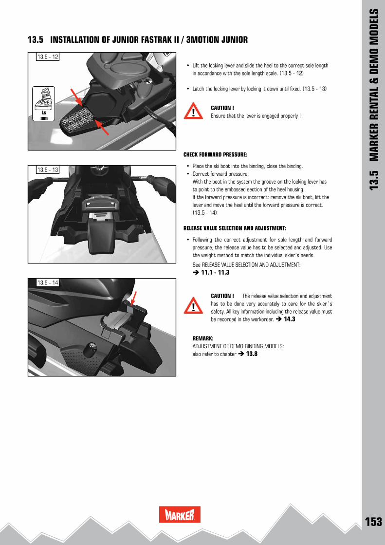
153
13.5 - 13
13.5 - 12
13.5 - 14
• Lift the locking lever and slide the heel to the correct sole length in accordance with the sole length scale. (13.5 - 12)
• Latch the locking lever by locking it down until fixed. (13.5 - 13)
CAUTION ! Ensure that the lever is engaged properly !
CHECK FORWARD PRESSURE:
• Place the ski boot into the binding, close the binding. • Correct forward pressure: With the boot in the system the groove on the locking lever has
to point to the embossed section of the heel housing. If the forward pressure is incorrect: remove the ski boot, lift the
lever and move the heel until the forward pressure is correct. (13.5 - 14)
RELEASE VALUE SELECTION AND ADJUSTMENT:
• Following the correct adjustment for sole length and forward pressure, the release value has to be selected and adjusted. Use the weight method to match the individual skier’s needs.
See RELEASE VALUE SELECTION AND ADJUSTMENT: 11.1 - 11.3
CAUTION ! The release value selection and adjustment has to be done very accurately to care for the skier´s safety. All key information including the release value must be recorded in the workorder. 14.3
REMARK:ADJUSTMENT OF DEMO BINDING MODELS:also refer to chapter 13.8
13.5
M
ARKE
R RE
NTA
L &
DEM
O M
ODEL
S
13.5 INSTALLATION OF JUNIOR FASTRAK II / 3MOTION JUNIOR
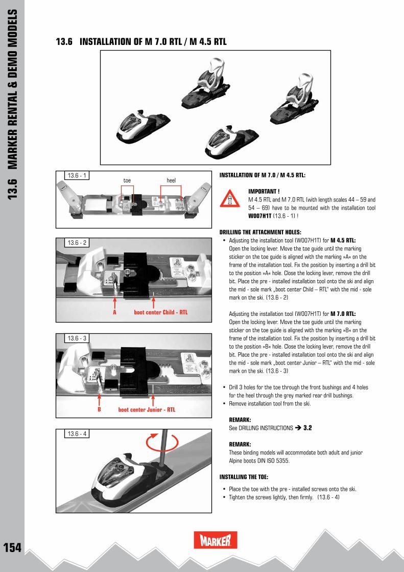
154
13.6 - 4
13.6 - 2
A boot center Child - RTL
13.6 - 3
B boot center Junior - RTL
13.6 - 1
13.6
M
ARKE
R RE
NTA
L &
DEM
O M
ODEL
S
13.6 INSTALLATION OF M 7.0 RTL / M 4.5 RTL
INSTALLATION OF M 7.0 / M 4.5 RTL:
IMPORTANT !M 4.5 RTL and M 7.0 RTL (with length scales 44 – 59 and 54 – 69) have to be mounted with the installation tool W007H1T (13.6 - 1) !
DRILLING THE ATTACHMENT HOLES: • Adjusting the installation tool (W007H1T) for M 4.5 RTL: Open the locking lever. Move the toe guide until the marking
sticker on the toe guide is aligned with the marking »A« on the frame of the installation tool. Fix the position by inserting a drill bit to the position »A« hole. Close the locking lever, remove the drill bit. Place the pre - installed installation tool onto the ski and align the mid - sole mark „boot center Child – RTL“ with the mid - sole mark on the ski. (13.6 - 2)
Adjusting the installation tool (W007H1T) for M 7.0 RTL: Open the locking lever. Move the toe guide until the marking
sticker on the toe guide is aligned with the marking »B« on the frame of the installation tool. Fix the position by inserting a drill bit to the position »B« hole. Close the locking lever, remove the drill bit. Place the pre - installed installation tool onto the ski and align the mid - sole mark „boot center Junior – RTL“ with the mid - sole mark on the ski. (13.6 - 3)
• Drill 3 holes for the toe through the front bushings and 4 holes for the heel through the grey marked rear drill bushings.
• Remove installation tool from the ski.
REMARK: See DRILLING INSTRUCTIONS 3.2
REMARK: These binding models will accommodate both adult and junior
Alpine boots DIN ISO 5355.
INSTALLING THE TOE:
• Place the toe with the pre - installed screws onto the ski. • Tighten the screws lightly, then firmly. (13.6 - 4)
toe heel
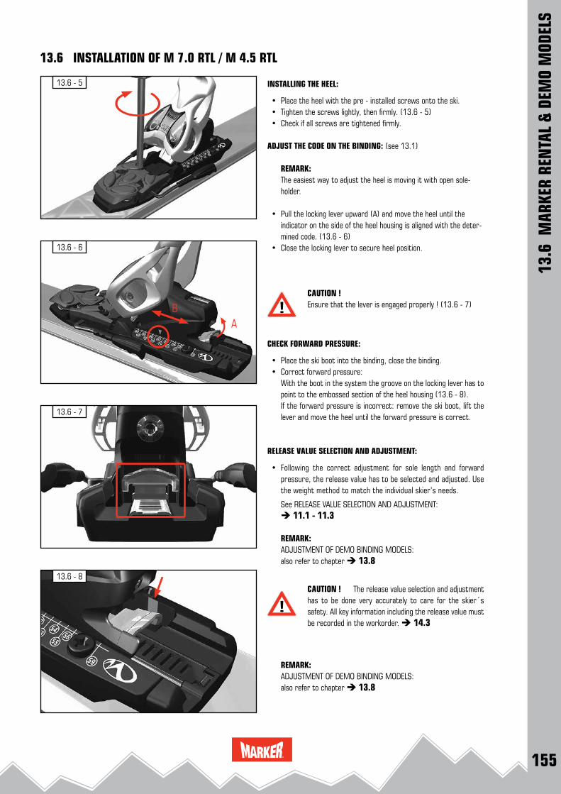
155
13.6 - 7
13.6 - 6
13.6 - 5
AB
13.6 - 8
13.6
MAR
KER
REN
TAL
& DE
MO
MOD
ELS
13.6 INSTALLATION OF M 7.0 RTL / M 4.5 RTL
INSTALLING THE HEEL:
• Place the heel with the pre - installed screws onto the ski. • Tighten the screws lightly, then firmly. (13.6 - 5) • Check if all screws are tightened firmly.
ADJUST THE CODE ON THE BINDING: (see 13.1)
REMARK: The easiest way to adjust the heel is moving it with open sole-holder.
• Pull the locking lever upward (A) and move the heel until the indicator on the side of the heel housing is aligned with the deter-mined code. (13.6 - 6)
• Close the locking lever to secure heel position.
CAUTION ! Ensure that the lever is engaged properly ! (13.6 - 7)
CHECK FORWARD PRESSURE:
• Place the ski boot into the binding, close the binding. • Correct forward pressure: With the boot in the system the groove on the locking lever has to
point to the embossed section of the heel housing (13.6 - 8). If the forward pressure is incorrect: remove the ski boot, lift the
lever and move the heel until the forward pressure is correct.
RELEASE VALUE SELECTION AND ADJUSTMENT:
• Following the correct adjustment for sole length and forward pressure, the release value has to be selected and adjusted. Use the weight method to match the individual skier’s needs.
See RELEASE VALUE SELECTION AND ADJUSTMENT: 11.1 - 11.3
REMARK:ADJUSTMENT OF DEMO BINDING MODELS:also refer to chapter 13.8
CAUTION ! The release value selection and adjustment has to be done very accurately to care for the skier´s safety. All key information including the release value must be recorded in the workorder. 14.3
REMARK:ADJUSTMENT OF DEMO BINDING MODELS:also refer to chapter 13.8

156
13.7 - 1
13.7 - 3
13.7 - 2
13.7 - 5
13.7 - 4
IMPORTANT !The MARKER Race Xcell Demo heel plate enlarges the sole length range of the heel to 60 mm.The Race Xcell Demo heel plate is designed to be moun-ted solely in conjunction with World Cup Piston Control Interface.
• Remove the attachment screw of the ski brake (13.7 - 1).
• Pull the ski brake slightly forward to remove (13.7 - 2).
• Remove the rear fixing screws. (13.7 - 3)
• Screw the heel backward from the base plate by turning the forward pressure adjustment screw. (13.7 - 4)
13.7
M
ARKE
R RE
NTA
L &
DEM
O M
ODEL
S
13.7 INSTALLATION OF RACE XCELL DEMO HEEL PLATE
• Pull the heel off the base plate. (13.7 - 5)

157
13.7 - 8
13.7 - 713.7 - 6
13.7 - 9
3 2 13 2 1
1: 260 - 3082: 309 - 3283: 329 - 362
4: 262 - 3185: 279 - 3286: 289 - 3387: 299 - 358
mm
5 764
• Slide the heel from the rear onto the Race Xcell Demo plate. Slide the heel forward until it stops. (13.7 - 6)
• With slight pressure, screw the heel forward onto the plate by turning the forward pressure adjustment screw. (13.7 - 7)
• Slide in the ski brake. Make sure that the metal hooks of the brake base latch beneath the metal base plate of the heel (13.7 - 8).
• Slide the ski brake backward until it stops. • Tighten the attachment screw of the ski brake (13.7 - 9).
INSTALLATION OF THE BINDING: see Installation of World Cup Piston Control Interface 6.11 see Installation of RACE XCELL BINDINGS 6.3
IMPORTANT SAFETY ADVICE ! Make sure that you do not exceed the »STOP« markingon the Race Xcell Demo plate when adjusting the sole length backward !
13.7
M
ARKE
R RE
NTA
L &
DEM
O M
ODEL
S
13.7 INSTALLATION OF RACE XCELL DEMO HEEL PLATE
MOUNTING POSITIONS RACE XCELL DEMO
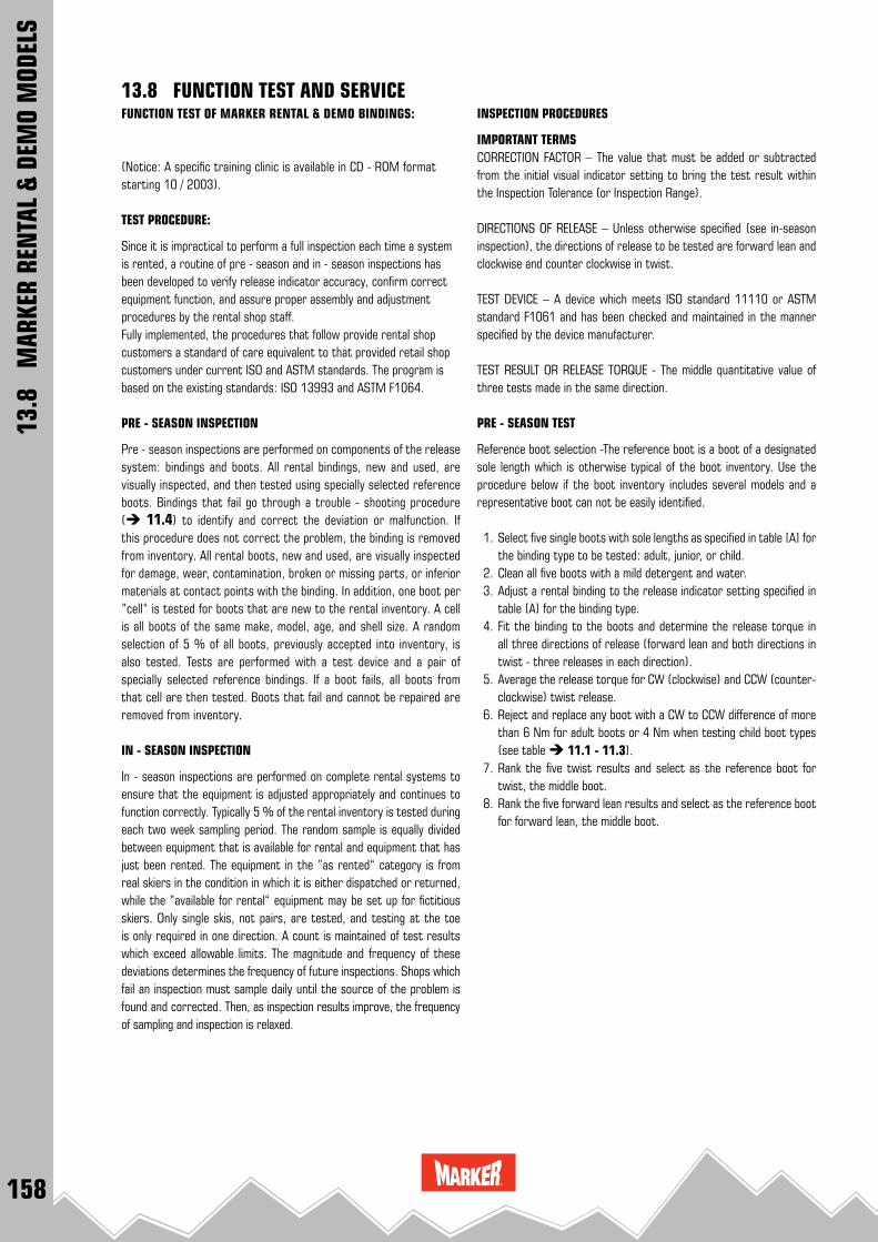
158
13.8
M
ARKE
R RE
NTA
L &
DEM
O M
ODEL
S
13.8 FUNCTION TEST AND SERVICEFUNCTION TEST OF MARKER RENTAL & DEMO BINDINGS:
(Notice: A specific training clinic is available in CD - ROM format starting 10 / 2003). TEST PROCEDURE:
Since it is impractical to perform a full inspection each time a system is rented, a routine of pre - season and in - season inspections has been developed to verify release indicator accuracy, confirm correct equipment function, and assure proper assembly and adjustment procedures by the rental shop staff.Fully implemented, the procedures that follow provide rental shop customers a standard of care equivalent to that provided retail shop customers under current ISO and ASTM standards. The program is based on the existing standards: ISO 13993 and ASTM F1064.
PRE - SEASON INSPECTION
Pre - season inspections are performed on components of the release system: bindings and boots. All rental bindings, new and used, are visually inspected, and then tested using specially selected reference boots. Bindings that fail go through a trouble - shooting procedure ( 11.4) to identify and correct the deviation or malfunction. If this procedure does not correct the problem, the binding is removed from inventory. All rental boots, new and used, are visually inspected for damage, wear, contamination, broken or missing parts, or inferior materials at contact points with the binding. In addition, one boot per ”cell“ is tested for boots that are new to the rental inventory. A cell is all boots of the same make, model, age, and shell size. A random selection of 5 % of all boots, previously accepted into inventory, is also tested. Tests are performed with a test device and a pair of specially selected reference bindings. If a boot fails, all boots from that cell are then tested. Boots that fail and cannot be repaired are removed from inventory.
IN - SEASON INSPECTION
In - season inspections are performed on complete rental systems to ensure that the equipment is adjusted appropriately and continues to function correctly. Typically 5 % of the rental inventory is tested during each two week sampling period. The random sample is equally divided between equipment that is available for rental and equipment that has just been rented. The equipment in the ”as rented“ category is from real skiers in the condition in which it is either dispatched or returned, while the ”available for rental“ equipment may be set up for fictitious skiers. Only single skis, not pairs, are tested, and testing at the toe is only required in one direction. A count is maintained of test results which exceed allowable limits. The magnitude and frequency of these deviations determines the frequency of future inspections. Shops which fail an inspection must sample daily until the source of the problem is found and corrected. Then, as inspection results improve, the frequency of sampling and inspection is relaxed.
INSPECTION PROCEDURES
IMPORTANT TERMSCORRECTION FACTOR – The value that must be added or subtracted from the initial visual indicator setting to bring the test result within the Inspection Tolerance (or Inspection Range).
DIRECTIONS OF RELEASE – Unless otherwise specified (see in-season inspection), the directions of release to be tested are forward lean and clockwise and counter clockwise in twist.
TEST DEVICE – A device which meets ISO standard 11110 or ASTM standard F1061 and has been checked and maintained in the manner specified by the device manufacturer.
TEST RESULT OR RELEASE TORQUE - The middle quantitative value of three tests made in the same direction.
PRE - SEASON TEST
Reference boot selection -The reference boot is a boot of a designated sole length which is otherwise typical of the boot inventory. Use the procedure below if the boot inventory includes several models and a representative boot can not be easily identified.
1. Select five single boots with sole lengths as specified in table [A] for the binding type to be tested: adult, junior, or child.
2. Clean all five boots with a mild detergent and water. 3. Adjust a rental binding to the release indicator setting specified in
table [A] for the binding type. 4. Fit the binding to the boots and determine the release torque in
all three directions of release (forward lean and both directions in twist - three releases in each direction).
5. Average the release torque for CW (clockwise) and CCW (counter-clockwise) twist release.
6. Reject and replace any boot with a CW to CCW difference of more than 6 Nm for adult boots or 4 Nm when testing child boot types (see table 11.1 - 11.3).
7. Rank the five twist results and select as the reference boot for twist, the middle boot.
8. Rank the five forward lean results and select as the reference boot for forward lean, the middle boot.
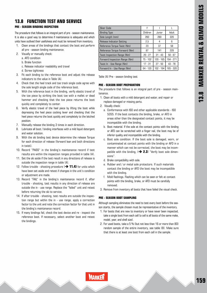
159
13.8
M
ARKE
R RE
NTA
L &
DEM
O M
ODEL
S
13.8 FUNCTION TEST AND SERVICESkier Code F I L
Binding Type Children Junior Adult
Sole Length (mm) 260 280 320
Release Indicator Setting 2,5 4 6
Reference Torque Twist (Nm) 23 37 58
Reference Torque Forward (Nm) 87 141 229
Twist Inspection Range (Nm) 20 - 27 31 - 43 50 - 67
Forward Inspection Range (Nm) 75 - 102 120 - 165 194 - 271
Twist In - Use Range (Nm) 17 - 31 27 - 50 43 - 78
Forward In - Use Range (Nm) 64 - 120 102 - 194 165 - 320
Table [A] Pre - season binding test
PRE - SEASON BOOT PREPARATION The procedure that follows is an integral part of pre - season main-tenance. 1. Clean all boots with a mild detergent and water, and repair or
replace damaged or missing parts. 2. Visually check:
a. Conformance with ISO and other applicable standards - ISO 5355. If the boot contacts the binding, brake, or AFD in areas other than the designated contact points, it may be incompatible with the binding.
b. Boot material. If the sole at the contact points with the binding or AFD can be scratched with a finger nail, the boot may be of inferior quality and incompatible with the binding.
c. Boot sole condition. If the boot sole is damaged, worn, or contaminated at contact points with the binding or AFD in a manner which can not be corrected, the boot may be incom-patible with the binding, ( 2.3) ”Verify boot sole dimen-sions“.
d. Brake compatibility with sole. e. Rubber and / or metal sole protectors. If such materials
contact the binding or AFD the boot may be incompatible with the binding.
f. Mold flashings. Flashing which can be seen or felt at contact points with the binding, brake, or AFD must be carefully removed.
3. Remove from inventory all boots that have failed the visual check.
PRE - SEASON BOOT SAMPLING
Although sampling eliminates the need to test every boot before the sea-son starts, the sample chosen must be representative of the inventory. 1. For boots that are new to inventory or have never been inspected,
take a single boot from each cell (a cell is all boots of the same make, model, year, and shell size).
2. For used boots, take a 5 % (but not less than 16 or more than 80) random sample of the entire inventory, see table [B]. Make sure that there is at least one boot from each cell in the sample.
PRE - SEASON BINDING INSPECTION
The procedure that follows is an integral part of pre - season maintenance. It is also a good way to determine if maintenance is adequate and which units have outlived their usefulness and must be removed from inventory. 1. Clean areas of the bindings that contact the boot and perform
all pre - season binding maintenance. 2. Visually or manually check:
a. AFD condition b. Brake function c. Release indicator readability and travel d. Screw tightness
3. Fit each binding to the reference boot and adjust the release indicators to the value in Table [A].
4. Check that the heel track and toe track single code agree with the sole length single code of the reference boot.
5. With the reference boot in the binding, verify elastic travel of the toe piece by striking the boot toe with a mallet or dead hammer and checking that the toe piece returns the boot quickly and completely to center.
6. Verify elastic travel of the heel piece by lifting the boot while depressing the heel piece cocking lever and checking that the heel piece returns the boot quickly and completely to the latched position.
7. Manually release the binding 3 times in each direction. 8. Lubricate all boot / binding interfaces with a mild liquid detergent
and water solution. 9. With the ski binding test device determine the release Torque
for each direction of release (forward lean and both directions in twist).
10. Record ”PASS“ in the binding‘s maintenance record if test results are within the inspection ranges provided in table [A].
11. Set the ski aside if the test result in any directions of release is outside the inspection range in table [A].
12. Follow trouble - shooting procedure ( 11.4) for units which have been set aside and retest if changes in the unit‘s condition or adjustment are made.
13. Record ”FAIL“ in the binding‘s maintenance record if, after trouble - shooting, test results in any direction of release are outside the in - use range. Replace the ”failed“ unit and retest before returning the ski to service.
14. If after trouble - shooting, test results are outside the inspec-tion range but within the in - use range, apply a correction factor to the unit and note the correction factor for that unit in the binding‘s maintenance record.
15. If many bindings fail, check the test device and re - inspect the reference boot. If necessary, select another boot and retest the bindings.
160
13.8
M
ARKE
R RE
NTA
L &
DEM
O M
ODEL
S
13.8 FUNCTION TEST AND SERVICE
PRE - SEASON BOOT INSPECTION:
The procedure that follows helps to assure both boot / binding compatibility and boot interchangability. Note: when using table [A],in the boot inspection procedures that follow, the sole length and release indicator setting columns should be ignored. 1. Randomly select a pair of bindings that have passed the pre-
season inspection from each binding type: adult, junior, child. 2. Lubricate all boot / binding contact points with a mild liquid
detergent. 3. Without regard to whether the boot is new or used, sort the
sample by sole type and length according to the 20 mm sole length categories defined by the release / retention adjust-ment chart.
4. In each sole length category rank the boots by sole length and select the middle boot.
5. In each sole length category fit the appropriate reference bindings to this „typical“ boot and adjust the two bindings to release as close as practical to the reference torque in table [A]. Use the reference torque corresponding to skier code [L] for the adult binding, [I] for the Junior binding, and [F] for the Child binding.
6. Rinse the lubricant from one binding and mark it „clean.“ Mark the other „lubricated“.
7. Test each boot in the sole length category with the clean reference binding and then the lubricated reference Binding in both twist and forward lean (only one direction in twist is required for the clean binding).
8. Set aside any boots for which the lubricated test result is more than 20 % less than the clean test result in the same direction of release or the Lubricated test result in any direc-tion of release is outside of the inspection range provided in table [A] for the skier code used to set up the reference binding (L, I, or F).
9. Repeat the visual check on all boots that have been set aside, correct any defects noted, and retest. Remove from inventory boots that fail the retest.
10. Check all other boots from the same cell (make, model, year, and shell size) as those that failed.
NOTE: On completion of the pre - season inspection, clean the liquid deter-gent from the equipment and lubricate the binding before returning it to service.
IN - SEASON SAMPLING AND INSPECTION:
The in - season inspection is a test of complete systems and all the procedures used by the rental staff to assemble and adjust the system. The program uses random samples of rental inventory taken at routine intervals. Any sampling program that gives every unit of inventory the same chance as every other of being picked is valid.
SAMPLE FREQUENCY:Random sampling is conducted throughout the entire season.
FREQUENCY IS AS FOLLOWS: 1. After 7 days of operation. 2. If the sample passes the next sampling is taken after another 7
days of operation. 3. If two consecutive samples pass, sampling frequency is increased
to 14 days. 4. If a sample fails at any time, daily sampling is instituted until
two consecutive samples pass, at which point weekly sampling resumes.
SAMPLE SIZE:
Sample size is 5 % of inventory but not less than 16 nor more than 80 units as noted in table [B]. Sample size is based on average daily out-put. If rental output drops below 50 % of capacity over the sam-pling period, the sample size can be reduced proportionately.
IN - SEASON INSPECTION:
1. Take a random sample of the rental inventory as determined by table [B]. Take half of the sample from inventory as it is either rented or returned and the remainder from inventory available for rental.
2. The returned samples are tested with the last customer’s data, the other samples adjust to randomly selected skier data. Consider already applied correction factors.
3. Wipe the boot clean and cycle the boot / binding systems at least once in each direction.
4. Test sample units in twist (one direction only) and forward lean. 5. Compare the test results with the inspection range for the
appropriate skier code, see ISO 11088 release / retention adjustment chart. (page 126 / 130)
6. If the results are within the inspection range, one value above to one value below the reference value, the unit passes.
7. If the results are outside inspection range but within the in - use range, two values above to two values below the reference value, count the unit as a class I deviation.
8. If the results are outside the in-use range, count the unit as a class II deviation.
9. Check elastic travel and visually inspect the ski brake function, interface areas between boot and binding, including AFD, lug height adjustment (if appropriate), and forward pressure. Count any deficiencies as class I deviations.
10. If more than the maximum number of class I deviations given in table B are found in the sample, or a single class II deviation is detected the sample fails and daily sampling must be conducted until the problem which led to the failed sample is found and corrected.
11. Record the date the sample was tested, the number of units tested, the number of class I and class II deviations, whether the sample passed or failed and any actions taken. There is no need to record the identity of units tested or actual test results.
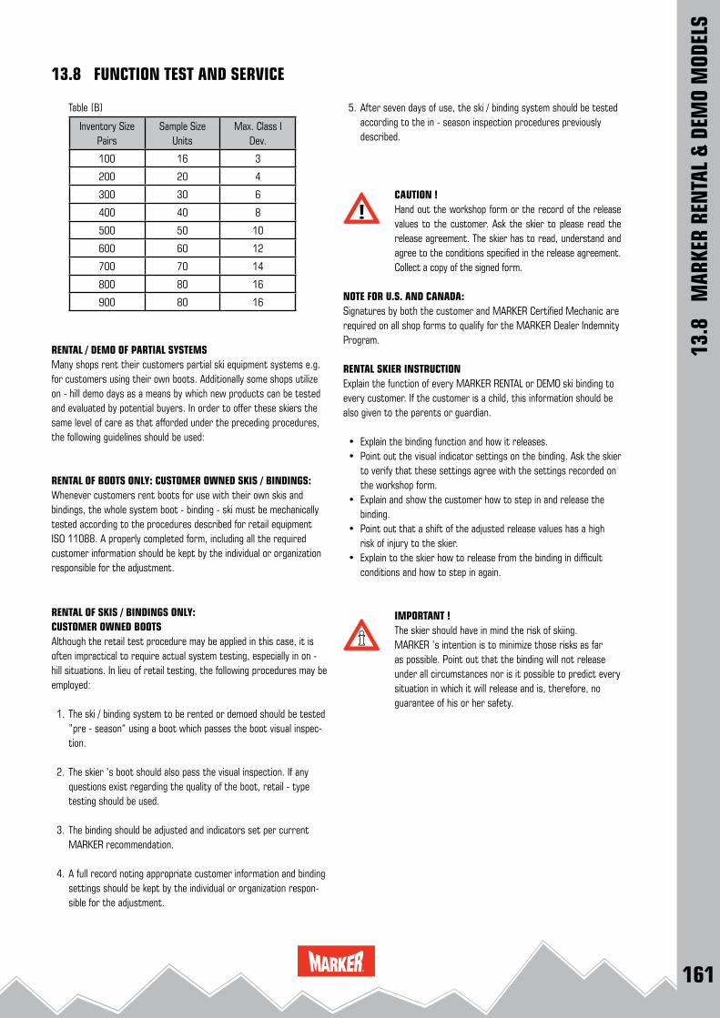
161
13.8
M
ARKE
R RE
NTA
L &
DEM
O M
ODEL
S
13.8 FUNCTION TEST AND SERVICE
5. After seven days of use, the ski / binding system should be tested according to the in - season inspection procedures previously described.
CAUTION !Hand out the workshop form or the record of the release values to the customer. Ask the skier to please read the release agreement. The skier has to read, understand and agree to the conditions specified in the release agreement. Collect a copy of the signed form.
NOTE FOR U.S. AND CANADA:Signatures by both the customer and MARKER Certified Mechanic are required on all shop forms to qualify for the MARKER Dealer Indemnity Program. RENTAL SKIER INSTRUCTIONExplain the function of every MARKER RENTAL or DEMO ski binding to every customer. If the customer is a child, this information should be also given to the parents or guardian.
• Explain the binding function and how it releases. • Point out the visual indicator settings on the binding. Ask the skier
to verify that these settings agree with the settings recorded on the workshop form.
• Explain and show the customer how to step in and release the binding.
• Point out that a shift of the adjusted release values has a high risk of injury to the skier.
• Explain to the skier how to release from the binding in difficult conditions and how to step in again .
IMPORTANT ! The skier should have in mind the risk of skiing. MARKER ’s intention is to minimize those risks as far as possible. Point out that the binding will not release under all circumstances nor is it possible to predict every situation in which it will release and is, therefore, no guarantee of his or her safety.
Table [B]
Inventory Size Pairs
Sample Size Units
Max. Class I Dev.
100 16 3
200 20 4
300 30 6
400 40 8
500 50 10
600 60 12
700 70 14
800 80 16
900 80 16
RENTAL / DEMO OF PARTIAL SYSTEMSMany shops rent their customers partial ski equipment systems e.g. for customers using their own boots. Additionally some shops utilize on - hill demo days as a means by which new products can be tested and evaluated by potential buyers. In order to offer these skiers the same level of care as that afforded under the preceding procedures, the following guidelines should be used:
RENTAL OF BOOTS ONLY: CUSTOMER OWNED SKIS / BINDINGS:Whenever customers rent boots for use with their own skis and bindings, the whole system boot - binding - ski must be mechanically tested according to the procedures described for retail equipment ISO 11088. A properly completed form, including all the required customer information should be kept by the individual or organization responsible for the adjustment.
RENTAL OF SKIS / BINDINGS ONLY: CUSTOMER OWNED BOOTSAlthough the retail test procedure may be applied in this case, it is often impractical to require actual system testing, especially in on - hill situations. In lieu of retail testing, the following procedures may be employed:
1. The ski / binding system to be rented or demoed should be tested ”pre - season“ using a boot which passes the boot visual inspec-tion.
2. The skier ’s boot should also pass the visual inspection. If any questions exist regarding the quality of the boot, retail - type testing should be used.
3. The binding should be adjusted and indicators set per current MARKER recommendation.
4. A full record noting appropriate customer information and binding settings should be kept by the individual or organization respon-sible for the adjustment.

162
14.1
- 14
.3 I
NFO
RMAT
ION
FOR
THE
SKI
ER
14.1 - 14.3 INFORMATION FOR THE SKIER
14.1 MAINTENANCE:To help ensure proper function, MARKER ski bindings should be kept clean and free of dirt, rust or other contaminations. To clean, wipe all exposed surfaces with a moist or dry cloth or use compressed air.
IMPORTANT ! Do not use solvents to clean the binding. Do not use silicone or any other lubricating agent on the toe cups and the heel cups (soleholder).
MARKER ski bindings should be cleaned at least once a season or whenever visible dirt or other contaminations are present.
14.2 WARRANTY:MARKER´s warranty is extended to the customer through the MARKER authorized retailer. MARKER requests that warranty claims or inquiries be processed by MARKER authorized retail ers on behalf of their customers. In some instances, if a retail customer should contact MARKER directly, MARKER will process the claim or inquiry. Defective product is defined as that product, component or part thereof which, due to material failure or defect in workmanship, no longer functions properly for its intended use. Final decisions regard-ing any claimed product defect will be made solely by a representative of MARKER. MARKER will, at its sole discretion, repair, replace or refund the purchase price of a defective retail binding for a period of two years (USA 3 years), rental and demo bindings one year.Damage caused by improper handling, non - observance of the in-structions for use, non - qualified installation, improper adjustment, insufficient maintenance and servicing, skiing accidents, abuse of product or normal wear is not covered under warranty. All wearing parts and cosmetics are exempt from warranty. MARKER will not be liable for incidental or consequential damages of any nature unless such limitation is expressly prohibited by law in the applicable juris-diction. All implied warranties are expressly disclaimed unless such disclaimer is prohibited by law. In that event, the duration of any implied warranties shall be concurrent with the period of express warranties stated herein.
14.3 SERVICE
WORKSHOP RECORDS:As a MARKER certified technician, you are required to keep accurate and complete records of all work performed on any MARKER ski binding. Workshop records must be kept on file.The workshop form includes the following required information: ►Skier name and address ►Skier weight / height / age / skier type ►Ski brand / model / serial number ►Boot brand / model / sole length ►Ski binding model ►Skier code ►System inspection result ►Visual indicator setting for each toe and heel ►Mechanical test result ►Date of inspection
SKIER INSTRUCTION:
After the final inspection the function unit ski / ski binding / ski boot has to be given to the customer together with the workshop form and the in - box instructions.
IMPORTANT !One of the most important responsibilities of the MARKER authorized retailer is to ensure that proper skier instruc-tions and warnings are provided every time a MARKER ski binding is sold, serviced or rented. Whenever possible, the following instructions should be given directly to the in-tended user. If the skier is a minor, the instructions should be given in the presence of both parents or legal guardian and the skier.
163
14.1
- 14
.3
INFO
RMAT
ION
FOR
THE
SKI
ER
14.1 - 14.3 INFORMATION FOR THE SKIERRECEIPT OF IN - BOX INSTRUCTIONS:
• Whenever a new ski binding is delivered to the skier she or he should receive the in - box instructions and the warranty informa-tion.
MAINTENANCE:
• Explain to the skier that the ski binding should be kept clean and free of dirt, rust, salt or other contaminants.
• Recommend that the complete function unit ski / ski binding / ski boot has to be brought to a MARKER authorized retailer for inspection prior to the beginning of each ski season.
• Also the function of the IAS - test could be shown to the skier.
IAS - TEST RECOMMENDATION: Check if the binding releases to one side while trying it with the
foot itself to verify the correct release value.
SKIER SIGNATURE
• The skier must read, understand and agree to the conditions specified in the workshop form and / or any release agreement.
• Make sure that the skier signs the workshop form and /or the release agreement. If the skier is a minor, this document should be signed by a parent or a legal guardian.
• A copy of the signed documents has to be handed to the cus-tomer.
IMPORTANT ! The skier should understand that there are inherent and other risks in the sport of skiing. Explain that the ski binding will not release under all circumstances nor is it possible to predict every situation in which it will release and is, therefore, no guarantee of his or her safety.
ENTRY: • Make sure that the boot sole is clear of snow, ice and dirt • Open the heel cup by pressing down the opening lever with the ski
pole tip, boot sole, ski tail or hand. • Center the ski boot in the toe cups and step straight down into
the heel cup.
EXIT:FOR ALL TWIN CAM STEP - IN, COMPACT STEP - IN, HOLLOW LINKAGE AND INTER PIVOT HEELS: • Press down on the opening lever with the ski pole tip, boot sole,
ski tail or hand. EXITING IN AN AWKWARD POSITION: • If the heel is closed, open the heel by pressing down on the
opening lever. Re - enter the system. • After lateral release always exit the ski binding and re - enter
again.
RE - ENTER THE SYSTEM:
• If the heel is closed, open the heel by pressing down on the open-ing lever.
• In soft snow while stepping in the force can be reduced ►by pressing down the opening lever (TWIN CAM Step - In
heels) ► by pulling the opening lever (all other Step - In heels)
SYSTEM EXPLANATION FOR THE SKIER:
• Explain the boot - to - binding adjustment. • Show where the release adjustment screws are and explain the
adjustment at the visual indicators on the ski bindings and how they correspond to the recorded numbers on the workshop form. The skier should know his own DIN settings and / or skier code.
• Point out the left and the right ski indicators. • If any system components are worn out of standard or otherwise
unsuitable for continued use, the skier must be clearly informed of the problem and warned that continued use may significantly increase his or her risk of injury.
• Advise that if any problem develops with any part of the function unit ski / ski binding / ski boot it should be brought to a MARKER authorized retailer for inspection and service.

164
14.4 - 3
14.4 - 1
14.4 - 2
14.4 - 5
14.4 - 4
SKI
WALK
180 °
14.4
IN
FORM
ATIO
N F
OR T
HE S
KIER
14.4 INFORMATION FOR THE SKIER - F 12 TOUR & F 10 TOUR
ADDITIONAL INFORMATION FOR THE MARKER TOURIn addition to the system explanations of page 162, the following instructions must be given to the intended user of a MARKER TOUR
CHANGING FROM SKIING - MODE TO WALKING - MODE:The TOUR engagement lever is located in the middle of the system plate.
With this lever you can adjust two positions (skiing - mode / walking - mode).
In order to change from the skiing - mode (locked position, 14.4 - 1) to the walking - mode (unlocked position, 14.4 - 3) switch the lever 180° backward (14.4 - 2)
IMPORTANT !The engagement lever has to be switched completely to the walk position, the lever hast to be flush with the ski´s top (14.4 - 4)
USING THE HIKING - AIDE:You can use the hiking - aide (14.4 - 5) in two positions when you are in the walking - mode.
IMPORTANT !Point out to the customer that the function of the clim-bing aide can be affected (the climbing aide can fold up) when the engagement lever is not completely switched to the walk position (flush with the ski top surface).

165
14.4 - 6
14.4 - 8
14.4 - 10
14.4 - 9
SKI
14.4 - 7
180 °
14.4
IN
FORM
ATIO
N F
OR T
HE S
KIER
14.4 INFORMATION FOR THE SKIER - F 12 TOUR & F 10 TOUR
HIKING AIDE LOW POSITIONFold the hiking - aide downward with the ski pole or by hand to the 7 ° position (14.4 - 6).
HIKING AIDE HIGH POSITION: • Fold the hiking aide down with the ski pole or by hand to the 13 °
position. (14.4 - 7)
HIKING AIDE BASIC POSITION: • Fold the hiking aide up to the basic position with the ski pole or by
hand.
CHANGING FROM WALKING - MODE TO SKIING - MODE:
REMARK: Free the bindings from snow and ice before changing from the walking - mode to the skiing - mode !
In order to change from the walking - mode (unlocked position) to the skiing - mode (locked position) switch the lever 180° forward (14.4 - 8).
CAUTION ! Press down the TOUR plate while you switch the engage-ment lever to the locked position !Assure that the TOUR plate is fully and uniformly sliding into the heel plate attachments (14.4 - 9) !
CAUTION ! Do not ski in the walking - mode (unlocked position) (14.4 - 10) !
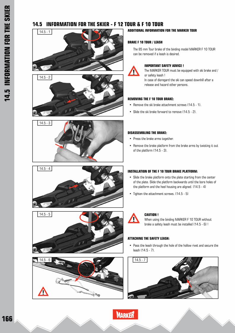
166
14.5 - 3
14.5 - 1
14.5 - 7
14.5 - 4
14.5 - 2
14.5 - 5
14.5 - 6
14.5
IN
FORM
ATIO
N F
OR T
HE S
KIER
14.5 INFORMATION FOR THE SKIER - F 12 TOUR & F 10 TOURADDITIONAL INFORMATION FOR THE MARKER TOUR
BRAKE F 10 TOUR / LEASH
The 85 mm Tour brake of the binding model MARKER F 10 TOUR can be removed if a leash is desired.
IMPORTANT SAFETY ADVICE !The MARKER TOUR must be equipped with ski brake and / or safety leash !In case of disregard the ski can speed downhill after a release and hazard other persons.
REMOVING THE F 10 TOUR BRAKE:
• Remove the ski brake attachment screws (14.5 - 1).
• Slide the ski brake forward to remove (14.5 - 2).
DISASSEMBLING THE BRAKE:
• Press the brake arms together.
• Remove the brake platform from the brake arms by twisting it out of the platform (14.5 - 3).
INSTALLATION OF THE F 10 TOUR BRAKE PLATFORM:
• Slide the brake platform onto the plate starting from the center of the plate. Slide the platform backwards until the bore holes of the platform and the heel housing are aligned. (14.5 - 4)
• Tighten the attachment screws. (14.5 - 5)
CAUTION !When using the binding MARKER F 10 TOUR without brake a safety leash must be installed (14.5 - 6) !
ATTACHING THE SAFETY LEASH:
• Pass the leash through the hole of the hollow rivet and secure the leash (14.5 - 7).

167
14.6 - 3
14.6 - 1
14.6 - 6
14.6 - 4
14.6 - 2
14.6 - 7
180 °
WALK
SKI
14.6 - 5
180 °
14.6
IN
FORM
ATIO
N F
OR T
HE S
KIER
14.6 INFORMATION FOR THE SKIER - DUKE EPF & BARON EPFADDITIONAL INFORMATION FOR THE MARKER DUKE EPF & BARONIn addition to the system explanations of page 162, the following instructions must be given to the intended user of a MARKER DUKE EPF and BARON EPF:
CHANGING FROM SKIING - MODE TO WALKING - MODE:The BCT engagement lever is located in the middle of the BCT plate. With this lever you can adjust two positions (skiing - mode / walking - mode). In order to change from the skiing - mode (locked position) to the walking - mode (unlocked position) switch the lever 180° back-ward (14.6 - 1 and 14.6 - 2).
USING THE HIKING - AIDE:You can use a hiking - aide in two positions when you are in the walk-ing - mode. Hiking aide low position: • Fold the hiking - aide downward with the ski pole or by hand to the 7 ° position. (14.6 - 3)Hiking aide high position: • Fold the hiking aide down with the ski pole or by hand to the 13 °
position. (14.6 - 4)
CHANGING FROM WALKING - MODE TO SKIING - MODE:In order to change from the walking - mode (unlocked position) to the skiing - mode (locked position) switch the lever 180° forward (14.6 - 5 and 14.6 - 6).
CAUTION ! Press down the BCT plate while you switch the BCT engagement lever to the locked position (14.6 - 5) !Assure that the BCT plate is fully and uniformly sliding into the heel plate attachments ! (14.6 - 7)
REMARK: Clean the bindings from snow and ice before changing from the walking - mode to the skiing - mode !
CAUTION ! Do not ski in the walking - mode (unlocked position) !
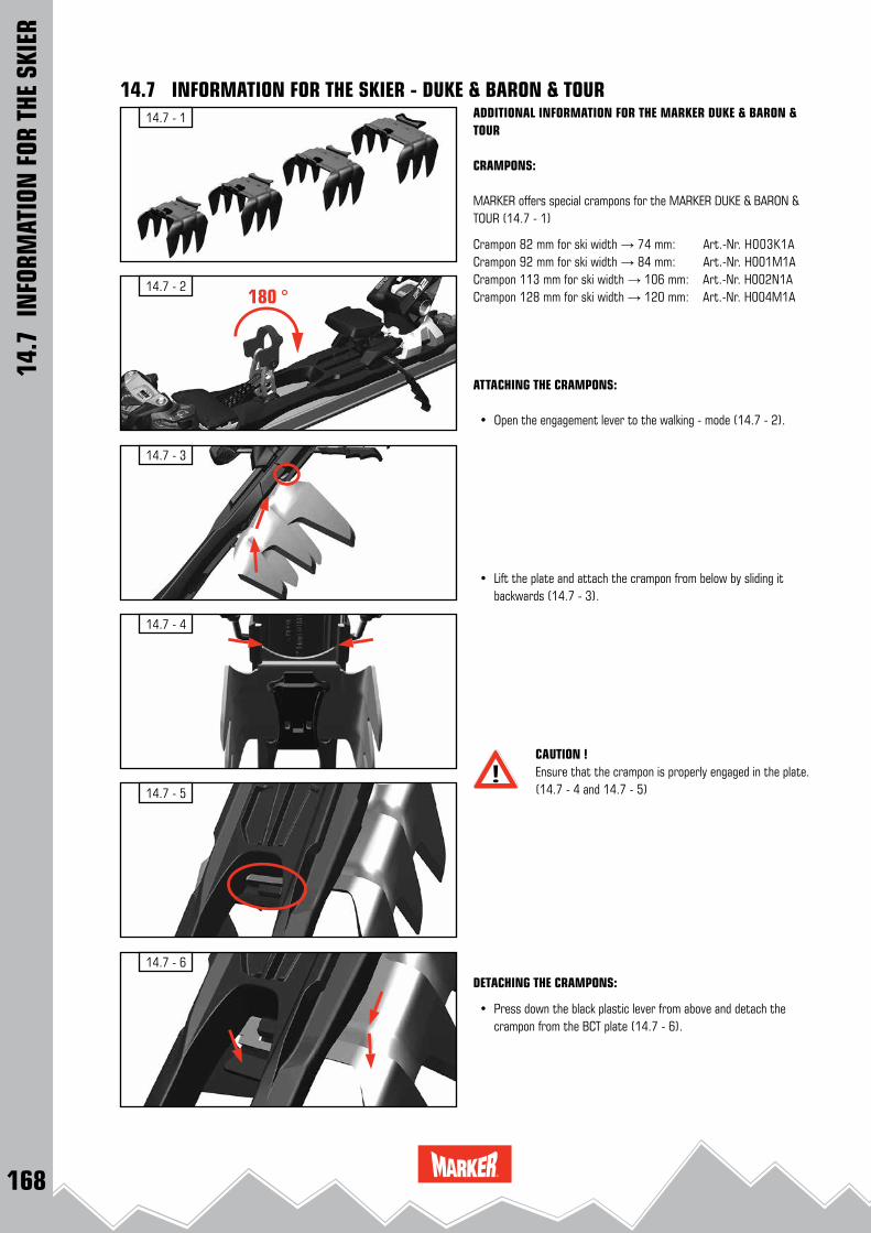
168
14.7 - 3
14.7 - 1
14.7 - 4
14.7 - 2
14.7 - 5
180 °
14.7 - 6
14.7 INFORMATION FOR THE SKIER - DUKE & BARON & TOURADDITIONAL INFORMATION FOR THE MARKER DUKE & BARON & TOUR
CRAMPONS:
MARKER offers special crampons for the MARKER DUKE & BARON & TOUR (14.7 - 1)
Crampon 82 mm for ski width → 74 mm: Art.-Nr. H003K1ACrampon 92 mm for ski width → 84 mm: Art.-Nr. H001M1A Crampon 113 mm for ski width → 106 mm: Art.-Nr. H002N1ACrampon 128 mm for ski width → 120 mm: Art.-Nr. H004M1A
ATTACHING THE CRAMPONS:
• Open the engagement lever to the walking - mode (14.7 - 2).
• Lift the plate and attach the crampon from below by sliding it backwards (14.7 - 3).
CAUTION ! Ensure that the crampon is properly engaged in the plate. (14.7 - 4 and 14.7 - 5)
DETACHING THE CRAMPONS:
• Press down the black plastic lever from above and detach the crampon from the BCT plate (14.7 - 6).
14.7
IN
FORM
ATIO
N F
OR T
HE S
KIER

169
14.8 - 2
14.8 - 1
14.8 - 3
14.8 - 8 14.8 - 9
14.8 - 6 14.8 - 7
14.8 - 4 14.8 - 5
AB
A
B
14.8 INFORMATION FOR THE SKIER - DUKE EPF & BARON EPF & TOUR EPF
14.8
IN
FORM
ATIO
N F
OR T
HE S
KIER
ADDITIONAL INFORMATION FOR THE MARKER DUKE EPF & BARON EPF & TOUR EPF:
ADAPTER FOR CRAMPONS:
For fitting the crampon to the plate of the DUKE EPF & BARON EPF & TOUR EPF the accompanying crampon adapter must be mounted on the crampons.
(Exception: crampon 128mm H004M1A & 113 mm H002N1A with premounted adapter)
• Remove the screws (14.8 - 1)
• Push the clamp down and towards the front, away from the crampon. (14.8 - 2 and 14.8 - 3)
• Fit the adapter (14.8 - 4) from the front / bottom to the crampon as shown. (14.8 - 5 and 14.8 - 6)
• Push the crampon adapter upwards and towards the back until it clicks into place. (14.8 - 7 and 14.8 - 8)
• Fit the screws and tighten them by hand. (14.8 - 9)
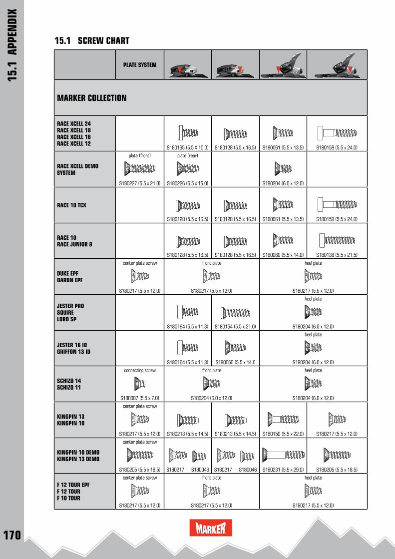
170
15.1
APP
ENDI
X
15.1 SCREW CHART
PLATE SYSTEM
MARKER COLLECTION
RACE XCELL 24RACE XCELL 18RACE XCELL 16RACE XCELL 12
S180165 (5.5 X 10.0) S180128 (5.5 x 16.5) S180061 (5.5 x 13.5) S180159 (5.5 x 24.0)
RACE XCELL DEMO SYSTEM
plate (front)
S180227 (5.5 x 21.0)
plate (rear)
S180226 (5.5 x 15.0) S180204 (6.0 x 12.0)
RACE 10 TCX
S180128 (5.5 x 16.5) S180128 (5.5 x 16.5) S180061 (5.5 x 13.5) S180159 (5.5 x 24.0)
RACE 10RACE JUNIOR 8
S180128 (5.5 x 16.5) S180128 (5.5 x 16.5) S180060 (5.5 x 14.0) S180138 (5.5 x 21.5)
DUKE EPFBARON EPF
center plate screw
S180217 (5.5 x 12.0)
front plate
S180217 (5.5 x 12.0)
heel plate
S180217 (5.5 x 12.0)
JESTER PRO SQUIRELORD SP
S180164 (5.5 x 11.3) S180154 (5.5 x 21.0)
heel plate
S180204 (6.0 x 12.0)
JESTER 16 IDGRIFFON 13 ID
S180164 (5.5 x 11.3) S180060 (5.5 x 14.0
heel plate
S180204 (6.0 x 12.0)
SCHIZO 14SCHIZO 11
connecting screw
S180087 (5.5 x 7.0)
front plate
S180204 (6.0 x 12.0)
heel plate
S180204 (6.0 x 12.0)
KINGPIN 13KINGPIN 10
center plate screw
S180217 (5.5 x 12.0) S180213 (5.5 x 14.5) S180213 (5.5 x 14.5) S180150 (5.5 x 22.0) S180217 (5.5 x 12.0)
KINGPIN 10 DEMOKINGPIN 13 DEMO
center plate screw
S180205 (5.5 x 18.5)
S180217 S180046
S180217 S180046 S180231 (5.5 x 29.0) S180205 (5.5 x 18.5)
F 12 TOUR EPFF 12 TOUR F 10 TOUR
center plate screw
S180217 (5.5 x 12.0)
front plate
S180217 (5.5 x 12.0)
heel plate
S180217 (5.5 x 12.0)

171
PLATE SYSTEM
15.1
APP
ENDI
X
15.1 SCREW CHART
GLIDE CONTROL D SYSTEM
front plate
S180105 (5.5 x 16.0)
heel plate
S180205 (5.5 x 18.5) S180204 (6.0 x 12.0)
M 11.0 TC EPS
S180128 (5.5 x 16.5) S180128 (5.5 x 16.5) S180060 (5.5 x 14.0) S180138 (5.5 x 21.5)
10.0 EPS
S180128 (5.5 x 16.5) S180128 (5.5 x 16.5) S180047 (5.5 x 19.5) S180142 (5.5 x 23.5)
FREE TEN
S180164 (5.5 x 11.3) S180154 (5.5 x 21.0) S180047 (5.5 x 19.5) S180142 (5.5 x 23.5)
FREE 8
S180176 (5.5 x 15.0) S180176 (5.5 x 15.0) S180139 (5.5 x 17.5) S180138 (5.5 x 21.5)
M 7.0 FREEM 7.0 EPSM 4.5 EPSJUNIOR RTL
S180176 (5.5 x 15.0) S180176 (5.5 x 15.0) S180047 (5.5 x 19.5) S180047 (5.5 x 19.5)
JESTER DEMO
front plate
S180204 (6.0 x 12.0)
heel plate
S180204 (6.0 x 12.0)
GRIFFON DSQUIRE D
front plate
S180061 (5.5 x 13.5)
heel plate
S180061 (5.5 x 13.5)
FDT 12 TPX
S180204 (6.0 x 12.0)
FDT 11 TPFDT 10 TPFDT 10 TLT
S180204 (6.0 x 12.0)
10.0 FASTRAK III TP
plate center screw
S180062 S180208 S180205 (5.5 x 18.5)
JUNIOR FASTRAK II
S180107 (5.5 x 10.) S180208 (5.5 x 13.0)
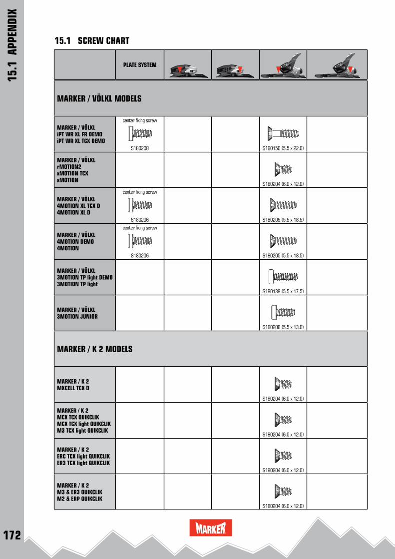
172
15.1
APP
ENDI
X
15.1 SCREW CHART
PLATE SYSTEM
MARKER / VÖLKL MODELS
MARKER / VÖLKLiPT WR XL FR DEMOiPT WR XL TCX DEMO
center fixing screw
S180208 S180150 (5.5 x 22.0)
MARKER / VÖLKLrMOTION2xMOTION TCXxMOTION
S180204 (6.0 x 12.0)
MARKER / VÖLKL4MOTION XL TCX D4MOTION XL D
center fixing screw
S180206 S180205 (5.5 x 18.5)
MARKER / VÖLKL4MOTION DEMO4MOTION
center fixing screw
S180206 S180205 (5.5 x 18.5)
MARKER / VÖLKL3MOTION TP light DEMO 3MOTION TP light
S180139 (5.5 x 17.5)
MARKER / VÖLKL3MOTION JUNIOR
S180208 (5.5 x 13.0)
MARKER / K 2 MODELS
MARKER / K 2MXCELL TCX D
S180204 (6.0 x 12.0)
MARKER / K 2MCX TCX QUIKCLIKMCX TCX light QUIKCLIKM3 TCX light QUIKCLIK
S180204 (6.0 x 12.0)
MARKER / K 2ERC TCX light QUIKCLIKER3 TCX light QUIKCLIK
S180204 (6.0 x 12.0)
MARKER / K 2M3 & ER3 QUIKCLIKM2 & ERP QUIKCLIK
S180204 (6.0 x 12.0)

173
15.1
APP
ENDI
X
15.1 SCREW CHART
PLATE SYSTEM
MARKER / K 2M3 & ER3 TCX LIGHTM3 & ER3M2 & ERP
S180176 (5.5 x 15.0) S180204 (6.0 x 12.0)
MARKER / K 2FASTRAK 3 TP
plate center screw
S180062 S180208 S180205 (5.5 x 18.5)
MARKER / K 2JUNIOR FASTRAK II
S180208 (5.5 x 13.0)
MARKER / NORDICA MODELS
MARKER / NORDICAN POWER EVON PRO EVO
S180150 (5.5 x 22.0) S180204 (6.0 x 12.0) S180062 (5.5 x 12.5)
MARKER / NORDICARACE XCELL 24RACE XCELL 18
S180165 (5.5 X 10.0) S180128 (5.5 x 16.5) S180061 (5.5 x 13.5) S180159 (5.5 x 24.0)
MARKER / NORDICARACE XCELL 16RACE XCELL 12
S180165 (5.5 X 10.0) S180128 (5.5 x 16.5) S180061 (5.5 x 13.5) S180159 (5.5 x 24.0)
MARKER / NORDICARACE 10RACE JUNIOR 8
S180128 (5.5 x 16.5) S180128 (5.5 x 16.5) S180060 (5.5 x 14.0) S180138 (5.5 x 21.5)
MARKER / NORDICAFREE 11 FDTRACE 10 FDT
S180204 (6.0 x 12.0)
MARKER / NORDICAFREE TEN
S180164 (5.5 x 11.3) S180154 (5.5 x 21.0) S180047 (5.5 x 19.5) S180142 (5.5 x 23.5)
MARKER / NORDICAJUNIOR FASTRAK II
S180208 (5.5 x 13.0)
MARKER / NORDICAIQ 7IQ 4.5
S180139 (5.5 x 17.5)
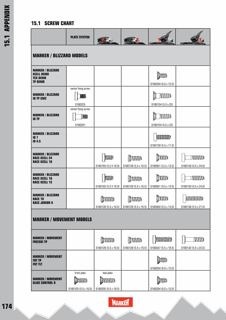
174
15.1
APP
ENDI
X
15.1 SCREW CHART
PLATE SYSTEM
MARKER / BLIZZARD MODELS
MARKER / BLIZZARDXCELL DEMOTCX DEMOTP DEMO
S180204 (6.0 x 12.0)
MARKER / BLIZZARDIQ TP CM2
center fixing screw
S180225 S180104 (5.5 x 22)
MARKER / BLIZZARDIQ TP
center fixing screw
S180201 S180104 (5.5 x 22)
MARKER / BLIZZARDIQ 7IQ 4.5
S180139 (5.5 x 17.5)
MARKER / BLIZZARDRACE XCELL 24RACE XCELL 18
S180165 (5.5 X 10.0) S180128 (5.5 x 16.5) S180061 (5.5 x 13.5) S180159 (5.5 x 24.0)
MARKER / BLIZZARDRACE XCELL 16RACE XCELL 12
S180165 (5.5 X 10.0) S180128 (5.5 x 16.5) S180061 (5.5 x 13.5) S180159 (5.5 x 24.0)
MARKER / BLIZZARDRACE 10RACE JUNIOR 8
S180128 (5.5 x 16.5) S180128 (5.5 x 16.5) S180060 (5.5 x 14.0) S180138 (5.5 x 21.5)
MARKER / MOVEMENT MODELS
MARKER / MOVEMENTFREESKI TP
S180128 (5.5 x 16.5) S180128 (5.5 x 16.5) S180047 (5.5 x 19.5) S180142 (5.5 x 23.5)
MARKER / MOVEMENTFDT TP FDT TLT
S180204 (6.0 x 12.0)
MARKER / MOVEMENT GLIDE CONTROL D
front plate
S180105 (5.5 x 16.0)
heel plate
S180205 (5.5 x 18.5) S180204 (6.0 x 12.0)

175
15.1
APP
ENDI
X
15.1 SCREW CHART
PLATE SYSTEM
MARKER / BOGNER & INDIGO MODELS
MARKER / BOGNER / INDIGO RACE XCELL DEMO
S180204 (6.0 x 12.0)
STANDARDBRAKE SCREW ROYAL FAMILY
S180204 (6.0 x 12.0)
BRAKE SCREWDUKE & JESTER PRO & JESTER ID & LORD SP &JESTER DEMO
S180062 (5.5 x 12.5)
STANDARDBRAKE SCREWMARKER TOUR
S180204 (6.0 x 12.0)
BRAKE SCREW JESTER DEMOGRIFFON DSQUIRE D
S180204 (6.0 x 12.0)
STANDARD BRAKE SCREWCOMPETITON & RACE
S180046 (5.5 x 8.75)
STANDARDBRAKE SCREWMARKER FDT
S180204 (6.0 x 12.0)

176
72 mm 80 mm 85 mm 90 mm 100 mm 110 mm 120 mm 136 mm
RACE XCELL 24RACE XCELL 18
W006O1B
RACE XCELL 16RACE XCELL 12RACE 10 TCX
W006O1B
RACE 10 RACE JUNIOR 8
W023H1B
DUKE EPFBARON EPF
W017G1B W016G1B W026O1B W015O1B
JESTER PROJESTER IDGRIFFON IDSQUIRE
W017G1B W016G1B W026O1B W015O1B
LORD SPSCHIZO 14SCHIZO 11
W017G1B W016G1B W026O1B W015O1B
F 12 TOUR EPF
W017G1B W016G1B W026O1B W015O1B
F 12 TOURF 10 TOUR
W024K1B W017G1B W016G1B
KINGPIN 13KINGPIN 10KINGPIN 13 DEMOKINGPIN 10 DEMO
W010P1B
W011P1B
GLIDE CONTROL D SYSTEM
W018M1B W017G1B W016G1B
M 11.0 TC EPS
W023H1B
FREE TENFREE 8
W021K1B W004L1B
15.2 BRAKE CHART
15.2
APP
ENDI
X

177
10.0 EPS
W020G1B W021K1B W004L1B
M 7.0 FREEM 7.0 EPSM 4.5 EPSJUNIOR FASTRAK II
W014G1B W002K1B W005L1B
XCELL 12 DEMO
W018M1B W017G1B W016G1B
JESTER DEMOGRIFFON D / ADJSQUIRE D / ADJ
W017G1B W016G1B W026O1B W015O1B
10.0 FASTRAK III10.0 FASTRAK III TP
W002L1B W003M1B
FDT TCX 12FDT TP 11
W018M1B W017G1B
FDT TP 10
W022N1B
JUNIOR RTL
W014G1B W005L1B
MARKER / VÖLKLiPT WIDERIDE XL FR DiPT WIDERIDE XL TCX D
W017G1B
MARKER / VÖLKLrMOTION2 16.0rMOTION2 12.0
W018M1B
MARKER / VÖLKL4MOTION XL D
W018M1B
72 mm 80 mm 85 mm 90 mm 100 mm 110 mm 120 mm 136 mm
15.2 BRAKE CHART
15.2
APP
ENDI
X
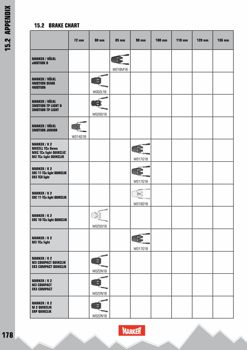
178
MARKER / VÖLKLxMOTION D
W018M1B
MARKER / VÖLKL4MOTION DEMO4MOTION
W002L1B
MARKER / VÖLKL3MOTION TP LIGHT D3MOTION TP LIGHT
W020G1B
MARKER / VÖLKL3MOTION JUNIOR
W014G1B
MARKER / K 2MXCELL TCx DemoMXC TCx light QUIKCLICM3 TCx light QUIKCLIK
W017G1B
MARKER / K 2ERC 11 TCx light QUIKCLIKER3 TCX light
W017G1B
MARKER / K 2ERC 11 TCx light QUIKCLIK
W019O1B
MARKER / K 2ERC 10 TCx light QUIKCLIK
W025O1B
MARKER / K 2M3 TCx light
W017G1B
MARKER / K 2M3 COMPACT QUIKCLIKER3 COMPACT QUIKCLIK
W022N1B
MARKER / K 2M3 COMPACTER3 COMPACT
W022N1B
MARKER / K 2M 2 QUIKCLIKERP QUIKCLIK
W022N1B
72 mm 80 mm 85 mm 90 mm 100 mm 110 mm 120 mm 136 mm
15.2 BRAKE CHART
15.2
APP
ENDI
X

179
MARKER / K 2M 2 / ERP
W022N1B
MARKER / K 2FASTRAK 3 10 TP
W002L1B W003M1B
MARKER / K 2JUNIOR FASTRAK II
W014G1B W005L1B
MARKER / NORDICAN POWER EVON PRO EVO
W018M1B W017G1B
RACE XCELL 24RACE XCELL 18
W006O1B
RACE XCELL 16RACE XCELL 12
W006O1B
RACE 10 RACE JUNIOR 8
W023H1B
MARKER / NORDICAFREE TEN
W021K1B
MARKER / NORDICAJUNIOR FASTRAK II
W014G1B W002K1B
MARKER / NORDICAIQ 7IQ 4.5
W014G1B
MARKER / BLIZZARDXCELL DEMO
W017G1B
MARKER / BLIZZARDTCX DEMO
W018M1B
72 mm 80 mm 85 mm 90 mm 100 mm 110 mm 120 mm 136 mm
15.2 BRAKE CHART
15.2
APP
ENDI
X

180
72 mm 80 mm 85 mm 90 mm 100 mm 110 mm 120 mm 136 mm
MARKER / BLIZZARDIQ TP 10.0 CM2IQ TP 10.0
W022N1B W024K1B
MARKER / BLIZZARDRACE XCELL 24RACE XCELL 18
W006O1B
MARKER / BLIZZARDRACE XCELL 16RACE XCELL 12
W006O1B
MARKER / BLIZZARDRACE 10RACE JUNIOR 8
W023H1B
MARKER / BLIZZARDTP 11 DEMO
W017G1B
MARKER / BLIZZARDTP 10 DEMO
W022N1B
MARKER / BLIZZARDIQ 7IQ 4.5
W014G1B
MARKER / MOVEMENTFDT TP 10
W017G1B
MARKER / MOVEMENTFDT TLT
W024K1B
MARKER / MOVEMENTFREESKI TP 120FREESKI TP 100
W021K1B W004L1B
MARKER / MOVEMENT GLIDE CONTROL D
W017G1B W016G1B
MARKER /BOGNER / INDIGOXCELL 12 DEMO
W018M1B
15.2 BRAKE CHART
15.2
APP
ENDI
X
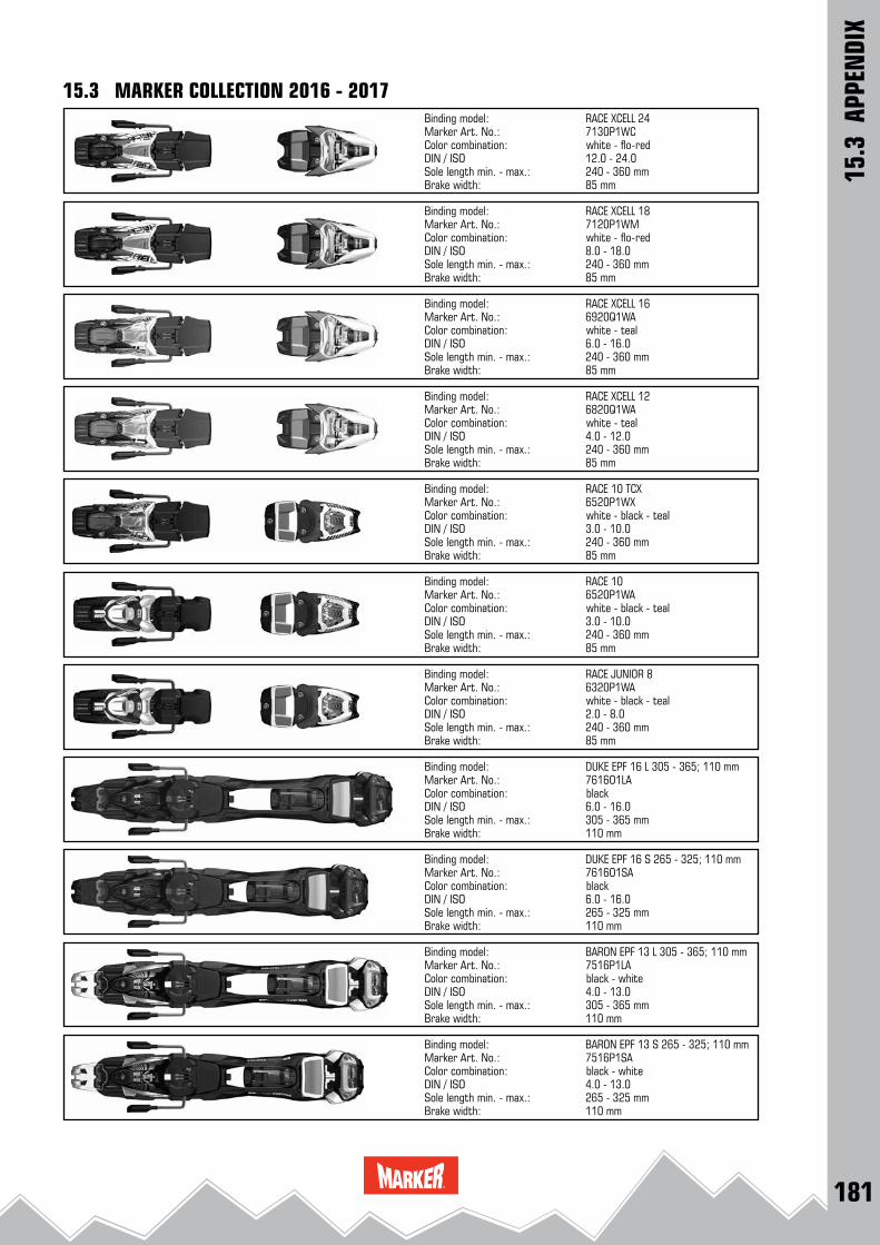
181
RACE XCELL 247130P1WC
12.0 - 24.0240 - 360 mm85 mm
RACE XCELL 187120P1WM
8.0 - 18.0240 - 360 mm85 mm
RACE XCELL 166920Q1WA
6.0 - 16.0240 - 360 mm85 mm
BARON EPF 13 S 265 - 325; 110 mm7516P1SA
4.0 - 13.0265 - 325 mm110 mm
RACE XCELL 126820Q1WA
4.0 - 12.0240 - 360 mm85 mm
RACE 10 TCX6520P1WX
3.0 - 10.0240 - 360 mm85 mm
RACE 106520P1WA
3.0 - 10.0240 - 360 mm85 mm
RACE JUNIOR 86320P1WA
2.0 - 8.0240 - 360 mm85 mm
DUKE EPF 16 L 305 - 365; 110 mm7616O1LA
6.0 - 16.0305 - 365 mm110 mm
DUKE EPF 16 S 265 - 325; 110 mm7616O1SA
6.0 - 16.0265 - 325 mm110 mm
BARON EPF 13 L 305 - 365; 110 mm7516P1LA
4.0 - 13.0305 - 365 mm110 mm
15.3 MARKER COLLECTION 2016 - 2017
15.3
APP
ENDI
X
Binding model: Marker Art. No.: Color combination: white - flo-redDIN / ISO Sole length min. - max.:Brake width:
Binding model: Marker Art. No.: Color combination: black - whiteDIN / ISO Sole length min. - max.:Brake width:
Binding model: Marker Art. No.: Color combination: white - flo-redDIN / ISO Sole length min. - max.:Brake width:
Binding model: Marker Art. No.: Color combination: white - tealDIN / ISO Sole length min. - max.:Brake width:
Binding model: Marker Art. No.: Color combination: white - tealDIN / ISO Sole length min. - max.:Brake width:
Binding model: Marker Art. No.: Color combination: white - black - tealDIN / ISO Sole length min. - max.:Brake width:
Binding model: Marker Art. No.: Color combination: white - black - tealDIN / ISO Sole length min. - max.:Brake width:
Binding model: Marker Art. No.: Color combination: white - black - tealDIN / ISO Sole length min. - max.:Brake width:
Binding model: Marker Art. No.: Color combination: blackDIN / ISO Sole length min. - max.:Brake width:
Binding model: Marker Art. No.: Color combination: blackDIN / ISO Sole length min. - max.:Brake width:
Binding model: Marker Art. No.: Color combination: black - whiteDIN / ISO Sole length min. - max.:Brake width:

182
JESTER 18 PRO; 90 mm / 120 mm7924Q1JS / 7924Q1JB
8.0 - 18.0240 - 370 mm110 mm
JESTER 16 ID; 90 mm7624Q1JA
6.0 - 16.0240 - 370 mm90 mm
JESTER 16 ID; 110 mm7624Q1JB
6.0 - 16.0240 - 370 mm110 mm
JESTER 16 ID; 136 mm7624Q1JC
6.0 - 16.0240 - 370 mm136 mm
Griffon 13 ID; 90 mm7524Q1GA
4.0 - 13.0240 - 370 mm90 mm
Griffon 13 ID; 110 mm7524Q1GB
4.0 - 13.0240 - 370 mm110 mm
Griffon 13 ID; 120 mm7524Q1GC
4.0 - 13.0240 - 370 mm120 mm
Griffon 13 ID; 90 mm7524Q1GD
4.0 - 13.0240 - 370 mm90 mm
Griffon 13 ID; 110 mm7524Q1GE
4.0 - 13.0240 - 370 mm110 mm
LORD SP 14; 90 mm7629N1LN
5.0 - 14.0240 - 370 mm90 mm
Griffon 13 ID; 120 mm7524Q1GF
4.0 - 13.0240 - 370 mm120 mm
15.3 MARKER COLLECTION 2016 - 2017
15.3
APP
ENDI
X
Binding model: Marker Art. No.: Color combination: redDIN / ISO Sole length min. - max.:Brake width:
Binding model: Marker Art. No.: Color combination: black - white - tealDIN / ISO Sole length min. - max.:Brake width:
Binding model: Marker Art. No.: Color combination: blackDIN / ISO Sole length min. - max.:Brake width:
Binding model: Marker Art. No.: Color combination: blackDIN / ISO Sole length min. - max.:Brake width:
Binding model: Marker Art. No.: Color combination: blackDIN / ISO Sole length min. - max.:Brake width:
Binding model: Marker Art. No.: Color combination: blackDIN / ISO Sole length min. - max.:Brake width:
Binding model: Marker Art. No.: Color combination: blackDIN / ISO Sole length min. - max.:Brake width:
Binding model: Marker Art. No.: Color combination: blackDIN / ISO Sole length min. - max.:Brake width:
Binding model: Marker Art. No.: Color combination: whiteDIN / ISO Sole length min. - max.:Brake width:
Binding model: Marker Art. No.: Color combination: whiteDIN / ISO Sole length min. - max.:Brake width:
Binding model: Marker Art. No.: Color combination: whiteDIN / ISO Sole length min. - max.:Brake width:

183
LORD SP 14; 110 mm7629N1LW
5.0 - 14.0240 - 370 mm110 mm
SQUIRE 11; 90 mm7424Q1MA
3.0 - 11.0240 - 370 mm90 mm
SQUIRE 11; 110 mm7424Q1MB
3.0 - 11.0240 - 370 mm110 mm
SCHIZO 11; 110 mm7425P1MD
3.0 - 11.0265 - 365 mm110 mm
SQUIRE 11; 90 mm7424Q1MC
3.0 - 11.0240 - 370 mm90 mm
SQUIRE 11; 110 mm7424Q1MD
3.0 - 11.0240 - 370 mm110 mm
SQUIRE 11; 90 mm7424Q1ME
3.0 - 11.0240 - 370 mm90 mm
SQUIRE 11; 110 mm7424Q1MF
3.0 - 11.0240 - 370 mm110 mm
SCHIZO 14; 90 mm7625P1GA
5.0 - 14.0265 - 365 mm90 mm
SCHIZO 14; 110 mm7625P1GB
5.0 - 14.0265 - 365 mm110 mm
SCHIZO 11; 90 mm7425P1MC
3.0 - 11.0265 - 365 mm90 mm
15.3 MARKER COLLECTION 2016 - 2017
15.3
APP
ENDI
X
Binding model: Marker Art. No.: Color combination: black - white - tealDIN / ISO Sole length min. - max.:Brake width:
Binding model: Marker Art. No.: Color combination: white - blueDIN / ISO Sole length min. - max.:Brake width:
Binding model: Marker Art. No.: Color combination: whiteDIN / ISO Sole length min. - max.:Brake width:
Binding model: Marker Art. No.: Color combination: whiteDIN / ISO Sole length min. - max.:Brake width:
Binding model: Marker Art. No.: Color combination: redDIN / ISO Sole length min. - max.:Brake width:
Binding model: Marker Art. No.: Color combination: redDIN / ISO Sole length min. - max.:Brake width:
Binding model: Marker Art. No.: Color combination: black - anthraciteDIN / ISO Sole length min. - max.:Brake width:
Binding model: Marker Art. No.: Color combination: black - anthraciteDIN / ISO Sole length min. - max.:Brake width:
Binding model: Marker Art. No.: Color combination: black - blueDIN / ISO Sole length min. - max.:Brake width:
Binding model: Marker Art. No.: Color combination: black - blueDIN / ISO Sole length min. - max.:Brake width:
Binding model: Marker Art. No.: Color combination: white - blueDIN / ISO Sole length min. - max.:Brake width:

184
F12 TOUR EPF; S 265 - 325; 110 mm7816P1SE
4.0 - 12.0265 - 325 mm110 mm
F12 TOUR EPF; L 305 - 365; 110 mm7816P1LE
4.0 - 12.0305 - 365 mm110 mm
F 12 TOUR S 265 - 325; 90 mm7816M1TA
4.0 - 12.0265 - 325 mm90 mm
F 12 TOUR L 305 - 365; 90 mm7816M1TB
4.0 - 12.0305 - 365 mm90 mm
F 10 TOUR S 265 - 325; 90 mm7716Q1TC
3.0 - 10.0265 - 325 mm90 mm
F 10 TOUR L 305 - 365; 90 mm7716Q1TD
3.0 - 10.0305 - 365 mm90 mm
KINGPIN 10; 75 - 100 mm7733Q1MA
5.0 - 10.0255 - 390 mm100 mm
KINGPIN 10; 100 - 125 mm7733Q1MB
5.0 - 10.0255 - 390 mm125 mm
KINGPIN 13; 75 - 100 mm7933Q1MA
6.0 - 13.0255 - 390 mm100 mm
KINGPIN 10 Demo; 75 - 100 mm7734Q1MA
5.0 - 10.0264 - 356 mm100 mm
KINGPIN 13; 100 - 125 mm7933Q1MB
6.0 - 13.0255 - 390 mm125 mm
15.3 MARKER COLLECTION 2016 - 2017
15.3
APP
ENDI
X
Binding model: Marker Art. No.: Color combination: black - anthraciteDIN / ISO Sole length min. - max.:Brake width:
Binding model: Marker Art. No.: Color combination: black - goldDIN / ISO Sole length min. - max.:Brake width:
Binding model: Marker Art. No.: Color combination: black - anthraciteDIN / ISO Sole length min. - max.:Brake width:
Binding model: Marker Art. No.: Color combination: black - redDIN / ISO Sole length min. - max.:Brake width:
Binding model: Marker Art. No.: Color combination: black - redDIN / ISO Sole length min. - max.:Brake width:
Binding model: Marker Art. No.: Color combination: black - whiteDIN / ISO Sole length min. - max.:Brake width:
Binding model: Marker Art. No.: Color combination: black - whiteDIN / ISO Sole length min. - max.:Brake width:
Binding model: Marker Art. No.: Color combination: black - goldDIN / ISO Sole length min. - max.:Brake width:
Binding model: Marker Art. No.: Color combination: black - goldDIN / ISO Sole length min. - max.:Brake width:
Binding model: Marker Art. No.: Color combination: black - goldDIN / ISO Sole length min. - max.:Brake width:
Binding model: Marker Art. No.: Color combination: black - goldDIN / ISO Sole length min. - max.:Brake width:

185
KINGPIN 13 Demo; 100 - 125 mm7934Q1MB
6.0 - 13.0264 - 356 mm125 mm
FREE TEN; 85 mm (+ screw kit)7224Q1MA
3.0 - 10.0240 - 360 mm85 mm
FREE TEN; 100 mm (+ screw kit)7224Q1MB
3.0 - 10.0240 - 360 mm100 mm
M 7.0 EPS; 85 mm6220N1WW
2.0 - 7.0190 - 310 mm85 mm
FREE 8; 100 mm6324Q1MA
2.0 - 8.0240 - 360 mm85 mm
M 7.0 FREE; 85 mm6220P1SF
2.0 - 7.0190 - 310 mm85 mm
M 11.0 TC EPS; 90 mm6720P1MA
3.0 - 10.0240 - 360 mm90 mm
M 11.0 TC EPS; 90 mm6720O1MB
3.0 - 10.0240 - 360 mm90 mm
10.0 EPS; 80 mm6520Q1MA
3.0 - 10.0240 - 360 mm80 mm
M 7.0 EPS6220M1WS
2.0 - 7.0190 - 310 mm72 mm
M 7.0 EPS6220M1WB
2.0 - 7.0190 - 310 mm72 mm
15.3 MARKER COLLECTION 2016 - 2017
15.3
APP
ENDI
X
Binding model: Marker Art. No.: Color combination: black - goldDIN / ISO Sole length min. - max.:Brake width:
Binding model: Marker Art. No.: Color combination: white - blackDIN / ISO Sole length min. - max.:Brake width:
Binding model: Marker Art. No.: Color combination: blackDIN / ISO Sole length min. - max.:Brake width:
Binding model: Marker Art. No.: Color combination: blackDIN / ISO Sole length min. - max.:Brake width:
Binding model: Marker Art. No.: Color combination: blackDIN / ISO Sole length min. - max.:Brake width:
Binding model: Marker Art. No.: Color combination: blackDIN / ISO Sole length min. - max.:Brake width:
Binding model: Marker Art. No.: Color combination: white - blackDIN / ISO Sole length min. - max.:Brake width:
Binding model: Marker Art. No.: Color combination: black - silverDIN / ISO Sole length min. - max.:Brake width:
Binding model: Marker Art. No.: Color combination: white - anthraciteDIN / ISO Sole length min. - max.:Brake width:
Binding model: Marker Art. No.: Color combination: white - blackDIN / ISO Sole length min. - max.:Brake width:
Binding model: Marker Art. No.: Color combination: white - anthracite - blueDIN / ISO Sole length min. - max.:Brake width:
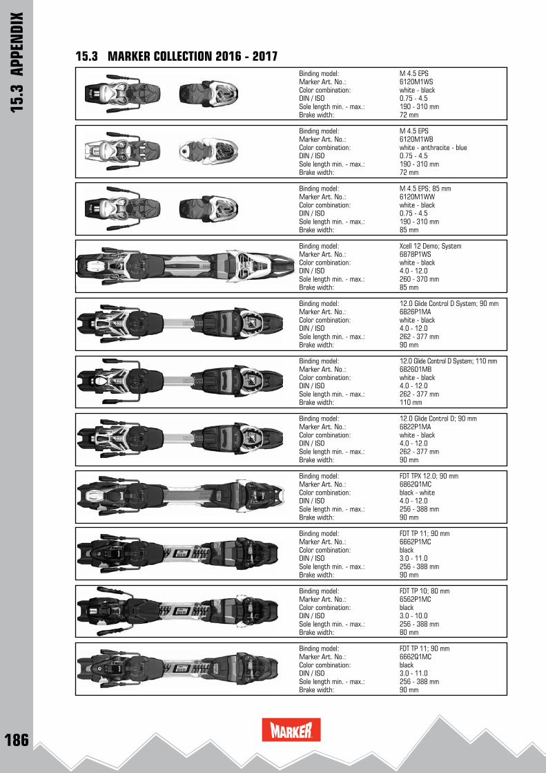
186
M 4.5 EPS6120M1WS
0.75 - 4.5190 - 310 mm72 mm
M 4.5 EPS6120M1WB
0.75 - 4.5190 - 310 mm72 mm
M 4.5 EPS; 85 mm6120M1WW
0.75 - 4.5190 - 310 mm85 mm
Xcell 12 Demo; System6878P1WS
4.0 - 12.0260 - 370 mm85 mm
12.0 Glide Control D System; 90 mm6826P1MA 4.0 - 12.0262 - 377 mm90 mm
12.0 Glide Control D System; 110 mm6826O1MB 4.0 - 12.0262 - 377 mm110 mm
12.0 Glide Control D; 90 mm6822P1MA 4.0 - 12.0262 - 377 mm90 mm
FDT TP 11; 90 mm6662P1MC
3.0 - 11.0256 - 388 mm90 mm
FDT TP 11; 90 mm6662Q1MC
3.0 - 11.0256 - 388 mm90 mm
FDT TP 10; 80 mm6562P1MC
3.0 - 10.0256 - 388 mm80 mm
FDT TPX 12.0; 90 mm6862Q1MC
4.0 - 12.0256 - 388 mm90 mm
15.3 MARKER COLLECTION 2016 - 2017
15.3
APP
ENDI
X
Binding model: Marker Art. No.: Color combination: white - blackDIN / ISO Sole length min. - max.:Brake width:
Binding model: Marker Art. No.: Color combination: blackDIN / ISO Sole length min. - max.:Brake width:
Binding model: Marker Art. No.: Color combination: white - anthracite - blueDIN / ISO Sole length min. - max.:Brake width:
Binding model: Marker Art. No.: Color combination: white - blackDIN / ISO Sole length min. - max.:Brake width:
Binding model: Marker Art. No.: Color combination: white - blackDIN / ISO Sole length min. - max.:Brake width:
Binding model: Marker Art. No.: Color combination: white - blackDIN / ISO Sole length min. - max.:Brake width:
Binding model: Marker Art. No.: Color combination: white - blackDIN / ISO Sole length min. - max.:Brake width:
Binding model: Marker Art. No.: Color combination: white - blackDIN / ISO Sole length min. - max.:Brake width:
Binding model: Marker Art. No.: Color combination: blackDIN / ISO Sole length min. - max.:Brake width:
Binding model: Marker Art. No.: Color combination: blackDIN / ISO Sole length min. - max.:Brake width:
Binding model: Marker Art. No.: Color combination: black - whiteDIN / ISO Sole length min. - max.:Brake width:
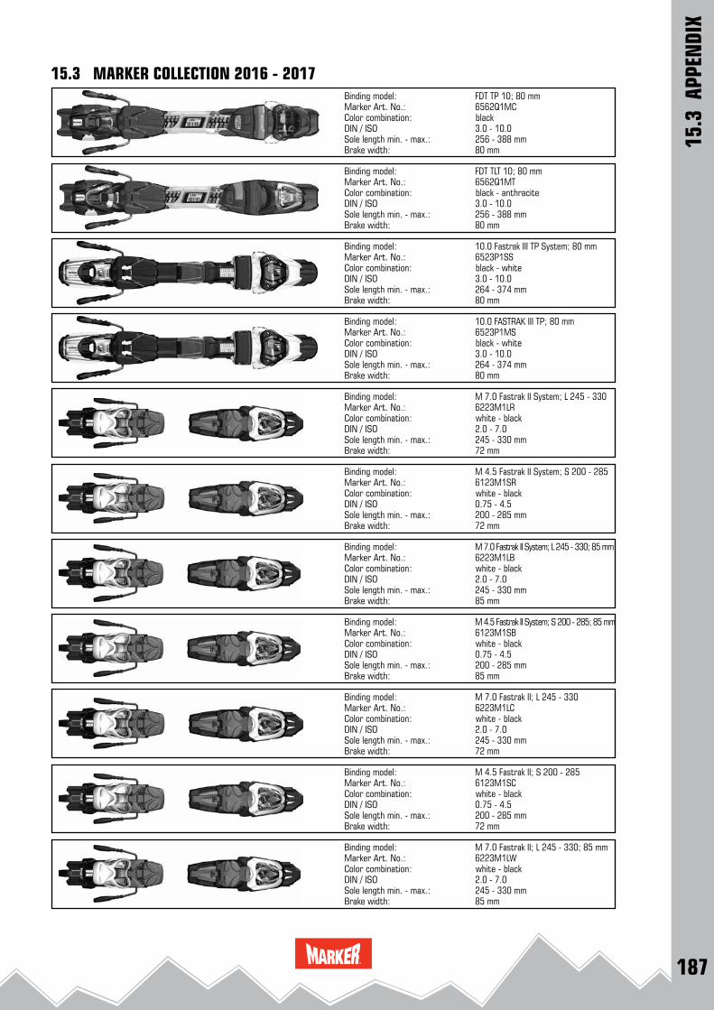
187
FDT TP 10; 80 mm6562Q1MC
3.0 - 10.0256 - 388 mm80 mm
FDT TLT 10; 80 mm6562Q1MT
3.0 - 10.0256 - 388 mm80 mm
10.0 Fastrak III TP System; 80 mm6523P1SS
3.0 - 10.0264 - 374 mm80 mm
M 7.0 Fastrak II; L 245 - 330; 85 mm6223M1LW
2.0 - 7.0245 - 330 mm85 mm
10.0 FASTRAK III TP; 80 mm6523P1MS
3.0 - 10.0264 - 374 mm80 mm
M 7.0 Fastrak II System; L 245 - 3306223M1LR
2.0 - 7.0245 - 330 mm72 mm
M 4.5 Fastrak II System; S 200 - 2856123M1SR
0.75 - 4.5200 - 285 mm72 mm
M 7.0 Fastrak II System; L 245 - 330; 85 mm6223M1LB
2.0 - 7.0245 - 330 mm85 mm
M 4.5 Fastrak II System; S 200 - 285; 85 mm6123M1SB
0.75 - 4.5200 - 285 mm85 mm
M 7.0 Fastrak II; L 245 - 3306223M1LC
2.0 - 7.0245 - 330 mm72 mm
M 4.5 Fastrak II; S 200 - 2856123M1SC
0.75 - 4.5200 - 285 mm72 mm
15.3 MARKER COLLECTION 2016 - 2017
15.3
APP
ENDI
X
Binding model: Marker Art. No.: Color combination: blackDIN / ISO Sole length min. - max.:Brake width:
Binding model: Marker Art. No.: Color combination: white - blackDIN / ISO Sole length min. - max.:Brake width:
Binding model: Marker Art. No.: Color combination: black - anthraciteDIN / ISO Sole length min. - max.:Brake width:
Binding model: Marker Art. No.: Color combination: black - whiteDIN / ISO Sole length min. - max.:Brake width:
Binding model: Marker Art. No.: Color combination: black - whiteDIN / ISO Sole length min. - max.:Brake width:
Binding model: Marker Art. No.: Color combination: white - blackDIN / ISO Sole length min. - max.:Brake width:
Binding model: Marker Art. No.: Color combination: white - blackDIN / ISO Sole length min. - max.:Brake width:
Binding model: Marker Art. No.: Color combination: white - blackDIN / ISO Sole length min. - max.:Brake width:
Binding model: Marker Art. No.: Color combination: white - blackDIN / ISO Sole length min. - max.:Brake width:
Binding model: Marker Art. No.: Color combination: white - blackDIN / ISO Sole length min. - max.:Brake width:
Binding model: Marker Art. No.: Color combination: white - blackDIN / ISO Sole length min. - max.:Brake width:

188
M 7.0 RTL6220M1MR
2.0 - 7.0240 - 304 mm72 mm
M 7.0 RTL; 85 mm6220M1MW
2.0 - 7.0240 - 304 mm85 mm
M 4.5 RTL6120M1MR
0.75 - 4.5200 - 264 mm72 mm
JESTER Demo; 90 mm7620O1JA
6.0 - 16.0265 - 365 mm90 mm
JESTER Demo; 110 mm7620O1JB
6.0 - 16.0265 - 365 mm110 mm
Griffon 13 D; 90 mm7520Q1GA
4.0 - 13.0256 - 388 mm90 mm
Griffon 13 D; 110 mm7520Q1GB
4.0 - 13.0256 - 388 mm110 mm
Squire 11 D; 90 mm7420Q1MA
3.0 - 11.0256 - 388 mm90 mm
Squire 11 D; 110 mm7420Q1MB
3.0 - 11.0256 - 388 mm110 mm
World Cup Piston Control Interface2020N1MW (2020N1MC bulk)
260 - 362 mm59 mm542 mm
Junior Race Interface 22027O1MB (bulk)
210 - 334 mm59 mm495 mm
15.3 MARKER COLLECTION 2016 - 2017
15.3
APP
ENDI
X
Binding model: Marker Art. No.: Color combination: white - blackDIN / ISO Sole length min. - max.:Brake width:
Interface model: Marker Art. No.: Color combination: white - blackSole length min. - max.:Width:Length:
Binding model: Marker Art. No.: Color combination: white - blackDIN / ISO Sole length min. - max.:Brake width:
Binding model: Marker Art. No.: Color combination: white - blackDIN / ISO Sole length min. - max.:Brake width:
Binding model: Marker Art. No.: Color combination: blackDIN / ISO Sole length min. - max.:Brake width:
Binding model: Marker Art. No.: Color combination: blackDIN / ISO Sole length min. - max.:Brake width:
Binding model: Marker Art. No.: Color combination: blackDIN / ISO Sole length min. - max.:Brake width:
Binding model: Marker Art. No.: Color combination: blackDIN / ISO Sole length min. - max.:Brake width:
Binding model: Marker Art. No.: Color combination: black - anthraciteDIN / ISO Sole length min. - max.:Brake width:
Binding model: Marker Art. No.: Color combination: black - anthraciteDIN / ISO Sole length min. - max.:Brake width:
Interface model: Marker Art. No.: Color combination: blackSole length min. - max.:Width:Length:

189

190
191
192