RT 740B - TIL Limited
12
RT 740B Product Guide ROUGH TERRAIN HYDRAULIC CRANE n MAX. CAPACITY (Outriggers) - 40.0 Tonnes at 3m Radius (85% Rating) 360° Slew n MAX. CAPACITY (On Tyres) - 17.35 Tonnes at 3m Radius (85% Rating) Over Front Features n BOOM - 4 SECTION Trapezoidal 10.6m - 33.5m n MAX. ROAD SPEED - 26 km/hr n CARRIER - 4 X 4 Wheel Drive with 4 Wheel Steer
-
Upload
khangminh22 -
Category
Documents
-
view
1 -
download
0
Transcript of RT 740B - TIL Limited

RT 740BProduct Guide
ROUGH TERRAIN HYDRAULIC CRANE
n MAX. CAPACITY (Outriggers) - 40.0 Tonnes at 3m Radius (85% Rating) 360° Slew
n MAX. CAPACITY (On Tyres) - 17.35 Tonnes at 3m Radius (85% Rating) Over Front
Featuresn BOOM - 4 SECTION Trapezoidal 10.6m - 33.5m
n MAX. ROAD SPEED - 26 km/hr
n CARRIER - 4 X 4 Wheel Drive with 4 Wheel Steer

Superstructure Specifications
BOOM10.6m - 33.5m four section, telescopic, full power, sequence synchronized, trapezoidal boom with single lever control. Telescoping boom sections slide on adjustable & replaceable low friction wear pads.
BOOM NOSEFour nylatron sheaves mounted on heavy duty tapered roller bearings with removable pin-type rope guards.Maximum Tip Height: 35.9m
BOOM ELEVATIONOne double acting hydraulic cylinder with integral holding valve.
BOOM ANGLE Maximum: 78°, Minimum: -3°.
SUPERSTRUCTURE FRAMEFabricated from high tensile steel plates and sections.
SLEW SYSTEMBall bearing swing circle with 360° continuous rotation. Planetary “Glide-Swing” with foot applied multi-disc brake. Spring applied hydraulically released parking brake, mechanical house lock operated from cab. Free slew facility provided.
SLEW SPEEDMaximum 2.0 RPM (Unladen).
HOIST SYSTEMPower up and down equal speed, grooved drum, planetary reduction with automatic spring applied multi-disc brake. Hoist drum fitted with third wrap indicator.
Non Spin Hoist Rope: 19mm dia. & length 152m.
Line Speed: Top layer 105m/min (Max) Unladen.
Maximum Permissible Line Pull: 5500Kg.
HOOK BLOCK40.0 Tonnes; 4 Sheaves - 8 falls.
COUNTERWEIGHTBolted with superstructure - 3708kg
OPERATOR’S CABTotally enclosed steel construction, full vision type cab with all crane functions control levers, driving controls, engine instrumentation & automotive type steering wheel. All windows fitted with toughened safety glass, lockable sliding door, cab interior light, circulating air fan, pantograph type electric wiper & electric horn.
LMI & A2B SYSTEMLoad Moment Indicator and Anti-Two Block system with audio–visual warning and control lever lock-out provides electronic display of boom angle, boom length, radius, relative load moment, maximum permissible load, load indication and warning of impending two-block condition.
HYDRAULIC SYSTEM PumpsTwo Section Gear pump driven through engine PTO.Two Section Gear pump driven through transmission PTO.
ValvesPrecision 4 way double acting pilot operated control valves. 3 Individual valve banks permit simultaneous control of multiple crane functions.
FiltersReturn line filter with replaceable cartridge having full flow with by-pass protection and service indicator.
Reservoir 378 liters with spin-on breather filter, external sight gauge, oil temperature gauge, clean out access, strap mounted to frame.
Pressure Check PanelSystem pressure test panel with quick release type fittings for each circuit.
OPTIONAL EQUIPMENTFixed Swingaway Extension9.8m lattice Swingaway boom extension with integral offset mechanism, off settable at 0°, 15° or 30°. Stows alongside base boom section when not in use.
Maximum tip height: 45.4m
Telescopic Swingaway Extension9.8m to 13.4m or 17.1m telescopic lattice swingaway extension with integral offset mechanism, off settable at 0°, 15° or 30°. Stows alongside base boom section when not in use.
Maximum tip height: 52.7m
Auxiliary Hoist
AC Cabin
Protective Super Cab
RT
740B
Technical Specification TIL/RT740B/1218

OPERATING RADIUS FROM AXIS OF ROTATION IN METRES
HEI
GH
T FR
OM
GRO
UN
D IN
MET
RES
BOO
M &
EX
TEN
SIO
N L
ENG
TH IN
MET
RES
NOTE: The above heights of lift and boom angles are based on a straight (unladen) boom and allowance should be made for boom deflections obtained under laden conditions.
Height of Lift : 10.6m - 33.5 Full Power Boom
WORKING RANGE DIAGRAM(BOOM DEFLECTION NOT SHOWN)
Hookblock Capacities - Tonnes
No. of fall 8 7 6 5 4 3 2 1Permissible Load 40.0 34.0 28.0 23.0 18.0 14.0 10.0 5.0 RT
740B
Technical Specification TIL/RT740B/1218
RT
740B
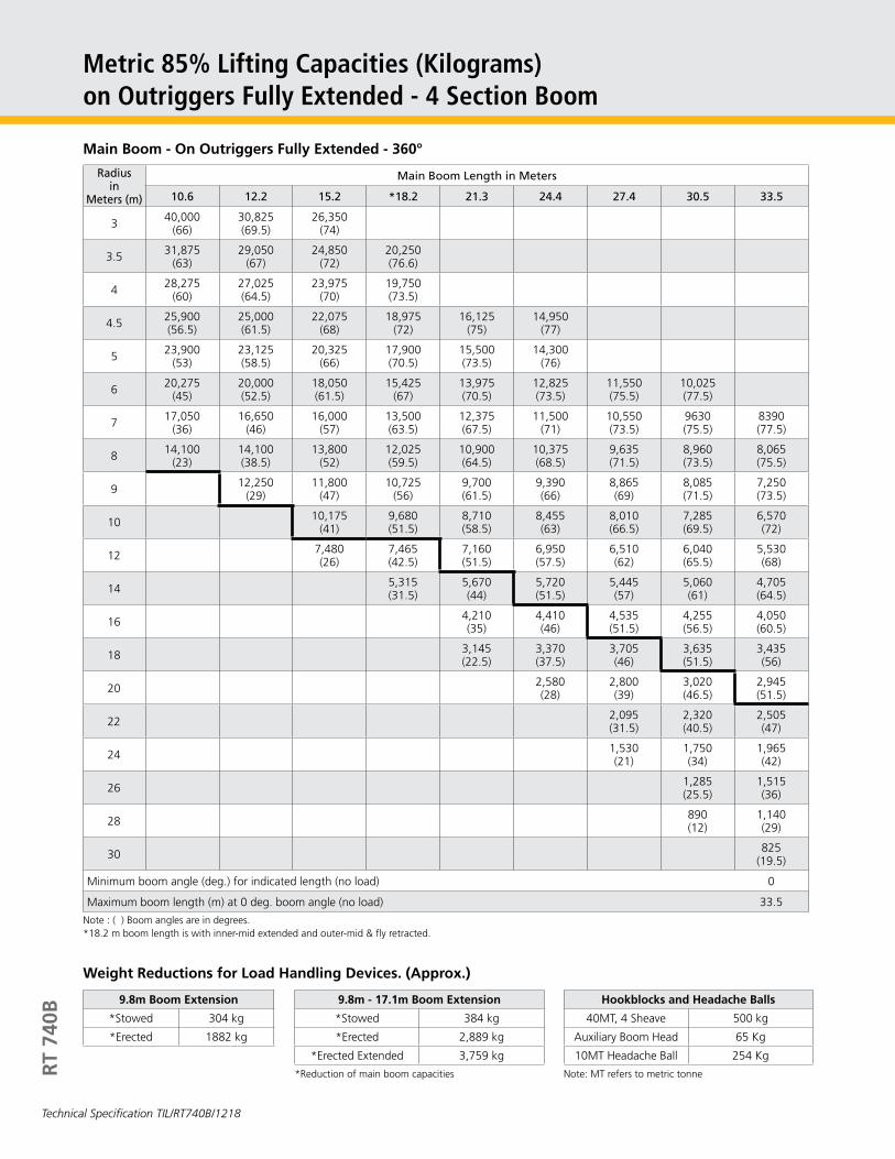
Metric 85% Lifting Capacities (Kilograms)on Outriggers Fully Extended - 4 Section Boom
Radius in
Meters (m)
Main Boom Length in Meters
10.6 12.2 15.2 *18.2 21.3 24.4 27.4 30.5 33.5
3 40,000 (66)
30,825 (69.5)
26,350 (74)
3.5 31,875 (63)
29,050 (67)
24,850 (72)
20,250 (76.6)
4 28,275 (60)
27,025 (64.5)
23,975 (70)
19,750 (73.5)
4.5 25,900 (56.5)
25,000 (61.5)
22,075 (68)
18,975 (72)
16,125 (75)
14,950 (77)
5 23,900 (53)
23,125 (58.5)
20,325(66)
17,900 (70.5)
15,500 (73.5)
14,300 (76)
6 20,275 (45)
20,000 (52.5)
18,050 (61.5)
15,425 (67)
13,975 (70.5)
12,825 (73.5)
11,550 (75.5)
10,025 (77.5)
7 17,050 (36)
16,650 (46)
16,000 (57)
13,500 (63.5)
12,375 (67.5)
11,500 (71)
10,550 (73.5)
9630 (75.5)
8390 (77.5)
8 14,100 (23)
14,100 (38.5)
13,800 (52)
12,025 (59.5)
10,900 (64.5)
10,375 (68.5)
9,635 (71.5)
8,960 (73.5)
8,065 (75.5)
9 12,250 (29)
11,800 (47)
10,725 (56)
9,700 (61.5)
9,390 (66)
8,865 (69)
8,085 (71.5)
7,250 (73.5)
10 10,175 (41)
9,680 (51.5)
8,710 (58.5)
8,455 (63)
8,010 (66.5)
7,285 (69.5)
6,570 (72)
12 7,480 (26)
7,465 (42.5)
7,160 (51.5)
6,950 (57.5)
6,510 (62)
6,040 (65.5)
5,530 (68)
14 5,315 (31.5)
5,670 (44)
5,720 (51.5)
5,445 (57)
5,060 (61)
4,705 (64.5)
16 4,210 (35)
4,410 (46)
4,535 (51.5)
4,255 (56.5)
4,050 (60.5)
18 3,145 (22.5)
3,370 (37.5)
3,705 (46)
3,635 (51.5)
3,435 (56)
20 2,580 (28)
2,800 (39)
3,020 (46.5)
2,945 (51.5)
22 2,095 (31.5)
2,320 (40.5)
2,505 (47)
24 1,530 (21)
1,750 (34)
1,965 (42)
26 1,285 (25.5)
1,515 (36)
28 890 (12)
1,140 (29)
30 825 (19.5)
Minimum boom angle (deg.) for indicated length (no load) 0
Maximum boom length (m) at 0 deg. boom angle (no load) 33.5
Note : ( ) Boom angles are in degrees.*18.2 m boom length is with inner-mid extended and outer-mid & fly retracted.
Main Boom - On Outriggers Fully Extended - 360°
Weight Reductions for Load Handling Devices. (Approx.)
9.8m Boom Extension
*Stowed 304 kg
*Erected 1882 kg
9.8m - 17.1m Boom Extension
*Stowed 384 kg
*Erected 2,889 kg
*Erected Extended 3,759 kg
*Reduction of main boom capacities
Hookblocks and Headache Balls
40MT, 4 Sheave 500 kg
Auxiliary Boom Head 65 Kg
10MT Headache Ball 254 Kg
Note: MT refers to metric tonne
Technical Specification TIL/RT740B/1218
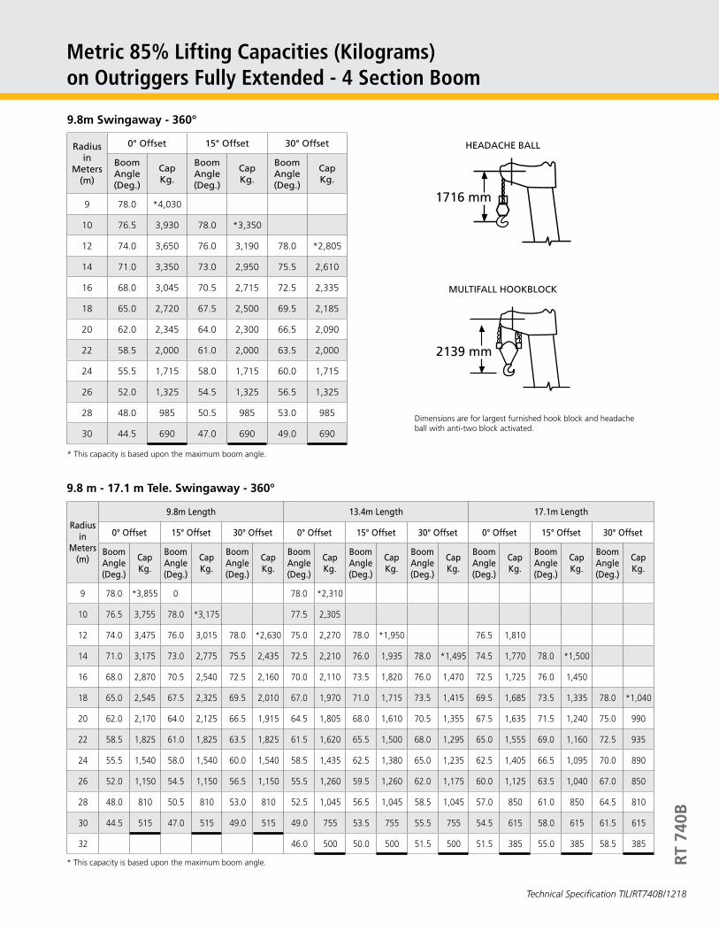
Metric 85% Lifting Capacities (Kilograms)on Outriggers Fully Extended - 4 Section Boom
HEADACHE BALL
MULTIFALL HOOKBLOCK
RT
740B
Radius in
Meters (m)
0° Offset 15° Offset 30° Offset
Boom Angle (Deg.)
Cap Kg.
Boom Angle (Deg.)
Cap Kg.
Boom Angle (Deg.)
Cap Kg.
9 78.0 *4,030
10 76.5 3,930 78.0 *3,350
12 74.0 3,650 76.0 3,190 78.0 *2,805
14 71.0 3,350 73.0 2,950 75.5 2,610
16 68.0 3,045 70.5 2,715 72.5 2,335
18 65.0 2,720 67.5 2,500 69.5 2,185
20 62.0 2,345 64.0 2,300 66.5 2,090
22 58.5 2,000 61.0 2,000 63.5 2,000
24 55.5 1,715 58.0 1,715 60.0 1,715
26 52.0 1,325 54.5 1,325 56.5 1,325
28 48.0 985 50.5 985 53.0 985
30 44.5 690 47.0 690 49.0 690
* This capacity is based upon the maximum boom angle.
9.8m Swingaway - 360°
2139 mm
1716 mm
Dimensions are for largest furnished hook block and headache ball with anti-two block activated.
Radius in
Meters (m)
9.8m Length 13.4m Length 17.1m Length
0° Offset 15° Offset 30° Offset 0° Offset 15° Offset 30° Offset 0° Offset 15° Offset 30° Offset
Boom Angle (Deg.)
Cap Kg.
Boom Angle (Deg.)
Cap Kg.
Boom Angle (Deg.)
Cap Kg.
Boom Angle (Deg.)
Cap Kg.
Boom Angle (Deg.)
Cap Kg.
Boom Angle (Deg.)
Cap Kg.
Boom Angle (Deg.)
Cap Kg.
Boom Angle (Deg.)
Cap Kg.
Boom Angle (Deg.)
Cap Kg.
9 78.0 *3,855 0 78.0 *2,310
10 76.5 3,755 78.0 *3,175 77.5 2,305
12 74.0 3,475 76.0 3,015 78.0 *2,630 75.0 2,270 78.0 *1,950 76.5 1,810
14 71.0 3,175 73.0 2,775 75.5 2,435 72.5 2,210 76.0 1,935 78.0 *1,495 74.5 1,770 78.0 *1,500
16 68.0 2,870 70.5 2,540 72.5 2,160 70.0 2,110 73.5 1,820 76.0 1,470 72.5 1,725 76.0 1,450
18 65.0 2,545 67.5 2,325 69.5 2,010 67.0 1,970 71.0 1,715 73.5 1,415 69.5 1,685 73.5 1,335 78.0 *1,040
20 62.0 2,170 64.0 2,125 66.5 1,915 64.5 1,805 68.0 1,610 70.5 1,355 67.5 1,635 71.5 1,240 75.0 990
22 58.5 1,825 61.0 1,825 63.5 1,825 61.5 1,620 65.5 1,500 68.0 1,295 65.0 1,555 69.0 1,160 72.5 935
24 55.5 1,540 58.0 1,540 60.0 1,540 58.5 1,435 62.5 1,380 65.0 1,235 62.5 1,405 66.5 1,095 70.0 890
26 52.0 1,150 54.5 1,150 56.5 1,150 55.5 1,260 59.5 1,260 62.0 1,175 60.0 1,125 63.5 1,040 67.0 850
28 48.0 810 50.5 810 53.0 810 52.5 1,045 56.5 1,045 58.5 1,045 57.0 850 61.0 850 64.5 810
30 44.5 515 47.0 515 49.0 515 49.0 755 53.5 755 55.5 755 54.5 615 58.0 615 61.5 615
32 46.0 500 50.0 500 51.5 500 51.5 385 55.0 385 58.5 385
* This capacity is based upon the maximum boom angle.
9.8 m - 17.1 m Tele. Swingaway - 360°
Technical Specification TIL/RT740B/1218

On Rubber 18.00 x 25-32 PR (Stationary Capacities - 360°)
Lifting Capacities on Rubber - 4 Section Boom
Radius in
Meters (m)
Tyre Inflation Pr. 8.1 kg/cm2
Main Boom Length in Meters
10.6 12.2 15.2 *18.2 21.3 24.4 27.4 30.5
314,900
(66)14,100 (69.5)
10,050 (74)
3.513,000
(63)12,400
(67)8,955 (72)
8,300 (75.5)
411,250
(60)10,950 (64.5)
8,010 (70)
7,800 (73.5)
4.59,845 (56.5)
9,810 (61.5)
7,340 (68)
7,120 (72)
58,670 (53)
8,670 (58.5)
6,795 (66)
6,555 (70.5)
66,835 (45)
6,765 (52.5)
5,900 (61.6)
5,735 (67)
4,750 (70.5)
2,800 (73.5)
75,235 (36)
5,045 (46)
4,840 (57)
4,525 (63.5)
3,990 (67.5)
2,800 (71)
84,020 (23)
3,810 (38.5)
3,605 (52)
3,370 (59.5)
3,300 (64.5)
2,800 (68.5)
2,050 (71.5)
920 (73.5)
92,895 (29)
2,680 (47)
2,430 (56)
2,635 (61.5)
2,435 (66)
2,050 (69)
920 (71.5)
102,190 (11.5)
1,965 (41)
1,730 (51.5)
2,180 (58.5)
2,055 (63)
2,040 (66.5)
920 (69.5)
12930 (26)
730 (42.5)
1,005 (51.5)
1,005 (57.5)
820 (62)
820 (65.5)
Note : ( ) Boom angles are in degrees. *18.2 m boom length is with inner-mid extended and outer-mid & fly retracted.
RT
740B
Technical Specification TIL/RT740B/1218

Lifting Capacities on Rubber - 4 Section Boom
On Rubber 18.00 x 25-32 PR (Stationary - Defined Arc Over Front)
Radius in
Meters (m)
Tyre Inflation Pr. 8.1 kg/cm2
Main Boom Length in Meters
10.6 12.2 15.2 *18.2 21.3 24.4 27.4 30.5
316,925
(66)14,100 (69.5)
10,050 (74)
3.515,325
(63)12,400
(67)9,295 (72)
8,300 (75.5)
413,850
(60)11,125 (64.5)
8,695 (70)
8,005 (73.5)
4.512,625 (56.5)
10,500 (61.5)
8,340 (68)
7,720 (72)
511,600
(53)10,075 (58.5)
8,090 (66)
7,215 (70.5)
69,920 (45)
9,465 (52.5)
7,720 (61.6)
6,205 (67)
5,215 (70.5)
4,710 (73.5)
78,630 (36)
8,360 (46)
6,735 (57)
5,460 (63.5)
4,835 (67.5)
4,360 (71)
87,605 (23)
7,405 (38.5)
5,875 (52)
4,955 (59.5)
4,535 (64.5)
4,105 (68.5)
3,555 (71.5)
2,865 (73.5)
96,305 (29)
5,250 (47)
4,585 (56)
4,250 (61.5)
3,885 (66)
3,355 (69)
2,695 (71.5)
105,030 (11.5)
4,670 (41)
4,305 (51.5)
4,050 (58.5)
3,675 (63)
3,195 (66.5)
2,590 (69.5)
123,170 (26)
3,045 (42.5)
3,210 (51.5)
3,210 (57.5)
2,965 (62)
2,420 (65.5)
141,940 (31.5)
1,995 (44)
1,995 (51.5)
1,995 (57)
1,995 (61)
161,125 (11)
1,125 (35)
1,125 (45)
1,125 (51.5)
1,125 (56.5)
18715
(22.5)715
(37.5)715 (46)
715 (51.5)
Note : ( ) Boom angles are in degrees. *18.2 m boom length is with inner-mid extended and outer-mid & fly retracted.
RT
740B
Technical Specification TIL/RT740B/1218

RT
740B
Lifting Capacities on Rubber - 4 Section Boom
On Rubber 18.00 x 25-32 PR (Pick & Carry Capacities upto 4.0 KPH - Boom Centered Over Front)
Radius in
Meters (m)
Tyre Inflation Pr. 8.1 kg/cm2
Main Boom Length in Meters
10.6 12.2 15.2 *18.2 21.3 24.4 27.4
317,350
(66)14,250 (69.5)
3.515,600
(63)13,400
(67)12,825
(72)
413,950
(60)12,750 (64.5)
12,075 (70)
4.512,575 (56.5)
12,550 (61.5)
11,425 (68)
10,450 (72)
511,425
(53)11,425 (58.5)
10,850 (66)
9,545 (70.5)
610,000
(45)9,580 (52.5)
9,455 (61.6)
7,980 (67)
6,330 (70.5)
78,000 (36)
8,000 (46)
7,890 (57)
6,730 (63.5)
5435 (67.5)
86,820 (23)
6,770 (38.5)
6,740 (52)
5,710 (59.5)
4,755 (64.5)
4,755 (68.5)
4,485 (71.5)
95,780 (29)
5,705 (47)
4,900 (56)
4,275 (61.5)
4,275 (66)
4,250 (69)
104,900 (11.5)
4,785 (41)
4,400 (51.5)
3,920 (58.5)
3,920 (63)
3,920 (66.5)
123,170 (26)
3,045 (42.5)
3,210 (51.5)
3,210 (57.5)
3,210 (62)
142,000 (31.5)
1,995 (44)
1,995 (51.5)
1,995 (57)
161,125 (11)
1,125 (35)
1,125 (45)
1,125 (51.5)
18715
(22.5)715
(37.5)715 (46)
Note : ( ) Boom angles are in degrees. *18.2 m boom length is with inner-mid extended and outer-mid & fly retracted.
Technical Specification TIL/RT740B/1218

Notes
Notes for Lifting Capacities
WARNING: THIS CHART IS ONLY A GUIDE. The Notes below are for illustration only and should not be relied upon to operate the crane. The individual crane’s load chart, operating instructions and other Instruction plates must be read and understood prior to operating the crane.
1. All rated loads have been tested to and meet minimum requirements of IS 4573-1982 Specification for Power Driven Mobile Cranes and do not exceed 85% of the tipping load on outriggers (85% of the tipping load on rubber) as determined by SAE J765 OCT80 Crane Stability Test Code.
2. The weight of hookblock, slings and all similarly used load handling devices must be added to the weight of the load. When more than minimum required reeving is used, the additional rope weight shall be considered part of the load.
3. Capacities appearing above the bold line are based on structural strength and tipping should not be relied upon as a capacity limitation.
4. All capacities are for crane on firm, level surface. It may be necessary to have structural supports under the outrigger floats or tyres to spread the load, to a larger bearing surface.
5. When either boom length or radius or both are between values listed, the smallest load shown at either the next larger radius or boom length shall be used.
6. On rubber, lifting with boom extensions is not permitted.
7. Tyres shall be inflated to the recommended pressure before lifting on rubber. Capacities must be reduced for lower tyre inflation.
8. If machine is equipped with individually controlled powered boom sections, the boom sections must be extended equally at all times.
9. Defined Arc ± 6° on either side of longitudinal centerline of machine.
10. For Pick & Carry operation, boom must be centered over front of machine, mechanical swing lock engaged and load restrained from swinging. When handling loads in the structural range with capacities close to max. rating, travel should be reduced to creep speeds (not over 61m of movement in 30 min, not exceeding 1.6 KPH).
11. Axle lockouts must be functioning before lifting on rubber.
12. 9.8 m Fixed off settable boom extension warning: For main boom length greater than 24.4 m with 9.8 m tele, boom extension in working position, the boom angle must not be less than 40° since loss of stability will occur causing a tipping condition.
13. 9.8 m - 17.1 m tele, off settable boom extension warning: For main boom length greater than 24.4 m with 9.8 m - 17.1m tele, boom extension in working position, the boom angle must not be less than 40° since loss of stability will occur causing a tipping condition.
14. Radii listed are for a fully extended boom with the boom extension erected. For main boom length less than fully extended, the rated loads are determined by boom angle. Use only the column which corresponds to the boom extension length and offset for which the machine is configured. For boom angles not shown, use the rating of the next lower boom angle.
WARNING: Operation of the machine with heavier load than the capacities listed is strictly prohibited. Machine tipping occurs without advance warning.
RT
740B
No Load Stability on Rubber
No load Stability DataMain Boom
33.5m
Front (No load)
Min. boom angle (deg.) for indicated length Max. boom length (m) at 0°
boom angle
4021.3
360° (No load)
Min. boom angle (deg.) for indicated length Max. boom length (m) at 0°
boom angle
55 15.2
Technical Specification TIL/RT740B/1218

Carrier Specification
FRAMEHigh strength alloy steel welded box section with integral outrigger housings and front/rear lifting, towing and tie down lugs.
OUTRIGGER SYSTEM4 hydraulically telescoping beams with ‘Inverted’ jacks with integral holding valves positioned two nos. in each outrigger housing. Provides steel fabricated quick release type outrigger float for each jack.
OUTRIGGER CONTROLSIndependent control of each outrigger beam located in cab on front dash panel along with level indicator.
ENGINECummins QSB6.7 Engine Series, 173 HP @ 2200 RPM Max. Torque - 881 Nm @ 1300 RPM Emission : BSIV-CEV
FUEL TANKCapacity 227 liters.
ELECTRICAL SYSTEMTwo 12 Volt-batteries, 24 Volt lighting equipment including two headlights, side, tail and stop lights and flashing direction indicators.
DRIVE4x4 / 4x2
STEERINGFully independent power steering:Front: Full hydraulic controlled by steering wheel.Rear: Full hydraulic selector switch controlled.Provides infinite variations of 4 main steering modes- front only, rear only, crab and coordinated. Rear wheel steer indicator. Auto - reversal steering mechanism.
TRANSMISSIONEngine mounted full power shift with 6 forward and 3 reverse speeds. Provides front axle disconnect for 4 x 2 travel.
AXLESFront: Drive-steer with differential and planetary reduction hubs rigidly mounted to the chassis frame.Rear: Drive-steer with differential and planetary reduction hubs, pivot mounted at centre of the chassis frame.
OSCILLATION LOCKOUTSAutomatic full hydraulic lockouts on rear axle permit oscillation only with boom centered over front.
TYRES18.00 X 25 - 32 PR earthmover tyres.
BRAKESFully hydraulic, split circuit operating on all wheels. Spring applied, hydraulically released front axle mounted parking brake.
INSTRUMENTATION Engine oil pressure gauge, Fuel gauge, Water temperature gauge, Voltmeter, Tacho-Hourmeter, Indicators and Switches for control.
OIL COOLERRemote mounted with thermostatically controlled, electric motor driven fan.
MAXIMUM SPEED26 kmph.
GRADEABILITY45% ( Maximum ) Unladen.
GROSS VEHICLE WEIGHT AND AXLE LOADS (approx)Front: 16,015 kgRear: 14,062 kgGVW: 30,077 kg
Optional Weights (approx.)Fixed Lattice : 953 kgTele lattice : 1,278 kgAuxiliary Hoist : 700 kgMan Carrying Basket : 550 kg
MISCELLANEOUS STANDARD EQUIPMENTFull width steel fenders, rear view mirror, back-up alarm, front stowage well, tool kit.
OPTIONAL EQUIPMENTFire suppression systemFire extinguisherCentralized Lubrication SystemTow hook on chassis frameMan Carrying Basket360° Beacon lightsCab Spot LightR
T 74
0B
Technical Specification TIL/RT740B/1218

GA Drawing
Constant improvement and engineering progress make it necessary that we reserve the right to make specification, equipment and price changes without notice. The photographs/drawings in this document are just for Illustrative purpose which may include optional equipment and accessories, which can be provided at an additional cost on request.
Dimensions in mm
RT
740B
Technical Specification TIL/RT740B/1218
Turning Radius2 Wheel Steer : 10,955 4 Wheel Steer : 6,390
Note:-Dimensions during Normal Travelling OrderOverall Length - 12710 mmOverall Height - 4500 mmOverall Width - 2997 mm

Copyright © 2018 TIL Limited. All Rights Reserved
TIL has a pan-India network of offices with service engineers located in the close proximity of jobsites.
Toll Free No: 1800 266 1535www.tilindia.in
Technical Specification TIL/RT740B/1218. This cancels Technical Specification TIL/RT740B/0818
TIL LimitedCIN: L74999WB1974PLC041725
Registered & Corporate Office:1, Taratolla Road, Garden Reach, Kolkata - 700024Phone: + 91 33 2469 3732-6 / 6497 | 6633 2000 / 2845 Mobile: +91 9831839025 | +91 9831054573Fax: + 91 33 2469 2143 / 3731Email: [email protected] | [email protected]
CHENNAITIL LimitedJhaver Plaza, 7th Floor 1-A Nungambakkam High Road Chennai 600 034, Tamil NaduPhone: +91 044 6670 3000 / 3010 Mobile: +91 9618562333 | +91 9790973502Fax: +91 44 2827 9681Email: [email protected]
DELHI NCRTIL Limited Plot 11, Site No.IVSahibabad Industrial AreaGhaziabad 201 010 U.P.Phone: +91 120 277 8735 / 8736 / 7468 Mobile: +91 9971091610 | 9903842544Fax: +91 120 277 7467Email: [email protected] | [email protected]
DELHITIL Limited302 Ansal Bhawan 16, Kasturba Gandhi Marg, New Delhi 110 001Phone: +91 11 2331 1607 / 8046 / 9248 | 2335 0250 / 0255Fax: +91 11 2331 3263 Email: [email protected]
KAMARHATTYTIL Limited517, Barrackpore Trunk Road Kolkata 700 058Phone: +91 33 2553 1352 / 1882 | 6633 4000Fax: +91 33 2553 2546 / 5971Email: [email protected] | [email protected]
KHARAGPURTIL LimitedVill. & P.O. Changual, KharagpurDist: Paschim Medinipur 721 301, West BengalPhone: +91 32 2266 1101
MUMBAITIL LimitedA - 606, A Wing, 6th Floor,215 Atrium, Andheri - Kurla Road,Andheri (East), Mumbai 400059, MaharashtraPhone: + 91 22 4969 1169 Mobile: +91 8850971609Email: [email protected] | [email protected]