RoofPak® Roof Mounted Singlezone Heating and Cooling Units
130
Installation and Maintenance Manual IM 926-3 Group: Applied Air Systems Part Number: IM 926 Date: October 2018 RoofPak ® Roof Mounted Singlezone Heating and Cooling Units RPS/RDT/RFS/RCS Models 015C–105C with MicroTech ® III Unit Controllers
-
Upload
khangminh22 -
Category
Documents
-
view
0 -
download
0
Transcript of RoofPak® Roof Mounted Singlezone Heating and Cooling Units
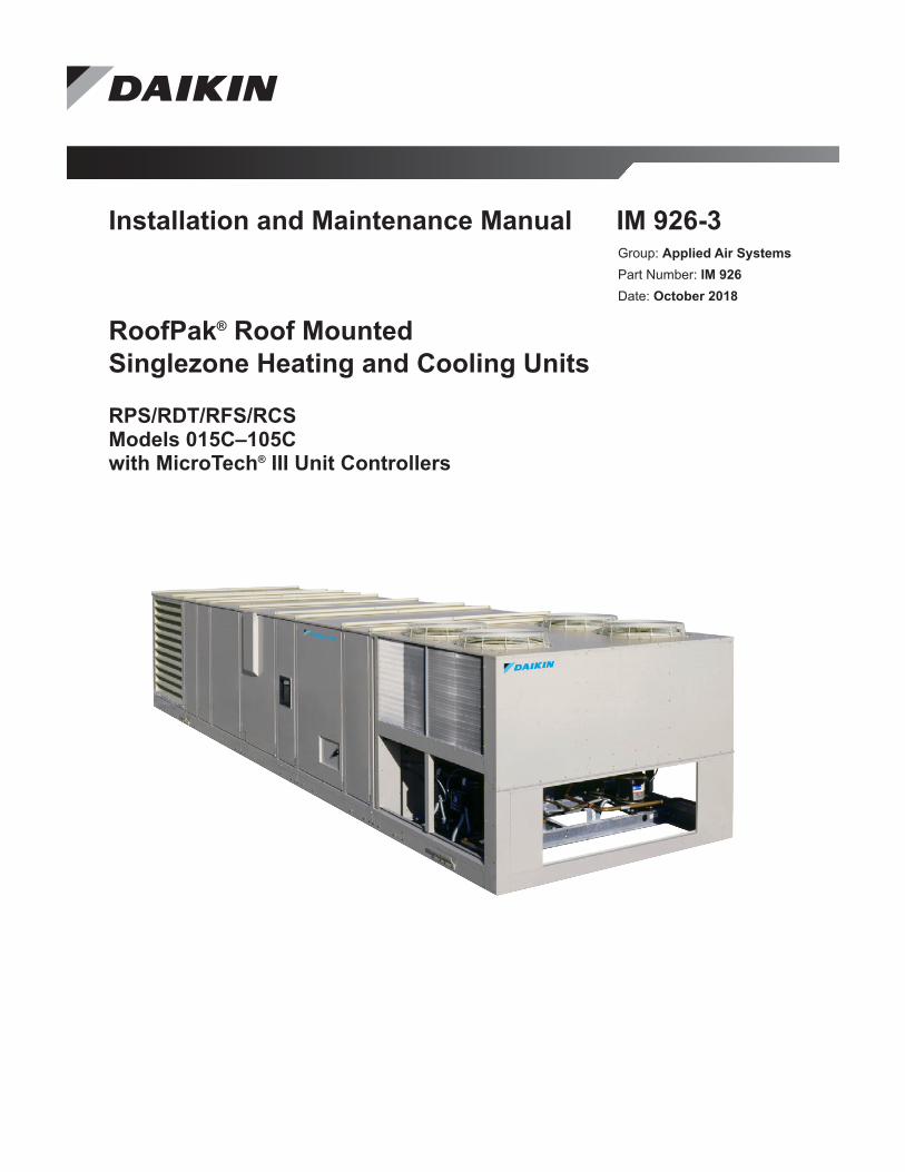
Installation and Maintenance Manual IM 926-3Group: Applied Air SystemsPart Number: IM 926Date: October 2018
RoofPak® Roof Mounted Singlezone Heating and Cooling Units
RPS/RDT/RFS/RCS Models 015C–105C with MicroTech® III Unit Controllers
IM 926-3 • ROOFPAK APPLIED SYSTEMS 2 www.DaikinApplied.com
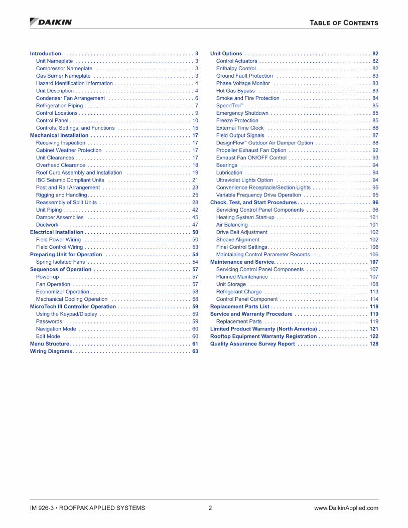
Table of Contents
Table of Contents
Introduction . . . . . . . . . . . . . . . . . . . . . . . . . . . . . . . . . . . . . . . . . . . . . 3Unit Nameplate . . . . . . . . . . . . . . . . . . . . . . . . . . . . . . . . . . . . . . . . 3Compressor Nameplate . . . . . . . . . . . . . . . . . . . . . . . . . . . . . . . . . 3Gas Burner Nameplate . . . . . . . . . . . . . . . . . . . . . . . . . . . . . . . . . . 3Hazard Identification Information . . . . . . . . . . . . . . . . . . . . . . . . . . . 4Unit Description . . . . . . . . . . . . . . . . . . . . . . . . . . . . . . . . . . . . . . . . 4Condenser Fan Arrangement . . . . . . . . . . . . . . . . . . . . . . . . . . . . . 6Refrigeration Piping . . . . . . . . . . . . . . . . . . . . . . . . . . . . . . . . . . . . . 7Control Locations . . . . . . . . . . . . . . . . . . . . . . . . . . . . . . . . . . . . . . . 9Control Panel . . . . . . . . . . . . . . . . . . . . . . . . . . . . . . . . . . . . . . . . . 10Controls, Settings, and Functions . . . . . . . . . . . . . . . . . . . . . . . . . 15
Mechanical Installation . . . . . . . . . . . . . . . . . . . . . . . . . . . . . . . . . . 17Receiving Inspection . . . . . . . . . . . . . . . . . . . . . . . . . . . . . . . . . . . 17Cabinet Weather Protection . . . . . . . . . . . . . . . . . . . . . . . . . . . . . 17Unit Clearances . . . . . . . . . . . . . . . . . . . . . . . . . . . . . . . . . . . . . . . 17Overhead Clearance . . . . . . . . . . . . . . . . . . . . . . . . . . . . . . . . . . . 18Roof Curb Assembly and Installation . . . . . . . . . . . . . . . . . . . . . . 19IBC Seismic Compliant Units . . . . . . . . . . . . . . . . . . . . . . . . . . . . 21Post and Rail Arrangement . . . . . . . . . . . . . . . . . . . . . . . . . . . . . . 23Rigging and Handling . . . . . . . . . . . . . . . . . . . . . . . . . . . . . . . . . . . 25Reassembly of Split Units . . . . . . . . . . . . . . . . . . . . . . . . . . . . . . . 28Unit Piping . . . . . . . . . . . . . . . . . . . . . . . . . . . . . . . . . . . . . . . . . . . 42Damper Assemblies . . . . . . . . . . . . . . . . . . . . . . . . . . . . . . . . . . . 45Ductwork . . . . . . . . . . . . . . . . . . . . . . . . . . . . . . . . . . . . . . . . . . . . 47
Electrical Installation . . . . . . . . . . . . . . . . . . . . . . . . . . . . . . . . . . . . 50Field Power Wiring . . . . . . . . . . . . . . . . . . . . . . . . . . . . . . . . . . . . 50Field Control Wiring . . . . . . . . . . . . . . . . . . . . . . . . . . . . . . . . . . . . 53
Preparing Unit for Operation . . . . . . . . . . . . . . . . . . . . . . . . . . . . . 54Spring Isolated Fans . . . . . . . . . . . . . . . . . . . . . . . . . . . . . . . . . . . 54
Sequences of Operation . . . . . . . . . . . . . . . . . . . . . . . . . . . . . . . . . 57Power-up . . . . . . . . . . . . . . . . . . . . . . . . . . . . . . . . . . . . . . . . . . . . 57Fan Operation . . . . . . . . . . . . . . . . . . . . . . . . . . . . . . . . . . . . . . . . 57Economizer Operation . . . . . . . . . . . . . . . . . . . . . . . . . . . . . . . . . . 58Mechanical Cooling Operation . . . . . . . . . . . . . . . . . . . . . . . . . . . 58
MicroTech III Controller Operation . . . . . . . . . . . . . . . . . . . . . . . . . 59Using the Keypad/Display . . . . . . . . . . . . . . . . . . . . . . . . . . . . . . . 59Passwords . . . . . . . . . . . . . . . . . . . . . . . . . . . . . . . . . . . . . . . . . . . 59Navigation Mode . . . . . . . . . . . . . . . . . . . . . . . . . . . . . . . . . . . . . . 60Edit Mode . . . . . . . . . . . . . . . . . . . . . . . . . . . . . . . . . . . . . . . . . . . 60
Menu Structure . . . . . . . . . . . . . . . . . . . . . . . . . . . . . . . . . . . . . . . . . 61Wiring Diagrams . . . . . . . . . . . . . . . . . . . . . . . . . . . . . . . . . . . . . . . . 63
Unit Options . . . . . . . . . . . . . . . . . . . . . . . . . . . . . . . . . . . . . . . . . . . 82Control Actuators . . . . . . . . . . . . . . . . . . . . . . . . . . . . . . . . . . . . . . 82Enthalpy Control . . . . . . . . . . . . . . . . . . . . . . . . . . . . . . . . . . . . . . 82Ground Fault Protection . . . . . . . . . . . . . . . . . . . . . . . . . . . . . . . . 83Phase Voltage Monitor . . . . . . . . . . . . . . . . . . . . . . . . . . . . . . . . . 83Hot Gas Bypass . . . . . . . . . . . . . . . . . . . . . . . . . . . . . . . . . . . . . . 83Smoke and Fire Protection . . . . . . . . . . . . . . . . . . . . . . . . . . . . . . 84SpeedTrol™ . . . . . . . . . . . . . . . . . . . . . . . . . . . . . . . . . . . . . . . . . . 85Emergency Shutdown . . . . . . . . . . . . . . . . . . . . . . . . . . . . . . . . . . 85Freeze Protection . . . . . . . . . . . . . . . . . . . . . . . . . . . . . . . . . . . . . 85External Time Clock . . . . . . . . . . . . . . . . . . . . . . . . . . . . . . . . . . . 86Field Output Signals . . . . . . . . . . . . . . . . . . . . . . . . . . . . . . . . . . . 87DesignFlow™ Outdoor Air Damper Option . . . . . . . . . . . . . . . . . . . 88Propeller Exhaust Fan Option . . . . . . . . . . . . . . . . . . . . . . . . . . . . 92Exhaust Fan ON/OFF Control . . . . . . . . . . . . . . . . . . . . . . . . . . . . 93Bearings . . . . . . . . . . . . . . . . . . . . . . . . . . . . . . . . . . . . . . . . . . . . 94Lubrication . . . . . . . . . . . . . . . . . . . . . . . . . . . . . . . . . . . . . . . . . . . 94Ultraviolet Lights Option . . . . . . . . . . . . . . . . . . . . . . . . . . . . . . . . 94Convenience Receptacle/Section Lights . . . . . . . . . . . . . . . . . . . . 95Variable Frequency Drive Operation . . . . . . . . . . . . . . . . . . . . . . . 95
Check, Test, and Start Procedures . . . . . . . . . . . . . . . . . . . . . . . . . 96Servicing Control Panel Components . . . . . . . . . . . . . . . . . . . . . . 96Heating System Start-up . . . . . . . . . . . . . . . . . . . . . . . . . . . . . . . 101Air Balancing . . . . . . . . . . . . . . . . . . . . . . . . . . . . . . . . . . . . . . . . 101Drive Belt Adjustment . . . . . . . . . . . . . . . . . . . . . . . . . . . . . . . . . 102Sheave Alignment . . . . . . . . . . . . . . . . . . . . . . . . . . . . . . . . . . . . 102Final Control Settings . . . . . . . . . . . . . . . . . . . . . . . . . . . . . . . . . . 106Maintaining Control Parameter Records . . . . . . . . . . . . . . . . . . . 106
Maintenance and Service . . . . . . . . . . . . . . . . . . . . . . . . . . . . . . . . 107Servicing Control Panel Components . . . . . . . . . . . . . . . . . . . . . 107Planned Maintenance . . . . . . . . . . . . . . . . . . . . . . . . . . . . . . . . . 107Unit Storage . . . . . . . . . . . . . . . . . . . . . . . . . . . . . . . . . . . . . . . . 108Refrigerant Charge . . . . . . . . . . . . . . . . . . . . . . . . . . . . . . . . . . . 113Control Panel Component . . . . . . . . . . . . . . . . . . . . . . . . . . . . . . 114
Replacement Parts List . . . . . . . . . . . . . . . . . . . . . . . . . . . . . . . . . 118Service and Warranty Procedure . . . . . . . . . . . . . . . . . . . . . . . . . 119
Replacement Parts . . . . . . . . . . . . . . . . . . . . . . . . . . . . . . . . . . . 119Limited Product Warranty (North America) . . . . . . . . . . . . . . . . . 121Rooftop Equipment Warranty Registration . . . . . . . . . . . . . . . . . 122Quality Assurance Survey Report . . . . . . . . . . . . . . . . . . . . . . . . 128
Introduction
www.DaikinApplied.com 3 IM 926-3 • ROOFPAK APPLIED SYSTEMS
Introduction
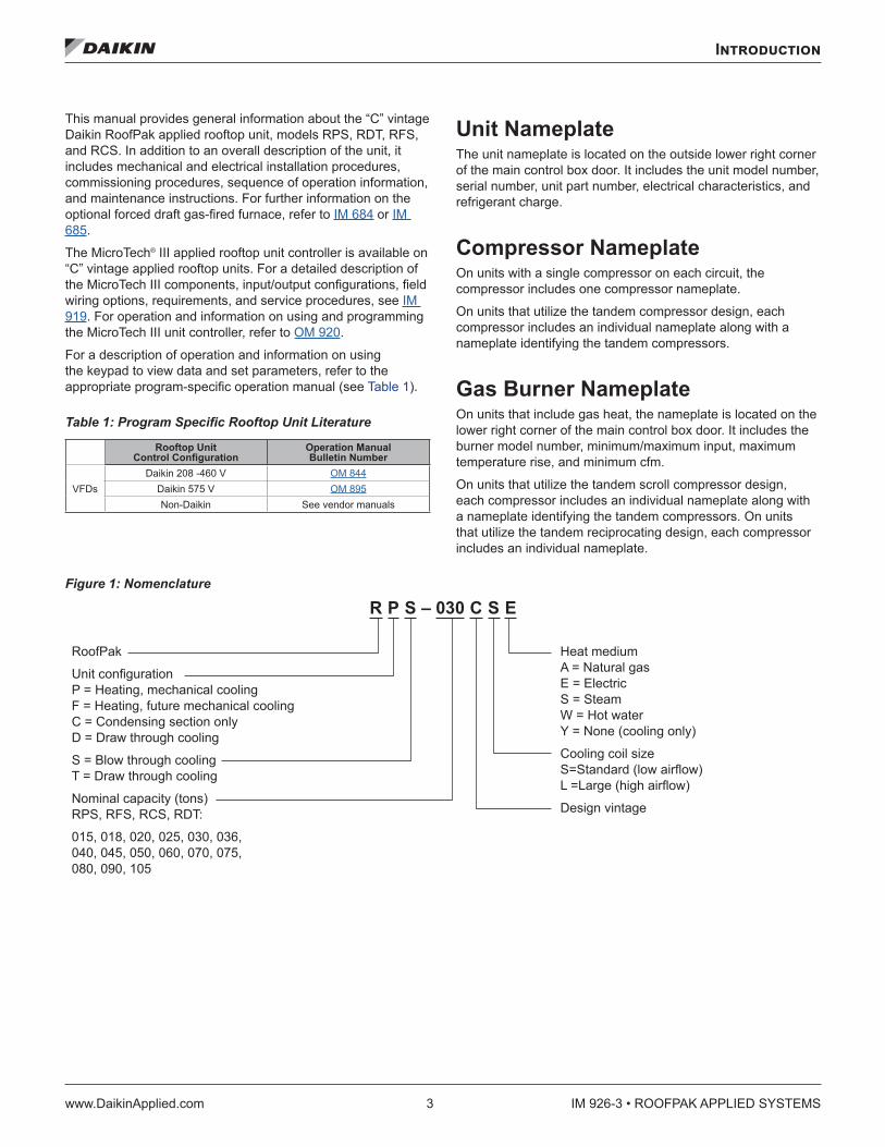
This manual provides general information about the “C” vintage Daikin RoofPak applied rooftop unit, models RPS, RDT, RFS, and RCS. In addition to an overall description of the unit, it includes mechanical and electrical installation procedures, commissioning procedures, sequence of operation information, and maintenance instructions. For further information on the optional forced draft gas-fired furnace, refer to IM 684 or IM 685.
The MicroTech® III applied rooftop unit controller is available on “C” vintage applied rooftop units. For a detailed description of the MicroTech III components, input/output configurations, field wiring options, requirements, and service procedures, see IM 919. For operation and information on using and programming the MicroTech III unit controller, refer to OM 920.
For a description of operation and information on using the keypad to view data and set parameters, refer to the appropriate program-specific operation manual (see Table 1).
Table 1: Program Specific Rooftop Unit Literature
Rooftop Unit Control Configuration
Operation Manual Bulletin Number
VFDsDaikin 208 -460 V OM 844
Daikin 575 V OM 895Non-Daikin See vendor manuals
Unit Nameplate The unit nameplate is located on the outside lower right corner of the main control box door. It includes the unit model number, serial number, unit part number, electrical characteristics, and refrigerant charge.
Compressor Nameplate On units with a single compressor on each circuit, the compressor includes one compressor nameplate.
On units that utilize the tandem compressor design, each compressor includes an individual nameplate along with a nameplate identifying the tandem compressors.
Gas Burner Nameplate On units that include gas heat, the nameplate is located on the lower right corner of the main control box door. It includes the burner model number, minimum/maximum input, maximum temperature rise, and minimum cfm.
On units that utilize the tandem scroll compressor design, each compressor includes an individual nameplate along with a nameplate identifying the tandem compressors. On units that utilize the tandem reciprocating design, each compressor includes an individual nameplate.
Figure 1: Nomenclature
R P S – 030 C S E
RoofPak
Unit configuration P = Heating, mechanical cooling F = Heating, future mechanical cooling C = Condensing section only D = Draw through cooling
S = Blow through cooling T = Draw through cooling
Nominal capacity (tons) RPS, RFS, RCS, RDT:
015, 018, 020, 025, 030, 036, 040, 045, 050, 060, 070, 075, 080, 090, 105
Heat medium A = Natural gas E = Electric S = Steam W = Hot water Y = None (cooling only)
Cooling coil size S=Standard (low airflow) L =Large (high airflow)
Design vintage
IM 926-3 • ROOFPAK APPLIED SYSTEMS 4 www.DaikinApplied.com
Introduction
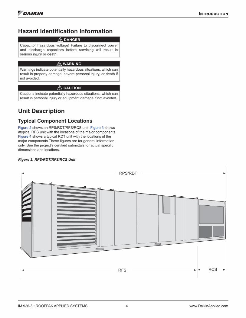
Hazard Identification Information DANGER
Capacitor hazardous voltage! Failure to disconnect power and discharge capacitors before servicing will result in serious injury or death.
WARNINGWarnings indicate potentially hazardous situations, which can result in property damage, severe personal injury, or death if not avoided.
CAUTIONCautions indicate potentially hazardous situations, which can result in personal injury or equipment damage if not avoided.
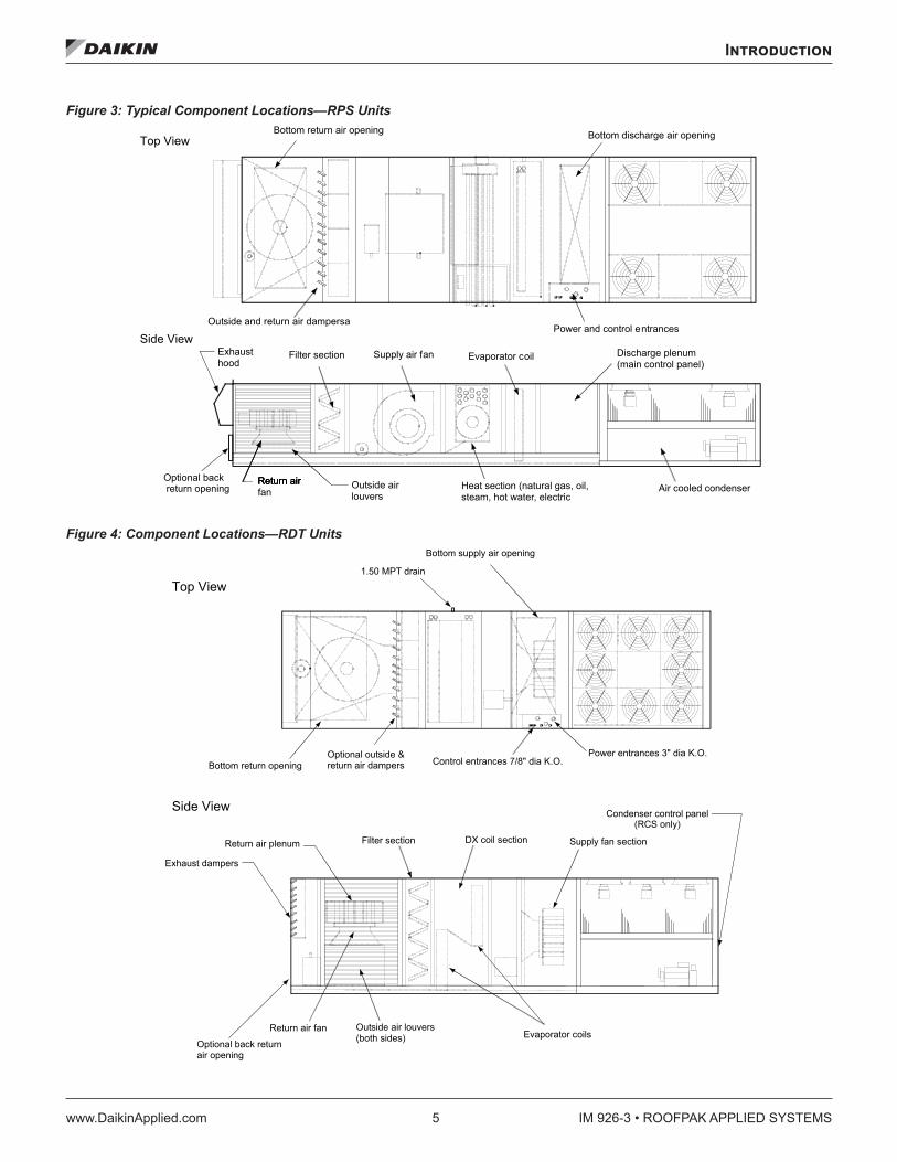
Unit Description Typical Component LocationsFigure 2 shows an RPS/RDT/RFS/RCS unit. Figure 3 shows atypical RPS unit with the locations of the major components.Figure 4 shows a typical RDT unit with the locations of the major components.These figures are for general information only. See the project’s certified submittals for actual specific dimensions and locations.
Figure 2: RPS/RDT/RFS/RCS Unit
� � � � � � �
� � � � � �
Introduction
www.DaikinApplied.com 5 IM 926-3 • ROOFPAK APPLIED SYSTEMS
Figure 3: Typical Component Locations—RPS Units
Figure 4: Component Locations—RDT Units
Evaporator coil
Power and control entrances
Discharge plenum(main control panel)
Air cooled condenserHeat section (natural gas, oil,steam, hot water, electric
Supply air fanFilter sectionExhausthood
Return airfan
Outside airlouvers
Bottom return air opening Bottom discharge air opening
Outside and return air dampersa
Return airReturn airOptional back return opening
Side View
Top View
Evaporator coilsOptional back returnair opening
Filter section
Optional outside &return air dampers
Power entrances 3" dia K.O.Control entrances 7/8" dia K.O.Bottom return opening
1.50 MPT drain
Bottom supply air opening
Outside air louvers(both sides)
Return air fan
Exhaust dampers
Return air plenum DX coil section Supply fan section
Side View
Top View

IM 926-3 • ROOFPAK APPLIED SYSTEMS 6 www.DaikinApplied.com
Introduction
Condenser Fan Arrangement Table 2 shows the condenser fan numbering conventions and locations for each unit size.
Table 2: Condenser Fan Arrangement
Unit size Refrigerant circuit Arrangement Unit size Refrigerant circuit Arrangement
015C 018C 020C
1 or 2
� � � � � � �
� � � � � � � � � � � � � � �
� �
� �
060C 070C
1� � � �
� � � �
� � � �
� � � � � � � � � � � � �
2
025C 030C 1 or 2
� �
� �
� �
� � � � � � � � � � � � � � �
075C 080C 090C
1
� � � � � � � � � � � � � �
� �
� �
� �
� �
� �
� �
� � � �
2
036C 040C
1
� � � � � � � � � � � � � �
� �
� �
� �
� �
105C
1
2 2
045C 050C
1
� � � � � � � � � � � � �
� � � �
� � � �2
Introduction
www.DaikinApplied.com 7 IM 926-3 • ROOFPAK APPLIED SYSTEMS
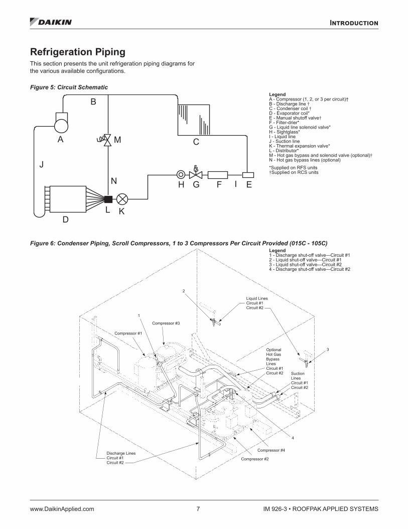
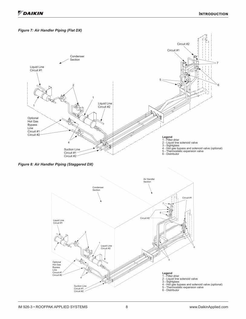
Refrigeration Piping This section presents the unit refrigeration piping diagrams for the various available configurations.
Figure 5: Circuit Schematic
Figure 6: Condenser Piping, Scroll Compressors, 1 to 3 Compressors Per Circuit Provided (015C - 105C)
B
A
J
DL K
N
M C
H G F I E
Legend A - Compressor (1, 2, or 3 per circuit)† B - Discharge line † C - Condenser coil † D - Evaporator coil* E - Manual shutoff valve† F - Filter-drier* G - Liquid line solenoid valve* H - Sightglass* I - Liquid line J - Suction line K - Thermal expansion valve* L - Distributor* M - Hot gas bypass and solenoid valve (optional)† N - Hot gas bypass lines (optional) *Supplied on RFS units †Supplied on RCS units
� � � � � � � � � � � � �
� � � � � � � � � � � � �
� � � � � � � � � � � � �
� � � � � � � � � � � � �
�
�
�
�
� � � � � � � � � � � � � �� � � � � � � �� � � � � � � �
� � � � � � � � � � �� � � � � � � �� � � � � � � �
� � � � � � �� � � � � �� � � � � �� � � � �� � � � � � � �� � � � � � � � � � � � �
� � � � �� � � � � � � �� � � � � � � �
Legend 1 - Discharge shut-off valve—Circuit #1 2 - Liquid shut-off valve—Circuit #1 3 - Liquid shut-off valve—Circuit #2 4 - Discharge shut-off valve—Circuit #2
IM 926-3 • ROOFPAK APPLIED SYSTEMS 8 www.DaikinApplied.com
Introduction
Figure 7: Air Handler Piping (Flat DX)
Figure 8: Air Handler Piping (Staggered DX)
� � � � � � � � � � �� � � � � � � � � �
�
�� � � � � � � � � � �� � � � � � � � � �
�
� � � � � � � � � � � �� � � � � � � � � �� � � � � � � � � �
� � � � � � � � � � � � �� � � � �� � � �� � � � � � � � � �� � � � � � � � � �
�
�
�
�
� � � � � � � � � �
� � � � � � � � � �
� � � � � � � � �� � � � � � �
Legend 1 - Filter-drier 2 - Liquid line solenoid valve 3 - Sightglass 4 - Hot gas bypass and solenoid valve (optional) 5 - Thermostatic expansion valve 6 - Distributor
� � � � � � � � � � �� � � � � � � � � �
�
�� � � � � � � � � � �� � � � � � � � � �
�
� � � � � � � � � � � �� � � � � � � � � �� � � � � � � � � �
� � � � � � � � � � � � �� � � � �� � � �� � � � � � � � � �� � � � � � � � � �
�
� � � � � � � � �� � � � � � �
� � � � � � � � � �
�
�
�
�
� � � � � � � � � �
� � � � � � � � � �� � � � � � �
Legend 1 - Filter-drier 2 - Liquid line solenoid valve 3 - Sightglass 4 - Hot gas bypass and solenoid valve (optional) 5 - Thermostatic expansion valve 6 - Distributor
Introduction
www.DaikinApplied.com 9 IM 926-3 • ROOFPAK APPLIED SYSTEMS
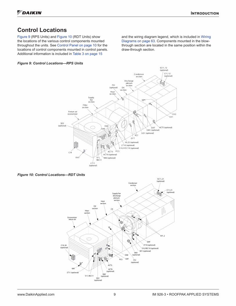
Control LocationsFigure 9 (RPS Units) and Figure 10 (RDT Units) show the locations of the various control components mounted throughout the units. See Control Panel on page 10 for the locations of control components mounted in control panels. Additional information is included in Table 3 on page 15
and the wiring diagram legend, which is included in Wiring Diagrams on page 63. Components mounted in the blow-through section are located in the same position within the draw-through section.
Figure 9: Control Locations—RPS Units
Figure 10: Control Locations—RDT Units
R eturn aireconomizer
F ilterse ction
Supplyfan
Heat
DX se ction
Dischargeplenumse ction
C ondensorse ction
R AT
LT 11(optional)
S11,REC11
OAE
AC T 3 P C 5
S 10, R E C 10LT 10
HL22
E F T
S D1
VM1DAT ACT5 (optional)
S V 1 S V 2
(optional)(optional)
(optional)
(optional)
(optional)
se ction
se ction
FS1(optional)
C19
OAT
AC T 6 (optional)
RAE (optional)
SD2(optional)
PC7
C11, 12 (optional)
SC11, 12(optional)
Economizer
Filter
Heatsection
Supply fandischargeplenumsection
Condenser
C19, 20
RAT
LT11 (optional)
S11, REC11SD2
RAE
ACT3
PC5
OAEVM1
LT10 (optional)
DAT
OAT
SV1, 2
SC11, 21(optional)
C11, 21(optional)
(optional)
DXsection
section
section
return air
(optional)
(optional)
(optional)
(optional)
C9
FS1(optional)
S10, REC10 (optional)
SD1 (optional)
ACT6
IM 926-3 • ROOFPAK APPLIED SYSTEMS 10 www.DaikinApplied.com
Introduction
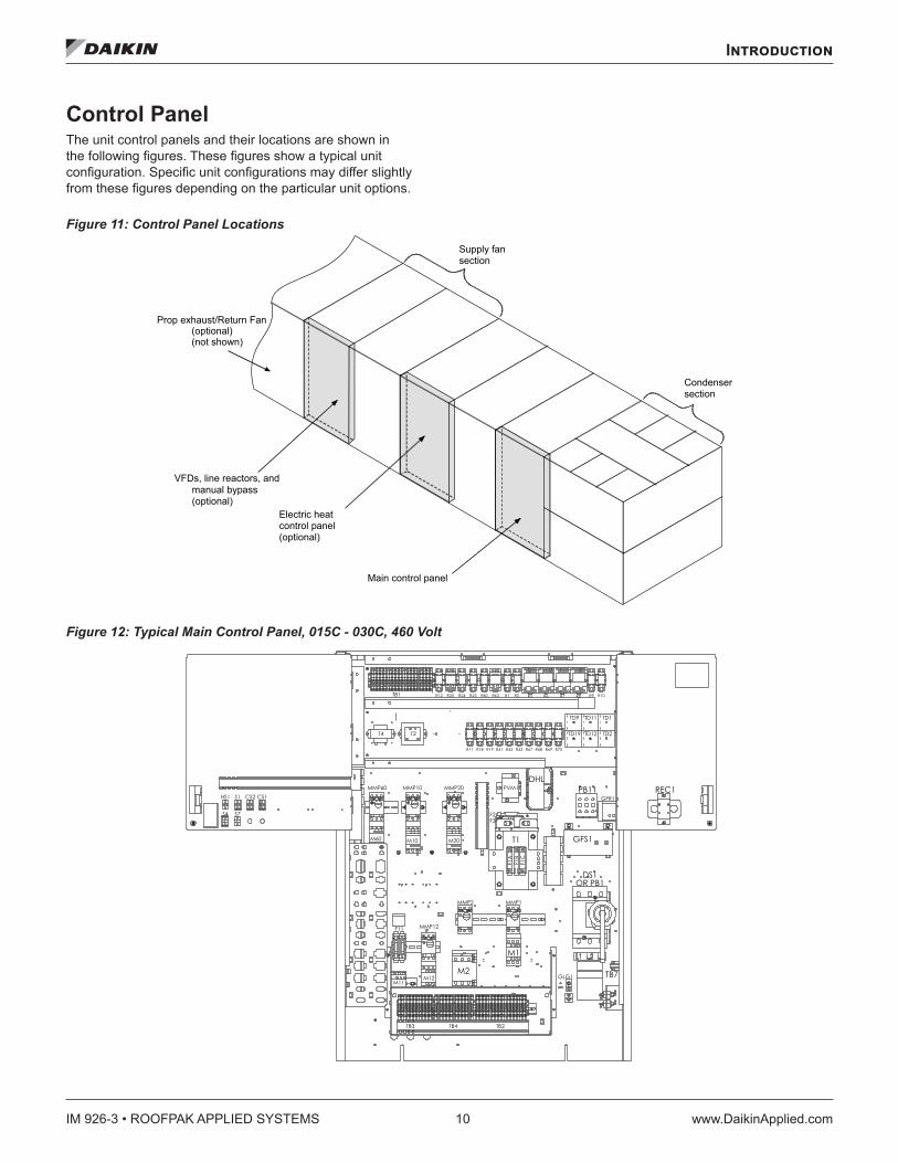
Control Panel The unit control panels and their locations are shown in the following figures. These figures show a typical unit configuration. Specific unit configurations may differ slightly from these figures depending on the particular unit options.
Figure 11: Control Panel Locations
Figure 12: Typical Main Control Panel, 015C - 030C, 460 Volt
Main control panel
Electric heat control panel(optional)
Supply fansection
Condensersection
VFDs, line reactors, andmanual bypass(optional)
Prop exhaust/Return Fan
not shown)(optional)(
Introduction
www.DaikinApplied.com 11 IM 926-3 • ROOFPAK APPLIED SYSTEMS
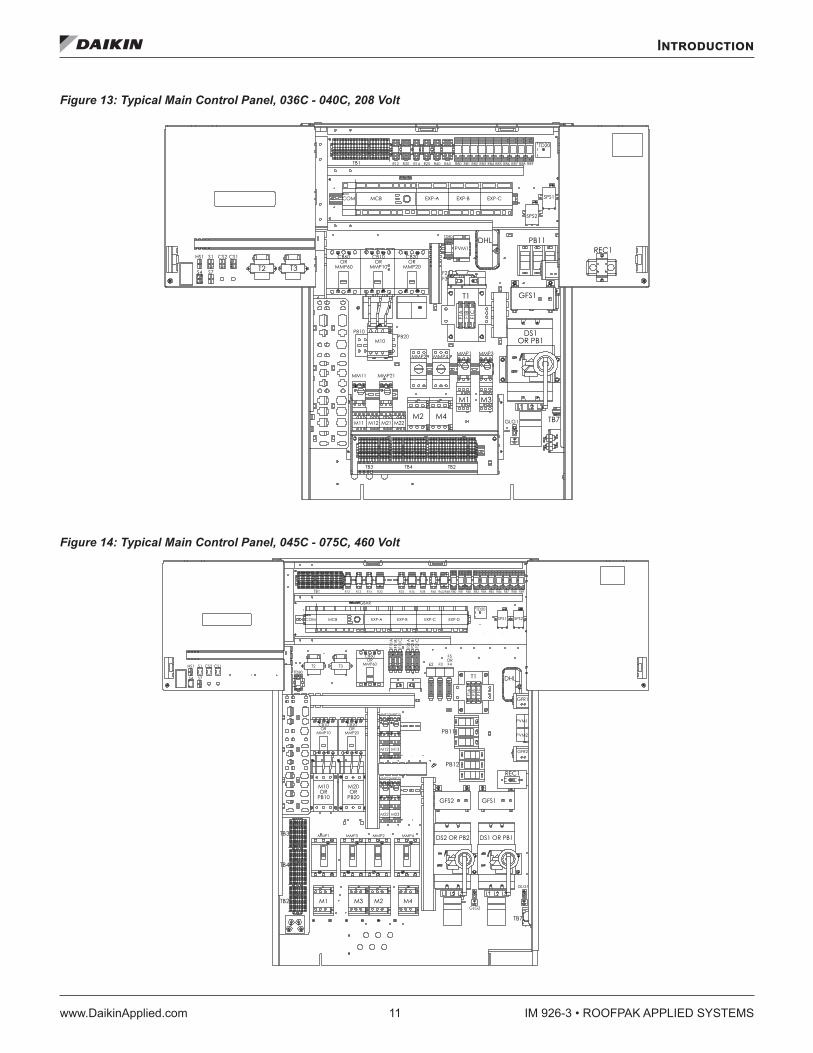
Figure 13: Typical Main Control Panel, 036C - 040C, 208 Volt
Figure 14: Typical Main Control Panel, 045C - 075C, 460 Volt
IM 926-3 • ROOFPAK APPLIED SYSTEMS 12 www.DaikinApplied.com
Introduction
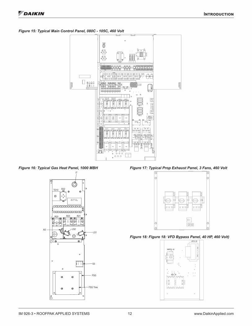
Figure 15: Typical Main Control Panel, 080C - 105C, 460 Volt
Figure 16: Typical Gas Heat Panel, 1000 MBH Figure 17: Typical Prop Exhaust Panel, 3 Fans, 460 Volt
Figure 18: Figure 18: VFD Bypass Panel, 40 HP, 460 Volt)
S3
FSG
FSG Time
LS1LS2AS
IT
TD10 R22
R20 R23 R21
LR10, 20
M30, 40
MMP30, 40
Introduction
www.DaikinApplied.com 13 IM 926-3 • ROOFPAK APPLIED SYSTEMS
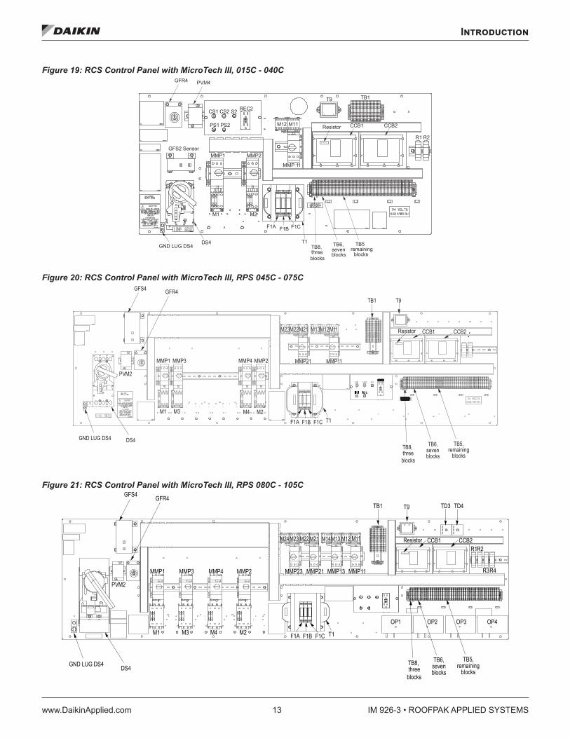
Figure 19: RCS Control Panel with MicroTech III, 015C - 040C
Figure 20: RCS Control Panel with MicroTech III, RPS 045C - 075C
Figure 21: RCS Control Panel with MicroTech III, RPS 080C - 105C
DS4GND LUG DS4
M1 M2
MMP1 MMP2GFS2 Sensor
F1A F1B F1C
PVM4GFR4
M12 M11
MMP 11
T9 TB1
Resistor CCB1 CCB2
R1 R2
T1 TB5remaining
blocks
TB6,sevenblocks
TB8,threeblocks
CS1 CS2 S2 REC2
PS1 PS2
IM 926-3 • ROOFPAK APPLIED SYSTEMS 14 www.DaikinApplied.com
Introduction
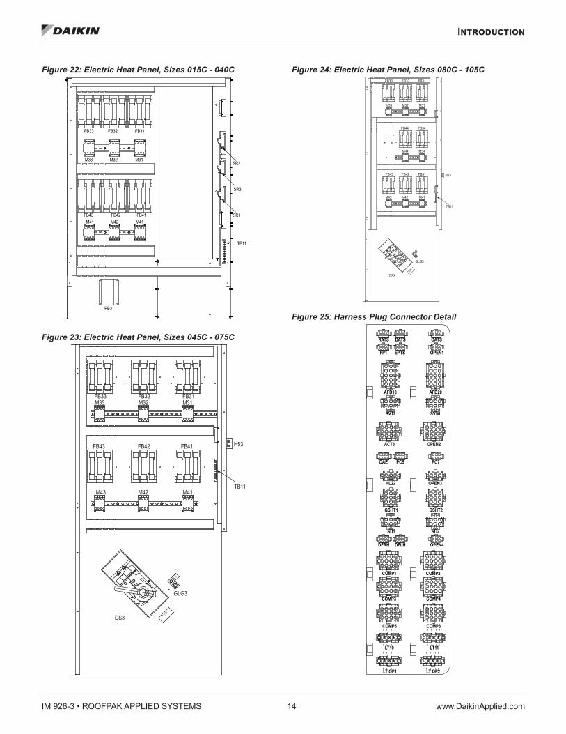
Figure 22: Electric Heat Panel, Sizes 015C - 040C
Figure 23: Electric Heat Panel, Sizes 045C - 075C
Figure 24: Electric Heat Panel, Sizes 080C - 105C
Figure 25: Harness Plug Connector Detail
M41 M42 M41
M33 M32 M31
FB33 FB32 FB31
FB43 FB42 FB41
PB3
SR2
SR3
SR1
TB11
GLG3
DS3
M41M43
FB41FB42FB43 H53
TB11
M31M32M33FB31FB32FB33
M42
GLG3
DS3
M41M42M43
FB41FB42FB43 H53
TB11
M34M44
M31M32M33
FB31FB32FB33
FB34FB44
LT OP1 LT OP2
LT11LT10
COMP6COMP5
COMP3 COMP4
COMP1 COMP2
DFRH DFLH OPEN4
SD1 SD2
GSHT1 GSHT2
HL22 OPEN3
OAE PC7PC5
ACT3 OPEN2
SV12 SV56
AFD10 AFD20
FP1 OPEN1EPTS
RATS OATSDATS
Introduction
www.DaikinApplied.com 15 IM 926-3 • ROOFPAK APPLIED SYSTEMS
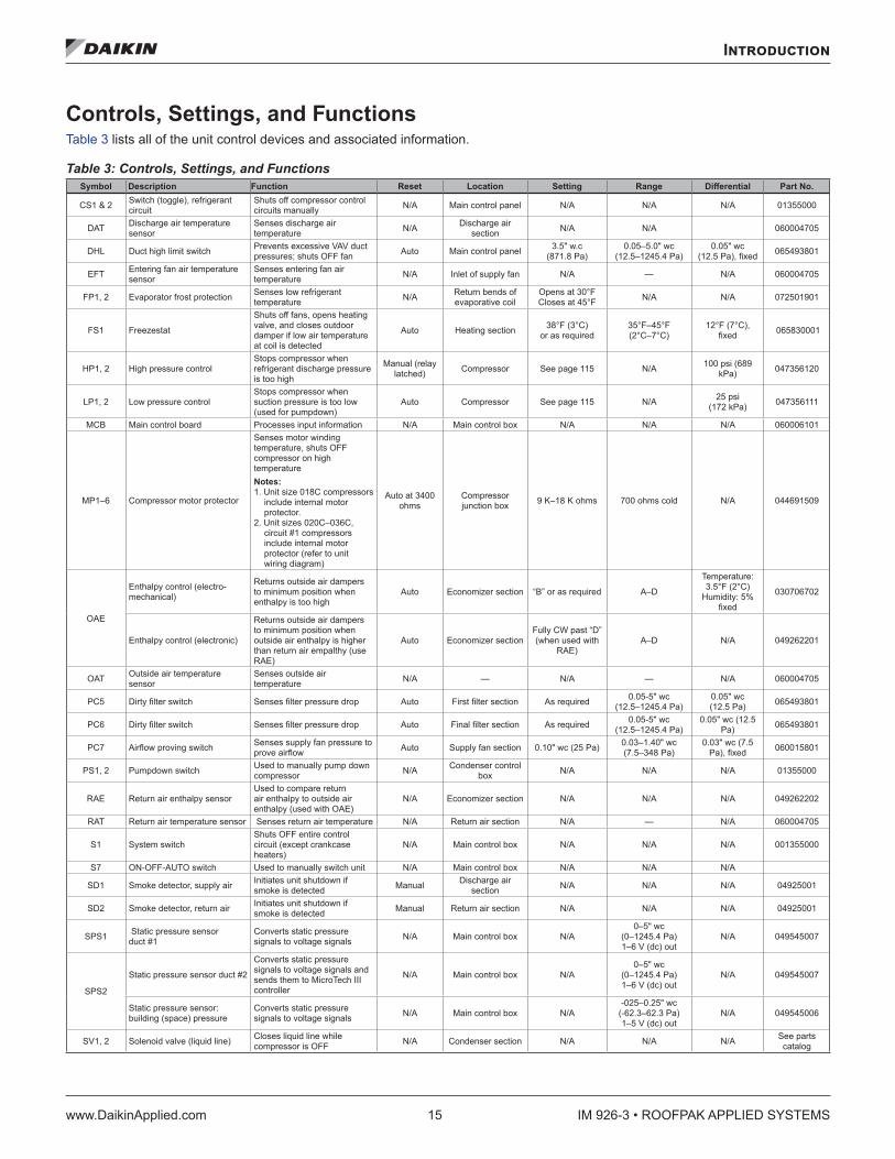
Controls, Settings, and Functions Table 3 lists all of the unit control devices and associated information.
Table 3: Controls, Settings, and Functions Symbol Description Function Reset Location Setting Range Differential Part No .
CS1 & 2 Switch (toggle), refrigerant circuit
Shuts off compressor control circuits manually N/A Main control panel N/A N/A N/A 01355000
DAT Discharge air temperature sensor
Senses discharge air temperature N/A Discharge air
section N/A N/A 060004705
DHL Duct high limit switch Prevents excessive VAV duct pressures; shuts OFF fan Auto Main control panel 3.5" w.c
(871.8 Pa)0.05–5.0" wc
(12.5–1245.4 Pa)0.05" wc
(12.5 Pa), fixed 065493801
EFT Entering fan air temperature sensor
Senses entering fan air temperature N/A Inlet of supply fan N/A — N/A 060004705
FP1, 2 Evaporator frost protection Senses low refrigerant temperature N/A Return bends of
evaporative coilOpens at 30°F Closes at 45°F N/A N/A 072501901
FS1 Freezestat
Shuts off fans, opens heating valve, and closes outdoor damper if low air temperature at coil is detected
Auto Heating section 38°F (3°C) or as required
35°F–45°F (2°C–7°C)
12°F (7°C), fixed 065830001
HP1, 2 High pressure controlStops compressor when refrigerant discharge pressure is too high
Manual (relay latched) Compressor See page 115 N/A 100 psi (689
kPa) 047356120
LP1, 2 Low pressure controlStops compressor when suction pressure is too low (used for pumpdown)
Auto Compressor See page 115 N/A 25 psi (172 kPa) 047356111
MCB Main control board Processes input information N/A Main control box N/A N/A N/A 060006101
MP1–6 Compressor motor protector
Senses motor winding temperature, shuts OFF compressor on high temperature Notes: 1. Unit size 018C compressors
include internal motor protector.
2. Unit sizes 020C–036C, circuit #1 compressors include internal motor protector (refer to unit wiring diagram)
Auto at 3400 ohms
Compressor junction box 9 K–18 K ohms 700 ohms cold N/A 044691509
OAE
Enthalpy control (electro-mechanical)
Returns outside air dampers to minimum position when enthalpy is too high
Auto Economizer section “B” or as required A–D
Temperature: 3.5°F (2°C)
Humidity: 5% fixed
030706702
Enthalpy control (electronic)
Returns outside air dampers to minimum position when outside air enthalpy is higher than return air empalthy (use RAE)
Auto Economizer sectionFully CW past “D” (when used with
RAE)A–D N/A 049262201
OAT Outside air temperature sensor
Senses outside air temperature N/A — N/A — N/A 060004705
PC5 Dirty filter switch Senses filter pressure drop Auto First filter section As required 0.05-5" wc (12.5–1245.4 Pa)
0.05" wc (12.5 Pa) 065493801
PC6 Dirty filter switch Senses filter pressure drop Auto Final filter section As required 0.05-5" wc (12.5–1245.4 Pa)
0.05" wc (12.5 Pa) 065493801
PC7 Airflow proving switch Senses supply fan pressure to prove airflow Auto Supply fan section 0.10" wc (25 Pa) 0.03–1.40" wc
(7.5–348 Pa)0.03" wc (7.5
Pa), fixed 060015801
PS1, 2 Pumpdown switch Used to manually pump down compressor N/A Condenser control
box N/A N/A N/A 01355000
RAE Return air enthalpy sensorUsed to compare return air enthalpy to outside air enthalpy (used with OAE)
N/A Economizer section N/A N/A N/A 049262202
RAT Return air temperature sensor Senses return air temperature N/A Return air section N/A — N/A 060004705
S1 System switchShuts OFF entire control circuit (except crankcase heaters)
N/A Main control box N/A N/A N/A 001355000
S7 ON-OFF-AUTO switch Used to manually switch unit N/A Main control box N/A N/A N/A
SD1 Smoke detector, supply air Initiates unit shutdown if smoke is detected Manual Discharge air
section N/A N/A N/A 04925001
SD2 Smoke detector, return air Initiates unit shutdown if smoke is detected Manual Return air section N/A N/A N/A 04925001
SPS1 Static pressure sensor duct #1
Converts static pressure signals to voltage signals N/A Main control box N/A
0–5" wc (0–1245.4 Pa) 1–6 V (dc) out
N/A 049545007
SPS2
Static pressure sensor duct #2
Converts static pressure signals to voltage signals and sends them to MicroTech III controller
N/A Main control box N/A0–5" wc
(0–1245.4 Pa) 1–6 V (dc) out
N/A 049545007
Static pressure sensor: building (space) pressure
Converts static pressure signals to voltage signals N/A Main control box N/A
-025–0.25" wc (-62.3–62.3 Pa) 1–5 V (dc) out
N/A 049545006
SV1, 2 Solenoid valve (liquid line) Closes liquid line while compressor is OFF N/A Condenser section N/A N/A N/A See parts
catalog
IM 926-3 • ROOFPAK APPLIED SYSTEMS 16 www.DaikinApplied.com
Introduction
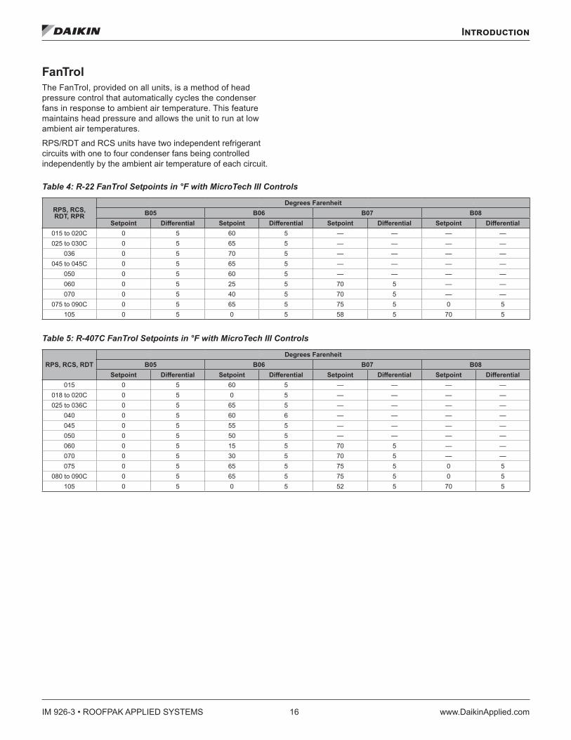
FanTrol The FanTrol, provided on all units, is a method of head pressure control that automatically cycles the condenser fans in response to ambient air temperature. This feature maintains head pressure and allows the unit to run at low ambient air temperatures.
RPS/RDT and RCS units have two independent refrigerant circuits with one to four condenser fans being controlled independently by the ambient air temperature of each circuit.
Table 4: R-22 FanTrol Setpoints in °F with MicroTech III Controls
RPS, RCS, RDT, RPR
Degrees FarenheitB05 B06 B07 B08
Setpoint Differential Setpoint Differential Setpoint Differential Setpoint Differential015 to 020C 0 5 60 5 — — — —025 to 030C 0 5 65 5 — — — —
036 0 5 70 5 — — — —045 to 045C 0 5 65 5 — — — —
050 0 5 60 5 — — — —060 0 5 25 5 70 5 — —070 0 5 40 5 70 5 — —
075 to 090C 0 5 65 5 75 5 0 5105 0 5 0 5 58 5 70 5
Table 5: R-407C FanTrol Setpoints in °F with MicroTech III Controls
RPS, RCS, RDTDegrees Farenheit
B05 B06 B07 B08Setpoint Differential Setpoint Differential Setpoint Differential Setpoint Differential
015 0 5 60 5 — — — —018 to 020C 0 5 0 5 — — — —025 to 036C 0 5 65 5 — — — —
040 0 5 60 6 — — — —045 0 5 55 5 — — — —050 0 5 50 5 — — — —060 0 5 15 5 70 5 — —070 0 5 30 5 70 5 — —075 0 5 65 5 75 5 0 5
080 to 090C 0 5 65 5 75 5 0 5105 0 5 0 5 52 5 70 5
Mechanical Installation
www.DaikinApplied.com 17 IM 926-3 • ROOFPAK APPLIED SYSTEMS
Mechanical Installation
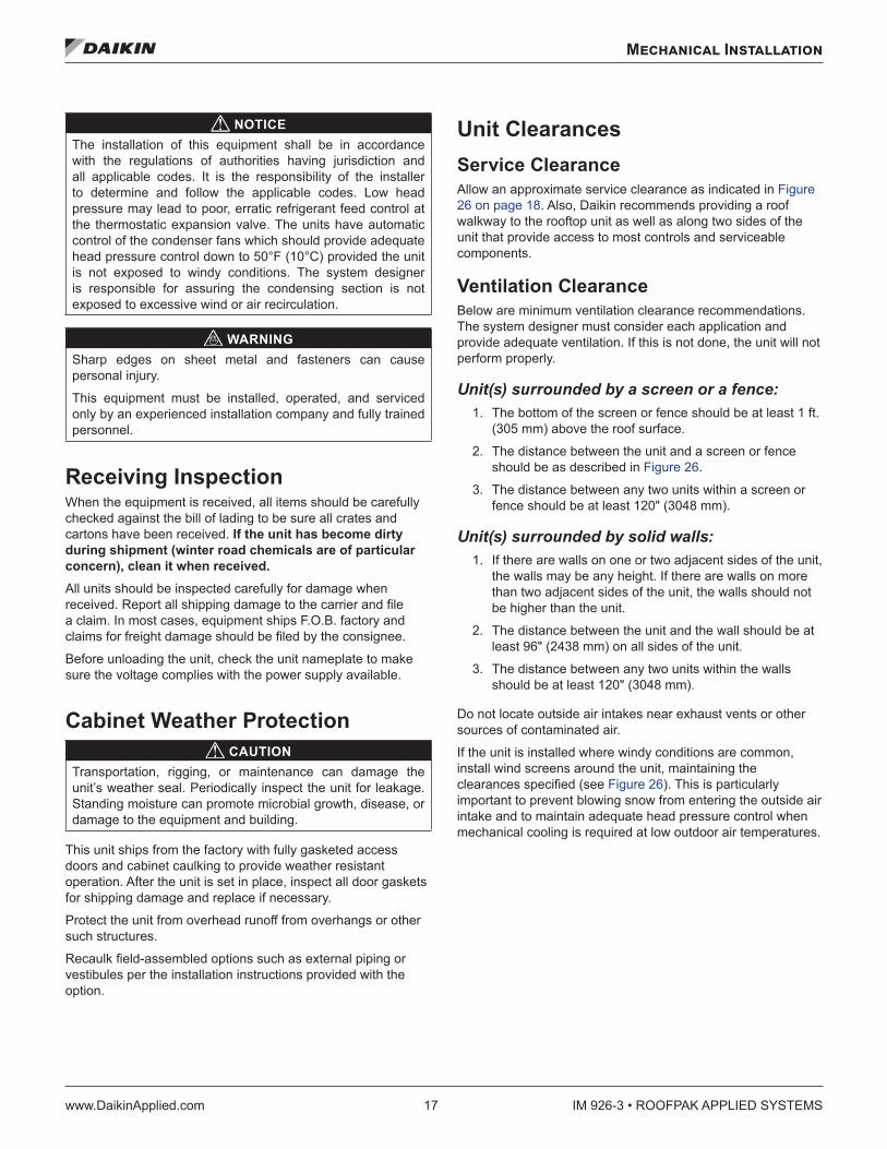
NOTICEThe installation of this equipment shall be in accordance with the regulations of authorities having jurisdiction and all applicable codes. It is the responsibility of the installer to determine and follow the applicable codes. Low head pressure may lead to poor, erratic refrigerant feed control at the thermostatic expansion valve. The units have automatic control of the condenser fans which should provide adequate head pressure control down to 50°F (10°C) provided the unit is not exposed to windy conditions. The system designer is responsible for assuring the condensing section is not exposed to excessive wind or air recirculation.
WARNINGSharp edges on sheet metal and fasteners can cause personal injury.
This equipment must be installed, operated, and serviced only by an experienced installation company and fully trained personnel.
Receiving Inspection When the equipment is received, all items should be carefully checked against the bill of lading to be sure all crates and cartons have been received. If the unit has become dirty during shipment (winter road chemicals are of particular concern), clean it when received .All units should be inspected carefully for damage when received. Report all shipping damage to the carrier and file a claim. In most cases, equipment ships F.O.B. factory and claims for freight damage should be filed by the consignee.
Before unloading the unit, check the unit nameplate to make sure the voltage complies with the power supply available.
Cabinet Weather Protection CAUTION
Transportation, rigging, or maintenance can damage the unit’s weather seal. Periodically inspect the unit for leakage. Standing moisture can promote microbial growth, disease, or damage to the equipment and building.
This unit ships from the factory with fully gasketed access doors and cabinet caulking to provide weather resistant operation. After the unit is set in place, inspect all door gaskets for shipping damage and replace if necessary.
Protect the unit from overhead runoff from overhangs or other such structures.
Recaulk field-assembled options such as external piping or vestibules per the installation instructions provided with the option.
Unit Clearances Service ClearanceAllow an approximate service clearance as indicated in Figure 26 on page 18. Also, Daikin recommends providing a roof walkway to the rooftop unit as well as along two sides of the unit that provide access to most controls and serviceable components.
Ventilation Clearance Below are minimum ventilation clearance recommendations. The system designer must consider each application and provide adequate ventilation. If this is not done, the unit will not perform properly.
Unit(s) surrounded by a screen or a fence: 1. The bottom of the screen or fence should be at least 1 ft.
(305 mm) above the roof surface.
2. The distance between the unit and a screen or fence should be as described in Figure 26.
3. The distance between any two units within a screen or fence should be at least 120" (3048 mm).
Unit(s) surrounded by solid walls: 1. If there are walls on one or two adjacent sides of the unit,
the walls may be any height. If there are walls on more than two adjacent sides of the unit, the walls should not be higher than the unit.
2. The distance between the unit and the wall should be at least 96" (2438 mm) on all sides of the unit.
3. The distance between any two units within the walls should be at least 120" (3048 mm).
Do not locate outside air intakes near exhaust vents or other sources of contaminated air.
If the unit is installed where windy conditions are common, install wind screens around the unit, maintaining the clearances specified (see Figure 26). This is particularly important to prevent blowing snow from entering the outside air intake and to maintain adequate head pressure control when mechanical cooling is required at low outdoor air temperatures.
IM 926-3 • ROOFPAK APPLIED SYSTEMS 18 www.DaikinApplied.com
Mechanical Installation
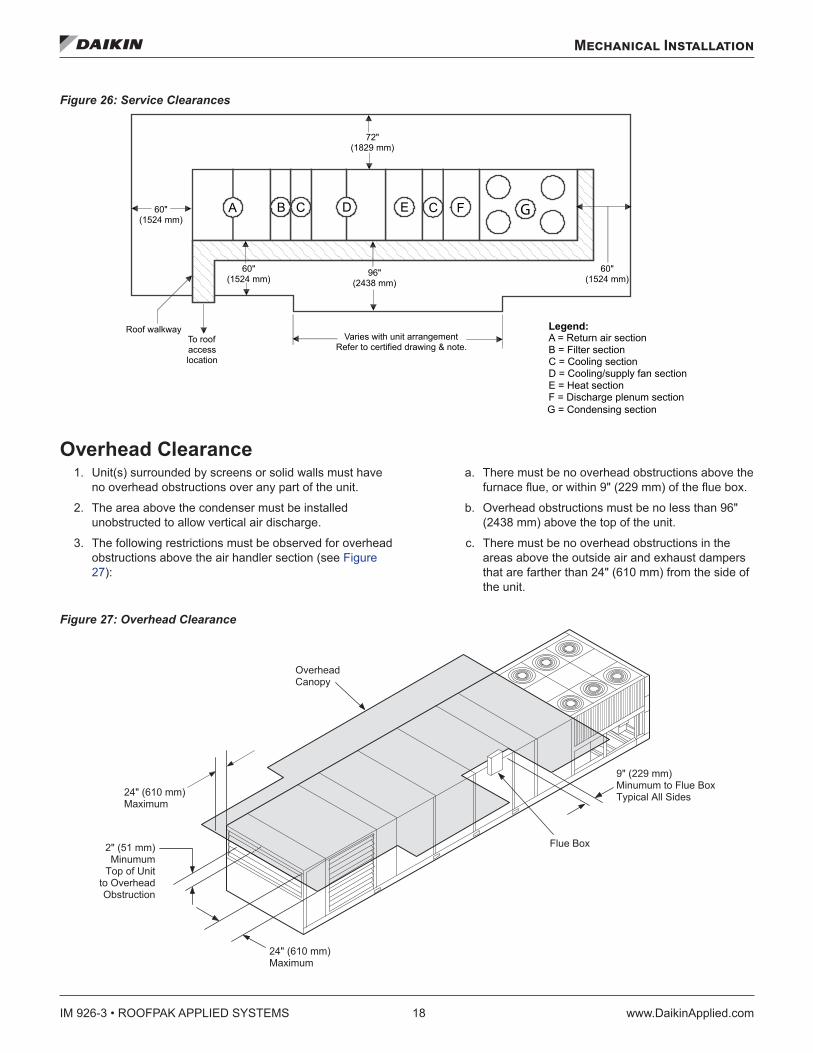
Figure 26: Service Clearances
Overhead Clearance1. Unit(s) surrounded by screens or solid walls must have
no overhead obstructions over any part of the unit.
2. The area above the condenser must be installed unobstructed to allow vertical air discharge.
3. The following restrictions must be observed for overhead obstructions above the air handler section (see Figure 27):
a. There must be no overhead obstructions above the furnace flue, or within 9" (229 mm) of the flue box.
b. Overhead obstructions must be no less than 96" (2438 mm) above the top of the unit.
c. There must be no overhead obstructions in the areas above the outside air and exhaust dampers that are farther than 24" (610 mm) from the side of the unit.
Figure 27: Overhead Clearance
Roof walkwayTo roofaccesslocation
Varies with unit arrangementRefer to certified drawing & note.
60"(1524 mm)
96"(2438 mm)
60"(1524 mm)
60"(1524 mm)
72"(1829 mm)
A B C D E C F
Legend:A = Return air sectionB = Filter sectionC = Cooling sectionD = Cooling/supply fan sectionE = Heat sectionF = Discharge plenum section
G
G = Condensing section
� � � � � � � � � � � �� � � � � � �
� � � � � � � � � �� � � � � � �� � � � � � �
� � � � � � � � �� � � � � � � �
� � � � � � � � � � � �� � � � � � �
� � � � � � � �� � � � �
� � � � � � � � � � �� � � � � � � � � � � � � � �� � � � � � � � � � � � � � � �
� � � � � �
Mechanical Installation
www.DaikinApplied.com 19 IM 926-3 • ROOFPAK APPLIED SYSTEMS
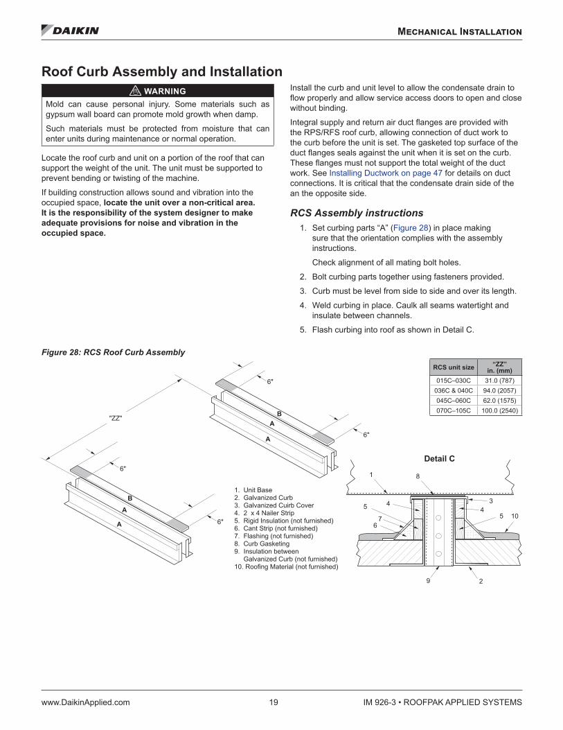
Roof Curb Assembly and Installation WARNING
Mold can cause personal injury. Some materials such as gypsum wall board can promote mold growth when damp.
Such materials must be protected from moisture that can enter units during maintenance or normal operation.
Locate the roof curb and unit on a portion of the roof that can support the weight of the unit. The unit must be supported to prevent bending or twisting of the machine.
If building construction allows sound and vibration into the occupied space, locate the unit over a non-critical area . It is the responsibility of the system designer to make adequate provisions for noise and vibration in the occupied space .
Install the curb and unit level to allow the condensate drain to flow properly and allow service access doors to open and close without binding.
Integral supply and return air duct flanges are provided with the RPS/RFS roof curb, allowing connection of duct work to the curb before the unit is set. The gasketed top surface of the duct flanges seals against the unit when it is set on the curb. These flanges must not support the total weight of the duct work. See Installing Ductwork on page 47 for details on duct connections. It is critical that the condensate drain side of the an the opposite side.
RCS Assembly instructions 1. Set curbing parts “A” (Figure 28) in place making
sure that the orientation complies with the assembly instructions.
Check alignment of all mating bolt holes.
2. Bolt curbing parts together using fasteners provided.
3. Curb must be level from side to side and over its length.
4. Weld curbing in place. Caulk all seams watertight and insulate between channels.
5. Flash curbing into roof as shown in Detail C.
Figure 28: RCS Roof Curb Assembly
�
�
�
�
��
�
�
� � � � � � � � � � � � �� � � � � � � � � � � � � � � �� � � � � � � � � � � � � � � � � � � � � � � � � � � � � � � � � � � � � � � � � � �� � � � � � � � � � � � � � � � � � � � � � � � � � � � � � � � � � � � � � � � � � � � � � � � � � � � � � � � � � �� � � � � � � � � � � � � � � � � � � � � � � � �� � � � � � � � � � � � � � � �� � � � � � � � � � � � � � � � � � � � � �� � � � � � � � � � � � � � � � � � � � � � � � � � � � � � �� � � � � � � � � � � � � � � � � � � � � � � � � � � � � � � � �
�
�
�
� �
�
� � � � � � � � �
�
� �
� � � �
�
��
�
RCS unit size “ZZ” in . (mm)
015C–030C 31.0 (787)036C & 040C 94.0 (2057)045C–060C 62.0 (1575)070C–105C 100.0 (2540)
IM 926-3 • ROOFPAK APPLIED SYSTEMS 20 www.DaikinApplied.com
Mechanical Installation
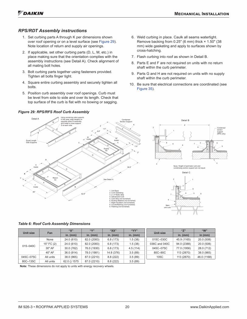
RPS/RDT Assembly instructions 1. Set curbing parts A through K per dimensions shown
over roof opening or on a level surface (see Figure 29). Note location of return and supply air openings.
2. If applicable, set other curbing parts (D, L, M, etc.) in place making sure that the orientation complies with the assembly instructions (see Detail A). Check alignment of all mating bolt holes.
3. Bolt curbing parts together using fasteners provided. Tighten all bolts finger tight.
4. Square entire curbing assembly and securely tighten all bolts.
5. Position curb assembly over roof openings. Curb must be level from side to side and over its length. Check that top surface of the curb is flat with no bowing or sagging.
6. Weld curbing in place. Caulk all seams watertight. Remove backing from 0.25" (6 mm) thick × 1.50" (38 mm) wide gasketing and apply to surfaces shown by cross-hatching.
7. Flash curbing into roof as shown in Detail B.
8. Parts E and F are not required on units with no return shaft within the curb perimeter.
9. Parts G and H are not required on units with no supply shaft within the curb perimeter.
10. Be sure that electrical connections are coordinated (see Figure 35).
Figure 29: RPS/RFS Roof Curb Assembly
Table 6: Roof Curb Assembly Dimensions
Unit size Fan“X” “Y” “XX” “YY”
Unit size“Z” “W”
in . (mm) in . (mm) in . (mm) in . (mm) in . (mm) in (mm)
015–040C
None 24.0 (610) 82.0 (2083) 6.8 (173) 1.5 (38) 015C–030C 45.9 (1165) 20.0 (508)15" FC (2) 24.0 (610) 82.0 (2083) 6.8 (173) 1.5 (38) 036C and 040C 94.0 (2388) 20.0 (508)
30" AF 30.0 (762) 76.0 (1930) 6.8 (173) 4.5 (114) 045C–075C 77.0 (1956) 28.0 (712)40" AF 36.0 (914) 78.0 (1981) 14.8 (376) 3.5 (89) 80C–90C 113 (2870) 38.0 (965)
045C–075C All units 38.0 (965) 87.0 (2210) 8.8 (222) 3.5 (89) 105C 113 (2870) 46.0 (1168)80C–135C All units 62.0 () 1575 87.0 (2210) 8.8 (222) 3.5 (89)
Note: These dimensions do not apply to units with energy recovery wheels.
Equal LengthSide Supports
L
Using remaining side supportsin this area, align lengths onopposite sides of assemblyand install a cross support
X
D at each side.
D
M
L
M
D
ReturnAir
F
B
F
E
Inside
Inside
85"62.8"
A
BE
X
D
See Detail A
38.8"
C
G
GC
H
HA
K
76"Inside
6.8"1.5"
7.5"
2"
Condenser Section Support
SupplyAir
Detail B
1
2
8 96
4
7
9
3 9
5
4
Condensersectionsupport(RPS only)
Note: Height of perimeter curb andcondensing section support are not equal.
Main
59
4
3
7
2 1
8
6
1. Unit Base2. Curb Gasketing3. 2 x 4 Nailer Strip4. Galvanized Curb5. Cant Strip (not furnished)6. Roofing Material (not furnished)7. Rigid Insulation (not furnished)8. Counterflashing (not furnished)9. Flashing (not furnished)
Winside
Y
unit curb
Detail C
Y
X
Z Z
Mechanical Installation
www.DaikinApplied.com 21 IM 926-3 • ROOFPAK APPLIED SYSTEMS
IBC Seismic Compliant Units CAUTION
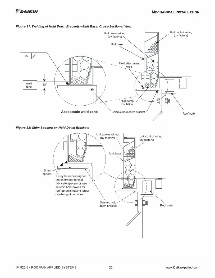
When welding unit to the curb, do not damage wiring (control panel side). Weld ONLY in the specified zone in the acceptable weld zone (see Figure 31 on page 22). Welding must comply with weld fillet size, etc. as indicated in Figure 31.
It is important to follow these installation instructions for all IBC Seismic compliant Daikin Rooftop units.
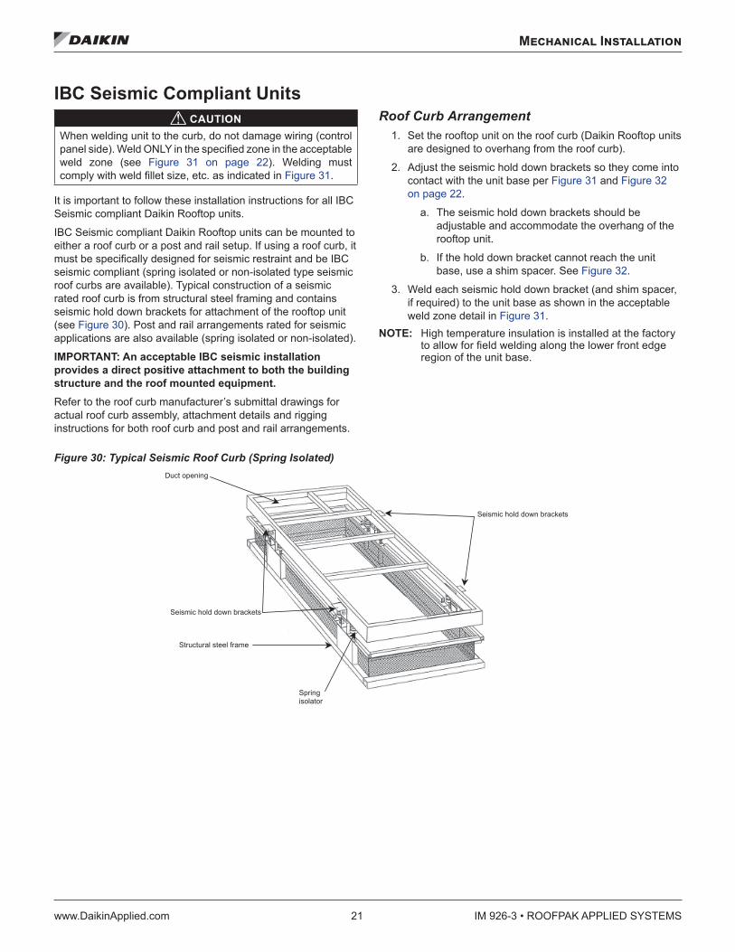
IBC Seismic compliant Daikin Rooftop units can be mounted to either a roof curb or a post and rail setup. If using a roof curb, it must be specifically designed for seismic restraint and be IBC seismic compliant (spring isolated or non-isolated type seismic roof curbs are available). Typical construction of a seismic rated roof curb is from structural steel framing and contains seismic hold down brackets for attachment of the rooftop unit (see Figure 30). Post and rail arrangements rated for seismic applications are also available (spring isolated or non-isolated).
IMPORTANT: An acceptable IBC seismic installation provides a direct positive attachment to both the building structure and the roof mounted equipment .Refer to the roof curb manufacturer’s submittal drawings for actual roof curb assembly, attachment details and rigging instructions for both roof curb and post and rail arrangements.
Roof Curb Arrangement 1. Set the rooftop unit on the roof curb (Daikin Rooftop units
are designed to overhang from the roof curb).
2. Adjust the seismic hold down brackets so they come into contact with the unit base per Figure 31 and Figure 32 on page 22.
a. The seismic hold down brackets should be adjustable and accommodate the overhang of the rooftop unit.
b. If the hold down bracket cannot reach the unit base, use a shim spacer. See Figure 32.
3. Weld each seismic hold down bracket (and shim spacer, if required) to the unit base as shown in the acceptable weld zone detail in Figure 31.
NOTE: High temperature insulation is installed at the factory to allow for field welding along the lower front edge region of the unit base.
Figure 30: Typical Seismic Roof Curb (Spring Isolated)
Seismic hold down brackets
Seismic hold down brackets
Structural steel frame
Springisolator
Duct opening
IM 926-3 • ROOFPAK APPLIED SYSTEMS 22 www.DaikinApplied.com
Mechanical Installation
Figure 31: Welding of Hold Down Brackets—Unit Base, Cross-Sectional View
Figure 32: Shim Spacers on Hold Down Brackets
Unit base
Seismic hold down bracket
Unit power wiring (by factory)
Unit control wiring (by factory)
High tempInsulation
Roof curbAcceptable weld zone
Field attachmentweld
Weldzone
.25
.50"
Unit base
Seismic holddown bracket
Unit power wiring(by factory) Unit control wiring
(by factory)
Roof curb
Shim spacer
It may be necessary for the contractor to field fabricate spacers or new seismic hold-downs for rooftop units having larger overhang dimensions.
Mechanical Installation
www.DaikinApplied.com 23 IM 926-3 • ROOFPAK APPLIED SYSTEMS
Post and Rail Arrangement CAUTION
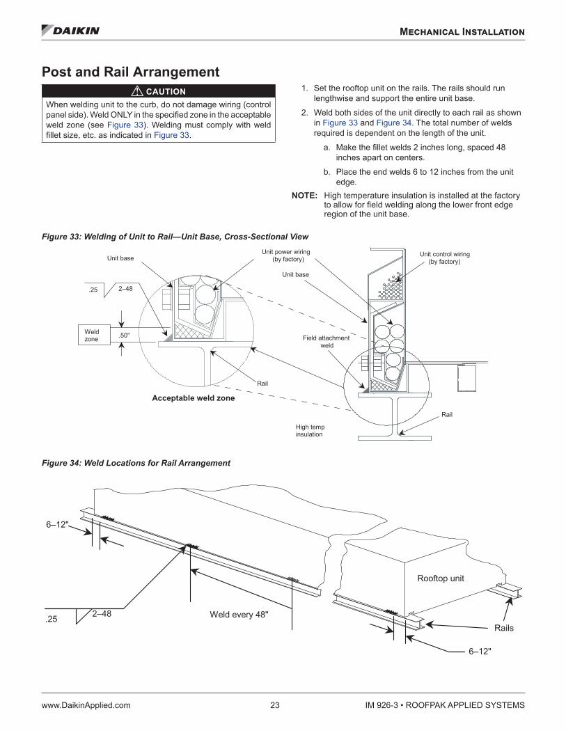
When welding unit to the curb, do not damage wiring (control panel side). Weld ONLY in the specified zone in the acceptable weld zone (see Figure 33). Welding must comply with weld fillet size, etc. as indicated in Figure 33.
1. Set the rooftop unit on the rails. The rails should run lengthwise and support the entire unit base.
2. Weld both sides of the unit directly to each rail as shown in Figure 33 and Figure 34. The total number of welds required is dependent on the length of the unit.
a. Make the fillet welds 2 inches long, spaced 48 inches apart on centers.
b. Place the end welds 6 to 12 inches from the unit edge.
NOTE: High temperature insulation is installed at the factory to allow for field welding along the lower front edge region of the unit base.
Figure 33: Welding of Unit to Rail—Unit Base, Cross-Sectional View
Figure 34: Weld Locations for Rail Arrangement
2–48
Rail
.25
Unit power wiring (by factory)
Unit control wiring (by factory)
High tempinsulation
Rail
Acceptable weld zone
Field attachment weld
Weldzone .50"
Unit base
Unit base
6–12"
2–48
Rooftop unit
.25 Weld every 48"
6–12"
Rails
IM 926-3 • ROOFPAK APPLIED SYSTEMS 24 www.DaikinApplied.com
Mechanical Installation
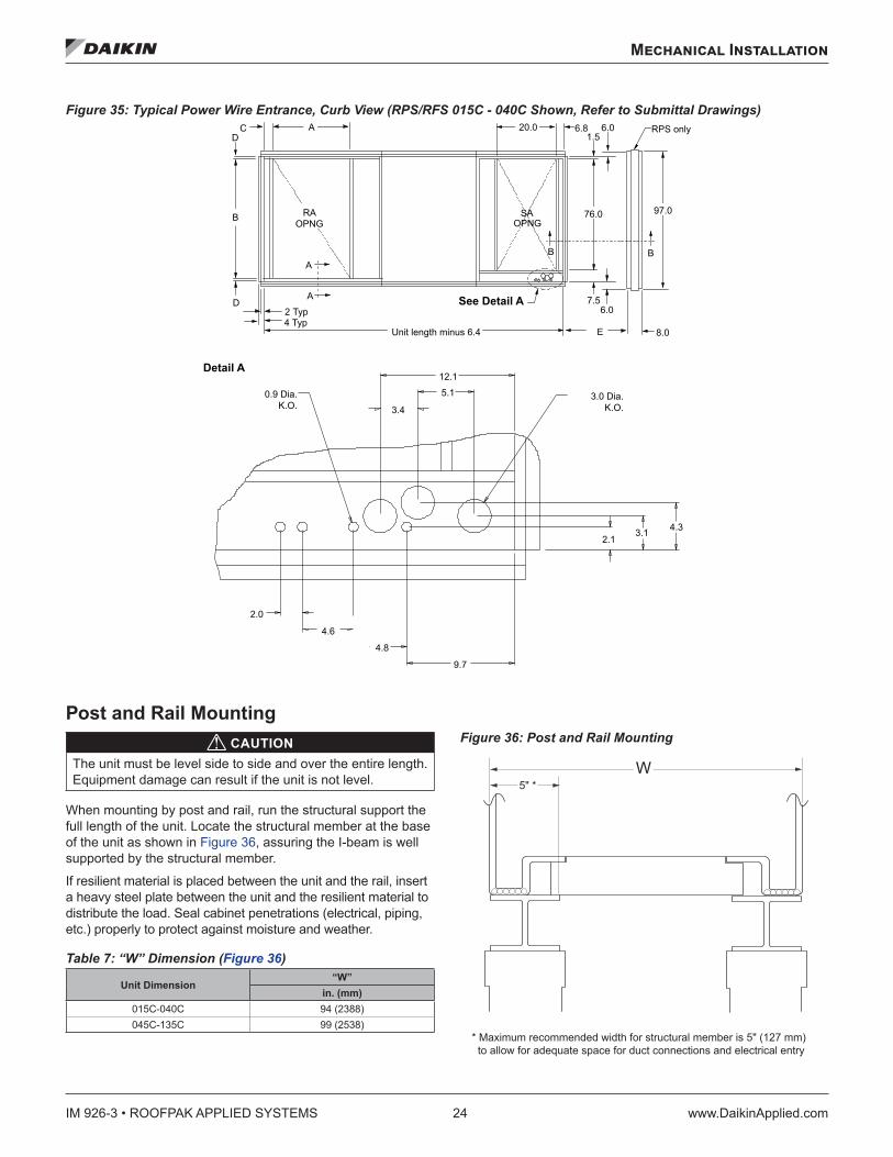
Figure 35: Typical Power Wire Entrance, Curb View (RPS/RFS 015C - 040C Shown, Refer to Submittal Drawings)
Post and Rail Mounting CAUTION
The unit must be level side to side and over the entire length. Equipment damage can result if the unit is not level.
When mounting by post and rail, run the structural support the full length of the unit. Locate the structural member at the base of the unit as shown in Figure 36, assuring the I-beam is well supported by the structural member.
If resilient material is placed between the unit and the rail, insert a heavy steel plate between the unit and the resilient material to distribute the load. Seal cabinet penetrations (electrical, piping, etc.) properly to protect against moisture and weather.
Table 7: “W” Dimension (Figure 36)
Unit Dimension“W”
in . (mm)015C-040C 94 (2388)045C-135C 99 (2538)
Figure 36: Post and Rail Mounting
Unit length minus 6.4
12.1
See Detail A
Detail A
3.4
5.10.9 Dia.K.O.
3.0 Dia.K.O.
4.6
4.8
2.0
2.14.33.1
9.7
E 8.0
97.076.0
6.07.5
20.01.5
6.06.8
OPNGB
2 Typ
A
AD
CD
4 Typ
A
B B
OPNG
RPS only
RA SA
W
* Maximum recommended width for structural member is 5" (127 mm) to allow for adequate space for duct connections and electrical entry
Mechanical Installation
www.DaikinApplied.com 25 IM 926-3 • ROOFPAK APPLIED SYSTEMS
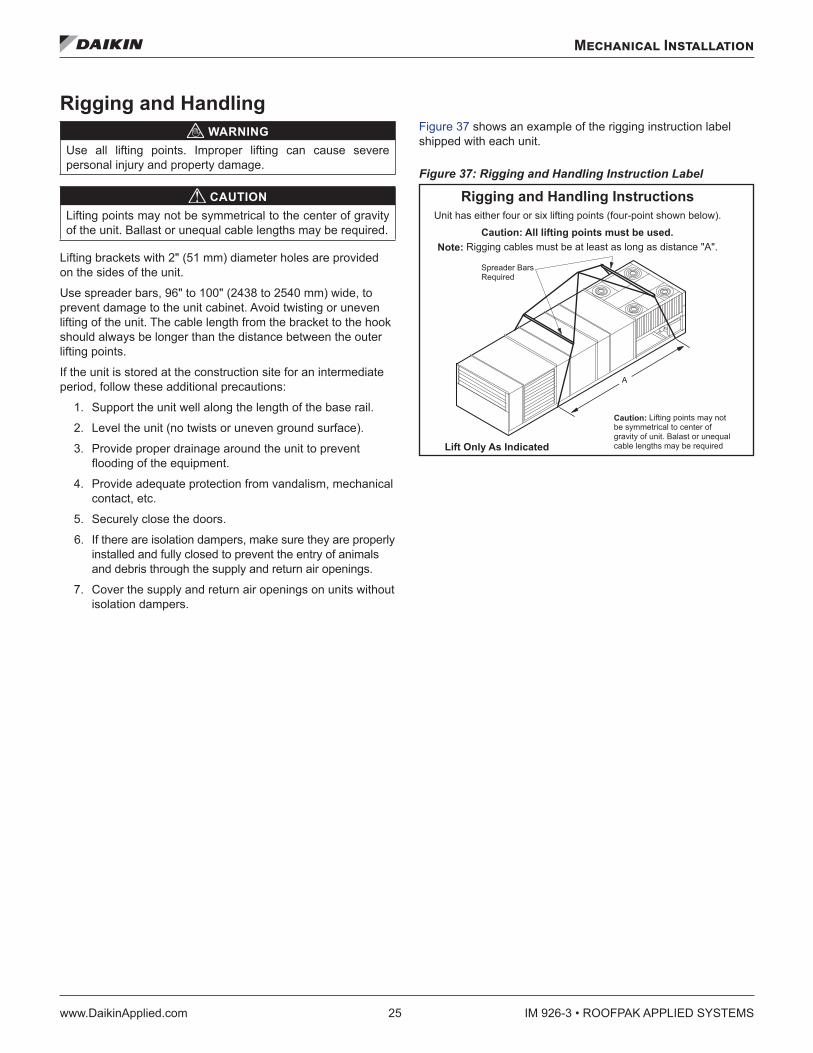
Rigging and Handling WARNING
Use all lifting points. Improper lifting can cause severe personal injury and property damage.
CAUTIONLifting points may not be symmetrical to the center of gravity of the unit. Ballast or unequal cable lengths may be required.
Lifting brackets with 2" (51 mm) diameter holes are provided on the sides of the unit.
Use spreader bars, 96" to 100" (2438 to 2540 mm) wide, to prevent damage to the unit cabinet. Avoid twisting or uneven lifting of the unit. The cable length from the bracket to the hook should always be longer than the distance between the outer lifting points.
If the unit is stored at the construction site for an intermediate period, follow these additional precautions:
1. Support the unit well along the length of the base rail.
2. Level the unit (no twists or uneven ground surface).
3. Provide proper drainage around the unit to prevent flooding of the equipment.
4. Provide adequate protection from vandalism, mechanical contact, etc.
5. Securely close the doors.
6. If there are isolation dampers, make sure they are properly installed and fully closed to prevent the entry of animals and debris through the supply and return air openings.
7. Cover the supply and return air openings on units without isolation dampers.
Figure 37 shows an example of the rigging instruction label shipped with each unit.
Figure 37: Rigging and Handling Instruction Label
A
Spreader BarsRequired
Caution: Lifting points may notbe symmetrical to center ofgravity of unit. Balast or unequal cable lengths may be required
Unit has either four or six lifting points (four-point shown below).
Caution: All lifting points must be used.Note: Rigging cables must be at least as long as distance "A".
Rigging and Handling Instructions
Lift Only As Indicated
IM 926-3 • ROOFPAK APPLIED SYSTEMS 26 www.DaikinApplied.com
Mechanical Installation
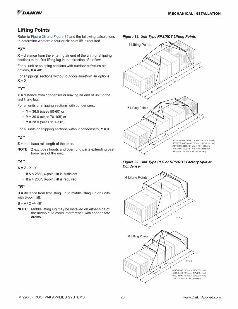
Lifting Points Refer to Figure 38 and Figure 39 and the following calculations to determine wheterh a four or six point lift is required.
“X”X = distance from the entering air end of the unit (or shipping section) to the first lifting lug in the direction of air flow.
For all unit or shipping sections with outdoor air/return air options, X = 48"
For shippings sections without outdoor air/return air options, X = 0
“Y”Y = distance from condenser or leaving air end of unit to the last lifting lug.
For all units or shipping sections with condensers,
• Y = 36.5 (sizes 50-60) or • Y = 30.0 (sizes 70-105) or • Y = 38.0 (sizes 110–115).
For all units or shipping sections without condensers, Y = 0.
“Z”Z = total base rail length of the units. NOTE: Z excludes hoods and overhung parts extending past
base rails of the unit.
“A”A = Z - X - Y
• If A < 288", 4-point lift is sufficient • If a > 288", 6-point lift is required
“B”B = distance from first lifting lug to middle lifting lug on units with 6-point lift.
B = A / 2 +/- 48" NOTE: Middle lifting lug may be installed on either side of
the midpoint to avoid interference with condensate drains.
Figure 38: Unit Type RPS/RDT Lifting Points
Figure 39: Unit Type RFS or RPS/RDT Factory Split at Condenser
RDT/RPS 015C–030C: “B” min. = 62" (1575 mm) RDT/RPS 036C–040C: “B” min. = 84" (2134 mm) RDT 045C–135C: “B” min. = 72" (1829 mm) RPS 045C–090C: “B” min. = 96" (2348 mm) RPS 105C: “B” min. = 120" (3048 mm)
015C–030C: “B” min. = 62" (1575 mm) 036C–040C: “B” min. = 84" (2134 mm) 045C–090C: “B” min. = 96" (2348 mm) 105C: “B” min. = 120" (3048 mm)
Mechanical Installation
www.DaikinApplied.com 27 IM 926-3 • ROOFPAK APPLIED SYSTEMS
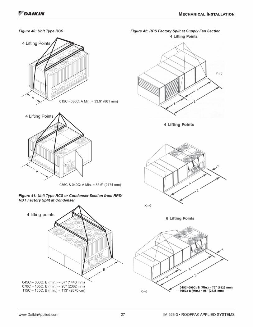
Figure 40: Unit Type RCS
Figure 41: Unit Type RCS or Condenser Section from RPS/RDT Factory Split at Condenser
Figure 42: RPS Factory Split at Supply Fan Section
4 lifting points
045C – 060C: B (min.) = 57" (1448 mm)070 C: B (min.) = 93" (2362 mm)
B
C – 105 115C – 135C: B (min.) = 113" (2870 cm)
IM 926-3 • ROOFPAK APPLIED SYSTEMS 28 www.DaikinApplied.com
Mechanical Installation
Reassembly of Split Units Although RoofPak units typically ship from the factory as complete units, they may be split at the factory in one of three possible configurations.
1. The RFS air handler section and RCS condenser section ship as two separate units, each with its own power supply and unit nameplate. This configuration is ordered when the condenser is intended to remain remote from the air handler because of space or structural constraints.
On all units except the RFS with end discharge, refrigerant piping is stubbed out the exterior of the cabinet for convenient field piping between the RCS and RFS units, and all necessary refrigeration components are provided. Detailed instructions starting on page 37.
2. The RPS/RDT unit factory split at the condenser ships as an air handler section and a condenser section that is recoupled together on the roof. This configuration is ordered if a packaged RPS unit is desired, but cannot go to the job site because of shipping length or weight limitations. A single nameplate is attached to the air handler section and power is fed to both sections through the main control box, as in a non-split RPS/RDT unit. Detailed instructions starting on page 28.
All interconnecting piping and refrigeration components are provided so that when the sections are coupled together, only field-provided couplings are required to connect the piping.
3. The RPS unit factory split at the fan ships as two pieces, split at the supply fan bulkhead, to recouple together on the roof. Like the RPS/RDT unit factory split at the condenser, this configuration is ordered if shipping length or weight limitation prevents a packaged RPS/RDT from being ordered. Splitting at the fan has the advantage of leaving all factory refrigerant piping intact so field evacuation and charging is not required.
A single nameplate is attached to the air handler section and power is fed to both sections through the main control box, as in a non-split RPS/RDT unit.
RPS/RDT Factory Split at Fan Field reassembly of an RPS/RDT unit that shipped split at the fan takes place in three phases:
(1) setting the sections, (2) mechanically recoupling the cabinet, and (3) reconnecting power and control wiring.
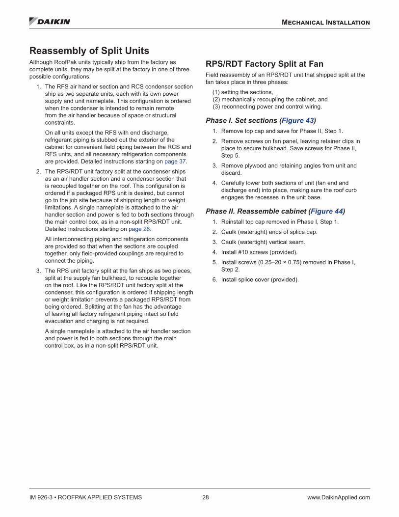
Phase I. Set sections (Figure 43) 1. Remove top cap and save for Phase II, Step 1.
2. Remove screws on fan panel, leaving retainer clips in place to secure bulkhead. Save screws for Phase II, Step 5.
3. Remove plywood and retaining angles from unit and discard.
4. Carefully lower both sections of unit (fan end and discharge end) into place, making sure the roof curb engages the recesses in the unit base.
Phase II. Reassemble cabinet (Figure 44) 1. Reinstall top cap removed in Phase I, Step 1.
2. Caulk (watertight) ends of splice cap.
3. Caulk (watertight) vertical seam.
4. Install #10 screws (provided).
5. Install screws (0.25–20 × 0.75) removed in Phase I, Step 2.
6. Install splice cover (provided).
Mechanical Installation
www.DaikinApplied.com 29 IM 926-3 • ROOFPAK APPLIED SYSTEMS
Figure 43: Set Sections—Steps 1–4, RPS Factory Split at Supply Fan
Figure 44: Re-Assemble Cabinet
1
2
3
4
4
Reinstall top cap saved in step 1
Caulk ends of splice cap
See detail
Splice cover, provided
#10 screws, provided
Nut clip-on, provided
Caulkverticalseam
Install screws (0.25 to 20 × 0.75)saved from step 1
1
2
6
4
5
3
IM 926-3 • ROOFPAK APPLIED SYSTEMS 30 www.DaikinApplied.com
Mechanical Installation
Phase III. Reconnect power and control wiring
CAUTIONConnect the power block correctly and maintain proper phasing. Improper installation can cause severe equipment damage.
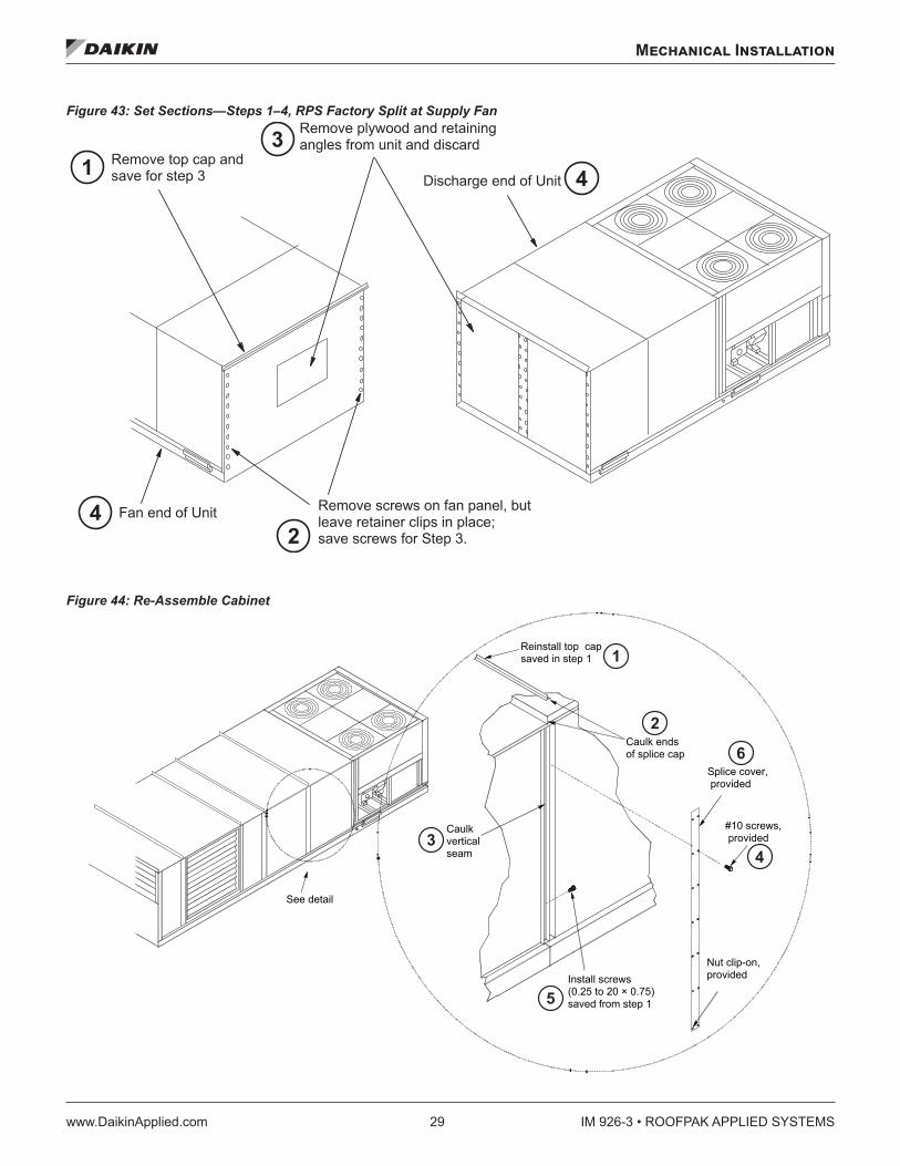
The DX coil/condenser section contains power and control harnesses that have their excess length in the blank or heat section, which normally is immediately downstream of the fan. Once the sections are physically reconnected, the ends of the power harness are fed back through the unit base into the junction box, per the unit’s electrical schematics.
1. Make electrical connections and reinstall inner raceway cover as shown in Figure 45.
2. When power wire reconnection is complete, reinstall the inner raceway cover in the blank or heat section. Figure 45 shows a typical installation of the raceway cover.
3. Run the control harnesses by removing the external raceway covers on either side of the unit split.
4. Remove the excess harness length from the external raceway on the DX side of the split; then route along the raceway, through the bushed hole in the fan section and into the junction box where control wiring terminal blocks are provided for reconnection.
5. Make all electrical connections per the unit’s electrical schematics.
6. Reinstall the external raceway covers after routing of the control wires is complete.
7. Draw through cooling coils only. Reconnect refrigerant piping. These refrigerant circuits for these units are shipped with a holding charge only. Figure 46 illustrates what the installer sees at the shipping split
a. To bridge the gap and connect the piping, remove the refrigerant piping caps and add fittings and copper tubing, as required.
b. Evacuate and charge the unit. See page 38 for further details.
Figure 45: Electrical Connections and Raceway Cover Installation
Figure 46: Refrigerant Lines
If applicable, install as shown with provided fasteners.
After routing wires, install inner raceway cover (see step 6).
3.72 ref.(94 mm)
Cappedrefrigerant
lines
Mechanical Installation
www.DaikinApplied.com 31 IM 926-3 • ROOFPAK APPLIED SYSTEMS
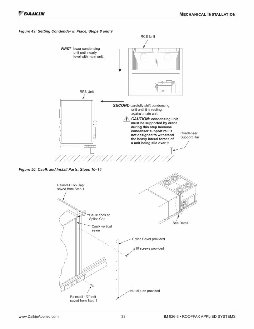
RPS/RDT Factory Split at Condensing Unit CAUTION
Do not damage piping components while setting condensing unit in place.
CAUTIONSupport condenser unit by crane during when moving since condenser support rail is not designed to withstand the heavy lateral forces of a unit being slid over it.
Field reassembly of an RPS/RDT unit that has shipped split at the condenser takes place in three phases: (1) setting the sections and mechanically recoupling the cabinet, (2) reconnecting refrigerant piping, and (3) reconnecting power and control wiring.
Phase I. Set sections and reassemble cabinet 1. Before setting sections together, remove top cap on air
handler section and wire cover on condensing section. See Figure 47. Discard wire cover.
2. Remove piping cover and discard. Reinstall screws in holes to prevent water leakage.
3. Loosen piping brackets and clamps on both sections so refrigerant lines can be moved out of the way to prevent interference and damage as the sections are set together. See Figure 47.
4. Physically rig the air handler section into place.
5. After air handler is installed, remove lifting bracket and adjacent bolts on air handler unit (see Figure 47) and save for Step 7. Discard lifting bracket.
If unit is post-and-rail mounted on a structural beam that runs the full length of the unit, leave bolts and lifting brackets in place.
6. On condenser unit, remove bolts adjacent to lifting bracket and save for Step 12.
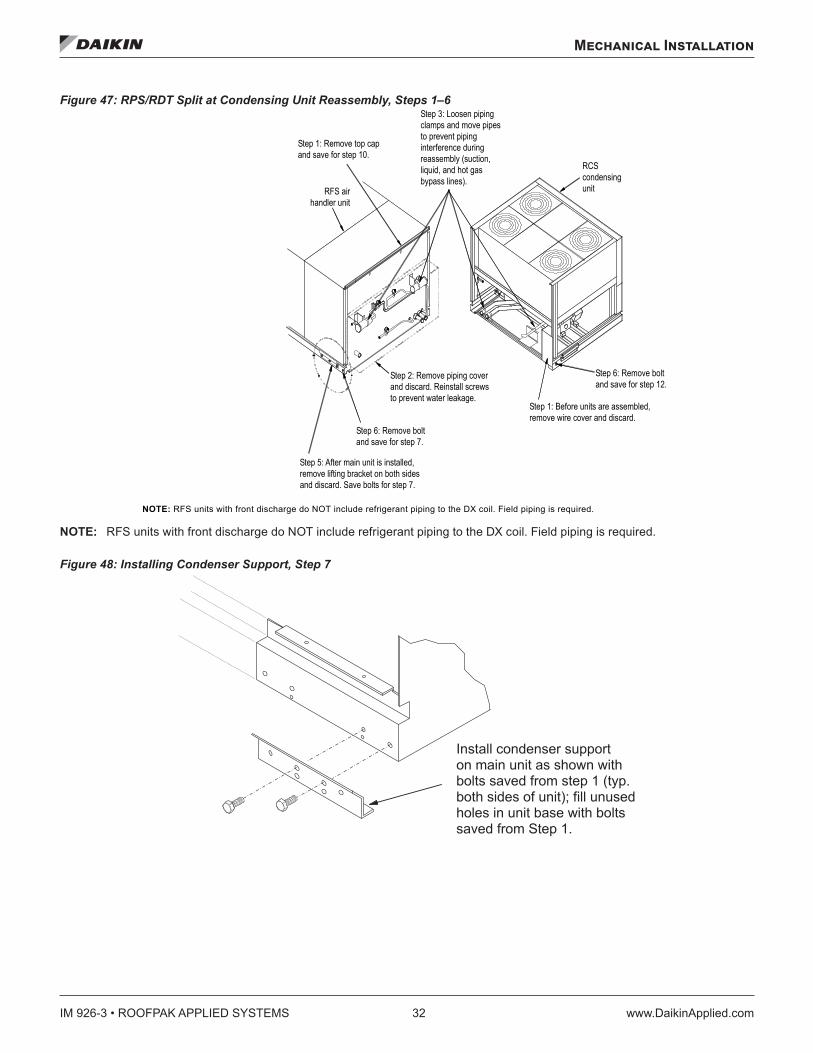
7. Install condenser support on air handler unit as shown in Figure 48. Fill unused holes in unit base with bolts saved in Step 6.
If unit is post-and-rail mounted on a structural beam that runs the full length of the unit, bolts and lifting brackets were not removed. Omit this step.
8. Lower the condenser unit until nearly level with main unit. See Figure 49.
9. Carefully shift condenser unit until it rests against the main unit. See Figure 49.
10. After condenser unit is set in place, install the top cap saved
11. Caulk (watertight) ends of splice cap and vertical seam. See Figure 50.
12. Install 1/2" bolt removed in Step 5. See Figure 47. in Step 1.
13. Install splice cover (provided), see Figure 50.
Phase II. Reconnect refrigerant piping All refrigerant piping required to reconnect the two sections is provided so when the piping closures are cut off, piping from the air handler and condenser sections lines up.
1. Connect piping using field-supplied couplings.
2. As with RFS/RCS units, both sections of the RPS/RDT split-at-condenser unit ship from the factory with a holding charge. Before removing the piping closures, inspect the unit for line breakage or loosening of fittings.
3. Perform pressure testing as described in the Leak Testing on page 38.
4. Perform evacuation, charging the system, and refrigerant charge requirements for the split-at-condenser unit per procedures on page 38.
NOTE: Use Table 11 through Table 15 to determine refrigerant charge requirements for the RPS/RDT split-at-condenser. Because no field-installed refrigerant piping is required, the total charge per circuit is the sum of the base R-22 charge and the DX coil charge.
IM 926-3 • ROOFPAK APPLIED SYSTEMS 32 www.DaikinApplied.com
Mechanical Installation
Figure 47: RPS/RDT Split at Condensing Unit Reassembly, Steps 1–6
NOTE: RFS units with front discharge do NOT include refrigerant piping to the DX coil. Field piping is required.
Figure 48: Installing Condenser Support, Step 7
NOTE: RFS units with front discharge do NOT include refrigerant piping to the DX coil. Field piping is required.
Step 1: Remove top capand save for step 10.
RFS airhandler unit
Step 3: Loosen piping clamps and move pipesto prevent piping interference during reassembly (suction, liquid, and hot gasbypass lines).
Step 2: Remove piping coverand discard. Reinstall screwsto prevent water leakage.
Step 6: Remove boltand save for step 7.
Step 5: After main unit is installed,remove lifting bracket on both sides and discard. Save bolts for step 7.
Step 1: Before units are assembled,remove wire cover and discard.
Step 6: Remove boltand save for step 12.
RCScondensingunit
� � � � � � � � � � � � � � � � � � � � � � � � �� � � � � � � � � � � � � � � � � � � � � � � � � � � � � � � � � � � � � � � � � � � � � � � � � � � � � � � � � � � � � � � � � � � � � � � � � � � � � � � � � � �� � � � � � � � � � � � � � � � � � � � � � � � � � �� � � � � � � � � � � � � � � � �
Mechanical Installation
www.DaikinApplied.com 33 IM 926-3 • ROOFPAK APPLIED SYSTEMS
Figure 49: Setting Condender in Place, Steps 8 and 9
Figure 50: Caulk and Install Parts, Steps 10–14
� � � � � � � � � � � � � � � � � � � � � � �� � � � � � � � � � � � � � � � � � � � � � � � � � � � � �� � � � � � � � � � � � � � � � � � � � � � � � � � � � � � � � �
� � � � � �
� � � � � � �
� � � � � � � � � � � � � � � � � � � �
� � � � � � � � � � � � � � � � � � � � � � � � � � � � � � � � �� � � � � � � � � � � � � � � � � � � � � � � � � � � �� � � � � � � � � � � � � � � � � � � � �
� � � � � � � � � � � � � � � � � � � � � � � �� � � � � � � � � � � � � � � � � � � � � � � � � �� � � � � � � � � � � � � � � � � � � � � � � �� � � � � � � � � � � � � � � � � � � � � � � �� � � � � � � � � � � � � � � � � � � � � � � � �� � � � � � � � � � � � � � � � � � � � � � � � � � � � � � � � � � � � � � � � � � � � � � � �
� � � � � � � � � � � � � � � � �� � � � � � � � � � � � � � � �
� � � � � � � � � � � � � � � � � � � �
� � � � � � � � �
� � � � � � � � � � � � � � � � � � �
� � � � � � � � � � � � � � � � � �
� � � � � � � � � � � � � � � � � � �
� � � � � � � � � � � �� � � �
� � � � � � � � � � � � � � � � � � �� � � � � � � � � � � � � � � �
IM 926-3 • ROOFPAK APPLIED SYSTEMS 34 www.DaikinApplied.com
Mechanical Installation
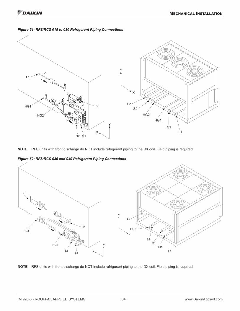
Figure 51: RFS/RCS 015 to 030 Refrigerant Piping Connections
NOTE: RFS units with front discharge do NOT include refrigerant piping to the DX coil. Field piping is required.
Figure 52: RFS/RCS 036 and 040 Refrigerant Piping Connections
NOTE: RFS units with front discharge do NOT include refrigerant piping to the DX coil. Field piping is required.
NOTE: RFS units with front discharge do NOT include refrigerant piping to the DX coil. Field piping is required.
NOTE: RFS units with front discharge do NOT include refrigerant piping to the DX coil. Field piping is required.

Mechanical Installation
www.DaikinApplied.com 35 IM 926-3 • ROOFPAK APPLIED SYSTEMS
Figure 53: RPS/RDT (Split)/RFS/RCS 045 to 105 Refrigerant Piping Connections
NOTE: RFS units with front discharge do NOT include refrigerant piping to the DX coil. Field piping is required.
Table 8: RFS/RCS 015–040 Connection Sizes and Locations, Figure 51 and Figure 52
Component circuitConnection sizes Connection locations
015C 020C 025C 030C to 040C
RFS 015 to 030 RCS 015 to 030 RFS 036 and 040 RCS 036 and 040X (in .) Y (in .) X (in .) Y (in .) X (in .) Y (in .) X (in .) Y (in .)
S1 Suction line Ckt.1 1-1/8 1-1/8 1-5/8 1-5/8 9.0 5.70 67.60 6.25 8.25 5.7 59.5 19.30S2 Suction line Ckt.2 1-3/8 1-5/8 1-3/8 1-5/8 14.0 5.7 28.0 6.25 13.25 5.7 34.6 19.30L1 Liquid line Ckt.1 5/8 5/8 7/8 7/8 56.0 32.0 75.0 6.25 79.0 25.0 70.5 25.0L2 Liquid line Ckt.2 7/8 7/8 7/8 7/8 7.6 28.0 21.0 6.25 15.0 25.0 23.5 25.0
HG1 HGBP line Ckt.1 7/8 7/8 7/8 7/8 52.0 10.0 60.8 6.25 67.0 6.7 64.6 6.6HG2 HGBP line Ckt.2 7/8 7/8 7/8 7/8 36.0 16.0 35.5 6.25 32.0 6.7 29.5 6.0
Table 9: RPS/RDT (Split)/RFS/RCS 045 to 105 Connection Sizes and Locations, Figure 53
Component circuit
Connection sizes Connection locations
045C 050C to 075C
080C to 90C
105C to 135C
RPS (split) and RFS 045 to 075C RCS 045 to 075C 080 to 105C
X (in .) Y (in .) X (in .) Y (in .) X (in .) Y (in .)S1 Suction line Ckt.1 1-5/8 2-1/8 2-1/8 2-5/8 11.7 5.2 21.0 7.0 5.7 11.7S2 Suction line Ckt.2 1-5/8 2-1/ 2-1/8 2-5/8 7.5 5.2 16.5 7.0 5.7 7.5L1 Liquid line Ckt.1 7/8 7/8 1-1/8 1-1/8 81.5 29.1 81.5 29.1 29.1 81.4L2 Liquid line Ckt.2 7/8 7/8 1-1/8 1-1/8 10.3 29.1 10.3 29.1 29.1 10.4
HG1 HGBP line Ckt.1 7/8 7/8 7/8 7/8 52.1 10.4 52.1 10.4 10.4 52.1HG2 HGBP line Ckt.2 7/8 7/8 7/8 7/8 40.9 4.7 40.9 4.7 4.7 40.9
NOTE: RFS units with front discharge do NOT include refrigerant piping to the DX coil. Field piping is required.
IM 926-3 • ROOFPAK APPLIED SYSTEMS 36 www.DaikinApplied.com
Mechanical Installation
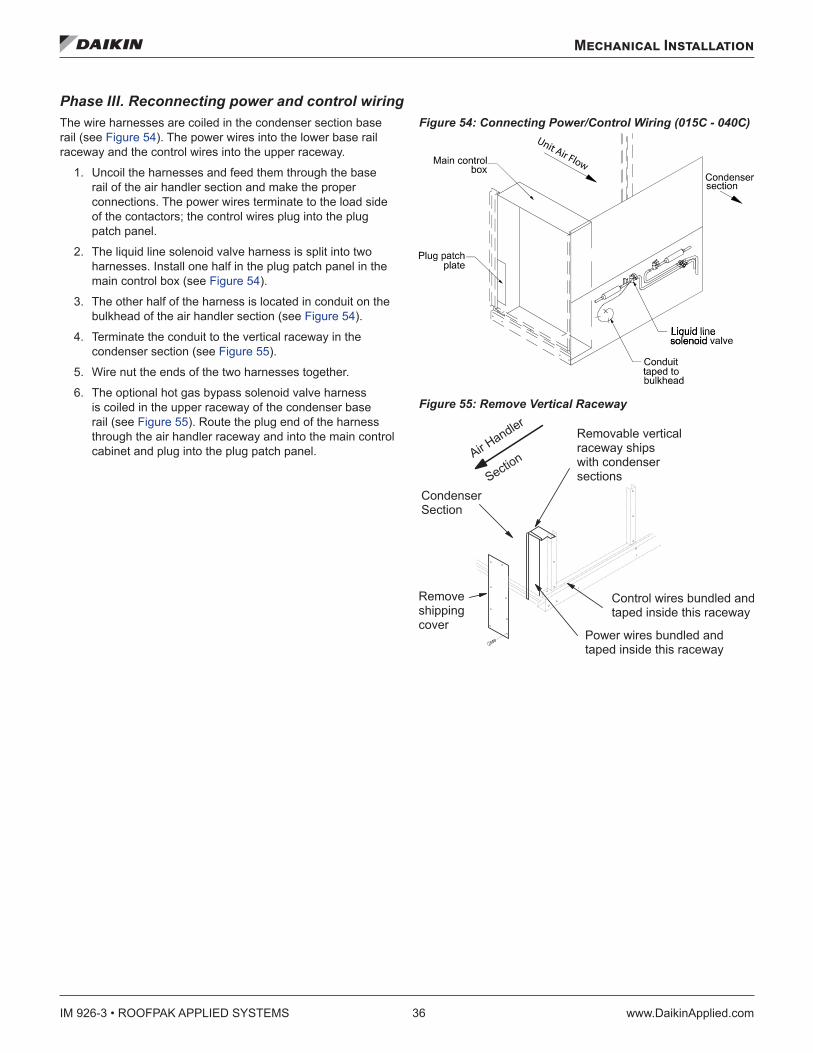
Phase III. Reconnecting power and control wiring The wire harnesses are coiled in the condenser section base rail (see Figure 54). The power wires into the lower base rail raceway and the control wires into the upper raceway.
1. Uncoil the harnesses and feed them through the base rail of the air handler section and make the proper connections. The power wires terminate to the load side of the contactors; the control wires plug into the plug patch panel.
2. The liquid line solenoid valve harness is split into two harnesses. Install one half in the plug patch panel in the main control box (see Figure 54).
3. The other half of the harness is located in conduit on the bulkhead of the air handler section (see Figure 54).
4. Terminate the conduit to the vertical raceway in the condenser section (see Figure 55).
5. Wire nut the ends of the two harnesses together.
6. The optional hot gas bypass solenoid valve harness is coiled in the upper raceway of the condenser base rail (see Figure 55). Route the plug end of the harness through the air handler raceway and into the main control cabinet and plug into the plug patch panel.
Figure 54: Connecting Power/Control Wiring (015C - 040C)
Figure 55: Remove Vertical Raceway
Unit Air Flow
Mechanical Installation
www.DaikinApplied.com 37 IM 926-3 • ROOFPAK APPLIED SYSTEMS
RFS/RCS Permanent Split Systems Piping Recommendations All field piping, wiring, and procedures must be performed in accordance with ASHRAE, EPA, and industry standards. Proper refrigerant piping can make the difference between a reliable system and an inefficient, problematic system.
The primary concerns related to piping are refrigerant pressure drop, a solid liquid feed to the expansion valves, continuous oil return and properly sized refrigerant specialties.
Insulate the suction line to reduce excessive superheat buildup. Insulate the liquid line, where located in areas above ambient temperature, to prevent loss of subcooling and consequent liquid flashing.
The recommended source for refrigerant piping techniques and sizing is the Daikin AG31-011 Refrigerant Piping Design Guide.
Although conflicting piping recommendations can be found in different sources, Daikin offers the following recommendations for these controversial issues.
The use of double risers for vertical gas risers is generally not required and should be used only as a last resort to maintain the minimum refrigerant flow to carry oil up the vertical risers. Slightly downsizing the vertical riser is a preferable option to providing double risers.
Slope the refrigerant lines 1" per 10 feet of horizontal run in the direction of refrigerant flow to assist oil return.
Pressure drops in the refrigerant lines should be maintained at or below the ASHRAE recommendations and line lengths should be made as short as possible. Exceeding these recommendations will decrease performance and could impact reliability.
Small traps should be provided at the base of each major vertical gas riser to assist in the collection of oil. If vertical risers exceed more than 25 feet, install a small trap at the midpoint and at a maximum of 20 foot intervals.
Use caution in sizing the liquid line in applications where the evaporator is above the outdoor section. The weight of the liquid refrigerant in the vertical column will decrease the pressure at the top of the riser (approximately 0.5 psi per foot of vertical rise) allowing some of the refrigerant to flash to a gas. Adequate refrigerant subcooling is needed at the outdoor section to prevent large volumes of refrigerant gas at the expansion valve.
The piping systems should always extend above the highest component in the refrigeration system before dropping down to make the final refrigerant connections to components. This practice will hinder the draining of condensed refrigerant to the lower component when normal shutdown procedures do not occur (such as a power failure).
NOTE: Do not run refrigerant lines underground.
Procedure1. Use type K or L clean copper tubing. Thoroughly clean or
braze all joints with high temperature solder. Make sure nitrogen is flowing through the tubes while brazing to minimize the formation of oxide contaminants.
2. Base piping sizes on temperature/pressure limitations as recommended in the following paragraphs. Under no circumstances should pipe size be based strictly upon coil or condensing unit piping connection size.
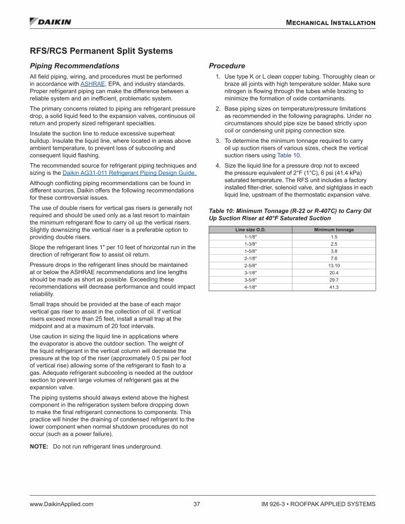
3. To determine the minimum tonnage required to carry oil up suction risers of various sizes, check the vertical suction risers using Table 10.
4. Size the liquid line for a pressure drop not to exceed the pressure equivalent of 2°F (1°C), 6 psi (41.4 kPa) saturated temperature. The RFS unit includes a factory installed filter-drier, solenoid valve, and sightglass in each liquid line, upstream of the thermostatic expansion valve.
Table 10: Minimum Tonnage (R-22 or R-407C) to Carry Oil Up Suction Riser at 40°F Saturated Suction
Line size O .D . Minimum tonnage1-1/8ʺ 1.51-3/8ʺ 2.51-5/8ʺ 3.82-1/8ʺ 7.62-5/8ʺ 13.103-1/8ʺ 20.43-5/8ʺ 29.74-1/8ʺ 41.3
IM 926-3 • ROOFPAK APPLIED SYSTEMS 38 www.DaikinApplied.com
Mechanical Installation
Holding Charge WARNING
Before applying heat to remove brazed piping caps and plugs, always vent piping to atmosphere. Failure to do so can cause hazardous pressures, explosion, severe personal injuries, or death.
The RFS unit and RCS unit ship with a nitrogen holding charge. At the time the unit is received, a visual inspection of the unit piping should be made to be sure no breakage occurred or that the fittings did not loosen during shipping. A pressure test on the RCS units should indicate a positive pressure in the unit. If no pressure is evident, the unit must be leak tested and the leak repaired. Note and report this to the Daikin sales representative and freight carrier (if the loss is due to shipping damage).
RCS—Vent to atmosphere by opening gauge ports at the compressors and liquid line shutoff valves. Make sure manual valves are not back seated to shut off the gauge ports.
RFS—Vent to atmospher by cutting off the process tubes on the suction line caps.
The RFS unit does not have gauge ports for pressure measurement. If no positive pressure is detected when cutting off the process tubes and removing the tubing caps, the unit should be leak tested as described below, after the interconnecting piping has been brazed in place. This test will also confirm the integrity of the field braze joints.
Leak Testing WARNING
Do not use oxygen or air to build up pressure. Explosion hazard can cause severe personal injury or death.
In the case of loss of the nitrogen holding charge, the unit should be checked for leaks prior to charging the complete system. If the full charge was lost, leak testing can be done by charging the refrigerant into the unit to build the pressure to approximately 10 psig and adding sufficient dry nitrogen to bring the pressure to a ximum of 125 psig. The unit should then be leak tested with halide or electronic leak detector. After making any necessary repair, the system should be evacuated as described in he following paragraphs.
Evacuation CAUTION
Before replacing refrigerant sensors or protective devices, see Refrigerant Charge on page 41 for an important warning to prevent an abrupt loss of the entire charge.
CAUTIONTo prevent liquid return and damage to the compressor on systems with optional hot gas bypass, locate the bypass solenoid valve on the RCS, not on the RFS unit.
CAUTIONTo service liquid line components, the manual shutoff valve is closed and refrigerant is pumped into the condenser. The pounds of refrigerant in the system may exceed the capacity of the condenser, depending on the amount of refrigerant in the liquid lines between the RFS and RCS units. Suitable means of containing the refrigerant is required.
After determining the unit is tight and there are no refrigerant leaks, evacuate the system. Use a vacuum pump with a pumping capacity of approximately 3 cu.ft./min. and the ability to reduce the vacuum in the unit to at least 1 mm (1000 microns).
1. Connect a mercury manometer or an electronic or other type of micron gauge to the unit at a point remote from the vacuum pump. For readings below 1 millimeter, use an electronic or other micron gauge.
2. Use the triple evacuation method, which is particularly helpful if the vacuum pump is unable to obtain the desired 1 mm of vacuum. The system is first evacuated to approximately 29" (740 mm) of mercury. Then add enough refrigerant vapor to the system to bring the pressure up to 0 pounds (0 microns).
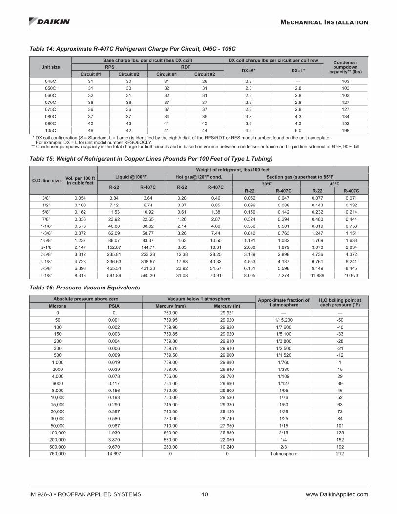
3. Evacuate the system again to 29" (740 mm) of vacuum. Repeat his procedure three times. This method is most effective by holding system pressure at 0 pounds (0 microns) for a minimum of 1 hour between evacuations. The first pulldown removes about 90% of the noncondensables; the second removes about 90% of that remaining from the first pulldown. After the third pulldown, only 1/10 of 1% of non-condensables remains. Table 16 on page 40 shows the relationship between pressure, microns, atmospheres, and the boiling point of water.
Mechanical Installation
www.DaikinApplied.com 39 IM 926-3 • ROOFPAK APPLIED SYSTEMS
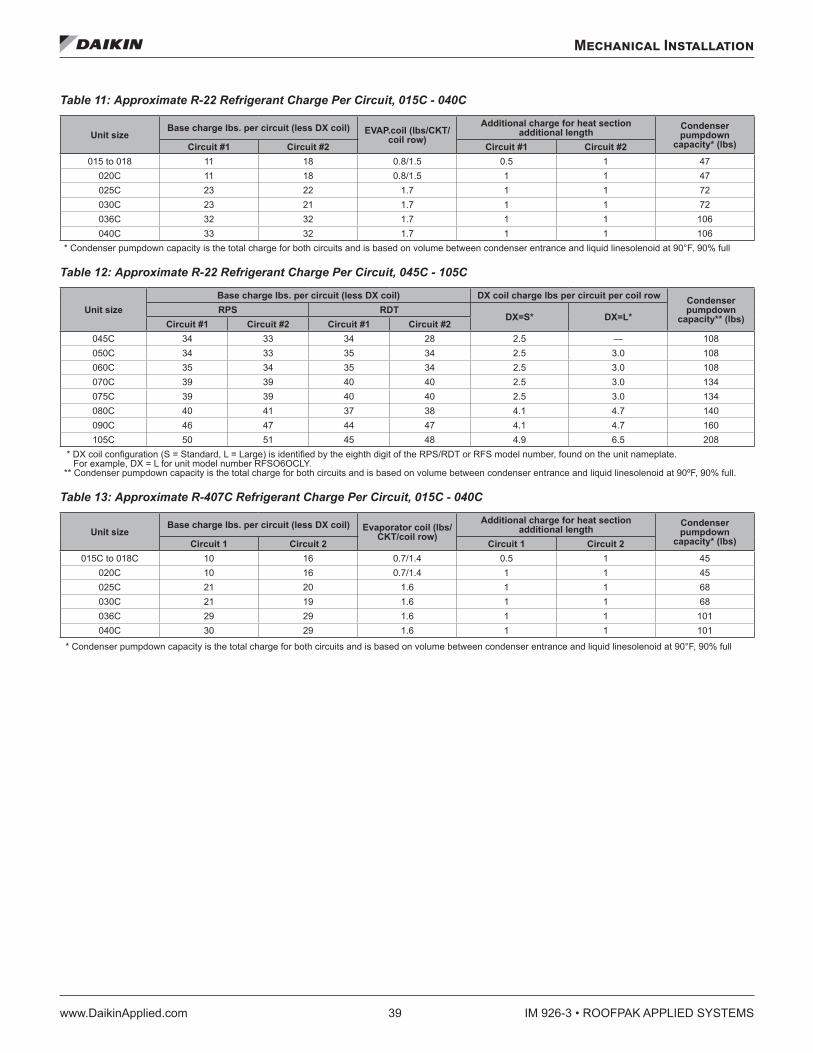
Table 11: Approximate R-22 Refrigerant Charge Per Circuit, 015C - 040C
Unit sizeBase charge lbs . per circuit (less DX coil) EVAP .coil (lbs/CKT/
coil row)Additional charge for heat section
additional lengthCondenser pumpdown
capacity* (lbs)Circuit #1 Circuit #2 Circuit #1 Circuit #2015 to 018 11 18 0.8/1.5 0.5 1 47
020C 11 18 0.8/1.5 1 1 47025C 23 22 1.7 1 1 72030C 23 21 1.7 1 1 72036C 32 32 1.7 1 1 106040C 33 32 1.7 1 1 106
* Condenser pumpdown capacity is the total charge for both circuits and is based on volume between condenser entrance and liquid linesolenoid at 90°F, 90% full
Table 12: Approximate R-22 Refrigerant Charge Per Circuit, 045C - 105C
Unit sizeBase charge lbs . per circuit (less DX coil) DX coil charge lbs per circuit per coil row Condenser
pumpdown capacity** (lbs)
RPS RDTDX=S* DX=L*
Circuit #1 Circuit #2 Circuit #1 Circuit #2045C 34 33 34 28 2.5 — 108050C 34 33 35 34 2.5 3.0 108060C 35 34 35 34 2.5 3.0 108070C 39 39 40 40 2.5 3.0 134075C 39 39 40 40 2.5 3.0 134080C 40 41 37 38 4.1 4.7 140090C 46 47 44 47 4.1 4.7 160105C 50 51 45 48 4.9 6.5 208
* DX coil configuration (S = Standard, L = Large) is identified by the eighth digit of the RPS/RDT or RFS model number, found on the unit nameplate. For example, DX = L for unit model number RFSO6OCLY.
** Condenser pumpdown capacity is the total charge for both circuits and is based on volume between condenser entrance and liquid linesolenoid at 90ºF, 90% full.
Table 13: Approximate R-407C Refrigerant Charge Per Circuit, 015C - 040C
Unit sizeBase charge lbs . per circuit (less DX coil) Evaporator coil (lbs/
CKT/coil row)Additional charge for heat section
additional lengthCondenser pumpdown
capacity* (lbs)Circuit 1 Circuit 2 Circuit 1 Circuit 2015C to 018C 10 16 0.7/1.4 0.5 1 45
020C 10 16 0.7/1.4 1 1 45025C 21 20 1.6 1 1 68030C 21 19 1.6 1 1 68036C 29 29 1.6 1 1 101040C 30 29 1.6 1 1 101
* Condenser pumpdown capacity is the total charge for both circuits and is based on volume between condenser entrance and liquid linesolenoid at 90°F, 90% full
IM 926-3 • ROOFPAK APPLIED SYSTEMS 40 www.DaikinApplied.com
Mechanical Installation
Table 14: Approximate R-407C Refrigerant Charge Per Circuit, 045C - 105C
Unit sizeBase charge lbs . per circuit (less DX coil) DX coil charge lbs per circuit per coil row Condenser
pumpdown capacity** (lbs)
RPS RDTDX=S* DX=L*
Circuit #1 Circuit #2 Circuit #1 Circuit #2045C 31 30 31 26 2.3 — 103050C 31 30 32 31 2.3 2.8 103060C 32 31 32 31 2.3 2.8 103070C 36 36 37 37 2.3 2.8 127075C 36 36 37 37 2.3 2.8 127080C 37 37 34 35 3.8 4.3 134090C 42 43 41 43 3.8 4.3 152105C 46 42 41 44 4.5 6.0 198
* DX coil configuration (S = Standard, L = Large) is identified by the eighth digit of the RPS/RDT or RFS model number, found on the unit nameplate. For example, DX = L for unit model number RFSO6OCLY.
** Condenser pumpdown capacity is the total charge for both circuits and is based on volume between condenser entrance and liquid line solenoid at 90ºF, 90% full
Table 15: Weight of Refrigerant in Copper Lines (Pounds Per 100 Feet of Type L Tubing)
O .D . line size Vol . per 100 ft in cubic feet
Weight of refrigerant, lbs ./100 feetLiquid @100°F Hot gas@120°F cond . Suction gas (superheat to 85°F)
R-22 R-407C R-22 R-407C30°F 40°F
R-22 R-407C R-22 R-407C3/8ʺ 0.054 3.84 3.64 0.20 0.46 0.052 0.047 0.077 0.0711/2ʺ 0.100 7.12 6.74 0.37 0.85 0.096 0.088 0.143 0.1325/8ʺ 0.162 11.53 10.92 0.61 1.38 0.156 0.142 0.232 0.2147/8ʺ 0.336 23.92 22.65 1.26 2.87 0.324 0.294 0.480 0.444
1-1/8ʺ 0.573 40.80 38.62 2.14 4.89 0.552 0.501 0.819 0.7561-3/8ʺ 0.872 62.09 58.77 3.26 7.44 0.840 0.763 1.247 1.1511-5/8ʺ 1.237 88.07 83.37 4.63 10.55 1.191 1.082 1.769 1.6332-1/8 2.147 152.87 144.71 8.03 18.31 2.068 1.879 3.070 2.8342-5/8ʺ 3.312 235.81 223.23 12.38 28.25 3.189 2.898 4.736 4.3723-1/8ʺ 4.728 336.63 318.67 17.68 40.33 4.553 4.137 6.761 6.2413-5/8ʺ 6.398 455.54 431.23 23.92 54.57 6.161 5.598 9.149 8.4454-1/8ʺ 8.313 591.89 560.30 31.08 70.91 8.005 7.274 11.888 10.973
Table 16: Pressure-Vacuum Equivalents
Absolute pressure above zero Vacuum below 1 atmosphere Approximate fraction of 1 atmosphere
H2O boiling point at each pressure (°F)Microns PSIA Mercury (mm) Mercury (in)
0 0 760.00 29.921 — —50 0.001 759.95 29,920 1/15,200 -50
100 0.002 759.90 29.920 1/7,600 -40150 0.003 759.85 29.920 1/5,100 -33200 0.004 759.80 29.910 1/3,800 -28300 0.006 759.70 29.910 1/2,500 -21500 0.009 759.50 29.900 1/1,520 -12
1,000 0.019 759.00 29.880 1/760 12000 0.039 758.00 29.840 1/380 154,000 0.078 756.00 29.760 1/189 296000 0.117 754.00 29.690 1/127 398,000 0.156 752.00 29.600 1/95 46
10,000 0.193 750.00 29.530 1/76 5215,000 0.290 745.00 29.330 1/50 6320,000 0.387 740.00 29.130 1/38 7230,000 0.580 730.00 28.740 1/25 8450,000 0.967 710.00 27.950 1/15 101
100,000 1.930 660.00 25.980 2/15 125200,000 3.870 560.00 22.050 1/4 152500,000 9.670 260.00 10.240 2/3 192760,000 14.697 0 0 1 atmosphere 212
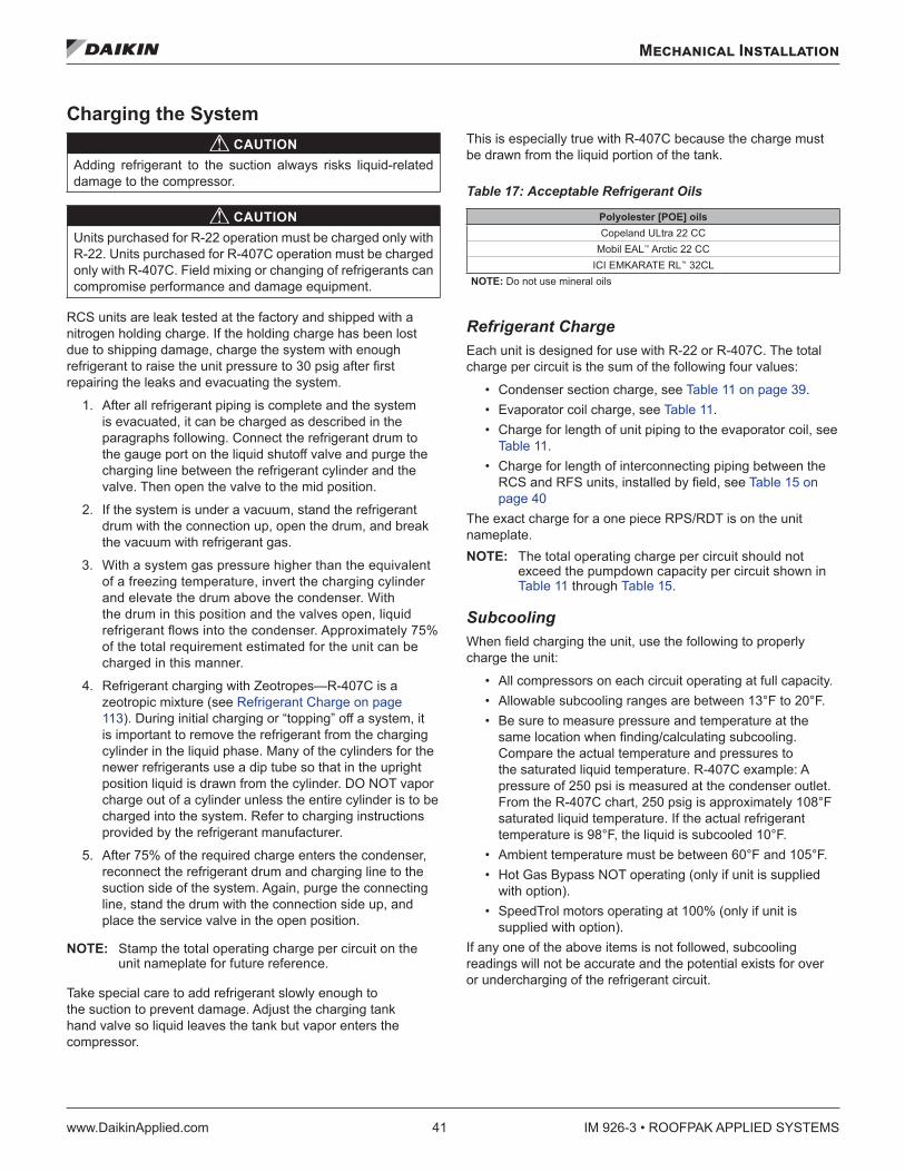
Mechanical Installation
www.DaikinApplied.com 41 IM 926-3 • ROOFPAK APPLIED SYSTEMS
Charging the System CAUTION
Adding refrigerant to the suction always risks liquid-related damage to the compressor.
CAUTIONUnits purchased for R-22 operation must be charged only with R-22. Units purchased for R-407C operation must be charged only with R-407C. Field mixing or changing of refrigerants can compromise performance and damage equipment.
RCS units are leak tested at the factory and shipped with a nitrogen holding charge. If the holding charge has been lost due to shipping damage, charge the system with enough refrigerant to raise the unit pressure to 30 psig after first repairing the leaks and evacuating the system.
1. After all refrigerant piping is complete and the system is evacuated, it can be charged as described in the paragraphs following. Connect the refrigerant drum to the gauge port on the liquid shutoff valve and purge the charging line between the refrigerant cylinder and the valve. Then open the valve to the mid position.
2. If the system is under a vacuum, stand the refrigerant drum with the connection up, open the drum, and break the vacuum with refrigerant gas.
3. With a system gas pressure higher than the equivalent of a freezing temperature, invert the charging cylinder and elevate the drum above the condenser. With the drum in this position and the valves open, liquid refrigerant flows into the condenser. Approximately 75% of the total requirement estimated for the unit can be charged in this manner.
4. Refrigerant charging with Zeotropes—R-407C is a zeotropic mixture (see Refrigerant Charge on page 113). During initial charging or “topping” off a system, it is important to remove the refrigerant from the charging cylinder in the liquid phase. Many of the cylinders for the newer refrigerants use a dip tube so that in the upright position liquid is drawn from the cylinder. DO NOT vapor charge out of a cylinder unless the entire cylinder is to be charged into the system. Refer to charging instructions provided by the refrigerant manufacturer.
5. After 75% of the required charge enters the condenser, reconnect the refrigerant drum and charging line to the suction side of the system. Again, purge the connecting line, stand the drum with the connection side up, and place the service valve in the open position.
NOTE: Stamp the total operating charge per circuit on the unit nameplate for future reference.
Take special care to add refrigerant slowly enough to the suction to prevent damage. Adjust the charging tank hand valve so liquid leaves the tank but vapor enters the compressor.
This is especially true with R-407C because the charge must be drawn from the liquid portion of the tank.
Table 17: Acceptable Refrigerant Oils
Polyolester [POE] oilsCopeland ULtra 22 CC
Mobil EAL™ Arctic 22 CC ICI EMKARATE RL™ 32CL
NOTE: Do not use mineral oils
Refrigerant Charge Each unit is designed for use with R-22 or R-407C. The total charge per circuit is the sum of the following four values:
• Condenser section charge, see Table 11 on page 39. • Evaporator coil charge, see Table 11. • Charge for length of unit piping to the evaporator coil, see
Table 11. • Charge for length of interconnecting piping between the
RCS and RFS units, installed by field, see Table 15 on page 40
The exact charge for a one piece RPS/RDT is on the unit nameplate. NOTE: The total operating charge per circuit should not
exceed the pumpdown capacity per circuit shown in Table 11 through Table 15.
Subcooling When field charging the unit, use the following to properly charge the unit:
• All compressors on each circuit operating at full capacity. • Allowable subcooling ranges are between 13°F to 20°F. • Be sure to measure pressure and temperature at the
same location when finding/calculating subcooling. Compare the actual temperature and pressures to the saturated liquid temperature. R-407C example: A pressure of 250 psi is measured at the condenser outlet. From the R-407C chart, 250 psig is approximately 108°F saturated liquid temperature. If the actual refrigerant temperature is 98°F, the liquid is subcooled 10°F.
• Ambient temperature must be between 60°F and 105°F. • Hot Gas Bypass NOT operating (only if unit is supplied
with option). • SpeedTrol motors operating at 100% (only if unit is
supplied with option). If any one of the above items is not followed, subcooling readings will not be accurate and the potential exists for over or undercharging of the refrigerant circuit.
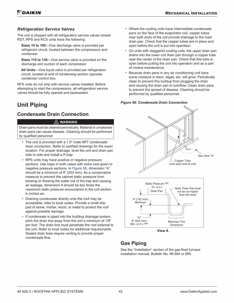
IM 926-3 • ROOFPAK APPLIED SYSTEMS 42 www.DaikinApplied.com
Mechanical Installation
Refrigeration Service Valves The unit is shipped with all refrigeration service valves closed. RDT, RPS and RCS units have the following:
Sizes 15 to 105—One discharge valve is provided per refrigerant circuit, located between the compressors and condenser.
Sizes 115 to 135—One service valve is provided on the discharge and suction of each compressor.
All Units—One liquid valve is provided per refrigeration circuit, located at end of condensing section opposite condenser control box.
RFS units do not ship with service valves installed. Before attempting to start the compressors, all refrigeration service valves should be fully opened and backseated.
Unit Piping Condensate Drain Connection
WARNINGDrain pans must be cleaned periodically. Material in uncleaned drain pans can cause disease. Cleaning should be performed by qualified personnel
• The unit is provided with a 1.5" male NPT condensate drain connection. Refer to certified drawings for the exact location. For proper drainage, level the unit and drain pan side to side and install a P-trap
• RPS units may have positive or negative pressure sections. Use traps in both cases with extra care given to negative pressure sections. In Figure 56, dimension “A” should be a minimum of 8" (203 mm). As a conservative measure to prevent the cabinet static pressure from blowing or drawing the water out of the trap and causing air leakage, dimension A should be two times the maximum static pressure encountered in the coil section in inches wc.
• Draining condensate directly onto the roof may be acceptable; refer to local codes. Provide a small drip pad of stone, mortar, wood, or metal to protect the roof against possible damage.
• If condensate is piped into the building drainage system, pitch the drain line away from the unit a minimum of 1/8" per foot. The drain line must penetrate the roof external to the unit. Refer to local codes for additional requirements. Sealed drain lines require venting to provide proper condensate flow.
• Where the cooling coils have intermediate condensate pans on the face of the evaporator coil, copper tubes near both ends of the coil provide drainage to the main drain pan. Check that the copper tubes are in place and open before the unit is put into operation.
• On units with staggered cooling coils, the upper drain pan drains into the lower coil drain pan through a copper tube near the center of the drain pan. Check that this tube is open before putting the unit into operation and as a part of routine maintenance.
• Because drain pans in any air conditioning unit have some moisture in them, algae, etc. will grow. Periodically clean to prevent this buildup from plugging the drain and causing the drain pan to overflow. Clean drain pans to prevent the spread of disease. Cleaning should be performed by qualified personnel.
Figure 56: Condensate Drain Connection
Gas Piping See the “Installation” section of the gas-fired furnace installation manual, Bulletin No. IM 684 or 685.
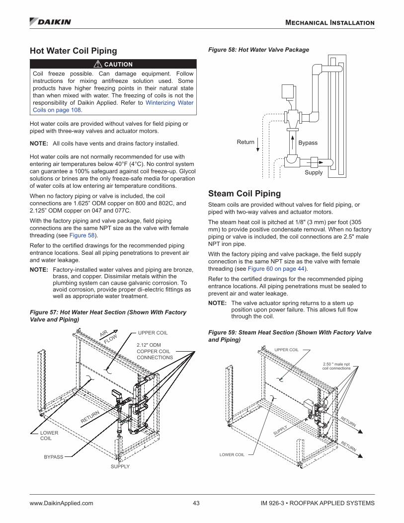
Mechanical Installation
www.DaikinApplied.com 43 IM 926-3 • ROOFPAK APPLIED SYSTEMS
Hot Water Coil Piping CAUTION
Coil freeze possible. Can damage equipment. Follow instructions for mixing antifreeze solution used. Some products have higher freezing points in their natural state than when mixed with water. The freezing of coils is not the responsibility of Daikin Applied. Refer to Winterizing Water Coils on page 108.
Hot water coils are provided without valves for field piping or piped with three-way valves and actuator motors.
NOTE: All coils have vents and drains factory installed.
Hot water coils are not normally recommended for use with entering air temperatures below 40°F (4°C). No control system can guarantee a 100% safeguard against coil freeze-up. Glycol solutions or brines are the only freeze-safe media for operation of water coils at low entering air temperature conditions.
When no factory piping or valve is included, the coil connections are 1.625” ODM copper on 800 and 802C, and 2.125” ODM copper on 047 and 077C.
With the factory piping and valve package, field piping connections are the same NPT size as the valve with female threading (see Figure 58).
Refer to the certified drawings for the recommended piping entrance locations. Seal all piping penetrations to prevent air and water leakage. NOTE: Factory-installed water valves and piping are bronze,
brass, and copper. Dissimilar metals within the plumbing system can cause galvanic corrosion. To avoid corrosion, provide proper di-electric fittings as well as appropriate water treatment.
Figure 57: Hot Water Heat Section (Shown With Factory Valve and Piping)
Figure 58: Hot Water Valve Package
Steam Coil Piping Steam coils are provided without valves for field piping, or piped with two-way valves and actuator motors.
The steam heat coil is pitched at 1/8" (3 mm) per foot (305 mm) to provide positive condensate removal. When no factory piping or valve is included, the coil connections are 2.5" male NPT iron pipe.
With the factory piping and valve package, the field supply connection is the same NPT size as the valve with female threading (see Figure 60 on page 44).
Refer to the certified drawings for the recommended piping entrance locations. All piping penetrations must be sealed to prevent air and water leakage. NOTE: The valve actuator spring returns to a stem up
position upon power failure. This allows full flow through the coil.
Figure 59: Steam Heat Section (Shown With Factory Valve and Piping)
� � � � � � � � � � � �
� � � � � �
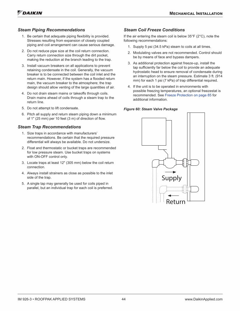
IM 926-3 • ROOFPAK APPLIED SYSTEMS 44 www.DaikinApplied.com
Mechanical Installation
Steam Piping Recommendations 1. Be certain that adequate piping flexibility is provided.
Stresses resulting from expansion of closely coupled piping and coil arrangement can cause serious damage.
2. Do not reduce pipe size at the coil return connection. Carry return connection size through the dirt pocket, making the reduction at the branch leading to the trap.
3. Install vacuum breakers on all applications to prevent retaining condensate in the coil. Generally, the vacuum breaker is to be connected between the coil inlet and the return main. However, if the system has a flooded return main, the vacuum breaker to the atmosphere; the trap design should allow venting of the large quantities of air.
4. Do not drain steam mains or takeoffs through coils. Drain mains ahead of coils through a steam trap to the return line.
5. Do not attempt to lift condensate.
6. Pitch all supply and return steam piping down a minimum of 1" (25 mm) per 10 feet (3 m) of direction of flow.
Steam Trap Recommendations 1. Size traps in accordance with manufacturers’
recommendations. Be certain that the required pressure differential will always be available. Do not undersize.
2. Float and thermostatic or bucket traps are recommended for low pressure steam. Use bucket traps on systems with ON-OFF control only.
3. Locate traps at least 12" (305 mm) below the coil return connection.
4. Always install strainers as close as possible to the inlet side of the trap.
5. A single tap may generally be used for coils piped in parallel, but an individual trap for each coil is preferred.
Steam Coil Freeze Conditions If the air entering the steam coil is below 35°F (2°C), note the following recommendations:
1. Supply 5 psi (34.5 kPa) steam to coils at all times.
2. Modulating valves are not recommended. Control should be by means of face and bypass dampers.
3. As additional protection against freeze-up, install the tap sufficiently far below the coil to provide an adequate hydrostatic head to ensure removal of condensate during an interruption on the steam pressure. Estimate 3 ft. (914 mm) for each 1 psi (7 kPa) of trap differential required.
4. If the unit is to be operated in environments with possible freezing temperatures, an optional freezestat is recommended. See Freeze Protection on page 85 for additional information.
Figure 60: Steam Valve Package
Supply
Return
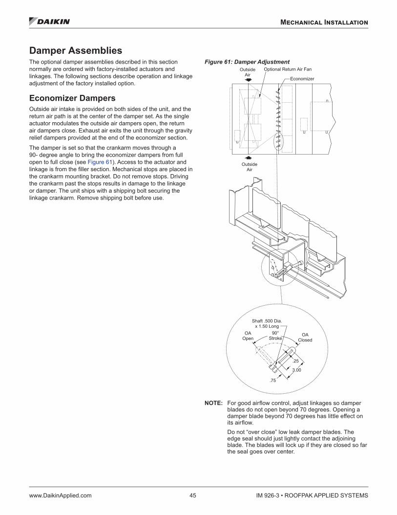
Mechanical Installation
www.DaikinApplied.com 45 IM 926-3 • ROOFPAK APPLIED SYSTEMS
Damper Assemblies The optional damper assemblies described in this section normally are ordered with factory-installed actuators and linkages. The following sections describe operation and linkage adjustment of the factory installed option.
Economizer Dampers Outside air intake is provided on both sides of the unit, and the return air path is at the center of the damper set. As the single actuator modulates the outside air dampers open, the return air dampers close. Exhaust air exits the unit through the gravity relief dampers provided at the end of the economizer section.
The damper is set so that the crankarm moves through a 90- degree angle to bring the economizer dampers from full open to full close (see Figure 61). Access to the actuator and linkage is from the filler section. Mechanical stops are placed in the crankarm mounting bracket. Do not remove stops. Driving the crankarm past the stops results in damage to the linkage or damper. The unit ships with a shipping bolt securing the linkage crankarm. Remove shipping bolt before use.
Figure 61: Damper Adjustment
NOTE: For good airflow control, adjust linkages so damper blades do not open beyond 70 degrees. Opening a damper blade beyond 70 degrees has little effect on its airflow. Do not “over close” low leak damper blades. The edge seal should just lightly contact the adjoining blade. The blades will lock up if they are closed so far the seal goes over center.
� �� � � � � �
� �� � � �
� � � �
� � �
� � �
� � � � � � �
� � � � � � � � � � � � �� � � � � � � � � � �
� � � � � � �� � �
� � � � � � � � � � � � � � � � � � � � � � �
� � � � � � � �
� � � � � � �� � �
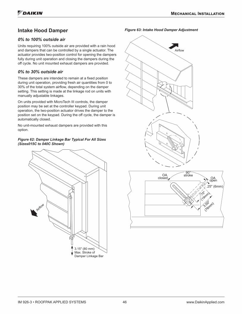
IM 926-3 • ROOFPAK APPLIED SYSTEMS 46 www.DaikinApplied.com
Mechanical Installation
Intake Hood Damper0% to 100% outside airUnits requiring 100% outside air are provided with a rain hood and dampers that can be controlled by a single actuator. The actuator provides two-position control for opening the dampers fully during unit operation and closing the dampers during the off cycle. No unit mounted exhaust dampers are provided.
0% to 30% outside airThese dampers are intended to remain at a fixed position during unit operation, providing fresh air quantities from 0 to 30% of the total system airflow, depending on the damper setting. This setting is made at the linkage rod on units with manually adjustable linkages.
On units provided with MicroTech III controls, the damper position may be set at the controller keypad. During unit operation, the two-position actuator drives the damper to the position set on the keypad. During the off cycle, the damper is automatically closed.
No unit-mounted exhaust dampers are provided with this option.
Figure 62: Damper Linkage Bar Typical For All Sizes (Sizes015C to 040C Shown)
Figure 63: Intake Hood Damper Adjustment
� � �� � ��
� � � � � � � � � � � � � � � � � � � � � � � �� � � � � � � � � � � � � � � � � �
OAclosed OA
open
90°stroke
.25" (6mm)
Airflow
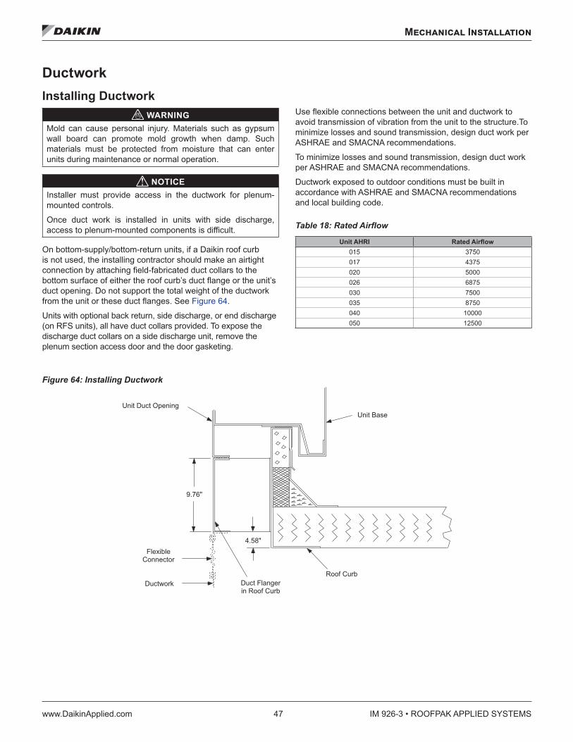
Mechanical Installation
www.DaikinApplied.com 47 IM 926-3 • ROOFPAK APPLIED SYSTEMS
DuctworkInstalling Ductwork
WARNINGMold can cause personal injury. Materials such as gypsum wall board can promote mold growth when damp. Such materials must be protected from moisture that can enter units during maintenance or normal operation.
NOTICEInstaller must provide access in the ductwork for plenum-mounted controls.
Once duct work is installed in units with side discharge, access to plenum-mounted components is difficult.
On bottom-supply/bottom-return units, if a Daikin roof curb is not used, the installing contractor should make an airtight connection by attaching field-fabricated duct collars to the bottom surface of either the roof curb’s duct flange or the unit’s duct opening. Do not support the total weight of the ductwork from the unit or these duct flanges. See Figure 64.
Units with optional back return, side discharge, or end discharge (on RFS units), all have duct collars provided. To expose the discharge duct collars on a side discharge unit, remove the plenum section access door and the door gasketing.
Use flexible connections between the unit and ductwork to avoid transmission of vibration from the unit to the structure.To minimize losses and sound transmission, design duct work per ASHRAE and SMACNA recommendations.
To minimize losses and sound transmission, design duct work per ASHRAE and SMACNA recommendations.
Ductwork exposed to outdoor conditions must be built in accordance with ASHRAE and SMACNA recommendations and local building code.
Table 18: Rated Airflow
Unit AHRI Rated Airflow015 3750017 4375020 5000026 6875030 7500035 8750040 10000050 12500
Figure 64: Installing Ductwork
� � � � � � � � � � � � � � � � �� � � � � � � � �
� � � �
� � �
� � � � � � � � �� � � � � � � � � � � �� � � � � � � � � � � �
� � � � � � � �� � � � � � � � �
� � � � � � � �
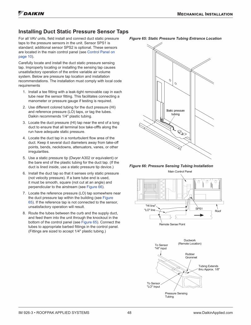
IM 926-3 • ROOFPAK APPLIED SYSTEMS 48 www.DaikinApplied.com
Mechanical Installation
Installing Duct Static Pressure Sensor Taps For all VAV units, field install and connect duct static pressure taps to the pressure sensors in the unit. Sensor SPS1 is standard; additional sensor SPS2 is optional. These sensors are located in the main control panel (see Control Panel on page 10).
Carefully locate and install the duct static pressure sensing tap. Improperly locating or installing the sensing tap causes unsatisfactory operation of the entire variable air volume system. Below are pressure tap location and installation recommendations. The installation must comply with local code requirements
1. Install a tee fitting with a leak-tight removable cap in each tube near the sensor fitting. This facilitates connecting a manometer or pressure gauge if testing is required.
2. Use different colored tubing for the duct pressure (HI) and reference pressure (LO) taps, or tag the tubes. Daikin recommends 1/4" plastic tubing.
3. Locate the duct pressure (HI) tap near the end of a long duct to ensure that all terminal box take-offfs along the run have adequate static pressure.
4. Locate the duct tap in a nonturbulent flow area of the duct. Keep it several duct diameters away from take-off points, bends, neckdowns, attenuators, vanes, or other irregularities.
5. Use a static pressure tip (Dwyer A302 or equivalent) or the bare end of the plastic tubing for the duct tap. (If the duct is lined inside, use a static pressure tip device.)
6. Install the duct tap so that it senses only static pressure (not velocity pressure). If a bare tube end is used, it must be smooth, square (not cut at an angle) and perpendicular to the airstream (see Figure 66).
7. Locate the reference pressure (LO) tap somewhere near the duct pressure tap within the building (see Figure 65). If the reference tap is not connected to the sensor, unsatisfactory operation will result.
8. Route the tubes between the curb and the supply duct, and feed them into the unit through the knockout in the bottom of the control panel (see Figure 65). Connect the tubes to appropriate barbed fittings in the control panel. (Fittings are sized to accept 1/4" plastic tubing.)
Figure 65: Static Pressure Tubing Entrance Location
Figure 66: Pressure Sensing Tubing Installation
Static pressuretubing
Main Control Panel
"HI line""LO" line
Remote Sense Point
RoofSPS1
RubberGrommet
Ductwork(Remote Location)To Sensor
"HI" input
Tubing Extendsthru Approx. 1/8"
To Sensor"LO" Input
Pressure SensingTubing
Mechanical Installation
www.DaikinApplied.com 49 IM 926-3 • ROOFPAK APPLIED SYSTEMS
Installing Building Static Pressure Sensor Taps CAUTION
Fragile sensor fittings. If you must remove tubing from a pressure sensor fitting, use care. Do not use excessive force or wrench the tubing back and forth to remove; the fitting can break off and damage sensor.
If a unit has direct building static pressure control capability, you must field install and connect static pressure taps to pressure sensor SPS2 in the unit. This sensor is located at the bottom of the main control panel next to terminal block TB2.
Locate and install the two static pressure sensing taps. Improper location or installation of the sensor taps causes unsatisfactory operation. Below are pressure tap location and installation recommendations for both building envelope and lab, or “space within a space” pressure control applications. The installation must comply with local code requirements.
Building Pressurization Applications 1. Install a tee fitting with a leak-tight removable cap in each
tube near the sensor fitting. This facilitates connecting a manometer or pressure gauge if testing is required.
2. Locate the building pressure (HI) tap in the area that requires the closest control. Typically, this is a ground level floor that has doors to the outside.
3. Locate the building tap so it is not influenced by any source of moving air (velocity pressure). These sources may include air diffusers or outside doors.
4. Route the building tap tube between the curb and the supply duct and feed it into the unit through the knockout in the bottom of the control panel (see Figure 65). Connect the tube to the 1/4-inch HI fitting for sensor SPS2.
5. Locate the reference pressure (LO) tap on the roof. Keep it away from the condenser fans, walls, or anything else that may cause air turbulence. Mount it high enough above the roof so it is not affected by snow. Not connecting the reference tap to the sensor results in unsatisfactory operation.
6. Use an outdoor static pressure tip (Dwyer A306 or equivalent) to minimize the effects of wind. Place a screen over the sensor to keep out insects. Loosely packed cotton works well.
7. Route the outdoor tap tube out of the main control panel through a small field-cut opening in the edge of the control wiring raceway cover (see Figure 65). Cut this “mouse hole” in the vertical portion of the edge. Seal the penetration to prevent water from entering. Connect tube to the 1/4-inch LO fitting for sensor SPS2.
Lab Pressurization Applications 1. Install a “T” fitting with a leak-tight removable cap in each
tube near the sensor fitting. This facilitates connecting a manometer or pressure gauge if testing is required.
2. Use different colored tubing for the controlled space pressure (HI) and reference pressure (LO) taps, or tag the tubes.
3. Regardless whether the controlled space is positive or negative with respect to its reference, locate the HI pressure tap in the controlled space (setpoint can be set between –0.2" and 0.2" wc).
4. Locate the reference pressure (LO) tap in the area surrounding the controlled space. Not locating the reference tap to the sensor results in unsatisfactory operation.
5. Locate both taps so they are not influenced by any source of moving air (velocity pressure). These sources may include air diffusers or doors between the high and low pressure areas.
6. Route the building tap tube between the curb and the supply duct and feed it into the unit through the knockout in the bottom of the control panel (see Figure 65).
7. Connect the tube to the 1/4-inch HI fitting for sensor SPS2.
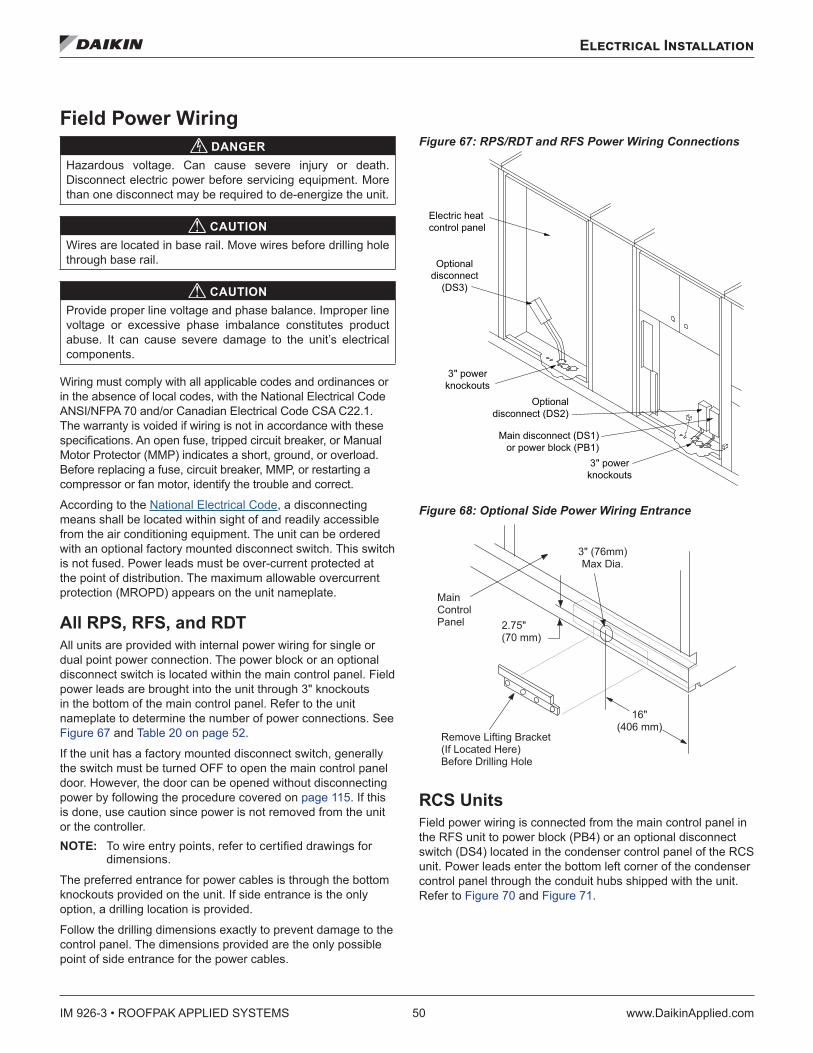
IM 926-3 • ROOFPAK APPLIED SYSTEMS 50 www.DaikinApplied.com
Electrical Installation
Electrical Installation
Field Power Wiring DANGER
Hazardous voltage. Can cause severe injury or death. Disconnect electric power before servicing equipment. More than one disconnect may be required to de-energize the unit.
CAUTIONWires are located in base rail. Move wires before drilling hole through base rail.
CAUTIONProvide proper line voltage and phase balance. Improper line voltage or excessive phase imbalance constitutes product abuse. It can cause severe damage to the unit’s electrical components.
Wiring must comply with all applicable codes and ordinances or in the absence of local codes, with the National Electrical Code ANSI/NFPA 70 and/or Canadian Electrical Code CSA C22.1. The warranty is voided if wiring is not in accordance with these specifications. An open fuse, tripped circuit breaker, or Manual Motor Protector (MMP) indicates a short, ground, or overload. Before replacing a fuse, circuit breaker, MMP, or restarting a compressor or fan motor, identify the trouble and correct.
According to the National Electrical Code, a disconnecting means shall be located within sight of and readily accessible from the air conditioning equipment. The unit can be ordered with an optional factory mounted disconnect switch. This switch is not fused. Power leads must be over-current protected at the point of distribution. The maximum allowable overcurrent protection (MROPD) appears on the unit nameplate.
All RPS, RFS, and RDT All units are provided with internal power wiring for single or dual point power connection. The power block or an optional disconnect switch is located within the main control panel. Field power leads are brought into the unit through 3" knockouts in the bottom of the main control panel. Refer to the unit nameplate to determine the number of power connections. See Figure 67 and Table 20 on page 52.
If the unit has a factory mounted disconnect switch, generally the switch must be turned OFF to open the main control panel door. However, the door can be opened without disconnecting power by following the procedure covered on page 115. If this is done, use caution since power is not removed from the unit or the controller. NOTE: To wire entry points, refer to certified drawings for
dimensions.
The preferred entrance for power cables is through the bottom knockouts provided on the unit. If side entrance is the only option, a drilling location is provided.
Follow the drilling dimensions exactly to prevent damage to the control panel. The dimensions provided are the only possible point of side entrance for the power cables.
Figure 67: RPS/RDT and RFS Power Wiring Connections
Figure 68: Optional Side Power Wiring Entrance
RCS Units Field power wiring is connected from the main control panel in the RFS unit to power block (PB4) or an optional disconnect switch (DS4) located in the condenser control panel of the RCS unit. Power leads enter the bottom left corner of the condenser control panel through the conduit hubs shipped with the unit. Refer to Figure 70 and Figure 71.
Electric heatcontrol panel
Optionaldisconnect
(DS3)
3" powerknockouts
Optionaldisconnect (DS2)
3" powerknockouts
Main disconnect (DS1)or power block (PB1)
� � � � � � � � � � � � � � � � � � � � � �� � � � � � � � � � � � � � � � � � � � � � � � � � � � � � � � � �
� � � �� � � � � � � �� � � � � � � � � �
� � � � � �
� � � � � � � � � � � � � � �
� � �� � � � � �
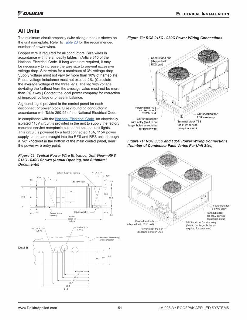
Electrical Installation
www.DaikinApplied.com 51 IM 926-3 • ROOFPAK APPLIED SYSTEMS
All Units The minimum circuit ampacity (wire sizing amps) is shown on the unit nameplate. Refer to Table 20 for the recommended number of power wires.
Copper wire is required for all conductors. Size wires in accordance with the ampacity tables in Article 310 of the National Electrical Code. If long wires are required, it may be necessary to increase the wire size to prevent excessive voltage drop. Size wires for a maximum of 3% voltage drop. Supply voltage must not vary by more than 10% of nameplate. Phase voltage imbalance must not exceed 2%. (Calculate the average voltage of the three legs. The leg with voltage deviating the farthest from the average value must not be more than 2% away.) Contact the local power company for correction of improper voltage or phase imbalance.
A ground lug is provided in the control panel for each disconnect or power block. Size grounding conductor in accordance with Table 250-95 of the National Electrical Code.
In compliance with the National Electrical Code, an electrically isolated 115V circuit is provided in the unit to supply the factory mounted service receptacle outlet and optional unit lights. This circuit is powered by a field connected 15A, 115V power supply. Leads are brought into the RFS and RPS units through a 7/8" knockout in the bottom of the main control panel, near the power wire entry point.
Figure 69: Typical Power Wire Entrance, Unit View—RPS 015C - 040C Shown (Actual Opening, see Submittal Documents)
Figure 70: RCS 015C - 030C Power Wiring Connections
Figure 71: RCS 036C and 105C Power Wiring Connections (Number of Condenser Fans Varies Per Unit Size)
Detail B
12.0
8.8
3.8
0.9 Dia. K.O. (Qty 4)
3.0 Dia. K.O. (Qty 3)
6.8
7.6 6.6
Varies based on options
Reference from leaving air end of section
Bottom return opening
86.5
76.0
3.8
10.0
6.0
20.0 Bottom Supply air opening
1.50 MPT drainA
10.03.8
C
B
C
E
3.8
94.0
11.9 12.9
22.3 17.7
15.3
24.3
Conduit and hub(shipped withRCS unit)
Terminal block TB8for 115V servicereceptical circuit
7/8" knockout forTB8 wire entry
switch DS4or disconnect
Power block PB4
7/8" knockout forwire entry (field to cut
larger holes as requiredfor power wire)
Power block PB4 ordisconnect switch DS4
7/8" knockout forTB8 wire entry
Terminal aTB8for 115V servicereceptical circuit
7/8" knockout for wire entry(field to cut larger holes asrequired for pwer wire)
Conduit and hub(shipped with RCS unit)
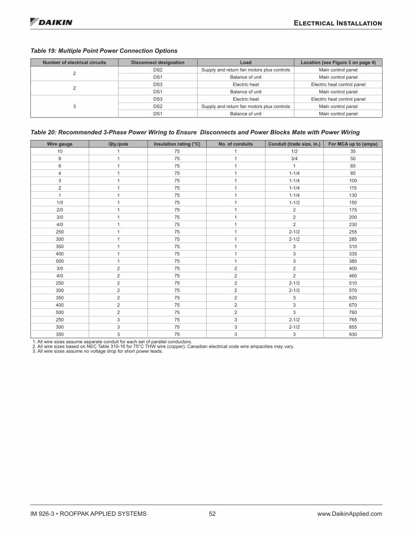
IM 926-3 • ROOFPAK APPLIED SYSTEMS 52 www.DaikinApplied.com
Electrical Installation
Table 19: Multiple Point Power Connection Options
Number of electrical circuits Disconnect designation Load Location (see Figure 3 on page 4)
2DS2 Supply and return fan motors plus controls Main control panel DS1 Balance of unit Main control panel
2DS3 Electric heat Electric heat control panel DS1 Balance of unit Main control panel
3DS3 Electric heat Electric heat control panel DS2 Supply and return fan motors plus controls Main control panel DS1 Balance of unit Main control panel
Table 20: Recommended 3-Phase Power Wiring to Ensure Disconnects and Power Blocks Mate with Power Wiring
Wire gauge Qty ./pole Insulation rating (°C) No . of conduits Conduit (trade size, in .) For MCA up to (amps) 10 1 75 1 1/2 358 1 75 1 3/4 506 1 75 1 1 654 1 75 1 1-1/4 853 1 75 1 1-1/4 1002 1 75 1 1-1/4 1151 1 75 1 1-1/4 130
1/0 1 75 1 1-1/2 1502/0 1 75 1 2 1753/0 1 75 1 2 2004/0 1 75 1 2 230250 1 75 1 2-1/2 255300 1 75 1 2-1/2 285350 1 75 1 3 310400 1 75 1 3 335500 1 75 1 3 3803/0 2 75 2 2 4004/0 2 75 2 2 460250 2 75 2 2-1/2 510300 2 75 2 2-1/2 570350 2 75 2 3 620400 2 75 2 3 670500 2 75 2 3 760250 3 75 3 2-1/2 765300 3 75 3 2-1/2 855350 3 75 3 3 930
1. All wire sizes assume separate conduit for each set of parallel conductors. 2. All wire sizes based on NEC Table 310-16 for 75°C THW wire (copper). Canadian electrical code wire ampacities may vary. 3. All wire sizes assume no voltage drop for short power leads.
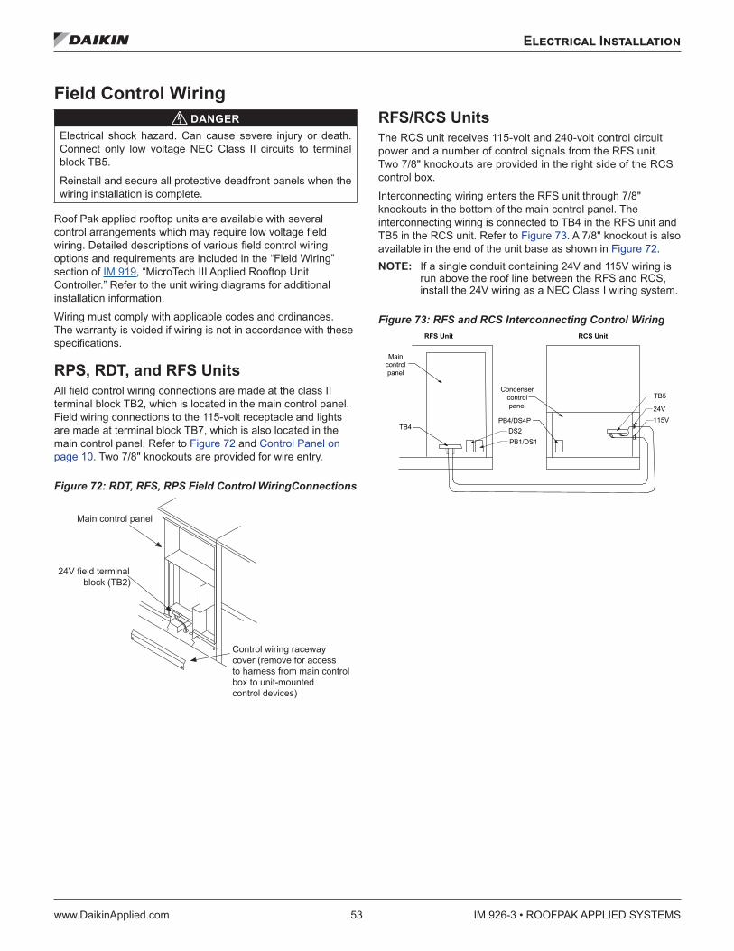
Electrical Installation
www.DaikinApplied.com 53 IM 926-3 • ROOFPAK APPLIED SYSTEMS
Field Control Wiring DANGER
Electrical shock hazard. Can cause severe injury or death. Connect only low voltage NEC Class II circuits to terminal block TB5.
Reinstall and secure all protective deadfront panels when the wiring installation is complete.
Roof Pak applied rooftop units are available with several control arrangements which may require low voltage field wiring. Detailed descriptions of various field control wiring options and requirements are included in the “Field Wiring” section of IM 919, “MicroTech III Applied Rooftop Unit Controller.” Refer to the unit wiring diagrams for additional installation information.
Wiring must comply with applicable codes and ordinances. The warranty is voided if wiring is not in accordance with these specifications.
RPS, RDT, and RFS Units All field control wiring connections are made at the class II terminal block TB2, which is located in the main control panel. Field wiring connections to the 115-volt receptacle and lights are made at terminal block TB7, which is also located in the main control panel. Refer to Figure 72 and Control Panel on page 10. Two 7/8" knockouts are provided for wire entry.
Figure 72: RDT, RFS, RPS Field Control WiringConnections
RFS/RCS Units The RCS unit receives 115-volt and 240-volt control circuit power and a number of control signals from the RFS unit. Two 7/8" knockouts are provided in the right side of the RCS control box.
Interconnecting wiring enters the RFS unit through 7/8" knockouts in the bottom of the main control panel. The interconnecting wiring is connected to TB4 in the RFS unit and TB5 in the RCS unit. Refer to Figure 73. A 7/8" knockout is also available in the end of the unit base as shown in Figure 72. NOTE: If a single conduit containing 24V and 115V wiring is
run above the roof line between the RFS and RCS, install the 24V wiring as a NEC Class I wiring system.
Figure 73: RFS and RCS Interconnecting Control Wiring
Main control panel
24V field terminalblock (TB2)
Control wiring raceway cover (remove for access to harness from main control box to unit-mounted control devices)
TB5
24V115VPB4/DS4P
Condensercontrolpanel
DS2PB1/DS1
TB4
Main
RFS Unit RCS Unit
controlpanel
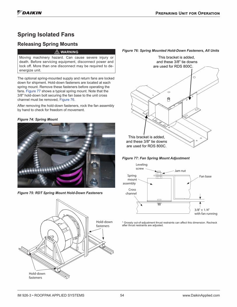
IM 926-3 • ROOFPAK APPLIED SYSTEMS 54 www.DaikinApplied.com
Preparing Unit for Operation
Preparing Unit for Operation
Spring Isolated Fans Releasing Spring Mounts
WARNINGMoving machinery hazard. Can cause severe injury or death. Before servicing equipment, disconnect power and lock off. More than one disconnect may be required to de-energize unit.
The optional spring-mounted supply and return fans are locked down for shipment. Hold-down fasteners are located at each spring mount. Remove these fasteners before operating the fans. Figure 77 shows a typical spring mount. Note that the 3/8" hold-down bolt securing the fan base to the unit cross channel must be removed, Figure 76.
After removing the hold-down fasteners, rock the fan assembly by hand to check for freedom of movement.
Figure 74: Spring Mount
Figure 75: RDT Spring Mount Hold-Down Fasteners
Figure 76: Spring Mounted Hold-Down Fasteners, All Units
Figure 77: Fan Spring Mount Adjustment
* Grossly out-of-adjustment thrust restraints can affect this dimension. Recheck after thrust restraints are adjusted.
Hold-downfasteners
Hold-downfasteners
This bracket is added,and these 3/8" tie downs
are used for RDS 800C.
This bracket is added,and these 3/8" tie downsare used for RDS 800C.
3 /8 " ± 1 /4 " with fan running
Leveling screw
Spring mount
assembly
Cross channel
Jam nut
Fan base
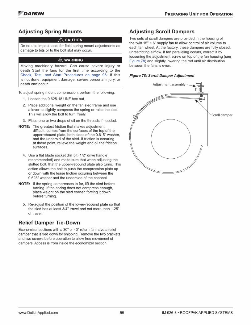
Preparing Unit for Operation
www.DaikinApplied.com 55 IM 926-3 • ROOFPAK APPLIED SYSTEMS
Adjusting Spring Mounts CAUTION
Do no use impact tools for field spring mount adjustments as damage to bits or to the bolt slot may occur.
WARNINGMoving machinery hazard. Can cause severe injury or death Start the fans for the first time according to the Check, Test, and Start Procedures on page 96. If this is not done, equipment damage, severe personal injury, or death can occur.
To adjust spring mount compression, perform the following:
1. Loosen the 0.625-18 UNF hex nut.
2. Place additional weight on the fan sled frame and use a lever to slightly compress the spring or raise the sled. This will allow the bolt to turn freely.
3. Place one or two drops of oil on the threads if needed. NOTE: The greatest friction that makes adjustment
difficult, comes from the surfaces of the top of the upperrebound plate, both sides of the 0.615" washer, and the undersid of the sled. If friction is occuring at these point, relieve the weight and oil the friction surfaces.
4. Use a flat blade socket drill bit (1/2" drive handle recommended) and make sure that when adjusting the slotted bolt, that the upper-rebound plate also turns. This action allows the bolt to push the compression plate up or down with the lease friction occuring between the 0.625" washer and the underside of the channel.
NOTE: If the spring compresses to far, lift the sled before turning. If the spring does not compress enough, place weight on the sled corner, forcing it down before turning.
5. Re-adjust the position of the lower-rebound plate so that the sled has at least 3/4" travel and not more than 1.25" of travel.
Relief Damper Tie-DownEconomizer sections with a 30" or 40" return fan have a relief damper that is tied down for shipping. Remove the two brackets and two screws before operation to allow free movement of dampers. Access is from inside the economizer section.
Adjusting Scroll DampersTwo sets of scroll dampers are provided in the housing of the twin 15" × 6" supply fan to allow control of air volume to each fan wheel. At the factory, these dampers are fully closed, unrestricting airflow. If fan paralleling occurs, correct it by loosening the adjustment screw on top of the fan housing (see Figure 78) and slightly lowering the rod until air distribution between the fans is even.
Figure 78: Scroll Damper Adjustment
Adjustment assembly
Scroll damper
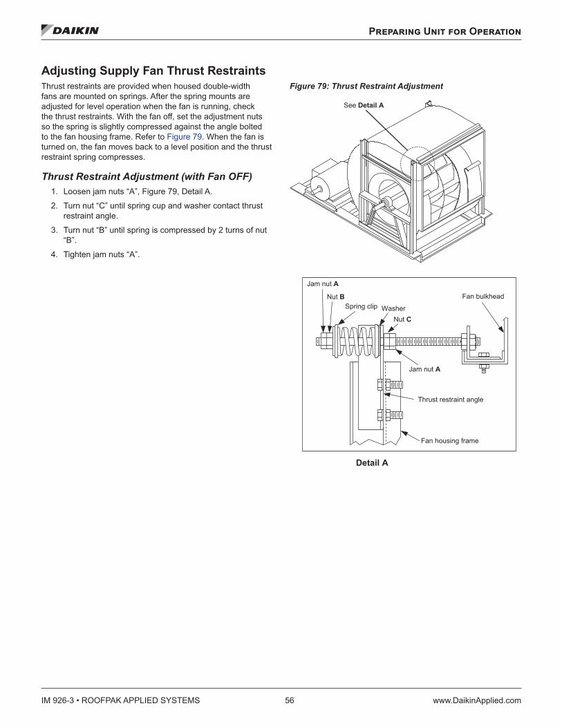
IM 926-3 • ROOFPAK APPLIED SYSTEMS 56 www.DaikinApplied.com
Preparing Unit for Operation
Adjusting Supply Fan Thrust Restraints Thrust restraints are provided when housed double-width fans are mounted on springs. After the spring mounts are adjusted for level operation when the fan is running, check the thrust restraints. With the fan off, set the adjustment nuts so the spring is slightly compressed against the angle bolted to the fan housing frame. Refer to Figure 79. When the fan is turned on, the fan moves back to a level position and the thrust restraint spring compresses.
Thrust Restraint Adjustment (with Fan OFF)1. Loosen jam nuts “A”, Figure 79, Detail A.
2. Turn nut “C” until spring cup and washer contact thrust restraint angle.
3. Turn nut “B” until spring is compressed by 2 turns of nut “B”.
4. Tighten jam nuts “A”.
Figure 79: Thrust Restraint Adjustment
Jam nut A
Nut BSpring clip
Nut C
Jam nut A
Washer
Fan bulkhead
Thrust restraint angle
Fan housing frame
See Detail A
Detail A
Thrust restraint adjustment (with fan off)1. Loosen jam nuts A.2. Turn nut C until spring cup and washer contact thrust restraint angle.3. Turn nut B until spring is compressed by two turns of nut B.4. Tighten jam nuts A.
Sequences of Operation
www.DaikinApplied.com 57 IM 926-3 • ROOFPAK APPLIED SYSTEMS
Sequences of Operation
The following sequences of operation are for a typical “C” vintage applied rooftop unit equipped with MicroTech III, an economizer, 4-compressor/4-stage cooling, 3 to 1 turn down burner, variable frequency drives (VFD), a return air fan and an external time clock. These sequences describe the ladder wiring diagram logic in detail; refer to Wiring Diagrams on page 63 as you read them. Note that your unit’s sequences of operation may vary from those described here. Refer to the wiring diagrams supplied with the unit for exact information.
For detailed description of operation information relating to the MicroTech III controller’s software, refer to the appropriate operation manual (see Table 1 on page 3). These manuals describe the various setpoints, parameters, operating states, and control algorithms that affect rooftop unit operation.
Power-up When primary power is connected to the unit, 115 V (ac) power is fed through control circuit transformer T1 and control circuit fuse F1C (line 166, Figure 84 on page 66) to compressor crankcase heaters HTR-1, HTR-2, HTR-3 and HTR-4 (lines 502-540, Figure 90 on page 76).
When system switch S1 (line 203, Figure 88 on page 72) is closed, low voltage transformers T2 (line 203, Figure 90 on page 76), T3 (line 251, Figure 88 on page 72) and T9 (line 802, not shown) energize, and 115 V (ac) power is supplied to the following:
• The supply fan VFD (line 135-137, Figure 84 on page 66)
• M40A to energize the return fan VFD (line 147-149, Figure 84 on page 66)
• Heating control panel (line 603, Figure 89 on page 74) • Economizer actuator (lines 256-257)
Transformer T2 supplies 24 V (AC) power to terminals 24V and COM on the main control board MCB (lines 207 and 208). Transformer T2 supplies 24 V (AC) power to the following (see Figure 84 on page 66):
• Switch S7 On-Auto-OFF (line 217) • Enthalpy sensor OAE (line 247) • External time clock contacts (line 215) • Airflow interlock switch PC7 (line 228) • Dirty filter switches PC5 and PC6 (lines 242 and 247,
not shown) • Gas furnace alarm relay R24 (line 225, not shown) • Freezestat switch FS1 (line 244, hot water or steam heat
only, not shown) • Smoke detectors SD1 and SD2 (line 237)
The time clock, S7 switch , and emergency shutdown terminals (lines 217-222) control fan operation.
NOTE: Unit ships with factory installed jumpers between TB2 101 and 105 and between 101 and 106.
Fan Operation When the main control board (MCB) commands the supply and return fans to start, the unit enters the Startup operating state. As a result, a 3-minute timer is set, output MCB-BO3 (line 307) energizes, and relay R26 energizes (line 306, not shown).
After the 3-minute timer expires, the unit enters the Recirc operating state. As a result, output MCB-BO1 energizes relay R67 (line 401). This gives a start signal to supply fan drive AFD10 (line 445). Four seconds after MCB-BO1 is energized, output MCB-BO2 energizes relay R68 (line 404). This gives a start signal to return fan drive AFD20 (line 445).
Within 120 seconds after the fans start, the controller expects airflow switch PC7 (line 228) to close and thus energize binary input MCB-BI6. (If MCB-BI6 does not energize, the controller assumes the fans did not start. It then shuts down the unit and generates an alarm.)
During the Recirc operating state, the outside air damper is held closed. The controller does this by energizing output MCB-BO5 (line 318). On VAV units, output MCB-BO12, the VAV box output, is also de-energized (line 309) during the Recirc state.
The supply fan adjustable frequency drive (AFD10) is modulated to maintain the duct static pressure setpoint. When energized, output MCB-BO14 (line 407) drives AFD10 toward increased capacity; MCB-BO13 (line 405) drives it toward decreased capacity. On VAV units or CAV units equipped with return fan capacity control, the adjustable frequency drive (AFD20) is modulated to maintain an acceptable building static pressure (using either VaneTrol logic or direct measurement of building pressure; see the appropriate OM for more information). When energized, output MCB-BO16 (line 409) drives AFD20 toward increased capacity; MCB-BO15 (line 411) drives them toward decreased capacity. NOTE: If the inverter bypass switch S4 (lines426 and 430)
is in the bypass position, MMP30 and MMP40 (line 132 and 144) protect the fans from excessive current draw. If either the supply or return fan is drawing excessive current, one of the MMPs triggers an auxiliary contacts (line 426) and open the circuit, causing both fans to stop.
IM 926-3 • ROOFPAK APPLIED SYSTEMS 58 www.DaikinApplied.com
Sequences of Operation
Economizer Operation Refer to Figure 90 on page 76. When the outdoor air is suitable for free cooling, the switch in enthalpy sensor OAE is in position “3” (line 248, Figure 90 on page 76) energizing analog input AIX5. When AIX5 energizes, the economizer is enabled. (Note: If selected from the keypad, the enthalpy decision can be made based on outdoor temperature. In that condition, if the outdoor air temperature is less than or equal to the changeover set point, the economizer is enabled.) If cooling is required, the economizer dampers (ACT3) are modulated to maintain the discharge air temperature setpoint. Analog input AIX5 drives the outdoor air dampers toward the open and closed (line 256) position. If the outdoor air dampers are wide open and more cooling is required, the dampers hold their positions and mechanical cooling is activated (see below).
When the outdoor air is not suitable for free cooling, the switch in enthalpy sensor OAE is in position “1,” de-energizing analog input AIX5. (Alternatively, the outdoor air temperature is above the changeover setpoint plus the economizer changeover differential). When the economizer is disabled, the dampers are held at their minimum position.
Mechanical Cooling Operation 4-Compressor/4-Stage Unit Refer to Figure 90 on page 76 and Figure 91 on page 78 as you read this sequence of operation. In this configuration there are four equally sized compressors and two cooling circuits. In the following description, compressor #1 is lead. However, if Auto Lead/Lag Staging is selected on the keypad, the lead compressor is the one in the lead circuit with the least number of run hours.
When the unit disconnect is closed, 115 V (ac) power is supplied directly from control transformer T1 to the compressor crankcase heaters, HTR-1, 2, 3, and 4 (lines 836 - 848, 853) and motor protectors MP1, 2, 3, and 4 (lines 836 - 848, 854). This same 115 V (ac) source also goes through:
• System switch, S1 (line 203, Figure 88 on page 72) • The optional phase voltage monitors, PVM1 and 2 (lines
203, 802, not shown) • The optional ground fault relays, GFR1 and 2 (lines 203,
802, not shown)
Compressors are staged by 115 V (ac) power supplied to the following:
• Frost protect FP1 to CCB1-BI8 (line 812, not shown)— Optional when no hot gas bypass is ordered on the unit
• Frost protect FP2 to CCB2-BI8 (line 823, not shown)— Optional when no hot gas bypass is ordered on the unit
• HP relay R1 to CCB1-BI7 (lines 812) • HP relay R2 to CCB2-BI7 (lines 823) • Compressor contactor status M1 to CCB1-BI9 (line 812) • Compressor contactor status M2 to CCB2-BI9 (line 823) • Compressor contactor status M3 to CCB1-BI10 (line 814) • Compressor contactor status M4 to CCB2-BI10 (line 825)
Cross Circuit Loading See line 812, Figure 91 on page 78. During a call for cooling, if HP1 is satisfied, then DO1 closes. If MMP1 and MP1 are satisfied, then M1 compressor contactor is energized to bring on compressor 1 on refrigerant circuit 1 (line 708 - 710, Figure 86 on page 70. The M1 auxiliary brings on:
• required condenser fans (line 854) • liquid line and optional hot gas solenoids (lines 855 and
856)
Compressor 2 (refrigerant circuit 2) is the 2nd stage of cooling and is brought on in the same manner (line 823, Figure 95 on page 82 and lines 708 - 710, Figure 86 on page 70).
Circuit 2 condenser fans and solenoids are controlled in the same manner on lines 861 - 865).
The 3rd stage of cooling is controlled by DO2 (line 814) and brings on compressor 3 if MMP3 and MP3 are satisfied.
The 4th stage of cooling is controlled by DO4 (lines 826) and brings on compressor 3 if MMP3 and MP3 are satisfied.
Lead Circuit Loading The loading and unloading process is similar except that both compressors in the lead cooling circuit 1 energize before energizing any compressors in lag circuit 2.
Heating Gas Furnace, Super Modulating Burner (20:1 Turndown) Refer to Figure 89 on page 74 for a sequence of operation.
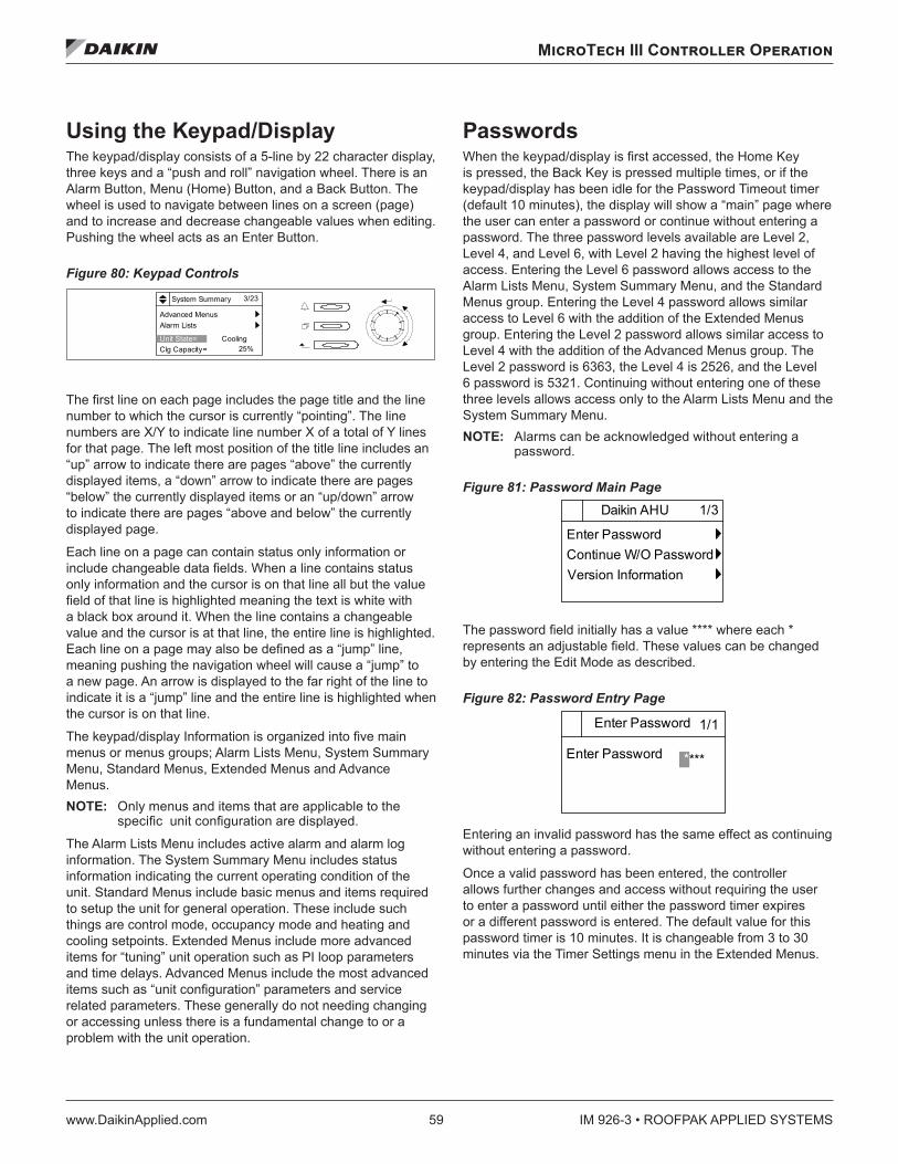
MicroTech III Controller Operation
www.DaikinApplied.com 59 IM 926-3 • ROOFPAK APPLIED SYSTEMS
MicroTech III Controller Operation
Using the Keypad/Display The keypad/display consists of a 5-line by 22 character display, three keys and a “push and roll” navigation wheel. There is an Alarm Button, Menu (Home) Button, and a Back Button. The wheel is used to navigate between lines on a screen (page) and to increase and decrease changeable values when editing. Pushing the wheel acts as an Enter Button.
Figure 80: Keypad Controls
The first line on each page includes the page title and the line number to which the cursor is currently “pointing”. The line numbers are X/Y to indicate line number X of a total of Y lines for that page. The left most position of the title line includes an “up” arrow to indicate there are pages “above” the currently displayed items, a “down” arrow to indicate there are pages “below” the currently displayed items or an “up/down” arrow to indicate there are pages “above and below” the currently displayed page.
Each line on a page can contain status only information or include changeable data fields. When a line contains status only information and the cursor is on that line all but the value field of that line is highlighted meaning the text is white with a black box around it. When the line contains a changeable value and the cursor is at that line, the entire line is highlighted. Each line on a page may also be defined as a “jump” line, meaning pushing the navigation wheel will cause a “jump” to a new page. An arrow is displayed to the far right of the line to indicate it is a “jump” line and the entire line is highlighted when the cursor is on that line.
The keypad/display Information is organized into five main menus or menus groups; Alarm Lists Menu, System Summary Menu, Standard Menus, Extended Menus and Advance Menus. NOTE: Only menus and items that are applicable to the
specific unit configuration are displayed.
The Alarm Lists Menu includes active alarm and alarm log information. The System Summary Menu includes status information indicating the current operating condition of the unit. Standard Menus include basic menus and items required to setup the unit for general operation. These include such things are control mode, occupancy mode and heating and cooling setpoints. Extended Menus include more advanced items for “tuning” unit operation such as PI loop parameters and time delays. Advanced Menus include the most advanced items such as “unit configuration” parameters and service related parameters. These generally do not needing changing or accessing unless there is a fundamental change to or a problem with the unit operation.
Passwords When the keypad/display is first accessed, the Home Key is pressed, the Back Key is pressed multiple times, or if the keypad/display has been idle for the Password Timeout timer (default 10 minutes), the display will show a “main” page where the user can enter a password or continue without entering a password. The three password levels available are Level 2, Level 4, and Level 6, with Level 2 having the highest level of access. Entering the Level 6 password allows access to the Alarm Lists Menu, System Summary Menu, and the Standard Menus group. Entering the Level 4 password allows similar access to Level 6 with the addition of the Extended Menus group. Entering the Level 2 password allows similar access to Level 4 with the addition of the Advanced Menus group. The Level 2 password is 6363, the Level 4 is 2526, and the Level 6 password is 5321. Continuing without entering one of these three levels allows access only to the Alarm Lists Menu and the System Summary Menu. NOTE: Alarms can be acknowledged without entering a
password.
Figure 81: Password Main Page
The password field initially has a value **** where each * represents an adjustable field. These values can be changed by entering the Edit Mode as described.
Figure 82: Password Entry Page
Entering an invalid password has the same effect as continuing without entering a password.
Once a valid password has been entered, the controller allows further changes and access without requiring the user to enter a password until either the password timer expires or a different password is entered. The default value for this password timer is 10 minutes. It is changeable from 3 to 30 minutes via the Timer Settings menu in the Extended Menus.
3/23System Summary
Advanced MenusAlarm Lists
Unit State= CoolingClg Capacity= 25%
1/3Daikin AHU
Enter PasswordContinue W/O PasswordVersion Information
1/1Enter Password
Enter Password ****
IM 926-3 • ROOFPAK APPLIED SYSTEMS 60 www.DaikinApplied.com
MicroTech III Controller Operation
Navigation Mode In the Navigation Mode, when a line on a page contains no editable fields all but the value field of that line is highlighted meaning the text is white with a black box around it. When the line contains an editable value field the entire line is inverted when the cursor is pointing to that line.
When the navigation wheel is turned clockwise, the cursor moves to the next line (down) on the page. When the wheel is turned counter-clockwise the cursor moves to the previous line (up) on the page. The faster the wheel is turned the faster the cursor moves.
When the Back Button is pressed the display reverts back to the previously displayed page. If the Back button is repeated pressed the display continues to revert one page back along the current navigation path until the “main menu” is reached.
When the Menu (Home) Button is pressed the display reverts to the “main page.”
When the Alarm Button is depressed, the Alarm Lists menu is displayed.
Edit Mode The Editing Mode is entered by pressing the navigation wheel while the cursor is pointing to a line containing an editable field. Once in the edit mode pressing the wheel again causes the editable field to be highlighted. Turning the wheel clockwise while the editable field is highlighted causes the value to be increased. Turning the wheel counter-clockwise while the editable field is highlighted causes the value to be decreased. The faster the wheel is turned the faster the value is increased or decreased. Pressing the wheel again cause the new value to be saved and the keypad/display to leave the edit mode and return to the navigation mode.
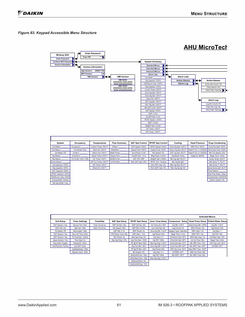
Menu Structure
www.DaikinApplied.com 61 IM 926-3 • ROOFPAK APPLIED SYSTEMS
Menu Structure
Figure 83: Keypad Accessible Menu Structure
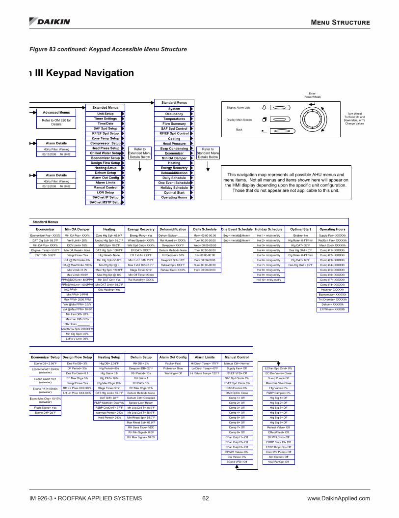
IM 926-3 • ROOFPAK APPLIED SYSTEMS 62 www.DaikinApplied.com
Menu Structure
Figure 83 continued: Keypad Accessible Menu Structure
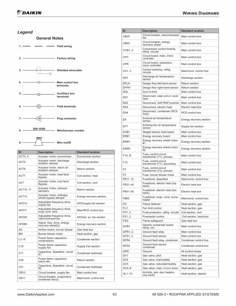
Wiring Diagrams
www.DaikinApplied.com 63 IM 926-3 • ROOFPAK APPLIED SYSTEMS
Wiring Diagrams
Legend
ID Description Standard locationACT3, 4 Actuator motor, economizer Economizer section
ACT5 Actuator motor, discharge isolation damper Discharge section
ACT6 Actuator motor, return air isolation damper Return section
ACT7 Actuator motor, heat face/bypass Coil section, heat
ACT Actuator motor, cool face/Bypass Coil section, cool
ACT10, 11 Actuator motor, exhaust dampers Return section
ACT12 Actuator motor, enthalpy wheel bypass damper Energy recovery section
AFD10 Adjustable frequency drive, supply fan AFD/supply fan section
AFD11 Adjustable frequency drive, evap cond. fans Main/RCE control box
AFD20 Adjustable frequency drive, return/exhaust fan AFD/ret. ex. fan section
AFD60 Adjust. freq. drive, energy recovery wheel(s) Energy recovery section
AS Airflow switch, burner blower Gas heat boxBM Burner blower motor Heat section, gas
C1–8 Power factor capacitors, compressors Condenser section
C10 Power factor capacitors, supply fan Supply Fan section
C11 Capacitors, Speedtrol, circuit #1 Condenser bulkhead
C20 Power factor capacitors, return fan Return section
C21 Capacitors, Speedtrol, circuit #2 Condenser bulkhead
CB10 Circuit breaker, supply fan Main control box
CB11 Circuit breaker, evaporative condenser fan(s) Main/cond. control box
ID Description Standard location
CB20 Circuit breaker, return/exhaust fan Main control box
CB60 Circuit breaker, energy recovery wheel Main control box
CCB1, 2 Compressor control boards, refrig. circuits Main control box
CPC Circuit board, main, micro controller Main control box
CPR Circuit board, expansion, micro controller Main control box
CS1, 2 Control switches, refrig. circuits Main/cond. control box
DAT Discharge air temperature sensor Discharge section
DFLH Design flow left-hand sensor Return sectionDFRH Design flow right-hand sensor Return sectionDHL Duct hi-limit Main control box
DS1 Disconnect, total unit or cond/heat Main control box
DS2 Disconnect, SAF/RAF/controls Main control boxDS3 Disconnect, electric heat Electric heat box
DS4 Disconnect, condenser (RCS Only) RCS control box
EA Exhaust air temperature sensor Energy recovery section
EFT Entering fan air temperature sensor Supply fan section
EHB1 Staged electric heat board Main control boxERB1 Energy recovery board Main control box
ERM1 Energy recovery wheel motor #1 Energy recovery section
ERM2 Energy recovery wheel motor #2 Energy recovery section
F1A, B Fuse, control circuit transformer (T1), primary Main control box
F1C Fuse, control circuit transformer (T1), secondary Main control box
F2 Fuse, control circuit transformer (T2), primary Main control box
F3 Fuse, burner blower motor Main control boxFB11, 12 Fuseblock, Speedtrol Main/cond. control box
FB31–40 Fuseblock, electric heat (top bank) Electric heat box
FB41–50 Fuseblock, electric heat (bot. bank) Electric heat box
FB65 Fuseblock, evap. cond. sump heater Main/cond. control box
FD Flame detector Heat section, gasFLC Fan limit control Heat section, gasFP1, 2 Frost protection, refrig. circuits Coil section, coolFS1, 2 Freezestat control Coil section, heat/coolFSG Flame safeguard Gas heat box
GCB1 Generic condenser board, refrig. circ. Main control box
GFR1, 2 Ground fault relay Main control boxGFS1, 2 Ground fault sensor Main control boxGFR4 Ground fault relay, condenser Condenser control box
GFS4 Ground fault sensor, condenser Condenser control box
GRD Ground All control boxesGV1 Gas valve, pilot Heat section, gasGV2 Gas valve, main/safety Heat section, gasGV3 Gas valve, redundant/safety Heat section, gasGV4–8 Gas valve, main, hi turn down Heat section, gas
HL1–10 Hi-limits, pwr, elec heaters (top bank) Heat section, electric
200/ H200
1. Field wiring
3. Shielded wire/cable
4. Main control box terminals
5. Auxilliary box terminals
6. Field terminals
7. Plug connector
8. Wire/harness number
General Notes
2. Factory wiring
9. Wire nut/IDWN7
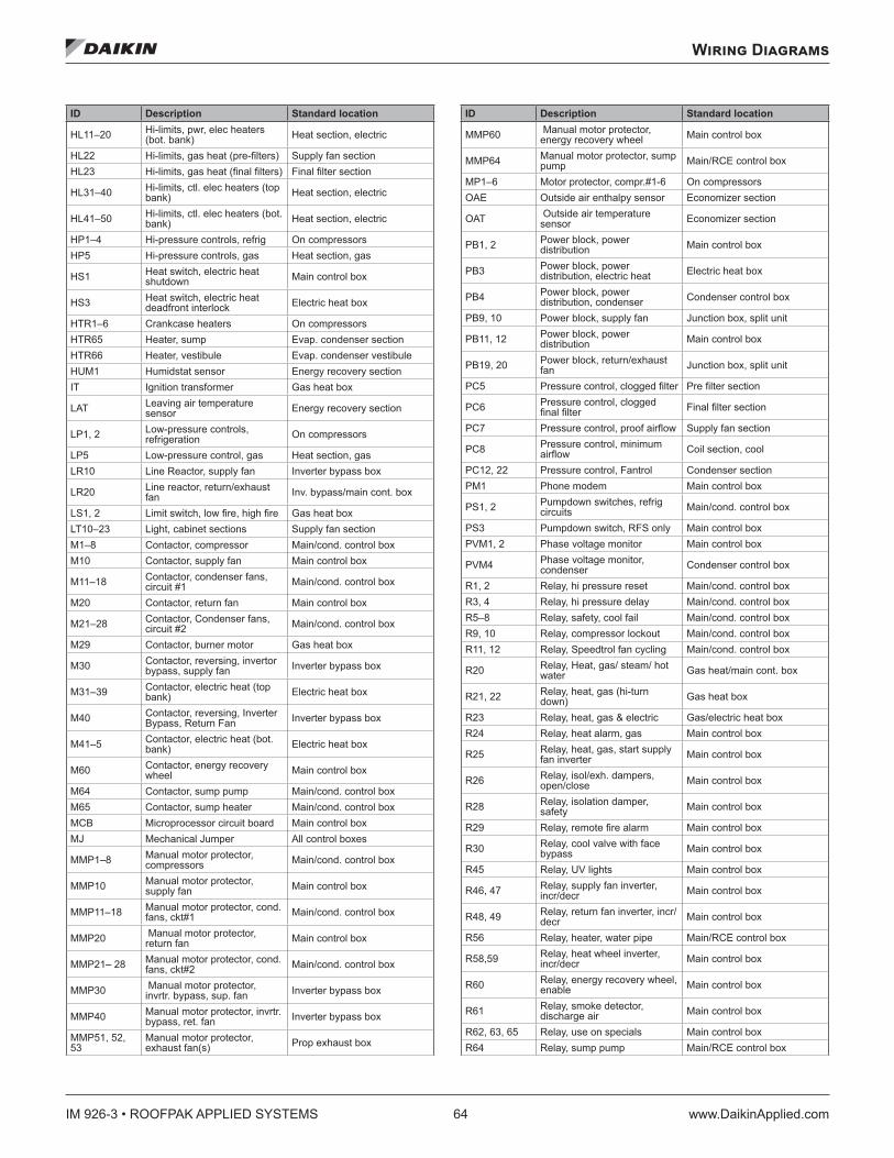
IM 926-3 • ROOFPAK APPLIED SYSTEMS 64 www.DaikinApplied.com
Wiring Diagrams
ID Description Standard location
HL11–20 Hi-limits, pwr, elec heaters (bot. bank) Heat section, electric
HL22 Hi-limits, gas heat (pre-filters) Supply fan sectionHL23 Hi-limits, gas heat (final filters) Final filter section
HL31–40 Hi-limits, ctl. elec heaters (top bank) Heat section, electric
HL41–50 Hi-limits, ctl. elec heaters (bot. bank) Heat section, electric
HP1–4 Hi-pressure controls, refrig On compressorsHP5 Hi-pressure controls, gas Heat section, gas
HS1 Heat switch, electric heat shutdown Main control box
HS3 Heat switch, electric heat deadfront interlock Electric heat box
HTR1–6 Crankcase heaters On compressorsHTR65 Heater, sump Evap. condenser sectionHTR66 Heater, vestibule Evap. condenser vestibuleHUM1 Humidstat sensor Energy recovery sectionIT Ignition transformer Gas heat box
LAT Leaving air temperature sensor Energy recovery section
LP1, 2 Low-pressure controls, refrigeration On compressors
LP5 Low-pressure control, gas Heat section, gasLR10 Line Reactor, supply fan Inverter bypass box
LR20 Line reactor, return/exhaust fan Inv. bypass/main cont. box
LS1, 2 Limit switch, low fire, high fire Gas heat boxLT10–23 Light, cabinet sections Supply fan sectionM1–8 Contactor, compressor Main/cond. control boxM10 Contactor, supply fan Main control box
M11–18 Contactor, condenser fans, circuit #1 Main/cond. control box
M20 Contactor, return fan Main control box
M21–28 Contactor, Condenser fans, circuit #2 Main/cond. control box
M29 Contactor, burner motor Gas heat box
M30 Contactor, reversing, invertor bypass, supply fan Inverter bypass box
M31–39 Contactor, electric heat (top bank) Electric heat box
M40 Contactor, reversing, Inverter Bypass, Return Fan Inverter bypass box
M41–5 Contactor, electric heat (bot. bank) Electric heat box
M60 Contactor, energy recovery wheel Main control box
M64 Contactor, sump pump Main/cond. control boxM65 Contactor, sump heater Main/cond. control boxMCB Microprocessor circuit board Main control boxMJ Mechanical Jumper All control boxes
MMP1–8 Manual motor protector, compressors Main/cond. control box
MMP10 Manual motor protector, supply fan Main control box
MMP11–18 Manual motor protector, cond. fans, ckt#1 Main/cond. control box
MMP20 Manual motor protector, return fan Main control box
MMP21– 28 Manual motor protector, cond. fans, ckt#2 Main/cond. control box
MMP30 Manual motor protector, invrtr. bypass, sup. fan Inverter bypass box
MMP40 Manual motor protector, invrtr. bypass, ret. fan Inverter bypass box
MMP51, 52, 53
Manual motor protector, exhaust fan(s) Prop exhaust box
ID Description Standard location
MMP60 Manual motor protector, energy recovery wheel Main control box
MMP64 Manual motor protector, sump pump Main/RCE control box
MP1–6 Motor protector, compr.#1-6 On compressorsOAE Outside air enthalpy sensor Economizer section
OAT Outside air temperature sensor Economizer section
PB1, 2 Power block, power distribution Main control box
PB3 Power block, power distribution, electric heat Electric heat box
PB4 Power block, power distribution, condenser Condenser control box
PB9, 10 Power block, supply fan Junction box, split unit
PB11, 12 Power block, power distribution Main control box
PB19, 20 Power block, return/exhaust fan Junction box, split unit
PC5 Pressure control, clogged filter Pre filter section
PC6 Pressure control, clogged final filter Final filter section
PC7 Pressure control, proof airflow Supply fan section
PC8 Pressure control, minimum airflow Coil section, cool
PC12, 22 Pressure control, Fantrol Condenser sectionPM1 Phone modem Main control box
PS1, 2 Pumpdown switches, refrig circuits Main/cond. control box
PS3 Pumpdown switch, RFS only Main control boxPVM1, 2 Phase voltage monitor Main control box
PVM4 Phase voltage monitor, condenser Condenser control box
R1, 2 Relay, hi pressure reset Main/cond. control boxR3, 4 Relay, hi pressure delay Main/cond. control boxR5–8 Relay, safety, cool fail Main/cond. control boxR9, 10 Relay, compressor lockout Main/cond. control boxR11, 12 Relay, Speedtrol fan cycling Main/cond. control box
R20 Relay, Heat, gas/ steam/ hot water Gas heat/main cont. box
R21, 22 Relay, heat, gas (hi-turn down) Gas heat box
R23 Relay, heat, gas & electric Gas/electric heat boxR24 Relay, heat alarm, gas Main control box
R25 Relay, heat, gas, start supply fan inverter Main control box
R26 Relay, isol/exh. dampers, open/close Main control box
R28 Relay, isolation damper, safety Main control box
R29 Relay, remote fire alarm Main control box
R30 Relay, cool valve with face bypass Main control box
R45 Relay, UV lights Main control box
R46, 47 Relay, supply fan inverter, incr/decr Main control box
R48, 49 Relay, return fan inverter, incr/decr Main control box
R56 Relay, heater, water pipe Main/RCE control box
R58,59 Relay, heat wheel inverter, incr/decr Main control box
R60 Relay, energy recovery wheel, enable Main control box
R61 Relay, smoke detector, discharge air Main control box
R62, 63, 65 Relay, use on specials Main control boxR64 Relay, sump pump Main/RCE control box
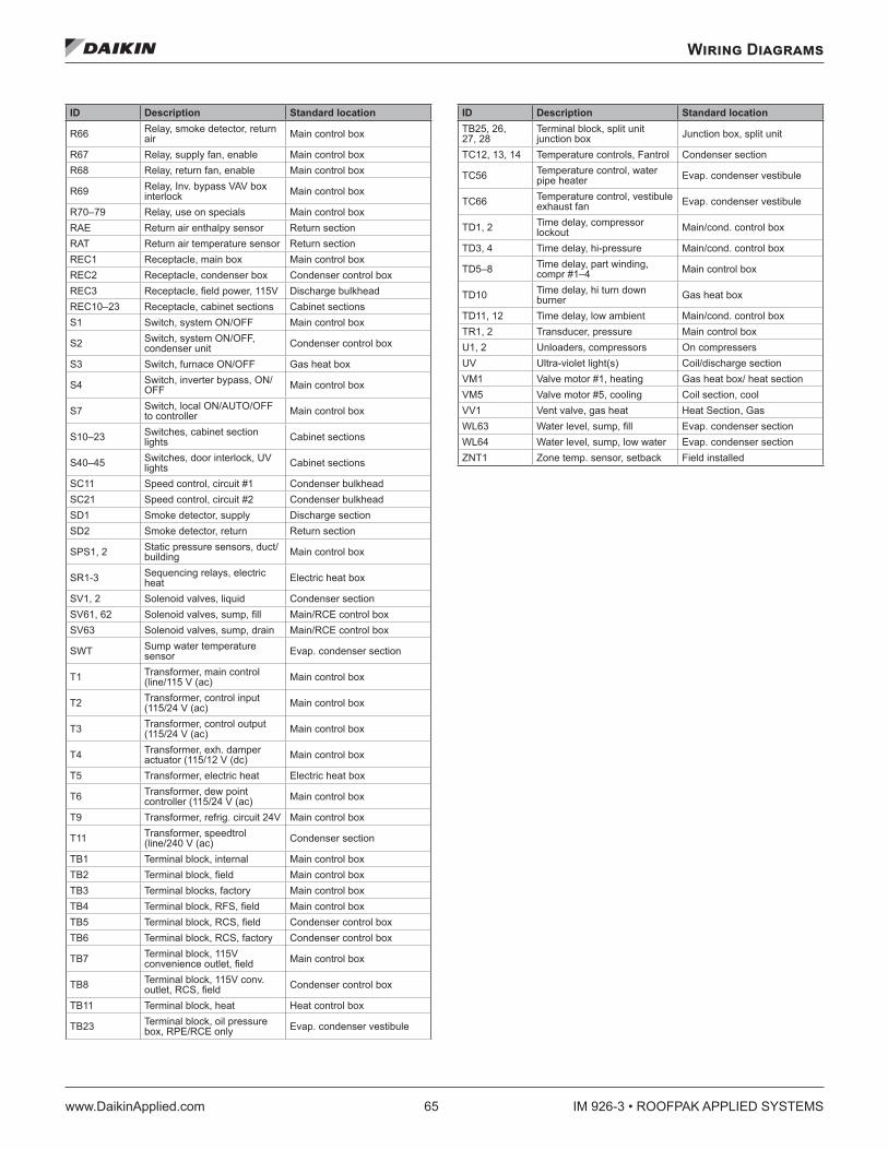
Wiring Diagrams
www.DaikinApplied.com 65 IM 926-3 • ROOFPAK APPLIED SYSTEMS
ID Description Standard location
R66 Relay, smoke detector, return air Main control box
R67 Relay, supply fan, enable Main control boxR68 Relay, return fan, enable Main control box
R69 Relay, Inv. bypass VAV box interlock Main control box
R70–79 Relay, use on specials Main control boxRAE Return air enthalpy sensor Return sectionRAT Return air temperature sensor Return sectionREC1 Receptacle, main box Main control boxREC2 Receptacle, condenser box Condenser control boxREC3 Receptacle, field power, 115V Discharge bulkheadREC10–23 Receptacle, cabinet sections Cabinet sectionsS1 Switch, system ON/OFF Main control box
S2 Switch, system ON/OFF, condenser unit Condenser control box
S3 Switch, furnace ON/OFF Gas heat box
S4 Switch, inverter bypass, ON/ OFF Main control box
S7 Switch, local ON/AUTO/OFF to controller Main control box
S10–23 Switches, cabinet section lights Cabinet sections
S40–45 Switches, door interlock, UV lights Cabinet sections
SC11 Speed control, circuit #1 Condenser bulkheadSC21 Speed control, circuit #2 Condenser bulkheadSD1 Smoke detector, supply Discharge sectionSD2 Smoke detector, return Return section
SPS1, 2 Static pressure sensors, duct/building Main control box
SR1-3 Sequencing relays, electric heat Electric heat box
SV1, 2 Solenoid valves, liquid Condenser sectionSV61, 62 Solenoid valves, sump, fill Main/RCE control boxSV63 Solenoid valves, sump, drain Main/RCE control box
SWT Sump water temperature sensor Evap. condenser section
T1 Transformer, main control (line/115 V (ac) Main control box
T2 Transformer, control input (115/24 V (ac) Main control box
T3 Transformer, control output (115/24 V (ac) Main control box
T4 Transformer, exh. damper actuator (115/12 V (dc) Main control box
T5 Transformer, electric heat Electric heat box
T6 Transformer, dew point controller (115/24 V (ac) Main control box
T9 Transformer, refrig. circuit 24V Main control box
T11 Transformer, speedtrol (line/240 V (ac) Condenser section
TB1 Terminal block, internal Main control boxTB2 Terminal block, field Main control boxTB3 Terminal blocks, factory Main control boxTB4 Terminal block, RFS, field Main control boxTB5 Terminal block, RCS, field Condenser control boxTB6 Terminal block, RCS, factory Condenser control box
TB7 Terminal block, 115V convenience outlet, field Main control box
TB8 Terminal block, 115V conv. outlet, RCS, field Condenser control box
TB11 Terminal block, heat Heat control box
TB23 Terminal block, oil pressure box, RPE/RCE only Evap. condenser vestibule
ID Description Standard locationTB25, 26, 27, 28
Terminal block, split unit junction box Junction box, split unit
TC12, 13, 14 Temperature controls, Fantrol Condenser section
TC56 Temperature control, water pipe heater Evap. condenser vestibule
TC66 Temperature control, vestibule exhaust fan Evap. condenser vestibule
TD1, 2 Time delay, compressor lockout Main/cond. control box
TD3, 4 Time delay, hi-pressure Main/cond. control box
TD5–8 Time delay, part winding, compr #1–4 Main control box
TD10 Time delay, hi turn down burner Gas heat box
TD11, 12 Time delay, low ambient Main/cond. control boxTR1, 2 Transducer, pressure Main control boxU1, 2 Unloaders, compressors On compressersUV Ultra-violet light(s) Coil/discharge sectionVM1 Valve motor #1, heating Gas heat box/ heat sectionVM5 Valve motor #5, cooling Coil section, coolVV1 Vent valve, gas heat Heat Section, GasWL63 Water level, sump, fill Evap. condenser sectionWL64 Water level, sump, low water Evap. condenser sectionZNT1 Zone temp. sensor, setback Field installed
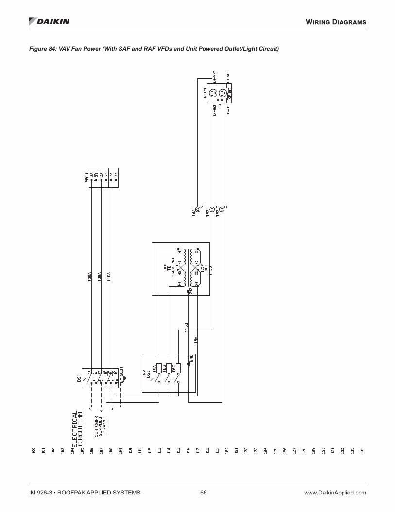
IM 926-3 • ROOFPAK APPLIED SYSTEMS 66 www.DaikinApplied.com
Wiring Diagrams
Figure 84: VAV Fan Power (With SAF and RAF VFDs and Unit Powered Outlet/Light Circuit)
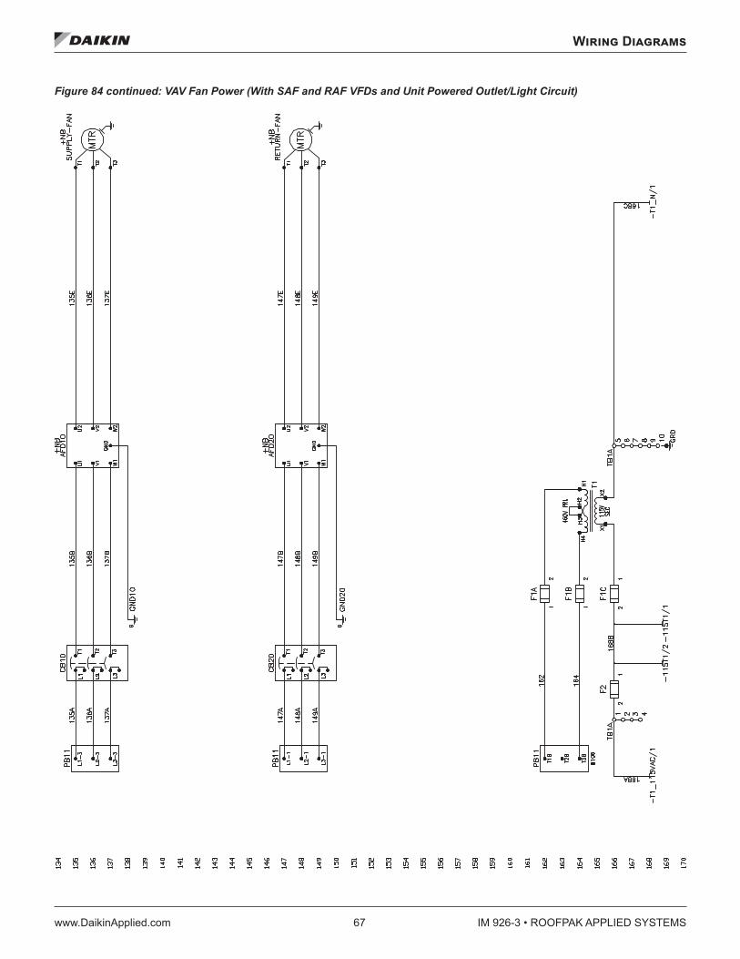
Wiring Diagrams
www.DaikinApplied.com 67 IM 926-3 • ROOFPAK APPLIED SYSTEMS
Figure 84 continued: VAV Fan Power (With SAF and RAF VFDs and Unit Powered Outlet/Light Circuit)
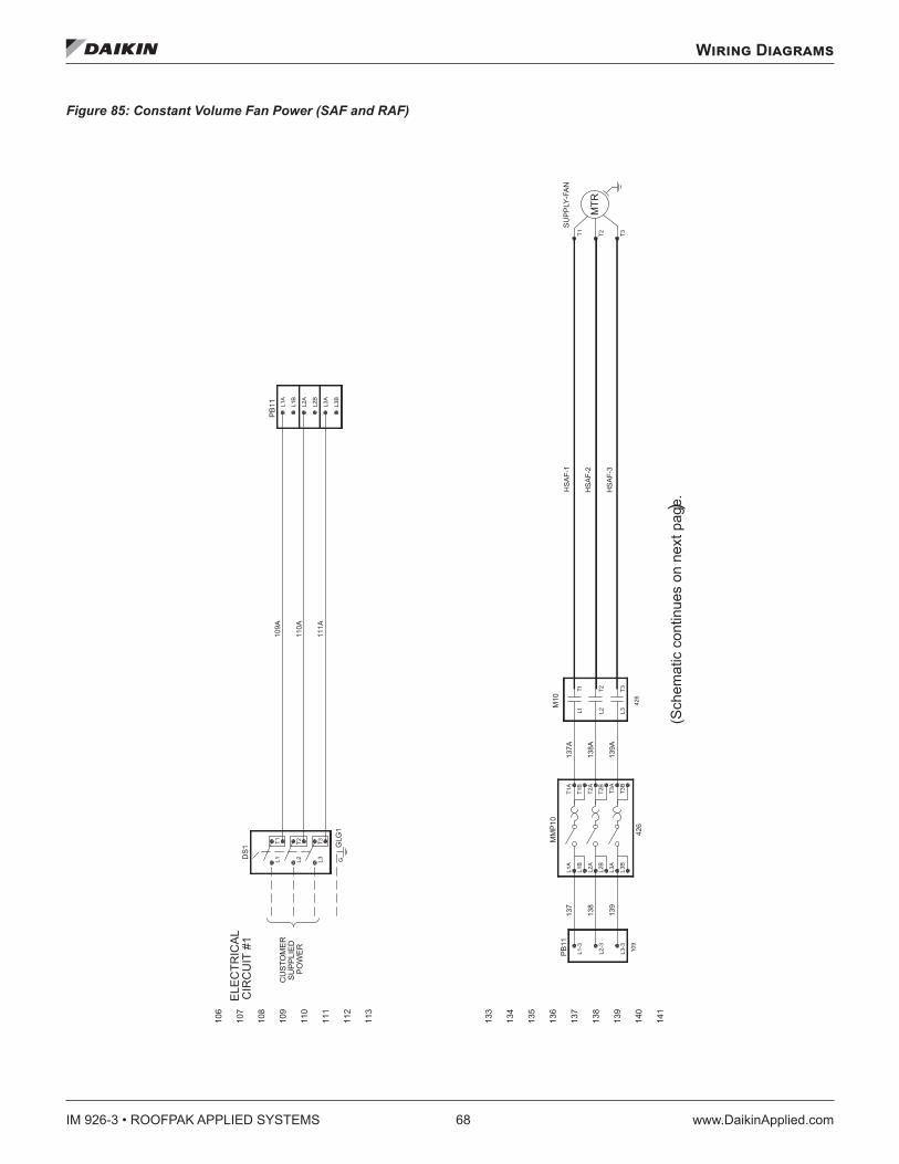
IM 926-3 • ROOFPAK APPLIED SYSTEMS 68 www.DaikinApplied.com
Wiring Diagrams
Figure 85: Constant Volume Fan Power (SAF and RAF)
HS
AF-
1
HS
AF-
2
HS
AF-
3
ELE
CTR
ICA
LC
IRC
UIT
#1
CU
STO
ME
RS
UP
PLI
ED
PO
WE
R
106
107
108
109
110
111
112
113
133
134
135
136
137
138
139
140
141
426
109
426
MTR
T3T2T1
T3B
T3A
T2B
T2A
T1B
T1A
L3B
L3A
L2B
L2A
L1B
L1A
T3T2
L3L21L1T
G
T3T2T1
L3L2L1
L3B
L3A
L2B
L2A
L1B
L1A
L3-3
L2-3
L1-3
SU
PP
LY-F
AN
MM
P10
M10
GLG
1
DS
1
PB
11
PB
11
111A
110A
109A
137A
138A
139A
137
138
139
(Sch
emat
ic c
ontin
ues
on n
ext p
age.)
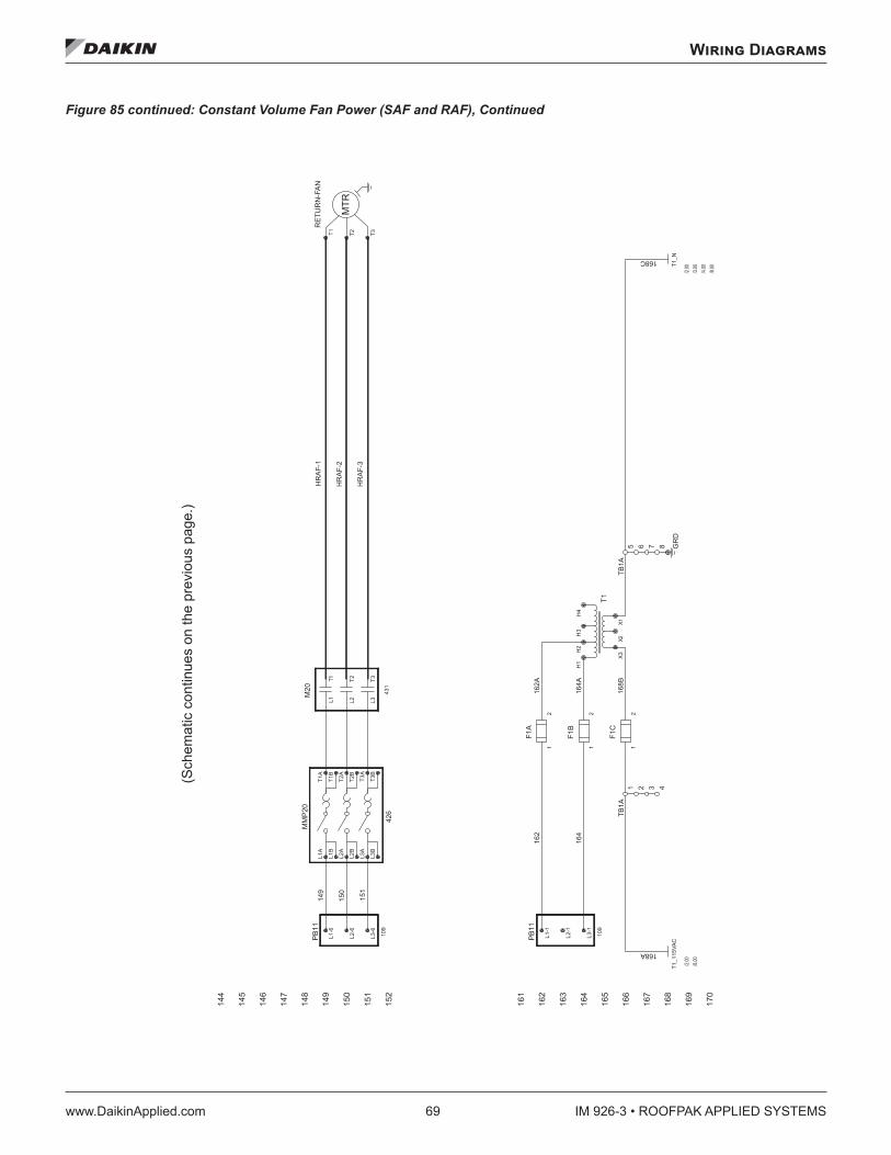
Wiring Diagrams
www.DaikinApplied.com 69 IM 926-3 • ROOFPAK APPLIED SYSTEMS
Figure 85 continued: Constant Volume Fan Power (SAF and RAF), Continued
/8.00
/4.00
/3.00
/2.00
/8.00
/2.00
HR
AF-
1
HR
AF-
2
HR
AF-
3
144
145
146
147
148
149
150
151
152
161
162
163
164
165
166
167
168
169
170
109
431
109
426
MTR
21
21
21
X3
2X1X
H4
H3
H2
H1
1 2 3 4
5 6 7 8 GR
D
L3-1
L2-1
L1-1
T3T2T1
T3T2
L3L21L1T
T3B
T3A
T2B
T2A
T1B
T1A
L3B
L3A
L2B
L2A
L1B
L1A
L3-6
L2-6
L1-6
F1C
F1A
F1B
T1_N
T1
T1_1
15VA
C
TB1A
TB1A
PB
11
RE
TUR
N-F
AN
M20
MM
P20
PB
11
168A
168C
168B
164A
162A
164
162
149
150
151
(Sch
emat
ic c
ontin
ues
on th
e pr
evio
us p
age.
)
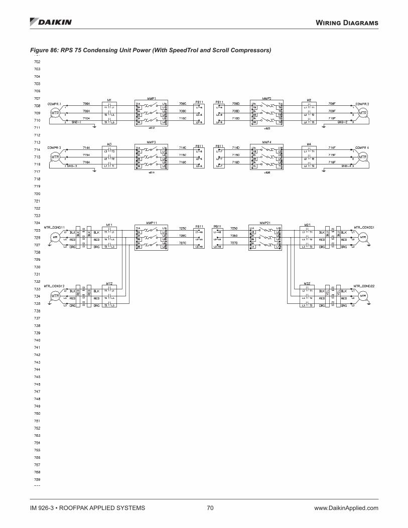
IM 926-3 • ROOFPAK APPLIED SYSTEMS 70 www.DaikinApplied.com
Wiring Diagrams
Figure 86: RPS 75 Condensing Unit Power (With SpeedTrol and Scroll Compressors)
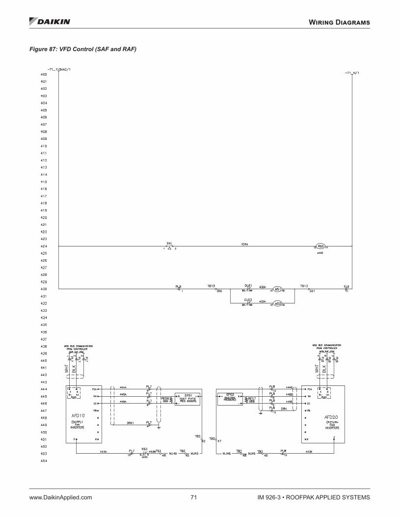
Wiring Diagrams
www.DaikinApplied.com 71 IM 926-3 • ROOFPAK APPLIED SYSTEMS
Figure 87: VFD Control (SAF and RAF)
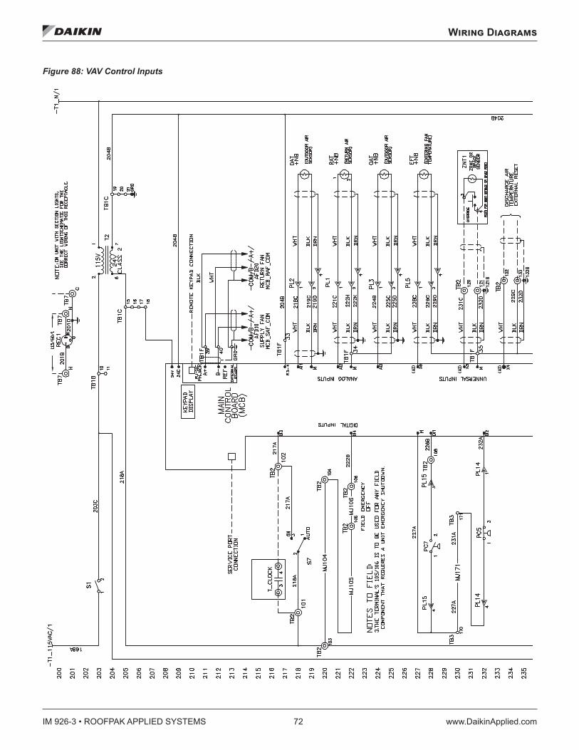
IM 926-3 • ROOFPAK APPLIED SYSTEMS 72 www.DaikinApplied.com
Wiring Diagrams
Figure 88: VAV Control Inputs
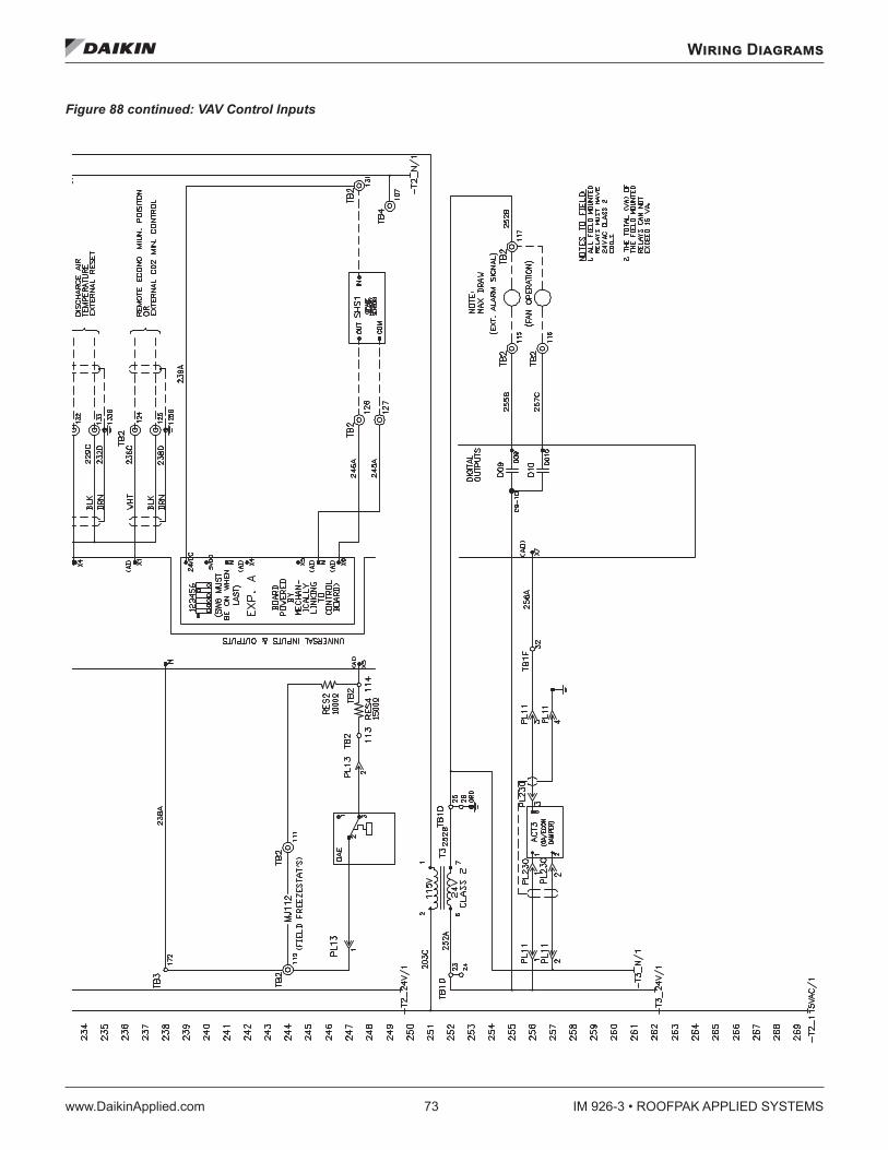
Wiring Diagrams
www.DaikinApplied.com 73 IM 926-3 • ROOFPAK APPLIED SYSTEMS
Figure 88 continued: VAV Control Inputs
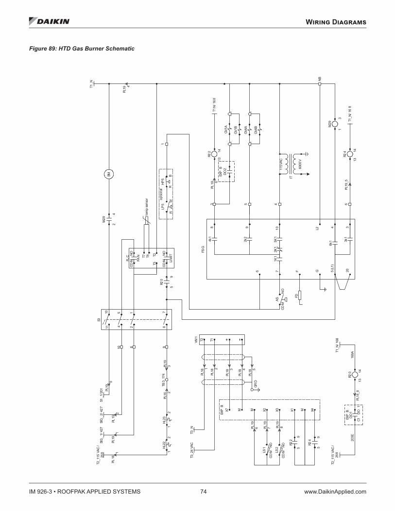
IM 926-3 • ROOFPAK APPLIED SYSTEMS 74 www.DaikinApplied.com
Wiring Diagrams
Figure 89: HTD Gas Burner Schematic
T1_N
6000
V
IT
115V
AC
R22
5 (L
1)4 3
02F
L2G
3k1
6k1
FD
FSG
8
6
9 017
4k1
2k2
1K1
1K2
1K5
COM
NO
AS
R20
21
45
87
1110
S3T2
_115
VAC
/26
8
HL22SI
G_1/
427
PL19
1
PL16
1
PL16
2PL
193
TB3_
174
10
PL19
2
5
9
1
3 5
13
14
PL19
4
NB
R24
T1_N
/ 16
8PL
19_5
13
14
S1_1
/201
M29
2
4
M29
1
3
GV4A
GV4B
GV1A
8 9
BM
4 6
SIG_
2/ 4
27
PL18
6T1
N/ 1
68
LP5
R
W
HP5
R
B
optio
nal
T3
T2
COM
N
O
FAN
LIM
IT
FLC T7 T8
COM
N
O
X7EX
P B
M X2 X3 X1
T3_2
4VA
C
M
R22
5
9
GRD
PL18
3
M X4R2
4
5
9
PL18
4
PL18
5
+VM1 -T2 T1
T3_N
R20
13
14
DO1
203E
C1
DO
1
T2_1
15VA
C/
268
T1_N
/ 168
EXP
B16
8APL
18_8
HL23
PL19
9
12
12
LS1
LS2
PL19
6 PL19
7 PL19
8CO
M
NO
COM
N
O
DO2
EXP
B
GV1B
PL18
2
PL18
1
tem
p se
nsor
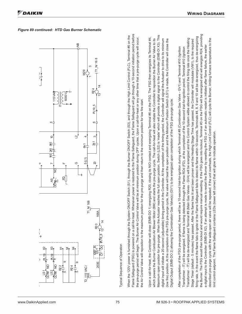
Wiring Diagrams
www.DaikinApplied.com 75 IM 926-3 • ROOFPAK APPLIED SYSTEMS
Figure 89 continued: HTD Gas Burner Schematic
6000
V
IT
115V
AC
5 (L
1)4 3
02F
L2G
3k1
6k1
FD
6
017
1K11K2
1K5CO
MN
OAS
NB
R24
T1_N
/ 16
8PL
19_5
13
14
M29
1
3
GV4B
4 6
X2 X3 X1R2
25
9
GRD
M X4R2
4
5
9
R20
13
14
DO1
203E
C1
DO
1
T2_1
15VA
C/
268
T1_N
/ 168
EXP
B16
8APL
18_8
LS1
LS2
6 PL19
7 PL19
8CO
M
NO
COM
N
O
Typi
cal S
eque
nce
of O
pera
tion
Whe
n 12
0V p
ower
is fu
rnis
hed
thro
ugh
the
and
thro
ugh
the
me
safe
guar
d (F
SG
) pr
epur
ge p
erio
d wi
ll be
gin.
The
bur
ner a
ir co
ntro
l val
ve w
ill b
e at
mi
any
othe
r tim
e th
at a
pre
pur
ge c
ycle
will
occ
ur, t
he
egruperp eht rof noitisop mu
mixam eht ot denoitisoper eb lli
w evlav lortnoc ria Upo
n a
call
for h
eat,
the
cont
roll
er w
ill c
lose
(EM
B-D
O 1
) ene
rgiz
ing
R20
, clo
sing
it’s
N/O
co
ntac
t an
d en
ergi
ze te
rmin
al #
6 o
n th
e FS
G.
The
FSG
then
ene
rgiz
es it
s te
rmin
al #
4,
whi
ch p
ower
s th
e bu
rner
co
mbu
stio
n ai
r blo
wer m
otor
(BM
) and
sta
rts th
e pr
epur
ge
cycl
e. T
he c
all f
or h
eat w
ill al
so in
itiat
e th
e co
ntro
ller t
o re
posi
tion
the
burn
er a
ir va
lve
to it
s oitisop nepo lluf eht sehcaer rotautca eht neh
W .egruperp rof noitisop nepo mu
mixam
n, s
witc
h (L
S2)
is '
mad
e' w
hich
will
pro
vide
a d
igita
l inp
ut to
the
cont
rolle
r (E
MB
-DI X
3).
This
dig
ital i
nput
will
initi
ate
a 20
sec
ond
(adj
usta
ble)
tim
ing
perio
d in
the
cont
rolle
r. A
t th
e co
mple
tion
of th
e tim
ing
perio
d, th
e co
ntro
ller w
ill s
igna
l the
act
uato
r to
driv
e to
its
min
imum
pos
ition
sw
itch
(LS
1) w
ill b
e 'm
ade'
, pr
ovid
ing
a di
gita
l inp
ut to
the
cont
rolle
r (E
MB
-DI X
2).
Whe
n th
e bu
esolc lliw rellortnoc eht ,eda
m si )1SL( hcti
ws noitisop wol eht dna noitisop
mumini
m ti ta si evlav ria renrth
e di
gita
l out
put (
EM
B-D
O 2
) allo
win
g th
e co
mbi
natio
n ga
s va
lve(
s) (G
V1)
to b
e en
ergi
zed
upon
com
pletio
n of
the
FSG
pre
purg
e cy
cle.
Afte
r com
pletio
n of
the
FSG
pre
purg
e pe
riod
ther
e w
ill be
a 1
0 se
cond
tria
l for
igni
tion
durin
g w
hich
term
inal
#8
(com
bina
tion
gas
valv
e - G
V1)
and
term
inal
#10
(ign
ition
ed
thro
ugh
the
rmin
al #
10 (i
gniti
on
trans
form
er -
IT)
will
be
de-e
nerg
ized
and
term
inal
#9
(mai
n ga
s va
lves
- G
V4)
will
be
ener
gize
d an
d th
e co
ntro
l sys
tan
d th
e he
atin
g st
age t
ime
has
pass
ed, t
h9,
and
10
will
be
de-e
nerg
ized,
thus
de
-ene
rgiz
ing
the
burn
er. T
he F
SG
wou
ld th
en lo
ckou
t and
wou
ld re
quire
man
ual r
eset
ting.
If th
e FS
G g
oes
into
lock
oput
, te
rmin
al 3
on
the
FSG
will
be
ener
gize
d an
d w
ill e
nerg
ize
R24
, pro
vidi
ng
a di
gita
l inp
ut to
the
cont
rolle
r (E
MB
-DI X
2If a
n at
tem
pt is
mad
e to
rest
art t
h retfa detaitini si tratser cita
motua na fi ro GSF eht gnitteser yb renrub e
desc
ribed
pre
purg
e cy
cle
with
the
wid
e op
en
air v
alve
will
be
repe
ated
. gniti
mil ,renrub eht elcyc lliw )CLF( lortnoc ti
mil hgih eht ,staehrevo tinu eht fIfu
rnac
e te
mpe
ratu
re to
the
Typi
cal S
eque
nce
of O
pera
tion
Whe
n th
e 12
0V p
ower
is fu
rnis
hed
thro
ugh
the
Syst
em O
N/O
FF S
witc
h (S
1), t
hrou
gh th
e Bu
rner
ON
/OFF
Sw
itch
(S3)
, and
thro
ugh
the
Hig
h Li
mit
Con
trol (
FLC
), Te
rmin
al #
6 on
the
Flam
e Sa
fegu
ard
(FSG
) is
pow
ered
on
a ca
ll-fo
r-hea
t. W
hene
ver p
ower
is re
stor
ed to
the
Flam
e Sa
fegu
ard,
the
Flam
e Sa
fegu
ard
will
go th
roug
h a
10-s
econ
d in
itiat
ion
perio
d be
fore
th
e pr
e-pu
rge
perio
d w
ill be
gin.
The
Bur
ner A
ir C
ontro
l Val
ve w
ill be
at m
inim
um p
ositi
on d
urin
g O
FF c
ycle
s. U
pon
a ca
ll-fo
r-hea
t or a
ny o
ther
tim
e th
at a
pre
-pur
ge c
ycle
will
occu
r, th
e Ai
r Con
trol V
alve
will
repo
sitio
n to
the
max
imum
pos
ition
for t
he p
re-p
urge
and
then
retu
rn to
the
min
imum
pos
ition
for l
ow fi
re s
tart.
Upo
n a
call-
for-h
eat,
the
Con
trolle
r will
clos
e (E
MB-
DO
1) e
nerg
izin
g R
20, c
losi
ng it
s N
/O c
onta
ct a
nd e
nerg
izin
g Te
rmin
al #
6 on
the
FSG
. The
FSG
then
ene
rgiz
es it
s Te
rmin
al #
4,
whi
ch p
ower
s th
e Bu
rner
Com
bust
ion
Air B
low
er M
otor
(BM
) and
sta
rts th
e pr
e-pu
rge
cycl
e. T
he c
all-f
or-h
eat w
ill al
so in
itiat
e th
e C
ontro
ller t
o re
posi
tion
the
Burn
er A
ir Va
lve
to it
s M
axim
um o
pen
posi
tion
for p
re-p
urge
. Whe
n th
e Ac
tuat
or re
ache
s th
e fu
ll op
en p
ositi
on, S
witc
h (L
S2) i
s ‘m
ade’
whi
ch w
ill pr
ovid
e a
digi
tal s
igna
l to
the
Con
trolle
r (EM
B-D
I X3)
. Thi
s di
gita
l inp
ut w
ill in
itiat
e a
20-s
econ
d (a
djus
tabl
e) ti
min
g pe
riod
in th
e C
ontro
ller.
At th
e co
mpl
etio
n of
the
timin
g pe
riod,
the
Con
trolle
r will
sign
al th
e Ac
tuat
or to
driv
e to
its
min
imum
(lo
w fi
re) p
ositi
on. A
t the
com
plet
ion
of th
e FS
G p
re-p
urge
cyc
le, t
he v
alve
will
beat
the
open
pos
ition
and
the
Min
imum
Pos
ition
Sw
itch
(LS1
) is
mad
e, th
e C
ontro
ller w
ill cl
ose
the
Dig
ital O
utpu
t (EM
B-D
O 2
) allo
win
g th
e C
ombi
natio
n G
as V
alve
(s) (
GV1
) to
be e
nerg
ized
upo
n co
mpl
etio
n of
the
FSG
pre
-pur
ge c
ycle
.
Afte
r com
plet
ion
of th
e FS
G p
re-p
urge
per
iod,
ther
e w
ill be
a 1
0-se
cond
tria
l-for
-igni
tion
durin
g w
hich
Ter
min
al #
8 (C
ombi
natio
n G
as V
alve
- G
V1) a
nd T
erm
inal
#10
(Ign
ition
Tr
ansf
orm
er -
IT) w
ill be
ene
rgiz
ed. I
f flam
e is
bei
ng d
etec
ted
thro
ugh
the
Flam
e R
Od
(FD
), at
the
com
plet
ion
of th
e 10
-sec
ond
trial
-for-i
gniti
on p
erio
d, T
erm
inal
#10
(Ign
ition
Tr
ansf
orm
er -
IT) w
ill be
de-
ener
gize
d an
d Te
rmin
al #
9 (M
ain
Gas
Val
ves
- GV4
) will
be e
nerg
ized
and
the
Con
trol S
yste
m w
illbe
allo
wed
to c
ontro
l the
firin
g ra
te o
nce
the
Hea
ting
Stag
e Ti
mer
(def
ault
- 5 m
inut
es) h
as p
asse
d. A
fter t
he fl
ame
has
lit a
nd b
een
prov
en a
nd th
e H
eatin
g St
age
Tim
e ha
s pa
ssed
, the
Con
trolle
r will
mod
ulat
e (V
M1)
, to
the
requ
ired
firin
g ra
te. I
n th
e ev
ent t
he fl
ame
fails
to ig
nite
or t
he F
lam
e Sa
fegu
ard
fails
to d
etec
t its
flam
e w
ithin
10-
seco
nds,
Ter
min
als
#4, 8
, 9 a
nd 1
0 w
ill be
de-
ener
gize
d, th
us d
e-en
ergi
zing
th
e Bu
rner
. The
FSG
wou
ld th
en lo
ckou
t and
wou
ld re
quire
man
ual r
eset
ting.
If th
e FS
G g
oes
into
lock
out,
Term
inal
#3
on th
e FS
G w
ill be
ene
rgiz
ed a
nd w
ill en
ergi
ze R
24, p
rovi
ding
a
digi
tal i
nput
to th
e C
ontro
ller (
EMB-
DI X
2). I
f an
atte
mpt
is m
ade
to re
star
t the
Bur
ner b
y re
setti
ng th
e FS
G o
r if a
n au
tom
atic
rest
art i
s in
itiat
ed a
fter fl
ame
failu
re, t
he e
arlie
r de
scrib
ed p
re-p
urge
cyc
le w
ith th
e w
ide-
open
air
valv
e w
ill be
repe
ated
. If t
he u
nit o
verh
eats
, the
Hig
h Li
mit
Con
trol (
FLC
) will
cycl
e th
e Bu
rner
, lim
iting
furn
ace
tem
pera
ture
to th
e lim
it co
ntro
l set
poin
t. Th
e Fl
ame
Safe
guar
d co
ntai
ns L
EDs
(low
er le
ft co
rner
) tha
t will
glow
to in
dica
te o
pera
tion.
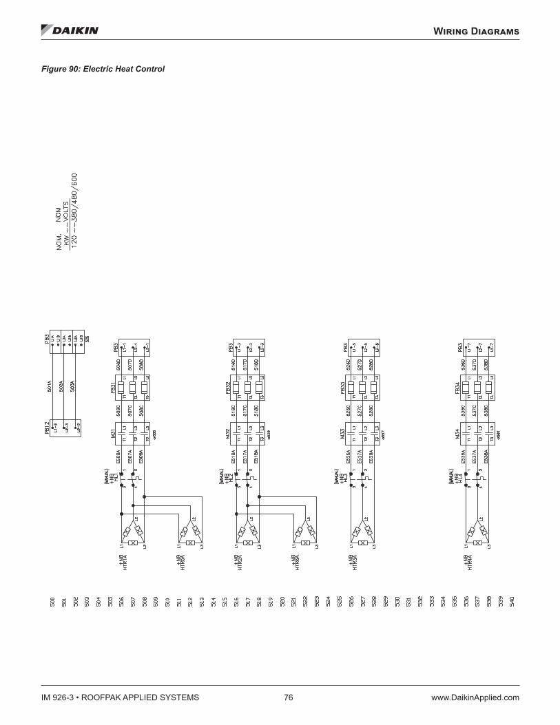
IM 926-3 • ROOFPAK APPLIED SYSTEMS 76 www.DaikinApplied.com
Wiring Diagrams
Figure 90: Electric Heat Control
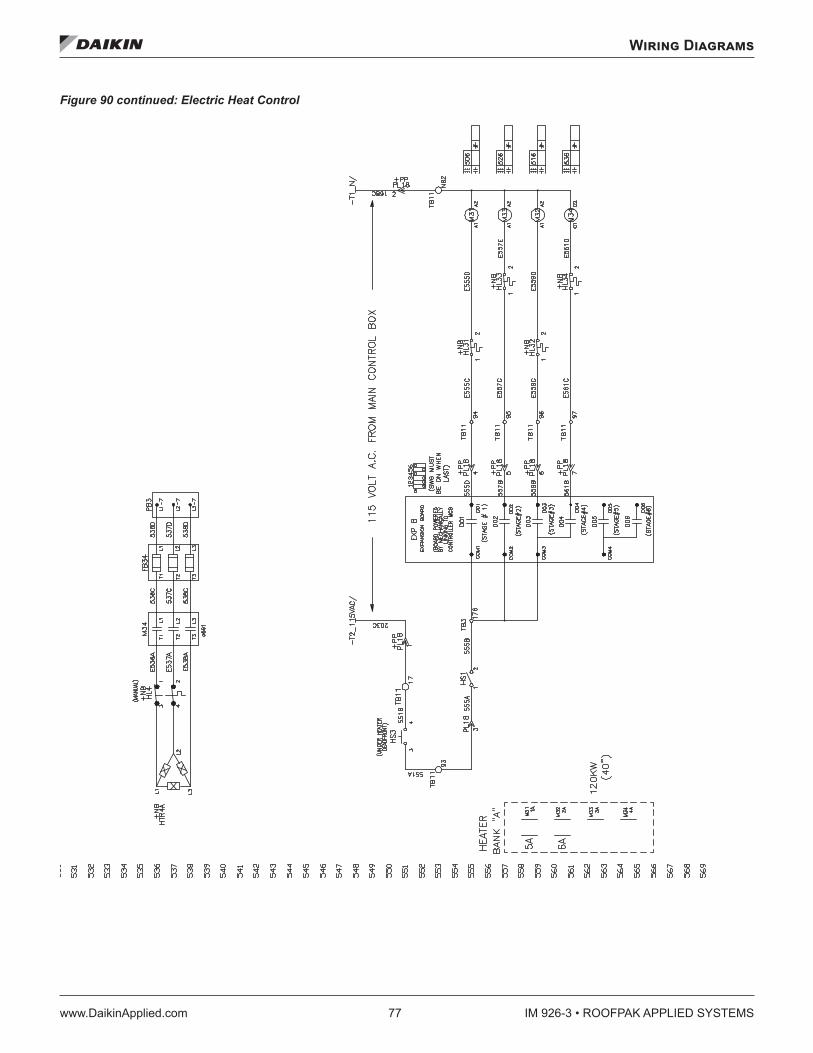
Wiring Diagrams
www.DaikinApplied.com 77 IM 926-3 • ROOFPAK APPLIED SYSTEMS
Figure 90 continued: Electric Heat Control
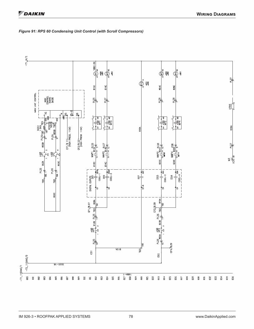
IM 926-3 • ROOFPAK APPLIED SYSTEMS 78 www.DaikinApplied.com
Wiring Diagrams
Figure 91: RPS 60 Condensing Unit Control (with Scroll Compressors)
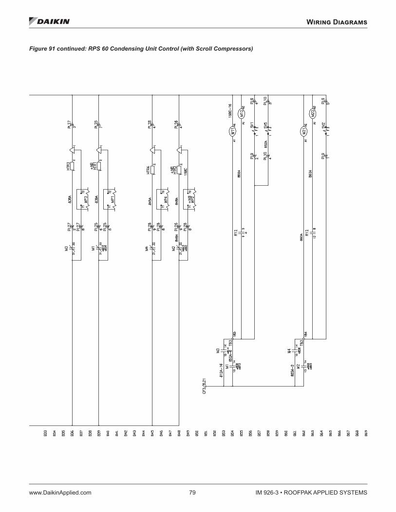
Wiring Diagrams
www.DaikinApplied.com 79 IM 926-3 • ROOFPAK APPLIED SYSTEMS
Figure 91 continued: RPS 60 Condensing Unit Control (with Scroll Compressors)
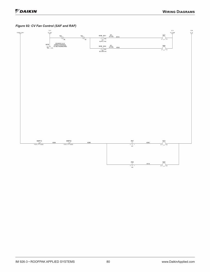
IM 926-3 • ROOFPAK APPLIED SYSTEMS 80 www.DaikinApplied.com
Wiring Diagrams
Figure 92: CV Fan Control (SAF and RAF)
401A
404A
426C426B426A
431A
TB2
42
TB2
45
2
R68
10
2
R67
10
R68
3404
1
R67
3401
1
M20
A2A1
M10
A2A1
jprs
24V SRC
MCB
2 2NO
BO2
RETURN FAN207
jprs
24V SRC
MCB
1 1NO
BO1
SUPPLY FAN207
61-9CRS
MCB207
11(31)
MMP10
12(32)
11(31)
MMP20
12(32)
TO MOTHERBOARDWIRED INTERNAL
SOURCE 9-16
T3_COM
11.3/
T3_24V
11.3/
115VAC_GF/1
T1_N
86.1/
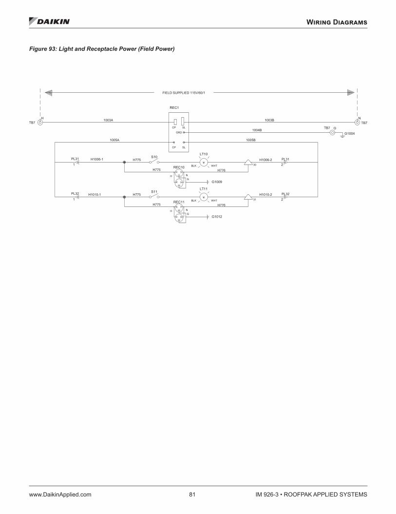
Wiring Diagrams
www.DaikinApplied.com 81 IM 926-3 • ROOFPAK APPLIED SYSTEMS
Figure 93: Light and Receptacle Power (Field Power)
1003B1003A
1004B
1005B1005A
NTB7
GTB7
HTB7
REC1
CP SL
GRD
SLCP
PL32
1
S11
PL31
1
S10
G1004
2PL32
G1012
NG
REC11
H
31
LT11
BLK WHTw
2PL31
G1009
NG
REC10
H
30
LT10
BLK WHTw
FIELD SUPPLIED 115V/60/1
H1010-2H1010-1
H775 H776
H775
H1006-2H1006-1
H776H775
H775
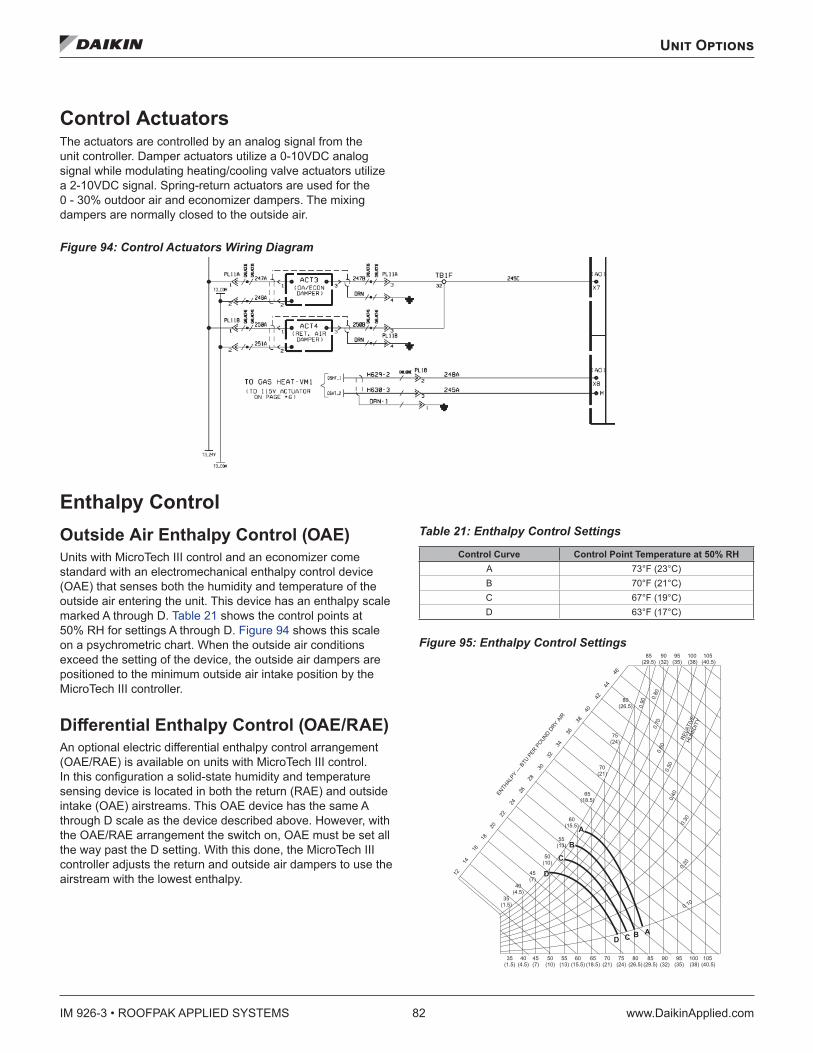
IM 926-3 • ROOFPAK APPLIED SYSTEMS 82 www.DaikinApplied.com
Unit Options
Unit Options
Control Actuators The actuators are controlled by an analog signal from the unit controller. Damper actuators utilize a 0-10VDC analog signal while modulating heating/cooling valve actuators utilize a 2-10VDC signal. Spring-return actuators are used for the 0 - 30% outdoor air and economizer dampers. The mixing dampers are normally closed to the outside air.
Figure 94: Control Actuators Wiring Diagram
Enthalpy Control Outside Air Enthalpy Control (OAE) Units with MicroTech III control and an economizer come standard with an electromechanical enthalpy control device (OAE) that senses both the humidity and temperature of the outside air entering the unit. This device has an enthalpy scale marked A through D. Table 21 shows the control points at 50% RH for settings A through D. Figure 94 shows this scale on a psychrometric chart. When the outside air conditions exceed the setting of the device, the outside air dampers are positioned to the minimum outside air intake position by the MicroTech III controller.
Differential Enthalpy Control (OAE/RAE) An optional electric differential enthalpy control arrangement (OAE/RAE) is available on units with MicroTech III control. In this configuration a solid-state humidity and temperature sensing device is located in both the return (RAE) and outside intake (OAE) airstreams. This OAE device has the same A through D scale as the device described above. However, with the OAE/RAE arrangement the switch on, OAE must be set all the way past the D setting. With this done, the MicroTech III controller adjusts the return and outside air dampers to use the airstream with the lowest enthalpy.
Table 21: Enthalpy Control Settings
Control Curve Control Point Temperature at 50% RH A 73°F (23°C)B 70°F (21°C)C 67°F (19°C)D 63°F (17°C)
Figure 95: Enthalpy Control Settings
� �� � � � �
� �� � � � �
� �� � �
� �� � � �
� �� � � � � �
� �� � � � � �
� �� � � �
� �� � � �
� �� � � � � �
� �� � � � � �
� �� � � �
� �� � � �
� � �� � � � �
� � �� � � � � � �
� �� � � �
� �� �
� �
� �� �
� �� �
� �
� �
� �� �
� �� �
� �� �
� �
� �
� �
� �� �
��
� � �� �
� �� �
� �� �
� �� ��
� � �
�
�
�
�
� � � �
� �� �
� �� �
� � ��
� � ��
� � ��
� �� �
� �� �
� �� �
� �� �
� ��
� �� �
� ��� �� �
� �� � � � �
� �� � � � �
� �� � �
� �� � � �
� �� � � �
� �� � � � � �
� �� � � � � �
� �� � � �
� �� � � �
� �� � � � � �
� �� � � � � �
� �� � � �
� �� � � �
� � �� � � � �
� � �� � � � � � �
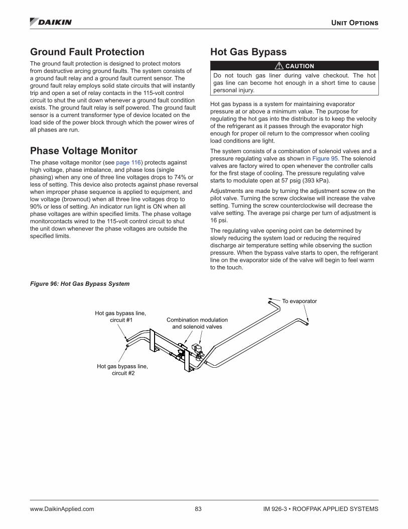
Unit Options
www.DaikinApplied.com 83 IM 926-3 • ROOFPAK APPLIED SYSTEMS
Ground Fault Protection The ground fault protection is designed to protect motors from destructive arcing ground faults. The system consists of a ground fault relay and a ground fault current sensor. The ground fault relay employs solid state circuits that will instantly trip and open a set of relay contacts in the 115-volt control circuit to shut the unit down whenever a ground fault condition exists. The ground fault relay is self powered. The ground fault sensor is a current transformer type of device located on the load side of the power block through which the power wires of all phases are run.
Phase Voltage Monitor The phase voltage monitor (see page 116) protects against high voltage, phase imbalance, and phase loss (single phasing) when any one of three line voltages drops to 74% or less of setting. This device also protects against phase reversal when improper phase sequence is applied to equipment, and low voltage (brownout) when all three line voltages drop to 90% or less of setting. An indicator run light is ON when all phase voltages are within specified limits. The phase voltage monitorcontacts wired to the 115-volt control circuit to shut the unit down whenever the phase voltages are outside the specified limits.
Hot Gas Bypass CAUTION
Do not touch gas liner during valve checkout. The hot gas line can become hot enough in a short time to cause personal injury.
Hot gas bypass is a system for maintaining evaporator pressure at or above a minimum value. The purpose for regulating the hot gas into the distributor is to keep the velocity of the refrigerant as it passes through the evaporator high enough for proper oil return to the compressor when cooling load conditions are light.
The system consists of a combination of solenoid valves and a pressure regulating valve as shown in Figure 95. The solenoid valves are factory wired to open whenever the controller calls for the first stage of cooling. The pressure regulating valve starts to modulate open at 57 psig (393 kPa).
Adjustments are made by turning the adjustment screw on the pilot valve. Turning the screw clockwise will increase the valve setting. Turning the screw counterclockwise will decrease the valve setting. The average psi charge per turn of adjustment is 16 psi.
The regulating valve opening point can be determined by slowly reducing the system load or reducing the required discharge air temperature setting while observing the suction pressure. When the bypass valve starts to open, the refrigerant line on the evaporator side of the valve will begin to feel warm to the touch.
Figure 96: Hot Gas Bypass System
Combination modulationand solenoid valves
Hot gas bypass line,circuit #2
Hot gas bypass line,circuit #1
To evaporator
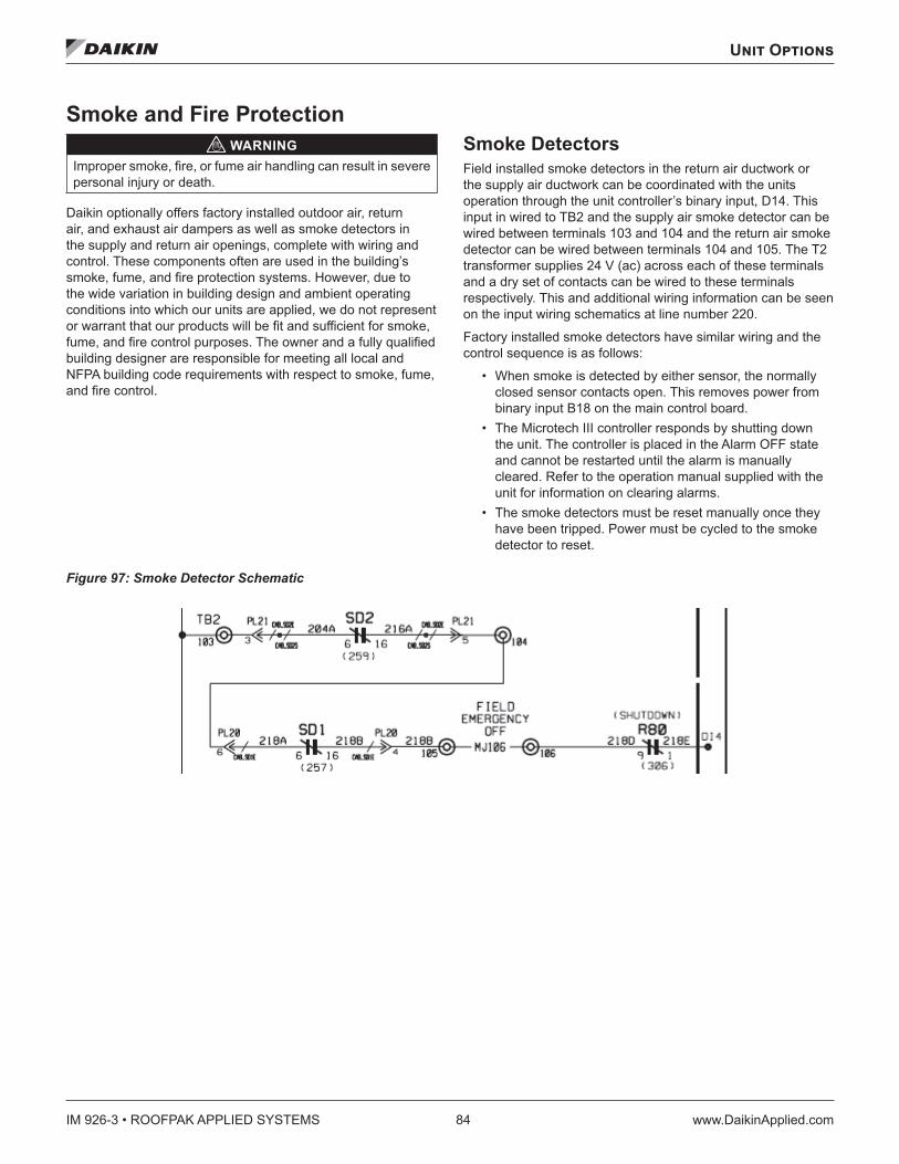
IM 926-3 • ROOFPAK APPLIED SYSTEMS 84 www.DaikinApplied.com
Unit Options
Smoke and Fire Protection WARNING
Improper smoke, fire, or fume air handling can result in severe personal injury or death.
Daikin optionally offers factory installed outdoor air, return air, and exhaust air dampers as well as smoke detectors in the supply and return air openings, complete with wiring and control. These components often are used in the building’s smoke, fume, and fire protection systems. However, due to the wide variation in building design and ambient operating conditions into which our units are applied, we do not represent or warrant that our products will be fit and sufficient for smoke, fume, and fire control purposes. The owner and a fully qualified building designer are responsible for meeting all local and NFPA building code requirements with respect to smoke, fume, and fire control.
Smoke Detectors Field installed smoke detectors in the return air ductwork or the supply air ductwork can be coordinated with the units operation through the unit controller’s binary input, D14. This input in wired to TB2 and the supply air smoke detector can be wired between terminals 103 and 104 and the return air smoke detector can be wired between terminals 104 and 105. The T2 transformer supplies 24 V (ac) across each of these terminals and a dry set of contacts can be wired to these terminals respectively. This and additional wiring information can be seen on the input wiring schematics at line number 220.
Factory installed smoke detectors have similar wiring and the control sequence is as follows:
• When smoke is detected by either sensor, the normally closed sensor contacts open. This removes power from binary input B18 on the main control board.
• The Microtech III controller responds by shutting down the unit. The controller is placed in the Alarm OFF state and cannot be restarted until the alarm is manually cleared. Refer to the operation manual supplied with the unit for information on clearing alarms.
• The smoke detectors must be reset manually once they have been tripped. Power must be cycled to the smoke detector to reset.
Figure 97: Smoke Detector Schematic
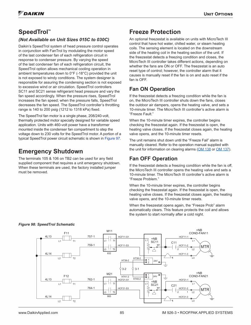
Unit Options
www.DaikinApplied.com 85 IM 926-3 • ROOFPAK APPLIED SYSTEMS
SpeedTrol™ (Not Available on Unit Sizes 015C to 030C) Daikin’s SpeedTrol system of head pressure control operates in conjunction with FanTrol by modulating the motor speed of the last condenser fan of each refrigeration circuit in response to condenser pressure. By varying the speed of the last condenser fan of each refrigeration circuit, the SpeedTrol option allows mechanical cooling operation in ambient temperatures down to 0°F (-18°C) provided the unit is not exposed to windy conditions. The system designer is responsible for assuring the condensing section is not exposed to excessive wind or air circulation. SpeedTrol controllers SC11 and SC21 sense refrigerant head pressure and vary the fan speed accordingly. When the pressure rises, SpeedTrol increases the fan speed; when the pressure falls, SpeedTrol decreases the fan speed. The SpeedTrol controller’s throttling range is 140 to 200 psig (1212 to 1318 kPa) fixed.
The SpeedTrol fan motor is a single phase, 208/240-volt, thermally protected motor specially designed for variable speed application. Units with 460-volt power have a transformer mounted inside the condenser fan compartment to step the voltage down to 230 volts for the SpeedTrol motor. A portion of a typical SpeedTrol power circuit schematic is shown in Figure 97.
Emergency Shutdown The terminals 105 & 106 on TB2 can be used for any field supplied component that requires a unit emergency shutdown. When these terminals are used, the factory installed jumper must be removed.
Freeze Protection An optional freezestat is available on units with MicroTech III control that have hot water, chilled water, or steam heating coils. The sensing element is located on the downstream side of the heating coil in the heating section of the unit. If the freezestat detects a freezing condition and closes, the MicroTech III controller takes different actions, depending on whether the fans are ON or OFF. The freezestat is an auto reset type of control; however, the controller alarm that it causes is manually reset if the fan is on and auto reset if the fan is OFF.
Fan ON Operation If the freezestat detects a freezing condition while the fan is on, the MicroTech III controller shuts down the fans, closes the outdoor air dampers, opens the heating valve, and sets a 10-minute timer. The MicroTech III controller’s active alarm is “Freeze Fault.”
When the 10-minute timer expires, the controller begins checking the freezestat again. If the freezestat is open, the heating valve closes. If the freezestat closes again, the heating valve opens, and the 10-minute timer resets.
The unit remains shut down until the “Freeze Fail” alarm is manually cleared. Refer to the operation manual supplied with the unit for information on clearing alarms (OM 138 or OM 137).
Fan OFF Operation If the freezestat detects a freezing condition while the fan is off, the MicroTech III controller opens the heating valve and sets a 10-minute timer. The MicroTech III controller’s active alarm is “Freeze Problem.”
When the 10-minute timer expires, the controller begins checking the freezestat again. If the freezestat is open, the heating valve closes. If the freezestat closes again, the heating valve opens, and the 10-minute timer resets.
When the freezestat opens again, the “Freeze Prob” alarm automatically clears. This feature protects the coil and allows the system to start normally after a cold night.
Figure 98: SpeedTrol Schematic
HCF11-1
HCF11-2
HCF11-3
HCF21-1
HCF21-2
HCF21-3
H739-2
H741-2
HCF11-S1
HCF11-S3
HCF21-S1
HCF21-S3
H738-2
H740-2
832
865
MTR
MTR
24V
24V
L3
L2
L1
L3
L2
L1
L1
M1
12
L1
M1
12
2 1
2 1
1111111
1111111
3-2 3-1
3L 3T
1L 1T
3L 3T
1L 1T
L2
L1
T2
T1
L2
L1
T2
T1
COND-FAN11+NB
COND-FAN21+NB
+NBSC11
+NBSC21
C11
C21
M11
M21
F11
F12
4L14
764-1
4L13 762-1
4L14
759-1
4L13 757-1
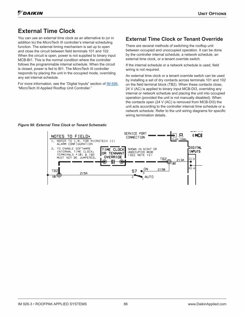
IM 926-3 • ROOFPAK APPLIED SYSTEMS 86 www.DaikinApplied.com
Unit Options
External Time Clock You can use an external time clock as an alternative to (or in addition to) the MicroTech III controller’s internal scheduling function. The external timing mechanism is set up to open and close the circuit between field terminals 101 and 102. When the circuit is open, power is not supplied to binary input MCB-BI1. This is the normal condition where the controller follows the programmable internal schedule. When the circuit is closed, power is fed to BI1. The MicroTech III controller responds by placing the unit in the occupied mode, overriding any set internal schedule.
For more information, see the “Digital Inputs” section of IM 696, “MicroTech III Applied Rooftop Unit Controller.”
External Time Clock or Tenant Override There are several methods of switching the rooftop unit between occupied and unoccupied operation. It can be done by the controller internal schedule, a network schedule, an external time clock, or a tenant override switch.
If the internal schedule or a network schedule is used, field wiring is not required.
An external time clock or a tenant override switch can be used by installing a set of dry contacts across terminals 101 and 102 on the field terminal block (TB2). When these contacts close, 24 V (AC) is applied to binary input MCB-DI3, overriding any internal or network schedule and placing the unit into occupied operation (provided the unit is not manually disabled). When the contacts open (24 V (AC) is removed from MCB-DI3) the unit acts according to the controller internal time schedule or a network schedule. Refer to the unit wiring diagrams for specific wiring termination details.
Figure 99: External Time Clock or Tenant Schematic
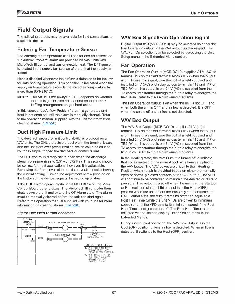
Unit Options
www.DaikinApplied.com 87 IM 926-3 • ROOFPAK APPLIED SYSTEMS
Field Output Signals The following outputs may be available for field connections to a suitable device.
Entering Fan Temperature Sensor The entering fan temperature (EFT) sensor and an associated “Lo Airflow Problem” alarm are provided on VAV units with MicroTech III control and gas or electric heat. The EFT sensor is located in the supply fan section of the unit at the supply air funnel.
Heat is disabled whenever the airflow is detected to be too low for safe heating operation. This condition is indicated when the supply air temperature exceeds the mixed air temperature by more than 60°F (16°C). NOTE: This value is not always 60°F. It depends on whether
the unit is gas or electric heat and on the burner/baffling arrangement on gas heat units.
In this case, a “Lo Airflow Problem” alarm is generated and heat is not enabled until the alarm is manually cleared. Refer to the operation manual supplied with the unit for information clearing alarms (OM 920).
Duct High Pressure Limit The duct high pressure limit control (DHL) is provided on all VAV units. The DHL protects the duct work, the terminal boxes, and the unit from over pressurization, which could be caused by, for example, tripped fire dampers or control failure.
The DHL control is factory set to open when the discharge plenum pressure rises to 3.5" wc (872 Pa). This setting should be correct for most applications; however, it is adjustable. Removing the front cover of the device reveals a scale showing the current setting. Turning the adjustment screw (located on the bottom of the device) adjusts the setting up or down.
If the DHL switch opens, digital input MCB BI 14 on the Main Control Board de-energizes. The MicroTech III controller then shuts down the unit and enters the Off-Alarm state. The alarm must be manually cleared before the unit can start again. Refer to the operation manual supplied with your unit for more information on clearing alarms (OM 920).
Figure 100: Field Output Schematic
VAV Box Signal/Fan Operation Signal Digital Output #10 (MCB-DO10) may be selected as either the Fan Operation output or the VAV output via the keypad. The VAV/Fan Op selection can be selected by accessing the Unit Setup menu in the Extended Menu section.
Fan Operation The Fan Operation Output (MCB-DO10) supplies 24 V (AC) to terminal 116 on the field terminal block (TB2) when the output is on. To use this signal, wire the coil of a field supplied and installed 24 V (AC) pilot relay across terminals 116 and 117 on TB2. When this output is on, 24 V (AC) is supplied from the T3 control transformer through the output relay to energize the field relay. Refer to the as-built wiring diagrams.
The Fan Operation output is on when the unit is not OFF and when both the unit is OFF and airflow is detected. It is OFF when the unit is off and airflow is not detected.
VAV Box Output The VAV Box Output (MCB-DO10) supplies 24 V (ac) to terminal 116 on the field terminal block (TB2) when the output is on. To use this signal, wire the coil of a field supplied and installed 24 V (AC) pilot relay across terminals 116 and 117 on TB2. When this output is on, 24 V (AC) is supplied from the T3 control transformer through the output relay to energize the field relay. Refer to the as-built wiring diagrams.
In the Heating state, the VAV Output is turned off to indicate that hot air instead of the normal cool air is being supplied to the VAV boxes. The VAV boxes are driven to their Heating Position when hot air is provided based on either the normally open or normally closed contacts of the VAV output. The VFD will continue to be controlled to maintain the desired duct static pressure. This output is also off when the unit is in the Startup or Recirculation states. If this output is in the Heat (OFF) position when the unit enters the Fan Only state or Minimum DAT Control state, the output remains off for an adjustable Post Heat Time (while the unit VFDs are driven to minimum speed) or until the VFD gets to its minimum speed if the Post Heat Time is set greater than 0. The Post Heat Timer can be adjusted via the keypad/display Timer Setting menu in the Extended Menus.
During unoccupied operation, the VAV Box Output is in the Cool (ON) position unless airflow is detected. When airflow is detected, it switches to the Heat (OFF) position.
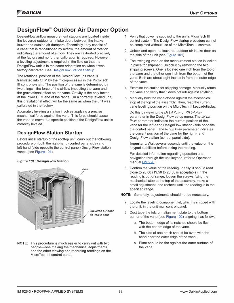
IM 926-3 • ROOFPAK APPLIED SYSTEMS 88 www.DaikinApplied.com
Unit Options
DesignFlow™ Outdoor Air Damper Option DesignFlow airflow measurement stations are located inside the louvered outdoor air intake doors between the intake louver and outside air dampers. Essentially, they consist of a vane that is repositioned by airflow, the amount of rotation indicating the amount of airflow. They are calibrated precisely at the factory and no further calibration is required. However, a leveling adjustment is required in the field so that the DesignFlow unit is in the same orientation as when it was factory calibrated. See DesignFlow Station Startup.
The rotational position of the DesignFlow unit vane is translated into CFM by the microprocessor in the MicroTech III control system. The position of the vane is determined by two things—the force of the airflow impacting the vane and the gravitational effect on the vane. Gravity is the only factor at the lower CFM end of the range. On a correctly leveled unit, this gravitational effect will be the same as when the unit was calibrated in the factory.
Accurately leveling a station involves applying a precise mechanical force against the vane. This force should cause the vane to move to a specific position if the DesignFlow unit is correctly leveled.
DesignFlow Station Startup Before initial startup of the rooftop unit, carry out the following procedure on both the right-hand (control panel side) and left-hand (side opposite the control panel) DesignFlow station vanes (see Figure 101).
Figure 101: DesignFlow Station
NOTE: This procedure is much easier to carry out with two people—one making the mechanical adjustments and the other viewing and recording readings on the MicroTech III control panel.
1. Verify that power is supplied to the unit’s MicroTech III control system. The DesignFlow startup procedure cannot be completed without use of the MicroTech III controls.
2. Unlock and open the louvered outdoor air intake door on the side of the unit (see Figure 101).
3. The swinging vane on the measurement station is locked in place for shipment. Unlock it by removing the two shipping screws. One is located one inch from the top of the vane and the other one inch from the bottom of the vane. Both are about eight inches in from the outer edge of the vane.
4. Examine the station for shipping damage. Manually rotate the vane and verify that it does not rub against anything.
5. Manually hold the vane closed against the mechanical stop at the top of the assembly. Then, read the current vane leveling position on the MicroTech III keypad/display.
Do this by viewing the LH Lvl Pos= or RH Lvl Pos= parameter in the DesignFlow setup menu. The LH Lvl Pos= parameter indicates the current position of the vane for the left-hand DesignFlow station (side opposite the control panel). The RH Lvl Pos= parameter indicates the current position of the vane for the right-hand DesignFlow station (control panel side).
Important: Wait several seconds until the value on the keypad stabilizes before taking the reading.
For detailed information regarding operation and navigation through the unit keypad, refer to Operation manual OM 920.
6. Confirm the value of the reading. Ideally, it should read close to 20.00 (19.50 to 20.50 is acceptable). If the reading is out of range, loosen the screws fixing the mechanical stop at the top of the assembly, make a small adjustment, and recheck until the reading is in the specified range.
NOTE: Generally, adjustments should not be necessary.
7. Locate the leveling component kit, which is shipped with the unit, in the unit mail control panel.
8. Duct tape the fulcrum alignment plate to the bottom corner of the vane (see Figure 102) aligning it as follows:
a. The bottom edge of its notches should be flush with the bottom edge of the vane.
b. The side of one notch should be even with the bend near the outer edge of the vane.
c. Plate should be flat against the outer surface of the vane.
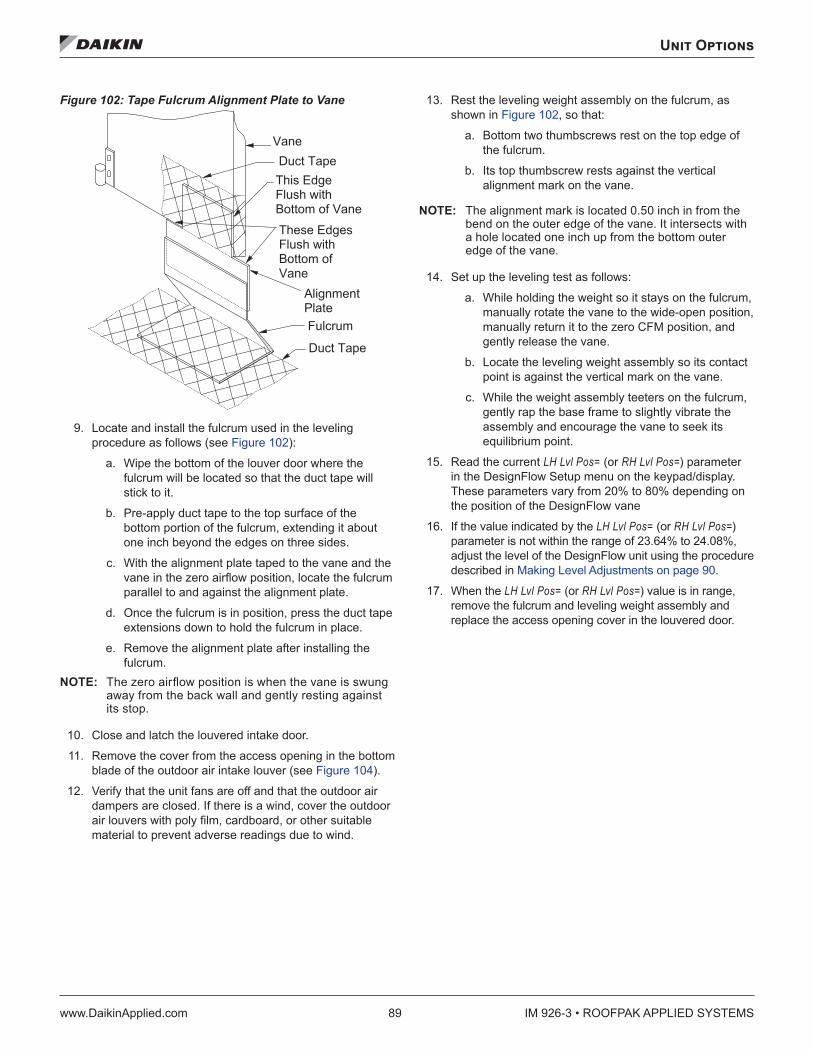
Unit Options
www.DaikinApplied.com 89 IM 926-3 • ROOFPAK APPLIED SYSTEMS
Figure 102: Tape Fulcrum Alignment Plate to Vane
9. Locate and install the fulcrum used in the leveling procedure as follows (see Figure 102):
a. Wipe the bottom of the louver door where the fulcrum will be located so that the duct tape will stick to it.
b. Pre-apply duct tape to the top surface of the bottom portion of the fulcrum, extending it about one inch beyond the edges on three sides.
c. With the alignment plate taped to the vane and the vane in the zero airflow position, locate the fulcrum parallel to and against the alignment plate.
d. Once the fulcrum is in position, press the duct tape extensions down to hold the fulcrum in place.
e. Remove the alignment plate after installing the fulcrum.
NOTE: The zero airflow position is when the vane is swung away from the back wall and gently resting against its stop.
10. Close and latch the louvered intake door.
11. Remove the cover from the access opening in the bottom blade of the outdoor air intake louver (see Figure 104).
12. Verify that the unit fans are off and that the outdoor air dampers are closed. If there is a wind, cover the outdoor air louvers with poly film, cardboard, or other suitable material to prevent adverse readings due to wind.
13. Rest the leveling weight assembly on the fulcrum, as shown in Figure 102, so that:
a. Bottom two thumbscrews rest on the top edge of the fulcrum.
b. Its top thumbscrew rests against the vertical alignment mark on the vane.
NOTE: The alignment mark is located 0.50 inch in from the bend on the outer edge of the vane. It intersects with a hole located one inch up from the bottom outer edge of the vane.
14. Set up the leveling test as follows:
a. While holding the weight so it stays on the fulcrum, manually rotate the vane to the wide-open position, manually return it to the zero CFM position, and gently release the vane.
b. Locate the leveling weight assembly so its contact point is against the vertical mark on the vane.
c. While the weight assembly teeters on the fulcrum, gently rap the base frame to slightly vibrate the assembly and encourage the vane to seek its equilibrium point.
15. Read the current LH Lvl Pos= (or RH Lvl Pos=) parameter in the DesignFlow Setup menu on the keypad/display. These parameters vary from 20% to 80% depending on the position of the DesignFlow vane
16. If the value indicated by the LH Lvl Pos= (or RH Lvl Pos=) parameter is not within the range of 23.64% to 24.08%, adjust the level of the DesignFlow unit using the procedure described in Making Level Adjustments on page 90.
17. When the LH Lvl Pos= (or RH Lvl Pos=) value is in range, remove the fulcrum and leveling weight assembly and replace the access opening cover in the louvered door.
� � � � � � � � �� � � �
� � � � � � �
� � � � � � � � � � � � �
� � � � � � � �� � � � � � � � � � �� � � � � � � � � � � � � �� � � � � � � � � �� � � � � � � � � �� � � � � � � � � �� � � �
� � � � � � � � �
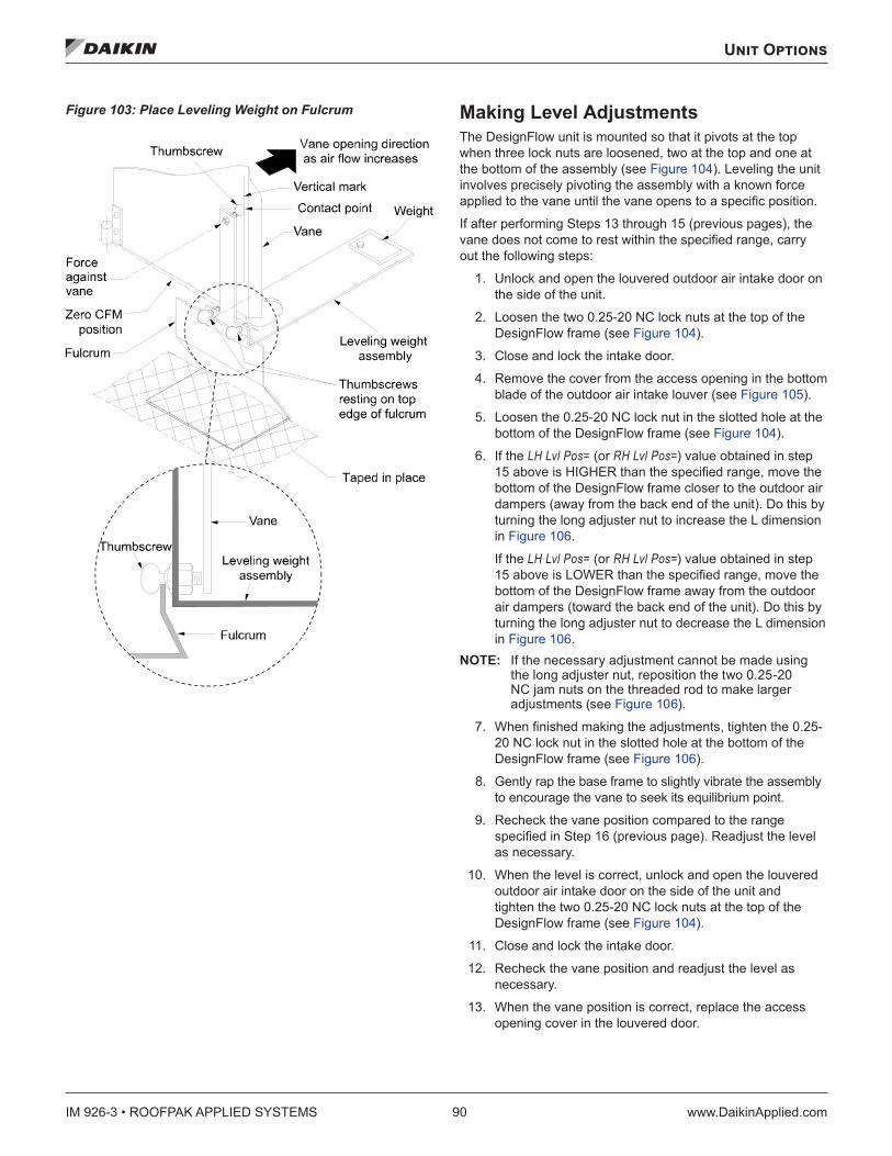
IM 926-3 • ROOFPAK APPLIED SYSTEMS 90 www.DaikinApplied.com
Unit Options
Figure 103: Place Leveling Weight on Fulcrum Making Level Adjustments The DesignFlow unit is mounted so that it pivots at the top when three lock nuts are loosened, two at the top and one at the bottom of the assembly (see Figure 104). Leveling the unit involves precisely pivoting the assembly with a known force applied to the vane until the vane opens to a specific position.
If after performing Steps 13 through 15 (previous pages), the vane does not come to rest within the specified range, carry out the following steps:
1. Unlock and open the louvered outdoor air intake door on the side of the unit.
2. Loosen the two 0.25-20 NC lock nuts at the top of the DesignFlow frame (see Figure 104).
3. Close and lock the intake door.
4. Remove the cover from the access opening in the bottom blade of the outdoor air intake louver (see Figure 105).
5. Loosen the 0.25-20 NC lock nut in the slotted hole at the bottom of the DesignFlow frame (see Figure 104).
6. If the LH Lvl Pos= (or RH Lvl Pos=) value obtained in step 15 above is HIGHER than the specified range, move the bottom of the DesignFlow frame closer to the outdoor air dampers (away from the back end of the unit). Do this by turning the long adjuster nut to increase the L dimension in Figure 106.
If the LH Lvl Pos= (or RH Lvl Pos=) value obtained in step 15 above is LOWER than the specified range, move the bottom of the DesignFlow frame away from the outdoor air dampers (toward the back end of the unit). Do this by turning the long adjuster nut to decrease the L dimension in Figure 106.
NOTE: If the necessary adjustment cannot be made using the long adjuster nut, reposition the two 0.25-20 NC jam nuts on the threaded rod to make larger adjustments (see Figure 106).
7. When finished making the adjustments, tighten the 0.25-20 NC lock nut in the slotted hole at the bottom of the DesignFlow frame (see Figure 106).
8. Gently rap the base frame to slightly vibrate the assembly to encourage the vane to seek its equilibrium point.
9. Recheck the vane position compared to the range specified in Step 16 (previous page). Readjust the level as necessary.
10. When the level is correct, unlock and open the louvered outdoor air intake door on the side of the unit and tighten the two 0.25-20 NC lock nuts at the top of the DesignFlow frame (see Figure 104).
11. Close and lock the intake door.
12. Recheck the vane position and readjust the level as necessary.
13. When the vane position is correct, replace the access opening cover in the louvered door.
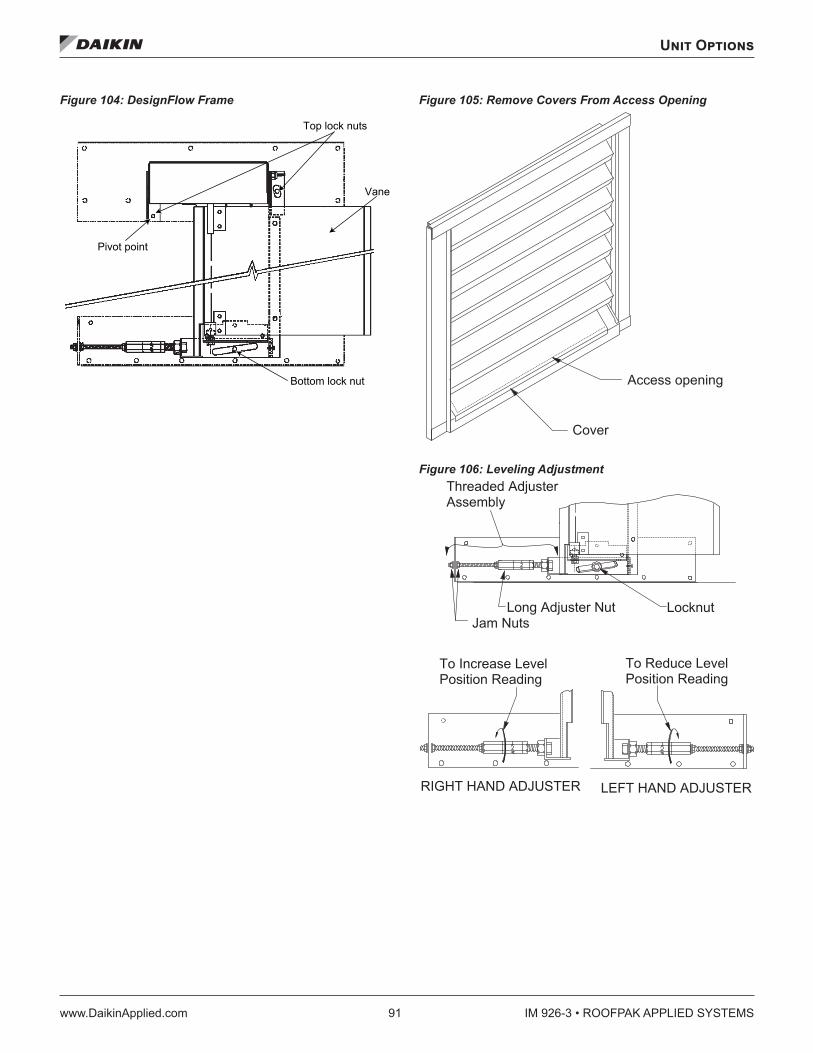
Unit Options
www.DaikinApplied.com 91 IM 926-3 • ROOFPAK APPLIED SYSTEMS
Figure 104: DesignFlow Frame Figure 105: Remove Covers From Access Opening
Figure 106: Leveling Adjustment
Top lock nuts
Vane
Bottom lock nut
Pivot point
Access opening
Cover
� � � � � � � � � � � � � � � � � � � � � � � � � � � � � � � � � � � � �
� � � � � � � � � � � � � �� � � � � �
� � � � � � � � � � � � � � � � � � � � � � � � �
� � � � � � � � � � � � � � �� � � � � � � � � � � � � �
� � � � � � � � � � � � � �� � � � � � � � � � � � � �
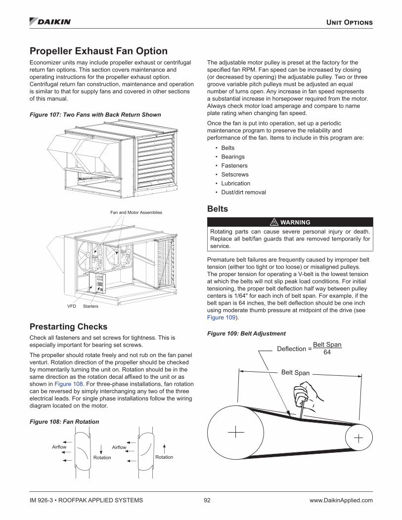
IM 926-3 • ROOFPAK APPLIED SYSTEMS 92 www.DaikinApplied.com
Unit Options
Propeller Exhaust Fan Option Economizer units may include propeller exhaust or centrifugal return fan options. This section covers maintenance and operating instructions for the propeller exhaust option. Centrifugal return fan construction, maintenance and operation is similar to that for supply fans and covered in other sections of this manual.
Figure 107: Two Fans with Back Return Shown
Prestarting Checks Check all fasteners and set screws for tightness. This is especially important for bearing set screws.
The propeller should rotate freely and not rub on the fan panel venturi. Rotation direction of the propeller should be checked by momentarily turning the unit on. Rotation should be in the same direction as the rotation decal affixed to the unit or as shown in Figure 108. For three-phase installations, fan rotation can be reversed by simply interchanging any two of the three electrical leads. For single phase installations follow the wiring diagram located on the motor.
Figure 108: Fan Rotation
The adjustable motor pulley is preset at the factory for the specified fan RPM. Fan speed can be increased by closing (or decreased by opening) the adjustable pulley. Two or three groove variable pitch pulleys must be adjusted an equal number of turns open. Any increase in fan speed represents a substantial increase in horsepower required from the motor. Always check motor load amperage and compare to name plate rating when changing fan speed.
Once the fan is put into operation, set up a periodic maintenance program to preserve the reliability and performance of the fan. Items to include in this program are:
• Belts • Bearings • Fasteners • Setscrews • Lubrication • Dust/dirt removal
Belts WARNING
Rotating parts can cause severe personal injury or death. Replace all belt/fan guards that are removed temporarily for service.
Premature belt failures are frequently caused by improper belt tension (either too tight or too loose) or misaligned pulleys. The proper tension for operating a V-belt is the lowest tension at which the belts will not slip peak load conditions. For initial tensioning, the proper belt deflection half way between pulley centers is 1/64" for each inch of belt span. For example, if the belt span is 64 inches, the belt deflection should be one inch using moderate thumb pressure at midpoint of the drive (see Figure 109).
Figure 109: Belt Adjustment
� � � � � � � � � � � � � � � � � � � � � � � �
� � � � � � � � � �
� � � � � � � � � � � � � �
� � � � � � � � � � � � � � � �
� � � � � � � � �
� � � � � � � � � � � � � � � � � � � � �� �
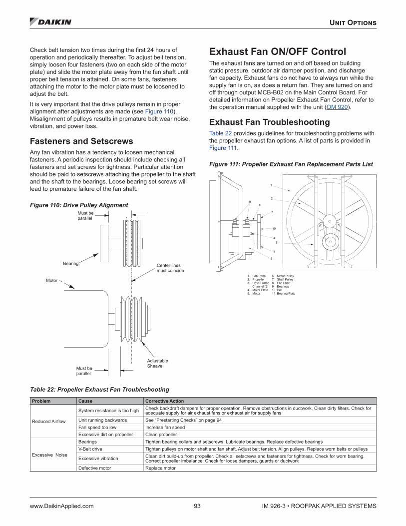
Unit Options
www.DaikinApplied.com 93 IM 926-3 • ROOFPAK APPLIED SYSTEMS
Check belt tension two times during the first 24 hours of operation and periodically thereafter. To adjust belt tension, simply loosen four fasteners (two on each side of the motor plate) and slide the motor plate away from the fan shaft until proper belt tension is attained. On some fans, fasteners attaching the motor to the motor plate must be loosened to adjust the belt.
It is very important that the drive pulleys remain in proper alignment after adjustments are made (see Figure 110). Misalignment of pulleys results in premature belt wear noise, vibration, and power loss.
Fasteners and Setscrews Any fan vibration has a tendency to loosen mechanical fasteners. A periodic inspection should include checking all fasteners and set screws for tightness. Particular attention should be paid to setscrews attaching the propeller to the shaft and the shaft to the bearings. Loose bearing set screws will lead to premature failure of the fan shaft.
Figure 110: Drive Pulley Alignment
Exhaust Fan ON/OFF Control The exhaust fans are turned on and off based on building static pressure, outdoor air damper position, and discharge fan capacity. Exhaust fans do not have to always run while the supply fan is on, as does a return fan. They are turned on and off through output MCB-B02 on the Main Control Board. For detailed information on Propeller Exhaust Fan Control, refer to the operation manual supplied with the unit (OM 920).
Exhaust Fan Troubleshooting Table 22 provides guidelines for troubleshooting problems with the propeller exhaust fan options. A list of parts is provided in Figure 111.
Figure 111: Propeller Exhaust Fan Replacement Parts List
Table 22: Propeller Exhaust Fan Troubleshooting
Problem Cause Corrective Action
Reduced Airflow
System resistance is too high Check backdraft dampers for proper operation. Remove obstructions in ductwork. Clean dirty filters. Check for adequate supply for air exhaust fans or exhaust air for supply fans
Unit running backwards See “Prestarting Checks” on page 94 Fan speed too low Increase fan speed Excessive dirt on propeller Clean propeller
Excessive Noise
Bearings Tighten bearing collars and setscrews. Lubricate bearings. Replace defective bearingsV-Belt drive Tighten pulleys on motor shaft and fan shaft. Adjust belt tension. Align pulleys. Replace worn belts or pulleys
Excessive vibration Clean dirt build-up from propeller. Check all setscrews and fasteners for tightness. Check for worn bearing. Correct propeller imbalance. Check for loose dampers, guards or ductwork
Defective motor Replace motor
� � � � � � � � � � � �� � � � � � � � � � � � �
� � � � � � �� � � � � � � �
� � � � � � �� � � � � � � �
� � � � � � � � �� � � �
� � � � �
� � � � � � �
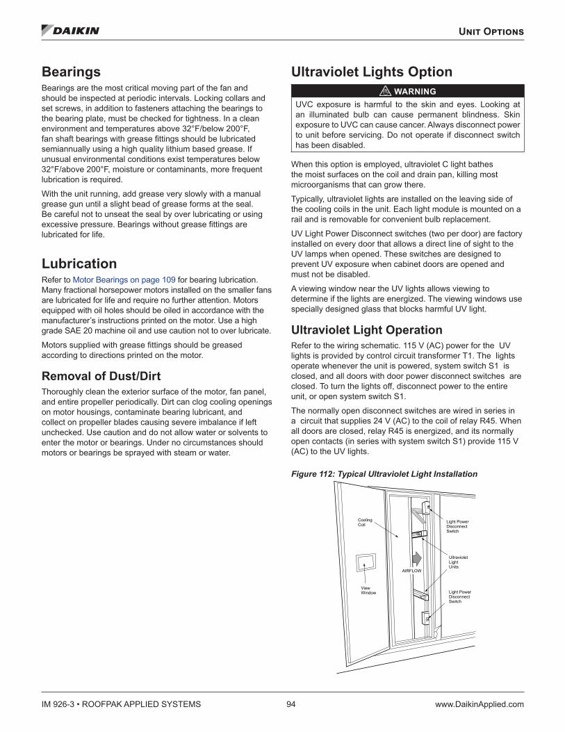
IM 926-3 • ROOFPAK APPLIED SYSTEMS 94 www.DaikinApplied.com
Unit Options
Bearings Bearings are the most critical moving part of the fan and should be inspected at periodic intervals. Locking collars and set screws, in addition to fasteners attaching the bearings to the bearing plate, must be checked for tightness. In a clean environment and temperatures above 32°F/below 200°F, fan shaft bearings with grease fittings should be lubricated semiannually using a high quality lithium based grease. If unusual environmental conditions exist temperatures below 32°F/above 200°F, moisture or contaminants, more frequent lubrication is required.
With the unit running, add grease very slowly with a manual grease gun until a slight bead of grease forms at the seal. Be careful not to unseat the seal by over lubricating or using excessive pressure. Bearings without grease fittings are lubricated for life.
Lubrication Refer to Motor Bearings on page 109 for bearing lubrication. Many fractional horsepower motors installed on the smaller fans are lubricated for life and require no further attention. Motors equipped with oil holes should be oiled in accordance with the manufacturer’s instructions printed on the motor. Use a high grade SAE 20 machine oil and use caution not to over lubricate.
Motors supplied with grease fittings should be greased according to directions printed on the motor.
Removal of Dust/Dirt Thoroughly clean the exterior surface of the motor, fan panel, and entire propeller periodically. Dirt can clog cooling openings on motor housings, contaminate bearing lubricant, and collect on propeller blades causing severe imbalance if left unchecked. Use caution and do not allow water or solvents to enter the motor or bearings. Under no circumstances should motors or bearings be sprayed with steam or water.
Ultraviolet Lights Option WARNING
UVC exposure is harmful to the skin and eyes. Looking at an illuminated bulb can cause permanent blindness. Skin exposure to UVC can cause cancer. Always disconnect power to unit before servicing. Do not operate if disconnect switch has been disabled.
When this option is employed, ultraviolet C light bathes the moist surfaces on the coil and drain pan, killing most microorganisms that can grow there.
Typically, ultraviolet lights are installed on the leaving side of the cooling coils in the unit. Each light module is mounted on a rail and is removable for convenient bulb replacement.
UV Light Power Disconnect switches (two per door) are factory installed on every door that allows a direct line of sight to the UV lamps when opened. These switches are designed to prevent UV exposure when cabinet doors are opened and must not be disabled.
A viewing window near the UV lights allows viewing to determine if the lights are energized. The viewing windows use specially designed glass that blocks harmful UV light.
Ultraviolet Light Operation Refer to the wiring schematic. 115 V (AC) power for the UV lights is provided by control circuit transformer T1. The lights operate whenever the unit is powered, system switch S1 is closed, and all doors with door power disconnect switches are closed. To turn the lights off, disconnect power to the entire unit, or open system switch S1.
The normally open disconnect switches are wired in series in a circuit that supplies 24 V (AC) to the coil of relay R45. When all doors are closed, relay R45 is energized, and its normally open contacts (in series with system switch S1) provide 115 V (AC) to the UV lights.
Figure 112: Typical Ultraviolet Light Installation
UltravioletLightUnits
Light Power DisconnectSwitch
Light Power DisconnectSwitch
ViewWindow
CoolingCoil
AIRFLOW
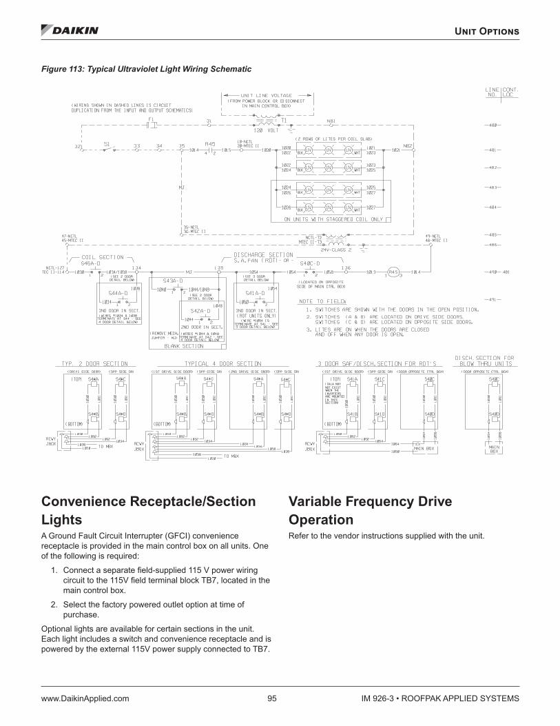
Unit Options
www.DaikinApplied.com 95 IM 926-3 • ROOFPAK APPLIED SYSTEMS
Figure 113: Typical Ultraviolet Light Wiring Schematic
Convenience Receptacle/Section Lights A Ground Fault Circuit Interrupter (GFCI) convenience receptacle is provided in the main control box on all units. One of the following is required:
1. Connect a separate field-supplied 115 V power wiring circuit to the 115V field terminal block TB7, located in the main control box.
2. Select the factory powered outlet option at time of purchase.
Optional lights are available for certain sections in the unit. Each light includes a switch and convenience receptacle and is powered by the external 115V power supply connected to TB7.
Variable Frequency Drive Operation Refer to the vendor instructions supplied with the unit.
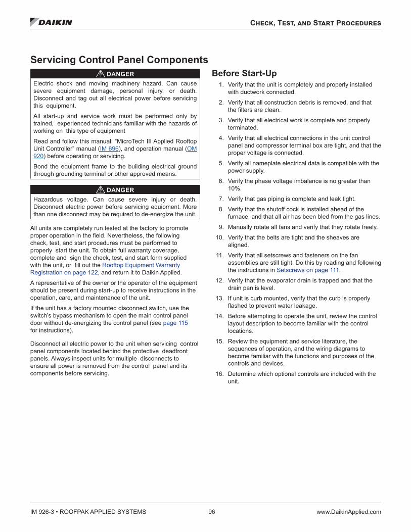
IM 926-3 • ROOFPAK APPLIED SYSTEMS 96 www.DaikinApplied.com
Check, Test, and Start Procedures
Check, Test, and Start Procedures
Servicing Control Panel Components DANGER
Electric shock and moving machinery hazard. Can cause severe equipment damage, personal injury, or death. Disconnect and tag out all electrical power before servicing this equipment.
All start-up and service work must be performed only by trained, experienced technicians familiar with the hazards of working on this type of equipment
Read and follow this manual: “MicroTech III Applied Rooftop Unit Controller” manual (IM 696), and operation manual (OM 920) before operating or servicing.
Bond the equipment frame to the building electrical ground through grounding terminal or other approved means.
DANGERHazardous voltage. Can cause severe injury or death. Disconnect electric power before servicing equipment. More than one disconnect may be required to de-energize the unit.
All units are completely run tested at the factory to promote proper operation in the field. Nevertheless, the following check, test, and start procedures must be performed to properly start the unit. To obtain full warranty coverage, complete and sign the check, test, and start form supplied with the unit, or fill out the Rooftop Equipment Warranty Registration on page 122, and return it to Daikin Applied.
A representative of the owner or the operator of the equipment should be present during start-up to receive instructions in the operation, care, and maintenance of the unit.
If the unit has a factory mounted disconnect switch, use the switch’s bypass mechanism to open the main control panel door without de-energizing the control panel (see page 115 for instructions).
Disconnect all electric power to the unit when servicing control panel components located behind the protective deadfront panels. Always inspect units for multiple disconnects to ensure all power is removed from the control panel and its components before servicing.
Before Start-Up 1. Verify that the unit is completely and properly installed
with ductwork connected.
2. Verify that all construction debris is removed, and that the filters are clean.
3. Verify that all electrical work is complete and properly terminated.
4. Verify that all electrical connections in the unit control panel and compressor terminal box are tight, and that the proper voltage is connected.
5. Verify all nameplate electrical data is compatible with the power supply.
6. Verify the phase voltage imbalance is no greater than 10%.
7. Verify that gas piping is complete and leak tight.
8. Verify that the shutoff cock is installed ahead of the furnace, and that all air has been bled from the gas lines.
9. Manually rotate all fans and verify that they rotate freely.
10. Verify that the belts are tight and the sheaves are aligned.
11. Verify that all setscrews and fasteners on the fan assemblies are still tight. Do this by reading and following the instructions in Setscrews on page 111.
12. Verify that the evaporator drain is trapped and that the drain pan is level.
13. If unit is curb mounted, verify that the curb is properly flashed to prevent water leakage.
14. Before attempting to operate the unit, review the control layout description to become familiar with the control locations.
15. Review the equipment and service literature, the sequences of operation, and the wiring diagrams to become familiar with the functions and purposes of the controls and devices.
16. Determine which optional controls are included with the unit.
Check, Test, and Start Procedures
www.DaikinApplied.com 97 IM 926-3 • ROOFPAK APPLIED SYSTEMS
17. Before closing (connecting) the power disconnect switch, open (disconnect) the following unit control circuit switches:
a. Main Control Panel
– Turn system switch S1 to OFF.
– Electric heat units: turn switch HS1 to OFF.
b. Furnace Control Compartment
– Turn furnace switch S3 to OFF.
– Main Control Panel Switch S7 to OFF.
18. If the DAC or SCC unit does not have an optional zone temperature sensor (ZNT1) connected to it, you may need to change the keypad entry under Setup/Service \ Unit Configuration \ Space Sensor= from YES to NO.
NOTE: If desired, you can significantly reduce all MicroTech III internal control timers by the changing the entry under keypad menu Setup/Service\Unit Configuration\Timer Settings\Service= from “0 min” to “X min” where X is the number of minutes you want the unit to operate with fast timers.
Power Up 1. Close the unit disconnect switch. With the control system
switch S1 in the OFF position, power should be available only to the control circuit transformer (TI) and the compressor crankcase heaters.
2. Turn the Switch S1 to ON. Power should now be supplied to the control panel and the LEDs on MCB1 should follow the normal startup sequence.
Fan Start-Up 1. Verify all duct isolation dampers are open. Unit mounted
isolation dampers may be mounted in the supply or return sections.
2. Place the unit into the “Fan Only” mode through the keypad menu System Summary\System\Ctrl Mode= Fan Only.
3. Turn Switch S7 to ON. The controller should enter the “Startup Initial” operating state. If the fan does not run:
a. Check fuses F1 and F3.
b. Check the manual motor protectors or that the circuit breakers have not tripped.
c. Check the optional phase monitor.
4. If the fans are equipped with optional spring isolators, check the fan spring mount adjustment. When the fans are running they should be level. Refer to Figure 75: RDT Spring Mount Hold-Down Fasteners on page 54.
5. Verify the rotation is correct.
6. Verify the DHL safety is opening at a pressure compatible with duct working pressure limits.
NOTE: The supply and return fan drives usually are selected for operation in the drive’s midspeed range. The return fan drives are usually shipped with fixed pitch sheaves that will provide the selected fan speed; however, the supply fan drives are usually shipped with variable pitch sheaves that are adjusted to provide the minimum fan speed. Both drives should be adjusted for proper airflow during air balancing. For more information, refer to Air Balancing on page 101.
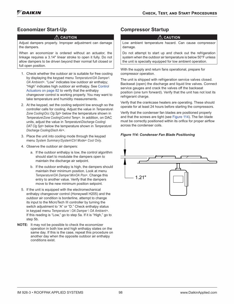
IM 926-3 • ROOFPAK APPLIED SYSTEMS 98 www.DaikinApplied.com
Check, Test, and Start Procedures
Economizer Start-Up CAUTION
Adjust dampers properly. Improper adjustment can damage the dampers.
When an economizer is ordered without an actuator, the linkage requires a 3.14" linear stroke to open it fully. Do not allow dampers to be driven beyond their normal full closed or full open position.
1. Check whether the outdoor air is suitable for free cooling by displaying the keypad menu Temperature\OA Damper\OA Ambient=. “Low” indicates low outdoor air enthalpy; “High” indicates high outdoor air enthalpy. See Control Actuators on page 82 to verify that the enthalpy changeover control is working properly. You may want to take temperature and humidity measurements.
2. At the keypad, set the cooling setpoint low enough so the controller calls for cooling. Adjust the value in Temperature\Zone Cooling\Occ Clg Spt= below the temperature shown in Temperature\Zone Cooling\Control Temp=. In addition, on DAC units, adjust the value in Temperature\Discharge Cooling\DAT Clg Spt= below the temperature shown in Temperature\Discharge Cooling\Disch Air=.
3. Place the unit into cooling mode through the keypad menu System Summary\System\Ctrl Mode= Cool Only.
4. Observe the outdoor air dampers:
a. If the outdoor enthalpy is low, the control algorithm should start to modulate the dampers open to maintain the discharge air setpoint.
b. If the outdoor enthalpy is high, the dampers should maintain their minimum position. Look at menu Temperature\OA Damper\MinOA Pos=. Change this entry to another value. Verify that the dampers move to the new minimum position setpoint.
5. If the unit is equipped with the electromechanical enthalpy changeover control (Honeywell H205) and the outdoor air condition is borderline, attempt to change its input to the MicroTech III controller by turning the switch adjustment to “A” or “D.” Check enthalpy status in keypad menu Temperature \ OA Damper \ OA Ambient=. If this reading is “Low,” go to step 5a. If it is “High,” go to step 5b.
NOTE: It may not be possible to check the economizer operation in both low and high enthalpy states on the same day. If this is the case, repeat this procedure on another day when the opposite outdoor air enthalpy conditions exist.
Compressor Startup CAUTION
Low ambient temperature hazard. Can cause compressor damage.
Do not attempt to start up and check out the refrigeration system when the outdoor air temperature is below 50°F unless the unit is specially equipped for low ambient operation.
With the supply and return fans operational, prepare for compressor operation.
The unit is shipped with refrigeration service valves closed. Backseat (open) the discharge and liquid line valves. Connect service gauges and crack the valves off the backseat position (one turn forward). Verify that the unit has not lost its refrigerant charge.
Verify that the crankcase heaters are operating. These should operate for at least 24 hours before starting the compressors.
Verify that the condenser fan blades are positioned properly and that the screws are tight (see Figure 114). The fan blade must be correctly positioned within its orifice for proper airflow across the condenser coils.
Figure 114: Condenser Fan Blade Positioning
1.21"
Check, Test, and Start Procedures
www.DaikinApplied.com 99 IM 926-3 • ROOFPAK APPLIED SYSTEMS
Scroll Compressor Rotational Direction CAUTION
Venting refrigerant to atmosphere is not allowed per most local laws and/or codes.
Scroll compressors only compress in one rotational direction. Three-phase compressors rotate in either direction depending upon phasing of the power to L1, L2, and L3. Since there is a 50/50 chance of connecting power to cause rotation in the reverse direction, verify that the compressor rotates in the proper direction after the system is installed. If the compressor is rotating properly, suction pressure drops and discharge pressure rises when the compressor is energized. If the compressor is rotating in reverse, the sound level is louder and current draw is reduced substantially. After several minutes of operation, the compressor’s internal protector trips.
All three-phase compressors are wired the same internally. Therefore, once the correct phasing is determined for a specific system or installation, connecting properly phased power leads to the same terminals should maintain proper rotation direction.
Perform the following procedure on all units:
1. At the keypad, set the cooling setpoint low enough so that the controller will call for cooling. The value in Temperature \ Zone Cooling \ Occ Clg Spt= will need to be adjusted below the temperature shown in Temperature \ Zone Cooling \ Control Temp=. In addition, on DAC units, the value in Temperature \ Discharge Cooling \ DAT Clg Spt= will need to be adjusted below the temperature shown in Temperature \ Discharge Cooling \ Disch Air=.
2. Place the unit into cooling mode through the keypad menu System Summary \ System \ Ctrl Mode= Cool Only.
3. Verify that the low ambient compressor lockout temperature setpoint, Temperature \ OA Damper \ OATComp Lock= is set below the current outside air temperature (shown in System Summary \ Temperatures \ OA Temp=).
NOTE: Do not attempt to operate the compressors if the outdoor air is too cool. See the warning statement under Compressor Startup on page 98.
4. Close the S1 switch. Now refrigeration circuit #1 is enabled, circuit #2 is disabled, and the MT III board starts its 5-minute timing cycle. Note that if the unit has an economizer and the outdoor air enthalpy is low, the economizer must fully open before the controller will energize mechanical cooling.
5. When the outdoor air damper has fully opened and the time delay has expired, liquid line solenoid valve SV1 should open and compressor #1 should start. If this does not happen, perform the following:
a. Verify that there is a call for cooling by checking the keypad menu System Summary \ System \ UnitStatus=. This should be in “Cooling.”
b. Check the keypad menu System Summary \ System \ Clg Status=. The compressors will only run if this reads either “All Clg” or “Mech Clg.”
c. Trace the control circuits.
6. Verify that compressor #1 starts. The compressor should start when the solenoid valve opens. If the compressor motor hums but does not run, verify that it is getting three-phase power.
7. The compressor should operate continuously while there is a call for cooling. If the compressor cycles on its low pressure switch, perform the following:
a. Verify that the circuit is not short of refrigerant.
b. Check for low airflow.
c. Check for clogged filters.
d. Check for restricted ductwork.
e. Check for very low temperature return air entering the unit.
f. Verify that the liquid line components, expansion valve, and distributor tubes are feeding the evaporator coil.
g. Verify that all air handling section panels are closed.
h. Verify that the liquid line service valves are completely open.
8. Verify that the compressors stage properly. As the circuit loads up, the second compressor (if available) will be energized. For more information on staging sequences, see IM 919, “MicroTech III Applied Rooftop Unit Controller.”
9. Verify that the condenser fans are cycling and rotating properly (blowing air upward). When the compressor starts, at least one condenser fan should also start. The CCB1 should control the remaining condenser fans based on outdoor air conditions. Look at keypad menu Setup/ Service \ Compressor Setup \ Cond Fan1= (also look at Cond Fan2=, Cond Fan3=, Cond Fan4=). The Table 18 on page 47 shows recommended setpoints based on the unit size. Cond Fan1 controls BO5, Cond Fan2 controls BO6, Cond Fan3 controls BO7, Cond Fan4 controls BO8. Refer to the unit wiring diagrams and Condenser Fan Arrangement on page 6.
IM 926-3 • ROOFPAK APPLIED SYSTEMS 100 www.DaikinApplied.com
Check, Test, and Start Procedures
10. Check the oil level in the compressor sightglass. If low oil is observed, it is possible that liquid refrigerant is returning to the compressor. Check the suction superheat, see Expansion Valve Superheat Adjustment. It should be between 10°F (5.5°C) and 13°F (7.2°C).
11. Open switch S1. The compressor(s) should stop. Place the unit into the “Fan Only” mode through the keypad menu System Summary \ System \ Ctrl Mode= Fan Only.
12. Check refrigerant circuit #2 by repeating steps 2 through 9, substituting circuit #2 nomenclature for circuit #1 nomenclature (S2, TD2, SV2, CCB2, compressor #2 and #4).
13. Verify that the condenser refrigerant subcooling at full capacity is between 13°F and 20°F.
Expansion Valve Superheat Adjustment It is very important that the expansion valve superheat setting be adjusted to be between 10°F (-12°C) and 13°F (-11°C). Insufficient superheat will cause liquid floodback to the compressor which may result in slugging. Excessive superheat will reduce system capacity and shorten compressor life.
Turn the adjustment stem clockwise to increase superheat. Not exceeding one turn, adjust the stem and then observe the superheat. Allow up to 30 minutes for the system to rebalance at the final superheat setting.
On refrigeration circuits with multiple expansion valves, the superheat adjustment should be approximately the same for all valves in the circuit. NOTE: If low oil level is accompanied by heavy foaming
visible in the oil sightglass, it is possible that excess liquid refrigerant is returning to the compressor depending on the rotation of the crank shaft. Check the suction superheat and adjust the expansion valve for 10°F (–12°C) to 13°F (–11°C) of superheat. If proper superheat is obtained, sightglass foaming is not a concern.
For RCS/RFS applications in which the condensing section is remote from the air handling section, consideration should have been given to proper piping between the sections, as this can affect the compressor oil level. Refer to the “ASHRAE Handbooks” for more information on proper refrigeration piping design and installation.
R-407C Superheat Due to refrigerant glide, when measuring and/or adjusting TEV superheat, it is important to use SATURATED VAPOR (Dew Point) TABLES. Example: The Pressure/Temperature (P/T) chart shows that the saturated vapor temperature, at the dew point, of R-407C for 79 psig is approximately 51°F. If the actual refrigerant temperature is 60°F, the superheat is 9°F.
Checking Superheat Following are recommendations for checking superheat:
1. Close the unit section doors. Running the unit with its doors open will affect expansion valve and system operation considerably.
2. For units with one expansion valve per circuit, check the pressure and temperature at the compressor suction valve.
3. For units with multiple expansion valves per circuit, check the pressure at the compressor, and check the temperature at the suction header that is fed by the valve.
Check, Test, and Start Procedures
www.DaikinApplied.com 101 IM 926-3 • ROOFPAK APPLIED SYSTEMS
Heating System Start-up General
1. At the keypad, set the heating setpoints high enough so that the controller will call for heating. The value in Temperature \ Zone Heating \ Occ Htg Spt= will need to be adjusted above the temperature shown in Temperature \ Zone Heating \ Control Temp=. In addition, on DAC units, the value in Temperature \ Discharge Heating \ DAT Htg Spt= will need to be adjusted above the temperature shown in Temperature \ Discharge Heating \ Disch Air=.
2. Place the unit into heating mode through the keypad menu System Summary \ System \ Ctrl Mode= Heat Only.
3. Verify that the high ambient heat lockout temperature setpoint, Temperature \ Zone Heating \ OATHtg Lock= is set above the current outside air temperature (shown in System Summary \ Temperatures \ OA Temp=).
Gas Furnace Refer to the “Start-up and Operating Procedures” section of the Forced Draft Gas Fired Furnace Installation Manual, IM 684 or IM 685. Perform the start-up procedures given in it.
Electric Heat Turn the electric heat switch HS1 to ON. The electric heaters should energize. If the unit has multistage electric heat, the MicroTech III Auxiliary Control board EHB1 should energize the heaters in successive stages. The rate of staging is set in keypad menu Setup/Service \ Heating Setup \ Stage Time=. The default value of “5 min” can be adjusted from 2 to 60 minutes.
Steam Heat The steam valve actuator should open the valve. The steam valve is open when the valve stem is up. If the unit loses power, the spring in the actuator should drive the valve wide open. Check this by opening system switch S1.
Hot Water Heat The hot water valve actuator should open the valve to the coil. The three-way hot water valve is open to the coil when the valve stem is down. If the unit loses power, the spring in the actuator should drive the valve wide open to the coil. Check this by opening system switch S1.
Air Balancing WARNING
Moving machinery hazard. Can cause severe personal injury or death.
Do not use a mechanically driven tachometer to measure the speed of return fans on this fan arrangement. Use a strobe tachometer.
WARNINGRotating parts can cause severe personal injury or death.
Replace all belt/fan guards that are temporarily removed for service.
Air balancing should be performed by a qualified air balancing technician. Note that the supply fan motors are usually shipped with variable pitch sheaves which are typically set at the low end of the drive’s fan rpm range. See Mounting and Adjusting Motor Sheaves on page 102 The return fan motors are usually shipped with fixed pitch sheaves.
The following should be erformed as part of the air balancing procedure:
1. Check the operating lance with the economizer dampers positioned for both outdoor air and minimum outdoor air.
2. Verify that the total airflow will never be less than that required for operation of the electric heaters or gas furnace.
3. For VAV units that have fan tracking control, adjust the supply/return fan balance by using the MicroTech III controller’s built-in automatic capability. For complete information on using this feature, see OM 920
4. When the final drive adjustments or changes are complete, check the current draw of the supply and return fan motors. The amperage must not exceed the service factor stamped on the motor nameplate.
5. Upon completion of the air balance, replace variable pitch motor sheaves (if any) with comparably sized fixed pitch sheaves. A fixed pitch sheave will reduce vibration and provide longer belt bearing life.
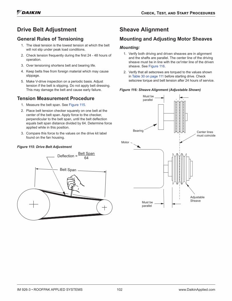
IM 926-3 • ROOFPAK APPLIED SYSTEMS 102 www.DaikinApplied.com
Check, Test, and Start Procedures
Drive Belt Adjustment General Rules of Tensioning
1. The ideal tension is the lowest tension at which the belt will not slip under peak load conditions.
2. Check tension frequently during the first 24 - 48 hours of operation.
3. Over tensioning shortens belt and bearing life.
4. Keep belts free from foreign material which may cause slippage.
5. Make V-drive inspection on a periodic basis. Adjust tension if the belt is slipping. Do not apply belt dressing. This may damage the belt and cause early failure.
Tension Measurement Procedure 1. Measure the belt span. See Figure 115.
2. Place belt tension checker squarely on one belt at the center of the belt span. Apply force to the checker, perpendicular to the belt span, until the belt deflection equals belt span distance divided by 64. Determine force applied while in this position.
3. Compare this force to the values on the drive kit label found on the fan housing.
Figure 115: Drive Belt Adjustment
Sheave Alignment Mounting and Adjusting Motor Sheaves Mounting:
1. Verify both driving and driven sheaves are in alignment and the shafts are parallel. The center line of the driving sheave must be in line with the ce1nter line of the driven sheave. See Figure 116.
2. Verify that all setscrews are torqued to the values shown in Table 30 on page 111 before starting drive. Check setscrew torque and belt tension after 24 hours of service.
Figure 116: Sheave Alignment (Adjustable Shown)
� � � � � � � � �
� � � � � � � � � � � � � � � � � � � � �� �
� � � � � � � � � � � �� � � � � � � � � � � � �
� � � � � � �� � � � � � � �
� � � � � � �� � � � � � � �
� � � � � � � � �� � � �
� � � � �
� � � � � � �
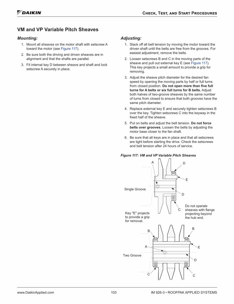
Check, Test, and Start Procedures
www.DaikinApplied.com 103 IM 926-3 • ROOFPAK APPLIED SYSTEMS
VM and VP Variable Pitch Sheaves Mounting:
1. Mount all sheaves on the motor shaft with setscrew A toward the motor (see Figure 117).
2. Be sure both the driving and driven sheaves are in alignment and that the shafts are parallel.
3. Fit internal key D between sheave and shaft and lock setscrew A securely in place.
Adjusting: 1. Slack off all belt tension by moving the motor toward the
driven shaft until the belts are free from the grooves. For easiest adjustment, remove the belts.
2. Loosen setscrews B and C in the moving parts of the sheave and pull out external key E (see Figure 117). This key projects a small amount to provide a grip for removing.
3. Adjust the sheave pitch diameter for the desired fan speed by opening the moving parts by half or full turns from closed position. Do not open more than five full turns for A belts or six full turns for B belts . Adjust both halves of two-groove sheaves by the same number of turns from closed to ensure that both grooves have the same pitch diameter.
4. Replace external key E and securely tighten setscrews B over the key. Tighten setscrews C into the keyway in the fixed half of the sheave.
5. Put on belts and adjust the belt tension. Do not force belts over grooves . Loosen the belts by adjusting the motor base closer to the fan shaft.
6. Be sure that all keys are in place and that all setscrews are tight before starting the drive. Check the setscrews and belt tension after 24 hours of service.
Figure 117: VM and VP Variable Pitch Sheaves
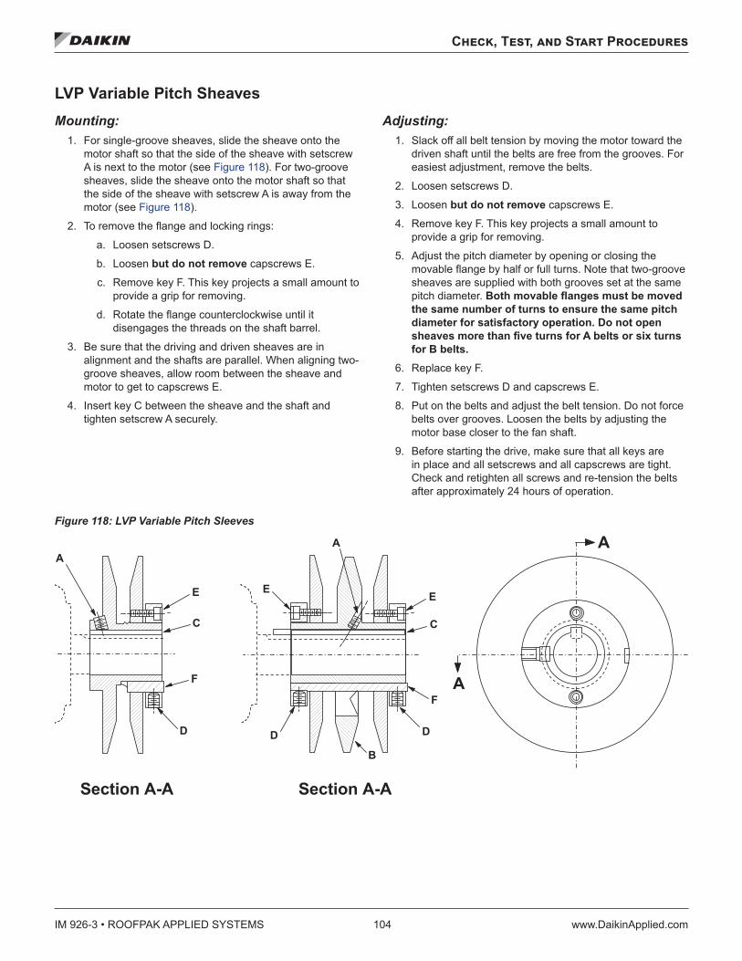
IM 926-3 • ROOFPAK APPLIED SYSTEMS 104 www.DaikinApplied.com
Check, Test, and Start Procedures
LVP Variable Pitch Sheaves Mounting:
1. For single-groove sheaves, slide the sheave onto the motor shaft so that the side of the sheave with setscrew A is next to the motor (see Figure 118). For two-groove sheaves, slide the sheave onto the motor shaft so that the side of the sheave with setscrew A is away from the motor (see Figure 118).
2. To remove the flange and locking rings:
a. Loosen setscrews D.
b. Loosen but do not remove capscrews E.
c. Remove key F. This key projects a small amount to provide a grip for removing.
d. Rotate the flange counterclockwise until it disengages the threads on the shaft barrel.
3. Be sure that the driving and driven sheaves are in alignment and the shafts are parallel. When aligning two-groove sheaves, allow room between the sheave and motor to get to capscrews E.
4. Insert key C between the sheave and the shaft and tighten setscrew A securely.
Adjusting: 1. Slack off all belt tension by moving the motor toward the
driven shaft until the belts are free from the grooves. For easiest adjustment, remove the belts.
2. Loosen setscrews D.
3. Loosen but do not remove capscrews E.
4. Remove key F. This key projects a small amount to provide a grip for removing.
5. Adjust the pitch diameter by opening or closing the movable flange by half or full turns. Note that two-groove sheaves are supplied with both grooves set at the same pitch diameter. Both movable flanges must be moved the same number of turns to ensure the same pitch diameter for satisfactory operation . Do not open sheaves more than five turns for A belts or six turns for B belts .
6. Replace key F.
7. Tighten setscrews D and capscrews E.
8. Put on the belts and adjust the belt tension. Do not force belts over grooves. Loosen the belts by adjusting the motor base closer to the fan shaft.
9. Before starting the drive, make sure that all keys are in place and all setscrews and all capscrews are tight. Check and retighten all screws and re-tension the belts after approximately 24 hours of operation.
Figure 118: LVP Variable Pitch Sleeves
� � � � � � � � � � � � � � � � � � � � � �
�
�
�
�
�
�
�
�
�
�
�
�
�
�
�
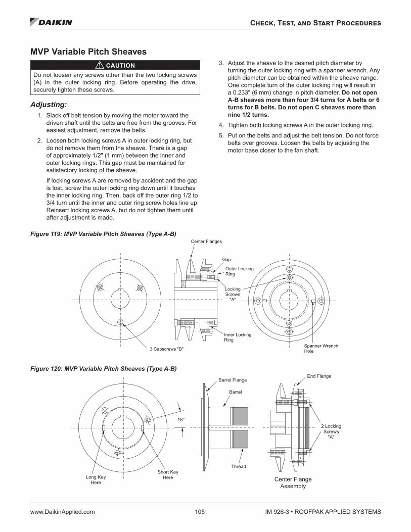
Check, Test, and Start Procedures
www.DaikinApplied.com 105 IM 926-3 • ROOFPAK APPLIED SYSTEMS
MVP Variable Pitch Sheaves CAUTION
Do not loosen any screws other than the two locking screws (A) in the outer locking ring. Before operating the drive, securely tighten these screws.
Adjusting: 1. Slack off belt tension by moving the motor toward the
driven shaft until the belts are free from the grooves. For easiest adjustment, remove the belts.
2. Loosen both locking screws A in outer locking ring, but do not remove them from the sheave. There is a gap of approximately 1/2" (1 mm) between the inner and outer locking rings. This gap must be maintained for satisfactory locking of the sheave.
If locking screws A are removed by accident and the gap is lost, screw the outer locking ring down until it touches the inner locking ring. Then, back off the outer ring 1/2 to 3/4 turn until the inner and outer ring screw holes line up. Reinsert locking screws A, but do not tighten them until after adjustment is made.
3. Adjust the sheave to the desired pitch diameter by turning the outer locking ring with a spanner wrench. Any pitch diameter can be obtained within the sheave range. One complete turn of the outer locking ring will result in a 0.233" (6 mm) change in pitch diameter. Do not open A-B sheaves more than four 3/4 turns for A belts or 6 turns for B belts . Do not open C sheaves more than nine 1/2 turns .
4. Tighten both locking screws A in the outer locking ring.
5. Put on the belts and adjust the belt tension. Do not force belts over grooves. Loosen the belts by adjusting the motor base closer to the fan shaft.
Figure 119: MVP Variable Pitch Sheaves (Type A-B)
Figure 120: MVP Variable Pitch Sheaves (Type A-B)
� � � � � � � � � � � � � �
� � �
� � � � � � � � � � � � �� � � �
� � � � � � � � � �� � �
� � � � � � � � � � � � � � �
� � � � � � � � � � � � �� � � �
� � � � � � � � � � � � � �� � � �
� � � � � � � � �� � � � � �� � �
� � � � � � � � �
� � � � � � � � � �� � � � � � � �
� � � � � �
� � � � � �
� � � � � � � � � � � �
� � �
� � � � � � � �� � � �� � � � � � � �
� � � �
IM 926-3 • ROOFPAK APPLIED SYSTEMS 106 www.DaikinApplied.com
Check, Test, and Start Procedures
Final Control SettingsWhen all start-up procedures are completed, set the controls and program the MicroTech III controller for normal operation. Use the following list as a guide; some items may not apply to your unit. For more detail, see IM 919 and OM 920.
1. Turn system switch S1 to ON and S7 to AUTO.
2. Turn gas furnace switch S3 to AUTO or turn electric heat switch HS1 to ON.
3. Set the electromechanical (Honeywell H205) enthalpy control (OAE) as required (A, B, C, or D). Set the solid-state (Honeywell H705/C7400) enthalpy control (OAE/ RAE) past “D.”
4. Set the heating and cooling parameters as required for normal unit operation:
a. Temperature \ Zone Cooling \
b. Temperature \ Zone Heating \
c. Temperature \ Discharge Cooling \
d. Temperature \ Discharge Heating \
5. Set the low ambient compressor lockout setpoint as required in menu, Temperature \ Zone Cooling \ OAT Clg Lock=. Do not set it below 50°F (10°C) unless the unit is equipped for low ambient operation.
6. Set the high ambient heat lockout temperature setpoint, Temperature \ Zone Heating \ OAT Htg Lock= as required.
7. Set the alarm limits as required in Setup/Service \ Alarm Limits \.
8. Set the compressor lead/lag function as desired using keypad menu Setup/Service \ Compressor Setup \ Lead Circuit= and Setup/Service \ Compressor Setup \ Comp Ctrl=. Refer to “Compressor Staging” in OM137 and OM138.
NOTE: If the unit has hot gas bypass on circuit #1 only, lead circuit must always be #1.
9. Set the duct static pressure control parameters as required in keypad menu Airflow \ Duct Pressure \.
10. Set the building static pressure control parameters as required in keypad menu Airflow \ Bldg Pressure \.
11. Set the fan tracking parameters as required in keypad menus Setup/Service \ Fan Tracking Setup \ and Setup/ Service \ Fan Balance \.
12. Set the economizer control parameters as required in keypad menu Temperature \ OA Damper \.
13. Set the control timers as required in keypad menu Setup/Service \ Timer Settings \.
14. Set the date and time in keypad menu Setup/Service \ Time/Date \.
15. Set the operating schedule as required using keypad menus. Note: When used with a Building Automation System, these settings may need to be kept at the default of no schedule:
a. Schedules \ Daily Schedule \
b. Schedules \ Holiday Schedule \
16. Temporarily disconnect static pressure sensor tubing from sensors SPS1 and SPS2 (if installed) and place the unit into the calibrate mode by using the keypad menu Setup/Service \ Unit Configuration \ Calibrate Mode= and changing the value from NO to YES. The calibrate mode automatically zeroes all static pressure sensors and calibrates any actuator feedback pots connected to the MicroTech III controller. When the calibration is finished, the keypad menu System Summary \ System \ Unit Status= changes from “Calib” to “Off Man.”
17. To restart the unit, reconnect static pressure tubing and change keypad menu System Summary \ System \ Ctrl Mode= from OFF to AUTO.
Maintaining Control Parameter Records Daikin recommends that the MicroTech III controller’s setpoints and parameters be recorded and saved for future reference. If the Microprocessor Control Board requires replacement, this record facilitates entering the unit’s proper data. The following tables display all the setpoints, monitoring points, and program variables offered by MicroTech III plus the keypad road map used to find each parameter.
A number of menus and menu items that appear on the unit keypad/display are conditional and may not apply to a specific unit, depending on the unit software configuration. The unit software configuration is defined by a “Software Configuration Code” shown on a label located near the keypad/display. The Software Configuration Code also can be displayed via the six menu items in the Config Code menu on the unit keypad/display. Refer to “Main Control Board (MCB) Configuration” in OM 920.
The shaded menus and menu items in Figure 83 on page 61 are conditional. A conditional menu or menu item includes a reference in Figure 83 to the position in the Software Configuration Code upon which its applicability depends. For example, the Duct Pressure menu in Figure 83 includes a notation [14=1 or 2]. This notation means that the Duct Pressure menu (and all its menu items) applies to the specific unit only if position 14 in its Software Configuration Code is a 1 or a 2. Otherwise, the menu or menu item is not applicable to the unit and does not affect its operation.
The items in Figure 83 include the factory-set value for all adjustable items. Keep a record of any changes made to any of these items.

Maintenance and Service
www.DaikinApplied.com 107 IM 926-3 • ROOFPAK APPLIED SYSTEMS
Maintenance and Service
Servicing Control Panel Components
WARNINGMoving machinery and electrical power hazards. Can cause severe personal injury or death.
Disconnect and lock off all power before servicing equipment.
CAUTIONSharp edges are inherent to sheet metal parts, screws, clips, and similar items. May cause personal injury. Exercise caution when servicing equipment.
DANGERHazardous voltage. Can cause severe injury or death. Disconnect electric power before servicing equipment. More than one disconnect may be required to de-energize the unit.
Installation and maintenance must be performed only by qualified personnel who are experienced with this type of equipment and familiar with local codes and regulations.
Disconnect all electric power to the unit when servicing control panel components Before servicing, always inspect units for multiple disconnects to ensure all power is removed from the control panel and its components.
Planned Maintenance Preventive maintenance is the best way to avoid unnecessary expense and inconvenience. Have this system inspected at regular intervals by a qualified service technician. The required frequency of inspections depends upon the total operating time and the indoor and outdoor environmental conditions. Routine maintenance should cover the following items:
• Tighten all belts, wire connections, and setscrews. • Clean the evaporator and condenser coils mechanically
or with cold water, if necessary. Usually any fouling is only matted on the entering air face of the coil and can be removed by brushing.
• Lubricate the motor and fan shaft bearings. • Align or replace the belts as needed. • Clean or replace the filters as needed. • Check each circuit’s refrigerant sightglass when
the circuit is operating under steady-state, full load conditions. The sightglass should then be full and clear. If it is not, check for refrigerant leaks.
NOTE: A partially full sight glass is not uncommon at part load conditions.
• Check for proper superheat. • Check for blockage of the condensate drain. Clean the
condensate pan as needed. • Check the power and control voltages. • Check the running amperage of all motors. • Check all operating temperatures and pressures. • Check and adjust all temperature and pressure controls
as needed. • Check and adjust all damper linkages as needed. • Check the operation of all safety controls. • Examine the gas furnace (see IM 684 or IM 685). • Check the condenser fans and tighten their setscrews. • Lubricate the door latch mechanisms.
IM 926-3 • ROOFPAK APPLIED SYSTEMS 108 www.DaikinApplied.com
Maintenance and Service
Unit Storage Location The Daikin Rooftop Packaged System Unit is an outdoor unit. However, the schedule may dictate storage either on the ground or in its final position at the site. If the unit is stored on the ground, additional precautions should be taken as follows:
Make sure that the unit is well supported along the length of the base rail.
• Make sure that the unit is level (no twists or uneven ground surface).
• Provide proper drainage around the unit to prevent flooding of the equipment.
• Provide adequate protection from vandalism, mechanical contact, etc. The condenser fins are particularly vulnerable to damage by even light contact with ground based objects.
• Make sure all doors are securely closed. • If isolation dampers are provided, verify that they are
properly installed and fully closed to prevent the entry of animals and debris through the supply and return air openings.
• Units without isolation dampers should be fitted with covers over the supply and return air openings.
Preparation Supply (and Return) Fans
1. Move the motor base to check and lubricate slides and leadscrews.
2. Remove the drive belts, tag them with the fan name and unit serial number, and store them in a conditioned space out of direct sunlight.
3. Once every two weeks, rotate the fan and motor shafts. Mark the shaft positions first to make sure they stop in a different position.
4. Depending on local climatic conditions, condensate may collect on components inside the units. To prevent surface rust and discoloration, spray all bare metal parts with a rust preventive compound. Pay close attention to fan shafts, sheaves, bearings, and bearing supports,
Cabinet Sections Once a month, open a door on each section and verify that no moisture or debris is accumulating in the unit.
Cooling Circuits The steps below are necessary only if the unit has been started.
1. Provide that each circuit is properly pumped down.
2. Pull the fuses to each compressor (store them in the control cabinet)
3. Close all the refrigerant service valves on each circuit
4. Tag the valves as a warning for the technician who restarts the units
Gas Furnace If the unit is equipped with a gas furnace, close the gas shutoff valve and open furnace control switch S3.
Control Compartment 1. Daikin Applied recommends that the electronic control
equipment in the unit be stored in a 5% to 95% RH (non-condensing) environment.
2. It may be necessary to put a heat source (light bulb) in the main control panel to prevent the accumulation of atmospheric condensate within the panel.
3. The location and wattage of the heat source is dependent on local environmental conditions.
4. Check the control compartment every two weeks to provide that the heat source is functional and is adequate for current conditions.
Winterizing Water Coils Coil freeze-up can be caused by such things as air stratification and failure of outdoor dampers and/or preheat coils. Routine draining of water cooling coils for winter shutdown cannot be depended upon as insurance against freeze-up. Severe coil damage may result. It is recommended that all coils be drained as thoroughly as possible and then treated in the following manner.
• Fill each coil independently with an antifreeze solution using a small circulating pump and again thoroughly drain.
• Check freezing point of antifreeze before proceeding to next coil. Due to a small amount of water always remaining in each coil, there will be a diluting effect. The small amount of antifreeze solution remaining in concentrated enough to prevent freeze-up.
NOTE: Carefully read instructions for mixing antifreeze solution used. Some products have a higher freezing point in their natural state than when mixed with water.
Maintenance and Service
www.DaikinApplied.com 109 IM 926-3 • ROOFPAK APPLIED SYSTEMS
Restart After extended storage, perform a complete start up. Inevitable accumulations of dirt, insect nests, etc. can contribute to problems if not cleaned out thoroughly prior to start up. In addition, thermal cycling tends to loosen mechanical and electrical connections. Following the startup procedure helps discover these and other issues that may have developed during the storage interval.
Gas Furnace For information on maintenance of the gas furnace, refer to IM 684 or IM 685.
Bearing Lubrication
CAUTIONBearing overheating potential. Can damage the equipment. Do not overlubricate bearings.
Use only a high grade mineral grease with a 200°F safe operating temperature. Refer to Table 24 for specific recommended lubricants.
Motor Bearings Supply and return fans—Supply and return fan motors should have grease added after every 2000 hours of operation. Use one of the greases shown in Table 23.
Using the following procedure, relubricate the bearings while the motor is warm, but not running.
1. Remove and clean upper and lower grease plugs.
2. Insert a grease fitting into the upper hole and add a small amount of clean grease (Table 23) with a low pressure gun.
3. Run the motor for five minutes before replacing the plugs.
NOTE: Specific greasing instructions are located on a tag attached to the motor. If special lubrication instructions are on the motor, they supersede all other instructions.
Condenser fan—Condenser fan motors are permanently lubricated and require no periodic lubrication.
Table 23: Recommended Lubricants and Amounts for Fan Motor Bearings
Mfr . Grease NEMA Size Amount to Add (oz .)
Texaco, Polystar or
Polyrex EM (Exxon Mobile)
or Rykon Premium #2
or Penzoil Pen 2 Lube
56 to 140 0.08140 0.15 180 0.19 210 0.30 250 0.47 280 0.61 320 0.76 360 0.81 400 1.25 440 2.12
Fan Shaft Bearings
CAUTIONFor safety, stop rotating equipment and lockout/tagout the disconnects. Add one half of the recommended amount shown in Table 25. Start bearing and run for a few minutes. Stop bearing and add the second half of the recommended amount. A temperature rise, sometimes 30°F (1°C), after relubrication is normal. Bearing should operate at temperature less than 200°F (94°C) and should not exceed 225°F (107°C) for intermittent operation. For a relubrication schedule, see Table 24. For any applications that are not in the ranges of the table, contact Daikin.
CAUTIONThe tables in this manual -state general lubrication recommendations based on our experience and are intended as suggested or starting points only. For best results, specific applications should be monitored regularly and lubrication intervals and amounts adjusted accordingly.
Any good quality lithium or lithium complex base grease, using mineral oil, conforming to NLGI grade 2 consistency, and an oil viscosity of 455-1135 SUS at 100°F (100-200 cSt at 40°C) may be used for relubrication.
Compatibility of grease is critical. Relubable Browning bearings are supplied with grease fittings or zerks for ease of lubrication with hand or automatic grease guns. Always wipe the fitting and grease nozzle clean.
Table 24: Relubrication Intervals
Speed Temperature Cleanliness Relub . intervals
100 rpm Up to 120°F (50°C) Clean 6 to 12 months
500 rpm Up to 150°F (65°C) Clean 2 to 6 months
1000 rpm Up to 210°F (100°C) Clean 2 weeks to 2
months
1500 rpmOver 210°F (100°C) to
250°F (120°C)Clean Weekly
Above 1500 rpm Up to 150°F (65°C) Dirty/wet 1 week to 1 month
Max catalog ratingOver 150°F (65°C)
to 250°F (120°C)
Dirty/wet Daily to 2 weeks
Above 250°F (120°C) Contact Browning
Use NLGI #2 Lithium or Lithium Complex Grease
Table 25: Recommended Fan Relubrication Grease Charge
Shaft Size [inches (mm)]
Weight [Ounces (grams)]
1/2 to 3/4 (13-20) 0.03 (0.85)7/8 to 1-3/16 (25-30) 0.10 (2.84)1-1/4 to 1-1/2 (35-40) 0.15 (4.25)
1-11/16 to 1-15/16 (45-50) 0.20 (5.67)2 to 2-7/16 (55-60) 0.30 (8.51)
2-1/2 to 2-15/16 (65-70) 0.50 (15.59)3 to 3-7/16 (75-80) 0.85 (24.10)3-1/2 to 4 (85-105) 1.50 (42.53)

IM 926-3 • ROOFPAK APPLIED SYSTEMS 110 www.DaikinApplied.com
Maintenance and Service
Bearing Replacement The following instructions must be read in entirety before attempting installation or removal. The procedures indicated should be carefully followed. Failure to do so can result in improper installation which could cause bearing performance problems as well as serious personal injury.
Bearings in Bolt-on Housings (Units) 1. Check area - Clean and organize bearing installation
area and keep well lit. Be sure mounting surfaces are clean and flat.
2. Check shaft - Shaft should be within tolerance range shown in Table 26, clean, and free of nicks and burrs. Mount bearing on unused section of shafting or repair/replace shafting as required.
3. Install unit - Slide unit onto shaft. If it is difficult to mount bearing on shaft, use a piece of emery cloth to reduce any high spots on shaft. Do not hammer on any component of the bearing.
4. Fasten unit in place - Install housing mounting bolts, check and align bearing and tighten mounting bolts to recommended fastener torques. Exercising extreme caution and safety, rotate shaft slowly to center bearing.
Table 26: Shaft Size Tolerances
Shaft Size (in) Tolerance 1/2 to 1-7/16 +0 and -0.001
1-11/16 to 2-7/16 +0 to -0.0015 2-7/16 and up +0 to -0.002
Table 27: Recommended Lubricants for Fan Shaft Ball Bearings
Name Temperature Base Thickener NLGI gradeTexaco,
Premium RB30° to 350°F
(34° to 177°C)Parafinic
mineral oil Lithium 2
Mobile, AW2 40° to 437°F (40° to 175°C) Mineral oil Lithium 2
Mobile, SHC 100
68° to 356°F (50° to 180°C) Synthetic Lithium 2
Chevron, Altiplex
Synthetic60° to 450°F
(51° to 232°C) Synthetic Lithium 2
Exxon, ronex MP
40° to 300°F (40° to 149°C) Mineral oil Lithium 2
NOTE: Temperature ranges over 225°F are shown for lubricants only. High temperature applications are not suitable for standard air handler components.
BOA Concentric Inserts 1. Be sure that BOA Concentric collar is fitted square and
snug against the shoulder on the inner ring.
2. Torque BOA Concentric collar cap screw to torque recommended in Table 28.
Table 28: Recommended Torque Values for Concentric Locking Bearing/Shaft Size
Fan Size (in .) Bore Size (in .) Torx Screw Size Weight in lbs .1 T-25 70
1-1/16 T-25 701-3/16 T-25 70
15 (FC)/24 (FCL) 1-7/16 T-27 9024 (FCM)/27 (FC) 1-11/16 T-27 9020 (AF)/24 (AF) 1-15/16 T-30 180
27 (AF)/40 & 49 (SWSI) 2-3/16 T-30 180
30 & 33 (AF)/ 44 (SWSI) 2-7/16 T-45 400
36 (AF) 2-11/16 T-45 40040 (AF) 2-15/16 T-45 400
NOTE: AF = DWDI AF, FCL = Low Pressure FC, FCM = Medium Pressure FC
Monitor Installed Bearing After bearing has been run for several minutes, and again after several hours, check bearing for excessive noise or vibration. Shutdown machine and check housing temperature: typical applications operate at 100°F - 105°F (38°C - 66°C). Tighten all locking devices after 500 hours or 3 months, whichever comes first.
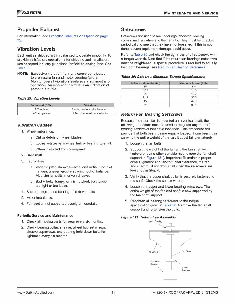
Maintenance and Service
www.DaikinApplied.com 111 IM 926-3 • ROOFPAK APPLIED SYSTEMS
Propeller Exhaust For information, see Propeller Exhaust Fan Option on page 92.
Vibration Levels Each unit as shipped is trim balanced to operate smoothly. To provide satisfactory operation after shipping and installation, use accepted industry guidelines for field balancing fans. See Table 29. NOTE: Excessive vibration from any cause contributes
to premature fan and motor bearing failure. Monitor overall vibration levels every six months of operation. An increase in levels is an indication of potential trouble.
Table 29: Vibration Levels
Fan speed (RPM) Vibration 800 or less 5 mils maximum displacement
801 or greater 0.20 in/sec maximum velocity
Vibration Causes 1. Wheel imbalance.
a. Dirt or debris on wheel blades.
b. Loose setscrews in wheel hub or bearing-to-shaft.
c. Wheel distorted from overspeed.
2. Bent shaft.
3. Faulty drive.
a. Variable pitch sheaves—Axial and radial runout of flanges; uneven groove spacing; out of balance. Also similar faults in driven sheave.
b. Bad V-belts; lumpy, or mismatched; belt tension too tight or too loose.
4. Bad bearings, loose bearing hold-down bolts.
5. Motor imbalance.
6. Fan section not supported evenly on foundation.
Periodic Service and Maintenance 1. Check all moving parts for wear every six months.
2. Check bearing collar, sheave, wheel hub setscrews, sheave capscrews, and bearing hold-down bolts for tightness every six months.
Setscrews Setscrews are used to lock bearings, sheaves, locking collars, and fan wheels to their shafts. They must be checked periodically to see that they have not loosened. If this is not done, severe equipment damage could occur.
Refer to Table 30 and check the tightness of all setscrews with a torque wrench. Note that if the return fan bearings setscrews must be retightened, a special procedure is required to equally load both bearings (see Return Fan Bearing Setscrews).
Table 30: Setscrew Minimum Torque Specifications
Setscrew diameter (in .) Minimum torque (ft .lb .) 1/4 5.5
5/16 10.5 3/8 19.0
7/16 29.0 1/2 42.0 5/8 92.0
Return Fan Bearing Setscrews Because the return fan is mounted on a vertical shaft, the following procedure must be used to retighten any return fan bearing setscrews that have loosened. This procedure will provide that both bearings are equally loaded. If one bearing is carrying the entire weight of the fan, it could fail prematurely.
1. Loosen the fan belts.
2. Support the weight of the fan and the fan shaft with timbers or some other suitable means (see the fan shaft support in Figure 121). Important: To maintain proper drive alignment and fan-to-tunnel clearance, the fan and shaft must not drop at all when the setscrews are loosened in Step 4.
3. Verify that the upper shaft collar is securely fastened to the shaft. Check the setscrew torque.
4. Loosen the upper and lower bearing setscrews. The entire weight of the fan and shaft is now supported by the fan shaft support.
5. Retighten all bearing setscrews to the torque specification given in Table 30. Remove the fan shaft support and re-tension the belts.
Figure 121: Return Fan Assembly � � � � � � � � � � � � �
� � � � � � � � �
� � � � � � � � �� � � � � �
� � � �� � � � � � �
� � � � � � � � �
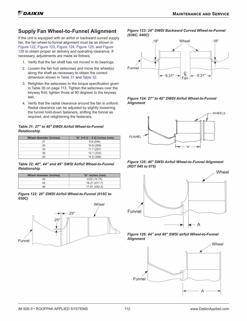
IM 926-3 • ROOFPAK APPLIED SYSTEMS 112 www.DaikinApplied.com
Maintenance and Service
Supply Fan Wheel-to-Funnel Alignment If the unit is equipped with an airfoil or backward curved supply fan, the fan wheel-to-funnel alignment must be as shown in Figure 122, Figure 123, Figure 124, Figure 125, and Figure 126 to obtain proper air delivery and operating clearance. If necessary, adjustments are made as follows:
1. Verify that the fan shaft has not moved in its bearings.
2. Loosen the fan hub setscrews and move the wheel(s) along the shaft as necessary to obtain the correct dimension shown in Table 31 and Table 32.
3. Retighten the setscrews to the torque specification given in Table 30 on page 113. Tighten the setscrews over the keyway first; tighten those at 90 degrees to the keyway last.
4. Verify that the radial clearance around the fan is uniform. Radial clearance can be adjusted by slightly loosening the funnel hold-down fasteners, shifting the funnel as required, and retightening the fasteners.
Table 31: 27" to 40" DWDI Airfoil Wheel-to-Funnel Relationship
Wheel diameter (inches) “A” [+0 .3/ – 0 .0] inches (mm)27 9.9 (246)30 10.6 (269)33 11.7 (297)36 13.1 (333)40 14.5 (368)
Table 32: 40", 44” and 49” SWSI Airfoil Wheel-to-Funnel Relationship
Wheel diameter (inches) “A” inches (mm)40 0.62 (15.75)44 16.21 (411.7)49 17.81 (452.4)
Figure 122: 20" DWDI Airfoil Wheel-to-Funnel (015C to 030C)
Figure 123: 24" DWDI Backward Curved Wheel-to-Funnel (036C, 040C)
Figure 124: 27" to 40" DWDI Airfoil Wheel-to-Funnel Alignment
Figure 125: 40" SWSI Airfoil Wheel-to-Funnel Alignment (RDT 045 to 075)
Figure 126: 44" and 49" SWSI airfoil Wheel-to-Funnel Alignment � � � � � �
� � � �
� � � �
� � � � �
� � � � �� � � �
� � � � � �
� � � � �� � � � � � �� � �
� � � �
� � � � �
� � � � � �
�
� � � � �
� � � � � �
�
Maintenance and Service
www.DaikinApplied.com 113 IM 926-3 • ROOFPAK APPLIED SYSTEMS
Refrigerant Charge WARNING
Potential severe loss of charge may occur if the high refrigerant pressure switch is replaced before reclaiming the refrigerant. Replace switch after reclaiming refrigerant.
The unit nameplate references proper charge for each RPS/ RDT refrigerant circuit in case a full charge must be added to the unit. Verify these values using the tables on page 39 through page 40. Also refer to the tables on page 39 through page 40 for RFS/RCS units.
Servicing Refrigerant Sensors or Switches The Daikin Rooftop unit includes the following refrigerant sensors or switches.
1. Low refrigerant pressure sensing, operating switch, automatic reset.
a. Disables their associated compressors on a drop in suction pressure to approximately 35 psig.
b. Enables their associated compressors on a rise in suction pressure to approximately 60 psig.
2. SpeedTrol™ high refrigerant pressure sensor (not available on sizes 15 to 30), see page 85 for more information.
3. High refrigerant pressure, protective switch, manual reset, reset by breaking control power to the S1 control switch.
a. R-407C high pressure switches disable their associated compressors on a rise to 425 psig discharge pressure.
b. The switches have a differential of 100 psig.
The low pressure and SpeedTrol sensors/ switches sense refrigerant pressure through shrader fittings that contain cores. The cores are stop valves that do not allow refrigerant to flow through the shrader unless the device is in place. Therefore the low pressure and SpeedTrol sensors/switches can be replaced without reclaiming the refrigerant.
The Shrader that serves the high pressure switch does not contain a core in order to maximize the functionality of the safety . Therefore it cannot be replaced unless the refrigerant has already been reclaimed .
Refrigerant Leaks R-407C is a zeotropic blend of three HFC refrigerants (R-32, R-125, and R-134a). Zeotropic blends do not behave as one substance. Therefore, a change of phase does not occur at a fixed temperature. R-407C has a “glide” of 8°F because it boils and evaporates over an 8°F change in temperature.
If an R-407C unit leaks refrigerant, there is no way to determine how much of each of the three component refrigerants leaked. However, experience in the field has shown that R-407C systems can be “topped off” after a leak and will operate normally . There is no need, except in the case of critically charged systems, to replace the entire charge after a leak. Add charge per instructions on page 41.
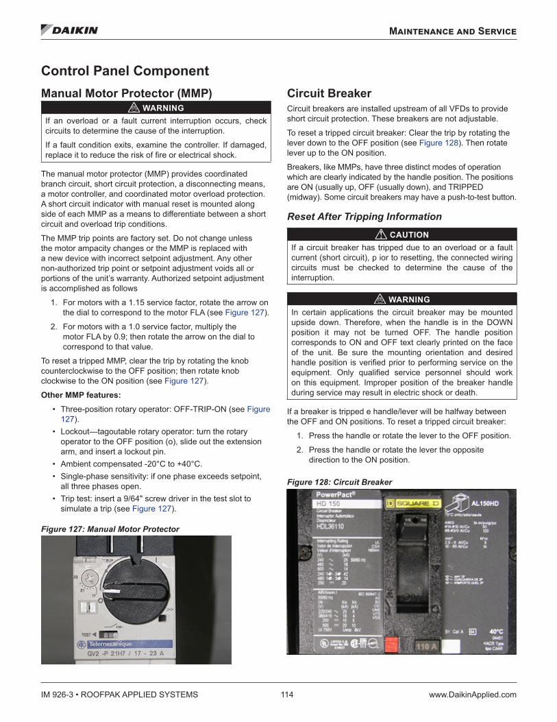
IM 926-3 • ROOFPAK APPLIED SYSTEMS 114 www.DaikinApplied.com
Maintenance and Service
Control Panel ComponentManual Motor Protector (MMP)
WARNINGIf an overload or a fault current interruption occurs, check circuits to determine the cause of the interruption.
If a fault condition exits, examine the controller. If damaged, replace it to reduce the risk of fire or electrical shock.
The manual motor protector (MMP) provides coordinated branch circuit, short circuit protection, a disconnecting means, a motor controller, and coordinated motor overload protection. A short circuit indicator with manual reset is mounted along side of each MMP as a means to differentiate between a short circuit and overload trip conditions.
The MMP trip points are factory set. Do not change unless the motor ampacity changes or the MMP is replaced with a new device with incorrect setpoint adjustment. Any other non-authorized trip point or setpoint adjustment voids all or portions of the unit’s warranty. Authorized setpoint adjustment is accomplished as follows
1. For motors with a 1.15 service factor, rotate the arrow on the dial to correspond to the motor FLA (see Figure 127).
2. For motors with a 1.0 service factor, multiply the motor FLA by 0.9; then rotate the arrow on the dial to correspond to that value.
To reset a tripped MMP, clear the trip by rotating the knob counterclockwise to the OFF position; then rotate knob clockwise to the ON position (see Figure 127).
Other MMP features: • Three-position rotary operator: OFF-TRIP-ON (see Figure
127). • Lockout—tagoutable rotary operator: turn the rotary
operator to the OFF position (o), slide out the extension arm, and insert a lockout pin.
• Ambient compensated -20°C to +40°C. • Single-phase sensitivity: if one phase exceeds setpoint,
all three phases open. • Trip test: insert a 9/64" screw driver in the test slot to
simulate a trip (see Figure 127).
Figure 127: Manual Motor Protector
Circuit BreakerCircuit breakers are installed upstream of all VFDs to provide short circuit protection. These breakers are not adjustable.
To reset a tripped circuit breaker: Clear the trip by rotating the lever down to the OFF position (see Figure 128). Then rotate lever up to the ON position.
Breakers, like MMPs, have three distinct modes of operation which are clearly indicated by the handle position. The positions are ON (usually up, OFF (usually down), and TRIPPED (midway). Some circuit breakers may have a push-to-test button.
Reset After Tripping Information
CAUTIONIf a circuit breaker has tripped due to an overload or a fault current (short circuit), p ior to resetting, the connected wiring circuits must be checked to determine the cause of the interruption.
WARNINGIn certain applications the circuit breaker may be mounted upside down. Therefore, when the handle is in the DOWN position it may not be turned OFF. The handle position corresponds to ON and OFF text clearly printed on the face of the unit. Be sure the mounting orientation and desired handle position is verified prior to performing service on the equipment. Only qualified service personnel should work on this equipment. Improper position of the breaker handle during service may result in electric shock or death.
If a breaker is tripped e handle/lever will be halfway between the OFF and ON positions. To reset a tripped circuit breaker:
1. Press the handle or rotate the lever to the OFF position.
2. Press the handle or rotate the lever the opposite direction to the ON position.
Figure 128: Circuit Breaker
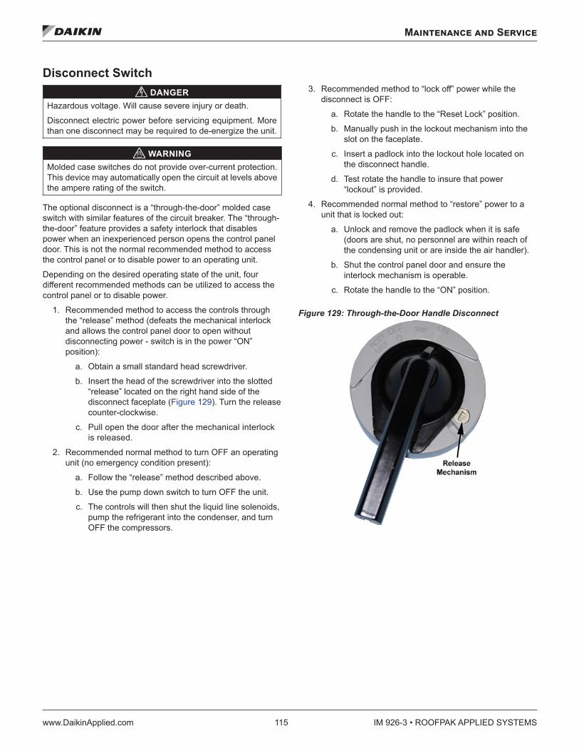
Maintenance and Service
www.DaikinApplied.com 115 IM 926-3 • ROOFPAK APPLIED SYSTEMS
Disconnect Switch DANGER
Hazardous voltage. Will cause severe injury or death.
Disconnect electric power before servicing equipment. More than one disconnect may be required to de-energize the unit.
WARNINGMolded case switches do not provide over-current protection. This device may automatically open the circuit at levels above the ampere rating of the switch.
The optional disconnect is a “through-the-door” molded case switch with similar features of the circuit breaker. The “through-the-door” feature provides a safety interlock that disables power when an inexperienced person opens the control panel door. This is not the normal recommended method to access the control panel or to disable power to an operating unit.
Depending on the desired operating state of the unit, four different recommended methods can be utilized to access the control panel or to disable power.
1. Recommended method to access the controls through the “release” method (defeats the mechanical interlock and allows the control panel door to open without disconnecting power - switch is in the power “ON” position):
a. Obtain a small standard head screwdriver.
b. Insert the head of the screwdriver into the slotted “release” located on the right hand side of the disconnect faceplate (Figure 129). Turn the release counter-clockwise.
c. Pull open the door after the mechanical interlock is released.
2. Recommended normal method to turn OFF an operating unit (no emergency condition present):
a. Follow the “release” method described above.
b. Use the pump down switch to turn OFF the unit.
c. The controls will then shut the liquid line solenoids, pump the refrigerant into the condenser, and turn OFF the compressors.
3. Recommended method to “lock off” power while the disconnect is OFF:
a. Rotate the handle to the “Reset Lock” position.
b. Manually push in the lockout mechanism into the slot on the faceplate.
c. Insert a padlock into the lockout hole located on the disconnect handle.
d. Test rotate the handle to insure that power “lockout” is provided.
4. Recommended normal method to “restore” power to a unit that is locked out:
a. Unlock and remove the padlock when it is safe (doors are shut, no personnel are within reach of the condensing unit or are inside the air handler).
b. Shut the control panel door and ensure the interlock mechanism is operable.
c. Rotate the handle to the “ON” position.
Figure 129: Through-the-Door Handle Disconnect
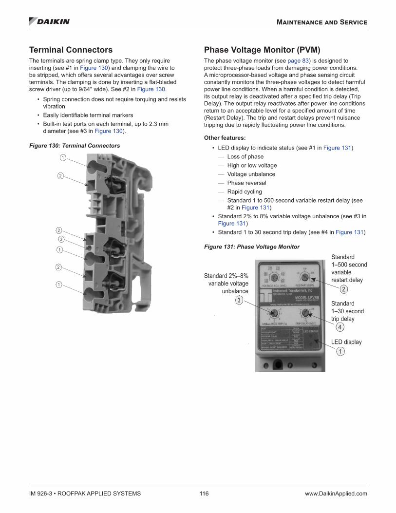
IM 926-3 • ROOFPAK APPLIED SYSTEMS 116 www.DaikinApplied.com
Maintenance and Service
Terminal Connectors The terminals are spring clamp type. They only require inserting (see #1 in Figure 130) and clamping the wire to be stripped, which offers several advantages over screw terminals. The clamping is done by inserting a flat-bladed screw driver (up to 9/64" wide). See #2 in Figure 130.
• Spring connection does not require torquing and resists vibration
• Easily identifiable terminal markers • Built-in test ports on each terminal, up to 2.3 mm
diameter (see #3 in Figure 130).
Figure 130: Terminal Connectors
Phase Voltage Monitor (PVM)The phase voltage monitor (see page 83) is designed to protect three-phase loads from damaging power conditions. A microprocessor-based voltage and phase sensing circuit constantly monitors the three-phase voltages to detect harmful power line conditions. When a harmful condition is detected, its output relay is deactivated after a specified trip delay (Trip Delay). The output relay reactivates after power line conditions return to an acceptable level for a specified amount of time (Restart Delay). The trip and restart delays prevent nuisance tripping due to rapidly fluctuating power line conditions.
Other features: • LED display to indicate status (see #1 in Figure 131)
— Loss of phase — High or low voltage — Voltage unbalance — Phase reversal — Rapid cycling — Standard 1 to 500 second variable restart delay (see #2 in Figure 131)
• Standard 2% to 8% variable voltage unbalance (see #3 in Figure 131)
• Standard 1 to 30 second trip delay (see #4 in Figure 131)
Figure 131: Phase Voltage Monitor
1
Standard1–500 secondvariablerestart delay
LED display
Standard 2%–8%variable voltage
unbalance
4
Standard1–30 secondtrip delay
Maintenance and Service
www.DaikinApplied.com 117 IM 926-3 • ROOFPAK APPLIED SYSTEMS
Pressure SensorsThe MicroTech III controller uses 0 to 5" W.C. static pressure transducers for measuring duct static pressure. As the duct static pressure varies from 0-5" W.C., the transducer output will vary from 4-20mA. The transducer output signal is 420mA however the signal entering the VFD is converted to a DC signal via a 500 Ohm resistor across the output signal at the transducer.
If building static pressure control is provided, a -0.25" W.C. to 0.25" W.C. static pressure transducer is used. As the building static pressure varies from -0.25" W.C. to 0.25" W.C., the transducer output will vary from 4-20mA. The transducer output signal is 4-20mA however the signal entering the VFD is converted to a DC signal via a 500 Ohm resistor across the output signal at the transducer.
Troubleshooting Pressure Transducers Use the following procedure to troubleshoot a suspect sensor:
If the duct static pressure always reads 0" WC on the unit keypad/display and the VFD speed is continuously ramping to 100%, check the following:
If the unit has two duct static pressure sensors (SPS1 and SPS2), verify that they both function properly per the following procedure. Also check for faulty wiring connections at the VFD analog inputs.
The controller displays and controls to the lower of the two readings. If a sensor is defective and inputs 0 volts to the VFD, the static pressure reading on the keypad/display reads 0 and the controller attempts to increase the 0 value to set point by ramping the VFD up.
If a second sensor (SPS2) is not installed or the pressure tubing to it is not connected, make sure the 2nd DSP Sensor= parameter in the Unit Configuration menu of the keypad/ display is set to “No” so that the controller ignores the second static pressure analog input.
If a second sensor (SPS2) is installed, make sure the 2nd DSP Sensor= parameter in the Unit Configuration menu of the keypad/display is set to “Yes.”
Check the 24 VDC power supply to the sensor, verify that there is 24 VDC between the suspect transducer “+” and “-” terminals.
Using an accurate manometer or gauge, measure the same pressure that the suspect transducer is sensing. To do this, tap into the transducer high and low pressure tubing or locate the measurement device taps next to the transducer taps.
If the suspect sensor is measuring duct static pressure, verify that the high and low pressure taps are properly installed. An improper pressure tap installation can cause severe fluctuations in the sensed pressure. Refer to the model-specific installation manual for pressure tap installation guidelines.
Measure the DC voltage output from the transducer across the sensor “S” and “-” terminals.
If the measured voltage and pressure do not match, there may be a wiring problem, the factory 500 ohm resistor across “S” and “-” or the transducer may be defective. Check the transducer input circuit wiring and connections for defects. If the measured voltage and pressure match, the VFD parameters and/or ModBus communication between the controller and the VFD will need to be verified.
Remove powers from the controller by opening system switch S1. If available, swap a similar good transducer with the suspect transducer or try installing a new transducer. Restore power by closing S1 and verify whether the suspect transducer is defective.
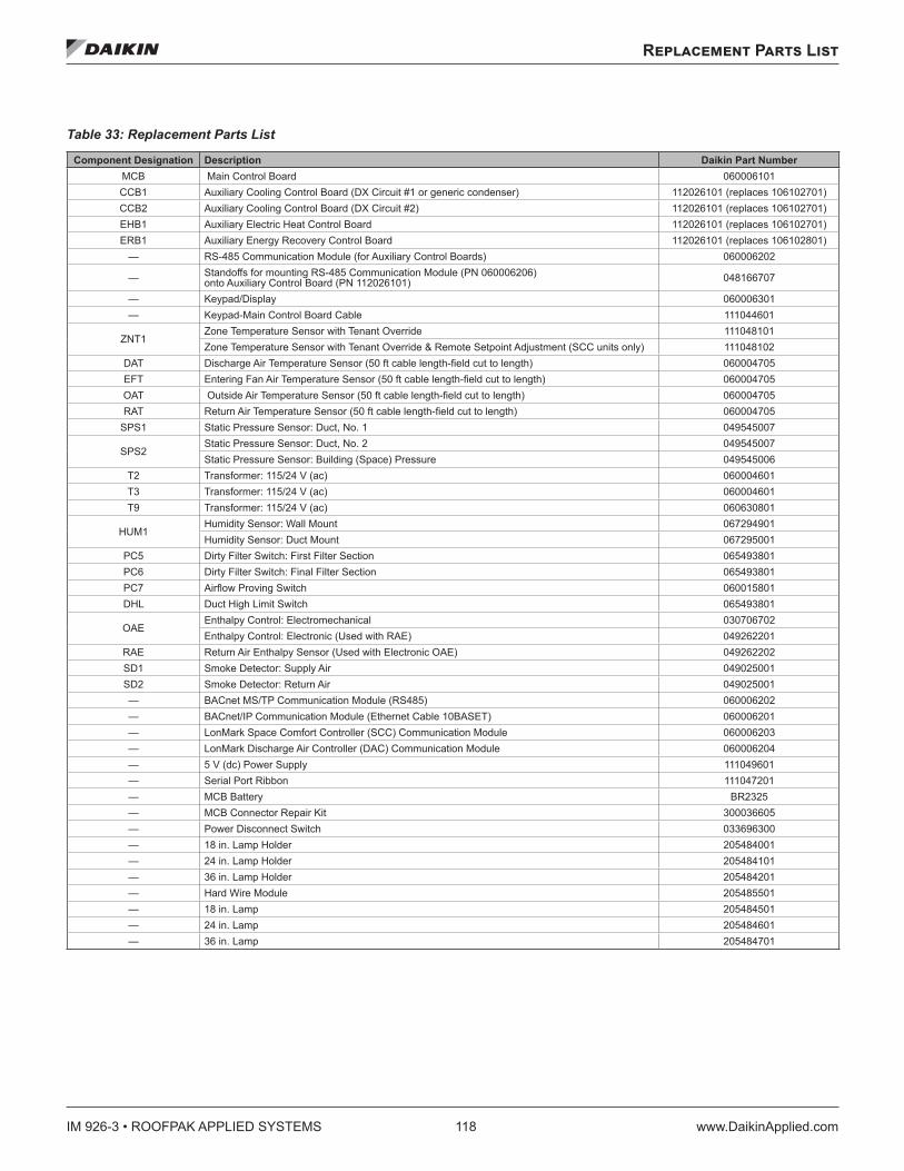
IM 926-3 • ROOFPAK APPLIED SYSTEMS 118 www.DaikinApplied.com
Replacement Parts List
Replacement Parts List
Table 33: Replacement Parts List
Component Designation Description Daikin Part NumberMCB Main Control Board 060006101CCB1 Auxiliary Cooling Control Board (DX Circuit #1 or generic condenser) 112026101 (replaces 106102701)CCB2 Auxiliary Cooling Control Board (DX Circuit #2) 112026101 (replaces 106102701)EHB1 Auxiliary Electric Heat Control Board 112026101 (replaces 106102701)ERB1 Auxiliary Energy Recovery Control Board 112026101 (replaces 106102801)
— RS-485 Communication Module (for Auxiliary Control Boards) 060006202
— Standoffs for mounting RS-485 Communication Module (PN 060006206) onto Auxiliary Control Board (PN 112026101) 048166707
— Keypad/Display 060006301— Keypad-Main Control Board Cable 111044601
ZNT1Zone Temperature Sensor with Tenant Override 111048101Zone Temperature Sensor with Tenant Override & Remote Setpoint Adjustment (SCC units only) 111048102
DAT Discharge Air Temperature Sensor (50 ft cable length-field cut to length) 060004705EFT Entering Fan Air Temperature Sensor (50 ft cable length-field cut to length) 060004705OAT Outside Air Temperature Sensor (50 ft cable length-field cut to length) 060004705RAT Return Air Temperature Sensor (50 ft cable length-field cut to length) 060004705
SPS1 Static Pressure Sensor: Duct, No. 1 049545007
SPS2Static Pressure Sensor: Duct, No. 2 049545007Static Pressure Sensor: Building (Space) Pressure 049545006
T2 Transformer: 115/24 V (ac) 060004601T3 Transformer: 115/24 V (ac) 060004601T9 Transformer: 115/24 V (ac) 060630801
HUM1Humidity Sensor: Wall Mount 067294901Humidity Sensor: Duct Mount 067295001
PC5 Dirty Filter Switch: First Filter Section 065493801PC6 Dirty Filter Switch: Final Filter Section 065493801PC7 Airflow Proving Switch 060015801DHL Duct High Limit Switch 065493801
OAEEnthalpy Control: Electromechanical 030706702Enthalpy Control: Electronic (Used with RAE) 049262201
RAE Return Air Enthalpy Sensor (Used with Electronic OAE) 049262202SD1 Smoke Detector: Supply Air 049025001SD2 Smoke Detector: Return Air 049025001— BACnet MS/TP Communication Module (RS485) 060006202— BACnet/IP Communication Module (Ethernet Cable 10BASET) 060006201— LonMark Space Comfort Controller (SCC) Communication Module 060006203— LonMark Discharge Air Controller (DAC) Communication Module 060006204— 5 V (dc) Power Supply 111049601— Serial Port Ribbon 111047201— MCB Battery BR2325— MCB Connector Repair Kit 300036605— Power Disconnect Switch 033696300— 18 in. Lamp Holder 205484001— 24 in. Lamp Holder 205484101— 36 in. Lamp Holder 205484201— Hard Wire Module 205485501— 18 in. Lamp 205484501— 24 in. Lamp 205484601— 36 in. Lamp 205484701
Service and Warranty Procedure
www.DaikinApplied.com 119 IM 926-3 • ROOFPAK APPLIED SYSTEMS
Service and Warranty Procedure
Replacement Parts When writing to Daikin for service or replacement parts, provide the model number, serial number, and unit part number of the unit as stamped on the serial plate attached to the unit. For questions regarding wiring diagrams, it will be necessary to provide the number on the specific diagram. If replacement parts are required, include the date of unit installation, the date of failure, an explanation of the malfunction, and a description of the replacement parts required.
Compressor Arrangements Daikin Rooftops use the following Copeland Scroll Compressors.
1. Single compressors, one per refrigerant circuit.
2. Tandem compressors, basically two compressors specifically manufactured by Copeland into a single assembly.
3. Trio compressors, basically three single compressors factory piped in parallel with equalization lines.
All Daikin Rooftop products include a first-year parts only warranty. The warranty period extends 12 months from startup or 18 months from date of shipment, whichever comes first. Labor to install these parts is not included with this warranty. Compressors are considered a part and are included in this standard warranty.
Scroll service replacement compressors for Daikin Rooftop Units can be obtained from the following two sources:
• Daikin Service Parts maintains a stock of replacement compressors.
• Copeland Refrigeration has stocking wholesalers throughout the U.S. who maintain a limited stock of replacement scroll compressors. The stock of single compressors is much better than the stock of tandems “tandem/trio ready”, single compressors. Trios are almost never in wholesaler stock and are not recommended for use on Daikin Rooftops due to piping interference. Copeland does offer quick ship options though their wholesalers.
Both sources can be used, at the customer’s discretion, within the first year warranty and with the following limitations.
1. RPS 018C to 020C (with single compressors, no limitations).
2. RPS 025C to 030C (with single and tandem compressors).
a. If any part of the tandem fails then the entire tandem must be replaced. Both sources are acceptable.
b. Single compressor. No limitations.
3. RPS 036C (with tandem compressors).
a. Circuit #1 tandem - If any part of the tandem fails then the entire tandem must be replaced. Both sources are acceptable.
b. Circuit #2 tandem–Each of the tandem’s compressors have a rotalock and only the failed portion of the tandem may need replacement.
4. RPS 040C to 060C—Each of the tandem’s compressors have a rotalock and only the failed portion of the tandem may need replacement.
5. RPS 070C to 105C—Each of the trio compressors have a rotalock and only the failed portion of the trio may need replacement.
6. Only a “tandem or trio ready” compressor, with oil equalizer lines, can be used to replace a portion of the tandem or trio.
IM 926-3 • ROOFPAK APPLIED SYSTEMS 120 www.DaikinApplied.com
Service and Warranty Procedure
Replacing Portions of a Tandem or Trio Compressor The decision to replace the failed portion of the tandem or trio, as opposed to replacing the entire tandem or trio, must be decided based on the following.
1. The entire tandem must be replaced if the individual portions do not include rotalocks and rotalocks are not available on the RPS 025 to 030 (tandems and the RPS circuit #1 tandem).
2. In warranty: Warranty only covers replacement of the failed portion of the tandem or trio. Either source may be used.
3. Out of warranty: The customer decides whether to replace the entire tandem/trio or just a portion and either source may be used.
When replacing an “in warranty” compressor through a Copeland Wholesaler, take the failed compressor to the wholesaler for an over-the-counter or an advanced replacement exchange. Credit is issued by Copeland on the returned motor compressor upon receipt and factory inspection of the inoperative motor compressor. In this transaction, be certain that the motor compressor is definitely defective.
If a motor compressor is received from the field that tests satisfactorily, a service charge plus a transportation charge will be charged against its original credit value. If there was a delay in the startup of the equipment and the first-year warranty (Copeland) has expired on the compressor, within the 18-month-from-shipment warranty, order the replacement compressor through the Daikin Parts Department (Minneapolis).
1. Contact the Daikin Parts Department for compressor availability.
2. Send a completed parts order form to the Daikin Parts Department.
3. The Parts Department processes the order and the compressors are shipped from our Dayton, OH warehouse via ground transportation. If next-day air is required, indicate this on the parts order form and a freight charge will be billed to your account. Air freight costs are not covered under the Daikin warranty.
4. After the failed compressor is replaced, return it to Daikin Applied with a Return Goods Tag attached, which you will receive in the mail. It must be attached to the compressor. The Return Goods Tag has instructions on where to send the compressor. If the compressor is not returned, you will be billed for the replacement compressor.
5. Consideration may be given at this time to a compressor teardown analysis, depending on the history of failures.
On Daikin equipment that includes the extended 2nd -5th year compressor warranty option, the replacement compressor must be ordered through the Daikin Parts Department (Minneapolis).
1. Contact the Daikin Parts Department for compressor availability.
2. Send the Daikin Parts Department a completed parts order form.
3. The Parts Department will process the order and the compressors will be shipped from our Dayton, OH warehouse via ground transportation. If next-day air is required, you will need to indicate this on the parts order form and a freight charge will be billed to your account. Air freight costs are not covered under the Daikin warranty.
4. After the failed compressor has been replaced, it must be returned to Daikin Applied with a Return Goods Tag attached. You will receive the tag in the mail and it must be attached to the compressor. The Return Goods Tag will have instructions on where to send the compressor. If the compressor is not returned, you will be billed for the replacement compressor.
5. Consideration may be given at this time to a compressor teardown analysis, depending on the history of failures.
In-Warranty Return Material Procedure Material other than compressors may not be returned except by permission of authorized factory service personnel of Daikin Applied at Minneapolis, Minnesota.
A “return goods” tag will be sent to be included with the returned material. Enter the information as called for on the tag in order to expedite handling at out factories and issuance of credits. All parts shall be returned to the factory designated on the return goods tag, transportation charges prepaid.
The return of the part does not constitute an order for replacement. A purchase order for the replacement part must be entered through your nearest Daikin representative. The order should include the component’s part number and description and the model and serial numbers of the unit involved.
If it is determined that the failure of the returned part is due to faulty material or workmanship within the standard warranty period, credit will be issued on the customer’s purchase order.
Limited Product Warranty (North America)
www.DaikinApplied.com 121 IM 926-3 • ROOFPAK APPLIED SYSTEMS
Limited Product Warranty (North America)
Daikin Applied (“Company”) warrants to contractor, purchaser and any owner of the product (collectively “Owner”) that Company, at its option, will repair or replace defective parts in the event any product manufactured by Company, including products sold under the brand names McQuay Air Conditioning, AAF Air Conditioning, AAF HermanNelson and Daikin Service, and used in the United States or Canada, proves defective in material or workmanship within twelve (12) months from initial startup or eighteen (18) months from the date shipped by Company, whichever occurs first. Authorized replaced parts are warranted for the duration of the original warranty. All shipments of such parts will be made FOB factory, freight prepaid and allowed. Company reserves the right to select carrier and method of shipment.
In addition, labor to repair or replace warranty parts is provided during Company normal working hours on products with rotary screw compressors, centrifugal compressors and on absorption chillers. Warranty labor is not provided for any other products.
Company’s liability to Owner under this warranty shall not exceed the lesser of the cost of correcting defects in the products sold or the original purchase price of the products.
PRODUCT STARTUP ON ABSORPTION, CENTRIFUGAL AND SCREW COMPRESSOR PRODUCTS IS MANDATORY and must be performed by Daikin Service or a Company authorized service representative.
It is Owner’s responsibility to complete and return the Registration and Startup Forms accompanying the product to Company within ten (10) days of original startup. If this is not done, the ship date and the startup date will be deemed the same for warranty period determination, and this warranty shall expire twelve (12) months from that date.
Exceptions 1. If free warranty labor is available as set forth above, such
free labor does not include diagnostic visits, inspections, travel time and related expenses, or unusual access time or costs required by product location.
2. Refrigerants, fluids, oils and expendable items such as filters are not covered by this warranty.
3. This warranty shall not apply to products or parts which (a) have been opened, disassembled, repaired, or altered by anyone other than Company or its authorized service representative; or (b) have been subjected to misuse, negligence, accidents, damage, or abnormal use or service; or (c) have been operated, installed, or startup has been provided in a manner contrary to Company’s printed instructions, or (d) were manufactured or furnished by others and which are not an integral part of a product manufactured by Company; or (e) have not been fully paid for by Owner.
Assistance To obtain assistance or information regarding this warranty, please contact your local sales representative or Daikin Service office.
Sole Remedy THIS WARRANTY CONSTITUTES THE OWNER’S SOLE REMEDY. IT IS GIVEN IN LIEU OF ALL OTHER WARRANTIES. THERE IS NO IMPLIED WARRANTY OF MERCHANTABILITY OR FITNESS FOR A PARTICULAR PURPOSE. IN NO EVENT AND UNDER NO CIRCUMSTANCE SHALL COMPANY BE LIABLE FOR INCIDENTAL, INDIRECT, SPECIAL, CONTINGENT OR CONSEQUENTIAL DAMAGES, WHETHER THE THEORY BE BREACH OF THIS OR ANY OTHER WARRANTY, NEGLIGENCE OR STRICT LIABILITY IN TORT.
No person (including any agent, sales representative, dealer or distributor) has the authority to expand the Company’s obligation beyond the terms of this express warranty or to state that the performance of the product is other than that published by Company.
For additional consideration, Company will provide an extended warranty(ies) on certain products or components thereof. The terms of the extended warranty(ies) are shown on a separate extended warranty statement.
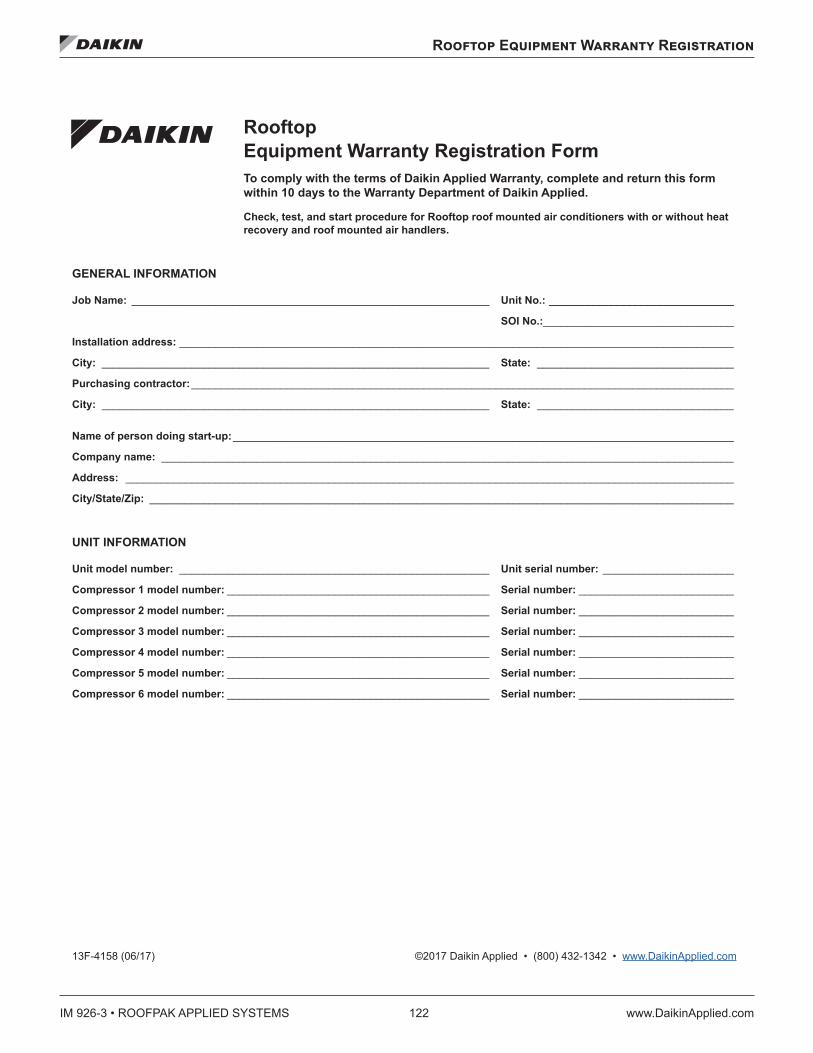
IM 926-3 • ROOFPAK APPLIED SYSTEMS 122 www.DaikinApplied.com
Rooftop Equipment Warranty Registration
Rooftop Equipment Warranty Registration
13F-4158 (06/17) ©2017 Daikin Applied • (800) 432-1342 • www.DaikinApplied.com
RooftopEquipment Warranty Registration FormTo comply with the terms of Daikin Applied Warranty, complete and return this form within 10 days to the Warranty Department of Daikin Applied.
Check, test, and start procedure for Rooftop roof mounted air conditioners with or without heat recovery and roof mounted air handlers.
GENERAL INFORMATION
Job Name: ____________________________________________________________ Unit No.: _______________________________
SOI No.:________________________________
Installation address: _____________________________________________________________________________________________
City: _________________________________________________________________ State: _________________________________
Purchasing contractor: ___________________________________________________________________________________________
City: _________________________________________________________________ State: _________________________________
Name of person doing start-up: ____________________________________________________________________________________
Company name: ________________________________________________________________________________________________
Address: ______________________________________________________________________________________________________
City/State/Zip: __________________________________________________________________________________________________
UNIT INFORMATION
Unit model number: ____________________________________________________ Unit serial number: ______________________
Compressor 1 model number: ____________________________________________ Serial number: __________________________
Compressor 2 model number: ____________________________________________ Serial number: __________________________
Compressor 3 model number: ____________________________________________ Serial number: __________________________
Compressor 4 model number: ____________________________________________ Serial number: __________________________
Compressor 5 model number: ____________________________________________ Serial number: __________________________
Compressor 6 model number: ____________________________________________ Serial number: __________________________
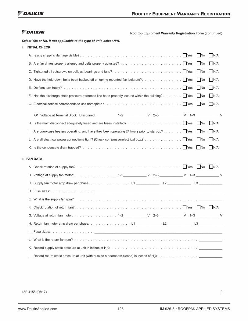
Rooftop Equipment Warranty Registration
www.DaikinApplied.com 123 IM 926-3 • ROOFPAK APPLIED SYSTEMS
Rooftop Equipment Warranty Registration Form (continued)
13F-4158 (06/17) 2
Select Yes or No. If not applicable to the type of unit, select N/A.
I. INITIAL CHECK
A. Is any shipping damage visible? . . . . . . . . . . . . . . . . . . . . . . . . . . . . . . . . . . . . . . . . Yes No N/A
B. Are fan drives properly aligned and belts properly adjusted? . . . . . . . . . . . . . . . . . . . . . . . . . Yes No N/A
C. Tightened all setscrews on pulleys, bearings and fans? . . . . . . . . . . . . . . . . . . . . . . . . . . . . Yes No N/A
D. Have the hold-down bolts been backed off on spring mounted fan isolators?. . . . . . . . . . . . . . . . . Yes No N/A
E. Do fans turn freely? . . . . . . . . . . . . . . . . . . . . . . . . . . . . . . . . . . . . . . . . . . . . . . Yes No N/A
F. Has the discharge static pressure reference line been properly located within the building? . . . . . . . . . Yes No N/A
G. Electrical service corresponds to unit nameplate?. . . . . . . . . . . . . . . . . . . . . . . . . . . . . . . Yes No N/A
G1. Voltage at Terminal Block | Disconnect 1–2_____________ V 2–3 _____________ V 1–3 _____________ V
H. Is the main disconnect adequately fused and are fuses installed? . . . . . . . . . . . . . . . . . . . . . . Yes No N/A
I. Are crankcase heaters operating, and have they been operating 24 hours prior to start-up? . . . . . . . . . Yes No N/A
J. Are all electrical power connections tight? (Check compressorelectrical box.) . . . . . . . . . . . . . . . . Yes No N/A
K. Is the condensate drain trapped? . . . . . . . . . . . . . . . . . . . . . . . . . . . . . . . . . . . . . . . Yes No N/A
II. FAN DATA
A. Check rotation of supply fan? . . . . . . . . . . . . . . . . . . . . . . . . . . . . . . . . . . . . . . . . . Yes No N/A
B. Voltage at supply fan motor: . . . . . . . . . . . . . . . . 1–2_____________ V 2–3 _____________ V 1–3 _____________ V
C. Supply fan motor amp draw per phase: . . . . . . . . . . . . . . . L1 _____________ L2 _____________ L3 _____________
D. Fuse sizes: . . . . . . . . . . . . . . . . ._______________________________________________________________________
E. What is the supply fan rpm? . . . . . . . . . . . . . . . . . . . . . . . . . . . . . . . . . . . . . . . . . . . . . . _____________
F. Check rotation of return fan?. . . . . . . . . . . . . . . . . . . . . . . . . . . . . . . . . . . . . . . . . . Yes No N/A
G. Voltage at return fan motor: . . . . . . . . . . . . . . . . 1–2_____________ V 2–3 _____________ V 1–3 _____________ V
H. Return fan motor amp draw per phase: . . . . . . . . . . . . . . . L1 _____________ L2 _____________ L3 _____________
I. Fuse sizes: . . . . . . . . . . . . . . . . ._______________________________________________________________________
J. What is the return fan rpm? . . . . . . . . . . . . . . . . . . . . . . . . . . . . . . . . . . . . . . . . . . . . . . _____________
K. Record supply static pressure at unit in inches of H20: . . . . . . . . . . . . . . . . . . . . . . . . . . . . . . . . _____________
L. Record return static pressure at unit (with outside air dampers closed) in inches of H20: . . . . . . . . . . . . . . . _____________
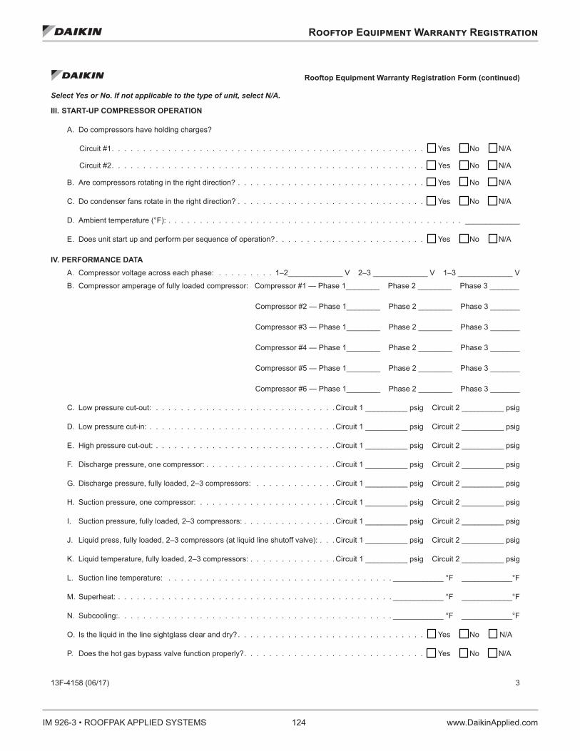
IM 926-3 • ROOFPAK APPLIED SYSTEMS 124 www.DaikinApplied.com
Rooftop Equipment Warranty Registration
Rooftop Equipment Warranty Registration Form (continued)
13F-4158 (06/17) 3
Select Yes or No. If not applicable to the type of unit, select N/A.
III. START-UP COMPRESSOR OPERATION
A. Do compressors have holding charges?
Circuit #1. . . . . . . . . . . . . . . . . . . . . . . . . . . . . . . . . . . . . . . . . . . . . . . . . . . . Yes No N/A
Circuit #2. . . . . . . . . . . . . . . . . . . . . . . . . . . . . . . . . . . . . . . . . . . . . . . . . . . . Yes No N/A
B. Are compressors rotating in the right direction? . . . . . . . . . . . . . . . . . . . . . . . . . . . . . . . . Yes No N/A
C. Do condenser fans rotate in the right direction? . . . . . . . . . . . . . . . . . . . . . . . . . . . . . . . . Yes No N/A
D. Ambient temperature (°F): . . . . . . . . . . . . . . . . . . . . . . . . . . . . . . . . . . . . . . . . . . . . . . . _____________
E. Does unit start up and perform per sequence of operation?. . . . . . . . . . . . . . . . . . . . . . . . . . Yes No N/A
IV. PERFORMANCE DATA A. Compressor voltage across each phase: . . . . . . . . . 1–2_____________ V 2–3 _____________ V 1–3 _____________ V
B. Compressor amperage of fully loaded compressor: Compressor #1 — Phase 1________ Phase 2 ________ Phase 3 _______
Compressor #2 — Phase 1________ Phase 2 ________ Phase 3 _______
Compressor #3 — Phase 1________ Phase 2 ________ Phase 3 _______
Compressor #4 — Phase 1________ Phase 2 ________ Phase 3 _______
Compressor #5 — Phase 1________ Phase 2 ________ Phase 3 _______
Compressor #6 — Phase 1________ Phase 2 ________ Phase 3 _______
C. Low pressure cut-out: . . . . . . . . . . . . . . . . . . . . . . . . . . . . . Circuit 1 __________ psig Circuit 2 __________ psig
D. Low pressure cut-in: . . . . . . . . . . . . . . . . . . . . . . . . . . . . . .Circuit 1 __________ psig Circuit 2 __________ psig
E. High pressure cut-out: . . . . . . . . . . . . . . . . . . . . . . . . . . . . .Circuit 1 __________ psig Circuit 2 __________ psig
F. Discharge pressure, one compressor: . . . . . . . . . . . . . . . . . . . . . Circuit 1 __________ psig Circuit 2 __________ psig
G. Discharge pressure, fully loaded, 2–3 compressors: . . . . . . . . . . . . . Circuit 1 __________ psig Circuit 2 __________ psig
H. Suction pressure, one compressor: . . . . . . . . . . . . . . . . . . . . . .Circuit 1 __________ psig Circuit 2 __________ psig
I. Suction pressure, fully loaded, 2–3 compressors: . . . . . . . . . . . . . . .Circuit 1 __________ psig Circuit 2 __________ psig
J. Liquid press, fully loaded, 2–3 compressors (at liquid line shutoff valve): . . . Circuit 1 __________ psig Circuit 2 __________ psig
K. Liquid temperature, fully loaded, 2–3 compressors: . . . . . . . . . . . . . .Circuit 1 __________ psig Circuit 2 __________ psig
L. Suction line temperature: . . . . . . . . . . . . . . . . . . . . . . . . . . . . . . . . . . . . ____________ °F ____________°F
M. Superheat: . . . . . . . . . . . . . . . . . . . . . . . . . . . . . . . . . . . . . . . . . . . . ____________ °F ____________°F
N. Subcooling:. . . . . . . . . . . . . . . . . . . . . . . . . . . . . . . . . . . . . . . . . . . . ____________ °F ____________°F
O. Is the liquid in the line sightglass clear and dry?. . . . . . . . . . . . . . . . . . . . . . . . . . . . . . . . Yes No N/A
P. Does the hot gas bypass valve function properly?. . . . . . . . . . . . . . . . . . . . . . . . . . . . . . . Yes No N/A
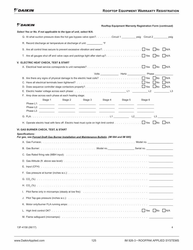
Rooftop Equipment Warranty Registration
www.DaikinApplied.com 125 IM 926-3 • ROOFPAK APPLIED SYSTEMS
Rooftop Equipment Warranty Registration Form (continued)
13F-4158 (06/17) 4
Select Yes or No. If not applicable to the type of unit, select N/A.
Q. At what suction pressure does the hot gas bypass valve open?. . . . . . . . Circuit 1 __________ psig Circuit 2 __________ psig
R. Record discharge air temperature at discharge of unit: ___________ °F
S. Are all control lines secure to prevent excessive vibration and wear?. . . . . . . . . . . . . . . . . . . . . Yes No N/A
T. Are all gauges shut off and valve caps and packings tight after start-up? . . . . . . . . . . . . . . . . . . . Yes No N/A
V. ELECTRIC HEAT CHECK, TEST & START A. Electrical heat service corresponds to unit nameplate? . . . . . . . . . . . . . . . . . . . . . . . . . . . . Yes No N/A
Volts _____________ Hertz _____________ Phase _____________
B. Are there any signs of physical damage to the electric heat coils? . . . . . . . . . . . . . . . . . . . . . . Yes No N/A
C. Have all electrical terminals been tightened? . . . . . . . . . . . . . . . . . . . . . . . . . . . . . . . . . Yes No N/A
D. Does sequence controller stage contactors properly? . . . . . . . . . . . . . . . . . . . . . . . . . . . . . Yes No N/A
E. Electric heater voltage across each phase: . . . . . . . . . . . . . . . . . ___________ L1 ___________ L2 ___________ L3
F. Amp draw across each phase at each heating stage:
Stage 1 Stage 2 Stage 3 Stage 4 Stage 5 Stage 6 Phase L1: ___________ ____________ ____________ ___________ ___________ ____________ Phase L2: ___________ ____________ ____________ ___________ ___________ ____________ Phase L3 ___________ ____________ ____________ ___________ ___________ ____________
G. FLA: . . . . . . . . . . . . . . . . . . . . . . . . . . . . . . . . . . . . . L1 ___________ L2____________ L3 ___________
H. Operate electric heat with fans off. Electric heat must cycle on high limit control . . . . . . . . . . . . . . . Yes No N/A
VI. GAS BURNER CHECK, TEST, & START Specifications: For gas, see Forced Draft Gas Burner Installation and Maintenance Bulletin. (IM 684 and IM 685)
A. Gas Furnace:. . . . . . . . . . . . . . . . . . . . . . . . . . . . . . . . . . . . . . . . . . . . . Model no. __________________
B. Gas Burner: . . . . . . . . . . . . . . . . . . . . . . . . . . .Model no.___________________ Serial no. ___________________
C. Gas Rated firing rate (MBH input): . . . . . . . . . . . . . . . . . . . . . . . . . . . . . . . . . . . . . . . ._________________
D. Gas Altitude (ft. above sea level): . . . . . . . . . . . . . . . . . . . . . . . . . . . . . . . . . . . . . . . . ._________________
E. Input (CFH): . . . . . . . . . . . . . . . . . . . . . . . . . . . . . . . . . . . . . . . . . . . . . . . . . . . _________________
F. Gas pressure at burner (inches w.c.): . . . . . . . . . . . . . . . . . . . . . . . . . . . . . . . . . . . . . . _________________
G. CO2 (%) . . . . . . . . . . . . . . . . . . . . . . . . . . . . . . . . . . . . . . . . . . . . . . . . . . . . . _________________
H. CO2 (%): . . . . . . . . . . . . . . . . . . . . . . . . . . . . . . . . . . . . . . . . . . . . . . . . . . . . . _________________
I. Pilot flame only in microamps (steady at low fire): . . . . . . . . . . . . . . . . . . . . . . . . . . . . . . . _________________
J. Pilot Tap-gas pressure (inches w.c.): . . . . . . . . . . . . . . . . . . . . . . . . . . . . . . . . . . . . . . _________________
K. Motor only/burner FLA running amps: . . . . . . . . . . . . . . . . . . . . . . . . . . . . . . . . . . . . . . _________________
L. High limit control OK? . . . . . . . . . . . . . . . . . . . . . . . . . . . . . . . . . . . . . . . . . . . . . Yes No N/A
M. Flame safeguard (microamps): . . . . . . . . . . . . . . . . . . . . . . . . . . . . . . . . . . . . . . . . . _________________
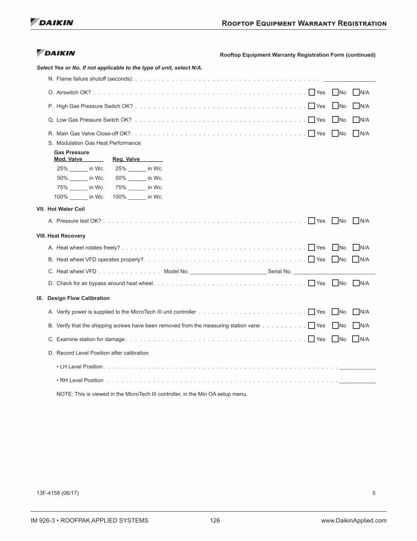
IM 926-3 • ROOFPAK APPLIED SYSTEMS 126 www.DaikinApplied.com
Rooftop Equipment Warranty Registration
Rooftop Equipment Warranty Registration Form (continued)
13F-4158 (06/17) 5
Select Yes or No. If not applicable to the type of unit, select N/A.
N. Flame failure shutoff (seconds): . . . . . . . . . . . . . . . . . . . . . . . . . . . . . . . . . . . . . . . . . _________________
O. Airswitch OK? . . . . . . . . . . . . . . . . . . . . . . . . . . . . . . . . . . . . . . . . . . . . . . . . . Yes No N/A
P. High Gas Pressure Switch OK? . . . . . . . . . . . . . . . . . . . . . . . . . . . . . . . . . . . . . . . . Yes No N/A
Q. Low Gas Pressure Switch OK? . . . . . . . . . . . . . . . . . . . . . . . . . . . . . . . . . . . . . . . . Yes No N/A
R. Main Gas Valve Close-off OK?. . . . . . . . . . . . . . . . . . . . . . . . . . . . . . . . . . . . . . . . . Yes No N/A
S. Modulation Gas Heat Performance
Gas PressureMod. Valve Reg. Valve 25% ______ in Wc. 25% ______ in Wc.
50% ______ in Wc. 50% ______ in Wc.
75% ______ in Wc. 75% ______ in Wc.
100% ______ in Wc. 100% ______ in Wc.
VII. Hot Water Coil
A. Pressure test OK? . . . . . . . . . . . . . . . . . . . . . . . . . . . . . . . . . . . . . . . . . . . . . . . Yes No N/A
VIII. Heat Recovery
A. Heat wheel rotates freely? . . . . . . . . . . . . . . . . . . . . . . . . . . . . . . . . . . . . . . . . . . . Yes No N/A
B. Heat wheel VFD operates properly? . . . . . . . . . . . . . . . . . . . . . . . . . . . . . . . . . . . . . . Yes No N/A
C. Heat wheel VFD . . . . . . . . . . . . . . Model No. _________________________ Serial No. ___________________________
D. Check for air bypass around heat wheel . . . . . . . . . . . . . . . . . . . . . . . . . . . . . . . . . . . . Yes No N/A
IX. Design Flow Calibration
A. Verify power is supplied to the MicroTech III unit controller . . . . . . . . . . . . . . . . . . . . . . . . . . Yes No N/A
B. Verify that the shipping screws have been removed from the measuring station vane . . . . . . . . . . . . Yes No N/A
C. Examine station for damage . . . . . . . . . . . . . . . . . . . . . . . . . . . . . . . . . . . . . . . . . . Yes No N/A
D. Record Level Position after calibration
• LH Level Position . . . . . . . . . . . . . . . . . . . . . . . . . . . . . . . . . . . . . . . . . . . . . . . . . . . . ____________
• RH Level Position . . . . . . . . . . . . . . . . . . . . . . . . . . . . . . . . . . . . . . . . . . . . . . . . . . . ____________
NOTE: This is viewed in the MicroTech III controller, in the Min OA setup menu.
Rooftop Equipment Warranty Registration
www.DaikinApplied.com 127 IM 926-3 • ROOFPAK APPLIED SYSTEMS
Rooftop Equipment Warranty Registration Form (continued)
13F-4158 (06/17) 6
Select Yes or No. If not applicable to the type of unit, select N/A.
X. Have all electronic or electrical controls been checked, adjusted, and tested for proper operation per the installation and maintenance bulletins?
. . . . . . . . . . . . . . . . . . . . . . . . . . . . . . . . . . . . . . . . . . . . . . . . . . . . . . . . Yes No N/A
XI. MAINTAINING MICROTECH CONTROL PARAMETER RECORDS After the unit is checked, tested, and started and the final control parameters are set, record the final settings. Keep these records on file and update whenever changes to the control parameters are made. Keeping a record facilitates any required analysis and troubleshooting of the system operation and facilitates restoration after a controller replacement.
Thank you for completing this form. Please sign and date below.
Signature _____________________________________________________________ Startup date: ___________________________
Return completed form by mail to: Daikin Warranty Department, 13600 Industrial Park Boulevard, Minneapolis, MN 55441
or by email to: [email protected] Please fill out the Daikin Applied “Quality Assurance Survey Report” and list any additional comments that could affect the operation of this unit; e.g., shipping damage, failed components, adverse installation applications, etc. If additional comment space is needed, write the comment(s) on a separate sheet, attach it to the Survey Report and return it to the Warranty Department of Daikin Applied with the completed Equipment Warranty Registration form.
Submit Form
Clear Form
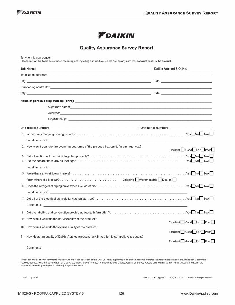
IM 926-3 • ROOFPAK APPLIED SYSTEMS 128 www.DaikinApplied.com
Quality Assurance Survey Report
Quality Assurance Survey Report
Quality Assurance Survey Report
To whom it may concern:Please review the items below upon receiving and installing our product. Select N/A on any item that does not apply to the product.
Job Name: _____________________________________________________________________ Daikin Applied S.O. No. _______________
Installation address: ____________________________________________________________________________________________________
City: ___________________________________________________________________________ State: _______________________________
Purchasing contractor: __________________________________________________________________________________________________
City: ___________________________________________________________________________ State: _______________________________
Name of person doing start-up (print): ___________________________________________________________________________________
Company name: ______________________________________________________________________________________
Address: ____________________________________________________________________________________________
City/State/Zip: _______________________________________________________________________________________
Unit model number: ____________________________________________________ Unit serial number: __________________________
1. Is there any shipping damage visible? . . . . . . . . . . . . . . . . . . . . . . . . . . . . . . . . . . . . . . . . . . . . . . . . . . . . . . . . . . . . . . . . . . Yes No N/A
Location on unit ____________________________________________________________________________________
2. How would you rate the overall appearance of the product; i.e., paint, fi n damage, etc.? Excellent Good Fair Poor
3. Did all sections of the unit fi t together properly? . . . . . . . . . . . . . . . . . . . . . . . . . . . . . . . . . . . . . . . . . . . . . . . . . . . . . . . . . . Yes No N/A4. Did the cabinet have any air leakage? . . . . . . . . . . . . . . . . . . . . . . . . . . . . . . . . . . . . . . . . . . . . . . . . . . . . . . . . . . . . . . . . . . Yes No N/A
Location on unit ___________________________________________________________________________________
5. Were there any refrigerant leaks? . . . . . . . . . . . . . . . . . . . . . . . . . . . . . . . . . . . . . . . . . . . . . . . . . . . . . . . . . . . . . . . . . . . . . Yes No N/A
From where did it occur? . . . . . . . . . . . . . . . . . . . . . . . . . . . . . . . . . . . Shipping Workmanship Design
6. Does the refrigerant piping have excessive vibration? . . . . . . . . . . . . . . . . . . . . . . . . . . . . . . . . . . . . . . . . . . . . . . . . . . . . . . Yes No N/A
Location on unit ___________________________________________________________________________________
7. Did all of the electrical controls function at start-up? . . . . . . . . . . . . . . . . . . . . . . . . . . . . . . . . . . . . . . . . . . . . . . . . . . . . . . . Yes No N/A
Comments _______________________________________________________________________________________
8. Did the labeling and schematics provide adequate information? . . . . . . . . . . . . . . . . . . . . . . . . . . . . . . . . . . . . . . . . . . . . . . Yes No N/A
9. How would you rate the serviceability of the product? Excellent Good Fair Poor
10. How would you rate the overall quality of the product? Excellent Good Fair Poor
11. How does the quality of Daikin Applied products rank in relation to competitive products? Excellent Good Fair Poor
Comments _______________________________________________________________________________________
Please list any additional comments which could affect the operation of this unit; i.e., shipping damage, failed components, adverse installation applications, etc. If additional comment space is needed, write the comment(s) on a separate sheet, attach the sheet to this completed Quality Assurance Survey Report, and return it to the Warranty Department with the completed preceding “Equipment Warranty Registration Form”.
13F-4160 (02/16) ©2016 Daikin Applied • (800) 432-1342 • www.DaikinApplied.com

IM 926-3 (10/18) ©2018 Daikin Applied | (800) 432–1342 | www.DaikinApplied.com
Daikin Applied Training and DevelopmentNow that you have made an investment in modern, efficient Daikin equipment, its care should be a high priority. For training information on all Daikin HVAC products, please visit us at www.DaikinApplied.com and click on Training, or call 540-248-9646 and ask for the Training Department.
Warranty
All Daikin equipment is sold pursuant to its standard terms and conditions of sale, including Limited Product Warranty. Consult your local Daikin Applied representative for warranty details. To find your local Daikin Applied representative, go to www.DaikinApplied.com.
Aftermarket Services
To find your local parts office, visit www.DaikinApplied.com or call 800-37PARTS (800-377-2787). To find your local service office, visit www.DaikinApplied.com or call 800-432-1342.
This document contains the most current product information as of this printing. For the most up-to-date product information, please go to www.DaikinApplied.com.
Products manufactured in an ISO Certified Facility.