
New human-specific brain landmark: The depth asymmetry of superior temporal sulcus
Role of the Medial Part of the Intraparietal Sulcus in Implementing Movement Direction
M. Davare1,4, A. Zenon1, G. Pourtois2, M. Desmurget3 and E. Olivier1
1Laboratory of Neurophysiology, Institute of Neuroscience, Universite catholique de Louvain, B-1200 Brussels, Belgium,2Department of Experimental Clinical and Health Psychology, University of Ghent, B-9000 Ghent, Belgium and 3Centre de
Neurosciences Cognitives, CNRS, UMR 5229, 69500 Bron, France.
4Present address: Sobell Department of Motor Neuroscience and Movement Disorders, UCL Institute of Neurology, University
College London, WC1N3BG London, UK
Address correspondence to Etienne Olivier, Laboratory of Neurophysiology, Institute of Neuroscience, Universite catholique de Louvain, 53, Avenue
Mounier, COSY B1.53.04, Brussels, Belgium. Email: [email protected].
The contribution of the posterior parietal cortex (PPC) to visuallyguided movements has been originally inferred from observationsmade in patients suffering from optic ataxia. Subsequent electro-physiological studies in monkeys and functional imaging data inhumans have corroborated the key role played by the PPC insensorimotor transformations underlying goal-directed movements,although the exact contribution of this structure remains debated.Here, we used transcranial magnetic stimulation (TMS) to interferetransiently with the function of the left or right medial part of theintraparietal sulcus (mIPS) in healthy volunteers performing visuallyguided movements with the right hand. We found that a ‘‘virtuallesion’’ of either mIPS increased the scattering in initial movementdirection (DIR), leading to longer trajectory and prolongedmovement time, but only when TMS was delivered 100--160 msbefore movement onset and for movements directed towardcontralateral targets. Control experiments showed that deficits inDIR consequent to mIPS virtual lesions resulted from an in-appropriate implementation of the motor command underlying theforthcoming movement and not from an inaccurate computation ofthe target localization. The present study indicates that mIPS playsa causal role in implementing specifically the direction vector ofvisually guided movements toward objects situated in thecontralateral hemifield.
Keywords: hand, reaching, TMS, visuomotor, wrist
Introduction
In humans, functional imaging studies have shown that several
areas in the posterior parietal cortex (PPC) are active during
visually guided movements (Deiber et al. 1996; Connolly et al.
2003; Prado et al. 2005; Culham and Valyear 2006; Blangero
et al. 2009; Filimon et al. 2009; Hinkley et al. 2009) and/or
while performing online corrections of such movements
(Desmurget et al. 2001). In particular, it has been suggested
that posterior regions of the PPC (the superior parieto-occipital
cortex [SPOC] and the posterior part of intraparietal sulcus
[IPS]) process the spatial location of the target whereas more
rostral parietal regions along the IPS, namely the medial part of
the intraparietal sulcus (mIPS) and anterior intraparietal sulcus
portions of the IPS may play a role in implementing the output
vector underlying reach-to-grasp movements (Grefkes et al.
2004; Beurze et al. 2009; Blangero et al. 2009; Cavina-Pratesi
et al. 2010). This conclusion about the contribution of mIPS to
visually guided movements is congruent with results from
nonhuman primate experiments showing that cells in the
anterior part of the medial intraparietal area (MIP), the putative
homolog of mIPS in humans (Grefkes and Fink 2005), encode
the arm movement direction in intrinsic (motor) coordinates
(Eskandar and Assad 1999).
However, in both monkeys and humans, the role of the
medial region of the IPS in reaching movements has only been
inferred from correlative techniques, and a formal demonstra-
tion that its reversible lesion during movement planning
actually affects the implementation of the motor command of
reaching movements is still lacking. To date, only a few studies
have investigated the disruptive effects of transcranial magnetic
stimulation (TMS) on the performance of reaching movements
(Smyrnis et al. 2003; Vesia et al. 2006; Vesia et al. 2008; Vesia
et al. 2010). However, probably because these studies have
used different tasks and targeted distinct PPC regions, their
conclusions remain discrepant. Whereas Smyrnis et al. (2003)
showed that TMS applied over the left PPC disrupts the
encoding of the target location in both visual hemifields at an
early stage of the visuomotor transformation, Vesia et al. (2006,
2008, 2010) concluded that the PPC involvement occurs
downstream to the target representation process, possibly
encoding the motor vector of the appropriate reaching
movement.
In order to investigate the precise role of mIPS in planning
visually guided movements, we used single-pulse TMS to
induce transient virtual lesions of either the left or right mIPS
in healthy subjects performing step-tracking movements with
their right wrist. Instead of using a whole-arm reaching task, we
chose to focus on a 2 degrees of freedom wrist movement task
for 2 main reasons. First, the kinematics and pattern of muscle
recruitment of these wrist movements have already been
investigated in great details in healthy volunteers by Strick and
collaborators (Hoffman and Strick 1999), which will facilitate
the interpretation of our behavioral and electromyographic
(EMG) data. Second, the neural network underlying the
execution of comparable 2D movements has already been
studied by using functional magnetic resonance imaging
(Grefkes et al. 2004; Grefkes and Fink 2005), allowing direct
comparison between our data and previous observations. Apart
from these points, one may also notice that wrist rotation is
a fundamental parameter during whole arm transport and it has
been recently shown that a similar area encodes wrist rotation
and whole-arm reaching movements (Fattori et al. 2009).
In the main experiment (Experiment #1), we explored the
consequence of mIPS virtual lesions when occurring during the
preparation of visually guided movements. In a first control
experiment (Experiment #2), we further investigated whether
mIPS is involved in coding the amplitude of goal-directed
movements. Then, in 2 subsequent control experiments, we
� The Author 2011. Published by Oxford University Press. All rights reserved.
For permissions, please e-mail: [email protected]
CCeerreebbrraall CCoorrtteexx JJuunnee 22001122;;2222::11382–11394
doi:10.1093/cercor/bhr210Advance Access publication August 1, 2011
by ET
IEN
NE
OL
IVIE
R on M
arch 18, 2013http://cercor.oxfordjournals.org/
Dow
nloaded from

tested whether the deficits in initial movement direction (DIR)
found in Experiment #1 following mIPS virtual lesions could
result from an inaccurate computation of the target position
(Experiment #3) or from an incorrect outcome of the
sensorimotor transformations (Experiment #4).
Materials and Methods
SubjectsTwenty-three healthy subjects participated in the present study (mean
age: 26.4 ± 5.1 years). They were all right handed (Oldfield 1971), with
normal, or corrected to normal vision and gave their informed consent.
None had a history of neurological disease. Potential risks of adverse
reactions to TMS were evaluated by means of the TMS Adult Safety
Screen questionnaire (Keel et al. 2001). None of the subjects had
unexpected reactions to TMS. The present experiment was approved
by the local ethical committee of the Universite catholique de Louvain.
Experimental SetupSubjects sat comfortably in front of a 17-inch computer screen located
at a distance of 65 cm. Their right forearm was fastened midway
between pronation and supination, and the right hand was used to
grasp the handle of a 2-axis manipulandum (Fig. 1A) (Hoffman and
Strick 1986; Davare, Duque, Vandermeeren, et al. 2007). Two
potentiometers placed on each axis of the manipulandum allowed us
to measure the wrist displacements in the horizontal (flexion--
extension) and vertical (radial--ulnar) planes, respectively. Feedback
of the manipulandum position (4-mm yellow circle, 0.4� of visual angle)was continuously displayed on the screen.
Transcranial Magnetic StimulationSingle-pulse TMS was delivered through a 70-mm figure-of-eight coil
connected to a Magstim 200 stimulator (Magstim, Whitland, UK).
Before each experiment, the resting motor threshold—defined as the
minimum intensity that induced motor evoked potentials >50 lV peak-
to-peak in the first dorsal interosseus in 5 of 10 trials—was estimated
for each subject. TMS intensity was then set at 120% of the resting
motor threshold for the whole experimental session.
In the present study, the coil was positioned, with the handle
pointing downward and perpendicular to the IPS, either over the left or
the right mIPS by using a neuronavigation technique. This allowed us to
project the center of the coil to the brain surface reconstructed from
a 3D structural magnetic resonance imaging (Fig. 1D) (Noirhomme
et al. 2004; Davare et al. 2006). In order to guide neuronavigation, the
coil was first positioned over the medial portion of the IPS, near the
caudal part of the angular gyrus. In a second step, the coil position was
further adjusted so that the stimulation coordinates corresponded to
the foci of activation found in the IPS during a similar task (Montreal
Neurological Institute [MNI] coordinates: –28, –50, 52 and 28, –56, 50
for the left and right mIPS, respectively) (Grefkes et al. 2004). In the
present study, the mean normalized MNI coordinates (±standarddeviation [SD]) of the stimulation points were –32 ± 5, –49 ± 6, and
46 ± 9 mm for the left mIPS and 33 ± 5, –46 ± 7, and 49 ± 10 mm for the
right mIPS (x, y, z), consistent with the location of the mIPS reported in
studies using various approaches (see Table 1). It is noteworthy that
our mIPS site is more anterior and lateral than the mIPS location used in
another recent TMS study (Vesia et al. 2010). Interestingly, Striemer
et al. (2011) also found a TMS effect similar to Vesia et al. (2010) over
a more anterior site, closer to our coordinates. Moreover, our
neuronavigation system projects the center of the TMS coil onto the
reconstructed cortical mesh and since we were targeting a sulcus, our
mIPS coordinates are found in the depth of the IPS; it is, however, more
likely that we stimulated the part of mIPS on the cortical convexity.
Participants wore a tight-fitting EEG cap, on which TMS sites were
marked. A chin rest was also used to minimize head movements.
Because the coil position changed in each block (left vs. right
hemisphere and sham vs. normal position) and because of the short
duration of each block, the coil was held by the experimenter.
The control condition was a sham TMS stimulation delivered over the
same sites but with the coil held perpendicular to the scalp surface.
Experimental ProcedureEach trial started with the wrist positioned midway between pronation
and supination, a condition fulfilled when the position signal of the
manipulandum (yellow circle) was positioned at the center of the
screen, indicated by a 17-mm (1.6�) blue square. Subjects were
instructed to fixate this square throughout the trial. After a 700-ms
delay, this central square was turned off and a 17-mm red square target
was turned on in one of the 4 corners of the screen (45, 135, 225, and
315�) at a retinal eccentricity of 7�. The amplitude of the wrist
movement needed to capture these targets was 20� (Fig. 1B). Subjects
were instructed to perform the movements as rapidly and as accurately
as possible and to keep the cursor inside the target for at least 700 ms.
Inter-trial interval varied randomly from 3.5 to 5 s.
Experiment #1
Nine subjects (mean age: 25.3 ± 4.2 years) participated in the main
experiment that consisted of 8 blocks of 40 trials each. TMS was
applied either over left mIPS (2 blocks) or right mIPS (2 blocks) and
delivered either 100 or 200 ms after target presentation; these 2
timings were selected to investigate the whole movement preparation
period, taking advantage of the normal variability in reaction time (RT,
see ‘‘Data Acquisition and Analysis’’). Four additional blocks were
gathered with the coil in the sham position, also located either over left
mIPS (2 blocks) or right mIPS (2 blocks). Targets appeared randomly
and the order of the 8 blocks was pseudorandomly counterbalanced
across subjects.
Experiment #2
In this first control experiment, we tested whether the absence of TMS-
induced deficits on movement amplitude (see results of Experiment
#1) could be explained by the fact that the target eccentricity
remained constant. To address this question, 6 new subjects (mean age:
26.7±5.8 years) performed an experiment in which targets were
displayed in the same 4 directions as in Experiment #1 but at 3
different retinal eccentricities, namely 3.5, 5.25, or 7�, corresponding,respectively, to a wrist movement amplitude of 10, 15, or 20�. In this
control experiment, we performed 6 blocks of 120 trials (2 blocks with
TMS delivered over left mIPS, 2 TMS blocks over right mIPS, and 2 sham
blocks, one over each mIPS). As in Experiment #1, single-pulse TMS was
delivered during movement preparation, 100 or 200 ms after target
display. In addition, in this experiment, eye position was monitored by
means of an infrared camera (Thomas Recordings, Giessen, Germany)
connected to a data acquisition card (National Instruments, Austin, TX)
on a personal computer. This was done to rule out the possibility that
specific effects of the TMS on eye movements could have explained the
results of Experiment #1.
Experiment #3
This second control experiment aimed to test whether the TMS-
induced deficits found in visually directed movements (see results,
Experiment #1) could be explained by an inaccurate computation of
the target position. To test this hypothesis, we used a delayed match-to-
sample paradigm in 8 additional subjects (mean age: 28.1 ± 5.1 years). In
this experiment, the subjects had to fixate a cross located at the center
of the screen. Next, a target (same location as targets 1 and 4 in
Experiment #1 and at a constant eccentricity of 7�, see Fig. 1) was
presented for 500 ms either in the right or left upper hemifield. Then,
following the display of a half-screen mask for 500 ms (red noise over
black background in the upper visual field), a second target was
displayed in the same hemifield and at the same eccentricity but in
a slightly different direction with respect to the first target (left or right
shift of 2, 4, or 8�). Randomly in 1 out of 7 trials, the second target
appeared at the exact same location as the first one. The task consisted
of pressing the right or left arrow key on a computer keyboard to
indicate whether the second target shifted clockwise or anti-clockwise,
respectively, in comparison with the first target. The eye position was
controlled throughout the experiment using an EyeLink camera (SR
Cerebral Cortex June 2012, V 22 N 6 1383
by ET
IEN
NE
OL
IVIE
R on M
arch 18, 2013http://cercor.oxfordjournals.org/
Dow
nloaded from

research, Ottawa, Canada) connected to a computer; if subjects broke
fixation, the trial was aborted and repeated later (this happened in less
than 4% of the trials and occurred randomly across experimental
conditions). A pilot study performed on 4 subjects and using 6 possible
shift sizes (±2, 4, 6, 8, 10, or 12� with respect to the first target) allowed
us to determine the optimal amplitude of the second target shift, i.e. the
shift size for which the probability of correct responses was 90, 75, and
65%. TMS was delivered either 160 or 200 ms after the first target
display. These 2 delays were used because, in Experiment #1, TMS-
induced effects were only significant in a 100- to 160-ms time window
before movement onset; because in this control task, the mean RT was
about 310 ms (SD = 30 ms), delivering TMS 160 or 200 ms after the
target display was necessary to investigate the same time window with
respect to the movement onset. Eight blocks of 84 trials were
performed in which the 3 TMS conditions (no TMS, TMS at 160 ms,
and TMS at 200 ms), the 7 shifts of the second target (–6, –4, –2, 0, 2, 4,
and 6�), and the 2 hemifields (left and right) were tested randomly 16
times each. In addition, 2 blocks of 40 trials (exact same conditions as
in Experiment #1) were performed to replicate the effect of TMS on
the initial movement direction (DIR).
Experiment #4
This third control experiment was designed to investigate whether the
increased variable error in the initial movement direction (DIRVE, see
results of Experiment #1) resulted from an inaccurate outcome of the
sensorimotor transformation. To do so, we compared 2 experimental
conditions in which the variability in the DIR was increased by the
same amount, with respect to the control condition, but by using 2
different procedures: 1) DIRVE was increased, as in Experiment #1, by
applying TMS over mIPS, and 2) it was increased by slightly varying the
target direction, in the absence of TMS (see Fig. 7). Importantly, in
these 2 experimental conditions, the mean initial direction was
identical. The aim of this experiment was to determine whether these
2 identical DIRVE values would, irrespective of their origins, lead to the
same muscle recruitment pattern. If so, this could be regarded as
evidence that the changes in the muscle recruitment pattern reported
in Experiment #1 resulted from an adequate adjustment to an
inaccurate target localization. In contrast, if 2 comparable DIRVE values
led to 2 different muscle recruitment patterns, this would indicate that
the change in muscle recruitment pattern consequent to mIPS virtual
Table 1MNI coordinates of mIPS reported in studies using different approaches
mIPS x y z
Grefkes et al. (2004) fMRI Left �28 �50 52Right 28 �56 50
Prado et al. (2005)* fMRI Left �25 ± 5 �54 ± 3 66 ± 3Right 29 ± 5 �56 ± 3 63 ± 2
Stark and Zohary (2008)* fMRI regionof interest
Left �22 ± 2 �61 ± 1 56 ± 1
Right 31 ± 4 �59 ± 7 48 ± 4Blangero et al. (2009)* fMRI
meta-analysisLeft �26 �61 58
Right 18 �65 55Vesia et al. (2010)* TMS Left �22 ± 3 �69 ± 6 42 ± 4
Right 26 ± 3 �66 ± 4 41 ± 3Mars et al. (2011) DTI Right 28 �55 55Striemer et al. (2011)* TMS Left �30 ± 5 �54 ± 5 49 ± 4Present study TMS Left �32 6 5 �49 6 6 46 6 9
Right 33 6 5 �46 6 7 49 6 10
Note: fMRI, functional magnetic resonance imaging; DTI, diffusion tensor imaging. Coordinates
have been converted into MNI space when originally provided in Talairach space (as indicated
by ‘‘*’’). Standard deviations are shown when available. Coordinates shown for Prado et al. (2005)
are the average of 3 cluster peaks found in mIPS. Coordinates from the present study are in bold.
Figure 1. Experimental setup. (A) Manipulandum used in the experiment. Thesubjects had to grasp the handle, which was adjusted so that the center of rotation ofthe manipulandum and the wrist joint coincided. The wrist was held in a positionmidway between pronation and supination. (B) Location of visual targets. The 4targets used in Experiment #1 are shown simultaneously for illustrative purpose only,in order to show their location (targets 1, 2, 3, and 4, respectively, in the upper right,lower right, lower left, and upper left corner). In the actual experimental conditions,only one target was shown at a time. The central square represents the startingpoint. Four real movement trajectories were superimposed on the target display. Thehorizontal and vertical axes represent the flexion--extension and the radial--ulnar axes,respectively. (C) Typical recording of the velocity and EMG activity during the step-tracking task. The inset shows the actual trajectory of this trial. Note that the FCU(acting as agonist) is active first and followed by a burst in the FCR and ECU (actingas stabilizers). The ECRL (acting as antagonist) shows a burst later during movement
performance. (D) Mean location of the stimulation points over mIPS in both the left andright hemispheres after normalization into the MNI coordinate system (n 5 23). Theellipse center is located over the mean MNI coordinates of each stimulation site; theellipse surface indicates the 95% confidence interval. The IPS is highlighted in blue.
Role of mIPS in Movement Direction d Davare et al.1384
by ET
IEN
NE
OL
IVIE
R on M
arch 18, 2013http://cercor.oxfordjournals.org/
Dow
nloaded from

lesions resulted from a corrupted outcome of the sensorimotor
transformations leading to the increase in DIRVE reported in
Experiment #1.
This experiment was performed in 6 subjects (who participated in
Experiment #1; mean age: 27.3 ± 6.7 years). In this experiment, a first
block of 40 trials was performed to measure the mean movement onset
time for each individual. Next, 2 blocks of 40 trials each were
performed in order to corroborate the effects found in Experiment #1.
TMS was applied over the left mIPS, on average, 130 ms before
movement onset, a timing at which TMS has been shown to affect the
DIR of visually guided movements (see results of Experiment #1). Then,
for each trial of each subject, we computed the deviation in DIR
induced by TMS when applied over left mIPS. Finally, in 2 additional
blocks (40 trials each), performed without TMS, the targets 1 and 2 (see
Fig. 1) were displayed at the same eccentricity (7�) as in Experiment #1
but at locations matching exactly the individual DIR deviation induced
by TMS for these 2 targets and measured in the 2 previous TMS blocks.
The 2 other targets (3 and 4) were presented at the same position as in
Experiment #1; in these 2 blocks, all 4 targets were randomly
presented. TMS was only applied over the left mIPS to minimize the
number of conditions.
Data Acquisition and AnalysisThe position of the manipulandum was computed from the output
signals of 2 potentiometers (sampling rate: 1 kHz; PCI-6023E; National
Instruments, Austin, TX) stored on a personal computer for offline
analysis. Then, these signals were low-pass filtered offline (16 Hz) with
a fourth-order, zero-phase lag, Butterworth filter (see Davare, Duque,
Vandermeeren, et al. 2007 for details). EMG activity was recorded
from 4 right forearm muscles: ‘‘extensor carpi radialis longus’’ (ECRL),
‘‘extensor carpi ulnaris’’ (ECU), ‘‘flexor carpi radialis’’ (FCR), and
‘‘flexor carpi ulnaris’’ (FCU, Fig. 1C). These 4 muscles were selected
because their pulling direction was nearly identical to the direction of
the movements required to reach each target (Hoffman and Strick
1999). The ECRL, ECU, FCU, and FCR were acting as agonists for
movement performed toward targets #1, #2, #3, and #4, respectively,
and as antagonists for the opposite targets; they acted as stabilizers
when their pulling direction was orthogonal to the target direction.
EMG signals were recorded from surface electrodes (Neuroline,
Medicotest, Denmark) placed 20 mm apart. The raw EMG signal was
amplified (gain: 1 K), digitized at 1 kHz and stored on a personal
computer for offline analysis. EMG signals were then rectified and low-
pass filtered with a fourth-order zero-phase-lag Butterworth filter
(16 Hz). For each muscle, the presence of an EMG burst was detected
automatically in individual trials provided the EMG signal exceeded,
for at least 10 successive samples, 25% of the maximal EMG amplitude
found in that trial; the peak value of the burst and its time of
occurrence with respect to the movement onset were then measured
(Hoffman and Strick 1999).
The following parameters were also computed: (1) the RT, defined as
the delay between target onset and movement onset; (2) the movement
time (MT), defined as the delay between the wrist movement onset
(the time when the wrist position exceeded the baseline +2 SD) and
the entrance of the cursor into the target, provided it remained inside
the target for at least 700 ms; (3) the displacement ratio (DR),
measured by computing the ratio between the total distance travelled
by the wrist to reach the target and the shortest distance between the
screen center and target. DR provides a reliable estimate of the
movement trajectory length, a unitary DR value corresponding to
a straight wrist displacement from the screen center to the target
(Davare, Duque, Vandermeeren, et al. 2007); (4) the velocity and
acceleration peaks, considered as immune from feedback corrections
because of their very short latencies (55.8 ± 10.2 and 25.2 ± 8.5 ms after
movement onset, respectively), were used to infer indirectly the
planned movement amplitude (Prablanc and Martin 1992; Desmurget
et al. 2005); (5) the DIR, measured by computing the direction of the
velocity vector at the acceleration peak before any feedback may occur
(Prablanc and Martin 1992; Desmurget et al. 2005). (6) The constant
error of initial movement direction (DIRCE) and DIRVE, which measure,
respectively, the deviation from the target direction and the in-
consistency, or variability, of the movement direction (Schmidt 1976).
These measures are important because TMS could not only induce
a systematic bias in the movement direction (DIRCE) but also influence
its variability (DIRVE).
Firstly, we analyzed the effect of TMS applied over the left or right
mIPS 100 or 200 ms after target presentation. Delivering TMS at 100 or
200 ms after target presentation had no effect on the RT (all F < 1).
Regarding the other movement parameters (MT, DR, DIRVE), there was
only a trend toward an effect of TMS delivered at 100 ms. This can be
explained by the fact that TMS effects only occur in a very narrow time
window. By taking the original TMS 100 ms timing, one would average
trials falling in the effective time window with trials falling outside, thus
decreasing the magnitude of the observed TMS effects. Therefore, in
order to determine more precisely the time course of the effects of
mIPS virtual lesions on these different movement parameters, each trial
was categorized according to the actual delay between TMS pulse and
movement onset and assigned to 1 of the 12 bins (bin width: 20 ms)
spanning over 240 ms, from 200 ms before to 40 ms after movement
onset. For each subject and for each bin, an average value of the
different movement parameters was computed, provided that at least 3
data points were available in that bin; mean values were then averaged
for all subjects (Davare, Duque, Vandermeeren, et al. 2007).
In Experiment #3, subjects’ responses were recorded and stored
using Matlab software (Mathworks, Natick, MA). The percentage of
‘‘right arrow key’’ responses was plotted against the angular distance
between the first and second target and was fitted with a logistic
function for each subject and each condition:
PR=1=ð1 + expðb0 + b0xÞÞ;in which PR is the probability of ‘‘right’’ response, x is the offset
between the first and second targets, in degrees, and b0 and b1 are the
parameters. The threshold, or point of subjective equality, of this
function is defined as the point on the x-axis for which the first
derivative of the function is maximal (inflexion point), and the slope of
the function corresponds to the value of the first derivative at this
point.
Statistical AnalysisBecause parameters of control movements gathered under the sham
condition were not statistically different across blocks (analysis of
variance [ANOVA], all F < 1), these data were pooled together and used
as a baseline in the following statistical analyses. Repeated-measure
ANOVA (ANOVARM) were performed with TMS (TMS over left mIPS,
TMS over right mIPS or sham), DELAY (12 bins), and TARGET
POSITION (left or right hemifield) as within-subject factors. In
Experiment #2, ANOVARM were performed on the velocity and
acceleration peaks with TARGET ECCENTRICITY as an additional
factor (10, 15, or 20�). In Experiment #3, ANOVARM were performed on
both the slope and threshold of the fitted logistic functions, with TMS
and TARGET POSITION as within-subject factors. In Experiment #4,
ANOVARM were used to compare the effects of left mIPS virtual lesions
and of ‘‘noise’’ addition in the target location on the muscle recruitment
pattern (timing and peak EMG amplitude) both for clockwise and
anticlockwise movement deviations. For all experiments, planned post
hoc comparisons (each bin with respect to the baseline control value)
were performed using Dunnett’s test (Winer 1971).
Results
Effects of mIPS Virtual Lesions on Visually GuidedMovements
In Experiment #1, we found that virtual lesions of mIPS
impaired movement kinematics as shown by an increased
movement trajectory (DR), a longer movement duration (MT),
and a larger DIRVE (ANOVARM: TMS 3 DELAY 3 TARGET
POSITION, all F > 5.32, all P < 0.027); the other movement
parameters were unaffected by mIPS virtual lesions (Table 2).
Post hoc analyses showed that TMS led to an increase in DR,
MT, and DIRVE only for certain delays and only for movements
Cerebral Cortex June 2012, V 22 N 6 1385
by ET
IEN
NE
OL
IVIE
R on M
arch 18, 2013http://cercor.oxfordjournals.org/
Dow
nloaded from

directed toward targets in the contralateral hemifield. Indeed,
virtual lesions of left mIPS yielded an increase in DR, MT, and
DIRVE for movements performed toward the right targets and
only when TMS was applied 100--160 ms before movement
onset (all t > 3.28, all P < 0.012, Fig. 2A,B; Table 2); TMS had no
effect when delivered outside this time window (all t < 1.47, all
P >0.05) and when movements were performed toward left
targets (all t < 1.58, all P > 0.05). Identical results were
obtained after right mIPS TMS: DR, MT, and DIRVE were
significantly increased when compared with controls only for
movements directed toward the left targets and when lesions
were performed 100--160 ms before movement onset (all
t > 5.32, all P < 0.008). Because DIRVE was found highly
correlated with DR (R = 0.84, P < 0.001), this suggests
a possible causal relationship between these 2 effects. In
addition, it is worth mentioning that, although virtual mIPS
lesions systematically yielded a larger DIRVE, it never affected
DIRCE (both F < 1). Indeed, as illustrated in Figure 3B,C, DIRVE
clearly increased for movements performed toward contralat-
eral targets, whereas DIRCE remained undistinguishable from
controls (Fig. 3A). In addition, a virtual lesion of either the left
or right mIPS led to similar deficits in movements performed
toward contralateral targets (post hoc: all P > 0.05, see Fig. 3).
Finally, it is noteworthy that mIPS lesions never affected the
acceleration peak nor its variability (SD) (Table 2, all F < 1),
a finding of particular importance because the acceleration
peak reveals the movement amplitude planned by the subject
before any visual feedback is available (Desmurget et al. 2005).
To investigate further this absence of effect of mIPS virtual
lesions on movement amplitude, in a first control experiment
(Experiment #2), the 4 targets were presented, at random, at 3
different eccentricities (see Methods). As already shown by
Hoffman and Strick (1999), we confirmed that the velocity
peak increased linearly with the target eccentricity (linear
regression: slope = 1.38 ± 0.23, mean ± SD, n = 6; Fig. 4) and
therefore with movement amplitude. Similar results were
found for the acceleration peak (linear regression:
slope = 2.07 ± 0.39, mean ± SD, n = 6). In line with these
results, we found a significant main effect of TARGET
ECCENTRICITY on velocity and acceleration peaks (ANOVARM
TARGET ECCENTRICITY, both F > 4.93, both P < 0.011).
Importantly, neither the velocity peak nor the acceleration
peak was altered by TMS applied over the left or right mIPS
Table 2Effects of mIPS virtual lesions on the step-tracking movement parameters
Control LeftmIPS100--160
P RightmIPS100--160
P
RT (ms)Target 1 (45�) 214.4 ± 23.2 227.2 ± 19.3 [0.05 217.3 ± 18.5 [0.05Target 2 (315�) 223.3 ± 27.3 234.4 ± 22.7 [0.05 213.6 ± 19.4 [0.05Target 3 (225�) 231.9 ± 24.9 227.5 ± 20.6 [0.05 234.2 ± 21.7 [0.05Target 4 (135�) 219.8 ± 26.4 221.7 ± 19.8 [0.05 229.4 ± 24.9 [0.05
MT (ms)Target 1 (45�) 380.5 ± 50.4 457.6 6 60.2 0.002 374.7 ± 76.1 [0.05Target 2 (315�) 395.4 ± 71.2 464.8 6 72.4 0.019 402.7 ± 82.3 [0.05Target 3 (225�) 405.3 ± 65.3 395.4 ± 54.8 [0.05 487.3 6 78.3 0.017Target 4 (135�) 377.1 ± 64.2 410.4 ± 76.4 [0.05 510.3 6 56.3 0.004
DRTarget 1 (45�) 2.02 ± 0.51 2.42 6 0.28 0.001 1.87 ± 0.43 [0.05Target 2 (315�) 2.14 ± 0.35 2.54 6 0.34 <0.001 2.05 ± 0.50 [0.05Target 3 (225�) 1.98 ± 0.43 2.08 ± 0.35 [0.05 2.50 6 0.54 <0.001Target 4 (135�) 2.01 ± 0.54 2.13 ± 0.43 [0.05 2.65 6 0.46 <0.001
Accel. peak (3103 deg.s�2)Target 1 (45�) 8.19 ±0.11 8.05 ±0.19 [0.05 8.15 ±0.14 [0.05Target 2 (315�) 8.12 ±0.17 8.21 ±0.16 [0.05 8.06 ±0.13 [0.05Target 3 (225�) 8.05 ±0.15 8.20 ±0.13 [0.05 8.09 ±0.17 [0.05Target 4 (135�) 8.20 ±0.15 8.08 ±0.16 [0.05 8.13 ±0.16 [0.05
DIR (�)Target 1 (45�) 48.7 ± 6.5 46.2 ± 14.8 [0.05 50.2 ± 6.4 [0.05Target 2 (315�) 316.2 ± 4.8 313.7 ± 11.2 [0.05 315.5 ± 8.6 [0.05Target 3 (225�) 232.5 ± 8.5 229.3 ± 8.5 [0.05 227.1 ± 13.7 [0.05Target 4 (135�) 128.3 ± 7.2 129.4 ± 7.2 [0.05 130.2 ± 11.2 [0.05
DIRVE (�)Target 1 (45�) 6.5 ± 5.4 14.8 6 5.7 0.012 6.4 ± 4.2 [0.05Target 2 (315�) 4.8 ± 4.6 11.2 6 6.1 0.003 8.6 ± 5.4 [0.05Target 3 (225�) 8.5 ± 5.9 8.5 ± 6.2 [0.05 13.7 6 6.4 <0.001Target 4 (135�) 7.2 ± 6.1 7.2 ± 5.1 [0.05 11.2 6 7.1 0.008
Stabilizer variability (ms)Target 1 (45�) 10.1 ± 3.4 21.7 6 4.3 <0.001 10.2 ± 4.1 [0.05Target 2 (315�) 12.5 ± 2.6 19.5 6 4.9 0.005 9.8 ± 3.7 [0.05Target 3 (225�) 9.4 ± 6.3 7.4 ± 3.2 [0.05 18.7 6 3.2 0.004Target 4 (135�) 10.7 ± 4.6 9.3 ± 4.1 [0.05 20.5 6 4.1 <0.001
Note: TMS100--160, TMS occurred 100--160 ms before movement onset; Accel. peak.: acceleration
peak; stabilizer variability: SD of the mean latency of the peak activity of both stabilizers. Target
numbers are the same as in Fig. 1B. Values are mean ± SD (n 5 9, Experiment #1). Significant
p-values are in bold.
Var
iabi
lity
of s
tabi
lizer
pea
ktim
e [m
s]
1.0
1.5
2.0
2.5
3.0
3.5
4.0
*
= right targets
= left targets
0
5
10
15
20
**
* **
0
5
10
15
20
-160 -40 0 40-120 -80 Control-200
DIR
[deg
]V
E
Delay between TMS and EMG onset [ms]
* **
DR
Figure 2. Time course of the effects of left mIPS lesions. Data were assigned to binsof 20 ms width; x-axis: delay between TMS triggering and movement onset. (A--C)illustrate, respectively, the effect of left mIPS TMS on the DR, DIRVE, and thevariability of the latency of the stabilizer peak activity (average of both). Dunnett’st-test multiple comparison procedure: *P \ 0.05. Note that for right mIPS virtuallesions, the effects were similar, but only for left targets.
Role of mIPS in Movement Direction d Davare et al.1386
by ET
IEN
NE
OL
IVIE
R on M
arch 18, 2013http://cercor.oxfordjournals.org/
Dow
nloaded from

(ANOVARM main effect of TMS and TMS 3 TARGET ECCEN-
TRICITY, all F < 1).
Effects of mIPS Virtual Lesions on Muscle Recruitment
As mentioned in the Introduction, one advantage of this step-
tracking task is that it allows us to quantify in great details the
pattern and time course of muscle activity accompanying the
wrist movements (Hoffman and Strick 1999). In the control
condition of Experiment #1, the peak activity in the muscles
acting as agonist occurred 6.3 ± 7.6 ms after the actual
movement onset (mean of all 4 muscles for all 9 subjects). The
activity of muscles, when they acted as antagonist, peaked at
66.3 ± 12.7 ms after wrist movement onset (Fig. 5A). The 2
other muscles, whose pulling direction is orthogonal to that of
the movement, are named ‘‘stabilizers’’ because they contribute
to fine-tune and to steady the movement direction. Indeed,
both their recruitment order and contraction level permit to
adjust the movement curvature (Hoffman and Strick 1999). In
the present study, the peak activity of both stabilizers occurred,
on average, 34.7 ± 13.2 ms after movement onset in the control
conditions. The peak latencies of the agonist, antagonist, and
stabilizers found in the present study are consistent with those
reported by Hoffman and Strick (1999).
We found that mIPS virtual lesions only altered the time
course of the stabilizer contraction, the recruitment of the
agonist and antagonist being unaffected. Indeed, TMS led to
a significant increase in the variability of the stabilizer peak
latencies (ANOVARM on the SD, TMS 3 DELAY 3 TARGET, both
F > 7.03, both P < 0.023, Fig. 5B,C), whereas the mean value of
these latencies was preserved (ANOVARM, both F < 1). As
described above for DR, MT, and DIRVE, the TMS-induced
changes in stabilizer recruitment were only observed when
45°135°
225° 315°
Control movements
Right mIPS TMS100-160
45°135°
225° 315°
Left mIPS TMS100-160
45°135°
225° 315°
100 deg.s-1
A
B
C
Figure 3. Effect of virtual mIPS lesions on the DIR. Polar plots showing the amplitudeand direction of the velocity vector computed at the peak of acceleration. (A--C)represent, respectively, results from control, left mIPS, and right mIPS conditions; forthese 2 latter conditions, only results gathered for the �160 to �100-ms interval areillustrated. The 4 dashed lines represent the actual target directions. The 4 black dotsindicate the mean amplitude and direction of the velocity vector for each target. Eachgray sector indicates ±2 SD of DIR and shows that the variability in DIR was differentfrom the control values; x- and y-values are expressed in deg.s�1.
10 15 2050
100
150
200
250
Vel
ocity
pea
k [d
eg.s
]-1
10 15 2050
100
150
200
250TMS over left mIPS
controls
TMS over right mIPS
Target eccentricity [deg]
Vel
ocity
pea
k [d
eg.s
]-1
Figure 4. Lack of effect of virtual mIPS lesions on the planned movement amplitude.Velocity peak values (y-axis) are plotted against the 3 target eccentricities(Experiment #2). (A) Control (sham) movements. (B) TMS delivered over the left orright mIPS. Values are the mean of velocity peaks of movements directed to all 4target directions.
Cerebral Cortex June 2012, V 22 N 6 1387
by ET
IEN
NE
OL
IVIE
R on M
arch 18, 2013http://cercor.oxfordjournals.org/
Dow
nloaded from

virtual mIPS lesions were induced 1) 100--160 ms before
movement onset and 2) during the preparation of movements
directed toward contralesional targets (post hoc analyses all
t > 4.37, all P < 0.005, Fig. 2C and Table 2). This congruence
indicates a possible causal link between the abnormal timing of
stabilizer contraction and the deficits observed in movement
kinematics.
To examine further the consequences of mIPS lesions on the
stabilizer recruitment, trials were categorized according to the
direction—clockwise or anticlockwise—of the TMS-induced
deviation of visually directed movements (Fig. 5B,C). Then, for
these 2 groups of trials, we analysed separately, for each
individual trial, the activity of the stabilizers whose pulling
direction was either clockwise or anticlockwise. In trials in
which TMS induced a clockwise deviation of reaching move-
ments, the peak of the ‘‘clockwise stabilizer’’ was much more
dispersed in time than that of the ‘‘anticlockwise stabilizer’’
(both F > 6.35, both P < 0.026, Fig. 5B). In addition, although
the amplitude of the ‘‘clockwise stabilizer’’ was normal, the
‘‘anticlockwise stabilizer’’ had a lower peak amplitude than the
clockwise stabilizer (both F > 5.63, both P < 0.018, Fig. 5B).
Comparable results were found for trials in which TMS induced
an anticlockwise deviation (Fig. 5C). Therefore, one possible
explanation for the deficits in movement direction consequent
to mIPS lesions is an unbalanced contraction of the 2 stabilizers
due to an inexact outcome of the sensorimotor transforma-
tions. Alternatively, it cannot be ruled out that this abnormal
recruitment pattern of stabilizers unveiled the consequences of
TMS-induced error in computing the correct target position,
a necessary condition to plan appropriate reaching movements.
We addressed these issues in the next 2 control experiments.
Effect of mIPS Lesions on Target Localization
In order to investigate whether the DIRVE increase reported in
Experiment #1 could be explained by a deficit in processing
the target location, we ran a match-to-sample control
experiment (Experiment #3) in which participants had to
discriminate the difference between the positions of 2 visual
stimuli displayed sequentially; these stimuli had the same size
and eccentricity as the targets used in the step-tracking task.
The outcome variable was the probability to report that the
second visual target was shifted clockwise with respect to the
first one (Fig. 6); these values were plotted as a function of the
angular distance between the 2 stimuli and then fitted with
a logistic function (mean R = 0.996 ± 0.005, n = 8), from which
2 parameters were computed: 1) the slope, which can be
Time to peak [ms]
Pea
kE
MG [m
V]
Am
plitu
de
-20 0 20 40 60 80
2
0
-20 0 20 40 60 80
2
0
2
0
-20 0 20 40 60 80
4 44
Time to peak [ms]Time to peak [ms]
Controls TMS over left mIPS
anticlockwisedeviation
clockwisedeviation
BA
100
20 deg.10 2010 20 deg.10 2010 20 deg.
10
20
10
20
10
20
100 deg.s-1100 deg.s-1100 deg.s-1
100100
Figure 5. Effect of virtual mIPS lesions on the pattern of muscle activity. Upper row: Typical trials are represented for controls (A) and for movements performed following TMSapplied over the left mIPS (B) which induced either a clockwise or anticlockwise deviation. Middle row: Polar plots showing the amplitude and direction of the velocity vector atthe peak of acceleration (see Fig. 3). For the TMS condition (B), trials were grouped according to the deviation induced by TMS, either clockwise (red) or anticlockwise (blue).Bottom row: The mean ± SD of the peak latencies of the agonist (Ag), stabilizer (Stab; average of both stabilizers), and antagonist (Ant) activity are represented, respectively, bythe green, gray, and purple rectangles below the x-axis. For stabilizers only, the peak activity and its latency are shown separately for the clockwise (red) and the anticlockwisestabilizers (blue). Movement onset corresponds to 0 ms on the x-axis.
Role of mIPS in Movement Direction d Davare et al.1388
by ET
IEN
NE
OL
IVIE
R on M
arch 18, 2013http://cercor.oxfordjournals.org/
Dow
nloaded from

regarded as an estimate of the variable error in discriminating
the 2 stimuli, and 2) the threshold, which represents the
constant error or the point of subjective equality. We found
that neither the slope nor the threshold was affected by the
TMS condition (ANOVARM: main effect of TMS: slope: F = 0.24,
P = 0.79, threshold: F = 1.30, P = 0.30; interaction TMS 3
TARGET POSITION: slope: F = 1.54, P = 0.25, threshold:
F = 0.61, P = 0.56). We only found a significant effect of TARGET
POSITION (left vs. right hemifield) on the threshold (F = 20.22,
p = 0.003). This effect consisted in a higher probability to
report the second target as located to the left (anti-clockwise
rotation) of the first one when displayed in the left hemifield
and to the right (clockwise rotation) when presented in the
right hemifield (Fig. 6). Finally, in the 2 blocks in which
subjects performed visually guided movements, we replicated
exactly the results of the main experiment, that is, TMS over
left mIPS yielded a larger DR, MT and DIRVE (ANOVARM: TMS 3
DELAY 3 TARGET POSITION, all F > 4.38, all P < 0.031), further
corroborating the results of Experiment #1.
Role of mIPS in Implementing the Direction Vector ofVisually Guided Movements
This last control experiment was designed to determine
whether the increased scattering in movement direction found
in Experiment #1 could be explained by an inexact outcome of
the sensorimotor transformations resulting from mIPS virtual
lesions. In Experiment #4, 2 out of the 4 targets used in
Experiment #1 (targets 1 and 2, see Fig. 1B) were displayed at
the same eccentricity but in a slightly different direction in
order to mimic the increased DIRVE induced by mIPS virtual
lesions in previous experiments. To do so, the different target
positions required to obtain comparable DIRVE were exactly
calculated for each subject from data gathered at the beginning
of each experiment, in 2 TMS blocks in which TMS was applied
over left mIPS; DIR was measured for each individual trial and
then added to the target position to reproduce the same DIRVE
in absence of TMS, by shifting the target position (see Materials
and Methods). This approach allowed us to compare the
recruitment pattern of the stabilizers in 2 distinct conditions:
one in which DIRVE increased following mIPS lesions (Fig. 7B)
and another condition, without TMS, in which DIRVE increased
because of a ‘‘noisy’’ target location (Fig. 7C). Assuming that the
same DIRVE values should lead to the same stabilizer re-
cruitment pattern, we predicted that, if the TMS-induced
increase in DIRVE found in Experiment #1 resulted from an
inaccurate outcome of the sensorimotor transformations, an
increased DIRVE induced by a ‘‘noisy’’ target location should
lead to a distinct stabilizer recruitment pattern. In contrast, if
injecting some ‘‘noise’’ in the target position replicates the
Left visual hemifield
prob
abili
ty(r
ight
war
d)pr
obab
ility
(rig
htw
ard)
shift in target location (deg)
-4 -3 -2 -1 0 1 2 3 40
0.2
0.4
0.6
0.8
1
no TMSTMS at 160msTMS at 200ms
-4 -3 -2 -1 0 1 2 3 40
0.2
0.4
0.6
0.8
1 Right visual hemifield
shift in target location (deg)
Figure 6. Lack of effect of mIPS virtual lesion on target location (Experiment #3). The probability of ‘‘rightward’’ responses as a function of the offset between the first andsecond target was fitted with a logistic function for the left (upper graph) and right hemifield (lowed graph) and TMS condition (no TMS, TMS at 160 ms and TMS at 200 ms).Note that there is no effect of TMS on neither the slope or the threshold of the logistic function.
Cerebral Cortex June 2012, V 22 N 6 1389
by ET
IEN
NE
OL
IVIE
R on M
arch 18, 2013http://cercor.oxfordjournals.org/
Dow
nloaded from

stabilizers’ recruitment pattern induced by mIPS virtual lesions,
this would suggest that mIPS virtual lesions altered the target
localization processing per se and that this is a likely
explanation for the noisy stabilizer recruitment pattern
reported in Experiment #1. The results of this control
experiment support the former hypothesis.
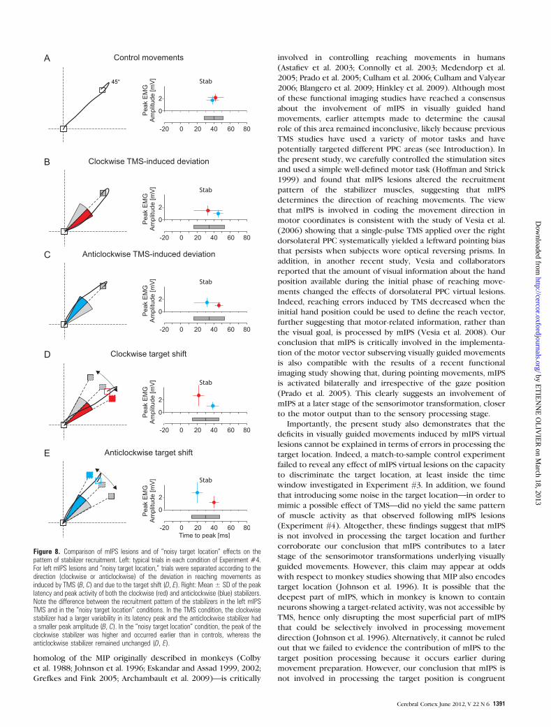
Importantly, this control experiment allowed us to confirm
again the results of Experiment #1: TMS delivered over left
mIPS 130 ms before movement onset led to an increase in
DIRVE, MT, and DR only for the contralateral targets (ANOVARM,
all F > 4.32, all P < 0.031; Fig. 8B,C). Moreover, as shown in
Figure 7, injecting some ‘‘noise’’ in the position of targets 1 and
2 (right targets) led to a DIRVE identical to that induced by left
mIPS lesions (F < 1, Fig. 7B,C), confirming the effectiveness of
our task manipulation. In the ‘‘noisy target location’’ condition,
we found that, when the target was shifted ‘‘clockwise,’’ the
contraction of the ‘‘clockwise stabilizer’’ occurred earlier and
was larger (ANOVARM: clockwise stabilizer peak latency and
amplitude; both F > 5.23, both P < 0.017) than in the control
trials (nonshifted targets 3 and 4); the recruitment pattern of
the ‘‘anticlockwise stabilizer’’ was unchanged (Fig. 8D).
Critically, such an earlier and stronger contraction of the
‘‘clockwise stabilizer’’ was never observed in visually directed
movements deviated clockwise following an mIPS virtual lesion
(ANOVARM on peak latency and amplitude of stabilizers in mIPS
TMS vs. ‘‘noisy target location’’ conditions: both F > 4.58, both
P < 0.013; compare Fig. 8B,D). Comparable results were found
when the target was shifted anticlockwise (all F > 5.78, all
P < 0.022, Fig. 8C,E).
Discussion
The present study demonstrates that mIPS is distinctively
involved in implementing the direction vector of visually
guided movements performed toward contralateral targets. We
found that the main consequence of mIPS ‘‘virtual lesions’’
occurring during the preparation of goal-directed movements
was an increased scattering in the initial direction of
movements toward contralateral targets, leading to online path
corrections and, therefore, increased trajectories and longer
movement durations. We also found that mIPS lesions induced
a change in the recruitment pattern of the stabilizer muscles,
which fine-tune the movement direction; this change is likely
to be at the origin of the increased variability in the DIR. This
conclusion is further supported by the results of a control
experiment showing that mIPS virtual lesions did not alter the
target localization. We also provided evidence that mIPS virtual
lesions did not affect the amplitude of reaching movements.
Finally, the present study failed to reveal any hemispheric
dominance in programming the direction of visually guided
movements since lesions of either mIPS symmetrically affected
movements performed toward contralateral targets.
Before discussing further these results, it is critical to rule out
that the effects reported in the present study may have resulted
from nonspecific TMS effects. Importantly, the parameters found
to be affected by virtual lesions of mIPS were complex
movement parameters (DIRVE, DR, and MT), unlikely, as the
RT, to be influenced by the TMS noise or tactile scalp
stimulation; this conclusion is further strengthened by an
absence of effects in the sham TMS condition. In addition, these
movement parameters were only affected when TMS was
applied during a very narrow time window (100--160 ms before
movement onset) and for movements planned toward contra-
lateral targets. Finally, we have recently reported that, in subjects
performing the same step-tracking task, TMS applied over the
primary motor (M1) or the dorsal premotor cortex affects
distinct movement parameters at different timings (Davare,
Duque, Vandermeeren, et al. 2007, Davare, Zenon, and Olivier
2007). Altogether, these different arguments support the
specificity of the effects described in the present study.
The present study corroborates the conclusions of several
neuroimaging studies showing that mIPS—regarded as the
TMS noisy target locationControl movementsA B C
45° 69°21° 45° 69°21°45° 69°21°
n=80 n=40 n=40
DIR (deg) DIR (deg) DIR (deg)
Figure 7. Distributions of initial direction (DIR) in Experiment #4. Upper row: Schematic illustration of the experimental protocol used in Experiment #4. (A) Control movements(n 5 80: targets 3 and 4 of the 2 TMS blocks and of the 2 ‘‘noisy target location’’ blocks). (B) TMS applied on the left mIPS 130 ms before movement onset induced a largerDIRVE, as represented by the larger gray sector. (C) condition in which we introduced some noise in the target location by displaying the stimuli at the same DIR as induced byTMS applied over mIPS. Targets were actually displayed at a location in between the 2 extreme targets depicted in the figure. Bottom row: The DIR distributions are shown bysteps of 3� for control movements (A), for left mIPS virtual lesions (B), and for the ‘‘noisy target location’’ condition (C).
Role of mIPS in Movement Direction d Davare et al.1390
by ET
IEN
NE
OL
IVIE
R on M
arch 18, 2013http://cercor.oxfordjournals.org/
Dow
nloaded from
homolog of the MIP originally described in monkeys (Colby
et al. 1988; Johnson et al. 1996; Eskandar and Assad 1999, 2002;
Grefkes and Fink 2005; Archambault et al. 2009)—is critically
involved in controlling reaching movements in humans
(Astafiev et al. 2003; Connolly et al. 2003; Medendorp et al.
2005; Prado et al. 2005; Culham et al. 2006; Culham and Valyear
2006; Blangero et al. 2009; Hinkley et al. 2009). Although most
of these functional imaging studies have reached a consensus
about the involvement of mIPS in visually guided hand
movements, earlier attempts made to determine the causal
role of this area remained inconclusive, likely because previous
TMS studies have used a variety of motor tasks and have
potentially targeted different PPC areas (see Introduction). In
the present study, we carefully controlled the stimulation sites
and used a simple well-defined motor task (Hoffman and Strick
1999) and found that mIPS lesions altered the recruitment
pattern of the stabilizer muscles, suggesting that mIPS
determines the direction of reaching movements. The view
that mIPS is involved in coding the movement direction in
motor coordinates is consistent with the study of Vesia et al.
(2006) showing that a single-pulse TMS applied over the right
dorsolateral PPC systematically yielded a leftward pointing bias
that persists when subjects wore optical reversing prisms. In
addition, in another recent study, Vesia and collaborators
reported that the amount of visual information about the hand
position available during the initial phase of reaching move-
ments changed the effects of dorsolateral PPC virtual lesions.
Indeed, reaching errors induced by TMS decreased when the
initial hand position could be used to define the reach vector,
further suggesting that motor-related information, rather than
the visual goal, is processed by mIPS (Vesia et al. 2008). Our
conclusion that mIPS is critically involved in the implementa-
tion of the motor vector subserving visually guided movements
is also compatible with the results of a recent functional
imaging study showing that, during pointing movements, mIPS
is activated bilaterally and irrespective of the gaze position
(Prado et al. 2005). This clearly suggests an involvement of
mIPS at a later stage of the sensorimotor transformation, closer
to the motor output than to the sensory processing stage.
Importantly, the present study also demonstrates that the
deficits in visually guided movements induced by mIPS virtual
lesions cannot be explained in terms of errors in processing the
target location. Indeed, a match-to-sample control experiment
failed to reveal any effect of mIPS virtual lesions on the capacity
to discriminate the target location, at least inside the time
window investigated in Experiment #3. In addition, we found
that introducing some noise in the target location—in order to
mimic a possible effect of TMS—did no yield the same pattern
of muscle activity as that observed following mIPS lesions
(Experiment #4). Altogether, these findings suggest that mIPS
is not involved in processing the target location and further
corroborate our conclusion that mIPS contributes to a later
stage of the sensorimotor transformations underlying visually
guided movements. However, this claim may appear at odds
with respect to monkey studies showing that MIP also encodes
target location (Johnson et al. 1996). It is possible that the
deepest part of mIPS, which in monkey is known to contain
neurons showing a target-related activity, was not accessible by
TMS, hence only disrupting the most superficial part of mIPS
that could be selectively involved in processing movement
direction (Johnson et al. 1996). Alternatively, it cannot be ruled
out that we failed to evidence the contribution of mIPS to the
target position processing because it occurs earlier during
movement preparation. However, our conclusion that mIPS is
not involved in processing the target position is congruent
Figure 8. Comparison of mIPS lesions and of ‘‘noisy target location’’ effects on thepattern of stabilizer recruitment. Left: typical trials in each condition of Experiment #4.For left mIPS lesions and ‘‘noisy target location,’’ trials were separated according to thedirection (clockwise or anticlockwise) of the deviation in reaching movements asinduced by TMS (B, C) and due to the target shift (D, E). Right: Mean ± SD of the peaklatency and peak activity of both the clockwise (red) and anticlockwise (blue) stabilizers.Note the difference between the recruitment pattern of the stabilizers in the left mIPSTMS and in the ‘‘noisy target location’’ conditions. In the TMS condition, the clockwisestabilizer had a larger variability in its latency peak and the anticlockwise stabilizer hada smaller peak amplitude (B, C). In the ‘‘noisy target location’’ condition, the peak of theclockwise stabilizer was higher and occurred earlier than in controls, whereas theanticlockwise stabilizer remained unchanged (D, E).
Cerebral Cortex June 2012, V 22 N 6 1391
by ET
IEN
NE
OL
IVIE
R on M
arch 18, 2013http://cercor.oxfordjournals.org/
Dow
nloaded from

with the results of several functional imaging studies showing
that processing the target position may occur in more posterior
occipitoparietal areas (Prado et al. 2005; Beurze et al. 2009;
Blangero et al. 2009; Filimon et al. 2009). Apart from these
points, it is also worth mentioning that visuospatial processing
remains difficult to investigate because it is easily confounded
with other cognitive functions such as spatial attention (Curtis
2006). Other brain structures commonly associated with
visuospatial processing are the dorsolateral prefrontal cortex,
the superior parietal lobule, and some areas in the IPS such as
the lateral intraparietal area and ventral intraparietal area. In
a TMS study investigating the neural substrate of visuospatial
processing, Oliveri and collaborators showed that whereas
a unilateral stimulation of PPC (P4 or P5) failed to affect
performance in a visuospatial task, a bilateral stimulation was
effective in altering the RTs (Oliveri et al. 2001). While this
study did not attempt to dissociate perceptive from memory
processes and did not clearly identify the targeted area, it
suggests that an interaction between left and right parietal
cortex is critical for processing of the localization of visual
targets. Another study by Mottaghy et al. (2002) investigated
the role of different prefrontal areas in a spatial localization and
face recognition tasks by using repetitive TMS (rTMS)
(Mottaghy et al. 2002). They found that whereas the disruption
of left ventral prefrontal cortex affected only performance in
the face recognition task, rTMS applied over the left
dorsolateral prefrontal cortex perturbed specifically the local-
ization task. These results, together with functional neuro-
imaging studies (reviewed in Curtis 2006), converge to suggest
that a complex network involving multiple areas in the PPC is
involved in encoding and/or storing visuospatial information.
Another interesting result of the present study is that the
velocity and acceleration peaks were not modified following
mIPS virtual lesions, suggesting that this area is not involved in
the early computation, or the implementation, of movement
amplitude (Desmurget et al. 2005). Interestingly, the deficits in
movements we found following mIPS virtual lesions are
reminiscent of observations made in patients with optic ataxia,
who mainly present an increased directional errors with no
biases in movement amplitude (Perenin and Vighetto 1988;
Darling et al. 2001; Karnath and Perenin 2005). Such
a dissociation between the direction and amplitude of goal-
directed movements is also consistent with a large body of
literature, suggesting that the basal ganglia (Desmurget et al.
2004; Krakauer et al. 2004; Desmurget and Turner 2008) are
involved in planning the amplitude of reaching movements,
likely in hand-centered coordinates (Gordon et al. 1994;
Vindras et al. 2005). As emphasized in a recent study (Ferraina
et al. 2009), such a dissociation seems to support the idea that
reaching movements are planned through a cascade of
sensorimotor transformations from a retinotopic to a binocular
viewer-centered to a hand-centered reference frame (for
a comprehensive discussion, Burnod et al. 1999; Battaglia-
Mayer et al. 2003). Finally, it is worth mentioning a recent TMS
study investigating the functional specificity of different
subregions in the PPC during saccade and reaching tasks
(Vesia et al. 2010). These authors reported different effector-
specific parietal regions that could underlie this cascade of
sensorimotor transformations occurring in distinct reference
frames during preparation of visually guided movements (Vesia
et al. 2010). Whereas SPOC encodes retinally peripheral reach
goals, more anterior--lateral regions (mIPS and the angular
gyrus) along the IPS possess overlapping maps for saccade and
reach planning and are more closely involved in motor
implementation. Although in the present study, we only
interfered with the function of a given area within the PPC,
our results are in close agreement with the conclusion of Vesia
and collaborators.
Finally, the question arises as to whether our findings can be
generalized to whole-arm reach-to-grasp movements. Three
lines of evidence support this viewpoint. First, it has been shown
that the execution of wrist step-tracking movements activates
the same parietal areas as reaching movements (Grefkes et al.
2004). Second, the step-tracking task used in the present study
relies inevitably on the computation of the same movement
parameters as whole-arm reach-to-grasp movements, namely the
direction and amplitude (Gordon et al. 1994; Vindras et al. 2005).
These 2 parameters define a motor vector that will be
subsequently transformed into a motor command sent to wrist
muscles (in the step-tracking task) or distributed to more
proximal arm muscles (in a whole-arm reaching task), taking
into account different degrees of freedom (d’Avella et al. 2006).
Finally, using a whole-arm reaching task, Vesia et al. (2010) have
recently shown that TMS over mIPS increased the end point
movement variability when vision of the moving hand is
prevented, a finding in agreement with the increase in DIR
variability in our study in which continuous visual feedback
allowed the subjects to correct this increased initial variability
on-line. Therefore, it is sensible to assume that our findings can
be generalized to whole-arm reach-to-grasp movements and we
predict that mIPS virtual lesions would likewise alter the
direction of reach-to-grasp movements, by resulting in a in-
accurate computation of the motor vector required to transport
the hand toward the object to be grasped. Our results
complement the findings of Vesia et al. (2010) by showing that
mIPS encodes a direction motor vector regardless of whether it
underlies a arm movement or a wrist rotation. Furthermore,
because the PPC contains distinct functional modules for
controlling the arm transport and grip components of reach-
to-grasp movements (Cavina-Pratesi et al. 2010; Davare et al.
2010, 2011), we predict that mIPS virtual lesions would leave the
grip component unaffected.
Funding
Actions de recherches concertees (Academie Louvain); the
Fonds Speciaux de Recherche of the Universite catholique de
Louvain; the Fonds de la Recherche Scientifique Medicale;
Fondation Medicale Reine Elisabeth.
Notes
The authors are grateful to P. L. Strick for his help with the
manipulandum design and also to M. Penta for his help with data
acquisition. Conflict of Interest : None declared.
References
Archambault PS, Caminiti R, Battaglia-Mayer A. 2009. Cortical mecha-
nisms for online control of hand movement trajectory: the role of
the posterior parietal cortex. Cereb Cortex. 19:2848--2864.
Astafiev SV, Shulman GL, Stanley CM, Snyder AZ, Van Essen DC,
Corbetta M. 2003. Functional organization of human intraparietal
and frontal cortex for attending, looking, and pointing. J Neurosci.
23:4689--4699.
Role of mIPS in Movement Direction d Davare et al.1392
by ET
IEN
NE
OL
IVIE
R on M
arch 18, 2013http://cercor.oxfordjournals.org/
Dow
nloaded from

Battaglia-Mayer A, Caminiti R, Lacquaniti F, Zago M. 2003. Multiple
levels of representation of reaching in the parieto-frontal network.
Cereb Cortex. 13:1009--1022.
Beurze SM, de Lange FP, Toni I, Medendorp WP. 2009. Spatial and
effector processing in the human parietofrontal network for
reaches and saccades. J Neurophysiol. 101:3053--3062.
Blangero A, Menz MM, McNamara A, Binkofski F. 2009. Parietal modules
for reaching. Neuropsychologia. 47:1500--1507.
Burnod Y, Baraduc P, Battaglia-Mayer A, Guigon E, Koechlin E,
Ferraina S, Lacquaniti F, Caminiti R. 1999. Parieto-frontal coding of
reaching: an integrated framework. Exp Brain Res. 129:325--346.
Cavina-Pratesi C, Monaco S, Fattori P, Galletti C, McAdam TD,
Quinlan DJ, Goodale MA, Culham JC. 2010. Functional magnetic
resonance imaging reveals the neural substrates of arm transport
and grip formation in reach-to-grasp actions in humans. J Neurosci.
30:10306--10323.
Colby CL, Gattass R, Olson CR, Gross CG. 1988. Topographical
organization of cortical afferents to extrastriate visual area PO in
the macaque: a dual tracer study. J Comp Neurol. 269:392--413.
Connolly JD, Andersen RA, Goodale MA. 2003. FMRI evidence for a ’parietal
reach region’ in the human brain. Exp Brain Res. 153:140--145.
Culham JC, Cavina-Pratesi C, Singhal A. 2006. The role of parietal cortex
in visuomotor control: what have we learned from neuroimaging?
Neuropsychologia. 44:2668--2684.
Culham JC, Valyear KF. 2006. Human parietal cortex in action. Curr
Opin Neurobiol. 16:205--212.
Curtis CE. 2006. Prefrontal and parietal contributions to spatial working
memory. Neuroscience. 139:173--180.
d’Avella A, Portone A, Fernandez L, Lacquaniti F. 2006. Control of fast-
reaching movements by muscle synergy combinations. J Neurosci.
26:7791--7810.
Darling WG, Rizzo M, Butler AJ. 2001. Disordered sensorimotor
transformations for reaching following posterior cortical lesions.
Neuropsychologia. 39:237--254.
Davare M, Andres M, Cosnard G, Thonnard JL, Olivier E. 2006.
Dissociating the role of ventral and dorsal premotor cortex in
precision grasping. J Neurosci. 26:2260--2268.
Davare M, Duque J, Vandermeeren Y, Thonnard JL, Olivier E. 2007. Role
of the ipsilateral primary motor cortex in controlling the timing of
hand muscle recruitment. Cereb Cortex. 17:353--362.
Davare M, Kraskov A, Rothwell JC, Lemon RN. Forthcoming 2011.
Interactions between areas of the cortical grasping network. Curr
Opin Neurobiol. doi: 10.1016/j.conb.2011.05.021.
Davare M, Rothwell JC, Lemon RN. 2010. Causal connectivity between
the human anterior intraparietal area and premotor cortex during
grasp. Curr Biol. 20:176--181.
Davare M, Zenon A, Olivier E. 2007. Double dissociation between the
role of the medial intraparietal area (MIP) and dorsal premotor cortex
(PMd) in reaching movements. 37th Annual meeting of the Society
for Neurosciences; Nov 3--7; San Diego, CA: The Society for
Neuroscience. Abstract (281.18/HH2).
Deiber MP, Ibanez V, Sadato N, Hallett M. 1996. Cerebral structures
participating in motor preparation in humans: a positron emission
tomography study. J Neurophysiol. 75:233--247.
Desmurget M, Grafton ST, Vindras P, Grea H, Turner RS. 2004. The basal
ganglia network mediates the planning of movement amplitude. Eur
J Neurosci. 19:2871--2880.
Desmurget M, Grea H, Grethe JS, Prablanc C, Alexander GE, Grafton ST.
2001. Functional anatomy of nonvisual feedback loops during
reaching: a positron emission tomography study. J Neurosci.
21:2919--2928.
Desmurget M, Turner RS. 2008. Testing basal ganglia motor functions
through reversible inactivations in the posterior internal globus
pallidus. J Neurophysiol. 99:1057--1076.
Desmurget M, Turner RS, Prablanc C, Russo GS, Alexander GE,
Grafton ST. 2005. Updating target location at the end of an
orienting saccade affects the characteristics of simple point-to-point
movements. J Exp Psychol Hum Percept Perform. 31:1510--1536.
Eskandar EN, Assad JA. 1999. Dissociation of visual, motor and
predictive signals in parietal cortex during visual guidance. Nat
Neurosci. 2:88--93.
Eskandar EN, Assad JA. 2002. Distinct nature of directional signals
among parietal cortical areas during visual guidance. J Neurophysiol.
88:1777--1790.
Fattori P, Breveglieri R, Marzocchi N, Filippini D, Bosco A, Galletti C.
2009. Hand orientation during reach-to-grasp movements modu-
lates neuronal activity in the medial posterior parietal area V6A.
J Neurosci. 29:1928--1936.
Ferraina S, Battaglia-Mayer A, Genovesio A, Archambault P, Caminiti R.
2009. Parietal encoding of action in depth. Neuropsychologia.
47:1409--1420.
Filimon F, Nelson JD, Huang RS, Sereno MI. 2009. Multiple parietal reach
regions in humans: cortical representations for visual and propriocep-
tive feedback during on-line reaching. J Neurosci. 29:2961--2971.
Gordon J, Ghilardi MF, Ghez C. 1994. Accuracy of planar reaching
movements. I. Independence of direction and extent variability. Exp
Brain Res. 99:97--111.
Grefkes C, Fink GR. 2005. The functional organization of the
intraparietal sulcus in humans and monkeys. J Anat. 207:3--17.
Grefkes C, Ritzl A, Zilles K, Fink GR. 2004. Human medial intraparietal
cortex subserves visuomotor coordinate transformation. Neuro-
image. 23:1494--1506.
Hinkley LB, Krubitzer LA, Padberg J, Disbrow EA. 2009. Visual-manual
exploration and posterior parietal cortex in humans. J Neurophysiol.
102:3433--3446.
Hoffman DS, Strick PL. 1986. Step-tracking movements of the wrist in
humans. I. Kinematic analysis. J Neurosci. 6:3309--3318.
Hoffman DS, Strick PL. 1999. Step-tracking movements of the wrist. IV.
Muscle activity associated with movements in different directions.
J Neurophysiol. 81:319--333.
Johnson PB, Ferraina S, Bianchi L, Caminiti R. 1996. Cortical networks
for visual reaching: physiological and anatomical organization of
frontal and parietal lobe arm regions. Cereb Cortex. 6:102--119.
Karnath HO, Perenin MT. 2005. Cortical control of visually guided
reaching: evidence from patients with optic ataxia. Cereb Cortex.
15:1561--1569.
Keel JC, Smith MJ, Wassermann EM. 2001. A safety screening
questionnaire for transcranial magnetic stimulation. Clin
Neurophysiol. 112:720.
Krakauer JW, Ghilardi MF, Mentis M, Barnes A, Veytsman M,
Eidelberg D, Ghez C. 2004. Differential cortical and subcortical
activations in learning rotations and gains for reaching: a PET study.
J Neurophysiol. 91:924--933.
Mars RB, Jbabdi S, Sallet J, O’Reilly JX, Croxson PL, Olivier E,
Noonan MP, Bergmann C, Mitchell AS, Baxter MG, et al. 2011.
Diffusion-weighted imaging tractography-based parcellation of the
human parietal cortex and comparison with human and macaque
resting-state functional connectivity. J Neurosci. 31:4087--4100.
Medendorp WP, Goltz HC, Crawford JD, Vilis T. 2005. Integration of
target and effector information in human posterior parietal cortex
for the planning of action. J Neurophysiol. 93:954--962.
Mottaghy FM, Gangitano M, Sparing R, Krause BJ, Pascual-Leone A.
2002. Segregation of areas related to visual working memory in the
prefrontal cortex revealed by rTMS. Cereb Cortex. 12:369--375.
Noirhomme Q, Ferrant M, Vandermeeren Y, Olivier E, Macq B,
Cuisenaire O. 2004. Registration and real-time visualization of
transcranial magnetic stimulation with 3-D MR images. IEEE Trans
Biomed Eng. 51:1994--2005.
Oldfield RC. 1971. The assessment and analysis of handedness: the
Edinburgh inventory. Neuropsychologia. 9:97--113.
Oliveri M, Turriziani P, Carlesimo GA, Koch G, Tomaiuolo F, Panella M,
Caltagirone C. 2001. Parieto-frontal interactions in visual-object and
visual-spatial working memory: evidence from transcranial magnetic
stimulation. Cereb Cortex. 11:606--618.
Perenin MT, Vighetto A. 1988. Optic ataxia: a specific disruption in
visuomotor mechanisms. I. Different aspects of the deficit in
reaching for objects. Brain. 111(Pt 3):643--674.
Prablanc C, Martin O. 1992. Automatic control during hand reaching at
undetected two-dimensional target displacements. J Neurophysiol.
67:455--469.
Cerebral Cortex June 2012, V 22 N 6 1393
by ET
IEN
NE
OL
IVIE
R on M
arch 18, 2013http://cercor.oxfordjournals.org/
Dow
nloaded from

Prado J, Clavagnier S, Otzenberger H, Scheiber C, Kennedy H,
Perenin MT. 2005. Two cortical systems for reaching in central
and peripheral vision. Neuron. 48:849--858.
Schmidt RA. 1976. Control processes in motor skills. Exerc Sport Sci
Rev. 4:229--261.
Smyrnis N, Theleritis C, Evdokimidis I, Muri RM, Karandreas N. 2003.
Single-pulse transcranial magnetic stimulation of parietal and
prefrontal areas in a memory delay arm pointing task. J Neuro-
physiol. 89:3344--3350.
Stark A, Zohary E. 2008. Parietal mapping of visuomotor transformations
during human tool grasping. Cereb Cortex. 18(10):2358--2368.
Striemer CL, Chouinard PA, Goodale MA. 2011. Programs for action in
superior parietal cortex: a triple-pulse TMS investigation. Neuro-
psychologia. 49(9):2391--2399.
Vesia M, Monteon JA, Sergio LE, Crawford JD. 2006. Hemispheric
asymmetry in memory-guided pointing during single-pulse trans-
cranial magnetic stimulation of human parietal cortex. J Neuro-
physiol. 96:3016--3027.
Vesia M, Prime SL, Yan X, Sergio LE, Crawford JD. 2010. Specificity of
human parietal saccade and reach regions during transcranial
magnetic stimulation. J Neurosci. 30:13053--13065.
Vesia M, Yan X, Henriques DY, Sergio LE, Crawford JD. 2008. TMS over
human dorsal-lateral posterior parietal cortex disrupts integration of
handposition signals into thereachplan. JNeurophysiol. 100:2005--2014.
Vindras P, Desmurget M, Viviani P. 2005. Error parsing in visuomotor
pointing reveals independent processing of amplitude and di-
rection. J Neurophysiol. 94:1212--1224.
Winer BJ. 1971. Statistical principles in experimental design. New York:
McGraw Hill.
Role of mIPS in Movement Direction d Davare et al.1394
by ET
IEN
NE
OL
IVIE
R on M
arch 18, 2013http://cercor.oxfordjournals.org/
Dow
nloaded from
Copyright © 2022 FDOKUMEN