
RISK CONTROL PRACTICE: OCCUPANCY - SCOR
235
Steel Handbook Steel industry - From mineral handling, steelmaking, finishing to processing RISK CONTROL PRACTICE: OCCUPANCY Didier L. SCHÜTZ Risk Control Practice Leader, SCOR Global P&C JANUARY 2022
-
Upload
khangminh22 -
Category
Documents
-
view
0 -
download
0
Transcript of RISK CONTROL PRACTICE: OCCUPANCY - SCOR
Steel HandbookSteel industry - From mineral handling,
steelmaking, finishing to processing
RISK CONTROL PRACTICE: OCCUPANCY
Didier L . SCHÜTZRisk Contro l Pract ice Leader ,
SCOR Global P&C
JANUARY 2022
2
Client Guidance Note - Risk Control Practice
As a founding signatory of the United Nations Environment Programme’s Principles for Sustainable Insurance, and a member of industry Net-Zero Alliances, SCOR is committed to engaging with policymakers and other stakeholders to identify and implement the required measures to tackle climate change. Through the review of our underwriting and investment policies and guidelines and future targets and commitments under the Net Zero frameworks, we seek to enable and indeed accelerate society’s shift to a net-zero carbon economy by 2050. Our conviction is that we have an important role to play in insuring the transition and will actively support our clients in their own commitments to follow credible transition pathways as they transform their business model toward net zero.
Disclaimer: SCOR accepts no responsibility or liability for any use of this handbook by any party to underwrite any particular risk or to determine an MPL or final loss amount. It is the responsibility of the relevant underwriter and (re)insurer to independently determine whether to accept, or not, any particular risk and the contract terms and prices required. Copyright: © Copyright SCOR Global P&C SE. All rights reserved. Permission granted to reproduce for personal and educational use only. © Shutterstock: Image(s) used under license from Shutterstock.com © Google image(s) labeled for reuse © Didier Schütz - DLS
3
Client Guidance Note - Risk Control Practice
CONTENT
SCOPE .................................................................................................................................. 7
ACKNOWLEDGEMENTS ..................................................................................................... 7
I - STEEL INDUSTRY OVERVIEW ................................................................................... 8
1. STEEL PRODUCTS ............................................................................................................ 8
2. STEEL PRODUCTION SEGMENTS .................................................................................... 8
Iron Ore Mining & Processing ............................................................................................... 8 Ironmaking, Steelmaking and Casting ................................................................................ 10 Steel Finishing (Shaping & Treating) .................................................................................. 12 Steel Processing ................................................................................................................. 12 Technology Developments ................................................................................................. 12 Sustainability Risk Management (SRM) ............................................................................. 13
II - SUPPLY CHAIN ......................................................................................................... 16
1. WORK FLOW .................................................................................................................... 16
2. INTERDEPENDENCIES, BI, CBI (CTE), SI ....................................................................... 17
III - LOSS ESTIMATE CONSIDERATIONS ...................................................................... 24
1. SCOR LOSS ESTIMATES ................................................................................................. 24
IV - MITIGATING MEASURES – CP, BCP/M ................................................................... 25
1. TERMINOLOGY & DEFINITION ........................................................................................ 25
2. RELIABILITY ISSUES ....................................................................................................... 26
3. WHEN TO CONSIDER A CP, BCP/M ................................................................................ 26
V - IRON ORE MINING & PROCESSING ........................................................................ 28
1. PROCESS ......................................................................................................................... 28
2. SPECIAL HAZARDS & RISK CONTROL ........................................................................... 39
Mining ................................................................................................................................. 39 Drilling and Blasting ............................................................................................................ 41 Mobile Mining Equipment and Related Facilities ................................................................ 41 Iron Ore handling ................................................................................................................ 43 Tailing ................................................................................................................................. 46 Iron Ore Processing ............................................................................................................ 47 Utilities ................................................................................................................................ 49 Control System ................................................................................................................... 51 Spare Parts Warehouse ..................................................................................................... 52
3. CONTINGENCY / BUSINESS CONTINUITY / RECOVERY PLAN .................................... 52
4. LOSS HISTORY ................................................................................................................ 53
5. LOSS ESTIMATES ............................................................................................................ 54
VI - IRONMAKING, STEELMAKING AND CASTING ....................................................... 55
4
Client Guidance Note - Risk Control Practice
1. PROCESS ......................................................................................................................... 55
2. SPECIAL HAZARDS & RISK CONTROL ........................................................................... 65
Raw Material Handling & Preparation ................................................................................ 65 Molten metal breakout and other extreme temperature exposures.................................... 73 Ironmaking .......................................................................................................................... 74 Steelmaking ........................................................................................................................ 82 Casting ................................................................................................................................ 88 Control System ................................................................................................................... 91 Spare Parts Warehouse ..................................................................................................... 92
3. CONTINGENCY / BUSINESS CONTINUITY / RECOVERY PLAN .................................... 93
4. LOSS HISTORY ................................................................................................................ 95
5. LOSS ESTIMATES .......................................................................................................... 102
VII - STEEL FINISHING (SHAPING & TREATING) ........................................................ 105
1. PROCESS ....................................................................................................................... 105
2. SPECIAL HAZARDS & RISK CONTROL – ROLLING MILLS .......................................... 106
Construction ...................................................................................................................... 106 Fire Hazards ..................................................................................................................... 107 Hydraulic & Lubricating Fluids .......................................................................................... 112 Rolling Fluids .................................................................................................................... 113 Fume Exhaust ................................................................................................................... 114 Combustible Dust Hazards ............................................................................................... 114 Mill Equipment .................................................................................................................. 117 Utilities .............................................................................................................................. 119 Control System ................................................................................................................. 125
Focus on Hot Rolling Mills ................................................................................................ 126 Focus on Cold Rolling Mills .............................................................................................. 135
3. SPECIAL HAZARDS & RISK CONTROL – OTHER FINISHING OPERATIONS.............. 136
4. CONTINGENCY / BUSINESS CONTINUITY / RECOVERY PLAN .................................. 144
5. LOSS HISTORY .............................................................................................................. 144
6. LOSS ESTIMATES .......................................................................................................... 149
VIII - STEEL PROCESSING.............................................................................................. 151
1. METAL WORKSHOP-1 ................................................................................................... 151
2. METAL WORKSHOP-2 ................................................................................................... 153
Occupancy ........................................................................................................................ 153 Special Hazards ................................................................................................................ 153 Construction ...................................................................................................................... 154 Fire Detection / protection: ................................................................................................ 154 Exposures: ........................................................................................................................ 154
IX - UTILITIES ................................................................................................................. 155
5
Client Guidance Note - Risk Control Practice
1. ARRANGEMENT ............................................................................................................. 155
2. SPECIAL HAZARDS & RISK CONTROL ......................................................................... 155
Electric Power ................................................................................................................... 155 Natural Gas ....................................................................................................................... 157 Air Products ...................................................................................................................... 157 Water ................................................................................................................................ 159 Fume Treatment ............................................................................................................... 159
3. CONTINGENCY / BUSINESS CONTINUITY / RECOVERY PLAN .................................. 160
4. LOSS ESTIMATES .......................................................................................................... 161
X - IMPORT / EXPORT FACILITIES FOCUS ................................................................ 162
1. FACILITIES ..................................................................................................................... 162
2. SPECIAL HAZARDS & RISK CONTROL ......................................................................... 164
Ship Loader / Unloader ..................................................................................................... 164 Discharge Bins .................................................................................................................. 165 Rubber Belt Conveyors ..................................................................................................... 166 Stacker Reclaimers ........................................................................................................... 166
3. CONTINGENCY / BUSINESS CONTINUITY / RECOVERY PLAN .................................. 166
4. LOSS HISTORY .............................................................................................................. 167
5. LOSS ESTIMATES .......................................................................................................... 168
XI - SUPPORT FOR LOSS PREVENTION RECOMMENDATIONS ............................... 169
1. STEAM TURBINE ............................................................................................................ 169
2. STATIONARY COMBUSTION ENGINE .......................................................................... 172
3. ARC FURNACE TRANSFORMERS - AFT (EAF / LF) ..................................................... 173
4. TRANSFORMER ............................................................................................................. 174
5. ELECTRO-STATIC PRECIPITATOR (ESP) .................................................................... 184
6. SUBSTATION / MCC ROOMS / SERVER ROOMS / ELECTRIC ROOMS ...................... 185
7. CABLE OPENINGS / CABLE TRAYS & RUNS / CABLE VAULTS / CABLE TUNNELS .. 187
8. BATTERY ROOM (ESS) .................................................................................................. 188
9. RUBBER BELT CONVEYOR........................................................................................... 189
10. COOLING TOWER ........................................................................................................ 194
11. HYDRAULIC / LUBRICATING GROUPS ....................................................................... 199
12. AIR COMPRESSOR ...................................................................................................... 201
13. FUEL LINE SAFETY COMBUSTION CONTROL .......................................................... 203
14. HAZMAT & AEROSOLS & COMPRESSED GAS CYLINDERS ..................................... 206
15. COMBUSTIBLE OIL STORAGE & HANDLING ............................................................. 206
16. OVERHEAD CRANES .................................................................................................. 207
17. CONTROL ROOM ......................................................................................................... 208
18. WAREHOUSE ............................................................................................................... 209
6
Client Guidance Note - Risk Control Practice
19. LARGE DRIVER STORAGE ......................................................................................... 210
20. DUCT SPRINKLER PROTECTION ............................................................................... 210
XII - ANNEX ..................................................................................................................... 212
1. ANNEX A: TECHNICAL REFERENCES .......................................................................... 212
2. ANNEX B: EXPLANATORY MATERIAL .......................................................................... 214
Ironmaking ........................................................................................................................ 214 Direct Reduction Midrex Process ..................................................................................... 216 Direct Reduction HyL Process .......................................................................................... 217 Combustible Metal ............................................................................................................ 218
3. ANNEX C: GLOSSARY OF TERMS ................................................................................ 220
7
Client Guidance Note - Risk Control Practice
SCOPE
The purpose of this Handbook / Guidance Note is to provide comprehensive technical support to Underwriters and Risk Control Engineers. The previous version V1.4 was released on May 24, 2007 focusing exclusively on steelmaking using Blast Furnaces, Electric Arc Furnaces and Rolling Mills only. This new version 1.5 dated 2022 intends addressing all major aspects of the steel industry from Iron Ore mining through to Steel Processing. The main processes of the steel industry and its related special hazards are described. This guide is mostly focused on fire explosion hazards and natural perils. Boilers & machinery hazards are not covered in detail in this document. Examples of losses are also given when relevant. Although this Handbook / Guidance Note is detailed and deals with a number of perils and potential scenarios, it is not intended to be a comprehensive analysis of every peril and potential scenario an underwriter may be requested to provide cover for. Any estimation or projection of an MPL and final loss amount must be based on reliable, accurate and current values, applicable scenarios and consideration of the relevant perils. Standard recommendations based on recognized international standards and good practices are proposed. Moreover, very good NFPA (National Fire Protection Association) and FM Global Property Loss Prevention Data Sheets on these subjects exist. Since there is no need to reinvent the wheel, readers are referred to those references when relevant. -NFPA free viewing at http://www.nfpa.org/ -FM Global Data Sheets free viewing and download available when registered at http://www.fmglobal.com/ Note that these materials are periodically revised and updated. Please monitor the above websites for updates and/or revisions. Acknowledgements Many thanks to the following people and organizations for their invaluable and extensive contributions:
• Emirates Steel (ES) Abu Dhabi UAE • World Steel Association (worldsteel) • American Iron and Steel Institute • Ispat - Satyendra Kumar Sarna, Metallurgist • FM Global - Factory Mutual Insurance Company • Nicole Jamieson, Conference Interpreter (AIIC) • Franck Orset (FPO), Loss Prevention Engineer – drawings and more
This occupancy guide was finally discussed and reviewed by Risk Control Engineers and Claims Managers working for insurance / reinsurance and qualified consultant companies or working as freelance consultants. Many thanks to them. Their names are given in this document with their permission.
8
Client Guidance Note - Risk Control Practice
I - STEEL INDUSTRY OVERVIEW
1. STEEL PRODUCTS
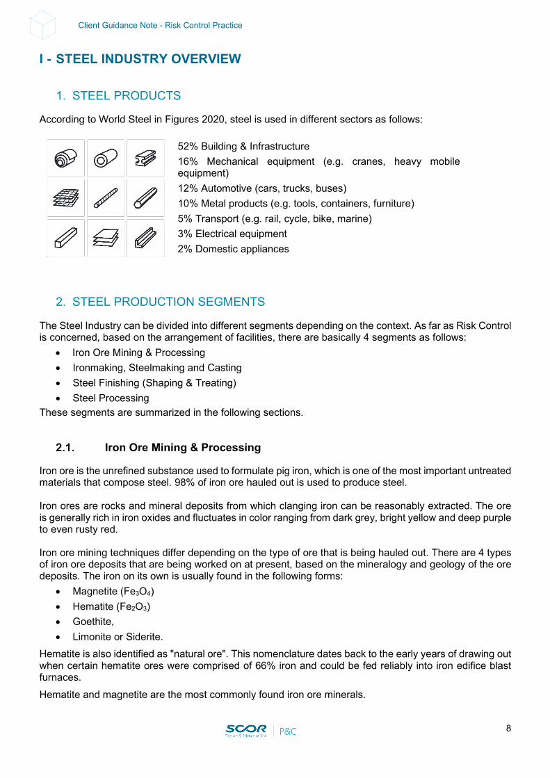
According to World Steel in Figures 2020, steel is used in different sectors as follows:
52% Building & Infrastructure 16% Mechanical equipment (e.g. cranes, heavy mobile
equipment) 12% Automotive (cars, trucks, buses) 10% Metal products (e.g. tools, containers, furniture) 5% Transport (e.g. rail, cycle, bike, marine) 3% Electrical equipment 2% Domestic appliances
2. STEEL PRODUCTION SEGMENTS
The Steel Industry can be divided into different segments depending on the context. As far as Risk Control is concerned, based on the arrangement of facilities, there are basically 4 segments as follows:
• Iron Ore Mining & Processing • Ironmaking, Steelmaking and Casting • Steel Finishing (Shaping & Treating) • Steel Processing
These segments are summarized in the following sections.
Iron Ore Mining & Processing
Iron ore is the unrefined substance used to formulate pig iron, which is one of the most important untreated materials that compose steel. 98% of iron ore hauled out is used to produce steel. Iron ores are rocks and mineral deposits from which clanging iron can be reasonably extracted. The ore is generally rich in iron oxides and fluctuates in color ranging from dark grey, bright yellow and deep purple to even rusty red. Iron ore mining techniques differ depending on the type of ore that is being hauled out. There are 4 types of iron ore deposits that are being worked on at present, based on the mineralogy and geology of the ore deposits. The iron on its own is usually found in the following forms:
• Magnetite (Fe3O4) • Hematite (Fe2O3) • Goethite, • Limonite or Siderite.
Hematite is also identified as "natural ore". This nomenclature dates back to the early years of drawing out when certain hematite ores were comprised of 66% iron and could be fed reliably into iron edifice blast furnaces. Hematite and magnetite are the most commonly found iron ore minerals.
9
Client Guidance Note - Risk Control Practice
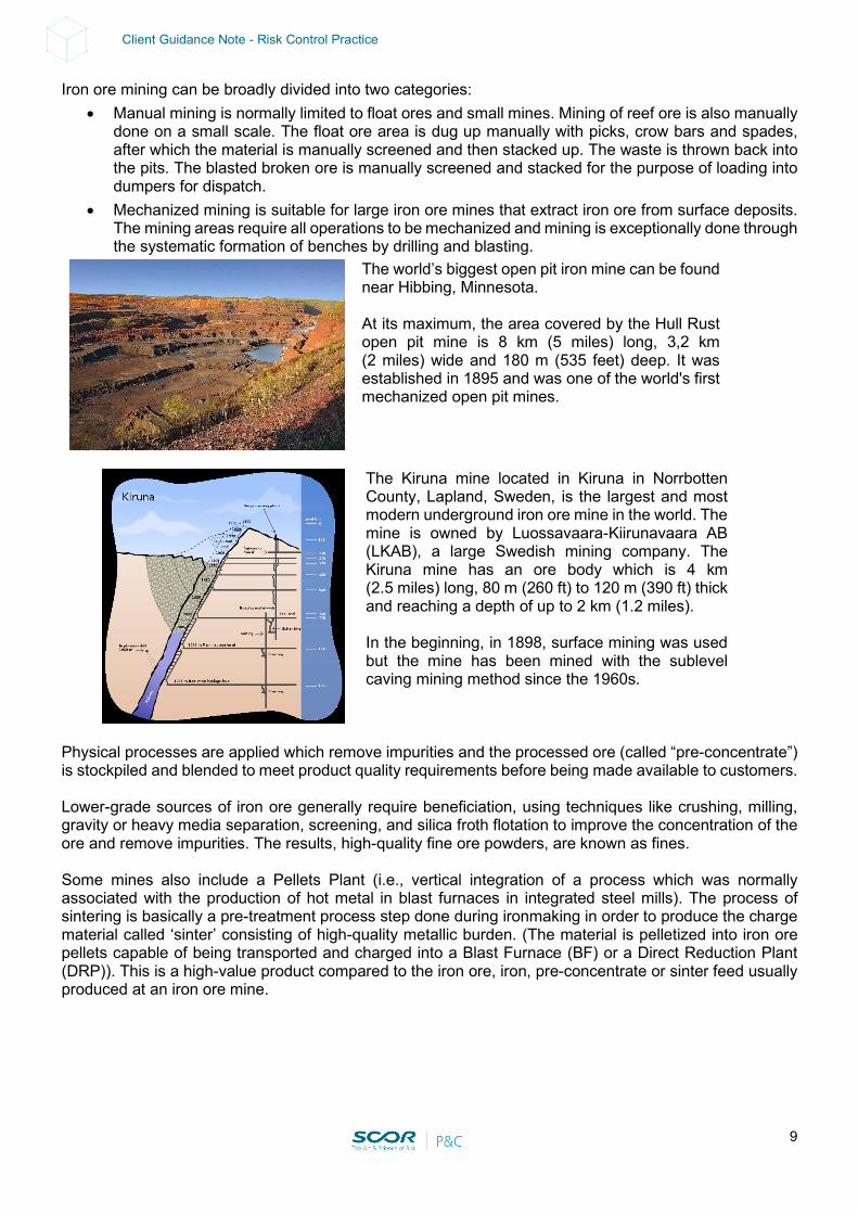
Iron ore mining can be broadly divided into two categories: • Manual mining is normally limited to float ores and small mines. Mining of reef ore is also manually
done on a small scale. The float ore area is dug up manually with picks, crow bars and spades, after which the material is manually screened and then stacked up. The waste is thrown back into the pits. The blasted broken ore is manually screened and stacked for the purpose of loading into dumpers for dispatch.
• Mechanized mining is suitable for large iron ore mines that extract iron ore from surface deposits. The mining areas require all operations to be mechanized and mining is exceptionally done through the systematic formation of benches by drilling and blasting.
The world’s biggest open pit iron mine can be found near Hibbing, Minnesota. At its maximum, the area covered by the Hull Rust open pit mine is 8 km (5 miles) long, 3,2 km (2 miles) wide and 180 m (535 feet) deep. It was established in 1895 and was one of the world's first mechanized open pit mines.
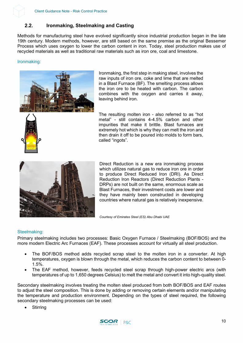
The Kiruna mine located in Kiruna in Norrbotten County, Lapland, Sweden, is the largest and most modern underground iron ore mine in the world. The mine is owned by Luossavaara-Kiirunavaara AB (LKAB), a large Swedish mining company. The Kiruna mine has an ore body which is 4 km (2.5 miles) long, 80 m (260 ft) to 120 m (390 ft) thick and reaching a depth of up to 2 km (1.2 miles). In the beginning, in 1898, surface mining was used but the mine has been mined with the sublevel caving mining method since the 1960s.
Physical processes are applied which remove impurities and the processed ore (called “pre-concentrate”) is stockpiled and blended to meet product quality requirements before being made available to customers. Lower-grade sources of iron ore generally require beneficiation, using techniques like crushing, milling, gravity or heavy media separation, screening, and silica froth flotation to improve the concentration of the ore and remove impurities. The results, high-quality fine ore powders, are known as fines. Some mines also include a Pellets Plant (i.e., vertical integration of a process which was normally associated with the production of hot metal in blast furnaces in integrated steel mills). The process of sintering is basically a pre-treatment process step done during ironmaking in order to produce the charge material called ‘sinter’ consisting of high-quality metallic burden. (The material is pelletized into iron ore pellets capable of being transported and charged into a Blast Furnace (BF) or a Direct Reduction Plant (DRP)). This is a high-value product compared to the iron ore, iron, pre-concentrate or sinter feed usually produced at an iron ore mine.
10
Client Guidance Note - Risk Control Practice
Ironmaking, Steelmaking and Casting
Methods for manufacturing steel have evolved significantly since industrial production began in the late 19th century. Modern methods, however, are still based on the same premise as the original Bessemer Process which uses oxygen to lower the carbon content in iron. Today, steel production makes use of recycled materials as well as traditional raw materials such as iron ore, coal and limestone. Ironmaking:
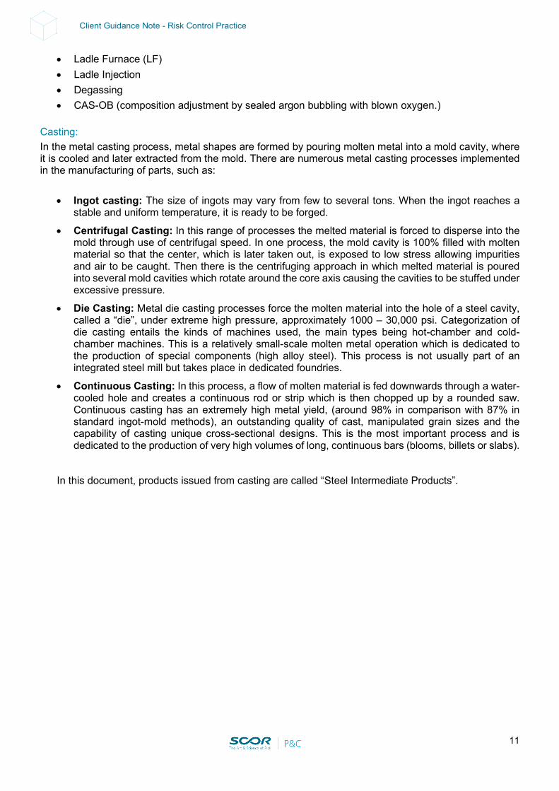
Ironmaking, the first step in making steel, involves the raw inputs of iron ore, coke and lime that are melted in a Blast Furnace (BF). The smelting process allows the iron ore to be heated with carbon. The carbon combines with the oxygen and carries it away, leaving behind iron. The resulting molten iron - also referred to as “hot metal” - still contains 4-4.5% carbon and other impurities that make it brittle. Blast furnaces are extremely hot which is why they can melt the iron and then drain it off to be poured into molds to form bars, called “ingots”.
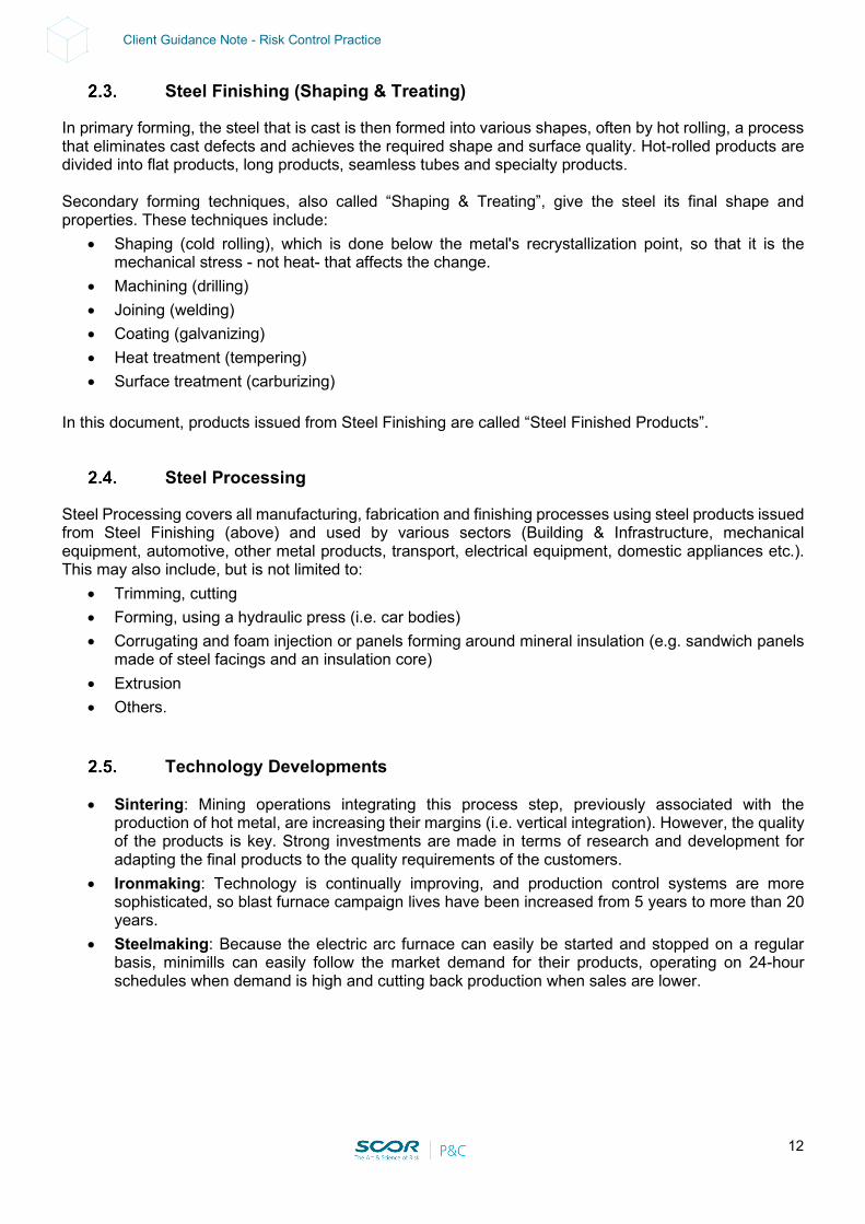
Direct Reduction is a new era ironmaking process which utilizes natural gas to reduce iron ore in order to produce Direct Reduced Iron (DRI). As Direct Reduction Iron Reactors (Direct Reduction Plants - DRPs) are not built on the same, enormous scale as Blast Furnaces, their investment costs are lower and they have mainly been constructed in developing countries where natural gas is relatively inexpensive. Courtesy of Emirates Steel (ES) Abu Dhabi UAE
Steelmaking: Primary steelmaking includes two processes: Basic Oxygen Furnace / Steelmaking (BOF/BOS) and the more modern Electric Arc Furnaces (EAF). These processes account for virtually all steel production.
• The BOF/BOS method adds recycled scrap steel to the molten iron in a converter. At high temperatures, oxygen is blown through the metal, which reduces the carbon content to between 0-1.5%.
• The EAF method, however, feeds recycled steel scrap through high-power electric arcs (with temperatures of up to 1,650 degrees Celsius) to melt the metal and convert it into high-quality steel.
Secondary steelmaking involves treating the molten steel produced from both BOF/BOS and EAF routes to adjust the steel composition. This is done by adding or removing certain elements and/or manipulating the temperature and production environment. Depending on the types of steel required, the following secondary steelmaking processes can be used:
• Stirring
11
Client Guidance Note - Risk Control Practice
• Ladle Furnace (LF) • Ladle Injection • Degassing • CAS-OB (composition adjustment by sealed argon bubbling with blown oxygen.)
Casting: In the metal casting process, metal shapes are formed by pouring molten metal into a mold cavity, where it is cooled and later extracted from the mold. There are numerous metal casting processes implemented in the manufacturing of parts, such as:
• Ingot casting: The size of ingots may vary from few to several tons. When the ingot reaches a stable and uniform temperature, it is ready to be forged.
• Centrifugal Casting: In this range of processes the melted material is forced to disperse into the mold through use of centrifugal speed. In one process, the mold cavity is 100% filled with molten material so that the center, which is later taken out, is exposed to low stress allowing impurities and air to be caught. Then there is the centrifuging approach in which melted material is poured into several mold cavities which rotate around the core axis causing the cavities to be stuffed under excessive pressure.
• Die Casting: Metal die casting processes force the molten material into the hole of a steel cavity, called a “die”, under extreme high pressure, approximately 1000 – 30,000 psi. Categorization of die casting entails the kinds of machines used, the main types being hot-chamber and cold-chamber machines. This is a relatively small-scale molten metal operation which is dedicated to the production of special components (high alloy steel). This process is not usually part of an integrated steel mill but takes place in dedicated foundries.
• Continuous Casting: In this process, a flow of molten material is fed downwards through a water-cooled hole and creates a continuous rod or strip which is then chopped up by a rounded saw. Continuous casting has an extremely high metal yield, (around 98% in comparison with 87% in standard ingot-mold methods), an outstanding quality of cast, manipulated grain sizes and the capability of casting unique cross-sectional designs. This is the most important process and is dedicated to the production of very high volumes of long, continuous bars (blooms, billets or slabs).
In this document, products issued from casting are called “Steel Intermediate Products”.
12
Client Guidance Note - Risk Control Practice
Steel Finishing (Shaping & Treating)
In primary forming, the steel that is cast is then formed into various shapes, often by hot rolling, a process that eliminates cast defects and achieves the required shape and surface quality. Hot-rolled products are divided into flat products, long products, seamless tubes and specialty products. Secondary forming techniques, also called “Shaping & Treating”, give the steel its final shape and properties. These techniques include:
• Shaping (cold rolling), which is done below the metal's recrystallization point, so that it is the mechanical stress - not heat- that affects the change.
• Machining (drilling) • Joining (welding) • Coating (galvanizing) • Heat treatment (tempering) • Surface treatment (carburizing)
In this document, products issued from Steel Finishing are called “Steel Finished Products”.
Steel Processing
Steel Processing covers all manufacturing, fabrication and finishing processes using steel products issued from Steel Finishing (above) and used by various sectors (Building & Infrastructure, mechanical equipment, automotive, other metal products, transport, electrical equipment, domestic appliances etc.). This may also include, but is not limited to:
• Trimming, cutting • Forming, using a hydraulic press (i.e. car bodies) • Corrugating and foam injection or panels forming around mineral insulation (e.g. sandwich panels
made of steel facings and an insulation core) • Extrusion • Others.
Technology Developments
• Sintering: Mining operations integrating this process step, previously associated with the production of hot metal, are increasing their margins (i.e. vertical integration). However, the quality of the products is key. Strong investments are made in terms of research and development for adapting the final products to the quality requirements of the customers.
• Ironmaking: Technology is continually improving, and production control systems are more sophisticated, so blast furnace campaign lives have been increased from 5 years to more than 20 years.
• Steelmaking: Because the electric arc furnace can easily be started and stopped on a regular basis, minimills can easily follow the market demand for their products, operating on 24-hour schedules when demand is high and cutting back production when sales are lower.
13
Client Guidance Note - Risk Control Practice
Sustainability Risk Management (SRM)
Sustainability risk management (SRM) is a business strategy that aligns profit goals with a company's environmental policies. The goal of SRM is to make this alignment efficient enough to sustain and grow a business while preserving the environment. Recycled steel • Steel has a long lifetime and low turnover rate. This means recycle. • Around 30% of the world’s steel is reportedly made from recycled steel. Steel has one of the highest
recycling rates of any material. • Steel recycling is mainly done in arc furnaces, driven by electricity. Each ton of steel produced
using this method produces about 0.4 tons of CO₂ – mostly due to emissions produced by burning fossil fuels for electricity generation.
• If the electricity was produced from renewable sources, the CO₂ output would be greatly reduced. • However steel cannot continuously be recycled. After a while, unwanted elements (copper, nickel,
tin, other) begin to accumulate in the steel, reducing its quality.
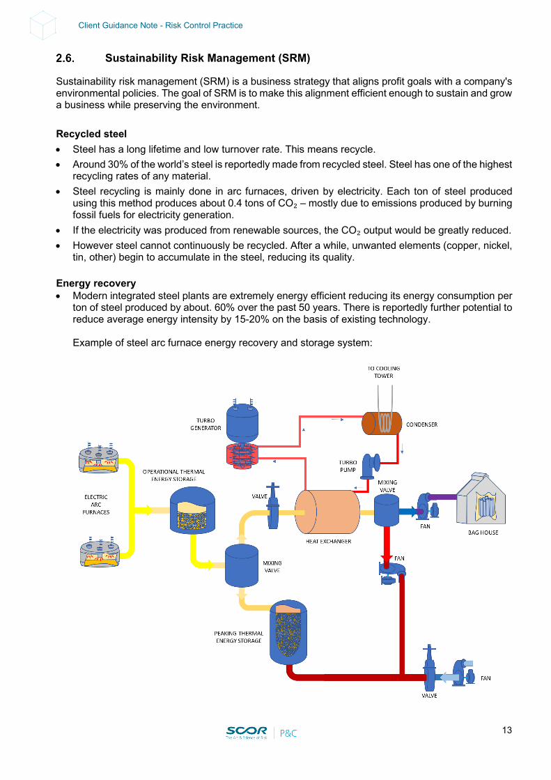
Energy recovery • Modern integrated steel plants are extremely energy efficient reducing its energy consumption per
ton of steel produced by about. 60% over the past 50 years. There is reportedly further potential to reduce average energy intensity by 15-20% on the basis of existing technology. Example of steel arc furnace energy recovery and storage system:
14
Client Guidance Note - Risk Control Practice
Breakthrough technologies • Steel industry is reportedly accounting for an 7-8% of global CO2 emissions. • The deployment of breakthrough technologies is key to achieve a 55% reduction of CO2
emissions by 2030 (vs. 1990 levels). See below. “Green Steel” • Steel-making requires stripping oxygen from iron ore to produce pure iron metal. In traditional steel-
making, this is done using coal (i.e. Blast Furnace – BF) or natural gas in a process that releases CO₂ (NG-Direct Reduced Iron - DRI).
• A new path is emerging: so-called “green steel”, made using hydrogen rather than coal, represents a huge opportunity.
• The hydrogen can strip oxygen away from the ore, generating water instead of CO₂. Blast Furnace (BF) • If hydrogen is used, the blast furnace (BF) needs more externally added heat to keep the
temperature high, compared with the coal method. • Moreover, solid coal in the main body of the furnace cannot be replaced with hydrogen. Some
alternatives have been developed, involving biomass – a fuel developed from living organisms – blended with coal.
• But sourcing biomass sustainably and at scale would be a challenge. And this process would still likely create some fossil-fuel derived emissions. So to ensure the process is “green”, these emissions would have to be captured and stored – a technology which is currently expensive and unproven at scale.
Direct reduced iron (DRI) or (Natural Gas-NG)-based direct reduction (DR) • DRI technology often uses methane gas to produce hydrogen and carbon monoxide, which are
then used to turn iron ore into iron. • This method still creates CO₂ emissions and requires more electricity than the blast furnace
method. However its overall emission intensity can be substantially lower. • The method reportedly accounts for less than 5% of production. Hydrogen-based direct reduction (H-DRI) • In “green steel production”, hydrogen made from renewable energy replaces fossil fuels. • Within DRI (or NG-based direct reduction) up to 70% of the hydrogen currently derived from
methane which could be replaced with green hydrogen (H-DRI) without having to modify the production process too much.
• The hydrogen-based route offering a huge potential for green steelmaking is strongly depending on the carbon footprint of the electricity used for the production of hydrogen.
• The “green steel production” requires renewable electricity (hydro, wind, solar) to produce green hydrogen (making hydrogen from water using electrolysis).
• Hydrogen-based direct reduction (H-DRI) appears to be the solution for the next 10-15 years. High-temperature iron electrolysis • Steel can be also produced via electrometallurgy, an electrochemical process that uses electricity
for the direct production of metals from metallic ores. Electricity is used to produce a decomposition reaction (a process called electrolysis).

15
Client Guidance Note - Risk Control Practice
• The high-temperature electrolysis previously relied on the use of carbon (graphite) anodes, which were consumed in the process, thereby generating carbon monoxide and carbon dioxide as byproducts or on anodes from high-cost precious metals (such as gold or iridium).
• The use of an inert anode is critical in enabling the electrolytic recovery of iron from a molten oxide electrolyte without generating CO2 emissions. However, there are difficulties in finding a suitable non-consumable anode material capable of weathering the challenging conditions of the process:
o The process temperature is c. 1,550°C, which can lead to the breakdown of the anode. o Under anodic polarization most metals corrode in such conditions. o Iron, oxide undergoes spontaneous reduction on contact with most refractory metals and
even carbon. • Based on the current concepts being pursued, iron electrolysis is estimated to use 15-30% less
electricity per ton of steel produced, relative to the hydrogen-based DRI route. • High-temperature iron electrolysis could come to the market by 2035, with the Molten Oxide
Electrolysis (MOE) process developed by US start-up Boston Metal looking the most promising so far.
16
Client Guidance Note - Risk Control Practice
II - SUPPLY CHAIN
1. WORK FLOW
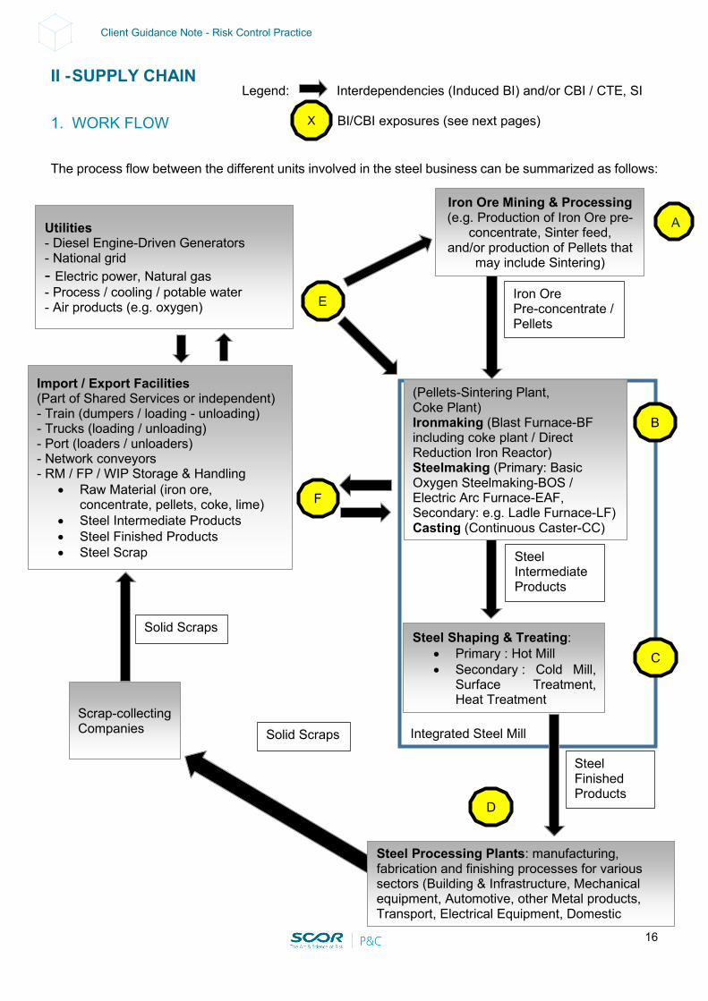
The process flow between the different units involved in the steel business can be summarized as follows:
Legend: Interdependencies (Induced BI) and/or CBI / CTE, SI BI/CBI exposures (see next pages) X
Iron Ore Mining & Processing (e.g. Production of Iron Ore pre-
concentrate, Sinter feed, and/or production of Pellets that
may include Sintering)
A
Integrated Steel Mill
E
(Pellets-Sintering Plant, Coke Plant) Ironmaking (Blast Furnace-BF including coke plant / Direct Reduction Iron Reactor) Steelmaking (Primary: Basic Oxygen Steelmaking-BOS / Electric Arc Furnace-EAF, Secondary: e.g. Ladle Furnace-LF) Casting (Continuous Caster-CC)
Steel Shaping & Treating: • Primary : Hot Mill • Secondary : Cold Mill,
Surface Treatment, Heat Treatment
Iron Ore Pre-concentrate / Pellets
C
Steel Intermediate Products
B
F
Utilities - Diesel Engine-Driven Generators - National grid - Electric power, Natural gas - Process / cooling / potable water - Air products (e.g. oxygen)
Import / Export Facilities (Part of Shared Services or independent) - Train (dumpers / loading - unloading) - Trucks (loading / unloading) - Port (loaders / unloaders) - Network conveyors - RM / FP / WIP Storage & Handling
• Raw Material (iron ore, concentrate, pellets, coke, lime)
• Steel Intermediate Products • Steel Finished Products • Steel Scrap
Scrap-collecting Companies
Steel Finished Products
Solid Scraps
Solid Scraps
D
Steel Processing Plants: manufacturing, fabrication and finishing processes for various sectors (Building & Infrastructure, Mechanical equipment, Automotive, other Metal products, Transport, Electrical Equipment, Domestic
17
Client Guidance Note - Risk Control Practice
2. INTERDEPENDENCIES, BI, CBI (CTE), SI
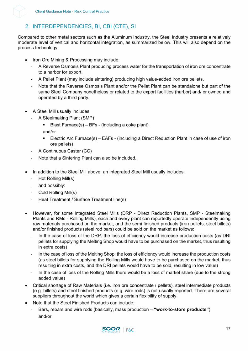
Compared to other metal sectors such as the Aluminum Industry, the Steel Industry presents a relatively moderate level of vertical and horizontal integration, as summarized below. This will also depend on the process technology:
• Iron Ore Mining & Processing may include: - A Reverse Osmosis Plant producing process water for the transportation of iron ore concentrate
to a harbor for export. - A Pellet Plant (may include sintering) producing high value-added iron ore pellets. - Note that the Reverse Osmosis Plant and/or the Pellet Plant can be standalone but part of the
same Steel Company nonetheless or related to the export facilities (harbor) and/ or owned and operated by a third party.
• A Steel Mill usually includes:
- A Steelmaking Plant (SMP) Blast Furnace(s) – BFs - (including a coke plant) and/or Electric Arc Furnace(s) – EAFs - (including a Direct Reduction Plant in case of use of iron
ore pellets) - A Continuous Caster (CC) - Note that a Sintering Plant can also be included.
• In addition to the Steel Mill above, an Integrated Steel Mill usually includes:
- Hot Rolling Mill(s) - and possibly: - Cold Rolling Mill(s) - Heat Treatment / Surface Treatment line(s)
• However, for some Integrated Steel Mills (DRP - Direct Reduction Plants, SMP - Steelmaking
Plants and RMs - Rolling Mills), each and every plant can reportedly operate independently using raw materials purchased on the market, and the semi-finished products (iron pellets, steel billets) and/or finished products (steel rod bars) could be sold on the market as follows:
- In the case of loss of the DRP: the loss of efficiency would increase production costs (as DRI pellets for supplying the Melting Shop would have to be purchased on the market, thus resulting in extra costs)
- In the case of loss of the Melting Shop: the loss of efficiency would increase the production costs (as steel billets for supplying the Rolling Mills would have to be purchased on the market, thus resulting in extra costs, and the DRI pellets would have to be sold, resulting in low value)
- In the case of loss of the Rolling Mills there would be a loss of market share (due to the strong added value)
• Critical shortage of Raw Materials (i.e. iron ore concentrate / pellets), steel intermediate products (e.g. billets) and steel finished products (e.g. wire rods) is not usually reported. There are several suppliers throughout the world which gives a certain flexibility of supply.
• Note that the Steel Finished Products can include: - Bars, rebars and wire rods (basically, mass production – “work-to-store products”)
and/or
18
Client Guidance Note - Risk Control Practice
- Heavy structural beams used for construction (different grades, ranges of products – “on demand production”)
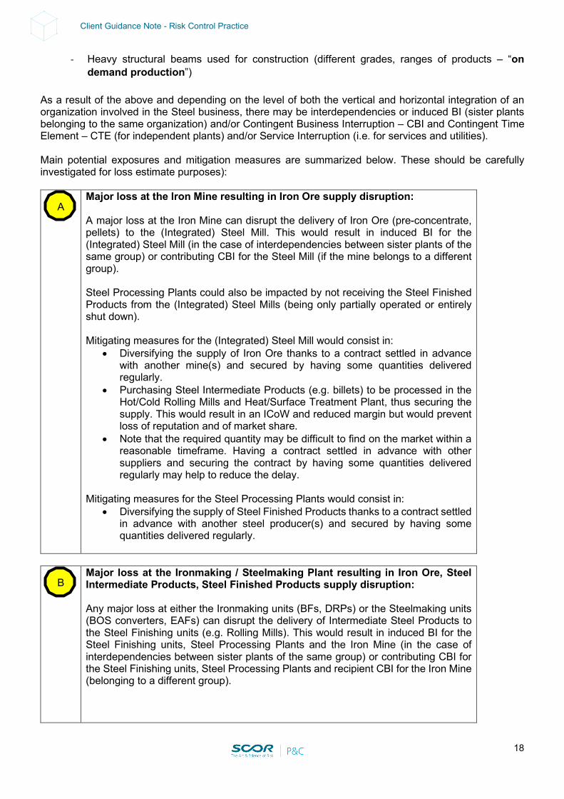
As a result of the above and depending on the level of both the vertical and horizontal integration of an organization involved in the Steel business, there may be interdependencies or induced BI (sister plants belonging to the same organization) and/or Contingent Business Interruption – CBI and Contingent Time Element – CTE (for independent plants) and/or Service Interruption (i.e. for services and utilities). Main potential exposures and mitigation measures are summarized below. These should be carefully investigated for loss estimate purposes): Major loss at the Iron Mine resulting in Iron Ore supply disruption:
A major loss at the Iron Mine can disrupt the delivery of Iron Ore (pre-concentrate, pellets) to the (Integrated) Steel Mill. This would result in induced BI for the (Integrated) Steel Mill (in the case of interdependencies between sister plants of the same group) or contributing CBI for the Steel Mill (if the mine belongs to a different group). Steel Processing Plants could also be impacted by not receiving the Steel Finished Products from the (Integrated) Steel Mills (being only partially operated or entirely shut down). Mitigating measures for the (Integrated) Steel Mill would consist in:
• Diversifying the supply of Iron Ore thanks to a contract settled in advance with another mine(s) and secured by having some quantities delivered regularly.
• Purchasing Steel Intermediate Products (e.g. billets) to be processed in the Hot/Cold Rolling Mills and Heat/Surface Treatment Plant, thus securing the supply. This would result in an ICoW and reduced margin but would prevent loss of reputation and of market share.
• Note that the required quantity may be difficult to find on the market within a reasonable timeframe. Having a contract settled in advance with other suppliers and securing the contract by having some quantities delivered regularly may help to reduce the delay.
Mitigating measures for the Steel Processing Plants would consist in:
• Diversifying the supply of Steel Finished Products thanks to a contract settled in advance with another steel producer(s) and secured by having some quantities delivered regularly.
Major loss at the Ironmaking / Steelmaking Plant resulting in Iron Ore, Steel
Intermediate Products, Steel Finished Products supply disruption: Any major loss at either the Ironmaking units (BFs, DRPs) or the Steelmaking units (BOS converters, EAFs) can disrupt the delivery of Intermediate Steel Products to the Steel Finishing units (e.g. Rolling Mills). This would result in induced BI for the Steel Finishing units, Steel Processing Plants and the Iron Mine (in the case of interdependencies between sister plants of the same group) or contributing CBI for the Steel Finishing units, Steel Processing Plants and recipient CBI for the Iron Mine (belonging to a different group).
A
B
19
Client Guidance Note - Risk Control Practice
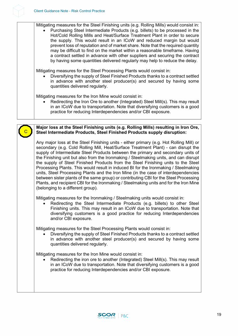
Mitigating measures for the Steel Finishing units (e.g. Rolling Mills) would consist in: • Purchasing Steel Intermediate Products (e.g. billets) to be processed in the
Hot/Cold Rolling Mills and Heat/Surface Treatment Plant in order to secure the supply. This would result in an ICoW and reduced margin but would prevent loss of reputation and of market share. Note that the required quantity may be difficult to find on the market within a reasonable timeframe. Having a contract settled in advance with other suppliers and securing the contract by having some quantities delivered regularly may help to reduce the delay.
Mitigating measures for the Steel Processing Plants would consist in:
• Diversifying the supply of Steel Finished Products thanks to a contract settled in advance with another steel producer(s) and secured by having some quantities delivered regularly.
Mitigating measures for the Iron Mine would consist in:
• Redirecting the Iron Ore to another (Integrated) Steel Mill(s). This may result in an ICoW due to transportation. Note that diversifying customers is a good practice for reducing Interdependencies and/or CBI exposure.
Major loss at the Steel Finishing units (e.g. Rolling Mills) resulting in Iron Ore,
Steel Intermediate Products, Steel Finished Products supply disruption: Any major loss at the Steel Finishing units - either primary (e.g. Hot Rolling Mill) or secondary (e.g. Cold Rolling Mill, Heat/Surface Treatment Plant) - can disrupt the supply of Intermediate Steel Products between the primary and secondary units of the Finishing unit but also from the Ironmaking / Steelmaking units, and can disrupt the supply of Steel Finished Products from the Steel Finishing units to the Steel Processing Plants. This would result in induced BI for the Ironmaking / Steelmaking units, Steel Processing Plants and the Iron Mine (in the case of interdependencies between sister plants of the same group) or contributing CBI for the Steel Processing Plants, and recipient CBI for the Ironmaking / Steelmaking units and for the Iron Mine (belonging to a different group). Mitigating measures for the Ironmaking / Steelmaking units would consist in:
• Redirecting the Steel Intermediate Products (e.g. billets) to other Steel Finishing units. This may result in an ICoW due to transportation. Note that diversifying customers is a good practice for reducing Interdependencies and/or CBI exposure.
Mitigating measures for the Steel Processing Plants would consist in:
• Diversifying the supply of Steel Finished Products thanks to a contract settled in advance with another steel producer(s) and secured by having some quantities delivered regularly.
Mitigating measures for the Iron Mine would consist in:
• Redirecting the iron ore to another (Integrated) Steel Mill(s). This may result in an ICoW due to transportation. Note that diversifying customers is a good practice for reducing Interdependencies and/or CBI exposure.
C
20
Client Guidance Note - Risk Control Practice
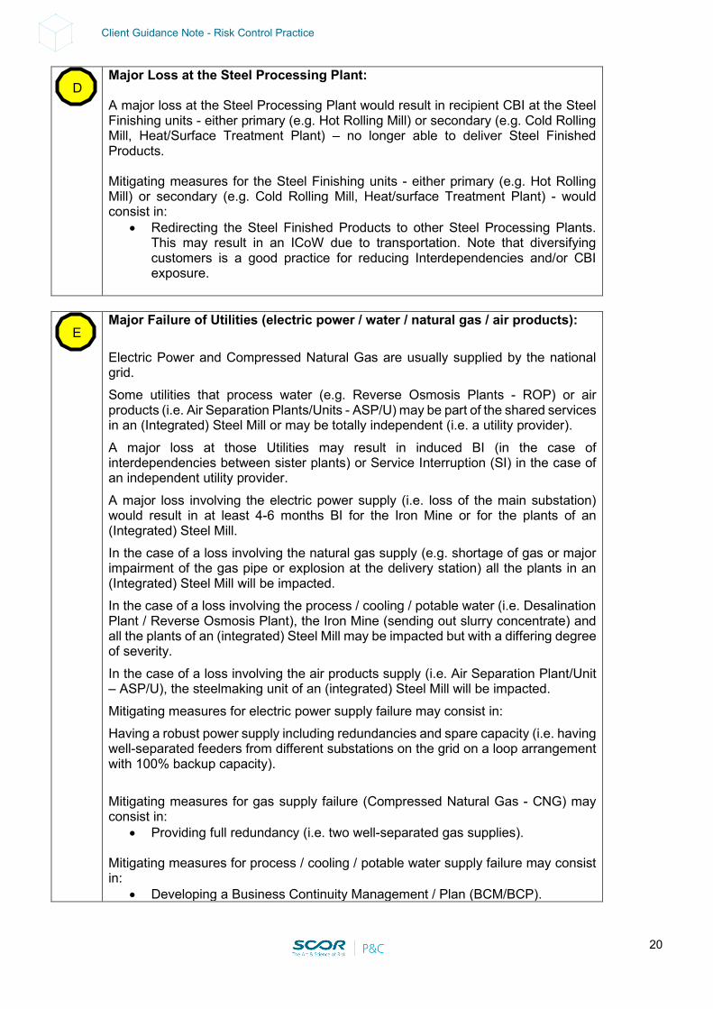
Major Loss at the Steel Processing Plant: A major loss at the Steel Processing Plant would result in recipient CBI at the Steel Finishing units - either primary (e.g. Hot Rolling Mill) or secondary (e.g. Cold Rolling Mill, Heat/Surface Treatment Plant) – no longer able to deliver Steel Finished Products. Mitigating measures for the Steel Finishing units - either primary (e.g. Hot Rolling Mill) or secondary (e.g. Cold Rolling Mill, Heat/surface Treatment Plant) - would consist in:
• Redirecting the Steel Finished Products to other Steel Processing Plants. This may result in an ICoW due to transportation. Note that diversifying customers is a good practice for reducing Interdependencies and/or CBI exposure.
Major Failure of Utilities (electric power / water / natural gas / air products):
Electric Power and Compressed Natural Gas are usually supplied by the national grid. Some utilities that process water (e.g. Reverse Osmosis Plants - ROP) or air products (i.e. Air Separation Plants/Units - ASP/U) may be part of the shared services in an (Integrated) Steel Mill or may be totally independent (i.e. a utility provider). A major loss at those Utilities may result in induced BI (in the case of interdependencies between sister plants) or Service Interruption (SI) in the case of an independent utility provider. A major loss involving the electric power supply (i.e. loss of the main substation) would result in at least 4-6 months BI for the Iron Mine or for the plants of an (Integrated) Steel Mill. In the case of a loss involving the natural gas supply (e.g. shortage of gas or major impairment of the gas pipe or explosion at the delivery station) all the plants in an (Integrated) Steel Mill will be impacted. In the case of a loss involving the process / cooling / potable water (i.e. Desalination Plant / Reverse Osmosis Plant), the Iron Mine (sending out slurry concentrate) and all the plants of an (integrated) Steel Mill may be impacted but with a differing degree of severity. In the case of a loss involving the air products supply (i.e. Air Separation Plant/Unit – ASP/U), the steelmaking unit of an (integrated) Steel Mill will be impacted. Mitigating measures for electric power supply failure may consist in:
Having a robust power supply including redundancies and spare capacity (i.e. having well-separated feeders from different substations on the grid on a loop arrangement with 100% backup capacity). Mitigating measures for gas supply failure (Compressed Natural Gas - CNG) may consist in:
• Providing full redundancy (i.e. two well-separated gas supplies). Mitigating measures for process / cooling / potable water supply failure may consist in:
• Developing a Business Continuity Management / Plan (BCM/BCP).
D
E
21
Client Guidance Note - Risk Control Practice
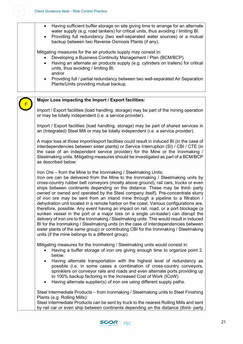
• Having sufficient buffer storage on site giving time to arrange for an alternate water supply (e.g. road tankers) for critical units, thus avoiding / limiting BI.
• Providing full redundancy (two well-separated water sources) or a mutual backup between two Reverse Osmosis Plants (if any).
Mitigating measures for the air products supply may consist in:
• Developing a Business Continuity Management / Plan (BCM/BCP). • Having an alternate air products supply (e.g. cylinders on trailers) for critical
units, thus avoiding / limiting BI. and/or
• Providing full / partial redundancy between two well-separated Air Separation Plants/Units providing mutual backup.
Major Loss impacting the Import / Export facilities:
Import / Export facilities (load handling, storage) may be part of the mining operation or may be totally independent (i.e. a service provider). Import / Export facilities (load handling, storage) may be part of shared services in an (Integrated) Steel Mill or may be totally independent (i.e. a service provider). A major loss at those import/export facilities could result in induced BI (in the case of interdependencies between sister plants) or Service Interruption (SI) / CBI / CTE (in the case of an independent service provider) for the Mine or the Ironmaking / Steelmaking units. Mitigating measures should be investigated as part of a BCM/BCP as described below: Iron Ore – from the Mine to the Ironmaking / Steelmaking Units:
Iron ore can be delivered from the Mine to the Ironmaking / Steelmaking units by cross-country rubber belt conveyors (mostly above ground), rail cars, trucks or even ships between continents depending on the distance. These may be third- party owned or owned and operated by the Steel company itself). Pre-concentrate slurry of iron ore may be sent from an inland mine through a pipeline to a filtration / dehydration unit located in a remote harbor on the coast. Various configurations are, therefore, possible. Any event having an impact on rail, road, or a port blockage (a sunken vessel in the port or a major loss on a single un-loader) can disrupt the delivery of iron ore to the Ironmaking / Steelmaking units. This would result in induced BI for the Ironmaking / Steelmaking units (in the case of interdependencies between sister plants of the same group) or contributing CBI for the Ironmaking / Steelmaking units (if the mine belongs to a different group).
Mitigating measures for the Ironmaking / Steelmaking units would consist in: • Having a buffer storage of iron ore giving enough time to organize point 2.
below. • Having alternate transportation with the highest level of redundancy as
possible (i.e. in some cases a combination of cross-country conveyors, sprinklers on conveyor rails and roads and even alternate ports providing up to 100% backup factoring in the Increased Cost of Work (ICoW).
• Having alternate supplier(s) of iron ore using different supply paths. Steel Intermediate Products – from Ironmaking / Steelmaking units to Steel Finishing Plants (e.g. Rolling Mills):
Steel Intermediate Products can be sent by truck to the nearest Rolling Mills and sent by rail car or even ship between continents depending on the distance (third- party
F

22
Client Guidance Note - Risk Control Practice
owned or owned and operated by the Steel company itself). Any event having an impact on rail, road, or a port blockage (a sunken vessel in the port) could disrupt the delivery of Steel Intermediate Products. This would result in induced BI for the Ironmaking / Steelmaking units and Steel Finishing units (in the case of interdependencies between sister plants of the same group) or contributing CBI for the Steel Finishing units and recipient CBI for the Ironmaking / Steelmaking units (the Steel Finishing units belonging to a different group).
Mitigating measures for the Steel Finishing units would consist in: • Having a buffer storage of Steel Intermediate Products giving enough time to
organize the point below. • Having alternate transportation with the highest level of redundancy as
possible (i.e. rail and road and even an alternate port / un-loader providing up to 100% backup factoring in the Increased Cost of Work (ICoW).
• Having alternate Suppliers for Steel Intermediate Products using different supply paths.
Steel Finished Products from Steel Finishing (e.g. Rolling Mills) to Steel Processing Plants:
Steel Finished Products produced at Steel Finishing units can be delivered to Steel Processing Plants by rail car, truck or even ship between continents depending on distance (third-party owned or owned and operated by the Steel company). Any event having an impact on rail, road, or a port blockage (a sunken vessel in the port) can disrupt the delivery of Steel Finished Products to the Steel Processing Plants. This would result in induced BI for the Steel Processing Plants, (Integrated) Steel Mill and Iron mine (in case of interdependencies between sister plants of the same group) or contributing CBI for the Steel Processing Plants and recipient CBI for (Integrated) Steel Mill and Iron mine (the Integrated Steel Mill and the mine belonging to a different group).
Mitigating measures for the Steel Processing Plants would consist in: • Having buffer storage for Steel Finished Products giving enough time to
organize point 2. Below. • Having alternate transportation with the highest level of redundancy as
possible providing up to 100% back up factoring in the Increased Cost of Work (ICoW).
• Having alternate Suppliers of Steel Finished Products using different supply paths.
Supplies of other Raw Materials for the Ironmaking / Steelmaking Plants may include:
• Coke, lime, other minerals and additives • Steel scraps
Any event having an impact on rail, road, or a port blockage (a sunken vessel in the
port or a major loss on a single un-loader) can disrupt the delivery of the above Raw Materials to the dedicated processing plant. This would result in induced BI for these plants and between these plants (in case of interdependencies between sister plants of the same group) or contributing CBI (the processing plants and the export / import facilities belonging to a different group).
Mitigating measures for the Steel Processing Plants would consist in: • Having a buffer storage of Raw Materials giving enough time to organize the
point below.

23
Client Guidance Note - Risk Control Practice
• Having alternate transportation with the highest level of redundancy as possible providing up to 100% back up factoring in the Increased Cost of Work (ICoW).
• Having alternate Suppliers of Raw Materials using different supply paths.
24
Client Guidance Note - Risk Control Practice
III - LOSS ESTIMATE CONSIDERATIONS
1. SCOR LOSS ESTIMATES
In terms of loss estimates at SCOR only MPL and NLE are considered, as detailed below. There is no leeway for using any other acronym or definition (i.e. MFL, EML, PML, etc.).
1.1. Maximum Possible Loss (MPL)
The MPL – Maximum Possible Loss – is the estimate in monetary terms of the largest loss which can be expected as a consequence of an insured event. It corresponds to the worst-case scenario after due consideration of all possible events or combination of events, in particular:
• Fire: all fire protection systems are inoperable, manual fire-fighting efforts are ineffective and fire can only be stopped by an impassable obstacle or by the lack of continuity of combustible materials (See MPL Handbook for details for minimum separating distances and MPL fire wall definition)
• All Other Losses: all possible scenarios must be considered in addition to fire and explosion, in
particular, natural perils (earthquakes, storms, floods), civil commotion and man-made catastrophes.
For the explosion scenario in petrochemical-related industries, the in-house Extool (former Explan) software program is used to determine the damage following a Vapor Cloud Explosion. The MPL calculation includes PD, BI and interdependencies between sister plants where relevant. Neighboring exposure and CBI should be notified in the scenario where relevant. However, they should not be considered for the MPL calculation. (See SCOR GAL; Group Accumulation Liability).
1.2. Normal Loss Expectancy (NLE)
NLE is the consequence of an accident which occurs when all the loss-limiting systems provided to minimize the consequences of that accident function to achieve the results intended. An assessment should be based on a single fire event unless another greater relevant exposure exists.
25
Client Guidance Note - Risk Control Practice
IV - MITIGATING MEASURES – CP, BCP/M
1. TERMINOLOGY & DEFINITION
There is usually much confusion concerning terminology used when referring to the Contingency Plan, Business Continuity Plan or Management / Disaster Recovery Plan. Giving one standard definition would be very difficult as almost all industrial sectors have their own. The two most common definitions are given below for information:
• Contingency Plan (CP): The purpose of a CP is to mitigate the consequences of a potential loss in terms of Business Interruption in the case of a loss of a critical utility or piece of machinery / equipment or sub-process unit. This contingency plan should be established taking all the critical facilities into consideration, such as process machinery & equipment, electrical rooms, transformers, and lubrication oil groups. This is particularly suitable for self-sufficient sites located in remote locations.
- All critical facilities, machinery and equipment should be identified. The availability of all critical spare parts should be defined. Critical spares with a relatively
long lead time should be available on site. Machinery and equipment representing severe bottlenecks should be duplicated and
stored or installed in separate fire areas. In the case where duplication and/or separation are impossible, adequate protection
should be installed. • Business Continuity Plan (BCP): The BCP goes beyond the usual contingency or recovery
plans. An organized BCP requires a continuous risk review, top-down or bottom-up, with the full support and commitment of top management as resources have to be assigned, aligned or re-aligned, such as the case may be. Business Interruption could be related to an earthquake, a severe storm, a fire, power outage over a wide area or the complete inaccessibility of a facility for an extended period of time. It should be clear that the cause of the interruption is not important. What is most important is Management’s ability to take control of the interruption. This is particularly suitable for sites with multiple interdependencies between sister plants and/or highly dependent on suppliers / customers.
- Within a BCP, the above existing Contingency Plan should be extended to a scenario-based major disaster, such as the total loss of one processing unit or an event impacting several plants in a relatively wide area (e.g. earthquake, hurricane).
- The possibility of the partial recovery of the activity, inside and outside the group, should be investigated.
- The potential interdependencies with sister plants, upstream and downstream, should be seriously considered.
Note: • Business Continuity Management – BCM – is also used instead of CP and or BCP. • Disaster Recovery Plans were originally only used for IT systems but are widely used now.
At the end of the day, the main purpose of these mitigating measures is to ensure Management’s ability to take control of the interruption. In order to prevent any confusion in this document, a BCP is used at the level of a group when one single event can impact different plants/entities (holistic view). The term CP is used at the level of a given plant/entity (site view).
26
Client Guidance Note - Risk Control Practice
2. RELIABILITY ISSUES
In actual fact, it is difficult, or virtually impossible, to make a CP, BCM/P fool proof or fail safe meeting all the following criteria considering that conditions may change over time (i.e. management, organization, priorities, etc.):
• Consider all possible scenarios • Avoid over-estimated back-up (CP) and/or resilience (BCP) capabilities • Implement formalized documentation • Organize regular testing • Review, update, upgrade documents when needed • Ensure leadership (who is responsible for what & when?)
As a result of the above, CPs, BCP/Ms are:
• Often designed as an a- posteriori disaster Supply Kit (though not everything can be done “by the book”)
• Not always expecting the unexpected • Not always ensuring companies can easily adjust to major shifts in markets or operating conditions
3. WHEN TO CONSIDER A CP, BCP/M
Contingency Plans, Business Continuity Management / Plans are not considered when dealing with worst-case scenarios (Maximum Possible Loss -MPL) for two main reasons:
• Philosophy: looking for the worst case including very adverse conditions (conservative approach) • Lack of reliability (see above)
Depending on the level of confidence in the CP, BCM/P it can be considered to some extent (use risk engineering judgment) for other loss scenarios (e.g. PML, NLE). Regarding Contingency Plans (CP) as per the definition given above (i.e. loss of a critical utility, machinery, sub-process unit), a CP can be considered for loss estimate considerations including the Worst Case (i.e. Maximum Possible Loss -MPL) when it is about duplication and to some extent about redundancy and spare capacity, as detailed below.
• Duplication: two subunits are duplicated so that in case of a loss of one unit there will not be any critical disruption in the process. This could consist of:
- Two operating subunits (so-called hot sites in IT), such as two PLC servers or two independent substations feeding the site on a loop.
- Two subunits, one on duty and one on standby (so-called cold sites in IT), with the standby unit taking over in case of failure of the usual unit on duty. This could take some time should a manual transfer and/or synchronization be needed (e.g. for power generating units reaching full load or national grid connections using Automatic Transfer Switches - ATS).
- Note that for reliability, when possible, the duplicated units should be well separated and segregated at least from a fire and explosion standpoint but also from a natural perils and exposure standpoint (e.g. flood). Any potential single failure point upstream or downstream from the duplicated units should be clearly identified and eliminated.

27
Client Guidance Note - Risk Control Practice
• Redundancy: the way to express the redundancy level has evolved over recent years as follows: - Up to a recent past: N+1 meant that N units on duty were able to run normal operations and that
there was one more unit available. - Today: N-1 is used instead of N+1. This means that even with one unit out of order the
operations still run normally. - The above N+1 and N-1 (e.g. transformers) means the same: there is one more unit on line
available that could take over in case of failure of the unit on duty. - Note that the main purpose of N+1 / N-1 redundancy is for maintenance: one unit can be taken
offline for maintenance and replaced by the N+1 unit. - Note that maintenance may necessitate a major overhaul or refurbishment of one unit. In some
cases, this could take several months as it could include dismantling and shipping overseas (e.g. a major overhaul of Steam Turbine rotors, transformers).
- Based on the above, in the case of a loss of one operating unit while the other unit is offline for maintenance, the related process unit may have to reduce production or even shut down.
- As a result, any reliable redundancy should include N+2 /N-2 units: one standby unit allowing for maintenance and one more unit providing full back up for any one unit.
- Note that for reliability, when possible, all units should be well separated and segregated at least from a fire and explosion standpoint (e.g. transformers separated by blast walls) and from a natural perils and exposure standpoint (e.g. flood).
• Spare capacity: some units may have spare capacity (e.g. an Air Separation Plant). This spare capacity may be considered for the Loss Estimate scenarios as follows:
- Two units with spare capacity and physically connected to each other so that one unit could partially or fully provide (depending on the spare capacity level) in reasonable time without generating a major disruption. This could be considered for the NLE and even the MPL when well documented.
- Note that for reliability, when possible, all units should be well separated and segregated at least from a fire and explosion standpoint (e.g. a minimum separating distance between Air Separation Plants avoiding mutual exposure in case of fire / explosion) and from a natural perils and exposure standpoint (e.g. flood). Any potential single failure point upstream or downstream from the duplicated units should be clearly identified and eliminated.
28
Client Guidance Note - Risk Control Practice
V - IRON ORE MINING & PROCESSING
1. PROCESS
1.1. Mining
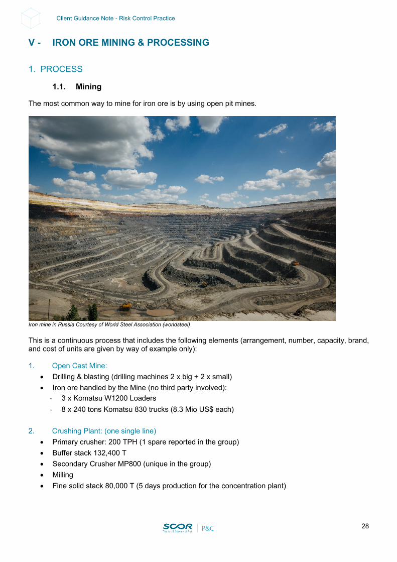
The most common way to mine for iron ore is by using open pit mines.
Iron mine in Russia Courtesy of World Steel Association (worldsteel) This is a continuous process that includes the following elements (arrangement, number, capacity, brand, and cost of units are given by way of example only): 1. Open Cast Mine:
• Drilling & blasting (drilling machines 2 x big + 2 x small) • Iron ore handled by the Mine (no third party involved):
- 3 x Komatsu W1200 Loaders - 8 x 240 tons Komatsu 830 trucks (8.3 Mio US$ each)
2. Crushing Plant: (one single line)
• Primary crusher: 200 TPH (1 spare reported in the group) • Buffer stack 132,400 T • Secondary Crusher MP800 (unique in the group) • Milling • Fine solid stack 80,000 T (5 days production for the concentration plant)
29
Client Guidance Note - Risk Control Practice
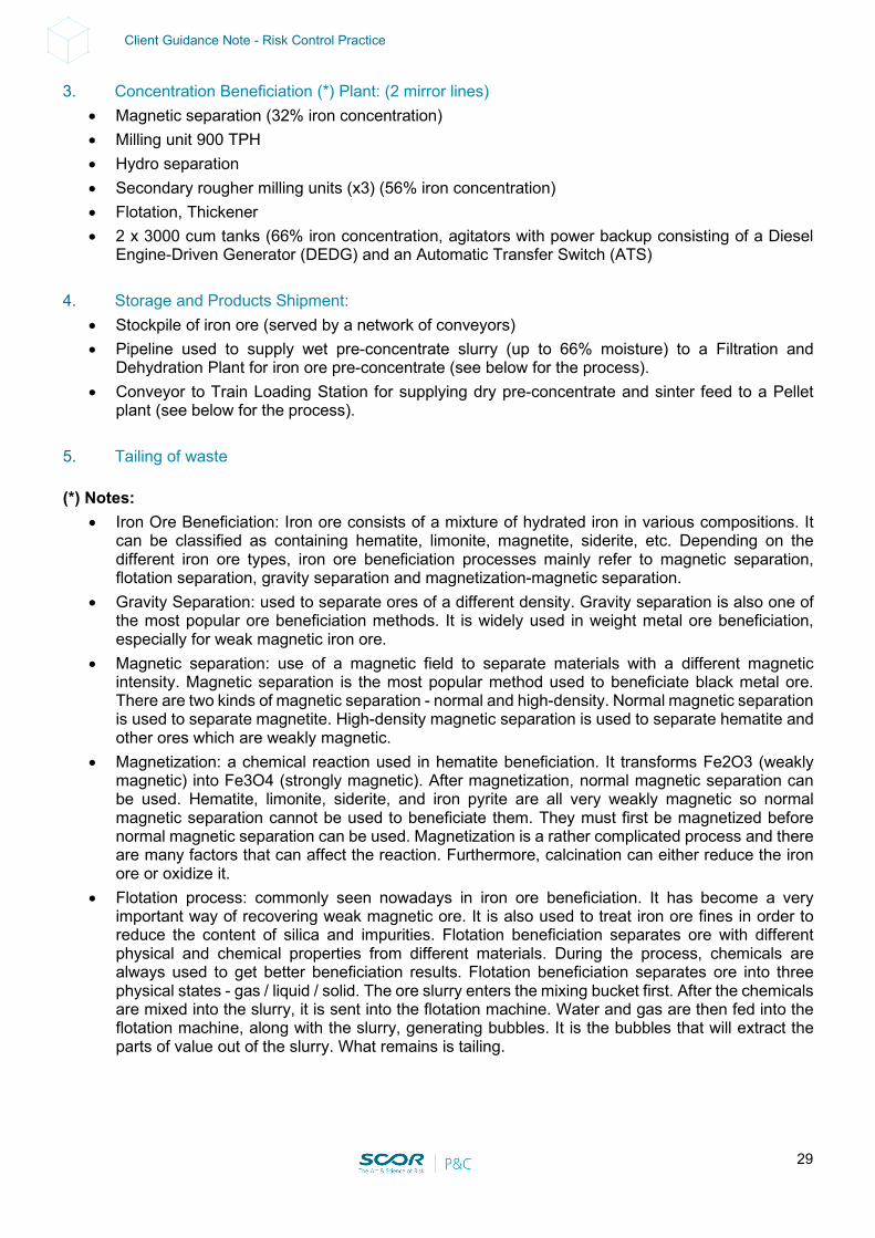
3. Concentration Beneficiation (*) Plant: (2 mirror lines) • Magnetic separation (32% iron concentration) • Milling unit 900 TPH • Hydro separation • Secondary rougher milling units (x3) (56% iron concentration) • Flotation, Thickener • 2 x 3000 cum tanks (66% iron concentration, agitators with power backup consisting of a Diesel
Engine-Driven Generator (DEDG) and an Automatic Transfer Switch (ATS) 4. Storage and Products Shipment:
• Stockpile of iron ore (served by a network of conveyors) • Pipeline used to supply wet pre-concentrate slurry (up to 66% moisture) to a Filtration and
Dehydration Plant for iron ore pre-concentrate (see below for the process). • Conveyor to Train Loading Station for supplying dry pre-concentrate and sinter feed to a Pellet
plant (see below for the process).
5. Tailing of waste (*) Notes:
• Iron Ore Beneficiation: Iron ore consists of a mixture of hydrated iron in various compositions. It can be classified as containing hematite, limonite, magnetite, siderite, etc. Depending on the different iron ore types, iron ore beneficiation processes mainly refer to magnetic separation, flotation separation, gravity separation and magnetization-magnetic separation.
• Gravity Separation: used to separate ores of a different density. Gravity separation is also one of the most popular ore beneficiation methods. It is widely used in weight metal ore beneficiation, especially for weak magnetic iron ore.
• Magnetic separation: use of a magnetic field to separate materials with a different magnetic intensity. Magnetic separation is the most popular method used to beneficiate black metal ore. There are two kinds of magnetic separation - normal and high-density. Normal magnetic separation is used to separate magnetite. High-density magnetic separation is used to separate hematite and other ores which are weakly magnetic.
• Magnetization: a chemical reaction used in hematite beneficiation. It transforms Fe2O3 (weakly magnetic) into Fe3O4 (strongly magnetic). After magnetization, normal magnetic separation can be used. Hematite, limonite, siderite, and iron pyrite are all very weakly magnetic so normal magnetic separation cannot be used to beneficiate them. They must first be magnetized before normal magnetic separation can be used. Magnetization is a rather complicated process and there are many factors that can affect the reaction. Furthermore, calcination can either reduce the iron ore or oxidize it.
• Flotation process: commonly seen nowadays in iron ore beneficiation. It has become a very important way of recovering weak magnetic ore. It is also used to treat iron ore fines in order to reduce the content of silica and impurities. Flotation beneficiation separates ore with different physical and chemical properties from different materials. During the process, chemicals are always used to get better beneficiation results. Flotation beneficiation separates ore into three physical states - gas / liquid / solid. The ore slurry enters the mixing bucket first. After the chemicals are mixed into the slurry, it is sent into the flotation machine. Water and gas are then fed into the flotation machine, along with the slurry, generating bubbles. It is the bubbles that will extract the parts of value out of the slurry. What remains is tailing.
30
Client Guidance Note - Risk Control Practice
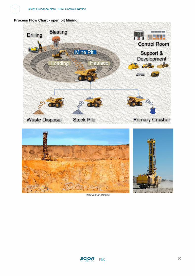
Process Flow Chart - open pit Mining:
Drilling prior blasting
31
Client Guidance Note - Risk Control Practice
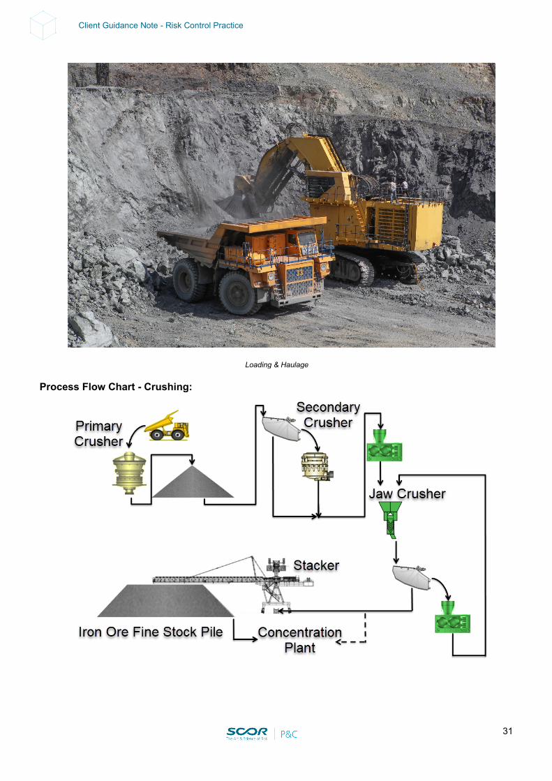
Loading & Haulage
Process Flow Chart - Crushing:
32
Client Guidance Note - Risk Control Practice
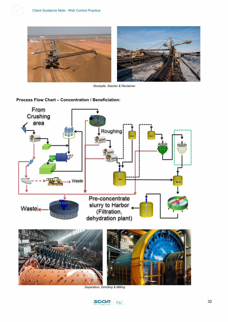
Stockpile, Stacker & Reclaimer Process Flow Chart – Concentration / Beneficiation:
Separation, Grinding & Milling
33
Client Guidance Note - Risk Control Practice
• A few underground iron ore mines are also in operation around the globe. One of the technics (used at Kiruna LKAB’s mine) is:
• Iron ore mining using sublevel caving, with sublevels spaced at 28.5 m vertically. With a burden of 3.0 - 3.5 m per ring, this yields around 8,500 t for each blast. Their subsidiary Kimit AB supplies the explosives and prepares the holes for blasting. The main haulage level at Kiruna lies at a depth of 1,045 m, with the mine’s ore-handling systems capable of handling 26 Mt/y of run-of-mine rock.
• Seven 500 t - capacity shuttle trains, controlled from the 775 m level, collect ore from ten groups of ore passes and deliver it to one of four crushing stations. 100 mm ore is then skip-hoisted in two stages to the 775 m level and then to the surface.
• Electric-powered, remote-controlled drilling and ore-handling equipment supplied by Atlas Copco and Tamrock is widely used.
• After blasting, load-haul dump machines (some of which are fully automated) carry the run-of-mine ore to the nearest ore pass, from which it is loaded automatically on to one of the trains operating on the 1,045 m level.
• After primary crushing, sampling using a Morgårdshammer automatic sampler to obtain the apatite and magnetite contents and hoisting to the surface, the ore is processed in Kiruna’s complex comprised of a sorting plant, two concentrators and two pellet plants producing pellet and sinter fine products.
• Some ore is moved by rail to LKAB’s Svappavaara plant for pelletization. Products are hauled by rail to the ports of Narvik (Norway) or Luleå for shipment.
• Iron ore - based products from iron mines are usually: • Pre-concentrate (wet / dry) • Sinter feed
1.2. Ore Processing
The above products are sent to the following units located at the mine or remotely on the coast near export facilities, or even in a steel mill. This may lead to the following arrangements including interdependencies and Service Interruption exposures: Filtration / Dehydration Plant:
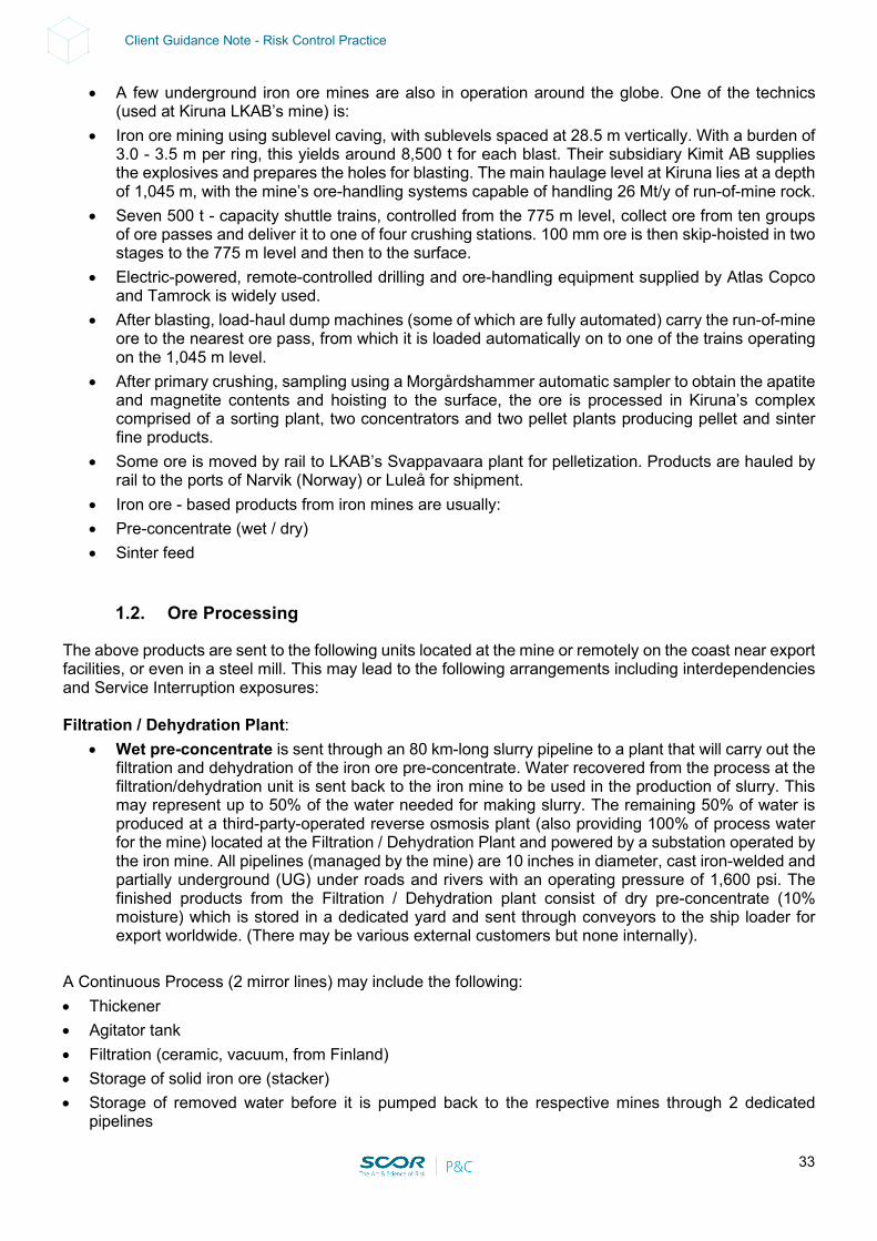
• Wet pre-concentrate is sent through an 80 km-long slurry pipeline to a plant that will carry out the filtration and dehydration of the iron ore pre-concentrate. Water recovered from the process at the filtration/dehydration unit is sent back to the iron mine to be used in the production of slurry. This may represent up to 50% of the water needed for making slurry. The remaining 50% of water is produced at a third-party-operated reverse osmosis plant (also providing 100% of process water for the mine) located at the Filtration / Dehydration Plant and powered by a substation operated by the iron mine. All pipelines (managed by the mine) are 10 inches in diameter, cast iron-welded and partially underground (UG) under roads and rivers with an operating pressure of 1,600 psi. The finished products from the Filtration / Dehydration plant consist of dry pre-concentrate (10% moisture) which is stored in a dedicated yard and sent through conveyors to the ship loader for export worldwide. (There may be various external customers but none internally).
A Continuous Process (2 mirror lines) may include the following: • Thickener • Agitator tank • Filtration (ceramic, vacuum, from Finland) • Storage of solid iron ore (stacker) • Storage of removed water before it is pumped back to the respective mines through 2 dedicated
pipelines
34
Client Guidance Note - Risk Control Practice
Process Flow Chart – Filtration / Dehydration (global view):
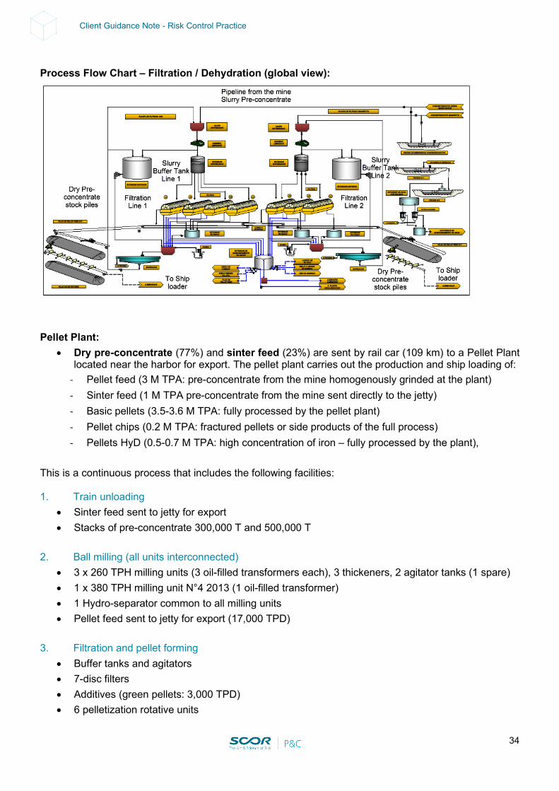
Pellet Plant:
• Dry pre-concentrate (77%) and sinter feed (23%) are sent by rail car (109 km) to a Pellet Plant located near the harbor for export. The pellet plant carries out the production and ship loading of:
- Pellet feed (3 M TPA: pre-concentrate from the mine homogenously grinded at the plant) - Sinter feed (1 M TPA pre-concentrate from the mine sent directly to the jetty) - Basic pellets (3.5-3.6 M TPA: fully processed by the pellet plant) - Pellet chips (0.2 M TPA: fractured pellets or side products of the full process) - Pellets HyD (0.5-0.7 M TPA: high concentration of iron – fully processed by the plant),
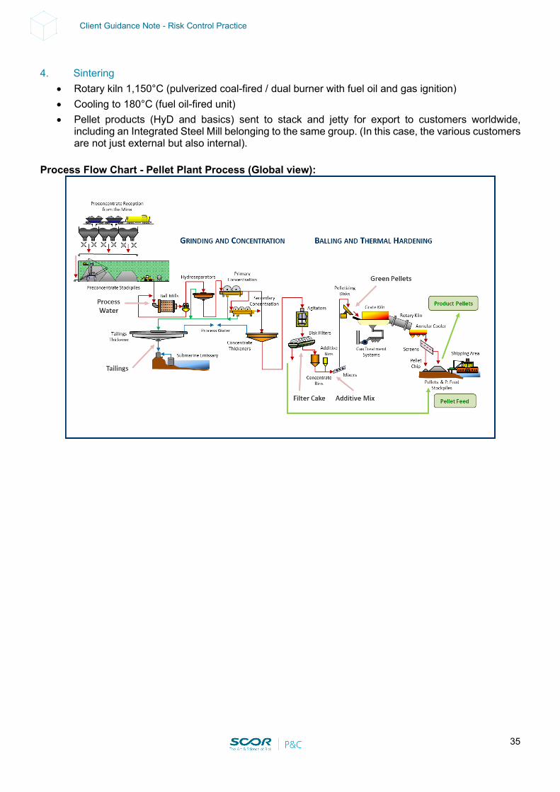
This is a continuous process that includes the following facilities: 1. Train unloading
• Sinter feed sent to jetty for export • Stacks of pre-concentrate 300,000 T and 500,000 T
2. Ball milling (all units interconnected)
• 3 x 260 TPH milling units (3 oil-filled transformers each), 3 thickeners, 2 agitator tanks (1 spare) • 1 x 380 TPH milling unit N°4 2013 (1 oil-filled transformer) • 1 Hydro-separator common to all milling units • Pellet feed sent to jetty for export (17,000 TPD)
3. Filtration and pellet forming
• Buffer tanks and agitators • 7-disc filters • Additives (green pellets: 3,000 TPD) • 6 pelletization rotative units
35
Client Guidance Note - Risk Control Practice
4. Sintering
• Rotary kiln 1,150°C (pulverized coal-fired / dual burner with fuel oil and gas ignition) • Cooling to 180°C (fuel oil-fired unit) • Pellet products (HyD and basics) sent to stack and jetty for export to customers worldwide,
including an Integrated Steel Mill belonging to the same group. (In this case, the various customers are not just external but also internal).
Process Flow Chart - Pellet Plant Process (Global view):
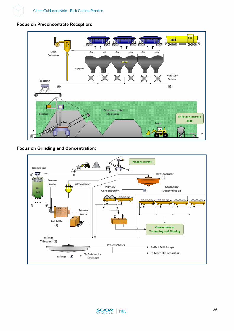
36
Client Guidance Note - Risk Control Practice
Focus on Preconcentrate Reception:
Focus on Grinding and Concentration:
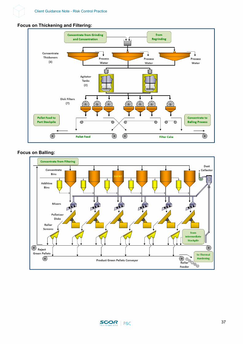
37
Client Guidance Note - Risk Control Practice
Focus on Thickening and Filtering:
Focus on Balling:
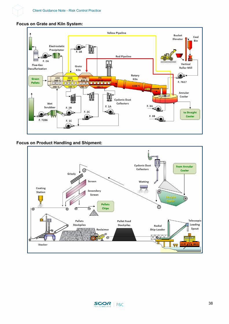
38
Client Guidance Note - Risk Control Practice
Focus on Grate and Kiln System:
Focus on Product Handling and Shipment:
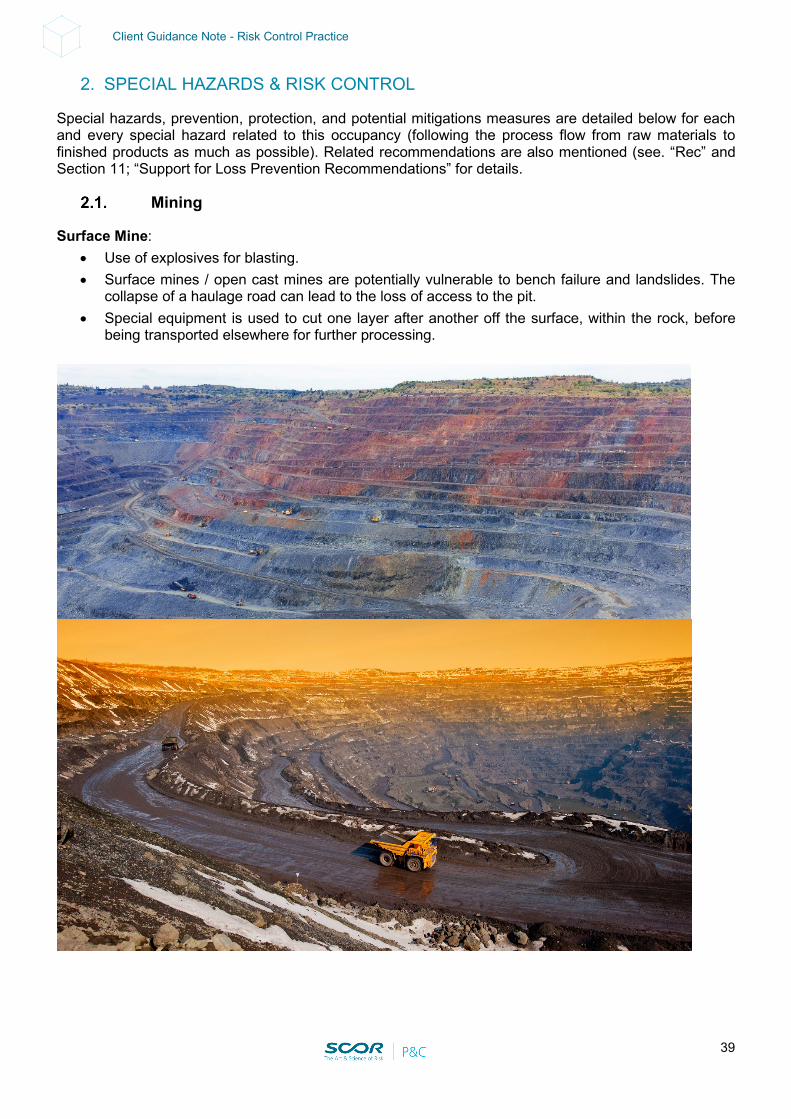
39
Client Guidance Note - Risk Control Practice
2. SPECIAL HAZARDS & RISK CONTROL
Special hazards, prevention, protection, and potential mitigations measures are detailed below for each and every special hazard related to this occupancy (following the process flow from raw materials to finished products as much as possible). Related recommendations are also mentioned (see. “Rec” and Section 11; “Support for Loss Prevention Recommendations” for details.
Mining
Surface Mine: • Use of explosives for blasting. • Surface mines / open cast mines are potentially vulnerable to bench failure and landslides. The
collapse of a haulage road can lead to the loss of access to the pit. • Special equipment is used to cut one layer after another off the surface, within the rock, before
being transported elsewhere for further processing.
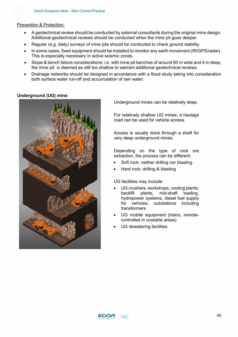
40
Client Guidance Note - Risk Control Practice
Prevention & Protection:
• A geotechnical review should be conducted by external consultants during the original mine design. Additional geotechnical reviews should be conducted when the mine pit goes deeper.
• Regular (e.g. daily) surveys of mine pits should be conducted to check ground stability. • In some cases, fixed equipment should be installed to monitor any earth movement (IR/GPS/radar).
This is especially necessary in active seismic zones. • Slope & bench failure considerations: i.e. with mine pit benches of around 50 m wide and 4 m deep,
the mine pit is deemed as still too shallow to warrant additional geotechnical reviews. • Drainage networks should be designed in accordance with a flood study taking into consideration
both surface water run-off and accumulation of rain water. Underground (UG) mine:
Underground mines can be relatively deep.
For relatively shallow UG mines, a haulage road can be used for vehicle access.
Access is usually done through a shaft for very deep underground mines.
Depending on the type of rock ore extraction, the process can be different: • Soft rock: neither drilling nor blasting • Hard rock: drilling & blasting UG facilities may include: • UG crushers, workshops, cooling plants,
backfill plants, mid-shaft loading, hydropower systems, diesel fuel supply for vehicles, substations including transformers
• UG mobile equipment (trains, remote-controlled in unstable areas)
• UG dewatering facilities
41
Client Guidance Note - Risk Control Practice
Prevention & Protection: Courtesy of a South African former mining contractor: The following points are critical:
• Good hoist conditions, maintenance • At least two shafts: 1 vent shaft / man and 1 material shaft (better than 1 single rock hoist mine in
case of shaft collapse) • Monitoring of noxious / toxic gases (if any) • Monitoring of water / mud in rush due to breach of aquifer, trapped water pocket • Adequate support methods (if any) and monitoring (collapse potential) • Backfill method (if any) • Prevention of rock burst (if any) • Fixed fire protection of fuel supply, electrics (prefer dry-type transformers)
Drilling and Blasting
• Blasting is usually done several times a week using Ammonium Nitrate Fuel Oil (ANFO) emulsion and electronic detonators. The ANFO explosives are usually supplied by a third company (several ton deliveries) by road and under police escort to be stored on site.
Prevention & Protection:
• The storage compound should be located sufficiently far away from the mine. Usual adequate measures for mitigating the possibility of an explosion blast destroying all storage consists of having at least two explosive magazines and one storeroom for detonators arranged in a triangle formation with at least 150 m between stores. A security sytem is key and should include access control and perimeter supervision.
• In some cases, the local police is present for all detonations and they control all access to the explosives storage compound. Blasts are controlled by a blast work order report.
• Having backup for drill rigs is good practice (e.g. two drill rigs for blasting, with only one normally required for blasting operations).
Mobile Mining Equipment and Related Facilities
• A fleet of mobile plant equipment can be: - owned and operated by the mining company - owned by the mine and operated by a third party - owned and operated by a third party - a mix of the above
• Mining equipment usually includes: - Excavator - Front Loader - 3 x Hydraulic excavators - 31 x 240 t trucks (5 Komatsu and 27 Caterpillar. (8.3 M US$ each). Max of 20-22 in use at the
same time and about 10 parked on the mine platform) - 5 Bulldozers
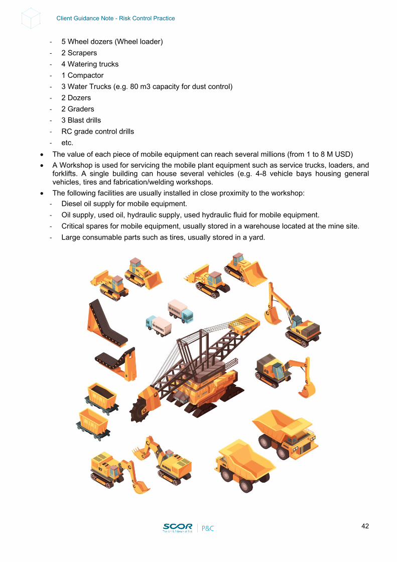
42
Client Guidance Note - Risk Control Practice
- 5 Wheel dozers (Wheel loader) - 2 Scrapers - 4 Watering trucks - 1 Compactor - 3 Water Trucks (e.g. 80 m3 capacity for dust control) - 2 Dozers - 2 Graders - 3 Blast drills - RC grade control drills - etc.
• The value of each piece of mobile equipment can reach several millions (from 1 to 8 M USD) • A Workshop is used for servicing the mobile plant equipment such as service trucks, loaders, and
forklifts. A single building can house several vehicles (e.g. 4-8 vehicle bays housing general vehicles, tires and fabrication/welding workshops.
• The following facilities are usually installed in close proximity to the workshop: - Diesel oil supply for mobile equipment. - Oil supply, used oil, hydraulic supply, used hydraulic fluid for mobile equipment. - Critical spares for mobile equipment, usually stored in a warehouse located at the mine site. - Large consumable parts such as tires, usually stored in a yard.
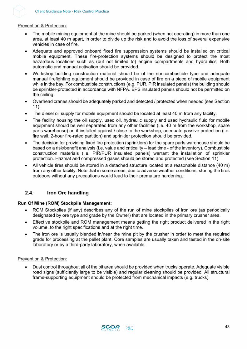
43
Client Guidance Note - Risk Control Practice
Prevention & Protection:
• The mobile mining equipment at the mine should be parked (when not operating) in more than one area, at least 40 m apart, in order to divide up the risk and to avoid the loss of several expensive vehicles in case of fire.
• Adequate and approved onboard fixed fire suppression systems should be installed on critical mobile equipment. These fire-protection systems should be designed to protect the most hazardous locations such as (but not limited to) engine compartments and hydraulics. Both automatic and manual activation should be provided.
• Workshop building construction material should be of the noncombustible type and adequate manual firefighting equipment should be provided in case of fire on a piece of mobile equipment while in the bay. For combustible constructions (e.g. PUR, PIR insulated panels) the building should be sprinkler-protected in accordance with NFPA. EPS insulated panels should not be permitted on the ceiling.
• Overhead cranes should be adequately parked and detected / protected when needed (see Section 11).
• The diesel oil supply for mobile equipment should be located at least 40 m from any facility. • The facility housing the oil supply, used oil, hydraulic supply and used hydraulic fluid for mobile
equipment should be well separated from any other facilities (i.e. 40 m from the workshop, spare parts warehouse) or, if installed against / close to the workshop, adequate passive protection (i.e. fire wall, 2-hour fire-rated partition) and sprinkler protection should be provided.
• The decision for providing fixed fire protection (sprinklers) for the spare parts warehouse should be based on a risk/benefit analysis (i.e. value and criticality – lead time - of the inventory). Combustible construction materials (i.e. PIR/PUR insulated panels) warrant the installation of sprinkler protection. Hazmat and compressed gases should be stored and protected (see Section 11).
• All vehicle tires should be stored in a detached structure located at a reasonable distance (40 m) from any other facility. Note that in some areas, due to adverse weather conditions, storing the tires outdoors without any precautions would lead to their premature hardening.
Iron Ore handling
Run Of Mine (ROM) Stockpile Management: • ROM Stockpiles (if any) describes any of the run of mine stockpiles of iron ore (as periodically
designated by ore type and grade by the Owner) that are located in the primary crusher area. • Effective stockpile and ROM management means getting the right product delivered in the right
volume, to the right specifications and at the right time. • The iron ore is usually blended in/near the mine pit by the crusher in order to meet the required
grade for processing at the pellet plant. Core samples are usually taken and tested in the on-site laboratory or by a third-party laboratory, when available.
Prevention & Protection:
• Dust control throughout all of the pit area should be provided when trucks operate. Adequate visible road signs (sufficiently large to be visible) and regular cleaning should be provided. All structural frame-supporting equipment should be protected from mechanical impacts (e.g. trucks).
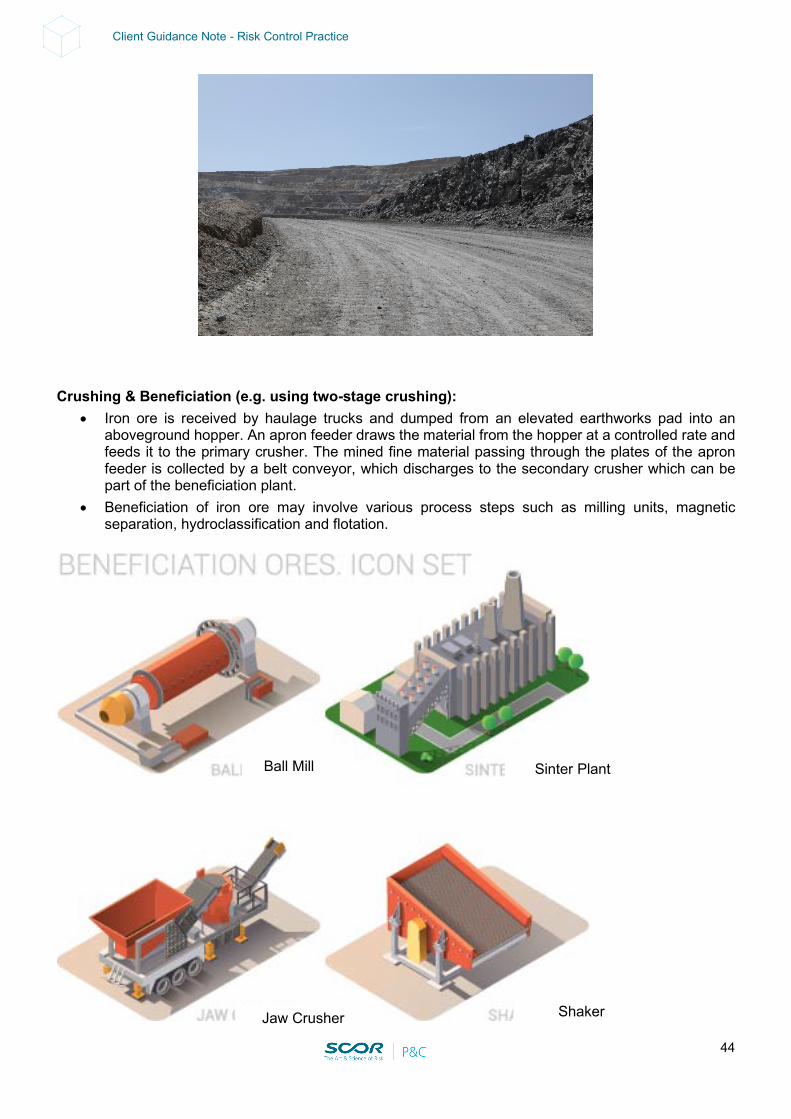
44
Client Guidance Note - Risk Control Practice
Crushing & Beneficiation (e.g. using two-stage crushing):
• Iron ore is received by haulage trucks and dumped from an elevated earthworks pad into an aboveground hopper. An apron feeder draws the material from the hopper at a controlled rate and feeds it to the primary crusher. The mined fine material passing through the plates of the apron feeder is collected by a belt conveyor, which discharges to the secondary crusher which can be part of the beneficiation plant.
• Beneficiation of iron ore may involve various process steps such as milling units, magnetic separation, hydroclassification and flotation.
Ball Mill Sinter Plant
Jaw Crusher Shaker
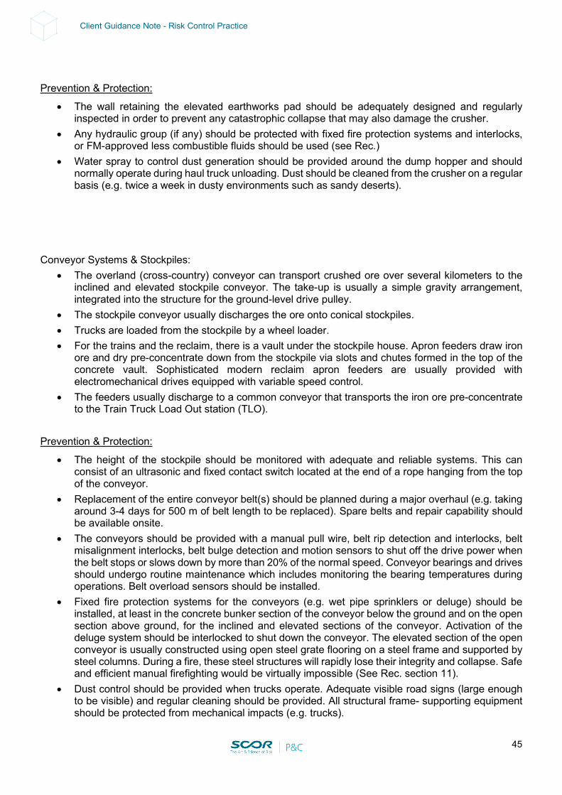
45
Client Guidance Note - Risk Control Practice
Prevention & Protection:
• The wall retaining the elevated earthworks pad should be adequately designed and regularly inspected in order to prevent any catastrophic collapse that may also damage the crusher.
• Any hydraulic group (if any) should be protected with fixed fire protection systems and interlocks, or FM-approved less combustible fluids should be used (see Rec.)
• Water spray to control dust generation should be provided around the dump hopper and should normally operate during haul truck unloading. Dust should be cleaned from the crusher on a regular basis (e.g. twice a week in dusty environments such as sandy deserts).
Conveyor Systems & Stockpiles:
• The overland (cross-country) conveyor can transport crushed ore over several kilometers to the inclined and elevated stockpile conveyor. The take-up is usually a simple gravity arrangement, integrated into the structure for the ground-level drive pulley.
• The stockpile conveyor usually discharges the ore onto conical stockpiles. • Trucks are loaded from the stockpile by a wheel loader. • For the trains and the reclaim, there is a vault under the stockpile house. Apron feeders draw iron
ore and dry pre-concentrate down from the stockpile via slots and chutes formed in the top of the concrete vault. Sophisticated modern reclaim apron feeders are usually provided with electromechanical drives equipped with variable speed control.
• The feeders usually discharge to a common conveyor that transports the iron ore pre-concentrate to the Train Truck Load Out station (TLO).
Prevention & Protection:
• The height of the stockpile should be monitored with adequate and reliable systems. This can consist of an ultrasonic and fixed contact switch located at the end of a rope hanging from the top of the conveyor.
• Replacement of the entire conveyor belt(s) should be planned during a major overhaul (e.g. taking around 3-4 days for 500 m of belt length to be replaced). Spare belts and repair capability should be available onsite.
• The conveyors should be provided with a manual pull wire, belt rip detection and interlocks, belt misalignment interlocks, belt bulge detection and motion sensors to shut off the drive power when the belt stops or slows down by more than 20% of the normal speed. Conveyor bearings and drives should undergo routine maintenance which includes monitoring the bearing temperatures during operations. Belt overload sensors should be installed.
• Fixed fire protection systems for the conveyors (e.g. wet pipe sprinklers or deluge) should be installed, at least in the concrete bunker section of the conveyor below the ground and on the open section above ground, for the inclined and elevated sections of the conveyor. Activation of the deluge system should be interlocked to shut down the conveyor. The elevated section of the open conveyor is usually constructed using open steel grate flooring on a steel frame and supported by steel columns. During a fire, these steel structures will rapidly lose their integrity and collapse. Safe and efficient manual firefighting would be virtually impossible (See Rec. section 11).
• Dust control should be provided when trucks operate. Adequate visible road signs (large enough to be visible) and regular cleaning should be provided. All structural frame- supporting equipment should be protected from mechanical impacts (e.g. trucks).
46
Client Guidance Note - Risk Control Practice
Train Load Out (TLO):
• Iron ore pre-concentrate is loaded onto train wagons at the Train Load Out station. The discharge from the bin is usually controlled by a volumetric feed system, which uses a load boot and flow control gates. The train travels through the station at a fixed speed, and wagon-sensing devices trigger the loading boot control gate. This floods the wagon and loads for a pre-determined time, before shutting off the flow until the next wagon is in position. The flow control gates are usually powered using a hydraulic oil system.
• Trains are either operated by the mining company or by a third party. Prevention & Protection:
• The hydraulic group powering the flow control gates should be adequately protected with a fixed fire-suppression system and interlocks should be provided, or FM-approved less combustible fluids should be used (See Rec.).
• The load in the train wagons should be measured and a safeguard should be provided for preventing overloading of the wagon. This could consist of:
- Load measured by load cells located under the rails. - An excavator arm and bucket mounted downstream of the load point to trim any overloaded
wagons. • Dust emissions should be controlled at the level of the TLO when the bin is filled (e.g. a bin vent
filter eliminating emissions of dust with displaced air when the bin is filled). • Dust control of roads should be provided when trucks operate. Adequate visible road signs (large
enough to be visible) and regular cleaning should be provided. All structural frame- supporting equipment should be protected from mechanical impacts (e.g., trucks).
Tailing
Overburden material: • All overburden mined out from the ore tops is usually dumped in in-pit dumps.
Prevention & Protection:
• A horizontal distance (around 50 m) should be maintained between the mining area and the backfill waste dump to help prevent any slippage impacting the mining operations.
Residues:
• A good option for ensuring safe tailing management is to opt for dried disposal rather than slurry disposal. Dry stacking is being applied in areas that have limited space and water resources, and in areas where topographic and geotechnical conditions contraindicate conventional impoundments.
• Although projects have demonstrated the technical feasibility of filtering iron ore tailings, it has not yet been implemented in all iron ore mines. Some of the reasons for this include the high cost of acquisition and operations, availability of water and topographical and geotechnical conditions favorable to dam installations.
• For slurry disposal, residue is usually stored in a tailings dam and can be up to 60% solid. • Once a residue disposal area has been filled up, the territory can be reclaimed by burying it in
sand, ash or dirt and planting certain types of trees and plants. While full reclamation can take years, in the end the territory will return to its original state.
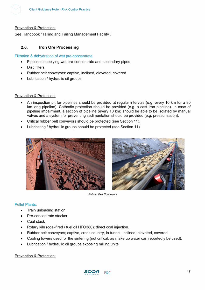
47
Client Guidance Note - Risk Control Practice
Prevention & Protection: See Handbook “Tailing and Failing Management Facility”.
Iron Ore Processing
Filtration & dehydration of wet pre-concentrate: • Pipelines supplying wet pre-concentrate and secondary pipes • Disc filters • Rubber belt conveyors: captive, inclined, elevated, covered • Lubrication / hydraulic oil groups
Prevention & Protection:
• An inspection pit for pipelines should be provided at regular intervals (e.g. every 10 km for a 80 km-long pipeline). Cathodic protection should be provided (e.g. a cast iron pipeline). In case of pipeline impairment, a section of pipeline (every 10 km) should be able to be isolated by manual valves and a system for preventing sedimentation should be provided (e.g. pressurization).
• Critical rubber belt conveyors should be protected (see Section 11). • Lubricating / hydraulic groups should be protected (see Section 11).
Rubber Belt Conveyors Pellet Plants:
• Train unloading station • Pre-concentrate stacker • Coal stack • Rotary kiln (coal-fired / fuel oil HFO380); direct coal injection. • Rubber belt conveyors; captive, cross country, in-tunnel, inclined, elevated, covered • Cooling towers used for the sintering (not critical, as make up water can reportedly be used). • Lubrication / hydraulic oil groups exposing milling units
Prevention & Protection:

48
Client Guidance Note - Risk Control Practice
• The stacks of coal should be divided into separate stacks at least 40 m apart without any continuity of combustible material in between. A contingent coal storage should be arranged in order to ensure the continuity of the coke plant operations in case of loss of the main storage.
• The rotary kiln should be equipped with adequate safety combustion control (see Section 11). • Critical rubber belt conveyors should be protected (see Section 11). • Cooling towers should be protected (see Section 11). • Lubricating / hydraulic groups should be protected (see Section 11).
49
Client Guidance Note - Risk Control Practice
Utilities
Electric Power • The mine can be fed from the national grid using, in most cases, a single overhead line connected
to the grid by a single substation. and/or
• The mine site might be too far away from any national grid-based power supply and therefore need to generate its own power supply. In such cases, a diesel Power Generation Plant located on site can provide power to the entire mine site. The power plant can contain skid- mounted, diesel-powered alternators (e.g. 5 x 2.2 MW / 2.75 MVA). Each alternator is usually supplied as a fully integrated skid package, with self-contained radiator cooling, governor, fuel pump, starter motor, associated auxiliaries, ducted air system to minimize the building heat load, and a 24-hour supply diesel fuel day tank located outside.
• Note that the power supply for the mine can also be used to supply the nearest village (community support), mine village (employees) and bore field (providing water).
• Each unit of the Power Generation Plant and/or the national grid feeder connects to a common busbar, with HV feeders providing the power supply to all substations on the mine site. Each and every substation consists of an outdoor/indoor transformer, switch gear / MCC cabinet room and a cable cellar, such as in this example:
- Substation 1 (Stockpile Feed) with 2 x 2.5 MVA 4.16/0.48 kV transformers. - Substation 2 (Crusher) with 2 x 2.5 MVA 4.16/0.48 kV transformers. - Substation 3 (Product Storage / TLO) with 2 x 3 MVA 4.16/0.48 kV transformers. - Substation 4 (Mine Administration and Services) with 1 MVA 4.16/0.48 kV transformer and 1
MVA 4.16/0.4 kV transformer. - Substation 5 (Bore Field) via 13.8 kV overhead lines with 250 kVA, 13.8/0.48 kV transformer. - Substation 6 (Mine Village, Bore Field, Explosives Compound) via 13.8 kV overhead lines with
500 kVA, 13.8/0.48 kV transformer and 2 MVA, 13.8/0.4 kV transformer located outside the Power Plant Building.
Prevention & Protection:
• Prefer a combination of national grid feeder and power plant generation providing at least 100% mutual backup.
• Power Generation Plant: - The building construction material should preferably be of the non-combustible type. In case of
combustible construction material (e.g. PUR, PIR insulated panels) the building should be sprinkler protected, in accordance with NFPA. EPS insulated panels should not be permitted on the ceiling.
- The skid-mounted diesel-powered alternators should be adequately protected, as per NFPA (see Rec. Section 10, Stationary Combustion Engine).
- Spare capacity should be provided (e.g. N+2 arrangement: under normal load conditions, 2-3 units operate, with one on standby and one offline available for maintenance.)
- The units should be provided with both battery and air start capability. - An integrated automated control system monitoring and controlling the startup, loading, running,
unloading and shutdown of the power station alternators is recommended for better reliability (optional). This control system provides fully automated functionality for black start operations and automated load regulation.
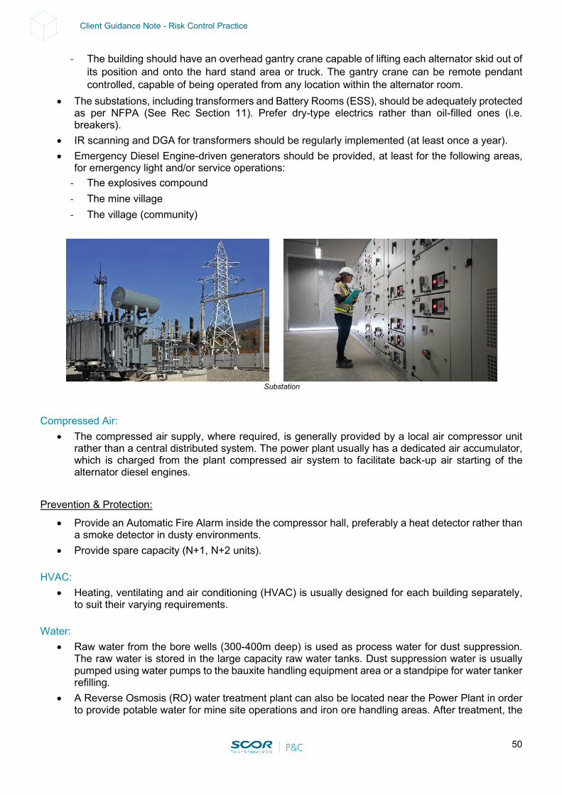
50
Client Guidance Note - Risk Control Practice
- The building should have an overhead gantry crane capable of lifting each alternator skid out of its position and onto the hard stand area or truck. The gantry crane can be remote pendant controlled, capable of being operated from any location within the alternator room.
• The substations, including transformers and Battery Rooms (ESS), should be adequately protected as per NFPA (See Rec Section 11). Prefer dry-type electrics rather than oil-filled ones (i.e. breakers).
• IR scanning and DGA for transformers should be regularly implemented (at least once a year). • Emergency Diesel Engine-driven generators should be provided, at least for the following areas,
for emergency light and/or service operations: - The explosives compound - The mine village - The village (community)
Substation
Compressed Air:
• The compressed air supply, where required, is generally provided by a local air compressor unit rather than a central distributed system. The power plant usually has a dedicated air accumulator, which is charged from the plant compressed air system to facilitate back-up air starting of the alternator diesel engines.
Prevention & Protection:
• Provide an Automatic Fire Alarm inside the compressor hall, preferably a heat detector rather than a smoke detector in dusty environments.
• Provide spare capacity (N+1, N+2 units). HVAC:
• Heating, ventilating and air conditioning (HVAC) is usually designed for each building separately, to suit their varying requirements.
Water:
• Raw water from the bore wells (300-400m deep) is used as process water for dust suppression. The raw water is stored in the large capacity raw water tanks. Dust suppression water is usually pumped using water pumps to the bauxite handling equipment area or a standpipe for water tanker refilling.
• A Reverse Osmosis (RO) water treatment plant can also be located near the Power Plant in order to provide potable water for mine site operations and iron ore handling areas. After treatment, the
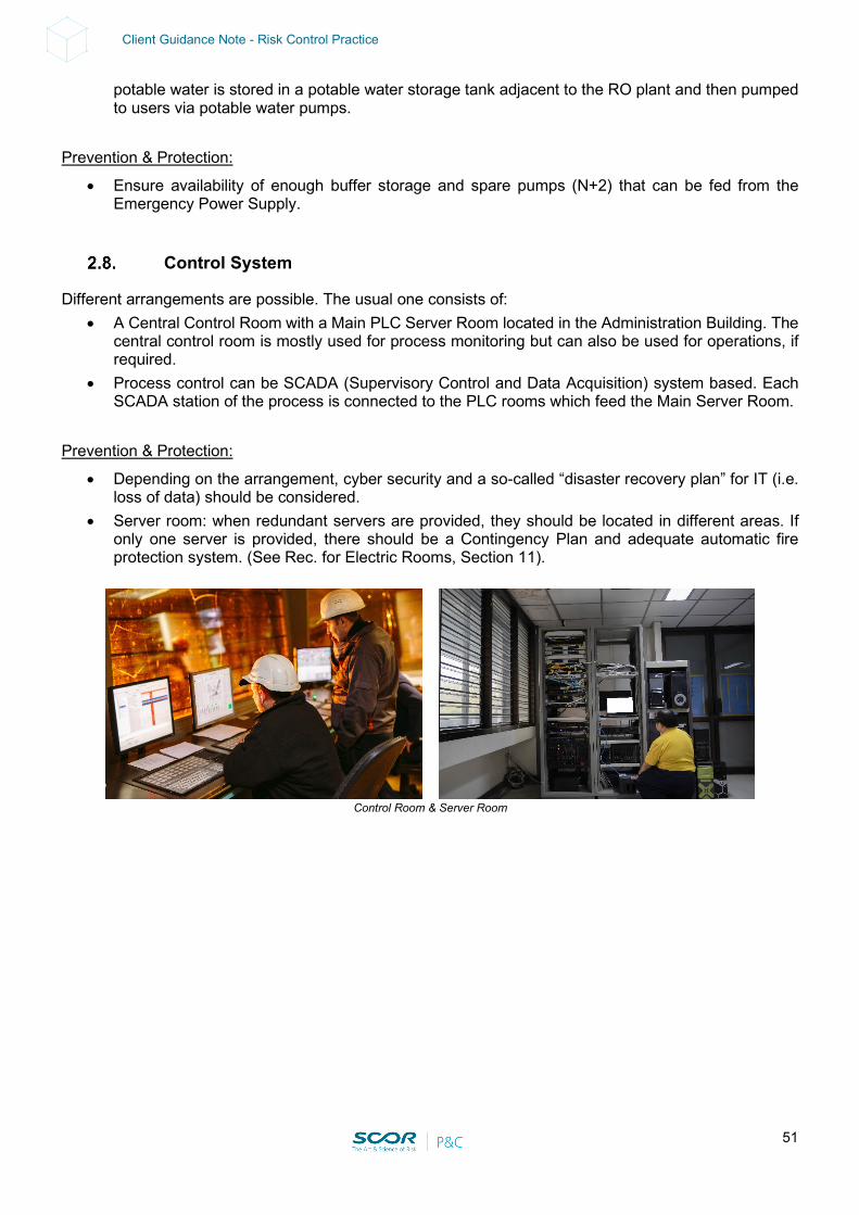
51
Client Guidance Note - Risk Control Practice
potable water is stored in a potable water storage tank adjacent to the RO plant and then pumped to users via potable water pumps.
Prevention & Protection:
• Ensure availability of enough buffer storage and spare pumps (N+2) that can be fed from the Emergency Power Supply.
Control System
Different arrangements are possible. The usual one consists of: • A Central Control Room with a Main PLC Server Room located in the Administration Building. The
central control room is mostly used for process monitoring but can also be used for operations, if required.
• Process control can be SCADA (Supervisory Control and Data Acquisition) system based. Each SCADA station of the process is connected to the PLC rooms which feed the Main Server Room.
Prevention & Protection:
• Depending on the arrangement, cyber security and a so-called “disaster recovery plan” for IT (i.e. loss of data) should be considered.
• Server room: when redundant servers are provided, they should be located in different areas. If only one server is provided, there should be a Contingency Plan and adequate automatic fire protection system. (See Rec. for Electric Rooms, Section 11).
Control Room & Server Room
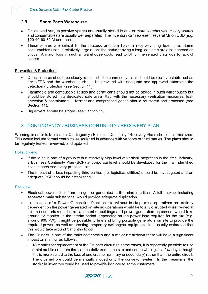
52
Client Guidance Note - Risk Control Practice
Spare Parts Warehouse
• Critical and very expensive spares are usually stored in one or more warehouses. Heavy spares and consumables are usually well separated. The inventory can represent several Milion USD (e.g. $20-40-60-80 M and more).
• These spares are critical to the process and can have a relatively long lead time. Some consumables used in relatively large quantities and/or having a long lead time are also deemed as critical. A major loss in such a warehouse could lead to BI for the related units due to lack of spares.
Prevention & Protection:
• Critical spares should be clearly identified. The commodity class should be clearly established as per NFPA and the warehouse should be provided with adequate and approved automatic fire detection / protection (see Section 11).
• Flammable and combustible liquids and spray cans should not be stored in such warehouses but should be stored in a dedicated safe area fitted with the necessary ventilation measures, leak detection & containment. Hazmat and compressed gases should be stored and protected (see Section 11).
• Big drivers should be stored (see Section 11).
3. CONTINGENCY / BUSINESS CONTINUITY / RECOVERY PLAN
Warning: in order to be reliable, Contingency / Business Continuity / Recovery Plans should be formalized. This would include formal contracts established in advance with vendors or third parties. The plans should be regularly tested, reviewed, and updated. Holistic view:
• If the Mine is part of a group with a relatively high level of vertical integration in the steel industry, a Business Continuity Plan (BCP) at corporate level should be developed for the main identified risks in each and every process unit.
• The impact of a loss impacting third parties (i.e. logistics, utilities) should be investigated and an adequate BCP should be established.
Site view:
• Electrical power either from the grid or generated at the mine is critical. A full backup, including separated main substations, would provide adequate duplication.
• In the case of a Power Generation Plant on site without backup: mine operations are entirely dependent on the power generated on site so operations would be totally disrupted whilst remedial action is undertaken. The replacement of buildings and power generation equipment would take around 12 months. In the interim period, depending on the power load required for the site (e.g. around 900 kW), it might be possible to hire and bring portable generators on site to provide the required power, as well as erecting temporary switchgear equipment. It is usually estimated that this would take around 3 months to do.
• The Crusher is one of the main bottlenecks and a major breakdown there will have a significant impact on mining, as follows:
- 18 months for replacement of the Crusher circuit: In some cases, it is reportedly possible to use rental mobile crushers that can be delivered to the site and set up within just a few days, though this is more suited to the loss of one crusher (primary or secondary) rather than the entire circuit. The crushed ore could be manually moved onto the conveyor system. In the meantime, the stockpile inventory could be used to provide iron ore to some customers.
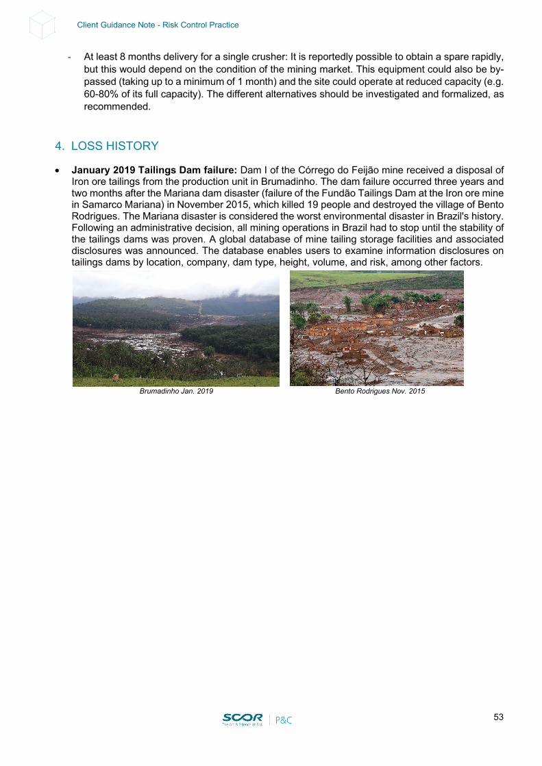
53
Client Guidance Note - Risk Control Practice
- At least 8 months delivery for a single crusher: It is reportedly possible to obtain a spare rapidly, but this would depend on the condition of the mining market. This equipment could also be by-passed (taking up to a minimum of 1 month) and the site could operate at reduced capacity (e.g. 60-80% of its full capacity). The different alternatives should be investigated and formalized, as recommended.
4. LOSS HISTORY
• January 2019 Tailings Dam failure: Dam I of the Córrego do Feijão mine received a disposal of Iron ore tailings from the production unit in Brumadinho. The dam failure occurred three years and two months after the Mariana dam disaster (failure of the Fundão Tailings Dam at the Iron ore mine in Samarco Mariana) in November 2015, which killed 19 people and destroyed the village of Bento Rodrigues. The Mariana disaster is considered the worst environmental disaster in Brazil's history. Following an administrative decision, all mining operations in Brazil had to stop until the stability of the tailings dams was proven. A global database of mine tailing storage facilities and associated disclosures was announced. The database enables users to examine information disclosures on tailings dams by location, company, dam type, height, volume, and risk, among other factors.
Brumadinho Jan. 2019 Bento Rodrigues Nov. 2015
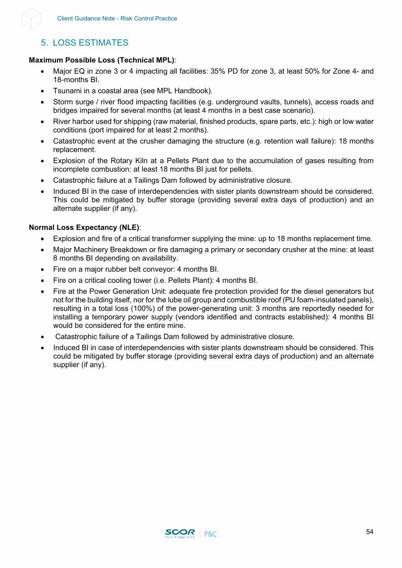
54
Client Guidance Note - Risk Control Practice
5. LOSS ESTIMATES
Maximum Possible Loss (Technical MPL): • Major EQ in zone 3 or 4 impacting all facilities: 35% PD for zone 3, at least 50% for Zone 4- and
18-months BI. • Tsunami in a coastal area (see MPL Handbook). • Storm surge / river flood impacting facilities (e.g. underground vaults, tunnels), access roads and
bridges impaired for several months (at least 4 months in a best case scenario). • River harbor used for shipping (raw material, finished products, spare parts, etc.): high or low water
conditions (port impaired for at least 2 months). • Catastrophic event at the crusher damaging the structure (e.g. retention wall failure): 18 months
replacement. • Explosion of the Rotary Kiln at a Pellets Plant due to the accumulation of gases resulting from
incomplete combustion: at least 18 months BI just for pellets. • Catastrophic failure at a Tailings Dam followed by administrative closure. • Induced BI in the case of interdependencies with sister plants downstream should be considered.
This could be mitigated by buffer storage (providing several extra days of production) and an alternate supplier (if any).
Normal Loss Expectancy (NLE):
• Explosion and fire of a critical transformer supplying the mine: up to 18 months replacement time. • Major Machinery Breakdown or fire damaging a primary or secondary crusher at the mine: at least
8 months BI depending on availability. • Fire on a major rubber belt conveyor: 4 months BI. • Fire on a critical cooling tower (i.e. Pellets Plant): 4 months BI. • Fire at the Power Generation Unit: adequate fire protection provided for the diesel generators but
not for the building itself, nor for the lube oil group and combustible roof (PU foam-insulated panels), resulting in a total loss (100%) of the power-generating unit: 3 months are reportedly needed for installing a temporary power supply (vendors identified and contracts established): 4 months BI would be considered for the entire mine.
• Catastrophic failure of a Tailings Dam followed by administrative closure. • Induced BI in case of interdependencies with sister plants downstream should be considered. This
could be mitigated by buffer storage (providing several extra days of production) and an alternate supplier (if any).

55
Client Guidance Note - Risk Control Practice
VI - IRONMAKING, STEELMAKING AND CASTING
1. PROCESS
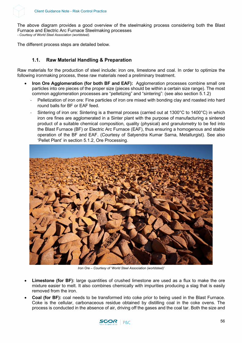
56
Client Guidance Note - Risk Control Practice
The above diagram provides a good overview of the steelmaking process considering both the Blast Furnace and Electric Arc Furnace Steelmaking processes - Courtesy of World Steel Association (worldsteel). The different process steps are detailed below.
1.1. Raw Material Handling & Preparation
Raw materials for the production of steel include: iron ore, limestone and coal. In order to optimize the following ironmaking process, these raw materials need a preliminary treatment.
• Iron Ore Agglomeration (for both BF and EAF): Agglomeration processes combine small ore particles into ore pieces of the proper size (pieces should be within a certain size range). The most common agglomeration processes are “pelletizing” and “sintering”: (see also section 5.1.2)
- Pelletization of iron ore: Fine particles of iron ore mixed with bonding clay and roasted into hard round balls for BF or EAF feed.
- Sintering of iron ore: Sintering is a thermal process (carried out at 1300°C to 1400°C) in which iron ore fines are agglomerated in a Sinter plant with the purpose of manufacturing a sintered product of a suitable chemical composition, quality (physical) and granulometry to be fed into the Blast Furnace (BF) or Electric Arc Furnace (EAF), thus ensuring a homogenous and stable operation of the BF and EAF. (Courtesy of Satyendra Kumar Sarna, Metallurgist). See also ‘Pellet Plant’ in section 5.1.2, Ore Processing.
Iron Ore – Courtesy of ‘World Steel Association (worldsteel)’
• Limestone (for BF): large quantities of crushed limestone are used as a flux to make the ore mixture easier to melt. It also combines chemically with impurities producing a slag that is easily removed from the iron.
• Coal (for BF): coal needs to be transformed into coke prior to being used in the Blast Furnace. Coke is the cellular, carbonaceous residue obtained by distilling coal in the coke ovens. The process is conducted in the absence of air, driving off the gases and the coal tar. Both the size and
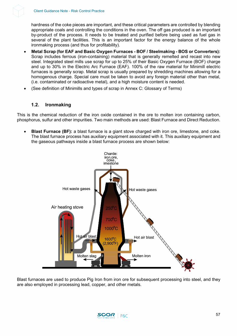
57
Client Guidance Note - Risk Control Practice
hardness of the coke pieces are important, and these critical parameters are controlled by blending appropriate coals and controlling the conditions in the oven. The off gas produced is an important by-product of the process. It needs to be treated and purified before being used as fuel gas in several of the plant facilities. This is an important factor for the energy balance of the whole ironmaking process (and thus for profitability).
• Metal Scrap (for EAF and Basic Oxygen Furnaces - BOF / Steelmaking - BOS or Converters): Scrap includes ferrous (iron-containing) material that is generally remelted and recast into new steel. Integrated steel mills use scrap for up to 25% of their Basic Oxygen Furnace (BOF) charge and up to 30% in the Electric Arc Furnace (EAF). 100% of the raw material for Minimill electric furnaces is generally scrap. Metal scrap is usually prepared by shredding machines allowing for a homogenous charge. Special care must be taken to avoid any foreign material other than metal, (i.e. contaminated or radioactive metal), and a high moisture content is needed.
• (See definition of Minimills and types of scrap in Annex C: Glossary of Terms)
1.2. Ironmaking
This is the chemical reduction of the iron oxide contained in the ore to molten iron containing carbon, phosphorus, sulfur and other impurities. Two main methods are used: Blast Furnace and Direct Reduction.
• Blast Furnace (BF): a blast furnace is a giant stove charged with iron ore, limestone, and coke. The blast furnace process has auxiliary equipment associated with it. This auxiliary equipment and the gaseous pathways inside a blast furnace process are shown below:
Blast furnaces are used to produce Pig Iron from iron ore for subsequent processing into steel, and they are also employed in processing lead, copper, and other metals.
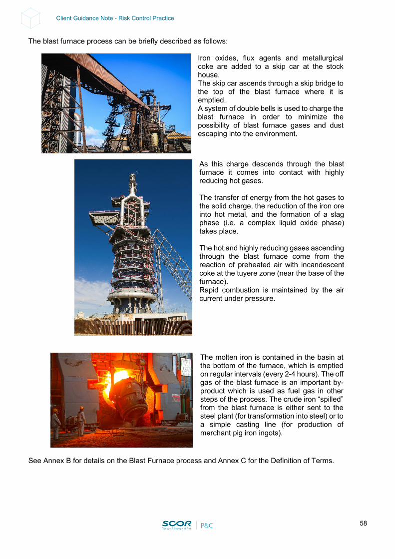
58
Client Guidance Note - Risk Control Practice
The blast furnace process can be briefly described as follows:
Iron oxides, flux agents and metallurgical coke are added to a skip car at the stock house. The skip car ascends through a skip bridge to the top of the blast furnace where it is emptied. A system of double bells is used to charge the blast furnace in order to minimize the possibility of blast furnace gases and dust escaping into the environment.
The molten iron is contained in the basin at the bottom of the furnace, which is emptied on regular intervals (every 2-4 hours). The off gas of the blast furnace is an important by-product which is used as fuel gas in other steps of the process. The crude iron “spilled” from the blast furnace is either sent to the steel plant (for transformation into steel) or to a simple casting line (for production of merchant pig iron ingots).
See Annex B for details on the Blast Furnace process and Annex C for the Definition of Terms.
As this charge descends through the blast furnace it comes into contact with highly reducing hot gases. The transfer of energy from the hot gases to the solid charge, the reduction of the iron ore into hot metal, and the formation of a slag phase (i.e. a complex liquid oxide phase) takes place. The hot and highly reducing gases ascending through the blast furnace come from the reaction of preheated air with incandescent coke at the tuyere zone (near the base of the furnace). Rapid combustion is maintained by the air current under pressure.
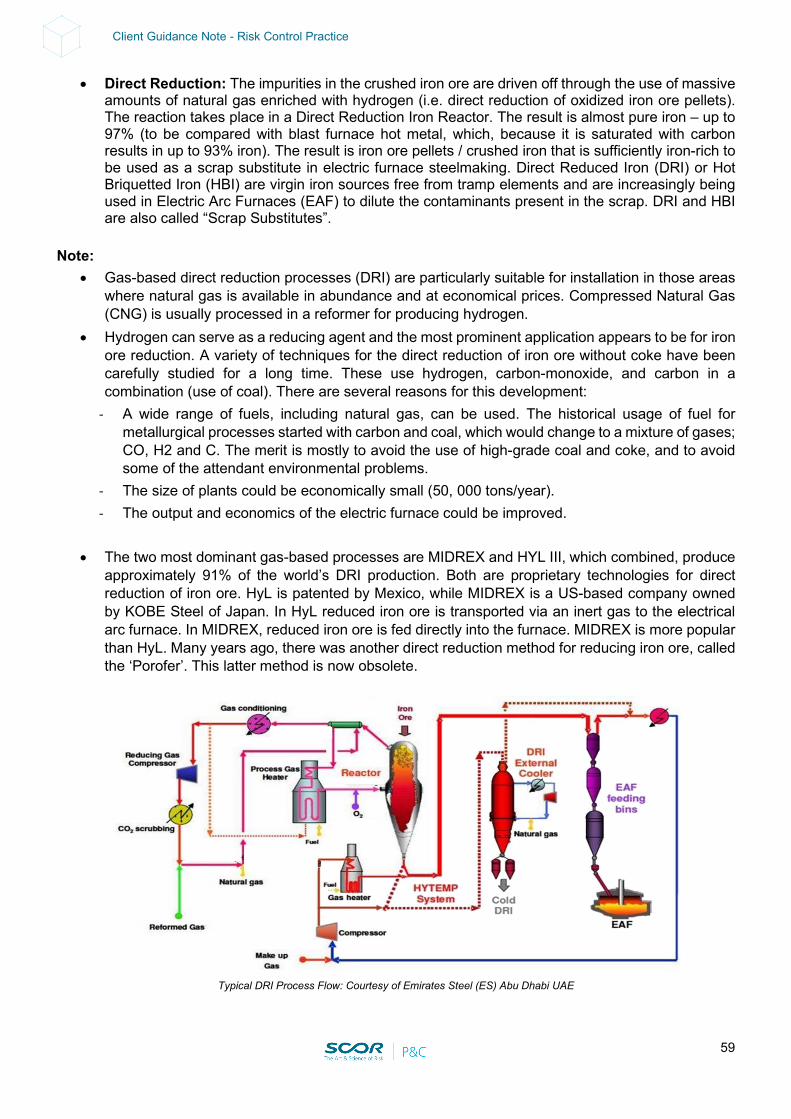
59
Client Guidance Note - Risk Control Practice
• Direct Reduction: The impurities in the crushed iron ore are driven off through the use of massive amounts of natural gas enriched with hydrogen (i.e. direct reduction of oxidized iron ore pellets). The reaction takes place in a Direct Reduction Iron Reactor. The result is almost pure iron – up to 97% (to be compared with blast furnace hot metal, which, because it is saturated with carbon results in up to 93% iron). The result is iron ore pellets / crushed iron that is sufficiently iron-rich to be used as a scrap substitute in electric furnace steelmaking. Direct Reduced Iron (DRI) or Hot Briquetted Iron (HBI) are virgin iron sources free from tramp elements and are increasingly being used in Electric Arc Furnaces (EAF) to dilute the contaminants present in the scrap. DRI and HBI are also called “Scrap Substitutes”.
Note:
• Gas-based direct reduction processes (DRI) are particularly suitable for installation in those areas where natural gas is available in abundance and at economical prices. Compressed Natural Gas (CNG) is usually processed in a reformer for producing hydrogen.
• Hydrogen can serve as a reducing agent and the most prominent application appears to be for iron ore reduction. A variety of techniques for the direct reduction of iron ore without coke have been carefully studied for a long time. These use hydrogen, carbon-monoxide, and carbon in a combination (use of coal). There are several reasons for this development:
- A wide range of fuels, including natural gas, can be used. The historical usage of fuel for metallurgical processes started with carbon and coal, which would change to a mixture of gases; CO, H2 and C. The merit is mostly to avoid the use of high-grade coal and coke, and to avoid some of the attendant environmental problems.
- The size of plants could be economically small (50, 000 tons/year). - The output and economics of the electric furnace could be improved.
• The two most dominant gas-based processes are MIDREX and HYL III, which combined, produce
approximately 91% of the world’s DRI production. Both are proprietary technologies for direct reduction of iron ore. HyL is patented by Mexico, while MIDREX is a US-based company owned by KOBE Steel of Japan. In HyL reduced iron ore is transported via an inert gas to the electrical arc furnace. In MIDREX, reduced iron ore is fed directly into the furnace. MIDREX is more popular than HyL. Many years ago, there was another direct reduction method for reducing iron ore, called the ‘Porofer’. This latter method is now obsolete.
Typical DRI Process Flow: Courtesy of Emirates Steel (ES) Abu Dhabi UAE

60
Client Guidance Note - Risk Control Practice
• Minimills: normally defined as steel mills that melt scrap metal to produce commodity products. Although minimills are subject to the same steel processing requirements (after the caster) as the integrated steel companies, they differ greatly as regards their minimum efficient size, labor relations, product markets and management style. As minimills expand their product abilities to sheet steel, they require much higher grades of scrap to approach the integrated mill quality. Enabling the minimills to use iron ore without a blast furnace, Direct Reduction Iron (DRI) can serve as a low residual raw material and alleviate the minimills’ dependence on cleaner, higher-priced scrap.
See Annex B for details on MIDREX and HYL processes and Annex C for a Definition of Terms.
1.3. Steelmaking
This is the transformation of molten crude iron into steel products, consisting of two steps as summarized below: Primary Steelmaking: Molten iron is refined into steel by reducing the carbon content and adding oxygen, lime, scrap metal and alloys. The amount and type of additives, furnace temperature and oxygen blow (key process parameters) all affect the characteristics of the steel. There are two main types of steelmaking furnaces; the Basic Oxygen Furnace / Steelmaking (BOF/BOS) and the more modern Electric Arc Furnaces (EAF) as summarized below:
• BOF/BOS: A basic oxygen furnace is basically a reactor (a pear-shaped structure with a closed bottom and an open top) in which a water-cooled oxygen lance is used to blow oxygen through molten pig iron that is heated to approximately 1,600℃ to convert it into steel.
The furnace contains the liquid metallic charge (including scrap metal) and oxygen is introduced via a water-cooled lance. The oxygen and the lime flux react with impurities producing heat. Commonly known as a BOF, this type of furnace relies on pure oxygen, rather than air, to convert iron into steel. These furnaces do not require any external fuel, but they depend on the oxygen supply. As the basic oxygen furnace shell is exposed to severe high-temperature conditions during use, its material experiences gradual degradation leading to thermal deformation and cracking that necessitates repair and exchange of the furnace body.
The shape of a basic oxygen furnace allows manufacturers to tilt it onto its side to charge and pour molten steel. On some rare occasions, oxygen is injected into the mixture through a process known as "bottom blowing," through a spout found at the bottom. Inputs such as iron ore and sometimes coal or limestone are added before being poured into a ladle, where other alloys and deoxidizers are added in order to reach the proper composition.
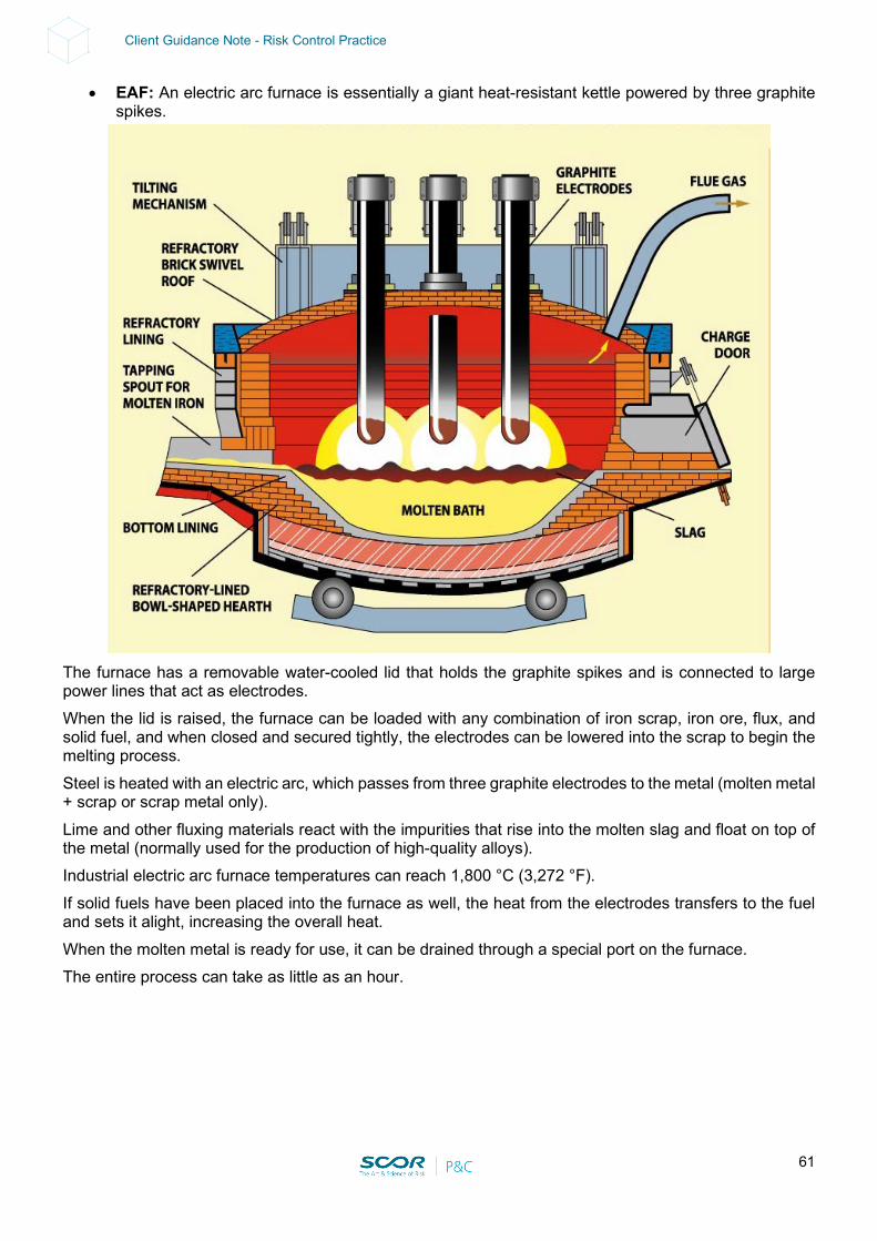
61
Client Guidance Note - Risk Control Practice
• EAF: An electric arc furnace is essentially a giant heat-resistant kettle powered by three graphite spikes.
The furnace has a removable water-cooled lid that holds the graphite spikes and is connected to large power lines that act as electrodes. When the lid is raised, the furnace can be loaded with any combination of iron scrap, iron ore, flux, and solid fuel, and when closed and secured tightly, the electrodes can be lowered into the scrap to begin the melting process. Steel is heated with an electric arc, which passes from three graphite electrodes to the metal (molten metal + scrap or scrap metal only). Lime and other fluxing materials react with the impurities that rise into the molten slag and float on top of the metal (normally used for the production of high-quality alloys). Industrial electric arc furnace temperatures can reach 1,800 °C (3,272 °F). If solid fuels have been placed into the furnace as well, the heat from the electrodes transfers to the fuel and sets it alight, increasing the overall heat. When the molten metal is ready for use, it can be drained through a special port on the furnace. The entire process can take as little as an hour.
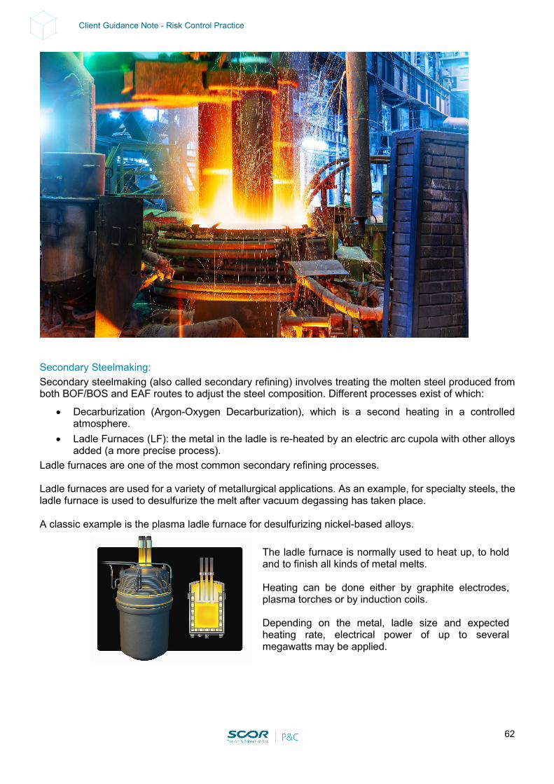
62
Client Guidance Note - Risk Control Practice
Secondary Steelmaking: Secondary steelmaking (also called secondary refining) involves treating the molten steel produced from both BOF/BOS and EAF routes to adjust the steel composition. Different processes exist of which:
• Decarburization (Argon-Oxygen Decarburization), which is a second heating in a controlled atmosphere.
• Ladle Furnaces (LF): the metal in the ladle is re-heated by an electric arc cupola with other alloys added (a more precise process).
Ladle furnaces are one of the most common secondary refining processes. Ladle furnaces are used for a variety of metallurgical applications. As an example, for specialty steels, the ladle furnace is used to desulfurize the melt after vacuum degassing has taken place. A classic example is the plasma ladle furnace for desulfurizing nickel-based alloys.
The ladle furnace is normally used to heat up, to hold and to finish all kinds of metal melts. Heating can be done either by graphite electrodes, plasma torches or by induction coils. Depending on the metal, ladle size and expected heating rate, electrical power of up to several megawatts may be applied.
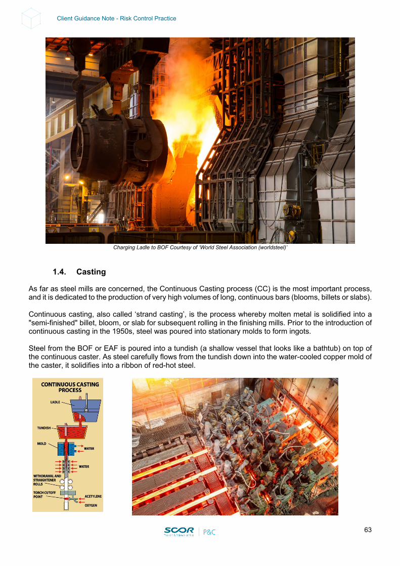
63
Client Guidance Note - Risk Control Practice
Charging Ladle to BOF Courtesy of ‘World Steel Association (worldsteel)’
1.4. Casting
As far as steel mills are concerned, the Continuous Casting process (CC) is the most important process, and it is dedicated to the production of very high volumes of long, continuous bars (blooms, billets or slabs). Continuous casting, also called ‘strand casting’, is the process whereby molten metal is solidified into a "semi-finished" billet, bloom, or slab for subsequent rolling in the finishing mills. Prior to the introduction of continuous casting in the 1950s, steel was poured into stationary molds to form ingots. Steel from the BOF or EAF is poured into a tundish (a shallow vessel that looks like a bathtub) on top of the continuous caster. As steel carefully flows from the tundish down into the water-cooled copper mold of the caster, it solidifies into a ribbon of red-hot steel.
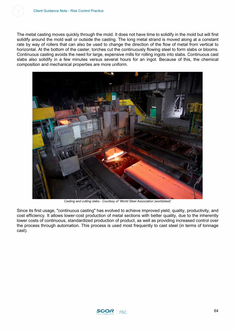
64
Client Guidance Note - Risk Control Practice
The metal casting moves quickly through the mold. It does not have time to solidify in the mold but will first solidify around the mold wall or outside the casting. The long metal strand is moved along at a constant rate by way of rollers that can also be used to change the direction of the flow of metal from vertical to horizontal. At the bottom of the caster, torches cut the continuously flowing steel to form slabs or blooms. Continuous casting avoids the need for large, expensive mills for rolling ingots into slabs. Continuous cast slabs also solidify in a few minutes versus several hours for an ingot. Because of this, the chemical composition and mechanical properties are more uniform.
Casting and cutting slabs - Courtesy of ‘World Steel Association (worldsteel)’
Since its first usage, "continuous casting" has evolved to achieve improved yield, quality, productivity, and cost efficiency. It allows lower-cost production of metal sections with better quality, due to the inherently lower costs of continuous, standardized production of product, as well as providing increased control over the process through automation. This process is used most frequently to cast steel (in terms of tonnage cast).
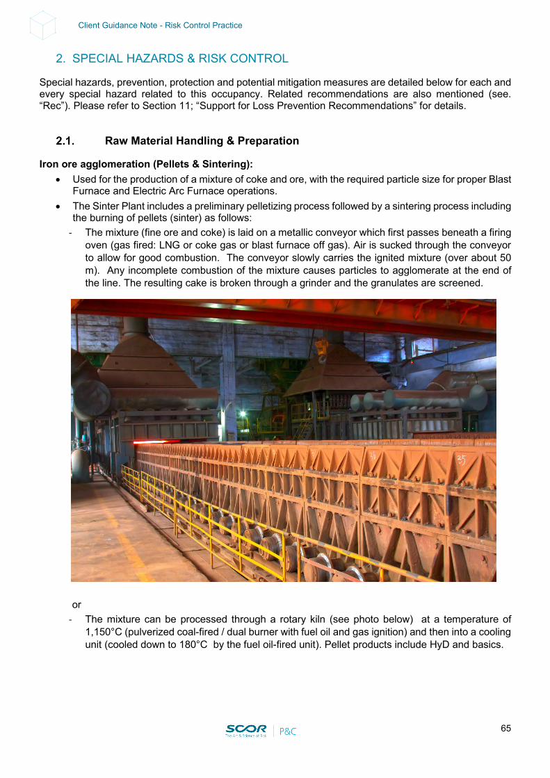
65
Client Guidance Note - Risk Control Practice
2. SPECIAL HAZARDS & RISK CONTROL
Special hazards, prevention, protection and potential mitigation measures are detailed below for each and every special hazard related to this occupancy. Related recommendations are also mentioned (see. “Rec”). Please refer to Section 11; “Support for Loss Prevention Recommendations” for details.
Raw Material Handling & Preparation
Iron ore agglomeration (Pellets & Sintering): • Used for the production of a mixture of coke and ore, with the required particle size for proper Blast
Furnace and Electric Arc Furnace operations. • The Sinter Plant includes a preliminary pelletizing process followed by a sintering process including
the burning of pellets (sinter) as follows: - The mixture (fine ore and coke) is laid on a metallic conveyor which first passes beneath a firing
oven (gas fired: LNG or coke gas or blast furnace off gas). Air is sucked through the conveyor to allow for good combustion. The conveyor slowly carries the ignited mixture (over about 50 m). Any incomplete combustion of the mixture causes particles to agglomerate at the end of the line. The resulting cake is broken through a grinder and the granulates are screened.
or
- The mixture can be processed through a rotary kiln (see photo below) at a temperature of 1,150°C (pulverized coal-fired / dual burner with fuel oil and gas ignition) and then into a cooling unit (cooled down to 180°C by the fuel oil-fired unit). Pellet products include HyD and basics.
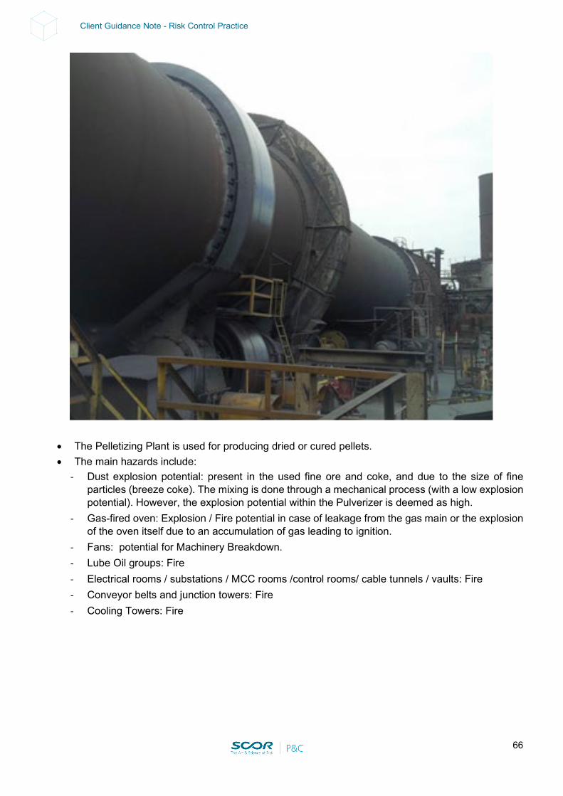
66
Client Guidance Note - Risk Control Practice
• The Pelletizing Plant is used for producing dried or cured pellets. • The main hazards include:
- Dust explosion potential: present in the used fine ore and coke, and due to the size of fine particles (breeze coke). The mixing is done through a mechanical process (with a low explosion potential). However, the explosion potential within the Pulverizer is deemed as high.
- Gas-fired oven: Explosion / Fire potential in case of leakage from the gas main or the explosion of the oven itself due to an accumulation of gas leading to ignition.
- Fans: potential for Machinery Breakdown. - Lube Oil groups: Fire - Electrical rooms / substations / MCC rooms /control rooms/ cable tunnels / vaults: Fire - Conveyor belts and junction towers: Fire - Cooling Towers: Fire
67
Client Guidance Note - Risk Control Practice
Prevention & Protection:
• Dust explosion potential could be mitigated by: a magnetic separator before the pulverizers in order to remove any metallic parts that could cause sparks; automatic fire protection of the pulverizer (water, CO2, nitrogen); explosion-proof electrics inside the building; sprinkler protection inside the building; explosion-relief panels on the grinders and on the dust extraction system filter; blanketing of pulverized coal silos (nitrogen).
• Gas-fired ovens: need proper combustion control including flame supervision, double-bleed & block valves on feed gas lines, adequate starting procedure (purge), safety interlocks (see Section 11).
• Fans: ensure that spare parts (drivers) are available (see Section 6.3. Contingency Plan). • Lube Oil groups: Fire protection (see Section 11). • Electrical rooms / substations / MCC rooms /control rooms/ cable tunnels / vaults: Fire protection
(see Section 11). • Conveyor belts and junction towers: Fire protection (see Section 11). • Cooling towers: Fire protection (see Section 11).
Coke preparation:
• A coke plant is used for producing quality coke and coke gas (off gas) for blast furnaces. A coke plant consists of 3 main areas that include the following process steps:
- Coal area: Coal is usually received by barge from USA, Australia, South America, South Africa, South East Asia, and Eastern countries. Coke making requires the mixing of 5 to 10 different types of coal. (1.4 tons of coal gives 1 ton of coke. 1 ton of coke produces 0.5 tons of coke gas). The main process areas are: Coal unloading facilities Coal yard storage Wheel-shovel Silos (about 10 on average) Proportioning and screening Hammermill (80% of coal<2mm) Clean coal bin
Main Hazards include:
Coal Fires: Coal piles are subject to auto-combustion due to the volatility of some components. Unloading equipment is typically used, including large cranes and conveyor belts as well as junction towers. The latter have a high fire potential resulting in BI issues. Ignition and fire can occur at a low rate of oxygen (12%). Finely- sized coal is even easier to ignite and more combustible (80% of sized coal is less than 2 mm). Storage and handling of coal is managed on a FIFO (First in First Out) basis (avoiding non-quality products.)
Coal dust explosions: relatively slight risk due to the humidity rate of coal (nearly 10%). Others: (olivine, castine, etc.): stockpiles in yard storage or in silos. Belt Conveyors: critical conveyors as well as critical junction towers must be clearly
identified looking for bottlenecks and potential redundancies.
68
Client Guidance Note - Risk Control Practice
Prevention & Protection:
• Stockpile management procedures: a formalized procedure should be established in order to ensure the safe arrangement of coal storage (keep it compact in order to avoid air reacting with the coal.); coal pile T° online with monitoring and alarms; strategic storage should be well separated from the main storage; regular audits should be conducted; deviations should be reported, and additional training given when needed.
• Wetting systems: an automatic wetting system consisting of an above-ground network delivering spray water through an open nozzle can be recommended to keep the level of moisture within the stockpile at an acceptable level (used in coal-fired thermal power plants).
• Separation from facilities: stockpiles should be stored at least 25 m from any building structures. • Manual Firefighting: hydrants should be installed around the stockpile every 75 m. • Automatic sprinkler protection: all belt conveyors and clean coal bins should be protected (see
Section 11). No credit can be given to the “so-called” fire retardant belt type. - Coke oven area: A battery of coke ovens houses several ovens (about 0.5 m wide, 12-15 m
long, 4-8 m high). Coal is usually dropped through the oven’s trough opening in the roof by a Larry car (or it can be introduced in from the side). Burning gas flues in the walls between ovens heat the coal to 1,200°C –1,350°C for 16-20 hours. Coal is thermally distilled by heating, without contact with air, at a high temperature. It is then converted into a variety of solid, liquid, and gaseous products. Heating drives off gases, oil, and tar, which are collected to be made into a myriad of useful by-products. Then, the end doors are removed, and a ram pushes the coke into a quenching car for cooling. The main process areas include: Larry car to coke oven battery (off gas to be treated) Quench car Quenching tower Screening Belt conveyor(s) to blast furnace (>25mm) and pellets (<25mm)
Main Hazards include:
Feed gas supply: a lack of feed gas (coke gas or a blend of coke gas and blast furnace off gas) for coke ovens could result in severe damage to the refractory bricks (silicon dioxide). Natural gas is usually only used to adjust and maintain an adequate temperature inside the coke ovens and to prevent damage to the refractory bricks. Warning: 2 or more coke batteries may be linked by a common coke gas duct in an underground basement where combustible gas can accumulate leading to an explosive atmosphere.
Electrical rooms: fire in an electrical room powering the coke ovens (e.g. MCC rooms, PLC rooms, including cable vaults/trenches) will result in the total loss of the process controls. Manual operations are usually quite impossible.
Lube oil groups: independent lube oil pumps and lube oil reservoirs for the equipment are usually installed in lube oil vaults/rooms that are normally non-occupied (risk of Larry car and reversal of cooking flue).
Larry car and push car: typically Machinery Breakdown potential. Life expectancy of a battery of coke ovens: nearly 30 years.
Prevention & Protection:
• Feed gas supply: ensure that a reliable backup for the feed gas is available (e.g. LNG, LPG). In the case of a feed gas shortage, an automatic inert gas (N2) should flood the feed gas-piping network. A CO and H2 explosion detection device should be installed in areas housing feed gas mains, when an explosion risk exists (with ignition sources such as electrical equipment, etc.).

69
Client Guidance Note - Risk Control Practice
• Electrical rooms: all electrical rooms should be protected (see Section 11). • Lube oil groups: all lube oil groups should be protected (see Section 11). • Larry cars and push cars: ensure there is a backup for both pieces of equipment. • Should there be any life duration extension projects, specialized surveys involving the use of non-
destructive technologies and advance studies should be carried out prior to any decision being taken. Experiences undergone by other similar plants and manufacturers around the world should be taken into account.
Coke plant - Courtesy of ‘World Steel Association (worldsteel)’
- Coke gas treatment: By-product gases from coke ovens are collected into a common gas main
and processed to separate the compounds, solids, and gases. The main process areas involve: Coke gas collection (T°700°C @ P°+7mce) Stabilization (ammoniac water recycled with caustic soda and steam) Primary condenser cooling (T090°C@ P°-10mce) Electrostatic tar de-sprayer (T024°C@ P>0mce / tar removal) Extraction (recovery of coal chemicals) Saturation (using H2SO4 sulfuric acid to form (NH3)2SO4) Last condenser Benzol removal (using fuel oil to remove benzol) Sulfur removal Gasometer (coke gas storage) and compressors/booster compressors
Main Hazards include:
Coke oven gas: mixture of H2 (55%-60%), CH4 (25%-28%), CO (5%-7%), N2 (4%) and CO2 (2%), which is lighter than air.
Cooling of coke gas mains: insufficient cooling would result in severe damage due to overheating. (up to 1-month replacement time).
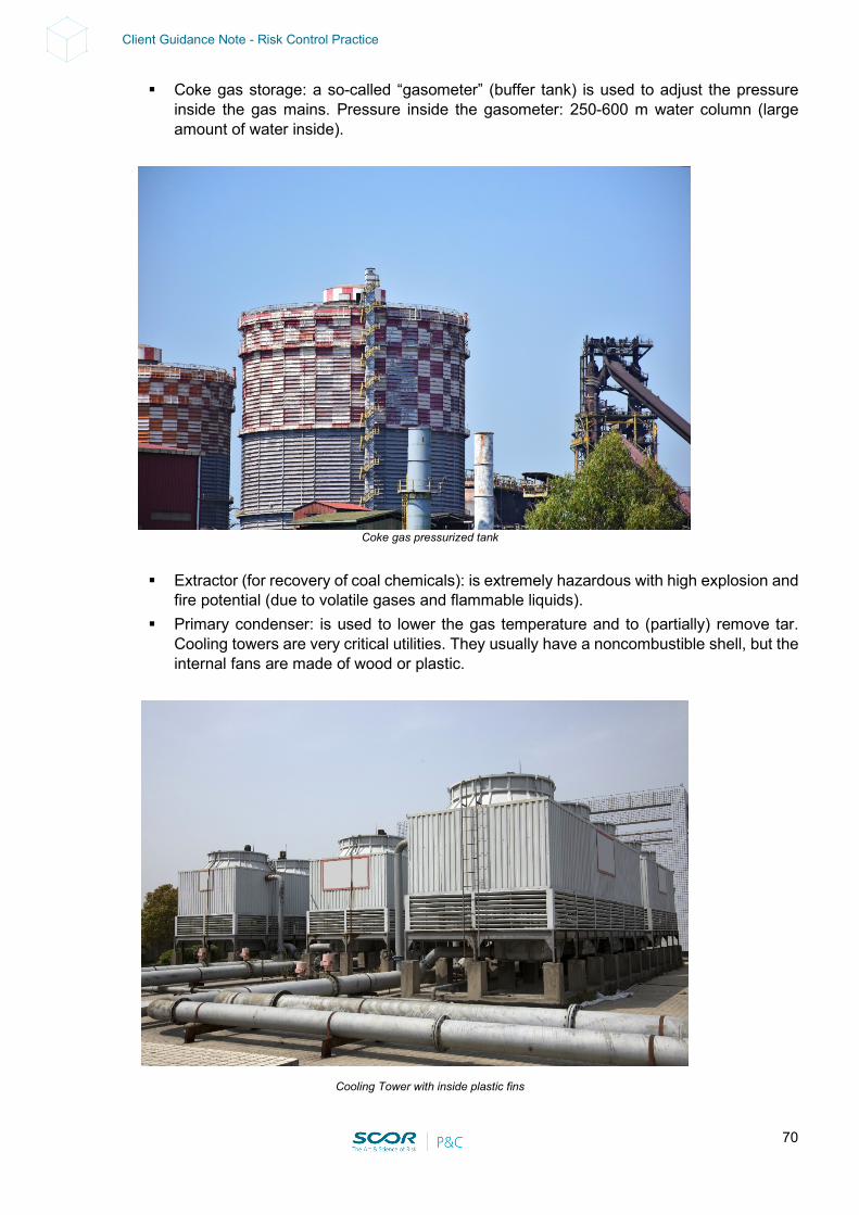
70
Client Guidance Note - Risk Control Practice
Coke gas storage: a so-called “gasometer” (buffer tank) is used to adjust the pressure inside the gas mains. Pressure inside the gasometer: 250-600 m water column (large amount of water inside).
Coke gas pressurized tank
Extractor (for recovery of coal chemicals): is extremely hazardous with high explosion and
fire potential (due to volatile gases and flammable liquids). Primary condenser: is used to lower the gas temperature and to (partially) remove tar.
Cooling towers are very critical utilities. They usually have a noncombustible shell, but the internal fans are made of wood or plastic.
Cooling Tower with inside plastic fins
71
Client Guidance Note - Risk Control Practice
Electrostatic tar de-sprayer: for electrostatic precipitation (magnetic field) of tar contained
in coke gas. The explosion potential of O2 is inside the coke gas mains. Extraction: the extractor is a critical piece of equipment used to extract coke gas from the
coke oven (no by-pass possible). An extractor room can house several extractors. (Potential BI issues).
Saturation: the removal of ammonia from coke gas using sulfuric acid to form ammonium sulfate. This could cause a potential hydrogen gas release.
Benzol removal: fuel oil is used to remove BTX mixtures (benzene, toluene, xylene (flash point (11°C) that are not water soluble; Flammable limits: lower 1.2% / upper 8%).
Sulfur removal: using either purifying boxes housing iron oxide on wood shavings and sawdust or a continuous flow of ethanol amine (flash point (86°C)) in scrubbing towers (followed by the recovery of ethanol amine). Flammable H2S gas can be released if an ethanolamine solution is used.
Compressors/booster compressors: Potential BI issues in case of limited back-up capabilities.
Prevention & Protection:
• Cooling of coke gas mains: a main circulating pump (electrical driver) with 100% backup (diesel engine-driven pump). An alternate supply could be industrial water (which is not reliable in the case of a major shutdown).
• Coke gas mains: install an on-line O2 detector. An emergency procedure should be established in case of O2 detection. This could include shutting down the electrostatic tar de-sprayer and extractor, and inerting the coke main with nitrogen; interlocked Safety Shutoff Valves (low and high gas pressure) and explosion-venting devices should be installed; grounding and bounding of gas mains recommended; the need for additional remotely operated valves (air-operated, of a fail-safe type or motorized) should be investigated; pressure safety valves should be provided.
• Gasometer: high-level alarms and independent high-high level alarms should be provided (modern radar types are preferred); pressure relief valves, static protection and lightning protection should be provided; on-line H2 detectors should be installed at the base covering the whole perimeter (4x); single or gridded lightning arresters should be installed on encroaching high facilities.
• Primary condenser cooling towers: if combustible construction materials are used, ensure that a 100% back-up capacity is provided for cooling towers (with adequate separation). In case there is no backup, sprinkler protection should be installed above the combustible fan (for ignition during maintenance operations). For a new project, it is recommended that the frame and shell be made of reinforced concrete or corrosion-resistant metal (package unit).
• Electrostatic tar de-sprayer: install on-line O2 detectors inside coke gas mains; deluge protection (automatically activated) of tank storage and tar pump rooms (tar flashpoint = 74°C).
• Extractor: X-proof equipment, continuous mechanical ventilation, and CO and H2 detectors should be installed inside the room. Alarms should be relayed to a constantly attended location. The lube oil group should be protected (see Section 11).
• Benzol removal: install automatic deluge protection rings and foam pourers on tanks and deluge foam protection above the handling areas (e.g. pumping station) as well as remotely operated valves between the pumps and the tanks. There should be a deluge system, adequate containment, and drainage on loading stations. Install lightning protection on high locations around storage, handling and loading stations.
• Sulfur removal: H2S detectors with alarms relayed on constantly attended locations are strongly recommended in critical areas (pump areas); on-line monitoring of the ethanolamine solution flow and pressure; isolation valves (remotely operated).

72
Client Guidance Note - Risk Control Practice
• Compressors/booster compressors: ensure a 100% back-up capacity is provided or that there is a Contingency Plan either within the group or involving other manufacturers and/or other surrounding industries.
Coal Injection Preparation:
• The preparation of coal (of an adequate particle size) to be pulverized into the blast furnace requires dryers, grinders and pulverizers involving heavy machinery and equipment.
• The blast furnace could run without the injection of coal. A few days would be needed to adjust the raw material charge (in order to obtain the required crude iron quality). Potential BI losses would be expected.
Main hazards include:
• Belt conveyors and junction towers from the yard to the unit: Fire potential. • Dust explosion potential: dust accumulation potential inside the buildings. • Electrical rooms, cable tunnels / vaults, substations, MCC Rooms: Fire potential • Lube oil groups: Fire potential
Prevention & Protection:
• Belt conveyors and junction towers: Fire protection (see Section 11). • Dust explosion potential: regular housekeeping and inspections. • Electrical rooms / substations / MCC rooms /control rooms/ cable tunnels / vaults: Fire protection
(see Section 11). • Lube oil groups: Fire protection (see Section 11).
Coal Injection Storage & Conveyor to Blast Furnace
Metal Scraps:
• External scraps may introduce contaminants that could jeopardize the finished product quality but also introduce major hazards inside the steel mill, such as high moisture content, liquid in

73
Client Guidance Note - Risk Control Practice
containers (e.g. cans) or even radioactive material. Some steel mills only accept internal scrap (from the Cast House itself or from an integrated downstream Rolling Mill).
• The introduction of radioactive material may contaminate all process equipment. • Steam explosions in furnaces, caused by violent boiling or flashing of water into steam, occurs
when water is rapidly heated by the interaction of molten metals. This can happen in a furnace. Prevention & Protection:
• Radioactive material detectors should be provided before the scrap enters the storage area. • Scrap metal visual inspection routines should be established. • Scrap storage areas should be protected from rain, snow, or surface water for a few days before
being used. • Moisture control should be run before introducing scrap into the furnace. • If scrap steel is stored outside and uncovered, develop a procedure for drying the scrap steel prior
to entering the arc furnace (e.g., scrap pre-heaters). • If the facility is located in a cold climate, develop a procedure that will address the possibility of ice
collecting within the compacted scrap steel.
Molten metal breakout and other extreme temperature exposures
• Breakout: the uncontrolled release of molten material from inside a furnace, ladle, mold, or other vessel. This risk should be considered for all iron and steelmaking phases.
Prevention & Protection:
• Use high-grade refractory in the construction and relining of all molten metal vessels, such as the blast furnace, the arc furnace, the basic oxygen furnace, and ladles.
• Provide refractory thickness monitoring of all furnaces, particularly in areas where gunnite has been applied.
• Locate control rooms and stations so they are not exposed to molten metal spills. If exposure cannot be avoided, provide protection for these areas.
• Route all electrical cables and equipment for monitoring and operating critical equipment and auxiliary equipment away from molten metal exposures. If exposure cannot be avoided, provide heat shielding between potential molten metal spill areas and the electrical cables and equipment.
• Protect all structural steel, including major supporting steel for the furnace and casting floor, from molten metal breakout and other extreme temperature exposures (e.g., super-heated air from furnace exhaust). The use of masonry covering on structural elements is appropriate.
• Protect all support equipment (mud guns, tap drills, blowers, tuyeres, tanks, and pumps) and their foundations from molten metal exposure.
• Provide sloped floors and drainage around and about the furnace to keep water accumulation from lying in areas subject to molten metal spills.
• Locate below-grade storm sewage and drainage openings so that molten metal spills cannot enter the system.
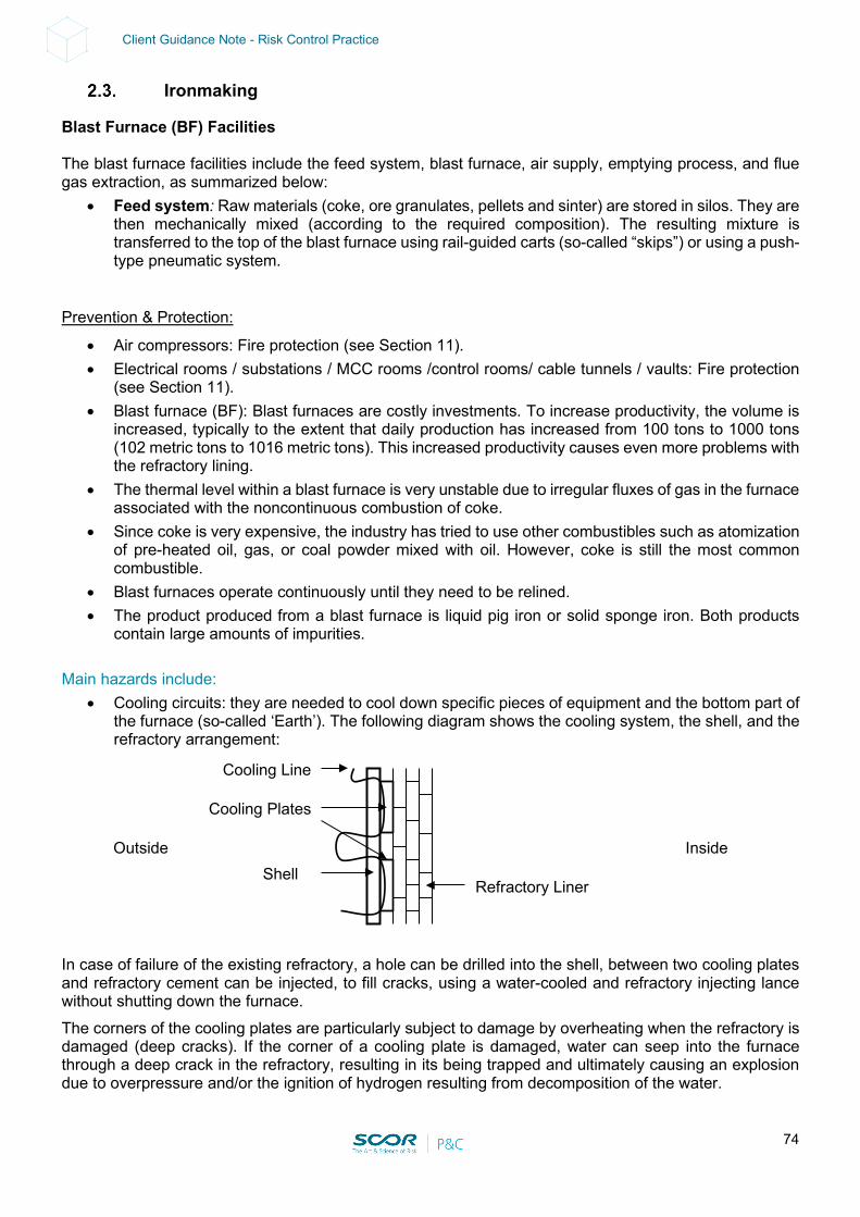
74
Client Guidance Note - Risk Control Practice
Ironmaking
Blast Furnace (BF) Facilities The blast furnace facilities include the feed system, blast furnace, air supply, emptying process, and flue gas extraction, as summarized below:
• Feed system: Raw materials (coke, ore granulates, pellets and sinter) are stored in silos. They are then mechanically mixed (according to the required composition). The resulting mixture is transferred to the top of the blast furnace using rail-guided carts (so-called “skips”) or using a push-type pneumatic system.
Prevention & Protection:
• Air compressors: Fire protection (see Section 11). • Electrical rooms / substations / MCC rooms /control rooms/ cable tunnels / vaults: Fire protection
(see Section 11). • Blast furnace (BF): Blast furnaces are costly investments. To increase productivity, the volume is
increased, typically to the extent that daily production has increased from 100 tons to 1000 tons (102 metric tons to 1016 metric tons). This increased productivity causes even more problems with the refractory lining.
• The thermal level within a blast furnace is very unstable due to irregular fluxes of gas in the furnace associated with the noncontinuous combustion of coke.
• Since coke is very expensive, the industry has tried to use other combustibles such as atomization of pre-heated oil, gas, or coal powder mixed with oil. However, coke is still the most common combustible.
• Blast furnaces operate continuously until they need to be relined. • The product produced from a blast furnace is liquid pig iron or solid sponge iron. Both products
contain large amounts of impurities. Main hazards include:
• Cooling circuits: they are needed to cool down specific pieces of equipment and the bottom part of the furnace (so-called ‘Earth’). The following diagram shows the cooling system, the shell, and the refractory arrangement:
In case of failure of the existing refractory, a hole can be drilled into the shell, between two cooling plates and refractory cement can be injected, to fill cracks, using a water-cooled and refractory injecting lance without shutting down the furnace. The corners of the cooling plates are particularly subject to damage by overheating when the refractory is damaged (deep cracks). If the corner of a cooling plate is damaged, water can seep into the furnace through a deep crack in the refractory, resulting in its being trapped and ultimately causing an explosion due to overpressure and/or the ignition of hydrogen resulting from decomposition of the water.
Cooling Line
Inside Outside
Refractory Liner Shell
Cooling Plates
75
Client Guidance Note - Risk Control Practice
During its lifetime (23 years max. world record in Japan), the blast furnace is never emptied. The thickness of the refractory decreases during its lifetime and can be very thin or even quietly disappear altogether, especially at the upper level of the furnace. As long as the bottom part (earth) has an adequate thickness of refractory, the furnace can still operate. Part of the shell and cooling plates located on the upper part of the furnace can be replaced (partial revamping) by lowering the level of the product inside the furnace. Full revamping, including the replacement of the entire shell and of the refractory liner, will require shutting down the furnace in order to empty it. If the water-cooling system is shut down, the blast furnace could be lost (severe damage to refractories and shell).
• Lube oil groups: several units are provided to move heavy pieces, doors, mobile platforms, drilling machines and plugging machines: Fire potential
• Electrical rooms / substations / MCC rooms /control rooms/ cable tunnels / vaults: Fire potential • Life duration extension projects: the earth of the blast furnace constitutes a very critical element. A
Total Loss could be expected in the case of inadequate project management. Prevention & Protection:
• Use high-grade refractory in the construction and relining of all molten metal vessels, such as the blast furnace, the arc furnace, the basic oxygen furnace, and ladles. Locate control rooms and stations so they are not exposed to molten metal spills. If exposure cannot be avoided, provide protection for these areas. Route all electrical cables and equipment for monitoring and operating critical equipment and auxiliary equipment away from molten metal exposures. If exposure cannot be avoided, provide heat shielding between potential molten metal spill areas and the electrical cables and equipment. Protect all structural steel, including major supporting steel for the furnace and casting floor, from molten metal breakout and other extreme temperature exposures (e.g., super-heated air from furnace exhaust). The use of masonry covering on structural elements is appropriate. Protect all support equipment (mud guns, tap drills, blowers, tuyeres, tanks, and pumps) and their foundations from molten metal exposure. Provide sloped floors and drainage around and about the furnace to keep water accumulation from lying in areas subject to molten metal spills. Locate below-grade storm sewage and drainage openings so that molten metal spills cannot enter the system.
• Cooling circuits: 100 % pump backup should be provided (e.g. electric driven pump and diesel engine or steam turbine). Carry out on-line monitoring of the cooling circuit flow in each section of the furnace using differential flow meters and temperature sensors. Install thermocouples at several levels within the refractory.
• Lube oil groups: Fire protection (see Section 11). • Electrical rooms / substations / MCC rooms /control rooms/ cable tunnels / vaults: Fire protection
(see Section 11). • Life duration extension projects: specialized surveys involving the use of nondestructive
technologies and advanced studies should be carried out prior to any decision being taken. Experiences of other similar plants and manufacturers around the world should be taken into account.
Air supply: Air is supplied by one or more large blowers. The air is preheated (to avoid thermal stress) in “cowpers” (cylindrical vertical ovens housing a brick packing). The brick packing is first heated by burning the Blast Furnace off gas. Then, the second step consists in blowing fresh air over the packing before injection (as preheated air) into the furnace. The cowpers’ internal pressure varies. (100 mbar - 3.5 bars during the injection sequence).
76
Client Guidance Note - Risk Control Practice
Main hazards include: • Blowers: total shutdown which could potentially cause severe damage to the blast furnace. • Heavy machinery & equipment: shutdown due to driver failure. • “Cowpers”: the temperature in the cowpers must not be too high at the risk of forming corrosive
nitrogen oxide. The temperature in the cowers must not drop below the dew point, or Stress Corrosion Cracking (SCC) - especially with cowpers with internal refractories - can occur due to moisture, stress and high temperature factors, or the packing might be damaged, and the top could collapse.
• Electrical rooms / substations / MCC rooms /control rooms/ cable tunnels / vaults: Fire potential. The process is highly automated (potential PD / BI issues).
• Lube oil groups: Fire potential. Any shutdown of some auxiliary units, due to the failure of the lube oil group, will result in severe damage to the blast furnace.
Prevention & Protection:
• Blowers: ensure spare capacity and 100% backup for the drivers (e.g. electric driver + diesel engine or steam turbine).
• Heavy machinery & equipment: ensure spare capacity and 100% backup for the drivers (e.g. electric driver + diesel engine).
• “Cowpers”: install a backflow preventor to prevent hot air from entering the heating gas system; safety combustion control, including interlocks, would be appropriate; carry out regular welding inspections (X-Ray, Ultrasound) and IR scanning to detect hot spots. Implement regular visual inspection programs and further investigations when needed.
• Electrical rooms / substations / MCC rooms /control rooms / cable tunnel / vaults: Fire protection (see Section 11).
• Lube oil groups: critical spares should be available: Fire protection (see Section 11). Emptying process: The product is liquid crude iron at the bottom of the blast furnace. On top of the product there is a liquid slag layer. The next step consists of drawing the crude iron and the slag through a hole which is drilled through the bottom of the blast furnace. The product (i.e. pig iron) is drained through refractory brick-lined channels towards torpedo rail cars or batches where it is transferred to the basic oxygen furnace.
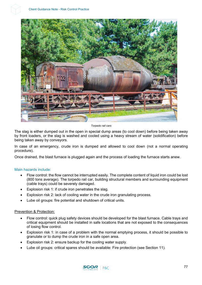
77
Client Guidance Note - Risk Control Practice
Torpedo rail cars
The slag is either dumped out in the open in special dump areas (to cool down) before being taken away by front loaders, or the slag is washed and cooled using a heavy stream of water (solidification) before being taken away by conveyors. In case of an emergency, crude iron is dumped and allowed to cool down (not a normal operating procedure). Once drained, the blast furnace is plugged again and the process of loading the furnace starts anew. Main hazards include:
• Flow control: the flow cannot be interrupted easily. The complete content of liquid iron could be lost (800 tons average). The torpedo rail car, building structural members and surrounding equipment (cable trays) could be severely damaged.
• Explosion risk 1: if crude iron penetrates the slag. • Explosion risk 2: lack of cooling water in the crude iron granulating process. • Lube oil groups: fire potential and shutdown of critical units.
Prevention & Protection:
• Flow control: quick plug safety devices should be developed for the blast furnace. Cable trays and critical equipment should be installed in safe locations that are not exposed to the consequences of losing flow control.
• Explosion risk 1: in case of a problem with the normal emptying process, it should be possible to granulate or to dump the crude iron in a safe open area.
• Explosion risk 2: ensure backup for the cooling water supply. • Lube oil groups: critical spares should be available: Fire protection (see Section 11).
78
Client Guidance Note - Risk Control Practice
Flue gas extraction: The Blast Furnace off gas is combustible and the concentration of CO is very high (toxic). The off gas must be treated (electrostatic precipitators and washers) prior to being used. The off gas can be used to run turbo generators (energy recovery) enabling a reduction in pressure. The treated off gas is used as fuel combustible gas that can feed the steel mill and other utilities or it can be sold to power plants. Main hazards include:
• Off gas high pressure: rupture of vessels, gas release ignition and explosion potential (VCE) in the gas treatment installation (confined space).
• Off gas mains rupture: usually of a large diameter and above ground. Potential rupture of mains can induce gas release, ignition and explosion potential (UVCE) in an unconfined space.
Prevention & Protection:
• Off gas high pressure: install flare lines to burn the off gas; Pressure Safety Valves (PSVs) and adequate inspection programs (3 years pre-pop test schedule – test bench on site); regular maintenance operations in order to prevent blocking of the precipitator or washers.
• Off gas mains rupture: install mechanical impact protection (e.g. pipe rack bridges over truck roads); regular inspection of main supports, main welds (X-Ray) and corrosion monitoring (thickness gauging).
Direct Reduction There is no molten metal phase for the Direct Reduction (DR) process unlike the Blast Furnace (BF) process. The direct reduction iron process is an alternative way of making iron using natural gas or coal. The process involves the direct reduction of fine iron ore concentrates in a series of reducing gas reactors. The iron is reduced in a solid state (in contrast to blast furnaces, which create iron in a molten state) at temperatures ranging from 1472°F to 2012°F (800°C to 1100°C). Hot briquetted iron (HBI) is a compacted form of DRI designed for easier handling, shipping, and storage. In the HBI process, iron ore is reduced to approximately 93% metallic iron using a reduction gas comprised of carbon monoxide (CO) and hydrogen (H2). The process operates at pressures as high as 160 psig (11 bar) and temperatures up to almost 1400°F (760°C). There are 2 main processes: Midrex and HYL:
• Both the Midrex and HYL processes (see Annex B) involve: - A unit producing reducing gases (i.e. H2 and CO). The reforming of natural gas requires a certain
level of oxidants (H2O and CO2), which must be carefully controlled, a high temperature (as a result of partial combustion) and an active catalyst, which is provided by the metallic iron units from the iron ore already reduced. Most hydrogen produced today is made via steam-methane reforming, a mature production process in which high-temperature steam (700°C–1,000°C) is used to produce hydrogen from a methane source, such as natural gas. In steam-methane reforming, methane reacts with steam under 3–25 bar pressure (1 bar = 14.5 psi) in the presence of a catalyst that produces hydrogen, carbon monoxide and a relatively small amount of carbon dioxide. Steam reforming is endothermic—that is, heat must be supplied to the process for the reaction to proceed. Explosion potential from incomplete combustion should be considered.
- A process gas compressor including a steam turbine and lubricating oil group. This could lead to disintegration and/or fire potential.
• The Midrex process takes place in a gas-based shaft furnace and is a solid-state reduction process which reduces iron ore pellets, or lump ore, into DRI without melting them, using reducing gas generally formed from natural gas.
• The HYL process is designed for the conversion of iron ore (pellets/lump ore) into metallic iron, by using reducing gases in a solid gas moving bed reactor.
• Oxygen (O2) is removed from the iron ore by chemical reactions based on hydrogen (H2) and carbon monoxide (CO) for the production of highly metallized Direct Reduced Iron (DRI)/Hot Briquetted Iron (HBI).
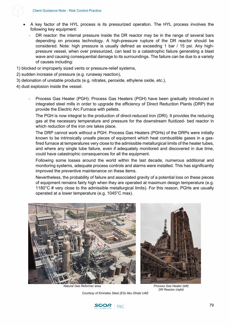
79
Client Guidance Note - Risk Control Practice
• A key factor of the HYL process is its pressurized operation. The HYL process involves the following key equipment:
- DR reactor: the internal pressure inside the DR reactor may be in the range of several bars depending on process technology. A high-pressure rupture of the DR reactor should be considered. Note: high pressure is usually defined as exceeding 1 bar / 15 psi. Any high-pressure vessel, when over pressurized, can lead to a catastrophic failure generating a blast wave and causing consequential damage to its surroundings. The failure can be due to a variety of causes including:
1) blocked or improperly sized vents or pressure-relief systems, 2) sudden increase of pressure (e.g. runaway reaction), 3) detonation of unstable products (e.g. nitrates, peroxide, ethylene oxide, etc.), 4) dust explosion inside the vessel.
- Process Gas Heater (PGH): Process Gas Heaters (PGH) have been gradually introduced in integrated steel mills in order to upgrade the efficiency of Direct Reduction Plants (DRP) that provide the Electric Arc Furnace with pellets. The PGH is now integral to the production of direct-reduced iron (DRI). It provides the reducing gas at the necessary temperature and pressure for the downstream fluidized- bed reactor in which reduction of the iron ore takes place. The DRP cannot work without a PGH. Process Gas Heaters (PGHs) of the DRPs were initially known to be intrinsically unsafe pieces of equipment which heat combustible gases in a gas-fired furnace at temperatures very close to the admissible metallurgical limits of the heater tubes, and where any single tube failure, even if adequately monitored and discovered in due time, could have catastrophic consequences for all the equipment. Following some losses around the world within the last decade, numerous additional and monitoring systems, adequate process controls and alarms were installed. This has significantly improved the preventive maintenance on these items. Nevertheless, the probability of failure and associated gravity of a potential loss on these pieces of equipment remains fairly high when they are operated at maximum design temperature (e.g. 1180°C # very close to the admissible metallurgical limits). For this reason, PGHs are usually operated at a lower temperature (e.g. 1045°C max).
Natural Gas Reformer area Process Gas Heater (left)
DR Reactor (right) Courtesy of Emirates Steel (ES) Abu Dhabi UAE
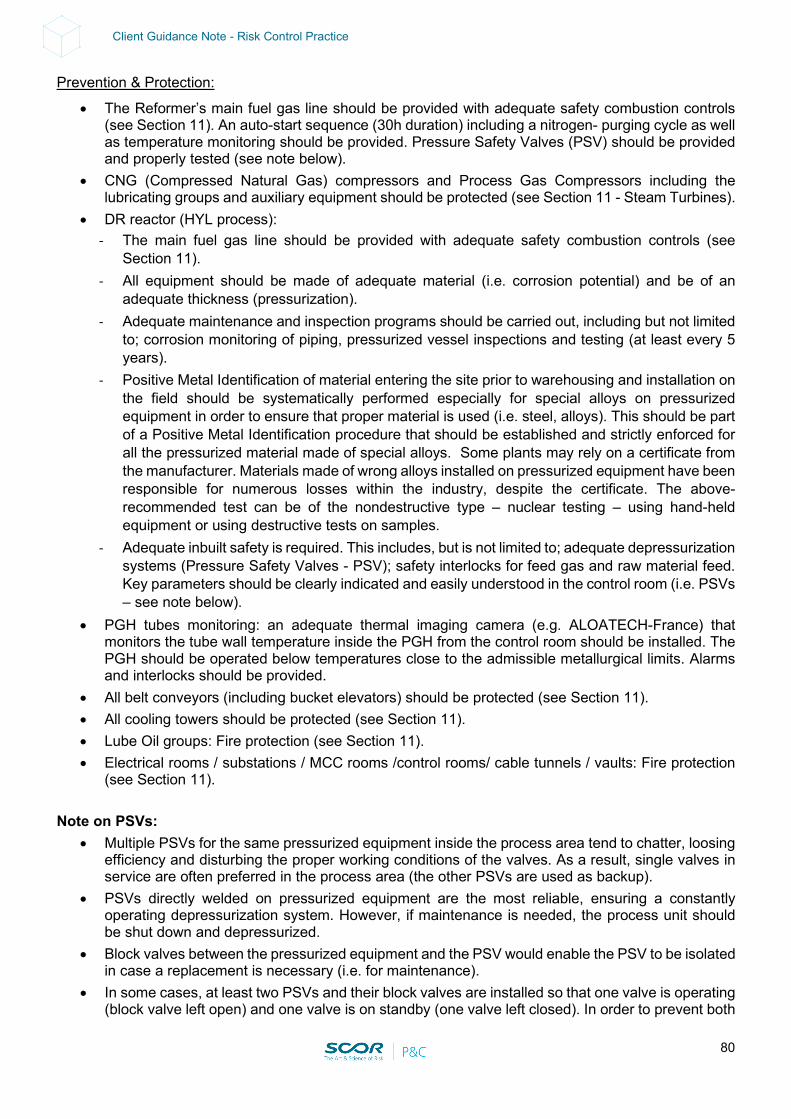
80
Client Guidance Note - Risk Control Practice
Prevention & Protection:
• The Reformer’s main fuel gas line should be provided with adequate safety combustion controls (see Section 11). An auto-start sequence (30h duration) including a nitrogen- purging cycle as well as temperature monitoring should be provided. Pressure Safety Valves (PSV) should be provided and properly tested (see note below).
• CNG (Compressed Natural Gas) compressors and Process Gas Compressors including the lubricating groups and auxiliary equipment should be protected (see Section 11 - Steam Turbines).
• DR reactor (HYL process): - The main fuel gas line should be provided with adequate safety combustion controls (see
Section 11). - All equipment should be made of adequate material (i.e. corrosion potential) and be of an
adequate thickness (pressurization). - Adequate maintenance and inspection programs should be carried out, including but not limited
to; corrosion monitoring of piping, pressurized vessel inspections and testing (at least every 5 years).
- Positive Metal Identification of material entering the site prior to warehousing and installation on the field should be systematically performed especially for special alloys on pressurized equipment in order to ensure that proper material is used (i.e. steel, alloys). This should be part of a Positive Metal Identification procedure that should be established and strictly enforced for all the pressurized material made of special alloys. Some plants may rely on a certificate from the manufacturer. Materials made of wrong alloys installed on pressurized equipment have been responsible for numerous losses within the industry, despite the certificate. The above-recommended test can be of the nondestructive type – nuclear testing – using hand-held equipment or using destructive tests on samples.
- Adequate inbuilt safety is required. This includes, but is not limited to; adequate depressurization systems (Pressure Safety Valves - PSV); safety interlocks for feed gas and raw material feed. Key parameters should be clearly indicated and easily understood in the control room (i.e. PSVs – see note below).
• PGH tubes monitoring: an adequate thermal imaging camera (e.g. ALOATECH-France) that monitors the tube wall temperature inside the PGH from the control room should be installed. The PGH should be operated below temperatures close to the admissible metallurgical limits. Alarms and interlocks should be provided.
• All belt conveyors (including bucket elevators) should be protected (see Section 11). • All cooling towers should be protected (see Section 11). • Lube Oil groups: Fire protection (see Section 11). • Electrical rooms / substations / MCC rooms /control rooms/ cable tunnels / vaults: Fire protection
(see Section 11). Note on PSVs:
• Multiple PSVs for the same pressurized equipment inside the process area tend to chatter, loosing efficiency and disturbing the proper working conditions of the valves. As a result, single valves in service are often preferred in the process area (the other PSVs are used as backup).
• PSVs directly welded on pressurized equipment are the most reliable, ensuring a constantly operating depressurization system. However, if maintenance is needed, the process unit should be shut down and depressurized.
• Block valves between the pressurized equipment and the PSV would enable the PSV to be isolated in case a replacement is necessary (i.e. for maintenance).
• In some cases, at least two PSVs and their block valves are installed so that one valve is operating (block valve left open) and one valve is on standby (one valve left closed). In order to prevent both
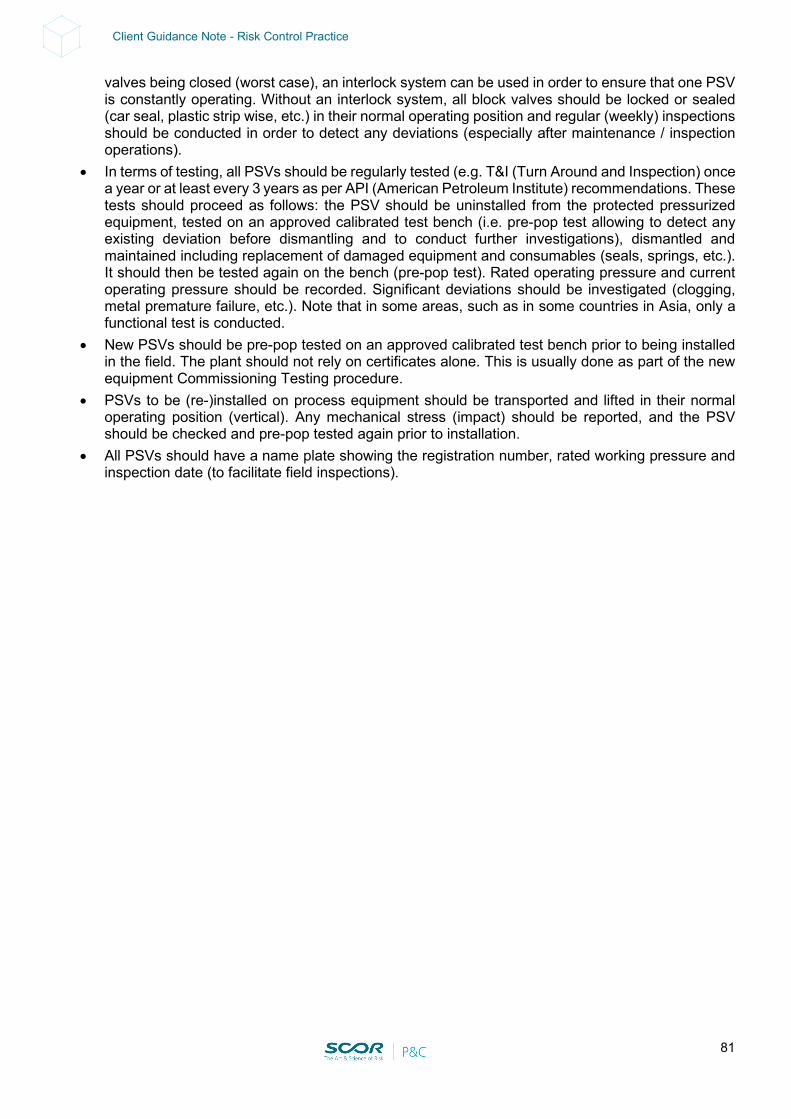
81
Client Guidance Note - Risk Control Practice
valves being closed (worst case), an interlock system can be used in order to ensure that one PSV is constantly operating. Without an interlock system, all block valves should be locked or sealed (car seal, plastic strip wise, etc.) in their normal operating position and regular (weekly) inspections should be conducted in order to detect any deviations (especially after maintenance / inspection operations).
• In terms of testing, all PSVs should be regularly tested (e.g. T&I (Turn Around and Inspection) once a year or at least every 3 years as per API (American Petroleum Institute) recommendations. These tests should proceed as follows: the PSV should be uninstalled from the protected pressurized equipment, tested on an approved calibrated test bench (i.e. pre-pop test allowing to detect any existing deviation before dismantling and to conduct further investigations), dismantled and maintained including replacement of damaged equipment and consumables (seals, springs, etc.). It should then be tested again on the bench (pre-pop test). Rated operating pressure and current operating pressure should be recorded. Significant deviations should be investigated (clogging, metal premature failure, etc.). Note that in some areas, such as in some countries in Asia, only a functional test is conducted.
• New PSVs should be pre-pop tested on an approved calibrated test bench prior to being installed in the field. The plant should not rely on certificates alone. This is usually done as part of the new equipment Commissioning Testing procedure.
• PSVs to be (re-)installed on process equipment should be transported and lifted in their normal operating position (vertical). Any mechanical stress (impact) should be reported, and the PSV should be checked and pre-pop tested again prior to installation.
• All PSVs should have a name plate showing the registration number, rated working pressure and inspection date (to facilitate field inspections).
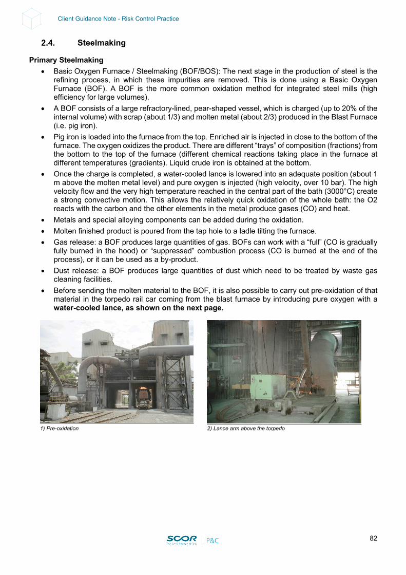
82
Client Guidance Note - Risk Control Practice
Steelmaking
Primary Steelmaking • Basic Oxygen Furnace / Steelmaking (BOF/BOS): The next stage in the production of steel is the
refining process, in which these impurities are removed. This is done using a Basic Oxygen Furnace (BOF). A BOF is the more common oxidation method for integrated steel mills (high efficiency for large volumes).
• A BOF consists of a large refractory-lined, pear-shaped vessel, which is charged (up to 20% of the internal volume) with scrap (about 1/3) and molten metal (about 2/3) produced in the Blast Furnace (i.e. pig iron).
• Pig iron is loaded into the furnace from the top. Enriched air is injected in close to the bottom of the furnace. The oxygen oxidizes the product. There are different “trays” of composition (fractions) from the bottom to the top of the furnace (different chemical reactions taking place in the furnace at different temperatures (gradients). Liquid crude iron is obtained at the bottom.
• Once the charge is completed, a water-cooled lance is lowered into an adequate position (about 1 m above the molten metal level) and pure oxygen is injected (high velocity, over 10 bar). The high velocity flow and the very high temperature reached in the central part of the bath (3000°C) create a strong convective motion. This allows the relatively quick oxidation of the whole bath: the O2 reacts with the carbon and the other elements in the metal produce gases (CO) and heat.
• Metals and special alloying components can be added during the oxidation. • Molten finished product is poured from the tap hole to a ladle tilting the furnace. • Gas release: a BOF produces large quantities of gas. BOFs can work with a “full” (CO is gradually
fully burned in the hood) or “suppressed” combustion process (CO is burned at the end of the process), or it can be used as a by-product.
• Dust release: a BOF produces large quantities of dust which need to be treated by waste gas cleaning facilities.
• Before sending the molten material to the BOF, it is also possible to carry out pre-oxidation of that material in the torpedo rail car coming from the blast furnace by introducing pure oxygen with a water-cooled lance, as shown on the next page.
1) Pre-oxidation 2) Lance arm above the torpedo
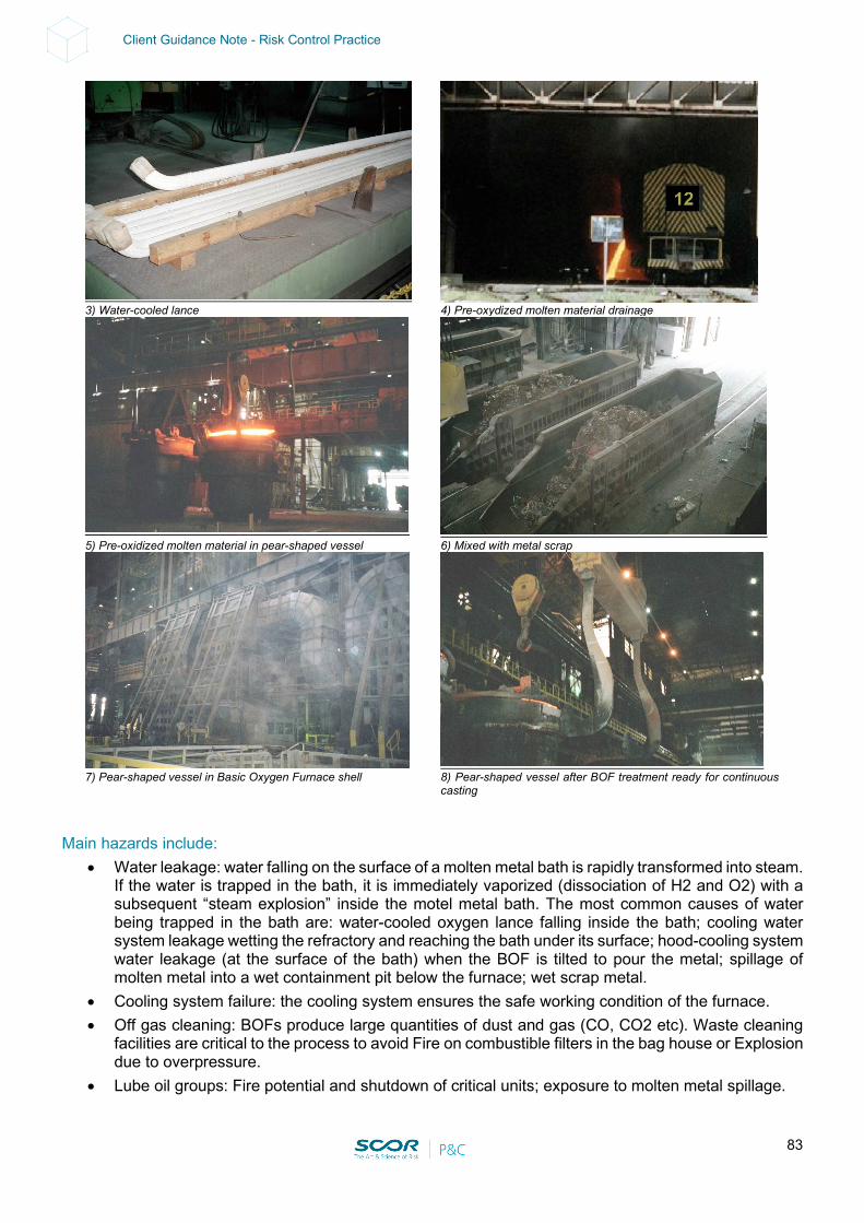
83
Client Guidance Note - Risk Control Practice
Main hazards include:
• Water leakage: water falling on the surface of a molten metal bath is rapidly transformed into steam. If the water is trapped in the bath, it is immediately vaporized (dissociation of H2 and O2) with a subsequent “steam explosion” inside the motel metal bath. The most common causes of water being trapped in the bath are: water-cooled oxygen lance falling inside the bath; cooling water system leakage wetting the refractory and reaching the bath under its surface; hood-cooling system water leakage (at the surface of the bath) when the BOF is tilted to pour the metal; spillage of molten metal into a wet containment pit below the furnace; wet scrap metal.
• Cooling system failure: the cooling system ensures the safe working condition of the furnace. • Off gas cleaning: BOFs produce large quantities of dust and gas (CO, CO2 etc). Waste cleaning
facilities are critical to the process to avoid Fire on combustible filters in the bag house or Explosion due to overpressure.
• Lube oil groups: Fire potential and shutdown of critical units; exposure to molten metal spillage.
3) Water-cooled lance 4) Pre-oxydized molten material drainage
5) Pre-oxidized molten material in pear-shaped vessel 6) Mixed with metal scrap
7) Pear-shaped vessel in Basic Oxygen Furnace shell 8) Pear-shaped vessel after BOF treatment ready for continuous
casting
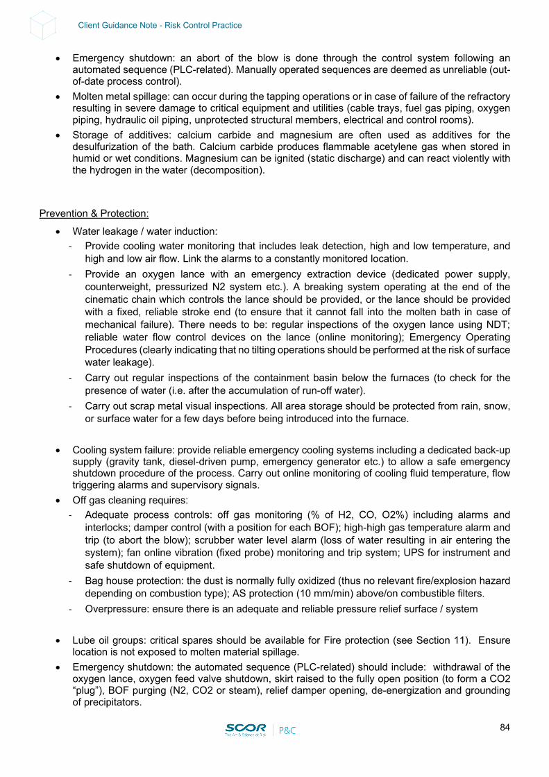
84
Client Guidance Note - Risk Control Practice
• Emergency shutdown: an abort of the blow is done through the control system following an automated sequence (PLC-related). Manually operated sequences are deemed as unreliable (out-of-date process control).
• Molten metal spillage: can occur during the tapping operations or in case of failure of the refractory resulting in severe damage to critical equipment and utilities (cable trays, fuel gas piping, oxygen piping, hydraulic oil piping, unprotected structural members, electrical and control rooms).
• Storage of additives: calcium carbide and magnesium are often used as additives for the desulfurization of the bath. Calcium carbide produces flammable acetylene gas when stored in humid or wet conditions. Magnesium can be ignited (static discharge) and can react violently with the hydrogen in the water (decomposition).
Prevention & Protection:
• Water leakage / water induction: - Provide cooling water monitoring that includes leak detection, high and low temperature, and
high and low air flow. Link the alarms to a constantly monitored location. - Provide an oxygen lance with an emergency extraction device (dedicated power supply,
counterweight, pressurized N2 system etc.). A breaking system operating at the end of the cinematic chain which controls the lance should be provided, or the lance should be provided with a fixed, reliable stroke end (to ensure that it cannot fall into the molten bath in case of mechanical failure). There needs to be: regular inspections of the oxygen lance using NDT; reliable water flow control devices on the lance (online monitoring); Emergency Operating Procedures (clearly indicating that no tilting operations should be performed at the risk of surface water leakage).
- Carry out regular inspections of the containment basin below the furnaces (to check for the presence of water (i.e. after the accumulation of run-off water).
- Carry out scrap metal visual inspections. All area storage should be protected from rain, snow, or surface water for a few days before being introduced into the furnace.
• Cooling system failure: provide reliable emergency cooling systems including a dedicated back-up supply (gravity tank, diesel-driven pump, emergency generator etc.) to allow a safe emergency shutdown procedure of the process. Carry out online monitoring of cooling fluid temperature, flow triggering alarms and supervisory signals.
• Off gas cleaning requires: - Adequate process controls: off gas monitoring (% of H2, CO, O2%) including alarms and
interlocks; damper control (with a position for each BOF); high-high gas temperature alarm and trip (to abort the blow); scrubber water level alarm (loss of water resulting in air entering the system); fan online vibration (fixed probe) monitoring and trip system; UPS for instrument and safe shutdown of equipment.
- Bag house protection: the dust is normally fully oxidized (thus no relevant fire/explosion hazard depending on combustion type); AS protection (10 mm/min) above/on combustible filters.
- Overpressure: ensure there is an adequate and reliable pressure relief surface / system
• Lube oil groups: critical spares should be available for Fire protection (see Section 11). Ensure location is not exposed to molten material spillage.
• Emergency shutdown: the automated sequence (PLC-related) should include: withdrawal of the oxygen lance, oxygen feed valve shutdown, skirt raised to the fully open position (to form a CO2 “plug”), BOF purging (N2, CO2 or steam), relief damper opening, de-energization and grounding of precipitators.
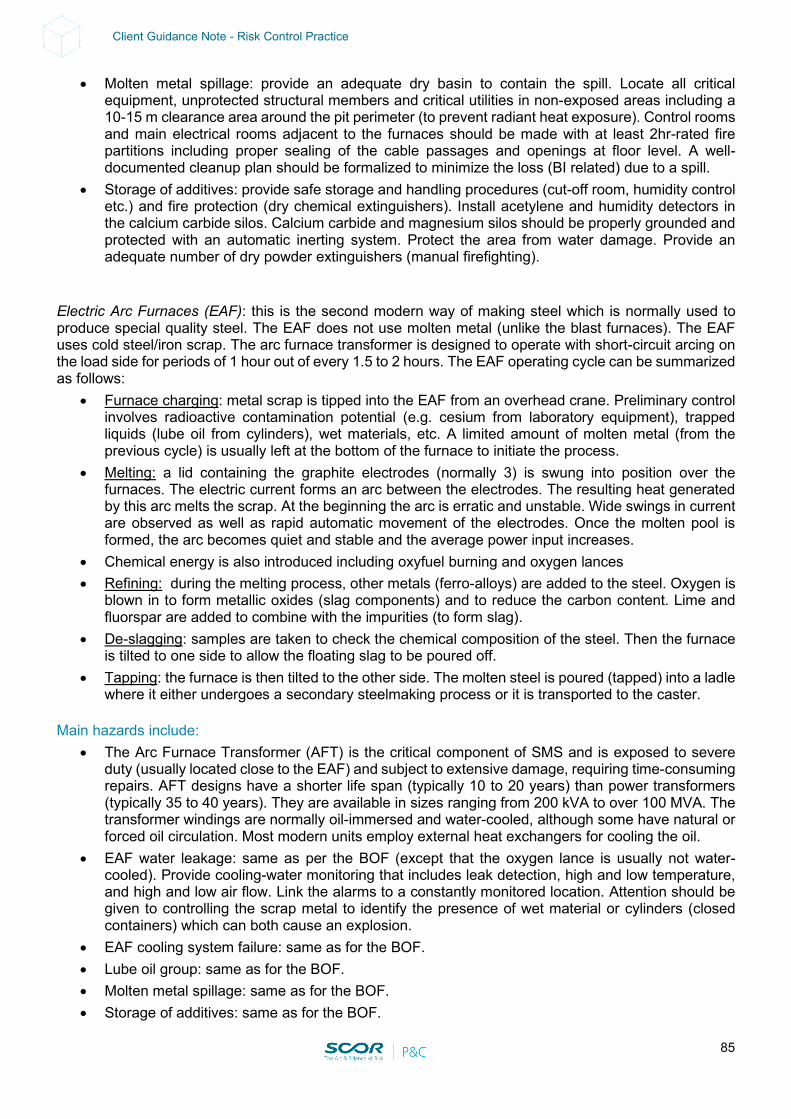
85
Client Guidance Note - Risk Control Practice
• Molten metal spillage: provide an adequate dry basin to contain the spill. Locate all critical equipment, unprotected structural members and critical utilities in non-exposed areas including a 10-15 m clearance area around the pit perimeter (to prevent radiant heat exposure). Control rooms and main electrical rooms adjacent to the furnaces should be made with at least 2hr-rated fire partitions including proper sealing of the cable passages and openings at floor level. A well-documented cleanup plan should be formalized to minimize the loss (BI related) due to a spill.
• Storage of additives: provide safe storage and handling procedures (cut-off room, humidity control etc.) and fire protection (dry chemical extinguishers). Install acetylene and humidity detectors in the calcium carbide silos. Calcium carbide and magnesium silos should be properly grounded and protected with an automatic inerting system. Protect the area from water damage. Provide an adequate number of dry powder extinguishers (manual firefighting).
Electric Arc Furnaces (EAF): this is the second modern way of making steel which is normally used to produce special quality steel. The EAF does not use molten metal (unlike the blast furnaces). The EAF uses cold steel/iron scrap. The arc furnace transformer is designed to operate with short-circuit arcing on the load side for periods of 1 hour out of every 1.5 to 2 hours. The EAF operating cycle can be summarized as follows:
• Furnace charging: metal scrap is tipped into the EAF from an overhead crane. Preliminary control involves radioactive contamination potential (e.g. cesium from laboratory equipment), trapped liquids (lube oil from cylinders), wet materials, etc. A limited amount of molten metal (from the previous cycle) is usually left at the bottom of the furnace to initiate the process.
• Melting: a lid containing the graphite electrodes (normally 3) is swung into position over the furnaces. The electric current forms an arc between the electrodes. The resulting heat generated by this arc melts the scrap. At the beginning the arc is erratic and unstable. Wide swings in current are observed as well as rapid automatic movement of the electrodes. Once the molten pool is formed, the arc becomes quiet and stable and the average power input increases.
• Chemical energy is also introduced including oxyfuel burning and oxygen lances • Refining: during the melting process, other metals (ferro-alloys) are added to the steel. Oxygen is
blown in to form metallic oxides (slag components) and to reduce the carbon content. Lime and fluorspar are added to combine with the impurities (to form slag).
• De-slagging: samples are taken to check the chemical composition of the steel. Then the furnace is tilted to one side to allow the floating slag to be poured off.
• Tapping: the furnace is then tilted to the other side. The molten steel is poured (tapped) into a ladle where it either undergoes a secondary steelmaking process or it is transported to the caster.
Main hazards include:
• The Arc Furnace Transformer (AFT) is the critical component of SMS and is exposed to severe duty (usually located close to the EAF) and subject to extensive damage, requiring time-consuming repairs. AFT designs have a shorter life span (typically 10 to 20 years) than power transformers (typically 35 to 40 years). They are available in sizes ranging from 200 kVA to over 100 MVA. The transformer windings are normally oil-immersed and water-cooled, although some have natural or forced oil circulation. Most modern units employ external heat exchangers for cooling the oil.
• EAF water leakage: same as per the BOF (except that the oxygen lance is usually not water- cooled). Provide cooling-water monitoring that includes leak detection, high and low temperature, and high and low air flow. Link the alarms to a constantly monitored location. Attention should be given to controlling the scrap metal to identify the presence of wet material or cylinders (closed containers) which can both cause an explosion.
• EAF cooling system failure: same as for the BOF. • Lube oil group: same as for the BOF. • Molten metal spillage: same as for the BOF. • Storage of additives: same as for the BOF.
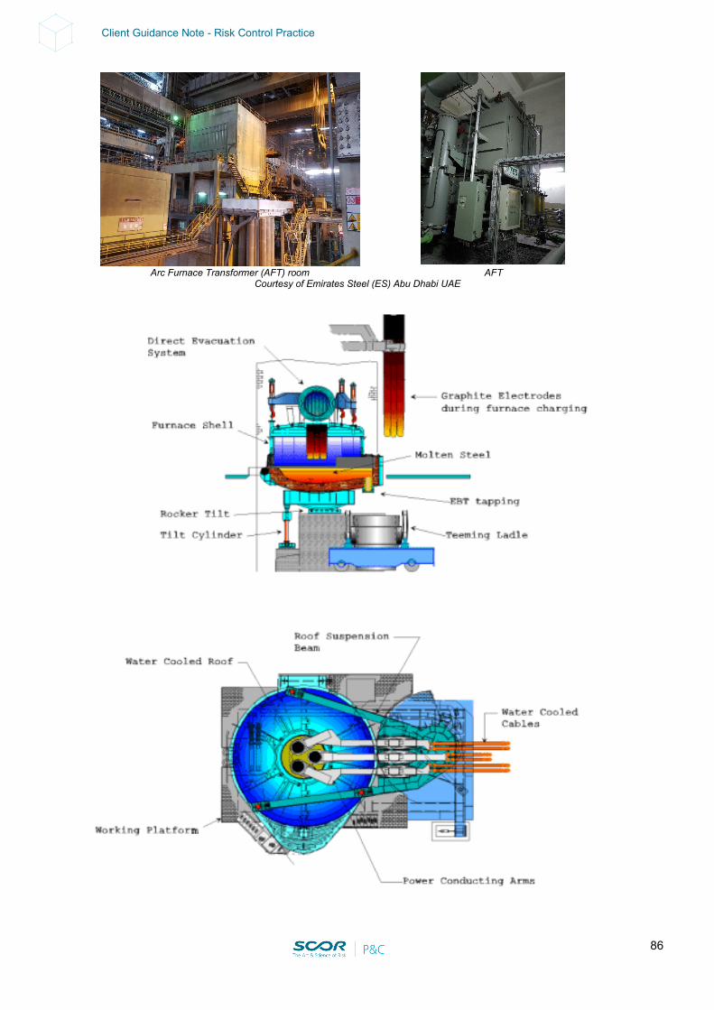
86
Client Guidance Note - Risk Control Practice
Courtesy of Emirates Steel (ES) Abu Dhabi UAE
Arc Furnace Transformer (AFT) room AFT
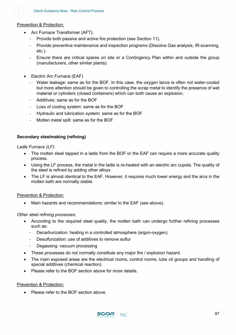
87
Client Guidance Note - Risk Control Practice
Prevention & Protection:
• Arc Furnace Transformer (AFT): - Provide both passive and active fire protection (see Section 11). - Provide preventive maintenance and inspection programs (Dissolve Gas analysis, IR-scanning,
etc.). - Ensure there are critical spares on site or a Contingency Plan within and outside the group
(manufacturers, other similar plants).
• Electric Arc Furnace (EAF) - Water leakage: same as for the BOF. In this case, the oxygen lance is often not water-cooled
but more attention should be given to controlling the scrap metal to identify the presence of wet material or cylinders (closed containers) which can both cause an explosion.
- Additives: same as for the BOF - Loss of cooling system: same as for the BOF - Hydraulic and lubrication system: same as for the BOF - Molten metal spill: same as for the BOF
Secondary steelmaking (refining) Ladle Furnace (LF):
• The molten steel tapped in a ladle from the BOF or the EAF can require a more accurate quality process.
• Using the LF process, the metal in the ladle is re-heated with an electric arc cupola. The quality of the steel is refined by adding other alloys.
• The LF is almost identical to the EAF. However, it requires much lower energy and the arcs in the molten bath are normally stable.
Prevention & Protection:
• Main hazards and recommendations: similar to the EAF (see above). Other steel refining processes:
• According to the required steel quality, the molten bath can undergo further refining processes such as:
- Decarburization: heating in a controlled atmosphere (argon-oxygen) - Desulfurization: use of additives to remove sulfur - Degassing: vacuum processing
• These processes do not normally constitute any major fire / explosion hazard. • The main exposed areas are the electrical rooms, control rooms, lube oil groups and handling of
special additives (chemical reaction). • Please refer to the BOF section above for more details.
Prevention & Protection:
• Please refer to the BOF section above.
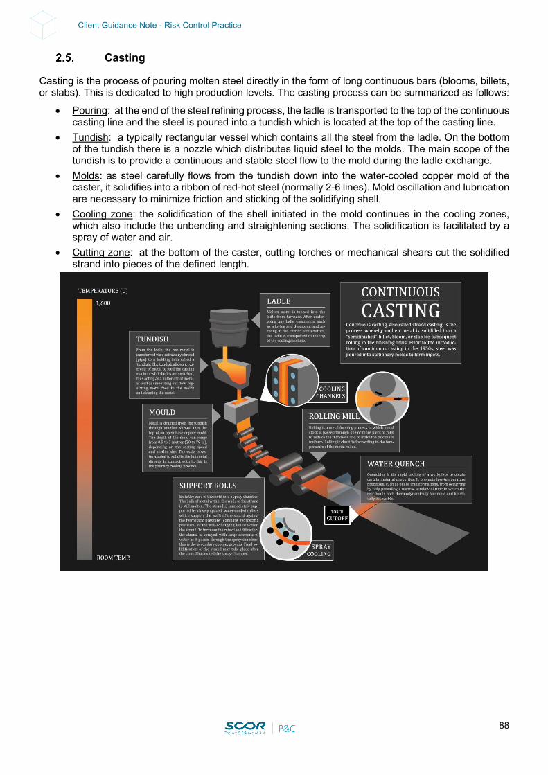
88
Client Guidance Note - Risk Control Practice
Casting
Casting is the process of pouring molten steel directly in the form of long continuous bars (blooms, billets, or slabs). This is dedicated to high production levels. The casting process can be summarized as follows:
• Pouring: at the end of the steel refining process, the ladle is transported to the top of the continuous casting line and the steel is poured into a tundish which is located at the top of the casting line.
• Tundish: a typically rectangular vessel which contains all the steel from the ladle. On the bottom of the tundish there is a nozzle which distributes liquid steel to the molds. The main scope of the tundish is to provide a continuous and stable steel flow to the mold during the ladle exchange.
• Molds: as steel carefully flows from the tundish down into the water-cooled copper mold of the caster, it solidifies into a ribbon of red-hot steel (normally 2-6 lines). Mold oscillation and lubrication are necessary to minimize friction and sticking of the solidifying shell.
• Cooling zone: the solidification of the shell initiated in the mold continues in the cooling zones, which also include the unbending and straightening sections. The solidification is facilitated by a spray of water and air.
• Cutting zone: at the bottom of the caster, cutting torches or mechanical shears cut the solidified strand into pieces of the defined length.
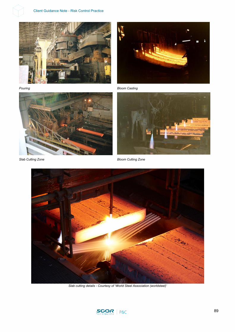
89
Client Guidance Note - Risk Control Practice
Pouring Bloom Casting
Slab Cutting Zone Bloom Cutting Zone
Slab cutting details - Courtesy of ‘World Steel Association (worldsteel)’
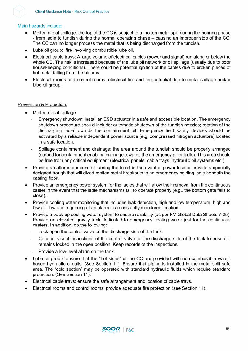
90
Client Guidance Note - Risk Control Practice
Main hazards include: • Molten metal spillage: the top of the CC is subject to a molten metal spill during the pouring phase
- from ladle to tundish during the normal operating phase – causing an improper stop of the CC. The CC can no longer process the metal that is being discharged from the tundish.
• Lube oil group: fire involving combustible lube oil. • Electrical cable trays: A large volume of electrical cables (power and signal) run along or below the
whole CC. The risk is increased because of the lube oil network or oil spillage (usually due to poor housekeeping conditions). There could be potential ignition of the cables due to broken pieces of hot metal falling from the blooms.
• Electrical rooms and control rooms: electrical fire and fire potential due to metal spillage and/or lube oil group.
Prevention & Protection:
• Molten metal spillage: - Emergency shutdown: install an ESD actuator in a safe and accessible location. The emergency
shutdown procedure should include: automatic shutdown of the tundish nozzles; rotation of the discharging ladle towards the containment pit. Emergency field safety devices should be activated by a reliable independent power source (e.g. compressed nitrogen actuators) located in a safe location.
- Spillage containment and drainage: the area around the tundish should be properly arranged (curbed for containment enabling drainage towards the emergency pit or ladle). This area should be free from any critical equipment (electrical panels, cable trays, hydraulic oil systems etc.)
• Provide an alternate means of turning the turret in the event of power loss or provide a specially designed trough that will divert molten metal breakouts to an emergency holding ladle beneath the casting floor.
• Provide an emergency power system for the ladles that will allow their removal from the continuous caster in the event that the ladle mechanisms fail to operate properly (e.g., the bottom gate fails to close).
• Provide cooling water monitoring that includes leak detection, high and low temperature, high and low air flow and triggering of an alarm in a constantly monitored location.
• Provide a back-up cooling water system to ensure reliability (as per FM Global Data Sheets 7-25). Provide an elevated gravity tank dedicated to emergency cooling water just for the continuous casters. In addition, do the following:
- Lock open the control valve on the discharge side of the tank. - Conduct visual inspections of the control valve on the discharge side of the tank to ensure it
remains locked in the open position. Keep records of the inspections. - Provide a low-level alarm on the tank.
• Lube oil group: ensure that the “hot sides” of the CC are provided with non-combustible water-based hydraulic circuits. (See Section 11). Ensure that piping is installed in the metal spill safe area. The “cold section” may be operated with standard hydraulic fluids which require standard protection. (See Section 11).
• Electrical cable trays: ensure the safe arrangement and location of cable trays. • Electrical rooms and control rooms: provide adequate fire protection (see Section 11).
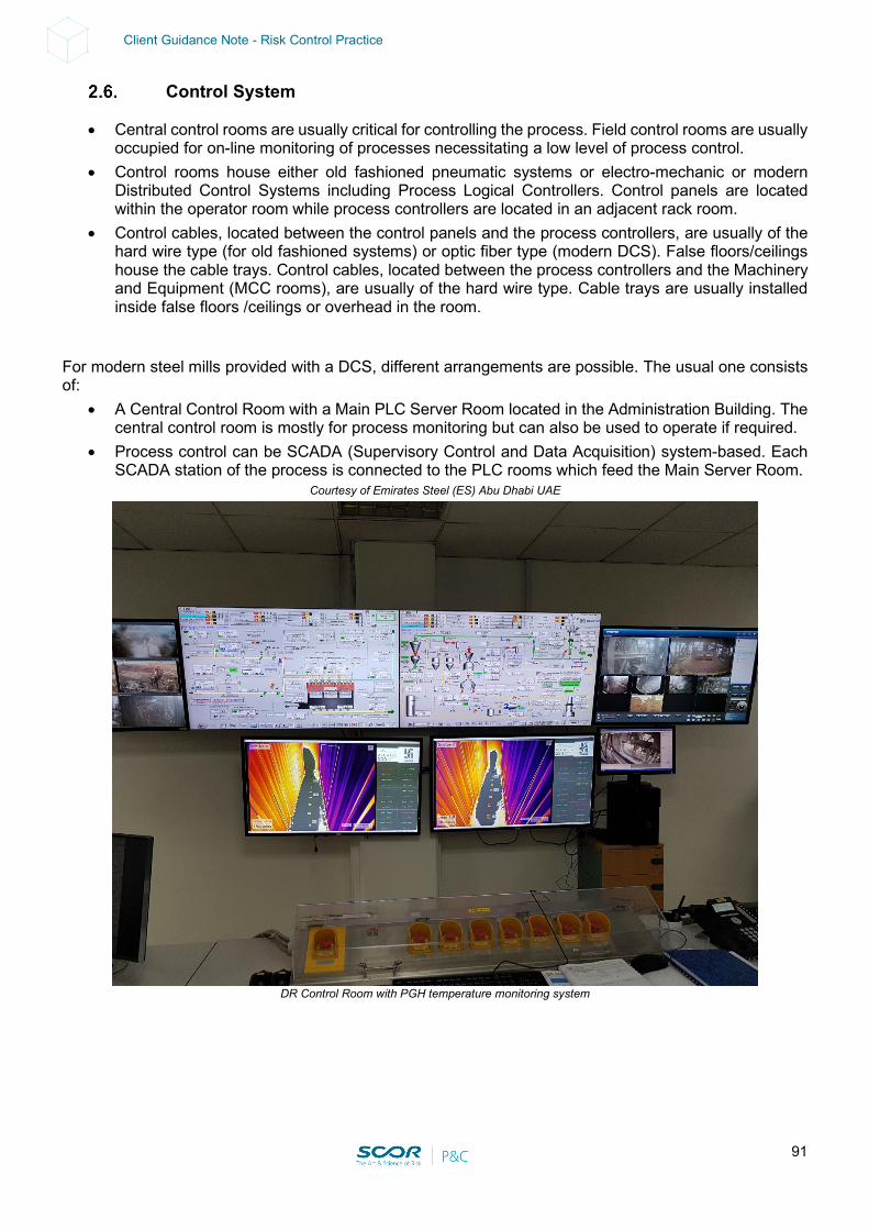
91
Client Guidance Note - Risk Control Practice
Control System
• Central control rooms are usually critical for controlling the process. Field control rooms are usually occupied for on-line monitoring of processes necessitating a low level of process control.
• Control rooms house either old fashioned pneumatic systems or electro-mechanic or modern Distributed Control Systems including Process Logical Controllers. Control panels are located within the operator room while process controllers are located in an adjacent rack room.
• Control cables, located between the control panels and the process controllers, are usually of the hard wire type (for old fashioned systems) or optic fiber type (modern DCS). False floors/ceilings house the cable trays. Control cables, located between the process controllers and the Machinery and Equipment (MCC rooms), are usually of the hard wire type. Cable trays are usually installed inside false floors /ceilings or overhead in the room.
For modern steel mills provided with a DCS, different arrangements are possible. The usual one consists of:
• A Central Control Room with a Main PLC Server Room located in the Administration Building. The central control room is mostly for process monitoring but can also be used to operate if required.
• Process control can be SCADA (Supervisory Control and Data Acquisition) system-based. Each SCADA station of the process is connected to the PLC rooms which feed the Main Server Room.
Courtesy of Emirates Steel (ES) Abu Dhabi UAE
DR Control Room with PGH temperature monitoring system
92
Client Guidance Note - Risk Control Practice
Main Hazards include: • Cable fire: fire potential depending on the combustible load; potential BI issues. • Rack room / MCC room fire: fire potential depending on the combustible load; BI issues. • Process Exposure: special attention should be given to the control rooms dedicated to processes
involving molten metal (blast furnaces, basic oxygen converts and arc furnaces). There could be potential damage due to the projection of molten material and/or explosion of hazardous process equipment.
Prevention & Protection:
• Depending on the arrangement, cyber security and a so-called “disaster recovery plan” for IT (i.e. loss of data) should be considered.
• Server room: when redundant servers are provided, they should be located in different areas. If only one server is provided, a Contingency Plan and an adequate automatic fire protection system should be provided (see ‘Rec. for Electric Rooms’, Section 11).
Spare Parts Warehouse
• Critical and very expensive spares are usally stored in one or more warehouses. Heavy spares and consumables are usually well separated. The inventory can represent several Milion USD (e.g. $60-80 M or more).
• These spares are critical to the process and can have a relatively long lead time. Some consumables used in relatively large quantities and/or having a long lead time are also deemed as critical. A major loss in such a warehouse could lead to BI for the related units due to lack of spares.
Prevention & Protection:
• Critical spares should be clearly identified. The commodity class should be clearly established as per NFPA and the warehouse should be provided with adequate and approved automatic fire detection / protection (see Section 11).
• Flammable and combustible liquids and spray cans should not be stored in such warehouses but rather in a dedicated safe area fitted with the necessary ventilation measures, leak detection & containment. Hazmat and compressed gases should be stored and protected (see Section 11).
• Big drivers should also be stored (see Section 11).
93
Client Guidance Note - Risk Control Practice
3. CONTINGENCY / BUSINESS CONTINUITY / RECOVERY PLAN
Warning: in order to be reliable, a Contingency / Business Continuity / Recovery Plan should be formalized. This would include formal contracts signed in advance with vendors and/or third parties. The plan should be regularly tested, reviewed and updated. Holistic view:
• If the Raw Material preparation, Ironmaking, Steelmaking and Casting is part of a group with a relatively high level of vertical integration in the Steel industry, a Business Continuity Plan (BCP) at corporate level should be developed for the main identified risks in each and every process unit.
• The impact of a loss impacting third parties (i.e. logistics, utilities) should be investigated and an adequate BCP should be established.
Site view:
• Raw Material Supply: identify and establish contracts with different suppliers for all RM. Receiving the required amount of RM may be challenging if there is a limited number of suppliers and if one main supplier fails.
• Provide spare parts for critical pieces of equipment, including, but not limited to the following items for the Blast Furnace (BF):
- Ore handling equipment: skip cars, rails, hoist drums, a gearbox and motor for the hoist. For modern blast furnace feed conveyors: spares for all moving parts and a spare feed belt.
- Furnace top: complete spare top, bell segments, distributor gear and bell rods. - Water-cooled components: multiple cooling plates, staves, hot blast valves, stove valves, and
tuyere coolers. - Bustle pipe, blow stock material and tuyeres: multiples of these components to expedite any
emergency repair. Provide additional inventory of tuyeres above the number typically needed to replace those that are consumed in normal operations.
- Tap hole assembly: complete set of spares for the mud gun and drill; spare tap hole refractory and assembly, including refractory block for the local hearth side wall.
- The furnace hearth: hearth steel of proper thickness and curvature, and sufficient spare hearth side wall block material for patch repair in case of breakout. Maintain a complete set of spare beams for the bottom of the hearth for furnaces that are near end-of-life or have known hearth problems.
- Flue gas and bag house: spare in-line fans and motors for the bag house. - Turbo blowers: at least one in-line assembled spare blower. In addition to the in-line spare
blower, provide a spare set of rotors and diaphragms and key parts. Provide spare parts for any gear box present between the driver and blower.
• Provide a viable spare arc furnace transformer of at least equal size. Ensure the spare arc furnace transformer is stored in a safe, clean, dry location (not outside or in the path of molten material traffic).
• Provide spare parts for critical pieces of equipment, including, but not limited to, the following items for the Electric Arc Furnace (EAF) and Ladle Furnace (LF):
- Hearth: side panels, top panels, and roof panels; a complete hearth bottom on site or shared between a number of locations.
- If a twin shell arc furnace is in use, provide a spare slew bearing for under the arc furnace mast. Store the spare slew bearing in oil to maintain its condition.
- Note: Similar exposures exist with a system called “Con-Arc,” where the arc mast swings between two large ladles used for AOD converting.
- Electrical supply: spare delta closure and surge packages.
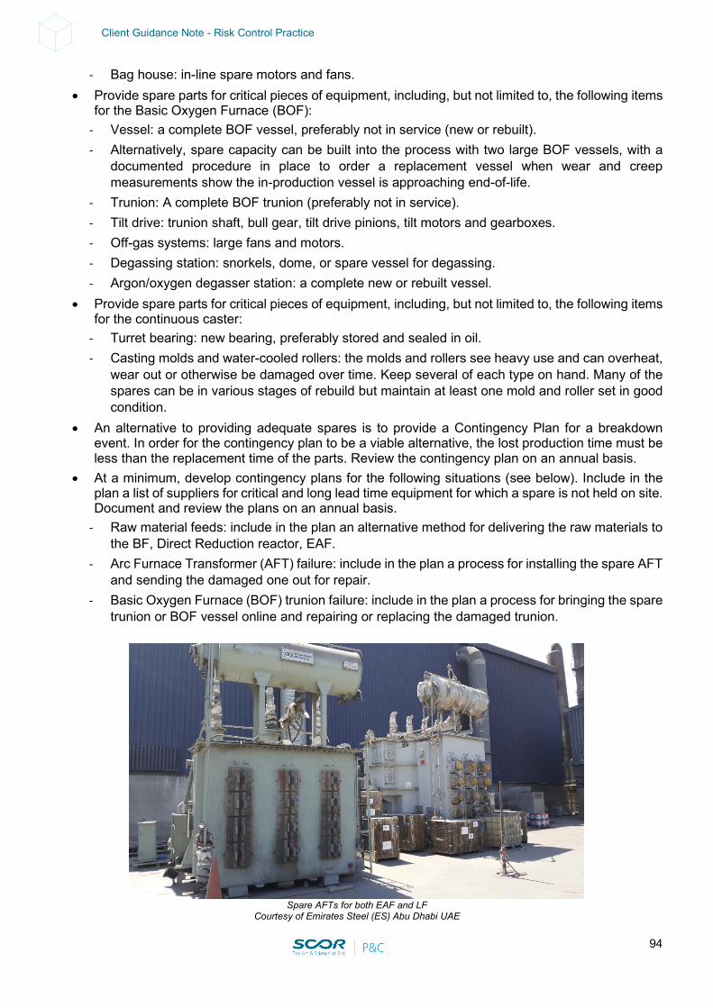
94
Client Guidance Note - Risk Control Practice
- Bag house: in-line spare motors and fans. • Provide spare parts for critical pieces of equipment, including, but not limited to, the following items
for the Basic Oxygen Furnace (BOF): - Vessel: a complete BOF vessel, preferably not in service (new or rebuilt). - Alternatively, spare capacity can be built into the process with two large BOF vessels, with a
documented procedure in place to order a replacement vessel when wear and creep measurements show the in-production vessel is approaching end-of-life.
- Trunion: A complete BOF trunion (preferably not in service). - Tilt drive: trunion shaft, bull gear, tilt drive pinions, tilt motors and gearboxes. - Off-gas systems: large fans and motors. - Degassing station: snorkels, dome, or spare vessel for degassing. - Argon/oxygen degasser station: a complete new or rebuilt vessel.
• Provide spare parts for critical pieces of equipment, including, but not limited to, the following items for the continuous caster:
- Turret bearing: new bearing, preferably stored and sealed in oil. - Casting molds and water-cooled rollers: the molds and rollers see heavy use and can overheat,
wear out or otherwise be damaged over time. Keep several of each type on hand. Many of the spares can be in various stages of rebuild but maintain at least one mold and roller set in good condition.
• An alternative to providing adequate spares is to provide a Contingency Plan for a breakdown event. In order for the contingency plan to be a viable alternative, the lost production time must be less than the replacement time of the parts. Review the contingency plan on an annual basis.
• At a minimum, develop contingency plans for the following situations (see below). Include in the plan a list of suppliers for critical and long lead time equipment for which a spare is not held on site. Document and review the plans on an annual basis.
- Raw material feeds: include in the plan an alternative method for delivering the raw materials to the BF, Direct Reduction reactor, EAF.
- Arc Furnace Transformer (AFT) failure: include in the plan a process for installing the spare AFT and sending the damaged one out for repair.
- Basic Oxygen Furnace (BOF) trunion failure: include in the plan a process for bringing the spare trunion or BOF vessel online and repairing or replacing the damaged trunion.
Spare AFTs for both EAF and LF
Courtesy of Emirates Steel (ES) Abu Dhabi UAE
95
Client Guidance Note - Risk Control Practice
• Obsolete equipment: obsolete equipment can be very difficult or quite impossible to replace in case of a loss resulting in BI issues. Ensure there is an adequate spare part management policy for obsolete equipment which should be clearly identified and listed. Availability, repair capabilities and replacement possibilities should be investigated (back engineering when needed).
4. LOSS HISTORY
4.1. 1993 - Blast Furnace No. 1 Explosion
This furnace was being started up following a full cooldown during the annual summer shutdown. During a cooldown, the molten metal level in the hearth is minimised and during a startup the hearth is heated by blowing through the tap holes. It is believed the molten metal level had not been sufficiently reduced and following startup, molten metal could not be tapped from the furnace. An emergency tapping was planned but before it could be executed an explosion occurred inside the furnace damaging the hearth. The blast furnace was out of operation for approximately 40 days resulting in a combined loss of USD 15 M.
4.2. 1997 - Blast Furnace n° 2 Steam Explosion
The cooling water system installed to protect a radar level detection device on the top of n° 2 furnace is believed to have leaked. The cooling system was on an open system that was not monitored and was therefore not detected. The water leak raised the level in the hearth, which reached the level of the tuyere and resulted in a tuyere explosion. The blast furnace was returned to full service after 32 days and resulted in a combined loss of USD 31 M.
4.3. 1998 - Gas Holder Explosion
The gasholder was out of service and was being prepared for a confined space entry to inspect the internal sections. The gas inside the holder was displaced with nitrogen to create a safe atmosphere, however, it is reported that the inerting was insufficient and the resulting flammable mixture exploded. The vessel had to be re-built during which time the remainder of the plant continued to operate without any significant loss of production. The incident resulted in a combined loss of USD 14 M.
4.4. 2000 - Conveyor Belt Fire
• The fire loss occurred, during the night, in one of the conveyors transferring the coke from the coke plant to the blast furnace of an integrated steel mill.
• The coke, which had not been properly cooled on leaving the coke oven, re-ignited during the several hundred meters-long journey (exacerbated by a strong wind). The fire started inside an intermediate concrete silo and propagated to the following conveyor feeding the stock house adjacent to the blast furnace.
• Plant personnel detected the fire when the flames were obviously visible (delayed notice) and the manual firefighting actions of the PEO and public FD were hampered by the height of the belt (between 5 to 30 m).
• Loss: - Structural damages to the concrete intermediate silos - Total loss of the conveyor belt and of the electrical cable running over the steel structure
96
Client Guidance Note - Risk Control Practice
- Minor structural damages to the conveyor steel structure - PD = 200,000 € - BI = 14 days for the conveyor
• Lesson: - In this case the damage was limited by the fact that this conveyor could be by-passed by
alternative coke transportation means. If the fire had also spread to the following conveyor (from the stock house to the blast furnace top) it would have caused the shutdown of the blast furnace and of most of the integrated plant.
- The BI damages should never be underestimated for critical conveyors, especially if damages to the structure cannot be excluded.
4.5. 2001 – Explosion of Blast Furnace No 5
The event: • No. 5 Blast Furnace exploded. The entire furnace, which with its contents weighed approximately
5,000 tons, lifted up bodily at the lap joint, rising some 0.75 m from its supporting structures, leading to the explosive release of hot materials (an estimated 200 tons in total, comprising largely solids and semisolids, with a little molten metal) and gases into the cast house. Three employees died. A further 12 employees and contractors sustained severe injuries. Many more suffered minor injuries and shock.
• The outcome of the explosion was unprecedented in the steelmaking industry but was the result of many failings in safety management by the company over an extended period. The explosion occurred after a prolonged attempt – over two days – to recover the furnace from a chilled-hearth situation caused by cooling water ingress. The immediate cause was the mixing of water and hot materials within the lower part of the furnace; the precise mechanism remains a matter that is not fully resolved.
• The event attracted considerable public attention locally, nationally and internationally within the wider steel-making industry.
• The company was subsequently prosecuted under sections of the Health and Safety at Work Act and was fined.
• The cause: • The immediate cause of the explosion was water and hot molten materials mixing together in the
lower part of the furnace vessel. • The water had entered the furnace from its cooling system following a chain of events initiated by
the failure of safety-critical water-cooling systems. At the time of the explosion, attempts were continuing to rectify the abnormal operating conditions that this had created and to recover the furnace.
• The precursors to the explosion were a combination of significant failures in health and safety management extending over many years. These failures were not confined solely to the blast furnace plant; they extended elsewhere within the company, and, in particular, to the Energy Department which supplied essential cooling water for the furnace.
• A failure to carry out suitable and sufficient risk assessments for blast furnace operations resulted in the failure to implement robust technical and procedural controls. There was insufficient redundancy and security of cooling water supplies, and overall cooling system reliability had shown a downward and deteriorating trend over several months.
97
Client Guidance Note - Risk Control Practice
4.6. 2002 - Explosion of a “Cowpers” at Blast Furnace No 1
• A process of SCC (Stress Corrosion Cracking – the occurrence of gradual deterioration of metal resistance characteristics) was already underway in the regenerators caused by cracks that were probably pre-existent to the Blast Furnace reform, but which were further aggravated by conditions to which the regenerators were ultimately submitted (pressure of 3.7 kg/cm² and dome temperature in the order of 1400°C). These conditions, although within the original draft specifications for these regenerators, are still within the aggravating limits for the formation of SCC.
• The explosion of the regenerator dome occurred due to leakage at dome welding spots (disruption of shell because of cracks). This leakage was visually noted by the blast furnace operator, moments before the explosion.
• The explosion occurred due to the reflux of blown air and the subsequent intake of gas from the blast furnace, coming from the combustion area in front of the blast furnace’s air outlets, meeting with the hot air of the regenerator’s dome.
• Damages: - PD: extensive damage to auxiliary equipment (about 6 M USD + 3.5 M USD for extra costs) - BI: total shutdown of the mill’s production for 12 days and partial shutdown for 28 days (about
30 M USD) • Lesson:
- Process design: cowper domes with an internal refractory liner can trap water between the liner and the metal shell when the working temperature is below the dew point. Cowpers without an internal refractory liner are, therefore, more reliable.
- Process operations: the working temperature should not drop below the dew point. On- line monitoring and interlocks should be investigated. Any abnormal situation (visual assessment) should be reported to the supervisor and corrective action should be taken in order to prevent unsafe process operations.
- Inspection programs: all welds should be performed by qualified welders and regular inspections should be conducted using NDT (X-Rays, ultra-sound). Hot spots should be detected using regular IR scanning. Regular shell thickness gauging and corrosion monitoring programs should be established. All results should be recorded in a modern computerized system that can perform history analyses and reliable forecasting to ensure efficient preventive / predictive maintenance.
4.7. 2014 - Process Gas Heater Failure – North America
• A PGH tripped because of high pressure in the radiant box caused by the rupture of a coil. • The flue gas duct temperature in one duct reached the preset value for emergency tripping with
venting which did not occur because this protection was by-passed in the safety system. • According to HYL process specialists, the reason for the failure of the PGH was thermal shock.
Thermal shock can be caused by rapid cooling either from inside or from outside. - With rapid cooling from the outside when the PGH has a total trip, the cooling rate varies from
400 up to 1,400°C/hr., the result of a very high draft caused by the opening (by interlock) of the flue gas by-pass damper.
- Rapid cooling from the inside is the result of a too-rapid gas introduction to the PGH after a trip during the restart procedure.
- Liquid water injection via the in-line decoking is the result of a “negative” slope on the steam sub-headers.
98
Client Guidance Note - Risk Control Practice
• High alloy steels: - The PGH is a direct-fired heat exchanger in which the process gas flows through coils made of
high alloy steel capable of sustaining high temperatures for a long period of time. - Although the alloys can operate at high temperatures (>1000°C) for an extended period of time
(100,000 hours), these types of materials are very sensitive to sudden changes in temperature. They can easily develop cracks when the temperature is changed too rapidly.
- For high alloy steels, a temperature change of 50°C per hour can be considered normal. Temperature changes up to 100°C per hour can be tolerated occasionally with no significant effect on the tube life.
- Cracks developed in the material will progress every time the alloys are heated up and cooled down. The rate of progressing is directly linked to the rate of temperature change.
- Even though, in general, high alloys are susceptible to cracks because of temperature changes, fittings are much more susceptible to the formation of cracks because of their shape and because they are thicker.
• PGH design issues & remediation:
- This plant design included two features aimed at keeping the PGH under hot conditions most of the time even in the case of disturbed conditions on the reduction circuit. These two features are:
- Minimum firing, for cases in which the process gas flow must be interrupted. - Problem: at the time of the event, even though the mechanics of the minimum firing operated
well at the beginning, the first five times that the PGH went into minimum firing, the dynamic response of the system caused a total trip.
- Remediation: after the fine tuning of the interlock/control was completed, the minimum firing condition has been always successful.
- Dummy quench, for cases in which the reduction process must be interrupted. - Problem: the switching from the reactor route to the dummy quench was an action performed
manually by the operators, and on several occasions, at the beginning, the operators were not quick enough in performing this action and they ended up with a situation that caused a PGH trip.
- Remediation: the switching to dummy quench occurs automatically in some cases and now, when the operator does it manually, it goes smoothly without tripping the PGH.
• PGH trip considerations and remediations:
- The normal shutdowns and the minimum firings have reportedly very little effect on the formation of cracks and/or the PGH coil’s life.
- In a normal shutdown, the cooling rate is controlled and kept, on average, at 50°C/hour. - When the PGH goes into minimum firing, the coils are kept at a high temperature (above 700°C)
and therefore, even though their temperature changes, they are already at a temperature high enough to be sufficiently ductile to absorb the temperature change without excessive stress.
- The total trips are the ones that cause uncontrolled cooling and therefore can lead to the formation of cracks in the different components of the coils, especially on the fittings and around the welds.
- About 50% of total trips were reportedly due to the learning curve of the plant where either a control loop (control system) was not properly tuned, or the maneuvers of the operators (operations) were not quick enough and ended up causing a total PGH trip.
- At the moment of PGH failure, all control loops were already tuned and running automatically.
99
Client Guidance Note - Risk Control Practice
- The minimum firing interlock was also properly tuned and the PGH was able to maintain this condition, as per design.
- The second cause for PGH total trips was electrical failure: after the event, all problems have reportedly been corrected.
- Control systems also caused some of the trips due to lack of tuning and to programing errors. After the event, both problems have been addressed and the tuning was completed.
- The maintenance errors have been identified and solved.
4.8. 2014 - Process Gas Heater Failure – Middle East
• A convection section fire incident occurred in the PGH. • The PGH convection section was, therefore, by-passed. • The temporary repair has enabled production of DRI to resume 5 months later but at a reduced
level compared to pre-incident production volumes. • Initial causation investigations suggested that metal dusting led to severe tube thinning and finally
to the convection tube failure. Metal dusting is an erosion process in which metallic components, such as tubes in this case, disintegrate into a dust of fine metal and metal oxide particles when mixed with the products of combustion during normal firing, i.e. carbon from the fuel used to heat the tube surfaces, in this case natural gas. Corrosion due to metal dusting (release of carbon carbide) is suspected to be linked to operating temperature.
• Permanent repairs consisted in installing a new PGH convection section 10 months after the event and the PGH returned to normal operations.
• Prevention / protection measures:
- 21 thermocouples were installed. - A gas analyzer was installed on the PGH stack to detect leakage. - A specialized company was contracted to develop technology for the internal inspections (similar
to a pig) of the thin tubes of the convection section during planned shutdowns. - The following were also foreseen:
Installation of a PGH tube monitoring temperature camera Installation of a system injecting sulfur to prevent metal dusting
4.9. 2018 - Process Gas Heater Failure – Gulf area
• A radiant section fire incident occurred in the PGH. The Direct Reduction Plant was therefore shut down.
• Findings after further investigations of the PGH: - Initiating tube failure either cracked the Electron Beams weld or ‘holed’ the tube. - Propagation of cracks occurred in EB welds (due to poor weld/weld defects, unsuitability for
application, mechanical factors). - XM parent tube material was inadequate: it wouldn’t last 100,000 hours as per the design criteria
(evidence was uncovered of thermal stress & creep and incipient melting due to operating near the maximum design limit).
100
Client Guidance Note - Risk Control Practice
• Loss: - PD: 6 M USD - BI: about 10 months
Further Loss Prevention measures taken:
• Change of tubes & fittings provider • Original Electron Beam welded hot coils gradually replaced with Gas Metal welded hot coils at
every shutdown • Additional thermocouples installed • Direct Reduction Plant was operated at less than 1,000°C resulting in production limitation • PGH tube monitoring installed consisting of a thermal imaging camera allowing monitoring of the
tube wall from inside the PGH control room • During the annual shutdown, life expectancy is estimated through tube diameter measurements
(reportedly used as a creep indicator as per the tubes’ Operating T° Vs life expectancy diagram), thickness gauging, 100% radiography of welds (vs 10 years as per the manufacturer) and destructive tests on samples and metallography.
4.10. 2019 - Process Gas Heater Failure – Africa
• Electrical issues caused a safety instrument to trigger a plant shutdown. • Following startup of the plant, several tubes failed in the convection section of the PGH which
generated uncontrolled heating of the system, affecting the convection section firebox. Heat damage also ensued downstream in the unit’s fans.
• As per the PGH manufacturer’s root cause analysis: - A pre-existing tube condition was identified: the unit was reportedly operating with a damaged
tube, as shown by increased CO levels detected in the flue gas. - Initial Plant Trip: the plant reportedly tripped because of electrical problems causing a safety
instrument wire break. - Interpretation of actions and events following the initial plant trip:
The DRI unit had reportedly been operating with CO being detected in the waste gas. The level of CO was relatively low, but nevertheless it was indicative of an existing tube problem.
A trip was activated that shut down the DRI plant and a few minutes later the operator reset the PGH plant condition allowing the restart of the DRI plant.
The failure of a tube that filled the convection section with combustible gas caused the CO analyzer to go off range.
The operators started up the air fans which provided an oxygen source for the combustible gas.
The convection section was rich. The high temperature of waste gases from the uncontrolled combustion inside the
convection section led to damage to the fans and air pre-heater.
- Interpretation of events regarding the water-cooling system: Water cooling of the convection section is not normally active in steady operations. It is
mainly used during startup and shutdown operations but in the post startup operation at the time of the event, the convection section temperatures necessitated water cooling to be activated.
101
Client Guidance Note - Risk Control Practice
Photographs showed a cooling pipe header with a spray nozzle missing. The water flow system was reportedly not installed properly (software recommendations
reportedly submitted before the event). Analysis infers that an uncontrolled water supply on one side of the convection section
caused the failure of five tubes.
• The following points were raised by the loss adjusters: - Thermal shock: one photograph showed a piece of the tube missing and it also showed bulging
and some distortion which could be attributed to thermal shock. Another photograph showed a circumferential crack at the weld heat-affected zone which is not typical of a thermal shock type failure. If it is accepted that thermal shock was a factor in the failure because it caused flooding in a localized area of the convection zone with water, the assumption is that the nozzle became unscrewed shortly after startup or alternatively it was unscrewed after its last use (at a time unknown). The photographs reportedly clearly showed that the nozzle became unscrewed from the nipple, rather than mechanically breaking off. It is likely that the nozzle had been working loose for some time because it seems very unlikely that it would have completely unscrewed in the very short time after the plant restart. As a result, thermal shock failure of the tubes may be possible, but without a review of fracture faces, this cannot be absolutely determined.
- Damage to the PGH Auxiliaries: it is reasonable to assume that the fans worked adequately before the first incident, and from the photographs provided to them, there seems to be considerable heat damage which was very likely caused by the overheating incident. On this basis, they cannot see any reason other than that the gas exiting the PGH overheated and caused damage to the fans and air pre-heater.
- Impact of the water-cooling Software Patch: It may be possible that the nozzle had already detached itself before the event. Similar localized flooding incidents could have occurred during later operations, at a later plant shutdown or startup. The water spray system had been continuously in service for several years of operations since the plant startup. In previous startups and shutdowns, before the software recommendations, it is reasonable to consider that the plant operated normally, without damaging convection section tubes. In their opinion, with the information available to them to-date, they considered that the localized flooding caused by the missing spray nozzle was much more significant than could have been caused by the mis-instalment of the software patch.
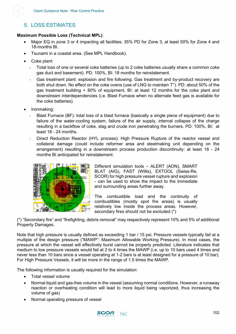
102
Client Guidance Note - Risk Control Practice
5. LOSS ESTIMATES
Maximum Possible Loss (Technical MPL): • Major EQ in zone 3 or 4 impacting all facilities: 35% PD for Zone 3, at least 50% for Zone 4 and
18-months BI. • Tsunami in a coastal area. (See MPL Handbook).
• Coke plant: - Total loss of one or several coke batteries (up to 2 coke batteries usually share a common coke
gas duct and basement). PD: 100%, BI: 18 months for reinstatement. - Gas treatment plant: explosion and fire following. Gas treatment and by-product recovery are
both shut down. No effect on the coke ovens (use of LNG to maintain T°). PD: about 50% of the gas treatment building + 80% of equipment, BI: at least 12 months for the coke plant and downstream interdependencies (i.e. Blast Furnace when no alternate feed gas is available for the coke batteries).
• Ironmaking: - Blast Furnace (BF): total loss of a blast furnace (basically a single piece of equipment) due to
failure of the water-cooling system, failure of the air supply, internal collapse of the charge resulting in a backflow of coke, slag and crude iron penetrating the burners. PD: 100%, BI: at least 18 - 24 months.
- Direct Reduction Reactor (HYL process): High Pressure Rupture of the reactor vessel and collateral damage (could include reformer area and steelmaking unit depending on the arrangement) resulting in a downstream process production discontinuity: at least 18 - 24 months BI anticipated for reinstatement.
Different simulation tools – ALERT (AON), SMART BLAT (AIG), FAST (Willis), EXTOOL (Swiss-Re, SCOR) for high pressure vessel rupture and explosion - can be used to show the impact to the immediate and surrounding areas further away. The combustible load and the continuity of combustibles (mostly spot fire areas) is usually relatively low inside the process areas. However, secondary fires should not be excluded (*)
(*) “Secondary fire” and “firefighting, debris removal” may respectively represent 10% and 5% of additional Property Damages. Note that high pressure is usually defined as exceeding 1 bar / 15 psi. Pressure vessels typically fail at a multiple of the design pressure (“MAWP”: Maximum Allowable Working Pressure). In most cases, the pressure at which the vessel will effectively burst cannot be properly predicted. Literature indicates that medium to low pressure vessels would fail at 2 to 4 times the MAWP (i.e. up to 10 bars used 4 times and never less than 10 bars since a vessel operating at 1-2 bars is at least designed for a pressure of 10 bar). For High Pressure Vessels, it will be more in the range of 1.5 times the MAWP. The following information is usually required for the simulation:
• Total vessel volume • Normal liquid and gas-free volume in the vessel (assuming normal conditions. However, a runaway
reaction or overheating condition will lead to more liquid being vaporized, thus increasing the volume of gas)
• Normal operating pressure of vessel
103
Client Guidance Note - Risk Control Practice
• “MAWP”: Maximum Allowable Working Pressure of vessel • Bursting pressure of vessel (when available)
For other processes at atmospheric pressure (no pressurized reactor / vessel), the MPL scenario is an explosion at the reformer or the disintegration of the Process Gas Compressor: up to 18 months BI for reinstatement. In the meantime, the Direct Reduction Plant would be shut down.
• Steelmaking: - BOF explosion with major collateral damage to adjacent equipment (other BOF’s,
electrical/control rooms). A major molten metal spillage can cause a partial collapse of the supporting structure: PD 100% of furnace and auxiliaries, BI at least 18 months.
- EAF/LF explosion with major collateral damage to adjacent equipment (other EAF/LF’s, electrical/control rooms). A major molten metal spillage can cause a partial collapse of the supporting structure: PD 100% of furnace, auxiliaries and adjacent Arc Furnace Transformers (AFT) when not properly segregated, at least 18 months BI.
- Arc Furnace Transformer (AFT for EAF/LF) explosion and major collateral damage to adjacent equipment (EAF/LF furnace, electrical/control rooms) when AFT is not adequately segregated (see Section 11): PD 100% of AFT and at least 20% of adjacent furnace, at least 18 months BI for replacement of the AFT.
• Continuous Casting (CC): a large molten metal spillage with ignition of electrical cable trays and lube oil networks causing a potential partial structure collapse; BI up to 18 months.
• Induced BI should be considered if there are any interdependencies with sister plants downstream. This could be mitigated by buffer storage (providing several extra days of production) and an alternate supplier (if any).
Normal Loss Expectancy (NLE):
• Coke Plant: - Fire on coal yard storage: PD: will depend on the stack size, BI: 1 month max. for delivery if
there is no strategic storage. - Extractor explosion due to a gas leak: PD:10M €, BI: 8 -10 months - Fire on the BTX tank: PD: about 5M €, BI: about 2 months - Explosion inside the electrostatic tar de-sprayer: BI: about 3 months - Fire on a major rubber belt conveyor resulting in 4 months BI - Fire on a critical electrics room resulting in at least 4 months BI - Fire on a lube oil group exposing the nearest facilities resulting in 4 months BI for the related
exposed unit.
• Ironmaking - Blast Furnace (BF):
Major blower failure resulting in the collapse of the blast furnace charge and an ensuing backflow of molten material into the tuyeres with the molten metal spill damaging surrounding equipment: PD: about 15% of the blast furnace value, BI: about 6 months.
Fire in a control room (cables in the raised floor) or electrical room (MCC etc.): PD: from 5 to 20M USD, BI: from 4 to 6 months.
Fire on the charging belt conveyor; PD: TBC, BI: from 1 to 4 months. Direct Reduction Plant: fire on a non-protected cooling tower resulting in a total loss: BI:
about 4 months. (See also Utilities Section).
104
Client Guidance Note - Risk Control Practice
• Steelmaking: - BOF: refractory failure and molten metal spillage with collateral damage to mechanical
equipment and control of the furnaces (depending on the arrangement): PD: at least 20%, BI: at least 3 months (for a single BOF).
- EAF/LF: refractory failure and molten metal spillage with collateral damage to mechanical equipment and control of the furnaces (depending on the arrangement): PD: at least 20% of the EAF/LF furnace, BI: at least 3 months (for a single EAF/LF).
• Continuous Casting (CC): molten metal spillage and ignition and fire in electrical cable trays and hydraulic networks. The extent of damage would depend on the arrangement and protection systems. BI: up to 6 months.
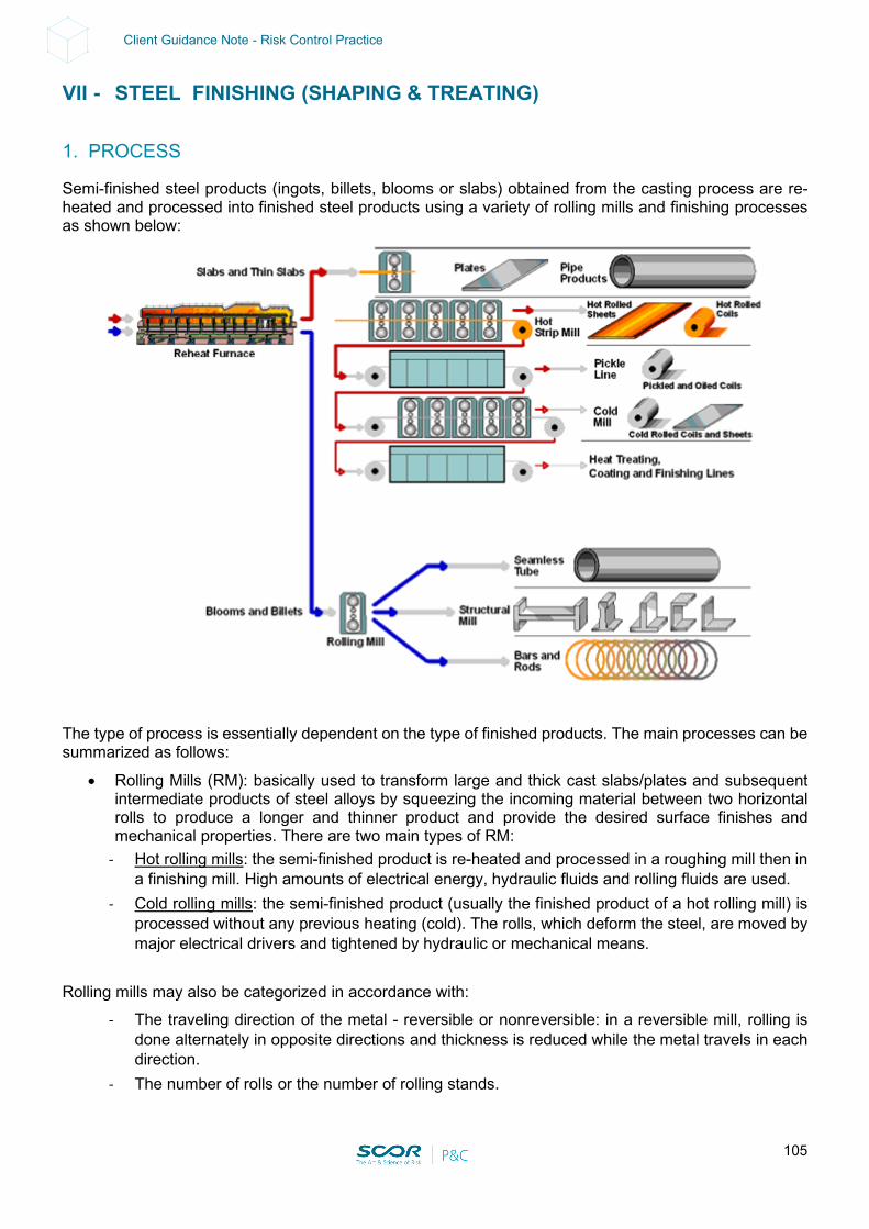
105
Client Guidance Note - Risk Control Practice
VII - STEEL FINISHING (SHAPING & TREATING)
1. PROCESS
Semi-finished steel products (ingots, billets, blooms or slabs) obtained from the casting process are re-heated and processed into finished steel products using a variety of rolling mills and finishing processes as shown below:
The type of process is essentially dependent on the type of finished products. The main processes can be summarized as follows:
• Rolling Mills (RM): basically used to transform large and thick cast slabs/plates and subsequent intermediate products of steel alloys by squeezing the incoming material between two horizontal rolls to produce a longer and thinner product and provide the desired surface finishes and mechanical properties. There are two main types of RM:
- Hot rolling mills: the semi-finished product is re-heated and processed in a roughing mill then in a finishing mill. High amounts of electrical energy, hydraulic fluids and rolling fluids are used.
- Cold rolling mills: the semi-finished product (usually the finished product of a hot rolling mill) is processed without any previous heating (cold). The rolls, which deform the steel, are moved by major electrical drivers and tightened by hydraulic or mechanical means.
Rolling mills may also be categorized in accordance with:
- The traveling direction of the metal - reversible or nonreversible: in a reversible mill, rolling is done alternately in opposite directions and thickness is reduced while the metal travels in each direction.
- The number of rolls or the number of rolling stands.
106
Client Guidance Note - Risk Control Practice
- How the rolls move vertically, as well as how pressure is exerted on the rolls (mechanically or hydraulically).
- From a fire hazard standpoint: i.e. the type of hydraulic fluid and the type of rolling fluid (coolant/lubricant) used.
• Heat treatment: annealing is the most frequently used heat treatment. It is used to restore the strength and corrosion resistance of the steel coils (continuous or by batch furnaces). The bonds between the grains of metal are stretched when a coil is cold rolled, leaving the steel brittle and breakable. Annealing “recrystallizes” the grain structure of steel by allowing new bonds to be formed at the higher temperature. There are two ways to anneal cold-rolled steel coils:
- Batch (Box): three to four coils are stacked on top of each other and covered for up to 3 days. They are then heated in a non-oxygen atmosphere (to prevent rust) and slowly cooled.
- Continuous: normally part of a coating line, the steel is uncoiled and run through a series of vertical loops inside a heater. The temperature and cooling rates are controlled to obtain the desired mechanical properties for the steel.
• Surface treatment: the last step involving different possible surface treatments such as pickling, molten metal coating, metal plating, lacquering etc. (mostly for steel plates).
2. SPECIAL HAZARDS & RISK CONTROL – ROLLING MILLS
This section is dedicated to Rolling Mills in general. In addition, dedicated sections for Steel Hot and Cold Rolling Mills are also included. Special hazards, prevention, protection and potential mitigation measures are detailed below for each and every special hazard related to this occupancy. Related recommendations are also mentioned (see. Rec. and Section 11 - “Support for Loss Prevention Recommendations” for details).
Construction
• Rolling Mill buildings may include plastic-based materials such as sandwich panels with plastic insulation (i.e. PIR, PUR, EPS.)
Prevention & Protection:
• Construct buildings or rooms containing a rolling mill and associated equipment using noncombustible building construction materials.
• If combustible or plastic building materials are required, use FM-approved materials. Combustible building construction may include insulated metal panels, insulated steel deck roof assemblies and interior plastic facings. Install FM-approved building materials in accordance with the manufacturer’s guidelines and their FM-approval listing.
• EPS insulated panels should not be permitted on the ceilings as there is no suitable fire protection system for such material installed on the ceiling.
• Where combustible type insulation material is used, appropriate loss prevention practices and strict control of installation and use of sandwich panels should be established & implemented.
107
Client Guidance Note - Risk Control Practice
Fire Hazards
• Fire hazards include: - Ignitable liquids and combustible deposits or residues originating from oil spills or leaks, and
rolling fluid spray accumulating on equipment, in ventilation systems or on interior building surfaces
- High-pressure hydraulic fluid for various functions - Spray of ignitable rolling fluid onto work surfaces for lubrication and cooling - Lubricating oil for roll bearings - Pool fire - Intense thermal exposure by an ignitable liquid hazard relsulting in severe damage to power
cabling, control wiring, instrumentation and motors - Electrical or control equipment rooms that may constitute a more severe exposure than in other
occupancies Prevention & Protection:
• Many fires involving rolling mills have occurred during maintenance operations. During such operations, local gaseous extinguishing systems may be taken out of service due to life safety concerns. Ignition sources may be present, such as hot work. A very strictly enforced, well-defined Hot Work Permit is needed to help minimize such hazards.
• Despite all precautions taken prior to authorizing such work, it should be recognized that it is extremely difficult to ensure complete cleaning of deposits in some areas that can be reached by hot metal particles, thus the so called primary mill protection (see below) should remain in service.
• Ignition of residue or deposits on equipment, in ventilation systems, or on interior building surfaces can lead to a fast fire spread, with the potential to out-run ceiling-level automatic sprinklers and increase the likelihood of igniting more substantial secondary fuel packages capable of overpowering fire protection systems. Source control, via exhaust ventilation and housekeeping, remain the primary safeguard to limit the release of combustibles and monitor and remove buildup.
• As a result of the above, the necessary fire protection for a mill depends on the fire hazards present and the physical arrangement of the mill, as follows (see FM Global Data Sheets 7-21 Rolling Mill).
• Note: as far as rolling mills are concerned, there are two classes of active fire protection systems: primary and supplementary (as described and shown below):
- Primary protection is water-based (e.g., ceiling-level / building-level / “high-level” sprinkler or mill-level / “equipment-level / “low-level” deluge system)
- Supplementary protection may be a fire extinguishing system using a gaseous suppression agent (e.g., local application carbon dioxide system)
- This terminology differs from that used in commercial and industrial risks: gaseous extinguishing systems are usually called “primary” due to greater frequency of use, and water-based protection systems are viewed as “backup”- activated in case the primary system fails
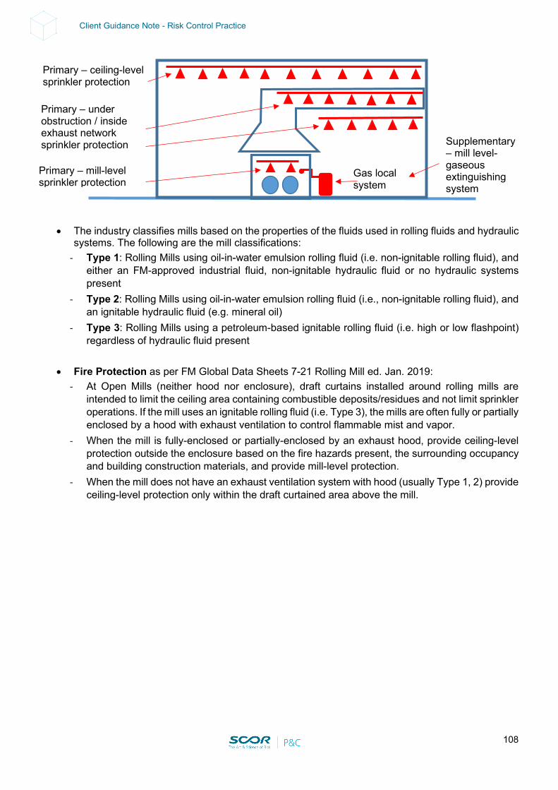
108
Client Guidance Note - Risk Control Practice
• The industry classifies mills based on the properties of the fluids used in rolling fluids and hydraulic systems. The following are the mill classifications:
- Type 1: Rolling Mills using oil-in-water emulsion rolling fluid (i.e. non-ignitable rolling fluid), and either an FM-approved industrial fluid, non-ignitable hydraulic fluid or no hydraulic systems present
- Type 2: Rolling Mills using oil-in-water emulsion rolling fluid (i.e., non-ignitable rolling fluid), and an ignitable hydraulic fluid (e.g. mineral oil)
- Type 3: Rolling Mills using a petroleum-based ignitable rolling fluid (i.e. high or low flashpoint) regardless of hydraulic fluid present
• Fire Protection as per FM Global Data Sheets 7-21 Rolling Mill ed. Jan. 2019:
- At Open Mills (neither hood nor enclosure), draft curtains installed around rolling mills are intended to limit the ceiling area containing combustible deposits/residues and not limit sprinkler operations. If the mill uses an ignitable rolling fluid (i.e. Type 3), the mills are often fully or partially enclosed by a hood with exhaust ventilation to control flammable mist and vapor.
- When the mill is fully-enclosed or partially-enclosed by an exhaust hood, provide ceiling-level protection outside the enclosure based on the fire hazards present, the surrounding occupancy and building construction materials, and provide mill-level protection.
- When the mill does not have an exhaust ventilation system with hood (usually Type 1, 2) provide ceiling-level protection only within the draft curtained area above the mill.
Gas local system
Primary – mill-level sprinkler protection
Primary – under obstruction / inside exhaust network sprinkler protection Supplementary
– mill level- gaseous extinguishing system
Primary – ceiling-level sprinkler protection
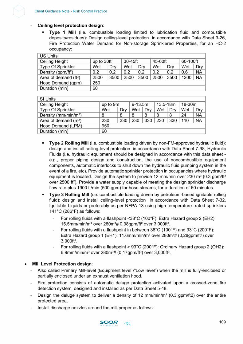
109
Client Guidance Note - Risk Control Practice
- Ceiling level protection design: Type 1 Mill (i.e. combustible loading limited to lubrication fluid and combustible
deposits/residues): Design ceiling-level protection in accordance with Data Sheet 3-26, Fire Protection Water Demand for Non-storage Sprinklered Properties, for an HC-2 occupancy:
US Units Ceiling Height up to 30ft 30-45ft 45-60ft 60-100ft Type Of Sprinkler Wet Dry Wet Dry Wet Dry Wet Dry Density (gpm/ft²) 0.2 0.2 0.2 0.2 0.2 0.2 0.6 NA Area of demand (ft²) 2500 3500 2500 3500 2500 3500 1200 NA Hose Demand (gpm) 250 Duration (min) 60
SI Units Ceiling Height up to 9m 9-13.5m 13.5-18m 18-30m Type Of Sprinkler Wet Dry Wet Dry Wet Dry Wet Dry Density (mm/min/m²) 8 8 8 8 8 8 24 NA Area of demand (m²) 230 330 230 330 230 330 110 NA Hose Demand (LPM) 950 Duration (min) 60
Type 2 Rolling Mill (i.e. combustible loading driven by non-FM-approved hydraulic fluid):
design and install ceiling-level protection in accordance with Data Sheet 7-98, Hydraulic Fluids (i.e. hydraulic equipment should be designed in accordance with this data sheet - e.g., proper piping design and construction, the use of noncombustible equipment components, automatic interlocks to shut down the hydraulic fluid pumping system in the event of a fire, etc). Provide automatic sprinkler protection in occupancies where hydraulic equipment is located. Design the system to provide 12 mm/min over 230 m² (0.3 gpm/ft² over 2500 ft²). Provide a water supply capable of meeting the design sprinkler discharge flow rate plus 1900 L/min (500 gpm) for hose streams, for a duration of 60 minutes.
Type 3 Rolling Mill (i.e. combustible loading driven by petroleum-based ignitable rolling fluid): design and install ceiling-level protection in accordance with Data Sheet 7-32, Ignitable Liquids or preferably as per NFPA 13 using high temperature- rated sprinklers 141°C (286°F) as follows: ⋅ For rolling fluids with a flashpoint <38°C (100°F): Extra Hazard group 2 (EH2)
15.5mm/min/m² over 280m²# 0,38gpm/ft² over 3,000ft². ⋅ For rolling fluids with a flashpoint in between 38°C (100°F) and 93°C (200°F):
Extra Hazard group 1 (EH1): 11.6mm/min/m² over 280m²# (0,28gpm/ft²) over 3,000ft².
⋅ For rolling fluids with a flashpoint > 93°C (200°F): Ordinary Hazard group 2 (OH2): 6.9mm/min/m² over 280m²# (0,17gpm/ft²) over 3,000ft².
• Mill Level Protection design: - Also called Primary Mill-level (Equipment level /“Low level”) when the mill is fully-enclosed or
partially enclosed under an exhaust ventilation hood. - Fire protection consists of automatic deluge protection activated upon a crossed-zone fire
detection system, designed and installed as per Data Sheet 5-48. - Design the deluge system to deliver a density of 12 mm/min/m² (0.3 gpm/ft2) over the entire
protected area. - Install discharge nozzles around the mill proper as follows:
110
Client Guidance Note - Risk Control Practice
On top of the stands on tending/operating and drive sides with coverage outside the stands, and within the roll stack covering the inside of the stands and rolls both above and below the pass line
At coiler and recoiler above and below the pass line Above hydraulic cylinders Above roll bearings Under exhaust hoods/enclosures Above pits, pipe channels, tunnels, or collection pans extending from the mill where
ignitable liquid may collect or combustible deposits may form Above any local ignitable liquid supply located within the mill footprint or immediately
adjacent to the mill (i.e., hydraulic fluid or lubricating oil systems) When deluge nozzles are used to protect vertical mill surfaces, use the area of the vertical
plan being protected to determine the necessary water discharge, nozzle spacing and coverage requirements.
Refer to Data Sheet 7-78, Industrial Exhaust Systems, for guidance on protecting exhaust ventilation ductwork and downstream emission control equipment as follows: ⋅ In locations where the combustible duct exteriors (non-FM-approved ducts) are
exposed to ceiling sprinklers, no other exterior protection is needed. If combustible ducts are located in an unsprinklered area and are of sufficient concentration or size to generate a self-propagating fire, install sprinklers over or near the duct, spaced not more than 3.7 m (12 ft) from the center. Generally, one line of sprinklers over the duct will suffice.
⋅ Base water supply on 75 L/min (20 gpm) per head over a maximum of 30 m (100 lineal ft) of duct, 74°C (165°F)-rated heads are satisfactory. When ducts are wide, sprinklers will also be needed underneath them if there are
⋅ combustibles below the duct (see Data Sheet 2-0, Installation Guidelines for Automatic Sprinklers, for details).
⋅ If the duct is covered with foam plastic insulation (polyurethane, polystyrene, etc.), follow the surface treatment and sprinkler protection recommendations in Data Sheet 1-57, Plastics in Construction.
⋅ Install sprinklers inside all ducts that have cross-sectional areas greater than or equal to 516 cm2 (80 in2) or that have diameters greater than or equal to 254 mm (10 in.) and which:
⋅ A. are combustible (including non-FM-approved plastics; treat plastic-lined ducts the same way as plastic ducts). or
⋅ B. contain combustibles likely to cause a damaging fire. ⋅ Use a minimum flow of 20 gpm (75 L/min) per sprinkler within the 100 ft (30 m)
limit. In most cases, this will yield a density over the projected area much larger than the minimum 0.20 gpm/ft2 previously specified.
⋅ Include a 250 gpm (945 L/min) hose stream demand.
Example: In a 2.4 m (8 ft) dia. by 60 m (200 ft) long duct, the projected design area will be: 2.4 m x 30 m max = 74 m² = 800 ft2 (8 ft x 100 ft max).
⋅ Use wet systems for sprinkler protection where possible. If the ducts or associated equipment are subject to freeze, arrange these fire protection systems on a dry-pipe, deluge, or non-freeze system.
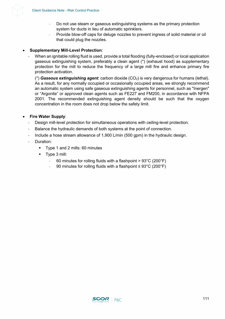
111
Client Guidance Note - Risk Control Practice
⋅ Do not use steam or gaseous extinguishing systems as the primary protection system for ducts in lieu of automatic sprinklers.
⋅ Provide blow-off caps for deluge nozzles to prevent ingress of solid material or oil that could plug the nozzles.
• Supplementary Mill-Level Protection: - When an ignitable rolling fluid is used, provide a total flooding (fully-enclosed) or local application
gaseous extinguishing system, preferably a clean agent (*) (exhaust hood) as supplementary protection for the mill to reduce the frequency of a large mill fire and enhance primary fire protection activation. (*) Gaseous extinguishing agent: carbon dioxide (CO2) is very dangerous for humans (lethal). As a result, for any normally occupied or occasionally occupied areas, we strongly recommend an automatic system using safe gaseous extinguishing agents for personnel, such as "Inergen" or “Argonite” or approved clean agents such as FE227 and FM200, in accordance with NFPA 2001. The recommended extinguishing agent density should be such that the oxygen concentration in the room does not drop below the safety limit.
• Fire Water Supply:
- Design mill-level protection for simultaneous operations with ceiling-level protection. - Balance the hydraulic demands of both systems at the point of connection. - Include a hose stream allowance of 1,900 L/min (500 gpm) in the hydraulic design. - Duration:
Type 1 and 2 mills: 60 minutes Type 3 mill:
⋅ 60 minutes for rolling fluids with a flashpoint > 93°C (200°F) ⋅ 90 minutes for rolling fluids with a flashpoint ≤ 93°C (200°F)
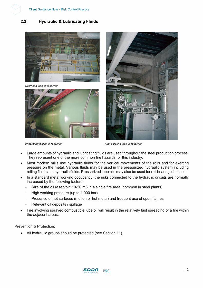
112
Client Guidance Note - Risk Control Practice
Hydraulic & Lubricating Fluids
Overhead lube oil reservoir
Underground lube oil reservoir Aboveground lube oil reservoir
• Large amounts of hydraulic and lubricating fluids are used throughout the steel production process. They represent one of the more common fire hazards for this industry.
• Most modern mills use hydraulic fluids for the vertical movements of the rolls and for exerting pressure on the metal. Various fluids may be used in the pressurized hydraulic system including rolling fluids and hydraulic fluids. Pressurized lube oils may also be used for roll bearing lubrication.
• In a standard metal working occupancy, the risks connected to the hydraulic circuits are normally increased by the following factors:
- Size of the oil reservoir: 10-20 m3 in a single fire area (common in steel plants) - High working pressure (up to 1 000 bar) - Presence of hot surfaces (molten or hot metal) and frequent use of open flames - Relevant oil deposits / spillage
• Fire involving sprayed combustible lube oil will result in the relatively fast spreading of a fire within the adjacent areas.
Prevention & Protection:
• All hydraulic groups should be protected (see Section 11).
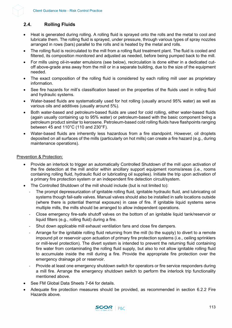
113
Client Guidance Note - Risk Control Practice
Rolling Fluids
• Heat is generated during rolling. A rolling fluid is sprayed onto the rolls and the metal to cool and lubricate them. The rolling fluid is sprayed, under pressure, through various types of spray nozzles arranged in rows (bars) parallel to the rolls and is heated by the metal and rolls.
• The rolling fluid is recirculated to the mill from a rolling fluid treatment plant. The fluid is cooled and filtered, its composition monitored and adjusted as needed, before being pumped back to the mill.
• For mills using oil-in-water emulsions (see below), recirculation is done either in a dedicated cut-off above-grade area away from the mill or in a separate building, due to the size of the equipment needed.
• The exact composition of the rolling fluid is considered by each rolling mill user as proprietary information.
• See fire hazards for mill’s classification based on the properties of the fluids used in rolling fluid and hydraulic systems.
• Water-based fluids are systematically used for hot rolling (usually around 95% water) as well as various oils and additives (usually around 5%).
• Both water-based and petroleum-based fluids are used for cold rolling, either water-based fluids (again usually containing up to 95% water) or petroleum-based with the basic component being a petroleum product similar to kerosene. Petroleum-based cold rolling fluids have flashpoints ranging between 45 and 110°C (110 and 230°F).
• Water-based fluids are inherently less hazardous from a fire standpoint. However, oil droplets deposited on all surfaces of the mills (particularly on hot mills) can create a fire hazard (e.g., during maintenance operations).
Prevention & Protection:
• Provide an interlock to trigger an automatically Controlled Shutdown of the mill upon activation of the fire detection at the mill and/or within ancillary support equipment rooms/areas (i.e., rooms containing rolling fluid, hydraulic fluid or lubricating oil supplies). Initiate the trip upon activation of a primary fire protection system or an independent fire detection circuit/system.
• The Controlled Shutdown of the mill should include (but is not limited to): - The prompt depressurization of ignitable rolling fluid, ignitable hydraulic fluid, and lubricating oil
systems though fail-safe valves. Manual valves should also be installed in safe locations outside (where there is potential thermal exposure) in case of fire. If ignitable liquid systems serve multiple mills, the mills should be arranged to allow independent operations.
- Close emergency fire-safe shutoff valves on the bottom of an ignitable liquid tank/reservoir or liquid filters (e.g., rolling fluid) during a fire.
- Shut down applicable mill exhaust ventilation fans and close fire dampers. - Arrange for the ignitable rolling fluid returning from the mill (to the supply) to divert to a remote
impound pit or reservoir upon actuation of primary fire protection systems (i.e., ceiling sprinklers or mill-level protection). The divert system is intended to prevent the returning fluid containing fire water from contaminating the rolling fluid supply, but also to not allow ignitable rolling fluid to accumulate inside the mill during a fire. Provide the appropriate fire protection over the emergency drainage pit or reservoir.
- Provide at least one emergency shutdown switch for operators or fire service responders during a mill fire. Arrange the emergency shutdown switch to perform the interlock trip functionality mentioned above.
• See FM Global Data Sheets 7-64 for details. • Adequate fire protection measures should be provided, as recommended in section 6.2.2 Fire
Hazards above.
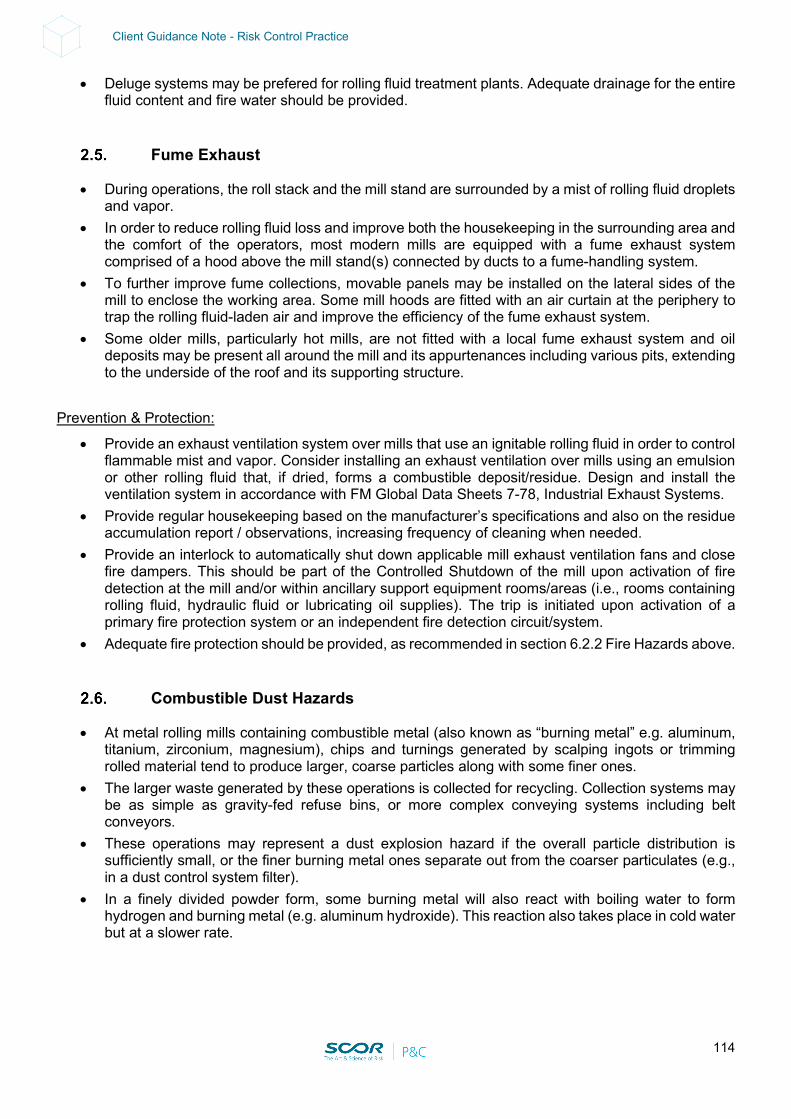
114
Client Guidance Note - Risk Control Practice
• Deluge systems may be prefered for rolling fluid treatment plants. Adequate drainage for the entire fluid content and fire water should be provided.
Fume Exhaust
• During operations, the roll stack and the mill stand are surrounded by a mist of rolling fluid droplets and vapor.
• In order to reduce rolling fluid loss and improve both the housekeeping in the surrounding area and the comfort of the operators, most modern mills are equipped with a fume exhaust system comprised of a hood above the mill stand(s) connected by ducts to a fume-handling system.
• To further improve fume collections, movable panels may be installed on the lateral sides of the mill to enclose the working area. Some mill hoods are fitted with an air curtain at the periphery to trap the rolling fluid-laden air and improve the efficiency of the fume exhaust system.
• Some older mills, particularly hot mills, are not fitted with a local fume exhaust system and oil deposits may be present all around the mill and its appurtenances including various pits, extending to the underside of the roof and its supporting structure.
Prevention & Protection:
• Provide an exhaust ventilation system over mills that use an ignitable rolling fluid in order to control flammable mist and vapor. Consider installing an exhaust ventilation over mills using an emulsion or other rolling fluid that, if dried, forms a combustible deposit/residue. Design and install the ventilation system in accordance with FM Global Data Sheets 7-78, Industrial Exhaust Systems.
• Provide regular housekeeping based on the manufacturer’s specifications and also on the residue accumulation report / observations, increasing frequency of cleaning when needed.
• Provide an interlock to automatically shut down applicable mill exhaust ventilation fans and close fire dampers. This should be part of the Controlled Shutdown of the mill upon activation of fire detection at the mill and/or within ancillary support equipment rooms/areas (i.e., rooms containing rolling fluid, hydraulic fluid or lubricating oil supplies). The trip is initiated upon activation of a primary fire protection system or an independent fire detection circuit/system.
• Adequate fire protection should be provided, as recommended in section 6.2.2 Fire Hazards above.
Combustible Dust Hazards
• At metal rolling mills containing combustible metal (also known as “burning metal” e.g. aluminum, titanium, zirconium, magnesium), chips and turnings generated by scalping ingots or trimming rolled material tend to produce larger, coarse particles along with some finer ones.
• The larger waste generated by these operations is collected for recycling. Collection systems may be as simple as gravity-fed refuse bins, or more complex conveying systems including belt conveyors.
• These operations may represent a dust explosion hazard if the overall particle distribution is sufficiently small, or the finer burning metal ones separate out from the coarser particulates (e.g., in a dust control system filter).
• In a finely divided powder form, some burning metal will also react with boiling water to form hydrogen and burning metal (e.g. aluminum hydroxide). This reaction also takes place in cold water but at a slower rate.
115
Client Guidance Note - Risk Control Practice
Prevention & Protection: Courtesy of Franck Orset (FPO), Loss Prevention Engineer:
Installation of dust control measures. • One obvious place for a dust explosion to initiate is where dust is produced. • In equipment such as dust collectors, a combustible mixture could be present whenever the
equipment is operating. • Other locations to consider are those where dust can settle, both in occupied areas and in hidden
concealed spaces. • The dust-containing systems (ducts and dust collectors) should be designed in such a manner (i.e.
no leaking) that fugitive dusts will not accumulate in the work area. • A strong housekeeping program should be implemented with regular cleaning frequencies
established for floors and horizontal surfaces, such as ducts, pipes, hoods, ledges and beams, to minimize dust accumulation inside operating areas of the facility.
• The working surfaces should be designed in a manner that minimizes dust accumulation and facilitates cleaning.
• Facilities should carefully identify the following in order to assess their potential for dust explosions: - Materials that can be combustible when finely divided - Processes which use, consume or produce combustible dust - Open areas where combustible dust may build up - Hidden areas where combustible dust may accumulate - Means by which dust may be dispersed in the air - Potential ignition sources
• The following are some possible recommendations for dust control: - Minimize the escape of dust from process equipment or ventilation systems - Use dust collection systems and filters - Utilize surfaces that minimize dust accumulation and facilitate cleaning - Provide access to all hidden areas to permit inspection - Inspect for dust residue in open and hidden areas at regular intervals - Clean dust residue at regular intervals - Use cleaning methods that do not generate dust clouds if ignition sources are present - Only use vacuum cleaners approved for dust collection - Locate relief valves away from dust hazard areas - Develop and implement a hazardous dust inspection, testing, housekeeping and control
program (preferably in writing, with established frequency and methods) Ignition Control Measures:
• Basic precautions are required to avoid a possible ignition source leading to an explosion with combustible dust:
- Strict no smoking policy within the premises - Strict and adequate Hot Work Permit procedure in place - Use of spark-resistant tools (for maintenance, repairs, replacement of material/equipment etc.) - Removal of static electricity (bonding and grounding with permanent ground wires for
equipment, machines, ductworks used for pneumatic conveying systems, grounding of personnel during hazardous operations etc.)
- Control of friction hazard (to minimize the possibility of friction sparks)
116
Client Guidance Note - Risk Control Practice
- Protection of bearings (ball or roller bearings should be sealed against dust) - Use appropriate electrical equipment and wiring methods. Electrical power and control should
be in keeping with the environment. Use of explosion-proof electrical appliances wherever necessary
- Use separator devices to remove foreign materials capable of igniting combustibles from process materials
- Separate heated surfaces from dust - Separate heating systems from dust - Proper use and type of industrial trucks (only industrial trucks that are approved for combustible
dust locations should be selected and used) • Hazards related to the collection of combustible dust should be carefully studied and approved safe
methods should be carefully selected. • See NFPA standards for more details on that topic (i.e., NFPA 484 for combustible metal dust).
Prevention Measures: Employees should be specifically trained in the explosion hazards of combustible dust.
• Workers are the first line of defense in preventing and mitigating fires and explosions. If the people closest to the source of the hazard are trained to recognize and prevent hazards associated with combustible dust in the plant, they can be instrumental in recognizing unsafe conditions, taking preventive action, and/or alerting management.
• All employees should be trained in safe work practices applicable to their job tasks, as well as in the overall plant programs for dust control and ignition source control. They should be trained before they start work and periodically refresh their knowledge, when reassigned, or when hazards or processes change.
• A team of qualified managers should be responsible for conducting a facility analysis (or for having one done by qualified outside persons) prior to the introduction of a hazard and for developing a prevention and protection scheme tailored to their operation. Supervisors and managers should be aware of - and support - the plant dust and ignition control programs. Their training should include identifying how they can encourage the reporting of unsafe practices and facilitate abatement actions.
Protection Measures:
• An emergency action plan should be implemented. • Dust collectors should not be located inside the buildings, particularly dry collectors. • Rooms, buildings or other enclosures (dust collectors) should be provided with an explosion- relief
venting outlet distributed over the exterior wall of buildings and enclosures. Explosion venting should be directed to a safe location away from employees and other critical pieces of equipment.
117
Client Guidance Note - Risk Control Practice
Mill Equipment
Reheat furnace: • Reheat furnaces are a major bottleneck in a rolling mill. • Potential accumulation of gas inside the furnace during start up may lead to an explosion upon
ignition. Prevention & Protection:
• Adequate safety combustion controls should be provided for the main fuel gas line and the burners (see Section 11).
Rolling Mill Stands:
• Stands include very critical equipment such as rolls, gears and drivers, hydraulic and lubricating groups.
• The reliability and availability of the above equipment is key. Prevention & Protection:
• Major roll-bearing on-line vibration monitoring is necessary (with displacement checked on a monthly basis).
• Workshop capabilities are important. • An adequate Maintenance and Inspection program is key. This includes, but is not limited to:
- A reliability team focusing on rotating equipment and electrical equipment (“bad actor tracking”) and conducting root cause analyses to eliminate failures
- Computerized Maintenance Management System (MMS) job order editing – “time-based maintenance”, overdue list, spare parts’ management, bad actor tracking - KPI
- A training program dedicated to maintenance teams for new projects - Welders’ re-qualifications compliant with ATSM standards - A once-a-year turnaround schedule (e.g. 10 days duration for each process unit) - Instrumentation (calibration of process instruments / protective devices):
Oil pressure gauges/temperature sensors / flow sensors Vibration probes / other measuring devices
- Rolling Mill drive gears maintained as per manufacturer’s specifications - Rolling Mill stands geometry regularly checked (e.g. every year, including geometry and
alignment of the frame, driving shaft, gears and driver). All operations should be documented. • Technical agreement with manufacturer allowing for quick repair and maintenance
Mill Drive Motor
• Several thousand horsepower drives introduce severe electrical breakdown hazards. • These pieces of equipment are very critical and present long lead times for repairs or replacement. • Lubricating oil is found in mill drive motors and gear boxes. The systems vary in oil volume from
tens to hundreds of gallons (tens to thousands of liters). Lubricating system operating pressures generally range from 20 to 60 psi (1.4 to 4.1 bar) but occasionally may exceed 100 psi (6.9 bar), while oil flow rates tend to be low, using small diameter supply piping and larger diameter piping for low pressure or gravity return, both presenting more of a pool fire hazard. Lubricating oil supplies may consist of a small console adjacent to the use point or a remote large central supply located in a below-grade space (i.e. oil cellar) for older mills, or in a mill-level cutoff room serving multiple use points. Most lubrication oil systems present a pool fire exposure.
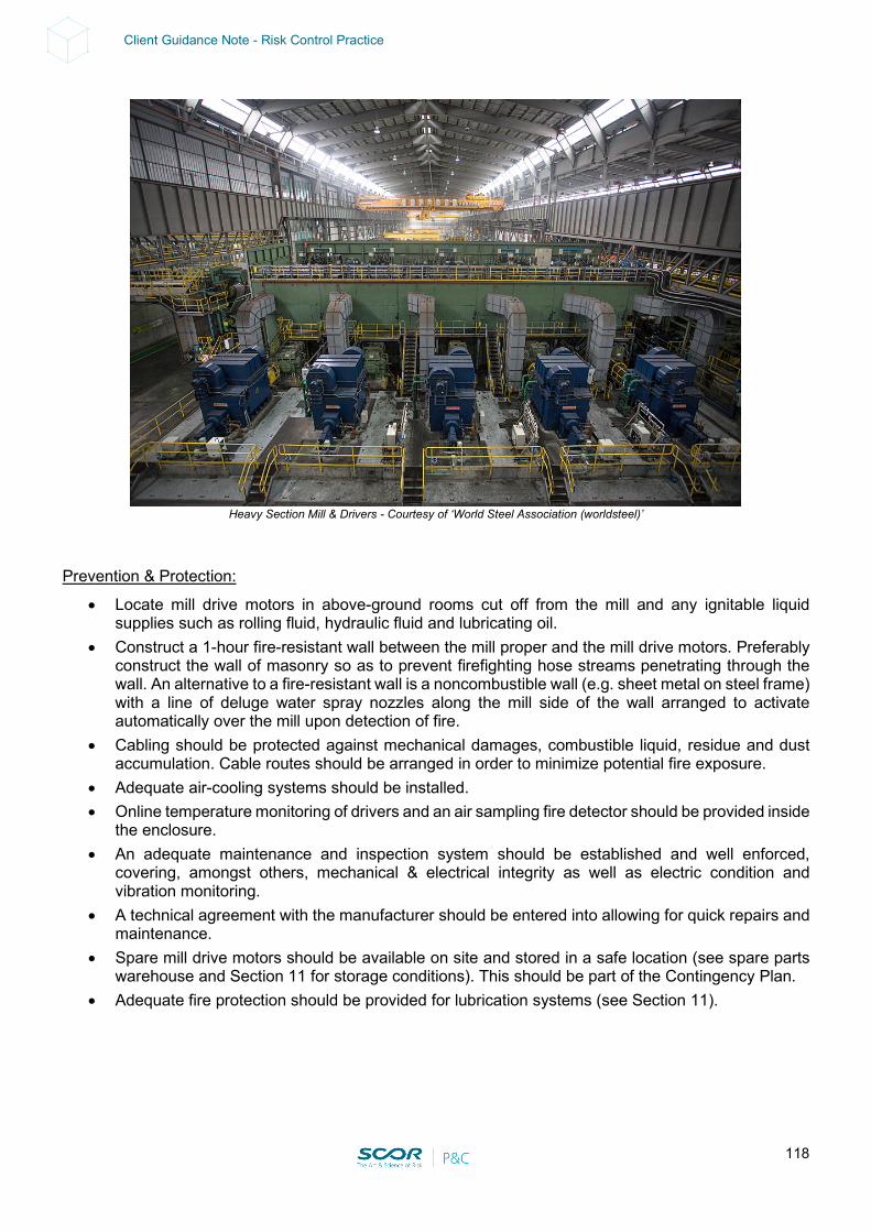
118
Client Guidance Note - Risk Control Practice
Heavy Section Mill & Drivers - Courtesy of ‘World Steel Association (worldsteel)’
Prevention & Protection:
• Locate mill drive motors in above-ground rooms cut off from the mill and any ignitable liquid supplies such as rolling fluid, hydraulic fluid and lubricating oil.
• Construct a 1-hour fire-resistant wall between the mill proper and the mill drive motors. Preferably construct the wall of masonry so as to prevent firefighting hose streams penetrating through the wall. An alternative to a fire-resistant wall is a noncombustible wall (e.g. sheet metal on steel frame) with a line of deluge water spray nozzles along the mill side of the wall arranged to activate automatically over the mill upon detection of fire.
• Cabling should be protected against mechanical damages, combustible liquid, residue and dust accumulation. Cable routes should be arranged in order to minimize potential fire exposure.
• Adequate air-cooling systems should be installed. • Online temperature monitoring of drivers and an air sampling fire detector should be provided inside
the enclosure. • An adequate maintenance and inspection system should be established and well enforced,
covering, amongst others, mechanical & electrical integrity as well as electric condition and vibration monitoring.
• A technical agreement with the manufacturer should be entered into allowing for quick repairs and maintenance.
• Spare mill drive motors should be available on site and stored in a safe location (see spare parts warehouse and Section 11 for storage conditions). This should be part of the Contingency Plan.
• Adequate fire protection should be provided for lubrication systems (see Section 11).
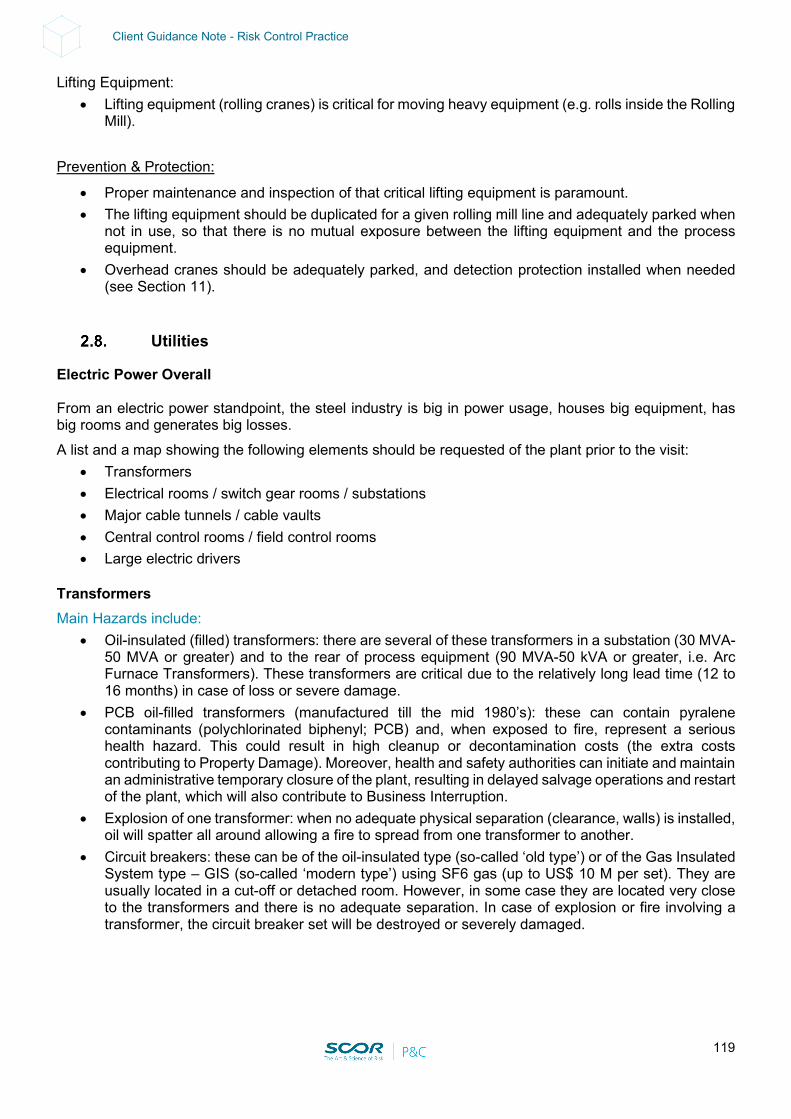
119
Client Guidance Note - Risk Control Practice
Lifting Equipment: • Lifting equipment (rolling cranes) is critical for moving heavy equipment (e.g. rolls inside the Rolling
Mill). Prevention & Protection:
• Proper maintenance and inspection of that critical lifting equipment is paramount. • The lifting equipment should be duplicated for a given rolling mill line and adequately parked when
not in use, so that there is no mutual exposure between the lifting equipment and the process equipment.
• Overhead cranes should be adequately parked, and detection protection installed when needed (see Section 11).
Utilities
Electric Power Overall From an electric power standpoint, the steel industry is big in power usage, houses big equipment, has big rooms and generates big losses. A list and a map showing the following elements should be requested of the plant prior to the visit:
• Transformers • Electrical rooms / switch gear rooms / substations • Major cable tunnels / cable vaults • Central control rooms / field control rooms • Large electric drivers
Transformers Main Hazards include:
• Oil-insulated (filled) transformers: there are several of these transformers in a substation (30 MVA-50 MVA or greater) and to the rear of process equipment (90 MVA-50 kVA or greater, i.e. Arc Furnace Transformers). These transformers are critical due to the relatively long lead time (12 to 16 months) in case of loss or severe damage.
• PCB oil-filled transformers (manufactured till the mid 1980’s): these can contain pyralene contaminants (polychlorinated biphenyl; PCB) and, when exposed to fire, represent a serious health hazard. This could result in high cleanup or decontamination costs (the extra costs contributing to Property Damage). Moreover, health and safety authorities can initiate and maintain an administrative temporary closure of the plant, resulting in delayed salvage operations and restart of the plant, which will also contribute to Business Interruption.
• Explosion of one transformer: when no adequate physical separation (clearance, walls) is installed, oil will spatter all around allowing a fire to spread from one transformer to another.
• Circuit breakers: these can be of the oil-insulated type (so-called ‘old type’) or of the Gas Insulated System type – GIS (so-called ‘modern type’) using SF6 gas (up to US$ 10 M per set). They are usually located in a cut-off or detached room. However, in some case they are located very close to the transformers and there is no adequate separation. In case of explosion or fire involving a transformer, the circuit breaker set will be destroyed or severely damaged.
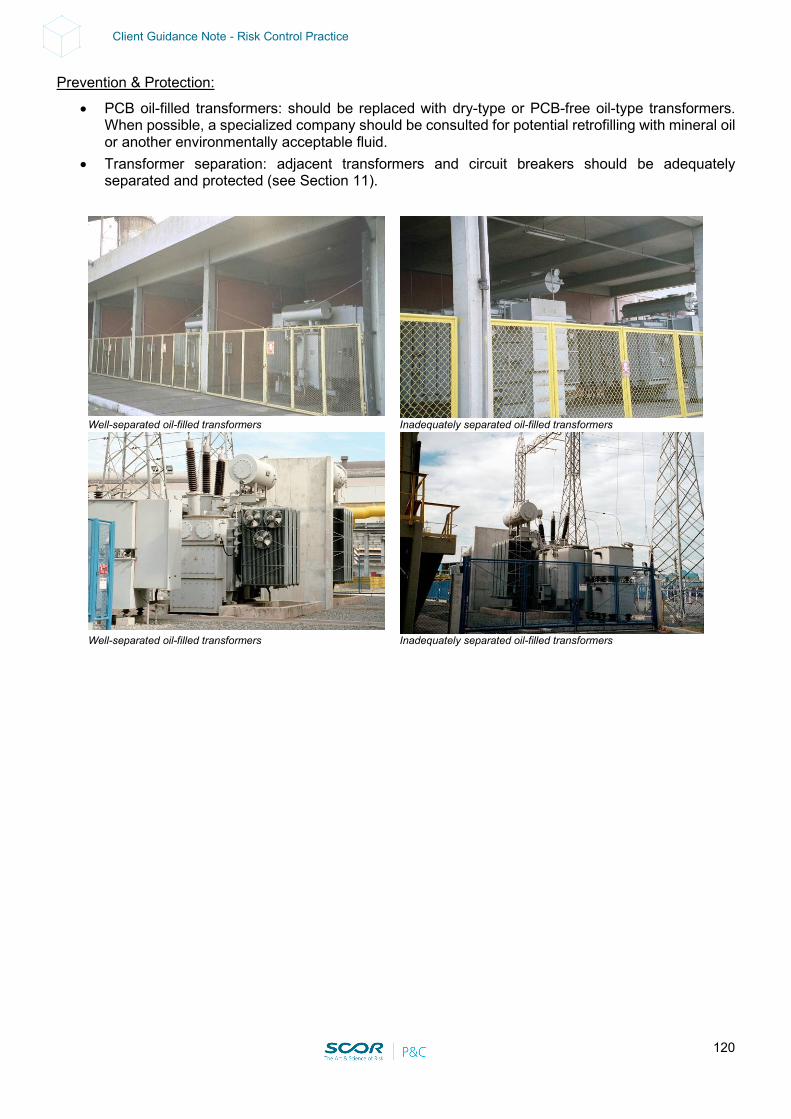
120
Client Guidance Note - Risk Control Practice
Prevention & Protection:
• PCB oil-filled transformers: should be replaced with dry-type or PCB-free oil-type transformers. When possible, a specialized company should be consulted for potential retrofilling with mineral oil or another environmentally acceptable fluid.
• Transformer separation: adjacent transformers and circuit breakers should be adequately separated and protected (see Section 11).
Well-separated oil-filled transformers Inadequately separated oil-filled transformers
Well-separated oil-filled transformers Inadequately separated oil-filled transformers

121
Client Guidance Note - Risk Control Practice
SF6 gas-insulated circuit breakers in a cut-off room
Electrical rooms / Switchgear rooms /Substations / MCC rooms
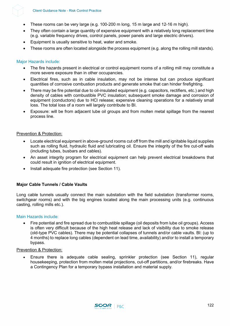
122
Client Guidance Note - Risk Control Practice
• These rooms can be very large (e.g. 100-200 m long, 15 m large and 12-16 m high). • They often contain a large quantity of expensive equipment with a relatively long replacement time
(e.g. variable frequency drives, control panels, power panels and large electric drivers). • Equipment is usually sensitive to heat, water and smoke. • These rooms are often located alongside the process equipment (e.g. along the rolling mill stands).
Major Hazards include:
• The fire hazards present in electrical or control equipment rooms of a rolling mill may constitute a more severe exposure than in other occupancies.
• Electrical fires, such as in cable insulation, may not be intense but can produce significant quantities of corrosive combustion products and generate smoke that can hinder firefighting.
• There may be fire potential due to oil-insulated equipment (e.g. capacitors, rectifiers, etc.) and high density of cables with combustible PVC insulation; subsequent smoke damage and corrosion of equipment (conductors) due to HCl release; expensive cleaning operations for a relatively small loss. The total loss of a room will largely contribute to BI.
• Exposure: will be from adjacent lube oil groups and from molten metal spillage from the nearest process line.
Prevention & Protection:
• Locate electrical equipment in above-ground rooms cut off from the mill and ignitable liquid supplies such as rolling fluid, hydraulic fluid and lubricating oil. Ensure the integrity of the fire cut-off walls (including tubes, busbars and cables).
• An asset integrity program for electrical equipment can help prevent electrical breakdowns that could result in ignition of electrical equipment.
• Install adequate fire protection (see Section 11). Major Cable Tunnels / Cable Vaults Long cable tunnels usually connect the main substation with the field substation (transformer rooms, switchgear rooms) and with the big engines located along the main processing units (e.g. continuous casting, rolling mills etc.). Main Hazards include:
• Fire potential and fire spread due to combustible spillage (oil deposits from lube oil groups). Access is often very difficult because of the high heat release and lack of visibility due to smoke release (old-type PVC cables). There may be potential collapses of tunnels and/or cable vaults. BI: (up to 4 months) to replace long cables (dependent on lead time, availability) and/or to install a temporary bypass.
Prevention & Protection: • Ensure there is adequate cable sealing, sprinkler protection (see Section 11), regular
housekeeping, protection from molten metal projections, cut-off partitions, and/or firebreaks. Have a Contingency Plan for a temporary bypass installation and material supply.
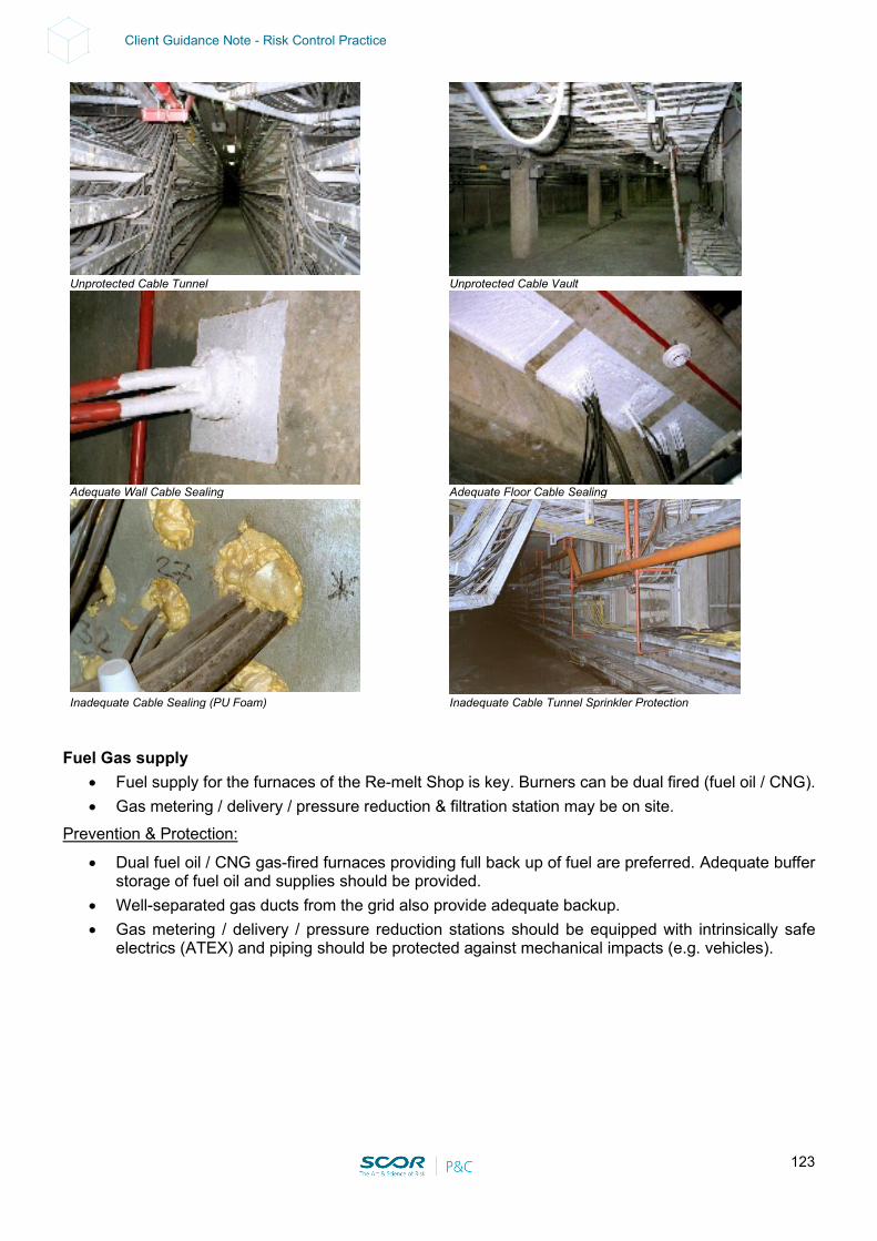
123
Client Guidance Note - Risk Control Practice
Unprotected Cable Tunnel Unprotected Cable Vault
Adequate Wall Cable Sealing Adequate Floor Cable Sealing
Inadequate Cable Sealing (PU Foam) Inadequate Cable Tunnel Sprinkler Protection
Fuel Gas supply
• Fuel supply for the furnaces of the Re-melt Shop is key. Burners can be dual fired (fuel oil / CNG). • Gas metering / delivery / pressure reduction & filtration station may be on site.
Prevention & Protection:
• Dual fuel oil / CNG gas-fired furnaces providing full back up of fuel are preferred. Adequate buffer storage of fuel oil and supplies should be provided.
• Well-separated gas ducts from the grid also provide adequate backup. • Gas metering / delivery / pressure reduction stations should be equipped with intrinsically safe
electrics (ATEX) and piping should be protected against mechanical impacts (e.g. vehicles).
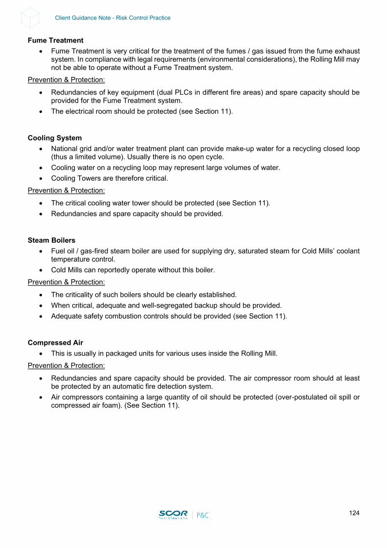
124
Client Guidance Note - Risk Control Practice
Fume Treatment • Fume Treatment is very critical for the treatment of the fumes / gas issued from the fume exhaust
system. In compliance with legal requirements (environmental considerations), the Rolling Mill may not be able to operate without a Fume Treatment system.
Prevention & Protection:
• Redundancies of key equipment (dual PLCs in different fire areas) and spare capacity should be provided for the Fume Treatment system.
• The electrical room should be protected (see Section 11). Cooling System
• National grid and/or water treatment plant can provide make-up water for a recycling closed loop (thus a limited volume). Usually there is no open cycle.
• Cooling water on a recycling loop may represent large volumes of water. • Cooling Towers are therefore critical.
Prevention & Protection:
• The critical cooling water tower should be protected (see Section 11). • Redundancies and spare capacity should be provided.
Steam Boilers
• Fuel oil / gas-fired steam boiler are used for supplying dry, saturated steam for Cold Mills’ coolant temperature control.
• Cold Mills can reportedly operate without this boiler. Prevention & Protection:
• The criticality of such boilers should be clearly established. • When critical, adequate and well-segregated backup should be provided. • Adequate safety combustion controls should be provided (see Section 11).
Compressed Air
• This is usually in packaged units for various uses inside the Rolling Mill. Prevention & Protection:
• Redundancies and spare capacity should be provided. The air compressor room should at least be protected by an automatic fire detection system.
• Air compressors containing a large quantity of oil should be protected (over-postulated oil spill or compressed air foam). (See Section 11).
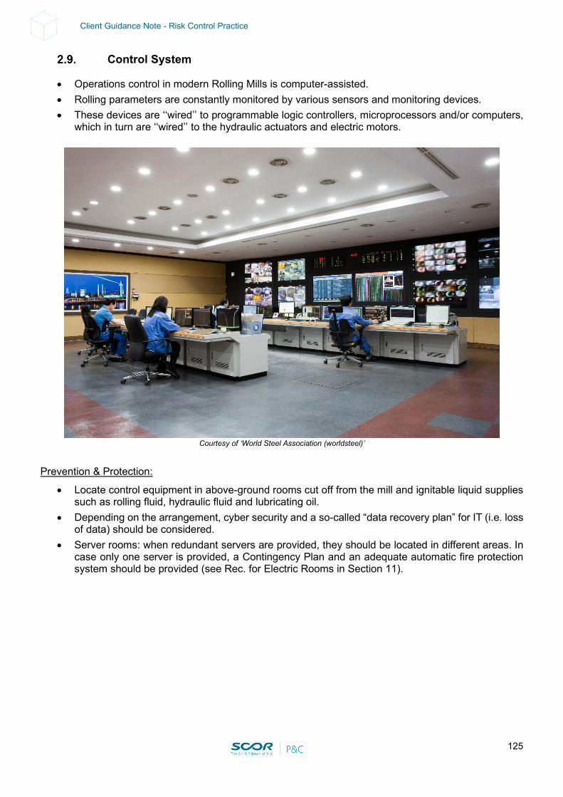
125
Client Guidance Note - Risk Control Practice
Control System
• Operations control in modern Rolling Mills is computer-assisted. • Rolling parameters are constantly monitored by various sensors and monitoring devices. • These devices are ‘‘wired’’ to programmable logic controllers, microprocessors and/or computers,
which in turn are ‘‘wired’’ to the hydraulic actuators and electric motors.
Courtesy of ‘World Steel Association (worldsteel)’
Prevention & Protection:
• Locate control equipment in above-ground rooms cut off from the mill and ignitable liquid supplies such as rolling fluid, hydraulic fluid and lubricating oil.
• Depending on the arrangement, cyber security and a so-called “data recovery plan” for IT (i.e. loss of data) should be considered.
• Server rooms: when redundant servers are provided, they should be located in different areas. In case only one server is provided, a Contingency Plan and an adequate automatic fire protection system should be provided (see Rec. for Electric Rooms in Section 11).

126
Client Guidance Note - Risk Control Practice
Focus on Hot Rolling Mills
“Flat” Products:
Preparation
• Slabs are taken from the slabs’ storage, using overhead cranes. The tendency is to reduce the slab storage duration to get the hottest slabs possible in order to reduce energy consumption in the furnaces.
• Slabs may be prepared: by calamine removal (using high-pressure water at 100-200 bars), removal of cracks (mechanically or through direct heating of the surface) and grinding (note that calamine removal takes place 2 or 3 more times along the process line).
Main hazards include:
• Overhead cranes: Machinery Breakdown (BI issue) • Crack removal: process gas explosion potential • Lube oil group: Fire potential
Prevention & Protection:
• Overhead cranes (see 7.2.8 Utilities above) • Crack removal: gas flow / pressure control, flame supervision and interlocks • Lube oil group protection (see Section 11)
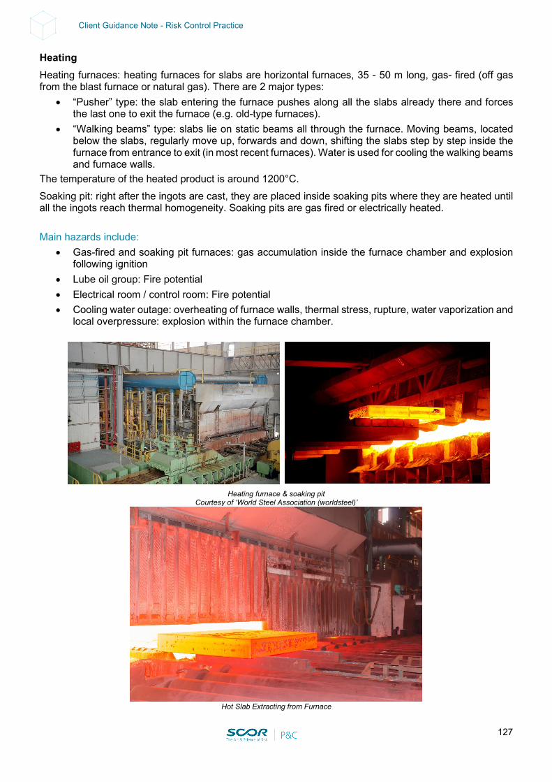
127
Client Guidance Note - Risk Control Practice
Heating Heating furnaces: heating furnaces for slabs are horizontal furnaces, 35 - 50 m long, gas- fired (off gas from the blast furnace or natural gas). There are 2 major types:
• “Pusher” type: the slab entering the furnace pushes along all the slabs already there and forces the last one to exit the furnace (e.g. old-type furnaces).
• “Walking beams” type: slabs lie on static beams all through the furnace. Moving beams, located below the slabs, regularly move up, forwards and down, shifting the slabs step by step inside the furnace from entrance to exit (in most recent furnaces). Water is used for cooling the walking beams and furnace walls.
The temperature of the heated product is around 1200°C. Soaking pit: right after the ingots are cast, they are placed inside soaking pits where they are heated until all the ingots reach thermal homogeneity. Soaking pits are gas fired or electrically heated. Main hazards include:
• Gas-fired and soaking pit furnaces: gas accumulation inside the furnace chamber and explosion following ignition
• Lube oil group: Fire potential • Electrical room / control room: Fire potential • Cooling water outage: overheating of furnace walls, thermal stress, rupture, water vaporization and
local overpressure: explosion within the furnace chamber.
Heating furnace & soaking pit
Courtesy of ‘World Steel Association (worldsteel)’
Hot Slab Extracting from Furnace
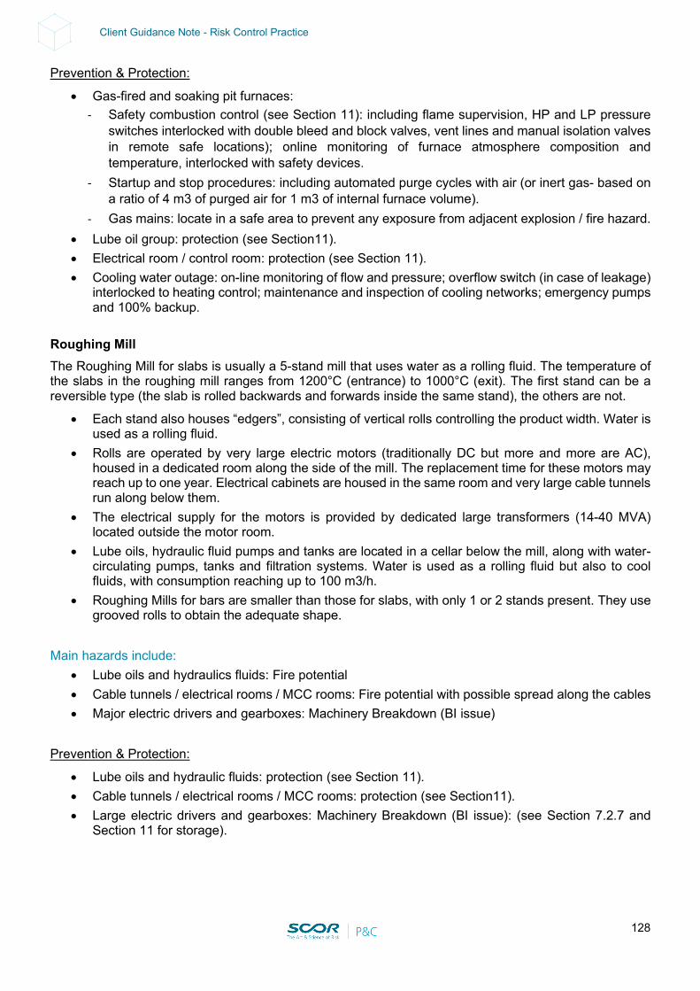
128
Client Guidance Note - Risk Control Practice
Prevention & Protection:
• Gas-fired and soaking pit furnaces: - Safety combustion control (see Section 11): including flame supervision, HP and LP pressure
switches interlocked with double bleed and block valves, vent lines and manual isolation valves in remote safe locations); online monitoring of furnace atmosphere composition and temperature, interlocked with safety devices.
- Startup and stop procedures: including automated purge cycles with air (or inert gas- based on a ratio of 4 m3 of purged air for 1 m3 of internal furnace volume).
- Gas mains: locate in a safe area to prevent any exposure from adjacent explosion / fire hazard. • Lube oil group: protection (see Section11). • Electrical room / control room: protection (see Section 11). • Cooling water outage: on-line monitoring of flow and pressure; overflow switch (in case of leakage)
interlocked to heating control; maintenance and inspection of cooling networks; emergency pumps and 100% backup.
Roughing Mill The Roughing Mill for slabs is usually a 5-stand mill that uses water as a rolling fluid. The temperature of the slabs in the roughing mill ranges from 1200°C (entrance) to 1000°C (exit). The first stand can be a reversible type (the slab is rolled backwards and forwards inside the same stand), the others are not.
• Each stand also houses “edgers”, consisting of vertical rolls controlling the product width. Water is used as a rolling fluid.
• Rolls are operated by very large electric motors (traditionally DC but more and more are AC), housed in a dedicated room along the side of the mill. The replacement time for these motors may reach up to one year. Electrical cabinets are housed in the same room and very large cable tunnels run along below them.
• The electrical supply for the motors is provided by dedicated large transformers (14-40 MVA) located outside the motor room.
• Lube oils, hydraulic fluid pumps and tanks are located in a cellar below the mill, along with water-circulating pumps, tanks and filtration systems. Water is used as a rolling fluid but also to cool fluids, with consumption reaching up to 100 m3/h.
• Roughing Mills for bars are smaller than those for slabs, with only 1 or 2 stands present. They use grooved rolls to obtain the adequate shape.
Main hazards include:
• Lube oils and hydraulics fluids: Fire potential • Cable tunnels / electrical rooms / MCC rooms: Fire potential with possible spread along the cables • Major electric drivers and gearboxes: Machinery Breakdown (BI issue)
Prevention & Protection:
• Lube oils and hydraulic fluids: protection (see Section 11). • Cable tunnels / electrical rooms / MCC rooms: protection (see Section11). • Large electric drivers and gearboxes: Machinery Breakdown (BI issue): (see Section 7.2.7 and
Section 11 for storage).
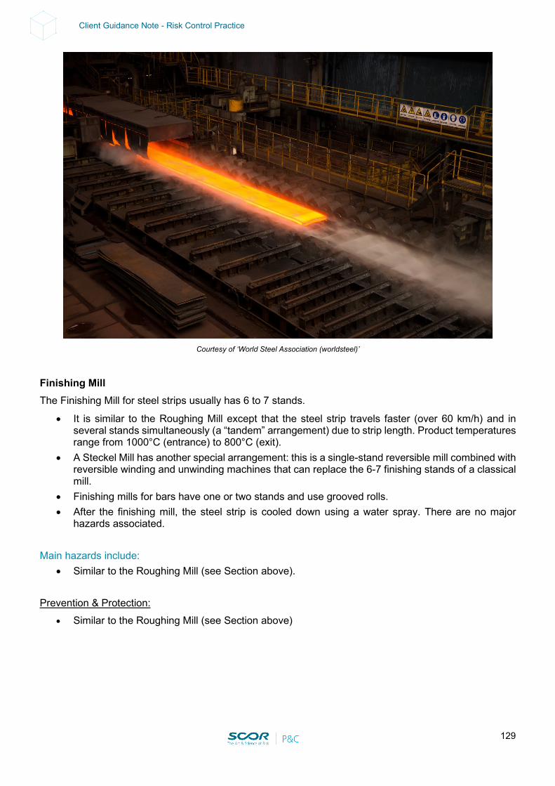
129
Client Guidance Note - Risk Control Practice
Courtesy of ‘World Steel Association (worldsteel)’
Finishing Mill The Finishing Mill for steel strips usually has 6 to 7 stands.
• It is similar to the Roughing Mill except that the steel strip travels faster (over 60 km/h) and in several stands simultaneously (a “tandem” arrangement) due to strip length. Product temperatures range from 1000°C (entrance) to 800°C (exit).
• A Steckel Mill has another special arrangement: this is a single-stand reversible mill combined with reversible winding and unwinding machines that can replace the 6-7 finishing stands of a classical mill.
• Finishing mills for bars have one or two stands and use grooved rolls. • After the finishing mill, the steel strip is cooled down using a water spray. There are no major
hazards associated. Main hazards include:
• Similar to the Roughing Mill (see Section above). Prevention & Protection:
• Similar to the Roughing Mill (see Section above)

130
Client Guidance Note - Risk Control Practice
Coiling In order to allow for practical handling of the steel strip which may be more than 2000 m long, the strip is coiled on downcoilers.
• This equipment uses large electrical motors, usually located in dedicated rooms, and hydraulic systems located in cellars.
Main hazards include:
• Similar to the Roughing Mill (see Section above).
Steel Coils - Courtesy of ‘World Steel Association (worldsteel)’
Prevention & Protection:
• Similar to the Roughing Mill (see Section above).
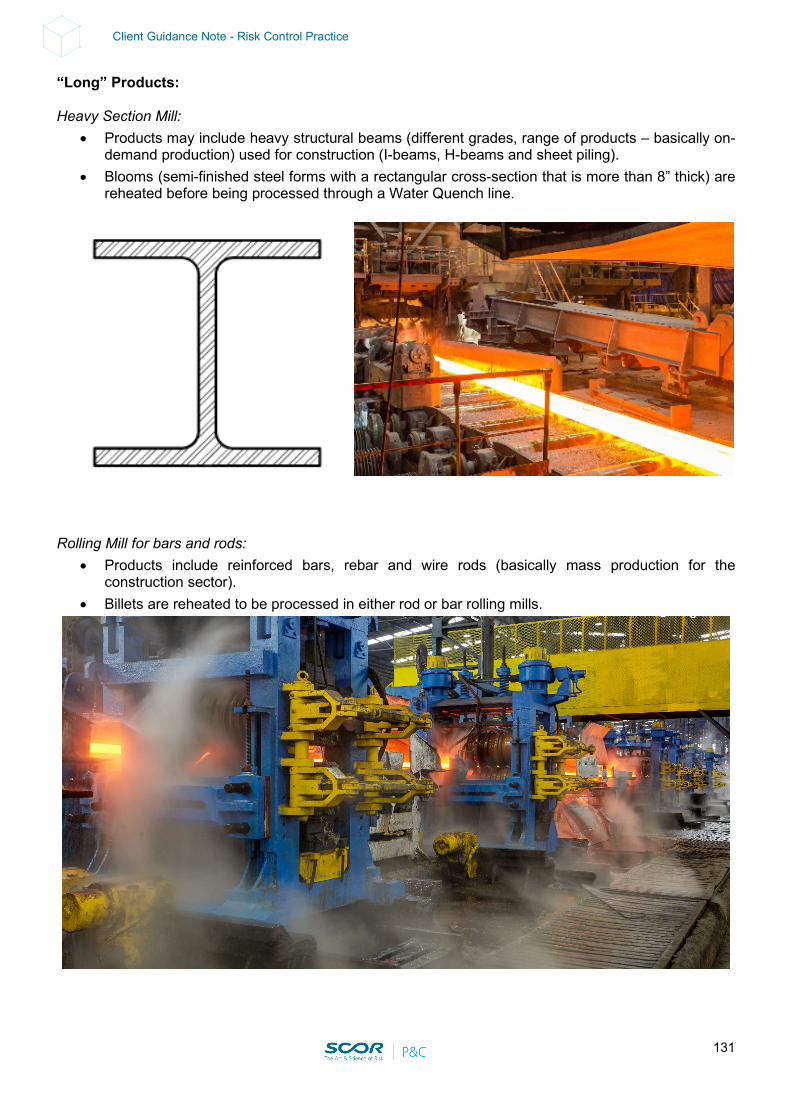
131
Client Guidance Note - Risk Control Practice
“Long” Products: Heavy Section Mill:
• Products may include heavy structural beams (different grades, range of products – basically on-demand production) used for construction (I-beams, H-beams and sheet piling).
• Blooms (semi-finished steel forms with a rectangular cross-section that is more than 8” thick) are reheated before being processed through a Water Quench line.
Rolling Mill for bars and rods:
• Products include reinforced bars, rebar and wire rods (basically mass production for the construction sector).
• Billets are reheated to be processed in either rod or bar rolling mills.
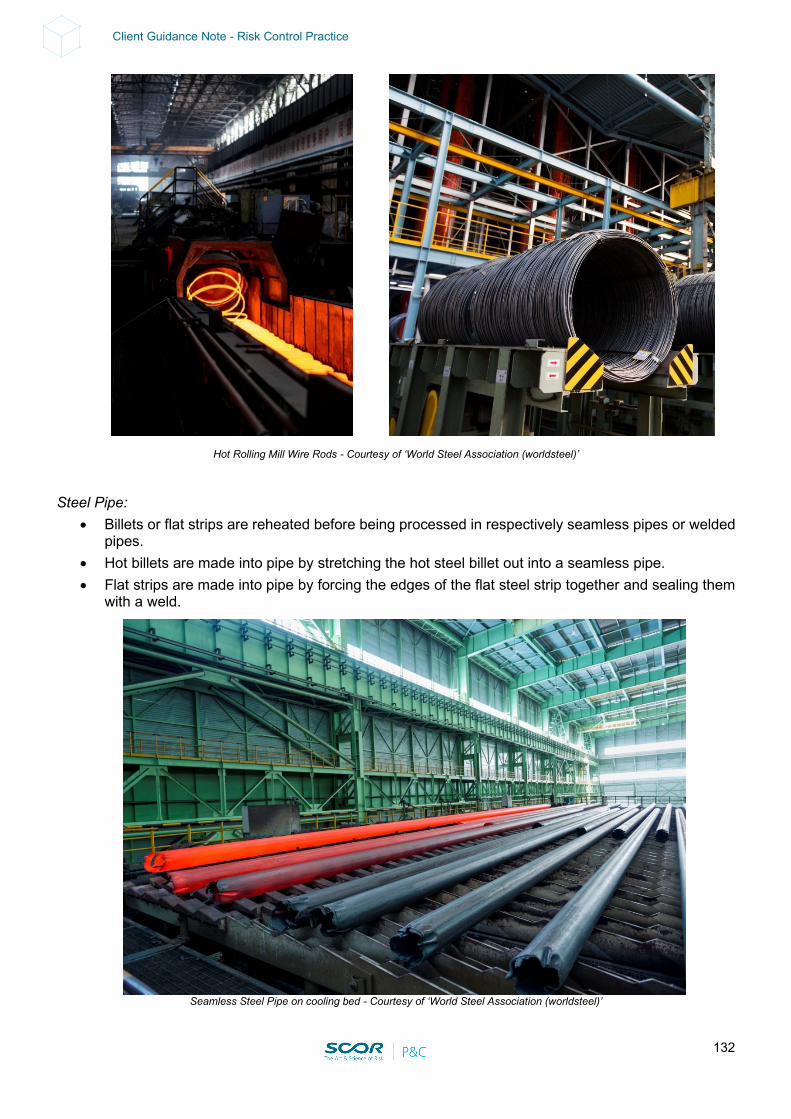
132
Client Guidance Note - Risk Control Practice
Hot Rolling Mill Wire Rods - Courtesy of ‘World Steel Association (worldsteel)’ Steel Pipe:
• Billets or flat strips are reheated before being processed in respectively seamless pipes or welded pipes.
• Hot billets are made into pipe by stretching the hot steel billet out into a seamless pipe. • Flat strips are made into pipe by forcing the edges of the flat steel strip together and sealing them
with a weld.
Seamless Steel Pipe on cooling bed - Courtesy of ‘World Steel Association (worldsteel)’
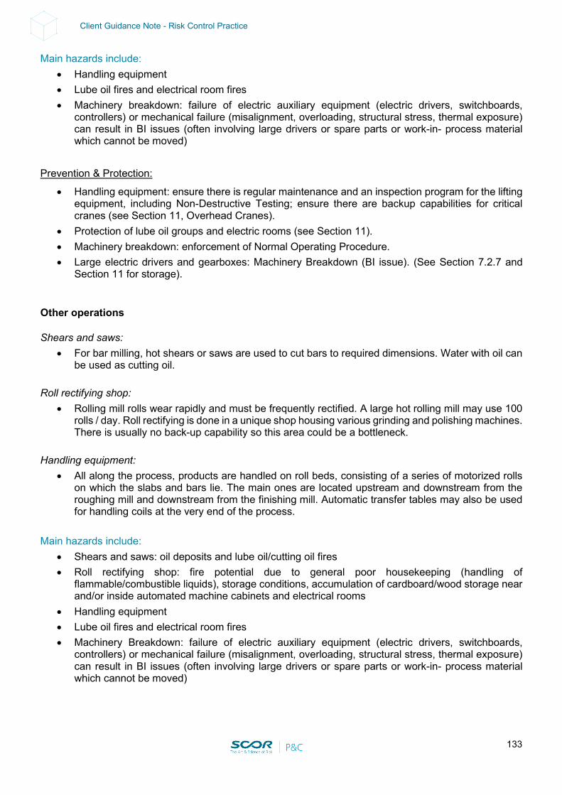
133
Client Guidance Note - Risk Control Practice
Main hazards include: • Handling equipment • Lube oil fires and electrical room fires • Machinery breakdown: failure of electric auxiliary equipment (electric drivers, switchboards,
controllers) or mechanical failure (misalignment, overloading, structural stress, thermal exposure) can result in BI issues (often involving large drivers or spare parts or work-in- process material which cannot be moved)
Prevention & Protection:
• Handling equipment: ensure there is regular maintenance and an inspection program for the lifting equipment, including Non-Destructive Testing; ensure there are backup capabilities for critical cranes (see Section 11, Overhead Cranes).
• Protection of lube oil groups and electric rooms (see Section 11). • Machinery breakdown: enforcement of Normal Operating Procedure. • Large electric drivers and gearboxes: Machinery Breakdown (BI issue). (See Section 7.2.7 and
Section 11 for storage). Other operations Shears and saws:
• For bar milling, hot shears or saws are used to cut bars to required dimensions. Water with oil can be used as cutting oil.
Roll rectifying shop:
• Rolling mill rolls wear rapidly and must be frequently rectified. A large hot rolling mill may use 100 rolls / day. Roll rectifying is done in a unique shop housing various grinding and polishing machines. There is usually no back-up capability so this area could be a bottleneck.
Handling equipment:
• All along the process, products are handled on roll beds, consisting of a series of motorized rolls on which the slabs and bars lie. The main ones are located upstream and downstream from the roughing mill and downstream from the finishing mill. Automatic transfer tables may also be used for handling coils at the very end of the process.
Main hazards include:
• Shears and saws: oil deposits and lube oil/cutting oil fires • Roll rectifying shop: fire potential due to general poor housekeeping (handling of
flammable/combustible liquids), storage conditions, accumulation of cardboard/wood storage near and/or inside automated machine cabinets and electrical rooms
• Handling equipment • Lube oil fires and electrical room fires • Machinery Breakdown: failure of electric auxiliary equipment (electric drivers, switchboards,
controllers) or mechanical failure (misalignment, overloading, structural stress, thermal exposure) can result in BI issues (often involving large drivers or spare parts or work-in- process material which cannot be moved)
134
Client Guidance Note - Risk Control Practice
Prevention & Protection:
• Shears and saws: ensure housekeeping and inspection. • Roll rectifying shop: recommend regular and adequate housekeeping, proper
flammable/combustible liquid handling procedures, storage procedures; establish regular inspections using checklists; give additional training when needed.
• Handling equipment: ensure there is regular maintenance and an inspection program for the lifting equipment, including Non-Destructive Testing; ensure there are back-up capabilities for critical cranes (see Section 11, Overhead Cranes).
• Protection of lube oil groups and electric rooms (see Section 11). • Machinery breakdown: enforcement of Normal Operating Procedure. • Large electric drivers and gearboxes: Machinery Breakdown (BI issue). (See Section 7.2.7 and
Section 11 for storage).
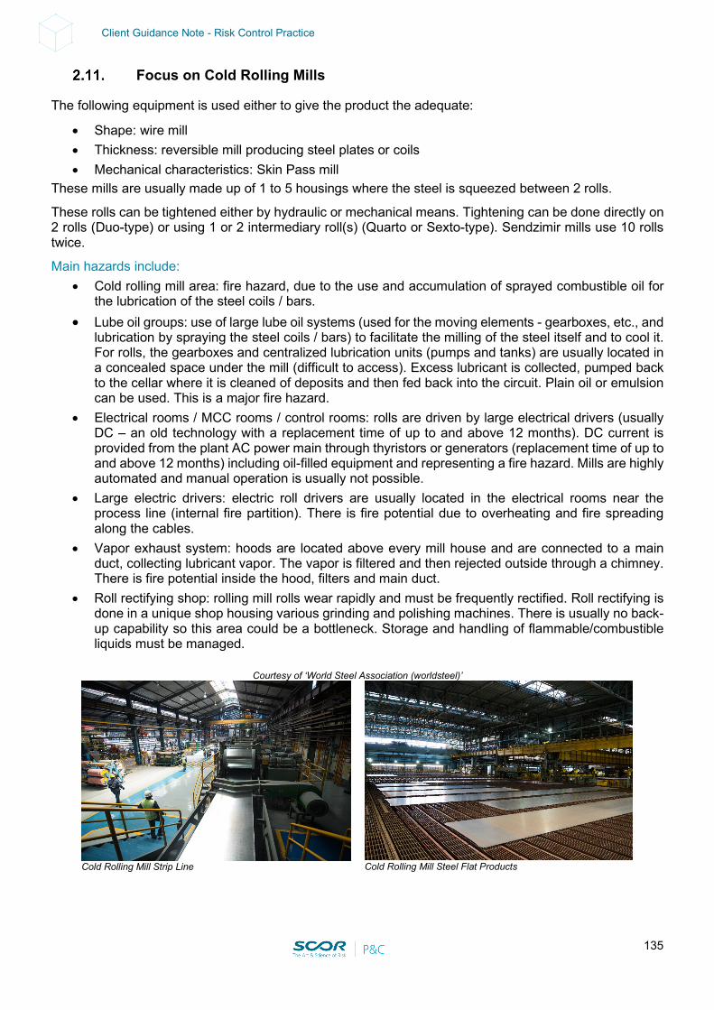
135
Client Guidance Note - Risk Control Practice
Focus on Cold Rolling Mills
The following equipment is used either to give the product the adequate:
• Shape: wire mill • Thickness: reversible mill producing steel plates or coils • Mechanical characteristics: Skin Pass mill
These mills are usually made up of 1 to 5 housings where the steel is squeezed between 2 rolls.
These rolls can be tightened either by hydraulic or mechanical means. Tightening can be done directly on 2 rolls (Duo-type) or using 1 or 2 intermediary roll(s) (Quarto or Sexto-type). Sendzimir mills use 10 rolls twice.
Main hazards include: • Cold rolling mill area: fire hazard, due to the use and accumulation of sprayed combustible oil for
the lubrication of the steel coils / bars. • Lube oil groups: use of large lube oil systems (used for the moving elements - gearboxes, etc., and
lubrication by spraying the steel coils / bars) to facilitate the milling of the steel itself and to cool it. For rolls, the gearboxes and centralized lubrication units (pumps and tanks) are usually located in a concealed space under the mill (difficult to access). Excess lubricant is collected, pumped back to the cellar where it is cleaned of deposits and then fed back into the circuit. Plain oil or emulsion can be used. This is a major fire hazard.
• Electrical rooms / MCC rooms / control rooms: rolls are driven by large electrical drivers (usually DC – an old technology with a replacement time of up to and above 12 months). DC current is provided from the plant AC power main through thyristors or generators (replacement time of up to and above 12 months) including oil-filled equipment and representing a fire hazard. Mills are highly automated and manual operation is usually not possible.
• Large electric drivers: electric roll drivers are usually located in the electrical rooms near the process line (internal fire partition). There is fire potential due to overheating and fire spreading along the cables.
• Vapor exhaust system: hoods are located above every mill house and are connected to a main duct, collecting lubricant vapor. The vapor is filtered and then rejected outside through a chimney. There is fire potential inside the hood, filters and main duct.
• Roll rectifying shop: rolling mill rolls wear rapidly and must be frequently rectified. Roll rectifying is done in a unique shop housing various grinding and polishing machines. There is usually no back-up capability so this area could be a bottleneck. Storage and handling of flammable/combustible liquids must be managed.
Courtesy of ‘World Steel Association (worldsteel)’
Cold Rolling Mill Strip Line
Cold Rolling Mill Steel Flat Products
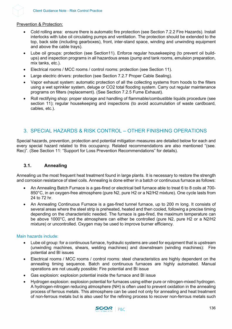
136
Client Guidance Note - Risk Control Practice
Prevention & Protection:
• Cold rolling area: ensure there is automatic fire protection (see Section 7.2.2 Fire Hazards). Install interlocks with lube oil circulating pumps and ventilation. The protection should be extended to the top, back side (including gearboxes), front, inter-stand space, winding and unwinding equipment and above the cable trays).
• Lube oil groups: protection (see Section11). Enforce regular housekeeping (to prevent oil build-ups) and inspection programs in all hazardous areas (pump and tank rooms, emulsion preparation, mix tanks, etc.).
• Electrical rooms / MCC rooms / control rooms: protection (see Section 11). • Large electric drivers: protection (see Section 7.2.7 Proper Cable Sealing). • Vapor exhaust system: automatic protection of all the collecting systems from hoods to the filters
using a wet sprinkler system, deluge or CO2 total flooding system. Carry out regular maintenance programs on filters (replacement). (See Section 7.2.5 Fume Exhaust).
• Roll rectifying shop: proper storage and handling of flammable/combustible liquids procedure (see section 11); regular housekeeping and inspections (to avoid accumulation of waste cardboard, cables, etc.).
3. SPECIAL HAZARDS & RISK CONTROL – OTHER FINISHING OPERATIONS
Special hazards, prevention, protection and potential mitigation measures are detailed below for each and every special hazard related to this occupancy. Related recommendations are also mentioned “(see. Rec)”. (See Section 11: “Support for Loss Prevention Recommendations” for details).
3.1. Annealing
Annealing us the most frequent heat treatment found in large plants. It is necessary to restore the strength and corrosion resistance of steel coils. Annealing is done either in a batch or continuous furnace as follows:
• An Annealing Batch Furnace is a gas-fired or electrical bell furnace able to treat 6 to 8 coils at 700-850°C, in an oxygen-free atmosphere (pure N2, pure H2 or a N2/H2 mixture). One cycle lasts from 24 to 72 hr.
• An Annealing Continuous Furnace is a gas-fired tunnel furnace, up to 200 m long. It consists of several areas where the steel strip is preheated, heated and then cooled, following a precise timing depending on the characteristic needed. The furnace is gas-fired, the maximum temperature can be above 1000°C, and the atmosphere can either be controlled (pure N2, pure H2 or a N2/H2 mixture) or uncontrolled. Oxygen may be used to improve burner efficiency.
Main hazards include:
• Lube oil group: for a continuous furnace, hydraulic systems are used for equipment that is upstream (unwinding machines, shears, welding machines) and downstream (winding machines): Fire potential and BI issues
• Electrical rooms / MCC rooms / control rooms: steel characteristics are highly dependent on the annealing timing sequence. Batch and continuous furnaces are highly automated. Manual operations are not usually possible: Fire potential and BI issue
• Gas explosion: explosion potential inside the furnace and BI issue • Hydrogen explosion: explosion potential for furnaces using either pure or nitrogen-mixed hydrogen.
A hydrogen-nitrogen reducing atmosphere (NH) is often used to prevent oxidation in the annealing process of ferrous metals. This atmosphere can be used not only for annealing and heat treatment of non-ferrous metals but is also used for the refining process to recover non-ferrous metals such
137
Client Guidance Note - Risk Control Practice
as tungsten, molybdenum and magnesium. A reducing atmosphere of pure hydrogen is used in tungsten processing when oxide compacts are sintered. The molybdenum trioxide is reduced in a furnace with hydrogen at about 1, 000°C to produce a metal powder. This powder is formed into a sintered rod in a hydrogen atmosphere. Magnesium chloride can be electrolyzed, or magnesium oxide can be thermally reduced. In both cases hydrogen gas is consumed. A N2/H2 mixture can be obtained from an ammoniac cracking unit, on-site supply or external supply (mains, mixing station).
• Oxygen: oxygen may be used for improving furnace heating: Fire and explosion potential due to high concentration of oxidizer.
Prevention & Protection:
• Lube oil group: protection (see Section 11). • Electrical rooms / MCC rooms / control rooms: protection (see Section 11). • Gas explosion: provide safety combustion control (flame supervision, HP and LP switches
interlocked with double block and bleed valves, vent line, manual isolation valve located in a safe location). (See Section 11); adequate startup and stop (automated purge with air or inert gas based on a ratio of 4 m3 of purged air for 1 m3 of internal furnace volume). Online monitoring of furnace atmospheric composition and temperature; trip system (interlocked with safety combustion control); gas pipes installed in a safe location and adequately arranged to prevent damage from explosion and/or fire.
• Hydrogen explosion: same recommendation as for gas explosion and extension to potential supply located outside.
• Oxygen: tank location and piping arrangements should be reviewed according to FM 6-10; provide an oxygen supply with a manually activated shutoff valve located in a safe location and/or a Remotely Operated Valve that is 15-min fire resistive.
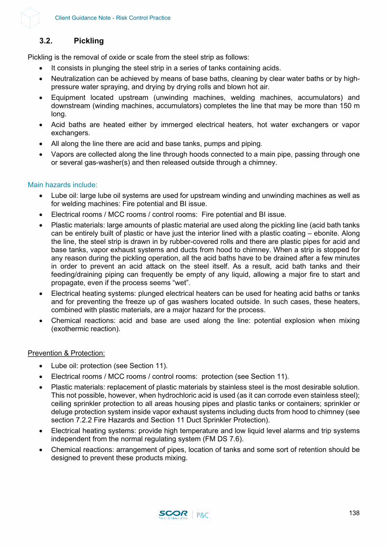
138
Client Guidance Note - Risk Control Practice
3.2. Pickling
Pickling is the removal of oxide or scale from the steel strip as follows: • It consists in plunging the steel strip in a series of tanks containing acids. • Neutralization can be achieved by means of base baths, cleaning by clear water baths or by high-
pressure water spraying, and drying by drying rolls and blown hot air. • Equipment located upstream (unwinding machines, welding machines, accumulators) and
downstream (winding machines, accumulators) completes the line that may be more than 150 m long.
• Acid baths are heated either by immerged electrical heaters, hot water exchangers or vapor exchangers.
• All along the line there are acid and base tanks, pumps and piping. • Vapors are collected along the line through hoods connected to a main pipe, passing through one
or several gas-washer(s) and then released outside through a chimney. Main hazards include:
• Lube oil: large lube oil systems are used for upstream winding and unwinding machines as well as for welding machines: Fire potential and BI issue.
• Electrical rooms / MCC rooms / control rooms: Fire potential and BI issue. • Plastic materials: large amounts of plastic material are used along the pickling line (acid bath tanks
can be entirely built of plastic or have just the interior lined with a plastic coating – ebonite. Along the line, the steel strip is drawn in by rubber-covered rolls and there are plastic pipes for acid and base tanks, vapor exhaust systems and ducts from hood to chimney. When a strip is stopped for any reason during the pickling operation, all the acid baths have to be drained after a few minutes in order to prevent an acid attack on the steel itself. As a result, acid bath tanks and their feeding/draining piping can frequently be empty of any liquid, allowing a major fire to start and propagate, even if the process seems “wet”.
• Electrical heating systems: plunged electrical heaters can be used for heating acid baths or tanks and for preventing the freeze up of gas washers located outside. In such cases, these heaters, combined with plastic materials, are a major hazard for the process.
• Chemical reactions: acid and base are used along the line: potential explosion when mixing (exothermic reaction).
Prevention & Protection:
• Lube oil: protection (see Section 11). • Electrical rooms / MCC rooms / control rooms: protection (see Section 11). • Plastic materials: replacement of plastic materials by stainless steel is the most desirable solution.
This not possible, however, when hydrochloric acid is used (as it can corrode even stainless steel); ceiling sprinkler protection to all areas housing pipes and plastic tanks or containers; sprinkler or deluge protection system inside vapor exhaust systems including ducts from hood to chimney (see section 7.2.2 Fire Hazards and Section 11 Duct Sprinkler Protection).
• Electrical heating systems: provide high temperature and low liquid level alarms and trip systems independent from the normal regulating system (FM DS 7.6).
• Chemical reactions: arrangement of pipes, location of tanks and some sort of retention should be designed to prevent these products mixing.
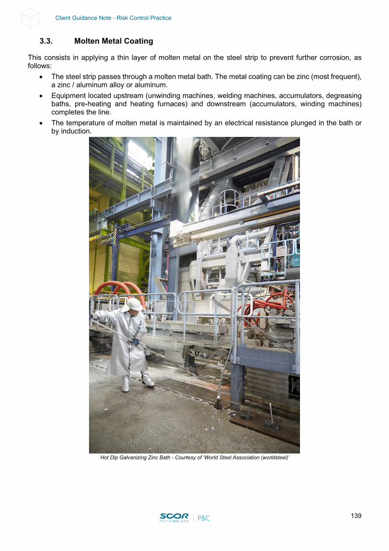
139
Client Guidance Note - Risk Control Practice
3.3. Molten Metal Coating
This consists in applying a thin layer of molten metal on the steel strip to prevent further corrosion, as follows:
• The steel strip passes through a molten metal bath. The metal coating can be zinc (most frequent), a zinc / aluminum alloy or aluminum.
• Equipment located upstream (unwinding machines, welding machines, accumulators, degreasing baths, pre-heating and heating furnaces) and downstream (accumulators, winding machines) completes the line.
• The temperature of molten metal is maintained by an electrical resistance plunged in the bath or by induction.
Hot Dip Galvanizing Zinc Bath - Courtesy of ‘World Steel Association (worldsteel)’
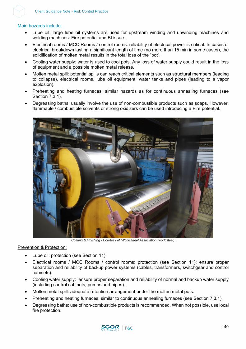
140
Client Guidance Note - Risk Control Practice
Main hazards include: • Lube oil: large lube oil systems are used for upstream winding and unwinding machines and
welding machines: Fire potential and BI issue. • Electrical rooms / MCC Rooms / control rooms: reliability of electrical power is critical. In cases of
electrical breakdown lasting a significant length of time (no more than 15 min in some cases), the solidification of molten metal results in the total loss of the “pot”.
• Cooling water supply: water is used to cool pots. Any loss of water supply could result in the loss of equipment and a possible molten metal release.
• Molten metal spill: potential spills can reach critical elements such as structural members (leading to collapse), electrical rooms, lube oil equipment, water tanks and pipes (leading to a vapor explosion).
• Preheating and heating furnaces: similar hazards as for continuous annealing furnaces (see Section 7.3.1).
• Degreasing baths: usually involve the use of non-combustible products such as soaps. However, flammable / combustible solvents or strong oxidizers can be used introducing a Fire potential.
Coating & Finishing - Courtesy of ‘World Steel Association (worldsteel)’
Prevention & Protection:
• Lube oil: protection (see Section 11). • Electrical rooms / MCC Rooms / control rooms: protection (see Section 11); ensure proper
separation and reliability of backup power systems (cables, transformers, switchgear and control cabinets).
• Cooling water supply: ensure proper separation and reliability of normal and backup water supply (including control cabinets, pumps and pipes).
• Molten metal spill: adequate retention arrangement under the molten metal pots. • Preheating and heating furnaces: similar to continuous annealing furnaces (see Section 7.3.1). • Degreasing baths: use of non-combustible products is recommended. When not possible, use local
fire protection.
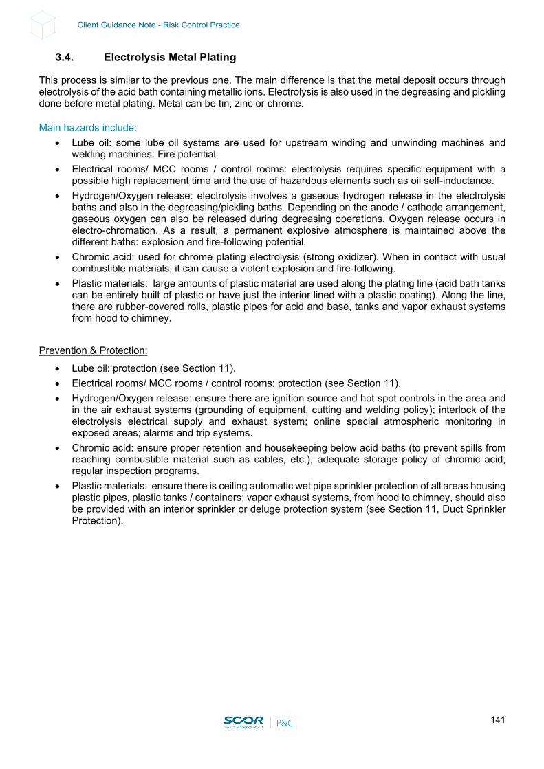
141
Client Guidance Note - Risk Control Practice
3.4. Electrolysis Metal Plating
This process is similar to the previous one. The main difference is that the metal deposit occurs through electrolysis of the acid bath containing metallic ions. Electrolysis is also used in the degreasing and pickling done before metal plating. Metal can be tin, zinc or chrome. Main hazards include:
• Lube oil: some lube oil systems are used for upstream winding and unwinding machines and welding machines: Fire potential.
• Electrical rooms/ MCC rooms / control rooms: electrolysis requires specific equipment with a possible high replacement time and the use of hazardous elements such as oil self-inductance.
• Hydrogen/Oxygen release: electrolysis involves a gaseous hydrogen release in the electrolysis baths and also in the degreasing/pickling baths. Depending on the anode / cathode arrangement, gaseous oxygen can also be released during degreasing operations. Oxygen release occurs in electro-chromation. As a result, a permanent explosive atmosphere is maintained above the different baths: explosion and fire-following potential.
• Chromic acid: used for chrome plating electrolysis (strong oxidizer). When in contact with usual combustible materials, it can cause a violent explosion and fire-following.
• Plastic materials: large amounts of plastic material are used along the plating line (acid bath tanks can be entirely built of plastic or have just the interior lined with a plastic coating). Along the line, there are rubber-covered rolls, plastic pipes for acid and base, tanks and vapor exhaust systems from hood to chimney.
Prevention & Protection:
• Lube oil: protection (see Section 11). • Electrical rooms/ MCC rooms / control rooms: protection (see Section 11). • Hydrogen/Oxygen release: ensure there are ignition source and hot spot controls in the area and
in the air exhaust systems (grounding of equipment, cutting and welding policy); interlock of the electrolysis electrical supply and exhaust system; online special atmospheric monitoring in exposed areas; alarms and trip systems.
• Chromic acid: ensure proper retention and housekeeping below acid baths (to prevent spills from reaching combustible material such as cables, etc.); adequate storage policy of chromic acid; regular inspection programs.
• Plastic materials: ensure there is ceiling automatic wet pipe sprinkler protection of all areas housing plastic pipes, plastic tanks / containers; vapor exhaust systems, from hood to chimney, should also be provided with an interior sprinkler or deluge protection system (see Section 11, Duct Sprinkler Protection).
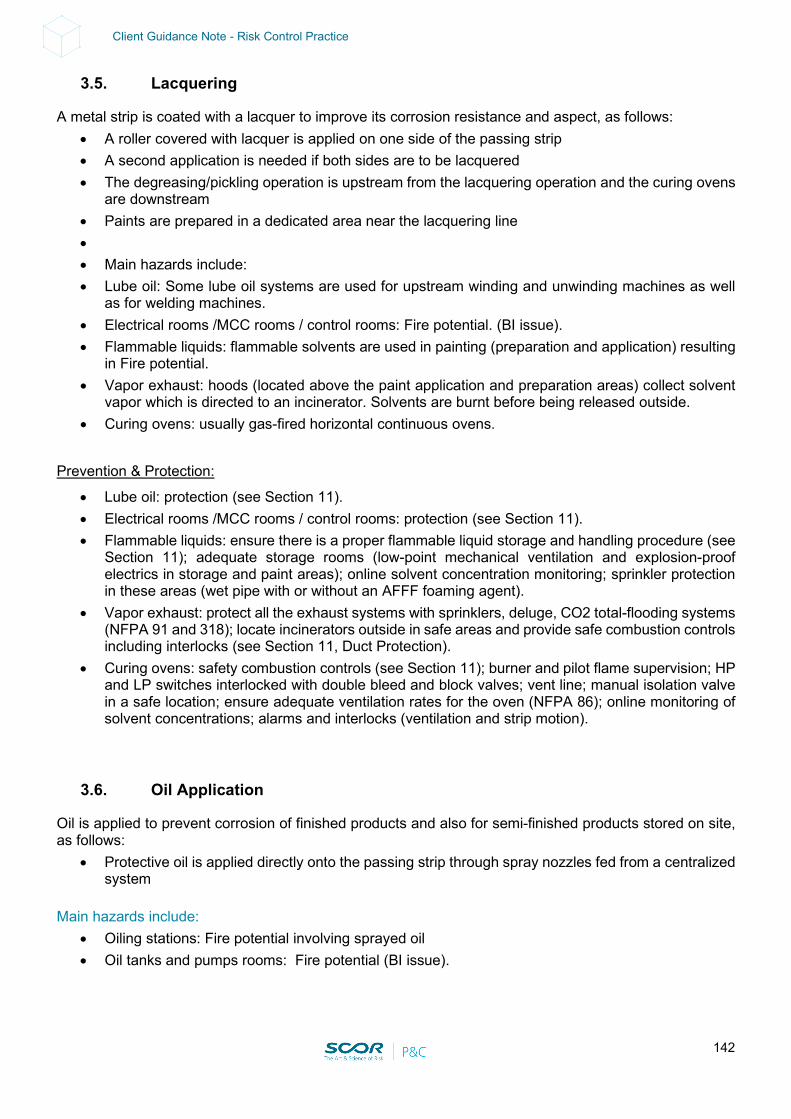
142
Client Guidance Note - Risk Control Practice
3.5. Lacquering
A metal strip is coated with a lacquer to improve its corrosion resistance and aspect, as follows: • A roller covered with lacquer is applied on one side of the passing strip • A second application is needed if both sides are to be lacquered • The degreasing/pickling operation is upstream from the lacquering operation and the curing ovens
are downstream • Paints are prepared in a dedicated area near the lacquering line • • Main hazards include: • Lube oil: Some lube oil systems are used for upstream winding and unwinding machines as well
as for welding machines. • Electrical rooms /MCC rooms / control rooms: Fire potential. (BI issue). • Flammable liquids: flammable solvents are used in painting (preparation and application) resulting
in Fire potential. • Vapor exhaust: hoods (located above the paint application and preparation areas) collect solvent
vapor which is directed to an incinerator. Solvents are burnt before being released outside. • Curing ovens: usually gas-fired horizontal continuous ovens.
Prevention & Protection:
• Lube oil: protection (see Section 11). • Electrical rooms /MCC rooms / control rooms: protection (see Section 11). • Flammable liquids: ensure there is a proper flammable liquid storage and handling procedure (see
Section 11); adequate storage rooms (low-point mechanical ventilation and explosion-proof electrics in storage and paint areas); online solvent concentration monitoring; sprinkler protection in these areas (wet pipe with or without an AFFF foaming agent).
• Vapor exhaust: protect all the exhaust systems with sprinklers, deluge, CO2 total-flooding systems (NFPA 91 and 318); locate incinerators outside in safe areas and provide safe combustion controls including interlocks (see Section 11, Duct Protection).
• Curing ovens: safety combustion controls (see Section 11); burner and pilot flame supervision; HP and LP switches interlocked with double bleed and block valves; vent line; manual isolation valve in a safe location; ensure adequate ventilation rates for the oven (NFPA 86); online monitoring of solvent concentrations; alarms and interlocks (ventilation and strip motion).
3.6. Oil Application
Oil is applied to prevent corrosion of finished products and also for semi-finished products stored on site, as follows:
• Protective oil is applied directly onto the passing strip through spray nozzles fed from a centralized system
Main hazards include:
• Oiling stations: Fire potential involving sprayed oil • Oil tanks and pumps rooms: Fire potential (BI issue).

143
Client Guidance Note - Risk Control Practice
Prevention & Protection:
• Oiling stations: local automatic sprinkler protection (10 mm/min on exposed surfaces) over the station and over all the oil-wetted areas OR complete ceiling sprinkler protection
• Oil tanks and pump rooms: protection (see Section 11).
3.7. Product Quality Control
Steel producers are facing a rising demand for high quality products, coming from aeronautics, car manufacturers, food packaging, but also rails for high-speed trains etc. Quality controls are, therefore, widespread along the process and at the end, as follows (this list does not intend to be exhaustive):
• Visually-manned controls • CCD camera visual controls • Thickness gauges for steel sheets, plates, wire • X-ray gauges • Ultrasonic controls
Due to the tracking policy of products, they are often marked, using paints with flammable liquid solvents. Even though these controls are not usually the cause of major losses, this part of the process can end up being a bottleneck without any backup capacities, and a fire destroying this equipment could lead to several weeks BI. Main hazards include:
• Printing shops: Fire potential involving flammable liquids and their application • Electrical rooms / MCC rooms / control rooms: specific equipment with possible high replacement
time; Fire potential • Electronic Data Processing: loss of quality process data (BI issue).
Prevention & Protection:
• Printing shops: ensure there is a procedure for the safe and proper storage and handling of flammable liquids and their application (NFPA 30 / 33); sprinkler protection on critical areas (bottleneck without backup or long lead time for replacement)
• Electrical rooms / MCC rooms / control rooms: protection (see Section 11); contingency plan within and outside the group (manufacturer, suppliers, etc.)
• Electronic Data Processing: adequate backup policies on site (regular, safe storage locations).
3.8. Process Control System
• See Section 7.2.10 for Rolling Mills
3.9. Spare Parts Warehouse
• See Section 6.2.3 for Ironmaking, Steelmaking and Casting
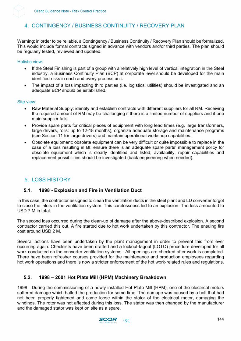
144
Client Guidance Note - Risk Control Practice
4. CONTINGENCY / BUSINESS CONTINUITY / RECOVERY PLAN
Warning: in order to be reliable, a Contingency / Business Continuity / Recovery Plan should be formalized. This would include formal contracts signed in advance with vendors and/or third parties. The plan should be regularly tested, reviewed and updated. Holistic view:
• If the Steel Finishing is part of a group with a relatively high level of vertical integration in the Steel industry, a Business Continuity Plan (BCP) at corporate level should be developed for the main identified risks in each and every process unit.
• The impact of a loss impacting third parties (i.e. logistics, utilities) should be investigated and an adequate BCP should be established.
Site view:
• Raw Material Supply: identify and establish contracts with different suppliers for all RM. Receiving the required amount of RM may be challenging if there is a limited number of suppliers and if one main supplier fails.
• Provide spare parts for critical pieces of equipment with long lead times (e.g. large transformers, large drivers, rolls: up to 12-18 months), organize adequate storage and maintenance programs (see Section 11 for large drivers) and maintain operational workshop capabilities.
• Obsolete equipment: obsolete equipment can be very difficult or quite impossible to replace in the case of a loss resulting in BI; ensure there is an adequate spare parts’ management policy for obsolete equipment which is clearly identified and listed; availability, repair capabilities and replacement possibilities should be investigated (back engineering when needed).
5. LOSS HISTORY
5.1. 1998 - Explosion and Fire in Ventilation Duct
In this case, the contractor assigned to clean the ventilation ducts in the steel plant and LD converter forgot to close the inlets in the ventilation system. This carelessness led to an explosion. The loss amounted to USD 7 M in total. The second loss occurred during the clean-up of damage after the above-described explosion. A second contractor carried this out. A fire started due to hot work undertaken by this contractor. The ensuing fire cost around USD 2 M. Several actions have been undertaken by the plant management in order to prevent this from ever occurring again. Checklists have been drafted and a lockout-tagout (LOTO) procedure developed for all work conducted on the converter ventilation systems. All openings are checked after work is completed. There have been refresher courses provided for the maintenance and production employees regarding hot work operations and there is now a stricter enforcement of the hot work-related rules and regulations.
5.2. 1998 – 2001 Hot Plate Mill (HPM) Machinery Breakdown
1998 - During the commissioning of a newly installed Hot Plate Mill (HPM), one of the electrical motors suffered damage which halted the production for some time. The damage was caused by a bolt that had not been properly tightened and came loose within the stator of the electrical motor, damaging the windings. The rotor was not affected during this loss. The stator was then changed by the manufacturer and the damaged stator was kept on site as a spare.

145
Client Guidance Note - Risk Control Practice
2001 - The lower motor of the HPM failed. One of the poles on the rotor had shifted some 30 mm in the axial direction, causing the pole to break loose from the fastening and causing damage to the stator. The old stator, kept as a spare from the previous loss, was installed while a new stator was manufactured and installed later during the summer shutdown. The bolts and fixtures in the HPM motors were also audited and proper locking devices were installed where necessary. The loss resulted in 225 hours of lost production with some 16,000 tonnes of finished plate that could not be produced during that time. BI was around € 5 M.
5.3. 1999 - Electric Room Fire – Hot Rolling Mill
• This loss occurred in the electrical room adjacent to a hot rolling mill dedicated to the production of bars (225,000 ton/year - 6/7 days/week). The rolling mill had 19 stands with 400 kW c.c. drivers.
• The electrical room (130 x 8 m on 2 levels) was separated from the rolling mill by a brick wall. • The electrical motors, the control and electrical panels (about 70 panels -built in 1976) and the
power transformers were located on the ground floor. • The basement housed the cable tunnel (built in 1976) and lubricating oil circuits.
Loss chronology:
• Saturday 12/12/99 • 06:00 Production shutdown. • 06:00-12:00 Maintenance operations underway (not in the affected area). • 12:03 An electrician enters the room to leave a piece of equipment and to check the panels before
leaving. All the panels are switched off except for 2 (but without any loading). He leaves the plant. • 12:15 The watchman sees black smoke coming out of the room (from the other side of the plant). • 12:18 The maintenance people at the plant try to enter the room, which is already full of smoke.
They can see flames on some electrical panels. • 12:40 The FD reaches the plant and extinguishes the fire with water and foam. • 16:00 The FD leaves the plant.
Situation on first visit:
• 20 panels were heavily damaged and had to be replaced (45 days) • 30 m of cable tunnel was destroyed • The whole room was contaminated by smoke
Action plan:
• It was decided to order in 20 new panels (€ 400,000) and to try to carry out a recovery action with a specialized Company that included:
- Building decontamination - Decontamination of the transformers, power centers and control panels - Cost: € 400,000 - Expected restart: 1-15 March - However, the plant only restarted operations in mid-May
Reason for the delay in startup:
• The electric motors had simply been dried • Decontamination of the room was successful
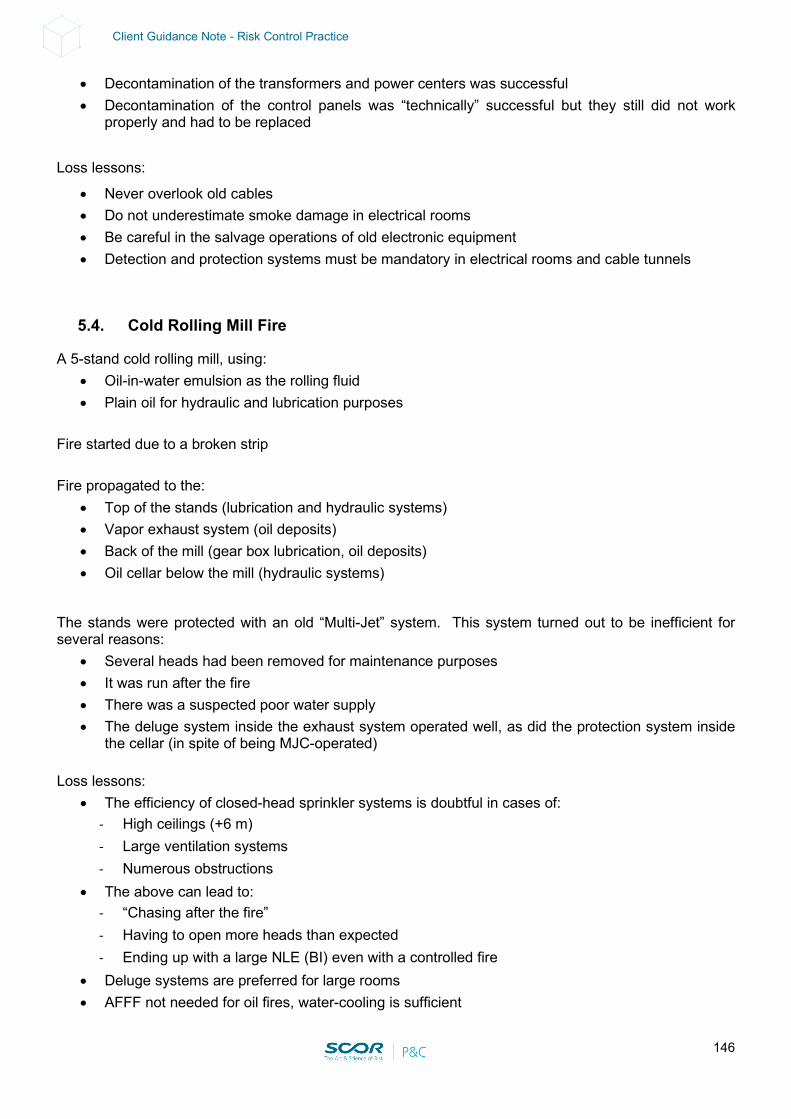
146
Client Guidance Note - Risk Control Practice
• Decontamination of the transformers and power centers was successful • Decontamination of the control panels was “technically” successful but they still did not work
properly and had to be replaced Loss lessons:
• Never overlook old cables • Do not underestimate smoke damage in electrical rooms • Be careful in the salvage operations of old electronic equipment • Detection and protection systems must be mandatory in electrical rooms and cable tunnels
5.4. Cold Rolling Mill Fire
A 5-stand cold rolling mill, using: • Oil-in-water emulsion as the rolling fluid • Plain oil for hydraulic and lubrication purposes
Fire started due to a broken strip Fire propagated to the:
• Top of the stands (lubrication and hydraulic systems) • Vapor exhaust system (oil deposits) • Back of the mill (gear box lubrication, oil deposits) • Oil cellar below the mill (hydraulic systems)
The stands were protected with an old “Multi-Jet” system. This system turned out to be inefficient for several reasons:
• Several heads had been removed for maintenance purposes • It was run after the fire • There was a suspected poor water supply • The deluge system inside the exhaust system operated well, as did the protection system inside
the cellar (in spite of being MJC-operated) Loss lessons:
• The efficiency of closed-head sprinkler systems is doubtful in cases of: - High ceilings (+6 m) - Large ventilation systems - Numerous obstructions
• The above can lead to: - “Chasing after the fire” - Having to open more heads than expected - Ending up with a large NLE (BI) even with a controlled fire
• Deluge systems are preferred for large rooms • AFFF not needed for oil fires, water-cooling is sufficient
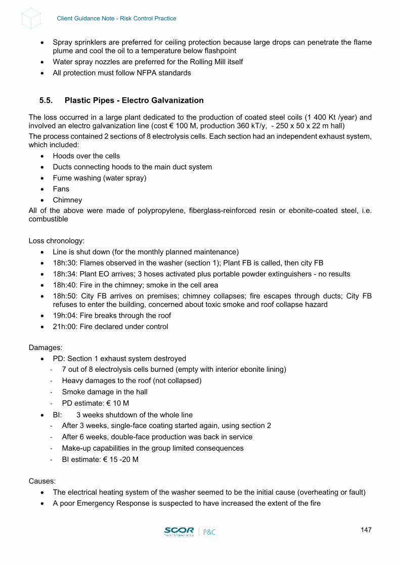
147
Client Guidance Note - Risk Control Practice
• Spray sprinklers are preferred for ceiling protection because large drops can penetrate the flame plume and cool the oil to a temperature below flashpoint
• Water spray nozzles are preferred for the Rolling Mill itself • All protection must follow NFPA standards
5.5. Plastic Pipes - Electro Galvanization
The loss occurred in a large plant dedicated to the production of coated steel coils (1 400 Kt /year) and involved an electro galvanization line (cost € 100 M, production 360 kT/y, - 250 x 50 x 22 m hall) The process contained 2 sections of 8 electrolysis cells. Each section had an independent exhaust system, which included:
• Hoods over the cells • Ducts connecting hoods to the main duct system • Fume washing (water spray) • Fans • Chimney
All of the above were made of polypropylene, fiberglass-reinforced resin or ebonite-coated steel, i.e. combustible Loss chronology:
• Line is shut down (for the monthly planned maintenance) • 18h:30: Flames observed in the washer (section 1); Plant FB is called, then city FB • 18h:34: Plant EO arrives; 3 hoses activated plus portable powder extinguishers - no results • 18h:40: Fire in the chimney; smoke in the cell area • 18h:50: City FB arrives on premises; chimney collapses; fire escapes through ducts; City FB
refuses to enter the building, concerned about toxic smoke and roof collapse hazard • 19h:04: Fire breaks through the roof • 21h:00: Fire declared under control
Damages:
• PD: Section 1 exhaust system destroyed - 7 out of 8 electrolysis cells burned (empty with interior ebonite lining) - Heavy damages to the roof (not collapsed) - Smoke damage in the hall - PD estimate: € 10 M
• BI: 3 weeks shutdown of the whole line - After 3 weeks, single-face coating started again, using section 2 - After 6 weeks, double-face production was back in service - Make-up capabilities in the group limited consequences - BI estimate: € 15 -20 M
Causes:
• The electrical heating system of the washer seemed to be the initial cause (overheating or fault) • A poor Emergency Response is suspected to have increased the extent of the fire
148
Client Guidance Note - Risk Control Practice
• The main factors were: - Extensive use of combustible material - Lack of partitioning - Lack of an automatic extinguishing system
Actions taken:
• Emergency reconstruction of the line was done, unfortunately using the same technology and materials
• Heating systems were suppressed • A water spray deluge system installation is being studied
Loss lessons:
• A fast-moving fire: - 10 min to collapse the chimney - 15 min to spread 60 m
• A difficult fire to fight - Heavy black smoke - Speed and changes in direction - Ducts 10 m high, cells 7 m high, roof 22 m high - Unprotected steel structures leading to FB concerns
• Some ducts must systematically be looked for and paid attention to whenever acids are used: - Chemical pickling lines - Electrolytic pickling lines - Electrolytic plating lines: Zinc, Chrome, Tin
• Ducts are not usually present in: - Painting lines - Rolling mill fume-exhaust systems - ASK for them, do not expect to CATCH them while visiting
149
Client Guidance Note - Risk Control Practice
6. LOSS ESTIMATES
According to multiple sources, the largest losses in rolling mills are almost equally split between: • Fire:
- Involving hydraulic fluid, rolling fluid - Inadequate supplementary protection (e.g. CO2) at equipment level, and ceiling protection - Ignition sources, including hot surfaces (break pit) and poorly controlled hot work
• Machinery Breakdown - Involving gear boxes, work rolls
• Electrical - Involving large drive motors or power supply components - Fire-following in about 1/3 of the cases
Maximum Possible Loss (Technical MPL):
• Major EQ in zone 3 or 4 impacting all facilities: 35% PD for zone 3, at least 50% for Zone 4 and 18-months BI.
• Tsunami in a coastal area (see MPL Handbook). • Storm surge / river flood impacting facilities (e.g. underground vault, tunnels), access roads and
bridges impaired for several months (at least 4 months in a best-case scenario). • River harbor used for shipping (raw material, finished products, spare parts, etc.): high or low water
conditions (port impaired for at least 2 months).
• Rolling Mill Overall: - Major fire inside a Rolling Mill involving combustible fluids (hydraulic and/or rolling and
lubricating) and combustible construction (if any. i.e. sandwich panels with plastic-based insulation). PD = 100% of the Rolling Mill in the case of a single building. In the case of multiple buildings, please refer to the MPL handbook for minimum separating distances and apply the MPL to the building with the largest values (PD & BI). BI = about 24 months
• Hot Rolling Mill:
- Explosion of a heating furnace: the following fire spreads to the lube oil group and/or electrical rooms; partial collapse of the building structural members above the rolling mill (steel structures); fire stops due to the lack of combustible (case-by-case study). PD = 100% of the area* involved BI = about 18-24 months (*): The area can represent up to 70% of the hot rolling mill depending on congestion, continuity of combustible and combustible load. Without any information (no visit on site, no detailed survey report), one must consider 100% of the hot rolling mill, especially in the presence of a combustible construction.
150
Client Guidance Note - Risk Control Practice
• Cold Rolling Mill and other Finishing Areas: - Fire on a lube oil group spreading to the electrical room and to the rolling mill: partial collapse of
the structural members above the rolling mill (for steel structures); fire stops due to the lack of combustible. PD = up to 100% of the area involved BI = about 18-24 months
• Induced BI should be considered if there are any interdependencies with sister plants downstream.
This could be mitigated by buffer storage (providing several extra days of production) and an alternate supplier (if any).
Normal Loss Expectancy (NLE):
• Rolling Mill Overall: - Fire starts inside the rolling mill: PD: in the case of an adequate and reliable sprinkler system,
the damages are limited to equipment only (building not damaged) on a surface equivalent to the surface of application of the ceiling sprinkler (see 7.2.2 Fire Hazards); BI: about 3-4 months for replacing damaged equipment. In the meantime, the rolling mill is shut down. In the case of a non-adequate sprinkler system (design and/or reliability issues), please refer to MPL above.
- Fire in a substation, electric room, MCC room (starting on an oil-filled transformer or in cabinets or in a cabled ceiling, spreading (or not) to the adjacent areas depending on the passive fire protection present – i.e. segregation): PD: total loss of the substation, electric room, MCC room if there is no adequate and reliable fixed fire protection; BI: at least 4 up to 6-8 months for replacing the damaged equipment. In the meantime, the related unit / rolling mill is shut down.
- Fire involving a set of cooling towers; PD: total loss of the cooling tower (e.g. USD 600 k) if there is no adequate and reliable fixed fire protection; BI: up to 4 months for the related process unit.
• Hot Rolling Mill:
- Lube oil group fire without structural collapse (PD: TBD; BI: up to 4 months depending on the fire protection level).
- Limited explosion of a heating furnace; PD: TBD; BI: up to 4-6 months depending on damage and repair feasibility and time available; destruction of the furnace is not normally foreseen in this so-called “poof” scenario).
- Fire in the electrical room and cable tunnel: PD: TBD; BI: up to 4 months depending on the fire protection level).
- Fire on a critical cooling tower resulting in 4 months BI (PD: usually <USD 1 M for a standard cooling tower).
• Cold Rolling Mill and Other Finishing areas:
- Lube oil group fire: will depend on the level of fire protection: without fire protection, PD: TBD; BI: up to 4 months or more if the structural members supporting the above process equipment collapse.
- Fire in an electrical room and/or cable tunnel: without fire protection, PD: up to €10-20 M; BI: at least 4 months (debris removal cleaning, re-cabling, testing) or more, depending on the availability of cables.
- Fire on a critical cooling tower: PD: usually <USD 1 M for a standard cooling tower) BI: 4 months.
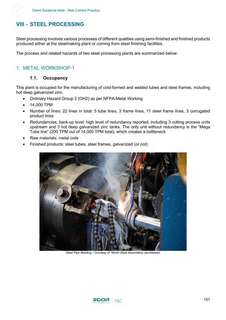
151
Client Guidance Note - Risk Control Practice
VIII - STEEL PROCESSING
Steel processing involves various processes of different qualities using semi-finished and finished products produced either at the steelmaking plant or coming from steel finishing facilities. The process and related hazards of two steel processing plants are summarized below:
1. METAL WORKSHOP-1
1.1. Occupancy
This plant is occupied for the manufacturing of cold-formed and welded tubes and steel frames, including hot deep galvanized zinc.
• Ordinary Hazard Group 2 (OH2) as per NFPA-Metal Working • 14,000 TPM • Number of lines: 22 lines in total: 5 tube lines, 3 frame lines, 11 steel frame lines, 3 corrugated
product lines • Redundancies, back-up level: high level of redundancy reported, including 3 cutting process units
upstream and 3 hot deep galvanized zinc tanks. The only unit without redundancy is the “Mega Tube line” (200 TPM out of 14,000 TPM total), which creates a bottleneck
• Raw materials: metal coils • Finished products: steel tubes, steel frames, galvanized (or not)
Steel Pipe Welding - Courtesy of ‘World Steel Association (worldsteel)’
152
Client Guidance Note - Risk Control Practice
1.2. Special Hazards
• Storage areas: RM (coils - 45,00 T capacity; average of 15,000 T) and FP (metal products) • Cold-forming electric driven machines (Italy, US, China, South Korea, Chile) using emulsion fluid
(water-based / 5% oil reported) • Hot deep galvanized tanks (99% Zn, 450°C, 4 dual fuel/CNG burners: non-adequate safety • combustion control (see Rec. Section 11) • Hydraulic groups along the process lines (see Rec. Section 11) • MCC cabinets along the process lines – local control only (see Rec. Section 11) • Lubrication / hydraulic oil groups near the process lines (see Rec. Section 11) • Electric power demand: 6.5 MW • Main power source: national grid, 1 x UG line • The main substation, housing oil-filled transformers, PCB oil-free transformers (1,000 kVA + 2 x
1,600 kVA + 5 x 750 kVA) and cabinets all in the same area, is located in the middle of the plant without any real fire separation (see Rec. Section 11)
• Mega Tubes substation: along the process line: (1,000 kVA) • Electrical equipment: dry-type equipment • Solar panels are installed on the roof (3 MW installed, power sold to the national grid). The solar
panels, including combustible frames, are currently installed over about 20% of the roof surface, constituting a serious aggravating factor
• LPG cylinder for the canteen • Cranes in the buildings: 3 x 32 + 1 x 25 TT inside RM warehouse and in various other processing
areas (5T – 25 T)
1.3. Construction
• Location: urban area • Property area: terrain - 73,735 m² and total floor area - 46,555 m² • Multi-location: main plant & off-site facility • Construction type of main process and storage buildings (1=2 stories): mainly LNC (Light
Noncombustible) without combustible insulation; office made of concrete frame and HCB walls; Class I metal deck roof (no combustible insulation) made of steel sheets with1 m wide strips (1 x 1 m wide strip every 7 metal strips) made of glass fiber
• Offices (3 stories) made of concrete frames filled with HCB or bricks • Separation between process units and storage area: adequate • Congestion: moderately congested in the main plant and lightly so at the offsite facility • Continuity of combustible: relatively high at the main plant due to oily emulsion spillage and light at
the offsite facility
1.4. Fire Detection / Protection:
• No Automatic Fire Alarm or fixed-fire protection (deemed as not adequate considering the combustible load and the continuity of combustible)
• The plant basically relies on manual firefighting using portable fire extinguishers, hose reels and hydrants fed from a neither adequate nor reliable Fire Water Supply
153
Client Guidance Note - Risk Control Practice
1.5. Exposures:
• As per the SCOR Global Hazards Map, the site is located in an area that is subject to highly hazardous natural perils including SCOR Zone 3 Earthquakes. There is no evidence of seismic design.
• Neighboring exposures in the area are considered to be minimal due to adequate separating distances.
2. METAL WORKSHOP-2
Occupancy
This plant is occupied for manufacturing metal cladding and composite insulated (sandwich) panels for buildings.
• 3,500 TPM of Finished Products • Ordinary Hazard Group 2 (OH2) as per NFPA –Metal Processing (cladding workshop) • Extra Hazard Group 1 (EH2) as per NFPA - Flammable Liquid Spraying (paint shop) & Plastic
Processing (cold product workshop) • Raw Material: 50% colored steel rolls / 50% ZnAl or galvanized steel rolls • Paint Shop: 1 line processing only part of the ZnAl or galvanized steel rolls (on demand) • Cladding Workshop: 60% of FP on 14 forming lines (electric-driven) • Cold Product Workshop: 40% of FP on 3 lines processing either colored steel rolls or painted rolls.
Plastic Foam Preforms (not produced on site) and metal facings are glued together using polyol and isocyanate + catalyst
• Redundancies, back up level: no back up for the Paint Shop
Special Hazards
• Gas-fired boiler and dryer tunnel burners in the Paint Shop: an adequate Safety Combustion Control was noted.
• Paint Shop: Flammable Paints: 100% polyester + solvent aromatic/oxygenated Pf: 63°C. NCH 1111. LEL 1.8-11%.
• Cold Products Workshop: storage and processing of EPS/PUR/PIR/Rockwool preforms and use of polyol and isocyanate (MDI) + catalyst pf: >17°C and expansion gas (cyclopentane/isopentane) for plastic-based preforms glued with facings.
• Machinery & Equipment: electric-driven from S. Korea, USA, Italy and China + hydraulic local control.
• Electric power demand: 2.4 MW • Electric power source: national grid. • No substations on site: the overhead line from the grid feeds 3 overhead oil-filled transformer areas
in series on pylons (one for each building: Paint Shop - 1 MVA; Cladding Workshop -1 x 300 +1 x 500 kVA; Cold Products Workshop - 1,000 kVA)
• Water from city grid: used for process cooling (standard package cooling set) in the Paint Shop and for the boilers in the Paint Shop.
• Flammable Liquids warehouses: detached and well segregated
154
Client Guidance Note - Risk Control Practice
Construction
• Location: Urban area • Property area: 94,000 m² • Total floor area: 24,300 m² • Multi-location: Paint shop (1=2 story noncombustible building) – 31 m clearance; Cladding
workshop (1=2 story noncombustible building) - 20m clearance; Cold Products workshop (1=2 story combustible building)
• Construction type of main buildings: mainly LNC (Light Noncombustible) without combustible insulation except for the Cold Product Workshop (false ceiling made of PUR-insulated panels). Office made of concrete frame and HCB walls
• Separation between process units and storage area: adequate • Congestion: light in Paint Shop, moderate in other areas • Continuity of combustible: light in Cladding Workshop, very high in Paint Shop and Cold Products
Workshop
Fire Detection / protection:
• No Automatic Fire Alarm or fixed-fire protection (deemed as not adequate considering the combustible load and the continuity of combustible)
• The plant basically relies on manual firefighting using Portable Fire Extinguishers, hose reels and 2 hydrants fed from a neither adequate nor reliable Fire Water Supply
Exposures:
• As per the SCOR Global Hazards Map, the site is located in an area subject to highly hazardous natural perils including SCOR Zone 3 Earthquake. There is no evidence of seismic design.
• Neighboring exposures in the area are considered to be minimal due to adequate separating distances.
155
Client Guidance Note - Risk Control Practice
IX - UTILITIES
1. ARRANGEMENT
This section is dedicated to the main utilities (i.e. Electric Power, Natural Gas, Air Products and Water) of an (Integrated) Steel Mill that may include all process units from Raw Material preparation, Ironmaking, Steelmaking, Steel finishing and even Steel processing facilities in some cases, depending on the level of vertical integration. Main utilities are usually part of the so called “Shared Services” for different process units of an Integrated Steel Mill. In some cases, main utilities are dedicated to one process area but are supplying a hub providing mutual backup to all process areas. As a result of the above, different arrangements are possible.
2. SPECIAL HAZARDS & RISK CONTROL
Special hazards, prevention, protection and potential mitigation measures are detailed below for each and every special hazard related to this occupancy. Related recommendations are also mentioned (see. Rec). Please refer to Section 11: “Support for Loss Prevention Recommendations” for details.
Electric Power
A large quantity of electrical energy is required to operate an (integrated) steel mill. The main power supply for an (Integrated) Steel Mill is usually the national grid. There are some cases where there is in-house generation (i.e. a Captive Power Plant) but this is not very common and is not covered in this document.
• National grid substation(s) may be located very close to the (Integrated) Steel Mill main substation supplying the (Integrated) Steel Mill power transformers through enclosed feeders.
• National grid substations may also be located far away from the (Integrated) Steel Mill. In such cases, a high voltage utility distribution network is installed. Transmission & Distribution Lines (T&D) lines may belong to:
- The National Grid - The (Integrated) Steel Mill (i.e. Shared Services); there may be several km between the process
areas and the port facilities (or even the Captive Power Plant if there is one). High Voltage feeders are usually overhead lines installed on pylons.
• Uninterruptible Power Systems (UPS) and Diesel Engine-Driven Generators (DEDGs) are usually installed for safety shutdowns of process equipment, maintaining critical utilities (i.e. cooling) and emergency lighting in case of a blackout.
Prevention & Protection:
• Prefer multiple feeders from different substations located in different areas (avoiding one single point of failure: e.g. fire, flood, tsunami on coastal areas).
• (Integrated) Steel Mill main substations should be protected (see Section 11: Electric rooms and Transformers). Noncombustible construction material should be used. The same level of maintenance, inspection and protection is expected for the National Grid main substation. This is
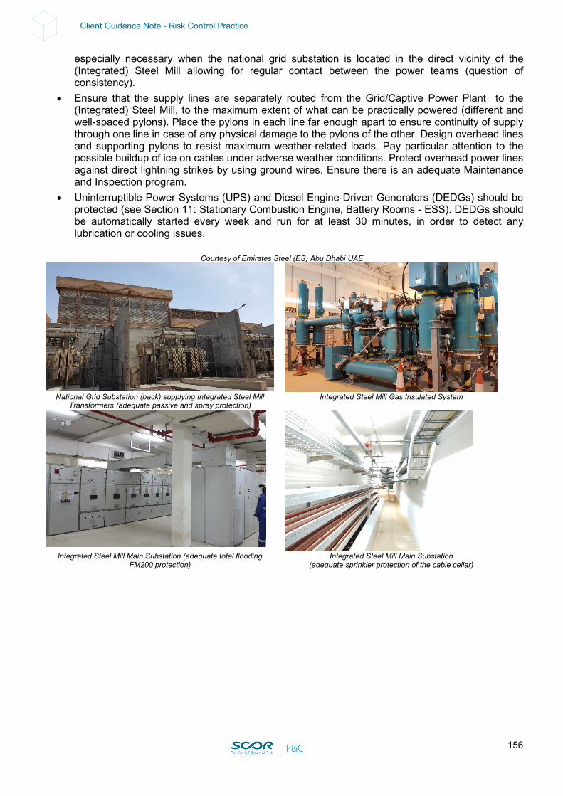
156
Client Guidance Note - Risk Control Practice
especially necessary when the national grid substation is located in the direct vicinity of the (Integrated) Steel Mill allowing for regular contact between the power teams (question of consistency).
• Ensure that the supply lines are separately routed from the Grid/Captive Power Plant to the (Integrated) Steel Mill, to the maximum extent of what can be practically powered (different and well-spaced pylons). Place the pylons in each line far enough apart to ensure continuity of supply through one line in case of any physical damage to the pylons of the other. Design overhead lines and supporting pylons to resist maximum weather-related loads. Pay particular attention to the possible buildup of ice on cables under adverse weather conditions. Protect overhead power lines against direct lightning strikes by using ground wires. Ensure there is an adequate Maintenance and Inspection program.
• Uninterruptible Power Systems (UPS) and Diesel Engine-Driven Generators (DEDGs) should be protected (see Section 11: Stationary Combustion Engine, Battery Rooms - ESS). DEDGs should be automatically started every week and run for at least 30 minutes, in order to detect any lubrication or cooling issues.
Courtesy of Emirates Steel (ES) Abu Dhabi UAE
National Grid Substation (back) supplying Integrated Steel Mill
Transformers (adequate passive and spray protection) Integrated Steel Mill Gas Insulated System
Integrated Steel Mill Main Substation (adequate total flooding
FM200 protection) Integrated Steel Mill Main Substation
(adequate sprinkler protection of the cable cellar)
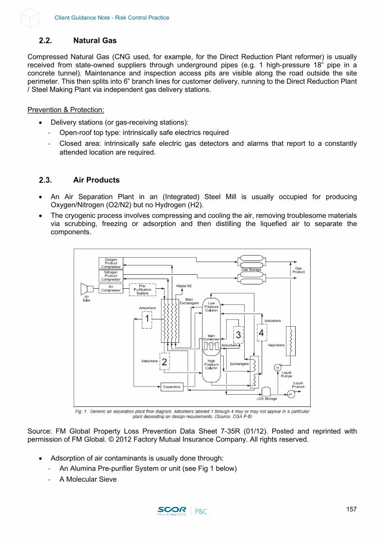
157
Client Guidance Note - Risk Control Practice
Natural Gas
Compressed Natural Gas (CNG used, for example, for the Direct Reduction Plant reformer) is usually received from state-owned suppliers through underground pipes (e.g. 1 high-pressure 18” pipe in a concrete tunnel). Maintenance and inspection access pits are visible along the road outside the site perimeter. This then splits into 6” branch lines for customer delivery, running to the Direct Reduction Plant / Steel Making Plant via independent gas delivery stations. Prevention & Protection:
• Delivery stations (or gas-receiving stations): - Open-roof top type: intrinsically safe electrics required - Closed area: intrinsically safe electric gas detectors and alarms that report to a constantly
attended location are required.
Air Products
• An Air Separation Plant in an (Integrated) Steel Mill is usually occupied for producing Oxygen/Nitrogen (O2/N2) but no Hydrogen (H2).
• The cryogenic process involves compressing and cooling the air, removing troublesome materials via scrubbing, freezing or adsorption and then distilling the liquefied air to separate the components.
Source: FM Global Property Loss Prevention Data Sheet 7-35R (01/12). Posted and reprinted with permission of FM Global. © 2012 Factory Mutual Insurance Company. All rights reserved.
• Adsorption of air contaminants is usually done through: - An Alumina Pre-purifier System or unit (see Fig 1 below) - A Molecular Sieve
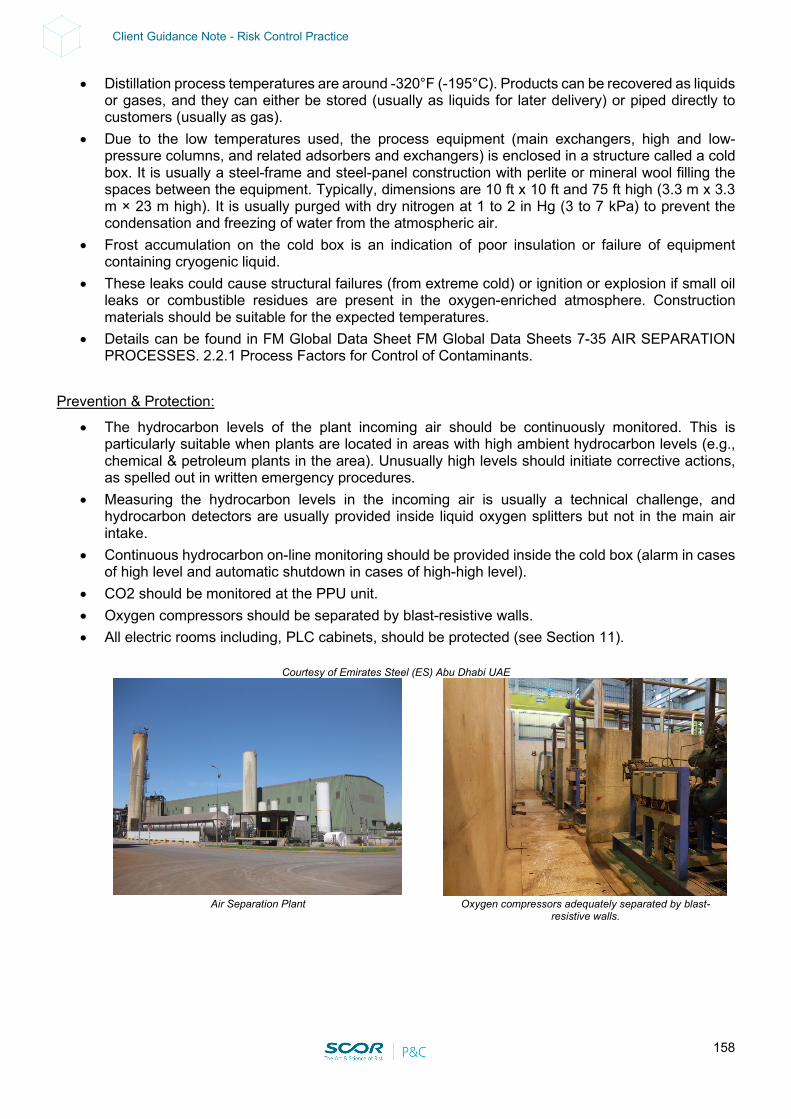
158
Client Guidance Note - Risk Control Practice
• Distillation process temperatures are around -320°F (-195°C). Products can be recovered as liquids or gases, and they can either be stored (usually as liquids for later delivery) or piped directly to customers (usually as gas).
• Due to the low temperatures used, the process equipment (main exchangers, high and low-pressure columns, and related adsorbers and exchangers) is enclosed in a structure called a cold box. It is usually a steel-frame and steel-panel construction with perlite or mineral wool filling the spaces between the equipment. Typically, dimensions are 10 ft x 10 ft and 75 ft high (3.3 m x 3.3 m × 23 m high). It is usually purged with dry nitrogen at 1 to 2 in Hg (3 to 7 kPa) to prevent the condensation and freezing of water from the atmospheric air.
• Frost accumulation on the cold box is an indication of poor insulation or failure of equipment containing cryogenic liquid.
• These leaks could cause structural failures (from extreme cold) or ignition or explosion if small oil leaks or combustible residues are present in the oxygen-enriched atmosphere. Construction materials should be suitable for the expected temperatures.
• Details can be found in FM Global Data Sheet FM Global Data Sheets 7-35 AIR SEPARATION PROCESSES. 2.2.1 Process Factors for Control of Contaminants.
Prevention & Protection:
• The hydrocarbon levels of the plant incoming air should be continuously monitored. This is particularly suitable when plants are located in areas with high ambient hydrocarbon levels (e.g., chemical & petroleum plants in the area). Unusually high levels should initiate corrective actions, as spelled out in written emergency procedures.
• Measuring the hydrocarbon levels in the incoming air is usually a technical challenge, and hydrocarbon detectors are usually provided inside liquid oxygen splitters but not in the main air intake.
• Continuous hydrocarbon on-line monitoring should be provided inside the cold box (alarm in cases of high level and automatic shutdown in cases of high-high level).
• CO2 should be monitored at the PPU unit. • Oxygen compressors should be separated by blast-resistive walls. • All electric rooms including, PLC cabinets, should be protected (see Section 11).
Courtesy of Emirates Steel (ES) Abu Dhabi UAE
Air Separation Plant Oxygen compressors adequately separated by blast-
resistive walls.
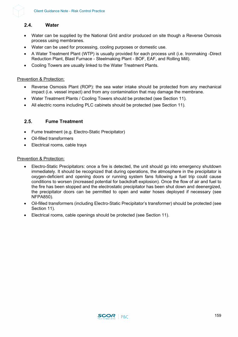
159
Client Guidance Note - Risk Control Practice
Water
• Water can be supplied by the National Grid and/or produced on site though a Reverse Osmosis process using membranes.
• Water can be used for processing, cooling purposes or domestic use. • A Water Treatment Plant (WTP) is usually provided for each process unit (i.e. Ironmaking -Direct
Reduction Plant, Blast Furnace - Steelmaking Plant - BOF, EAF, and Rolling Mill). • Cooling Towers are usually linked to the Water Treatment Plants.
Prevention & Protection:
• Reverse Osmosis Plant (ROP): the sea water intake should be protected from any mechanical impact (i.e. vessel impact) and from any contamination that may damage the membrane.
• Water Treatment Plants / Cooling Towers should be protected (see Section 11). • All electric rooms including PLC cabinets should be protected (see Section 11).
Fume Treatment
• Fume treatment (e.g. Electro-Static Precipitator) • Oil-filled transformers • Electrical rooms, cable trays
Prevention & Protection:
• Electro-Static Precipitators: once a fire is detected, the unit should go into emergency shutdown immediately. It should be recognized that during operations, the atmosphere in the precipitator is oxygen-deficient and opening doors or running system fans following a fuel trip could cause conditions to worsen (increased potential for backdraft explosion). Once the flow of air and fuel to the fire has been stopped and the electrostatic precipitator has been shut down and deenergized, the precipitator doors can be permitted to open and water hoses deployed if necessary (see NFPA850).
• Oil-filled transformers (including Electro-Static Precipitator’s transformer) should be protected (see Section 11).
• Electrical rooms, cable openings should be protected (see Section 11).
160
Client Guidance Note - Risk Control Practice
3. CONTINGENCY / BUSINESS CONTINUITY / RECOVERY PLAN
Warning: in order to be reliable, Contingency / Business Continuity / Recovery Plans should be formalized. This would include formal contracts being established with vendors or third parties in advance. The plans should be regularly tested, reviewed and updated. Holistic view:
• If the Steel Finishing is part of a group with a relatively high level of vertical integration in the steel industry, a Business Continuity Plan (BCP) at corporate level should be developed for the main identified risks in each and every process unit.
• The impact of a loss impacting third parties (i.e. logistics, utilities) should be investigated and an adequate BCP should be established.
Site view: Electric power
• Having a robust power supply, including redundancies and spare capacity, is key. This could consist in having well-separated feeders from different substations than the grid (on a loop arrangement) with 100% back-up capacity.
• Note that regardless of how robust the power supply from a capacity and redundancy standpoint is, there is (in most of the cases) one single point of failure that may lead to a total power outage. This single point of failure may consist of:
- All power supplies linked to the same substation (*) feeding the (Integrated) Steel Mill (a spur arrangement or dead-end instead of 2 well-separated substations organized on a loop).
- Redundant power lines (i.e. N+2) installed on different pylons but exposing each other (i.e. lack of clearance).
- Power supplies severely exposed to Cat Nat (i.e. EQ, Tsunami, Ice Storm) that may impact the entire power supply.
• As a result of the above, all single points of failure should be identified, and adequate alternatives considered. This could include the duplication of some facilities in different fire and natural peril areas (e.g. flood, tsunami in coastal areas).
Natural Gas
• An alternate gas supply should be provided when possible. Air Products
• A given Air Separation Plant (ASP) should be provided with spare capacity and buffer storage. • Purchasing Air Products on the market and supplied on trailers should be considered in the case
of major ASP impairment. This could provide some backup (to be evaluated). • Having two or more ASPs on site, with spare capacity and buffer storage linked to the same
distribution hub, will provide partial or full backup in case of major impairment at one ASP. Water
• A given Reverse Osmosis Plant (ROP) should be provided with spare capacity and buffer storage. Spare membranes should be available and contracts with suppliers should be established.
• Purchasing water on the market and supplied by road tankers should be considered in the case of major ROP impairment. This could provide some backup (to be evaluated).
• Having two or more ROPs on site, with spare capacity and buffer storage, linked to the same distribution hub will provide partial or full backup in case of major impairment at one ROP.
161
Client Guidance Note - Risk Control Practice
4. LOSS ESTIMATES
Maximum Possible Loss (Technical MPL – SCOR): • Scenario: major fire destroying the Main Substation on the (Integrated) Steel Mill). • PD: up to USD 20 M • BI: up to 6-8 months for all related process units • Induced BI should be considered if there are interdependencies with sister plants upstream and/or
downstream. This could be mitigated by buffer storage (providing several extra days of production) and alternate supplier (if any).
Normal Loss Expectancy (NLE – SCOR):
• Scenario: An Air Separation Plant (ASP) or Reverse Osmosis Plant (ROP) Fire inside the cabinet room. All fire alarms are relayed to the control room. The fire cannot be controlled at its early stage of development due to the lack of automatic fixed-fire protection. The fire is finally manually extinguished. There is severe fire and smoke damage to the cabinet room.
• PD: up to USD 10 M • BI: about 4 months for the related process unit. • Note: this scenario is no longer valid once adequate and approved fire protection is provided (see
Section 11). • Induced BI should be considered if there any interdependencies with sister plants upstream and or
downstream (i.e. a pot freeze at the smelter). This could be mitigated by buffer storage (providing several extra days of production) and an alternate supplier (if any).
Note: other scenarios may include the contamination of the ROP (i.e. hydrocarbons released by a cargo ship at the level of the sea water intake). All membranes on duty would be lost. Decontamination of the ROP may take some time (TBD). The impact on the process unit would depend on the level of redundancy on site and the alternate water supply capability (see Contingency above).
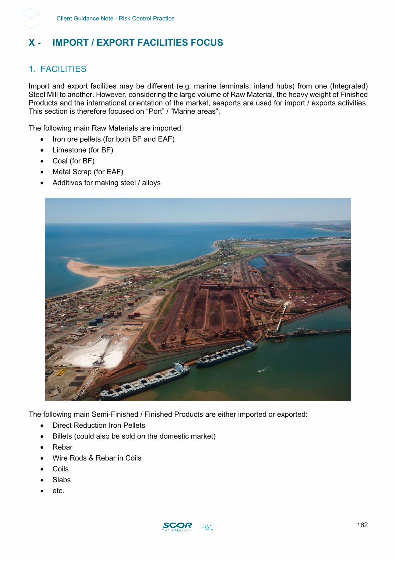
162
Client Guidance Note - Risk Control Practice
X - IMPORT / EXPORT FACILITIES FOCUS
1. FACILITIES
Import and export facilities may be different (e.g. marine terminals, inland hubs) from one (Integrated) Steel Mill to another. However, considering the large volume of Raw Material, the heavy weight of Finished Products and the international orientation of the market, seaports are used for import / exports activities. This section is therefore focused on “Port” / “Marine areas”. The following main Raw Materials are imported:
• Iron ore pellets (for both BF and EAF) • Limestone (for BF) • Coal (for BF) • Metal Scrap (for EAF) • Additives for making steel / alloys
The following main Semi-Finished / Finished Products are either imported or exported:
• Direct Reduction Iron Pellets • Billets (could also be sold on the domestic market) • Rebar • Wire Rods & Rebar in Coils • Coils • Slabs • etc.
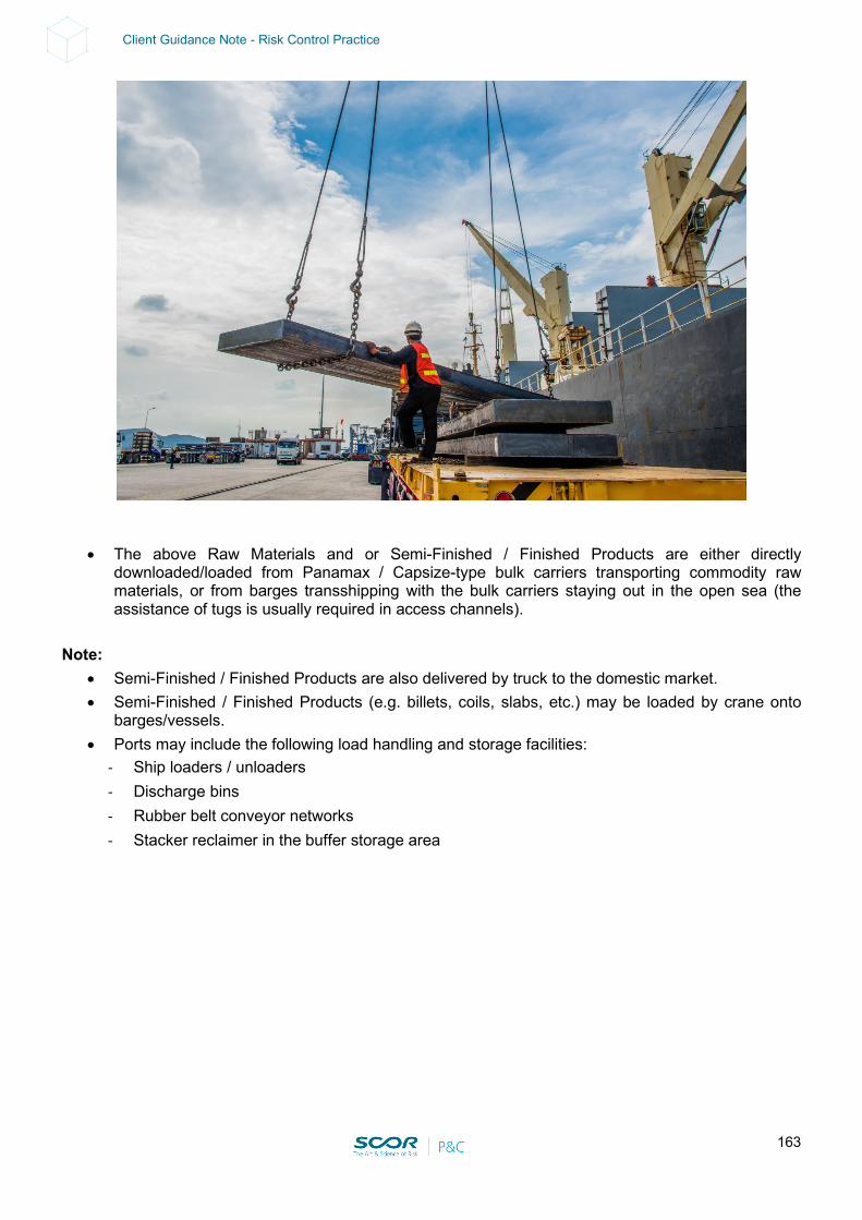
163
Client Guidance Note - Risk Control Practice
• The above Raw Materials and or Semi-Finished / Finished Products are either directly downloaded/loaded from Panamax / Capsize-type bulk carriers transporting commodity raw materials, or from barges transshipping with the bulk carriers staying out in the open sea (the assistance of tugs is usually required in access channels).
Note:
• Semi-Finished / Finished Products are also delivered by truck to the domestic market. • Semi-Finished / Finished Products (e.g. billets, coils, slabs, etc.) may be loaded by crane onto
barges/vessels. • Ports may include the following load handling and storage facilities:
- Ship loaders / unloaders - Discharge bins - Rubber belt conveyor networks - Stacker reclaimer in the buffer storage area
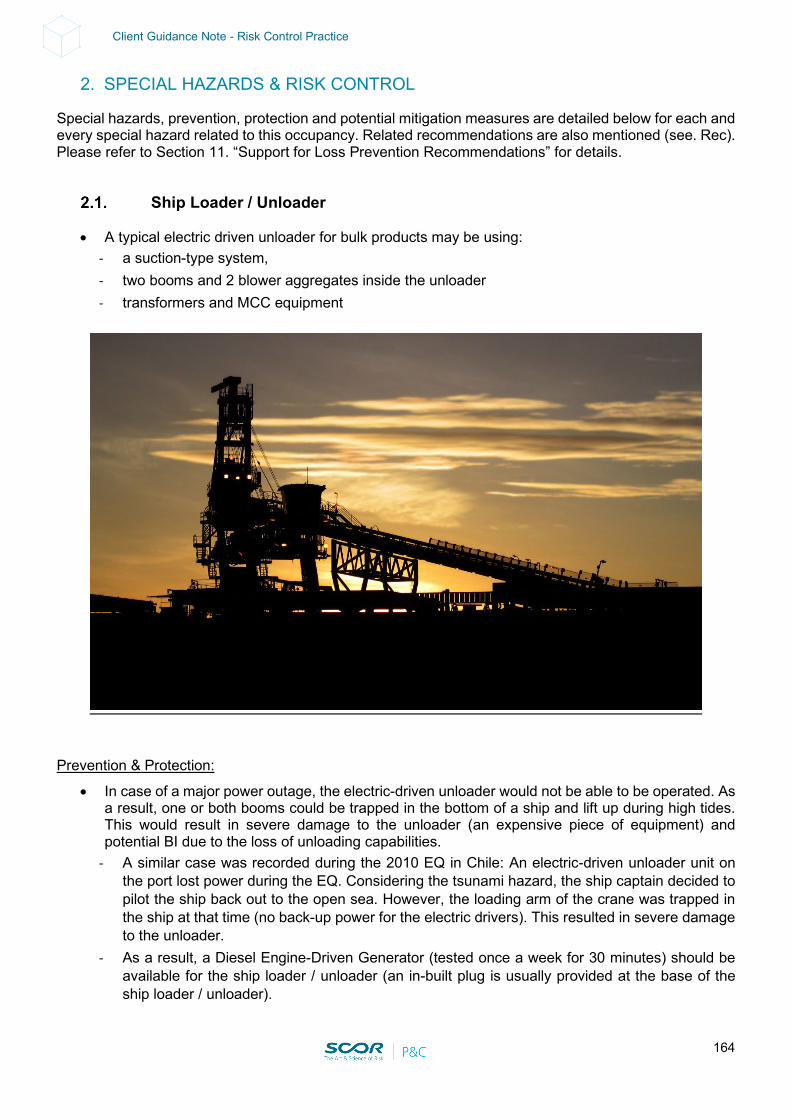
164
Client Guidance Note - Risk Control Practice
2. SPECIAL HAZARDS & RISK CONTROL
Special hazards, prevention, protection and potential mitigation measures are detailed below for each and every special hazard related to this occupancy. Related recommendations are also mentioned (see. Rec). Please refer to Section 11. “Support for Loss Prevention Recommendations” for details.
Ship Loader / Unloader
• A typical electric driven unloader for bulk products may be using: - a suction-type system, - two booms and 2 blower aggregates inside the unloader - transformers and MCC equipment
Prevention & Protection:
• In case of a major power outage, the electric-driven unloader would not be able to be operated. As a result, one or both booms could be trapped in the bottom of a ship and lift up during high tides. This would result in severe damage to the unloader (an expensive piece of equipment) and potential BI due to the loss of unloading capabilities.
- A similar case was recorded during the 2010 EQ in Chile: An electric-driven unloader unit on the port lost power during the EQ. Considering the tsunami hazard, the ship captain decided to pilot the ship back out to the open sea. However, the loading arm of the crane was trapped in the ship at that time (no back-up power for the electric drivers). This resulted in severe damage to the unloader.
- As a result, a Diesel Engine-Driven Generator (tested once a week for 30 minutes) should be available for the ship loader / unloader (an in-built plug is usually provided at the base of the ship loader / unloader).
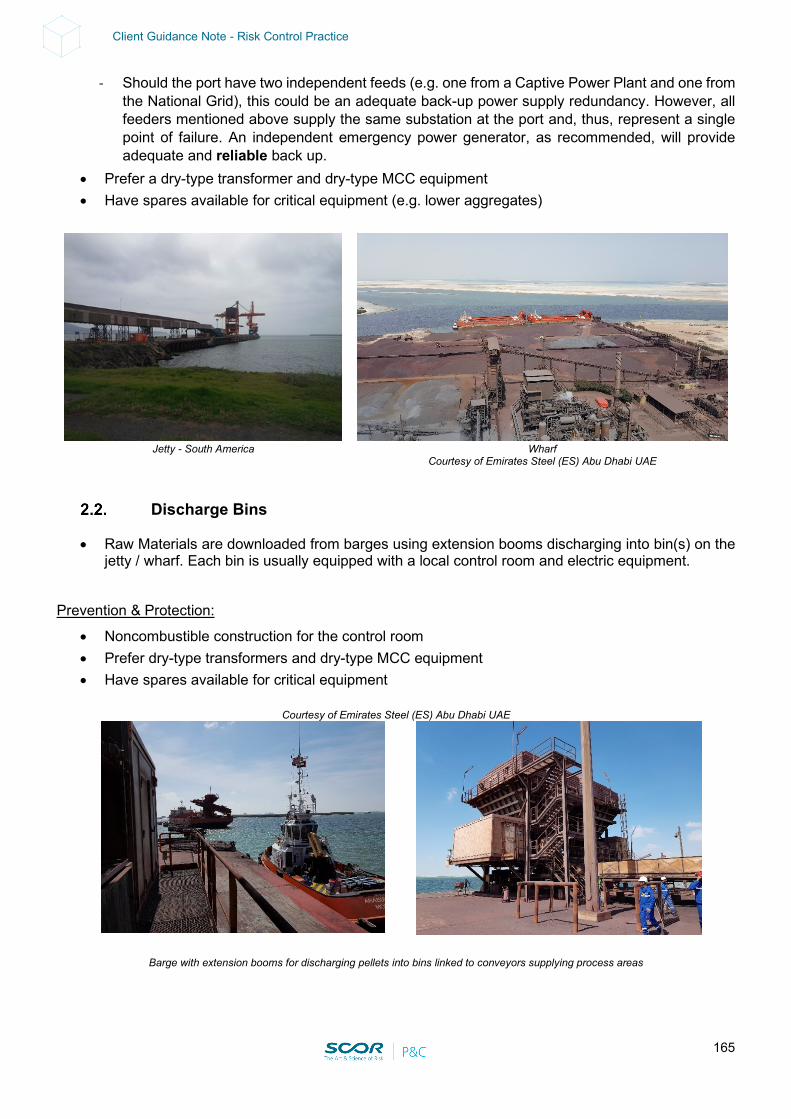
165
Client Guidance Note - Risk Control Practice
- Should the port have two independent feeds (e.g. one from a Captive Power Plant and one from the National Grid), this could be an adequate back-up power supply redundancy. However, all feeders mentioned above supply the same substation at the port and, thus, represent a single point of failure. An independent emergency power generator, as recommended, will provide adequate and reliable back up.
• Prefer a dry-type transformer and dry-type MCC equipment • Have spares available for critical equipment (e.g. lower aggregates)
Jetty - South America
Wharf
Courtesy of Emirates Steel (ES) Abu Dhabi UAE
Discharge Bins
• Raw Materials are downloaded from barges using extension booms discharging into bin(s) on the jetty / wharf. Each bin is usually equipped with a local control room and electric equipment.
Prevention & Protection:
• Noncombustible construction for the control room • Prefer dry-type transformers and dry-type MCC equipment • Have spares available for critical equipment
Courtesy of Emirates Steel (ES) Abu Dhabi UAE
Barge with extension booms for discharging pellets into bins linked to conveyors supplying process areas
166
Client Guidance Note - Risk Control Practice
Rubber Belt Conveyors
• Rubber belt conveyors run between the bins, the process units and the buffer storage area. • Inclined, elevated and overhead conveyors run from the ship loader / unloader to the silos via
junction tower(s). Prevention & Protection:
• Conveyors should be provided with adequate interlocks and fire protection (see Section 11).
Stacker Reclaimers
• These are expensive electric-driven single pieces of equipment with a long lead time. Prevention & Protection:
• Prefer dry-type transformers and dry-type MCC equipment • Have spares available for critical equipment • Ensure there is an adequate Maintenance & Inspection program
3. CONTINGENCY / BUSINESS CONTINUITY / RECOVERY PLAN
Warning: in order to be reliable, Contingency / Business Continuity / Recovery Plans should be formalized. This would include formal contracts established in advance with vendors or third parties. The plans should be regularly tested, reviewed and updated. Holistic view:
• If the Port is part of a group with a relatively high level of vertical integration in the steel industry, a Business Continuity Plan (BCP) at corporate level should be developed for the main identified risks (e.g. sunken vessels, loss of ship loader / unloader, fire on conveyor, substations) for each and every process unit.
• The impact of a loss impacting third parties (i.e. logistics, utilities) should be investigated and an adequate BCP should be established.
• The use of an alternate Port and organizing alternate ground transportation should be investigated & incorporated into the BCP.
Site view:
• A Port Blockage is often the main issue (i.e. access channel blocked by a sunken vessel, vessel impact on jetty, ship sinking or political issues e.g. Strait of Hormuz).
- Maintain sufficient buffer storage for Raw Materials (e.g. good practice is up to 3 months for some Integrated Steel Mills).
- Have a contract with a recognized, specialized ship recovery company (in the case of a sunken vessel). Delays and durations should be defined.
- Alternate ports should be identified (possessing adequate loading / unloading equipment) and ground transportation should be secured. (This may include heavy vehicles over relatively long distances and be subject to clearance from authorities. Third party liability exposure should also be investigated).
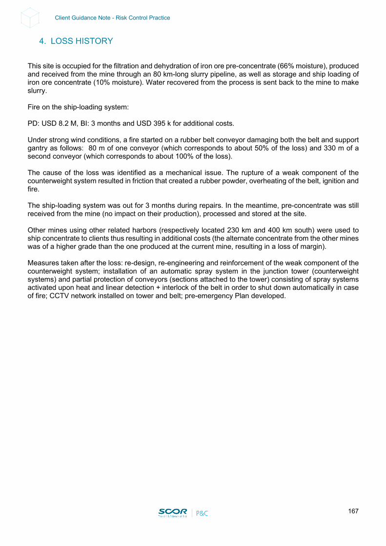
167
Client Guidance Note - Risk Control Practice
4. LOSS HISTORY
This site is occupied for the filtration and dehydration of iron ore pre-concentrate (66% moisture), produced and received from the mine through an 80 km-long slurry pipeline, as well as storage and ship loading of iron ore concentrate (10% moisture). Water recovered from the process is sent back to the mine to make slurry. Fire on the ship-loading system: PD: USD 8.2 M, BI: 3 months and USD 395 k for additional costs. Under strong wind conditions, a fire started on a rubber belt conveyor damaging both the belt and support gantry as follows: 80 m of one conveyor (which corresponds to about 50% of the loss) and 330 m of a second conveyor (which corresponds to about 100% of the loss). The cause of the loss was identified as a mechanical issue. The rupture of a weak component of the counterweight system resulted in friction that created a rubber powder, overheating of the belt, ignition and fire. The ship-loading system was out for 3 months during repairs. In the meantime, pre-concentrate was still received from the mine (no impact on their production), processed and stored at the site. Other mines using other related harbors (respectively located 230 km and 400 km south) were used to ship concentrate to clients thus resulting in additional costs (the alternate concentrate from the other mines was of a higher grade than the one produced at the current mine, resulting in a loss of margin). Measures taken after the loss: re-design, re-engineering and reinforcement of the weak component of the counterweight system; installation of an automatic spray system in the junction tower (counterweight systems) and partial protection of conveyors (sections attached to the tower) consisting of spray systems activated upon heat and linear detection + interlock of the belt in order to shut down automatically in case of fire; CCTV network installed on tower and belt; pre-emergency Plan developed.

168
Client Guidance Note - Risk Control Practice
5. LOSS ESTIMATES
Maximum Possible Loss (Technical MPL – SCOR): • Scenario: Tsunami. • PD: Port severely damaged. • BI: 12-18 months • Induced BI should be considered if there are any interdependencies with sister plants upstream
and/or downstream. This could be mitigated by buffer storage (providing several extra days of production) and an alternate supplier (if any).
• Other scenario: Sunken vessel in access chanel or impact on jetty with only 1 single access point. • PD: Port Blockage. • BI: 12-18 months • Induced BI should be considered if there are any interdependencies with sister plants upstream
and/or downstream. This could be mitigated by buffer storage (providing several extra days of production) and an alternate supplier (if any).
• Other scenario: Collapse or major fire on the ship loader / unloader. • PD: Total loss of the ship loader / unloader. • BI: 18-24 months • Induced BI should be considered if there are any interdependencies with sister plants upstream
and/or downstream. This could be mitigated by buffer storage (providing several extra days of production) and an alternate supplier (if any).
• Other scenario: Storm surge / river flood impacting facilities. • PD: Underground vault, tunnels, access roads and bridges impaired. • BI: several months (at least 4 months). • Induced BI should be considered if there are any interdependencies with sister plants upstream
and/or downstream. This could be mitigated by buffer storage (providing several extra days of production) and an alternate supplier (if any).
• Other Scenario: river harbor used for shipping (Raw Material, Finished Products, Spare parts,
etc..): high or low water conditions. • PD: port impaired. • BI: at least 2 months. • Induced BI should be considered if there are any interdependencies with sister plants upstream
and/or downstream. This could be mitigated by buffer storage (providing several extra days of production) and an alternate supplier (if any).
Normal Loss Expectancy (NLE – SCOR):
• Major fire starting on conveyor or in the electric room. • PD: Limited to the protected unit. Total loss when no fixed fire protection. • BI: up to 4 months. • Induced BI should be considered if there are any interdependencies with sister plants upstream
and/or downstream. This could be mitigated by buffer storage (providing several extra days of production) and an alternate supplier (if any).

169
Client Guidance Note - Risk Control Practice
XI - SUPPORT FOR LOSS PREVENTION RECOMMENDATIONS
The following recommendations apply for the special hazards mentioned in the previous sections:
1. STEAM TURBINE
With the invaluable and kind support of Frank Orset, Loss Prevention Engineer: Inadequate fire-protection systems and a lack of proper emergency protocols can lead to serious damage and extended outages in the event of a lube-oil fire in a steam turbine. Oil releases of pressurized-oil systems used in bearing lubrication, seal oil, hydraulics or control systems are most often caused by electrical failure, fitting failures, operator error or vibration. This may cause a spray fire, a pool fire or a three-dimensional spill fire. Adequate, reliable and approved fire protection systems should be installed to protect the steam turbine as well as the lubrication oil group. The systems should take guidance from the recommended practices of FM Global Data Sheets 7-101 “Fire Protection for Steam Turbines and Electric Generators”, with some additional remarks: a) Turbine operating floor: Turbine bearings should be protected with an automatic closed-head sprinkler system using directional nozzles. Automatic actuation is more reliable than manual actuation. Fire protection systems for turbine bearings should be designed for a density of 10.2 mm/min (0.25 gpm/ft2) over the protected area of all bearings. This system comprises one to two closed 90° directional spray nozzles over each bearing and directed at the shaft seal. The nozzles should be rated at approximately 83°C (150°F) above the highest ambient temperature. These nozzles should also be located approximately 60 cm (2 ft) from the shaft at the 10 o’clock and 2 o'clock positions, thus providing the proper spray pattern, cooling and flushing of any oil spray/leak below the turbine deck. Additionally, one heat detector rated at approximately 30°C (86°F) above the highest ambient temperature should be installed 60 cm (2 ft) directly above the shaft. In the case of a fire, the heat released by the fire triggers the heat detectors, which in turn open the valve. Protection for bearing housing and areas under turbine skirts: Accidental water discharge on bearing points and hot turbine parts should be considered, hence a pre-action system, as said above, is recommended. If necessary, these areas can, in addition, be protected by shields and encasing insulation with metal covers. If turbine bearings are protected with a manually operated sprinkler system, the following should be provided:
• Manual activation should be from the control room or a readily accessible location not exposing the operator to the fire condition. Plant personnel should be sufficiently trained to promptly handle this function as well as other responsibilities during an emergency of this nature.
• Automatic fire detection should be provided over the area of each bearing and within the skirting of the turbine where a potential for oil to pool can alert operators to a fire condition.
• Documented procedures should be in place with authority given to operators to activate the system, if necessary, in a fire condition.
• Periodic training should be given to operators covering the need for prompt operation of the system.

170
Client Guidance Note - Risk Control Practice
• Regular inspection of the sprinkler & detection system should be conducted to ensure proper functionality at all times.
Automatically actuated systems have proven to actuate properly under fire conditions and are not prone to spurious actuation. If a manually operated water system is installed, consideration should be given to a supplemental automatic gaseous fire-extinguishing system. Accidental water discharge on bearing points and hot turbine parts should be considered. If necessary, these areas may be protected by shields and encasing insulation with metal covers. The decision for the installation of fire protection systems subject to accidental water discharge on the turbine bearings and hot turbine parts must be a local management decision. Alternatives should consist of the use of special fire protection gaseous agents in accordance with NFPA / FM Standards. All areas beneath the turbine operating floor that are subject to oil flow, oil spray or oil accumulation should be protected by an automatic sprinkler or a foam-water sprinkler system. This coverage normally includes all areas beneath the operating floor in the turbine building. The sprinkler system beneath the turbine should take into consideration obstructions from structural members and piping and should be designed to deliver a density of 12.2 mm/min (0.3 gpm/sq ft) over a minimum application of 465 m2 (5000 sq ft) with standard spray sprinkler heads rated at 141°C (286°F) (K115 (K8.0) preferably) for a roof height up to 4.5 m (15 ft). If there is no intermediate protection below the mezzanine or over areas with a pool fire hazard, for roof heights between 4.5 and 9 m (15 and 30 ft), the sprinkler system should be designed to deliver a density of 16 mm/min (0.4 gpm/sq ft) over a minimum application of 465 m2 (5000 sq ft) with standard spray sprinkler heads preferably rated at 141°C (286°F) (K160 (K11.2)). Sprinkler protection with no intermediate levels: When grated mezzanines are provided below the operating floor, additional sprinkler protection should be provided below, as well as at intermediate levels where oil spills are liable to accumulate. The sprinkler system beneath the turbine should take into consideration obstructions from structural members and piping and should be designed to deliver a density of 12.2 mm/min (0.3 gpm/sq ft) over a minimum application of 465 m2 (5000 sq ft) with standard spray sprinkler heads preferably rated at 141°C (286°F) (K115 (K8.0)). The density below the grated mezzanines, depending on the height between the sprinklers and the ground, should be designed the same way as for the protection below the operating floor -over 232 m2 (2500 sq ft) for the lower mezzanine and 12.2 mm/min (0.3 gpm/sq ft) over 140 m2 (1500 sq ft) for the intermediate levels. The temperature rating of the sprinkler heads below the mezzanines can be ordinary or high. Sprinkler protection with grated mezzanines: Lubricating oil lines above the turbine operating floor should be protected with an automatic sprinkler system covering those areas subject to oil accumulation, including the area within the turbine lagging (skirt). The automatic sprinkler system should be designed to deliver a density of 12.2 mm/min (0.3 gpm/sq ft) with standard spray sprinkler heads preferably rated at 141°C 286°F (K115 (K8.0)).
171
Client Guidance Note - Risk Control Practice
b) The Lubrication Group Lubricating oil reservoirs and handling equipment should be protected by an automatic sprinkler or foam-water sprinkler system. The sprinkler system should take into consideration obstructions from structural members and piping and should be designed to deliver a density of 12.2 mm/min (0.3 gpm/sq ft) over a minimum application of 465m2 (5000 sq ft) with standard spray sprinkler heads preferably rated at 141°C (286°F) (K115 (K8.0)). If the lube oil reservoir is elevated, the sprinkler protection should be extended to protect the area beneath the reservoir. Note: In some particular circumstances, there is no ceiling above the lube oil tanks and there is no technical possibility to provide a reliable way of collecting the convective heat plume at the sprinkler head position. In these situations, the above-mentioned protection would not be reliable and should be replaced with the following:
• The protection on the lube oil tanks should be based on a deluge system with open sprinkler heads and a designed density of 12 mm/min (0.3 gpm/sq ft) over the entire area of the lube oil tanks.
• The system should be activated either by a pilot line (68°C (154°F)-rated sprinkler heads would be preferable with heat collector plates above the detector heads) or an appropriate fire detection system.
• An additional way of manually activating the deluge system from a remote and safe area should be provided (in case the detection system is not working for any reason).
• The plant should be designed, and equipment arranged, so that lubricating oils will be confined to a specified area. The use of trenching, curbs and dikes plus the utilization of natural holding sumps, such as condenser pits, can serve as an aid in accomplishing this requirement.
• It is preferable that turbine lube oil storage tanks and reservoirs be cut off from all other areas of the turbine building by fire barriers of 180-min fire-resistance.
• A properly engineered fixed fire extinguishing system (see above) should be provided throughout all such enclosures.
Where oil storage tanks are not cut off from other areas, they are acceptable provided that:
• They are located in areas where the ceiling is protected by an overhead sprinkler system and the sprinkler protection extends sufficiently over the peripheral areas subject to oil spray and oil flow, to control the heat produced by oil fires and maintain building temperatures below those which cause deformation of the structures
• The tanks are protected by an automatic water spray system • An oil containment system is installed in accordance with Standards.
To prevent potential damage from the effects of water spray, emergency lube oil pumps should be of the enclosed type with the electrical circuits to the oil pump motors routed and protected so that control will not be impaired by the fire emergency. Turbine oil reservoirs and lube oil filters, equipped with hinged access panels designed to relieve internal pressure, should have tamper-resistant devices installed so that pressure relief of the tank is rendered possible, e.g. locked cages can be installed over the covers, arranged in such a way that the covers can be raised. Non-condensable vapor extractors should be vented outdoors. Cables for operating the lube oil pumps should be protected from fire exposure. Protection can consist of separating cables for AC and DC oil pumps or 1-hour fire-resistive coating (derating of cables should be considered).
172
Client Guidance Note - Risk Control Practice
If the lubricating oil equipment is in a separate room enclosure, protection can be provided by a total flooding gaseous extinguishing system (e.g. CO2, designed to deliver a minimum concentration of 34% for at least 10 min).
• The lubrication pumps should be interlocked with the sprinkler protection in order to enable them to automatically shut down in the case of water discharge (when safe shutdown is possible without lubrication), preventing oil from being sprayed on hot parts and igniting. or
• there should be a low-oil pressure switch inside each reservoir, arranged to shut down the machine. To extinguish a three-dimensional spray oil fire in the turbine bearing and oil pipe areas, a water spray system with a design water density of 40 to 60 mm/min (1 to 1.5 gpm/sq ft) may be recommended. Commonly used water spray densities of 12 to 20 mm/min (0.3 to 0.5 gpm/sq ft) will protect and cool machinery and building constructions, but not necessarily extinguish a three-dimensional fire. The area that should be protected on the operating floor depends on curbing and drainage but should generally be extended to a distance of 6 m (20 ft) around the turbine. The operating temperature of the sprinkler heads should be set 30°C (86°F) above the highest expected ambient temperature.
2. STATIONARY COMBUSTION ENGINE
With the invaluable and kind support of Franck Orset (FPO), Loss Prevention Engineer: All stationary Combustion Engines such as Diesel Engine-Driven Generators and Diesel Engine -Driven Fire Pumps should be provided with the following fire protection, in compliance with NFPA 13 and NFPA 850. The preferred choice is a sprinkler system. Sprinkler and water spray systems: Sprinkler and water spray protection systems should be designed either:
• for a minimum density of 12.2 mm/min (0.3 gpm/sq ft) over 232 m2 (2500 sq ft) with standard spray sprinkler heads preferably rated at 141°C (286°F) (K115 (K8.0).
• For a minimum density of 10.2 mm/min (0.25 gpm/sq ft) over the entire area for a deluge system. The maximum area of coverage per sprinkler or nozzle should be 9 m2 (100 sq ft). The sprinkler and water spray system coverage should be extended to all areas in the enclosure located within 6 m (20 ft) of the engine, the lubricating oil system and the fuel system (i.e. the entire room in most configurations). Gas protection systems: For gas protection systems, the designed concentration should be maintained for a minimum duration of 20 minutes, or the rundown time of the turbine, or for the time engine surfaces are above the autoignition temperature of the fluid, whichever is greater. The agent concentration should be determined for the specific combustible material involved (i.e.: 34% in the case of CO2 gas protection and a fuel/diesel standby generator). An extended discharge should be provided to compensate for leakage from the compartment and to maintain an extinguishing concentration for the rundown time of the engine (or 20 minutes).
173
Client Guidance Note - Risk Control Practice
For the activation of the gas protection system, heat detectors should be provided at the ceiling level of the diesel generator enclosure. These detectors should operate in a constantly attended area and should be interlocked to shut off the fuel supply. The compartment ventilation system should be interlocked to shut off in the case of a system discharge. Automatic closing doors or dampers should also be provided for openings not normally closed. A full discharge test should be conducted to verify that extinguishing concentrations can be maintained for the rundown time of the engine (or 20 minutes minimum). If this test has not been conducted, the system should not be considered reliable. Gaseous agent fire suppression systems should be designed to have the capacity to supply 2 full discharges to avoid having to keep the engine shut down until the gaseous agent reservoir can be replenished, in particular after a minor fire or accidental discharge.
3. ARC FURNACE TRANSFORMERS - AFT (EAF / LF)
Contingency Plan: Spare Arc Furnace Transformer(s) (AFT) should be available on site for the three operating SMS. Segregation: The fire rating of the enclosure made of reinforced concrete housing the Arc Furnace Transformers should be investigated. When not in accordance with FM Global Data Sheets 7-27 “Molten Steel Production” (at least 3 hours required), the installation of fixed fire protection should be considered as follows:
• If an FM-approved transformer fluid is used, provide one of the following: - One-hour fire-rated construction if no automatic sprinkler protection is provided
or - Noncombustible construction if automatic fire protection (*) is provided in accordance with Data
Sheet 5-4, “Transformers”.
• If an FM-approved transformer fluid is not used, provide one of the following: - Three-hour fire-rated construction if no automatic sprinkler protection is provided; provide
protection for all exposed structural steel within the room or
- One-hour fire-rated construction if automatic fire protection (*) is provided in accordance with Data Sheet 5-4.
(*) Note that a gaseous extinguishing system is not a substitute for a water-based automatic sprinkler protection. Oil Emergency Drainage: Ensure that liquid spill containment and emergency drainage for the transformer room is provided in accordance with FM Global Data Sheets 7-83, “Drainage and Containment for Ignitable Liquids”. An alternative to providing emergency drainage to remove spilled transformer fluid from the room is to protect the room with automatic water-mist or foam-water sprinklers, as per FM Global Data Sheets 5-4 or NFPA standards.

174
Client Guidance Note - Risk Control Practice
Other Precautions: • Locate the furnace control panel outside the transformer room. • Install a 1-hour fire-rated, liquid-tight subdivision to isolate any transformer control panels and
circuit breakers or other critical equipment from exposure to an oil fire originating in the transformer room.
• Use blank, liquid-tight walls sealed to the floor. • If door openings must be made in interior walls, provide sills above the level of the minimum curb
height, as specified in Data Sheet 7-83.
4. TRANSFORMER
Notes: • The following recommendation addresses Polychlorinated Biphenyls (PCB)-free oil-filled
transformers. • When PCB-filled transformers exist, it is recommended to replace them with PCB-free
transformers. Alternatively, flush and fill the transformers with PCB-free fluid. This should be investigated with the manufacturer.
• An explosion suppression system is not a substitute for the following recommended protection. Moreover, when such systems exist, they should be FM-approved and UL-listed.
Based on NFPA 850 “Recommended Practice for Fire Protection for Electric Generating Plants and High Voltage Direct Current Converter Stations”: 1] Indoor oil-filled transformer exposing other facilities: In order to prevent an oil-filled transformer from severely exposing other facilities inside the site in case of fire or explosion, the following fire protection solutions and their potential alternatives should be considered in detail:
• The indoor oil-filled transformers should be replaced with dry-type transformers when possible. or
• The indoor oil-filled transformers should be relocated outside the building in compliance with [point 2] or attached to the building in an open cell [point 3] and well segregated from other oil-filled transformers [point 4 below]. or
• The following fire separation (i.e. cut-off room) and/or fixed fire protection should be provided: i. Oil-insulated transformers of greater than 380 L (100 gallons) oil capacity installed indoors
should be separated from adjacent areas by fire barriers with a 3-hour fire- resistance rating. No fixed fire protection is required, as per NFPA.
ii. Transformers with a rating greater than 35 kV, insulated with a less flammable liquid or nonflammable fluid and installed indoors should be separated from adjacent areas by fire barriers with a 3-hour fire-resistance rating. No fixed fire protection is required, as per NFPA.
iii. When the transformers are protected by an automatic fire suppression system (see point iv
below), the fire barrier fire-resistance rating may be reduced to 1 hour.
iv. Combustible (mineral) oil-filled transformers, including the adjacent non-absorbing ground areas, should be protected with an automatic water-based spray system. The minimum density
175
Client Guidance Note - Risk Control Practice
is 10 mm/min (0.25 gpm/sq ft) for the surface area of the transformers and 6 mm/min (0.15gpm/sq ft) on the non-absorbing ground areas.
If a wet pipe sprinkler system is installed, the protection should be based on a minimum density of 12.2mm/min (0.30gpm/ sq ft) over the entire area containing the transformer(s) and extending 6.1 m (20 ft) beyond (or over the entire room housing the transformers, up to 232 m2 [2500 sq ft]). Gas protection systems are not recommended as it is difficult to maintain the design concentration for a sufficient length of time and the fire might start again when the door is opened for final firefighting operations. Water mist systems are not recommended for reasons of reliability. Adequate oil containment should be provided (see Section 7).
v. For transformers with approved less flammable dielectric fluids: With approved less flammable transformer fluids, no fire protection is required when the equipment is located inside a one-hour fire-rated room. If the transformer is located inside a noncombustible room (but less than one-hour- rated), sprinkler protection should be provided over the entire room with a minimum density of 8 mm/min (0.20 gpm/sq ft) over the entire area. 2] Oil-filled transformers in open front cells attached to the building: The fire resistance of the existing walls and roof of the open front cells housing the existing oil-filled transformers should be upgraded when needed, in accordance with the quantity of insulating liquid in the transformer, as follows: a) For 0.38cum (100 US gal) or less, one of the following methods should be used:
i. Location within a one-hour fire-resistant cell. Moreover, an adequate and approved heat detector should be installed under the roof.
ii. Location within a less than one-hour fire-resistant cell and provided with an adequate and
approved automatic sprinkler protection system (discharge density of 12.2 mm/min [0.30gpm/ft2], over the area of the cell).
b) For more than 0.38 cum (100 US gal), one of the following methods should be used:
i. Location within a three-hour fire-resistant cell. Moreover, an adequate and approved heat detector should be installed under the roof.
ii. Location within a one-hour fire-resistant cell and provided with an adequate and approved
automatic sprinkler protection system (discharge density of 12.2 mm/min [0.30 gpm/ sq ft], over the protected area or over the area of the cell).
c) Adequate oil containment should be provided (see Section 7). d) The project should be reviewed by a qualified Fire Protection Engineer familiar with NFPA
standards.
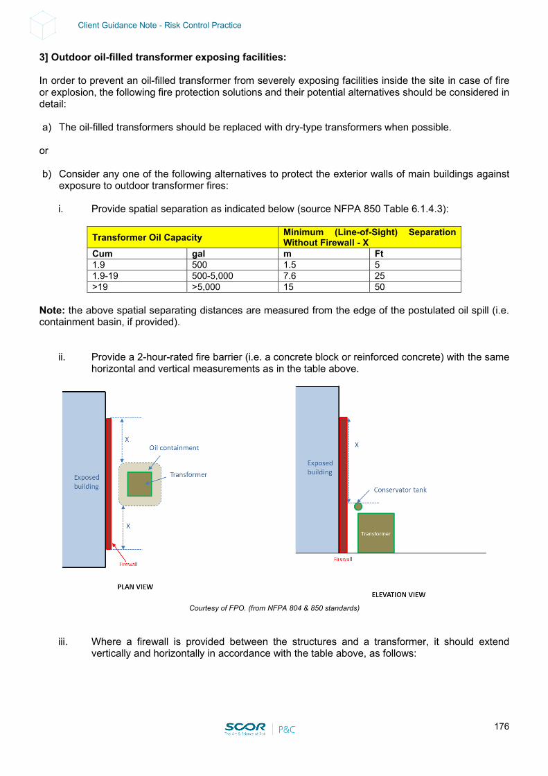
176
Client Guidance Note - Risk Control Practice
3] Outdoor oil-filled transformer exposing facilities: In order to prevent an oil-filled transformer from severely exposing facilities inside the site in case of fire or explosion, the following fire protection solutions and their potential alternatives should be considered in detail: a) The oil-filled transformers should be replaced with dry-type transformers when possible.
or b) Consider any one of the following alternatives to protect the exterior walls of main buildings against
exposure to outdoor transformer fires:
i. Provide spatial separation as indicated below (source NFPA 850 Table 6.1.4.3):
Transformer Oil Capacity Minimum (Line-of-Sight) Separation Without Firewall - X
Cum gal m Ft 1.9 500 1.5 5 1.9-19 500-5,000 7.6 25 >19 >5,000 15 50
Note: the above spatial separating distances are measured from the edge of the postulated oil spill (i.e. containment basin, if provided).
ii. Provide a 2-hour-rated fire barrier (i.e. a concrete block or reinforced concrete) with the same horizontal and vertical measurements as in the table above.
Courtesy of FPO. (from NFPA 804 & 850 standards)
iii. Where a firewall is provided between the structures and a transformer, it should extend vertically and horizontally in accordance with the table above, as follows:
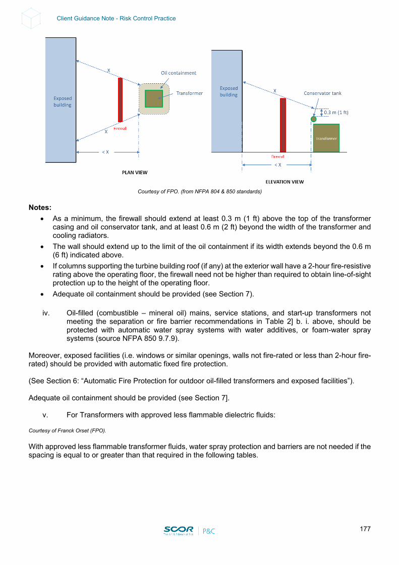
177
Client Guidance Note - Risk Control Practice
Courtesy of FPO. (from NFPA 804 & 850 standards)
Notes:
• As a minimum, the firewall should extend at least 0.3 m (1 ft) above the top of the transformer casing and oil conservator tank, and at least 0.6 m (2 ft) beyond the width of the transformer and cooling radiators.
• The wall should extend up to the limit of the oil containment if its width extends beyond the 0.6 m (6 ft) indicated above.
• If columns supporting the turbine building roof (if any) at the exterior wall have a 2-hour fire-resistive rating above the operating floor, the firewall need not be higher than required to obtain line-of-sight protection up to the height of the operating floor.
• Adequate oil containment should be provided (see Section 7).
iv. Oil-filled (combustible – mineral oil) mains, service stations, and start-up transformers not meeting the separation or fire barrier recommendations in Table 2] b. i. above, should be protected with automatic water spray systems with water additives, or foam-water spray systems (source NFPA 850 9.7.9).
Moreover, exposed facilities (i.e. windows or similar openings, walls not fire-rated or less than 2-hour fire-rated) should be provided with automatic fixed fire protection. (See Section 6: “Automatic Fire Protection for outdoor oil-filled transformers and exposed facilities”). Adequate oil containment should be provided (see Section 7].
v. For Transformers with approved less flammable dielectric fluids: Courtesy of Franck Orset (FPO). With approved less flammable transformer fluids, water spray protection and barriers are not needed if the spacing is equal to or greater than that required in the following tables.
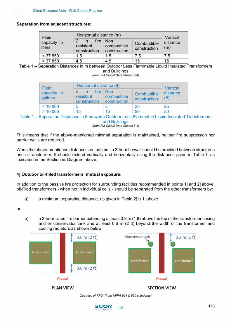
178
Client Guidance Note - Risk Control Practice
Separation from adjacent structures:
Fluid capacity in liters
Horizontal distance (m) Vertical distance (m)
2 h fire resistant construction
Non combustible construction
Combustible construction
< 37 850 1.5 1.5 7.5 7.5 > 37 850 4.5 4.5 15 15
Table 1 – Separation Distances in m between Outdoor Less Flammable Liquid Insulated Transformers and Buildings
(from FM Global Data Sheets 5-4)
Fluid capacity in gallons
Horizontal distance (ft) Vertical distance (ft)
2 h fire resistant construction
Non combustible construction
Combustible construction
< 10 000 5 5 25 25 > 10 000 15 15 50 50
Table 1 – Separation Distances in ft between Outdoor Less Flammable Liquid Insulated Transformers and Buildings
(from FM Global Data Sheets 5-4) This means that if the above-mentioned minimal separation is maintained, neither fire suppression nor barrier walls are required. When the above-mentioned distances are not met, a 2-hour firewall should be provided between structures and a transformer. It should extend vertically and horizontally using the distances given in Table 1, as indicated in the Section iii. Diagram above. 4] Outdoor oil-filled transformers’ mutual exposure: In addition to the passive fire protection for surrounding facilities recommended in points 1] and 2] above, oil-filled transformers - when not in individual cells - should be separated from the other transformers by:
a) a minimum separating distance, as given in Table 2] b. i. above or
b) a 2-hour-rated fire barrier extending at least 0.3 m (1 ft) above the top of the transformer casing and oil conservator tank and at least 0.6 m (2 ft) beyond the width of the transformer and cooling radiators as shown below:
Courtesy of FPO. (from NFPA 804 & 850 standards)

179
Client Guidance Note - Risk Control Practice
Note: • Where a firewall is provided, it should be designed to withstand the effects of projectiles from
exploding transformer bushings or lightning arresters. • A higher noncombustible shield may be provided to protect against the effects of an exploding
transformer bushing. • The wall should extend up to the limit of the oil containment if its width extends beyond the 0.6 m
(2ft) indicated above.
Courtesy of FPO. (from NFPA 804 & 850 standards)
• If columns supporting the turbine building roof (if any) at the exterior wall have a 2-hour fire-resistive
rating above the operating floor, the firewall need not be higher than required to obtain a line-of-sight protection up to the height of the operating floor.
• Fixed fire protection should be considered for oil-filled transformers (see Section 6). • Adequate oil containment should be provided (see Section 7).
c) For Transformers with approved less flammable dielectric fluids: Courtesy of Franck Orset (FPO). Separation from adjacent transformers is given in Table 2:
Fluid capacity in liters
Min. separation in meters
< 37 850 1.5 m > 37 850 7.5 m
Table 2 – Outdoor Less Flammable Fluid Insulated Transformers Equipment Separation Distances in m between adjacent transformers
(from FM Global Data Sheets 5-4)
Fluid capacity in gallons
Min. separation in ft
< 10 000 5 ft > 10 000 25 ft
Table 2 – Outdoor Less Flammable Fluid Insulated Transformers Equipment Separation Distances in ft between adjacent transformers
(from FM Global Data Sheets 5-4)
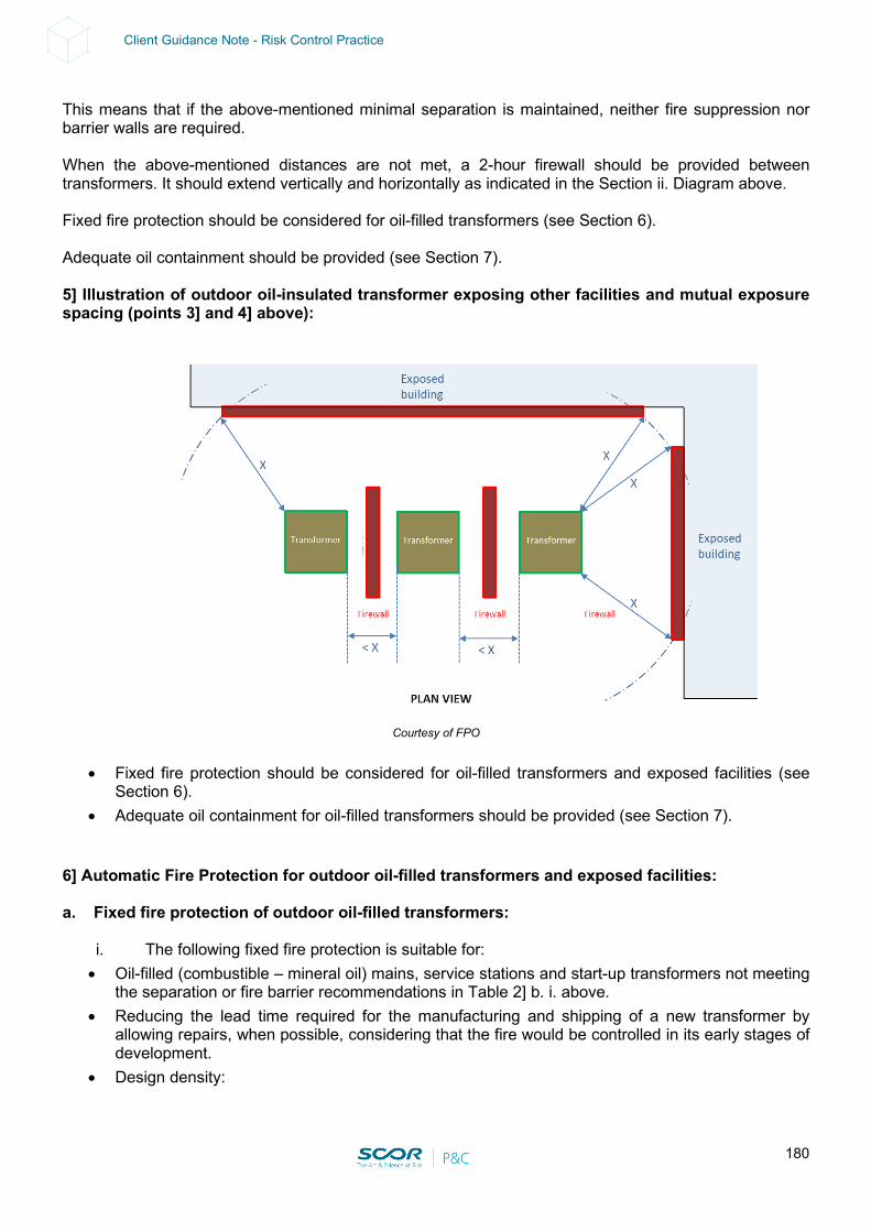
180
Client Guidance Note - Risk Control Practice
This means that if the above-mentioned minimal separation is maintained, neither fire suppression nor barrier walls are required. When the above-mentioned distances are not met, a 2-hour firewall should be provided between transformers. It should extend vertically and horizontally as indicated in the Section ii. Diagram above. Fixed fire protection should be considered for oil-filled transformers (see Section 6). Adequate oil containment should be provided (see Section 7). 5] Illustration of outdoor oil-insulated transformer exposing other facilities and mutual exposure spacing (points 3] and 4] above):
Courtesy of FPO
• Fixed fire protection should be considered for oil-filled transformers and exposed facilities (see
Section 6). • Adequate oil containment for oil-filled transformers should be provided (see Section 7).
6] Automatic Fire Protection for outdoor oil-filled transformers and exposed facilities: a. Fixed fire protection of outdoor oil-filled transformers:
i. The following fixed fire protection is suitable for: • Oil-filled (combustible – mineral oil) mains, service stations and start-up transformers not meeting
the separation or fire barrier recommendations in Table 2] b. i. above. • Reducing the lead time required for the manufacturing and shipping of a new transformer by
allowing repairs, when possible, considering that the fire would be controlled in its early stages of development.
• Design density:
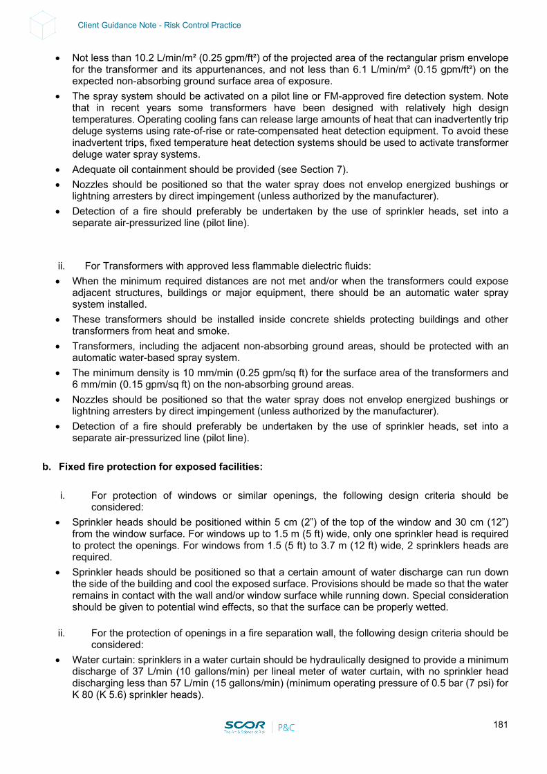
181
Client Guidance Note - Risk Control Practice
• Not less than 10.2 L/min/m² (0.25 gpm/ft²) of the projected area of the rectangular prism envelope for the transformer and its appurtenances, and not less than 6.1 L/min/m² (0.15 gpm/ft²) on the expected non-absorbing ground surface area of exposure.
• The spray system should be activated on a pilot line or FM-approved fire detection system. Note that in recent years some transformers have been designed with relatively high design temperatures. Operating cooling fans can release large amounts of heat that can inadvertently trip deluge systems using rate-of-rise or rate-compensated heat detection equipment. To avoid these inadvertent trips, fixed temperature heat detection systems should be used to activate transformer deluge water spray systems.
• Adequate oil containment should be provided (see Section 7). • Nozzles should be positioned so that the water spray does not envelop energized bushings or
lightning arresters by direct impingement (unless authorized by the manufacturer). • Detection of a fire should preferably be undertaken by the use of sprinkler heads, set into a
separate air-pressurized line (pilot line).
ii. For Transformers with approved less flammable dielectric fluids: • When the minimum required distances are not met and/or when the transformers could expose
adjacent structures, buildings or major equipment, there should be an automatic water spray system installed.
• These transformers should be installed inside concrete shields protecting buildings and other transformers from heat and smoke.
• Transformers, including the adjacent non-absorbing ground areas, should be protected with an automatic water-based spray system.
• The minimum density is 10 mm/min (0.25 gpm/sq ft) for the surface area of the transformers and 6 mm/min (0.15 gpm/sq ft) on the non-absorbing ground areas.
• Nozzles should be positioned so that the water spray does not envelop energized bushings or lightning arresters by direct impingement (unless authorized by the manufacturer).
• Detection of a fire should preferably be undertaken by the use of sprinkler heads, set into a separate air-pressurized line (pilot line).
b. Fixed fire protection for exposed facilities:
i. For protection of windows or similar openings, the following design criteria should be
considered: • Sprinkler heads should be positioned within 5 cm (2”) of the top of the window and 30 cm (12”)
from the window surface. For windows up to 1.5 m (5 ft) wide, only one sprinkler head is required to protect the openings. For windows from 1.5 (5 ft) to 3.7 m (12 ft) wide, 2 sprinklers heads are required.
• Sprinkler heads should be positioned so that a certain amount of water discharge can run down the side of the building and cool the exposed surface. Provisions should be made so that the water remains in contact with the wall and/or window surface while running down. Special consideration should be given to potential wind effects, so that the surface can be properly wetted.
ii. For the protection of openings in a fire separation wall, the following design criteria should be
considered: • Water curtain: sprinklers in a water curtain should be hydraulically designed to provide a minimum
discharge of 37 L/min (10 gallons/min) per lineal meter of water curtain, with no sprinkler head discharging less than 57 L/min (15 gallons/min) (minimum operating pressure of 0.5 bar (7 psi) for K 80 (K 5.6) sprinkler heads).
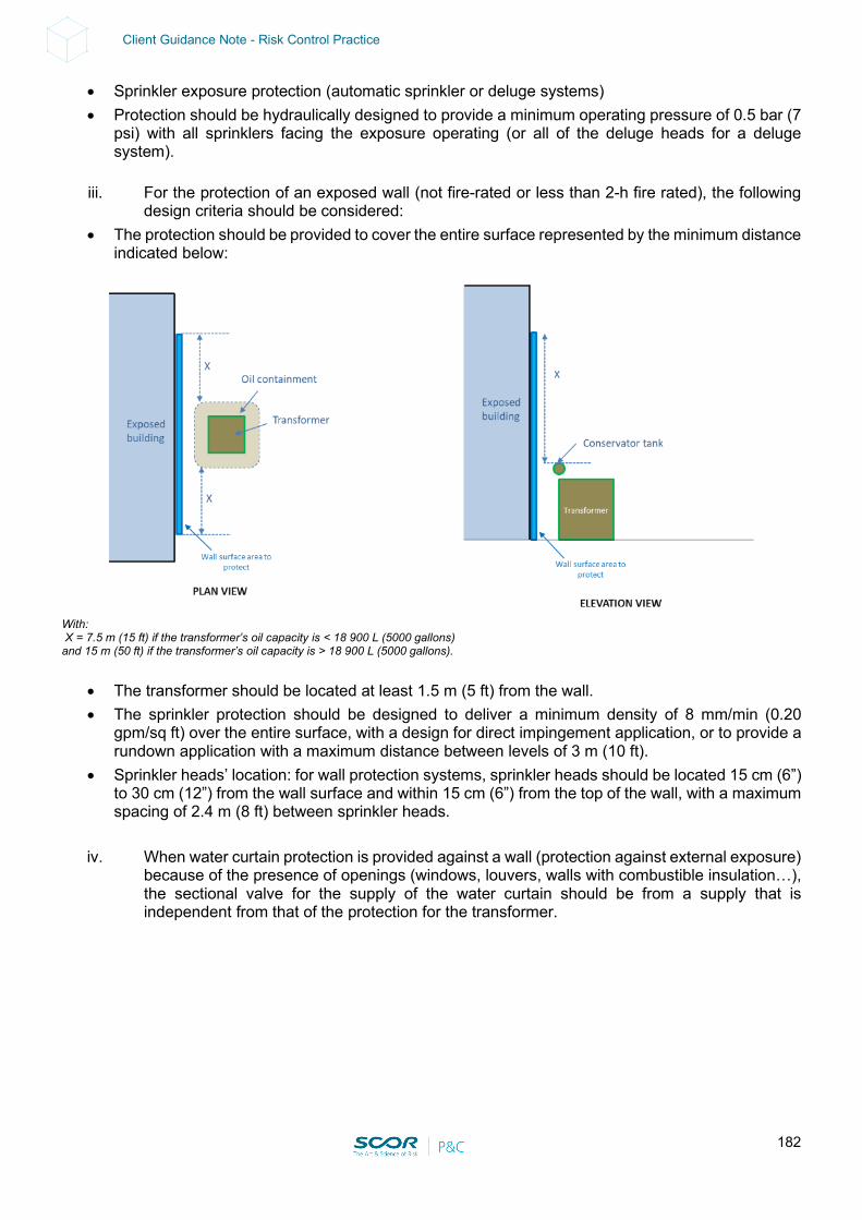
182
Client Guidance Note - Risk Control Practice
• Sprinkler exposure protection (automatic sprinkler or deluge systems) • Protection should be hydraulically designed to provide a minimum operating pressure of 0.5 bar (7
psi) with all sprinklers facing the exposure operating (or all of the deluge heads for a deluge system).
iii. For the protection of an exposed wall (not fire-rated or less than 2-h fire rated), the following
design criteria should be considered: • The protection should be provided to cover the entire surface represented by the minimum distance
indicated below:
With: X = 7.5 m (15 ft) if the transformer’s oil capacity is < 18 900 L (5000 gallons) and 15 m (50 ft) if the transformer’s oil capacity is > 18 900 L (5000 gallons).
• The transformer should be located at least 1.5 m (5 ft) from the wall. • The sprinkler protection should be designed to deliver a minimum density of 8 mm/min (0.20
gpm/sq ft) over the entire surface, with a design for direct impingement application, or to provide a rundown application with a maximum distance between levels of 3 m (10 ft).
• Sprinkler heads’ location: for wall protection systems, sprinkler heads should be located 15 cm (6”) to 30 cm (12”) from the wall surface and within 15 cm (6”) from the top of the wall, with a maximum spacing of 2.4 m (8 ft) between sprinkler heads.
iv. When water curtain protection is provided against a wall (protection against external exposure)
because of the presence of openings (windows, louvers, walls with combustible insulation…), the sectional valve for the supply of the water curtain should be from a supply that is independent from that of the protection for the transformer.

183
Client Guidance Note - Risk Control Practice
Courtesy of Franck Orset (FPO)
This is to be sure that in case of failure of the deluge protection on the main transformer, it is still possible to isolate the sectional valve controlling the transformer without affecting the water flow on the water curtain. 7] Oil containment:
• Outdoor liquid-filled transformers should be provided with spill containment if the accidental release of the transformer fluid could expose a main building, adjacent equipment or storage to fire damage.
• A catch basin should be provided beneath each transformer with sufficient capacity to hold 120% of the oil contents of the transformer, or retention with a drain, leading to an underground tank.
• The area of the bund should be sufficient to be able to capture all oil ejected from pressure relief devices, ruptured bushing turrets, main tanks, oil coolers and the conservator.
• The provision of crushed stones is a good practice to prevent large fires at the transformer location. • In the event of a transformer failure the spilling oil will effectively be cooled down by the yard stones
to below the combustion temperature. The stones will effectively prevent the oil from burning uncontrolled throughout the containment area.
• Only the area that was exposed to the oil spill will have surface oil that will burn until dry. This will minimize the actual time and severity of the fire due to the limited amount of surface oil and the reduction in oil temperature.
• In passive systems with crushed stone, no less than 300 mm (12 in.) of stone should be provided to extinguish the oil, if on fire. Smaller stone is more effective, 20 mm to 40 mm (¾ in. to 1½ in.) is recommended. While larger stone permits quicker penetration by the oil, its size makes it less effective as a quenching stone.
• The volume of the bunding and the rock ballast must be sufficient to hold the total volume of oil from the transformer at 100 mm (4 in.) below the surface of the rocks to ensure that a pool fire is not sustained.
184
Client Guidance Note - Risk Control Practice
• Note that rock ballast tends to collect dust and other wind-borne debris over time and may silt up and require cleaning at infrequent intervals.
• A system for removal of rainwater from the containment area should be provided.
5. ELECTRO-STATIC PRECIPITATOR (ESP)
The following points should be considered in detail: 1] All oil-filled transformer supports located at the top of ESPs should be provided with adequate stoppers in order to prevent any horizontal and vertical movement in case of earthquake tremors (in regions with EQ exposure). 2] In order to prevent oil-filled transformers from severely exposing the Electro-Static Precipitator in the case of fire or explosion, the following fire protection solutions and their potential alternatives should be considered in detail:
a) The oil-filled transformers should be replaced with dry-type transformers when possible. or
b) The oil-filled transformers installed above the ESP should be adequately protected as per NFPA 850 as follows:
• Adequate automatic spray (deluge) systems should be installed above the transformers in accordance with NFPA standards. All material and equipment should be FM-approved and/or UL-listed. All alarms should be relayed to a constantly attended location. This protection should be fed by an adequate and reliable Fire Water supply.
• A catch basin should be provided beneath each transformer with sufficient capacity to hold 120% (oil and fire water) of the oil contents of the transformer, or a retention with a drain leading to an underground tank.
• The project should be reviewed by a qualified Fire Protection Engineer familiar with NFPA standards.
Comment:
• Oil-filled transformers constitute a severe exposure threat to ESPs as they are usually located at elevated levels on top of the ESP. Technically speaking, thermal power-generating units, boilers and kilns could operate without an ESP. However, sometimes local environmental regulations stipulate that an ESP is mandatory.
• 1] In the case of an EQ tremor (EQ exposed areas), these transformers may fall out of the rails and be damaged so that the combustible insulating oil is released and may be ignited by a hot surface or by friction resulting in fire and loss.
• 2] In the case of an explosion and/or a fire involving an oil-filled transformer, oil would spread over the ESP, resulting in severe property damage and potential shutdown. Safe and efficient manual firefighting at such heights would be virtually impossible.
185
Client Guidance Note - Risk Control Practice
6. SUBSTATION / MCC ROOMS / SERVER ROOMS / ELECTRIC ROOMS
All Substations / MCC Rooms / Server Rooms / Electric Rooms that have no physical well- segregated backup (located in a different fire / flood / other perils area than the main unit) and that may lead to production disruption in case of a total loss should be identified. These facilities are deemed as critical. The following solutions A), B) and C) and their alternatives should be considered in detail for these critical utilities:
A) Duplication: a full backup should be provided for these rooms. This can consist of duplicating these rooms (so that in the case of loss on a hot site, the standby room could immediately take over, or on a cold site there would be a limited switch time for limiting interruption). The main room and the back-up room(s) should be located in different well- separated fire areas consisting of a minimum separating distance (25 m for noncombustible construction and 40 m for combustible construction) or a physical barrier (at least a 2-hr fire partition without any opening such as a door or even a fire door which risks being left open), false floors / ceiling penetrations or windows. An adequate NFPA and FM-approved automatic fire detection system should be installed in both the main room and the back-up room.
and/or
B) Protection: if a backup or any other redundancies are not available or cannot be fully completed, as detailed in point A. above, the following fire protection alternatives should be considered:
• Rooms housing electric equipment such as cable vaults, breakers, drivers, PLC cabinets, GIS bay
cabinets, etc.: For standard-size airtight rooms: Approved and adequate automatic gaseous extinguishing total flooding inside the rooms and inside the cable trench / false floor / false ceiling should be considered. For reliability, these gaseous extinguishing systems could be of the double-shot type and/or an automatic wet pipe sprinkler protection system under the ceiling could provide an adequate backup in the case of single / double- shot gaseous extinguishing systems. Wet pipe sprinklers for trenches / false floors at least 80 cm deep can also be considered. or: For large-size non-airtight rooms: Approved and adequate automatic wet pipe sprinklers under the ceiling and inside the cable trenches / false floors / false ceilings of at least 80 cm deep should be considered. Should the site have concerns about electrical shocks and/or accidental water discharge, a pre-action system could be considered for the cabinet rooms. (A wet pipe sprinkler and pre-action - minimum design density should be 6 mm/min (0.15 gpm/sq ft) over 186 m2 (2000 sq ft) with K 80 (K 5.6) standard spray sprinklers rated at 68°C (165°F) - are suitable for large-size rooms and when it is difficult to make the room airtight for a gaseous extinguishing system). or: For control panels in large-size rooms - high ceilings, relatively low combustible load (i.e. GIS / control bay panels in process areas): Approved and adequate automatic gaseous extinguishing systems locally discharging inside the cabinets and inside the cable trenches / false floors / false ceilings should be considered. For reliability purposes, these gaseous extinguishing systems could be of the double-shot type and/or an automatic wet pipe sprinkler protection system under the ceiling could provide an adequate backup in the case of single / double-shot gaseous extinguishing systems. Wet pipe sprinklers for false floors of at least 80 cm deep can also be considered. and:
• Cable vaults / tunnels: Cable vaults and tunnels should be protected with an approved and adequate automatic wet pipe sprinkler protection system. Moreover, cables in open-side cable vaults exposed to wind should also be coated with adequate and FM-approved intumescent material.
186
Client Guidance Note - Risk Control Practice
and: C) Contingency Plan:
A Contingency Plan should be developed in the case of a loss of a Substation / Electric Room identifying by-pass possibilities, vendors and/or manufacturers or locations where spare cabinets are available. The lead time and installation time should be investigated by specialists. The Contingency Plan should be formalized, regularly reviewed and updated. Ownership and leadership should be clearly defined.
D) Important Note: The following points regarding the above fire protection solutions and their potential alternatives should be considered:
• Gaseous extinguishing agent: carbon dioxide (CO2) is very dangerous for humans (lethal). As a result, for any normally occupied or occasionally occupied areas, we strongly recommend an automatic system using safe gaseous extinguishing agents for personnel, such as "Inergen" or “Argonite” or approved clean agents such as FE227 and FM200, in accordance with NFPA 2001. The recommended extinguishing agent density should be such that the oxygen concentration in the room does not drop below the safety limit. If a carbon dioxide system is selected for a raised floor, a special low-velocity discharge system should be used so that the carbon dioxide does not rise above knee height in the room. Under-floor halocarbon agent systems (e.g. FE227 and FM200) are not permitted when the space above the raised floor is not equipped with a halocarbon agent system. A fire in the space above the raised floor could draw the discharged halocarbon agent upwards, causing it to decompose and become very toxic. Only equipment tested and approved by a recognized laboratory should be accepted.
• Ventilation Interlock: the ventilation system should be interlocked to the fire detection / protection system in order to shut down automatically upon fire detection. Ventilation interlocks should permit ventilation to stop when fire is detected in a room. This is in order to prevent the supply of oxygen to a fire and the escape of gaseous extinguishing agents, when provided.
• Ventilation Duct Segregation: fire dampers should be installed in each ventilation system which is common to different rooms. These dampers should be interlocked to their respective fire detection system, to close automatically in case of fire detected in one of these rooms. Some ventilation ducts may be common to at least 2 utility rooms. Without fire dampers closing when fire is detected in a room, smoke may spread to the adjacent rooms and gaseous extinguishing agents may also escape from the room where it has been discharged, though the ventilation duct.
• Water-Based Fire Protection & Electric Shocks: regarding sprinkler protection, should the plant have concerns about electric shocks, the mains switch may be interlocked to the sprinkler system in order to de-energize the area in case of sprinkler water discharge.
• Fire Water Supply: the above recommended sprinkler protection should be fed by an adequate and reliable fire water supply in accordance with the latest version of NFPA, as recommended.
• Alarms and signals: all fire alarms, supervisory signals and trouble signals should be relayed to a constantly attended location.
• Materials and equipment: all fire detection / protection material and equipment should be UL-listed or FM-approved and should be installed by a qualified contractor familiar with NFPA/FM standards.
• Plan Review: the project should be reviewed by a qualified Fire Protection Engineer familiar with NFPA standards.
187
Client Guidance Note - Risk Control Practice
Comment: Solution A) consisting of adequately-segregated redundancies is the most reliable but also the most expensive. Solution B) is the most efficient when A) is not possible. Automatic Sprinkler wet pipe or pre-action systems are suitable for large-size rooms and when it is difficult to make the room airtight for a gaseous extinguishing system. Automatic fire protection systems can fail (i.e. faulty design, lack of maintenance, impairment). Back-up systems (sprinkler and pre-action) for gaseous extinguishing systems are therefore recommended. Cable coating (2-hour fire-rated maximum) in cable vaults is an acceptable solution for areas handling material that could react with water (i.e. hot molten metal). This should however not be a systematic substitute for an automatic sprinkler in other areas. For open-side cable vaults exposed to wind that could divert water discharge, both automatic sprinklers and coatings providing mutual backup are recommended. Solution C) – the Contingency Plan- is not a substitute for either duplication (point A. above) or automatic fire protection (point B. above). The main purpose of a Contingency Plan is to limit Business Interruption in case of the loss of a protected room (protection could be impaired) with or without redundancies provided, as per point A. In such cases the CP aims at ensuring the availability / reliability of the redundancy(ies) (if any). The ultimate goal of this recommendation is to mitigate the impact of Business Interruption. The decision should be based on ‘what-ifs’ and risk / benefit analysis.
7. CABLE OPENINGS / CABLE TRAYS & RUNS / CABLE VAULTS / CABLE TUNNELS
The following points should be considered in detail: A) All Cable Openings to substations, electrical rooms, MCC rooms, electric cabinets, control rooms, rack rooms, server rooms and processing areas, should be sealed with an FM-approved fire sealant. If these openings are only temporary, then approved provisional sealing materials should be used. Cable openings could be filled with non-combustible insulation material (glass wool) and sealed with non-combustible gypsum material as an acceptable alternative to an approved fire sealant. B) All horizontal Cable Trays running in processing areas should be provided with large fire breaks, 2 m in size, made from FM-approved non-combustible intumescent paint, applied on cables every 30 m. As an acceptable alternative to approved intumescent material, non-combustible gypsum material could be applied to cable trays. C) In vertical Cable Runs, the trays should have a fire barrier installed every 10 m. The cable openings between the floors of buildings should be sealed with FM-approved fire-resistant material. Comment: A) Some polyurethane foams contain a fire retardant. The retardant allows the flammability of the PU foam to be temporarily reduced by reducing ignition potential and flame spread. However, when exposed to a sustainable fire, the combustible PU foam will burn. Furthermore, the property of the fire retardant may change depending on time and ambient conditions. In order to be approved, fire-retardant materials need to be tested by NFPA 255, Standard Method of Test of Surface Burning Characteristics of Building Materials. As a result, we strongly recommend the use of approved sealant non-combustible intumescent material. B), C) Long unprotected cable trays usually run along the inside of processing areas. A potential fire could spread along the entire length of the cables, from one area to another.
188
Client Guidance Note - Risk Control Practice
8. BATTERY ROOM (ESS)
Courtesy of Franck Orset (FPO), Loss Prevention Engineer: Based on NFPA 855 ed 2020 “Installation of Stationary Energy Storage Systems” and FM Global Data Sheets 5-33 “Electrical Energy Storage System” Standard:
• Closed hydrogen systems are preferred for Energy Storage Systems (ESS). Location:
• Batteries should be installed in a separate 1-h fire compartment. • Energy Storage Systems (ESS) should be arranged in groups with a maximum energy capacity of
250 kWh each. • Each group should be spaced at least 90 cm (3 ft) away from other groups and from walls in the
storage room or area. • The maximum rated energy should be 600 kWh.
Storage:
• No combustible storage, unrelated to the battery room, should be allowed inside the room. • Combustible material related to the battery room should be stored at a minimum distance of 90 cm
(3 ft) from the equipment. Electrical equipment:
• All electrical equipment installed or used in battery rooms should be explosion-proof. • Direct current switchgear and inverters should not be located in the battery rooms.
Ventilation:
• Battery rooms (flooded lead-acid, flooded Ni-Cd and VRLA batteries) should be provided with natural ventilation to limit the concentration of hydrogen to 1% by volume (25% of the LEL – Lower Explosive Limit) and equipped with a hydrogen detection system. The hydrogen concentrations should be monitored. or
• Mechanical exhaust ventilation should be provided at a rate of not less than 1 cubic foot per minute per square foot (1 ft3/min/ft2) [0.0051 m3/s / m2] of the floor area of the room and should be activated by a hydrogen detection system set to operate the ventilation at 25% of the LEL (1% of H2 inside the room).
• The hydrogen concentrations should be monitored.
• The mechanical ventilation should remain on until the flammable gas detected is less than 25% of the LEL. or
• Continuous ventilation should be provided at a rate of not less than 1 cubic foot per minute per square foot (1 ft3/min/ft2) [0.0051 m3/s / m2] of the floor area of the room. Excessive concentrations (>1 % vol.) and/or loss of ventilation and/or failure of the gas detection system should sound an alarm signal at a constantly attended location (Main Control Room). The exhaust ventilation lines should be located at the highest level of the fire compartment.
189
Client Guidance Note - Risk Control Practice
Exception: Lithium ion and lithium metal polymer batteries should not require additional ventilation beyond that which would normally be required for human occupancy of the space. Detection:
• Fire detection should be provided inside the room. Room protection:
• Battery rooms should preferably be protected by automatic sprinklers designed to deliver a minimum density of 12.2 mm/min (0.3 gpm/sq ft) over the entire area of the room or 232 m2 – 2500 sq ft, - whichever is smaller.
• Thermal runaway events create a large amount of heat. The heat, coupled with plastic construction components, can lead to a very large fire. Although sprinkler protection may not be practical in exterior installations, it is the best method of cooling a fire involving an ESS.
• Total flooding gas protection systems could be provided and should be designed to maintain the design concentration within the enclosure for a time sufficient to ensure that the fire is extinguished and that the ESS temperatures have cooled to below the autoignition temperature of combustible material present and the temperature that could cause thermal runaway (with a minimum of 10 minutes).
• The design of the system should be based on: • The agent concentrations required for the specific combustible materials involved
- The specific configuration of the equipment and enclosure - Protections by water mist or dry chemical systems are not advised/recommended.
9. RUBBER BELT CONVEYOR
The following points should be considered in detail:
A) Identification: All critical rubber belt conveyors should be identified.
B) Contingency Plan: a Contingency Plan should be developed in case of loss of a critical rubber belt conveyor including the belt and its structural support, identifying vendors and/or manufacturers or locations where spare conveyors are available.
or
C) Protection: in case the replacement time is not acceptable from a Business Interruption standpoint, an automatic sprinkler protection, following the requirements of international standards (NFPA / FM Global Data Sheets 7-11 Conveyor Belts), should be installed for all critical rubber belt conveyors.
• The belt drivers should be interlocked to the sprinkler system to enable them to stop automatically
in case of water discharge. • All fire alarms, perturbations and supervisory signals should be relayed to a constantly attended
location. • All material and equipment should be approved and/or UL-listed. • A project plan review of the fire protection systems should be conducted by qualified and
recognized fire protection engineers familiar with NFPA / FM standards prior to installation, and a visit on site should be conducted during and after installation, before acceptance.
• The protection system should be installed by qualified contractors.
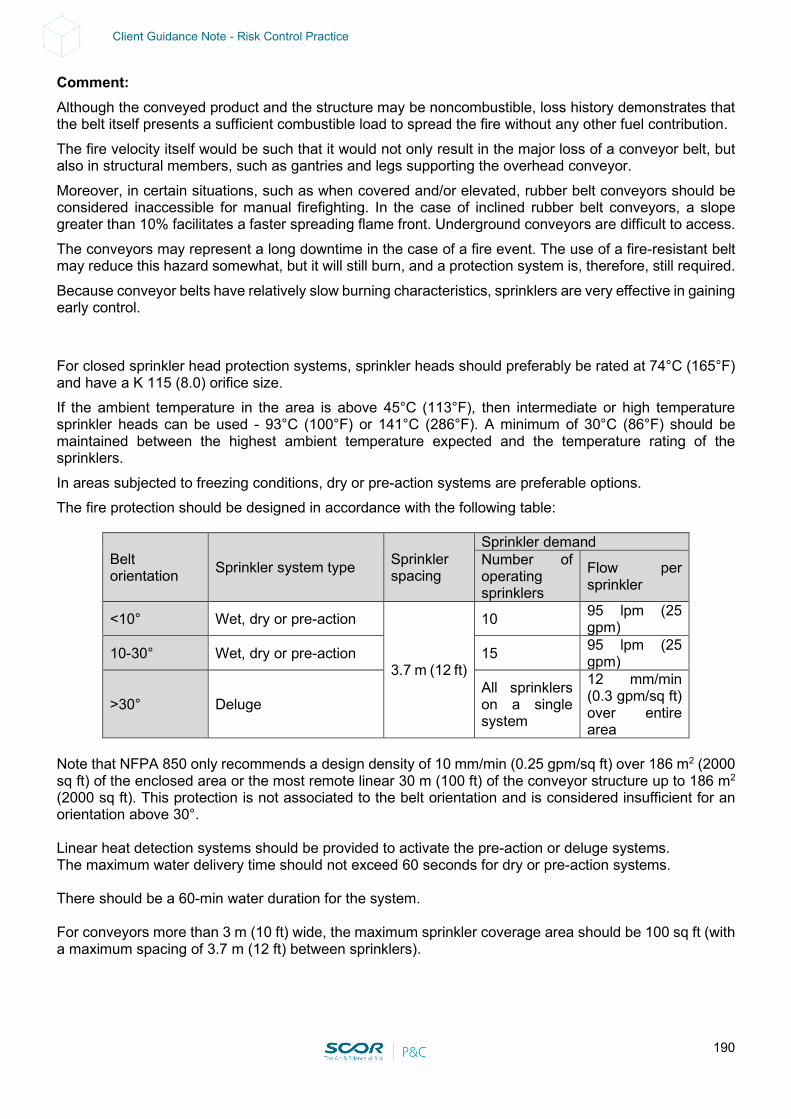
190
Client Guidance Note - Risk Control Practice
Comment: Although the conveyed product and the structure may be noncombustible, loss history demonstrates that the belt itself presents a sufficient combustible load to spread the fire without any other fuel contribution. The fire velocity itself would be such that it would not only result in the major loss of a conveyor belt, but also in structural members, such as gantries and legs supporting the overhead conveyor. Moreover, in certain situations, such as when covered and/or elevated, rubber belt conveyors should be considered inaccessible for manual firefighting. In the case of inclined rubber belt conveyors, a slope greater than 10% facilitates a faster spreading flame front. Underground conveyors are difficult to access. The conveyors may represent a long downtime in the case of a fire event. The use of a fire-resistant belt may reduce this hazard somewhat, but it will still burn, and a protection system is, therefore, still required. Because conveyor belts have relatively slow burning characteristics, sprinklers are very effective in gaining early control. For closed sprinkler head protection systems, sprinkler heads should preferably be rated at 74°C (165°F) and have a K 115 (8.0) orifice size. If the ambient temperature in the area is above 45°C (113°F), then intermediate or high temperature sprinkler heads can be used - 93°C (100°F) or 141°C (286°F). A minimum of 30°C (86°F) should be maintained between the highest ambient temperature expected and the temperature rating of the sprinklers. In areas subjected to freezing conditions, dry or pre-action systems are preferable options. The fire protection should be designed in accordance with the following table:
Belt orientation Sprinkler system type Sprinkler
spacing
Sprinkler demand Number of operating sprinklers
Flow per sprinkler
<10° Wet, dry or pre-action
3.7 m (12 ft)
10 95 lpm (25 gpm)
10-30° Wet, dry or pre-action 15 95 lpm (25 gpm)
>30° Deluge All sprinklers on a single system
12 mm/min (0.3 gpm/sq ft) over entire area
Note that NFPA 850 only recommends a design density of 10 mm/min (0.25 gpm/sq ft) over 186 m2 (2000 sq ft) of the enclosed area or the most remote linear 30 m (100 ft) of the conveyor structure up to 186 m2 (2000 sq ft). This protection is not associated to the belt orientation and is considered insufficient for an orientation above 30°. Linear heat detection systems should be provided to activate the pre-action or deluge systems. The maximum water delivery time should not exceed 60 seconds for dry or pre-action systems. There should be a 60-min water duration for the system. For conveyors more than 3 m (10 ft) wide, the maximum sprinkler coverage area should be 100 sq ft (with a maximum spacing of 3.7 m (12 ft) between sprinklers).
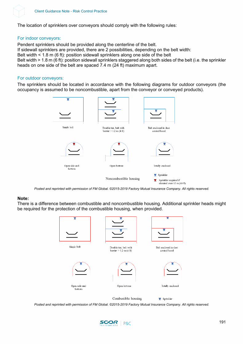
191
Client Guidance Note - Risk Control Practice
The location of sprinklers over conveyors should comply with the following rules: For indoor conveyors: Pendent sprinklers should be provided along the centerline of the belt. If sidewall sprinklers are provided, there are 2 possibilities, depending on the belt width: Belt width < 1.8 m (6 ft): position sidewall sprinklers along one side of the belt Belt width > 1.8 m (6 ft): position sidewall sprinklers staggered along both sides of the belt (i.e. the sprinkler heads on one side of the belt are spaced 7.4 m (24 ft) maximum apart. For outdoor conveyors: The sprinklers should be located in accordance with the following diagrams for outdoor conveyors (the occupancy is assumed to be noncombustible, apart from the conveyor or conveyed products).
Posted and reprinted with permission of FM Global. ©2015-2019 Factory Mutual Insurance Company. All rights reserved.
Note: There is a difference between combustible and noncombustible housing. Additional sprinkler heads might be required for the protection of the combustible housing, when provided.
Posted and reprinted with permission of FM Global. ©2015-2019 Factory Mutual Insurance Company. All rights reserved.
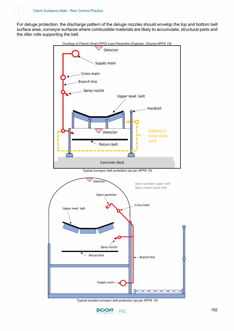
192
Client Guidance Note - Risk Control Practice
For deluge protection, the discharge pattern of the deluge nozzles should envelop the top and bottom belt surface area, conveyor surfaces where combustible materials are likely to accumulate, structural parts and the idler rolls supporting the belt.
Courtesy of Franck Orset (FPO) Loss Prevention Engineer. (Source NFPA 15):
Typical conveyor belt protection (as per NFPA 15)
Typical hooded conveyor belt protection (as per NFPA 15)
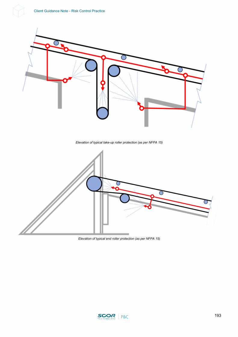
193
Client Guidance Note - Risk Control Practice
Elevation of typical take-up roller protection (as per NFPA 15)
Elevation of typical end roller protection (as per NFPA 15)

194
Client Guidance Note - Risk Control Practice
10. COOLING TOWER
The impact on production of a potential total loss of a cooling tower set should be investigated. The following solutions A) or B) should be considered in detail for mitigating the loss:
A) Contingency Plan: a Contingency Plan should be developed (in case of the loss of a cooling tower set), identifying process-cooling alternatives, vendors and/or manufacturers or locations where entire sets are available. Or
B) Protection: in case the above Contingency Plan is not acceptable from a Business Interruption standpoint, critical cooling towers (having a direct impact on production) should be adequately protected with approved sprinkler protection, as per NFPA 214 / FM Global Data Sheets 1.6. All material and equipment should be approved and/or listed. The project should be reviewed by a qualified Fire Protection Engineer familiar with NFPA standards. All alarms should be relayed to a constantly attended location. This protection should be fed from an adequate and reliable Fire Water supply. Comments:
• The study should include the loss of an entire set of cooling towers, comprising several cells without fire separation (i.e. 40 m).
• Cooling towers are usually made of combustible material such as FRP hoods, shells and packing. If there are multiple cells on the same set, even with a concrete shell and walls, the fire would be able to spread to the hood or to the front or bottom openings.
• Several fires during maintenance periods in the cooling tower (dry conditions) are recorded each year. The electrical failure of drivers and overheating, friction of the fan on the hood and lighting are also serious sources of ignition.
• Due to a relatively fast fire spread, safe and efficient manual firefighting would be virtually impossible.

195
Client Guidance Note - Risk Control Practice
FM Global Data Sheets 1-6 “Cooling Towers”. Fig. 1, 2, 3 and 4. Posted and reprinted with permission of FM Global. ©2020 Factory Mutual Insurance Company. All rights reserved.
Minimum recommended density, as per FM Global Data Sheets1-6: • For cementitious fill and a combustible fan deck: wet pipe / dry pipe of 6mm/min (0.15 gpm/ft²) • For a combustible fan deck: wet pipe / dry pipe of 14 mm/min (0.35 gpm/ft²) • For combustible fill & fan deck: deluge, 20 mm/min (0.50 gpm/ft²)
Minimum rate of application, as per NFPA 214:
• Deluge, under the fan decks, 20.4 mm/min (0.50 gpm/ft²) including the fan opening.
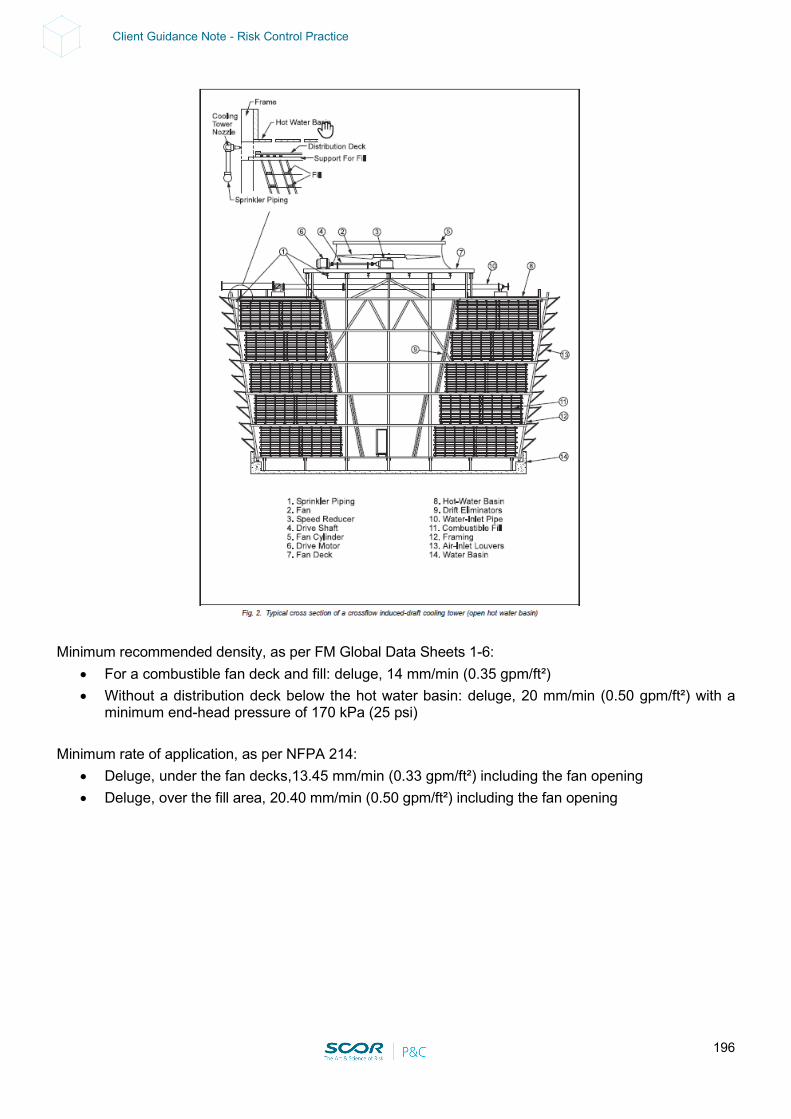
196
Client Guidance Note - Risk Control Practice
Minimum recommended density, as per FM Global Data Sheets 1-6:
• For a combustible fan deck and fill: deluge, 14 mm/min (0.35 gpm/ft²) • Without a distribution deck below the hot water basin: deluge, 20 mm/min (0.50 gpm/ft²) with a
minimum end-head pressure of 170 kPa (25 psi) Minimum rate of application, as per NFPA 214:
• Deluge, under the fan decks,13.45 mm/min (0.33 gpm/ft²) including the fan opening • Deluge, over the fill area, 20.40 mm/min (0.50 gpm/ft²) including the fan opening
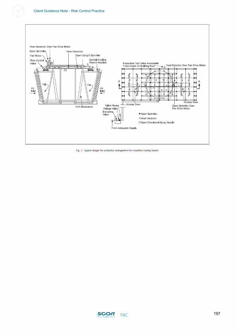
197
Client Guidance Note - Risk Control Practice
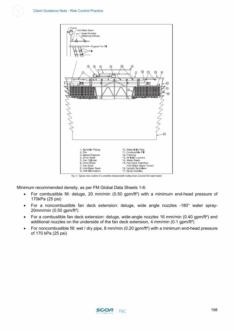
198
Client Guidance Note - Risk Control Practice
Minimum recommended density, as per FM Global Data Sheets 1-6:
• For combustible fill: deluge, 20 mm/min (0.50 gpm/ft²) with a minimum end-head pressure of 170kPa (25 psi)
• For a noncombustible fan deck extension: deluge, wide angle nozzles -180° water spray- 20mm/min (0.50 gpm/ft²)
• For a combustible fan deck extension: deluge, wide-angle nozzles 16 mm/min (0.40 gpm/ft²) and additional nozzles on the underside of the fan deck extension, 4 mm/min (0.1 gpm/ft²)
• For noncombustible fill: wet / dry pipe, 8 mm/min (0.20 gpm/ft²) with a minimum end-head pressure of 170 kPa (25 psi)
199
Client Guidance Note - Risk Control Practice
11. HYDRAULIC / LUBRICATING GROUPS
Hydraulic oil might very well have a high flash point (320°C) but it can definitely burn. Adequate physical protection devices should be provided as follows: A) All areas housing hydraulic and/or lubrication groups using 380 L or more of fluids under pressure
should be provided with:
• Sprinkler protection for the areas containing these hydraulic / lubricating groups, installed in accordance with NFPA. All material and equipment should be FM-approved and/or UL-listed. All alarms, perturbations and supervisory signals should be relayed to a constantly attended location. This protection should be fed from an adequate and reliable Fire Water supply. The project plans should be reviewed by a qualified Fire Protection Engineer familiar with NFPA standards. and
• All hydraulic / lubricating pumps should be interlocked to the sprinkler system in order to automatically shut down all machines operating in the fire area (when a safe shutdown is possible without lubrication). or
• A low oil pressure switch should be located within each reservoir, arranged to shut down the machine.
B) All areas housing hydraulic and lubrication groups using less than 380 L of fluid under pressure but
still exposing the adjacent facilities should be:
• Sprinkler-protected in accordance with NFPA. This can consist of sprinkler heads installed under a noncombustible canopy above the hydraulic / lubricating group. All material and equipment should be FM-approved and/or UL-listed. All alarms, perturbations and supervisory signals should be relayed to a constantly attended location. This protection should be fed from an adequate and reliable Fire Water supply. The project plans should be reviewed by a qualified Fire Protection Engineer familiar with NFPA standards. and
• The hydraulic / lubricating pumps should be interlocked to the sprinkler system in order to shut down automatically in case of fire water discharge (when safe shut down is possible without lubrication).
C) As an alternative to points A & B above:
• Use a nonignitable liquid that will not sustain combustion even when in the form of a spray (e.g. water). or
• Use FM-approved less-combustible fluids when possible. This should be investigated with the equipment manufacturer. FM-approved industrial fluids present a minimal fire hazard and do not, by themselves, necessitate fire protection features for the equipment or building. The need for automatic sprinkler protection should be determined based on the surrounding occupancy’s combustible load and the continuity of the combustible (e.g. combustible construction, cable trays, storage of combustible goods). or
• When it is not possible to use a nonignitable liquid or an FM-approved industrial fluid, use a fluid with as high a flash point as possible and provide additional safeguards to adequately protect the hazard, as recommended in points A and B above (i.e. sprinkler systems and interlocks)
200
Client Guidance Note - Risk Control Practice
D) Lubricating groups at atmospheric pressure or under low pressure (2-4 bar) present a minimal fire hazard and do not, by themselves, necessitate fire protection features for the equipment when enough clearance is provided all around (i.e. 15 m radius). If the clearance is less than 15 m, the need for automatic sprinkler protection should be determined based on the surrounding occupancy’s combustible load, continuity of the combustible (e.g. combustible construction, cable trays, storage of combustible goods), exposure to surrounding equipment (e.g. process / utility equipment) and access for manual firefighting (e.g. elevated mezzanines with 3D fire potential, oil cellars). The sprinkler protection should be in accordance with NFPA. This can consist of sprinkler heads installed under a noncombustible canopy above the hydraulics. All material and equipment should be FM-approved and/or UL-listed. All alarms, perturbations and supervisory signals should be relayed to a constantly attended location. This protection should be fed from an adequate and reliable Fire Water supply. The project plans should be reviewed by a qualified Fire Protection Engineer familiar with NFPA standards.
Comments: In the case of a hose rupture, combustible oil would be sprayed over the area and could easily be ignited by contact with a hot surface or another ignition source. The resulting fire is usually torch-like, with a very high rate of heat release. Causes of Oil Release: High-pressure pipes with welded and threaded joints, steel and copper tubing, and metal-reinforced rubber hoses are used to carry oil to the various units under pressure. The failure of piping, failure of valves and gaskets or fittings, ripping out of copper and steel tubing from fittings, and rupture of flexible hoses have been the principal causes of oil release from the system. A lack of adequate support or anchorage, preventing vibration or pipe movement, has been a factor in these failures. Repeated flexing and abrasion of rubber hoses against other hoses or parts of machines have created weak spots, which eventually resulted in rupture. Tubing under pressure has released oil when accidentally cut by welding torches or stepped on during maintenance procedures. Safe and efficient manual firefighting of oil on fire (especially within confined spaces) will be virtually impossible. Spray fires cannot be extinguished by automatic sprinklers, so this high-heat release fire will continue until the flow of liquid is shut down. This is the most efficient way of preventing the release of combustible fluid (a fuel source for the fire) and then sprinklers may be used for controlling the fire in its early stages of development. FM-approved industrial fluids have been developed to replace petroleum-based oils in all types of hydraulic systems. FM-approved industrial fluids present a minimal fire hazard and do not, by themselves, necessitate fire protection features for the equipment or building. These fluids, if sprayed onto very hot surfaces, can result in a flaring fire. However, these fluids should stop burning when they flow away from the hot surface. Loss experience indicates that properly maintained systems with FM-approved hydraulic fluids significantly reduce the extent of damage caused by a fire as compared to systems with petroleum-based oils. Follow procedures recommended by the manufacturers of the FM-approved fluid and of the hydraulic equipment when converting machines away from ignitable liquids such as mineral oil. Consult the manufacturers to address issues such as draining the old fluid from the system; replacing seals, gaskets, packing and filters; filling the system with the new fluid and monitoring equipment; and operating conditions (e.g., temperatures, inlet and outlet pressures, flow rates, fluid viscosity and stability, corrosion, etc.). Warning: Some hydraulic fluids are available that are designated as “less flammable.” These fluids are not considered to be equivalent to FM-approved industrial fluids in terms of the fire hazard they present. The methodologies used in validating these other fluids as “less flammable” are inconsistent and not fully understood. The actual fire hazard that these liquids present is unknown, and they may still sustain a high heat-release-rate spray fire despite their designation.

201
Client Guidance Note - Risk Control Practice
An Ignitable Liquid comprises any liquid or liquid mixture that is capable of fueling a fire, including flammable liquids, combustible liquids, inflammable liquids or any other term for a liquid that will burn. An ignitable liquid is one that has a fire point. High-water content fluids may not exhibit a fire point. However, high-water content fluids can still burn in the form of an atomized spray. FM Approval Standard 6930 also includes criteria to evaluate fluids without a fire point for approval. Please refer to FM Global Data Sheets 7.98 Hydraulic Fluids, Appendix C2 for more details.
12. AIR COMPRESSOR
Courtesy of Franck Orset (FPO) Loss prevention Engineer: The Hazard Many air compressor explosions and fires originate from oil and carbon deposits in the compressor systems. Excessive deposits in the system are the result of over-lubrication, use of unsuitable lubricants or dirty and/or chemically contaminated suction air. Under conditions of high temperature and pressure, contaminants and oily carbon deposits may oxidize and ignite spontaneously, creating an ignition source for vapors and residues. Glowing particles may be carried to a point in this system where there is a combustible or explosive mixture. Localized heating may weaken the equipment walls to the point of failure. Another important cause of air compressor fires and explosions is excessively high discharge temperatures. Abnormal temperatures are caused by recompression due to leakage through faulty valves or to blow-by in double-acting cylinders, by inadequate cooling water jackets and after-coolers, caused by high cylinder pressure due to severe restriction of discharge lines by deposits, or by mechanical friction or broken compressor parts. Other air compressor fires and explosions have originated in the compressor drive motor, controls, or associated electrical equipment. A few fires have been caused by friction due to slippage of drive belts or pulleys; by external ignition sources that involved oily residues; by solvent cleaners or combustibles in the vicinity of the compressor that in some cases heated the compressor system to a point where internal carbon deposits ignited; and by oily lint or other combustibles in contact with the outside surfaces of hot compressor parts. The frequency of fires in oil-flooded rotary-screw compressors is much greater than in other air compressors.

202
Client Guidance Note - Risk Control Practice
STANDARD Location Air compressors should be located in noncombustible buildings or cut-off rooms. No other equipment or storage should be located in the same room. Ventilation Rotary-screw compressor air-receiver vents should discharge to a safe location because the vented air/oil mixture may be flammable. Air intakes should be located away from sources of flammable vapors, gas, steam, dust or other contaminants. Intake-air filters should be provided to remove suspended solids. Fire protection Sprinkler protection is only required if one of the following conditions exists:
• The room or building is of combustible construction • An adjacent occupancy is combustible or represents a fire hazard • Compressors have an external lubrication system with a capacity above 380 L (100 gal.) or a flow
rate exceeding 95 L/min (25 gpm). If there are multiple compressors, the capacity should be considered as the aggregate total for all compressors within 8 m (25 ft).
The sprinkler protection should be designed to deliver a minimum density of 8 mm/min (0.2 gpm/sq ft) over the postulated oil spill, or compressed air foam, with a maximum area of application of 280 m2 (3000 sq ft), with K 80 (K 5.6) spray sprinklers rated at 141°C (286°F) - or a higher density if the adjacent occupancy/storage within the room requires it. If the protection is only over the units (no need to protect the rest of the room), then the sprinkler protection should extend at least 6 m (20 ft) beyond the units (the compressor and any part of the oil system). If sprinkler protection is omitted, consideration should be given to providing heat-actuated detectors interlocked to an automatic shutdown for high-value units or areas.

203
Client Guidance Note - Risk Control Practice
13. FUEL LINE SAFETY COMBUSTION CONTROL
An automatic starting sequence including a purging cycle, and inerting of the combustion chamber and ignition interlock should be provided. The safety combustion controls on the fuel line should include modern safety devices such as (but not limited to): high- and low-pressure switches, Safety Shut-Off Valves (SSOV) and Valve Seal Over Travel Interlocks (VSOI). This should be in accordance with NFPA 85 (Boiler and Combustion Systems Hazards Code) as summarized below: Courtesy of Franck Orset (FPO) Loss Prevention Engineer:
Legend:
1-Manual cock 2-Pressure regulator 3-Low gas pressure switch 4-Safety shutoff valve 5-Relief valve (if required)
6-Test connection 7-High pressure gas switch 8-Combustion air pressure switch 9-Combustion air blower
10-Main burner
11-Igniter 12-Combustion air 13-Gas supply 14-Normally open valve (see note) 15-Vent line to atmosphere (see note)
Note: the vent valve and vent line to atmosphere are required by NFPA on units greater than 3.7 MW (12.5 mBtu/h) input Note 1: When a modulating valve is provided on the main gas line, it should be located between the second safety shutoff valve and the manual cock at the burner. An alternate location is between the gas pressure regulator and the first safety shutoff valve.
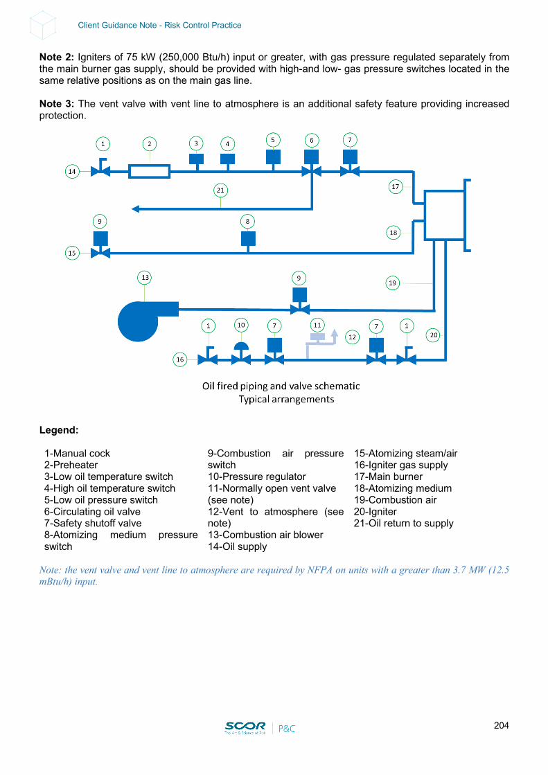
204
Client Guidance Note - Risk Control Practice
Note 2: Igniters of 75 kW (250,000 Btu/h) input or greater, with gas pressure regulated separately from the main burner gas supply, should be provided with high-and low- gas pressure switches located in the same relative positions as on the main gas line. Note 3: The vent valve with vent line to atmosphere is an additional safety feature providing increased protection.
Legend:
1-Manual cock 2-Preheater 3-Low oil temperature switch 4-High oil temperature switch 5-Low oil pressure switch 6-Circulating oil valve 7-Safety shutoff valve 8-Atomizing medium pressure
switch
9-Combustion air pressure switch 10-Pressure regulator 11-Normally open vent valve (see note) 12-Vent to atmosphere (see note) 13-Combustion air blower 14-Oil supply
15-Atomizing steam/air 16-Igniter gas supply 17-Main burner 18-Atomizing medium 19-Combustion air 20-Igniter 21-Oil return to supply
Note: the vent valve and vent line to atmosphere are required by NFPA on units with a greater than 3.7 MW (12.5 mBtu/h) input.
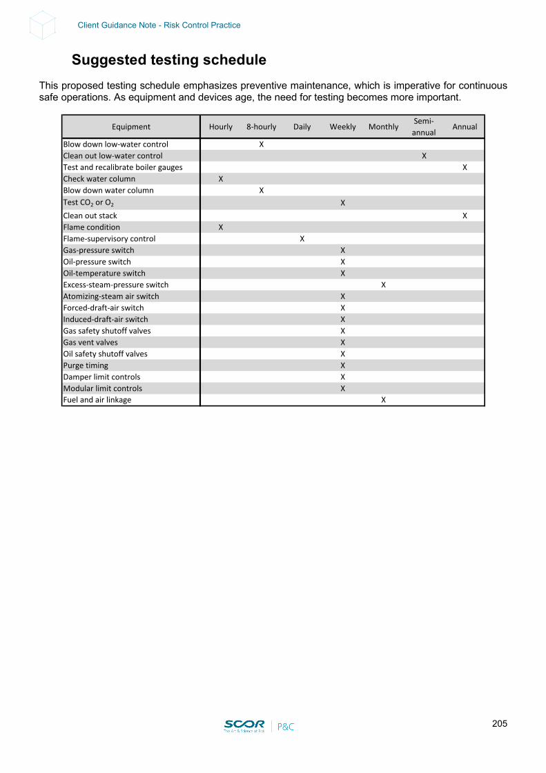
205
Client Guidance Note - Risk Control Practice
Suggested testing schedule This proposed testing schedule emphasizes preventive maintenance, which is imperative for continuous safe operations. As equipment and devices age, the need for testing becomes more important.
Equipment Hourly 8-hourly Daily Weekly MonthlySemi-
annualAnnual
Blow down low-water control XClean out low-water control XTest and recalibrate boiler gauges XCheck water column XBlow down water column XTest CO2 or O2 XClean out stack XFlame condition XFlame-supervisory control XGas-pressure switch XOil-pressure switch XOil-temperature switch XExcess-steam-pressure switch XAtomizing-steam air switch XForced-draft-air switch XInduced-draft-air switch XGas safety shutoff valves XGas vent valves XOil safety shutoff valves XPurge timing XDamper limit controls XModular limit controls XFuel and air linkage X
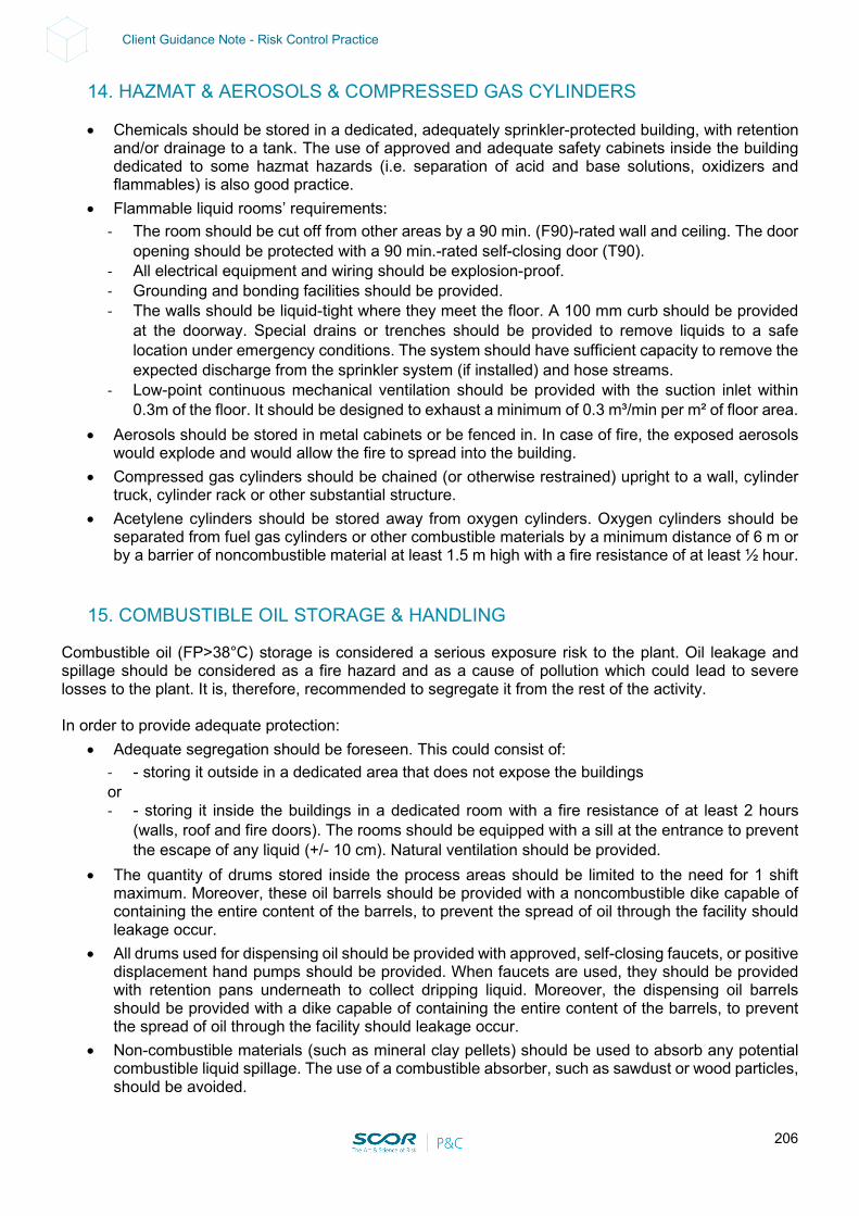
206
Client Guidance Note - Risk Control Practice
14. HAZMAT & AEROSOLS & COMPRESSED GAS CYLINDERS
• Chemicals should be stored in a dedicated, adequately sprinkler-protected building, with retention and/or drainage to a tank. The use of approved and adequate safety cabinets inside the building dedicated to some hazmat hazards (i.e. separation of acid and base solutions, oxidizers and flammables) is also good practice.
• Flammable liquid rooms’ requirements: - The room should be cut off from other areas by a 90 min. (F90)-rated wall and ceiling. The door
opening should be protected with a 90 min.-rated self-closing door (T90). - All electrical equipment and wiring should be explosion-proof. - Grounding and bonding facilities should be provided. - The walls should be liquid-tight where they meet the floor. A 100 mm curb should be provided
at the doorway. Special drains or trenches should be provided to remove liquids to a safe location under emergency conditions. The system should have sufficient capacity to remove the expected discharge from the sprinkler system (if installed) and hose streams.
- Low-point continuous mechanical ventilation should be provided with the suction inlet within 0.3m of the floor. It should be designed to exhaust a minimum of 0.3 m³/min per m² of floor area.
• Aerosols should be stored in metal cabinets or be fenced in. In case of fire, the exposed aerosols would explode and would allow the fire to spread into the building.
• Compressed gas cylinders should be chained (or otherwise restrained) upright to a wall, cylinder truck, cylinder rack or other substantial structure.
• Acetylene cylinders should be stored away from oxygen cylinders. Oxygen cylinders should be separated from fuel gas cylinders or other combustible materials by a minimum distance of 6 m or by a barrier of noncombustible material at least 1.5 m high with a fire resistance of at least ½ hour.
15. COMBUSTIBLE OIL STORAGE & HANDLING
Combustible oil (FP>38°C) storage is considered a serious exposure risk to the plant. Oil leakage and spillage should be considered as a fire hazard and as a cause of pollution which could lead to severe losses to the plant. It is, therefore, recommended to segregate it from the rest of the activity. In order to provide adequate protection:
• Adequate segregation should be foreseen. This could consist of: - - storing it outside in a dedicated area that does not expose the buildings or - - storing it inside the buildings in a dedicated room with a fire resistance of at least 2 hours
(walls, roof and fire doors). The rooms should be equipped with a sill at the entrance to prevent the escape of any liquid (+/- 10 cm). Natural ventilation should be provided.
• The quantity of drums stored inside the process areas should be limited to the need for 1 shift maximum. Moreover, these oil barrels should be provided with a noncombustible dike capable of containing the entire content of the barrels, to prevent the spread of oil through the facility should leakage occur.
• All drums used for dispensing oil should be provided with approved, self-closing faucets, or positive displacement hand pumps should be provided. When faucets are used, they should be provided with retention pans underneath to collect dripping liquid. Moreover, the dispensing oil barrels should be provided with a dike capable of containing the entire content of the barrels, to prevent the spread of oil through the facility should leakage occur.
• Non-combustible materials (such as mineral clay pellets) should be used to absorb any potential combustible liquid spillage. The use of a combustible absorber, such as sawdust or wood particles, should be avoided.
207
Client Guidance Note - Risk Control Practice
16. OVERHEAD CRANES
Courtesy of Franck Orset (FPO) Loss Prevention Engineer: Overhead cranes should not be positioned above critical equipment (GIS, turbine…) when not in operation. Smoke detection systems, as well as portable fire extinguishers, should be provided for the electric cabinets of the main overhead cranes (turbine hall and reactor building as a minimum). Smoke detection should be provided in the battery room, machinery room, elevator shaft, elevator machine room, transformer room, transformer blower room, near main electrical disconnects and group cable trays, and in any similar areas without fixed protection. The alarm must sound in the control cab and at the base of the crane. The alarm should also be transmitted to the Main Control Room. Upon activation of the fire detection system, the procedure should include positioning the crane in a safe area (not above critical equipment such as the fuel pool or the turbine equipment), accessible for manual firefighting. Then, the electrical supply should be shut down to limit fire activation on electrical equipment. The need to provide an automatic fixed gas-protection system should be considered if, in case of fire, the access is deemed too difficult (or delayed) for manual firefighting means. In that case, an automatic gaseous fire protection system should be provided in the control room, cable room and cabinets, switchgear cabinets and other similar areas where combustibles are present. If a time-delay interlock needs to be provided on the system, set it to the minimum required for the safe evacuation of personnel. Note that situations where electrical cabinets are located inside the beam of the crane (bridge beam) are more problematic than when the electrical cabinets are located outside (in terms of fire damages). There are further disadvantages to having the electrical cabinets located inside:
• Smoke is difficult to detect by operators (it remains inside the beam). • Even with a limited amount of combustible material involved in a fire inside the beam, the heat
released can have serious adverse effects on the steel structure of the crane (a phenomenon similar to a “pizza stove” effect).
208
Client Guidance Note - Risk Control Practice
17. CONTROL ROOM
Courtesy of Franck Orset (FPO) Loss Prevention Engineer: Construction/Safe separation The Control Room should be separated from adjacent areas of the plant by floors, walls, ceilings and roof assemblies with a minimum fire resistance of 3 hours. Peripheral rooms in the control room should be equipped with a water-based fixed-fire protection system and separated from the main control room by a noncombustible construction with a minimum fire rating of 1 h. There should be no kitchen in the same fire area of the Main Control Room (if a kitchen is directly accessible from the Main Control Room, it should be fire-separated, equipped with a self-closing fire door and with a smoke or thermal fire detection system). Combustible construction materials should not be used in the Control Room. The use of decorative wood paneling and plastic grid ceilings should be avoided. Raised floors and suspended ceilings should be avoided, or the smoke detection system should be extended to these areas. When raised floors are present, access to the space under raised floors should not be restricted and tools necessary for access (such as suction cups) must be clearly marked and readily available in the computer room. Fire detection A smoke detection system should be provided in the Control Room to detect fires at their incipient stage. Air sampling-type detection systems are recommended. Smoke detection systems should be provided in the Control Room complex and the electrical cabinets and consoles (and under the raised floor or above the false ceiling, if provided and if cables are present). Cabinets containing electric and electronic equipment should have detectors installed inside. Fire protection Automatic fire protection is not necessary in a Control Room that is constantly attended (24/7). Automatic fire protection systems might be recommended for adjacent rooms such as the computer room or adjacent electrical and relay rooms. Automatic fire protection might also be recommended under raised floors or above false ceilings when large concentrations of cables are present. Ventilation Automatic fire dampers that close when the smoke detection system is operating, and fire suppression systems should be provided for ventilation system openings between the Control Room and peripheral rooms. The outside air intakes for the Control Room ventilation system should be provided with smoke detection capabilities to trigger the alarm in the Control Room and enable manual isolation of the Control Room ventilation system (to prevent smoke from entering). Venting of smoke produced by a fire in the Control Room, by means of a normal ventilation system, is acceptable if provision is made for isolating the recirculation portion of the normal ventilation system. Manually operated venting of the Control Room should be available to the operators.
209
Client Guidance Note - Risk Control Practice
Cables All cables entering the Control Room should terminate inside the Control Room. No cabling should be routed through the Control Room from one area to the other. Cable openings, through walls or floors, should be adequately sealed to avoid a fire spread from one side to the other. Breathing apparatus Breathing apparatus should be available with sufficient capacity to achieve a safe shutdown. Emergency Control Area A separate Emergency Control Area (ECA) should be available should the Control Room be unavailable. The ECA should be situated in a fire compartment separate from the Control Room. There should be a safe access route from the Control Room to the ECA. The smoke management system should ensure a habitable environment for the operators to safely transfer the Control Room to the ECA. The ECA should contain all instrumentation and control equipment needed to achieve and maintain a hot shutdown. There should be full electrical isolation and fire separation from the MCRC. Manual firefighting There should be easy access to individual cabinets to facilitate the use of portable hand-held extinguishers. Manual firefighting capabilities should be provided for fires originating within a cabinet, console or connecting cable, as well as for exposure fires involving combustible materials in the room area. A suction cup to lift false floor tiles should be provided inside the Control Room if raised floors are located within the main Control Room and/or adjacent computer control room & electrical room. Nonsmoking policy The Main Control Room should be a strictly non-smoking area. A smoking corner, even well arranged, should NOT be allowed inside the Main Control Room.
18. WAREHOUSE
Commodity Class II (i.e. large metal parts in wooden crates or on wooden pallets) in noncombustible construction warehouses (i.e. single metal sheets, mineral wool-insulated panels) should be provided with adequate and approved Automatic Fire Alarm systems (i.e. smoke detectors, laser beams) as per NFPA. All alarms, perturbations and supervisory signals should be relayed to a constantly attended location (even when manned 24/7). Adequate sprinkler protection, as per NFPA 13, should be provided for the following cases:
• Warehouses made of combustible construction material (e.g. PUR, PIR panels. Note that the use of EPS panels under the ceiling should be prohibited as there is no automatic fire protection solution)
• Spares and consumables exceeding Commodity Class II, as per NFPA (e.g. cables and PVC insulation on wooden spools, rubber hoses, open-top plastic containers, PE wrapping rolls)
210
Client Guidance Note - Risk Control Practice
19. LARGE DRIVER STORAGE
Large drivers that are stored for a relatively long time without a regular rotation of the rotor could lead to a major failure when finally installed and operated. The following points should be considered in detail:
• Procedure: a procedure should be established and strictly enforced in order to ensure the regular rotation of the rotors of large drivers that are in storage. The schedule and the rotation degree (270° every month) should be clearly indicated.
• Indicators: visible markers that show the position and date of the rotations should be provided on
the large stored drivers.
20. DUCT SPRINKLER PROTECTION
Courtesy of Franck Orset (FPO) Loss Prevention Engineer STANDARD Any portion of a piping/exhaust system with the potential for a combustible residue buildup on the inside, where the duct sectional area is greater than or equal to 480 cm2 (75 in.2) - i.e. for pipes with a 250 mm (10 in.) diameter or larger - should be provided with an automatic extinguishing system inside the duct. Sprinkler protection should also be provided in ductworks (for combustible ductworks of a sectional cross diameter of 250 mm (10 in.) or larger, and for smaller diameters whenever practical). A separate indicating control valve should be provided for the sprinklers installed in the ductworks. The sprinkler protection inside the exhaust ducts/pipes should meet the following requirements:
• The sprinkler protection should be designed over a maximum length of 30 m (100 ft), with a minimum flow of 114 L/min (30 gpm/min) per head at a minimum of 1 bar (15 psi) pressure, over the 30 m (100 ft) of duct (horizontal or vertical).
• Use 74°C (165°F)-rated sprinkler heads (or heads with a temperature rating at least 30°C (86°F) above the temperature of the environment inside the duct).
• One sprinkler should be located at the top of each vertical riser and at the midpoint of each offset. Additional sprinklers should be spaced on 7.3 m (24 ft) centers if the rise is greater than 7.3 m.
• Maximum spacing between sprinkler heads should be 3.7 m (12 ft) for horizontal ducts. The first sprinkler should be located no more than 1.7 m (6 ft) from the duct entrance.
• Sprinkler heads should be arranged in exhaust ducts containing baffles in such a way that the sprinkler distribution pattern is not obstructed.
• To prevent the collection of paint on the sprinkler heads (which would delay activation), the heads should be covered with a cellophane bag up to 0.076 mm (0.003 in.) thick, or with a thin paper bag. This covering should be replaced frequently so that heavy deposits of residue do not accumulate.
• Sprinkler piping should be installed outside the ductwork and supported independently from the ductwork system.
• Access to the piping system should be provided to enable a regular check of the sprinkler heads. Flexible sprinkler fittings allow for easier inspection. See Figure 2 below.
• Automatic drains should be provided to eliminate extinguishing water and to prevent water accumulation in the duct or flow of water back to a process subject that could be damaged by water.
• If duct width or diameter is larger than 3.7 m (12 ft), an additional line of sprinklers, with the same spacing, should be provided inside the duct. For rounded ducts, the sprinkler lines should be positioned at 2 o’clock and 10 o’clock.
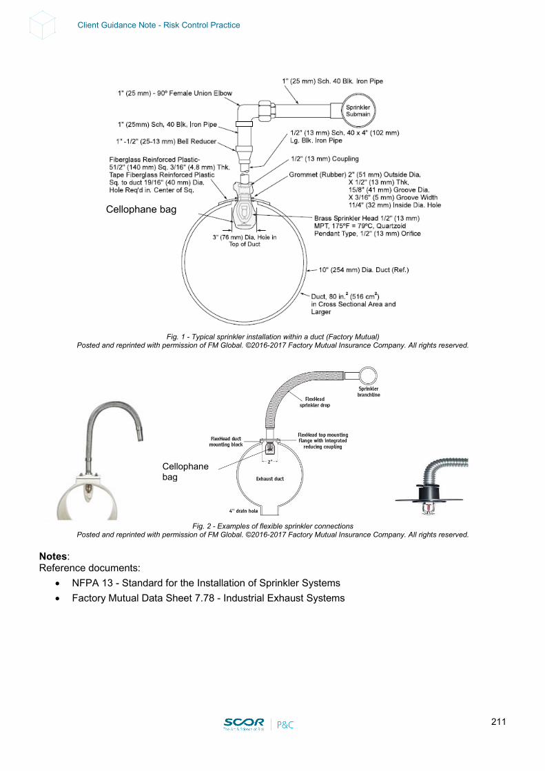
211
Client Guidance Note - Risk Control Practice
Fig. 1 - Typical sprinkler installation within a duct (Factory Mutual)
Posted and reprinted with permission of FM Global. ©2016-2017 Factory Mutual Insurance Company. All rights reserved.
Fig. 2 - Examples of flexible sprinkler connections
Posted and reprinted with permission of FM Global. ©2016-2017 Factory Mutual Insurance Company. All rights reserved. Notes: Reference documents:
• NFPA 13 - Standard for the Installation of Sprinkler Systems • Factory Mutual Data Sheet 7.78 - Industrial Exhaust Systems
Cellophane bag
Cellophane bag
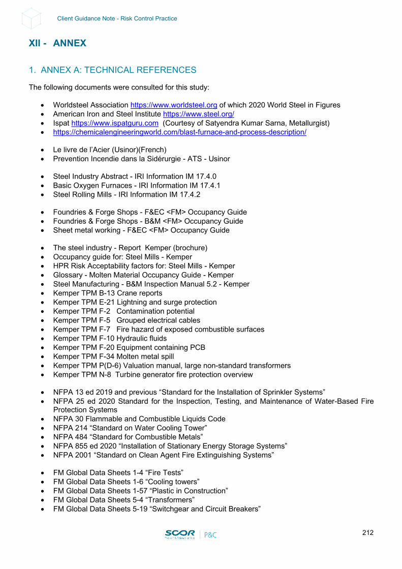
212
Client Guidance Note - Risk Control Practice
XII - ANNEX
1. ANNEX A: TECHNICAL REFERENCES
The following documents were consulted for this study:
• Worldsteel Association https://www.worldsteel.org of which 2020 World Steel in Figures • American Iron and Steel Institute https://www.steel.org/ • Ispat https://www.ispatguru.com (Courtesy of Satyendra Kumar Sarna, Metallurgist) • https://chemicalengineeringworld.com/blast-furnace-and-process-description/
• Le livre de l’Acier (Usinor)(French) • Prevention Incendie dans la Sidérurgie - ATS - Usinor
• Steel Industry Abstract - IRI Information IM 17.4.0 • Basic Oxygen Furnaces - IRI Information IM 17.4.1 • Steel Rolling Mills - IRI Information IM 17.4.2
• Foundries & Forge Shops - F&EC <FM> Occupancy Guide • Foundries & Forge Shops - B&M <FM> Occupancy Guide • Sheet metal working - F&EC <FM> Occupancy Guide
• The steel industry - Report Kemper (brochure) • Occupancy guide for: Steel Mills - Kemper • HPR Risk Acceptability factors for: Steel Mills - Kemper • Glossary - Molten Material Occupancy Guide - Kemper • Steel Manufacturing - B&M Inspection Manual 5.2 - Kemper • Kemper TPM B-13 Crane reports • Kemper TPM E-21 Lightning and surge protection • Kemper TPM F-2 Contamination potential • Kemper TPM F-5 Grouped electrical cables • Kemper TPM F-7 Fire hazard of exposed combustible surfaces • Kemper TPM F-10 Hydraulic fluids • Kemper TPM F-20 Equipment containing PCB • Kemper TPM F-34 Molten metal spill • Kemper TPM P(D-6) Valuation manual, large non-standard transformers • Kemper TPM N-8 Turbine generator fire protection overview
• NFPA 13 ed 2019 and previous “Standard for the Installation of Sprinkler Systems” • NFPA 25 ed 2020 Standard for the Inspection, Testing, and Maintenance of Water-Based Fire
Protection Systems • NFPA 30 Flammable and Combustible Liquids Code • NFPA 214 “Standard on Water Cooling Tower” • NFPA 484 “Standard for Combustible Metals” • NFPA 855 ed 2020 “Installation of Stationary Energy Storage Systems” • NFPA 2001 “Standard on Clean Agent Fire Extinguishing Systems”
• FM Global Data Sheets 1-4 “Fire Tests” • FM Global Data Sheets 1-6 “Cooling towers” • FM Global Data Sheets 1-57 “Plastic in Construction” • FM Global Data Sheets 5-4 “Transformers” • FM Global Data Sheets 5-19 “Switchgear and Circuit Breakers”
213
Client Guidance Note - Risk Control Practice
• FM Global Data Sheets 5-33 “Electrical Energy Storage System” • FM Global Data Sheets 7-11 “Conveyor Belts” • FM Global Data Sheets 7-21 “Rolling Mills” • FM Global Data Sheets 7-25 “Molten Steel Production” • FM Global Data Sheets FM Global Data Sheets 7-32 “Flammable Liquid Operations”. • FM Global Data Sheets 7-33 “High-Temperature Molten Materials”. • FM Global Data Sheets 7-52 “Oxygen” • FM Global Data Sheets 7-78 “Industrial Exhaust Systems” • FM Global Data Sheets 7-83 “Drainage and Containment for Ignitable Liquids” • FM Global Data Sheets 7-98 “Hydraulic Fluids” • FM Global Data Sheets 7-101 “Fire Protection for Steam Turbines and Electric Generators” • FM Global Data Sheets 7-104 “Metal Treatment Processes, for guidance on steel pickling
operations and steel coating” This list is not exhaustive.
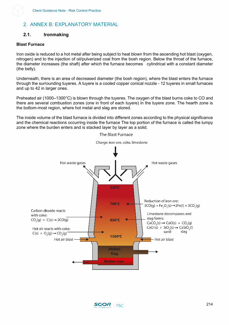
214
Client Guidance Note - Risk Control Practice
2. ANNEX B: EXPLANATORY MATERIAL
Ironmaking
Blast Furnace Iron oxide is reduced to a hot metal after being subject to heat blown from the ascending hot blast (oxygen, nitrogen) and to the injection of oil/pulverized coal from the bosh region. Below the throat of the furnace, the diameter increases (the shaft) after which the furnace becomes cylindrical with a constant diameter (the belly). Underneath, there is an area of decreased diameter (the bosh region), where the blast enters the furnace through the surrounding tuyeres. A tuyere is a cooled copper conical nozzle - 12 tuyeres in small furnaces and up to 42 in larger ones. Preheated air (1000–1300°C) is blown through the tuyeres. The oxygen of the blast burns coke to CO and there are several combustion zones (one in front of each tuyere) in the tuyere zone. The hearth zone is the bottom-most region, where hot metal and slag are stored. The inside volume of the blast furnace is divided into different zones according to the physical significance and the chemical reactions occurring inside the furnace The top portion of the furnace is called the lumpy zone where the burden enters and is stacked layer by layer as a solid.
215
Client Guidance Note - Risk Control Practice
The reduction of iron oxide takes place in the cohesive zone. Hematite (Fe2O3) is converted into magnetite (Fe3O4), and then into wüstite (FexO) by the ascending reducing gas containing carbon monoxide, producing carbon dioxide as a reaction product. The iron ore begins to soften and melt in the cohesive zone. At the lower end, the iron melts and disperses through the solid coke layers. Below the cohesive zone, the raceway starts. Here, the coke is burnt to carbon monoxide, which consists of oxygen and some inert nitrogen. At the center of the bosh, there lies a closely packed stack of unreacted coke known as the dead-man zone. The final zone is the hearth zone where slag floats on the surface of the hot metal and is separated away. In the upper part of a hearth (about half a meter below the edge of the bosh), opening spaces are provided throughout the periphery through which heated air is blown in through the tuyeres. The hot blast gasifies coke and other carbon-based materials injected through the tuyeres. The other materials are usually coal, natural gas and oil. Direct Reduction In this process, the oxygen in the blast is transformed into gaseous carbon monoxide. Coke (Ck), together with other raw materials, descends from the throat into the hearth and comes into contact with the hot blast in the oxidation zone in front of the individual tuyeres, where intensive combustion of the coke carbon takes place. Ck + O2 => CO2 As there is surplus carbon in the hearth, carbon dioxide is reduced to carbon monoxide. This carbon monoxide always escapes from the oxidation zones as a product of coke combustion. Ck + CO2 => 2CO In areas with a lack of oxygen, the coke carbon is imperfectly burnt to CO. Ck + 0.5O2 => CO The raw materials (iron ore, coke and limestone) are charged into the furnace from the top through the throat. The iron oxide (ore) Fe2O3 is mainly reduced by the ascending CO. The reduction of the iron ore takes place and it is converted into the final hot metal. Fe2O3 ⇒ Fe3O4 ⇒ FexO ⇒ Fe A layered structure of raw materials forms inside the shaft (ore, flux and coke). This structure is then melted, in the lower part of the furnace, as the burden layers gradually move downward. The burden distribution plays an important role in the smooth operation of the furnace. The charging equipment manipulates the burden distribution. Modern equipment is a better option for distributing the burden effectively. (Source: Chemical Engineering World)
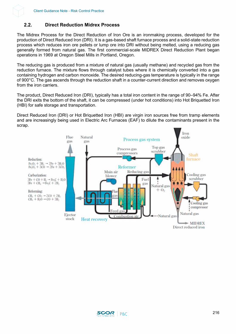
216
Client Guidance Note - Risk Control Practice
Direct Reduction Midrex Process
The Midrex Process for the Direct Reduction of Iron Ore is an ironmaking process, developed for the production of Direct Reduced Iron (DRI). It is a gas-based shaft furnace process and a solid-state reduction process which reduces iron ore pellets or lump ore into DRI without being melted, using a reducing gas generally formed from natural gas. The first commercial-scale MIDREX Direct Reduction Plant began operations in 1969 at Oregon Steel Mills in Portland, Oregon. The reducing gas is produced from a mixture of natural gas (usually methane) and recycled gas from the reduction furnace. The mixture flows through catalyst tubes where it is chemically converted into a gas containing hydrogen and carbon monoxide. The desired reducing-gas temperature is typically in the range of 900°C. The gas ascends through the reduction shaft in a counter-current direction and removes oxygen from the iron carriers. The product, Direct Reduced Iron (DRI), typically has a total iron content in the range of 90–94% Fe. After the DRI exits the bottom of the shaft, it can be compressed (under hot conditions) into Hot Briquetted Iron (HBI) for safe storage and transportation. Direct Reduced Iron (DRI) or Hot Briquetted Iron (HBI) are virgin iron sources free from tramp elements and are increasingly being used in Electric Arc Furnaces (EAF) to dilute the contaminants present in the scrap.

217
Client Guidance Note - Risk Control Practice
Direct Reduction HyL Process
The HYL process is designed for the conversion of iron ore (pellets/lump ore) into metallic iron, by using reducing gases in a solid-gas moving bed reactor. Oxygen (O2) is removed from the iron ore by chemical reactions based on hydrogen (H2) and carbon monoxide (CO) for the production of highly-metallized Direct Reduced Iron (DRI)/Hot Briquetted Iron (HBI). The first industrial scale direct reduction plant was put into operation in 1957 at the Hylsa Monterrey 1-M plant in Mexico.
The main characteristics of the HYL process consist in using H2-rich reducing gases with an H2/CO ratio of more than 4, and a high-reduction temperature of usually more than 930°C. The equipment includes a Process Gas Heater (PGH). This process is flexible and produces three different product forms, depending on the specific requirements of each user. The three forms of DRI are: cold DRI, HBI or hot DRI (‘Hytemp’ iron). Cold DRI discharge is normally used in an adjacent steel melt shop close to the Direct Reduction plant. It can also be shipped and exported, provided certain procedures are followed and precautions are taken to avoid reoxidation. HBI is the DRI which is discharged in a hot, briquetted form, and then cooled. It is a merchant product usually destined for overseas export. Hytemp iron is the hot discharged DRI, pneumatically transported from the DR plant to an adjacent steel melt shop where it is directly fed into the electric arc furnace (EAF). A key factor of the HYL process is its pressurized operation. The use of O2 depends on the hydrocarbon content. DRI metallization and C are controlled independently. The reforming of natural gas requires a certain level of oxidants (H2O and CO2) which have to be carefully controlled, a high temperature (the result of partial combustion), and an active catalyst, which is provided by the metallic iron units resulting from the iron ore that has already been reduced. The oxidants produced by the reduction reactions are partially consumed by the reforming reactions. In this manner, once in contact with the solid material inside the shaft furnace, further methane reforming takes place in-situ due to the catalytic effect of metallic iron (Fe). Under these conditions, the methane is always in contact with the new catalyst (metallic Fe in DRI) since DRI is continuously being removed from the shaft furnace.
218
Client Guidance Note - Risk Control Practice
Therefore, in-situ reducing gas generation and reduction take place in a highly efficient environment. This reforming process is highly endothermic and it continues as long as the temperature remains sufficiently high. Once the temperature drops below a certain level, in-situ reforming no longer occurs and only iron ore reduction continues. Most of the DRI carburization takes place by cracking methane (CH4) to produce iron carbide (Fe3C). For cold DRI, a cooling gas is fed into the lower conical part of the shaft furnace at around 40°C, flowing upwards, counter-current to the DRI moving bed. The gas distribution is uniform and there is a high degree of direct contact between the gas and the solid, without any physical restrictions to the flow of solids or gases inside the furnace. Hot DRI is discharged by means of the rotary valve of the shaft furnace, through the diverter valve, which delivers material either to the Hytemp system or to an alternative external cooler (for cold DRI production). Pneumatic transport is normally carried out at the same rate as the shaft furnace production rate. For the production of HBI, hot DRI is continuously discharged, at a temperature greater than 700°C, to the hot briquetting machines arranged below. The HBI is cooled in vibrating cooling conveyors using cooling water before being discharged to the HBI transport conveyor. The Hytemp iron uses a pneumatic system for the transport of hot DRI to the Electric Arc Furnace (EAF). It uses nitrogen (N2) or process gases as the transport gas.
Combustible Metal
This section applies to operations (so called secondary processing) where metal or metal alloys are subjected to processing or finishing operations that produce combustible powder or dust. “Burning metal” Under proper conditions, most metals in their elemental form will react with oxygen to form an oxide. These reactions are exothermic. Any metal in a fine enough form can be combustible and/or explosive. However, some metal fires (like fires involving zirconium, titanium, magnesium, aluminum and hafnium) can reach very high temperatures but generate very little smoke. Combustion of such metal dust in the air is stimulated by the presence of limited amounts (5 to 10 %) of water. Very finely divided metal powder that is completely immersed in water is difficult to ignite. But once ignited, it burns more violently than in air. Courtesy of Franck Orset -FPO) Loss Prevention Engineer Secondary processing operations The following gives definitions for combustible metal from secondary processing operations: Casting: Object or finished shape obtained by solidification of a substance in a mold. Chips: Particles produced from a cutting or machining operation that are not oxidized and that are not diluted by noncombustible materials. Metal dust: Particulate metal resulting from a solid-state secondary processing operation. Fines: The portion of a powder composed of particles that are smaller than 45 microns (µm).
219
Client Guidance Note - Risk Control Practice
Superfines. Particles in size smaller than 10 microns. Ultrafines. Particles in size generally less than 1 micron. Flake: A flat or scale-like particulate material that is relatively thin with a large aspect ratio. Paste: Mixture consisting of a liquid and suspended particles or flakes. Powder: Particles of matter intentionally manufactured into a specific size and shape. Typically, powders are less than 1 millimeter in size and can be elemental or alloy in composition and regular, irregular, spherical, spongy, granular, dendritic or nodular in shape. Ribbon: Manufactured product or continuous chip resulting from a secondary processing operation (e.g. boring, grinding, milling, turning…) of a ductile material. Scraps: Discarded metal parts suitable for reprocessing. Sponge: Metal after it has been obtained from the ore but before it is melted. Swarf: Particles produced from a cutting, machining or grinding operation that causes partial oxidation of the parent material or dilution by other inert materials. Sweepings: Waste materials containing metal which are mixed with organic waste that cannot be melted down, i.e. materials that are impure. Sweepings include:
• Waste from polishing • Floor sweepings • Sludge • Filter dust
220
Client Guidance Note - Risk Control Practice
3. ANNEX C: GLOSSARY OF TERMS
Courtesy of the American Iron and Steel Institute: • Agglomerating Processes: Fine particles of limestone (flux) and iron ore are difficult to handle
and transport because of dusting and decomposition. The powdery material is therefore usually processed into larger pieces. The raw material’s properties determine the technique that is used by mills.
- Sinter: Baked particles that stick together in roughly one-inch chunks. Normally used for iron ore dust collected from the blast furnaces.
- Pellets: Iron ore or limestone particles are rolled into little balls in a balling drum and hardened by heat.
- Briquettes: Small lumps are formed by pressing material together. Hot Briquetted Iron (HBI) is a concentrated iron ore substitute for scrap, for use in electric furnaces.
• Alloying Element: Any metallic element added during the melting of steel or aluminum for the purpose of increasing corrosion resistance, hardness, or strength. The metals most commonly used as alloying elements in stainless steel include chromium, nickel and molybdenum.
- Alloy Steel: An iron-based mixture is considered to be an alloy steel when manganese is greater than 1.65%, silicon over 0.5%, copper above 0.6%, or other minimum quantities of alloying elements such as chromium, nickel, molybdenum or tungsten are present. An enormous variety of distinct properties can be created for the steel by substituting these elements in the recipe.
- Aluminum Killed Steel (Special Killed) 1: Steel deoxidized with aluminum in order to reduce the oxygen content to a minimum so that no reaction occurs between carbon and oxygen during solidification.
• Annealing: A heat or thermal treatment process by which a previously cold-rolled steel coil is made more suitable for forming and bending. The steel sheet is heated to a designated temperature for a sufficient amount of time and then cooled.
• Arc furnace transformer (AFT): A specialized transformer used in the steel industry for making both carbon and specialty steel. The transformer produces electric arcs between electrodes that provide the energy to melt the steel.
• Argon Oxygen Decarbonization (AOD): This process is used almost exclusively to produce stainless steel and other high-grade alloys. The AOD lowers the carbon levels within the molten metal batch by regular injections or oxygen mixed with argon. The mixing of argon with the oxygen reduces the chances of oxidizing the alloys.
• Austenitic: The largest category of stainless steel, accounting for about 70% of all production. The austenitic class offers the most resistance to corrosion in the stainless group, owing to its substantial nickel content and higher levels of chromium. Austenitic stainless steels are hardened and strengthened through cold working (changing the structure and shape of steel by applying stress at low temperature) instead of by heat treatment. Ductility (ability to change shape without fracture) is exceptional for the austenitic stainless steels. Excellent weldability and superior performance in very low-temperature services are additional features of this class. Applications include cooking utensils, food processing equipment, exterior architecture, equipment for the chemical industry, truck trailers and kitchen sinks. The two most common grades are Type 304 (the most widely specified stainless steel, providing corrosion resistance in numerous standard services) and Type 316 (similar to 304, with molybdenum added, to increase opposition to various forms of deterioration).
• Auto Stamping Plant: A facility that presses a steel blank into the desired form of a car door or hood, for example, with a powerful die (pattern). The steel used must be ductile (malleable) enough to bend into shape without breaking.
221
Client Guidance Note - Risk Control Practice
• Baghouse: An air pollutant control device used to trap particles by filtering gas streams through large cloth or fiberglass bags.
• Bake Hardenable Steel: A cold-rolled, low-carbon sheet steel used for automotive body panel applications. Because of special processing, the steel has good stamping and strength characteristics, and, after paint is baked on, improved dent resistance.
• Basic Oxygen Furnace (BOF): This process is used to transform iron into steel and is the most efficient way of producing low and medium carbon and alloy steels. A pear-shaped furnace, lined with refractory bricks, that refines molten iron from the blast furnace and scrap into steel. Oxygen is blown onto the surface of the molten iron to help assist in the process.
• Bars: Long steel products that are rolled from billets. Merchant bar and reinforcing bar (rebar) are two common categories of bars, where merchants include rounds, flats, angles, squares, and channels that are used by manufacturers to manufacture a wide variety of products such as furniture, stair railings and farm equipment. Rebar is used to strengthen concrete in highways, bridges, and buildings.
• Bar Turning: Involves machining a metal bar into a smaller diameter.
• Bending: The forming of metals into various angles.
• Billet: A semi-finished steel form that is used for “long” products: bars, channels, or other structural shapes. A billet is different from a slab because of its outer dimensions; billets are normally two to seven inches square, while slabs are 30 inches to 80 inches wide and two inches to ten inches thick. Both shapes are generally continually cast, but they may differ greatly in their chemistry.
• Black Plate: Cold-reduced sheet steel, 12 inches to 32 inches wide, that serves as the substrate (raw material) to be coated in the tin mill.
• Blast Furnace: A blast furnace is used to make iron from raw materials such as iron ore, lime, and coke. A towering cylinder lined with heat-resistant (refractory) bricks, is used by integrated steel mills to smelt iron from iron ore. Its name comes from the “blast” of hot air and gases forced up through the iron ore, coke, and limestone that loads the furnace.
• Blanking: An early step in preparing flat-rolled steel for use by an end user. A blank is a section of sheet that has the same outer dimensions as a specified part (such as a car door or hood), but that has not yet been stamped. Steel processors may offer blanking for their customers to reduce their labor and transportation costs; excess steel can be trimmed prior to shipment.
• Bloom: A semi-finished steel form, with a rectangular cross-section that is more than 8”. This large cast steel shape is broken down in the mill to produce the familiar I-beams, H-beams, and sheet piling. Blooms are also part of the high-quality bar manufacturing process. Reduction of a bloom to a much smaller cross-section can improve the quality of the metal.
• Breakout: The uncontrolled release of molten material from the inside of a furnace, ladle, mold, or other vessel; an accident caused by the failure of the walls of the hearth of the blast furnace, resulting in liquid iron or slag (or both) flowing uncontrolled out of the blast furnace.
• Brownfield Expansion: A “brownfield” is in contrast to a “greenfield” (or a brand-new facility). A brownfield expansion entails adding on to an already existing facility.
• Burr: The very subtle ridge on the edge of strip steel left by cutting operations such as slitting, trimming, shearing, or blanking. For example, as a steel processor parallelly trims the sides of the sheet steel or cuts a sheet of steel into strips, its edges will bend with the direction of the cut (see Edge Rolling).
• Busheling: Scrap consisting of sheet clips and stampings from metal production. This term arose from the practice of collecting the material in bushel baskets during World War II.
• Butt-Weld Pipe: The standard pipe used in plumbing. Heated skelp is continuously passed through welding rolls, which form the tube and squeeze the hot edges together to make a solid weld.
222
Client Guidance Note - Risk Control Practice
• Carbon Steel: Steel that has properties that are mostly made up of carbon and which relies on the carbon content for structure. Most of the steel produced in the world is carbon steel.
• Casing: Casing is the structural retainer for the walls of oil and gas wells. Casing is used to prevent contamination of both the surrounding water table and the well itself. Casing lasts the entire life of a well and is not usually removed when a well is closed.
• Casting: The process of pouring molten metal into a mold so that the cooled, solid metal retains the shape of the mold.
• Castrip: Process that directly casts molten steel into a final shape and thickness without additional hot or cold rolling. This reduces capital investment, energy and environmental costs.
• Cladding: Method of applying a stainless-steel coating to carbon steel or lower alloy steel (i.e., steel with an alloying element content below 5%) to increase corrosion resistance at a lower initial cost than if stainless steel were exclusively used. This is done by 1) welding stainless steel onto carbon steel; 2) pouring melted stainless steel around a solid carbon steel slab in a mold; or 3) placing a slab of carbon steel between two plates of stainless steel and bonding them by rolling at high temperature on a plate mill.
• Coating: The process of covering steel with another material (tin, chrome and zinc), primarily for corrosion resistance.
• Coil: Metal sheet that has been wound. The metal, once rolled flat, is more than one-quarter mile long; coils are the most efficient way to store and transport sheet steel.
• Coke: The basic fuel consumed in blast furnaces in the smelting of iron. Coke is a processed form of coal. About 1,000 pounds of coke are needed to process a ton of pig iron, an amount which represents more than 50% of an integrated steel mill’s total energy use. Metallurgical coal burns sporadically and reduces to a sticky mass. Processed coke, however, burns steadily inside and out, and is not crushed by the weight of the iron ore in the blast furnace. Inside the narrow confines of the coke oven, coal is heated without oxygen for 18 hours to drive off gases and impurities.
• Coke Oven Battery: A set of ovens that process coal into coke. Coke ovens are constructed in batteries of ten to 100 ovens that are 20 feet tall, 40 feet long and less than two feet wide. Coke batteries, because of the exhaust fumes emitted when coke is pushed from the ovens, are often the dirtiest area of a steel mill complex.
• Cold Reduction: Finishing mills roll cold coils of pickled hot-rolled sheet to make the steel thinner, smoother and stronger by applying pressure, rather than heat. Stands of rolls in a cold-reduction mill are set very close together and press a sheet of steel from one-quarter inch thick into less than an eighth of an inch, while more than doubling its length.
• Cold-Rolled Strip (Sheet): Sheet steel that has been pickled and run through a cold-reduction mill. Strip has a final product width of approximately 12 inches, while sheet may be more than 80 inches wide. Cold-rolled sheet is considerably thinner and stronger than hot-rolled sheet, so it will sell for a premium (see Sheet Steel).
• Cold Working (Rolling): Changes in the structure and shape of steel achieved through rolling, hammering, or stretching the steel at a low temperature (often room temperature). This permanently increases the hardness and strength of the steel. The application of forces to the steel causes changes in the composition that enhance certain properties. In order for these improvements to be sustained, the temperature must be below a certain range, because the structural changes are eliminated by higher temperatures.
• Continuous Casting: A method of pouring steel directly from the furnace into a billet, bloom or slab directly from its molten form. The product only passes once through the mill.
• COREX®: This is a coal-based smelting process that yields hot metal or pig iron. The output can be used by integrated mills or EAF mills. The process gasifies non-coking coal in a smelting reactor, which also produces liquid iron. The gasified coal is fed into a shaft furnace, where it removes oxygen from iron ore lumps, pellets, or sinter; the reduced iron is then fed to the smelting reactor.
223
Client Guidance Note - Risk Control Practice
• Degassing: This process is used to remove unwanted excess gas from the molten steel mix, which increases the quality of the steel.
• Descaling: The process of removing scale from the surface of steel. Scale forms most readily when the steel is hot, through the union of oxygen with iron. Common methods are:
- (1) crack the scale using roughened rolls and remove with a forceful water spray,
- (2) throw salt or wet sand or wet burlap on the steel just prior to its passage through the rolls.
• Desulfurization: Operation that injects a chemical mixture into a ladle full of hot metal to remove sulfur prior to its being charged into the Basic Oxygen Furnace. Sulfur enters the steel from the coke in the blast furnace smelting operation, and there is little the steelmaker can do to reduce its presence. Because excess sulfur in the steel impedes its welding and forming characteristics, the mill must add this step to the steelmaking process.
• Direct Reduced Iron (DRI): Also known as “sponge iron”, this is produced by reducing the raw iron ore into pellets and is an alternative way of making iron (as opposed to using a blast furnace). This processed iron ore is iron-rich enough to be used as a scrap substitute in electric furnace steelmaking. The impurities in the crushed iron ore are driven off with the use of massive amounts of natural gas.
• Drawn-Over-Mandrel: A procedure for producing specialty tubing using a drawbench to pull tubing through a die and over a mandrel, giving excellent control over the inside diameter and wall thickness. Advantages of this technique are its inside and outside surface quality and gauge tolerance. Major markets include automotive applications and hydraulic cylinders.
• Ductility: Ability of steel to undergo permanent changes in shape without fracture at room temperature.
• Duplex: A category of stainless steel with high amounts of chromium and moderate nickel content. The duplex class is so named because it is a mixture of austenitic (chromium-nickel stainless class) and ferritic (plain chromium stainless category) structures. This combination was originated to offer more strength than either of those stainless steels. Duplex stainless steels provide high resistance to stress corrosion cracking (formation of cracks caused by a combination of corrosion and stress) and are suitable for heat exchangers, desalination plants and marine applications.
• Edge Rolling (Edge Conditioning): Rolling a strip of steel to smooth the edges. By removing the burr of the coil, it is safer for customers to manipulate. The edging mill (or edger) shapes the sides of the slab or rolled product often using two vertical rolls. The edger rolls and sizes the side face of the slab and breaks off loose scale from the edges.
• Electric Arc Furnace (EAF): Invented in France in 1907, these furnaces are a crucial part of iron and steel recycling operations. They are featured in "minimills" that recycle iron scrap for reuse; a steel-making furnace where scrap generally amounts to 100% of the charge. Heat is supplied from electricity that arcs between the graphite electrodes and the metal bath. Furnaces may either be an alternating current (AC) or direct current (DC). DC units consume less energy and fewer electrodes, but they are more expensive.
• Electrolytic Galvanized: Cold Rolled or Black Plate to which a coating of zinc is applied by electrodeposition; used for applications in which corrosion resistance and paintability is a primary concern.
• Electrolytic Tin Coated Sheets (ETCS): Cold-rolled sheets coated with tin by electrodeposition through an acid or alkaline process.
• Electrolytic Tin Plate (ETP): Light-gauge, low-carbon, cold-reduced steel on which tin has been electrodeposited; black plate coated with a tin (Sn) electron deposit.
• Electropolishing: The process used on stainless steel tubing and fittings to simultaneously smooth, brighten, clean and passivate the interior surfaces of these components. Electropolishing is an electrochemical removal process that selectively removes a thin layer of metal, including
224
Client Guidance Note - Risk Control Practice
surface flaws and imbedded impurities. Electropolishing is a required surface treatment process for all ultra-high purity components used in the gas distribution systems of semiconductor manufacturers worldwide and many sterile water distribution systems in pharmaceutical and biotechnology companies.
• Exotic Alloys: Zirconium, niobium, hafnium and tantalum products.
• Extrusion: The process of shaping material by forcing it to flow through a shaped opening in a die.
• Fastmet: A process to directly reduce iron ore to metallic iron pellets that can be fed into an electric arc furnace with an equal amount of scrap. This process is designed to bypass the coke oven-blast furnace route to produce hot metal from iron ore. It is also one of several methods that minimills might use to reduce their dependence on high-quality scrap inputs (see Direct Reduced Iron and Hot Briquetted Iron).
• Feedstock: Any raw material; substrate.
• Ferritic: The second-largest class of stainless steel, constituting approximately 25% of stainless production. Ferritic stainless steels are plain chromium steels with no significant nickel content; the lack of nickel results in lower corrosion resistance than the austenitics (chromium-nickel stainless steels). Ferritics are best suited for general and high-temperature corrosion applications rather than services requiring high strength. They are used in automotive trim and exhaust systems, interior architectural trim and hot water tanks. Two of the most common grades are Type 430 (general-purpose grade for many applications, including decorative ones) and Type 409 (low-cost grade well suited to withstanding high temperatures).
• Ferroalloy: A metal product commonly used as a raw material feed in steelmaking, to aid various stages of the steelmaking process such as deoxidation and desulfurization while increasing strength. Examples: ferrochrome, ferromanganese and ferrosilicon.
• Ferrochrome: An alloy of iron and chromium with up to 72% chromium. Ferrochrome is commonly used as a raw material in the making of stainless steel.
• Ferrous: Metals that consist primarily of iron.
• Finmet: A process that reduces iron ore fines with gas in a descending series of fluidized bed reactors. The reduced iron is hot briquetted.
• Finish: The surface appearance of steel after final treatment.
• Finishing Facilities (Mill): The portion of the steelmaking complex that processes semi-finished steel (slabs or billets) into forms that can be used by others. Finishing operations can include rolling mills, pickle lines, tandem mills, annealing facilities and temper mills. The original rough shape is turned into a finished hot-rolled product. This product can either leave the plant at this stage or continue on to be further reduced using cold-rolling processes. Many different finishing operations can be performed on the product prior to delivery to the end users. Finishing operations may include heat treatments, size changing operations such as slitting and cutting, metallurgical treatment such as tension levelling and stretching, and surface finishing, including various types of coatings. All these finishing operations can be performed on continuous equipment.
- Flat products may be cut to desired dimensions. Coiled strip width may be adjusted to requirements with slitting shears. Stretchers are used to homogenize stress and align fibers of flat products (see Data Sheet 13-8). Similarly, coiled products may be tension-levelled by uncoiling and recoiling under tension (to improve the flatness of the strip).
- Surface finishing includes washing and degreasing operations, varnishing, painting, lacquering operations, oil coating (prior to rework on punching or stamping presses) and anodizing.
- Surface finishing also includes the use of specialized rolling mills for a bright finish or special embossed profiles.
225
Client Guidance Note - Risk Control Practice
- Several layers of different alloys, metals, or combinations of metals and non-metallic materials may be laminated together on a rolling mill to manufacture a layered composite material. An example would be an inner material of high strength, but low resistance to corrosion, protected by two outer layers of lower strength but higher resistance to corrosion.
• Finishing Stand: The last stand in a rolling mill, which determines the surface finish and final gauge.
• Flat-Rolled Steel: Category of steel that includes sheet, strip and tin plate, amongst others; produced by passing an ingot/slab through pairs of rolls.
• Flux: An iron cleaning agent. Limestone and lime react with impurities within the metallic pool to form a slag that floats to the top of the relatively heavier (and now more pure) liquid iron.
• Forging: A metal part worked to a predetermined shape by one or more processes such as hammering, pressing, or rolling.
• Full Hard Cold-Rolled: Hot-rolled pickled steel that is cold reduced to a specified thickness and subject to no further processing (not annealed or temper rolled). The product is very stiff; it is not intended for flat work where deformation is very minimal.
• Full Hard Tempe: Full Hard Cold-Rolled steel produced to a Rockwell hardness of 84 and higher on the B scale.
• Forming: Bending and forming plate or sheet products into customer-specified shapes and sizes with press brakes.
• Galfan: A galvanized product coated with 95% free zinc, 5% aluminum and traces of misch metal in the coating; provides extra corrosion protection with a lighter coating weight; has improved formability over regular free zinc coatings (hot-dipped galvanized regular products).
• Galvaneal Coating: Coatings on hot-dipped galvanized steels processed to convert the coating completely to zinc-iron alloys; dull gray in appearance, have no spangle, and after proper preparation, are well suited for painting.
• Galvanized Coatings: Free zinc coatings applied to a hot-rolled or cold-rolled steel to produce galvanized steel. The coating can be applied by the hot-dip or electrodeposition process.
• Galvanized Steel: Steel coated with a thin layer of zinc to provide corrosion resistance in underbody auto parts, garbage cans, storage tanks, or fencing wire. Sheet steel must normally be cold-rolled prior to the galvanizing stage.
- Hot-Dipped: Steel is run through a molten zinc coating bath, followed by an air stream “wipe” that controls the thickness of the zinc finish.
- Electrogalvanized: Zinc plating process whereby the molecules on the positively-charged zinc anode attach to the negatively-charged sheet steel. The thickness of the zinc coating is readily controlled. By increasing the electric charge or slowing the speed of the steel through the plating area, the coating will thicken.
- Differences: Electrogalvanizing equipment is more expensive to build and to operate than hot-dipped, but it gives the steelmaker more precise control over the weight of the zinc coating. The automotive manufacturers, because they need the superior welding, forming and painting ability of electrogalvanized steel, purchase 90% of all tonnage produced.
• Galvalume®: Steel sheet with a unique coating of 55% aluminum and 45% zinc that resists corrosion. The coating is applied in a continuous hot-dipped process, which improves the steel’s weather resistance. Galvalume® is a trademark of BHP Steel, and the product is popular in the metal building market.
226
Client Guidance Note - Risk Control Practice
• Galvannealed: An extra tight coat of galvanizing metal (zinc) applied to a soft steel sheet, after which the sheet is passed through an oven at about 1200°F. The resulting coat is dull gray without spangle, particularly suited to subsequent painting.
• Gauge: The thickness of sheet steel. Better-quality steel has a consistent gauge to prevent weak spots or deformation.
• Hafnium: An exotic alloy usually obtained as a by-product of zirconium production with outstanding corrosion resistance and good mechanical properties. It is added to specialty alloys for use in jet engine parts and as control rod material in nuclear reactors.
• Hardening: Process that increases the hardness of steel, i.e., the degree to which steel will resist cutting, abrasion, penetration, bending and stretching. The increased endurance provided by hardening makes steel suitable for additional applications. Hardening can be achieved through various methods, including:
- (1) heat treatment, where the properties of steel are altered by subjecting the steel to a series of temperature changes;
- and (2) cold working, in which changes in the structure and shape of steel are achieved through rolling, hammering, or stretching the steel at a relatively low temperature.
• Hardness: Defined in terms of the method of measurement. Usually the resistance to indentation, stiffness or temper of wrought products; machinability characteristics.
• Heat Treatment: Altering the properties of steel by subjecting it to a series of temperature changes; to increase the hardness, strength, or ductility of steel so that it is suitable for additional applications. The steel is heated and then cooled as necessary to provide changes in the structural form that will impart the desired characteristics. The time spent at each temperature and the rates of cooling have a significant impact on the effect of the treatment.
• Heavy Structural Shapes: A general term given to rolled, flanged sections that have at least one dimension of their cross sections measuring three inches or more. The category includes beams, channels, tees and zees if the depth is three inches or more, and angles if the length of the leg is three inches or more.
• Heat treatment: During cold rolling, the metal loses ductility, and annealing is often necessary between successive rolling operations. Also, depending on the end use and required characteristics, it may be necessary to subject the metal to various heat treatments, including solution heat treatment followed by water quenching, precipitation treatment and annealing. Heat treatment may be done in batch-type or continuous-type furnaces, under normal or special atmospheres.
• High-Carbon Steel: Steel with more than 0.3% carbon. The more carbon that is dissolved in the iron, the less formable and the tougher the steel becomes. High-carbon steel’s hardness makes it suitable for plow blades, shovels, bedsprings, cutting edges, or other high-wear applications.
• High-Strength Low Alloy (HSLA): A specific group of steel in which higher strength, and in some cases additional resistance to atmospheric corrosion or improved formability, is obtained by moderate amounts of one or more alloying elements such as columbium, vanadium or titanium, used alone or in combination.
• Hot Band (Hot-Rolled Steel): A coil of steel rolled on a hot-strip mill (hot-rolled steel). It can be sold in this form to customers or further processed into other finished products.
• Hot-Briquetted Iron (HBI): Direct reduced iron that has been processed into briquettes. Instead of using a blast furnace, the oxygen is removed from the ore using natural gas and results in a substance that is 90%–92% iron. Because DRI may spontaneously combust during transportation, HBI is preferred when the metallic material must be stored or moved.

227
Client Guidance Note - Risk Control Practice
• Hot End: The section of a steelmaking complex from the furnace up to, but not including, the hot-strip mill.
• Hot Metal: The name for the molten iron produced in a blast furnace. It continues on to the basic oxygen furnace in molten form or is cast as pig iron.
• Hot Mill: The rolling mill that reduces a hot slab into a coil of specified thickness; the processing is done at a relatively high temperature (when the steel is still “red”).
• Hot Roll: Product that is sold in its “as produced state” off the Hot Mill with no further reduction or processing steps aside from being pickled and oiled (if specified).
• Hot-Strip Mill: A rolling mill of several stands of rolls that convert slabs into hot-rolled coils. The hot-strip mill squeezes slabs, (which can range in thickness from two to ten inches, depending on the type of continuous caster), between horizontal rolls with a progressively smaller space between them (while vertical rolls govern the width) to produce a coil of flat-rolled steel about a quarter-inch in thickness and a quarter-mile in length.
• HYL I, HYL III: Processes for producing DRI and HBI developed by Hylsa. The processes reduce iron ore lumps or pellets with reformed natural gas in a vertical shaft furnace. The HYL I process uses four fixed-bed reactors; HYL III uses a single-shaft furnace.
• Hydrate: An aluminum oxide with three molecules of chemically combined water.
• Hydroforming: A forming process in which a tube is placed into a forming die. The tube is then formed to the shape of the die through the application of internal water pressure. The hydroforming process allows for severe shape deformation, making it ideal for automotive structural parts such as engine cradles, radiator supports and body rails. Various shaped and sized holes can be punched in the tube almost anywhere during the process.
• I-Beams: Structural sections on which the flanges are tapered and are typically not as long as the flanges on wide-flange beams. The flanges are thicker at the cross sections and thinner at the toes of the flanges. They are produced with depths of 3” to 24”.
• Ignitable liquid supply: Tanks/reservoirs, pumps, filtration and ancillary equipment supporting use-point(s), in this case on the mill, typically containing much more fluid hold-up capacity than the use point(s). Supplies can range in volumetric size from tens of gallons to thousands of gallons of fluid.
• Inmetco: This is a coal-based process similar to FASTMET that uses iron oxide fines and pulverized coal to produce a scrap substitute. Mill scale and flue dust, inexpensive by-products of steelmaking, can be mixed with the iron oxide fines. Inmetco, unlike other direct reduction products, is intended to be hot charged into an EAF, with attendant energy savings. The process includes three steps. First, iron oxide fines, pulverized coal and a binder are formed into pellets. Second, the pellets, two to three layers deep, are heated in a gas-fired rotary hearth furnace for 15–20 minutes to produce sponge iron. Subsequently, the iron must be desulfurized. The coal in the pellets provides much of the energy required in the second phase.
• Integrated Mills: These facilities make steel by processing iron ore and other raw materials in blast furnaces. Technically, only the hot end differentiates integrated mills from minimills. However, the differing technological approaches to molten steel imply different scale efficiencies and, therefore, separate management styles, labor relations and product markets. Nearly all domestic integrated mills specialize in flat-rolled steel or plate.
• Interstitial Free Steel: A recently developed sheet steel product with very low carbon levels that is used primarily in automotive deep-drawing applications. Interstitial Free Steel’s improved ductility (drawing ability) is made possible by vacuum degassing.
• Iron Carbide: One of several substitutes for high-quality, low-residual scrap for use in electric furnace steelmaking. Iron carbide producers use natural gas to reduce iron ore to iron carbide.
228
Client Guidance Note - Risk Control Practice
• Iron Ore: Mineral containing enough iron to be a commercially viable source of the element for use in steelmaking. Except for fragments of meteorites found on earth, iron is not a free element; instead, it is trapped in the earth’s crust in its oxidized form.
• Ladle: A “bucket” lined with refractory (heat resistant) bricks, used to transport molten steel from process to process in a steel plant.
• Ladle Metallurgy Furnace (LMF): An intermediate steel processing unit that further refines the chemistry and temperature of molten steel while it is still in the ladle. The ladle metallurgy step comes after the steel is melted and refined in the electric arc or basic oxygen furnace, but before the steel is sent to the continuous caster.
• Lance: A long metallic tube through which oxygen is blown into the BOS vessel under high pressure.
• Light-Gauge Steel: Very thin steel sheet that has been temper-rolled or passed through a cold-reduction mill. Light gauge steel is normally plated with tin or chrome for use in food containers.
• Line Pipe: Pipe used in the surface transmission of oil, natural gas and other fluids.
• Low-Carbon Steel: Steel with less than 0.005% carbon is more ductile (malleable): it is capable of being drawn out or rolled thinly for use in automotive body applications. Carbon is removed from the steel bath through vacuum degassing.
• Machining: Refers to performing multiple processes on a piece of metal to produce a customer-specified component part.
• Martensitic: Small category of stainless steel characterized by the use of heat treatment for hardening and strengthening. Martensitic stainless steels are plain chromium steels with no significant nickel content. They are utilized in equipment for the chemical and oil industries and in surgical instruments. The most popular martensitic stainless steel is Type 410 (a grade appropriate for non-severe corrosion environments requiring high strength).
• Matte Finish: A dull or gritty surface appearance achieved by rolling on rolls which have been roughened by mechanical, chemical, or electrical means to various degrees of surface texture.
• Mechanical: Those properties of a material that reveal the elastic and inelastic reaction when force is applied, or that involve the relationship between stress and strain; for example, the modulus of elasticity, tensile strength and fatigue limit. These properties have often been designated as “physical properties,” but the term “mechanical properties” is much preferred.
• Mill stand: A section of the mill housing set(s) of rolls.
• Minimills: Normally defined as steel mills that melt scrap metal to produce commodity products..
• Pellets: Fine particles of iron ore mixed with bonding clay and roasted into hard round balls for blast furnace feed.
• Pickling: Process that cleans a steel coil of its rust, dirt and oil so that further work can be done to the metal. When hot-rolled coils cool, rust forms on the unprotected metal. Often coils are stored or transported while exposed to outside air and water. Through a continuous process, the steel is uncoiled and sent through a series of hydrochloric acid baths that remove the oxides (rust). The steel sheet is then rinsed and dried.
• Pig Iron: The name for the melted iron produced in a blast furnace, containing a large quantity of carbon (above 1.5%). Named long ago when molten iron was poured through a trench in the ground to flow into shallow earthen holes, the arrangement looked like newborn pigs suckling. The central channel became known as the “sow,” and the molds were “pigs.”
• Piling (Sheet Piling): A structural steel product with edges designed to interlock; used in the construction of cofferdams or riverbank reinforcement.
229
Client Guidance Note - Risk Control Practice
• Pipe Threading: Cutting of threads around the circumference of the pipe.
• Plate: Sheet steel with a width of more than eight inches, and a thickness ranging from one quarter of an inch to more than one foot (see Sheet Steel).
• Plate mill: These mills produce plate products. Plate mills can either be universal mills or sheared-plate mills (discreet or individual plates).
• Powder Metals: Fabrication technology in which fine metallic powder is compacted under high pressure and then heated at a temperature slightly below the melting point to solidify the material. Primary users of powder metal parts are auto, electronics and aerospace industries.
• Precipitation Hardening (PH): A small group of stainless steels with high chromium and nickel content, with the most common types having characteristics close to those of martensitic (plain chromium stainless class with exceptional strength) steels. Heat treatment provides this class with its very high strength and hardness. Applications for PH stainless steels include shafts for pumps and valves as well as aircraft parts.
• Primary mill: A mill that only handles ingots.
• Pulverized Coal Injection System (PCI): A blast furnace enhancement to reduce an integrated mill’s reliance on coke (because of environmental problems caused by its production). Up to 30% of the coke charged into a blast furnace can be replaced by this talcum-like coal powder, which is injected through nozzles at the bottom of the furnace.
• Punching: The cutting of holes into carbon steel beams or plates by pressing or welding in accordance with customer specifications.
• Q-BOP: Modified Basic Oxygen Furnace in which the oxygen and other gases are blown in from the bottom, rather than from the top. While the Q-BOP stirs the metal bath more vigorously, allowing for faster processing, the design essentially produces the same steel grades as a top-blowing basic oxygen furnace. Today’s state-of-the-art furnace design combines the previous technologies: 60% of the oxygen is blown from above, with the rest blown through the bottom of the vessel.
• Quench Hardening: A process of hardening a ferrous alloy of suitable composition by heating within or above the transformation range and cooling at a rate sufficient to substantially increase the hardness. The process usually involves the formation of martensite.
• Reducing Agent: Either natural gas or coal can be used to remove the oxygen from iron ore in order to produce a scrap substitute. In gas-based processes, the iron ore is heated in a vessel as reformed natural gas passes through. In coal-based processes, iron ore is combined with gasified or ground coal and heated. The oxygen in the ore combines with carbon and hydrogen in the gas or coal, producing reduced or metallic iron.
• Refractory Brick: Heat-resistant brick. Because its melting point is well above the operating temperatures of the process, refractory brick lines most steelmaking vessels that come in contact with molten metal, like the walls of the blast furnace, sides of the ladles and inside the BOF.
• Reinforcing Bar (Rebar): A commodity-grade steel used to strengthen concrete in highway and building construction.
• Reline: The process of replacing the refractory lining of a liquid steel vessel. Once it wears out, the brick lining of a furnace must be cooled, stripped and replaced. This maintenance can be significant because a blast furnace reline may require up to three months to complete.
• Residuals: The impurities in minimill steel as the result of the mix of metals entering the process dissolved in obsolete scrap. Residuals are key concerns given the minimills’ recent entry into the flat-rolled market, where high residuals can leave sheet steel too brittle for customer use.
• Reversing Mill: The product is passed back and forth through the same mill. Reversing mills can be used to work slabs, heavy plate, or finished products; the stand of rolls used to reduce steel
230
Client Guidance Note - Risk Control Practice
sheet or plate by passing the steel back and forth between the rolls. The gap between the rolls is reduced after each pass.
• Rod: Round, thin semi-finished steel length that is rolled from a billet and coiled for further processing. Rod is commonly drawn into wire products or used to make bolts and nails. Rod trains (rolling facilities) can run as fast as 20,000 feet per minute — more than 200 miles an hour.
• Roll Force Systems: Mill stands place considerable pressure on slabs, blooms and coils to further process the material. There are two general ways of applying the force to the steel — screw and hydraulic systems.
- Hydraulic (Pancake Cylinder): This modern system uses fluid pressure to rapidly adjust the roll spacing several times per second. These minute, instantaneous adjustments allow for superior gauge tracking and higher quality products.
• Rolling Mill: Any of the mills in which metal undergoes a rolling process. These include the slabbing mill, hot-roll mills, cold-roll mills, SR mills and DR mills; any operating unit that reduces gauge by application of loads through revolving cylindrical rolls. Operations can be hot or cold. The elevated-temperature rolling mill is a Hot Mill and it is capable of reducing the gauge of a slab by 92%-99%.
• Roughing Mill / Stand: The first operation in the hot milling process. The first rolling stand through which metal passes during hot rolling. The roughing mill (or rougher) takes the ingot or cast product and further reduces it into the “rough” shape of the product via vertical force. These mills are usually reversing mills. Once reduced by the roughing stands, the metal continues on to the finishing stands where smoother rolls with a smaller gap are used to complete the hot-rolled process.
• Sintering or frittage: The process of compacting and forming a solid mass of material by applying heat or pressure without melting it to the point of liquefaction. Most, if not all, metals can be sintered. Sintering is a thermal process (carried out at 1300°C to 1400°C) whereby iron ore fines are agglomerated in a sinter plant with the purpose of manufacturing a sintered product of a suitable chemical composition, quality (physical) and granulometry to be fed into the Blast Furnace (BF) or Electric Arc Furnace (EAF) , thus ensuring a homogenous and stable operation of the BF and EAF.
• Sawing: Cutting metal into customer specified lengths, shapes, or sizes.
• Sawing Scale: The iron oxide that forms on the surface of steel after heating.
• Scrap (Ferrous): Ferrous (iron-containing) material that is generally remelted and recast into new steel. Integrated steel mills use scrap for up to 25% of their basic oxygen furnace charge; 100% of the minimills’ raw material for their electric furnaces is generally scrap.
- Home Scrap: Waste steel that is generated from within the steel mill, through edge trimming and rejects. It is normally sent directly back to the furnace.
- Prompt (Industrial) Scrap: Excess steel that is trimmed by the auto and appliance stampers and auctioned off to scrap buyers as factory bundles. This is a high-quality scrap as the result of its low-residual content and consistent chemistry.
- Obsolete Scrap: Iron-bearing items such as old automobiles, household appliances, farm, office, and industrial equipment, ships and railroad cars, or buildings and bridges that have completed their useful life and which can be recovered from the junkyard and remelted. The residual impurity of such scrap normally relegates obsolete scrap to the minimills (see Heavy Melt).
- Scrap Substitute: Raw material that can be charged in place of scrap in Electric Arc Furnaces and Basic Oxygen Furnaces. Scrap substitutes include, among others, DRI, HBI, iron carbide and pig iron.
• Scrubber: An air pollutant device that reduces the temperature of an emission – a liquid spray is used to remove pollutants from a gas stream by absorption or chemical reaction.
231
Client Guidance Note - Risk Control Practice
• Seamless Pipe: Pipe made from a solid billet, which is heated, then rotated under extreme pressure. This rotational pressure creates an opening in the center of the billet, which is then shaped by a mandrel to form pipe.
• Secondary Steel: Steel that does not meet the original customer’s specifications because of a defect in its chemistry, gauge or surface quality.
• Semi-finished Steel: Steel shapes — for example, blooms, billets, or slabs — that are later rolled into finished products such as beams, bars, or sheet.
• Sendzimir mill (Z-Mill): A cold-rolling mill used in the processing of specialty metals such as stainless steel, silicon steel, titanium, zirconium and beryllium. This compact mill is used for rolling cold coils of stainless steel in order to make the steel thinner, smoother and stronger. The rolls reduce the steel to the desired thickness. This allows for a better control of steel thickness at a lower capital cost and makes it possible to roll thinner sheets and strips. Stainless steel sheets or strips pass between a matching pair of small work rolls with extremely smooth surfaces, heavily reinforced by clusters of back-up rolls.
• Shape Correcting: Rolling, heating and quenching steel sheet often affects the dimensions of the steel. Levelers, temper mills and edge trimmers rework the processed steel to match customer specifications.
• Shearing: If the edges of sheets and strips are not controlled during reduction, they must be trimmed parallelly by shears. This process may be performed by either the steel mill or steel processor to match customer needs.
• Sheet Steel: Thin, flat-rolled steel. Coiled sheet steel accounts for nearly one half of all steel shipped domestically and is created in a hot strip mill by rolling a cast slab flat while maintaining the side dimensions. The malleable steel lengthens to several hundred feet as it is squeezed by the rolling mill. The most common differences between steel bars, strips, plate and sheet are merely their physical dimensions of width and gauge (thickness).
• Shredded Scrap: Fist-sized, homogenous pieces of old automobile hulks. After cars are sent through a shredder, the recyclable steel is separated by magnets. Minimills consume shredded scrap in their electric arc furnace operations.
• Silicon Electrical Steel: A type of specialty steel created by introducing silicon during the steelmaking process. Electrical steel exhibits certain magnetic properties, which make it optimum for use in transformers, power generators and electric motors.
• Sintering: A process that combines iron-bearing particles (see Agglomerating Processes).
• Skelp: Steel that is the entry material for a pipe mill. It resembles hot-rolled strip, but its properties allow for the severe forming and welding operations required for pipe production.
• Slab: The most common type of semi-finished steel. Traditional slabs are ten inches thick and 30–85 inches wide (averaging about 20 feet in length), while the output of the recently developed “thin-slab” casters is approximately two inches thick. Subsequent to casting, slabs are sent to the hot-strip mill to be rolled into coiled sheet and plate products.
• Slag: The impurities in a molten pool of iron. Flux such as limestone may be added to foster the congregation of undesired elements into a slag. Because slag is lighter than iron, it will float on top of the pool, where it can be skimmed.
• Slitting: Cutting a sheet of steel into narrower strips to match customer needs. Because steel mills have limited flexibility as to the widths of the sheet that they produce, service centers will normally cut the sheet for the customer.
• Spangle: Finish achieved when zinc is allowed to “freeze” naturally on the sheet – galvanize. Achieved by adding antimony to the hot dip bath.
232
Client Guidance Note - Risk Control Practice
• Special Bar Quality (SBQ): SBQ represents a wide variety of higher-quality carbon and alloy bars that are used in the forging, machining, and cold-drawing industries for the production of automotive parts, hand tools, electric motor shafts and valves. SBQ generally contains more alloys than merchant quality and commodity grades of steel bars and is produced with more precise dimensions and chemistry.
• Specialty Steel: Category of steel that includes electrical (see Silicon Electrical Steel), alloy (see Alloy Steel), stainless (see Stainless Steel) and tool steels (see Tool Steels).
• Specialty Tube: Refers to a wide variety of high-quality custom-made tubular products requiring critical tolerances, precise dimensional control and special metallurgical properties. Specialty tubing is used in the manufacture of automotive, construction and agricultural equipment, and in industrial applications such as hydraulic cylinders, machine parts and printing rollers.
• Stainless Steel: The term for grades of steel that contain more than 10% chromium, with or without other alloying elements. Stainless steel resists corrosion, maintains its strength at high temperatures and is easily maintained. For these reasons, it is widely used in items such as automotive and food processing products, as well as medical and health equipment. The most common grades of stainless steel are:
- Type 304: The most commonly specified austenitic (chromium-nickel stainless class) stainless steel, accounting for more than half of the stainless steel produced in the world. This grade withstands ordinary corrosion in architecture, is durable in typical food processing environments, and resists most chemicals. Type 304 is available in virtually all product forms and finishes.
- Type 316: Austenitic (chromium-nickel stainless class) stainless steel containing 2%–3% molybdenum (whereas 304 has none). The inclusion of molybdenum gives 316 greater resistance to various forms of deterioration.
- Type 409: Ferritic (plain chromium stainless category) stainless steel suitable for high temperatures. This grade has the lowest chromium content of all stainless steels and, thus, is the least expensive.
- Type 410: The most widely used martensitic (plain chromium stainless class with exceptional strength) stainless steel, featuring a high level of strength conferred by the martensitics. It is a low-cost, heat-treatable grade suitable for non-severe corrosion applications.
- Type 430: The most widely used ferritic (plain chromium stainless category) stainless steel, offering general-purpose corrosion resistance, often in decorative applications.
• Steckel mill: This is a reversing steel sheet reduction mill with heated coil boxes at each end. It uses two coils of sheet steel to feed the sheet back and forth through the mill, rather than driving it through with the rollers. If a Steckel mill is being used in hot rolling, a furnace is located at each end to help maintain the steel at the desired temperature. By reheating the steel prior to each pass, the rolls can squeeze the steel thinner per pass and impart a better surface finish. There are no furnaces present if the Steckel mill is being used for cold rolling. Steckel mills are commonly used for stainless or acid-resistant grade steel, nickel and cobalt alloys, or titanium alloys.
• Steel Intensity: The amount of steel used per unit of gross domestic product. Intensity reflects the secular demand for steel, as opposed to cyclical demand. The amount of steel used in vehicles and the popularity of alternative materials affects the intensity, or how much steel is needed per unit produced. The state of the economy, however, determines the number of units.
• Steel Strapping: Banding and packaging material that is used to close and reinforce shipping units, such as bales, boxes, cartons, coils, crates and skids.
• Strength: Properties related to the ability of steel to oppose applied forces. Forms of strength include withstanding imposed loads without a permanent change in shape or structure and resistance to stretching.
233
Client Guidance Note - Risk Control Practice
• Stress Corrosion Cracking (SCC): Slow growth of cracks in stainless steel caused by the combined effect of mechanical stress and exposure to a corrosive environment.
• Strip mill: Produces hot-rolled sheet. (Typical as from 1970s). In general, these mills consist of a reversing rougher, and multiple finishing mill stands. Upon exiting the last finishing mill stand, the sheet is wound into coils. A strip mill can also be arranged so that the metal only passes one way through the mill. If this arrangement is being used, there are normally multiple stands, arranged far apart, for the metal to pass through. It produces thin, flat steel that resembles hot-rolled sheet, but is normally narrower (up to 12 inches wide) and produced to more closely controlled thicknesses. Strips may also be cut from steel sheet by a slitting machine (see Sheet Steel).
• Structurals: Steel product group that includes I-beams, H-beams, wide-flange beams and sheet piling. These products are used in the construction of multi-story buildings, industrial buildings, bridge trusses, vertical highway supports and riverbank reinforcement.
• Substrate: Raw material used as an input for steel processing: for example, hot-rolled steel is the substrate for cold-rolling operations.
• Superalloy: An alloy, usually based on nickel, cobalt, or iron, developed for high- temperature service where relatively severe mechanical stressing is encountered and where high-surface stability is frequently required.
• Super Stainless Steel: Stainless steel alloys with significant additions of chromium, nickel, molybdenum, or copper. Super stainless steel is used in chemical processing, petroleum refining, marine, heat treating, pollution and waste control industries where there are requirements for extra corrosion protection, strength, or heat resistance.
• Taconite: Natural mineral containing less than 30% iron. It is the primary ore used in blast furnaces. Origin: domestic supplies of iron-rich ores (greater than 50% iron) were largely depleted in the 1940s, so integrated steel companies now process the lower grade taconite rendering it useful.
• Tailored Blanks: A section of sheet or strip that is cut-to-length and trimmed to match specifications for the manufacturer’s stamping design for a particular part. Because excess steel is cut away (to save shipping costs), all that remains for the stamper is to impart the three-dimensional shape with a die press (see Blanking).
• Tandem Mill: A type of cold-rolling mill, the tandem mill imparts greater strength, a uniform and smoother surface, and reduced thickness to the steel sheet. Unlike the original single-stand mills, a tandem mill rolls steel through a series of rolls (generally three to five in a row) to achieve a desired thickness and surface quality.
• Tantalum: An exotic alloy with high corrosion resistance; used for medical implants, chemical process equipment and aerospace engine components.
• Tap-to-Tap Time: The length of time between successive melting cycles or heats.
• Teeming: Pouring; ingot molds are filled (teemed) by iron-bearing ladles.
• Tee Splitting: Involves splitting metal beams. Tee straightening is the process of straightening split beams.
• Temper Mill: A type of cold-rolling mill, usually with only one or two stands, that finishes cold-rolled, annealed sheet steel by improving the finish or texture to develop the required final mechanical properties. By changing the rolls of the temper mill, steel can be shipped with a shiny, dull, or grooved surface.
• Terne: Sheet steel coated with a mixture of lead and tin. Terne is principally used in the manufacture of gasoline tanks, although it can also be found in chemical containers, oil filters and television chassis.
• Tin Mill: Continuous tin-plating facility to produce tin mill steel sheet to be used in food and beverage cans and other containers.
234
Client Guidance Note - Risk Control Practice
• Tin/Chrome Plating: A plating process whereby the molecules from the positively charged tin or chromium anode attach to the negatively charged sheet steel. The thickness of the coating is readily controlled through regulation of the voltage and speed of the sheet through the plating area.
• Tin-Free Steel: Chromium-coated steel. Because it is used in food cans just like tin plate, it is ironically classified as a tin mill product. Tin-free steel is easier to recycle because tin will contaminate scrap steel even in small concentrations.
• Tin Plate: Thin sheet steel with a very thin coating of metallic tin. Tin plate is used primarily for making cans.
• Tool Steels: Steels that are hardened for use in the manufacture of tools and dies.
• Tundish: The shallow refractory-lined basin on top of the continuous caster. It receives the liquid steel from the ladle, prior to the cast, allowing the operator to precisely regulate the flow of metal into the mold. In other words, this is the container used for pouring molten metal into a mold during the casting process.
• Tunnel Furnace: Type of furnace whereby stock to be heated is placed on cars, which are then pushed or pulled slowly through the furnace.
• Tuyeres: The nozzles used to deliver oxygen and combustion air to the interior of the blast furnace.
• Vacuum Degassing: An advanced steel refining facility that removes oxygen, hydrogen and nitrogen under low pressures (in a vacuum) to produce ultra-low-carbon steel for demanding electrical and automotive applications. Normally performed in the ladle, the removal of dissolved gases results in cleaner, higher-quality and purer steel (see Ladle Metallurgy).
• Vacuum Oxygen Decarburization (VOD): Process for further refinement of stainless steel through reduction of carbon content. The amount of carbon in stainless steel must be lower than that in carbon steel or a lower alloy steel (i.e., steel with an alloying element content below 5%). While Electric Arc Furnaces (EAF) are the conventional means of melting and refining stainless steel, VOD is an economical supplement, as the operating time is reduced and temperatures are lower than in EAF steelmaking. Additionally, using VOD for refining stainless steel increases the availability of the EAF for melting purposes. Molten, unrefined steel is transferred from the EAF into a separate vessel, where it is heated and stirred by an electrical current while oxygen enters from the top of the vessel. Substantial quantities of undesirable gases escape from the steel and are drawn off by a vacuum pump. Alloys and other additives are then mixed in to refine the molten steel further.
• Walking Beam Furnace: A hot strip mill reheat furnace where the slab is repeatedly lifted and set down further along in the furnace; this is in contrast to a batch reheat furnace or a pusher-type reheat furnace.
• Welding: Joining of two or more pieces of metal.
• Wheelabrating / Shot Blasting and Bead Blasting: Involves pressure-blasting a metal grid into carbon steel products to remove rust and scale from the surface.
• Wire: A long product that ranges from 0.030” (0.76 mm) to ¼” (6.35 mm) in diameter, in round, square, octagonal, or hexagonal cross-sections.
• Yield: The ratio of the amount of final product compared to the amount of material input in a process or group of processes.
To learn more about SCOR’s strategy, goals, commitments and markets, visit our website.
www.scor.com
Follow us on social media
Other publications in this series:
• RISK CONTROL PRACTICE: CONSTRUCTION MATERIAL Wall Assembly Classification Handbook
• RISK CONTROL PRACTICE: EXPOSURE Falling Aircraft Handbook
• RISK CONTROL PRACTICE: SPECIAL HAZARDS
• RISK CONTROL PRACTICE: OCCUPANCYRenewable Energy Handbook Aluminium Handbook
• RISK CONTROL PRACTICE: LOST ESTIMATE Maximum Possible Loss (MPL)Handbook
Embankment Dams HandbookTailings & Tailings Management Facilities Handbook