RF Based Spy Robot Project Report
28
CHAPTER -1 INTROD UCTION
Transcript of RF Based Spy Robot Project Report

CHAPTER -1
INTROD
UCTION
RF BASED SPY ROBOT
Introduction:
Robotics is a fascinating subject-
more so, if you have to fabricate a robot
yourself. The field of robotics encompasses a
number of engineering disciplines such as
electronics (including electrical), structural,
pneumatics and mechanical.
The structural part involves use of
frames, beams, linkages, axles, etc. the
mechanical parts/ accessories comprise various
types of gears (spurs, crowns, bevels, worms and
differential gear systems), pulleys and belts,
drive systems(differentials, castors, wheels and
steering) etc. The pneumatics plays a vital role
in generating specific pushing and pulling
movements such as those simulating arms or leg
movement. Pneumatic grippers are also used with
advantage in robotics because of their simplicity
and cost effectiveness. The electrical items
include DC and Stepper motors, actuators,
electrical grips, clutches and their control. The
electronic parts involves remote control, sensors
(touch sensors, light sensor, collision sensor,
etc), there interface circuitry and a
microcontroller for overall control functions.

CHAPTER -2
CIRCUIT DISCRIPTION AND WORKING
Project Overview:
What we present here
is an elementary robotic land rover that can be
control remotely using primarily the RF mode. The
RF remote control has the advantage of adequate
range (up to 200m with proper antenna) besides
being omni directional. On the other hand, an IR
remote would function over a limited range of
about 5m and the remote transmitter has to be
oriented towards the receiver module quite
precisely. However, the cost involve in using RF
modules is much higher than that of IR components
and as such, we have included the replacement
alternative of RF modules with their IR
counterparts for using the IR remote control.
The proposed land rover can move in
forward and reverse direction. You will also be
able to steer it towards left and right
directions. While being turn to left and right,
the corresponding blinking LEDs would blink to
indicate the direction of its turning. Similarly,
during reverse movement, reversing LEDs would be
lit. Front and rear bumpers are provided using
long operating lever of micro switches to switch
off the drive motors during any collision. The
decoder being used for the project has latch
outputs and as such you don’t have to keep the
buttons on remote control pressed for more than a
few milliseconds. This helps prolong the battery
life for remote.
The entire project is split up into sections
and each section is explain in the sufficient
detail to enable you not only to fabricate the

present design but also exploit this principles
for evolving your own design with added
functions.
Forward and reverse movement:
To keep your design as simple
as possible, we have coupled a 30rpm geared 6v DC
motor to the left front wheel and another
identical motor to the right front wheel. Both
these front motors are mounted side by side by
facing in opposite direction. Wheel rims (5cm
diameter) along with rubber wheels are directly
coupled to each of the motor shafts. This
arrangement does not require separate axles.
During forward (or reverse)
movement of the vehicle, the two wheel shafts, as
viewed from the motor ends, would move in
opposite directions (one clockwise and the other

anticlockwise). For reversing the direction, you
simply have to reverse the DC supply polarity of
the two motors driving the respective wheels.
Steering control:
There are different methods available for
steering a robotic vehicle. The commonly used
ones are:
1. Front wheels are used for steering,
while rear wheels are used for driving eg.
Tractors.
2. Front wheels are used for steering as
well as driving eg, in most light vehicles. In
these vehicles (such as cars), the front wheels
are coupled using a differential gear
arrangement. It comes into play only when one
wheel needs to rotate differentially with respect
to their axes.
Drive circuit for the motors:
Here is a typical circuit for
driving one of the motors, in forward or reverse
direction, coupled to, say the left hand front
wheel. Simultaneously, the right direction for
the moving the vehicle in the same direction. It
means that input terminals of the motor drive
circuit for the right hand motor have to be fed
with reverse polarity control signals compared to
those of the left hand motor drive circuit.
In the H-bridge motor
drive circuit when A1 input is made high and A2
is made low, transistor T1(NPN) is forward biased
and driven into saturation, while transistor T2
(PnP), being reverse biased, is cut off. This

extends the battery’s positive rail to terminal1
of the motor. Simultaneously with input A2 at
ground potential, transistor T3 (NPN) is cutoff,
while T4 (PnP) is forward biased and driven into
saturation. This results in ground being extended
to terminal2 of the motor. Thus the motor rotates
in one direction.
Now, if the two inputs are logically
complemented, the motor will run in the opposite
direction. When both the inputs are at the same
logic level (gnd or vcc), the motor is at rest.
Thus WI can control the movement (forward,
reverse and stop) as well as the direction of
rotation of the motor with the help of logic
level of the two control input signals to the
motor.
Motor control logic:

As per the preceding
explanation, the input logic levels required at
terminals A1 and A2 of the left hand motor drive
circuit and at input terminals B1 of B2 of the
right hand motor drive circuit are shown in fig.
Table can be rearranged as table
, which can be further simplified as table . The
equivalent hex values of the binary control
signals are indicated in table. It transpires
that if we connect(short) input terminals A2 and
B1 of the two motor control both the motors for
forward, reverse left and right movement of the
vehicle using the 3 bit binary number shown in
table
. This fact will be used while arriving at
the integrated circuit for controlling the motors
for appropriate movement of body.

Remote control:
For remote control we have used Holtek
encoder-decoder pair of HT12E and HT12D employing
these are 18 pin DIP ICs.
Operation of Holtek HT12E and HT12D:
These are CMOS ICs with working voltage ranging
from 2.4v to 12v. Encoder HT12E has eight address
and another four address/data lines. The data set
on these twelve lines is serially transmitted
when the transmit enable pin TE is taken low. The
data output appears serially on the Dout pin. The
data is transmitted four times in succession. It
consists of differing length of positive going
pulses for `1` and `0`, the pulse width for `0`
being twice the pulse width of `1`. The frequency
of these pulses may lie between 1.5 and 7 kHz
depending on the resistor value between OSC1 and
OSC2 pins. The internal oscillator frequency of

decoder HT12D is 50 times the oscillator
frequency HT12E. The values of timing resistors
connected between OSC1 and OSC2 pins of HT12E and
HT12D, for given supply voltages, can be found
out from the graphs given in the datasheet of the
respective chips. The resistor values used in the
circuits here are chosen for approximately 3 kHz
frequency for encoder HT12E and 150 kHz for
decoder HT12D at Vdd of 5V.
The HT12D receive the data from HT12E on
its Din pin serially. If the address part of the
data receive matches the level on A0 through A7
pins four times in succession, the valid
transmission (Vt) pin is taken high. The data on
pin AD8 through AD11 of the HT12E appears on pins
D8 through D11 of the HT12D. Thus, the device
acts as a receiver of four bit data (16 possible
codes) with 8 bit addressing (256 possible
channel).
The test circuit given in fig will help you
in checking the functional service ability and
synchronization of the frequency of operation.
Once the frequency of pair is aligned, on the
pressing of push switch S1 on the encoder, LED on
the decoder should glow. You can also check the
transfer of data on pin AD8 through AD11( the
data pin of the encoder can be set as a high and
low using switches S2 through S5), which is
latched on pin D8 through D11 of the decoder once
TE pin is taken low momentary using push switch
S1. This completes the testing of encoder decoder
pair of HT12E and HT12D.
RF transmitter and RF receiver:

The RF transmitter and receiver marketed by
Aplus India, Mumbai have been employed for RF
remote control. The RF transmitter TX433 is an
AM/ASK transmitter. Its feature includes:
1. 5V-12V single supply operation
2. ON/OFF key(OOK)/ASK data format
3. Up to 9.6kbps data rate
4. +9dBm output power(about 200m range)
5. SAW-based architecture
6. For Antenna, 45cm wire is adequate
The output power and current range of RF
transmitter for Vcc of 5V and 12V are tabulated
in table.
The pin configuration of the transmitter
module is shown. The RF receiver RX433 is a 433
MHz module.
Remote Transmitter
The receiver address to be transmitted can
be set with the help of 8way DIP switch DIP-SW2.
When any switch is open the pin connected to
that switch at logic 1, and when it is closed the
respective pin is at logic 0. the data pin are
pulled high via resistor R2 through R5. In this
condition, if TE pin is taken low (by depressing
stop switch), the binary data transmitted via
pins AD8 through AD11 will be
‘1111’ (decimal 15). When any other data pin
marked forward, reverse left, right alone is
pressed, a ‘0’ will be sent at that position,

while other data pin will represent logic’1’
state. The logic circuitry at the receiver
decoder end will be decoding the data
appropriately for controlling the two motor of
the land rover.
RF& IR TRANSMITTER
IR based alternative:
The RF modulator used in the
remote can be easily replaced with the IR module
circuit build around IC2 and transistor T1. The
RF/IR selection can be affected by moving the

shorting link of Con-1 connector. Similarly, the
RF receiver module in the RF receiver decoder can
be replaced with the IR receiver module shown in
fig.
For using the IR based
Encoder, the Dout signal pin 17 of HT12E is to be
connected to Din pin 5 of astable oscillator IC
CD4047 for modulating its output. The frequency
of the astable at output pin 10 is determine by
the timing component as follows
Frequency=1/4.71*(R6+VR1)*C3 Hz
This frequency is adjusted for 38 KHz with pin 5
held at logic 1. The modulated 38 kHz, after
amplification by Darlington pair of transistor T1
and T2, drives IR LED 1 LD271 (or equivalent).

RF receiver decoder:
The complete RF receiver decoder circuit
employing HT12D is shown. Assuming that identical
address is selected on the encoder and decoder,
when any of the switches on the transmitter
(marked as forward, reverse, and right, left) is
depressed, the corresponding data pin of the
demodulator will go low. The data output of HT12D
are fed to 8 bit priority encoder CD4532 via
inverter to generate appropriate logic output in
conformity with table. To control the left, right
of motor for required motion of land rover is
explained earlier. However, when stop button is
pressed on transmitter, all data pins (D8 through
D11) on the decoder will latched to the high
output state. After inversion by NAND gates N1
through N4, all the output will be low and hence

EI (pin 5) of CD4532 will go low to force all its
output to go low. As a result, both the motor
will stop running.
RF/IR RECEIVER
You may like to verify the code generated at
the output of CD4532 with the help of truth
table. The following is the exact sequence of
operation at the receiver and motor driver when a
specific push switch momentarily pressed on the
transmitter:
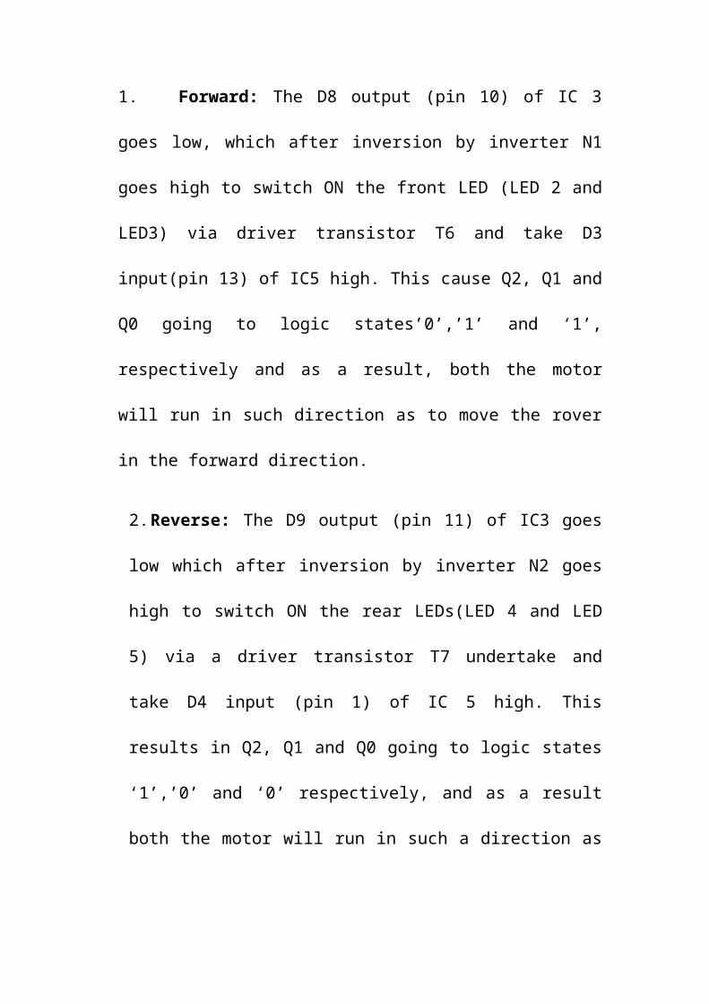
1. Forward: The D8 output (pin 10) of IC 3
goes low, which after inversion by inverter N1
goes high to switch ON the front LED (LED 2 and
LED3) via driver transistor T6 and take D3
input(pin 13) of IC5 high. This cause Q2, Q1 and
Q0 going to logic states’0’,’1’ and ‘1’,
respectively and as a result, both the motor
will run in such direction as to move the rover
in the forward direction.
2.Reverse: The D9 output (pin 11) of IC3 goes
low which after inversion by inverter N2 goes
high to switch ON the rear LEDs(LED 4 and LED
5) via a driver transistor T7 undertake and
take D4 input (pin 1) of IC 5 high. This
results in Q2, Q1 and Q0 going to logic states
‘1’,’0’ and ‘0’ respectively, and as a result
both the motor will run in such a direction as

to move the rover in the Reverse or backward
direction.
3.Left: The D10 output (pin 12) of IC 3 goes
low, which after inversion by inverter N3 goes
high to switch ON the left LED 7 after a second
inversion by inverter/ driver gate N6 and make D2
input pin 12 of IC5 high. This results in Q2, Q1
and Q0 going to logic states ‘0’,’1’ and ‘0’
respectively, and as a result only the right hand
side motor will run and left hand side motor will
be static. This cause the rover to perform a left
turn.
4. Right: The D11 output (pin 13) of IC 3 goes
low, which after inversion by inverter N3 goes
high to switch ON the right blinking LED 6 after

a second inversion by inverter/ driver gate N5
and make D1 input pin 11 of IC5 high. This
results in Q2, Q1 and Q0 going to logic states
‘0’,’0’ and ‘1’ respectively, and as a result
only the left hand side motor will run and right
hand side motor will be static. This cause the
rover to perform a right turn.
5.Stop: The D8 through D11 output of IC3 goes
high and, after inversion by N1 through N4
because blocking of diode D5 through D8. As a
result, ground is extended to EI pin 5 through
resistor R17 and all the outputs (Q2, Q1 and Q0)
of CD4532 go low to stop both the motors, all the
LEDs also stop glowing.
FUTURE APPLICATION:
1.This project concept is widely used in
ROBOTICS
2.The installation in loading vehicles may
carry the loads in industries
3.The new and widely used PLC systems are used
for AUTONOMOUS TECHNOLOGY.
4.It also used as servant robot by implementing
AUTOMATIC GUIDED VEHICLE (AGV) .
5.It also act as sample collector and observing
the behavior of animals where human beings
cannot reach.
6.By implementing NANOTECHNOLOGY in project, it
also generates power for itself and project
work 24 hours.
7.By using VOICE RECOGNITION SYSTEM we also
control the project on commanding in our
voice.
8.On implementing Microprocessor programming we
also used it as automatically controlled
robot or a vehicle.
9.The project also used in alma maters as a
supplementary carrier during examinations.
10. On implementing camera and spy devices
we also get the pictures and information
during charged suspect.
Wireless control devices are gaining enormous applications in robotics and industrial automation applications. The main objective of our project rf based spy robot is implement a radio frequency based wireless robot using a micro controller. In This RF based robot project we high lightened the importance of automated robots in defense and automatic guided vehicle systems.

Wireless robot circuit:
The robot is controlled by means of an RF module, it advantageous when compared to IR transmission in high range accessing.
The forward and back movements are controlled by themicro controller. The dc motor is interface with themicro controller, based on the instructions from themicro controller the dc motor acts.
Holtek encoder-decoder pair of HT12E and HT12D is used as the remote controlling device.
The RF transmitter TX433 and RF receiver RX433 are used for receiving commands and transmitting instructions.
For over view on circuit diagrams used in this project see this video.http://www.youtube.com/watch?v=blv2eFh5U8I&feature=youtu.be

Remote control rf based spy robot circuitry:
The circuitry of robot consists of Stepper motors, actuators, and electrical grips and Pneumatic grippers for pushing and pulling mechanisms and remote control unit, touch sensors, light sensor, collision sensor and micro controller interface for control operations the components used in this prototype model are flexible and cost effective.
Download RF Based Spy Robot Project Report
Advantages:
Used as confidential surveyors in military agencies. Hot spot wireless security. Remote area exploration, and in rescue operations.
Future enhancement:
In autonomous technology using PLC systems we can implement the automatic guided vehicle systems, these systems are converted into self powering automated devices using nano technology in their internal circuitry. By interfacing the voice recognition system wecan manipulate the robot based on voice commands; these systems can provide pictorial information using camera and wireless communication module.

REFRENCE:
Books
1. Electronic for you.
Internet
1. http:/www.google.com
2. http:/www.ask.com