Review on Fixed and Floating Offshore Structures. Part I - MDPI
52
Citation: Amaechi, C.V.; Reda, A.; Butler, H.O.; Ja’e, I.A.; An, C. Review on Fixed and Floating Offshore Structures. Part I: Types of Platforms with Some Applications. J. Mar. Sci. Eng. 2022, 10, 1074. https://doi.org/ 10.3390/jmse10081074 Academic Editors: María Clavero and María Esther Gómez-Martín Received: 18 June 2022 Accepted: 22 July 2022 Published: 5 August 2022 Publisher’s Note: MDPI stays neutral with regard to jurisdictional claims in published maps and institutional affil- iations. Copyright: © 2022 by the authors. Licensee MDPI, Basel, Switzerland. This article is an open access article distributed under the terms and conditions of the Creative Commons Attribution (CC BY) license (https:// creativecommons.org/licenses/by/ 4.0/). Journal of Marine Science and Engineering Review Review on Fixed and Floating Offshore Structures. Part I: Types of Platforms with Some Applications Chiemela Victor Amaechi 1,2, * , Ahmed Reda 3 , Harrison Obed Butler 4 , Idris Ahmed Ja’e 5,6 and Chen An 7 1 Department of Engineering, Lancaster University, Bailrigg, Lancaster LA1 4YR, UK 2 Standards Organisation of Nigeria (SON), 52 Lome Crescent, Wuse Zone 7, Abuja 900287, Nigeria 3 School of Civil and Mechanical Engineering, Curtin University, Bentley, WA 6102, Australia 4 Department of Wind Energy, Danmarks Tekniske Universitet (Technical University of Denmark), DTU, 2800 KGS Lyngby, Denmark 5 Department of Civil Engineering, Universiti Teknologi Petronas, Seri Iskandar 32610, Malaysia 6 Department of Civil Engineering, Ahmadu Bello University, Zaria 810107, Nigeria 7 College of Safety and Ocean Engineering, China University of Petroleum-Beijing, Beijing 102249, China * Correspondence: [email protected] Abstract: Diverse forms of offshore oil and gas structures are utilized for a wide range of purposes and in varying water depths. They are designed for unique environments and water depths around the world. The applications of these offshore structures require different activities for proper equipment selection, design of platform types, and drilling/production methods. This paper will provide a general overview of these operations as well as the platform classifications. In this paper, a comprehensive review is conducted on different offshore petroleum structures. This study examines the fundamentals of all types of offshore structures (fixed and floating), as well as the applications of these concepts for oil exploration and production. The study also presents various design parameters for state-of-the-art offshore platforms and achievements made in the industry. Finally, suitable types of offshore platforms for various water depths are offered for long-term operations. An extension of this study (Part II) covers sustainable design approaches and project management on these structures; this review helps designers in understanding existing offshore structures, and their uniqueness. Hence, the review also serves as a reference data source for designing new offshore platforms and related structures. Keywords: offshore structure; offshore platform; fixed platform; floating platform; oil and gas platform; production platform; drilling platform rig; coastal structure; marine structure; offshore facilities and subsea systems; review; offshore 1. Introduction With the increase in the need for more energy sources, fossil fuel has recently had huge competition as a non-renewable energy source with other renewable energy sources. How- ever, some of these newer platforms have extended technologies that stem from the existing offshore platforms used in oil and gas exploration. Currently, there are advances made in ocean engineering which include a variety of innovative offshore structure designs, ranging from fixed platforms to floating platforms [1–5]. Some of these structures include the deep- water semisubmersible platforms, jack-up rigs, floating offshore wind turbines (FOWTs), FPS (floating production systems) units, floating production storage and offloading (FPSO) units, FSO (floating storage and offloading) units, FSU (floating storage units), FPU (floating production units), FDPSO (floating drilling production storage and offloading), MODU (mobile offshore production unit) and FLNG (floating liquid natural gas vessel) [6–10]. However, there are other applications for offshore platforms, such as dynamic positioning, exploratory activities, drilling/production, navigation, (un)loading ships, fluid transport, and bridge support [11–16]. Offshore petroleum structures are utilized for a wide range of J. Mar. Sci. Eng. 2022, 10, 1074. https://doi.org/10.3390/jmse10081074 https://www.mdpi.com/journal/jmse
-
Upload
khangminh22 -
Category
Documents
-
view
0 -
download
0
Transcript of Review on Fixed and Floating Offshore Structures. Part I - MDPI

Citation: Amaechi, C.V.; Reda, A.;
Butler, H.O.; Ja’e, I.A.; An, C. Review
on Fixed and Floating Offshore
Structures. Part I: Types of Platforms
with Some Applications. J. Mar. Sci.
Eng. 2022, 10, 1074. https://doi.org/
10.3390/jmse10081074
Academic Editors: María Clavero
and María Esther Gómez-Martín
Received: 18 June 2022
Accepted: 22 July 2022
Published: 5 August 2022
Publisher’s Note: MDPI stays neutral
with regard to jurisdictional claims in
published maps and institutional affil-
iations.
Copyright: © 2022 by the authors.
Licensee MDPI, Basel, Switzerland.
This article is an open access article
distributed under the terms and
conditions of the Creative Commons
Attribution (CC BY) license (https://
creativecommons.org/licenses/by/
4.0/).
Journal of
Marine Science and Engineering
Review
Review on Fixed and Floating Offshore Structures. Part I: Typesof Platforms with Some ApplicationsChiemela Victor Amaechi 1,2,* , Ahmed Reda 3, Harrison Obed Butler 4, Idris Ahmed Ja’e 5,6 and Chen An 7
1 Department of Engineering, Lancaster University, Bailrigg, Lancaster LA1 4YR, UK2 Standards Organisation of Nigeria (SON), 52 Lome Crescent, Wuse Zone 7, Abuja 900287, Nigeria3 School of Civil and Mechanical Engineering, Curtin University, Bentley, WA 6102, Australia4 Department of Wind Energy, Danmarks Tekniske Universitet (Technical University of Denmark), DTU,
2800 KGS Lyngby, Denmark5 Department of Civil Engineering, Universiti Teknologi Petronas, Seri Iskandar 32610, Malaysia6 Department of Civil Engineering, Ahmadu Bello University, Zaria 810107, Nigeria7 College of Safety and Ocean Engineering, China University of Petroleum-Beijing, Beijing 102249, China* Correspondence: [email protected]
Abstract: Diverse forms of offshore oil and gas structures are utilized for a wide range of purposes andin varying water depths. They are designed for unique environments and water depths around theworld. The applications of these offshore structures require different activities for proper equipmentselection, design of platform types, and drilling/production methods. This paper will providea general overview of these operations as well as the platform classifications. In this paper, acomprehensive review is conducted on different offshore petroleum structures. This study examinesthe fundamentals of all types of offshore structures (fixed and floating), as well as the applications ofthese concepts for oil exploration and production. The study also presents various design parametersfor state-of-the-art offshore platforms and achievements made in the industry. Finally, suitable typesof offshore platforms for various water depths are offered for long-term operations. An extension ofthis study (Part II) covers sustainable design approaches and project management on these structures;this review helps designers in understanding existing offshore structures, and their uniqueness.Hence, the review also serves as a reference data source for designing new offshore platforms andrelated structures.
Keywords: offshore structure; offshore platform; fixed platform; floating platform; oil and gasplatform; production platform; drilling platform rig; coastal structure; marine structure; offshorefacilities and subsea systems; review; offshore
1. Introduction
With the increase in the need for more energy sources, fossil fuel has recently had hugecompetition as a non-renewable energy source with other renewable energy sources. How-ever, some of these newer platforms have extended technologies that stem from the existingoffshore platforms used in oil and gas exploration. Currently, there are advances made inocean engineering which include a variety of innovative offshore structure designs, rangingfrom fixed platforms to floating platforms [1–5]. Some of these structures include the deep-water semisubmersible platforms, jack-up rigs, floating offshore wind turbines (FOWTs),FPS (floating production systems) units, floating production storage and offloading (FPSO)units, FSO (floating storage and offloading) units, FSU (floating storage units), FPU (floatingproduction units), FDPSO (floating drilling production storage and offloading), MODU(mobile offshore production unit) and FLNG (floating liquid natural gas vessel) [6–10].However, there are other applications for offshore platforms, such as dynamic positioning,exploratory activities, drilling/production, navigation, (un)loading ships, fluid transport,and bridge support [11–16]. Offshore petroleum structures are utilized for a wide range of
J. Mar. Sci. Eng. 2022, 10, 1074. https://doi.org/10.3390/jmse10081074 https://www.mdpi.com/journal/jmse

J. Mar. Sci. Eng. 2022, 10, 1074 2 of 52
purposes and in a wide range of sea depths and environments around the world, hence theyneed supporting attachments such as drilling marine risers [17–23], composite productionrisers [24–30], marine hoses [31–40] and mooring lines [41–49]. Figure 1 shows differentfixed and floating offshore platforms operating in varying water depths (see details inthe caption).
Figure 1. Different types of deep-water offshore production facilities, showing (1,2) conventional fixedplatforms{150–412 m}; (3) compliant tower {457–914 m}; (4,5) tension leg platform (TLP) {457–2134 m};(5) mini tension leg platform (TLP); (6) Truss SPAR {610–3048 m}; (7,8) semisubmersibles {457–1920 m};(9) floating production, storage and offloading (FPSO) unit {1345–1500 m}; and (10) jacket platform{150–412 m}; and (11) subsea completion and tieback to a host facility, and (12) subsea manifold.(Adapted from public domain source, with permission obtained to re-use image; Courtesy: NationalOceanic and Atmospheric Administration, NOAA).
Offshore platforms could be used as artificial reefs for many years, as they have alsobeen used in a variety of aquatic environments. As a result, their design and upkeep areextremely difficult. Hence, it is pertinent that the design and maintenance of offshorestructures are well considered, to prevent early decommissioning, high risks of corrosion,oil spillage, and other irreversible environmental damages. The applications of theseoffshore structures require different activities for proper equipment selection [50–57], de-sign of platform types [58–64], engineering management of well bores [65–73] and otherdrilling/production methods [74–80]. Offshore oil production is one of the most visible ofthese applications, and it provides a significant task to the product designer or offshoreengineer [81–83]. The design considerations include environmental loadings [84–88], hy-drodynamics [89–96], hydroelasticity [97], corrosion [98], failure analysis [99], ocean wavemechanics [100–108], fluid content loadings [109–115], fatigue limits [116–120], reliabil-ity [121–128], etc. Therefore, the designer must ensure that there is safety, stability, highfatigue resistance with a long service life. The design with that is safe, but cost must beconsidered; hence the designer should make it economical for the client. Generally, theseoffshore assets must operate safely for at least twenty-five (25) years (depending on thepurpose of the offshore structure), because they are exposed to extremely severe marineenvironments and varying sea depths. Hence the designs are conducted by using peakloads provided during the platform design life by the hurricane wind and waves. Environ-mental conditions are also important in designing different offshore structures [129–135].Also, there are more developments made in oceanography and environmental sciences thatreflect in different designs of offshore structures [136–142]. The fatigue loads caused bywaves over the platform’s lifetime and platform motion are all critical design issues consid-ered in standards elaboration such as the American Petroleum Institute (API) [136–141],and Det Norske Veritas (DNV) [142–152]. Over time, these developed API standards havebeen revised to include hurricane conditions in the Gulf of Mexico (GoM), adaptable in

J. Mar. Sci. Eng. 2022, 10, 1074 3 of 52
other seas [153–157]. Strong currents can sometimes hit the platforms, putting strain onthe entire system’s integrity. Another challenge that oil corporations face is the projectscheduling involving the length of time for the design and construction of these offshoreassets. Furthermore, the size of these offshore structures is a consideration in designingtheir stability and hydrodynamics. Figure 2 shows the number of global deep water drillingactivities across five (5) continents. Although it reflects a decrease in oil drilling/explorationactivities due to the decline in oil price globally in 2016, it is evident that the highest drillingactivities were recorded in South America in the time range from 2010 to 2021. Due to therecent COVID19 pandemic in 2020/2021, the exploration also had a decrease in oil wellexploration; however, it was seen to pick up in 2021/2022.
Figure 2. Global deep water exploration wells drilled by region for 2010–2021 with forecast for2016**–2021** using data from QuestOffshore (Image Courtesy: Author 1—C.V.A.).
Another consideration factored in the design is the material density. Most offshoreplatforms are fabricated in shipyards using massive steel, or in-situ using concrete, as seenin gravity-based structures. These offshore structures- both fixed and floating structures aremostly used for energy generation or oil production. Offshore constructions are meant tobe installed thousands of kilometers from shorelines in the open sea, lakes, gulfs, and otherbodies of water. Steel, reinforced concrete, or a combination of the two, may be used toconstruct these buildings. Most oil and gas platforms are produced from a variety of steelgrades. These range from mild steel to high-strength steel, despite some earlier structuresbeing made of reinforced concrete called the Concrete Gravity Based Structures (CGBS).Steel platforms come in different sizes and shapes, based on their intended function and,most importantly, the water depth in which they will operate [29–34]. However, properfailure analysis and reliability studies have to be carried out on these offshore structures.Offshore platforms are extremely hefty and among the world’s tallest man-made structures.Floating structures have been classified, based on water depths, such as shallow water(91–120 m and lesser than 91 m), mid water (121–305 m), deep water (306–1219.50 m)and ultra-deep water (1220.50–2285.69 m and greater than 2285.69 m). These offshorestructures are available at different locations, from Offshore West Africa (OWA) to theBaltic Sea, the Persian Sea, the North Sea (NS) and the Gulf of Mexico (GoM). These seashave different oil companies and energy operators involved in offshore operations acrossdifferent geographical locations. Presently, different oil companies have high impact oilwells as seen in some operators of various offshore platforms. These oil operators rangefrom Exxon, Total, Petronas, CNOOC, Equinor, Qatar Energy, BP, Petrobras, Pemex, Hess,Aker BP, Lukoil and Lundin, as seen in the high impact drilling represented in Figure 3.

J. Mar. Sci. Eng. 2022, 10, 1074 4 of 52
Figure 3. High impact exploration drilling activities in 2021 by different oil companies (Courtesy:Westwood Global Energy Group).
Part I of the review is conducted on different types of fixed and floating offshorestructures. Details of the sustainable design approaches and project management for theseoffshore structures are given in Part II [5]. In this review, Section 2 provides an overview ofsustainable drilling/production operations, the platform classifications and applications.Section 3 presents different types of offshore structures. Section 4 discusses various appli-cations, advantages and disadvantages of various offshore structures. Section 5 presentsthe conclusions and recommendations for future research. This review helps designers inunderstanding existing structures and their uniqueness and helps to serve as a referencedata source for designing new offshore platforms and other related structures.
2. Overview of Platform Installations
The historical development of different offshore platforms differ over varying time-lines, as seen in designs, inventions and patents. This section presents the historicalbackgrounds of certain offshore structures, depending on the classification of the structure.In addition, these platform installations have evolved with different standards. In addition,various standard bodies have also evolved in the general design of offshore structures suchas the following: API [158–170], DNV [171–181], Det Norske Veritas and GermanischerLloyd (DNVGL) [182–186] the American Bureau of Shipping (ABS) [187–198] and Interna-tional Organization for Standardization (ISO) [199–211]. Historically, most of the earlieroffshore constructions had standards as bulletins, and they were developed over time.These standards ensure that the design of the offshore structure, including its attachments(such as the marine risers and the mooring system), as well as different dynamic effects(such as vortex shedding) are specified [212–219]. Today, there are more standards thatare used for the design and analysis of offshore structures, oil and gas exploration, andproduction and extraction activities [220–231]. Figures A1–A6 of Appendix A show thevariety of offshore platforms deployed in deep waters. Table 1 shows an inventory ofdeep-water offshore platforms in the Gulf of Mexico (GoM).
Statistically, the number of offshore platforms is not as high as that of land buildingssuch as high-rise buildings or sky-scrapers. However, some of these offshore platforms aretaller than the tallest structures (such as high-rise buildings), although some of their lengthsare underneath the sea, as seen in Appendix A. From the image illustrated in Figure A1of Appendix A, the tallest Truss SPARs (Perdido SPAR in GoM and Aasta Hansteen inNorway) has been compared along the tallest structures in the world such as the EiffelTower in Paris, France, the Burj Khalifa in Dubai, United Arab Emirates (U.A.E.) and theOne Twin Towers in New York, United States of America (U.S.A.), NICOM House in Lagos,Nigeria, and ONE Shell Plaza in Houston, U.S.A. These structures were found to be tall
J. Mar. Sci. Eng. 2022, 10, 1074 5 of 52
but not quite as much as the depth of these offshore structures, as most of the structurallength of the offshore structures lie under water. However, the illustration in Appendix Aalso showed that, compared to other offshore structures such as semisubmersibles and theTension Leg Platforms, the Truss SPARs are very tall.
Table 1. Inventory of deep water platforms in GoM; (Courtesy: BOEM, data retrieved in 2016).
Platform Sidetrack Subsea Well Sidetrack Dry Trees Well Amount Subsea Field
FPSO 1 (2) 2 (0) 1 1 (1)Mobile offshore production units (MOPU) 6 (13) – – 1 – (2)Semisubmersible 32 (28) 22 (16) 9 6 (18)Mini TLP 17 (17) 11 (16) 5 1 (6)Tension Leg Platform (TLP) 51 (60) 123 (150) 10 8 (14)Single Point Anchor Reservoir (SPAR) 34 (43) 133 (129) 16 13 (18)Fixed Platform (FP) 47 (49) 630 (449) 50 49 (30)Compliant towers (CT) 3 (1) 76 (46) 3 4 (2)AGGREGATE 191 (213) 997 (806) 95 82 (91)
By function characterization, the fixed structures are fixed while the floating structuresfloat [232–241]. Generally, a platform can be physically anchored to the sea floor in shallowwater in some cases which is referred to as a fixed platform setup. The ‘legs,’ which extenddown from the platform and are secured to the bottom with piles, are made of concrete orsteel. The weight of the legs and seafloor platform on some concrete constructions is so vastthat they do not need to be physically anchored to the seafloor and can just rest on theirmass. These fixed, permanent platforms can be designed in a variety of ways. The mainadvantages of these platforms are their stability and minimal vulnerability to movementdue to wind and waves because they are anchored to the sea floor [242–250]. However,these platforms cannot be used in ultra-deep water since the cost of construction columns(or legs) that are very lengthy is not economically viable. For ultra-deep waters, specificoffshore platforms are designed and deployed in such cases. Although offshore platformscould be fixed or floating structures used, the size of an offshore platform can differ as wellas the type of the platform and the water depth where it will be operating [251–261]. Varioustypes of offshore floating platforms operating in varying water depths are illustrated inFigure A2 of Appendix A and Section 3.
Based on platform classification, the selection of offshore platforms for any specificsite is determined by the environmental and operational water depth where the oil andgas deposits are discovered. Hence, the following alternatives for the offshore fields werepresented by Sadeghi [83], based on the environment and seawater depths:
(a) Jack-up rig or Tender rig for extraction of oil/gas, drilling and templates (jackets) inwater depths up to 150 m;
(b) A semi-submersible drilling rig with a template (jacket) platform for extraction ofoil/gas, at sea depths of 150 to 300 m;
(c) A semi-submersible drilling rig with guyed-tower platforms for oil/gas extraction atdepths of 300 to 400 m;
(d) Semi-submersible drilling rig with tension leg platform or semi-submersible oil/gasextraction platform for water depths of 400 m to 1800 m;
(e) Drillship rig with tension leg, subsea system, or spar platforms for oil/gas extractionin depths greater than 1800 m;
(f) Floating production storage and offloading (FPSO) are found operating in waterdepths ranging from 200 m to more than 3000 m [260] and depending on the envi-ronmental condition, they are maintained in position using either a spread or turretmooring system.

J. Mar. Sci. Eng. 2022, 10, 1074 6 of 52
2.1. Floating Production Systems
Floating production systems are similar to semi-submersible drilling rigs, but theyalso include petroleum production equipment in addition to drilling equipment. Ships canpotentially be utilized as floating manufacturing platforms. Large, heavy anchors or thedynamic positioning mechanism utilized by drillships can be used to keep the platforms inplace. With a floating production system, the wellhead is attached to the seafloor ratherthan the platform once the drilling is completed. The extracted petroleum is delivered byrisers from the wellhead to the semi-submersible platform’s production facilities. Theseproduction devices can work in up to 6000 feet of water.
2.2. Fixed Offshore Platform Design
Fixed Offshore Platforms such as the template type platforms made of steel are themost often used offshore platforms in the U.S.A.’s Gulf of Mexico, California shorelines,Niger Delta regions of Nigeria, and the Persian Gulf for oil/gas exploration and produc-tion [14,83]. These offshore constructions must be designed and analyzed in compliancewith the American Petroleum Institute (API)’s recommendations. There are four differenttypes of fixed offshore platforms, which are conventional fixed platforms, compliant towers,junction platforms and bridged platforms (or complexes, as seen in Figure 4).
Figure 4. Typical platforms showing (a) conventional jacket platforms and (b) bridged fixed jacketplatform on Zuluf oil field in Arabian Gulf, offshore northeast Saudi Arabian coast, with the waterdepth of about 40 m (Image (b) Courtesy: Saudi Aramco).
2.3. Subsea System
Wells on the sea floor, rather than at the surface, are used in subsea production systems.Petroleum is extracted at the seafloor, similar to a floating production system, and then‘tied-back’ to an existing production platform. The well can be drilled with a mobile rig, andinstead of constructing a production platform for that well, the recovered oil and naturalgas can be delivered to a nearby production platform through a riser or even an underseapipeline. This enables a single strategically located production platform to service a largenumber of wells across a vast area. Subsea systems can be installed in both shallow watersand deep waters. They are normally utilized at depths of 2100 m (6890 feet) or more, andthey can only extract and transfer, not drill. Subsea systems are typically those systemswhereby their wells have the wellhead mounted upon the floor of the seabed after drillingoperations from the wells, by any of the drilling platforms deployed. Recent advancesmade in sea systems can be seen in the realization of Statoil’s Subsea Factory [232–234], asseen in Figure 5. The targeted ambition for such subsea systems is summarized in Table 2.

J. Mar. Sci. Eng. 2022, 10, 1074 7 of 52
Figure 5. Subsea Production Systems in the Statoil Subsea FactoryTM (Courtesy: Statoil).
Table 2. Targeted ambitions for subsea factory.
Key Parameters Heavy Oil Fields Oil Fields Gas/Condensate Fields
Colder (heavy/complex fluids) Cold transport Cold flow Sour/Acid gas issues
Colder (arctic environment) Harsh environment Under ice Under ice
Deep water (deeper environment) 2000 m 3000 m 3000 m
Longer power 50 MW 20 MW 100 MW
Longer transport 50 km 200 km 250 km
3. Types of Offshore Platforms
Different types of offshore oil rigs and platforms are utilized depending on the waterdepth and location of the offshore oil/gas field. To drill wells and produce oil and gas, rigsare employed, and platforms are set up in the field. To achieve fossil fuels from oil products,drilling and production activities must be carried out using oil rigs and platforms. Drillingcan be used for obtaining natural gas and oil offshore, offshore. Most of the oil depositsare far from the closest mainland, which involves a series of obstacles not encounteredwhen drilling onshore. When drilling at sea (i.e., offshore), the sea floor could be manymeters below sea level. As a result, while onshore drilling uses the land as a platform,drilling at sea necessitates the construction of an artificial drilling platform. Since there aredifferent types of offshore structures as depicted in Figures 1 and 6, a comparative analysisof offshore structures is necessary.
J. Mar. Sci. Eng. 2022, 10, 1074 8 of 52
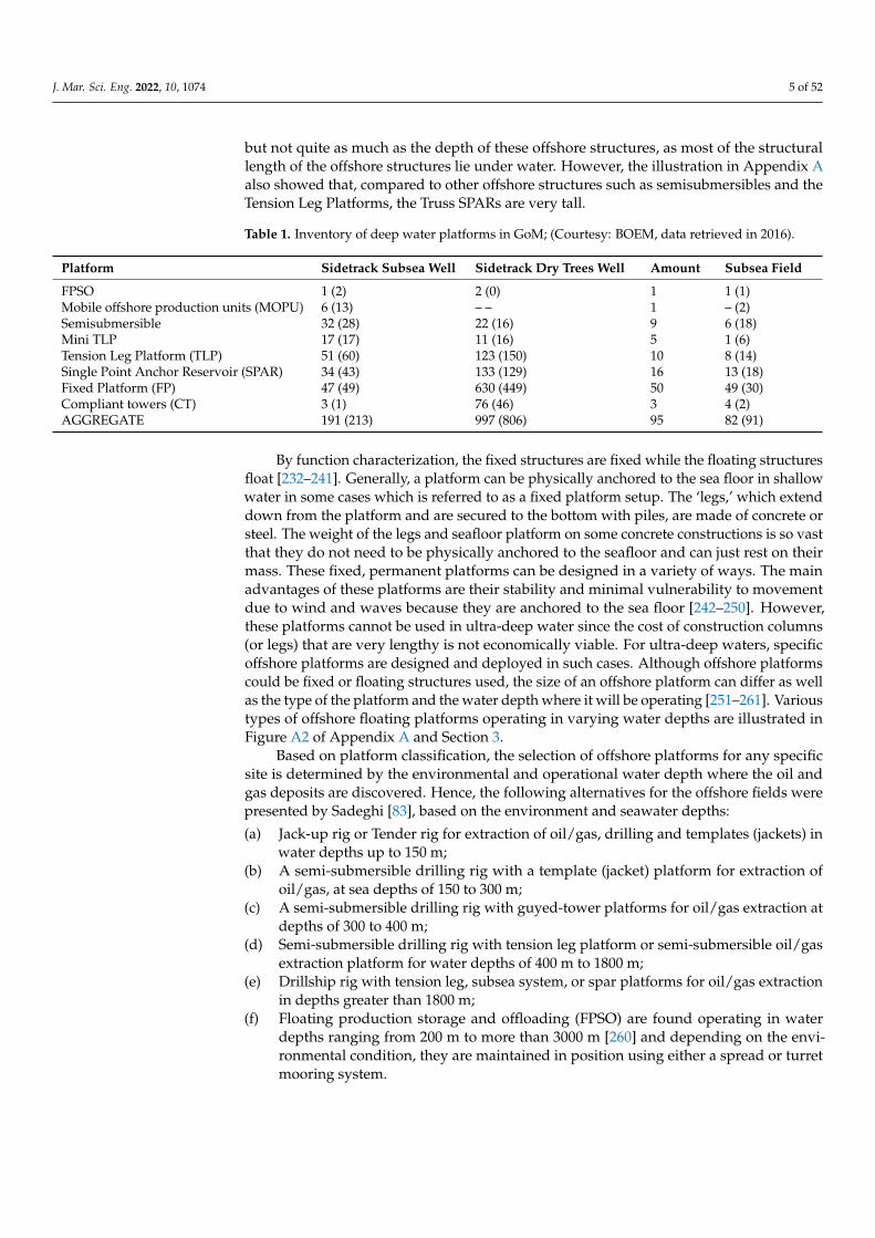
Figure 6. Types of Drilling Rigs.
3.1. Moveable Offshore Drilling Platforms
Offshore drilling rigs/platforms are divided into two categories. The first is a mobileoffshore drilling rig that can be moved from one location to another, while the second is astationary offshore drilling rig. Historically, the first submersible mobile drilling equipmentto drill offshore in 1954 was called Mr. Charlie [261]. Over the years, newer developmentshave been made on moveable platforms. Offshore drilling platforms (and drilling rigs) arethose platforms that can be moved from one drilling location to another or even higherapplication in the industry, as seen in recent leases. A mobile offshore drilling unit (MODU)or unit is a ship that can conduct drilling operations to explore for petrochemical mineralsor exploit resources such as liquid or gaseous hydrocarbons, sulfur or salt that are presentbeneath the seabed. MODU can be jack-up, semi-submersible, barge-type or ship-shaped.For offshore oil and gas drilling, rigid platforms are necessary for drilling operations.They can be moved and retained in place by their own azimuth thrusters with dynamicpositioning or hauled into place by a tugboat and moored. A recognized design andoperational standard for semi-submersible mobile offshore drilling units (MODU) is theIMO’s MODU Code.
3.2. Drilling Barges
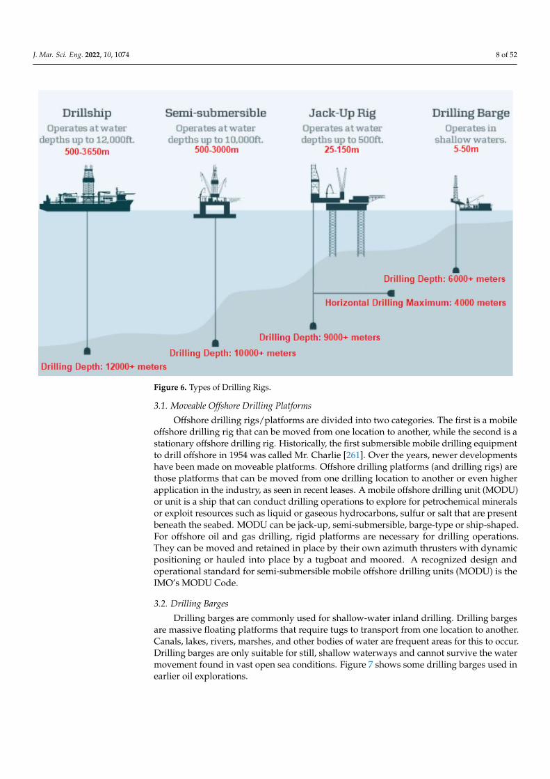
Drilling barges are commonly used for shallow-water inland drilling. Drilling bargesare massive floating platforms that require tugs to transport from one location to another.Canals, lakes, rivers, marshes, and other bodies of water are frequent areas for this to occur.Drilling barges are only suitable for still, shallow waterways and cannot survive the watermovement found in vast open sea conditions. Figure 7 shows some drilling barges used inearlier oil explorations.
J. Mar. Sci. Eng. 2022, 10, 1074 9 of 52
Figure 7. Drilling barge.
3.3. Jackup Drilling Platforms/Rigs
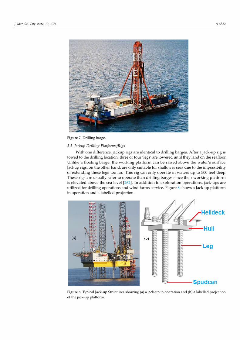
With one difference, jackup rigs are identical to drilling barges. After a jack-up rig istowed to the drilling location, three or four ‘legs’ are lowered until they land on the seafloor.Unlike a floating barge, the working platform can be raised above the water’s surface.Jackup rigs, on the other hand, are only suitable for shallower seas due to the impossibilityof extending these legs too far. This rig can only operate in waters up to 500 feet deep.These rigs are usually safer to operate than drilling barges since their working platformis elevated above the sea level [262]. In addition to exploration operations, jack-ups areutilized for drilling operations and wind farms service. Figure 8 shows a Jack-up platformin operation and a labelled projection.
Figure 8. Typical Jack-up Structures showing (a) a jack-up in operation and (b) a labelled projectionof the jack-up platform.

J. Mar. Sci. Eng. 2022, 10, 1074 10 of 52
3.4. Offshore Wind Turbine Platforms
The global concern about the emission of greenhouse gases has provided a line ofresearch into alternative renewable and clean energy. In this regard, wind power is one ofthe fastest-growing alternative technologies. However, this technology could help powera clean energy transition only if it can overcome hurdles of cost, design and oppositionfrom fishing. More so, the application of offshore structures in renewable energy has takenmore interests on breakwater devices, water energy converters, and wind turbines (suchas FOWTs). The scale of wind turbines are larger and more adaptable forms of offshorestructures are seen today. Offshore wind turbines may either be fixed-bottom or floatingtypes [263]. The fixed-bottom platform is quite common in off the coast of Denmark,consisting of 91 wind turbines [264]. By design, offshore wind turbines, which are anchoredto the seabed with monopile or jacket foundations, can only operate in waters less than50 m deep. This eliminates sites with the greatest winds and, in many cases, easy accessto large markets. However, there are exceptions as the application of Fixed-bottom windturbines is more economical as it operates in shallow water depths of 50 or 60 m [265].On the other hand, the floating wind turbines are anchored to the seabed using mooringlines, thus, are suitable for deeper water locations and areas with the soft seabed. Floatingwind turbines have been used in water depths of up to 700 m [264,265]. Different conceptshave been identified in on FOWTs projects with different platform types. The projectsinclude DeepCWind, HyWind, WindFloat, NRMI, DTU and MARINTEK wind turbines.The ability to install FOWTs in deeper waters has an open huge amount of the oceansfor the generation of renewable wind power. Table 3 shows some existing wind turbineswith details.
Table 3. List of some offshore wind farms by capacity.
Name Installation Year Diameter Tower Height Capacity Status
Hornsea 2 2002 167 m 190 m 1396 MW Active
Burbo Bank Extension 2017 164 m 113 m 800 MW Active
Westermost Rough 2014 154 m 102 m 600 MW Active
Anholt 2012 120 m 82 m 360 MW Active
Horns Rev 2 2009 93 m 68 m 230 MW Active
Nysted 2003 82.4 m 69 m 230 MW Active
Middelgrund 2000 76 m 64 m 200 MW Active
Vindeby 1991 35 m 35 m 4.95 MW Inactive
Although, the floating wind energy is still in its early stage of utilization, close to 80%of the wind power potential is found in deeper water. However, only about 80 megawattsof a total of about 32 GW (0.25%) of the installed offshore wind capacity is from floatingwind turbines [265]. This narrative may change in the near future with the US governmentunder USA’s President Joe Biden pledging to build more than 30 GW of offshore windturbines by the year 2030, worth more than $100 m [265]. Hence, this might bring theassertions of the National Renewable Energy Laboratory (NREL) to reality, which suggeststhat the floating turbine projects could achieve cost parity with the fixed turbines by theyear 2030.
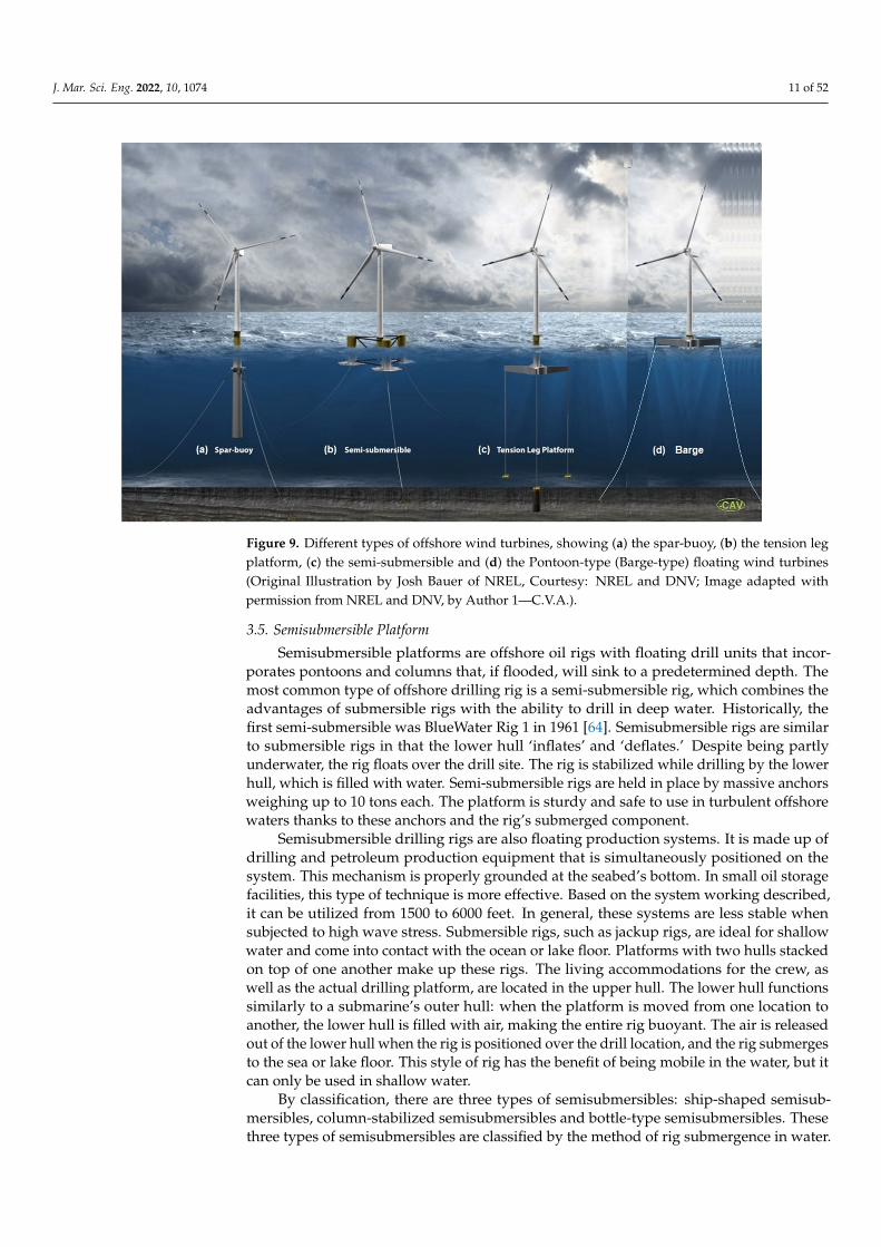
By classification, there are four main types of floating platforms, namely the spar-buoy,the tension leg platform, the semi-submersible and the Pontoon-type (Barge-type) floatingwind turbines. However, there are other types and design concepts because these are themost common platform already installed and adapted for various planned projects, suchas the Semi-submersible platforms which are expected to be used in about 50% to 75% ofprojects. Figure 9 shows four (4) types of offshore wind turbines.
J. Mar. Sci. Eng. 2022, 10, 1074 11 of 52
Figure 9. Different types of offshore wind turbines, showing (a) the spar-buoy, (b) the tension legplatform, (c) the semi-submersible and (d) the Pontoon-type (Barge-type) floating wind turbines(Original Illustration by Josh Bauer of NREL, Courtesy: NREL and DNV; Image adapted withpermission from NREL and DNV, by Author 1—C.V.A.).
3.5. Semisubmersible Platform
Semisubmersible platforms are offshore oil rigs with floating drill units that incor-porates pontoons and columns that, if flooded, will sink to a predetermined depth. Themost common type of offshore drilling rig is a semi-submersible rig, which combines theadvantages of submersible rigs with the ability to drill in deep water. Historically, thefirst semi-submersible was BlueWater Rig 1 in 1961 [64]. Semisubmersible rigs are similarto submersible rigs in that the lower hull ‘inflates’ and ‘deflates.’ Despite being partlyunderwater, the rig floats over the drill site. The rig is stabilized while drilling by the lowerhull, which is filled with water. Semi-submersible rigs are held in place by massive anchorsweighing up to 10 tons each. The platform is sturdy and safe to use in turbulent offshorewaters thanks to these anchors and the rig’s submerged component.
Semisubmersible drilling rigs are also floating production systems. It is made up ofdrilling and petroleum production equipment that is simultaneously positioned on thesystem. This mechanism is properly grounded at the seabed’s bottom. In small oil storagefacilities, this type of technique is more effective. Based on the system working described,it can be utilized from 1500 to 6000 feet. In general, these systems are less stable whensubjected to high wave stress. Submersible rigs, such as jackup rigs, are ideal for shallowwater and come into contact with the ocean or lake floor. Platforms with two hulls stackedon top of one another make up these rigs. The living accommodations for the crew, aswell as the actual drilling platform, are located in the upper hull. The lower hull functionssimilarly to a submarine’s outer hull: when the platform is moved from one location toanother, the lower hull is filled with air, making the entire rig buoyant. The air is releasedout of the lower hull when the rig is positioned over the drill location, and the rig submergesto the sea or lake floor. This style of rig has the benefit of being mobile in the water, but itcan only be used in shallow water.
By classification, there are three types of semisubmersibles: ship-shaped semisub-mersibles, column-stabilized semisubmersibles and bottle-type semisubmersibles. Thesethree types of semisubmersibles are classified by the method of rig submergence in water.

J. Mar. Sci. Eng. 2022, 10, 1074 12 of 52
While the ship shaped semisubmersibles can be designed as ships, as the name implies,they are also one of the most often used hull systems for the design and construction ofoffshore deep water drilling and production platforms, followed by the column stabilizedsemisubmersible platform [56,58,219,252,253]. The bottle-type semisubmersible platform,on the other hand, is made up of bottle-shaped hulls that are positioned beneath the drillingdeck and can be submerged by filling them with water. Bottle-type semisubmersibles, thefirst manifestation of this type of drilling rig, were designed as submersible rigs. The bottlesbelow the rig were totally submerged due to this design consideration for the submersible,which rests on the ocean floor. Furthermore, the rig of the bottle-type semisubmersible pro-vided remarkable drilling stability. It also provides stability for rolling, as well as reducingpitching caused by waves and wind. This type of semisubmersible needs to be studied be-cause of the various environmental conditions. Some drilling sites are always difficult, withturbulent waves and occasional weather concerns such as hurricanes, storms, cyclones, hightides, and strong winds. As a result, it is necessary to dig into deeper and more turbulentseas. Semi-submersibles have recently opened up a new path for exploration and develop-ment operations. However, as time went on, naval architects understood that if the bottleswere only partially submerged, the rig would keep its stability when drilling in deeperseas. The semisubmersibles are moored using mooring lines, and the anchors are the onlyconnection the rig has with the seafloor. These bottle-type rigs were eventually designed toonly be used as semisubmersibles. Bottle-type semisubmersibles’ configuration and designhave a different impact on their hydrodynamic behavior in rough weather situations, andhence on their use and functionality in ocean engineering. The semisubmersibles can haveother classifications based on evolution such as sixth generation semisubmersibles, and bydesign, such as the Dry-Tree Semisubmersible (DTS). Since the construction of drilling rigshave traditionally taken place during economic booms, different “batches” of drilling rigshave been constructed. Depending on the year of construction and water depth capability,offshore drilling rigs have been roughly categorized into nominal “generations”. Table 4gives different generations for classifying semisubmersibles.
Table 4. Classification of semisubmersibles by generations.
Generation TimelinesWater Depth
Meters (m) Feet (ft)
First Early 1960s 200 m about 600 ft
Second 1969–1974 300 m about 1000 ft
Third Early 1980s 500 m about 1500 ft
Fourth 1990s 1000 m about 3000 ft
Fifth 1998–2004 2500 m about 7500 ft
Sixth 2005–2012 3000 m about 10,000 ft
Seventh 2013–2022 >3000 m over 10,000 ft
Generally, semisubmersibles are multi-legged offshore floating structures consistingof a large deck, with several legs interconnected at the bottom underwater with horizontalbuoyant members referred to as pontoons. The semisubmersibles are one of the preferredfloating offshore platforms alternatives due to their advantages, including, stability andmotion. However, their natural frequencies vary inversely with the draft and length, theappropriate selection of the geometric shape constitutes an essential criterion in the designof semisubmersibles [266]. Semi-Submersible may be stationed using dynamic positioningsystems or anchored using mooring systems. For example, in 2002, a semi moored wasdeployed using spread mooring lines at a water depth 1875 m in offshore Malaysia, whileanother installation using a dynamic positioning system in 2003 was deployed in Braziloperating at a water depth of 2890 m. In the same year, a semi operating in 2730 m waterdepth was also positioned in the Gulf of Mexico (GoM) [267]. However, more recent

J. Mar. Sci. Eng. 2022, 10, 1074 13 of 52
developments have been made. Table 5 presents the list of some semisubmersible platformsused in recent developments. The most recent is the Appomattox semisubmersible platformoperated by Shell in GoM, which was installed in 2019, as shown in Figure 10a. Figure 10billustrates the parts of a semisubmersible.
Table 5. List of some semisubmersible platforms for deep water drilling and production.
Platform Water Depth (m) Operator Installation Year Location
Appomattox 2195 m Shell 2019 GoM, USA
Thunder Horse PDQ 1841 m BP & ExxonMobil 2010 GoM, USA
Na Kika 1829 m Shell & BP 2003 GoM, USA
Atlantis PQ 2134 m BP & BHP 2007 GoM, USA
Argos /Mad Dog Phase 2 1311 m BP 2022 GoM, USA
Vito 1189 m Shell 2022 GoM, USA
Delta House 1370 m LLOG 2015 GoM, USA
Figure 10. Semisubmersibles showing (a) Appomattox Semi-Submersible oil platform in GoMinstalled in 2019 (Courtesy: Shell), and (b) an illustration of part of a semisubmersible.
3.6. Dynamic Positioned Drillships
Drillships are exactly what they sound like: ships that are used to conduct drillingoperations. These boats are designed specifically to transport drilling platforms to deep-seaareas. A typical drillship will feature a drilling platform and derrick in the middle of itsdeck, in addition to all of the other equipment found on a huge ocean ship. Drillships alsohave a hole called a “moonpool” that runs the length of the ship and down through the hull,allowing the drill string to extend through the boat and into the water. This offshore oil rigis capable of drilling in extremely deep water. ‘Dynamic positioning’ systems are used bydrillships. Drillships have electric motors mounted on the underside of the hull that canmove the ship in any direction. These motors are incorporated into the ship’s computersystem, which employs satellite positioning technology and sensors on the drilling templateto guarantee that the ship is always directly over the drill site. Dynamic positioning canalso be used to keep semi-submersible rigs in place. Drilling rigs that are Semi-submersibledrilling rigs can drill in much deeper water than the rigs mentioned earlier. Deeper depthsof up to 6000 feet (1800 m) may now be reached safely and quickly thanks to technologicaladvancements. Figure 11 shows a drillship semisubmersible by Transocean.

J. Mar. Sci. Eng. 2022, 10, 1074 14 of 52
Figure 11. DrillShip semisubmersible (Courtesy: Transocean).
3.7. SPAR Platforms
Spar platforms are among the most often used offshore platforms. The acronymSPAR stands for Single Point Anchor Reservoir. The SPAR platform is an offshore floatingplatform with a relatively large draft to diameter ratio (aspect ratio). Its deep draft madethe natural periods outside the wave ranges thereby attributing to its wide acceptance fordifferent operational scenarios, especially in deeper waters.
The Spar platform is the world’s largest oil extraction platform which can be employedat depths up to 10,000 feet. This platform is mainly comprised of a massive cylinder supportsystem and a standard fixed rig platform. This large cylinder does not stretch all the wayto the seabed. It is held together by large steel cables that are attached to the seabed. Theextraction devices are mounted above this cylinder and will perform their duties. A bigcylinder supports a standard fixed rig platform on these massive platforms. The cylinder,on the other hand, does not reach all the way to the seafloor and is instead held in placeby several cables and wires. The big cylinder helps to keep the platform afloat while alsoallowing for mobility to absorb the energy of any impending hurricanes.
Currently, the Perdido platform, operated by Shell, is the tallest SPAR, and is compara-tively one of the tallest structures in the world at 267 m, as depicted in Figure 12. However,the Perdido SPAR which operates in a water depth of 2450 m installed in 2010 has beenovertaken by Stone FPSO operating in a water depth of 2925 m installed in 2016, and bothare operating in the Gulf of Mexico (GoM).
Figure 12. Perdido deep water SPAR platform in the Gulf of Mexico (GoM), (Courtesy: Statoil).
In September of 1996, the first SPAR platform was placed in the Gulf of Mexico (GoM)was commissioned. The platform’s cylinder was 770 feet long and 70 feet in diameter, andit functioned at a sea depth of 1930 feet (see details in Table 6). Unlike the semi-submersible,the spar platform consists of a single large diameter cylinder supporting a deck. The hull is

J. Mar. Sci. Eng. 2022, 10, 1074 15 of 52
normally maintained in position using a taut mooring system consisting of lines rangingfrom 6–20 [267]. Based on the design, spar platforms are available in three configurations,namely: Truss spar, cylindrical, and cell spar, as illustrated in Figure 13. Table 6 gives a listof some SPARs, while Figure A3 of Appendix A shows a list of different SPAR platformsthat have evolved over the years.
Table 6. List of some SPAR platforms constructed.
Platform Water Depth (m) Type Length (ft) Diameter (ft) Operator Installation Year Location
Neptune SPAR 1935 ft Classic 705 ft 72 ft Noble Energy 1996 GoM, USA
Medusa SPAR 2223 ft Truss 586 ft 94 ft Murphy E&P 2003 GoM, USA
Front Runner SPAR 3350 ft (1021 m) Truss 587 ft 94 ft Murphy E&P 2004 GoM, USA
Mad dog SPAR 4500 ft (1311 m) Truss 555 ft 128 ft BP 2005 GoM, USA
Perdido SPAR 7817 ft (2450 m) Truss 555 ft 118 ft Shell 2010 GoM, USA
Genesis SPAR 2590 ft Classic 705 ft 122 ft Chevron USA 1998 GoM, USA
Hoover DianaDDCV SPAR 4825 ft Classic 705 ft 122 ft Exxon Mobil 2000 GoM, USA
Boomvang SPAR 3450 ft Truss 543 ft 90 ft Anadarko 2002 GoM, USA
Nansen SPAR 3680 ft Truss 543 ft 90 ft Anadarko 2001 GoM, USA
Horn Mountain 5400 ft Truss 555 ft 106 ft Anadarko 2002 GoM, USA
Gunnison 3122 ft Truss 549 ft 3122 ft Anadarko 2003 GoM, USA
Holstein 4344 ft Truss 746 ft 149.28 ft Anadarko 2004 GoM, USA
Constitution SPAR 5000 ft Truss 550 ft 98 ft Anadarko 2005 GoM, USA
Kikeh SPAR 4364 ft Truss 465 ft 106 ft Murphy 2007 Malaysia
Tahiti SPAR 4200 ft Truss 555 ft 128 ft Chevron USA 2008 GoM, USA
Lucius SPAR 7000 ft Truss 605 ft 110 ft Anadarko 2014 GoM, USA
Devils Tower SPAR 5610 ft Truss 586 ft 94 ft Eni US 2004 GoM, USA
Heidelberg SPAR 5300 ft Truss 605 ft 110 ft Anadarko 2016 GoM, USA
Gulfstar SPAR 4600 ft Classic 584 ft 85 ft Hess 2014
Aasta Hansteen SPAR 4265 ft Truss 643 ft 164 ft Equinor 2019 North Sea,Norway
Red Hawk SPAR 5300 ft Cell 560 ft 64 ft Kerr McGee &Devon Energy 2004 GoM
Figure 13. Types of Spar Platform: (a) Classic (b) Truss (c) Cell.
J. Mar. Sci. Eng. 2022, 10, 1074 16 of 52
3.8. Jacket Platforms
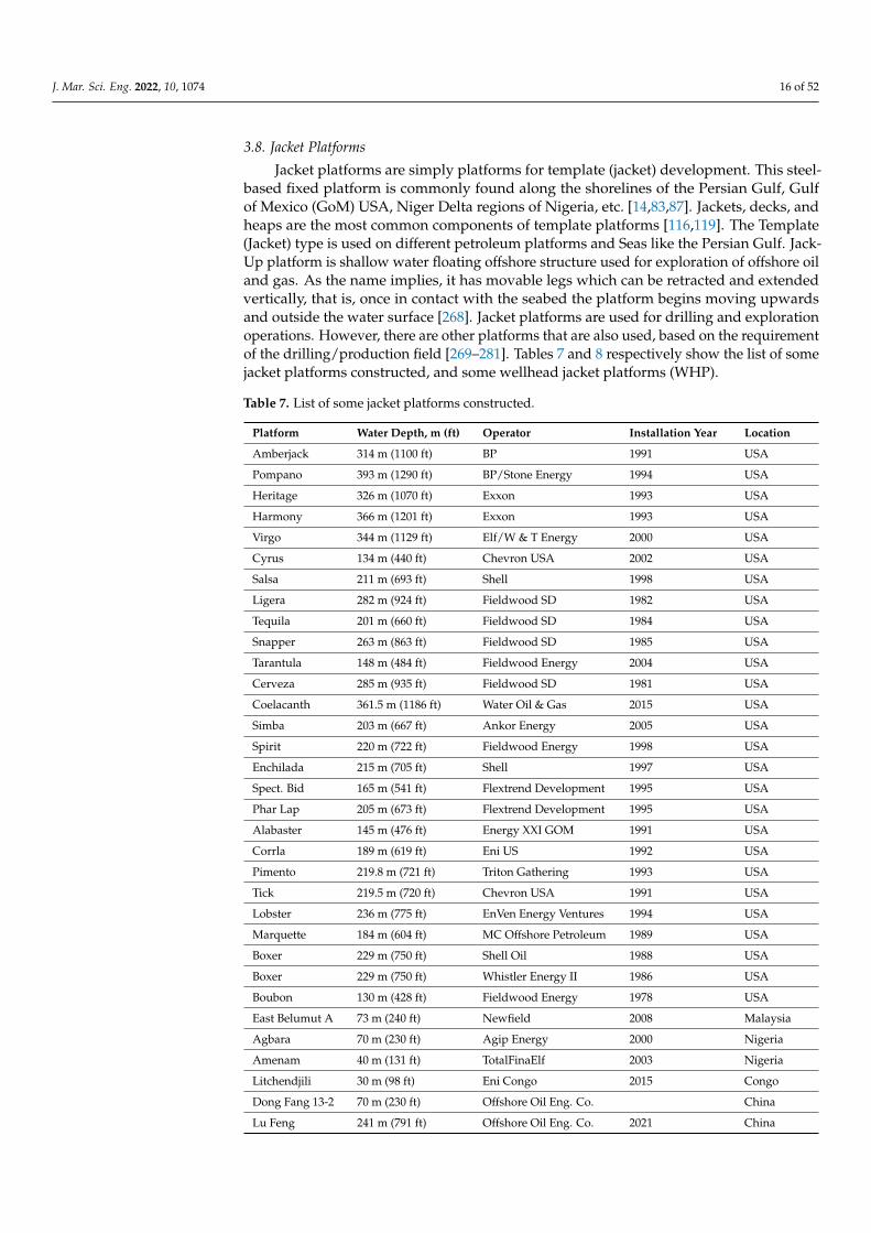
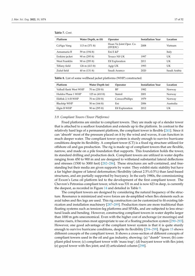
Jacket platforms are simply platforms for template (jacket) development. This steel-based fixed platform is commonly found along the shorelines of the Persian Gulf, Gulfof Mexico (GoM) USA, Niger Delta regions of Nigeria, etc. [14,83,87]. Jackets, decks, andheaps are the most common components of template platforms [116,119]. The Template(Jacket) type is used on different petroleum platforms and Seas like the Persian Gulf. Jack-Up platform is shallow water floating offshore structure used for exploration of offshore oiland gas. As the name implies, it has movable legs which can be retracted and extendedvertically, that is, once in contact with the seabed the platform begins moving upwardsand outside the water surface [268]. Jacket platforms are used for drilling and explorationoperations. However, there are other platforms that are also used, based on the requirementof the drilling/production field [269–281]. Tables 7 and 8 respectively show the list of somejacket platforms constructed, and some wellhead jacket platforms (WHP).
Table 7. List of some jacket platforms constructed.
Platform Water Depth, m (ft) Operator Installation Year Location
Amberjack 314 m (1100 ft) BP 1991 USA
Pompano 393 m (1290 ft) BP/Stone Energy 1994 USA
Heritage 326 m (1070 ft) Exxon 1993 USA
Harmony 366 m (1201 ft) Exxon 1993 USA
Virgo 344 m (1129 ft) Elf/W & T Energy 2000 USA
Cyrus 134 m (440 ft) Chevron USA 2002 USA
Salsa 211 m (693 ft) Shell 1998 USA
Ligera 282 m (924 ft) Fieldwood SD 1982 USA
Tequila 201 m (660 ft) Fieldwood SD 1984 USA
Snapper 263 m (863 ft) Fieldwood SD 1985 USA
Tarantula 148 m (484 ft) Fieldwood Energy 2004 USA
Cerveza 285 m (935 ft) Fieldwood SD 1981 USA
Coelacanth 361.5 m (1186 ft) Water Oil & Gas 2015 USA
Simba 203 m (667 ft) Ankor Energy 2005 USA
Spirit 220 m (722 ft) Fieldwood Energy 1998 USA
Enchilada 215 m (705 ft) Shell 1997 USA
Spect. Bid 165 m (541 ft) Flextrend Development 1995 USA
Phar Lap 205 m (673 ft) Flextrend Development 1995 USA
Alabaster 145 m (476 ft) Energy XXI GOM 1991 USA
Corrla 189 m (619 ft) Eni US 1992 USA
Pimento 219.8 m (721 ft) Triton Gathering 1993 USA
Tick 219.5 m (720 ft) Chevron USA 1991 USA
Lobster 236 m (775 ft) EnVen Energy Ventures 1994 USA
Marquette 184 m (604 ft) MC Offshore Petroleum 1989 USA
Boxer 229 m (750 ft) Shell Oil 1988 USA
Boxer 229 m (750 ft) Whistler Energy II 1986 USA
Boubon 130 m (428 ft) Fieldwood Energy 1978 USA
East Belumut A 73 m (240 ft) Newfield 2008 Malaysia
Agbara 70 m (230 ft) Agip Energy 2000 Nigeria
Amenam 40 m (131 ft) TotalFinaElf 2003 Nigeria
Litchendjili 30 m (98 ft) Eni Congo 2015 Congo
Dong Fang 13-2 70 m (230 ft) Offshore Oil Eng. Co. China
Lu Feng 241 m (791 ft) Offshore Oil Eng. Co. 2021 China
J. Mar. Sci. Eng. 2022, 10, 1074 17 of 52
Table 7. Cont.
Platform Water Depth, m (ft) Operator Installation Year Location
CaNgu Vang 113 m (371 ft) Hoan Vu Joint Oper. Co.(HVJOC) 2008 Vietnam
Annamaria B 59 m (194 ft) Eni E &P Italy
Erskine jacket 90 m (295 ft) Texaco NS UK 1997 UK
West Franklin 90 m (295 ft) Elf Exploration 2011 UK
Tiffany field 126 m (413 ft) Agip UK 1993 UK
Zuluf field 40 m (131 ft) Saudi Aramco 2020 Saudi Arabia
Table 8. List of some wellhead jacket platforms (WHP) constructed.
Platform Water Depth (m) Operator Installation Year Location
Valhall flank West WHP 70 m (230 ft) BP 1982 Norway
Huldra Phase 1 WHP 125 m (410 ft) Statoil 2001 Norway
Eldfisk 2/4 B WHP 70 m (230 ft) ConocoPhillips 1979 Norway
Blacktip WHP 50 m (164 ft) Eni 2006 Australia
Elgin B WHP 90 m (295 ft) Elf Exploration 2012 UK
3.9. Compliant Towers (Tower Platforms)
Fixed platforms are similar to compliant towers. They are made up of a slender towerthat is attached to a seafloor foundation and extends up to the platform. In contrast to therelatively hard legs of a permanent platform, the compliant tower is flexible [241]. Since itcan ‘absorb’ most of the pressure placed on it by the wind and waves, it can function inmuch deeper water. The compliant tower system is sturdy enough to survive hurricaneconditions despite its flexibility. A compliant tower (CT) is a fixed rig structure utilized foroffshore oil and gas production. The rig is made up of compliant towers that are flexible,narrow, and made on a pile foundation that supports. This foundation holds the tower,its standard drilling and production deck. Compliant towers are utilized in water depthsranging from 450 to 900 m and are designed to withstand substantial lateral deflectionsand stresses (1500 to 3000 feet) [282–286]. These structures are self-contained, and free-standing but their media are given supports by water. They exhibit static stability but havea far higher degree of lateral deformation/flexibility (about 2.5%:0.5%) than land-basedstructures, and are partially supported by buoyancy. In the early 1980s, the commissioningof Exxon’s Lena oil platform led to the development of the first compliant tower. TheChevron’s Petronius compliant tower, which was 531 m and is now 623 m deep, is currentlythe deepest, as recorded in Figure 14 and detailed in Table 9.
The compliant towers are designed by considering the natural frequency of the struc-ture. Resonance is minimized and wave forces are de-amplified when flex elements such asaxial tubes and flex legs are used. This rig construction can be customized to fit existing fab-rication and installation machinery [287–289]. Production risers are more traditional thanfloating systems such as tension-leg platforms and SPARs, and are subjected to less struc-tural loads and bending. However, constructing compliant towers in water depths largerthan 1000 m gets uneconomical. Even with the higher cost of anchorage (or moorings) andmarine risers, it becomes most appropriate to use of a floating production system [290–293].However, one good advantage of the compliant tower system is that it is quite sturdyenough to survive hurricane conditions, despite its flexibility [294–299]. Figure 15 showsdifferent concepts of the compliant tower. It shows a cross-section of different concepts ofcompliant towers used in the oil and gas industry, showing: (a) “dumb” tower; (b) com-pliant piled tower; (c) compliant tower with ‘mass trap’; (d) buoyant tower with flex joint;(e) guyed tower with flex joint; and (f) articulated column [298].

J. Mar. Sci. Eng. 2022, 10, 1074 18 of 52
Figure 14. Illustrations showing (a) the Five Compliant Tower Platforms in the World including thosesanctioned, installed and operating platforms while (b) shows a labelled compliant tower. (Revisedimage (a), adapted from Offshore Magazine Poster, Courtesy: Wood Group Mustang).
Table 9. Parameters of compliant towers showing the structural weights.
Platform Parameters Petronius Lena GuyedTower Baldpate Bullwinkle (Fixed) Cognac
Benguela-BelizeLobito-Tomboco(BBLT)
Tombua-Landana
Location GoM GoM GoM GoM GoM Angola Angola
Installation Year 1997 1983 1998 1988 1978 2006 2009
Design Type Type ‘b’ Type ‘e’ Type ‘a’ Type ‘a’ Type ‘a’ Type ‘e’ Type ‘e’
Operator Chevron ExxonMobil Hess Shell Shell Chevron Chevron
Natural Period (s) 33 28 ~30 ~30 ~30 ~29 ~28
Wave height Hs (m) 22.49 12.5 18.2 18.2 21.34 8.84 8.84
Water Depth, (m) 535 m 305 m 503 m 413 m 314 m 390 m 366 m
Topside weight, (tons) 8800 9500 9000 2033 14,000 43,500 36,000
Structure weight, (tons) 43,000 23,400 28,900 49,375 59,000 49,800 56,400
Well slot 21 21 19 60 62 40 46
Base Dimension (m) 33.53 × 33.53 37 × 37 42.67 × 42.67 148 × 124 122 × 116 33.53 × 33.53 33.53 × 33.53
Section 2 2 2 2 3 2 2
Diameter of flex-leg 2.13 m (84”) 1.37 m (54”) - - 2.1 m (83”) 2.59 m (102”) 2.59 m (102”)
No. of flex-legs 12 8 12 12 24 12 12
Diameter offoundation piles 2.44 m (96”) 1.83 m (72”) 2.13 m (84”) - 2.4 m (96”) 2.74 m (108”) 2.74 m (108”)
No. of Foundation piles 12 8 12 12 24 12 12
Max. pile penetration (m) 141.7 m 167.6 m 162 m - 137.2 m 154.8 m 160.8 m

J. Mar. Sci. Eng. 2022, 10, 1074 19 of 52
Figure 15. Cross-section of different concepts of compliant towers used in the oil and gas indus-try, showing (a) “dumb” tower, (b) compliant piled tower, (c) compliant tower with ‘mass trap’,(d) buoyant tower with flex joint, (e) guyed tower with flex joint, and (f) articulated column.
3.10. Tension Leg Platform and Seastar Platform
The Tension Leg platform is a type of platforms that is held by tendons. The tensionleg platform operates on the same principles as the SeaStar platform. Since there is nowater chamber to oppose the lateral movement, such a construction is less stable than aSeaStar platform. The Seastar platform is a larger form of the Tension Leg platform. Theplatform’s long, flexible legs are anchored to the seafloor and run up to it. These legs,like the SeaStar platform, allow for a lot of side-to-side movement (up to 20 feet) but verylimited vertical mobility. Tension leg platforms are capable of working at depths of up to7000 feet. SeaStar platforms resemble tension leg platforms in size. The platform is madeup of a floating rig, similar to the semi-submersible type (as mentioned in Section 3.5) [299].When drilling, a lower hull is filled with water, increasing the platform’s stability againstwind and sea movement. Seastar platforms, in addition to this semi-submersible rig, alsoinclude the tension leg system found on larger platforms. Long, hollow tendons that gofrom the seafloor to the floating platform are known as tension legs. These legs are keptunder continual tension and prevent the platform from moving up or down. Their elasticity,on the other hand, allows for side-to-side movement, allowing the platform to endure thepower of the ocean and the wind without breaking the legs. When it is not cost-effectiveto build a larger platform, Seastar platforms are often employed for smaller deep-waterreservoirs. They can operate in up to 3500 feet of water.
A floating rig, a lower hull, and tension cables comprise the Seastar platform. Awater-filled lower shell boosts the platform’s stability against wind and water movement.It also has a tensioned system in addition to the semi-submersible rig. The tension leg,which is made out of high-strength steel cables, is part of the tension system. Tension stressis not a problem with these wires. This construction is vulnerable to high wave and windpressures, but the water-filled body will mitigate these effects, making the structure morestable. Figure 16 shows an illustration of typical TLP.
The Tension Leg Platform has been used in making notable historical developments inthe oil and gas industry. The Heidrun Tension Leg Platform (TLP) was the first platformwhere a composite riser joint was deployed in 2002. It is also the first platform thatcomposite riser joint was successfully deployed after extensive composite research. TheTLP has 56 well slots on the subsea riser template. The Heidrun TLP has a total height of109 m, a square pontoon having a box cross-section, a pontoon height of 110 m, a pontoonheight of 13 m, and eight decks located near each of the four circular columns located ateach corner. It is the first and biggest floating TLP with a concrete hull. It is the largestfloating structure carrying the largest deck load ever, with a topside weight of 43,000 tons,

J. Mar. Sci. Eng. 2022, 10, 1074 20 of 52
and a total platform displacement of 288,200 tons. Conoco discovered the Heidrun fieldin 1985, which lies about 175 km off Norway’s coast and north of Kristiansund at a waterdepth of about 350 m. It produces 65,000 barrels of oil daily, 110,000 barrels of waterdaily, and 760 m3 of natural gas. The Heidrun TLP has produced over 944 million oiland gas barrels since October 1995, at 05:37 when the choke valve was opened to becomeoperational. Figure 17 shows the Heidrun Tension Leg Platform (TLP), while Table 10 listssome tension leg platforms constructed with their details.
Figure 16. Illustrations showing (a) the tension leg platform (TLP), and (b) a labelled TLP.
Figure 17. Heidrun Tension Leg Platform (TLP). (Courtesy: Statoil.).

J. Mar. Sci. Eng. 2022, 10, 1074 21 of 52
Table 10. List of some tension leg platforms constructed.
Platform Water Depth (m) Operator Installation Year Location
Prince TLP 454 m EnVen Energy Corp. 2001 GoM, USA
Kizomba TLP 1012 m Esso Exploration 2004 Angola
Marlin TLP 986 m BP & Anadarko 1999 GoM, USA
Marco Polo TLP 1311 m Anadarko Petroleum Corp. 2003 GoM, USA
Ram-Powell TLP 1000 m Shell 1997 GoM, USA
Magnolia ETLP 1420 m ConocoPhillips 2003 GoM, USA
Heidrun TLP 350 m Conoco 1995 North Sea, Norway
Moho Nord TLP 1200 m Total Energies 2015 Congo
Stampede TLP 1067 m Hess Corporation 2017 GoM, USA
Shenzi TLP 1333 m BHP Billiton Petroleum Inc. 2008 GoM, USA
URSA TLP 1204 m Shell 1999 GoM, USA
Olympus /Mars B 914 m Shell 2014 GoM, USA
Mars TLP 896 m Shell 1996 GoM, USA
Auger TLP 872 m Shell 1993 GoM, USA
Jolliet TLP 536 m MC Offshore Petroleum & Conoco 1989 GoM, USA
Hutton TLP 148 m ConocoPhillips 1984 North Sea, UK
Snorre TLP 310 m Saga Petroleum 1992 North Sea, Norway
Oveng TLP 271 m Hess 2006 Equatorial Guinea
Okume/Ebano TLP 503 m Hess 2006 Equatorial Guinea
Brutus TLP 910 m Shell 2001 GoM, USA
Malikai TLP 500 m Shell 2014 Malaysia
3.11. FPSO
The acronym FPSO stands for floating production storage and offloading. As the nameimplies, the FPSO is a production system equipped with processing equipment for theseparation and treatment of crude oil and gas together with a large storage hull to store thetreated oil for export [260,268–270]. With the continuous push of production activities intodeeper waters, the FPSOs have over the years dominated the oil and gas industry mainlydue to their attributed advantages which include large storage hulls, and their suitabilityfor application in remote offshore areas [269,270]. The International Maritime Association(IMA) and World Energy Reports (WER) reveal a total of 175 FPSO units in operation as ofNovember 2022, which is equivalent to 68% of the overall floating production systems.
Shuttle tankers are also classified as FPSOs used for offshore production activities, suchas with loading and discharging fluid products using (un)loading marine hoses [31–39].Depending on the environmental condition, FPSOs are either maintained in position usinga spread or turret mooring system as illustrated in Figure 18. A spread of FPSOs located indifferent geological locations is presented in Table 11 and Figure A4 of Appendix A.
Figure 18. FPSO mooring system: (a) Internal turret (b) external turret, and (c) spread mooring system.

J. Mar. Sci. Eng. 2022, 10, 1074 22 of 52
Table 11. List of some FPSOs globally used on oil and gas facilities.
FPSO Water Depth (m) Vessel Length (m) Storage Capacity(Barrels) Operator Owner Year Fields
Stones (orTurritella FPSO) 2914 m 247 m 800,000 Shell SBM Offshore 2016 GoM, USA
Bonga FPSO ~1800 m 295 m 2,000,000 Shell Shell & NNPC 2005 Niger Delta,Nigeria
Agbami FPSO ~1463 m 319.99 m 2,150,000 Chevron Chevron &NNPC 2007 Agbami, Nigeria
Parque dasConchas (BC-10) ~1800 m 330 m 2,000,000 Shell Shell 2010 Brazil
Kikeh FPSO ~1350 m 337 m 2,000,000 MDPX Sdn Bhd MDFT Labaun 2007 Malaysia
Peregrino FPSO 100 m 332.99 m 1,600,000 Statoil Maersk 2010 Brazil
Sevan PiranemaFPSO 1100 m 66 m (dia.) 300,000 Petrobras Teekay 2008 Brazil
Goliat FPSO 420 m 112 m (dia) 1000,000 Eni & Statoil Eni 2015 Barents Sea,Norway
Polvo FPSO 160 m 340.6 m 1,266,000 HRT BW Offshore 2007 Brazil
Frade FPSO 1128 m 337.06 m 1,550,000 Chevron SBM Offshore 1976, 2009 Brazil
Cidade deVitoria FPSO 1386 m 337 m 1,900,000 Petrobras Saipem 2007 Brazil
Marlim Sul FPSO 1670 m 342.99 m 1,000,000 Petrobras SBM Offshore 2004 Brazil
Terra Nova FPSO 100 m 292.25 m 960,000 Suncor Suncor 2001 Canada
Aquila FPSO 1233 m 700,000 Eni Eni 2013 Adriatic Sea, Italy
Triton FPSO 95 m 244 m 630,000 Dana Dana 2000 UK
Gryphon FPSO 112 m 257.6 m 540,000 Total Energies Maersk 1993 UK
Äsgard A FPSO 300 m 276 m 910,000 Statoil & Eni Statoil 1998 Norway
Alvheim FPSO(converted Odin) 112 m 285 m 560,000 Marathon & Det
Norske Statoil/Marathon 2008 North Sea, Norway
Firenze FPSO 815 m 268 m 700,000 Eni Saipem 2011 Adriatic Sea, Italy
3.12. Concrete Gravity-Based Structure (GBS)
A support structure maintained in place by gravity is referred to as a “gravity-basedstructure,” most prominently offshore oil rigs. Due to their protected area and adequatedepth, fjords are frequently used to build these structures. The basis of construction forthe Concrete Gravity-Based Structure was the application of reinforced concrete. Thebase’s design incorporates vacuum spaces or caissons to provide the structure with naturalbuoyancy, allowing it to be floated to a field development site. Once on site, the blankspaces on the seabed are flooded, and the topside modules are hauled into place. Thevacant holes were then filled with permanent iron ore ballast or utilized as crude oil storagecompartments. Due to the sheer massive weight of concrete structures, foundation piles arenot required, thus the name gravity base structure [299–307]. Figure 19 illustrates a typicalGBS, showing Troll A concept.
An example of a concrete gravity-based structure is the Troll A platform (as shown inFigure 20), which exists off the west coast of Norway, in the Troll gas field. This offshorestructure was built in 1996, and it is recorded as the largest structure ever moved anddropped into the ocean [301,307]. Table 12 and Figure A5 of Appendix A show differentGBS platforms with their details.
Table 12. Installation of different concrete gravity-based structures.
Installation Water Depth (m) Type Location Year Operator
Troll A 303 m Condeep, 4 shafts North Sea, Norway 1995 Norske Shell
Beryl A 120 m Condeep, 3 shafts North Sea, UK 1975 Mobil
Brent B 140 m Condeep, 3 shafts North Sea, UK 1975 Shell

J. Mar. Sci. Eng. 2022, 10, 1074 23 of 52
Table 12. Cont.
Installation Water Depth (m) Type Location Year Operator
Brent D 140 m Condeep, 3 shafts North Sea, UK 1976 Shell
Frigg TCP2 104 m Condeep, 3 shafts North Sea, Norway 1977 Elf
Stratfjord A 146 m Condeep, 3 shafts North Sea, Norway 1977 Mobil
Stratfjord B 146 m Condeep, 4 shafts North Sea, Norway 1981 Mobil
Stratfjord C 146 m Condeep, 4 shafts North Sea, Norway 1984 Mobil
Gullfaks A 135 m Condeep, 4 shafts North Sea, Norway 1986 Statoil
Gullfaks B 142 m Condeep, 3 shafts North Sea, Norway 1987 Statoil
Oseberg A 109 m Condeep, 4 shafts North Sea, Norway 1988 Norsk Hydro
Gullfaks C 216 m Condeep, 4 shafts North Sea, Norway 1989 Statoil
Draugen 251 m Condeep, 1 shaft North Sea, Norway 1993 Shell
Sleipner A 82 m Condeep, 4 shafts North Sea, Norway 1993 Statoil
Figure 19. Illustrations showing (a) the concrete gravity base structure (GBS), and (b) a labelled GBS.
Figure 20. The Troll A concrete gravity base structure (Courtesy: Statoil).
4. Applications of Offshore Platforms
There are a variety of applications for offshore platforms, with the advantages pre-sented in this section.
J. Mar. Sci. Eng. 2022, 10, 1074 24 of 52
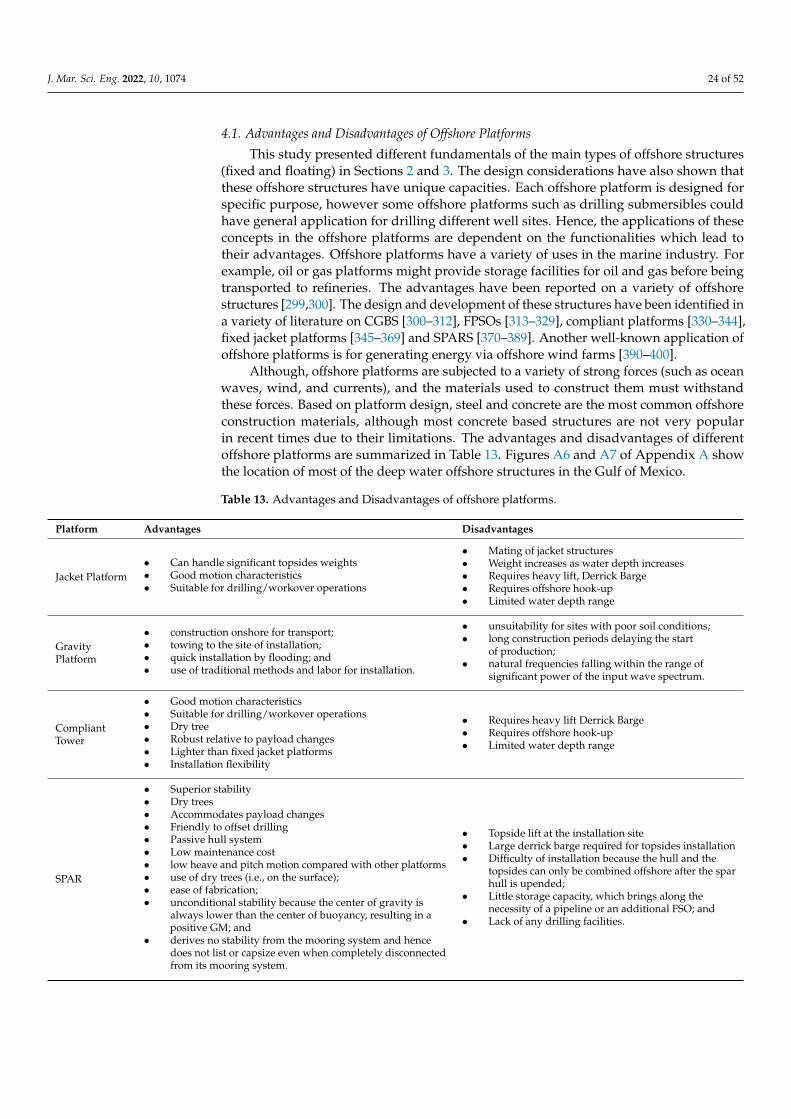
4.1. Advantages and Disadvantages of Offshore Platforms
This study presented different fundamentals of the main types of offshore structures(fixed and floating) in Sections 2 and 3. The design considerations have also shown thatthese offshore structures have unique capacities. Each offshore platform is designed forspecific purpose, however some offshore platforms such as drilling submersibles couldhave general application for drilling different well sites. Hence, the applications of theseconcepts in the offshore platforms are dependent on the functionalities which lead totheir advantages. Offshore platforms have a variety of uses in the marine industry. Forexample, oil or gas platforms might provide storage facilities for oil and gas before beingtransported to refineries. The advantages have been reported on a variety of offshorestructures [299,300]. The design and development of these structures have been identified ina variety of literature on CGBS [300–312], FPSOs [313–329], compliant platforms [330–344],fixed jacket platforms [345–369] and SPARS [370–389]. Another well-known application ofoffshore platforms is for generating energy via offshore wind farms [390–400].
Although, offshore platforms are subjected to a variety of strong forces (such as oceanwaves, wind, and currents), and the materials used to construct them must withstandthese forces. Based on platform design, steel and concrete are the most common offshoreconstruction materials, although most concrete based structures are not very popularin recent times due to their limitations. The advantages and disadvantages of differentoffshore platforms are summarized in Table 13. Figures A6 and A7 of Appendix A showthe location of most of the deep water offshore structures in the Gulf of Mexico.
Table 13. Advantages and Disadvantages of offshore platforms.
Platform Advantages Disadvantages
Jacket Platform• Can handle significant topsides weights• Good motion characteristics• Suitable for drilling/workover operations
• Mating of jacket structures• Weight increases as water depth increases• Requires heavy lift, Derrick Barge• Requires offshore hook-up• Limited water depth range
GravityPlatform
• construction onshore for transport;• towing to the site of installation;• quick installation by flooding; and• use of traditional methods and labor for installation.
• unsuitability for sites with poor soil conditions;• long construction periods delaying the start
of production;• natural frequencies falling within the range of
significant power of the input wave spectrum.
CompliantTower
• Good motion characteristics• Suitable for drilling/workover operations• Dry tree• Robust relative to payload changes• Lighter than fixed jacket platforms• Installation flexibility
• Requires heavy lift Derrick Barge• Requires offshore hook-up• Limited water depth range
SPAR
• Superior stability• Dry trees• Accommodates payload changes• Friendly to offset drilling• Passive hull system• Low maintenance cost• low heave and pitch motion compared with other platforms• use of dry trees (i.e., on the surface);• ease of fabrication;• unconditional stability because the center of gravity is
always lower than the center of buoyancy, resulting in apositive GM; and
• derives no stability from the mooring system and hencedoes not list or capsize even when completely disconnectedfrom its mooring system.
• Topside lift at the installation site• Large derrick barge required for topsides installation• Difficulty of installation because the hull and the
topsides can only be combined offshore after the sparhull is upended;
• Little storage capacity, which brings along thenecessity of a pipeline or an additional FSO; and
• Lack of any drilling facilities.

J. Mar. Sci. Eng. 2022, 10, 1074 25 of 52
Table 13. Cont.
Platform Advantages Disadvantages
TLP
• Dry tree• Dry wellheads• Quayside topsides-hull integration• deep water capability;• Low maintenance cost;• mobility and reusability;• low-cost increase with the increase in water depth; and• stability, because the platform has minimal vertical motion.
• Sensitive to deck payload change• Active hull system• Not friendly to offset drilling• Tendon fatigue• high initial cost;• fatigue of tension legs;• high subsea cost;• little or no storage; and• difficult maintenance of subsea systems.
Semisubmersible
• A large number of flexible risers possible• Good motion response• having better stability in harsh environments,• large deck area; and• higher mobility
• Wet tree only• High maintenance cost• Fatigue motion unfriendly to risers• Limited topside weight capacity• No oil storage facility
FPSO
• Early production• Providing field storage• Extensive deck area of a large tanker provides flexibility in
process plant layout• Less weight sensitive than other types of floating
production systems• Ability to utilize aging or surplus tanker hulls for
conversion to an FSPO vessel;• low cost;• mobility and reusability;• reduced lead time;• quick disconnecting capability which can be useful in
iceberg-prone areas;• little infrastructure required; and• turret mooring system enables FPS (converted ship type) to
head into the wind/waves reducing their effect.
• The subsea tiebacks connected with FPSOs typicallyresult in increased well maintenance expenses.
• limited to small fields;• low deck load capacity;• damage to risers due to motion;• poor stability in rough seas; and• little oil storage capabilities.
4.2. Exploratory Application of Offshore Platforms
This study presented various exploratory applications of offshore structures (fixedand floating) used in the oil and gas industry. Due to the orientation of the superstructure,the foundation of this semi-submersible in deeper waters needs high payload integrationfor minimized motion responses across every degree of freedom (DoF). During productionon the platform, the oil and gas are separated and transferred to shore via pipelines ortankers. To achieve these, proper planning must be conducted for the lifting, transportation,installation, design, fabrication, and commissioning of these offshore petroleum platforms.Among the exploratory applications are (un)loading hose applications via shuttle tankers(or FPSO) and single point mooring (SPM) buoys. Other applications are ocean monitoringbuoys, breakwater and wave energy devices. However, larger exploratory applicationsare seen as presented in recent luxury semisubmersibles, semisubmersible crane vessels(SSCV), offshore support vessels (OSV), and rocket launch pads.
4.2.1. Luxury Cruise
Due to the obvious level of stability that semisubmersibles can provide through recon-figuration, deep-draft semisubmersibles are the wave of the future for ocean engineering.Various press publications, ranging from a Cable News Network (CNN) article to an ex-clusive Forbes article, New York Times, Huffington Post, The Sun News, and Yatch Worldreview made reviewed this Kokomo Ailand [400–407]. These journalists published articlescovering the event on a novel kind of luxury cruise that was fashioned after a mini-island inSeptember of 2015 [390]. Migaloo Private Submersible Yachts designed the floating systemby using he column stabilized semisubmersible concept to construct the hull of the floatingmini island. This hull would have an exceptionally high level of stability in order to operateas a yacht or luxury cruise ship [254]. The type and extent of deck support integration werethe main advantages it provided over traditional cruise ships [400–407]. Recent years have
J. Mar. Sci. Eng. 2022, 10, 1074 26 of 52
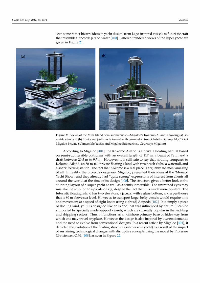
seen some rather bizarre ideas in yacht design, from Lego-inspired vessels to futuristic craftthat resemble Concorde jets on water [400]. Different rendered views of the super yacht aregiven in Figure 21.
Figure 21. Views of the Mini Island Semisubmersible—Migaloo’s Kokomo Ailand, showing (a) iso-metric view and (b) front view (Adapted/Reused with permission from Christian Gumpold, CEO ofMigaloo Private Submersible Yachts and Migaloo Submarines. Courtesy: Migaloo).
According to Migaloo [401], the Kokomo Ailand is a private floating habitat basedon semi-submersible platforms with an overall length of 117 m, a beam of 78 m and adraft between 20.5 m to 9.7 m. However, it is still safe to say that nothing compares toKokomo Ailand, an 80-m-tall private floating island with two beach clubs, a waterfall, anda shark feeding station. The fact that Kokomo is a real place is arguably the most amazingof all. In reality, the project’s designers, Migaloo, presented their ideas at the ‘MonacoYacht Show’, and they already had “quite strong” expressions of interest from clients allaround the world, at the time of its design [400]. The structure gives a better look at thestunning layout of a super yacht as well as a semisubmersible. The untrained eyes maymistake the ship for an upscale oil rig, despite the fact that it is much more opulent. Thefuturistic floating island has two elevators, a jacuzzi with a glass bottom, and a penthousethat is 80 m above sea level. However, to transport large, hefty vessels would require timeand movement at a speed of eight knots using eight (8) Azipods [402]. It is simply a pieceof floating land, yet it is designed like an island that was influenced by nature. It can besupported by specially made support vessels, which are currently popular in the yachtingand shipping sectors. Thus, it functions as an offshore primary base or hideaway fromwhich one may travel anyplace. However, the design is also inspired by owners demandsand the need to evolve from conventional designs. In a recent article by Migaloo [401], itdepicted the evolution of the floating structure (submersible yacht) as a result of the impactof sustaining technological changes with disruptive concepts using the model by ProfessorChristensen C.M. [408], as seen in Figure 22.

J. Mar. Sci. Eng. 2022, 10, 1074 27 of 52
Figure 22. The impact of evolution and sustaining technological changes with disruptive concepts tomeet market demands and product performance (Courtesy: Migaloo).
4.2.2. Offshore Rocket Launch and Landing Platform
Another application is an offshore rocket launch and landing platform. Space Explo-ration Technologies (SpaceX) is investigating the potential use of modified semi-submersibleoil drilling rigs for the launch and landing of their new completely reusable rocket Starshipon a specific Starship offshore platform [409–417]. SpaceX has acquired two old offshore oildrilling rigs as the ENSCO/Valaris 8506 offshore model, which is a specified destinationfor the Starship spaceship. The two floating spaceports—Phobos and Deimos, were giventhem the names as the named after the moons of Mars. However, launch pads can alsobe used in other ways. A semi-submersible drilling rig called Ocean Odyssey has beenmodified to use as a rocket launcher. The drilling platforms were essentially identical whenthey were built and when Elon Musk, the owner of SpaceX, purchased them under thenames ENSCO/Valaris 8500 and 8501, respectively. As part of a six-month effort, Phoboswas relocated from the Port of Galveston to Pascagoula, Mississippi, in January 2021 to startthe retrofit of the rig for Starship operations. The majority of the outdated equipment onthe rig’s deck has been removed as of July 2021. Since one of the platforms was supposedto be substantially operational by the end of 2021 and that Starships would fly out to seaand land on the platform later in 2022 to be carried to the platforms, refitting had alsostarted around January 2021 on Deimos at the Port of Brownsville, USA. At the time of thispublication, the Deimos platform was still under development. Figure 23 shows Deimosocean offshore spaceport which is an offshore launch platform.

J. Mar. Sci. Eng. 2022, 10, 1074 28 of 52
Figure 23. Rendering views of the Deimos rocket launch platform to be completed in 2022/2023,showing (a) the starship fueling up before liftoff on its offshore launch platform, and (b) the aerialview of ocean offshore spaceport Deimos (Courtesy: SpaceX).
4.2.3. Converted Offshore Structures
In recent times, the use of converted offshore structures has been seen to have increas-ing advantages in exploratory, drilling and production activities. For floating offshoreunits, there are eight (8) distinct hull types to choose from [418]. These converted offshorestructures include Mobile offshore drilling units (MODU), Service Offshore Vessels (SOV),and Offshore support vessels (OSV). The ship-shaped monohull is the most prevalent kindof vessel, such as the use of the Floating Storage and Offloading unit (FSO) P-47 which wasconverted from a former Very Large Crude Cargo (VLCC).
The offshore energy market is subject to frequent fluctuations, which also affect thedemand for installation tools, floating structures, and support vessels [419]. The cost of newconstruction is high, and it frequently takes too long to reap the benefits of an opportunitywhen it arises. Another option is to upgrade or convert an existing unit. There are differenttiers of capability growth when converting or upgrading existing equipment. With eachlevel come higher complexity, hazards, and rebuilding expenses. Options include extendingthe life and modernising an older ship, temporarily converting it, increasing its capacity,adding features, altering its current function, and finally, completely converting an oldermerchant cargo ship into a brand-new offshore unit. If a major vessel conversion project isproperly planned and managed, it is possible for it to be competitive with newbuildingchoices. There are a lot of excellent prospects for upgrades and conversions within thesizable pool of current commercial and offshore vessels, both ageing and new vessels. Thisnew lease on life broadens their operational and financial horizons and assists the offshoreindustry in making extraordinary strides in the performance of transport, building, andinstallation [418–422].
The considerations for the selection of offshore platforms are very important also forconverting offshore structures from one purpose to another [419]. Purpose-built productionsemi-submersible platforms were created when the oil industry expanded into harsherregions and deeper waters. ‘Deepsea Saga’ was converted on Agyll oil field, as Agyll FPFsemi-submersible which was later converted to Deepsea Pioneer. The Transworld 58 wasthe first purpose-built semi-submersible production platform used on the Balmoral field in
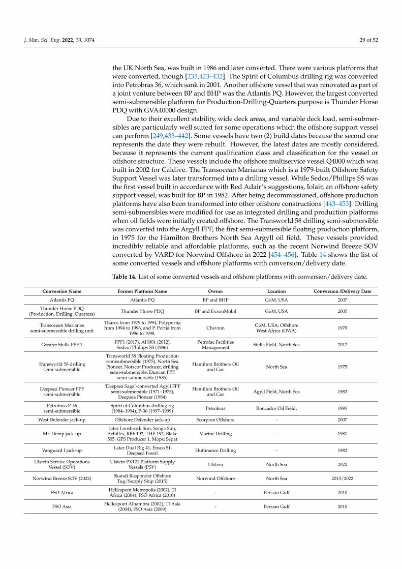
J. Mar. Sci. Eng. 2022, 10, 1074 29 of 52
the UK North Sea, was built in 1986 and later converted. There were various platforms thatwere converted, though [235,423–432]. The Spirit of Columbus drilling rig was convertedinto Petrobras 36, which sank in 2001. Another offshore vessel that was renovated as part ofa joint venture between BP and BHP was the Atlantis PQ. However, the largest convertedsemi-submersible platform for Production-Drilling-Quarters purpose is Thunder HorsePDQ with GVA40000 design.
Due to their excellent stability, wide deck areas, and variable deck load, semi-submer-sibles are particularly well suited for some operations which the offshore support vesselcan perform [249,433–442]. Some vessels have two (2) build dates because the second onerepresents the date they were rebuilt. However, the latest dates are mostly considered,because it represents the current qualification class and classification for the vessel oroffshore structure. These vessels include the offshore multiservice vessel Q4000 which wasbuilt in 2002 for Caldive. The Transocean Marianas which is a 1979-built Offshore SafetySupport Vessel was later transformed into a drilling vessel. While Sedco/Phillips SS wasthe first vessel built in accordance with Red Adair’s suggestions, Iolair, an offshore safetysupport vessel, was built for BP in 1982. After being decommissioned, offshore productionplatforms have also been transformed into other offshore constructions [443–453]. Drillingsemi-submersibles were modified for use as integrated drilling and production platformswhen oil fields were initially created offshore. The Transworld 58 drilling semi-submersiblewas converted into the Argyll FPF, the first semi-submersible floating production platform,in 1975 for the Hamilton Brothers North Sea Argyll oil field. These vessels providedincredibly reliable and affordable platforms, such as the recent Norwind Breeze SOVconverted by VARD for Norwind Offshore in 2022 [454–456]. Table 14 shows the list ofsome converted vessels and offshore platforms with conversion/delivery date.
Table 14. List of some converted vessels and offshore platforms with conversion/delivery date.
Conversion Name Former Platform Name Owner Location Conversion /Delivery Date
Atlantis PQ Atlantis PQ BP and BHP GoM, USA 2007
Thunder Horse PDQ(Production, Drilling, Quarters) Thunder Horse PDQ BP and ExxonMobil GoM, USA 2005
Transocean Marianassemi-submersible drilling unit
Tharos from 1979 to 1994, Polyportiafrom 1994 to 1996, and P. Portia from
1996 to 1998.Chevron GoM, USA; Offshore
West Africa (OWA) 1979
Greater Stella FPF 1 FPF1 (2017), AH001 (2012),Sedco/Phillips SS (1986)
Petrofac FacilitiesManagement Stella Field, North Sea 2017
Transworld 58 drillingsemi-submersible
Transworld 58 Floating Productionsemisubmersible (1975), North SeaPioneer, Norscot Producer, drilling
semi-submersible, Duncan FPFsemi-submersible (1985)
Hamilton Brothers Oiland Gas North Sea 1975
Deepsea Pioneer FPFsemi-submersible
‘Deepsea Saga’-converted Agyll FPFsemi-submersible (1971–1975),
Deepsea Pioneer (1984)
Hamilton Brothers Oiland Gas Agyll Field, North Sea 1983
Petrobras P-36semi-submersible
Spirit of Columbus drilling rig(1984–1994), P-36 (1997–1999) Petrobras Roncador Oil Field, 1995
West Defender jack-up Offshore Defender jack-up Scorpion Offshore - 2007
Mr. Demp jack-uplater Loosbrock Sun, Songa Sun,
Achilles, RBF 192, THE 192, Blake505, GPS Producer 1, Mopu Sepat
Marine Drilling - 1981
Vanguard I jack-up Later Dual Rig 41, Ensco 51,Deepsea Fossil Huthnance Drilling - 1982
Ulstein Service OperationsVessel (SOV)
Ulstein PX121 Platform SupplyVessels (PSV) Ulstein North Sea 2022
Norwind Breeze SOV (2022) Skandi Responder OffshoreTug/Supply Ship (2015) Norwind Offshore North Sea 2015/2022
FSO Africa Hellespont Metropolis (2002), TIAfrica (2004), FSO Africa (2010) - Persian Gulf 2010
FSO Asia Hellespont Alhambra (2002), TI Asia(2004), FSO Asia (2009) - Persian Gulf 2010
J. Mar. Sci. Eng. 2022, 10, 1074 30 of 52
Table 14. Cont.
Conversion Name Former Platform Name Owner Location Conversion /Delivery Date
Transworld Rig 64 jack-upLater Noble Rig 64, Johnnie
Hoffman, Noble Johnnie Hoffman,Paragon 8301
Transworld Drilling - 1976
Pool Rig 53 Later Well Services Rig 53 Pool Company - 1982
Zephyr I semi-submersible Later Ocean Zephyr, nowAtlantic Zephyr Odeco - 1973
Pat Rutherford Sr. Later Dixilyn-Field 95, Sonat D-F 95,Boss Prithvi, Seadrill, Odin Neptune Viking Offshore A/S - 1974
5. Conclusions and Recommendations for Future Research
The manuscript presents a comprehensive review on different offshore structures—fixedand floating offshore platforms to examine some sustainable design approaches. It givesvery interesting data and provides a valuable tool in support the general understanding, de-sign and management of these structures, certainly in accordance with the industry designguidelines. The manuscript includes an introduction with a description of the state-of-artof the different types of offshore facilities and their purpose, classification of different typesof these applications, with their advantages and disadvantages. Part II of this review [5]presents an in-depth review on considerations of most relevant parameters influencingthe design process, a section focused on considerations regarding the management of theoffshore facilities and the need for future research.
In this paper, the comprehensive review included the state-of-the-art on variousoffshore platforms and achievements made in the industry. Suitable types of offshore plat-forms for various seawater depths are offered for long-term operations, high productivity,high serviceability and sustainability. From this review, it has been identified that theseplatforms are divided into numerous sorts based on their functionality, and application andthe depths of water where they operate. Therefore, it is evident that each offshore platformis different, as this review shows their variabilities and unique applicability. Althoughthese platforms are subjected to somewhat large changes as a result of widespread waveactivity. These platforms also remain extremely robust in a severe ocean environment,with a large portion of their structure submerged. An example of such platforms is thesemisubmersible, as different oil and gas corporations have taken notice of its adaptablebut durable properties.
In general, this type of platform is favored due to its ability to produce oil and gas aswell as its cost effectiveness. However, other types of offshore platforms are also utilizedbased on their respective unique applications. Drilling rigs and Semisubmersible platformswere found to be the most promising design in the review study, and they are a viablechoice for offshore exploration and production. These designs are also carried out in avariety of geographic locations and environmental conditions. Fixed jacket platforms havebeen seen in the North Sea and Persian Sea, as these areas do not require offshore structureswith ultra-deep drafts, and the weather are not very extreme as most locations in the Gulfof Mexico. Furthermore, the efficient factors required to thoroughly improve the servicelife and failure patterns of these offshore structures should be considered. In more recentdesigns, there are exploratory applications of new concepts, production facilities and relateddevices such as wave energy and breakwater devices. Hence, new and sustainable designapproaches have been applied as these techniques are more adaptable to these devices,and aid faster design of offshore structures. However, adequate validation to verify eachdesign is recommended. In a nutshell, this review presents types of application, benefitsand challenges of offshore structures. The solutions from these different technologies canaid in the design and construction of offshore structures by presenting a reference datasource. This review also sheds more light towards the understanding of offshore structuresto enable designers with more innovative concepts that are more resilient, efficient, durableand sustainable in the industry.

J. Mar. Sci. Eng. 2022, 10, 1074 31 of 52
Author Contributions: Conceptualization, C.V.A.; methodology, C.V.A. and A.R.; software, C.V.A.,A.R., I.A.J. and C.A.; validation, C.V.A. and A.R.; formal analysis, C.V.A., A.R., I.A.J. and C.A.;investigation, C.V.A., A.R., H.O.B., I.A.J. and C.A.; resources, C.V.A. and A.R.; writing—original draftpreparation, C.V.A.; writing—reviewing draft, C.V.A., A.R., I.A.J. and C.A.; data curation, C.V.A. andA.R.; visualization, C.V.A., A.R., I.A.J., H.O.B. and C.A.; supervision, C.V.A.; project administration,C.V.A., A.R., I.A.J. and C.A.; funding acquisition, C.V.A. All authors have read and agreed to thepublished version of the manuscript.
Funding: The Engineering and Physical Sciences Research Council (EPSRC)’s Doctoral TrainingCentre (DTC), UK and the Department of Engineering, Lancaster University, UK are highly appreci-ated. Additionally, Niger Delta Development Commission (NDDC), Nigeria is also appreciated forfunding via Overseas Postgraduate Scholarship. The authors also recognize the support of StandardsOrganization of Nigeria (SON), F.C.T Abuja, Nigeria. Lastly, the funding support for the APC chargesto Author 1—C.V.A. from MDPI’s JMSE is well appreciated.
Institutional Review Board Statement: Not applicable.
Informed Consent Statement: Not applicable.
Data Availability Statement: The data for this study is not shared as it is an aspect of an on-goingstudy on this present research.
Acknowledgments: The authors also acknowledge the permissions of different publishers andindustry firms on the images used in this publication. We acknowledge Christian Gumpold, CEOof Migaloo Private Submersible Yachts and Migaloo Submarines, for permission to use images ofMigaloo’s Kokomo Ailand. The authors acknowledge the feedback and support of the reviewers.
Conflicts of Interest: The funders had no role in the design of the study; in the collection, analyses,or interpretation of data; in the writing of the manuscript, or in the decision to publish the results.The authors declare no conflict of interest.
Abbreviations
2D Two-Dimensional3D Three-DimensionalAISC American Institute of Steel ConstructionAPI American Petroleum InstituteASTM American Society for Testing and MaterialsBOEM Bureau of Ocean Energy ManagementBOP Blowout PreventerCFD Computational Fluid DynamicsCEV Carbon Equivalent ValueCNN Cable News NetworkCPU Central Processing UnitCT Compliant TowerDD Semi Deep Draft SemisubmersibleDDCV Deep-Draft Caisson VesselDNV Det Norske VeritasDoF Degree of FreedomDTS Dry-Tree SemisubmersibleFDPSO Floating Drilling Production Storage and OffloadingFLNG Floating Liquid Natural GasFOWT Floating Offshore Wind TurbineFPS Floating Production SystemsFPSO Floating, Production, Storage and OffloadingFPU Floating Production UnitsFSU Floating Storage UnitsFSO Floating Storage and OffloadingGBS Gravity Base StructureGoM Gulf of MexicoIMA International Maritime Association

J. Mar. Sci. Eng. 2022, 10, 1074 32 of 52
MET-INT Metocean InterimMODU mobile offshore drilling unitMOPU Mobile Offshore Production UnitNOAA National Oceanic and Atmospheric AdministrationNREL National Renewable Energy LaboratoryOSV Offshore Support VesselPSV Platform Service VesselRAO Respond Amplitude OperatorRP Recommended PracticeSCR Steel Catenary RisersSOV Service Offshore VesselSpaceX Space Exploration TechnologiesSPAR Single Point Anchor ReservoirSPM single point mooringTLP Tension Leg PlatformTTR Top Tension RiserU.A.E. United Arab EmiratesU.S.A. United States of AmericaVIV Vortex Induced VibrationVLCC Very Large Crude CarrierWEC Wave Energy ConverterWER World Energy Report
Appendix A
Figure A1. Offshore oil platforms compared to tallest building structures [Credit: Author 1—C.V.A.].

J. Mar. Sci. Eng. 2022, 10, 1074 33 of 52
Figure A2. History of Offshore Deep water platforms showing different offshore platforms, theirwater depths and installation years [Image Credit: Author 1—C.V.A.].
Figure A3. Historical development of SPAR platforms (Courtesy: Technip).

J. Mar. Sci. Eng. 2022, 10, 1074 34 of 52
Figure A4. Worldwide distribution and location of floating production, storage and offloading (FPSO)vessels (Courtesy: Offshore magazine, Wood & EMA.).
Figure A5. Different Condeep concepts of gravity based structures in the North Sea (Courtesy:Dr.techn, OlavOlsen A.S).

J. Mar. Sci. Eng. 2022, 10, 1074 35 of 52
Figure A6. Map of breakdown of Application envelopes for deep-water platforms in the Gulf ofMexico {Illustrated by: Author 1—C.V.A.}.
Figure A7. Map of Gulf of Mexico showing Deep water explorations as at 2020 (Courtesy: QuestOff-shore and Offshore Magazine).

J. Mar. Sci. Eng. 2022, 10, 1074 36 of 52
References1. Chakrabarti, S.K. Handbook of Offshore Engineering, 1st ed.; Elsevier: Plainfield, IL, USA, 2005; Volume 1.2. Haritos, N. Introduction to the analysis and design of offshore structures—An overview. Electron. J. Struct. Eng. (eJSE) 2007, 7,
55–65. Available online: https://ejsei.com/EJSE/article/download/65/64 (accessed on 12 February 2022).3. Söding, H.; Blok, J.J.; Chen, H.H.; Hagiwara, K.; Isaacson, M.; Jankowski, J.; Jefferys, E.R.; Mathisen, J.; Rask, I.; Richer, J.-P.; et al.
Environmental forces of offshore structures: A state-of-the-art review. Mar. Struct. 1990, 3, 59–81. [CrossRef]4. Amiri, N.; Shaterabadi, M.; Reza Kashyzadeh, K.; Chizari, M. A comprehensive review on design, monitoring, and failure in
fixed offshore platforms. J. Mar. Sci. Eng. 2021, 9, 1349. [CrossRef]5. Amaechi, C.V.; Reda, A.; Butler, H.O.; Ja’e, I.A.; An, C. Review on fixed and floating offshore structures. Part II: Sustainable
design approaches and project management. J. Mar. Sci. Eng. 2022, 10, 973. [CrossRef]6. El-Reedy, M. Offshore Structures: Design, Construction and Maintenance; Imprint: Gulf Professional Publishing; Elsevier: London,
UK, 2012. [CrossRef]7. Bai, Y.; Bai, Q. Subsea Engineering Handbook; Elsevier: Oxford, UK, 2010.8. Wilson, J. Dynamics of Offshore Structures, 2nd ed.; John Wiley & Sons: Hoboken, NJ, USA, 2022.9. Ladeira, I.; Márquez, L.; Echeverry, S.; Le Sourne, H.; Rigo, P. Review of methods to assess the structural response of offshore
wind turbines subjected to ship impacts. Ships Offshore Struct. 2022. ahead-of-print. [CrossRef]10. Jaculli, M.A.; Leira, B.J.; Sangesland, S.; Morooka, C.K.; Kiryu, P.O. Dynamic response of a novel heave-compensated floating
platform: Design considerations and the effects of mooring. Ships Offshore Struct. 2022. ahead-of-print. [CrossRef]11. Al-Sharif, A.A. Design, fabrication and installation of fixed offshore platforms in the Arabian Gulf. In Proceedings of the Fourth
Saudi Engineering Conference, Dhahran, Saudi Arabia, 5–8 November 1995; pp. 99–105.12. Al-Yafei, E.F. Sustainable Design for Offshore Oil and Gas Platforms: A Conceptual Framework for Topside Facilities Projects. Ph.D.
Thesis, School of Energy, Geoscience, Infrastructure & Society, Heriot Watt University, Edinburgh, UK, 2018. Available online:https://www.ros.hw.ac.uk/bitstream/handle/10399/3513/Al-YafeiE_0418_egis.pdf?sequence=1&isAllowed=y (accessed on12 February 2022).
13. Kreidler, T.D. The Offshore Petroleum Industry: The Formative Years, 1945–1962. Ph.D. Thesis, History Department, Texas TechUniversity, Lubbock, TX, USA, 1997. Available online: https://citeseerx.ist.psu.edu/viewdoc/download?doi=10.1.1.455.2343&rep=rep1&type=pdf (accessed on 12 February 2022).
14. Sadeghi, K. An overview on design, construction and installation of offshore template platforms suitable for Persian Gulf oil/gasfields. In Proceedings of the First International Symposium on Engineering, Artificial Intelligence and Applications, Kyrenia,Cyprus, 6–8 November 2013.
15. Sadeghi, K. Significant guidance for design and construction of marine and offshore structures. GAU J. Soc. Appl. Sci. 2008,4, 67–92. Available online: https://www.researchgate.net/publication/250310894_Significant_Guidance_for_Design_and_Construction_of_Marine_and_Offshore_Structures (accessed on 6 July 2022).
16. Sadeghi, K.; Dilek, H. An Introduction to the design of Offshore Structures. Acad. Res. Int. 2019, 10, 19–27. Available online:http://www.savap.org.pk/journals/ARInt./Vol.10(1)/ARInt.2019(10.1-03).pdf (accessed on 12 February 2022).
17. Bernitsas, M.M.; Kokarakis, J.E. Importance of nonlinearities in static riser analysis. Appl. Ocean. Res. 1988, 10, 2–9. [CrossRef]18. Liao, M.; Wang, G.; Gao, Z.; Zhao, Y.; Li, R. Mathematical modelling and dynamic analysis of an offshore drilling riser. Shock. Vib.
2020, 2020, 8834011. [CrossRef]19. Bernitsas, M.M.; Kokarakis, J.E.; Imron, A. Large deformation three-dimensional static analysis of deep water marine risers. Appl.
Ocean. Res. 1985, 7, 178–187. [CrossRef]20. Patel, M.H.; Sarohia, S.; Ng, K.F. Finite-element analysis of the marine riser. Eng. Struct. 1984, 6, 175–184. [CrossRef]21. Burke, B.G. An analysis of marine risers for deep water. In Proceedings of the Offshore Technology Conference, Houston, TX,
USA, 30 April–2 May 1973. [CrossRef]22. Bae, Y.; Bernitsas, M.M. Importance of nonlinearities in static and dynamic analyses of marine risers. In Proceedings of the
International Offshore and Polar Engineering Conference, Hague, The Netherlands, 11–16 June 1995. Available online: https://onepetro.org/ISOPEIOPEC/proceedings-abstract/ISOPE95/All-ISOPE95/ISOPE-I-95-125/23069 (accessed on 6 July 2022).
23. Wang, Y.; Gao, D.; Fang, J. Coupled dynamic analysis of deepwater drilling riser under combined forcing and parametricexcitation. J. Nat. Gas Sci. Eng. 2015, 27, 1739–1747. [CrossRef]
24. Amaechi, C.V.; Chesterton, C.; Butler, H.O.; Gillet, N.; Wang, C.; Ja’e, I.A.; Reda, A.; Odijie, A.C. Review of composite marinerisers for deep-water applications: Design, development and mechanics. J. Compos. Sci. 2022, 6, 96. [CrossRef]
25. Toh, W.; Tan, L.B.; Jaiman, R.K.; Tay, T.E.; Tan, V.B.C. A comprehensive study on composite risers: Material solution, local endfitting design and global response. Mar. Struct. 2018, 61, 155–169. [CrossRef]
26. Amaechi, C.V.; Gillett, N.; Odijie, A.C.; Hou, X.; Ye, J. Composite risers for deep waters using a numerical modelling approach.Compos. Struct. 2019, 210, 486–499. [CrossRef]
27. Amaechi, C.V. Local tailored design of deep water composite risers subjected to burst, collapse and tension loads. Ocean Eng.2022, 250, 110196. [CrossRef]
28. Roberts, D.; Hatton, S.A. Development and qualification of end fittings for composite riser pipe. In Proceedings of the OffshoreTechnology Conference, Houston, TX, USA, 6–9 May 2013. Paper Number: OTC-23977-MS. [CrossRef]
J. Mar. Sci. Eng. 2022, 10, 1074 37 of 52
29. Amaechi, C.V.; Gillet, N.; Ja’e, I.A.; Wang, C. Tailoring the local design of deep water composite risers to minimise structuralweight. J. Compos. Sci. 2022, 6, 103. [CrossRef]
30. Pham, D.-C.; Sridhar, N.; Qian, X.; Sobey, A.J.; Achintha, M.; Shenoi, A. A review on design, manufacture and mechanics ofcomposite risers. Ocean Eng. 2016, 112, 82–96. [CrossRef]
31. Amaechi, C.V.; Wang, F.; Hou, X.; Ye, J. Strength of submarine hoses in Chinese-lantern configuration from hydrodynamic loadson CALM buoy. Ocean Eng. 2019, 171, 429–442. [CrossRef]
32. Amaechi, C.V.; Wang, F.; Ye, J. Numerical studies on CALM buoy motion responses and the effect of buoy geometry cum skirtdimensions with its hydrodynamic waves-current interactions. Ocean Eng. 2022, 244, 110378. [CrossRef]
33. Gao, Q.; Zhang, P.; Duan, M.; Yang, X.; Shi, W.; An, C.; Li, Z. Investigation on structural behavior of ring-stiffened compositeoffshore rubber hose under internal pressure. Appl. Ocean Res. 2018, 79, 7–19. [CrossRef]
34. Amaechi, C.V.; Chesterton, C.; Butler, H.O.; Wang, F.; Ye, J. Review on the design and mechanics of bonded marine hoses forCatenary Anchor Leg Mooring (CALM) buoys. Ocean Eng. 2021, 242, 110062. [CrossRef]
35. Amaechi, C.V.; Chesterton, C.; Butler, H.O.; Wang, F.; Ye, J. An overview on bonded marine hoses for sustainable fluid transferand (un)loading operations via Floating Offshore Structures (FOS). J. Mar. Sci. Eng. 2021, 9, 1236. [CrossRef]
36. Gao, P.; Gao, Q.; An, C.; Zeng, J. Analytical modeling for offshore composite rubber hose with spiral stiffeners under internalpressure. J. Reinf. Plast. Compos. 2021, 40, 352–364. [CrossRef]
37. Tonatto, M.L.; Tita, V.; Araujo, R.T.; Forte, M.M.; Amico, S.C. Parametric analysis of an offloading hose under internal pressurevia computational modeling. Mar. Struct. 2017, 51, 174–187. [CrossRef]
38. Amaechi, C.V.; Wang, F.; Ye, J. Mathematical modelling of marine bonded hoses for single point mooring (SPM) systems, withcatenary anchor leg mooring (CALM) buoy application—A review. J. Mar. Sci. Eng. 2021, 9, 1179. [CrossRef]
39. Amaechi, C.V.; Wang, F.; Ja’e, I.A.; Aboshio, A.; Odijie, A.C.; Ye, J. A literature review on the technologies of bonded hoses formarine applications. Ships Offshore Struct. 2022. ahead-of-print. [CrossRef]
40. Wichers, I.J. Guide to Single Point Moorings; WMooring Inc.: Houston, TX, USA, 2013. Available online: http://www.wmooring.com/files/Guide_to_Single_Point_Moorings.pdf (accessed on 17 May 2022).
41. Petrone, C.; Oliveto, N.D.; Sivaselvan, M.V. Dynamic analysis of mooring cables with application to floating offshore windturbines. J. Eng. Mech. 2015, 142, 1–12. [CrossRef]
42. Mavrakos, S.A.; Papazoglou, V.J.; Triantafyllou, M.S.; Hatjigeorgiou, J. Deep-water mooring dynamics. Mar. Struct. 1996, 9,181–209. [CrossRef]
43. Mavrakos, S.A.; Chatjigeorgiou, J. Dynamic behavior of deep-water mooring lines with submerged buoys. Comput. Struct. 1997,64, 819–835. [CrossRef]
44. Ja’e, I.A.; Ali, M.O.A.; Yenduri, A.; Nizamani, Z.; Nakayama, A. Optimisation of mooring line parameters for offshore floatingstructures: A review paper. Ocean Eng. 2022, 247, 110644. [CrossRef]
45. Amaechi, C.V.; Wang, F.; Odijie, A.C.; Ye, J. Numerical investigation on mooring line configurations of a Paired ColumnSemisubmersible for its global performance in deep water condition. Ocean Eng. 2022, 250, 110572. [CrossRef]
46. Xu, S.; Ji, C.Y.; Soares, C.G. Experimental and numerical investigation a semi-submersible moored by hybrid mooring systems.Ocean. Eng. 2018, 163, 641–678. [CrossRef]
47. Xue, X.; Chen, N.Z.; Wu, Y.; Xiong, Y.; Guo, Y. Mooring system fatigue analysis for a semi-submersible. Ocean. Eng. 2018, 156,550–563. [CrossRef]
48. Wang, K.; Er, G.K.; Iu, V.P. Nonlinear vibrations of offshore floating structures moored by cables. Ocean. Eng. 2018, 156, 479–488.[CrossRef]
49. Harnois, V.; Weller, S.D.; Johanning, L.; Thies, P.R.; Le Boulluec, M.; Le Roux, D.; Soule, V.; Ohana, J. Numerical model validationfor mooring systems: Method and application for wave energy converters. Renew. Energy 2015, 75, 869–887. [CrossRef]
50. Wang, Z.; Bai, Y.; Wei, Q. Mechanical properties of glass fibre reinforced pipeline during the laying process. Ships Offshore Struct.2022, ahead-of-print. [CrossRef]
51. Liu, W.; Bai, Y.; Gao, Y.; Song, X.; Han, Z. Analysis of the mechanical properties of a reinforced thermoplastic composite pipe joint.Ships Offshore Struct. 2021, 17, 1515–1521. [CrossRef]
52. Liu, W.; Gao, Y.; Shao, Q.; Cai, W.; Han, Z.; Chi, M. Design and analysis of joints in reinforced thermoplastic composite pipeunder internal pressure. Ships Offshore Struct. 2022, 17, 1276–1285. [CrossRef]
53. Ochoa, O.O.; Salama, M.M. Offshore composites: Transition barriers to an enabling technology. Compos. Sci. Technol. 2005, 65,2588–2596. [CrossRef]
54. Langena, I.; Skjbtadb, O.; Haver, S. Measured and predicted dynamic behaviour of an offshore gravity platform. Appl. Ocean. Res.1998, 20, 15–26. [CrossRef]
55. Chandrasekaran, S.; Uddin, S.A.; Wahab, M. Dynamic analysis of semi-submersible under the postulated failure of restrainingsystem with buoy. Int. J. Steel Struct. 2020, 21, 118–131. [CrossRef]
56. Zhao, W.; Zou, L.; Wan, D.; Hu, Z. Numerical investigation of vortex-induced motions of a paired-column semi-submersible incurrents. Ocean. Eng. 2018, 164, 272–283. [CrossRef]
57. Anastasiades, K.; Michels, S.; van Wuytswinkel, H.; Blom, J.; Audenaert, A. Barriers for the circular reuse of steel in the Belgianconstruction sector: An industry wide perspective. Proc. Inst. Civ. Eng.-Manag. Procure. Law 2022, 1–14. [CrossRef]

J. Mar. Sci. Eng. 2022, 10, 1074 38 of 52
58. Odijie, A.C.; Quayle, S.; Ye, J. Wave induced stress profile on a paired column semisubmersible hull formation for columnreinforcement. Eng. Struct. 2017, 143, 77–90. [CrossRef]
59. Odijie, A.C.; Ye, J. Effect of vortex induced vibration on a paired-column semisubmersible platform. Int. J. Struct. Stab. Dyn. 2015,15, 1540019. [CrossRef]
60. Chandrasekaran, S.; Srivastava, G. Design Aids for Offshore Structures under Special Environmental Loads, Including Fire Resistance;Springer: Singapore, 2017; ISBN 978-981-322-10-7608-7.
61. Barltrop, N.D.P.; Adams, A.J. Dynamics of Fixed Marine Structures, 3rd ed.; Butterworth Heinemann: Oxford, UK, 1991.62. Brebbia, C.A.; Walker, S. Dynamic Analysis of Offshore Structures, 1st ed.; Newnes-Butterworth & Co. Publishers Ltd.: London,
UK, 1979.63. Chandrasekaran, S. Dynamic Analysis and Design of Offshore Structures, 2nd ed.; Springer: Singapore, 2018; ISBN 978-981-10-6089-2.
[CrossRef]64. Leffler, W.L.; Pattarozzi, R.; Sterling, G. Deepwater Petroleum Exploration & Production: A Nontechnical Guide; PennWell: Tulsa, OK,
USA, 2011; ISBN 9781593702533.65. Fang, H.; Duan, M. Offshore Operation Facilities; Imprint: Gulf Professional Publishing; Elsevier: Waltham, MA, USA, 2014.
[CrossRef]66. Aird, P. Deepwater Drilling: Well Planning, Design, Engineering, Operations, and Technology Application; Imprint: Gulf Professional
Publishing; Elsevier: Cambridge, MA, USA, 2019. [CrossRef]67. Joshi, S.D. Horizontal Well Technology; Pennwell Books: Tulsa, OK, USA, 1991.68. Stewart, G. Well Test Design and Analysis; Pennwell Books: Tulsa, OK, USA, 2011.69. Azar, J.J.; Samuel, R. Drilling Engineering; Pennwell Books: Tulsa, OK, USA, 2007.70. Samie, N.N. Practical Engineering Management of Offshore Oil and Gas Platforms; Imprint: Gulf Professional Publishing; Elsevier:
Cambridge, MA, USA, 2016. [CrossRef]71. Clews, R.J. Project Finance for the International Petroleum Industry; Academic Press: Cambridge, MA, USA, 2016; ISBN 978-0-12-800158-5.72. Chandrasekaran, S.; Jain, A.K. Ocean Structures, Construction, Materials, and Operations; CRC Press: Boca Raton, FL, USA, 2016;
ISBN 978-149-87-9742-9.73. Laik, S. Offshore Petroleum Drilling and Production, 1st ed.; CRC Press: Boca Raton, FL, USA, 2018.74. Speight, J.G. Handbook of Offshore Oil and Gas Operations; Imprint: Gulf Professional Publishing; Elsevier: Waltham, MA, USA, 2011.
[CrossRef]75. Grace, R.D. Blowout and Well Control Handbook; Imprint: Gulf Professional Publishing; Elsevier: Cambridge, MA, USA, 2017.
[CrossRef]76. Wan, R. Advanced Well Completion Engineering; Imprint: Gulf Professional Publishing; Elsevier: Waltham, MA, USA, 2011.
[CrossRef]77. Byrom, T.G. Casing and Liners for Drilling and Completion: Design and Application, 2nd ed.; A Volume in Gulf Drilling Guides;
Imprint: Gulf Professional Publishing; Elsevier: Waltham, MA, USA, 2015. [CrossRef]78. Caenn, R.; Darley, H.C.H.; Gray, G.R. Composition and Properties of Drilling and Completion Fluids, 7th ed.; Imprint: Gulf Professional
Publishing; Elsevier: Cambridge, MA, USA, 2017. [CrossRef]79. Devereux, S. Practical Well Planning and Drilling Manual; Pennwell Books: Tulsa, OK, USA, 1998.80. Veatch, R.W., Jr.; King, G.E.; Holditch, S.A. Essentials of Hydraulic Fracturing: Vertical and Horizontal Wellbores; Pennwell Books:
Tulsa, OK, USA, 2017.81. Raymond, M.S.; Leffler, W.L. Oil & Gas Production in Nontechnical Language; Pennwell Books: Tulsa, OK, USA, 2017.82. Crumpton, H. Well Control for Completions and Interventions; Imprint: Gulf Professional Publishing; Elsevier: Cambridge, MA,
USA, 2017. [CrossRef]83. Sadeghi, K. An overview of design, analysis, construction and installation of offshore petroleum platforms suitable for Cyprus
oil/gas fields. GAU J. Soc. Appl. Sci. 2007, 2, 1–16. Available online: https://cemtelecoms.iqpc.co.uk/media/6514/786.pdf(accessed on 12 February 2022).
84. Yan, J.; Qiao, D.; Ou, J. Optimal design and hydrodynamic response analysis of deep-water mooring systems with submergedbuoys. Ships Offshore Struct. 2018, 13, 476–487. [CrossRef]
85. Ormberg, H.; Larsen, K. Coupled analysis of floater motion and mooring dynamics for a turret-moored ship. Appl. Ocean Res.1998, 20, 55–67. [CrossRef]
86. Qiao, D.; Ou, J. Global responses analysis of a semi-submersible platform with different mooring models in South China Sea.Ships Offshore Struct. 2012, 8, 441–456. [CrossRef]
87. Bargi, K.; Hosseini, S.R.; Tadayon, M.H.; Sharifian, H. Seismic response of a typical fixed jacket-type offshore platform (SPD1)under sea waves. Open J. Mar. Sci. 2011, 1, 36–42. [CrossRef]
88. Jang, J.; Jyh-Shinn, G. Analysis of maximum wind force for offshore structure design. J. Mar. Sci. Technol. 1999, 7, 43–51. [CrossRef]89. Thiagarajan, K.P.; Finch, S. An investigation into the effect of turret mooring location on the vertical motions of an FPSO vessel.
J. Offshore Mech. Arct. Eng. 1999, 121, 71–76. [CrossRef]90. Ja’e, I.A.; Ali, M.O.A.; Yenduri, A.; Nizamani, Z.; Nakayama, A. Effect of various mooring materials on hydrodynamic responses
of turret-moored FPSO with emphasis on intact and damaged conditions. J. Mar. Sci. Eng. 2022, 10, 453. [CrossRef]
J. Mar. Sci. Eng. 2022, 10, 1074 39 of 52
91. Sheng, W.; Tapoglou, E.; Ma, X.; Taylor, C.J.; Dorrell, R.M.; Parsons, D.R.; Aggidis, G. Hydrodynamic studies of floating structures:Comparison of wave-structure interaction modelling. Ocean Eng. 2022, 249, 110878. [CrossRef]
92. Hirdaris, S.E.; Bai, W.; Dessi, D.; Ergind, A.; Gu, X.; Hermundstad, O.A.; Huijsmans, R.; Iijima, K.; Nielsen, U.D.; Parunov, J.; et al.Loads for use in the design of ships and offshore structures. Ocean Eng. 2014, 78, 131–174. [CrossRef]
93. Lee, Y.; Incecik, A.; Chan, H.S. Prediction of global loads and structural response analysis on a multi-purpose semi-submersible.In Proceedings of the ASME 2005 24th International Conference on Offshore Mechanics and Arctic Engineering, Halkidiki, Greece,12–17 June 2005; American Society of Mechanical Engineers Digital Collection; pp. 3–13. [CrossRef]
94. Newman, J.N. Marine Hydrodynamics; IT Press: London, UK, 1977; Reprint in 1999.95. Chakrabarti, S.K. Hydrodynamics of Offshore Structures; WIT Press: Southampton, UK, 2001; Reprint.96. Faltinsen, O.M. Sea Loads on Ships and Offshore Structures; Cambridge University Press: Cambridge, UK, 1990.97. Bishop, R.E.D.; Price, W.G. Hydroelasticity of Ships; Cambridge University Press: New York, NY, USA, 2005.98. Singh, R. Corrosion Control for Offshore Structures; Imprint: Gulf Professional Publishing; Elsevier: Waltham, MA, USA, 2015.
[CrossRef]99. Chandrasekaran, S.; Uddin, S.A. Postulated failure analyses of a spread-moored semi-submersible. Innov. Infrastruct. Solut. 2020,
5, 1–16. [CrossRef]100. Sarpkaya, T. Wave Forces on Offshore Structures, 1st ed.; Cambridge University Press: New York, NY, USA, 2014.101. Clauss, G.; Lehmann, E.; Östergaard, C. Offshore Structures: Volume I: Conceptual Design and Hydromechanics, 1st ed.; English
Translation; Springer: London, UK, 2012.102. McCormick, M.E. Ocean Engineering Mechanics with Applications; Cambridge University Press: New York, NY, USA, 2010.103. Holthuijsen, L.H. Waves in Oceanic and Coastal Waters, 1st ed.; Cambridge University Press: New York, NY, USA, 2007.104. Dean, R.G.; Dalrymple, R.A. Water Wave Mechanics for Engineers and Scientists-Advanced Series on Ocean Engineering; World
Scientific: Singapore, 1991; Volume 2.105. Sorensen, R.M. Basic Coastal Engineering, 3rd ed.; Springer: New York, NY, USA, 2006.106. Sorensen, R.M. Basic Wave Mechanics: For Coastal and Ocean Engineers; John Wiley and Sons: London, UK, 1993.107. Boccotti, P. Wave Mechanics and Wave Loads on Marine Structures; Elsevier B.V. & Butterworth-Heinemann: Waltham, MA,
USA, 2015.108. Boccotti, P. Wave Mechanics for Ocean Engineering; Elsevier B.V.: Amsterdam, The Netherlands, 2000.109. Seyed, F.B.; Patel, M.H. Mathematics of flexible risers including pressure and internal flow effects. Mar. Struct. 1992, 5, 121–150.
[CrossRef]110. Dareing, D.W. Mechanics of Drillstrings and Marine Risers; ASME Press: New York, NY, USA, 2012; 396p, Available online:
https://doi.org/10.1115/1.859995 (accessed on 15 February 2022).111. Sparks, C. Fundamentals of Marine Riser Mechanics: Basic Principles and Simplified Analyses, 2nd ed.; PennWell Books: Tulsa, OK,
USA, 2018.112. Bai, Y.; Bai, Q. Subsea Pipelines and Risers, 1st ed.; Elsevier Ltd.: Oxford, UK, 2005; Reprint 2013. [CrossRef]113. Bai, Y.; Bai, Q.; Ruan, W. Flexible Pipes: Advances in Pipes and Pipelines; Wiley Scrivener Publishing: Beverly, MA, USA, 2017.114. Sævik, S. On Stresses and Fatigue in Flexible Pipes. Ph.D. Thesis, Department Marine Structures, Norwegian Institute Technology,
Trondheim, Norway, 1992. Available online: https://trid.trb.org/view/442338 (accessed on 15 February 2022).115. Amaechi, C.V. Novel Design, Hydrodynamics and Mechanics of Marine Hoses in Oil/Gas Applications. Ph.D. Thesis, Engineering
Department, Lancaster University, Lancaster, UK, 2022.116. Ali, L.; Khan, S.; Bashmal, S.; Iqbal, N.; Dai, W.; Bai, Y. Fatigue crack monitoring of T-type joints in steel offshore oil and gas jacket
platform. Sensors 2021, 21, 3294. [CrossRef]117. Paik, J.K.; Lee, D.H.; Park, D.K.; Ringsberg, J.W. Full-scale collapse testing of a steel stiffened plate structure under axial-
compressive loading at a temperature of −80 ◦C. Ships Offshore Struct. 2021, 16, 255–270. [CrossRef]118. He, K.; Kim, H.J.; Thomas, G.; Paik, J.K. Analysis of fire-induced progressive collapse for topside structures of a VLCC-class
ship-shaped offshore installation. Ships Offshore Struct. 2022. ahead-of print. [CrossRef]119. Ali, L.; Khan, S.; Iqbal, N.; Bashmal, S.; Hameed, H.; Bai, Y. An experimental study of damage detection on typical joints of jackets
platform based on electro-mechanical impedance technique. Materials 2021, 14, 7168. [CrossRef]120. Zhang, X.; Ni, W.; Sun, L. Fatigue analysis of the oil offloading lines in FPSO system under wave and current loads. J. Mar. Sci.
Eng. 2022, 10, 225. [CrossRef]121. Soares, C.G.; Garbatov, Y. Reliability of maintained ship hulls subjected to corrosion. J. Ship Res. 1996, 40, 235–243. [CrossRef]122. Soares, C.G.; Garbatov, Y. Fatigue reliability of the ship hull girder accounting for inspection and repair. Reliab. Eng. Syst. Saf.
1996, 51, 341–351. [CrossRef]123. Hussein, A.; Soares, C.G. Reliability and residual strength of double hull tankers designed according to the new IACS common
structural rules. Ocean Eng. 2009, 36, 1446–1459. [CrossRef]124. Soares, C.; Garbatov, Y. Reliability of maintained, corrosion protected plates subjected to non-linear corrosion and compressive
loads. Mar. Struct. 1999, 12, 425–445. [CrossRef]125. Teixeira, A.P.; Soares, C.G.; Netto, T.A.; Estefen, S.F. Reliability of pipelines with corrosion defects. Int. J. Press. Vessel. Pip. 2008,
85, 228–237. [CrossRef]
J. Mar. Sci. Eng. 2022, 10, 1074 40 of 52
126. Aboshio, A.; Uche, A.O.; Akagwu, P.; Ye, J. Reliability-based design assessment of offshore inflatable barrier structures made offibre-reinforced composites. Ocean Eng. 2021, 233, 109016. [CrossRef]
127. Chojaczyk, A.A.; Teixeira, A.P.; Neves, L.C.; Cardoso, J.B.; Soares, C.G. Review and application of Artificial Neural Networksmodels in reliability analysis of steel structures. Struct. Saf. 2015, 52, 78–89. [CrossRef]
128. Gaspar, B.; Teixeira, A.P.; Soares, C.G. Assessment of the efficiency of Kriging surrogate models for structural reliability analysis.Probabilistic Eng. Mech. 2014, 37, 24–34. [CrossRef]
129. Santala, M.J. API RP-2MET Metocean 2nd edition; Updates to the Gulf of Mexico regional annex. In Proceedings of the OffshoreTechnology Conference, Houston, TX, USA, 30 April–3 May 2018. [CrossRef]
130. Stear, J.B. Development of API RP2 Met: The new path for Metocean. In Proceedings of the Offshore Technology Conference,Houston, TX, USA, 5–8 May 2008. [CrossRef]
131. Stear, J. Use of RP 2MET annex Gulf Metocean conditions with 2A and 2SIM. In Proceedings of the Offshore TechnologyConference, Houston, TX, USA, 30 April–3 May 2012. [CrossRef]
132. Stear, J. SS: New API codes: Updates, new suite of standards/“RP 2MET: An API standard for Metocean”. In Proceedings of theOffshore Technology Conference, Houston, TX, USA, 3–6 May 2010. [CrossRef]
133. Puskar, F.; Robert, S. SS: New API codes: Updates, new suite of standards—API bulletin 2HINS—Guidance for post-hurricanestructural inspection of offshore structures. In Proceedings of the Offshore Technology Conference, Houston, TX, USA,3–6 May 2010. [CrossRef]
134. Zwerneman, F.; Digre, K.A. SS: New API codes: Updates, new suite of standards: API RP 2A-WSD, the 23rd edition. InProceedings of the Offshore Technology Conference, Houston, TX, USA, 3–6 May 2010. [CrossRef]
135. O’Connor, P.E.; Versowsky, P.; Day, M.; Westlake, H.; Bucknell, J. Platform assessment: Recent Section 17 updates and futureAPI/industry developments. In Proceedings of the Offshore Technology Conference, Houston, TX, USA, 2–5 May 2005. [CrossRef]
136. Versowski, P.; Rodenbusch, G.; O’Connor, P.; Prins, M. Hurricane impact reviewed through API. In Proceedings of the OffshoreTechnology Conference, Houston, TX, USA, 1–4 May 2006. [CrossRef]
137. Balint, S.W.; Orange, D. Panel discussion: Future of the Gulf of Mexico after Katrina and Rita. In Proceedings of the OffshoreTechnology Conference, Houston, TX, USA, 1–4 May 2006. [CrossRef]
138. Maxwell, P.; Verret, S.M.; Haugland, T. Fixed platform performance during recent hurricanes: Comparison to design standards.In Proceedings of the Offshore Technology Conference, Houston, TX, USA, 30 April–3 May 2007. [CrossRef]
139. Westlake, H.S.; Puskar, F.J.; O’Connor, P.E.; Bucknell, J.R. The development of a recommended practice for Structural IntegrityManagement (SIM) of fixed offshore platforms. In Proceedings of the Offshore Technology Conference, Houston, TX, USA,1–4 May 2006. [CrossRef]
140. Wisch, D.J.; Mangiavacchi, A. Alignment of API offshore structures standards with ISO 19900 series and usage of the API suite.In Proceedings of the Off-Shore Technology Conference, Houston, TX, USA, 30 April–3 May 2012. [CrossRef]
141. Wisch, D.J.; Puskar, F.J.; Laurendine, T.T.; O’Connor, P.E.; Versowsky, P.E.; Bucknell, J. An update on API RP 2A section 17 forthe assessment of existing platforms. In Proceedings of the Offshore Technology Conference, Houston, TX, USA, 3–6 May 2004.[CrossRef]
142. Lotsberg, I. Background for revision of DNV-RP-C203 fatigue analysis of offshore steel structure. In Proceedings of the ASME2005 24th International Conference on Offshore Mechanics and Arctic Engineering, Halkidiki, Greece, 12–17 June 2005; Volume 3,pp. 297–306. [CrossRef]
143. Horn, A.M.; Lotsberg, I.; Orjaseater, O. The rationale for update of S-N curves for single sided girth welds for risers and pipelinesin DNV GL RP C-203 based on fatigue performance of more than 1700 full scale fatigue test results. In Proceedings of the ASME2018 37th International Conference on Ocean, Offshore and Arctic Engineering, Madrid, Spain, 17–22 June 2018; Volume 4:Materials Technology, Paper No. V004T03A024. [CrossRef]
144. Lotsberg, I. Development of fatigue design standards for marine structures. In Proceedings of the ASME 2017 36th InternationalConference on Ocean, Offshore and Arctic Engineering, Trondheim, Norway, 25–30 June 2017; Volume 9: Offshore Geotechnics;Torgeir Moan Honoring Symposium, Paper No. V009T12A005. [CrossRef]
145. Lotsberg, I. Fatigue design recommendations for conical connections in tubular structures. In Proceedings of the ASME 201736th International Conference on Ocean, Offshore and Arctic Engineering, Trondheim, Norway, 25–30 June 2017; Volume 4:Materials Technology, Paper No. V004T03A026. [CrossRef]
146. Echtermeyer, A.T.; Osnes, H.; Ronold, K.O.; Moe, E.T. Recommended practice for composite risers. In Proceedings of the OffshoreTechnology Conference, Houston, TX, USA, 6–9 May 2002. [CrossRef]
147. Echtermeyer, A.; Steuten, B. Thermoplastic composite riser guidance note. In Proceedings of the Offshore Technology Conference,Houston, TX, USA, 6–9 May 2013. [CrossRef]
148. Echtermeyer, A.T.; Sund, O.E.; Ronold, K.O.; Moslemian, R.; Moe, E.T. A new recommended practice for thermoplastic compositepipes. In Proceedings of the 21st International Conference on Composite Materials, Xi’an, China, 20–25 August 2017. Availableonline: http://iccm-central.org/Proceedings/ICCM21proceedings/papers/3393.pdf (accessed on 15 July 2022).
149. Lotsberg, I.; Fjeldstad, A.; Ronold, K.O. Background for revision of DNVGL-RP-C203 fatigue design of offshore steel structures in2016. In Proceedings of the ASME 2016 35th International Conference on Ocean, Offshore and Arctic Engineering, Busan, Korea,19–24 June 2016; Volume 4: Materials Technology, Paper No. V004T03A015. [CrossRef]

J. Mar. Sci. Eng. 2022, 10, 1074 41 of 52
150. Lotsberg, I.; Sigurdsson, G. A new recommended practice for inspection planning of fatigue cracks in offshore structures based onprobabilistic methods. In Proceedings of the ASME 2014 33rd International Conference on Ocean, Offshore and Arctic Engineering,San Francisco, CA, USA, 8–13 June 2014; Volume 5: Materials Technology; Petroleum Technology, Paper No. V005T03A005.[CrossRef]
151. Lotsberg, I. Background for new revision of DNV-RP-C203 fatigue design of offshore steel structures. In Proceedings of the ASME2010 29th International Conference on Ocean, Offshore and Arctic Engineering, Shanghai, China, 6–11 June 2010; Volume 6,pp. 125–134. [CrossRef]
152. Lotsberg, I.; Skjelby, T.; Vareide, K.; Amundsgård, O.; Landet, E. A new DNV recommended practice for fatigue analysis ofoffshore ships. In Proceedings of the 25th International Conference on Offshore Mechanics and Arctic Engineering, Hamburg,Germany, 4–9 June 2006; pp. 573–580, Volume 3: Safety and Reliability; Materials Technology; Douglas Faulkner Symposium onReliability and Ultimate Strength of Marine Structures. [CrossRef]
153. API RP 2MET; Derivation of Metocean Design and Operating Conditions. American Petroleum Institute (API): Washington, DC,USA, 2012.
154. American Petroleum Institute (API). API 2INT-MET Interim Guidance on Hurricane Conditions in the Gulf of Mexico; Bulletin2INT-MET; American Petroleum Institute (API): Washington, DC, USA, 2007. Available online: https://law.resource.org/pub/us/cfr/ibr/002/api.2int-met.2007.pdf (accessed on 12 February 2022).
155. American Petroleum Institute (API). Interim Guidance for Design of Offshore Structures for Hurricane Conditions; API Bulletin2INT-DG; American Petroleum Institute (API): Washington, DC, USA, 2007.
156. American Petroleum Institute (API). Interim Guidance for Assessment of Existing Offshore Structures for Hurricane Conditions; APIBulletin 2INT-EX; American Petroleum Institute (API): Washington, DC, USA, 2007.
157. American Petroleum Institute (API). API RP 95F, Gulf of Mexico MODU Mooring Practices for the 2007 Hurricane Season—InterimRecommendations, 2nd ed.; American Petroleum Institute (API): Washington, DC, USA, 2007.
158. American Petroleum Institute (API). API RP 2SM, Recommended Practice for Design, Manufacture, Installation, and Maintenance ofSynthetic Fiber Ropes for Offshore Mooring, 1st ed.; American Petroleum Institute (API): Washington, DC, USA, 2001; Addendumin 2007.
159. American Petroleum Institute (API). API-RP-2AWSD, Recommended Practice for Planning Designing and Construction Fixed OffshoreStructure—Working Stress Design, 21st ed.; American Petroleum Institute (API): Washington, DC, USA, 2007.
160. American Petroleum Institute (API). API-RP-2SK, API Recommended Practice 2SK, Design and Analysis of Stationkeeping Systems forFloating Structures, 3rd ed.; American Petroleum Institute (API): Washington, DC, USA, 2005.
161. American Petroleum Institute (API). API RP 2SK, Design and Analysis of Stationkeeping Systems for Floating Structures, 3rd ed.;American Petroleum Institute (API): Washington, DC, USA, 2005.
162. American Petroleum Institute (API). API RP 2I, In-Service Inspection of Mooring Hardware for Floating Structures, 3rd ed.; AmericanPetroleum Institute (API): Washington, DC, USA, 2008.
163. American Petroleum Institute (API). API RP 2Q, Recommended Practice for Design and Operation of Marine Drilling Riser Systems,2nd ed.; American Petroleum Institute: Washington, DC, USA, 1984.
164. American Petroleum Institute (API). Bulletin on Comparison of Marine Drilling Riser Analyses; API 16J Bulletin; American PetroleumInstitute (API): Washington, DC, USA, 1992.
165. American Petroleum Institute (API). Recommended Practice 2RD: Design of Risers for Floating Production Systems (FPSs) and Tension-legPlatforms (TLPs); American Petroleum Institute (API): Washington, DC, USA, 1998.
166. American Petroleum Institute (API). Design of Flat Plat Structure; American Petroleum Institute (API): Washington, DC, USA, 2008.167. American Petroleum Institute (API). Recommended Practice for Fitness-for-Service; API 579; American Petroleum Institute: Washing-
ton, DC, USA, 2000.168. American Petroleum Institute (API). Design, Selection, Operation and Maintenance of Marine Drilling Riser Systems; API RP 16Q;
American Petroleum Institute: Washington, DC, USA, 2010.169. American Petroleum Institute (API). Qualification of Spoolable Reinforced Plastic Line Pipe; API 15S; American Petroleum Institute:
Washington, DC, USA, 2013.170. American Petroleum Institute (API). Specification for Unbonded Pipe; API 17J; American Petroleum Institute: Washington, DC,
USA, 2013.171. Det Norske Veritas (DNV). Strength Analysis of Min Structures of Column Stabilized Units (Semisubmersible Platforms); DNV-CN-31;
Det Norske Veritas: Oslo, Norway, 1987.172. Det Norske Veritas (DNV). Fatigue Strength Analysis of Offshore Steel Structures; DNV-RP-C203; Det Norske Veritas: Oslo, Norway,
April 2010.173. Det Norske Veritas (DNV). Structural Design of Offshore Units (WSD Method); DNV-OS-C201; Det Norske Veritas (DNV): Oslo,
Norway, 2011.174. Det Norske Veritas (DNV). Structural Design of Self-Elevating Units (LRFD Method); DNV-OS-C104; Det Norske Veritas (DNV):
Oslo, Norway, 2012.175. Det Norske Veritas (DNV). Composite Risers: Recommended Practice; DNV-RP-F202; Det Norske Veritas: Oslo, Norway, 2010.176. Det Norske Veritas (DNV). Dynamic Risers: Recommended Practice; DNV-OS-F201; Det Norske Veritas: Oslo, Norway, 2010.
J. Mar. Sci. Eng. 2022, 10, 1074 42 of 52
177. Det Norske Veritas (DNV). Composite Components: Recommended Practice; DNV-OS-C501; Det Norske Veritas (DNV): Oslo,Norway, 2013.
178. Det Norske Veritas (DNV). Riser Fatigue: Recommended Practice; DNV-RP-F204; Det Norske Veritas (DNV): Oslo, Norway, 2010.179. Det Norske Veritas (DNV). Design of Titanium Risers: Recommended Practice; DNV-RP-F201; Det Norske Veritas: Oslo, Norway, 2002.180. Det Norske Veritas (DNV). Environmental Conditions and Environmental Loads: Recommended Practice; DNV-RP-C205; Det Norske
Veritas (DNV): Oslo, Norway, 2007.181. Det Norske Veritas (DNV). Offshore Classification Projects—Testing and Commissioning: Class Guideline; DNVGL-CG-0170; Det
Norske Veritas (DNV): Oslo, Norway, 2015.182. Det Norske Veritas & Germanischer Lloyd (DNVGL). Offshore Loading Buoys; DNVGL-OS-E403; Det Norske Veritas & Germanis-
cher Lloyd (DNVGL): Oslo, Norway, 2015.183. Det Norske Veritas & Germanischer Lloyd (DNVGL). DNVGL-CG-0128: Buckling. October 2015. Available online: https:
//rules.dnvgl.com/docs/pdf/DNVGL/CG/2015-10/DNVGL-CG-0128.pdf (accessed on 15 July 2022).184. Det Norske Veritas & Germanischer Lloyd (DNVGL). Global Performance Analysis of Deepwater Floating Structures; DNVGL-RP-F205;
Det Norske Veritas & Germanischer Lloyd (DNVGL): Oslo, Norway, 2017.185. Det Norske Veritas & Germanischer Lloyd (DNVGL). Recommended Practice: Technology Qualification; DNVGL-RP-A203; Det
Norske Veritas (DNVGL): Oslo, Norway, 2019.186. Det Norske Veritas & Germanischer Lloyd (DNVGL). Recommended Practice: Thermoplastic Composite Pipes; DNVGL-RP-F119;
Det Norske Veritas & Germanischer Lloyd (DNVGL): Oslo, Norway, 2015. Available online: https://www.dnvgl.com/oilgas/download/dnvgl-st-f119-thermoplastic-composite-pipes.html (accessed on 15 February 2022).
187. American Bureau of Shipping (ABS). Subsea Riser Systems: Guide for Building and Classing; American Bureau of Shipping (ABS):Houston, TX, USA, 2017. Available online: https://ww2.eagle.org/content/dam/eagle/rules-and-guides/current/offshore/123_guide_building_and_classing_subsea_riser_systems_2017/Riser_Guide_e-Mar18.pdf (accessed on 15 February 2022).
188. American Bureau of Shipping (ABS). Guide for Buckling and Ultimate Strength Assessment for Offshore Structures; American Bureauof Shipping (ABS): Houston, TX, USA, 2004.
189. American Bureau of Shipping (ABS). Rules for Building and Classing Marine Vessels 2022—Part 5D, Offshore Support Vessels for Spe-cialized Services; American Bureau of Shipping (ABS): Houston, TX, USA, 2022. Available online: https://ww2.eagle.org/content/dam/eagle/rules-and-guides/current/other/1_marinevesselrules_2022/mvr-part-5d-jan22.pdf (accessed on 17 May 2022).
190. American Bureau of Shipping (ABS). Rules for Building and Classing Steel Barges 2022; American Bureau of Shipping (ABS):Houston, TX, USA, 2022. Available online: https://ww2.eagle.org/content/dam/eagle/rules-and-guides/current/special_service/10_barges_2022/barge-rules-jan22.pdf (accessed on 17 May 2022).
191. American Bureau of Shipping (ABS). Rules for Certification of Cargo Containers 1998; American Bureau of Shipping (ABS): Houston,TX, USA, 1998. Available online: https://ww2.eagle.org/content/dam/eagle/rules-and-guides/current/equipment_and_component_certification/13_certofcargocontainers/pub13_cargocontainers.pdf (accessed on 17 May 2022).
192. American Bureau of Shipping (ABS). Guide for the Certification of Offshore Mooring Chain; American Bureau of Shipping (ABS):Houston, TX, USA, 2017. Available online: https://ww2.eagle.org/content/dam/eagle/rules-and-guides/current/survey_and_inspection/39_certificationoffshoremooringchain_2017/Mooring_Chain_Guide_e-May17.pdf (accessed on 17 May 2022).
193. American Bureau of Shipping (ABS). Guide for Building and Classing Accommodation Barges 2021; American Bureau of Shipping(ABS): Houston, TX, USA, 2021. Available online: https://ww2.eagle.org/content/dam/eagle/rules-and-guides/current/special_service/48_accommbarges_2021/accommodation-barge-guide-dec21.pdf (accessed on 17 May 2022).
194. American Bureau of Shipping (ABS). Guide for the Classification of Drilling Systems 2021; American Bureau of Shipping (ABS):Houston, TX, USA, 2021. Available online: https://ww2.eagle.org/content/dam/eagle/rules-and-guides/current/offshore/57_Classification_of_Drilling_Systems_2021/cds-guide-feb21.pdf (accessed on 17 May 2022).
195. American Bureau of Shipping (ABS). Rules for Building and Classing Facilities on Offshore Installations 2022; American Bureau ofShipping (ABS): Houston, TX, USA, 2022. Available online: https://ww2.eagle.org/content/dam/eagle/rules-and-guides/current/offshore/63_facilities_2022/fac-rules-jan22.pdf (accessed on 17 May 2022).
196. American Bureau of Shipping (ABS). Rules for Building and Classing Floating Production Installations 2022; American Bureau ofShipping (ABS): Houston, TX, USA, 2022. Available online: https://ww2.eagle.org/content/dam/eagle/rules-and-guides/current/offshore/82_FPI_2022/fpi-rules-jan22.pdf (accessed on 17 May 2022).
197. American Bureau of Shipping (ABS). Guidance Notes on the Application of Fiber Rope for Offshore Mooring; American Bureau ofShipping (ABS): Houston, TX, USA, 2022. Available online: https://ww2.eagle.org/content/dam/eagle/rules-and-guides/current/offshore/90_fiberrope_2021/fiber-rope-gn-june21.pdf (accessed on 17 May 2022).
198. American Bureau of Shipping (ABS). Rules for Building and Classing High Speed Craft 2022—Part 3, Hull Construction and Equipment;American Bureau of Shipping (ABS): Houston, TX, USA, 2022. Available online: https://ww2.eagle.org/content/dam/eagle/rules-and-guides/current/special_service/61_highspeedcraft_2022/hsc-part-3-jan22.pdf (accessed on 17 May 2022).
199. ISO 13624-1:2009; Petroleum and Natural Gas Industries—Drilling and Production Equipment—Part 1: Design and Operation ofMarine Drilling Riser Equipment. International Organization for Standardization (ISO): Geneva, Switzerland, 2009.
200. ISO/TR 13624-2:2009; Petroleum and Natural Gas Industries—Drilling and Production Equipment—Part 2: Deepwater DrillingRiser Methodologies, Operations, and Integrity Technical Report. International Organization for Standardization (ISO): Geneva,Switzerland, 2009.

J. Mar. Sci. Eng. 2022, 10, 1074 43 of 52
201. ISO 13625:2002; Petroleum and Natural Gas Industries—Drilling and Production Equipment—Marine Drilling Riser Couplings.International Organization for Standardization (ISO): Geneva, Switzerland, 2002.
202. ISO 13628-1:2005; Petroleum and Natural Gas Industries—Design and Operation of Subsea Production Systems—Part 1: GeneralRequirements and Recommendations. International Organization for Standardization (ISO): Geneva, Switzerland, 2005.
203. 203. ISO 13628-2:2006; Petroleum and Natural Gas Industries—Design and Operation of Subsea Production Systems—Part 2:Unbonded Flexible Pipe Systems for Subsea and Marine Applications. International Organization for Standardization (ISO):Geneva, Switzerland, 2006.
204. ISO 13628-3:2000; Petroleum and Natural Gas Industries—Design and Operation of Subsea Production Systems—Part 3: ThroughFlowline (TFL) Systems. International Organization for Standardization (ISO): Geneva, Switzerland, 2000.
205. ISO 13628-4:2010; Petroleum and Natural Gas Industries—Design and Operation of Subsea Production Systems—Part 4: SubseaWellhead and Tree Equipment. International Organization for Standardization (ISO): Geneva, Switzerland, 2010.
206. ISO 13628-5:2009; Petroleum and Natural Gas Industries—Design and Operation of Subsea Production Systems—Part 5: SubseaUmbilicals. International Organization for Standardization (ISO): Geneva, Switzerland, 2009.
207. ISO 13628-6:2006; Petroleum and Natural Gas Industries—Design and Operation of Subsea Production Systems—Part 6: SubseaProduction Control Systems. International Organization for Standardization (ISO): Geneva, Switzerland, 2006.
208. ISO 13628-7:2005; Petroleum and natural gas industries—Design and Operation of Subsea Production Systems—Part 7: Comple-tion/Workover Riser Systems. International Organization for Standardization (ISO): Geneva, Switzerland, 2005.
209. ISO 13628-8:2002; Petroleum and Natural Gas Industries—Design and Operation of Subsea Production Systems—Part 8: RemotelyOperated Vehicle (ROV) Interfaces on Subsea Production Systems. International Organization for Standardization (ISO): Geneva,Switzerland, 2002.
210. ISO 13628-9:2000; Petroleum and Natural Gas Industries—Design and Operation of Subsea Production Systems—Part 9: RemotelyOperated Tool (ROT) Intervention Systems. International Organization for Standardization (ISO): Geneva, Switzerland, 2000.
211. ISO 13628-10:2005; Petroleum and Natural Gas Industries—Design and Operation of Subsea Production Systems—Part 10:Specification for Bonded Flexible Pipe. International Organization for Standardization (ISO): Geneva, Switzerland, 2005.
212. Tahar, A.; Kim, M. Hull/mooring/riser coupled dynamic analysis and sensitivity study of a tanker-based FPSO. Appl. Ocean Res.2003, 25, 367–382. [CrossRef]
213. Ja’e, I.A.; Ali, M.O.A.; Yenduri, A. Numerical Validation of Hydrodynamic Responses and Mooring Top Tension of a TurretMoored FPSO Using Simulation and Experimental Results. In Advances in Civil Engineering Materials. Lecture Notes in CivilEngineering; Awang, M., Ling, L., Emamian, S.S., Eds.; Springer: Singapore, 2022; Volume 223. [CrossRef]
214. Ja’e, I.A.; Ali, M.O.A.; Yenduri, A. Numerical studies on the effects of mooring configuration and line diameter on the restoringbehaviour of a turret-moored FPSO. In Proceedings of the 5th International Conference on Civil, Structural and TransportationEngineering, Virtual Conference, 12–14 November 2020. Available online: https://avestia.com/ICCSTE2020_Proceedings/files/paper/ICCSTE_321.pdf (accessed on 17 May 2022).
215. Ali, M.O.A.; Ja’e, I.A.; Hwa, M.G.Z. Effects of water depth, mooring line diameter and hydrodynamic coefficients on the behaviourof deepwater FPSOs. Ain Shams Eng. J. 2019, 11, 727–739. [CrossRef]
216. Montasir, O.A.A.; Yenduri, A.; Kurian, V.J. Mooring system optimisation and effect of different line design variables on motionsof truss spar platforms in intact and damaged conditions. China Ocean Eng. 2019, 33, 385–397. [CrossRef]
217. Montasir, O.A.A. Numerical and Experimental Studies on the Slow Drift Motions and the Mooring Line Responses of Truss SparPlatform. Ph.D. Thesis, Universiti Teknologi Petronas, Seri Iskandar, Malaysia, 2012.
218. Otteren, A. A mathematical model for dynamic analysis of a flexible marine riser connected to a floating vessel. Model. Identif.Control 1982, 3, 187–209. [CrossRef]
219. Bureau of Ocean Energy Management (BOEM). Deepwater Gulf of Mexico Report 2019; BOEM 2021-005; Bureau of Ocean EnergyManagement (BOEM), U.S. Department of the Interior: Washington, DC, USA, 2019. Available online: https://www.boem.gov/sites/default/files/documents/about-boem/Deepwater-Gulf-of-Mexico-Report-2019.pdf (accessed on 12 July 2022).
220. Craig, J.; Gerali, F.; Macaulay, F.; Sorkhabi, R. (Eds.) The history of the European oil and gas industry (1600s–2000s). In History ofthe European Oil and Gas Industry; Special Publications; Geological Society: London, UK, 2018; Volume 465, pp. 1–24. Availableonline: https://sp.lyellcollection.org/content/specpubgsl/early/2018/06/20/SP465.23.full.pdf (accessed on 12 February 2022).[CrossRef]
221. Craig, J. Drilling: History of onshore drilling and technology. In Encyclopedia of Petroleum Geoscience; Sorkhabi, R., Ed.; SpringerNature Switzerland AG: Clam, Switzerland, 2021. [CrossRef]
222. Craig, J. History of oil: The premodern era (thirteenth to mid-nineteenth centuries). In Encyclopedia of Petroleum Geoscience;Sorkhabi, R., Ed.; Springer Nature Switzerland AG: Clam, Switzerland, 2021. [CrossRef]
223. Craig, J. History of oil: The birth of the modern oil industry (1859–1939). In Encyclopedia of Petroleum Geoscience; Sorkhabi, R., Ed.;Springer Nature Switzerland AG: Clam, Switzerland, 2021. [CrossRef]
224. Craig, J. History of oil: Regions and uses of petroleum in the Classical and Medieval periods. In Encyclopedia of PetroleumGeoscience; Sorkhabi, R., Ed.; Springer Nature Switzerland AG: Clam, Switzerland, 2020. [CrossRef]
225. Purcell, P. Oil and Gas Exploration in East Africa: A Brief History. GEO EXPRO Magazine, 1 September 2014. Available online:https://www.geoexpro.com/articles/2014/09/oil-and-gas-exploration-in-east-africa-a-brief-history (accessed on 12 July 2022).

J. Mar. Sci. Eng. 2022, 10, 1074 44 of 52
226. Glennie, K.W. History of exploration in the southern North Sea. In Petroleum Geology of the Southern North Sea: Future Potential;Ziegler, K., Turner, P., Daines, S.R., Eds.; Special Publications 123; Geological Society: London, UK, 1997; pp. 5–16.
227. Macini, P.; Mesini, E. History of petroleum and petroleum engineering. In Petroleum Engineering—Upstream, Vol IV; EolssPublishers Co. Ltd.: Oxford, UK, 2018.
228. Kontorovich, A.E.; Eder, L.V.; Filimonova, V.; Mishenin, M.V.; Nemov, V.Y. Oil industry of major historical centre of the Volga-Uralpetroleum province: Past, current state, and long-run prospects. Russ. Geol. Geophys. 2016, 57, 1653–1667. [CrossRef]
229. Krzywiec, P. Birth of the oil industry in the northern Carpathians. In Proceeding of the Geological Society Conference on EuropeanOil & Gas Industry History, London, UK, 3–4 March 2016; pp. 32–33.
230. Krzywiec, P. The birth and development of the oil and gas industry in the Northern Carpathians (up until 1939). In History of theEuropean Oil and Gas Industry; Craig, J., Gerali, F., MacAulay, F., Sorkhabi, R., Eds.; Special Publications; The Geological Society:London, UK, 2018; Volume 465, pp. 165–190.
231. Spencer, A.M.; Chew, K. Petroleum exploration history: Discovery pattern versus manpower, technology and the development ofexploration principles. First Break 2009, 27, 35–41. [CrossRef]
232. Zhang, G.; Qu, H.; Chen, G.; Zhao, C.; Zhang, F.; Yang, H.; Zhao, Z.; Ma, M. Giant discoveries of oil and gas fields in globaldeepwaters in the past 40 years and the prospect of exploration. J. Nat. Gas Geosci. 2019, 4, 1–28. [CrossRef]
233. Clauss, G.; Lehmann, E.; Ostergaard, C. Offshore Structures; Volume I: Conceptual Design and Hydromechanics; Springer: London,UK, 1992; p. 64. [CrossRef]
234. Ahmad, O. An overview of design, construction, and installation of gravity offshore platforms. Int. J. Adv. Eng. Sci. Appl. 2021, 3,27–32. [CrossRef]
235. Department of Trade and Industry (DTI). An Overview of Offshore Oil and Gas Exploration and Production Activities; Prepared byHartley Anderson Limited for Department of Trade and Industry (DTI); Department of Trade and Industry (DTI): Aberdeen,UK, 2001. Available online: https://assets.publishing.service.gov.uk/government/uploads/system/uploads/attachment_data/file/197799/SD_SEA2EandP.pdf (accessed on 12 February 2022).
236. Chalke, A.; Nalawade, S.; Khadake, N. Review on analysis of offshore structure. Int. Res. J. Eng. Technol. 2020, 7, 1241–1245.Available online: https://www.irjet.net/archives/V7/i8/IRJET-V7I8202.pdf (accessed on 12 February 2022).
237. Sarhan, O.; Raslan, M. Offshore petroleum rig platforms—An overview of analysis, design, construction and installation. Int.J. Adv. Eng. Sci. Appl. 2021, 2, 7–12. [CrossRef]
238. Elrahim, M.K.A.; Husban, M. Analysis of the Lebanese oil and gas exploration in the Mediterranean Sea: An overview andanalysis of offshore platforms. Int. J. Adv. Eng. Sci. Appl. 2021, 2, 25–29. [CrossRef]
239. Kharade, A.; Kapadiya, S. Offshore engineering: An overview of types and loadings on structures. Int. J. Struct. Civ. Eng. Res.2014, 3, 16–28.
240. Sadeghi, K.; Bichi, A. Offshore tower platforms: An overview of design, analysis, construction and installation. Acad. Res.Int. 2018, 9, 62–70. Available online: http://www.savap.org.pk/journals/ARInt./Vol.9(1)/ARInt.2018(9.1-08).pdf (accessed on6 July 2022).
241. Sadeghi, K.; Guvensoy, A. Compliant tower platforms: A general guidance for analysis, construction, and installation. Acad.Res. Int. 2018, 8, 37–56. Available online: https://www.researchgate.net/publication/323706788_Compliant_tower_platforms_general_guidance_for_analysis_construction_and_installation (accessed on 6 July 2022).
242. Sadeghi, K.; Tozan, H. Tension leg platforms: An overview of planning, design, construction and installation. Acad. Res. Int. 2018,9, 55–65. Available online: http://www.savap.org.pk/journals/ARInt./Vol.9(2)/ARInt.2018(9.2-06).pdf (accessed on 6 July 2022).
243. Sadeghi, K.; Al-koiy, K.; Nabi, K. General guidance for the design, fabrication and installation of jack-up platforms. Asian J. Nat.Appl. Sci. 2017, 6, 77–84. Available online: http://www.ajsc.leena-luna.co.jp/AJSCPDFs/Vol.6(4)/AJSC2017(6.4-08).pdf (accessedon 22 May 2022).
244. Esteban, M.D.; Couñago, B.; López-Gutiérrez, J.S.; Negro, V.; Vellisco, F. Gravity based support structures for offshore windturbine generators: Review of the installation process. Ocean Eng. 2015, 110, 281–291. [CrossRef]
245. Shell. Shell’s Deep Water Portfolio in the Gulf of Mexico. Available online: https://www.shell.us/energy-and-innovation/energy-from-deepwater/shell-deep-water-portfolio-in-the-gulf-of-mexico.html (accessed on 26 August 2020).
246. bp America. Our Platforms—Gulf of Mexico. Available online: https://www.bp.com/en_us/united-states/home/where-we-operate/gulf-of-mexico/our-platforms.html (accessed on 26 August 2020).
247. Bureau of Safety and Environmental Enforcement (BSEE). FAQS/How Many Platforms Are in the Gulf of Mexico? Availableonline: https://www.bsee.gov/subject/decommissioning-faqs (accessed on 26 August 2020).
248. Chitwood, J.E.; McClure, A.C. Semisubmersible Drilling Tender Unit. SPE Drill. Eng. 1987, 2, 104–110. [CrossRef]249. Lim, E.F.H.; Ronalds, B.F. Evolution of the production semisubmersible. In Proceedings of the SPE Annual Technical Conference
and Exhibition, Dallas, TX, USA, 1–4 October 2000. Paper No. 63036-MS. [CrossRef]250. Ochoa, O.O. Composite Riser Experience and Design Guidance; MMS Project Number 490; Offshore Technology Research Center:
Austin, TX, USA, 2006. Available online: https://www.bsee.gov/sites/bsee.gov/files/tap-technical-assessment-program//490aa.pdf (accessed on 13 January 2022).
251. Chandrasekaran, S.; Nagavinothini, R. Offshore triceratops under impact forces in ultra-deep arctic waters. Int. J. Steel Struct.2020, 20, 464–479. [CrossRef]

J. Mar. Sci. Eng. 2022, 10, 1074 45 of 52
252. Odijie, A.C. Design of Paired Column Semisubmersible Hull. Ph.D. Thesis, Engineering Department, Lancaster University,Lancaster, UK, 2016. [CrossRef]
253. Odijie, A.C.; Wang, F.; Ye, J. A review of floating semisubmersible hull systems: Column stabilized unit. Ocean Eng. 2017, 144,191–202. [CrossRef]
254. Yu, L.C.; King, L.S.; Hoon, A.T.C.; Yean, P.C.C. A review study of oil and gas facilities for fixed and floating offshore platforms.Res. J. Appl. Sci. Eng. Technol. 2015, 10, 672–679. [CrossRef]
255. Zhang, J.; Koh, C.G.; Trinh, T.N.; Wang, X.; Zhang, Z. Identification of jack-up spudcan fixity by an output-only substructuralstrategy. Mar. Struct. 2012, 29, 71–88. [CrossRef]
256. Ronalds, B.F. Applicability ranges for offshore oil and gas production facilities. Mar. Struct. 2005, 18, 251–263. [CrossRef]257. Reddy, D.; Swamidas, A. Essentials of Offshore Structures: Theory and Applications, 1st ed.; CRC Press: Boca Raton, FL, USA, 2013.258. Tan, X.; Li, J.; Lu, C. Structural behaviour prediction for jack-up units during jacking operations. Comput. Struct. 2003, 81,
2409–2416. [CrossRef]259. Hartman, L. Top 10 Things You Didn’t Know About Offshore Wind Energy; US Department of Energy (DOE), Wind Energy
Technologies Office: Washington, DC, USA, 2021. Available online: https://www.energy.gov/eere/wind/articles/top-10-things-you-didnt-know-about-offshore-wind-energy (accessed on 30 May 2022).
260. Murugaiah, S. A Review Study of Floating, Production, Storage and Offloading (F.P.S.O.) Oil and Gas Platform. Bachelor’sThesis, Department of Petrochemical Engineering, Universiti Tunku Abdul Rahman, Kampar, Malaysia, 2015. Available on-line: http://eprints.utar.edu.my/1759/1/A_Review_Study_of_Floating%2C_Production%2C_Storage_and_Offloading_(FPSO)_Oil_and_Gas_Platform.pdf (accessed on 30 May 2022).
261. Wells, B.A.; Wells, K.L. Mr. Charlie, First Mobile Offshore Drilling Rig; American Oil & Gas Historical Society (AOGHS): Washington,DC, USA, 2018. Available online: https://aoghs.org/offshore-history/mr-charlie-first-mobile-offshore-drilling-rig/ (accessed on30 May 2022).
262. Menon, J. What Are Jack Up Barges? Marine Insight. 2021. Available online: https://www.marineinsight.com/offshore/jack-up-barges/ (accessed on 30 May 2022).
263. Wang, C.M.; Utsunomiya, T.; Wee, S.C.; Choo, Y.S. Research on floating wind turbines: A literature survey. IES J. Part A Civ.Struct. Eng. 2010, 3, 267–277. [CrossRef]
264. Renewable Energy Magazine (REM). Horns rev 2 offshore wind farm in Denmark topped 10 billion kWh. Renewable EnergyMagazine, 5 February 2021. Available online: https://www.renewableenergymagazine.com/wind/horns-rev-2-offshore-wind-farm-in-20210205 (accessed on 30 May 2022).
265. Rosa-Aquino, P. Floating wind turbines could open up vast ocean tracts for renewable power. The Guardian, 29 August 2021.Available online: https://www.theguardian.com/environment/2021/aug/29/floating-wind-turbines-ocean-renewable-power(accessed on 30 May 2022).
266. Chanrasekaran, S. Design of Marine Risers with Functionally Graded Materials; Civil and Structural Engineering Series; WoodheadPublishing: Duxford, UK, 2021; Volume 1. [CrossRef]
267. Bai, Y.; Bai, Q. Subsea Engineering Handbook, 2nd ed.; Imprint: Gulf Professional Publishing; Elsevier: Cambridge, MA, USA, 2018.[CrossRef]
268. Duggal, A.S.; Liu, Y.H.A.; Caspar, N.H. Global analysis of shallow water FPSOs. In Proceedings of the Offshore TechnologyConference, Houston, TX, USA, 3–6 May 2004. [CrossRef]
269. Meng, H.; Kloul, L.; Rauzy, A. Production availability analysis of floating production storage and offloading (FPSO) systems.Appl. Ocean. Res. 2018, 74, 117–126. [CrossRef]
270. McCaul, J. Market Reports: FPSO—Charting Path Ahead. Offshore Engineer, 15 February 2021. Available online: https://www.oedigital.com/news/485300-market-report-fpsos-charting-the-path-ahead (accessed on 30 May 2022).
271. Muyiwa, O.A.; Sadeghi, K. Construction planning of an offshore petroleum platform. GAU J. Soc. Appl. Sci. 2007, 2, 82–85.Available online: https://www.researchgate.net/publication/242252099_Construction_Planning_of_an_Offshore_Petroleum_Platform (accessed on 30 May 2022).
272. Konispoliatis, D.N. Performance of an array of oscillating water column devices in front of a fixed vertical breakwater. J. Mar. Sci.Eng. 2020, 8, 912. [CrossRef]
273. Mustapa, M.A.; Yaakob, O.B.; Ahmed, Y.M.; Rheem, C.-K.; Koh, K.K.; Adnan, F.A. Wave energy device and breakwater integration:A review. Renew. Sustain. Energy Rev. 2017, 77, 43–58. [CrossRef]
274. Zhao, X.; Ning, D. Experimental investigation of breakwater-type WEC composed of both stationary and floating pontoons.Energy 2018, 155, 226–233. [CrossRef]
275. He, F.; Huang, Z.; Law, A.W.-K. An experimental study of a floating breakwater with asymmetric pneumatic chambers for waveenergy extraction. Appl. Energy 2013, 106, 222–231. [CrossRef]
276. Mares-Nasarre, P.; Argente, G.; Gómez-Martín, M.E.; Medina, J.R. Armor damage of overtopped mound breakwaters in depth-limited breaking wave conditions. J. Mar. Sci. Eng. 2021, 9, 952. [CrossRef]
277. Howe, D.; Nader, J.-R. OWC WEC integrated within a breakwater versus isolated: Experimental and numerical theoretical study.Int. J. Mar. Energy 2017, 20, 165–182. [CrossRef]
278. Doyle, S.; Aggidis, G.A. Development of multi-oscillating water columns as wave energy converters. Renew. Sustain. Energy Rev.2019, 107, 75–86. [CrossRef]

J. Mar. Sci. Eng. 2022, 10, 1074 46 of 52
279. Doyle, S.; Aggidis, G.A. Experimental investigation and performance comparison of a 1 single OWC, array and M-OWC. Renew.Energy 2021, 168, 365–374. [CrossRef]
280. Konispoliatis, D.N.; Mavrakos, S.A. Hydrodynamic efficiency of a wave energy converter in front of an orthogonal breakwater.J. Mar. Sci. Eng. 2021, 9, 94. [CrossRef]
281. Fern, D.T.; Waddell, J.W. A New Compliant Pile and Its Application to Compliant Towers. In Proceedings of the OffshoreTechnology Conference, Houston, TX, USA, 27–30 April 1987. [CrossRef]
282. SkyscraperPage. Petronius Compliant Tower. 2020. Available online: https://skyscraperpage.com/cities/?buildingID=23522(accessed on 11 June 2022).
283. Will, S.A. Compliant towers: The next generation. Offshore Magazine, 1 June 1999; Reprinted with revisions by PennWellCorporation, Tulsa, OK, USA. 2020. Available online: https://www.offshore-mag.com/business-briefs/equipment-engineering/article/16757589/compliant-towers-the-next-generation (accessed on 11 June 2022).
284. Will, S.A.; Edel, J.C.; Kallaby, J.; des Deserts, L.D. Design of the Baldplate compliant tower. In Proceedings of the OffshoreTechnology Conference, Houston, TX, USA, 3–6 May 1999. Paper OTC No. 10915. [CrossRef]
285. Will, S.A.; Calkins, D.E.; Morrison, D.G. The compliant composite leg platform: A new configuration for deepwater fixedplatforms and compliant towers. In Proceedings of the Offshore Technology Conference, Houston, TX, USA, 2–5 May 1988.[CrossRef]
286. Simon, J.V.; Edel, J.C.; Melancon, C.H. An overview of the Baldplate project. In Proceedings of the Offshore TechnologyConference, Houston, TX, USA, 3–6 May 1999. Paper OTC No. 10914. [CrossRef]
287. Edel, J.C.; Thibodeaux, S.; Sezer, F.; Payne, J.D.; Willis, C.H. Fabrication of the Baldpate compliant tower. In Proceedings of theOffshore Technology Conference, Houston, TX, USA, 3–6 May 1999. [CrossRef]
288. Li, Y.; Li, Z.; Ni, K.; Li, J. An overview of in-service deep-water compliant tower platforms worldwide. In Proceedings of the 30thInternational Ocean and Polar Engineering Conference, Virtual, 11–16 October 2020. Available online: https://onepetro.org/ISOPEIOPEC/proceedings-abstract/ISOPE20/All-ISOPE20/ISOPE-I-20-1321/446544 (accessed on 11 July 2022).
289. De Koeijer, D.; Renkema, D.; Edel, J.C.; Willis, C.H.; Payne, D. Installation of the Baldpate compliant tower. In Proceedings of theOffshore Technology Conference, Houston, TX, USA, 3–6 May 1999. [CrossRef]
290. Des Deserts, L.; Cortez, A.J. The delta tower: A light, compliant tower for the Gulf of Mexico. In Proceedings of the OffshoreTechnology Conference, Houston, TX, USA, 7–10 May 1990. [CrossRef]
291. Chang, B.C.; Peng, B.-F.; Edel, J.C.; Kallaby, J. Dynamic response of the Baldpate compliant tower platform to major hurricanes inGulf of Mexico. In Proceedings of the Offshore Technology Conference, Houston, TX, USA, 30 April–3 May 2012. [CrossRef]
292. Cho, H.-W.; Woo, W.-K.; Kim, J.-G.; Nam, H.-S.; Shin, Y.-K. An introduction to design, construction and installation of com-pliant piled tower in West Africa. In Proceedings of the Sixteenth International Offshore and Polar Engineering Conference,San Francisco, CA, USA, 28 May–2 June 2006. Available online: https://onepetro.org/ISOPEIOPEC/proceedings-abstract/ISOPE06/All-ISOPE06/ISOPE-I-06-047/9741 (accessed on 30 June 2022).
293. Daneshvaran, M.T.S.; Vickery, B.J. Dynamic response of a compliant tower in wind and waves. In Proceedings of the OffshoreTechnology Conference, Houston, TX, USA, 1–4 May 1995. [CrossRef]
294. Moog, K.H.; Lou, J.Y.K. Parametric study and dynamic analysis of compliant piled towers. In Proceedings of the OffshoreTechnology Conference, Houston, TX, USA, 6–9 May 1991. [CrossRef]
295. Chen, C.Y.; Suhendra, R. Design force envelopes for compliant towers. In Proceedings of the Offshore Technology Conference,Houston, TX, USA, 7–10 May 1990. [CrossRef]
296. Li, J.; Ran, A.; Ling, J. Compliant piled tower technology and its application in South China Sea. In Proceedings of the30th International Ocean and Polar Engineering Conference, Virtual, 11–16 October 2020. Available online: https://onepetro.org/ISOPEIOPEC/proceedings-abstract/ISOPE20/All-ISOPE20/ISOPE-I-20-1322/446582?redirectedFrom=PDF (accessed on11 June 2022).
297. Steele, K.M.; Finn, L.D.; Lambrakos, K.F. Compliant tower response prediction procedures. In Proceedings of the OffshoreTechnology Conference, Houston, TX, USA, 2–5 May 1988. [CrossRef]
298. Kurojjanawong, K. Compliant Tower Type in Offshore Oil and Gas Industry. Offshore Structural Corner, 13 March 2014. Avail-able online: https://kkurojjanawong.wordpress.com/2014/03/13/compliant-tower-type-in-offshore-oil-and-gas-industry/(accessed on 11 June 2022).
299. Shields, D.R.; Rajabi, F.; Ghosh, S.; Oran, C. Review Of Semisubmersible and Tension Leg Platform Analysis Techniques: Volume 1Literature Survey; Brown and Root Development, Inc.: Baton Rouge, LA, USA, 1985; Accession Number: AD1076298. Report Date:1985-01-01. Available online: https://apps.dtic.mil/sti/pdfs/AD1076298.pdf (accessed on 11 June 2022).
300. Norsk OljeMuseum (NOM). Oil and Gas Fields in Norway: Industrial Heritage Plan; Norsk OljeMuseum (NOM): Stavanger, Norway,2016; 53794 NOM_KMP Book; pp. 17–40. Available online: https://www.norskolje.museum.no/wp-content/uploads/2016/02/3467_841157c4653f48b7bf4003ca04f5c6c1.pdf (accessed on 11 June 2022).
301. Andenæs, E.; Skomedal, E.; Lindseth, S. Installation of the Troll Phase I Gravity Base Platform. In Proceedings of the OffshoreTechnology Conference, Houston, TX, USA, 6–9 May 1996. [CrossRef]
302. Dai, J.; Ang, K.K.; Jin, J.; Wang, C.M.; Hellan, Ø.; Watn, A. Large floating structure with free-floating, self-stabilizing tanks forhydrocarbon storage. Energies 2019, 12, 3487. [CrossRef]
https://www.norskolje.museum.no/wp-content/uploads/2016/02/3467_841157c4653f48b7bf4003ca04f5c6c1.pdf

J. Mar. Sci. Eng. 2022, 10, 1074 47 of 52
303. Galbraith, D.N. Beryl Alpha—Condeep GBS analysis. In Proceedings of the SPE Offshore Europe Conference, Aberdeen, UK,7–10 September 1993. [CrossRef]
304. Galbraith, D.N.; Hodgson, T. Beryl Alpha: Increase in deck-load capacity. In Proceedings of the SPE Offshore Europe, Aberdeen,UK, 3–6 September 1991. [CrossRef]
305. De Svano, G.; Skomedal, E.; Jostad, H.P.; Tjelta, T.I. Foundation behaviour of a giant gravity platform on soft soils as evidencedafter ten years of monitoring. In Proceedings of the Offshore Site Investigation and Geotechnics: Confronting New Challengesand Sharing Knowledge, London, UK, 11–13 September 2007. Available online: https://onepetro.org/SUTOSIG/proceedings-abstract/OSIG07/All-OSIG07/SUT-OSIG-07-237/3265 (accessed on 11 June 2022).
306. Knudsen, A.; Skjaeveland, H.; Lindseth, S.; Høklie, M. Record-breaking water depth for fixed concrete platforms. In Proceedingsof the Offshore Technology Conference, Houston, TX, USA, 2–5 May 1994. [CrossRef]
307. Olsen, T.O. Offshore concrete structures. In Proceedings of the New Zealand Concrete Industry Conference 09, Rotorua,New Zealand, 8–10 October 2009; pp. 1–16. Available online: https://cdn.ymaws.com/concretenz.org.nz/resource/resmgr/docs/conf/2009/s1_p2_ole_olsen.pdf (accessed on 11 July 2022).
308. Olsen, T.O. Concrete, particularly for the oil and gas industry. In Proceedings of the New Zealand Concrete Industry Conference09, Rotorua, New Zealand, 8–10 October 2009; pp. 1–5. Available online: https://cdn.ymaws.com/concretenz.org.nz/resource/resmgr/docs/conf/2009/s5a_p3_ole_olsen.pdf (accessed on 11 July 2022).
309. Olsen, T.O. Concrete for marine structures. JPCI J. Pap. 2009, 1–10. Available online: http://www.jpci.or.jp/jpci-sympo2015-cd/pdf/toku01.pdf (accessed on 11 July 2022).
310. Olsen, T.O.; Weider, O.; Myhr, A. Large marine concrete structures: The Norwegian design experience. In Large Floating Structures;Wang, C.M., Wang, B.T., Eds.; Springer: Singapore, 2015. [CrossRef]
311. Olsen, T.O. Concrete gravity platforms. In Encyclopedia of Maritime and Offshore Engineering; John Wiley & Sons, Ltd.: Hoboken,NJ, USA, 2009. [CrossRef]
312. Sadeghi, K.; Houseen, Q.A.H.; Alsel, S.A. Gravity platforms: Design and construction overview. Int. J. Innov. Technol. Explor.Eng. 2017, 7, 6–11. Available online: https://ijitee.org/wp-content/uploads/papers/v7i3/C2480127317.pdf (accessed on11 July 2022).
313. Olsen, T.O. Concrete Structures for Oil and Gas Fields in Hostile Marine Environments; State-of-Art Report Prepared by Task Group1.5; CEB-FIP Bulletin 50; International Federation for Structural Concrete (FIB): Lausanne, Switzerland, 2009. Available online:https://docplayer.net/95916942-Concrete-structures-for-oil-and-gas-fields-in-hostile-marine-environments.html (accessed on11 July 2022).
314. Otunyo, A.W. Design of offshore concrete gravity platforms. Niger. J. Technol. 2011, 30, 34–46. Available online: https://www.ajol.info/index.php/njt/article/view/123512/113044 (accessed on 11 July 2022).
315. Widianto; Åldstedt, E.; Fosså, K.T.; Hurff, J.; Khan, M.S. Offshore concrete gravity-based structures. Concr. Int. 2019, 41, 27–30.Available online: https://www.concrete.org/publications/internationalconcreteabstractsportal.aspx?m=details&ID=51715523(accessed on 11 June 2022).
316. Autin, D.B.; Tijani, A.; Boulais, H.; Montbarbon, S.; Underland, H. Erha and Erha North development: Setting the pace forNigerian content. In Proceedings of the Offshore Technology Conference, Houston, TX, USA, 30 April–3 May 2007. [CrossRef]
317. Bloomer, C. SS: Agbami field development: Agbami Project: People and partnerships delivering a world scale field development.In Proceedings of the Offshore Technology Conference, Houston, TX, USA, 4–7 May 2009. [CrossRef]
318. Carrick, G.J.; Delong, I.; Ewida, A.A.; Knight, R.J. East Coast of Canada: An Industry Perspective on the Opportunities andChallenges. In Proceedings of the Offshore Technology Conference, Houston, TX, USA, 2–5 May 2005. [CrossRef]
319. Colby, C.; Matos, S.; Mony, S.K. Compliance for FPSO-Gulf of Mexico and speculative builds. In Proceedings of the OffshoreTechnology Conference, Houston, TX, USA, 30 April–3 May 2007. [CrossRef]
320. Daughdrill, W.H.; Brown, M.J. The regulatory scheme applicable to floating production, storage, and offloading systems. InProceedings of the Offshore Technology Conference, Houston, TX, USA, 3–6 May 1999. [CrossRef]
321. Day, S.M.; Parker, G.J.; Barclay, P.; Boulais, H. Erha and Erha North Development: Erha floating production, storage, andoffloading vessel. In Proceedings of the Offshore Technology Conference, Houston, TX, USA, 30 April–3 May 2007. [CrossRef]
322. Ehondor, H.U. SS: Agbami field development: Agbami Nigerian content execution: Successes, challenges, and lessons learned. InProceedings of the Offshore Technology Conference, Houston, TX, USA, 4–7 May 2009. [CrossRef]
323. Ewida, A.; Kean, J.R. Terra Nova design challenges and operational integrity strategy. In Proceedings of the Eleventh InternationalOffshore and Polar Engineering Conference, Stavanger, Norway, 17–22 June 2001.
324. Ganguly, P.; Mastrangelo, C.F.; Daniel, J. First floating, production, storage and offloading vessel in U.S. Gulf of Mexico. InProceedings of the Offshore Technology Conference, Houston, TX, USA, 6–9 May 2013. [CrossRef]
325. Grove, T.W.; Montaruli, B.C. Benefits of classification for new construction of floating offshore structures in the Gulf of Mexico. InProceedings of the Offshore Technology Conference, Houston, TX, USA, 4–7 May 1998. [CrossRef]
326. Lever, G.V. 5 floating production system design considerations for East Coast Canada. In Proceedings of the 13th World PetroleumCongress, Buenos Aires, Argentina, 20–25 October 1991. Available online: https://onepetro.org/WPCONGRESS/proceedings-abstract/WPC13/All-WPC13/WPC-24142/202393 (accessed on 13 July 2022).

J. Mar. Sci. Eng. 2022, 10, 1074 48 of 52
327. Lever, G.V.; Kean, J.R. Harsh environments FPSO development For Terra Nova. In Proceedings of the Tenth International Offshoreand Polar Engineering Conference, Seattle, WA, USA, 28 May–2 June 2000. Available online: https://onepetro.org/ISOPEIOPEC/proceedings-abstract/ISOPE00/All-ISOPE00/ISOPE-I-00-001/6847 (accessed on 13 July 2022).
328. Lever, G.V.; Dunsmore, B.; Kean, J.R. Terra Nova development: Challenges and lessons learned. In Proceedings of the OffshoreTechnology Conference, Houston, TX, USA, 30 April–3 May 2001. [CrossRef]
329. Maretti, S.; Hoekstra, S.; Mitwally, H. Special session, AGBAMI field development—AGBAMI offloading system—Worldwidedesign and fabrication challenges. In Proceedings of the Offshore Technology Conference, Houston, TX, USA, 4–7 May 2009.[CrossRef]
330. Mastrangelo, C.F.; Lan, C.M.; Smith, C.E. From tanker-ships to the first FPSO in the US GoM. In Proceedings of the OffshoreTechnology Conference, Houston, TX, USA, 6–9 May 2019. [CrossRef]
331. Moore, B.; Easton, A.; Cabrera, J.; Webb, C.; George, B. Stones development: Turritella FPSO—Design and fabrication of theworld’s deepest producing unit. In Proceedings of the Offshore Technology Conference, Houston, TX, USA, 1–4 May 2017.[CrossRef]
332. Parker, W.J.; Grove, T.W. FPSO standards and recommended practices. In Proceedings of the Offshore Technology Conference,Houston, TX, USA, 30 April–3 May 2001. [CrossRef]
333. Robison, E.J.; Mullett, C. Regulatory compliance issues for the LLOG WHO DAT floating production unit. In Proceedings of theOffshore Technology Conference, Houston, TX, USA, 30 April–3 May 2012. [CrossRef]
334. Regg, J.B. Floating production, storage, and offloading systems in the Gulf of Mexico OCS: A regulatory perspective. InProceedings of the Offshore Technology Conference, Houston, TX, USA, 3–6 May 1999. [CrossRef]
335. Salem, A.G.; Connaulte, X.S.; Webb, C. The stones buoy turret mooring BTM: The evolution of design leading to the delivery ofthe largest buoy ever built. In Proceedings of the Offshore Technology Conference, Houston, TX, USA, 1–4 May 2017. [CrossRef]
336. Van Berkel, P. Managing design and construction of the Central North Sea FPSO. In Proceedings of the Offshore TechnologyConference, Houston, TX, USA, 6–9 May 1996.
337. Duggal, A.S.; Heyl, C.N.; Vance, G.P. Global analysis of the Terra Nova FPSO turret mooring system. In Proceedings of theOffshore Technology Conference, Houston, TX, USA, 1–4 May 2000. [CrossRef]
338. Boening, D.E.; Howell, E.R. Lena Guyed Tower project overview. In Proceedings of the Offshore Technology Conference, Houston,TX, USA, 7–9 May 1984. [CrossRef]
339. Brown, C.P.; Fontenette, L.M.; Dove, P.G.S. Installation of guying system—Lena Guyed Tower. In Proceedings of the OffshoreTechnology Conference, Houston, TX, USA, 7–9 May 1984. [CrossRef]
340. Collipp, B.G.; Johnson, P.G. Marine equipment and procedures for the cognac platform installation. In Proceedings of the OffshoreTechnology Conference, Houston, TX, USA, 30 April–3 May 1979. [CrossRef]
341. Dearing, B.W.; Lucas, M.W.; Snell, C.K. The design and development of loadout procedures for the Lena Guyed and Tower. InProceedings of the Offshore Technology Conference, Houston, TX, USA, 6–9 May 1985. [CrossRef]
342. Eaton, L.F.; Reinhardt, W.R.; Bennett, J.S. Liner hanger trapped annulus pressure issues at the Magnolia Deepwater Development.In Proceedings of the IADC/SPE Drilling Conference, Miami, FL, USA, 21–23 February 2006. [CrossRef]
343. Elliott, G.S.; Brockman, R.A.; Shivers, R.M. HPHT drilling and completion design for the Erskine field. In Proceedings of the SPEOffshore Europe, Aberdeen, UK, 5–8 September 1995. [CrossRef]
344. Ferguson, N.; Zarate, H.; Kitani, T.; Inokoshi, O.; Masuda, S. An analytical study and systematic monitoring procedure developedfor the load-out operation of the North Rankin Jacket ‘A’. In Proceedings of the Offshore Technology Conference, Houston, TX,USA, 2–5 May 1983. [CrossRef]
345. Finn, L.D.; Maus, L.D. lessons learned from the Lena Guyed Tower. In Proceedings of the European Petroleum Conference,London, UK, 22–25 October 1984. [CrossRef]
346. Flood, J.K.; Pichini, P.O.; Danaczko, M.A.; Greiner, W.L. Side launch of the Lena Guyed Tower jacket. In Proceedings of theOffshore Technology Conference, Houston, TX, USA, 7–9 May 1984. [CrossRef]
347. Goolsby, D.G.; McGuke, D.P. Cathodic protection upgrade of the 1050 water depth cognac platform. In Proceedings of theCorrosion97, New Orleans, LA, USA, 9–14 March 1997. Available online: https://onepetro.org/NACECORR/proceedings-abstract/CORR97/All-CORR97/NACE-97472/113515 (accessed on 13 July 2022).
348. Lamb, W.C.; Hibbard, H.C.; James, A.L.; Koerner, W.A.; Rothberg, R.H. Instrumentation for monitoring behavior of Lena GuyedTower. In Proceedings of the Offshore Technology Conference, Houston, TX, USA, 7–9 May 1984. [CrossRef]
349. Lester, G.S.; Lanier, G.H.; Javanmardi, K.; Bernardi, T.; Halal, A.S. Ram/Powell tension-leg platform: Horizontal well-design andoperational experience. In Proceedings of the Offshore Technology Conference, Houston, TX, USA, 3–6 May 1999. [CrossRef]
350. Maus, L.D.; Finn, L.D.; Turner, J.W. Development of the Guyed Tower: A case history. J. Pet. Technol. 1985, 37, 647–654. [CrossRef]351. Mayfield, J.G.; Arnold, P.; Eekman, M.M.; Wellink, J. Installation of the bullwinkle platform. In Proceedings of the Offshore
Technology Conference, Houston, TX, USA, 1–4 May 1989. [CrossRef]352. Mayfield, J.G.; Strohbeck, E.E.; Olivier, J.C.; Wilkins, J.R. Installation of the pile foundation for the cognac platform. In Proceedings
of the Offshore Technology Conference, Houston, TX, USA, 30 April–3 May 1979. [CrossRef]353. Parnell, R.E.; Houghton, R.J.; McClellan, J.D. Fabrication of the Lena Guyed Tower jacket. In Proceedings of the Offshore
Technology Conference, Houston, TX, USA, 7–9 May 1984. [CrossRef]

J. Mar. Sci. Eng. 2022, 10, 1074 49 of 52
354. Peterson, D.C. COGNAC positioning system. In Proceedings of the Offshore Technology Conference, Houston, TX, USA,30 April–3 May 1979. [CrossRef]
355. Piter, E.S.; Digre, K.A.; Tabone, A.M. Bullwinkle loadout analysis. In Proceedings of the Offshore Technology Conference,Houston, TX, USA, 1–4 May 1989. [CrossRef]
356. Shivers, R.M.; Brubaker, J.P. Development planning for the HPHT Erskine field. In Proceedings of the SPE Offshore Europe,Aberdeen, UK, 5–8 September 1995. [CrossRef]
357. Simpson, W.F. The instrumentation system for the cognac platform. In Proceedings of the Offshore Technology Conference,Houston, TX, USA, 30 April–3 May 1979. [CrossRef]
358. Sircar, S.; Chandra, T.K.; Mills, T.R.J.; Roberson, W.P.; Schultz, A.R. Analytical predictions and field observations of the loadoutoperations of the’ Kilauea jacket. In Proceedings of the Offshore Technology Conference, Houston, TX, USA, 7–10 May 1990.[CrossRef]
359. Smetak, E.C.; Lombardi, J.; Roussel, H.J.; Wozniak, T.C. Jacket, deck, and pipeline installation—Lena Guyed Tower. In Proceedingsof the Offshore Technology Conference, Houston, TX, USA, 7–9 May 1984. [CrossRef]
360. Smith, P.L.; Hodges, S.B.; Digre, K.A.; Sarwono, B.A.; Schipper, H. Ursa TLP hull design, fabrication and transportation. InProceedings of the Offshore Technology Conference, Houston, TX, USA, 3–6 May 1999. [CrossRef]
361. Sterling, G.H.; Casbarian, A.O.P.; Dodge, N.L.; Godfrey, D.G. Construction of the cognac platform, 1025 feet of water, Gulf ofMexico. In Proceedings of the Offshore Technology Conference, Houston, TX, USA, 30 April–3 May 1979. [CrossRef]
362. Sterling, G.H.; Cox, B.E.; Warrington, R.M. Design of the COGNAC platform for 1025 feet water depth, Gulf of Mexico. InProceedings of the Offshore Technology Conference, Houston, TX, USA, 30 April–3 May 1979. [CrossRef]
363. Sterling, G.H.; Krebs, J.E.; Dunn, F.P. The Bullwinkle Project: An overview. In Proceedings of the Offshore Technology Conference,Houston, TX, USA, 1–4 May 1989. [CrossRef]
364. Stuart, C.R.; Digre, K.A.; Rodrique, M.J. The fabrication of the Bullwinkle platform. In Proceedings of the Offshore TechnologyConference, Houston, TX, USA, 1–4 May 1989. [CrossRef]
365. White, G.J.; Preston, S.; McKenzie, R.H. The Hutton TLP foundation installation. In Proceedings of the Offshore TechnologyConference, Houston, TX, USA, 6–9 May 1985. [CrossRef]
366. Wu, F.; Alvarez, C.; Osterman, G.; Chen, C.-H.; Litton, R.W.; Apostolakis, G. Lena Guyed Tower decommissioning engineering. InProceedings of the Offshore Technology Conference, Virtual and Houston, TX, USA, 16–19 August 2021. [CrossRef]
367. Ziems, L.D.; Kan, W.C.; Stidston, E.B.; Neudorfer, M.L. Dynamically positioned derrick barge and position measuring equipmentfor Lena Guyed Tower installation. In Proceedings of the Offshore Technology Conference, Houston, TX, USA, 7–9 May 1984.[CrossRef]
368. Antony, A.; Park, Y.-C.; Zou, J.; Jamnongpipatkul, A. Gulfstar—Naval architecture from design to hull installation. In Proceedingsof the Offshore Technology Conference, Houston, TX, USA, 4–7 May 2015. [CrossRef]
369. Beattie, S.M.; Pyles, S.R.; McCandless, C.R.; Kuuri, J. Nansen/Boomvang field development—Construction and installation. InProceedings of the Offshore Technology Conference, Houston, TX, USA, 6–9 May 2002. [CrossRef]
370. Bugg, D.L.; Vickers, D.T.; Dorchak, C.J. Mad Dog Project: Regulatory approval process for the new technology of synthetic(polyester) moorings in the Gulf of Mexico. In Proceedings of the Offshore Technology Conference, Houston, TX, USA,3–6 May 2004. [CrossRef]
371. Cizek, M.; Godfrey, D.; Wright, L. Fabrication and installation of the Williams Gulfstar 1 FPS (GS1) classic spar hull. In Proceedingsof the Offshore Technology Conference, Houston, TX, USA, 4–7 May 2015. [CrossRef]
372. Edelson, D.; Jegannathan, M.; Harris, T.; Theckumpurath, B.; Selstad, H.; Krokeide, B.; Person, M. Aasta Hansteen Spar InshorePre-Service Operations. In Proceedings of the Offshore Technology Conference, Houston, TX, USA, 6–9 May 2019. [CrossRef]
373. Kocaman, A.; Verdin, E. Neptune Project: Spar hull, mooring and topsides installation. In Proceedings of the Offshore TechnologyConference, Houston, TX, USA, 5–8 May 1997. [CrossRef]
374. Korloo, J. Design and installation of a cost-effective spar buoy flare system. In Proceedings of the Offshore Technology Conference,Houston, TX, USA, 3–6 May 1993. [CrossRef]
375. Kuuri, J.; Lehtinen, T.; Miettinen, J. Neptune Project: Spar hull and mooring system design and fabrication. In Proceedings of theOffshore Technology Conference, Houston, TX, USA, 5–8 May 1997. [CrossRef]
376. Li, L.; Li, B.; Ou, J. Feasibility analysis on global motions of truss spar in Liwan 3-1 area of South China Sea. In Proceedings of theTwentieth International Offshore and Polar Engineering Conference, Beijing, China, 20–25 June 2010.
377. Maher, J.V.; Weaver, T.O.; Thomas, H.; Erdal, E.I.; Holland, S. Red hawk hull design and topsides interfaces. In Proceedings of theOffshore Technology Conference, Houston, TX, USA, 2–5 May 2005. [CrossRef]
378. Parker, W.J.; Ghosh, S.; Praught, M.W. Neptune Project: Regulatory and classification issues and requirements. In Proceedings ofthe Offshore Technology Conference, Houston, TX, USA, 5–8 May 1997. [CrossRef]
379. Perryman, S.; Gebara, J.; Botros, F.; Yu, A. Holstein truss spar and top tensioned riser system design challenges and innovations.In Proceedings of the Offshore Technology Conference, Houston, TX, USA, 2–5 May 2005. [CrossRef]
380. Perryman, S.R. Challenges encountered while constructing the world’s largest spar. In Proceedings of the Fourteenth InternationalOffshore and Polar Engineering Conference, Toulon, France, 23–24 May 2004.
381. Sablok, A.K.; Weaver, T.O.; Halkyard, J.E. The spar platform—Transforming deepwater development. In Proceedings of theOffshore Technology Conference, Houston, TX, USA, 4–7 May 2020. [CrossRef]

J. Mar. Sci. Eng. 2022, 10, 1074 50 of 52
382. Sablok, A.; Kim, J.; Tallavajhula, S.; Wang, F.; Dalane, O.; Aronsen, K.H.; Kippenes, J. Aasta Hansteen spar FPSO substructure,mooring, riser and systems design. In Proceedings of the Offshore Technology Conference, Houston, TX, USA, 6–9 May 2019.[CrossRef]
383. Thibodeaux, C.J.; Vardeman, R.D.; Kindel, C.E. Nansen/Boomvang Projects: Overview and project management. In Proceedingsof the Offshore Technology Conference, Houston, TX, USA, 6–9 May 2002. [CrossRef]
384. Tule, J. Lucius spar: Design to delivery. In Proceedings of the Offshore Technology Conference, Houston, TX, USA, 4–7 May 2015.[CrossRef]
385. Vatdeman, R.D.; Richardson, S.; McCandless, C.R. Neptune Project: Overview and project management. In Proceedings of theOffshore Technology Conference, Houston, TX, USA, 5–8 May 1997. [CrossRef]
386. Wu, S. Overview of design considerations for spars in the pre-service conditions. In Proceedings of the SNAME 11th OffshoreSymposium, Houston, TX, USA, 20 February 2002. Available online: https://onepetro.org/SNAMETOS/proceedings-abstract/TOS02/1-TOS02/D013S002R001/3750 (accessed on 11 July 2022).
387. Young, W.S.; May, B.C.; Varnado, B.R. Genesis development project—Overview. In Proceedings of the Offshore TechnologyConference, Houston, TX, USA, 3–6 May 1999. [CrossRef]
388. Yu, W.; Huang, W. A new concept of spar and its hydrodynamic analysis. In Proceedings of the Twentieth International Offshoreand Polar Engineering Conference, Beijing, China, 20–25 June 2010.
389. Islam, A.B.M.S.; Jameel, M.; Jumaat, M.Z.; Shirazi, S.M.; Salman, F.A. Review of offshore energy in Malaysia and floating Sparplatform for sustainable exploration. Renew. Sustain. Energy Rev. 2012, 16, 6268–6284. [CrossRef]
390. Pegalajar-Jurado, A.; Hansen, A.M.; Laugesen, R.; Mikkelsen, R.F.; Borg, M.; Kim, T.; Heilskov, N.F.; Bredmose, H. Experimentaland numerical study of a 10MW TLP wind turbine in waves and wind. Phys. Conf. Ser. 2016, 753, 092007. [CrossRef]
391. Ramachandran, G.K.V.K. A numerical model for a floating TLP wind turbine. Ph.D. Thesis, Technical University of Denmark(DTU), Copenhagen, Denmark, 2013.
392. Liu, Y.; Li, S.; Yi, Q.; Chen, D. Developments in semi-submersible floating foundations supporting wind turbines: A comprehensivereview. Renew. Sustain. Energy Rev. 2016, 60, 433–449. [CrossRef]
393. Otter, A.; Murphy, J.; Pakrashi, V.; Robertson, A.; Desmond, C. A review of modelling techniques for floating offshore windturbines. Wind Energy 2021, 25, 831–857. [CrossRef]
394. Chen, J.; Kim, M.-H. Review of recent offshore wind turbine research and optimization methodologies in their design. J. Mar. Sci.Eng. 2022, 10, 28. [CrossRef]
395. Chen, P.; Chen, J.; Hu, Z. Review of experimental-numerical methodologies and challenges for floating offshore wind turbines.J. Mar. Sci. Appl. 2020, 19, 339–361. [CrossRef]
396. Asim, T.; Islam, S.Z.; Hemmati, A.; Khalid, M.S.U. A review of recent advancements in offshore wind turbine technology. Energies2022, 15, 579. [CrossRef]
397. Stewart, G.; Muskulus, M. A Review and comparison of floating offshore wind turbine model experiments. Energy Procedia 2016,94, 227–231. [CrossRef]
398. Sauder, T.; Bachynski, E. MARINTEK Ocean Energy Review: Experimental Modelling of Wind Loads on Offshore Wind Turbines in WaveTanks; Tech. Rep. 3; Norwegian Marine Technology Research Institute (MARINTEK): Trondheim, Norway, 2014.
399. Jonkman, J.; Larsen, T.; Hansen, A.; Nygaard, T.; Maus, K.; Karimirad, M.; Gao, Z.; Moan, T.; Fylling, I. Offshore Code ComparisonCollaboration within IEA Wind Task 23: Phase IV Results Regarding Floating Wind Turbine Modeling; National Renewable Energy Lab.(NREL): Golden, CO, USA, 2010.
400. CNN. Monaco Yacht Show 2015: Forget the Boat, Here’s the Island You Can Sail. 2015. Available online: https://edition.cnn.com/2015/09/24/sport/gallery/migaloo-submersible-yacht-floating-island/index.html (accessed on 13 July 2022).
401. Migaloo. Kokomo Ailand—Private Floating Habitat, Migaloo Private Submersible Yachts, Graz, Austria. 2015. Available online:https://www.migaloo-submarines.com/kokomo-ailand/ (accessed on 13 July 2022).
402. Migaloo. Kokomo Ailand by Migaloo Private Submersible Yachts. 2015. Available online: https://www.youtube.com/watch?v=rv2dS63Kzb8 (accessed on 13 July 2022).
403. Kussin, Z. Behold, your own private floating island. New York Post, 22 September 2015. Available online: https://nypost.com/2015/09/22/behold-your-own-private-floating-island/ (accessed on 13 July 2022).
404. Strtner, S. You Never Thought You Needed a Mobile Private Island . . . Until Now. Huffington Post, 25 September 2015. Availableonline: https://www.huffingtonpost.co.uk/entry/migaloo-mobile-private-island_n_560580fce4b0af3706dc0ac6 (accessed on13 July 2022).
405. Gizauskas, R. Float Your Boat? You Thought Migaloo’s Submarine Superyacht Was Amazing—Now Look at Their Floating IslandYou Can Drive. The Sun, 2 March 2018. Available online: https://www.thesun.co.uk/travel/5700792/migaloo-are-selling-a-floating-island-that-you-can-drive-to-different-destinations/ (accessed on 13 July 2022).
406. Ashton, P. Kokomo Ailand: A Go-Anywhere Private Island. SuperYacht World, 16 September 2015. Future Publishing LimitedQuay House: Bath, UK, 2015. Available online: https://www.superyachtworld.com/yachts/kokomo-ailand-a-go-anywhere-private-island-8396 (accessed on 13 July 2022).
407. Dobson, J. Exclusive First Look at Kokomo Island: The World’s Only Island for Private Submarines. Forbes, 7 September 2015.Forbes: New York, NY, USA, 2015. Available online: https://www.forbes.com/sites/jimdobson/2015/09/07/exclusive-first-look-at-kokomo-island-the-worlds-only-island-for-private-submarines/?sh=7213a95902a5 (accessed on 13 July 2022).
J. Mar. Sci. Eng. 2022, 10, 1074 51 of 52
408. Christensen, C.M. The Innovator’s Dilemma: When New Technologies Cause Great Firms to Fail, 2nd ed.; Harvard Business ReviewPress: Boston, MA, USA, 2013.
409. Sheetz, M. SpaceX bought two former valaris oil rigs to build floating launchpads for its starship rocket. CNBC, 19 January 2021.Available online: https://www.cnbc.com/2021/01/19/spacex-bought-former-valaris-oil-rigs-to-build-starship-launchpads.html (accessed on 13 July 2022).
410. Sheetz, M. Elon Musk says SpaceX’s starship rocket will launch hundreds of missions before flying people. CNBC, 2 September2020. Available online: https://www.cnbc.com/2020/09/01/elon-musk-spacex-starship-to-fly-hundreds-of-missions-before-people.html (accessed on 13 July 2022).
411. Mosher, D. Elon Musk: ‘SpaceX is building floating, superheavy-class spaceports’ for its starship rocket to reach the Moon, Mars,and fly passengers around Earth. Business Insider, 17 June 2020. Available online: https://www.businessinsider.com/elon-musk-spacex-starship-ocean-spaceports-offshore-engineer-job-posting-2020-6?r=US&IR=T (accessed on 13 July 2022).
412. Arevalo, E. SpaceX is repurposing oil rigs to build a starship spaceport that could be in ‘limited operation’ this year. Tesma-nian, 24 February 2021. Available online: https://www.tesmanian.com/blogs/tesmanian-blog/spaceport-at-sea (accessed on13 July 2022).
413. Kurkowski, S. Update on SpaceX’s Gulf coast fleet; A shortfall of gravitas droneship and phobos launch platform. SpaceExplored, 7 July 2021. Available online: https://spaceexplored.com/2021/07/07/update-on-spacexs-gulf-coast-fleet-a-shortfall-of-gravitas-droneship-and-phobos-launch-platform/ (accessed on 13 July 2022).
414. Burghardt, T. SpaceX acquires former oil rigs to serve as floating starship spaceports. NASA SpaceFlight, 20 January 2021. Availableonline: https://www.nasaspaceflight.com/2021/01/spacex-rigs-starship-spaceports/ (accessed on 13 July 2022).
415. Mooney, J.; Bergin, C. Musk outlines starship progress towards self-sustaining Mars City. NASA Spaceflight, 11 February 2022.Available online: https://www.nasaspaceflight.com/2022/02/starships-self-sustaining-city-mars/ (accessed on 13 July 2022).
416. Ramirez, V.B. SpaceX acquires former oil rigs to serve as floating starship spaceports. Singularity Hub, 3 June 2021. Availableonline: https://singularityhub.com/2021/06/03/spacex-will-have-an-offshore-spaceport-ready-for-launches-as-soon-as-next-year/ (accessed on 13 July 2022).
417. Wall, M. SpaceX wants to build an offshore spaceport near Texas for starship Mars Rocket. Space, 17 June 2020. Available online:https://www.space.com/spacex-mars-starship-offshore-launch-landing.html (accessed on 13 July 2022).
418. Fachetti, M.B.; Valério, C.G.P.; Loureiro, J.E.; Henídio, Q.J. The Conversion of Spirit of Columbus Semi-submersible into Petrobras36. In Proceedings of the Offshore Technology Conference, Houston, TX, USA, 1–4 May 2000. [CrossRef]
419. Mentes, A.; Helvacioglu, I.H. An offshore platform selection approach for the Black Sea Region. In Proceedings of the ASME2013 32nd International Conference on Ocean, Offshore and Arctic Engineering 2013, Nantes, France, 9–14 June 2013; Volume 1:Offshore Technology, Paper No. V001T01A063. [CrossRef]
420. D’Souza, R.B.; Delepine, Y.M.; Cordy, A.R. An Approach To The Design And Selection Of A Cost-Effective Floating ProductionStorage And Offloading System. In Proceedings of the Offshore Technology Conference, Houston, TX, USA, 2–5 May 1994.[CrossRef]
421. Hewett, J. The Shape of These Monsters: From Fixed to Floating Offshore Oil and Gas Production, 1976–2006; Bureau of Ocean EnergyManagement (BOEM): Washington, DC, USA, 2019. [CrossRef]
422. USOC. Deep Water: The Gulf Oil Disaster and the Future of Offshore Drilling. Report to the President. US Oil Commission(USOC), National Commission on the BP Deepwater Horizon Oil Spill and Offshore Drilling, USA. January 2011. Available online:https://www.govinfo.gov/content/pkg/GPO-OILCOMMISSION/pdf/GPO-OILCOMMISSION.pdf (accessed on 21 July 2022).
423. Miorelli, J. Management Processes for a Large Passenger Ship Conversion. In Proceedings of the SNAME Maritime Convention,Houston, TX, USA, 22–24 October 2014. [CrossRef]
424. Waterman, K.M.; Maxwell, N.E.; Matthew, T.V. Conversion of a Commercial Working Vessel to a Minelayer. In Proceedings of theSNAME Maritime Convention, Providence, RI, USA, 27–29 October 2021. [CrossRef]
425. Terpstra, T.; Schouten, G.; Ursini, L. Design and Conversion of FPSO Mystras. In Proceedings of the Offshore TechnologyConference, Houston, TX, USA, 3–6 May 2004. [CrossRef]
426. Henriques, C.C.D.; Brandão, F.E.N. From P-34 to P-50: FPSO Evolution. In Proceedings of the Offshore Technology Conference,Houston, TX, USA, 30 April–3 May 2007. [CrossRef]
427. Van Wijngaarden, A.M.; Daniels, N. Upgrading and Conversion Opportunities for Floating Offshore Units. In Proceedings of theOffshore Technology Conference, Houston, TX, USA, 6–9 May 2019. [CrossRef]
428. Neto, T.G.; de Souza Lima, H.A. Conversion of Tankers into FPSOs and FSOs: Practical Design Experiences. In Proceedings of theOffshore Technology Conference, Houston, TX, USA, 30 April–3 May 2001. [CrossRef]
429. Langrock, D.G.; Ogunlade, O.A.; Schuster, A.R. Offshore Platform Maintenance with a Specially Outfitted Vessel. In Proceedingsof the Offshore Technology Conference, Houston, TX, USA, 6–9 May 1985. [CrossRef]
430. Kokarakis, J.E.; Dimoulas, V.; Kariambas, E. Technical Challenges in Tanker Conversions. In Proceedings of the SNAME MaritimeConvention, Houston, TX, USA, 17–18 October 2008. [CrossRef]
431. Malahy, R.C. Installation of a DP System and Adaptation of the Reel Barge Chickasaw for Deep Water Pipelay. In Proceedings ofthe Offshore Technology Conference, Houston, TX, USA, 1–4 May 1995. [CrossRef]
432. Machado, C.L.; Wu, J.; Huang, W. Classification Society Studies on FPSO Life Extension Requirements. In Proceedings of theOTC Brasil, Rio de Janeiro, Brazil, 27–29 October 2015. [CrossRef]

J. Mar. Sci. Eng. 2022, 10, 1074 52 of 52
433. Assayag, S.; Prallon, E.; Sartori, F. Improvements in Design of Converted FPSOs Regarding 20 Years Operation without Docking.In Proceedings of the Offshore Technology Conference, Houston, TX, USA, 5–8 May 1997. [CrossRef]
434. Daidola, J.C.; Behr, R.S.; Lynch, J.G.; Koehler, E.W. The T-AGS-39 Class Ocean Survey Ships and Their Conversion to Schoolships.Mar. Technol. SNAME News 2002, 39, 170–186. [CrossRef]
435. Zhao, C.; Wu, J.F.; Huang, K.; Shin, Y. Environment Severity Factors and Their Applications in FPSO Hull Strength Assessment.In Proceedings of the Offshore Technology Conference, Houston, TX, USA, 6–9 May 2002. [CrossRef]
436. Adamson, R.J.; Fitzgerald, M.J. Sedco Phillips S.S. (Semi-Submersible) Service Vessel. J. R. Nav. Med. Serv. 1978, 64, 194–197.[PubMed]
437. Van Voorst, O.; deBaan, J.; van Loenhout, A.; van Krekel, M. Conversion of Existing Tanker to North Sea FPSO Use. In Proceedingsof the Offshore Technology Conference, Houston, TX, USA, 1–4 May 1995. [CrossRef]
438. Bryans, R.A. Conversion of the “Deepsea Pioneer”. In Proceedings of the Offshore Technology Conference, Houston, TX, USA,2–5 May 1988. [CrossRef]
439. Hammett, D.S.; Wilson, J.S. Semi-Submersible Utility Service Vessel. In Proceedings of the Offshore Technology Conference,Houston, TX, USA, 7–10 May 1978. [CrossRef]
440. Serratella, C.; Spong, R. Understanding Through Experience—Key Findings From The FPSO Structural Performance JointIndustry Project. In Proceedings of the Offshore Technology Conference, Houston, TX, USA, 2–5 May 2005. [CrossRef]
441. Kerr, D.R.; Berglund, J. SS: Canadian: Atlantic Development-Conversion of a Fishing Vessel to a 3-D Seismic Vessel. In Proceedingsof the Offshore Technology Conference, Houston, TX, USA, 4–7 May 2009. [CrossRef]
442. Zu, Y.; Chiu, C.; Cho, C.; Wang, A.; Ruskin, A.; Qiu, X. DP Conversion for a Successful Float-over Installation. In Proceedings ofthe 26th International Ocean and Polar Engineering Conference, Rhodes, Greece, 26 June–2 July 2016. Available online: https://onepetro.org/ISOPEIOPEC/proceedings-abstract/ISOPE16/All-ISOPE16/ISOPE-I-16-167/17692 (accessed on 21 July 2022).
443. Franklin, D.; Reeve, H.; Hubbard, B. Converting Existing LNG Carriers for Floating LNG Applications (FLNG, FSRU, FSO). InProceedings of the Offshore Technology Conference, Houston, TX, USA, 3–6 May 2010. [CrossRef]
444. Beveridge, A.J. Marine Operations For Platform Maintenance And Repair. In Proceedings of the SPE European PetroleumConference, London, UK, 24–27 October 1978. [CrossRef]
445. Manoudakis, C.P.; Williams, L.M.; Grecco, M.G. A Guide to Cost-Effective Tanker-Based Floating Production Systems. InProceedings of the Offshore Technology Conference, Houston, TX, USA, 27–30 April 1987. [CrossRef]
446. Al-Sharif, M.M.; Owen, T. Conceptualization, Conversion, Integration & Commissioning of Gulf of Mexico First Ship Shape DPFOI. In Proceedings of the Offshore Technology Conference, Houston, TX, USA, 2–5 May 2011. [CrossRef]
447. Biasotto, P.; Bonniol, V.; Cambos, P. Selection of Trading Tankers for FPSO Conversion Projects. In Proceedings of the OffshoreTechnology Conference, Houston, TX, USA, 2–5 May 2005. [CrossRef]
448. Wyllie, M.W.J.; Joynson, J. Recent Trends in FPSO Design and Project Execution Applied to Leased Vessels. In Proceedings of theOffshore Technology Conference, Houston, TX, USA, 1–4 May 2006. [CrossRef]
449. Taylor, M.J.; McBee, H.E.; Edelblum, L.S.; Henderson, A.D.; Scovell, D.C. Garden Banks 388 Floating Production Vessel Selection& Conversion. In Proceedings of the Offshore Technology Conference, Houston, TX, USA, 1–4 May 1995. [CrossRef]
450. Caruso, N.; Johnson, M.; Grove, T. A Structural Strength and Fatigue Assessment Methodology Applicable to Conversion-TypeFPSO Designs. In Proceedings of the Offshore Technology Conference, Houston, TX, USA, 4–7 May 1998. [CrossRef]
451. Portella, R.B.; de Souza Lima, H.A. Cessão Onerosa FPSOs—Challenges and Achievements Conducting Four Simultaneous HullConversion Designs. In Proceedings of the Offshore Technology Conference, Houston, TX, USA, 2–5 May 2016. [CrossRef]
452. Mitchell, R.A.; York, S.D. Sakhalin II Conversion of the Molikpaq for Drilling/Production and Deeper Water. In Proceedings ofthe Offshore Technology Conference, Houston, TX, USA, 3–6 May 1999. [CrossRef]
453. Ambrose, B.D.; Randall, R.E.; Luke, J. Ocean Scout: Conversion to a Multi-Service Vessel. Mar. Technol. SNAME News 1997, 34,136–147. [CrossRef]
454. Colton, T. Drilling Rigs Built in U.S. Shipyards. Ship Building History. 2021. Available online: http://shipbuildinghistory.com/shipssincewwii/3drillingrigs.htm (accessed on 21 July 2022).
455. Ulstein. PSV Conversion—Moving to a New Lease of Life as SOV or IMR Vessel. Ulstein Design & Solutions AS, Ulsteinvik,Norway. 2019. Available online: https://ulstein.com/news/psv-conversion-moving-to-a-new-lease-of-life-as-sov-or-imr-vessel(accessed on 21 July 2022).
456. MaritimeExecutive. Oil and Gas Platform Vessel Rebuilt as SOV for Offshore Wind Sector. The Maritime Executive. 2022.Available online: https://maritime-executive.com/article/oil-and-gas-platform-vessel-rebuilt-as-sov-for-offshore-wind-sector(accessed on 21 July 2022).