Review of the Franke Project Altamira District, Region II, Chile
143
Review of the Franke Project Altamira District, Region II, Chile National Instrument 43-101 Technical Report Effective Date 11, 2008 Prepared by: AMEC International (Chile) S.A R. Marinho P.Geo CPG (AIPG) R. Penner, MAusIMM S. Anderson, P.Eng. L. Gormely, P.Eng. A. Maycock, P.Eng Prepared for: Centenario Copper Corporation Project Number 2126 March 27, 2008
-
Upload
khangminh22 -
Category
Documents
-
view
3 -
download
0
Transcript of Review of the Franke Project Altamira District, Region II, Chile

Review of the Franke ProjectAltamira District, Region II, ChileNational Instrument 43-101Technical ReportEffective Date 11, 2008
Prepared by:
AMEC International (Chile) S.AR. Marinho P.Geo CPG (AIPG)R. Penner, MAusIMMS. Anderson, P.Eng.L. Gormely, P.Eng.A. Maycock, P.Eng
Prepared for:
Centenario Copper CorporationProject Number 2126March 27, 2008
www.amec.com
CERTIFICATE OF QUALIFIED PERSON Rodrigo Marinho, CPG (AIPG)
AMEC International (Chile) S.A. Americo Vespucio Sur 100, Oficina 203
Las Condes, Santiago, Chile Tel: +56 2 210 9500 Fax: +56 2 210 9510
I, Rodrigo Marinho, CPG (AIPG) am a Principal Geologist with AMEC International (Chile) S.A., Americo Vespucio Sur 100, Oficina 203, Las Condes, Santiago, Chile. This certificate applies to the technical report entitled “”Review of the Franke Project Altamira District, Region II, Chile – National Instrument 43-101 – Technical Report” dated March 27, 2008 with an effective date of March 11, 2008. I am a practicing geologist and a member of AIPG (CPG, Nº 10971). I am a graduate of Universidade do Estado de Sao Paulo, Brazil and hold a degree in Geology. I have practiced my profession continuously since 1993. Since then I have been involved in various mineral exploration projects for precious and base metals and industrial minerals in Brazil, Canada, the United States, Chile, Peru, Colombia, Venezuela, India, Australia and Burkina. As a result of my experience and qualifications, I am a “Qualified Person” as that term is defined in National Instrument 43-101 Standards of Disclosure for Mineral Projects (“NI 43-101”). I have personally visited the Franke property on February 20, 2008. I am responsible for or have contributed to the preparation of Sections 1 to 15, 17.1 and 17.2 and 20 to 23 of the Review of the Franke Project Altamira District, Region II, Chile – National Instrument 43-101 – Technical Report dated March 27, 2008 an effective date of March 11, 2008. I am independent of Centenario Copper Corporation pursuant to section 1.4 of NI 43-101. I have not been involved with Franke property prior to the preparation of this report. I have read NI 43-101 and this report has been prepared in compliance with the Instrument. As of the date of this certificate, to the best of my knowledge, information and belief, the technical report contains all scientific and technical information that is required to be disclosed to make the technical report not misleading. Dated at Santiago de Chile, on March 27, 2008 ________________________ Rodrigo Marinho CPG (AIPG)

www.amec.com
CERTIFICATE OF QUALIFIED PERSON
Anthony Ralph Maycock, P. Eng. AMEC International (Chile) S.A.
Av. Américo Vespucio Sur 100, piso 2 Las Condes, Santiago, Chile
Tel: (56-2) 2109500 Fax: (56-2) 2109510
I, Anthony Maycock., am employed as Project Director with AMEC International.
This certificate applies to the technical report entitled “”Review of the Franke Project Altamira District, Region II, Chile – National Instrument 43-101 – Technical Report” dated March 27, 2008 with an effective date of March 11, 2008. I am a member of the Association of Professional Engineers and Geoscientists of BC (No.13275). I graduated from the University of London, Imperial College, Royal School of Mines.
I have practiced my profession for 38 years. I have been directly involved in plant operations, process design and project management for mines and projects in Zambia, Canada, USA, Brazil, Peru, Argentina and Chile.
As a result of my experience and qualifications, I am a Qualified Person as defined in National Instrument 43–101 Standards of Disclosure for Mineral Projects (NI 43–101).
I have not visited the Franke property.
I am responsible for supervising the economic evaluation completed by AMEC employee Graham Wood (Sections 19.3 to 19.9 and portions of Sections 1, 3 and 20 to 23) and was also responsible for preparing, or supervising the preparation of the Review of the Franke Project Altamira District, Region II, Chile – National Instrument 43-101 – Technical Report dated March 27, 2008 an effective date of March 11, 2008. I am independent of Centenario Corporation as independence is described by Section 1.4 of NI 43–101.
I have had no previous involvement with the Franke property.
I have read NI 43–101 and this report has been prepared in compliance with that Instrument.
As of the date of this certificate, to the best of my knowledge, information and belief, the technical report contains all scientific and technical information that is required to be disclosed to make the technical report not misleading.
Dated at Santiago de Chile, on March 27, 2008
Anthony R. Maycock, P. Eng.

CERTIFICATE OF QUALIFIED PERSON
Lynton Gormely, Ph.D., P.Eng. 111 Dunsmuir Street, Suite 400
Vancouver, BC Tel: (604) 664-3312 Fax: (604) 664-3057
[email protected] I, Lynton Gormely, Ph.D., P.Eng., am a Professional Engineer, employed as a Principal Process Engineer of AMEC Americas Limited. I am a member of the Association of Professional Engineers and Geoscientists of British Columbia and the Association of Professional Engineers, Geologists, and Geophysicists of Alberta. I graduated from the University of British Columbia with a Bachelor of Applied Science degree in 1968 and a Ph.D. in 1973, both in Chemical Engineering. I have practiced my profession continuously since 1973 and have been involved in: research, development, design engineering, and commissioning of process plants for the mining industry. As a result of my experience and qualifications, I am a Qualified Person as defined in National Instrument 43-101. This certificate applies to the technical report entitled “Review of the Franke Project, Altamira District, Region II, Chile, National Instrument 43-101 Technical Report, Effective Date March 11, 2008”. I have not visited the Franke project in Chile. I was responsible for the review of process test work and feasibility process design as summarized in section 16 and 19.2 and portions of Sections 1 and 20 to 23 for the Franke Project. I am independent of Centenario Copper Corporation in accordance with the application of Section 1.4 of National Instrument 43-101. I was previously a Qualified Person and contributing author to the technical report “Review of the Franke Project, Altamira District, Region II, Chile, National Instrument 43-101 Technical Report, Effective Date August 31, 2007”. I have read National Instrument 43-101 and this report has been prepared in compliance with same. As of the date of this certificate, to the best of my knowledge, information, and belief, the technical report contains all the scientific and technical information that is required to be disclosed to make the technical report not misleading. Dated at Vancouver, British Columbia, this 27th day of March, 2008. “signed, sealed” _________________________ Lynton Gormely, Ph.D., P.Eng.
AMEC International (Chile) S.A Av. Américo Vespucio Sur 100, Piso 2 Las Condes, Santiago, Chile Tel +56 2 210 9500 Fax +56 2 210 9510 www.amec.com
CERTIFICATE OF QUALIFIED PERSON
Ralph Penner, MAusIMM AMEC International (Chile) S.A
Americo Vespucio Sur 100, Oficina 203 Las Condes, Santiago, Chile
Tel: (562) 210-9500 Fax: (562) 210-9510
I, Ralph Penner, MAusIMM, am employed as a Manager Technical Services – Mining with AMEC International (Chile) S.A.
This certificate applies to the technical report entitled “”Review of the Franke Project Altamira District, Region II, Chile – National Instrument 43-101 – Technical Report” dated March 27, 2008 with an effective date of March 11, 2008. I am a member of AusIMM. I graduated from Queen’s University with an Honours Bachelor of Science Degree in Mining Engineering in 1991.
I have practiced my profession for 16 years. I have been directly involved in underground and surface mine operations and consulting in North and South America.
As a result of my experience and qualifications, I am a Qualified Person as defined in National Instrument 43–101 Standards of Disclosure for Mineral Projects (NI 43–101).
I have never visited the Franke Property.
I am responsible for preparing or supervising the preparation of the mining sections (Section 17.3, except 17.3.1, and Sections 19.1, 19.10 and 19.11 and portions of Sections 1 and 20 to 23) of the technical report titled Review of the Franke Project, Altamira District, Region II, Chile.
I am independent of Centenario Corporation as independence is described by Section 1.4 of NI 43–101.
I have no previous involvement with the Franke Project.
I have read NI 43–101 and this report has been prepared in compliance with that Instrument.
As of the date of this certificate, to the best of my knowledge, information and belief, the technical report contains all scientific and technical information that is required to be disclosed to make the technical report not misleading. Dated at Santiago de Chile, on March 27, 2008
Ralph Penner, MAusIMM

�
AMEC Earth and Environmental 2227 Douglas Road, Burnaby, BC Tel +1 604 279 3811 Fax +1 604 274 4664 www.amec.com
CERTIFICATE OF QUALIFIED PERSON
W. S. Anderson AMEC Earth and Environmental
2227 Douglas Road Burnaby, BC
V5C5A9
I, W. Stuart Anderson, P Eng, am employed as an Associate Geological Engineer with AMEC Earth and Environmental in Burnaby B.C. I am a member in good standing with the Association of Professional Engineers and Geoscientist of B.C. I am a graduate of the University of BC in 1988 from the Geological Engineering Program (Geotechnical Option) and have been practicing in my profession both in consulting and mine operations over the last 18 years. As a result of my experience and qualifications, I am a “Qualified Person” as that term is defined in National Instrument 43-101 Standards of Disclosure for Mineral Projects (“NI 43-101”). I have visited the Franke Property in May of 2007. This certificate applies to the technical report entitled “”Review of the Franke Project Altamira District, Region II, Chile – National Instrument 43-101 – Technical Report” dated March 27, 2008 with an effective date of March 11, 2008. I am responsible for the geotechnical design of the open pit and waste dump (Section 17.3.1) for the Franke Project. I am independent of Centenario Copper Corporation pursuant to section 1.4 of NI 43-101. I have had no previous involvement with the Franke Project. I have read NI 43-101 and this report has been prepared in compliance with the Instrument. As of the date of this certificate, to the best of my knowledge, information and belief, the technical report contains all scientific and technical information that is required to be disclosed to make the technical report not misleading. Dated at Vancouver, on March 27, 2008 “Signed/sealed” _______________________ W.S. (Stu) Anderson P Eng

IMPORTANT NOTICE This report was prepared as a National Instrument 43-101 Technical Report for Centenario Copper Corporation by AMEC International (Chile) S.A. (AMEC). The quality of information, conclusions and estimates contained herein is consistent with the level of effort involved in AMEC’s services, based on: i) information available at the time of preparation, ii) data supplied by outside sources and iii) the assumptions, conditions and qualifications set forth in this report. This report is intended for use subject to the terms and conditions of its contract with AMEC. This contract permits Centenario Copper to file this report as a Technical Report with Canadian Securities Regulatory Authorities pursuant to National Instrument 43-101, Standards of Disclosure for Mineral Projects. Except for the
purposes legislated under provincial securities laws, any other use of this
report by any third party is at that party’s sole risk.

CENTENARIO COPPER CORPORATIONREVIEW OF THE FRANKE PROJECT
43-101 TECHNICAL REPORT
Project No: 2126 TOC i March 27, 2008
C O N T E N T S
1.0� SUMMARY ................................................................................................................................... 1-1�
2.0� INTRODUCTION AND TERMS OF REFERENCE ...................................................................... 2-1�2.1� Qualified Persons and Participating Personnel ............................................................... 2-1�2.2� Scope of Work ................................................................................................................. 2-2�2.3� Terms and Definitions...................................................................................................... 2-2�2.4� Units................................................................................................................................. 2-3�
3.0� RELIANCE ON OTHER EXPERTS.............................................................................................. 3-1�
4.0� PROPERTY DESCRIPTION AND LOCATION............................................................................ 4-1�4.1� Location ........................................................................................................................... 4-1�4.2� Land Tenure .................................................................................................................... 4-1�4.3� Environmental Liabilities.................................................................................................. 4-5�
5.0� ACCESSIBILITY, CLIMATE, LOCAL RESOURCES, INFRASTRUCTURE AND PHYSIOGRAPHY......................................................................................................................... 5-1�5.1� Access ............................................................................................................................. 5-1�5.2� Climate and Topography ................................................................................................. 5-1�5.3� Local Resources and Infrastructure ................................................................................ 5-1�
6.0� HISTORY...................................................................................................................................... 6-1�6.1� Production History ........................................................................................................... 6-2�
7.0� GEOLOGICAL SETTING ............................................................................................................. 7-1�7.1� Regional Geology ............................................................................................................ 7-1�
7.1.1� Stratigraphy ........................................................................................................ 7-2�7.1.2� Structure ............................................................................................................. 7-4�
7.2� Local and Property Geology............................................................................................ 7-5�
8.0� DEPOSIT TYPES ......................................................................................................................... 8-1�
9.0� MINERALIZATION ....................................................................................................................... 9-1�
10.0� EXPLORATION .......................................................................................................................... 10-1�
11.0� DRILLING ................................................................................................................................... 11-1�11.1� Core Drilling ................................................................................................................... 11-2�11.2� RC Drilling...................................................................................................................... 11-3�11.3� 2007 Drill Program......................................................................................................... 11-3�
12.0� SAMPLING METHOD AND APPROACH .................................................................................. 12-1�12.1� ASARCO Programs (1997-1999) .................................................................................. 12-1�12.2� CCC 2004 Program ....................................................................................................... 12-2�12.3� CCC 2005 Program ....................................................................................................... 12-3�12.4� CCC 2006 Program ....................................................................................................... 12-3�12.5� CCC 2007 Program ....................................................................................................... 12-4�
13.0� SAMPLE PREPARATION, ANALYSES AND SECURITY ......................................................... 13-1�13.1� Quality Assurance / Quality Control Definitions and Protocols ..................................... 13-1�13.2� Asarco Programs (1997-1999) ...................................................................................... 13-2�13.3� CCC 2004 Program ....................................................................................................... 13-3�

CENTENARIO COPPER CORPORATIONREVIEW OF THE FRANKE PROJECT
43-101 TECHNICAL REPORT
Project No: 2126 TOC ii March 27, 2008
13.4� Re-Assay Program in 2005 ........................................................................................... 13-3�13.5� CCC 2006 Program ....................................................................................................... 13-4�13.6� CCC 2007 Program ....................................................................................................... 13-5�13.7� Specific Gravity and Density........................................................................................ 13-10�13.8� Opinion on the Adequacy of Sample Preparation, Security and Analyses ................. 13-12�
14.0� DATA VERIFICATION................................................................................................................ 14-1�14.1� Drill Hole Database........................................................................................................ 14-2�
14.1.1� Database Verification ....................................................................................... 14-2�14.1.2� Data Entry Quality ............................................................................................ 14-2�14.1.3� Down-hole Surveys .......................................................................................... 14-2�
14.2� Down-Hole Contamination Analysis .............................................................................. 14-3�14.3� Geotechnical Information............................................................................................... 14-3�14.4� Conclusions and Recommendations............................................................................. 14-4�
15.0� ADJACENT PROPERTIES ........................................................................................................ 15-1�
16.0� MINERAL PROCESSING AND METALLURGICAL TESTING .................................................. 16-1�16.1� Introduction .................................................................................................................... 16-1�16.2� Mineralization ................................................................................................................ 16-1�16.3� Metallurgical Tests......................................................................................................... 16-1�
16.3.1� Historical Testwork ........................................................................................... 16-2�16.3.2� SGS First and Second Campaigns .................................................................. 16-3�16.3.3� Variability Characterization............................................................................... 16-4�16.3.4� Metso Crushing Tests....................................................................................... 16-5�16.3.5� SGS Third Campaign ....................................................................................... 16-5�16.3.6� SGS Fourth Campaign ..................................................................................... 16-6�16.3.7� SGS Bottle Roll Leaching with ILS Solution..................................................... 16-6�16.3.8� SGS Bottle Roll Leaches with Ferric Iron Addition........................................... 16-7�16.3.9� SGS Closed Circuit Campaign ......................................................................... 16-7�16.3.10�SGS Fifth Campaign......................................................................................... 16-8�16.3.11�Pilot Heap Campaign........................................................................................ 16-8�
16.4� Interpretation of Test Results ........................................................................................ 16-9�16.4.1� Heap Height...................................................................................................... 16-9�16.4.2� Leach Cycle.................................................................................................... 16-10�16.4.3� Copper Extraction........................................................................................... 16-11�
16.5� Technical Issues.......................................................................................................... 16-18�
17.0� MINERAL RESOURCE AND MINERAL RESERVE ESTIMATES............................................. 17-1�17.1� Definitions ...................................................................................................................... 17-1�17.2� Mineral Resource .......................................................................................................... 17-1�
17.2.1� Drilling Database .............................................................................................. 17-2�17.2.2� Domain Definition ............................................................................................. 17-2�17.2.3� Domain Interpretations ..................................................................................... 17-2�17.2.4� Composites....................................................................................................... 17-5�17.2.5� Variography ...................................................................................................... 17-5�17.2.6� Exploratory Data Analysis ................................................................................ 17-5�17.2.7� Capping ............................................................................................................ 17-6�17.2.8� Density.............................................................................................................. 17-6�17.2.9� Block Model Dimensions and Grade Estimation .............................................. 17-7�17.2.10�Block Model Validation ..................................................................................... 17-8�17.2.11�Reject Stockpiles .............................................................................................. 17-9�17.2.12�Resource Classification .................................................................................... 17-9�

CENTENARIO COPPER CORPORATIONREVIEW OF THE FRANKE PROJECT
43-101 TECHNICAL REPORT
Project No: 2126 TOC iii March 27, 2008
17.2.13�Mineral Resource Statement.......................................................................... 17-10�17.2.14�Conclusions and Recommendations.............................................................. 17-10�
17.3� Mineral Reserves......................................................................................................... 17-11�17.3.1� Geotechnical and Slope Design ..................................................................... 17-11�17.3.2� Pit Optimization .............................................................................................. 17-13�17.3.3� Phase Design ................................................................................................. 17-14�17.3.4� Mine Plan........................................................................................................ 17-16�17.3.5� Net Profit Cut-Off ............................................................................................ 17-17�17.3.6� Equipment Fleet Design ................................................................................. 17-17�17.3.7� Drilling and Blasting........................................................................................ 17-17�17.3.8� Truck Loading and Hauling Equipment .......................................................... 17-17�17.3.9� Ancillary Equipment........................................................................................ 17-18�17.3.10�Manpower ....................................................................................................... 17-18�17.3.11�Mine Operating Cost....................................................................................... 17-18�17.3.12�Mine Capital Cost ........................................................................................... 17-19�17.3.13�Mineral Reserves Statement .......................................................................... 17-19�17.3.14�Conclusions and Recommendations.............................................................. 17-20�
18.0� OTHER RELEVANT DATA AND INFORMATION ..................................................................... 18-1�
19.0� ADDITIONAL REQUIREMENTS FOR TECHNICAL REPORTS ON DEVELOPMENT AND PRODUCTION PROPERTIES ................................................................................................... 19-1�19.1� Mining ............................................................................................................................ 19-1�19.2� Process and Recoverability ........................................................................................... 19-3�19.3� Markets .......................................................................................................................... 19-4�19.4� Contracts ....................................................................................................................... 19-4�19.5� Hedging ......................................................................................................................... 19-6�19.6� Environmental Considerations....................................................................................... 19-6�
19.6.1� Environmental Impact Study – EIS................................................................... 19-6�19.6.2� Changes in the Franke Project......................................................................... 19-7�19.6.3� Brief Description of Approval of EID................................................................. 19-8�19.6.4� Environmental Sector Permits (ESP) ............................................................... 19-9�19.6.5� Non-Environmental Sector Permits .................................................................. 19-9�
19.7� Taxes and Royalties .................................................................................................... 19-10�19.8� Capital and Operating Cost Estimates ........................................................................ 19-10�
19.8.1� Capital Costs .................................................................................................. 19-10�19.8.2� Mine Sustaining Capital Cost Estimate .......................................................... 19-11�19.8.3� Operating Cost Estimates .............................................................................. 19-11�
19.9� Economic Analysis ...................................................................................................... 19-12�19.9.1� Metal Prices.................................................................................................... 19-13�19.9.2� Financial Analysis........................................................................................... 19-13�
19.10� Project Execution......................................................................................................... 19-19�19.11� Mine Life ...................................................................................................................... 19-19�
20.0� INTERPRETATION AND CONCLUSIONS ................................................................................ 20-1�
21.0� RECOMMENDATIONS .............................................................................................................. 21-1�
22.0� REFERENCES ........................................................................................................................... 22-1�
23.0� DATE AND SIGNATURE PAGE ................................................................................................ 23-1�

CENTENARIO COPPER CORPORATIONREVIEW OF THE FRANKE PROJECT
43-101 TECHNICAL REPORT
Project No: 2126 TOC iv March 27, 2008
T A B L E S
Table 1-1: Mineral Resource Statement (AMEC) TCu Cut-off = 0.3%..................................................... 1-1�Table 1-2: Mineral Reserve Statement (Jan 2008) TCu Cut-off = 0.3%. ................................................. 1-2�Table 1-3: Cash Flow Analysis (using Diesel price of US$0.459/litre) ..................................................... 1-4�Table 1-4: Discounted Cash Flow ............................................................................................................ 1-5�Table 1-5: Copper Forward Price Values ................................................................................................. 1-6�Table 1-6: Effect of Forward Copper Prices (using Diesel price of US$0.459/litre) ................................. 1-6�Table 4-1: Mining Concessions ................................................................................................................ 4-1�Table 11-1: Franke Exploration Drilling Summary.................................................................................. 11-1�Table 13-1: Analytical Methods used by CIMM...................................................................................... 13-3�Table 13-2: Average Assays of Duplicate Sample Pairs........................................................................ 13-4�Table 13-3: Analytical Methods used by ALS and CIMM....................................................................... 13-6�Table 13-4: QA/QC Controls used by CCC............................................................................................ 13-7�Table 13-5: Standard Reference Material Best Values .......................................................................... 13-8�Table 13-6: Standard Reference Material Results - 2007...................................................................... 13-9�Table 13-7: Control Samples RMA Analysis ........................................................................................ 13-10�Table 16-1: Pre-Centenario Testwork Summary.................................................................................... 16-2�Table 16-2: Campaign 1 and 2 Oxide Results ....................................................................................... 16-3�Table 16-3: Effect of Particle Size on Recovery..................................................................................... 16-4�Table 16-4: Range for Mineralization Types Parameters....................................................................... 16-5�Table 16-5: Column Campaign 4 Head Analysis ................................................................................... 16-6�Table 16-6: Test Results and Leaching Cycle...................................................................................... 16-10�Table 16-7: LOM Feed Grades for Different Leach Cycles .................................................................. 16-11�Table 17-1: Domain Description ............................................................................................................. 17-2�Table 17-2: Variogram Models ............................................................................................................... 17-5�Table 17-3: Density Assignation............................................................................................................. 17-6�Table 17-4: Mineral Resources Classification Criteria ........................................................................... 17-9�Table 17-5: Mineral Resource Statement (AMEC) TCu Cut-Off=0.3%................................................ 17-10�Table 17-6: Other Pit Optimization Costs............................................................................................. 17-14�Table 17-7: NCL January 2008 Mine Plan (adjusted by AMEC to exclude inferred mineral resources)17-16�Table 17-8: Mine Operating Costs by Unit Operation .......................................................................... 17-19�Table 17-9: Mineral Reserve Statement (January 2008) ..................................................................... 17-20�Table 19-1: NCL January 2008 Mine Plan, adjusted by AMEC ............................................................. 19-2�Table 19-2: Pit Design Parameters ........................................................................................................ 19-2�Table 19-3: Capital Costs for Construction .......................................................................................... 19-10�Table 19-4: Operating Cost Summary by Cost Type ........................................................................... 19-12�Table 19-5: Operating Cost Summary by Area .................................................................................... 19-12�Table 19-6: Copper Prices.................................................................................................................... 19-13�Table 19-7: Cash Flow Analysis ........................................................................................................... 19-15�Table 19-8: Copper Forward Price Values ........................................................................................... 19-18�Table 19-9: Results of Applying Forward Price Values (using diesel price of US$0.459/litre)............. 19-18�

CENTENARIO COPPER CORPORATIONREVIEW OF THE FRANKE PROJECT
43-101 TECHNICAL REPORT
Project No: 2126 TOC v March 27, 2008
F I G U R E S
Figure 4-1: General Location Map............................................................................................................ 4-2�Figure 4-2: Mineral Concessions (Sernageomin-Centenario, 2008)........................................................ 4-3�Figure 4-3: Inventory of Mining Properties and Easements (Centenario, 2008)...................................... 4-5�Figure 6-1: Main Underground Stopes ..................................................................................................... 6-3�Figure 7-1: Map Showing Location of Atacama Fault .............................................................................. 7-1�Figure 7-2: Cretaceous Rocks in the Altamira District.............................................................................. 7-3�Figure 7-3: Landsat Map Showing Regional Structural Interpretation ..................................................... 7-4�Figure 7-4: Structural Pattern at Franke................................................................................................... 7-5�Figure 11-1: Drill hole Collars and May 2007 Final Pit ........................................................................... 11-2�Figure 12-1: Drill hole Collars (2007 Campaign in White Dots, Older Campaigns in Yellow)................ 12-5�Figure 16-1: Recovery Algorithm versus Column Test Results ........................................................... 16-13�Figure 16-2: Bottle Roll Acid Consumption Correlation........................................................................ 16-14�Figure 16-3: Column Tests Acid Consumption Correlation.................................................................. 16-15�Figure 16-4: Scaled Bottle Roll Acid Consumption Correlation............................................................ 16-16�Figure 17-1: NE-SW sections – 2006 and EW sections - 2007 ............................................................. 17-3�Figure 17-2: Sample Plan Model - 2007................................................................................................. 17-4�Figure 17-3: General View – 3D Geological Model ................................................................................ 17-4�Figure 17-4: Year 2 Pit with Surveyed Cavities.................................................................................... 17-15�Figure 19-1: Final Pit Design .................................................................................................................. 19-3�Figure 19-2: Chilean Peso Relationship to Copper Price..................................................................... 19-14�Figure 19-3: Sensitivity of After Tax IRR .............................................................................................. 19-17�Figure 19-4: Sensitivity of After Tax NPV............................................................................................. 19-17�

CENTENARIO COPPER CORPORATIONREVIEW OF THE FRANKE PROJECT
43-101 TECHNICAL REPORT
Project No: 2126 TOC vi March 27, 2008
U N I T S O F M E A S U R E
Centimetre ...................................................................................................... cm Cubic metre .................................................................................................... m3
Degree ............................................................................................................ ° Degrees Celsius ............................................................................................. °C Gram............................................................................................................... g Grams per litre ................................................................................................ g/L Grams per tonne............................................................................................. g/t Hectare (10,000 m2) ....................................................................................... ha Hour ................................................................................................................ h (not hr) Kilo (thousands) ............................................................................................. K Kilogram.......................................................................................................... kg Kilogram per tonne ......................................................................................... kg/t Kilometre......................................................................................................... km Kilovolt ............................................................................................................ kV Litre ................................................................................................................. L Litres per second ............................................................................................ L/s Megawatt ........................................................................................................ MW Metre............................................................................................................... m Metres above sea level .................................................................................. m.a.s.l. Metric ton (tonne)............................................................................................ t Milligram ......................................................................................................... mg Milligrams per litre........................................................................................... mg/L Millilitre............................................................................................................ mL Millimetre ........................................................................................................ mm Million.............................................................................................................. M Million tonnes.................................................................................................. Mt Minute (plane angle) ....................................................................................... ' Percent ........................................................................................................... % Pound(s) ......................................................................................................... lb Soluble Copper…………………………………………………………………….. SCu Second (plane angle) ..................................................................................... " Square metre .................................................................................................. m2 Thousand tonnes ............................................................................................ kt Tonne (1,000 kg) ............................................................................................ t Tonnes per day............................................................................................... t/d Tonnes per hour ............................................................................................. t/h Total Copper……………………………………………………………………….. TCu

CENTENARIO COPPER CORPORATIONREVIEW OF THE FRANKE PROJECT
43-101 TECHNICAL REPORT
Project No: 2126 Page 1-1 March 27, 2008
1.0 SUMMARY
Centenario Copper Chile S.C.M. (CCC) is a Chilean subsidiary of Centenario Copper Corporation, a Canadian mining company with a Chilean project execution team. CCC holds the rights to the Franke deposit, located in the Altamira mining district, 65 kilometres to the north of the town of Diego de Almagro. The Altamira mining district is located in Region II, 12 kilometres north of the border with Region III in Chile.
The deposit, mined for years by artisanal miners, is located in a plateau between the coast and mountains of Chile, in the arid Atacama Desert. This area, rich in copper minerals, has been commercially mined since the 1920’s by the Salvador division of Codelco, and previously the Anaconda Mining Company.
The mineral property has been evaluated by numerous exploration campaigns, the last of which have been performed by CCC. The surface rights held by CCC permit the construction of the plant facilities on mining concessions owned by CCC and on certain contiguous areas surrounding the Franke mineral deposit. Said rights have been confirmed in the courts according to Chilean law.
The Franke deposit contains an estimated 36.7 million tonnes of Measured and Indicated Mineral Resources constrained within an optimized pit with an average grade of 0.83% total copper 0.60% SCu and 4.19% CO3 (see Table 1-1). In addition, there are 2.5 million tonnes of Inferred Mineral Resources grading 1.02% TCu, 0.41% SCu and 3.65% CO3 contained in the Resources pit defined by AMEC.
Table 1-1: Mineral Resource Statement (AMEC) TCu Cut-off = 0.3%
Resource Tonnage TCu Cu SCu CO3 Category (Mt) (%) (Mlb) (%) (%)
Measured 27.7 0.86 521 0.60 4.16 Indicated 9.0 0.76 151 0.60 4.28 Measured+Indicated 36.7 0.83 672 0.60 4.19
The Franke deposit contains an estimated 31.7 million tonnes of Mineral Reserves (see Table 1-2), with an average grade of 0.83% total copper and a strip ratio of 1.23:1. The Franke process plant is designed as a Solvent Extraction – Electrowinning (SX-EW), heap leach operation, using standard technology that is currently in use in many producing copper mines in Chile and elsewhere. The nominal design capacity calls for an annual production of 30,000 tonnes of high quality copper cathode over its estimated eight Year (7.6 years) mine life.

CENTENARIO COPPER CORPORATIONREVIEW OF THE FRANKE PROJECT
43-101 TECHNICAL REPORT
Project No: 2126 Page 1-2 March 27, 2008
Table 1-2: Mineral Reserve Statement (Jan 2008) TCu Cut-off = 0.3%.
Reserve Tonnage TCu SCu CO3 Source
Category (Mt) (%) (%) (%)
Proven 24.7 0.84 0.60 4.04 Probable 6.2 0.78 0.64 4.16 In-Situ reserves Subtotal 30.9 0.82 0.61 4.1 Proven 0.8 0.93 0.73 3.8 Surface
Stockpiles Subtotal 0.8 0.93 0.73 3.8 Proven 25.5 0.84 0.60 4.0
Probable 6.2 0.78 0.64 4.2 Total Proven + Probable 31.7 0.83 0.61 4.1
CCC is currently developing the Franke deposit and plans to start pre-stripping and to initiate pad loading in December, 2008 with first copper production in first quarter of 2009, while also pursuing the development of other prospects owned or optioned by the company in the same area. This includes the Pelusa property, located several kilometres to the west of the Franke Project. Part of this growth strategy has included establishing strong relationships with the communities of Diego de Almagro and Taltal, as well as the Salvador division of Codelco, with the final goal of attracting qualified professionals and manpower from the area. To this end, CCC has established a hiring office and in March, 2008 commenced training in the community of Diego de Almagro. This will add to the social development of the region, an area considered to be economically depressed in the Chilean context.
The Franke deposit is located in the Atacama Desert, considered to be one of the most arid deserts on earth. The availability of water is critical, as there is little to no rainfall in the area. The water in the area is generally collected from the Andes snowpack, approximately 100 km east of the Franke deposit. However, CCC has signed a water supply agreement for 50 L/s with Codelco (Salvador Division), located 70 km from the site. This contract secures the water supply for the entire mine life of the Franke project.
The ore has been assayed to determine the total copper, soluble copper, and carbonate content. The metallurgical testwork campaigns have indicated a life-of-mine average recovery of 86.9% total copper, with a net specific sulphuric acid consumption in the range of 11.6 kg acid per kg of copper cathode produced.
Use of bottle rolls executed on ground material provides a poor simulation of the leaching conditions anticipated to be found in commercial heap leaching. Reliance on results from ground pulps rather than column leach tests to estimate acid consumption leads to more uncertainty in the predictions. As well, the latest column leach test
CENTENARIO COPPER CORPORATIONREVIEW OF THE FRANKE PROJECT
43-101 TECHNICAL REPORT
Project No: 2126 Page 1-3 March 27, 2008
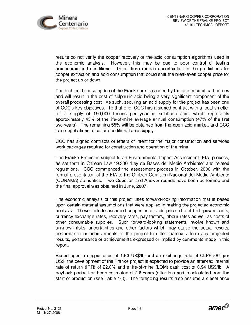
results do not verify the copper recovery or the acid consumption algorithms used in the economic analysis. However, this may be due to poor control of testing procedures and conditions. Thus, there remain uncertainties in the predictions for copper extraction and acid consumption that could shift the breakeven copper price for the project up or down.
The high acid consumption of the Franke ore is caused by the presence of carbonates and will result in the cost of sulphuric acid being a very significant component of the overall processing cost. As such, securing an acid supply for the project has been one of CCC’s key objectives. To that end, CCC has a signed contract with a local smelter for a supply of 150,000 tonnes per year of sulphuric acid, which represents approximately 45% of the life-of-mine average annual consumption (47% of the first two years). The remaining 55% will be obtained from the open acid market, and CCC is in negotiations to secure additional acid supply.
CCC has signed contracts or letters of intent for the major construction and services work packages required for construction and operation of the mine.
The Franke Project is subject to an Environmental Impact Assessment (EIA) process, as set forth in Chilean Law 19,300 “Ley de Bases del Medio Ambiente” and related regulations. CCC commenced the assessment process in October, 2006 with the formal presentation of the EIA to the Chilean Comision Nacional del Medio Ambiente (CONAMA) authorities. Two Question and Answer rounds have been performed and the final approval was obtained in June, 2007.
The economic analysis of this project uses forward-looking information that is based upon certain material assumptions that were applied in making the projected economic analysis. These include assumed copper price, acid price, diesel fuel, power costs, currency exchange rates, recovery rates, pay factors, labour rates as well as costs of other consumable supplies. Such forward-looking statements involve known and unknown risks, uncertainties and other factors which may cause the actual results, performance or achievements of the project to differ materially from any projected results, performance or achievements expressed or implied by comments made in this report.
Based upon a copper price of 1.50 US$/lb and an exchange rate of CLP$ 584 per US$, the development of the Franke project is expected to provide an after-tax internal rate of return (IRR) of 22.0% and a life-of-mine (LOM) cash cost of 0.94 US$/lb. A payback period has been estimated at 2.8 years (after tax) and is calculated from the start of production (see Table 1-3). The foregoing results also assume a diesel price

CENTENARIO COPPER CORPORATIONREVIEW OF THE FRANKE PROJECT
43-101 TECHNICAL REPORT
Project No: 2126 Page 1-4 March 27, 2008
of US$0.459/litre. For the sake of comparison, if this figure is changed to US$1.00/litre (see comments in Section 19.9 below) then the after-tax IRR falls to 19.4%, the LOM cash cost rises to US$1.00/lb and the payback period increases to 3.0 years.
The financial analysis results show that the project's financial outcome is sensitive to variation in the price/cost factors in the following order: metal price, metallurgical recovery rate, operating cost (acid included), capital expenditure, sulphuric acid price, exchange rate.
Table 1-3: Cash Flow Analysis (using Diesel price of US$0.459/litre)
Base Case
Sensitivity to Copper Price
Commodity
Copper US$/lb 1.50 0.75 1.00 1.25 1.75 2.00 2.25 2.50
Exchange Rate
Chilean Pesos per US$ CLP$/US$ 584 712 669 626 548 548 548 548
Pre-Tax
Internal Rate of Return % 25.6% N/A 8.0% 18.0% 31.8% 37.5% 42.6% 47.2%
Cumulative Net Cash Flow (CNCF) US$million 219 (42) 47 132 305 395 485 575
Net Present Value Discounted at 8% US$million 109 (56) 0 54 163 220 277 335
Net Present Value Discounted at 10% US$million 90 (59) (8) 40 139 190 241 293
Net Present Value Discounted at 12% US$million 73 (61) (16) 28 117 163 210 256
Payback Period Years 2.5 8.0 4.6 2.9 2.3 2.1 2.0 1.9
After Tax
Internal Rate of Return % 22.0% N/A 6.1% 15.2% 27.5% 32.6% 37.2% 41.4%
Cumulative Net Cash Flow (CNCF) US$million 179 (51) 36 107 249 324 398 472
Net Present Value Discounted at 8% US$million 83 (64) (8) 38 127 174 221 268
Net Present Value Discounted at 10% US$million 66 (66) (16) 25 106 148 191 233
Net Present Value Discounted at 12% US$million 51 (68) (23) 14 87 126 164 202
Payback Period Years 2.8 N/A 5.7 3.4 2.5 2.3 2.2 2.1
LOM Cash Cost
Unit Cash Cost US$/lb 0.94 0.82 0.86 0.90 0.98 1.02 1.05 1.08
Notes:
• Payback period is calculated from start of production (following 1.5 years of capital development). Cash flows occur at the end of each year. LOM cash costs vary due to acid contract copper price participation features.
• Acid and water prices are based on a selling price for copper of US$1.50 per pound. • Diesel cost is based upon a diesel price of US$0.459/litre (see comment in Section 19.9). • Sensitivity to changes in copper price has been applied only to unhedged sales.

CENTENARIO COPPER CORPORATIONREVIEW OF THE FRANKE PROJECT
43-101 TECHNICAL REPORT
Project No: 2126 Page 1-5 March 27, 2008
Table 1-4: Discounted Cash Flow
Year (December 31st) 2007 2008 2009 2010 2011 2012 2013 2014 2015 2016
Production time -2 -1 1 2 3 4 5 6 7 8 Expected mineral price Copper price ($/pound) 1.50 1.50 1.50 1.50 1.50 1.50 1.50 1.50 1.50 1.50
Production model
Recovered mineral
Copper (Klb) 0 0 55,171 66,139 66,139 66,139 66,139 66,139 66,139 49,397 Smelter mineral deductions
Copper (Klb) 0 0 0 0 0 0 0 0 0 0
Payable mineral
Copper (Klbs) 0 0 55,171 66,139 66,139 66,139 66,139 66,139 66,139 49,397
Cash flow calculation ($ million) Total mineral revenue 0 0 117,139 161,755 100,531 100,531 100,531 100,531 100,531 75,083
Copper revenue 0 0 116,036 160,432 99,208 99,208 99,208 99,208 99,208 74,095
Cathode premium 0 0 1,103 1,323 1,323 1,323 1,323 1,323 1,323 988 Total production costs 0 0 65,014 61,216 57,164 59,481 63,673 63,817 64,751 36,658
Mining 0 0 11,877 12,056 12,628 12,404 13,463 13,730 14,374 9,335
Acid 0 0 24,556 20,855 19,125 21,653 24,578 24,563 25,082 12,118
Water 0 0 1,062 1,062 1,062 1,062 1,062 1,062 1,062 620
Power 0 0 11,180 11,180 7,777 7,777 7,777 7,777 7,777 4,511 Process (excluding above) 0 0 16,338 16,062 16,571 16,584 16,792 16,684 16,455 10,074 Total metal payments 0 0 0 0 0 0 0 0 0 0
Mineral deduction 0 0 0 0 0 0 0 0 0 0
Total other costs 0 0 0 0 0 0 0 0 0 0
Social investment 0 0 0 0 0 0 0 0 0 0 Operating Cash Flow 0 0 52,125 100,539 43,367 41,049 36,858 36,714 35,780 38,425 Capital expenditure 27,111 131,796 3,854 0 0 0 0 0 0 3,050 Working capital variation 0 8,928 1,586 316 0 0 0 0 0 -10,830 Pre-tax project cash flow -27,111 -140,725 46,686 100,224 43,367 41,049 36,858 36,714 35,780 46,205 Corporate income tax 0 0 -1,898 -10,128 -409 -4,719 -4,006 -3,982 -6,083 0 Government royalty 0 0 -308 -695 -238 -293 -259 -258 -286 0 After tax project cash flow -27,111 -140,725 44,480 89,400 42,720 36,038 32,592 32,474 29,411 46,205

CENTENARIO COPPER CORPORATIONREVIEW OF THE FRANKE PROJECT
43-101 TECHNICAL REPORT
Project No: 2126 Page 1-6 March 27, 2008
Two reverting, forward copper price scenarios were also considered (Table 1-5). The results of using this price scenarios are summarized and compared with the base case in Table 1-6
Table 1-5: Copper Forward Price Values
Cu Price, $/lb 2009 2010 2011 2012 2013 2014 2015 2016 Scenario A 3.35 3.15 3.00 2.90 1.50 1.50 1.50 1.50 Scenario B 3.35 3.15 3.00 2.90 2.00 2.00 2.00 2.00
Table 1-6: Effect of Forward Copper Prices (using Diesel price of US$0.459/litre)
Unit Base Case
Scenario A
Scenario B
Commodity Copper US$/lb 1.50 Exchange Rate Chilean Pesos per US$ CLP$/US$ 584 584 584 Pre-Tax Internal Rate of Return % 25.6% 57.5% 59.9% Cumulative Net Cash Flow (CNCF) US$million 219 494 618 Net Present Value Discounted at 8% US$million 109 314 385 Net Present Value Discounted at 10% US$million 90 282 343 Net Present Value Discounted at 12% US$million 73 252 306 Payback Period Years 2.5 1.5 1.5 After Tax Internal Rate of Return % 22.0% 49.3% 51.8% Cumulative Net Cash Flow (CNCF) US$million 179 405 507 Net Present Value Discounted at 8% US$million 83 252 310 Net Present Value Discounted at 10% US$million 66 224 274 Net Present Value Discounted at 12% US$million 51 199 243 Payback Period Years 2.8 1.7 1.7
AMEC recommends that Minera Centenario proceed with the development of the Franke Property and recommends continuing the mine development activities on the Franke Property that are expected to reduce project technical risk, allow improved detailed engineering design, and improve operational performance in a commercial mine. These include metallurgical performance from the test heap, and geotechnical studies to support optimum pit slope.

CENTENARIO COPPER CORPORATIONREVIEW OF THE FRANKE PROJECT
43-101 TECHNICAL REPORT
Project No: 2126 Page 2-1 March 27, 2008
2.0 INTRODUCTION AND TERMS OF REFERENCE
Centenario Copper Chile S.C.M. (CCC) commissioned AMEC International Chile (AMEC) to provide an independent Qualified Person’s review of the Franke copper project in Chile and to prepare a Technical Report which meets the requirements of Canadian National Instrument 43-101 Standards of Disclosure for Mineral Projects (NI 43-101).
The cut-off date for the drilling information was December 24, 2007. Additional technical data were received early in 2008 with the latest metallurgical testwork report received on March 11, 2008. The purpose of this technical report is to provide CCC with an update of an earlier technical report dated August 2007, that includes results of infill drilling and other activities that have taken place since August 2007 and to provide an independent review of the updated Franke copper mineral resource and mineral reserve estimates. The basis of the Franke copper project information is the 2007 feasibility study by AMEC, plus detailed mine design and project development managed by AMEC, with contributions from various third parties.
The effective date of the updated mineral resource and mineral reserve estimates is December 24, 2007, and the effective date of the report of March 11, 2008 reflects the latest metallurgical testwork received. An infill drilling program was completed on July 12, 2007 and the results are included in this new mineral resource estimate.
2.1 Qualified Persons and Participating Personnel
Rodrigo Marinho, CPG (AIPG), an employee of AMEC, served as the Qualified Person responsible for preparing and supervising the preparation of the sections or portions of sections 1 to 15, 17.1, 17.2, 20 to 23 of this technical report. Mr. Marinho visited the Franke property site on February 20, 2008. During this visit, AMEC reviewed the location of a large number of collars from the 1997 to 2007 drilling campaigns, underground cavities, reject stockpiles, as well as the pits from the stockpile sampling program. AMEC also observed chip samples that are stored at the Geovectra facility in Santiago
Ralph Penner, MAusIMM, an employee of AMEC, served as the Qualified Person responsible for preparing or supervising the preparation of the mining sections of the technical report (Section 17.3, except 17.3.1, and Sections 19.1, 19.10 and 19.11 and portions of Sections 1 and 20 to 23).
CENTENARIO COPPER CORPORATIONREVIEW OF THE FRANKE PROJECT
43-101 TECHNICAL REPORT
Project No: 2126 Page 2-2 March 27, 2008
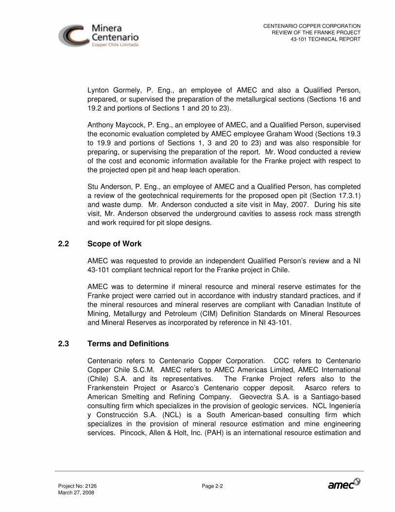
Lynton Gormely, P. Eng., an employee of AMEC and also a Qualified Person, prepared, or supervised the preparation of the metallurgical sections (Sections 16 and 19.2 and portions of Sections 1 and 20 to 23).
Anthony Maycock, P. Eng., an employee of AMEC, and a Qualified Person, supervised the economic evaluation completed by AMEC employee Graham Wood (Sections 19.3 to 19.9 and portions of Sections 1, 3 and 20 to 23) and was also responsible for preparing, or supervising the preparation of the report. Mr. Wood conducted a review of the cost and economic information available for the Franke project with respect to the projected open pit and heap leach operation.
Stu Anderson, P. Eng., an employee of AMEC and a Qualified Person, has completed a review of the geotechnical requirements for the proposed open pit (Section 17.3.1) and waste dump. Mr. Anderson conducted a site visit in May, 2007. During his site visit, Mr. Anderson observed the underground cavities to assess rock mass strength and work required for pit slope designs.
2.2 Scope of Work
AMEC was requested to provide an independent Qualified Person’s review and a NI 43-101 compliant technical report for the Franke project in Chile.
AMEC was to determine if mineral resource and mineral reserve estimates for the Franke project were carried out in accordance with industry standard practices, and if the mineral resources and mineral reserves are compliant with Canadian Institute of Mining, Metallurgy and Petroleum (CIM) Definition Standards on Mineral Resources and Mineral Reserves as incorporated by reference in NI 43-101.
2.3 Terms and Definitions
Centenario refers to Centenario Copper Corporation. CCC refers to Centenario Copper Chile S.C.M. AMEC refers to AMEC Americas Limited, AMEC International (Chile) S.A. and its representatives. The Franke Project refers also to the Frankenstein Project or Asarco’s Centenario copper deposit. Asarco refers to American Smelting and Refining Company. Geovectra S.A. is a Santiago-based consulting firm which specializes in the provision of geologic services. NCL Ingeniería y Construcción S.A. (NCL) is a South American-based consulting firm which specializes in the provision of mineral resource estimation and mine engineering services. Pincock, Allen & Holt, Inc. (PAH) is an international resource estimation and
CENTENARIO COPPER CORPORATIONREVIEW OF THE FRANKE PROJECT
43-101 TECHNICAL REPORT
Project No: 2126 Page 2-3 March 27, 2008
mine consulting and engineering firm. The CIMM laboratory refers to the Centro de Investigación Minera y Metalúrgica laboratory.
The total copper and soluble copper grade values are referenced as TCu and SCu respectively, unless otherwise noted.
2.4 Units
Unless otherwise specified, all units of measurement in this report are metric. Grades are described in terms of percent (%) with tonnages stated in metric tonnes. Saleable base metals are described in terms of metric tonnes or pounds (lb).
The base currency used to prepare the cost estimate was the January 2008 United States dollar (US$). All costs were denominated in this currency; therefore, the local costs (Chilean pesos or CLP) were converted by using the exchange rates indicated in Section 19.8.
CENTENARIO COPPER CORPORATIONREVIEW OF THE FRANKE PROJECT
43-101 TECHNICAL REPORT
Project No: 2126 Page 3-1 March 27, 2008
3.0 RELIANCE ON OTHER EXPERTS
AMEC has relied on an untitled document dated April 4, 2007 which was provided to CCC by the law firm of Edmundo Eluchans y Cia. More specifically, this document confirms that CCC is the owner in good standing for the mineral concessions on the Franke property which are list in Section 4.2.
ARCADIS Geotechnica has been responsible for the submission of the environmental impact study (EIS) for the Franke project as well as the geotechnical report for the waste dump. AMEC has relied on information provided by ARCADIS specifically in Sections 4.3, 17.3.1 and 19.5.
INGEROC has been responsible for the submission of the design of the open pit slopes for the Franke project. AMEC has relied on information provided by INGEROC specifically in Section 17.3.1.
Market analysis studies were conducted for copper (OAC Ltda, undated) and sulphuric acid (OAC Ltda, May 2007 and December, 2007 Update) by Ricardo Olivares of OAC Ltda on behalf of CCC. AMEC has specifically relied upon these studies in Section 19.3.
AMEC has relied upon tax information provided by Jose Luis Aviles of Grant Thornton in Section 19.7.
AMEC believes it is reasonable to rely on these experts and disclaims responsibility for any errors or omissions in the information provided by these other experts. This report should be read in its entirety.
CENTENARIO COPPER CORPORATIONREVIEW OF THE FRANKE PROJECT
43-101 TECHNICAL REPORT
Project No: 2126 Page 4-1 March 27, 2008
4.0 PROPERTY DESCRIPTION AND LOCATION
4.1 Location
The Franke deposit is located in the Altamira mining district, 65 km to the north of the town of Diego de Almagro. The Altamira mining district is located in Region II, 12 km north of the border with Region III in Chile. It is also located approximately 235 km to the southeast of the city of Antofagasta. Elevations range from about 1,600 metres above sea level to slightly over 1,700 metres within the project area. The area is easily accessed by road from the cities of Copiapó or Antofagasta. Access to the project from the west is available via a 56 km dirt road between the Pan-American Highway and the project. A general location map is shown in Figure 4-1.
4.2 Land Tenure
The Franke property consists of 649.22 hectares of mining concessions and rights of way which cover the Franke and San Guillermo deposits. The concessions are listed in Table 4-1 and shown in Figure 4-2.
Table 4-1: Mining Concessions
Claim Parcels Area Rights of Way (ha) (ha) Frankenstein 1-3 15 8.93 Tres Marias 1-5 25 San Guillermo 1-64 320 43.97 Viviana 1-36 166 28.82 San Carlos 1-4 20 9.50 Año Nuevo Dos 1-12 12 Total 124 558 91.22

CENTENARIO COPPER CORPORATIONREVIEW OF THE FRANKE PROJECT
43-101 TECHNICAL REPORT
Project No: 2126 Page 4-2 March 27, 2008
Figure 4-1: General Location Map
Source: Geovectra et al, 2005
CENTENARIO COPPER CORPORATIONREVIEW OF THE FRANKE PROJECT
43-101 TECHNICAL REPORT
Project No: 2126 Page 4-3 March 27, 2008
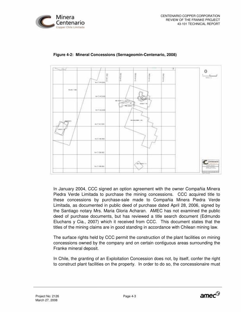
Figure 4-2: Mineral Concessions (Sernageomin-Centenario, 2008)
In January 2004, CCC signed an option agreement with the owner Compañia Minera Piedra Verde Limitada to purchase the mining concessions. CCC acquired title to these concessions by purchase-sale made to Compañia Minera Piedra Verde Limitada, as documented in public deed of purchase dated April 28, 2006, signed by the Santiago notary Mrs. Maria Gloria Acharan. AMEC has not examined the public deed of purchase documents, but has reviewed a title search document (Edmundo Eluchans y Cia., 2007) which it received from CCC. This document states that the titles of the mining claims are in good standing in accordance with Chilean mining law.
The surface rights held by CCC permit the construction of the plant facilities on mining concessions owned by the company and on certain contiguous areas surrounding the Franke mineral deposit.
In Chile, the granting of an Exploitation Concession does not, by itself, confer the right to construct plant facilities on the property. In order to do so, the concessionaire must

CENTENARIO COPPER CORPORATIONREVIEW OF THE FRANKE PROJECT
43-101 TECHNICAL REPORT
Project No: 2126 Page 4-4 March 27, 2008
first either acquire the surface rights to the property or acquire a mining easement over the property.
The surface rights to the Franke Concessions, as well as to surrounding third party mining concessions, are held by the State of Chile. CCC has applied for and obtained mining easements on the Franke Concessions, as well as on certain surrounding properties on which third parties currently hold valid Exploitation Concessions. Together, these mining easements (First Easement) cover the proposed footprint for the Franke processing plant, waste dumps and related infrastructure. CCC will make an annual payment to the State of Chile (as established by the courts) for these mining easements. These mining easements will apply throughout the life of the Franke project.
In addition to the First Easement granted July 16 2007, CCC applied for additional easements over an expanded area that will allow for potential future expansion of the Franke plant (Second and Third Easements). These mining easements were granted on July 30, 2007.
The layout of the proposed Franke processing plant and related infrastructure, as well as the location Franke Concessions and the approved mining easements is set out in Figure 4-3.
In Figure 4-3, the Franke plant footprint, including the pit, waste dump, process pad and leach dumps overlays the property areas. The Franke Concessions are shown in green (as is the Pelusa exploitation concession block to the west, also owned by CCC). The Easements are shown in yellow.

CENTENARIO COPPER CORPORATIONREVIEW OF THE FRANKE PROJECT
43-101 TECHNICAL REPORT
Project No: 2126 Page 4-5 March 27, 2008
Figure 4-3: Inventory of Mining Properties and Easements (Centenario, 2008)
As indicated, the Franke pit is located in the Franke Concessions (turquoise), while the balance of the Franke plant footprint is located either in the Franke Concessions (turquoise) or in the surrounding area that is covered by the First Easement.
The Easement also extends to the west to the Pelusa concessions (also in turquoise and held by CCC, see Section 15). The current Franke plant footprint is adequately covered by the Easements that also provide additional space to accommodate future growth in the processing plant; leach pad and waste dump areas.
4.3 Environmental Liabilities
The Franke Project is subject to an Environmental Impact Assessment (EIA) process, as set forth in Chilean Law 19,300 “Ley de Bases del Medio Ambiente”, and related regulations. CCC commenced the assessment process in October, 2006 with the formal presentation of the EIA to the Chilean Comision Nacional del Medio Ambiente

CENTENARIO COPPER CORPORATIONREVIEW OF THE FRANKE PROJECT
43-101 TECHNICAL REPORT
Project No: 2126 Page 4-6 March 27, 2008
(CONAMA) authorities. Two Question and Answer rounds have been performed and the final approval was obtained in June 2007.
In addition to the EIA, there are a number of additional environmental and non-environmental related permits that will be required in order to develop the Franke project which will be applied for following the completion of the EIA process. A summary of these permits is set out below:
• Application for approval of changes to the project design that were made subsequent to the initial submission of the EIA. These changes will likely be addressed through Environmental Impact Declarations (EID’s), and include:
o Secondary Leaching Elimination with subsequent Barren-Rock Disposal Site Creation (to be placed on the waste dumps);
o Modification of the Headrace Line (Water Pipeline) Layout; o Construction of a High-Voltage Line (HVL).
• Approximately 10 other environmental related permits, of which the “Construction Permit for Hydraulic Works Stipulated in Article 294 of the Water Code” is expected to require special attention, due to the expected review period and detailed engineering required. CCC has completed detailed engineering of the water line and it does not currently consider that this review process will be on the project development critical path.
• Approximately 46 non-environmental permits, most of which should be issued in the normal course.
More detailed permitting information is presented in Section 19.5.
CENTENARIO COPPER CORPORATIONREVIEW OF THE FRANKE PROJECT
43-101 TECHNICAL REPORT
Project No: 2126 Page 5-1 March 27, 2008
5.0 ACCESSIBILITY, CLIMATE, LOCAL RESOURCES, INFRASTRUCTURE AND PHYSIOGRAPHY
5.1 Access
The Franke copper deposit is located in the Altamira district, near the southern limit of the Antofagasta Region (Region II) of Chile. The area is easily accessed from Km 1075 of the Pan-American Highway, and about 56 km of dirt road heading eastwards. Km 1075 is located 70 km south of Taltal and 150 km north of Copiapó.
Two other improved dirt roads may be used to access the property. A 70 km road provides access from the south from the community of Diego de Almagro. The city of Chanaral may be accessed to the southwest by means of 90 km of improved dirt road plus 36 km of highway.
5.2 Climate and Topography
The Franke deposit is located in a plateau between the coast and mountains of Chile, in the Atacama desert. The Atacama desert is considered to be one of the most arid deserts on earth. Local physiography consists of low hills and extended plains at 1,600 m.a.s.l., with local elevations of 1,700 m.a.s.l. The climate is arid with no rainfall in normal years. The average annual precipitation is usually less than one or two millimetres. Summer temperatures range from about 18 to 32°C, while in winter, temperatures fall below 0°C. Overcast skies and some snow flurries are common in winter. Weather presents no severe conditions and work can be conducted year round.�
Vegetation is minimal, supporting only desert scrub and sparse cactus. There are no perennial streams in the area.
5.3 Local Resources and Infrastructure
Labour force in the neighbouring towns of Taltal (100 km), Chañaral (116 km) and Diego de Almagro (70 km) is abundant and experienced in mining, since several copper, iron and gold mines are operating in the region. Workers will be bussed to and from the site. Some dirt portions of the access roads would require minor improvement and maintenance. The commute time would be approximately one hour each way to any of these three towns.

CENTENARIO COPPER CORPORATIONREVIEW OF THE FRANKE PROJECT
43-101 TECHNICAL REPORT
Project No: 2126 Page 5-2 March 27, 2008
CCC has begun establishing strong relationships with the communities of Diego de Almagro and Taltal, as well as the Salvador division of Codelco, with the final goal of attracting qualified professionals and manpower from the area. To this end, CCC has established a hiring office in the community of Diego de Almagro. Through March and April, 2008 training courses are being run at the Adult Education Centre (Centro de Educación Integral para Adultos) in Diego de Almagro. After that time and up to October, CCC intends to continue training at similar operations and on site. This will add to the social development of the region, an area considered to be economically depressed in the Chilean context.
The availability of water is critical, as there is little to no rainfall in the area. The water in the area is generally collected from the Andes snowpack, approximately 100 km east of the Franke deposit. However, CCC has signed a water supply agreement for 50 L/s with Codelco (Salvador Division) located 70 km from the site. This contract secures the water supply for the entire mine life of the Franke project.
The high acid consumption of the Franke ore is caused by carbonates and will result in the cost of sulphuric acid being a significant component of the overall processing cost. As such, securing an acid supply for the project has been one of CCC’s key objectives. To that end, CCC has a signed contract with a local smelter for a supply of 150,000 tonnes per year of sulphuric acid, which represents approximately 45% of the life-of-mine average annual consumption (47% of the first two years). The remaining 55% will be obtained from the open acid market, though CCC is in negotiations to secure additional acid supply.
A fully operational rail track, currently not in service, is located 3 km to the east of the area. The regular railroad operation stopped three decades ago, but the track is still maintained by the railroad company. A rail spur to the plant area has been designed and will be installed by a contractor specializing in this type of work. The earthworks required will be completed as part of the earthworks contract. This rail line will be used for shipping cathodes from Franke to the port of Barquitos at Chañaral. Most consumable goods will likely be shipped through this port.
The electrical supply to the Project will be from the Diego de Almagro substation. A 110 kV high voltage line is being constructed between Diego de Almagro and the Franke site. The energy cost has been negotiated with various energy suppliers, and an agreement has been reached with Pacific Hydro, who offered the best technical-economical proposal.

CENTENARIO COPPER CORPORATIONREVIEW OF THE FRANKE PROJECT
43-101 TECHNICAL REPORT
Project No: 2126 Page 6-1 March 27, 2008
6.0 HISTORY
This area of Chile, rich in copper minerals, has been commercially mined since the 1920’s by the Salvador division of Codelco and the Anaconda Mining Company.
The earliest geological studies on Franke were reportedly performed by Enami as free technical support to the small scale mining community (1971). The discovery in 1983 of the neighbouring Altamira deposit by Codelco (now owned by Minera Las Cenizas) triggered some interest on the Franke Hill and four holes were drilled by RTZ Chile in 1984, reaching a maximum vertical depth of about 150 m. One of the holes intersected oxide mineralization, but RTZ abandoned activities since no sulphide intersections were encountered.
Asarco began exploration in the district in early 1997 with field reconnaissance work, identifying the potential for leachable copper ores in the Franke area. An initial reconnaissance drill program of 13 holes was completed by June 1997. Due to the encouraging results of this campaign at Franke, a new drill program was started in September 1997 that confirmed the presence of a significant copper oxide deposit at the site. A third program of infill/definition drilling totalling 213 holes began in November, 1997 and consisted of a mix of diamond and reverse circulation holes.
At that time, a shallow drill program identified an anomalous zone at the San Guillermo area, which was followed by 8 reconnaissance reverse circulation holes in September, 1998, encountering copper oxide mineralization within the anomalous zone. Subsequently, 38 additional holes were drilled in San Guillermo.
Environmental and preliminary engineering studies were also initiated concurrently with the third drilling campaign. This program ended in March 1999. The resource estimates and preliminary pit optimizations undertaken by Asarco concluded that a Geologic Resource of about 50 million tonnes grading 0.5-0.6% Cu at a 0.2% cut-off grade existed at the site. The initial pit optimization runs arrived to an “in-pit resource” of about 34 million tonnes at 0.7% Cu at a cut-off grade of 0.3%, with a strip ratio of 0.3 waste to ore tonnes.
The activity on the project ceased in February 1999 and Asarco returned the property to the original owners. Asarco spent about US$ 3,000,000 on the project in the 1997-99 period.
The resource estimates stated above in this section are historical references that were completed prior to the implementation of NI 43-101. There is insufficient information to compare the Geologic Resource category to CIM Mineral Resource categories. A
CENTENARIO COPPER CORPORATIONREVIEW OF THE FRANKE PROJECT
43-101 TECHNICAL REPORT
Project No: 2126 Page 6-2 March 27, 2008
qualified person has not done sufficient work to classify the historical estimates as current Mineral Resources. Historical estimates should not be relied upon and have been superseded the current mineral resources and reserves in Section 17 of this report.
6.1 Production History
The Franke deposit has been mined since the mid sixties under contract with the claim holder. At that time several groups of pirquineros (pick and shovel miners) were working in small underground stopes and caves, selling high grade ores to the Enami buying agency located at the Altamira railroad station. After 1973 small mining activities were reduced and the agency closed. Small mining activities restarted during the eighties and the ore was sold in Taltal, either to Enami or to other private mills. Notice to the contractors was given by the claim owner in January 2006 to stop mining operations in three months according their contract and they vacated the property in March, 2006.
No accurate historical production records exist for the Franke project. Recent production was approximately 150 – 200 t/d ore from the shafts. After hand sorting, roughly 50 tonnes of high grade ore grading 4% Cu and about 100 to 180 g/t Ag was sent by truck daily to Taltal. Leaching of the oxides or concentration of the sulphide ores were carried out in Taltal.
Twenty-four underground workings were surveyed, mapped and sampled by Geovectra in 2005 with different degrees of accuracy grades. The stope designs were integrated into the 5 m bench maps and discounted from the resources (Geovectra et al, 2005). Geovectra estimated a stope volume of 565,065 m³. This represented, approximately, 1.5 million tonnes of extracted material when an average density of 2.6 tonnes per cubic metre was used. The main underground stopes are displayed in Figure 6-1 as identified by Geovectra in 2005.
The mining contractors only shipped high grade ores so the lower grade material was left scattered in dumps and stockpiles throughout the Franke area. Geovectra also surveyed the reject stockpiles in 2005 and estimated the volume to be 416,994 m³. At an approximate density of 1.9 tonnes per cubic metre, Geovectra estimated that the dumps contained approximately 792,288 tonnes of material. In 2006 based on a sampling program in the stockpiles and using a density of 1.79 t/m3, Geovectra estimated the dumps at 746,419 tonnes. In 2007 based on a new survey and a density of 1.79 t/m3, Geovectra estimated a stockpile tonnage of 874,000 tonnes.

CENTENARIO COPPER CORPORATIONREVIEW OF THE FRANKE PROJECT
43-101 TECHNICAL REPORT
Project No: 2126 Page 6-3 March 27, 2008
Figure 6-1: Main Underground Stopes
Source: Geovectra et al, 2005
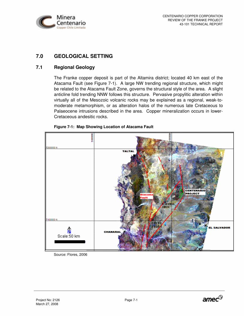
CENTENARIO COPPER CORPORATIONREVIEW OF THE FRANKE PROJECT
43-101 TECHNICAL REPORT
Project No: 2126 Page 7-1 March 27, 2008
7.0 GEOLOGICAL SETTING
7.1 Regional Geology
The Franke copper deposit is part of the Altamira district; located 40 km east of the Atacama Fault (see Figure 7-1). A large NW trending regional structure, which might be related to the Atacama Fault Zone, governs the structural style of the area. A slight anticline fold trending NNW follows this structure. Pervasive propylitic alteration within virtually all of the Mesozoic volcanic rocks may be explained as a regional, weak-to-moderate metamorphism, or as alteration halos of the numerous late Cretaceous to Palaeocene intrusions described in the area. Copper mineralization occurs in lower-Cretaceous andesitic rocks.
Figure 7-1: Map Showing Location of Atacama Fault
Source: Flores, 2006

CENTENARIO COPPER CORPORATIONREVIEW OF THE FRANKE PROJECT
43-101 TECHNICAL REPORT
Project No: 2126 Page 7-2 March 27, 2008
7.1.1 Stratigraphy
The country rocks of the Altamira district belong to the lower-Cretaceous Aeropuerto (or Cerros Florida) Formation (Figure 7-2).
Stratigraphically, two principal geologic formations are recognized around and within the Altamira. Both the Jurassic La Negra Formation and the overlying Cretaceous Cerros Florida (Aeropuerto) Formation are sequences of andesitic volcanic rocks with subordinate intercalated sedimentary rocks. The Altamira district and the Franke deposit are interpreted to be hosted within the Cerros Florida Formation.
The Jurassic La Negra formation is older and more widespread than the overlying Cerros Florida Formation. It occurs along the Coastal Range Mountains and varies in thickness from less than 3,000 m to greater than 5,000 m. It primarily consists of andesitic-basaltic flows, volcanic flow breccias, dacitic tuffs, and calcareous sandstones and conglomerates. This formation is thought to be sub-aerial, but localized pillow lava structures have been reported in coastal areas.
The base of the overlying Cerros Florida Formation is characterised by a series of intercalated andesitic and sedimentary units, which represent the downward transition into the La Negra volcanic rocks. This transition has been mapped on Sierra Altamira several kilometres north of the Altamira district, where it appears to be conformable and transitional. Above this, there are approximately 250 m of andesite and flow breccias that comprise the lower base of the Cerros Florida Formation.
The upward transition into the middle portion of the Cerros Florida Formation is the interpreted host unit for the Franke deposit. This part of the formation displays a pronounced porphyritic series of flows (“ocoitas” in local terminology) and flow breccias, plus minor andesitic dikes. The flows exhibit amygdaloidal flow tops and bottoms. There are minor interbedded sedimentary rocks consisting of a mixture of volcaniclastic sandstones, siltstones and impure limestones that appear to be lacustrine and fluvial in origin.

CENTENARIO COPPER CORPORATIONREVIEW OF THE FRANKE PROJECT
43-101 TECHNICAL REPORT
Project No: 2126 Page 7-3 March 27, 2008
Figure 7-2: Cretaceous Rocks in the Altamira District
Source: Geovectra et al., 2005

CENTENARIO COPPER CORPORATIONREVIEW OF THE FRANKE PROJECT
43-101 TECHNICAL REPORT
Project No: 2126 Page 7-4 March 27, 2008
7.1.2 Structure
The main structural trends within the Altamira district are the north-to-northwest (N10-50°W) faults and fold axes, as well as the dominant strike of the stratigraphy (see Figure 7-3). There are also subsidiary trends, one west-northwest (N60-70°W) that might be an older structural fabric, since these faults are segmented by the previous ones and another trend nearly N-S (N 10-20°E). The last one might be related to wrench faulting along the major structures and folds. Hydrothermal copper mineralization was injected into the favourable (permeable) rock horizons by using any of the previously described structures as feeders. A fourth structural trend, striking northeast (N30-45°E), is also present in the district, representing the last mid-upper tertiary tectonic events and is responsible for the down-drop of the Altamira (Cenizas) block with respect to the Franke one.
Figure 7-3: Landsat Map Showing Regional Structural Interpretation
Source: Flores, 2006

CENTENARIO COPPER CORPORATIONREVIEW OF THE FRANKE PROJECT
43-101 TECHNICAL REPORT
Project No: 2126 Page 7-5 March 27, 2008
7.2 Local and Property Geology
The Franke area exhibits a shallowly dipping anticline fold striking N20-40°W (Figure 7-4). It is slightly steeper on the southwest flank (up to 20°) than on the northeast flank (5-15°). Bedding along the axis of the anticline is an almost horizontal crest zone about 100-200 m wide, as observed in the underground workings dug into this area. However, previous studies have suggested that this anticline also plunges to the NNW and SSE, defining a gently dipping structural dome.
Flanking the sub-horizontal crest zone of the anticline, several steeply dipping N25-35°W/70-80°E faults are apparently one of the main mineralization controls for the emplacement of high grade copper in the Franke deposit. The other control is given by the segments of the N60-70°W structural trend. .
Figure 7-4: Structural Pattern at Franke
Source: Geovectra, 2005
N
Scale: 250m
�

CENTENARIO COPPER CORPORATIONREVIEW OF THE FRANKE PROJECT
43-101 TECHNICAL REPORT
Project No: 2126 Page 7-6 March 27, 2008
The geometry of the ore zones in the Franke deposit is closely related with this particular structural arrangement: while the mineralization at the flanks of the anticline is typically formed by one or more ore horizons of limited thicknesses (1 to 5 m), the mineralization within and near the structural corridors located near the anticline crest, tends to be thicker and higher in grade, forming 10 to 30 m thick mineralized blocks separated by relatively thin barren horizons.
The Franke and San Guillermo deposits are separated by a shear zone where two parallel northwest-trending faults appear to down-drop some of the interbedded sedimentary rocks creating a small graben of strongly disrupted sedimentary rocks.
There appears to be a crude outward zonation of alteration centered roughly on the top of the Franke deposit but it is distorted by the several vein-stockwork zones that similarly exhibit more intensive alteration and primary mineralization. The central and most intensive alteration includes moderate to strong alteration of plagioclase phenocrysts to sericite and clays, plus total conversion of magnetite to specularite; a strong propylitic to weak sericitic assemblage. Outward from this central area the alteration generally decreases in intensity until finally grading with the regional green schist assemblage.
CENTENARIO COPPER CORPORATIONREVIEW OF THE FRANKE PROJECT
43-101 TECHNICAL REPORT
Project No: 2126 Page 8-1 March 27, 2008
8.0 DEPOSIT TYPES
Andesite hosted hydrothermal stockwork deposits are relatively common in the Coastal Belt of northern Chile. Most of them are related to the Upper-Jurassic island arc volcanism of the La Negra Formation and generally the stratabound fraction has been fed by hydrothermal breccias surrounding dioritic intrusive necks of age similar to the volcanic piles.
The deposits of the Altamira district share several features with those of La Negra Formation, but they are slightly younger, are clearly related to sub aerial volcanism (lenticular and irregular flows intercalated with sedimentary beds) and their feeders are fault-veins of limited size instead of hydrothermal breccias. No intrusive bodies that could account for the mineralization have been found so far.
The deposits of the Altamira district, as those of the La Negra Formation, are hydrothermal copper (± silver) andesite hosted stockwork sulphide deposits that have been partially oxidized. The injected hydrothermal materials were rich in copper but poor in iron and sulphur, consequently the resulting primary mineralization is largely chalcocite (minor covellite and bornite and traces of chalcopyrite). Due to the lack of pyrite in the primary assemblages, no sulphuric acid was generated during the oxidation process and therefore, the conversion of the primary sulphides into secondary assemblages (copper oxide minerals and minor secondary sulphides) took place largely “in situ”, with limited displacement of the mineralization from its original location.

CENTENARIO COPPER CORPORATIONREVIEW OF THE FRANKE PROJECT
43-101 TECHNICAL REPORT
Project No: 2126 Page 9-1 March 27, 2008
9.0 MINERALIZATION
The mineralization of copper is found in the form of oxides species (Atacamite, Malachite, Chrysocolla, etc.) and to a lesser extent, sulphides (Chalcocite). The Franke - Altamira “manto-type” copper deposit presents a Cu-Ag association (Flores, 2006). The flow breccias are of sub-aerial origin and they are found in most of the deeper drilling under the Franke deposit.
The uppermost unit of the Aeropuerto Formation is dominantly equigranular andesite, in contrast with the porphyritic flows of the middle portion and has little exposure on the surface of the district.
The middle portion of the Aeropuerto Formation that hosts most of the copper mineralization in the Altamira district is about 100 – 200 m thick at the Franke deposit and is dominated by distinctively discontinuous lava flows of porphyritic phases interbedded, in the upper part, with sedimentary rocks that are highly lenticular, indicating a fluvial or lacustrine terrestrial origin.
Most of the copper mineralization is hosted in porphyritic amygdaloidal andesites and ocoitas, but an important amount is hosted in equigranular andesites and in a lesser amount in volcaniclastic and calcareous sediments. Basal andesitic flow breccias and upper chocolate – brown andesites are generally barren units.
The high grade portion of the Franke deposit is formed by a large number of stratabound pods of different sizes, each one connected to one or more faults striking NW, WNW or N. These faults are now sealed by hydrothermal material and were used by the hydrothermal fluids to pervade into the favourable horizons (i.e. vesicular flows, contacts, micro fractures and stockworks). The horizontal size of these pods varies from a few metres to tens of metres from the feeders and the fading of the mineralization pinches within a very short distance, even if the favourable horizon persists.
The oxidation profile at Franke is rather complex, lacking clear definitive surfaces defining the top of the sulphides and the bottom of the oxides. The upper 20 m of the stratabound mineralization is largely, but not completely oxidized. Between 20 and 60 m depth, the mixed ores with subordinated sulphides are the most common assemblages while at deeper levels the sulphides start to predominate. Inversions of this sequence are very common and oxidized horizons may reappear under sulphide ore zones.
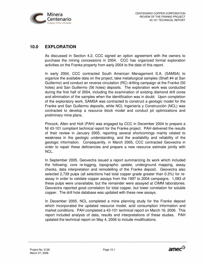
CENTENARIO COPPER CORPORATIONREVIEW OF THE FRANKE PROJECT
43-101 TECHNICAL REPORT
Project No: 2126 Page 10-1 March 27, 2008
10.0 EXPLORATION
As discussed in Section 4.2, CCC signed an option agreement with the owners to purchase the mining concessions in 2004. CCC has organized formal exploration activities on the Franke property from early 2004 to the date of this report.
In early 2004, CCC contracted South American Management S.A. (SAMSA) to organize the available data on the project, take metallurgical samples (Shaft #4 at San Guillermo) and conduct an reverse circulation (RC) drilling campaign at the Franke (50 holes) and San Guillermo (56 holes) deposits. The exploration work was conducted during the first half of 2004, including the examination of existing diamond drill cores and elimination of the samples when the identification was in doubt. Upon completion of the exploratory work, SAMSA was contracted to construct a geologic model for the Franke and San Guillermo deposits, while NCL Ingeniería y Construcción (NCL) was contracted to develop a resource block model and conduct pit optimizations and preliminary mine plans.
Pincock, Allen and Holt (PAH) was engaged by CCC in December 2004 to prepare a NI 43-101 compliant technical report for the Franke project. PAH delivered the results of their review in January 2005, reporting several shortcomings mainly related to weakness in the geologic understanding, and the availability and reliability of the geologic information. Consequently, in March 2005, CCC contracted Geovectra in order to repair these deficiencies and prepare a new resource estimate jointly with NCL.
In September 2005, Geovectra issued a report summarizing its work which included the following: core re-logging, topographic update, underground mapping, assay checks, data interpretation and remodelling of the Franke deposit. Geovectra also selected 2,739 pulps (all selections had total copper grade greater than 0.3%) for re-assay in order to validate copper assays from the 1997 to 2004 campaigns. 1,083 of these pulps were unavailable, but the remainder were assayed at CIMM laboratories. Geovectra reported good correlation for total copper, but lower correlation for soluble copper. The drill hole database was updated with these new assays.
In December 2005, NCL completed a mine planning study for the Franke deposit which incorporated the updated resource model, acid consumption information and market conditions. PAH completed a 43-101 technical report on March 16, 2006. This report included analysis of data, results and interpretations of these studies. PAH updated the technical report on May 4, 2006 to include modifications.

CENTENARIO COPPER CORPORATIONREVIEW OF THE FRANKE PROJECT
43-101 TECHNICAL REPORT
Project No: 2126 Page 10-2 March 27, 2008
In 2006, an RC drill campaign was completed in February and March. A total of 129 RC infill and extension holes were drilled in the Franke area, totalling 10,450 metres. Of these holes, 100 drill holes were used to increase the drill density in the Franke area while 29 holes tested the deposit limits. Results indicated that barren rock exists to the north and west of Franke, but mineralization extends to the southeast towards the San Guillermo deposit.
Geovectra and NCL were retained by CCC in 2006 to jointly perform work required to update the Franke resource model by August, 2006. The work included a new drilling campaign, the generation of an improved geological model, a new geostatistical resource estimation of in-situ resources, and a resource estimation of the reject stockpiles present in the area. A total of 100 evenly distributed sampling sites were excavated on the Franke reject stockpiles in order to obtain sample information which could be used to estimate the stockpile mineral resources. Approximately 16 tonnes of rock material were extracted from each site by an excavator and separately transported by truck to a crushing plant in El Salado. After crushing, 12 litre samples were collected for Cu assay from the conveyor discharge stream. On average, 10 samples were collected for every sampling site. The volume of the reject stockpiles had been measured and reported in Geovectra et al. 2006. An average density of 1.79 t/m3 was used for the tonnage calculation, measured by weighing the loaded truck in a truck weighing station. The reject stockpile resource estimation yielded 746,000 tonnes at 1.01% TCu Total copper), 0.78% SCu (soluble copper), and 4.06% CO3 (carbonate). NCL incorporated the August 2006 resource model in a Preliminary Feasibility level mine planning study of the Franke deposit which it delivered to CCC in October 2006. The mine plan developed for this study was based upon production of 30,000 tonnes of copper cathode per year.
On February 12, 2007, PAH submitted to CCC a report entitled “CNI 43-101 Technical Report, Preliminary Feasibility for the Franke Project”.
In May 2007, NCL delivered to CCC a report entitled “Feasibility - Mining Discipline, Franke Project, Final Report, Rev 0”.
In January 2008, NCL delivered to CCC a report entitled “Mine Plan Update, Franke Project, Rev. A”. CCC completed 351 holes (all RC) between March and July 2007, totalling 30,773 metres and reducing the spacing from 50 metres to 25 metres. This infill campaign was executed within the portion of the deposit in the forecasted two-year pit outline (NCL, May 2007). In addition, during the 2007 drilling campaign, Geovectra found new piles and estimated 874,000 tonnes of indicated category stockpile material at 1.0% TCu, 0.78% SCu, and 3.9% CO3.

CENTENARIO COPPER CORPORATIONREVIEW OF THE FRANKE PROJECT
43-101 TECHNICAL REPORT
Project No: 2126 Page 11-1 March 27, 2008
11.0 DRILLING
The Franke project has been the object of several campaigns over the last 10 years. A total of 744 drill holes (65,393 metres) have been conducted on the Franke deposit area. Asarco drilled 214 holes (195 RC, 19 DDH) for a total of 21,205 metres on the Franke deposit area in several campaigns that took place between June, 1997 and February, 1999. CCC conducted another campaign with 179 RC holes totalling 13,415 metres between mid 2004 and mid 2006. In addition, CCC completed 351 holes (all RC) between March and July, 2007 reducing the spacing from 50 m to 25 m. This infill campaign was executed within the limits of the portion of the forecasted two-year pit outline. The Franke deposit drilling is summarized in Table 11-1 and collar locations are displayed in Figure 11-1.
Table 11-1: Franke Exploration Drilling Summary
DDH Drilling RC Drilling Total Year
Company
No. Holes Metres
No. Holes Metres
No. Holes Metres
1997 ASARCO 9 1,344 79 7,970 88 9,314 1998 ASARCO 10 1,135 116 10,756 126 11,891 2004 CCC 0 0 50 2,965 50 2,965 2006 CCC 0 0 129 10,450 129 10,450 2007 CCC 0 0 351 30,773 351 30,773
Total 19 2,479 725 62,914 744 65,393 DDH = diamond drill holes, RC = reverse circulation, Source: Geovectra et al., 2006 and 2007.
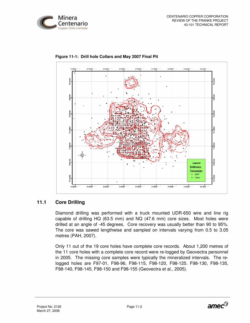
CENTENARIO COPPER CORPORATIONREVIEW OF THE FRANKE PROJECT
43-101 TECHNICAL REPORT
Project No: 2126 Page 11-2 March 27, 2008
Figure 11-1: Drill hole Collars and May 2007 Final Pit
11.1 Core Drilling
Diamond drilling was performed with a truck mounted UDR-650 wire and line rig capable of drilling HQ (63.5 mm) and NQ (47.6 mm) core sizes. Most holes were drilled at an angle of -45 degrees. Core recovery was usually better than 90 to 95%. The core was sawed lengthwise and sampled on intervals varying from 0.5 to 3.05 metres (PAH, 2007).
Only 11 out of the 19 core holes have complete core records. About 1,200 metres of the 11 core holes with a complete core record were re-logged by Geovectra personnel in 2005. The missing core samples were typically the mineralized intervals. The re-logged holes are F97-01, F98-96, F98-115, F98-120, F98-125. F98-130, F98-135, F98-140, F98-145, F98-150 and F98-155 (Geovectra et al., 2005).
CENTENARIO COPPER CORPORATIONREVIEW OF THE FRANKE PROJECT
43-101 TECHNICAL REPORT
Project No: 2126 Page 11-3 March 27, 2008
11.2 RC Drilling
During the Asarco campaigns, all drilling was done dry and sampled at two metre intervals. The 1997 campaign was the exception, with samples taken at 1 metre intervals. Drill holes were oriented along the azimuths of 65° and 245°. These orientations were selected as they were approximately perpendicular to the northwest strike direction of the primary veins and structure. The last campaign in 1999 resulted in erratic and discontinuous mineralization in San Guillermo, so no additional drilling was planned (PAH, 2007).
The 2004 RC drilling campaign was conducted by SAMSA and sampled at two metre intervals. CCC supervised and directed this project. RC drilling was dry for both the Franke and San Guillermo drilling. Samples used for geologic description were washed on site and both the fine and coarse fractions were kept in hard plastic boxes (PAH, 2007).
There are no references about RC logging procedures prior to 2006. In 2006, Geovectra was contracted to organize and supervise the drilling of 129 reverse circulation holes in the Franke area. One hundred of the holes were considered infill drill holes while the remaining 29 were extension holes. All of the drill holes were drilled at an azimuth between 235 and 250 degrees. Only four holes were drilled vertically, with the remainder drilled at approximately 60 degrees from horizontal. Most holes were drilled to less that 100 m depth, with the deepest holes at 150 m. All drill holes were surveyed down the hole using a Maxibor instrument. The samples were collected in regular two metre intervals and weighed, yielding approximately 80 kg on average. The samples were reduced in the field using a sample splitter to obtain a 10 kg sample. Goevectra used tablet PCs using the GVMapper software, (developed by Geovectra) to enter the logging results into the database. After the drilling campaign, cutting boxes were transported to Geovectra´s facilities in Santiago and then submitted to the ALS Chemex laboratory in La Serena. Once laboratory assays became available and were imported into the database, all logs were compared against total and soluble copper concentrations and mineral zone mappings were revised by one of the Geovectra geologists involved in the original drill hole logging. Additionally, some portions of the drill hole logs considered important for the geological model were re-logged in greater detail.
11.3 2007 Drill Program
CCC commissioned Geovectra to conduct an infill drilling program that started in mid-March and was completed in mid-July 2007 totalling approximately 30,773 m.

CENTENARIO COPPER CORPORATIONREVIEW OF THE FRANKE PROJECT
43-101 TECHNICAL REPORT
Project No: 2126 Page 11-4 March 27, 2008
Geovectra logged the drill holes, constructed the database and estimated the mineralized inventory of Franke deposit.
CCC contracted PerfoChile Ltda (PCH) for the drilling service. Geovectra personnel instructed PCH to drill through stopes. The procedure was successful since it resulted in the discovery of several new mineralized intercepts.
The drilling program was completed in a regular 25 m square grid pattern in order to confirm the continuity of the grade and volume of the deposit within the limits of the forecasted two-year pit outline designed by NCL (2007). The locations of these drill holes are depicted in Figure 11-1.
All drill holes used reverse circulation methods and there were no diamond drill holes in this campaign. All drill holes were dry.
AMEC reviewed the data and the results were incorporated into a new mineral resource estimate.

CENTENARIO COPPER CORPORATIONREVIEW OF THE FRANKE PROJECT
43-101 TECHNICAL REPORT
Project No: 2126 Page 12-1 March 27, 2008
12.0 SAMPLING METHOD AND APPROACH
AMEC reviewed the available information for the drill campaigns conducted by Asarco and CCC. This section summarizes methods described by Geovectra (2005 and 2006) and PAH (2007) in previous reports to CCC.
12.1 ASARCO Programs (1997-1999)
All core samples for the Franke deposit were obtained during these campaigns by Asarco personnel.
Core samples were collected from the wire-line inner tube and placed directly into core boxes, with wood blocks marking the depth at the end of every drill run, commonly every 0.5 – 3.05 metres. Correct down-hole orientation was maintained in a uniform manner for all core. Measurements of core recovery, specific gravity and Rock Quality Designation (RQD) were made after the core was transported to the field compound. Recovery generally averaged better than 95 percent, except locally in a few faulted zones or when underground workings were encountered.
The core was sawed lengthwise on-site with a water-lubricated diamond rock saw, and half was sent to the laboratory for analysis. The other half was saved in standard waxed cardboard core boxes, labelled with indelible black ink, and logged by geologists. A small portion of the saved core has subsequently been sent off for metallurgical test work. A significant portion of the core is missing or has been disturbed at the original storage place and is no longer reliable. CCC transported the still-usable Asarco core to a storage facility located in Copiapó.
Asarco conducted Specific Gravity measurements using the core samples. A triple-beam balance with a secondary base suspended underneath a bucket of water was used.
Reverse circulation samples were collected at uniform two metre intervals throughout the program, except holes from the first drill campaign for which samples were collected on one metre intervals. All RC holes were dry. The sample cuttings were collected within the closed cyclone for two metres of drilling, and then upon completion of each two metre interval, the cyclone was opened and the sample permitted to fall into the radial cone splitter mounted directly under the cyclone. Two pre-labelled sample bags were mounted on two of the eight divisions of the splitter and the sample was collected directly into the sample bags. This method produced two 1/8 splits of about 10-12 kg each which were then tied-off and saved. One of the sample splits

CENTENARIO COPPER CORPORATIONREVIEW OF THE FRANKE PROJECT
43-101 TECHNICAL REPORT
Project No: 2126 Page 12-2 March 27, 2008
was sent to the analytical laboratory and the other was saved as a duplicate on-site. After collection and removal of the samples, the hole was thoroughly flushed with high-pressure air. The cyclone and sample splitter were also air-blast cleaned, and then the next drill interval started.
Standard olefin sample bags were used for all RC drill samples. All duplicate samples were originally stored on-site as well as laboratory rejects and pulps. All these samples were damaged throughout the years and are no longer usable.
Three vertical shafts were excavated in 1998 for metallurgical samples to depths of 60.3, 28.7 and 48.7 metres. All advances were mapped and sampled daily by Asarco personnel under the supervision of the on-site geologist. The square shafts are 2 m x 2 m, and advanced between 0.9 and 1.5 metres daily. One or two vertical pilot holes were drilled and assayed for copper before each of the three shafts were selected. Upon excavation of the shafts, two adjoining faces were channel-sampled, and the same two faces mapped geologically by the resident geologist. Finally, the full sample from each advance round was carefully collected and stored in separate lots on the surface for subsequent crushing and sampling on site. These lots represent approximately 915 tonnes each.
12.2 CCC 2004 Program
The 2004 drill campaign was contracted to SAMSA and only included RC drilling and a single bulk metallurgical sample.
The samples of the reverse circulation drill holes were taken at two metre intervals. The sample was stored at first in the cyclone collector of the machine (Driltech S 40 KX equipped with 600 HP). The sample was then emptied directly into a quartered normal stainless steel Jones Riffle Divider (JRD). The first split eliminated ½ of the sample. The remaining half was sent through the JRD again where ¼ of the original sample was eliminated. This ¼ split was then sent through the JRD again where 1/8 of the sample (approximately 7 to 8 kg) was kept as reserve in a plastic bag labelled outside and inside. The other 1/8 split was sent through the splitter again, separating 1/16 of the sample with an approximate weight of 3 to 4 kg. One of these 1/16 splits was eliminated and the other one was placed in a plastic bag labelled outside and inside and was shipped to the CIMM laboratory. Before proceeding to the next sample interval, the sample splitter and the cyclone were intensely cleaned with a high-pressure air blast and then the next drill interval started. The operation was executed by the sampling assistants who were trained for consistent and rigorous sampling

CENTENARIO COPPER CORPORATIONREVIEW OF THE FRANKE PROJECT
43-101 TECHNICAL REPORT
Project No: 2126 Page 12-3 March 27, 2008
protocols by SAMSA. The recovery of the reverse circulation drill holes was not measured.
CCC sunk a vertical shaft to a depth of 5.8 m located about 25 m east of Asarco’s shaft #1. A 24 tonne bulk sample was extracted for metallurgical tests later performed by CIMM.
12.3 CCC 2005 Program
A total of 24 levels of six old underground mining areas were surveyed, mapped and sampled. A 2 m x 2 m panel chip sampling method was selected for the stopes, given the irregular boundaries of the caves that prevented a more systematic approach. The underground samples were not used for estimation purposes, but only as a reference for the location and continuity of the mineralized pods.
About 1,200 metres of the 11 core holes with a complete core record were re-logged by Geovectra personnel in 2005 (the missing part of most of the other core holes were within the mineralized intercepts). All of these core holes were from the 1997 and 1998 drill campaigns. The re-logged holes are F97-01, F98-96, F98-115, F98-120, F98-125. F98-130, F98-135, F98-140, F98-145, F98-150 and F98-155. A relatively simple mapping code was configured to be compatible with former logs by Asarco and SAMSA, covering lithological, alteration, mineralization and structural variables.
12.4 CCC 2006 Program
Geovectra was contracted to supervise the surveying, logging and sampling of the 2006 drilling campaign. Samples were collected at two metre intervals. Drill cuttings weighed approximately 80 kg for each two metre sample and were reduced to about 10 kg by splitting at the drill sites. These samples were placed into bags and transported to Geovectra’s facility in Santiago, where they were then picked up by the ALS Chemex laboratory personnel.
Samples were collected by Geovectra in order to investigate a positive linear relationship between density and insoluble copper grade. A total of 396 samples were selected to represent a wide range of copper grades and degrees of oxidation. A number of samples (36 cores and 74 hand samples) had been collected for previous studies and were stored at Geovectra´s facilities. These samples include andesitic and volcaniclastic rocks. The remaining samples (286) were andesitic rocks collected from the Franke reject stockpiles in April 2006.

CENTENARIO COPPER CORPORATIONREVIEW OF THE FRANKE PROJECT
43-101 TECHNICAL REPORT
Project No: 2126 Page 12-4 March 27, 2008
A systematic surface stockpile sampling program was carried out under the supervision of two Geovectra geologists. One hundred sampling sites were selected, evenly distributed over the top of almost all the reject stockpiles where rock material was collected with an excavator. For every site the volume of material extracted typically had an area of 2.5 m x 2.5 m or 3 m x 3 m, and a thickness of 1 to 1.5 m. After extraction, all sampling locations were measured by GPS and marked by a flag.
A two-step crushing sequence was adopted taking into account the amount of sample to be collected and the grain size reduction necessary to obtain a representative copper grade.
Rock material extracted from each site was transported separately by truck to a crushing plant in El Salado, where it was loaded directly from the truck into the primary crusher hopper. The primary crusher consisted on a 7 x 10 inch jaw crusher. At this stage, excessively large fragments that prevented the crusher from working properly were removed and discarded. After primary crushing, sample material was transported by a conveyor belt and loaded into the secondary crusher, were the rock material was further reduced to a maximum fragment size of approximately 6 cm.
From the secondary crusher, the rock material was re-loaded into the truck with a conveyor belt. At this stage, 12 litre samples were collected for Cu assay. Depending on the crushing speed and pouring rate from the conveyor into the truck, a sample was collected every five to eight minutes. On average, 10 samples were collected for every sampling site. In total, 1,010 samples were collected and assayed for total and soluble copper grades. Crushed material was returned and stored at the Franke project site.
12.5 CCC 2007 Program
CCC drilled 351 vertical drill holes (including two extensions of older holes) with RC methodology. The RC drill hole bit diameter was 5 ½” to 5 ¾”. The samples were taken on 2 m regular intervals from a 6 m drill rod length. No wet samples were found during drilling. The samples were weighed in the field, with a typical sample weighing about 80 kg. According to CCC sampling protocols, the samples were divided using a riffle splitter into two equal portions. One half of the sample (40 kg) was discarded and the other half was subsequently divided, using a riffle splitter, into two samples weighing approximately 10 kg each, one for the laboratory and the other retained for backup. Samples intended for the laboratory were prepared at the drill site, and had a drill hole identification printed on the clear plastic bag. Following the onsite sample splitting, one sample was sent to the laboratory for sample preparation and assaying. A small portion of the coarse material (approximately 0.5 kg) of the backup sample
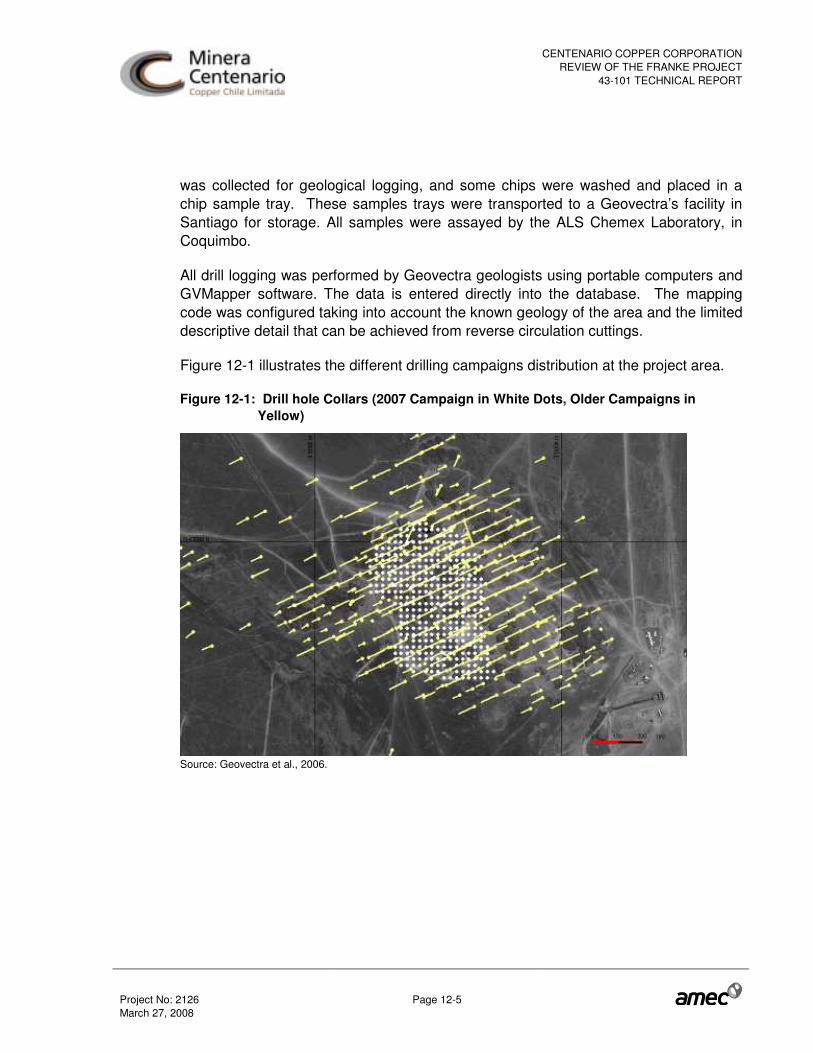
CENTENARIO COPPER CORPORATIONREVIEW OF THE FRANKE PROJECT
43-101 TECHNICAL REPORT
Project No: 2126 Page 12-5 March 27, 2008
was collected for geological logging, and some chips were washed and placed in a chip sample tray. These samples trays were transported to a Geovectra’s facility in Santiago for storage. All samples were assayed by the ALS Chemex Laboratory, in Coquimbo.
All drill logging was performed by Geovectra geologists using portable computers and GVMapper software. The data is entered directly into the database. The mapping code was configured taking into account the known geology of the area and the limited descriptive detail that can be achieved from reverse circulation cuttings.
Figure 12-1 illustrates the different drilling campaigns distribution at the project area.
Figure 12-1: Drill hole Collars (2007 Campaign in White Dots, Older Campaigns in Yellow)
Source: Geovectra et al., 2006.

CENTENARIO COPPER CORPORATIONREVIEW OF THE FRANKE PROJECT
43-101 TECHNICAL REPORT
Project No: 2126 Page 13-1 March 27, 2008
13.0 SAMPLE PREPARATION, ANALYSES AND SECURITY
13.1 Quality Assurance / Quality Control Definitions and Protocols
NI 43-101 and CIM Exploration Best Practices Guidelines state that a program of data verification should accompany an exploration program to confirm validity of exploration data. Furthermore, the CIM Estimation of Mineral Resources and Mineral Reserves Best Practice Guidelines require that a quality assurance and quality control (QA/QC) program be utilized to ensure that analytical accuracy and precision are adequate to support resource estimation.
There are some basic concepts related to any QA/QC program, applicable to all elements in this program:
• Precision: the ability to consistently reproduce a measurement in similar conditions;
• Accuracy: the closeness of those measurements to the “true” or accepted value; • Contamination: the inadvertent transference of material from one sample to
another.
As a rule, two laboratories are used during a sampling campaign: a primary laboratory, where all the original samples are assayed, and a secondary (or umpire) laboratory, where a representative portion of the samples assayed at the primary laboratory are re-assayed. The QA/QC program includes the submission of original samples to the primary laboratory, accompanied by a proportion (usually 5 to 10%) of blind control samples, and the submission of a portion of the original sample coarse rejects from the primary laboratory to the secondary laboratory, also accompanied by a proportion (usually 5 to 10%) of blind control samples.
The purpose of the blind insertion of control samples is to prevent the laboratory from identifying the control samples, or at least the nature and equivalency of the control samples. All accredited laboratories have internal QA/QC procedures, and usually the assay certificates include the results of the internal QA/QC. However, some laboratories customarily will only reveal those checks which pass their internal controls, but not the failures. For this reason, the internal laboratory QA/QC should not replace the client’s own QA/QC program.
A QA/QC program should monitor various essential elements of the sampling-assaying sequence, in an effort to control or minimize the total possible error in the sampling, splitting and assaying sequence:

CENTENARIO COPPER CORPORATIONREVIEW OF THE FRANKE PROJECT
43-101 TECHNICAL REPORT
Project No: 2126 Page 13-2 March 27, 2008
• Sample collection and splitting (sampling variance, or sampling precision); • Sample preparation and sub-sampling (sub-sampling variance, or sub-sampling
precision; contamination during preparation); • Analytical accuracy, analytical precision and analytical contamination; • Data transfer accuracy (from paper to digital).
Monitoring of the first three points is achieved through the random insertion of various control samples (blanks, standard reference materials and check assays), preferably in the same sample batch as the original samples. Data transfer accuracy can be monitored through double data entry, which consists of using two independent teams to enter all the data into two independent databases, and subsequently cross-checking both data sets.
13.2 Asarco Programs (1997-1999)
AMEC was not provided access to reports related to the Asarco sample preparation and assaying procedures. The statements made in this section summarize comments made by PAH in their technical report to CCC (PAH, 2007).
The first 13 drill holes had their samples sent to Geolab laboratory in Copiapo. They were analysed for total copper, soluble copper, and occasionally for silver. The remainder of the samples were sent to the CIMM laboratory in Antofagasta. CIMM used internal laboratory checks for about one in every 20 samples. A detection limit was stated as 0.003 % Cu. Analysis for soluble copper was also carried out when total copper grades were greater than 0.1%.
The CIMM laboratory method for total copper analysis was as follows:
• Crush sample to -10 mesh • Split out 150 grams • Pulverize to 95% -100 mesh • Split out 3 grams pulp • Analyze with 3-acid digestion, filtration and Atomic Absorption (AA).
The soluble copper method included placing 2.5 grams of pulp into a 5% solution of sulphuric acid, agitated in ambient temperature for 30 minutes, diluted, filtered and then analyzing by atomic absorption.

CENTENARIO COPPER CORPORATIONREVIEW OF THE FRANKE PROJECT
43-101 TECHNICAL REPORT
Project No: 2126 Page 13-3 March 27, 2008
Geolab S.A. and ITS Bondar Clegg (Bondar) were used mainly as check laboratories. Cone Geochemical also performed a small amount of silver and gold analyses using 4-acid digest and AA analysis. No duplicate core samples were re-analyzed. A Jones-type riffle was used for all sample splitting. Dry samples permitted easy splitting.
AMEC reviewed original assay certificates of the Asarco campaigns and performed checks for data entry. There error rate was less than one percent so AMEC considered the Asarco database acceptable for supporting mineral resource estimates.
13.3 CCC 2004 Program
Drill samples were collected at site by ALS Chemex personnel and transported to Antofagasta in a closed and sealed truck. Samples were prepared and sent to La Serena for assaying. AMEC has reviewed internal laboratory QA/QC results and found no issues.
AMEC is not aware of any blind control samples (blanks, standard reference materials and check assays) for this campaign. AMEC is also not aware of any secondary laboratory checks for the 2004 campaign, which was conducted by SAMSA.
13.4 Re-Assay Program in 2005
Geovectra and NCL selected 2,739 pulp samples for re-assay at CIMM Santiago. The analytical methods used by CIMM are listed in Table 13-1. The samples were selected as follows:
• All pulps with TCu ≥ 0.3% • All pulps between two close intervals (less than 10 m distance) with TCu ≥ 0.3% • One or two samples before and after each mineralized interval (with TCu ≥ 0.3%).
Table 13-1: Analytical Methods used by CIMM
Laboratory Item TCu SCu C*
CIMM Digestion/Determination
Multiacid (��������������
����); 1 g aliquot, 100 mL
solution, AAS
1 g aliquot, H2SO4
solution to 250 mL
CS-444 C IR analyzer
Lower Detection Limit 0.003% 0.003% 0.005% CO3-
Upper Detection Limit Not Available Not Available Not Available * Note: Reported as CO3.
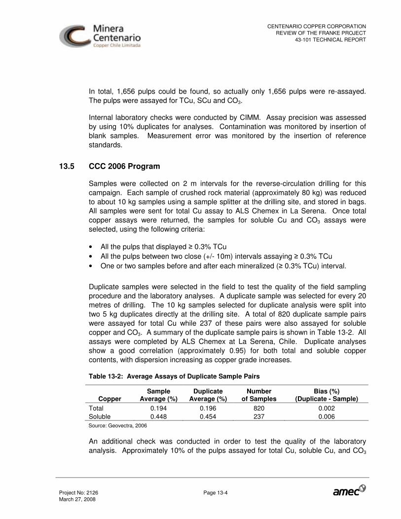
CENTENARIO COPPER CORPORATIONREVIEW OF THE FRANKE PROJECT
43-101 TECHNICAL REPORT
Project No: 2126 Page 13-4 March 27, 2008
In total, 1,656 pulps could be found, so actually only 1,656 pulps were re-assayed. The pulps were assayed for TCu, SCu and CO3.
Internal laboratory checks were conducted by CIMM. Assay precision was assessed by using 10% duplicates for analyses. Contamination was monitored by insertion of blank samples. Measurement error was monitored by the insertion of reference standards.
13.5 CCC 2006 Program
Samples were collected on 2 m intervals for the reverse-circulation drilling for this campaign. Each sample of crushed rock material (approximately 80 kg) was reduced to about 10 kg samples using a sample splitter at the drilling site, and stored in bags. All samples were sent for total Cu assay to ALS Chemex in La Serena. Once total copper assays were returned, the samples for soluble Cu and CO3 assays were selected, using the following criteria:
• All the pulps that displayed � 0.3% TCu • All the pulps between two close (+/- 10m) intervals assaying � 0.3% TCu • One or two samples before and after each mineralized (� 0.3% TCu) interval.
Duplicate samples were selected in the field to test the quality of the field sampling procedure and the laboratory analyses. A duplicate sample was selected for every 20 metres of drilling. The 10 kg samples selected for duplicate analysis were split into two 5 kg duplicates directly at the drilling site. A total of 820 duplicate sample pairs were assayed for total Cu while 237 of these pairs were also assayed for soluble copper and CO3. A summary of the duplicate sample pairs is shown in Table 13-2. All assays were completed by ALS Chemex at La Serena, Chile. Duplicate analyses show a good correlation (approximately 0.95) for both total and soluble copper contents, with dispersion increasing as copper grade increases.
Table 13-2: Average Assays of Duplicate Sample Pairs
Copper Sample
Average (%) Duplicate
Average (%) Number
of Samples Bias (%)
(Duplicate - Sample) Total 0.194 0.196 820 0.002 Soluble 0.448 0.454 237 0.006 Source: Geovectra, 2006
An additional check was conducted in order to test the quality of the laboratory analysis. Approximately 10% of the pulps assayed for total Cu, soluble Cu, and CO3

CENTENARIO COPPER CORPORATIONREVIEW OF THE FRANKE PROJECT
43-101 TECHNICAL REPORT
Project No: 2126 Page 13-5 March 27, 2008
(93 samples) were randomly selected and then submitted for re-assay. Duplicate pulp analyses show very high correlations (greater than 0.998), thus validating the laboratory procedures. All assays were performed by ALS Chemex in La Serena, Chile.
Geovectra and NCL (2006) prepared X-Y plots of the original assays versus the duplicate assays for TCu and SCu. AMEC reviewed the coarse duplicate plots, and could identify a reduced proportion of failures for TCu and SCu, considering a failure limit of 20% relative error (RE). The actual failure proportion estimated by Geovectra and NCL (2006) for the TCu duplicates was 14% (pairs with relative error above 20%), which is considered as marginally acceptable. Therefore, the sub-sampling precision was within acceptable ranges.
AMEC also reviewed the pulp duplicate plots, and did not identify failures, using a failure limit of 10% RE. Therefore, the analytical precision was within acceptable ranges.
Geovectra did not insert blind standard samples or blanks during the drilling campaigns. For that reason, the analytical accuracy could not be fully assessed, nor the possibility of cross-contamination during preparation or assaying. However, AMEC did review internal standards from the laboratory which showed no significant bias.
ALS Chemex collected the RC samples at the Geovectra facilities and transported them to the laboratory with its own truck. The sample preparation protocol consisted of drying, crushing to 70% passing -2 mm, screening, splitting and pulverization of 1,000 g to 85% passing 200 mesh (75 microns). About 500 g of the pulverised sample (pulp) were split to perform the analytical procedures for each sample.
ALS Chemex implemented four acid digestion and Atomic Absorption (AA) methods to determine total copper. These methods are applicable for a range of 0.01 to 50% Cu. Soluble copper was determined by using AA methods applied to a leached 5% sulphuric acid solution of the sample; applicable to a range of 0.001 to 10 % Cu. ALS Chemex is ISO 9001 certified for all of its laboratories in Chile. A complete description of the ALS Chemex sample preparation procedures is included in the appendices of the AMEC feasibility study.
13.6 CCC 2007 Program
All samples were prepared and assayed at the ALS Chemex Laboratory in Coquimbo following similar procedures detailed in the original assay certificates. ALS Chemex is

CENTENARIO COPPER CORPORATIONREVIEW OF THE FRANKE PROJECT
43-101 TECHNICAL REPORT
Project No: 2126 Page 13-6 March 27, 2008
certified under ISO 9001-2000. Approximately 17,650 samples were submitted in 2007 for TCu, SCu and CO3.
Sample preparation was as follows:
• Drying was not reported. • Crushing to 70% passing 2 mm with Terminator or Boyds crushers (ALS procedure
code CRU-31). • Homogenizing and splitting sample using riffle splitter (procedure SPL-21) to obtain
a nominal 250 g sub-sample for pulverizing. • Pulverizing the nominal 250 g split with an LM-2 pulverizer to 85% passing 0.075
mm (PUL-31).
ALS Chemex was used as the principal laboratory and CIMM was used as the secondary or control laboratory (Table 13-3).
Table 13-3: Analytical Methods used by ALS and CIMM
Laboratory TCu SCu C*
ALS Chemex
Multiacid (������������������); 0.4 g
aliquot, 100 mL solution, AAS; low detection limit:
%0.01. Code: Cu-AA62
Aprox. 1 g aliquot; H2SO4 solution to 250 mL at room
temperatures; low detection limit: 0.001%.
Code: Cu-AA05.
Sample combustion, CO2 is quantitatively detected by infrared spectrometry;
carbon is reported as CO3
Code: C-IR07
CIMM Multiacid (������������������); 1 g aliquot,
100 mL solution, AAS
1 g aliquot, H2SO4 solution to 250 mL CS-444 C IR analyzer
* Note: Reported as CO3
The QA/QC program and results from the 2007 campaign are described by Geovectra (2007). The QA/QC program implemented at the time of drilling included the regular insertion of 1,837 duplicates (approximately 10.4% of the total assays) such as field duplicates, coarse duplicates and fine duplicates. A total of 1,286 coarse and fine blanks were inserted in the sample stream at a rate of 7.3%. Standard Reference Material (SRM) was prepared in CIMM laboratory and assayed for TCu and SCu (Table 13-4). This material was inserted in the flow of regular samples to control the accuracy of analytical results. Approximately, 1,218 SRM samples (6.9%) were submitted for assaying.

CENTENARIO COPPER CORPORATIONREVIEW OF THE FRANKE PROJECT
43-101 TECHNICAL REPORT
Project No: 2126 Page 13-7 March 27, 2008
Table 13-4: QA/QC Controls used by CCC
Control Sample
Database Code
Count % of Total
Assays
Description
DC 693 3.9
Field Duplicates, 10kg from half total sample
DG 513 2.9
Coarse Duplicates, <2 mm reject lab sample crushing reject
DP 631 3.6
Fine (pulp) duplicates, <0.105 mm lab sample pulverizing reject
Duplicates
DE 629 3.6
Fine (pulp) duplicates, <0.105 mm lab sample pulverizing reject
S1 382 2.2
Pulverized material, S1 = 0.359% TCu and 0,300% SCu
S2 441 2.5
Pulverized material, S2 = 0.878% TCu and 0,810% SCu
Standards (SRM)
S3 395 2.2
Pulverized material, S3 = 1.559% TCu and 1.484% SCu
BF 755 4.3
Pulp reject from low Cu concentration material
Blanks
BG 531 3.0
Coarse field material with low TCu concentration
Duplicates
Field duplicate samples were prepared by splitting the sample at the drill rig. In this way, the sampling error in the sample preparation step can be evaluated correctly.
Geovectra et al. (2007) reviewed analytical results and found that differences in the means for original and duplicate analytical results were not significant at a 95% confidence interval.
AMEC performed a series of analyses including the evaluation of sample duplicates according to the Hyperbolic Method and confirmed Geovectra’s findings.

CENTENARIO COPPER CORPORATIONREVIEW OF THE FRANKE PROJECT
43-101 TECHNICAL REPORT
Project No: 2126 Page 13-8 March 27, 2008
In AMEC’s opinion, the insertion rate of duplicates is adequate and the precision of the assays is acceptable.
Standard Reference Materials
Quality control and data verification during the 2007 drill program were controlled by the use of three standards. The accepted grades (BV=Best Value) are shown in Table 13.5. Approximately 1,218 SRM samples (6.9%) were submitted for assay.
The standards were prepared by CIMM T&S S.A. (CIMM) of Santiago. The mineralized material was supplied by CCC from the Pelusa deposit, close to the Franke deposit. The matrix of these standards is very similar to that of Franke.
Standard S1 has copper grades near operational cut-off (0.359% TCu and 0.300% SCu), Standard S2 has higher copper values than the average resource grade (0.878% TCu and 0.810% SCu) and Standard S3 has copper values near the upper limit of expected grades for the deposit (1.559% TCu and 1.484% SCu).
Table 13-5: Standard Reference Material Best Values
Standard Best Value* Error S1 0.359% TCu; 0.300% SCu 0.004%; 0.005% S2 0.878% TCu; 0.810% SCu 0.010%; 0.014% S3 1.559% TCu; 1.484% SCu 0.018%; 0.020% * Round Robin Test performed by CIMM (2006).
AMEC prepared control charts for each SRM and for each documented element. AMEC also prepared accuracy plots (Mean versus Best Value) for all the standards and studied elements to calculate the bias.
The overall bias for TCu and SCu are -0.08% and -2.86%, respectively.
Most of the inserted SRM’s had a very low proportion of outliers and non-significant bias, reflecting a good accuracy level for the assays (see Table13-6).

CENTENARIO COPPER CORPORATIONREVIEW OF THE FRANKE PROJECT
43-101 TECHNICAL REPORT
Project No: 2126 Page 13-9 March 27, 2008
Table 13-6: Standard Reference Material Results - 2007
Standard - TCu S1 S2 S3 Samples 382 441 395 Average (%) 0.359 0.889 1.557 Standard Deviation (SD) 0.010 0.021 0.035 Outliers (> and < 3* SD) 6 7 4 Outliers (%) 1.6 1.6 1.0 Best Value BV (%) 0.359 0.878 1.559 Average without outliers (%) 0.359 0.887 1.557 Bias (%) 0.08 1.04 -0.14 Standard - SCu S1 S2 S3 Samples 382 441 395 Average (%) 0.301 0.794 1.439 Standard Deviation (SD) 0.012 0.041 0.131 Outliers (> and < 3* SD) 4 5 3 Outliers (%) 1.1 1.1 0.8 Best Value BV (%) 0.300 0.810 1.559 Average without outliers (%) 0.302 0.796 1.450 Bias (%) 0.50 -1.70 -2.30
Duplicates in Control Laboratory
CCC submitted samples for external check to the CIMM T&S S.A. laboratory at the time of the drill campaign. This check was performed using stored pulps as the project advanced. Approximately 3.6% of the total samples were analyzed for TCu, SCu and CO3.
Check samples are equivalent to duplicate samples, re-submitted in this case to an external certified laboratory (secondary laboratory). These samples are used to estimate the accuracy, together with the standards.
AMEC calculated the reduced major axis regression (RMA) for each element. The results are shown in Table 13-7.

CENTENARIO COPPER CORPORATIONREVIEW OF THE FRANKE PROJECT
43-101 TECHNICAL REPORT
Project No: 2126 Page 13-10 March 27, 2008
Table 13-7: Control Samples RMA Analysis
TCu SCu CO3 Samples 693 678 626 Outliers 10 15 67 Pairs 693 693 693 Outliers (%) 1.4 2.2 9.7 R2 0.988 0.989 0.987 Bias (%) 1.0 0.5 -0.6
Blanks
CCC inserted blank samples, consisting of low copper grade material. AMEC has not been informed about the source and nature of these samples, preparation or the accepted levels of copper grade. Contamination of samples is suspected if the blank concentration exceeds four to five times the practical detection limit for the studied element where the blank contains none of the element of interest.
There are sixteen Fine Blanks results out of a total of 755 samples reporting anomalous values above 0.1% TCu (five times the practical detection limit). It is likely that these anomalous values are caused by sample mislabelling. Ten samples were labelled as Blanks instead of Standards. However, six anomalous Fine Blanks could not be ascribed to mislabelling. In addition, there are 14 Coarse Blanks with anomalous concentrations of TCu above 0.1% that do not have an explanation. AMEC finds that an erroneous selection of coarse blank material is likely affecting these results.
AMEC analyzed this information in a Blank-Previous Sample chart for TCu and SCu for Fine Blanks and Coarse Blanks, ordered by the previous sample Cu concentration along the X-axis. The analysis demonstrated the absence of significant contamination.
13.7 Specific Gravity and Density
Specific gravity determinations were performed by Geovectra in 2005, 2006 and 2007 using standard procedures. Many measurements for cores and hand samples (from mine dumps) were done using common water displacement methods. Geovectra used the following nomenclatures: Apparent Specific Gravity (ASG) and Bulk Specific Gravity (BSG) for those methods used to measure the volume of water displaced by a sample. Most ASG measurements (396 samples) and BSG measurements (84 core samples) were performed by Geovectra in house (Geovectra et al, 2006, Geovectra, 2007). Seventy BSG measurements were done at the ALS Chemex Laboratory in La

CENTENARIO COPPER CORPORATIONREVIEW OF THE FRANKE PROJECT
43-101 TECHNICAL REPORT
Project No: 2126 Page 13-11 March 27, 2008
Serena (Geovectra et al., 2005). The difference in the methodologies (ASG and BSG) consisted mainly in the amount of time the rock remained in the water. In the ASG method the rock is weighed immediately once it is immersed in the water. In the BSG method, the rock is weighed after is has been saturated in water for 24 hours.
ASG may be calculated as the weight of dry sample in air (Ma) divided by the difference of the weight of the dry sample in air (Ma) and the weight of the sample in water (Mw).
Hence:
ASG= Ma / (Ma-Mw)
This simple buoyancy method may be used for competent, non-porous and dry core samples, otherwise the rock could contain some water during the weight in air measurement, or water can infuse the sample while weighing in water, thus giving systematic positive errors that lead to overestimates of resource tonnages. This problem can be solved by drying the core samples to a constant weight (weigh and dry repeatedly until the weight does not decrease) before weighing in air, and sealing the core (either with paraffin coating or plastic coating or wrap) prior to weighing in water.
The BGS method considers the water saturation of the sample before weighing.
BSG= Ma / (Msa-Msw)
Where Msa is the mass of the water saturated sample weighed in air and Msw is the mass of the water saturated sample weighed in the water.
BSG will always be lower than ASG, but they should be correlated. However, no correlation was observed in the case of Franke (Geovectra et al., 2006).
In addition to the analyses reported in 2005 and 2006, the specific gravity of 84 core fragments was determined using the ASTM Standard and a linear correlation was calculated between the apparent specific gravity (ASG) and insoluble Cu of andesite samples where the insoluble Cu was greater than 1% (Geovectra 2007).
The Specific Gravity formula implemented for the mineral resource model is as follows:
ASG = Insoluble Cu % * 0.03 + 2.6
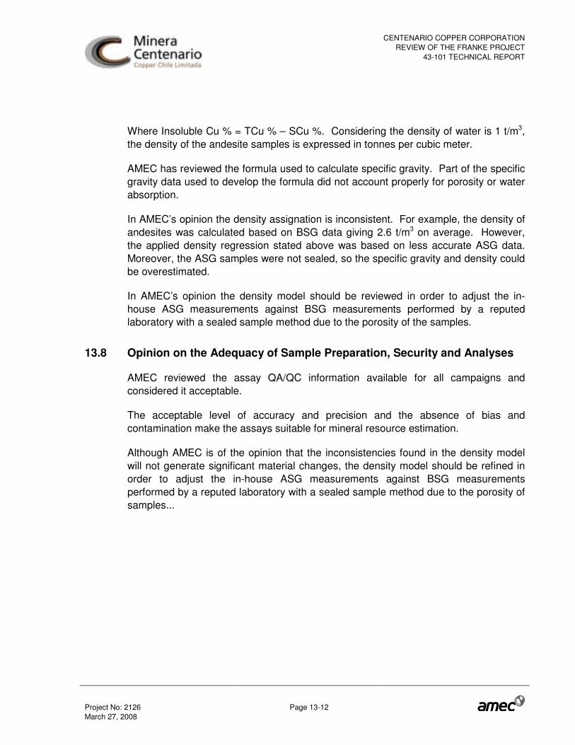
CENTENARIO COPPER CORPORATIONREVIEW OF THE FRANKE PROJECT
43-101 TECHNICAL REPORT
Project No: 2126 Page 13-12 March 27, 2008
Where Insoluble Cu % = TCu % – SCu %. Considering the density of water is 1 t/m3, the density of the andesite samples is expressed in tonnes per cubic meter.
AMEC has reviewed the formula used to calculate specific gravity. Part of the specific gravity data used to develop the formula did not account properly for porosity or water absorption.
In AMEC’s opinion the density assignation is inconsistent. For example, the density of andesites was calculated based on BSG data giving 2.6 t/m3 on average. However, the applied density regression stated above was based on less accurate ASG data. Moreover, the ASG samples were not sealed, so the specific gravity and density could be overestimated.
In AMEC’s opinion the density model should be reviewed in order to adjust the in-house ASG measurements against BSG measurements performed by a reputed laboratory with a sealed sample method due to the porosity of the samples.
13.8 Opinion on the Adequacy of Sample Preparation, Security and Analyses
AMEC reviewed the assay QA/QC information available for all campaigns and considered it acceptable.
The acceptable level of accuracy and precision and the absence of bias and contamination make the assays suitable for mineral resource estimation.
Although AMEC is of the opinion that the inconsistencies found in the density model will not generate significant material changes, the density model should be refined in order to adjust the in-house ASG measurements against BSG measurements performed by a reputed laboratory with a sealed sample method due to the porosity of samples...
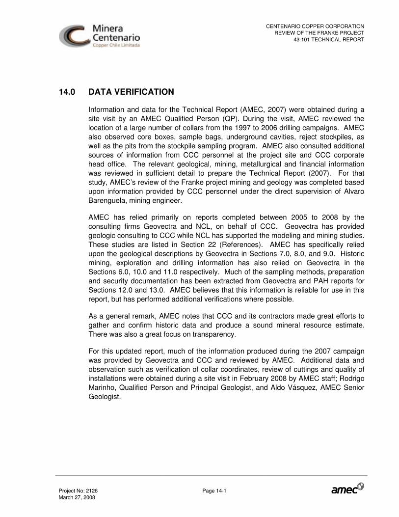
CENTENARIO COPPER CORPORATIONREVIEW OF THE FRANKE PROJECT
43-101 TECHNICAL REPORT
Project No: 2126 Page 14-1 March 27, 2008
14.0 DATA VERIFICATION
Information and data for the Technical Report (AMEC, 2007) were obtained during a site visit by an AMEC Qualified Person (QP). During the visit, AMEC reviewed the location of a large number of collars from the 1997 to 2006 drilling campaigns. AMEC also observed core boxes, sample bags, underground cavities, reject stockpiles, as well as the pits from the stockpile sampling program. AMEC also consulted additional sources of information from CCC personnel at the project site and CCC corporate head office. The relevant geological, mining, metallurgical and financial information was reviewed in sufficient detail to prepare the Technical Report (2007). For that study, AMEC’s review of the Franke project mining and geology was completed based upon information provided by CCC personnel under the direct supervision of Alvaro Barenguela, mining engineer.
AMEC has relied primarily on reports completed between 2005 to 2008 by the consulting firms Geovectra and NCL, on behalf of CCC. Geovectra has provided geologic consulting to CCC while NCL has supported the modeling and mining studies. These studies are listed in Section 22 (References). AMEC has specifically relied upon the geological descriptions by Geovectra in Sections 7.0, 8.0, and 9.0. Historic mining, exploration and drilling information has also relied on Geovectra in the Sections 6.0, 10.0 and 11.0 respectively. Much of the sampling methods, preparation and security documentation has been extracted from Geovectra and PAH reports for Sections 12.0 and 13.0. AMEC believes that this information is reliable for use in this report, but has performed additional verifications where possible.
As a general remark, AMEC notes that CCC and its contractors made great efforts to gather and confirm historic data and produce a sound mineral resource estimate. There was also a great focus on transparency.
For this updated report, much of the information produced during the 2007 campaign was provided by Geovectra and CCC and reviewed by AMEC. Additional data and observation such as verification of collar coordinates, review of cuttings and quality of installations were obtained during a site visit in February 2008 by AMEC staff; Rodrigo Marinho, Qualified Person and Principal Geologist, and Aldo Vásquez, AMEC Senior Geologist.

CENTENARIO COPPER CORPORATIONREVIEW OF THE FRANKE PROJECT
43-101 TECHNICAL REPORT
Project No: 2126 Page 14-2 March 27, 2008
14.1 Drill Hole Database
14.1.1 Database Verification
AMEC has performed verification procedures on the information on Franke up to the 2007 drilling campaign.
The data of the campaigns prior to 2007 were checked and reported by AMEC in a previous Technical Report (AMEC, 2007). No discrepancies were found.
AMEC reviewed the Franke geological and assay database for the 2007 drilling campaign and checked its integrity. AMEC has verified the completeness of the documentation supporting the geological and assay database.
AMEC has checked that every drill hole is supported by a digital geological log (in the database software developed by Geovectra) and assay certificates signed by the laboratory.
The vast majority of the drill-holes have full documentation. However, no drill recovery data was found or provided to AMEC by Geovectra or CCC.
14.1.2 Data Entry Quality
AMEC review the original laboratory certificates in Acrobat PDF format from the 2007 campaign.
AMEC re-entered 789 of a total of 18,205 TCu and SCu assays in an MS Excel® spreadsheet, and compared them with the Excel database provided to AMEC by Geovectra. The number of checked assays represents 4.33% of the entire total copper and soluble copper database.
No discrepancies were found.
AMEC checked the rate of entry errors in the total copper and soluble copper database and observed an error rate of 0%.
14.1.3 Down-hole Surveys
AMEC visited the area and checked 38 collar locations corresponding to 5.07% of 749 drill holes using a portable E-TrexTM GPS device. No significant differences were found in the data.

CENTENARIO COPPER CORPORATIONREVIEW OF THE FRANKE PROJECT
43-101 TECHNICAL REPORT
Project No: 2126 Page 14-3 March 27, 2008
In addition to the collar survey, AMEC also verified the inclination and the azimuth of the drill holes using the clinometer of a Brunton compass and no differences were found when compared to the information stored in the drill hole database.
AMEC understands that some down-hole checks were performed by Geovectra using a clinometer. However, due to blockage in several holes, the trajectory of over 30% of the 2007 holes was not surveyed. From the 235 vertical holes surveyed by CCC personnel, only 30 have deviations in excess of 3 m in plan view, with 6.14 m being the highest deviation. Similarly, only 112 of the remaining 393 holes have measured trajectories (Geovectra, 2007). To avoid a partial bias induced by the absence of trajectory data for more than half of the drill holes, and considering that the available deviations are below the resolution of the model, Geovectra did not use the deviation data and all drill holes were assumed undeviated in the resource estimation.
In AMEC’s opinion the drill holes are relatively short (88 m/hole on average) and AMEC does not expect significant drill hole deviation.
14.2 Down-Hole Contamination Analysis
RC drilling is vulnerable to contamination by material from an upper mineralized portion of a drill hole working its way into the sample stream. Contamination is more likely when drilling wet rather than dry, because water is more effective than air at washing material from the sides of the drill hole and transporting it to the bit face.
AMEC investigated the possibility of RC down-hole contamination at Franke for all RC drilling campaigns. This study used two approaches for assessing possible down-hole contamination problems that can occur in RC drilling: decay and cyclicity.
The decay and cyclicity analysis using in-house software showed no detectable down-hole contamination.
14.3 Geotechnical Information
Geotechnical (slope stability) studies were conducted by Ingeroc. AMEC reviewed these studies and found them insufficient to support the pit slope design. AMEC has recommended that additional work be conducted.

CENTENARIO COPPER CORPORATIONREVIEW OF THE FRANKE PROJECT
43-101 TECHNICAL REPORT
Project No: 2126 Page 14-4 March 27, 2008
14.4 Conclusions and Recommendations
AMEC did not detect any fatal flaw in the data supporting the mineral resource estimates.
The drill hole data showed the absence of down-hole contamination.
AMEC recommends that the drill recovery data documentation be available for analysis.

CENTENARIO COPPER CORPORATIONREVIEW OF THE FRANKE PROJECT
43-101 TECHNICAL REPORT
Project No: 2126 Page 15-1 March 27, 2008
15.0 ADJACENT PROPERTIES
CCC has an interest in several exploration properties near the Franke deposit. The San Guillermo deposit is located approximately one to two kilometres to the south of Franke. It is a copper oxide deposit similar to Franke, but has been much less actively explored than Franke due to more erratic mineralization results from previous drilling campaigns. Pelusa is a copper oxide and gold exploration target located about five kilometres to the west. Its exploration information is also at a much earlier stage than Franke, but it is currently being explored with geologic mapping, trenching, drilling and sampling. It has advanced to a mineral resource estimation stage and a preliminary assessment was completed in September, 2007 to determine, among other possibilities, whether it could be processed at the Franke facility.
The Altamira copper and silver mine is located to the immediate east of the Franke deposit. This mine is owned by Minera Las Cenizas and was purchased from Minera Pudahuel in 2003. It is being mined by underground mining methods and has been in production since 2005. A decline is used to access the mining levels. The Altamira deposit shares many of the characteristics with Franke, but is deeper and therefore does not have as much secondary oxide mineralization. The ore is transported by truck to the Las Luces de Taltal plant in Region II (Antofagasta), also owned by Minera Las Cenizas. The project reportedly contains approximately 2.5 million tonnes of sulphides and mixed sulphides with grades in the range of 1.6 to 1.7 % Cu. AMEC has no knowledge that a qualified person has done sufficient work to classify this estimate as a current Mineral Resource, so this estimate should not be relied upon. AMEC has not verified the accuracy of the above information, but it is available to the public on the Minera Cenizas website (www.cenizas.cl). During the May, 2007 site visit, AMEC did witness operating activity at the Altamira mine site.

CENTENARIO COPPER CORPORATIONREVIEW OF THE FRANKE PROJECT
43-101 TECHNICAL REPORT
Project No: 2126 Page 16-1 March 27, 2008
16.0 MINERAL PROCESSING AND METALLURGICAL TESTING
16.1 Introduction
The Franke Project has advanced to a full feasibility level of study. A copper recovery process based on heap leach, solvent extraction, and electro-winning has been designed, and capital and operating costs for the process plant have been estimated. The results of this work have been presented by AMEC International (Chile) SA in a feasibility study document, “Report No. 2115-Repo-9-001 for Feasibility Study Report” which is the source for the material summarized in this section.
Much of this material was presented in the previous Technical Report (August 2007). Since that time, the project has advanced into detailed engineering design and construction. At the same time, additional metallurgical testing has been completed to try to answer questions that were outstanding in the last report. Section 16 includes discussion of the results of the latest testing and design.
16.2 Mineralization
The Franke orebody is primarily a copper oxide deposit, with sulphide copper mineralization found at depth. It consists of hydrothermal copper/silver sulphide minerals that have been oxidized to various degrees depending on the depth from the surface. The orebody is rich in copper but lacks a significant iron and sulphur presence; the sulphide mineralization that is found is predominantly chalcocite.
The orebody has complex oxidation patterns, with minor carbonates (malachite), halides (Atacamite), sulphates (brochantite and chrysocolla) being present. The upper 20 m of the deposit is largely copper oxides, transitioning to largely sulphide mineralogy at depths below 60 m.
16.3 Metallurgical Tests
The process plant design is based on criteria developed from industrial practice supplemented by process laboratory testing. The historical sequence of testing is summarized as follows:
• Pre-Centenario Testing, prior to 2006 • SGS First Campaign, April 2006 • SGS Second Campaign, October 2006

CENTENARIO COPPER CORPORATIONREVIEW OF THE FRANKE PROJECT
43-101 TECHNICAL REPORT
Project No: 2126 Page 16-2 March 27, 2008
• Variability (“GeoMetallurgical”) Characterization, October 2006 • Metso Crushing Tests, December 2006 • SGS Third Campaign, March 2007 • SGS Fourth Campaign, April 2007 • Bottles with ILS Solution, April 2007 • Bottles with Ferric Solution, April 2007 • SGS Closed Circuit Campaign, January 2008 • SGS Fifth Campaign (Intermediate Leach Solution), March 2008.
In chronological order, each program is briefly summarized in the following sections of this report.
16.3.1 Historical Testwork
Metallurgical studies of the Franke project were undertaken between 1997 and 2004. An outline of the tests performed is shown in Table 16-1.
Table 16-1: Pre-Centenario Testwork Summary
Year Acid Cure Bottle Rolls Mini-Columns Column Tests
1997 0 14 0 0 1998 12 0 0 0 1999 2 9 0 2 2000 0 0 0 6 2004 0 11 7 0
These testwork campaigns were conducted on a variety of samples and under a variety of testwork conditions, which established a general understanding of the metallurgical behaviour of the Franke deposit. They demonstrated that the Franke oxide mineralization is amenable to leaching with sulphuric acid, and have high acid consumption compared to other commercial operations. However, the quality control of the assays and poor pH control in the tests limited the extent of design information that could be inferred from the results.
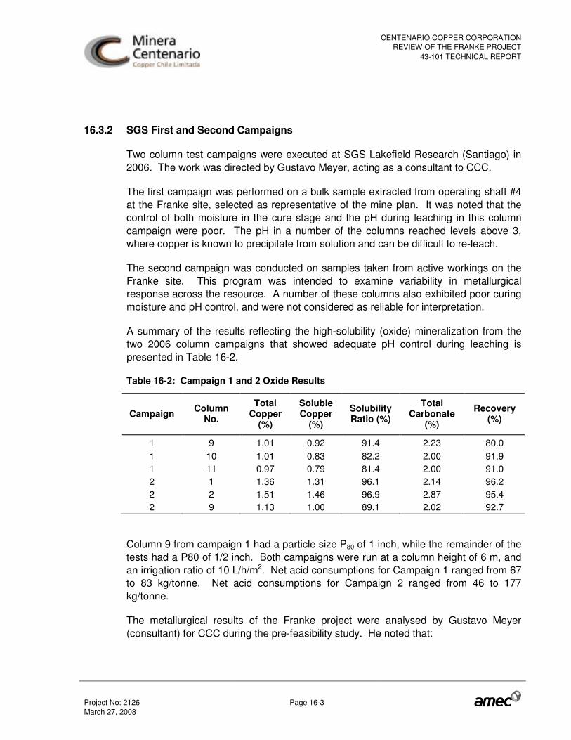
CENTENARIO COPPER CORPORATIONREVIEW OF THE FRANKE PROJECT
43-101 TECHNICAL REPORT
Project No: 2126 Page 16-3 March 27, 2008
16.3.2 SGS First and Second Campaigns
Two column test campaigns were executed at SGS Lakefield Research (Santiago) in 2006. The work was directed by Gustavo Meyer, acting as a consultant to CCC.
The first campaign was performed on a bulk sample extracted from operating shaft #4 at the Franke site, selected as representative of the mine plan. It was noted that the control of both moisture in the cure stage and the pH during leaching in this column campaign were poor. The pH in a number of the columns reached levels above 3, where copper is known to precipitate from solution and can be difficult to re-leach.
The second campaign was conducted on samples taken from active workings on the Franke site. This program was intended to examine variability in metallurgical response across the resource. A number of these columns also exhibited poor curing moisture and pH control, and were not considered as reliable for interpretation.
A summary of the results reflecting the high-solubility (oxide) mineralization from the two 2006 column campaigns that showed adequate pH control during leaching is presented in Table 16-2.
Table 16-2: Campaign 1 and 2 Oxide Results
Campaign Column No.
Total Copper
(%)
Soluble Copper
(%)
Solubility Ratio (%)
Total Carbonate
(%)
Recovery (%)
1 9 1.01 0.92 91.4 2.23 80.0 1 10 1.01 0.83 82.2 2.00 91.9 1 11 0.97 0.79 81.4 2.00 91.0 2 1 1.36 1.31 96.1 2.14 96.2 2 2 1.51 1.46 96.9 2.87 95.4 2 9 1.13 1.00 89.1 2.02 92.7
Column 9 from campaign 1 had a particle size P80 of 1 inch, while the remainder of the tests had a P80 of 1/2 inch. Both campaigns were run at a column height of 6 m, and an irrigation ratio of 10 L/h/m2. Net acid consumptions for Campaign 1 ranged from 67 to 83 kg/tonne. Net acid consumptions for Campaign 2 ranged from 46 to 177 kg/tonne.
The metallurgical results of the Franke project were analysed by Gustavo Meyer (consultant) for CCC during the pre-feasibility study. He noted that:
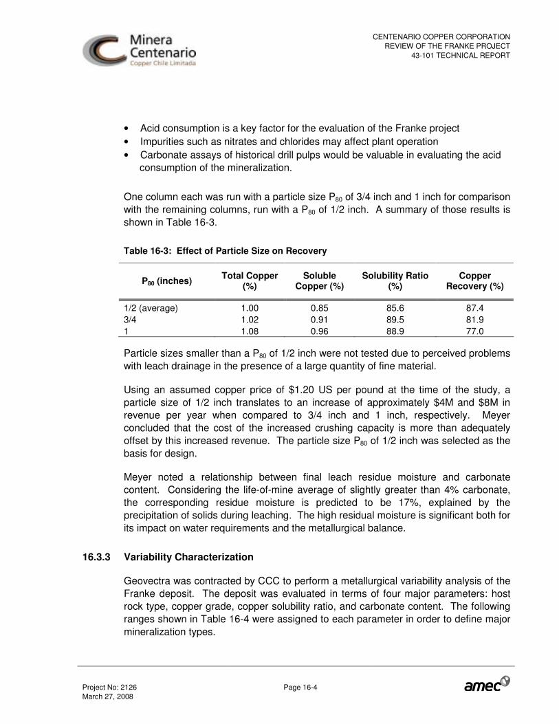
CENTENARIO COPPER CORPORATIONREVIEW OF THE FRANKE PROJECT
43-101 TECHNICAL REPORT
Project No: 2126 Page 16-4 March 27, 2008
• Acid consumption is a key factor for the evaluation of the Franke project • Impurities such as nitrates and chlorides may affect plant operation • Carbonate assays of historical drill pulps would be valuable in evaluating the acid
consumption of the mineralization.
One column each was run with a particle size P80 of 3/4 inch and 1 inch for comparison with the remaining columns, run with a P80 of 1/2 inch. A summary of those results is shown in Table 16-3.
Table 16-3: Effect of Particle Size on Recovery
P80 (inches) Total Copper (%)
Soluble Copper (%)
Solubility Ratio (%)
Copper Recovery (%)
1/2 (average) 1.00 0.85 85.6 87.4 3/4 1.02 0.91 89.5 81.9 1 1.08 0.96 88.9 77.0
Particle sizes smaller than a P80 of 1/2 inch were not tested due to perceived problems with leach drainage in the presence of a large quantity of fine material.
Using an assumed copper price of $1.20 US per pound at the time of the study, a particle size of 1/2 inch translates to an increase of approximately $4M and $8M in revenue per year when compared to 3/4 inch and 1 inch, respectively. Meyer concluded that the cost of the increased crushing capacity is more than adequately offset by this increased revenue. The particle size P80 of 1/2 inch was selected as the basis for design.
Meyer noted a relationship between final leach residue moisture and carbonate content. Considering the life-of-mine average of slightly greater than 4% carbonate, the corresponding residue moisture is predicted to be 17%, explained by the precipitation of solids during leaching. The high residual moisture is significant both for its impact on water requirements and the metallurgical balance.
16.3.3 Variability Characterization
Geovectra was contracted by CCC to perform a metallurgical variability analysis of the Franke deposit. The deposit was evaluated in terms of four major parameters: host rock type, copper grade, copper solubility ratio, and carbonate content. The following ranges shown in Table 16-4 were assigned to each parameter in order to define major mineralization types.

CENTENARIO COPPER CORPORATIONREVIEW OF THE FRANKE PROJECT
43-101 TECHNICAL REPORT
Project No: 2126 Page 16-5 March 27, 2008
Of the 72 possible combinations of parameters, 10 were shown to represent 85% of the oxide, mixed and sulphide mineralization contained in the deposit. Test samples reflecting these ten combinations were selected for the basis of subsequent metallurgical testing.
Table 16-4: Range for Mineralization Types Parameters
Parameter Descriptor Range
Host rock Andesite N/A Volcanic Sandstone N/A Copper grade High > 2.0 % Medium 0.6 – 2.0% Low < 0.6% Solubility Oxide > 80% oxide Mixed-Oxide 50 – 80% oxide Mixed-Sulphide 20 – 50% oxide Sulphide < 20% oxide Carbonate content High > 6% CO3
Medium 3 – 6% CO3 Low < 3% CO3
16.3.4 Metso Crushing Tests
Crushing tests were performed on Franke mineralization samples by Metso Minerals in their laboratory facility in Sorocaba, Brazil. The specific gravity, abrasion index, and crushing work index were experimentally determined for five samples from operating shafts at the project site. The results from the crushing tests indicate that the crushing circuit will have relatively low wear-part replacement owing to the low abrasion index, but fairly high specific energy consumption.
16.3.5 SGS Third Campaign
Column Campaign 3 was undertaken to confirm the results from Campaign 2, but with a column height of 3 metres rather than the previous height of 6 metres. Tests of both oxide and sulphide samples were included. Bottle rolls were also conducted on samples corresponding to the columns in order to investigate the scale-up factors.
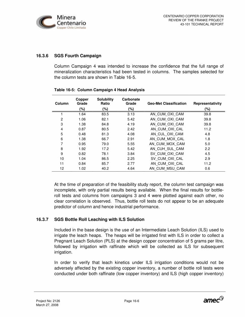
CENTENARIO COPPER CORPORATIONREVIEW OF THE FRANKE PROJECT
43-101 TECHNICAL REPORT
Project No: 2126 Page 16-6 March 27, 2008
16.3.6 SGS Fourth Campaign
Column Campaign 4 was intended to increase the confidence that the full range of mineralization characteristics had been tested in columns. The samples selected for the column tests are shown in Table 16-5.
Table 16-5: Column Campaign 4 Head Analysis
Column Copper Grade
Solubility Ratio
Carbonate Grade Geo-Met Classification Representativity
(%) (%) (%) (%) 1 1.64 83.5 3.13 AN_CUM_OXI_CAM 39.8 2 1.06 82.1 5.42 AN_CUM_OXI_CAM 39.8 3 1.38 84.8 4.19 AN_CUM_OXI_CAM 39.8 4 0.87 80.5 2.42 AN_CUM_OXI_CAL 11.2 5 0.48 81.3 4.08 AN_CUL_OXI_CAM 4.8 6 1.38 66.7 2.91 AN_CUM_MOX_CAL 1.8 7 0.95 79.0 5.55 AN_CUM_MOX_CAM 5.0 8 1.92 17.2 5.42 AN_CUH_SUL_CAM 2.2 9 0.82 78.1 3.84 SV_CUM_OXI_CAM 4.5
10 1.04 86.5 2.25 SV_CUM_OXI_CAL 2.9 11 0.84 85.7 2.77 AN_CUM_OXI_CAL 11.2 12 1.02 40.2 4.64 AN_CUM_MSU_CAM 0.6
At the time of preparation of the feasibility study report, the column test campaign was incomplete, with only partial results being available. When the final results for bottle-roll tests and columns from campaigns 3 and 4 were plotted against each other, no clear correlation is observed. Thus, bottle roll tests do not appear to be an adequate predictor of column and hence industrial performance.
16.3.7 SGS Bottle Roll Leaching with ILS Solution
Included in the base design is the use of an Intermediate Leach Solution (ILS) used to irrigate the leach heaps. The heaps will be irrigated first with ILS in order to collect a Pregnant Leach Solution (PLS) at the design copper concentration of 5 grams per litre, followed by irrigation with raffinate which will be collected as ILS for subsequent irrigation.
In order to verify that leach kinetics under ILS irrigation conditions would not be adversely affected by the existing copper inventory, a number of bottle roll tests were conducted under both raffinate (low copper inventory) and ILS (high copper inventory)

CENTENARIO COPPER CORPORATIONREVIEW OF THE FRANKE PROJECT
43-101 TECHNICAL REPORT
Project No: 2126 Page 16-7 March 27, 2008
conditions. The sample selected for the tests is of high solubility, which has generally exhibited rapid dissolution kinetics. Results indicate that copper inventory in irrigation solution has a trivial effect on recovery kinetics, within the bounds of measurement error. Thus, the results of the column tests, which reflect a single-stage leach cycle, can be applied to the two-stage design without modification.
16.3.8 SGS Bottle Roll Leaches with Ferric Iron Addition
In previous phases, the leaching of sulphide minerals was believed to require the presence of bacteria. This, in turn, required that the sulphide leach be maintained separate from the oxide leach due to concerns regarding impurity build-up, particularly chloride and fluoride, with harmful effects on the bacteria. The effect of this requirement on plant design was that separate solution handling facilities for the sulphide solutions were required. Preliminary results from column campaigns 1 and 2 showed a significant presence of ferric iron in leach product solutions, in the order of 7-8 kg generated per tonne of ore processed. This led to an investigation of the effect of ferric level in the leach feed solution on dissolution kinetics of sulphide minerals. Sufficient dissolution of sulphide minerals in the presence of ferric iron without the presence of bacteria would enable the plant design to consider a single solution handling system and a combined leach of sulphide and oxide minerals.
Bottle roll tests were performed at SGS Lakefield on a variety of samples, each being performed with a constant acid concentration of 20 g/L. Three levels of concentration of ferric iron in the tests were considered: 0, 4 and 12 g/L. Results showed that while the presence of ferric iron in the leaching solution enhanced copper recovery, more than 4 g/L contributed little additional effect. On average, the presence of ferric iron in the feed solution at 4 g/L improves non-soluble and overall copper recovery by 14.8% and 27.4%, respectively over the tests performed in the absence of ferric iron in the feed solution.
16.3.9 SGS Closed Circuit Campaign
The campaign was intended to determine the levels of solution impurities in closed circuit. Results are reported in SGS report “Final Report, Closed Circuit Leaching Tests in Columns with Solvent Extraction and Impurities Analyses, Prepared for Minera Centenario Copper SCM, Project Nº 3517, January 2008”. Iodide and bromide were not followed. Six columns of representative ore were prepared and leached in columns in closed circuit with batch solvent extraction. Raffinates and PLS were managed (combined) to provide suitable feed to SX and to the column leaching. Two columns were cured with 70 kg/t; four with 30 kg/t, each column represented a distinct

CENTENARIO COPPER CORPORATIONREVIEW OF THE FRANKE PROJECT
43-101 TECHNICAL REPORT
Project No: 2126 Page 16-8 March 27, 2008
sample (i.e., not an overall blend), and leach durations were varied to suit the ore characteristics.
General steady state was not achieved as the sulphate level, density and viscosity were still increasing at the conclusion of the series. Nitrate appeared to achieve steady state at around 900 mg/L, well below level of any concern. The most significant cationic impurities were ferrous and ferric iron, aluminium, and magnesium.
The algorithms developed in the feasibility study for acid consumption prediction were not verified in the test program. Significantly higher acid consumptions than would be forecast might be traced to high acid levels used in leaching (reported PLS levels ranging from 8 to 19 g/L free acid). These levels might have been selected to emphasize impurity leaching. High acid addition may be responsible for the observed high extractions of ferric and total iron
16.3.10 SGS Fifth Campaign
Eleven columns were run representing various minerals at Franke, of which three incorporated rest cycles as a potential optimization. The columns were run at a heap height of 4.25 metres, P80 of ½”, with a two-stage (ILS and raffinate) leach. Leaching chemistry was characterized as acid-ferric.
Due to an error in interpretation of operational data in all columns, SGS extended the leaching cycle beyond what is anticipated for industrial design, and added more acid than is expected to be necessary. Accordingly, the campaign yielded no useful information with regard to expected copper extractions and acid consumptions in the industrial operation
16.3.11 Pilot Heap Campaign
A three stage pilot program will be run during 2008 as follows:
Stage 1:
Stage 1 is the pilot plant start up and includes:
• Training of pilot plant operators • Development of work procedures • Development of test protocols • Start up and operation of the pilot plant in the areas of crushing, agglomeration,
leach boxes, columns and SX/EW.

CENTENARIO COPPER CORPORATIONREVIEW OF THE FRANKE PROJECT
43-101 TECHNICAL REPORT
Project No: 2126 Page 16-9 March 27, 2008
• Generate raffinate and ILS solutions for subsequent tests.
Stage 2:
Stage 2 constitutes a series of tests in columns and boxes with ore representative of the first 3 months of the mine plan. The specific objectives are:
• Generate a representative sample of the ore to be treated during the first 3 months of operation.
• Develop column tests to optimize critical variables particularly acid consumption. • Develop tests in leach boxes using the Project parameters to simulate the start up
conditions.
Stage 3:
Stage 3 and subsequent stages constitute a series of tests in columns and leach boxes with ore representative of operational quarters 2 to 8, i.e. the first 2 years of operation. The specific objective is:
• Identification of the operational parameters suitable for the ore types to be processed
It is evident that this new knowledge will be obtained too late to assist in design, but it should facilitate training, and faster ramp-up and optimization of operations after production start-up.
16.4 Interpretation of Test Results
16.4.1 Heap Height
Results from Column Campaign 2, conducted at a height of six metres, were compared with the corresponding duplicate column tests of Campaign 3, conducted at a height of three metres. One test showed a significant difference between the two heap heights, but consideration of the operating conditions led to the conclusion that this result was not valid. The results indicate that the key metallurgical parameters of recovery and acid consumption are not sensitive to leach heap height. As such, the metallurgical projections developed in the preceding sections can be applied to leach heaps of three to six metres depth.

CENTENARIO COPPER CORPORATIONREVIEW OF THE FRANKE PROJECT
43-101 TECHNICAL REPORT
Project No: 2126 Page 16-10 March 27, 2008
16.4.2 Leach Cycle
The leach cycle durations have been defined as “short” and “long”. The short leach cycle will be 60 days; the long cycle will be 120 or 180 days. The material that is >1.5% copper, 5% carbonate, or less than 70% solubility will be considered “long” leach cycle. Samples with high copper content (>1.5%) reached the required copper recovery within 60 days at times, but not universally. As such, mine blocks with copper grades over 1.5% are considered “long” cycle.
Columns with high carbonate generally exhibited longer leach times than samples with similar copper content. In light of this effect, mine blocks with a carbonate grade over 5% are considered “long” leach.
Table 16-6 below shows the results of tests from the second and third campaigns; those highlighted would be assigned a long leach cycle of 120 days. The actual cycle time to achieve 88% recovery is shown in the far right column.
Table 16-6: Test Results and Leaching Cycle
TCu = Total Copper SCu = Acid Soluble Copper Leach kinetics are not available for the predominantly sulphide minerals as column tests had not been completed at the time of the feasibility study. Because kinetics were not available for sulphide minerals, all mining blocks with a solubility ratio less than 70% were considered “long” leach cycle.
Column TCu SCu SCu/TCu CO 3 Heap
Height Days
# % % % % m (88% Rec) 1 1.36 1.31 96 2.1 6 42 2 1.51 1.46 97 2.9 6 43 8 3.76 3.46 92 2.4 6 87 9 1.13 1.00 89 2.0 6 30
10 3.14 2.98 95 3.1 6 57 11 0.63 0.51 81 5.8 6 78 1 2.08 1.95 94 2.2 3 44 2 1.73 1.59 92 2.7 3 52 8 3.65 3.40 93 2.5 3 48 9 0.72 0.60 84 1.8 3 27
10 2.63 2.35 90 2.1 3 50 11 0.81 0.63 78 5.1 3 83
Third Campaign
Second Campaign
Campaign

CENTENARIO COPPER CORPORATIONREVIEW OF THE FRANKE PROJECT
43-101 TECHNICAL REPORT
Project No: 2126 Page 16-11 March 27, 2008
The 120-day cycle was selected for the “long” leach cycle as a conservative value that will enable the leaching of the material with carbonate over 5%, copper over 1.5%, or mixed sulphide samples (50-70% solubility). Based on meeting one of the criteria presented above, and based on the mining plan of January 2008, the life-of-mine (LOM) feed to the plant will be approximately 57% short leach cycle and 43% long leach cycle, with feed grades as shown in Table 16-7.
Table 16-7: LOM Feed Grades for Different Leach Cycles
Leach Cycles Cycle Unit
Short Long
Copper Grade (%) 0.72 0.97 Solubility Ratio (%) 85.2 60.5 Carbonate Grade (%) 3.34 5.16
As the solubility ratio of the ore block decreases below 50% solubility, it is anticipated that a longer cycle time will be required. As such, a 180 day cycle will be used for sulphide samples (<50% solubility).
16.4.3 Copper Extraction
Soluble Copper
Using the classifications determined by Geovectra, and the column leaching results from Campaigns 3 and 4, a weighted average copper extraction for soluble copper is estimated to be 95.6%. This extraction estimate is then derated by applying a factor of 0.97 to translate from laboratory to industrial scale. Thus the soluble copper recovery term in the overall recovery model is:
( ) ( ) ( ) ( )���
������
������� ������������� =⋅⋅=
Where: RSCu(%) is the recovery of soluble copper SCu is the head grade of soluble copper (weight %) TCu is the head grade of total copper (weight %) SCu/TCu is the copper solubility ratio

CENTENARIO COPPER CORPORATIONREVIEW OF THE FRANKE PROJECT
43-101 TECHNICAL REPORT
Project No: 2126 Page 16-12 March 27, 2008
Non-soluble Copper
Due to the long leach cycles associated with non-soluble copper mineralogy (typically two to three times that of soluble copper minerals), column tests that reflect the ferric-driven leach process have not been completed for the feasibility study. Instead, the bottle roll tests under ferric conditions have been used to provide an indication of the range of expected recoveries for non-soluble copper.
Minerals in the Franke deposit have been shown through the column and bottle roll campaigns to generate ferric iron during the leaching process. The average ferric generation observed in the columns of 7.5 kg/tonne is equivalent to a solution concentration of 3.0 g/L when leached with the average specific irrigation ratio of 2.5 m3/tonne of ore.
A ferric concentration of 4 g/L in the feed solution provided an average recovery of 81.9% of non-soluble copper in bottle roll tests. The same scaling factors as applied to the soluble copper recovery algorithm in the previous project development work have been applied to this average value to estimate industrial recovery. In addition, a factor of 0.96 has been applied to scale from bottle roll particle size (ground material) to commercial heap leach (P80= 12 mm), resulting in a scaled average non-soluble copper recovery of 0.97*0.96*81.9 = 76.3%.
Due to the limited number of tests, a non-soluble copper recovery of 70% was adopted for the feasibility study. The equation for the non-soluble copper recovery is thus:
( )���
�������� −= ����
where: RNSCu (%) is the recovery of non-soluble copper SCu is the head grade of soluble copper (weight %) TCu is the head grade of total copper (weight %) SCu/TCu is the copper solubility ratio

CENTENARIO COPPER CORPORATIONREVIEW OF THE FRANKE PROJECT
43-101 TECHNICAL REPORT
Project No: 2126 Page 16-13 March 27, 2008
Total Copper Recovery
The recovery of total copper is the sum of the recoveries of soluble and non-soluble copper:
( ) ( )���
������
������� −+= ��������
where: RTCu (%) is the recovery of total copper SCu is the head grade of soluble copper (weight %) TCu is the head grade of total copper (weight %) SCu/TCu is the copper solubility ratio
This relation for copper recovery has been used in the feasibility study economic evaluation. In Figure 16-1, the projected recovery is plotted against the column results.
Figure 16-1: Recovery Algorithm versus Column Test Results
R = 92.7*RS + 70*(1-RS)
50
55
60
65
70
75
80
85
90
95
100
0 10 20 30 40 50 60 70 80 90 100
CuS/CuT, %
Cop
per
Rec
over
y,%
Columns Relation

CENTENARIO COPPER CORPORATIONREVIEW OF THE FRANKE PROJECT
43-101 TECHNICAL REPORT
Project No: 2126 Page 16-14 March 27, 2008
It is noted that the majority of the column tests were conducted without ferric iron in the feed solution, so the recovery of non-soluble copper species was typically below what is predicted by the recovery algorithm.
Acid Consumption
Acid consumption was evaluated in the feasibility study using data from the bottle tests conducted during Campaigns 3 and 4 of the column testwork, as well as the ILS recirculation tests. The ratio of carbonate grade to soluble copper grade (wt%/wt%) is plotted against specific acid consumption (kg acid consumed per kg of copper produced) in Figure 16-2.
Figure 16-2: Bottle Roll Acid Consumption Correlation
y = 3.0987x0.7689
R2 = 0.8832
0
2
4
6
8
10
12
14
16
18
20
22
24
26
28
30
32
0.0 2.0 4.0 6.0 8.0 10.0 12.0 14.0 16.0 18.0 20.0
Carbonate Grade to Soluble Copper Grade Ratio (wt %/wt %)
Spe
cific
Aci
d C
onsu
mpt
ion
(kg/
kg C
u)
When the net acid consumption results from the column campaigns are plotted against their corresponding soluble copper to carbonate ratios greater data scatter is observed. The net acid consumption trends higher, as seen in Figure 16-3.

CENTENARIO COPPER CORPORATIONREVIEW OF THE FRANKE PROJECT
43-101 TECHNICAL REPORT
Project No: 2126 Page 16-15 March 27, 2008
Figure 16-3: Column Tests Acid Consumption Correlation
y = 3.0216x0.9876
R2 = 0.6079
0.0
2.0
4.0
6.0
8.0
10.0
12.0
14.0
16.0
18.0
20.0
22.0
24.0
26.0
28.0
30.0
32.0
34.0
36.0
38.0
40.0
42.0
44.0
0.00 2.00 4.00 6.00 8.00 10.00 12.00 14.00 16.00
Carbonate Grade to Soluble Copper Grade (wt%/wt%)
Spe
cific
Net
Aci
d C
onsu
mpt
ion
(kg/
kg C
u) Columns
Relationship (Columns)
Relationship (Bottles)
Only one point from the column campaign exists in the range of 3.7 to 7.7 on the x-axis. This range reflects the maximum and minimum annual averages shown in the mine plan. The single point at 8.1 %/% @ 41 kg/kg skews the column curve and is likely an outlier.
The bottle roll acid consumption correlation was preferred over the columns as a conservative economic and design basis due to the poor correlation of the column results, inadequate column coverage of the carbonate ratios expected from the mine plan, the fine particle size (100% <#10 mesh) and improved solution-contact characteristics present in bottle roll tests. Although the tests were of short duration (6 days), ultimate acid consumption was believed to have been achieved. On the basis that ultimate acid consumption had been achieved, a scale-up factor of 0.90 was applied to the relationship derived from the bottle roll test results; both curves are shown in Figure 16-4.

CENTENARIO COPPER CORPORATIONREVIEW OF THE FRANKE PROJECT
43-101 TECHNICAL REPORT
Project No: 2126 Page 16-16 March 27, 2008
Figure 16-4: Scaled Bottle Roll Acid Consumption Correlation
Thus, the feasibility study used the following relationship to predict the industrial scale acid consumption of the Franke ore:
( )����� ��������
��� =
where: C is the specific net acid consumption in kg/kg Cu SCu is the soluble copper grade (weight %) CO3 is the carbonate grade (weight %) In the current mining plan, CCC have employed a different correlation which was developed by Geovectra in 2006, based on tests with ground pulps. It is based on carbonate content only, and does not give explicit credit to acid that may be generated in processing soluble copper that occurs in the deposit as sulphate minerals.
������ += ���
Bottles y = 3.0987x 0.7689
R 2 = 0.8832
Factor y = 2.7888x 0.7689
0 2 4 6 8
10 12 14 16 18 20 22 24 26 28 30 32
0.0 2.0 4.0 6.0 8.0 10.0 12.0 14.0 16.0 18.0 20.0 Carbonate Grade to Soluble Copper Grade Ratio (wt %/wt %)
Bottles
Relationship (Bottles)
Relationship w/ factor
Spe
cific
Aci
d C
onsu
mpt
ion
(kg/
kg C
u)

CENTENARIO COPPER CORPORATIONREVIEW OF THE FRANKE PROJECT
43-101 TECHNICAL REPORT
Project No: 2126 Page 16-17 March 27, 2008
where:
C is the net acid consumption in kg/tonne ore CO3 is the carbonate grade (weight %)
This relationship was compared with the AMEC feasibility study correlation for years 1 to 7. In each case, the CCC relationship predicted a slightly higher annual consumption of acid, and thus is believed to be conservative.
Results from the closed circuit and intermediate leach solution column campaigns do not verify the correlation discussed above. In most of the columns, acid consumptions significantly exceeded those predicted by both the AMEC and CCC algorithms.
In the closed circuit campaign, acid levels during leaching (both on-solution and off-solution) looked quite high, which may contribute to the observed high acid consumptions and impurity levels. It is not known if these high acid levels are required to achieve the copper extractions, which were reasonable. However, in a minority of instances, daily column effluents contained negligible free acid, indicating insufficient acid was provided at these times (i.e., high acid levels were required at these times).
Impurities
During the first testwork campaign, the presence of nitrate and chloride impurities was observed in the Franke PLS solutions obtained from the column tests. At high nitrate levels, nitration of the organic solvent extraction reagent, enabled by presence of chloride, bromide, or iodide, can destroy its effectiveness and require partial or complete replacement.
In order to better predict the steady-state impurity levels, a number of closed-circuit columns and mini-columns were run (SGS Closed-Circuit Campaign). The results show that if the samples represent the nitrate content to be encountered in plant feed, then accumulation of nitrate in the circulating leach solution is not likely to be a problem for the solvent extraction circuit. This should be verified by recalculating the process balance for the conditions used in these tests.
Accumulation of iron, magnesium, and aluminium may eventually contribute to problems due to high viscosity (affects phase separation in SX) and aluminium precipitation within the heaps (affecting permeability). A bleed might need to be implemented to control this.
The plant design approach to dealing with the impurities is further described in Section 19.2.

CENTENARIO COPPER CORPORATIONREVIEW OF THE FRANKE PROJECT
43-101 TECHNICAL REPORT
Project No: 2126 Page 16-18 March 27, 2008
16.5 Technical Issues
Summarized below are areas of processing risk, as of the date of this report, which have been identified in this review:
Copper Extraction and Acid Consumption Forecasts
The predictions of copper recovery and acid consumption are the two process results having the largest impact on the economic success of the project. There appear to be several uncertainties resulting from the manner with which this information has been developed.
The oxide and sulphide extraction correlations used to forecast the technical and economic performance of this project have been developed independently, using experiments where the sulphide copper extraction data were not collected under the same conditions as the oxide copper extraction results. Industrially, these two extractions must be obtained simultaneously; this should be modelled in test programs seeking to predict industrial performance.
Copper Extractions
The relationships developed for the soluble copper recovery, which apply to in the order of 80% of the reserves, are considered to be strong. Uncertainty in the extraction obtainable from non-soluble copper minerals, where some doubt remains, is proportionally less significant, since this form of copper only constitutes about 20% of the reserve, and the extraction predictions are believed to be conservative.
Use of bottle rolls executed on ground material provides a poor simulation of the leaching conditions anticipated to be found in commercial heap leaching. Generally, the larger the scale of testing, the better it is likely to forecast industrial performance. Column testing is not perfect, but it has become one of the most widely used tools for heap leach process development. Bottle roll tests on ground material have not achieved this status. They find their widest application for defining trends and proving applicability of a particular chemical approach to a range of rock types.
Non-soluble copper extraction predictions have been developed from bottle roll testing as a means to shorten the testing duration that would be encountered with column testing. Bottle roll testing may provide a useful indication of industrial performance when the bottle roll test results can be calibrated using industrial results (larger-scale tests) on the same material. However, such correlations, when they work, are site or

CENTENARIO COPPER CORPORATIONREVIEW OF THE FRANKE PROJECT
43-101 TECHNICAL REPORT
Project No: 2126 Page 16-19 March 27, 2008
material specific, and cannot be reliably translated to the Franke data. The recovery relation for non-soluble copper as derived from bottle results considers an industrial recovery of 70%; the average from representativity-weighted column tests was 63.3%, which can be considered a pessimistic case for the recovery of non-soluble copper.
The most recent column tests (intermediate leach solution series) have failed to confirm the relationships used to forecast copper recovery in the economic analysis. This was due to errors in operational procedures by SGS.
Acid Consumption
Both the AMEC and CCC acid consumption correlations are based on short term test results using ground samples. In the development of the AMEC relationship for the feasibility study, only one column result is within the expected range of the independent parameter, ratio of carbonate grade to soluble copper grade, so column results were not considered. The Geovectra/CCC relationship is based on leaching ground pulps, presumably to permit examination of a wide range of samples. Reliance on results from ground pulps rather than column leach tests leads to more uncertainty in the predictions.
The failure of the closed circuit campaign to verify the acid consumption algorithm is likely traceable to higher than normal acid additions used in this test series. The failure of the intermediate leach solution campaign to verify the acid consumption algorithm may be due to errors in procedure by SGS. Nevertheless, the algorithm remains unverified by column leaching tests.
Impact of Copper Extraction and Acid Consumption Forecasts on the Project
Sensitivities of project returns to copper price and acid price have been investigated in the financial analysis, discussed further in Section 19.8.3. Sensitivities to price variations are equivalent to sensitivities to quantity variations for commodities produced or consumed. Overall, the uncertainty in the predictions for copper extraction and acid consumption could shift the breakeven copper price for the project up or down.
Ferric iron
Ferric iron is required in the leach solution to oxidize sulphides and thereby release the associated copper. The current design assumes that sufficient ferric iron is available

CENTENARIO COPPER CORPORATIONREVIEW OF THE FRANKE PROJECT
43-101 TECHNICAL REPORT
Project No: 2126 Page 16-20 March 27, 2008
through dissolution of iron-containing minerals in the ore, such as hematite and limonite. However, addition of chemical ferric iron to some tests did yield an improvement in copper recovery, suggesting a deficit in ferric iron may arise with some samples. The samples for which this effect was observed were of very low solubility (approximately 20%), that is to say nearly pure sulphides. The Franke mine plan considers a blended plant feed that does not drop below 70% solubility in order to ensure sufficient ferric supply.
A balance that has been calculated based on ferric levels measured in test solutions suggests that sufficient ferric iron can be generated by the dissolution of ferric minerals. However, no attempt was made to sterilize the tests, and access to oxygen from air would not be impeded in the small scale tests that were done, as it would be in an industrial heap. Levels of bacterial activity in the tests are not believed to have been high, but still it is possible that the ferric iron observed in the test solutions was partially generated by bacterial oxidation to an extent that might not be seen in the industrial operation.
The Franke design specifically does not provide for any oxidation of sulphides directly by bacteria or by bacterially regenerated ferric iron, inasmuch as no aeration is provided and solution quality is not managed for optimum bacterial leaching (high total dissolved solids are permitted). Accordingly, there is some risk that sulphide copper may not be recovered efficiently in the Franke process if ferric iron is not generated at the expected levels.
Non-soluble copper is of the order of 20% of the total copper reserve to be processed at Franke. The impact of this risk on project success is that a portion of this copper which has been assumed to be recoverable may not, in fact, be recovered as thoroughly as predicted.
The impact of lower ferric iron generation can be mitigated (if economically justified) by installing aeration piping with blowers in the heaps, and solution management can be modified to provide an environment more favourable to bacterial growth, thereby regenerating the required ferric iron. Aeration piping is in use commercially for heap leaching when copper production is substantially dependent on oxidation of sulphides. These additions would constitute a minor retrofit for the Franke process.
Mitigation may also be provided during commercial operations by ferric iron dissolved in the inventory of circulating leach solution. For short term deficits in ferric iron supply as well as periods of enhanced consumption (high sulphide feed), this inventory may supply the required oxidation.

CENTENARIO COPPER CORPORATIONREVIEW OF THE FRANKE PROJECT
43-101 TECHNICAL REPORT
Project No: 2126 Page 16-21 March 27, 2008
Dissolved Impurities
Because the levels of impurities, in particular nitrate and iodide, were not determined as part of the orebody definition and mining plan development, there is some risk that these components will not achieve steady-state levels in circulating solutions that the process can tolerate. Closed-cycle testing provides an indication that the concentrations of nitrate and iodide are tolerable, but because the sample tested represents a limited percentage of the LOM plant feed, the test outcome cannot provide an assured prediction of commercial performance over the LOM. However, it is believed that the presence of these impurities is a surface phenomenon, whose significance will decline with deeper ore.
Of the PLS solutions from the open-circuit column tests analyzed for impurities, the results from the final two tests of campaign 1, which exhibited good pH control, showed the highest concentrations. Mass balance calculations based on those results indicate that these impurities will likely remain within acceptable operating ranges. Further support for this conclusion has been developed in the closed circuit column testing that has been conducted.
As discussed above, and in Section 19.2, engineering of the process has taken into account the likely presence of these impurities, although the levels cannot be accurately forecast. In operation, there is an established bleed of these materials out of the process with the washed ripios. In spite of this, if these impurities were to build to levels that adversely affect the process performance, an additional solution bleed stream will need to be established to control the levels. It should be noted that the Franke residues have a high moisture content, which essentially acts as a bleed solution which serves to mitigate the buildup of impurities.
An additional bleed would also remove water and copper from the process, leading to an increased water demand. If the copper losses are economically significant, the copper can be precipitated, (e.g. with the relatively inexpensive reagents limestone/lime) and the copper-containing precipitates can be reintroduced to the process, for example at the agglomeration drum.
Two Stage Leach
Adoption of the two-stage (intermediate leach solution) leach is an optimization technique, but its effectiveness had only been demonstrated in bottle roll experiments at the date of the previous Technical Report. The campaign for intermediate leach solution management was intended to demonstrate that these procedures would not decrease leaching performance. Due to late receipt of the results from SGS, and
CENTENARIO COPPER CORPORATIONREVIEW OF THE FRANKE PROJECT
43-101 TECHNICAL REPORT
Project No: 2126 Page 16-22 March 27, 2008
questions about their validity, a comparison of these results with single stage columns was not provided for review. The pilot plant testing will demonstrate and confirm the convenience of the two stage leaching.
Design Changes since the Feasibility Study
Lift Height
The feasibility study assumed a lift height of 3 meters. Initial column work was conducted at lift heights of both 6 and 3 meters, though a lift height of 4.25 m is being used in the plant design. A greater lift height should permit leach pads of lesser area, with capital savings, if leaching performance is not otherwise affected.
With the mining and irrigation rates unchanged, one concept is that each tonne should be processed by the same amount of leach solution as previously (3 m height), implying a longer leach cycle. An extended leach cycle may result in a need for pad expansion during the mine life.
With the extended leach cycle, there should be a slight increase in copper extraction and acid consumption, leading to slightly higher concentrations in PLS to the solvent extraction plant. The increases should not be great, because increments in copper extraction with cycle time should not be large. There are disadvantages associated with leaching a greater lift height that may negate any increment achieved.
There is an opportunity to reduce or eliminate the extension in leach cycle by increasing the acid strength of the raffinate used for irrigation. This would reduce or eliminate any need for additional pad area. Use of a higher acid strength in the feed might cause an increased acid consumption. If this course is pursued, the amount of solution used to process each tonne of ore will be reduced, which might yield a small reduction in leaching performance. Available testwork indicates that copper extraction is unaffected by lift height within the range of interest.
If the process plant receives the same flow of solution as previously, but at higher copper tenor due to increased lift height, copper that cannot be fully extracted by the SX plant as designed will be returned to the heaps in raffinate. The plant operating under this condition will be producing at or above its design production rate, so the feasibility of the project should be unaffected from a processing standpoint.
Solvent Extraction Electro-Winning Plant
CENTENARIO COPPER CORPORATIONREVIEW OF THE FRANKE PROJECT
43-101 TECHNICAL REPORT
Project No: 2126 Page 16-23 March 27, 2008
The AMEC feasibility study assumed conventional mixer settler units for solvent extraction and a conventional electro-winning tankhouse design. Subsequently, Engineer-Procure-Construct (EPC) for these facilities has been contracted to Outotec. Outotec are supplying mixer-settlers of proprietary design (DOP feed pumps, Spirok VSF mixers, Outotec deep settlers with DDG fences and launders). While incorporating new ideas on plant design, several of these plants have been installed industrially, and are believed to be performing as expected. The contracted design criteria ensure that the economic performance achieved by this plant will not be inferior to that forecast in the feasibility study.
Crushing and Materials Handling
EPC for the crushing and materials handling facilities has been contracted to FL Schmidt. Side-by-side comparison of the AMEC and FL Smidth design criteria shows some differing internal flows and screen apertures, and the three FL Smidth Coarse Ore Stockpile reclaim feeders are sized for 50% of design flow vs AMEC’s 100%. The contracted design criteria ensure that the economic performance achieved by this plant will not be inferior to that forecast in the feasibility study, although the operational flexibility may not be as great.
CENTENARIO COPPER CORPORATIONREVIEW OF THE FRANKE PROJECT
43-101 TECHNICAL REPORT
Project No: 2126 Page 17-1 March 27, 2008
17.0 MINERAL RESOURCE AND MINERAL RESERVE ESTIMATES
In 2007, Geovectra and NCL updated the mineral resource estimate and the mineral reserve estimate of the Franke deposit respectively.
The information from the 2007 drilling campaign was used to update the resource model. The resource model estimation incorporated geostatistical methods and a block size of 5 m by 5 m by 5 m. Vulcan® software was used for geological modelling and resource estimation.
17.1 Definitions
Stated mineral resources and mineral reserves are derived from estimated quantities of mineralized material recoverable by established or tested mining methods. Mineral reserves include material in place and on stockpiles.
The Franke deposit resource estimates were prepared under the supervision of Jozsef Ambrus, President of Geovectra. Rodrigo Marinho, Principal Geologist and a Member of AIPG and Aldo Vásquez, Senior Geologist at AMEC have reviewed the mineral resource estimate. Ralph Penner, Manager of Mining for AMEC and a Member of the AusIMM, Marcelo Hernando and Francisco Labbe, AMEC Mining Engineers have reviewed the mineral reserve estimate.
There are numerous uncertainties inherent in estimating mineral resources and mineral reserves. The accuracy of any reserve and resource estimation is the function of the quality of available data and of engineering and geological interpretation and judgment. Results from drilling, testing and production, as well as material changes in copper prices, subsequent to the date of the estimate may justify revision of such estimates.
17.2 Mineral Resource
Geovectra generated models for total copper, soluble copper and carbonate. AMEC audited all three models, with particular focus on the following:
• Parameters of data quality (documented in Section 14, Data Verification) • Global and local bias detection • Appropriateness and correctness of the mineral resource classification
The resource model validation by AMEC was comprised of the following checks:

CENTENARIO COPPER CORPORATIONREVIEW OF THE FRANKE PROJECT
43-101 TECHNICAL REPORT
Project No: 2126 Page 17-2 March 27, 2008
• Geological model review • Compositing validation • Block model setup and kriging parameters verification • Density review • Visual inspection of the kriged grade models on-screen • Comparison of the kriged estimate and nearest-neighbour estimate statistics • Check for geographical biases using swath plots of the kriged and nearest-
neighbour estimates • Resource classification validation.
17.2.1 Drilling Database
AMEC received digital copies of the drill hole database, reports, assay certificates and block model from Geovectra on December 24, 2007. This drilling campaign as well as the drill hole database was closed off as at July 12, 2007. The database contains diamond and reverse circulation drilling information from the various campaigns as described in Section 11.
17.2.2 Domain Definition
Geovectra defined five domains listed in Table 17-1.
Geovectra interpreted the Oxide and Sulphide domains based on geological observations (proportion of both oxide and sulphide mineral assemblages) and the solubility ratio (SR) as a ratio of SCu over TCu. A threshold of SR = 0.5 was used to discriminate between the Oxide and Sulphide domains.
Table 17-1: Domain Description
Domain Description Oxides Oxides are greater than Sulphides, TCu>0.2% and SR > 0.5 Sulphides Sulphides are greater than Oxides and TCu>0.2% and SR < 0.5 Mine Dumps Ore material piled at surface Stopes Underground cavities Waste All domain outside of previous zones
17.2.3 Domain Interpretations
The 2007 geological model was created based on 48 E-W vertical sections evenly spaced every 25 m and reconciled in plan. The locations of these sections are displayed in Figure 17-1.

CENTENARIO COPPER CORPORATIONREVIEW OF THE FRANKE PROJECT
43-101 TECHNICAL REPORT
Project No: 2126 Page 17-3 March 27, 2008
Figure 17-1: NE-SW sections – 2006 and EW sections - 2007
Source: Geovectra, 2007.
Polygons of mineralized bodies were interpreted in plan view on 28 levels between elevations of 1,600 and 1,735 m, spaced every five metres, plus one plan at 1,550 m elevation. Figure 17.2 shows a plan view of the interpreted 0.2% TCu cut-off grade-shell.
Three-dimensional solids were created from these polygons by extrusion. In other words the polygons were vertically projected 5 m above the level of its interpretation. Plan 1550 was extruded 50 m up. The 3D model is illustrated in Figure 17.3.
The mineralized bodies were interpreted directly as a diluted model using five metre bench composites. In areas where no new drill hole data were available, the diluted model was re-interpreted from the projection of the 2006 plan model into the E-W sections.
AMEC reviewed the interpretations and found them globally reasonable.

CENTENARIO COPPER CORPORATIONREVIEW OF THE FRANKE PROJECT
43-101 TECHNICAL REPORT
Project No: 2126 Page 17-4 March 27, 2008
Figure 17-2: Sample Plan Model - 2007
Source: Geovectra, 2007. Intersection with the diluted model in sections (horizontal lines) and drill hole TCu assay composites (dots) are displayed.
Figure 17-3: General View – 3D Geological Model
Source: Geovectra 2007

CENTENARIO COPPER CORPORATIONREVIEW OF THE FRANKE PROJECT
43-101 TECHNICAL REPORT
Project No: 2126 Page 17-5 March 27, 2008
17.2.4 Composites
Geovectra composited the drill hole intervals to 5 m high bench intervals. AMEC considers this to be an appropriate composite length as the mining benches will be designed to this height. However, AMEC recommends using the down hole compositing method for future grade estimations to ensure all composites have the same length.
17.2.5 Variography
Geovectra (2007) developed variogram models for TCu and SCu in Oxide and Sulphide domains using GSLib software, based on the composited data and individually for Oxide and Sulphide domains. The variogram models utilized by Geovectra are summarized in Table 17-2. Geovectra found no anisotropies in the horizontal variograms and similar models were applied in the Oxide and Sulphide domains. However, for estimation purposes the search was oriented N28W in the horizontal plan since this is the main direction of continuity of the mineralization.
Table 17-2: Variogram Models
1st sill - Range (m)
2nd sill - Range (m)
Domain Model Type
Nugget Co
C1
C2
Major Minor Vertical Major Minor Vertical
Oxides Spherical 0.602 0.289 0.109 50 50 15 50 50 �
Sulphides Spherical 0.514 0.428 0.058 50 50 20 50 50 � AMEC agrees with Geovectra’s conclusions.
17.2.6 Exploratory Data Analysis
The Geovectra geological interpretation incorporates drill log information as entered into the in-house database (GVMapper®).
The lithological units as well as the mineralization units are well codified in the database. All of them show well defined contacts.
Geovectra grouped the diverse lithologies of the deposit in five units: Andesites, Volcanic Sandstones, Limestones, Caliche and Low Density Rock for modelling. In addition, Geovectra grouped the mineralization units in both Oxide and Sulphide domains.

CENTENARIO COPPER CORPORATIONREVIEW OF THE FRANKE PROJECT
43-101 TECHNICAL REPORT
Project No: 2126 Page 17-6 March 27, 2008
AMEC observed the lithological contacts and found that they are hard; meanwhile the mineralization contacts are soft. This observation is well documented in the database.
AMEC considers that the data interpretation and unit contacts are acceptable.
17.2.7 Capping
Geovectra capped the composite grades at 5% TCu and 5% SCu based on visual observations of a cumulative probability chart. Thirteen TCu composite values were affected by the capping and only one SCu composite was affected.
Carbonate composite values were not capped.
AMEC recommends reviewing the capping strategy and consider additional criteria such as the distribution of the grades in the domains.
17.2.8 Density
The average density of each rock type in the geological model was calculated and assigned by default to the block model (Table 17-3).
Table 17-3: Density Assignation
Rock Type Model Code Density (t/m3) Andesite 1000 2.6 Volcanic Sandstone 2000 2.5 Limestone/Mudstone 4000 2.5 Caliche 5000 2.2 “Low density rock” 6000 2.2 Source: Geovectra, 2007.
For andesite blocks with insoluble copper greater that 1%, the default density was replaced with a density calculated using the following formula:
Density = Insol Cu % * 0.03 + 2.6
Where the Insol Cu% is the insoluble copper calculated as the absolute difference between TCu and SCu.

CENTENARIO COPPER CORPORATIONREVIEW OF THE FRANKE PROJECT
43-101 TECHNICAL REPORT
Project No: 2126 Page 17-7 March 27, 2008
17.2.9 Block Model Dimensions and Grade Estimation
The block model consisted of 12,144,000 blocks. Geovectra estimated four variables:
• Total Copper (TCu in %): Estimated using Ordinary Kriging • Soluble Copper (SCu in %): Estimated using Ordinary Kriging • Solubility ratio: Estimated SCu / Estimated TCu • Carbonates (CO3): Estimated using Inverse Distance Squared (ID2)
The blocks assigned to the mine dumps were estimated using the polygonal method. The samples used for this estimation are the 1,010 samples collected directly from the mine dumps (Geovectra et al., 2006). Only blocks within the solids defined in the geological model were interpolated and classified into resource categories.
In order to adjust the block model for voids of previous underground workings, Geovectra reset the Stope block values of TCu, SCu, CO3 and density to zero. Waste blocks grades were set equal to 0 and density to 2.6 t/m3.
Estimation Plan
Geovectra estimated TCu and SCu in Oxide and Sulphide domains using Ordinary Kriging; meanwhile ID2 was applied to estimate CO3 without differentiating domains.
The High Grade search radius for the composites with concentration above 2% TCu was restricted. The search ellipse, for grade estimation, was oriented 28° to the west and no inclination was used. This is in agreement with the geological observations and in AMEC’s opinion is adequate because all geological interpretations were based on the orientation of the NW-SE local structural setting (see Figure 17-2).
In AMEC’s opinion the estimation plan is reasonable and includes the evident anisotropy in the local and regional structural setting but not in the variograms.
Dilution
AMEC observed that the mineralization unit contacts are soft and the high copper grade zones are controlled by a more restricted search radius in the interpolation. AMEC considers that the resource model is adequately diluted for in-situ and contact dilution.

CENTENARIO COPPER CORPORATIONREVIEW OF THE FRANKE PROJECT
43-101 TECHNICAL REPORT
Project No: 2126 Page 17-8 March 27, 2008
17.2.10 Block Model Validation
AMEC generated a NN model to validate the Ordinary Kriging (OK) and the Inverse Distance Squared (ID2) models. There is almost no difference in average grade between the NN and the OK and the ID2 models.
Drift Analysis
A drift analysis was performed for all variables in the North-South, East-West and vertical directions using in house software. Swath plot validation compares the averaged grades from kriged and nearest-neighbour models along different directions.
The kriged and NN models agree quite well and no significant spatial bias is observed. The TCu, SCu and CO3 estimates are unbiased globally.
Smoothing
Kriging, as with all linear interpolation methods, has a tendency to smooth the estimates. The risk associated with smoothing is that tonnage and the grade above a cut-off may be overestimated if the cut-off is higher than the mean grade.
AMEC compared the NN model adjusted for variance by a Hermitian transformation (Herco) grade-tonnage curve with the kriged model grade-tonnage curve.
AMEC focused its analysis on TCu in the Oxide and Sulphide zones which are the most important domains in terms of tonnage and grade.
AMEC considers that the smoothing in the kriged blocks is well controlled.

CENTENARIO COPPER CORPORATIONREVIEW OF THE FRANKE PROJECT
43-101 TECHNICAL REPORT
Project No: 2126 Page 17-9 March 27, 2008
17.2.11 Reject Stockpiles
The volume of the reject stockpiles from underground workings was measured and reported in 2005 by Geovectra. In 2006, 1,010 evenly spaced samples were taken in order to determine the metal content of the reject stockpiles. The average density used for the tonnage calculation was 1.79 t/m3. The average bulk density was determined by weighing each of the loaded trucks in a truck weighing station after being loaded with an excavator. The reject stockpile resource estimation yielded 746,000 tonnes at 1.01% TCu, 0.78% SCu and 4.06% CO3.
During 2007 Geovectra surveyed new stockpiles and estimated a total of 874,000 tonnes at 1.0% TCu, 0.78% SCu, and 3.9% CO3.
17.2.12 Resource Classification
Geovectra applied a series of geometric criteria to classify the mineral resources into the inferred, indicated and measured categories as detailed in Table 17-4. AMEC finds that these geometric criteria are reasonable given the geological and grade continuity at Franke.
Table 17-4: Mineral Resources Classification Criteria
Zone Category Criteria
Measured Second nearest sample is located 25 m away or less
Indicated Second nearest sample was located more than 25 m and less than 50 m away
Oxide / Sulphide
Inferred Second nearest sample is located more than 50 m away
Measured Nearest sample is located 35 m away ore less Mine Dumps
Inferred Nearest sample was located more than 35 m away
AMEC performed a pit optimization using Whittle® software considering a long-term price of 1.65 US$/lb Cu that is higher than 1.50 US$/lb used for the mineral reserve and financial evaluation but appropriate for mineral resource classification. Remaining optimization parameters are the same as the ones used for reserve classification and are described in Section 17.3.

CENTENARIO COPPER CORPORATIONREVIEW OF THE FRANKE PROJECT
43-101 TECHNICAL REPORT
Project No: 2126 Page 17-10 March 27, 2008
17.2.13 Mineral Resource Statement
From the original mineral inventory (at TCu cut-off = 0.3%) reported by Geovectra (2007) AMEC estimates 36.7 Mt of measured and indicated categories that fell into the optimized pit, as detailed in Table 17-5.
Table 17-5: Mineral Resource Statement (AMEC) TCu Cut-Off=0.3%
Resource Tonnage TCu Cu SCu CO3 Category (Mt) (%) (Mlb) (%) (%)
Measured 27.7 0.86 521 0.60 4.16 Indicated 9.0 0.76 151 0.60 4.28 Measured+Indicated 36.7 0.83 672 0.60 4.19
In addition to the measured and indicated mineral resources reported above at a 0.3% TCu cut-off, there are 2.5 million tonnes of inferred mineral resources at 1.02% TCu, 0.41% SCu and 3.65% CO3 contained in the Resource pit.
17.2.14 Conclusions and Recommendations
AMEC did not detect any fatal flaw in the resource or geological model. The model is accurate, unbiased, not excessively smoothed and honours the drill-hole data.
The dilution in the model is adequate.
However, AMEC recommends that the following measures be implemented to improve the local accuracy of future models:
• The density model should be refined in order to adjust the in-house measurements against measurements performed by a reputed laboratory with a sealed sample method.
• The capping strategy for composites should be improved considering each element and domains separately.
CENTENARIO COPPER CORPORATIONREVIEW OF THE FRANKE PROJECT
43-101 TECHNICAL REPORT
Project No: 2126 Page 17-11 March 27, 2008
17.3 Mineral Reserves
Three different software packages were used to estimate the mineral reserves. The pit optimization was performed using the Lerchs-Grossman algorithm included in the Whittle FX software; VULCAN was used for operational designs; finally, NCL used in-house software (PolyPlan) for production planning.
AMEC has verified NCL’s mine plan and reserves using Whittle FX and Datamine.
17.3.1 Geotechnical and Slope Design
Pit Slopes
The Franke mine will consist of several small open pits to exploit the ore body, the largest of which is approximately 400 m long, 250 m wide and 80 m deep. NCL used a slope angle of 49.2 degrees for the pit optimization for the Franke Deposit, but the NCL report (March, 2007) makes no mention of any geotechnical analysis. AMEC reviewed a geotechnical data prepared by Ingeroc Engineers (2007) and found that the geotechnical design is lacking supporting information for the analysis that was completed. Mr. Stu Anderson of AMEC completed a site visit in May, 2007 at the same time as Ingeroc and identified additional investigation and geotechnical work that should be completed.
Additional investigation work was completed in August, 2007 by Ingeroc at the Franke project. A revised report was provided to AMEC for review in February, 2008. The investigations in the report confirms the presence of a NNW-SSE structural trend based on downhole survey as well as geological mapping, and, after various analyses, recommends all orientations of the proposed pit wall slopes to be designed with bench face angles of 75º, 20 m bench heights and 6.5 m wide berms, resulting in an inter-ramp slope angle of approximately 55º. Although the data supports this design criterion for the majority of wall orientations not sub-parallel to the primary structural trend, it is AMEC’s opinion that pit walls, such as those oriented in the NNW-SSE direction, will exhibit poor performance at these design angles and may require flattening due to toppling type behaviour and/or rockfall hazard.
The majority of the fault structures which have been identified from the Ingeroc report also trend NNW-SSE and tend to be steeply dipping structures, greater than the inter- ramp angles proposed by Ingeroc. There does not appear to be a rock mass stability problem with the pit walls, except where material may be highly weathered near surface. This is not expected to cause significant concern unless poor blasting techniques result in inadequate berm widths for rockfall catchment.

CENTENARIO COPPER CORPORATIONREVIEW OF THE FRANKE PROJECT
43-101 TECHNICAL REPORT
Project No: 2126 Page 17-12 March 27, 2008
Groundwater is not expected to be an issue with the current pit depths identified.
The impact of underground workings on both the operation and pit wall design will need to be properly assessed and procedures established for equipment working around or above current underground workings. Pit floor and wall stability can be adversely affected and therefore proper stand-off distance procedures for investigations of the voids and backfilling of the voids must be implemented. Pit wall berms may be lost when walls intersect workings which can increase the hazard of rockfall due to the loss of catchment.
Initial excavation of the open pit(s) and exposure of the rock mass will result is an excellent opportunity for CCC to map and confirm the structural controls for the open pit slopes and re-evaluate the pit slope design. It is highly recommended that this be completed.
Waste Dump
The waste dump design has been carried out by Arcadis Geotechnica and the dump is located immediately north of the Franke pit(s). The waste dump is designed to store approximately 60 million tonnes of pit run waste (31 Mt) and leached ore (29 Mt). The dump configuration is square (approximately 900 m by 900 m) and will comprise of a pit run waste outer shell with the internal volume storing the leached ore.
Arcadis identifies 3 horizons for the foundation, two of which are soil, and the third bedrock. It has been assumed that the depth of soil cover is less 1.5 m in the vicinity of the dump, which may or may not be correct.
The dump shell is expected to be 65 m high at the highest point, constructed in three separate lifts, with each lift possessing angle of repose side slopes (1.3H:1V) and various top surface widths (widths not defined in the Arcadis report). The perimeter shell of the dump will initially be constructed using a 20 m high waste tip head from 1,700 m elevation to 1,720 m elevation and the interior of the dump filled with leached ore to the same elevation. A 30 m high tip head is used to develop the next lift stage and perimeter shell for the dump (to 1,750 m elevation), with the final lift to 1,765 m elevation to be constructed last.
Analysis of the overall stability of the dump has been completed along critical sections of the final dump configuration. Based on the sections presented by Arcadis, the dump appears to possess adequate stability against static and pseudo-static conditions.

CENTENARIO COPPER CORPORATIONREVIEW OF THE FRANKE PROJECT
43-101 TECHNICAL REPORT
Project No: 2126 Page 17-13 March 27, 2008
AMEC has identified some geotechnical issues regarding the waste dump design and they are listed below:
• No site investigations have been completed within the dump footprint; Arcadis quote experience from elsewhere in the project area to support their claim of thickness and characteristics of the dump foundation soils.
• It is not clear or stated what the overall slope of the outer dump face is to be and what offsets between toe and crest of subsequent lifts are.
• Scheduling of the pit run and leached waste has not been taken into account to assess impact on dump design and configuration.
• Stability analysis of the dump design has not taken into account the phased approach to dump construction as well as potential instability of upstream shell slope on leached waste.
• Stability analysis of the dump design has not indicated whether or not pre-strip of the foundation is necessary under the outer shell to enhance stability.
• Stability of an active high tip head comprised of leached waste needs to be addressed.
• Trafficability of the shell and leached waste material requires a discussion and whether sheeting will be necessary for the tip head areas and access roads.
17.3.2 Pit Optimization
AMEC verified the Lerchs-Grossman open pit optimization in Whittle FX and could reproduce the results of NCL.
AMEC verified that technical and financial parameters mentioned in the NCL report (January, 2008) were those actually used in the pit optimization. AMEC considers that parameters used for optimization were reasonable.
Metallurgical recovery of TCu is a variable that depends on the solubility ratio as shown in the following mathematical expression taken from the NCL report (January, 2008).
��
���
� −+=���
���
���
���� ��������������
Where Rec is the Metallurgical Recovery.
CENTENARIO COPPER CORPORATIONREVIEW OF THE FRANKE PROJECT
43-101 TECHNICAL REPORT
Project No: 2126 Page 17-14 March 27, 2008
AMEC checked that this formula was correctly applied in the pit optimization.
The processing cost depends on acid consumption, which, in turn, depends on the carbonate grade. Similar to the metallurgical recovery, the following mathematical expression was applied to determine the acid consumption prior to import to the Whittle program:
���� �������� �� += ����
Its effect on Process cost (leaching) was calculated in Whittle:
����������������� ����� ��������� +=
Where, AC(kg/t) is the kilograms of acid per tonne of leached mineral, CO3 (%) is the carbonate grade, and CostLeaching (US$/t) is the leaching process cost.
A constant cost of acid of 59 US$/t was provided by CCC; this cost is related to a copper price of 1.50 US$/lb.
Table 17-6 summarizes the other costs provided by CCC. NCL used a discount rate of 8.5% for the Whittle optimization.
Table 17-6: Other Pit Optimization Costs
Process Unit Cost
Mining US$/t 1.620 SX - EW Processing US$/lb 0.145 Overhead and Administration US$/lb 0.058
17.3.3 Phase Design
The operational design did not consider the effect of the old stope cavities left from decades of artisanal mining. At a Feasibility stage, this may be acceptable provided that the appropriate adjustment is made in the mineral reserve classification. However, the health and safety and short-term production planning issues related with the cavities are such that mining around these cavities must be carefully planned before production start up. Ideally this should be done at the detailed engineering phase of the project. Figure 17-4 shows cavities in and near the pit at the end of second production year.
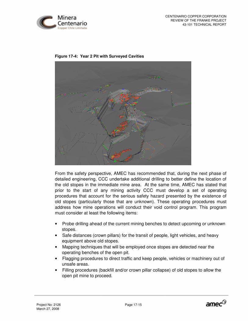
CENTENARIO COPPER CORPORATIONREVIEW OF THE FRANKE PROJECT
43-101 TECHNICAL REPORT
Project No: 2126 Page 17-15 March 27, 2008
Figure 17-4: Year 2 Pit with Surveyed Cavities
From the safety perspective, AMEC has recommended that, during the next phase of detailed engineering, CCC undertake additional drilling to better define the location of the old stopes in the immediate mine area. At the same time, AMEC has stated that prior to the start of any mining activity CCC must develop a set of operating procedures that account for the serious safety hazard presented by the existence of old stopes (particularly those that are unknown). These operating procedures must address how mine operations will conduct their void control program. This program must consider at least the following items:
• Probe drilling ahead of the current mining benches to detect upcoming or unknown stopes.
• Safe distances (crown pillars) for the transit of people, light vehicles, and heavy equipment above old stopes.
• Mapping techniques that will be employed once stopes are detected near the operating benches of the open pit.
• Flagging procedures to direct traffic and keep people, vehicles or machinery out of unsafe areas.
• Filling procedures (backfill and/or crown pillar collapse) of old stopes to allow the open pit mine to proceed.

CENTENARIO COPPER CORPORATIONREVIEW OF THE FRANKE PROJECT
43-101 TECHNICAL REPORT
Project No: 2126 Page 17-16 March 27, 2008
• Additional equipment required to comply with these procedures. • Additional operating costs to comply with these procedures. • Productivity derating associated with these procedures.
AMEC considers the development of and compliance with these procedures to be necessary for the safe operation of the planned open pit.
17.3.4 Mine Plan
NCL prepared a mine plan, from the final pit and the operational phases using NCL’s in-house planning software, considering the resources (including inferred resources) within the final pit as well as the surface reject stockpiles. AMEC adjusted the mine plan excluding the inferred resources, which AMEC considers as waste material.
The mine plan targets 30 kt of copper cathode production per year (see Table 17-7). Surface stockpiles will be consumed in the first half of year 1. The stockpiles are usually close to old underground workings.
Table 17-7: NCL January 2008 Mine Plan (adjusted by AMEC to exclude inferred mineral resources)
Ore Cathode Acid Consumption Waste Total
Period (kt) TCu
(%) SCu (%)
CO3 (%)
Rec (%) (t) (kg/t) (kt) (kt)
Stripping Ratio
Year 1 3,899 0.87 0.71 3.77 88.4 30,000 77.6 4,094 7,992 1.32
Year 2 3,933 0.88 0.64 3.83 86.6 30,000 84.0 4,492 8,424 1.14
Year 3 4,391 0.77 0.64 3.47 88.9 30,000 69.8 4,388 8,779 1.00
Year 4 4,292 0.80 0.61 3.82 87.4 30,000 79.5 4,336 8,627 1.01
Year 5 4,331 0.78 0.65 4.67 88.9 30,000 88.1 5,086 9,418 1.17
Year 6 4,279 0.79 0.64 4.61 88.4 30,000 89.1 5,348 9,627 1.25
Year 7 4,162 0.84 0.58 4.30 85.8 30,000 93.4 5,969 10,131 1.43
Year 8 2,437 0.94 0.25 3.89 76.0 17,431 86.3 4,187 6,623 1.72
Total 31,723 0.83 0.61 4.06 86.9 227,431 83.3 37,900 69,623 1.23
Obs.: Net profit cut-off greater than zero

CENTENARIO COPPER CORPORATIONREVIEW OF THE FRANKE PROJECT
43-101 TECHNICAL REPORT
Project No: 2126 Page 17-17 March 27, 2008
17.3.5 Net Profit Cut-Off
NCL used a net profit cut-off of zero. This concept depends on TCu, SCu, CO3, copper price, acid cost, acid consumption, TCu recovery, and SX-EW and G&A cost as shown below.
Net Profit Cut-off = (Cuprice – SXEWcost – G&Acost)*TCurecovery – Processingcost > 0
17.3.6 Equipment Fleet Design
The criterion for mining operations was previously to consider owner operation by CCC. In the August 31, 2007 Technical Report, AMEC reviewed the equipment fleet design provided by NCL. For this update CCC has tendered the mining operations to local contractors.
The contractor calculation basis is 360 days per year, 24 hours per day in two shifts with twelve hours per shift. AMEC agrees with the calculated contractor equipment fleet and estimated cost per tonne.
17.3.7 Drilling and Blasting
The contractor offered two drills (Atlas Copco ROC L8), with drill range between 5 and 8 inches blast hole diameter. These machines are new and will be maintained by a maintenance and repair contract. The drilling requirements are correct for the local conditions.
The contractor will be working directly with ENAEX (a major supplier of explosives and explosive placement equipment) in all activities related with the blast process design and operation.
17.3.8 Truck Loading and Hauling Equipment
The contractor offered two new excavators Komatsu PC-1250 (6.7 m3 bucket). One of these excavators is for ore material and the other one for waste material. Besides this loading fleet, the contractor considered two front-end loaders (Komatsu WA 600-7). One of these front-end loaders is for waste material and leach material and the other front-end loader is “stand by” loading equipment.
The contractor offered ten new Komatsu HD 465-7 haul trucks (55 t) to transport ore, waste and leach material.

CENTENARIO COPPER CORPORATIONREVIEW OF THE FRANKE PROJECT
43-101 TECHNICAL REPORT
Project No: 2126 Page 17-18 March 27, 2008
The contractor has considered four operators for each of the loading and hauling equipment, which is a standard practice in similar operations.
The maintenance for all loading and hauling equipment is considered under a maintenance and repair contract with Komatsu.
17.3.9 Ancillary Equipment
In AMEC’s opinion, the ancillary equipment type and number are adequate.
AMEC recommends that the road maintenance and dust control equipment be increased; however this will not have a material effect on the estimated contracted mining cost.
17.3.10 Manpower
Since mining operations will be carried out by a contractor, CCC will only administer the mining process. The CCC operations staff was reviewed by AMEC and increased from 13 to 20 people (Geologist, Mining Engineer, Superintendent, Contractor Manager, Mining Planners, Surveyor, Geologist Assistants, and Surveyor Assistants) in order to ensure operational continuity.
In AMEC’s opinion the number of contractor staff, technicians, operators and subcontractors is adequate for this operation.
17.3.11 Mine Operating Cost
Mine operating cost includes; the contractor price for ore and waste material, fuel oil consumption and CCC labour cost. AMEC reviewed the contractor operating cost and found it reasonable and globally well documented for unit price. The contractor price includes items such as manpower, materials, equipment, general bills and utilities. Mine operating costs are summarized in Table 17-8. Diesel price assumed was US$ 0.459/litre; however, sensitivity analysis was also completed in the financial model using US$ 1.00/litre.

CENTENARIO COPPER CORPORATIONREVIEW OF THE FRANKE PROJECT
43-101 TECHNICAL REPORT
Project No: 2126 Page 17-19 March 27, 2008
Table 17-8: Mine Operating Costs by Unit Operation
Unit Operation Units Cost
Drilling US$/t 0.125 Blasting US$/t 0.210 Loading US$/t 0.326 Hauling US$/t 0.678 Support US$/t 0.317 CCC Labour US$/t 0.082 Total US$/t 1.737 A special criterion was applied for the contractor price for ore and waste in the first year. This price includes a proportion of access road construction cost in order to decrease the initial capital cost.
AMEC reviewed the contractor and CCC manpower cost and found that the salaries and benefits are reasonable for similar mining operations and the local conditions for this mine.
17.3.12 Mine Capital Cost
The mine capital cost includes contractor facilities and road access. AMEC reviewed the contractor costs and all main sub-items that are included and found them to be adequate.
17.3.13 Mineral Reserves Statement
The level of detail and confidence in the geotechnical design, mine design, metallurgical design, cost estimation, and financial analyses is such that, in AMEC’s opinion, all the measured and indicated mineral resources within the mine plan may be converted into proven and probable reserves respectively.
Table 17-9 shows proven and probable mineral reserves (January, 2008).

CENTENARIO COPPER CORPORATIONREVIEW OF THE FRANKE PROJECT
43-101 TECHNICAL REPORT
Project No: 2126 Page 17-20 March 27, 2008
Table 17-9: Mineral Reserve Statement (January 2008)
Net Profit Cut-off > 0 Resource Tonnage TCu SCu CO3 Source Category (Mt) (%) (%) (%)
Proven 24.7 0.84 0.60 4.04 Probable 6.2 0.78 0.64 4.16 In-Situ reserves Subtotal 30.9 0.82 0.61 4.1 Proven 0.8 0.93 0.73 3.8
Surface Stockpiles Subtotal 0.8 0.93 0.73 3.8 Proven 25.5 0.84 0.60 4.0
Probable 6.2 0.78 0.64 4.2 Total Proven + Probable 31.7 0.83 0.61 4.1
17.3.14 Conclusions and Recommendations
AMEC has reviewed the mine planning and reserve estimation process and found it globally reasonable and compliant with the CIM Guidelines. However, AMEC is concerned with the following:
• Cavities have no influence in the pit optimization but will have an impact on short- and medium term planning. Their effect was not well accounted for in the mine plan.
• In the bidding process, CCC has noted cavities for the contractors in the Technical Bases and AutoCAD files. Despite this, the contractor’s documents do not make any mention of cavities or specific treatment for this condition.
• The mine plan developed by NCL (January, 2008) was modified by AMEC. The 303 kt of inferred mineral resource that was originally included in the mine plan as material to be processed on the heaps, was treated as waste material in the AMEC revised mine plan. NI 43-101 does not allow the inclusion of inferred mineral resources in an economic analysis of a project that has advanced to feasibility level.

CENTENARIO COPPER CORPORATIONREVIEW OF THE FRANKE PROJECT
43-101 TECHNICAL REPORT
Project No: 2126 Page 18-1 March 27, 2008
18.0 OTHER RELEVANT DATA AND INFORMATION
There is an upside potential to the project if any of the Pelusa deposits are advanced to production and can provide additional economies of scale by sharing infrastructure and processing facilities.
AMEC is not aware of any other additional information that is considered relevant for the review of the Franke project.

CENTENARIO COPPER CORPORATIONREVIEW OF THE FRANKE PROJECT
43-101 TECHNICAL REPORT
Project No: 2126 Page 19-1 March 27, 2008
19.0 ADDITIONAL REQUIREMENTS FOR TECHNICAL REPORTS ON DEVELOPMENT AND PRODUCTION PROPERTIES
The Franke deposit contains an estimated 31.7 million tonnes of mineral reserves, with an average grade of 0.83% total copper and a strip ratio of 1.23:1. The Franke process plant is designed as a Solvent Extraction – Electrowinning (SX-EW), heap leach operation, using standard technology that is currently in use in many producing copper mines in Chile and elsewhere. The nominal design capacity calls for an annual production of 30,000 tonnes of high quality copper cathode over its current 7.6 year mine life.
19.1 Mining
The selected mining method will be open pit mining, where haul trucks will be used to deliver mineralized material to a primary crusher for crushing and placement onto heap leach pads. The crusher is located west of the final pit, while the single waste disposal area is planned to be north of the final pit. It is scheduled to be completed in three horizontal platforms, with heights between 30 and 35 metres. It will have a total capacity of 60 million tonnes. The current mining plan (January, 2008) exceeds the dump capacity design, defined by Arcadis-Geotechnica by almost 10 million tonnes (waste + leach material); however AMEC has reviewed the dump design and has found that the additional capacity is available within the same dump footprint by simply completing the final lift.
CCC has opted to use a contractor for the mining operation; the local contractor has selected the Komatsu HD465-7 haul truck which is approximately 4 m wide. The haul road width of 16 m is approximately four times the width of these haul trucks which allows for two-way traffic and a safety berm on the outside edge of the road.
An engineering report titled “Franke Project Mine Plan Update Rev. A” was developed by NCL Ingenieria y Construcción S.A. (NCL) and issued in January 2008. This report was based on the new resource model developed for CCC by NCL with Geovectra in 2007. Mineral reserve estimates and mine plans were created by NCL. Mine equipment selection, and capital and operating costs were defined by CCC and a mining contractor.
AMEC has accepted the NCL mine plan shown in Table 19-1. The mine plan also includes 806 kt of surface stockpile material from old underground workings. All known resources can be exploited by open pit methods at a reasonable stripping ratio and there is very little pre-stripping required. Production is scheduled at approximately

CENTENARIO COPPER CORPORATIONREVIEW OF THE FRANKE PROJECT
43-101 TECHNICAL REPORT
Project No: 2126 Page 19-2 March 27, 2008
11,000 t/d of ore and 13,000 t/d of waste. AMEC adjusted the mine plan to exclude the inferred mineral resources from the material to be treated on the heaps so that they are now considered as waste material.
Table 19-1: NCL January 2008 Mine Plan, adjusted by AMEC
Ore Cathode Acid Consumption Waste Total
Period (kt) TCu
(%) SCu (%)
CO3 (%)
Rec (%) (t) (kg/t) (kt) (kt)
Stripping Ratio
Year 1 3,899 0.87 0.71 3.77 88.4 30,000 77.6 4,094 7,992 1.32
Year 2 3,933 0.88 0.64 3.83 86.6 30,000 84.0 4,492 8,424 1.14
Year 3 4,391 0.77 0.64 3.47 88.9 30,000 69.8 4,388 8,779 1.00
Year 4 4,292 0.80 0.61 3.82 87.4 30,000 79.5 4,336 8,627 1.01
Year 5 4,331 0.78 0.65 4.67 88.9 30,000 88.1 5,086 9,418 1.17
Year 6 4,279 0.79 0.64 4.61 88.4 30,000 89.1 5,348 9,627 1.25
Year 7 4,162 0.84 0.58 4.30 85.8 30,000 93.4 5,969 10,131 1.43
Year 8 2,437 0.94 0.25 3.89 76.0 17,431 86.3 4,187 6,623 1.72
Total 31,723 0.83 0.61 4.06 86.9 227,431 83.3 37,900 69,623 1.23
Obs: Net profit cut-off greater than zero
The pit design parameters used by NCL are listed in Table 19-2. A total of six operative phases were designed, with the final pit design as shown in Figure 19-1. The lowest bench in the pit design is at 1,605 m elevation and has an average depth from topography of approximately 130 metres.
Table 19-2: Pit Design Parameters
Design Parameter Value Bench height Quadruple benches, 20 m high total Interramp slope 55.3º Batter angle 70º Berm width 6.5 m Haulage ramp width 16 m Haulage ramp slope 10% Minimum pushback width 40 m
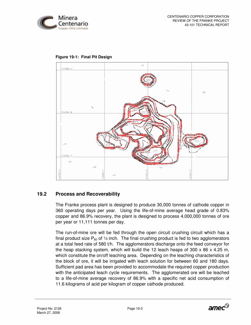
CENTENARIO COPPER CORPORATIONREVIEW OF THE FRANKE PROJECT
43-101 TECHNICAL REPORT
Project No: 2126 Page 19-3 March 27, 2008
Figure 19-1: Final Pit Design
19.2 Process and Recoverability
The Franke process plant is designed to produce 30,000 tonnes of cathode copper in 360 operating days per year. Using the life-of-mine average head grade of 0.83% copper and 86.9% recovery, the plant is designed to process 4,000,000 tonnes of ore per year or 11,111 tonnes per day.
The run-of-mine ore will be fed through the open circuit crushing circuit which has a final product size P80 of ½ inch. The final crushing product is fed to two agglomerators at a total feed rate of 580 t/h. The agglomerators discharge onto the feed conveyor for the heap stacking system, which will build the 12 leach heaps of 300 x 86 x 4.25 m, which constitute the on/off leaching area. Depending on the leaching characteristics of the block of ore, it will be irrigated with leach solution for between 60 and 180 days. Sufficient pad area has been provided to accommodate the required copper production with the anticipated leach cycle requirements. The agglomerated ore will be leached to a life-of-mine average recovery of 86.9% with a specific net acid consumption of 11.6 kilograms of acid per kilogram of copper cathode produced.

CENTENARIO COPPER CORPORATIONREVIEW OF THE FRANKE PROJECT
43-101 TECHNICAL REPORT
Project No: 2126 Page 19-4 March 27, 2008
In the leaching area there are solution ponds for Pregnant Leach Solutions (PLS), Intermediate Leach Solutions (ILS), and raffinate. The PLS will be collected in a 17,000 m3 pond, then transported by gravity to the solvent extraction plant, while the leached residues will be transported to the mine waste dump by truck.
The solvent extraction electro-winning plant will be a proprietary design supplied by Outotec. The pregnant leach solution will be fed to the series-parallel solvent extraction circuit where the copper will be transferred to an organic extraction reagent. After washing the organic to remove impurities, it will be sent to the stripping stage where the rich electrolyte, with an average copper concentration of 50 g/L, will be generated and sent to the electrowinning tankhouse. Here, high purity copper metal cathodes will be produced by electrolysis.
The Franke mineral is known to contain nitrate and chloride impurities among others. These impurities build up in solution over time and can cause problems in plant performance if the facilities are not designed to accommodate their presence. Due to the historical difficulty in predicting the concentrations of these impurities through testwork, the Franke plant design and operating conditions integrate industry experience at other operations which have these impurities present at far greater concentrations than predicted at Franke. This approach, including selection of organic reagent, has minimized the risk associated with these impurities.
The infrastructure required to support the process facilities includes: roads, administration offices, diesel and reagent storage tanks, electrical supply and distribution, water supply and distribution, internal and external communication systems, fire suppression system, and general plant installation.
19.3 Markets
Market analyses were developed for copper and sulphuric acid by OAC Ltda. on behalf of CCC. No summary is reported herein, but AMEC has relied upon OAC Ltda. to provide appropriate analysis for CCC. The market information was used in supporting the operating costs and revenues that form the basis for the cut-off grades for the mineral resources and mineral reserves, and in the financial analysis of the project.
19.4 Contracts
CCC has signed Letters of Intent or contracts for the following major work packages:
• Marineer, for contract mining on a unit price basis.
CENTENARIO COPPER CORPORATIONREVIEW OF THE FRANKE PROJECT
43-101 TECHNICAL REPORT
Project No: 2126 Page 19-5 March 27, 2008
• FL Schmidt, for design, supply and construction of the crushing and materials handling plant on a lump sum, turn key basis.
• Outotec, for design, supply and construction of the solvent extraction and electro-winning plant on a lump sum, turn key basis.
• JRI-Incolur, for supply and construction of the fresh water supply line on a lump sum, turn key basis.
• Cical, for site earthmoving on a unit price basis and for construction of the high voltage power line on a lump sum basis.
• AMEC, for engineering and procurement for the balance of the plant and overall construction management and start up services on an hourly rate basis.
• Vector, for heap and pond engineering.
• Tecnofast, for temporary buildings and construction camp.
• Sodexho, for catering, camp management, security and site access control.
• Copec, for fuel tank installation and fuel supply. At various times quotes were received from Copec for supply of fuel, one for US$459/cubic metre (US$0.459/litre) and another for US$738/cubic metre. To this date no contract has been entered into. For the sake of comparison, economic analysis has been completed using US$0.459/litre and US$1.00/litre.
• Multical, for design, supply and erection of the Franke electrical substation and 23 kV power distribution line.
• Codelco, for the supply of fresh water and 150,000 tonnes per year of sulphuric acid. This tonnage represents approximately 45% of the life-of-mine average annual consumption (47% of the first two years). The remaining 55% will be obtained from the open acid market, though CCC is in negotiations to secure additional acid supply.
• Pacific Hydro, for power supply.
• Ferronor, for the transportation of sulphuric acid to site and for cathodes from site to the port of Chañaral.
• CBA, Investec and HVB for hedging contracts for 25.5 million pounds of copper at an average price of US$ 2.80/lb in 2009 and 49.0 million pounds at an average price of US$ 2.75/lb in 2010.
As CCC expects to produce high quality copper cathodes (99.99% pure) they expect to be paid in full for the copper content, without deductions. No refining will be

CENTENARIO COPPER CORPORATIONREVIEW OF THE FRANKE PROJECT
43-101 TECHNICAL REPORT
Project No: 2126 Page 19-6 March 27, 2008
necessary. Furthermore, owing to the readiness of their product for market, CCC expects to receive an effective premium of 0.02 US$/lb copper cathode.
19.5 Hedging
CCC has signed agreements with Investec, HypoVereinsbank and the Commonwealth bank of Australia. These agreements cover a total of 74.6 million pounds of copper at an average price of US$2.77 per pound for the first two years of production.
19.6 Environmental Considerations
The following is a summary of the permits required for the development of the Franke project, together with the status as of the time of writing.
The construction and start-up stages of the Franke Project, owned by CCC require obtaining a series of permits, which can be classified as:
• Environmental Permits (Environmental Impact Study� or EIS). Furthermore, with regard to Environmental Permits, any project change depending on the magnitude requires a new Environmental Impact Declaration (EID)���or another EIS��
• Environmental Sector Permits (ESPs). • Non-Environmental Sector Permits (NESPs).
19.6.1 Environmental Impact Study – EIS
On October 30, 2006, CCC filed the EIS document for the Franke Project with the Chilean Environmental authority, CONAMA, for processing through the Environmental-Impact Assessment System (SEIA).
On January 24, 2007, CCC received the first Consolidated Report, known as ICSARA No. 1 (a Request for the EIS Clarifications, Rectifications or Extensions) from the Executive Director’s Office of CONAMA, the “DEC”. This document gathered the comments from the various evaluating organizations.
CCC prepared an Addendum No. 1 in response to ICSARA No. 1, and submitted it on February 26, 2007.
������������������������������ !"#��$$��%&���!�'()#�&�� ��!����������* �����+�����,�&����&�����!��+�����"�&��'(-��
�������������������.�,�����&��#��$$��%&���!�'(.#�/�������� ��!����������* �����+�����,�&����&�����!��+�����������'()��

CENTENARIO COPPER CORPORATIONREVIEW OF THE FRANKE PROJECT
43-101 TECHNICAL REPORT
Project No: 2126 Page 19-7 March 27, 2008
On April 9, 2007, the DEC issued Exempt Resolution No. 0798/02007 requesting that the evaluation period be extended for an additional 60 days. This additional term applies from April 16, 2007.
CCC received the ICSARA No. 2 report on April 18, 2007. This report included the comments of the evaluating organizations to Addendum No. 1.
Addendum No. 2 was submitted on April 24, 2007, in reply to ICSARA No. 2. The organizations were expected to issue their comments to Addendum No. 2 by May 18, 2007. The process was completed without further comments or additional requests from the authorities.
CONAMA prepared the Franke-Project Consolidated Technical Report (ICE), which was endorsed, and the CONAMA Executive Director finally issued the corresponding Environmental Qualification Resolution (RCA) on June 28, 2007.
19.6.2 Changes in the Franke Project
CCC has provided AMEC with information regarding the following changes that are contemplated for the Franke Project, as submitted in its initial EIS report:
• Secondary Leaching Elimination with subsequent Barren Rock Disposal Site Creation (to be placed on the waste dumps)
• Modification of the Headrace Line (Water Pipeline) Layout • Construction of a High-Voltage Line (HVL).
Each of these changes must be subject to the SEIA (Sistema de Evaluación de Impacto Ambiental – System for Evaluation of Environmental Impact), either through an EIS if they cause any of the effects, characteristics or circumstances considered in Article 11 of the Law on General Environmental Bases (LGEB) or otherwise through an EID. According to the information provided by CCC, none of these changes or additions would give rise to any of the events stated in the previously mentioned article, which leads us to believe that they can enter the SEIA by means of an EID.
The EID for Modification of the Headrace Line (Water Pipeline) Layout was submitted to CONAMA on July 31, 2007 and obtained its environmental approval on November 26, 2007.
The EID for Construction of a High-Voltage Line (HVL) was submitted to CONAMA on October 31, 2007, and was approved on February 21, 2008.

CENTENARIO COPPER CORPORATIONREVIEW OF THE FRANKE PROJECT
43-101 TECHNICAL REPORT
Project No: 2126 Page 19-8 March 27, 2008
The EID for Secondary Leaching Elimination with subsequent Barren Rock Disposal Site Creation (to be placed on the waste dumps), was submitted to CONAMA on November 21, 2007, and at the time of this report is in the final process for environmental approval.
19.6.3 Brief Description of Approval of EID
The process of approval of an EID begins with the EID submittal, whereupon the Regional (COREMA) or National (CONAMA) Environmental Commission, whichever the case may be, must pronounce thereon within 60 days. This period may be extended once for an additional 30 days in qualifying and duly founded cases. If upon expiry of the aforesaid term, the relevant State organizations have not granted the environmental sector permits or made the pronouncements required for the corresponding project, the COREMA or CONAMA, as the case may be, will require, upon request of CCC, that the responsible State organization issues the pertinent permit or pronouncement within 30 days.
If the COREMA or CONAMA, as the case may be, ascertains errors, omissions or inaccuracies in the EID, it may request the clarifications, rectifications or extensions that it deems necessary, granting CCC a period to do so. Such period may be suspended by mutual consent at any time during the EID evaluation process.
A favourable Environmental Qualification Resolution (RCA) will certify compliance with all applicable environmental requirements, including any subsequent mitigation and rehabilitation measure, with no State organization having the ability to deny the pertinent environmental authorizations. The certificate will also stipulate, as required, the environmental conditions or demands to be fulfilled in the execution of projects and those under which the legally required permits will be granted by State organizations.
An unfavourable RCA may reject the EID if the EID contains errors, omissions or inaccuracies that are not rectified or if the project requires an EIS, as per the provisions in the LGEB. An appeal may be filed against such resolution before the CONAMA within 30 days of notification. The appeal must be ruled upon within 60 days of filing, and CONAMA’s latter resolution may be appealed before the corresponding civil court within 30 days of notification. In the event that an EID is declared inadmissible, CCC is entitled to submit a new one.
CENTENARIO COPPER CORPORATIONREVIEW OF THE FRANKE PROJECT
43-101 TECHNICAL REPORT
Project No: 2126 Page 19-9 March 27, 2008
19.6.4 Environmental Sector Permits (ESP)
Regarding the EIS that is currently in process, once the RCA is issued, there are 10 (ten) ESPs which must be processed prior to the Project construction and operation stages. Compliance with all the documentation requirements is needed to facilitate processing these permits. (This documentation could be prepared as soon as the detail engineering data is available).
AMEC has reviewed with Arcadis Geotechnica the requirements relating to each of the 10 ESPs and concluded that processing of most of these should be in the normal course and should not present potential timing difficulties. However, Arcadis Geotechnica believes that special attention and diligence should be given to the “Construction Permit for Hydraulic Works Stipulated in Article 294 of the Water Code”. In their experience, its processing may take 6 to 8 months and must be supported by much detailed engineering information, in accordance with the requirements of the D.G.A. (General Water Department). CCC has completed detailed engineering of the water pipeline in order that the granting of this permit should not fall on the project development critical time line.
19.6.5 Non-Environmental Sector Permits
Based on the characteristics of the Franke Project, there are approximately 46 (forty-six) NESPs which must be processed prior to or during construction and operation.
The difficulty of their processing may be classified as follows:
• Simple or slightly complex processing (permits requiring written notification to the authority or filling out relevant organization pre-defined forms):
o Eleven (11) of the NESPs are in this category; • Medium complexity processing (permits requiring specific technical information,
such as drawings, basis of estimates, among others, for which specific and controlled processing procedures must be followed):
o Thirty-five (35) of the NESPs are in this category; • Complex processing or critical path (permits without legally established
processing times and the availability of which may result in Project delays): o None of the NESPs is in this category.
Therefore, while precise dates for the granting of all the required permits for the Franke Project cannot be determined, based on the information and subject to the statements contained herein, AMEC is not aware of any issues that would cause significant delays in the processing of these permits.

CENTENARIO COPPER CORPORATIONREVIEW OF THE FRANKE PROJECT
43-101 TECHNICAL REPORT
Project No: 2126 Page 19-10 March 27, 2008
19.7 Taxes and Royalties
AMEC has relied upon tax advice provided by Jose Luis Aviles of Grant Thornton. A corporate tax rate of 17% percent was used. 51% of plant capital is depreciated over three years. The remainder of plant capital is depreciated over six years.
A Chilean government royalty of 0.8% was applied to the project’s operating cash flow (EBIT).
19.8 Capital and Operating Cost Estimates
19.8.1 Capital Costs
The capital costs for the construction of the Franke project are summarized in Table 19-3.
Table 19-3: Capital Costs for Construction
Description Supply (kUS$)
Construction & Erection (kUS$)
Total (kUS$)
Plant Direct 59,270 72,758 132,029 Indirect Costs 0 16,872 16,872 Contingencies 0 4,496 4,496 Subtotal Plant 59,270 94,127 153,397 Realised Fx loss 0 1,253 1,253 Owner's Cost 0 7,137 7,137 Working Capital 0 8,928 8,928 Total Plant 59,270 111,445 170,715 Mine Costs 0 974 974 Total - Mine Included 59,270 112,419 171,689
The revised capital cost estimate excludes an unrealized foreign exchange loss that arises from variations in the Chilean peso in relation to the US dollar. Approximately 30% of the revised capital costs are denominated in US dollars while the balance is in Chilean pesos. The revised capital cost has been calculated at a constant foreign exchange rate of 535 Chilean pesos to the US$, consistent with the Control Budget and the 2007 Franke Technical Report. However, the US dollar has recently devalued against the Chilean peso as well as against most other currencies. At a recent

CENTENARIO COPPER CORPORATIONREVIEW OF THE FRANKE PROJECT
43-101 TECHNICAL REPORT
Project No: 2126 Page 19-11 March 27, 2008
exchange rate of 470 Chilean peso to the US$, the project faces an unrealized foreign exchange loss of $14.1 million (or 8.2% of the revised capital cost). The actual foreign exchange gain or loss that will ultimately be realized will depend on the foreign exchange rates in effect over the project’s remaining construction period, which may be higher or lower than the recent rate.
Sources for the capital cost estimates are as follows:
• Mine: Capital Cost for the mine was developed by CCC and a local mining contractor through a bidding process
• Process Facility, Infrastructure: Capital Cost for the process facilities and infrastructure was developed by AMEC
• Owner’s Costs: provided by CCC.
19.8.2 Mine Sustaining Capital Cost Estimate
The mining operation has been awarded to a contract mining firm. No sustaining capital is required by CCC.
19.8.3 Operating Cost Estimates
The life-of-mine average plant operating costs by cost type are summarized in Table 19-4.
The life-of-mine average operating costs by area are summarized in Table 19-5.

CENTENARIO COPPER CORPORATIONREVIEW OF THE FRANKE PROJECT
43-101 TECHNICAL REPORT
Project No: 2126 Page 19-12 March 27, 2008
Table 19-4: Operating Cost Summary by Cost Type
Cost Type Cost Cost
kUS$/year US$/ lb Cu
Percent of Total
Salaries & wages (excluding mining) $ 3,690 0.056 5.9% Leaching operation & waste handling $ 3,924 0.059 6.3% Cathode transport $ 348 0.005 0.6% Plant maintenance $ 1,913 0.029 3.1% Reagents consumed $ 1,416 0.021 2.3% Power $ 8,666 0.131 13.9% Diesel $ 3,363 0.051 5.4% Acid $ 22,736 0.344 36.6% Water $ 1,062 0.016 1.7% Mine contract $ 13,160 0.199 21.2% Other $ 1,892 0.029 3.0% Total $ 62,170 0.941 100.0% Acid and water prices are based on a selling price for copper of US$1.50 per pound.
Diesel cost is based upon a diesel price of US$0.459/litre (see comment in Section 19.9).
Table 19-5: Operating Cost Summary by Area
Area Cost Cost Percent of Total
kUS$/year US$/ lb Cu
Mine $ 15,212 0,23 24,5% Crush/Aggl/Leach $ 9,921 0,15 16,0% Acid Cost $ 22,487 0.34 36,2% SX/EW $ 9,921 0.15 16,0% G&A $ 4,630 0.07 7,3% Total $ 62,170 0.94 100.0% Acid and water prices are based on a selling price for copper of US$1.50 per pound.
Diesel cost is based upon a diesel price of US$0.459/litre (see comment in Section 19.9).
19.9 Economic Analysis
The Franke Feasibility Study has been evaluated on the basis of 100% equity-financing as per instruction from CCC.
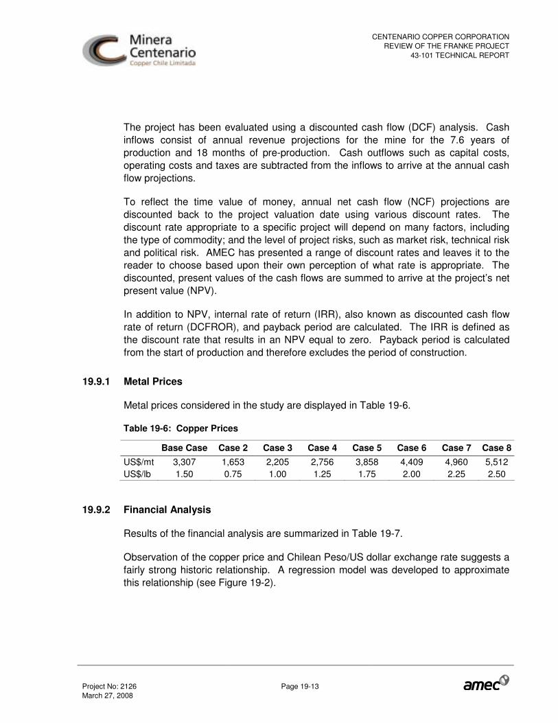
CENTENARIO COPPER CORPORATIONREVIEW OF THE FRANKE PROJECT
43-101 TECHNICAL REPORT
Project No: 2126 Page 19-13 March 27, 2008
The project has been evaluated using a discounted cash flow (DCF) analysis. Cash inflows consist of annual revenue projections for the mine for the 7.6 years of production and 18 months of pre-production. Cash outflows such as capital costs, operating costs and taxes are subtracted from the inflows to arrive at the annual cash flow projections.
To reflect the time value of money, annual net cash flow (NCF) projections are discounted back to the project valuation date using various discount rates. The discount rate appropriate to a specific project will depend on many factors, including the type of commodity; and the level of project risks, such as market risk, technical risk and political risk. AMEC has presented a range of discount rates and leaves it to the reader to choose based upon their own perception of what rate is appropriate. The discounted, present values of the cash flows are summed to arrive at the project’s net present value (NPV).
In addition to NPV, internal rate of return (IRR), also known as discounted cash flow rate of return (DCFROR), and payback period are calculated. The IRR is defined as the discount rate that results in an NPV equal to zero. Payback period is calculated from the start of production and therefore excludes the period of construction.
19.9.1 Metal Prices
Metal prices considered in the study are displayed in Table 19-6.
Table 19-6: Copper Prices
Base Case Case 2 Case 3 Case 4 Case 5 Case 6 Case 7 Case 8 US$/mt 3,307 1,653 2,205 2,756 3,858 4,409 4,960 5,512 US$/lb 1.50 0.75 1.00 1.25 1.75 2.00 2.25 2.50
19.9.2 Financial Analysis
Results of the financial analysis are summarized in Table 19-7.
Observation of the copper price and Chilean Peso/US dollar exchange rate suggests a fairly strong historic relationship. A regression model was developed to approximate this relationship (see Figure 19-2).

CENTENARIO COPPER CORPORATIONREVIEW OF THE FRANKE PROJECT
43-101 TECHNICAL REPORT
Project No: 2126 Page 19-14 March 27, 2008
Figure 19-2: Chilean Peso Relationship to Copper Price
Cu Price - Exchange Rate
400
450
500
550
600
650
700
750
0.50 1.00 1.50 2.00 2.50 3.00 3.50
Copper Price
Exc
hang
e R
ate
(CLP
/US
$)
Using this model, at the base case copper price of 1.50 US$/lb the equivalent exchange rate would be CLP 584 per US$. Using these parameters, development of the Franke project is expected to provide an after-tax internal rate of return of 22.0% and a life-of-mine (LOM) cash cost of 0.94 US$/lb. The payback period has been estimated at 2.8 years (after tax) and is calculated from the start of production. This analysis used a diesel price of US$0.459/litre (see below).
The economic analysis of this project uses forward-looking information that is based upon certain material assumptions that were applied in making the projected economic analysis. These include assumed copper price, acid price, diesel fuel, power costs, currency exchange rates, recovery rates, pay factors, labour rates as well as costs of other consumable supplies. Such forward-looking statements involve known and unknown risks, uncertainties and other factors which may cause the actual results, performance or achievements of the project to differ materially from any projected results, performance or achievements expressed or implied by comments made in this report. Based on the foregoing assumptions, the necessary economic conditions for statement of reserves in Section 17 are considered to have been met.

CENTENARIO COPPER CORPORATIONREVIEW OF THE FRANKE PROJECT
43-101 TECHNICAL REPORT
Project No: 2126 Page 19-15 March 27, 2008
Table 19-7: Cash Flow Analysis
Base Case
Sensitivity to Copper Price
Commodity
Copper US$/lb 1.50 0.75 1.00 1.25 1.75 2.00 2.25 2.50
Exchange Rate
Chilean Pesos per US$ CLP$/US$ 584 712 669 626 548 548 548 548
Pre-Tax
Internal Rate of Return % 25.6% N/A 8.0% 18.0% 31.8% 37.5% 42.6% 47.2%
Cumulative Net Cash Flow (CNCF) US$million 219 (42) 47 132 305 395 485 575
Net Present Value Discounted at 8% US$million 109 (56) 0 54 163 220 277 335 Net Present Value Discounted at 10% US$million 90 (59) (8) 40 139 190 241 293
Net Present Value Discounted at 12% US$million 73 (61) (16) 28 117 163 210 256
Payback Period Years 2.5 8.0 4.6 2.9 2.3 2.1 2.0 1.9
After Tax
Internal Rate of Return % 22.0% N/A 6.1% 15.2% 27.5% 32.6% 37.2% 41.4%
Cumulative Net Cash Flow (CNCF) US$million 179 (51) 36 107 249 324 398 472
Net Present Value Discounted at 8% US$million 83 (64) (8) 38 127 174 221 268 Net Present Value Discounted at 10% US$million 66 (66) (16) 25 106 148 191 233
Net Present Value Discounted at 12% US$million 51 (68) (23) 14 87 126 164 202
Payback Period Years 2.8 N/A 5.7 3.4 2.5 2.3 2.2 2.1
LOM Cash Cost
Unit Cash Cost US$/lb 0.94 0.82 0.86 0.90 0.98 1.02 1.05 1.08
Notes:
• Payback period is calculated from start of production (following 1.5 years of capital development). Cash flows occur at the end of each year. LOM cash costs vary due to acid & water contract copper price participation features.
• Acid and water prices are based on a selling price for copper of US$1.50 per pound. • Diesel cost is based upon a diesel price of US$0.459/litre (see comment in Section 19.9). • Sensitivity to changes in copper price has been applied only to unhedged sales.
The above analysis is based on diesel being provided to the mine at a cost of US$0.459/litre. This figure had been quoted to CCC during 2006, however, while this figure seemed reasonable when considering a long-term price of copper to be US$1.30/pound, it is considered to be highly optimistic when matched with copper sales which are hedged at US$2.77/pound.
For the sake of comparison, if the price of diesel fuel was to rise to US$1.00/litre, the effect of this on the Base Case would be to reduce After-tax IRR from 22.0% to 19.4%, Cumulative Net Cash Flow from US$179 million to US$154 million, NPV 10% from $66
CENTENARIO COPPER CORPORATIONREVIEW OF THE FRANKE PROJECT
43-101 TECHNICAL REPORT
Project No: 2126 Page 19-16 March 27, 2008
million to $51 million, and it would increase the payback period from 2.8 years to 3.0 years. In the case where unhedged copper is sold at US$2.50 per pound, the effect would be to reduce After-tax IRR from 41.4% to 39.6%, Cumulative Net Cash Flow from US$472 million to US$447 million, NPV 10% from $233 million to $218 million, and increase the payback period from 2.1 years to 2.2 years.
Sensitivity analysis was performed on the base case. Positive and negative variations, up to 30% in either direction, were applied independently to each of the following parameters:
• Copper price - a change in metal price has the same effect as a similar change in grade or recovery rate (limited to an upper bound below 100%)
• Capital expenditure • Operating cost • Sulphuric acid consumption (considered to have the same impact as variation in
cost).
The results of this analysis (see Figures 19-3 and 19-4) show that the project’s financial outcome is sensitive to variation in the price/cost factors in the following order: metal price, metallurgical recovery rate, operating cost (acid included), capital expenditure, sulphuric acid price, exchange rate.

CENTENARIO COPPER CORPORATIONREVIEW OF THE FRANKE PROJECT
43-101 TECHNICAL REPORT
Project No: 2126 Page 19-17 March 27, 2008
Figure 19-3: Sensitivity of After Tax IRR
Sensitivity of After Tax IRR
0.0%
5.0%
10.0%
15.0%
20.0%
25.0%
30.0%
35.0%
40.0%
45.0%
-40% -30% -20% -10% 0% 10% 20% 30% 40%
Factor (%)
Aft
er T
ax IR
R (
%)
Cu PriceOpexCapexAcid CostXrate
Figure 19-4: Sensitivity of After Tax NPV
Sensitivity of After Tax NPV 8%
-50,000
0
50,000
100,000
150,000
200,000
250,000
-40% -30% -20% -10% 0% 10% 20% 30% 40%
Factor (%)
Aft
er T
ax N
PV
8%
(U
S$0
00)
Cu PriceOpexCapexAcid CostXrate
Two reverting, copper forward price curve scenarios, A and B, were also considered in the sensitivity analysis. Details of these are shown in Table 19-8. The effect of using

CENTENARIO COPPER CORPORATIONREVIEW OF THE FRANKE PROJECT
43-101 TECHNICAL REPORT
Project No: 2126 Page 19-18 March 27, 2008
these price scenarios in combination with the hedging contracts is shown in Table 19-9.
Table 19-8: Copper Forward Price Values
Cu Price, $/lb 2009 2010 2011 2012 2013 2014 2015 2016 Scenario A 3.35 3.15 3.00 2.90 1.50 1.50 1.50 1.50 Scenario B 3.35 3.15 3.00 2.90 2.00 2.00 2.00 2.00
Table 19-9: Results of Applying Forward Price Values (using diesel price of US$0.459/litre)
Unit Base Case
Scenario A
Scenario B
Commodity Copper US$/lb 1.50 Exchange Rate 1 Chilean Pesos per US$ CLP$/US$ 584 584 584 Pre-Tax Internal Rate of Return % 25.6% 57.5% 59.9% Cumulative Net Cash Flow (CNCF) US$million 219 494 618 Net Present Value Discounted at 8% US$million 109 314 385 Net Present Value Discounted at 10% US$million 90 282 343 Net Present Value Discounted at 12% US$million 73 252 306 Payback Period Years 2.5 1.5 1.5 After Tax Internal Rate of Return % 22.0% 49.3% 51.8% Cumulative Net Cash Flow (CNCF) US$million 179 405 507 Net Present Value Discounted at 8% US$million 83 252 310 Net Present Value Discounted at 10% US$million 66 224 274 Net Present Value Discounted at 12% US$million 51 199 243 Payback Period Years 2.8 1.7 1.7
If a price of US$1.00/litre was used for diesel fuel, the effect of this on Forward Price Scenario A would be to reduce After-tax IRR from 49.3% to 47.3%, Cumulative Net Cash Flow from US$405 million to US$380 million, NPV 10% from $224 million to $208 million. In the case of Forward Price Scenario B this would reduce After-tax IRR from 51.8% to 50.0%, Cumulative Net Cash Flow from US$507 million to US$482 million, NPV 10% from $274 million to $259 million.

CENTENARIO COPPER CORPORATIONREVIEW OF THE FRANKE PROJECT
43-101 TECHNICAL REPORT
Project No: 2126 Page 19-19 March 27, 2008
19.10 Project Execution
The activities of the owner (CCC) are oriented towards general supervision of the EPCM of the plant, mining activities, and obtaining permissions required to build and operate the plant.
The Franke project construction is being developed through a series of EPC and conventional construction contracts. An EPCM contract covers the balance of plant engineering, acquisitions management, contracts administration, construction administration, pre-commissioning and commissioning in a mixed team between the EPCM contractor (AMEC) and the CCC key team. The facilities involved include mine infrastructure, crushing plant, leaching pads and solution handling, solvent extraction, electro-winning; power and water supply and distribution, and ancillary facilities.
The implementation strategy for the project considers a team composed of CCC and AMEC professionals that integrate the owner’s team duties and responsibilities with the EPCM team duties and responsibilities.
19.11 Mine Life
Mine life is estimated to be eight years (7.6 years) based on the current mine plan prepared by NCL (January, 2008). The difference between the current and previous mine plan is due to the increased reserves of nearly 6 million tonnes as a result of additional drilling.

CENTENARIO COPPER CORPORATIONREVIEW OF THE FRANKE PROJECT
43-101 TECHNICAL REPORT
Project No: 2126 Page 20-1 March 27, 2008
20.0 INTERPRETATION AND CONCLUSIONS
The Franke deposit contains an estimated 31.7 million tonnes of mineral reserve, with an average grade of 0.83% total copper and a strip ratio of 1.23:1. The Franke process plant is designed as a solvent extraction–electro-winning (SX-EW), heap leach operation, using standard technology that is currently in use in many producing copper mines in Chile and elsewhere. The nominal design capacity calls for an annual production of 30,000 tonnes of high quality copper cathode over its current 7.6 year mine life.
The geographical location of the deposit is in the Atacama desert, considered to be one of the most arid deserts on earth. The availability of water is critical, as there is little to no rainfall in the area. The water in the area is generally collected from the Andes snowpack, approximately 100 km east of the Franke deposit. However, CCC has signed a water supply agreement for 50 L/s with Codelco (Salvador Division), located 70 km from the site. This contract secures the water supply for the entire mine life of the Franke project.
The ore has been assayed to determine the total copper, soluble copper, and carbonate. The testwork campaigns have indicated a life-of-mine average recovery of 86.9% of total copper, with a net specific sulphuric acid consumption in the range of 11.6 kg acid per kg of copper cathode produced.
The project will require a capital investment of US$ 171.7M. Copper cathodes will be produced at a cost of 0.94 US$/lb.
The high acid consumption of the Franke ore is caused by carbonates and will result in the cost of sulphuric acid being a very significant component of the overall processing cost. As such, securing an acid supply for the project has been one of CCC’s key objectives. To that end, CCC has a signed contract with a local smelter for a supply of 150,000 tonnes per year of sulphuric acid, which represents approximately 45% of the life-of-mine average annual consumption (47% of the first two years). The remaining 55% will be obtained from the open acid market, though CCC is in negotiations to secure additional acid supply. The acid will be transported to site by train and truck.
The electrical supply to the Project will be from the Diego de Almagro substation. A 110 kV high voltage line is being constructed between Diego de Almagro and the Franke site. The energy cost has been negotiated with various energy suppliers, and a contract has been signed with Pacific Hydro, who offered the best technical-economical proposal.
CENTENARIO COPPER CORPORATIONREVIEW OF THE FRANKE PROJECT
43-101 TECHNICAL REPORT
Project No: 2126 Page 20-2 March 27, 2008
The Franke Project is subject to an Environmental Impact Assessment (EIA) process, as set forth in Chilean Law 19,300 “Ley de Bases del Medio Ambiente”, and related regulations. CCC commenced the assessment process in October, 2006 with the formal presentation of the EIA to the Chilean Comision Nacional del Medio Ambiente (CONAMA) authorities. Two Question and Answer rounds have been performed and the final approval was obtained in June, 2007.
AMEC has reviewed the mineral resource and mineral reserve estimates and has not found any fatal flaw. Geovectra prepared the mineral resource estimate while NCL generated the mineral reserve estimate. The resource model is accurate, unbiased, not excessively smoothed and honours the drill-hole data. From the 42.4 Mt of the mineral inventory (at TCu cut-off = 0.3%) reported by Geovectra (2007), only 36.7 Mt fell into the optimized pit, considering a price of 1.65 US$/lb Cu.
To date, there are issues in the project that reflect points of uncertainty or risk which may result in a variation in capital and/or operating costs. They are as follows:
• Mining near cavities may have higher production costs and lower productivity than anticipated in the mine plan.
• Geotechnical investigations are still underway and there is a risk that the pit slope angle may need to be modified.
• To date, CCC has secured approximately 45% of the life-of-mine acid supply through a contract with Codelco. For the remaining 55% supply, CCC is currently in negotiations with other suppliers. While it is understood that negotiations are proceeding in good faith and in a timely manner, until the balance of acid supply is assured via signed contract, it remains a critical point of uncertainty.
• Use of bottle rolls executed on ground material provides a poor simulation of the leaching conditions anticipated to be found in commercial heap leaching. Reliance on results from ground pulps rather than column leach tests to estimate acid consumption leads to more uncertainty in the predictions..
• The latest column leach test results do not verify the copper recovery or the acid consumption algorithms used in the economic analysis. However, this may be due to poor control of testing procedures and conditions.
• Operations at nearby operating mines can impact manpower and acid availability.
A number of opportunities exist for additional project value. They are as follows:
• CCC has a number of other properties in the vicinity of the Franke deposit at various levels of technical development. These represent significant possible
CENTENARIO COPPER CORPORATIONREVIEW OF THE FRANKE PROJECT
43-101 TECHNICAL REPORT
Project No: 2126 Page 20-3 March 27, 2008
synergies for the project if they can be developed and produced using shared infrastructure and processing facilities.
• A pilot heap leach test is planned to commence in March, 2008 with the objective of optimizing leach conditions and acid consumption.

CENTENARIO COPPER CORPORATIONREVIEW OF THE FRANKE PROJECT
43-101 TECHNICAL REPORT
Project No: 2126 Page 21-1 March 27, 2008
21.0 RECOMMENDATIONS
In order to improve the local confidence of the future model, AMEC recommends that the following measures be implemented to improve the resources:
• Despite the drill holes being short, CCC must measure the trajectories in a significant proportion in order to control the deviation.
• The recovery data of RC and DDH hole material must be registered.
• The density model should be refined in order to adjust the in-house ASG measurements against laboratory measurements.
A mine plan should be developed at the detailed engineering stage which includes more detailed scheduling and costing for mining in and near old underground workings. Associated work procedures should be established and documented for mining near old workings so that personnel can perform their work in the most safe and efficient manner.
AMEC recommends an evaluation of the impact of underground workings on both the operation and pit wall design and the establishment of procedures for equipment working around or above current underground workings. Pit floor and wall stability can be adversely affected and therefore proper stand-off distance procedures for investigations of the voids and backfilling of the voids must be implemented. Pit wall berms may be lost when walls intersect workings which can increase the hazard of rockfall due to the loss of catchment.
AMEC highly recommends that CCC map and confirm the structural controls for the open pit slopes and re-evaluate the pit slope design during the initial excavation of the open pit(s) and exposure of the rock mass.
AMEC recommends that the following geotechnical issues be addressed prior to the start of dump construction:
• Conduct site investigations within the dump footprint to support assumptions of thickness and characteristics of the dump foundation soils.
• Clarify design parameters for overall slope of the outer dump face and offsets between toe and crest of subsequent lifts.

CENTENARIO COPPER CORPORATIONREVIEW OF THE FRANKE PROJECT
43-101 TECHNICAL REPORT
Project No: 2126 Page 21-2 March 27, 2008
• Assess impact on dump design and configuration of the pit run and leached waste scheduling.
• Assess the impact on the stability of the dump design taking into account the phased approach to dump construction as well as potential instability of upstream shell slope on leached waste.
• Assess the requirement for pre-strip of the foundation for dump stability and whether or not it is necessary under the outer shell to enhance stability.
• Address stability of an active high tip head comprised of leached waste.
• Trafficability of the shell and leached waste material requires a discussion and whether sheeting will be necessary for the tip head areas and access roads.
AMEC recommends that the heap leach pilot testing be properly monitored and controlled and results incorporated into the commissioning and operating plan.
AMEC recommends that Minera Centenario proceed with the development of the Franke Property and recommends continuing the mine development activities on the Franke Property that are expected to reduce project technical risk, allow improved detailed engineering design, and improve operational performance in a commercial mine. These include metallurgical performance from the test heap, and geotechnical studies to support optimum pit slope.

CENTENARIO COPPER CORPORATIONREVIEW OF THE FRANKE PROJECT
43-101 TECHNICAL REPORT
Project No: 2126 Page 22-1 March 27, 2008
22.0 REFERENCES
AMEC International (Chile) S.A., Feasibility Study of the Franke Project, Report No. 2115-Repo-9-001, draft version, June 2007.
AMEC International (Chile) S.A., Review of the Franke Project, Altamira District, II Region, Chile. National Instrument, Technical Report, August, 2007.
Arcadis Geotechnica, Estudio de Impacto Ambiental Proyecto Franke, October 2006.
Cade-Idepe Consultores en Ingenieria, Final Report, 2229-INF-000-PR-005, Rev. 1, 2006, Compañia Minera Centenario Copper Ltda., Conceptual Engineering, Franke Project, Production Scenario 30,000 tpy, November 2006.
CIM, CIM Definition Standards - For Mineral Resources and Mineral Reserves, Canadian Institute of Mining, Metallurgy and Petroleum, 2005.
CIM, Estimation of Mineral Resources and Mineral Reserves - Best Practice Guidelines, Canadian Institute of Mining, Metallurgy and Petroleum, 2003.
CSA, Canadian Securities Administrators, National Instrument 43-101 – Standards of Disclosure for Mineral Projects, 2005.
Edmundo Eluchans Y Cia., Sociedao Civil de Profesionales de Responsabilidad Limitada, Abogados, “No Title” (Land ownership study), prepared for CCC, “Lopez y Ashton”, April 4, 2007.
Flores, Roman V., Pelusa Copper Project, Internal Centenario report, April 2006.
Geovectra, NCL Ingenieria y Construccion S.A., Centenario Copper Ltd., Geologic Resources & Reserves of the Frankenstein – San Guillermo Deposits, Antofagasta Region - Chile, September 2005.
Geovectra, NCL Ingenieria y Construccion S.A., Centenario Copper Ltd., Update of the Geological Resources & Reserves of the Frankenstein Deposit, Antofagasta Region- Chile, August 2006.
Geovectra S.A., Centenario Copper Ltd., Geological Model of The Franke Deposit, draft version, December 2007.
Ingeroc Estudio de Estabilidad de Taludes Franke August 2007 Rev 1�
CENTENARIO COPPER CORPORATIONREVIEW OF THE FRANKE PROJECT
43-101 TECHNICAL REPORT
Project No: 2126 Page 22-2 March 27, 2008
Jose Luis Aviles, Grant Thornton, Tax Advice for May 2007, prepared for CCC, undated.
Long S, 2000, Assay Quality Assurance-Quality Control Program for Drilling Projects at the Prefeasibility to Feasibility Report Level. Mineral Resource Development Inc., Internal Report.
Marineer Zona Franca S.A., Propuesta Técnica y Económica, Licitación Privada de Explotación de Minas a Rajo Abierto y Obras Complementarias Proyecto Franke, Diciembre 2007.
NCL Ingenieria y Construccion S.A., Final Report, Mine Design and Planning of the Frankenstein Deposit, Antofagasta Region – Chile, Conceptual Engineering, December 2005.
NCL Ingenieria y Construccion S.A., Pre Feasibility – Mining Discipline, Frankenstein Project, October 2006.
NCL Ingenieria y Construccion S.A., Feasibility – Mining Discipline, Franke Project, Final Report, Rev B, March 2007.
NCL Ingenieria y Construccion S.A., Feasibility – Mining Discipline, Franke Project, Final Report, Rev 0, May 2007.
NCL Ingenieria y Construccion S.A., Mine Plan Update, Franke Project, Rev. A, January 2008
OAC Ltda, (Ricardo Olivares), Copper Marketing Plan, prepared for CCC, undated.
OAC Ltda, (Ricardo Olivares), Sulphuric Acid Market Study, prepared for CCC, May 2007.
OAC Ltda, (Ricardo Olivares), Sulphuric Acid Market Study, prepared for CCC, December 2007 Update.
Pincock, Allen & Holt, Inc., NI 43-101 Technical Report of Minera Centenario’s Frankenstein Project, Chile, Report 34091, March 16, 2006.
Pincock, Allen & Holt, Inc., NI 43-101 Technical Report of Minera Centenario’s Frankenstein Project, Chile, Report 34091, May 4, 2006.
CENTENARIO COPPER CORPORATIONREVIEW OF THE FRANKE PROJECT
43-101 TECHNICAL REPORT
Project No: 2126 Page 22-3 March 27, 2008
Pincock, Allen & Holt, Inc., CNI 43-101 Technical Report, Preliminary Feasibility for the Franke Project, Altamira District, Region II, Chile, Report 70536, February 12, 2007.
Simón, A., 2006. Quality Assurance and Quality Control in Exploration Geology. Proceedings, MININ 2006, May 23 to 26, 2006, Santiago de Chile.
CENTENARIO COPPER CORPORATIONREVIEW OF THE FRANKE PROJECT
43-101 TECHNICAL REPORT
Project No: 2126 Page 23-1 March 27, 2008
23.0 DATE AND SIGNATURE PAGE
The undersigned prepared this technical report titled “Review of the Franke Project Altamira District, Region II, Chile, National Instrument 43-101 Technical Report”, effective date March 11, 2008.
Signed,
“SIGNED AND SEALED”
R. PENNER, MAUSIMM 27 MARCH 2008 AMEC INTERNATIONAL (CHILE) S.A.
“SIGNED AND SEALED”
R.MARINHO, CPG (AIPG) 27 MARCH 2008 AMEC INTERNATIONAL (CHILE) S.A.
“SIGNED AND SEALED”
L. GORMELY, P.ENG. 27 MARCH 2008 AMEC AMERICAS LIMITED.

CENTENARIO COPPER CORPORATIONREVIEW OF THE FRANKE PROJECT
43-101 TECHNICAL REPORT
Project No: 2126 Page 23-2 March 27, 2008
“SIGNED AND SEALED”
S. ANDERSON, P.ENG. 27 MARCH 2008 AMEC E & E
“SIGNED AND SEALED”
A. MAYCOCK, P.ENG. 27 MARCH 2008 AMEC INTERNATIONAL (CHILE) S.A.