REMOTE CONTROL SYSTEM RC-200 ALL SPORT ...
82
201 Daktronics Drive Brookings, SD 57006-5128 www.daktronics.com/support 800.325.8766 REMOTE CONTROL SYSTEM RC-200 ALL SPORT OPERATION MANUAL P1110 DD3572889 Rev 02 26 August 2021
-
Upload
khangminh22 -
Category
Documents
-
view
2 -
download
0
Transcript of REMOTE CONTROL SYSTEM RC-200 ALL SPORT ...

201 Daktronics DriveBrookings, SD 57006-5128www.daktronics.com/support800.325.8766
REMOTE CONTROL SYSTEMRC-200
ALL SPORT OPERATION MANUAL
P1110DD3572889
Rev 0226 August 2021

Copyright © 2018-2021All rights reserved. While every precaution has been taken in the preparation of this manual, the publisher assumes no responsibility for errors or omissions. No part of this book covered by the copyrights hereon may be reproduced or copied in any form or by any means—graphic, electronic, or mechanical, including photocopying, taping, or information storage and retrieval systems—without written permission of the publisher.Daktronics trademarks are property of Daktronics, Inc. All other trademarks are property of their respective companies.
FCC StatementSupplier Declaration of Conformity (SDoC)This product complies with Part 15 of the FCC Rules. Operation is subject to the following two conditions: (1) This device may not cause harmful interference, and (2) this device must accept any interference received, including interference that may cause undesired operation.
Note: This equipment has been tested and found to comply with the limits for a Class A digital device, pursuant to part 15 of the FCC Rules. These limits are designed to provide reasonable protection against harmful interference when the equipment is operated in a commercial environment. This equipment generates, uses, and can radiate radio frequency energy and, if not installed and used in accordance with the instruction manual, may cause harmful interference to radio communications. Operation of this equipment in a residential area is likely to cause harmful interference in which case the user will be required to correct the interference at their own expense.
Warning: The user is cautioned that changes and modifications made to the equipment without the approval of manufacturer could void the user’s authority to operate this equipment.
Industry Canada Regulatory InformationThis Class A digital apparatus complies with Canadian ICES-003.Cet appareil numérique de la classe A est conforme à la norme NMB-003 du Canada.
InquiriesContact Daktronics with any questions regarding our product compliance.
Mail:Daktronics201 Daktronics Dr. Brookings, SD 57006 USA
Phone:800-325-8766
Website:www.daktronics.com

– i –
Table of Contents1 Introduction ���������������������������������������������������������������������������������������������������������������������������1
Important Safeguards ..........................................................................................................................1Specifications Label .............................................................................................................................1Recommended Temperatures ...........................................................................................................1Resources ..............................................................................................................................................1Daktronics Exchange and Repair & Return Programs .....................................................................2
Exchange Program ��������������������������������������������������������������������������������������������������������������������������2Repair & Return Program �����������������������������������������������������������������������������������������������������������������3Daktronics Warranty & Limitation of Liability ����������������������������������������������������������������������������������3
2 RC-200 System Overview �����������������������������������������������������������������������������������������������������4Important Installation Range Considerations �����������������������������������������������������������������������������������4
3 RC-200 Handheld Controller������������������������������������������������������������������������������������������������5Powering the Controller On and Off ..................................................................................................5
Using the Keypad ����������������������������������������������������������������������������������������������������������������������������5Using External Power ������������������������������������������������������������������������������������������������������������������������5
Battery Operation .................................................................................................................................5Idle Time ��������������������������������������������������������������������������������������������������������������������������������������������5
Battery Recharging .............................................................................................................................5Config Mode .........................................................................................................................................6
Setting Default Radio Broadcast Group and Channel ������������������������������������������������������������������6Setting LCD Contrast �������������������������������������������������������������������������������������������������������������������������6Setting Power Save Mode ����������������������������������������������������������������������������������������������������������������6
Connect Mode .....................................................................................................................................7Switching to Connect Mode ������������������������������������������������������������������������������������������������������������7Signal Strength Indicator �����������������������������������������������������������������������������������������������������������������7
Common Keys .......................................................................................................................................8Alternate Function Keys �������������������������������������������������������������������������������������������������������������������9
4 All Sport Applications ���������������������������������������������������������������������������������������������������������10Selecting All Sport Applications (Code Numbers) ..........................................................................10Keypad Inserts .....................................................................................................................................11
Keypad Insert Operation Concepts ���������������������������������������������������������������������������������������������11Common All Sport Application Keys ................................................................................................12
New Code (Alt� Function) ��������������������������������������������������������������������������������������������������������������12New Game (Alt� Function) �������������������������������������������������������������������������������������������������������������12Start ��������������������������������������������������������������������������������������������������������������������������������������������������13Stop ��������������������������������������������������������������������������������������������������������������������������������������������������13Set Time �������������������������������������������������������������������������������������������������������������������������������������������13UP/DN (Alt� Function) ���������������������������������������������������������������������������������������������������������������������14Dim (Alt� Function) ��������������������������������������������������������������������������������������������������������������������������14Manual Horn �����������������������������������������������������������������������������������������������������������������������������������14Auto Horn ����������������������������������������������������������������������������������������������������������������������������������������15
5 Clock/Score Operation �����������������������������������������������������������������������������������������������������16

– ii –
Table of ContentsScore (+1/-1) .......................................................................................................................................16Period +1 ..............................................................................................................................................16Set TOD (Alt. Function) .......................................................................................................................16
6 Volleyball Operation ����������������������������������������������������������������������������������������������������������17Score (+1/-1) .......................................................................................................................................17Won (+1/-1) .........................................................................................................................................17Reset Game Score .............................................................................................................................17Game (+1/-1) ......................................................................................................................................17
7 Baseball Operation ������������������������������������������������������������������������������������������������������������18Score (+1/-1) .......................................................................................................................................18Out +1, Inning +1.................................................................................................................................18Ball +1, Strike +1, Clear Ball & Strike ..................................................................................................18Hit ..........................................................................................................................................................18Error ......................................................................................................................................................19Time, At Bat, H/E (Alt. Function) ........................................................................................................19Time/At Bat ..........................................................................................................................................19
8 Play Clock and Pitch Timer Operation �����������������������������������������������������������������������������20Set Reset 1, Set Reset 2 ......................................................................................................................20Reset 1, Reset 2 ...................................................................................................................................20
9 Segment Timer Operation ��������������������������������������������������������������������������������������������������21Segment Timer Information ...............................................................................................................21Segment Number/Time ......................................................................................................................21First/Last Segment ...............................................................................................................................21Current Segment +1 ...........................................................................................................................22Reset Current Segment ......................................................................................................................22Reset to First Segment ........................................................................................................................22Interval Time ........................................................................................................................................22Copy Range ........................................................................................................................................22Auto Stop .............................................................................................................................................23Warning Time ......................................................................................................................................23
10 Tennis Operation �����������������������������������������������������������������������������������������������������������������24Court Selection ...................................................................................................................................24Serve ....................................................................................................................................................24Game +1 .............................................................................................................................................24Point .....................................................................................................................................................25Reset Game ........................................................................................................................................25Tie Break ...............................................................................................................................................25TOD/Game ..........................................................................................................................................25Set +1 ...................................................................................................................................................25Matches Won (Alt. Function) ............................................................................................................26Reset Match (Alt. Function) ...............................................................................................................26Next Match (Alt. Function – DakTennis Only) ..................................................................................26

– iii –
Table of ContentsWinner (Alt. Function – DakTennis Only)...........................................................................................26
11 Sand Volleyball Operation ������������������������������������������������������������������������������������������������27Court Selection ...................................................................................................................................27Serve ....................................................................................................................................................27Point .....................................................................................................................................................27Set +1 ...................................................................................................................................................28Reset Game (Reset Match) ..............................................................................................................28TOD/Game ..........................................................................................................................................28Matches Won (Alt. Function) ............................................................................................................28Game +1, Tie Break, Next Match, Winner ........................................................................................28
12 Basketball Operation ���������������������������������������������������������������������������������������������������������29Score (+1/+2) ......................................................................................................................................29Score (+3/-1) (Alt. Functions) .............................................................................................................29Fouls +1 ................................................................................................................................................29Possession ............................................................................................................................................29Period +1 ..............................................................................................................................................30Set TOD (Alt. Function) .......................................................................................................................301/10 SEC (Alt. Function) .....................................................................................................................30Bonus (Alt. Function)...........................................................................................................................30
13 Football Operation �������������������������������������������������������������������������������������������������������������31Score (+1/+6) ......................................................................................................................................31Score (+3/-1) (Alt. Functions) .............................................................................................................31QTR +1 ..................................................................................................................................................31Down +1 ...............................................................................................................................................31To Go ....................................................................................................................................................32Ball On ..................................................................................................................................................32TOL -1 ...................................................................................................................................................32Possession (Alt. Function) ...................................................................................................................32
14 Remote Start/Stop Operation ��������������������������������������������������������������������������������������������33Start .....................................................................................................................................................33Stop ......................................................................................................................................................33Manual Horn/Reset ............................................................................................................................33
15 Goal Judge Operation �������������������������������������������������������������������������������������������������������34Goal Light On/Off ...............................................................................................................................34
16 CAN Handheld Operation �������������������������������������������������������������������������������������������������35Common CAN Handheld Operation ...............................................................................................35Diving and Synchronized Swimming Operations ............................................................................35Rodeo Operations ..............................................................................................................................35
17 Troubleshooting ������������������������������������������������������������������������������������������������������������������36Handheld Controller Error Messages ................................................................................................36Base Station Errors ...............................................................................................................................37
IN RANGE LED On Start-up �������������������������������������������������������������������������������������������������������������37

– iv –
Table of ContentsGeneral Base Station Failures ��������������������������������������������������������������������������������������������������������37Obtaining Base Station Status Information �����������������������������������������������������������������������������������37
A Reference Drawings �����������������������������������������������������������������������������������������������������������39B Sport Inserts �������������������������������������������������������������������������������������������������������������������������57C Daktronics Warranty and Limitation of Liability ���������������������������������������������������������������71

Introduction1
1 IntroductionThis manual is designed to explain the operation of the Daktronics RC-200 Remote Control System for All Sport® applications. For additional information regarding the safety, installation, operation, or service of this system, refer to the telephone numbers listed in Daktronics Exchange and Repair & Return Programs (p�2).
Important Safeguards• Read and understand all instructions, both general and for specific applications. • Always turn off and/or unplug the control equipment when it is not in use� Never yank
the power cord to pull the plug from the outlet� Grasp the plug and pull to disconnect� • Do not drop the control console or allow it to get wet� • Do not disassemble control equipment or electronic controls of the display; failure to
follow this safeguard will make the warranty null and void� • Do not let any power cord touch hot surfaces or hang over the edge of a table that
would damage or cut the cord� • If an extension cord is necessary, use a three-pronged, polarized cord� Arrange the
cord with care so that it will not be tripped over or pulled out� • Inspect console for shipping damage such as rattles and dents, and verify that all
equipment is included as itemized on the packing slip� Immediately report any problems to Daktronics; save all packing materials if exchange is necessary�
• Use only the 18 VDC wallpack charger or charging station provided from Daktronics for recharging the battery� Refer to Battery Recharging (p�5)�
CAUTION! RISK OF EXPLOSION IF BATTERY IS INCORRECTLY REPLACED�
DISPOSE OF USED BATTERIES ACCORDING TO THE INSTRUCTIONS�
Specifications LabelPower specifications as well as product assembly information can be found on an ID label on the back of the handheld device and on the bottom of the base station, similar to those shown in Figure 1.
When calling Daktronics customer service, please have the assembly number and the date manufactured available to ensure the request is serviced as quickly as possible.
Recommended Temperatures• Operation: 14° to 149° Fahrenheit (-10° to 65° Celsius) • Charging: 32° to 104° Fahrenheit (0° to 40° Celsius) • Storage: -4° to 113° Fahrenheit (-20° to 45° Celsius)
ResourcesFigure 2 illustrates a Daktronics drawing label. This manual refers to drawings by listing the last set of digits. In the example, the drawing would be referred to as DWG-1007804. All references to drawing numbers, appendices, figures, or other manuals are presented in bold typeface.
ASSY NO.
SER. NO.
MFG DATE
BROOKINGS, SD 57006-5128 PHONE 800-325-8766 LL-2305 R01201 DAKTRONICS DR.DAKTRONICS
Wireless Handheld:
Wireless Base Station:
ASSY NO.
SER. NO.
MFG DATE
BROOKINGS, SD 57006-5128 PHONE 800-325-8766 LL-2305 R01201 DAKTRONICS DR.DAKTRONICS
0A-1110-0062 S/N: ####(DATE) REV ##POWER: 18V , 1.1AMODEL: DAKT-0406-00
0A-1110-0067 S/N: ####(DATE) REV ##POWER: 12-18V , 0.1AMODEL: DAKT-0406-00
Figure 1: Specifications Labels
Drawing Number
Figure 2: Drawing Label

Introduction2
Any drawings referenced in a section are listed at the beginning of it as shown below:
Reference Drawings: System Riser Diagram ....................................................................................... DWG-1007804
Daktronics identifies manuals by the DD or ED number located on the cover page.
Daktronics Exchange and Repair & Return Programs
Exchange ProgramThe Daktronics Exchange Program is a service for quickly replacing key components in need of repair. If a component fails, Daktronics sends a replacement part to the customer who, in turn, returns the failed component to Daktronics. This decreases equipment downtime. Customers who follow the program guidelines explained below will receive this service.
Before contacting Daktronics, identify these important numbers:
Display Serial Number: ________________________________________________________________
Display Model Number: _______________________________________________________________
Job/Contract Number: _______________________________________________________________
Date Manufactured/Installed: _________________________________________________________
Daktronics Customer ID Number: ______________________________________________________
To participate in the Exchange Program, follow these steps:
1� Call Daktronics Customer Service�
United States & Canada: 1-800-DAK-TRON (325-8766)
Outside the U.S. & Canada: +1-605-275-1040
2� When the new exchange part is received, mail the old part to Daktronics�
If the replacement part fixes the problem, send in the problem part being replaced.
a� Package the old part in the same shipping materials in which the replacement part arrived.
b� Fill out and attach the enclosed UPS shipping document.
c� Ship the part to Daktronics.
3� The defective or unused parts must be returned to Daktronics within 5 weeks of initial order shipment�
If any part is not returned within five (5) weeks, a non-refundable invoice will be presented to the customer for the costs of replenishing the exchange parts inventory with a new part. Daktronics reserves the right to refuse parts that have been damaged due to acts of nature or causes other than normal wear and tear.
Introduction3
Repair & Return ProgramFor items not subject to exchange, Daktronics offers a Repair & Return Program. To send a part for repair, follow these steps:
1� Call Daktronics Customer Service�
United States & Canada: 1-800-DAK-TRON (325-8766)
Outside the U.S. & Canada: +1-605-275-1040
2� Receive a case number before shipping�
This expedites repair of the part.
3� Package and pad the item carefully to prevent damage during shipment�
Electronic components, such as printed circuit boards, should be placed in an antistatic bag before boxing. Daktronics does not recommend using packing peanuts when shipping.
4� Enclose:
• name
• address
• phone number
• the case number
• a clear description of symptoms
5� Ship to:
Daktronics Customer Service
[Case #]
201 Daktronics Drive, Dock E
Brookings, SD 57006
Daktronics Warranty & Limitation of LiabilityThe Daktronics Warranty & Limitation of Liability is located at the end of this manual. The Warranty is independent of Extended Service agreements and is the authority in matters of service, repair, and display operation.

RC-200 System Overview4
2 RC-200 System OverviewThe RC-200 system allows wireless control of multiple scoring and display applications. This system is made up of two distinct hardware components: the RC-200 wireless handheld controller, and the RC-200 wireless Base Station.
The RC-200 wireless handheld controller (Figure 3) includes a 4x4 keypad and a 97x32 liquid crystal display (LCD). The RC-200 wireless handheld controller is used to enter information to be displayed on a scoreboard or display. The handheld operates using a 2.4 GHz radio with internal antenna and comes with a rechargeable Ni-MH (Nickel Metal Hydride) 2000 mAh battery which provides 8-10 hours of operation. A complete RC-200 system may include multiple RC-200 wireless handheld controllers.
The RC-200 wireless Base Station processes information received from the wireless handheld controllers and sends this information to the scoreboard or another external controller. Based on the application, an RC-200 wireless receiver may be mounted inside the display (Figure 4), or placed in an external tabletop enclosure (Figure 5). An outdoor enclosure is also available for certain applications.
Important Installation Range ConsiderationsThe wireless Base Station must be located at least 10' (3 m) from the wireless handheld controller and no more than 500' (152 m) away. If the wireless handheld is used outside this range, the wireless handheld signal may drop out. Ideally, the handheld controller should have a clear line-of-sight to the Base Station antenna. Make sure the Base Station antenna is pointed straight up for best reception (it should look like a capital “L” when viewed from the side).
Figure 3: RC-200 Handheld Controller
Figure 4: Internal RC-200 Receiver
Figure 5: External RC-200 Base Station (Tabletop Enclosure)

RC-200 Handheld Controller5
3 RC-200 Handheld Controller
Powering the Controller On and Off
Using the Keypad • Press and hold the <ON/OFF> key momentarily to power on the controller. If the LCD
does not display text within a few seconds, the internal battery is most likely dead and will need to be recharged. Refer to Battery Recharging (p�5).
• Press and hold the <ON/OFF> key for 5 seconds to power off the controller. The LCD will display a power down message.
Using External PowerPlugging the wireless handheld controller into an external power source via the power connector on top of the unit will turn it on (and charge its internal batteries). The wireless handheld will not turn off if connected to external power. When connected to external power, the top line of the LCD will show a power plug (Figure 6).
When external power is removed and charging is complete, the wireless handheld will power down after a 5 second prompt to conserve battery power. Press any key during the prompt after disconnecting external power to keep the handheld unit powered on.
Battery OperationWhen the controller is powered on, an indicator on the top line of the LCD shows the current battery status (Figure 7). The three segments within the battery will gradually disappear as the battery loses its charge.
Idle TimeWhen using battery power, by default the wireless handheld shuts itself off or “sleeps” automatically after 45 minutes of inactivity. The idle time setting may be turned off as described in Config Mode (p.6), but to increase battery life, be sure to manually turn the unit off when it will be inactive for a long period of time.
Battery Recharging A charger is contained inside the wireless handheld for recharging the batteries.
To recharge the batteries when not in use, simply connect an external power source to the power connector on top of the unit. A completely discharged battery will take approximately 1.5 hours of fast charging to recharge.
A power adapter is included with the wireless handheld controller for recharging the batteries and providing external power. Daktronics also offers a charging station capable of recharging up to 6 units at a time. Refer to DWG-3639831 in Appendix A for more information on charging station operation.
Figure 6: External Power Detect Status
Figure 7: Battery Status

RC-200 Handheld Controller6
Config ModeConfig (“configuration”) mode (Figure 8) is used when a wireless server Base Station is not controlling a wireless handheld. Config mode is used to set up operational settings in the wireless handheld controller.
If the wireless handheld has not yet been configured for a specific channel, the Config mode will start automatically when the device is first powered on. If it has been previously configured, the wireless handheld will attempt to connect at the last connected channel.
• Configuration mode may be entered at any time by pressing and holding the <CONFIG> key for 5 seconds.
• Use the <↑> and <↓> arrow keys to move through the possible configuration items.
Setting Default Radio Broadcast Group and ChannelDisplay Action
PRESS ENT TOSET CHANNEL
Press <ENTER> to set the default radio broadcast group and channel numbers.
GROUP (1-8): XX*CHAN (1-8): YY
XX = Broadcast Group # (Default: 1)YY = Channel # (Default: 1)
Note: For International units, only groups 1-4 are selectable.
Use the number keys to enter the desired broadcast group and channel numbers. Press <ENTER> again to save the settings.
Note: The broadcast group and channel numbers should match the setting on the desired wireless Base Station to connect to on power-up.
Setting LCD ContrastDisplay Action
PRESS ENT TO SET CONTRAST
CONTRAST { - }CURRENT: NN
NN = contrast value
Press <ENTER> to set the contrast level.
Use the up or down arrow keys on the keypad to set the desired contrast.
Press <ENTER> again to save the setting.
Setting Power Save ModeDisplay Action
PRESS ENT TO SET PWR ON TIME
POWER SAVE: ON { OR } TO SET
Press <ENTER> to set the power off (idle) time. With this setting enabled, the controller will turn off automatically after 45 minutes of inactivity.
Use the up or down arrow keys on the keypad to turn the power save mode ON or OFF.
Press <ENTER> again to save the setting.
Figure 8: Config Mode LCD Icon

RC-200 Handheld Controller7
Connect ModeConnect mode (Figure 9) is used when the wireless handheld is connected to a wireless server Base Station. In Connect mode, the wireless Base Station determines the operation of the handheld, and all operation is specific to the wireless Base Station Function selected.
Switching to Connect ModeAfter all initialization and configuration is complete, the wireless handheld controller will be ready to connect to a wireless Base Station.
Display Action
INITIALIZINGRADIO
CONNECTING VIAB: XX C: YY
XX = Broadcast Group #YY = Channel #
Press <CONNECT> to create a connection to an available wireless Base Station on the broadcast group and channel numbers shown.
Note: The Wireless Base Station must be powered on and must be set to the specified broadcast group and channel.
• If a connection was made, the wireless handheld will be operating in Connect mode. Refer to the application-specific sections for operation details.
• If a connection could not be made, refer to Section 17: Troubleshooting (p�36) for information about how to resolve the problem.
Signal Strength IndicatorOnce a connection has been made, the top line of the LCD will show the signal strength (Figure 10). This indicator shows the approximate signal strength of the network connection. Each successive bar indicates an additional level of signal strength between the handheld and Base Station.
When no bars or 1 bar is visible, the connection to the wireless network is likely to be limited, and the console may occasionally fail to respond. To improve signal strength, move within range of the Base Station, and remove any obstacles located between the Base Station and handheld controller if possible. For more information, refer to Section 2: RC-200 System Overview (p�4).
Figure 9: Connect Mode LCD Icon
Figure 10: Signal Strength

RC-200 Handheld Controller8
Common KeysSeveral keys on the default keypad layout are common to multiple wireless handheld applications. These keys are noted in Figure 11. For a description of the function of keys for a particular application, refer to the application-specific sections of this manual.
SPORTINSERT/CODE #
SPORTINSERT/CODE #
AUTOHORN
9
1
Primary Function
Alternate Function3
54
2
Figure 11: Common RC-200 Keys
# Key Function
1 CONNECT
This key is used to connect to a wireless Base Station. Refer to Connect Mode (p�7) for more information.
Pressing <ALT> followed by <CONNECT> when a connection is made to a wireless Base Station will show Base Station revision information. Refer to Base Station Errors (p�37) for more information.
2 NumbersThese keys are used for numeric entry functions. While a particular key may normally be assigned to application-specific functions, in an Edit routine, they are also used to enter the number shown in the corner of the key.
3 Up/Down Arrows
These keys are used to navigate through menu choices and make certain selections. Arrows may also be assigned to application-specific functions.
4
ON/OFF
CLEAR/NO
ALT
The ON/OFF operation of this key is described in Powering the Controller On and Off (p�5).
The CLEAR operation of this key pertains to editing and data entry routines. When editing a value, press <CLEAR> to remove that value. The CLEAR operation may also be used to escape out of an editing function. If a key was pressed inadvertently, or if the value being edited should not be changed, pressing <CLEAR> twice exits the editing routine without modifying the value.
The NO operation of this key also pertains to editing and data entry routines. When a question prompt is shown on the LCD, press this key to answer the question with a “No.”
The ALT operation of this key selects alternate actions for certain application keys. Press this key before pressing another key to activate a secondary function. Refer to the section following this table for more information.

RC-200 Handheld Controller9
# Key Function
5
CONFIG
ENTER/YES
EDIT
The CONFIG operation of this key is described in Config Mode (p.6).
The ENTER function of this key pertains to editing and data entry routines. After editing a value, press <ENTER> to save the change.
The YES function of this key also pertains to editing and data entry routines. When a question prompt is shown on the LCD, press this key to answer the question with a “Yes.”
The EDIT function of this key is used to edit the data associated with a particular key. For instance, pressing <EDIT> followed by a “+1” key will allow the operator to manually type in a new value using the number keys. Refer to the application-specific sections for more information about which keys have EDIT functionality.
Alternate Function KeysAn alternate function of a key, if applicable, will be shown on the bottom the key below a horizontal line. Refer to Figure 12 for an example.
• Press the key for primary function.
• Press <ALT> followed by the key for alternate function.
SPORTINSERT/CODE #
SPORTINSERT/CODE #
AUTOHORN
9
1
Primary Function
Alternate Function3
54
2
Figure 12: Key with ALT Functionality

All Sport Applications10
4 All Sport ApplicationsThis section provides information about the “All Sport” function of the RC-200 wireless Base Station. Refer to the sections following this section for sport-specific operation.
Selecting All Sport Applications (Code Numbers)To select a specific All Sport application (such as baseball, tennis, etc.) the “All Sport” function must first be set in the wireless Base Station.
Once the All Sport function has been selected, an All Sport application may be selected by entering a specific code number on the wireless handheld controller. This number is typically located on the bottom center of the keypad insert. These numbers are also listed in Keypad Inserts (p�11) and in the application-specific sections.
Display Action
ENTER CODE NN(APPLICATION)
NN = current setting
Enter the code number corresponding to the application using the number keys on the keypad. When the code number is correctly selected, a short description will be shown on the bottom line of the LCD.
Note: Since the wireless Base Station is typically used with a single application, once the code number has been set, the wireless Base Station will continue to use the same code number each time power is reset. To change code numbers, use the <NEW CODE> key on the wireless hand-held. Refer to Common All Sport Application Keys (p�12) for more information.
ENTER CODE NNNOT FOUND
“NOT FOUND” is shown on bottom line of the LCD if the specified code number was not available. This typically means either the code was entered incorrectly, or the Base Station firmware does not support it. If this is a new code number that is not supported, the Base Station will need to be either replaced or reprogrammed. Contact Daktronics Customer Service. Refer to Daktronics Exchange and Repair & Return Programs (p�2).
RESUME PREVIOUSGAME?
If the handheld controller is powered down and powered back on, the question at left will appear. Press <YES> to retain the previously-entered settings, or press <NO> to start a new game under the last code entered.
Note: For RC-200 systems using a Controller Area Network (CAN), it will not be necessary to enter a sport code. Instead, the RC-200 will automatically detect the operation mode when correctly connected to a controller (typically an OmniSport 2000).

All Sport Applications11
Keypad InsertsKeypad inserts allow a single console to control multiple sports and applications. Select the proper insert from the chart below and slide it into the opening on the bottom of the controller until it stops. To remove an insert, pull on the tab that extends from the controller.
If an insert is lost or damaged, a copy of the sport insert drawing, located in Appendix B, can be used until a replacement can be ordered.
Sport/Application Insert Number CodeClock/Score LL-2613 01
Volleyball 0G-239304 02
Baseball LL-2605 03, 23
Play Clock / Pitch Timer LL-2653 05
Segment Timer LL-2613 06
Tennis LL-2607 08
Sand Volleyball LL-2607 09
Basketball LL-2632 10
Football 0G-1031603 61, 62
Remote Start/Stop 0G-319079 98
Goal Judge LL-2663 99
Judge’s Console (CAN) LL-2606 N/A
Rodeo (CAN) LL-2608 N/A
Keypad Insert Operation ConceptsA keypad insert identifies the keys required for normal operation of a specific sport or application. In most cases, pressing a key immediately changes the scoreboard/display. Keys that require entry of additional information are marked by a dot, (such as <SET TIME •>). This additional information is usually a number followed by the <ENTER> key.
Some keys are labeled +1. Pressing one of these keys once “increments”, or increases, the corresponding field on the scoreboard by one (such as score or period). A key with -1 “decrements”, or decreases, by one.
On some inserts, certain keys have been grouped together under the heading HOME or GUEST. These keys are team keys and work the same for both teams. They affect the statistics only for that one team. Keys not under one of these headings are Game keys. They are general keys for the progress of the game (such as period or quarter). Other keys may be grouped in a similar way to emphasize that they work together.

All Sport Applications12
Common All Sport Application KeysSeveral All Sport applications have keys with the same functionality, as described below.
Note: For other common wireless handheld keys, refer to Common Keys (p�8).
New Code (Alt� Function)The New Code key (Figure 13) is used to select a new code number and change the current All Sport application.
Applies to: Baseball, Basketball, Clock/Score, Football, Goal Judge, Play Clock/Pitch Timer, Segment Timer, Tennis, Volleyball, Sand Volleyball
Display Action
PRESS ENT TO SELECT NEW CODE
This key is typically implemented as an alternate function. Press <ALT> followed by <NEW CODE>.
Press <ENTER> to select a new code number. Refer to Selecting All Sport Applications (Code Numbers) (p�10).
Note: All data for the current application will be lost.
Press <CLEAR> to cancel and resume normal operation.
New Game (Alt� Function)The New Game key (Figure 14) is used to reset all current game data for a specific application. Use it to prepare for a new game by removing all data from the display.
Applies to: Baseball, Basketball, Clock/Score, Football, Volleyball
Display Action
PRESS ENT TO SELECT NEW GAME
This key is typically implemented as an alternate function. Press <ALT> followed by <NEW GAME>.
Press <ENTER> to start a new game.
Note: All data for the current game in progress will be lost.
Press <CLEAR> to cancel and resume normal operation.
SPORTINSERT/CODE #
SPORTINSERT/CODE #
AUTOHORN
9
1
Primary Function
Alternate Function3
54
2
Figure 13: New Code Key
SPORTINSERT/CODE #
SPORTINSERT/CODE #
AUTOHORN
9
1
Primary Function
Alternate Function3
54
2
Figure 14: New Game Key

All Sport Applications13
StartPress <START> (Figure 15) to start the main clock.
Applies to: Baseball, Basketball, Clock/Score, Football, Play Clock/Pitch Timer, Remote Start/Stop, Sand Volleyball, Segment Timer, Tennis
StopPress <STOP> (Figure 16) to stop the main clock.
Applies to: Baseball, Basketball, Clock/Score, Football, Play Clock/Pitch Timer, Remote Start/Stop, Sand Volleyball, Segment Timer, Tennis
Set TimeThe Set Time key (Figure 17) is used to set or adjust the game time after the game clock has been stopped (or before it has started).
Applies to: Basketball, Clock/Score, Football, Play Clock/Pitch Timer, Sand Volleyball, Segment Timer, Tennis
Display Action
TIME EDIT SETCURR MM:SS.T
TIME EDIT SETPERIOD MM:SS.T
MM:SS.T = minutes, seconds, tenths of a second
CLOCK RUNNING MM:SS.T
Press <SET TIME •> to display the current clock time. To change the time, enter the desired value the using the number keys on the keypad and press <ENTER>.
Press <SET TIME •> twice to display the Period time. To change the time, enter the desired value the using the number keys on the keypad and press <ENTER>. This replaces the Current time and becomes the default Period time for new games.
Press <CLEAR> twice to cancel any changes and return to the game.
If the clock is running when the <SET TIME •> key is pressed, the message at left will appear briefly. This feature may be used to view the current clock time on the controller.
Note: Only basketball supports tenths of a second. Baseball supports hours, minutes, and seconds.
SPORTINSERT/CODE #
SPORTINSERT/CODE #
AUTOHORN
9
1
Primary Function
Alternate Function3
54
2
Figure 15: Start Key
SPORTINSERT/CODE #
SPORTINSERT/CODE #
AUTOHORN
9
1
Primary Function
Alternate Function3
54
2
Figure 16: Stop Key
SPORTINSERT/CODE #
SPORTINSERT/CODE #
AUTOHORN
9
1
Primary Function
Alternate Function3
54
2
Figure 17: Set Time Key

All Sport Applications14
UP/DN (Alt� Function) The UP/DN key (Figure 18) is typically the alternate function of the Set Time key. This key lets the operator select whether the game clock counts up to the set time or counts down from the set time.
Applies to: Basketball, Clock/Score, Football, Play Clock/Pitch Timer, Sand Volleyball, Segment Timer, Tennis
Display Action
MAIN CLOCK-DOWN}1-UP 2-DOWN
This key is typically implemented as an alternate function. After the main clock has been stopped, press <ALT> followed by <UP/DN> to set the direction of the clock.
Press <1> or <2> to select UP or DOWN (default). The current direction of the clock is shown by an arrow on the LCD.
Dim (Alt� Function)The Dim key (Figure 19) sets the dimming level (brightness) of the display.
Applies to: Baseball, Basketball, Clock/Score, Football, Play Clock/ Pitch Timer, Sand Volleyball, Segment Timer, Tennis, Volleyball
Display Action
DIMMINGLEVEL(O-9): NN%
NN = current level
NONE = <0> 50% = <5>90% = <1> 40% = <6>80% = <2> 30% = <7>70% = <3> 20% = <8>60% = <4> 10% = <9>
This key is typically implemented as an alternate function. Press <ALT> followed by <DIM> to view the current dimming level.
Press <0> (brightest) through <9> (dimmest) to change the dimming level. Press <ENTER> to save.
Press <CLEAR> to cancel and resume normal operation.
Manual HornPress the <MANUAL HORN> key (Figure 20) to sound the horn. The horn sounds as long as the key is pressed and stops sounding when the key is released.
Applies to: Basketball, Clock/Score, Football, Remote Start/Stop, Sand Volleyball, Segment Timer, Tennis
SPORTINSERT/CODE #
SPORTINSERT/CODE #
AUTOHORN
9
1
Primary Function
Alternate Function3
54
2
Figure 18: UP/DN Key
SPORTINSERT/CODE #
SPORTINSERT/CODE #
AUTOHORN
9
1
Primary Function
Alternate Function3
54
2
Figure 19: Dim Key
SPORTINSERT/CODE #
SPORTINSERT/CODE #
AUTOHORN
9
1
Primary Function
Alternate Function3
54
2 Figure 20: Manual Horn Key

All Sport Applications15
Auto HornUse the <AUTO HORN •> key (Figure 21) to set whether the horn sounds automatically when the main clock reaches 0:00.
Applies to: Basketball, Clock/Score, Football, Segment Timer
Note: For Football, Auto Horn is an alternate (<ALT>) function.
Display Action
AUTO HORN-ON {1-ON, 2-OFF
Press <AUTO HORN •> and then press <1> or <2> to select ON (default) or OFF.
When Auto Horn is enabled, a small ‘h’ will appear under the clock direction arrow on the LCD. Figure 22 shows an example where the clock is counting down and the auto horn is enabled.
SPORTINSERT/CODE #
SPORTINSERT/CODE #
AUTOHORN
9
1
Primary Function
Alternate Function3
54
2 Figure 21: Auto Horn Key
Figure 22: Auto Horn Indicator

Clock/Score Operation16
5 Clock/Score OperationSport Insert: LL-2613Code: 01 (Use Code 11 for optimized server/client operation.)
The sport insert drawing is located in Appendix B. If an insert is lost or damaged, a copy of the insert drawing can be used until a replacement arrives. Refer to Powering the Controller On and Off (p�5) for information on starting the console and Common All Sport Application Keys (p�12) for additional All Sport application keys.
Score (+1/-1)Display Action
HOME SCORE + 1 NN
NN = current setting
Press the home/guest <SCORE +1> key to increase the team score, or press the <SCORE -1> key to decrease the team score.
The LCD shows which key was pressed and the new value.
HOME SCOREEDIT NN*
NN = current setting
Press <EDIT> followed by any score key to display the current setting. Enter the correct value using the number keys, and then press <ENTER>.
Period +1Display Action
PERIOD +1N
N = current setting
Press <PERIOD +1> to increment the current period number.
The new period number displays briefly.
PERIOD EDITN *
N = current setting
Press <EDIT> followed by <PERIOD +1> to display the current setting. Enter the correct value using the number keys, and then press <ENTER>.
Set TOD (Alt. Function)Display Action
SET TIME OF DAY12HR HH:MM:SS*
HH:MM:SS = hours, mins, secs
Press <ALT> followed by <SET TOD> to set the Time of Day. Enter the correct number using the number keys, and then press <ENTER>. The time of day clock is now displayed, if the scoreboard has that capability.
Volleyball Operation17
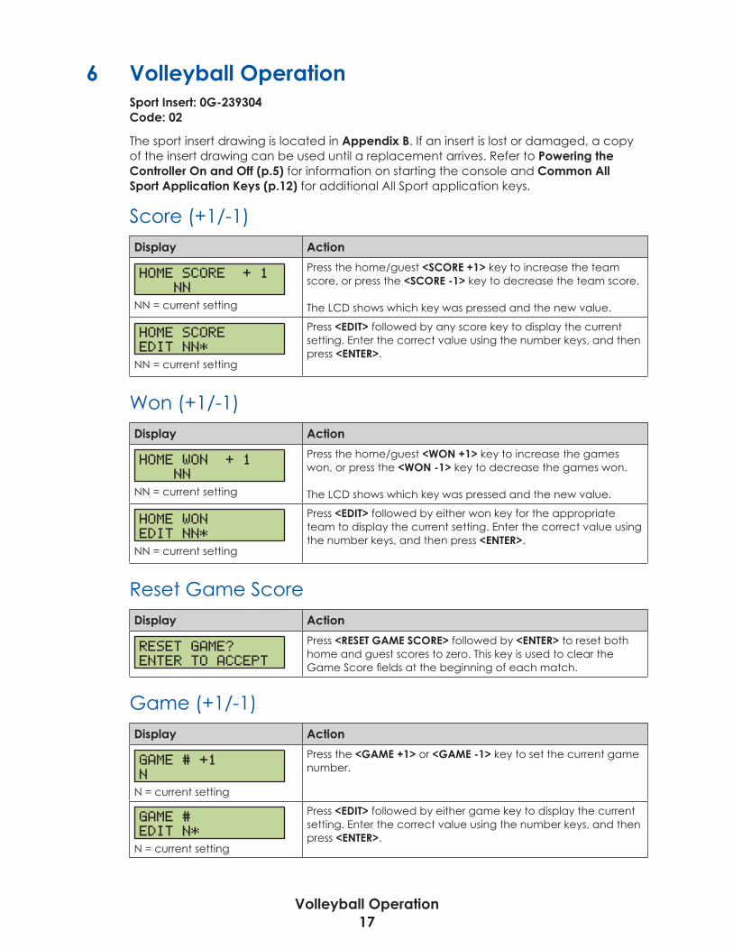
6 Volleyball OperationSport Insert: 0G-239304Code: 02
The sport insert drawing is located in Appendix B. If an insert is lost or damaged, a copy of the insert drawing can be used until a replacement arrives. Refer to Powering the Controller On and Off (p�5) for information on starting the console and Common All Sport Application Keys (p�12) for additional All Sport application keys.
Score (+1/-1)Display Action
HOME SCORE + 1 NN
NN = current setting
Press the home/guest <SCORE +1> key to increase the team score, or press the <SCORE -1> key to decrease the team score.
The LCD shows which key was pressed and the new value.
HOME SCOREEDIT NN*
NN = current setting
Press <EDIT> followed by any score key to display the current setting. Enter the correct value using the number keys, and then press <ENTER>.
Won (+1/-1)Display Action
HOME WON + 1 NN
NN = current setting
Press the home/guest <WON +1> key to increase the games won, or press the <WON -1> key to decrease the games won.
The LCD shows which key was pressed and the new value.
HOME WONEDIT NN*
NN = current setting
Press <EDIT> followed by either won key for the appropriate team to display the current setting. Enter the correct value using the number keys, and then press <ENTER>.
Reset Game ScoreDisplay Action
RESET GAME?ENTER TO ACCEPT
Press <RESET GAME SCORE> followed by <ENTER> to reset both home and guest scores to zero. This key is used to clear the Game Score fields at the beginning of each match.
Game (+1/-1)Display Action
GAME # +1N
N = current setting
Press the <GAME +1> or <GAME -1> key to set the current game number.
GAME #EDIT N*
N = current setting
Press <EDIT> followed by either game key to display the current setting. Enter the correct value using the number keys, and then press <ENTER>.

Baseball Operation18
7 Baseball OperationSport Insert: LL-2605Code: 03, 23
The sport insert drawing is located in Appendix B. If an insert is lost or damaged, a copy of the insert drawing can be used until a replacement arrives. Refer to Powering the Controller On and Off (p�5) for information on starting the console and Common All Sport Application Keys (p�12) for additional All Sport application keys.
Score (+1/-1)Display Action
HOME SCORE + 1 NN
NN = current setting
Press the home/guest <SCORE +1> key to increase the team score, or press the <SCORE -1> key to decrease the team score.
The LCD shows which key was pressed and the new value.
HOME SCOREEDIT NN*
NN = current setting
Press <EDIT> followed by any score key to display the current setting. Enter the correct value using the number keys, and then press <ENTER>.
Out +1, Inning +1Press <OUT +1> or <INNING +1> to increment the total outs or innings, respectively. The new numbers appear immediately on the LCD.
Display Action
INNING # EDITNN*
NN = current setting
Press <EDIT> followed by <OUT +1> or <INNING +1> to display the current setting. Enter the correct value using the number keys, and then press <ENTER>.
Ball +1, Strike +1, Clear Ball & StrikePress <BALL +1> or <STRIKE +1> to increment the pitch types. Press <CLEAR BALL & STRIKE> to immediately reset both values to 0.
Note: If the ball value is 4 when <BALL +1> is pressed, the value is blanked out. If the strike value is 3 when <STRIKE +1> is pressed, the value is blanked out.
HitDisplay Action
HIT ON
HIT OFF
Press <HIT> to turn on the hit indicator or digits. Press <HIT> again to turn off the hit indicator or digits.
The hit status displays briefly.
Note: When hit is already on, pressing <ERROR> will turn it off.

Baseball Operation19
ErrorDisplay Action
ERROR ON
ERROR OFF
Press <ERROR> to turn on the hit indicator or digits. Press <ERROR> again to turn off the hit indicator or digits.
The error status displays briefly.
Note: When error is already on, pressing <HIT> will turn it off.
Time, At Bat, H/E (Alt. Function)Press <ALT> followed by a key below to select what is displayed on the scoreboard:
• <TIME> shows two digits of time.
• <AT BAT> shows the player At Bat number.
• <H/E> shows an “H” or an “E” when <HIT> or <ERROR> is pressed.
Time/At BatIf the controller is set to show the time, the <TIME/AT BAT •> key operates like the standard <SET TIME> key. Refer to Common All Sport Application Keys (p�12).
If the controller is set to show AT BAT, <TIME/AT BAT •> key operates as shown below.
Display Action
AT BAT: EDIT NN*
NN = current setting
Press <TIME/AT BAT •>, enter the correct value using the number keys, and then press <ENTER>.
Play Clock and Pitch Timer Operation20
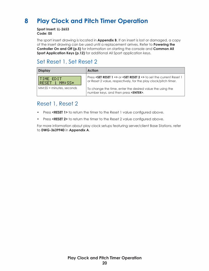
8 Play Clock and Pitch Timer OperationSport Insert: LL-2653Code: 05
The sport insert drawing is located in Appendix B. If an insert is lost or damaged, a copy of the insert drawing can be used until a replacement arrives. Refer to Powering the Controller On and Off (p�5) for information on starting the console and Common All Sport Application Keys (p�12) for additional All Sport application keys.
Set Reset 1, Set Reset 2Display Action
TIME EDITRESET 1 MM:SS*
MM:SS = minutes, seconds
Press <SET RESET 1 •> or <SET RESET 2 •> to set the current Reset 1 or Reset 2 value, respectively, for the play clock/pitch timer.
To change the time, enter the desired value the using the number keys, and then press <ENTER>.
Reset 1, Reset 2• Press <RESET 1> to return the timer to the Reset 1 value configured above.
• Press <RESET 2> to return the timer to the Reset 2 value configured above.
For more information about play clock setups featuring server/client Base Stations, refer to DWG-3639940 in Appendix A.

Segment Timer Operation21
9 Segment Timer OperationSport Insert: LL-2613Code: 06
The sport insert drawing is located in Appendix B. If an insert is lost or damaged, a copy of the insert drawing can be used until a replacement arrives. Refer to Powering the Controller On and Off (p�5) for information on starting the console and Common All Sport Application Keys (p�12) for additional All Sport application keys.
Segment Timer InformationThe segment timer is used to time events such as practice sessions. Operation of the segment timer is determined by 40 segments of pre-programmed length. The segment timer will count down starting at the segment number that is set as First Segment. When the first segment is completed, the timer will count the preset Interval Time and move on to the next segment. The timer will continue counting segments until the segment number that is set as Last Segment is complete. It then will reset to the segment saved as the First Segment and will either begin counting down or wait for the <START> key to be pressed, depending on the Auto Stop At Last Seg setting. Refer to Auto Stop (p�23) to set the segment-stopping feature.
The First Segment and Last Segment values can be used to set up specific practice sessions. For example, the practice session for one sport could be programmed for 5-minute segments on segments 1–10, while another might use 10-minute segments on segments 11–20. Set the First Segment and Last Segment values to the desired segment numbers for the session, and the console will count down each of the segments in order. It may also be set to either stop on the last segment or loop back to the first segment segments, again based on the Auto Stop At Last Seg setting.
Segment Number/TimeDisplay Action
SEGMENT: NNTIME EDIT MM:SS*
SEGMENT: NN*TIME EDIT
NN = segment numberMM:SS = minutes, seconds
Press <SEG� NO� • TIME •> to set individual segment times.
Enter the segment to be edited using the number keys, and then press <ENTER>.
Enter the time for the segment using the number keys. Press <ENTER> to move to the next segment time.
Press <ENTER> again to exit the function.
First/Last SegmentDisplay Action
FIRST SEG NN*LAST SEG XX
NN = current first segmentXX = current last segment
Press <FIRST/LAST SEGMENT>, use the number keys to enter the segment to be set as the first segment, and then press <ENTER>.Use the number keys to enter the segment to be set as the last segment, and then press <ENTER>.
The console will be reset to the segment selected here when the <RESET TO FIRST SEGMENT> key is pressed. After the segment set as the last segment is completed, the console will automatically reset to the segment saved as the first segment.

Segment Timer Operation22
Current Segment +1Press <CURRENT SEGMENT +1> to move to the next segment. The new segment number appears immediately on the LCD.
Display Action
CURRENT SEGMENT:EDIT NN*
NN = current setting
Press <EDIT> followed by <CURRENT SEGMENT +1> to display the current setting. Enter the correct value using the number keys, and then press <ENTER>.
Reset Current SegmentPress <RESET CURRENT SEGMENT> to reset the segment time to the value specified by the current segment. The segment number will remain at the current value.
Reset to First SegmentPress <RESET TO FIRST SEGMENT> to return to the first segment.
Note: This function is disabled while the clock is running.
Interval TimeThe interval time is the time between each segment.
Display Action
INTERVAL TIME:MM:SS*
MM:SS = minutes, seconds
Press <INTERVAL TIME •> to display the current value of interval time. Enter the interval time using the number keys, and then press <ENTER>.
DISPLAY INTERVAL1-YES 2*NO
* = current setting
This setting determines whether the interval count will be displayed on the scoreboard.
Press <1> to display the interval time on the scoreboard. Press <2> to disable interval time display. The interval time will be displayed only on the controller.
Note: Regardless of this setting, the value saved in interval time will be counted down between segments. Set the interval time to 00:00 if no interval between segments is desired.
Note: When the interval time is being displayed, the segment number on the scoreboard flashes to indicate that the time displayed is interval time.
Copy RangeThis key sets a range of segments to a specific time value.
Display Action
COPY: MM:SS *SEG XX TO YY
MM:SS = minutes, seconds XX = starting segment valueYY = ending segment value
Press <COPY RANGE •> and enter the time desired. Press <ENTER> to move to the next field. Enter the first and last segments that will have this time. When the last segment in the copy range is set, the menu will exit.
Once completed, all segments from XX to YY (inclusive) will be set to the specified time.

Segment Timer Operation23
Auto Stop
Note: To set the console to stop after the last segment in the series is completed, the auto stop at each segment setting must be set to NO.
Display Action
STOP AT EACH SEG1-YES 2*NO
* = current setting
Press <AUTO STOP> to enter this menu.
• Press <1> to set the console to stop after each segment is completed.
• Press <2> to set the console to automatically begin the next segment when each segment is completed.
STOP AT LAST SEG1*YES 2-NO
* = current setting
If Stop at Each Segment is set to NO, the console will prompt for the Auto Stop at Last Segment setting:
• Press <1> to set the console to stop when the last segment has been completed.
• Press <2> to set the console to start over at the first segment when the last segment is completed.
Warning TimeDisplay Action
WARNING TIMEMM:SS*
MM:SS = minutes, seconds
When the warning time is reached, the segment number flashes until the main clock reaches zero.
Press <WARNING TIME •>, enter the time in minutes and seconds using the number keys, and then press <ENTER>.
Enter 00:00 for no warning time (default).

Tennis Operation24
10 Tennis OperationSport Insert: LL-2607Code: 08
The sport insert drawing is located in Appendix B. If an insert is lost or damaged, a copy of the insert drawing can be used until a replacement arrives. Refer to Powering the Controller On and Off (p�5) for information on starting the console and Common All Sport Application Keys (p�12) for additional All Sport application keys.
Court SelectionMultiple wireless handheld controllers may be connected to a single wireless Base Station in the Tennis application. Each connected handheld controller will operate a specific court, and the controller number for the handheld is selected when powered up.
Display Action
ENTER CONTROLLERNUMBER NN*
NN = current setting
Enter the controller number for the court that this particular handheld will operate, and then press <ENTER>.
Typically, controller 1 would run court 1, controller 2 would run court 2, and so on. Some systems may be set up differently.
ERROR - NUMBERTAKEN
ERROR - INVALIDNUMBER
• If the number entered has already been selected for another controller, the error message at top left will display. Select another number.
• If the controller number entered is too high, the error message at bottom left will display. Select another number.
ServeDisplay Action
TOP SERVEON
TOP SERVEOFF
Press the Top/Bottom <SERVE> key to turn the serve indicators ON or OFF for the respective player/team.
Note: When one serve indicator is already on, pressing the opposite <SERVE> key will turn it off.
Game +1Display Action
GAMES WON +1SET X TOP Y
X = current setY = games won
Press the Top/Bottom <GAME +1> key to increment the number of games won in the current set for the respective player/team.
The LCD shows which key was pressed and the new value.
GAMES WON EDITSET X TOP Y
X = current setY = games won
Press <EDIT> followed by the Top/Bottom <GAME +1> key to display the current setting. Enter the correct value using the number keys, and then press <ENTER>.

Tennis Operation25
PointPress the Top/Bottom <POINT> key to increment the total points for the respective player/team. The points will increment as 15, 30, 40 AD or GA. If Tie Break scoring mode is selected, the points will increment by 1. The new point values appear immediately on the LCD.
Display Action
TOP=NN* BOT= EDIT TOP
NN = current setting
Press <EDIT> followed by the Top/Bottom <POINT> key to display the current setting. Enter the correct value using the number keys, and then press <ENTER>.
Reset GamePress <RESET GAME> to immediately reset the player points for the current game.
Tie BreakPress <TIE BREAK> to set the mode of scoring to Tie Break mode. In Tie Break scoring mode, player points increase by one with each press of the <POINTS> key.
Note: Tie Break scoring mode may only be selected when both player point values are 0. To change scoring mode back to normal, press the <RESET GAME> key.
TOD/GameThe <TOD/GAME •> key toggles the console between displaying game time or time of day (TOD) and allows the operator to change the time of day.
Display Action
SET TIME OF DAY12HR HH:MM:SS*
HH:MM:SS = hours, mins, secs
Press <TOD/GAME> to set the Time of Day. Enter the correct value using the number keys, and then press <ENTER>. The time of day clock is now displayed, if the scoreboard has that capability.
Set +1Press <SET +1> to increment the current set number. The new set number appears immediately on the LCD.
Display Action
SET EDITNN
NN = current setting
Press <EDIT> followed by <SET +1> to display the current setting. Enter the correct value using the number keys, and then press <ENTER>.
INVALID SETPLEASE RE-ENTER
If the set number entered is invalid, the error message at left will display. Enter another set number.

Tennis Operation26
Matches Won (Alt. Function)Display Action
MATCHES WON EDITTOP NN*
NN = current setting
Press <ALT> followed by the Top/Bottom <MATCHES WON> key to display the matches won. Enter the correct value using the number keys, and then press <ENTER>.
Reset Match (Alt. Function)Display Action
PRESS ENT TOSTART NEW MATCH
Press <ALT> followed by <RESET MATCH>.Press <ENTER> to reset the current match, or press <CLEAR> to cancel.
All set scores and the current game score will be cleared, and the set number will return to 1.
Next Match (Alt. Function – DakTennis Only)Display Action
NEXT MATCHSELECTED
Press <ALT> followed by <NEXT MATCH> to tell the DakTennis™ software to switch to the next match. The LCD will show that the next match was selected.
Winner (Alt. Function – DakTennis Only)Display Action
TOP WINON
Press <ALT> followed by <WINNER> for the Top/Bottom player/team to tell the DakTennis™ software to set them as the winner if currently off or clear the winner if currently on. The LCD will show the status of the winner being set ON or OFF.
For more information, refer to the DakTennis Version 3 Installation & Operation Manual (DD1965926), available online at www.daktronics.com/manuals.

Sand Volleyball Operation27
11 Sand Volleyball OperationSport Insert: LL-2607Code: 09
The sport insert drawing is located in Appendix B. If an insert is lost or damaged, a copy of the insert drawing can be used until a replacement arrives. Refer to Powering the Controller On and Off (p�5) for information on starting the console and Common All Sport Application Keys (p�12) for additional All Sport application keys.
Court SelectionMultiple wireless handheld controllers may be connected to a single wireless Base Station in the Sand Volleyball application. Each connected handheld controller will operate a specific court, and the controller number for the handheld is selected when powered up.
Display Action
ENTER CONTROLLERNUMBER NN*
NN = current setting
Enter the controller number for the court that this particular handheld will operate and then press <ENTER>.
Typically, controller 1 would run court 1, controller 2 would run court 2, and so on. Some systems may be set up differently.
ERROR - NUMBERTAKEN
ERROR - INVALIDNUMBER
• If the number entered has already been selected for another controller, the error message at top left will display. Select another number.
• If the controller number entered is too high, the error message at bottom left will display. Select another number.
Note: On the sport insert and LCD, “TOP” = HOME and “BOT” = GUEST.
ServeDisplay Action
TOP SERVEON
TOP SERVEOFF
Press the Top/Bottom <SERVE> key to turn the serve indicators ON or OFF for the respective team.
Note: When one serve indicator is already on, pressing the opposite <SERVE> key will turn it off.
PointPress the Top/Bottom <POINT> key to increment the total points by 1 for the respective team in the currently selected set. The new point values appear immediately on the LCD.
Display Action
SCORE EDITTOP NN*
NN = current setting
Press <EDIT> followed by the Top/Bottom <POINT> key to display the current setting. Enter the correct value using the number keys, and then press <ENTER>.

Sand Volleyball Operation28
Set +1Press <SET +1> to increment the current set number. The new set number appears immediately on the LCD. The scores will be set to 0 for each team, if they do not already have points entered for the set.
Display Action
SET EDITNN
NN = current setting
Press <EDIT> followed by <SET +1> to display the current setting. Enter the correct value using the number keys, and then press <ENTER>.
INVALID SETPLEASE RE-ENTER
If the set number entered is invalid, the error message at left will display. Enter another set number.
Reset Game (Reset Match)Display Action
PRESS ENT TOSTART NEW MATCH
Press <RESET GAME> followed by <ENTER> to confirm resetting the current match. This is typically performed after completion of the final set.
All scores will be cleared, and the set number will return to 1.
TOD/GameThe <TOD/GAME •> key toggles the console between displaying game time or time of day (TOD) and allows the operator to change the time of day.
Display Action
SET TIME OF DAY12HR HH:MM:SS*
HH:MM:SS = hours, mins, secs
Press <TOD/GAME> to set the Time of Day. Enter the correct value using the number keys, and then press <ENTER>. The time of day clock is now displayed, if the scoreboard has that capability.
Matches Won (Alt. Function)Display Action
MATCHES WON EDITTOP NN*
NN = current setting
Press <ALT> followed by the Top/Bottom <MATCHES WON> key to display the matches won. Enter the correct value using the number keys, and then press <ENTER>.
Game +1, Tie Break, Next Match, WinnerThese keys are not used for Sand Volleyball mode.

Basketball Operation29
12 Basketball OperationSport Insert: LL-2632Code: 10 (Use Code 20 for optimized server/client operation.)
The sport insert drawing is located in Appendix B. If an insert is lost or damaged, a copy of the insert drawing can be used until a replacement arrives. Refer to Powering the Controller On and Off (p�5) for information on starting the console and Common All Sport Application Keys (p�12) for additional All Sport application keys.
Score (+1/+2)Display Action
HOME SCORE + 1 NNN
NNN = current setting
Press the home/guest <SCORE +1> or <SCORE +2> key to increase the team score by the value printed on the key.
The LCD shows which key was pressed and the new value.
HOME SCOREEDIT NNN*
NNN = current setting
Press <EDIT> followed by any score key to display the current setting. Enter the correct value using the number keys, and then press <ENTER*>.
Score (+3/-1) (Alt. Functions)Display Action
HOME SCORE + 3 NNN
NNN = current setting
Press <ALT> followed by the home/guest <SCORE +3> key to increase the team score, or the <SCORE -1> key to decrease the team score.
The LCD shows which key was pressed and the new value.
Fouls +1Display Action
HOME FOULS + 1 NN
NN = current setting
Press the home/guest <FOULS +1> key to increase the number of team fouls.
The LCD shows which key was pressed and the new value.
HOME FOULSEDIT NN*
NN = current setting
Press <EDIT> followed by any fouls key to display the current setting. Enter the correct value using the number keys, and then press <ENTER>.
PossessionDisplay Action
HOME POSSESSIONLIGHT ON
GUEST POSSESSIONLIGHT ON
Press <POSS> to light the appropriate indicator. Each press will turn the other possession light on.

Basketball Operation30
Period +1Display Action
PERIOD +1NN
N = current setting
Press <PERIOD +1> to increment the current period.
The new period number displays briefly.
PERIOD EDITN *
N = current setting
Press <EDIT> followed by <PERIOD +1> to display the current setting. Enter the correct value using the number keys, and then press <ENTER>.
Set TOD (Alt. Function)Display Action
SET TIME OF DAY12HR HH:MM:SS*
HH:MM:SS = hours, mins, secs
Press <ALT> followed by <SET TOD> to set the Time of Day. Enter the correct number using the number keys, and then press <ENTER>. The time of day clock is now displayed, if the scoreboard has that capability.
1/10 SEC (Alt. Function)Display Action
TIME MM:SS H- G-
MM:SS = minutes, seconds
TIME MM:SS.T H- G-
MM:SS.T = minutes, seconds, tenths of a second
Press <ALT> followed by <1/10 SEC> to toggle showing 1/10 of a second on the main clock.
The top line of the LCD immediately updates to show the extra tenth of a second.
Bonus (Alt. Function)Display Action
HOME BONUSLIGHT 1-ON-1
HOME BONUSLIGHT 2-SHOT
HOME BONUSLIGHT OFF
Press <ALT> followed by the home/guest <BONUS> key to turn on the 1-ON-1 bonus light.
Press <ALT> followed by the same <BONUS> key a second time to turn on the 2 SHOT bonus light.
Press <ALT> followed by the same <BONUS> key a third time to turn on the bonus light OFF.

Football Operation31
13 Football OperationSport Insert: 0G-1031603 Code: 61, 62
The sport insert drawing is located in Appendix B. If an insert is lost or damaged, a copy of the insert drawing can be used until a replacement arrives. Refer to Powering the Controller On and Off (p�5) for information on starting the console and Common All Sport Application Keys (p�12) for additional All Sport application keys.
Score (+1/+6)Display Action
HOME SCORE + 1 NNN
NNN = current setting
Press the home/guest <SCORE +1> or <SCORE +6> key to increase the team score by the value printed on the key.
The LCD shows which key was pressed and the new value.
HOME SCOREEDIT NNN*
NNN = current setting
Press <EDIT> followed by any score key to display the current setting. Enter the correct value using the number keys, and then press <ENTER*>.
Score (+3/-1) (Alt. Functions)Display Action
HOME SCORE + 3 NNN
NNN = current setting
Press <ALT> followed by the home/guest <SCORE +3> key to increase the team score, or the <SCORE -1> key to decrease the team score.
The LCD shows which key was pressed and the new value.
QTR +1Display Action
QUARTER +1N
N = current setting
Press <QTR +1> to increment the current quarter.
The new quarter number displays briefly.
QUARTER EDITN *
N = current setting
Press <EDIT> followed by <QTR +1> to display the current setting. Enter the correct value using the number keys, and then press <ENTER>.
Down +1Display Action
DOWN +1N
N = current setting
Press the <DOWN +1> key to increment the down number. The value increments from 1 to 4 then repeats.

Football Operation32
Display Action
DOWN EDITN*
N = current setting
Press <EDIT> followed by <DOWN +1> to display the current setting. Enter the correct value using the number keys, and then press <ENTER>.
To GoDisplay Action
TO GO EDITNN*
NN = current setting
Press <TO GO •> to set the distance to go until first down. Enter the correct value using the number keys, and then press <ENTER>.
Ball OnDisplay Action
BALL ON EDITNN*
NN = current setting
Press <BALL ON •> to set the yard line of the ball. Enter the correct value using the number keys, and then press <ENTER>.
TOL -1Display Action
HOME TOL - 1 N
N = current setting
Press the home/guest <TOL -1> key to decrement the number of Time Outs Left (TOL). By default, each team starts the game with 3 time outs.
HOME TOLEDIT N*
N = current setting
Press <EDIT> followed by any TOL key to display the current setting. Enter the correct value using the number keys, and then press <ENTER>.
Possession (Alt. Function)Display Action
HOME POSSLIGHT ON
HOME POSSLIGHT OFF
Press <ALT> followed by the home/guest <POSS> key to light the possession indicator. A second press will turn the indicator off, as will turning on the opposing team’s indicator.

Remote Start/Stop Operation33
14 Remote Start/Stop OperationSport Insert: 0G-319079 Code: 98
The sport insert drawing is located in Appendix B. If an insert is lost or damaged, a copy of the insert drawing can be used until a replacement arrives. Refer to Powering the Controller On and Off (p�5) for information on starting the console and Common All Sport Application Keys (p�12) for additional All Sport application keys.
Start Display Action
REM START/STOPCLOCK OFF
CLOCK STARTCLOCK RUN
When the clock is stopped, the LCD will show the clock status on the bottom line as OFF.
Press <START> and the top line of the LCD will briefly show the function, and then the clock status will change to RUN.
StopDisplay Action
REM START/STOPCLOCK RUN
CLOCK STOPCLOCK OFF
When the clock is already running, the LCD will show the clock status on the bottom line as RUN.
Press <STOP> and the top line of the LCD will briefly show the function, and then the clock status will change back to OFF.
Manual Horn/ResetDepending on the current jack the Base Station is connected to on the All Sport 5000 controller, this key will have different functions:
• When connected to the J4 (main clock) jack, the key functions as a manual horn.
• When connected to the J7 (shot/play clock) jack, the key functions as a timer reset.
For more information on Remote Start/Stop setups, refer to DWG-3660093 in Appendix A.
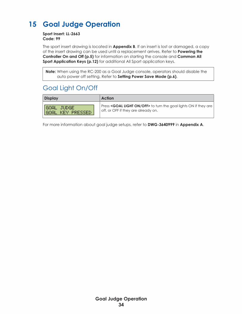
Goal Judge Operation34
15 Goal Judge OperationSport Insert: LL-2663 Code: 99
The sport insert drawing is located in Appendix B. If an insert is lost or damaged, a copy of the insert drawing can be used until a replacement arrives. Refer to Powering the Controller On and Off (p�5) for information on starting the console and Common All Sport Application Keys (p�12) for additional All Sport application keys.
Note: When using the RC-200 as a Goal Judge console, operators should disable the auto power off setting. Refer to Setting Power Save Mode (p�6).
Goal Light On/OffDisplay Action
GOAL JUDGEGOAL KEY PRESSED
Press <GOAL LIGHT ON/OFF> to turn the goal lights ON if they are off, or OFF if they are already on.
For more information about goal judge setups, refer to DWG-3640999 in Appendix A.
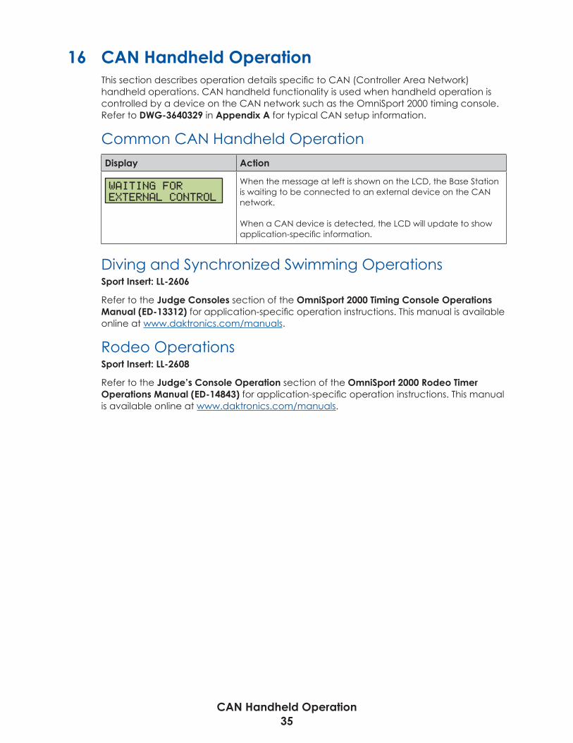
CAN Handheld Operation35
16 CAN Handheld OperationThis section describes operation details specific to CAN (Controller Area Network) handheld operations. CAN handheld functionality is used when handheld operation is controlled by a device on the CAN network such as the OmniSport 2000 timing console. Refer to DWG-3640329 in Appendix A for typical CAN setup information.
Common CAN Handheld OperationDisplay Action
WAITING FOREXTERNAL CONTROL
When the message at left is shown on the LCD, the Base Station is waiting to be connected to an external device on the CAN network.
When a CAN device is detected, the LCD will update to show application-specific information.
Diving and Synchronized Swimming OperationsSport Insert: LL-2606
Refer to the Judge Consoles section of the OmniSport 2000 Timing Console Operations Manual (ED-13312) for application-specific operation instructions. This manual is available online at www.daktronics.com/manuals.
Rodeo OperationsSport Insert: LL-2608
Refer to the Judge’s Console Operation section of the OmniSport 2000 Rodeo Timer Operations Manual (ED-14843) for application-specific operation instructions. This manual is available online at www.daktronics.com/manuals.

Troubleshooting36
17 Troubleshooting
Handheld Controller Error MessagesDisplay Cause/Solution
NO SERVER FOUNDB: XX C: YY
XX = Broadcast Group #YY = Channel #
ENT TO RETRYCLEAR SETS CHAN
The wireless handheld could not find a server on the specified broadcast group and channel.
• Make sure the wireless Base Station is powered on, and is set for the specified broadcast group and channel.
• Make sure the handheld is within minimum and maximum range limits. Refer to Section 2: RC-200 System Overview (p�4).
• Press <ENTER> to retry the connection (if the handheld was just moved in range or the wireless Base Station has been correctly configured).
• Press <CLEAR> to set the broadcast group and channel to a different number and retry.
NO RESPONSE ON B: XX C: YY
XX = Broadcast Group #YY = Channel #
ENT TO RETRYCLEAR SETS CHAN
The wireless handheld did find a server on the specified broadcast group and channel, but the server did not respond.
• Make sure the handheld is within minimum and maximum range limits. Refer to Section 2: RC-200 System Overview (p�4).
• Cycle power to the wireless Base Station and retry the connection.
• Make sure that there are no other wireless Base Stations within range on the same group or channel. Try a different group/channel if necessary.
• Press <ENTER> to retry the connection (if the handheld was just moved in range or the wireless Base Station has been correctly configured).
• Press <CLEAR> to set the group/channel to a different number and retry.
ERROR - THISCHANNEL IN USE
The message at left is displayed if another wireless handheld controller is currently connected to the Base Station and the application does not permit multiple handheld units.
Power off any other unused handheld units on the same channel in the area. Refer to Powering the Controller On and Off (p�5).
Although multiple wireless handheld controllers may be connected to a single Base Station, the following applications only allow one handheld device to be connected at a time:
• Baseball • Play Clock/Pitch Timer• Basketball • Remote Start/Stop• Clock/Score • Segment Timer• Football • Volleyball• Goal Judge

Troubleshooting37
Display Cause/Solution
LOW SIGNALSTRENGTH
PRESS CLEAR FORCONFIG MENU
The Base Station has stopped responding to the wireless handheld. This could mean any following scenario is true:
• The Base Station was turned off or has lost power.
• The Base Station was changed to a different broadcast group or channel.
• The Base Station and handheld are too far away or too close. Refer to Section 2: RC-200 System Overview (p�4).
If all of these problems have been checked and the handheld still shows Low Signal Strength, cycle power on both the handheld and Base Station.
Base Station Errors
IN RANGE LED On Start-upThe IN RANGE LED flashes several times at start-up while the server Base Station searches for other Base Stations on the same channel within range. If another server Base Station is found, this LED will flash continuously, indicating that only one server Base Station is allowed on a given channel.
General Base Station FailuresThe wireless Base Station uses the on-board LEDs to indicate failure status. When a failure occurs, the DATA OUT / TX and IN RANGE LEDs flash in a repetitive pattern to indicate the failure type. The LEDs will flash on for a long period of time, followed by a series of short flashes that give the error type. This sequence will repeat 5 times, after which the Base Station will reset.
If an error sequence is being displayed on the LEDs, first cycle power to the wireless Base Station by disconnecting power for several seconds and then reconnecting. If the problem persists, please contact Daktronics Customer Service. Refer to Daktronics Exchange and Repair & Return Programs (p�2).
Obtaining Base Station Status InformationWhen connected to a wireless Base Station in any All Sport function, the wireless handheld can obtain status information about the Base Station. This information includes the Base Station broadcast group/channel, firmware version number, and region.
Display Action
VN.N DD-3561942BG:XX CH:YY R
N.N = firmware versionXX = broadcast group #YY = channel #R = region (D for Domestic, I for International)
Press <ALT> followed by <CONNECT> to display Base Station status information. Press any key to return to normal operation.

This page intentionally left blank.

Reference Drawings39
A Reference DrawingsRefer to Resources (p�1) for information regarding how to read the drawing number. Any contract-specific drawings take precedence over the general drawings.
Reference Drawings:Charging Station- Specifications and Operation ......................................... DWG-3639831System Riser Diagram: RC-200- Baseball/Tennis ............................................ DWG-3639930System Riser Diagram: RC-200 Server/Client Line ......................................... DWG-3639940System Riser; Tennis; Remote Base Station ..................................................... DWG-3640082System Riser; Tennis; Multi-Court, DakTennis, Radio, CG .............................. DWG-3640119System Riser Diagram; DakTennis, Video Control ......................................... DWG-3640268System Riser; Indoor/Outdoor Single Court, RC-200 ..................................... DWG-3640312System Riser: RC-200, Rodeo/Diving/Sync Swimming .................................. DWG-3640329System Riser; Tennis; Outdoor Multi-Court, CG .............................................. DWG-3640342System Riser; Tennis; Indoor Multi-Court, CG ................................................. DWG-3640403Base Station: Indoor Installation ...................................................................... DWG-3640534Base Station: Outdoor Installation .................................................................. DWG-3640913Base Station: DistaView Scoreboard Installation .......................................... DWG-3640952Riser Diagram: Goal Indicator System w/ RC-200 ......................................... DWG-3640999System Riser; Tennis; Multi-Court, RC-200 Direct ............................................ DWG-3641206System Riser, RC-100 Game/DOG Clock Remote St/St ............................... DWG-3660093

This page intentionally left blank.

THE CONCEPTS EXPRESSED AND DETAILS SHOWN ON THIS DRAWINGARE CONFIDENTIAL AND PROPRIETARY. DO NOT REPRODUCE BY
ANY MEANS WITHOUT THE EXPRESS WRITTEN CONSENT OFDAKTRONICS, INC. OR ITS WHOLLY OWNED SUBSIDIARIES.
COPYRIGHT 2017 DAKTRONICS, INC. (USA)
THIRD ANGLE PROJECTION
AH
REV
TITLE:
PROJECT:
INCHES [MILLIMETERS]
DESIGN:
SCALE:
DIM UNITS:DATE: SHEET
DO NOT SCALE DRAWINGFUNC - TYPE - SIZE
DRAWN: -JOB NO.
-
RC-200 CONSOLECHARGING STATION- SPECIFICATIONS AND OPERATION
AHUNTER
16 MAY 17
P1110 R 04 A
NTSAVB 3639831
00
21.80"
4.75"
6.39"

THE CONCEPTS EXPRESSED AND DETAILS SHOWN ON THIS DRAWINGARE CONFIDENTIAL AND PROPRIETARY. DO NOT REPRODUCE BY
ANY MEANS WITHOUT THE EXPRESS WRITTEN CONSENT OFDAKTRONICS, INC. OR ITS WHOLLY OWNED SUBSIDIARIES.
COPYRIGHT 2017 DAKTRONICS, INC. (USA)
THIRD ANGLE PROJECTION
AH
HOMEGUEST
INNING
DAKTRONICS
BALL STRIKE OUT
REV
TITLE:
PROJECT:
INCHES [MILLIMETERS]
DESIGN:
SCALE:
DIM UNITS:DATE: SHEET
DO NOT SCALE DRAWINGFUNC - TYPE - SIZE
DRAWN: -JOB NO.
-
RADIO LINKSYSTEM RISER DIAGRAM: RC-200- BASEBALL/TENNIS
AHUNTER
16 MAY 17
P1110 R 01 A
NONERTAGTOW 3639930
00

THE CONCEPTS EXPRESSED AND DETAILS SHOWN ON THIS DRAWINGARE CONFIDENTIAL AND PROPRIETARY. DO NOT REPRODUCE BY
ANY MEANS WITHOUT THE EXPRESS WRITTEN CONSENT OFDAKTRONICS, INC. OR ITS WHOLLY OWNED SUBSIDIARIES.
COPYRIGHT 2017 DAKTRONICS, INC. (USA)
THIRD ANGLE PROJECTION
AH
30
3010 3020 40 50 40
10 30 4020 50 40
20 10
1020
Dak
tronics
Daktronics
REV
TITLE:
PROJECT:
INCHES [MILLIMETERS]
DESIGN:
SCALE:
DIM UNITS:DATE: SHEET
DO NOT SCALE DRAWINGFUNC - TYPE - SIZE
DRAWN: -JOB NO.
-
RC-200 SERVER/CLIENT LINE3639940.dwg
AHUNTER
16 MAY 17
P1110 R 01 A
NONEARICHTE 3639940
00

THE CONCEPTS EXPRESSED AND DETAILS SHOWN ON THIS DRAWINGARE CONFIDENTIAL AND PROPRIETARY. DO NOT REPRODUCE BY
ANY MEANS WITHOUT THE EXPRESS WRITTEN CONSENT OFDAKTRONICS, INC. OR ITS WHOLLY OWNED SUBSIDIARIES.
COPYRIGHT 2017 DAKTRONICS, INC. (USA)
THIRD ANGLE PROJECTION
AH
W-1267 (10')
LAPTOP COMPUTER
USBUSB USBNETWORK
DAKTENNIS
25FT CABLE WITH BASE STATION
0A-1065-0173
RS232TX/RX
TB1JUMPERS12-N13-P
A-2221USB TO SERIALADAPTER @2
5+6-
23
87
9
54
61
A-3430138
JB1 - PIN OUT
PIN #
J1-4
J1-6J1-5
J1-1
J1-3J1-2
FUNCTION
N/CCL TX+
DC GND, CL TX-
12-24VDC +
J1-7J1-8J1-9
W-1234,22AWG, 2 PAIR W/SHIELD
MAX 125FT.
RC-200 CONTROLLER0A-1110-0062
INSERT: LL-2607CODE: 08
NOTE:THE RC-200 CONTROLLER(S) USE ANYGROUP/CHANNEL. HOWEVER, THE BASE STATIONAND RC-200 CONTROLLER(S) MUST BEOPERATING ON THE SAME GROUP/CHANNEL. MAXOF 8 RC-200 CONTROLLERS CAN BE USED WITH 1BASE STATION.
0A-1196-0099JB1 - JUNCTION BOX
0A-1196-0167JB2 - JUNCTION BOX
OUTDOOR BASE STATION0A-1110-0068
FUNCTION SETTING = 2ANY GROUP/CHANNEL
J1
0A-1065-0173
RS232TX/RX
TB11+2-
TO SCOREBOARD(S),22AWG, 2 PAIR W/SHIELD
JB2 - PIN OUTPIN #
J3-4
J3-6J3-5
J3-1
J3-3J3-2
FUNCTION
DC GND, CL TX-RS232 RX +
12-24VDC +CL TX+NOT USED
RS232 TX +
TERMINAL CONNECTION
TB2-1TB1-1TB1-2
N/C
J2
J1
J2
W-1267 (10')JUMPERS
12-N13-P
W-123422AWG, 2 PAIR
W/SHIELD
CLEAR LINE OF SIGHT
N/C
N/CN/CN/CN/C
N/C
N/C
CONTROL LOCATION
REMOTE LOCATION UP TO 125FTAWAY.
ALLSPORT5010R6
J1J2J3J4J6J7
OPTIONALALLSPORT 5010 OR 5100SERIES, WITH RADIOCODE 5900
OPTIONAL W-1249 (6')
TO SCOREBOARD VIA RADIOOPTION
OPTIONAL0A-1110-0108 (3')
TERMINAL
N/CN/C
TB2-1
TB1-1TB1-2
N/CN/CN/CN/C
CONNECTION TO
N/CN/C
TB1-6
N/C TB1-5
N/CN/CN/CN/C
CONNECTION CONVERTER
REV
TITLE:
PROJECT:
INCHES [MILLIMETERS]
DESIGN:
SCALE:
DIM UNITS:DATE: SHEET
DO NOT SCALE DRAWINGFUNC - TYPE - SIZE
DRAWN: -JOB NO.
-
RC-200 TENNISSYSTEM RISER; TENNIS; REMOTE BASE STATION
AHUNTER
15 MAY 17
P1110 R 01 A
NONEKBIERBA 3640082
00

INDOOR MULTI-COURT SCOREBOARD LAYOUTREFER TO MANUAL FOR ALL POWER, SIGNAL, ANDINSTALLATION DETAILS.
SIGIN
SIGOUT
SIGIN
SIGOUT
SIGIN
SIGOUT
SIGIN
SIGOUT
W-1236 (20FT)
SIGIN
SIGOUT
SIGIN
SIGOUT
SIGIN
SIGOUT
W-1236 (20FT) W-1340 (10FT) W-1340 (10FT)
W-1340 (10FT) W-1340 (10FT)
INSTALL NOTE: MOLDED SIGNALINTERCONNECT CABLES WITH
SCOREBOARD.
W-1267 (10FT)
PWRRS232
A-3430138
0A-1110-0066 BASE STATION KIT.TYPICAL SETTING:
FUNCTION = 2ANY GROUP/CHANNEL
SERVER JUMPER ENABLED.NOTE: SEE DWG-3640082 AND OUTDOORBASE STATION 0A-1110-0067 IF YOU NEEDTO REMOTE LOCATE FOR BETTER LINE OF
SIGHT.
A-3430138A-3430138A-3430138
PRODUCTION LOCATIONALLSPORT CG SETUP
W-1249 (10FT)W-1236 (20FT)
OUTDOOR MULTI-COURT SCOREBOARD LAYOUTREFER TO MANUAL FOR ALL POWER, SIGNAL, ANDINSTALLATION DETAILS.
ALL RADIOCOMMUNICATIONREQUIRES CLEAR
LINE OF SIGHT.
THE CONCEPTS EXPRESSED AND DETAILS SHOWN ON THIS DRAWINGARE CONFIDENTIAL AND PROPRIETARY. DO NOT REPRODUCE BY
ANY MEANS WITHOUT THE EXPRESS WRITTEN CONSENT OFDAKTRONICS, INC. OR ITS WHOLLY OWNED SUBSIDIARIES.
COPYRIGHT 2017 DAKTRONICS, INC. (USA)
THIRD ANGLE PROJECTION
BH
REV
TITLE:
PROJECT:
INCHES [MILLIMETERS]
DESIGN:
SCALE:
DIM UNITS:DATE: SHEET
DO NOT SCALE DRAWINGFUNC - TYPE - SIZE
DRAWN: -JOB NO.
-
TENNIS SCOREBOARDSYSTEM RISER; TENNIS; MULTI-COURT, DAKTENNIS, RADIO,CG
AHUNTER
15 MAY 17
P1164 E 10 B
NONERTAGTOW 3640119
00

THE CONCEPTS EXPRESSED AND DETAILS SHOWN ON THIS DRAWINGARE CONFIDENTIAL AND PROPRIETARY. DO NOT REPRODUCE BY
ANY MEANS WITHOUT THE EXPRESS WRITTEN CONSENT OFDAKTRONICS, INC. OR ITS WHOLLY OWNED SUBSIDIARIES.
COPYRIGHT 2017 DAKTRONICS, INC. (USA)
THIRD ANGLE PROJECTION
AH
FIBER OPTICCABLE RUN IN CONDUIT
MONITOR
3210
CAN
W-1267 (10')
POWERRS23212 VAC
BASE STATION0A-1110-0066
FUNCTION SETTING = 2 ANY GROUP/CHANNEL
LAPTOP COMPUTER
USBUSB COMPRINTER
DAKTENNISUSER'S KIT
A-3430138
NOTE:THE (6) RC-200 CONTROLLERS USE ANY GROU[/CHANNEL,HOWEVER, THE BASE STATION AND HAND HELDCONTROLLERS MUST BE OPERATING ON THE SAMECHANNEL. USE CODE 08 FOR TENNIS.
NOTES:
THIS IS NOT A SCALED DRAWING AND SHOULD BE USEDFOR POWER AND SIGNAL REQUIREMENTS ONLY.
IT IS THE RESPONSIBILITY OF THE ELECTRICALINSTALLATION CONTRACTOR TO ENSURE THAT ALLELECTRICAL WORK PERFORMED ON SITE MEETS OREXCEEDS ALL LOCAL AND NATIONAL ELECTRICAL CODES.
ALL DISPLAYS MUST BE GROUNDED PER ARTICLE 250AND 600 OF THE NATIONAL ELECTRICAL CODE WITH NOMORE THAN 10 OHMS GROUND RESISTANCE.
VIDEO MATRIX DISPLAY
USB TO SERIALADAPTOR
W-1350 (6')
PRIMARY
ROCKET
OUTPUT
RC-100'S AT COURT LOCATIONS
VENUS 7000 ORDMP SYSTEM
RC-200INSERT KIT
LL-2806 RC-200 TENNIS INSERT USE CODE 08
RC-200 BLACK, SOFT CARRY CASEEN-1995
0A-1000-1079 CD; SOFTWARE, ALL SPORT MANUALSRC-200 WIRELESS HANDHELD0A-1110-0062
TRANSFORMER; 12VAC; WALLPACK 6' CORDA-3430138
PART ID ASSEMBLY # DESCRIPTION AND OPERATOR INFO
SEE TABLE BELOW FOR CONTENTS OF RC-100 HANDHELD, CONTROLLER KIT:0A-1110-0102
RC-200 WIRELESS HANDHELD: 0A-1110-0062, TYP. @6. INCLUDEDIN RC-200 HANDHELD, CONTROLLER KIT: 0A-1110-0064.
REV
TITLE:
PROJECT:
INCHES [MILLIMETERS]
DESIGN:
SCALE:
DIM UNITS:DATE: SHEET
DO NOT SCALE DRAWINGFUNC - TYPE - SIZE
DRAWN: -JOB NO.
-
TENNIS SCOREBOARDSYSTEM RISER DIAGRAM; DAKTENNIS, VIDEO CONTROL
AHUNTER
16 MAY 17
P1164 E 10 A
NONERTAGTOW 3640268
00

THE CONCEPTS EXPRESSED AND DETAILS SHOWN ON THIS DRAWINGARE CONFIDENTIAL AND PROPRIETARY. DO NOT REPRODUCE BY
ANY MEANS WITHOUT THE EXPRESS WRITTEN CONSENT OFDAKTRONICS, INC. OR ITS WHOLLY OWNED SUBSIDIARIES.
COPYRIGHT 2017 DAKTRONICS, INC. (USA)
THIRD ANGLE PROJECTION
AH
PLAYER GAME 1 2 3
REV
TITLE:
PROJECT:
INCHES [MILLIMETERS]
DESIGN:
SCALE:
DIM UNITS:DATE: SHEET
DO NOT SCALE DRAWINGFUNC - TYPE - SIZE
DRAWN: -JOB NO.
-
TENNIS SCOREBOARDSSYSTEM RISER; INDOOR/OUTDOOR SINGLE COURT, RC-200
AHUNTER
16 MAY 17
P1164 R 01 A
NONE
364031200

THE CONCEPTS EXPRESSED AND DETAILS SHOWN ON THIS DRAWINGARE CONFIDENTIAL AND PROPRIETARY. DO NOT REPRODUCE BY
ANY MEANS WITHOUT THE EXPRESS WRITTEN CONSENT OFDAKTRONICS, INC. OR ITS WHOLLY OWNED SUBSIDIARIES.
COPYRIGHT 2017 DAKTRONICS, INC. (USA)
THIRD ANGLE PROJECTION
AH
CANRS232POWER12 VAC
12 VAC RS232 CAN
POWER
12 VACPOWER
RS232CAN
REV
TITLE:
PROJECT:
INCHES [MILLIMETERS]
DESIGN:
SCALE:
DIM UNITS:DATE: SHEET
DO NOT SCALE DRAWINGFUNC - TYPE - SIZE
DRAWN: -JOB NO.
-
RADIO LINKSYSTEM RISER: RC-200- RODEO/DIVING/SYNC SWIMMING
AHUNTER
24 MAY 17
P1110 R 01 A
NONERTAGTOW 3640329
00

THE CONCEPTS EXPRESSED AND DETAILS SHOWN ON THIS DRAWINGARE CONFIDENTIAL AND PROPRIETARY. DO NOT REPRODUCE BY
ANY MEANS WITHOUT THE EXPRESS WRITTEN CONSENT OFDAKTRONICS, INC. OR ITS WHOLLY OWNED SUBSIDIARIES.
COPYRIGHT 2017 DAKTRONICS, INC. (USA)
THIRD ANGLE PROJECTION
BH
SINGLE COURTSINGLE COURT SINGLE COURTSINGLE COURT
PS: INTERNAL PWR/SIG. TERM LOCATION.EXACTLY LOCATION IS DETERMINED BYMODEL PURCHASED.
PS PS PS PS
1 1 1 1 1 1
TYP. USB TO SERIALADAPTERS BY
OTHERS.
0A-1009-00382"X4" J-BOX
0L-40683 (10')
0A-1065-0173SIGNAL CONVERTER
W-1267 (10')
PWRRS232
A-3430138
0A-1110-0066 BASE STATION KIT.TYPICAL SETTING:
FUNCTION = 2 ANY GROUP/CHANNEL
SERVER JUMPER ENABLED.NOTE: SEE DRAWING 3640082 AND
OUTDOOR BASE STATION 0A-1110-0067 IFYOU NEED TO REMOTE LOCATE, FOR
BETTER LINE OF SIGHT.
0A-1009-00382"X4" J-BOX
0A-1065-0197 1 TO 15DISTRIBUTION AMP. 1RU,
REAR VIEW SHOWN BELOW
W-1077, 1 PAIR, 22AWG MINIMUM INCONDUIT WHERE REQUIRED.1000FT MAX. DISTANCE
PRODUCTION LOCATIONALLSPORT CG SETUP
1
1
REV
TITLE:
PROJECT:
INCHES [MILLIMETERS]
DESIGN:
SCALE:
DIM UNITS:DATE: SHEET
DO NOT SCALE DRAWINGFUNC - TYPE - SIZE
DRAWN: -JOB NO.
-
TENNIS SCOREBOARDSSYSTEM RISER; TENNIS; OUTDOOR MULTI-COURT, CG
AHUNTER
16 MAY 17
P1164 R 01 B
NONEMMILLER 3640342
00

THE CONCEPTS EXPRESSED AND DETAILS SHOWN ON THIS DRAWINGARE CONFIDENTIAL AND PROPRIETARY. DO NOT REPRODUCE BY
ANY MEANS WITHOUT THE EXPRESS WRITTEN CONSENT OFDAKTRONICS, INC. OR ITS WHOLLY OWNED SUBSIDIARIES.
COPYRIGHT 2017 DAKTRONICS, INC. (USA)
THIRD ANGLE PROJECTION
BH
SINGLE COURT SCBD.
SIG IN
INDOOR SCOREBOARD LAYOUT
SIGIN
SIGOUT
SIGIN
SIGOUT
SIGIN
SIGOUT
SIGIN
SIGOUT
W-1236 (20FT)
SIGIN
SIGOUT
SIGIN
SIGOUT
SIGIN
SIGOUT
W-1236 (20FT) W-1340 (10FT) W-1340 (10FT)
W-1340 (10FT) W-1340 (10FT)
INSTALL NOTE: MOLDED SIGNALINTERCONNECT CABLES WITH
SCOREBOARD.
SIGOUT
SINGLE COURT SCBD.
SIG IN
SIGOUT
SINGLE COURT SCBD.
SIG IN
SIGOUT
SINGLE COURT SCBD.
SIG IN
SIGOUT
JB
JB & SC: 10FT CABLE WITH DISPLAY.2"X4" PULL/SPLICE BOX BY OTHERS. USEDWG-28124 FOR TERMINATIONINSTRUCTIONS
SB: 2"X4" PHONE JACK J-BOX.0A-1009-0038 BY DAKTRONICS. INSTALL BYOTHERS.
SCJB
SCSB
ADDITIONAL ORDEREDONLY FOR SINGLE COURTSCBD SECTIONSW-1236 (20FT)
JBSC
JBSC
1
1 1 1 1JB1SC
JBSC
1SC SC SC SC
ONLY FOR SINGLECOURT SCBDS
TYP. USB TO SERIALADAPTERS BY
OTHERS.
0A-1009-00382"X4" J-BOX
0L-40683 (10')
0A-1065-0173SIGNAL CONVERTER
W-1267 (10')
DAKTENNIS CONTROL LOCATIONCLEAR LINE OF SIGHT REQUIRED.
0A-1110-0066 BASE STATION KIT.TYPICAL SETTING:
FUNCTION = 2ANY GROUP/CHANNEL
SERVER JUMPER ENABLED.**NOTE: SEE DWG-3640082 AND OUTDOORBASE STATION 0A-1110-0067 IF YOU NEEDTO REMOTE LOCATE FOR BETTER LINE OF
SIGHT.
PRODUCTION LOCATIONALLSPORT CG SETUP
JBSC
1
REV
TITLE:
PROJECT:
INCHES [MILLIMETERS]
DESIGN:
SCALE:
DIM UNITS:DATE: SHEET
DO NOT SCALE DRAWINGFUNC - TYPE - SIZE
DRAWN: -JOB NO.
-
TENNIS SCOREBOARDSSYSTEM RISER; TENNIS; INDOOR MULTI-COURT, CG
RTAGTOW
11 JAN 05
P1164 R 01 B
NONE
364040300

THE CONCEPTS EXPRESSED AND DETAILS SHOWN ON THIS DRAWINGARE CONFIDENTIAL AND PROPRIETARY. DO NOT REPRODUCE BY
ANY MEANS WITHOUT THE EXPRESS WRITTEN CONSENT OFDAKTRONICS, INC. OR ITS WHOLLY OWNED SUBSIDIARIES.
COPYRIGHT 2017 DAKTRONICS, INC. (USA)
THIRD ANGLE PROJECTION
AH
EXTERNAL ANTENNAON OUTSIDE FACEOF SCOREBOARD.ANTENNA PARTNUMBER AND SIZEWILL VARY.
REV
TITLE:
PROJECT:
INCHES [MILLIMETERS]
DESIGN:
SCALE:
DIM UNITS:DATE: SHEET
DO NOT SCALE DRAWINGFUNC - TYPE - SIZE
DRAWN: -JOB NO.
-
RC-100BASE STATION: INDOOR INSTALLATION
DULSCHM
11 NOV 04
P1110 E 07 A
NONE
364053400
SER
VER
FUN
CC
HAN
BCAS
T
SER
VER
FUN
CC
HAN
BCAS
T

THE CONCEPTS EXPRESSED AND DETAILS SHOWN ON THIS DRAWINGARE CONFIDENTIAL AND PROPRIETARY. DO NOT REPRODUCE BY
ANY MEANS WITHOUT THE EXPRESS WRITTEN CONSENT OFDAKTRONICS, INC. OR ITS WHOLLY OWNED SUBSIDIARIES.
COPYRIGHT 2017 DAKTRONICS, INC. (USA)
THIRD ANGLE PROJECTION
AH
EXTERNAL ANTENNAON OUTSIDE FACEOF SCOREBOARD.ANTENNA PARTNUMBER AND SIZEWILL VARY.
REV
TITLE:
PROJECT:
INCHES [MILLIMETERS]
DESIGN:
SCALE:
DIM UNITS:DATE: SHEET
DO NOT SCALE DRAWINGFUNC - TYPE - SIZE
DRAWN: -JOB NO.
-
RC-200BASE STATION: OUTDOOR INSTALLATION
AHUNTER
17 MAY 17
P1110 E 07 A
NTSMMILLER 3640913
01
SER
VER
FUN
CC
HAN
BCAS
T
REV DATE: BY:01 15 SEPT 2017 SJC
CORRECTED TITLE

THE CONCEPTS EXPRESSED AND DETAILS SHOWN ON THIS DRAWINGARE CONFIDENTIAL AND PROPRIETARY. DO NOT REPRODUCE BY
ANY MEANS WITHOUT THE EXPRESS WRITTEN CONSENT OFDAKTRONICS, INC. OR ITS WHOLLY OWNED SUBSIDIARIES.
COPYRIGHT 2017 DAKTRONICS, INC. (USA)
THIRD ANGLE PROJECTION
AH
EXTERNAL ANTENNAON OUTSIDE FACEOF SCOREBOARD.ANTENNA PARTNUMBER AND SIZEWILL VARY.
REV
TITLE:
PROJECT:
INCHES [MILLIMETERS]
DESIGN:
SCALE:
DIM UNITS:DATE: SHEET
DO NOT SCALE DRAWINGFUNC - TYPE - SIZE
DRAWN: -JOB NO.
-
RC-100BASE STATION: DISTAVIEW SCOREBOARD INSTALLATION
APAGE
14 MAR 06
P1110 E 07 A
1 = 7
364095200
SER
VER
FUN
CC
HAN
BCAS
T

THE CONCEPTS EXPRESSED AND DETAILS SHOWN ON THIS DRAWINGARE CONFIDENTIAL AND PROPRIETARY. DO NOT REPRODUCE BY
ANY MEANS WITHOUT THE EXPRESS WRITTEN CONSENT OFDAKTRONICS, INC. OR ITS WHOLLY OWNED SUBSIDIARIES.
COPYRIGHT 2017 DAKTRONICS, INC. (USA)
THIRD ANGLE PROJECTION
AH
REV
TITLE:
PROJECT:
INCHES [MILLIMETERS]
DESIGN:
SCALE:
DIM UNITS:DATE: SHEET
DO NOT SCALE DRAWINGFUNC - TYPE - SIZE
DRAWN: -JOB NO.
-
STANDARD INDOOR LED SCOREBOARDSRISER DIAGRAM: GOAL INDICATOR SYSTEM W/ RC-200
AHUNTER
17 MAY 17
P1152 R 01 A
NTSMMILLER 3640999
00

THE CONCEPTS EXPRESSED AND DETAILS SHOWN ON THIS DRAWINGARE CONFIDENTIAL AND PROPRIETARY. DO NOT REPRODUCE BY
ANY MEANS WITHOUT THE EXPRESS WRITTEN CONSENT OFDAKTRONICS, INC. OR ITS WHOLLY OWNED SUBSIDIARIES.
COPYRIGHT 2017 DAKTRONICS, INC. (USA)
THIRD ANGLE PROJECTION
BH
SINGLE COURT SCBD.
SIG IN
SINGLE COURTSINGLE COURT SINGLE COURTSINGLE COURT
OUTDOOR SCOREBOARD LAYOUT
INDOOR SCOREBOARD LAYOUT
SIGIN
SIGOUT
SIGIN
SIGOUT
SIGIN
SIGOUT
SIGIN
SIGOUT
W-1236 (20FT)
SIGIN
SIGOUT
SIGIN
SIGOUT
SIGIN
SIGOUT
W-1236 (20FT) W-1340 (10FT) W-1340 (10FT)
W-1340 (10FT) W-1340 (10FT)
INSTALL NOTE: MOLDED SIGNALCABLES WITH SCOREBOARD.
SIGOUT
SINGLE COURT SCBD.
SIG IN
SIGOUT
SINGLE COURT SCBD.
SIG IN
SIGOUT
SINGLE COURT SCBD.
SIG IN
SIGOUT
JB
JB & SC: 10FT CABLE WITH DISPLAY.2"X4" PULL/SPLICE BOX BY OTHERS. USEDWG-28124 FOR TERMINATIONINSTRUCTIONS
SB: 2"X4" PHONE JACK J-BOX.0A-1009-0038 BY DAKTRONICS. INSTALL BYOTHERS.
SCJB
SCSB
ADD ONLY FOR SINGLECOURT SCBD SECTIONSW-1236 (20FT)
JBSC
JBSC
1
1 1 1 1JB1SC
JBSC
1SC SC SC SC
PS: INTERNAL PWR/SIG. TERM LOCATION.EXACTLY LOCATION IS DETERMINED BYMODEL PURCHASED.
1
PS PS PS PS
RC-200 AT EACH COURT. COMMUNICATION TOMAIN MULTI-COURT RECEIVER.
ADD ONLY FORSINGLE COURT SCBDS
1 1 1 1 1 1
REV
TITLE:
PROJECT:
INCHES [MILLIMETERS]
DESIGN:
SCALE:
DIM UNITS:DATE: SHEET
DO NOT SCALE DRAWINGFUNC - TYPE - SIZE
DRAWN: -JOB NO.
-
TENNIS SCORBOARDSSYSTEM RISER; TENNIS; MULTI-COURT, RC-200 DIRECT
AHUNTER
17 MAY 17
P1164 R 01 B
NONERTAGOW 3641206
00
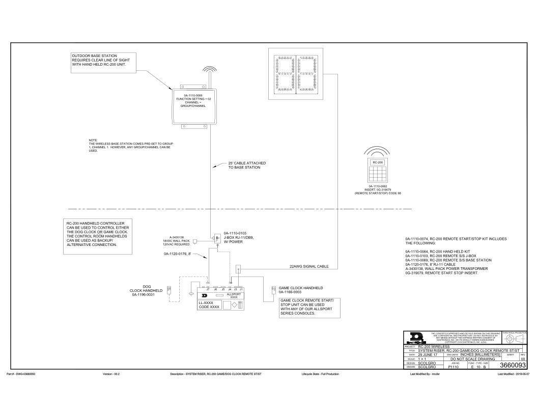
CLOCK HANDHELDDOG
0A-1196-0031 ALLSPORT
J7 J6 J5 J4 J3
CODE XXXXLL-XXXX
J1
XXXX
0A-1110-0103J-BOX RJ-11/DB9,W/ POWER
0A-1110-0062INSERT: 0G-319079
(REMOTE START/STOP) CODE 98
NOTE:THE WIRELESS BASE STATION COMES PRE-SET TO GROUP1, CHANNEL 1. HOWEVER, ANY GROUP/CHANNEL CAN BEUSED.
0A-1110-0069 FUNCTION SETTING = 02
CHANNEL =GROUP/CHANNEL
0A-1120-0176, 8'
25' CABLE ATTACHEDTO BASE STATION
OUTDOOR BASE STATIONREQUIRES CLEAR LINE OF SIGHTWITH HAND HELD RC-200 UNIT.
GAME CLOCK REMOTE START/STOP UNIT CAN BE USEDWITH ANY OF OUR ALLSPORTSERIES CONSOLES.
0A-1110-0074, RC-200 REMOTE START/STOP KIT INCLUDESTHE FOLLOWING:
0A-1110-0064, RC-200 HAND HELD KIT0A-1110-0103, RC-200 REMOTE S/S J-BOX0A-1110-0069, RC-200 REMOTE S/S BASE STATION0A-1120-0176, 8' RJ-11 CABLEA-3430138, WALL PACK POWER TRANSFORMER0G-319079, REMOTE START STOP INSERT.
GAME CLOCK HANDHELD0A-1166-0003
RC-200
RC-200 HANDHELD CONTROLLERCAN BE USED TO CONTROL EITHERTHE DOG CLOCK OR GAME CLOCK.THE CONTROL ROOM HANDHELDSCAN BE USED AS BACKUP/ALTERNATIVE CONNECTION.
22AWG SIGNAL CABLE
THE CONCEPTS EXPRESSED AND DETAILS SHOWN ON THIS DRAWINGARE CONFIDENTIAL AND PROPRIETARY. DO NOT REPRODUCE BY
ANY MEANS WITHOUT THE EXPRESS WRITTEN CONSENT OFDAKTRONICS, INC. OR ITS WHOLLY OWNED SUBSIDIARIES.
COPYRIGHT 2016 DAKTRONICS, INC. (USA)
THIRD ANGLE PROJECTION
BH
REV
TITLE:
PROJECT:
INCHES [MILLIMETERS]
DESIGN:
SCALE:
DIM UNITS:DATE: SHEET
DO NOT SCALE DRAWINGFUNC - TYPE - SIZE
DRAWN: -JOB NO.
-
RC-200 WIRELESSSYSTEM RISER, RC-200 GAME/DOG CLOCK REMOTE ST/ST
SCOLGRO
29 JUNE 17
P1110 E 10 B
1 = 1SCOLGRO 3660093
00
A-343013818VDC WALL PACK.120VAC REQUIRED.
PPaarrtt ## -- DDWWGG--0033666600009933 VVeerrssiioonn -- 0000..22 DDeessccrriippttiioonn -- SSYYSSTTEEMM RRIISSEERR,, RRCC--220000 GGAAMMEE//DDOOGG CCLLOOCCKK RREEMMOOTTEE SSTT//SSTT LLiiffeeccyyccllee SSttaattee -- FFuullll PPrroodduuccttiioonn LLaasstt MMooddiiffiieedd BByy -- mmrruuffeerr LLaasstt MMooddiiffiieedd -- 22001199--0055--0077

Sport Inserts57
B Sport InsertsRefer to Resources (p�1) for information regarding how to read the drawing number.
Reference Drawings:Insert; LL-2608, RC-100, Rodeo .......................................................................... DWG-231529Insert: LL-2605- RC-100- Baseball ....................................................................... DWG-231530Insert; LL-2607, RC-100, Tennis ............................................................................ DWG-231531Insert; LL-2606, RC-100, Judges Console .......................................................... DWG-231532Custom Insert; Volleyball, RC-100 ..................................................................... DWG-239304Insert; LL-2613, RC-100 Clock/Score ................................................................. DWG-239307Insert; LL-2613 Back, RC-100 Segment Timer .................................................... DWG-247621Insert, LL-2632, RC-100, Basketball .................................................................... DWG-253583Insert; LL-2653, RC-100 Play Clock ..................................................................... DWG-280870Insert; LL-2663, RC-100 Goal Judge .................................................................. DWG-298780Insert: Custom- RC-100- Start/Stop Remote ..................................................... DWG-319079Insert; Custom, RC-100, Football ..................................................................... DWG-1031603

This page intentionally left blank.


HOMEGUEST


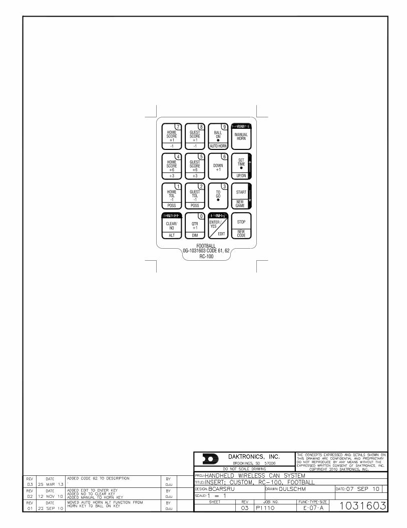

Daktronics Warranty and Limitation of Liability71
C Daktronics Warranty and Limitation of LiabilityThis section includes the Daktronics Warranty & Limitation of Liability statement (SL-02374)�

This page intentionally left blank.

DAKTRONICS WARRANTY & LIMITATION OF LIABILITY
SL-02374 Rev 14 13 January 2020 Page 1 of 3 Copyright © Daktronics, Inc.
This Warranty and Limitation of Liability (the “Warranty”) sets forth the warranty provided by Daktronics with respect to the Equipment. By accepting delivery of the Equipment, Purchaser and End User agree to be bound by and accept these terms and conditions. Unless otherwise defined herein, all terms within the Warranty shall have the same meaning and definition as provided elsewhere in the Agreement. DAKTRONICS WILL ONLY BE OBLIGATED TO HONOR THE WARRANTY SET FORTH IN THESE TERMS AND CONDITIONS UPON RECEIPT OF FULL PAYMENT FOR THE EQUIPMENT
1. Warranty Coverage.
A. Daktronics warrants to the original end user (the “End User”, which may also be the Purchaser) that the Equipment will be free from Defects (as defined below) in materials and workmanship for a period of one (1) year (the “Warranty Period”). The Warranty Period shall commence on the earlier of: (i) four weeks from the date that the Equipment leaves Daktronics’ facility; or (ii) Substantial Completion as defined herein. The Warranty Period shall expire on the first anniversary of the commencement date.
“Substantial Completion” means the operational availability of the Equipment to the End User in accordance with the Equipment’s specifications, without regard to punch-list items, or other non-substantial items which do not affect the operation of the Equipment
B. Daktronics’ obligation under this Warranty is limited to, at Daktronics’ option, replacing or repairing, any Equipment or part thereof that is found by Daktronics not to conform to the Equipment’s specifications. Unless otherwise directed by Daktronics, any defective part or component shall be returned to Daktronics for repair or replacement. This Warranty does not include on-site labor charges to remove or install these components. Daktronics may, at its option, provide on-site warranty service. Daktronics shall have a reasonable period of time to make such replacements or repairs and all labor associated therewith shall be performed during regular working hours. Regular working hours are Monday through Friday between 8:00 a.m. and 5:00 p.m. at the location where labor is performed, excluding any holidays observed by Daktronics.
C. Daktronics shall pay ground transportation charges for the return of any defective component of the Equipment. All such items shall be shipped by End User DDP Daktronics designated facility per Incoterms® 2020. If returned Equipment is repaired or replaced under the terms of this Warranty, Daktronics will prepay ground transportation charges back to End User and shall ship such items DDP End User’s designated facility per Incoterms® 2020; otherwise, End User shall pay transportation charges to return the Equipment back to the End User and such Equipment shall be shipped Ex Works Daktronics designated facility per Incoterms® 2020. All returns must be pre-approved by Daktronics before shipment. Daktronics shall not be obligated to pay freight for any unapproved return. End User shall pay any upgraded or expedited transportation charges
D. Any replacement parts or Equipment will be new or serviceably used, comparable in function and performance to the original part or Equipment and warranted for the remainder of the Warranty Period. Purchasing additional parts or Equipment from the Seller does not extend the Warranty Period.
E. Defects shall be defined as follows. With regard to the Equipment (excepting LEDs), a “Defect” shall refer to a material variance from the design specifications that prohibit the Equipment from operating for its intended use. With respect to LEDs, “Defects” are defined as LED pixels that cease to emit light. Unless otherwise expressly provided, this Warranty does not impose any duty or liability upon Daktronics for partial LED pixel degradation. Notwithstanding the foregoing, in no event does this Warranty include LED pixel degradation caused by UV light. This Warranty does not provide for the replacement or installation of communication methods including but not limited to, wire, fiber optic cable, conduit, trenching, or for the purpose of overcoming local site interference radio equipment substitutions.
EXCEPT AS OTHERWISE EXPRESSLY SET FORTH IN THIS WARRANTY, TO THE MAXIMUM EXTENT PERMITTED BY APPLICABLE LAW, DAKTRONICS DISCLAIMS ANY AND ALL OTHER PROMISES, REPRESENTATIONS AND WARRANTIES APPLICABLE TO THE EQUIPMENT AND REPLACES ALL OTHER WARRANTIES OR CONDITIONS, EXPRESS OR IMPLIED, INCLUDING, BUT NOT LIMITED TO, ANY IMPLIED WARRANTIES OR CONDITIONS OF MERCHANTABILITY, FITNESS FOR A PARTICULAR PURPOSE, OR ACCURACY OR QUALITY OF DATA. OTHER ORAL OR WRITTEN INFORMATION OR ADVICE GIVEN BY DAKTRONICS, ITS AGENTS OR EMPLOYEES, SHALL NOT CREATE A WARRANTY OR IN ANY WAY INCREASE THE SCOPE OF THIS LIMITED WARRANTY.
THIS LIMITED WARRANTY IS NOT TRANSFERABLE.
2. Exclusion from Warranty Coverage
This Warranty does not impose any duty or liability upon Daktronics for any:
A. damage occurring at any time, during shipment of Equipment unless otherwise provided for in the Agreement. When returning Equipment to Daktronics for repair or replacement, End User assumes all risk of loss or damage, agrees to use any shipping containers that might be provided by Daktronics, and to ship the Equipment in the manner prescribed by Daktronics;
B. damage caused by: (i)the improper handling, installation, adjustment, use, repair, or service of the Equipment, or (ii) any physical damage which includes, but is not limited to, missing, broken, or cracked components resulting from non-electrical causes;
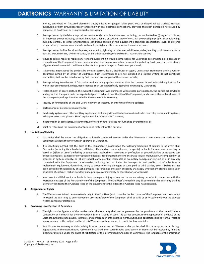
DAKTRONICS WARRANTY & LIMITATION OF LIABILITY
SL-02374 Rev 14 13 January 2020 Page 2 of 3 Copyright © Daktronics, Inc.
altered, scratched, or fractured electronic traces; missing or gauged solder pads; cuts or clipped wires; crushed, cracked, punctured, or bent circuit boards; or tampering with any electronic connections, provided that such damage is not caused by personnel of Daktronics or its authorized repair agents;
C. damage caused by the failure to provide a continuously suitable environment, including, but not limited to: (i) neglect or misuse; (ii) improper power including, without limitation, a failure or sudden surge of electrical power; (iii) improper air conditioning, humidity control, or other environmental conditions outside of the Equipment’s technical specifications such as extreme temperatures, corrosives and metallic pollutants; or (iv) any other cause other than ordinary use;
D. damage caused by fire, flood, earthquake, water, wind, lightning or other natural disaster, strike, inability to obtain materials or utilities, war, terrorism, civil disturbance, or any other cause beyond Daktronics’ reasonable control;
E. failure to adjust, repair or replace any item of Equipment if it would be impractical for Daktronics personnel to do so because of connection of the Equipment by mechanical or electrical means to another device not supplied by Daktronics, or the existence of general environmental conditions at the site that pose a danger to Daktronics personnel;
F. statements made about the product by any salesperson, dealer, distributor or agent, unless such statements are in a written document signed by an officer of Daktronics. Such statements as are not included in a signed writing do not constitute warranties, shall not be relied upon by End User and are not part of the contract of sale;
G. damage arising from the use of Daktronics products in any application other than the commercial and industrial applications for which they are intended, unless, upon request, such use is specifically approved in writing by Daktronics;
H. replenishment of spare parts. In the event the Equipment was purchased with a spare parts package, the parties acknowledge and agree that the spare parts package is designed to exhaust over the life of the Equipment, and as such, the replenishment of the spare parts package is not included in the scope of this Warranty;
I. security or functionality of the End User’s network or systems, or anti-virus software updates;
J. performance of preventive maintenance;
K. third-party systems and other ancillary equipment, including without limitation front-end video control systems, audio systems, video processors and players, HVAC equipment, batteries and LCD screens;
L. incorporation of accessories, attachments, software or other devices not furnished by Daktronics; or
M. paint or refinishing the Equipment or furnishing material for this purpose.
3. Limitation of Liability
A. Daktronics shall be under no obligation to furnish continued service under this Warranty if alterations are made to the Equipment without the prior written approval of Daktronics.
B. It is specifically agreed that the price of the Equipment is based upon the following limitation of liability. In no event shall Daktronics (including its subsidiaries, affiliates, officers, directors, employees, or agents) be liable for any claims asserting or based on (a) loss of use of the facility or equipment; lost business, revenues, or profits; loss of goodwill; failure or increased cost of operations; loss, damage or corruption of data; loss resulting from system or service failure, malfunction, incompatibility, or breaches in system security; or (b) any special, consequential, incidental or exemplary damages arising out of or in any way connected with the Equipment or otherwise, including but not limited to damages for lost profits, cost of substitute or replacement equipment, down time, injury to property or any damages or sums paid to third parties, even if Daktronics has been advised of the possibility of such damages. The foregoing limitation of liability shall apply whether any claim is based upon principles of contract, tort or statutory duty, principles of indemnity or contribution, or otherwise
C. In no event shall Daktronics be liable for loss, damage, or injury of any kind or nature arising out of or in connection with this Warranty in excess of the Purchase Price of the Equipment. The End User’s remedy in any dispute under this Warranty shall be ultimately limited to the Purchase Price of the Equipment to the extent the Purchase Price has been paid.
4. Assignment of Rights
A. The Warranty contained herein extends only to the End User (which may be the Purchaser) of the Equipment and no attempt to extend the Warranty to any subsequent user-transferee of the Equipment shall be valid or enforceable without the express written consent of Daktronics.
5. Governing Law; Election of Remedies
A. The rights and obligations of the parties under this Warranty shall not be governed by the provisions of the United Nations Convention on Contracts for the International Sales of Goods of 1980. The parties consent to the application of the laws of the State of South Dakota to govern, interpret, and enforce each of the parties’ rights, duties, and obligations arising from, or relating in any manner to, the subject matter of this Warranty, without regard to conflict of law principles.
B. Any dispute, controversy or claim arising from or related to this Warranty, the parties shall first attempt to settle through negotiations. In the event that no resolution is reached, then such dispute, controversy, or claim shall be resolved by final and binding arbitration under the Rules of Arbitration of the International Chamber of Commerce. The language of the arbitration

DAKTRONICS WARRANTY & LIMITATION OF LIABILITY
SL-02374 Rev 14 13 January 2020 Page 3 of 3 Copyright © Daktronics, Inc.
shall be English. The place of the arbitration shall be Sioux Falls, SD. A single arbitrator selected by the parties shall preside over the proceeding. If a single arbitrator cannot be agreed upon by the parties, each party shall select an arbitrator, and those arbitrators shall confer and agree on the appointed arbitrator to adjudicate the arbitration. The arbitrator shall have the power to grant any provisional or final remedy or relief that it deems appropriate, including conservatory measures and an award of attorneys’ fees. The arbitrator shall make its decisions in accordance with applicable law. By agreeing to arbitration, the Parties do not intend to deprive any court of its jurisdiction to issue a pre-arbitral injunction, pre-arbitral attachment, or other order in aid of arbitration proceedings and the enforcement of any award. Without prejudice to such provisional remedies as may be available under the jurisdiction of a court, the arbitrator shall have full authority to grant provisional remedies and to direct the Parties to request that any court modify or vacate any temporary or preliminary relief issued by such court, and to award damages for the failure of any Party to respect the arbitrator’s orders to that effect.
6. Availability of Extended Service Agreement
A. For End User’s protection, in addition to that afforded by the warranties set forth herein, End User may purchase extended warranty services to cover the Equipment. The Extended Service Agreement, available from Daktronics, provides for electronic parts repair and/or on-site labor for an extended period from the date of expiration of this warranty. Alternatively, an Extended Service Agreement may be purchased in conjunction with this Warranty for extended additional services. For further information, contact Daktronics Customer Service at 1-800-DAKTRONics (1-800-325-8766).
Additional Terms applicable to sales outside of the United States
The following additional terms apply only where the installation site of the Equipment is located outside of the United States of America.
1. In the event that the installation site of the Equipment is in a country other than the U.S.A., then, notwithstanding Section 5 of the Warranty, where the selling entity is the entity listed in Column 1, then the governing law of this Warranty is the law of the jurisdiction listed in the corresponding row in Column 2 without regard to its conflict of law principles. Furthermore, if the selling entity is an entity listed in Column 1, then the place of arbitration is listed in the corresponding row in Column 3.
Column 1 (Selling Entity)
Column 2 (Governing Law)
Column 3 (Location of Arbitration)
Daktronics, Inc. The state of Illinois Chicago, IL, U.S.A. Daktronics Canada, Inc. The Province of Ontario, Canada Toronto, Ontario, Canada Daktronics UK Ltd. England and Wales Bristol, UK Daktronics GmbH The Federal Republic of Germany Wiesbaden, Germany Daktronics Hong Kong Limited Hong Kong, Special Administrative Region of the P.R.C. Hong Kong SAR Daktronics Shanghai Co., Ltd. The Peoples Republic of China Shanghai, P.R.C. Daktronics France, SARL France Paris, France Daktronics Japan, Inc. Japan Tokyo, Japan Daktronics International Limited Macau, Special Administrative Region of the P.R.C. Macau SAR Daktronics Australia Pad Ltd Australia Sydney, Australia Daktronics Singapore Pte. Ltd Singapore Singapore Daktronics Brazil LTDA Brazil São Paulo, Brazil Daktronics Spain S.L.U. Spain Madrid, Spain Daktronics Belgium N. V Belgium Kruibeke, Belgium Daktronics Ireland Co. Ltd. Ireland Dublin, Ireland

This page intentionally left blank.