REMANUFACTURED CNC BENDER CHIYODA SP-15
50
REMANUFACTURED CNC BENDER CHIYODA SP-15 JOHNSON CONTROLS SMT SO# 22760/22760A 10/05/2005 OPERATOR CONTROLS & PROGRAMMING MANUAL
-
Upload
khangminh22 -
Category
Documents
-
view
0 -
download
0
Transcript of REMANUFACTURED CNC BENDER CHIYODA SP-15

REMANUFACTURED CNC BENDER
CHIYODA SP-15JOHNSON CONTROLS
SMT SO# 22760/22760A
10/05/2005
OPERATOR CONTROLS &PROGRAMMING MANUAL


THIS EQUIPMENT MAY CAUSE INJURY IF NOT
USED AS INTENDED, OR IF BODY OR FOREIGN
MATERIAL IS EXPOSED TO IT.
THIS MACHINE IS TO BE OPERATED WITH
ALL GUARDING IN PLACE. FAILURE TO DO
SO MAY RESULT IN INJURY ! !
DO NOT BYPASS SAFETY DEVICES OR
SENSORS OR ALTER THEIR INTENDED USE!
WORK ON EQUIPMENT SHOULD BE
PERFORMED BY QUALIFIED PERSONNEL;
WITH ALL ELECTRIC, AIR, AND HYDRAULIC
DEVICES OFF AND LOCKED IN OFF POSITION !
DO NOT ATTEMPT TO UNJAM MACHINE OR
FREE PARTS FROM MACHINE WITH ANY PART
OF THE BODY, OR WHILE MACHINE IS UNDER
POWER ! !


CNC Bender User Manual Page 3
Advanced Tubular Technologies, Inc.
CNC Bender User Manual Version: 10.0.2.5
Version Date: July 22, 2004
Michael B. Cone

CNC Bender User Manual Page 4
Advanced Tubular Technologies Press
5499 Perry Drive, Unit J
Waterford, Michigan 48329 248.674.2059 248.674.2157 (fax) Published by Advanced Tubular Technologies in
association with SMT Industries, Inc.
COPYRIGHT
Copyright © 2004 by Advanced Tubular Technologies,
Inc.
All rights reserved. No part of this book may be reproduced or transmitted in any form or by any means, electronic, mechanical, photocopying, recording, or otherwise, without prior written permission of Advanced Tubular Technologies, Inc.
TRADEMARKS
CNC Bender, CNC Processor, CNC Mobile, and Benderlink are trademarks of Advanced Tubular Technologies, Inc.

CNC Bender User Manual Page 5
Credits
AuthorMichael B. Cone, Advanced Tubular Technologies, Inc.
CompositorJohn W. Esralian, Advanced Tubular Technologies, Inc.
Technical Review Jeff Tucker, SMT Industries, Inc. David L. Keener, SMT Industries, Inc.
Software Developers Michael B. Cone, Advanced Tubular Technologies, Inc. Mathew B. Parker, Advanced Tubular Technologies, Inc.

CNC Bender User Manual Page 6

CNC BENDER Revision Document Version 10.0.2.6, August 30, 2004
Page 1 of 3
CNC BENDER Revision Document
Version 10.0.2.6 August 30, 2004

CNC BENDER Revision Document Version 10.0.2.6, August 30, 2004
Page 2 of 3
��
ENHANCED SAFETY MAT MODE ACTIVATION
During SAFETY MAT activation, all axes are now disabled while the bender remains running. - All axes will stop immediately because CNC
Bender HALTS then DISABLES ALL AXES in this new version of CNC Bender. (Older versions only applied the HALT command.)
- If moving, the FEED and ROTATE axes will often generate a fault if the mat is stepped activated.
- The BEND and HORIZONTAL HEAD axes will stop immediately but will not generate a fault.
- You can confirm that this new feature is active by viewing the Axis ENABLE states in either the processor menu or the module status menu. The moment you step on the mat, the ENABLE states should all switch to disabled immediately without shutting down the bender.
CYCLE START ISSUE RESOLVED
The Cycle Start activation problem is resolved. - The problem where the users had to press the
Cycle Start button twice coming out of cycle hold is repaired.
- The Cycle Start and Cycle Hold buttons are activated more quickly now than in older versions of CNC Bender.
ROTATE AXIS HALT
The Rotate axis will now halt when the manual HALT buttons are pressed.
CNC BENDER Revision Document Version 10.0.2.6, August 30, 2004
Page 3 of 3
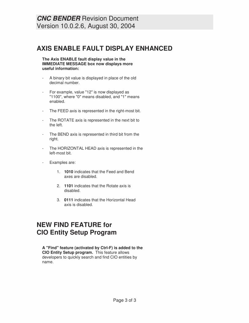
AXIS ENABLE FAULT DISPLAY ENHANCED
The Axis ENABLE fault display value in the IMMEDIATE MESSAGE box now displays more useful information: - A binary bit value is displayed in place of the old
decimal number.
- For example, value "12" is now displayed as "1100", where "0" means disabled, and "1" means enabled.
- The FEED axis is represented in the right-most bit.
- The ROTATE axis is represented in the next bit to the left.
- The BEND axis is represented in third bit from the right.
- The HORIZONTAL HEAD axis is represented in the left-most bit.
- Examples are:
1. 1010 indicates that the Feed and Bend
axes are disabled.
2. 1101 indicates that the Rotate axis is disabled.
3. 0111 indicates that the Horizontal Head axis is disabled.
NEW FIND FEATURE for CIO Entity Setup Program
A "Find" feature (activated by Ctrl-F) is added to the CIO Entity Setup program. This feature allows developers to quickly search and find CIO entities by name.�


CNC BENDER Revision DocumentVersion 10.0.2.7, August 31, 2004
Page 1 of 2
CNC BENDER
Revision Document
Version 10.0.2.7August 31, 2004

CNC BENDER Revision DocumentVersion 10.0.2.7, August 31, 2004
Page 2 of 2
ENHANCED CNC PROCESSORRANGE ERROR CHECK
CNC Processor will now range-error check for thepressure die boost NOT RETURNED if the bend arm isabout to return to zero degrees from a forward position.
- If the check finds that the pressure die boost is not home,then CNC Processor will report a range error with amessage in the Immediate Message box.
- The safety feature is added to prevent any accidentalcrash of the bend arm into the extended pressure dieboost slide if operators forget to separate the pressure dieand clamp return movements while using the ArC releasefeature.
- If this check fails, then CNC Processor will halt thebending process.
- The condition where this could occur is if the operator hasselected:
o
o If Pressure Die AND Clamp return is selectedin the last B cell of the FRB data, then thepressure die will not open until the clamp opens.The pressure die boost will not return to itshome position. The arm will crash into theextended pressure die.
- ArC means that the clamp continues to hold the partwhile the bend arm returns to its home position. The partis rotated back with the arm. Then the release button isrequested.
- Select Pressure Die THEN Clamp Return in the last Bcell of the FRB data when using this release mode. Thisoption separates the pressure die and clamp returnmovements into two moves. The pressure die opens andthe pressure die boost returns before the arm returnshome. Then the release button is requested.
- Note: Our customers use the ArC part release feature tomake unloading easier and safer presenting the part tothe operator in a more optimum position for unloading.Then the release button is requested.

CNC BENDER Revision DocumentVersion 10.0.2.8, September 21, 2004
Page 1 of 10
CNC BENDERRevision Document
Version 10.0.2.8September 21, 2004

CNC BENDER Revision DocumentVersion 10.0.2.8, September 21, 2004
Page 2 of 10
SAFETY ENHANCEMENTfor CNC PROCESSORduring RUN HALT PROCESS
CNC Processor will now stop all active outputs in thecurrent process list command during RUN HALTS.
- This feature is added to ensure that all outputs in thecurrent command are switched OFF if the bendingprocess is stopped by the internal error-checking logic.
- For example, the pressure die boost output will now bedeactivated if a bend range-error is detected and theprocess is halted.

CNC BENDER Revision DocumentVersion 10.0.2.8, September 21, 2004
Page 3 of 10
NEW HELP FILE ADDED
The following help file is added to the c:\cnc\config\helpfolder:
Option_EnableBendDieReturnLogic.rtf
NEW CIO Objects ADDED
The following CIO objects were added to the CIOdictionary file (c:\cnc\config\cio\Main CIO Dictionary.ciolost):
Input_BendAlign_BeginInput_BendAlign_EndOutput_BendAlign_RepeatOutput_BendDieAlign_OffOutput_Enable_ClampDieHighSpeed_ConstantOutput_Enable_PressureDieHighSpeed_Constant
These CIO objects must be imported into older CIOdictionaries in order for CNC Bender to compile aprocess list.
NEW COMDEF Objects ADDED
The following COMDEF files were added to the COMDEFfolder (c:\cnc\config\comdef):
PressureDieSpeedHigh.comdefClampDieSpeedHigh.comdefBendDieAlign.comdefBendDieAlignOff.comdef
These commands must be imported into older COMDEFfolders in order for CNC Bender to compile a process list.

CNC BENDER Revision DocumentVersion 10.0.2.8, September 21, 2004
Page 4 of 10
NEW BEND DIE ALIGN Feature
CNC Bender now supports BEND DIE ALIGNMENT forbenders with separate bend die return.
- The logic for handling the bend die alignment is enabledin the General Dynamic options in the Low Level Menu.The enable switch is labeled: Enable Bend Die ReturnLogic.
IN THE PROCESS LIST
If this feature is enabled, then the BendDieAlign command willbe added to the bending process list when it is compiled.
Logic in CNC Bender Process List:
- Check for the Bend axis position < 1 degree- Check for the Clamp HOME- Check for Bend Aligned input not yet activated- Activate the output for the Bend Die Align actuator- Until the Bend Aligned input is true- Then deactivate the Bend Die Align actuator output
Example process list snippet:
// ** Adding COMDEF Group Bend Die Align **[IF] AND, pos(3)<1.000, input=Input_ClampIsHome_End, input=not(Input_BendAlign_End)
[DISPLAY] Next Step: (Part Origination) Return the Bend Die Before ClampingBendDieAlign = cto:6000[DISPLAY] Completed: (Part Origination) Return the Bend Die Before Clamping
[END]// ** End of COMDEF Group Bend Die Align **
IN THE MANUAL PAGE
The feature is built into the Manual Jogs 2 page.
If the CLAMP ADVANCE command is issued, then theBend Aligned input (prox switch) must be ENABLED.
If the BEND DIE ALIGN command is issued, then theCLAMP must be HOME, and the BEND ARM POSITIONless than 1 degree before the output is activated.
CNC BENDER Revision DocumentVersion 10.0.2.8, September 21, 2004
Page 5 of 10
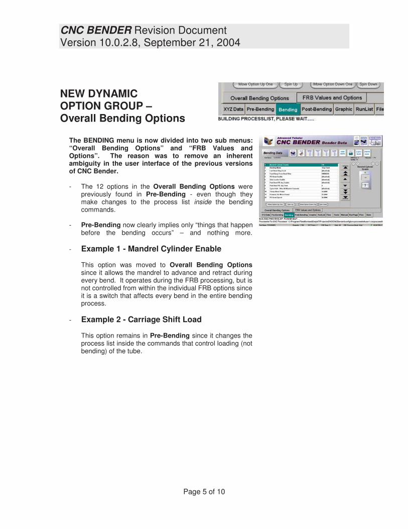
NEW DYNAMICOPTION GROUP –Overall Bending Options
The BENDING menu is now divided into two sub menus:“Overall Bending Options” and “FRB Values andOptions”. The reason was to remove an inherentambiguity in the user interface of the previous versionsof CNC Bender.
- The 12 options in the Overall Bending Options werepreviously found in Pre-Bending - even though theymake changes to the process list inside the bendingcommands.
- Pre-Bending now clearly implies only “things that happenbefore the bending occurs” – and nothing more.
- Example 1 - Mandrel Cylinder Enable
This option was moved to Overall Bending Optionssince it allows the mandrel to advance and retract duringevery bend. It operates during the FRB processing, but isnot controlled from within the individual FRB options sinceit is a switch that affects every bend in the entire bendingprocess.
- Example 2 - Carriage Shift Load
This option remains in Pre-Bending since it changes theprocess list inside the commands that control loading (notbending) of the tube.

CNC BENDER Revision DocumentVersion 10.0.2.8, September 21, 2004
Page 6 of 10
ADDED CONTROL for PRESSUREPOWER During Bending
Now the Clamp and Pressure Die Power values can becontrolled during the die closing event.
The Clamp Move Power, Pressure Die Move Power, and thePD Boost Speed values in the Overall Bending Optionsmenu are values that are now used throughout the bendingprocess repeatedly before every die close event.
When pressure or speed control is available on SMTbenders, this new feature gives the operator the ability to close the dies at pressure lowerthan the system pressure.
This is a sample of a process list (see below) that was builtusing the values shown above. Before the AllDiesClosecommand is issued, the Clamp and Pressure Die powersare set to the values shown in the Overall Bending Optionsmenu.
After the dies are closed, and before bending begins, thepressure powers change to the unique value that isprogrammed for that bend in the FRB page.

CNC BENDER Revision DocumentVersion 10.0.2.8, September 21, 2004
Page 7 of 10
NEW FEATURE -AUTOMATIC OLD CONFIGURATIONFILE - DETECTION AND UPDATE
During previous upgrades to new CNC Bender softwareversions, the end-user was required to perform a functionin LOW LEVEL menu that updated the dynamic optionsinto the latest format. The feature was called RESTOREOPTIONS in the LOW LEVEL SYSTEM menu.
CNC Bender now automatically detects when an olderconfiguration file exists and performs this update featureautomatically.
This is the dialog that will display when NEW versions of CNC Bender are run with olderversions of the main configuration file. The dialog will only display once after any softwareupgrade if it senses that the configuration file needs converting.

CNC BENDER Revision DocumentVersion 10.0.2.8, September 21, 2004
Page 8 of 10
FIX – File Save in FRB
The FILE SAVE feature in the FRB page wouldalways add a line to the Run List. This has beenrepaired.
Now it only saves the file.
ENHANCMENT – New ReportOption –Overall Bending
The Overall Bending Options are added to thereport choices in the REPORT menu.

CNC BENDER Revision DocumentVersion 10.0.2.8, September 21, 2004
Page 9 of 10
Post Bending RELEASE MODE logicMODIFIED in the Process ListCompiler
The release mode in Post Bending was modified so thatmodes 5 and 6 ALWAYS open the pressure die and returnthe boost before opening the clamp die.
Mode 5 - Bend Arm Homes, Press Release, Clamp OpensMode 6 - Arm Returns Home, Clamp Opens (Full Auto)
This is regardless of the PD/Clamp Open method is set.
OVERRIDE of PD/Clamp Open Mode
- The last BEND row option PD and Clamp Openmode has no effect on release modes 5 and 6.
- Both modes assume that the clamp die must remainclosed until after the bend arm homes.
- Also, since it is not possible for the bend arm tohome with the pressure die slide extended, it isnecessary for the pressure die and pressure dieboost to retract first regardless of the PD and ClampOpen mode.
Release Mode RTF Help FileMODIFIED
The following file was modified to reflect changes in therelease logic (see above) (It is found in folderc:\cnc\config\help):
Option_ReleaseMode.rtf

CNC BENDER Revision DocumentVersion 10.0.2.8, September 21, 2004
Page 10 of 10
COMDEF Objects MODIFIED
The following COMDEF files were modified to activate theHIGH PRESSURE output when activated (They are foundin folder c:\cnc\config\comdef):
PressureDieClose.comdefClampCloseComplete.comdefAllDiesClose.comdefMandrelRetract.comdef
The high pressure CIO object used automatically switches offat the end of the command.
Because of this change, HIGH PRESSURE CONSTANT ONin General Dynamic options has no appreciable effect on theoverall process when it is enabled unless all of the aboveCOMDEFs are modified to remove the high pressure outputenable.

CNC BENDER Revision Document Version 10.0.2.9, October 14, 2004
Page 1 of 8
CNC BENDER Revision Document
Version 10.0.2.9 October 14, 2004

CNC BENDER Revision Document Version 10.0.2.9, October 14, 2004
Page 2 of 8
�
TERMINOLOGY CHANGE - BENDING MODE is changed to FEED-BENDING Mode
1. Stop Feed is changed to Feed Boost 2. Hitch Feed is changed to Feed Rechuck
They are functionally the same options.
NEW HELP FILES ADDED
The following help file is added to the c:\cnc\config\help folder:
Option_FeedBendingMode.rtf
Option_LastBendFeedBoost.rtf Option_EarlyMandrelSafetyOff.rtf Option_OverallBend_DiesLowSpeedEnabled.rtf
HELP FILES MODIFIED
The following help file is added to the c:\cnc\config\help folder:
Option_MandrelEarlyAdvance.rtf
CNC BENDER Revision Document Version 10.0.2.9, October 14, 2004
Page 3 of 8
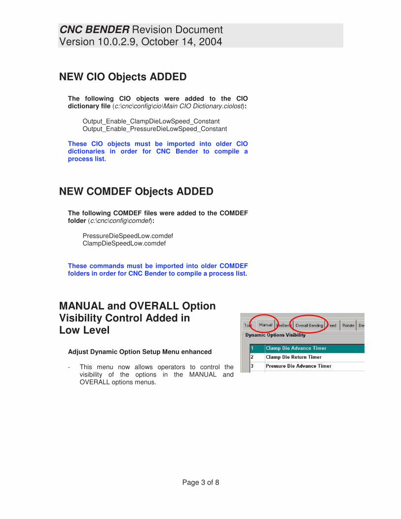
NEW CIO Objects ADDED
The following CIO objects were added to the CIO dictionary file (c:\cnc\config\cio\Main CIO Dictionary.ciolost):
Output_Enable_ClampDieLowSpeed_Constant Output_Enable_PressureDieLowSpeed_Constant
These CIO objects must be imported into older CIO dictionaries in order for CNC Bender to compile a process list.
NEW COMDEF Objects ADDED
The following COMDEF files were added to the COMDEF folder (c:\cnc\config\comdef):
PressureDieSpeedLow.comdef ClampDieSpeedLow.comdef
These commands must be imported into older COMDEF folders in order for CNC Bender to compile a process list.
MANUAL and OVERALL Option Visibility Control Added in Low Level
Adjust Dynamic Option Setup Menu enhanced - This menu now allows operators to control the
visibility of the options in the MANUAL and OVERALL options menus.

CNC BENDER Revision Document Version 10.0.2.9, October 14, 2004
Page 4 of 8
New DIE LOW SPEED option In OVERALL Added
This option allows benders with a low speed capability to shift the dies to low speed mode during the entire bend process. The new option is found in the Overall Bending Options menu.
IN THE PROCESS LIST
This is an example snapshot of the new commands that the new option adds to the process list:
IN THE MANUAL PAGE
The feature is also built into the Manual Jogs 1 page with a new button above the Constant On button. It is named “Low Speed Dies”. When this button is enabled, all Clamp and Pressure Die CLOSE movements will run in LOW SPEED if this option is available on the bender.

CNC BENDER Revision Document Version 10.0.2.9, October 14, 2004
Page 5 of 8
FIX - CYCLE START INDEX is RESET AFTER FIRST USE
The CYCLE START INDEX is now always reset to 1 after being instructed to start in the middle of process list.
ENHANCED Select CYCLE START INDEX Menu
The menu now displays STEP numbers in the left side of the list that correspond to the STEP numbers in the RUN PAGE. This helps operators find the appropriate starting line if they need to start in the middle of the bending process list.

CNC BENDER Revision Document Version 10.0.2.9, October 14, 2004
Page 6 of 8
NEW PREBEND OPTION – Mandrel Early Advance Safety OFF
The SAFETY feature is designed to place a RUN BUTTONS press request in the process list if Mandrel Early Advance in PreBend is ENABLED. However… - There are applications where this is not necessary. This
is especially true when the carriage is forward and the mandrel is sufficiently supported.
- This will remove the RUN BUTTONS request from the process list.
- The operator should confirm that the mandrel will not collide with the dies when this enabled. If the mandrel is advanced, and is caught in a die, tool damage could occur.

CNC BENDER Revision Document Version 10.0.2.9, October 14, 2004
Page 7 of 8
FIX – Now Clamp Die CLOSE is ALLOWED with Boost Safety Off
The Clamp Die is now allowed to move in the MANUAL page when the BOOST SAFETY is OFF. - This is true no matter what position the dies are in when the jog
request is made.
- The operator should confirm that the dies will not collide in the current condition before closing or opening the Clamp die.

CNC BENDER Revision Document Version 10.0.2.9, October 14, 2004
Page 8 of 8
FIX – FEED OPTIONS AUTO ADJUST RECAPTURE Distances now copy to the current Feed values properly.
The “This Feed Alone” buttons now properly copy the values to the option list.
CNC BENDER Revision DocumentVersion 10.0.3.8, April 22, 2005
Page 1 of 4
CNC BENDERRevision Document
Version 10.0.3.8April 22, 2005

CNC BENDER Revision DocumentVersion 10.0.3.8, April 22, 2005
Page 2 of 4
New Capabilityfor HSL1 Type Loaders
All of the additional objects and logicdescribed on this page were added to allowCNC Bender to move the carriage into theload position and chuck on the tube whilethe last bend is still being formed.
Added secondaryprocess lists for newsimultaneous motion forhopper sideloaders.
These secondary processes were added inorder to allow the carriage to move backand chuck on the tube while the last bendwas still being formed.
This secondary process list is built andenabled if these two conditions are true:
The secondary process list bender_readyexamines the Feed Axis on a recurring basisat the end of the main process list when theabsolute feed clearance is called. When thefeed axis is lower than Preload Position + 1mm, the bender is ready signal is set toTRUE.
This secondary process handles thecarriage move into the LOAD position and
chucking on the part while the last bend isstill forming. It is only active whenbender_ready is also active (sameconditions to activate).
New Logic for CNCCompilerThe new secondary processes put the partin the collet during the last bend, so CNCBender must not attempt to get anotherpart at the beginning of the next part sprocess list.
The new Auto Side Loader Chuck logicin the main process list prevents LOADFeed/Chuck motion if part is alreadypresent in the collet. This is only active ifPRELOAD is also being used. The Part inCollet input device must be installed.

CNC BENDER Revision DocumentVersion 10.0.3.8, April 22, 2005
Page 3 of 4
New Capabilityfor HSL1 Type Loaders
Previously, the feed axis would not startmoving toward the start position until theloader arm was completely OUT of thebender.
This takes too much time in someapplications so a new General (low level)option is added that allows CNC Bendercompiler to change the COMDEF calledfrom
With the Mid COMDEF replacing the OutCOMDEF in the process list, CNC Benderwill allow the FEED axis to start movingtoward the START position before theloader arm is fully out.
Added new CIO ObjectsThis CIO objects was added for the newcapability. Input module 4 (192.168.0.204),point 13 is unused, so this CIO wasassigned to that point.
Input_HSL1_SL_Mid_Begin
Added new COMDEFObjectsThis COMDEF object is added. It containsthe new CIO object above.
HSL1_WaitForLoaderMid

CNC BENDER Revision DocumentVersion 10.0.3.8, April 22, 2005
Page 4 of 4
Resolved CNC ProcessorProblem -
Feed Axis MovingBackward At End ofFeedBendBoost
CNC Processor no longer attempts toinstruct the slave axes that the currentposition is their new goal position at the endof multiple axes motion. This command wascausing the FEED axis to backup at the endof each FeedBendBoost command duringAUTO cycle in some applications, thuspotentially pulling the part out of the chuck.
If an improper RADIUS VALUE is enteredduring setup, then the FEED AXIS maynever come to position until the CLAMP andPD releases the tube shape. In this case,the FEED axis will most likely lurch in onedirection or another to make up for the erroraccumulated.
Resolve Cycle HoldIssue
Cycle Hold is now properly activated whenenabled after the last bend.
Added Error Check forthe MAIN.AXISLIST file
A new error check is performed whenloading the main.axislist configuration file tobe sure that it is setup properly.
New in CNC Processor
CNC Processor now switches to HIGHPRESSURE whenever trying to move axesduring a home process setup.

CNC BENDER Revision DocumentVer 10.0.3.9-10.0.4.1, June 8, 2005
Page 1 of 8
CNC BENDERRevision Document
Versions 10.0.3.9 - 10.0.4.1June 8, 2005
pdfMachine by Broadgun Software - a great PDF writer! - a great PDF creator! - http://www.pdfmachine.com http://www.broadgun.com

CNC BENDER Revision DocumentVer 10.0.3.9-10.0.4.1, June 8, 2005
Page 2 of 8
Version 10.0.3.9Issue Resolved-
Missing Presses of theCycle Start Button
CNC Bender Standard: IncludedCNC Bender Lite: Included
The Cycle Start button press logic waschanged significantly to prevent CNCBender from missing the event of anoperator pressing the CYCLE STARTbutton when CNC Processor is busyperforming other operations.
The new logic senses the button press inthe lowest level high-speed loop in CNCProcessor, stores the fact that the buttonpress occurred, and then handles therequest when CNC Processor is able todedicate time to the task.
The likelihood of missing the event is nowgreatly diminished � no matter how quicklythe button is pressed and released.
Version 10.0.3.9Logic Change -
Subservient Axes areNow Issued HALT WhenMaster is In Position
CNC Bender Standard: IncludedCNC Bender Lite: Included
The slave axes are now issued the HALTcommand when the MASTER axisindicates that it is in position.
This replaces the logic that attempted toreset the carriage position of slave axeswhen the MASTER came into position.The older logic would fail at times duringextreme system load, and cause thecarriage to jump backwards.
Version 10.0.3.9Issue Resolved-
Negative Bend Anglesare Now Prevented
CNC Bender Standard: IncludedCNC Bender Lite: Included
Even though negative bend angles werenever allowed in the process list, the FRBpage would allow them. This has beenchanged so that negative values entered byoperators are automatically converted to apositive number.
The Bend Adjust values still acceptnegative values.
The FEED and ROTATE values still acceptnegative values.

CNC BENDER Revision DocumentVer 10.0.3.9-10.0.4.1, June 8, 2005
Page 3 of 8
Version 10.0.3.9New Feature -
Master Part Storage
CNC Bender Standard: IncludedCNC Bender Lite: Included
Master part storageallows defaultMASTER data files tobe stored in a non-working area to allowoperators to tune partsetup in regular CNCBender data fileswithout disturbing theoriginal data.
This featuredecreases thepossibility thatsupervisors may haveto re-enter a part thatwas changed somuch by operatorsthat the original dataand intent of the filewas lost.
Version 10.0.4.0New Feature -NEW Button in File Page
CNC Bender Standard: IncludedCNC Bender Lite: Included
This new feature allows CNC Benderoperators to quickly reset CNC Bendermemory to a default starting setup.
Managers can setup CNC Bender withdefault settings using the System menu inthe Low Level page.
Sections and MANUAL OptionsSections can be reset independently. Alsomanual option values can be reset todefault value. CNC Bender will ask forchoice of sections before initializingmemory.

CNC BENDER Revision DocumentVer 10.0.3.9-10.0.4.1, June 8, 2005
Page 4 of 8
Version 10.0.4.0New Feature �
SAVE DefaultConfigurationin Low Level / System
CNC Bender Standard: IncludedCNC Bender Lite: Included
1. This new feature allows
operators to setup CNC Bender with default settings in order to
start a completely new part
with settings preset. The values in this file are used
when clearing the data in all of
CNC Bender and starting with a new part. (See NEW Button in
the previous page)
2. When a new FRB row is created
(through insertion or increasing the number of rows in setup),
the default settings found in the
default configuration FRB ROW 1 will be used to preset
all the values in the new row.
3. This file is used by CNC
Bender Lite to override any
incoming option settings that are marked as disabled in the
local CNC Bender setup.
For example, the incoming data
file may have the INSIDE SWING AWAY WIPER DIE
system ENABLED. But always
DISABLED is the only setting that makes sense for the
receiving bender because it has
no swing away inside wiper die mechanism installed.
Since this feature is disabled in
the bender that is receiving the
data file, it is critical that the incoming setting be overridden
by whatever value is in the
DEFAULT configuration file. In this case, the value would be
always DISABLED, regardless of the incoming value�s setting.
This feature prevents unwanted values and settings from being
accidentally enabled or changed
in CNC Bender Lite.
Version 10.0.4.0Issue Resolved -
Initialzation of OptionValues Not Present inIncoming Data Files
CNC Bender Standard: IncludedCNC Bender Lite: Included
The data structure in older files does nothave information for newer optionsbecause the new options do not exist in theolder versions of the control.
When the older data files were loaded intoa newer control, compiler errors wouldresult, due to the newer values not beinginitialized during load. The problem couldbe temporarily resolved by operator editingthose values in the numeric keypad. (Thiswould initialize the values.)
This issue has been resolved becauseCNC Bender now initializes even the newoption values that do not exist in the olderdata file. It is no longer necessary to editthe newer values in order for the processlist compiler to work properly.

CNC BENDER Revision DocumentVer 10.0.3.9-10.0.4.1, June 8, 2005
Page 5 of 8
Version 10.0.4.1Carriage Track AdvanceOption Moved to ToolOptions
CNC Bender Standard: IncludedCNC Bender Lite: Optional
Carriage Track Advance option is movedfrom the Low Level Machine menu to theTOOL page, and the process list compilerlogic was enhanced for more efficientoperation.
This enables a carriage track commandin the process list.
If enabled, the carriage track advance isused to move the carriage track awayfrom the bend die during:
1. Preload (always)
2. Load (always)
3. Start (always)
4. If Feed Away from Dies isenabled in Overall Bendingoptions, then the track is movedduring bending � even if radiusshifting is set to OFF.
Version 10.0.4.1Feature Change -New Order In Clipboard
CNC Bender Standard: IncludedCNC Bender Lite: Included
The keyboard clipboard values are nowre-ordered so that the most recent item isnow placed at the top of the pull-down list.All other items are now pushed down onein the list.
This ordering is more intuitive than theolder method of adding to the bottom of thelist.

CNC BENDER Revision DocumentVer 10.0.3.9-10.0.4.1, June 8, 2005
Page 6 of 8
Version 10.0.4.0Feed-Bend MotionAdjust Percent Option
CNC Bender Standard: IncludedCNC Bender Lite: Included
This OVERALL BENDING value will adjustthe Feed motion during FEED BENDINGby a percentage value to overcomeelongation.
Using a Value of ZEROA value of ZERO will cause no adjustmentin the Feed motion during Feed Bending.
Using a Value BELOW ZEROFor example, enter -5 (negative 5) toadjust the Feed motion during Feedbending by negative 5 percent.
Use this value will accommodate for...
1 - Extreme elongation that cause theFeed axis to jump after the motion iscomplete and the bend dies open.(Larger/stiffer tubes)
2 - Bowing of the smaller diameter tubes.
Decreasing the value too much will likelycause the tube to pull from the chuck.
Using a Value ABOVE ZEROFor example, enter 5 (positive 5) to move5 percent further during Feed Bending.
Increasing the value too much will causethe Feed to attempt to press further for
final position, not allowing it to come intoposition.
Version 10.0.4.1New Feature -Added New Pressure DieBoost Inhibit Zone
CNC Bender Standard: IncludedCNC Bender Lite: Included
There are now two PDB Inhibit Zones inevery Pressure Die Boost assisted bend.The new zone is Angle from Start. Thevalue is edited in the tool page either in themain menu or the dynamic options menu.

CNC BENDER Revision DocumentVer 10.0.3.9-10.0.4.1, June 8, 2005
Page 7 of 8
Version 10.0.4.1New Option -Dies Close Delay Enable
CNC Bender Standard: IncludedCNC Bender Lite: Optional
This new OVERALL BENDING optionallows a time-delayed pause before all dieclose motions.
The purpose of the feature is to allow otheractuators without proximity switches (likepossibly Carriage Track Advance) tocomplete their motion before the dies close.
EXCEPTION � Recapture -This delay does not affect the die closerelated to recapture. All other pressuredie close and clamp close motion isaffected.
BOTH Dies Open Rule -If either the pressure die or the clamp dieare already closed, then the delay isbypassed in the process list because it isassumed to be no longer necessary.
See Also - To set the value of this timerdelay, use Dies Close Delay Durationoption.
Version 10.0.4.1New Option -Dies Close DelayDuration
CNC Bender Standard: IncludedCNC Bender Lite: Optional
This new OVERALL BENDING optioncontrols the duration in milliseconds forthe Dies Close Delay.
CNC BENDER Revision DocumentVer 10.0.3.9-10.0.4.1, June 8, 2005
Page 8 of 8
Version 10.0.4.1New Option -Feed Torque/VelocityMode
CNC Bender Standard: IncludedCNC Bender Lite: Included
In: General Dynamic Options
This option is used to control what type ofmode the Feed axis uses during motion.
1 - Torque ModeThis is the standard mode. It allowstorque to be controlled by sending atorque value the Feed axis.
2 - Vel - Low/High TorqueThis mode is for VELOCITY modebenders. It always assumes that thetorque should be set to 100%, since thetorque setting in this mode controlsvelocity.
This is used on benders that require anoutput to be sent to the I2T module outputto indicate that the Feed axis is operatingin low or high torque.
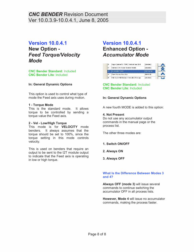
Version 10.0.4.1Enhanced Option -Accumulator Mode
CNC Bender Standard: IncludedCNC Bender Lite: Included
In: General Dynamic Options
A new fourth MODE is added to this option:
4. Not PresentDo not use any accumulator outputcommands in the manual page or theprocess list.
The other three modes are:
1. Switch ON/OFF
2. Always ON
3. Always OFF
What Is the Difference Between Modes 3and 4?
Always OFF (mode 3) will issue severalcommands to continue switching theaccumulator OFF in all process lists.
However, Mode 4 will issue no accumulatorcommands, making the process faster.

CNC BENDER REVISION
Revision: 10.0.5.0
Date: October 2005
1 - MOVED GLOBAL
BUTTONS
The AutoBuild, Runlist,
and Calculator buttons
are moved to a right-
side vertical toolbar
menu in CNC Bender
Data.
This gives operators
access to these buttons
from four more tab
menus. (XYZ, Pre-Bend,
Overall Bend, FRB, Post-
Bend)
pdfMachine by Broadgun Software - a great PDF writer! - a great PDF creator! - http://www.pdfmachine.com http://www.broadgun.com

Page 2 of 2 CNC Bender Rev 10.0.5.0
2 - NEW CUSTOM PROCESS INSERTION
BEFORE AND AFTER BENDS
Two new General Dynamic
Options are added that allow
anyone to insert custom
process list commands before
and/or after any bend arm
motion. The options allow six
choices each - "Disabled", or
"Custom Process 1" through
"Custom Process 5".
The Custom Process lists are
fixed filename filed found in the
c:\cnc\config\cncprocesslist
folder. The names use the form
"custom_process_before_bend_x.cncprocesslist" and
"custom_process_after_bend_x.cncprocesslist" where an integer from 1 to 5 is used in
place of the "x".
Please use care in selecting valid process list commands (either internal or external).

CNC BENDER REVISION
Revision: 10.0.5.1
Date: November 1 2005
1 � NEW HOME STATUS
PAGE
The new CNC Bender HOME
STATUS page is redesigned to
give more information about the
homing process than the old
home-process pages.
For example, the page shows the
current process list command
being run by CNC Processor, as
well as a list of previous
commands successfully run in the
COMMAND HISTORY box.
If a problem occurs, then
diagnosis is now much easier due
to this new information.
pdfMachine by Broadgun Software - a great PDF writer! - a great PDF creator! - http://www.pdfmachine.com http://www.broadgun.com

Page 2 of 4 CNC Bender Rev 10.0.5.1
2 - NEW EDGE TRIGGER LOGIC
CNC Bender now uses edge-trigger logic of
that feature is enabled in the CIO input.
The edge trigger insures that a button must
change from ON to OFF before switching
back ON.
This will prevent buttons being
tied to ON and allowing the
machine to continue. It will also
prevent machine operation if a
button is mechanically or
electronically stuck in the ON
position.
This feature can be applied to any
CIO input or output (if the output
is also examined as in input).
This logic should be applied to
buttons and pedals from this
point on in order to insure that
the buttons are released before
being pressed.

Page 3 of 4 CNC Bender Rev 10.0.5.1
3 � NEW ANALOG MODULE SETUP CAPABILITY
Schneider Electric Momentum digital to analog cards used
in SMT benders can control up to four actuators.
The maximum analog positive range of the card for each
channel is 0 to +10 volts, which is set using a digital
scale of 0 to 32000 in CNC Bender.
Previous versions of CNC Bender controlled the analog
output modules with one set of digital ranges for all four
channels. However, each actuator requires a unique
minimum and a unique maximum voltage for each actuator.
So CNC Bender is adjusted so that each channel can have
a different digital range. The digital ranges are set like
this in the analog_output.vml file: (These are example values)
// Channel 1 = PD Boost Speed
// 1.95v to 8.45v
Analog Module Digital Value For Zero Percent Voltage For Channel 1 = 6240
Analog Module Digital Value For 100 Percent Voltage For Channel 1 = 27040
// Channel 2 = PD Pressure
// 0.59v to 5.21v
Analog Module Digital Value For Zero Percent Voltage For Channel 2 = 1888
Analog Module Digital Value For 100 Percent Voltage For Channel 2 = 16672
// Channel 3 = Clamp Pressure
Analog Module Digital Value For Zero Percent Voltage For Channel 3 = 0
Analog Module Digital Value For 100 Percent Voltage For Channel 3 = 32000
// Channel 4 = PD Boost Pressure
// 0.61v to 5.0v
Analog Module Digital Value For Zero Percent Voltage For Channel 4 = 1952
Analog Module Digital Value For 100 Percent Voltage For Channel 4 = 16192

Page 4 of 4 CNC Bender Rev 10.0.5.1
4 � NEW LOGIC FOR NEW DISTINCTION BETWEEN PD BOOST PRESSURE
AND PD BOOST SPEED
CNC Bender was modified so
that it made a distinction
between Pressure Die Boost
PRESSURE and Pressure Die
Boost VELOCITY.
General Dynamic Options (in
low level) now includes
switches that will enable or disable each of these features.
CNC Bender�s Compiler now includes logic to control the PRESSURE and VELOCITY of the
PD Boost actuator if they are present (as set in the General Dynamic Options).
5 � OPTIMIZED PROCESS LIST COMPILING in CNCC32.EXE
Process list compilation was significantly optimized in order to save memory and shorten compilation time.