Release Planning Patterns for the Automotive Domain - MDPI
26
Citation: Marner, K.; Wagner, S.; Ruhe, G. Release Planning Patterns for the Automotive Domain. Computers 2022, 11, 89. https:// doi.org/10.3390/computers11060089 Academic Editor: Paolo Bellavista Received: 6 April 2022 Accepted: 27 May 2022 Published: 30 May 2022 Publisher’s Note: MDPI stays neutral with regard to jurisdictional claims in published maps and institutional affil- iations. Copyright: © 2022 by the authors. Licensee MDPI, Basel, Switzerland. This article is an open access article distributed under the terms and conditions of the Creative Commons Attribution (CC BY) license (https:// creativecommons.org/licenses/by/ 4.0/). computers Article Release Planning Patterns for the Automotive Domain Kristina Marner 1, * , Stefan Wagner 1 and Guenther Ruhe 2 1 Institute of Software Engineering, University of Stuttgart, 70569 Stuttgart, Germany; [email protected] 2 Software Engineering Decision Support Laboratory, University of Calgary, Calgary, AB T2N 1N4, Canada; [email protected] * Correspondence: [email protected] Abstract: Context: Today’s vehicle development is focusing more and more on handling the vast amount of software and hardware inside the vehicle. The resulting planning and development of the software especially confronts original equipment manufacturers (OEMs) with major challenges that have to be mastered. This makes effective and efficient release planning that provides the development scope in the required quality even more important. In addition, the OEMs have to deal with boundary conditions given by the OEM itself and the standards as well as legislation the software and hardware have to conform to. Release planning is a key activity for successfully developing vehicles. Objective: The aim of this work is to introduce release planning patterns to simplify the release planning of software and hardware installed in a vehicle. Method: We followed a pattern identification process that was conducted at Dr. Ing. h. c. F. Porsche AG. Results: We introduce eight release planning patterns, which both address the fixed boundary conditions and structure the actual planning content of a release plan. The patterns address an automotive context and have been developed from a hardware and software point of view based on two examples from the case company. Conclusions: The presented patterns address recurring problems in an automotive context and are based on real life examples. The gathered knowledge can be used for further application in practice and related domains. Keywords: release planning patterns; initial release plan; automotive 1. Introduction Nowadays, vehicles are part of a mobility ecosystem that consists of connectivity, shared mobility, e-mobility and app-based services [1]. Over-the-air connectivity enables a holistic ecosystem between vehicle, backend, external services, and the consumer world. The requirements related to automotive software will change and hardware and software development is exposed to a high dynamic to master the “data tsunami” [2]. The boundaries of the vehicle are increasingly crossed and the vehicle is part of the digital world. Thus, the software built into the vehicle becomes more and more important. The increasing amount of electronics and software in vehicles [3] as well as the growing complexity in this digital environment pose challenges for OEMs (original equipment manufacturers) that need to be managed not only technically but also in terms of planning and strategy. These new trends are accompanied by further problems for the OEMs and the resulting need for action in the vehicle development process. One of the key drivers towards facing the challenges in a technical way is the move towards a more centralized software and EE (electrical/electronic) architecture. A new type of vehicle electronics network is necessary to incorporate the vehicle seamlessly into the digital environment. That will be possible with new high-performance computing platforms (HPCP) that group the distributed functions within a vehicle in one computer [4]. OEMs benefit from a well-working release planning [5] because it allows them to respond to the increasing complexity within the vehicle development. Release planning is Computers 2022, 11, 89. https://doi.org/10.3390/computers11060089 https://www.mdpi.com/journal/computers
-
Upload
khangminh22 -
Category
Documents
-
view
0 -
download
0
Transcript of Release Planning Patterns for the Automotive Domain - MDPI
Citation: Marner, K.; Wagner, S.;
Ruhe, G. Release Planning Patterns
for the Automotive Domain.
Computers 2022, 11, 89. https://
doi.org/10.3390/computers11060089
Academic Editor: Paolo Bellavista
Received: 6 April 2022
Accepted: 27 May 2022
Published: 30 May 2022
Publisher’s Note: MDPI stays neutral
with regard to jurisdictional claims in
published maps and institutional affil-
iations.
Copyright: © 2022 by the authors.
Licensee MDPI, Basel, Switzerland.
This article is an open access article
distributed under the terms and
conditions of the Creative Commons
Attribution (CC BY) license (https://
creativecommons.org/licenses/by/
4.0/).
computers
Article
Release Planning Patterns for the Automotive DomainKristina Marner 1,* , Stefan Wagner 1 and Guenther Ruhe 2
1 Institute of Software Engineering, University of Stuttgart, 70569 Stuttgart, Germany;[email protected]
2 Software Engineering Decision Support Laboratory, University of Calgary, Calgary, AB T2N 1N4, Canada;[email protected]
* Correspondence: [email protected]
Abstract: Context: Today’s vehicle development is focusing more and more on handling the vastamount of software and hardware inside the vehicle. The resulting planning and development ofthe software especially confronts original equipment manufacturers (OEMs) with major challengesthat have to be mastered. This makes effective and efficient release planning that provides thedevelopment scope in the required quality even more important. In addition, the OEMs have todeal with boundary conditions given by the OEM itself and the standards as well as legislationthe software and hardware have to conform to. Release planning is a key activity for successfullydeveloping vehicles. Objective: The aim of this work is to introduce release planning patterns tosimplify the release planning of software and hardware installed in a vehicle. Method: We followeda pattern identification process that was conducted at Dr. Ing. h. c. F. Porsche AG. Results: Weintroduce eight release planning patterns, which both address the fixed boundary conditions andstructure the actual planning content of a release plan. The patterns address an automotive contextand have been developed from a hardware and software point of view based on two examplesfrom the case company. Conclusions: The presented patterns address recurring problems in anautomotive context and are based on real life examples. The gathered knowledge can be used forfurther application in practice and related domains.
Keywords: release planning patterns; initial release plan; automotive
1. Introduction
Nowadays, vehicles are part of a mobility ecosystem that consists of connectivity,shared mobility, e-mobility and app-based services [1]. Over-the-air connectivity enables aholistic ecosystem between vehicle, backend, external services, and the consumer world.The requirements related to automotive software will change and hardware and softwaredevelopment is exposed to a high dynamic to master the “data tsunami” [2]. The boundariesof the vehicle are increasingly crossed and the vehicle is part of the digital world. Thus,the software built into the vehicle becomes more and more important. The increasingamount of electronics and software in vehicles [3] as well as the growing complexity inthis digital environment pose challenges for OEMs (original equipment manufacturers)that need to be managed not only technically but also in terms of planning and strategy.These new trends are accompanied by further problems for the OEMs and the resultingneed for action in the vehicle development process. One of the key drivers towards facingthe challenges in a technical way is the move towards a more centralized software and EE(electrical/electronic) architecture. A new type of vehicle electronics network is necessary toincorporate the vehicle seamlessly into the digital environment. That will be possible withnew high-performance computing platforms (HPCP) that group the distributed functionswithin a vehicle in one computer [4].
OEMs benefit from a well-working release planning [5] because it allows them torespond to the increasing complexity within the vehicle development. Release planning is
Computers 2022, 11, 89. https://doi.org/10.3390/computers11060089 https://www.mdpi.com/journal/computers
Computers 2022, 11, 89 2 of 26
a key activity for developing products successfully. It describes the selection of an optimalsubset of features that will be implemented in a particular release [6]. At its core, releaseplanning aims to map the features to be developed to the releases to deliver the producton time. Release plans are numerous in software development and a release plan is partof every successful software development. Hardware and software release planning isessential to meet the challenges mentioned above and to remain competitive as an OEM [7].Not only is the increasing connectivity of vehicles reflected in the release plans, but alsothe given boundary conditions have an impact on the release planning. The automotiveindustry, as a highly regulated domain, must observe numerous conditions such as legalrequirements and fulfil the specifications of authorities to launch safe products on the road.For an OEM, it is essential to consider these boundary conditions in the release plan. Itis a basic requirement to deal with the structure of a release plan to develop a vehicle ontime and with high quality. This structure of a release plan includes the consideration ofnumerous constraints as well as the content to be planned.
To the best of our knowledge, there has been no research that discusses a releaseplanning structure in an automotive context. Furthermore, there are no approaches thatdemonstrate how to deal with the given conditions. In addition, there is a lack of proce-dures in both science and practice on how the respective planning content can be usefullystructured for hardware development as well as for software development. For this rea-son, we collected proven solutions in an abstract form as patterns. These patterns greatlysupport the handling of the challenges mentioned before. The presented results in thiswork have been developed at Dr. Ing. h. c. F. Porsche AG. The outcomes were generatedin cooperation with two projects of the case company. One project is such a new technol-ogy, a high-performance computing platform (HPCP), and the second project representsa software component (SWC) located on that HPCP. The patterns set up an initial releaseplanning structure considering the boundary conditions that comprise the timeline of arelease plan and deal with the scope to be planned. These two points form the researchquestion (RQ): What are suitable release planning patterns and visualisations for struc-turing time and other contents in a release plan? The patterns demonstrate, both fromthe point of view of an HPCP and as a software function, how the boundary conditionscan be tackled and how the respective planning content is structured in a release plan.The patterns intend to provide the user with a structured procedure to identify whichhard constraints imposed by an OEM have to be taken into account in the release plan.The results are primarily aimed at users who are responsible for an electric control unit(ECU) and who are function owners. The users’ tasks should also include release planning.While the patterns arose from an HPCP context, we are confident that they are applicableto other software/hardware contexts. The patterns are expected to achieve a better under-standing of the range of influencing factors with regard to the upcoming current softwareand hardware development. The complex release planning process can be divided intoindividual transparent tasks and provide the user with well-structured instructions whenusing the possibility offered by the patterns. Furthermore, we address in the discussionwhy release planning patterns should be considered from both a hardware and softwareperspective. Within this contribution, we present for the first time release planning patternsthat have also been applied in industry.
The remainder of this paper is structured as follows: In Section 2, we present re-lated work and background information. In Section 3 there are definitions for a betterunderstanding of the presented patterns and terms that are used in the pattern description.Section 4 contains the research approach and presents the pattern identification processas well as the pattern format. The release planning patterns for the boundary conditionsand the planning content are presented in Section 5. A discussion of the results is part ofSection 6. We conclude our work and outline future research in Section 7.
Computers 2022, 11, 89 3 of 26
2. Background and Related Work2.1. Strategic Framework and Influencing Factors to Release Planning
The software in an automobile is only one part of a mechatronic system consistingof electronics, mechatronics, and software. The development as well as the validation ofthis software is controlled by release planning [8]. Release planning as a tool to managegeneral planning, implementation, and control of a product [6] constitutes an optimiza-tion problem for companies [5]. According to [9] release planning is subject to numerousrestrictions, which can be divided into technical and non-technical influencing factors.The non-technical influencing factors [9] include, for example, the time horizon, whichrepresents the release cycle and defines the time interval in which the product is to bereleased. The non-technical dependencies can be extended by the strategic guidelines by anOEM as well as legal requirements and provide a strategic framework for the development.The automotive industry is a highly regulated domain that has to comply with numerousregulations and standards. Vehicle development follows a defined generic product develop-ment process, which is divided into several phases and different milestones. The strategictargets are defined specifically for OEMs and contain objectives for each product to bedeveloped. This product development process represents an ideal-typical process thatrequires a particular adaptation of these general milestones for each vehicle project. Thesemilestones characterize the vehicle development with a required target value and thereforeeach milestone type has an influence on the development process. Furthermore, the mile-stones serve as synchronization points to check predefined criteria. If the criteria are met,the previous phase is released, and the project is continued. Synchronization also includesthe integration of mechatronics, electronics and software that represent the vehicle as acomplete system on different levels. This complex structure is subject to release planningin the automotive industry. Technical factors include, for example, dependencies betweenfunctions and trade-offs between the whole system.
The OEM specific requirements are not the only ones that have to be observed andhave an impact on release planning. In addition, numerous general legal requirementsand guidelines have to be taken into account, which can be summarized under the termtechnical conformity and have different characteristics depending on the country [10].These include, for example, requirements on noise emissions from electric vehicles, electro-magnetic compatibility, and exhaust gas regulations.
The sales market for vehicles is distributed worldwide and therefore each of these regu-lated markets has country-specific requirements to be considered in development, planningand testing. All these requirements are further factors that influence release planning.
2.2. Release Planning Models and Approaches
In their systematic literature study about software release planning approaches,Ameller et al. [11] analyzed existing software release planning models reported in theliterature. They updated the results by Svahnberg [12] and reviewed the characteristicsof these models. They examined the surveyed papers for the characteristic “used inputfactors”. We focus on this feature and the literature analyzed in [11], because in this paperpatterns for an initial structure of a release plan are presented. The analyzed approachesuse different input factors processed by the models. As suggested by Svahnberg et al. [12],these factors can be divided into hard and soft constraints. Hard constraints are char-acterized by factors that influence the time, and order features have to be implementedsuch as requirements dependencies, quality constraints and other technical constraints.Soft constraints consist of factors that are more difficult to estimate and to measure. Thisgroup includes stakeholders’ influence factors, value factors, risk factors, and resourceconsumption factors.
The quality criteria, which include the legal requirements, as well as the time con-straints, as Ameller et al. [11] suggest, are particularly important for an initial release plan inthe automotive industry and the patterns presented in this paper. Among the new modelsAmeller et al. [11] have studied, no approach explicitly considers quality criteria. Time
Computers 2022, 11, 89 4 of 26
constraints are only considered by two models [13,14]. The approach EVOLVE by Greer andRuhe [15] and its extensions [16] support the decision-making process in software releaseplanning. Among the EVOLVE-based models there is exactly one approach that explicitlyincorporates quality criteria into its approach [17]. In the Q-EVOLVE II approach presentedby Felderer et al. [17], more attention is placed on test activities and the associated bugfixing, thereby increasing quality.
The results of the study reveal that the selected work tends to focus on the essentialcore of release planning, namely the selection of suitable features and its assignment toreleases. The results analyzed in the study do not go into detail about hard constraints.Colares et al. [18], Wohlin and Aurum [19] and Lindgren et al. [5] have already noted thatthe various influencing factors have not been discussed further. There is also a lack ofapplications in a practical context of the already existing approaches [20].
Release planning approaches that consider both the software and hardware level arehardly found in the literature. Neither are there any proposed models that have been testedin a related domain with similar framework conditions as the automotive industry. In ourprevious work [21] we identified related work that includes release planning approachesthat involve both the software and hardware levels and are in a similar context to theautomotive industry [5,22–24].
To the best of our knowledge, there is no research on release planning regardingsoftware and hardware development.
2.3. Pattern-Based Release Planning
Alexander [25] introduced the pattern approach for the domain of architectures.In time, his approach has spread and expanded to other fields, especially to softwareengineering. There are several books and publications about patterns in software engi-neering, such as for example Design Patterns for Object-Oriented Software [26]. A patterndescribes a recurring problem that arises in a certain context and contains a proven so-lution [27]. It can be stated that the solution proposed by a pattern includes a balancebetween certain constraints and interests to present the best solution.
A pattern-based release planning cannot be found in the literature except for in thework of Danesh [20]. He presented ten patterns for requirements prioritization, resourceestimation and patterns for pre-released planning. These patterns focus only on softwarerelease planning and are validated with case companies developing either financial soft-ware, insurance software or are a manufacturer of electronics and telecommunication. Allthe case companies used agile development methods. In the automotive industry not onlyare agile methods used, but traditional development methods also have to be included.Danesh [20] developed release planning patterns for the aforementioned context, but hedoes not elaborate on the actual planning content and does not further consider the factorsthat influence release planning. Furthermore, with his patterns he does not take into ac-count domains in which not only software but also hardware and mechanical componentshave to be planned.
There is a research gap regarding hard constraints and the scope to be planned in arelease plan. We will present for the first time patterns that focus on the given constraintsin the automotive domain as well as the scope that has to be planned. The patterns weredeveloped with two pilot projects that make us confident that the patterns are applicable toboth software and hardware development.
3. Terminology and Definitions
In this section, we provide definitions of terms used to describe the release planningpattern. The terminology defines: (i) planning objects; and (ii) different dates. Thissummary provides a clear understanding of the results. For the presentation of the patternsbelow, the definition of terms has been made as follows.
Computers 2022, 11, 89 5 of 26
3.1. Planning Objects
Software components (SWC): Part of the software architecture and forms the applicationlayer. It is located on a HPCP and consists of several sub functions.High-performance computing platform (HPCP): Computer that centralizes functionsand ECUs that are previously distributed throughout the vehicle.
3.2. Framework and Dates
Strategic framework: Specification of the OEM representing the time and content require-ments; consisting of project-specific milestones, validation milestones and delivery dates.Quality gate: Date at which defined quality criteria of produced results are considered inorder to issue the release.Delivery date: Time at which a certain scope must be delivered in (required maturitylevel) containing the agreed implemented content.Delivery dates for SWCs: Date at which an SWC has to deliver its content to the HPCPto be integrated.
These definitions will be used in the release planning patterns in Section 5.
4. Research Approach4.1. Research Question
Release planning is influenced by numerous factors that have to be considered indifferent ways and therefore have an impact on the actual planning. For this reason,a structured approach is needed to support the user in dealing with the factors in theautomotive industry. This paper aims to answer the following research question (RQ) tosupport the user with release planning patterns to handle the given factors:
RQ: What are suitable release planning patterns and visualisations for structuring timeand other contents in a release plan?
4.2. Case Company Projects
The results were identified within Dr. Ing. h. c. F. Porsche AG and were obtained fromMay 2020 until September 2020 during two pilot projects. These two projects were describedin more detail in our previous work [28]. The first pilot project is one for a new systemarchitecture and results in new high-performance computing platforms (HPCPs) that hosthundreds of different functions. An HPCP can be regarded as a representative exampleof a main ECU and represents the hardware point of view for the pattern development.The development scope of the HPCP includes not only software development but alsothe complete development of the hardware for ECUs. The HPCP follows a traditionaldevelopment methodology. The second view from which release planning is required isthe software component aspect that is reflected by a second project. The second project is afunction located on that platform and forms the second view from which the patterns wereidentified. This software component is developed in an agile manner. The developmentmethods used in both projects enable the patterns to be applied to both agile and traditionaldevelopment methods.
The team of the HPCP consists of one HPCP owner, three developers, one tester, oneproject owner and one representative of the quality department of the HPCP. The teamof the second project is composed of one software function owner, three developers, twotesters and one responsible from the quality department. We combined the experience ofthe authors due to the active involvement of the first author in both pattern research teamsand the experience of the second and third authors regarding software engineering.
For both pilot projects, practice-oriented release plans were developed iteratively ineach case and successively transformed into general procedures, created by the patternsshown here. As soon as general approaches became visible, they were summarized andgrouped. This resulted in first ideas for patterns and indicators that are important for ageneral release planning approach.
Computers 2022, 11, 89 6 of 26
4.3. Pattern Identification Process
To answer the research question, we followed the pattern identification process sug-gested by Fehling et al. [29]. We selected this method because Fehling et al. [29] extendedtheir process, for example, with the subprocesses “Domain Coverage”and “Pattern Refine-ment”. These two activities fit into the project environment in which the patterns werecreated and are appropriate for larger pattern research communities. In the following wewill present the separate phases of this process. The iterative process to identify, authorand apply patterns is divided into three phases pattern identification: (i) pattern authoring;(ii) pattern application; (iii) comprising of several sub-activities. We conducted the processfor both pilot projects and we will give a description of each phase afterwards.
4.3.1. Phase 1: Pattern Identification
In this phase, the information concerning the domain in which patterns are to be de-tected is collected and structured. In the domain of release planning, we discussed differentrelease plans of the two pilot projects. The framework conditions were determined and thescope was specified, which is part of the strategic framework as well as the planning scope.Furthermore, we ensured a common understanding of terms and formulated constraints tomanage the collected information. The fact that different people were involved in all thedifferent phases implies the need to agree on a common solution. In this phase the differentideas concerning the domain as well as the pattern format were discussed and resulted inthe patterns presented in this paper. The work of Marner et al. [28] was used as an input fora detailed description of the problem, highlighting the challenges and problems regardingrelease planning in the automotive industry. We reviewed these results and incorporatedthem into the domain structure in which patterns should be identified.
4.3.2. Phase 2: Pattern Authoring
As first steps in this phase, we finalized the appropriate elements of the pattern formatof phase one for suitable release planning patterns. In phase two, procedures were identi-fied at a high level of abstraction and in a further, iterative step, the patterns presented inSection 5 were created. Furthermore, we determined which patterns were valid for bothviews of the pilot projects and where an appropriate pattern was useful for the respec-tive project. After the first patterns were created, we established relationships betweenthe patterns and expressed which patterns were directly related and had mutual effects.The results were discussed and reviewed by three HPCP owners as well as five softwarecomponent owners within the case company. For an extended validation the patterns werediscussed by a total of six experts by Audi AG. Among the experts who validated thepatterns were people with experience from aerospace besides their automotive background.One expert contributed his knowledge and experience from the defence industry. Both theaerospace and defence industries share similar conditions (regulated domains, complexsupplier relationships and high safety requirements) to the automotive industry. As a firststep towards a pattern language for release planning patterns, the developed patterns werecategorized to reveal patterns that are related to each other.
4.3.3. Phase 3: Pattern Application
The pattern application phase was performed independently from the other twophases, as the patterns were further developed through application, revealing differentsolutions. The pattern users who were not part of the pattern writing team received thelatest pattern versions and provided feedback. The feedback of users was very importantfor the appropriate level of the patterns because the patterns should be a support forexisting problems on the one hand and on the other hand, they should offer enough spacefor the application. This balancing act was especially apparent during the creation ofsolution sketches because we tended to give too detailed specifications. However, thesewere corrected by the feedback of users in order to guarantee a wide range of applications.
Computers 2022, 11, 89 7 of 26
4.4. Pattern Format
There are several publications about pattern writing [30–34]. These publicationscontain guidelines, approaches, and pattern formats. In the following, the pattern formatused in the release planning patterns is described.
The name allows the pattern to be identified. The context describes the circumstancesin which the pattern can be applied. Preconditions for the execution of the pattern areoften named here, which have an effect on the solution. The problem section indicates theproblem, which occurs repeatedly and is solved by the pattern. The solution explains howthe problem described can be solved in core steps and often includes a solution sketchthat graphically represents the solution. The solution sketches presented in this work aredeveloped with Business Process Model and Notation language (BPMN). The result showsthe outcome after applying a pattern. It shows the change the pattern implies. The sectionrelated patterns shows the connections that can occur between different patterns. It showsthe combinations that can be applied to other patterns or whether patterns are mutuallyexclusive. Finally, an example illustrates an exemplary application of the pattern. This canbe a practical application scenario from practice or literature.
4.5. Threats to Validity
We used the following four criteria suggested by Wohlin et al. [35] for validity.Construct validity: The patterns were based on a pattern identification process and
were developed with two industry projects. To reduce the risk of misunderstandings weagreed on a common pattern format. Researchers two and three, authors two and threeat present, contributed with their respective expertise to ensure that the results are valid.To check the applicability of the patterns, too-detailed descriptions and information are notbeneficial for the user, since the difficulty is to provide the user with sufficient informationto enable him or her to apply the pattern to his or her problem. For this reason, a detailedintroduction for the user was omitted.
The patterns were developed iteratively, and a common understanding was ensuredbefore the specific results from the release plans of both projects were transferred into ageneral approach.
Internal validity: Internal validity with regard to release planning patterns focuseson the pattern writing phase. Each initial pattern was followed by a discussion and areview by a reviewer with sufficient background knowledge. The reviewers were able tocritically review the patterns because they were involved in different projects and werenot team members of the pilot projects. We reduced this threat by performing severalcycles with employees of different departments within the case company that were usersof the presented release planning patterns who were not involved in the pattern writingactivities. Furthermore, we extended our reviews and discussed the patterns with expertsfrom Audi AG.
External validity: Due to the fact that our patterns were developed with one casecompany, we have to reflect on the generalisability of our results. Although the patternswere developed with two industrial projects, the application of the patterns was based onthe fact that they can be applied to a specific problem and were designed for it. During thesuccessive validation process, we ensured that the participants had a professional back-ground beyond the case company’s limitations in addition to their expertise. For example,the reviewers included participants who had gained experience in other OEMs or workedfor example in the defense industry. This experience from other domains, which havesimilar framework conditions (regulated domains, complex supplier relationships and highsafety requirements) to the case company, enhances the validation of the patterns.
Conclusion validity: Conclusion validity is reflected amongst others in the patternauthoring phase. Patterns are developed iteratively to be improved and verified by ad-ditional people. We included further participants to our review process because of theirspecialist knowledge. As a result, new findings are constantly being incorporated into thealready developed patterns.
Computers 2022, 11, 89 8 of 26
5. Release Planning Patterns
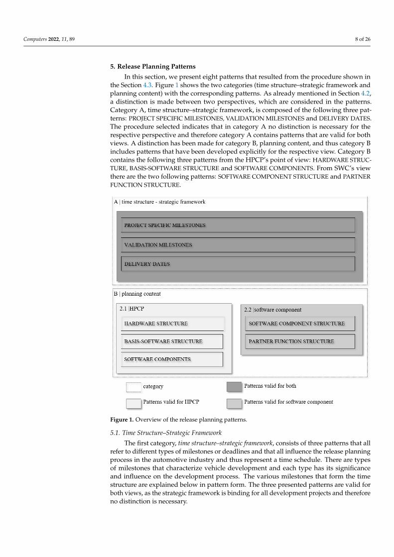
In this section, we present eight patterns that resulted from the procedure shown inthe Section 4.3. Figure 1 shows the two categories (time structure–strategic framework andplanning content) with the corresponding patterns. As already mentioned in Section 4.2,a distinction is made between two perspectives, which are considered in the patterns.Category A, time structure–strategic framework, is composed of the following three pat-terns: PROJECT SPECIFIC MILESTONES, VALIDATION MILESTONES and DELIVERY DATES.The procedure selected indicates that in category A no distinction is necessary for therespective perspective and therefore category A contains patterns that are valid for bothviews. A distinction has been made for category B, planning content, and thus category Bincludes patterns that have been developed explicitly for the respective view. Category Bcontains the following three patterns from the HPCP’s point of view: HARDWARE STRUC-TURE, BASIS-SOFTWARE STRUCTURE and SOFTWARE COMPONENTS. From SWC’s viewthere are the two following patterns: SOFTWARE COMPONENT STRUCTURE and PARTNERFUNCTION STRUCTURE.
Figure 1. Overview of the release planning patterns.
5.1. Time Structure–Strategic Framework
The first category, time structure–strategic framework, consists of three patterns that allrefer to different types of milestones or deadlines and that all influence the release planningprocess in the automotive industry and thus represent a time schedule. There are typesof milestones that characterize vehicle development and each type has its significanceand influence on the development process. The various milestones that form the timestructure are explained below in pattern form. The three presented patterns are valid forboth views, as the strategic framework is binding for all development projects and thereforeno distinction is necessary.
Computers 2022, 11, 89 9 of 26
5.1.1. Project-Specific Milestones
Context: The project-specific milestones represent key milestones that emerge fromeach OEM’s product development process projected on the development project. Thesemilestones contain required targets that have to be met to pass the gates. The project-specific development procedure has to be aligned to the required content of each milestoneand has to be considered accordingly in the release planning. The automotive industry is astrictly regulated domain, which has to comply with numerous standards and legislations.For this reason, several milestones characterize the vehicle development and the associatedrelease planning. These pre-defined milestones represent general dates that have to beconsidered and passed during the development process.
Problem: The strategic framework forms a time structure, which has to be consideredduring the initial creation of the release plan. From the project-specific milestones, a selec-tion has to be made of which milestones are relevant for release planning, since the samemilestones are not required for every development project.
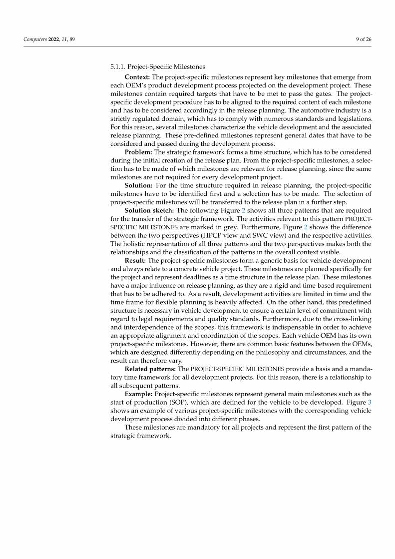
Solution: For the time structure required in release planning, the project-specificmilestones have to be identified first and a selection has to be made. The selection ofproject-specific milestones will be transferred to the release plan in a further step.
Solution sketch: The following Figure 2 shows all three patterns that are requiredfor the transfer of the strategic framework. The activities relevant to this pattern PROJECT-SPECIFIC MILESTONES are marked in grey. Furthermore, Figure 2 shows the differencebetween the two perspectives (HPCP view and SWC view) and the respective activities.The holistic representation of all three patterns and the two perspectives makes both therelationships and the classification of the patterns in the overall context visible.
Result: The project-specific milestones form a generic basis for vehicle developmentand always relate to a concrete vehicle project. These milestones are planned specifically forthe project and represent deadlines as a time structure in the release plan. These milestoneshave a major influence on release planning, as they are a rigid and time-based requirementthat has to be adhered to. As a result, development activities are limited in time and thetime frame for flexible planning is heavily affected. On the other hand, this predefinedstructure is necessary in vehicle development to ensure a certain level of commitment withregard to legal requirements and quality standards. Furthermore, due to the cross-linkingand interdependence of the scopes, this framework is indispensable in order to achievean appropriate alignment and coordination of the scopes. Each vehicle OEM has its ownproject-specific milestones. However, there are common basic features between the OEMs,which are designed differently depending on the philosophy and circumstances, and theresult can therefore vary.
Related patterns: The PROJECT-SPECIFIC MILESTONES provide a basis and a manda-tory time framework for all development projects. For this reason, there is a relationship toall subsequent patterns.
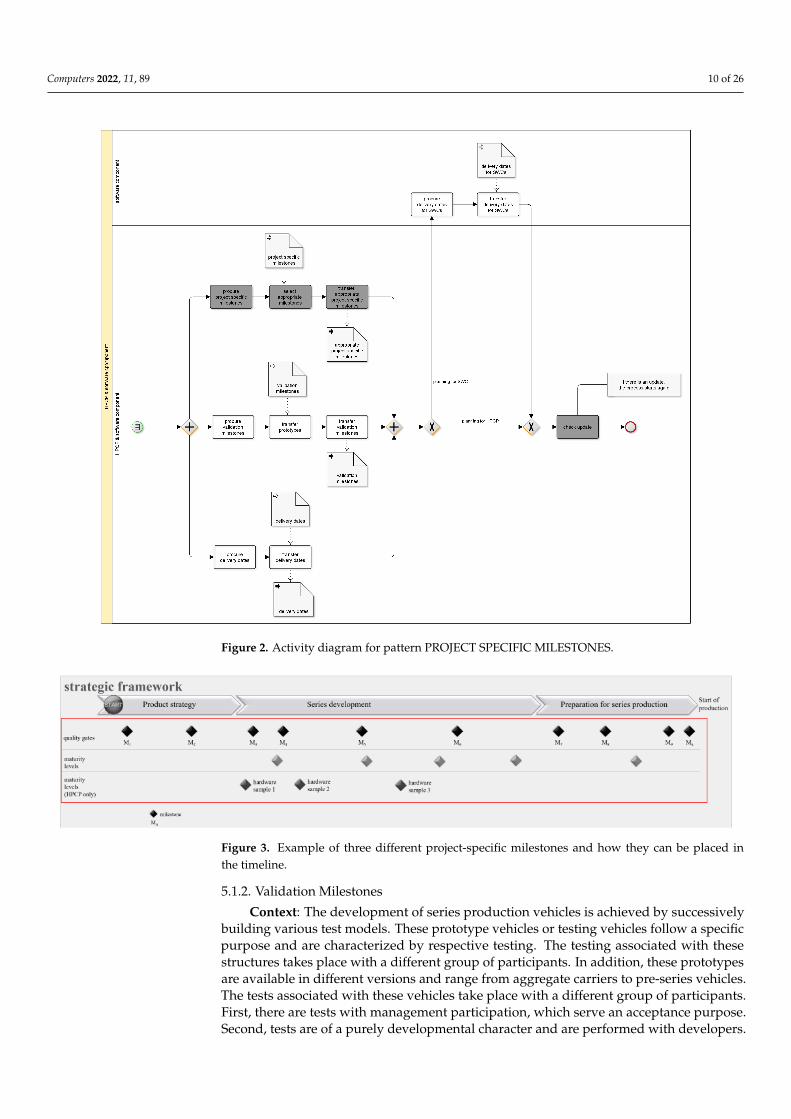
Example: Project-specific milestones represent general main milestones such as thestart of production (SOP), which are defined for the vehicle to be developed. Figure 3shows an example of various project-specific milestones with the corresponding vehicledevelopment process divided into different phases.
These milestones are mandatory for all projects and represent the first pattern of thestrategic framework.
Computers 2022, 11, 89 10 of 26
Figure 2. Activity diagram for pattern PROJECT SPECIFIC MILESTONES.
Figure 3. Example of three different project-specific milestones and how they can be placed inthe timeline.
5.1.2. Validation Milestones
Context: The development of series production vehicles is achieved by successivelybuilding various test models. These prototype vehicles or testing vehicles follow a specificpurpose and are characterized by respective testing. The testing associated with thesestructures takes place with a different group of participants. In addition, these prototypesare available in different versions and range from aggregate carriers to pre-series vehicles.The tests associated with these vehicles take place with a different group of participants.First, there are tests with management participation, which serve an acceptance purpose.Second, tests are of a purely developmental character and are performed with developers.
Computers 2022, 11, 89 11 of 26
Some types of testing take place under different climatic conditions (e.g. hot and coldambient testing) and are conducted under different environmental conditions dependingon the requirements of development scope (e.g. squeak and rattle testing and high-altitudetesting). Furthermore, the test specific milestones include testing such as test drives inurban traffic, under maximal performance operation and country-specific testing.
Problem: The tests to be carried out are linked to climatic conditions and are thereforeseasonally limited. This leads to an increasing complexity in the coordination and executionof the different tests with corresponding vehicles. The dependence on seasonal climaticconditions has to be incorporated at an early stage in the planning of the developmentscope. In addition, dependencies on other systems with different levels of maturity, whichare not the focus of the respective testing, complicate consideration in the release plan. Dueto climatic conditions and the time available, tests are carried out in parallel and are anti-cyclical. On the one hand, this saves time and, on the other hand, makes debugging moredifficult when cold and hot ambient testing take place simultaneously. The preparationand post-processing of the vehicles, as well as transport routes to the test locations or eventhe import and export by customs, are activities that require a certain amount of time andshould also be considered in the release plan.
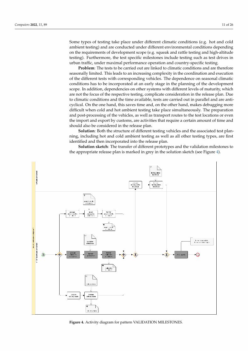
Solution: Both the structure of different testing vehicles and the associated test plan-ning, including hot and cold ambient testing as well as all other testing types, are firstidentified and then incorporated into the release plan.
Solution sketch: The transfer of different prototypes and the validation milestones tothe appropriate release plan is marked in grey in the solution sketch (see Figure 4).
Figure 4. Activity diagram for pattern VALIDATION MILESTONES.
Computers 2022, 11, 89 12 of 26
Result: On the one hand, the validation milestones represent the different testing vehi-cles and serve to coordinate necessary testing with activities to be implemented. The struc-ture of the testing vehicles is project-specific and has a corresponding effect on the testplanning. These milestones are a further part of the strategic framework and control theupcoming development activities accordingly. As a result of this process step, both theprototypes and the validation milestones are now included in the release plan. The valida-tion milestones are defined for a specific vehicle project, and since each OEM has its ownmilestones, the result can differ.
Related patterns: The validation milestones are based on the PROJECT SPECIFICMILESTONES and are defined accordingly.
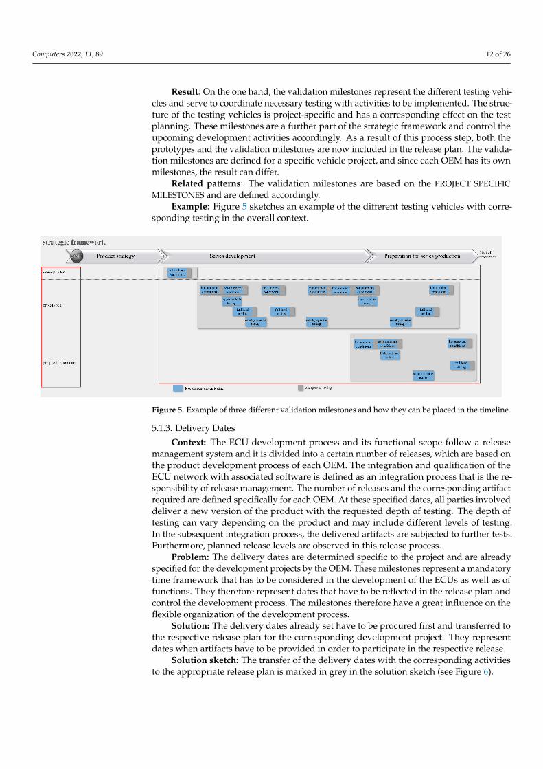
Example: Figure 5 sketches an example of the different testing vehicles with corre-sponding testing in the overall context.
Figure 5. Example of three different validation milestones and how they can be placed in the timeline.
5.1.3. Delivery Dates
Context: The ECU development process and its functional scope follow a releasemanagement system and it is divided into a certain number of releases, which are based onthe product development process of each OEM. The integration and qualification of theECU network with associated software is defined as an integration process that is the re-sponsibility of release management. The number of releases and the corresponding artifactrequired are defined specifically for each OEM. At these specified dates, all parties involveddeliver a new version of the product with the requested depth of testing. The depth oftesting can vary depending on the product and may include different levels of testing.In the subsequent integration process, the delivered artifacts are subjected to further tests.Furthermore, planned release levels are observed in this release process.
Problem: The delivery dates are determined specific to the project and are alreadyspecified for the development projects by the OEM. These milestones represent a mandatorytime framework that has to be considered in the development of the ECUs as well as offunctions. They therefore represent dates that have to be reflected in the release plan andcontrol the development process. The milestones therefore have a great influence on theflexible organization of the development process.
Solution: The delivery dates already set have to be procured first and transferred tothe respective release plan for the corresponding development project. They representdates when artifacts have to be provided in order to participate in the respective release.
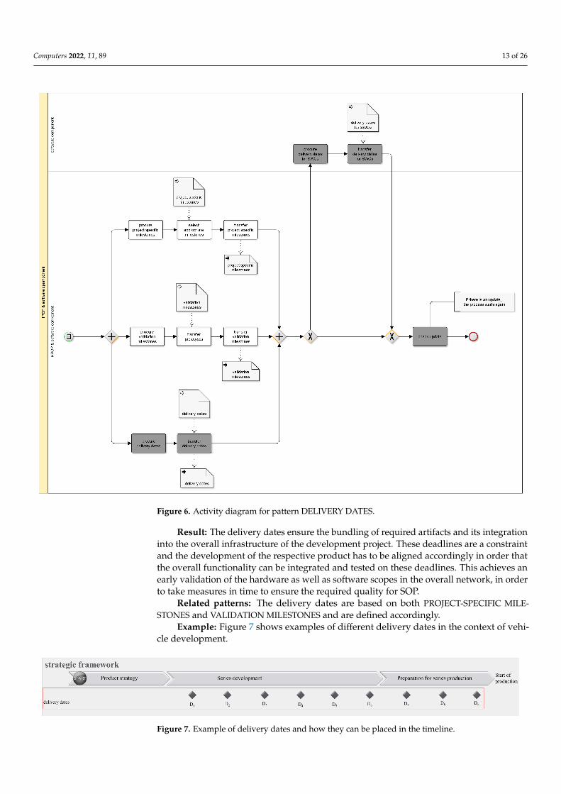
Solution sketch: The transfer of the delivery dates with the corresponding activitiesto the appropriate release plan is marked in grey in the solution sketch (see Figure 6).
Computers 2022, 11, 89 13 of 26
Figure 6. Activity diagram for pattern DELIVERY DATES.
Result: The delivery dates ensure the bundling of required artifacts and its integrationinto the overall infrastructure of the development project. These deadlines are a constraintand the development of the respective product has to be aligned accordingly in order thatthe overall functionality can be integrated and tested on these deadlines. This achieves anearly validation of the hardware as well as software scopes in the overall network, in orderto take measures in time to ensure the required quality for SOP.
Related patterns: The delivery dates are based on both PROJECT-SPECIFIC MILE-STONES and VALIDATION MILESTONES and are defined accordingly.
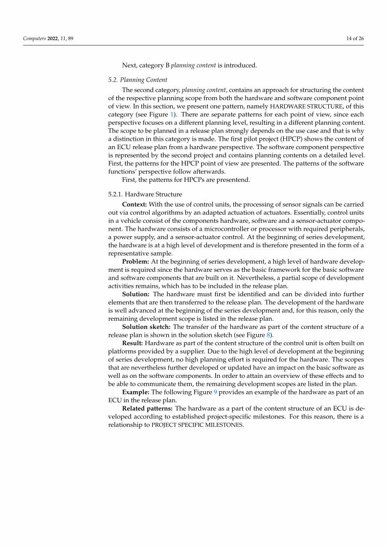
Example: Figure 7 shows examples of different delivery dates in the context of vehi-cle development.
Figure 7. Example of delivery dates and how they can be placed in the timeline.
Computers 2022, 11, 89 14 of 26
Next, category B planning content is introduced.
5.2. Planning Content
The second category, planning content, contains an approach for structuring the contentof the respective planning scope from both the hardware and software component pointof view. In this section, we present one pattern, namely HARDWARE STRUCTURE, of thiscategory (see Figure 1). There are separate patterns for each point of view, since eachperspective focuses on a different planning level, resulting in a different planning content.The scope to be planned in a release plan strongly depends on the use case and that is whya distinction in this category is made. The first pilot project (HPCP) shows the content ofan ECU release plan from a hardware perspective. The software component perspectiveis represented by the second project and contains planning contents on a detailed level.First, the patterns for the HPCP point of view are presented. The patterns of the softwarefunctions’ perspective follow afterwards.
First, the patterns for HPCPs are presentend.
5.2.1. Hardware Structure
Context: With the use of control units, the processing of sensor signals can be carriedout via control algorithms by an adapted actuation of actuators. Essentially, control unitsin a vehicle consist of the components hardware, software and a sensor-actuator compo-nent. The hardware consists of a microcontroller or processor with required peripherals,a power supply, and a sensor-actuator control. At the beginning of series development,the hardware is at a high level of development and is therefore presented in the form of arepresentative sample.
Problem: At the beginning of series development, a high level of hardware develop-ment is required since the hardware serves as the basic framework for the basic softwareand software components that are built on it. Nevertheless, a partial scope of developmentactivities remains, which has to be included in the release plan.
Solution: The hardware must first be identified and can be divided into furtherelements that are then transferred to the release plan. The development of the hardwareis well advanced at the beginning of the series development and, for this reason, only theremaining development scope is listed in the release plan.
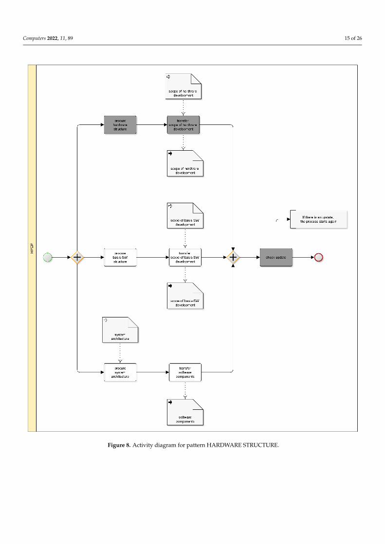
Solution sketch: The transfer of the hardware as part of the content structure of arelease plan is shown in the solution sketch (see Figure 8).
Result: Hardware as part of the content structure of the control unit is often built onplatforms provided by a supplier. Due to the high level of development at the beginningof series development, no high planning effort is required for the hardware. The scopesthat are nevertheless further developed or updated have an impact on the basic software aswell as on the software components. In order to attain an overview of these effects and tobe able to communicate them, the remaining development scopes are listed in the plan.
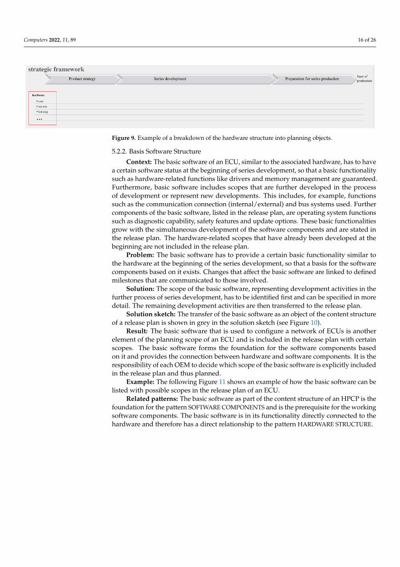
Example: The following Figure 9 provides an example of the hardware as part of anECU in the release plan.
Related patterns: The hardware as a part of the content structure of an ECU is de-veloped according to established project-specific milestones. For this reason, there is arelationship to PROJECT SPECIFIC MILESTONES.
Computers 2022, 11, 89 15 of 26
Figure 8. Activity diagram for pattern HARDWARE STRUCTURE.
Computers 2022, 11, 89 16 of 26
Figure 9. Example of a breakdown of the hardware structure into planning objects.
5.2.2. Basis Software Structure
Context: The basic software of an ECU, similar to the associated hardware, has to havea certain software status at the beginning of series development, so that a basic functionalitysuch as hardware-related functions like drivers and memory management are guaranteed.Furthermore, basic software includes scopes that are further developed in the processof development or represent new developments. This includes, for example, functionssuch as the communication connection (internal/external) and bus systems used. Furthercomponents of the basic software, listed in the release plan, are operating system functionssuch as diagnostic capability, safety features and update options. These basic functionalitiesgrow with the simultaneous development of the software components and are stated inthe release plan. The hardware-related scopes that have already been developed at thebeginning are not included in the release plan.
Problem: The basic software has to provide a certain basic functionality similar tothe hardware at the beginning of the series development, so that a basis for the softwarecomponents based on it exists. Changes that affect the basic software are linked to definedmilestones that are communicated to those involved.
Solution: The scope of the basic software, representing development activities in thefurther process of series development, has to be identified first and can be specified in moredetail. The remaining development activities are then transferred to the release plan.
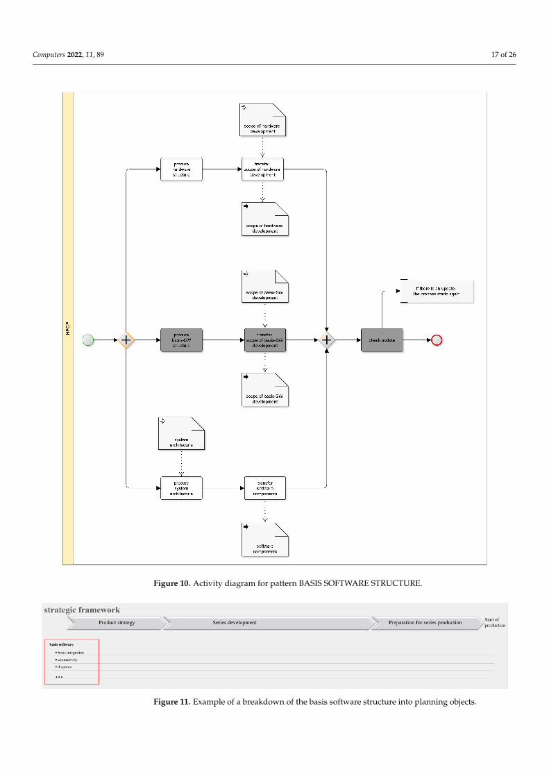
Solution sketch: The transfer of the basic software as an object of the content structureof a release plan is shown in grey in the solution sketch (see Figure 10).
Result: The basic software that is used to configure a network of ECUs is anotherelement of the planning scope of an ECU and is included in the release plan with certainscopes. The basic software forms the foundation for the software components basedon it and provides the connection between hardware and software components. It is theresponsibility of each OEM to decide which scope of the basic software is explicitly includedin the release plan and thus planned.
Example: The following Figure 11 shows an example of how the basic software can belisted with possible scopes in the release plan of an ECU.
Related patterns: The basic software as part of the content structure of an HPCP is thefoundation for the pattern SOFTWARE COMPONENTS and is the prerequisite for the workingsoftware components. The basic software is in its functionality directly connected to thehardware and therefore has a direct relationship to the pattern HARDWARE STRUCTURE.
Computers 2022, 11, 89 17 of 26
Figure 10. Activity diagram for pattern BASIS SOFTWARE STRUCTURE.
Figure 11. Example of a breakdown of the basis software structure into planning objects.
Computers 2022, 11, 89 18 of 26
5.2.3. Software Components
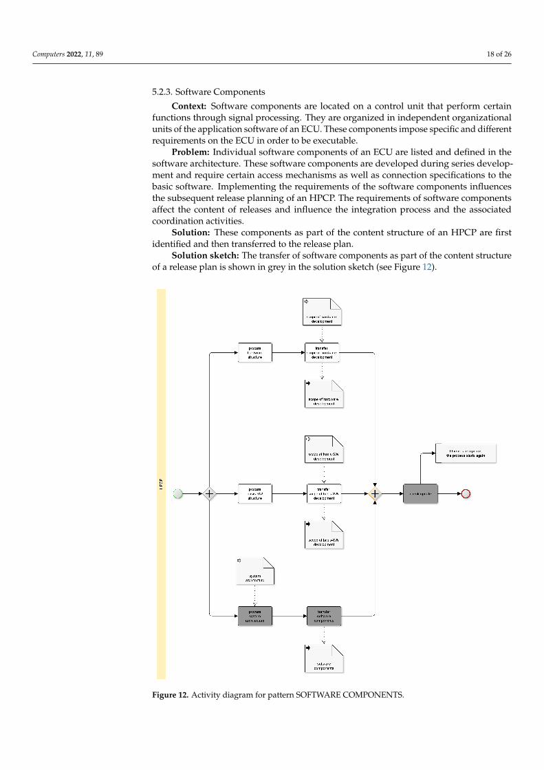
Context: Software components are located on a control unit that perform certainfunctions through signal processing. They are organized in independent organizationalunits of the application software of an ECU. These components impose specific and differentrequirements on the ECU in order to be executable.
Problem: Individual software components of an ECU are listed and defined in thesoftware architecture. These software components are developed during series develop-ment and require certain access mechanisms as well as connection specifications to thebasic software. Implementing the requirements of the software components influencesthe subsequent release planning of an HPCP. The requirements of software componentsaffect the content of releases and influence the integration process and the associatedcoordination activities.
Solution: These components as part of the content structure of an HPCP are firstidentified and then transferred to the release plan.
Solution sketch: The transfer of software components as part of the content structureof a release plan is shown in grey in the solution sketch (see Figure 12).
Figure 12. Activity diagram for pattern SOFTWARE COMPONENTS.
Computers 2022, 11, 89 19 of 26
Result: Software components encapsulate implementation details and are an impor-tant structuring element of the entire control unit software. Software components locatedon an ECU are listed in the release plan of the HPCP and implement the functions of anapplication. Software components, as a decoupled, functional-bearing application layer,have standardized interfaces and can, in principle, be relocated at any place within theECU network.
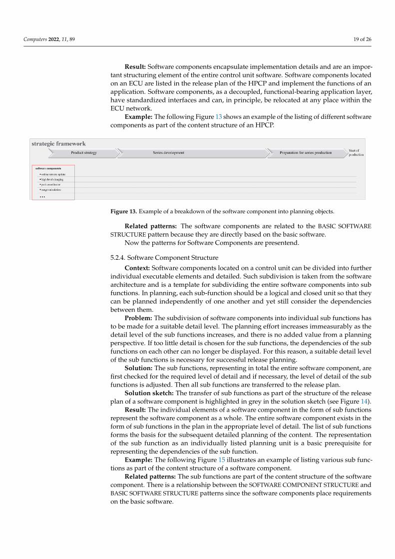
Example: The following Figure 13 shows an example of the listing of different softwarecomponents as part of the content structure of an HPCP.
Figure 13. Example of a breakdown of the software component into planning objects.
Related patterns: The software components are related to the BASIC SOFTWARESTRUCTURE pattern because they are directly based on the basic software.
Now the patterns for Software Components are presentend.
5.2.4. Software Component Structure
Context: Software components located on a control unit can be divided into furtherindividual executable elements and detailed. Such subdivision is taken from the softwarearchitecture and is a template for subdividing the entire software components into subfunctions. In planning, each sub-function should be a logical and closed unit so that theycan be planned independently of one another and yet still consider the dependenciesbetween them.
Problem: The subdivision of software components into individual sub functions hasto be made for a suitable detail level. The planning effort increases immeasurably as thedetail level of the sub functions increases, and there is no added value from a planningperspective. If too little detail is chosen for the sub functions, the dependencies of the subfunctions on each other can no longer be displayed. For this reason, a suitable detail levelof the sub functions is necessary for successful release planning.
Solution: The sub functions, representing in total the entire software component, arefirst checked for the required level of detail and if necessary, the level of detail of the subfunctions is adjusted. Then all sub functions are transferred to the release plan.
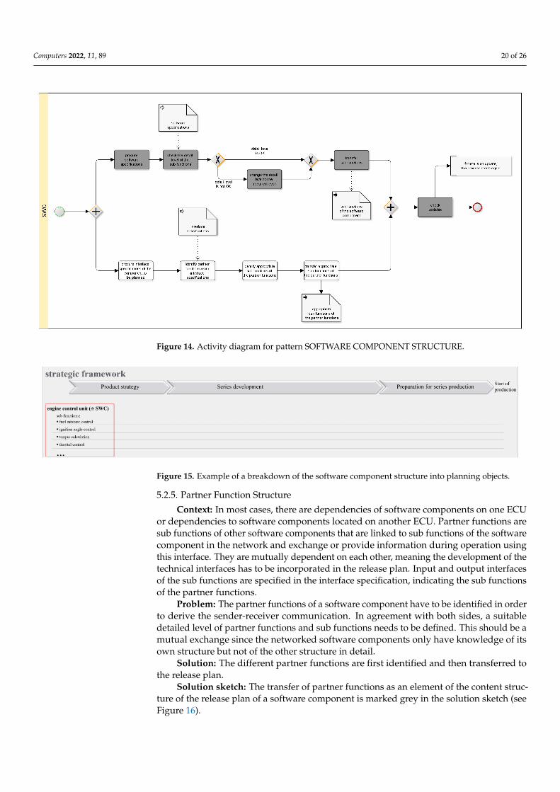
Solution sketch: The transfer of sub functions as part of the structure of the releaseplan of a software component is highlighted in grey in the solution sketch (see Figure 14).
Result: The individual elements of a software component in the form of sub functionsrepresent the software component as a whole. The entire software component exists in theform of sub functions in the plan in the appropriate level of detail. The list of sub functionsforms the basis for the subsequent detailed planning of the content. The representationof the sub function as an individually listed planning unit is a basic prerequisite forrepresenting the dependencies of the sub function.
Example: The following Figure 15 illustrates an example of listing various sub func-tions as part of the content structure of a software component.
Related patterns: The sub functions are part of the content structure of the softwarecomponent. There is a relationship between the SOFTWARE COMPONENT STRUCTURE andBASIC SOFTWARE STRUCTURE patterns since the software components place requirementson the basic software.
Computers 2022, 11, 89 20 of 26
Figure 14. Activity diagram for pattern SOFTWARE COMPONENT STRUCTURE.
Figure 15. Example of a breakdown of the software component structure into planning objects.
5.2.5. Partner Function Structure
Context: In most cases, there are dependencies of software components on one ECUor dependencies to software components located on another ECU. Partner functions aresub functions of other software components that are linked to sub functions of the softwarecomponent in the network and exchange or provide information during operation usingthis interface. They are mutually dependent on each other, meaning the development of thetechnical interfaces has to be incorporated in the release plan. Input and output interfacesof the sub functions are specified in the interface specification, indicating the sub functionsof the partner functions.
Problem: The partner functions of a software component have to be identified in orderto derive the sender-receiver communication. In agreement with both sides, a suitabledetailed level of partner functions and sub functions needs to be defined. This should be amutual exchange since the networked software components only have knowledge of itsown structure but not of the other structure in detail.
Solution: The different partner functions are first identified and then transferred tothe release plan.
Solution sketch: The transfer of partner functions as an element of the content struc-ture of the release plan of a software component is marked grey in the solution sketch (seeFigure 16).
Computers 2022, 11, 89 21 of 26
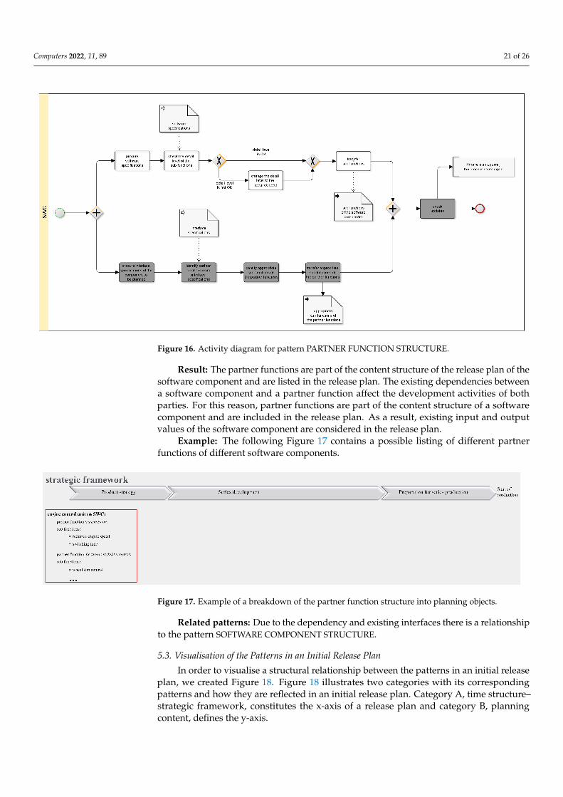
Figure 16. Activity diagram for pattern PARTNER FUNCTION STRUCTURE.
Result: The partner functions are part of the content structure of the release plan of thesoftware component and are listed in the release plan. The existing dependencies betweena software component and a partner function affect the development activities of bothparties. For this reason, partner functions are part of the content structure of a softwarecomponent and are included in the release plan. As a result, existing input and outputvalues of the software component are considered in the release plan.
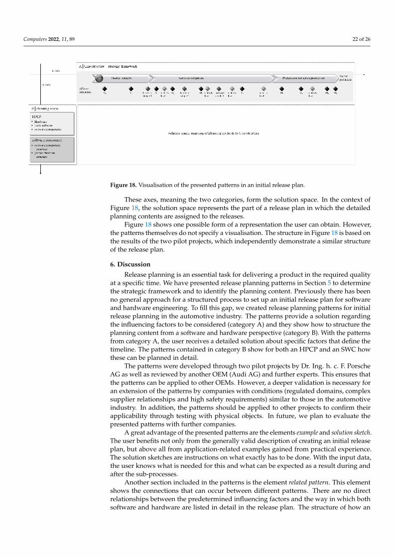
Example: The following Figure 17 contains a possible listing of different partnerfunctions of different software components.
Figure 17. Example of a breakdown of the partner function structure into planning objects.
Related patterns: Due to the dependency and existing interfaces there is a relationshipto the pattern SOFTWARE COMPONENT STRUCTURE.
5.3. Visualisation of the Patterns in an Initial Release Plan
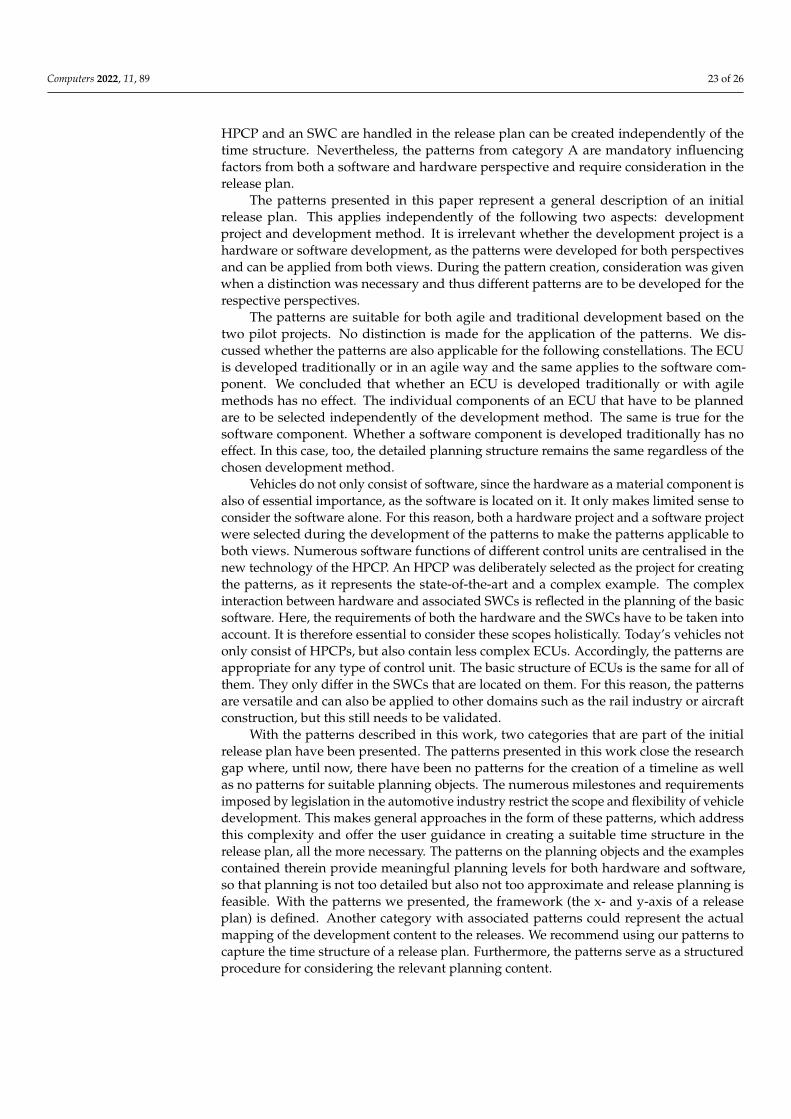
In order to visualise a structural relationship between the patterns in an initial releaseplan, we created Figure 18. Figure 18 illustrates two categories with its correspondingpatterns and how they are reflected in an initial release plan. Category A, time structure–strategic framework, constitutes the x-axis of a release plan and category B, planningcontent, defines the y-axis.
Computers 2022, 11, 89 22 of 26
Figure 18. Visualisation of the presented patterns in an initial release plan.
These axes, meaning the two categories, form the solution space. In the context ofFigure 18, the solution space represents the part of a release plan in which the detailedplanning contents are assigned to the releases.
Figure 18 shows one possible form of a representation the user can obtain. However,the patterns themselves do not specify a visualisation. The structure in Figure 18 is based onthe results of the two pilot projects, which independently demonstrate a similar structureof the release plan.
6. Discussion
Release planning is an essential task for delivering a product in the required qualityat a specific time. We have presented release planning patterns in Section 5 to determinethe strategic framework and to identify the planning content. Previously there has beenno general approach for a structured process to set up an initial release plan for softwareand hardware engineering. To fill this gap, we created release planning patterns for initialrelease planning in the automotive industry. The patterns provide a solution regardingthe influencing factors to be considered (category A) and they show how to structure theplanning content from a software and hardware perspective (category B). With the patternsfrom category A, the user receives a detailed solution about specific factors that define thetimeline. The patterns contained in category B show for both an HPCP and an SWC howthese can be planned in detail.
The patterns were developed through two pilot projects by Dr. Ing. h. c. F. PorscheAG as well as reviewed by another OEM (Audi AG) and further experts. This ensures thatthe patterns can be applied to other OEMs. However, a deeper validation is necessary foran extension of the patterns by companies with conditions (regulated domains, complexsupplier relationships and high safety requirements) similar to those in the automotiveindustry. In addition, the patterns should be applied to other projects to confirm theirapplicability through testing with physical objects. In future, we plan to evaluate thepresented patterns with further companies.
A great advantage of the presented patterns are the elements example and solution sketch.The user benefits not only from the generally valid description of creating an initial releaseplan, but above all from application-related examples gained from practical experience.The solution sketches are instructions on what exactly has to be done. With the input data,the user knows what is needed for this and what can be expected as a result during andafter the sub-processes.
Another section included in the patterns is the element related pattern. This elementshows the connections that can occur between different patterns. There are no directrelationships between the predetermined influencing factors and the way in which bothsoftware and hardware are listed in detail in the release plan. The structure of how an
Computers 2022, 11, 89 23 of 26
HPCP and an SWC are handled in the release plan can be created independently of thetime structure. Nevertheless, the patterns from category A are mandatory influencingfactors from both a software and hardware perspective and require consideration in therelease plan.
The patterns presented in this paper represent a general description of an initialrelease plan. This applies independently of the following two aspects: developmentproject and development method. It is irrelevant whether the development project is ahardware or software development, as the patterns were developed for both perspectivesand can be applied from both views. During the pattern creation, consideration was givenwhen a distinction was necessary and thus different patterns are to be developed for therespective perspectives.
The patterns are suitable for both agile and traditional development based on thetwo pilot projects. No distinction is made for the application of the patterns. We dis-cussed whether the patterns are also applicable for the following constellations. The ECUis developed traditionally or in an agile way and the same applies to the software com-ponent. We concluded that whether an ECU is developed traditionally or with agilemethods has no effect. The individual components of an ECU that have to be plannedare to be selected independently of the development method. The same is true for thesoftware component. Whether a software component is developed traditionally has noeffect. In this case, too, the detailed planning structure remains the same regardless of thechosen development method.
Vehicles do not only consist of software, since the hardware as a material component isalso of essential importance, as the software is located on it. It only makes limited sense toconsider the software alone. For this reason, both a hardware project and a software projectwere selected during the development of the patterns to make the patterns applicable toboth views. Numerous software functions of different control units are centralised in thenew technology of the HPCP. An HPCP was deliberately selected as the project for creatingthe patterns, as it represents the state-of-the-art and a complex example. The complexinteraction between hardware and associated SWCs is reflected in the planning of the basicsoftware. Here, the requirements of both the hardware and the SWCs have to be taken intoaccount. It is therefore essential to consider these scopes holistically. Today’s vehicles notonly consist of HPCPs, but also contain less complex ECUs. Accordingly, the patterns areappropriate for any type of control unit. The basic structure of ECUs is the same for all ofthem. They only differ in the SWCs that are located on them. For this reason, the patternsare versatile and can also be applied to other domains such as the rail industry or aircraftconstruction, but this still needs to be validated.
With the patterns described in this work, two categories that are part of the initialrelease plan have been presented. The patterns presented in this work close the researchgap where, until now, there have been no patterns for the creation of a timeline as wellas no patterns for suitable planning objects. The numerous milestones and requirementsimposed by legislation in the automotive industry restrict the scope and flexibility of vehicledevelopment. This makes general approaches in the form of these patterns, which addressthis complexity and offer the user guidance in creating a suitable time structure in therelease plan, all the more necessary. The patterns on the planning objects and the examplescontained therein provide meaningful planning levels for both hardware and software,so that planning is not too detailed but also not too approximate and release planning isfeasible. With the patterns we presented, the framework (the x- and y-axis of a releaseplan) is defined. Another category with associated patterns could represent the actualmapping of the development content to the releases. We recommend using our patterns tocapture the time structure of a release plan. Furthermore, the patterns serve as a structuredprocedure for considering the relevant planning content.
Computers 2022, 11, 89 24 of 26
7. Conclusions and Future Work
Today’s vehicles, but also those of the future, will be characterized by software. Thismeans that the planning and development of the software and hardware installed in thevehicle will become increasingly important. New legal requirements extend the existingrequirements for hardware and software development. As a result, the complexity offactors influencing release planning is also enhanced. Release planning, consisting in itscore task of assigning content to releases, is a complicated matter itself. Due to the lack of ageneral approach, such as hard constraints influencing release planning in the automotiveindustry and the way release plans are created, we presented eight release planningpatterns. The patterns belonging to the category time structure–strategic framework addressthe firmly defined milestones, providing a binding timeline. Project-specific milestones,testing vehicles and test phases, as well as the delivery dates, which are valid for bothhardware and software development, are included. The planning content from the HPCPand software component view is covered by the patterns from category B. From the HPCPperspective, three components—hardware, basic software and the software components—are planned. In its release plan, the software component itself lists sub functions and subfunctions of partner functions that represent the scope of planning.
The results demonstrated offer support to release planners and other interested usersfor their own solution. Using a structured, practice-based approach, we demonstrated howto deal with the given framework conditions and what should be considered as planningcontent from an HPCP and software component point of view. The relationships betweenthe individual patterns reveal interactions and the complexity of release plans. The patternspoint out that further patterns should be created and added in order to create a compre-hensive initial release plan. We are already working on further patterns. In the future, wewant to create a pattern language for release planning that considers and connects all thepatterns. The coherent description is intended to provide a better understanding, structureand creation of release plans from both a hardware and software perspective.
Author Contributions: Conceptualization, K.M., S.W. and G.R.; methodology, K.M. and S.W.; valida-tion, K.M., S.W. and G.R.; investigation, K.M.; data curation, K.M.; writing—original draft preparation,K.M.; writing—review and editing, K.M., S.W. and G.R.; visualization, K.M.; supervision, K.M., S.W.and G.R. All authors have read and agreed to the published version of the manuscript.
Funding: This research received no external funding.
Institutional Review Board Statement: Not applicable.
Informed Consent Statement: Informed consent was obtained from all subjects involved in thestudy. Written informed consent has been obtained from the patient(s) to publish this paper.
Data Availability Statement: Not applicable.
Conflicts of Interest: The authors declare no conflict of interest.
AbbreviationsThe following abbreviations are used in this manuscript:
ECU Electric Control UnitE/E Electrical/ElectronicHPCP High-Performance Computing PlatformHW HardwareOEM Original Equipment ManufacturerSOP Start Of ProductionSWC Software ComponentSW Software
Computers 2022, 11, 89 25 of 26
References1. Unseld, R. The development trends toward vehicle computer architecture. ATZelectronics Worldw. 2020, 15, 14–17. [CrossRef]2. Burkacky, O.; Deichmann, J.; Stein, J.P. Automotive Software and Electronics 2030. 2021. Available online: https://www.mckinsey.
com/industries/automotive-and-assembly/our-insights/disruptive-trends-that-will-transform-the-auto-industry/de-de (ac-cessed on 26 April 2021).
3. Antinyan, V. Revealing the complexity of automotive software. In Proceedings of the 28th ACM Joint Meeting on EuropeanSoftware Engineering Conference and Symposium on the Foundations of Software Engineering, Sacramento, CA, USA, 16November 2020; Devanbu, P., Cohen, M., Zimmermann, T., Eds.; ACM: New York, NY, USA, 2020; pp. 1525–1528. [CrossRef]
4. Friedrich, H.E.; Ulrich, C.; Schmid, S. New vehicle concepts for future business model. In 19. Internationales Stuttgarter Symposium;Bargende, M., Reuss, H.C., Wagner, A., Wiedemann, J., Eds.; Springer Fachmedien Wiesbaden: Wiesbaden, Germany, 2019;Volume 76, pp. 815–829. [CrossRef]
5. Lindgren, M.; Land, R.; Norstr, C.; Wall, A. Key Aspects of Software Release Planning in Industry. In Proceedings of the 19thAustralian Conference on Software Engineering (aswec 2008), Perth, WA, Australia, 26–28 March 2008; pp. 320–329. [CrossRef]
6. Ruhe, G. Product Release Planning: Methods, Tools, and Applications; CRC Press: Boca Raton, FL, USA, 2010.7. Bock, F.; Sippl, C.; Siegl, S.; German, R. Status Report on Automotive Software Development. In Automotive Systems and Software
Engineering; Dajsuren, Y., van den Brand, M., Eds.; Springer International Publishing: Cham, Switzerland, 2019; Volume 39,pp. 29–57. [CrossRef]
8. Abel, H.B.; Blume, H.J.; Brabetz, L.; Broy, M.; Fürst, S.; Ganzelmeier, L.; Helbig, J.; Heyen, G.; Jipp, M.; Kasties, G.; et al.Elektrik/Elektronik/Software. In Vieweg Handbuch Kraftfahrzeugtechnik; Pischinger, S., Seiffert, U., Eds.; Springer FachmedienWiesbaden: Wiesbaden, Germany, 2016; pp. 925–1104. [CrossRef]
9. Saliu, O.; Ruhe, G. Supporting Software Release Planning Decisions for Evolving Systems. In Proceedings of the 29th AnnualIEEE/NASA Software Engineering Workshop, Greenbelt, MD, USA, 6–7 April 2005; pp. 14–26.doi: 10.1109/SEW.2005.42. [CrossRef]
10. Directive2007/46/EG. For European Vehicles. Available online: https://eur-lex.europa.eu/legal-content/DE/TXT/?uri=celex%3A32007L0046(accessed on 20 May 2020).
11. Ameller, D.; Farré, C.; Franch, X.; Rufian, G. A Survey on Software Release Planning Models. In Product-Focused Software ProcessImprovement; Lecture Notes in Computer Science; Abrahamsson, P., Jedlitschka, A., Nguyen Duc, A., Felderer, M., Amasaki, S.,Mikkonen, T., Eds.; Springer International Publishing: Cham, Switzerland, 2016; Volume 10027, pp. 48–65. [CrossRef]
12. Svahnberg, M.; Gorschek, T.; Feldt, R.; Torkar, R.; Saleem, S.B.; Shafique, M.U. A systematic review on strategic release planningmodels. Inf. Softw. Technol. 2010, 52, 237–248. [CrossRef]
13. Szoke, Á. Conceptual scheduling model and optimized release scheduling for agile environments. Inf. Softw. Technol. 2011,53, 574–591. [CrossRef]
14. Li, C.; van den Akker, M.; Brinkkemper, S.; Diepen, G. An integrated approach for requirement selection and scheduling insoftware release planning. Requir. Eng. 2010, 15, 375–396. [CrossRef]
15. Greer, D.; Ruhe, G. Software release planning: An evolutionary and iterative approach. Inf. Softw. Technol. 2004, 46, 243–253.[CrossRef]
16. Ruhe, G.; Ngo The, A. Hybrid Intelligence in Software Release Planning. Int. J. Hybrid Intell. Syst. 2004, 1, 99–110. [CrossRef]17. Felderer, M.; Beer, A.; Ho, J.; Ruhe, G. Industrial evaluation of the impact of quality-driven release planning. In Proceedings of
the 8th ACM/IEEE International Symposium on Empirical Software Engineering and Measurement—ESEM ’14, Torino, Italy,18–19 September 2014; Morisio, M., Ed.; ACM Press: New York, NY, USA, 2014; pp. 1–8. [CrossRef]
18. Colares, F.; Souza, J.; Carmo, R.; Pádua, C.; Mateus, G.R. A New Approach to the Software Release Planning. In Proceedings ofthe 2009 XXIII Brazilian Symposium on Software Engineering, Fortaleza, Brazil, 5–9 October 2009; pp. 207–215. [CrossRef]
19. Wohlin, C.; Aurum, A. What is important when deciding to include a software requirement in a project or release? In Proceedingsof the 2005 International Symposium on Empirical Software Engineering, Noosa Heads, Australia, 17–18 November 2005;pp. 237–246. [CrossRef]
20. Danesh, A.S. A Pattern-Based Release Planning Methodology for Market-Driven Software. Ph.D. Thesis, University of Malaya,Kuala Lumpur, Malaysia, 2016.
21. Marner, K.; Theobald, S.; Wagner, S. Release Planning in a Hybrid Project Environment. In Advances in Agile and User-CentredSoftware Engineering; Lecture Notes in Business Information Processing; Przybyłek, A., Morales-Trujillo, M.E., Eds.; SpringerInternational Publishing: Cham, Switzerland, 2020; Volume 376, pp. 19–40. [CrossRef]
22. Sax, E.; Reussner, R.; Guissouma, H.; Klare, H. A Survey on the State and Future of Automotive Software Release and ConfigurationManagement; KIT: Amsterdam, The Netherlands, 2017.
23. Bestfleisch, U.; Herbst, J.; Reichert, M. Requirements for the Workflow-based Support of Release Management Processes in theAutomotive Sector. In Proceedings of the 12th European Concurrent Engineering Conference (ECEC’05), Toulouse, France, 11–13April 2005; pp. 130–134.
24. Müller, D.; Herbst, J.; Hammori, M.; Reichert, M. IT Support for Release Management Processes in the Automotive Industry. InBusiness Process Management; Lecture Notes in Computer Science; Hutchison, D., Kanade, T., Kittler, J., Kleinberg, J.M., Mattern, F.,Mitchell, J.C., Naor, M., Nierstrasz, O., Pandu Rangan, C., Steffen, B., et al., Eds.; Springer: Berlin/Heidelberg, Germany, 2006;Volume 4102, pp. 368–377. [CrossRef]
Computers 2022, 11, 89 26 of 26
25. Alexander, C. A Pattern Language: Towns, Buildings, Construction; Oxford University Press: Oxford, UK, 1977.26. Gamma, E. Design Patterns: Elements of Reusable Object-Oriented Software; Pearson Education India: Delhi, India, 1995.27. Buschmann, F.; Henney, K.; Schmidt, D. Pattern-Oriented Software Architecture: A Pattern Language for Distributed Computing.
Volume 4, 1st ed.; Wiley Series in Software Design Patterns; John Wiley & Sons: New York, NY, USA, 2007.28. Marner, K.; Wagner, S.; Ruhe, G. Stakeholder identification for a structured release planning approach in the automotive domain.
Requir. Eng. 2020, 27, 211–230. [CrossRef]29. Fehling, C.; Barzen, J.; Breitenbücher, U.; Leymann, F. A process for pattern identification, authoring, and application. In
Proceedings of the 19th European Conference on Pattern Languages of Programs—EuroPLoP ’14, Irsee, Germany, 9–13 July 2014;Eloranta, V.P., van Heesch, U., Eds.; ACM Press: New York, NY, USA, 2014; pp. 1–9. [CrossRef]
30. Meszaros, G.; Doble, J. A pattern language for pattern writing. Pattern Lang. Program Des. 1998, 3, 529–574.31. Harrison, N.B.; Avaya Inc. Advanced Pattern Writing Patterns for Experienced Pattern Authors; Citeseer: University Park, PA,
USA, 2006.32. Harrison, N.B. The language of shepherding. Pattern Lang. Program Des. 1999, 5, 507–530.33. Wellhausen, T.; Fiesser, A. How to write a pattern? In Proceedings of the 16th European Conference on Pattern Languages of
Programs—EuroPLoP ’11, Irsee, Germany, 13–17 July 2011; Avgeriou, P., Fiesser, A., Eds.; ACM Press: New York, New York, USA,2011; pp. 1–9. [CrossRef]
34. Fehling, C. Cloud Computing Patterns: Fundamentals to Design, Build, and Manage Cloud Applications; Computer Science; Springer:Vienna, Austria, 2014.
35. Wohlin, C.; Runeson, P.; Höst, M. Experimentation in Software Engineering; Springer Science & Business Media: New York, NY,USA, 2012.