REINFORCED CONCRETE STRUCTURE I "Reinforced Concrete Code History" CIVIL ENGINEERING DEPARTMENT...
17
REINFORCED CONCRETE STRUCTURE I “Reinforced Concrete Code History” Revised : 12-September-2013 1 CIVIL ENGINEERING DEPARTMENT FACULTY OF CIVIL ENGINEERING AND PLANNING INSTITUT TEKNOLOGI SEPULUH NOPEMBER SURABAYA Prepared By : LB3-ITS
-
Upload
independent -
Category
Documents
-
view
0 -
download
0
Transcript of REINFORCED CONCRETE STRUCTURE I "Reinforced Concrete Code History" CIVIL ENGINEERING DEPARTMENT...
REINFORCED CONCRETE
STRUCTURE I
“Reinforced Concrete Code History”
Revised : 12-September-2013
1
CIVIL ENGINEERING DEPARTMENT
FACULTY OF CIVIL ENGINEERING AND PLANNING
INSTITUT TEKNOLOGI SEPULUH NOPEMBER
SURABAYA
Prepared By : LB3-ITS

Codes Development of RC
Philosophy design of RC were developed through out the 20th century, some
records of the development is shown below :
1. Working Stress Design (WSD) (1900-1999)
2. Ultimate Strength Design (USD) (1956-Now)
3. Unified Design Method (UDM) (2002-Now)
4. Strut and Tie Model (STM) For Shear (2002-Now)
2 Prepared By : LB3-ITS
P
0.8
0.7
0.65
Aksial Tarik Aksial Tekan Kecil
Kolom Bertulangan Spiral
Kolom Bersengkang
7.0'1.0
1.08.0
cAgf
Pu
65.0'1.0
15.08.0
cAgf
Pu
0.1f'cAg0
P
0.8
0.7
0.65
Compression Controlled Transition
Kolom Bertulangan Spiral
Kolom Bersengkang
t 6757.0
t 8348.0
t=0.002cdt=0.600
Tension Controlled
t=0.005cdt=0.375
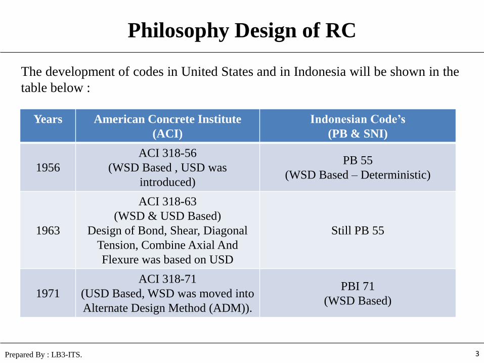
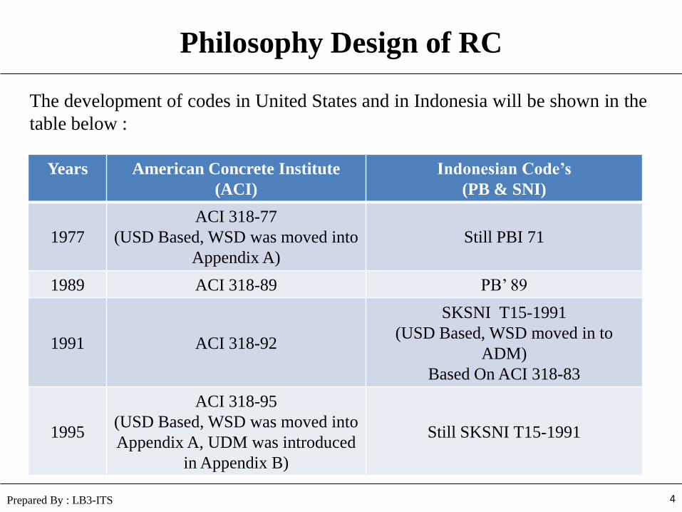
Philosophy Design of RC
The development of codes in United States and in Indonesia will be shown in the
table below :
3 Prepared By : LB3-ITS.
Years American Concrete Institute
(ACI)
Indonesian Code’s
(PB & SNI)
1956
ACI 318-56
(WSD Based , USD was
introduced)
PB 55
(WSD Based – Deterministic)
1963
ACI 318-63
(WSD & USD Based)
Design of Bond, Shear, Diagonal
Tension, Combine Axial And
Flexure was based on USD
Still PB 55
1971
ACI 318-71
(USD Based, WSD was moved into
Alternate Design Method (ADM)).
PBI 71
(WSD Based)
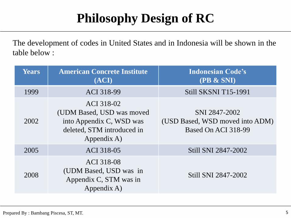
Philosophy Design of RC
The development of codes in United States and in Indonesia will be shown in the
table below :
4 Prepared By : LB3-ITS
Years American Concrete Institute
(ACI)
Indonesian Code’s
(PB & SNI)
1977
ACI 318-77
(USD Based, WSD was moved into
Appendix A)
Still PBI 71
1989 ACI 318-89 PB’ 89
1991 ACI 318-92
SKSNI T15-1991
(USD Based, WSD moved in to
ADM)
Based On ACI 318-83
1995
ACI 318-95
(USD Based, WSD was moved into
Appendix A, UDM was introduced
in Appendix B)
Still SKSNI T15-1991
Philosophy Design of RC
The development of codes in United States and in Indonesia will be shown in the
table below :
5 Prepared By : Bambang Piscesa, ST, MT.
Years American Concrete Institute
(ACI)
Indonesian Code’s
(PB & SNI)
1999 ACI 318-99 Still SKSNI T15-1991
2002
ACI 318-02
(UDM Based, USD was moved
into Appendix C, WSD was
deleted, STM introduced in
Appendix A)
SNI 2847-2002
(USD Based, WSD moved into ADM)
Based On ACI 318-99
2005 ACI 318-05 Still SNI 2847-2002
2008
ACI 318-08
(UDM Based, USD was in
Appendix C, STM was in
Appendix A)
Still SNI 2847-2002
REINFORCED CONCRETE
STRUCTURE I
“Serviceability, Strength and Structural Safety”
Revised : 12-September-2013
6
CIVIL ENGINEERING DEPARTMENT
FACULTY OF CIVIL ENGINEERING AND PLANNING
INSTITUT TEKNOLOGI SEPULUH NOPEMBER
SURABAYA
Prepared By : LB3-ITS.
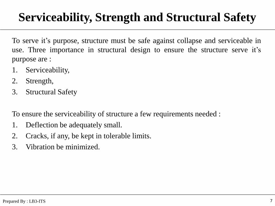
Serviceability, Strength and Structural Safety
To serve it’s purpose, structure must be safe against collapse and serviceable in
use. Three importance in structural design to ensure the structure serve it’s
purpose are :
1. Serviceability,
2. Strength,
3. Structural Safety
To ensure the serviceability of structure a few requirements needed :
1. Deflection be adequately small.
2. Cracks, if any, be kept in tolerable limits.
3. Vibration be minimized.
7 Prepared By : LB3-ITS
Serviceability, Strength and Structural Safety
To ensure the strength and structural safety of structure a few requirements
needed :
1. Strength of the structure is adequate for all loads that may foreseeable act on
it.
2. Strength of the structure must be predicted accurately.
3. The loads acting on the structure such as (Moment, Shear, Axial Forces)
must be known accurately.
4. Providing a carrying capacity just barely in excess of the known loads.
8 Prepared By : LB3-ITS
Uncertainty in Analysis and Design
These source of uncertainty, in which require a definite margin of safety as
follows :
1. Actual loads may differ from those assumed.
2. Actual loads may distributed in a manner different from those assumed.
3. Actual member dimension may differ from those specified.
4. The assumption and simplification inherent in any analysis and design may
different from those, in fact, act on the structure.
5. The actual structure behavior may differ from that assumed, owing to
imperfect knowledge.
6. Reinforcement may be not in its proper position.
7. Actual material strength may be different from that specified.
9 Prepared By : LB3-ITS
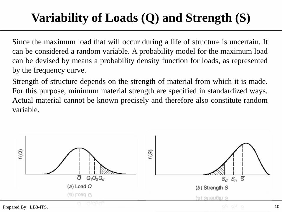
Variability of Loads (Q) and Strength (S)
Since the maximum load that will occur during a life of structure is uncertain. It
can be considered a random variable. A probability model for the maximum load
can be devised by means a probability density function for loads, as represented
by the frequency curve.
Strength of structure depends on the strength of material from which it is made.
For this purpose, minimum material strength are specified in standardized ways.
Actual material cannot be known precisely and therefore also constitute random
variable.
10 Prepared By : LB3-ITS.
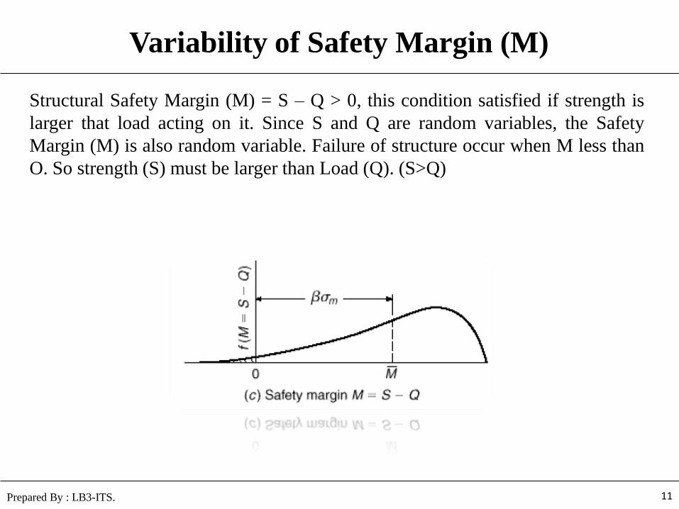
Variability of Safety Margin (M)
Structural Safety Margin (M) = S – Q > 0, this condition satisfied if strength is
larger that load acting on it. Since S and Q are random variables, the Safety
Margin (M) is also random variable. Failure of structure occur when M less than
O. So strength (S) must be larger than Load (Q). (S>Q)
11 Prepared By : LB3-ITS.
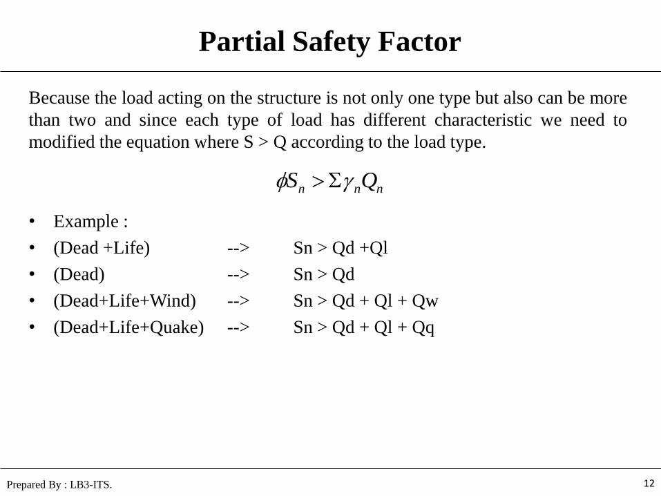
Partial Safety Factor
Because the load acting on the structure is not only one type but also can be more
than two and since each type of load has different characteristic we need to
modified the equation where S > Q according to the load type.
• Example :
• (Dead +Life) --> Sn > Qd +Ql
• (Dead) --> Sn > Qd
• (Dead+Life+Wind) --> Sn > Qd + Ql + Qw
• (Dead+Life+Quake) --> Sn > Qd + Ql + Qq
12 Prepared By : LB3-ITS.
nnn QS
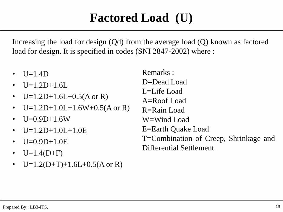
Factored Load (U)
Increasing the load for design (Qd) from the average load (Q) known as factored
load for design. It is specified in codes (SNI 2847-2002) where :
• U=1.4D
• U=1.2D+1.6L
• U=1.2D+1.6L+0.5(A or R)
• U=1.2D+1.0L+1.6W+0.5(A or R)
• U=0.9D+1.6W
• U=1.2D+1.0L+1.0E
• U=0.9D+1.0E
• U=1.4(D+F)
• U=1.2(D+T)+1.6L+0.5(A or R)
13 Prepared By : LB3-ITS.
Remarks :
D=Dead Load
L=Life Load
A=Roof Load
R=Rain Load
W=Wind Load
E=Earth Quake Load
T=Combination of Creep, Shrinkage and
Differential Settlement.

Strength Reduction Factor ()
Strength reduction factor () was defined to reduce the strength of the structure
because of the variability of material compound that made the structure. The value of
reduction factor determined in the codes (SNI 2847-2002).
1. Bending with or without tension, = 0.80
2. Compression member, spirally reinforced, = 0.70
3. Compression member, tied, = 0.65
4. Shear and Torsion = 0.75
5. Bearing on concrete = 0.65
6. Plain concrete, = 0.55
7. Compression member, low axial loads:
– Spiral = 0.8 – Pu/ fc’ Ag
– Tied = 0.8 – 1.5Pu/fc’ Ag
14 Prepared By : LB3-ITS.
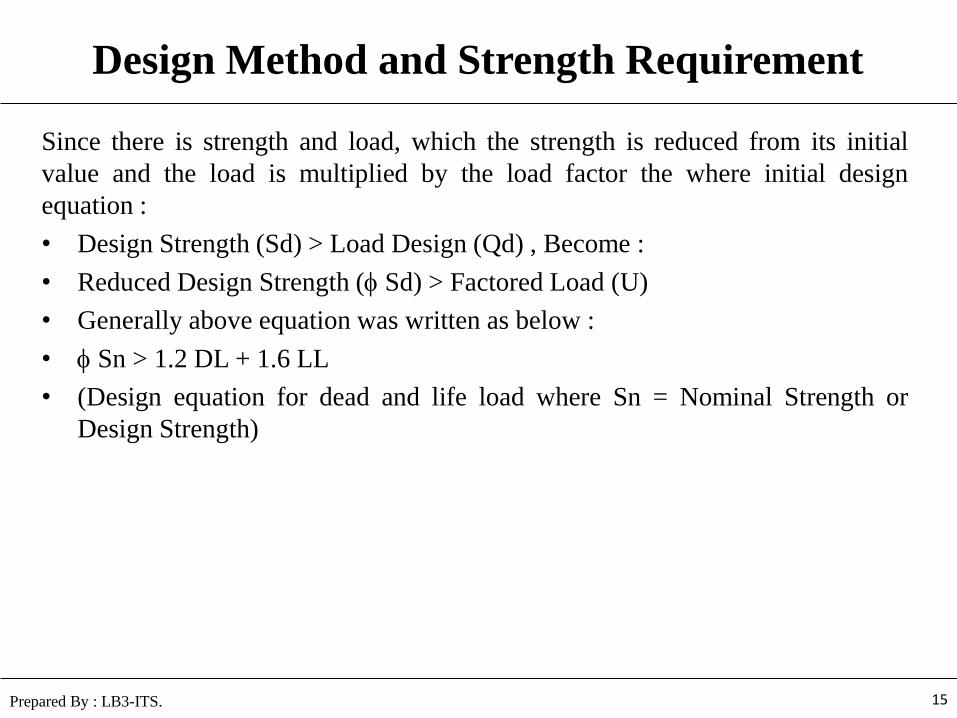
Design Method and Strength Requirement
Since there is strength and load, which the strength is reduced from its initial
value and the load is multiplied by the load factor the where initial design
equation :
• Design Strength (Sd) > Load Design (Qd) , Become :
• Reduced Design Strength ( Sd) > Factored Load (U)
• Generally above equation was written as below :
• Sn > 1.2 DL + 1.6 LL
• (Design equation for dead and life load where Sn = Nominal Strength or
Design Strength)
15 Prepared By : LB3-ITS.

Safety Factor comparison
Safety factor determine the safety of structure against load applied on the
structure, the result of Ultimate Strength Design seems conservative compared
with Working Stress Method (ACI term : Alternate Stress Design (ASD)) usually
have safety factor 1.5 for upper structure’s.
16 Prepared By : LB3-ITS
121
LD
LDSF

Thank You